Questions as text
Q1 · Two mirrors placed at right angles to each other 0625/32 Feb/March 2017
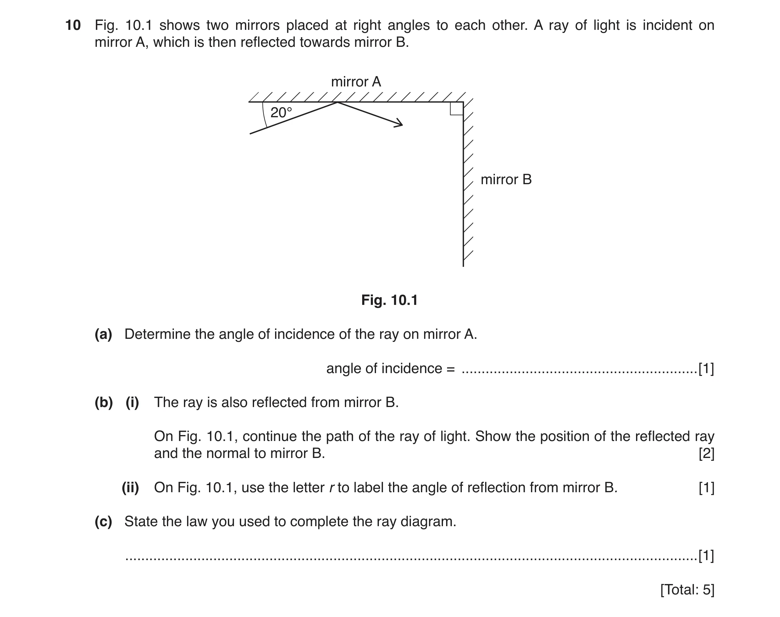
10 Fig. 10.1 shows two mirrors placed at right angles to each other. A ray of light is incident on mirror A, which is then reflected towards mirror B. mirror A 20° mirror B Fig. 10.1 (a) Determine the angle of incidence of the ray on mirror A. angle of incidence = … [1] (b) (i) The ray is also reflected from mirror B. On Fig. 10.1, continue the path of the ray of light. Show the position of the reflected ray and the normal to mirror B. [2] (ii) On Fig. 10.1, use the letter r to label the angle of reflection from mirror B. [1] (c) State the law you used to complete the ray diagram. … [1] [Total: 5]
5 marks
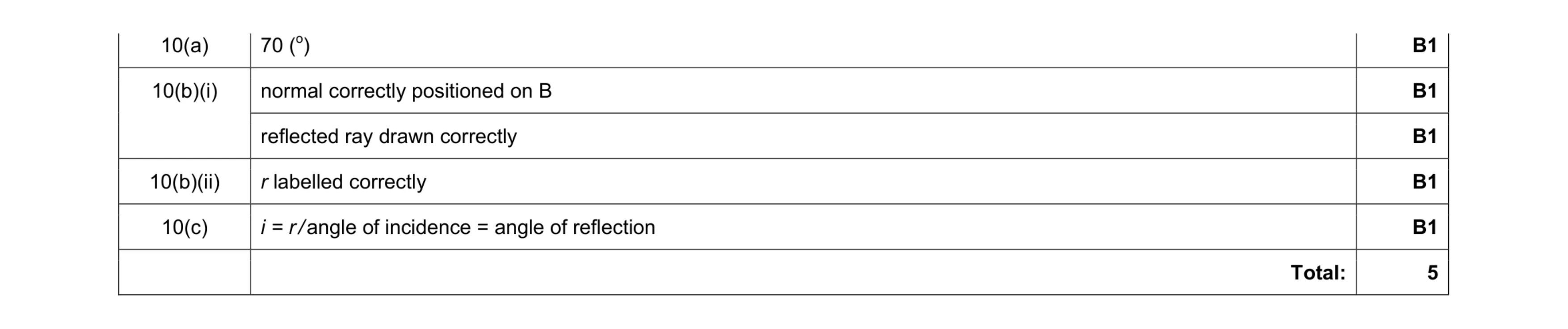
Mark scheme: 10(a) B1 10(b)(i) normal correctly positioned on B B1 reflected ray drawn correctly B1 10(b)(ii) r labelled correctly B1 10(c) i = r / angle of incidence = angle of reflection B1 Total: 5
This question in 0625/32 Feb/March 2017
Q2 · An overhead view of two cars approaching a road junction 0625/32 May/June 2017
6 (a) Fig. 6.1 shows an overhead view of two cars approaching a road junction. A plane mirror helps the drivers to see other cars. plane mirror ray of light from car 1 road driver 2 car 2 driver 1 car 1 tall building Fig. 6.1 (i) A ray of light from car 1 is shown. On Fig. 6.1, clearly draw the normal to the plane mirror where this ray hits the plane mirror. Label the normal N. [1] (ii) On Fig. 6.1, carefully draw the reflected ray of light. [1] (iii) State the law used in your answer to (a)(ii). … [1] (iv) Can each driver see the other car? … Explain your answer. … [1] (b) Fig. 6.2 shows a ray of light incident on a glass block. glass block ray of light Fig. 6.2 (i) On Fig. 6.2, continue the path of the ray into the block. [1] (ii) On Fig. 6.2, clearly label the angle of incidence i and the angle of refraction r. [2] [Total: 7]
7 marks
Mark scheme: 6(a)(i) normal line drawn at 90° to mirror by eye B1 6(a)(ii) reflected ray drawn with i = r by eye B1 6(a)(iii) angle of incidence = angle of reflection B1 6(a)(iv) Mark is for the explanation linked to candidate’s diagram. e.g. if answer is YES they should state that the reflected ray hits/reaches the (other)driver/car or can be seen B1 6(b)(i) ray refracted toward the normal B1 6(b)(ii) angle of incidence labelled B1 angle of refraction labelled B1 Total: 7
This question in 0625/32 May/June 2017
Q3 · The diagrams in Fig 0625/33 May/June 2017
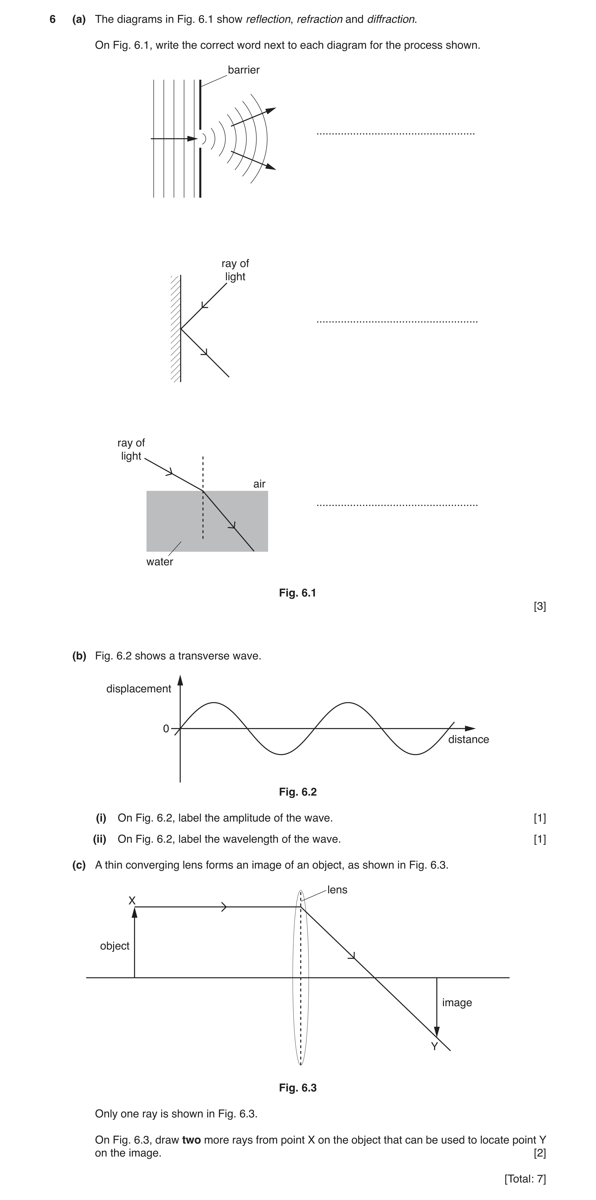
6 (a) The diagrams in Fig. 6.1 show reflection, refraction and diffraction. On Fig. 6.1, write the correct word next to each diagram for the process shown. barrier … ray of light … ray of light air … water Fig. 6.1 [3] (b) Fig. 6.2 shows a transverse wave. displacement 0 distance Fig. 6.2 (i) On Fig. 6.2, label the amplitude of the wave. [1] (ii) On Fig. 6.2, label the wavelength of the wave. [1] (c) A thin converging lens forms an image of an object, as shown in Fig. 6.3. lens X object image Y Fig. 6.3 Only one ray is shown in Fig. 6.3. On Fig. 6.3, draw two more rays from point X on the object that can be used to locate point Y on the image. [2] [Total: 7]
7 marks
Mark scheme: 6(a) B1 middle diagram labelled reflection B1 bottom diagram labelled refraction B1 6(b)(i) amplitude correctly indicated by eye B1 6(b)(ii) wavelength correctly indicated by eye B1 6(c) straight line (by eye) drawn through centre of lens to Y B1 sloping ray that emerges horizontally from lens to Y B1 Total: 7
This question in 0625/33 May/June 2017
Q4 · A ray of light inside a semi-circular glass block 0625/31 Oct/Nov 2017
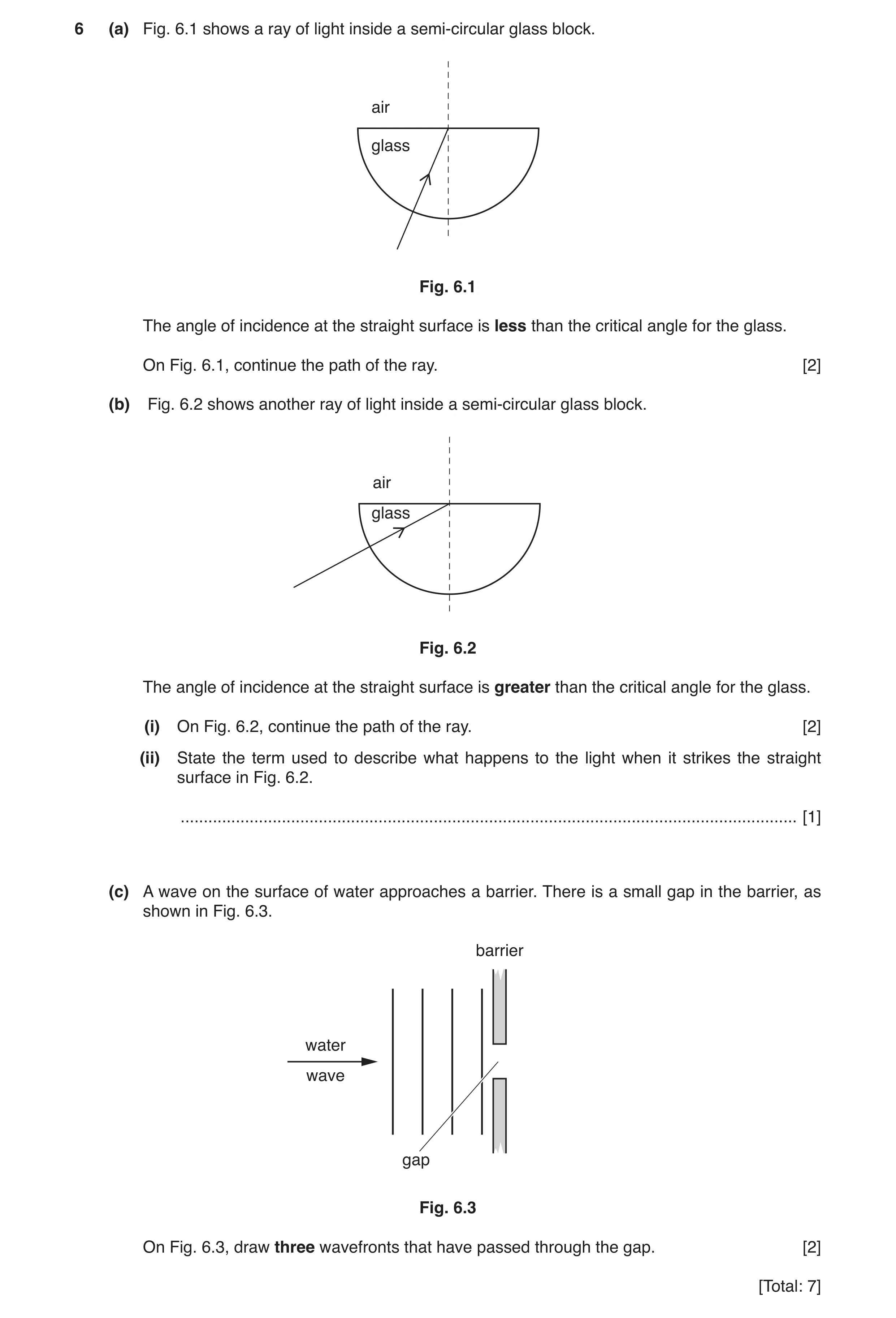
6 (a) Fig. 6.1 shows a ray of light inside a semi-circular glass block. air glass Fig. 6.1 The angle of incidence at the straight surface is less than the critical angle for the glass. On Fig. 6.1, continue the path of the ray. [2] (b) Fig. 6.2 shows another ray of light inside a semi-circular glass block. air glass Fig. 6.2 The angle of incidence at the straight surface is greater than the critical angle for the glass. (i) On Fig. 6.2, continue the path of the ray. [2] (ii) State the term used to describe what happens to the light when it strikes the straight surface in Fig. 6.2. … [1] (c) A wave on the surface of water approaches a barrier. There is a small gap in the barrier, as shown in Fig. 6.3. barrier water wave gap Fig. 6.3 On Fig. 6.3, draw three wavefronts that have passed through the gap. [2] [Total: 7]
7 marks
Mark scheme: 6(a) ray leaves glass at top surface B1 ray refracted away from normal B1 6(b)(i) ray reflected into glass B1 angle i = angle r by eye B1 6(b)(ii) total internal reflection B1 6(c) waves with arcs centred on gap B1 same wavelength B1
This question in 0625/31 Oct/Nov 2017
Q5 · A ray of light reflected from mirror 1 at point P and striking mirror 2 at point Q 0625/32 Oct/Nov 2017
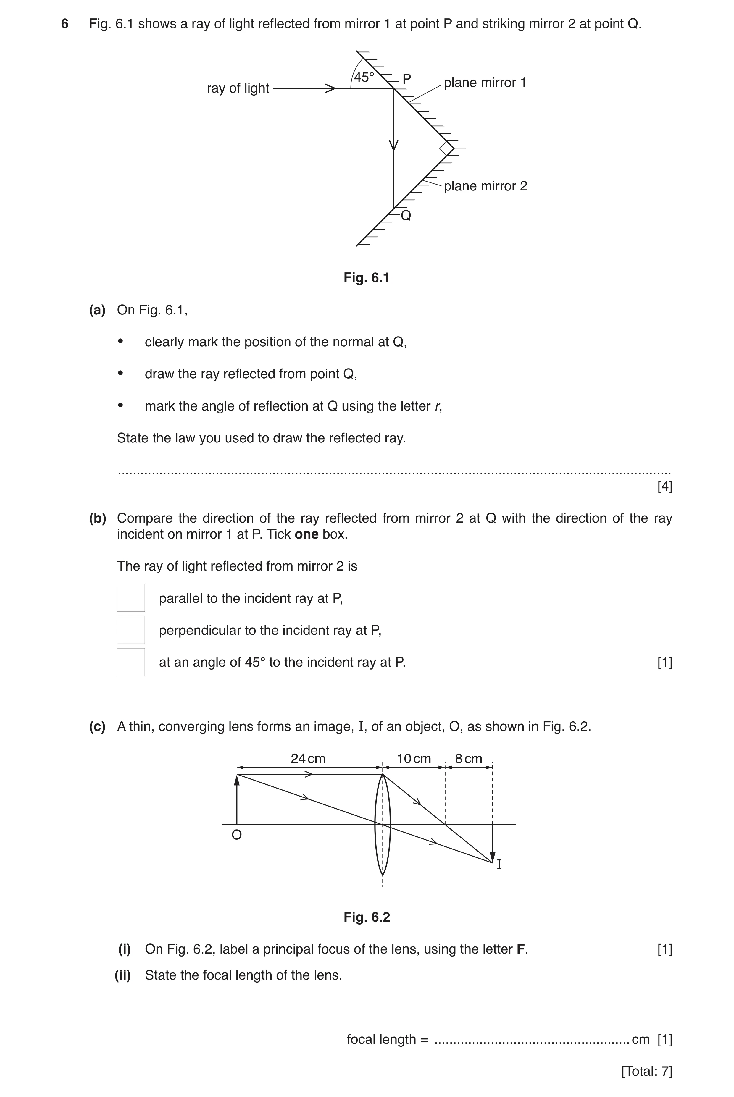
6 Fig. 6.1 shows a ray of light reflected from mirror 1 at point P and striking mirror 2 at point Q. 45° P plane mirror 1 ray of light plane mirror 2 Q Fig. 6.1 (a) On Fig. 6.1, • clearly mark the position of the normal at Q, • draw the ray reflected from point Q, • mark the angle of reflection at Q using the letter r, State the law you used to draw the reflected ray. … [4] (b) Compare the direction of the ray reflected from mirror 2 at Q with the direction of the ray incident on mirror 1 at P. Tick one box. The ray of light reflected from mirror 2 is parallel to the incident ray at P, perpendicular to the incident ray at P, at an angle of 45° to the incident ray at P. [1] (c) A thin, converging lens forms an image, I, of an object, O, as shown in Fig. 6.2. 24 cm 10 cm 8 cm O I Fig. 6.2 (i) On Fig. 6.2, label a principal focus of the lens, using the letter F. [1] (ii) State the focal length of the lens. focal length = … cm [1] [Total: 7]
7 marks
Mark scheme: 6(a) normal correctly positioned B1 6(a)(ii) correct reflected ray at 45° to normal B1 6(a)(iii) r correctly indicated B1 6(a)(iv) angle i = angle r B1 6(b) parallel to the incident ray at P B1 6(c) F correctly labelled / 10 cm from lens B1 10 (cm) B1
This question in 0625/32 Oct/Nov 2017
Q6 · Two parallel rays of light that pass through a thin converging lens 0625/33 Oct/Nov 2017
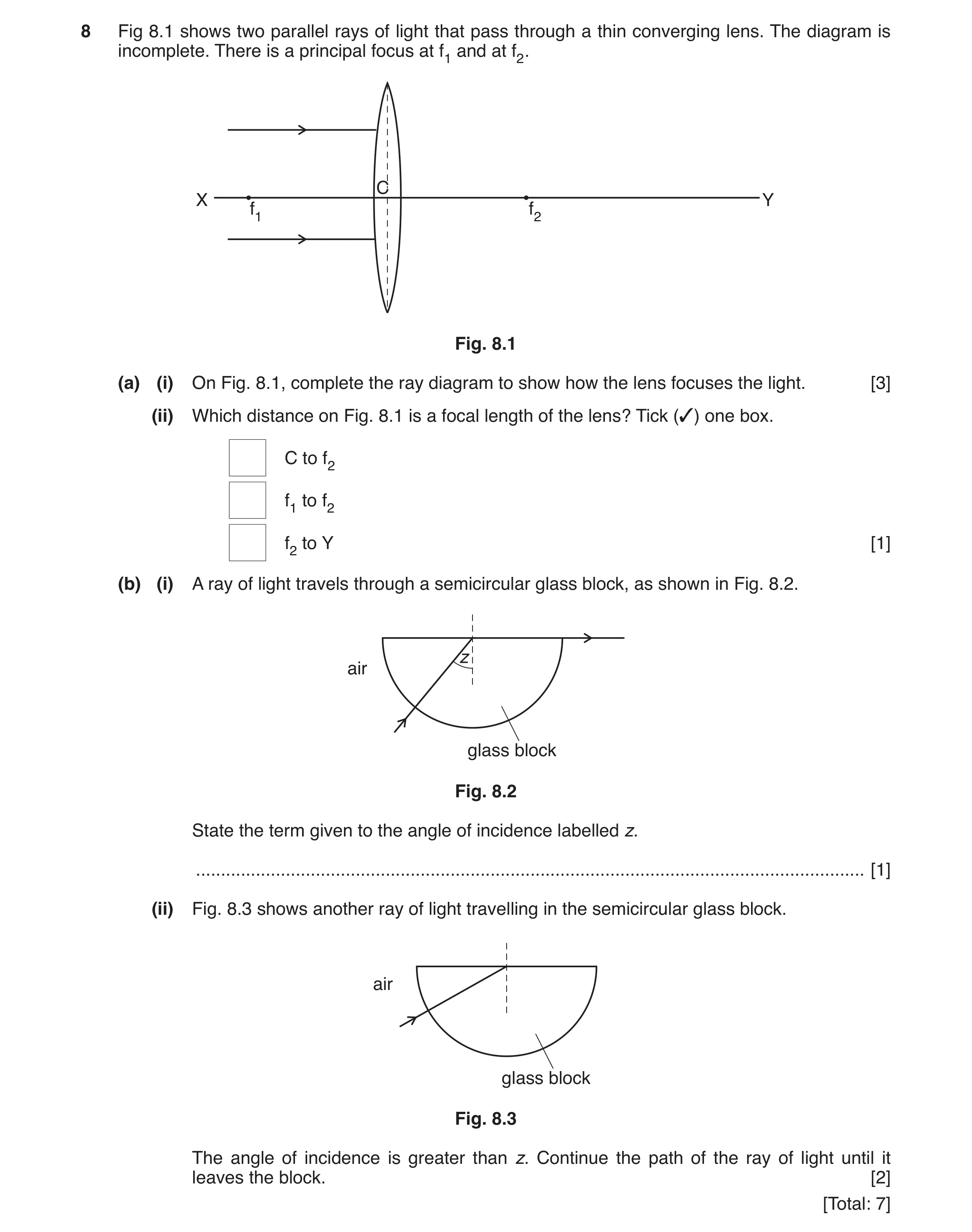
8 Fig 8.1 shows two parallel rays of light that pass through a thin converging lens. The diagram is incomplete. There is a principal focus at f1 and at f2. C X Y f1 f2 Fig. 8.1 (a) (i) On Fig. 8.1, complete the ray diagram to show how the lens focuses the light. [3] (ii) Which distance on Fig. 8.1 is a focal length of the lens? Tick (✓) one box. C to f2 f1 to f2 f2 to Y [1] (b) (i) A ray of light travels through a semicircular glass block, as shown in Fig. 8.2. z air glass block Fig. 8.2 State the term given to the angle of incidence labelled z. … [1] (ii) Fig. 8.3 shows another ray of light travelling in the semicircular glass block. air glass block Fig. 8.3 The angle of incidence is greater than z. Continue the path of the ray of light until it leaves the block. [2] [Total: 7]
7 marks
Mark scheme: 8(a)(i) top ray passes through f2 B1 bottom ray passes through f2 B1 refraction correctly shown either at centre of lens OR at both edges of lens B1 8(a)(ii) C to f2 B1 8(b)(i) critical angle B1 8(b)(ii) ray internally reflected B1 reflecting angle = incident angle B1
This question in 0625/33 Oct/Nov 2017
Q7 · The spectrum of white light is made up of seven colours 0625/31 May/June 2018
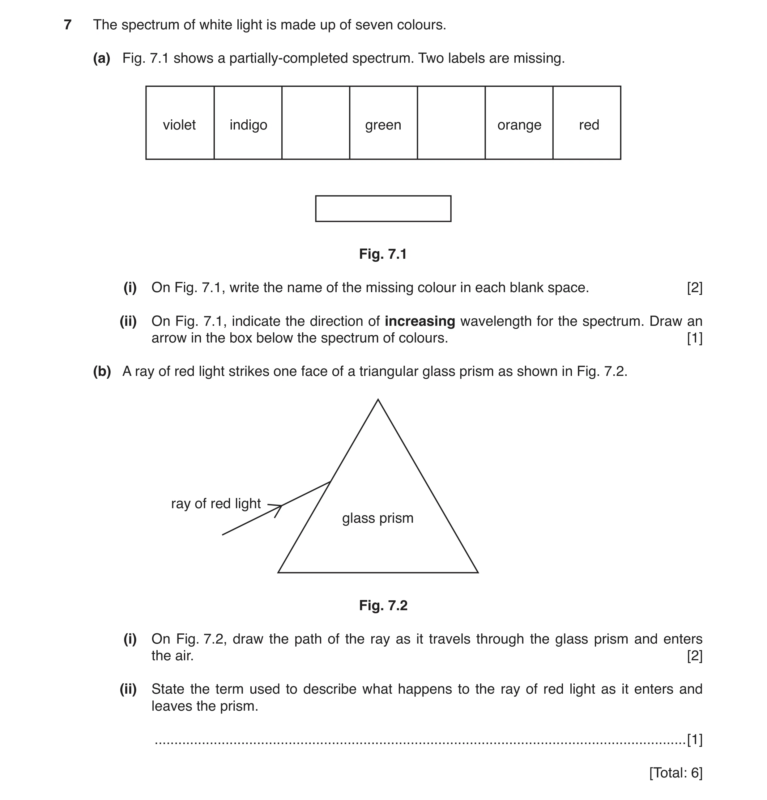
7 The spectrum of white light is made up of seven colours. (a) Fig. 7.1 shows a partially-completed spectrum. Two labels are missing. violet indigo green orange red Fig. 7.1 (i) On Fig. 7.1, write the name of the missing colour in each blank space. [2] (ii) On Fig. 7.1, indicate the direction of increasing wavelength for the spectrum. Draw an arrow in the box below the spectrum of colours. [1] (b) A ray of red light strikes one face of a triangular glass prism as shown in Fig. 7.2. ray of red light glass prism Fig. 7.2 (i) On Fig. 7.2, draw the path of the ray as it travels through the glass prism and enters the air. [2] (ii) State the term used to describe what happens to the ray of red light as it enters and leaves the prism. … [1] [Total: 6]
6 marks
Mark scheme: 7(a)(i) blue between indigo and green 1 yellow between green and orange 1 7(a)(ii) arrow pointing right 1 7(b)(i) ray(s) refracted down at first boundary (air/glass) 1 correct refraction for candidate’s ray (in glass prism) 1 7(b)(ii) refraction 1
This question in 0625/31 May/June 2018
Q8 · An object positioned on the principal axis of a thin lens 0625/32 May/June 2018
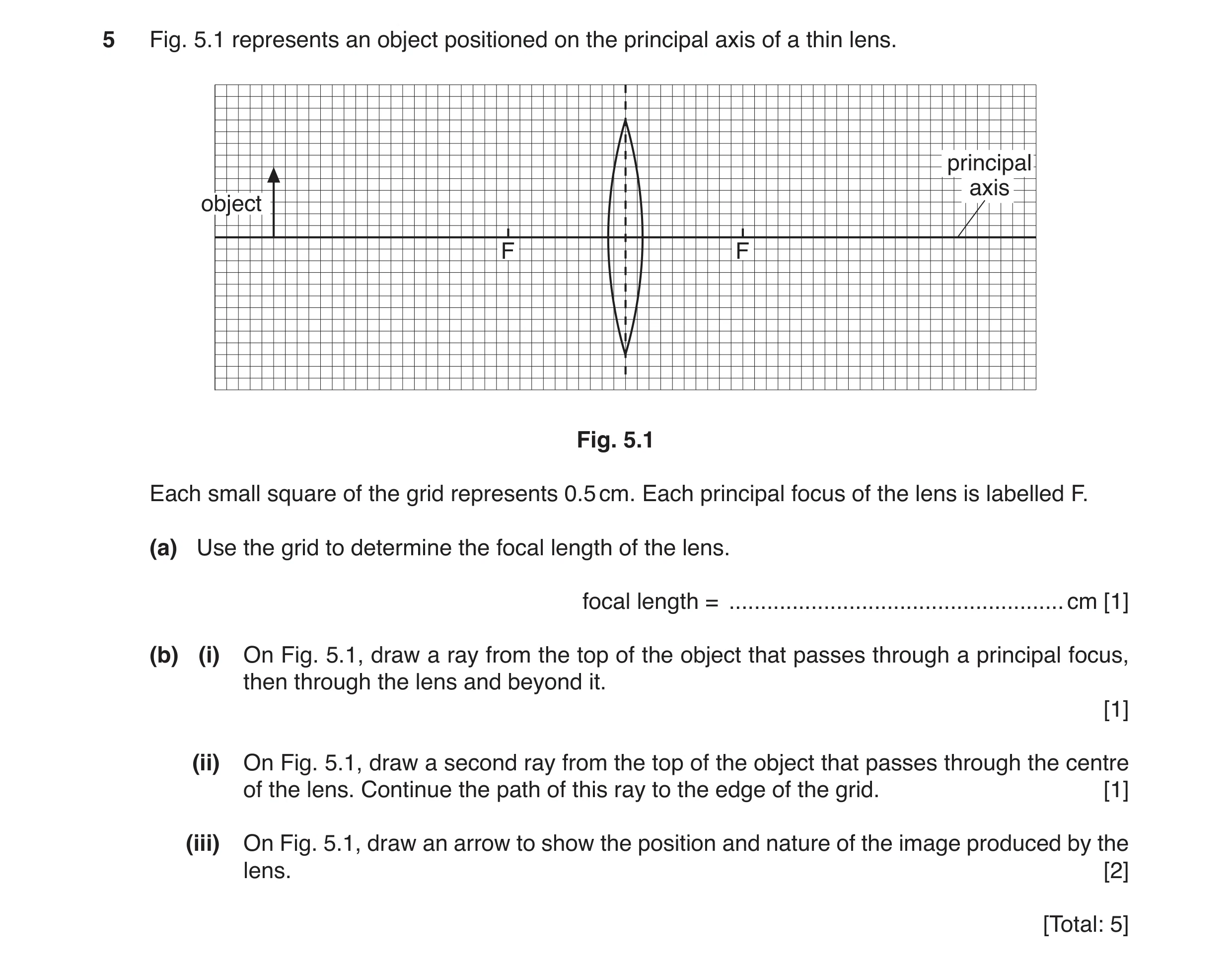
5 Fig. 5.1 represents an object positioned on the principal axis of a thin lens. principal axis object F F Fig. 5.1 Each small square of the grid represents 0.5 cm. Each principal focus of the lens is labelled F. (a) Use the grid to determine the focal length of the lens. focal length = … cm [1] (b) (i) On Fig. 5.1, draw a ray from the top of the object that passes through a principal focus, then through the lens and beyond it. [1] (ii) On Fig. 5.1, draw a second ray from the top of the object that passes through the centre of the lens. Continue the path of this ray to the edge of the grid. [1] (iii) On Fig. 5.1, draw an arrow to show the position and nature of the image produced by the lens. [2] [Total: 5]
5 marks
Mark scheme: 5(a) (focal length =) 5 (cm) 1 5(b)(i) straight line through F and then parallel to PA from centre of lens 1 5(b)(ii) straight line from top of object through centre of lens 1 5(b)(iii) image indicated at point where rays cross 1 arrow drawn inverted on RHS of lens 1
This question in 0625/32 May/June 2018
Q9 · A ray of red light incident on part of a lens 0625/32 Oct/Nov 2018
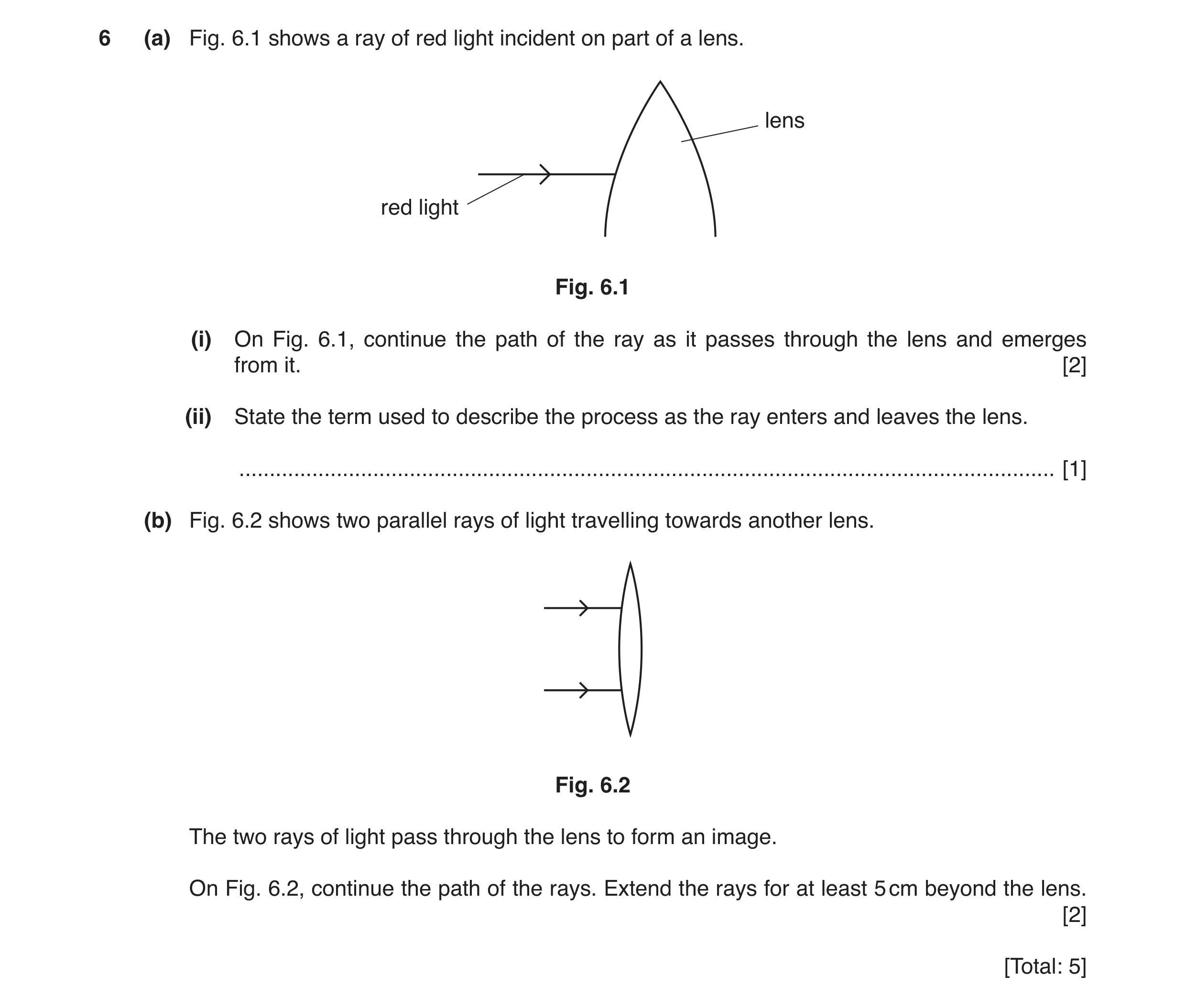
6 (a) Fig. 6.1 shows a ray of red light incident on part of a lens. lens red light Fig. 6.1 (i) On Fig. 6.1, continue the path of the ray as it passes through the lens and emerges from it. [2] (ii) State the term used to describe the process as the ray enters and leaves the lens. … [1] (b) Fig. 6.2 shows two parallel rays of light travelling towards another lens. Fig. 6.2 The two rays of light pass through the lens to form an image. On Fig. 6.2, continue the path of the rays. Extend the rays for at least 5 cm beyond the lens. [2] [Total: 5]
5 marks
Mark scheme: 6(a)(i) refracted at first boundary correctly B1 refracted at second boundary correctly B1 6(a)(ii) refraction B1 6(b)(i) converging / bent inwards / meet at a point e.g. focus B1 6(b)(ii) two straight rays drawn converging B1
This question in 0625/32 Oct/Nov 2018
Q10 · A ray of white light is incident on a glass prism 0625/32 Oct/Nov 2018
7 (a) A ray of white light is incident on a glass prism. It forms a spectrum that is visible on the screen. Fig. 7.1 shows the arrangement. screen narrow slit ray of white light red violet Fig. 7.1 Two of the colours in the visible spectrum are listed in the box below. Complete the box. List the five missing colours of the visible spectrum, in the correct order. red … … … … … violet [2] (b) Electromagnetic radiation has many uses. (i) Draw a line from each use to the type of radiation it requires. use type of radiation radio waves detecting an intruder at night microwaves infra-red communicating by satellite visible light for a telephone ultraviolet detecting broken bones in X-rays the body gamma rays [3] (ii) The types of radiation listed in (b)(i) form the electromagnetic spectrum. amplitude frequency velocity Complete the sentence. Choose a word from the box. The position of each type of radiation in the electromagnetic spectrum depends on its … . [1] [Total: 6]
6 marks
Mark scheme: 7(a) orange yellow green blue indigo B2 7(b)(i) detecting an intruder to infra-red B1 communicating by satellite to microwaves B1 detecting broken bones to X-rays B1 7(b)(ii) frequency B1
This question in 0625/32 Oct/Nov 2018
Q11 · A ray of green light hitting a glass prism 0625/33 Oct/Nov 2018
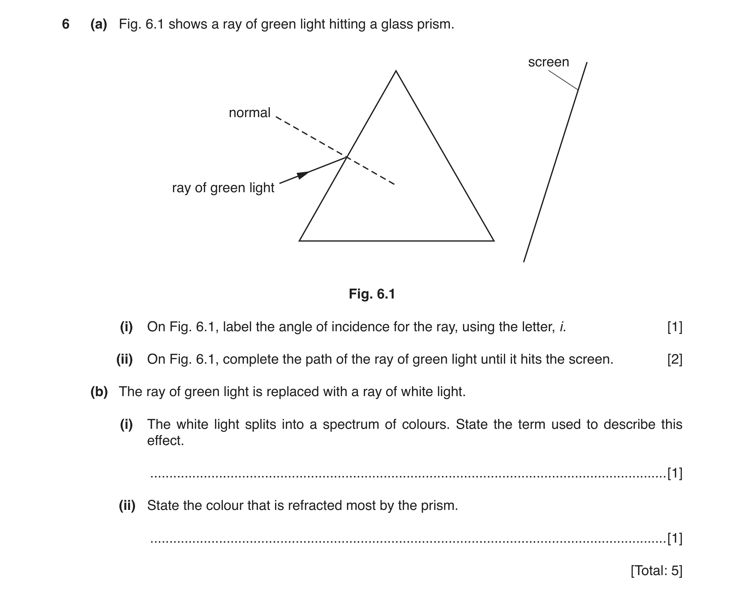
6 (a) Fig. 6.1 shows a ray of green light hitting a glass prism. screen normal ray of green light Fig. 6.1 (i) On Fig. 6.1, label the angle of incidence for the ray, using the letter, i. [1] (ii) On Fig. 6.1, complete the path of the ray of green light until it hits the screen. [2] (b) The ray of green light is replaced with a ray of white light. (i) The white light splits into a spectrum of colours. State the term used to describe this effect. … [1] (ii) State the colour that is refracted most by the prism. … [1] [Total: 5]
5 marks
Mark scheme: 6(a)(i) i placed between incident ray and normal B1 6(a)(ii) ray refracted towards normal at 1st surface B1 ray refracted down at 2nd surface B1 6(b)(i) dispersion B1 6(b)(ii) violet B1
This question in 0625/33 Oct/Nov 2018
Q12 · A ray of light that is reflected by a mirror 0625/32 May/June 2019
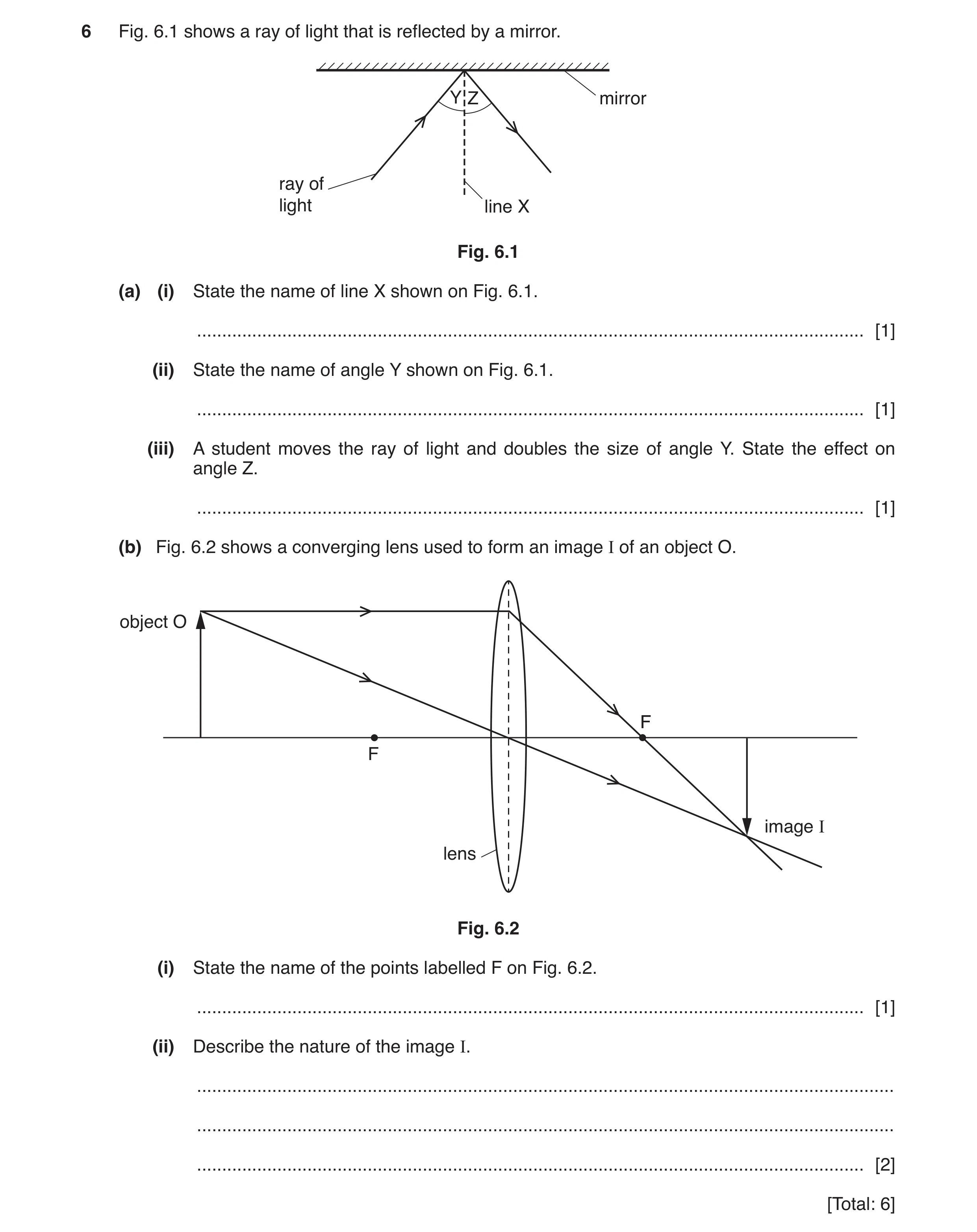
6 Fig. 6.1 shows a ray of light that is reflected by a mirror. Y Z mirror ray of light line X Fig. 6.1 (a) (i) State the name of line X shown on Fig. 6.1. … [1] (ii) State the name of angle Y shown on Fig. 6.1. … [1] (iii) A student moves the ray of light and doubles the size of angle Y. State the effect on angle Z. … [1] (b) Fig. 6.2 shows a converging lens used to form an image I of an object O. object O F F image I lens Fig. 6.2 (i) State the name of the points labelled F on Fig. 6.2. … [1] (ii) Describe the nature of the image I. … … … [2] [Total: 6]
6 marks
Mark scheme: 6(a)(i) normal B1 6(a)(ii) (angle of) incidence B1 6(a)(iii) double(s) B1 6(b)(i) principal focus B1 6(b)(ii) inverted diminished B2
This question in 0625/32 May/June 2019
Q13 · A ray of red light being reflected at the flat surface of a glass block 0625/33 May/June 2019
7 Fig. 7.1 shows a ray of red light being reflected at the flat surface of a glass block. glass block ray of air red light Fig. 7.1 (a) Explain why the ray of red light is totally internally reflected by the surface of the glass block. … … [1] (b) A ray of white light passes through a prism and produces a spectrum of colours on a screen, as shown in Fig. 7.2. screen ray of white light A spectrum of colours B Fig. 7.2 (i) State the name of the process of separating white light into a spectrum. … [1] (ii) Write the names of the seven colours that appear on the screen between A and B. colour at A … … … … … … colour at B … [1] (c) Visible light is one part of the electromagnetic spectrum. State the name of one other part of the electromagnetic spectrum and describe a use of this type of radiation. name of radiation … use of radiation … [2] [Total: 5]
5 marks
Mark scheme: 7(a) Any one from: angle of incidence is greater than the critical angle light is travelling from a(n optically) more dense medium to(wards an optically) less dense medium (at a large angle) B1 7(b)(i) dispersion B1 7(b)(ii) From A to B: red, orange, yellow, green, blue, indigo, violet B1 7(c) correct name for any part of em spectrum other than visible light M1 correct use of named part of em spectrum A1
This question in 0625/33 May/June 2019
Q14 · An incomplete ray diagram of a converging lens forming an image of the object, O 0625/33 May/June 2019
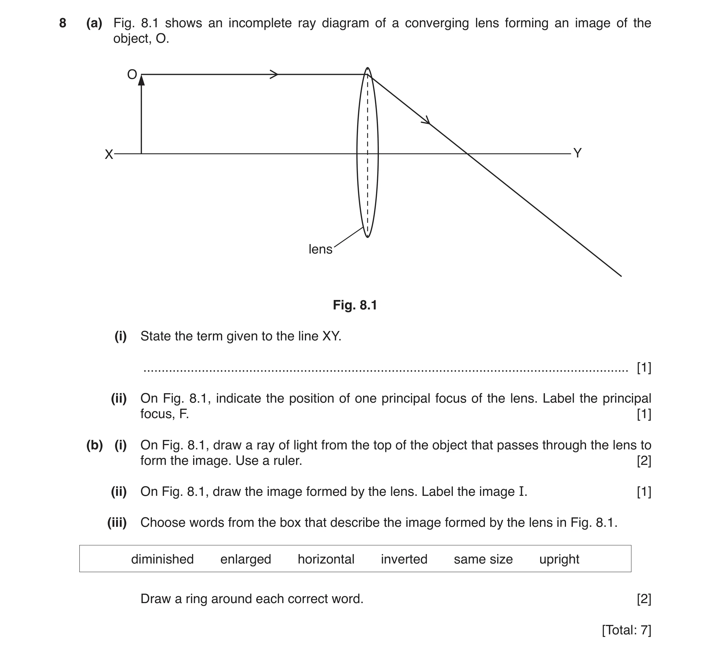
8 (a) Fig. 8.1 shows an incomplete ray diagram of a converging lens forming an image of the object, O. O X Y lens Fig. 8.1 (i) State the term given to the line XY. … [1] (ii) On Fig. 8.1, indicate the position of one principal focus of the lens. Label the principal focus, F. [1] (b) (i) On Fig. 8.1, draw a ray of light from the top of the object that passes through the lens to form the image. Use a ruler. [2] (ii) On Fig. 8.1, draw the image formed by the lens. Label the image I. [1] (iii) Choose words from the box that describe the image formed by the lens in Fig. 8.1. diminished enlarged horizontal inverted same size upright Draw a ring around each correct word. [2] [Total: 7]
7 marks
Mark scheme: 8(a)(i) (principal) axis ignore X-axis B1 8(a)(ii) F marked near intersection of ray and principle axis B1 8(b)(i) Either: ray from top of object towards centre of lens B1 continues from centre and crosses initial ray B1 OR 1st ray through F on left of lens (needs to be added by candidate) (B1) 2nd ray parallel to principle axis and crosses initial ray (B1) 8(b)(ii) inverted arrow drawn from axis to point where rays cross B1 8(b)(iii) diminished circled B1 inverted circled B1
This question in 0625/33 May/June 2019
Question 15 0625/31 Oct/Nov 2019
6 Fig. 6.1 shows a mirror periscope. The periscope is used to view a golfer over the heads of other people. The periscope has two plane mirrors each at an angle of 45° to the vertical. periscope 45° ray of light plane mirror golfer 45° plane mirror Fig. 6.1 (not to scale) (a) (i) On Fig. 6.1: 1. Continue the ray of light from the golfer towards the upper mirror of the periscope 2. Draw and label the normal at the point where the ray strikes the mirror. [1] (ii) On Fig. 6.1, continue the ray of light after reflection at the upper mirror until it leaves the periscope. [1] (iii) State the law of reflection used to deduce the position of the ray of light after striking the mirrors. … [1] (b) Fig. 6.2 shows three rays of red light each entering a semi-circular glass block. air X semi-circular glass block ray of red light air Y semi-circular glass block ray of red light air Z semi-circular glass block ray of red light Fig. 6.2 Table 6.1 angle of incidence description X less than the critical angle Y equal to the critical angle Z greater than the critical angle Using the information in Table 6.1, draw on Fig. 6.2 to complete the path of each ray of red light. [3] [Total: 6]
6 marks
Mark scheme: 6(a)(i) straight line to mirror AND normal correctly positioned B1 6(a)(ii) two correct reflections drawn B1 6(a)(iii) angle of incidence = angle of reflection B1 6(b) refracted away from normal B1 refracted along straight edge B1 totally internally reflected B1
This question in 0625/31 Oct/Nov 2019
Q16 · An object, OX, is placed in front of a converging lens 0625/31 Oct/Nov 2019
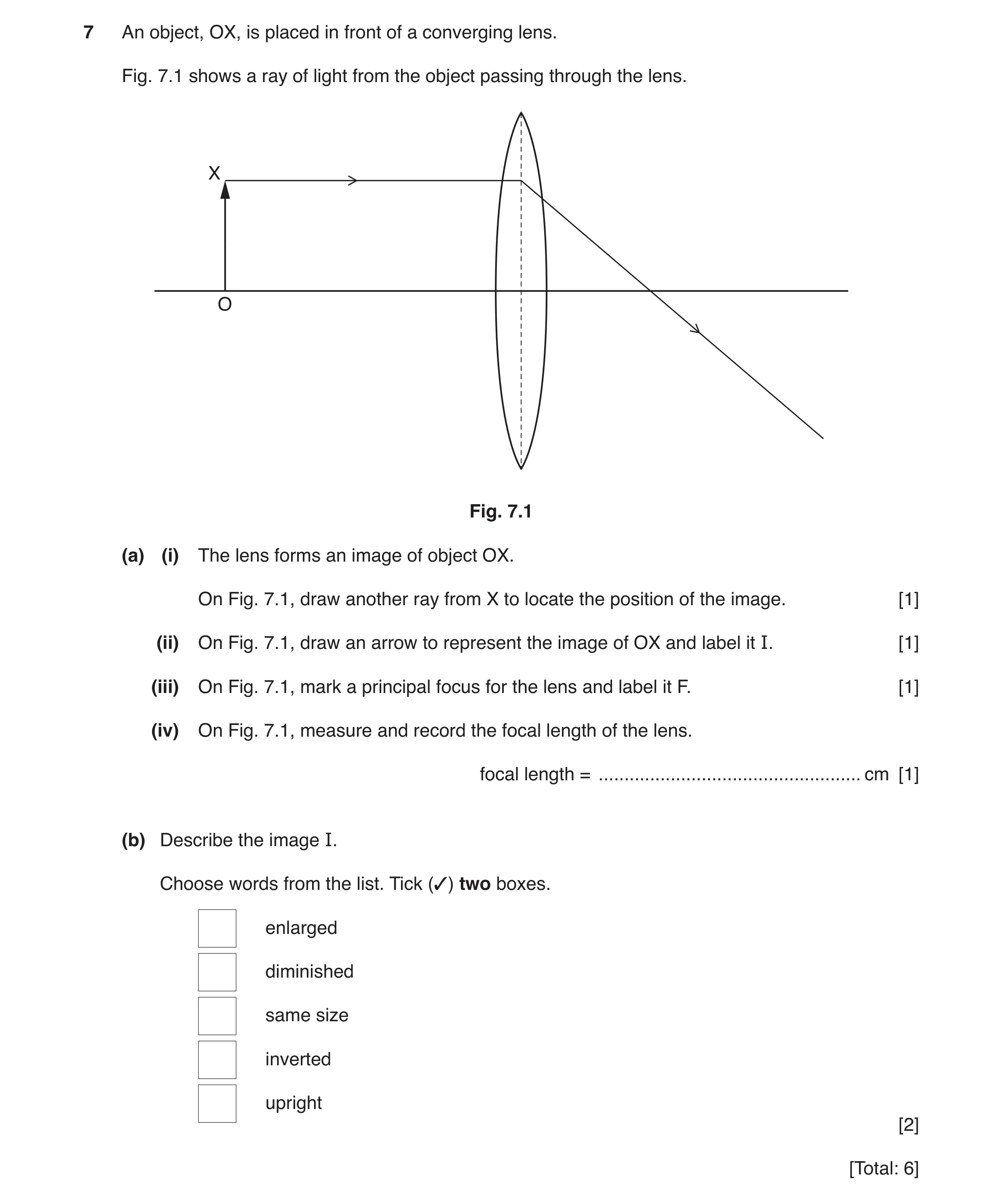
7 An object, OX, is placed in front of a converging lens. Fig. 7.1 shows a ray of light from the object passing through the lens. X O Fig. 7.1 (a) (i) The lens forms an image of object OX. On Fig. 7.1, draw another ray from X to locate the position of the image. [1] (ii) On Fig. 7.1, draw an arrow to represent the image of OX and label it I. [1] (iii) On Fig. 7.1, mark a principal focus for the lens and label it F. [1] (iv) On Fig. 7.1, measure and record the focal length of the lens. focal length = … cm [1] (b) Describe the image I. Choose words from the list. Tick (✓) two boxes. enlarged diminished same size inverted upright [2] [Total: 6]
6 marks
Mark scheme: 7(a)(i) ray from X through centre of lens B1 7(a)(ii) image drawn from axis to point where rays cross and labelled I B1 7(a)(iii) point labelled F where ray crosses principal axis B1 7(a)(iv) 2.7 (cm) ± 0.2 cm B1 7(b) diminished 2nd box ticked B1 inverted 4th box ticked B1
This question in 0625/31 Oct/Nov 2019
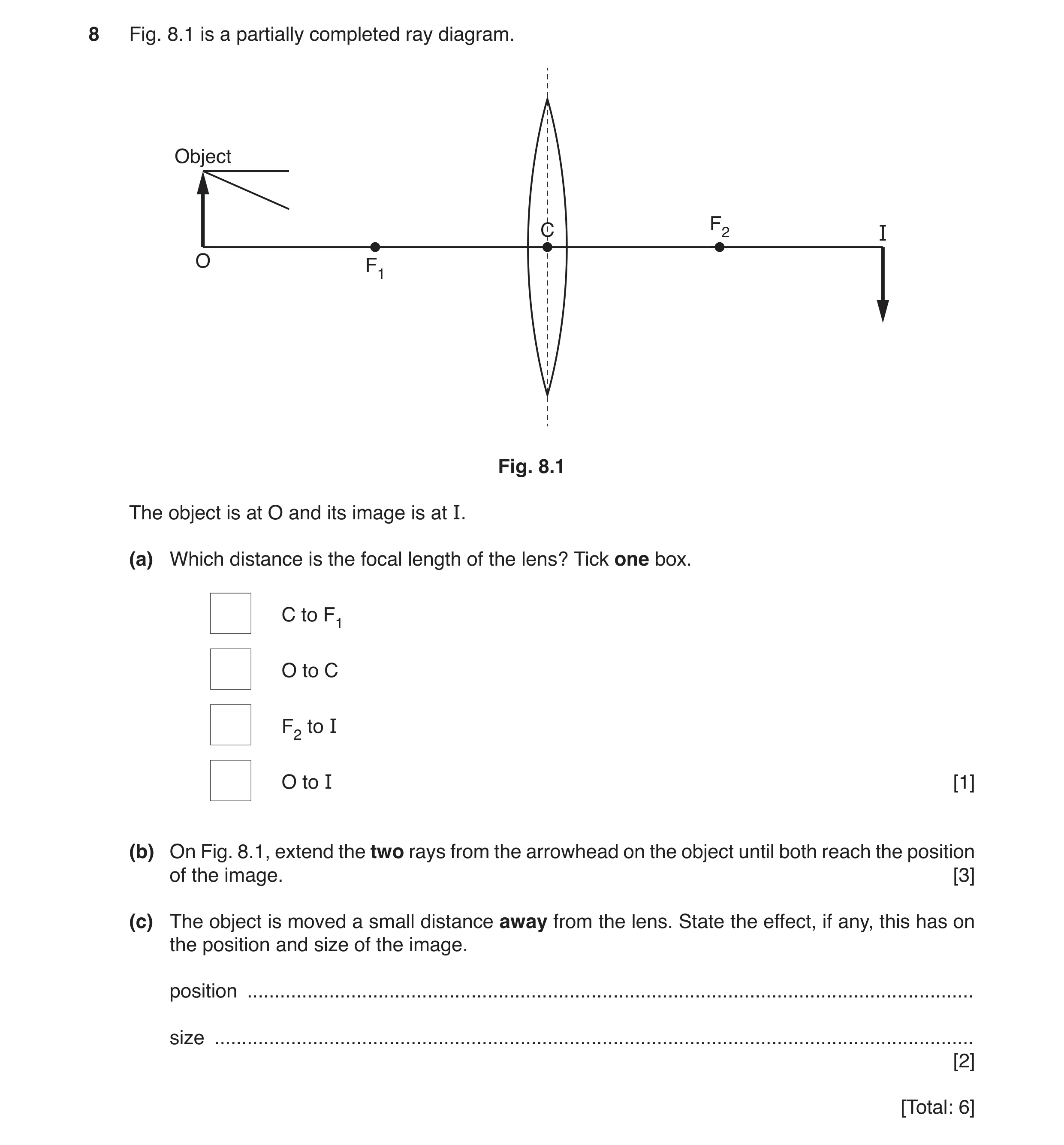
Q17 · A partially completed ray diagram 0625/32 Oct/Nov 2019
8 Fig. 8.1 is a partially completed ray diagram. Object C F2 I O F1 Fig. 8.1 The object is at O and its image is at I. (a) Which distance is the focal length of the lens? Tick one box. C to F1 O to C F2 to I O to I [1] (b) On Fig. 8.1, extend the two rays from the arrowhead on the object until both reach the position of the image. [3] (c) The object is moved a small distance away from the lens. State the effect, if any, this has on the position and size of the image. position … size … [2] [Total: 6]
6 marks
Mark scheme: 8(a) top box ticked C to F1 B1 8(b) Diagonal ray through F1 to lens then parallel to optical axis to I. B1 ray parallel to principal axis to lens then refracted through F2 to I B1 both rays meet at arrowhead of image B1 8(c) (image) closer (to lens / F2) owtte (image) smaller B1 B1
This question in 0625/32 Oct/Nov 2019
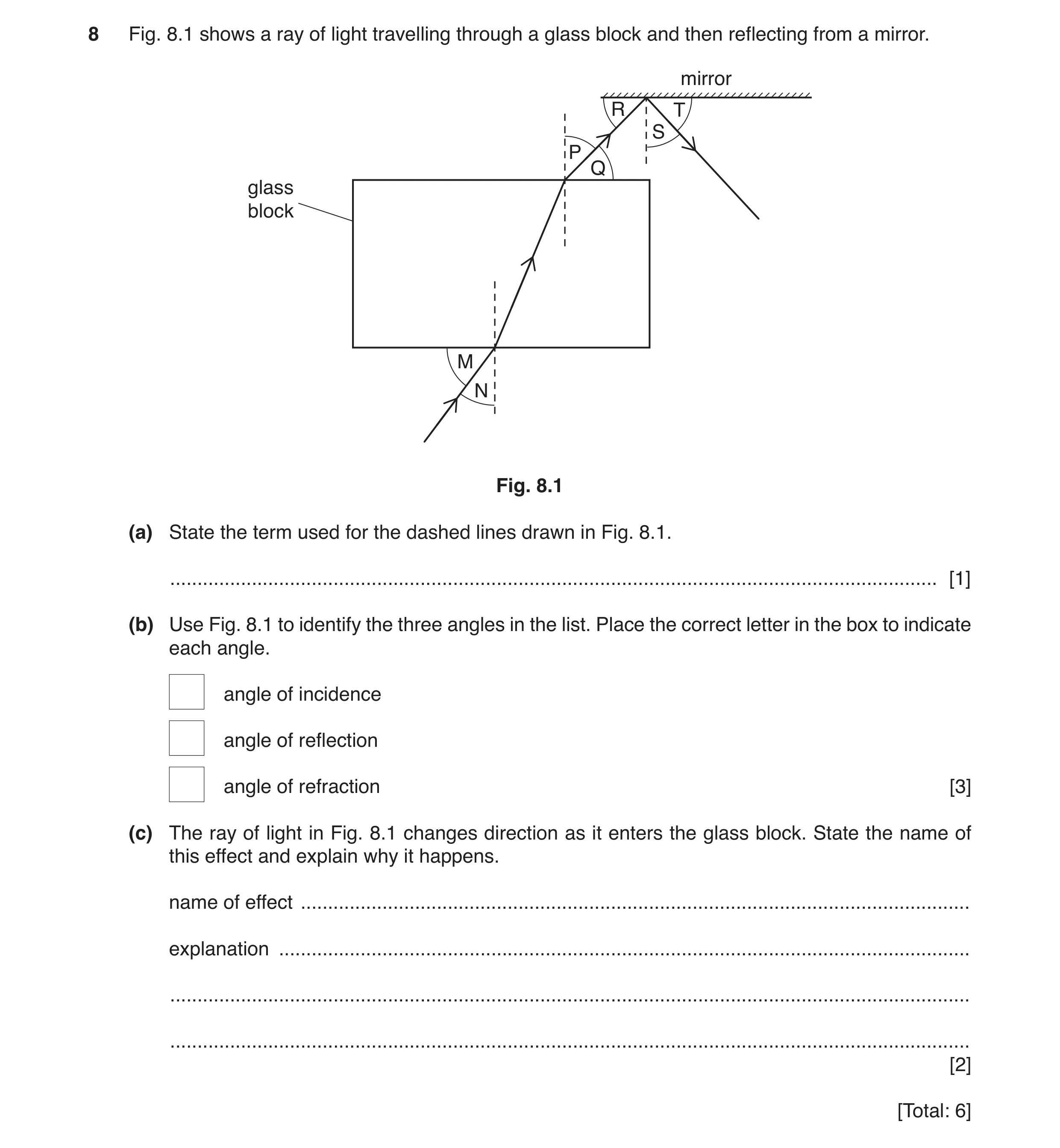
Q18 · A ray of light travelling through a glass block and then reflecting from a mirror 0625/33 Oct/Nov 2019
8 Fig. 8.1 shows a ray of light travelling through a glass block and then reflecting from a mirror. mirror R T S P Q glass block M N Fig. 8.1 (a) State the term used for the dashed lines drawn in Fig. 8.1. … [1] (b) Use Fig. 8.1 to identify the three angles in the list. Place the correct letter in the box to indicate each angle. angle of incidence angle of reflection angle of refraction [3] (c) The ray of light in Fig. 8.1 changes direction as it enters the glass block. State the name of this effect and explain why it happens. name of effect … explanation … … … [2] [Total: 6]
6 marks
Mark scheme: 8(a) normal B1 8(b) angle of incidence: N angle of reflection: S angle of refraction: P B1 B1 B1 8(c) refraction change in speed OR different refractive indices B1
This question in 0625/33 Oct/Nov 2019
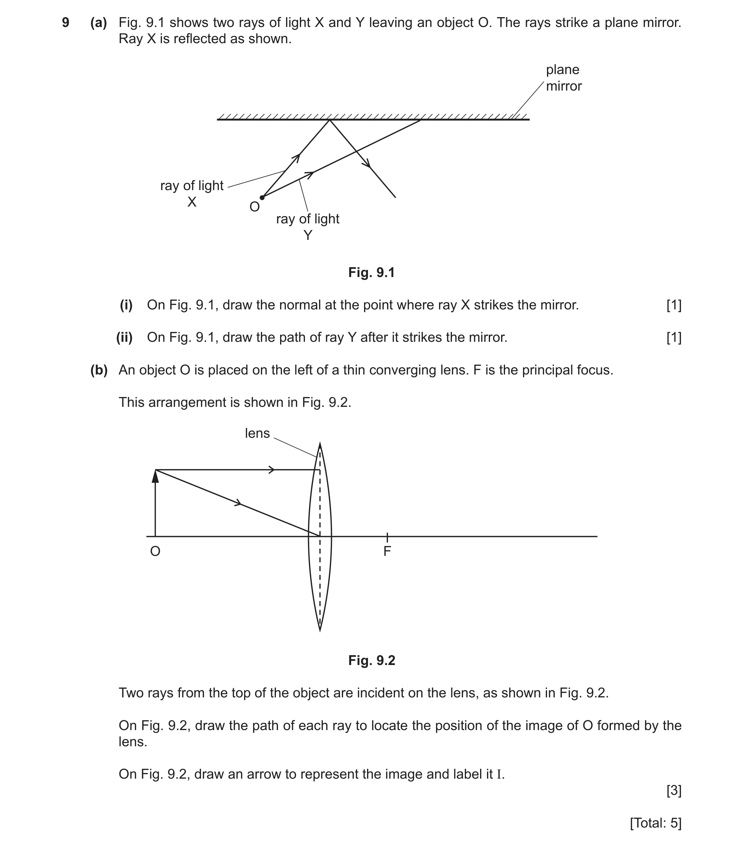
Q19 · Two rays of light X and Y leaving an object O 0625/32 Feb/March 2020
9 (a) Fig. 9.1 shows two rays of light X and Y leaving an object O. The rays strike a plane mirror. Ray X is reflected as shown. plane mirror ray of light X O ray of light Y Fig. 9.1 (i) On Fig. 9.1, draw the normal at the point where ray X strikes the mirror. [1] (ii) On Fig. 9.1, draw the path of ray Y after it strikes the mirror. [1] (b) An object O is placed on the left of a thin converging lens. F is the principal focus. This arrangement is shown in Fig. 9.2. lens O F Fig. 9.2 Two rays from the top of the object are incident on the lens, as shown in Fig. 9.2. On Fig. 9.2, draw the path of each ray to locate the position of the image of O formed by the lens. On Fig. 9.2, draw an arrow to represent the image and label it I. [3] [Total: 5]
5 marks
Mark scheme: 9(a)(i) normal at X correct by eye B1 9(a)(ii) reflected ray for Y has angle i = angle r by eye B1 9(b) horizontal ray drawn to continue through F B1 ray to centre drawn to continue undeviated B1 image drawn correctly where rays cross B1
This question in 0625/32 Feb/March 2020
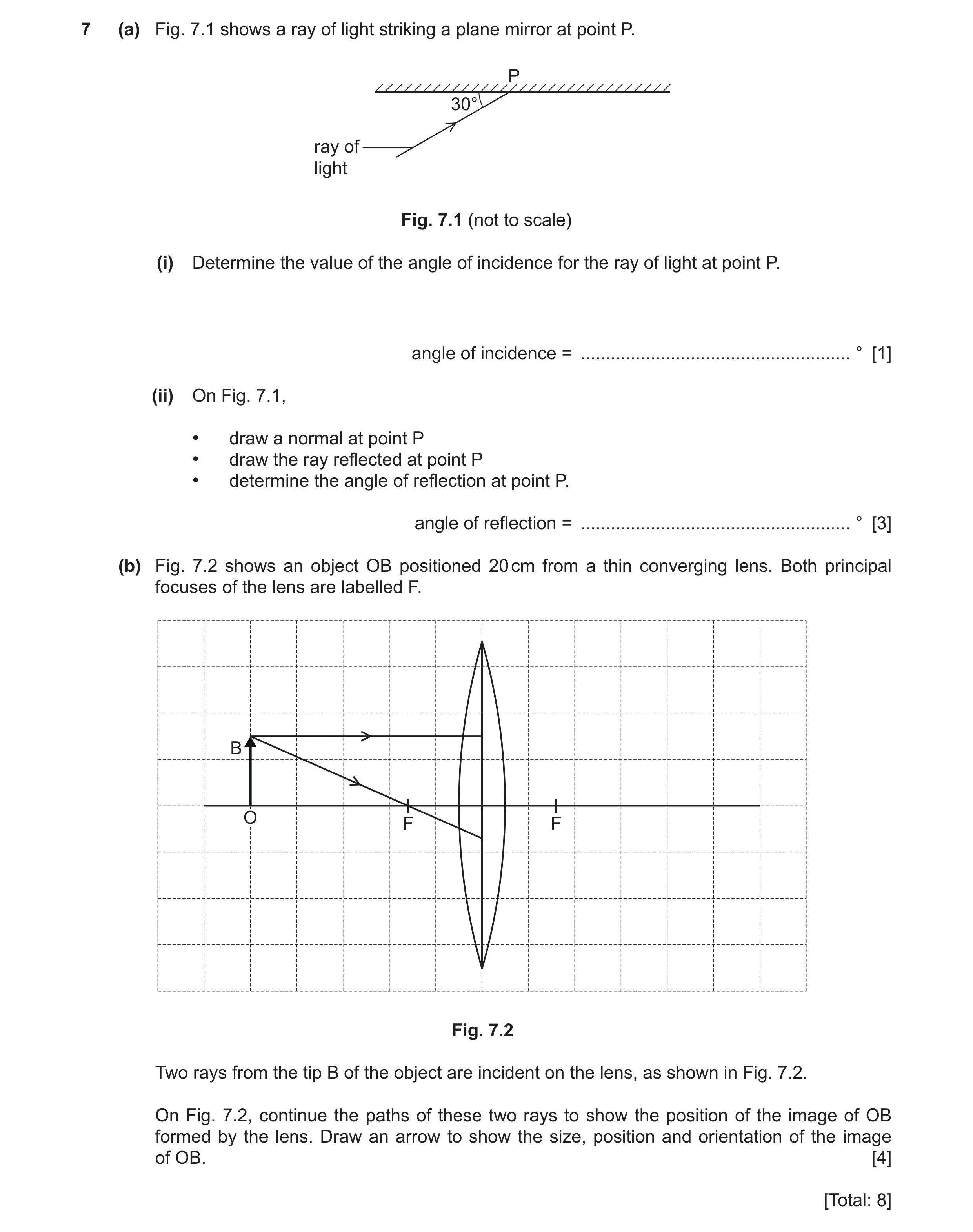
Q20 · A ray of light striking a plane mirror at point P 0625/31 May/June 2020
7 (a) Fig. 7.1 shows a ray of light striking a plane mirror at point P. P 30° ray of light Fig. 7.1 (not to scale) (i) Determine the value of the angle of incidence for the ray of light at point P. angle of incidence = … ° [1] (ii) On Fig. 7.1, • draw a normal at point P • draw the ray reflected at point P • determine the angle of reflection at point P. angle of reflection = … ° [3] (b) Fig. 7.2 shows an object OB positioned 20 cm from a thin converging lens. Both principal focuses of the lens are labelled F. B O F F Fig. 7.2 Two rays from the tip B of the object are incident on the lens, as shown in Fig. 7.2. On Fig. 7.2, continue the paths of these two rays to show the position of the image of OB formed by the lens. Draw an arrow to show the size, position and orientation of the image of OB. [4] [Total: 8]
8 marks
Mark scheme: 7(a)(i) 60(°) B1 7(a)(ii) normal correctly positioned B1 correct reflected ray at 60° to normal B1 same value as (i) B1 7(b) horizontal ray drawn to continue through F B1 ray through principal focus continues parallel to axis B1 image indicated in correct position B1 image indicated with correct orientation B1
This question in 0625/31 May/June 2020
Q21 · A ray of red light passing through a semicircular glass block 0625/32 May/June 2020
5 Fig. 5.1 shows a ray of red light passing through a semicircular glass block. air ray of red light q p r s semicircular glass block Fig. 5.1 (a) (i) State the term for the dotted line shown in Fig. 5.1. … [1] (ii) State which angle p, q, r or s is the angle of incidence for the ray of red light. … [1] (iii) State which angle p, q, r or s is the angle of refraction. … [1] (iv) State what happens to the speed of the red light as it enters the semicircular glass block from the air. … [1] (b) Fig. 5.2 shows the path of a ray of light entering a semicircular glass block. The critical angle for the glass block is 42°. On Fig. 5.2, continue the path of the ray. Show clearly its direction on leaving the glass block. ray of light 62° semicircular glass block Fig. 5.2 [2] (c) A ray of white light passes through two prisms as shown in Fig. 5.3. prisms D E F ray of white light Fig. 5.3 Draw one line to link the letter for each position to the correct effect at that position. position effect (i) refraction D diffraction total internal reflection [1] (ii) reflection E dispersion diffraction [1] (iii) red, green and blue light only produced F white light produced spectrum of visible light produced [1] [Total: 9]
9 marks
Mark scheme: 5(a)(i) normal B1 5(a)(ii) p B1 5(a)(iii) r B1 5(a)(iv) speed decreases B1 Question Answer Marks 5(b) reflects off flat surface at same angle (by eye) B1 passes through curved surface without deviation B1 5(c)(i) D – total internal reflection B1 5(c)(ii) E – dispersion B1 5(c)(iii) F – spectrum of visible light B1
This question in 0625/32 May/June 2020
Q22 · A ray of light incident on a plane mirror at point X 0625/31 Oct/Nov 2020
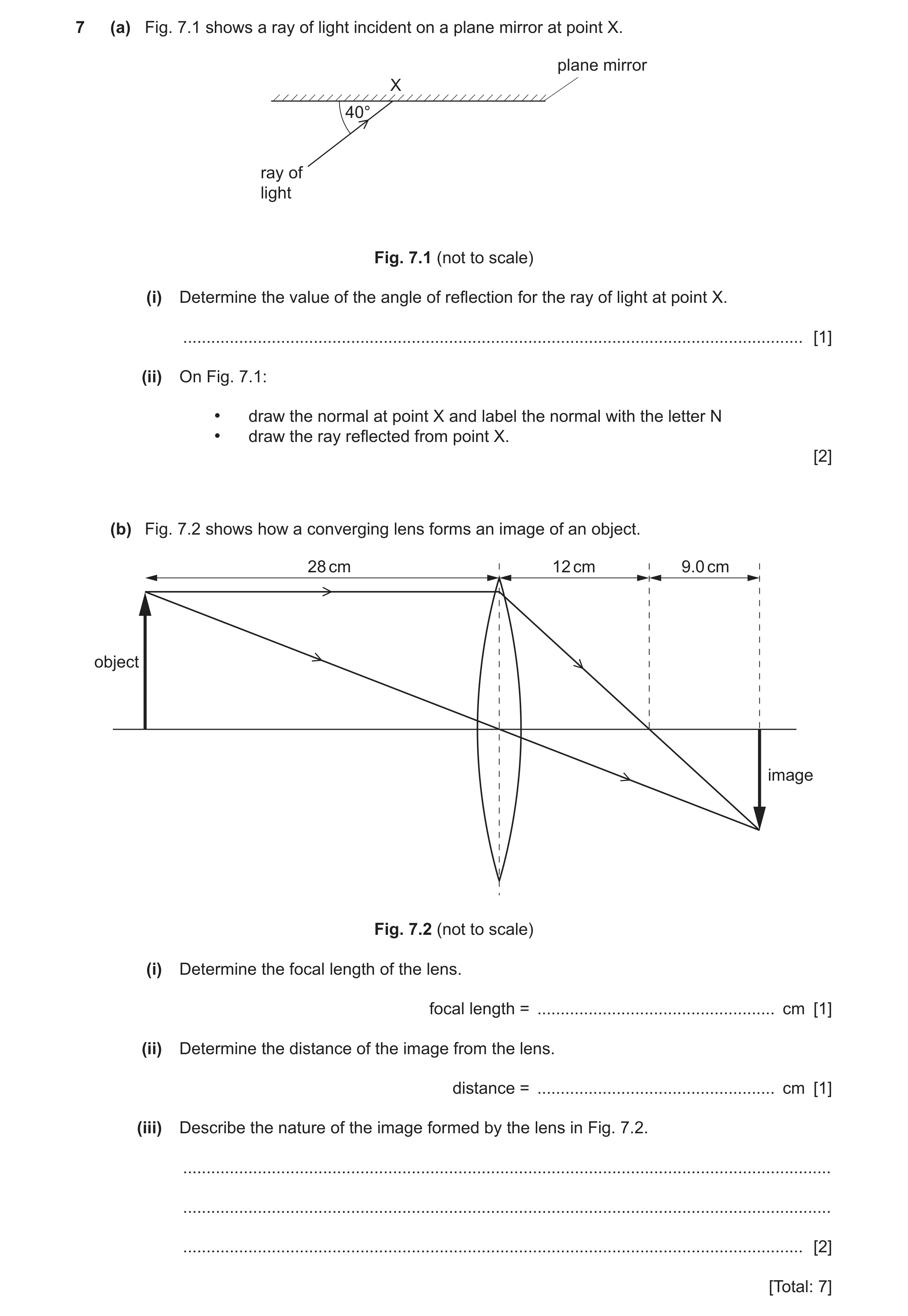
7 (a) Fig. 7.1 shows a ray of light incident on a plane mirror at point X. plane mirror X 40° ray of light Fig. 7.1 (not to scale) (i) Determine the value of the angle of reflection for the ray of light at point X. … [1] (ii) On Fig. 7.1: • draw the normal at point X and label the normal with the letter N • draw the ray reflected from point X. [2] (b) Fig. 7.2 shows how a converging lens forms an image of an object. 28 cm 12 cm 9.0 cm object image Fig. 7.2 (not to scale) (i) Determine the focal length of the lens. focal length = … cm [1] (ii) Determine the distance of the image from the lens. distance = … cm [1] (iii) Describe the nature of the image formed by the lens in Fig. 7.2. … … … [2] [Total: 7]
7 marks
Mark scheme: 7(a)(i) 50° B1 7(a)(ii) normal correctly positioned B1 correct reflected ray at 50° to normal B1 7(b)(i) 12 (cm) B1 7(b)(ii) 21 (cm) B1 7(b)(iii) inverted B1 smaller / diminished B1
This question in 0625/31 Oct/Nov 2020
Q23 · A converging lens and an object 0625/32 Oct/Nov 2020
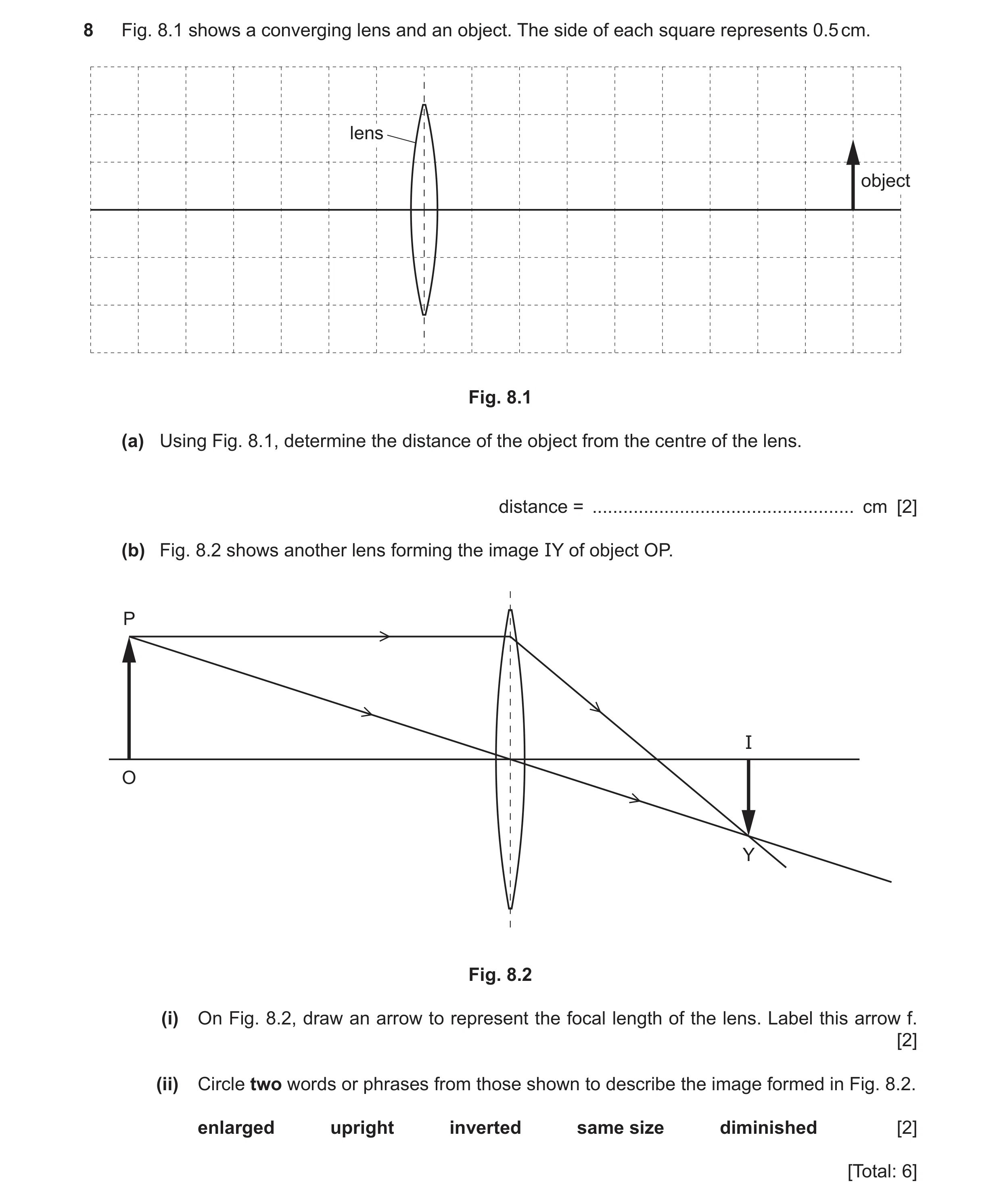
8 Fig. 8.1 shows a converging lens and an object. The side of each square represents 0.5 cm. lens object Fig. 8.1 (a) Using Fig. 8.1, determine the distance of the object from the centre of the lens. distance = … cm [2] (b) Fig. 8.2 shows another lens forming the image IY of object OP. P I O Y Fig. 8.2 (i) On Fig. 8.2, draw an arrow to represent the focal length of the lens. Label this arrow f. [2] (ii) Circle two words or phrases from those shown to describe the image formed in Fig. 8.2. enlarged upright inverted same size diminished [2] [Total: 6]
6 marks
Mark scheme: 8(a) 8.5 to 9.1 squares counted C1 4.5 (cm) A1 8(b)(i) focal length marked from centre of lens B1 to point where ray parallel to axis is refracted by lens to cross axis B1 8(b)(ii) inverted (third word circled) B1 diminished (5th / last word circled) B1
This question in 0625/32 Oct/Nov 2020
Q24 · Complete the following sentences about light 0625/33 Oct/Nov 2020
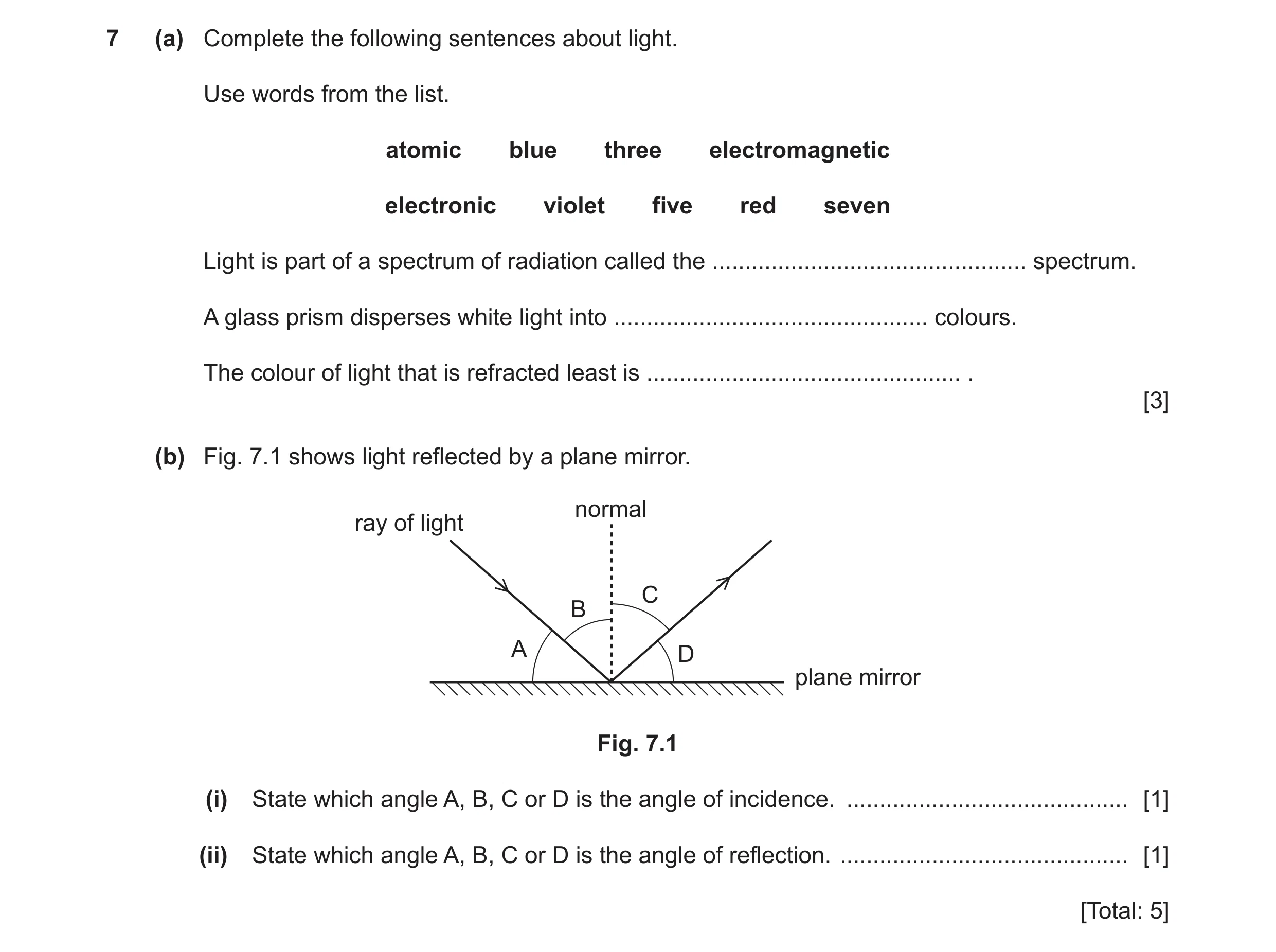
7 (a) Complete the following sentences about light. Use words from the list. atomic blue three electromagnetic electronic violet five red seven Light is part of a spectrum of radiation called the … spectrum. A glass prism disperses white light into … colours. The colour of light that is refracted least is … . [3] (b) Fig. 7.1 shows light reflected by a plane mirror. normal ray of light C B A D plane mirror Fig. 7.1 (i) State which angle A, B, C or D is the angle of incidence. … [1] (ii) State which angle A, B, C or D is the angle of reflection. … [1] [Total: 5]
5 marks
Mark scheme: 7(a) electromagnetic B1 seven B1 red B1 7(b)(i) B B1 7(b)(ii) C B1
This question in 0625/33 Oct/Nov 2020
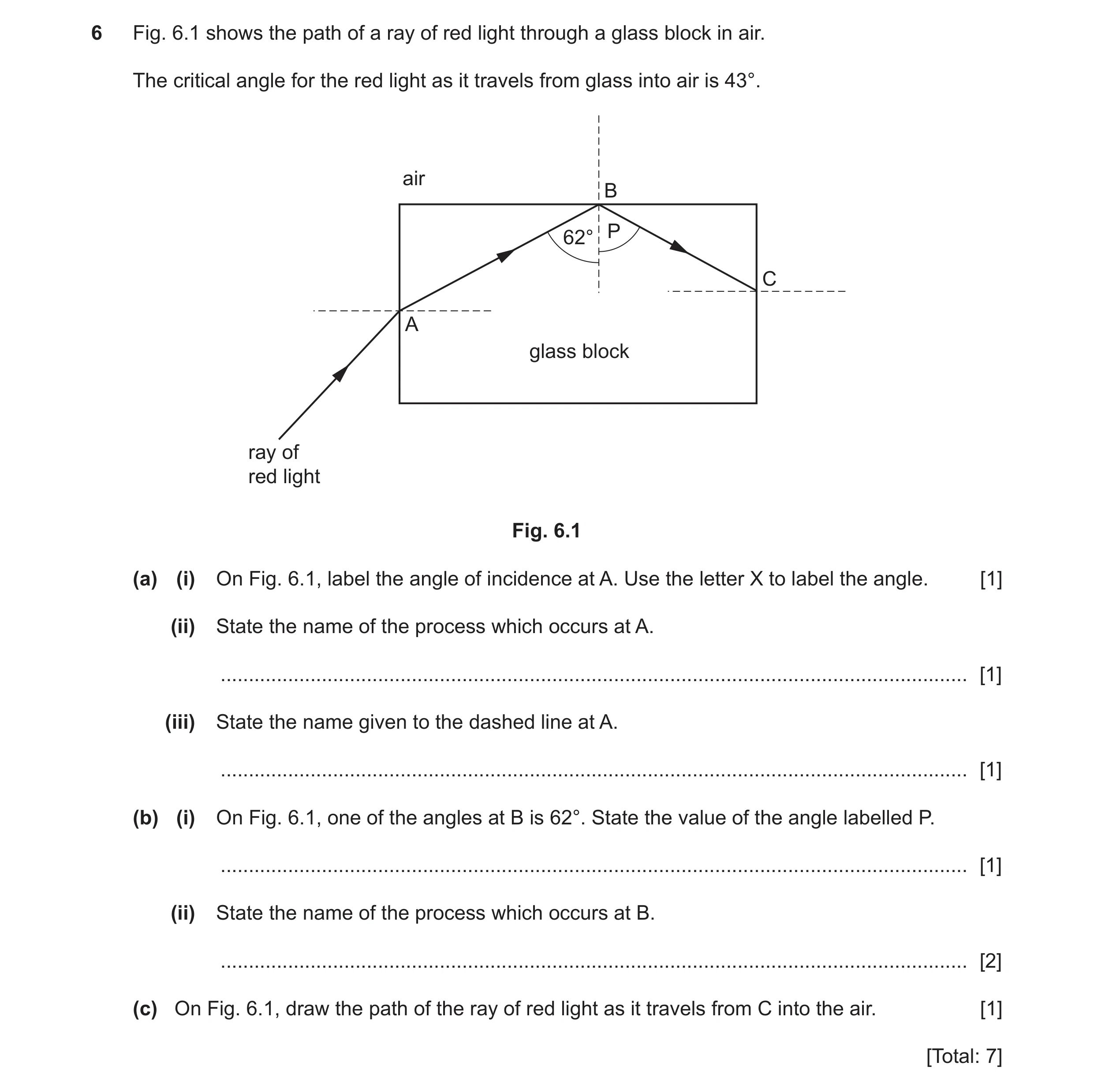
Q25 · The path of a ray of red light through a glass block in air 0625/32 Feb/March 2021
6 Fig. 6.1 shows the path of a ray of red light through a glass block in air. The critical angle for the red light as it travels from glass into air is 43°. air B P 62° C A glass block ray of red light Fig. 6.1 (a) (i) On Fig. 6.1, label the angle of incidence at A. Use the letter X to label the angle. [1] (ii) State the name of the process which occurs at A. … [1] (iii) State the name given to the dashed line at A. … [1] (b) (i) On Fig. 6.1, one of the angles at B is 62°. State the value of the angle labelled P. … [1] (ii) State the name of the process which occurs at B. … [2] (c) On Fig. 6.1, draw the path of the ray of red light as it travels from C into the air. [1] [Total: 7]
7 marks
Mark scheme: 6(a)(i) angle of incidence correctly identified (with × between normal and incident ray) B1 6(a)(ii) refraction B1 6(a)(iii) normal (line) B1 6(b)(i) 62° B1 6(b)(ii) reflection C1 total internal reflection A1 6(c) ray refracted away from normal B1
This question in 0625/32 Feb/March 2021
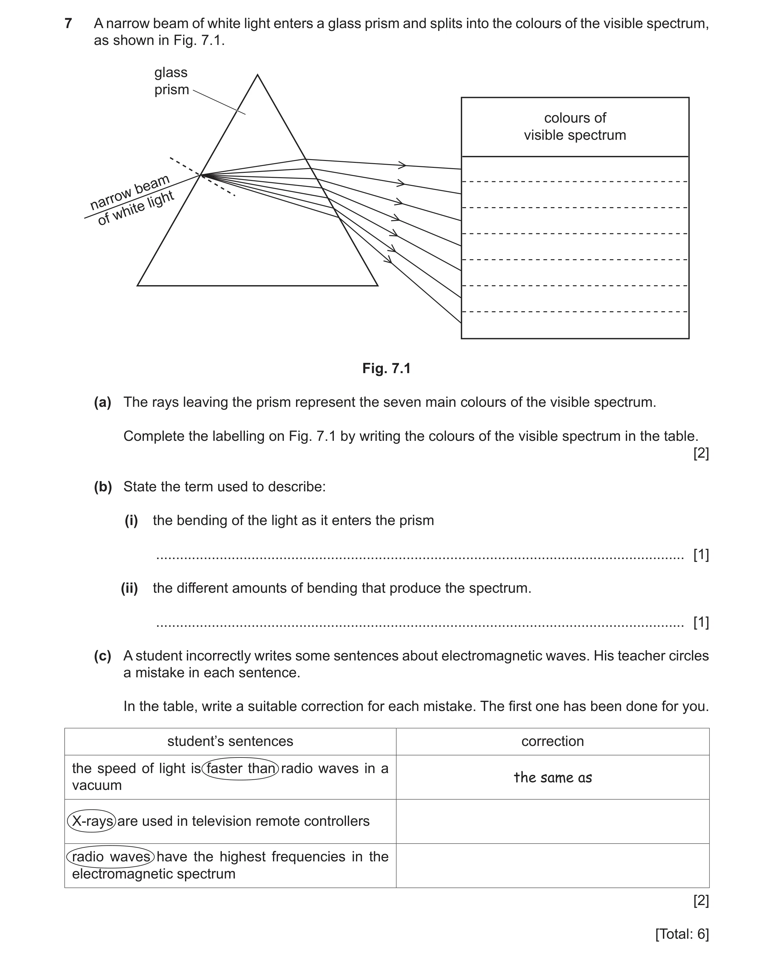
Q26 · A narrow beam of white light enters a glass prism and splits into the colours of the… 0625/31 May/June 2021
7 A narrow beam of white light enters a glass prism and splits into the colours of the visible spectrum, as shown in Fig. 7.1. glass prism colours of visible spectrum beam narrow light white of Fig. 7.1 (a) The rays leaving the prism represent the seven main colours of the visible spectrum. Complete the labelling on Fig. 7.1 by writing the colours of the visible spectrum in the table. [2] (b) State the term used to describe: (i) the bending of the light as it enters the prism … [1] (ii) the different amounts of bending that produce the spectrum. … [1] (c) A student incorrectly writes some sentences about electromagnetic waves. His teacher circles a mistake in each sentence. In the table, write a suitable correction for each mistake. The first one has been done for you. student’s sentences correction the speed of light is faster than radio waves in a the same as vacuum X-rays are used in television remote controllers radio waves have the highest frequencies in the electromagnetic spectrum [2] [Total: 6]
6 marks
Mark scheme: 7(a) any 6 correct colours from: red, orange, yellow, green, blue, indigo, violet M1 candidate’s colours in correct order A1 7(b)(i) refraction B1 7(b)(ii) dispersion B1 7(c) infrared (rays/waves) (are used in tv remote controllers) B1 gamma (rays/waves) (have the highest frequencies in em spectrum) B1
This question in 0625/31 May/June 2021
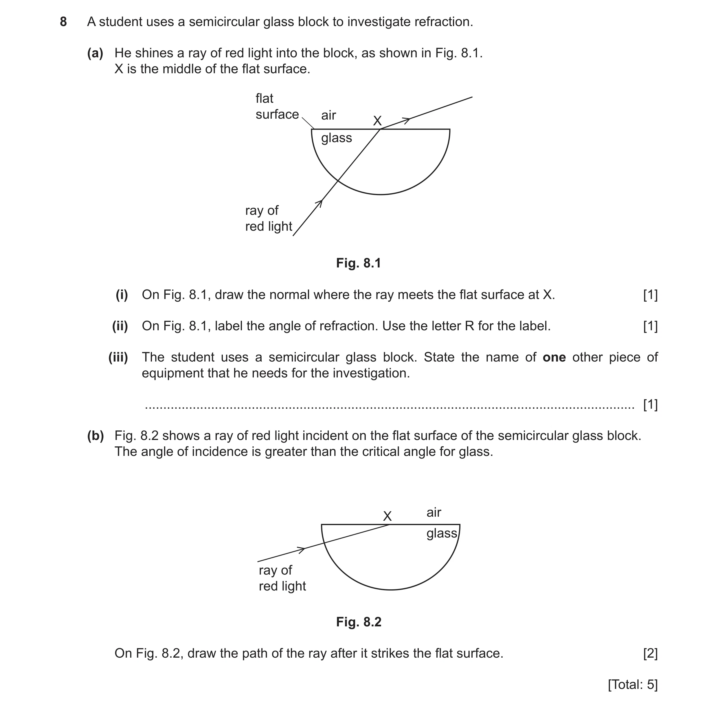
Q27 · A student uses a semicircular glass block to investigate refraction 0625/32 May/June 2021
8 A student uses a semicircular glass block to investigate refraction. (a) He shines a ray of red light into the block, as shown in Fig. 8.1. X is the middle of the flat surface. flat surface air X glass ray of red light Fig. 8.1 (i) On Fig. 8.1, draw the normal where the ray meets the flat surface at X. [1] (ii) On Fig. 8.1, label the angle of refraction. Use the letter R for the label. [1] (iii) The student uses a semicircular glass block. State the name of one other piece of equipment that he needs for the investigation. … [1] (b) Fig. 8.2 shows a ray of red light incident on the flat surface of the semicircular glass block. The angle of incidence is greater than the critical angle for glass. air X glass ray of red light Fig. 8.2 On Fig. 8.2, draw the path of the ray after it strikes the flat surface. [2] [Total: 5]
5 marks
Mark scheme: 8(a)(i) 8(a)(ii) angle of refraction correctly labelled B1 Question Answer Marks 8(a)(iii) any one from: • pin(s) OR ray box owtte OR (low voltage) power supply OR • protractor OR ruler B1 8(b) ray reflected from flat surface M1 ray reflected with angle i = angle r A1
This question in 0625/32 May/June 2021
Q28 · A ray of light incident on a plane mirror 0625/33 May/June 2021
8 (a) Fig. 8.1 shows a ray of light incident on a plane mirror. X a plane mirror b c ray of light Fig. 8.1 (i) State which angle, a, b or c, is the angle of incidence. angle of incidence = … [1] (ii) State the name of the line labelled X. … [1] (iii) The mirror reflects the ray of light. On Fig. 8.1, draw the reflected ray. [2] (b) Fig. 8.2 shows a ray of red light travelling through a semicircular glass block. air 42° glass ray of block red light Fig. 8.2 (i) Fig. 8.3 shows another ray of red light entering the semicircular glass block at 60°. Continue the path of this ray through the glass block and into the air. air 60° ray of red light glass block Fig. 8.3 [2] (ii) Fig. 8.4 shows another ray of red light entering the semicircular glass block at 20°. Continue the path of this ray through the glass block and into the air. air 20° glass ray of block red light Fig. 8.4 [2] [Total: 8]
8 marks
Mark scheme: 8(a)(i) c B1 8(a)(ii) normal B1 8(a)(iii) reflected ray a continuation of incident ray AND in correct quadrant M1 angle of reflection equals angle of incidence A1 Question Answer Marks 8(b)(i) continuation of incident ray AND reflected internally in correct quadrant M1 angle of reflection equals angle of incidence A1 8(b)(ii) continuation of incident ray AND emerging from block in correct quadrant M1 angle of refraction larger than angle of incidence A1
This question in 0625/33 May/June 2021
Q29 · A ray of red light entering a semicircular glass block 0625/31 Oct/Nov 2021
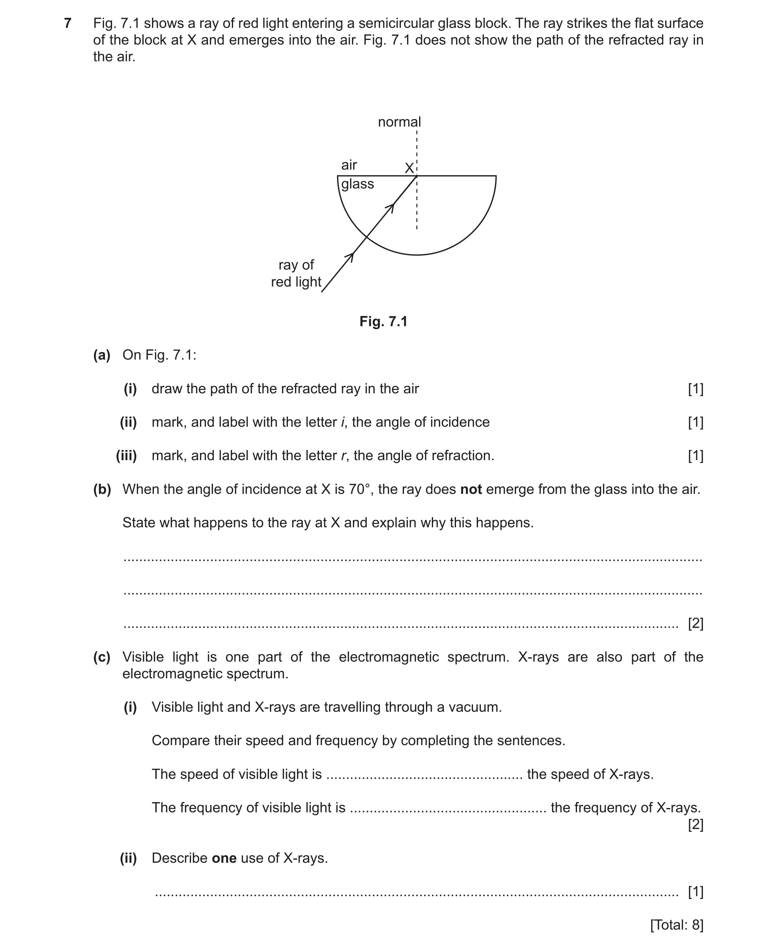
7 Fig. 7.1 shows a ray of red light entering a semicircular glass block. The ray strikes the flat surface of the block at X and emerges into the air. Fig. 7.1 does not show the path of the refracted ray in the air. normal air X glass ray of red light Fig. 7.1 (a) On Fig. 7.1: (i) draw the path of the refracted ray in the air [1] (ii) mark, and label with the letter i, the angle of incidence [1] (iii) mark, and label with the letter r, the angle of refraction. [1] (b) When the angle of incidence at X is 70°, the ray does not emerge from the glass into the air. State what happens to the ray at X and explain why this happens. … … … [2] (c) Visible light is one part of the electromagnetic spectrum. X‑rays are also part of the electromagnetic spectrum. (i) Visible light and X‑rays are travelling through a vacuum. Compare their speed and frequency by completing the sentences. The speed of visible light is … the speed of X‑rays. The frequency of visible light is … the frequency of X‑rays. [2] (ii) Describe one use of X‑rays. … [1] [Total: 8]
8 marks
Mark scheme: 7(a)(i) ray drawn refracted away from normal B1 7(a)(ii) angle of incidence correctly identified B1 7(a)(iii) angle of refraction correctly identified B1 7(b) total internal reflection (at flat surface) B1 angle (of incidence) is greater than the critical angle B1 7(c)(i) (The speed of visible light is) same (as) (the speed of X-rays.) B1 (The frequency of visible light is) lower OR smaller (than the frequency of X-rays) B1 7(c)(ii) example of medical / security imaging or treatment of cancer B1
This question in 0625/31 Oct/Nov 2021
Q30 · A ray of light reflected by a plane mirror 0625/32 Oct/Nov 2021
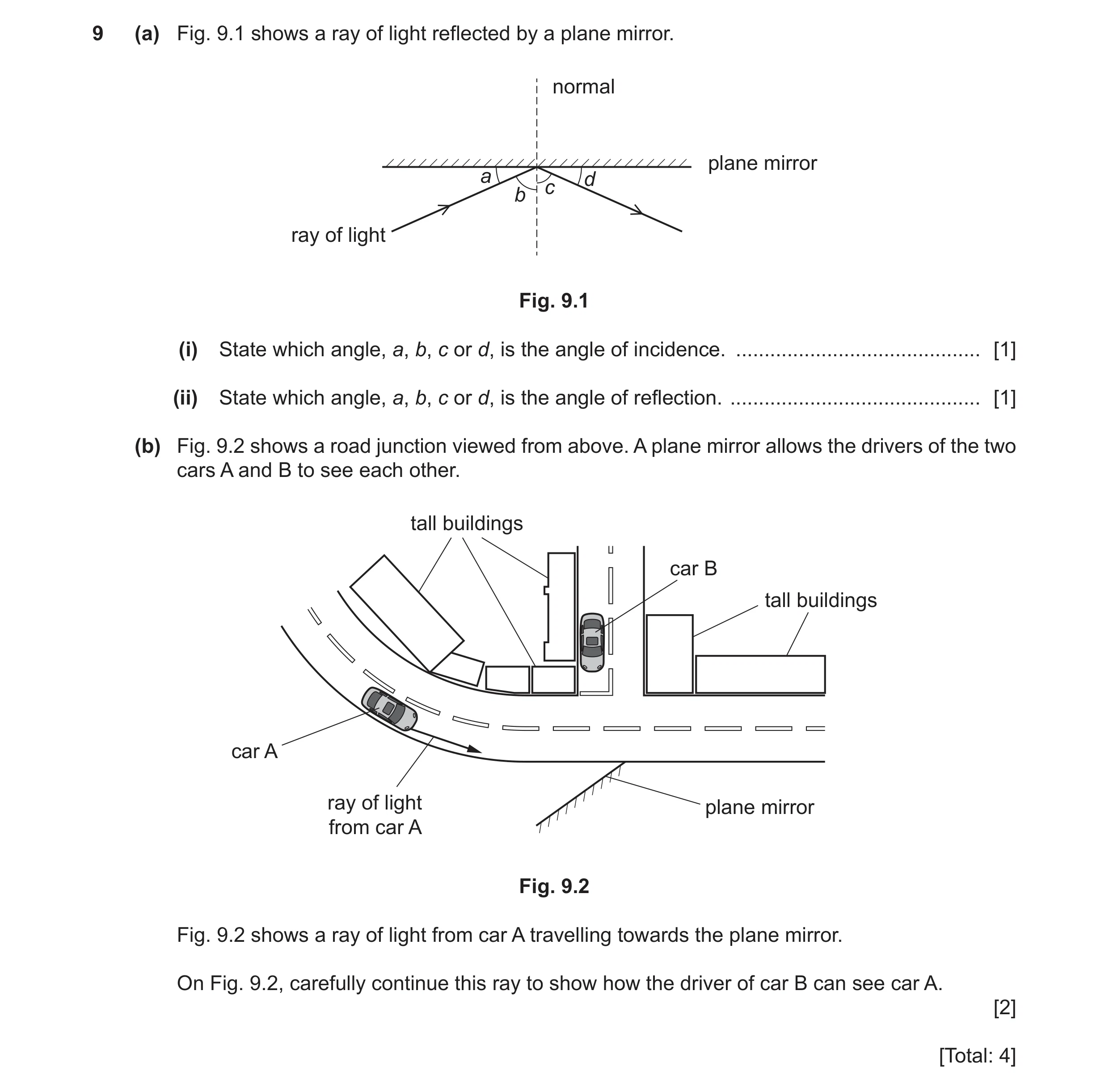
9 (a) Fig. 9.1 shows a ray of light reflected by a plane mirror. normal plane mirror a d c b ray of light Fig. 9.1 (i) State which angle, a, b, c or d, is the angle of incidence. … [1] (ii) State which angle, a, b, c or d, is the angle of reflection. … [1] (b) Fig. 9.2 shows a road junction viewed from above. A plane mirror allows the drivers of the two cars A and B to see each other. tall buildings car B tall buildings car A ray of light plane mirror from car A Fig. 9.2 Fig. 9.2 shows a ray of light from car A travelling towards the plane mirror. On Fig. 9.2, carefully continue this ray to show how the driver of car B can see car A. [2] [Total: 4]
4 marks
Mark scheme: 9(a)(i) b B1 9(a)(ii) c B1 9(b) ray from lamp extended to mirror as straight line (by eye) M1 ray reflected to car B A1
This question in 0625/32 Oct/Nov 2021
Q31 · The diagram in Fig 0625/33 Oct/Nov 2021
8 (a) The diagram in Fig. 8.1 shows a ray of light travelling from a glass block into air. ray of light b glass block a c d f air e Fig. 8.1 (i) State the name for the dashed line shown in Fig. 8.1. … [1] (ii) State the letter, a, b, c, d, e or f, which indicates the angle of incidence of the ray in Fig. 8.1. … [1] (iii) State the letter, a, b, c, d, e or f, which indicates the angle of refraction of the ray in Fig. 8.1. … [1] (b) The diagram in Fig. 8.2 shows an object and a thin converging lens. Two rays are drawn from the object to the lens. The points marked F are the principal focuses of the lens. object F F Fig. 8.2 (i) Continue the paths of the two rays in Fig. 8.2 to show how the lens forms an image of the object. [2] (ii) On Fig. 8.2, draw an arrow to represent the image. [1] (iii) Tick (✓) two rows to indicate the nature of the image formed by the lens in Fig. 8.2. nature of image tick enlarged the same size diminished upright inverted [2] [Total: 8]
8 marks
Mark scheme: 8(a)(i) normal B1 8(a)(ii) b B1 8(a)(iii) e B1 8(b)(i) top ray continued through F on right hand side of lens B1 lower ray continued parallel to principal axis (by eye) B1 8(b)(ii) arrow drawn from where their rays cross to principal axis B1 8(b)(iii) diminished B1 inverted B1
This question in 0625/33 Oct/Nov 2021
Q32 · A student investigates refraction through a parallel- sided glass block 0625/32 May/June 2022
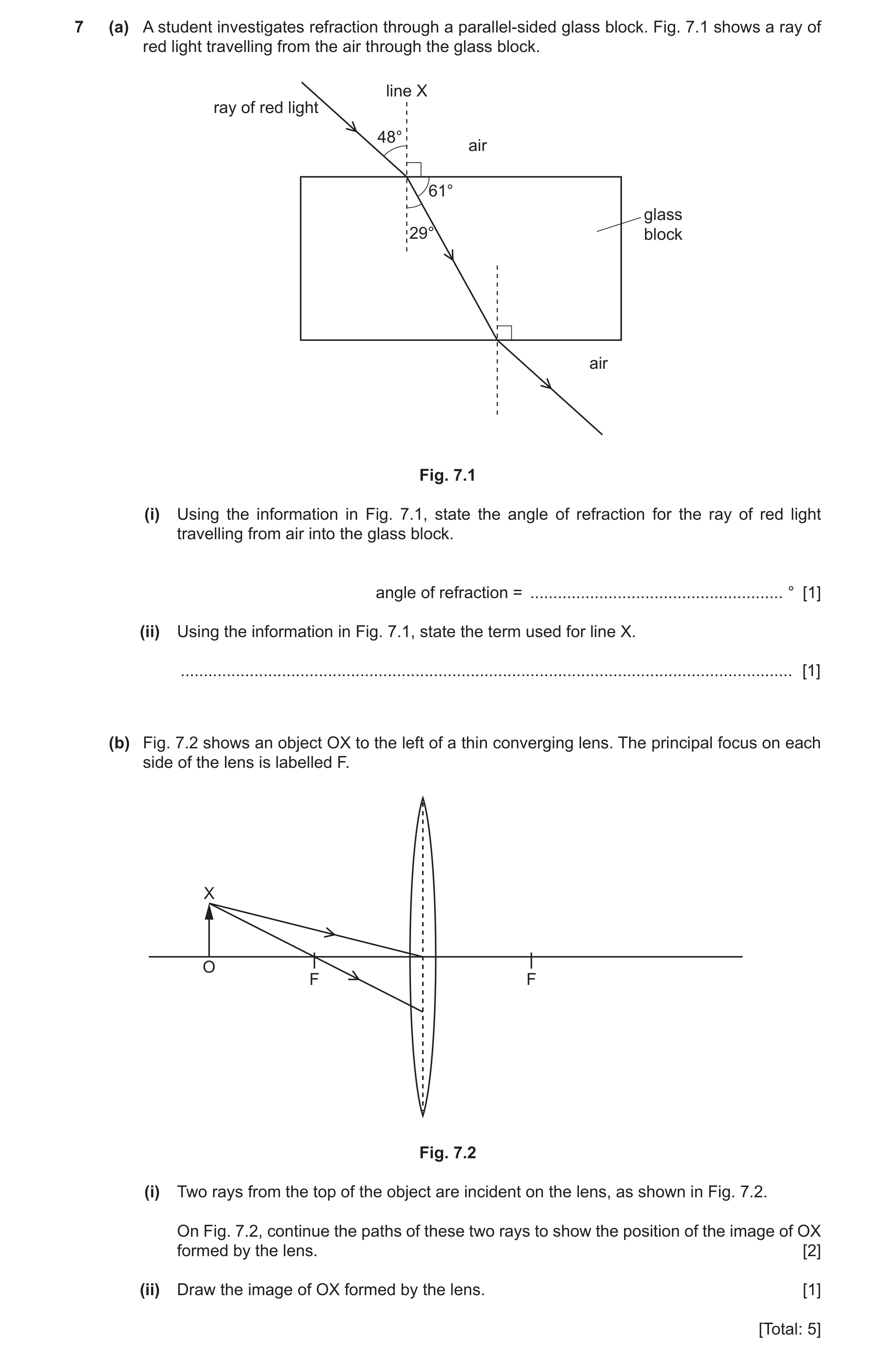
7 (a) A student investigates refraction through a parallel- sided glass block. Fig. 7.1 shows a ray of red light travelling from the air through the glass block. line X ray of red light 48° air 61° glass 29° block air Fig. 7.1 (i) Using the information in Fig. 7.1, state the angle of refraction for the ray of red light travelling from air into the glass block. angle of refraction = … ° [1] (ii) Using the information in Fig. 7.1, state the term used for line X. … [1] (b) Fig. 7.2 shows an object OX to the left of a thin converging lens. The principal focus on each side of the lens is labelled F. X O F F Fig. 7.2 (i) Two rays from the top of the object are incident on the lens, as shown in Fig. 7.2. On Fig. 7.2, continue the paths of these two rays to show the position of the image of OX formed by the lens. [2] (ii) Draw the image of OX formed by the lens. [1] [Total: 5]
5 marks
Mark scheme: 7(a)(i) 29(°) B1 7(a)(ii) normal (line) B1 7(b)(i) ray through centre continues in straight line B1 (ray through F) drawn parallel to principal axis B1 7(b)(ii) arrow drawn from principal axis to where rays cross B1
This question in 0625/32 May/June 2022
Q33 · A diver is swimming under water 0625/33 May/June 2022
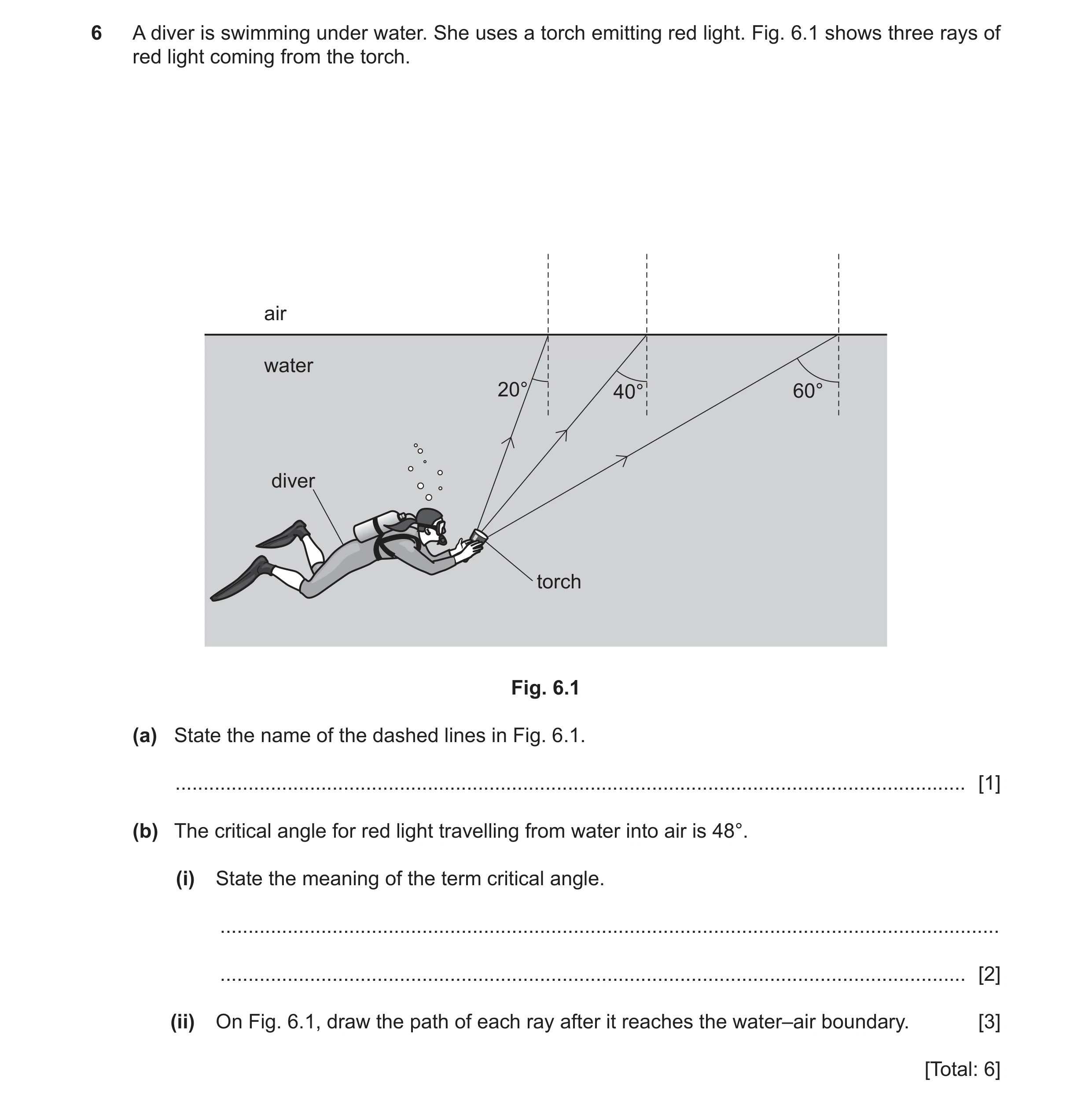
6 A diver is swimming under water. She uses a torch emitting red light. Fig. 6.1 shows three rays of red light coming from the torch. air water 20° 40° 60° diver torch Fig. 6.1 (a) State the name of the dashed lines in Fig. 6.1. … [1] (b) The critical angle for red light travelling from water into air is 48°. (i) State the meaning of the term critical angle. … … [2] (ii) On Fig. 6.1, draw the path of each ray after it reaches the water–air boundary. [3] [Total: 6]
6 marks
Mark scheme: 6(a) normal(s) B1 6(b)(i) angle of incidence B1 that gives an angle of refraction of 90° B1 6(b)(ii) 20° – emergent ray is refracted in air B1 40° – emergent ray is refracted in air AND greater refraction B1 60° – ray is reflected internally B1
This question in 0625/33 May/June 2022
Q34 · A ray of light striking a plane mirror 0625/32 Oct/Nov 2022
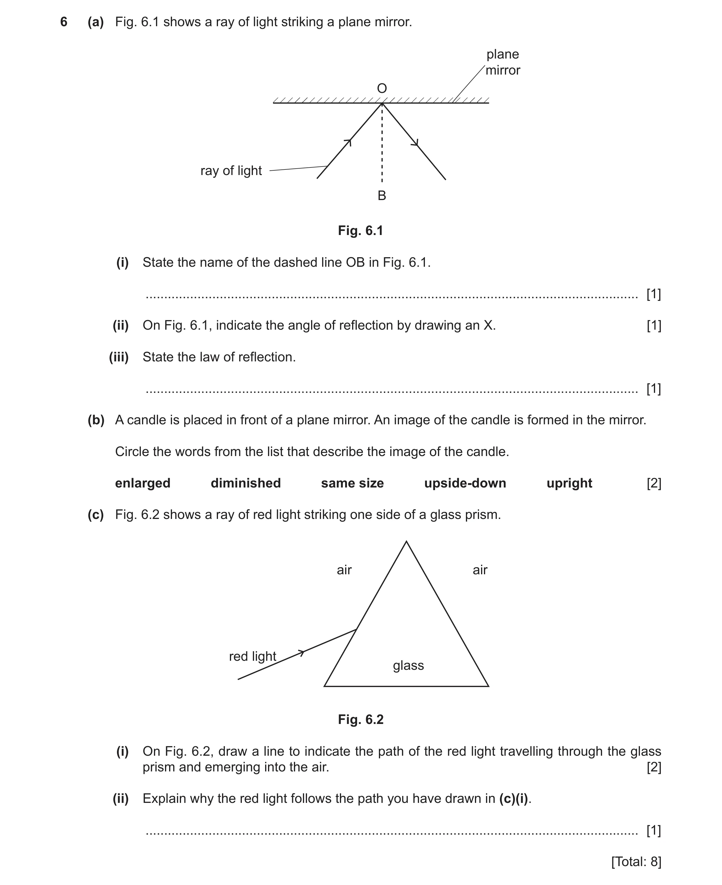
6 (a) Fig. 6.1 shows a ray of light striking a plane mirror. plane mirror O ray of light B Fig. 6.1 (i) State the name of the dashed line OB in Fig. 6.1. … [1] (ii) On Fig. 6.1, indicate the angle of reflection by drawing an X. [1] (iii) State the law of reflection. … [1] (b) A candle is placed in front of a plane mirror. An image of the candle is formed in the mirror. Circle the words from the list that describe the image of the candle. enlarged diminished same size upside-down upright [2] (c) Fig. 6.2 shows a ray of red light striking one side of a glass prism. air air red light glass Fig. 6.2 (i) On Fig. 6.2, draw a line to indicate the path of the red light travelling through the glass prism and emerging into the air. [2] (ii) Explain why the red light follows the path you have drawn in (c)(i). … [1] [Total: 8]
8 marks
Mark scheme: 6(a)(i) normal (line) B1 6(a)(ii) correct angle clearly indicated B1 6(a)(iii) angle of incidence = angle of reflection B1 6(b) same size B1 upright B1 6(c)(i) single ray with correct refraction in glass B1 emergent ray with correct refraction B1 6(c)(ii) refraction B1
This question in 0625/32 Oct/Nov 2022
Q35 · A student shines a ray of red light towards a large glass prism, as shown in Fig 0625/33 Oct/Nov 2022
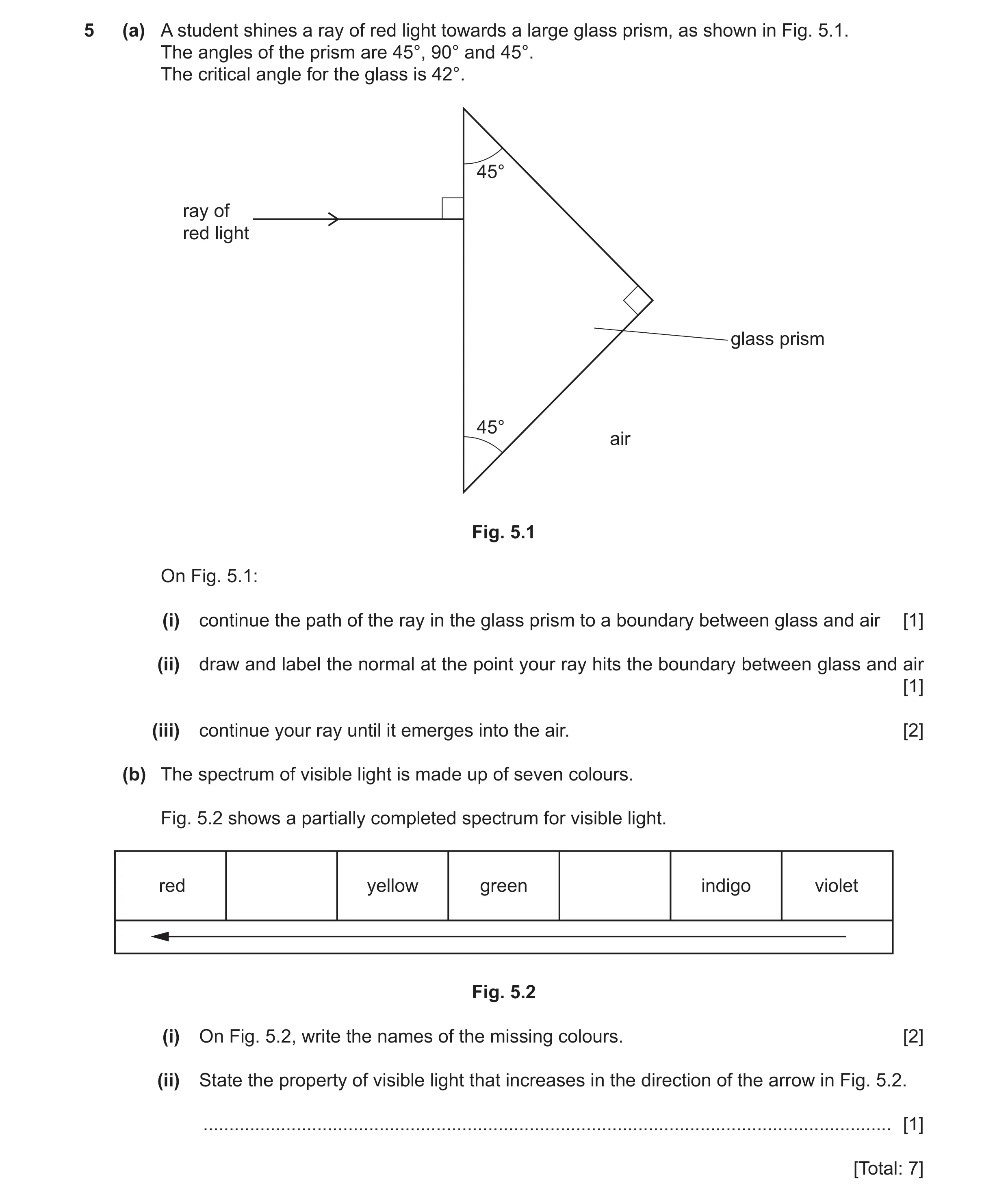
5 (a) A student shines a ray of red light towards a large glass prism, as shown in Fig. 5.1. The angles of the prism are 45°, 90° and 45°. The critical angle for the glass is 42°. 45° ray of red light glass prism 45° air Fig. 5.1 On Fig. 5.1: (i) continue the path of the ray in the glass prism to a boundary between glass and air [1] (ii) draw and label the normal at the point your ray hits the boundary between glass and air [1] (iii) continue your ray until it emerges into the air. [2] (b) The spectrum of visible light is made up of seven colours. Fig. 5.2 shows a partially completed spectrum for visible light. red yellow green indigo violet Fig. 5.2 (i) On Fig. 5.2, write the names of the missing colours. [2] (ii) State the property of visible light that increases in the direction of the arrow in Fig. 5.2. … [1] [Total: 7]
7 marks
Mark scheme: 5(a)(i) ray continues normally into glass B1 5(a)(ii) one correct normal seen B1 5(a)(iii) ray is totally internally reflected at a glass / air boundary B1 ray emerging from hypotenuse B1 5(b)(i) orange – between red and yellow B1 blue – between green and indigo B1 5(b)(ii) wavelength B1
This question in 0625/33 Oct/Nov 2022
Q36 · A vertical arrow O is used as an object for a converging lens 0625/33 Oct/Nov 2022
6 A vertical arrow O is used as an object for a converging lens. Fig. 6.1 shows a ray of light from the object passing through the lens. O P F Fig. 6.1 The point labelled F is a principal focus of the lens. (a) State the name of the distance labelled PF on Fig. 6.1. … [1] (b) On Fig. 6.1, draw another ray that enables you to locate the image of O. [2] (c) Draw an arrow to indicate the image. Label the image I. [1] (d) Circle two words from the list which describe the image I. enlarged diminished same size inverted upright [2] [Total: 6]
6 marks
Mark scheme: 6(a) focal length B1 6(b) paraxial ray to lens B1 ray passes through F B1 OR ray passing through principal focus on lhs paraxial ray on rhs 6(c) labelled inverted arrow from where (their) rays cross to principal axis B1 6(d) diminished B1 inverted B1
This question in 0625/33 Oct/Nov 2022
Q37 · A student places a book in front of a plane mirror 0625/32 Feb/March 2023
7 (a) A student places a book in front of a plane mirror. State three characteristics of the image of the book formed by the plane mirror. 1 … 2 … 3 … [3] (b) Visible light is one region of the electromagnetic spectrum. Another region is ultraviolet radiation. (i) Give one use of ultraviolet radiation. … [1] (ii) Give one possible harmful effect of excessive exposure to ultraviolet radiation. … [1] [Total: 5]
5 marks
Mark scheme: 7(a) same size (as object / book) B1 same distance from mirror (as book / object) B1 virtual B1 7(b) (use:) security marking OR detecting fake bank notes OR sterilising water B1 (harmful effect:) damage to surface cells / skin OR eyes OR damage to cells / genes / DNA OR skin cancer B1
This question in 0625/32 Feb/March 2023
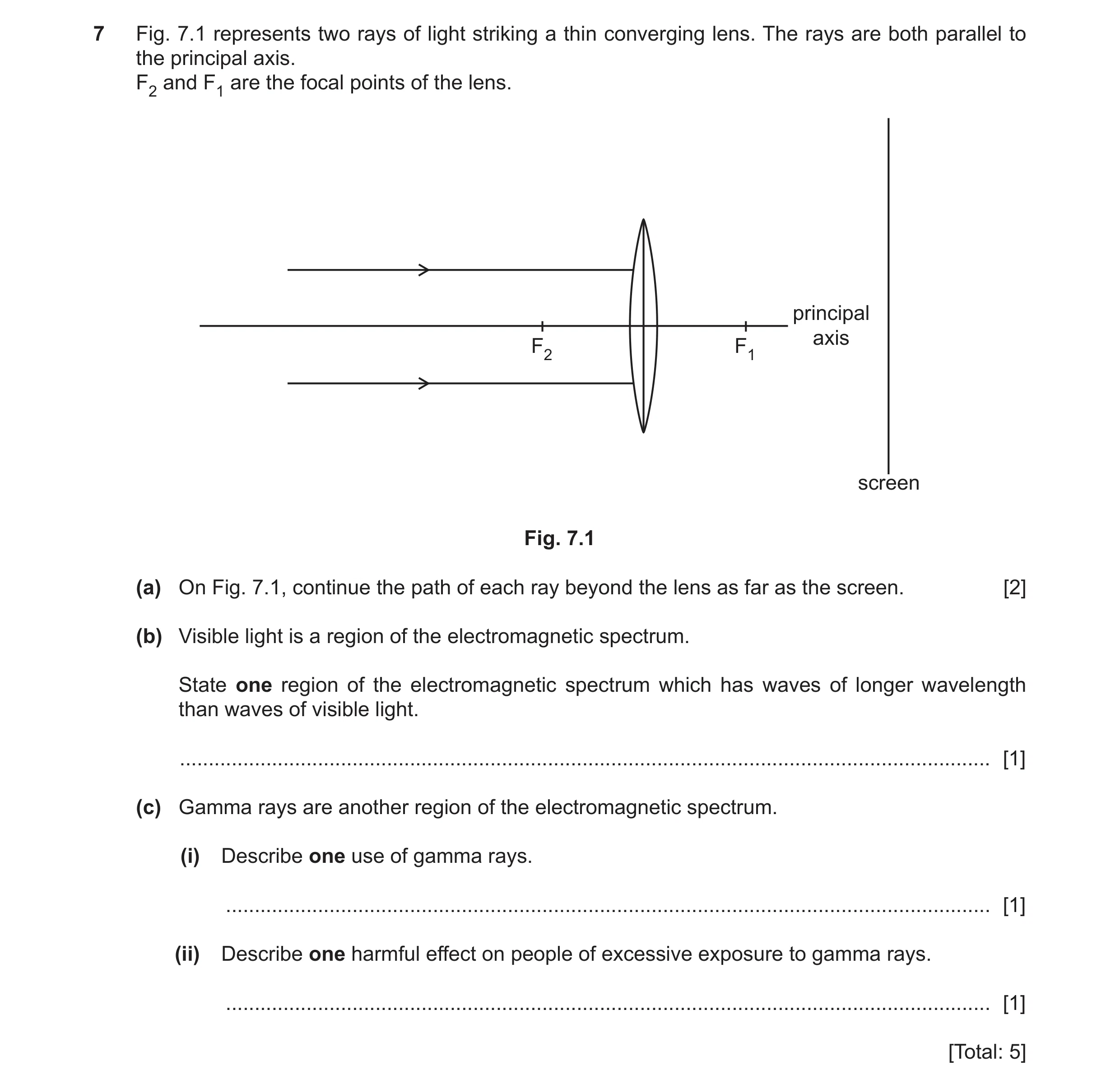
Q38 · Two rays of light striking a thin converging lens 0625/31 May/June 2023
7 Fig. 7.1 represents two rays of light striking a thin converging lens. The rays are both parallel to the principal axis. F2 and F1 are the focal points of the lens. principal axis F2 F1 screen Fig. 7.1 (a) On Fig. 7.1, continue the path of each ray beyond the lens as far as the screen. [2] (b) Visible light is a region of the electromagnetic spectrum. State one region of the electromagnetic spectrum which has waves of longer wavelength than waves of visible light. … [1] (c) Gamma rays are another region of the electromagnetic spectrum. (i) Describe one use of gamma rays. … [1] (ii) Describe one harmful effect on people of excessive exposure to gamma rays. … [1] [Total: 5]
5 marks
Mark scheme: 7(a) both rays refracted toward principal axis B1 both rays meet at F1 B1 7(b) infrared (rays / waves) OR microwaves OR radio (waves) B1 7(c)(i) any one from: sterilising food / water sterilising (medical) equipment detection of cancer treatment of cancer space telescopes B1 7(c)(ii) mutation (of cells / DNA) OR damage to cells / DNA B1
This question in 0625/31 May/June 2023
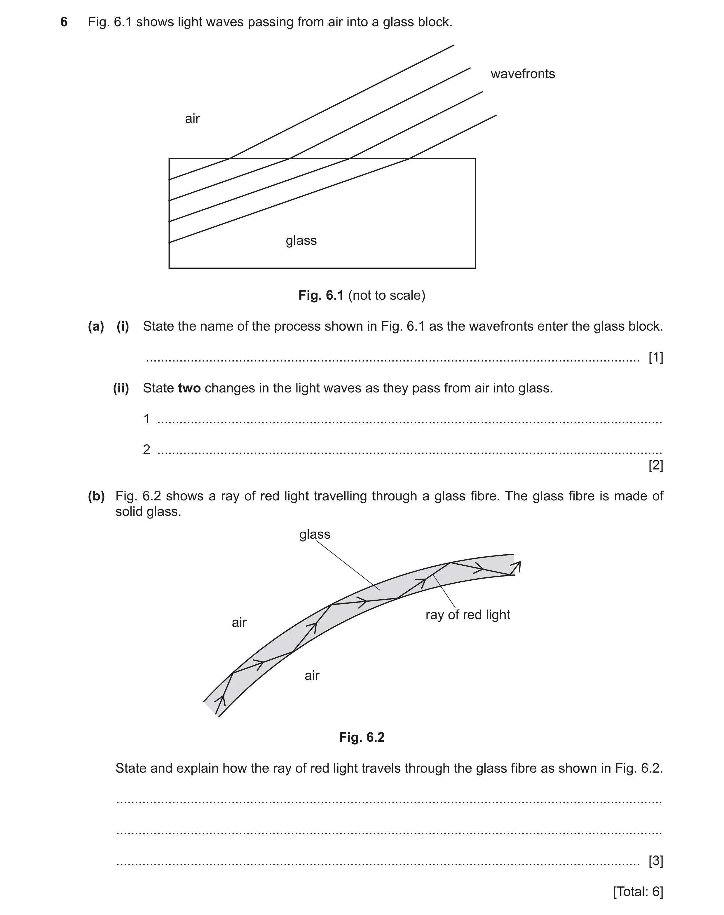
Q39 · Light waves passing from air into a glass block 0625/32 May/June 2023
6 Fig. 6.1 shows light waves passing from air into a glass block. wavefronts air glass Fig. 6.1 (not to scale) (a) (i) State the name of the process shown in Fig. 6.1 as the wavefronts enter the glass block. … [1] (ii) State two changes in the light waves as they pass from air into glass. 1 … 2 … [2] (b) Fig. 6.2 shows a ray of red light travelling through a glass fibre. The glass fibre is made of solid glass. glass ray of red light air air Fig. 6.2 State and explain how the ray of red light travels through the glass fibre as shown in Fig. 6.2. … … … [3] [Total: 6]
6 marks
Mark scheme: 6(a)(i) refraction B1 6(a)(ii) any two from: wavelength speed direction B2 6(b) total internal reflection B1 (red light) travelling from more dense OR into / towards less dense (medium) B1 incident on surface at an angle / angle of incidence greater than critical angle B1
This question in 0625/32 May/June 2023
Q40 · Students are investigating the refraction of light as it travels from air into glass 0625/33 May/June 2023
7 (a) Students are investigating the refraction of light as it travels from air into glass. Their task is to measure the angle of incidence and the angle of refraction at the surface of the glass block. The students have the equipment shown in Fig. 7.1. pencil 30 cm rule protractor sheet of paper ray box glass block Fig. 7.1 Describe the method for the task. You may draw a diagram as part of your answer. … … … … [4] (b) Fig. 7.2 and Fig. 7.3 show two identical lenses, each forming an image. The images I1 and I2 have different characteristics. I2 O O F F F I1 F Fig. 7.2 Fig. 7.3 One difference in the characteristics of the two images is: diminished enlarged Image I1 is … but image I2 is … . State two more differences in the characteristics of the images: Image I1 is … but image I2 is … . Image I1 is … but image I2 is … . [3] [Total: 7]
7 marks
Mark scheme: 7(a) any four from: draw round the block (on the paper) use ray box to shine a ray through block draw crosses on incident and emergent rays draw ray through block draw normals measure angles between rays and normals B4 7(b) Image I1 is real but image I2 is virtual. Image I1 is inverted but image I2 upright. 4 correct – 3 marks 3 or 2 correct – 2 marks 1 correct – 1 mark if no marks scored but all three or four characteristics named, award 1 mark B3
This question in 0625/33 May/June 2023
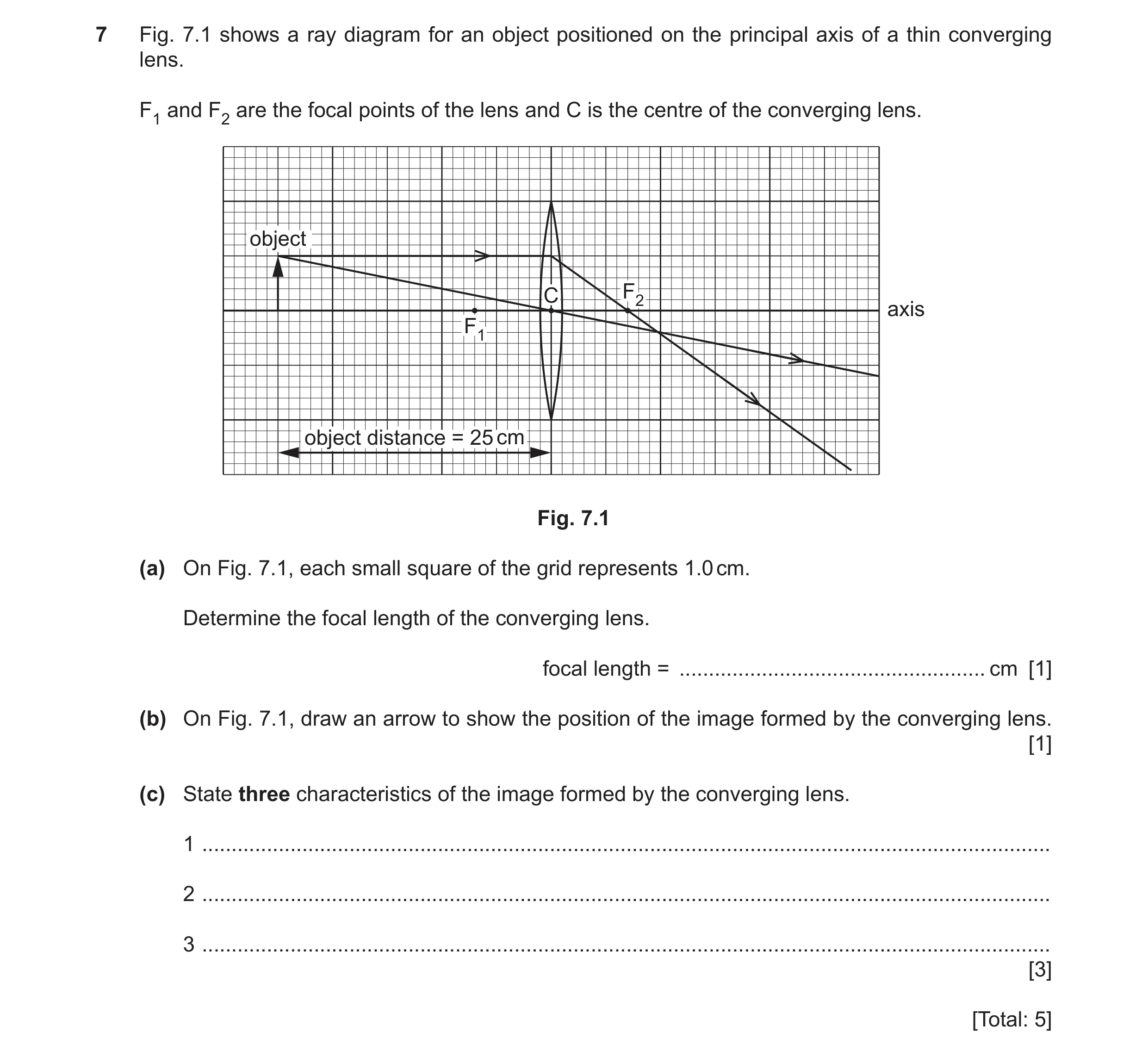
Q41 · A ray diagram for an object positioned on the principal axis of a thin converging lens 0625/31 Oct/Nov 2023
7 Fig. 7.1 shows a ray diagram for an object positioned on the principal axis of a thin converging lens. F1 and F2 are the focal points of the lens and C is the centre of the converging lens. object C F2 axis F1 object distance = 25 cm Fig. 7.1 (a) On Fig. 7.1, each small square of the grid represents 1.0 cm. Determine the focal length of the converging lens. focal length = … cm [1] (b) On Fig. 7.1, draw an arrow to show the position of the image formed by the converging lens. [1] (c) State three characteristics of the image formed by the converging lens. 1 … 2 … 3 … [3] [Total: 5]
5 marks
Mark scheme: 7(a) 7 (cm) B1 7(b) arrow drawn (perpendicularly) from principal axis to intersection of rays. B1 7(c) (image is) real B1 inverted B1
This question in 0625/31 Oct/Nov 2023
Question 42 0625/32 Oct/Nov 2023
8 (a) In Fig. 8.1, each diagram illustrates a wave property. Draw a line from each diagram to the correct wave property. waves reflection barrier diffraction dispersion glass refraction ray of red light Fig. 8.1 [2] (b) An object O is placed in front of a converging lens. Fig. 8.2 shows two rays of light from the object passing through the lens. O F X Y Fig. 8.2 (i) State the name of the line XY in Fig. 8.2. … [1] (ii) State the name of the point labelled F in Fig. 8.2. … [1] (iii) On Fig. 8.2, draw an arrow to represent the image of O. [1] (iv) Using a ruler, measure the focal length of the converging lens. focal length = … cm [1] (v) Describe characteristics of the image in Fig. 8.2. Choose words from the list. Tick (3) three boxes. enlarged diminished same size inverted upright virtual real [3] [Total: 9]
9 marks
Mark scheme: 8(a) top diagram ----------- diffraction B1 bottom diagram ---------- refraction B1 8(b)(i) principal axis B1 8(b)(ii) principal focus B1 8(b)(iii) vertical line from point where rays cross to the principal axis B1 8(b)(iv) 1.9 (cm) B1 8(b)(v) B1 enlarged ✓ B1 diminished B1 same size inverted ✓ upright virtual real ✓
This question in 0625/32 Oct/Nov 2023
Q43 · A student shines a ray of red light into a rectangular glass block, as shown in Fig 0625/33 Oct/Nov 2023
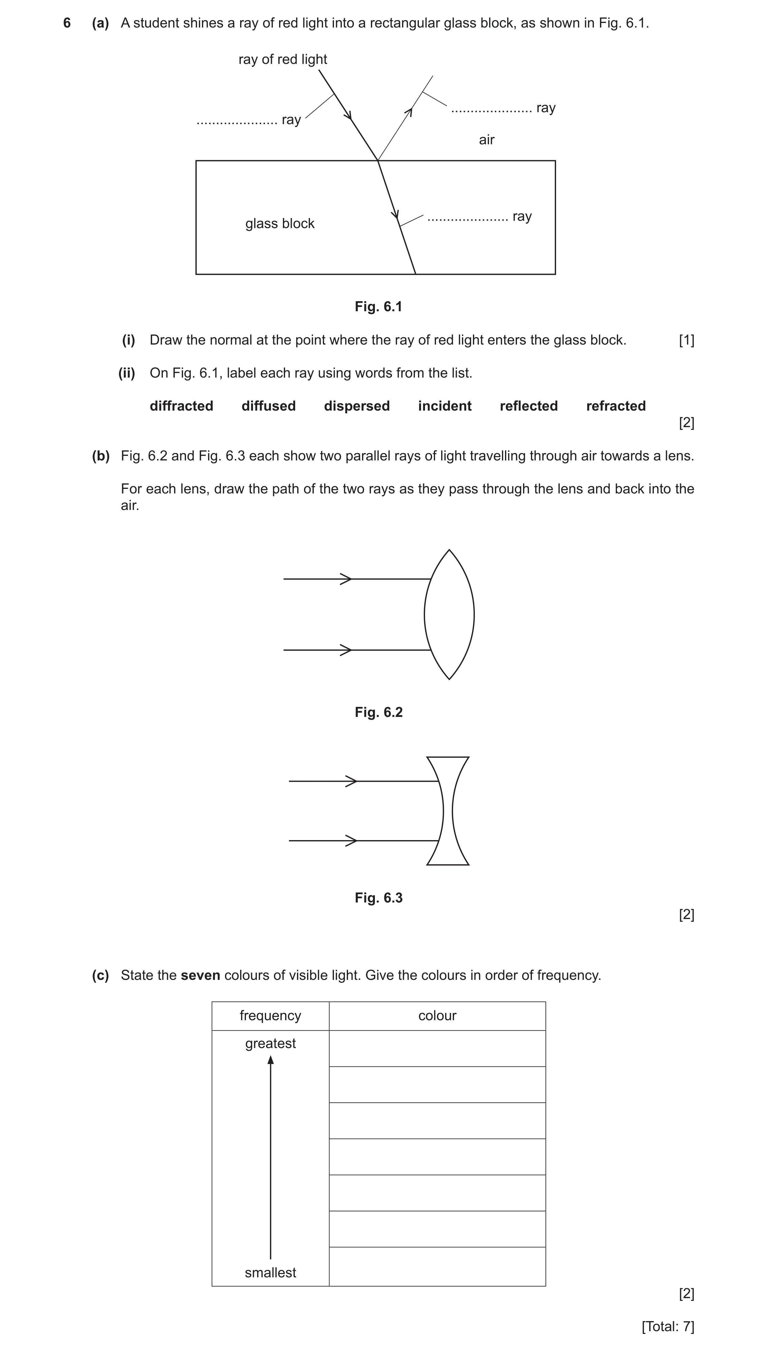
6 (a) A student shines a ray of red light into a rectangular glass block, as shown in Fig. 6.1. ray of red light … ray … ray air … ray glass block Fig. 6.1 (i) Draw the normal at the point where the ray of red light enters the glass block. [1] (ii) On Fig. 6.1, label each ray using words from the list. diffracted diffused dispersed incident reflected refracted [2] (b) Fig. 6.2 and Fig. 6.3 each show two parallel rays of light travelling through air towards a lens. For each lens, draw the path of the two rays as they pass through the lens and back into the air. Fig. 6.2 Fig. 6.3 [2] (c) State the seven colours of visible light. Give the colours in order of frequency. frequency colour greatest smallest [2] [Total: 7]
7 marks
Mark scheme: 6(a)(i) normal correctly drawn B1 6(a)(ii) incident (ray) reflected (ray) B2 refracted (ray) 6(b) Fig. 6.2. – emerging rays converge B1 Fig. 6.3. – emerging rays diverge B1 6(c) all 7 colours named M1 greatest frequency violet AND in correct order (VIBGYOR) A1
This question in 0625/33 Oct/Nov 2023
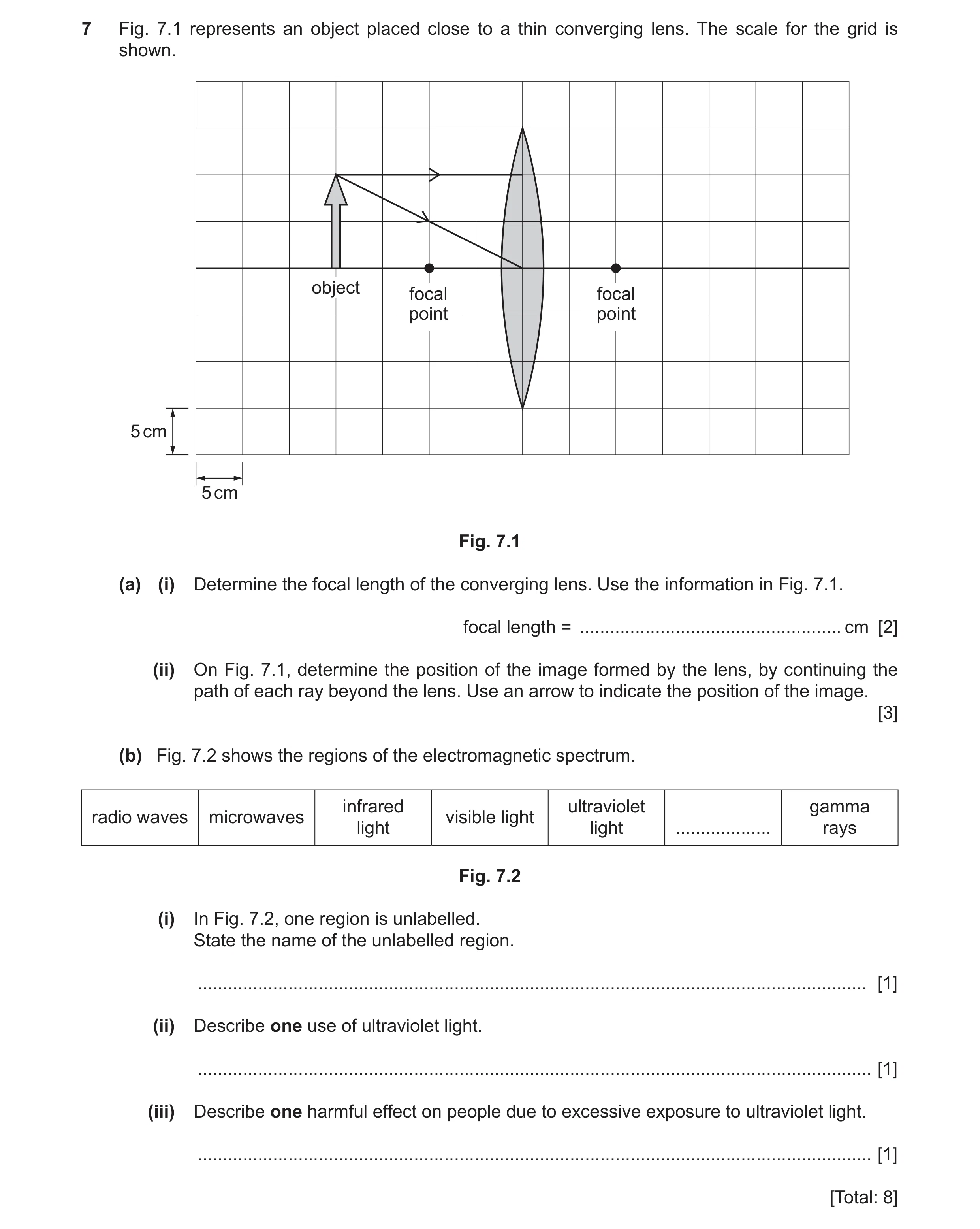
Q44 · An object placed close to a thin converging lens 0625/32 Feb/March 2024
7 Fig. 7.1 represents an object placed close to a thin converging lens. The scale for the grid is shown. object focal focal point point 5 cm 5 cm Fig. 7.1 (a) (i) Determine the focal length of the converging lens. Use the information in Fig. 7.1. focal length = … cm [2] (ii) On Fig. 7.1, determine the position of the image formed by the lens, by continuing the path of each ray beyond the lens. Use an arrow to indicate the position of the image. [3] (b) Fig. 7.2 shows the regions of the electromagnetic spectrum. infrared ultraviolet gamma radio waves microwaves visible light light light … rays Fig. 7.2 (i) In Fig. 7.2, one region is unlabelled. State the name of the unlabelled region. … [1] (ii) Describe one use of ultraviolet light. … [1] (iii) Describe one harmful effect on people due to excessive exposure to ultraviolet light. … [1] [Total: 8]
8 marks
Mark scheme: 7(a)(i) 10 (cm) A2 (focal length =) 2 5 (C1) 7(a)(ii) ray continued in straight line through centre of lens B1 ray parallel to axis continued to pass through focal point B1 (top of) image position indicated as where rays cross B1 7(b)(i) X-rays B1 7(b)(ii) security marker OR detecting fake bank notes OR sterilising food / water B1 7(b)(iii) damage to (surface) cells / skin / eyes B1 OR (leading to) cancer / eye conditions
This question in 0625/32 Feb/March 2024
Q45 · A ray of light striking a plane mirror 0625/31 May/June 2024
7 (a) Fig. 7.1 shows a ray of light striking a plane mirror. The ray is reflected as shown. plane mirror ray of light normal Fig. 7.1 The angle of incidence for the ray of light is 40°. (i) Indicate the angle of reflection by drawing a letter R on Fig. 7.1. [1] (ii) State the size of the angle of reflection in Fig. 7.1. angle of reflection = … ° [1] (b) An object O is placed to the left of a thin converging lens. F1 is the principal focus on one side of the lens and F2 is the principal focus on the other side of the lens. Two rays from the top of the object are incident on the lens, as shown in Fig. 7.2. O F1 F2 thin converging lens Fig. 7.2 (i) On Fig. 7.2, locate the image of O by continuing the path of each ray. [2] (ii) Draw an arrow to represent the image of O. [1] (c) Fig. 7.3 shows a prism producing a spectrum of colours from a narrow beam of white light. prism X narrow beam of white light spectrum of seven colours Z Fig. 7.3 (i) The prism refracts the white light. State the name of the effect that produces a spectrum. … [1] (ii) In the spectrum shown in Fig. 7.3, there are seven colours. List the seven colours in the order they appear between X and Z. X … … … … … … Z … [2] [Total: 8]
8 marks
Mark scheme: 7(a)(i) angle of reflection identified B1 7(a)(ii) 40 (°) B1 7(b)(i) horizontal ray drawn to continue through F2 B1 ray to centre drawn to continue undeviated B1 7(b)(ii) (image drawn / identified) where rays cross B1 7(c)(i) dispersion B1 7(c)(ii) all 7 colours AND in correct order A2 6 of the seven colours given (C1)
This question in 0625/31 May/June 2024
Q46 · A ray of red light incident on a glass prism at point P 0625/33 May/June 2024
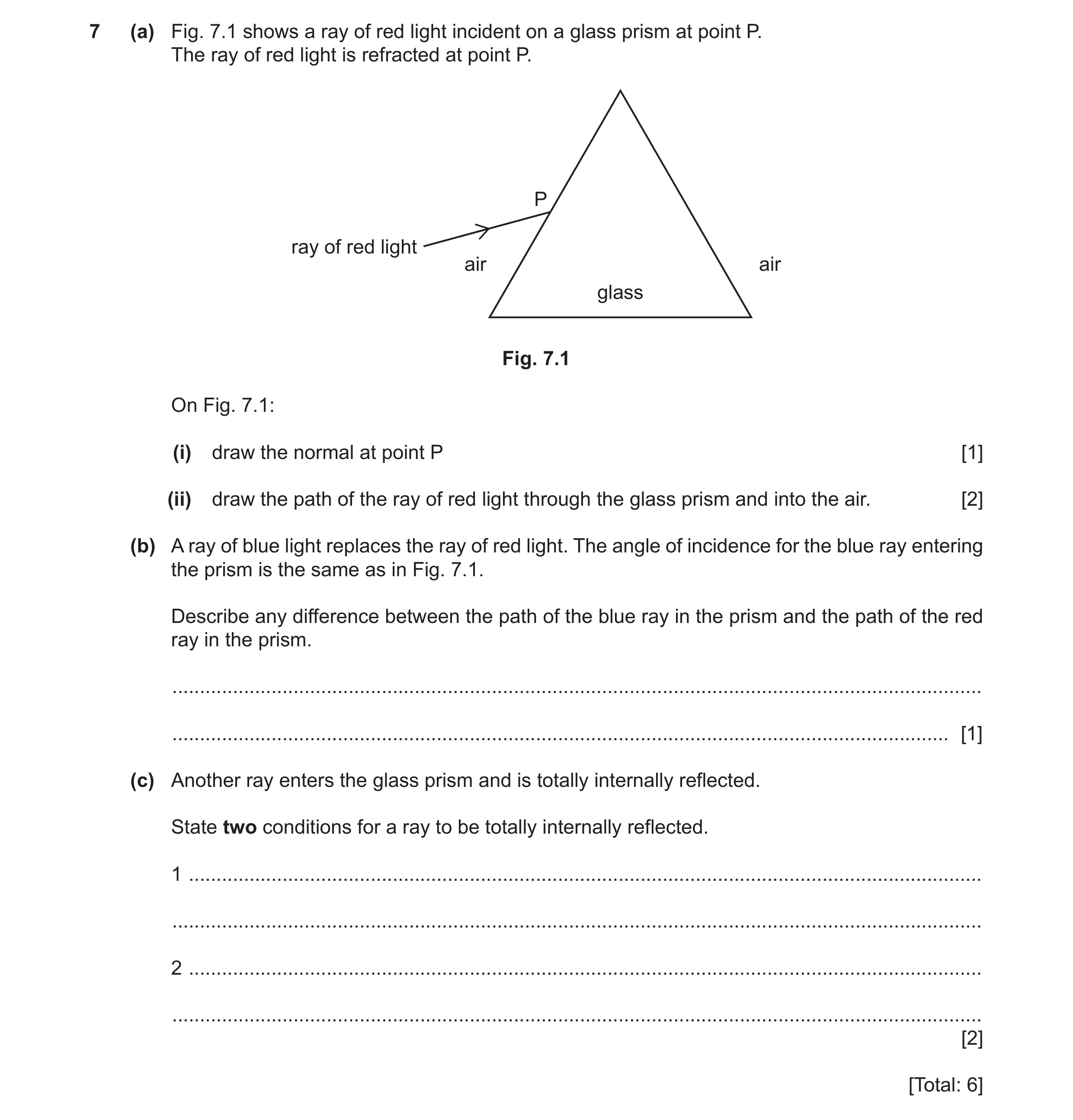
7 (a) Fig. 7.1 shows a ray of red light incident on a glass prism at point P. The ray of red light is refracted at point P. P ray of red light air air glass Fig. 7.1 On Fig. 7.1: (i) draw the normal at point P [1] (ii) draw the path of the ray of red light through the glass prism and into the air. [2] (b) A ray of blue light replaces the ray of red light. The angle of incidence for the blue ray entering the prism is the same as in Fig. 7.1. Describe any difference between the path of the blue ray in the prism and the path of the red ray in the prism. … … [1] (c) Another ray enters the glass prism and is totally internally reflected. State two conditions for a ray to be totally internally reflected. 1 … … 2 … … [2] [Total: 6]
6 marks
Mark scheme: 7(a)(i) correct normal B1 7(a)(ii) ray in glass refracted towards the normal B1 ray in air refracted away from the normal B1 7(b) greater refraction / smaller angle of refraction (at air–glass boundary) B1 7(c) (ray of light) travelling from glass to air B1 angle of incidence greater than critical angle B1
This question in 0625/33 May/June 2024
Q47 · A ray diagram for a thin converging lens 0625/31 Oct/Nov 2024
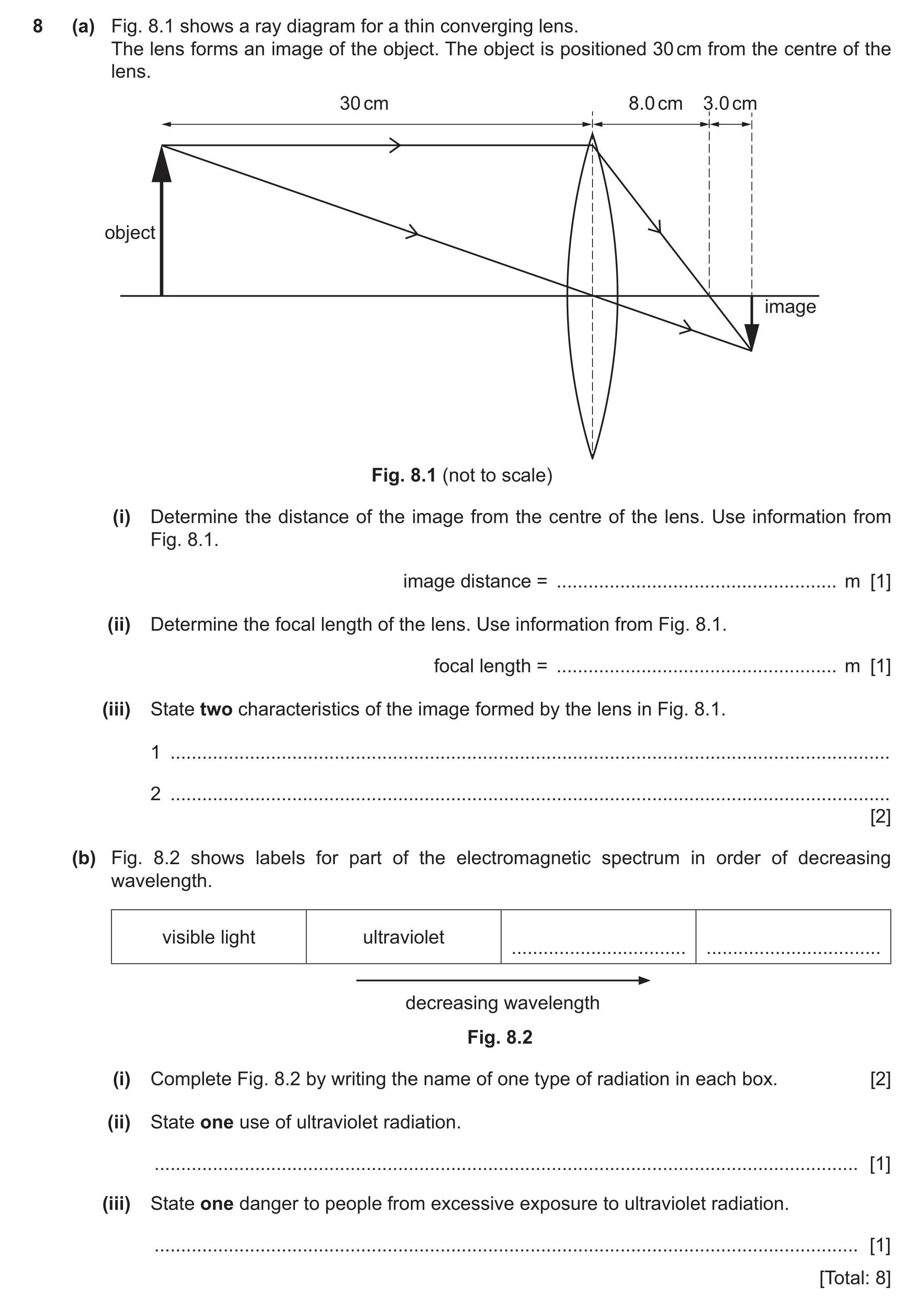
8 (a) Fig. 8.1 shows a ray diagram for a thin converging lens. The lens forms an image of the object. The object is positioned 30 cm from the centre of the lens. 30 cm 8.0 cm 3.0 cm object image Fig. 8.1 (not to scale) (i) Determine the distance of the image from the centre of the lens. Use information from Fig. 8.1. image distance = … m [1] (ii) Determine the focal length of the lens. Use information from Fig. 8.1. focal length = … m [1] (iii) State two characteristics of the image formed by the lens in Fig. 8.1. 1 … 2 … [2] (b) Fig. 8.2 shows labels for part of the electromagnetic spectrum in order of decreasing wavelength. visible light ultraviolet … … decreasing wavelength Fig. 8.2 (i) Complete Fig. 8.2 by writing the name of one type of radiation in each box. [2] (ii) State one use of ultraviolet radiation. … [1] (iii) State one danger to people from excessive exposure to ultraviolet radiation. … [1] [Total: 8]
8 marks
Mark scheme: 8(a)(i) 0.11 (m) B1 8(a)(ii) 0.08 (m) B1 8(a)(iii) any two from: B2 • diminished OR smaller • inverted OR upside down • real 8(b)(i) X (–rays) (box on left) B1 gamma (rays / radiation) (box on right) B1 8(b)(ii) security marker OR detecting fake bank notes OR sterilising (medical instruments / water / food) B1 8(b)(iii) damage to skin OR (surface) cells OR eyes B1
This question in 0625/31 Oct/Nov 2024
Q48 · A ray of red light entering one side of a glass block 0625/32 Feb/March 2025
7 (a) Fig. 7.1 represents a ray of red light entering one side of a glass block. glass block air air ray of red light Fig. 7.1 On Fig. 7.1 draw the path of the ray of red light through the glass block and into the air. [2] (b) Fig. 7.2 represents the dispersion of white light by a glass prism. air air white light red light violet light glass prism Fig. 7.2 Two of the colours of the visible spectrum are shown in Fig. 7.2. State the other five colours of the visible spectrum in the correct order. red … … … … … violet [1] (c) Fig. 7.3 represents the regions of the electromagnetic spectrum. infrared gamma radio waves microwaves visible light X-rays waves rays Fig. 7.3 (i) In Fig. 7.3, one region is unlabelled. State the name of the unlabelled region. … [1] (ii) Describe one use of gamma rays. … [1] (iii) Describe one harmful effect on people of excessive exposure to gamma rays. … [1] [Total: 6]
6 marks
Mark scheme: 7(a) ray refracted toward normal as it enters glass (by eye) B1 ray refracted away from normal on leaving glass (by eye) B1 OR emergent ray parallel with incident ray (by eye) 7(b) orange B1 yellow green blue indigo 7(c)(i) ultraviolet (rays / light) B1 7(c)(ii) detecting / treating cancer OR sterilising food / medical equipment B1 OR (medical) imaging OR detecting leaks in (underground) pipes 7(c)(iii) mutation or damage to cells / organs / DNA OR cancer B1
This question in 0625/32 Feb/March 2025
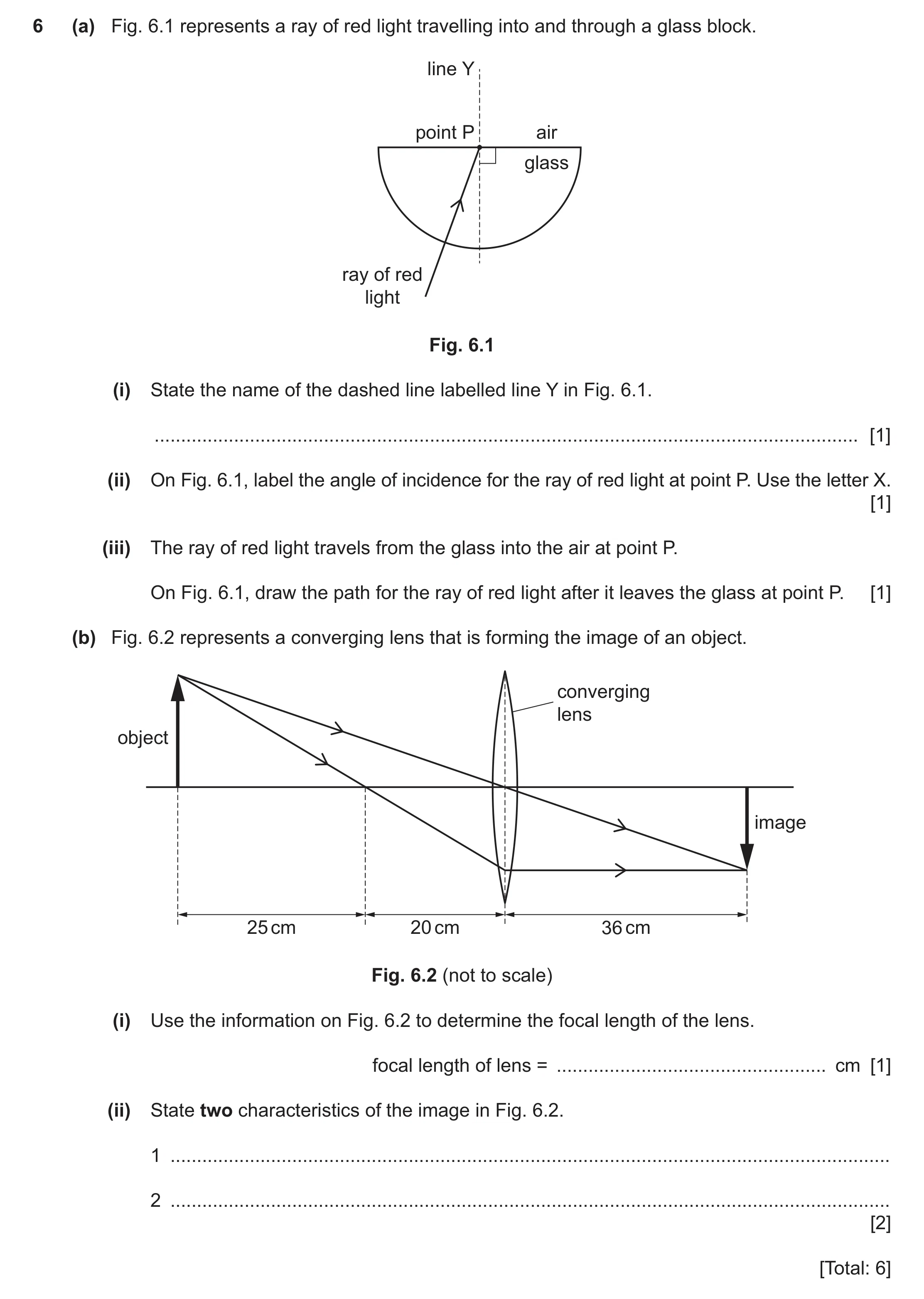
Q49 · A ray of red light travelling into and through a glass block 0625/31 May/June 2025
6 (a) Fig. 6.1 represents a ray of red light travelling into and through a glass block. line Y point P air glass ray of red light Fig. 6.1 (i) State the name of the dashed line labelled line Y in Fig. 6.1. … [1] (ii) On Fig. 6.1, label the angle of incidence for the ray of red light at point P. Use the letter X. [1] (iii) The ray of red light travels from the glass into the air at point P. On Fig. 6.1, draw the path for the ray of red light after it leaves the glass at point P. [1] (b) Fig. 6.2 represents a converging lens that is forming the image of an object. converging lens object image 25 cm 20 cm 36 cm Fig. 6.2 (not to scale) (i) Use the information on Fig. 6.2 to determine the focal length of the lens. focal length of lens = … cm [1] (ii) State two characteristics of the image in Fig. 6.2. 1 … 2 … [2] [Total: 6]
6 marks
Mark scheme: 6(a)(i) normal B1 6(a)(ii) angle of incidence indicated B1 6(a)(iii) ray refracted away from normal B1 6(b)(i) (focal length of lens =) 20 (cm) B1 6(b)(ii) any two from: B2 • real • inverted OR upside down owtte • diminished OR small(er) owtte
This question in 0625/31 May/June 2025
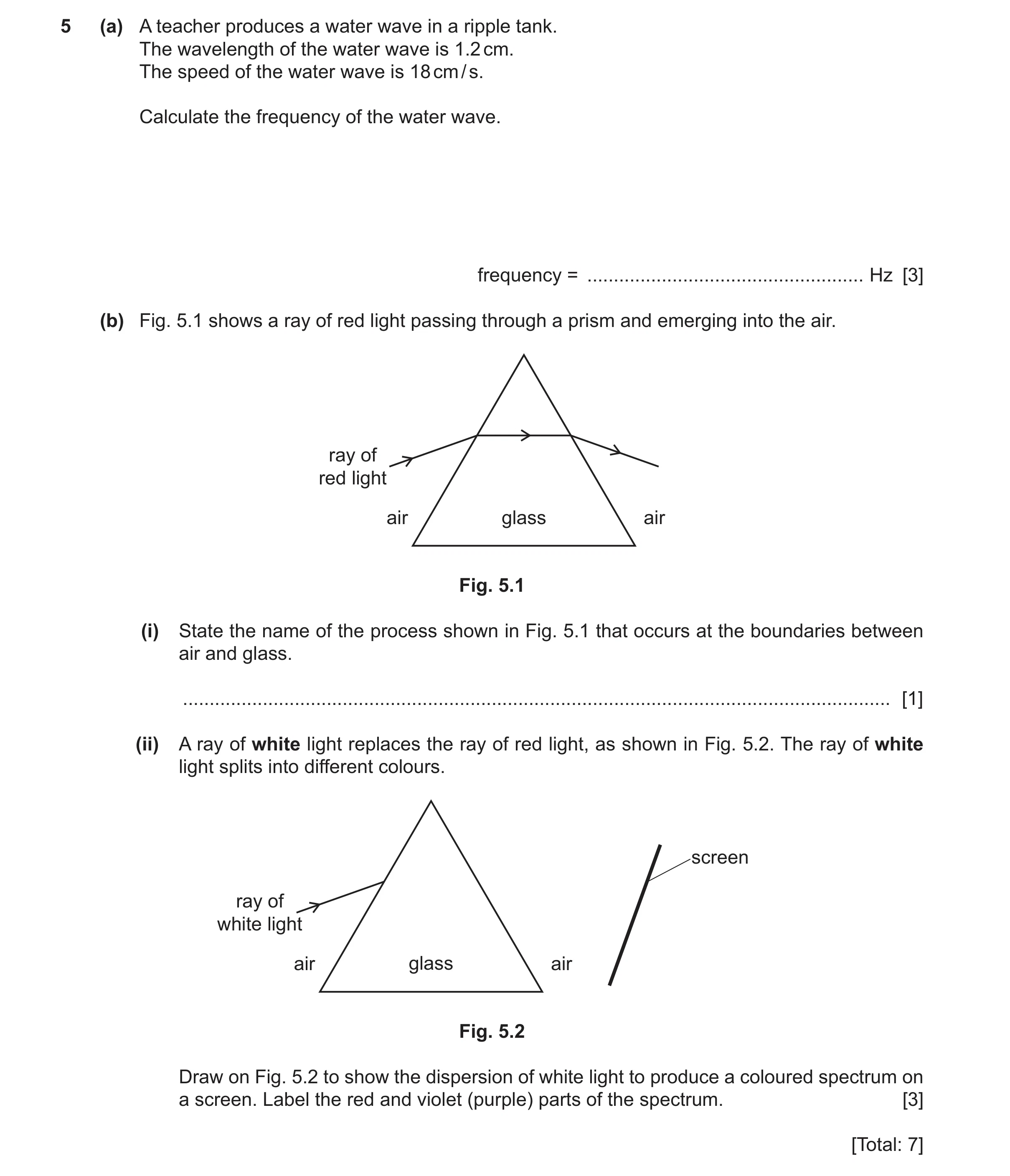
Q50 · A teacher produces a water wave in a ripple tank 0625/32 May/June 2025
5 (a) A teacher produces a water wave in a ripple tank. The wavelength of the water wave is 1.2 cm. The speed of the water wave is 18 cm / s. Calculate the frequency of the water wave. frequency = … Hz [3] (b) Fig. 5.1 shows a ray of red light passing through a prism and emerging into the air. ray of red light air glass air Fig. 5.1 (i) State the name of the process shown in Fig. 5.1 that occurs at the boundaries between air and glass. … [1] (ii) A ray of white light replaces the ray of red light, as shown in Fig. 5.2. The ray of white light splits into different colours. screen ray of white light air glass air Fig. 5.2 Draw on Fig. 5.2 to show the dispersion of white light to produce a coloured spectrum on a screen. Label the red and violet (purple) parts of the spectrum. [3] [Total: 7]
7 marks
Mark scheme: 5(a) 15 (Hz) A3 18 ÷ 1.2 C2 (frequency =) speed ÷ wavelength C1 5(b)(i) refraction B1 5(b)(ii) dispersion at air-glass boundary AND rays continue to screen A2 dispersion / ray broadens seen at either boundary C1 red (at top) and violet / purple (at bottom) B1
This question in 0625/32 May/June 2025
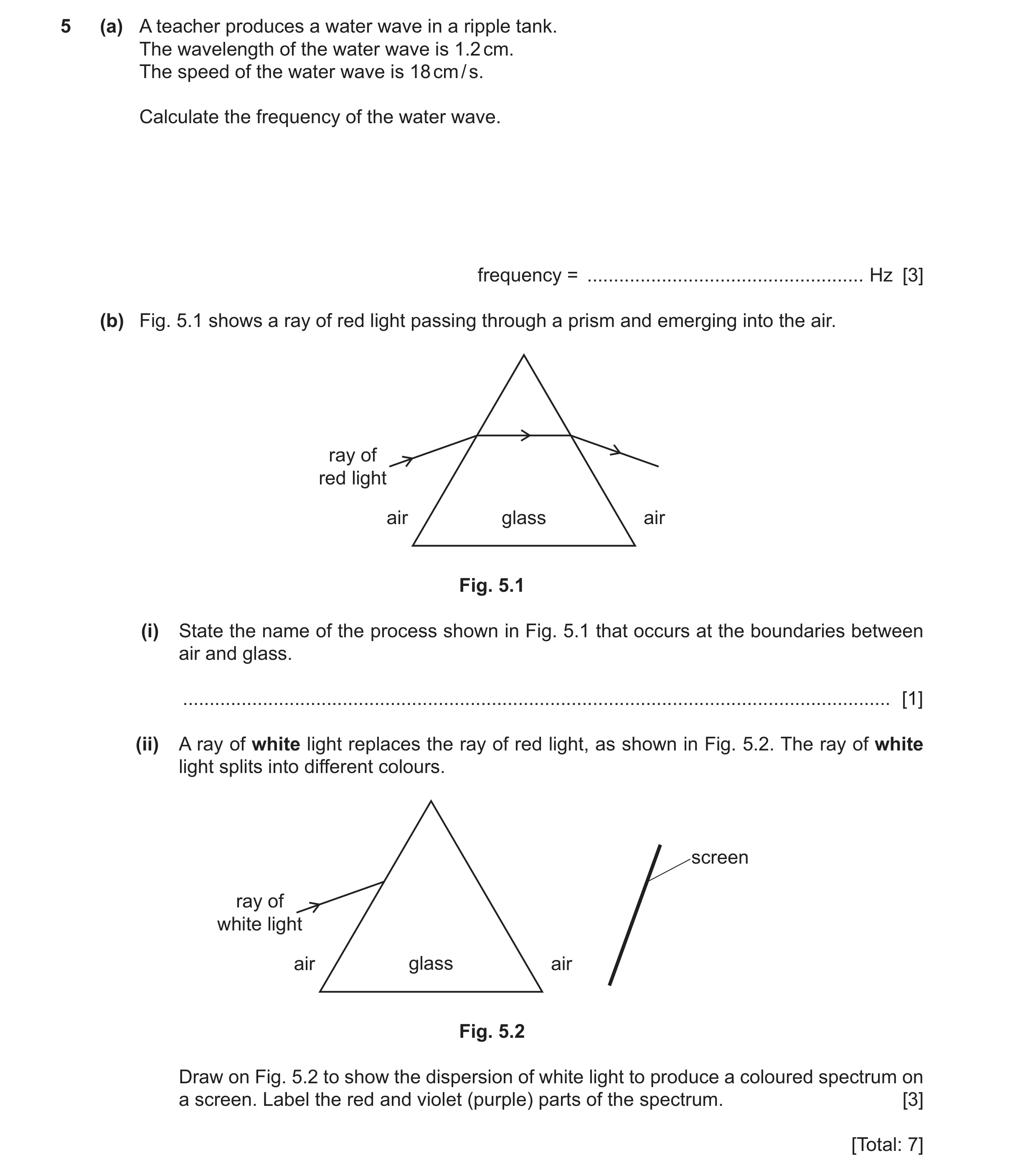
Q51 · A teacher produces a water wave in a ripple tank 0625/33 May/June 2025
5 (a) A teacher produces a water wave in a ripple tank. The wavelength of the water wave is 1.2 cm. The speed of the water wave is 18 cm / s. Calculate the frequency of the water wave. frequency = … Hz [3] (b) Fig. 5.1 shows a ray of red light passing through a prism and emerging into the air. ray of red light air glass air Fig. 5.1 (i) State the name of the process shown in Fig. 5.1 that occurs at the boundaries between air and glass. … [1] (ii) A ray of white light replaces the ray of red light, as shown in Fig. 5.2. The ray of white light splits into different colours. screen ray of white light air glass air Fig. 5.2 Draw on Fig. 5.2 to show the dispersion of white light to produce a coloured spectrum on a screen. Label the red and violet (purple) parts of the spectrum. [3] [Total: 7]
7 marks
Mark scheme: 5(a) 15 (Hz) A3 18 ÷ 1.2 C2 (frequency =) speed ÷ wavelength C1 5(b)(i) refraction B1 5(b)(ii) dispersion at air-glass boundary AND rays continue to screen A2 dispersion / ray broadens seen at either boundary C1 red (at top) and violet / purple (at bottom) B1
This question in 0625/33 May/June 2025
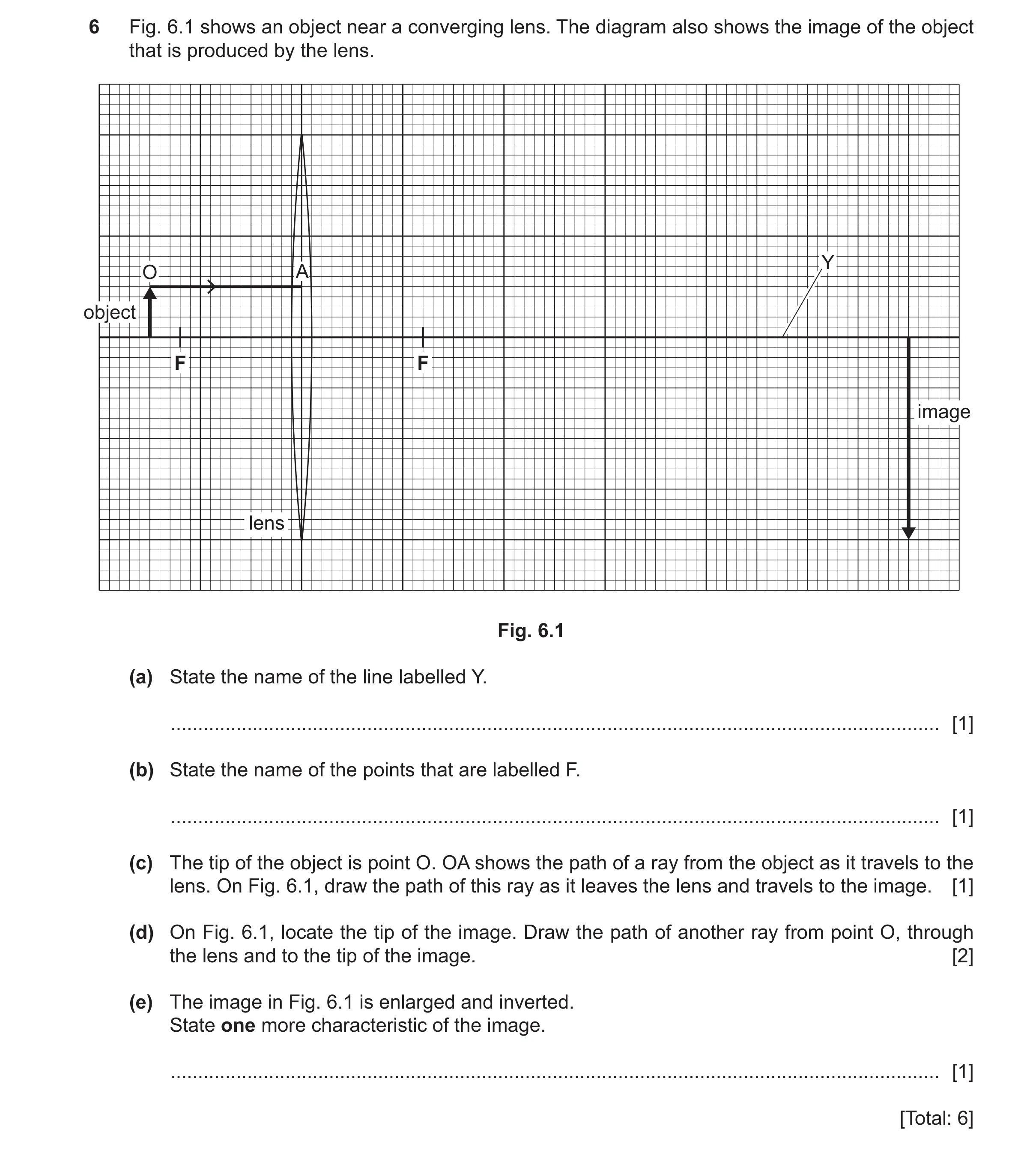
Q52 · An object near a converging lens 0625/32 Oct/Nov 2025
6 Fig. 6.1 shows an object near a converging lens. The diagram also shows the image of the object that is produced by the lens. Y O A object F F image lens Fig. 6.1 (a) State the name of the line labelled Y. … [1] (b) State the name of the points that are labelled F. … [1] (c) The tip of the object is point O. OA shows the path of a ray from the object as it travels to the lens. On Fig. 6.1, draw the path of this ray as it leaves the lens and travels to the image. [1] (d) On Fig. 6.1, locate the tip of the image. Draw the path of another ray from point O, through the lens and to the tip of the image. [2] (e) The image in Fig. 6.1 is enlarged and inverted. State one more characteristic of the image. … [1] [Total: 6]
6 marks
Mark scheme: 6(a) principal axis B1 6(b) principal focus or principal focii or focal point (s) B1 6(c) ray continued through F to top of image B1 6(d) one of the following: M1 • ray from top of object to centre of lens • ray continued to top of image or A1 • ray from top of object through F to lens • horizontal paraxial ray from lens to top of image 6(e) real B1
This question in 0625/32 Oct/Nov 2025
Q53 · The path of a ray of visible light travelling from the top of an object and passing… 0625/33 Oct/Nov 2025
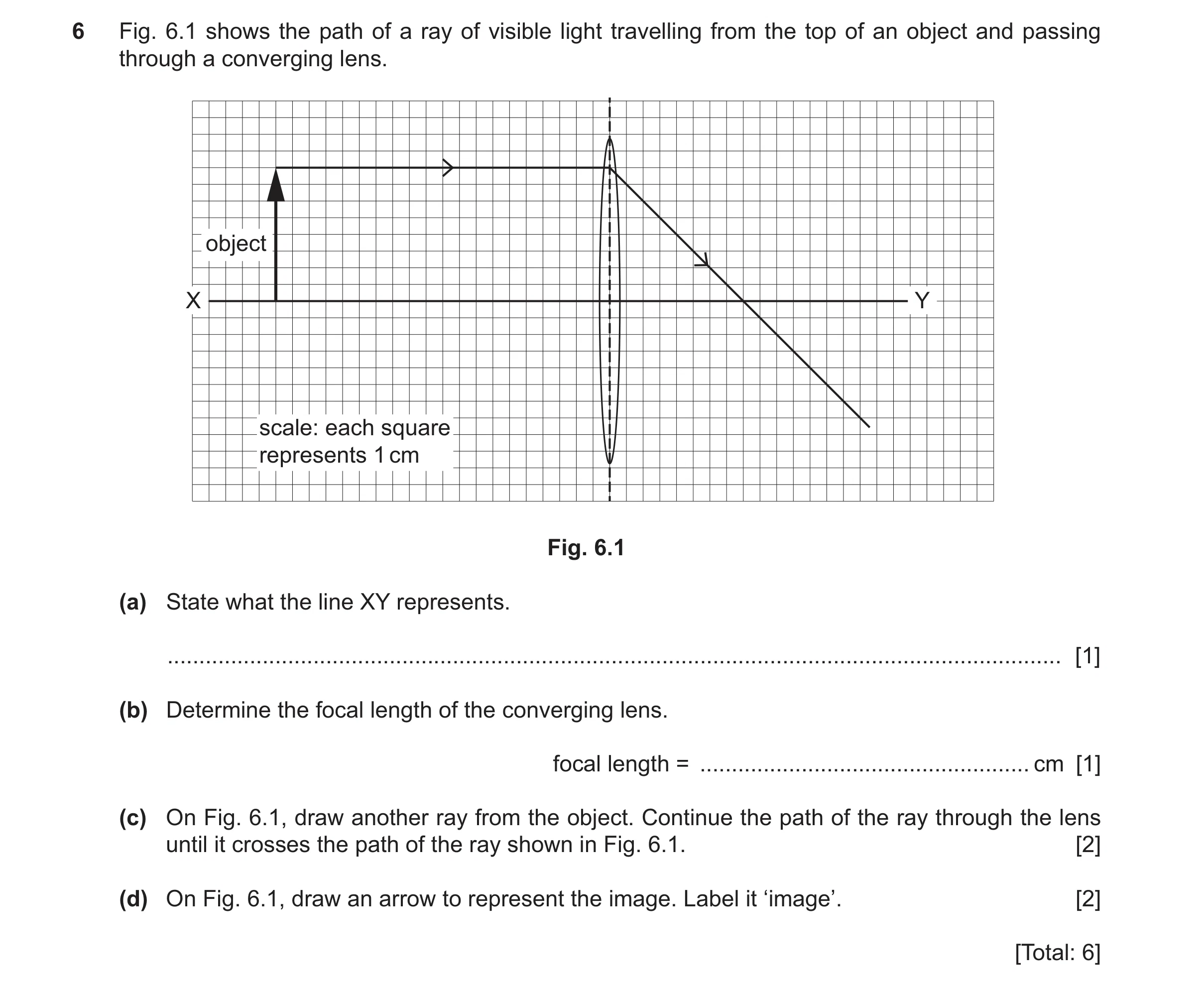
6 Fig. 6.1 shows the path of a ray of visible light travelling from the top of an object and passing through a converging lens. object X Y scale: each square represents 1 cm Fig. 6.1 (a) State what the line XY represents. … [1] (b) Determine the focal length of the converging lens. focal length = … cm [1] (c) On Fig. 6.1, draw another ray from the object. Continue the path of the ray through the lens until it crosses the path of the ray shown in Fig. 6.1. [2] (d) On Fig. 6.1, draw an arrow to represent the image. Label it ‘image’. [2] [Total: 6]
6 marks
Mark scheme: 6(a) principal axis B1 6(b) 8 (.0) (cm) B1 6(c) ray from top of object to centre of lens M1 ray continued in a straight line to cross drawn ray or A1 ray from top of object through principal focus on LHS of lens to the centre of the lens ray continued as a straight paraxial line to cross drawn ray 6(d) upside down (vertical) arrow (labelled image) from principal axis to point where rays cross A2 point where rays cross indicated C1
This question in 0625/33 Oct/Nov 2025
 1 / 60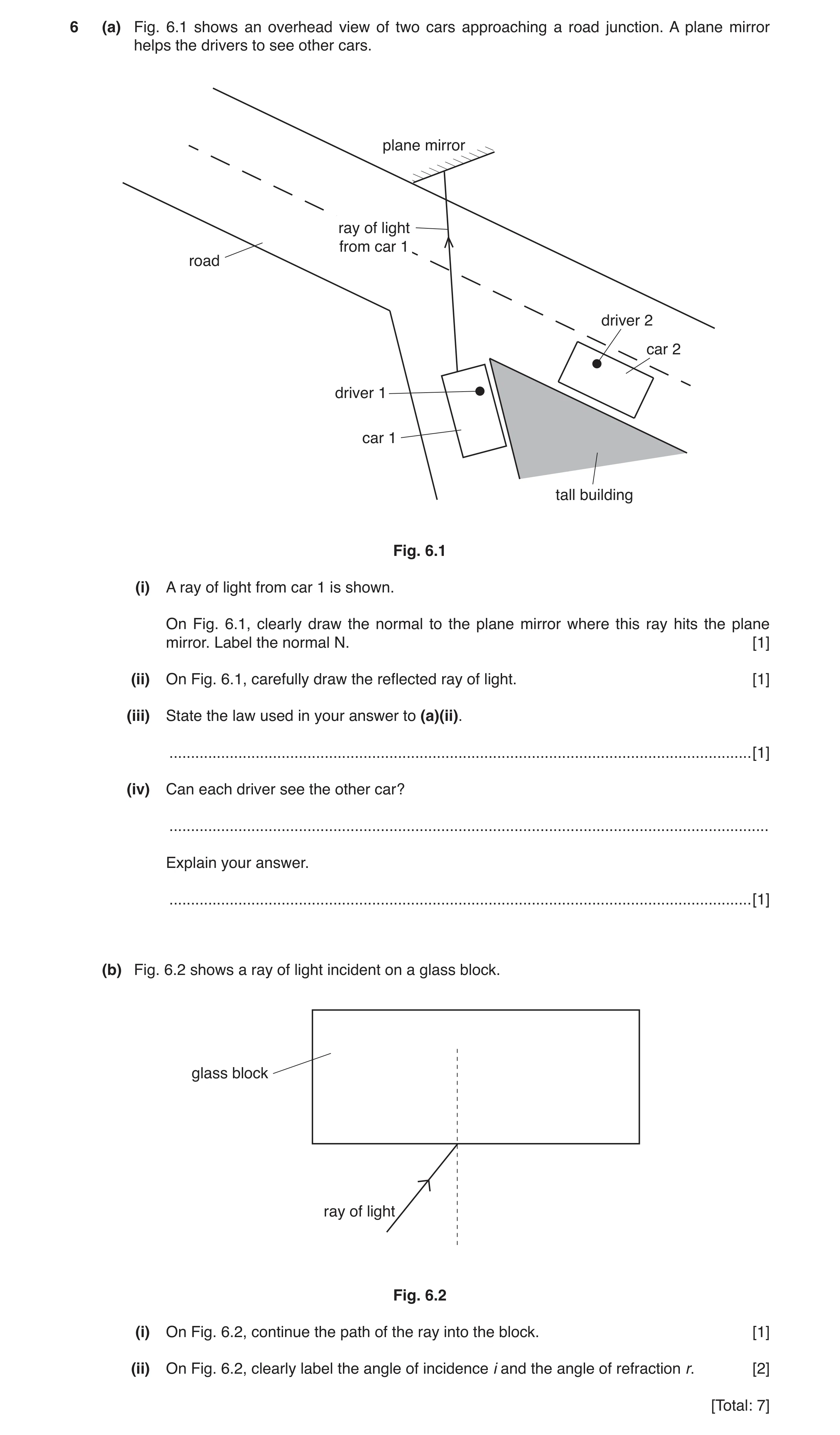
 7 / 60
 8 / 60
 9 / 60
 10 / 60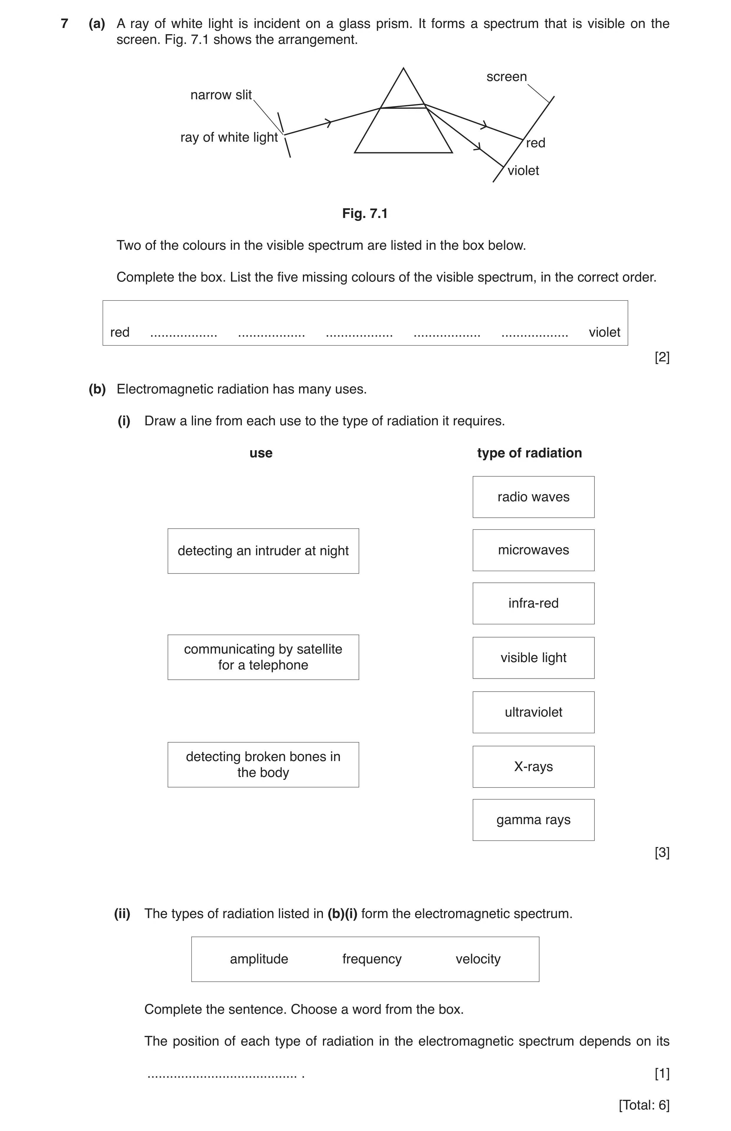
 12 / 60
 13 / 60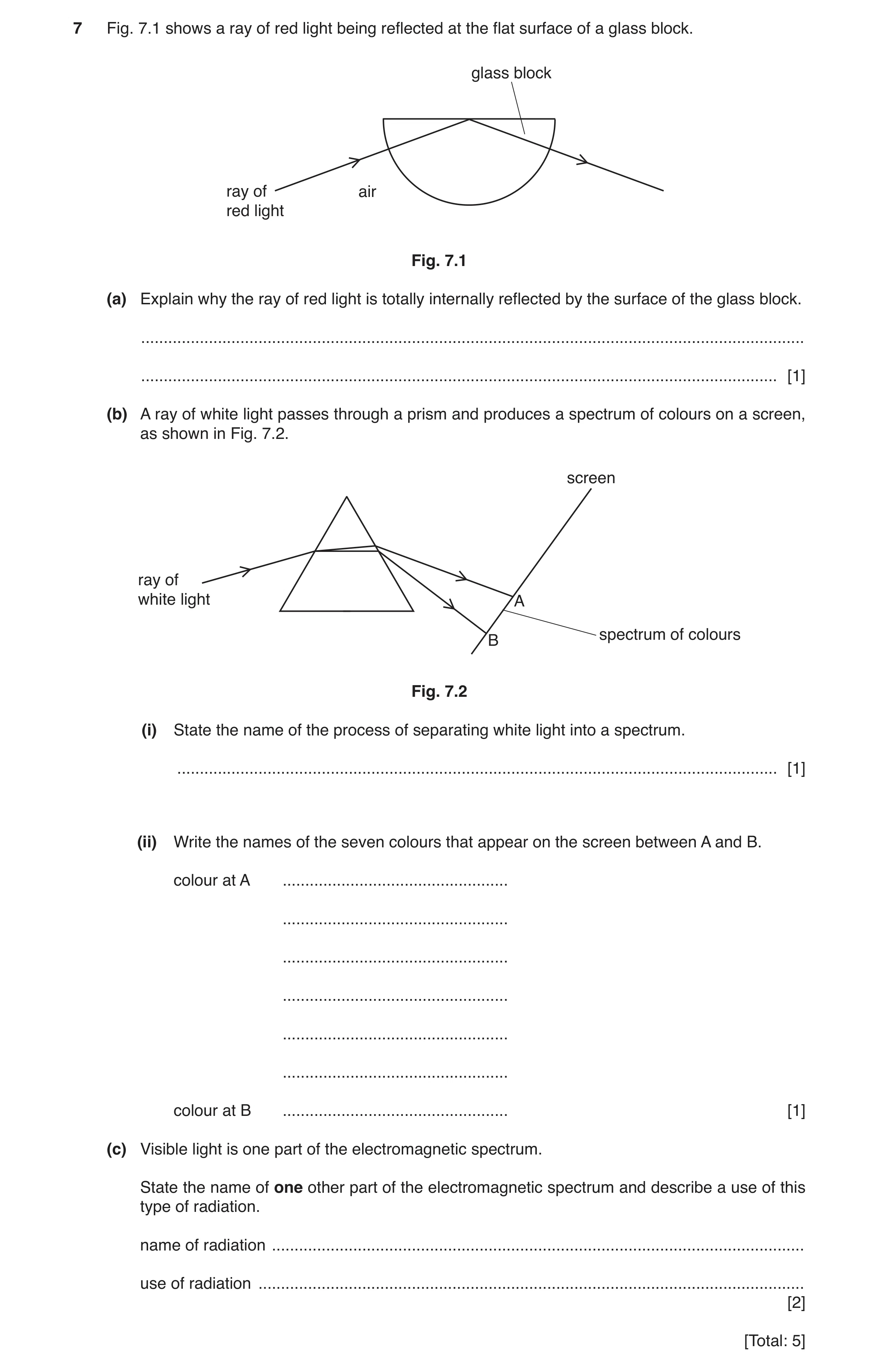
 15 / 60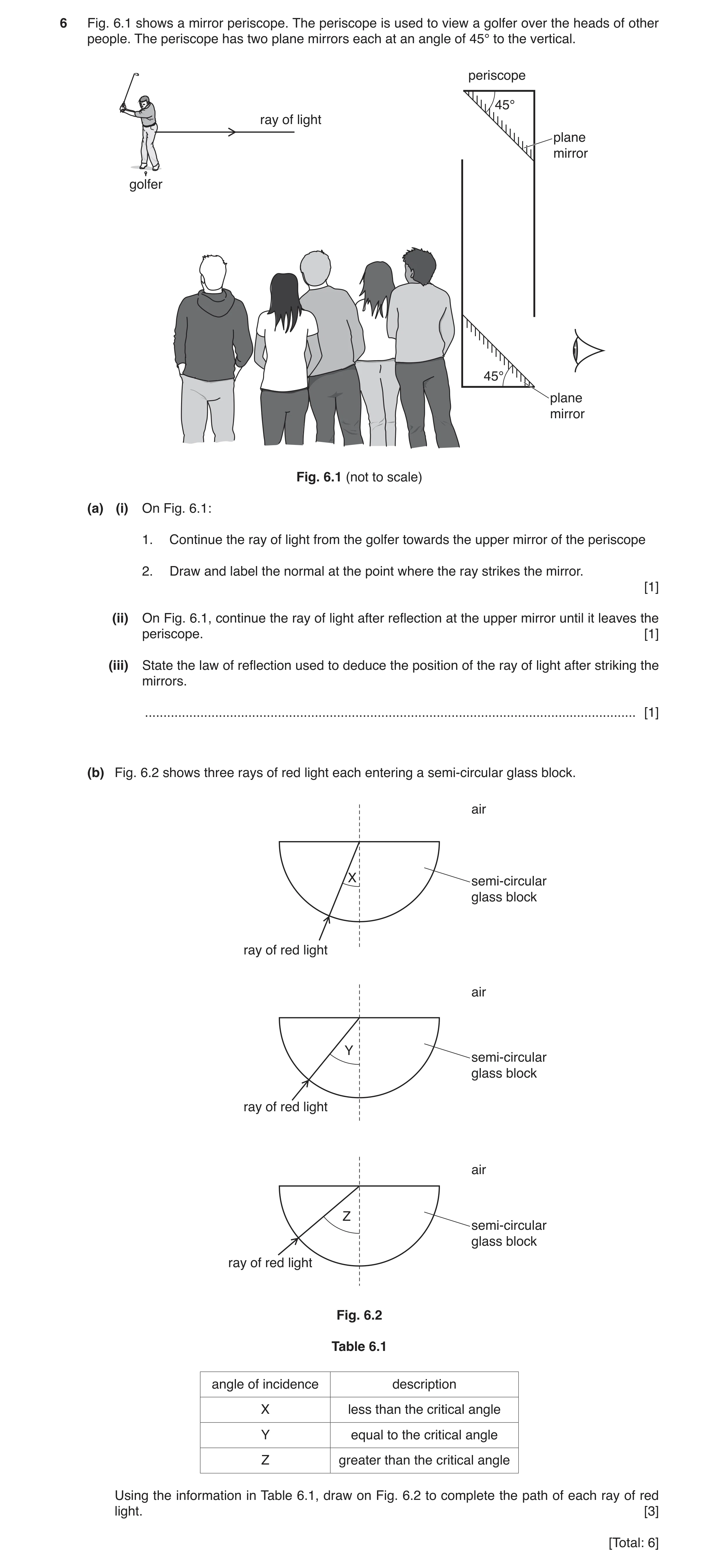
 18 / 60
 19 / 60
 20 / 60
 21 / 60
 22 / 60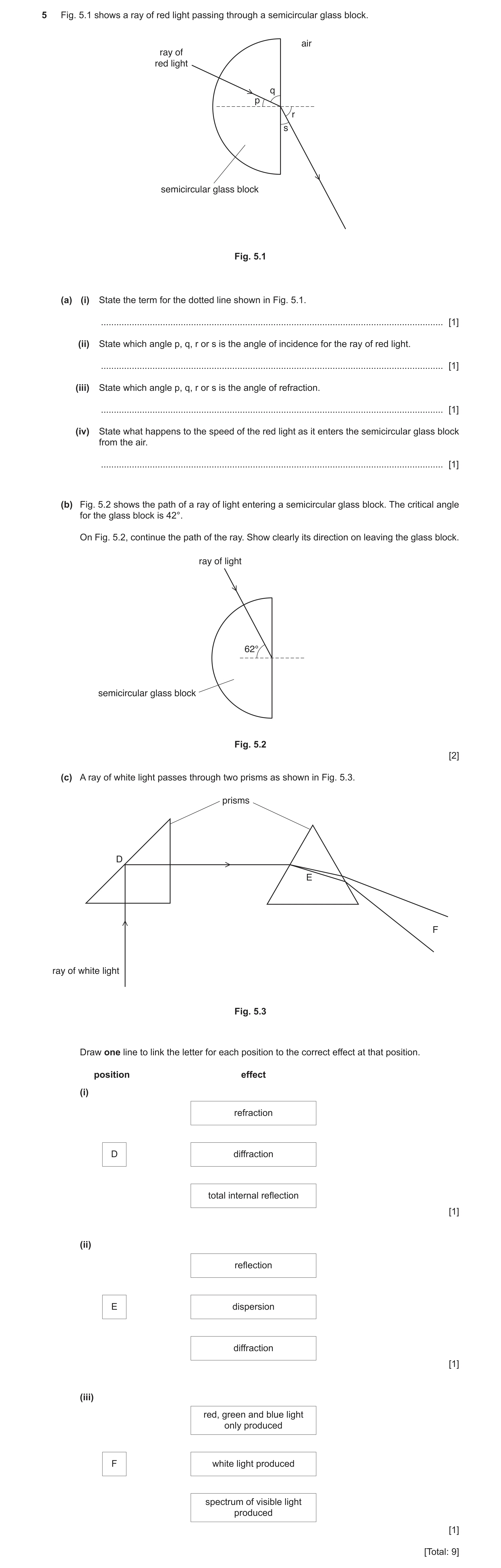
 27 / 60
 28 / 60
 29 / 60
 30 / 60
 31 / 60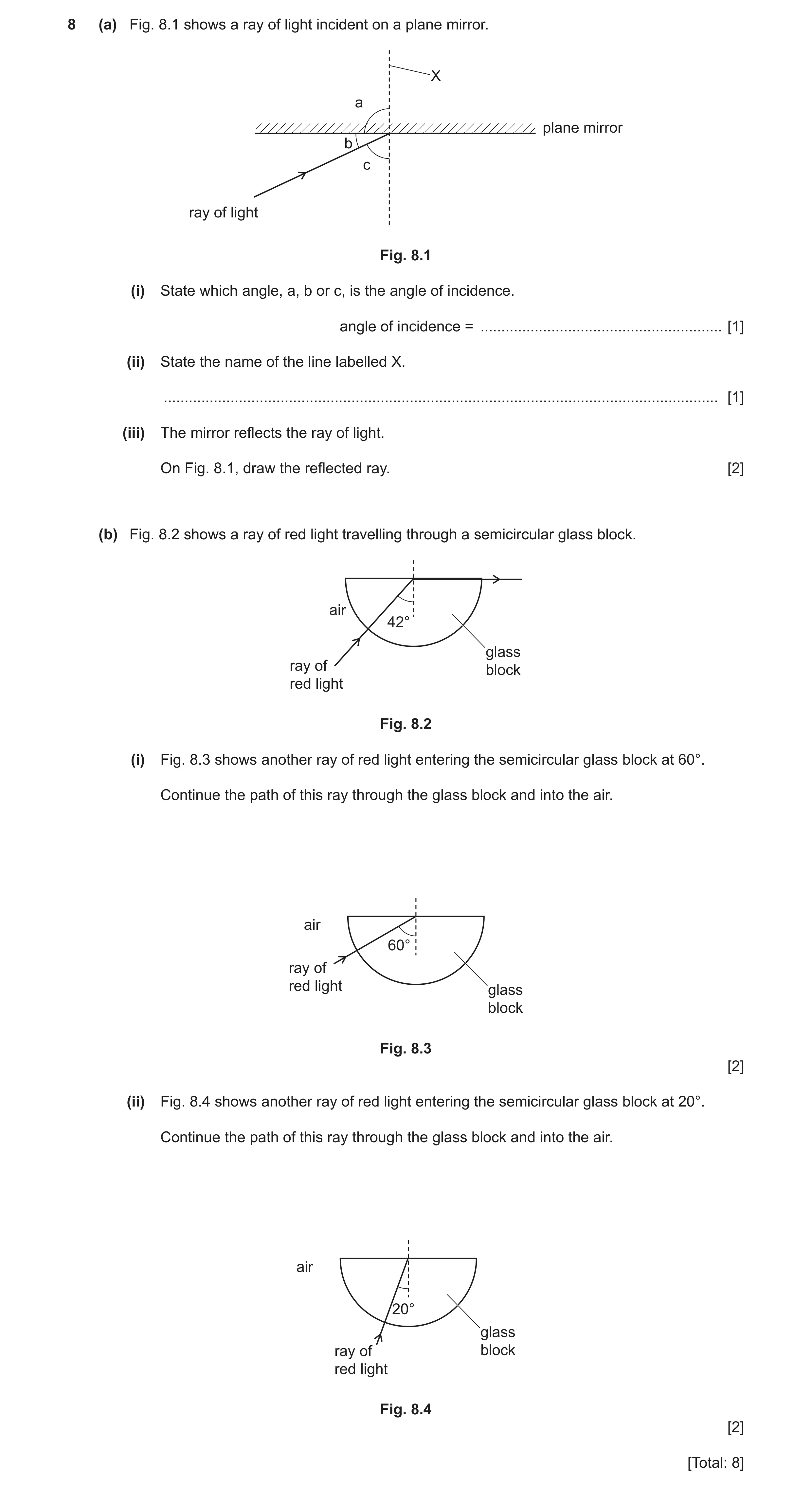
 33 / 60
 34 / 60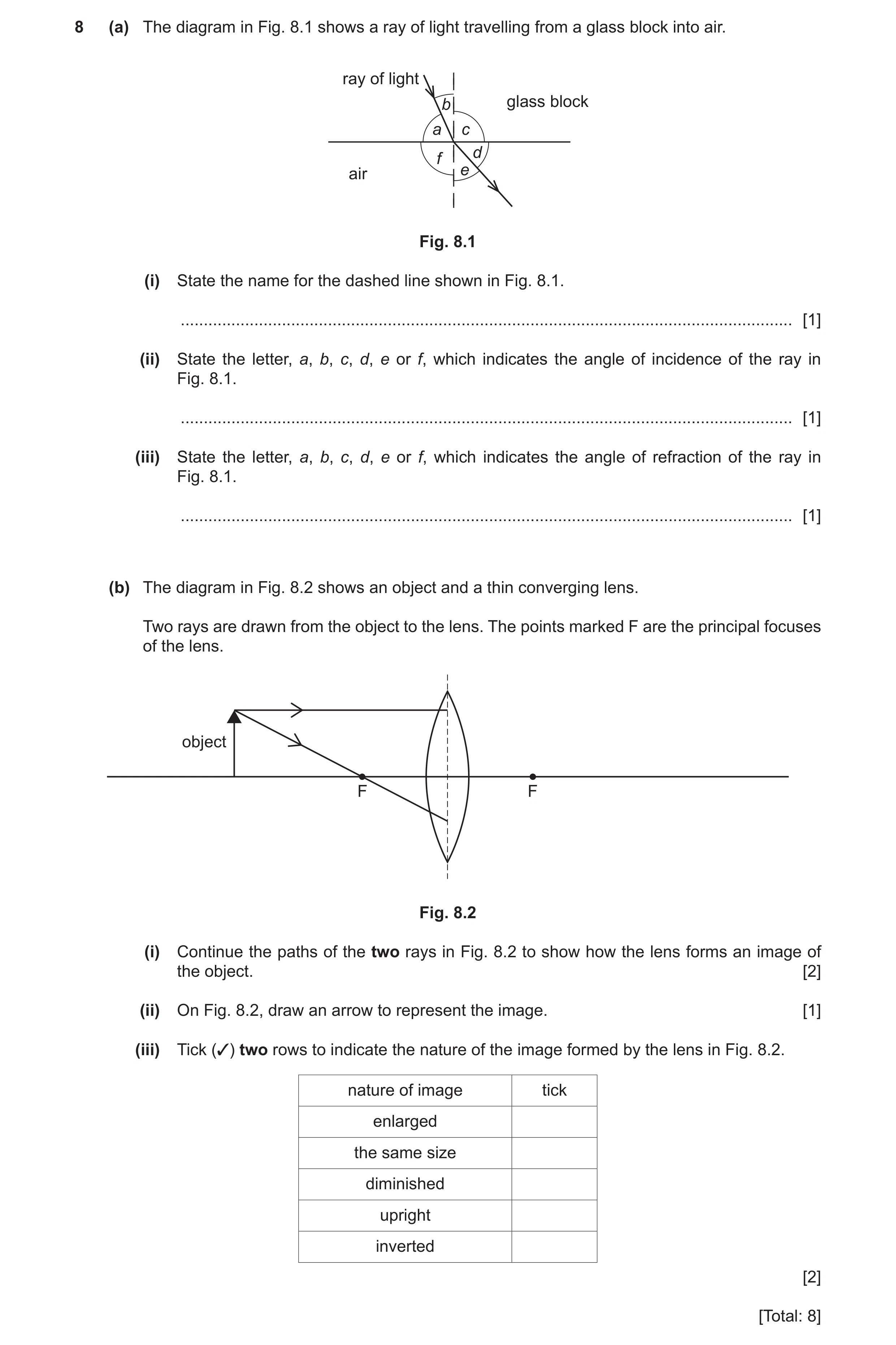
 37 / 60
 38 / 60
 39 / 60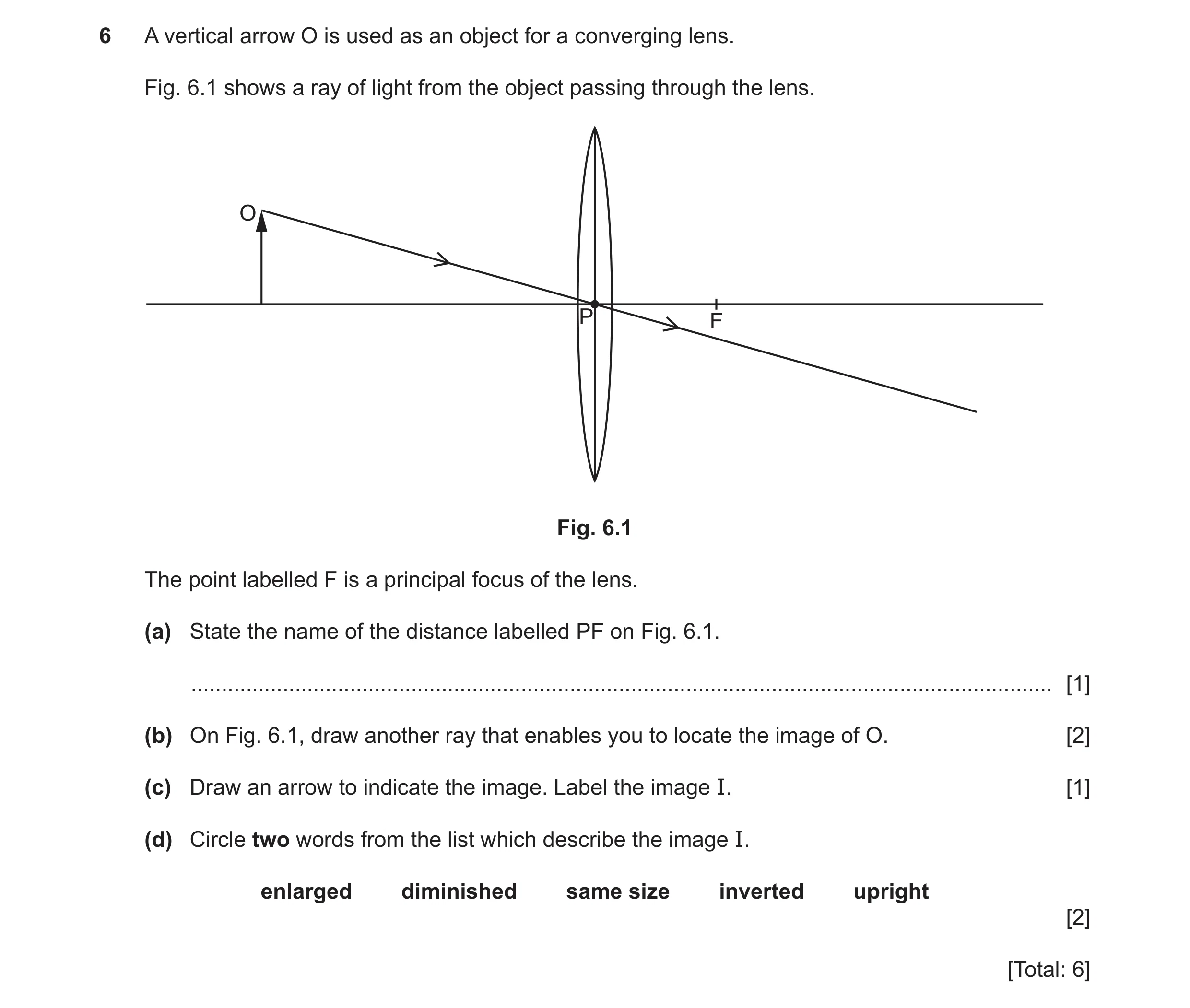
 40 / 60
 41 / 60
 42 / 60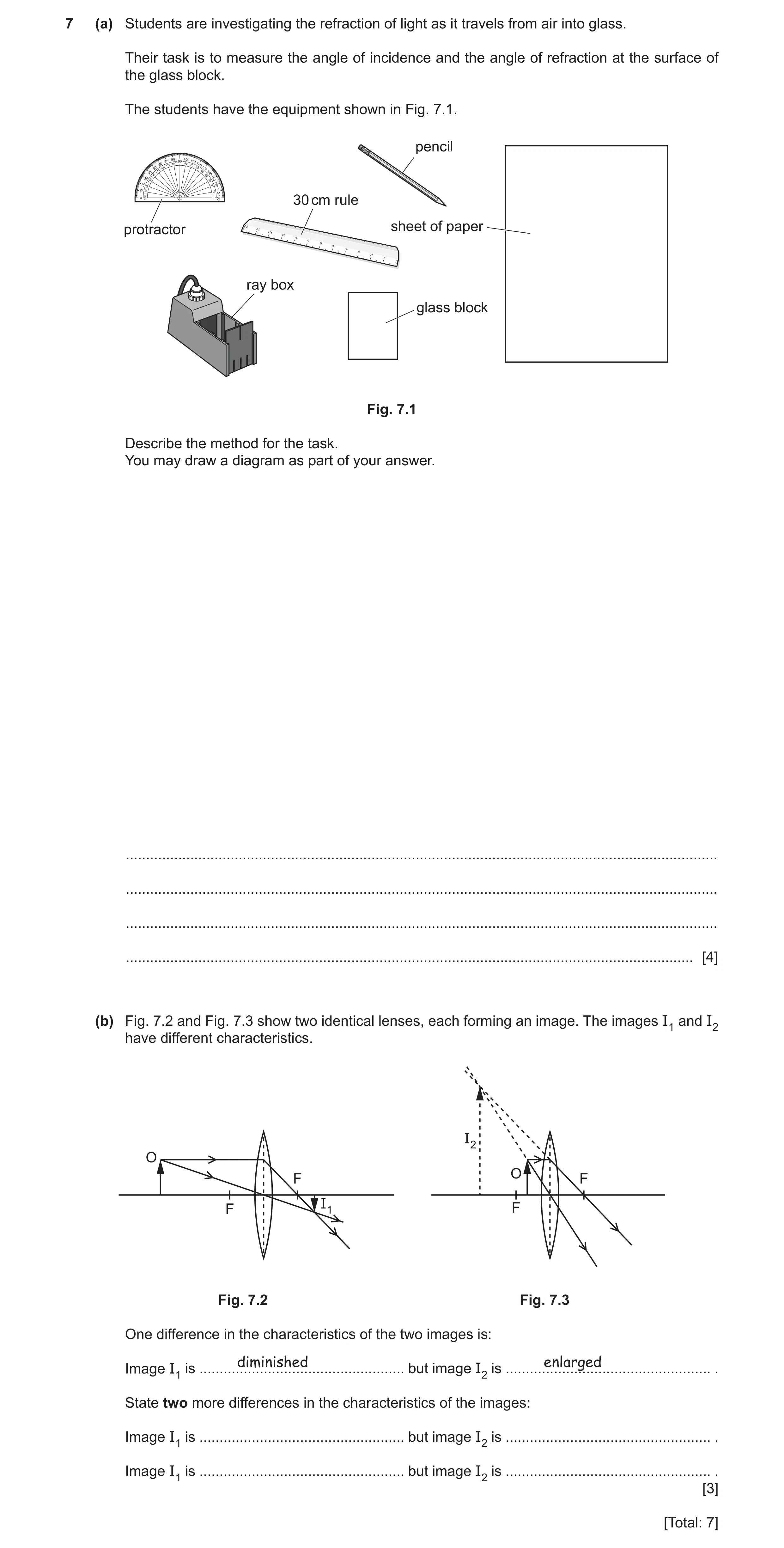
 45 / 60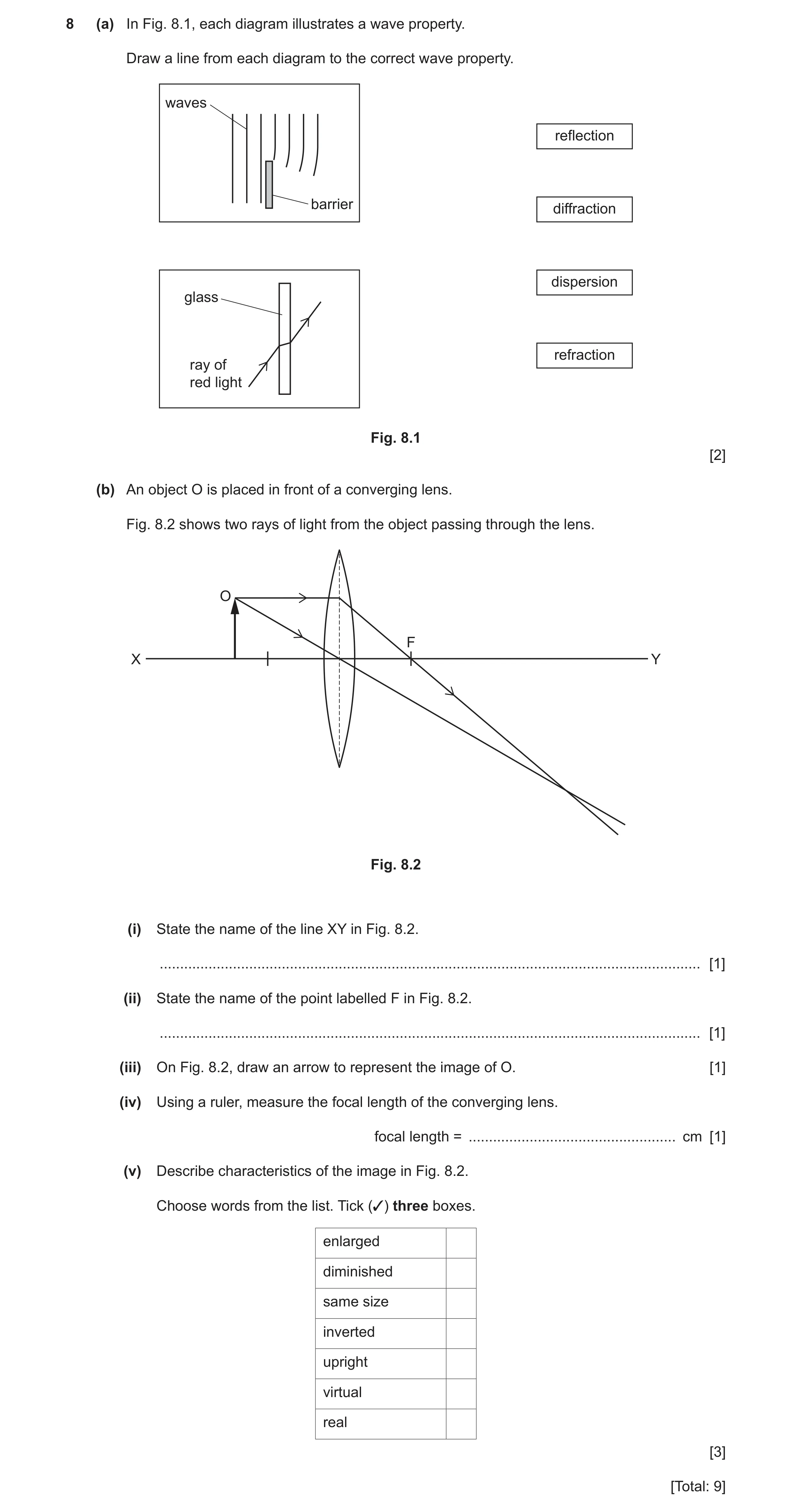
 49 / 60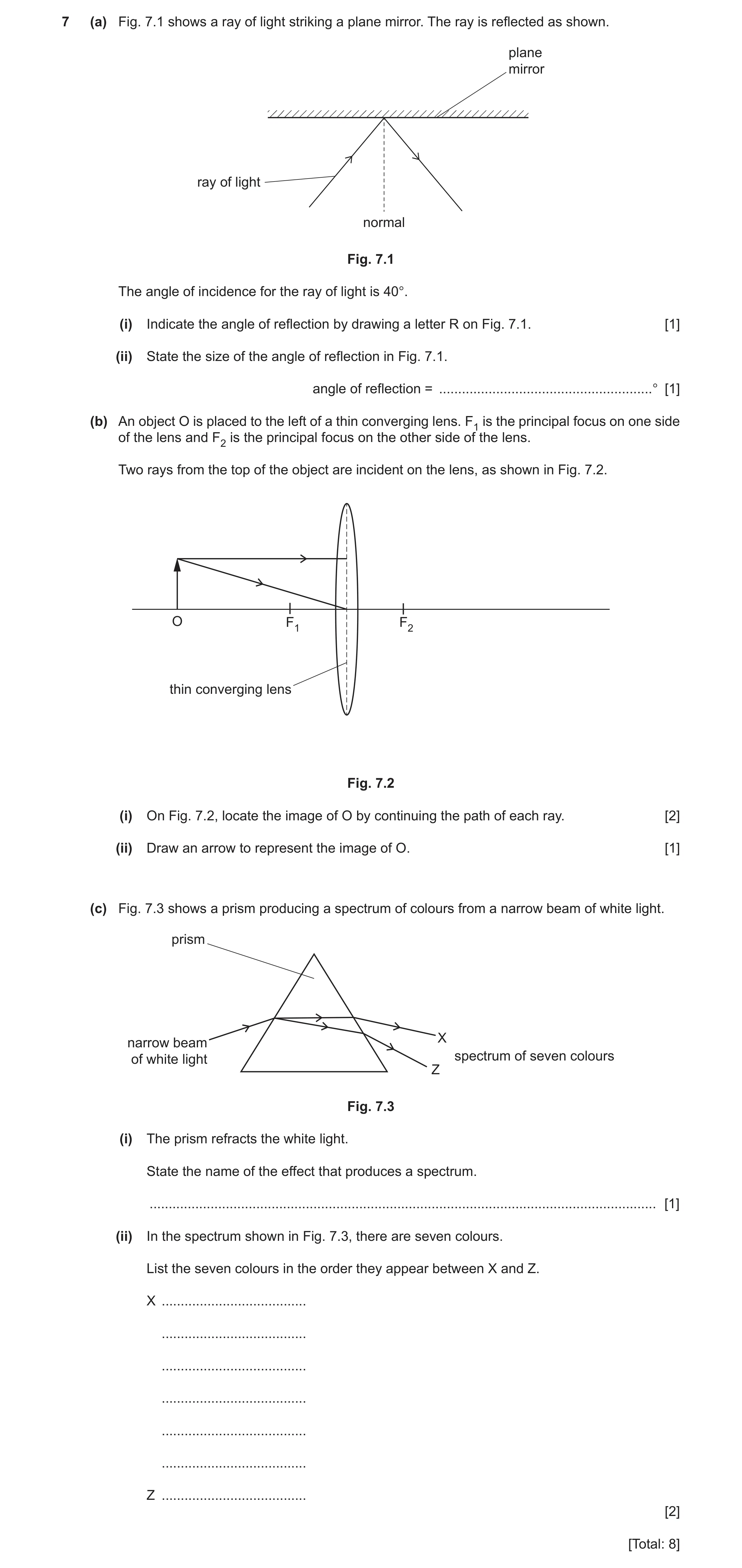
 52 / 60
 53 / 60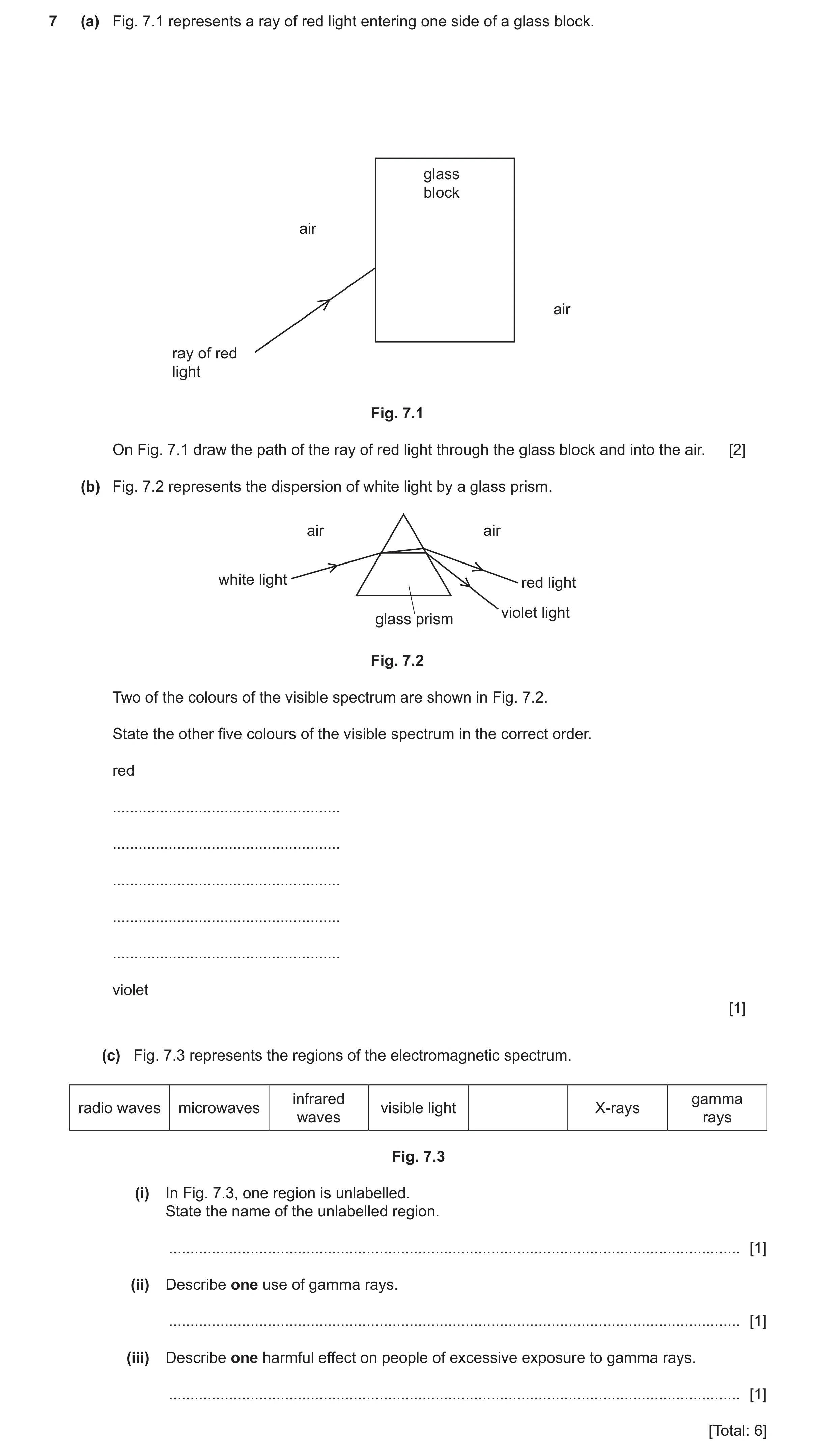
 56 / 60
 57 / 60
 58 / 60
 59 / 60
 60 / 60
 5
5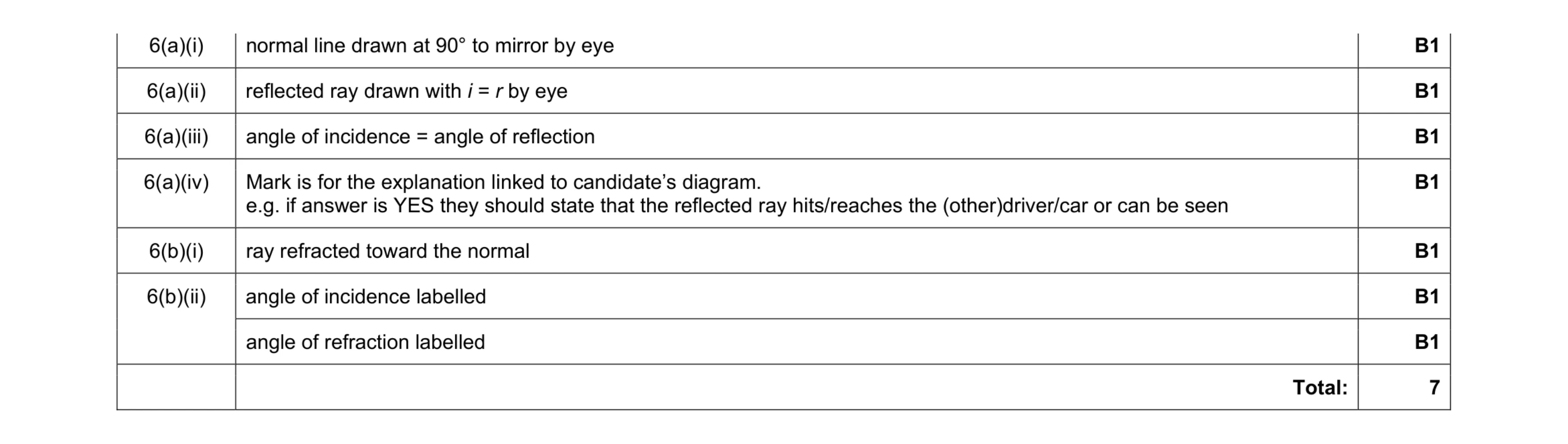 7
7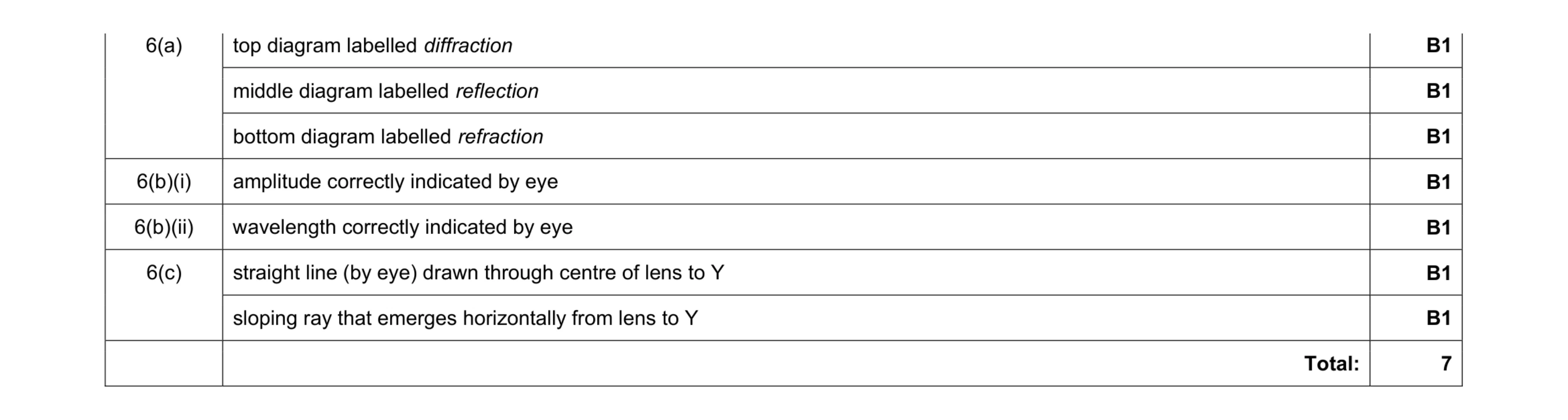 7
7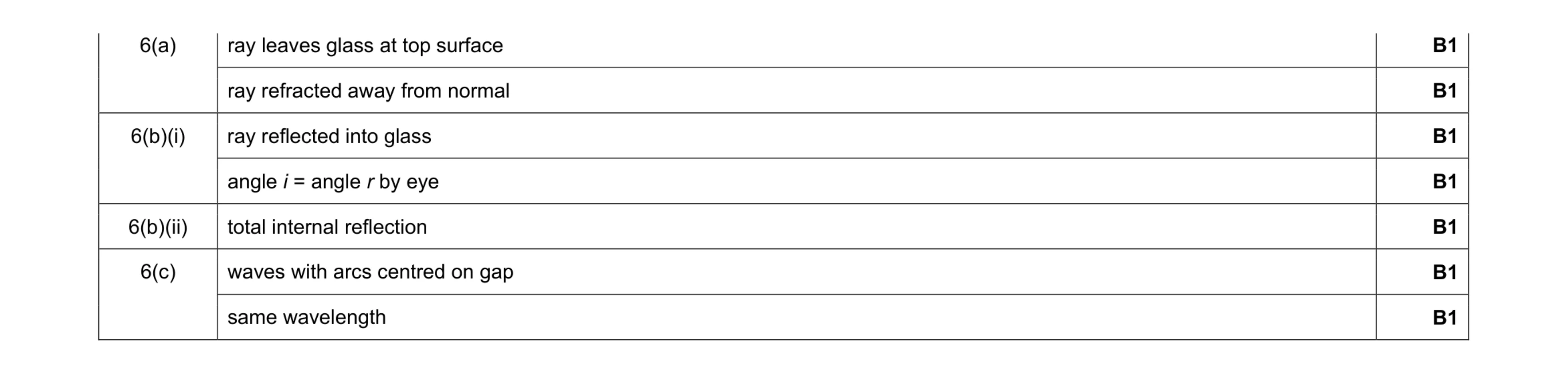 7
7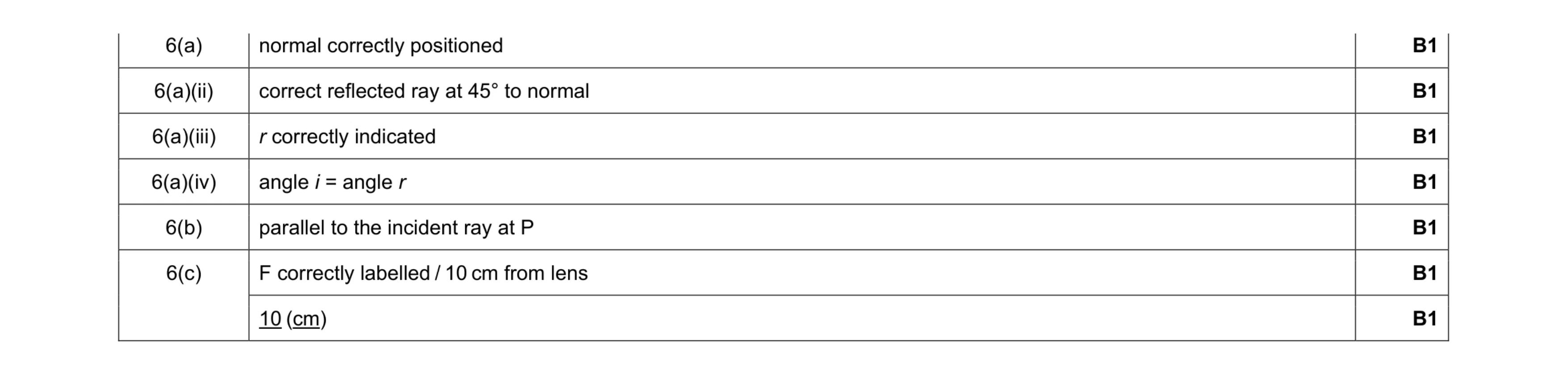 7
7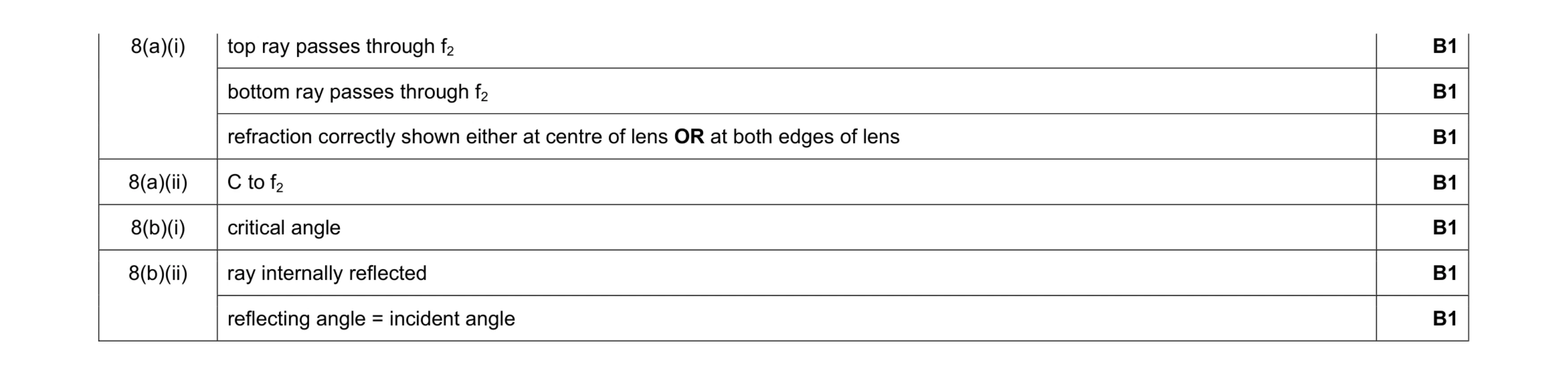 7
7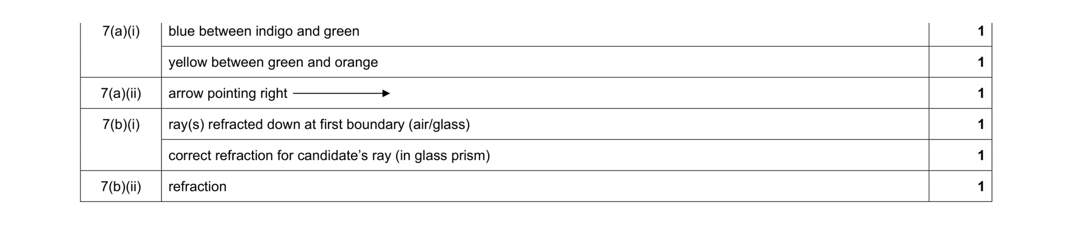 6
6 5
5 5
5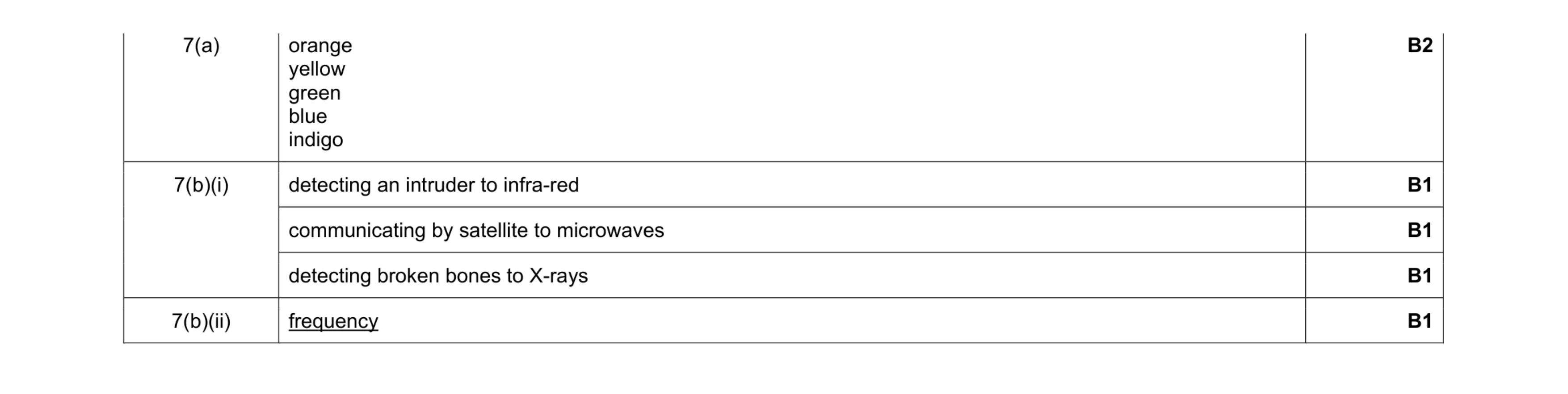 6
6 5
5 6
6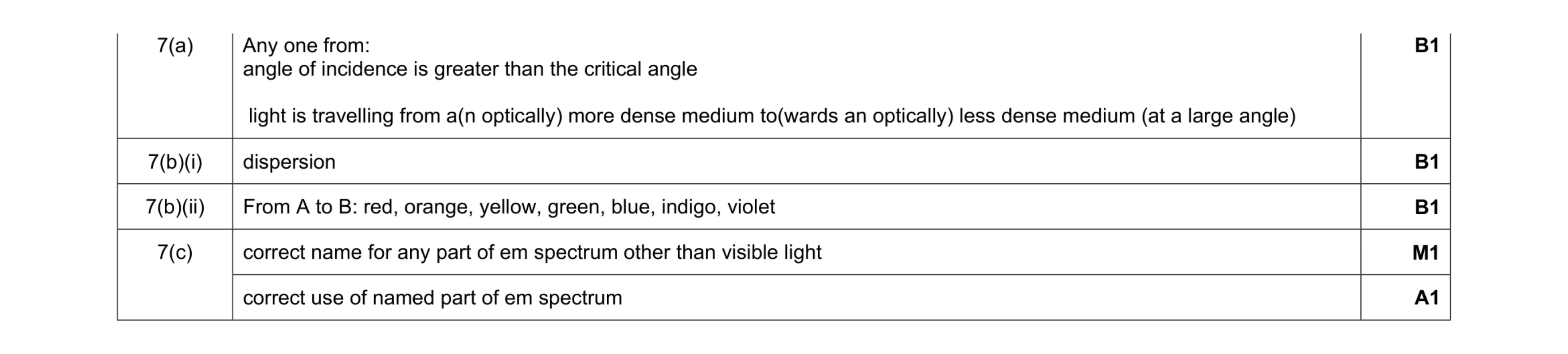 5
5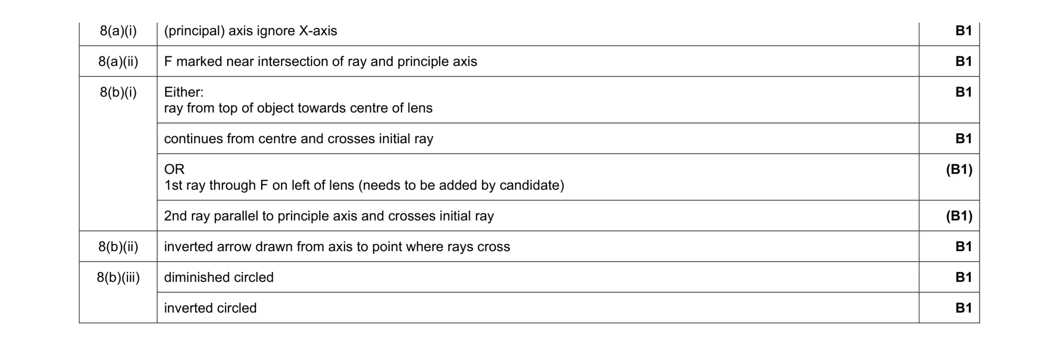 7
7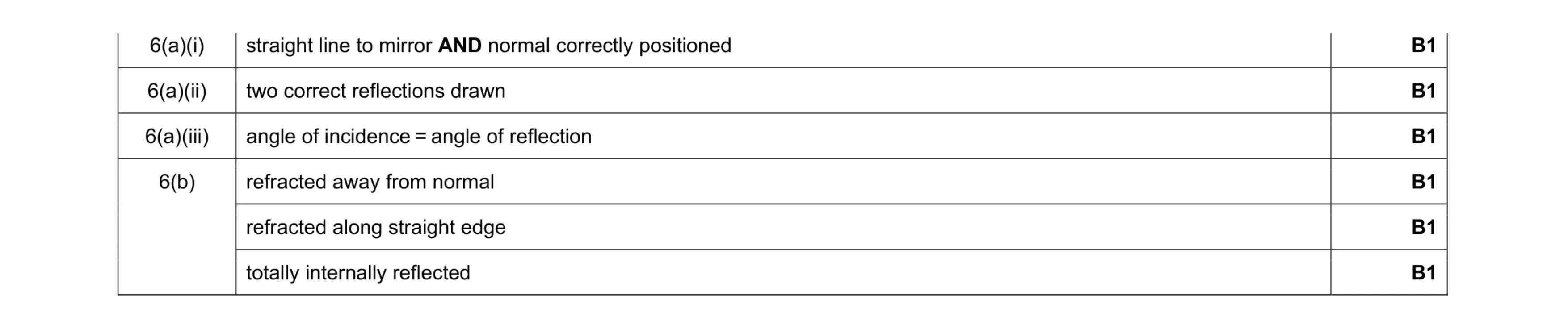 6
6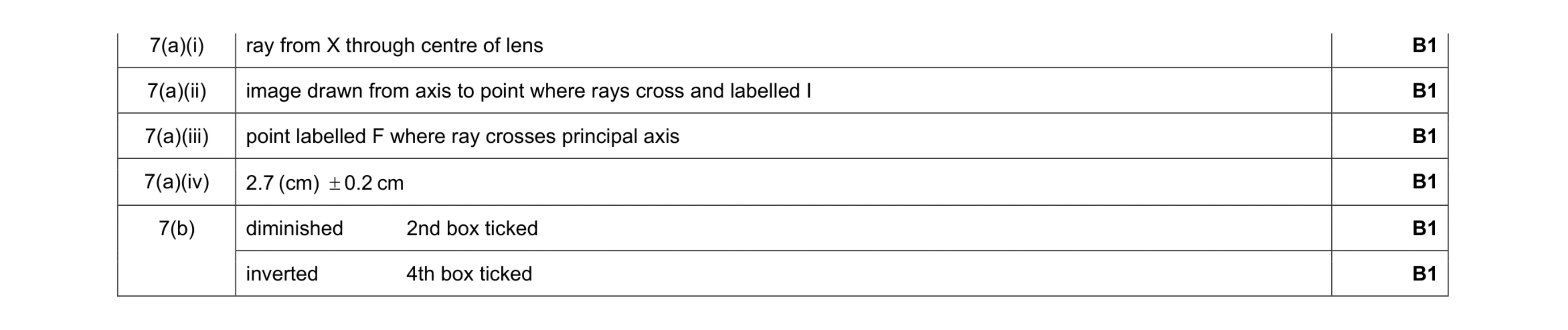 6
6 6
6 6
6 5
5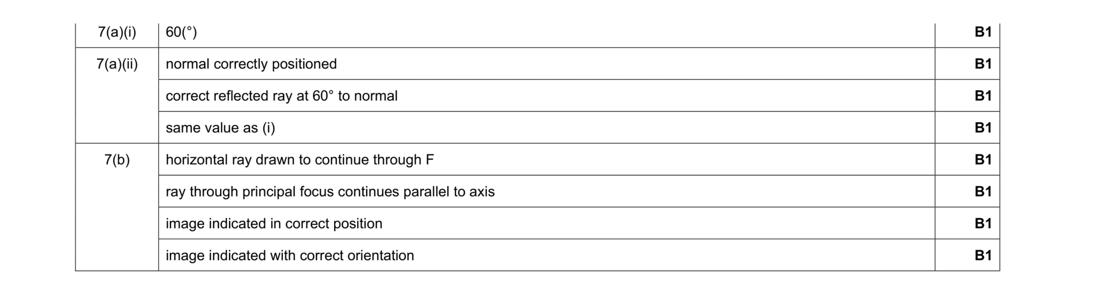 8
8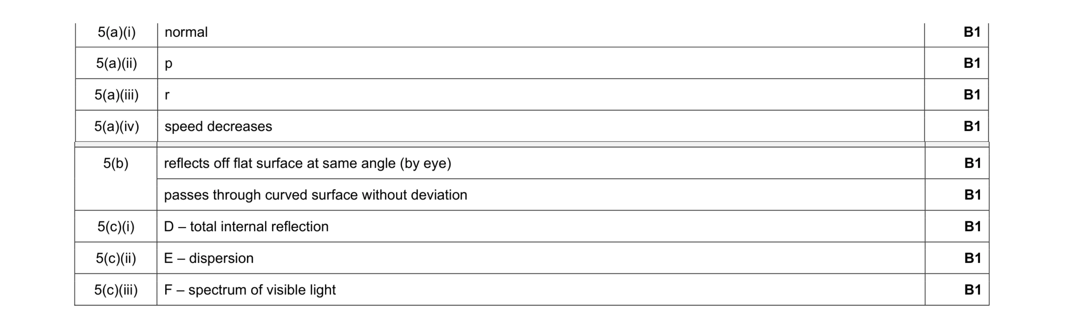 9
9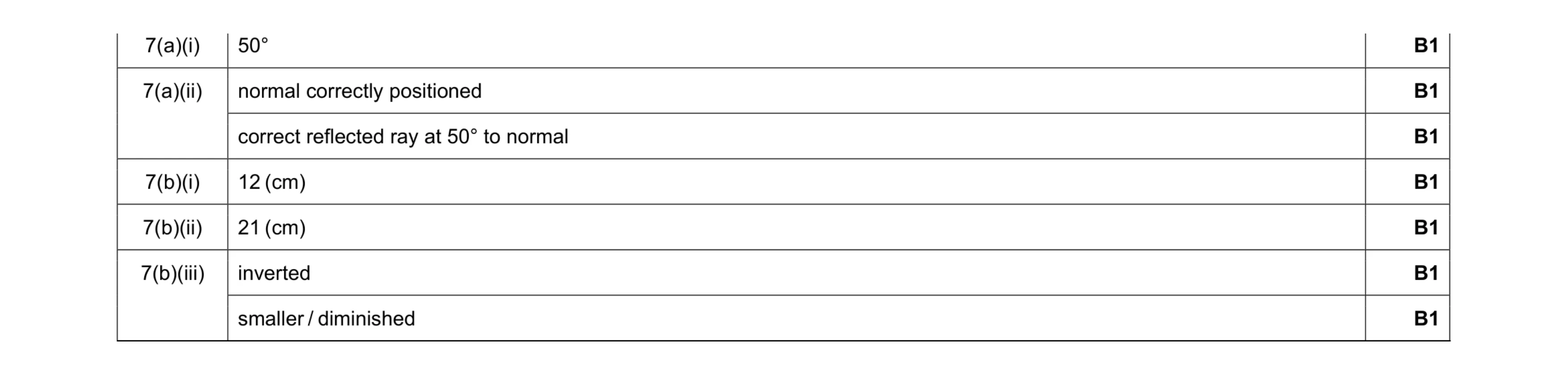 7
7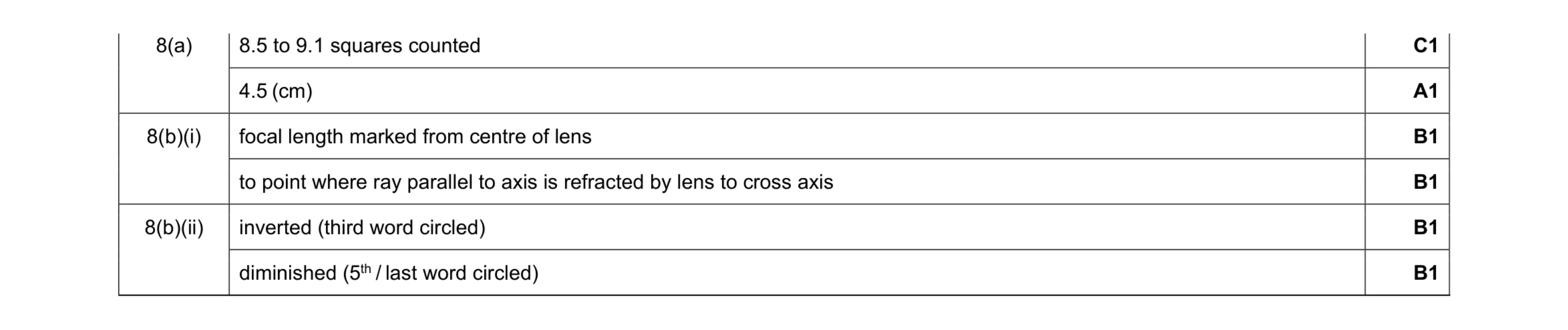 6
6 5
5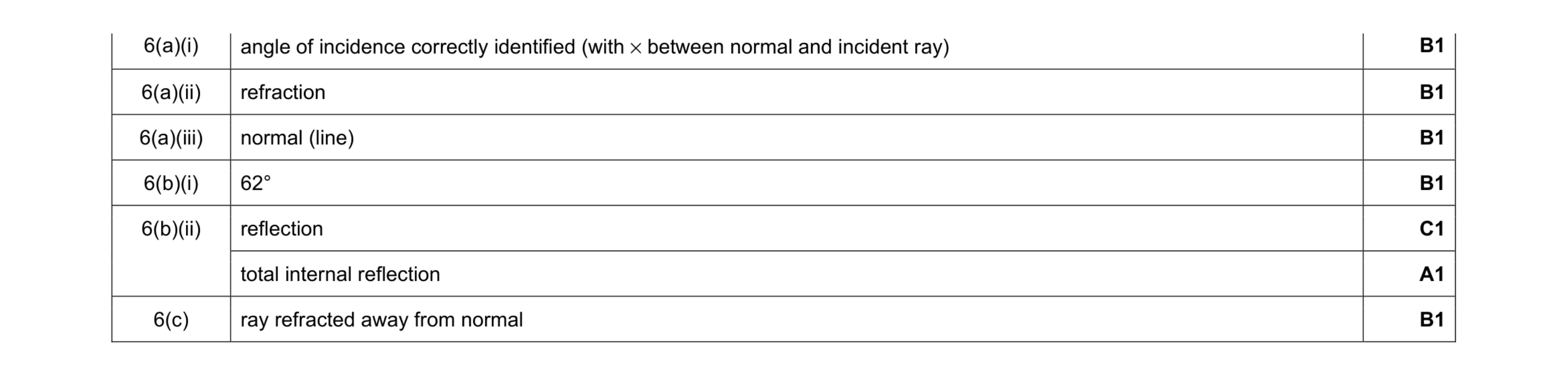 7
7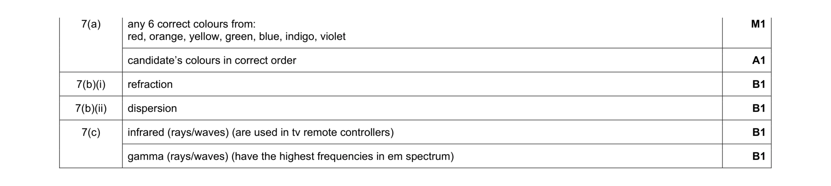 6
6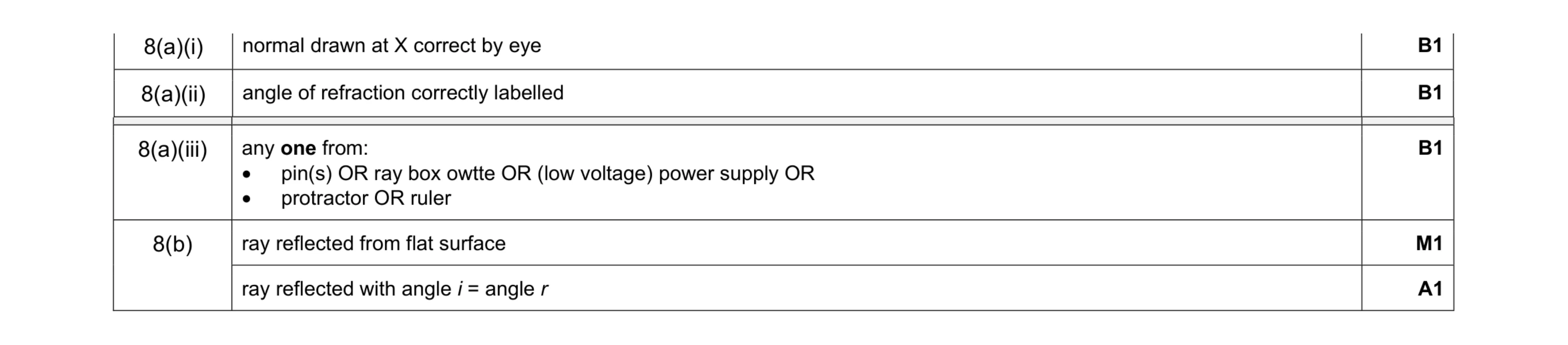 5
5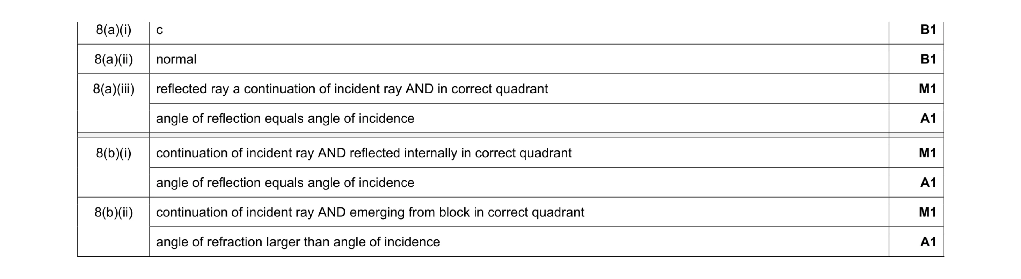 8
8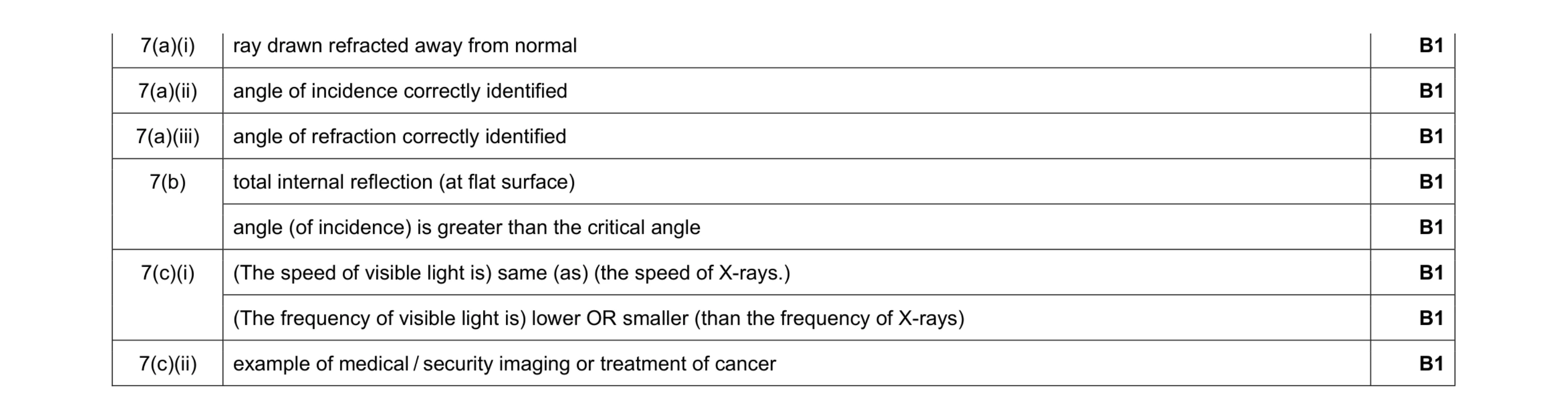 8
8 4
4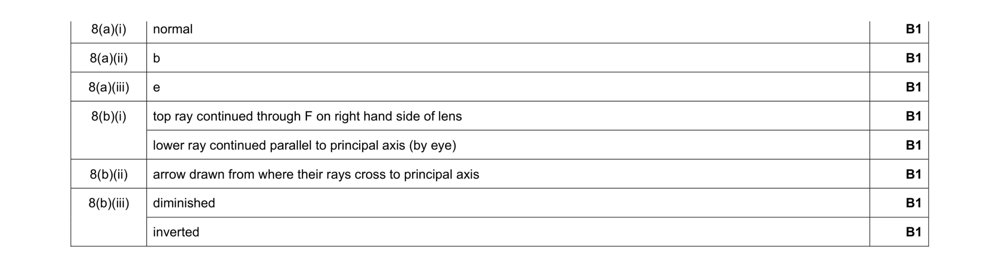 8
8 5
5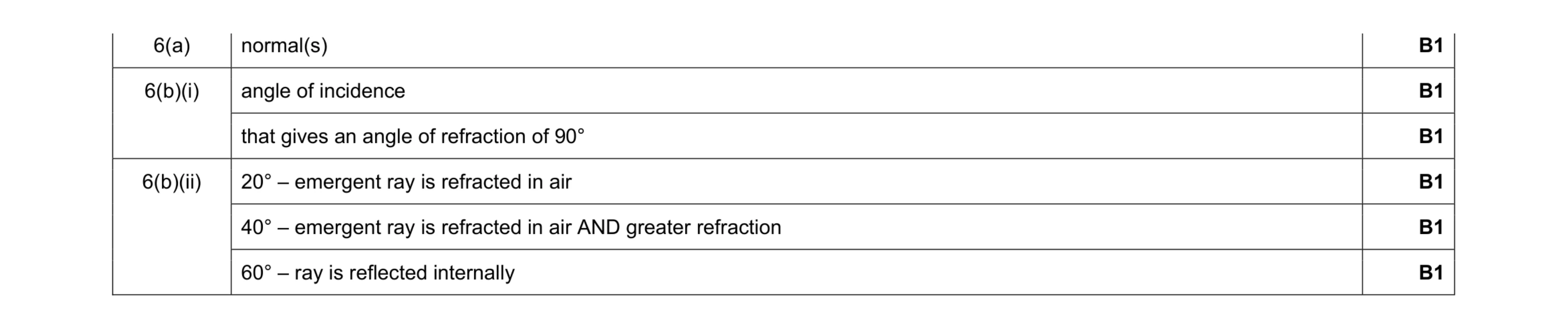 6
6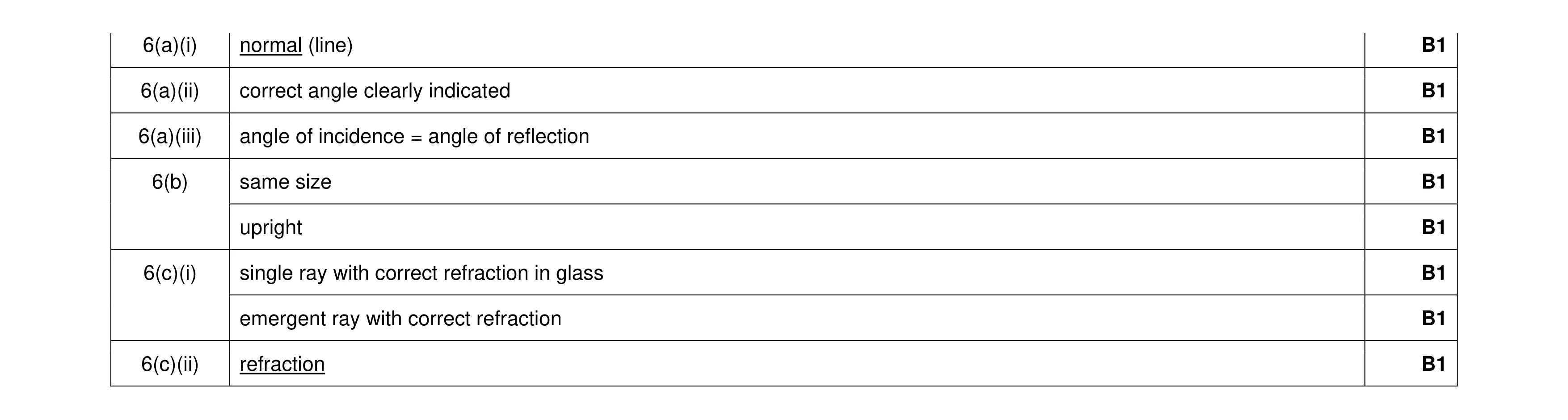 8
8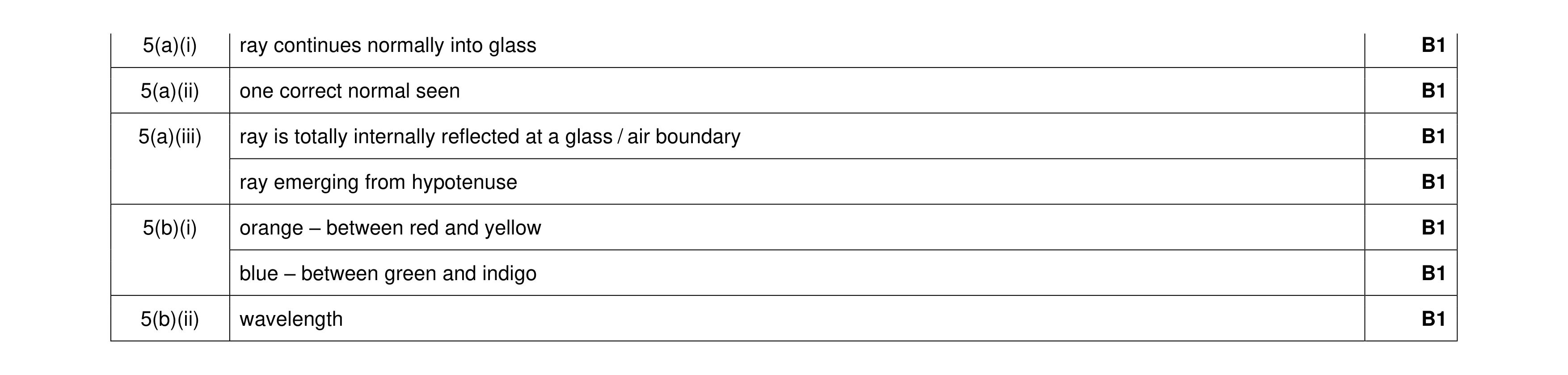 7
7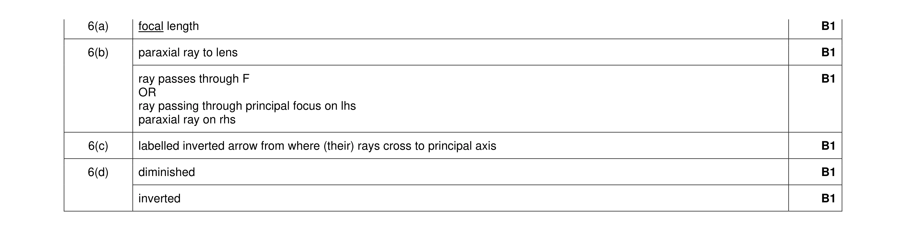 6
6 5
5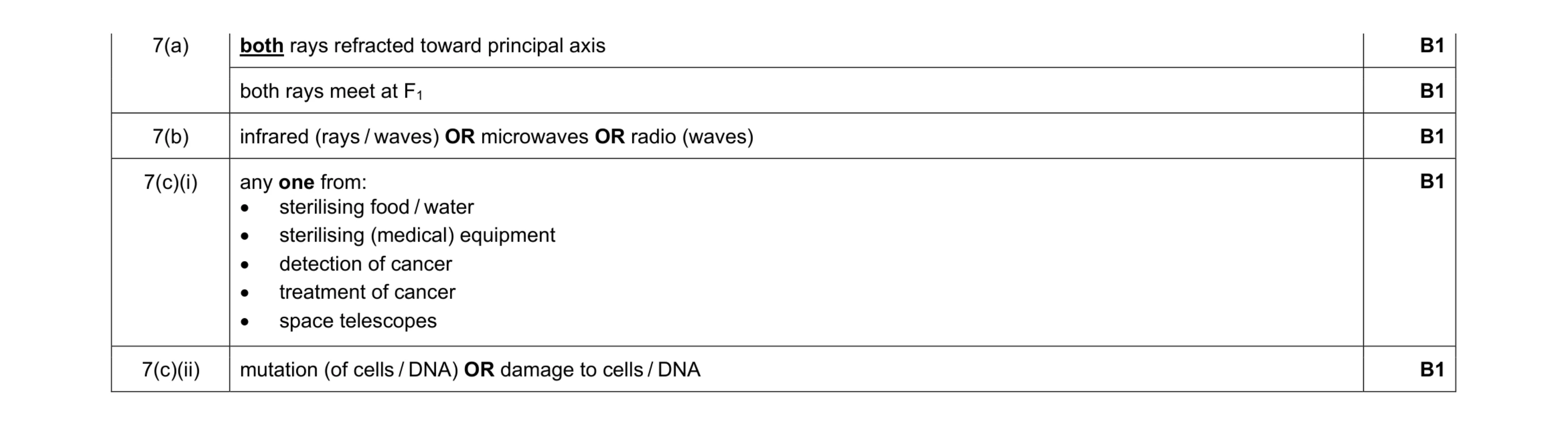 5
5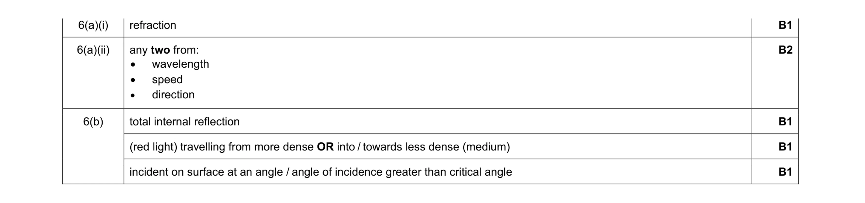 6
6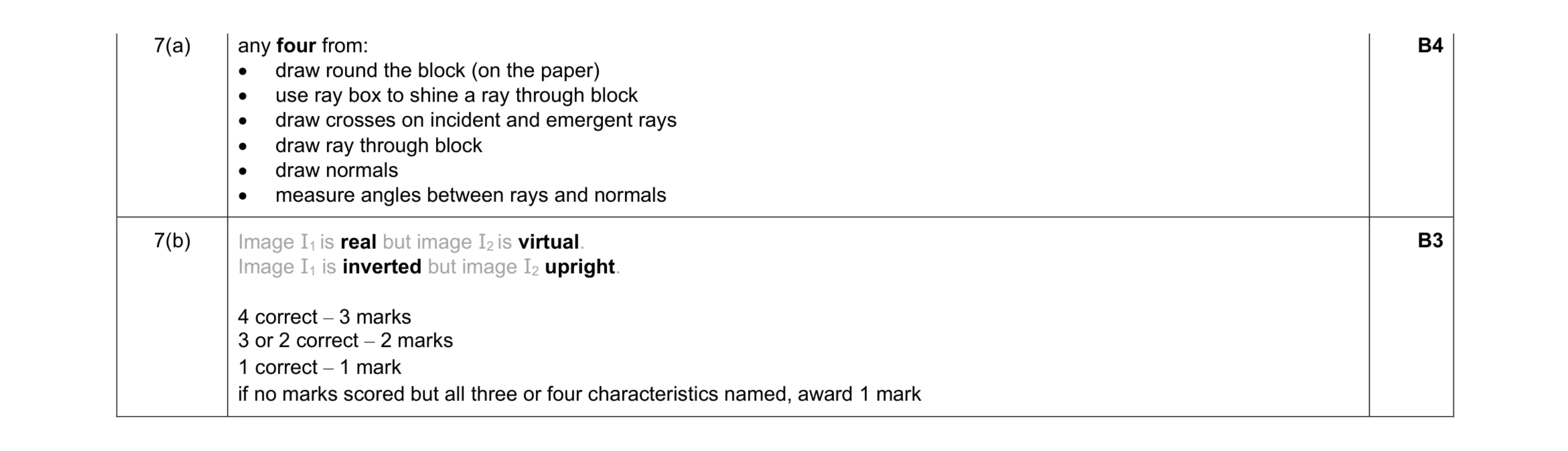 7
7 5
5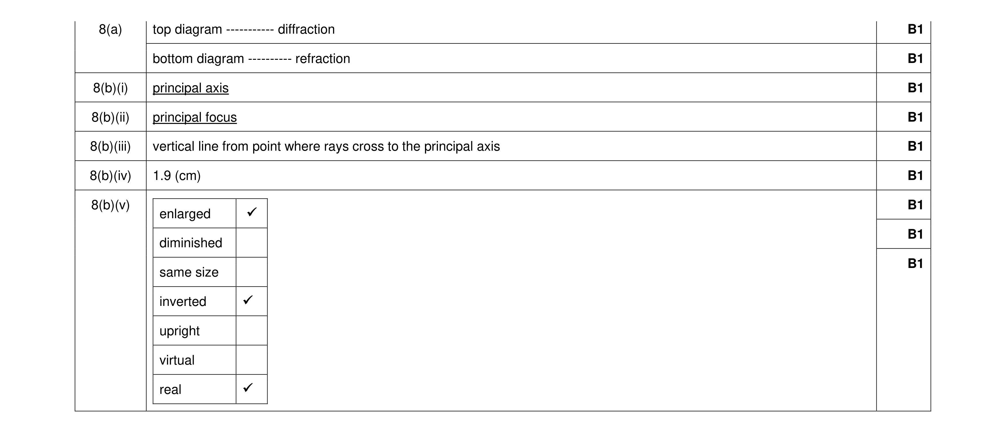 9
9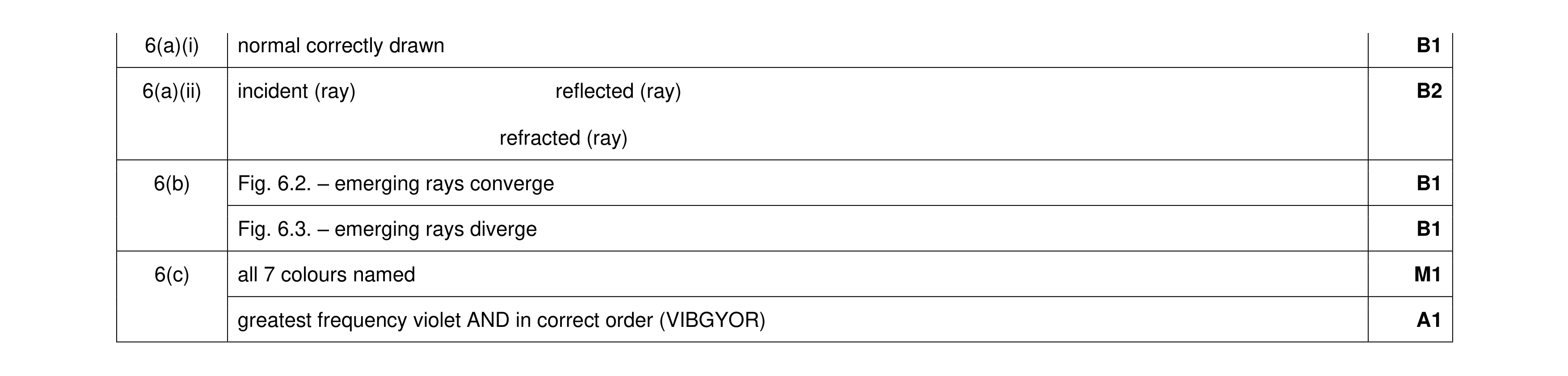 7
7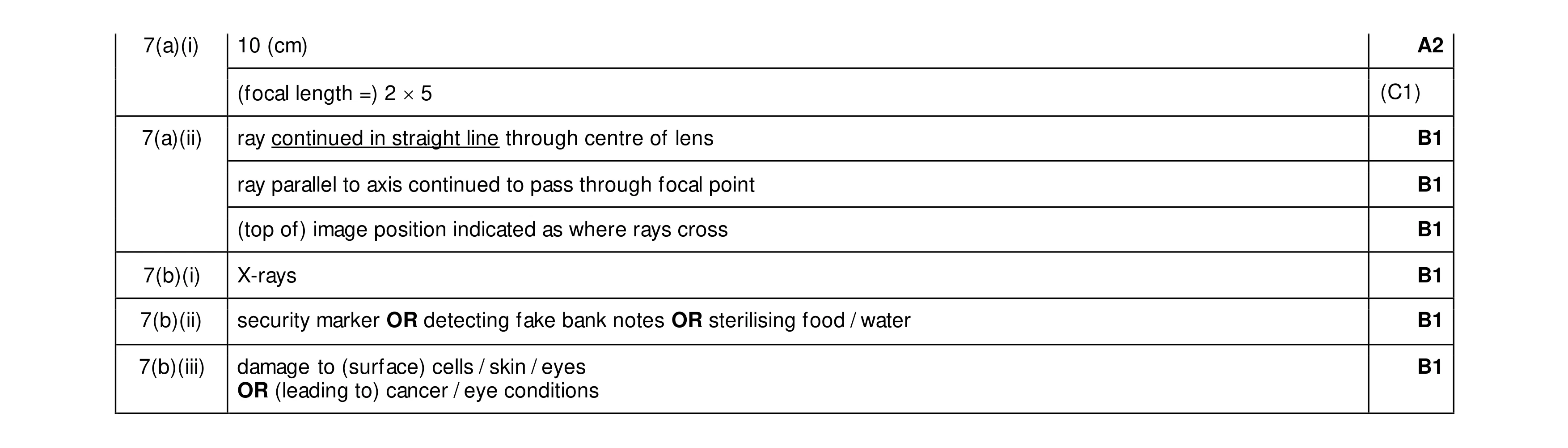 8
8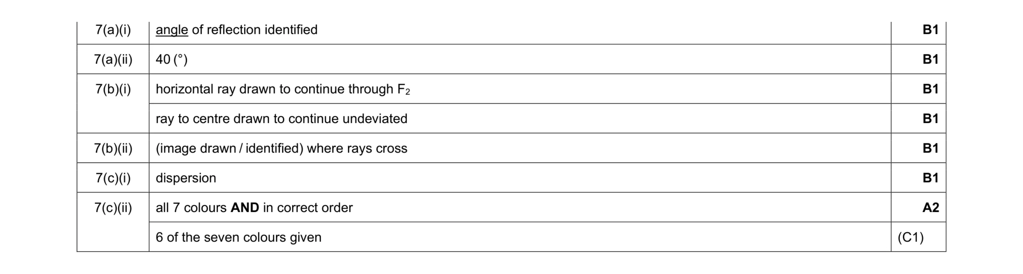 8
8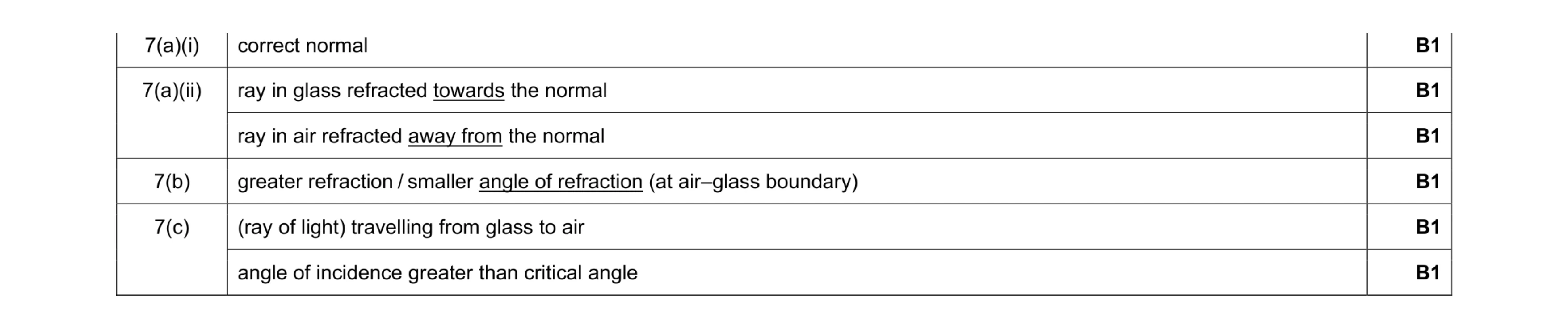 6
6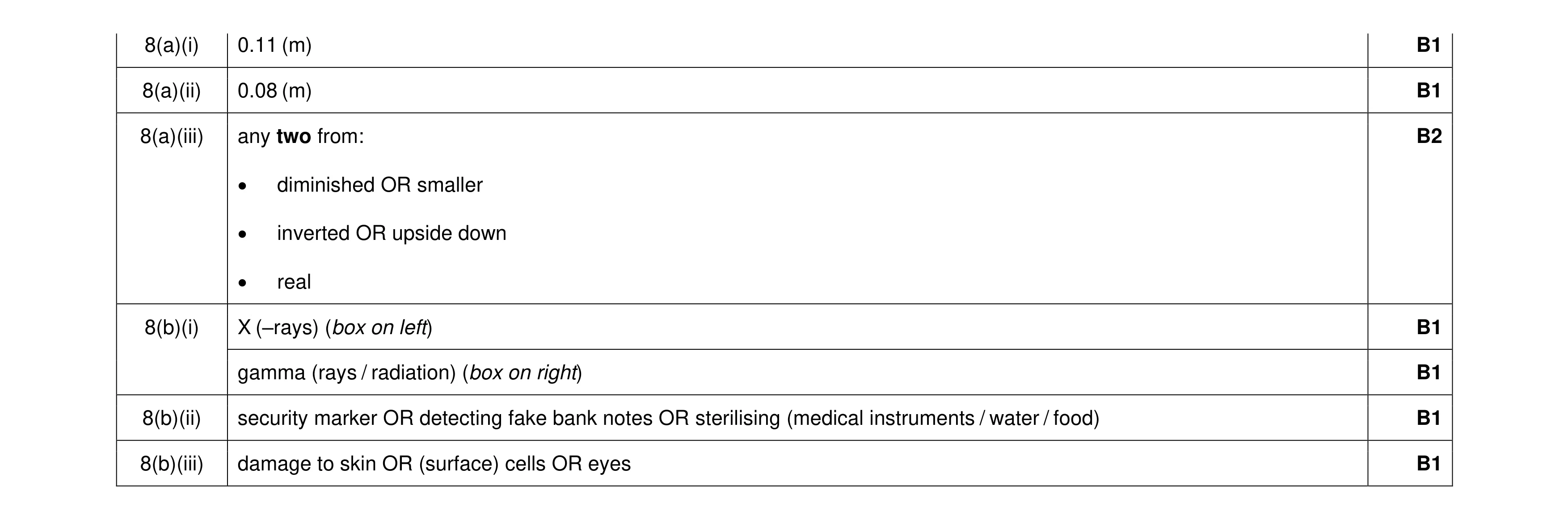 8
8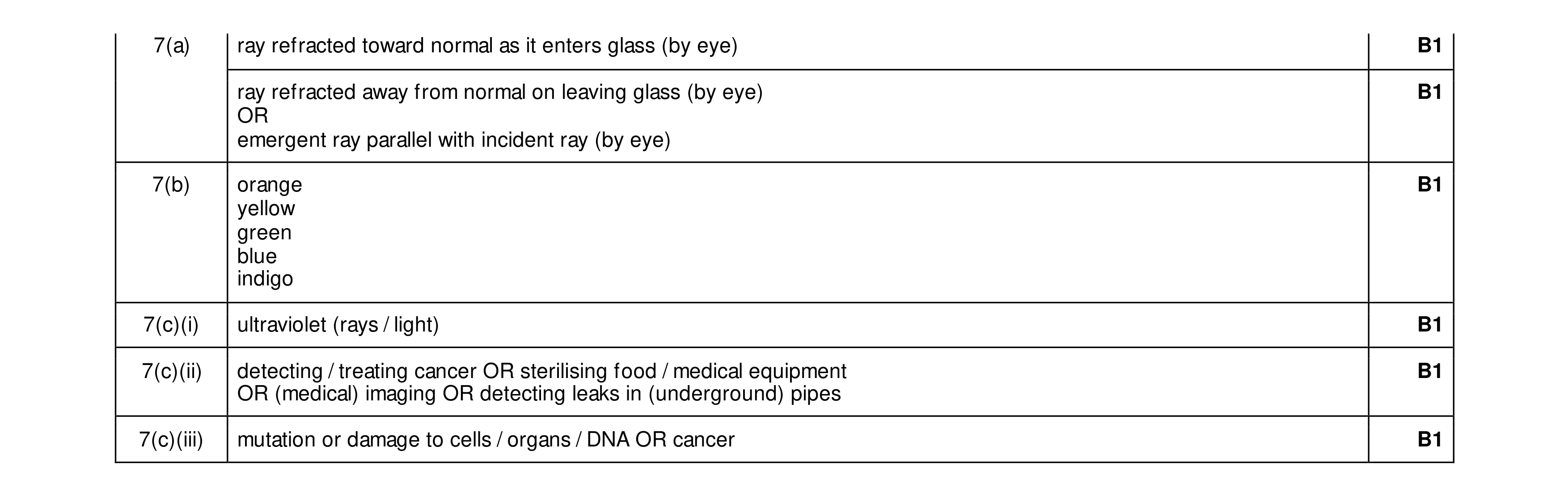 6
6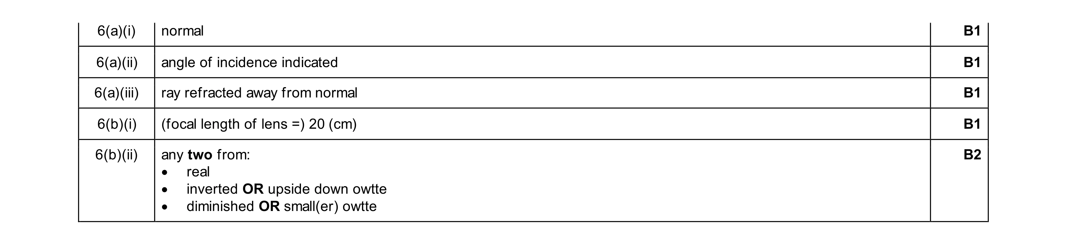 6
6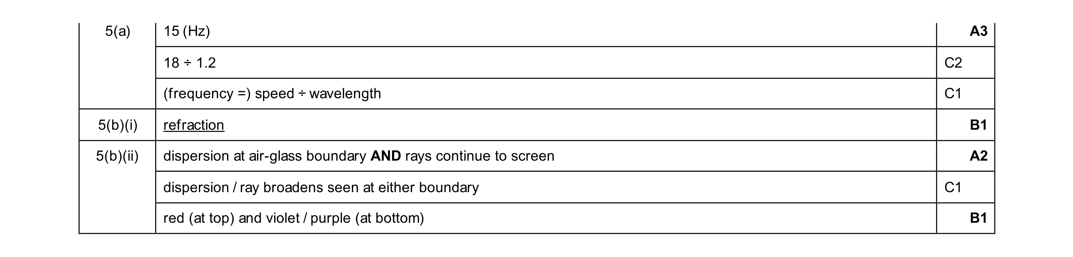 7
7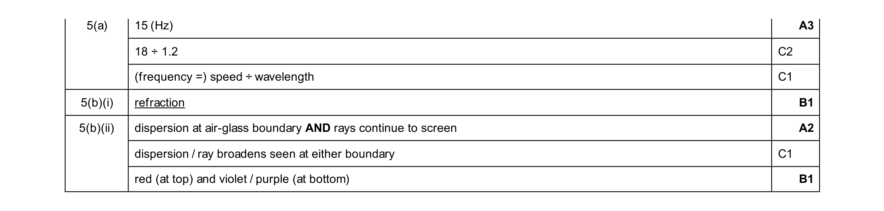 7
7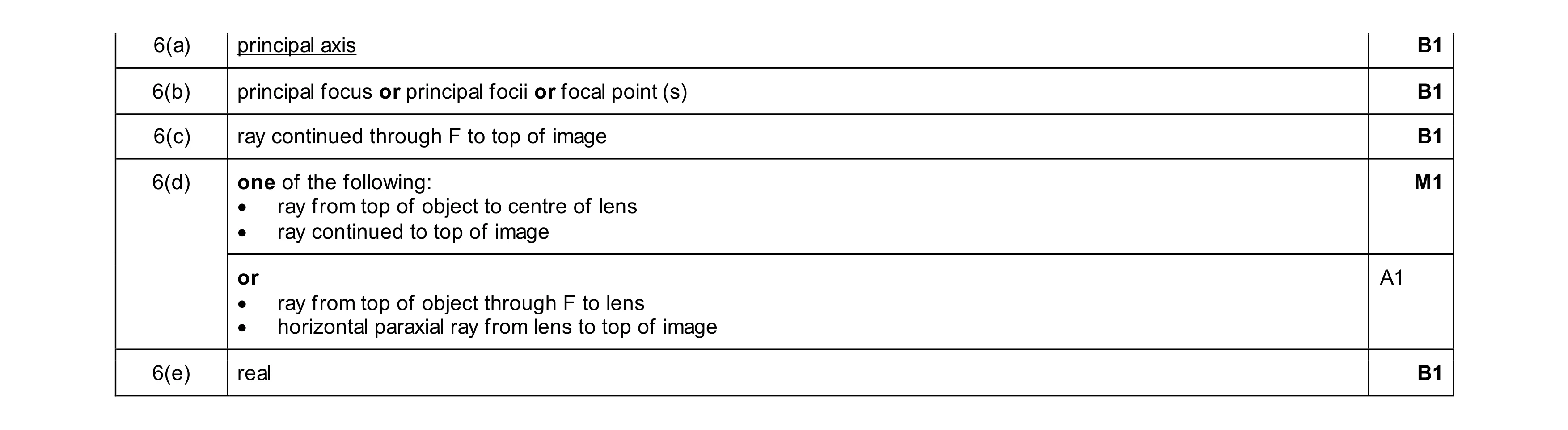 6
6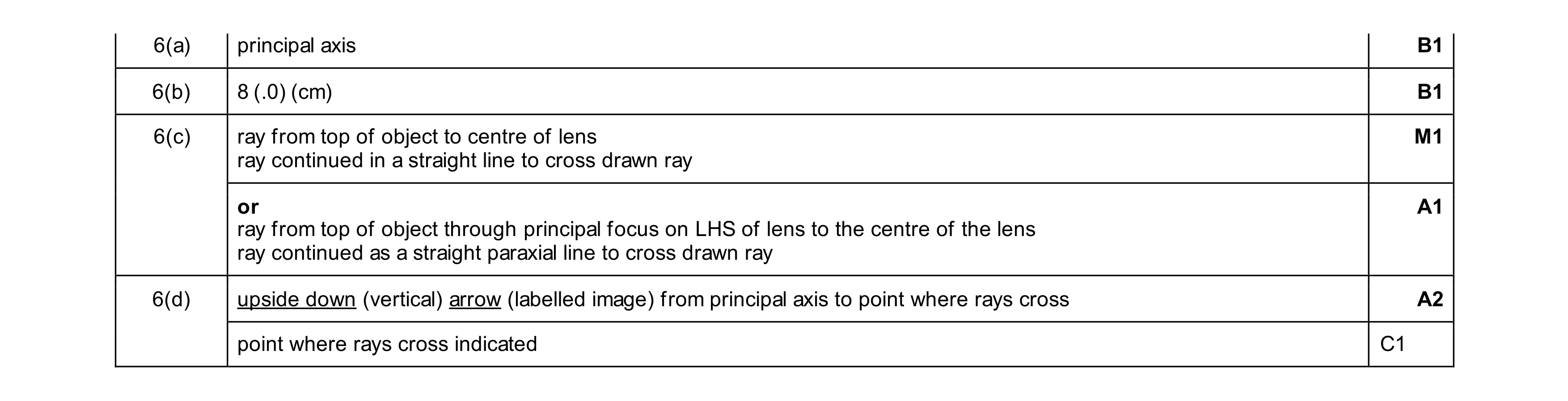 6
6