Cambridge IGCSE Physics 0625 — 2019 May/June Paper 3 · Variant 2
0625/32/M/J/19 · 12 questions · 80 marks · ≈90 min
The question paper and its mark scheme, free to read here and free to download. This is Cambridge’s own paper, exactly as it was sat.
Question paper16 pages
Mark scheme9 pages
Answers below. Sit the paper first if you are practising.
Questions as text
Q1 · A student moves a model car along a bench
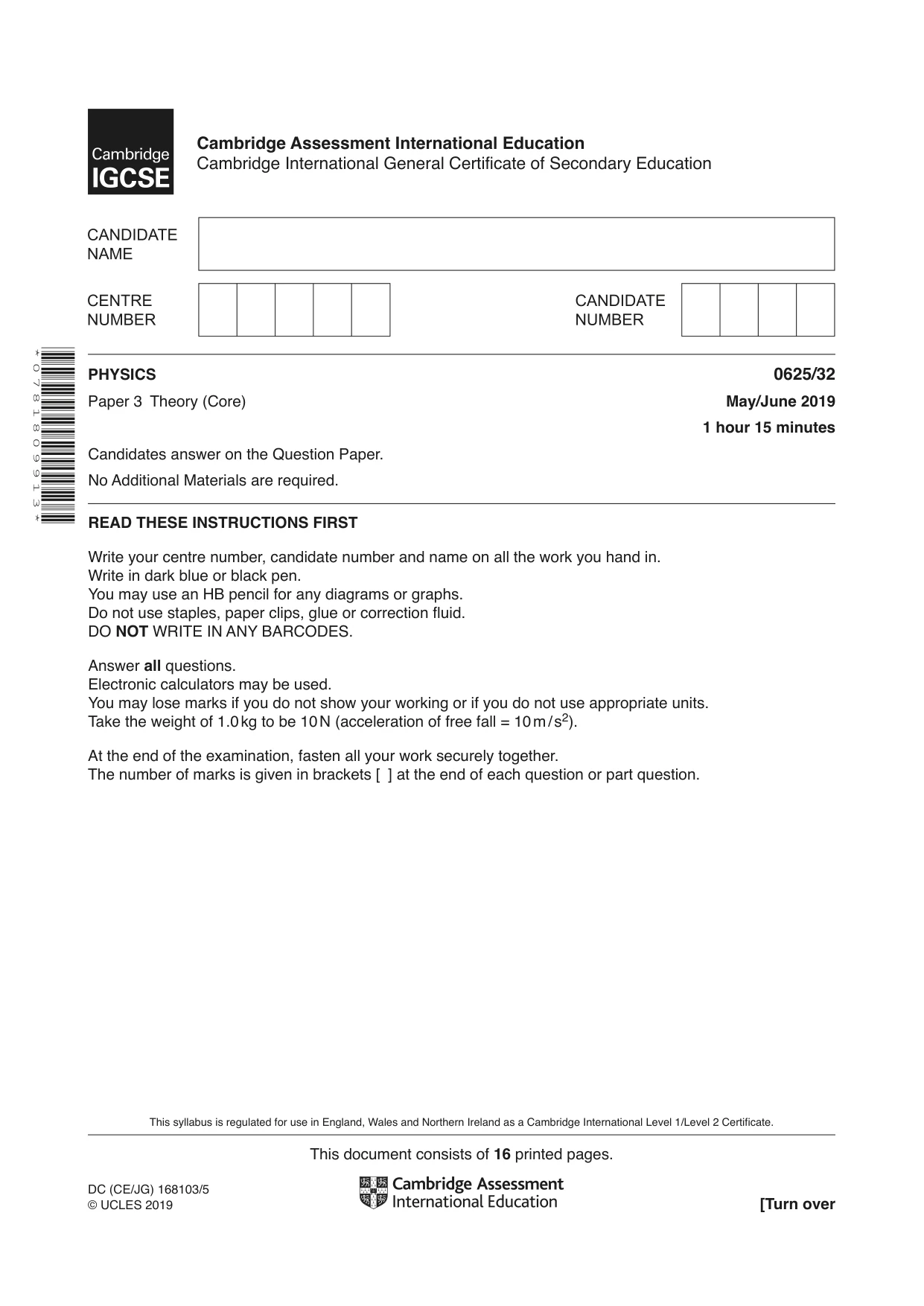
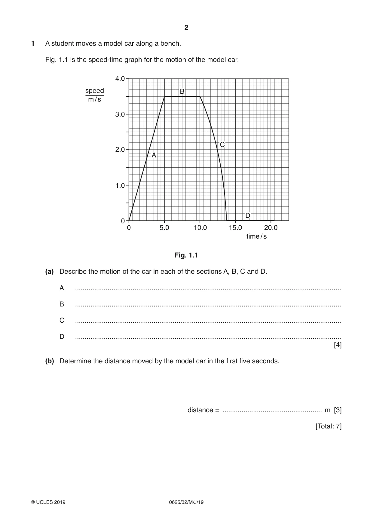
1 A student moves a model car along a bench. Fig. 1.1 is the speed-time graph for the motion of the model car. 4.0 speed B m / s 3.0 C 2.0 A 1.0 D 0 0 5.0 10.0 15.0 20.0 time / s Fig. 1.1 (a) Describe the motion of the car in each of the sections A, B, C and D. A ........................................................................................................................................... B ........................................................................................................................................... C ........................................................................................................................................... D ........................................................................................................................................... [4] (b) Determine the distance moved by the model car in the first five seconds. distance = .................................................... m [3] [Total: 7]
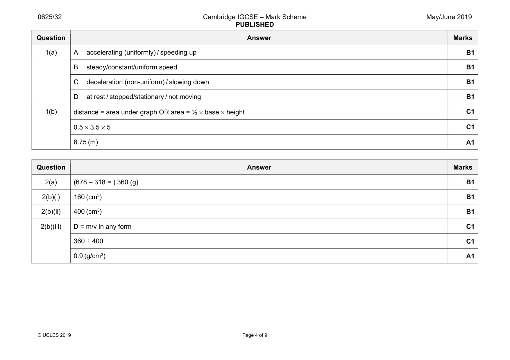
Mark scheme: 1(a) A accelerating (uniformly) / speeding up B1 B steady/constant/uniform speed B1 C deceleration (non-uniform) / slowing down B1 D at rest / stopped/stationary / not moving B1 1(b) distance = area under graph OR area = ½ × base × height C1 0.5 × 3.5 × 5 C1 8.75 (m) A1
Q2 · A bottle contains some oil
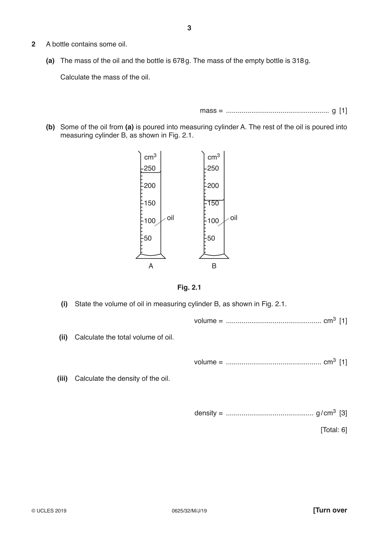
2 A bottle contains some oil. (a) The mass of the oil and the bottle is 678 g. The mass of the empty bottle is 318 g. Calculate the mass of the oil. mass = ..................................................... g [1] (b) Some of the oil from (a) is poured into measuring cylinder A. The rest of the oil is poured into measuring cylinder B, as shown in Fig. 2.1. cm3 cm3 250 250 200 200 150 150 oil oil 100 100 50 50 A B Fig. 2.1 (i) State the volume of oil in measuring cylinder B, as shown in Fig. 2.1. volume = ................................................. cm3 [1] (ii) Calculate the total volume of oil. volume = ................................................. cm3 [1] (iii) Calculate the density of the oil. density = ............................................. g / cm3 [3] [Total: 6]
Mark scheme: 2(a) (678 – 318 = ) 360 (g) B1 2(b)(i) 160 (cm3) B1 2(b)(ii) 400 (cm3) B1 2(b)(iii) D = m/v in any form C1 360 ÷ 400 C1 0.9 (g/cm3) A1
Q3 · A simple pendulum swinging backwards and forwards between P and Q
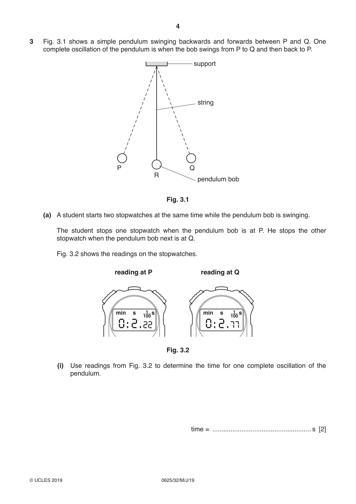
3 Fig. 3.1 shows a simple pendulum swinging backwards and forwards between P and Q. One complete oscillation of the pendulum is when the bob swings from P to Q and then back to P. support string P Q R pendulum bob Fig. 3.1 (a) A student starts two stopwatches at the same time while the pendulum bob is swinging. The student stops one stopwatch when the pendulum bob is at P. He stops the other stopwatch when the pendulum bob next is at Q. Fig. 3.2 shows the readings on the stopwatches. reading at P reading at Q min s 1 s min s 1 s 100 100 0 : 2 : 22 0 : 2 : 77 Fig. 3.2 (i) Use readings from Fig. 3.2 to determine the time for one complete oscillation of the pendulum. time = ...................................................... s [2] (ii) The method described in (a) does not give an accurate value for one complete oscillation of the pendulum. Describe how the student could obtain an accurate value for one complete oscillation of the pendulum. ........................................................................................................................................... ........................................................................................................................................... ........................................................................................................................................... ........................................................................................................................................... ........................................................................................................................................... ..................................................................................................................................... [4] (b) As the pendulum bob moves from R to Q it gains 0.4 J of gravitational potential energy. Air resistance can be ignored. State the value of kinetic energy of the pendulum bob at 1. R ................................................ J 2. Q .................................................J [2] [Total: 8]
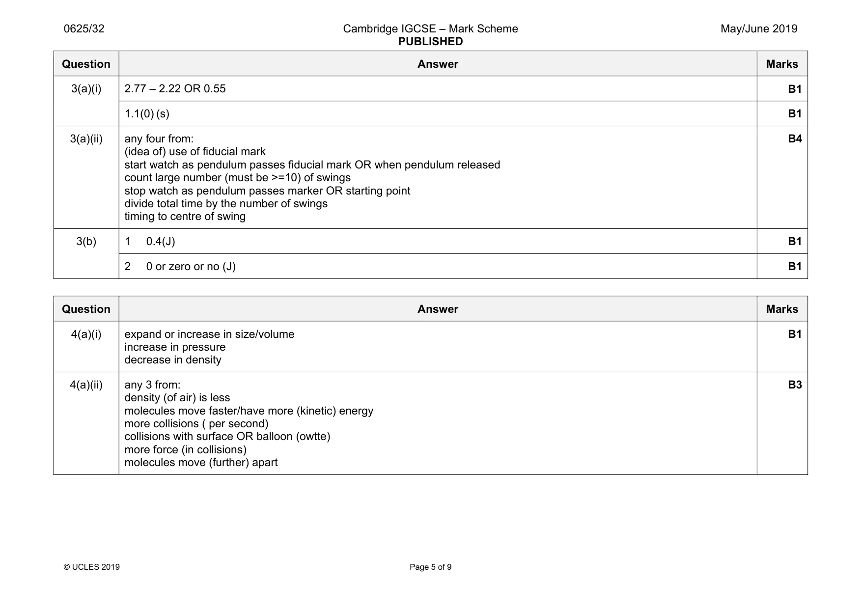
Mark scheme: 3(a)(i) 2.77 – 2.22 OR 0.55 B1 1.1(0) (s) B1 3(a)(ii) any four from: (idea of) use of fiducial mark start watch as pendulum passes fiducial mark OR when pendulum released count large number (must be >=10) of swings stop watch as pendulum passes marker OR starting point divide total time by the number of swings timing to centre of swing B4 3(b) 1 0.4(J) B1 2 0 or zero or no (J) B1
Q4 · A student places a balloon filled with air next to a window, as shown in Fig
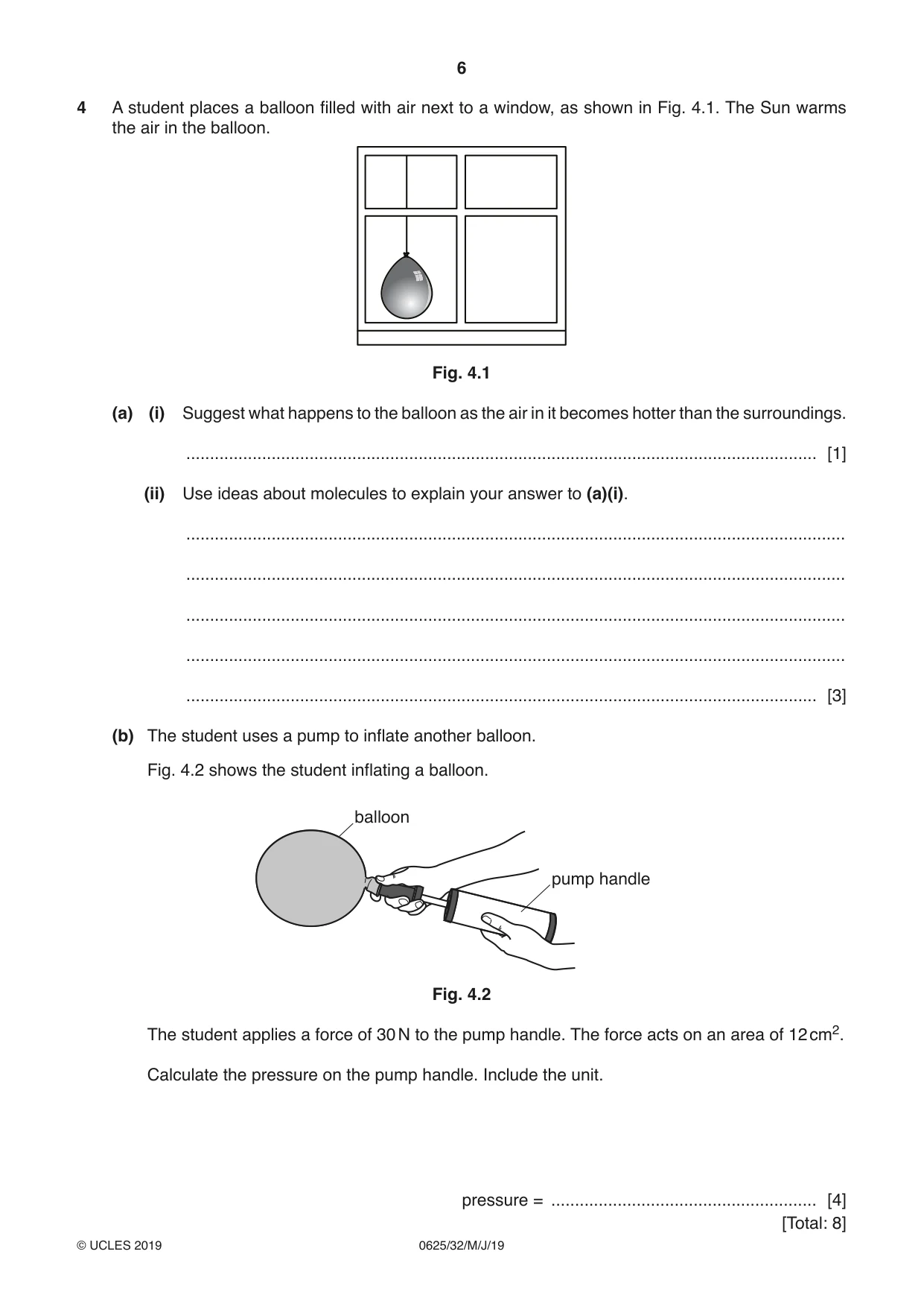
4 A student places a balloon filled with air next to a window, as shown in Fig. 4.1. The Sun warms the air in the balloon. Fig. 4.1 (a) (i) Suggest what happens to the balloon as the air in it becomes hotter than the surroundings. ..................................................................................................................................... [1] (ii) Use ideas about molecules to explain your answer to (a)(i). ........................................................................................................................................... ........................................................................................................................................... ........................................................................................................................................... ........................................................................................................................................... ..................................................................................................................................... [3] (b) The student uses a pump to inflate another balloon. Fig. 4.2 shows the student inflating a balloon. balloon pump handle Fig. 4.2 The student applies a force of 30 N to the pump handle. The force acts on an area of 12 cm2. Calculate the pressure on the pump handle. Include the unit. pressure = ........................................................ [4] [Total: 8]
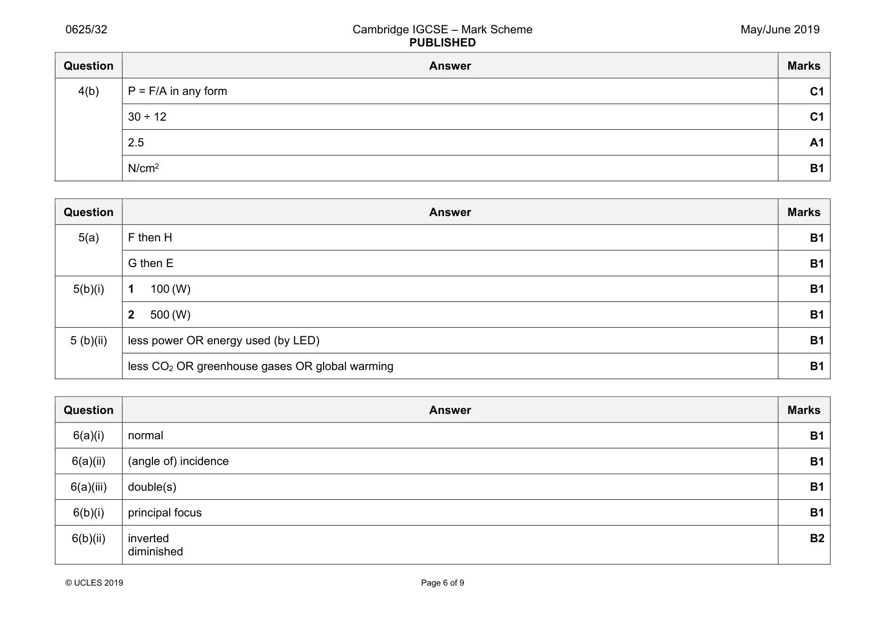
Mark scheme: 4(a)(i) expand or increase in size/volume increase in pressure decrease in density B1 4(a)(ii) any 3 from: density (of air) is less molecules move faster/have more (kinetic) energy more collisions ( per second) collisions with surface OR balloon (owtte) more force (in collisions) molecules move (further) apart B3 Question Answer Marks 4(b) P = F/A in any form C1 30 ÷ 12 C1 2.5 A1 N/cm2 B1
Q5 · A nuclear power station generates electrical energy
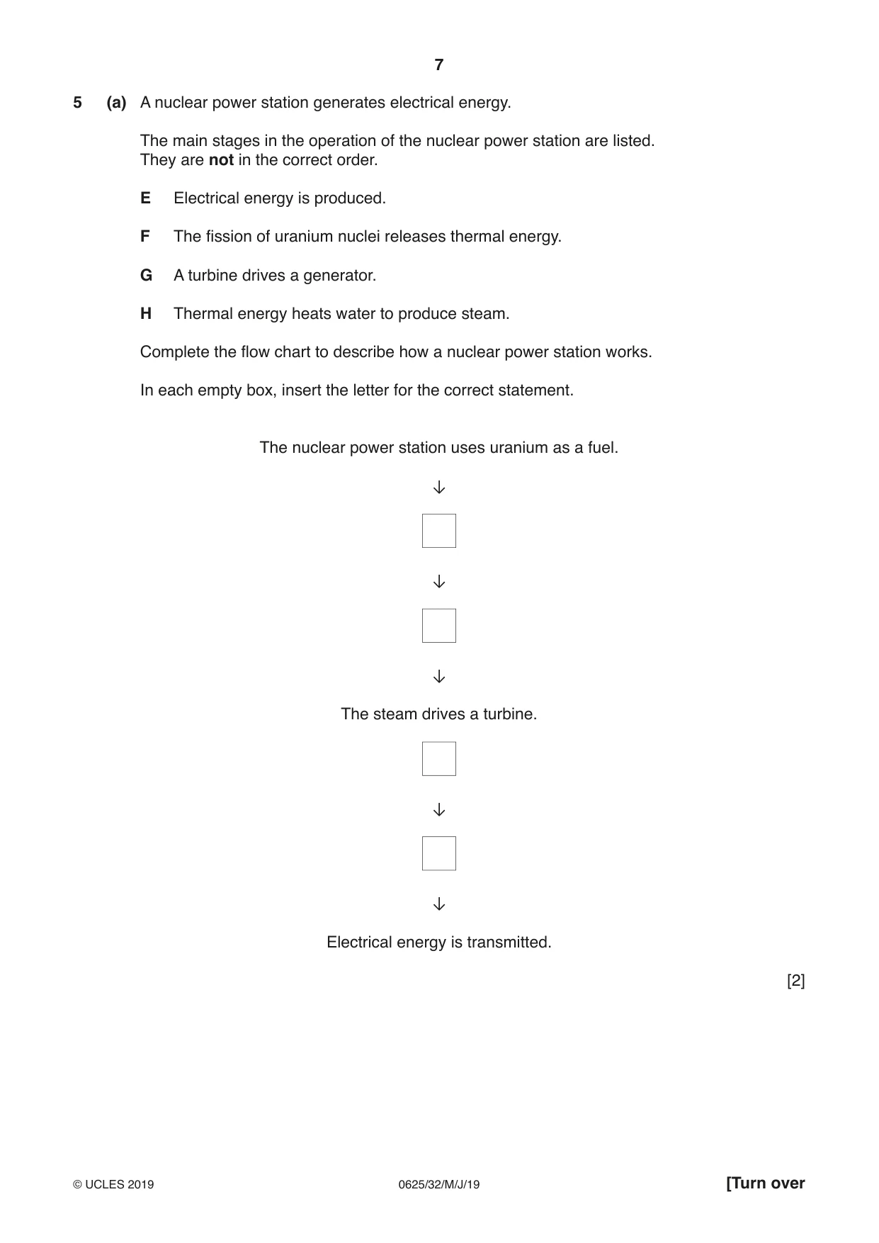
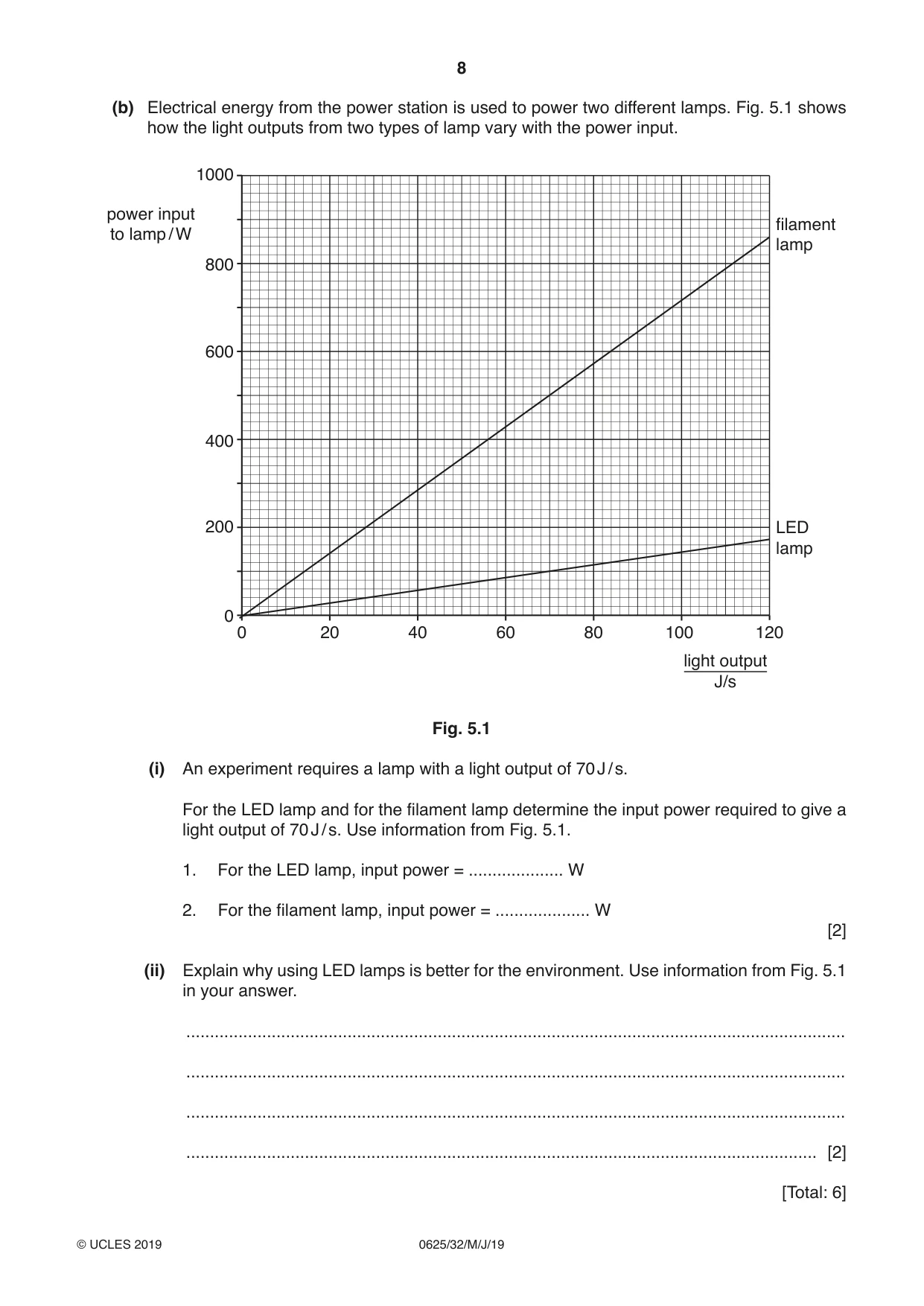
5 (a) A nuclear power station generates electrical energy. The main stages in the operation of the nuclear power station are listed. They are not in the correct order. E Electrical energy is produced. F The fission of uranium nuclei releases thermal energy. G A turbine drives a generator. H Thermal energy heats water to produce steam. Complete the flow chart to describe how a nuclear power station works. In each empty box, insert the letter for the correct statement. The nuclear power station uses uranium as a fuel. ↓ ↓ ↓ The steam drives a turbine. ↓ ↓ Electrical energy is transmitted. [2] (b) Electrical energy from the power station is used to power two different lamps. Fig. 5.1 shows how the light outputs from two types of lamp vary with the power input. 1000 power input filamentto lamp / W lamp 800 600 400 200 LED lamp 0 0 20 40 60 80 100 120 light output J/s Fig. 5.1 (i) An experiment requires a lamp with a light output of 70 J / s. For the LED lamp and for the filament lamp determine the input power required to give a light output of 70 J / s. Use information from Fig. 5.1. 1. For the LED lamp, input power = .................... W 2. For the filament lamp, input power = .................... W [2] (ii) Explain why using LED lamps is better for the environment. Use information from Fig. 5.1 in your answer. ........................................................................................................................................... ........................................................................................................................................... ........................................................................................................................................... ..................................................................................................................................... [2] [Total: 6]
Mark scheme: 5(a) F then H B1 G then E B1 5(b)(i) 1 100 (W) B1 2 500 (W) B1 5 (b)(ii) less power OR energy used (by LED) B1 less CO2 OR greenhouse gases OR global warming B1
Q6 · A ray of light that is reflected by a mirror
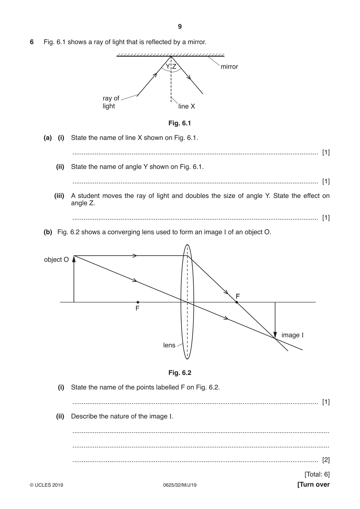
6 Fig. 6.1 shows a ray of light that is reflected by a mirror. Y Z mirror ray of light line X Fig. 6.1 (a) (i) State the name of line X shown on Fig. 6.1. ..................................................................................................................................... [1] (ii) State the name of angle Y shown on Fig. 6.1. ..................................................................................................................................... [1] (iii) A student moves the ray of light and doubles the size of angle Y. State the effect on angle Z. ..................................................................................................................................... [1] (b) Fig. 6.2 shows a converging lens used to form an image I of an object O. object O F F image I lens Fig. 6.2 (i) State the name of the points labelled F on Fig. 6.2. ..................................................................................................................................... [1] (ii) Describe the nature of the image I. ........................................................................................................................................... ........................................................................................................................................... ..................................................................................................................................... [2] [Total: 6]
Mark scheme: 6(a)(i) normal B1 6(a)(ii) (angle of) incidence B1 6(a)(iii) double(s) B1 6(b)(i) principal focus B1 6(b)(ii) inverted diminished B2
Q7 · Solid, liquid and gas are three states of matter
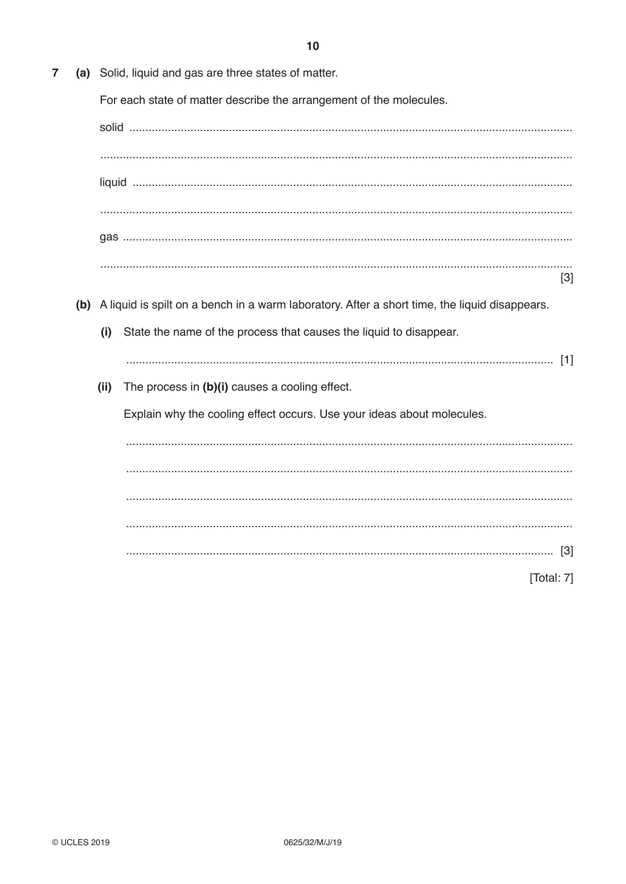
7 (a) Solid, liquid and gas are three states of matter. For each state of matter describe the arrangement of the molecules. solid .......................................................................................................................................... ................................................................................................................................................... liquid ......................................................................................................................................... ................................................................................................................................................... gas ............................................................................................................................................ ................................................................................................................................................... [3] (b) A liquid is spilt on a bench in a warm laboratory. After a short time, the liquid disappears. (i) State the name of the process that causes the liquid to disappear. ..................................................................................................................................... [1] (ii) The process in (b)(i) causes a cooling effect. Explain why the cooling effect occurs. Use your ideas about molecules. ........................................................................................................................................... ........................................................................................................................................... ........................................................................................................................................... ........................................................................................................................................... ..................................................................................................................................... [3] [Total: 7]
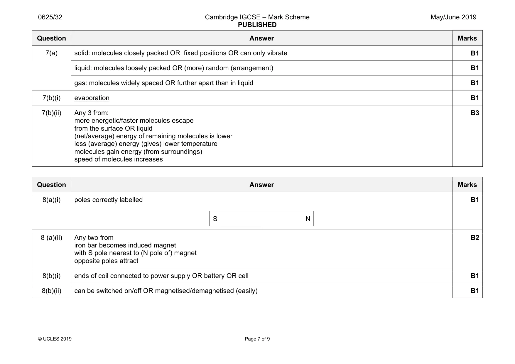
Mark scheme: 7(a) solid: molecules closely packed OR fixed positions OR can only vibrate B1 liquid: molecules loosely packed OR (more) random (arrangement) B1 gas: molecules widely spaced OR further apart than in liquid B1 7(b)(i) evaporation B1 7(b)(ii) Any 3 from: more energetic/faster molecules escape from the surface OR liquid (net/average) energy of remaining molecules is lower less (average) energy (gives) lower temperature molecules gain energy (from surroundings) speed of molecules increases B3
Q8 · The magnetic field pattern around a bar magnet
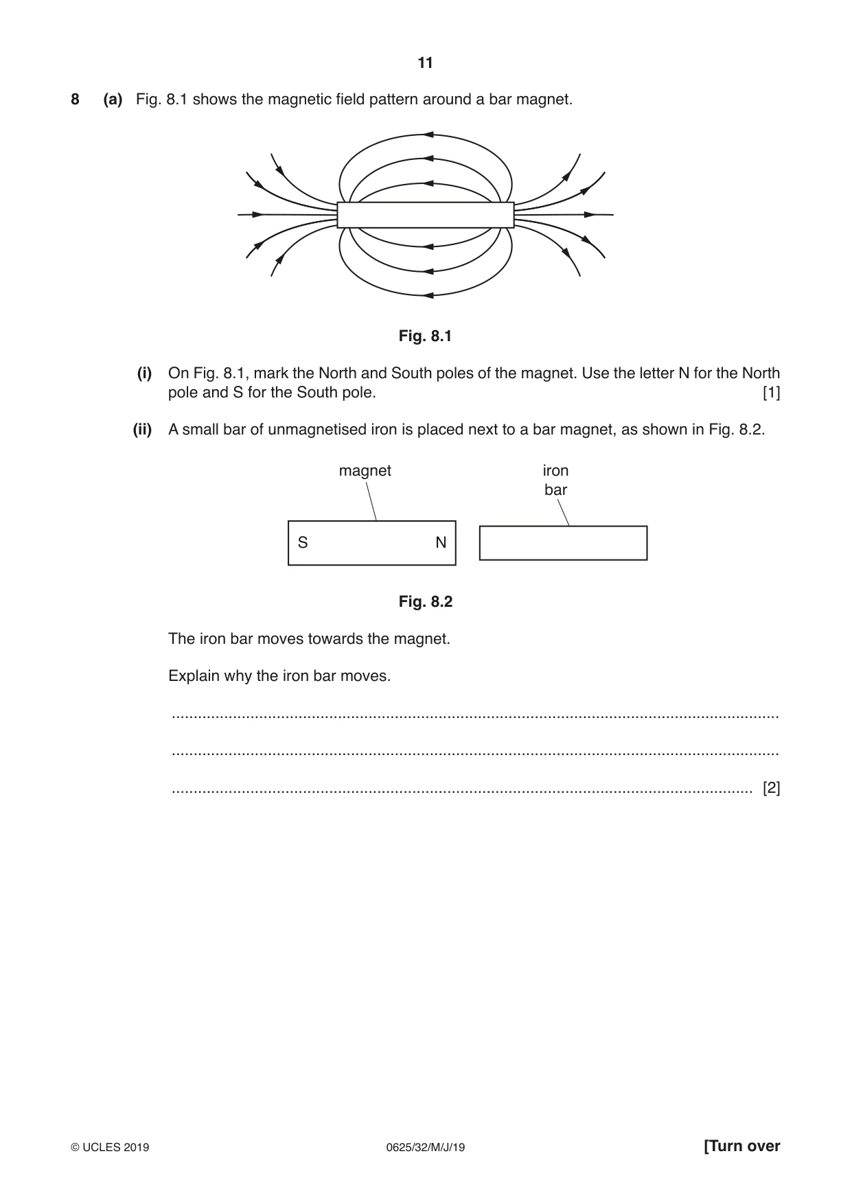
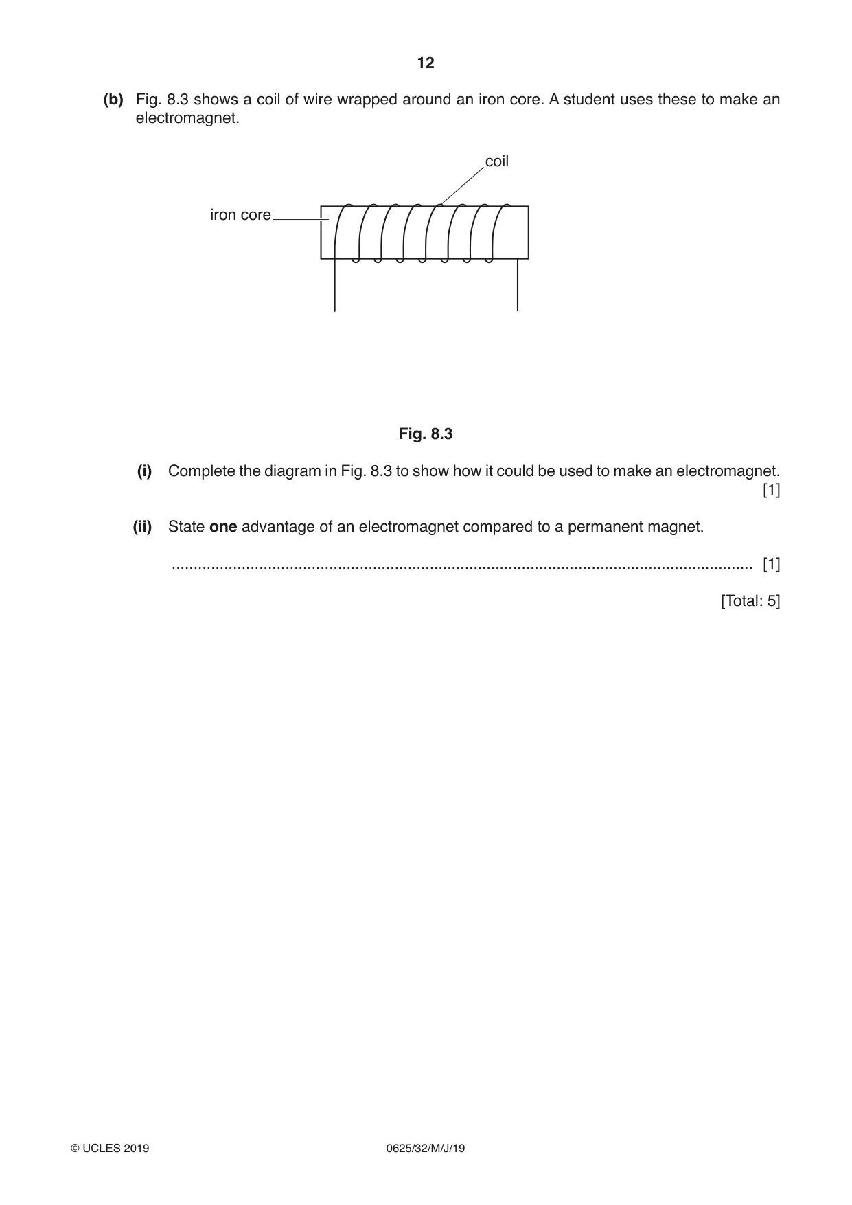
8 (a) Fig. 8.1 shows the magnetic field pattern around a bar magnet. Fig. 8.1 (i) On Fig. 8.1, mark the North and South poles of the magnet. Use the letter N for the North pole and S for the South pole. [1] (ii) A small bar of unmagnetised iron is placed next to a bar magnet, as shown in Fig. 8.2. magnet iron bar S N Fig. 8.2 The iron bar moves towards the magnet. Explain why the iron bar moves. ........................................................................................................................................... ........................................................................................................................................... ..................................................................................................................................... [2] (b) Fig. 8.3 shows a coil of wire wrapped around an iron core. A student uses these to make an electromagnet. coil iron core Fig. 8.3 (i) Complete the diagram in Fig. 8.3 to show how it could be used to make an electromagnet. [1] (ii) State one advantage of an electromagnet compared to a permanent magnet. ..................................................................................................................................... [1] [Total: 5]
Mark scheme: 8(a)(i) poles correctly labelled S N B1 8 (a)(ii) Any two from iron bar becomes induced magnet with S pole nearest to (N pole of) magnet opposite poles attract B2 8(b)(i) ends of coil connected to power supply OR battery OR cell B1 8(b)(ii) can be switched on/off OR magnetised/demagnetised (easily) B1
Question 9
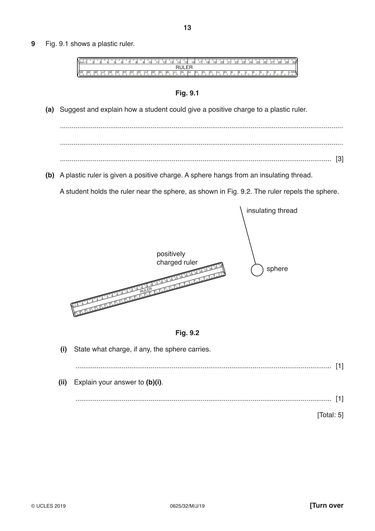
9 Fig. 9.1 shows a plastic ruler. Fig. 9.1 (a) Suggest and explain how a student could give a positive charge to a plastic ruler. ................................................................................................................................................... ................................................................................................................................................... ............................................................................................................................................. [3] (b) A plastic ruler is given a positive charge. A sphere hangs from an insulating thread. A student holds the ruler near the sphere, as shown in Fig. 9.2. The ruler repels the sphere. insulating thread positively charged ruler sphere Fig. 9.2 (i) State what charge, if any, the sphere carries. ..................................................................................................................................... [1] (ii) Explain your answer to (b)(i). ..................................................................................................................................... [1] [Total: 5]
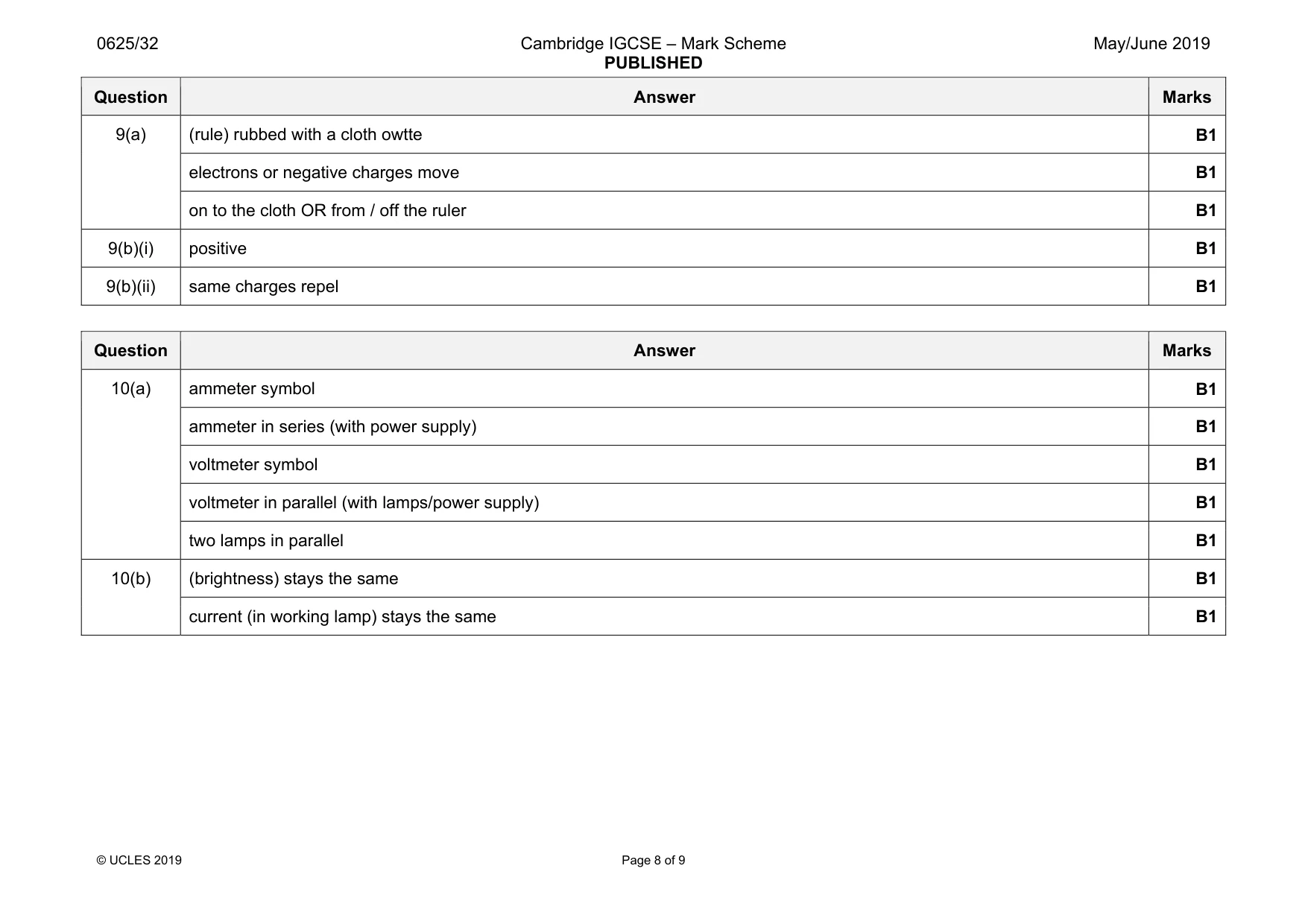
Mark scheme: 9(a) (rule) rubbed with a cloth owtte B1 electrons or negative charges move B1 on to the cloth OR from / off the ruler B1 9(b)(i) positive B1 9(b)(ii) same charges repel B1
Q10 · An incomplete circuit diagram for two identical lamps arranged in parallel
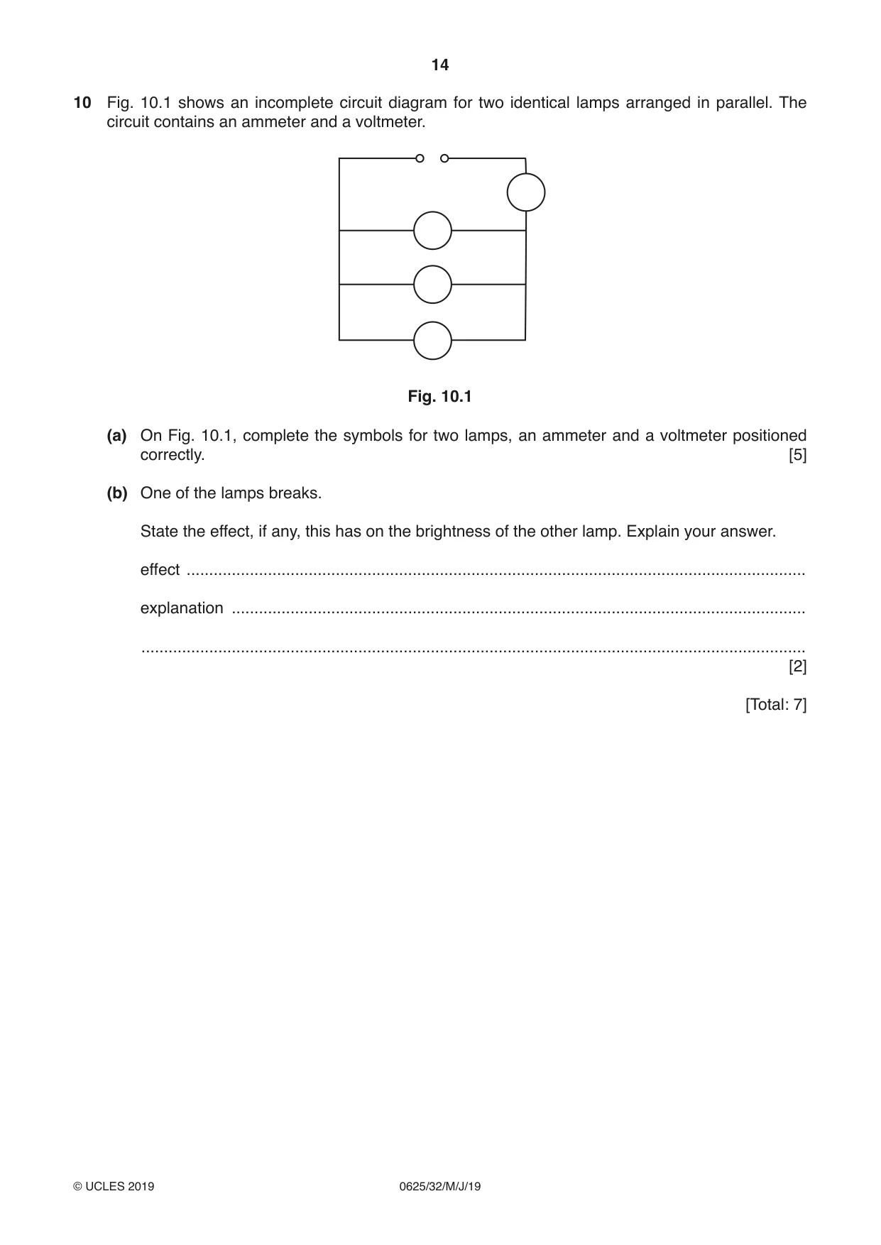
10 Fig. 10.1 shows an incomplete circuit diagram for two identical lamps arranged in parallel. The circuit contains an ammeter and a voltmeter. Fig. 10.1 (a) On Fig. 10.1, complete the symbols for two lamps, an ammeter and a voltmeter positioned correctly. [5] (b) One of the lamps breaks. State the effect, if any, this has on the brightness of the other lamp. Explain your answer. effect ......................................................................................................................................... explanation ............................................................................................................................... ................................................................................................................................................... [2] [Total: 7]
Mark scheme: 10(a) ammeter symbol B1 ammeter in series (with power supply) B1 voltmeter symbol B1 voltmeter in parallel (with lamps/power supply) B1 two lamps in parallel B1 10(b) (brightness) stays the same B1 current (in working lamp) stays the same B1
Q11 · A transformer that can provide two different output voltages from a 240 volt mains a.c
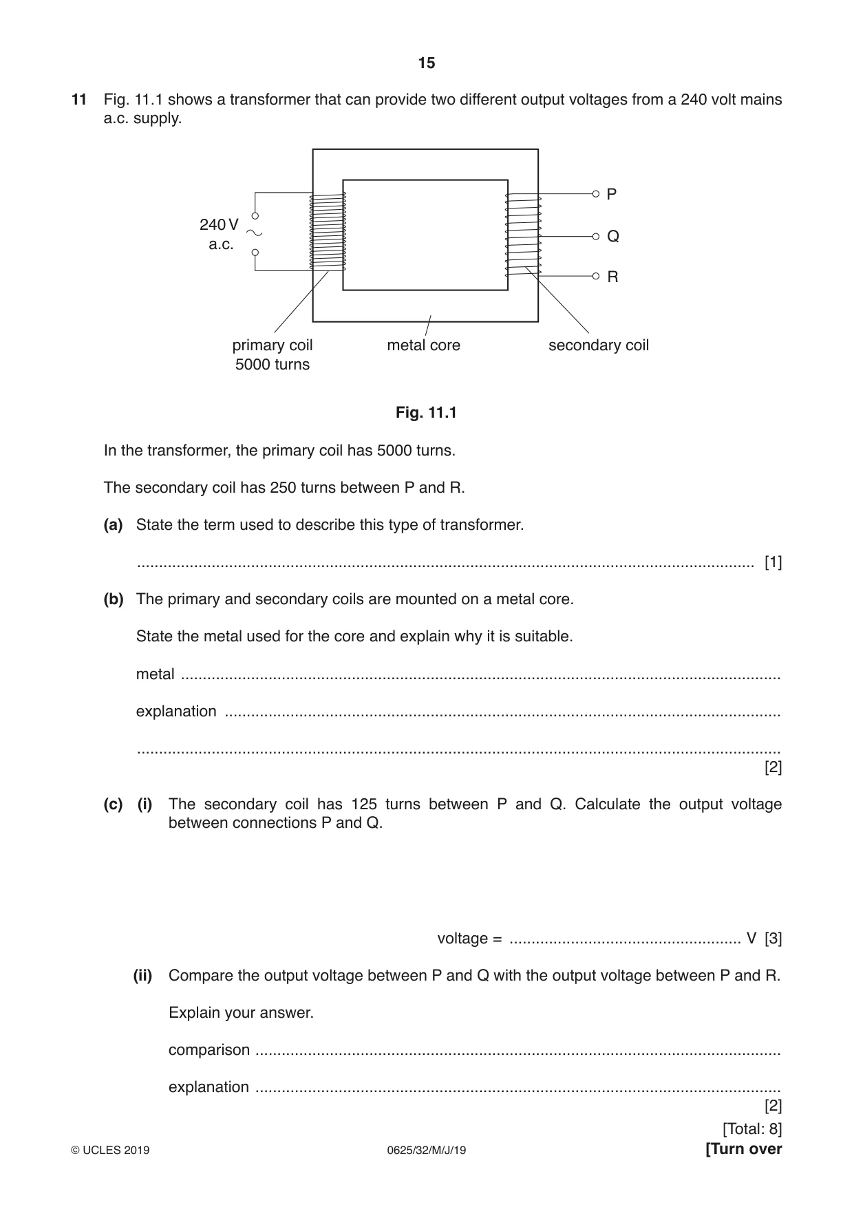
11 Fig. 11.1 shows a transformer that can provide two different output voltages from a 240 volt mains a.c. supply. P 240 V Q a.c. R primary coil metal core secondary coil 5000 turns Fig. 11.1 In the transformer, the primary coil has 5000 turns. The secondary coil has 250 turns between P and R. (a) State the term used to describe this type of transformer. ............................................................................................................................................. [1] (b) The primary and secondary coils are mounted on a metal core. State the metal used for the core and explain why it is suitable. metal ......................................................................................................................................... explanation ............................................................................................................................... ................................................................................................................................................... [2] (c) (i) The secondary coil has 125 turns between P and Q. Calculate the output voltage between connections P and Q. voltage = ..................................................... V [3] (ii) Compare the output voltage between P and Q with the output voltage between P and R. Explain your answer. comparison ........................................................................................................................ explanation ........................................................................................................................ [2]
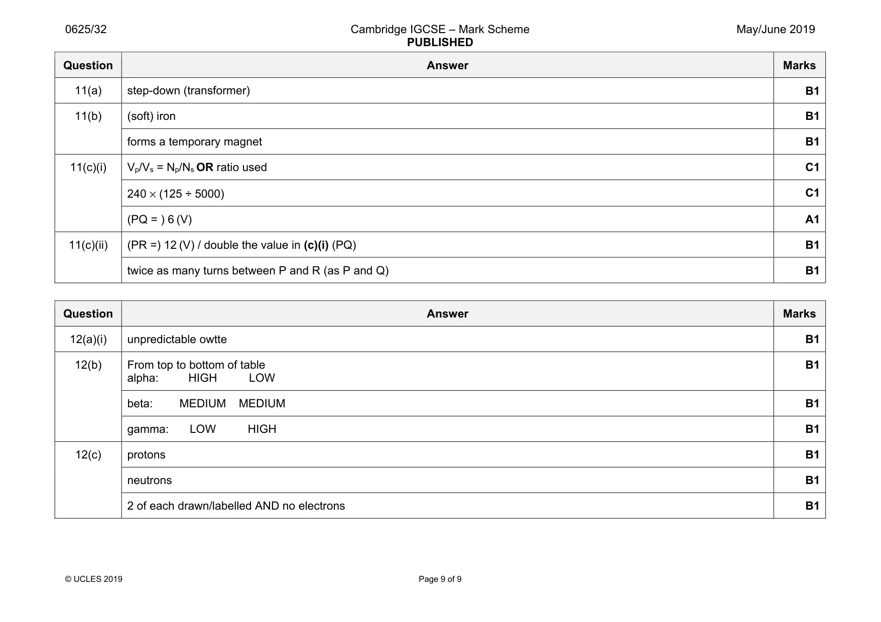
Mark scheme: 11(a) step-down (transformer) B1 11(b) (soft) iron B1 forms a temporary magnet B1 11(c)(i) Vp/Vs = Np/Ns OR ratio used C1 240 × (125 ÷ 5000) C1 (PQ = ) 6 (V) A1 11(c)(ii) (PR =) 12 (V) / double the value in (c)(i) (PQ) B1 twice as many turns between P and R (as P and Q) B1
Q12 · Radioactive emission is a random process
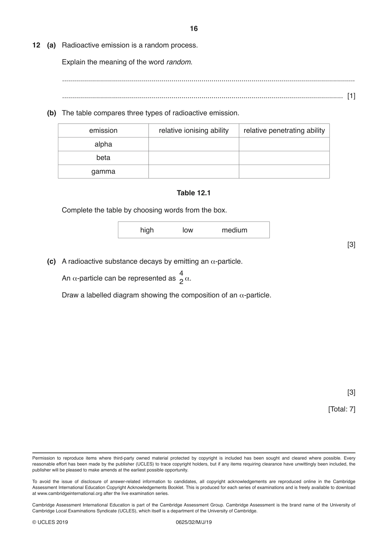
12 (a) Radioactive emission is a random process. Explain the meaning of the word random. ................................................................................................................................................... ............................................................................................................................................. [1] (b) The table compares three types of radioactive emission. emission relative ionising ability relative penetrating ability alpha beta gamma Table 12.1 Complete the table by choosing words from the box. high low medium [3] (c) A radioactive substance decays by emitting an α-particle. 4 An α-particle can be represented as α. 2 Draw a labelled diagram showing the composition of an α-particle. [3] [Total: 7]
Mark scheme: 12(a)(i) unpredictable owtte B1 12(b) From top to bottom of table alpha: HIGH LOW B1 beta: MEDIUM MEDIUM B1 gamma: LOW HIGH B1 12(c) protons B1 neutrons B1 2 of each drawn/labelled AND no electrons B1
What was in this paper
The subtopics covered by these 12 questions, and how many questions each got. Open one in a new tab to see every Cambridge question on it.
What you needed in this session
Cambridge’s own grade thresholds for 2019 May/June, Paper 3 · Variant 2. A higher threshold means an easier paper — the bar moves with how the cohort did.