Cambridge IGCSE Physics 0625 — 2009 Oct/Nov Paper 3 · Variant 1
0625/31/O/N/09 · 11 questions · 80 marks · ≈90 min
The question paper and its mark scheme, free to read here and free to download. This is Cambridge’s own paper, exactly as it was sat.
Question paper16 pages
Mark scheme8 pages
Answers below. Sit the paper first if you are practising.
Questions as text
Q1 · Part of a measuring instrument
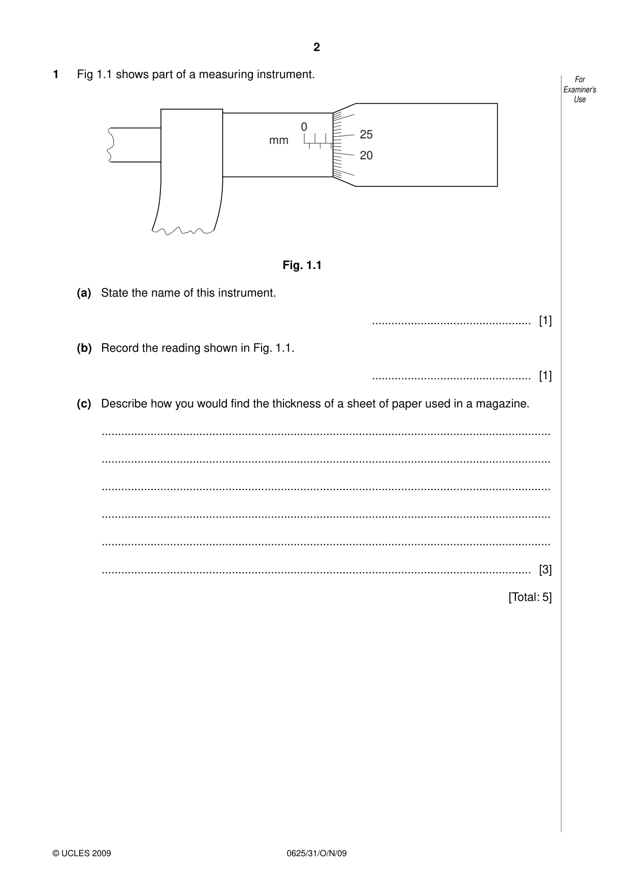
1 Fig 1.1 shows part of a measuring instrument. For Examiner’s Use 0 25 mm 20 Fig. 1.1 (a) State the name of this instrument. ................................................. [1] (b) Record the reading shown in Fig. 1.1. ................................................. [1] (c) Describe how you would find the thickness of a sheet of paper used in a magazine. .......................................................................................................................................... .......................................................................................................................................... .......................................................................................................................................... .......................................................................................................................................... .......................................................................................................................................... .................................................................................................................................... [3] [Total: 5]
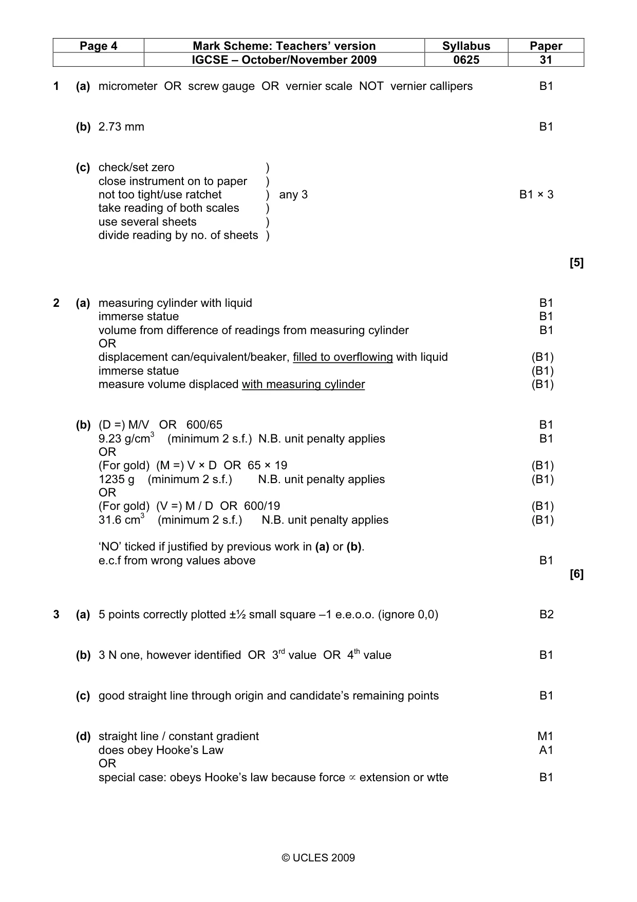
Mark scheme: 1 (a) micrometer OR screw gauge OR vernier scale NOT vernier callipers B1 (b) 2.73 mm B1 (c) check/set zero ) close instrument on to paper ) not too tight/use ratchet ) any 3 B1 × 3 take reading of both scales ) use several sheets ) divide reading by no. of sheets ) [5]
More questions on Physical quantities and measurement techniques
Q2 · The list below gives the approximate densities of various metals
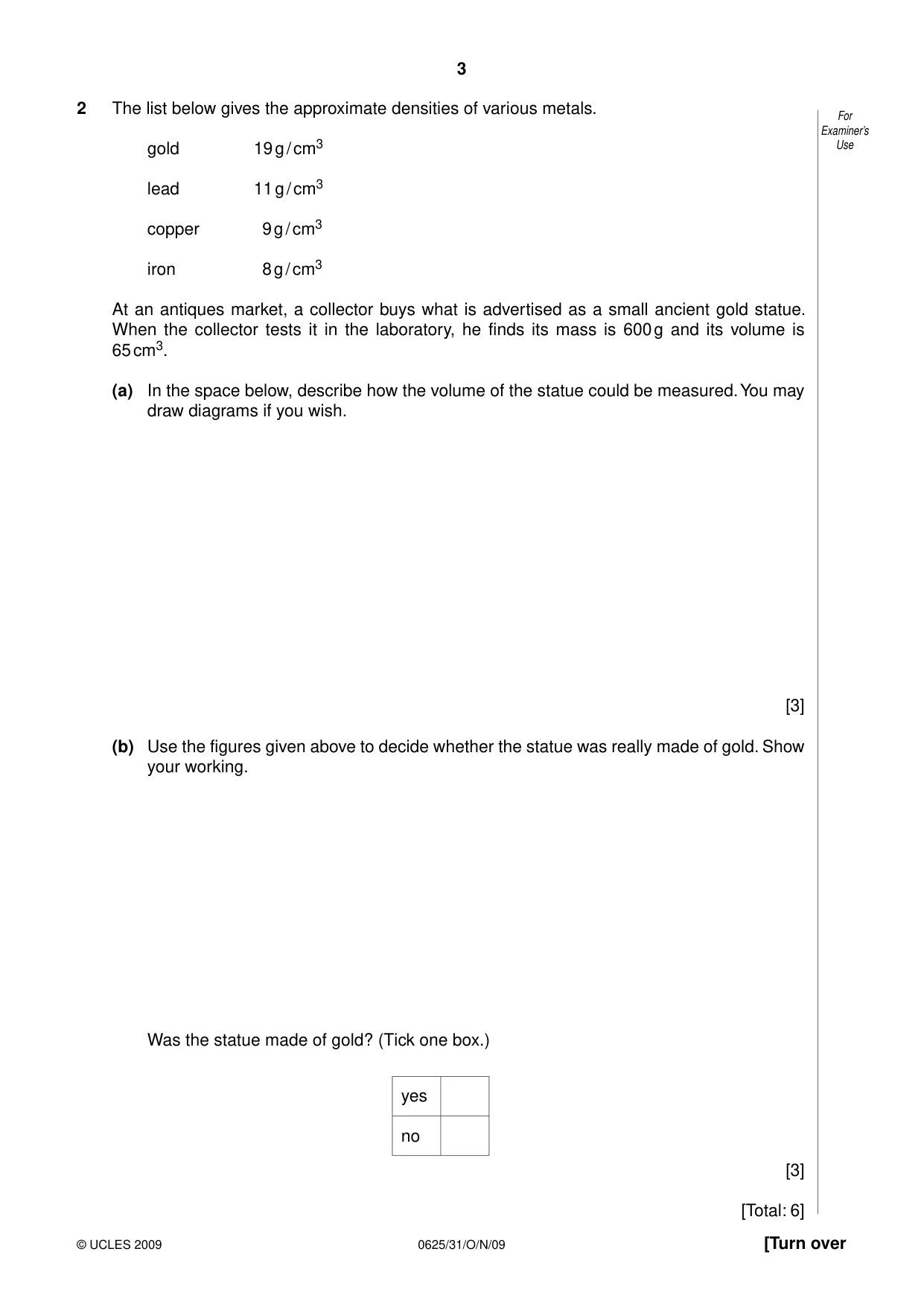
2 The list below gives the approximate densities of various metals. For Examiner’s gold 19 g / cm3 Use lead 11 g / cm3 copper 9 g / cm3 iron 8 g / cm3 At an antiques market, a collector buys what is advertised as a small ancient gold statue. When the collector tests it in the laboratory, he finds its mass is 600 g and its volume is 65 cm3. (a) In the space below, describe how the volume of the statue could be measured. You may draw diagrams if you wish. [3] (b) Use the figures given above to decide whether the statue was really made of gold. Show your working. Was the statue made of gold? (Tick one box.) yes no [3] [Total: 6]
Mark scheme: 2 (a) measuring cylinder with liquid B1 immerse statue B1 volume from difference of readings from measuring cylinder B1 OR displacement can/equivalent/beaker, filled to overflowing with liquid (B1) immerse statue (B1) measure volume displaced with measuring cylinder (B1) (b) (D =) M/V OR 600/65 B1 9.23 g/cm3 (minimum 2 s.f.) N.B. unit penalty applies B1 OR (For gold) (M =) V × D OR 65 × 19 (B1) 1235 g (minimum 2 s.f.) N.B. unit penalty applies (B1) OR (For gold) (V =) M / D OR 600/19 (B1) 31.6 cm3 (minimum 2 s.f.) N.B. unit penalty applies (B1) ‘NO’ ticked if justified by previous work in (a) or (b). e.c.f from wrong values above B1 [6]
More questions on Physical quantities and measurement techniques
Q3 · A student investigated the stretching of a spring by hanging various weights from it and…
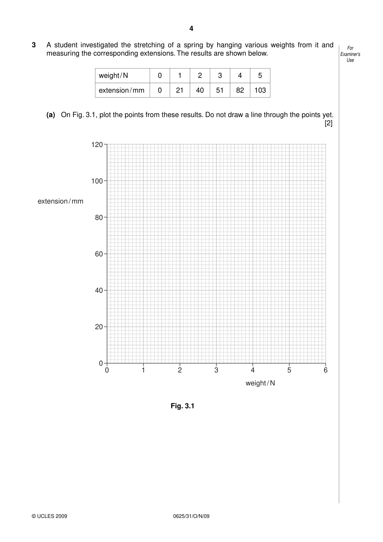
3 A student investigated the stretching of a spring by hanging various weights from it and For measuring the corresponding extensions. The results are shown below. Examiner’s Use weight / N 0 1 2 3 4 5 extension / mm 0 21 40 51 82 103 (a) On Fig. 3.1, plot the points from these results. Do not draw a line through the points yet. [2] 120 100 extension / mm 80 60 40 20 0 0 1 2 3 4 5 6 weight / N Fig. 3.1 (b) The student appears to have made an error in recording one of the results. For Examiner’s Which result is this? Use .................................................................................................................................... [1] (c) Ignoring the incorrect result, draw the best straight line through the remaining points. [1] (d) State and explain whether this spring is obeying Hooke’s Law. .......................................................................................................................................... .......................................................................................................................................... .......................................................................................................................................... .......................................................................................................................................... .................................................................................................................................... [2] (e) Describe how the graph might be shaped if the student continued to add several more weights to the spring. .......................................................................................................................................... .......................................................................................................................................... .......................................................................................................................................... .................................................................................................................................... [1] (f) The student estimates that if he hangs a 45 N load on the spring, the extension will be 920 mm. Explain why this estimate may be unrealistic. .......................................................................................................................................... .......................................................................................................................................... .......................................................................................................................................... .................................................................................................................................... [1] [Total: 8]
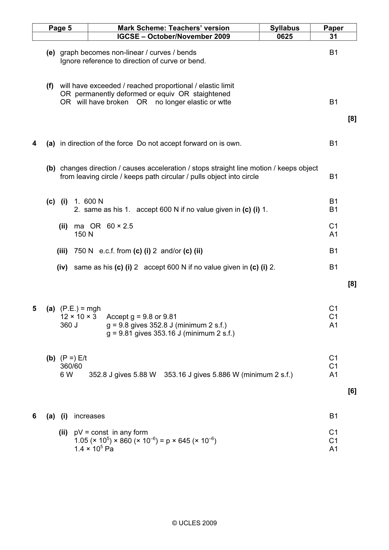
Mark scheme: 3 (a) 5 points correctly plotted ±½ small square –1 e.e.o.o. (ignore 0,0) B2 (b) 3 N one, however identified OR 3rd value OR 4th value B1 (c) good straight line through origin and candidate’s remaining points B1 (d) straight line / constant gradient M1 does obey Hooke’s Law A1 OR special case: obeys Hooke’s law because force ú extension or wtte B1 IGCSE – October/November 2009 0625 31 (e) graph becomes non-linear / curves / bends B1 Ignore reference to direction of curve or bend. (f) will have exceeded / reached proportional / elastic limit OR permanently deformed or equiv OR staightened OR will have broken OR no longer elastic or wtte B1 [8]
More questions on Physical quantities and measurement techniques
Q4 · A force acting on an object causes the object to accelerate
4 (a) A force acting on an object causes the object to accelerate. For Examiner’s In which direction is the acceleration? Use ................................................. [1] (b) Any object moving in a circle has a force acting on it towards the centre of the circle. What does this force do to the object? .................................................................................................................................... [1] (c) A woman of mass 60 kg is standing in a lift at a shopping centre. (i) The lift is at rest. 1. State the value of the weight of the woman. ................................................. [1] 2. State the value of the force exerted on the woman by the floor of the lift. ............................................................................................................................ [1] (ii) Calculate the force required to accelerate a mass of 60 kg at 2.5 m / s2. force = ................................................ [2] (iii) The lift accelerates upwards at 2.5 m / s2. Calculate the force exerted on the woman by the floor when the lift is accelerating. force = ................................................ [1] (iv) The lift reaches a steady upward speed. State the value of the force exerted on the woman by the floor at this steady speed. ............................................................................................................................ [1] [Total: 8]
Mark scheme: 4 (a) in direction of the force Do not accept forward on is own. B1 (b) changes direction / causes acceleration / stops straight line motion / keeps object from leaving circle / keeps path circular / pulls object into circle B1 (c) (i) 1. 600 N B1 2. same as his 1. accept 600 N if no value given in (c) (i) 1. B1 (ii) ma OR 60 × 2.5 C1 150 N A1 (iii) 750 N e.c.f. from (c) (i) 2 and/or (c) (ii) B1 (iv) same as his (c) (i) 2 accept 600 N if no value given in (c) (i) 2. B1 [8]
Q5 · A farmer uses an electric pump to raise water from a river in order to fill the…
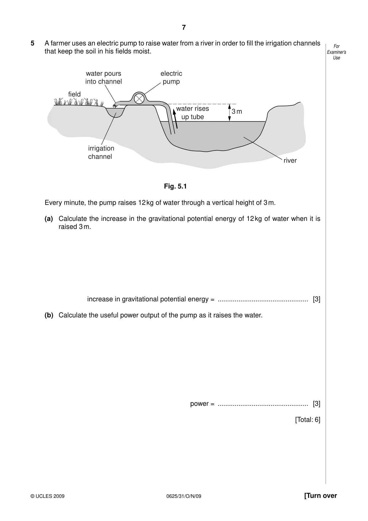
5 A farmer uses an electric pump to raise water from a river in order to fill the irrigation channels For that keep the soil in his fields moist. Examiner’s Use water pours electric into channel pump field water rises 3 m up tube irrigation channel river Fig. 5.1 Every minute, the pump raises 12 kg of water through a vertical height of 3 m. (a) Calculate the increase in the gravitational potential energy of 12 kg of water when it is raised 3 m. increase in gravitational potential energy = ................................................ [3] (b) Calculate the useful power output of the pump as it raises the water. power = ................................................ [3] [Total: 6]
Mark scheme: 5 (a) (P.E.) = mgh C1 12 × 10 × 3 Accept g = 9.8 or 9.81 C1 360 J g = 9.8 gives 352.8 J (minimum 2 s.f.) A1 g = 9.81 gives 353.16 J (minimum 2 s.f.) (b) (P =) E/t C1 360/60 C1 6 W 352.8 J gives 5.88 W 353.16 J gives 5.886 W (minimum 2 s.f.) A1 [6]
Q6 · A vertical cylinder has a smooth well-fitting piston in it
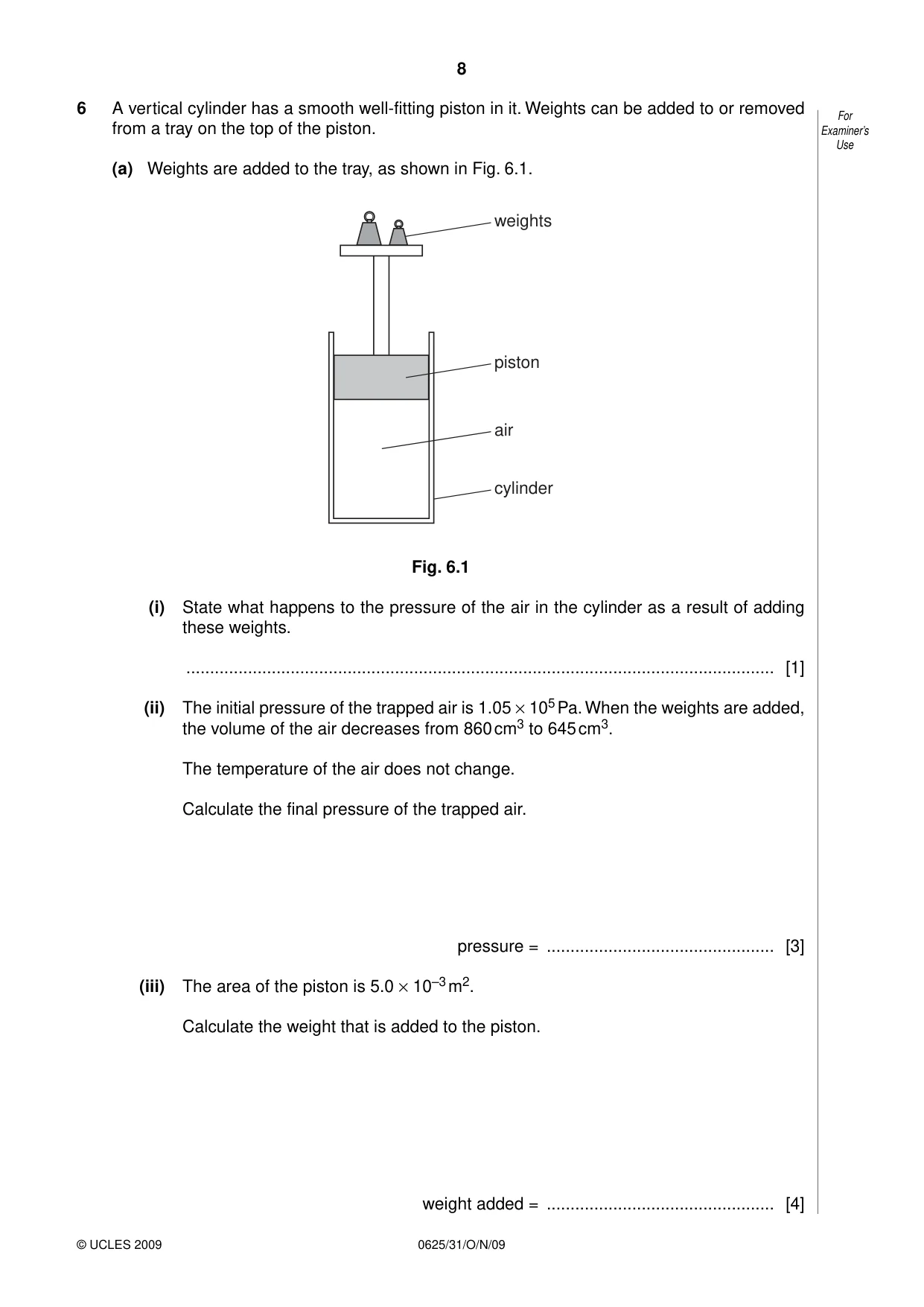
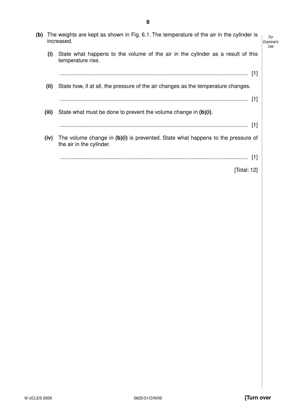
6 A vertical cylinder has a smooth well-fitting piston in it. Weights can be added to or removed For from a tray on the top of the piston. Examiner’s Use (a) Weights are added to the tray, as shown in Fig. 6.1. weights piston air cylinder Fig. 6.1 (i) State what happens to the pressure of the air in the cylinder as a result of adding these weights. ............................................................................................................................ [1] (ii) The initial pressure of the trapped air is 1.05 × 10⁵ Pa. When the weights are added, the volume of the air decreases from 860 cm3 to 645 cm3. The temperature of the air does not change. Calculate the final pressure of the trapped air. pressure = ................................................ [3] (iii) The area of the piston is 5.0 × 10⁻³ m2. Calculate the weight that is added to the piston. weight added = ................................................ [4] (b) The weights are kept as shown in Fig. 6.1. The temperature of the air in the cylinder is For increased. Examiner’s Use (i) State what happens to the volume of the air in the cylinder as a result of this temperature rise. ............................................................................................................................ [1] (ii) State how, if at all, the pressure of the air changes as the temperature changes. ............................................................................................................................ [1] (iii) State what must be done to prevent the volume change in (b)(i). ............................................................................................................................ [1] (iv) The volume change in (b)(i) is prevented. State what happens to the pressure of the air in the cylinder. ............................................................................................................................ [1] [Total: 12]
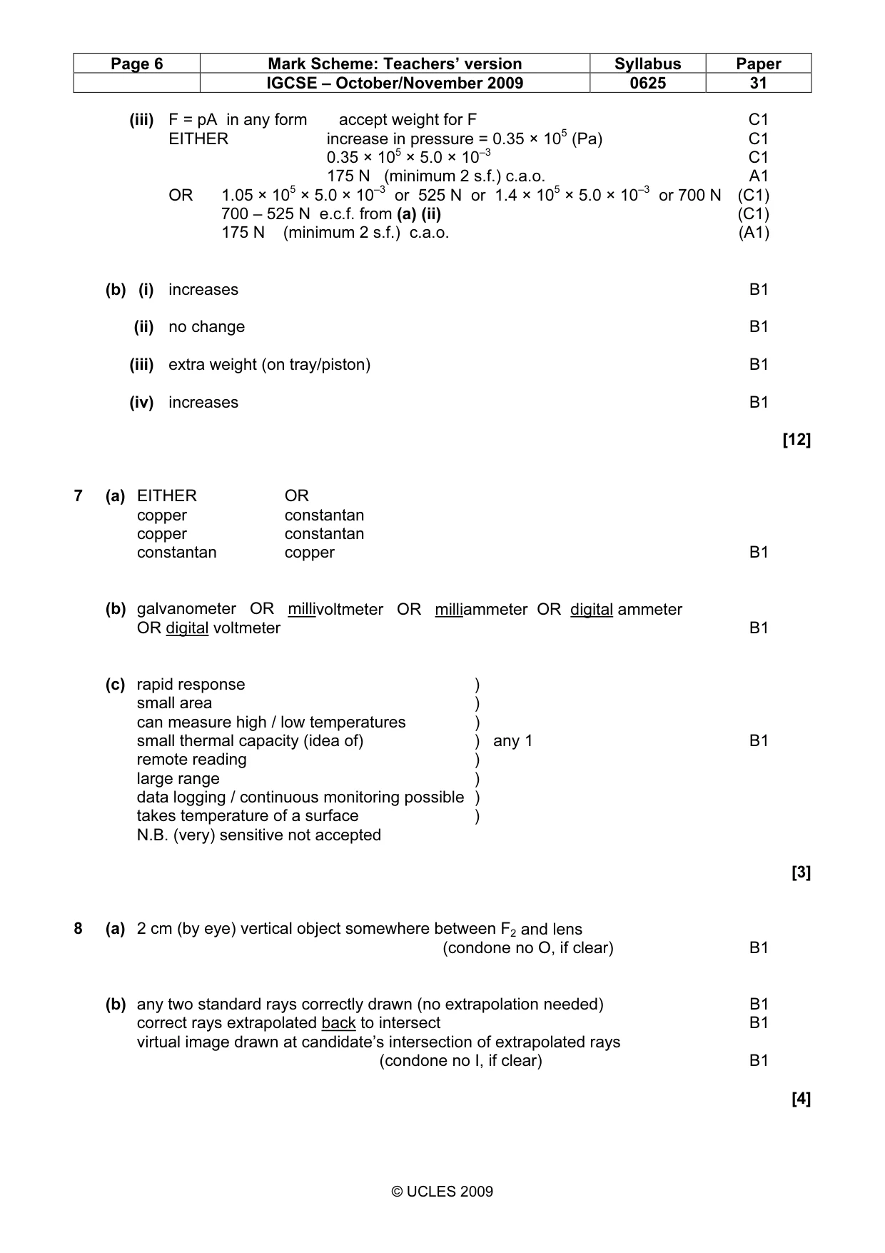
Mark scheme: 6 (a) (i) increases B1 (ii) pV = const in any form C1 1.05 (× 105) × 860 (× 10–6) = p × 645 (× 10–6) C1 1.4 × 10⁵ Pa A1 IGCSE – October/November 2009 0625 31 (iii) F = pA in any form accept weight for F C1 EITHER increase in pressure = 0.35 × 10⁵ (Pa) C1 0.35 × 105 × 5.0 × 10–3 C1 175 N (minimum 2 s.f.) c.a.o. A1 OR 1.05 × 105 × 5.0 × 10–3 or 525 N or 1.4 × 105 × 5.0 × 10–3 or 700 N (C1) 700 – 525 N e.c.f. from (a) (ii) (C1) 175 N (minimum 2 s.f.) c.a.o. (A1) (b) (i) increases B1 (ii) no change B1 (iii) extra weight (on tray/piston) B1 (iv) increases B1 [12]
Q7 · Three wires and a meter are used to construct a thermocouple for measuring the surface…
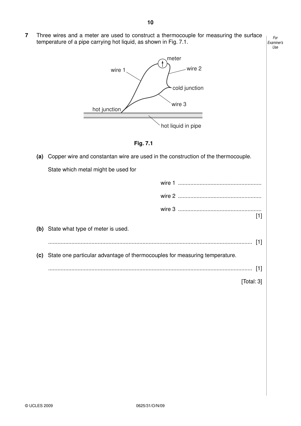
7 Three wires and a meter are used to construct a thermocouple for measuring the surface For temperature of a pipe carrying hot liquid, as shown in Fig. 7.1. Examiner’s Use meter wire 1 wire 2 cold junction wire 3 hot junction hot liquid in pipe Fig. 7.1 (a) Copper wire and constantan wire are used in the construction of the thermocouple. State which metal might be used for wire 1 ...................................................... wire 2 ...................................................... wire 3 ...................................................... [1] (b) State what type of meter is used. .................................................................................................................................... [1] (c) State one particular advantage of thermocouples for measuring temperature. .................................................................................................................................... [1] [Total: 3]
Mark scheme: 7 (a) EITHER OR copper constantan copper constantan constantan copper B1 (b) galvanometer OR millivoltmeter OR milliammeter OR digital ammeter OR digital voltmeter B1 (c) rapid response ) small area ) can measure high / low temperatures ) small thermal capacity (idea of) ) any 1 B1 remote reading ) large range ) data logging / continuous monitoring possible ) takes temperature of a surface ) N.B. (very) sensitive not accepted [3]
Q8 · A thin converging lens
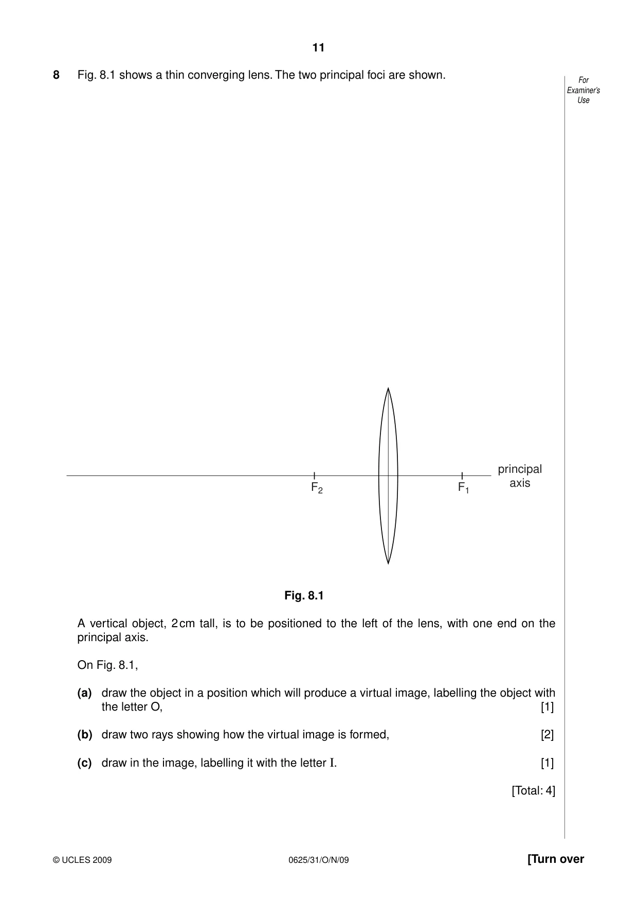
8 Fig. 8.1 shows a thin converging lens. The two principal foci are shown. For Examiner’s Use principal axis F2 F1 Fig. 8.1 A vertical object, 2 cm tall, is to be positioned to the left of the lens, with one end on the principal axis. On Fig. 8.1, (a) draw the object in a position which will produce a virtual image, labelling the object with the letter O, [1] (b) draw two rays showing how the virtual image is formed, [2] (c) draw in the image, labelling it with the letter I. [1] [Total: 4]
Mark scheme: 8 (a) 2 cm (by eye) vertical object somewhere between F2 and lens (condone no O, if clear) B1 (b) any two standard rays correctly drawn (no extrapolation needed) B1 correct rays extrapolated back to intersect B1 virtual image drawn at candidate’s intersection of extrapolated rays (condone no I, if clear) B1 [4] IGCSE – October/November 2009 0625 31
Q9 · State what is meant by specific heat capacity
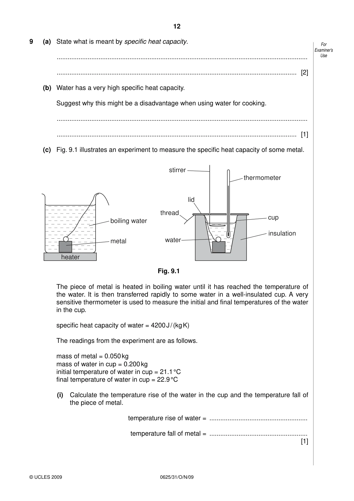
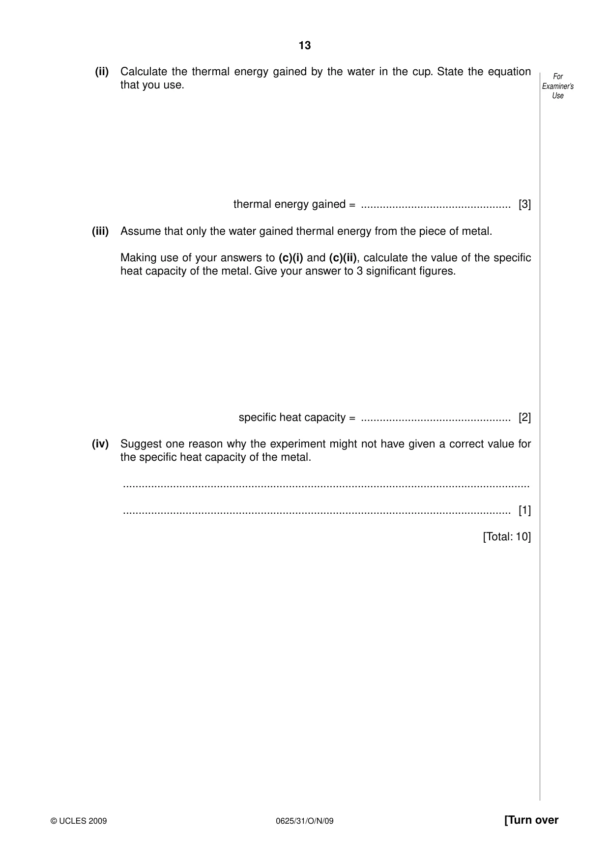
9 (a) State what is meant by specific heat capacity. For Examiner’s .......................................................................................................................................... Use .................................................................................................................................... [2] (b) Water has a very high specific heat capacity. Suggest why this might be a disadvantage when using water for cooking. .......................................................................................................................................... .................................................................................................................................... [1] (c) Fig. 9.1 illustrates an experiment to measure the specific heat capacity of some metal. stirrer thermometer lid thread cup boiling water insulation metal water heater Fig. 9.1 The piece of metal is heated in boiling water until it has reached the temperature of the water. It is then transferred rapidly to some water in a well-insulated cup. A very sensitive thermometer is used to measure the initial and final temperatures of the water in the cup. specific heat capacity of water = 4200 J / (kg K) The readings from the experiment are as follows. mass of metal = 0.050 kg mass of water in cup = 0.200 kg initial temperature of water in cup = 21.1 °C final temperature of water in cup = 22.9 °C (i) Calculate the temperature rise of the water in the cup and the temperature fall of the piece of metal. temperature rise of water = ...................................................... temperature fall of metal = ...................................................... [1] (ii) Calculate the thermal energy gained by the water in the cup. State the equation For that you use. Examiner’s Use thermal energy gained = ................................................ [3] (iii) Assume that only the water gained thermal energy from the piece of metal. Making use of your answers to (c)(i) and (c)(ii), calculate the value of the specific heat capacity of the metal. Give your answer to 3 significant figures. specific heat capacity = ................................................ [2] (iv) Suggest one reason why the experiment might not have given a correct value for the specific heat capacity of the metal. .................................................................................................................................. ............................................................................................................................ [1] [Total: 10]
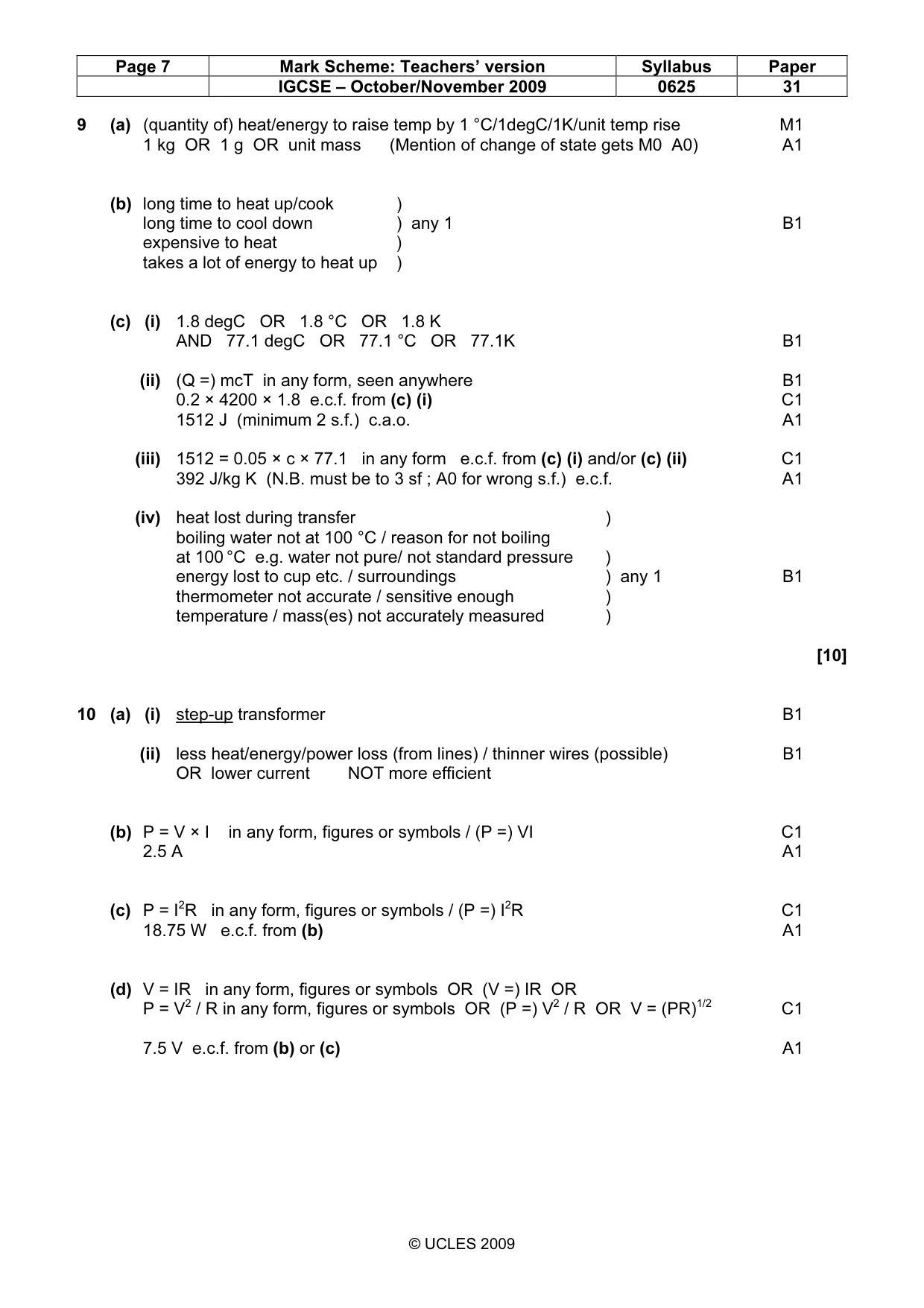
Mark scheme: 9 (a) (quantity of) heat/energy to raise temp by 1 °C/1degC/1K/unit temp rise M1 1 kg OR 1 g OR unit mass (Mention of change of state gets M0 A0) A1 (b) long time to heat up/cook ) long time to cool down ) any 1 B1 expensive to heat ) takes a lot of energy to heat up ) (c) (i) 1.8 degC OR 1.8 °C OR 1.8 K AND 77.1 degC OR 77.1 °C OR 77.1K B1 (ii) (Q =) mcT in any form, seen anywhere B1 0.2 × 4200 × 1.8 e.c.f. from (c) (i) C1 1512 J (minimum 2 s.f.) c.a.o. A1 (iii) 1512 = 0.05 × c × 77.1 in any form e.c.f. from (c) (i) and/or (c) (ii) C1 392 J/kg K (N.B. must be to 3 sf ; A0 for wrong s.f.) e.c.f. A1 (iv) heat lost during transfer ) boiling water not at 100 °C / reason for not boiling at 100 °C e.g. water not pure/ not standard pressure ) energy lost to cup etc. / surroundings ) any 1 B1 thermometer not accurate / sensitive enough ) temperature / mass(es) not accurately measured ) [10]
Q10 · Alternating current electricity is delivered at 22 000 V to a pair of transmission lines
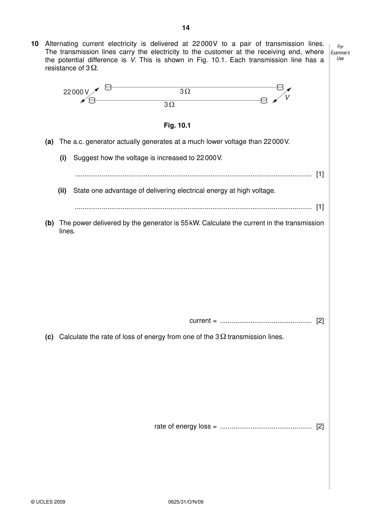
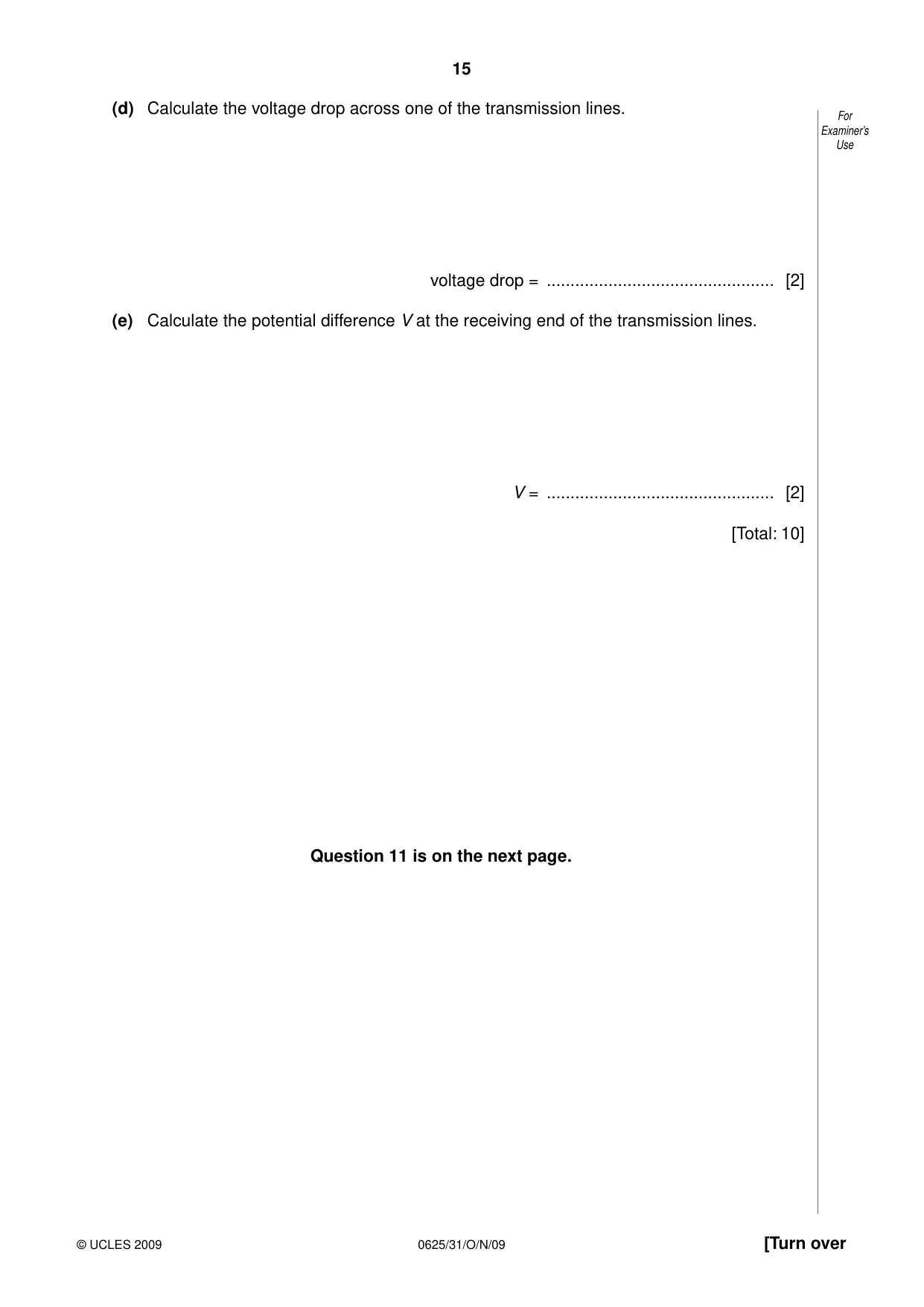
10 Alternating current electricity is delivered at 22 000 V to a pair of transmission lines. For The transmission lines carry the electricity to the customer at the receiving end, where Examiner’s the potential difference is V. This is shown in Fig. 10.1. Each transmission line has a Use resistance of 3 Ω. 22 000 V 3 Ω V 3 Ω Fig. 10.1 (a) The a.c. generator actually generates at a much lower voltage than 22 000 V. (i) Suggest how the voltage is increased to 22 000 V. ............................................................................................................................ [1] (ii) State one advantage of delivering electrical energy at high voltage. ............................................................................................................................ [1] (b) The power delivered by the generator is 55 kW. Calculate the current in the transmission lines. current = ................................................ [2] (c) Calculate the rate of loss of energy from one of the 3 Ω transmission lines. rate of energy loss = ................................................ [2] (d) Calculate the voltage drop across one of the transmission lines. For Examiner’s Use voltage drop = ................................................ [2] (e) Calculate the potential difference V at the receiving end of the transmission lines. V = ................................................ [2] [Total: 10] Question 11 is on the next page.
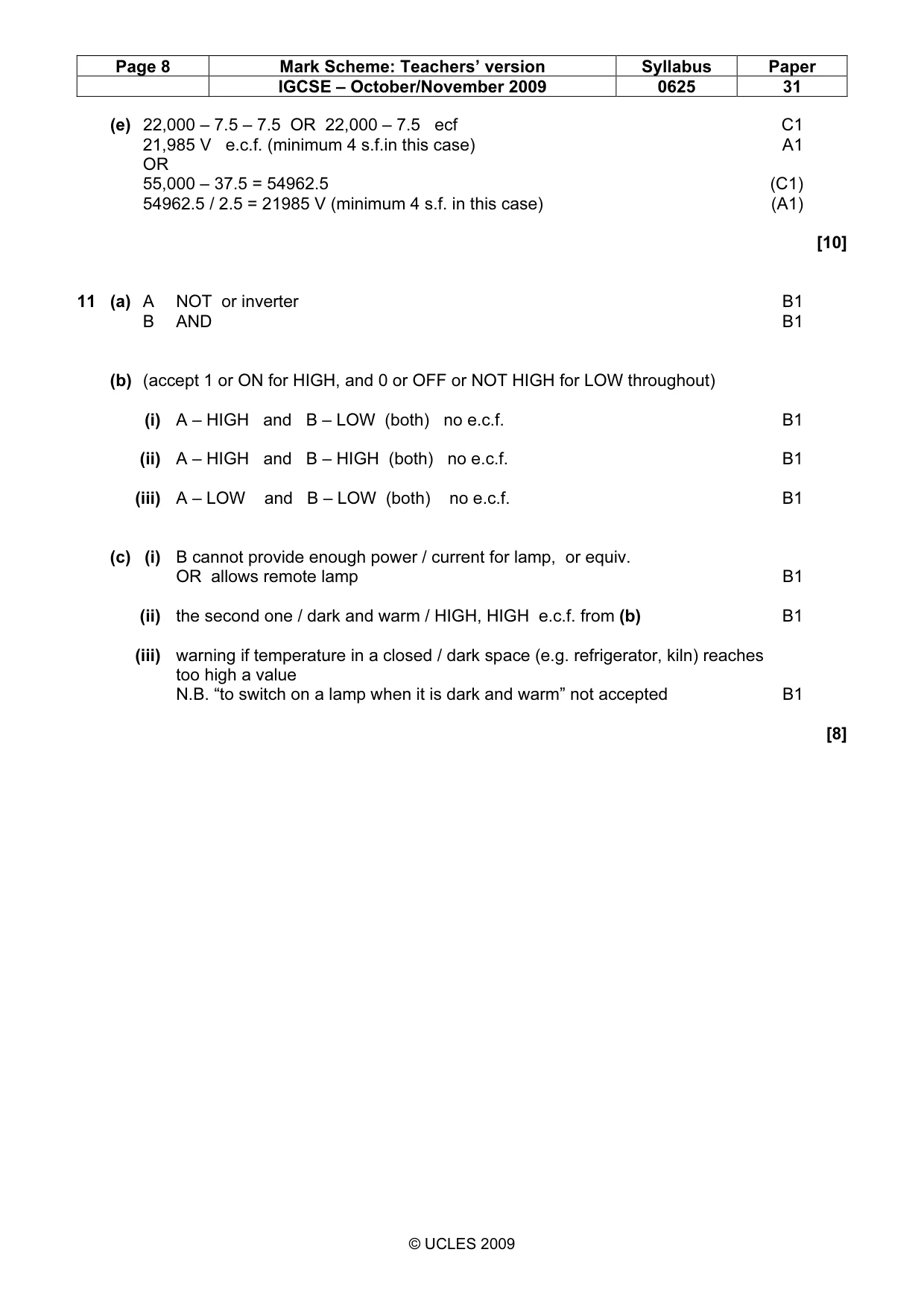
Mark scheme: 10 (a) (i) step-up transformer B1 (ii) less heat/energy/power loss (from lines) / thinner wires (possible) B1 OR lower current NOT more efficient (b) P = V × I in any form, figures or symbols / (P =) VI C1 2.5 A A1 (c) P = I2R in any form, figures or symbols / (P =) I2R C1 18.75 W e.c.f. from (b) A1 (d) V = IR in any form, figures or symbols OR (V =) IR OR P = V2 / R in any form, figures or symbols OR (P =) V2 / R OR V = (PR)1/2 C1 7.5 V e.c.f. from (b) or (c) A1 IGCSE – October/November 2009 0625 31 (e) 22,000 – 7.5 – 7.5 OR 22,000 – 7.5 ecf C1 21,985 V e.c.f. (minimum 4 s.f.in this case) A1 OR 55,000 – 37.5 = 54962.5 (C1) 54962.5 / 2.5 = 21985 V (minimum 4 s.f. in this case) (A1) [10]
Q11 · A schematic diagram of an electronic circuit controlling a lamp
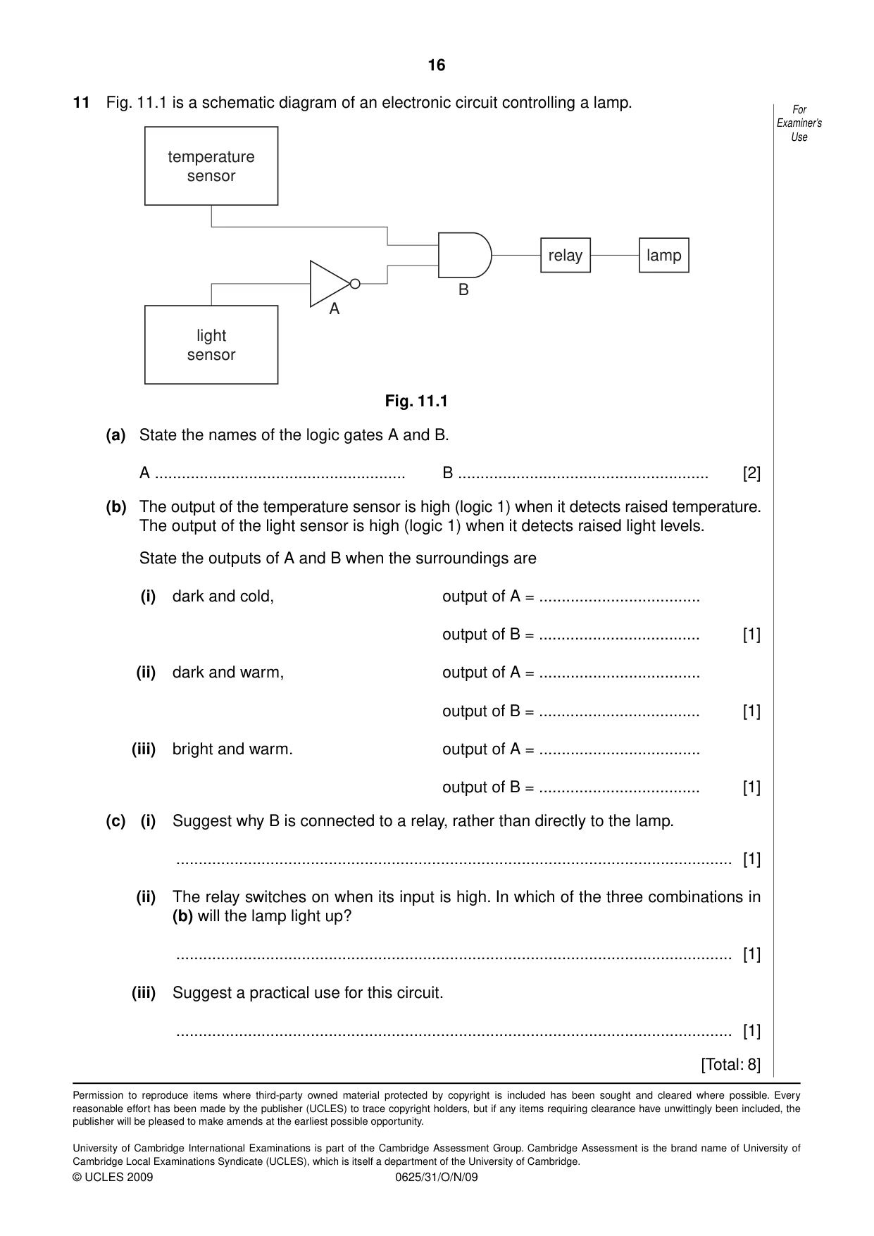
11 Fig. 11.1 is a schematic diagram of an electronic circuit controlling a lamp. For Examiner’s Use temperature sensor relay lamp B A light sensor Fig. 11.1 (a) State the names of the logic gates A and B. A ........................................................ B ........................................................ [2] (b) The output of the temperature sensor is high (logic 1) when it detects raised temperature. The output of the light sensor is high (logic 1) when it detects raised light levels. State the outputs of A and B when the surroundings are (i) dark and cold, output of A = .................................... output of B = .................................... [1] (ii) dark and warm, output of A = .................................... output of B = .................................... [1] (iii) bright and warm. output of A = .................................... output of B = .................................... [1] (c) (i) Suggest why B is connected to a relay, rather than directly to the lamp. ............................................................................................................................ [1] (ii) The relay switches on when its input is high. In which of the three combinations in (b) will the lamp light up? ............................................................................................................................ [1] (iii) Suggest a practical use for this circuit. ............................................................................................................................ [1] [Total: 8]
Mark scheme: 11 (a) A NOT or inverter B1 B AND B1 (b) (accept 1 or ON for HIGH, and 0 or OFF or NOT HIGH for LOW throughout) (i) A – HIGH and B – LOW (both) no e.c.f. B1 (ii) A – HIGH and B – HIGH (both) no e.c.f. B1 (iii) A – LOW and B – LOW (both) no e.c.f. B1 (c) (i) B cannot provide enough power / current for lamp, or equiv. OR allows remote lamp B1 (ii) the second one / dark and warm / HIGH, HIGH e.c.f. from (b) B1 (iii) warning if temperature in a closed / dark space (e.g. refrigerator, kiln) reaches too high a value N.B. “to switch on a lamp when it is dark and warm” not accepted B1 [8]
What was in this paper
The subtopics covered by these 11 questions, and how many questions each got. Open one in a new tab to see every Cambridge question on it.
What you needed in this session
Cambridge’s own grade thresholds for 2009 Oct/Nov, Paper 3 · Variant 1. A higher threshold means an easier paper — the bar moves with how the cohort did.