Cambridge IGCSE Physics 0625 — 2016 Oct/Nov Paper 3 · Variant 3
0625/33/O/N/16 · 12 questions · 80 marks · ≈90 min
The question paper and its mark scheme, free to read here and free to download. This is Cambridge’s own paper, exactly as it was sat.
Question paper20 pages

Mark scheme10 pages
Answers below. Sit the paper first if you are practising.
Questions as text
Q1 · A speed-time graph for part of a train’s journey
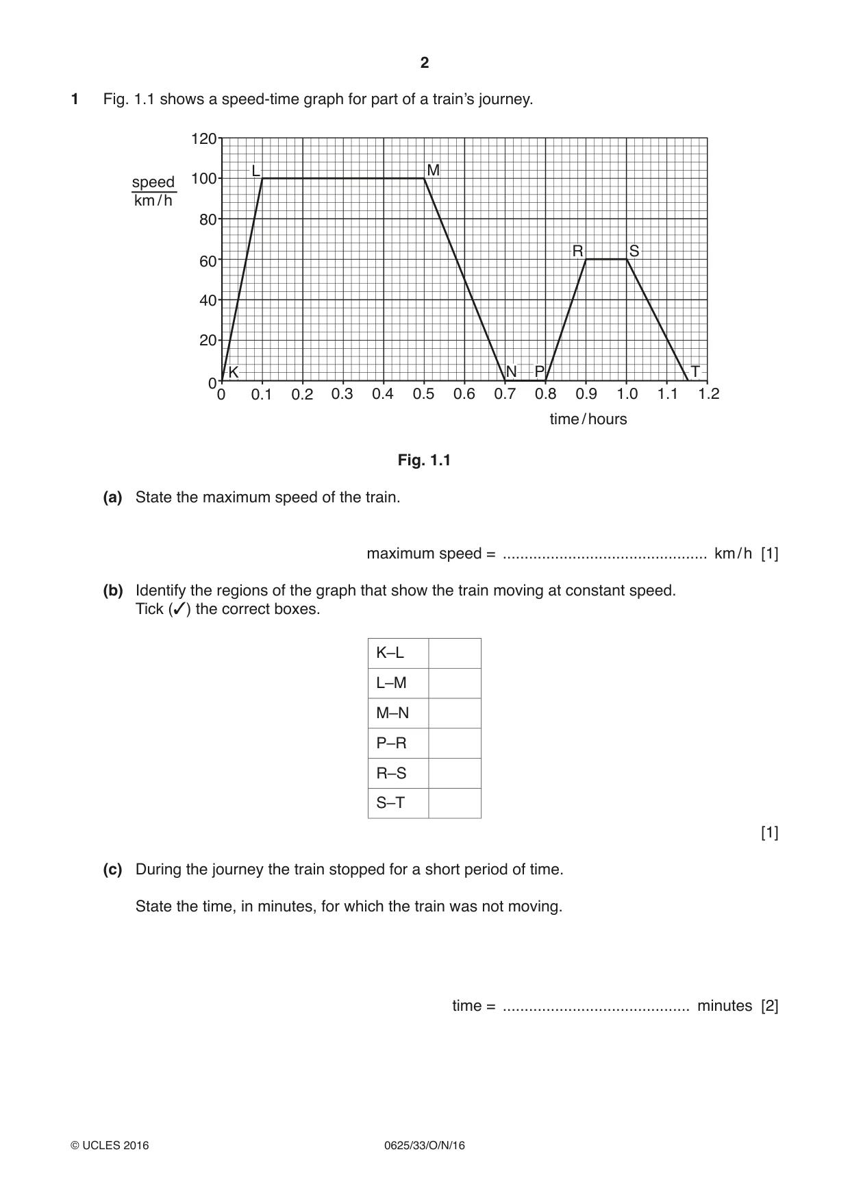
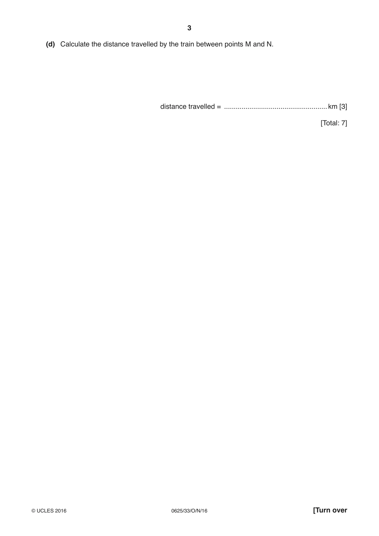
1 Fig. 1.1 shows a speed-time graph for part of a train’s journey. 120 L M speed 100 km / h 80 R S 60 40 20 K N P T 00 0.1 0.2 0.3 0.4 0.5 0.6 0.7 0.8 0.9 1.0 1.1 1.2 time / hours Fig. 1.1 (a) State the maximum speed of the train. maximum speed = ............................................... km / h [1] (b) Identify the regions of the graph that show the train moving at constant speed. Tick (✓) the correct boxes. K–L L–M M–N P–R R–S S–T [1] (c) During the journey the train stopped for a short period of time. State the time, in minutes, for which the train was not moving. time = ........................................... minutes [2] (d) Calculate the distance travelled by the train between points M and N. distance travelled = ..................................................... km [3] [Total: 7]
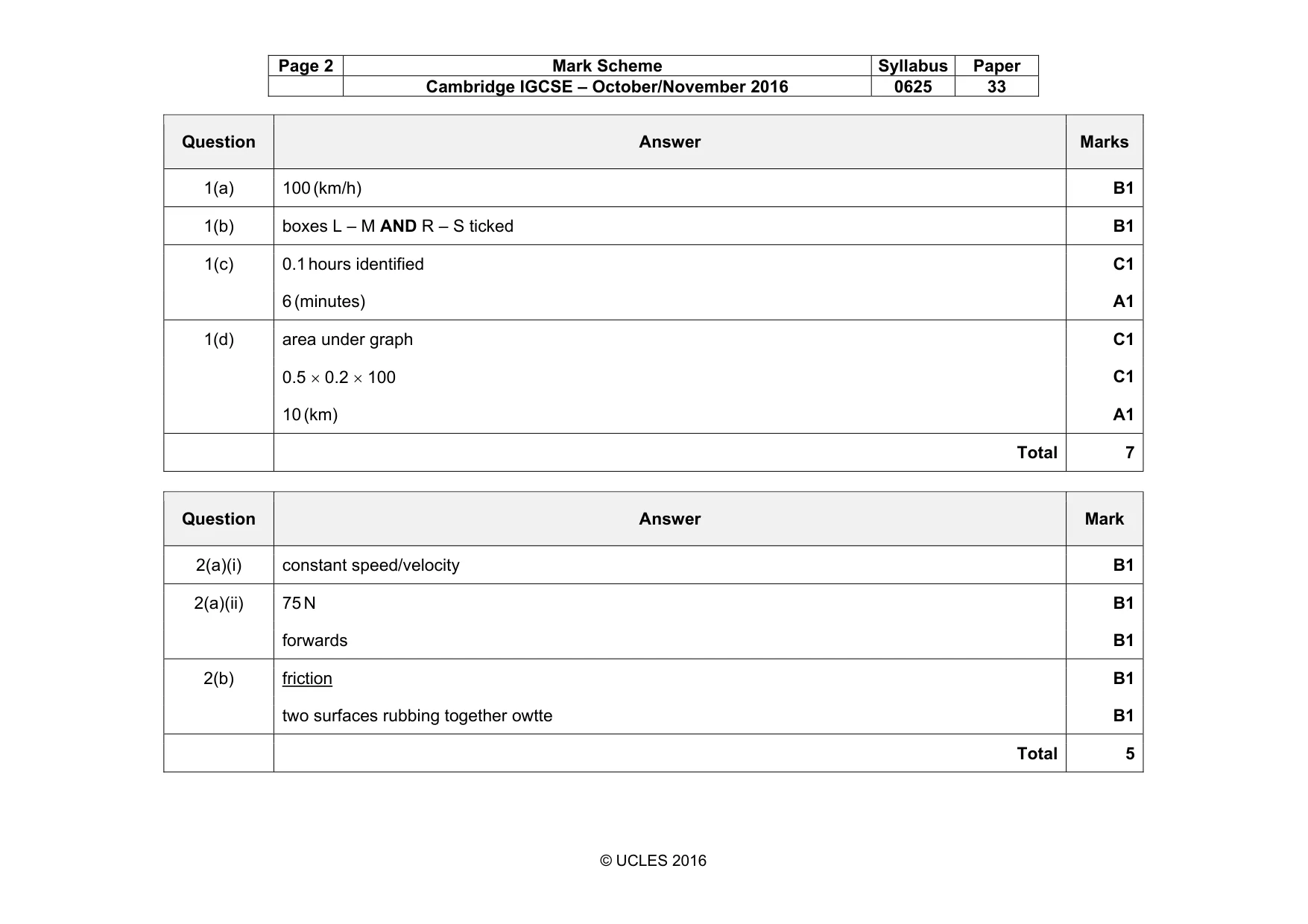
Mark scheme: 1(a) 100 (km/h) B1 1(b) boxes L – M AND R – S ticked B1 1(c) 0.1 hours identified C1 6 (minutes) A1 1(d) area under graph C1 0.5 × 0.2 × 100 C1 10 (km) A1 Total 7
Q2 · A cyclist travelling along a level road
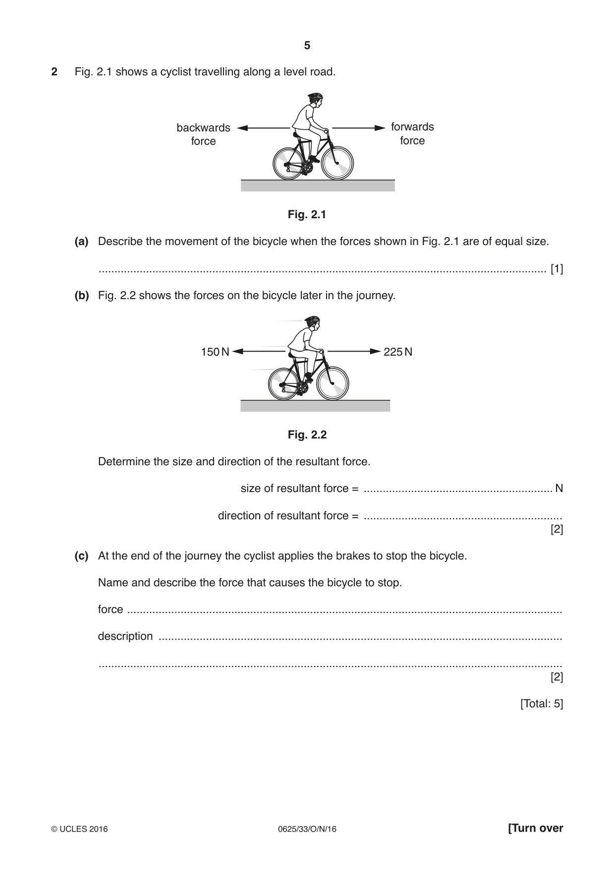
2 Fig. 2.1 shows a cyclist travelling along a level road. backwards forwards force force Fig. 2.1 (a) Describe the movement of the bicycle when the forces shown in Fig. 2.1 are of equal size. .............................................................................................................................................. [1] (b) Fig. 2.2 shows the forces on the bicycle later in the journey. 150 N 225 N Fig. 2.2 Determine the size and direction of the resultant force. size of resultant force = ............................................................ N direction of resultant force = ............................................................... [2] (c) At the end of the journey the cyclist applies the brakes to stop the bicycle. Name and describe the force that causes the bicycle to stop. force .......................................................................................................................................... description ................................................................................................................................ ................................................................................................................................................... [2] [Total: 5]
Mark scheme: 2(a)(i) constant speed/velocity B1 2(a)(ii) 75 N B1 forwards B1 2(b) friction B1 two surfaces rubbing together owtte B1 Total 5
Q3 · A load is hung from a spring, as shown in Fig
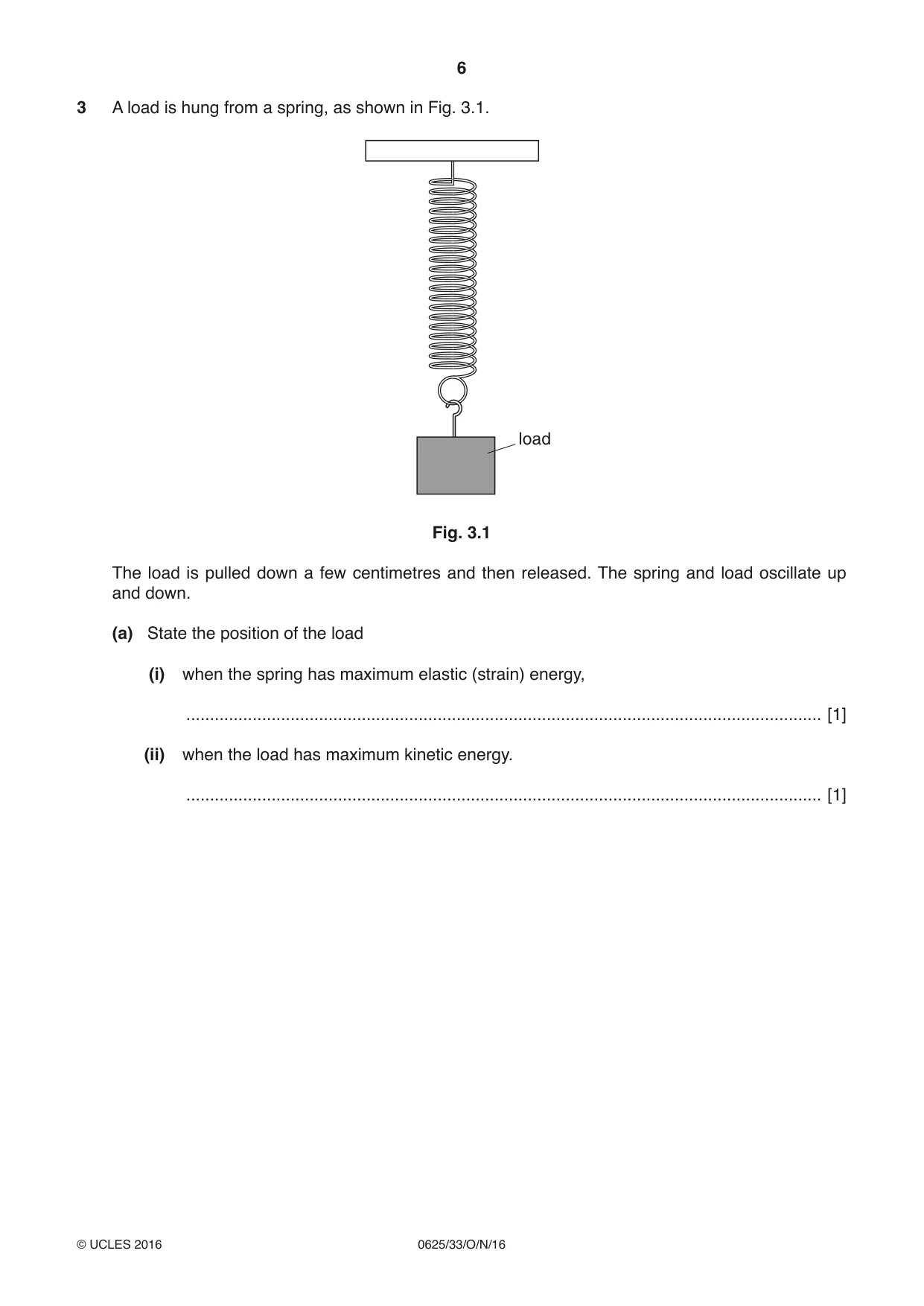
3 A load is hung from a spring, as shown in Fig. 3.1. load Fig. 3.1 The load is pulled down a few centimetres and then released. The spring and load oscillate up and down. (a) State the position of the load (i) when the spring has maximum elastic (strain) energy, ...................................................................................................................................... [1] (ii) when the load has maximum kinetic energy. ...................................................................................................................................... [1] (b) The spring oscillates up and down for a short time. (i) State the principle of conservation of energy. ........................................................................................................................................... ...................................................................................................................................... [1] (ii) Describe the energy changes as the spring and load oscillate and suggest why the load and spring eventually stop moving. ........................................................................................................................................... ........................................................................................................................................... ........................................................................................................................................... ........................................................................................................................................... ........................................................................................................................................... ........................................................................................................................................... ........................................................................................................................................... ........................................................................................................................................... ........................................................................................................................................... ........................................................................................................................................... ...................................................................................................................................... [3] [Total: 6]
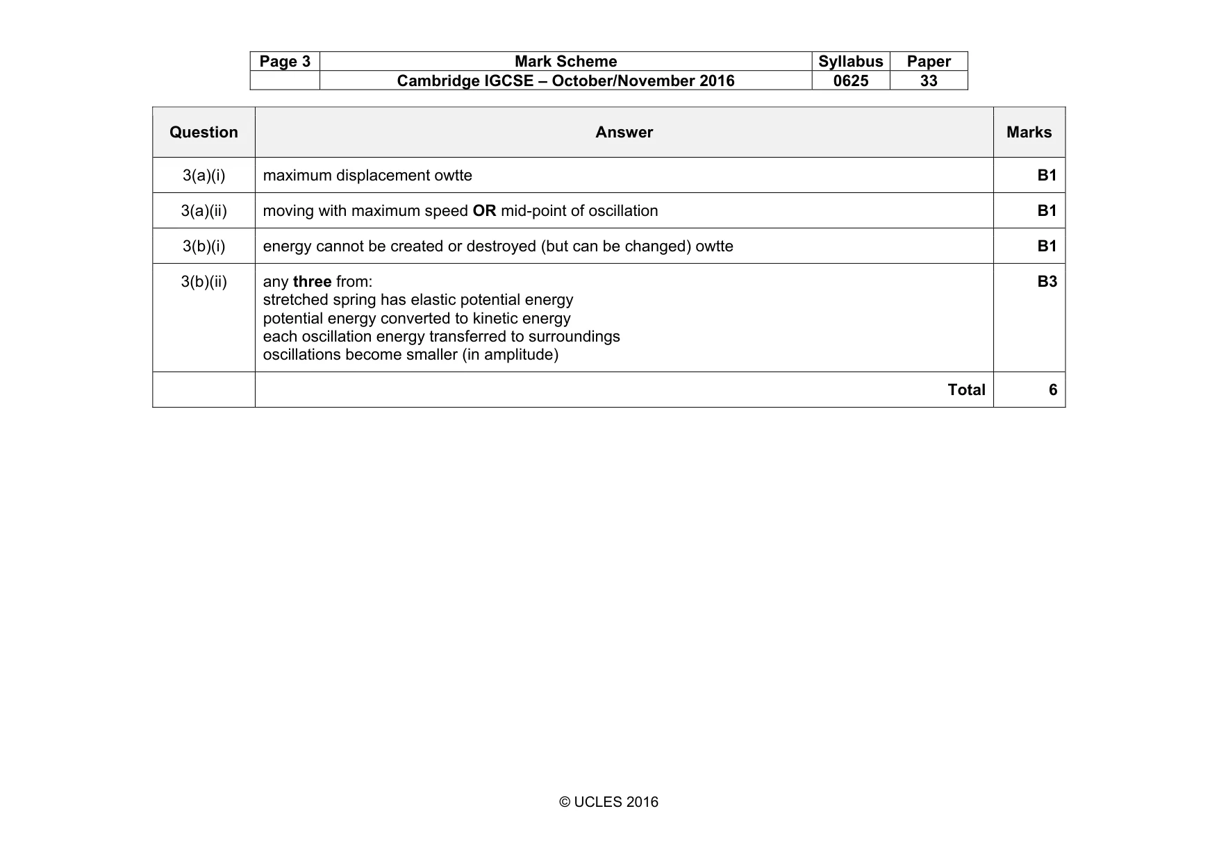
Mark scheme: 3(a)(i) maximum displacement owtte B1 3(a)(ii) moving with maximum speed OR mid-point of oscillation B1 3(b)(i) energy cannot be created or destroyed (but can be changed) owtte B1 3(b)(ii) any three from: stretched spring has elastic potential energy potential energy converted to kinetic energy each oscillation energy transferred to surroundings oscillations become smaller (in amplitude) B3 Total 6
Q4 · A car parked on a road
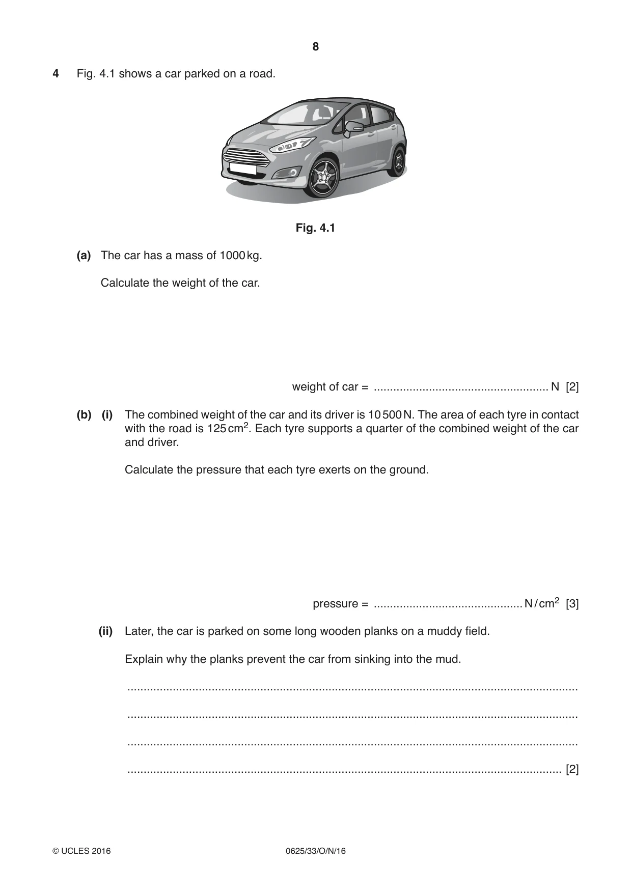
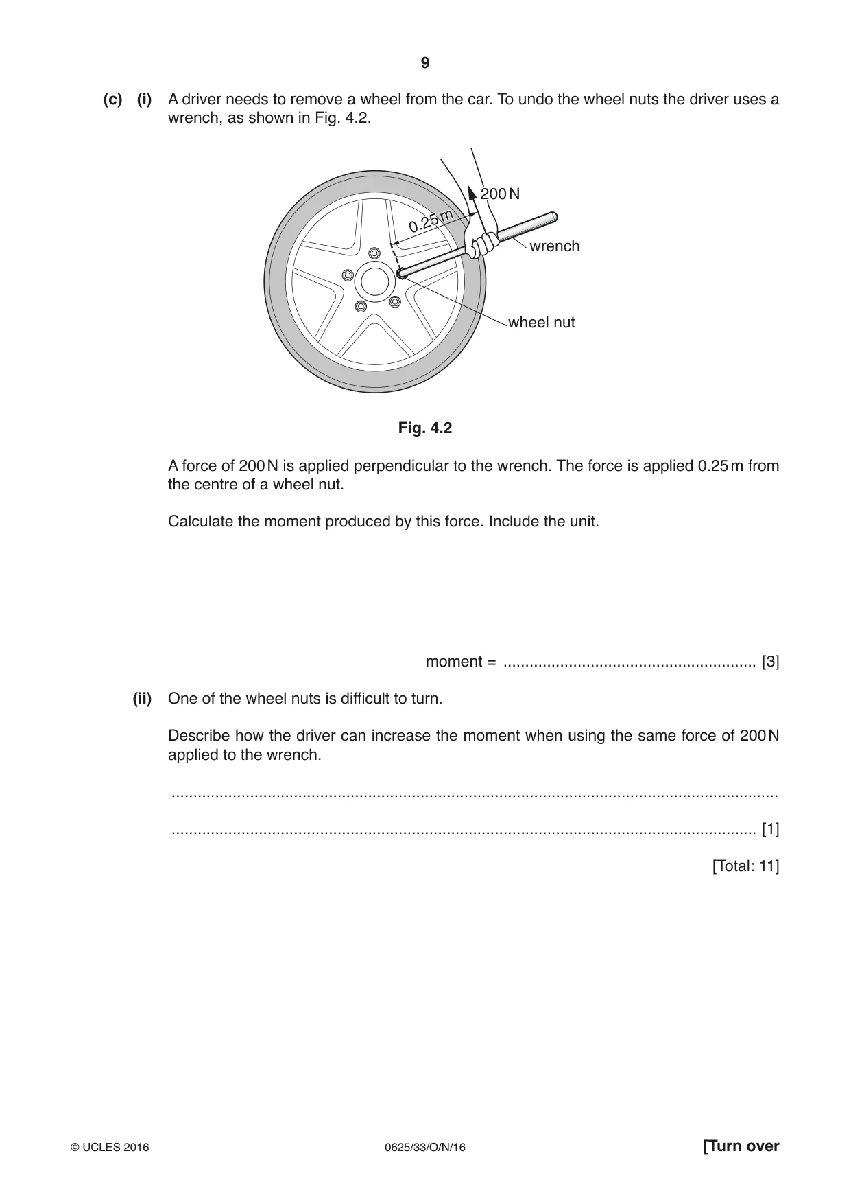
4 Fig. 4.1 shows a car parked on a road. Fig. 4.1 (a) The car has a mass of 1000 kg. Calculate the weight of the car. weight of car = ...................................................... N [2] (b) (i) The combined weight of the car and its driver is 10 500 N. The area of each tyre in contact with the road is 125 cm2. Each tyre supports a quarter of the combined weight of the car and driver. Calculate the pressure that each tyre exerts on the ground. pressure = .............................................. N / cm2 [3] (ii) Later, the car is parked on some long wooden planks on a muddy field. Explain why the planks prevent the car from sinking into the mud. ........................................................................................................................................... ........................................................................................................................................... ........................................................................................................................................... ...................................................................................................................................... [2] (c) (i) A driver needs to remove a wheel from the car. To undo the wheel nuts the driver uses a wrench, as shown in Fig. 4.2. 200200200 NNN mm 0.250.25 wrench wheel nut Fig. 4.2 A force of 200 N is applied perpendicular to the wrench. The force is applied 0.25 m from the centre of a wheel nut. Calculate the moment produced by this force. Include the unit. moment = .......................................................... [3] (ii) One of the wheel nuts is difficult to turn. Describe how the driver can increase the moment when using the same force of 200 N applied to the wrench. ........................................................................................................................................... ...................................................................................................................................... [1] [Total: 11]
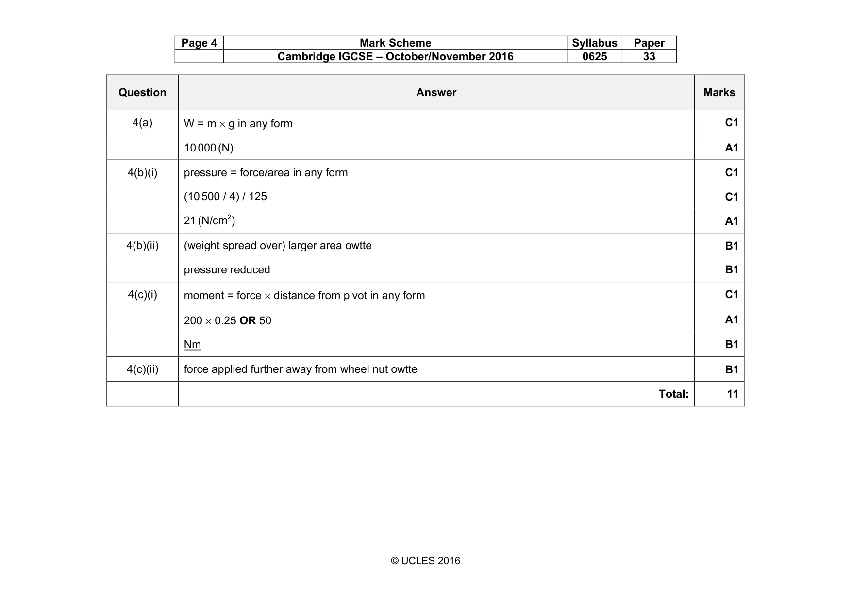
Mark scheme: 4(a) C1 10 000 (N) A1 4(b)(i) pressure = force/area in any form C1 (10 500 / 4) / 125 C1 21 (N/cm2) A1 4(b)(ii) (weight spread over) larger area owtte B1 pressure reduced B1 4(c)(i) moment = force × distance from pivot in any form C1 200 × 0.25 OR 50 A1 Nm B1 4(c)(ii) force applied further away from wheel nut owtte B1 Total: 11
Q5 · A fisherman notices that the water in a lake is warm and that there is a cool breeze from…
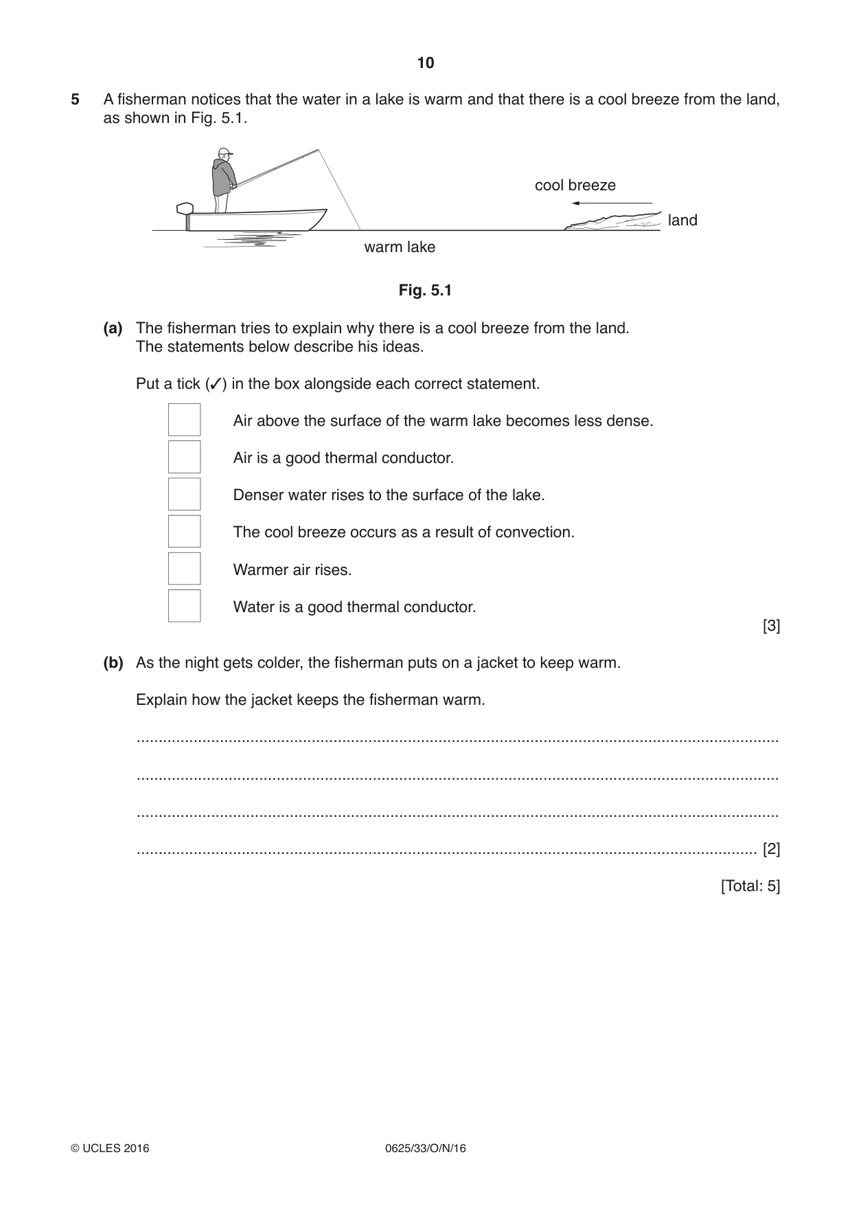
5 A fisherman notices that the water in a lake is warm and that there is a cool breeze from the land, as shown in Fig. 5.1. cool breeze land warm lake Fig. 5.1 (a) The fisherman tries to explain why there is a cool breeze from the land. The statements below describe his ideas. Put a tick (✓) in the box alongside each correct statement. Air above the surface of the warm lake becomes less dense. Air is a good thermal conductor. Denser water rises to the surface of the lake. The cool breeze occurs as a result of convection. Warmer air rises. Water is a good thermal conductor. [3] (b) As the night gets colder, the fisherman puts on a jacket to keep warm. Explain how the jacket keeps the fisherman warm. ................................................................................................................................................... ................................................................................................................................................... ................................................................................................................................................... .............................................................................................................................................. [2] [Total: 5]
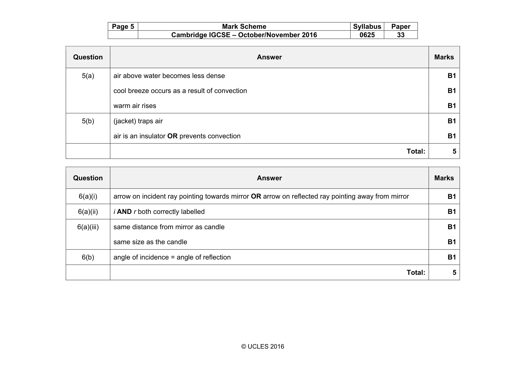
Mark scheme: 5(a) air above water becomes less dense B1 cool breeze occurs as a result of convection B1 warm air rises B1 5(b) (jacket) traps air B1 air is an insulator OR prevents convection B1 Total: 5
Q6 · A candle is placed in front of a vertical mirror
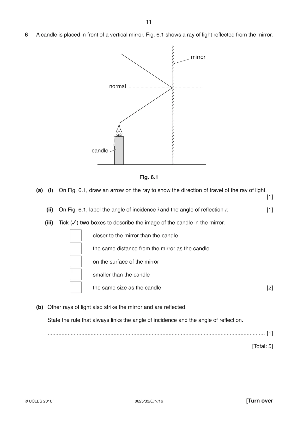
6 A candle is placed in front of a vertical mirror. Fig. 6.1 shows a ray of light reflected from the mirror. mirror normal candle Fig. 6.1 (a) (i) On Fig. 6.1, draw an arrow on the ray to show the direction of travel of the ray of light. [1] (ii) On Fig. 6.1, label the angle of incidence i and the angle of reflection r. [1] (iii) Tick (✓) two boxes to describe the image of the candle in the mirror. closer to the mirror than the candle the same distance from the mirror as the candle on the surface of the mirror smaller than the candle the same size as the candle [2] (b) Other rays of light also strike the mirror and are reflected. State the rule that always links the angle of incidence and the angle of reflection. .............................................................................................................................................. [1] [Total: 5]
Mark scheme: 6(a)(i) arrow on incident ray pointing towards mirror OR arrow on reflected ray pointing away from mirror B1 6(a)(ii) i AND r both correctly labelled B1 6(a)(iii) same distance from mirror as candle B1 same size as the candle B1 6(b) angle of incidence = angle of reflection B1 Total: 5
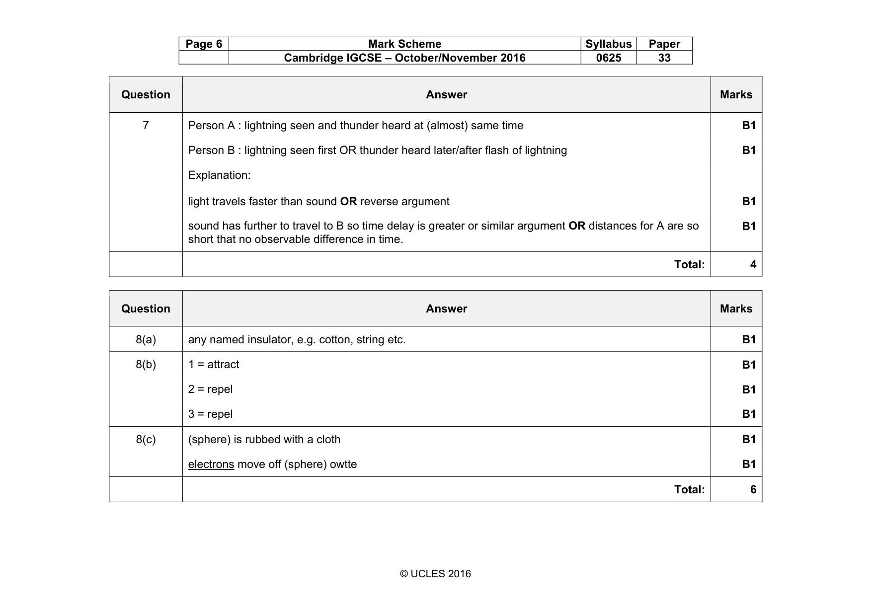
Q7 · Two people watch a storm cloud above a tree
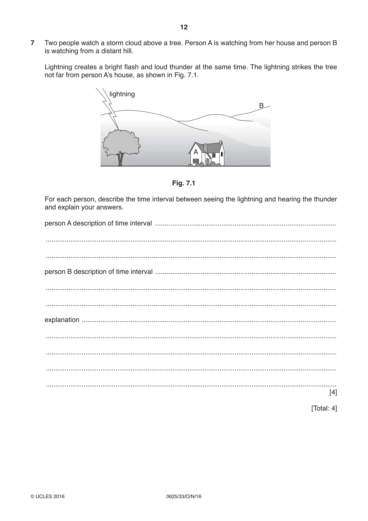
7 Two people watch a storm cloud above a tree. Person A is watching from her house and person B is watching from a distant hill. Lightning creates a bright flash and loud thunder at the same time. The lightning strikes the tree not far from person A’s house, as shown in Fig. 7.1. lightning B A Fig. 7.1 For each person, describe the time interval between seeing the lightning and hearing the thunder and explain your answers. person A description of time interval ................................................................................................ .......................................................................................................................................................... .......................................................................................................................................................... person B description of time interval ................................................................................................ .......................................................................................................................................................... .......................................................................................................................................................... explanation ....................................................................................................................................... .......................................................................................................................................................... .......................................................................................................................................................... .......................................................................................................................................................... .......................................................................................................................................................... [4] [Total: 4]
Mark scheme: 7 Person A : lightning seen and thunder heard at (almost) same time B1 Person B : lightning seen first OR thunder heard later/after flash of lightning B1 Explanation: light travels faster than sound OR reverse argument B1 sound has further to travel to B so time delay is greater or similar argument OR distances for A are so short that no observable difference in time. B1 Total: 4
Q8 · Two uncharged (neutral) plastic spheres
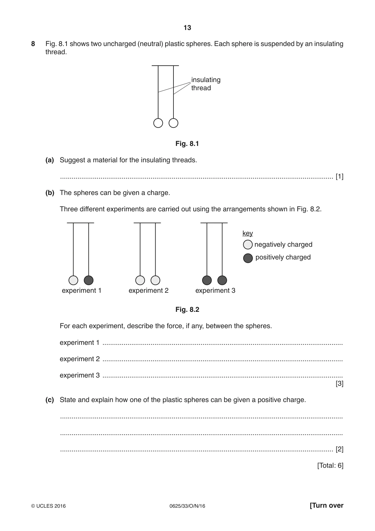
8 Fig. 8.1 shows two uncharged (neutral) plastic spheres. Each sphere is suspended by an insulating thread. insulating thread Fig. 8.1 (a) Suggest a material for the insulating threads. .............................................................................................................................................. [1] (b) The spheres can be given a charge. Three different experiments are carried out using the arrangements shown in Fig. 8.2. key negatively charged positively charged experiment 1 experiment 2 experiment 3 Fig. 8.2 For each experiment, describe the force, if any, between the spheres. experiment 1 ............................................................................................................................. experiment 2 ............................................................................................................................. experiment 3 ............................................................................................................................. [3] (c) State and explain how one of the plastic spheres can be given a positive charge. ................................................................................................................................................... ................................................................................................................................................... .............................................................................................................................................. [2] [Total: 6]
Mark scheme: 8(a) any named insulator, e.g. cotton, string etc. B1 8(b) 1 = attract B1 2 = repel B1 3 = repel B1 8(c) (sphere) is rubbed with a cloth B1 electrons move off (sphere) owtte B1 Total: 6
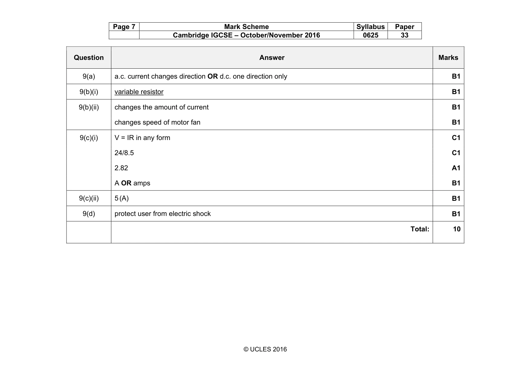
Q9 · The electric circuit for a fan heater
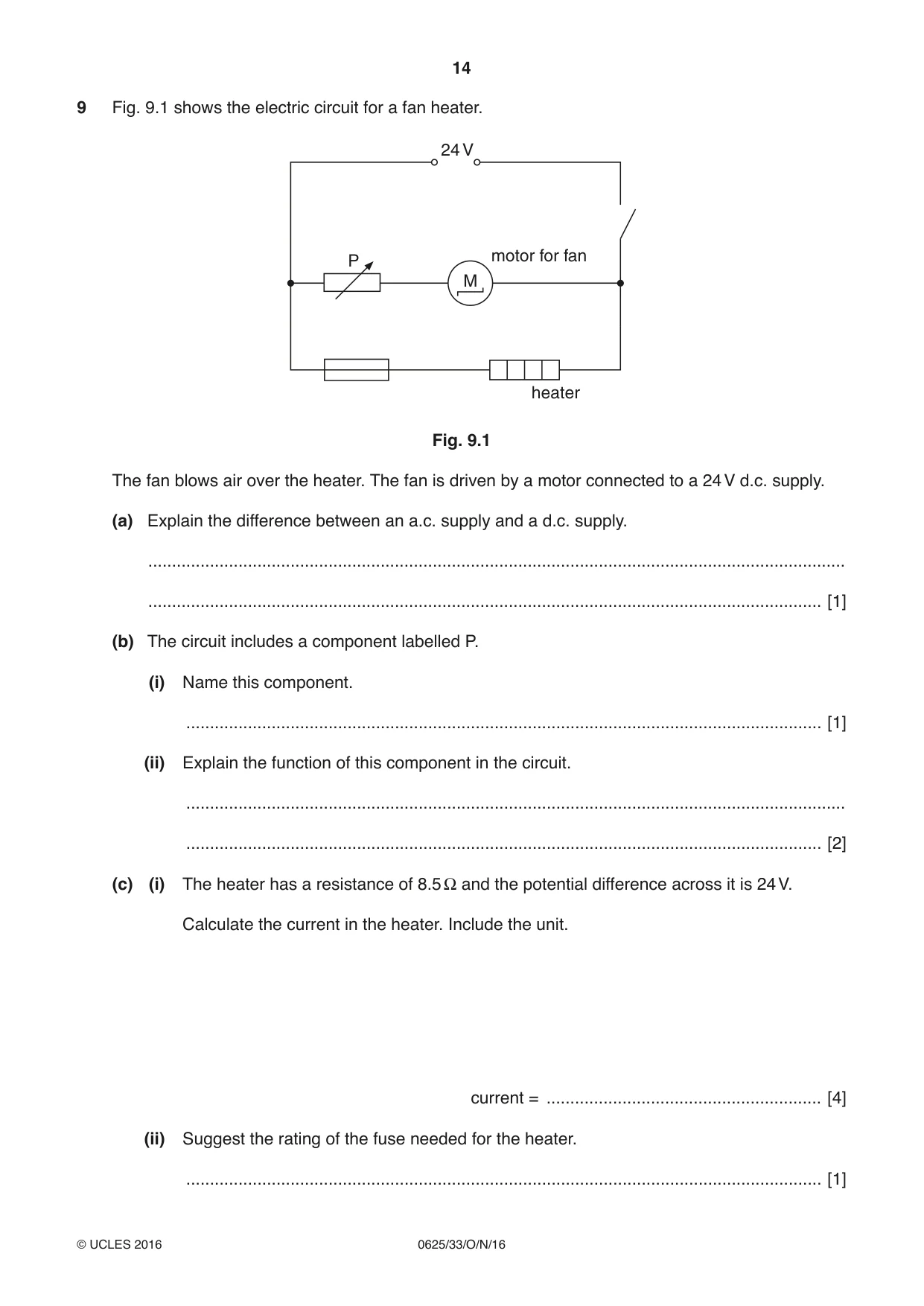
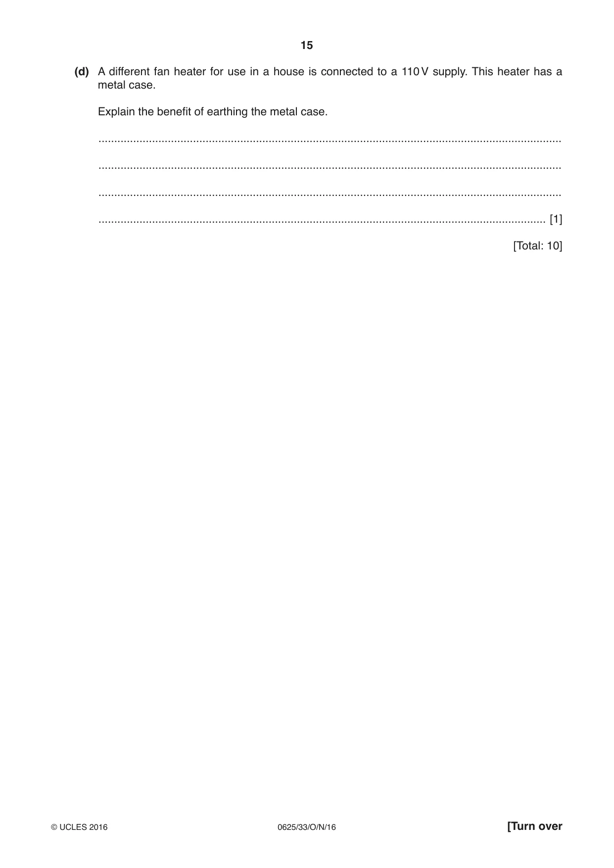
9 Fig. 9.1 shows the electric circuit for a fan heater. 24 V motor for fan P M heater Fig. 9.1 The fan blows air over the heater. The fan is driven by a motor connected to a 24 V d.c. supply. (a) Explain the difference between an a.c. supply and a d.c. supply. ................................................................................................................................................... .............................................................................................................................................. [1] (b) The circuit includes a component labelled P. (i) Name this component. ...................................................................................................................................... [1] (ii) Explain the function of this component in the circuit. ........................................................................................................................................... ...................................................................................................................................... [2] (c) (i) The heater has a resistance of 8.5 Ω and the potential difference across it is 24 V. Calculate the current in the heater. Include the unit. current = .......................................................... [4] (ii) Suggest the rating of the fuse needed for the heater. ...................................................................................................................................... [1] (d) A different fan heater for use in a house is connected to a 110 V supply. This heater has a metal case. Explain the benefit of earthing the metal case. ................................................................................................................................................... ................................................................................................................................................... ................................................................................................................................................... .............................................................................................................................................. [1] [Total: 10]
Mark scheme: 9(a) a.c. current changes direction OR d.c. one direction only B1 9(b)(i) variable resistor B1 9(b)(ii) changes the amount of current B1 changes speed of motor fan B1 9(c)(i) V = IR in any form C1 24/8.5 C1 2.82 A1 A OR amps B1 9(c)(ii) 5 (A) B1 9(d) protect user from electric shock B1 Total: 10
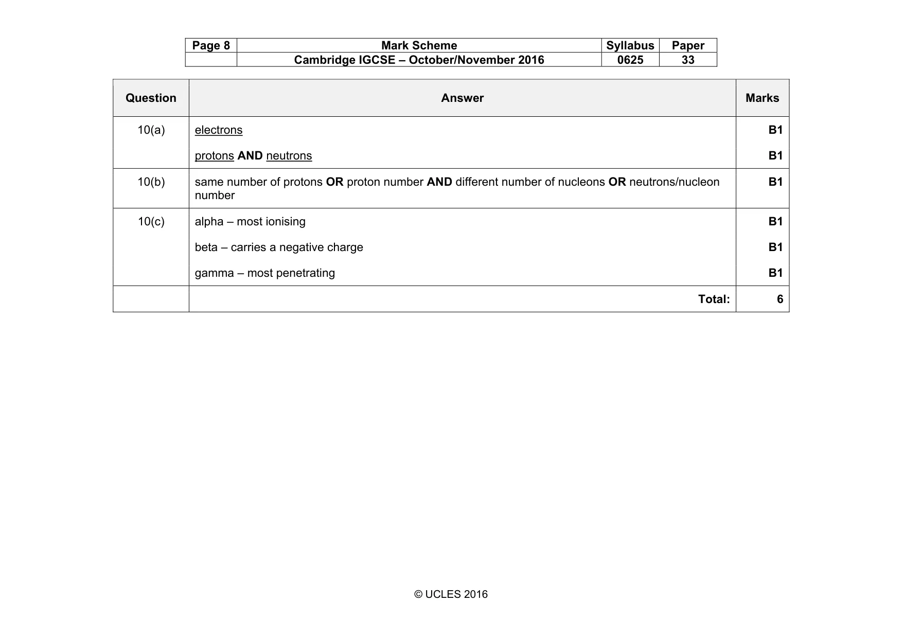
Q10 · This question is about atoms
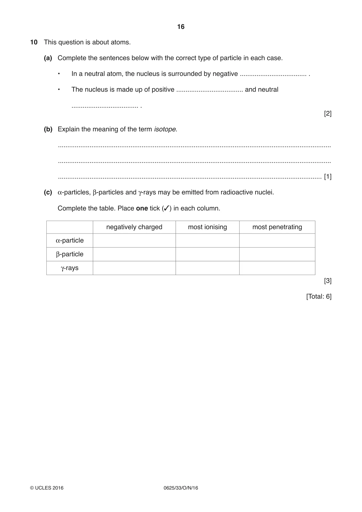
10 This question is about atoms. (a) Complete the sentences below with the correct type of particle in each case. • In a neutral atom, the nucleus is surrounded by negative .................................... . • The nucleus is made up of positive .................................... and neutral .................................... . [2] (b) Explain the meaning of the term isotope. ................................................................................................................................................... ................................................................................................................................................... .............................................................................................................................................. [1] (c) α-particles, β-particles and γ-rays may be emitted from radioactive nuclei. Complete the table. Place one tick (✓) in each column. negatively charged most ionising most penetrating α-particle β-particle γ-rays [3] [Total: 6]
Mark scheme: 10(a) electrons B1 protons AND neutrons B1 10(b) same number of protons OR proton number AND different number of nucleons OR neutrons/nucleon number B1 10(c) alpha – most ionising B1 beta – carries a negative charge B1 gamma – most penetrating B1 Total: 6
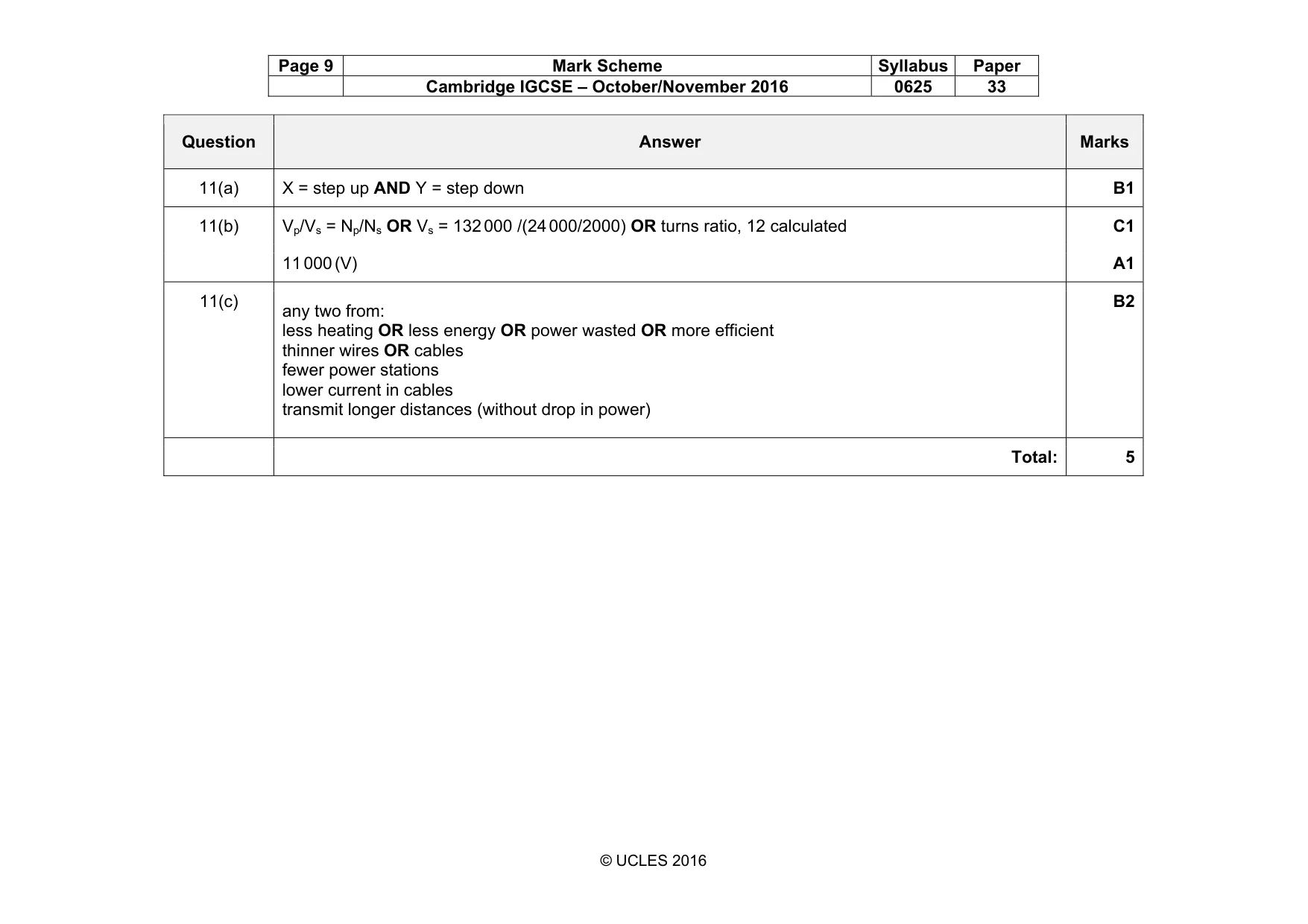
Q11 · Part of an electricity transmission system
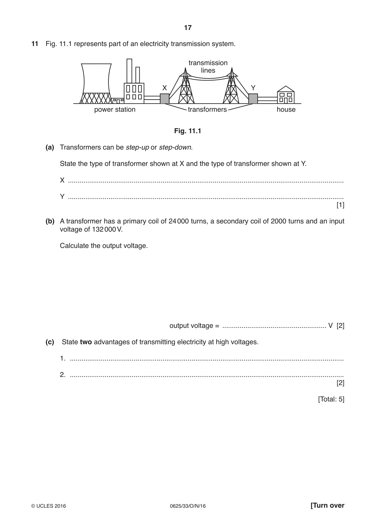
11 Fig. 11.1 represents part of an electricity transmission system. transmission lines X Y power station transformers house Fig. 11.1 (a) Transformers can be step-up or step-down. State the type of transformer shown at X and the type of transformer shown at Y. X ............................................................................................................................................... Y ............................................................................................................................................... [1] (b) A transformer has a primary coil of 24 000 turns, a secondary coil of 2000 turns and an input voltage of 132 000 V. Calculate the output voltage. output voltage = ...................................................... V [2] (c) State two advantages of transmitting electricity at high voltages. 1. .............................................................................................................................................. 2. .............................................................................................................................................. [2] [Total: 5]
Mark scheme: 11(a) X = step up AND Y = step down B1 11(b) Vp/Vs = Np/Ns OR Vs = 132 000 /(24 000/2000) OR turns ratio, 12 calculated C1 11 000 (V) A1 11(c) any two from: less heating OR less energy OR power wasted OR more efficient thinner wires OR cables fewer power stations lower current in cables transmit longer distances (without drop in power) B2 Total: 5
Q12 · A coil of wire between the poles of a magnet
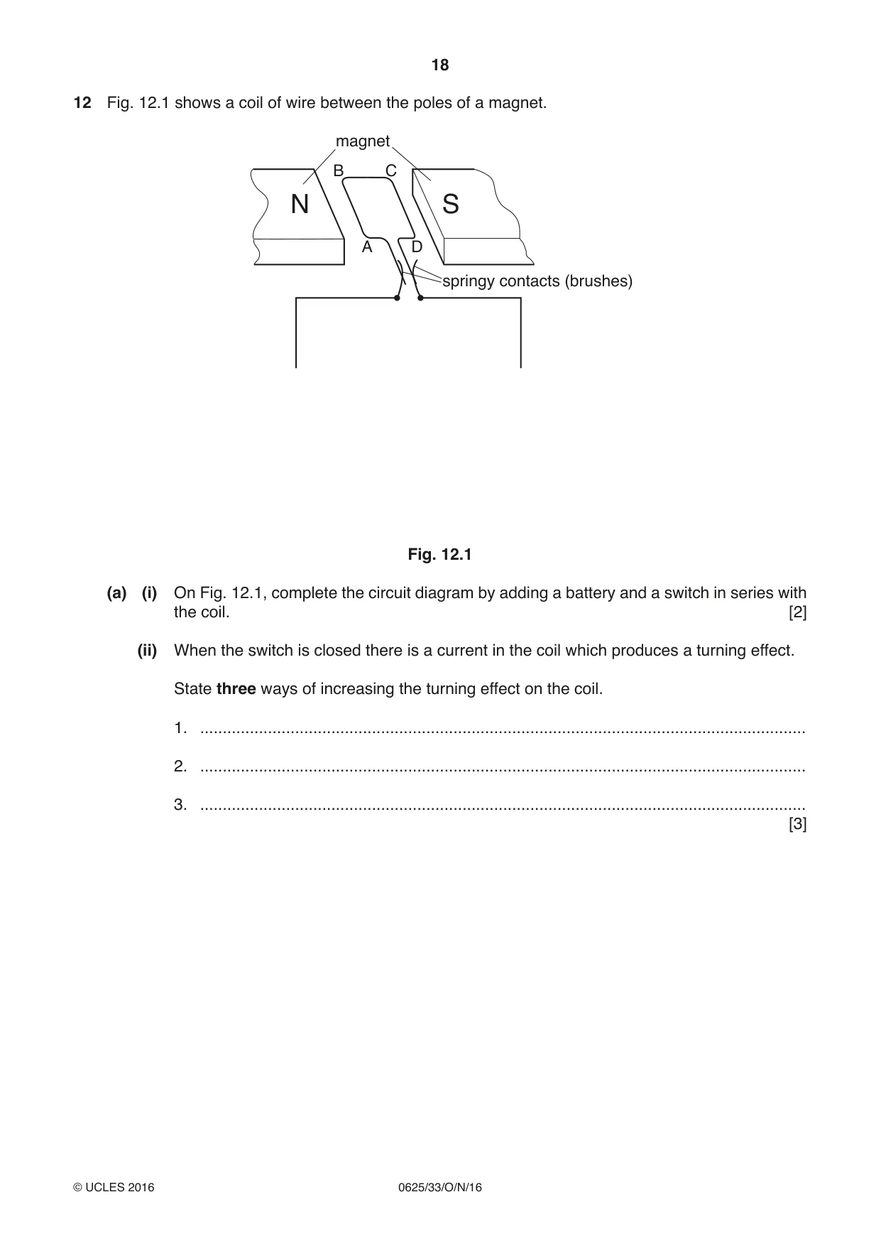
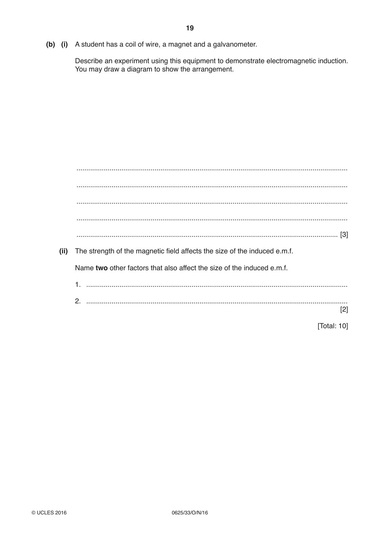
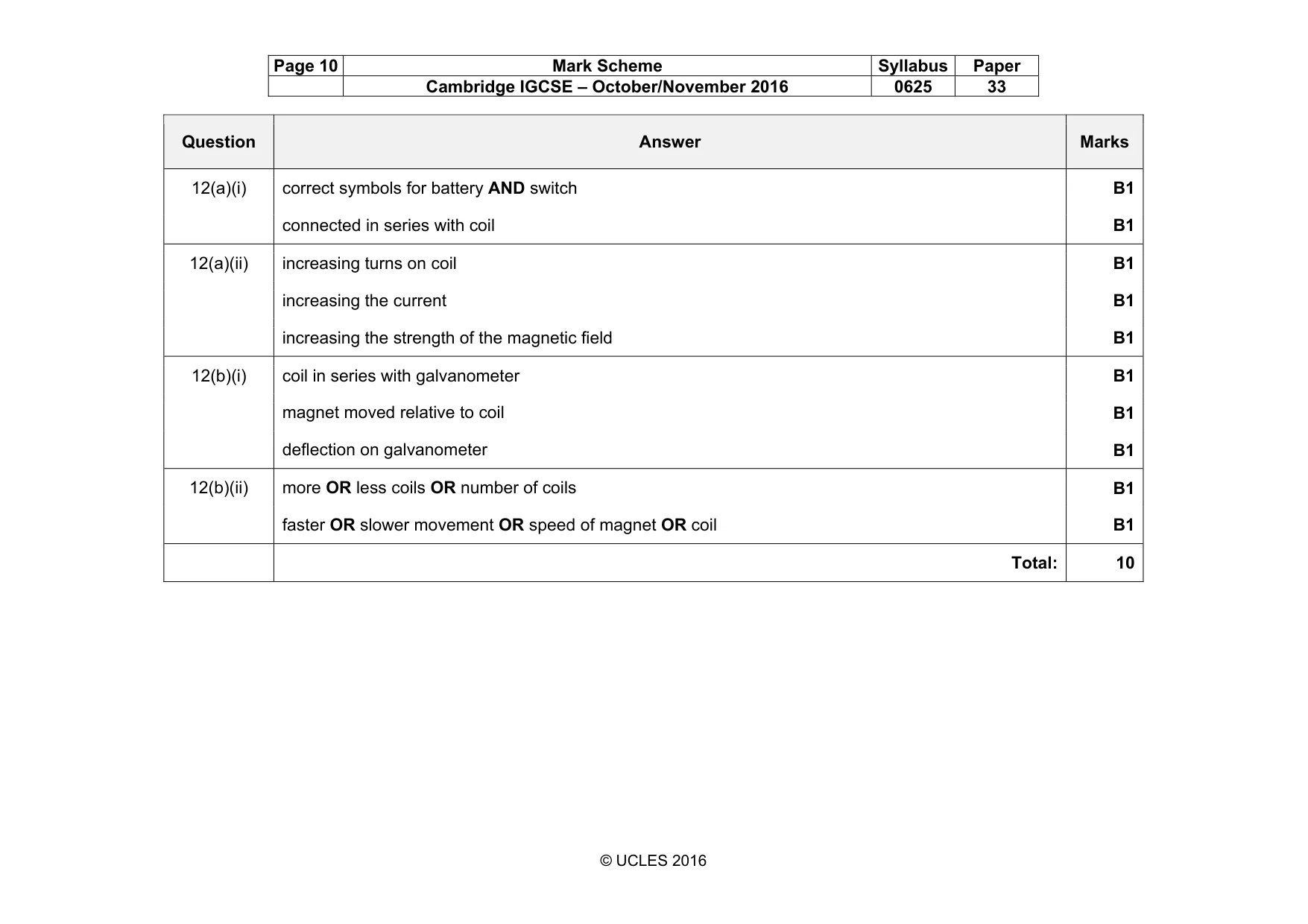
12 Fig. 12.1 shows a coil of wire between the poles of a magnet. magnet B C N S A D springy contacts (brushes) Fig. 12.1 (a) (i) On Fig. 12.1, complete the circuit diagram by adding a battery and a switch in series with the coil. [2] (ii) When the switch is closed there is a current in the coil which produces a turning effect. State three ways of increasing the turning effect on the coil. 1. ...................................................................................................................................... 2. ...................................................................................................................................... 3. ...................................................................................................................................... [3] (b) (i) A student has a coil of wire, a magnet and a galvanometer. Describe an experiment using this equipment to demonstrate electromagnetic induction. You may draw a diagram to show the arrangement. ........................................................................................................................................... ........................................................................................................................................... ........................................................................................................................................... ........................................................................................................................................... ...................................................................................................................................... [3] (ii) The strength of the magnetic field affects the size of the induced e.m.f. Name two other factors that also affect the size of the induced e.m.f. 1. ...................................................................................................................................... 2. ...................................................................................................................................... [2] [Total: 10]
Mark scheme: 12(a)(i) correct symbols for battery AND switch B1 connected in series with coil B1 12(a)(ii) increasing turns on coil B1 increasing the current B1 increasing the strength of the magnetic field B1 12(b)(i) coil in series with galvanometer B1 magnet moved relative to coil B1 deflection on galvanometer B1 12(b)(ii) more OR less coils OR number of coils B1 faster OR slower movement OR speed of magnet OR coil B1 Total: 10
What was in this paper
The subtopics covered by these 12 questions, and how many questions each got. Open one in a new tab to see every Cambridge question on it.
What you needed in this session
Cambridge’s own grade thresholds for 2016 Oct/Nov, Paper 3 · Variant 3. A higher threshold means an easier paper — the bar moves with how the cohort did.