Cambridge IGCSE Physics 0625 — 2011 Oct/Nov Paper 3 · Variant 1
0625/31/O/N/11 · 11 questions · 80 marks · ≈90 min
The question paper and its mark scheme, free to read here and free to download. This is Cambridge’s own paper, exactly as it was sat.
Question paper16 pages
Mark scheme8 pages
Answers below. Sit the paper first if you are practising.
Questions as text
Question 1
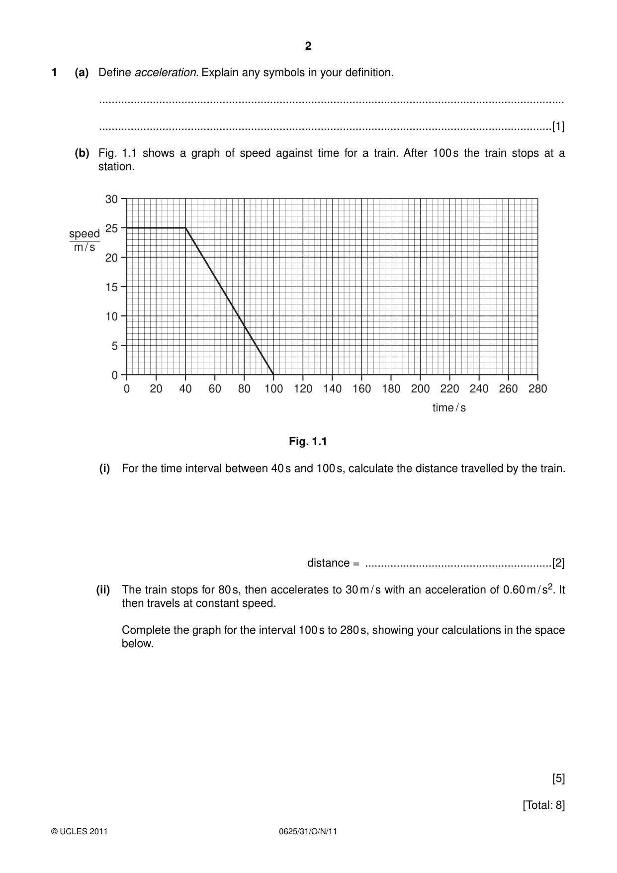
1 (a) Define acceleration. Explain any symbols in your definition. ................................................................................................................................................... ...............................................................................................................................................[1] (b) Fig. 1.1 shows a graph of speed against time for a train. After 100 s the train stops at a station. 30 25 speed m / s 20 15 10 5 0 0 20 40 60 80 100 120 140 160 180 200 220 240 260 280 time / s Fig. 1.1 (i) For the time interval between 40 s and 100 s, calculate the distance travelled by the train. distance = ...........................................................[2] (ii) The train stops for 80 s, then accelerates to 30 m / s with an acceleration of 0.60 m / s2. It then travels at constant speed. Complete the graph for the interval 100 s to 280 s, showing your calculations in the space below. [5] [Total: 8]
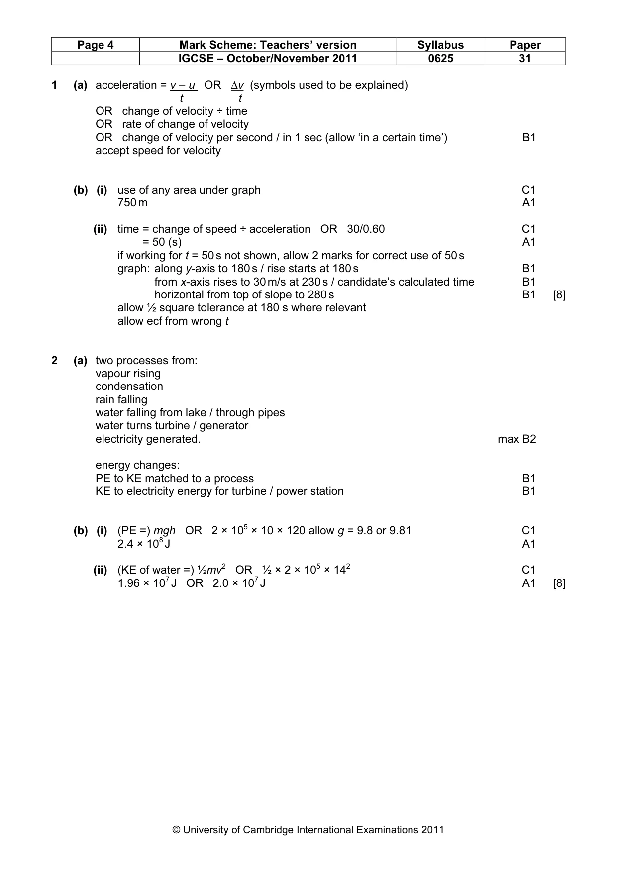
Mark scheme: 1 (a) acceleration = v – u OR ∆v (symbols used to be explained) t t OR change of velocity ÷ time OR rate of change of velocity OR change of velocity per second / in 1 sec (allow ‘in a certain time’) B1 accept speed for velocity (b) (i) use of any area under graph C1 750 m A1 (ii) time = change of speed ÷ acceleration OR 30/0.60 C1 = 50 (s) A1 if working for t = 50 s not shown, allow 2 marks for correct use of 50 s graph: along y-axis to 180 s / rise starts at 180 s B1 from x-axis rises to 30 m/s at 230 s / candidate’s calculated time B1 horizontal from top of slope to 280 s B1 [8] allow ½ square tolerance at 180 s where relevant allow ecf from wrong t
Q2 · Energy from the Sun evaporates water from the sea
2 (a) Energy from the Sun evaporates water from the sea. Some of this water eventually drives a hydroelectric power station. Give an account of the processes and energy changes involved. ................................................................................................................................................... ................................................................................................................................................... ................................................................................................................................................... ................................................................................................................................................... ................................................................................................................................................... ................................................................................................................................................... ................................................................................................................................................... ................................................................................................................................................... ................................................................................................................................................... ...............................................................................................................................................[4] (b) In a hydroelectric power station, 200 000 kg of water per second fall through a vertical distance of 120 m. The water passes through turbines to generate electricity, and leaves the turbines with a speed of 14 m / s. (i) Calculate the gravitational potential energy lost by the water in 1 second. Use g = 10 m / s2. potential energy lost = ............................................................[2] (ii) Calculate the kinetic energy of the water leaving the turbines in 1 second. kinetic energy = ............................................................[2] [Total: 8]
Mark scheme: 2 (a) two processes from: vapour rising condensation rain falling water falling from lake / through pipes water turns turbine / generator electricity generated. max B2 energy changes: PE to KE matched to a process B1 KE to electricity energy for turbine / power station B1 (b) (i) (PE =) mgh OR 2 × 105 × 10 × 120 allow g = 9.8 or 9.81 C1 2.4 × 10⁸ J A1 (ii) (KE of water =) ½mv2 OR ½ × 2 × 105 × 142 C1 1.96 × 10⁷ J OR 2.0 × 10⁷ J A1 [8] IGCSE – October/November 2011 0625 31
Q3 · State the two conditions required for the equilibrium of a body acted upon by a number of…
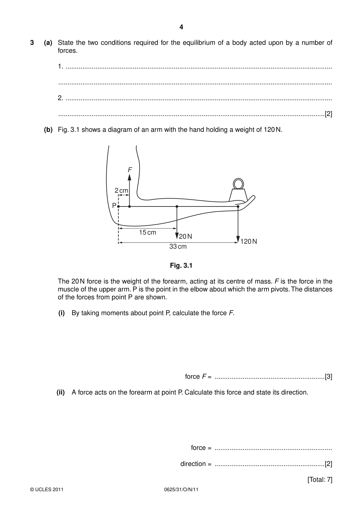
3 (a) State the two conditions required for the equilibrium of a body acted upon by a number of forces. 1. ............................................................................................................................................... ................................................................................................................................................... 2. ............................................................................................................................................... ...............................................................................................................................................[2] (b) Fig. 3.1 shows a diagram of an arm with the hand holding a weight of 120 N. F 2 cm P 15 cm 20 N 120 N 33 cm Fig. 3.1 The 20 N force is the weight of the forearm, acting at its centre of mass. F is the force in the muscle of the upper arm. P is the point in the elbow about which the arm pivots. The distances of the forces from point P are shown. (i) By taking moments about point P, calculate the force F. force F = ...........................................................[3] (ii) A force acts on the forearm at point P. Calculate this force and state its direction. force = ............................................................... direction = ...........................................................[2] [Total: 7]
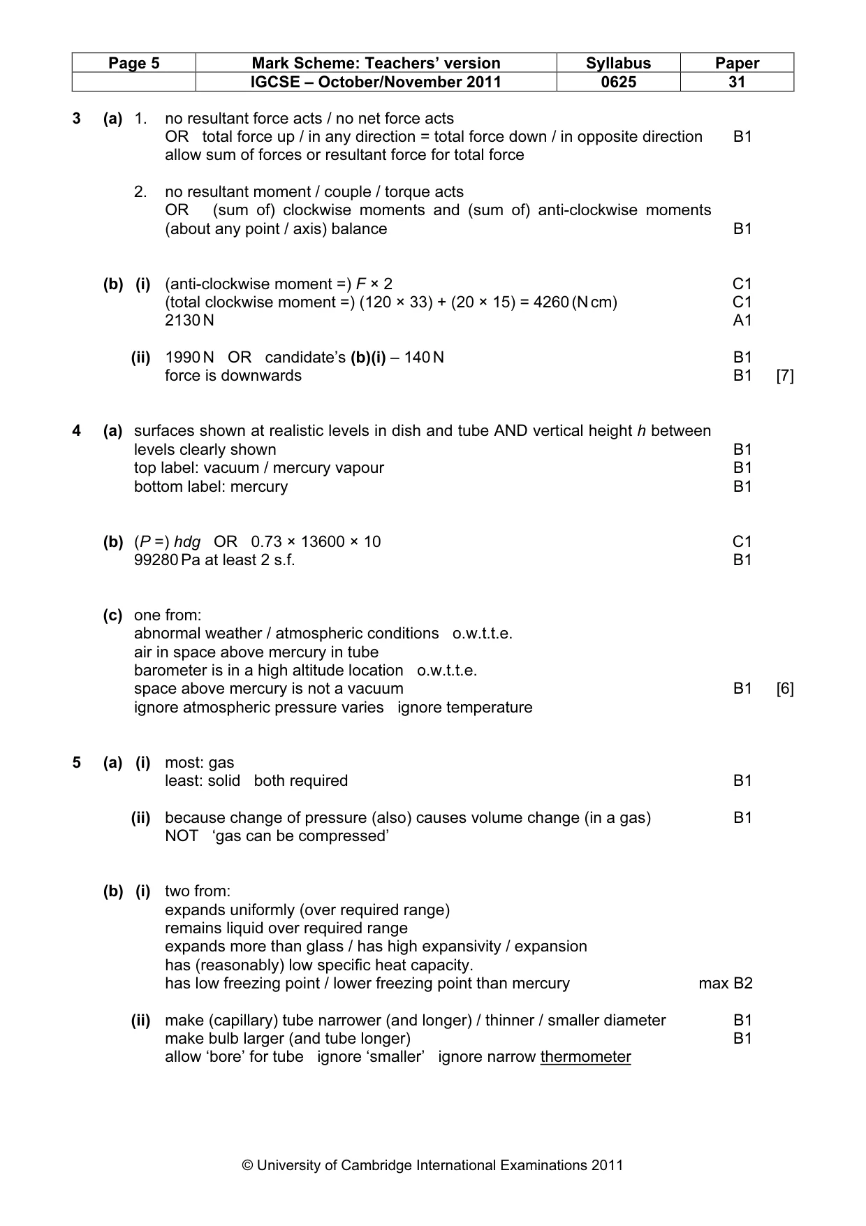
Mark scheme: 3 (a) 1. no resultant force acts / no net force acts OR total force up / in any direction = total force down / in opposite direction B1 allow sum of forces or resultant force for total force 2. no resultant moment / couple / torque acts OR (sum of) clockwise moments and (sum of) anti-clockwise moments (about any point / axis) balance B1 (b) (i) (anti-clockwise moment =) F × 2 C1 (total clockwise moment =) (120 × 33) + (20 × 15) = 4260 (N cm) C1 2130 N A1 (ii) 1990 N OR candidate’s (b)(i) – 140 N B1 force is downwards B1 [7]
Question 4
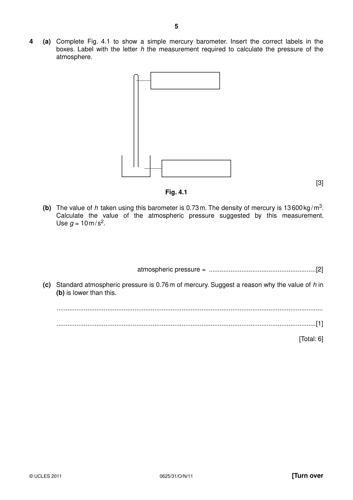
4 (a) Complete Fig. 4.1 to show a simple mercury barometer. Insert the correct labels in the boxes. Label with the letter h the measurement required to calculate the pressure of the atmosphere. [3] Fig. 4.1 (b) The value of h taken using this barometer is 0.73 m. The density of mercury is 13 600 kg / m3. Calculate the value of the atmospheric pressure suggested by this measurement. Use g = 10 m / s2. atmospheric pressure = ...........................................................[2] (c) Standard atmospheric pressure is 0.76 m of mercury. Suggest a reason why the value of h in (b) is lower than this. ................................................................................................................................................... ...............................................................................................................................................[1] [Total: 6]
Mark scheme: 4 (a) surfaces shown at realistic levels in dish and tube AND vertical height h between levels clearly shown B1 top label: vacuum / mercury vapour B1 bottom label: mercury B1 (b) (P =) hdg OR 0.73 × 13600 × 10 C1 99280 Pa at least 2 s.f. B1 (c) one from: abnormal weather / atmospheric conditions o.w.t.t.e. air in space above mercury in tube barometer is in a high altitude location o.w.t.t.e. space above mercury is not a vacuum B1 [6] ignore atmospheric pressure varies ignore temperature
Q5 · Equal volumes of a gas held at constant pressure, a liquid and a solid undergo the same…
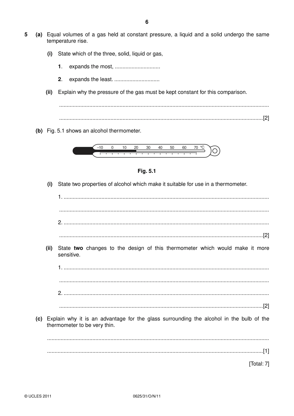
5 (a) Equal volumes of a gas held at constant pressure, a liquid and a solid undergo the same temperature rise. (i) State which of the three, solid, liquid or gas, 1. expands the most, .............................. 2. expands the least. .............................. (ii) Explain why the pressure of the gas must be kept constant for this comparison. ........................................................................................................................................... .......................................................................................................................................[2] (b) Fig. 5.1 shows an alcohol thermometer. –10 0 10 20 30 40 50 60 70 °C Fig. 5.1 (i) State two properties of alcohol which make it suitable for use in a thermometer. 1. ........................................................................................................................................ ........................................................................................................................................... 2. ........................................................................................................................................ .......................................................................................................................................[2] (ii) State two changes to the design of this thermometer which would make it more sensitive. 1. ........................................................................................................................................ ........................................................................................................................................... 2. ........................................................................................................................................ .......................................................................................................................................[2] (c) Explain why it is an advantage for the glass surrounding the alcohol in the bulb of the thermometer to be very thin. ................................................................................................................................................... ...............................................................................................................................................[1] [Total: 7]
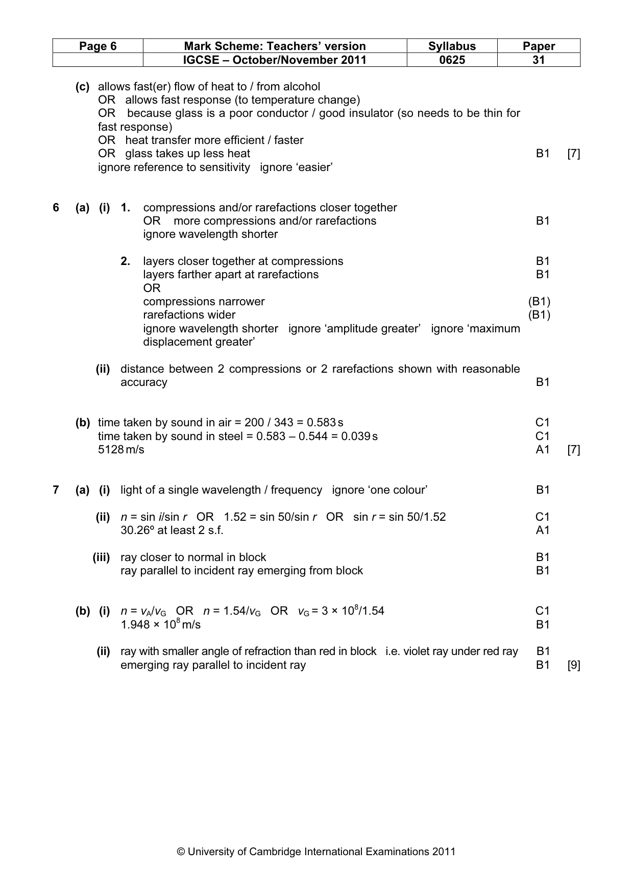
Mark scheme: 5 (a) (i) most: gas least: solid both required B1 (ii) because change of pressure (also) causes volume change (in a gas) B1 NOT ‘gas can be compressed’ (b) (i) two from: expands uniformly (over required range) remains liquid over required range expands more than glass / has high expansivity / expansion has (reasonably) low specific heat capacity. has low freezing point / lower freezing point than mercury max B2 (ii) make (capillary) tube narrower (and longer) / thinner / smaller diameter B1 make bulb larger (and tube longer) B1 allow ‘bore’ for tube ignore ‘smaller’ ignore narrow thermometer IGCSE – October/November 2011 0625 31 (c) allows fast(er) flow of heat to / from alcohol OR allows fast response (to temperature change) OR because glass is a poor conductor / good insulator (so needs to be thin for fast response) OR heat transfer more efficient / faster OR glass takes up less heat B1 [7] ignore reference to sensitivity ignore ‘easier’
Q6 · The position of layers of air, at one moment, as a sound wave of constant frequency…
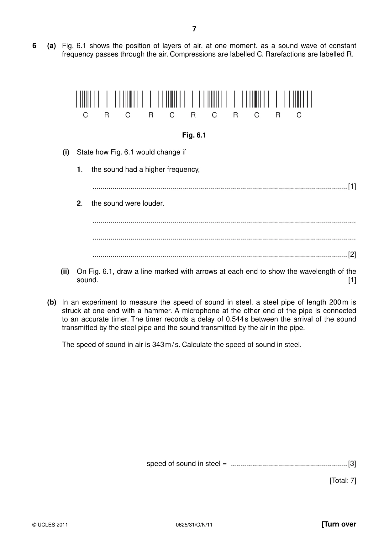
6 (a) Fig. 6.1 shows the position of layers of air, at one moment, as a sound wave of constant frequency passes through the air. Compressions are labelled C. Rarefactions are labelled R. C R C R C R C R C R C Fig. 6.1 (i) State how Fig. 6.1 would change if 1. the sound had a higher frequency, ................................................................................................................................[1] 2. the sound were louder. .................................................................................................................................... .................................................................................................................................... ................................................................................................................................[2] (ii) On Fig. 6.1, draw a line marked with arrows at each end to show the wavelength of the sound. [1] (b) In an experiment to measure the speed of sound in steel, a steel pipe of length 200 m is struck at one end with a hammer. A microphone at the other end of the pipe is connected to an accurate timer. The timer records a delay of 0.544 s between the arrival of the sound transmitted by the steel pipe and the sound transmitted by the air in the pipe. The speed of sound in air is 343 m / s. Calculate the speed of sound in steel. speed of sound in steel = ...........................................................[3] [Total: 7]
Mark scheme: 6 (a) (i) 1. compressions and/or rarefactions closer together OR more compressions and/or rarefactions B1 ignore wavelength shorter 2. layers closer together at compressions B1 layers farther apart at rarefactions B1 OR compressions narrower (B1) rarefactions wider (B1) ignore wavelength shorter ignore ‘amplitude greater’ ignore ‘maximum displacement greater’ (ii) distance between 2 compressions or 2 rarefactions shown with reasonable accuracy B1 (b) time taken by sound in air = 200 / 343 = 0.583 s C1 time taken by sound in steel = 0.583 – 0.544 = 0.039 s C1 5128 m/s A1 [7]
Q7 · A ray of monochromatic red light, in air, incident on a glass block at an angle of…
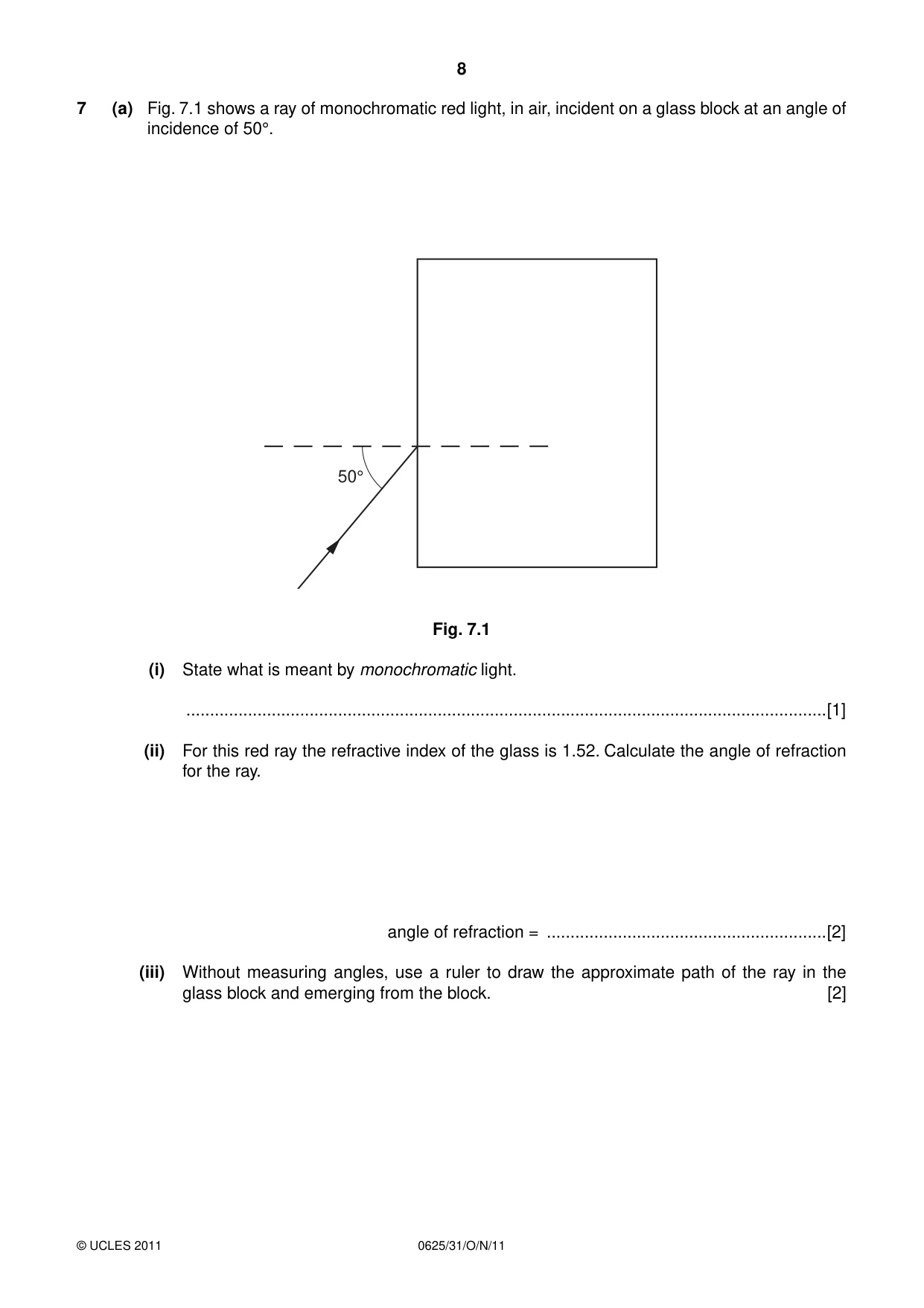
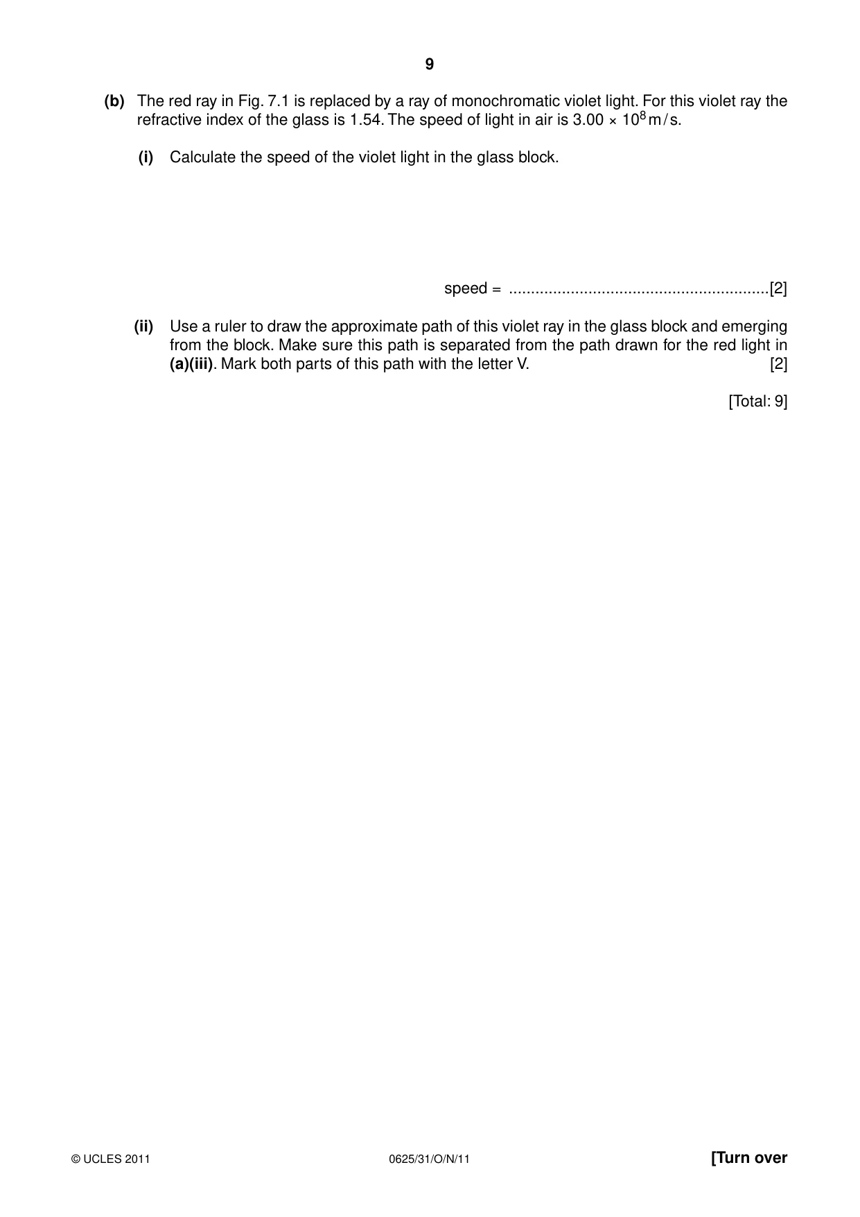
7 (a) Fig. 7.1 shows a ray of monochromatic red light, in air, incident on a glass block at an angle of incidence of 50°. 50° Fig. 7.1 (i) State what is meant by monochromatic light. .......................................................................................................................................[1] (ii) For this red ray the refractive index of the glass is 1.52. Calculate the angle of refraction for the ray. angle of refraction = ...........................................................[2] (iii) Without measuring angles, use a ruler to draw the approximate path of the ray in the glass block and emerging from the block. [2] (b) The red ray in Fig. 7.1 is replaced by a ray of monochromatic violet light. For this violet ray the refractive index of the glass is 1.54. The speed of light in air is 3.00 × 10⁸ m / s. (i) Calculate the speed of the violet light in the glass block. speed = ...........................................................[2] (ii) Use a ruler to draw the approximate path of this violet ray in the glass block and emerging from the block. Make sure this path is separated from the path drawn for the red light in (a)(iii). Mark both parts of this path with the letter V. [2] [Total: 9]
Mark scheme: 7 (a) (i) light of a single wavelength / frequency ignore ‘one colour’ B1 (ii) n = sin i/sin r OR 1.52 = sin 50/sin r OR sin r = sin 50/1.52 C1 30.26º at least 2 s.f. A1 (iii) ray closer to normal in block B1 ray parallel to incident ray emerging from block B1 (b) (i) n = vA/vG OR n = 1.54/vG OR vG = 3 × 10⁸/1.54 C1 1.948 × 10⁸ m/s B1 (ii) ray with smaller angle of refraction than red in block i.e. violet ray under red ray B1 emerging ray parallel to incident ray B1 [9] IGCSE – October/November 2011 0625 31
Question 8
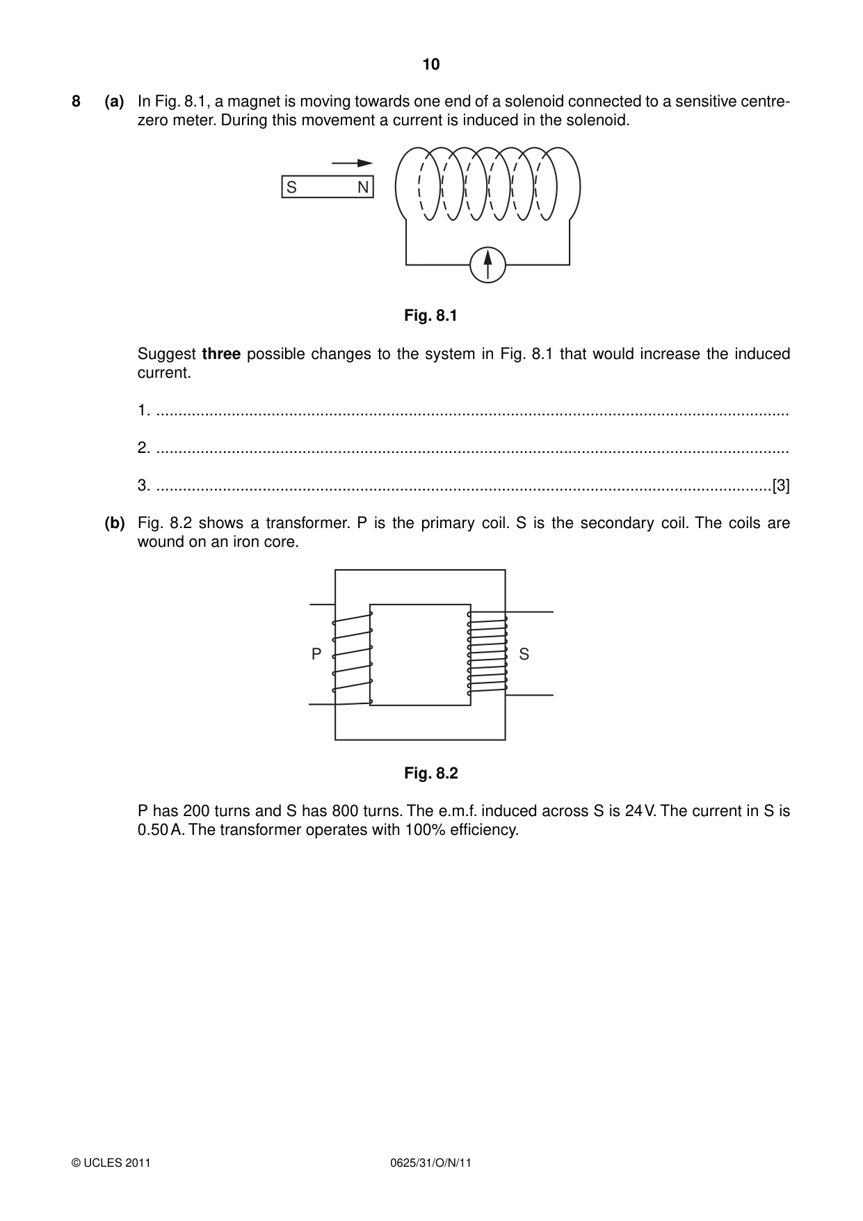
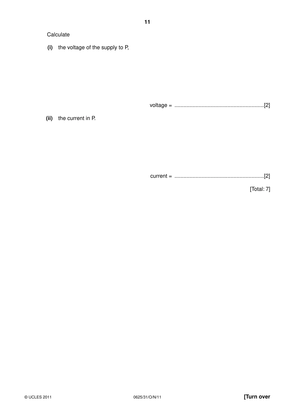
8 (a) In Fig. 8.1, a magnet is moving towards one end of a solenoid connected to a sensitive centre- zero meter. During this movement a current is induced in the solenoid. S N Fig. 8.1 Suggest three possible changes to the system in Fig. 8.1 that would increase the induced current. 1. ............................................................................................................................................... 2. ............................................................................................................................................... 3. ...........................................................................................................................................[3] (b) Fig. 8.2 shows a transformer. P is the primary coil. S is the secondary coil. The coils are wound on an iron core. P S Fig. 8.2 P has 200 turns and S has 800 turns. The e.m.f. induced across S is 24 V. The current in S is 0.50 A. The transformer operates with 100% efficiency. Calculate (i) the voltage of the supply to P, voltage = ...........................................................[2] (ii) the current in P. current = ...........................................................[2] [Total: 7]
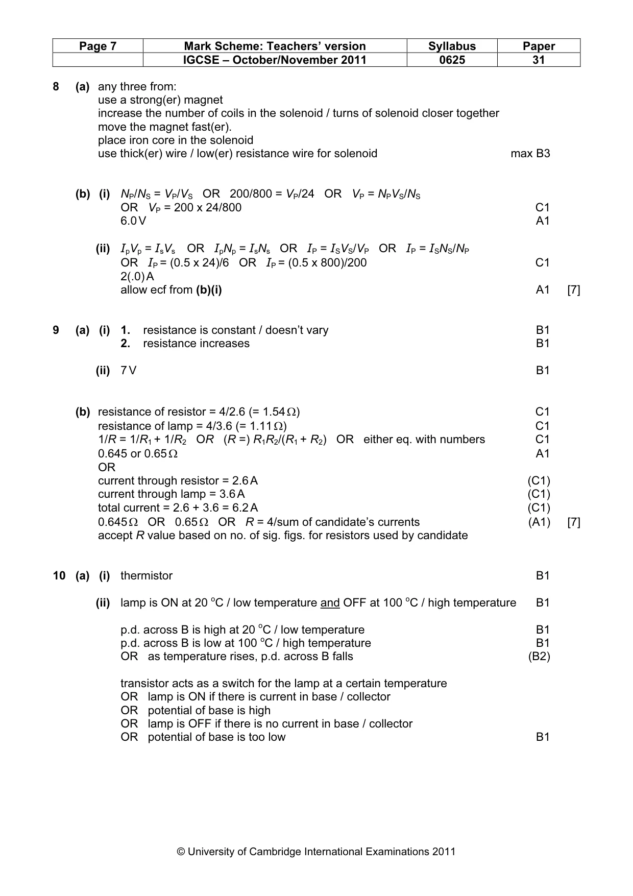
Mark scheme: 8 (a) any three from: use a strong(er) magnet increase the number of coils in the solenoid / turns of solenoid closer together move the magnet fast(er). place iron core in the solenoid use thick(er) wire / low(er) resistance wire for solenoid max B3 (b) (i) NP/NS = VP/VS OR 200/800 = VP/24 OR VP = NPVS/NS OR VP = 200 x 24/800 C1 6.0 V A1 (ii) IpVp = IsVs OR IpNp = IsNs OR IP = ISVS/VP OR IP = ISNS/NP OR IP = (0.5 x 24)/6 OR IP = (0.5 x 800)/200 C1 2(.0) A allow ecf from (b)(i) A1 [7]
Q9 · The graphs in Fig
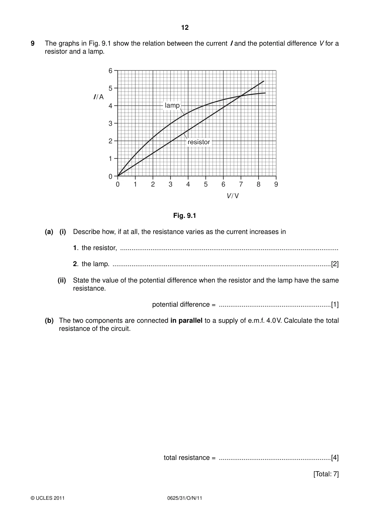
9 The graphs in Fig. 9.1 show the relation between the current I and the potential difference V for a resistor and a lamp. 6 5 I / A 4 lamp 3 2 resistor 1 0 0 1 2 3 4 5 6 7 8 9 V / V Fig. 9.1 (a) (i) Describe how, if at all, the resistance varies as the current increases in 1. the resistor, ................................................................................................................... 2. the lamp. ...................................................................................................................[2] (ii) State the value of the potential difference when the resistor and the lamp have the same resistance. potential difference = ...........................................................[1] (b) The two components are connected in parallel to a supply of e.m.f. 4.0 V. Calculate the total resistance of the circuit. total resistance = ...........................................................[4] [Total: 7]
Mark scheme: 9 (a) (i) 1. resistance is constant / doesn’t vary B1 2. resistance increases B1 (ii) 7 V B1 (b) resistance of resistor = 4/2.6 (= 1.54 Ω) C1 resistance of lamp = 4/3.6 (= 1.11 Ω) C1 1/R = 1/R1 + 1/R2 OR (R =) R1R2/(R1 + R2) OR either eq. with numbers C1 0.645 or 0.65 Ω A1 OR current through resistor = 2.6 A (C1) current through lamp = 3.6 A (C1) total current = 2.6 + 3.6 = 6.2 A (C1) 0.645 Ω OR 0.65 Ω OR R = 4/sum of candidate’s currents (A1) [7] accept R value based on no. of sig. figs. for resistors used by candidate
Question 10
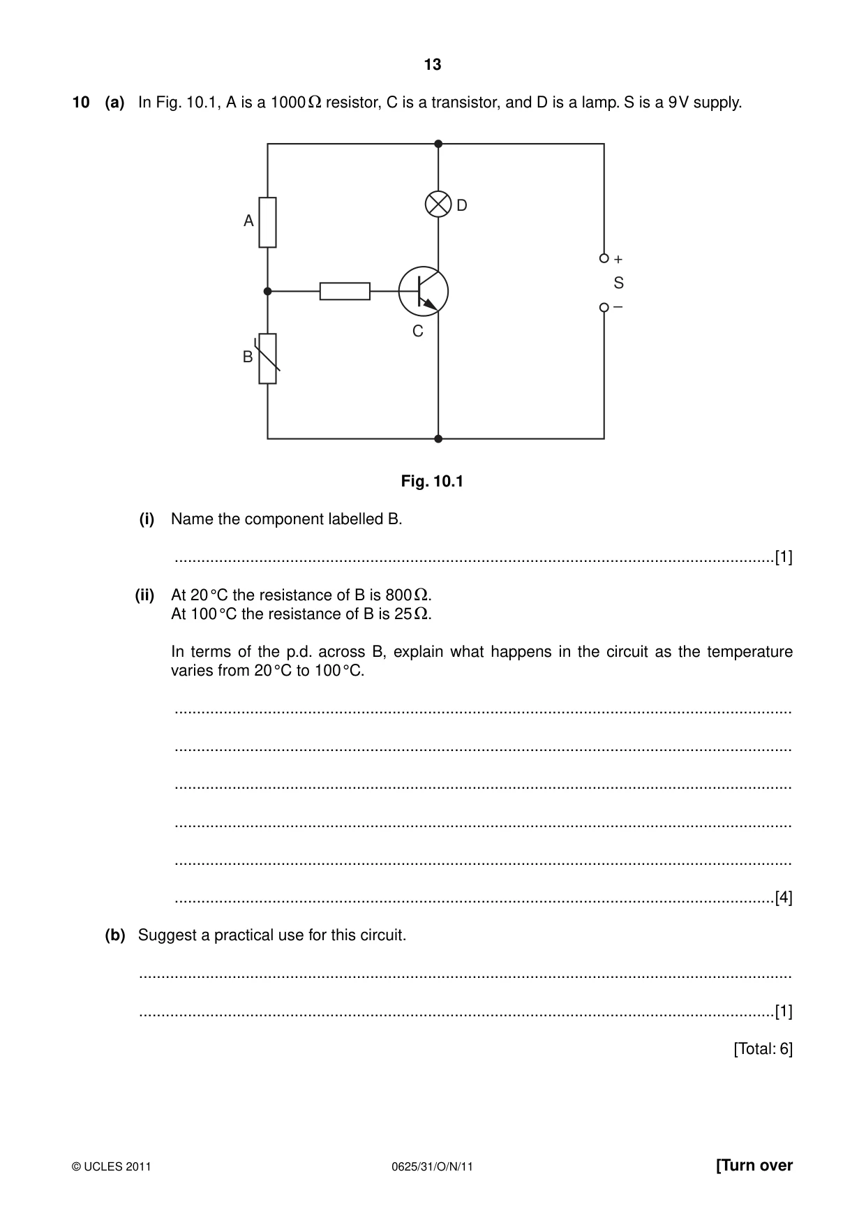
10 (a) In Fig. 10.1, A is a 1000 resistor, C is a transistor, and D is a lamp. S is a 9 V supply. D A + S – C B Fig. 10.1 (i) Name the component labelled B. .......................................................................................................................................[1] (ii) At 20 °C the resistance of B is 800 . At 100 °C the resistance of B is 25 . In terms of the p.d. across B, explain what happens in the circuit as the temperature varies from 20 °C to 100 °C. ........................................................................................................................................... ........................................................................................................................................... ........................................................................................................................................... ........................................................................................................................................... ........................................................................................................................................... .......................................................................................................................................[4] (b) Suggest a practical use for this circuit. ................................................................................................................................................... ...............................................................................................................................................[1] [Total: 6]
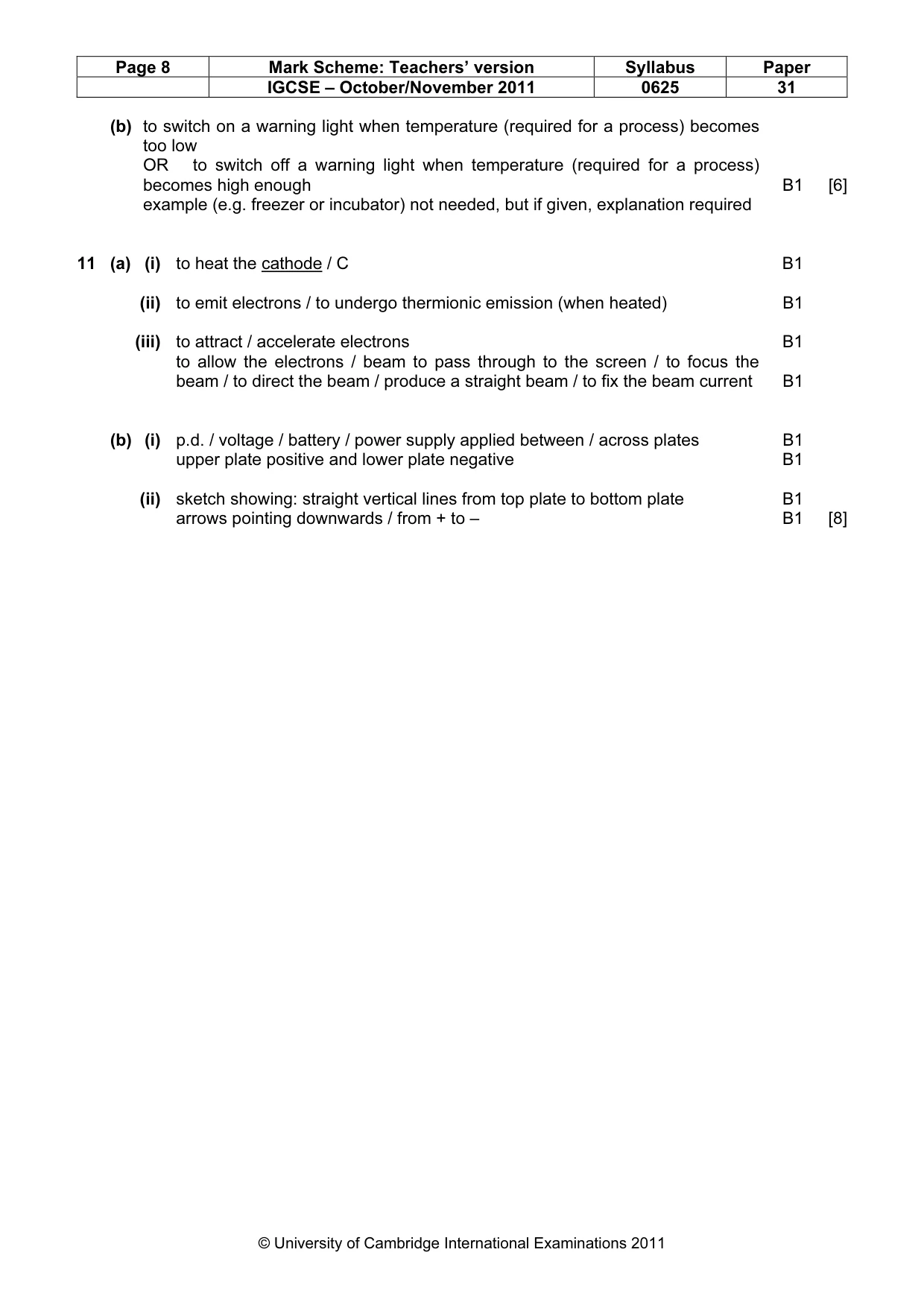
Mark scheme: 10 (a) (i) thermistor B1 (ii) lamp is ON at 20 oC / low temperature and OFF at 100 oC / high temperature B1 p.d. across B is high at 20 oC / low temperature B1 p.d. across B is low at 100 oC / high temperature B1 OR as temperature rises, p.d. across B falls (B2) transistor acts as a switch for the lamp at a certain temperature OR lamp is ON if there is current in base / collector OR potential of base is high OR lamp is OFF if there is no current in base / collector OR potential of base is too low B1 IGCSE – October/November 2011 0625 31 (b) to switch on a warning light when temperature (required for a process) becomes too low OR to switch off a warning light when temperature (required for a process) becomes high enough B1 [6] example (e.g. freezer or incubator) not needed, but if given, explanation required
Q11 · The main components of a cathode-ray oscilloscope
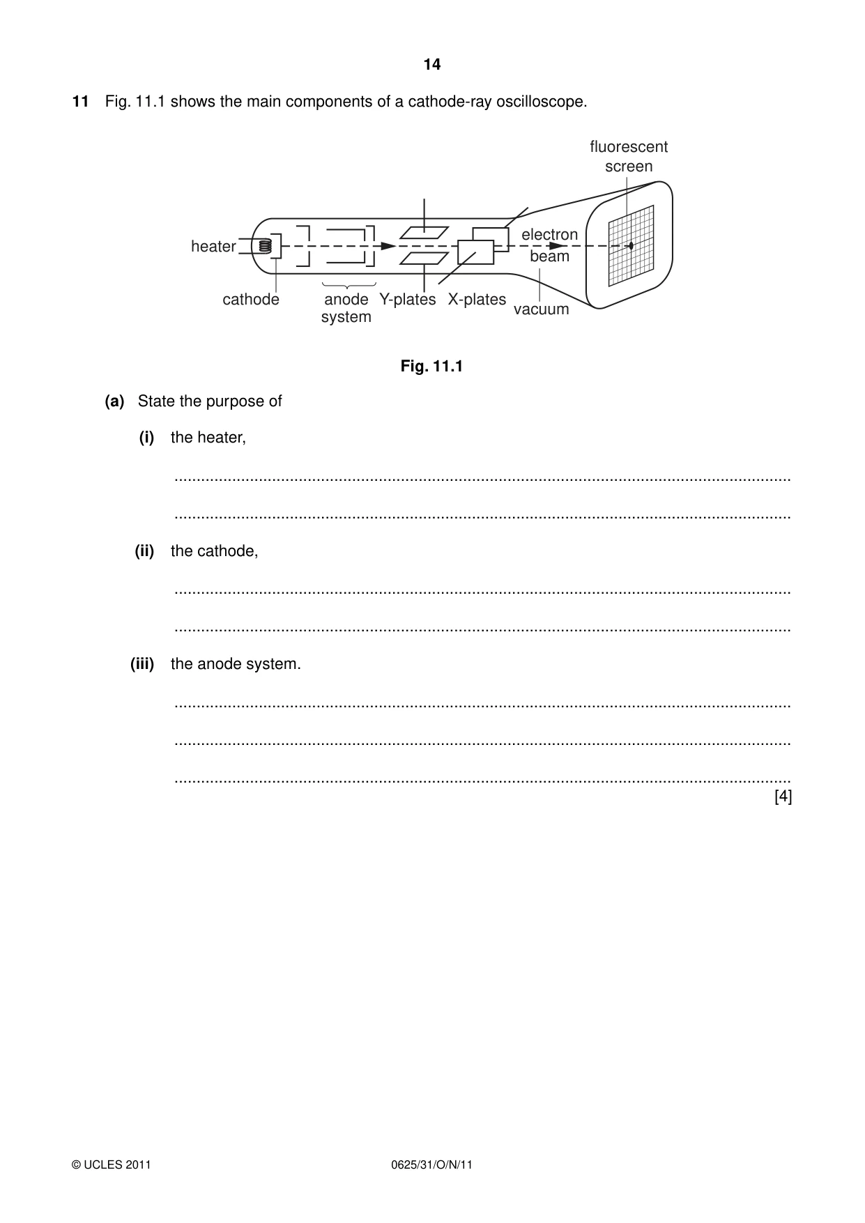
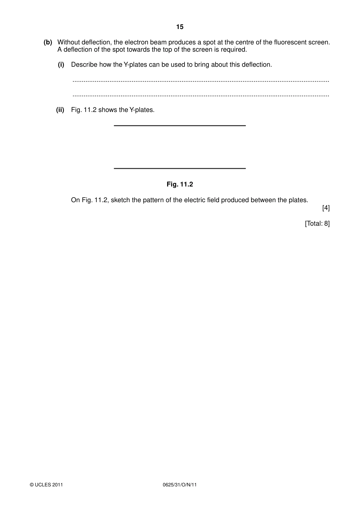
11 Fig. 11.1 shows the main components of a cathode-ray oscilloscope. fluorescent screen electron heater beam cathode anode Y-plates X-plates vacuum system Fig. 11.1 (a) State the purpose of (i) the heater, ........................................................................................................................................... ........................................................................................................................................... (ii) the cathode, ........................................................................................................................................... ........................................................................................................................................... (iii) the anode system. ........................................................................................................................................... ........................................................................................................................................... ........................................................................................................................................... [4] (b) Without deflection, the electron beam produces a spot at the centre of the fluorescent screen. A deflection of the spot towards the top of the screen is required. (i) Describe how the Y-plates can be used to bring about this deflection. ........................................................................................................................................... ........................................................................................................................................... (ii) Fig. 11.2 shows the Y-plates. Fig. 11.2 On Fig. 11.2, sketch the pattern of the electric field produced between the plates. [4] [Total: 8]
Mark scheme: 11 (a) (i) to heat the cathode / C B1 (ii) to emit electrons / to undergo thermionic emission (when heated) B1 (iii) to attract / accelerate electrons B1 to allow the electrons / beam to pass through to the screen / to focus the beam / to direct the beam / produce a straight beam / to fix the beam current B1 (b) (i) p.d. / voltage / battery / power supply applied between / across plates B1 upper plate positive and lower plate negative B1 (ii) sketch showing: straight vertical lines from top plate to bottom plate B1 arrows pointing downwards / from + to – B1 [8]
What was in this paper
The subtopics covered by these 11 questions, and how many questions each got. Open one in a new tab to see every Cambridge question on it.
What you needed in this session
Cambridge’s own grade thresholds for 2011 Oct/Nov, Paper 3 · Variant 1. A higher threshold means an easier paper — the bar moves with how the cohort did.