Cambridge IGCSE Physics 0625 — 2015 May/June Paper 3 · Variant 2
0625/32/M/J/15 · 11 questions · 80 marks · ≈90 min
The question paper and its mark scheme, free to read here and free to download. This is Cambridge’s own paper, exactly as it was sat.
Question paper20 pages


Mark scheme7 pages
Answers below. Sit the paper first if you are practising.
Questions as text
Q1 · An experiment is carried out to find the acceleration of free fall
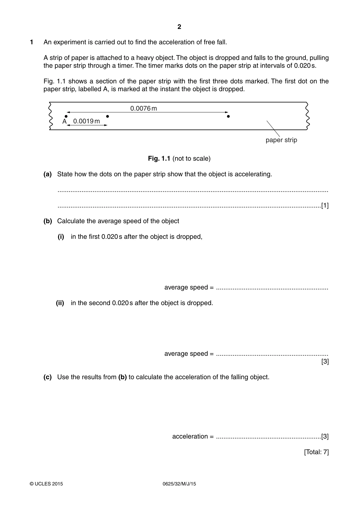
1 An experiment is carried out to find the acceleration of free fall. A strip of paper is attached to a heavy object. The object is dropped and falls to the ground, pulling the paper strip through a timer. The timer marks dots on the paper strip at intervals of 0.020 s. Fig. 1.1 shows a section of the paper strip with the first three dots marked. The first dot on the paper strip, labelled A, is marked at the instant the object is dropped. 0.0076 m A 0.0019 m paper strip Fig. 1.1 (not to scale) (a) State how the dots on the paper strip show that the object is accelerating. ................................................................................................................................................... ...............................................................................................................................................[1] (b) Calculate the average speed of the object (i) in the first 0.020 s after the object is dropped, average speed = ............................................................. (ii) in the second 0.020 s after the object is dropped. average speed = ............................................................. [3] (c) Use the results from (b) to calculate the acceleration of the falling object. acceleration = .........................................................[3] [Total: 7]
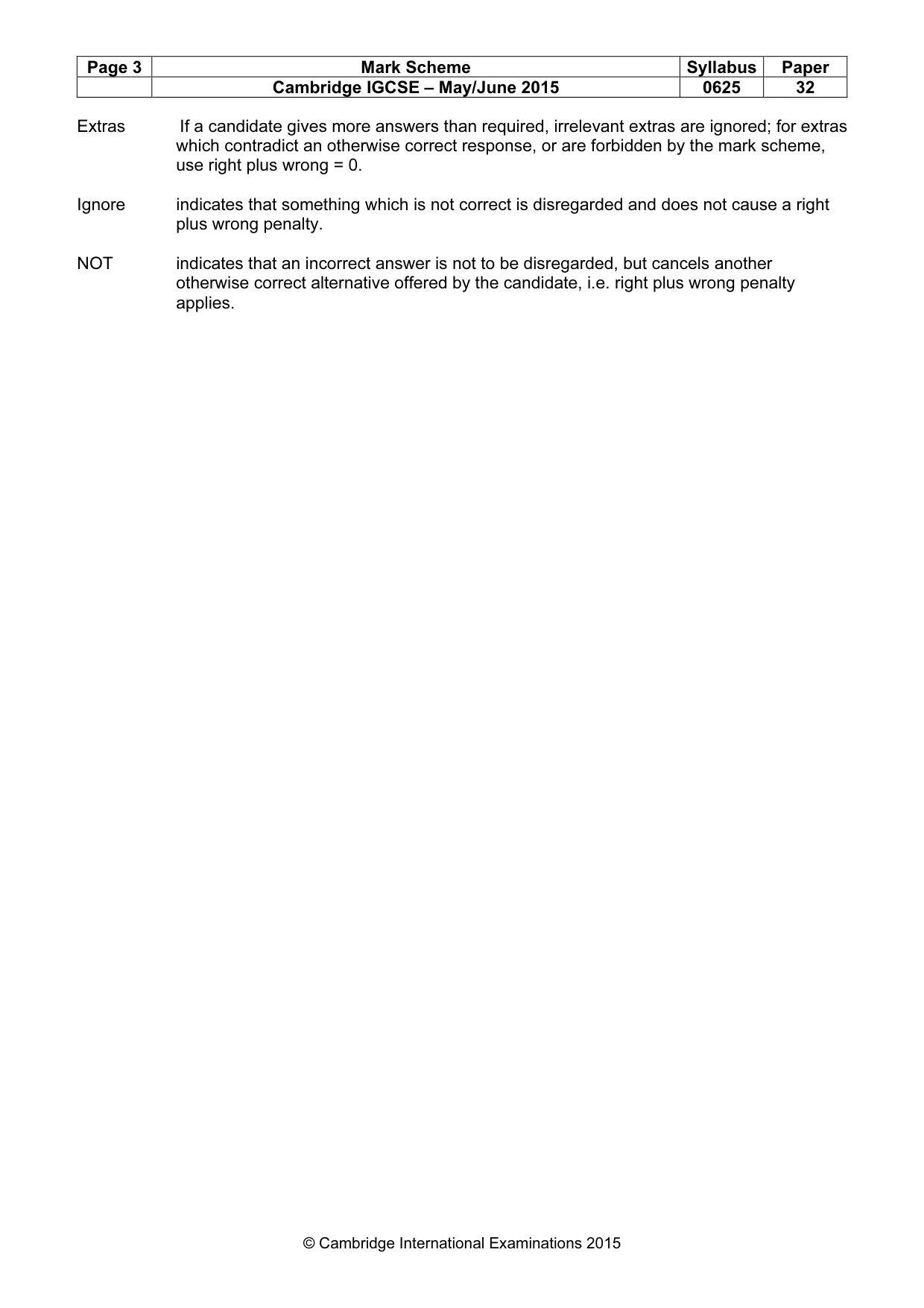
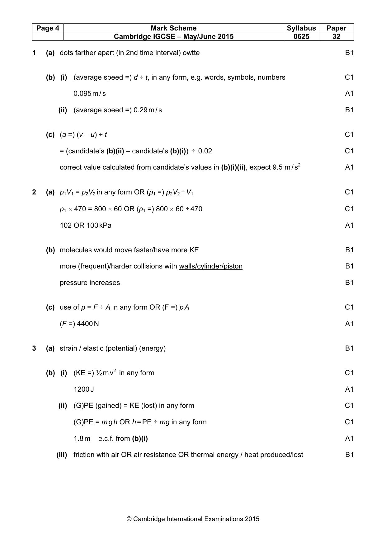
Mark scheme: 1 (a) dots farther apart (in 2nd time interval) owtte B1 (b) (i) (average speed =) d ÷ t, in any form, e.g. words, symbols, numbers C1 0.095 m / s A1 (ii) (average speed =) 0.29 m / s B1 (c) (a =) (v – u) ÷ t C1 = (candidate’s (b)(ii) – candidate’s (b)(i)) ÷ 0.02 C1 correct value calculated from candidate’s values in (b)(i)(ii), expect 9.5 m / s2 A1
Q2 · A cylinder containing gas compressed by the movement of a piston
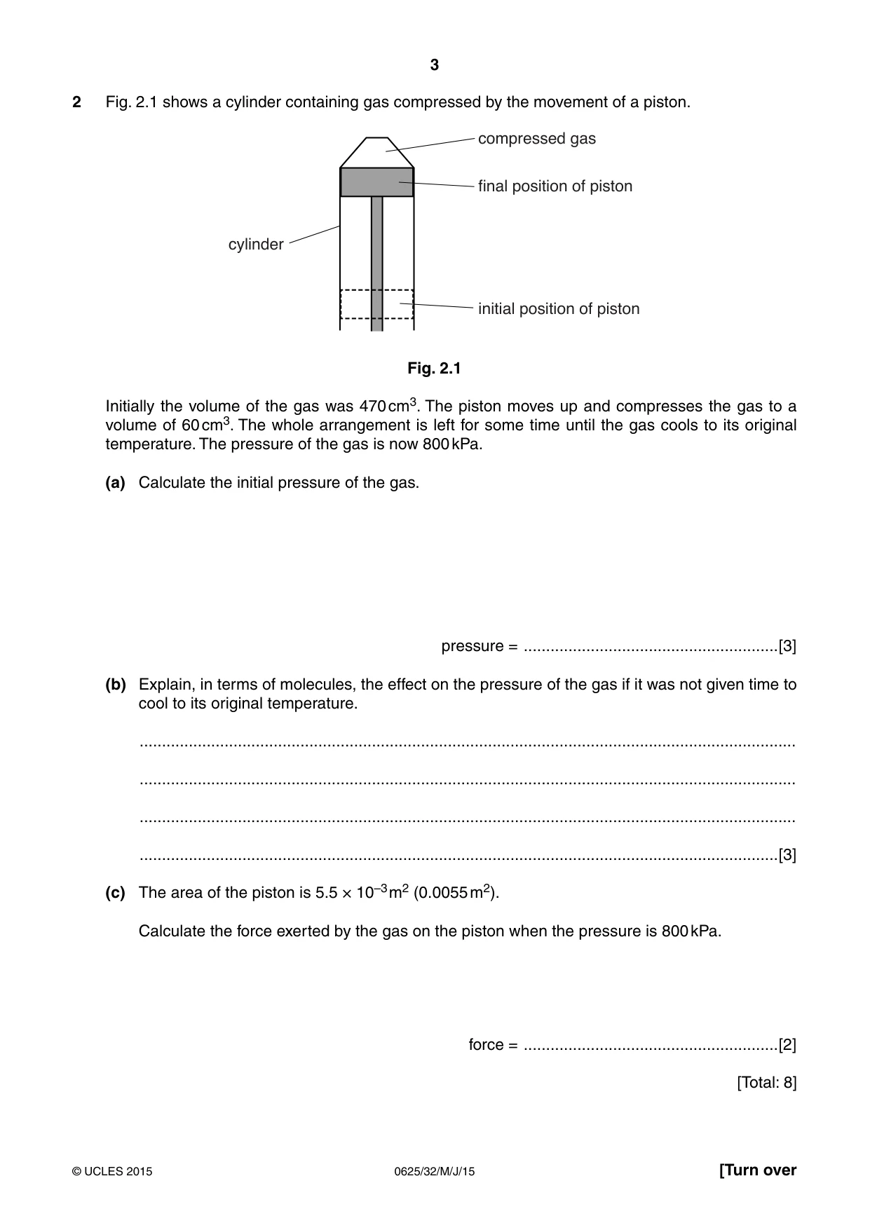
2 Fig. 2.1 shows a cylinder containing gas compressed by the movement of a piston. compressed gas final position of piston cylinder initial position of piston Fig. 2.1 Initially the volume of the gas was 470 cm3. The piston moves up and compresses the gas to a volume of 60 cm3. The whole arrangement is left for some time until the gas cools to its original temperature. The pressure of the gas is now 800 kPa. (a) Calculate the initial pressure of the gas. pressure = .........................................................[3] (b) Explain, in terms of molecules, the effect on the pressure of the gas if it was not given time to cool to its original temperature. ................................................................................................................................................... ................................................................................................................................................... ................................................................................................................................................... ...............................................................................................................................................[3] (c) The area of the piston is 5.5 × 10⁻³ m2 (0.0055 m2). Calculate the force exerted by the gas on the piston when the pressure is 800 kPa. force = .........................................................[2] [Total: 8]
Mark scheme: 2 (a) p1V1 = p2V2 in any form OR (p1 =) p2V2 ÷ V1 C1 p1 × 470 = 800 × 60 OR (p1 =) 800 × 60 ÷ 470 C1 102 OR 100 kPa A1 (b) molecules would move faster/have more KE B1 more (frequent)/harder collisions with walls/cylinder/piston B1 pressure increases B1 (c) use of p = F ÷ A in any form OR (F =) p A C1 (F =) 4400 N A1
Q3 · An athlete of mass 64 kg is bouncing up and down on a trampoline
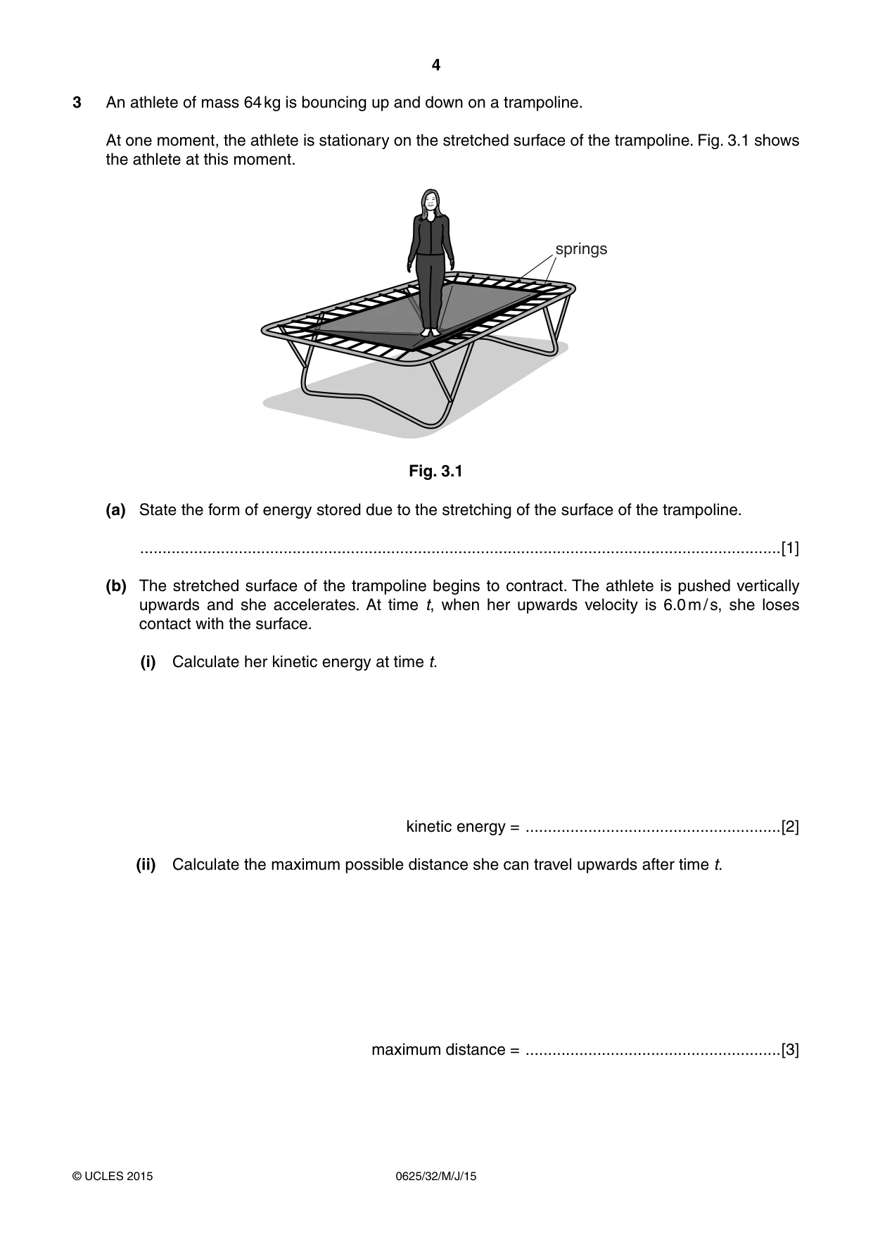
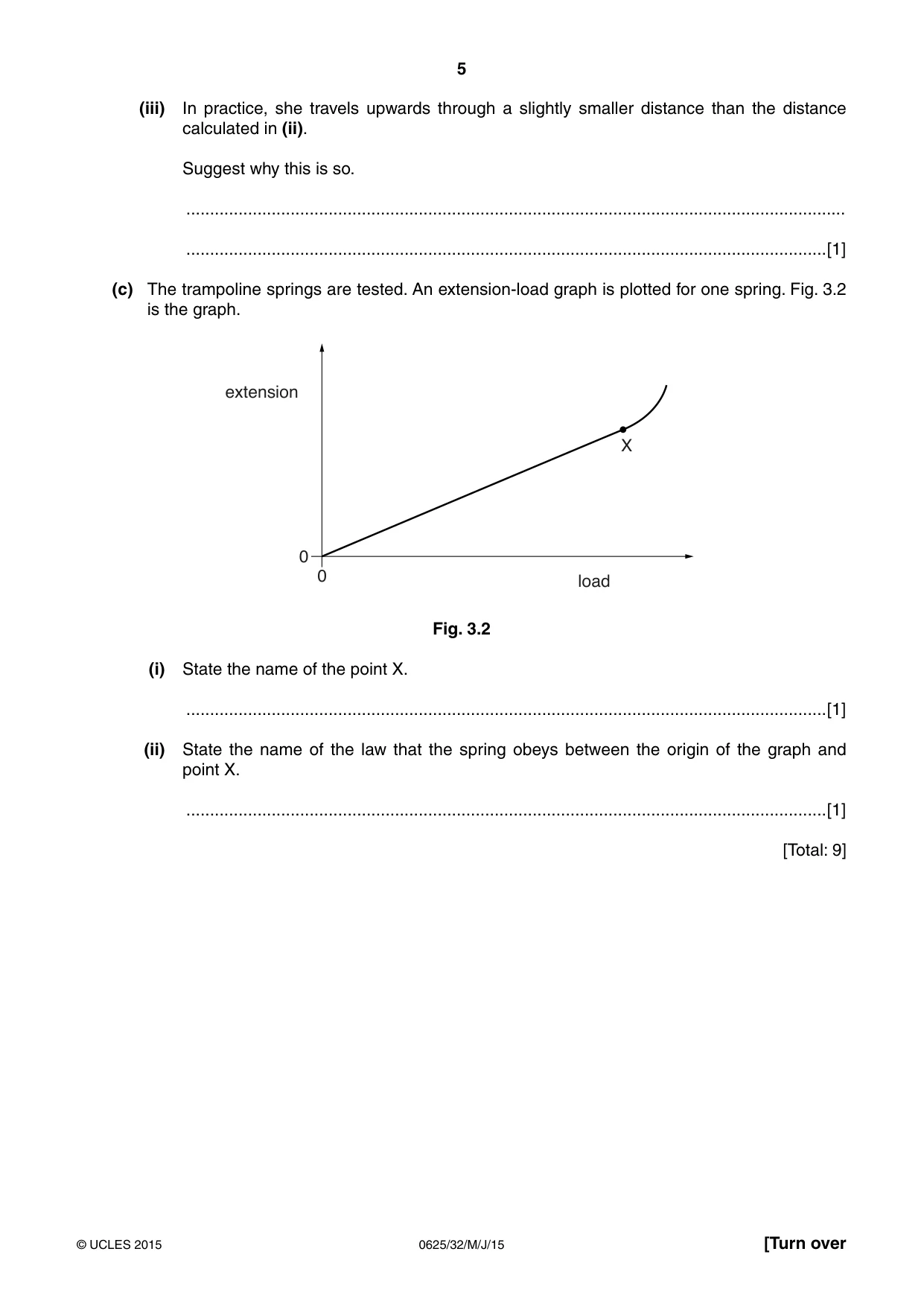
3 An athlete of mass 64 kg is bouncing up and down on a trampoline. At one moment, the athlete is stationary on the stretched surface of the trampoline. Fig. 3.1 shows the athlete at this moment. springs Fig. 3.1 (a) State the form of energy stored due to the stretching of the surface of the trampoline. ...............................................................................................................................................[1] (b) The stretched surface of the trampoline begins to contract. The athlete is pushed vertically upwards and she accelerates. At time t, when her upwards velocity is 6.0 m / s, she loses contact with the surface. (i) Calculate her kinetic energy at time t. kinetic energy = .........................................................[2] (ii) Calculate the maximum possible distance she can travel upwards after time t. maximum distance = .........................................................[3] (iii) In practice, she travels upwards through a slightly smaller distance than the distance calculated in (ii). Suggest why this is so. ........................................................................................................................................... .......................................................................................................................................[1] (c) The trampoline springs are tested. An extension-load graph is plotted for one spring. Fig. 3.2 is the graph. extension X 0 0 load Fig. 3.2 (i) State the name of the point X. .......................................................................................................................................[1] (ii) State the name of the law that the spring obeys between the origin of the graph and point X. .......................................................................................................................................[1] [Total: 9]
Mark scheme: 3 (a) strain / elastic (potential) (energy) B1 (b) (i) (KE =) ½ m v2 in any form C1 1200 J A1 (ii) (G)PE (gained) = KE (lost) in any form C1 (G)PE = m g h OR h = PE ÷ mg in any form C1 1.8 m e.c.f. from (b)(i) A1 (iii) friction with air OR air resistance OR thermal energy / heat produced/lost B1 (c) (i) limit of proportionality B1 (ii) Hooke’s law B1
Q4 · A device used as a thermocouple thermometer
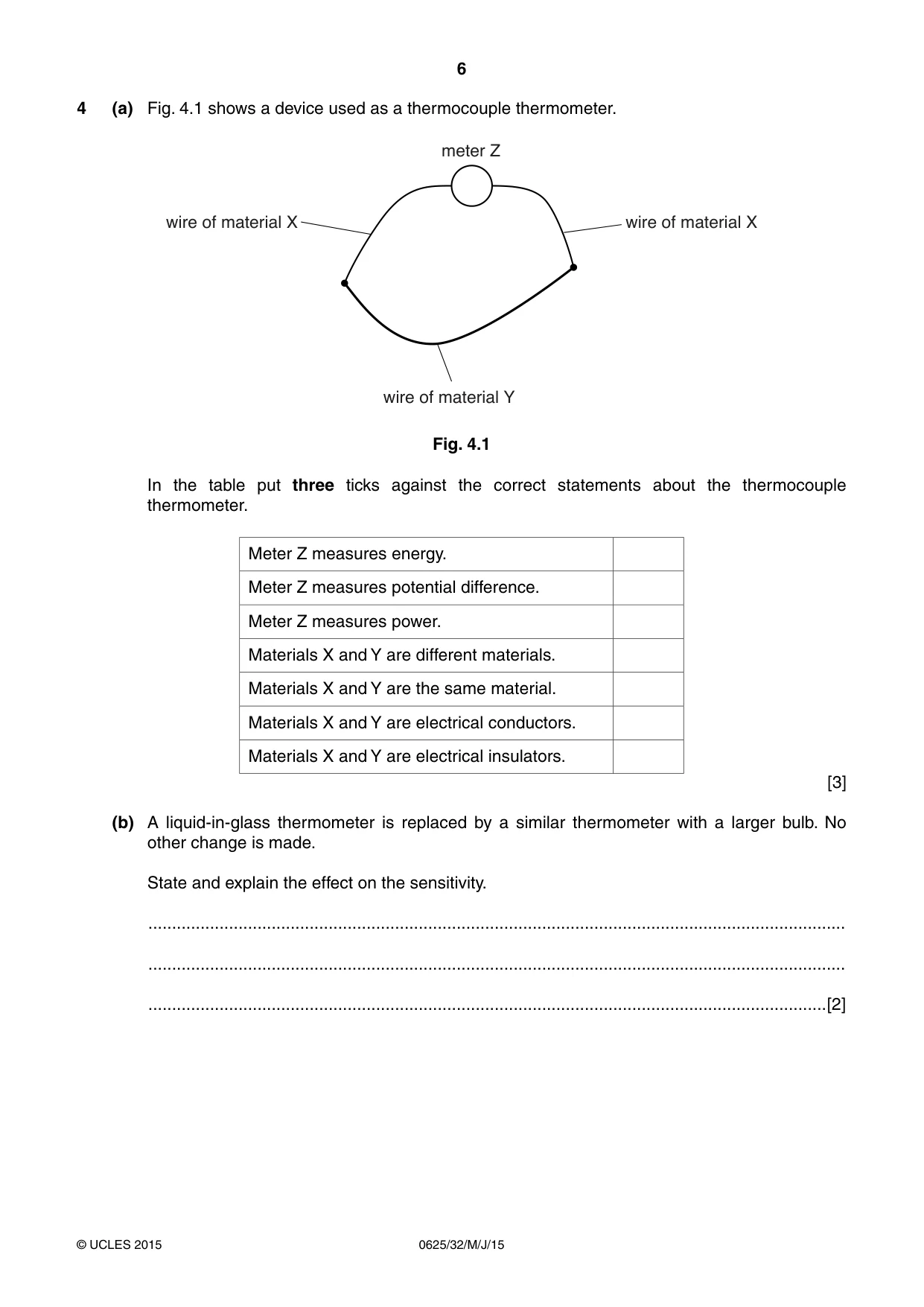
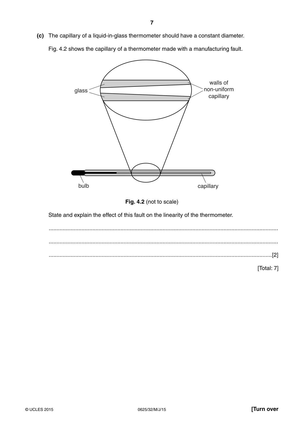
4 (a) Fig. 4.1 shows a device used as a thermocouple thermometer. meter Z wire of material X wire of material X wire of material Y Fig. 4.1 In the table put three ticks against the correct statements about the thermocouple thermometer. Meter Z measures energy. Meter Z measures potential difference. Meter Z measures power. Materials X and Y are different materials. Materials X and Y are the same material. Materials X and Y are electrical conductors. Materials X and Y are electrical insulators. [3] (b) A liquid-in-glass thermometer is replaced by a similar thermometer with a larger bulb. No other change is made. State and explain the effect on the sensitivity. ................................................................................................................................................... ................................................................................................................................................... ...............................................................................................................................................[2] (c) The capillary of a liquid-in-glass thermometer should have a constant diameter. Fig. 4.2 shows the capillary of a thermometer made with a manufacturing fault. walls of glass non-uniform capillary bulb capillary Fig. 4.2 (not to scale) State and explain the effect of this fault on the linearity of the thermometer. ................................................................................................................................................... ................................................................................................................................................... ...............................................................................................................................................[2] [Total: 7]
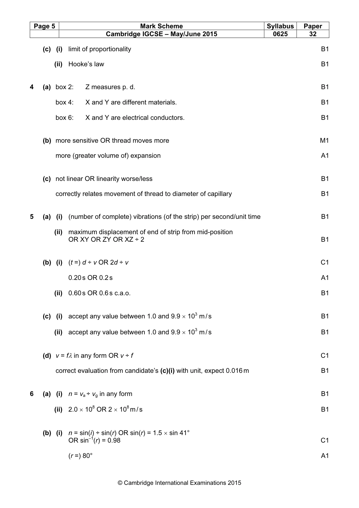
Mark scheme: 4 (a) box 2: Z measures p. d. B1 box 4: X and Y are different materials. B1 box 6: X and Y are electrical conductors. B1 (b) more sensitive OR thread moves more M1 more (greater volume of) expansion A1 (c) not linear OR linearity worse/less B1 correctly relates movement of thread to diameter of capillary B1
Q5 · A metal strip, held in a clamp
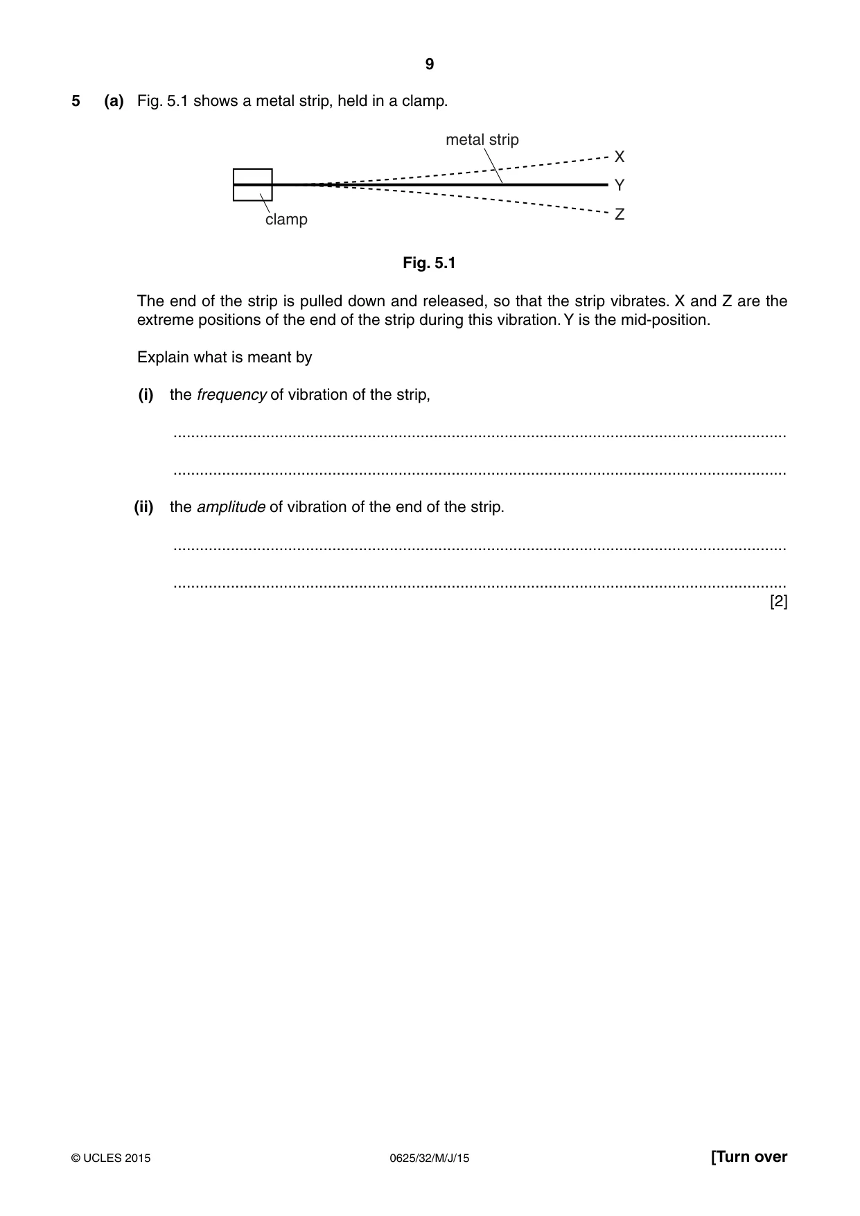
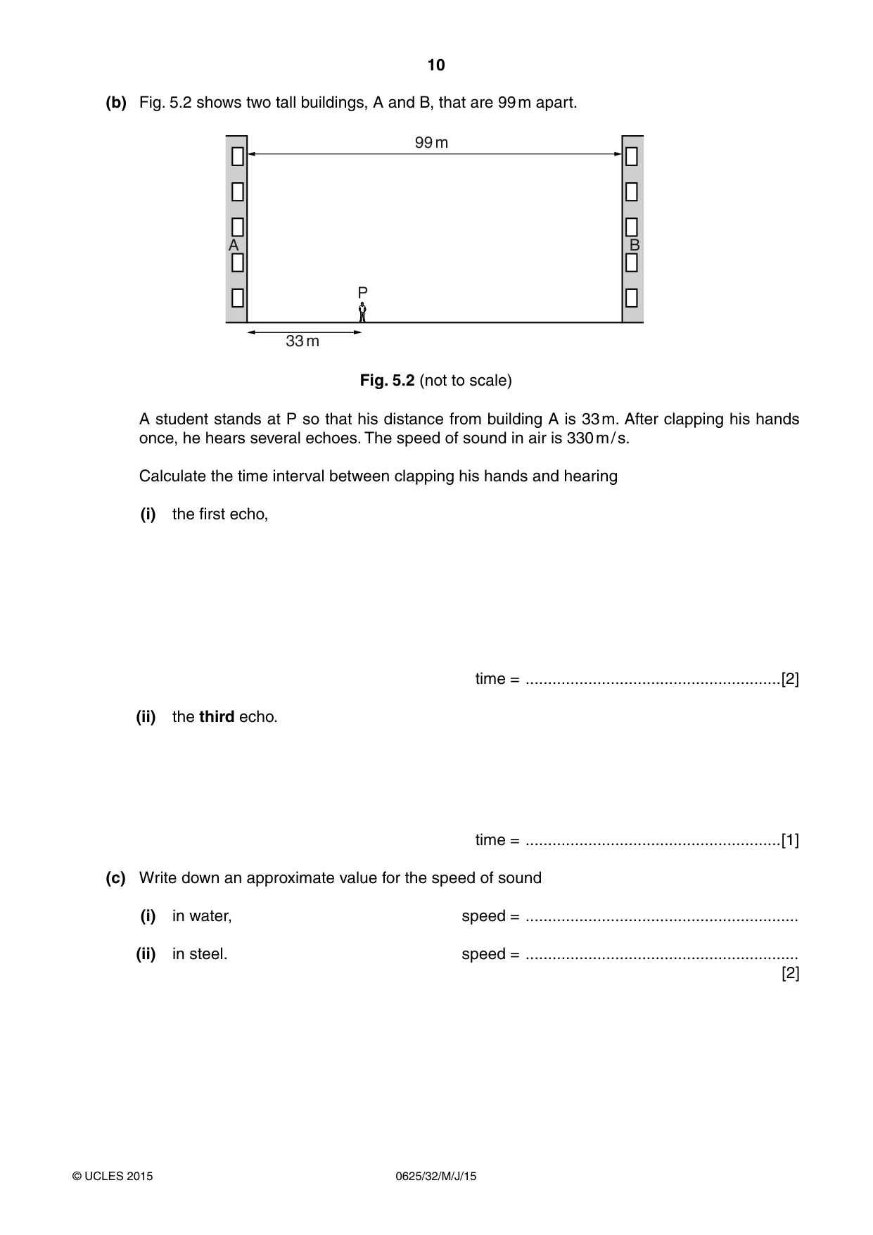
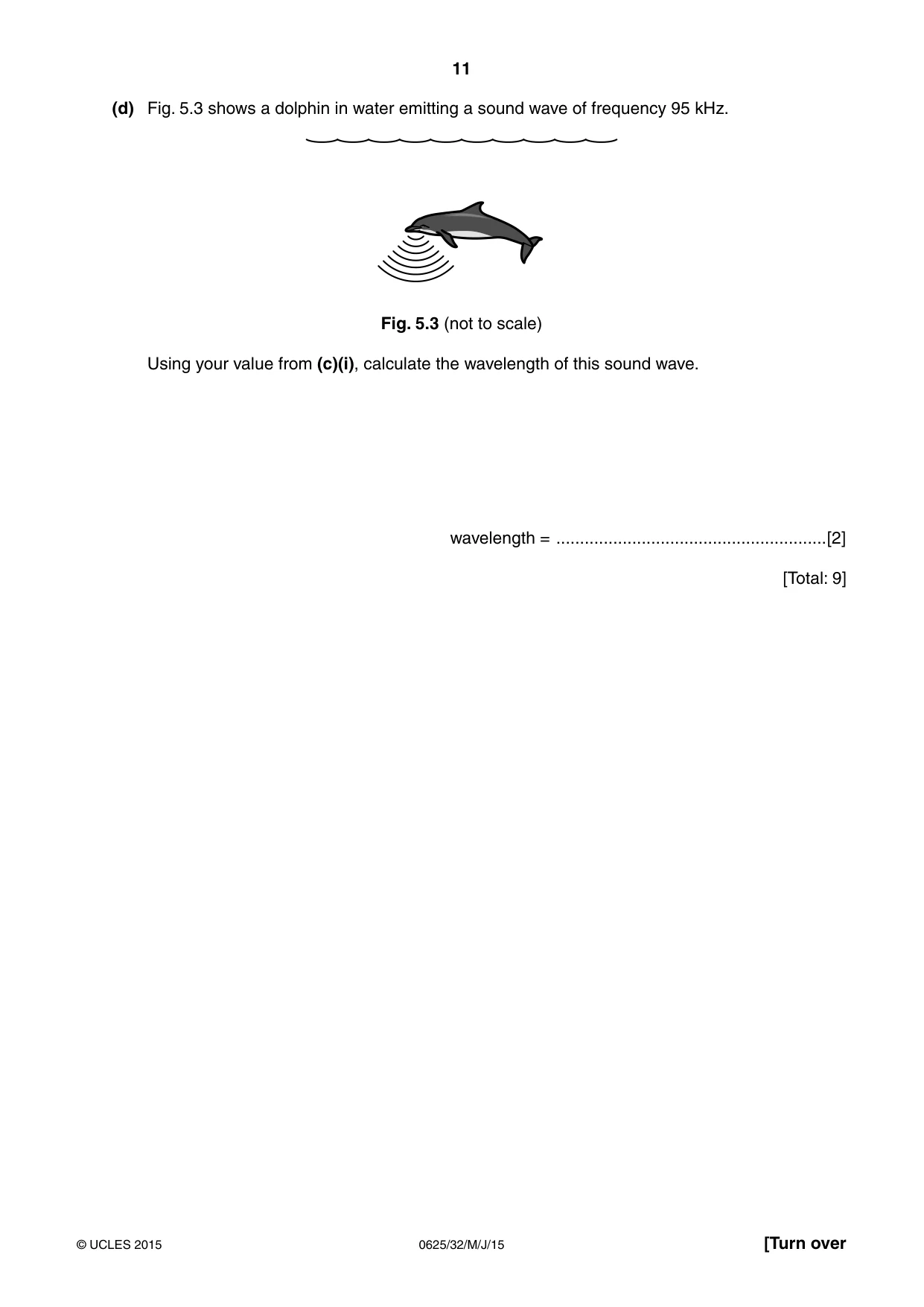
5 (a) Fig. 5.1 shows a metal strip, held in a clamp. metal strip X Y Z clamp Fig. 5.1 The end of the strip is pulled down and released, so that the strip vibrates. X and Z are the extreme positions of the end of the strip during this vibration. Y is the mid-position. Explain what is meant by (i) the frequency of vibration of the strip, ........................................................................................................................................... ........................................................................................................................................... (ii) the amplitude of vibration of the end of the strip. ........................................................................................................................................... ........................................................................................................................................... [2] (b) Fig. 5.2 shows two tall buildings, A and B, that are 99 m apart. 99 m A B P 33 m Fig. 5.2 (not to scale) A student stands at P so that his distance from building A is 33 m. After clapping his hands once, he hears several echoes. The speed of sound in air is 330 m / s. Calculate the time interval between clapping his hands and hearing (i) the first echo, time = .........................................................[2] (ii) the third echo. time = .........................................................[1] (c) Write down an approximate value for the speed of sound (i) in water, speed = ............................................................. (ii) in steel. speed = ............................................................. [2] (d) Fig. 5.3 shows a dolphin in water emitting a sound wave of frequency 95 kHz. Fig. 5.3 (not to scale) Using your value from (c)(i), calculate the wavelength of this sound wave. wavelength = .........................................................[2] [Total: 9]
Mark scheme: 5 (a) (i) (number of complete) vibrations (of the strip) per second/unit time B1 (ii) maximum displacement of end of strip from mid-position OR XY OR ZY OR XZ ÷ 2 B1 (b) (i) (t =) d ÷ v OR 2d ÷ v C1 0.20 s OR 0.2 s A1 (ii) 0.60 s OR 0.6 s c.a.o. B1 (c) (i) accept any value between 1.0 and 9.9 × 10³ m / s B1 (ii) accept any value between 1.0 and 9.9 × 10³ m / s B1 (d) v = fλ in any form OR v ÷ f C1 correct evaluation from candidate’s (c)(i) with unit, expect 0.016 m B1
Q6 · The refractive index n of glass in air is 1.5
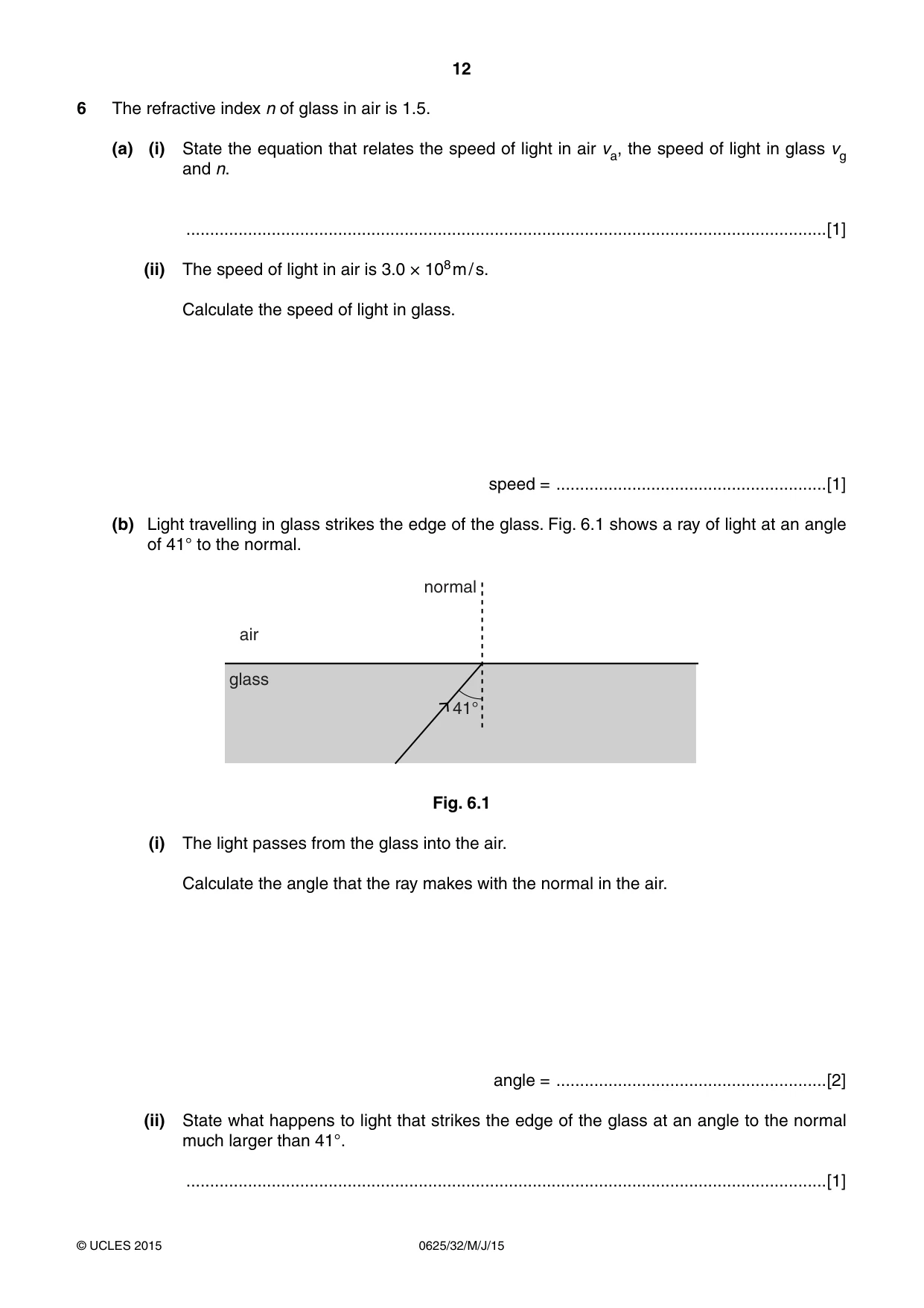
6 The refractive index n of glass in air is 1.5. (a) (i) State the equation that relates the speed of light in air va, the speed of light in glass vg and n. .......................................................................................................................................[1] (ii) The speed of light in air is 3.0 × 10⁸ m / s. Calculate the speed of light in glass. speed = .........................................................[1] (b) Light travelling in glass strikes the edge of the glass. Fig. 6.1 shows a ray of light at an angle of 41° to the normal. normal air glass 41° Fig. 6.1 (i) The light passes from the glass into the air. Calculate the angle that the ray makes with the normal in the air. angle = .........................................................[2] (ii) State what happens to light that strikes the edge of the glass at an angle to the normal much larger than 41°. .......................................................................................................................................[1] (c) Describe one example of how optical fibres are used in medicine. ................................................................................................................................................... ................................................................................................................................................... ................................................................................................................................................... ...............................................................................................................................................[2] [Total: 7]
Mark scheme: 6 (a) (i) n = va ÷ vg in any form B1 (ii) 2.0 × 10⁸ OR 2 × 10⁸ m / s B1 (b) (i) n = sin(i) ÷ sin(r) OR sin(r) = 1.5 × sin 41° OR sin–1(r) = 0.98 C1 (r =) 80° A1 (ii) total (internal) reflection OR no refraction OR all light reflected B1 (c) some indication of multiple reflections in optical fibre, accept from diagram B1 appropriate further information, e.g. endoscope OR looking/illuminating inside body B1
Q7 · A physics teacher suspends two pointers in a magnetic field
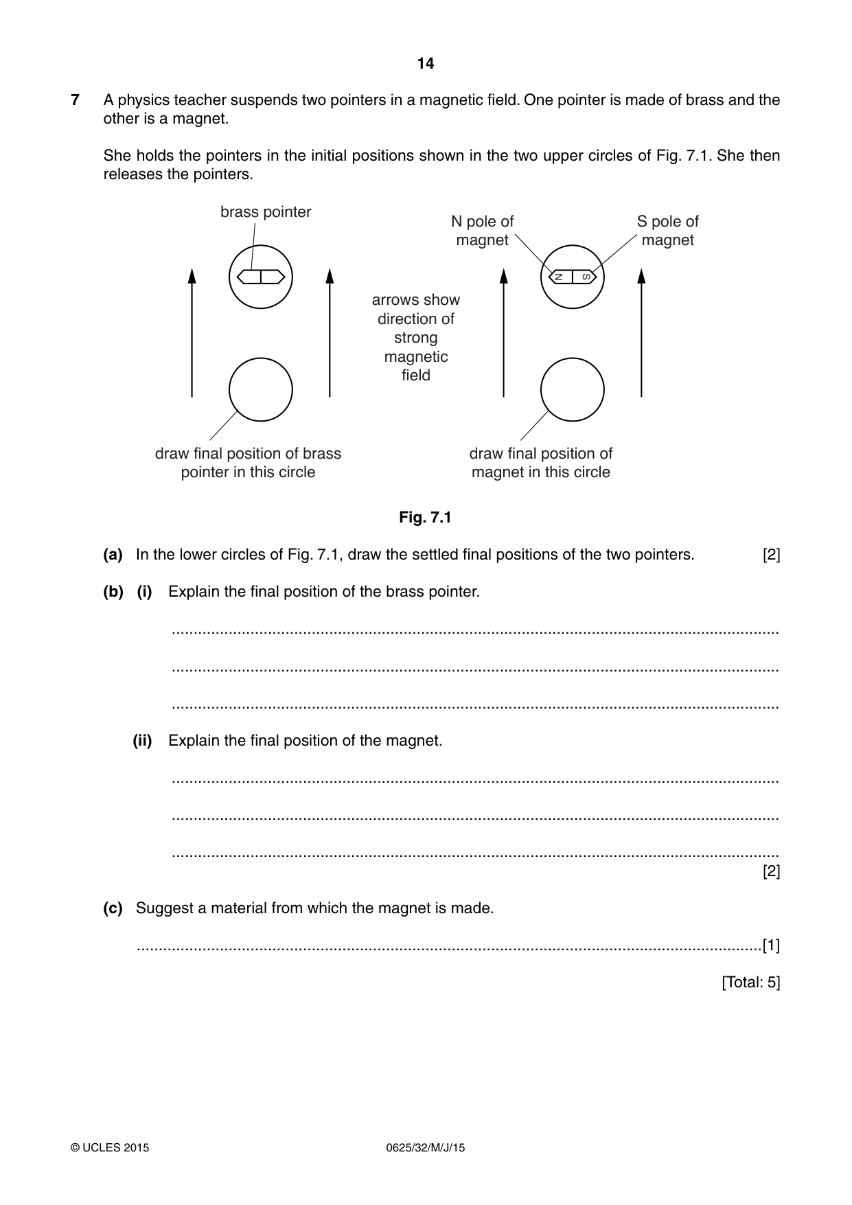
7 A physics teacher suspends two pointers in a magnetic field. One pointer is made of brass and the other is a magnet. She holds the pointers in the initial positions shown in the two upper circles of Fig. 7.1. She then releases the pointers. brass pointer N pole of S pole of magnet magnet N S arrows show direction of strong magnetic field draw final position of brass draw final position of pointer in this circle magnet in this circle Fig. 7.1 (a) In the lower circles of Fig. 7.1, draw the settled final positions of the two pointers. [2] (b) (i) Explain the final position of the brass pointer. ........................................................................................................................................... ........................................................................................................................................... ........................................................................................................................................... (ii) Explain the final position of the magnet. ........................................................................................................................................... ........................................................................................................................................... ........................................................................................................................................... [2] (c) Suggest a material from which the magnet is made. ...............................................................................................................................................[1] [Total: 5]
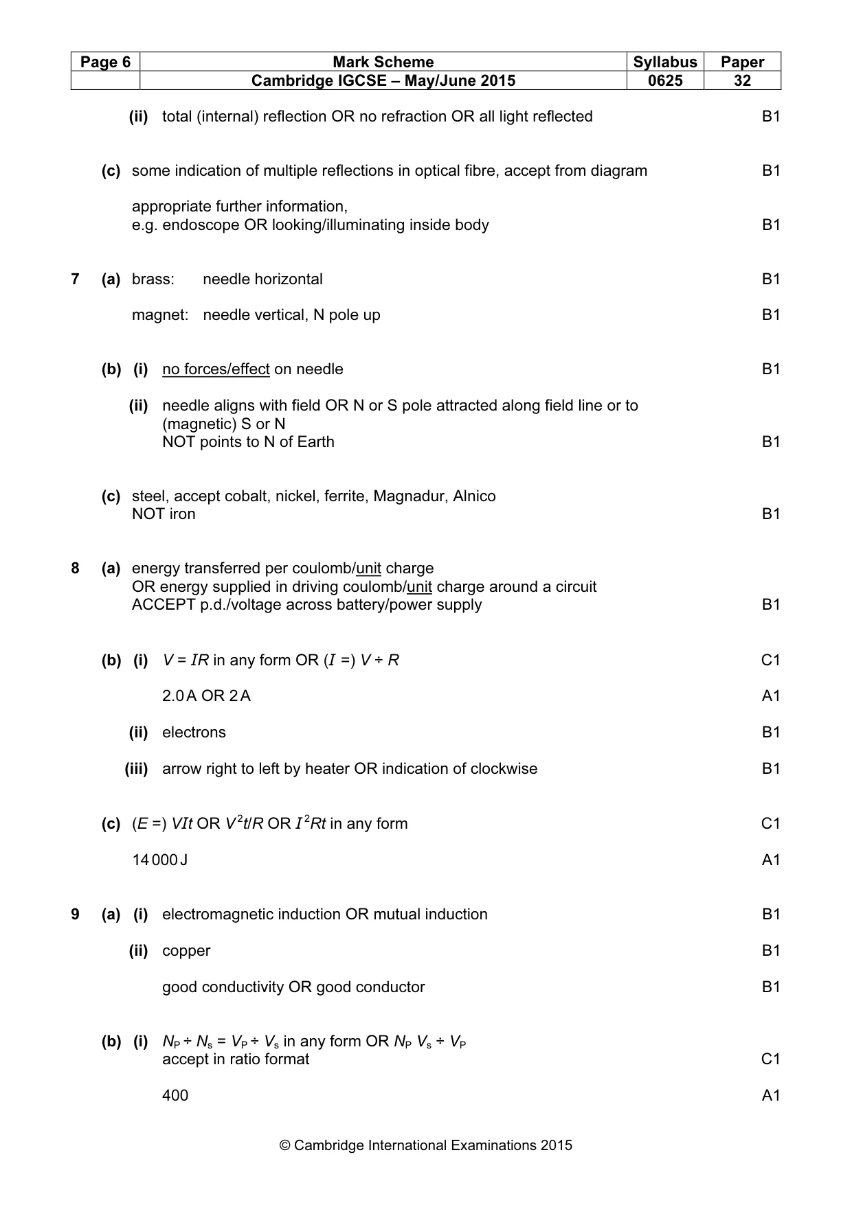
Mark scheme: 7 (a) brass: needle horizontal B1 magnet: needle vertical, N pole up B1 (b) (i) no forces/effect on needle B1 (ii) needle aligns with field OR N or S pole attracted along field line or to (magnetic) S or N NOT points to N of Earth B1 (c) steel, accept cobalt, nickel, ferrite, Magnadur, Alnico NOT iron B1
Q8 · A circuit containing a battery of electromotive force (e.m.f.) 12 V and a heater of…
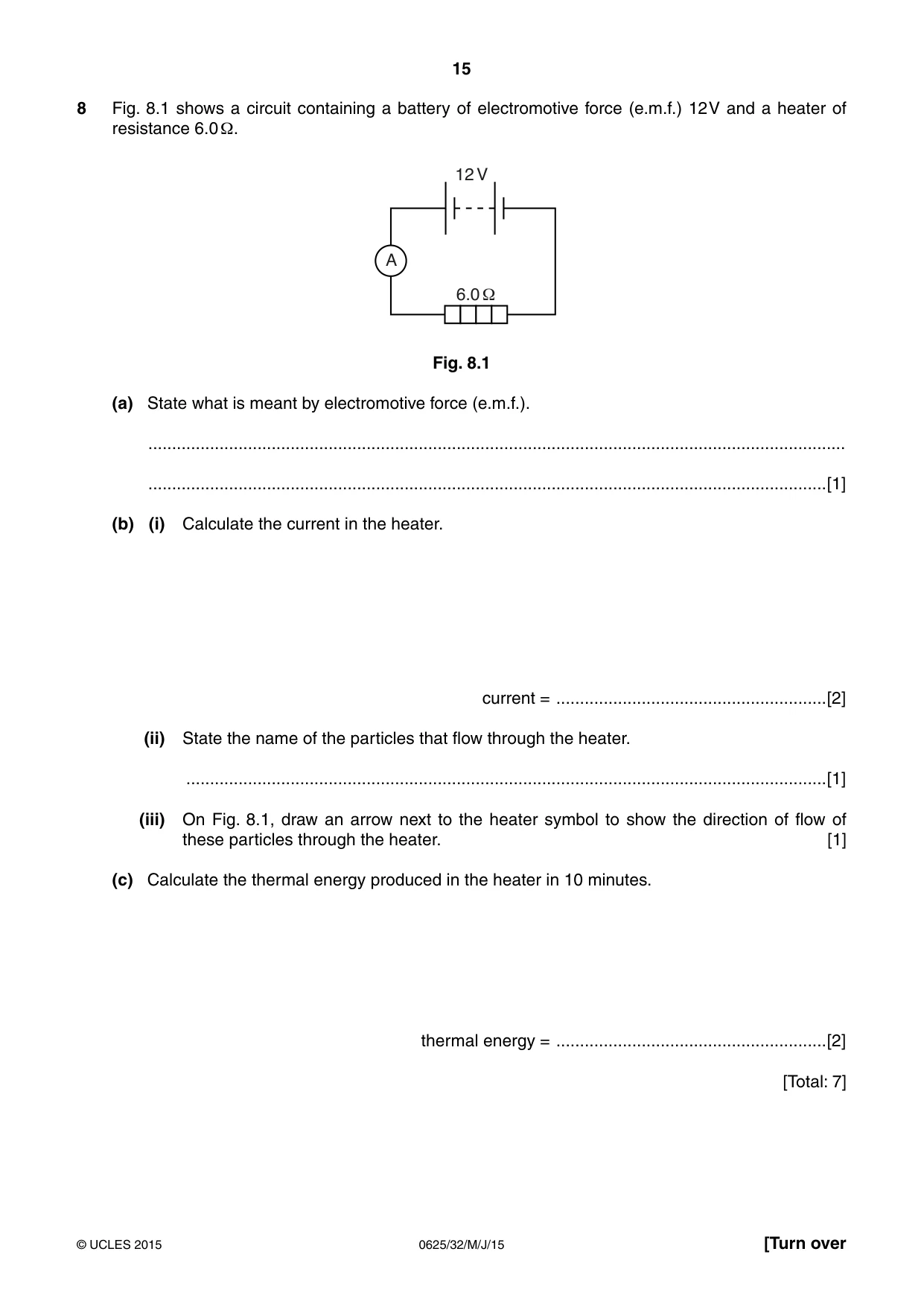
8 Fig. 8.1 shows a circuit containing a battery of electromotive force (e.m.f.) 12 V and a heater of resistance 6.0 Ω. 12 V A 6.0 1 Fig. 8.1 (a) State what is meant by electromotive force (e.m.f.). ................................................................................................................................................... ...............................................................................................................................................[1] (b) (i) Calculate the current in the heater. current = .........................................................[2] (ii) State the name of the particles that flow through the heater. .......................................................................................................................................[1] (iii) On Fig. 8.1, draw an arrow next to the heater symbol to show the direction of flow of these particles through the heater. [1] (c) Calculate the thermal energy produced in the heater in 10 minutes. thermal energy = .........................................................[2] [Total: 7]
Mark scheme: 8 (a) energy transferred per coulomb/unit charge OR energy supplied in driving coulomb/unit charge around a circuit ACCEPT p.d./voltage across battery/power supply B1 (b) (i) V = IR in any form OR (I =) V ÷ R C1 2.0 A OR 2 A A1 (ii) electrons B1 (iii) arrow right to left by heater OR indication of clockwise B1 (c) (E =) VIt OR V 2t/R OR I 2Rt in any form C1 14 000 J A1
Question 9
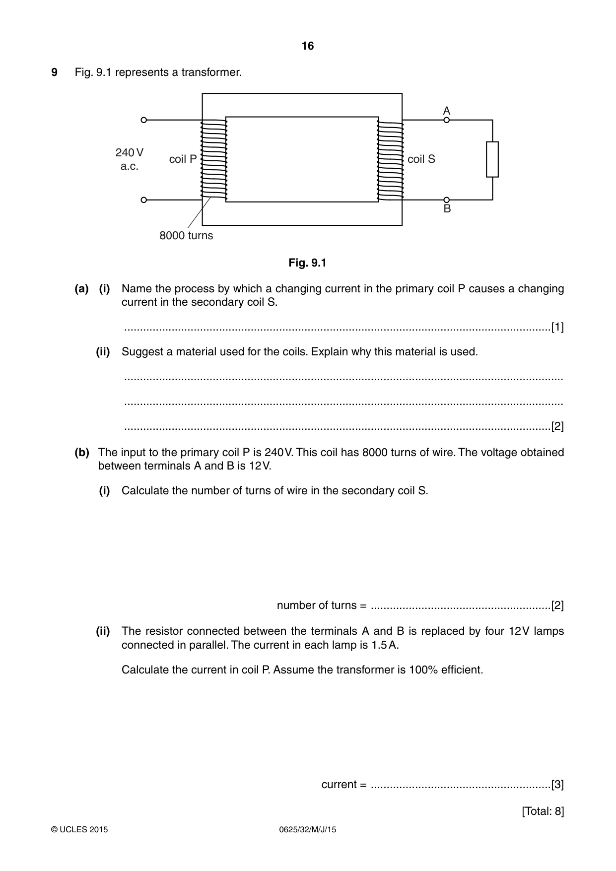
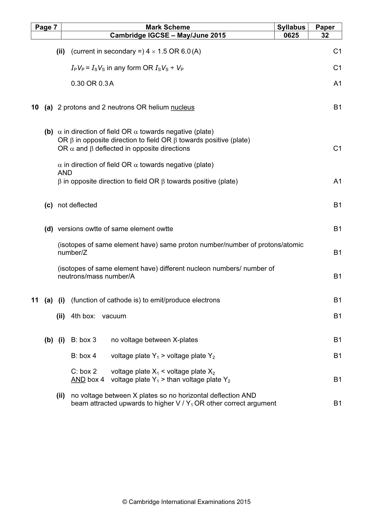
9 Fig. 9.1 represents a transformer. A 240 V coil P coil S a.c. B 8000 turns Fig. 9.1 (a) (i) Name the process by which a changing current in the primary coil P causes a changing current in the secondary coil S. .......................................................................................................................................[1] (ii) Suggest a material used for the coils. Explain why this material is used. ........................................................................................................................................... ........................................................................................................................................... .......................................................................................................................................[2] (b) The input to the primary coil P is 240 V. This coil has 8000 turns of wire. The voltage obtained between terminals A and B is 12 V. (i) Calculate the number of turns of wire in the secondary coil S. number of turns = .........................................................[2] (ii) The resistor connected between the terminals A and B is replaced by four 12 V lamps connected in parallel. The current in each lamp is 1.5 A. Calculate the current in coil P. Assume the transformer is 100% efficient. current = .........................................................[3] [Total: 8]
Mark scheme: 9 (a) (i) electromagnetic induction OR mutual induction B1 (ii) copper B1 good conductivity OR good conductor B1 (b) (i) NP ÷ Ns = VP ÷ Vs in any form OR NP Vs ÷ VP accept in ratio format C1 400 A1 (ii) (current in secondary =) 4 × 1.5 OR 6.0 (A) C1 IPVP = ISVS in any form OR ISVS ÷ VP C1 0.30 OR 0.3 A A1
Q10 · State the nature of an α-particle
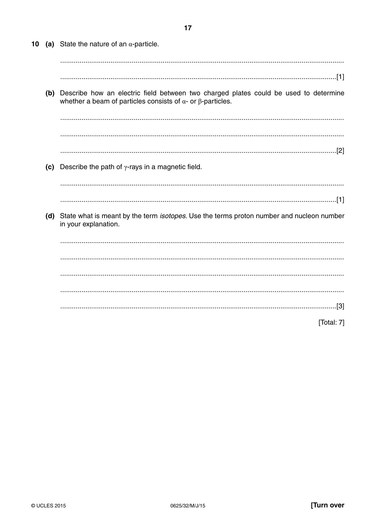
10 (a) State the nature of an α-particle. ................................................................................................................................................... ...............................................................................................................................................[1] (b) Describe how an electric field between two charged plates could be used to determine whether a beam of particles consists of α- or β-particles. ................................................................................................................................................... ................................................................................................................................................... ...............................................................................................................................................[2] (c) Describe the path of γ-rays in a magnetic field. ................................................................................................................................................... ...............................................................................................................................................[1] (d) State what is meant by the term isotopes. Use the terms proton number and nucleon number in your explanation. ................................................................................................................................................... ................................................................................................................................................... ................................................................................................................................................... ................................................................................................................................................... ...............................................................................................................................................[3] [Total: 7]
Mark scheme: 10 (a) 2 protons and 2 neutrons OR helium nucleus B1 (b) α in direction of field OR α towards negative (plate) OR β in opposite direction to field OR β towards positive (plate) OR α and β deflected in opposite directions C1 α in direction of field OR α towards negative (plate) AND β in opposite direction to field OR β towards positive (plate) A1 (c) not deflected B1 (d) versions owtte of same element owtte B1 (isotopes of same element have) same proton number/number of protons/atomic number/Z B1 (isotopes of same element have) different nucleon numbers/ number of neutrons/mass number/A B1
Q11 · The main components of a cathode-ray oscilloscope
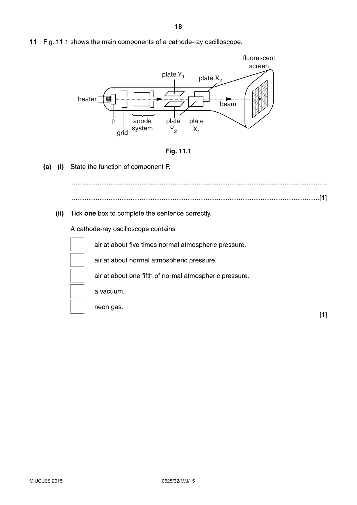
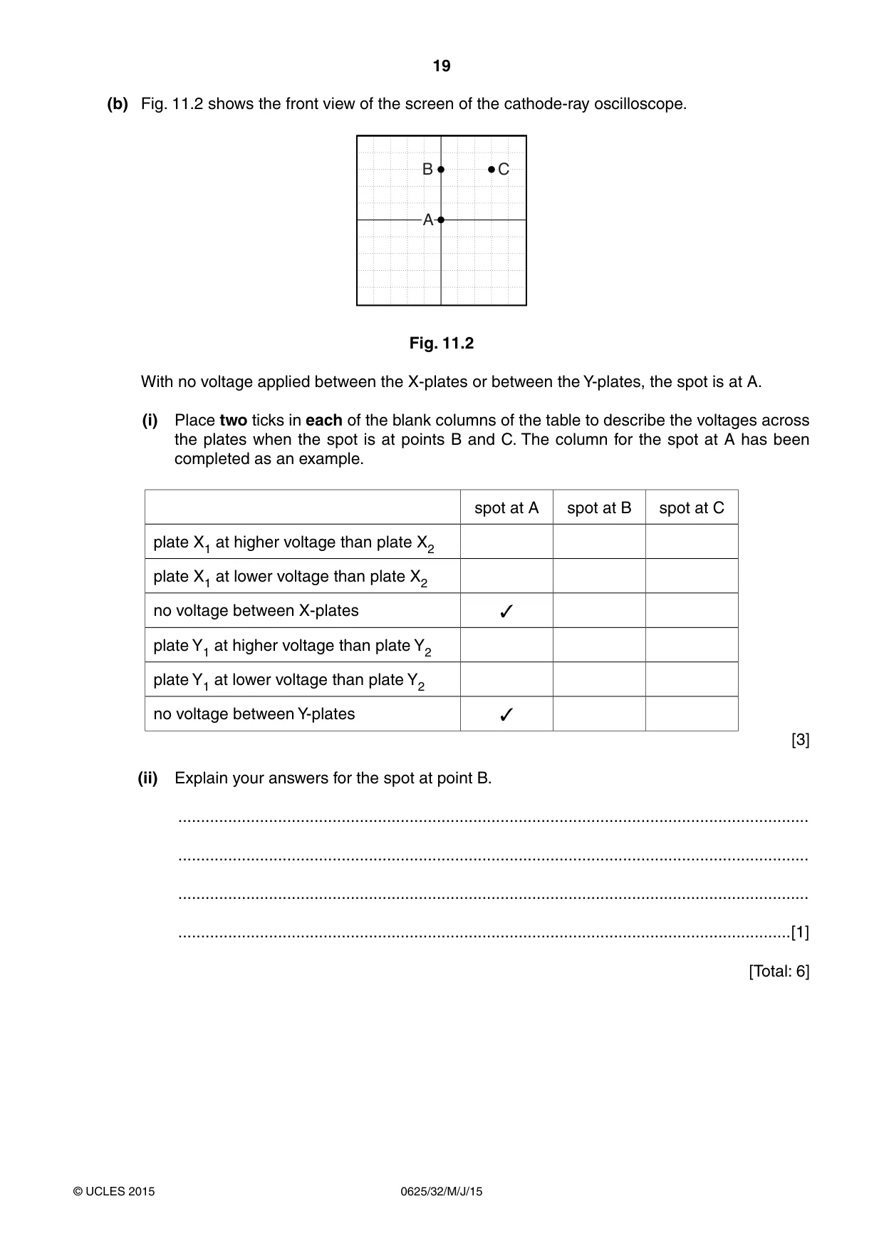
11 Fig. 11.1 shows the main components of a cathode-ray oscilloscope. fluorescent screen plate Y1 plate X2 heater beam P anode plate plate system Y2 X1 grid Fig. 11.1 (a) (i) State the function of component P. ........................................................................................................................................... .......................................................................................................................................[1] (ii) Tick one box to complete the sentence correctly. A cathode-ray oscilloscope contains air at about five times normal atmospheric pressure. air at about normal atmospheric pressure. air at about one fifth of normal atmospheric pressure. a vacuum. neon gas. [1] (b) Fig. 11.2 shows the front view of the screen of the cathode-ray oscilloscope. B C A Fig. 11.2 With no voltage applied between the X-plates or between the Y-plates, the spot is at A. (i) Place two ticks in each of the blank columns of the table to describe the voltages across the plates when the spot is at points B and C. The column for the spot at A has been completed as an example. spot at A spot at B spot at C plate X1 at higher voltage than plate X2 plate X1 at lower voltage than plate X2 no voltage between X-plates ✓ plate Y1 at higher voltage than plate Y2 plate Y1 at lower voltage than plate Y2 no voltage between Y-plates ✓ [3] (ii) Explain your answers for the spot at point B. ........................................................................................................................................... ........................................................................................................................................... ........................................................................................................................................... .......................................................................................................................................[1] [Total: 6]
Mark scheme: 11 (a) (i) (function of cathode is) to emit/produce electrons B1 (ii) 4th box: vacuum B1 (b) (i) B: box 3 no voltage between X-plates B1 B: box 4 voltage plate Y1 > voltage plate Y2 B1 C: box 2 voltage plate X1 < voltage plate X2 AND box 4 voltage plate Y1 > than voltage plate Y2 B1 (ii) no voltage between X plates so no horizontal deflection AND beam attracted upwards to higher V / Y1 OR other correct argument B1
What was in this paper
The subtopics covered by these 11 questions, and how many questions each got. Open one in a new tab to see every Cambridge question on it.
What you needed in this session
Cambridge’s own grade thresholds for 2015 May/June, Paper 3 · Variant 2. A higher threshold means an easier paper — the bar moves with how the cohort did.