Cambridge IGCSE Physics 0625 — 2022 Oct/Nov Paper 3 · Variant 2
0625/32/O/N/22 · 11 questions · 80 marks · ≈90 min
The question paper and its mark scheme, free to read here and free to download. This is Cambridge’s own paper, exactly as it was sat.
Question paper16 pages
Mark scheme12 pages
Answers below. Sit the paper first if you are practising.
Questions as text
Q1 · A skydiver jumps from an aeroplane
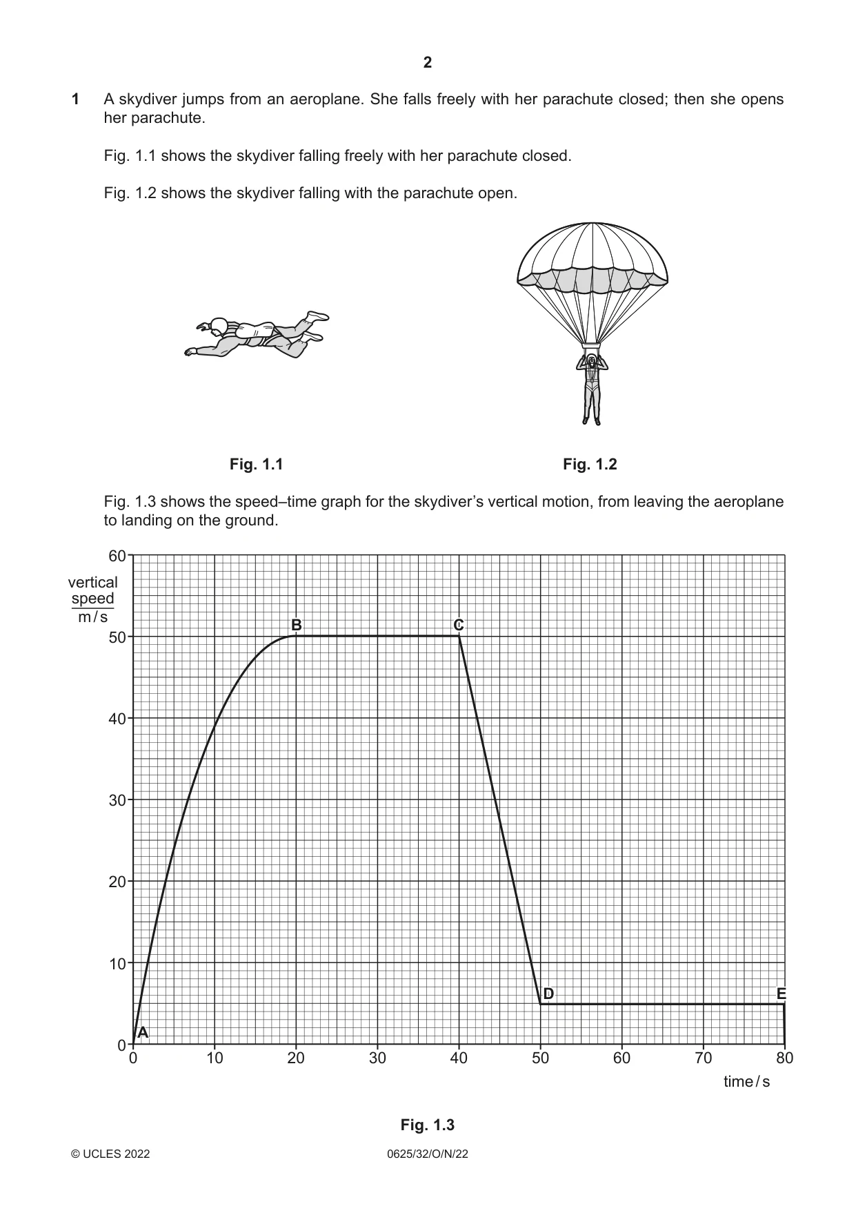
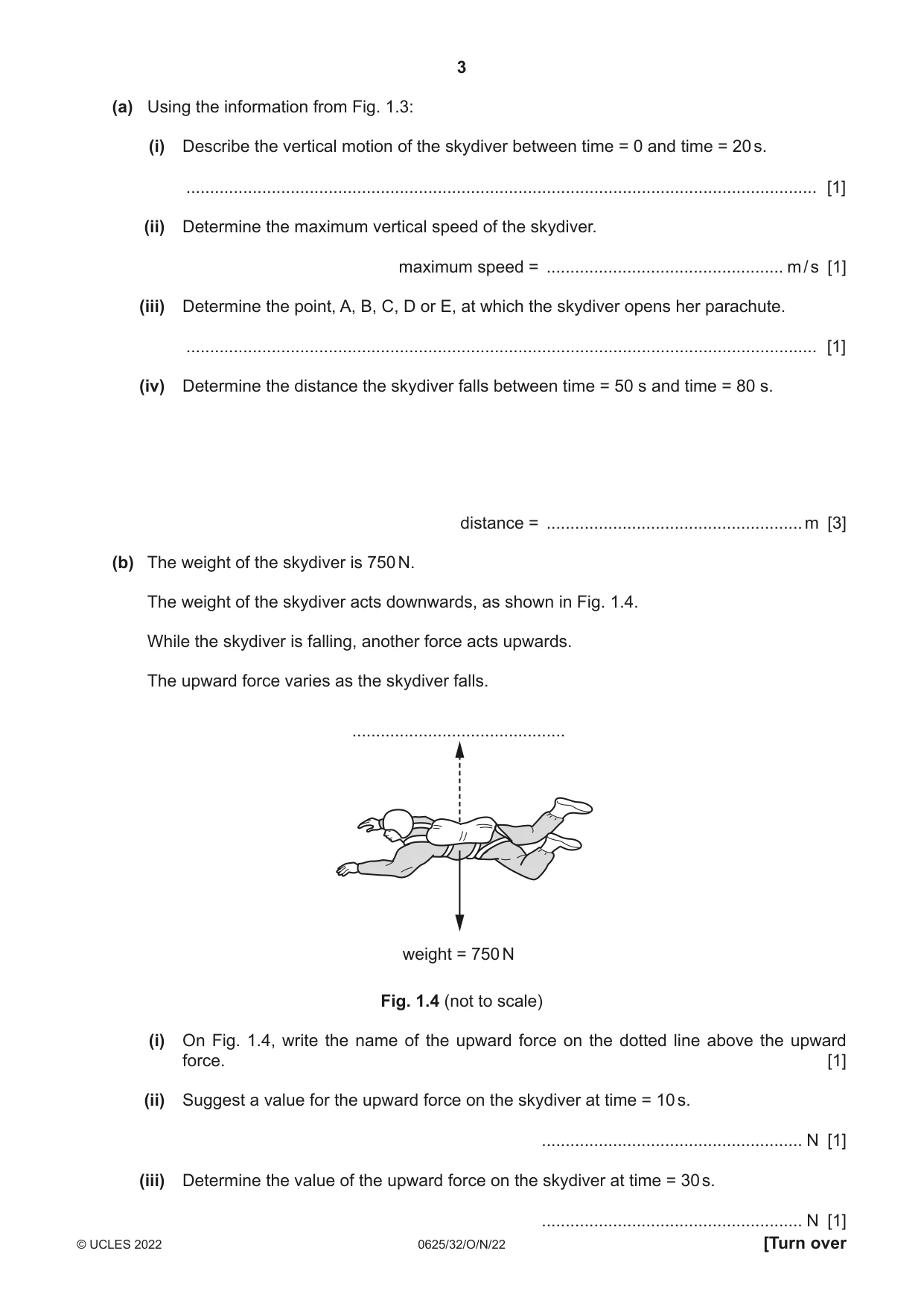
1 A skydiver jumps from an aeroplane. She falls freely with her parachute closed; then she opens her parachute. Fig. 1.1 shows the skydiver falling freely with her parachute closed. Fig. 1.2 shows the skydiver falling with the parachute open. Fig. 1.1 Fig. 1.2 Fig. 1.3 shows the speed–time graph for the skydiver’s vertical motion, from leaving the aeroplane to landing on the ground. 60 vertical speed m / s BB CC 50 40 30 20 10 DD EE A 0 0 10 20 30 40 50 60 70 80 time / s Fig. 1.3 (a) Using the information from Fig. 1.3: (i) Describe the vertical motion of the skydiver between time = 0 and time = 20 s. ..................................................................................................................................... [1] (ii) Determine the maximum vertical speed of the skydiver. maximum speed = .................................................. m / s [1] (iii) Determine the point, A, B, C, D or E, at which the skydiver opens her parachute. ..................................................................................................................................... [1] (iv) Determine the distance the skydiver falls between time = 50 s and time = 80 s. distance = ...................................................... m [3] (b) The weight of the skydiver is 750 N. The weight of the skydiver acts downwards, as shown in Fig. 1.4. While the skydiver is falling, another force acts upwards. The upward force varies as the skydiver falls. ............................................. weight = 750 N Fig. 1.4 (not to scale) (i) On Fig. 1.4, write the name of the upward force on the dotted line above the upward force. [1] (ii) Suggest a value for the upward force on the skydiver at time = 10 s. ....................................................... N [1] (iii) Determine the value of the upward force on the skydiver at time = 30 s. ....................................................... N [1] (c) The weight of the skydiver is 750 N. Calculate the mass of the skydiver. mass = ..................................................... kg [3] [Total: 12]
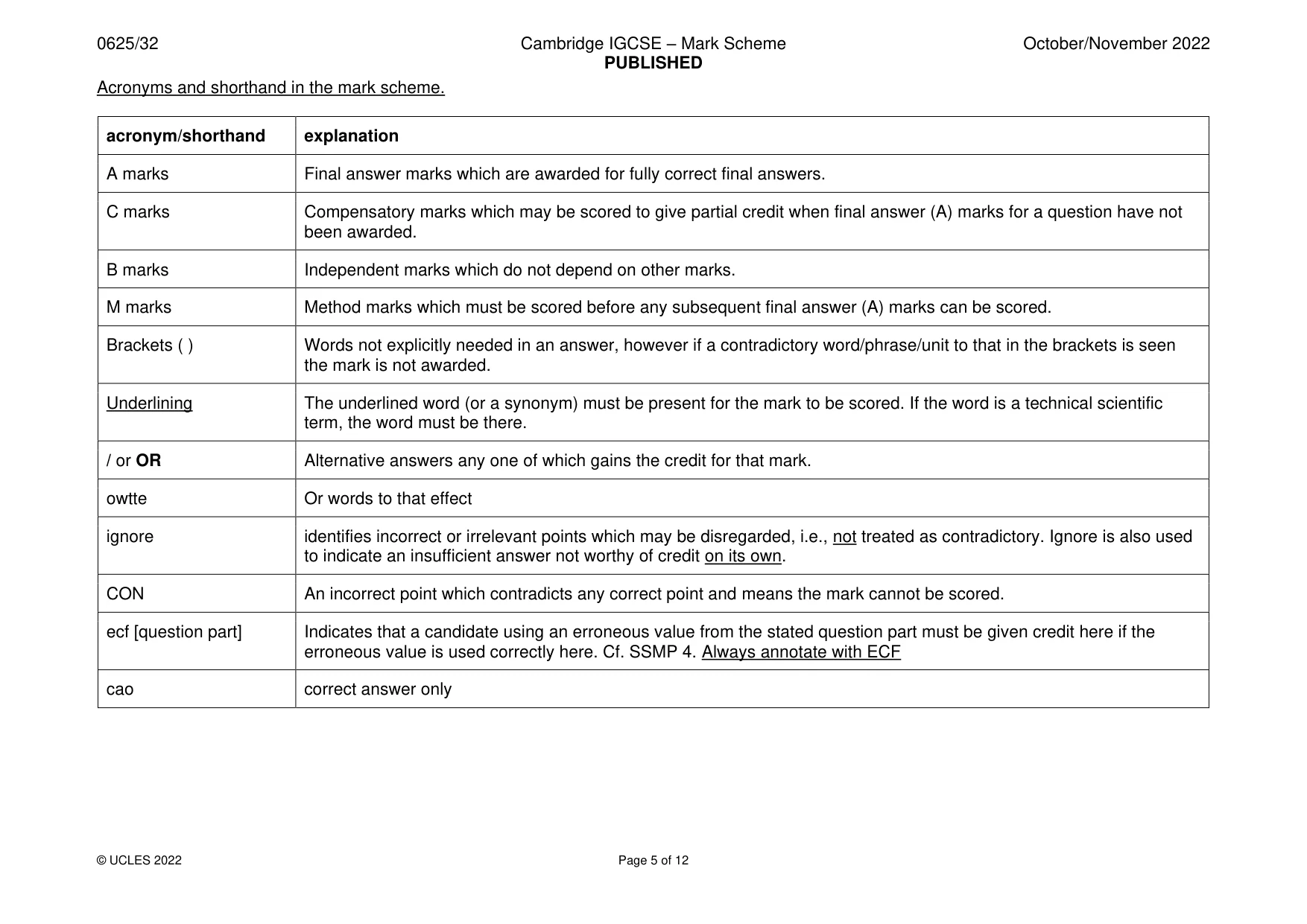
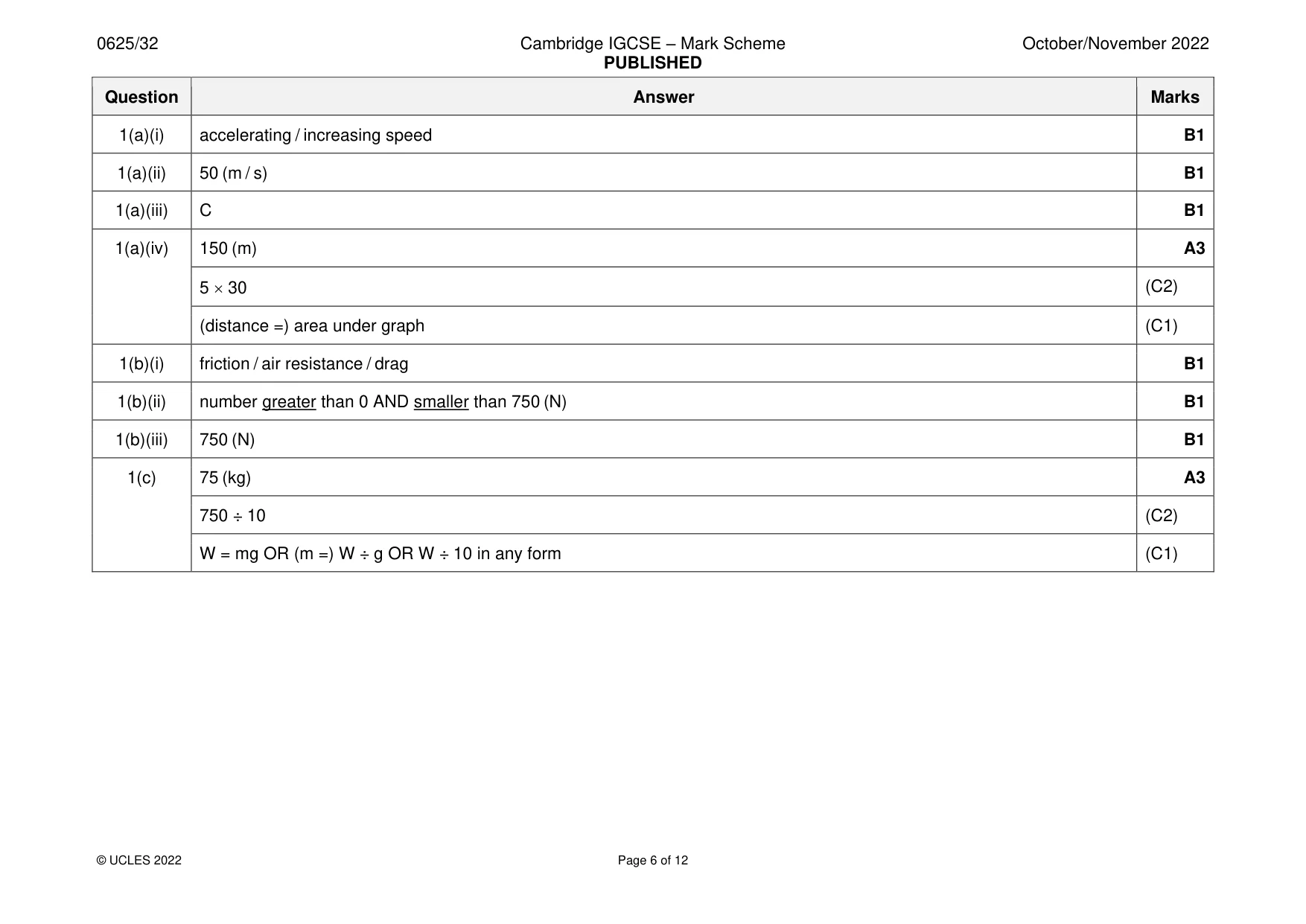
Mark scheme: Question Answer Marks 1(a)(i) accelerating / increasing speed B1 1(a)(ii) 50 (m / s) B1 1(a)(iii) C B1 1(a)(iv) 150 (m) A3 5 30 (C2) (distance =) area under graph (C1) 1(b)(i) friction / air resistance / drag B1 1(b)(ii) number greater than 0 AND smaller than 750 (N) B1 1(b)(iii) 750 (N) B1 1(c) 75 (kg) A3 750 ÷ 10 (C2) W = mg OR (m =) W ÷ g OR W ÷ 10 in any form (C1)
Q2 · A device for measuring gas pressure is connected to a gas supply as shown in Fig
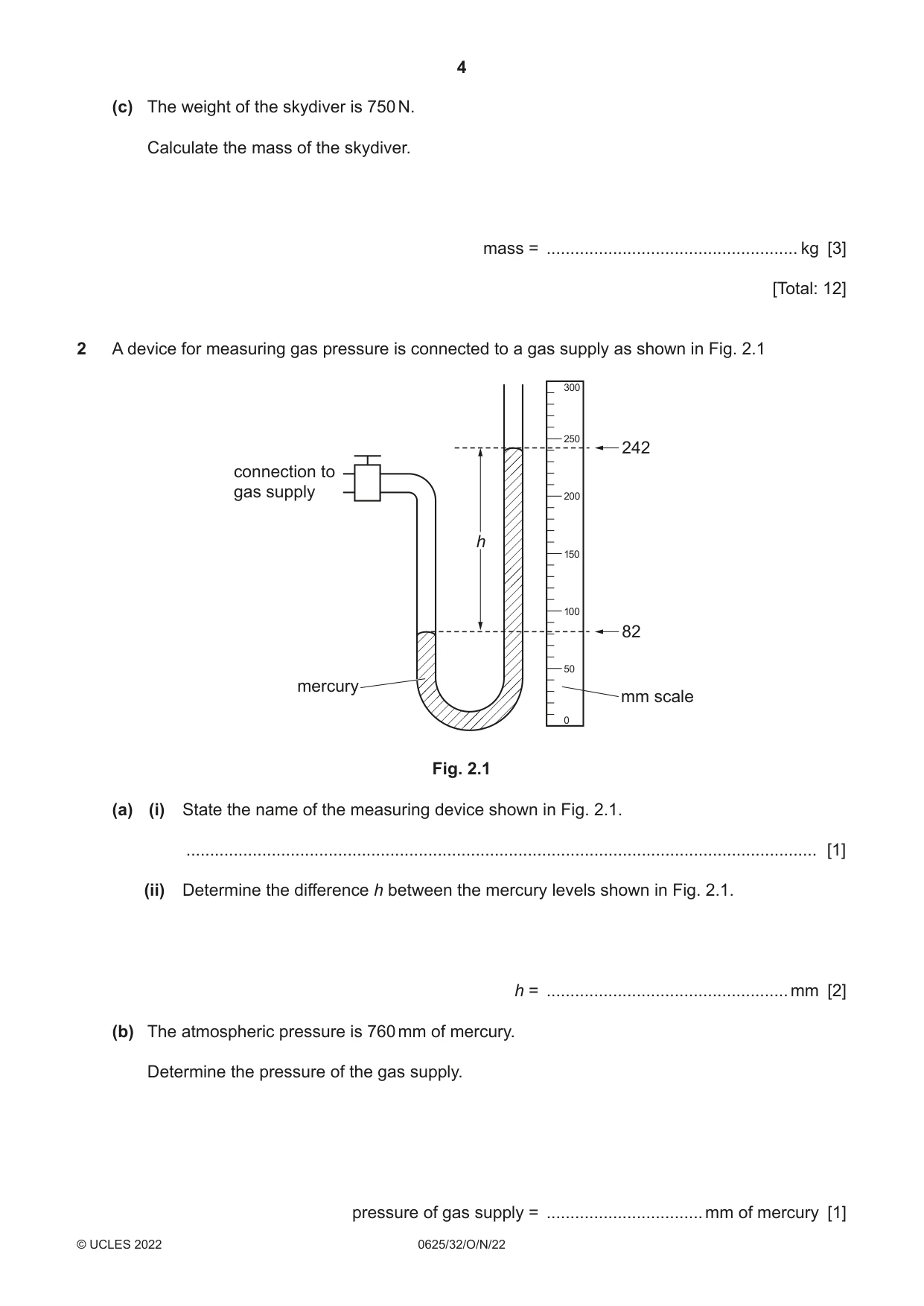
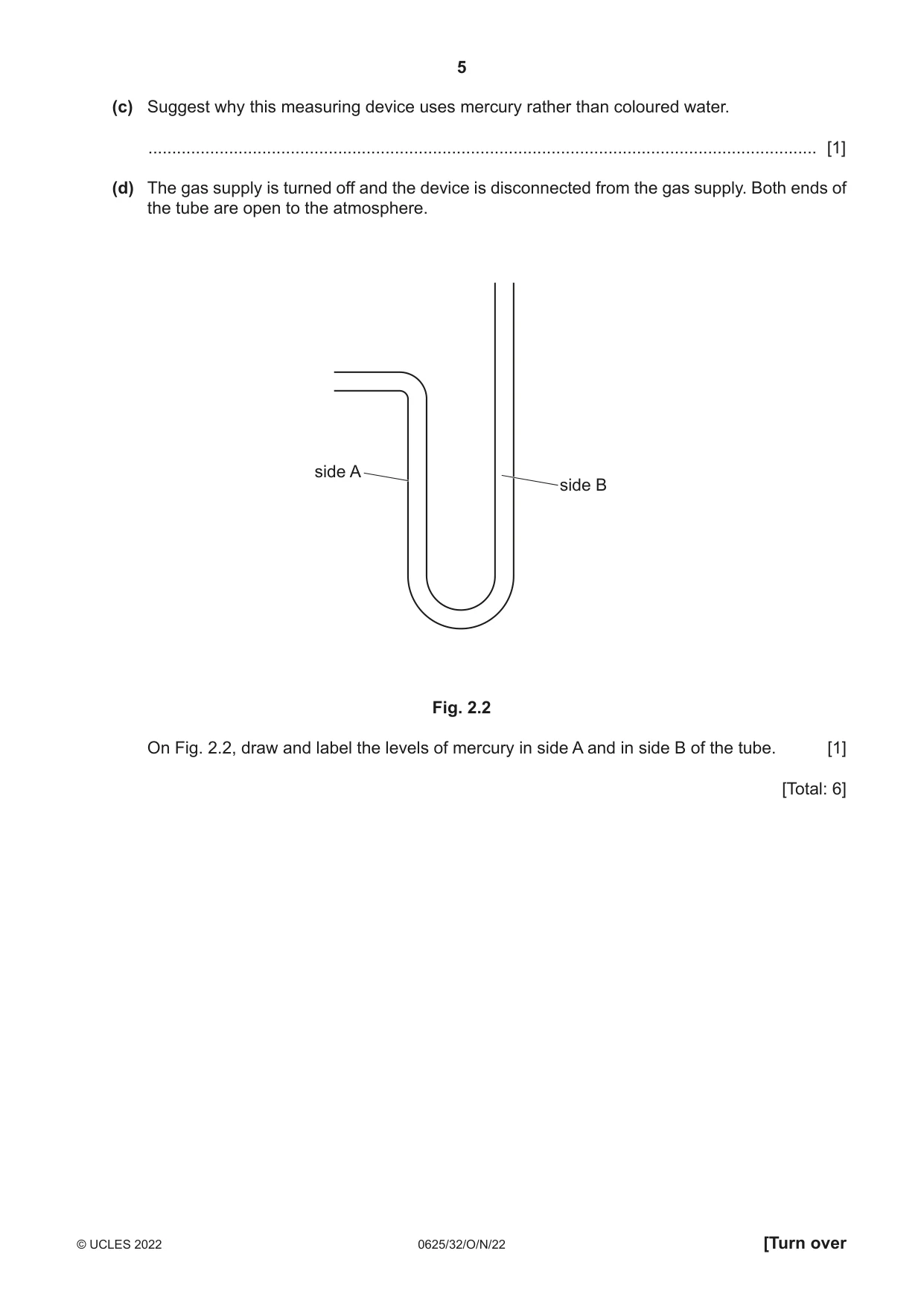
2 A device for measuring gas pressure is connected to a gas supply as shown in Fig. 2.1 300 250 242 connection to gas supply 200 h 150 100 82 50 mercury mm scale 0 Fig. 2.1 (a) (i) State the name of the measuring device shown in Fig. 2.1. ..................................................................................................................................... [1] (ii) Determine the difference h between the mercury levels shown in Fig. 2.1. h = ................................................... mm [2] (b) The atmospheric pressure is 760 mm of mercury. Determine the pressure of the gas supply. pressure of gas supply = ................................. mm of mercury [1] (c) Suggest why this measuring device uses mercury rather than coloured water. ............................................................................................................................................. [1] (d) The gas supply is turned off and the device is disconnected from the gas supply. Both ends of the tube are open to the atmosphere. side A side B Fig. 2.2 On Fig. 2.2, draw and label the levels of mercury in side A and in side B of the tube. [1] [Total: 6]
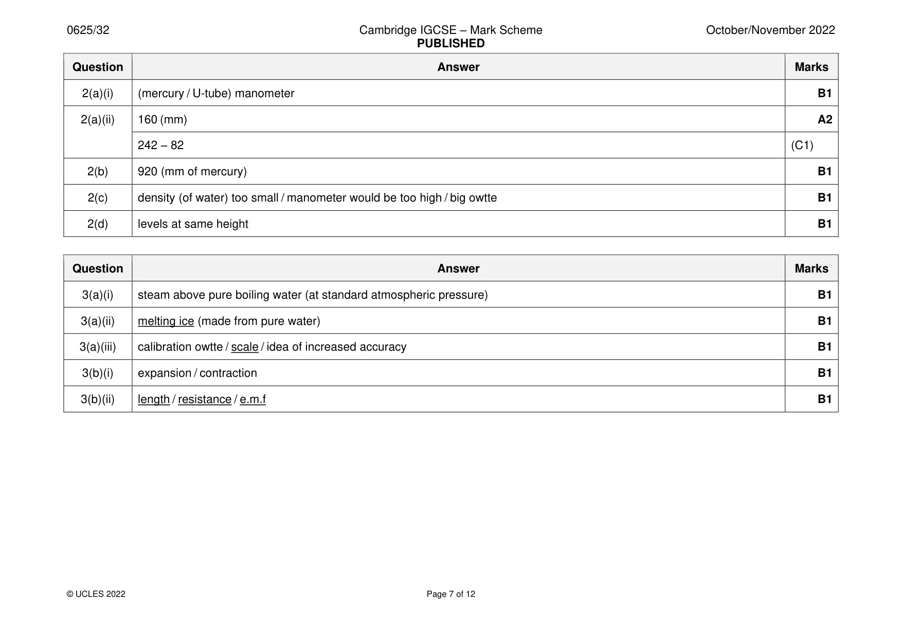
Mark scheme: 2(a)(i) (mercury / U-tube) manometer B1 2(a)(ii) 160 (mm) A2 242 – 82 (C1) 2(b) 920 (mm of mercury) B1 2(c) density (of water) too small / manometer would be too high / big owtte B1 2(d) levels at same height B1
Q3 · A liquid-in-glass thermometer has a scale with marks from –10 °C to 110 °C
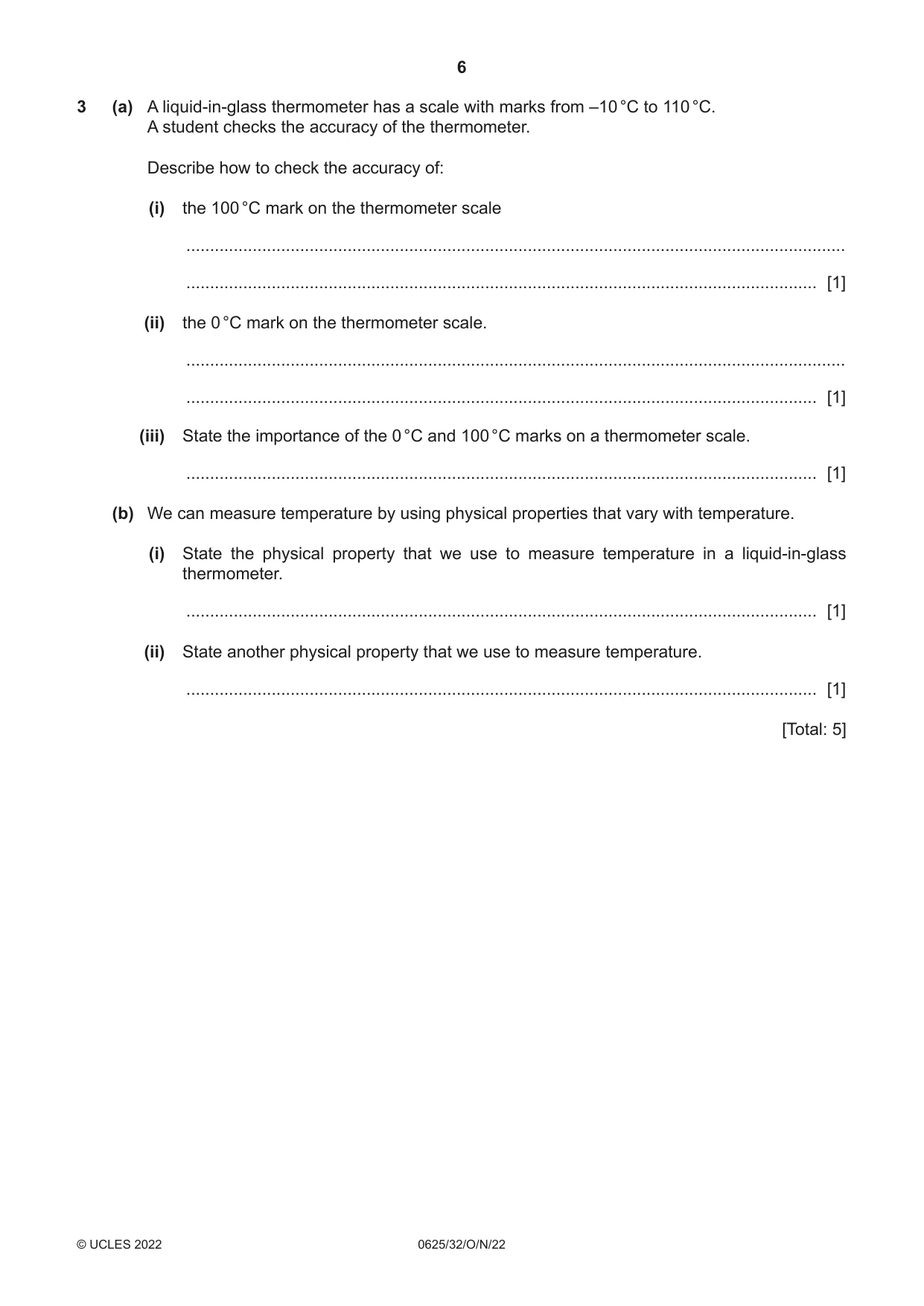
3 (a) A liquid-in-glass thermometer has a scale with marks from –10 °C to 110 °C. A student checks the accuracy of the thermometer. Describe how to check the accuracy of: (i) the 100 °C mark on the thermometer scale ........................................................................................................................................... ..................................................................................................................................... [1] (ii) the 0 °C mark on the thermometer scale. ........................................................................................................................................... ..................................................................................................................................... [1] (iii) State the importance of the 0 °C and 100 °C marks on a thermometer scale. ..................................................................................................................................... [1] (b) We can measure temperature by using physical properties that vary with temperature. (i) State the physical property that we use to measure temperature in a liquid-in-glass thermometer. ..................................................................................................................................... [1] (ii) State another physical property that we use to measure temperature. ..................................................................................................................................... [1] [Total: 5]
Mark scheme: 3(a)(i) steam above pure boiling water (at standard atmospheric pressure) B1 3(a)(ii) melting ice (made from pure water) B1 3(a)(iii) calibration owtte / scale / idea of increased accuracy B1 3(b)(i) expansion / contraction B1 3(b)(ii) length / resistance / e.m.f B1
Q4 · Students walking to school
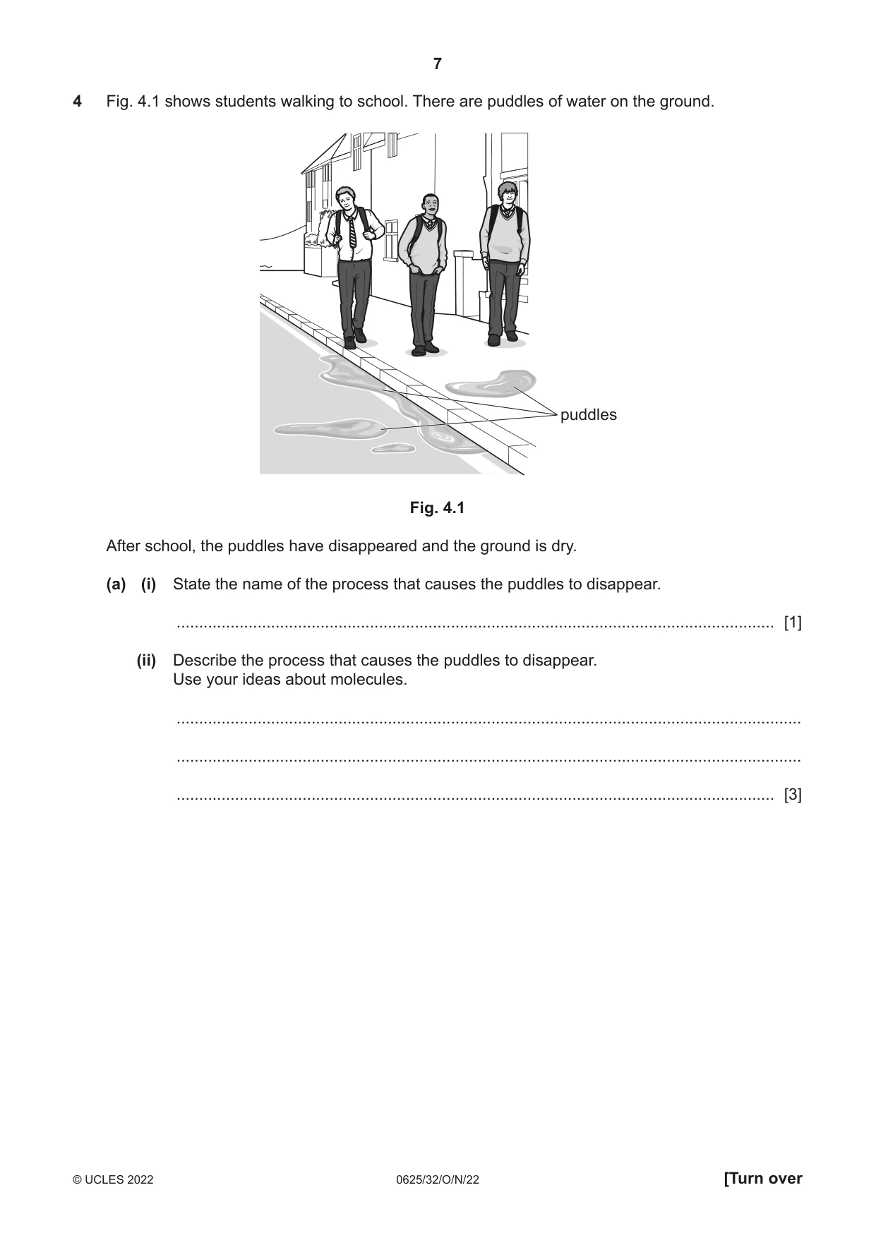
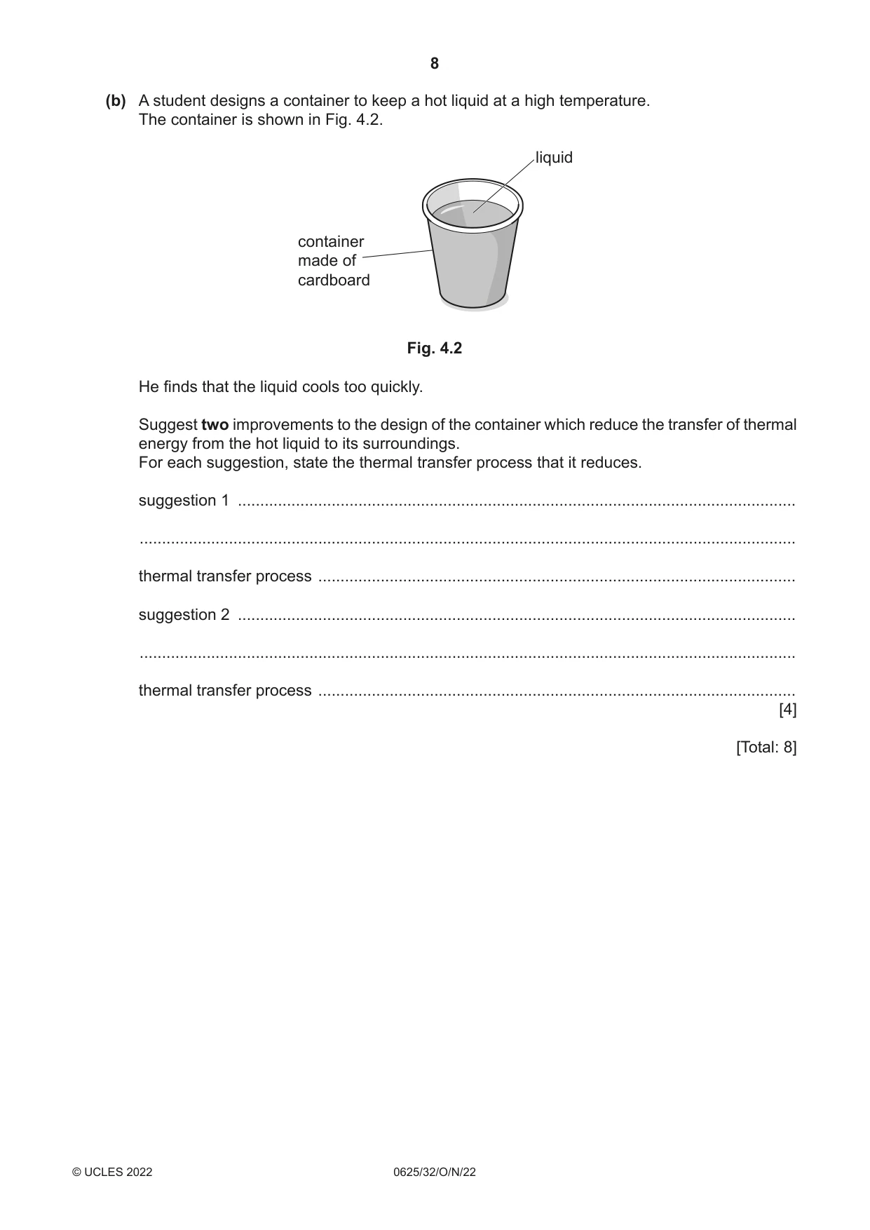
4 Fig. 4.1 shows students walking to school. There are puddles of water on the ground. puddles Fig. 4.1 After school, the puddles have disappeared and the ground is dry. (a) (i) State the name of the process that causes the puddles to disappear. ..................................................................................................................................... [1] (ii) Describe the process that causes the puddles to disappear. Use your ideas about molecules. ........................................................................................................................................... ........................................................................................................................................... ..................................................................................................................................... [3] (b) A student designs a container to keep a hot liquid at a high temperature. The container is shown in Fig. 4.2. liquid container made of cardboard Fig. 4.2 He finds that the liquid cools too quickly. Suggest two improvements to the design of the container which reduce the transfer of thermal energy from the hot liquid to its surroundings. For each suggestion, state the thermal transfer process that it reduces. suggestion 1 ............................................................................................................................. ................................................................................................................................................... thermal transfer process ........................................................................................................... suggestion 2 ............................................................................................................................. ................................................................................................................................................... thermal transfer process ........................................................................................................... [4] [Total: 8]
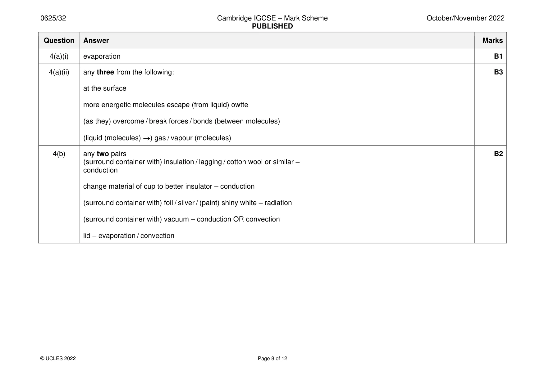
Mark scheme: 4(a)(i) evaporation B1 4(a)(ii) any three from the following: B3 at the surface more energetic molecules escape (from liquid) owtte (as they) overcome / break forces / bonds (between molecules) (liquid (molecules) →) gas / vapour (molecules) 4(b) any two pairs B2 (surround container with) insulation / lagging / cotton wool or similar – conduction change material of cup to better insulator – conduction (surround container with) foil / silver / (paint) shiny white – radiation (surround container with) vacuum – conduction OR convection lid – evaporation / convection
Q5 · The diagram in Fig
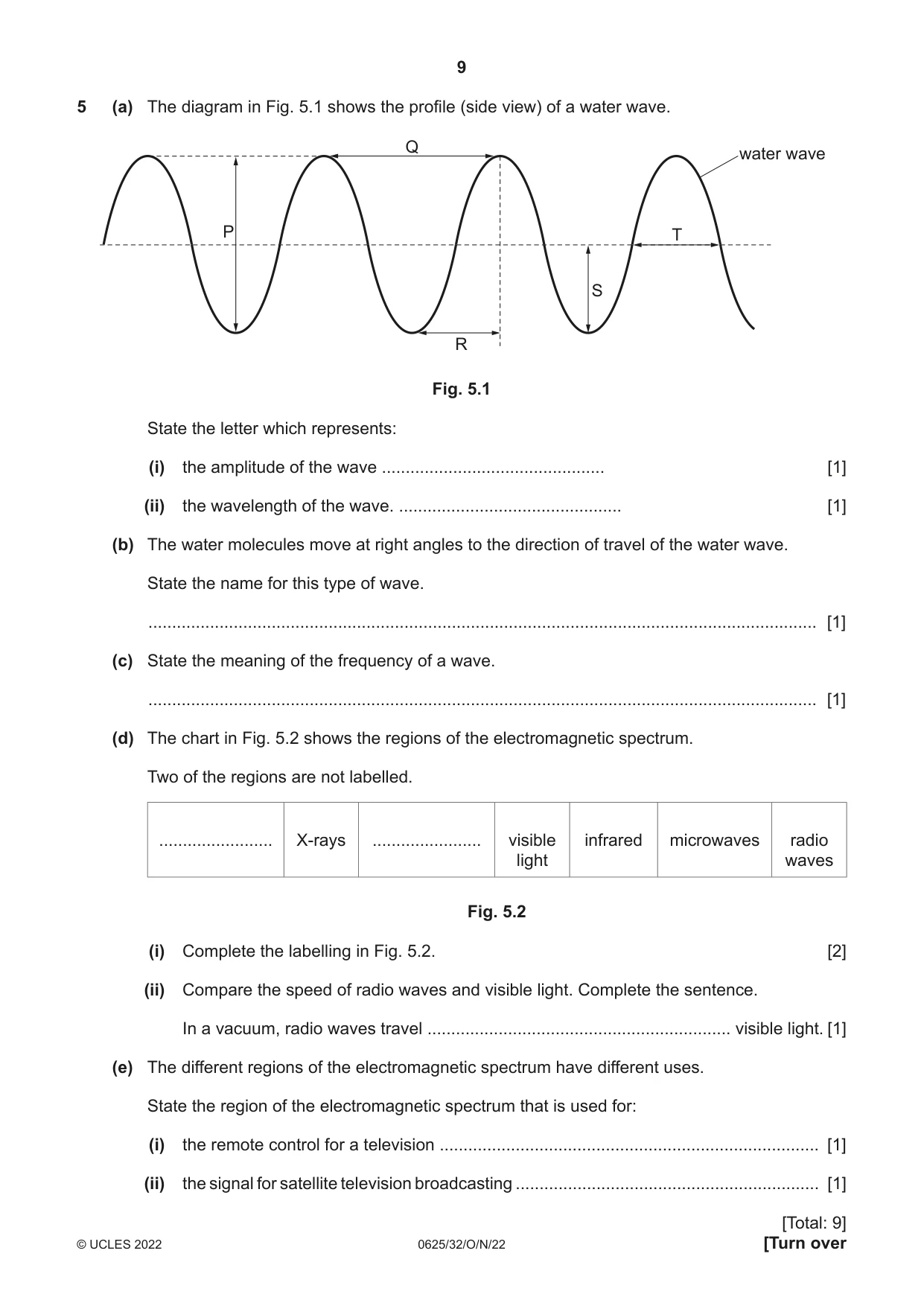
5 (a) The diagram in Fig. 5.1 shows the profile (side view) of a water wave. Q water wave P T S R Fig. 5.1 State the letter which represents: (i) the amplitude of the wave ............................................... [1] (ii) the wavelength of the wave. ............................................... [1] (b) The water molecules move at right angles to the direction of travel of the water wave. State the name for this type of wave. ............................................................................................................................................. [1] (c) State the meaning of the frequency of a wave. ............................................................................................................................................. [1] (d) The chart in Fig. 5.2 shows the regions of the electromagnetic spectrum. Two of the regions are not labelled. ........................ X-rays ....................... visible infrared microwaves radio light waves Fig. 5.2 (i) Complete the labelling in Fig. 5.2. [2] (ii) Compare the speed of radio waves and visible light. Complete the sentence. In a vacuum, radio waves travel ................................................................ visible light. [1] (e) The different regions of the electromagnetic spectrum have different uses. State the region of the electromagnetic spectrum that is used for: (i) the remote control for a television ................................................................................ [1] (ii) the signal for satellite television broadcasting ................................................................ [1]
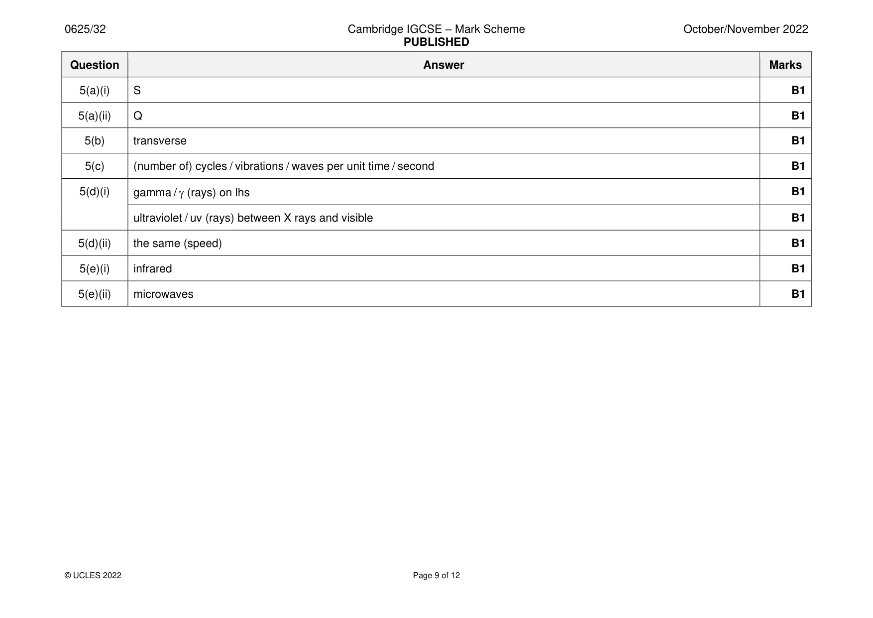
Mark scheme: 5(a)(i) S B1 5(a)(ii) Q B1 5(b) transverse B1 5(c) (number of) cycles / vibrations / waves per unit time / second B1 5(d)(i) gamma / (rays) on lhs B1 ultraviolet / uv (rays) between X rays and visible B1 5(d)(ii) the same (speed) B1 5(e)(i) infrared B1 5(e)(ii) microwaves B1
Q6 · A ray of light striking a plane mirror
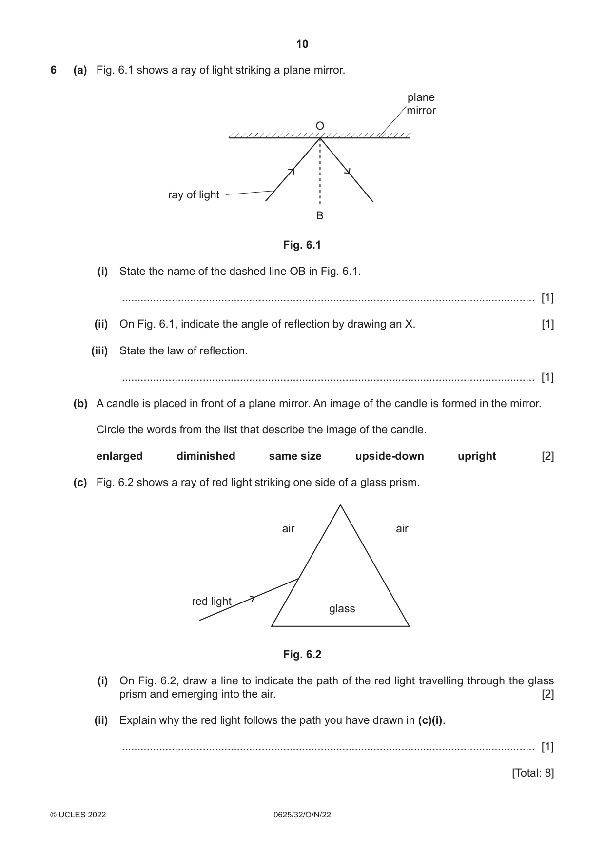
6 (a) Fig. 6.1 shows a ray of light striking a plane mirror. plane mirror O ray of light B Fig. 6.1 (i) State the name of the dashed line OB in Fig. 6.1. ..................................................................................................................................... [1] (ii) On Fig. 6.1, indicate the angle of reflection by drawing an X. [1] (iii) State the law of reflection. ..................................................................................................................................... [1] (b) A candle is placed in front of a plane mirror. An image of the candle is formed in the mirror. Circle the words from the list that describe the image of the candle. enlarged diminished same size upside-down upright [2] (c) Fig. 6.2 shows a ray of red light striking one side of a glass prism. air air red light glass Fig. 6.2 (i) On Fig. 6.2, draw a line to indicate the path of the red light travelling through the glass prism and emerging into the air. [2] (ii) Explain why the red light follows the path you have drawn in (c)(i). ..................................................................................................................................... [1] [Total: 8]
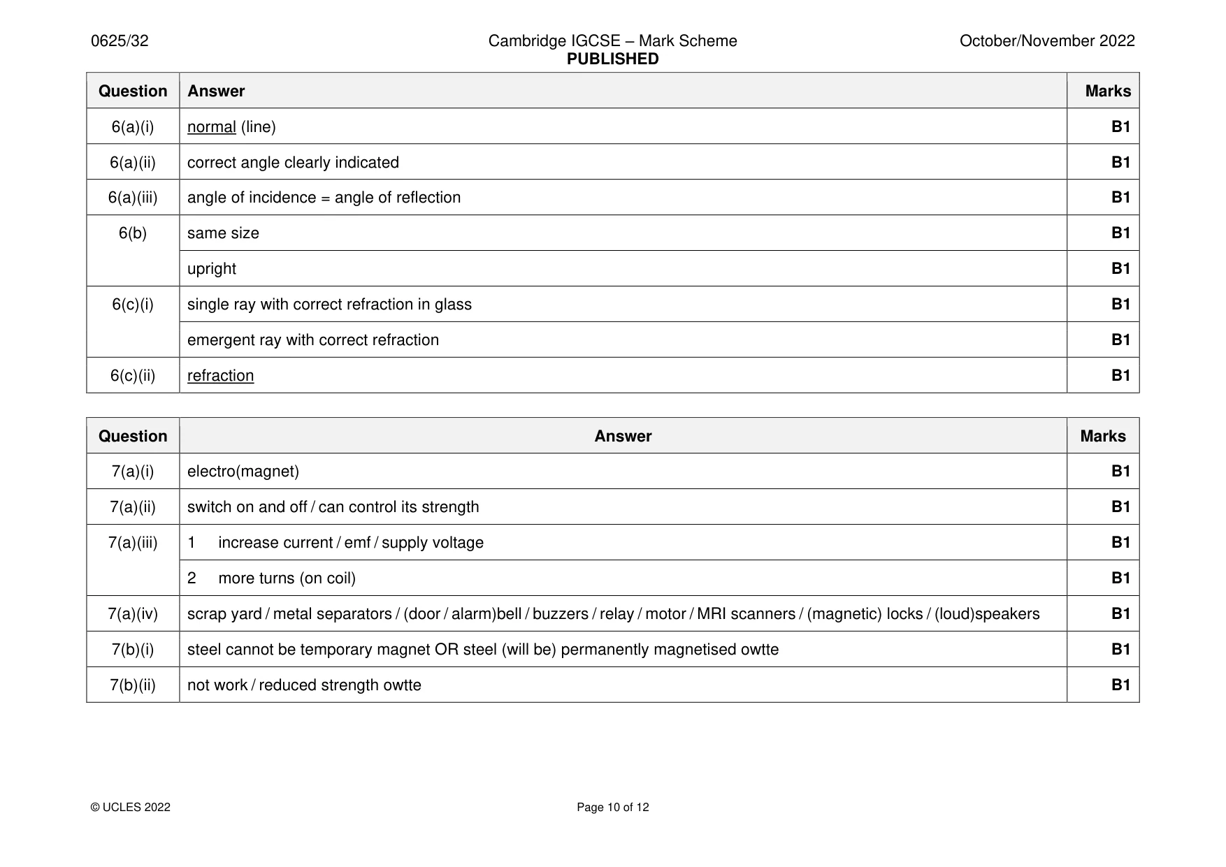
Mark scheme: 6(a)(i) normal (line) B1 6(a)(ii) correct angle clearly indicated B1 6(a)(iii) angle of incidence = angle of reflection B1 6(b) same size B1 upright B1 6(c)(i) single ray with correct refraction in glass B1 emergent ray with correct refraction B1 6(c)(ii) refraction B1
Q7 · An arrangement that can produce a magnet
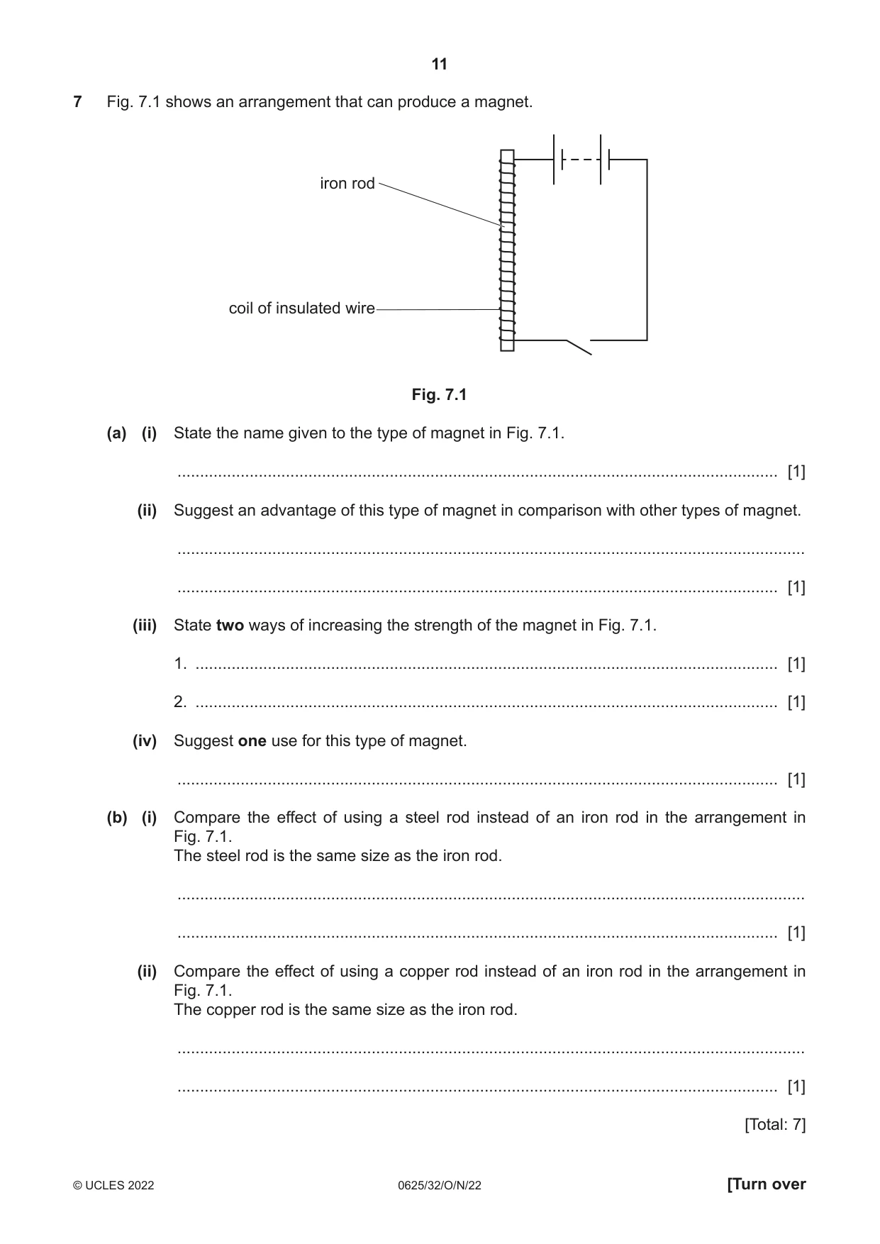
7 Fig. 7.1 shows an arrangement that can produce a magnet. iron rod coil of insulated wire Fig. 7.1 (a) (i) State the name given to the type of magnet in Fig. 7.1. ..................................................................................................................................... [1] (ii) Suggest an advantage of this type of magnet in comparison with other types of magnet. ........................................................................................................................................... ..................................................................................................................................... [1] (iii) State two ways of increasing the strength of the magnet in Fig. 7.1. 1. ................................................................................................................................. [1] 2. ................................................................................................................................. [1] (iv) Suggest one use for this type of magnet. ..................................................................................................................................... [1] (b) (i) Compare the effect of using a steel rod instead of an iron rod in the arrangement in Fig. 7.1. The steel rod is the same size as the iron rod. ........................................................................................................................................... ..................................................................................................................................... [1] (ii) Compare the effect of using a copper rod instead of an iron rod in the arrangement in Fig. 7.1. The copper rod is the same size as the iron rod. ........................................................................................................................................... ..................................................................................................................................... [1] [Total: 7]
Mark scheme: 7(a)(i) electro(magnet) B1 7(a)(ii) switch on and off / can control its strength B1 7(a)(iii) 1 increase current / emf / supply voltage B1 2 more turns (on coil) B1 7(a)(iv) scrap yard / metal separators / (door / alarm)bell / buzzers / relay / motor / MRI scanners / (magnetic) locks / (loud)speakers B1 7(b)(i) steel cannot be temporary magnet OR steel (will be) permanently magnetised owtte B1 7(b)(ii) not work / reduced strength owtte B1
Q8 · A student uses the circuit in Fig
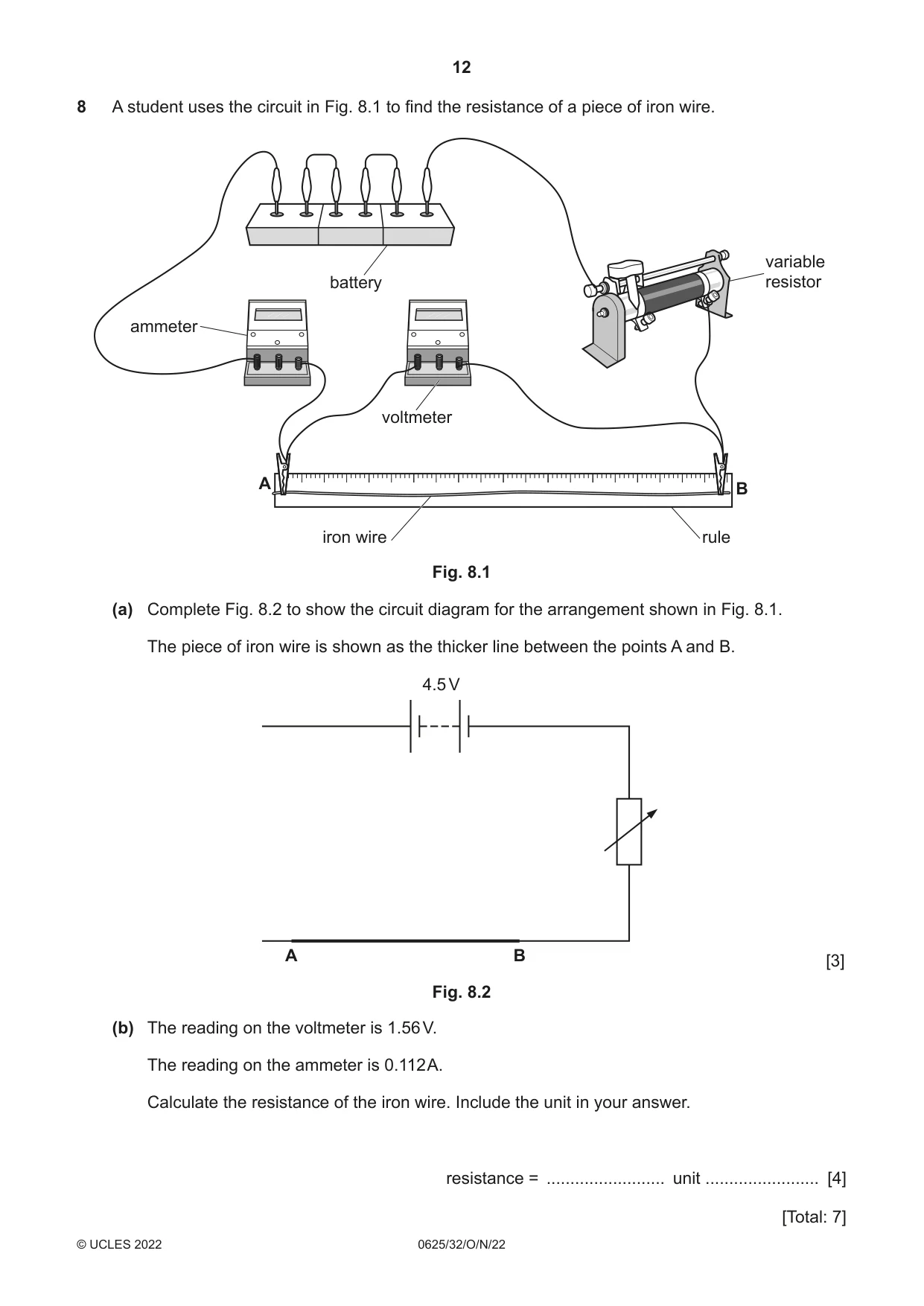
8 A student uses the circuit in Fig. 8.1 to find the resistance of a piece of iron wire. variable battery resistor ammeter voltmeter A B iron wire rule Fig. 8.1 (a) Complete Fig. 8.2 to show the circuit diagram for the arrangement shown in Fig. 8.1. The piece of iron wire is shown as the thicker line between the points A and B. 4.5 V A B [3] Fig. 8.2 (b) The reading on the voltmeter is 1.56 V. The reading on the ammeter is 0.112 A. Calculate the resistance of the iron wire. Include the unit in your answer. resistance = ......................... unit ........................ [4] [Total: 7]
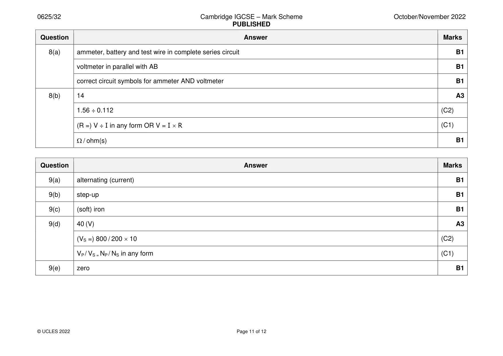
Mark scheme: 8(a) ammeter, battery and test wire in complete series circuit B1 voltmeter in parallel with AB B1 correct circuit symbols for ammeter AND voltmeter B1 8(b) 14 A3 1.56 ÷ 0.112 (C2) (R =) V ÷ I in any form OR V = I R (C1) / ohm(s) B1
Question 9
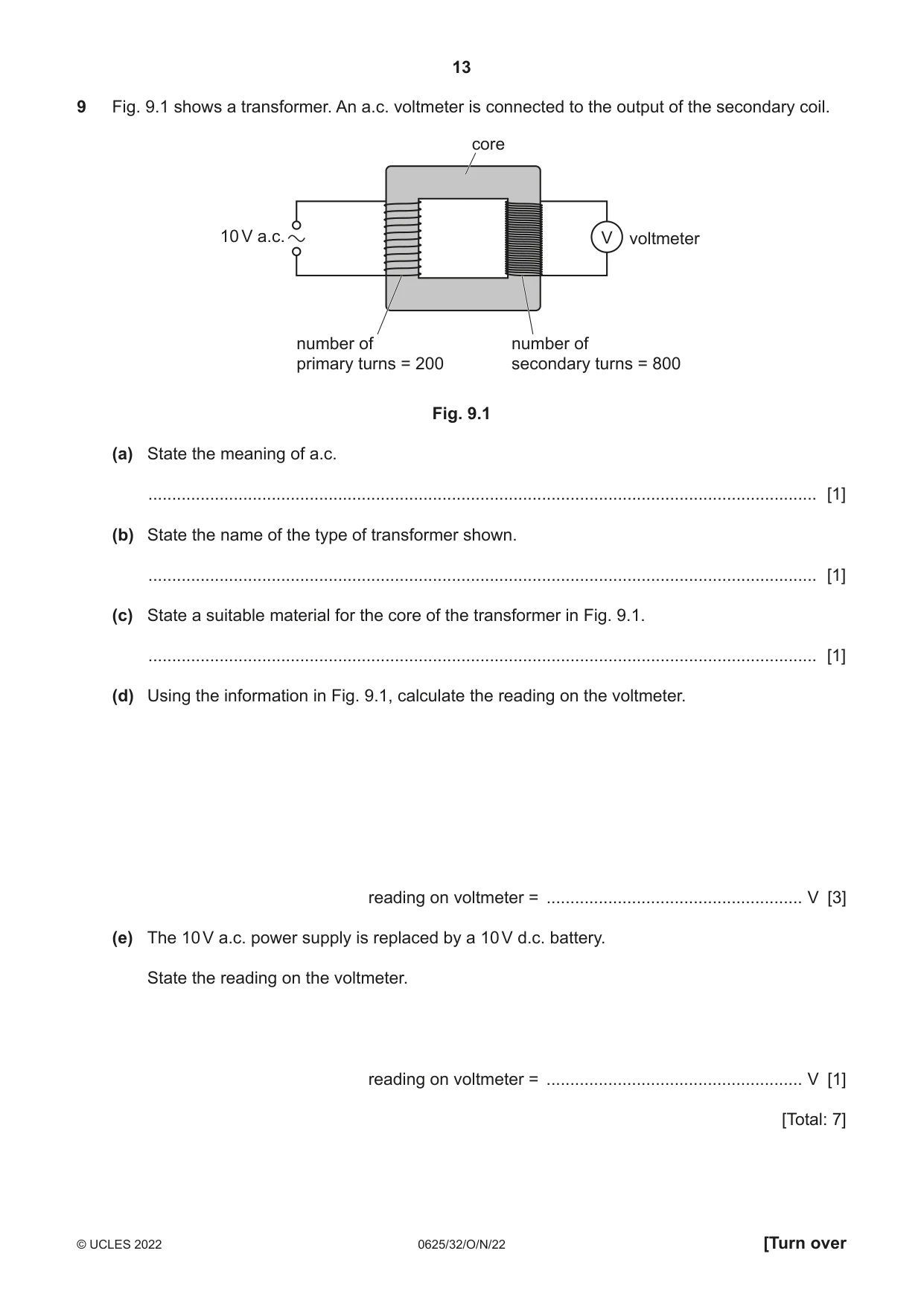
9 Fig. 9.1 shows a transformer. An a.c. voltmeter is connected to the output of the secondary coil. core 10 V a.c. V voltmeter number of number of primary turns = 200 secondary turns = 800 Fig. 9.1 (a) State the meaning of a.c. ............................................................................................................................................. [1] (b) State the name of the type of transformer shown. ............................................................................................................................................. [1] (c) State a suitable material for the core of the transformer in Fig. 9.1. ............................................................................................................................................. [1] (d) Using the information in Fig. 9.1, calculate the reading on the voltmeter. reading on voltmeter = ...................................................... V [3] (e) The 10 V a.c. power supply is replaced by a 10 V d.c. battery. State the reading on the voltmeter. reading on voltmeter = ...................................................... V [1] [Total: 7]
Mark scheme: 9(a) alternating (current) B1 9(b) step-up B1 9(c) (soft) iron B1 9(d) 40 (V) A3 (VS =) 800 / 200 10 (C2) VP / VS = NP / NS in any form (C1) 9(e) zero B1
Q10 · The equipment used by a teacher in a laboratory demonstration
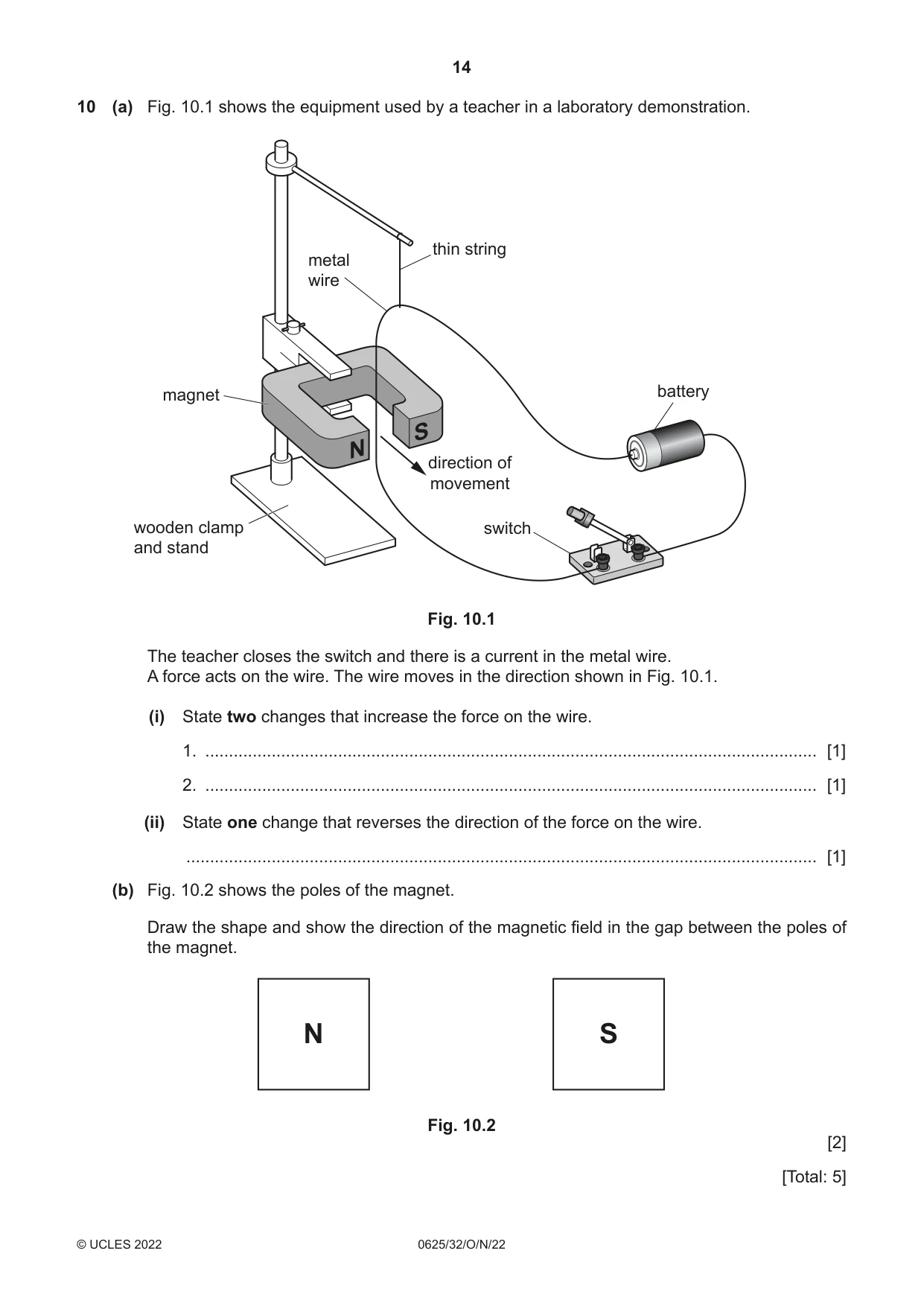
10 (a) Fig. 10.1 shows the equipment used by a teacher in a laboratory demonstration. thin string metal wire magnet battery S N direction of movement wooden clamp switch and stand Fig. 10.1 The teacher closes the switch and there is a current in the metal wire. A force acts on the wire. The wire moves in the direction shown in Fig. 10.1. (i) State two changes that increase the force on the wire. 1. ................................................................................................................................. [1] 2. ................................................................................................................................. [1] (ii) State one change that reverses the direction of the force on the wire. ..................................................................................................................................... [1] (b) Fig. 10.2 shows the poles of the magnet. Draw the shape and show the direction of the magnetic field in the gap between the poles of the magnet. N S Fig. 10.2 [2] [Total: 5]
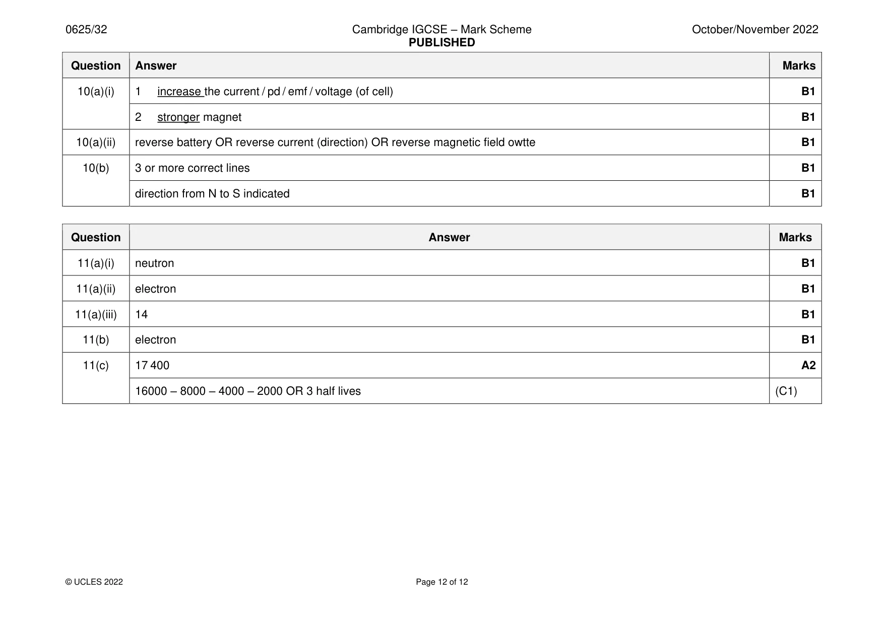
Mark scheme: 10(a)(i) 1 increase the current / pd / emf / voltage (of cell) B1 2 stronger magnet B1 10(a)(ii) reverse battery OR reverse current (direction) OR reverse magnetic field owtte B1 10(b) 3 or more correct lines B1 direction from N to S indicated B1
Q11 · An atom of carbon-14
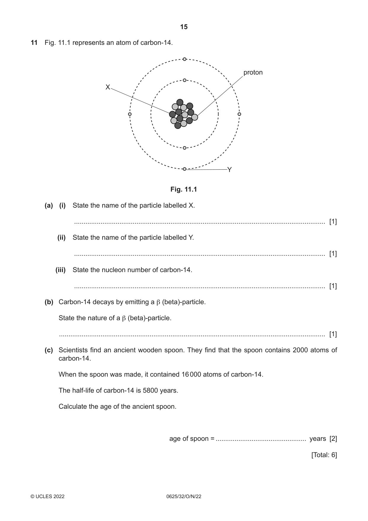
11 Fig. 11.1 represents an atom of carbon-14. proton X Y Fig. 11.1 (a) (i) State the name of the particle labelled X. ..................................................................................................................................... [1] (ii) State the name of the particle labelled Y. ..................................................................................................................................... [1] (iii) State the nucleon number of carbon-14. ..................................................................................................................................... [1] (b) Carbon-14 decays by emitting a β (beta)-particle. State the nature of a β (beta)-particle. ............................................................................................................................................. [1] (c) Scientists find an ancient wooden spoon. They find that the spoon contains 2000 atoms of carbon-14. When the spoon was made, it contained 16 000 atoms of carbon-14. The half-life of carbon-14 is 5800 years. Calculate the age of the ancient spoon. age of spoon = ................................................ years [2] [Total: 6]
Mark scheme: 11(a)(i) neutron B1 11(a)(ii) electron B1 11(a)(iii) 14 B1 11(b) electron B1 11(c) 17 400 A2 16000 – 8000 – 4000 – 2000 OR 3 half lives (C1)
What was in this paper
The subtopics covered by these 11 questions, and how many questions each got. Open one in a new tab to see every Cambridge question on it.
What you needed in this session
Cambridge’s own grade thresholds for 2022 Oct/Nov, Paper 3 · Variant 2. A higher threshold means an easier paper — the bar moves with how the cohort did.