Cambridge IGCSE Physics 0625 — 2007 May/June Paper 3 · Variant 1
0625/31/M/J/07 · 11 questions · 80 marks · ≈90 min
The question paper and its mark scheme, free to read here and free to download. This is Cambridge’s own paper, exactly as it was sat.
Question paper16 pages

Mark scheme7 pages
Answers below. Sit the paper first if you are practising.
Questions as text
Q1 · A model car moving clockwise around a horizontal circular track
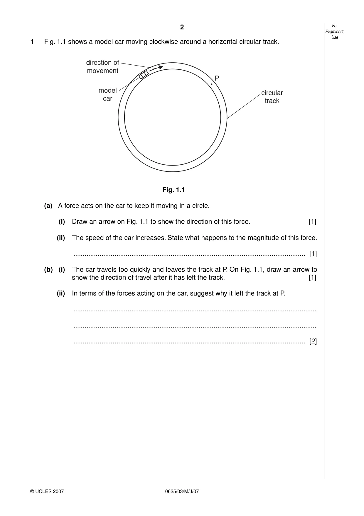
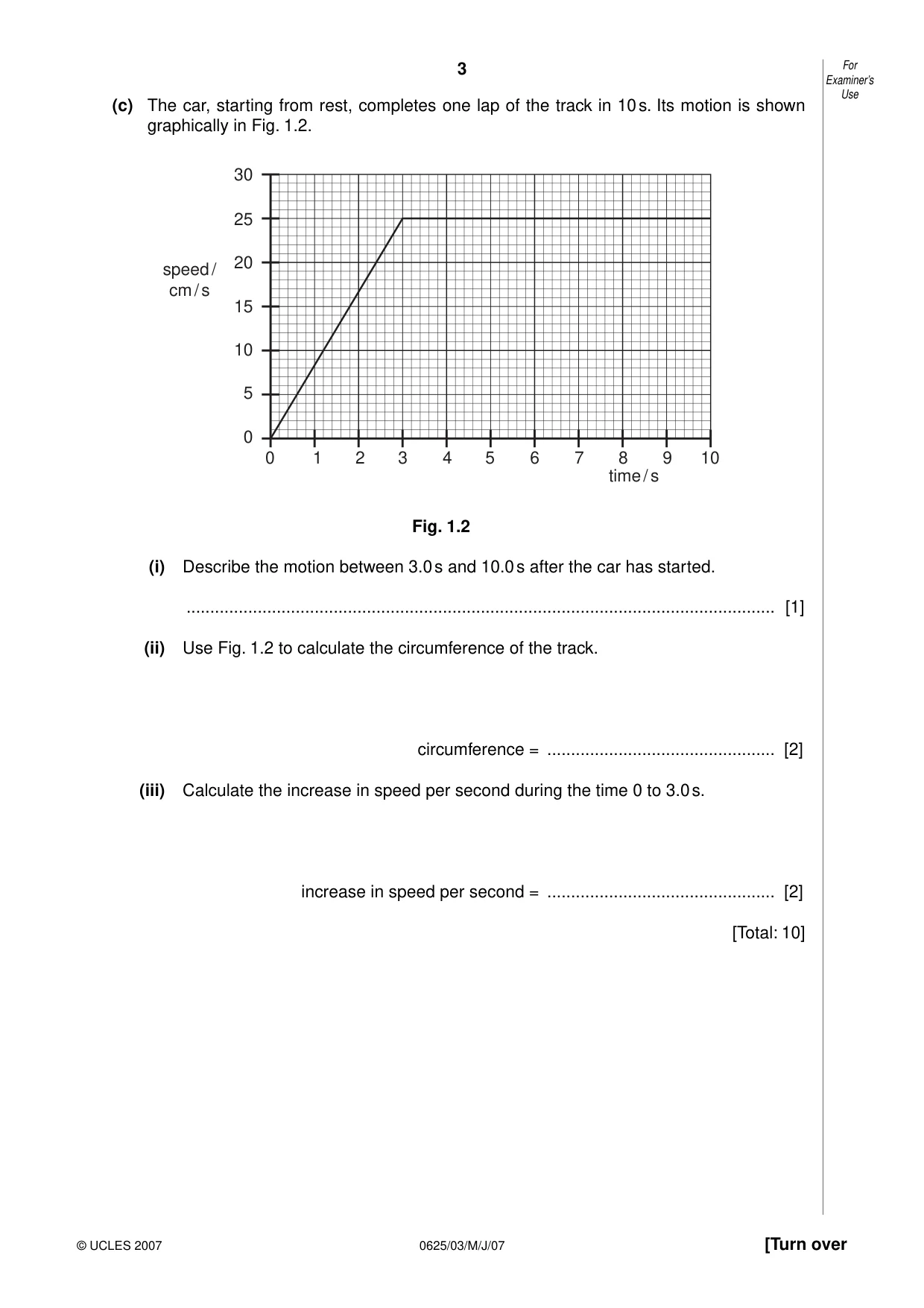
1 Fig. 1.1 shows a model car moving clockwise around a horizontal circular track. direction of movement P model circular car track Fig. 1.1 (a) A force acts on the car to keep it moving in a circle. (i) Draw an arrow on Fig. 1.1 to show the direction of this force. [1] (ii) The speed of the car increases. State what happens to the magnitude of this force. ............................................................................................................................ [1] (b) (i) The car travels too quickly and leaves the track at P. On Fig. 1.1, draw an arrow to show the direction of travel after it has left the track. [1] (ii) In terms of the forces acting on the car, suggest why it left the track at P. .................................................................................................................................. .................................................................................................................................. ............................................................................................................................ [2] Examiner’s Use (c) The car, starting from rest, completes one lap of the track in 10 s. Its motion is shown graphically in Fig. 1.2. 30 25 20 speed / cm / s 15 10 5 0 0 1 2 3 4 5 6 7 8 9 10 time / s Fig. 1.2 (i) Describe the motion between 3.0 s and 10.0 s after the car has started. ............................................................................................................................ [1] (ii) Use Fig. 1.2 to calculate the circumference of the track. circumference = ................................................ [2] (iii) Calculate the increase in speed per second during the time 0 to 3.0 s. increase in speed per second = ................................................ [2] [Total: 10]
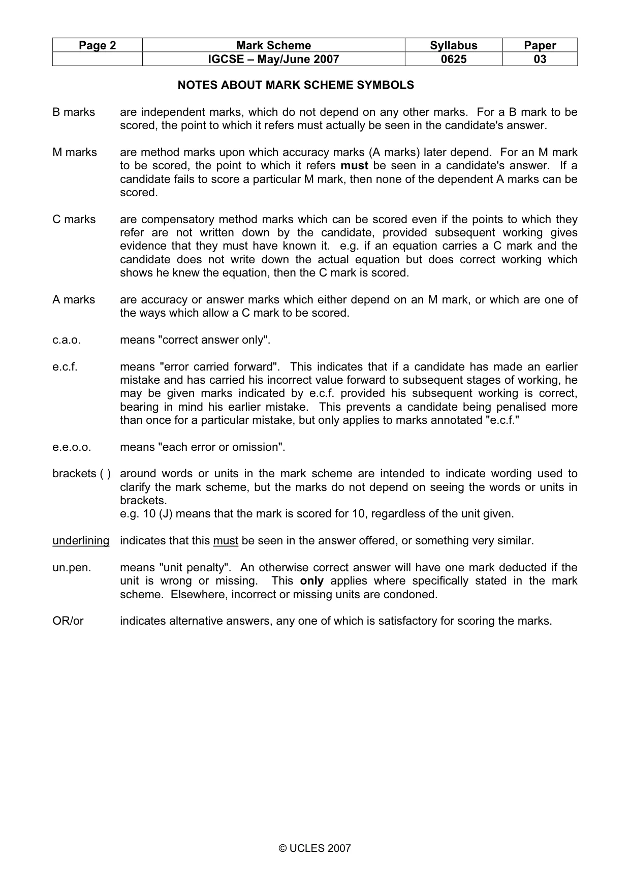
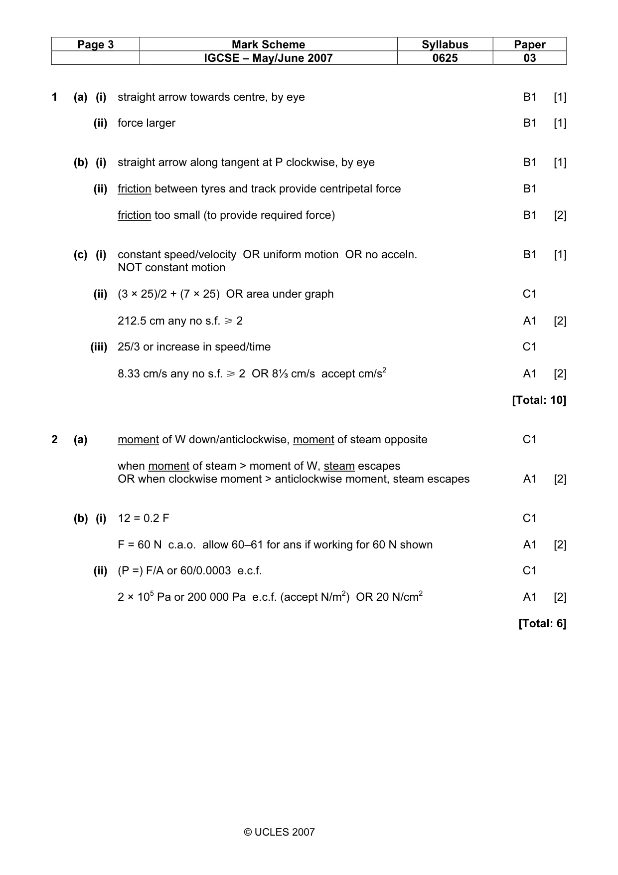
Mark scheme: 1 (a) (i) straight arrow towards centre, by eye B1 [1] (ii) force larger B1 [1] (b) (i) straight arrow along tangent at P clockwise, by eye B1 [1] (ii) friction between tyres and track provide centripetal force B1 friction too small (to provide required force) B1 [2] (c) (i) constant speed/velocity OR uniform motion OR no acceln. B1 [1] NOT constant motion (ii) (3 × 25)/2 + (7 × 25) OR area under graph C1 212.5 cm any no s.f. ğ 2 A1 [2] (iii) 25/3 or increase in speed/time C1 8.33 cm/s any no s.f. ğ 2 OR 8⅓ cm/s accept cm/s2 A1 [2] [Total: 10]
Q2 · A steam safety valve
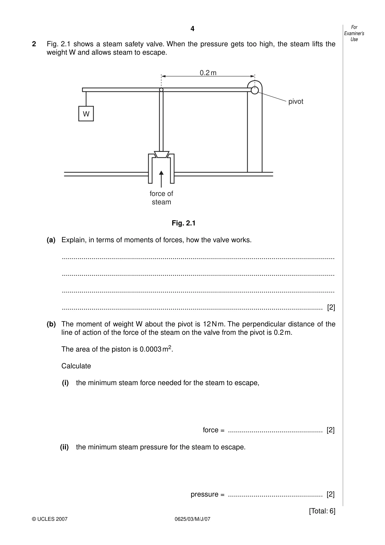
2 Fig. 2.1 shows a steam safety valve. When the pressure gets too high, the steam lifts the weight W and allows steam to escape. 0.2 m pivot W force of steam Fig. 2.1 (a) Explain, in terms of moments of forces, how the valve works. .......................................................................................................................................... .......................................................................................................................................... .......................................................................................................................................... .................................................................................................................................... [2] (b) The moment of weight W about the pivot is 12 N m. The perpendicular distance of the line of action of the force of the steam on the valve from the pivot is 0.2 m. The area of the piston is 0.0003 m2. Calculate (i) the minimum steam force needed for the steam to escape, force = ................................................ [2] (ii) the minimum steam pressure for the steam to escape. pressure = ................................................ [2] [Total: 6]
Mark scheme: 2 (a) moment of W down/anticlockwise, moment of steam opposite C1 when moment of steam > moment of W, steam escapes OR when clockwise moment > anticlockwise moment, steam escapes A1 [2] (b) (i) 12 = 0.2 F C1 F = 60 N c.a.o. allow 60–61 for ans if working for 60 N shown A1 [2] (ii) (P =) F/A or 60/0.0003 e.c.f. C1 2 × 10⁵ Pa or 200 000 Pa e.c.f. (accept N/m2) OR 20 N/cm2 A1 [2] [Total: 6] IGCSE – May/June 2007 0625 03
Q3 · A student wishes to work out how much power she uses to lift her body when climbing a…
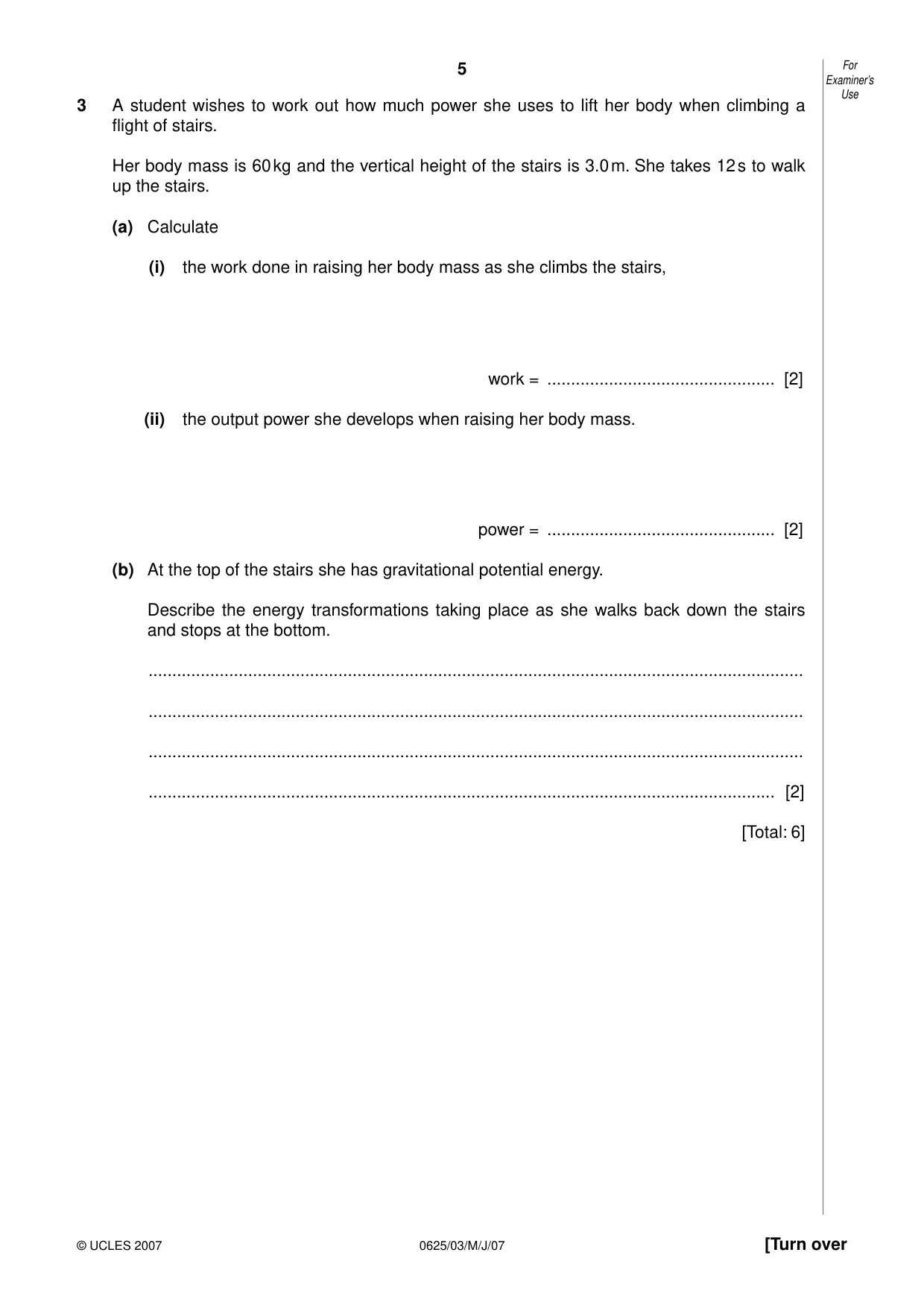
3 A student wishes to work out how much power she uses to lift her body when climbing a flight of stairs. Her body mass is 60 kg and the vertical height of the stairs is 3.0 m. She takes 12 s to walk up the stairs. (a) Calculate (i) the work done in raising her body mass as she climbs the stairs, work = ................................................ [2] (ii) the output power she develops when raising her body mass. power = ................................................ [2] (b) At the top of the stairs she has gravitational potential energy. Describe the energy transformations taking place as she walks back down the stairs and stops at the bottom. .......................................................................................................................................... .......................................................................................................................................... .......................................................................................................................................... .................................................................................................................................... [2] [Total: 6]
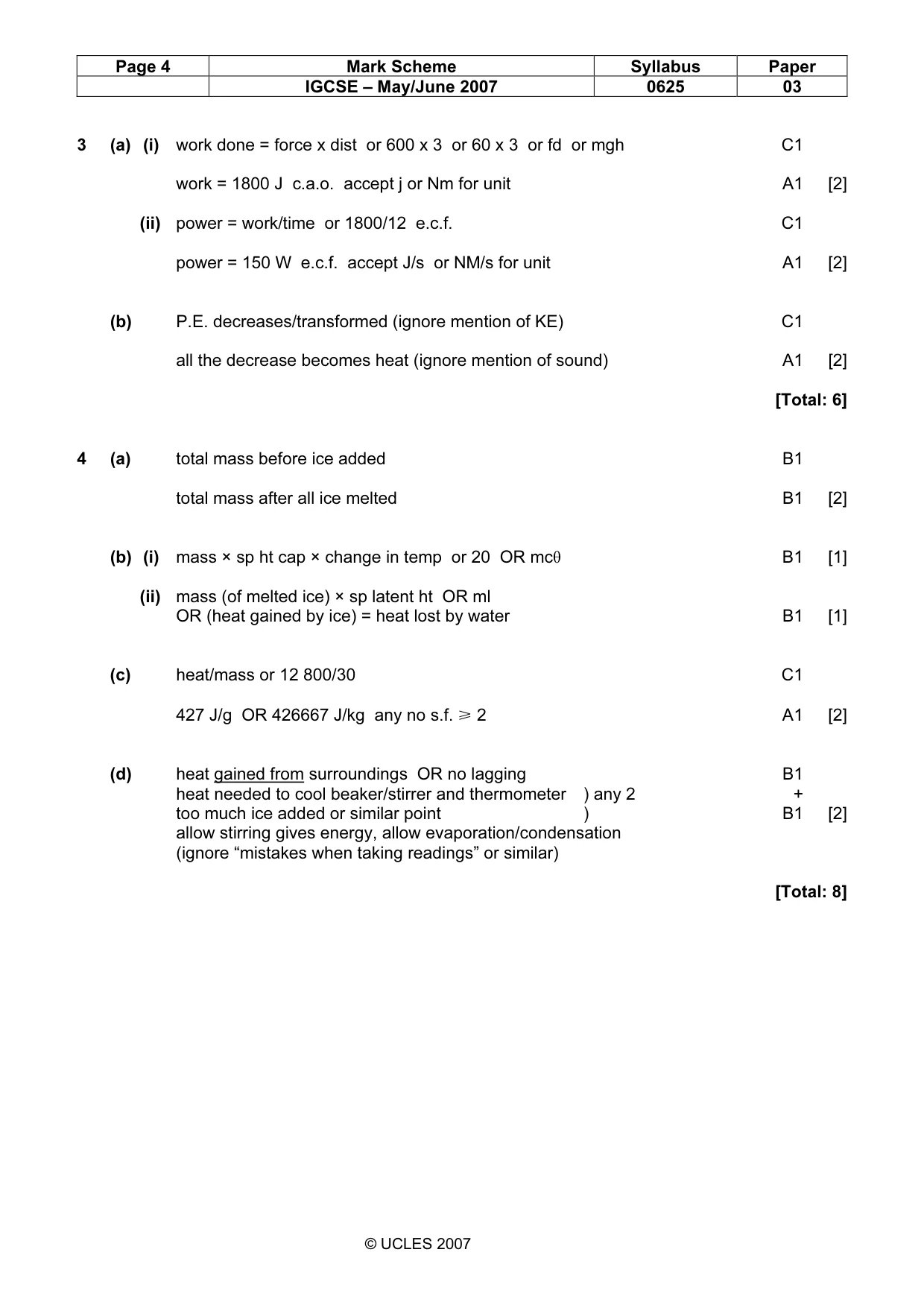
Mark scheme: 3 (a) (i) work done = force x dist or 600 x 3 or 60 x 3 or fd or mgh C1 work = 1800 J c.a.o. accept j or Nm for unit A1 [2] (ii) power = work/time or 1800/12 e.c.f. C1 power = 150 W e.c.f. accept J/s or NM/s for unit A1 [2] (b) P.E. decreases/transformed (ignore mention of KE) C1 all the decrease becomes heat (ignore mention of sound) A1 [2] [Total: 6]
Q4 · A student’s attempt to estimate the specific latent heat of fusion of ice by adding ice…
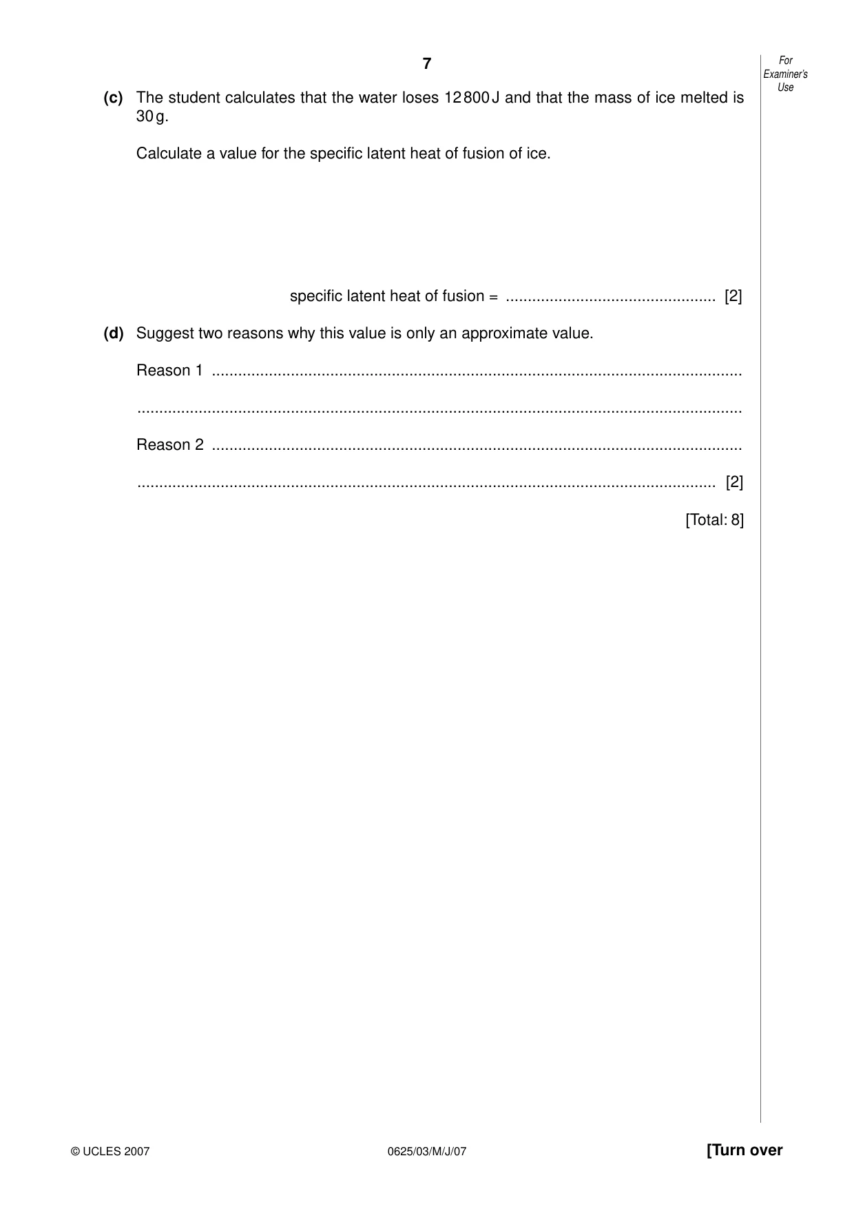
4 Fig. 4.1 shows a student’s attempt to estimate the specific latent heat of fusion of ice by adding ice at 0 °C to water at 20 °C. The water is stirred continuously as ice is slowly added until the temperature of the water is 0 °C and all the added ice has melted. glass rod thermometer stirrer ice glass beaker water top-pan balance Fig. 4.1 (a) Three mass readings are taken. A description of the first reading is given. Write down descriptions of the other two. reading 1 the mass of the beaker + stirrer + thermometer reading 2 ......................................................................................................................... reading 3 ................................................................................................................... [2] (b) Write down word equations which the student could use to find (i) the heat lost by the water as it cools from 20 °C to 0 °C, ............................................................................................................................ [1] (ii) the heat gained by the melting ice. ............................................................................................................................ [1] Examiner’s Use (c) The student calculates that the water loses 12 800 J and that the mass of ice melted is 30 g. Calculate a value for the specific latent heat of fusion of ice. specific latent heat of fusion = ................................................ [2] (d) Suggest two reasons why this value is only an approximate value. Reason 1 ......................................................................................................................... .......................................................................................................................................... Reason 2 ......................................................................................................................... .................................................................................................................................... [2] [Total: 8]
Mark scheme: 4 (a) total mass before ice added B1 total mass after all ice melted B1 [2] (b) (i) mass × sp ht cap × change in temp or 20 OR mcθ B1 [1] (ii) mass (of melted ice) × sp latent ht OR ml OR (heat gained by ice) = heat lost by water B1 [1] (c) heat/mass or 12 800/30 C1 427 J/g OR 426667 J/kg any no s.f. ğ 2 A1 [2] (d) heat gained from surroundings OR no lagging B1 heat needed to cool beaker/stirrer and thermometer ) any 2 + too much ice added or similar point ) B1 [2] allow stirring gives energy, allow evaporation/condensation (ignore “mistakes when taking readings” or similar) [Total: 8] IGCSE – May/June 2007 0625 03
Q5 · Some apparatus designed to compare the ability of two surfaces to absorb infra-red…
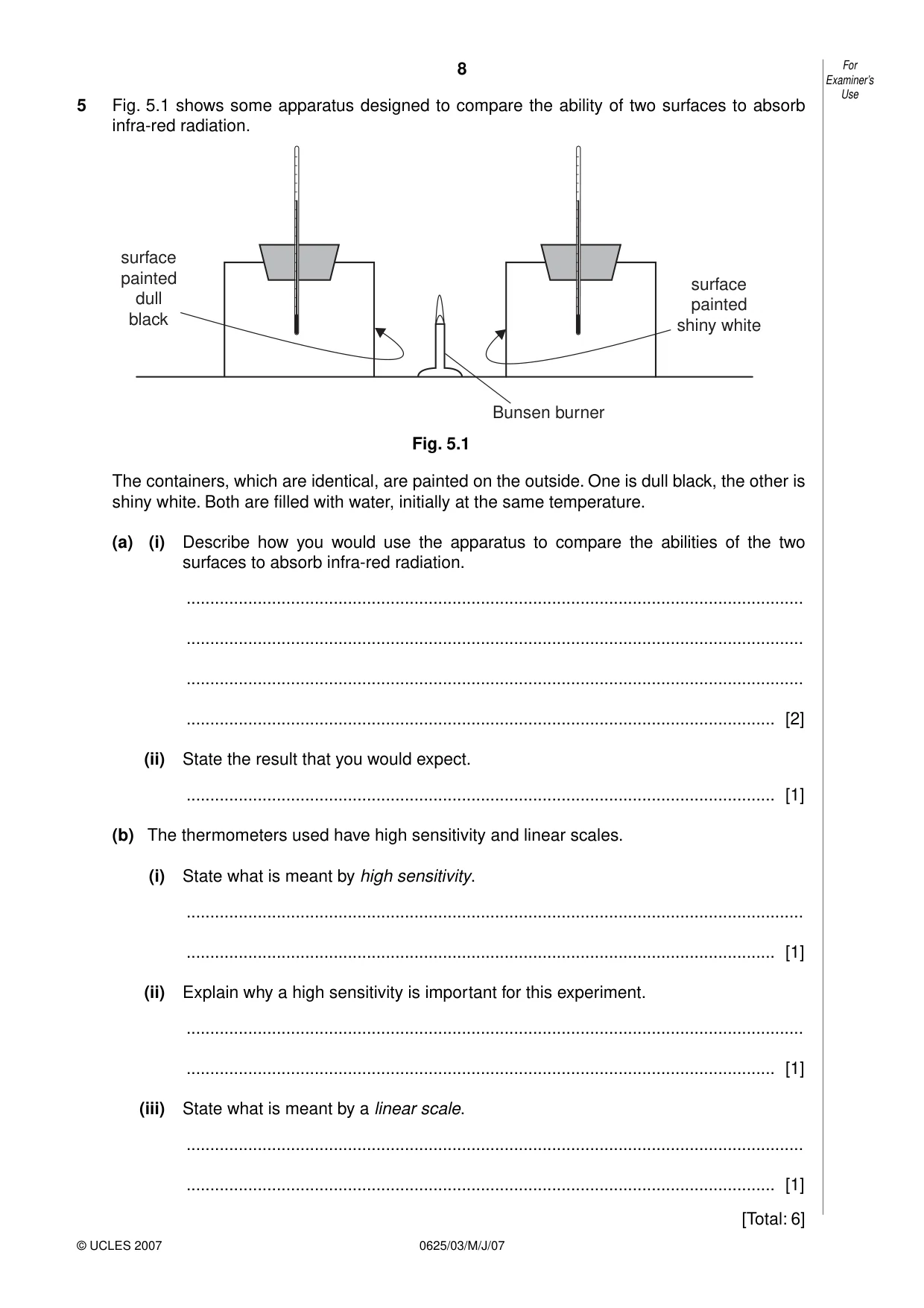
5 Fig. 5.1 shows some apparatus designed to compare the ability of two surfaces to absorb infra-red radiation. surface painted surface dull painted black shiny white Bunsen burner Fig. 5.1 The containers, which are identical, are painted on the outside. One is dull black, the other is shiny white. Both are filled with water, initially at the same temperature. (a) (i) Describe how you would use the apparatus to compare the abilities of the two surfaces to absorb infra-red radiation. .................................................................................................................................. .................................................................................................................................. .................................................................................................................................. ............................................................................................................................ [2] (ii) State the result that you would expect. ............................................................................................................................ [1] (b) The thermometers used have high sensitivity and linear scales. (i) State what is meant by high sensitivity. .................................................................................................................................. ............................................................................................................................ [1] (ii) Explain why a high sensitivity is important for this experiment. .................................................................................................................................. ............................................................................................................................ [1] (iii) State what is meant by a linear scale. .................................................................................................................................. ............................................................................................................................ [1] [Total: 6]
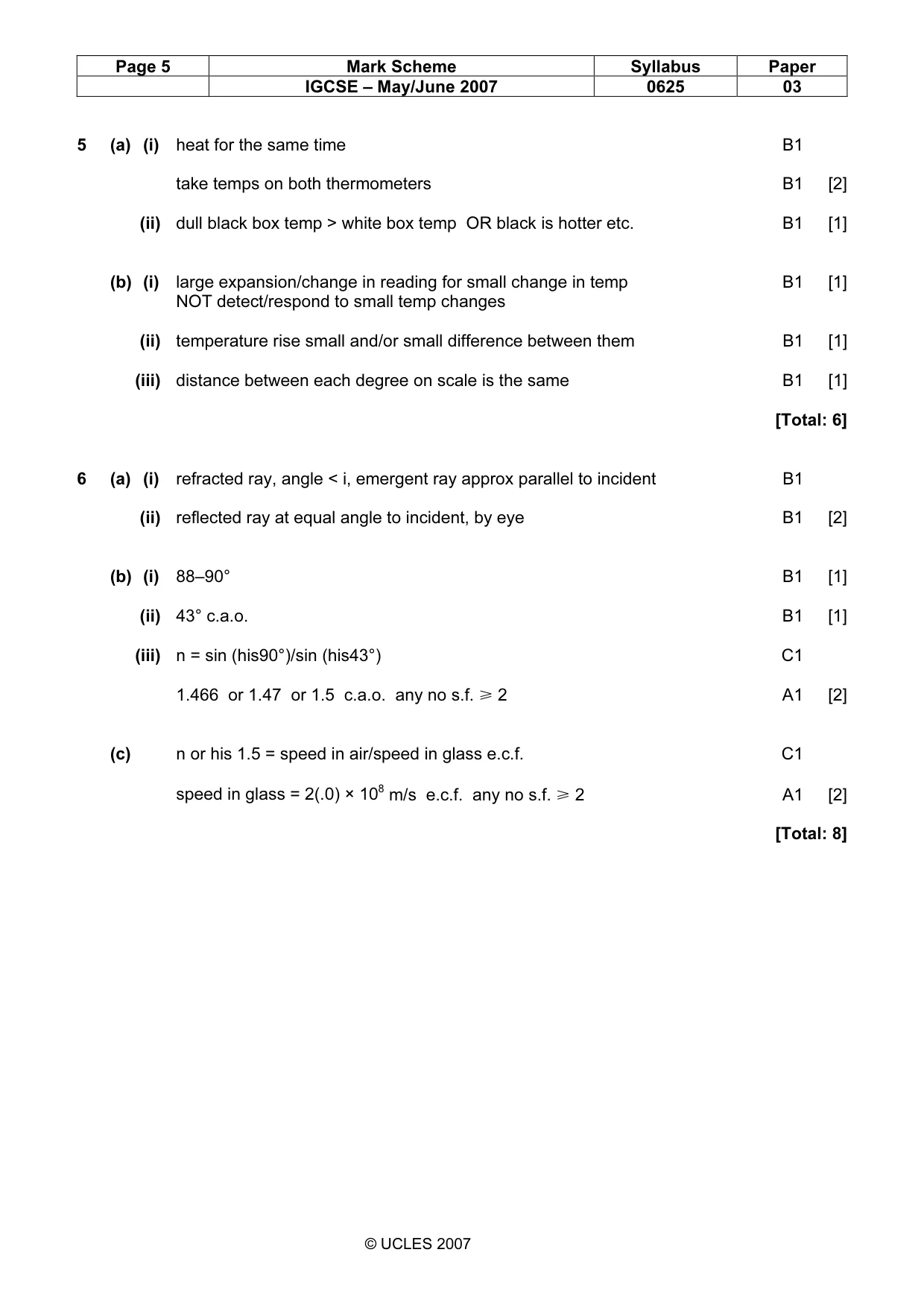
Mark scheme: 5 (a) (i) heat for the same time B1 take temps on both thermometers B1 [2] (ii) dull black box temp > white box temp OR black is hotter etc. B1 [1] (b) (i) large expansion/change in reading for small change in temp B1 [1] NOT detect/respond to small temp changes (ii) temperature rise small and/or small difference between them B1 [1] (iii) distance between each degree on scale is the same B1 [1] [Total: 6]
Q6 · A rectangular glass block ABCD
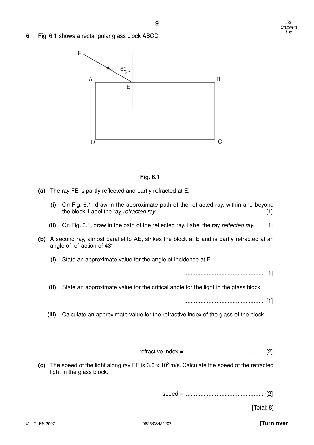
6 Fig. 6.1 shows a rectangular glass block ABCD. F 60 o A B E D C Fig. 6.1 (a) The ray FE is partly reflected and partly refracted at E. (i) On Fig. 6.1, draw in the approximate path of the refracted ray, within and beyond the block. Label the ray refracted ray. [1] (ii) On Fig. 6.1, draw in the path of the reflected ray. Label the ray reflected ray. [1] (b) A second ray, almost parallel to AE, strikes the block at E and is partly refracted at an angle of refraction of 43°. (i) State an approximate value for the angle of incidence at E. ................................................. [1] (ii) State an approximate value for the critical angle for the light in the glass block. ................................................. [1] (iii) Calculate an approximate value for the refractive index of the glass of the block. refractive index = ................................................ [2] (c) The speed of the light along ray FE is 3.0 x 10⁸ m/s. Calculate the speed of the refracted light in the glass block. speed = ................................................ [2] [Total: 8]
Mark scheme: 6 (a) (i) refracted ray, angle < i, emergent ray approx parallel to incident B1 (ii) reflected ray at equal angle to incident, by eye B1 [2] (b) (i) 88–90° B1 [1] (ii) 43° c.a.o. B1 [1] (iii) n = sin (his90°)/sin (his43°) C1 1.466 or 1.47 or 1.5 c.a.o. any no s.f. ğ 2 A1 [2] (c) n or his 1.5 = speed in air/speed in glass e.c.f. C1 speed in glass = 2(.0) × 108 m/s e.c.f. any no s.f. ğ 2 A1 [2] [Total: 8] IGCSE – May/June 2007 0625 03
Q7 · Two students are asked to determine the speed of sound in air on the school playing fields
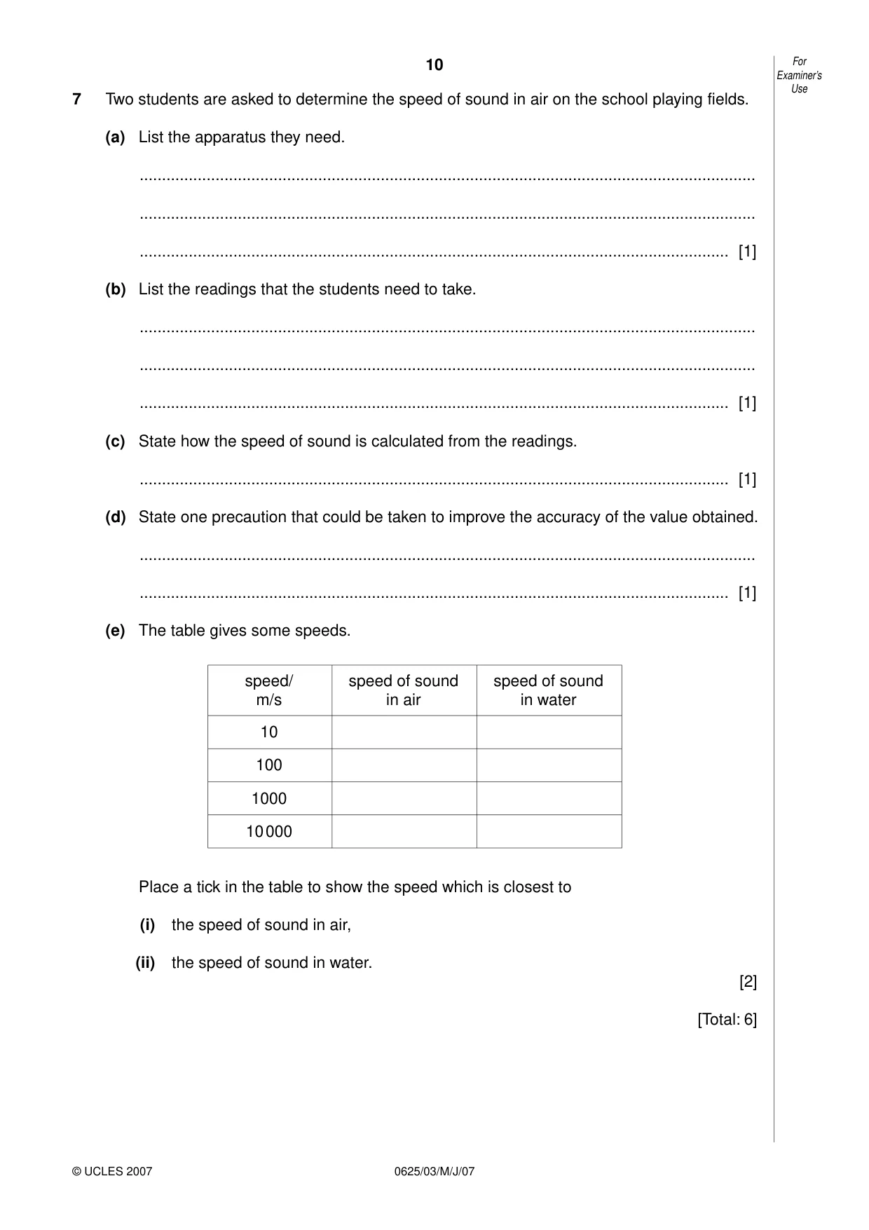
7 Two students are asked to determine the speed of sound in air on the school playing fields. (a) List the apparatus they need. .......................................................................................................................................... .......................................................................................................................................... .................................................................................................................................... [1] (b) List the readings that the students need to take. .......................................................................................................................................... .......................................................................................................................................... .................................................................................................................................... [1] (c) State how the speed of sound is calculated from the readings. .................................................................................................................................... [1] (d) State one precaution that could be taken to improve the accuracy of the value obtained. .......................................................................................................................................... .................................................................................................................................... [1] (e) The table gives some speeds. speed/ speed of sound speed of sound m/s in air in water 10 100 1000 10 000 Place a tick in the table to show the speed which is closest to (i) the speed of sound in air, (ii) the speed of sound in water. [2] [Total: 6]
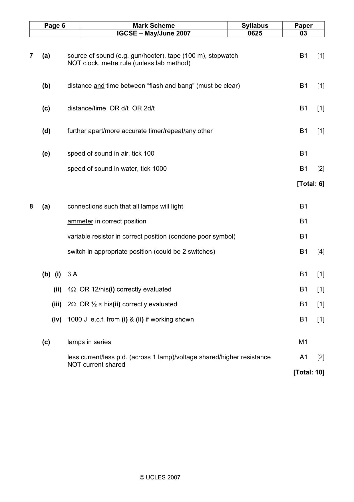
Mark scheme: 7 (a) source of sound (e.g. gun/hooter), tape (100 m), stopwatch B1 [1] NOT clock, metre rule (unless lab method) (b) distance and time between “flash and bang” (must be clear) B1 [1] (c) distance/time OR d/t OR 2d/t B1 [1] (d) further apart/more accurate timer/repeat/any other B1 [1] (e) speed of sound in air, tick 100 B1 speed of sound in water, tick 1000 B1 [2] [Total: 6]
More questions on Physical quantities and measurement techniques
Q8 · Part of a low-voltage lighting circuit containing five identical lamps
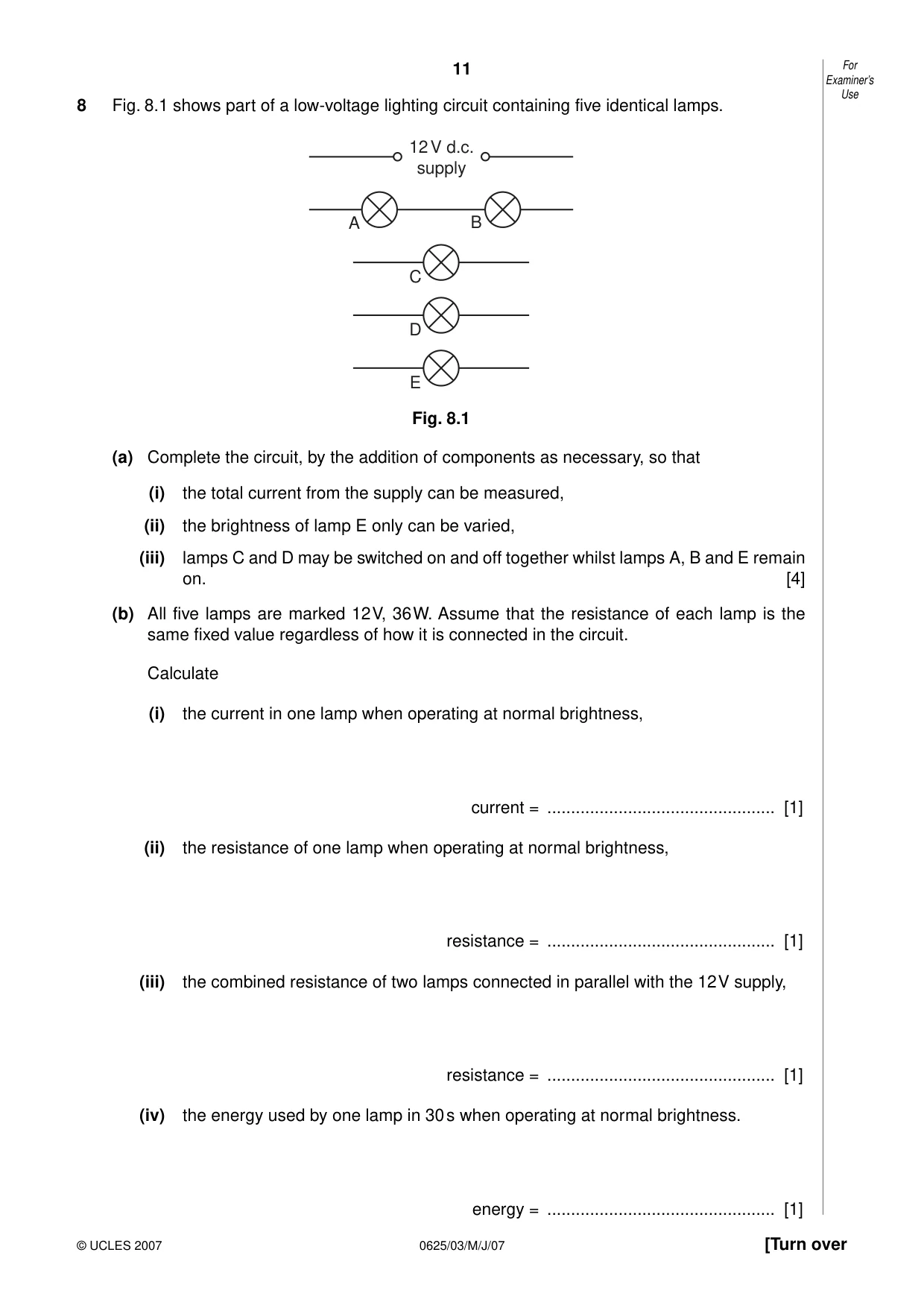
8 Fig. 8.1 shows part of a low-voltage lighting circuit containing five identical lamps. 12 V d.c. supply A B C D E Fig. 8.1 (a) Complete the circuit, by the addition of components as necessary, so that (i) the total current from the supply can be measured, (ii) the brightness of lamp E only can be varied, (iii) lamps C and D may be switched on and off together whilst lamps A, B and E remain on. [4] (b) All five lamps are marked 12 V, 36 W. Assume that the resistance of each lamp is the same fixed value regardless of how it is connected in the circuit. Calculate (i) the current in one lamp when operating at normal brightness, current = ................................................ [1] (ii) the resistance of one lamp when operating at normal brightness, resistance = ................................................ [1] (iii) the combined resistance of two lamps connected in parallel with the 12 V supply, resistance = ................................................ [1] (iv) the energy used by one lamp in 30 s when operating at normal brightness. energy = ................................................ [1] Examiner’s Use (c) The whole circuit is switched on. Explain why the brightness of lamps A and B is much less than that of one lamp operating at normal brightness. .......................................................................................................................................... .......................................................................................................................................... .................................................................................................................................... [2] [Total: 10]
Mark scheme: 8 (a) connections such that all lamps will light B1 ammeter in correct position B1 variable resistor in correct position (condone poor symbol) B1 switch in appropriate position (could be 2 switches) B1 [4] (b) (i) 3 A B1 [1] (ii) 4Ω OR 12/his(i) correctly evaluated B1 [1] (iii) 2Ω OR ½ × his(ii) correctly evaluated B1 [1] (iv) 1080 J e.c.f. from (i) & (ii) if working shown B1 [1] (c) lamps in series M1 less current/less p.d. (across 1 lamp)/voltage shared/higher resistance A1 [2] NOT current shared [Total: 10] IGCSE – May/June 2007 0625 03
Q9 · A sketch of some apparatus, found in a Science museum, which was once used to show how…
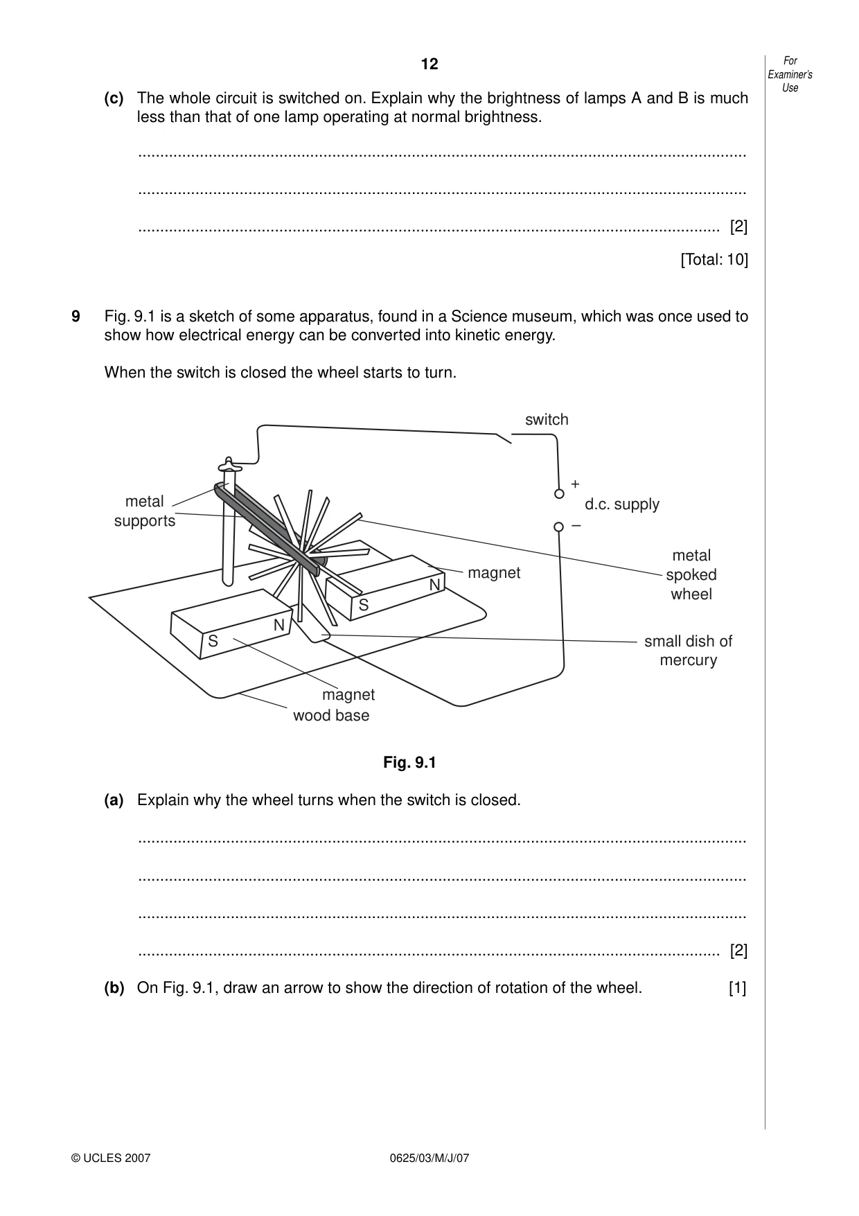
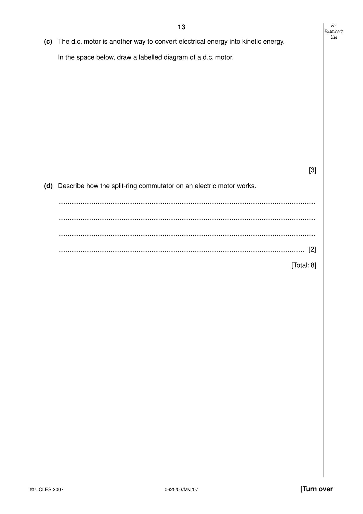
9 Fig. 9.1 is a sketch of some apparatus, found in a Science museum, which was once used to show how electrical energy can be converted into kinetic energy. When the switch is closed the wheel starts to turn. switch + metal d.c. supply supports – metal magnet spoked N wheel S N S small dish of mercury magnet wood base Fig. 9.1 (a) Explain why the wheel turns when the switch is closed. .......................................................................................................................................... .......................................................................................................................................... .......................................................................................................................................... .................................................................................................................................... [2] (b) On Fig. 9.1, draw an arrow to show the direction of rotation of the wheel. [1] Examiner’s Use (c) The d.c. motor is another way to convert electrical energy into kinetic energy. In the space below, draw a labelled diagram of a d.c. motor. [3] (d) Describe how the split-ring commutator on an electric motor works. .......................................................................................................................................... .......................................................................................................................................... .......................................................................................................................................... .................................................................................................................................... [2] [Total: 8]
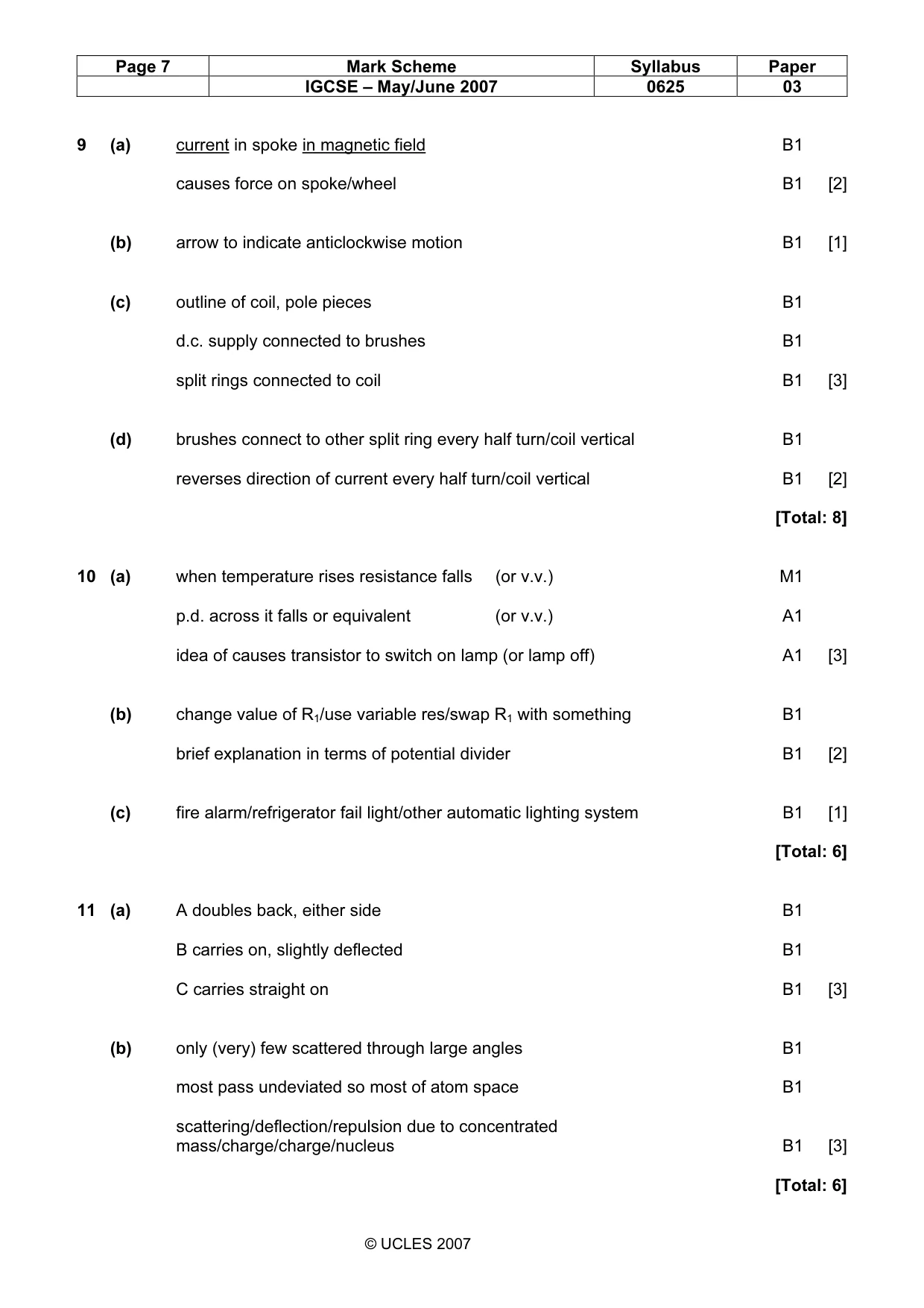
Mark scheme: 9 (a) current in spoke in magnetic field B1 causes force on spoke/wheel B1 [2] (b) arrow to indicate anticlockwise motion B1 [1] (c) outline of coil, pole pieces B1 d.c. supply connected to brushes B1 split rings connected to coil B1 [3] (d) brushes connect to other split ring every half turn/coil vertical B1 reverses direction of current every half turn/coil vertical B1 [2] [Total: 8]
Q10 · A circuit based on a transistor and a thermistor
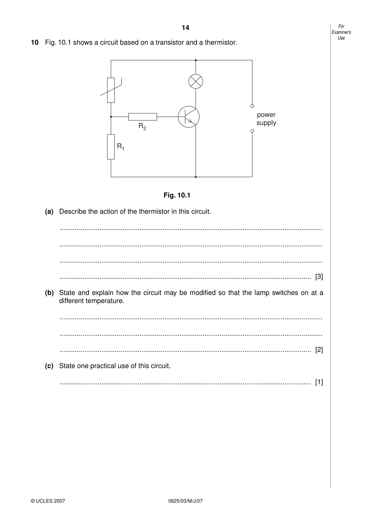
10 Fig. 10.1 shows a circuit based on a transistor and a thermistor. power supply R2 R1 Fig. 10.1 (a) Describe the action of the thermistor in this circuit. .......................................................................................................................................... .......................................................................................................................................... .......................................................................................................................................... .................................................................................................................................... [3] (b) State and explain how the circuit may be modified so that the lamp switches on at a different temperature. .......................................................................................................................................... .......................................................................................................................................... .................................................................................................................................... [2] (c) State one practical use of this circuit. .................................................................................................................................... [1]
Mark scheme: 10 (a) when temperature rises resistance falls (or v.v.) M1 p.d. across it falls or equivalent (or v.v.) A1 idea of causes transistor to switch on lamp (or lamp off) A1 [3] (b) change value of R1/use variable res/swap R1 with something B1 brief explanation in terms of potential divider B1 [2] (c) fire alarm/refrigerator fail light/other automatic lighting system B1 [1] [Total: 6]
Q11 · The paths of three α-particles moving towards a thin gold foil
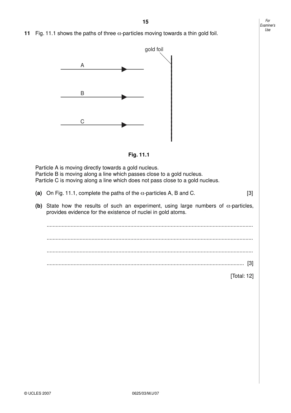
11 Fig. 11.1 shows the paths of three α-particles moving towards a thin gold foil. gold foil A B C Fig. 11.1 Particle A is moving directly towards a gold nucleus. Particle B is moving along a line which passes close to a gold nucleus. Particle C is moving along a line which does not pass close to a gold nucleus. (a) On Fig. 11.1, complete the paths of the α-particles A, B and C. [3] (b) State how the results of such an experiment, using large numbers of α-particles, provides evidence for the existence of nuclei in gold atoms. .......................................................................................................................................... .......................................................................................................................................... .......................................................................................................................................... .................................................................................................................................... [3] [Total: 12]
Mark scheme: 11 (a) A doubles back, either side B1 B carries on, slightly deflected B1 C carries straight on B1 [3] (b) only (very) few scattered through large angles B1 most pass undeviated so most of atom space B1 scattering/deflection/repulsion due to concentrated mass/charge/charge/nucleus B1 [3] [Total: 6]
What was in this paper
The subtopics covered by these 11 questions, and how many questions each got. Open one in a new tab to see every Cambridge question on it.
What you needed in this session
Cambridge’s own grade thresholds for 2007 May/June, Paper 3 · Variant 1. A higher threshold means an easier paper — the bar moves with how the cohort did.