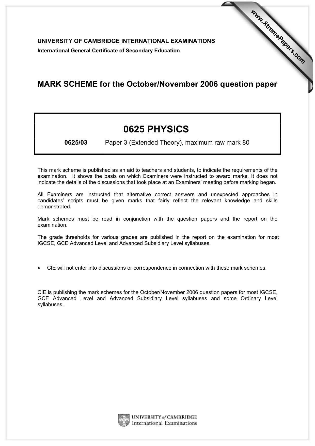
Cambridge IGCSE Physics 0625 — 2006 Oct/Nov Paper 3 · Variant 1
0625/31/O/N/06 · 11 questions · 80 marks · ≈90 min
The question paper and its mark scheme, free to read here and free to download. This is Cambridge’s own paper, exactly as it was sat.
Question paper16 pages
Mark scheme4 pages
Answers below. Sit the paper first if you are practising.
Questions as text
Q1 · A stone falls from the top of a building and hits the ground at a speed of 32 m/s
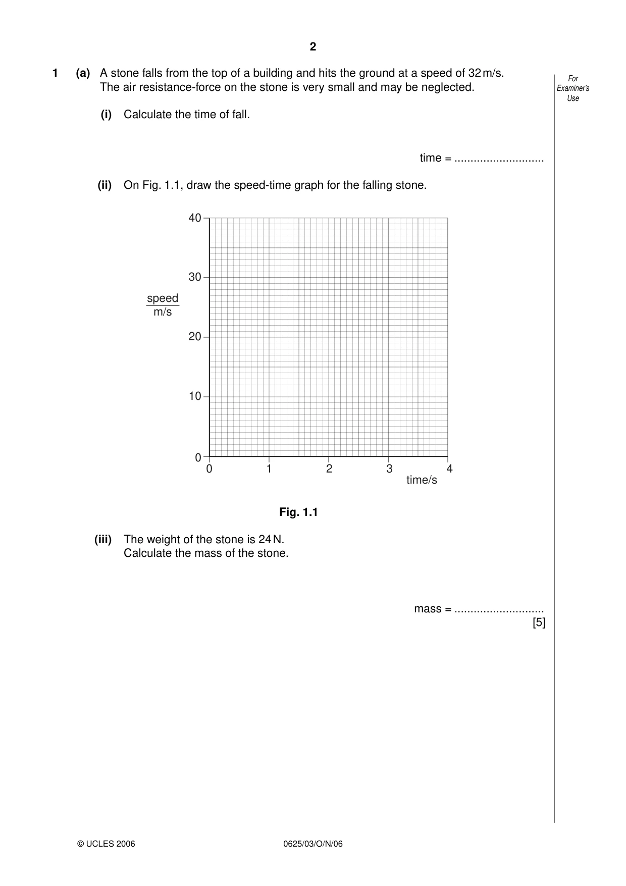
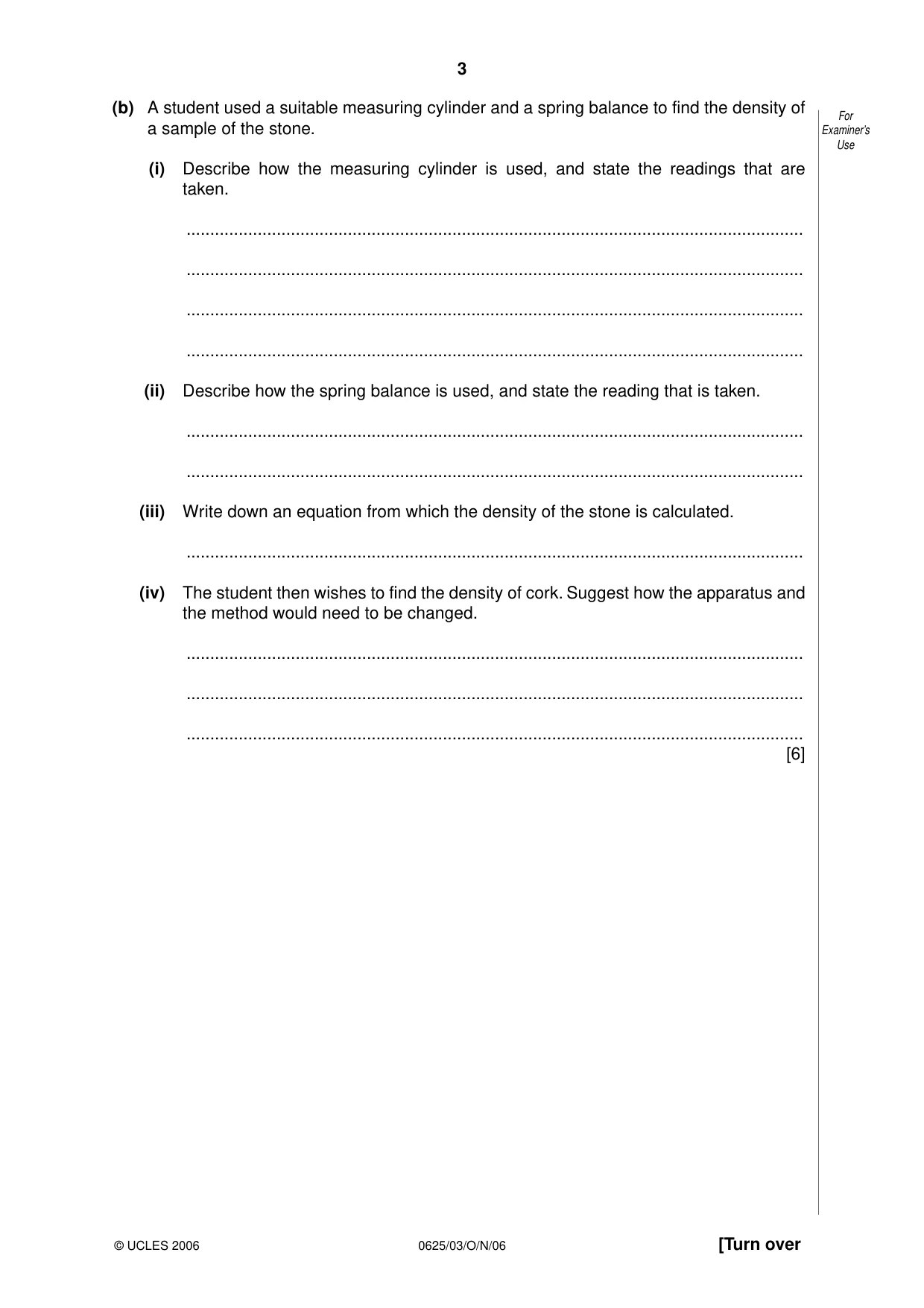
1 (a) A stone falls from the top of a building and hits the ground at a speed of 32 m/s. For The air resistance-force on the stone is very small and may be neglected. Examiner’s Use (i) Calculate the time of fall. time = ............................ (ii) On Fig. 1.1, draw the speed-time graph for the falling stone. 40 30 speed m/s 20 10 0 0 1 2 3 4 time/s Fig. 1.1 (iii) The weight of the stone is 24 N. Calculate the mass of the stone. mass = ............................ [5] (b) A student used a suitable measuring cylinder and a spring balance to find the density of For a sample of the stone. Examiner’s Use (i) Describe how the measuring cylinder is used, and state the readings that are taken. .................................................................................................................................. .................................................................................................................................. .................................................................................................................................. .................................................................................................................................. (ii) Describe how the spring balance is used, and state the reading that is taken. .................................................................................................................................. .................................................................................................................................. (iii) Write down an equation from which the density of the stone is calculated. .................................................................................................................................. (iv) The student then wishes to find the density of cork. Suggest how the apparatus and the method would need to be changed. .................................................................................................................................. .................................................................................................................................. .................................................................................................................................. [6]
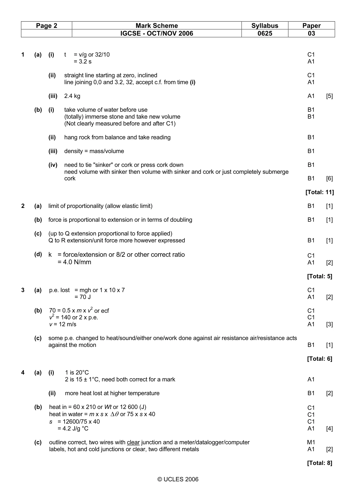
Mark scheme: 1 (a) (i) t = v/g or 32/10 C1 = 3.2 s A1 (ii) straight line starting at zero, inclined C1 line joining 0,0 and 3.2, 32, accept c.f. from time (i) A1 (iii) 2.4 kg A1 [5] (b) (i) take volume of water before use B1 (totally) immerse stone and take new volume B1 (Not clearly measured before and after C1) (ii) hang rock from balance and take reading B1 (iii) density = mass/volume B1 (iv) need to tie "sinker" or cork or press cork down B1 need volume with sinker then volume with sinker and cork or just completely submerge cork B1 [6] [Total: 11]
Q2 · In an experiment, forces are applied to a spring as shown in Fig
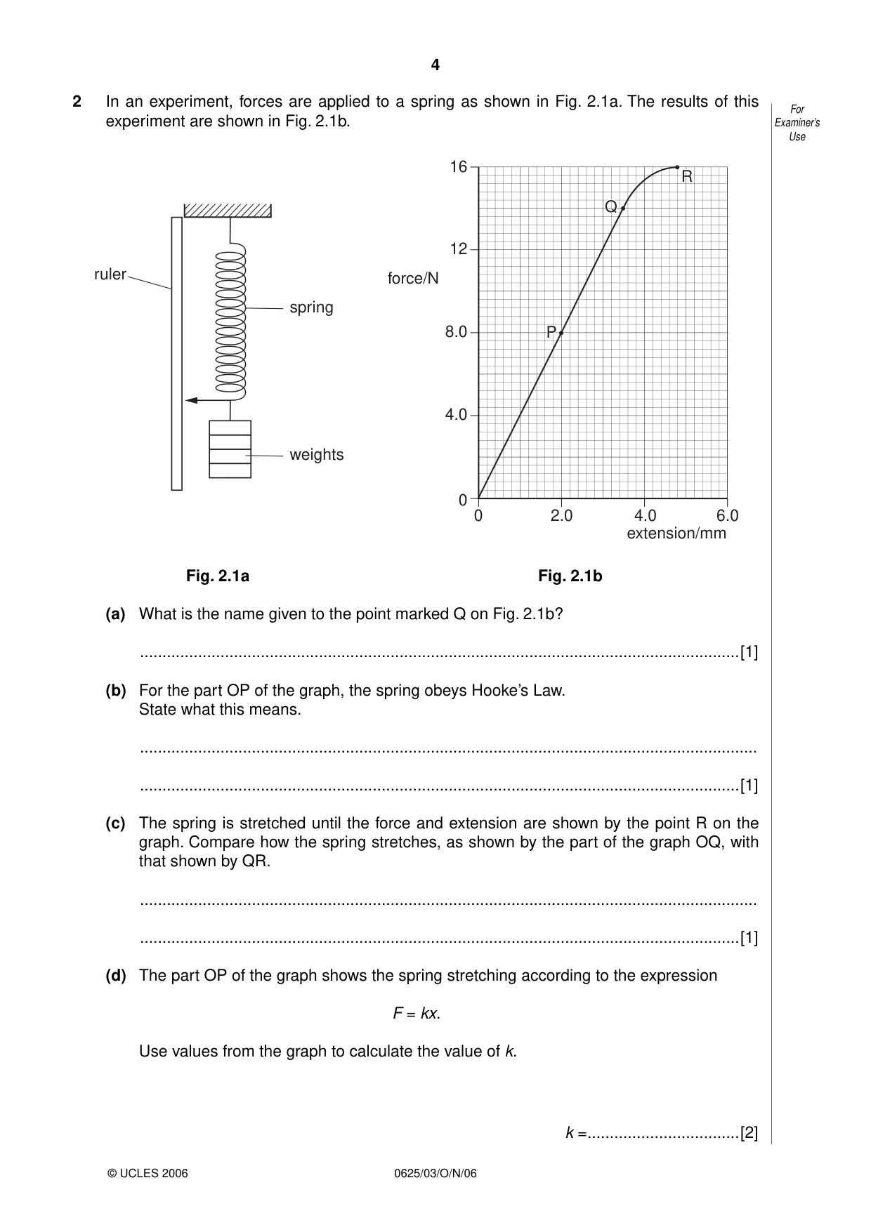
2 In an experiment, forces are applied to a spring as shown in Fig. 2.1a. The results of this For experiment are shown in Fig. 2.1b. Examiner’s Use 16 RR QQ 12 ruler force/N spring 8.0 PP 4.0 weights 0 0 2.0 4.0 6.0 extension/mm Fig. 2.1a Fig. 2.1b (a) What is the name given to the point marked Q on Fig. 2.1b? ......................................................................................................................................[1] (b) For the part OP of the graph, the spring obeys Hooke’s Law. State what this means. .......................................................................................................................................... ......................................................................................................................................[1] (c) The spring is stretched until the force and extension are shown by the point R on the graph. Compare how the spring stretches, as shown by the part of the graph OQ, with that shown by QR. .......................................................................................................................................... ......................................................................................................................................[1] (d) The part OP of the graph shows the spring stretching according to the expression F = kx. Use values from the graph to calculate the value of k. k = ..................................[2]
Mark scheme: 2 (a) limit of proportionality (allow elastic limit) B1 [1] (b) force is proportional to extension or in terms of doubling B1 [1] (c) (up to Q extension proportional to force applied) Q to R extension/unit force more however expressed B1 [1] (d) k = force/extension or 8/2 or other correct ratio C1 = 4.0 N/mm A1 [2] [Total: 5]
Q3 · Water falling over a dam
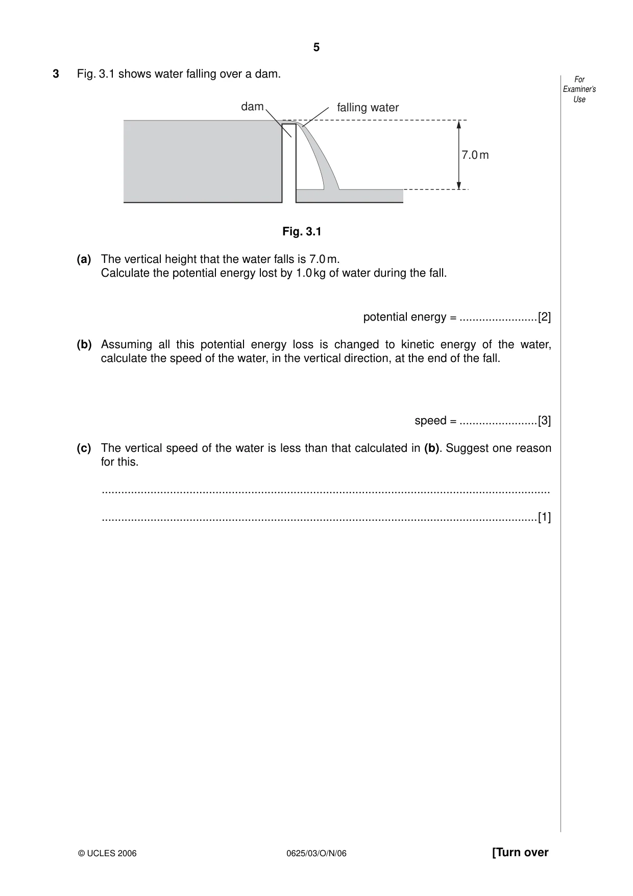
3 Fig. 3.1 shows water falling over a dam. For Examiner’s Use dam falling water 7.0 m Fig. 3.1 (a) The vertical height that the water falls is 7.0 m. Calculate the potential energy lost by 1.0 kg of water during the fall. potential energy = ........................[2] (b) Assuming all this potential energy loss is changed to kinetic energy of the water, calculate the speed of the water, in the vertical direction, at the end of the fall. speed = ........................[3] (c) The vertical speed of the water is less than that calculated in (b). Suggest one reason for this. .......................................................................................................................................... ......................................................................................................................................[1]
Mark scheme: 3 (a) p.e. lost = mgh or 1 x 10 x 7 C1 = 70 J A1 [2] (b) 70 = 0.5 x m x v2 or ecf C1 v2 = 140 or 2 x p.e. C1 v = 12 m/s A1 [3] (c) some p.e. changed to heat/sound/either one/work done against air resistance air/resistance acts against the motion B1 [1] [Total: 6]
Q4 · Some water is heated electrically in a glass beaker in an experiment to find the specific…
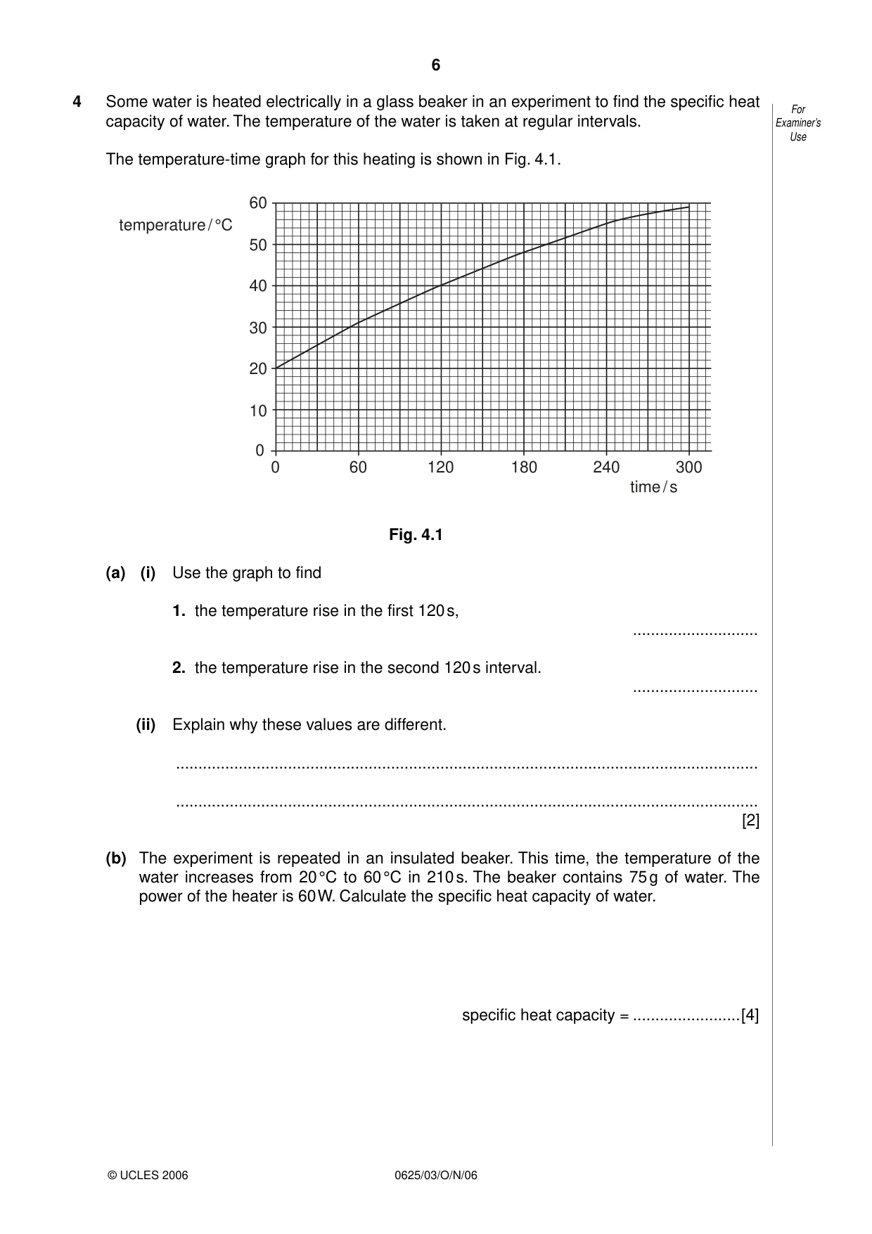
4 Some water is heated electrically in a glass beaker in an experiment to find the specific heat For capacity of water. The temperature of the water is taken at regular intervals. Examiner’s Use The temperature-time graph for this heating is shown in Fig. 4.1. 60 temperature / °C 50 40 30 20 10 0 0 60 120 180 240 300 time / s Fig. 4.1 (a) (i) Use the graph to find 1. the temperature rise in the first 120 s, ............................ 2. the temperature rise in the second 120 s interval. ............................ (ii) Explain why these values are different. .................................................................................................................................. .................................................................................................................................. [2] (b) The experiment is repeated in an insulated beaker. This time, the temperature of the water increases from 20 °C to 60 °C in 210 s. The beaker contains 75 g of water. The power of the heater is 60 W. Calculate the specific heat capacity of water. specific heat capacity = ........................[4] (c) In order to measure the temperature during the heating, a thermocouple is used. For Draw a labelled diagram of a thermocouple connected to measure temperature. Examiner’s Use [2]
Mark scheme: 4 (a) (i) 1 is 20°C 2 is 15 ± 1°C, need both correct for a mark A1 (ii) more heat lost at higher temperature B1 [2] (b) heat in = 60 x 210 or Wt or 12 600 (J) C1 heat in water = m x s x ∆θ or 75 x s x 40 C1 s = 12600/75 x 40 C1 = 4.2 J/g °C A1 [4] (c) outline correct, two wires with clear junction and a meter/datalogger/computer M1 labels, hot and cold junctions or clear, two different metals A1 [2] [Total: 8] IGCSE - OCT/NOV 2006 0625 03
Q5 · A copper rod AB being heated at one end
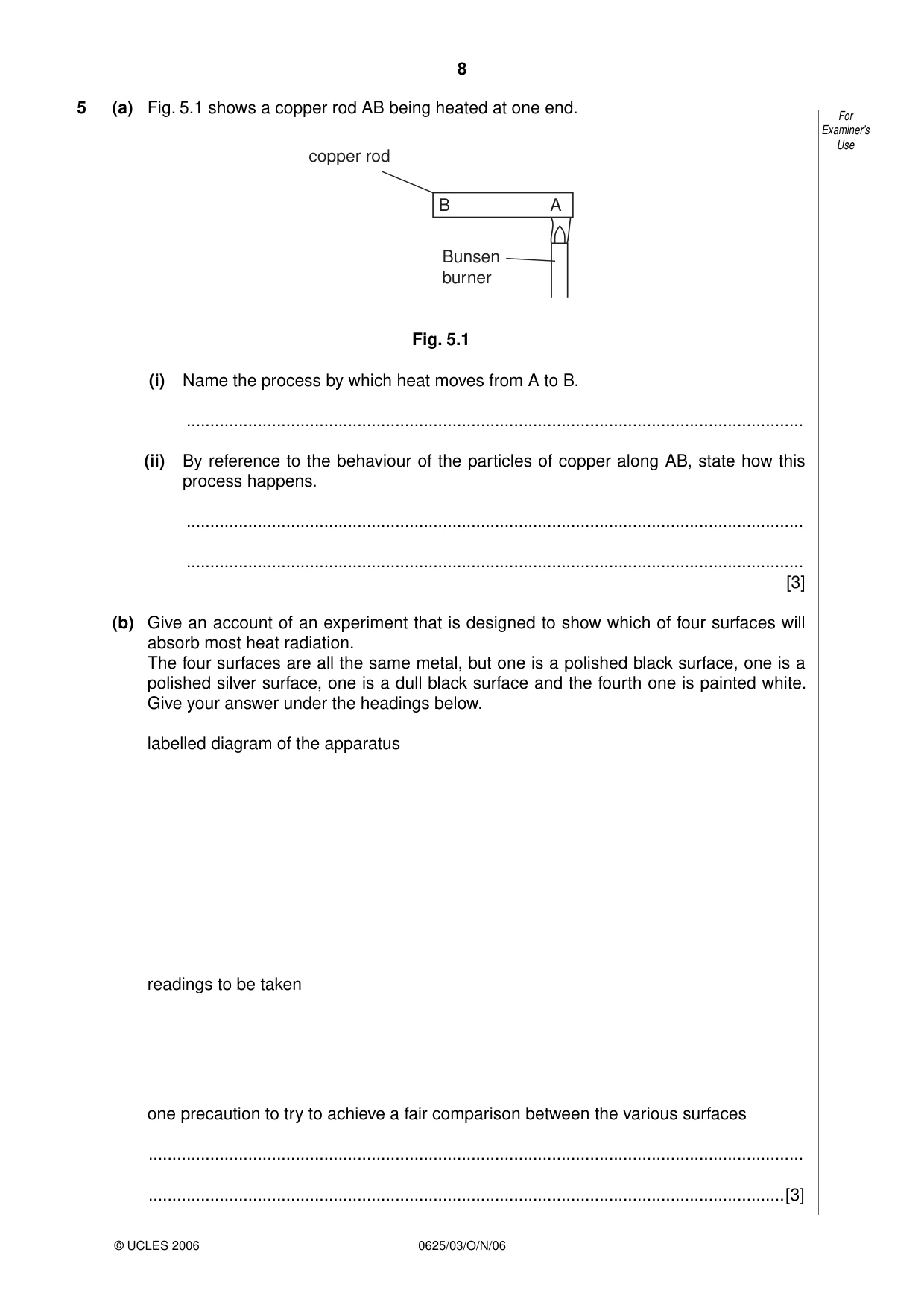
5 (a) Fig. 5.1 shows a copper rod AB being heated at one end. For Examiner’s Use copper rod B A Bunsen burner Fig. 5.1 (i) Name the process by which heat moves from A to B. .................................................................................................................................. (ii) By reference to the behaviour of the particles of copper along AB, state how this process happens. .................................................................................................................................. .................................................................................................................................. [3] (b) Give an account of an experiment that is designed to show which of four surfaces will absorb most heat radiation. The four surfaces are all the same metal, but one is a polished black surface, one is a polished silver surface, one is a dull black surface and the fourth one is painted white. Give your answer under the headings below. labelled diagram of the apparatus readings to be taken one precaution to try to achieve a fair comparison between the various surfaces .......................................................................................................................................... ......................................................................................................................................[3]
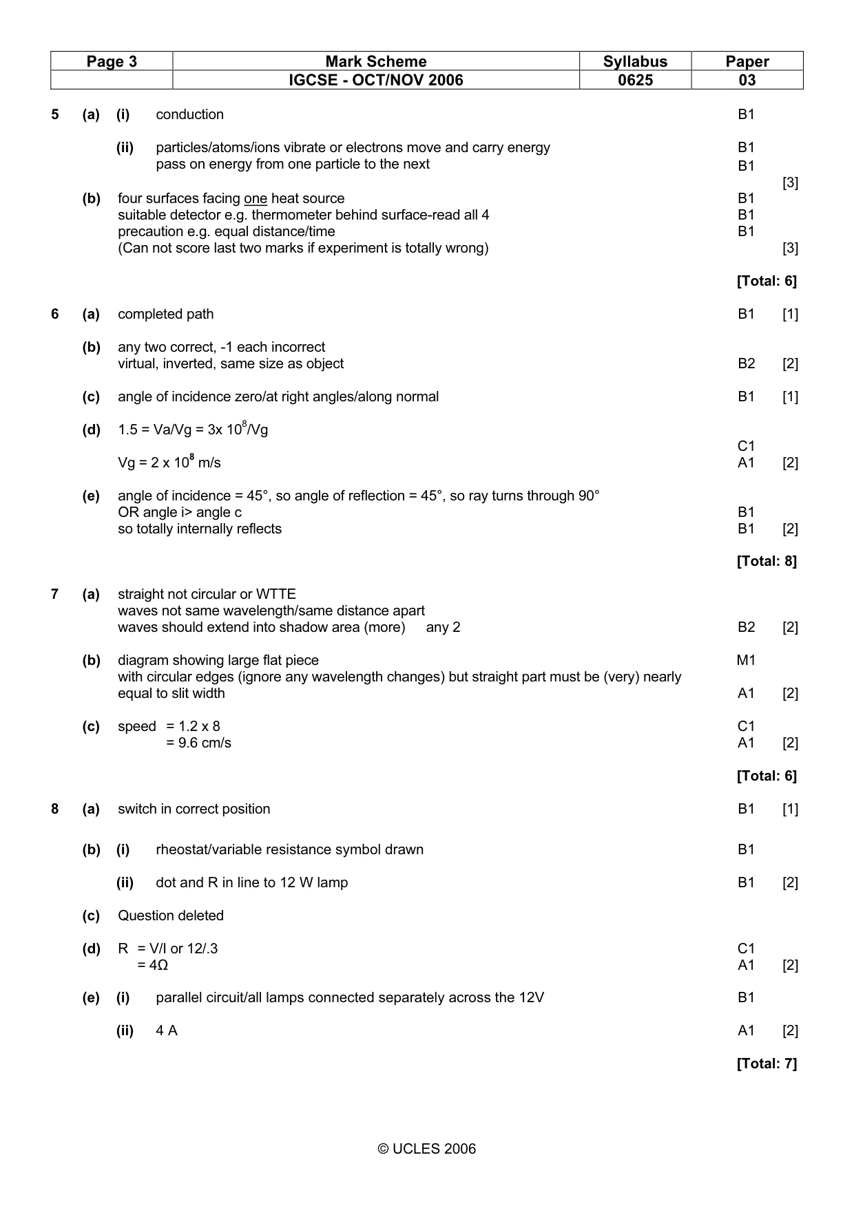
Mark scheme: 5 (a) (i) conduction B1 (ii) particles/atoms/ions vibrate or electrons move and carry energy B1 pass on energy from one particle to the next B1 [3] (b) four surfaces facing one heat source B1 suitable detector e.g. thermometer behind surface-read all 4 B1 precaution e.g. equal distance/time B1 (Can not score last two marks if experiment is totally wrong) [3] [Total: 6]
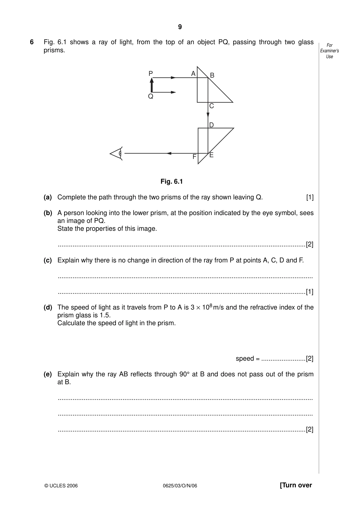
Q6 · A ray of light, from the top of an object PQ, passing through two glass For prisms
6 Fig. 6.1 shows a ray of light, from the top of an object PQ, passing through two glass For prisms. Examiner’s Use P A B Q C D F E Fig. 6.1 (a) Complete the path through the two prisms of the ray shown leaving Q. [1] (b) A person looking into the lower prism, at the position indicated by the eye symbol, sees an image of PQ. State the properties of this image. ......................................................................................................................................[2] (c) Explain why there is no change in direction of the ray from P at points A, C, D and F. .......................................................................................................................................... ......................................................................................................................................[1] (d) The speed of light as it travels from P to A is 3 × 10⁸ m/s and the refractive index of the prism glass is 1.5. Calculate the speed of light in the prism. speed = ........................[2] (e) Explain why the ray AB reflects through 90° at B and does not pass out of the prism at B. .......................................................................................................................................... .......................................................................................................................................... ......................................................................................................................................[2]
Mark scheme: 6 (a) completed path B1 [1] (b) any two correct, -1 each incorrect virtual, inverted, same size as object B2 [2] (c) angle of incidence zero/at right angles/along normal B1 [1] (d) 1.5 = Va/Vg = 3x 10⁸/Vg C1 Vg = 2 x 10⁸ m/s A1 [2] (e) angle of incidence = 45°, so angle of reflection = 45°, so ray turns through 90° OR angle i> angle c B1 so totally internally reflects B1 [2] [Total: 8]
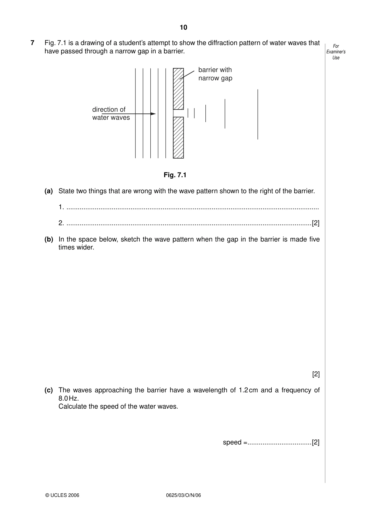
Q7 · A drawing of a student’s attempt to show the diffraction pattern of water waves that For…
7 Fig. 7.1 is a drawing of a student’s attempt to show the diffraction pattern of water waves that For have passed through a narrow gap in a barrier. Examiner’s Use barrier with narrow gap direction of water waves Fig. 7.1 (a) State two things that are wrong with the wave pattern shown to the right of the barrier. 1. ...................................................................................................................................... 2. ..................................................................................................................................[2] (b) In the space below, sketch the wave pattern when the gap in the barrier is made five times wider. [2] (c) The waves approaching the barrier have a wavelength of 1.2 cm and a frequency of 8.0 Hz. Calculate the speed of the water waves. speed = ..................................[2]
Mark scheme: 7 (a) straight not circular or WTTE waves not same wavelength/same distance apart waves should extend into shadow area (more) any 2 B2 [2] (b) diagram showing large flat piece M1 with circular edges (ignore any wavelength changes) but straight part must be (very) nearly equal to slit width A1 [2] (c) speed = 1.2 x 8 C1 = 9.6 cm/s A1 [2] [Total: 6]
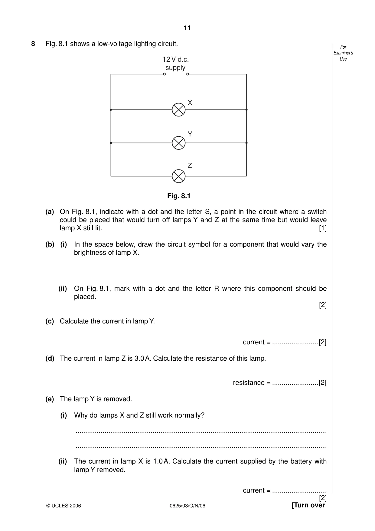
Q8 · A low-voltage lighting circuit
8 Fig. 8.1 shows a low-voltage lighting circuit. For Examiner’s 12 V d.c. Use supply X Y Z Fig. 8.1 (a) On Fig. 8.1, indicate with a dot and the letter S, a point in the circuit where a switch could be placed that would turn off lamps Y and Z at the same time but would leave lamp X still lit. [1] (b) (i) In the space below, draw the circuit symbol for a component that would vary the brightness of lamp X. (ii) On Fig. 8.1, mark with a dot and the letter R where this component should be placed. [2] (c) Calculate the current in lamp Y. current = ........................[2] (d) The current in lamp Z is 3.0 A. Calculate the resistance of this lamp. resistance = ........................[2] (e) The lamp Y is removed. (i) Why do lamps X and Z still work normally? .................................................................................................................................. .................................................................................................................................. (ii) The current in lamp X is 1.0 A. Calculate the current supplied by the battery with lamp Y removed. current = ............................ [2]
Mark scheme: 8 (a) switch in correct position B1 [1] (b) (i) rheostat/variable resistance symbol drawn B1 (ii) dot and R in line to 12 W lamp B1 [2] (c) Question deleted (d) R = V/I or 12/.3 C1 = 4Ω A1 [2] (e) (i) parallel circuit/all lamps connected separately across the 12V B1 (ii) 4 A A1 [2] [Total: 7] IGCSE - OCT/NOV 2006 0625 03
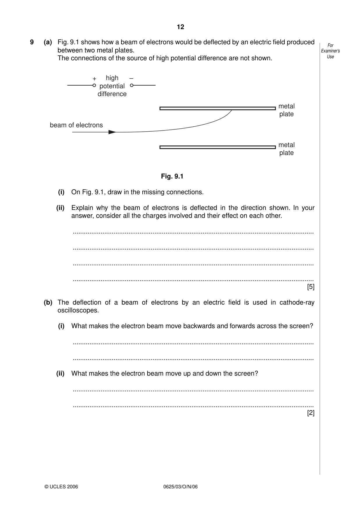
Q9 · How a beam of electrons would be deflected by an electric field produced For between two…
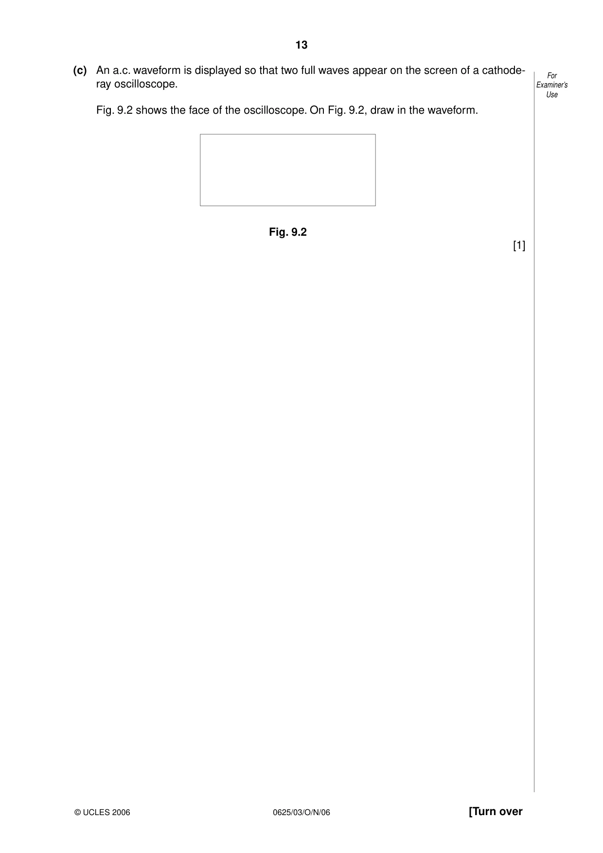
9 (a) Fig. 9.1 shows how a beam of electrons would be deflected by an electric field produced For between two metal plates. Examiner’s The connections of the source of high potential difference are not shown. Use + high – potential difference metal plate beam of electrons metal plate Fig. 9.1 (i) On Fig. 9.1, draw in the missing connections. (ii) Explain why the beam of electrons is deflected in the direction shown. In your answer, consider all the charges involved and their effect on each other. .................................................................................................................................. .................................................................................................................................. .................................................................................................................................. .................................................................................................................................. [5] (b) The deflection of a beam of electrons by an electric field is used in cathode-ray oscilloscopes. (i) What makes the electron beam move backwards and forwards across the screen? .................................................................................................................................. .................................................................................................................................. (ii) What makes the electron beam move up and down the screen? .................................................................................................................................. .................................................................................................................................. [2] (c) An a.c. waveform is displayed so that two full waves appear on the screen of a cathode- For ray oscilloscope. Examiner’s Use Fig. 9.2 shows the face of the oscilloscope. On Fig. 9.2, draw in the waveform. Fig. 9.2 [1]
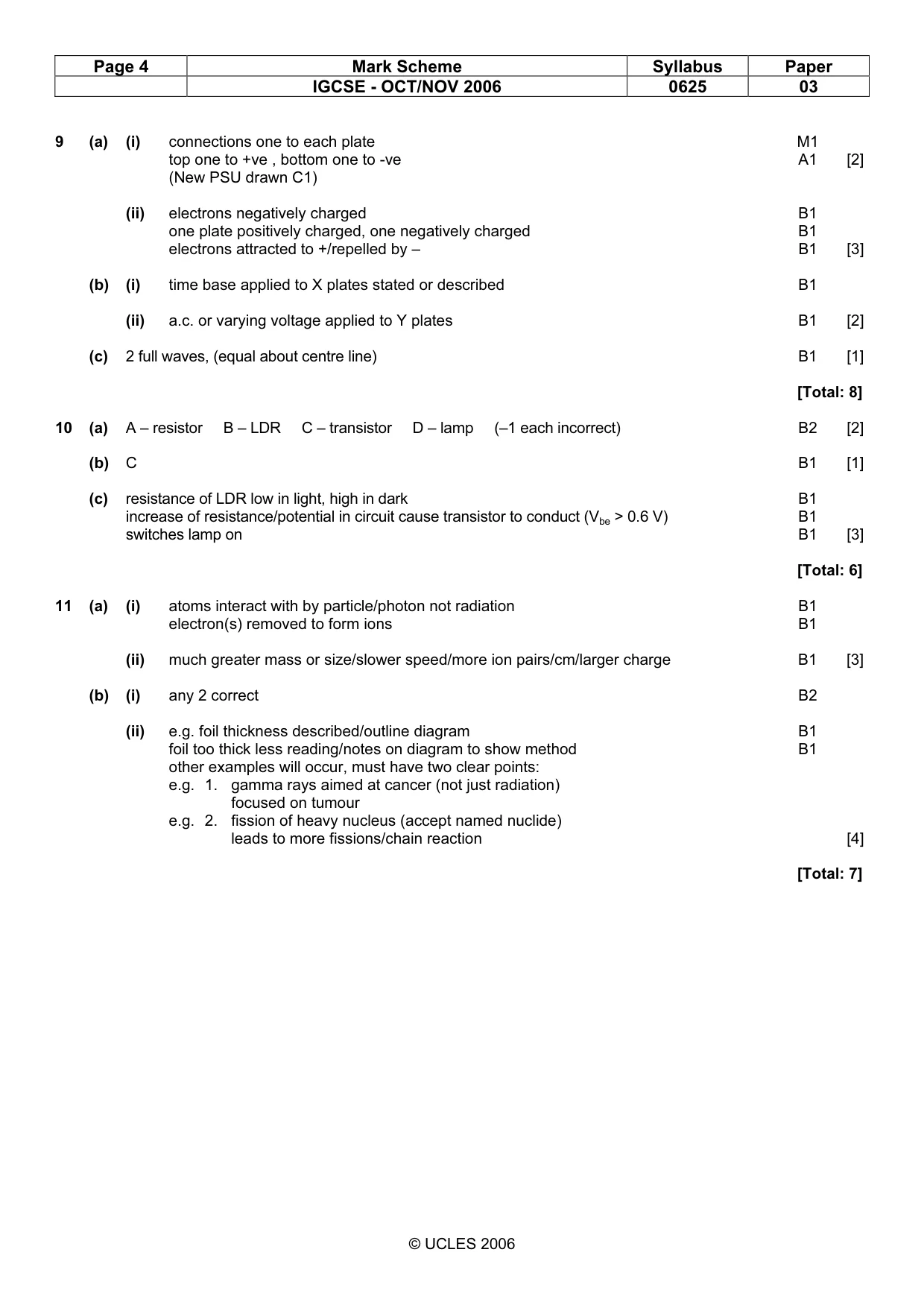
Mark scheme: 9 (a) (i) connections one to each plate M1 top one to +ve , bottom one to -ve A1 [2] (New PSU drawn C1) (ii) electrons negatively charged B1 one plate positively charged, one negatively charged B1 electrons attracted to +/repelled by – B1 [3] (b) (i) time base applied to X plates stated or described B1 (ii) a.c. or varying voltage applied to Y plates B1 [2] (c) 2 full waves, (equal about centre line) B1 [1] [Total: 8]
Q10 · A circuit that is used to switch on a lamp automatically when it starts to go For dark
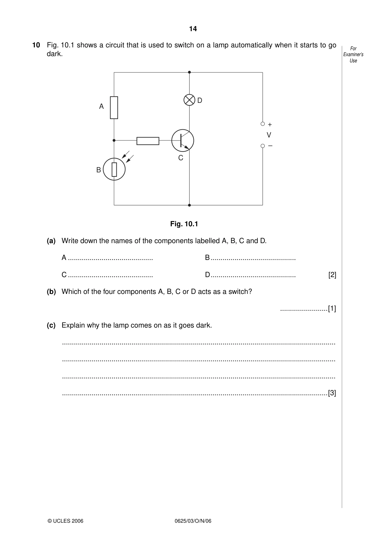
10 Fig. 10.1 shows a circuit that is used to switch on a lamp automatically when it starts to go For dark. Examiner’s Use D A + V – C B Fig. 10.1 (a) Write down the names of the components labelled A, B, C and D. A ........................................... B ........................................... C ........................................... D ........................................... [2] (b) Which of the four components A, B, C or D acts as a switch? ........................[1] (c) Explain why the lamp comes on as it goes dark. .......................................................................................................................................... .......................................................................................................................................... .......................................................................................................................................... ......................................................................................................................................[3]
Mark scheme: 10 (a) A – resistor B – LDR C – transistor D – lamp (–1 each incorrect) B2 [2] (b) C B1 [1] (c) resistance of LDR low in light, high in dark B1 increase of resistance/potential in circuit cause transistor to conduct (Vbe > 0.6 V) B1 switches lamp on B1 [3] [Total: 6]
Q11 · Α-particles, β-particles and γ-rays are known as ionising radiations
11 (a) α-particles, β-particles and γ-rays are known as ionising radiations. For Examiner’s (i) Describe what happens when gases are ionised by ionising radiations. Use .................................................................................................................................. .................................................................................................................................. .................................................................................................................................. (ii) Suggest why α-particles are considered better ionisers of gas than β-particles. .................................................................................................................................. .................................................................................................................................. [3] (b) (i) Suggest two practical applications of radioactive isotopes. 1. .............................................................................................................................. 2. .............................................................................................................................. (ii) For one of the applications that you have suggested, describe how it works, or draw a labelled diagram to illustrate it in use. .................................................................................................................................. .................................................................................................................................. .................................................................................................................................. [4]
Mark scheme: 11 (a) (i) atoms interact with by particle/photon not radiation B1 electron(s) removed to form ions B1 (ii) much greater mass or size/slower speed/more ion pairs/cm/larger charge B1 [3] (b) (i) any 2 correct B2 (ii) e.g. foil thickness described/outline diagram B1 foil too thick less reading/notes on diagram to show method B1 other examples will occur, must have two clear points: e.g. 1. gamma rays aimed at cancer (not just radiation) focused on tumour e.g. 2. fission of heavy nucleus (accept named nuclide) leads to more fissions/chain reaction [4] [Total: 7]
What was in this paper
The subtopics covered by these 11 questions, and how many questions each got. Open one in a new tab to see every Cambridge question on it.
What you needed in this session
Cambridge’s own grade thresholds for 2006 Oct/Nov, Paper 3 · Variant 1. A higher threshold means an easier paper — the bar moves with how the cohort did.