Cambridge IGCSE Physics 0625 — 2013 May/June Paper 3 · Variant 2
0625/32/M/J/13 · 11 questions · 80 marks · ≈90 min
The question paper and its mark scheme, free to read here and free to download. This is Cambridge’s own paper, exactly as it was sat.
Question paper20 pages

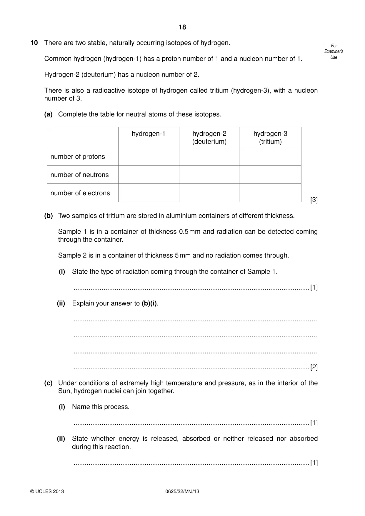
Mark scheme9 pages
Answers below. Sit the paper first if you are practising.
Questions as text
Q1 · A side view of a large tank in a marine visitor attraction
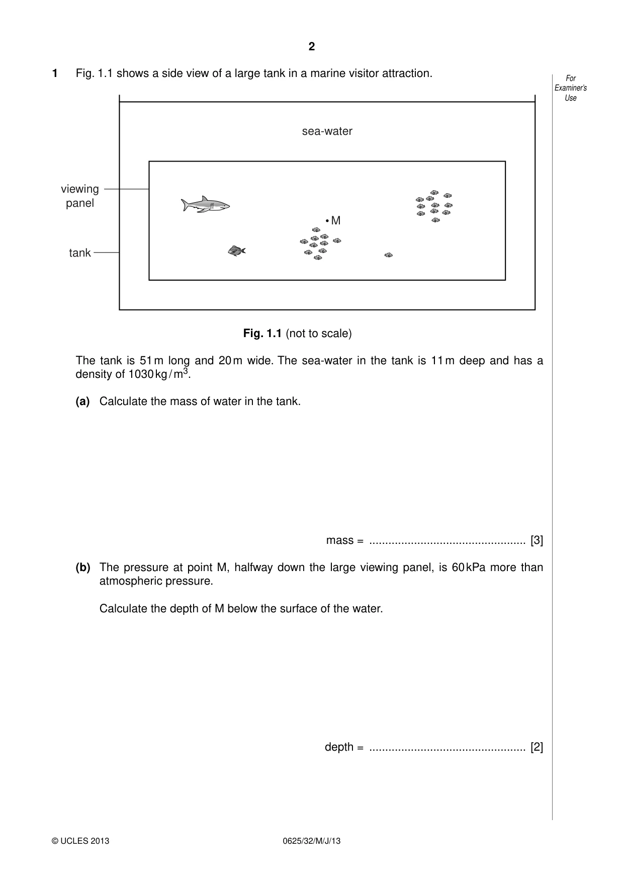
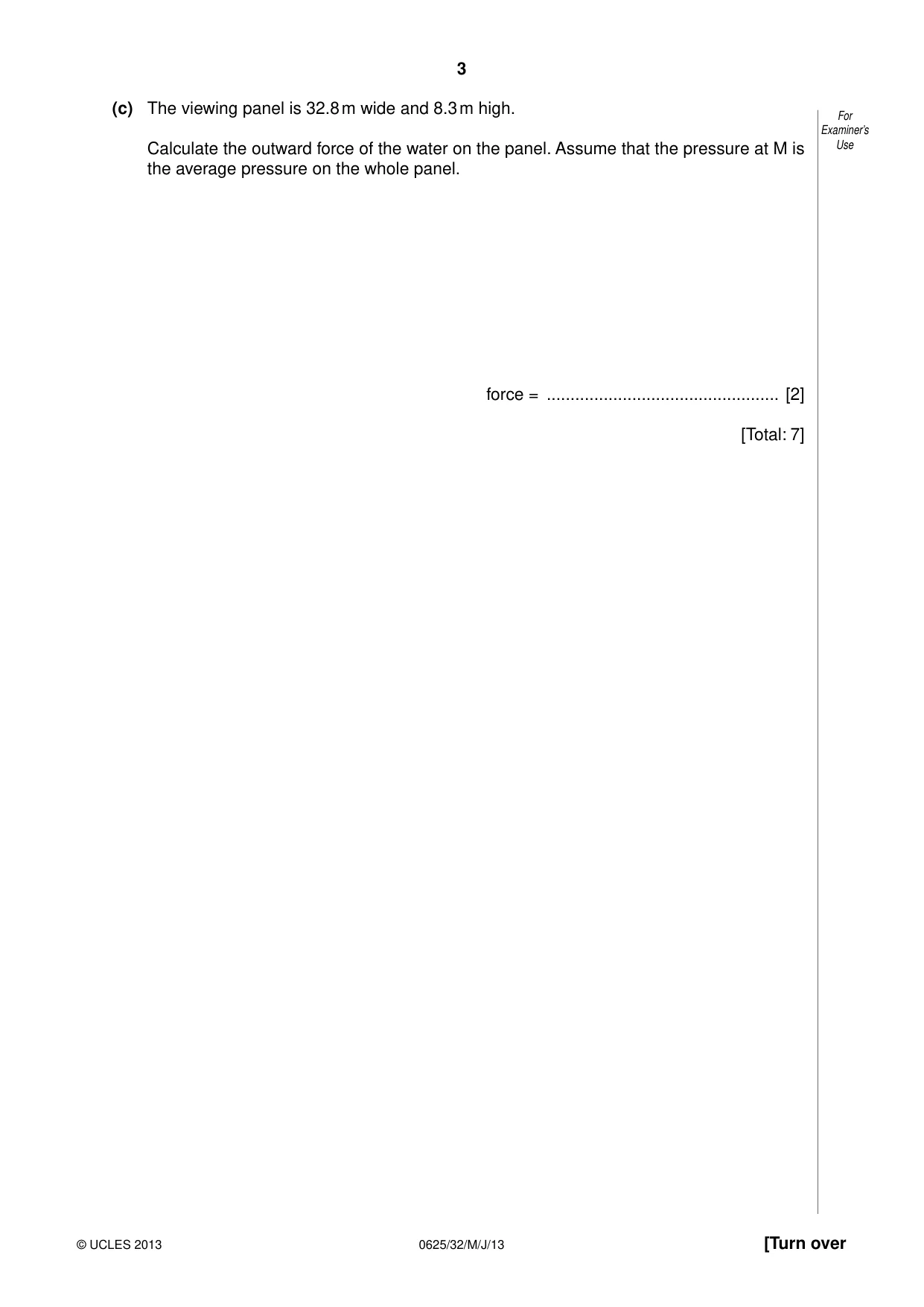
1 Fig. 1.1 shows a side view of a large tank in a marine visitor attraction. For Examiner’s Use sea-water viewing panel M tank Fig. 1.1 (not to scale) The tank is 51 m long and 20 m wide. The sea-water in the tank is 11 m deep and has a density of 1030 kg / m3. (a) Calculate the mass of water in the tank. mass = ................................................. [3] (b) The pressure at point M, halfway down the large viewing panel, is 60 kPa more than atmospheric pressure. Calculate the depth of M below the surface of the water. depth = ................................................. [2] (c) The viewing panel is 32.8 m wide and 8.3 m high. For Examiner’s Calculate the outward force of the water on the panel. Assume that the pressure at M is Use the average pressure on the whole panel. force = ................................................. [2] [Total: 7]
Mark scheme: 1 (a) V = W × L × D in any form words, symbols or numbers C1 use of M = ρV in any form OR ρV words, symbols or numbers C1 (M = 51 × 20 × 11 × 1030 = 11 556 600 =) 1.2 × 10⁷ kg A1 [3] (b) p = ρg(∆)h in any form words, symbols or numbers C1 (∆h = 60 000 / (1030 × 10) =) 5.8(25) m A1 [2] (c) use of F = pA in any form or pA words, symbols or numbers C1 (F = 60 000 × 32.8 × 8.3 = 60 000 × 272.2 =) 1.6(33) × 107 N A1 [2] e.c.f. from (b) [Total: 7]
Q2 · The extension-load graph for a spring
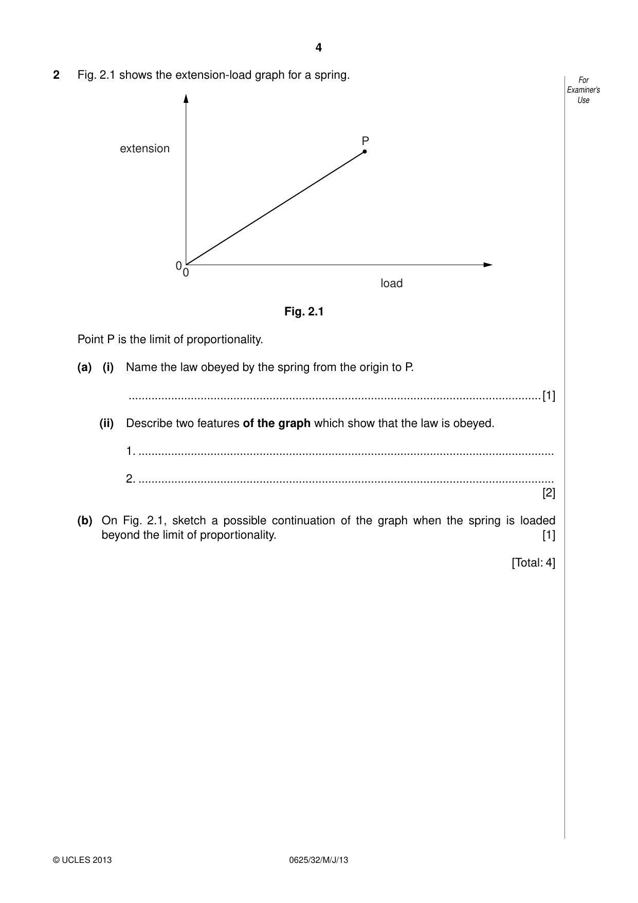
2 Fig. 2.1 shows the extension-load graph for a spring. For Examiner’s Use P extension 0 0 load Fig. 2.1 Point P is the limit of proportionality. (a) (i) Name the law obeyed by the spring from the origin to P. ..............................................................................................................................[1] (ii) Describe two features of the graph which show that the law is obeyed. 1. ............................................................................................................................... 2. ............................................................................................................................... [2] (b) On Fig. 2.1, sketch a possible continuation of the graph when the spring is loaded beyond the limit of proportionality. [1] [Total: 4]
Mark scheme: 2 (a) (i) Hooke’s Law B1 [1] (ii) straight line (graph) / constant gradient B1 through origin/(0,0) B1 [2] ignore through zero ignore extension proportional to load (b) curved extension to graph with increasing gradient, condone decreasing NOT if any part of curve is vertical/horizontal or has negative gradient B1 [1] [Total: 4] IGCSE – May/June 2013 0625 32
Q3 · Water molecules evaporate from a puddle and escape to the atmosphere
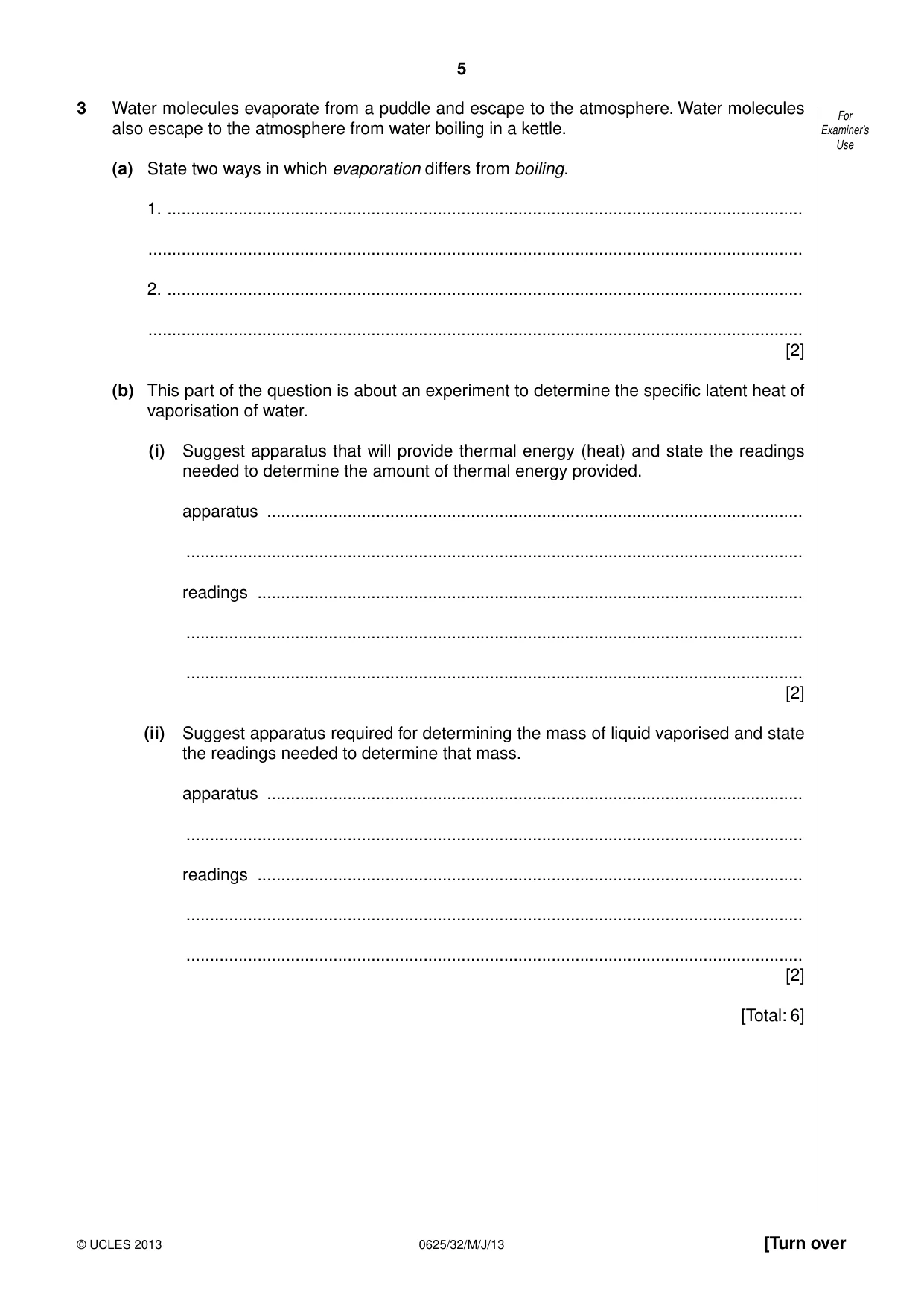
3 Water molecules evaporate from a puddle and escape to the atmosphere. Water molecules For also escape to the atmosphere from water boiling in a kettle. Examiner’s Use (a) State two ways in which evaporation differs from boiling. 1. ...................................................................................................................................... .......................................................................................................................................... 2. ...................................................................................................................................... .......................................................................................................................................... [2] (b) This part of the question is about an experiment to determine the specific latent heat of vaporisation of water. (i) Suggest apparatus that will provide thermal energy (heat) and state the readings needed to determine the amount of thermal energy provided. apparatus ................................................................................................................. .................................................................................................................................. readings ................................................................................................................... .................................................................................................................................. .................................................................................................................................. [2] (ii) Suggest apparatus required for determining the mass of liquid vaporised and state the readings needed to determine that mass. apparatus ................................................................................................................. .................................................................................................................................. readings ................................................................................................................... .................................................................................................................................. .................................................................................................................................. [2] [Total: 6]
Mark scheme: 3 (a) any two from: at surface / not within liquid (if other way round must be explicit) B1 at any temperature / not at boiling point (if other way round must be explicit) B1 [2] (evaporation) causes cooling boiling requires a heat source bubbles rising (b) (i) viable heat source clearly described e.g. electrical/immersion heater B1 appropriate readings e.g. V, I, t or P & t or joulemeter readings B1 [2] OR combustion heater but only with some mention of amount of fuel used B1 correct measurement of amount of fuel used B1 (ii) viable mass measuring device clearly described B1 e.g. (top pan) balance/scales appropriate readings B1 [2] e.g. mass of water before and after / change of mass of water OR measuring cylinder B1 volume of water before and after / change of volume of water B1 [Total: 6]
Q4 · A rocket, initially at rest on the ground, accelerates vertically
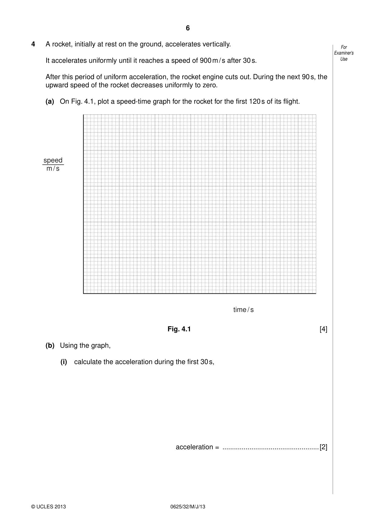
4 A rocket, initially at rest on the ground, accelerates vertically. For Examiner’s It accelerates uniformly until it reaches a speed of 900 m / s after 30 s. Use After this period of uniform acceleration, the rocket engine cuts out. During the next 90 s, the upward speed of the rocket decreases uniformly to zero. (a) On Fig. 4.1, plot a speed-time graph for the rocket for the first 120 s of its flight. speed m / s time / s Fig. 4.1 [4] (b) Using the graph, (i) calculate the acceleration during the first 30 s, acceleration = ..................................................[2] (ii) determine the height reached by the rocket after 120 s. For Examiner’s Use height reached = ..................................................[2] [Total: 8]
Mark scheme: 4 (a) suitable scales (more than half each scale used, no products of 3 s, 7 s etc.) B1 2 straight line sections, continuous 0 to 120 s, 1st section positive gradient, 2nd section negative gradient B1 section 1 straight line, from(0, 0) to (30, 900) B1 section 2 straight line from end of section 1 to (120, 0) B1 [4] (b) (i) use of a = ∆v / t or ∆v / t in any form words, symbols or numbers C1 (a = 900 / 30 =) 30 m / s2 A1 [2] e.c.f. from graph (ii) use of s = area under graph (accept valid equation(s)) C1 (distance = 0.5 × 900 × 120 =) 54 000 m A1 [2] e.c.f. from continuous graph, if curves working must be clear no e.c.f. from graph if it’s a single rectangle [Total: 8] IGCSE – May/June 2013 0625 32
Q5 · An aerial view of wavefronts passing from the open sea into an outer For harbour
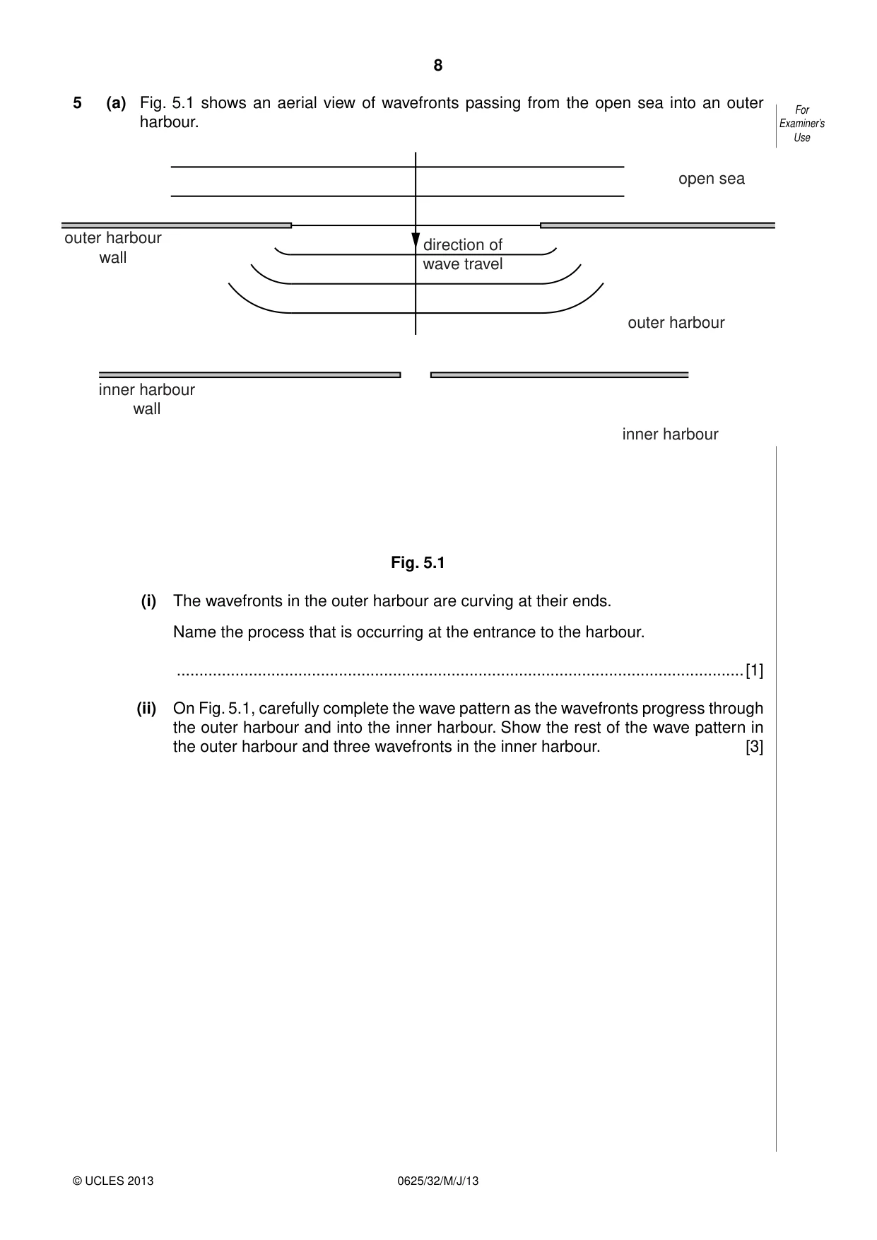
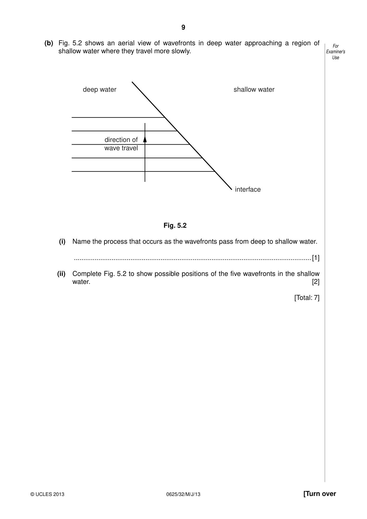
5 (a) Fig. 5.1 shows an aerial view of wavefronts passing from the open sea into an outer For harbour. Examiner’s Use open sea outer harbour direction of wall wave travel outer harbour inner harbour wall inner harbour Fig. 5.1 (i) The wavefronts in the outer harbour are curving at their ends. Name the process that is occurring at the entrance to the harbour. ..............................................................................................................................[1] (ii) On Fig. 5.1, carefully complete the wave pattern as the wavefronts progress through the outer harbour and into the inner harbour. Show the rest of the wave pattern in the outer harbour and three wavefronts in the inner harbour. [3] (b) Fig. 5.2 shows an aerial view of wavefronts in deep water approaching a region of For shallow water where they travel more slowly. Examiner’s Use deep water shallow water direction of wave travel interface Fig. 5.2 (i) Name the process that occurs as the wavefronts pass from deep to shallow water. ..............................................................................................................................[1] (ii) Complete Fig. 5.2 to show possible positions of the five wavefronts in the shallow water. [2] [Total: 7]
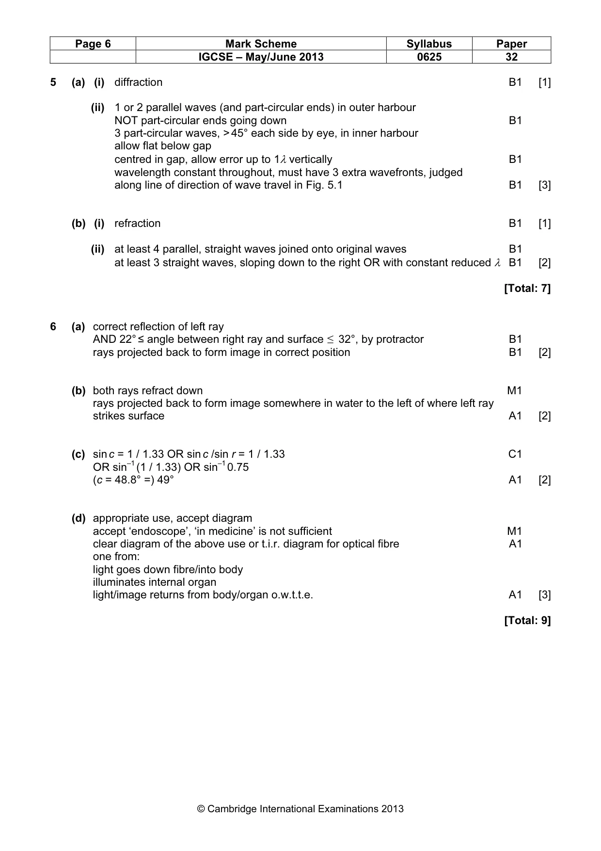
Mark scheme: 5 (a) (i) diffraction B1 [1] (ii) 1 or 2 parallel waves (and part-circular ends) in outer harbour NOT part-circular ends going down B1 3 part-circular waves, > 45° each side by eye, in inner harbour allow flat below gap centred in gap, allow error up to 1λ vertically B1 wavelength constant throughout, must have 3 extra wavefronts, judged along line of direction of wave travel in Fig. 5.1 B1 [3] (b) (i) refraction B1 [1] (ii) at least 4 parallel, straight waves joined onto original waves B1 at least 3 straight waves, sloping down to the right OR with constant reduced λ B1 [2] [Total: 7]
Q6 · Two rays from a point object P incident on a water surface
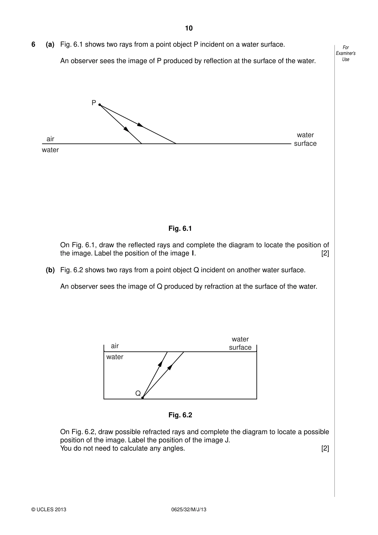
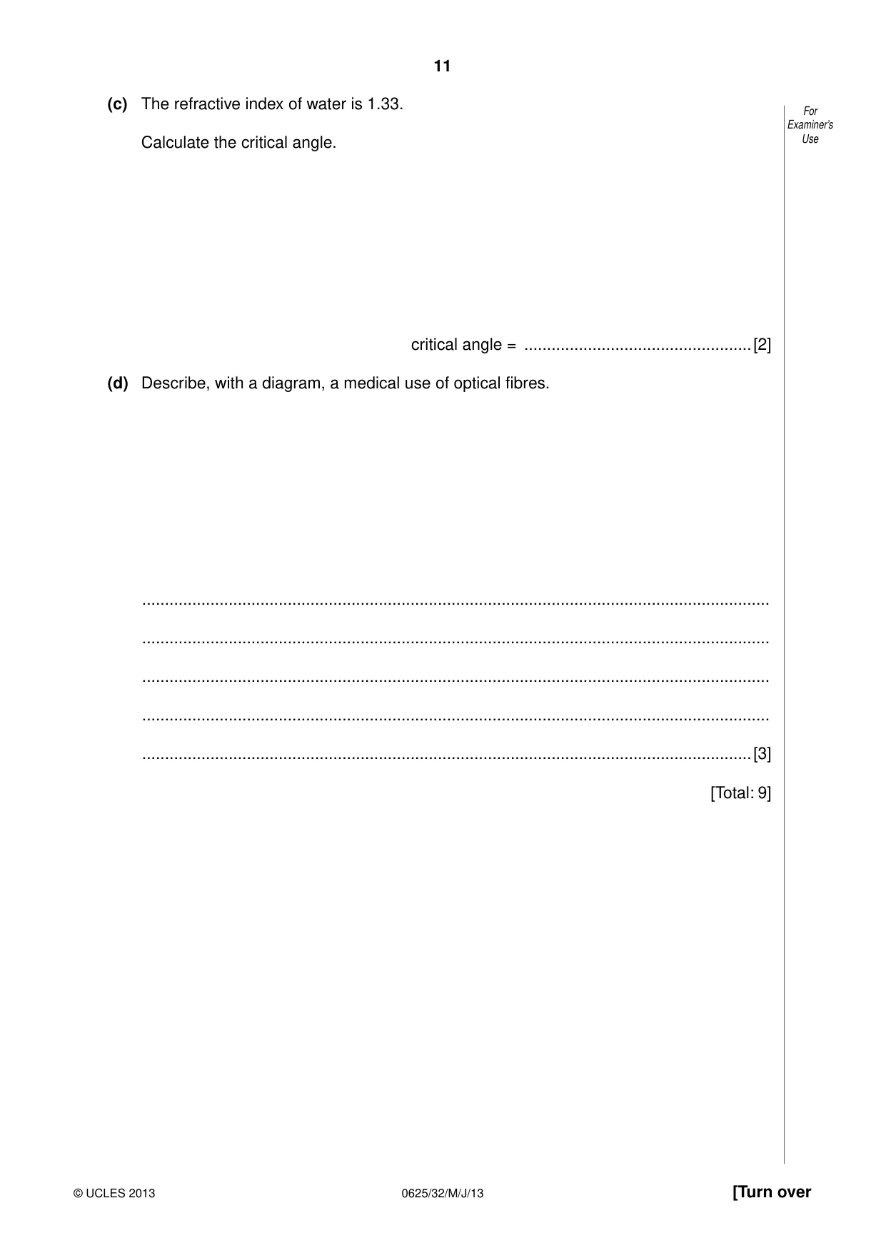
6 (a) Fig. 6.1 shows two rays from a point object P incident on a water surface. For Examiner’s An observer sees the image of P produced by reflection at the surface of the water. Use P water air surface water Fig. 6.1 On Fig. 6.1, draw the reflected rays and complete the diagram to locate the position of the image. Label the position of the image I. [2] (b) Fig. 6.2 shows two rays from a point object Q incident on another water surface. An observer sees the image of Q produced by refraction at the surface of the water. water air surface water Q Fig. 6.2 On Fig. 6.2, draw possible refracted rays and complete the diagram to locate a possible position of the image. Label the position of the image J. You do not need to calculate any angles. [2] (c) The refractive index of water is 1.33. For Examiner’s Calculate the critical angle. Use critical angle = ..................................................[2] (d) Describe, with a diagram, a medical use of optical fibres. .......................................................................................................................................... .......................................................................................................................................... .......................................................................................................................................... .......................................................................................................................................... ......................................................................................................................................[3] [Total: 9]
Mark scheme: 6 (a) correct reflection of left ray AND 22° ≤ angle between right ray and surface ≤ 32°, by protractor B1 rays projected back to form image in correct position B1 [2] (b) both rays refract down M1 rays projected back to form image somewhere in water to the left of where left ray strikes surface A1 [2] (c) sin c = 1 / 1.33 OR sin c /sin r = 1 / 1.33 C1 OR sin–1 (1 / 1.33) OR sin–1 0.75 (c = 48.8° =) 49° A1 [2] (d) appropriate use, accept diagram accept ‘endoscope’, ‘in medicine’ is not sufficient M1 clear diagram of the above use or t.i.r. diagram for optical fibre A1 one from: light goes down fibre/into body illuminates internal organ light/image returns from body/organ o.w.t.t.e. A1 [3] [Total: 9] IGCSE – May/June 2013 0625 32
Q7 · The solar charger shown in Fig
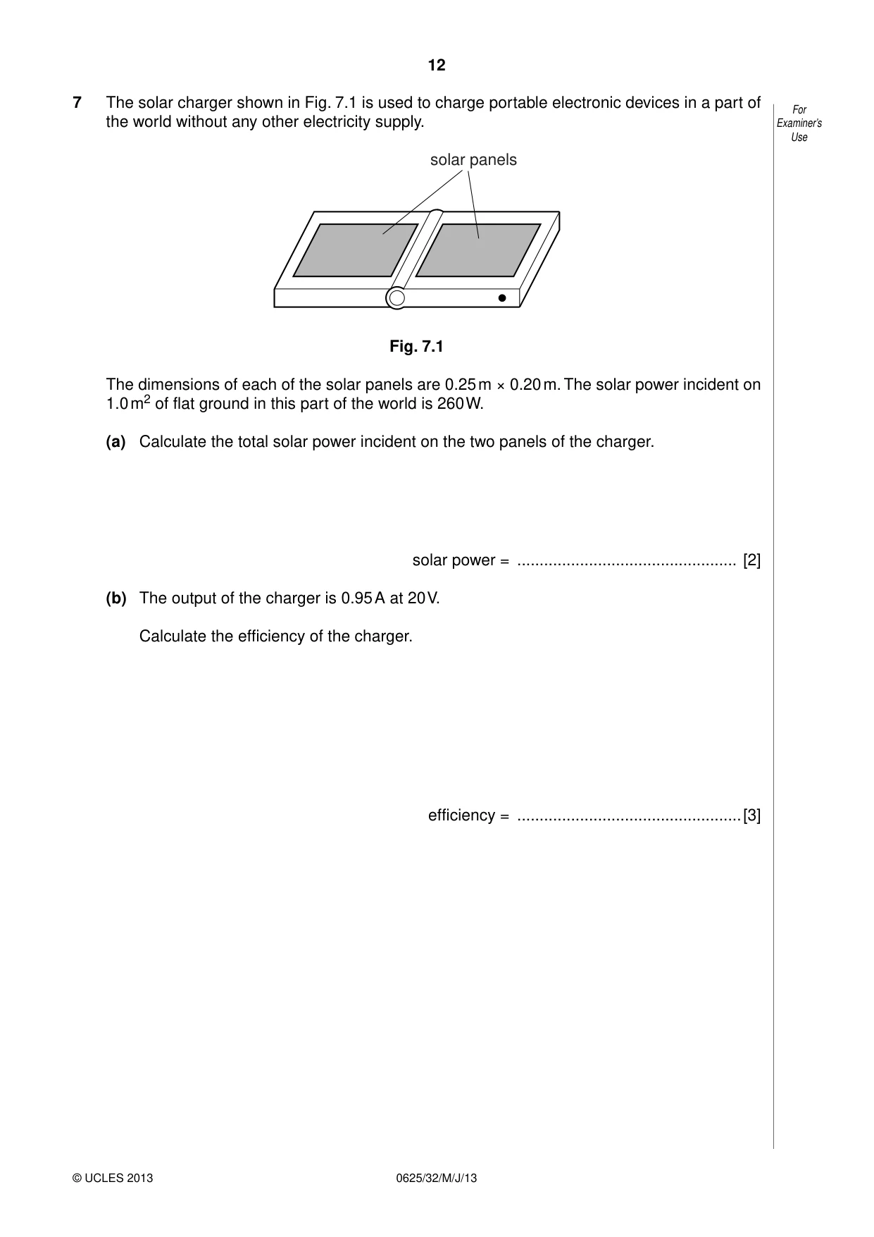
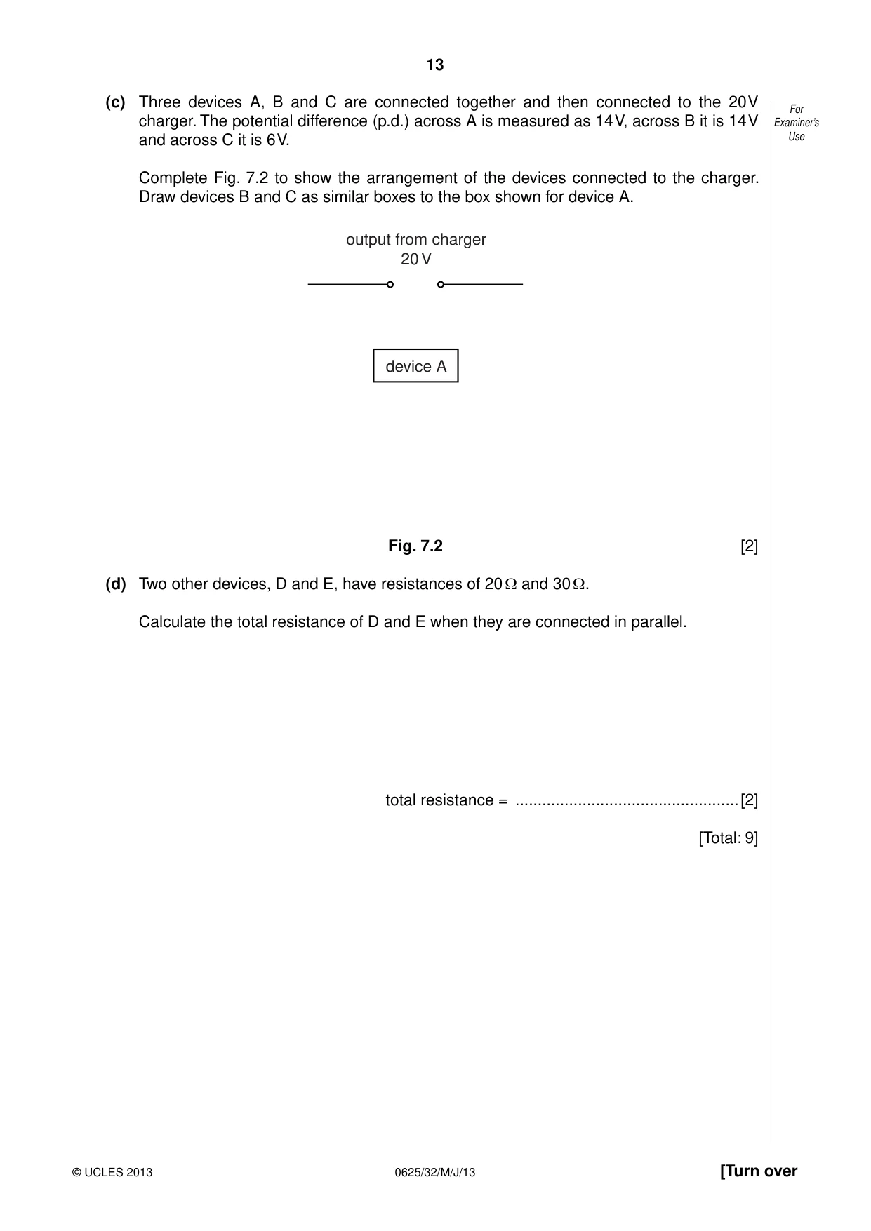
7 The solar charger shown in Fig. 7.1 is used to charge portable electronic devices in a part of For the world without any other electricity supply. Examiner’s Use solar panels Fig. 7.1 The dimensions of each of the solar panels are 0.25 m × 0.20 m. The solar power incident on 1.0 m2 of flat ground in this part of the world is 260 W. (a) Calculate the total solar power incident on the two panels of the charger. solar power = ................................................. [2] (b) The output of the charger is 0.95 A at 20 V. Calculate the efficiency of the charger. efficiency = ..................................................[3] (c) Three devices A, B and C are connected together and then connected to the 20 V For charger. The potential difference (p.d.) across A is measured as 14 V, across B it is 14 V Examiner’s and across C it is 6 V. Use Complete Fig. 7.2 to show the arrangement of the devices connected to the charger. Draw devices B and C as similar boxes to the box shown for device A. output from charger 20 V device A Fig. 7.2 [2] (d) Two other devices, D and E, have resistances of 20 Ω and 30 Ω. Calculate the total resistance of D and E when they are connected in parallel. total resistance = ..................................................[2] [Total: 9]
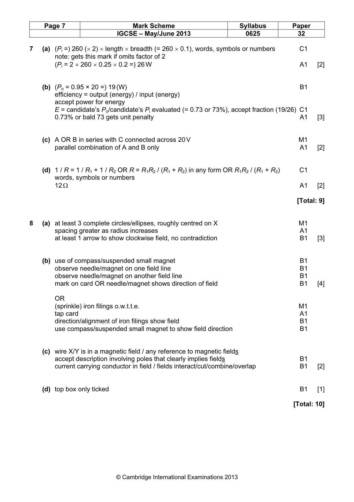
Mark scheme: 7 (a) (Pi =) 260 (× 2) × length × breadth (= 260 × 0.1), words, symbols or numbers C1 note: gets this mark if omits factor of 2 (Pi = 2 × 260 × 0.25 × 0.2 =) 26 W A1 [2] (b) (Po = 0.95 × 20 =) 19 (W) B1 efficiency = output (energy) / input (energy) accept power for energy E = candidate’s Po/candidate’s Pi evaluated (= 0.73 or 73%), accept fraction (19/26) C1 0.73% or bald 73 gets unit penalty A1 [3] (c) A OR B in series with C connected across 20 V M1 parallel combination of A and B only A1 [2] (d) 1 / R = 1 / R1 + 1 / R2 OR R = R1R2 / (R1 + R2) in any form OR R1R2 / (R1 + R2) C1 words, symbols or numbers 12 Ω A1 [2] [Total: 9]
Q8 · A vertical current-carrying wire passing through a card at point X
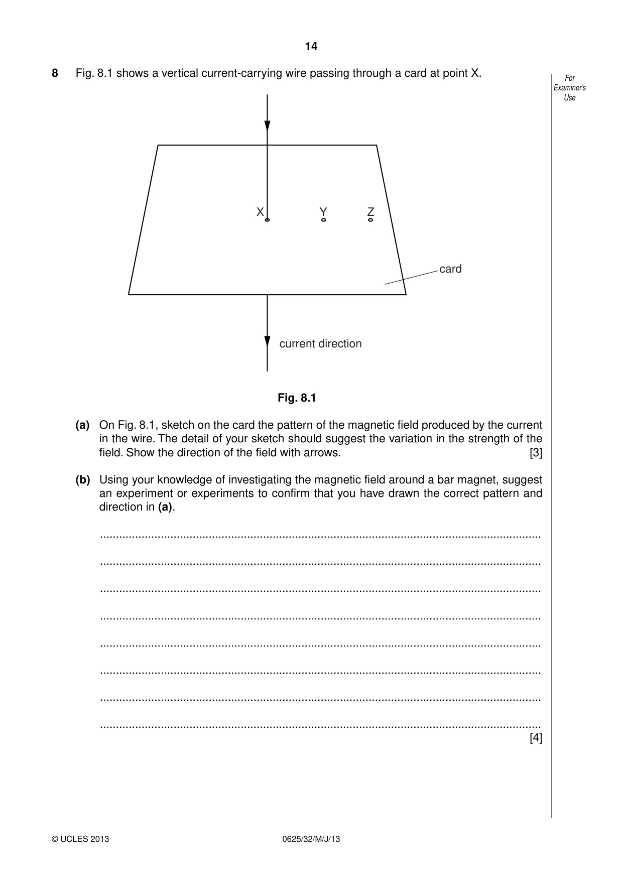
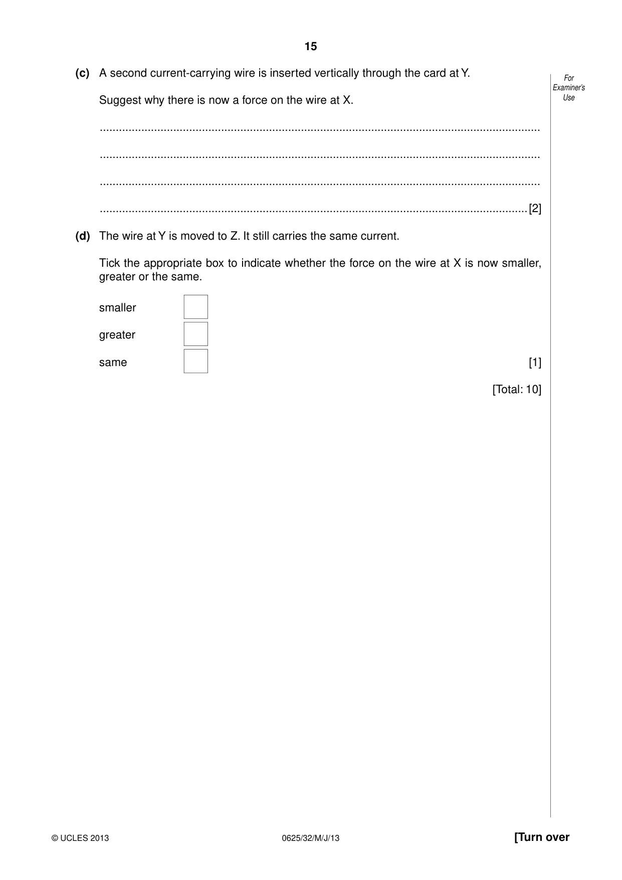
8 Fig. 8.1 shows a vertical current-carrying wire passing through a card at point X. For Examiner’s Use X Y Z card current direction Fig. 8.1 (a) On Fig. 8.1, sketch on the card the pattern of the magnetic field produced by the current in the wire. The detail of your sketch should suggest the variation in the strength of the field. Show the direction of the field with arrows. [3] (b) Using your knowledge of investigating the magnetic field around a bar magnet, suggest an experiment or experiments to confirm that you have drawn the correct pattern and direction in (a). .......................................................................................................................................... .......................................................................................................................................... .......................................................................................................................................... .......................................................................................................................................... .......................................................................................................................................... .......................................................................................................................................... .......................................................................................................................................... .......................................................................................................................................... [4] (c) A second current-carrying wire is inserted vertically through the card at Y. For Examiner’s Suggest why there is now a force on the wire at X. Use .......................................................................................................................................... .......................................................................................................................................... .......................................................................................................................................... ......................................................................................................................................[2] (d) The wire at Y is moved to Z. It still carries the same current. Tick the appropriate box to indicate whether the force on the wire at X is now smaller, greater or the same. smaller greater same [1] [Total: 10]
Mark scheme: 8 (a) at least 3 complete circles/ellipses, roughly centred on X M1 spacing greater as radius increases A1 at least 1 arrow to show clockwise field, no contradiction B1 [3] (b) use of compass/suspended small magnet B1 observe needle/magnet on one field line B1 observe needle/magnet on another field line B1 mark on card OR needle/magnet shows direction of field B1 [4] OR (sprinkle) iron filings o.w.t.t.e. M1 tap card A1 direction/alignment of iron filings show field B1 use compass/suspended small magnet to show field direction B1 (c) wire X/Y is in a magnetic field / any reference to magnetic fields accept description involving poles that clearly implies fields B1 current carrying conductor in field / fields interact/cut/combine/overlap B1 [2] (d) top box only ticked B1 [1] [Total: 10] IGCSE – May/June 2013 0625 32
Q9 · There is an alternating current in the primary coil of the transformer shown in Fig
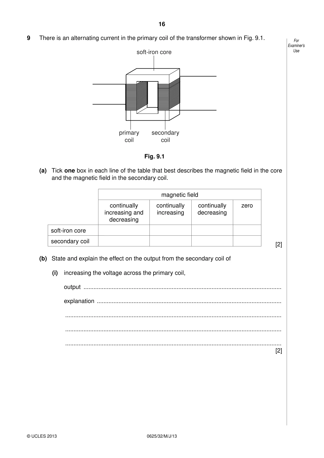
9 There is an alternating current in the primary coil of the transformer shown in Fig. 9.1. For Examiner’s soft-iron core Use primary secondary coil coil Fig. 9.1 (a) Tick one box in each line of the table that best describes the magnetic field in the core and the magnetic field in the secondary coil. magnetic field continually continually continually zero increasing and increasing decreasing decreasing soft-iron core secondary coil [2] (b) State and explain the effect on the output from the secondary coil of (i) increasing the voltage across the primary coil, output ....................................................................................................................... explanation ............................................................................................................... .................................................................................................................................. .................................................................................................................................. .................................................................................................................................. [2] (ii) replacing the alternating current in the primary coil with direct current from a battery. For Examiner’s output ....................................................................................................................... Use explanation ............................................................................................................... .................................................................................................................................. .................................................................................................................................. .................................................................................................................................. [2] [Total: 6]
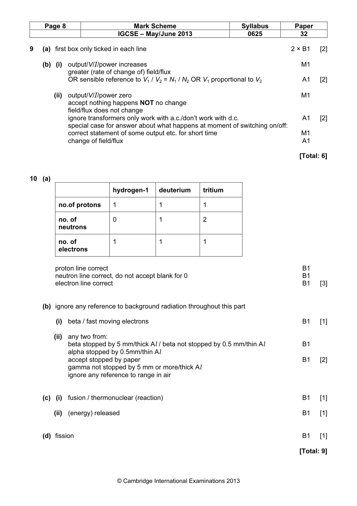
Mark scheme: 9 (a) first box only ticked in each line 2 × B1 [2] (b) (i) output/V/I/power increases M1 greater (rate of change of) field/flux OR sensible reference to V1 / V2 = N1 / N2 OR V1 proportional to V2 A1 [2] (ii) output/V/I/power zero M1 accept nothing happens NOT no change field/flux does not change ignore transformers only work with a.c./don’t work with d.c. A1 [2] special case for answer about what happens at moment of switching on/off: correct statement of some output etc. for short time M1 change of field/flux A1 [Total: 6]
Q10 · There are two stable, naturally occurring isotopes of hydrogen
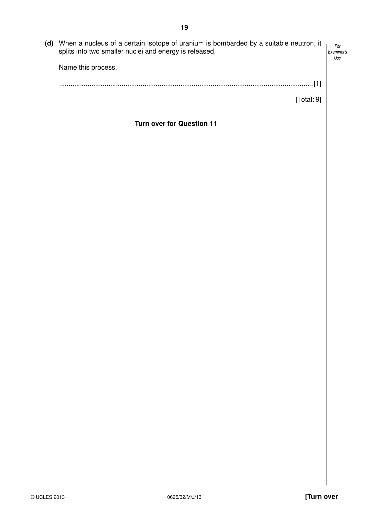
10 There are two stable, naturally occurring isotopes of hydrogen. For Examiner’s Common hydrogen (hydrogen-1) has a proton number of 1 and a nucleon number of 1. Use Hydrogen-2 (deuterium) has a nucleon number of 2. There is also a radioactive isotope of hydrogen called tritium (hydrogen-3), with a nucleon number of 3. (a) Complete the table for neutral atoms of these isotopes. hydrogen-1 hydrogen-2 hydrogen-3 (deuterium) (tritium) number of protons number of neutrons number of electrons [3] (b) Two samples of tritium are stored in aluminium containers of different thickness. Sample 1 is in a container of thickness 0.5 mm and radiation can be detected coming through the container. Sample 2 is in a container of thickness 5 mm and no radiation comes through. (i) State the type of radiation coming through the container of Sample 1. ..............................................................................................................................[1] (ii) Explain your answer to (b)(i). .................................................................................................................................. .................................................................................................................................. .................................................................................................................................. ..............................................................................................................................[2] (c) Under conditions of extremely high temperature and pressure, as in the interior of the Sun, hydrogen nuclei can join together. (i) Name this process. ..............................................................................................................................[1] (ii) State whether energy is released, absorbed or neither released nor absorbed during this reaction. ..............................................................................................................................[1] (d) When a nucleus of a certain isotope of uranium is bombarded by a suitable neutron, it For splits into two smaller nuclei and energy is released. Examiner’s Use Name this process. ......................................................................................................................................[1] [Total: 9] Turn over for Question 11
Mark scheme: 10 (a) hydrogen-1 deuterium tritium no.of protons 1 1 1 no. of 0 1 2 neutrons no. of 1 1 1 electrons proton line correct B1 neutron line correct, do not accept blank for 0 B1 electron line correct B1 [3] (b) ignore any reference to background radiation throughout this part (i) beta / fast moving electrons B1 [1] (ii) any two from: beta stopped by 5 mm/thick Al / beta not stopped by 0.5 mm/thin Al B1 alpha stopped by 0.5mm/thin Al accept stopped by paper B1 [2] gamma not stopped by 5 mm or more/thick Al ignore any reference to range in air (c) (i) fusion / thermonuclear (reaction) B1 [1] (ii) (energy) released B1 [1] (d) fission B1 [1] [Total: 9] IGCSE – May/June 2013 0625 32
Q11 · The main components of a cathode-ray oscilloscope
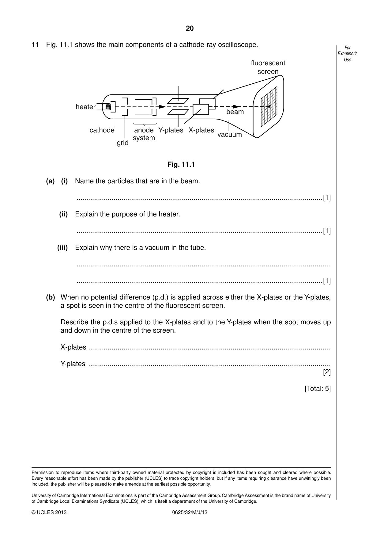
11 Fig. 11.1 shows the main components of a cathode-ray oscilloscope. For Examiner’s Use IOXRUHVFHQW VFUHHQ KHDWHU EHDP FDWKRGH DQRGH < SODWHV ; SODWHV YDFXXP V\VWHP JULG Fig. 11.1 (a) (i) Name the particles that are in the beam. ..............................................................................................................................[1] (ii) Explain the purpose of the heater. ..............................................................................................................................[1] (iii) Explain why there is a vacuum in the tube. .................................................................................................................................. ..............................................................................................................................[1] (b) When no potential difference (p.d.) is applied across either the X-plates or the Y-plates, a spot is seen in the centre of the fluorescent screen. Describe the p.d.s applied to the X-plates and to the Y-plates when the spot moves up and down in the centre of the screen. X-plates ............................................................................................................................ Y-plates ............................................................................................................................ [2] [Total: 5]
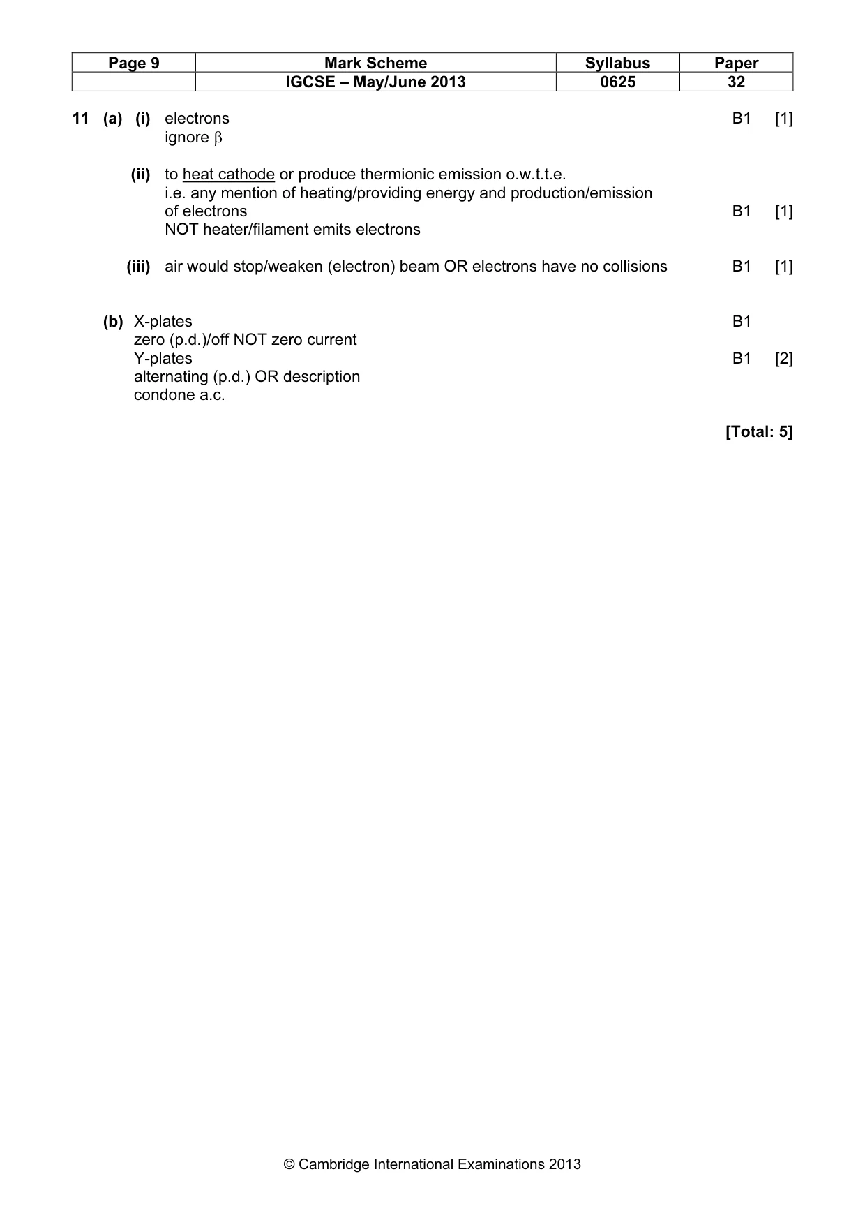
Mark scheme: 11 (a) (i) electrons B1 [1] ignore β (ii) to heat cathode or produce thermionic emission o.w.t.t.e. i.e. any mention of heating/providing energy and production/emission of electrons B1 [1] NOT heater/filament emits electrons (iii) air would stop/weaken (electron) beam OR electrons have no collisions B1 [1] (b) X-plates B1 zero (p.d.)/off NOT zero current Y-plates B1 [2] alternating (p.d.) OR description condone a.c. [Total: 5]
What was in this paper
The subtopics covered by these 11 questions, and how many questions each got. Open one in a new tab to see every Cambridge question on it.
What you needed in this session
Cambridge’s own grade thresholds for 2013 May/June, Paper 3 · Variant 2. A higher threshold means an easier paper — the bar moves with how the cohort did.