Cambridge IGCSE Physics 0625 — 2015 Oct/Nov Paper 3 · Variant 1
0625/31/O/N/15 · 11 questions · 80 marks · ≈90 min
The question paper and its mark scheme, free to read here and free to download. This is Cambridge’s own paper, exactly as it was sat.
Question paper16 pages
Mark scheme8 pages
Answers below. Sit the paper first if you are practising.
Questions as text
Q1 · A rocket-powered sled travelling along a straight track
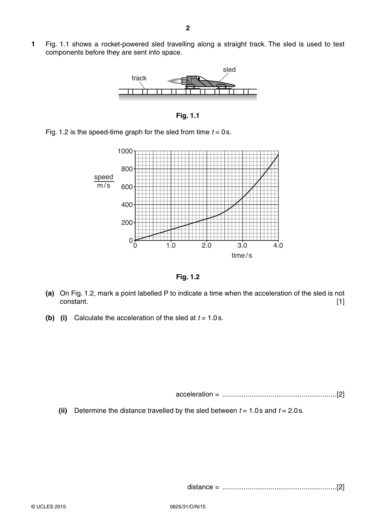
1 Fig. 1.1 shows a rocket-powered sled travelling along a straight track. The sled is used to test components before they are sent into space. sled track Fig. 1.1 Fig. 1.2 is the speed-time graph for the sled from time t = 0 s. 1000 800 speed m / s 600 400 200 0 0 1.0 2.0 3.0 4.0 time / s Fig. 1.2 (a) On Fig. 1.2, mark a point labelled P to indicate a time when the acceleration of the sled is not constant. [1] (b) (i) Calculate the acceleration of the sled at t = 1.0 s. acceleration = ...........................................................[2] (ii) Determine the distance travelled by the sled between t = 1.0 s and t = 2.0 s. distance = ...........................................................[2] (c) The resultant force acting on the sled remains constant during the test. Suggest why the acceleration of the sled is not constant. ................................................................................................................................................... ...............................................................................................................................................[1] [Total: 6]
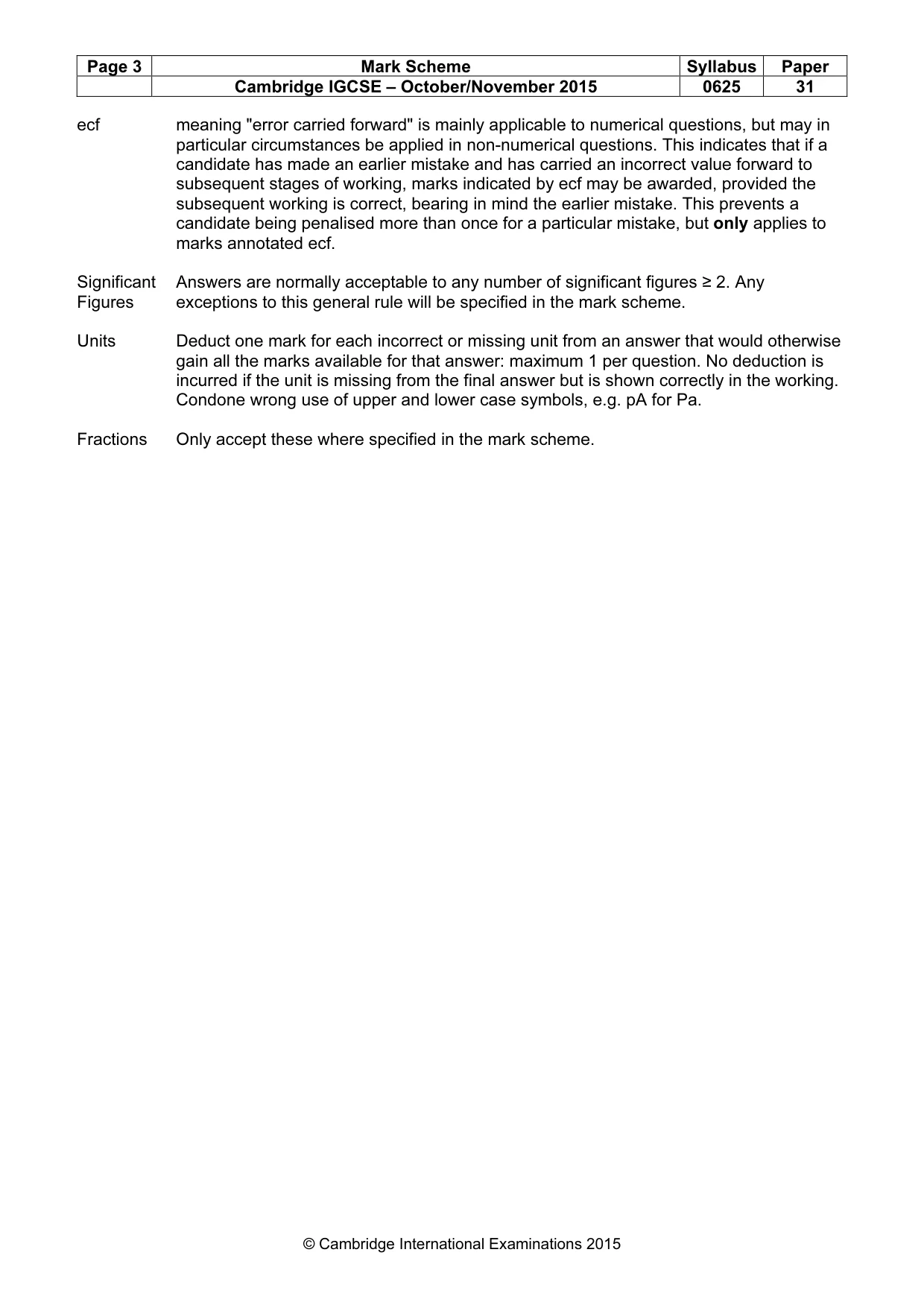
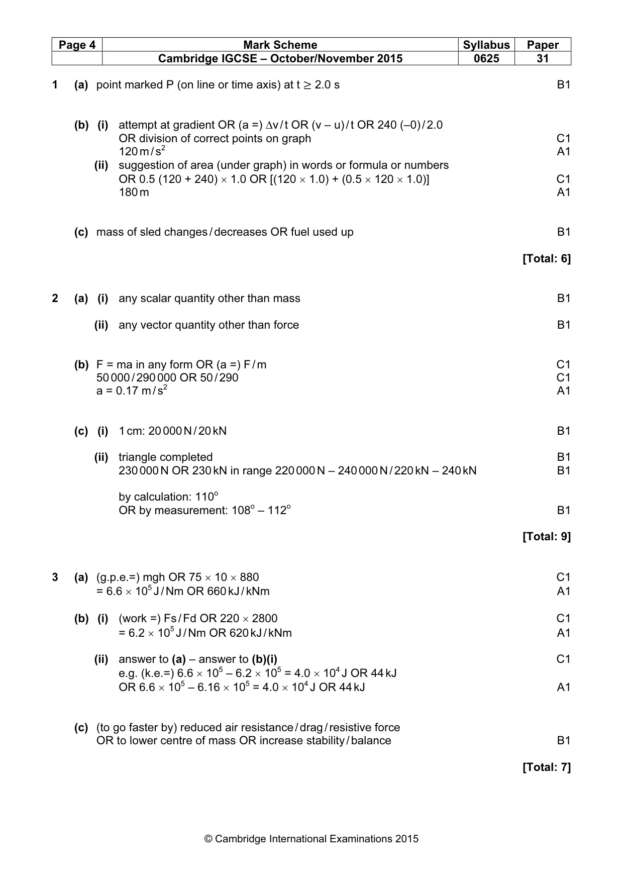
Mark scheme: 1 (a) point marked P (on line or time axis) at t ≥ 2.0 s B1 (b) (i) attempt at gradient OR (a =) ∆v / t OR (v – u) / t OR 240 (–0) / 2.0 OR division of correct points on graph C1 120 m / s2 A1 (ii) suggestion of area (under graph) in words or formula or numbers OR 0.5 (120 + 240) × 1.0 OR [(120 × 1.0) + (0.5 × 120 × 1.0)] C1 180 m A1 (c) mass of sled changes / decreases OR fuel used up B1 [Total: 6]
Q2 · Mass is a scalar quantity
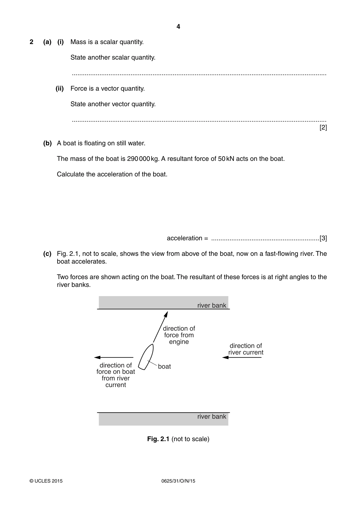
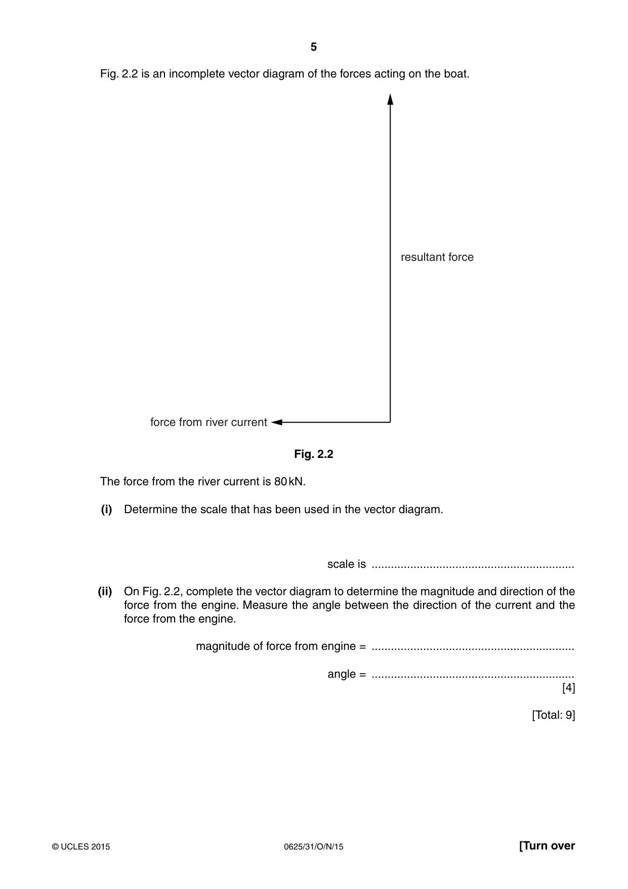
2 (a) (i) Mass is a scalar quantity. State another scalar quantity. ........................................................................................................................................... (ii) Force is a vector quantity. State another vector quantity. ........................................................................................................................................... [2] (b) A boat is floating on still water. The mass of the boat is 290 000 kg. A resultant force of 50 kN acts on the boat. Calculate the acceleration of the boat. acceleration = ...........................................................[3] (c) Fig. 2.1, not to scale, shows the view from above of the boat, now on a fast-flowing river. The boat accelerates. Two forces are shown acting on the boat. The resultant of these forces is at right angles to the river banks. river bank direction of force from engine direction of river current direction of boat force on boat from river current river bank Fig. 2.1 (not to scale) Fig. 2.2 is an incomplete vector diagram of the forces acting on the boat. resultant force force from river current Fig. 2.2 The force from the river current is 80 kN. (i) Determine the scale that has been used in the vector diagram. scale is ............................................................... (ii) On Fig. 2.2, complete the vector diagram to determine the magnitude and direction of the force from the engine. Measure the angle between the direction of the current and the force from the engine. magnitude of force from engine = ............................................................... angle = ............................................................... [4] [Total: 9]
Mark scheme: 2 (a) (i) any scalar quantity other than mass B1 (ii) any vector quantity other than force B1 (b) F = ma in any form OR (a =) F / m C1 50 000 / 290 000 OR 50 / 290 C1 a = 0.17 m / s2 A1 (c) (i) 1 cm: 20 000 N / 20 kN B1 (ii) triangle completed B1 230 000 N OR 230 kN in range 220 000 N – 240 000 N / 220 kN – 240 kN B1 by calculation: 110o OR by measurement: 108o – 112o B1 [Total: 9]
More questions on Physical quantities and measurement techniques
Q3 · A skier taking part in a downhill race
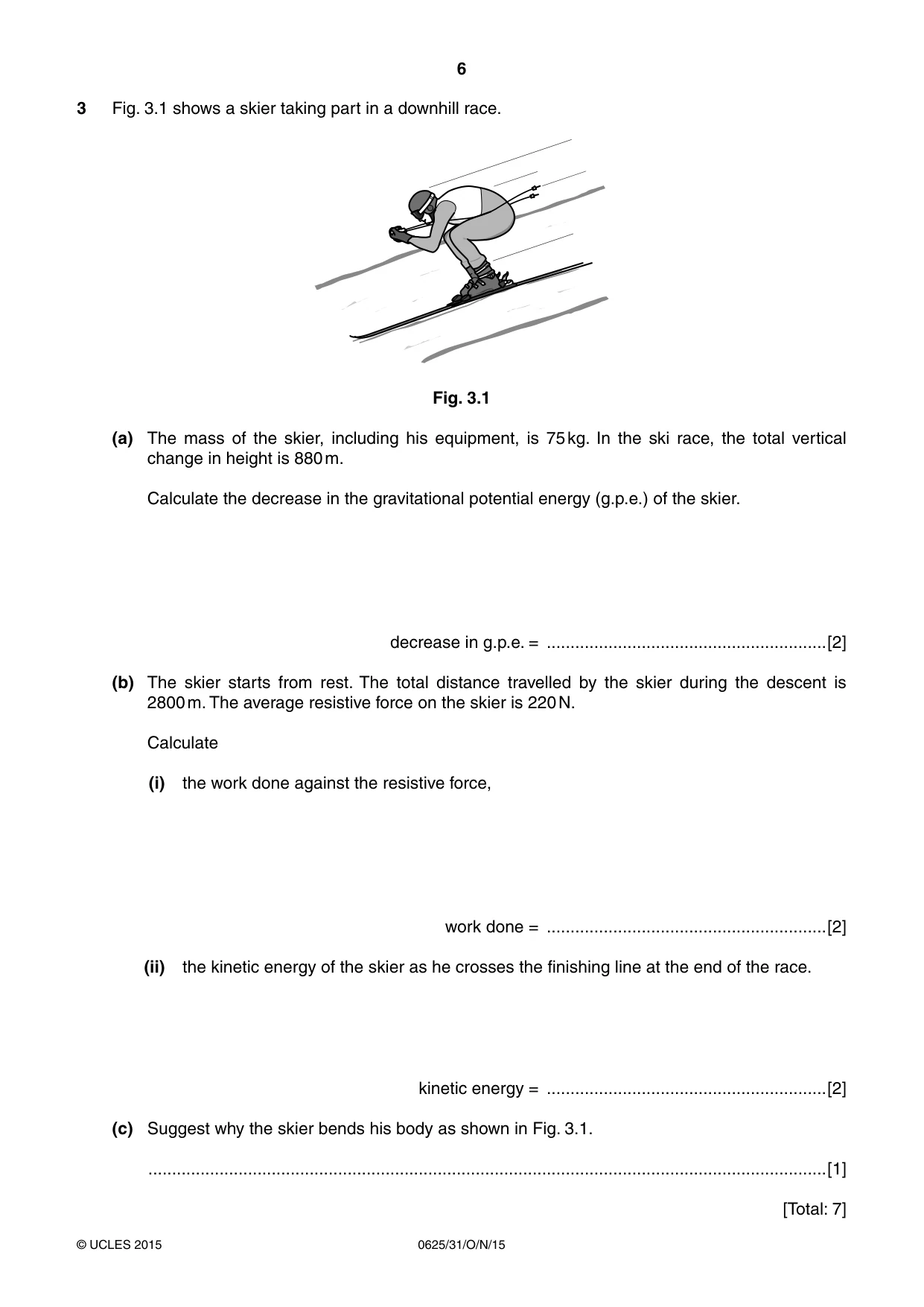
3 Fig. 3.1 shows a skier taking part in a downhill race. Fig. 3.1 (a) The mass of the skier, including his equipment, is 75 kg. In the ski race, the total vertical change in height is 880 m. Calculate the decrease in the gravitational potential energy (g.p.e.) of the skier. decrease in g.p.e. = ...........................................................[2] (b) The skier starts from rest. The total distance travelled by the skier during the descent is 2800 m. The average resistive force on the skier is 220 N. Calculate (i) the work done against the resistive force, work done = ...........................................................[2] (ii) the kinetic energy of the skier as he crosses the finishing line at the end of the race. kinetic energy = ...........................................................[2] (c) Suggest why the skier bends his body as shown in Fig. 3.1. ...............................................................................................................................................[1] [Total: 7]
Mark scheme: 3 (a) (g.p.e.=) mgh OR 75 × 10 × 880 C1 = 6.6 × 10⁵ J / Nm OR 660 kJ / kNm A1 (b) (i) (work =) Fs / Fd OR 220 × 2800 C1 = 6.2 × 10⁵ J / Nm OR 620 kJ / kNm A1 (ii) answer to (a) – answer to (b)(i) C1 e.g. (k.e.=) 6.6 × 10⁵ – 6.2 × 105 = 4.0 × 10⁴ J OR 44 kJ OR 6.6 × 10⁵ – 6.16 × 105 = 4.0 × 10⁴ J OR 44 kJ A1 (c) (to go faster by) reduced air resistance / drag / resistive force OR to lower centre of mass OR increase stability / balance B1 [Total: 7]
Q4 · An object of mass m and specific heat capacity c is supplied with a quantity of thermal…
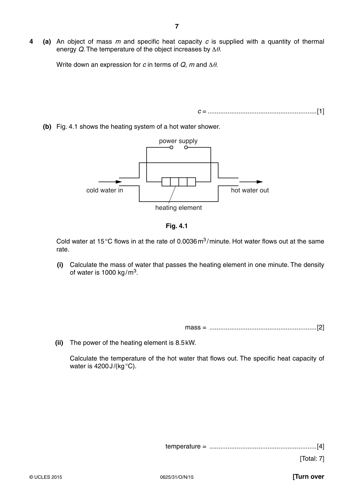
4 (a) An object of mass m and specific heat capacity c is supplied with a quantity of thermal energy Q. The temperature of the object increases by Δθ. Write down an expression for c in terms of Q, m and Δθ. c = ............................................................[1] (b) Fig. 4.1 shows the heating system of a hot water shower. power supply cold water in hot water out heating element Fig. 4.1 Cold water at 15 °C flows in at the rate of 0.0036 m3 / minute. Hot water flows out at the same rate. (i) Calculate the mass of water that passes the heating element in one minute. The density of water is 1000 kg / m3. mass = ...........................................................[2] (ii) The power of the heating element is 8.5 kW. Calculate the temperature of the hot water that flows out. The specific heat capacity of water is 4200 J /(kg °C). temperature = ...........................................................[4] [Total: 7]
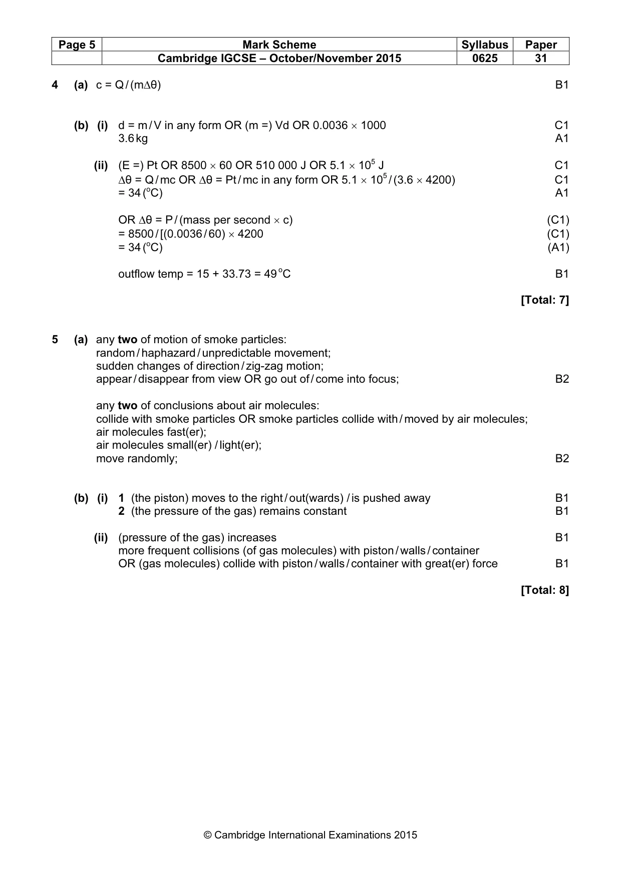
Mark scheme: 4 (a) c = Q / (m∆θ) B1 (b) (i) d = m / V in any form OR (m =) Vd OR 0.0036 × 1000 C1 3.6 kg A1 (ii) (E =) Pt OR 8500 × 60 OR 510 000 J OR 5.1 × 10⁵ J C1 ∆θ = Q / mc OR ∆θ = Pt / mc in any form OR 5.1 × 10⁵ / (3.6 × 4200) C1 = 34 (oC) A1 OR ∆θ = P / (mass per second × c) (C1) = 8500 / [(0.0036 / 60) × 4200 (C1) = 34 (oC) (A1) outflow temp = 15 + 33.73 = 49 oC B1 [Total: 7]
Q5 · Smoke particles are introduced into a glass box containing air
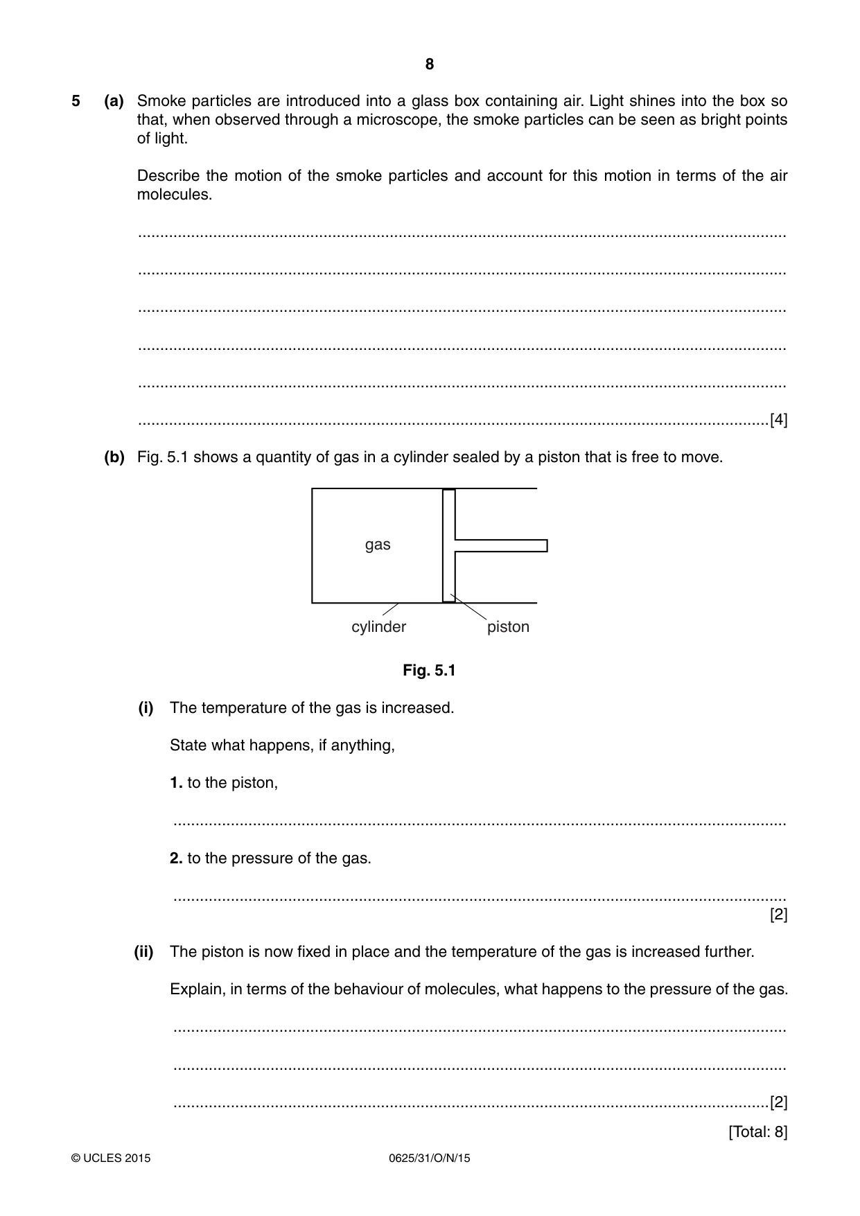
5 (a) Smoke particles are introduced into a glass box containing air. Light shines into the box so that, when observed through a microscope, the smoke particles can be seen as bright points of light. Describe the motion of the smoke particles and account for this motion in terms of the air molecules. ................................................................................................................................................... ................................................................................................................................................... ................................................................................................................................................... ................................................................................................................................................... ................................................................................................................................................... ...............................................................................................................................................[4] (b) Fig. 5.1 shows a quantity of gas in a cylinder sealed by a piston that is free to move. gas cylinder piston Fig. 5.1 (i) The temperature of the gas is increased. State what happens, if anything, 1. to the piston, ........................................................................................................................................... 2. to the pressure of the gas. ........................................................................................................................................... [2] (ii) The piston is now fixed in place and the temperature of the gas is increased further. Explain, in terms of the behaviour of molecules, what happens to the pressure of the gas. ........................................................................................................................................... ........................................................................................................................................... .......................................................................................................................................[2] [Total: 8]
Mark scheme: 5 (a) any two of motion of smoke particles: random / haphazard / unpredictable movement; sudden changes of direction / zig-zag motion; appear / disappear from view OR go out of / come into focus; B2 any two of conclusions about air molecules: collide with smoke particles OR smoke particles collide with / moved by air molecules; air molecules fast(er); air molecules small(er) / light(er); move randomly; B2 (b) (i) 1 (the piston) moves to the right / out(wards) / is pushed away B1 2 (the pressure of the gas) remains constant B1 (ii) (pressure of the gas) increases B1 more frequent collisions (of gas molecules) with piston / walls / container OR (gas molecules) collide with piston / walls / container with great(er) force B1 [Total: 8]
Q6 · A sound wave, travelling in air, approaches a solid barrier with a gap in the middle
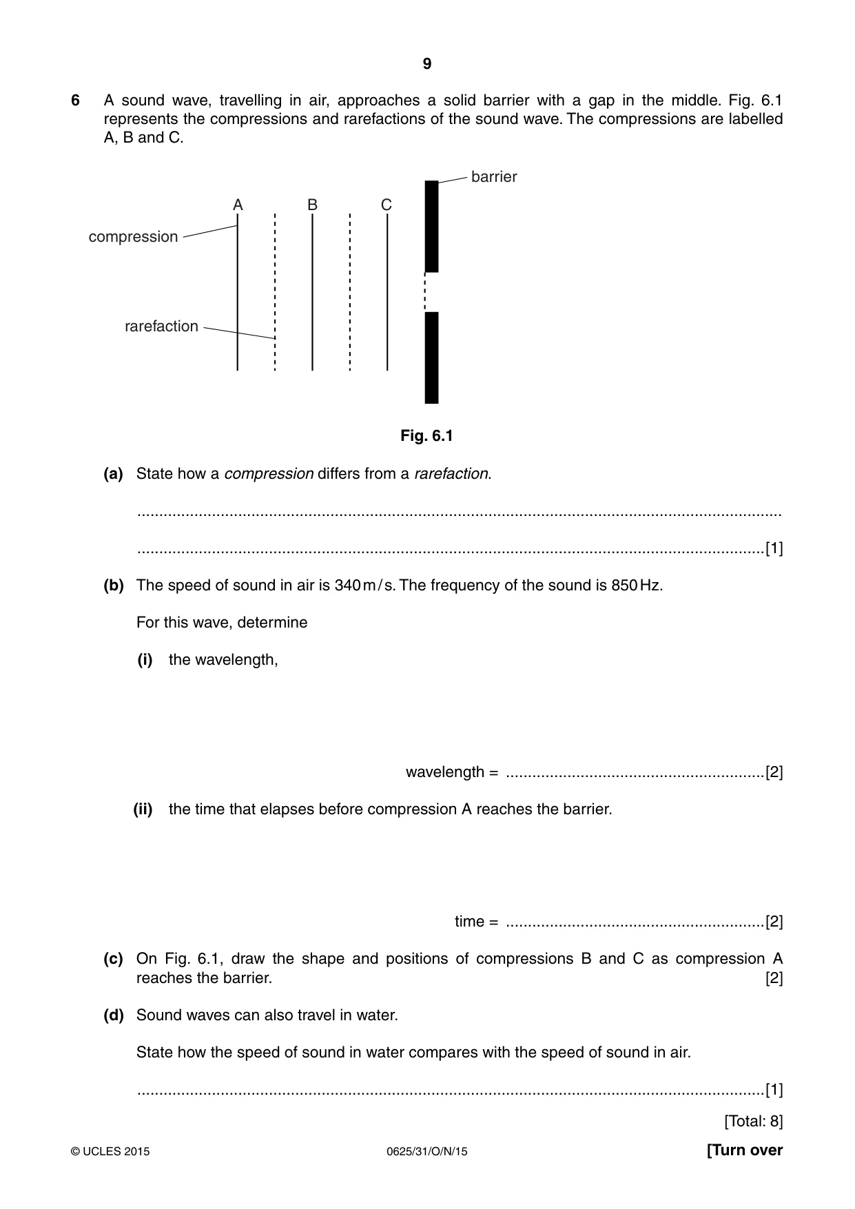
6 A sound wave, travelling in air, approaches a solid barrier with a gap in the middle. Fig. 6.1 represents the compressions and rarefactions of the sound wave. The compressions are labelled A, B and C. barrier A B C compression rarefaction Fig. 6.1 (a) State how a compression differs from a rarefaction. ................................................................................................................................................... ...............................................................................................................................................[1] (b) The speed of sound in air is 340 m / s. The frequency of the sound is 850 Hz. For this wave, determine (i) the wavelength, wavelength = ...........................................................[2] (ii) the time that elapses before compression A reaches the barrier. time = ...........................................................[2] (c) On Fig. 6.1, draw the shape and positions of compressions B and C as compression A reaches the barrier. [2] (d) Sound waves can also travel in water. State how the speed of sound in water compares with the speed of sound in air. ...............................................................................................................................................[1] [Total: 8]
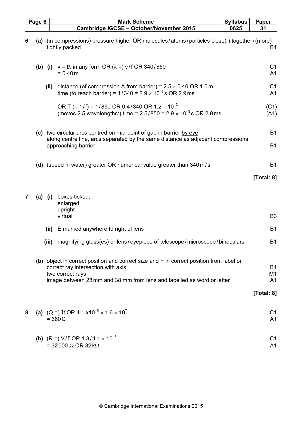
Mark scheme: 6 (a) (in compressions) pressure higher OR molecules / atoms / particles close(r) together / (more) tightly packed B1 (b) (i) v = fλ in any form OR (λ =) v / f OR 340 / 850 C1 = 0.40 m A1 (ii) distance (of compression A from barrier) = 2.5 × 0.40 OR 1.0 m C1 time (to reach barrier) = 1 / 340 = 2.9 × 10⁻³ s OR 2.9 ms A1 OR T (= 1 / f) = 1 / 850 OR 0.4 / 340 OR 1.2 × 10⁻³ (C1) (moves 2.5 wavelengths:) time = 2.5 / 850 = 2.9 × 10⁻³ s OR 2.9 ms (A1) (c) two circular arcs centred on mid-point of gap in barrier by eye B1 along centre line, arcs separated by the same distance as adjacent compressions approaching barrier B1 (d) (speed in water) greater OR numerical value greater than 340 m / s B1 [Total: 8]
Q7 · A convex lens being used to produce an image of an object
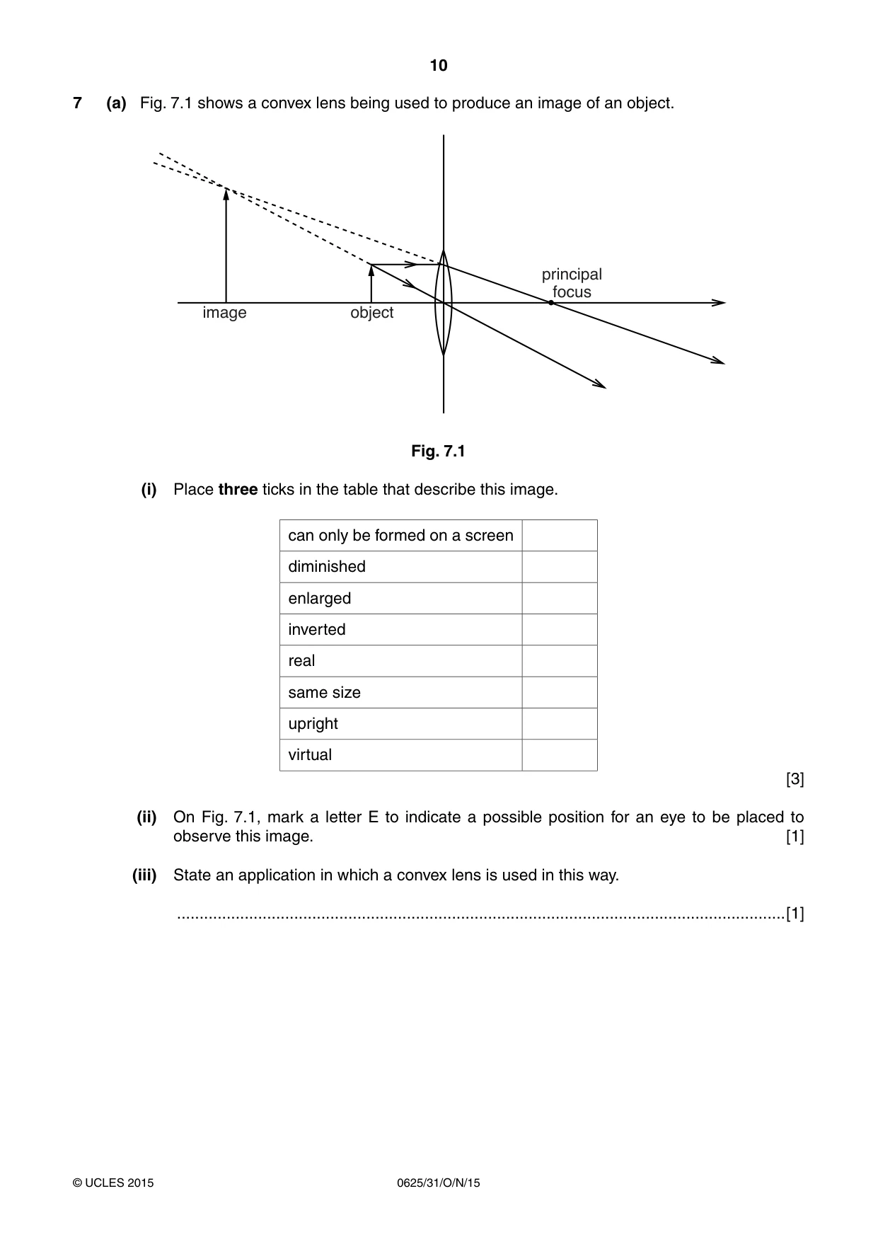
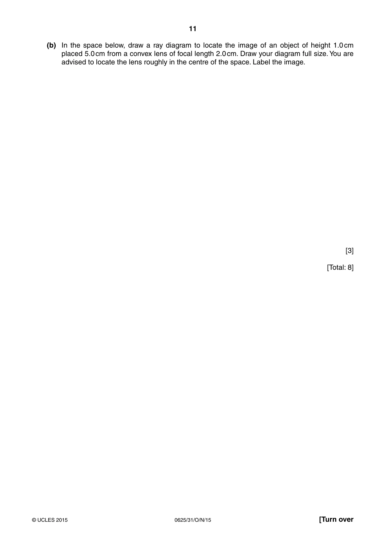
7 (a) Fig. 7.1 shows a convex lens being used to produce an image of an object. principal focus image object Fig. 7.1 (i) Place three ticks in the table that describe this image. can only be formed on a screen diminished enlarged inverted real same size upright virtual [3] (ii) On Fig. 7.1, mark a letter E to indicate a possible position for an eye to be placed to observe this image. [1] (iii) State an application in which a convex lens is used in this way. .......................................................................................................................................[1] (b) In the space below, draw a ray diagram to locate the image of an object of height 1.0 cm placed 5.0 cm from a convex lens of focal length 2.0 cm. Draw your diagram full size. You are advised to locate the lens roughly in the centre of the space. Label the image. [3] [Total: 8]
Mark scheme: 7 (a) (i) boxes ticked: enlarged upright virtual B3 (ii) E marked anywhere to right of lens B1 (iii) magnifying glass(es) or lens / eyepiece of telescope / microscope / binoculars B1 (b) object in correct position and correct size and F in correct position from label or correct ray intersection with axis B1 two correct rays M1 image between 28 mm and 38 mm from lens and labelled as word or letter A1 [Total: 8] 5 7
Q8 · A digital watch is powered by a 1.3 V cell
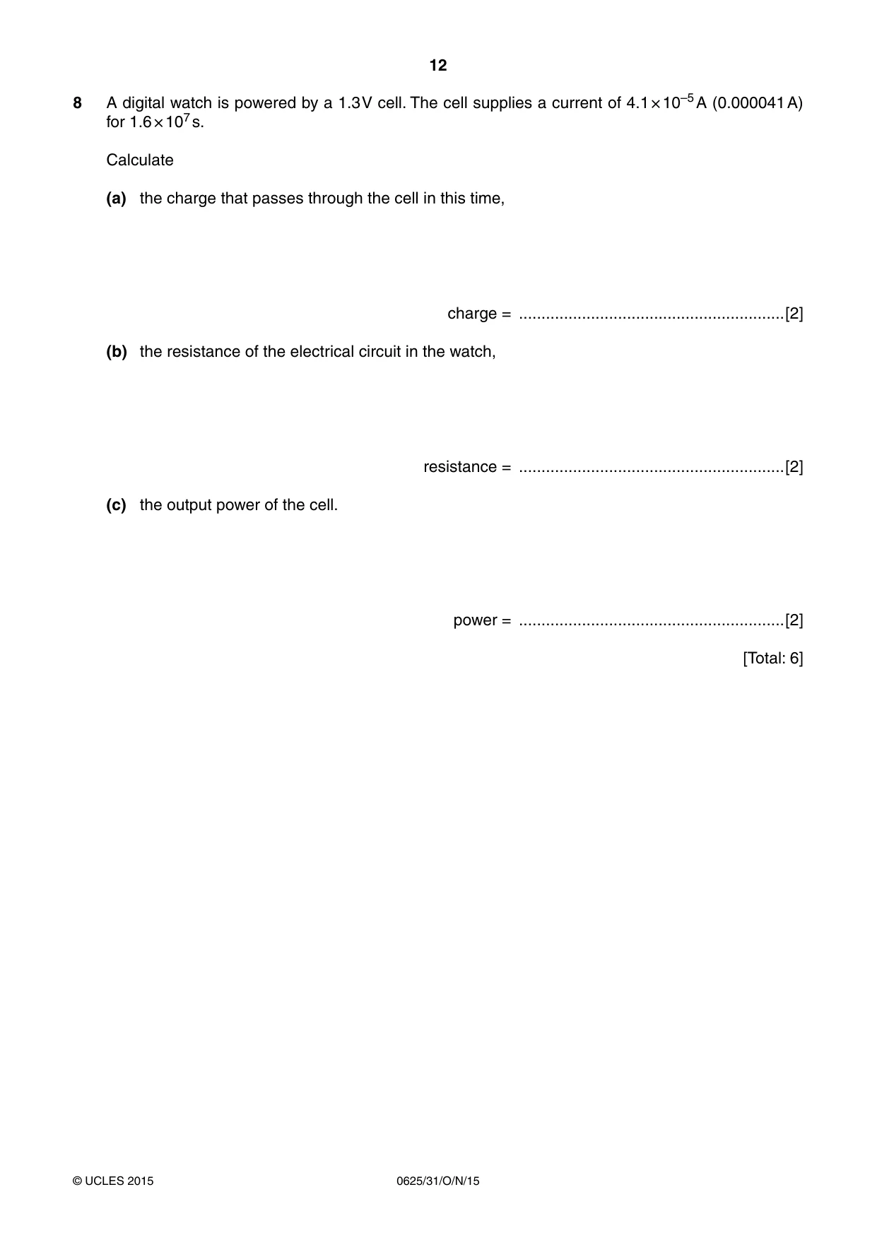
8 A digital watch is powered by a 1.3 V cell. The cell supplies a current of 4.1 × 10⁻⁵ A (0.000041 A) for 1.6 × 10⁷ s. Calculate (a) the charge that passes through the cell in this time, charge = ...........................................................[2] (b) the resistance of the electrical circuit in the watch, resistance = ...........................................................[2] (c) the output power of the cell. power = ...........................................................[2] [Total: 6]
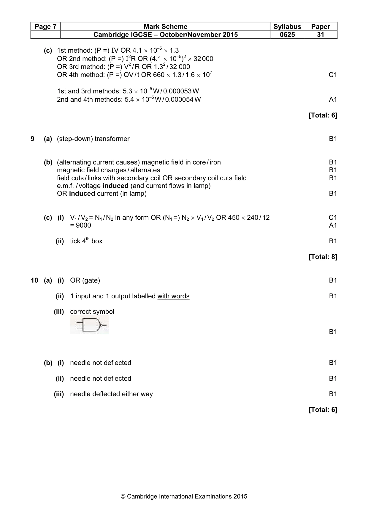
Mark scheme: 8 (a) (Q =) It OR 4.1 x10–5 × 1.6 × 107 C1 = 660 C A1 (b) (R =) V / I OR 1.3 / 4.1 × 10⁻⁵ C1 = 32 000 Ω OR 32 kΩ A1 (c) 1st method: (P =) IV OR 4.1 × 10–5 × 1.3 OR 2nd method: (P =) I2R OR (4.1 × 10⁻⁵)2 × 32 000 OR 3rd method: (P =) V2 / R OR 1.32 / 32 000 OR 4th method: (P =) QV / t OR 660 × 1.3 / 1.6 × 10⁷ C1 1st and 3rd methods: 5.3 × 10⁻⁵ W / 0.000053 W 2nd and 4th methods: 5.4 × 10⁻⁵ W / 0.000054 W A1 [Total: 6]
Q9 · Two separate coils of wire wound around an iron core
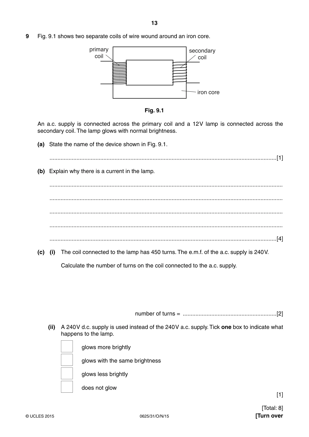
9 Fig. 9.1 shows two separate coils of wire wound around an iron core. primary secondary coil coil iron core Fig. 9.1 An a.c. supply is connected across the primary coil and a 12 V lamp is connected across the secondary coil. The lamp glows with normal brightness. (a) State the name of the device shown in Fig. 9.1. ...............................................................................................................................................[1] (b) Explain why there is a current in the lamp. ................................................................................................................................................... ................................................................................................................................................... ................................................................................................................................................... ................................................................................................................................................... ...............................................................................................................................................[4] (c) (i) The coil connected to the lamp has 450 turns. The e.m.f. of the a.c. supply is 240 V. Calculate the number of turns on the coil connected to the a.c. supply. number of turns = ...........................................................[2] (ii) A 240 V d.c. supply is used instead of the 240 V a.c. supply. Tick one box to indicate what happens to the lamp. glows more brightly glows with the same brightness glows less brightly does not glow [1] [Total: 8]
Mark scheme: 9 (a) (step-down) transformer B1 (b) (alternating current causes) magnetic field in core / iron B1 magnetic field changes / alternates B1 field cuts / links with secondary coil OR secondary coil cuts field B1 e.m.f. / voltage induced (and current flows in lamp) OR induced current (in lamp) B1 (c) (i) V1 / V2 = N1 / N2 in any form OR (N1 =) N2 × V1 / V2 OR 450 × 240 / 12 C1 = 9000 A1 (ii) tick 4th box B1 [Total: 8]
Q10 · The symbol for a logic gate
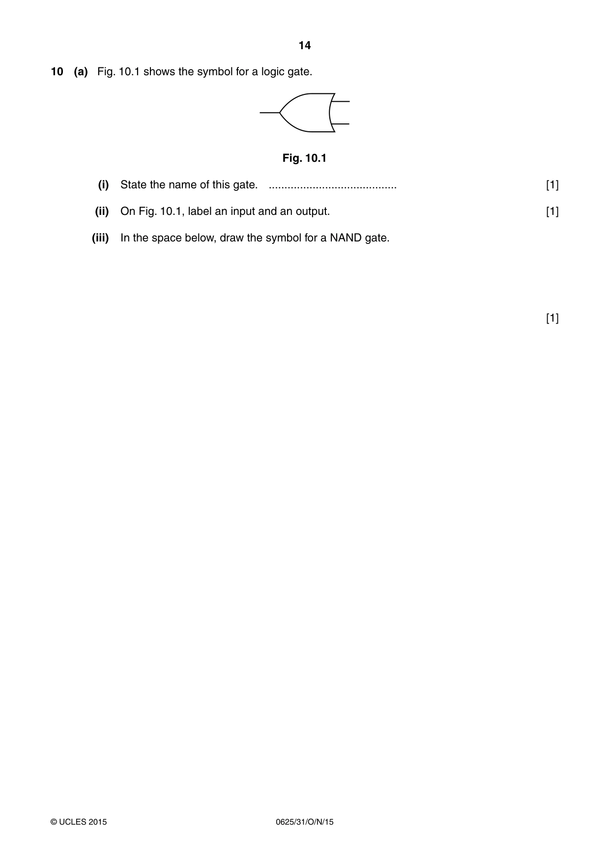
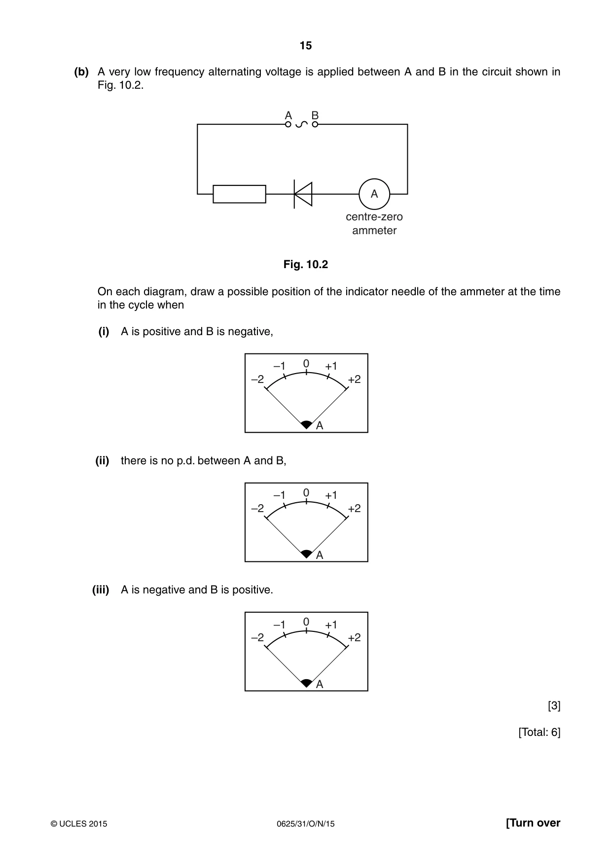
10 (a) Fig. 10.1 shows the symbol for a logic gate. Fig. 10.1 (i) State the name of this gate. ......................................... [1] (ii) On Fig. 10.1, label an input and an output. [1] (iii) In the space below, draw the symbol for a NAND gate. [1] (b) A very low frequency alternating voltage is applied between A and B in the circuit shown in Fig. 10.2. A B A centre-zero ammeter Fig. 10.2 On each diagram, draw a possible position of the indicator needle of the ammeter at the time in the cycle when (i) A is positive and B is negative, –1 0 +1 –2 +2 A (ii) there is no p.d. between A and B, –1 0 +1 –2 +2 A (iii) A is negative and B is positive. –1 0 +1 –2 +2 A [3] [Total: 6]
Mark scheme: 10 (a) (i) OR (gate) B1 (ii) 1 input and 1 output labelled with words B1 (iii) correct symbol B1 (b) (i) needle not deflected B1 (ii) needle not deflected B1 (iii) needle deflected either way B1 [Total: 6]
Q11 · State, in terms of the particles in each nucleus, how the nuclei of two isotopes of the…
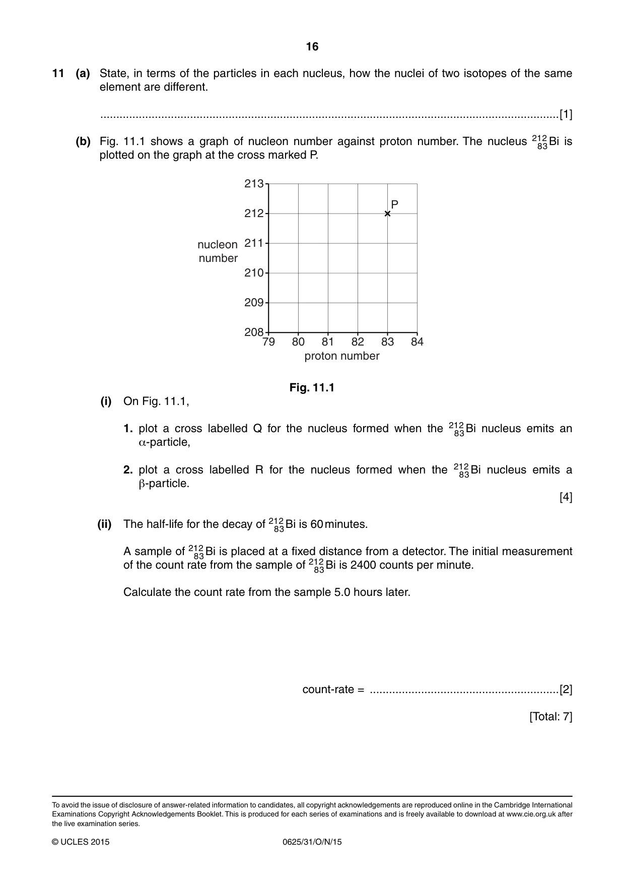
11 (a) State, in terms of the particles in each nucleus, how the nuclei of two isotopes of the same element are different. ...............................................................................................................................................[1] (b) Fig. 11.1 shows a graph of nucleon number against proton number. The nucleus 21 2 Bi is 8 3 plotted on the graph at the cross marked P. 213 P 212 nucleon 211 number 210 209 208 79 80 81 82 83 84 proton number Fig. 11.1 (i) On Fig. 11.1, 1. plot a cross labelled Q for the nucleus formed when the 21 2 Bi nucleus emits an 8 3 α-particle, 2. plot a cross labelled R for the nucleus formed when the 21 2 Bi nucleus emits a 8 3 β-particle. [4] (ii) The half-life for the decay of 21 2 Bi is 60 minutes. 8 3 A sample of 21 2 Bi is placed at a fixed distance from a detector. The initial measurement 8 3 of the count rate from the sample of 21 2 Bi is 2400 counts per minute. 8 3 Calculate the count rate from the sample 5.0 hours later. count-rate = ...........................................................[2] [Total: 7]
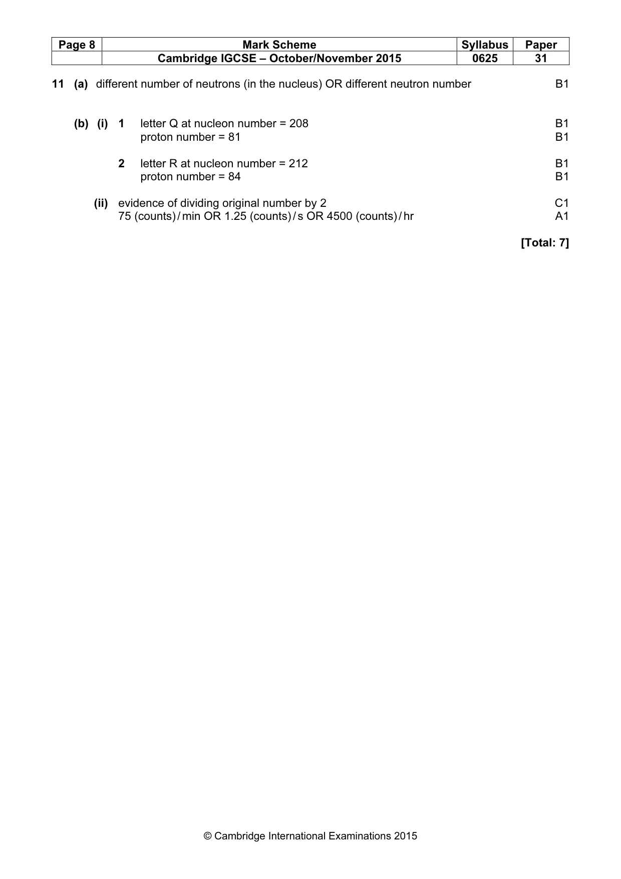
Mark scheme: 11 (a) different number of neutrons (in the nucleus) OR different neutron number B1 (b) (i) 1 letter Q at nucleon number = 208 B1 proton number = 81 B1 2 letter R at nucleon number = 212 B1 proton number = 84 B1 (ii) evidence of dividing original number by 2 C1 75 (counts) / min OR 1.25 (counts) / s OR 4500 (counts) / hr A1 [Total: 7]
What was in this paper
The subtopics covered by these 11 questions, and how many questions each got. Open one in a new tab to see every Cambridge question on it.
What you needed in this session
Cambridge’s own grade thresholds for 2015 Oct/Nov, Paper 3 · Variant 1. A higher threshold means an easier paper — the bar moves with how the cohort did.