Cambridge IGCSE Physics 0625 — 2010 Oct/Nov Paper 3 · Variant 3
0625/33/O/N/10 · 11 questions · 80 marks · ≈90 min
The question paper and its mark scheme, free to read here and free to download. This is Cambridge’s own paper, exactly as it was sat.
Question paper20 pages

Mark scheme6 pages
Answers below. Sit the paper first if you are practising.
Questions as text
Q1 · A young athlete has a mass of 42 kg
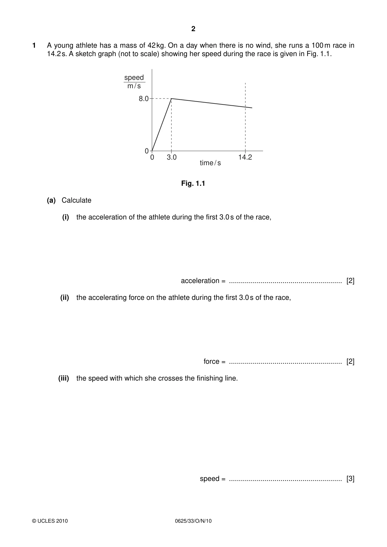
1 A young athlete has a mass of 42 kg. On a day when there is no wind, she runs a 100 m race in 14.2 s. A sketch graph (not to scale) showing her speed during the race is given in Fig. 1.1. speed m / s 8.0 0 0 3.0 14.2 time / s Fig. 1.1 (a) Calculate (i) the acceleration of the athlete during the first 3.0 s of the race, acceleration = ......................................................... [2] (ii) the accelerating force on the athlete during the first 3.0 s of the race, force = ......................................................... [2] (iii) the speed with which she crosses the finishing line. speed = ......................................................... [3] (b) Suggest two differences that might be seen in the graph if there had been a strong wind opposing the runners in the race. 1. ............................................................................................................................................... ................................................................................................................................................... 2. ............................................................................................................................................... ............................................................................................................................................. [2] [Total: 9]
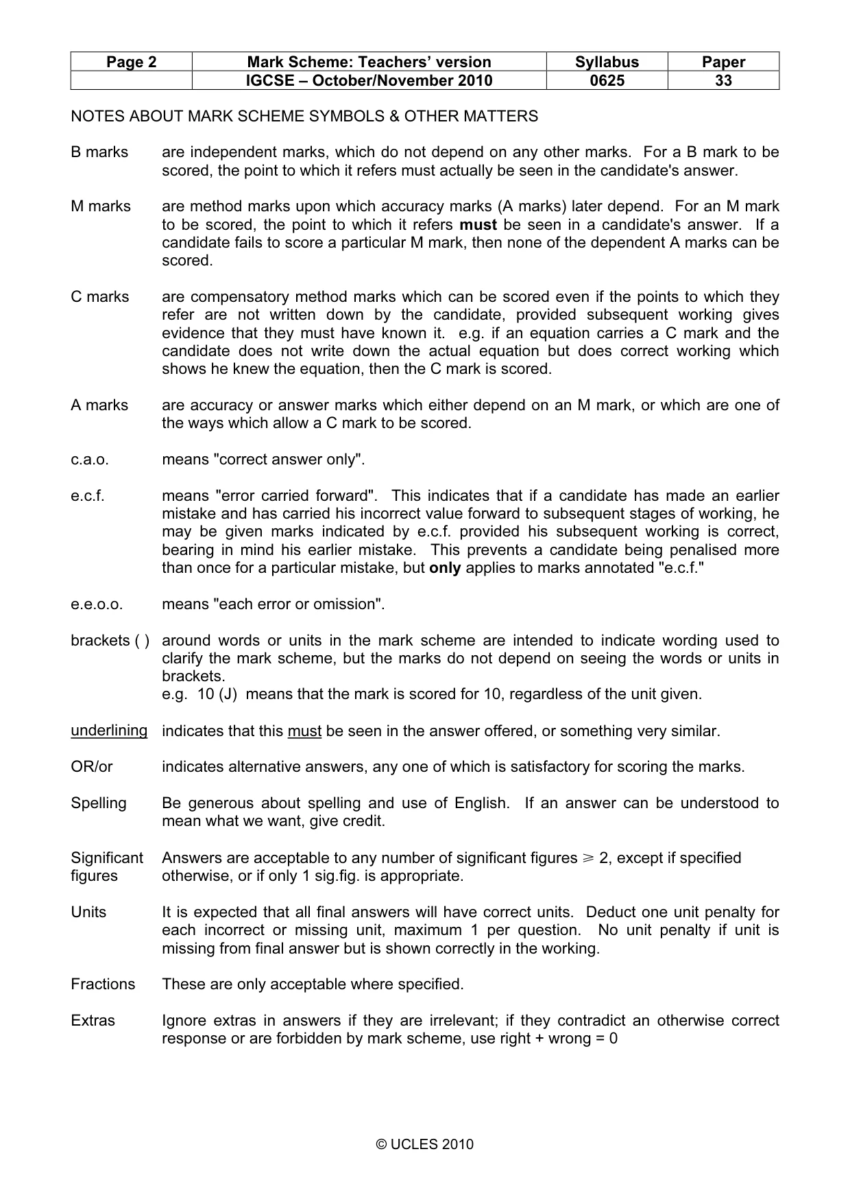
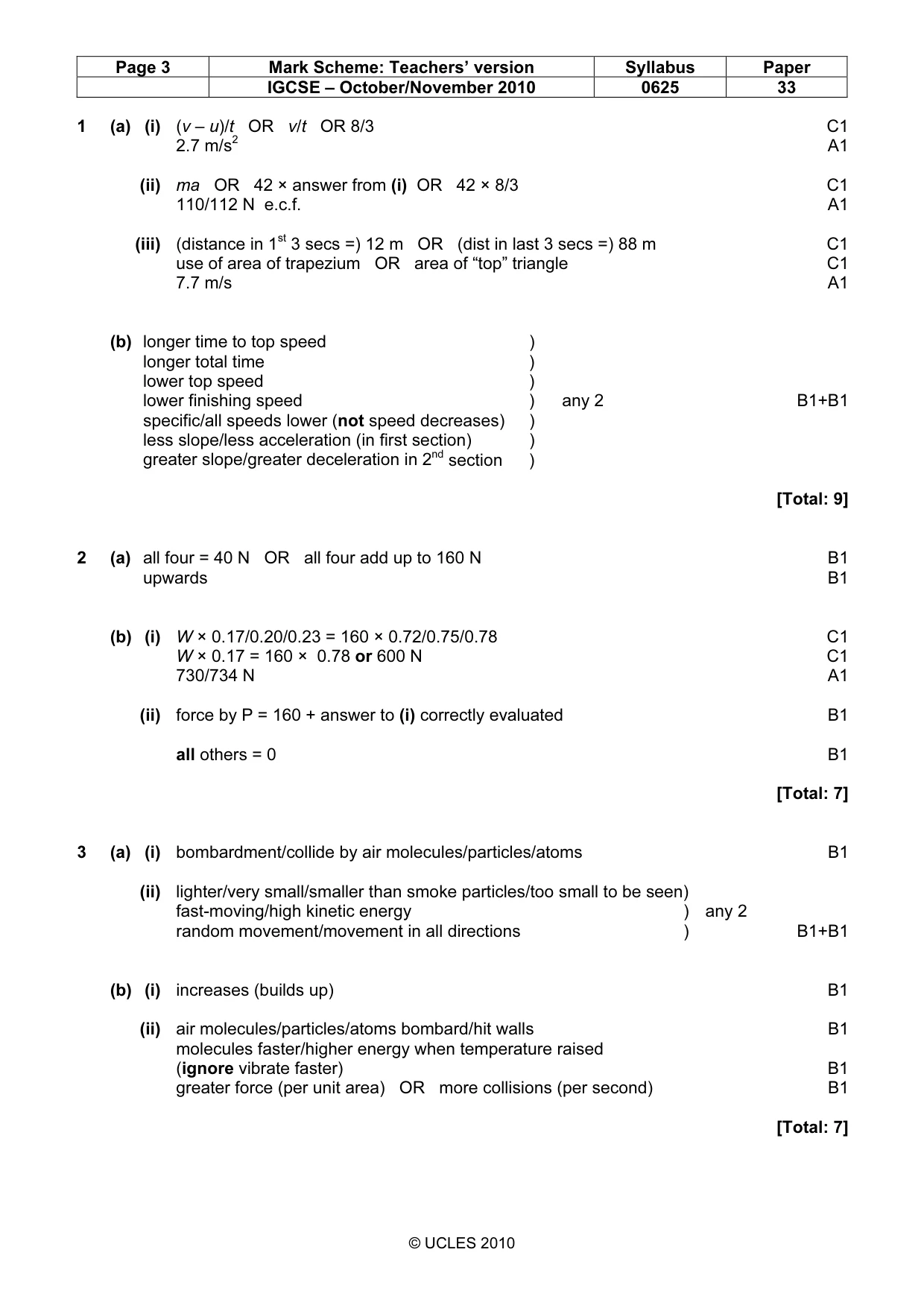
Mark scheme: 1 (a) (i) (v – u)/t OR v/t OR 8/3 C1 2.7 m/s2 A1 (ii) ma OR 42 × answer from (i) OR 42 × 8/3 C1 110/112 N e.c.f. A1 (iii) (distance in 1st 3 secs =) 12 m OR (dist in last 3 secs =) 88 m C1 use of area of trapezium OR area of “top” triangle C1 7.7 m/s A1 (b) longer time to top speed ) longer total time ) lower top speed ) lower finishing speed ) any 2 B1+B1 specific/all speeds lower (not speed decreases) ) less slope/less acceleration (in first section) ) greater slope/greater deceleration in 2nd section ) [Total: 9]
Q2 · A loose uniform wooden floorboard weighs 160 N and rests symmetrically on four supports…
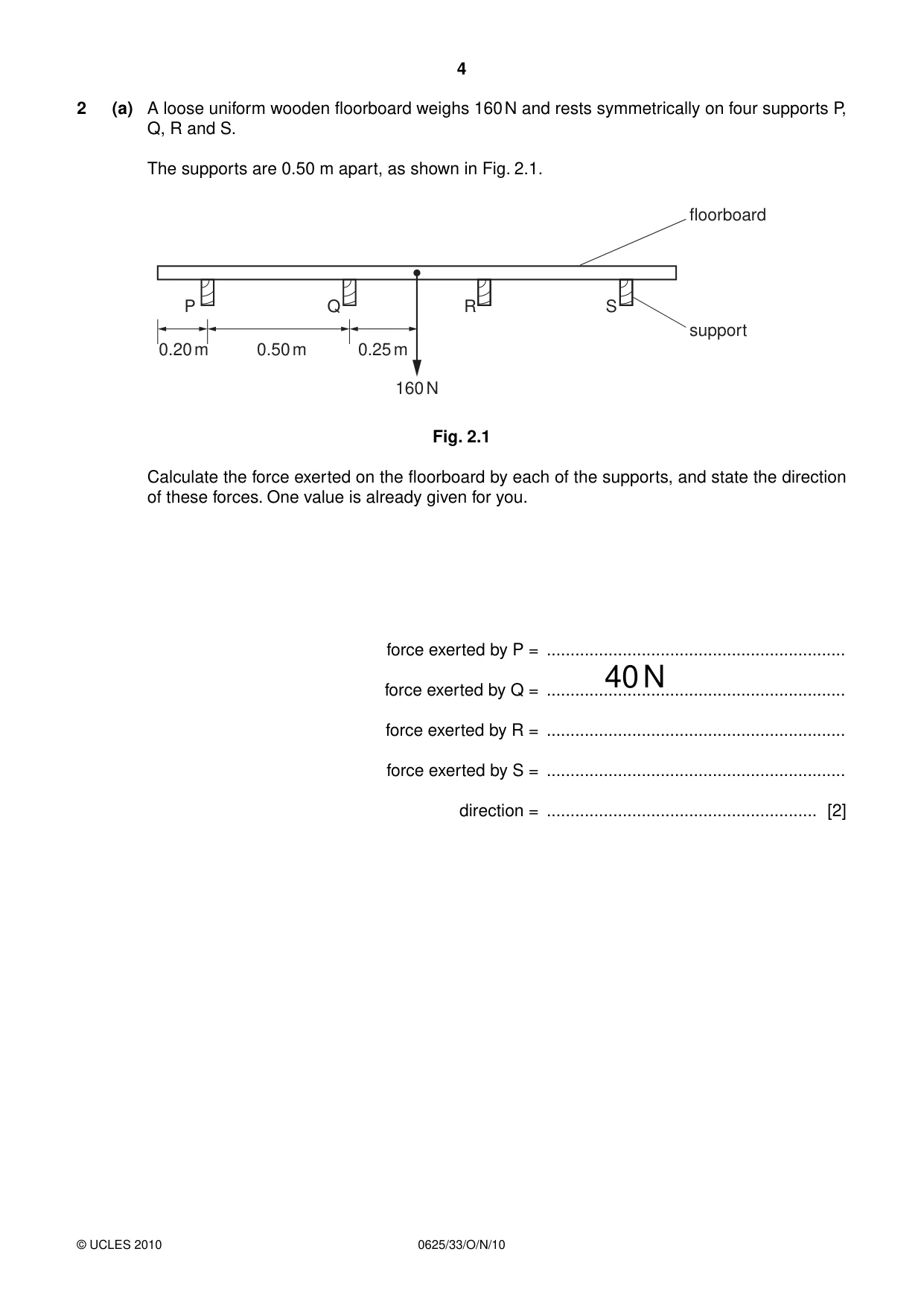
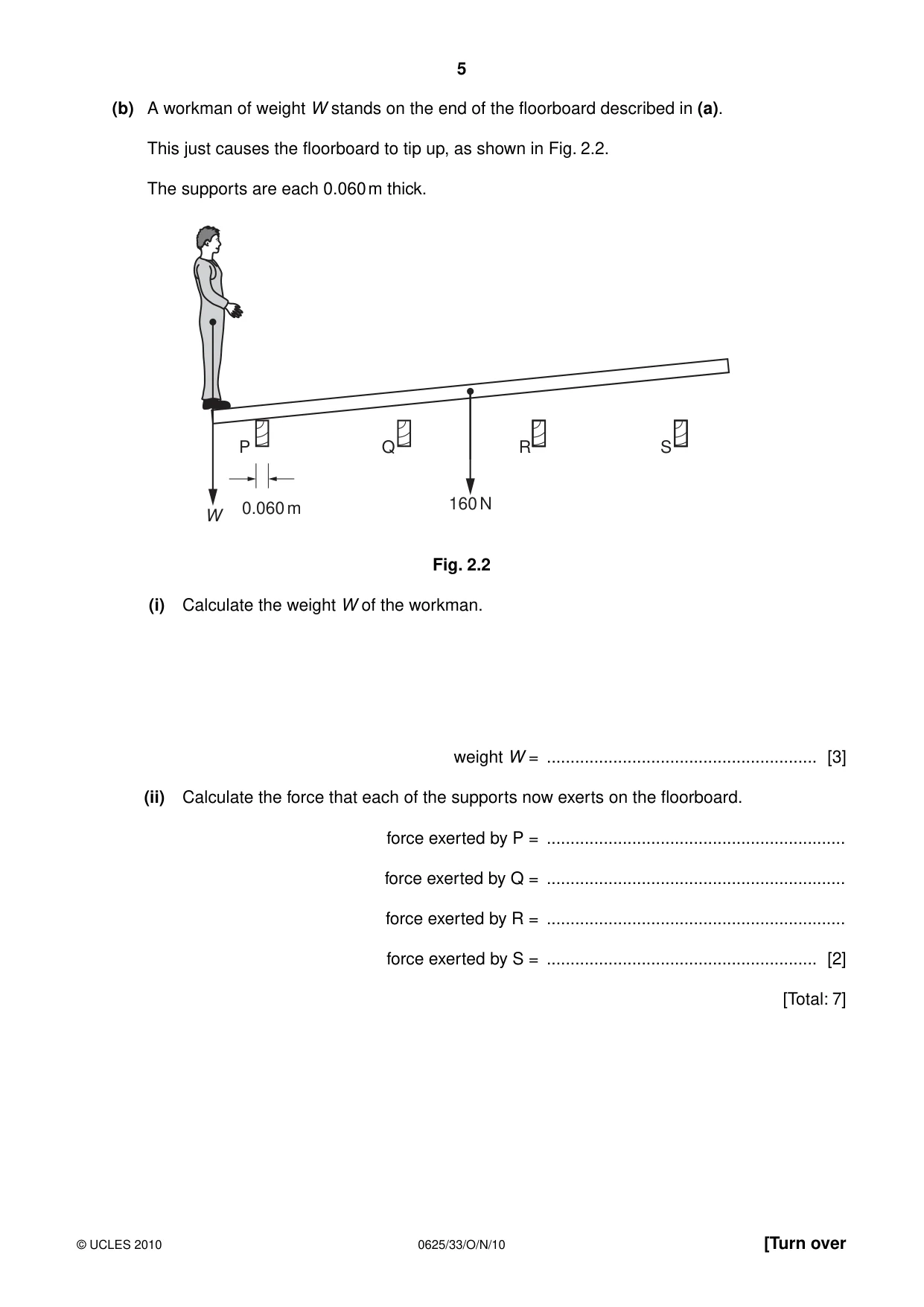
2 (a) A loose uniform wooden floorboard weighs 160 N and rests symmetrically on four supports P, Q, R and S. The supports are 0.50 m apart, as shown in Fig. 2.1. floorboard P Q R S support 0.20 m 0.50 m 0.25 m 160 N Fig. 2.1 Calculate the force exerted on the floorboard by each of the supports, and state the direction of these forces. One value is already given for you. force exerted by P = ............................................................... force exerted by Q = ...............................................................40 N force exerted by R = ............................................................... force exerted by S = ............................................................... direction = ......................................................... [2] (b) A workman of weight W stands on the end of the floorboard described in (a). This just causes the floorboard to tip up, as shown in Fig. 2.2. The supports are each 0.060 m thick. P Q R S 0.060 m 160 N W Fig. 2.2 (i) Calculate the weight W of the workman. weight W = ......................................................... [3] (ii) Calculate the force that each of the supports now exerts on the floorboard. force exerted by P = ............................................................... force exerted by Q = ............................................................... force exerted by R = ............................................................... force exerted by S = ......................................................... [2] [Total: 7]
Mark scheme: 2 (a) all four = 40 N OR all four add up to 160 N B1 upwards B1 (b) (i) W × 0.17/0.20/0.23 = 160 × 0.72/0.75/0.78 C1 W × 0.17 = 160 × 0.78 or 600 N C1 730/734 N A1 (ii) force by P = 160 + answer to (i) correctly evaluated B1 all others = 0 B1 [Total: 7]
Q3 · The path taken in air by a smoke particle, as seen in a Brownian motion experiment
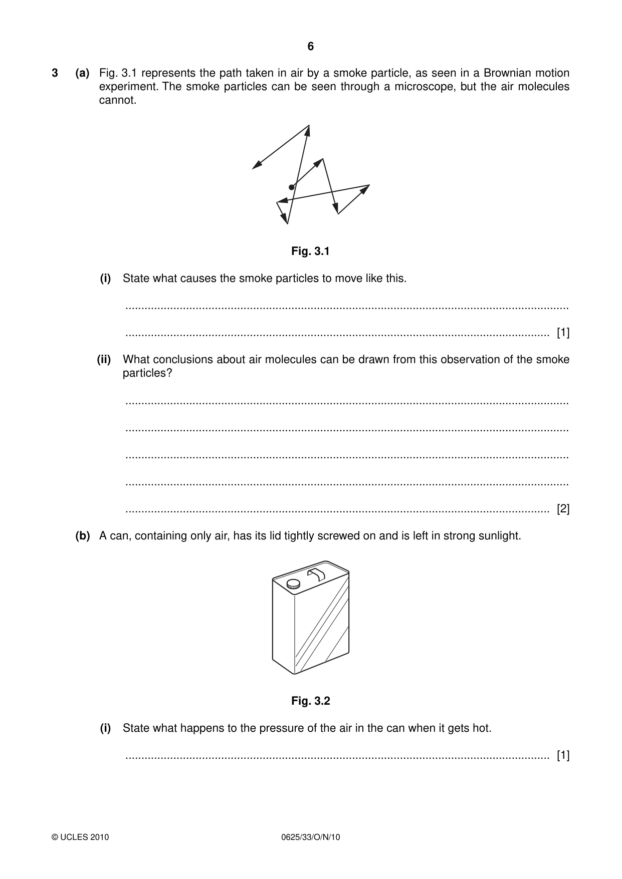
3 (a) Fig. 3.1 represents the path taken in air by a smoke particle, as seen in a Brownian motion experiment. The smoke particles can be seen through a microscope, but the air molecules cannot. Fig. 3.1 (i) State what causes the smoke particles to move like this. ........................................................................................................................................... ..................................................................................................................................... [1] (ii) What conclusions about air molecules can be drawn from this observation of the smoke particles? ........................................................................................................................................... ........................................................................................................................................... ........................................................................................................................................... ........................................................................................................................................... ..................................................................................................................................... [2] (b) A can, containing only air, has its lid tightly screwed on and is left in strong sunlight. Fig. 3.2 (i) State what happens to the pressure of the air in the can when it gets hot. ..................................................................................................................................... [1] (ii) In terms of molecules, explain your answer to (b)(i). ........................................................................................................................................... ........................................................................................................................................... ........................................................................................................................................... ..................................................................................................................................... [3] [Total: 7]
Mark scheme: 3 (a) (i) bombardment/collide by air molecules/particles/atoms B1 (ii) lighter/very small/smaller than smoke particles/too small to be seen) fast-moving/high kinetic energy ) any 2 random movement/movement in all directions ) B1+B1 (b) (i) increases (builds up) B1 (ii) air molecules/particles/atoms bombard/hit walls B1 molecules faster/higher energy when temperature raised (ignore vibrate faster) B1 greater force (per unit area) OR more collisions (per second) B1 [Total: 7] IGCSE – October/November 2010 0625 33
Q4 · Name the process by which thermal energy is transferred through a metal rod
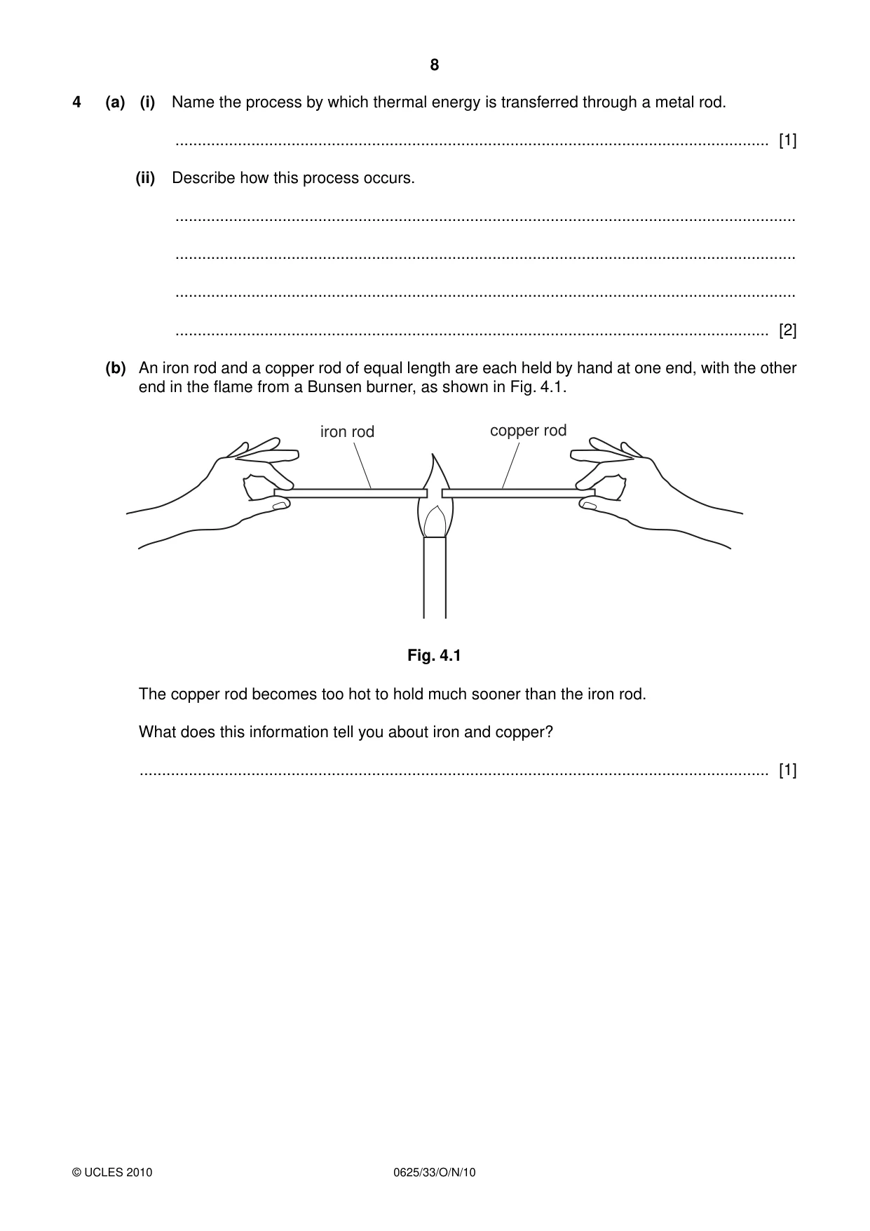
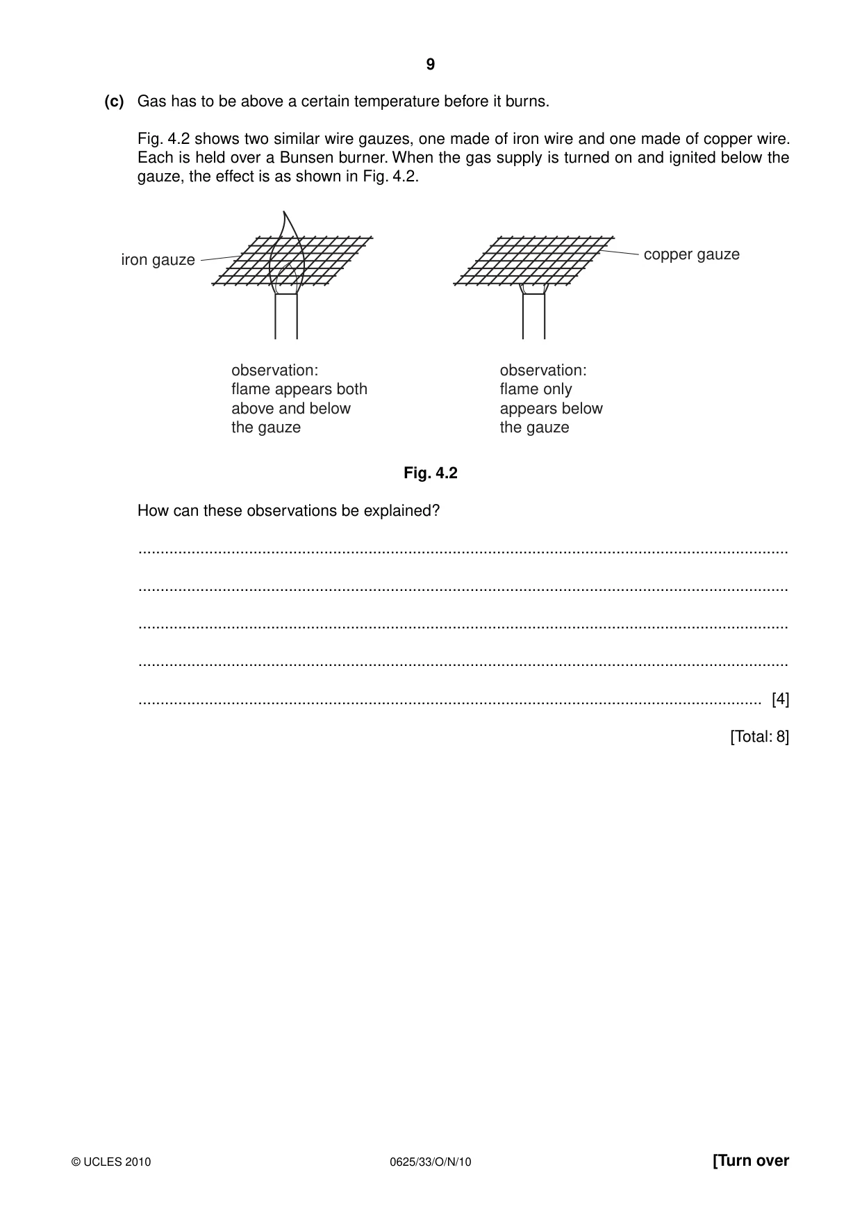
4 (a) (i) Name the process by which thermal energy is transferred through a metal rod. ..................................................................................................................................... [1] (ii) Describe how this process occurs. ........................................................................................................................................... ........................................................................................................................................... ........................................................................................................................................... ..................................................................................................................................... [2] (b) An iron rod and a copper rod of equal length are each held by hand at one end, with the other end in the flame from a Bunsen burner, as shown in Fig. 4.1. iron rod copper rod Fig. 4.1 The copper rod becomes too hot to hold much sooner than the iron rod. What does this information tell you about iron and copper? ............................................................................................................................................. [1] (c) Gas has to be above a certain temperature before it burns. Fig. 4.2 shows two similar wire gauzes, one made of iron wire and one made of copper wire. Each is held over a Bunsen burner. When the gas supply is turned on and ignited below the gauze, the effect is as shown in Fig. 4.2. copper gauze iron gauze observation: observation: flame appears both flame only above and below appears below the gauze the gauze Fig. 4.2 How can these observations be explained? ................................................................................................................................................... ................................................................................................................................................... ................................................................................................................................................... ................................................................................................................................................... ............................................................................................................................................. [4] [Total: 8]
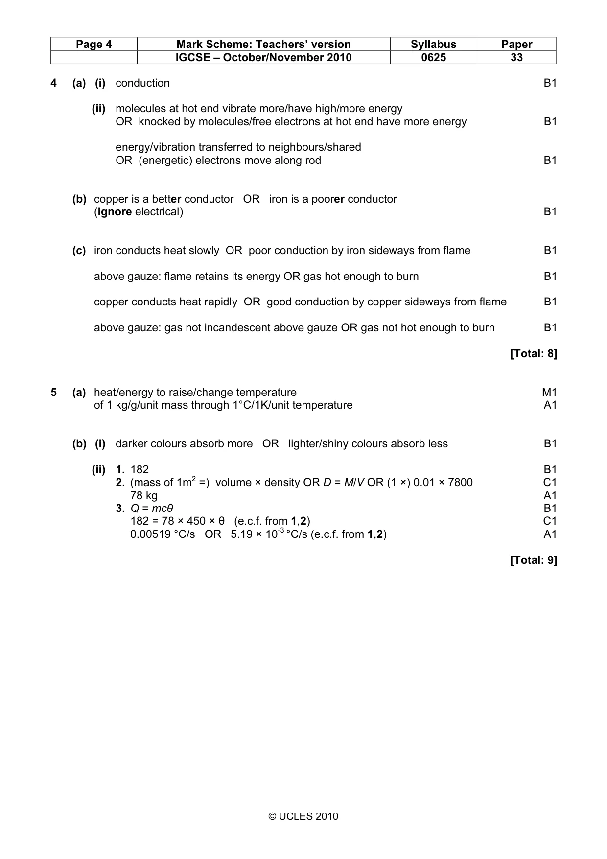
Mark scheme: 4 (a) (i) conduction B1 (ii) molecules at hot end vibrate more/have high/more energy OR knocked by molecules/free electrons at hot end have more energy B1 energy/vibration transferred to neighbours/shared OR (energetic) electrons move along rod B1 (b) copper is a better conductor OR iron is a poorer conductor (ignore electrical) B1 (c) iron conducts heat slowly OR poor conduction by iron sideways from flame B1 above gauze: flame retains its energy OR gas hot enough to burn B1 copper conducts heat rapidly OR good conduction by copper sideways from flame B1 above gauze: gas not incandescent above gauze OR gas not hot enough to burn B1 [Total: 8]
Q5 · Define specific heat capacity
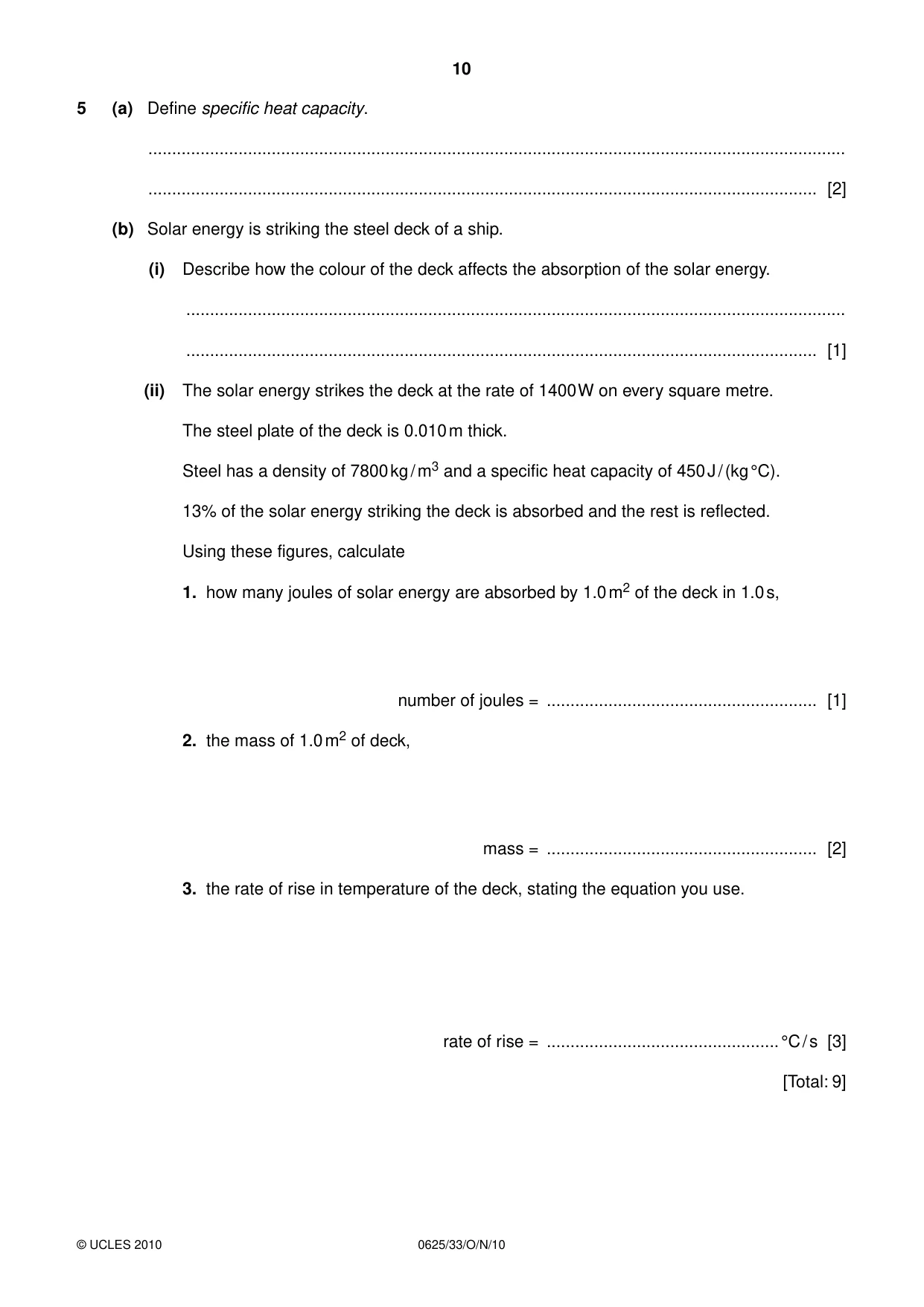
5 (a) Define specific heat capacity. ................................................................................................................................................... ............................................................................................................................................. [2] (b) Solar energy is striking the steel deck of a ship. (i) Describe how the colour of the deck affects the absorption of the solar energy. ........................................................................................................................................... ..................................................................................................................................... [1] (ii) The solar energy strikes the deck at the rate of 1400 W on every square metre. The steel plate of the deck is 0.010 m thick. Steel has a density of 7800 kg / m3 and a specific heat capacity of 450 J / (kg °C). 13% of the solar energy striking the deck is absorbed and the rest is reflected. Using these figures, calculate 1. how many joules of solar energy are absorbed by 1.0 m2 of the deck in 1.0 s, number of joules = ......................................................... [1] 2. the mass of 1.0 m2 of deck, mass = ......................................................... [2] 3. the rate of rise in temperature of the deck, stating the equation you use. rate of rise = .................................................°C / s [3] [Total: 9]
Mark scheme: 5 (a) heat/energy to raise/change temperature M1 of 1 kg/g/unit mass through 1°C/1K/unit temperature A1 (b) (i) darker colours absorb more OR lighter/shiny colours absorb less B1 (ii) 1. 182 B1 2. (mass of 1m2 =) volume × density OR D = M/V OR (1 ×) 0.01 × 7800 C1 78 kg A1 3. Q = mcθ B1 182 = 78 × 450 × θ (e.c.f. from 1,2) C1 0.00519 °C/s OR 5.19 × 10⁻³ °C/s (e.c.f. from 1,2) A1 [Total: 9] IGCSE – October/November 2010 0625 33
Q6 · A boy drops a ball of mass 0.50 kg
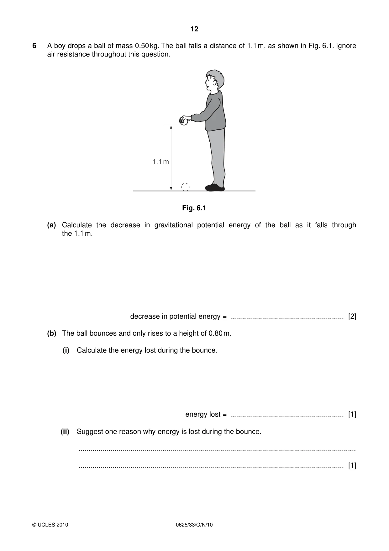
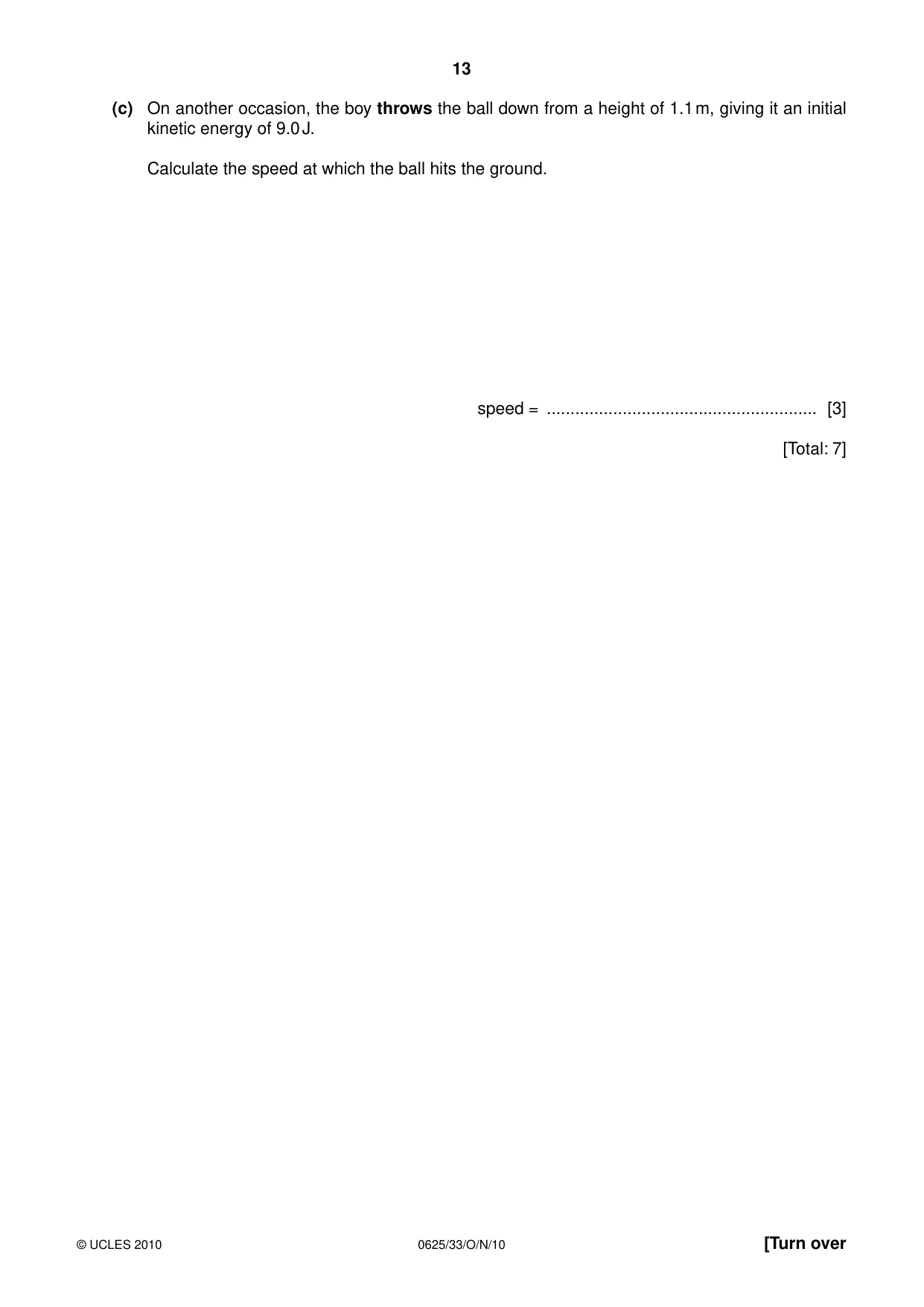
6 A boy drops a ball of mass 0.50 kg. The ball falls a distance of 1.1 m, as shown in Fig. 6.1. Ignore air resistance throughout this question. 1.1 m Fig. 6.1 (a) Calculate the decrease in gravitational potential energy of the ball as it falls through the 1.1 m. decrease in potential energy = ......................................................... [2] (b) The ball bounces and only rises to a height of 0.80 m. (i) Calculate the energy lost during the bounce. energy lost = ......................................................... [1] (ii) Suggest one reason why energy is lost during the bounce. ........................................................................................................................................... ..................................................................................................................................... [1] (c) On another occasion, the boy throws the ball down from a height of 1.1 m, giving it an initial kinetic energy of 9.0 J. Calculate the speed at which the ball hits the ground. speed = ......................................................... [3] [Total: 7]
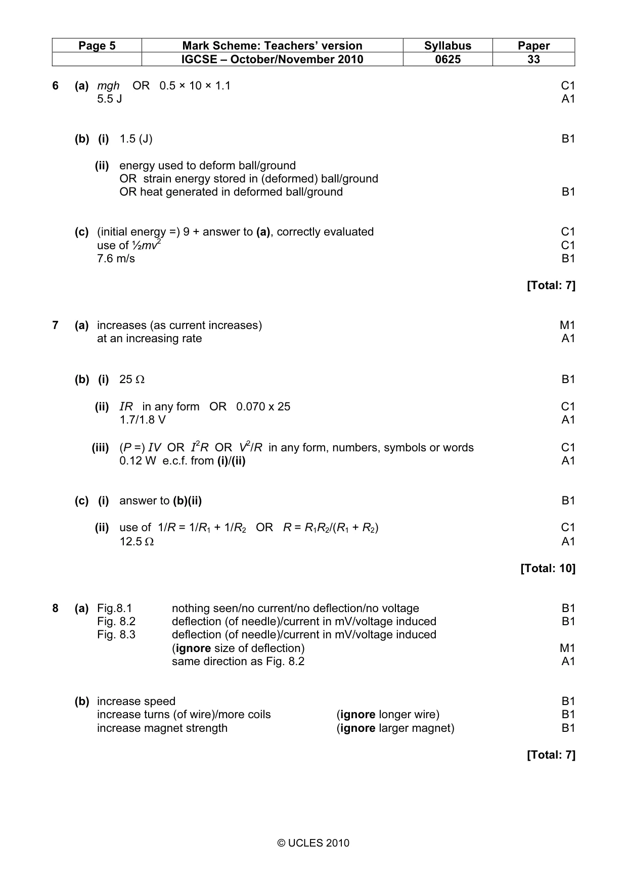
Mark scheme: 6 (a) mgh OR 0.5 × 10 × 1.1 C1 5.5 J A1 (b) (i) 1.5 (J) B1 (ii) energy used to deform ball/ground OR strain energy stored in (deformed) ball/ground OR heat generated in deformed ball/ground B1 (c) (initial energy =) 9 + answer to (a), correctly evaluated C1 use of ½mv2 C1 7.6 m/s B1 [Total: 7]
Q7 · How the resistance of the filament of a lamp changes as the current through the lamp…
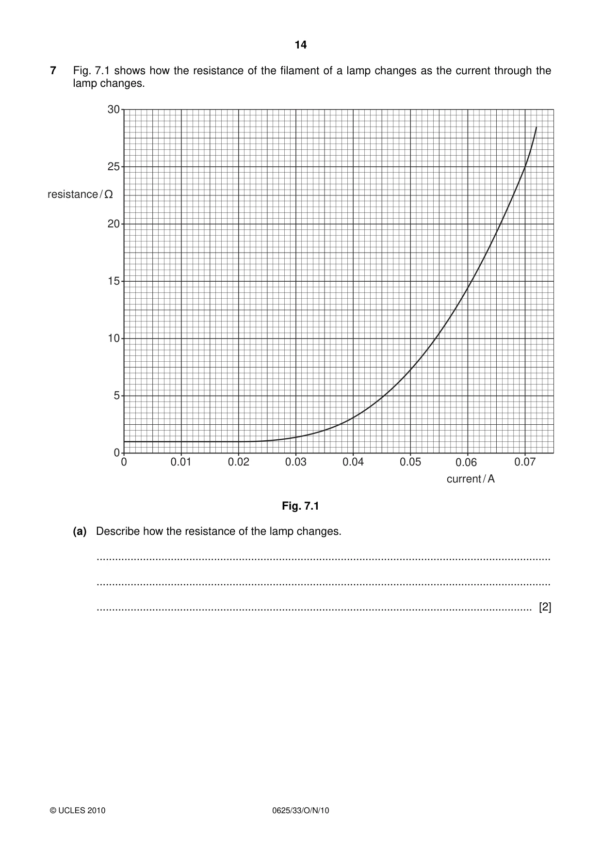
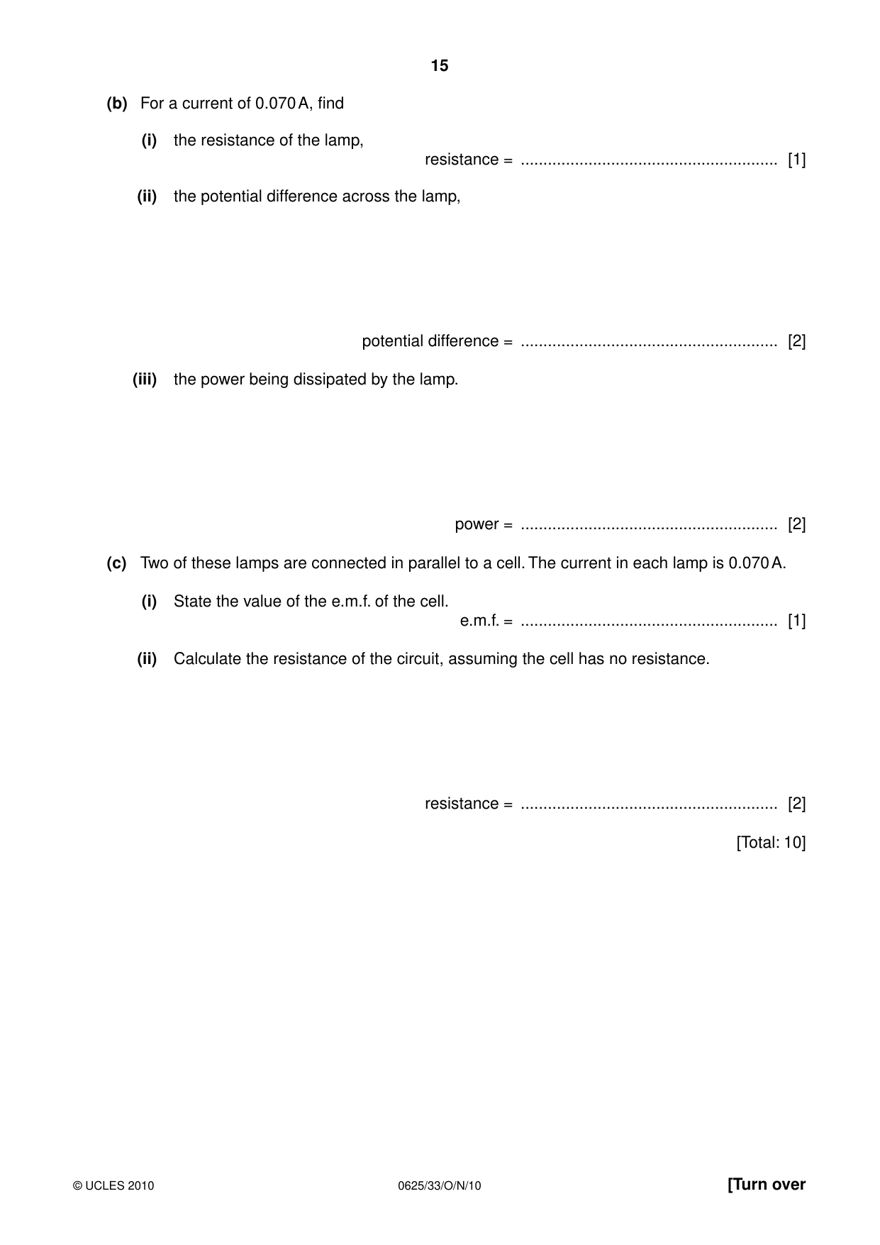
7 Fig. 7.1 shows how the resistance of the filament of a lamp changes as the current through the lamp changes. 30 25 resistance / 20 15 10 5 0 0 0.01 0.02 0.03 0.04 0.05 0.06 0.07 current / A Fig. 7.1 (a) Describe how the resistance of the lamp changes. ................................................................................................................................................... ................................................................................................................................................... ............................................................................................................................................. [2] (b) For a current of 0.070 A, find (i) the resistance of the lamp, resistance = ......................................................... [1] (ii) the potential difference across the lamp, potential difference = ......................................................... [2] (iii) the power being dissipated by the lamp. power = ......................................................... [2] (c) Two of these lamps are connected in parallel to a cell. The current in each lamp is 0.070 A. (i) State the value of the e.m.f. of the cell. e.m.f. = ......................................................... [1] (ii) Calculate the resistance of the circuit, assuming the cell has no resistance. resistance = ......................................................... [2] [Total: 10]
Mark scheme: 7 (a) increases (as current increases) M1 at an increasing rate A1 (b) (i) 25 Ω B1 (ii) IR in any form OR 0.070 x 25 C1 1.7/1.8 V A1 (iii) (P =) IV OR I2R OR V2/R in any form, numbers, symbols or words C1 0.12 W e.c.f. from (i)/(ii) A1 (c) (i) answer to (b)(ii) B1 (ii) use of 1/R = 1/R1 + 1/R2 OR R = R1R2/(R1 + R2) C1 12.5 Ω A1 [Total: 10]
Q8 · A coil is wound on a cylindrical cardboard tube and connected to a sensitive centre-zero…
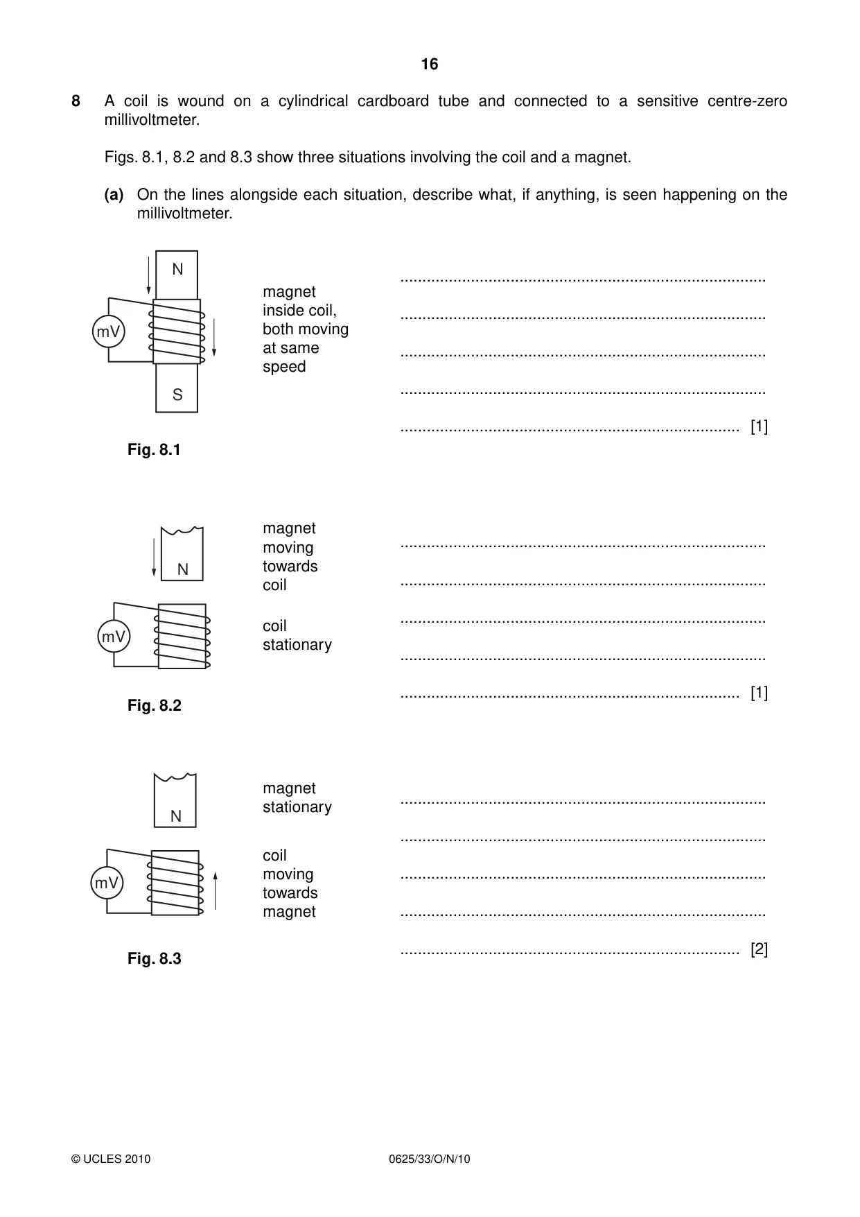
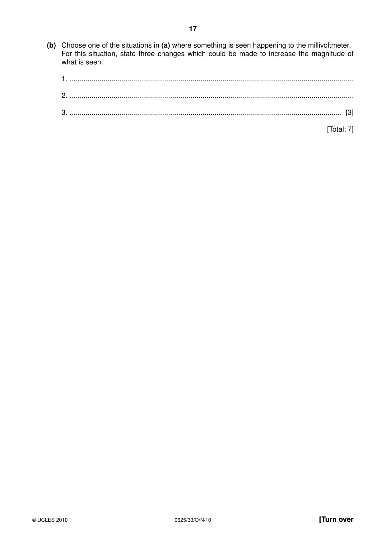
8 A coil is wound on a cylindrical cardboard tube and connected to a sensitive centre-zero millivoltmeter. Figs. 8.1, 8.2 and 8.3 show three situations involving the coil and a magnet. (a) On the lines alongside each situation, describe what, if anything, is seen happening on the millivoltmeter. N ................................................................................... magnet inside coil, ................................................................................... mV both moving at same ................................................................................... speed ................................................................................... S ............................................................................. [1] Fig. 8.1 magnet ................................................................................... moving N towards ................................................................................... coil ................................................................................... coil mV stationary ................................................................................... ............................................................................. [1] Fig. 8.2 magnet ................................................................................... stationary N ................................................................................... coil moving ................................................................................... mV towards magnet ................................................................................... ............................................................................. [2] Fig. 8.3 (b) Choose one of the situations in (a) where something is seen happening to the millivoltmeter. For this situation, state three changes which could be made to increase the magnitude of what is seen. 1. ............................................................................................................................................... 2. ............................................................................................................................................... 3. ......................................................................................................................................... [3] [Total: 7]
Mark scheme: 8 (a) Fig.8.1 nothing seen/no current/no deflection/no voltage B1 Fig. 8.2 deflection (of needle)/current in mV/voltage induced B1 Fig. 8.3 deflection (of needle)/current in mV/voltage induced (ignore size of deflection) M1 same direction as Fig. 8.2 A1 (b) increase speed B1 increase turns (of wire)/more coils (ignore longer wire) B1 increase magnet strength (ignore larger magnet) B1 [Total: 7] IGCSE – October/November 2010 0625 33
Question 9
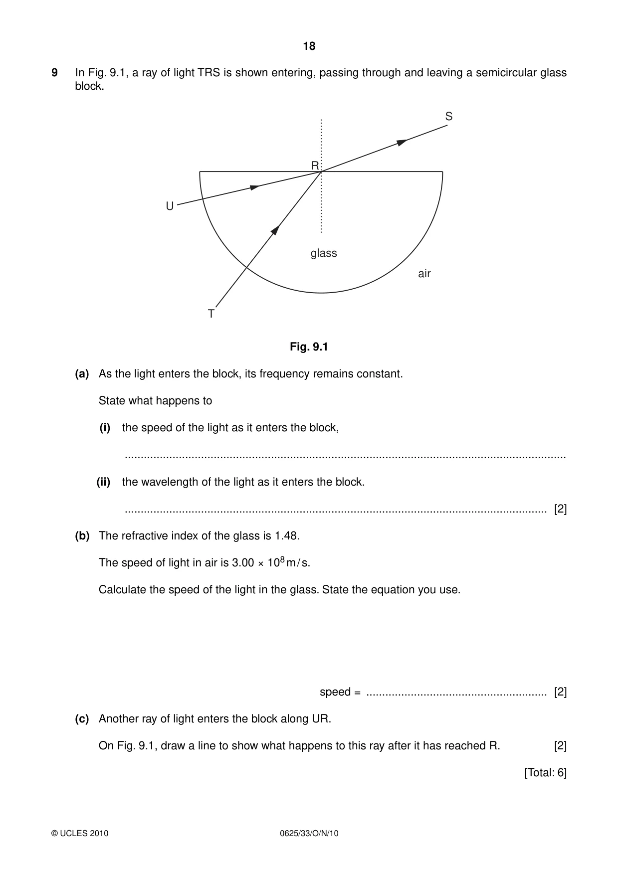
9 In Fig. 9.1, a ray of light TRS is shown entering, passing through and leaving a semicircular glass block. S R U glass air T Fig. 9.1 (a) As the light enters the block, its frequency remains constant. State what happens to (i) the speed of the light as it enters the block, ........................................................................................................................................... (ii) the wavelength of the light as it enters the block. ..................................................................................................................................... [2] (b) The refractive index of the glass is 1.48. The speed of light in air is 3.00 × 10⁸ m / s. Calculate the speed of the light in the glass. State the equation you use. speed = ......................................................... [2] (c) Another ray of light enters the block along UR. On Fig. 9.1, draw a line to show what happens to this ray after it has reached R. [2] [Total: 6]
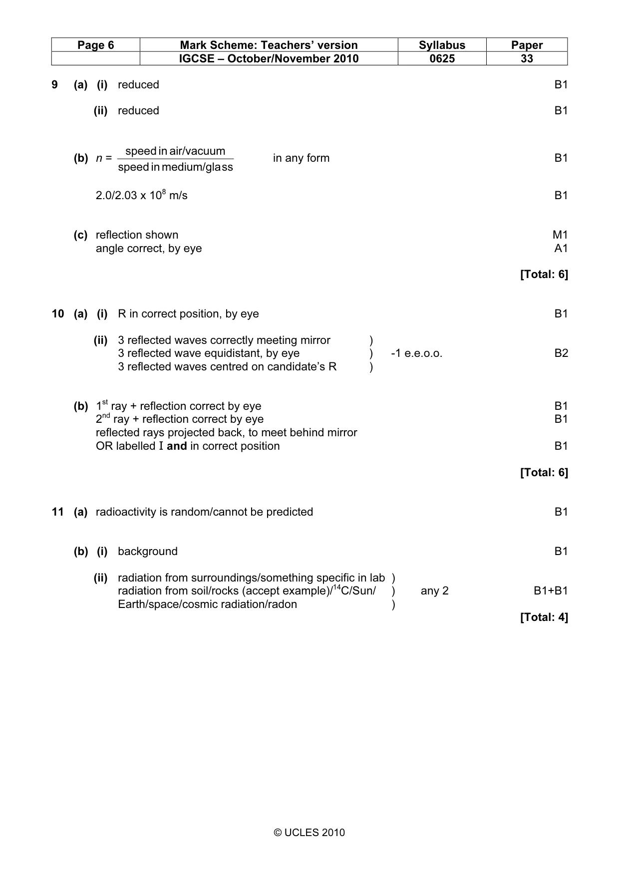
Mark scheme: 9 (a) (i) reduced B1 (ii) reduced B1 speed in air/vacuum (b) n = in any form B1 speed in medium/gla ss 2.0/2.03 x 108 m/s B1 (c) reflection shown M1 angle correct, by eye A1 [Total: 6]
Q10 · A small object S is dipped repeatedly into water near a flat reflecting surface
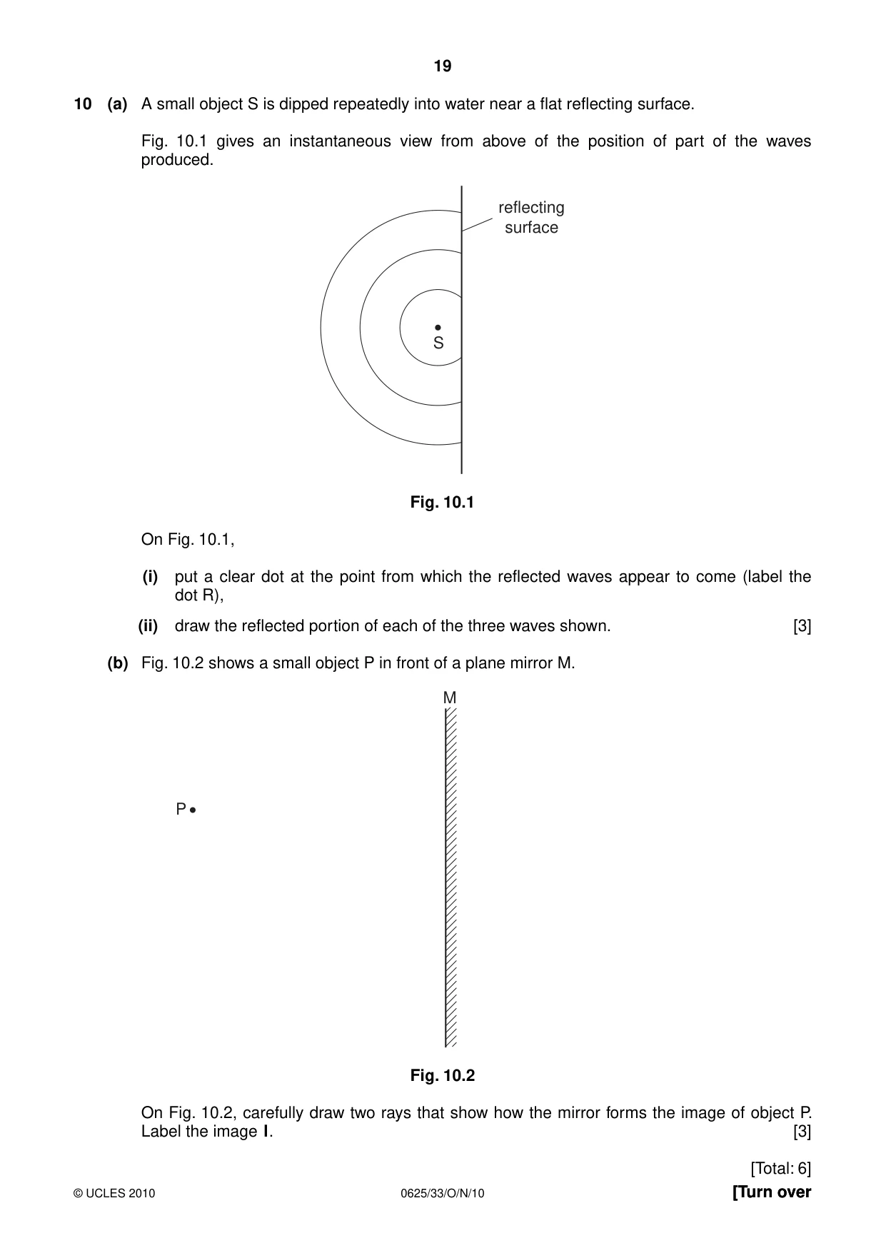
10 (a) A small object S is dipped repeatedly into water near a flat reflecting surface. Fig. 10.1 gives an instantaneous view from above of the position of part of the waves produced. reflecting surface S Fig. 10.1 On Fig. 10.1, (i) put a clear dot at the point from which the reflected waves appear to come (label the dot R), (ii) draw the reflected portion of each of the three waves shown. [3] (b) Fig. 10.2 shows a small object P in front of a plane mirror M. M P Fig. 10.2 On Fig. 10.2, carefully draw two rays that show how the mirror forms the image of object P. Label the image I. [3] [Total: 6]
Mark scheme: 10 (a) (i) R in correct position, by eye B1 (ii) 3 reflected waves correctly meeting mirror ) 3 reflected wave equidistant, by eye ) -1 e.e.o.o. B2 3 reflected waves centred on candidate’s R ) (b) 1st ray + reflection correct by eye B1 2nd ray + reflection correct by eye B1 reflected rays projected back, to meet behind mirror OR labelled I and in correct position B1 [Total: 6]
Q11 · A radioactive source is placed near a radiation detector connected to a counter, as shown…
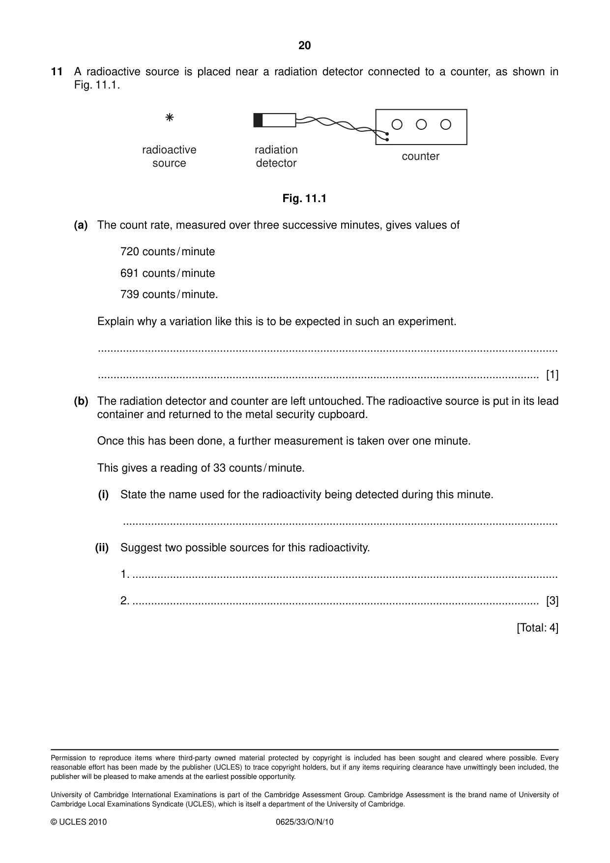
11 A radioactive source is placed near a radiation detector connected to a counter, as shown in Fig. 11.1. radioactive radiation counter source detector Fig. 11.1 (a) The count rate, measured over three successive minutes, gives values of 720 counts / minute 691 counts / minute 739 counts / minute. Explain why a variation like this is to be expected in such an experiment. ................................................................................................................................................... ............................................................................................................................................. [1] (b) The radiation detector and counter are left untouched. The radioactive source is put in its lead container and returned to the metal security cupboard. Once this has been done, a further measurement is taken over one minute. This gives a reading of 33 counts / minute. (i) State the name used for the radioactivity being detected during this minute. ........................................................................................................................................... (ii) Suggest two possible sources for this radioactivity. 1. ........................................................................................................................................ 2. .................................................................................................................................. [3] [Total: 4]
Mark scheme: 11 (a) radioactivity is random/cannot be predicted B1 (b) (i) background B1 (ii) radiation from surroundings/something specific in lab ) radiation from soil/rocks (accept example)/14C/Sun/ ) any 2 B1+B1 Earth/space/cosmic radiation/radon ) [Total: 4]
What was in this paper
The subtopics covered by these 11 questions, and how many questions each got. Open one in a new tab to see every Cambridge question on it.
What you needed in this session
Cambridge’s own grade thresholds for 2010 Oct/Nov, Paper 3 · Variant 3. A higher threshold means an easier paper — the bar moves with how the cohort did.