Cambridge IGCSE Physics 0625 — 2020 May/June Paper 3 · Variant 1
0625/31/M/J/20 · 12 questions · 80 marks · ≈90 min
The question paper and its mark scheme, free to read here and free to download. This is Cambridge’s own paper, exactly as it was sat.
Question paper16 pages
Mark scheme10 pages
Answers below. Sit the paper first if you are practising.
Questions as text
Q1 · A coil of wire
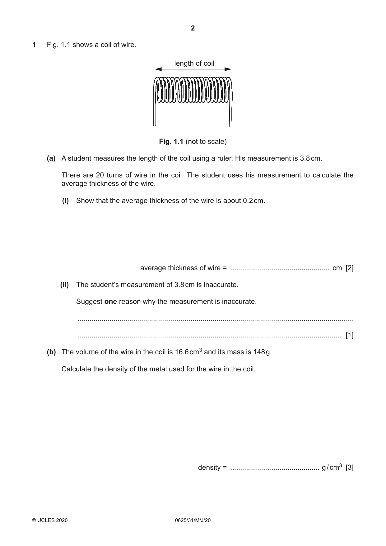
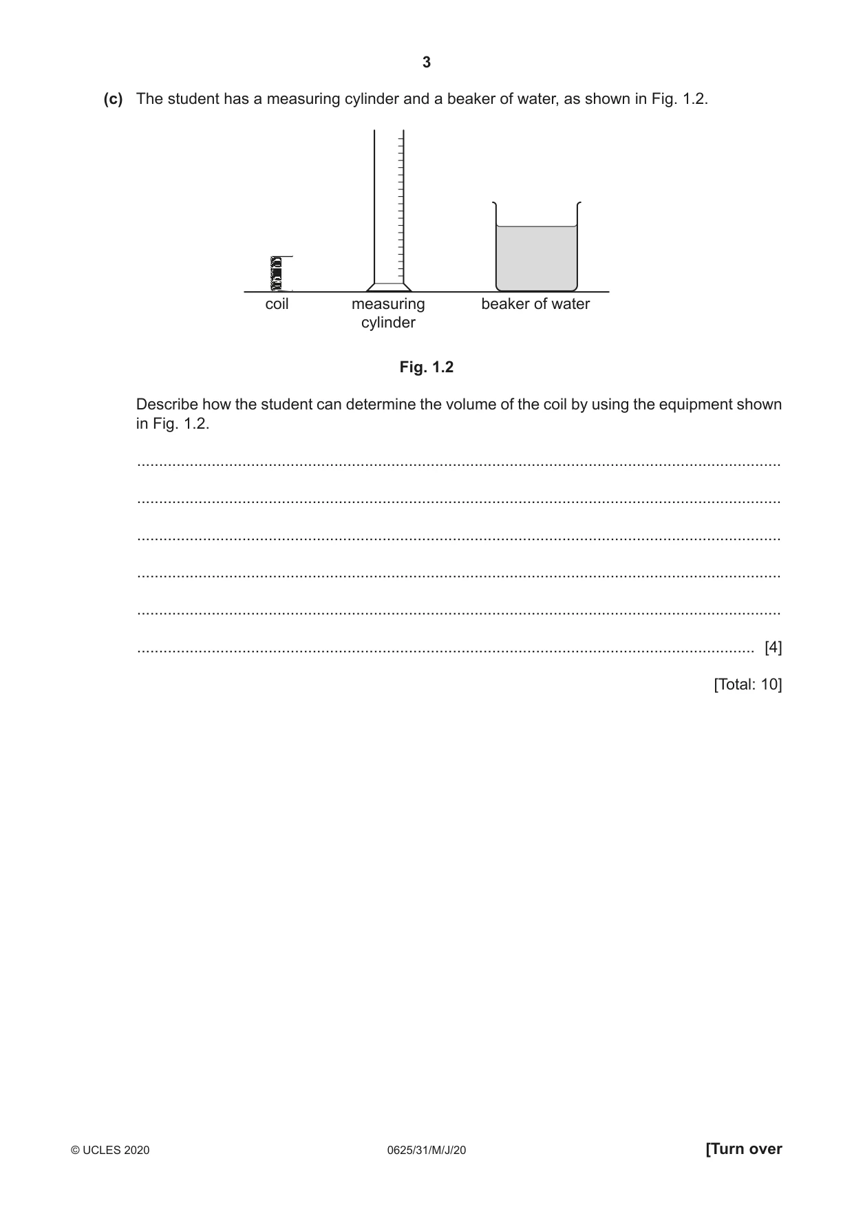
1 Fig. 1.1 shows a coil of wire. length of coil Fig. 1.1 (not to scale) (a) A student measures the length of the coil using a ruler. His measurement is 3.8 cm. There are 20 turns of wire in the coil. The student uses his measurement to calculate the average thickness of the wire. (i) Show that the average thickness of the wire is about 0.2 cm. average thickness of wire = .................................................. cm [2] (ii) The student’s measurement of 3.8 cm is inaccurate. Suggest one reason why the measurement is inaccurate. ........................................................................................................................................... ..................................................................................................................................... [1] (b) The volume of the wire in the coil is 16.6 cm3 and its mass is 148 g. Calculate the density of the metal used for the wire in the coil. density = ............................................. g / cm3 [3] (c) The student has a measuring cylinder and a beaker of water, as shown in Fig. 1.2. coil measuring beaker of water cylinder Fig. 1.2 Describe how the student can determine the volume of the coil by using the equipment shown in Fig. 1.2. ................................................................................................................................................... ................................................................................................................................................... ................................................................................................................................................... ................................................................................................................................................... ................................................................................................................................................... ............................................................................................................................................. [4] [Total: 10]
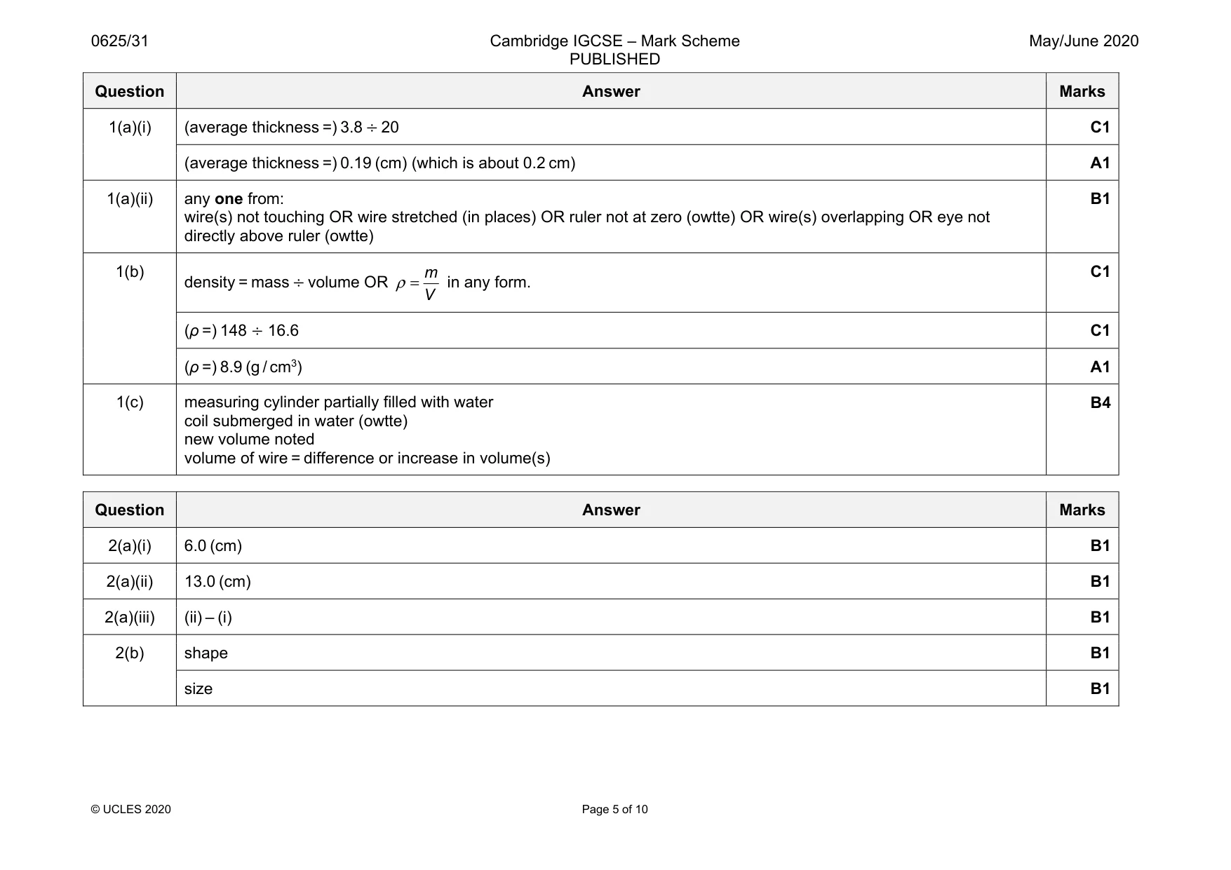
Mark scheme: 1(a)(i) C1 (average thickness =) 0.19 (cm) (which is about 0.2 cm) A1 1(a)(ii) any one from: wire(s) not touching OR wire stretched (in places) OR ruler not at zero (owtte) OR wire(s) overlapping OR eye not directly above ruler (owtte) B1 1(b) density = mass ÷ volume OR m V ρ = in any form. C1 (ρ =) 148 ÷ 16.6 C1 (ρ =) 8.9 (g / cm3) A1 1(c) measuring cylinder partially filled with water coil submerged in water (owtte) new volume noted volume of wire = difference or increase in volume(s) B4
More questions on Physical quantities and measurement techniques
Q2 · A student stretches a spring by adding different loads to it
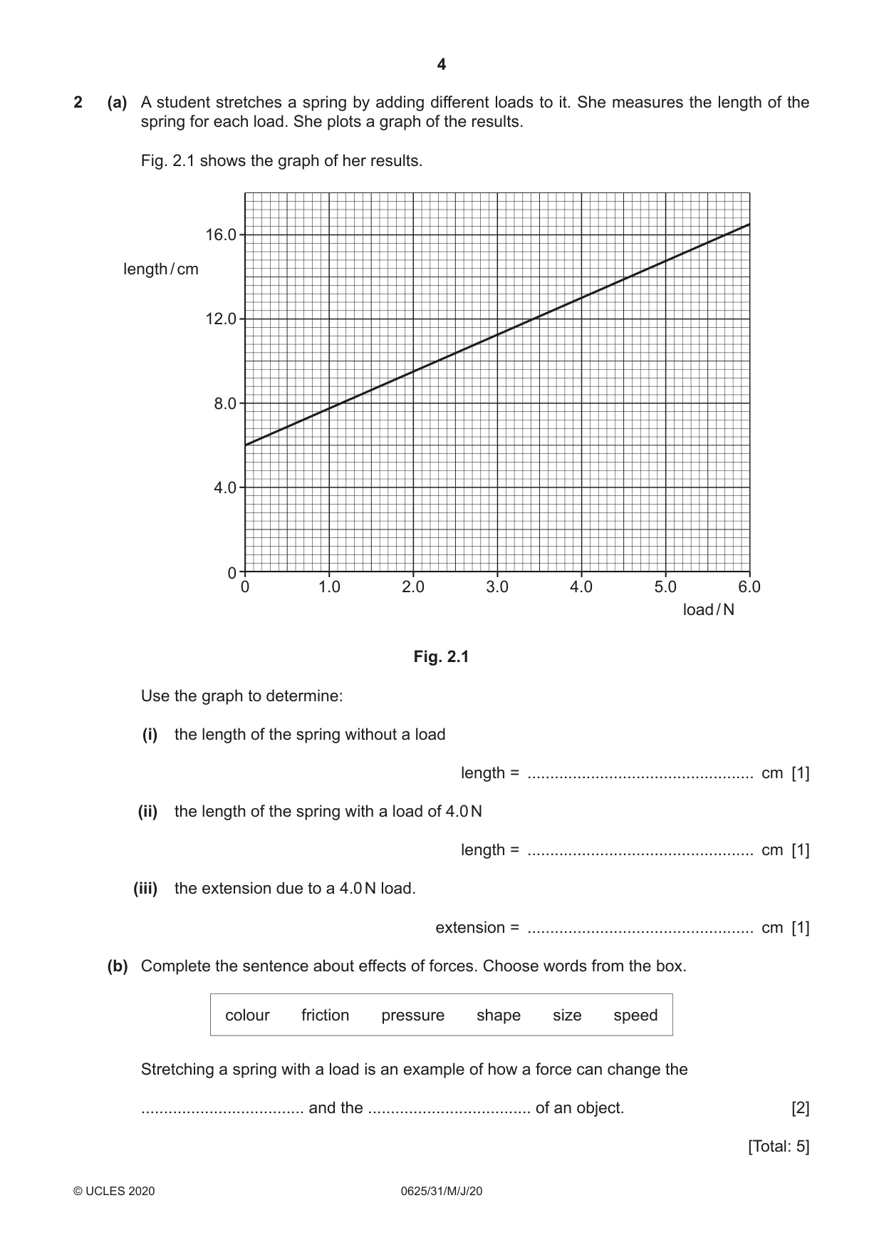
2 (a) A student stretches a spring by adding different loads to it. She measures the length of the spring for each load. She plots a graph of the results. Fig. 2.1 shows the graph of her results. 16.0 length / cm 12.0 8.0 4.0 0 0 1.0 2.0 3.0 4.0 5.0 6.0 load / N Fig. 2.1 Use the graph to determine: (i) the length of the spring without a load length = .................................................. cm [1] (ii) the length of the spring with a load of 4.0 N length = .................................................. cm [1] (iii) the extension due to a 4.0 N load. extension = .................................................. cm [1] (b) Complete the sentence about effects of forces. Choose words from the box. colour friction pressure shape size speed Stretching a spring with a load is an example of how a force can change the .................................... and the .................................... of an object. [2] [Total: 5]
Mark scheme: 2(a)(i) 6.0 (cm) B1 2(a)(ii) 13.0 (cm) B1 2(a)(iii) (ii) – (i) B1 2(b) shape B1 size B1
Q3 · Some gas molecules are in a box at room temperature
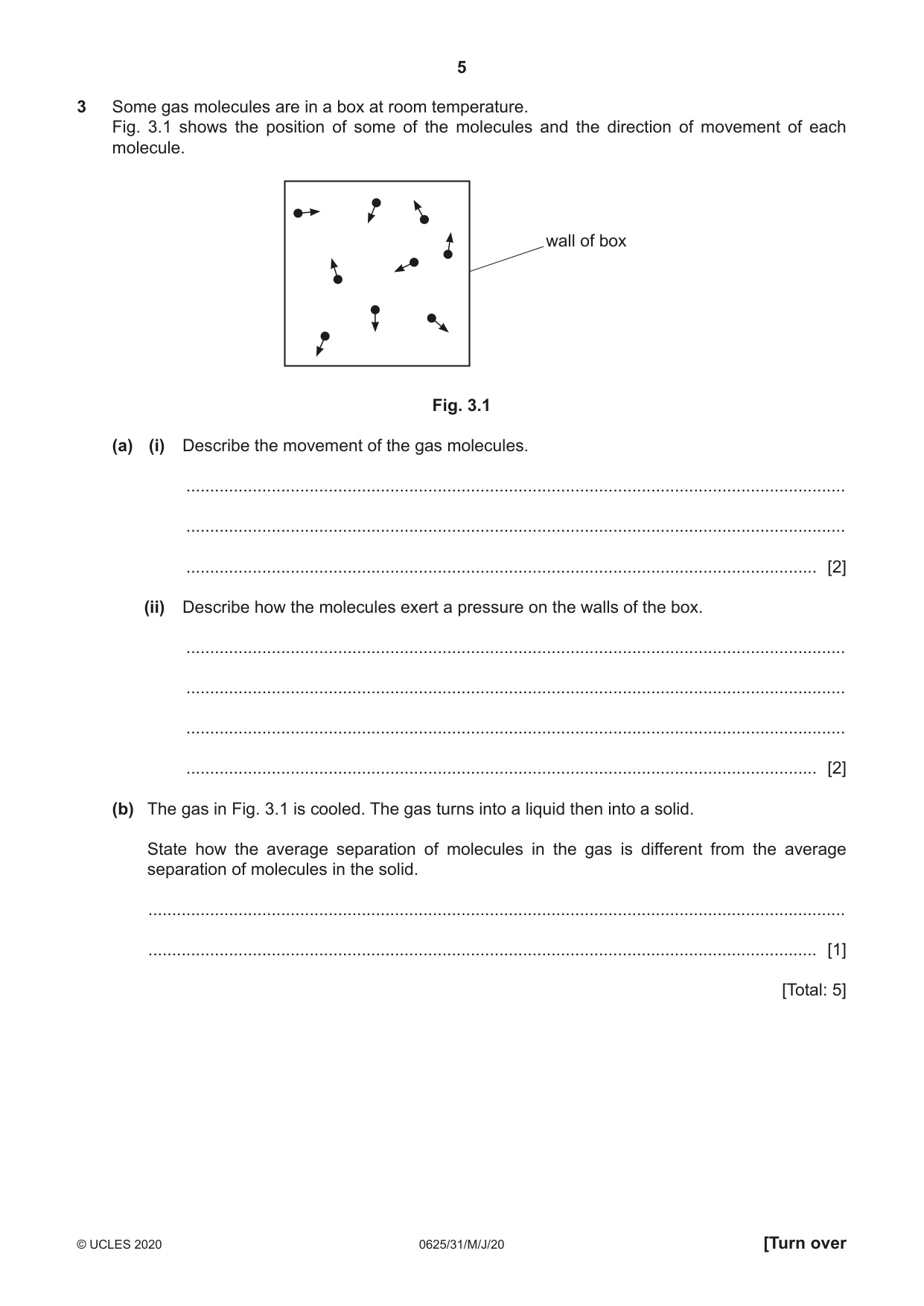
3 Some gas molecules are in a box at room temperature. Fig. 3.1 shows the position of some of the molecules and the direction of movement of each molecule. wall of box Fig. 3.1 (a) (i) Describe the movement of the gas molecules. ........................................................................................................................................... ........................................................................................................................................... ..................................................................................................................................... [2] (ii) Describe how the molecules exert a pressure on the walls of the box. ........................................................................................................................................... ........................................................................................................................................... ........................................................................................................................................... ..................................................................................................................................... [2] (b) The gas in Fig. 3.1 is cooled. The gas turns into a liquid then into a solid. State how the average separation of molecules in the gas is different from the average separation of molecules in the solid. ................................................................................................................................................... ............................................................................................................................................. [1] [Total: 5]
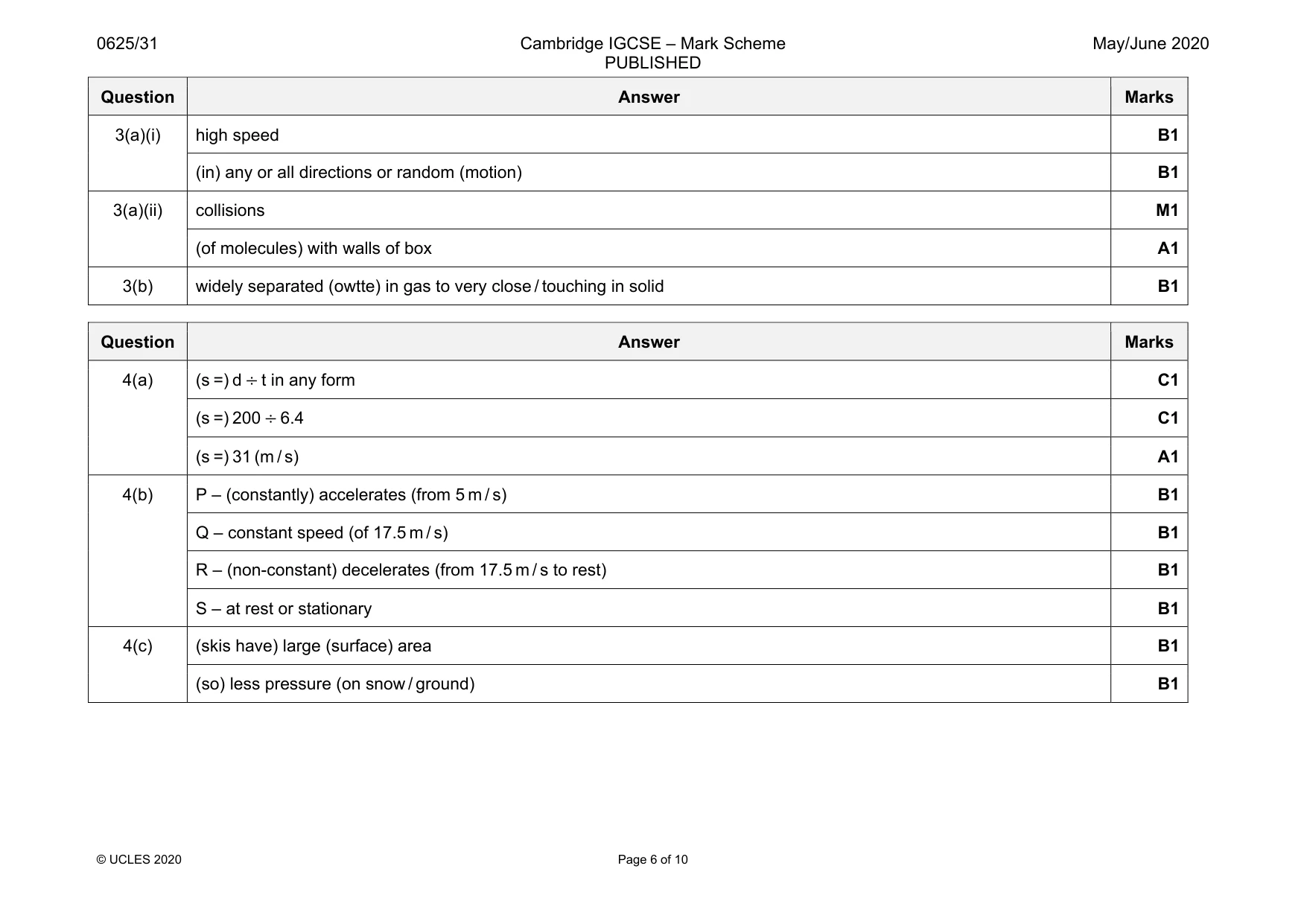
Mark scheme: 3(a)(i) high speed B1 (in) any or all directions or random (motion) B1 3(a)(ii) collisions M1 (of molecules) with walls of box A1 3(b) widely separated (owtte) in gas to very close / touching in solid B1
Q4 · During part of a race, a skier travels a distance of 200 m in a time of 6.4 s
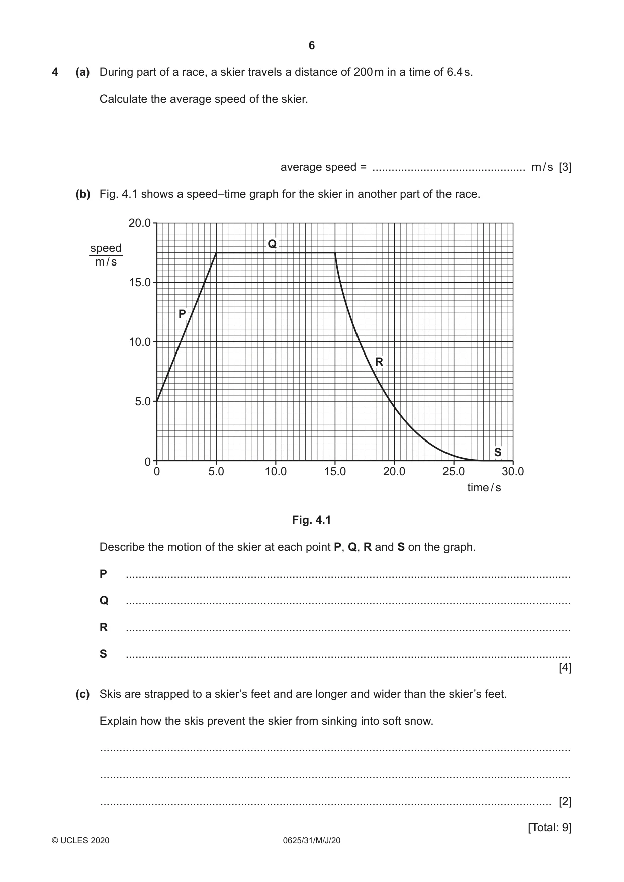
4 (a) During part of a race, a skier travels a distance of 200 m in a time of 6.4 s. Calculate the average speed of the skier. average speed = ................................................ m / s [3] (b) Fig. 4.1 shows a speed–time graph for the skier in another part of the race. 20.0 Q speed m / s 15.0 P 10.0 R 5.0 S 0 0 5.0 10.0 15.0 20.0 25.0 30.0 time / s Fig. 4.1 Describe the motion of the skier at each point P, Q, R and S on the graph. P ........................................................................................................................................... Q ........................................................................................................................................... R ........................................................................................................................................... S ........................................................................................................................................... [4] (c) Skis are strapped to a skier’s feet and are longer and wider than the skier’s feet. Explain how the skis prevent the skier from sinking into soft snow. ................................................................................................................................................... ................................................................................................................................................... ............................................................................................................................................. [2] [Total: 9]
Mark scheme: 4(a) C1 (s =) 200 ÷ 6.4 C1 (s =) 31 (m / s) A1 4(b) P – (constantly) accelerates (from 5 m / s) B1 Q – constant speed (of 17.5 m / s) B1 R – (non-constant) decelerates (from 17.5 m / s to rest) B1 S – at rest or stationary B1 4(c) (skis have) large (surface) area B1 (so) less pressure (on snow / ground) B1
Q5 · A metre rule is balanced on a pivot by three vertical forces, as shown in Fig
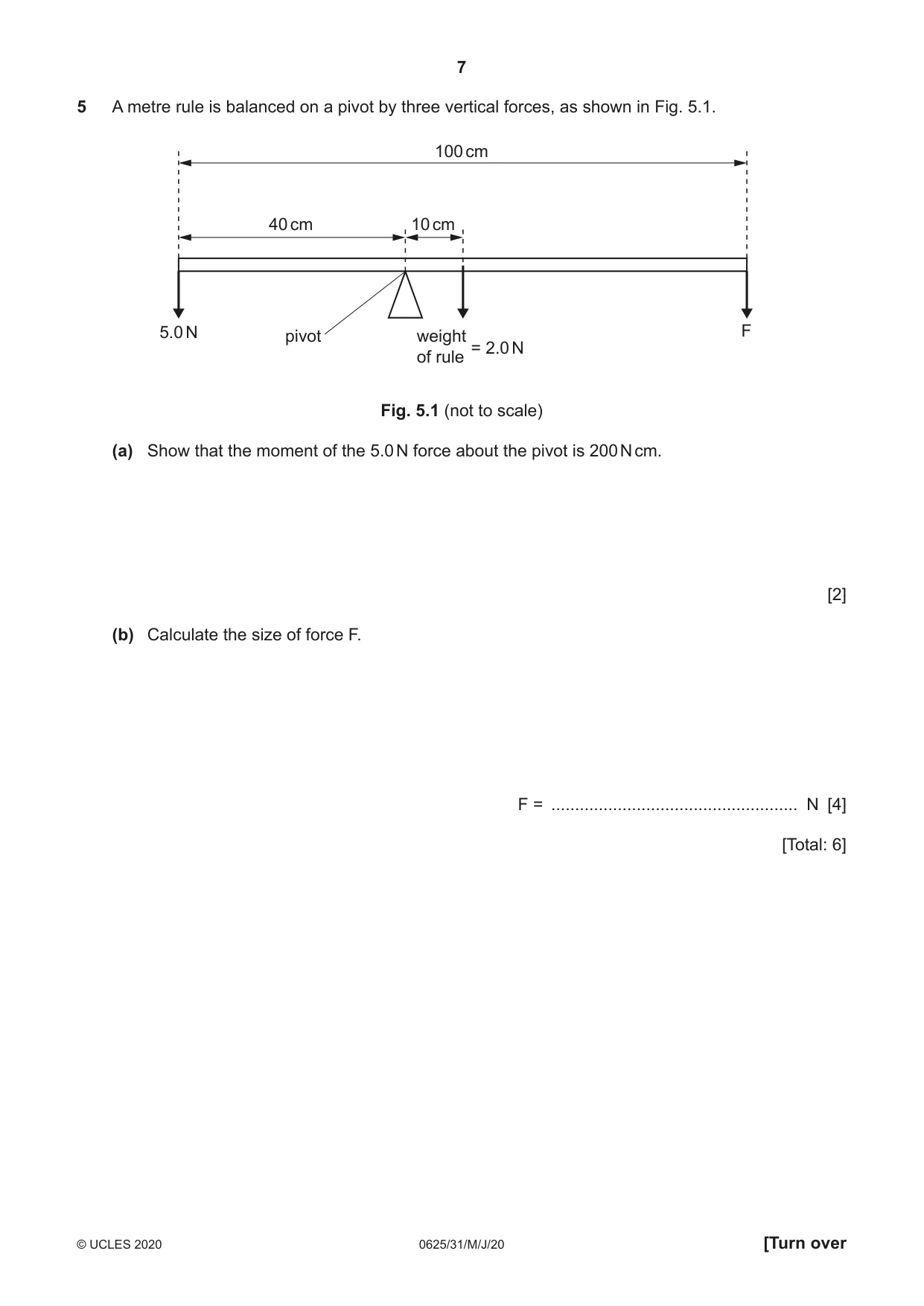
5 A metre rule is balanced on a pivot by three vertical forces, as shown in Fig. 5.1. 100 cm 40 cm 10 cm 5.0 N pivot weight F = 2.0 N of rule Fig. 5.1 (not to scale) (a) Show that the moment of the 5.0 N force about the pivot is 200 N cm. [2] (b) Calculate the size of force F. F = .................................................... N [4] [Total: 6]
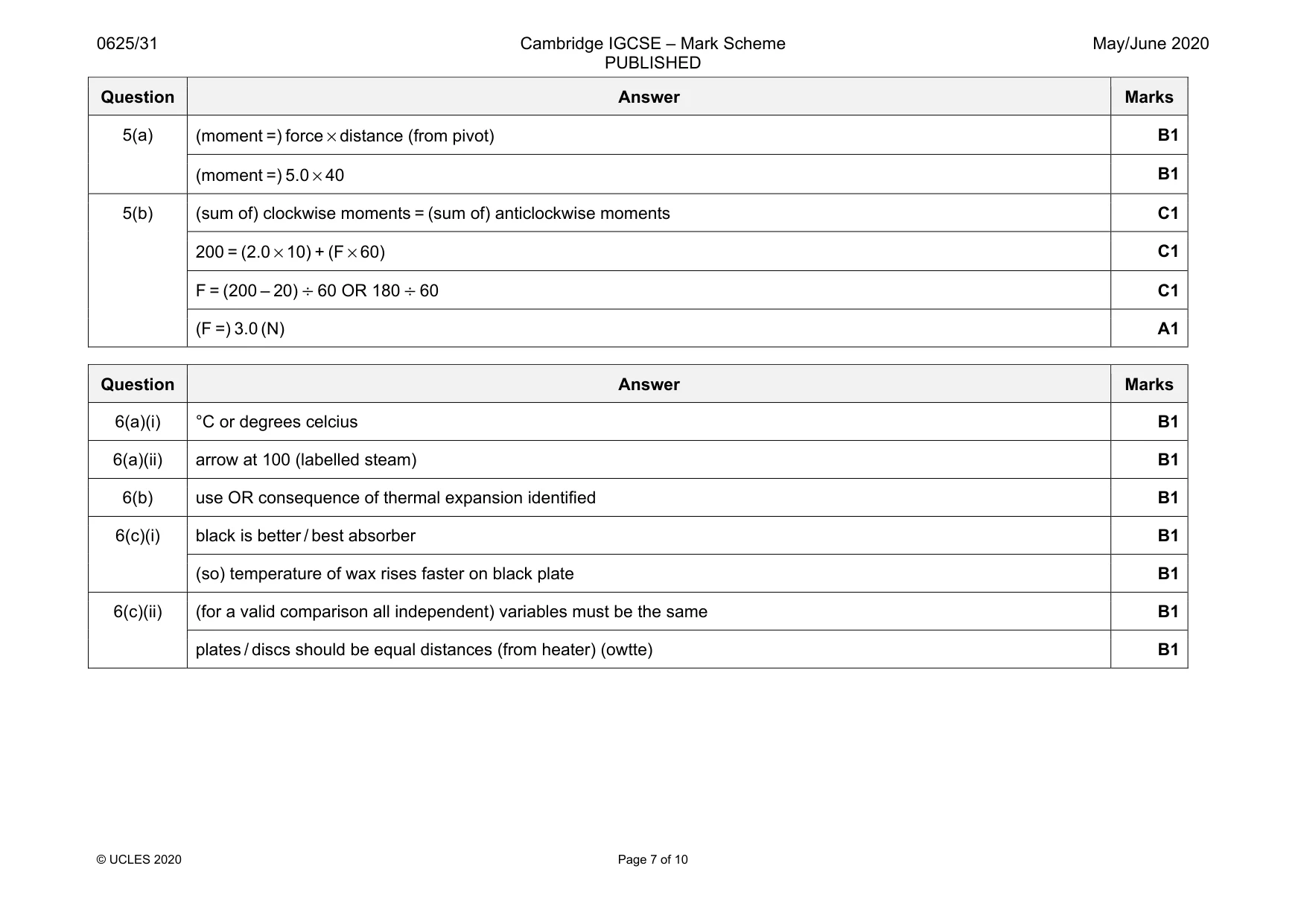
Mark scheme: 5(a) (moment =) force × distance (from pivot) B1 (moment =) 5.0 × 40 B1 5(b) (sum of) clockwise moments = (sum of) anticlockwise moments C1 200 = (2.0 × 10) + (F × 60) C1 F = (200 – 20) ÷ 60 OR 180 ÷ 60 C1 (F =) 3.0 (N) A1
Question 6
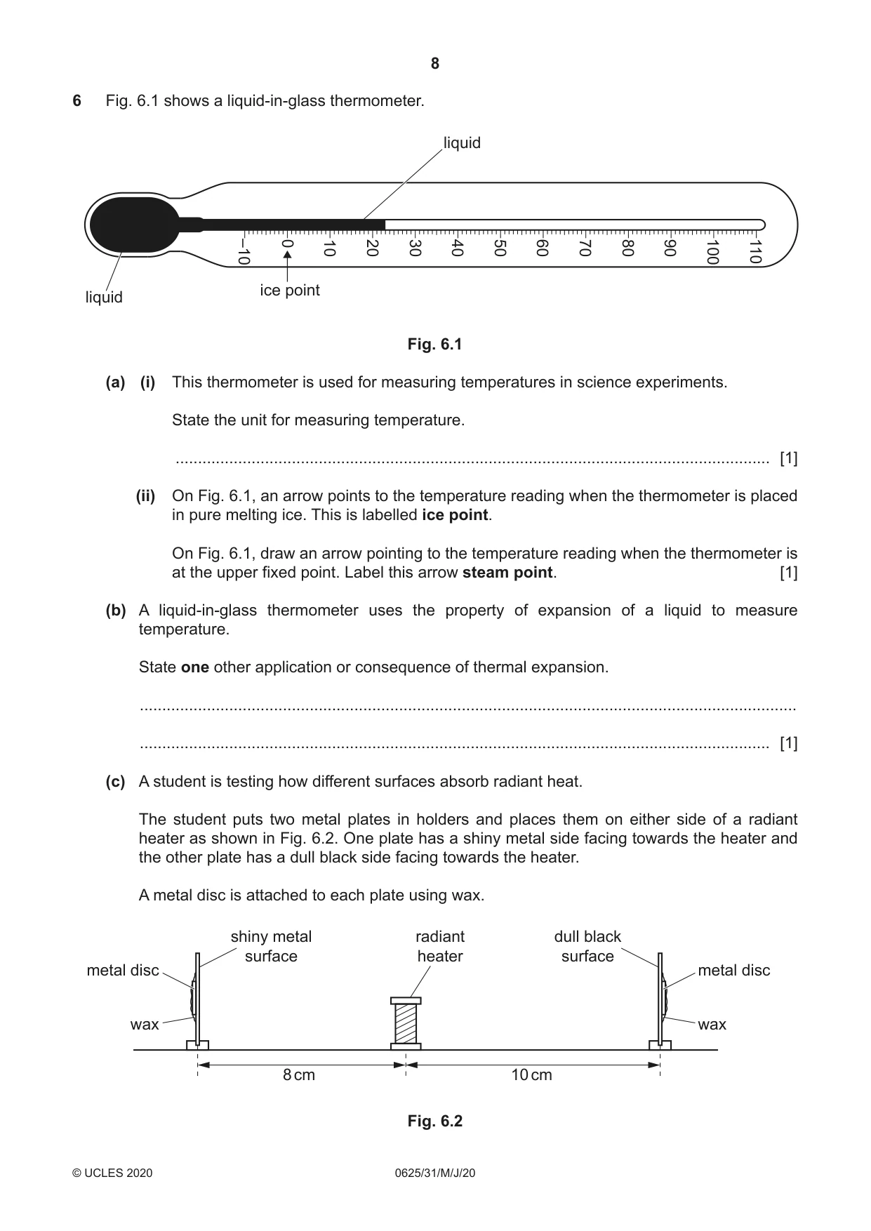
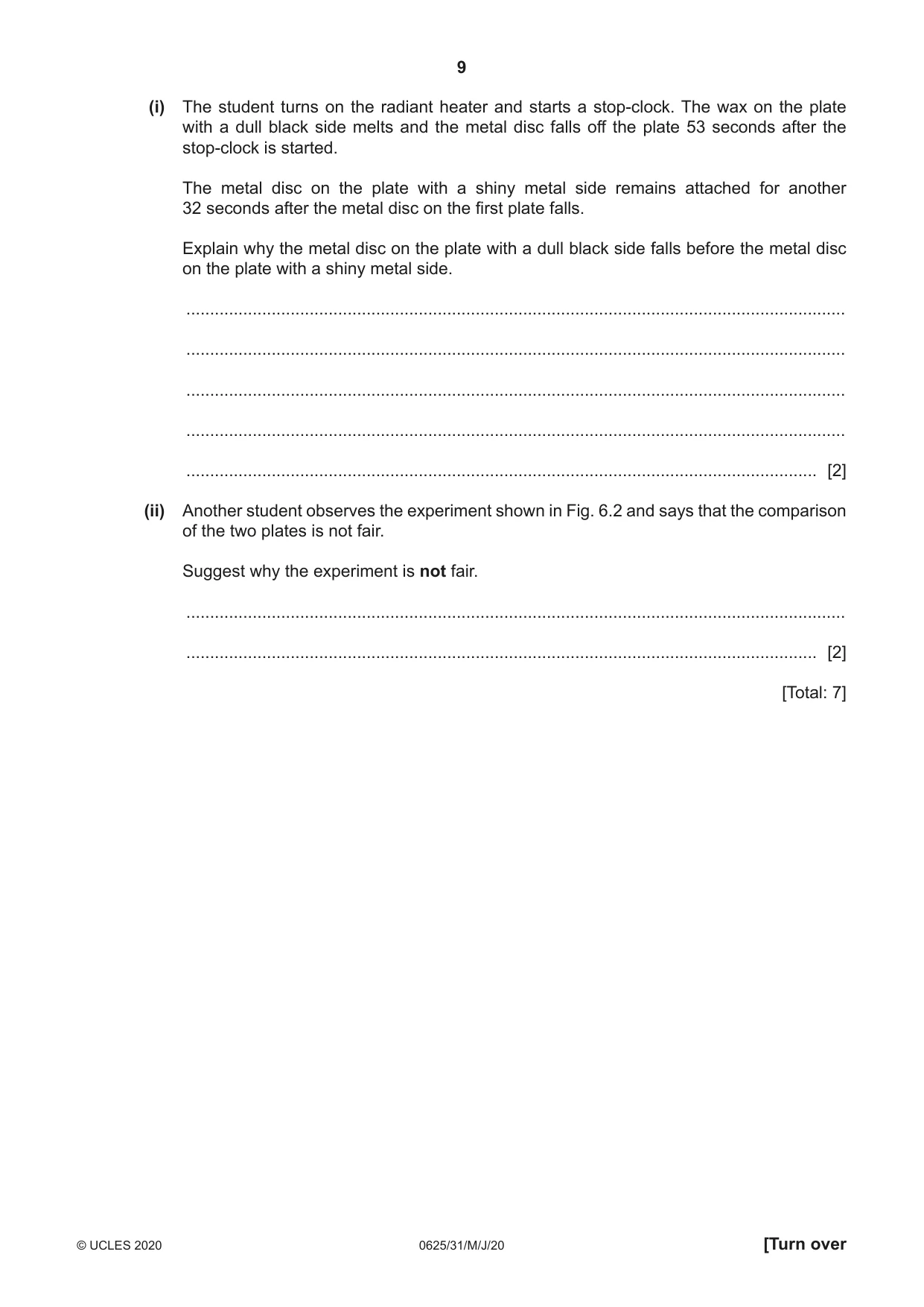
6 Fig. 6.1 shows a liquid-in-glass thermometer. liquid –10 0 10 20 30 40 50 60 70 80 90 100 110 ice point liquid Fig. 6.1 (a) (i) This thermometer is used for measuring temperatures in science experiments. State the unit for measuring temperature. ..................................................................................................................................... [1] (ii) On Fig. 6.1, an arrow points to the temperature reading when the thermometer is placed in pure melting ice. This is labelled ice point. On Fig. 6.1, draw an arrow pointing to the temperature reading when the thermometer is at the upper fixed point. Label this arrow steam point. [1] (b) A liquid-in-glass thermometer uses the property of expansion of a liquid to measure temperature. State one other application or consequence of thermal expansion. ................................................................................................................................................... ............................................................................................................................................. [1] (c) A student is testing how different surfaces absorb radiant heat. The student puts two metal plates in holders and places them on either side of a radiant heater as shown in Fig. 6.2. One plate has a shiny metal side facing towards the heater and the other plate has a dull black side facing towards the heater. A metal disc is attached to each plate using wax. shiny metal radiant dull black surface heater surface metal disc metal disc wax wax 8 cm 10 cm Fig. 6.2 (i) The student turns on the radiant heater and starts a stop-clock. The wax on the plate with a dull black side melts and the metal disc falls off the plate 53 seconds after the stop-clock is started. The metal disc on the plate with a shiny metal side remains attached for another 32 seconds after the metal disc on the first plate falls. Explain why the metal disc on the plate with a dull black side falls before the metal disc on the plate with a shiny metal side. ........................................................................................................................................... ........................................................................................................................................... ........................................................................................................................................... ........................................................................................................................................... ..................................................................................................................................... [2] (ii) Another student observes the experiment shown in Fig. 6.2 and says that the comparison of the two plates is not fair. Suggest why the experiment is not fair. ........................................................................................................................................... ..................................................................................................................................... [2] [Total: 7]
Mark scheme: 6(a)(i) °C or degrees celcius B1 6(a)(ii) arrow at 100 (labelled steam) B1 6(b) use OR consequence of thermal expansion identified B1 6(c)(i) black is better / best absorber B1 (so) temperature of wax rises faster on black plate B1 6(c)(ii) (for a valid comparison all independent) variables must be the same B1 plates / discs should be equal distances (from heater) (owtte) B1
Q7 · A ray of light striking a plane mirror at point P
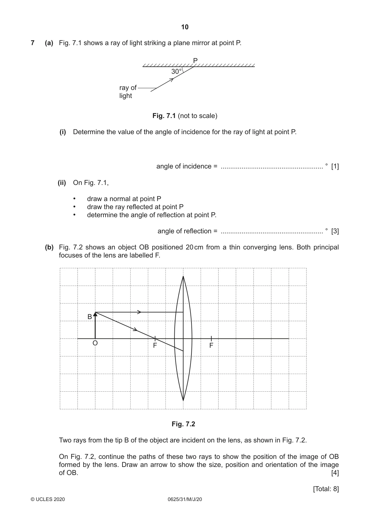
7 (a) Fig. 7.1 shows a ray of light striking a plane mirror at point P. P 30° ray of light Fig. 7.1 (not to scale) (i) Determine the value of the angle of incidence for the ray of light at point P. angle of incidence = ...................................................... ° [1] (ii) On Fig. 7.1, • draw a normal at point P • draw the ray reflected at point P • determine the angle of reflection at point P. angle of reflection = ...................................................... ° [3] (b) Fig. 7.2 shows an object OB positioned 20 cm from a thin converging lens. Both principal focuses of the lens are labelled F. B O F F Fig. 7.2 Two rays from the tip B of the object are incident on the lens, as shown in Fig. 7.2. On Fig. 7.2, continue the paths of these two rays to show the position of the image of OB formed by the lens. Draw an arrow to show the size, position and orientation of the image of OB. [4] [Total: 8]
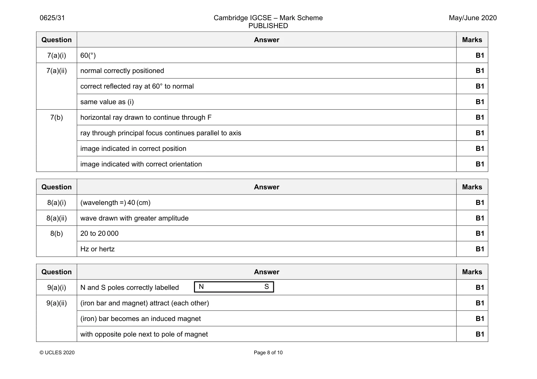
Mark scheme: 7(a)(i) 60(°) B1 7(a)(ii) normal correctly positioned B1 correct reflected ray at 60° to normal B1 same value as (i) B1 7(b) horizontal ray drawn to continue through F B1 ray through principal focus continues parallel to axis B1 image indicated in correct position B1 image indicated with correct orientation B1
Q8 · The pressure at one instant along part of a sound wave
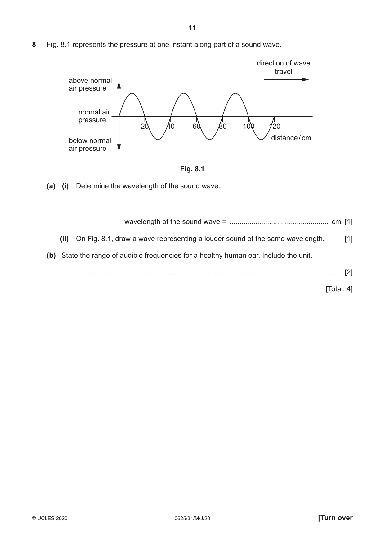
8 Fig. 8.1 represents the pressure at one instant along part of a sound wave. direction of wave travel above normal air pressure normal air pressure 20 40 60 80 100 120 distance / cm below normal air pressure Fig. 8.1 (a) (i) Determine the wavelength of the sound wave. wavelength of the sound wave = .................................................. cm [1] (ii) On Fig. 8.1, draw a wave representing a louder sound of the same wavelength. [1] (b) State the range of audible frequencies for a healthy human ear. Include the unit. ............................................................................................................................................. [2] [Total: 4]
Mark scheme: 8(a)(i) (wavelength =) 40 (cm) B1 8(a)(ii) wave drawn with greater amplitude B1 8(b) 20 to 20 000 B1 Hz or hertz B1
Q9 · The magnetic field pattern around a bar magnet
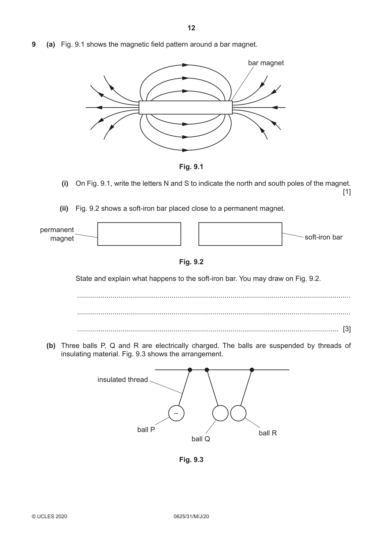
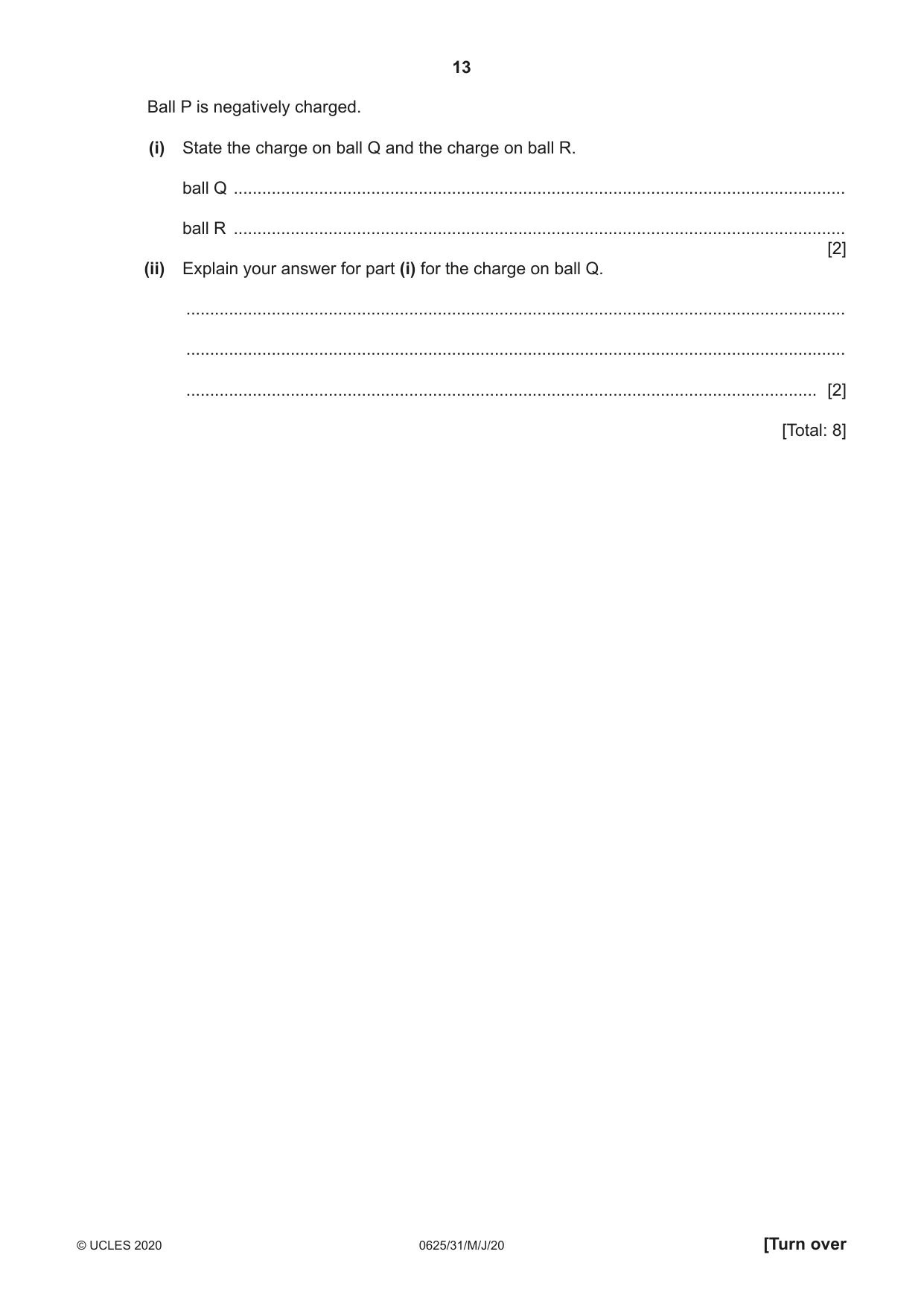
9 (a) Fig. 9.1 shows the magnetic field pattern around a bar magnet. bar magnet Fig. 9.1 (i) On Fig. 9.1, write the letters N and S to indicate the north and south poles of the magnet. [1] (ii) Fig. 9.2 shows a soft-iron bar placed close to a permanent magnet. permanent magnet soft-iron bar Fig. 9.2 State and explain what happens to the soft-iron bar. You may draw on Fig. 9.2. ........................................................................................................................................... ........................................................................................................................................... ..................................................................................................................................... [3] (b) Three balls P, Q and R are electrically charged. The balls are suspended by threads of insulating material. Fig. 9.3 shows the arrangement. insulated thread – ball P ball R ball Q Fig. 9.3 Ball P is negatively charged. (i) State the charge on ball Q and the charge on ball R. ball Q ................................................................................................................................. ball R ................................................................................................................................. [2] (ii) Explain your answer for part (i) for the charge on ball Q. ........................................................................................................................................... ........................................................................................................................................... ..................................................................................................................................... [2] [Total: 8]
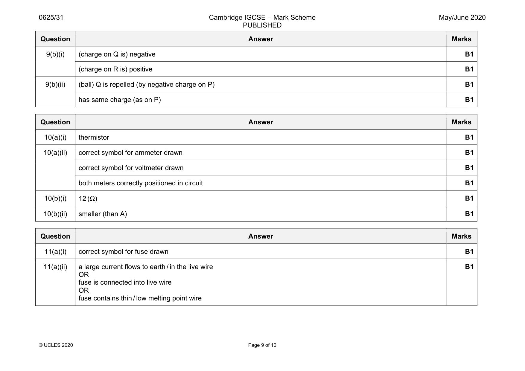
Mark scheme: 9(a)(i) N and S poles correctly labelled B1 9(a)(ii) (iron bar and magnet) attract (each other) B1 (iron) bar becomes an induced magnet B1 with opposite pole next to pole of magnet B1 Question Answer Marks 9(b)(i) (charge on Q is) negative B1 (charge on R is) positive B1 9(b)(ii) (ball) Q is repelled (by negative charge on P) B1 has same charge (as on P) B1
Q10 · A student investigates the electrical resistance of some components
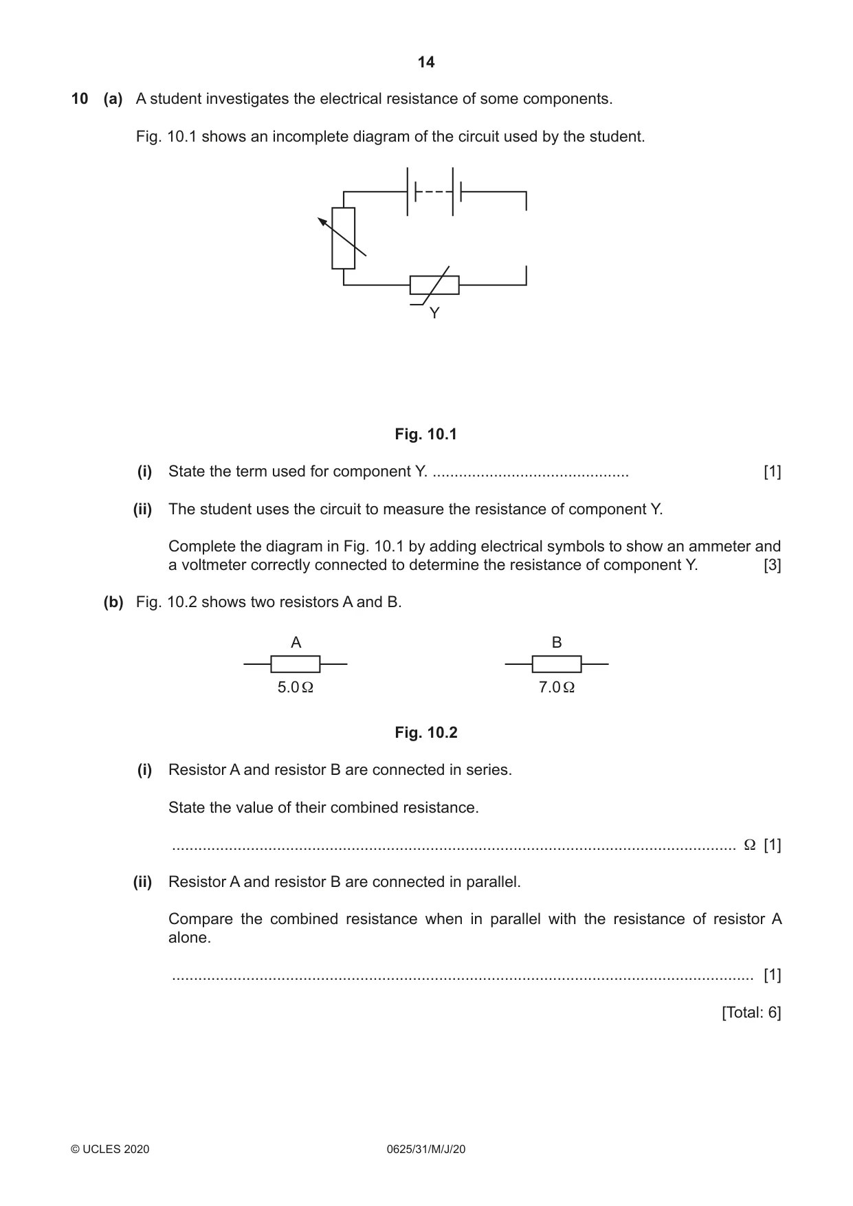
10 (a) A student investigates the electrical resistance of some components. Fig. 10.1 shows an incomplete diagram of the circuit used by the student. Y Fig. 10.1 (i) State the term used for component Y. ............................................. [1] (ii) The student uses the circuit to measure the resistance of component Y. Complete the diagram in Fig. 10.1 by adding electrical symbols to show an ammeter and a voltmeter correctly connected to determine the resistance of component Y. [3] (b) Fig. 10.2 shows two resistors A and B. A B 5.0 Ω 7.0 Ω Fig. 10.2 (i) Resistor A and resistor B are connected in series. State the value of their combined resistance. ................................................................................................................................. Ω [1] (ii) Resistor A and resistor B are connected in parallel. Compare the combined resistance when in parallel with the resistance of resistor A alone. ..................................................................................................................................... [1] [Total: 6]
Mark scheme: 10(a)(i) thermistor B1 10(a)(ii) correct symbol for ammeter drawn B1 correct symbol for voltmeter drawn B1 both meters correctly positioned in circuit B1 10(b)(i) 12 (Ω) B1 10(b)(ii) smaller (than A) B1
Q11 · A teacher uses a power supply in a metal case
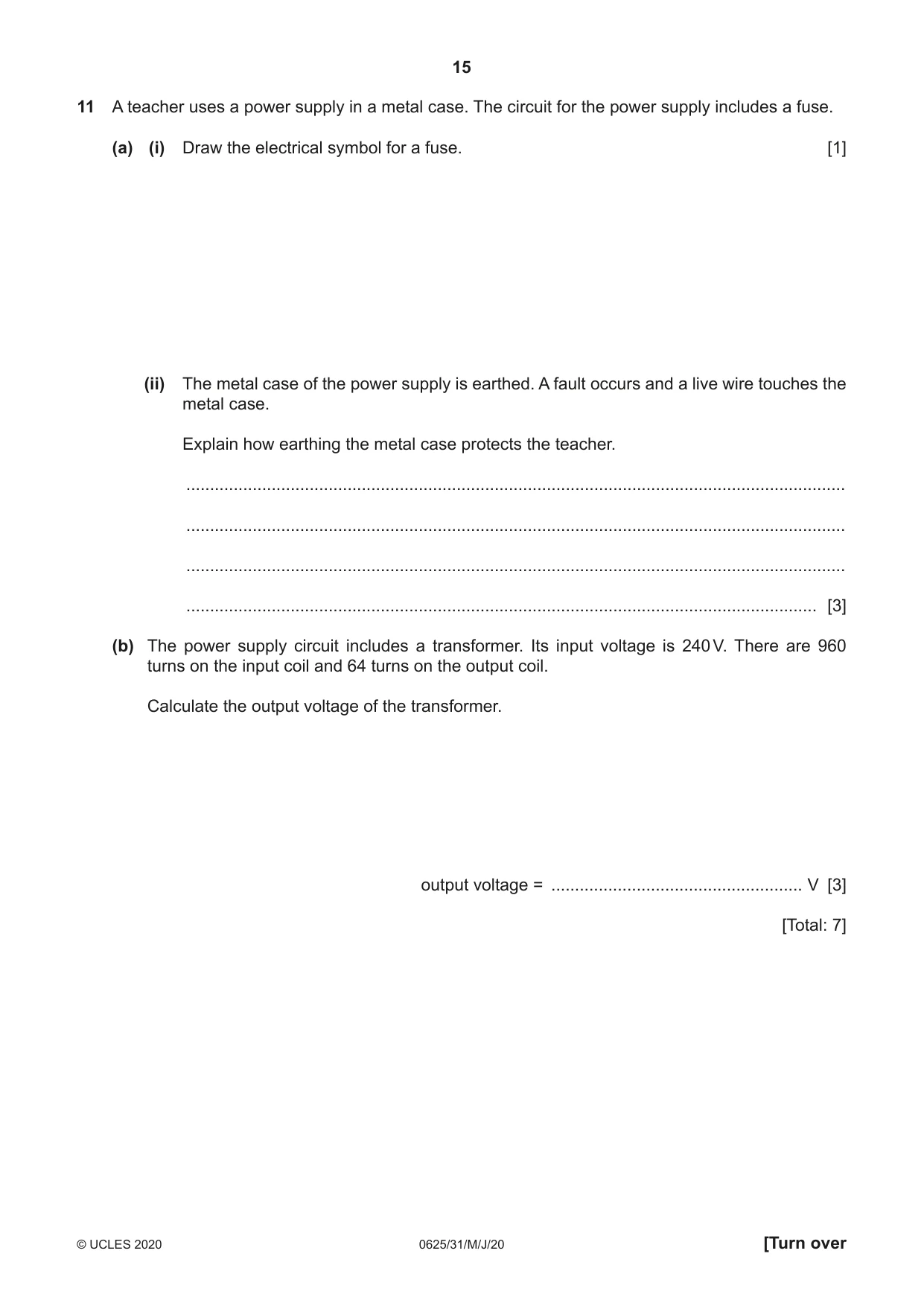
11 A teacher uses a power supply in a metal case. The circuit for the power supply includes a fuse. (a) (i) Draw the electrical symbol for a fuse. [1] (ii) The metal case of the power supply is earthed. A fault occurs and a live wire touches the metal case. Explain how earthing the metal case protects the teacher. ........................................................................................................................................... ........................................................................................................................................... ........................................................................................................................................... ..................................................................................................................................... [3] (b) The power supply circuit includes a transformer. Its input voltage is 240 V. There are 960 turns on the input coil and 64 turns on the output coil. Calculate the output voltage of the transformer. output voltage = ..................................................... V [3] [Total: 7]
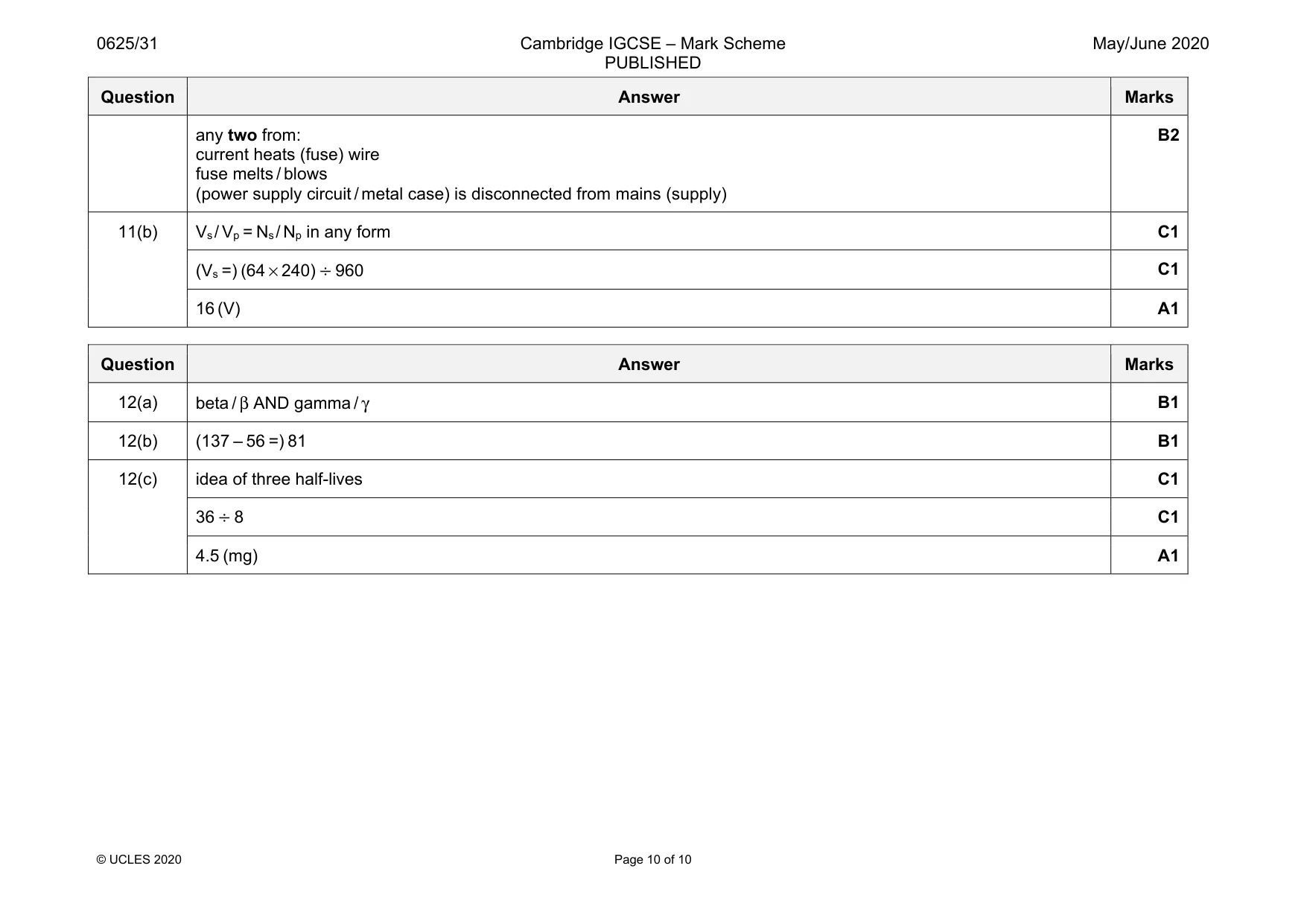
Mark scheme: 11(a)(i) correct symbol for fuse drawn B1 11(a)(ii) a large current flows to earth / in the live wire OR fuse is connected into live wire OR fuse contains thin / low melting point wire B1 Question Answer Marks any two from: current heats (fuse) wire fuse melts / blows (power supply circuit / metal case) is disconnected from mains (supply) B2 11(b) Vs/ Vp = Ns/ Np in any form C1 (Vs =) (64 × 240) ÷ 960 C1 16 (V) A1
Q12 · Radioactive sources emit α-(alpha), β-(beta) and γ-(gamma) radiations
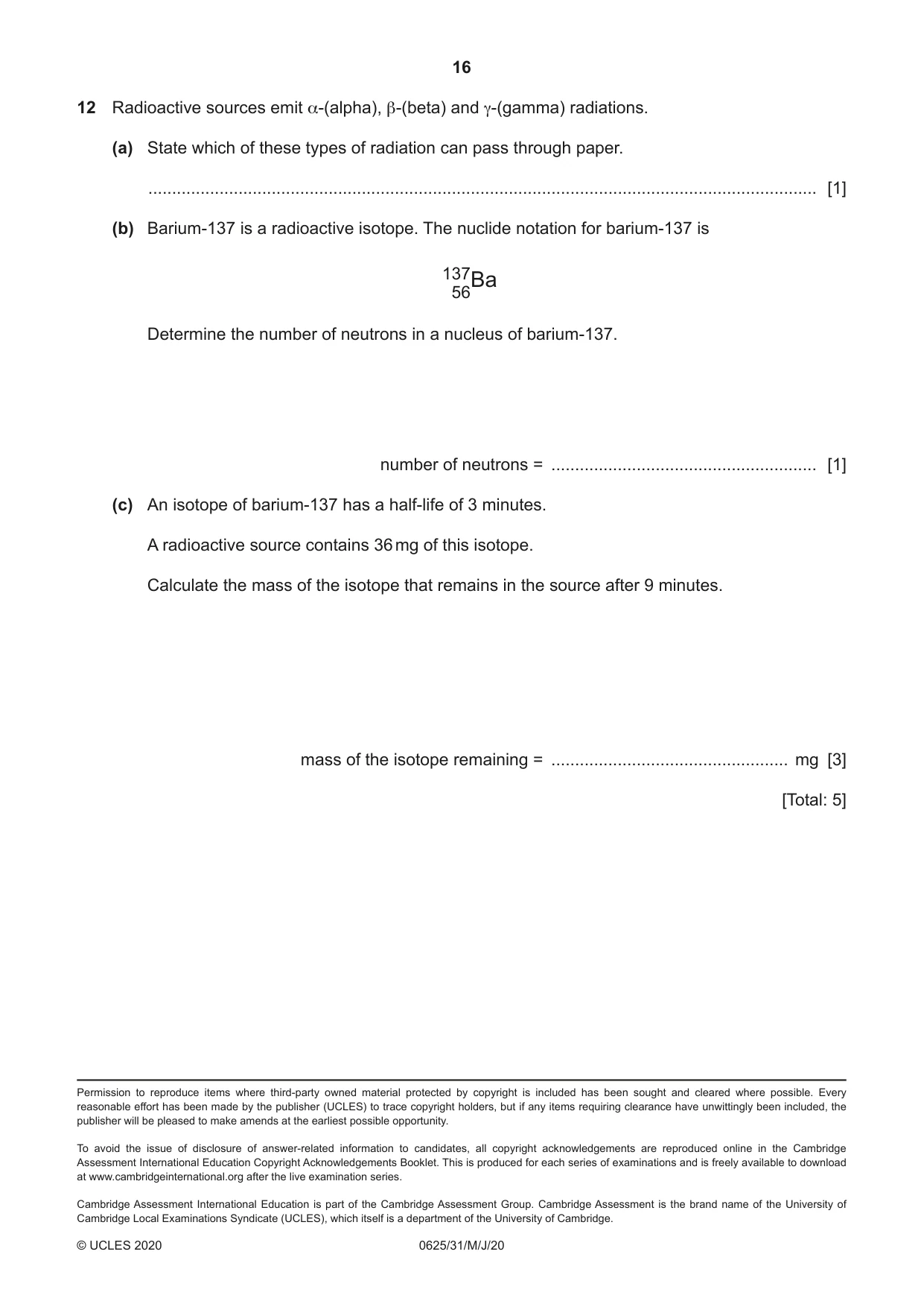
12 Radioactive sources emit α-(alpha), β-(beta) and γ-(gamma) radiations. (a) State which of these types of radiation can pass through paper. ............................................................................................................................................. [1] (b) Barium-137 is a radioactive isotope. The nuclide notation for barium-137 is 13756Ba Determine the number of neutrons in a nucleus of barium-137. number of neutrons = ........................................................ [1] (c) An isotope of barium-137 has a half-life of 3 minutes. A radioactive source contains 36 mg of this isotope. Calculate the mass of the isotope that remains in the source after 9 minutes. mass of the isotope remaining = .................................................. mg [3] [Total: 5]
Mark scheme: 12(a) beta / β AND gamma / γ B1 12(b) (137 – 56 =) 81 B1 12(c) idea of three half-lives C1 36 ÷ 8 C1 4.5 (mg) A1
What was in this paper
The subtopics covered by these 12 questions, and how many questions each got. Open one in a new tab to see every Cambridge question on it.