Cambridge IGCSE Physics 0625 — 2006 May/June Paper 3 · Variant 1
0625/31/M/J/06 · 11 questions · 80 marks · ≈90 min
The question paper and its mark scheme, free to read here and free to download. This is Cambridge’s own paper, exactly as it was sat.
Question paper12 pages
Mark scheme4 pages
Answers below. Sit the paper first if you are practising.
Questions as text
Q1 · A bus travels from one bus stop to the next
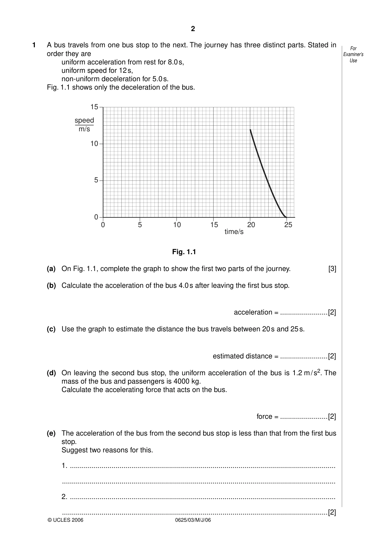
1 A bus travels from one bus stop to the next. The journey has three distinct parts. Stated in For order they are Examiner’s uniform acceleration from rest for 8.0 s, Use uniform speed for 12 s, non-uniform deceleration for 5.0 s. Fig. 1.1 shows only the deceleration of the bus. 15 speed m/s 10 5 0 0 5 10 15 20 25 time/s Fig. 1.1 (a) On Fig. 1.1, complete the graph to show the first two parts of the journey. [3] (b) Calculate the acceleration of the bus 4.0 s after leaving the first bus stop. acceleration = ........................[2] (c) Use the graph to estimate the distance the bus travels between 20 s and 25 s. estimated distance = ........................[2] (d) On leaving the second bus stop, the uniform acceleration of the bus is 1.2 m / s2. The mass of the bus and passengers is 4000 kg. Calculate the accelerating force that acts on the bus. force = ........................[2] (e) The acceleration of the bus from the second bus stop is less than that from the first bus stop. Suggest two reasons for this. 1. ...................................................................................................................................... .......................................................................................................................................... 2. ...................................................................................................................................... ......................................................................................................................................[2]
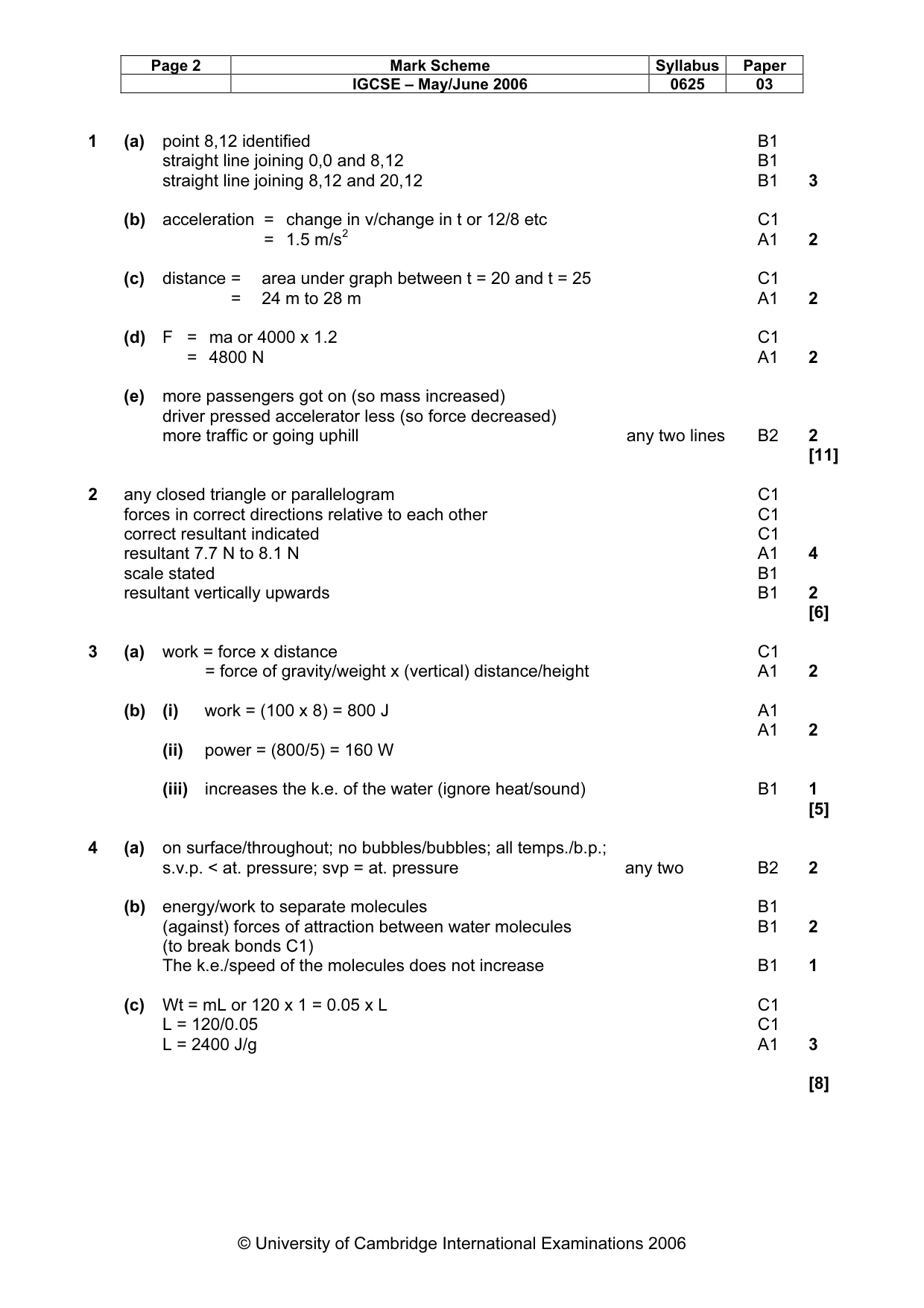
Mark scheme: 1 (a) point 8,12 identified B1 straight line joining 0,0 and 8,12 B1 straight line joining 8,12 and 20,12 B1 3 (b) acceleration = change in v/change in t or 12/8 etc C1 = 1.5 m/s2 A1 2 (c) distance = area under graph between t = 20 and t = 25 C1 = 24 m to 28 m A1 2 (d) F = ma or 4000 x 1.2 C1 = 4800 N A1 2 (e) more passengers got on (so mass increased) driver pressed accelerator less (so force decreased) more traffic or going uphill any two lines B2 2 [11]
Q2 · A student sets up the apparatus shown in Fig
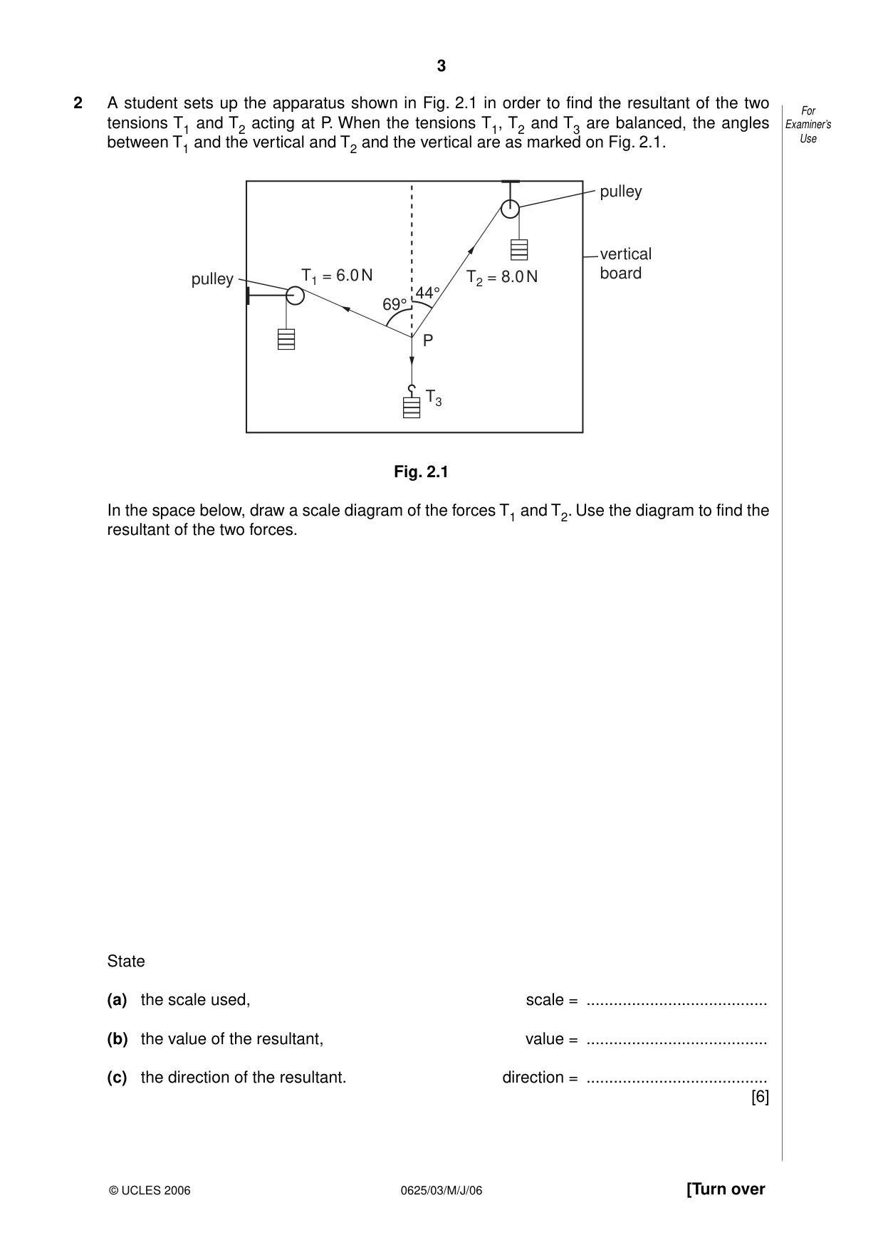
2 A student sets up the apparatus shown in Fig. 2.1 in order to find the resultant of the two For Examiner’s tensions T1 and T2 acting at P. When the tensions T1, T2 and T3 are balanced, the angles between T1 and the vertical and T2 and the vertical are as marked on Fig. 2.1. Use pulley vertical pulley T1 = 6.0 N T2 = 8.0 N board 44° 69° P T3 Fig. 2.1 In the space below, draw a scale diagram of the forces T1 and T2. Use the diagram to find the resultant of the two forces. State (a) the scale used, scale = ........................................ (b) the value of the resultant, value = ........................................ (c) the direction of the resultant. direction = ........................................ [6]
Mark scheme: 2 any closed triangle or parallelogram C1 forces in correct directions relative to each other C1 correct resultant indicated C1 resultant 7.7 N to 8.1 N A1 4 scale stated B1 resultant vertically upwards B1 2 [6]
Q3 · An electric pump is used to raise water from a well, as shown in Fig
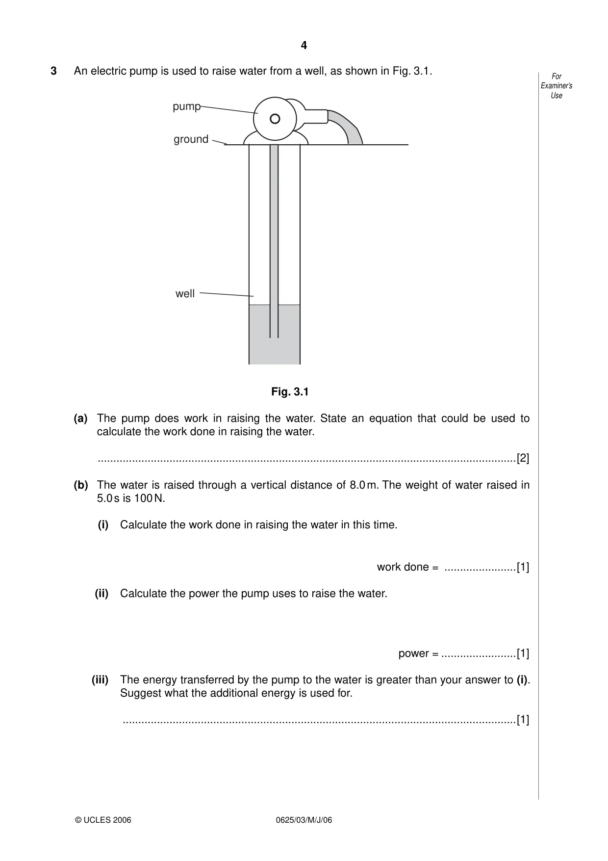
3 An electric pump is used to raise water from a well, as shown in Fig. 3.1. For Examiner’s Use pump ground well Fig. 3.1 (a) The pump does work in raising the water. State an equation that could be used to calculate the work done in raising the water. ......................................................................................................................................[2] (b) The water is raised through a vertical distance of 8.0 m. The weight of water raised in 5.0 s is 100 N. (i) Calculate the work done in raising the water in this time. work done = .......................[1] (ii) Calculate the power the pump uses to raise the water. power = ........................[1] (iii) The energy transferred by the pump to the water is greater than your answer to (i). Suggest what the additional energy is used for. ..............................................................................................................................[1]
Mark scheme: 3 (a) work = force x distance C1 = force of gravity/weight x (vertical) distance/height A1 2 (b) (i) work = (100 x 8) = 800 J A1 A1 2 (ii) power = (800/5) = 160 W (iii) increases the k.e. of the water (ignore heat/sound) B1 1 [5]
Q4 · State two differences between evaporation of water and boiling of water
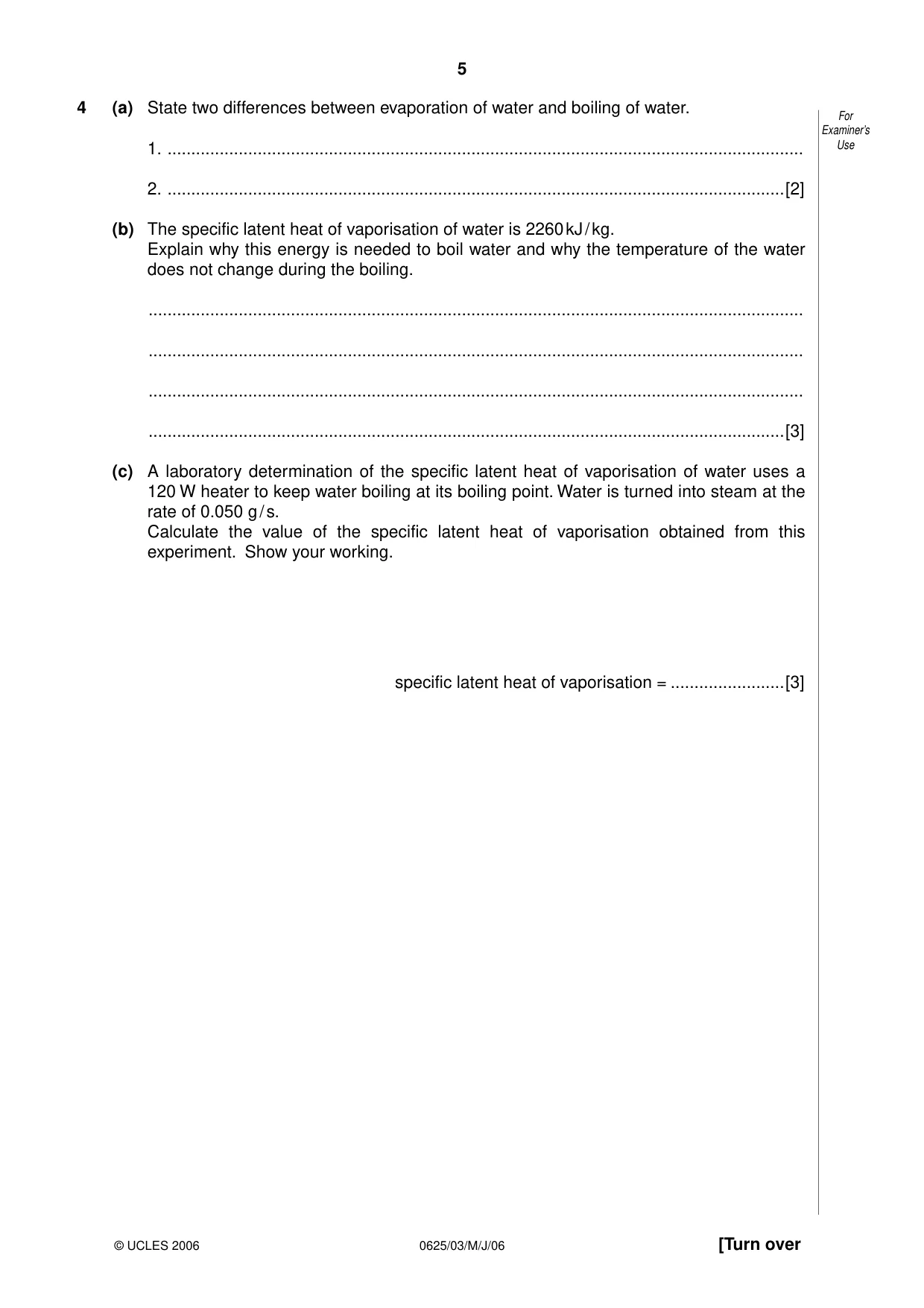
4 (a) State two differences between evaporation of water and boiling of water. For Examiner’s 1. ...................................................................................................................................... Use 2. ..................................................................................................................................[2] (b) The specific latent heat of vaporisation of water is 2260 kJ / kg. Explain why this energy is needed to boil water and why the temperature of the water does not change during the boiling. .......................................................................................................................................... .......................................................................................................................................... .......................................................................................................................................... ......................................................................................................................................[3] (c) A laboratory determination of the specific latent heat of vaporisation of water uses a 120 W heater to keep water boiling at its boiling point. Water is turned into steam at the rate of 0.050 g / s. Calculate the value of the specific latent heat of vaporisation obtained from this experiment. Show your working. specific latent heat of vaporisation = ........................[3]
Mark scheme: 4 (a) on surface/throughout; no bubbles/bubbles; all temps./b.p.; s.v.p. < at. pressure; svp = at. pressure any two B2 2 (b) energy/work to separate molecules B1 (against) forces of attraction between water molecules B1 2 (to break bonds C1) The k.e./speed of the molecules does not increase B1 1 (c) Wt = mL or 120 x 1 = 0.05 x L C1 L = 120/0.05 C1 L = 2400 J/g A1 3 [8] IGCSE – May/June 2006 0625 03
Q5 · A tank used for evaporating salt solution to produce crystals
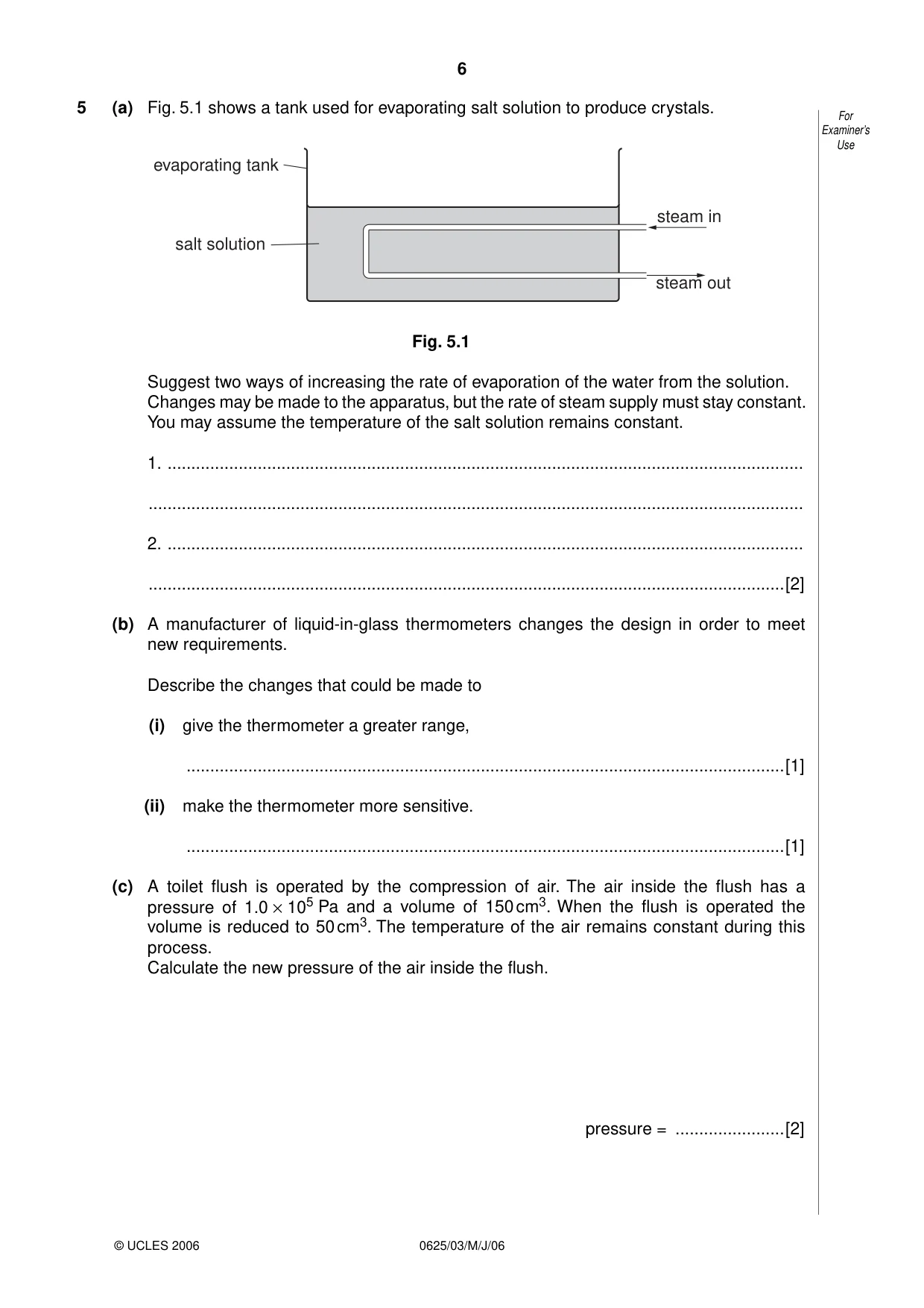
5 (a) Fig. 5.1 shows a tank used for evaporating salt solution to produce crystals. For Examiner’s Use evaporating tank steam in salt solution steam out Fig. 5.1 Suggest two ways of increasing the rate of evaporation of the water from the solution. Changes may be made to the apparatus, but the rate of steam supply must stay constant. You may assume the temperature of the salt solution remains constant. 1. ...................................................................................................................................... .......................................................................................................................................... 2. ...................................................................................................................................... ......................................................................................................................................[2] (b) A manufacturer of liquid-in-glass thermometers changes the design in order to meet new requirements. Describe the changes that could be made to (i) give the thermometer a greater range, ..............................................................................................................................[1] (ii) make the thermometer more sensitive. ..............................................................................................................................[1] (c) A toilet flush is operated by the compression of air. The air inside the flush has a pressure of 1.0 × 10⁵ Pa and a volume of 150 cm3. When the flush is operated the volume is reduced to 50 cm3. The temperature of the air remains constant during this process. Calculate the new pressure of the air inside the flush. pressure = .......................[2]
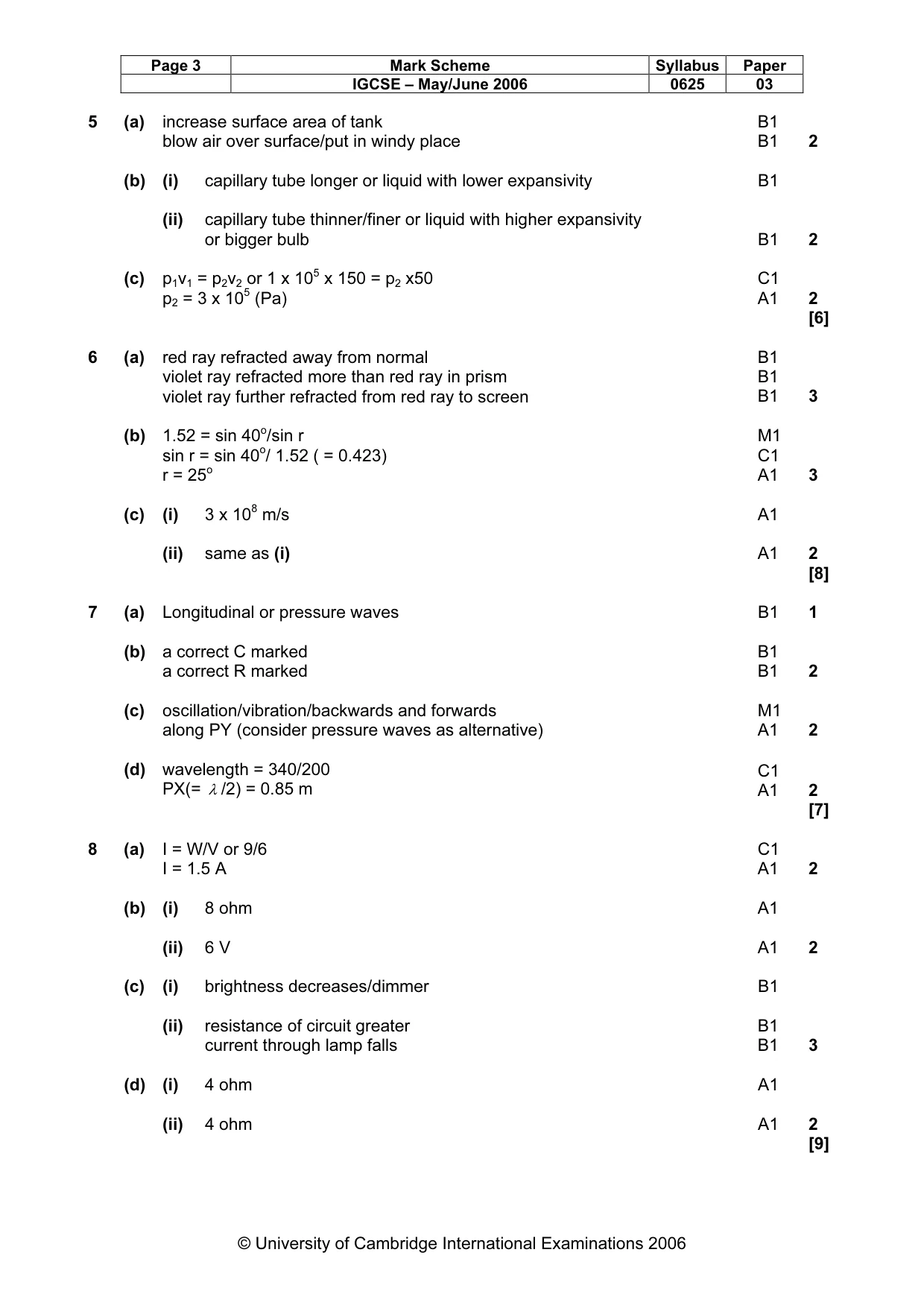
Mark scheme: 5 (a) increase surface area of tank B1 blow air over surface/put in windy place B1 2 (b) (i) capillary tube longer or liquid with lower expansivity B1 (ii) capillary tube thinner/finer or liquid with higher expansivity or bigger bulb B1 2 (c) p1v1 = p2v2 or 1 x 105 x 150 = p2 x50 C1 p2 = 3 x 10⁵ (Pa) A1 2 [6]
Q6 · White light incident at P on a glass prism
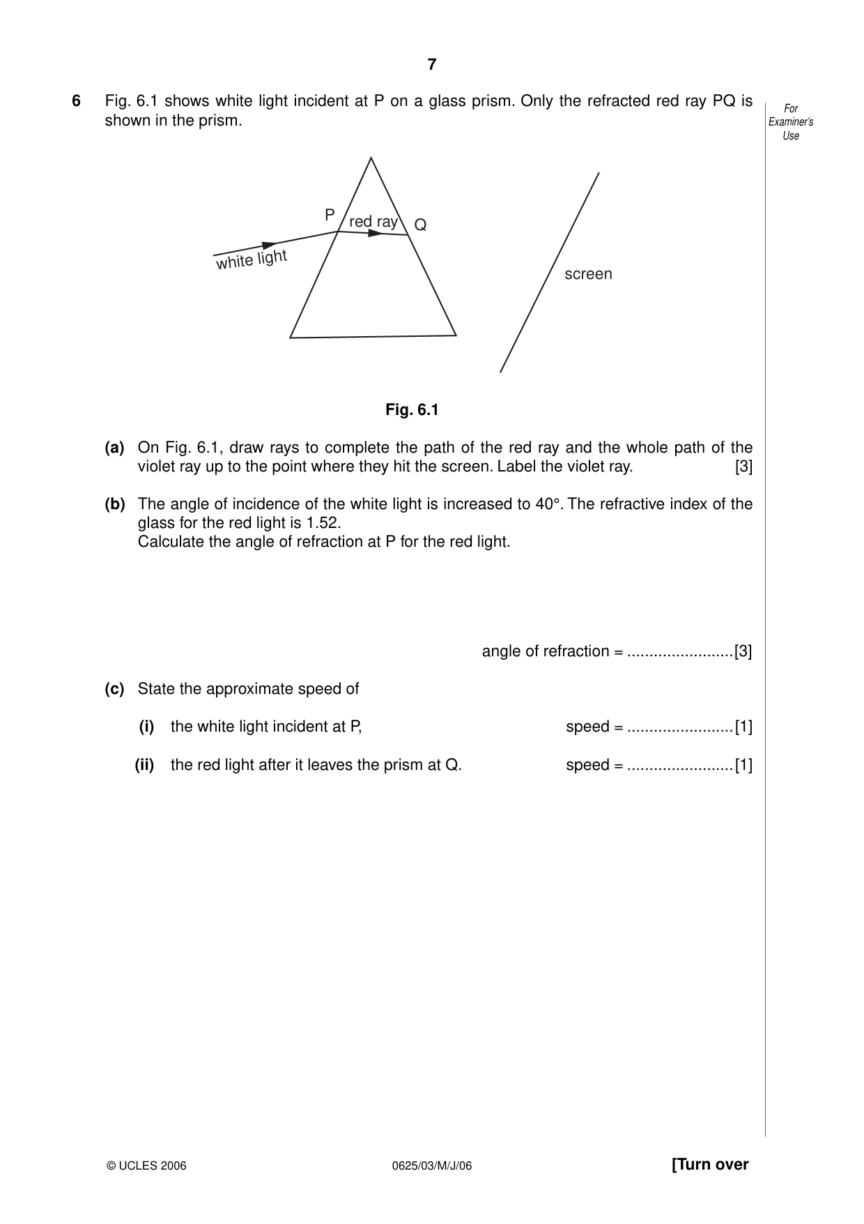
6 Fig. 6.1 shows white light incident at P on a glass prism. Only the refracted red ray PQ is For shown in the prism. Examiner’s Use P red ray Q light white screen Fig. 6.1 (a) On Fig. 6.1, draw rays to complete the path of the red ray and the whole path of the violet ray up to the point where they hit the screen. Label the violet ray. [3] (b) The angle of incidence of the white light is increased to 40°. The refractive index of the glass for the red light is 1.52. Calculate the angle of refraction at P for the red light. angle of refraction = ........................[3] (c) State the approximate speed of (i) the white light incident at P, speed = ........................[1] (ii) the red light after it leaves the prism at Q. speed = ........................[1]
Mark scheme: 6 (a) red ray refracted away from normal B1 violet ray refracted more than red ray in prism B1 violet ray further refracted from red ray to screen B1 3 (b) 1.52 = sin 40o/sin r M1 sin r = sin 40o/ 1.52 ( = 0.423) C1 r = 25o A1 3 (c) (i) 3 x 10⁸ m/s A1 (ii) same as (i) A1 2 [8]
Q7 · How the air pressure at one instant varies with distance along the path of a For…
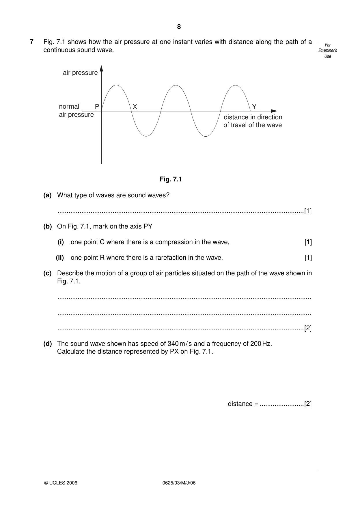
7 Fig. 7.1 shows how the air pressure at one instant varies with distance along the path of a For continuous sound wave. Examiner’s Use air pressure normal P X Y air pressure distance in direction of travel of the wave Fig. 7.1 (a) What type of waves are sound waves? ......................................................................................................................................[1] (b) On Fig. 7.1, mark on the axis PY (i) one point C where there is a compression in the wave, [1] (ii) one point R where there is a rarefaction in the wave. [1] (c) Describe the motion of a group of air particles situated on the path of the wave shown in Fig. 7.1. .......................................................................................................................................... .......................................................................................................................................... ......................................................................................................................................[2] (d) The sound wave shown has speed of 340 m / s and a frequency of 200 Hz. Calculate the distance represented by PX on Fig. 7.1. distance = ........................[2]
Mark scheme: 7 (a) Longitudinal or pressure waves B1 1 (b) a correct C marked B1 a correct R marked B1 2 (c) oscillation/vibration/backwards and forwards M1 along PY (consider pressure waves as alternative) A1 2 (d) wavelength = 340/200 C1 PX(= λ /2) = 0.85 m A1 2 [7]
Question 8
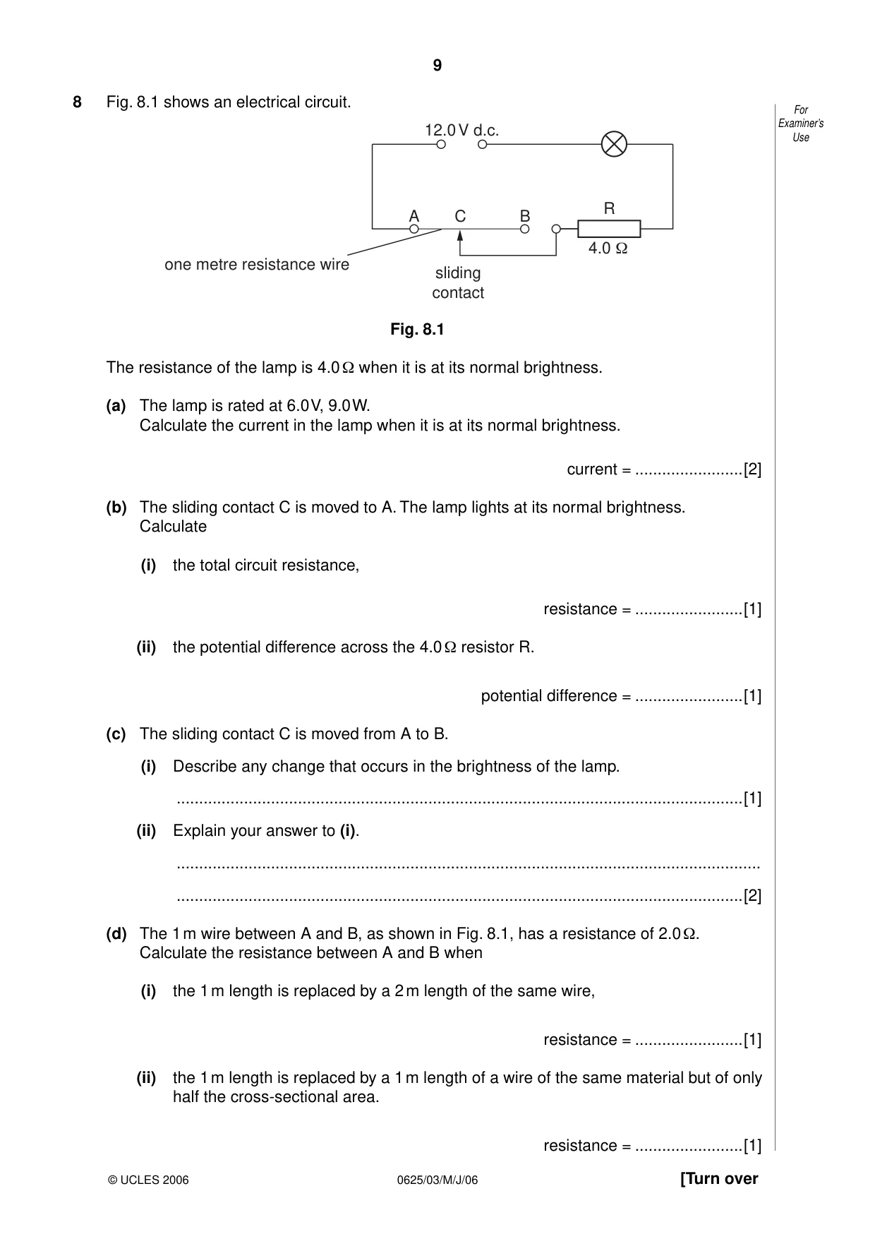
8 Fig. 8.1 shows an electrical circuit. For 12.0 V d.c. Examiner’s Use R A C B 4.0 Ω one metre resistance wire sliding contact Fig. 8.1 The resistance of the lamp is 4.0 Ω when it is at its normal brightness. (a) The lamp is rated at 6.0 V, 9.0 W. Calculate the current in the lamp when it is at its normal brightness. current = ........................[2] (b) The sliding contact C is moved to A. The lamp lights at its normal brightness. Calculate (i) the total circuit resistance, resistance = ........................[1] (ii) the potential difference across the 4.0 Ω resistor R. potential difference = ........................[1] (c) The sliding contact C is moved from A to B. (i) Describe any change that occurs in the brightness of the lamp. ..............................................................................................................................[1] (ii) Explain your answer to (i). .................................................................................................................................. ..............................................................................................................................[2] (d) The 1 m wire between A and B, as shown in Fig. 8.1, has a resistance of 2.0 Ω. Calculate the resistance between A and B when (i) the 1 m length is replaced by a 2 m length of the same wire, resistance = ........................[1] (ii) the 1 m length is replaced by a 1 m length of a wire of the same material but of only half the cross-sectional area. resistance = ........................[1]
Mark scheme: 8 (a) I = W/V or 9/6 C1 I = 1.5 A A1 2 (b) (i) 8 ohm A1 (ii) 6 V A1 2 (c) (i) brightness decreases/dimmer B1 (ii) resistance of circuit greater B1 current through lamp falls B1 3 (d) (i) 4 ohm A1 (ii) 4 ohm A1 2 [9] IGCSE – May/June 2006 0625 03
Q9 · A transformer is needed to step down a 240 V a.c
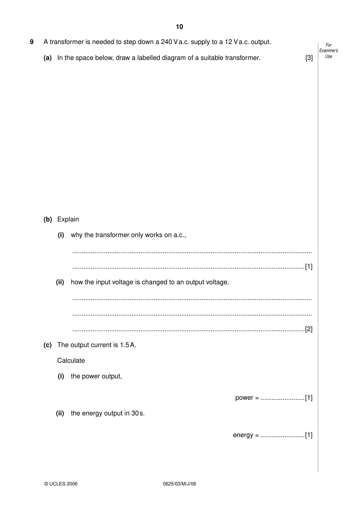
9 A transformer is needed to step down a 240 V a.c. supply to a 12 V a.c. output. For Examiner’s (a) In the space below, draw a labelled diagram of a suitable transformer. [3] Use (b) Explain (i) why the transformer only works on a.c., .................................................................................................................................. ..............................................................................................................................[1] (ii) how the input voltage is changed to an output voltage. .................................................................................................................................. .................................................................................................................................. ..............................................................................................................................[2] (c) The output current is 1.5 A. Calculate (i) the power output, power = ........................[1] (ii) the energy output in 30 s. energy = ........................[1]
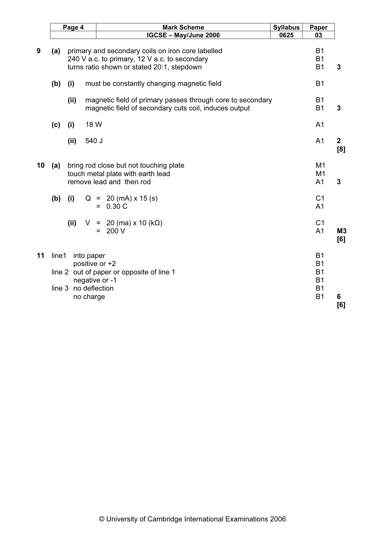
Mark scheme: 9 (a) primary and secondary coils on iron core labelled B1 240 V a.c. to primary, 12 V a.c. to secondary B1 turns ratio shown or stated 20:1, stepdown B1 3 (b) (i) must be constantly changing magnetic field B1 (ii) magnetic field of primary passes through core to secondary B1 magnetic field of secondary cuts coil, induces output B1 3 (c) (i) 18 W A1 (ii) 540 J A1 2 [8]
Q10 · A positively charged plastic rod, a metal plate resting on an insulator, For and a lead…
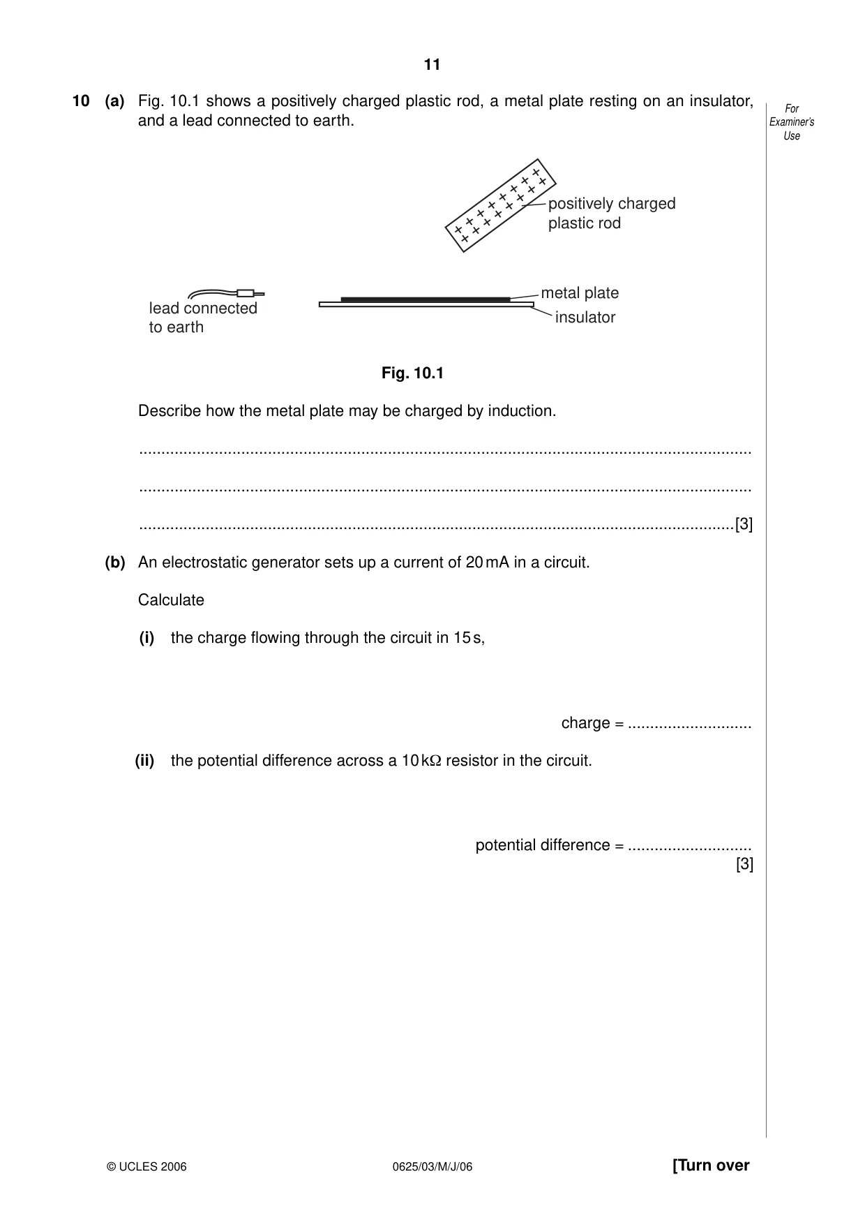
10 (a) Fig. 10.1 shows a positively charged plastic rod, a metal plate resting on an insulator, For and a lead connected to earth. Examiner’s Use positively charged plastic rod metal plate lead connected insulator to earth Fig. 10.1 Describe how the metal plate may be charged by induction. .......................................................................................................................................... .......................................................................................................................................... ......................................................................................................................................[3] (b) An electrostatic generator sets up a current of 20 mA in a circuit. Calculate (i) the charge flowing through the circuit in 15 s, charge = ............................ (ii) the potential difference across a 10 kΩ resistor in the circuit. potential difference = ............................ [3]
Mark scheme: 10 (a) bring rod close but not touching plate M1 touch metal plate with earth lead M1 remove lead and then rod A1 3 (b) (i) Q = 20 (mA) x 15 (s) C1 = 0.30 C A1 (ii) V = 20 (ma) x 10 (kΩ) C1 = 200 V A1 M3 [6]
Q11 · A beam of radiation that contains α-particles, β-particles and γ-rays
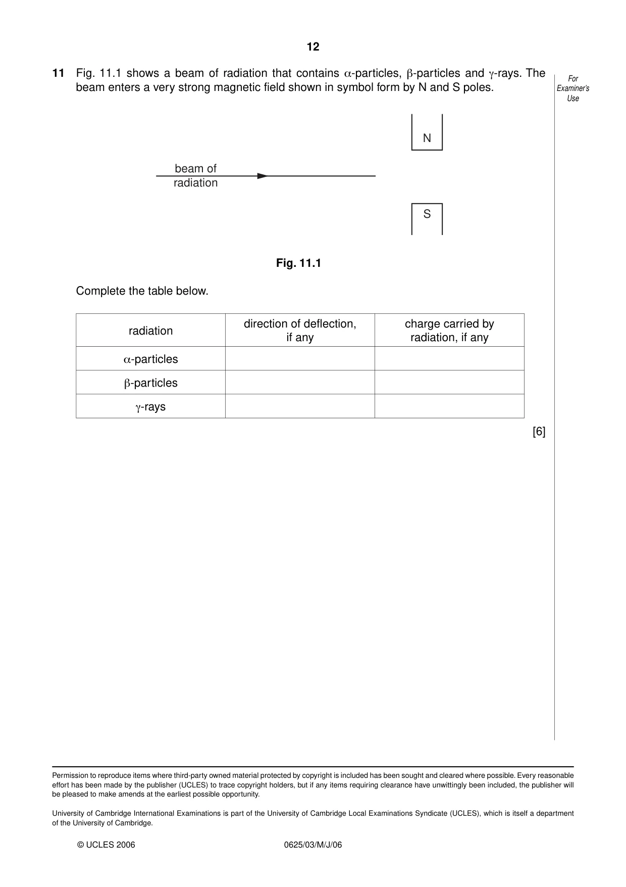
11 Fig. 11.1 shows a beam of radiation that contains α-particles, β-particles and γ-rays. The For beam enters a very strong magnetic field shown in symbol form by N and S poles. Examiner’s Use N beam of radiation S Fig. 11.1 Complete the table below. direction of deflection, charge carried by radiation if any radiation, if any α-particles β-particles γ-rays [6]
Mark scheme: 11 line1 into paper B1 positive or +2 B1 line 2 out of paper or opposite of line 1 B1 negative or -1 B1 line 3 no deflection B1 no charge B1 6 [6]
What was in this paper
The subtopics covered by these 11 questions, and how many questions each got. Open one in a new tab to see every Cambridge question on it.
What you needed in this session
Cambridge’s own grade thresholds for 2006 May/June, Paper 3 · Variant 1. A higher threshold means an easier paper — the bar moves with how the cohort did.