Questions as text
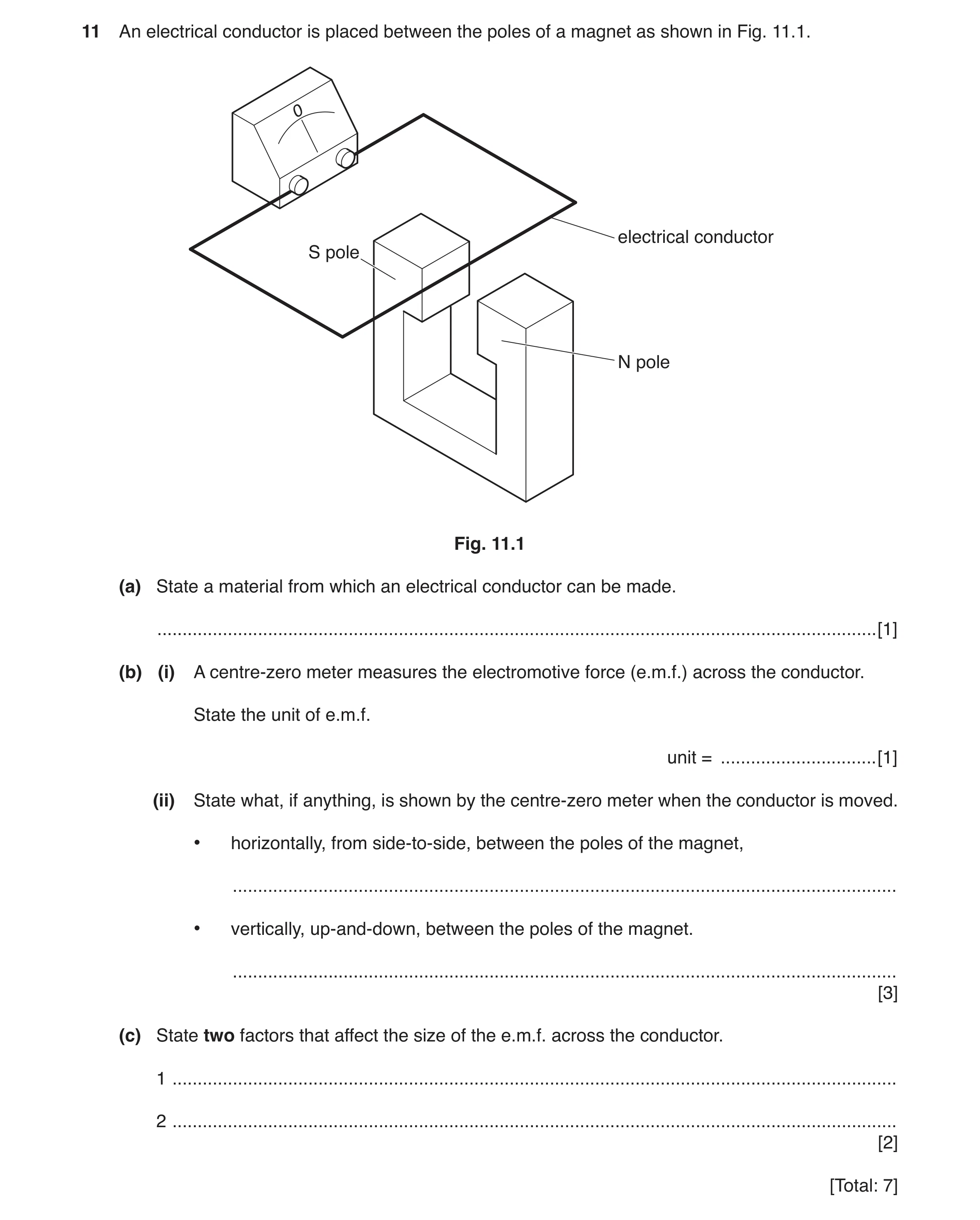
Q1 · An electrical conductor is placed between the poles of a magnet as shown in Fig 0625/32 Feb/March 2017
11 An electrical conductor is placed between the poles of a magnet as shown in Fig. 11.1. 0 electrical conductor S pole N pole Fig. 11.1 (a) State a material from which an electrical conductor can be made. … [1] (b) (i) A centre-zero meter measures the electromotive force (e.m.f.) across the conductor. State the unit of e.m.f. unit = … [1] (ii) State what, if anything, is shown by the centre-zero meter when the conductor is moved. • horizontally, from side-to-side, between the poles of the magnet, … • vertically, up-and-down, between the poles of the magnet. … [3] (c) State two factors that affect the size of the e.m.f. across the conductor. 1 … 2 … [2] [Total: 7]
7 marks
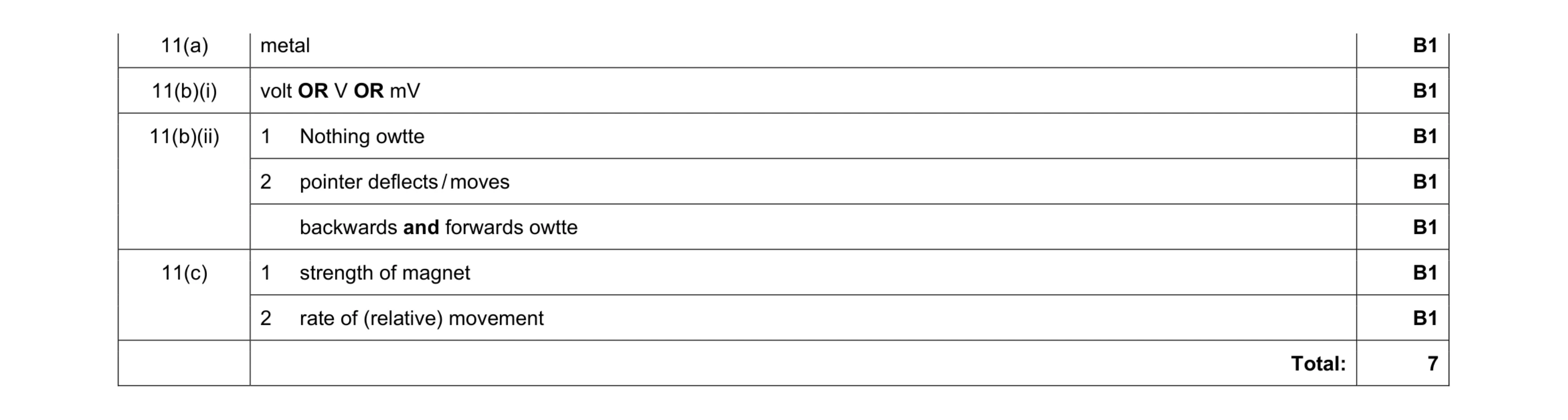
Mark scheme: 11(a) metal B1 11(b)(i) volt OR V OR mV B1 11(b)(ii) 1 Nothing owtte B1 2 pointer deflects / moves B1 backwards and forwards owtte B1 11(c) 1 strength of magnet B1 2 rate of (relative) movement B1 Total: 7
This question in 0625/32 Feb/March 2017
Q2 · A student demonstrates electromagnetic induction 0625/31 May/June 2017
12 A student demonstrates electromagnetic induction. (a) Describe how to demonstrate electromagnetic induction using a magnet, a coil of wire and a sensitive ammeter. You may include a diagram. … … … … [3] (b) State two factors that affect the size of an induced electromotive force (e.m.f.) 1. … 2. … [2] [Total: 5]
5 marks
Mark scheme: 12(a) coil of wire connected in series with (sensitive) ammeter B1 magnet moves relative to coil B1 meter indicates/measures (induced) current B1 12(b) Any two from: B2 speed of movement owtte strength of magnet number of coils/turns per metre Total: 5
This question in 0625/31 May/June 2017
Q3 · A current-carrying coil in a magnetic field 0625/32 May/June 2017
9 Fig. 9.1 shows a current-carrying coil in a magnetic field. coil B C current N S A D F connections to battery + – battery Fig. 9.1 The direction of the current in side AB of the coil is labelled. The force F on side AB is also labelled. (a) On Fig. 9.1, draw • an arrow labelled X, on side CD, to show the direction of the current in this side of the coil, • an arrow labelled P, to show the direction of the force on CD. [2] (b) Give two ways of increasing the forces F and P on the sides of the coil. 1. … … 2. … … [2] (c) (i) Name the particles that flow in the metal wire of the coil. … [1] (ii) The wire of the coil is replaced by a thinner wire. This wire is the same length and is made of the same metal. State and explain how this changes the current in the coil. … … … [2] [Total: 7]
7 marks
Mark scheme: 9(a) arrow drawn pointing from C to D B1 arrow on /near side CD pointing upwards B1 9(b) any 2 from: increase (size of) current increase strength of magnet increase number of turns in coil B2 9(c)(i) electrons B1 9(c)(ii) current is smaller B1 (as) resistance of coil/wire is greater B1 Total: 7
This question in 0625/32 May/June 2017
Q4 · The plug for a television contains a fuse 0625/32 May/June 2017
11 (a) The plug for a television contains a fuse. Explain the purpose of the fuse. … … … [2] (b) The circuit of the television includes transformers. (i) State the metal used for the two coils of each transformer. … [1] (ii) One transformer has an input voltage of 224 V and an output voltage of 16.0 V. The input coil contains 308 turns. Calculate the number of turns on the output coil. number of turns = … [3] [Total: 6]
6 marks
Mark scheme: 11(a) protects circuit if current too large B2 11(b)(i) copper B1 11(b)(ii) S S P P N V N V = in any form C1 S S 16 N 224 308 or 224 308 16 N = = C1 22 (turns) A1 Total: 6
This question in 0625/32 May/June 2017
Q5 · A transformer is connected to a 240 V supply 0625/33 May/June 2017
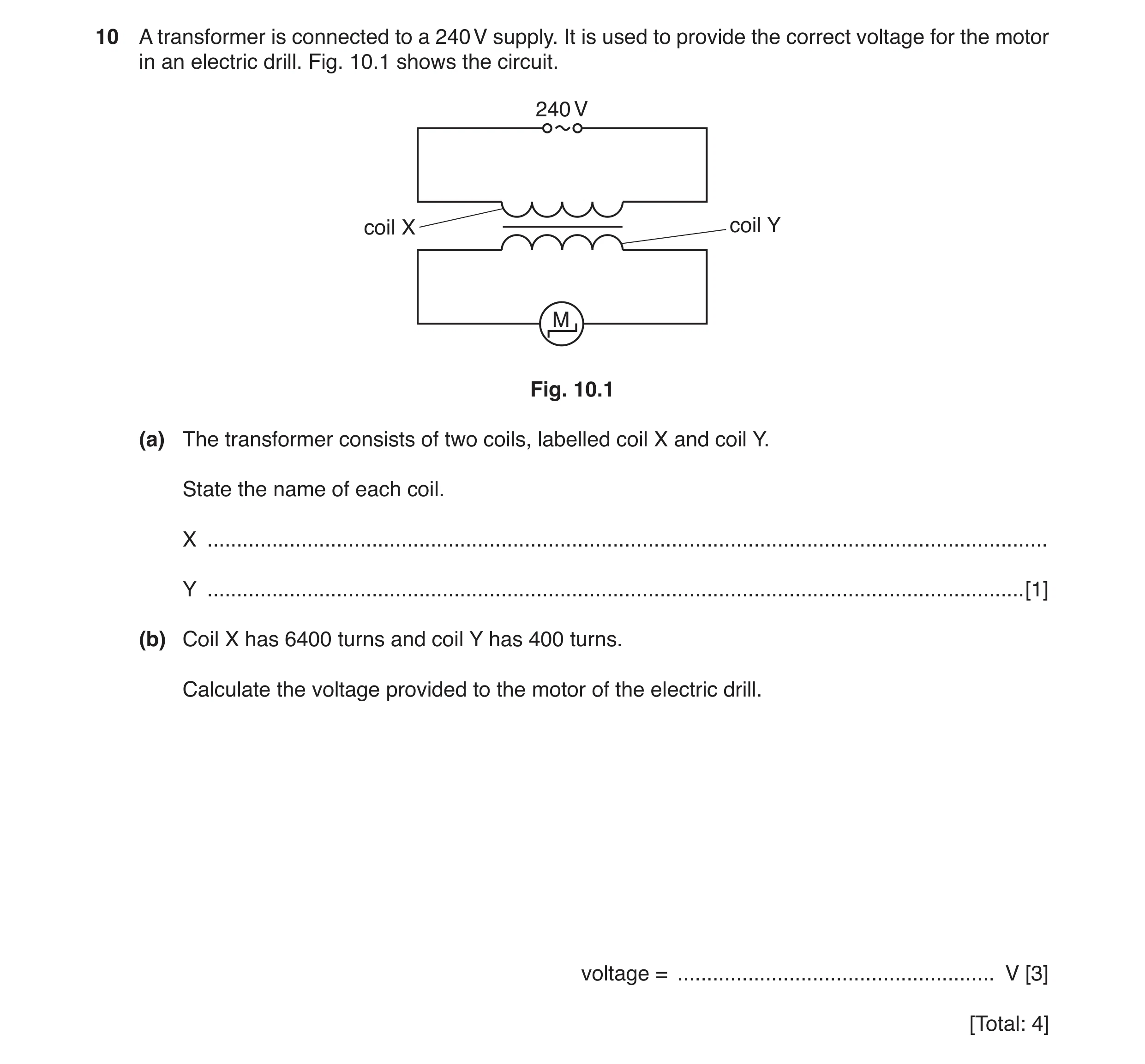
10 A transformer is connected to a 240 V supply. It is used to provide the correct voltage for the motor in an electric drill. Fig. 10.1 shows the circuit. 240 V coil X coil Y M Fig. 10.1 (a) The transformer consists of two coils, labelled coil X and coil Y. State the name of each coil. X … Y … [1] (b) Coil X has 6400 turns and coil Y has 400 turns. Calculate the voltage provided to the motor of the electric drill. voltage = … V [3] [Total: 4]
4 marks
Mark scheme: 10(a) (coil X) primary (coil Y) secondary B1 10(b) Ns/ Np = Vs / Vp in any form C1 240 / Vs = 6400 / 400 OR Vs/ 240 = 400 / 6400 C1 15 (V) A1 Total: 4
This question in 0625/33 May/June 2017
Q6 · A student investigates electromagnetic induction 0625/31 Oct/Nov 2017
10 (a) A student investigates electromagnetic induction. Fig. 10.1 shows the arrangement she uses. wire S N 0 –2 +2 sensitive centre-zero meter Fig. 10.1 When the student holds the wire stationary, as shown in Fig. 10.1, the reading on the meter is zero. She moves the wire down between the poles of the magnet. Then she holds it stationary and then moves it up. (i) The meter measures the size and direction of the induced electromotive force (e.m.f.). On Fig. 10.2, draw the position of the pointer on the meter at each stage. One has been done for you. 0 0 0 –2 +2 –2 +2 –2 +2 wire moving down wire stationary wire moving up [2] Fig. 10.2 (ii) Describe how the student could increase the size of the induced electromotive force (e.m.f.). … … … [2] (b) A transformer is used near a power station. There are 60 turns on the input coil and 660 turns on the output coil. The input voltage is 25 000 V. Calculate the output voltage. output voltage = … V [3] (c) State two advantages of high-voltage transmission of electrical energy. 1. … 2. … [2] [Total: 9]
9 marks
Mark scheme: 10(a)(i) Pointer(s) not on zero B1 Pointers in opposite directions B1 10(a)(ii) Any 2 from: Increase speed of wire B2 wrap wire into a coil Increase strength of magnet 10(b) Ns/Np = Vs/Vp OR 660 ÷ 60 = Vs ÷ 25 000 C1 Vs or output voltage = (660 / 60) × 25 000 = 11 × 25 000 C1 275 000 (V) A1 10(c) Any 2 from: Reduced energy / power losses B2 Smaller conductors needed Reduced voltage drop (across cable)
This question in 0625/31 Oct/Nov 2017
Q7 · A charger for a mobile (cell) phone 0625/32 Oct/Nov 2017
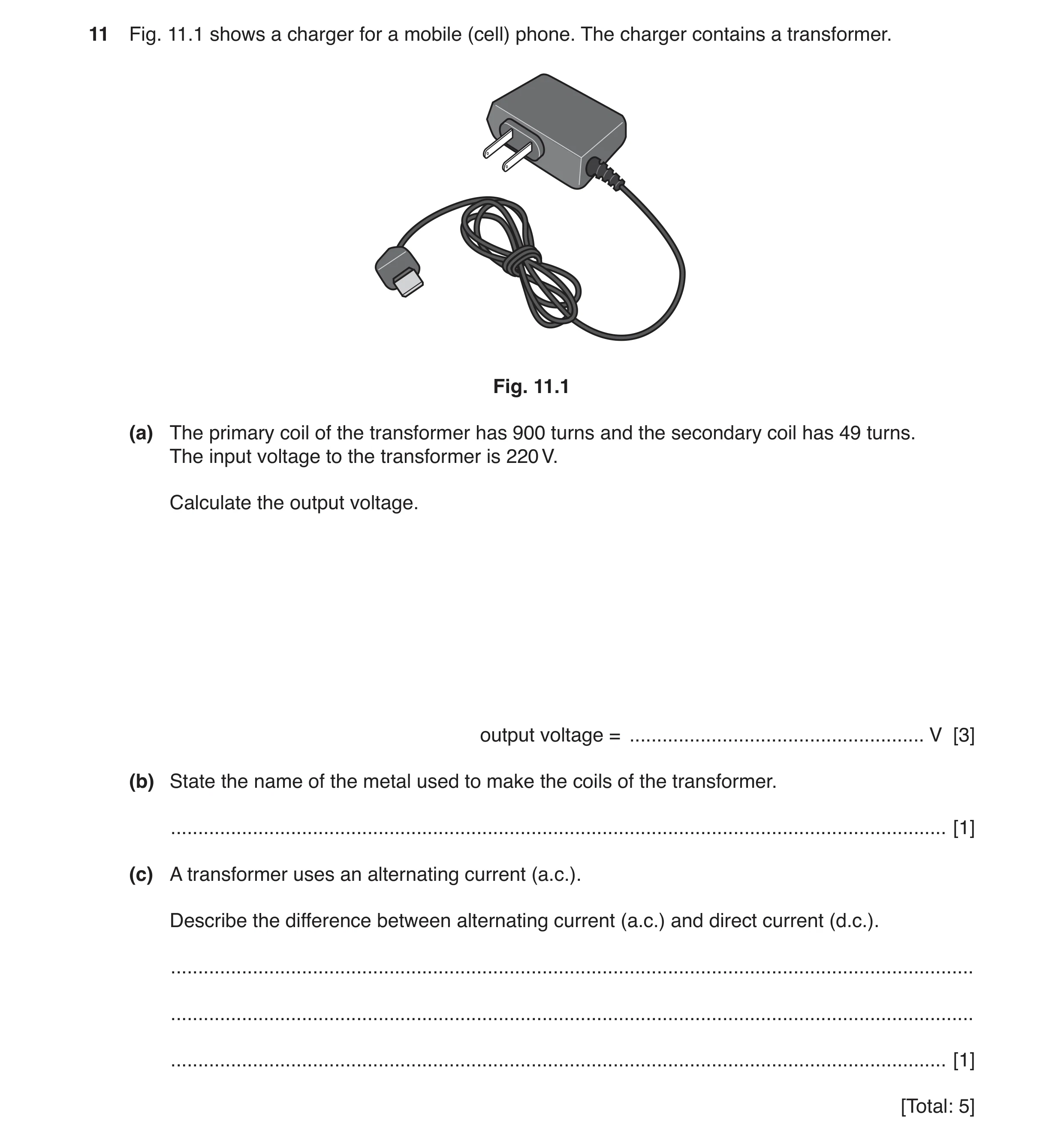
11 Fig. 11.1 shows a charger for a mobile (cell) phone. The charger contains a transformer. Fig. 11.1 (a) The primary coil of the transformer has 900 turns and the secondary coil has 49 turns. The input voltage to the transformer is 220 V. Calculate the output voltage. output voltage = … V [3] (b) State the name of the metal used to make the coils of the transformer. … [1] (c) A transformer uses an alternating current (a.c.). Describe the difference between alternating current (a.c.) and direct current (d.c.). … … … [1] [Total: 5]
5 marks
Mark scheme: 11(a) N1/ N2 = V1 / V2 C1 (49 / 900) × 220 OR use of ratios seen C1 11.98 OR 12 (V) A1 11(b) copper B1 11(c) d.c. is in one direction only / a.c. changes direction B1
This question in 0625/32 Oct/Nov 2017
Q8 · A vertical conductor passing through a horizontal piece of card 0625/31 May/June 2018
11 Fig. 11.1 shows a vertical conductor passing through a horizontal piece of card. conductor card Fig. 11.1 (a) (i) On Fig. 11.1, draw a cell and a switch in series with the conductor to form a complete circuit. Use the correct circuit symbols. [2] (ii) A student sprinkles iron filings onto the card and closes the switch. There is a current in the conductor. Describe the pattern of the magnetic field seen. … … [2] (iii) The student reverses the direction of the current in the conductor. State the effect, if any, on the pattern he sees. … [1] (b) Describe an experiment to show that a force acts on a current-carrying conductor in a magnetic field. Show how to arrange the equipment. Include a diagram in your answer. … … … … … … … [4] [Total: 9]
9 marks
Mark scheme: 11(a)(i) cell and switch connected in series with any part of conductor (on Fig.11.1) 1 correct symbols used – (on Fig.11.1) 1 11(a)(ii) circular 1 around conductor/wire 1 11(a)(iii) no change/nothing 1 11(b) conductor/wire between the poles of a magnet 1 opposite poles facing each other 1 current in wire 1 wire moves/Flemings left hand rule indicated 1
This question in 0625/31 May/June 2018
Question 9 0625/32 May/June 2018
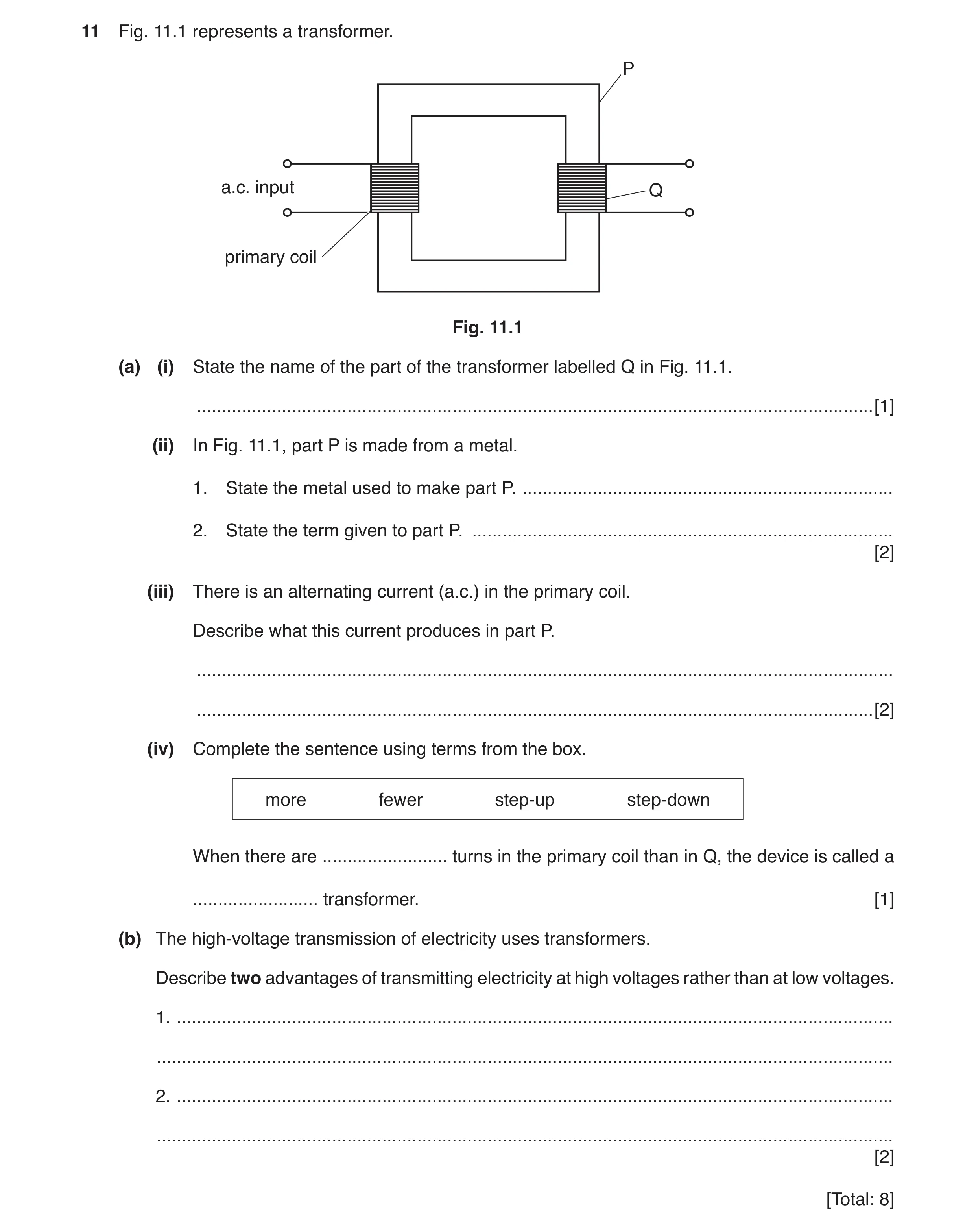
11 Fig. 11.1 represents a transformer. P a.c. input Q primary coil Fig. 11.1 (a) (i) State the name of the part of the transformer labelled Q in Fig. 11.1. … [1] (ii) In Fig. 11.1, part P is made from a metal. 1. State the metal used to make part P. … 2. State the term given to part P. … [2] (iii) There is an alternating current (a.c.) in the primary coil. Describe what this current produces in part P. … … [2] (iv) Complete the sentence using terms from the box. more fewer step-up step-down When there are … turns in the primary coil than in Q, the device is called a … transformer. [1] (b) The high-voltage transmission of electricity uses transformers. Describe two advantages of transmitting electricity at high voltages rather than at low voltages. 1. … … 2. … … [2] [Total: 8]
8 marks
Mark scheme: 11(a)(i) (Q is the) secondary/output (coil) 1 11(a)(ii) 1. (soft–) iron 1 2. core 1 11(a)(iii) magnetic field OR e.m.f. OR magnet 1 changing OR alternating 1 11(a)(iv) EITHER more «AND step-down OR fewer «AND step-up 1 11(b) any two from: smaller current (in wires) smaller drop in p.d./voltage (across cables) smaller heating effect less energy wasted/more efficient thinner cables can be used fewer pylons neededl (electricity) can be transmitted over long(er) distances 2
This question in 0625/32 May/June 2018
Q10 · A coil (solenoid) wrapped around a plastic tube 0625/33 May/June 2018
11 Fig. 11.1 shows a coil (solenoid) wrapped around a plastic tube. There is a current in the coil. The arrows show the direction of the current in the coil. plastic tube Fig. 11.1 (a) On Fig. 11.1, draw the pattern of the magnetic field lines around the coil. Add arrows to show the direction of the magnetic field. [3] (b) A long soft iron bar is placed inside the plastic tube. There is a current in the coil. This forms a device. State the name of the device. … [1] (c) Fig. 11.2 shows a relay operated by switch S. springy metal M A contacts B pivot insulator soft iron armature soft iron core coil of wire S Fig. 11.2 Using Fig. 11.2, describe how closing the switch, S, causes the electric motor to operate. … … … … … … … … [4] [Total: 8]
8 marks
Mark scheme: 11(a) Correctly-drawn magnetic field around coil 1 lines to start and end near coil/tube 1 field line arrows point towards left hand of coil 1 11(b) electromagnet 1 11(c) (when switch S1 is closed there is a) current in the coil (of wire) 1 (soft) iron (core) becomes magnetised/magnetic field created 1 soft iron armature attracted (to core) 1 contacts/A and B close/(motor) circuit completed/current in motor circuit 1
This question in 0625/33 May/June 2018
Q11 · A student has a model electric railway 0625/31 Oct/Nov 2018
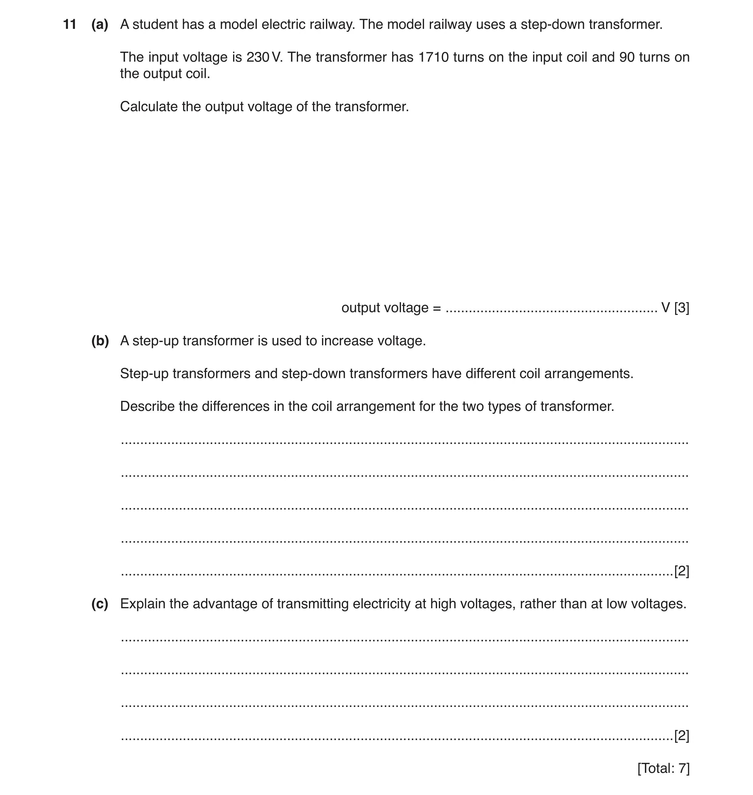
11 (a) A student has a model electric railway. The model railway uses a step-down transformer. The input voltage is 230 V. The transformer has 1710 turns on the input coil and 90 turns on the output coil. Calculate the output voltage of the transformer. output voltage = … V [3] (b) A step-up transformer is used to increase voltage. Step-up transformers and step-down transformers have different coil arrangements. Describe the differences in the coil arrangement for the two types of transformer. … … … … … [2] (c) Explain the advantage of transmitting electricity at high voltages, rather than at low voltages. … … … … [2] [Total: 7]
7 marks
Mark scheme: 11(a) (Vp / Vs) = (Np / Ns) in any form C1 230 / Vs = 1710 / 90 or Vs = (230 × 90) / 1710 OR Vs = 230 / 19 C1 12 (V) A1 11(b) In a step-down transformer there are fewer turns on secondary / output coil (than on primary / input coil) In a step-up transformer there are more turns on secondary / output coil (than on primary / input coil) B2 11(c) less energy / power wasted (in cables ) / more efficient (transmission) B1 And any one from: (because) smaller current (in transmission cables) (and so) smaller heating effect (in transmission cables) (and so) thinner cables can be used (which are cheaper) B1
This question in 0625/31 Oct/Nov 2018
Q12 · A student fits an electrical generator to a bicycle 0625/32 Oct/Nov 2018
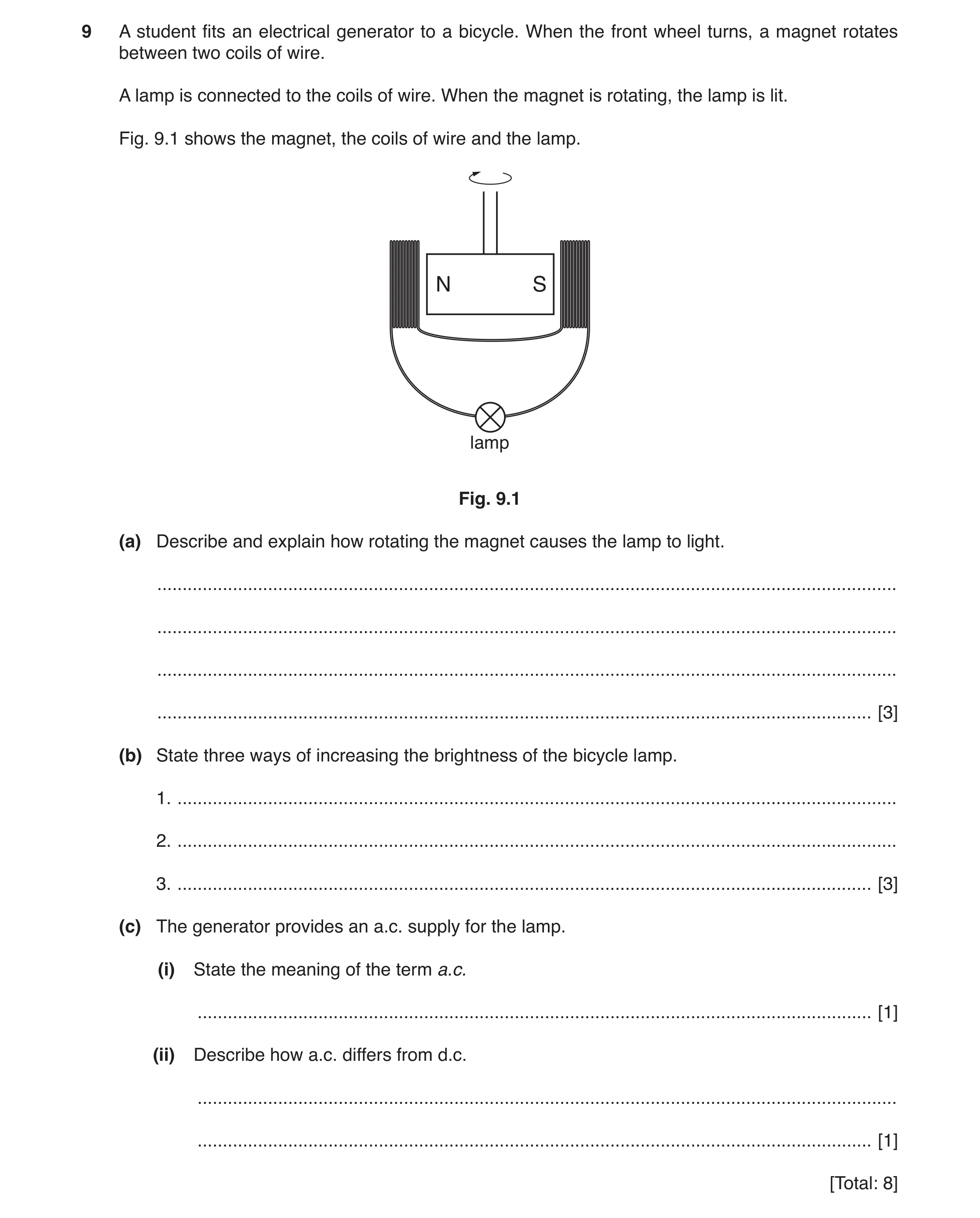
9 A student fits an electrical generator to a bicycle. When the front wheel turns, a magnet rotates between two coils of wire. A lamp is connected to the coils of wire. When the magnet is rotating, the lamp is lit. Fig. 9.1 shows the magnet, the coils of wire and the lamp. N S lamp Fig. 9.1 (a) Describe and explain how rotating the magnet causes the lamp to light. … … … … [3] (b) State three ways of increasing the brightness of the bicycle lamp. 1. … 2. … 3. … [3] (c) The generator provides an a.c. supply for the lamp. (i) State the meaning of the term a.c. … [1] (ii) Describe how a.c. differs from d.c. … … [1] [Total: 8]
8 marks
Mark scheme: 9(a) magnetic field (of magnet) B1 changes / cuts coil / linked to coil B1 induces / causes / produces / generates an emf / voltage / current OR electromagnetic induction B1 9(b) stronger magnet more turns on coil(s) turn magnet at higher speed B3 9(c)(i) alternating (current) B1 9(c)(ii) a.c. changes direction OR d.c one direction only B1
This question in 0625/32 Oct/Nov 2018
Q13 · A long straight wire passes through a piece of card 0625/32 Oct/Nov 2018
11 (a) A long straight wire passes through a piece of card. There is a current in the wire, as shown in Fig. 11.1. current card Fig. 11.1 Fig. 11.2 shows the view of the card from above. The current is into the page. card magnetic field line Fig. 11.2 The current in the wire produces a magnetic field around the wire. One magnetic field line is drawn. On Fig. 11.2, draw two more magnetic field lines around the wire. Show the direction of the magnetic field by drawing an arrow on each field line. [2] (b) Fig. 11.3 shows the circuit for an electric bell. contact screw soft iron hammer armature springy metal strip coils of wire bell switch Fig. 11.3 Explain how the circuit causes the hammer to hit the bell repeatedly when the switch is closed. Use your ideas about circuits and electromagnets. … … … … … … … [5] [Total: 7]
7 marks
Mark scheme: 11(a) two roughly circular lines drawn B1 arrow showing clockwise direction B1 11(b) any 5 from: current in circuit / coil(s) coil becomes electromagnet owtte (coil / electromagnet) attracts (soft iron) armature (so) hammer hits gong circuit is broken (at A / contact screw) electromagnet loses magnetic field / stops working armature springs back cycle repeats B5
This question in 0625/32 Oct/Nov 2018
Q14 · Devices that generate electricity 0625/33 Oct/Nov 2018
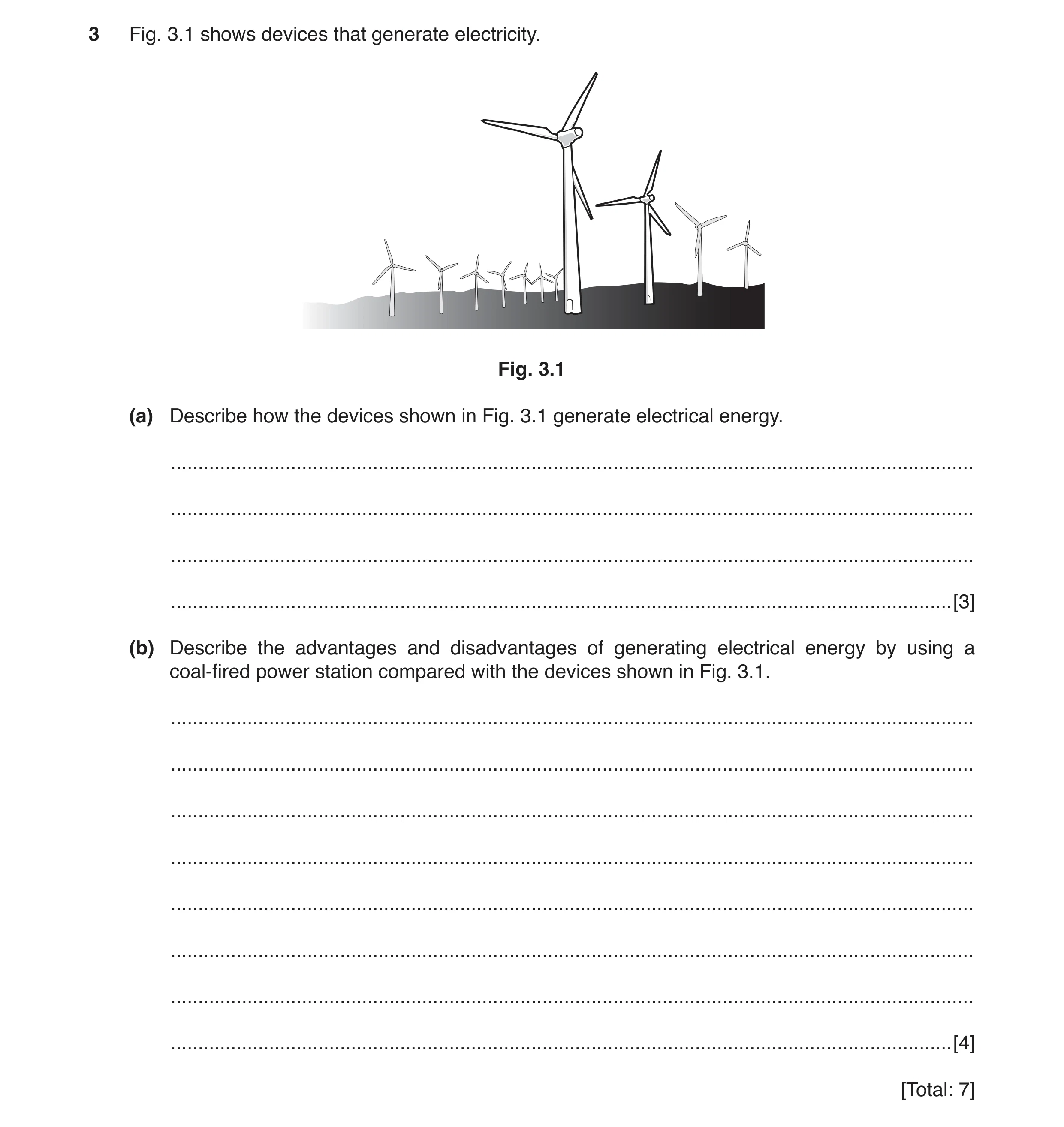
3 Fig. 3.1 shows devices that generate electricity. Fig. 3.1 (a) Describe how the devices shown in Fig. 3.1 generate electrical energy. … … … … [3] (b) Describe the advantages and disadvantages of generating electrical energy by using a coal-fired power station compared with the devices shown in Fig. 3.1. … … … … … … … … [4] [Total: 7]
7 marks
Mark scheme: 3(a) Kinetic OR movement energy from wind OR moving air B1 turns turbine B1 turbine turns generator (to generate electricity) B1 3(b) Any two advantages from: reliable supply of electricity owtte large amount of electrical energy produced / power output plentiful supply of fuel B2 Any two disadvantages from: non-renewable (energy source) greenhouse gases / carbon dioxide produced / increases global warming contributes to atmospheric / air pollution / acid rain B2
This question in 0625/33 Oct/Nov 2018
Q15 · A sheet of paper 0625/33 Oct/Nov 2018
8 Fig. 8.1 shows a sheet of paper. A bar magnet is underneath the paper. A student sprinkles iron filings onto the paper. paper position of magnet under paper Fig. 8.1 (a) On Fig. 8.1 Label the position of each pole of the magnet. Use the label N for the north pole and S • for the south pole. Draw one magnetic field line above the magnet and draw one magnetic field line below • the magnet. Add one arrow to show the direction of the magnetic field. • [4] (b) A student places a soft iron rod inside a coil of insulated wire. The coil is connected to a battery, as shown in Fig. 8.2. soft iron rod battery coil of insulated wire switch Fig. 8.2 (i) State the name given to the device shown in Fig. 8.2. … [1] (ii) The student puts one end of the device in Fig. 8.2 just above a pile of iron filings. He closes the switch for a short time and then opens it again. Describe the effect this has on the iron filings. … … [1] (iii) The student removes the soft iron rod and replaces it with a steel rod. He puts one end of the steel rod just above the pile of iron filings. He closes the switch for a short time and then opens it again. Describe the effect this has on the iron fillings. … … … [1] [Total: 7]
7 marks
Mark scheme: 8(a) N and S labelled at either end of magnet correct field line shown above magnet correct field line shown below magnet field points in direction N to S B4 8(b)(i) electromagnet B1 8(b)(ii) (soft iron) filings attracted, but (most) fall off when switch opened B1 8(b)(iii) (steel) (most / more / they) remain attached when switch opened B1
This question in 0625/33 Oct/Nov 2018
Q16 · A simple electric motor 0625/33 Oct/Nov 2018
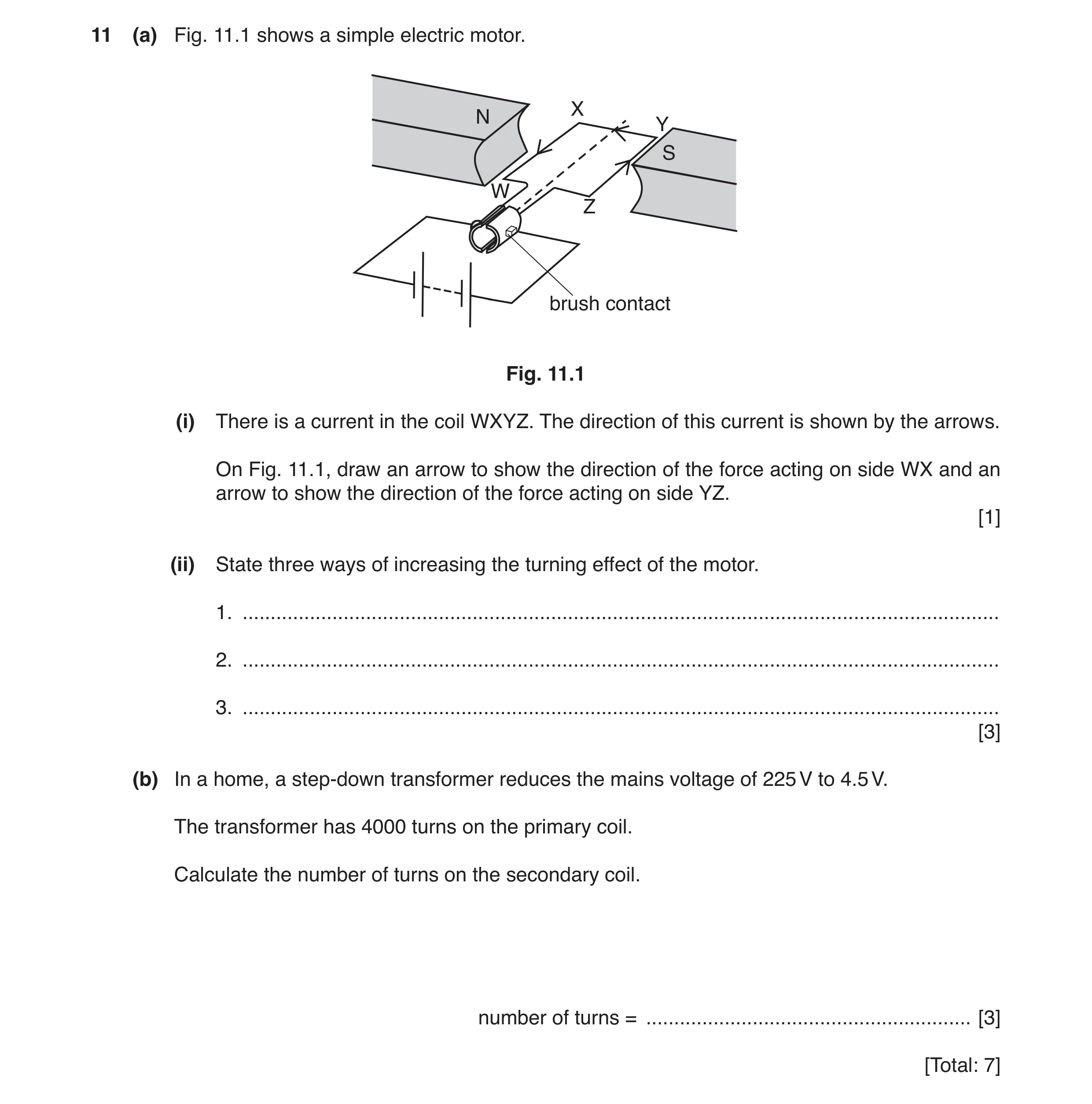
11 (a) Fig. 11.1 shows a simple electric motor. X N Y S W Z brush contact Fig. 11.1 (i) There is a current in the coil WXYZ. The direction of this current is shown by the arrows. On Fig. 11.1, draw an arrow to show the direction of the force acting on side WX and an arrow to show the direction of the force acting on side YZ. [1] (ii) State three ways of increasing the turning effect of the motor. 1. … 2. … 3. … [3] (b) In a home, a step-down transformer reduces the mains voltage of 225 V to 4.5 V. The transformer has 4000 turns on the primary coil. Calculate the number of turns on the secondary coil. number of turns = … [3] [Total: 7]
7 marks
Mark scheme: 11(a)(i) arrow up from side WX of coil AND an arrow down from side YZ of coil B1 11(a)(ii) any three from: stronger / more powerful magnets smaller gap between coil and magnet(s) larger current in coil more coils / turns B3 11(b) Vp/ Vs = Np / Ns OR ratio used C1 4000 ÷ (225 ÷ 4.5) OR (4000 × 4.5) ÷ 225 OR 4000 ÷ 50 C1 80 A1
This question in 0625/33 Oct/Nov 2018
Question 17 0625/32 Feb/March 2019
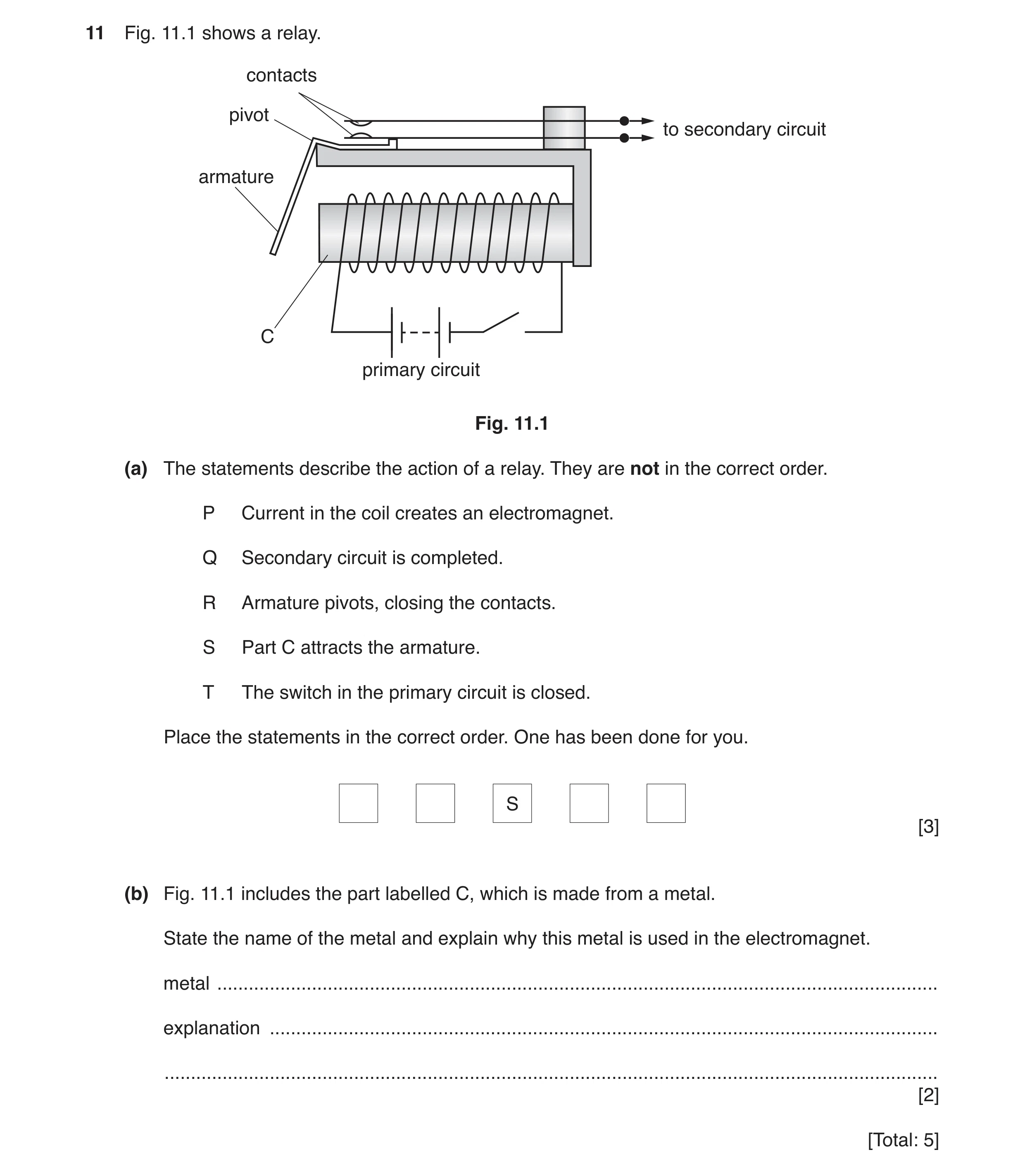
11 Fig. 11.1 shows a relay. contacts pivot to secondary circuit armature C primary circuit Fig. 11.1 (a) The statements describe the action of a relay. They are not in the correct order. P Current in the coil creates an electromagnet. Q Secondary circuit is completed. R Armature pivots, closing the contacts. S Part C attracts the armature. T The switch in the primary circuit is closed. Place the statements in the correct order. One has been done for you. S [3] (b) Fig. 11.1 includes the part labelled C, which is made from a metal. State the name of the metal and explain why this metal is used in the electromagnet. metal … explanation … … [2] [Total: 5]
5 marks
Mark scheme: 11(a) T P (S) R Q B3 11(b) (soft) iron B1 (forms a) temporary magnet B1
This question in 0625/32 Feb/March 2019
Q18 · In each of the diagrams a current-carrying conductor and a magnetic field pattern 0625/31 May/June 2019
11 (a) Fig. 11.1 shows in each of the diagrams a current-carrying conductor and a magnetic field pattern. current-carrying current-carrying current-carrying conductor conductor conductor A B C Fig. 11.1 State the diagram which correctly shows the magnetic field around a current-carrying conductor. … [1] (b) Fig. 11.2 shows three pieces of equipment. coil S N bar magnet coil with 100 sensitive centre-zero turns of wire meter Fig. 11.2 (i) Describe how to generate and detect an electromotive force (e.m.f.) using the equipment in Fig. 11.2. You may draw a diagram. … … … … [3] (ii) Describe two changes that will generate a larger e.m.f. using similar equipment to that in Fig. 11.2. … … … … [2] (c) A student connects a lamp and centre-zero galvanometer in series with a generator, as shown in Fig. 11.3. lamp centre-zero generator G galvanometer Fig. 11.3 The student observes the galvanometer needle moving from side-to-side repeatedly. Explain why the needle moves in this way. … … … [1] [Total: 7]
7 marks
Mark scheme: 11(a) (diagram) A B1 11(b)(i) connect coil to (centre zero) meter B1 move magnet in OR / AND out of coil B1 (observe) deflection on meter B1 11(b)(ii) any two from: use stronger magnet move magnet faster more turns on coil OR use more than 100 turns B2 11(c) (generator produces) alternating current OR direction of current keeps changing B1
This question in 0625/31 May/June 2019
Q19 · A transformer that can provide two different output voltages from a 240 volt mains a.c 0625/32 May/June 2019
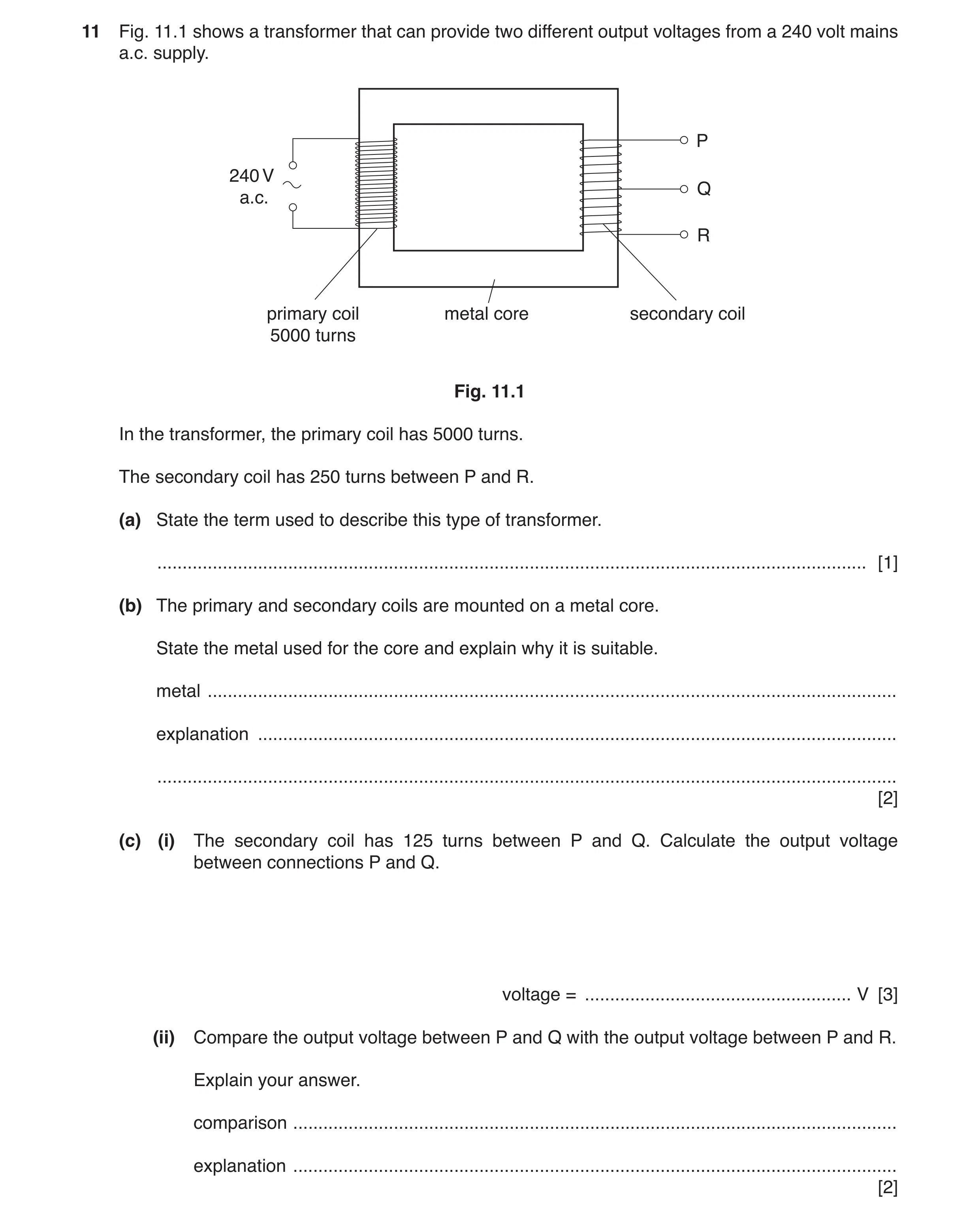
11 Fig. 11.1 shows a transformer that can provide two different output voltages from a 240 volt mains a.c. supply. P 240 V Q a.c. R primary coil metal core secondary coil 5000 turns Fig. 11.1 In the transformer, the primary coil has 5000 turns. The secondary coil has 250 turns between P and R. (a) State the term used to describe this type of transformer. … [1] (b) The primary and secondary coils are mounted on a metal core. State the metal used for the core and explain why it is suitable. metal … explanation … … [2] (c) (i) The secondary coil has 125 turns between P and Q. Calculate the output voltage between connections P and Q. voltage = … V [3] (ii) Compare the output voltage between P and Q with the output voltage between P and R. Explain your answer. comparison … explanation … [2]
8 marks
Mark scheme: 11(a) step-down (transformer) B1 11(b) (soft) iron B1 forms a temporary magnet B1 11(c)(i) Vp/Vs = Np/Ns OR ratio used C1 240 × (125 ÷ 5000) C1 (PQ = ) 6 (V) A1 11(c)(ii) (PR =) 12 (V) / double the value in (c)(i) (PQ) B1 twice as many turns between P and R (as P and Q) B1
This question in 0625/32 May/June 2019
Question 20 0625/33 May/June 2019
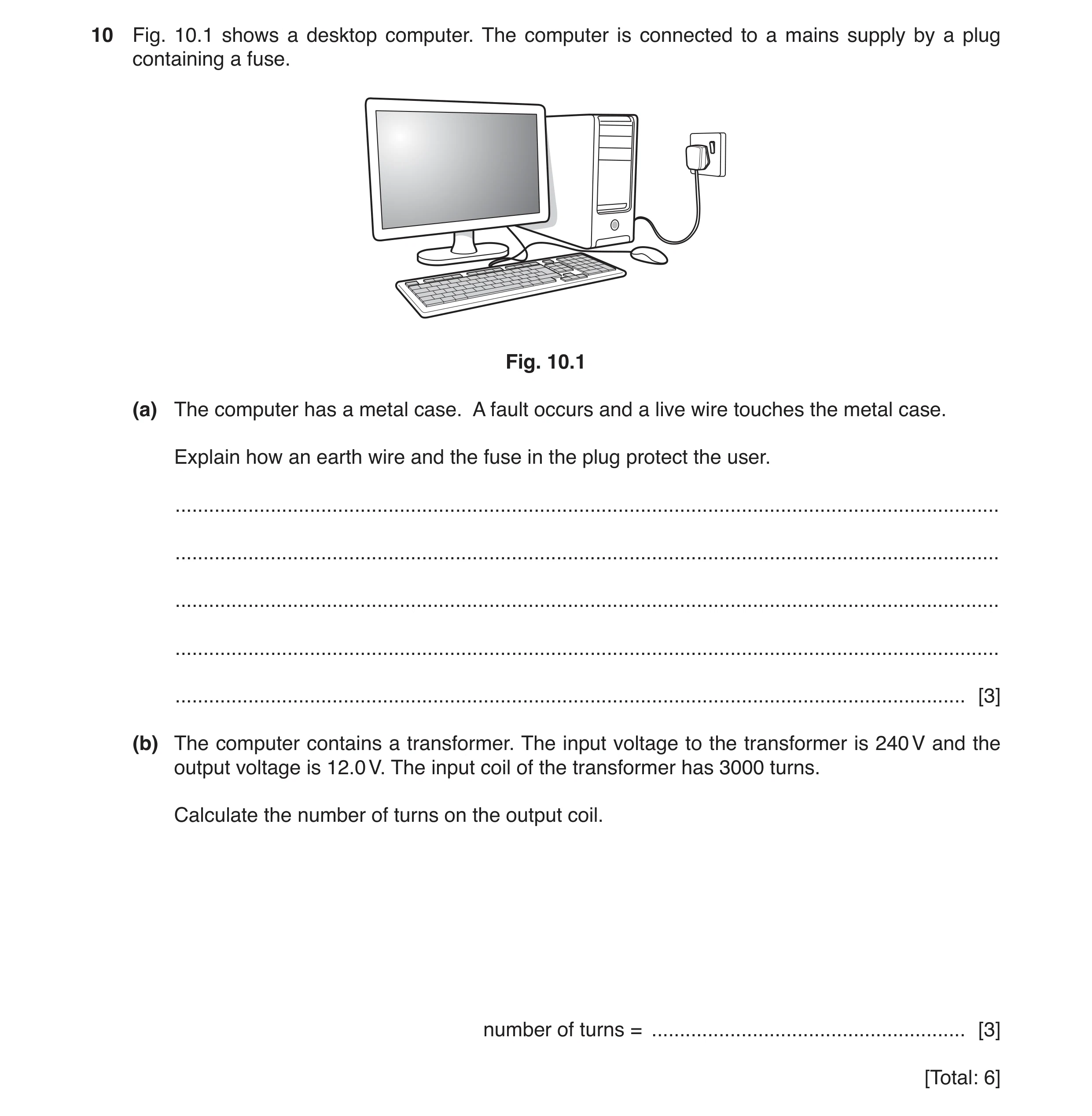
10 Fig. 10.1 shows a desktop computer. The computer is connected to a mains supply by a plug containing a fuse. Fig. 10.1 (a) The computer has a metal case. A fault occurs and a live wire touches the metal case. Explain how an earth wire and the fuse in the plug protect the user. … … … … … [3] (b) The computer contains a transformer. The input voltage to the transformer is 240 V and the output voltage is 12.0 V. The input coil of the transformer has 3000 turns. Calculate the number of turns on the output coil. number of turns = … [3] [Total: 6]
6 marks
Mark scheme: 10(a) any 3 from: earth wire is connected to metal case earth wire has low resistance large current in earth wire fuse in live wire fuse (heats up and) melts this disconnects case/computer/circuit from supply ( and so protects user) B3 10(b) (Vp / Vs ) = (Np / Ns ) in any form C1 240 / 12 = 3000 / Ns OR Ns = 3000 × (12/240) OR Ns = 3000 / 20 C1 150 (turns) A1
This question in 0625/33 May/June 2019
Q21 · A student uses the equipment shown in Fig 0625/33 May/June 2019
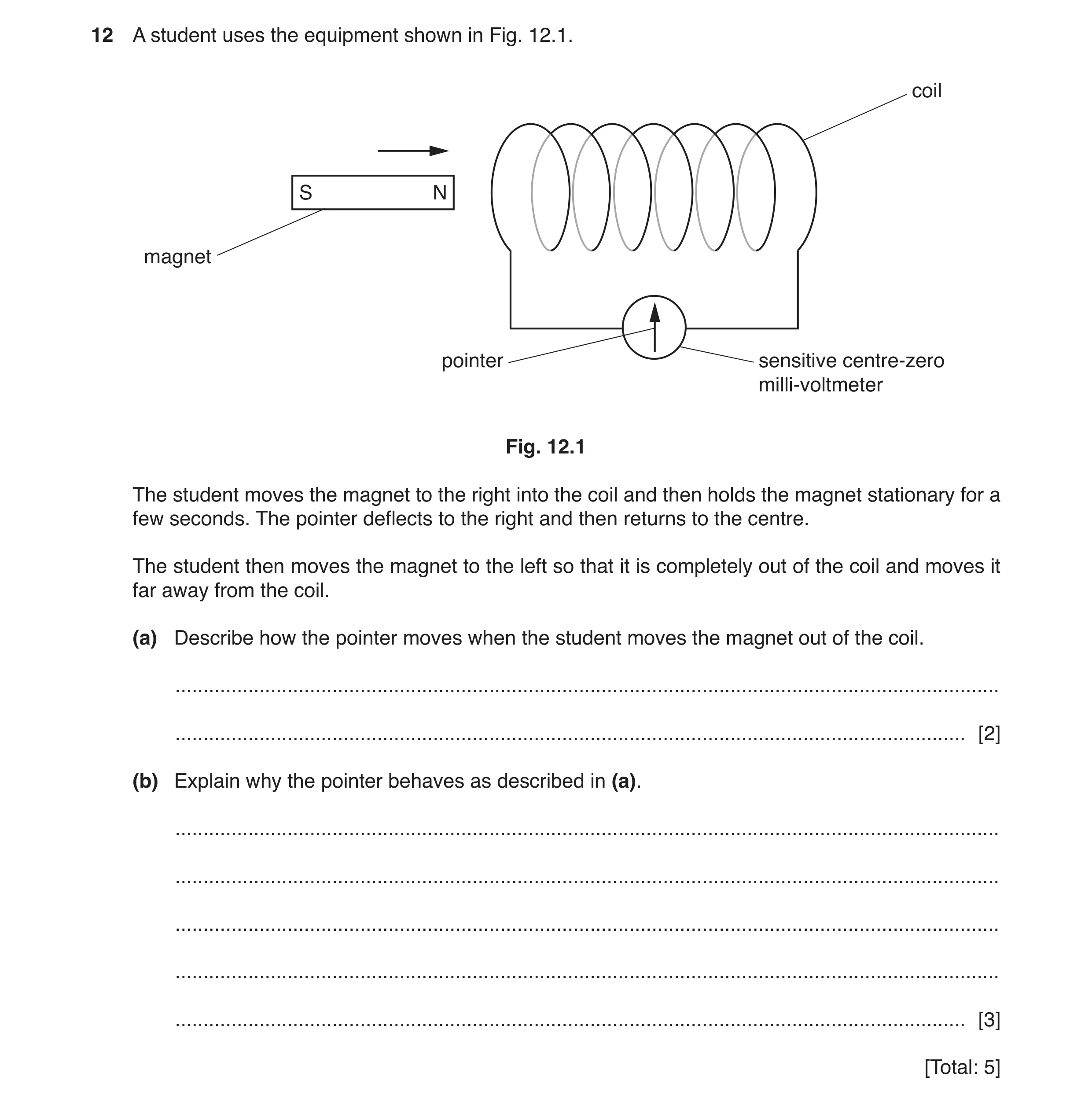
12 A student uses the equipment shown in Fig. 12.1. coil S N magnet pointer sensitive centre-zero milli-voltmeter Fig. 12.1 The student moves the magnet to the right into the coil and then holds the magnet stationary for a few seconds. The pointer deflects to the right and then returns to the centre. The student then moves the magnet to the left so that it is completely out of the coil and moves it far away from the coil. (a) Describe how the pointer moves when the student moves the magnet out of the coil. … … [2] (b) Explain why the pointer behaves as described in (a). … … … … … [3] [Total: 5]
5 marks
Mark scheme: 12(a) pointer deflects to the left B1 (then pointer) returns to zero reading B1 12(b) any three from: (magnet has a) magnetic field conductor/coil cuts magnetic field (this) induces or produces emf/voltage/p.d. in the conductor/coil (so reading on meter) no cutting of field when far from coil (so no reading on meter) B3
This question in 0625/33 May/June 2019
Q22 · A student is experimenting with electromagnetic effects 0625/31 Oct/Nov 2019
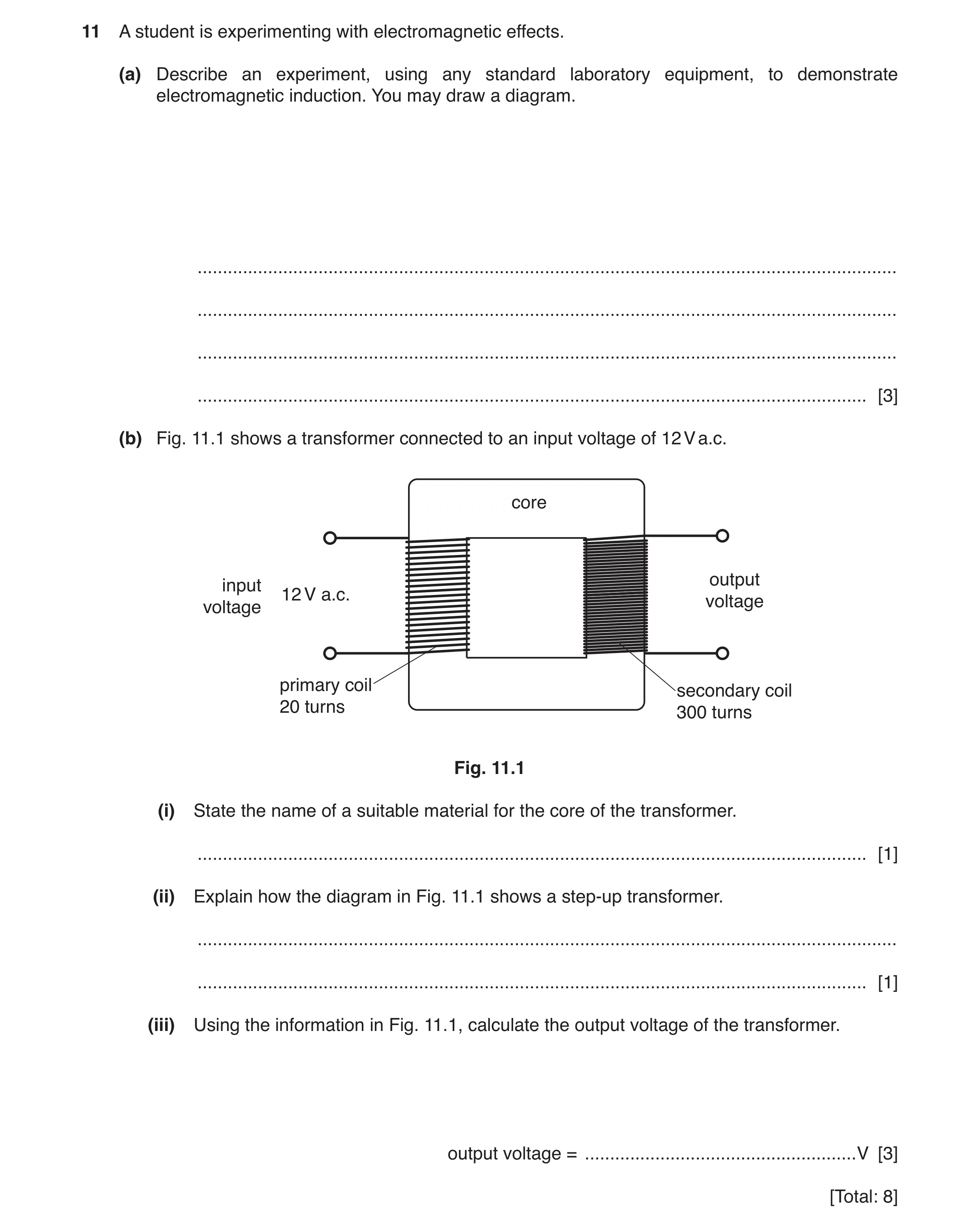
11 A student is experimenting with electromagnetic effects. (a) Describe an experiment, using any standard laboratory equipment, to demonstrate electromagnetic induction. You may draw a diagram. … … … … [3] (b) Fig. 11.1 shows a transformer connected to an input voltage of 12 V a.c. core output input 12 V a.c. voltage voltage primary coil secondary coil 20 turns 300 turns Fig. 11.1 (i) State the name of a suitable material for the core of the transformer. … [1] (ii) Explain how the diagram in Fig. 11.1 shows a step-up transformer. … … [1] (iii) Using the information in Fig. 11.1, calculate the output voltage of the transformer. output voltage = … V [3] [Total: 8]
8 marks
Mark scheme: 11(a) relative movement (between conductor and magnetic field) And any two from: connect conductor/coil to (sensitive) meter use of magnet/magnetic field B1 deflection on meter (indicates emf) OR voltage generated OR current in conductor B2 11(b)(i) (soft-) iron B1 11(b)(ii) more turns on output coil (than input coil) ora B1 11(b)(iii) Vs / Vp = Ns / Np in any form C1 Vs / 12 = 300 / 20 OR Vs = (300 / 20) × 12 OR Vs = 15 × 12 OR 12 / 20 = ? / 300 C1 180 (V) A1
This question in 0625/31 Oct/Nov 2019
Q23 · Identify which of the following metals can be permanently magnetised 0625/32 Oct/Nov 2019
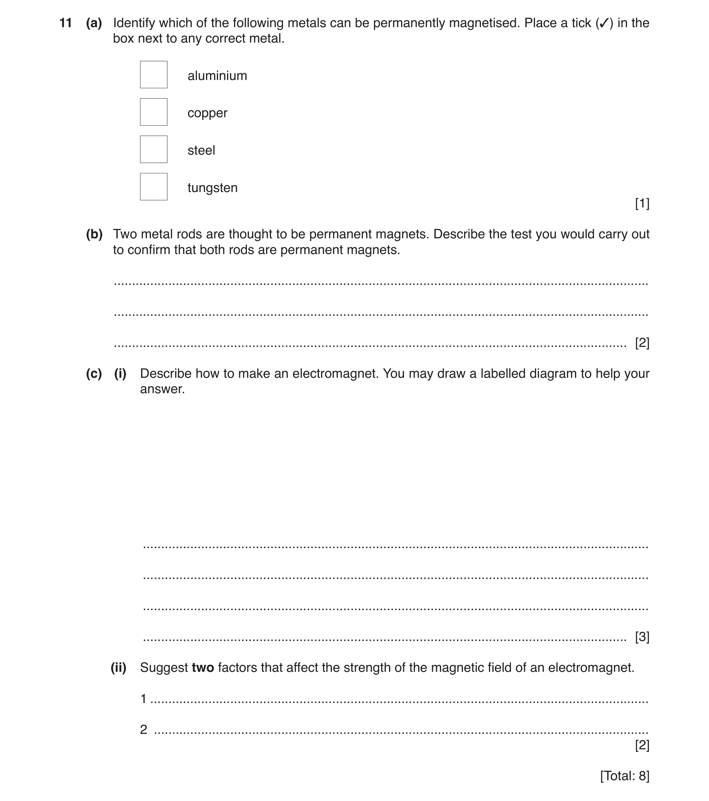
11 (a) Identify which of the following metals can be permanently magnetised. Place a tick (3) in the box next to any correct metal. aluminium copper steel tungsten [1] (b) Two metal rods are thought to be permanent magnets. Describe the test you would carry out to confirm that both rods are permanent magnets. … … … [2] (c) (i) Describe how to make an electromagnet. You may draw a labelled diagram to help your answer. … … … … [3] (ii) Suggest two factors that affect the strength of the magnetic field of an electromagnet. 1 … 2 … [2] [Total: 8]
8 marks
Mark scheme: 11(a) 3rd box ticked steel B1 11(b) place ends/poles together B1 repulsion (takes place) B1 11(c)(i) coil of wire B1 iron rod inside B1 coil connected to an (electrical) power supply OR current in coil B1 11(c)(ii) number of turns (in coil) B1 current (in coil) B1
This question in 0625/32 Oct/Nov 2019
Q24 · A diagram of an electrical device 0625/33 Oct/Nov 2019
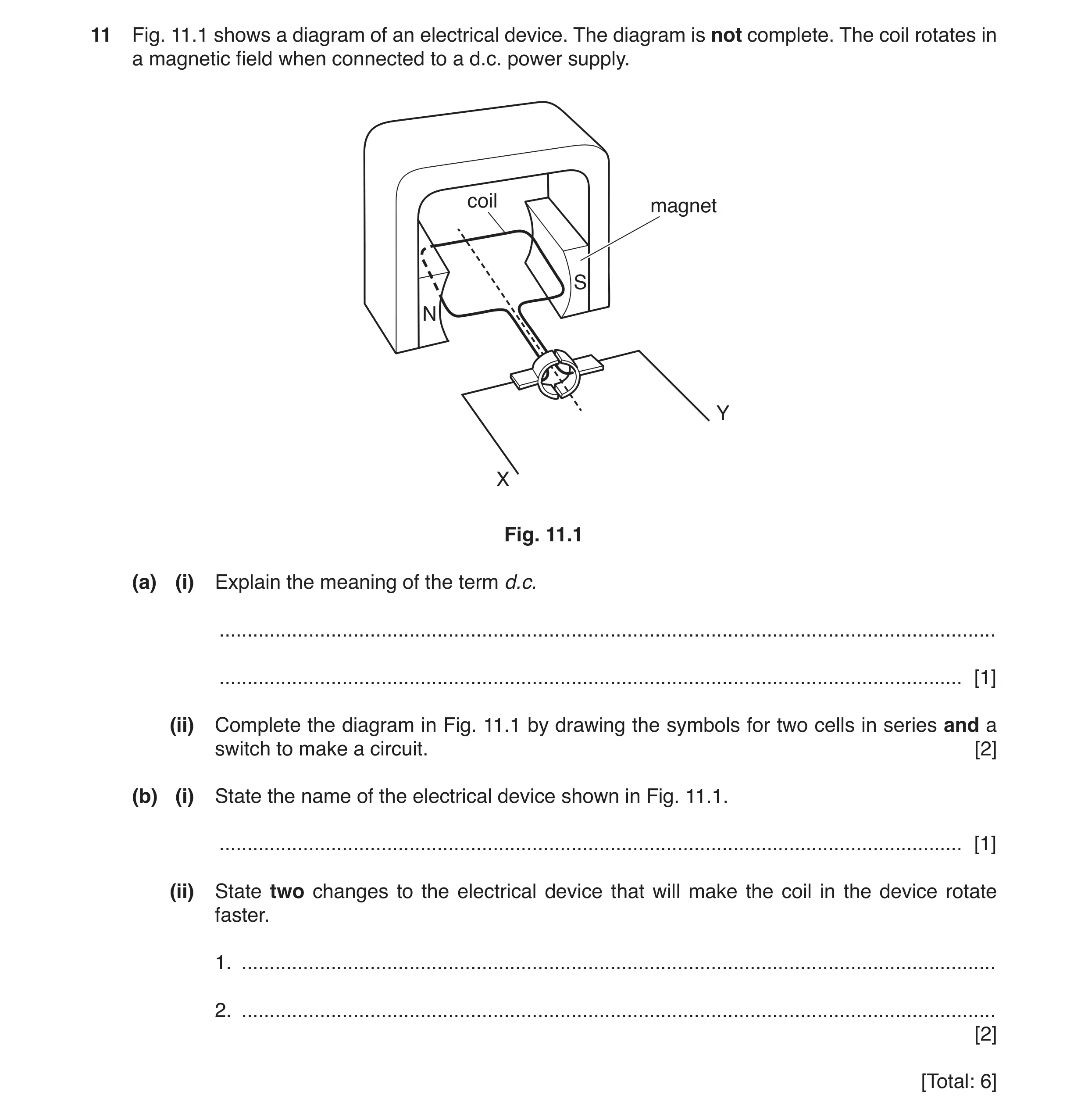
11 Fig. 11.1 shows a diagram of an electrical device. The diagram is not complete. The coil rotates in a magnetic field when connected to a d.c. power supply. coil magnet S N Y X Fig. 11.1 (a) (i) Explain the meaning of the term d.c. … … [1] (ii) Complete the diagram in Fig. 11.1 by drawing the symbols for two cells in series and a switch to make a circuit. [2] (b) (i) State the name of the electrical device shown in Fig. 11.1. … [1] (ii) State two changes to the electrical device that will make the coil in the device rotate faster. 1. … 2. … [2] [Total: 6]
6 marks
Mark scheme: 11(a)(i) current is in one direction B1 11(a)(ii) symbols for two cells connected in series symbol for a switch B1 B1 11(b)(i) motor B1 11(b)(ii) any two from: increasing number of turns on coil increasing the current (in the coil) increasing the strength of the magnetic field B2
This question in 0625/33 Oct/Nov 2019
Question 25 0625/32 Feb/March 2020
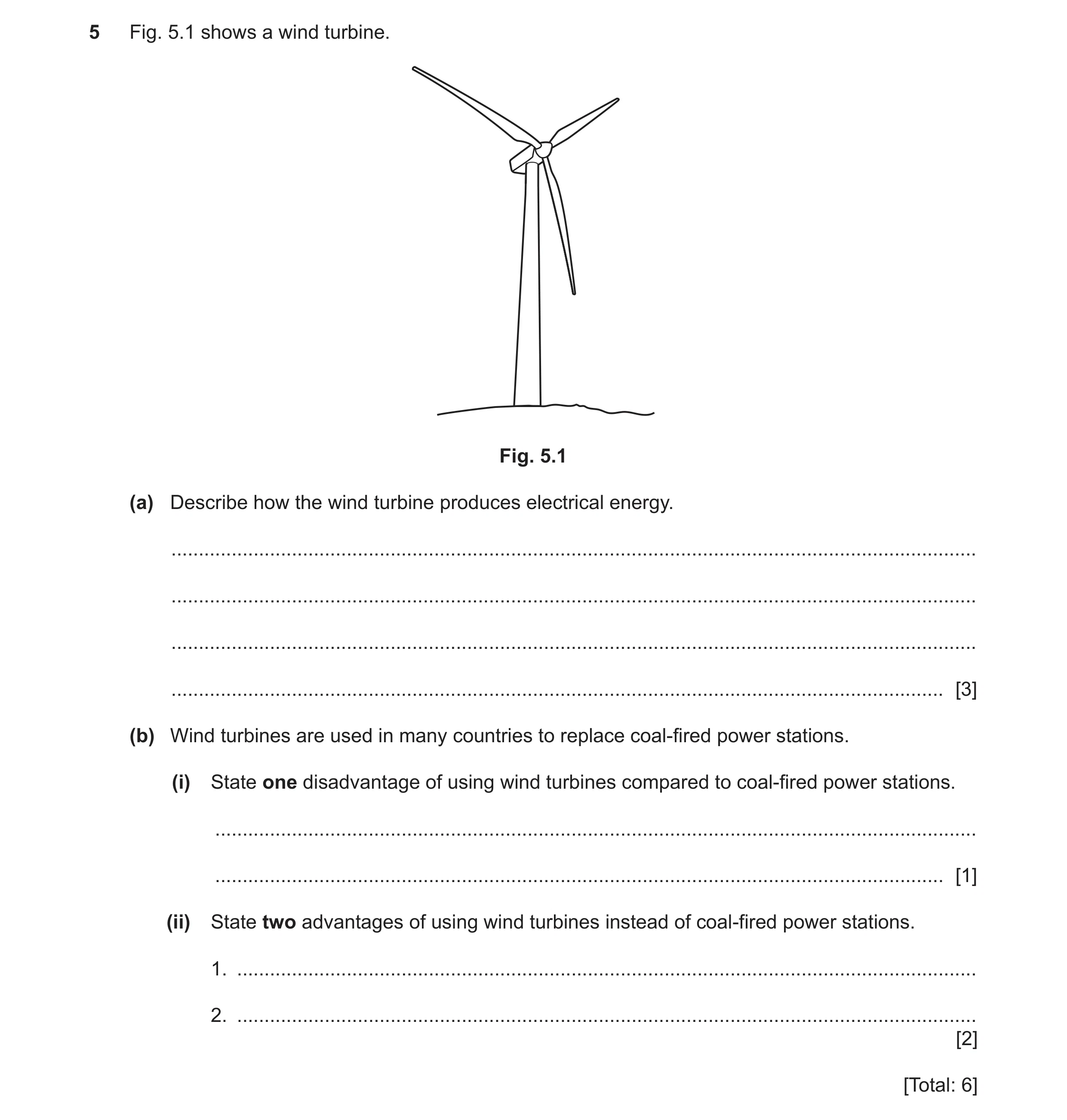
5 Fig. 5.1 shows a wind turbine. Fig. 5.1 (a) Describe how the wind turbine produces electrical energy. … … … … [3] (b) Wind turbines are used in many countries to replace coal-fired power stations. (i) State one disadvantage of using wind turbines compared to coal-fired power stations. … … [1] (ii) State two advantages of using wind turbines instead of coal-fired power stations. 1. … 2. … [2] [Total: 6]
6 marks
Mark scheme: 5(a) Any three from: kinetic energy (of wind / air) turns / drives turbine (blades) (turbine blades) turn generator coil turns in magnetic field B3 5(b)(i) any one from: a dilute source of energy dependent on weather / intermittent supply B1 5(b)(ii) any two from: renewable source of energy no atmospheric pollution conserves fossil fuels owtte do not contribute to global warming B2
This question in 0625/32 Feb/March 2020
Q26 · A model train uses an electric motor 0625/32 May/June 2020
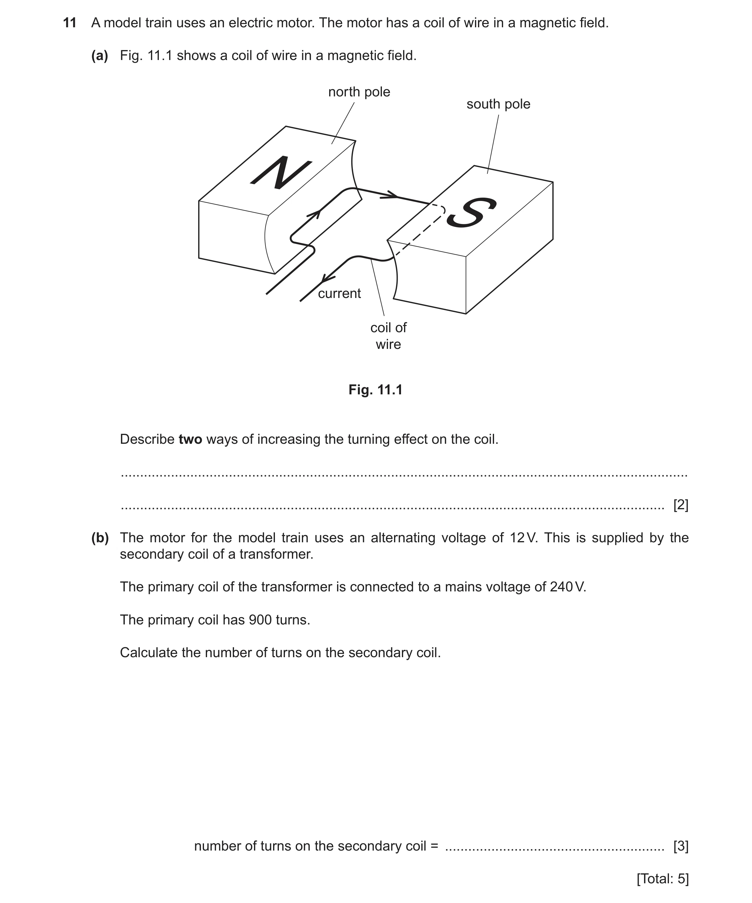
11 A model train uses an electric motor. The motor has a coil of wire in a magnetic field. (a) Fig. 11.1 shows a coil of wire in a magnetic field. north pole south pole N S current coil of wire Fig. 11.1 Describe two ways of increasing the turning effect on the coil. … … [2] (b) The motor for the model train uses an alternating voltage of 12 V. This is supplied by the secondary coil of a transformer. The primary coil of the transformer is connected to a mains voltage of 240 V. The primary coil has 900 turns. Calculate the number of turns on the secondary coil. number of turns on the secondary coil = … [3] [Total: 5]
5 marks
Mark scheme: 11(a) any two from: increase current increase magnetic field strength field more turns on coil B2 11(b) (Vp / Vs) = (Np / Ns) in any form C1 Ns = (12 ÷ 240) × 900 C1 45 A1
This question in 0625/32 May/June 2020
Q27 · Two circuits, A and B, linked by a relay 0625/31 Oct/Nov 2020
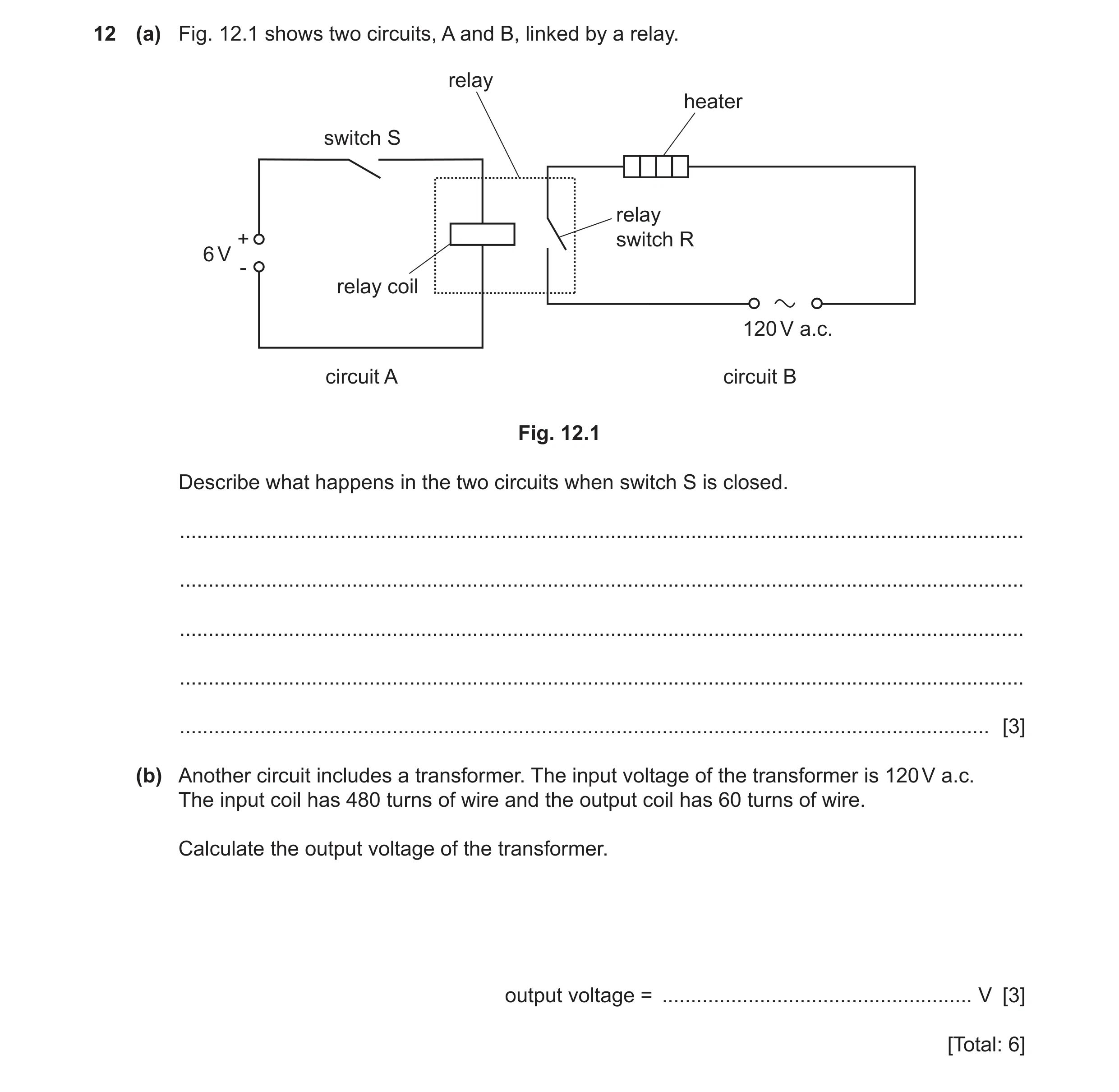
12 (a) Fig. 12.1 shows two circuits, A and B, linked by a relay. relay heater switch S relay + switch R 6 V - relay coil 120 V a.c. circuit A circuit B Fig. 12.1 Describe what happens in the two circuits when switch S is closed. … … … … … [3] (b) Another circuit includes a transformer. The input voltage of the transformer is 120 V a.c. The input coil has 480 turns of wire and the output coil has 60 turns of wire. Calculate the output voltage of the transformer. output voltage = … V [3] [Total: 6]
6 marks
Mark scheme: 12(a) any three from: current in relay coil produces magnetic field relay / switch R is closed heater connected to 120 V or switches on B3 12(b) Vs / Vp = Ns / Np in any form C1 (Vs =) (60 × 120) ÷ 480 OR 120 ÷ 8 C1 15 (V) A1
This question in 0625/31 Oct/Nov 2020
Question 28 0625/32 Oct/Nov 2020
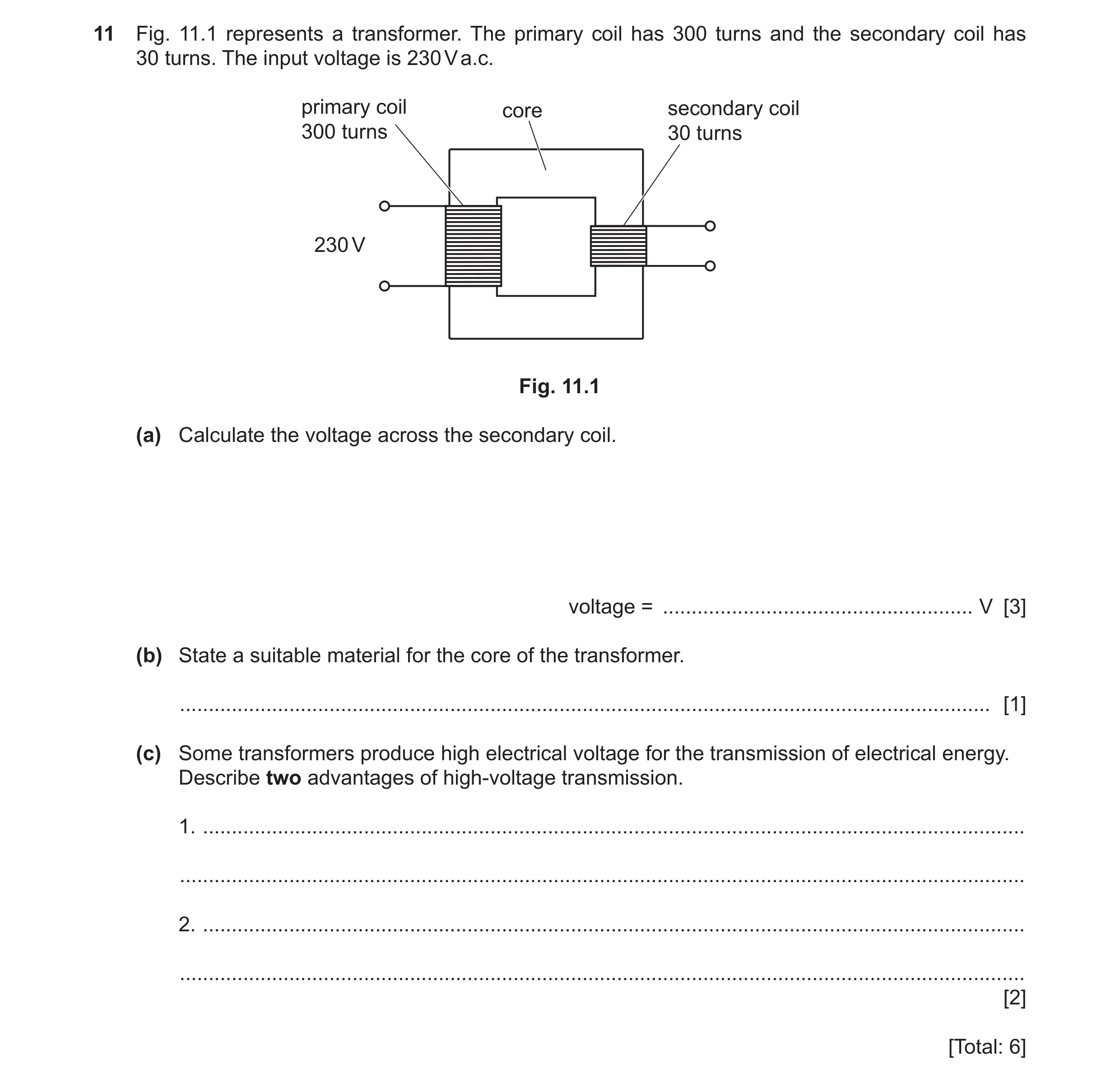
11 Fig. 11.1 represents a transformer. The primary coil has 300 turns and the secondary coil has 30 turns. The input voltage is 230 V a.c. primary coil core secondary coil 300 turns 30 turns 230 V Fig. 11.1 (a) Calculate the voltage across the secondary coil. voltage = … V [3] (b) State a suitable material for the core of the transformer. … [1] (c) Some transformers produce high electrical voltage for the transmission of electrical energy. Describe two advantages of high-voltage transmission. 1. … … 2. … … [2] [Total: 6]
6 marks
Mark scheme: 11(a) Vp ÷ Vs = Np ÷ Ns C1 230 ÷ Vs = 300 ÷ 30 C1 23 (V) A1 11(b) (soft) iron B1 11(c) Any two from: less energy or power wasted OR less heating(of wires) OR more efficient lower current (in transmission wires) can use thinner (transmission) wires / cables fewer power stations needed (so) lower cost for cable and supporting pylons transmit (energy over) longer distances (without drop in power) B2
This question in 0625/32 Oct/Nov 2020
Q29 · A clamp and stand hold a soft-iron bar above a bench 0625/33 Oct/Nov 2020
9 (a) A clamp and stand hold a soft-iron bar above a bench. A coil of wire is wrapped round the soft-iron bar. The coil of wire is part of an electric circuit. Fig. 9.1 shows the arrangement. soft-iron bar S clamp and soft-iron stand disc bench Fig. 9.1 Switch S is closed. A student holds a soft-iron disc close to the bar and releases the disc. The disc becomes attached to the bar as shown in Fig. 9.1. Explain why the soft-iron disc is attracted to the soft-iron bar. … … … [3] (b) The circuit in Fig. 9.1 is used to operate a bell in a different circuit, as shown in Fig. 9.2. soft-iron bar S clamp soft-iron arm and stand contacts pivot bell insulator Fig. 9.2 (i) Switch S is closed. The soft-iron arm is attracted to the soft-iron bar. Explain why the bell operates when the switch S is opened. … … … … … [4] (ii) The switch S is closed. The soft-iron arm is attracted to the soft-iron bar. The battery in the circuit containing the soft-iron bar becomes fully discharged. State and explain whether the bell operates. … … [1] [Total: 8]
8 marks
Mark scheme: 9(a) current (in coil / circuit) B1 magnetic (effect of current) C1 coil OR soft iron rod / bar (becomes a electro)magnet A1 9(b)(i) any four from: residual magnetism circuit broken OR no current in electromagnet / circuit electromagnet switched off / no longer attracts the (pivoted) arm (pivoted) arm falls current in bell OR alarm / bell circuit complete B4 9(b)(ii) bell rings M0 (because) electromagnet switched off / no longer attracts the (pivoted) arm / (pivoted) arm falls B1
This question in 0625/33 Oct/Nov 2020
Q30 · Describe an experiment to show that a force acts on a current-carrying conductor placed… 0625/33 Oct/Nov 2020
10 (a) Describe an experiment to show that a force acts on a current-carrying conductor placed in a magnetic field. You may draw a diagram to help your answer. … … … … … … … [4] (b) A current in a wire can cause the wire to get hot and melt the wire. Describe how to reduce the heating effect of a current. … … [1] [Total: 5]
5 marks
Mark scheme: 10(a) wire or rod positioned between magnetic poles B1 diagram or description of working circuit B1 current in circuit OR switch circuit on B1 wire / rod moves owtte B1 10(b) use resistor in series / only allow current to flow for a short time / use a smaller current / use a smaller p.d. / reduce the pd of the power supply B1
This question in 0625/33 Oct/Nov 2020
Q31 · The magnetic field pattern around a bar magnet 0625/32 Feb/March 2021
8 (a) Fig. 8.1 shows the magnetic field pattern around a bar magnet. S N Fig. 8.1 (i) Describe an experiment to identify the pattern and direction of magnetic field lines around a bar magnet as shown in Fig. 8.1. You may add to Fig. 8.1 as part of your answer. … … … … … [3] (ii) State a material that can be used to make a permanent bar magnet. … [1] (b) A student uses two bar magnets to create a uniform magnetic field. He places a current- carrying wire at right angles to the magnetic field, as shown in Fig. 8.2. separation of poles bar magnet bar magnet N S uniform current-carrying magnetic field wire Fig. 8.2 There is a force on the current-carrying wire. (i) The student wants to reverse the direction of the force on the wire. State one change that reverses the direction of the force on the wire. … [1] (ii) The student increases the separation of the poles of the permanent magnets. State and explain how increasing the separation affects the force on the current-carrying wire. … … [2] [Total: 7]
7 marks
Mark scheme: 8(a)(i) (plotting) compass OR iron filings B1 detail of method B1 use of (plotting) compass to give direction of field B1 8(a)(ii) steel B1 8(b)(i) reverse magnetic field owtte OR reverse current in wire B1 8(b)(ii) force is weaker B1 (because) magnetic field is weaker B1
This question in 0625/32 Feb/March 2021
Q32 · A student uses a laptop computer 0625/32 Feb/March 2021
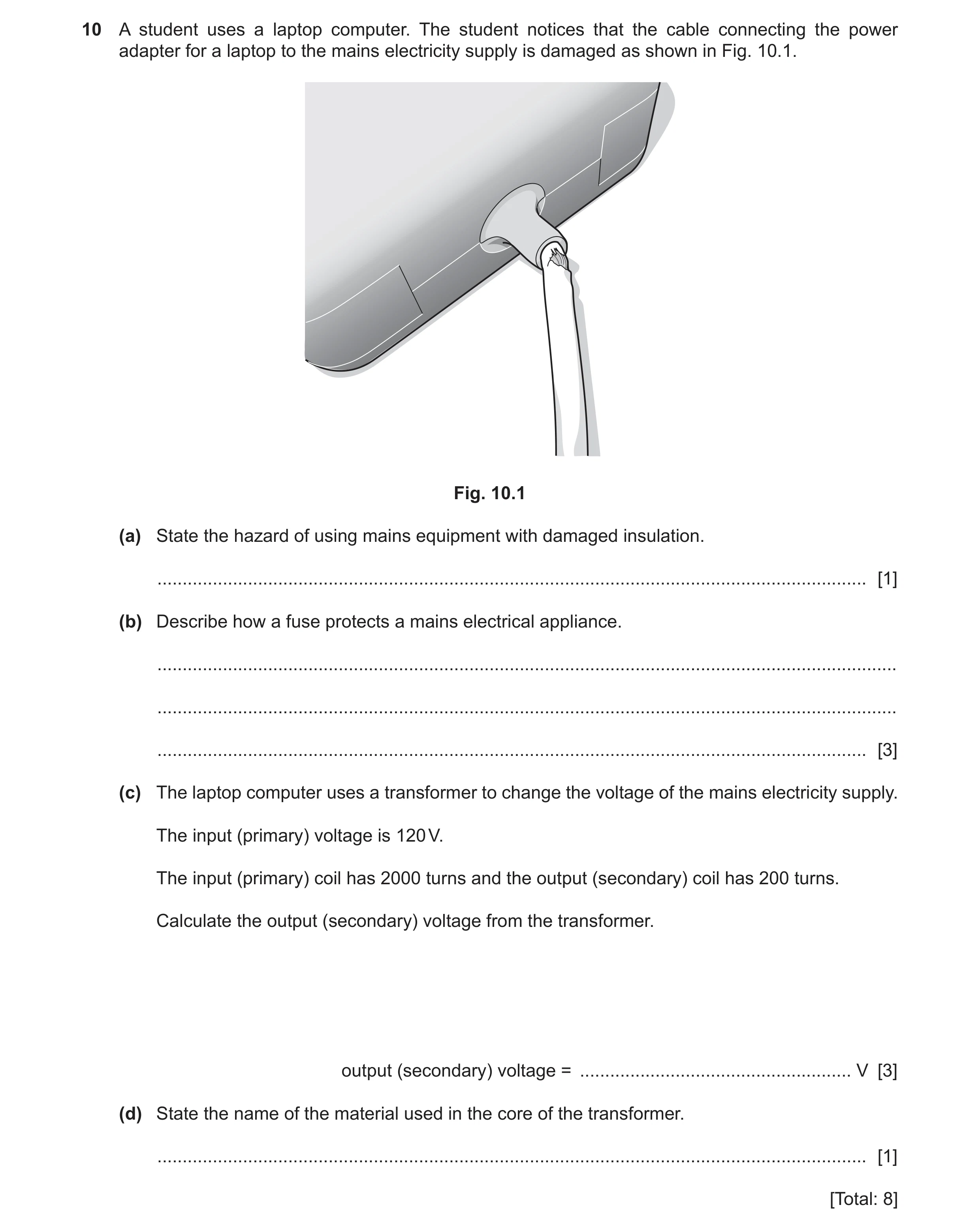
10 A student uses a laptop computer. The student notices that the cable connecting the power adapter for a laptop to the mains electricity supply is damaged as shown in Fig. 10.1. Fig. 10.1 (a) State the hazard of using mains equipment with damaged insulation. … [1] (b) Describe how a fuse protects a mains electrical appliance. … … … [3] (c) The laptop computer uses a transformer to change the voltage of the mains electricity supply. The input (primary) voltage is 120 V. The input (primary) coil has 2000 turns and the output (secondary) coil has 200 turns. Calculate the output (secondary) voltage from the transformer. output (secondary) voltage = … V [3] (d) State the name of the material used in the core of the transformer. … [1] [Total: 8]
8 marks
Mark scheme: 10(a) electrocution OR overheating / fire B1 10(b) large current (in fuse) B1 (causes) fuse / it to melt B1 isolating appliance from supply OR prevents current in appliance OR breaks circuit B1 10(c) Vs / Vp = Ns / Np C1 Vs / 120 = 200 / 2000 OR Vs = 120 × 200 / 2000 OR Vs = 120 / 10 C1 12 (V) A1 10(d) (soft) iron B1
This question in 0625/32 Feb/March 2021
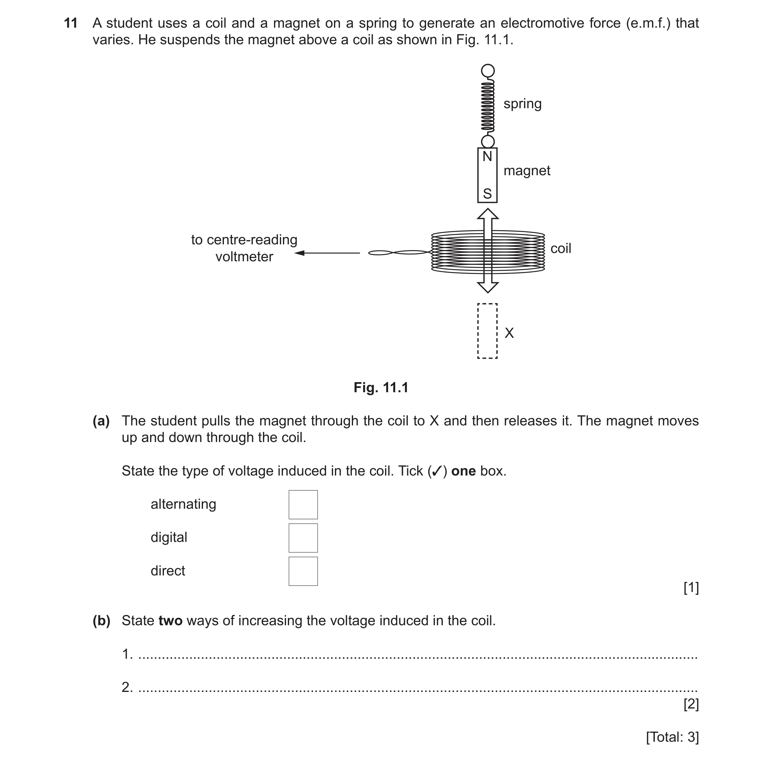
Q33 · A student uses a coil and a magnet on a spring to generate an electromotive force… 0625/31 May/June 2021
11 A student uses a coil and a magnet on a spring to generate an electromotive force (e.m.f.) that varies. He suspends the magnet above a coil as shown in Fig. 11.1. spring N magnet S to centre-reading coil voltmeter X Fig. 11.1 (a) The student pulls the magnet through the coil to X and then releases it. The magnet moves up and down through the coil. State the type of voltage induced in the coil. Tick (3) one box. alternating digital direct [1] (b) State two ways of increasing the voltage induced in the coil. 1. … 2. … [2] [Total: 3]
3 marks
Mark scheme: 11(a) top box ticked (alternating) B1 11(b) any two from: increase strength of magnet/magnetic field increase speed of magnet increase number of turns (of wire in coil) B2
This question in 0625/31 May/June 2021
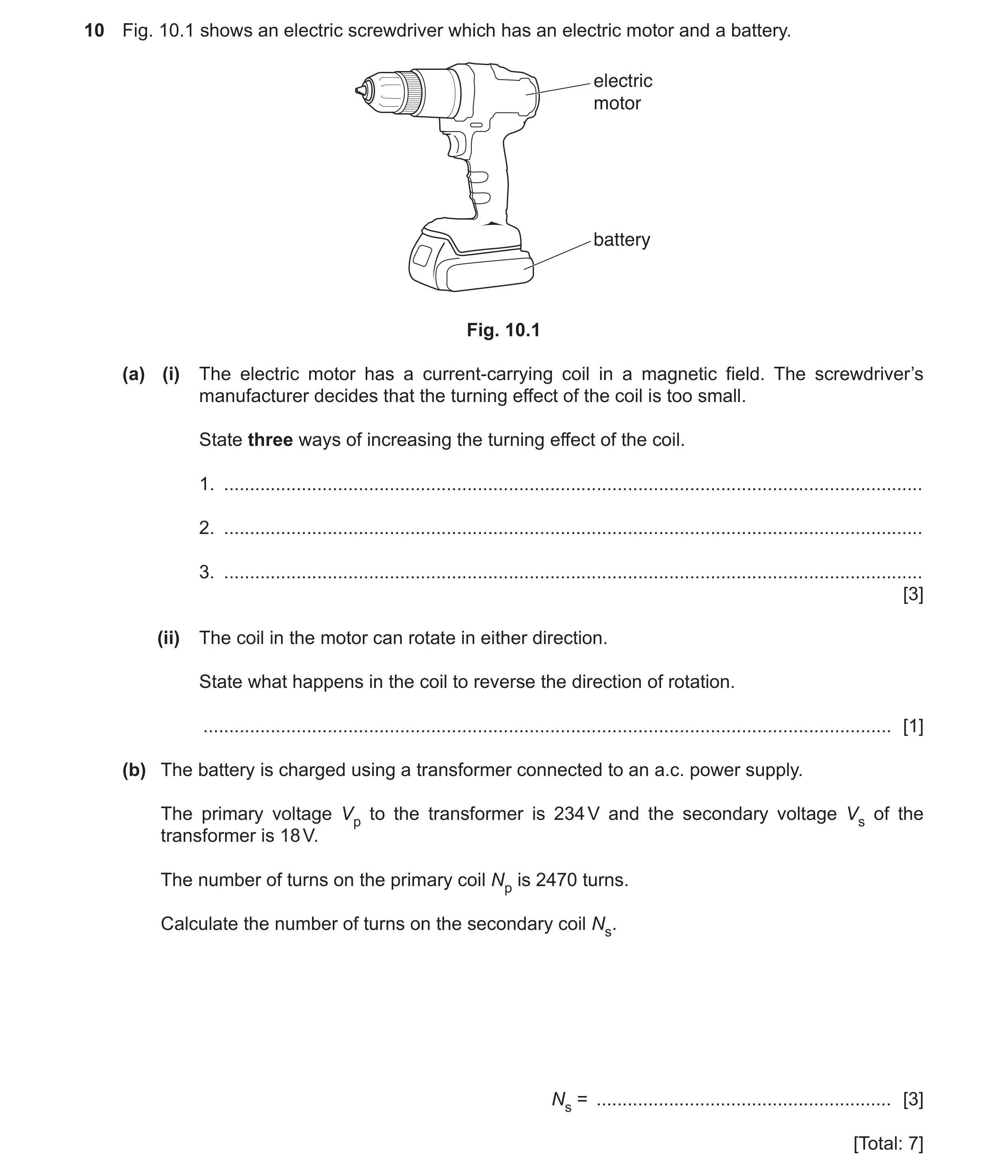
Q34 · An electric screwdriver which has an electric motor and a battery 0625/32 May/June 2021
10 Fig. 10.1 shows an electric screwdriver which has an electric motor and a battery. electric motor battery Fig. 10.1 (a) (i) The electric motor has a current-carrying coil in a magnetic field. The screwdriver’s manufacturer decides that the turning effect of the coil is too small. State three ways of increasing the turning effect of the coil. 1. … 2. … 3. … [3] (ii) The coil in the motor can rotate in either direction. State what happens in the coil to reverse the direction of rotation. … [1] (b) The battery is charged using a transformer connected to an a.c. power supply. The primary voltage Vp to the transformer is 234 V and the secondary voltage Vs of the transformer is 18 V. The number of turns on the primary coil Np is 2470 turns. Calculate the number of turns on the secondary coil Ns. Ns = … [3] [Total: 7]
7 marks
Mark scheme: 10(a)(i) increase current (in coil) B1 increase strength of magnet(s) or magnetic field(s) B1 increase the number of turns on the coil B1 Question Answer Marks 10(a)(ii) (direction of the) current (in the coil) is reversed B1 10(b) (Vp/Vs) = (Np/Ns) in any form C1 234 ÷ 18 = 2470 ÷ Ns OR Ns = 2470 ÷ (234 ÷ 18) OR 2470 ÷ 13 C1 (turns on secondary/output coil Ns =) 190 A1
This question in 0625/32 May/June 2021
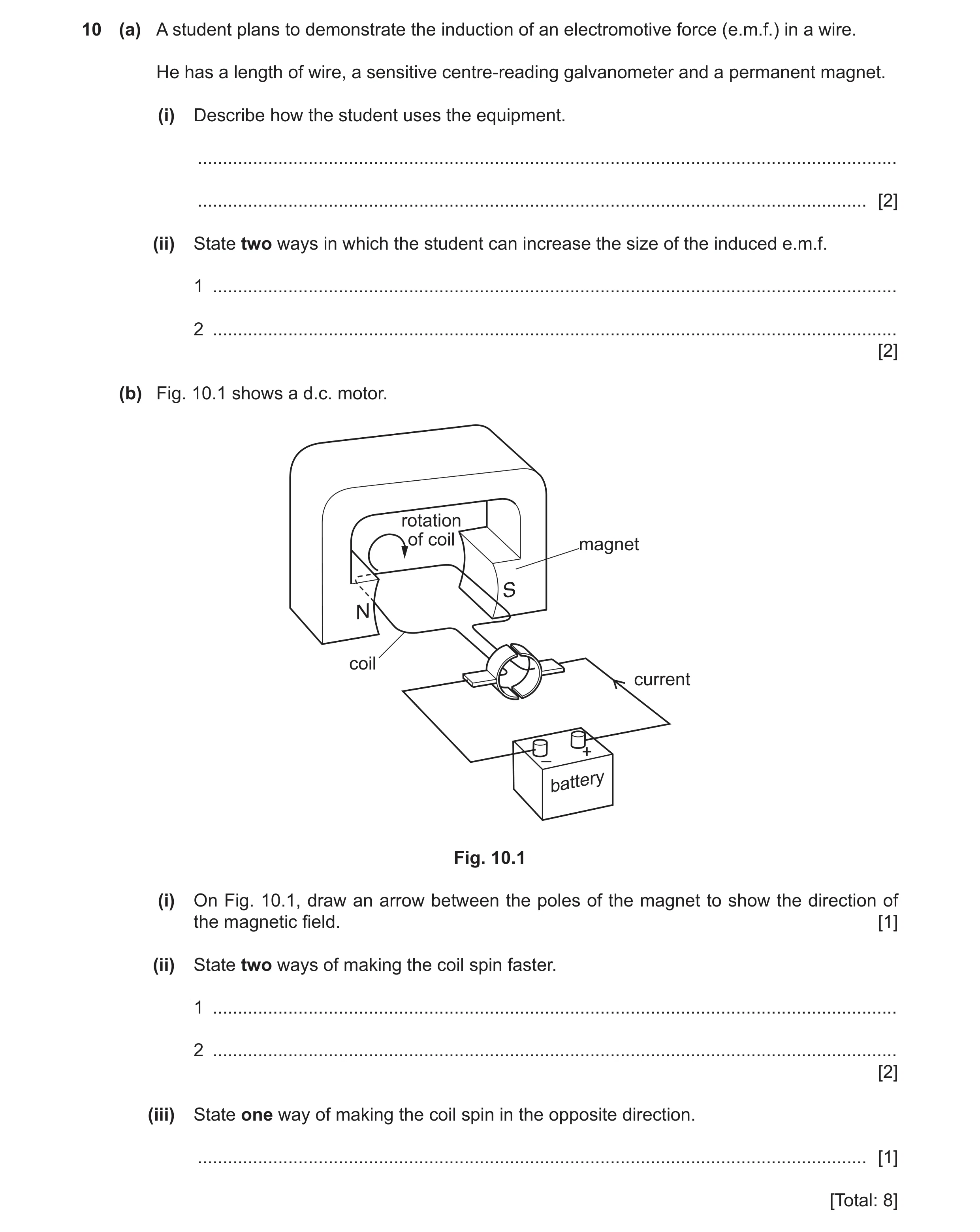
Q35 · A student plans to demonstrate the induction of an electromotive force (e.m.f.) in a wire 0625/31 Oct/Nov 2021
10 (a) A student plans to demonstrate the induction of an electromotive force (e.m.f.) in a wire. He has a length of wire, a sensitive centre‑reading galvanometer and a permanent magnet. (i) Describe how the student uses the equipment. … … [2] (ii) State two ways in which the student can increase the size of the induced e.m.f. 1 … 2 … [2] (b) Fig. 10.1 shows a d.c. motor. rotation of coil magnet coil current + – battery Fig. 10.1 (i) On Fig. 10.1, draw an arrow between the poles of the magnet to show the direction of the magnetic field. [1] (ii) State two ways of making the coil spin faster. 1 … 2 … [2] (iii) State one way of making the coil spin in the opposite direction. … [1] [Total: 8]
8 marks
Mark scheme: 10(a)(i) connect (both ends of) wire to galvanometer B1 move wire relative to magnet owtte B1 10(a)(ii) any two from: increase strength of magnet(ic field) OR strong(er) magnet turn wire into a coil owtte increase the speed (of relative motion) B2 10(b)(i) arrow drawn from N to S on Fig. 10.1 B1 10(b)(ii) any two from: increase (battery) voltage OR larger current in coil increase strength of magnet(ic) field OR strong(er) magnet increase number of turns in coil B2 10(b)(iii) reverse polarity of battery owtte OR reverse magnet(ic field) owtte B1
This question in 0625/31 Oct/Nov 2021
Q36 · A magnet and a coil of wire connected to a galvanometer 0625/32 Oct/Nov 2021
11 (a) Fig. 11.1 shows a magnet and a coil of wire connected to a galvanometer. magnet coil of wire S N direction of movement galvanometer Fig. 11.1 A student slowly moves the magnet into the coil. The pointer on the galvanometer moves to the left. This deflection shows that an electromotive force (e.m.f.) is induced in the coil. State three ways of increasing the size of the e.m.f. in the coil. 1 … 2 … 3 … [3] (b) Fig. 11.2 shows a transformer. primary coil secondary coil 1000 turns 50 turns 240 V core Fig. 11.2 (i) Name one material that is suitable for the core of the transformer. … [1] (ii) The primary coil has 1000 turns and its input is 240 V a.c. The secondary coil has 50 turns. Calculate the output voltage across the secondary coil. output voltage = … V [3] [Total: 7]
7 marks
Mark scheme: 11(a) strong(er) magnet B1 move (magnet) more quickly / faster movement B1 more turns / coils (per unit length) B1 11(b)(i) (soft) iron B1 11(b)(ii) Vp / Vs = Np / Ns in any form C1 (Vs =) 240 × 50 / 1000 C1 12 (V) A1
This question in 0625/32 Oct/Nov 2021
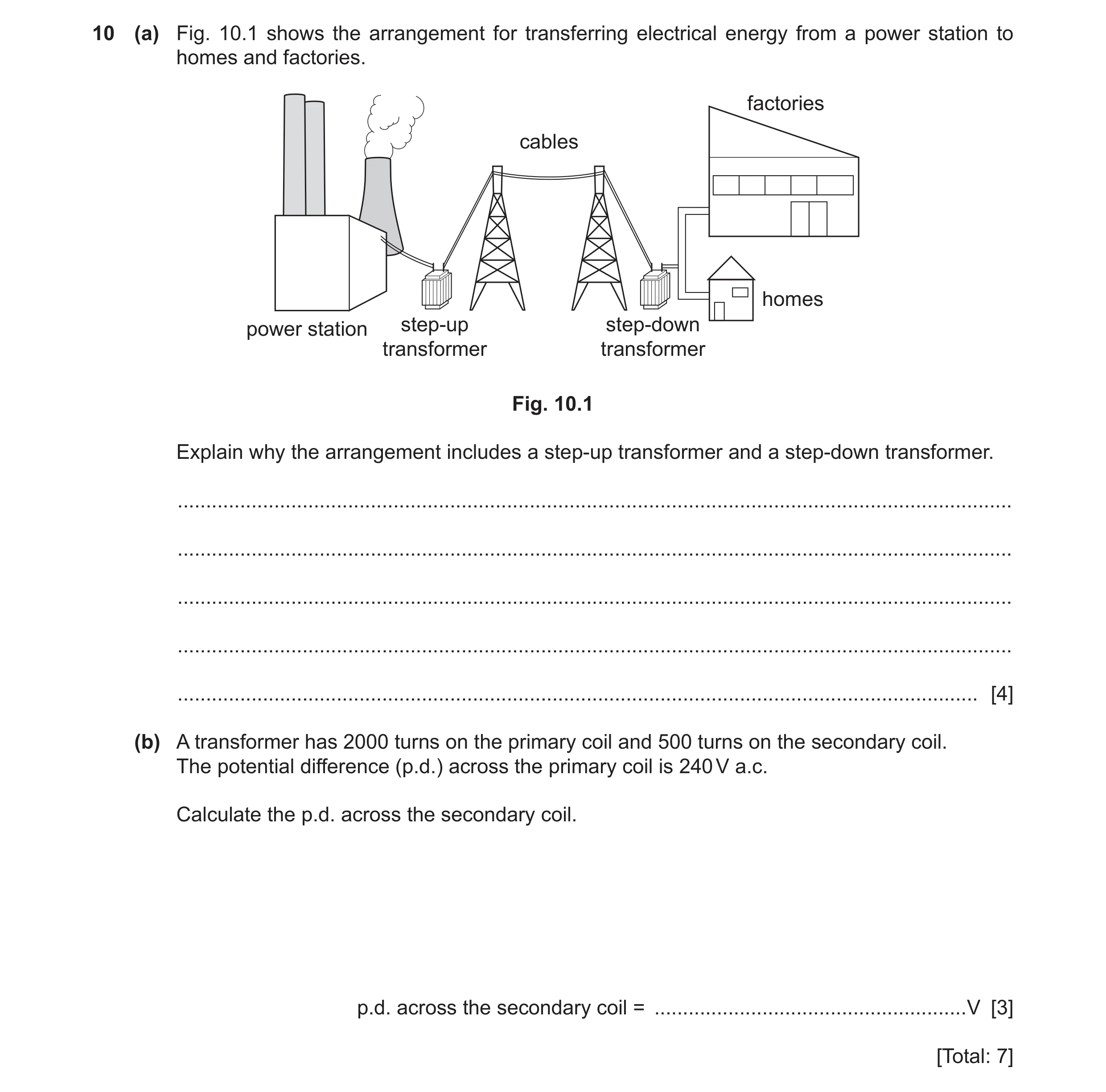
Q37 · The arrangement for transferring electrical energy from a power station to homes and… 0625/33 Oct/Nov 2021
10 (a) Fig. 10.1 shows the arrangement for transferring electrical energy from a power station to homes and factories. factories cables homes power station step-up step-down transformer transformer Fig. 10.1 Explain why the arrangement includes a step-up transformer and a step-down transformer. … … … … … [4] (b) A transformer has 2000 turns on the primary coil and 500 turns on the secondary coil. The potential difference (p.d.) across the primary coil is 240 V a.c. Calculate the p.d. across the secondary coil. p.d. across the secondary coil = … V [3] [Total: 7]
7 marks
Mark scheme: 10(a) any four from: step up: increase voltage / high voltage in power lines lower current reduce power / energy losses step down: lower voltage / low voltage in homes safety/match for appliances / machines thinner cables (can be used) 10(b) Vp / Vs = Np / Ns in any form C1 Vs = (500 / 2000) × 240 C1 60 (V) A1
This question in 0625/33 Oct/Nov 2021
Q38 · A battery charger for a laptop computer includes a transformer 0625/32 Feb/March 2022
11 A battery charger for a laptop computer includes a transformer. (a) The primary voltage Vp to the transformer is 240 V. The number of turns on the primary coil Np is 590 turns and the number of turns on the secondary coil Ns of the transformer is 48 turns. Calculate the secondary voltage Vs of the transformer. secondary voltage Vs = … V [3] (b) The plug connecting the transformer to the supply voltage contains a fuse. Describe how a fuse works. … … … … [3] [Total: 6]
6 marks
Mark scheme: 11(a) 20 (V) A3 Vs / 240 = 48 / 590 OR Vs = (48 / 590) × 240 OR Vs = 240 ÷ 12.3 OR 48 / 590 = ? / 240 OR 240 48 590 × (C2) Vs / Vp = Ns / Np in any form (C1) 11(b) large current (in fuse) B1 (causes) fuse to melt B1 isolating appliance from supply OR prevents / stops current in appliance / circuit B1
This question in 0625/32 Feb/March 2022
Q39 · Describe how a wind turbine generates electricity from energy in the wind 0625/31 May/June 2022
5 (a) Describe how a wind turbine generates electricity from energy in the wind. … … … [3] (b) Apart from cost, state two advantages of generating electricity using wind turbines compared with using a power station that burns coal. 1. … 2. … [2] (c) Apart from cost, state two disadvantages of generating electricity using wind turbines compared with using a power station that burns coal. 1. … 2. … [2] [Total: 7]
7 marks
Mark scheme: 5(a) any three from: (moving) air has kinetic energy OR wind has kinetic energy (moving) air / wind turns turbine/blades turbine turns generator (rotating) generator produces/generates electricity B3 5(b) any two from: (wind is) renewable (energy source) no greenhouse gases / CO2 produced (during operation) no SO2 OR acidic gases produced (during operation) OR no nitrous oxides produced B2 5(c) any two from: large(r) area of land needed OR dilute energy source intermittent/inconsistent/unreliable supply OR cannot work if wind too strong/weak (possible) harm to (migrating) birds difficult to maintain (particularly if off-shore) B2
This question in 0625/31 May/June 2022
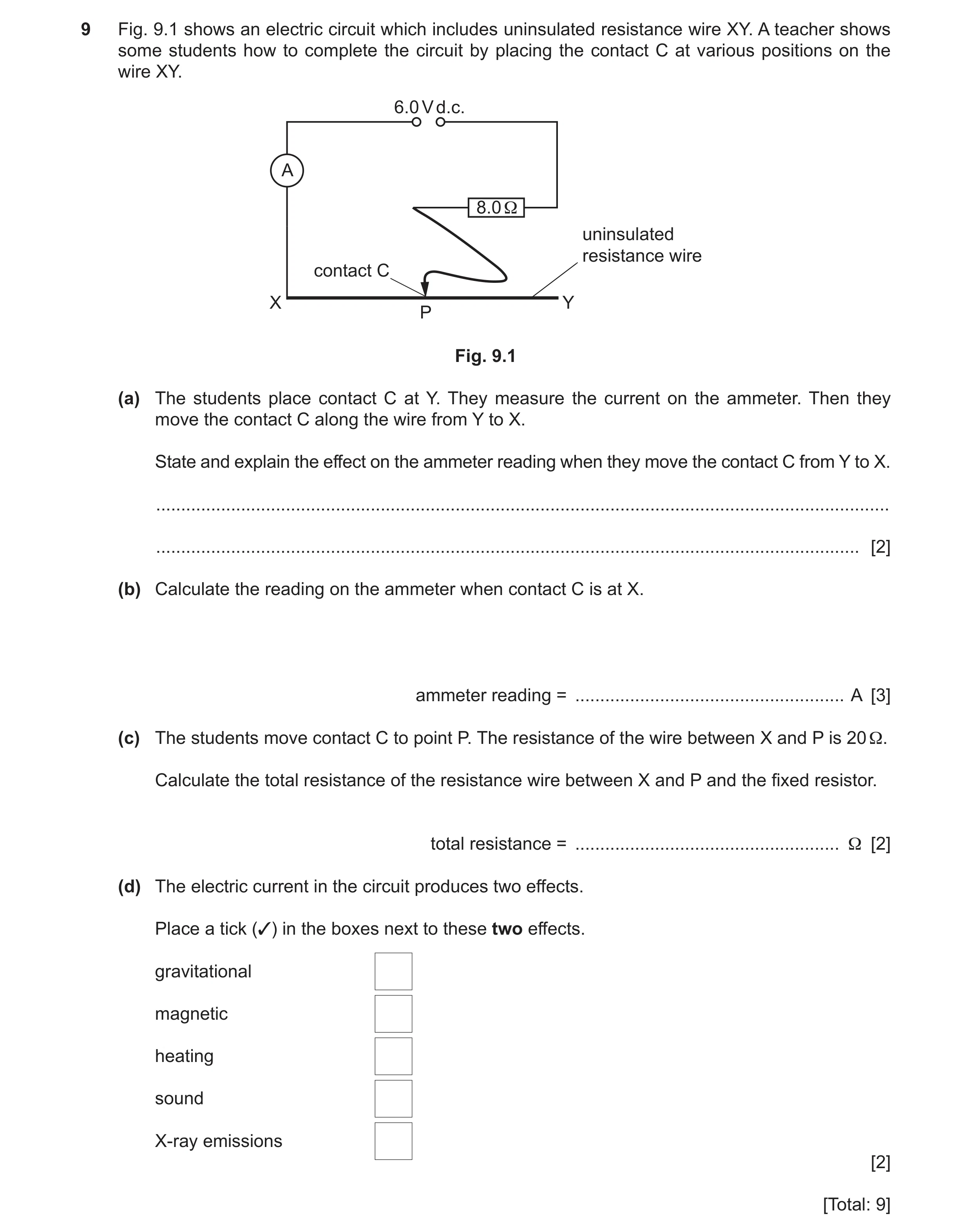
Q40 · An electric circuit which includes uninsulated resistance wire XY 0625/31 May/June 2022
9 Fig. 9.1 shows an electric circuit which includes uninsulated resistance wire XY. A teacher shows some students how to complete the circuit by placing the contact C at various positions on the wire XY. 6.0 V d.c. A 8.0 Ω uninsulated resistance wire contact C X Y P Fig. 9.1 (a) The students place contact C at Y. They measure the current on the ammeter. Then they move the contact C along the wire from Y to X. State and explain the effect on the ammeter reading when they move the contact C from Y to X. … … [2] (b) Calculate the reading on the ammeter when contact C is at X. ammeter reading = … A [3] (c) The students move contact C to point P. The resistance of the wire between X and P is 20 Ω. Calculate the total resistance of the resistance wire between X and P and the fixed resistor. total resistance = … Ω [2] (d) The electric current in the circuit produces two effects. Place a tick (3) in the boxes next to these two effects. gravitational magnetic heating sound X-ray emissions [2] [Total: 9]
9 marks
Mark scheme: 9(a) (current/reading/it) increases B1 (because circuit) resistance decreases B1 9(b) 0.75 (A) A3 6(.0) ÷ 8(.0) (C2) V= IR or (I =) V/R (C1) 9(c) 28 () A2 (total resistance =) R1 + R2 OR 20 + 8(.0) (C1) 9(d) tick in 2nd box (magnetic) B1 tick in 3rd box (heating) B1
This question in 0625/31 May/June 2022
Q41 · A microwave oven has a metal case and is connected to a 240 V electricity supply 0625/31 May/June 2022
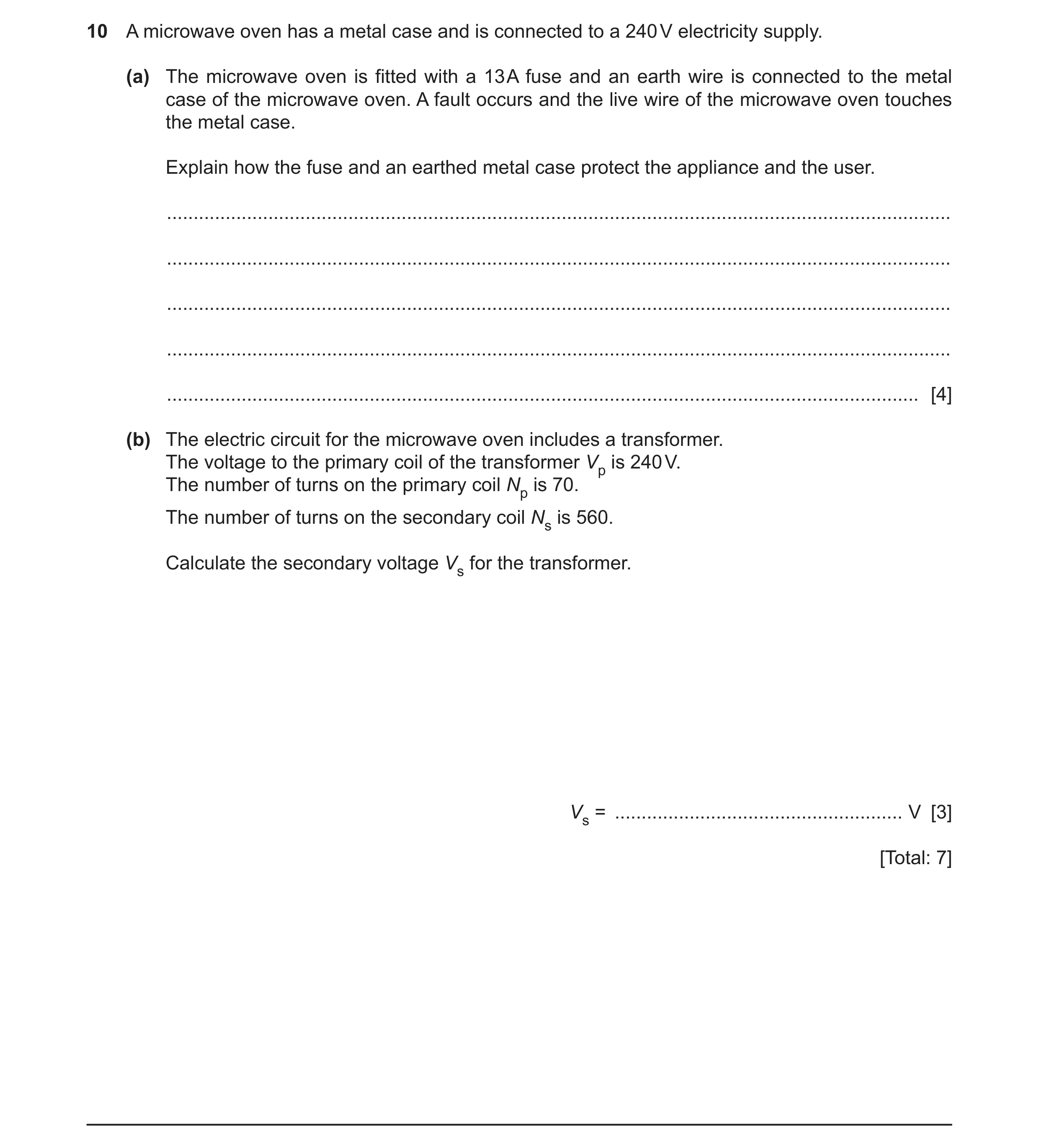
10 A microwave oven has a metal case and is connected to a 240 V electricity supply. (a) The microwave oven is fitted with a 13 A fuse and an earth wire is connected to the metal case of the microwave oven. A fault occurs and the live wire of the microwave oven touches the metal case. Explain how the fuse and an earthed metal case protect the appliance and the user. … … … … … [4] (b) The electric circuit for the microwave oven includes a transformer. The voltage to the primary coil of the transformer Vp is 240 V. The number of turns on the primary coil Np is 70. The number of turns on the secondary coil Ns is 560. Calculate the secondary voltage Vs for the transformer. Vs = … V [3] [Total: 7]
7 marks
Mark scheme: 10(a) any four from: Earth wire keeps case at zero volts/earth (potential) (so) user not electrocuted (live wire touching metal case produces) large current (in fuse/earth wire) (causes) fuse to melt isolating appliance from supply OR (so) no current in appliance OR disconnects/breaks the circuit prevent(s/ing electrical) fire/overheating (in cables/appliance) Question Answer Marks 10(b) 1920 (V) A3 Vs / 240 = 560/70 OR Vs = (560/70) 240 OR Vs = 240 8 OR 560/70 = ? / 240 (C2) Vs/Vp = Ns/Np in any form (C1)
This question in 0625/31 May/June 2022
Q42 · Parts of a coal-fired power station 0625/32 May/June 2022
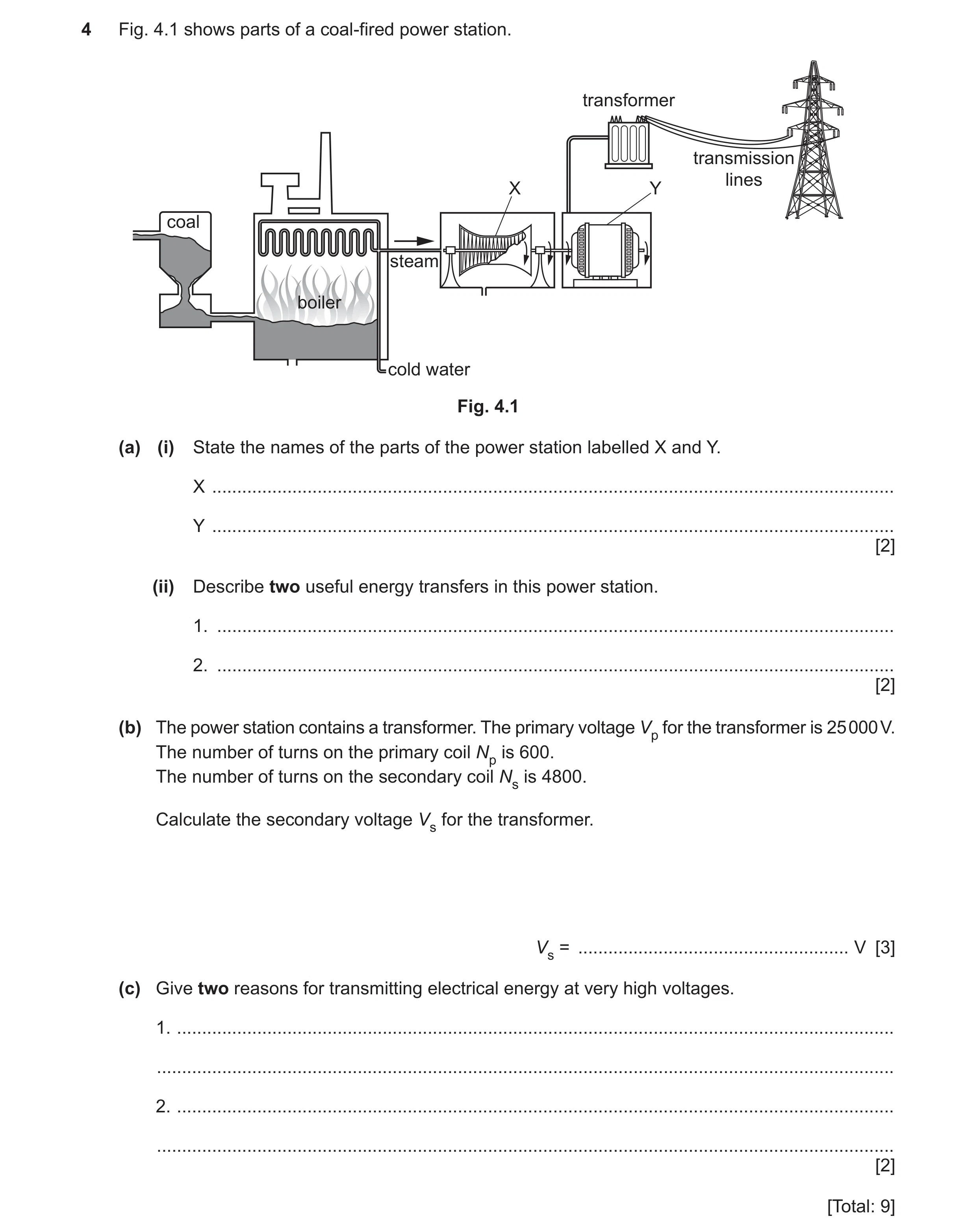
4 Fig. 4.1 shows parts of a coal-fired power station. transformer transmission lines X Y coal steam boiler cold water Fig. 4.1 (a) (i) State the names of the parts of the power station labelled X and Y. X … Y … [2] (ii) Describe two useful energy transfers in this power station. 1. … 2. … [2] (b) The power station contains a transformer. The primary voltage Vp for the transformer is 25 000 V. The number of turns on the primary coil Np is 600. The number of turns on the secondary coil Ns is 4800. Calculate the secondary voltage Vs for the transformer. Vs = … V [3] (c) Give two reasons for transmitting electrical energy at very high voltages. 1. … … 2. … … [2] [Total: 9]
9 marks
Mark scheme: 4(a)(i) (X is a) turbine B1 (Y is a) generator B1 4(a)(ii) any two from: chemical energy (in coal) to thermal/internal energy (in boiler) thermal/internal energy (of steam/water) to kinetic energy (of steam) kinetic energy of steam to kinetic energy of turbine/generator kinetic energy (of generator) to electrical energy B2 4(b) 200 000 (V) A3 Vs / 25 000 = 4800/600 OR Vs = (4800/600) 25 000 OR Vs = 25 000 8 OR 4800/600 = ? / 25 000 (C2) Vs/Vp = Ns/Np in any form (C1) Question Answer Marks 4(c) any two from: reduces current (in cables) less energy or power wasted or less heating or more efficient enables use of thinner cables (so) lower cost for cable and supporting pylons transmit (electricity over) longer distances (without drop in p.d.) B2
This question in 0625/32 May/June 2022
Q43 · A wire passing through a card 0625/32 May/June 2022
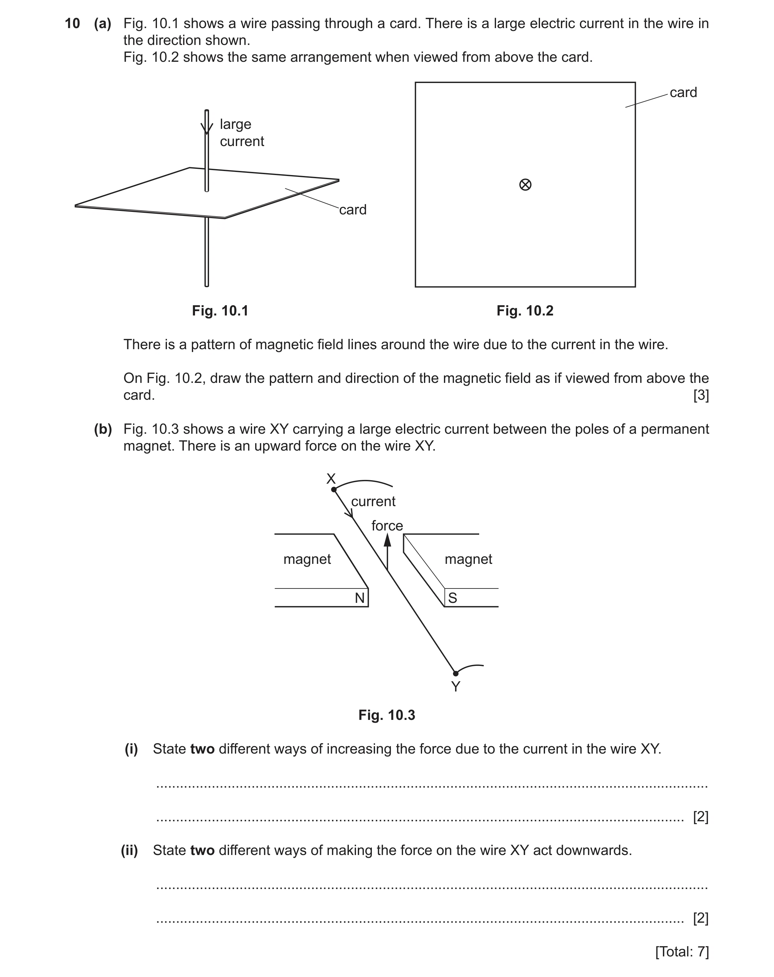
10 (a) Fig. 10.1 shows a wire passing through a card. There is a large electric current in the wire in the direction shown. Fig. 10.2 shows the same arrangement when viewed from above the card. card large current card Fig. 10.1 Fig. 10.2 There is a pattern of magnetic field lines around the wire due to the current in the wire. On Fig. 10.2, draw the pattern and direction of the magnetic field as if viewed from above the card. [3] (b) Fig. 10.3 shows a wire XY carrying a large electric current between the poles of a permanent magnet. There is an upward force on the wire XY. X current force magnet magnet N S Y Fig. 10.3 (i) State two different ways of increasing the force due to the current in the wire XY. … … [2] (ii) State two different ways of making the force on the wire XY act downwards. … … [2] [Total: 7]
7 marks
Mark scheme: 10(a) circles drawn B1 concentric (by eye) with wire B1 arrow drawn clockwise on/near field (line) B1 10(b)(i) any two from: increase current (in wire) increase strength of magnets or magnetic field move poles closer together B2 10(b)(ii) reverse the (direction of the) current (in the wire) B1 reverse the magnetic field B1
This question in 0625/32 May/June 2022
Q44 · The device in Fig 0625/33 May/June 2022
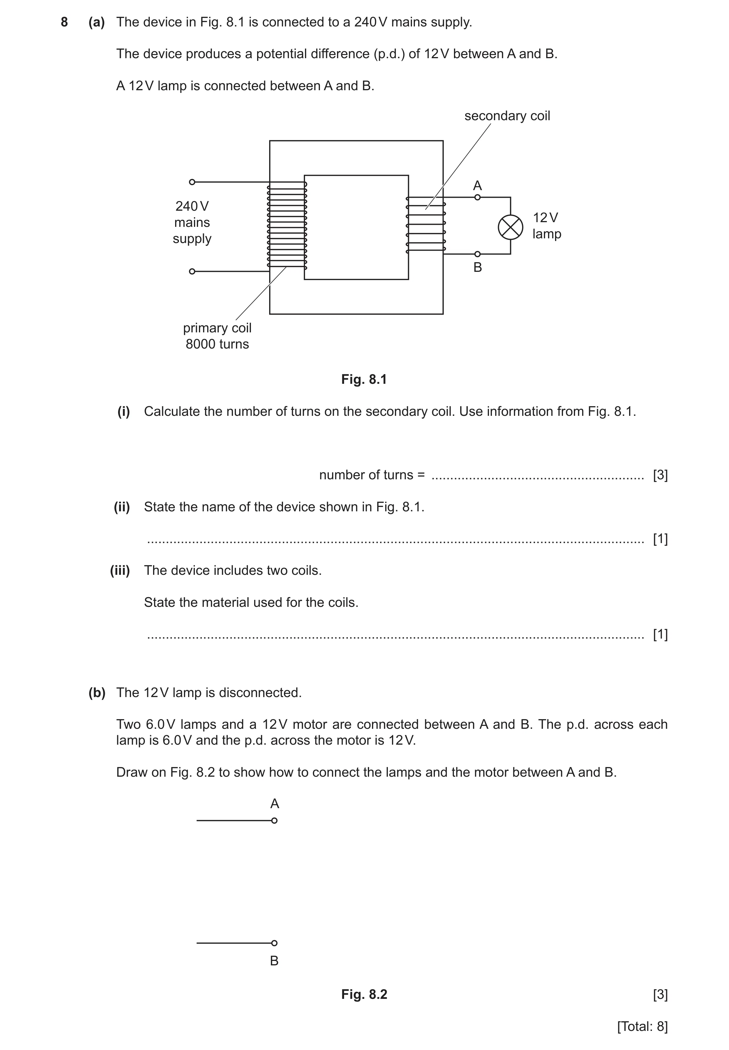
8 (a) The device in Fig. 8.1 is connected to a 240 V mains supply. The device produces a potential difference (p.d.) of 12 V between A and B. A 12 V lamp is connected between A and B. secondary coil A 240 V 12 V mains lamp supply B primary coil 8000 turns Fig. 8.1 (i) Calculate the number of turns on the secondary coil. Use information from Fig. 8.1. number of turns = … [3] (ii) State the name of the device shown in Fig. 8.1. … [1] (iii) The device includes two coils. State the material used for the coils. … [1] (b) The 12 V lamp is disconnected. Two 6.0 V lamps and a 12 V motor are connected between A and B. The p.d. across each lamp is 6.0 V and the p.d. across the motor is 12 V. Draw on Fig. 8.2 to show how to connect the lamps and the motor between A and B. A B Fig. 8.2 [3] [Total: 8]
8 marks
Mark scheme: 8(a)(i) 400 A3 (Ns = ) NP VS/VP OR 8000 12/240 (C2) VP/VS = NP/NS in any form (C1) 8(a)(ii) (step-down) transformer B1 8(a)(iii) copper B1 8(b) motor connected between A and B B1 2 lamps in series connected between A and B A2 2 lamps in series (C1)
This question in 0625/33 May/June 2022
Q45 · A transformer used on a building site 0625/31 Oct/Nov 2022
9 Fig. 9.1 shows a transformer used on a building site. output socket mains plug for transformer Fig. 9.1 (a) The mains plug for the transformer contains a fuse. (i) Give a reason why the plug includes a fuse. … [1] (ii) Explain how a fuse works. … … [2] (b) The mains input (primary) potential difference (p.d.) to the transformer is 230 V a.c. The number of turns on the input (primary) coil is 314. The number of turns on the output (secondary) coil is 150. Calculate the output (secondary) p.d. from the transformer. output p.d. = … V [3] (c) Fig. 9.2 shows an outline of the transformer. core primary coil secondary coil 314 turns 150 turns 230 V a.c. Fig. 9.2 (i) State a suitable material for the core of the transformer. … [1] (ii) State a suitable material for the primary and secondary coils of the transformer. … [1] (iii) Explain how Fig. 9.2 shows a step-down transformer. … [1] [Total: 9]
9 marks
Mark scheme: 9(a)(i) protects (transformer / wiring) from fire / overheating B1 9(a)(ii) any two from: B2 • large current (in fuse) • (causes) fuse to melt • (and so) prevents current in appliance OR breaks circuit OR isolates appliance from supply. 9(b) 110 (V) A3 Vs / 230 = 150 / 314 OR Vs = (150 / 314) × 230 OR Vs = 230 / 2.093 OR 150 / 314 = ? / 230 C2 Vs / Vp = Ns / Np C1 9(c)(i) (soft) iron B1 9(c)(ii) copper B1 9(c)(iii) fewer turns on output / secondary (than on input coil) B1
This question in 0625/31 Oct/Nov 2022
Question 46 0625/32 Oct/Nov 2022
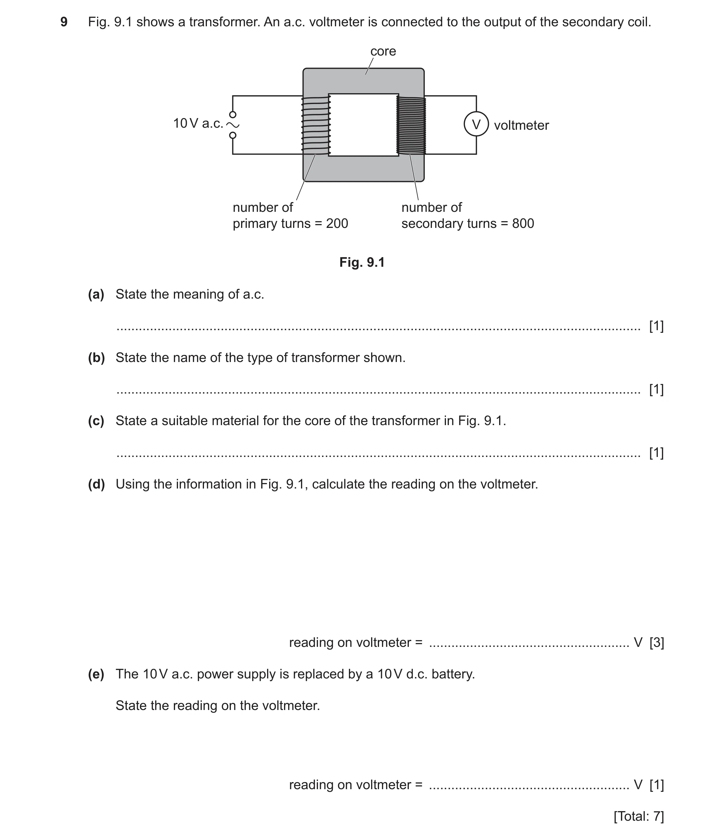
9 Fig. 9.1 shows a transformer. An a.c. voltmeter is connected to the output of the secondary coil. core 10 V a.c. V voltmeter number of number of primary turns = 200 secondary turns = 800 Fig. 9.1 (a) State the meaning of a.c. … [1] (b) State the name of the type of transformer shown. … [1] (c) State a suitable material for the core of the transformer in Fig. 9.1. … [1] (d) Using the information in Fig. 9.1, calculate the reading on the voltmeter. reading on voltmeter = … V [3] (e) The 10 V a.c. power supply is replaced by a 10 V d.c. battery. State the reading on the voltmeter. reading on voltmeter = … V [1] [Total: 7]
7 marks
Mark scheme: 9(a) alternating (current) B1 9(b) step-up B1 9(c) (soft) iron B1 9(d) 40 (V) A3 (VS =) 800 / 200 10 (C2) VP / VS = NP / NS in any form (C1) 9(e) zero B1
This question in 0625/32 Oct/Nov 2022
Q47 · The equipment used by a teacher in a laboratory demonstration 0625/32 Oct/Nov 2022
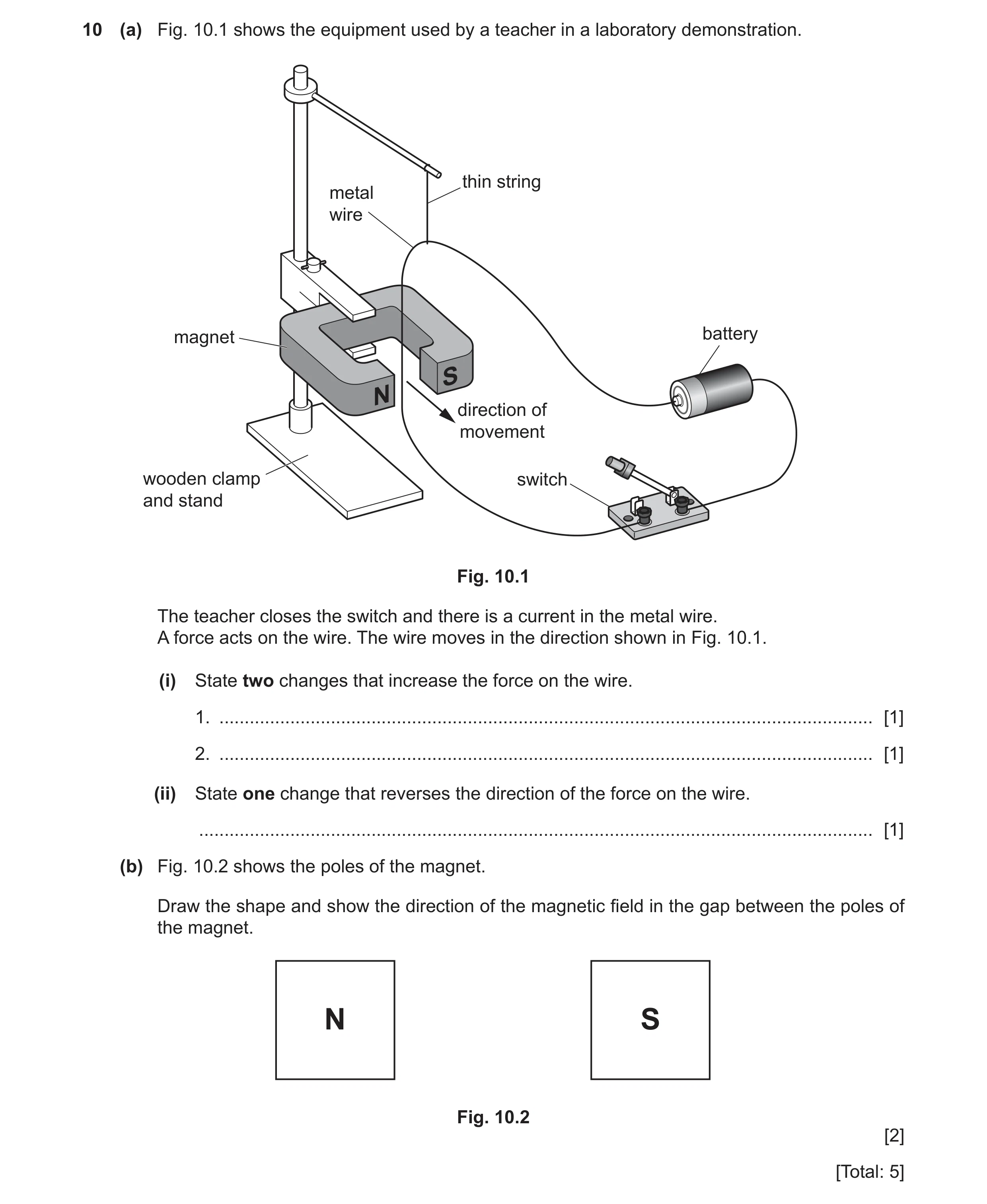
10 (a) Fig. 10.1 shows the equipment used by a teacher in a laboratory demonstration. thin string metal wire magnet battery S N direction of movement wooden clamp switch and stand Fig. 10.1 The teacher closes the switch and there is a current in the metal wire. A force acts on the wire. The wire moves in the direction shown in Fig. 10.1. (i) State two changes that increase the force on the wire. 1. … [1] 2. … [1] (ii) State one change that reverses the direction of the force on the wire. … [1] (b) Fig. 10.2 shows the poles of the magnet. Draw the shape and show the direction of the magnetic field in the gap between the poles of the magnet. N S Fig. 10.2 [2] [Total: 5]
5 marks
Mark scheme: 10(a)(i) 1 increase the current / pd / emf / voltage (of cell) B1 2 stronger magnet B1 10(a)(ii) reverse battery OR reverse current (direction) OR reverse magnetic field owtte B1 10(b) 3 or more correct lines B1 direction from N to S indicated B1
This question in 0625/32 Oct/Nov 2022
Q48 · Two coils of wire P and Q, each in a circuit 0625/32 Feb/March 2023
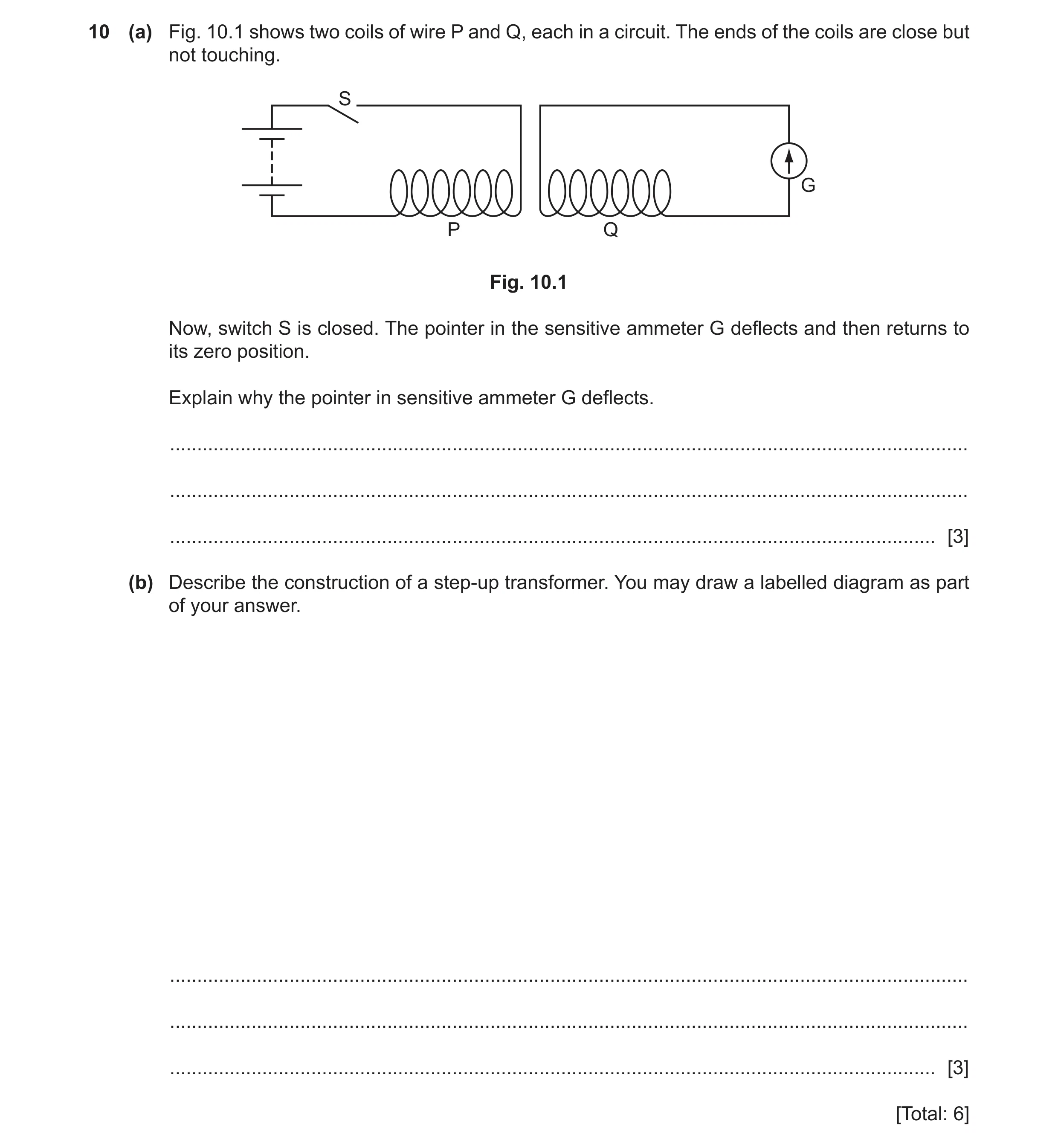
10 (a) Fig. 10.1 shows two coils of wire P and Q, each in a circuit. The ends of the coils are close but not touching. S G P Q Fig. 10.1 Now, switch S is closed. The pointer in the sensitive ammeter G deflects and then returns to its zero position. Explain why the pointer in sensitive ammeter G deflects. … … … [3] (b) Describe the construction of a step-up transformer. You may draw a labelled diagram as part of your answer. … … … [3] [Total: 6]
6 marks
Mark scheme: 10(a) any three from B3 (when switch S closed) current in coil P coil P has (changing) magnetic field magnetic field (from P) links with / cuts coil Q e.m.f. / voltage / current induced / produced / generated in coil Q 10(b) two coils (of copper wire) B1 (wrapped around / linked by soft) iron core B1 more turns on secondary coil OR less turns on primary coil B1
This question in 0625/32 Feb/March 2023
Q49 · An arrangement used to demonstrate electromagnetic induction 0625/31 May/June 2023
10 (a) Fig. 10.1 shows an arrangement used to demonstrate electromagnetic induction. magnet moves towards coil coil of wire S N permanent magnet sensitive voltmeter Fig. 10.1 (i) When the magnet moves towards the coil of wire, the pointer on the sensitive voltmeter deflects to the right. Explain why the pointer deflects. … … [2] (ii) State two changes that increase the deflection on the sensitive voltmeter. 1 … 2 … [2] (b) Fig. 10.2 shows the symbol for a transformer. The primary coil is connected to a voltage of 180 V a.c. primary voltage Vp = 180 V a.c. primary coil secondary coil 4800 turns 200 turns secondary voltage Vs Fig. 10.2 Calculate the secondary voltage Vs for the transformer. Vs = … V [3] [Total: 7]
7 marks
Mark scheme: 10(a)(i) any two from: magnetic field cuts / links with coil / conductor / wire e.m.f. / voltage / p.d. induced (in coil) 10(a)(ii) any two from: increase strength of the magnet(ic field) increase speed of the magnet increase (the number of) turns on coil B2 10(b) (Vs =) 7.5 (V) A3 Vs/ 180 = 200 / 4800 OR (Vs =) (200 180) 4800 (C2) Vs/ Vp = Ns/ Np (C1)
This question in 0625/31 May/June 2023
Q50 · A student has a desktop computer that connects to the 240 V a.c 0625/32 May/June 2023
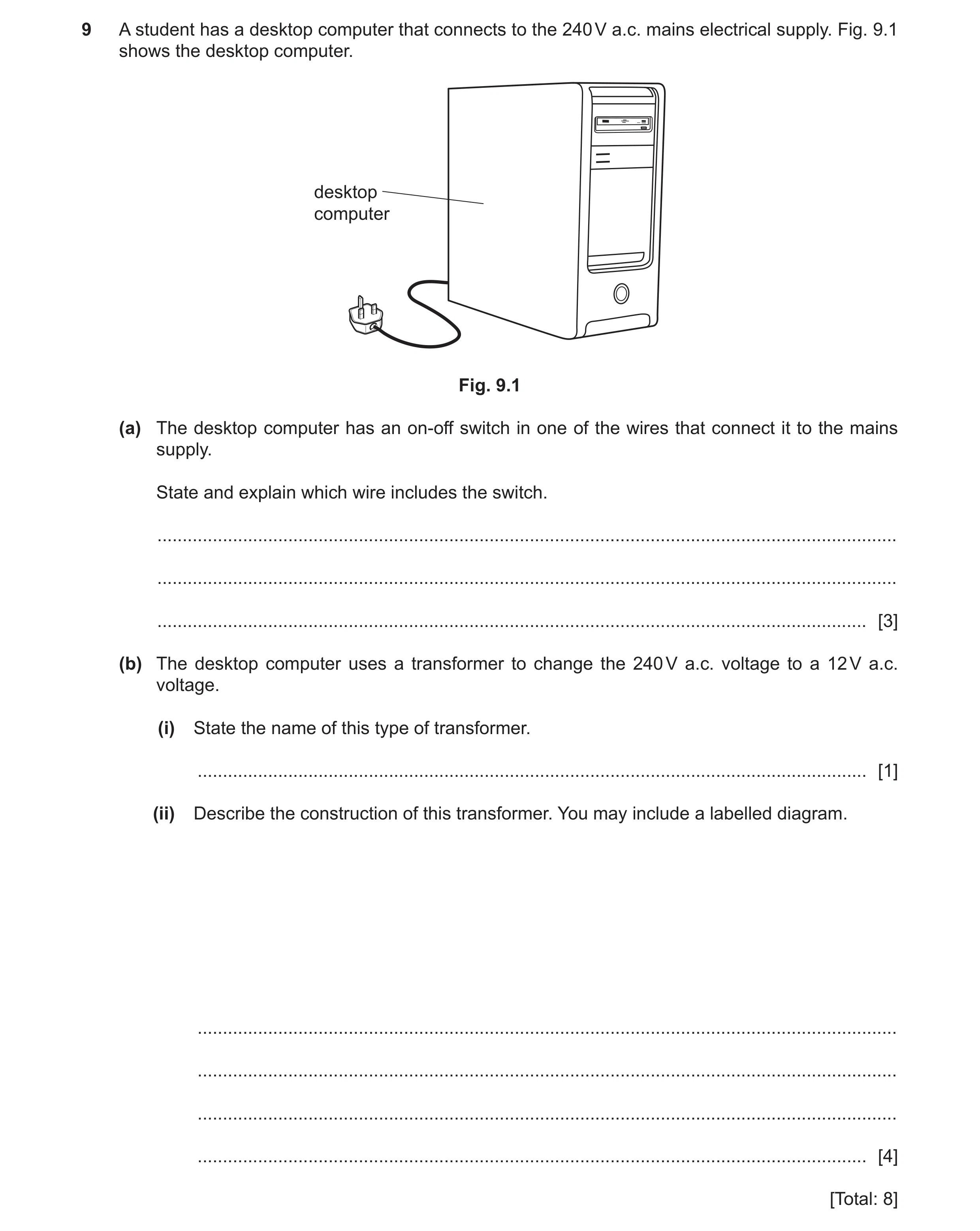
9 A student has a desktop computer that connects to the 240 V a.c. mains electrical supply. Fig. 9.1 shows the desktop computer. desktop computer Fig. 9.1 (a) The desktop computer has an on-off switch in one of the wires that connect it to the mains supply. State and explain which wire includes the switch. … … … [3] (b) The desktop computer uses a transformer to change the 240 V a.c. voltage to a 12 V a.c. voltage. (i) State the name of this type of transformer. … [1] (ii) Describe the construction of this transformer. You may include a labelled diagram. … … … … [4] [Total: 8]
8 marks
Mark scheme: 9(a) (switch is in) the live wire B1 (so when switch is off, desktop is) disconnected from supply / mains(voltage) OR high voltage B1 (so) no current (in computer / circuit) OR no risk of electrocution B1 9(b)(i) step-down (transformer) B1 9(b)(ii) any four from: (soft) iron core two coils of copper wire primary coil AND secondary coil transformer equation stated turns ratio of 20 : 1 OR 240 : 12 owtte OR use of transformer equation B4
This question in 0625/32 May/June 2023
Question 51 0625/31 Oct/Nov 2023
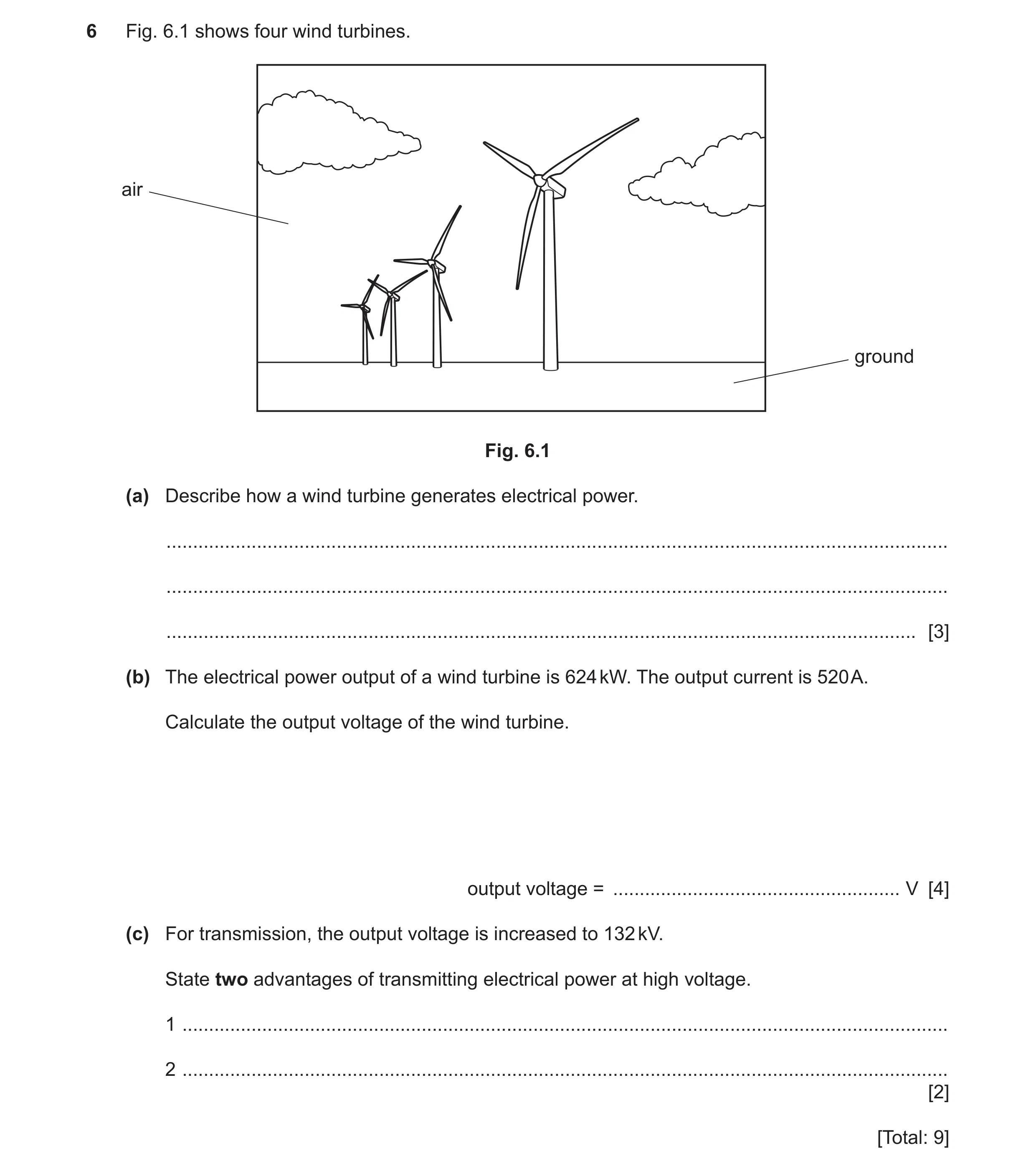
6 Fig. 6.1 shows four wind turbines. air ground Fig. 6.1 (a) Describe how a wind turbine generates electrical power. … … … [3] (b) The electrical power output of a wind turbine is 624 kW. The output current is 520 A. Calculate the output voltage of the wind turbine. output voltage = … V [4] (c) For transmission, the output voltage is increased to 132 kV. State two advantages of transmitting electrical power at high voltage. 1 … 2 … [2] [Total: 9]
9 marks
Mark scheme: 6(a) KE of wind B1 rotates / turns / spins turbine OR blades B1 (turbine) turns / spins / rotates generator B1 6(b) (output voltage =) 1200 (V) OR 1.2 kV A4 (V =) 624 000 ÷ 520 (C3) conversion: 624 kW = 624 000 (W) (C1) power = I V OR (V =) P ÷ I (C1) 6(c) any two from: B2 greater efficiency as lower current (is used) (so) reduces power / energy losses thinner cables can be used (so reducing costs) OR pylons further apart idea of increased distance of transmission (of electrical power)
This question in 0625/31 Oct/Nov 2023
Q52 · A solenoid (long coil of wire) connected in a circuit 0625/31 Oct/Nov 2023
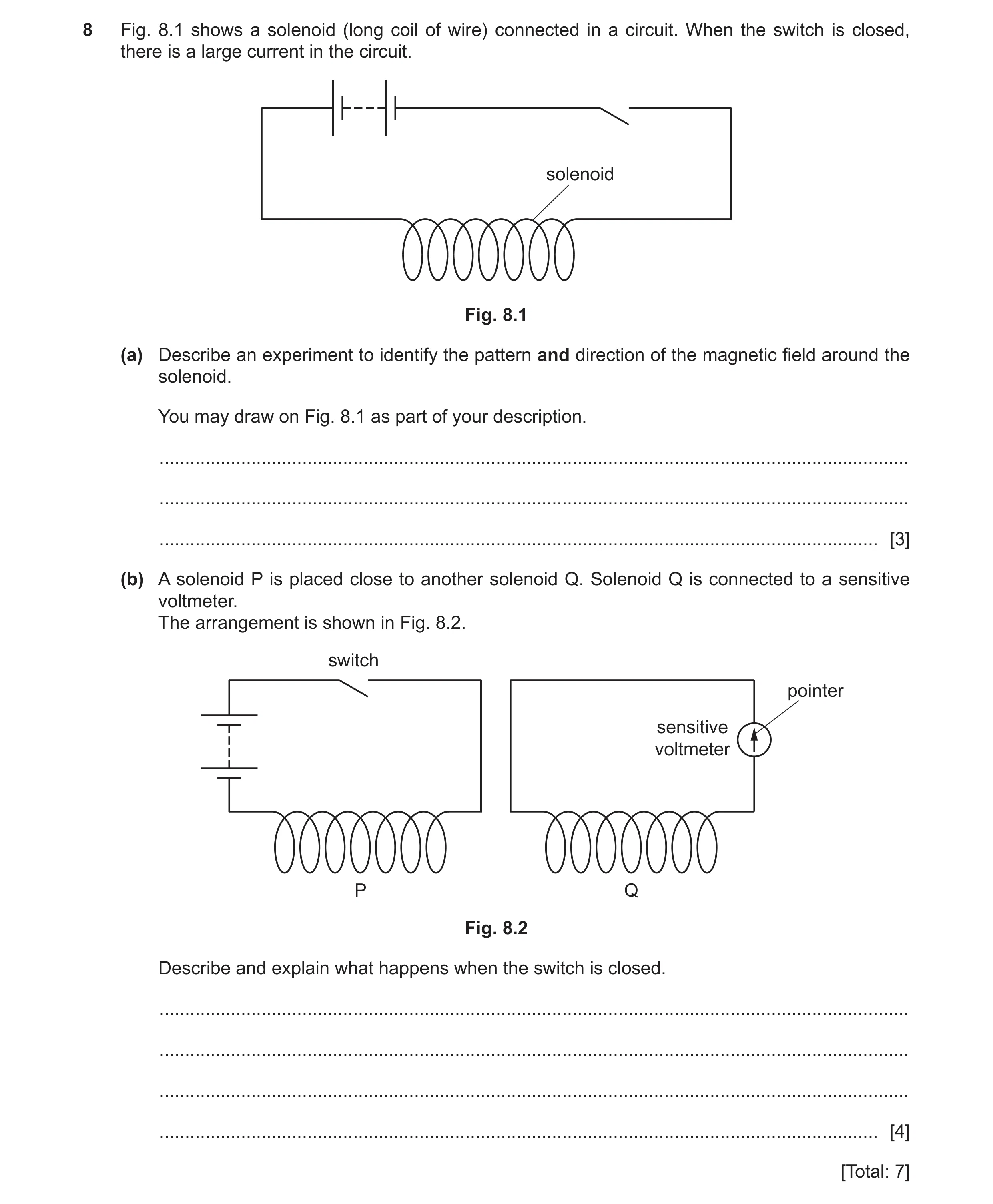
8 Fig. 8.1 shows a solenoid (long coil of wire) connected in a circuit. When the switch is closed, there is a large current in the circuit. solenoid Fig. 8.1 (a) Describe an experiment to identify the pattern and direction of the magnetic field around the solenoid. You may draw on Fig. 8.1 as part of your description. … … … [3] (b) A solenoid P is placed close to another solenoid Q. Solenoid Q is connected to a sensitive voltmeter. The arrangement is shown in Fig. 8.2. switch pointer sensitive voltmeter P Q Fig. 8.2 Describe and explain what happens when the switch is closed. … … … … [4] [Total: 7]
7 marks
Mark scheme: 8(a) (plotting) compass OR iron filings B1 detail of method B1 idea of using a (plotting) compass to give direction of magnetic field B1 8(b) any four from: B4 current in coil P (changing) magnetic field around / in coil P (magnetic field) links with / cuts coil Q an induced emf (across) coil Q OR voltage / current produced / generated in coil Q (induced emf) causes pointer on (sensitive) voltmeter to move when current steady no changing magnetic field OR no field (lines) cutting coil Q pointer then returns to zero
This question in 0625/31 Oct/Nov 2023
Q53 · Different materials have differing magnetic properties 0625/32 Oct/Nov 2023
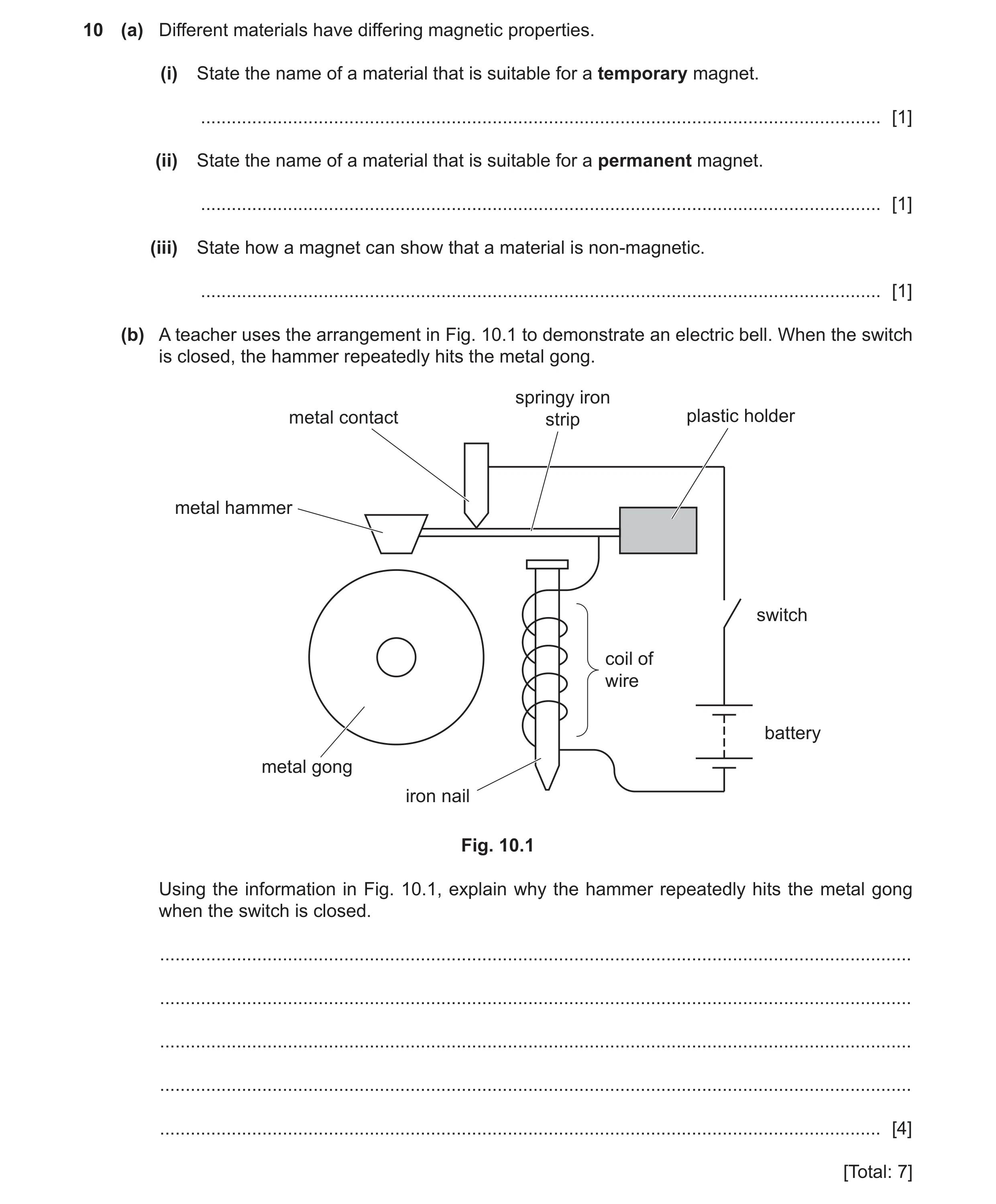
10 (a) Different materials have differing magnetic properties. (i) State the name of a material that is suitable for a temporary magnet. … [1] (ii) State the name of a material that is suitable for a permanent magnet. … [1] (iii) State how a magnet can show that a material is non‑magnetic. … [1] (b) A teacher uses the arrangement in Fig. 10.1 to demonstrate an electric bell. When the switch is closed, the hammer repeatedly hits the metal gong. springy iron metal contact strip plastic holder metal hammer switch coil of wire battery metal gong iron nail Fig. 10.1 Using the information in Fig. 10.1, explain why the hammer repeatedly hits the metal gong when the switch is closed. … … … … … [4] [Total: 7]
7 marks
Mark scheme: 10(a)(i) (soft) iron B1 10(a)(ii) steel B1 10(a)(iii) magnet does not attract a non-magnetic material B1 10(b) any four from: B4 (when switch closed) there is a complete circuit current in the circuit magnetic effect (of current / in coil) owtte (coil and nail become) electromagnet (springy) iron (strip) attracted to (nail / electromagnet) circuit broken owtte springy iron strip springs back / makes contact (again) owtte
This question in 0625/32 Oct/Nov 2023
Q54 · An arrangement for transmitting electricity generated by a power station 0625/33 Oct/Nov 2023
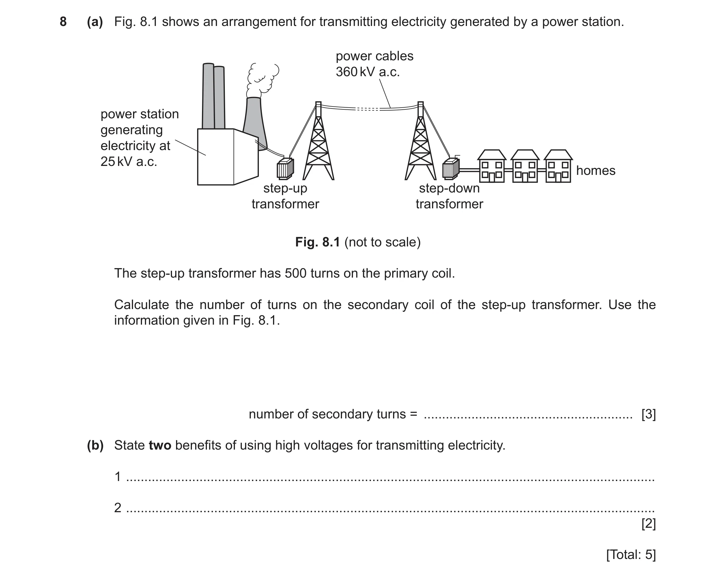
8 (a) Fig. 8.1 shows an arrangement for transmitting electricity generated by a power station. power cables 360 kV a.c. power station generating electricity at 25 kV a.c. homes step-up step-down transformer transformer Fig. 8.1 (not to scale) The step-up transformer has 500 turns on the primary coil. Calculate the number of turns on the secondary coil of the step-up transformer. Use the information given in Fig. 8.1. number of secondary turns = … [3] (b) State two benefits of using high voltages for transmitting electricity. 1 … 2 … [2] [Total: 5]
5 marks
Mark scheme: 8(a) 7200 A3 (Ns =) 500 360 / 25 OR 360 20 (C2) Vp / Vs = Np / Ns (C1) 8(b) any two from: B2 smaller current (in cables) more efficient less power / heating losses thinner / cheaper cables / pylons further apart owtte less voltage drop OR transfer energy over longer distance
This question in 0625/33 Oct/Nov 2023
Q55 · Describe what is meant by alternating current (a.c.) 0625/33 Oct/Nov 2023
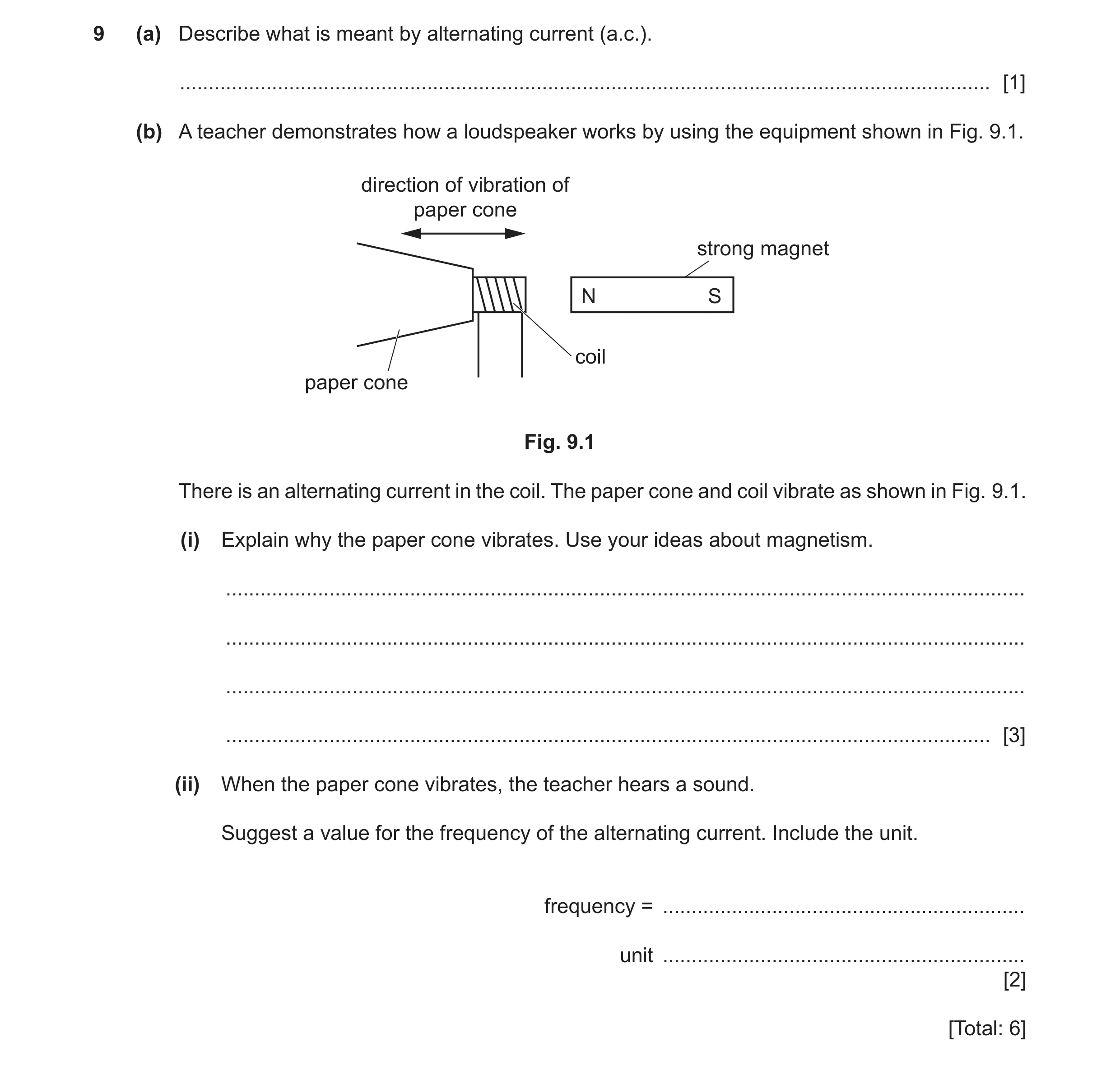
9 (a) Describe what is meant by alternating current (a.c.). … [1] (b) A teacher demonstrates how a loudspeaker works by using the equipment shown in Fig. 9.1. direction of vibration of paper cone strong magnet N S coil paper cone Fig. 9.1 There is an alternating current in the coil. The paper cone and coil vibrate as shown in Fig. 9.1. (i) Explain why the paper cone vibrates. Use your ideas about magnetism. … … … … [3] (ii) When the paper cone vibrates, the teacher hears a sound. Suggest a value for the frequency of the alternating current. Include the unit. frequency = … unit … [2] [Total: 6]
6 marks
Mark scheme: 9(a) (current repeatedly) changes direction B1 9(b)(i) any three from: B3 magnetic effect of current coil becomes an electromagnet attracted to magnet repelled by magnet 9(b)(ii) any number(s) between 20 and 20 000 B1 Hz / kHz B1
This question in 0625/33 Oct/Nov 2023
Q56 · The power cable for connecting a desktop computer to the mains electricity circuit 0625/31 May/June 2024
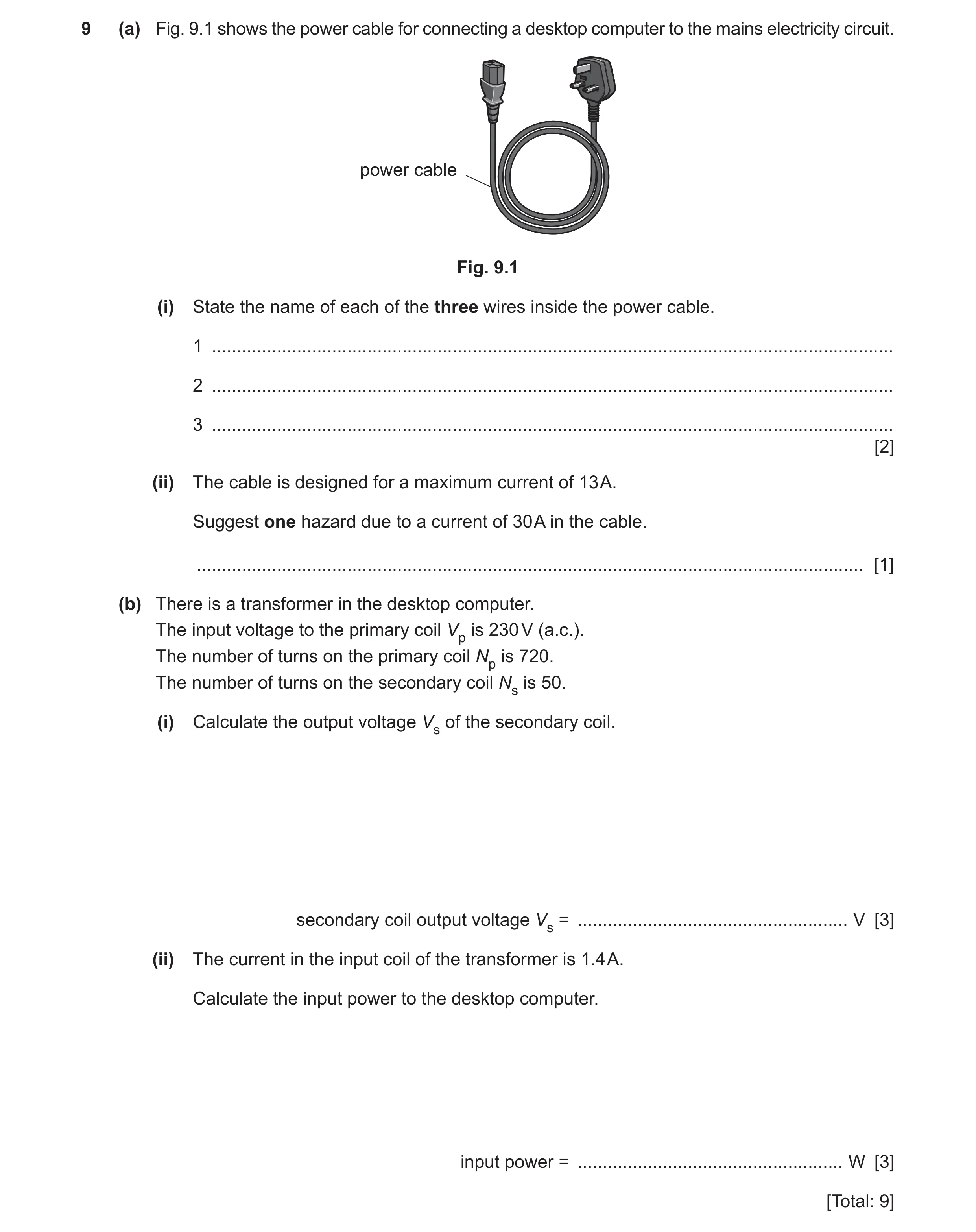
9 (a) Fig. 9.1 shows the power cable for connecting a desktop computer to the mains electricity circuit. power cable Fig. 9.1 (i) State the name of each of the three wires inside the power cable. 1 … 2 … 3 … [2] (ii) The cable is designed for a maximum current of 13 A. Suggest one hazard due to a current of 30 A in the cable. … [1] (b) There is a transformer in the desktop computer. The input voltage to the primary coil Vp is 230 V (a.c.). The number of turns on the primary coil Np is 720. The number of turns on the secondary coil Ns is 50. (i) Calculate the output voltage Vs of the secondary coil. secondary coil output voltage Vs = … V [3] (ii) The current in the input coil of the transformer is 1.4 A. Calculate the input power to the desktop computer. input power = … W [3] [Total: 9]
9 marks
Mark scheme: 9(a)(i) live (wire) neutral (wire) earth (wire) 3 correct – 2 marks 1 or 2 correct – 1 mark B2 9(a)(ii) idea of (cable) overheating OR (insulation) melting / burning B1 9(b)(i) (secondary coil voltage Vs =) 16 (V) A3 230 / Vs = 720 / 50 OR (Vs =) {230 50} ÷ 720 (C2) (Vp / Vs) = (Np / Ns) in any form (C1) 9(b)(ii) (P =) 320 (W) A3 (P =) 1.4 230 (C2) (P =) I V (C1)
This question in 0625/31 May/June 2024
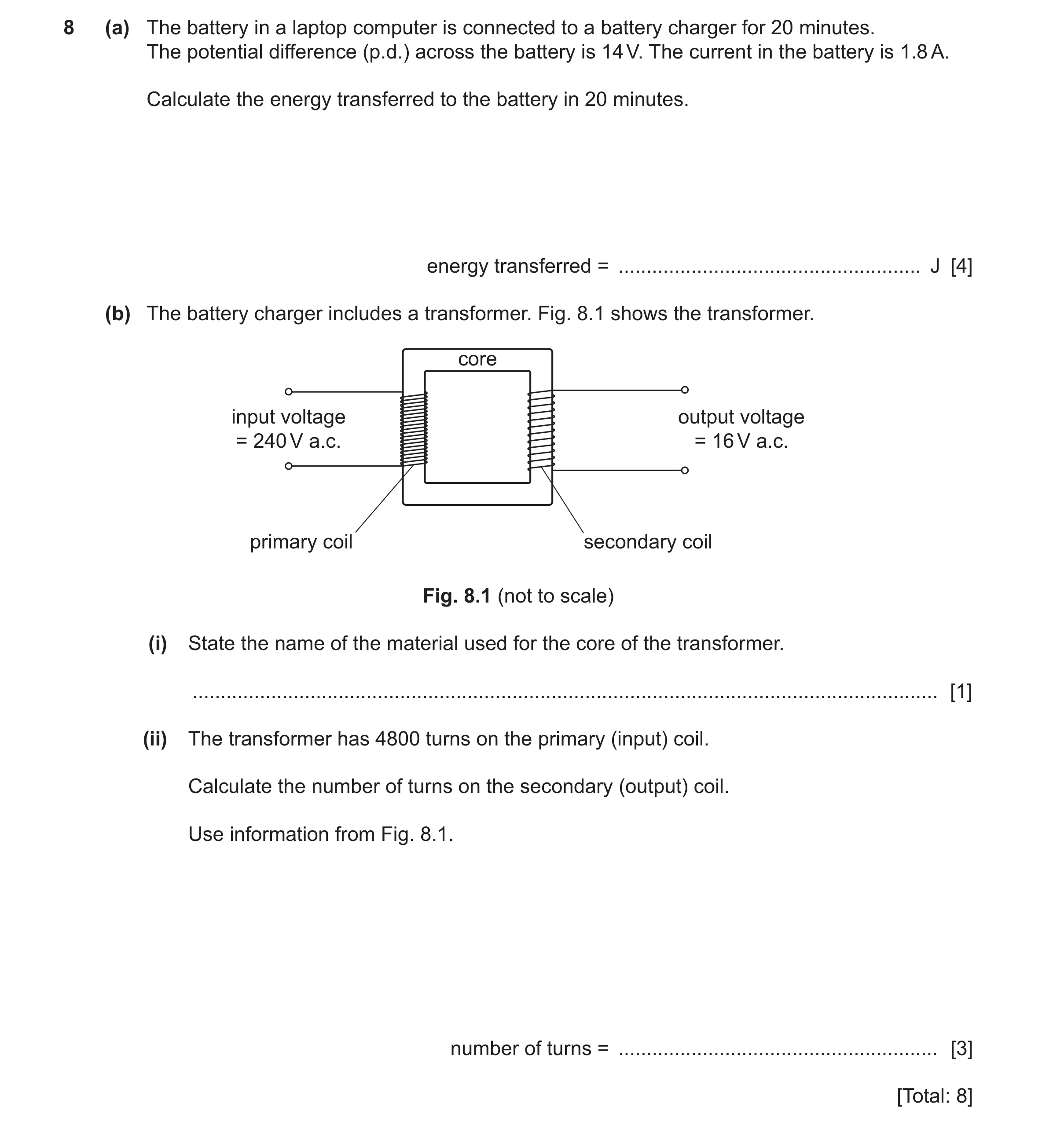
Q57 · The battery in a laptop computer is connected to a battery charger for 20 minutes 0625/32 May/June 2024
8 (a) The battery in a laptop computer is connected to a battery charger for 20 minutes. The potential difference (p.d.) across the battery is 14 V. The current in the battery is 1.8 A. Calculate the energy transferred to the battery in 20 minutes. energy transferred = … J [4] (b) The battery charger includes a transformer. Fig. 8.1 shows the transformer. core input voltage output voltage = 240 V a.c. = 16 V a.c. primary coil secondary coil Fig. 8.1 (not to scale) (i) State the name of the material used for the core of the transformer. … [1] (ii) The transformer has 4800 turns on the primary (input) coil. Calculate the number of turns on the secondary (output) coil. Use information from Fig. 8.1. number of turns = … [3] [Total: 8]
8 marks
Mark scheme: 8(a) (E =) 30 000 (J) A4 (E =) 1.8 1200 14 OR 2160 14 (C3) (E =) 1.8 20 14 OR 36 14 (C2) (E =) I t V OR E = P t AND P = I V (C1) conversion 20 (minutes) = 1200 (s) (C1) 8(b)(i) (soft) iron B1 8(b)(ii) 320 (turns) A3 16 / 240 = Ns / 4800 OR 240 / 16 = 4800 / Ns OR Ns = 4800 {16 / 240} (C2) (Vs / Vp) = (Ns / Np) in any form (C1)
This question in 0625/32 May/June 2024
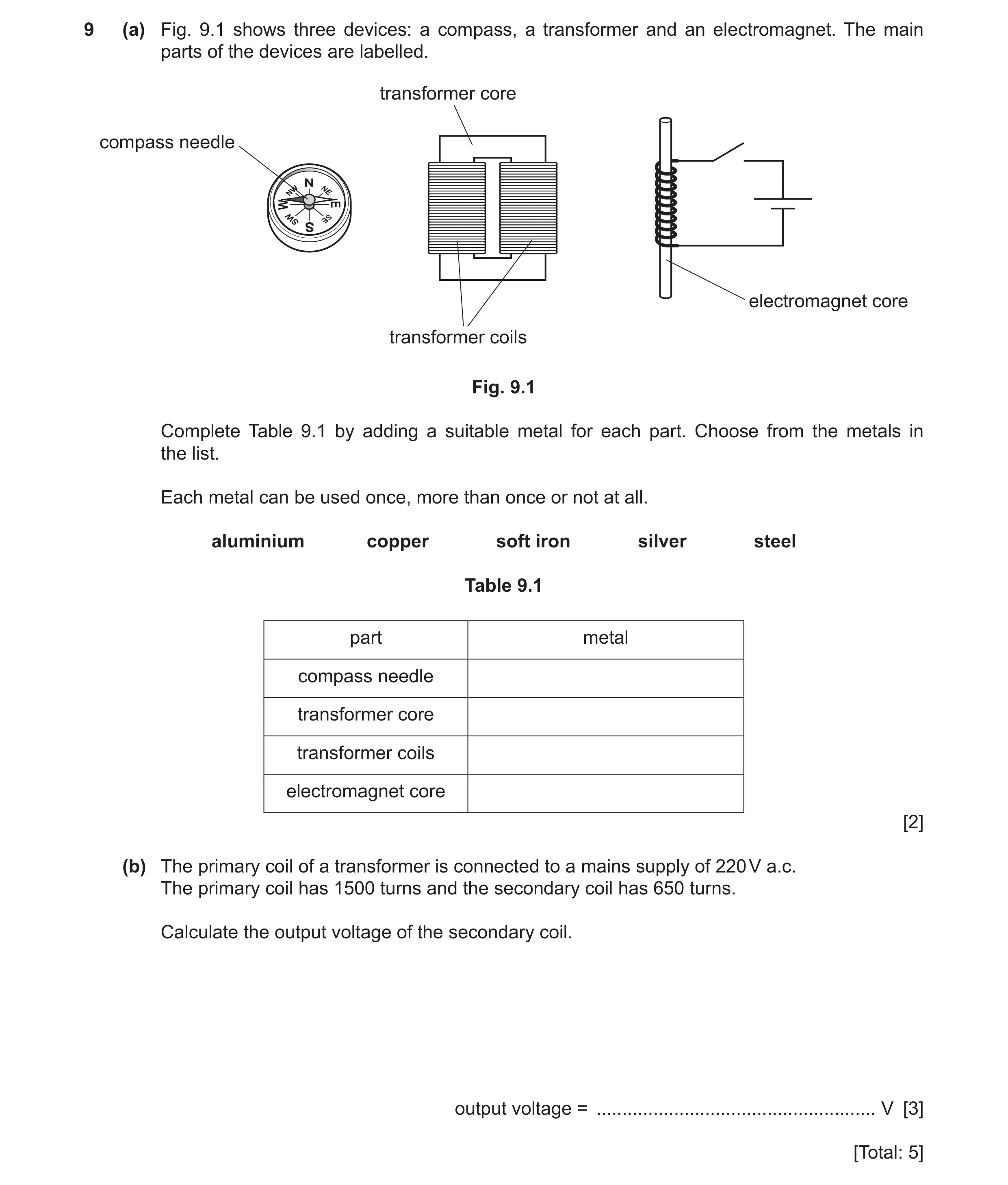
Q58 · Three devices: a compass, a transformer and an electromagnet 0625/33 May/June 2024
9 (a) Fig. 9.1 shows three devices: a compass, a transformer and an electromagnet. The main parts of the devices are labelled. transformer core compass needle electromagnet core transformer coils Fig. 9.1 Complete Table 9.1 by adding a suitable metal for each part. Choose from the metals in the list. Each metal can be used once, more than once or not at all. aluminium copper soft iron silver steel Table 9.1 part metal compass needle transformer core transformer coils electromagnet core [2] (b) The primary coil of a transformer is connected to a mains supply of 220 V a.c. The primary coil has 1500 turns and the secondary coil has 650 turns. Calculate the output voltage of the secondary coil. output voltage = … V [3] [Total: 5]
5 marks
Mark scheme: 9(a) part metal compass needle steel transformer core soft iron transformer coils copper / silver electromagnet core soft iron 4 correct – 2 marks 2 or 3 correct – 1 mark B2 9(b) 95 (V) A3 (Vs =) 650 / 1500 220 OR 1500 / 650 = 220 / Vs (C2) (Vp / Vs) = (Np / Ns) in any form (C1)
This question in 0625/33 May/June 2024
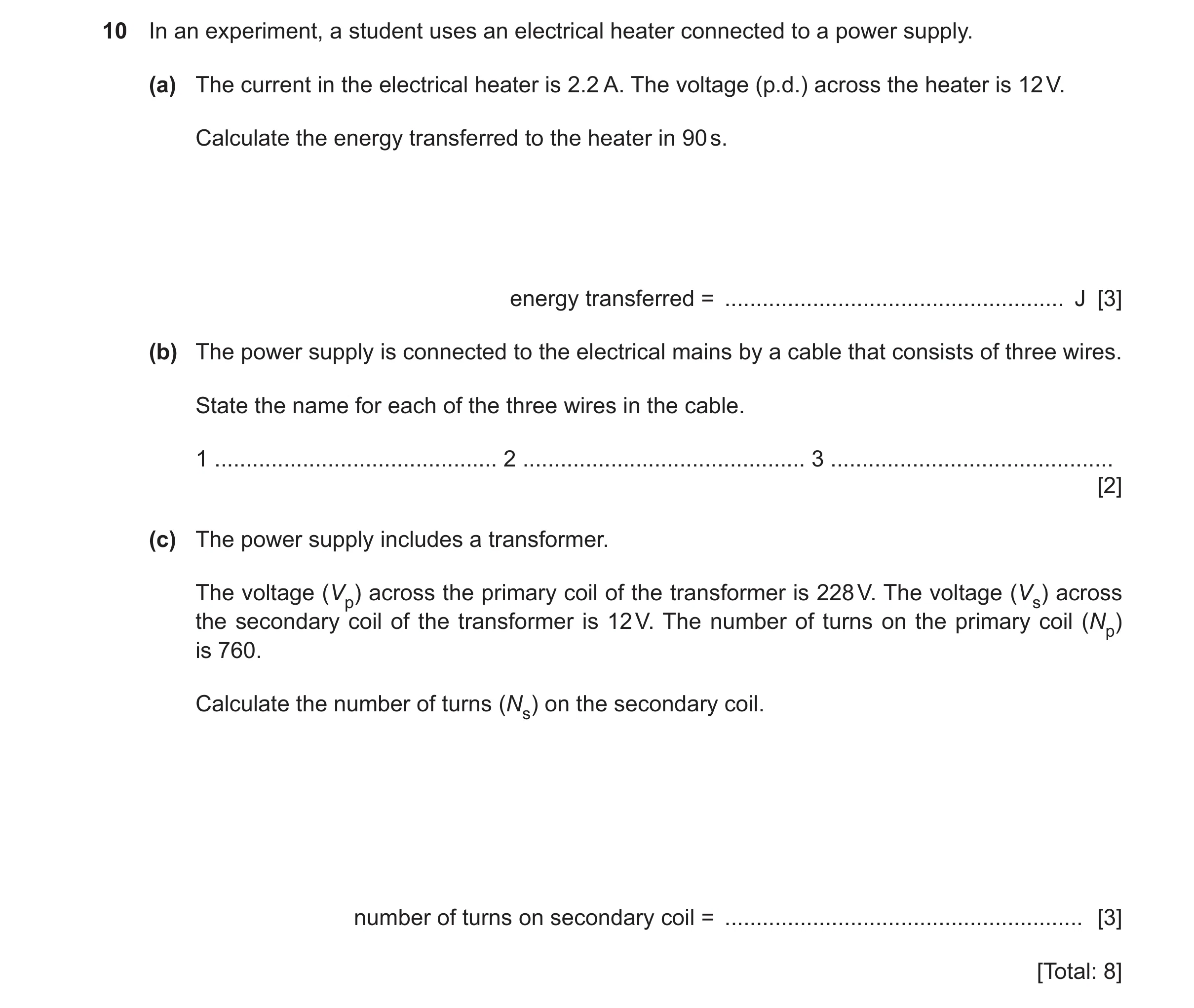
Q59 · In an experiment, a student uses an electrical heater connected to a power supply 0625/31 Oct/Nov 2024
10 In an experiment, a student uses an electrical heater connected to a power supply. (a) The current in the electrical heater is 2.2 A. The voltage (p.d.) across the heater is 12 V. Calculate the energy transferred to the heater in 90 s. energy transferred = … J [3] (b) The power supply is connected to the electrical mains by a cable that consists of three wires. State the name for each of the three wires in the cable. 1 … 2 … 3 … [2] (c) The power supply includes a transformer. The voltage (Vp) across the primary coil of the transformer is 228 V. The voltage (Vs) across the secondary coil of the transformer is 12 V. The number of turns on the primary coil (Np) is 760. Calculate the number of turns (Ns) on the secondary coil. number of turns on secondary coil = … [3] [Total: 8]
8 marks
Mark scheme: 10(a) (energy =) 2400 (J) A3 (energy =) 2.2 90 12 (C2) (energy =) current time voltage OR(E) = V I t OR (energy =) power time OR P t (C1) 10(b) live OR line earth OR ground neutral B2 10(c) 40 A3 (Ns) = (12 228) 760 OR 228 / 12 = 760 / Ns (C2) Ns / Np = Vs / Vp (C1)
This question in 0625/31 Oct/Nov 2024
Q60 · Part of a d.c 0625/32 Oct/Nov 2024
9 (a) Fig. 9.1 represents part of a d.c. electric motor. The coil of wire rotates at a steady speed. current coil of wire Fig. 9.1 State two ways to make the coil rotate faster. 1 … 2 … [2] (b) Fig. 9.2 shows an electric fan. Fig. 9.2 The electric motor for the fan requires 120 V a.c. The mains voltage is 220 V a.c. A transformer steps down the mains voltage as shown in Fig. 9.3. primary coil secondary coil 800 turns mains voltage 220 V a.c. output voltage 120 V a.c. Fig. 9.3 Calculate the number of turns on the secondary coil. Use the information in Fig. 9.3. number of turns on the secondary coil = … [3] (c) A plug connects the transformer to the mains supply. There is a fuse in the plug. Describe how a fuse works. … … … [2] [Total: 7]
7 marks
Mark scheme: 9(a) any two from: B2 • increase (battery) voltage OR larger current in coil • increase strength of magnet(ic) field OR strong(er) magnet • increase number of turns (in coil) 9(b) 440 (turns) A3 (NS =) 800 120 / 220 (C2) VP / VS = NP / NS (C1) 9(c) any two from: B2 • large current (in fuse) • (causes) fuse to melt • isolating appliance from supply OR prevents / stops current in appliance
This question in 0625/32 Oct/Nov 2024
Q61 · A magnet spinning steadily near to a coil 0625/33 Oct/Nov 2024
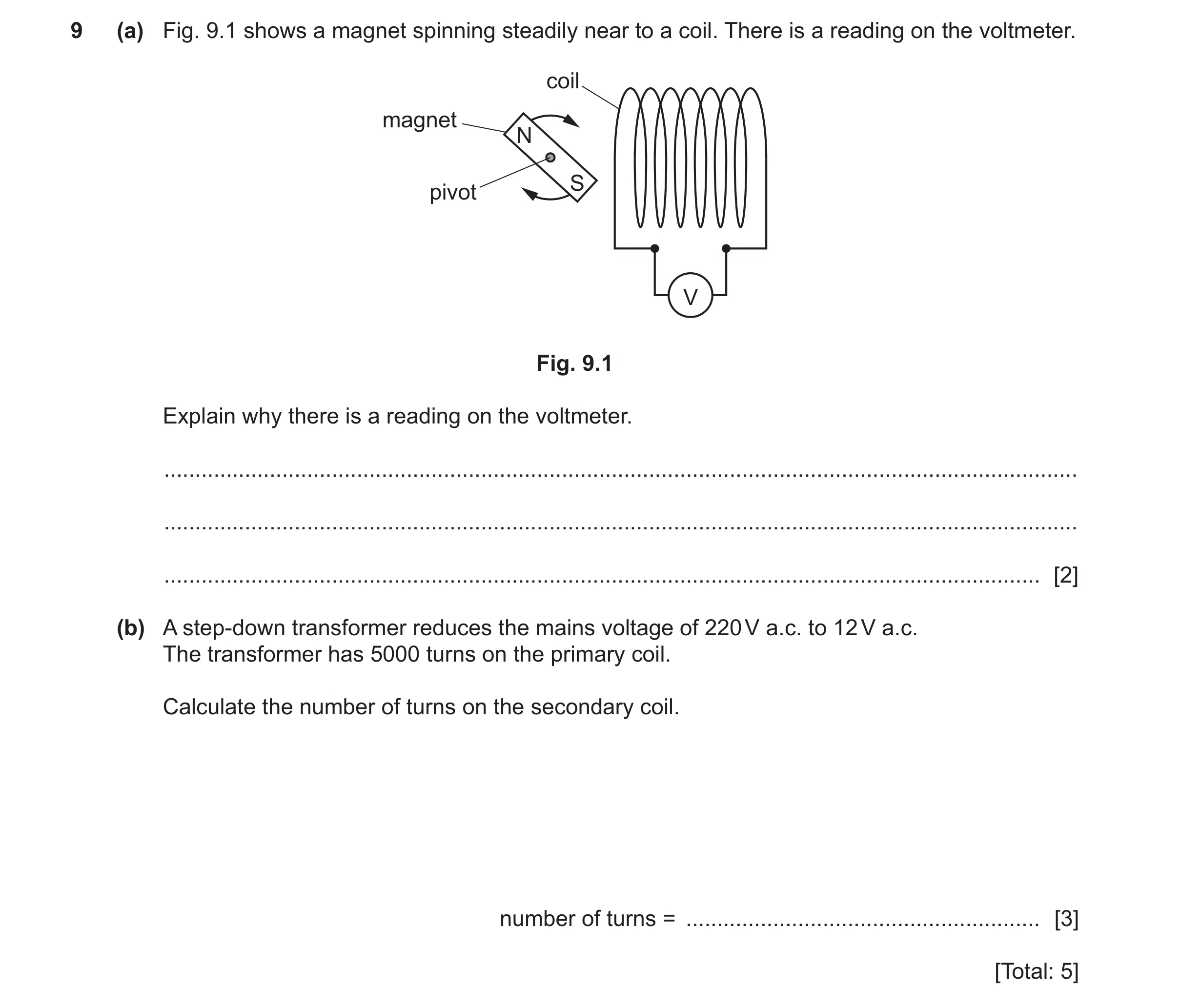
9 (a) Fig. 9.1 shows a magnet spinning steadily near to a coil. There is a reading on the voltmeter. coil magnet N S pivot V Fig. 9.1 Explain why there is a reading on the voltmeter. … … … [2] (b) A step-down transformer reduces the mains voltage of 220 V a.c. to 12 V a.c. The transformer has 5000 turns on the primary coil. Calculate the number of turns on the secondary coil. number of turns = … [3] [Total: 5]
5 marks
Mark scheme: 9(a) induced e.m.f.(in the coil) B1 changing magnetic field (in the coil) B1 9(b) (number of turns =) 270 A3 (NS =) 12 / 220 5000 (C2) VP / VS = NP / NS (C1)
This question in 0625/33 Oct/Nov 2024
Q62 · The apparatus used by a student to demonstrate electromagnetic induction 0625/32 Feb/March 2025
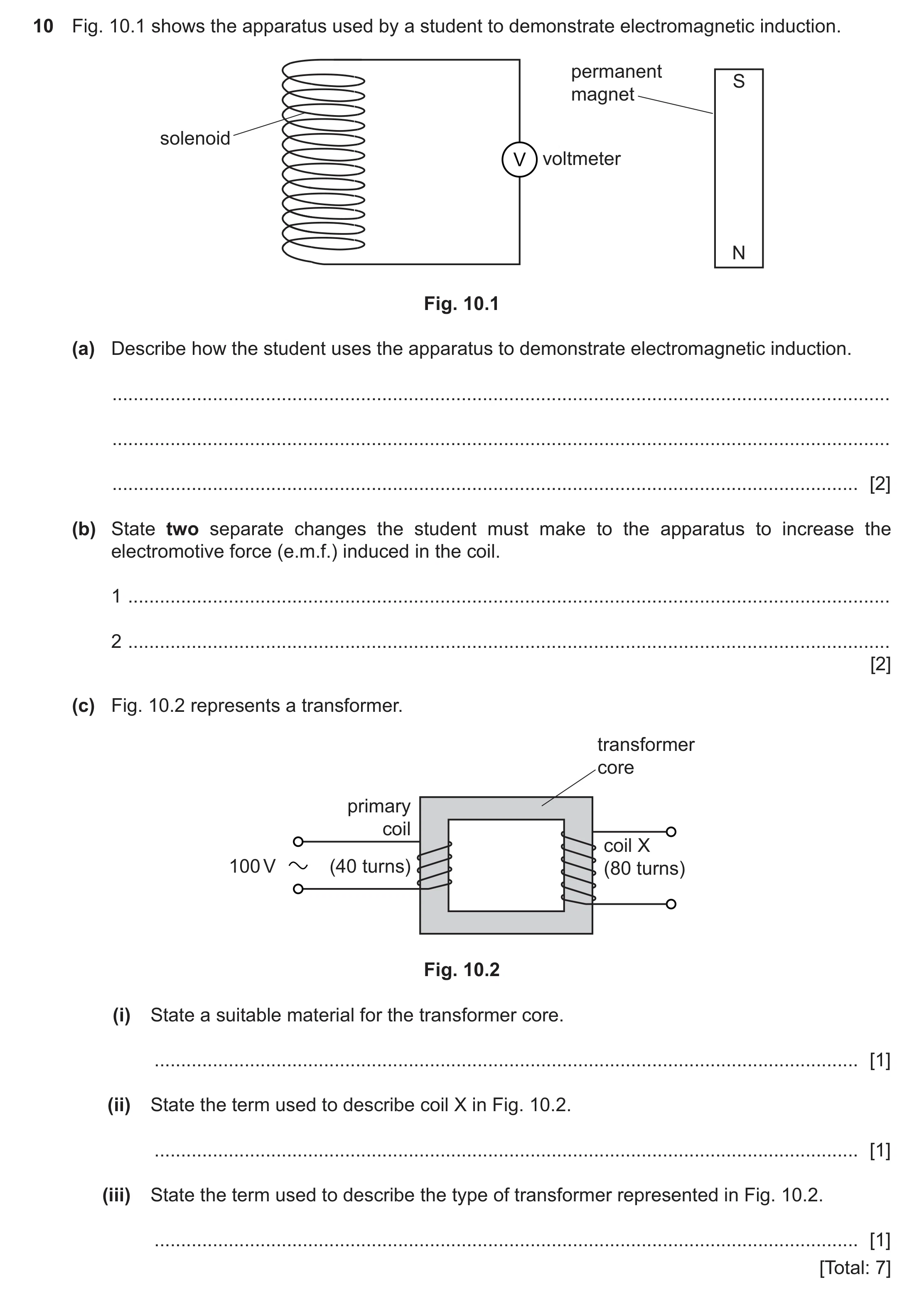
10 Fig. 10.1 shows the apparatus used by a student to demonstrate electromagnetic induction. permanent S magnet solenoid V voltmeter N Fig. 10.1 (a) Describe how the student uses the apparatus to demonstrate electromagnetic induction. … … … [2] (b) State two separate changes the student must make to the apparatus to increase the electromotive force (e.m.f.) induced in the coil. 1 … 2 … [2] (c) Fig. 10.2 represents a transformer. transformer core primary coil coil X 100 V (40 turns) (80 turns) Fig. 10.2 (i) State a suitable material for the transformer core. … [1] (ii) State the term used to describe coil X in Fig. 10.2. … [1] (iii) State the term used to describe the type of transformer represented in Fig. 10.2. … [1] [Total: 7]
7 marks
Mark scheme: 10(a) move the magnet M1 {into OR out of OR relative to} the solenoid / coil A1 10(b) any two from: B2 use a stronger magnet increase the number of turns on the coil increasing the speed of (movement of the) magnet 10(c)(i) (soft) iron B1 10(c)(ii) secondary (coil) B1 10(c)(iii) step-up (transformer) B1
This question in 0625/32 Feb/March 2025
Question 63 0625/31 May/June 2025
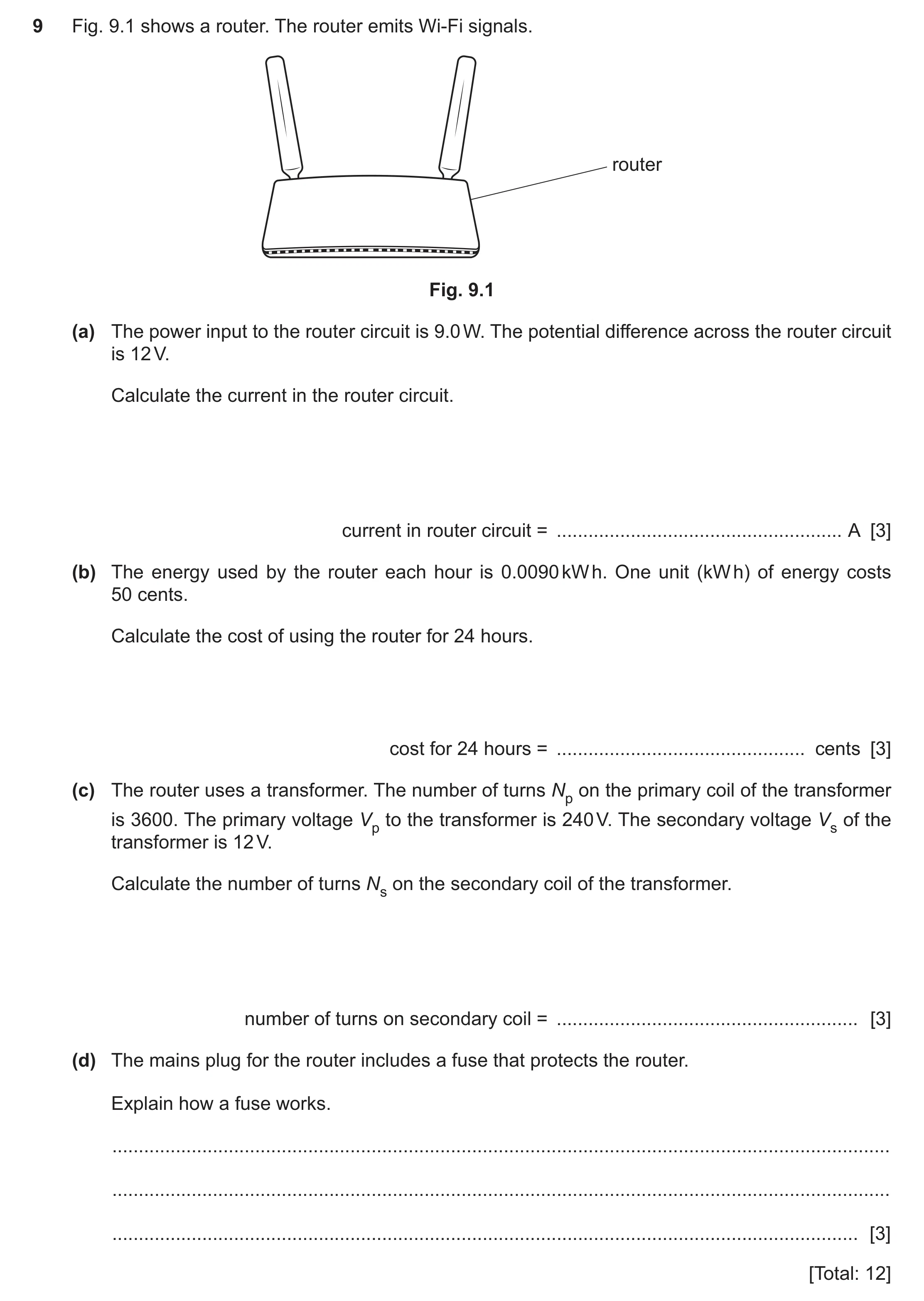
9 Fig. 9.1 shows a router. The router emits Wi-Fi signals. router Fig. 9.1 (a) The power input to the router circuit is 9.0 W. The potential difference across the router circuit is 12 V. Calculate the current in the router circuit. current in router circuit = … A [3] (b) The energy used by the router each hour is 0.0090 kW h. One unit (kW h) of energy costs 50 cents. Calculate the cost of using the router for 24 hours. cost for 24 hours = … cents [3] (c) The router uses a transformer. The number of turns Np on the primary coil of the transformer is 3600. The primary voltage Vp to the transformer is 240 V. The secondary voltage Vs of the transformer is 12 V. Calculate the number of turns Ns on the secondary coil of the transformer. number of turns on secondary coil = … [3] (d) The mains plug for the router includes a fuse that protects the router. Explain how a fuse works. … … … [3] [Total: 12]
12 marks
Mark scheme: 9(a) (current =) 0.75 (A) A3 (current =) 9 ÷ 12 C2 power = IV OR (I =) P ÷ V C1 9(b) 11 (cents) A3 (cost =) 0.009(0) 24 50 OR 0.216 50 OR 0.009 1200 OR 0.45 24 C2 (cost =) (energy in) kW h (number of) hours cost (of one unit) C1 9(c) (Ns =) 180 A3 (Ns =) {12 3600} ÷ 240 OR (Ns =) 3600 ÷ 20 OR 240 ÷ 12 = 3600 ÷ Ns C2 Vs ÷ Vp = Ns ÷ Np C1 9(d) any three from: B3 • idea of large current (in fuse or any part of circuit) • (large current causes) heating in fuse • idea that fuse is made from low melting point wire • fuse / (fuse) wire melts • (and) idea disconnects / isolates (router / wires / circuit) from supply / mains
This question in 0625/31 May/June 2025
Q64 · A television uses many electrical components 0625/31 Oct/Nov 2025
8 A television uses many electrical components. (a) The potential difference (voltage) across a component is 72 V. The current in the component is 0.024 A. Calculate the resistance of the component. resistance = … Ω [3] (b) The television uses a transformer. The input voltage (Vp) to the transformer is 120 V. The number of turns (Np) on the input coil is 560. The number of turns (Ns) on the output coil is 70. Calculate the output voltage (Vs) of the transformer. output voltage = … V [3] (c) The potential difference (voltage) across a resistor is 64 V. The current in the resistor is 2.2 mA. Calculate the power of the resistor. power = … W [4] (d) The energy used by the television in one hour is 0.14 kWh. The cost of one kWh of energy is 36 cents. Calculate the cost of using the television for 6.0 hours. cost for 6 hours = … cents [3] [Total: 13]
13 marks
Mark scheme: 8(a) 3000 () A3 72 / 0.024 (C2) V = IR OR (R = )V / I (C1) 8(b) (output voltage Vs =) 15 (V) A3 Vs / 120 = 70 / 560 OR (Vs =) (70 / 560) 120 (C2) Vs / Vp = Ns / Np in any form (C1) 8(c) (power = ) 0.14 (W) A4 (power = ) 2.2 10-3 64 (C3) (power = ) I V (C1) 2.2 (mA) = 0. 0022 (A) OR 2.2 x 10⁻³ (A) (C1) 8(d) 30 (cents) A3 (cost = ) 0.14 6(.0) 36 OR 0.84 36 OR 0.14 216 OR 5.04 6 (C2) (cost = ) (energy in) kW h (number of) hours cost (of one unit) (C1)
This question in 0625/31 Oct/Nov 2025
Q65 · A toy train on a railway track with a tunnel 0625/32 Oct/Nov 2025
8 (a) Fig. 8.1 shows a toy train on a railway track with a tunnel. The toy train consists of an engine with a truck that is carrying a magnet. tunnel railway track engine magnet on truck N S Fig. 8.1 Fig. 8.2 shows the toy train approaching the tunnel. lamp direction of movement coil S N track Fig. 8.2 (paper cover of tunnel not shown) The tunnel consists of a coil of wire that is covered in paper. The ends of the coil are connected to a lamp. When the toy train moves through the coil of wire, the lamp becomes bright. (i) Explain why the lamp becomes bright when the toy train moves through the coil of wire. … … … … [2] (ii) Describe two ways of increasing the brightness of the lamp. 1 … [1] 2 … [1] (b) Another toy train uses a transformer. State which metals are used in a transformer. i(i) for the core of a transformer … [1] (ii) for the coils of a transformer … [1] [Total: 6]
6 marks
Mark scheme: 8(a)(i) any two from: B2 1 magnetic field (from magnet) links with / cuts (large) coil 2 relative movement of magnetic field and coil 3 e.m.f. / voltage / current induced / produced / generated (in large coil) 8(a)(ii) any two from: B2 • strong (er) magnet • (train / magnet) move fast (er) owtte • more coils / turns 8(b)(i) (soft) iron B1 8(b)(ii) copper B1
This question in 0625/32 Oct/Nov 2025
Q66 · A coal-fired power station is far from a city 0625/33 Oct/Nov 2025
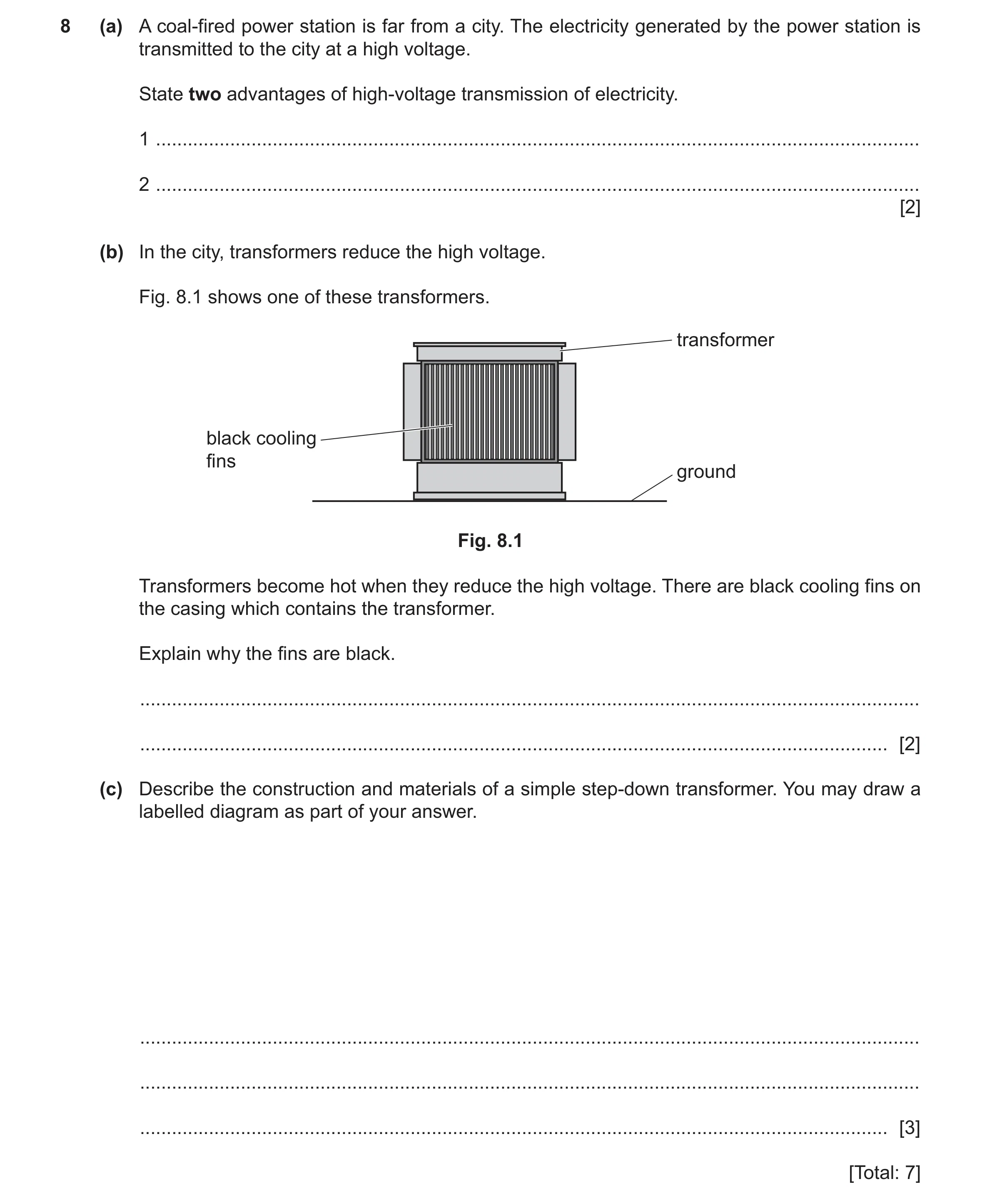
8 (a) A coal-fired power station is far from a city. The electricity generated by the power station is transmitted to the city at a high voltage. State two advantages of high-voltage transmission of electricity. 1 … 2 … [2] (b) In the city, transformers reduce the high voltage. Fig. 8.1 shows one of these transformers. transformer black cooling fins ground Fig. 8.1 Transformers become hot when they reduce the high voltage. There are black cooling fins on the casing which contains the transformer. Explain why the fins are black. … … [2] (c) Describe the construction and materials of a simple step-down transformer. You may draw a labelled diagram as part of your answer. … … … [3] [Total: 7]
7 marks
Mark scheme: 8(a) any two from: B2 • smaller current (in cables) • more efficient • less power / heating losses • thinner / cheaper cables / pylons further apart owtte • less voltage drop • allows for transmission over a longer distance • fewer / larger power stations can supply more area / whole country 8(b) (black is a) good / best emitter M1 of thermal radiation / infrared A1 8(c) any three from: B3 • two coils • copper wire / coils • (coils wrapped round / linked by soft) iron core • more turns on primary coil
This question in 0625/33 Oct/Nov 2025
 1 / 70
 2 / 70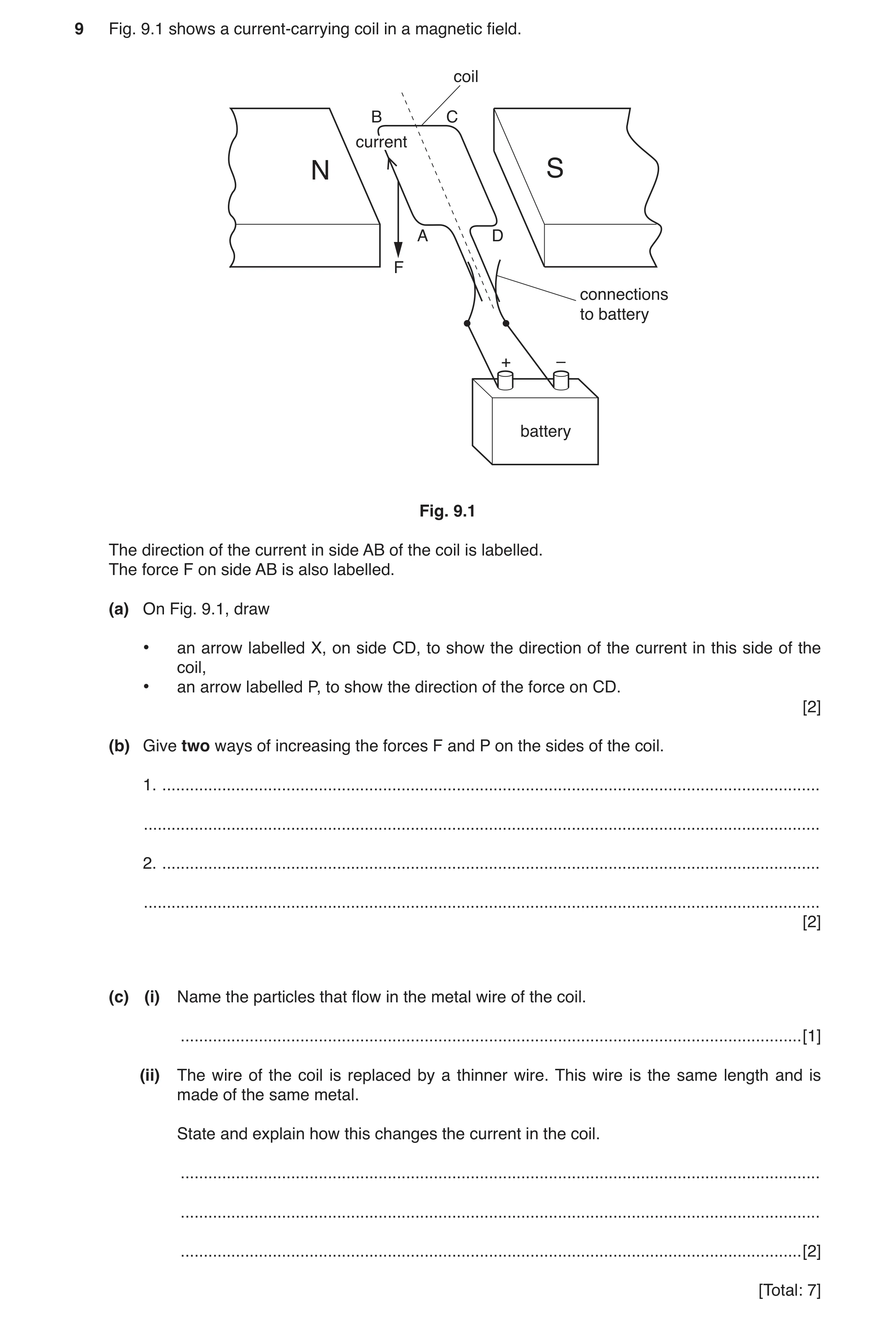
 4 / 70
 5 / 70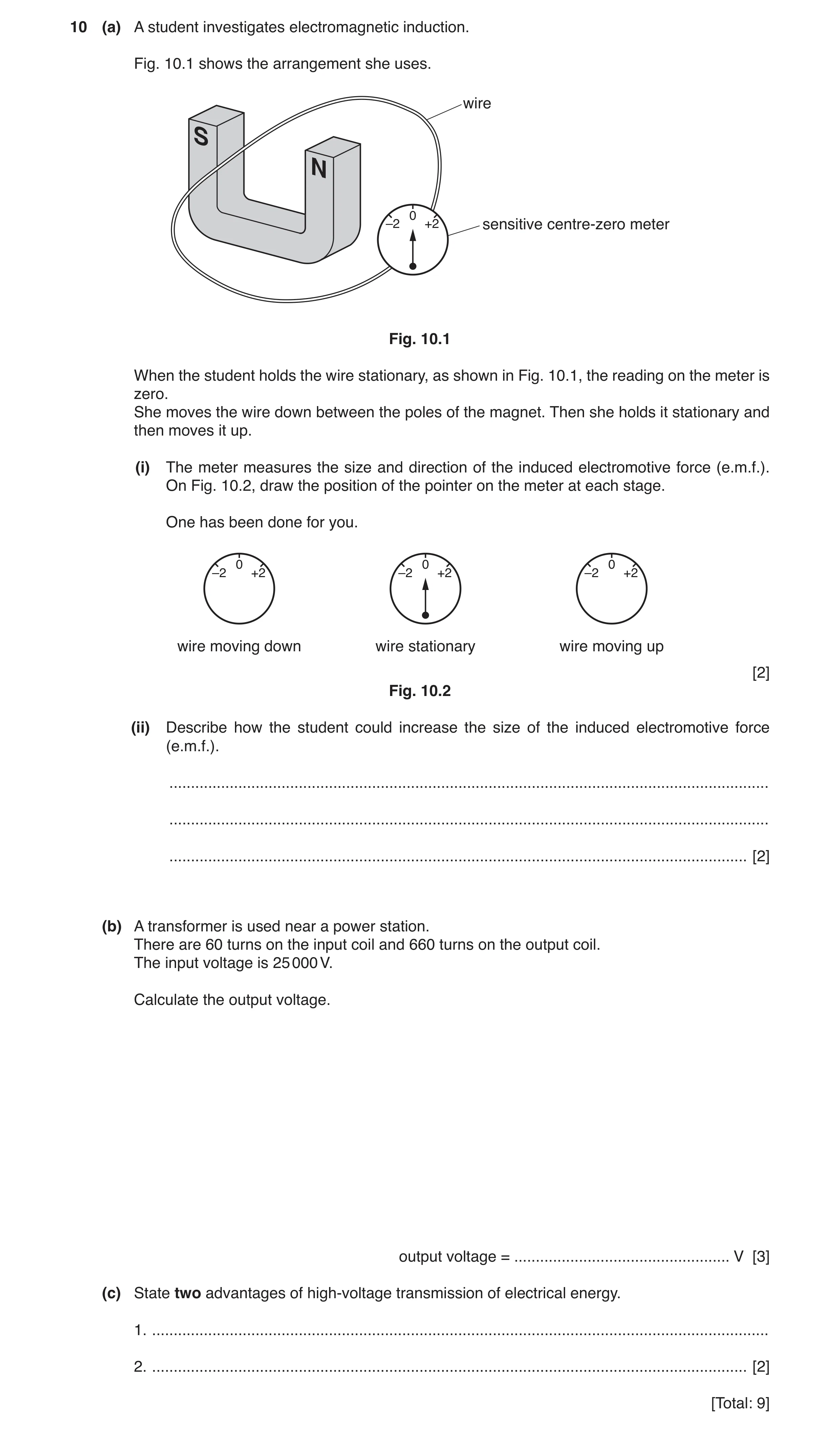
 7 / 70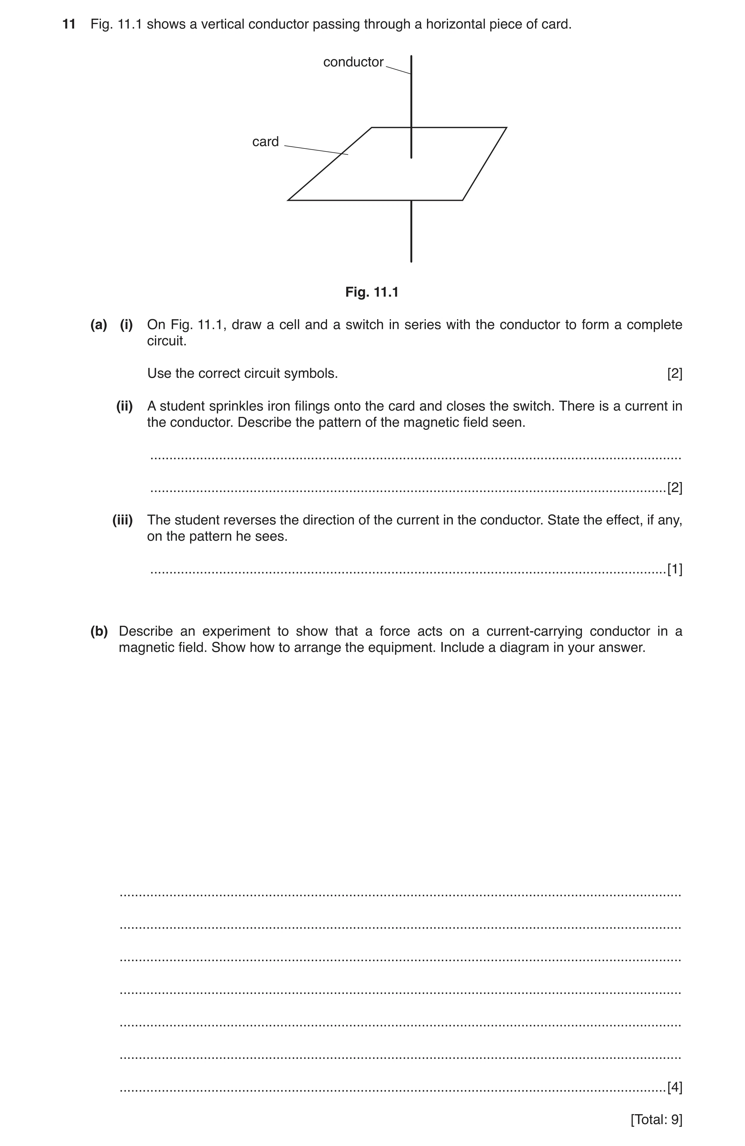
 10 / 70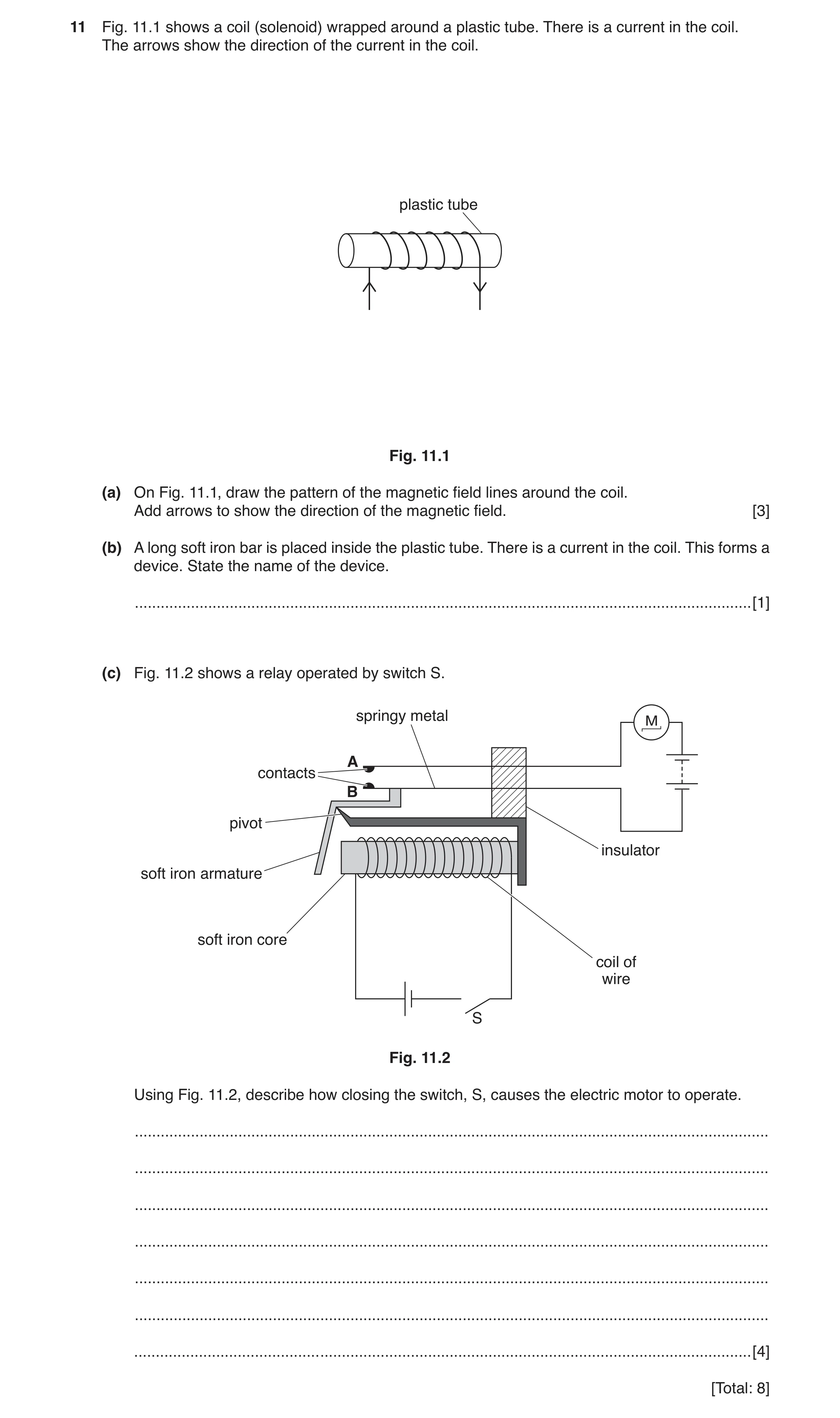
 12 / 70
 13 / 70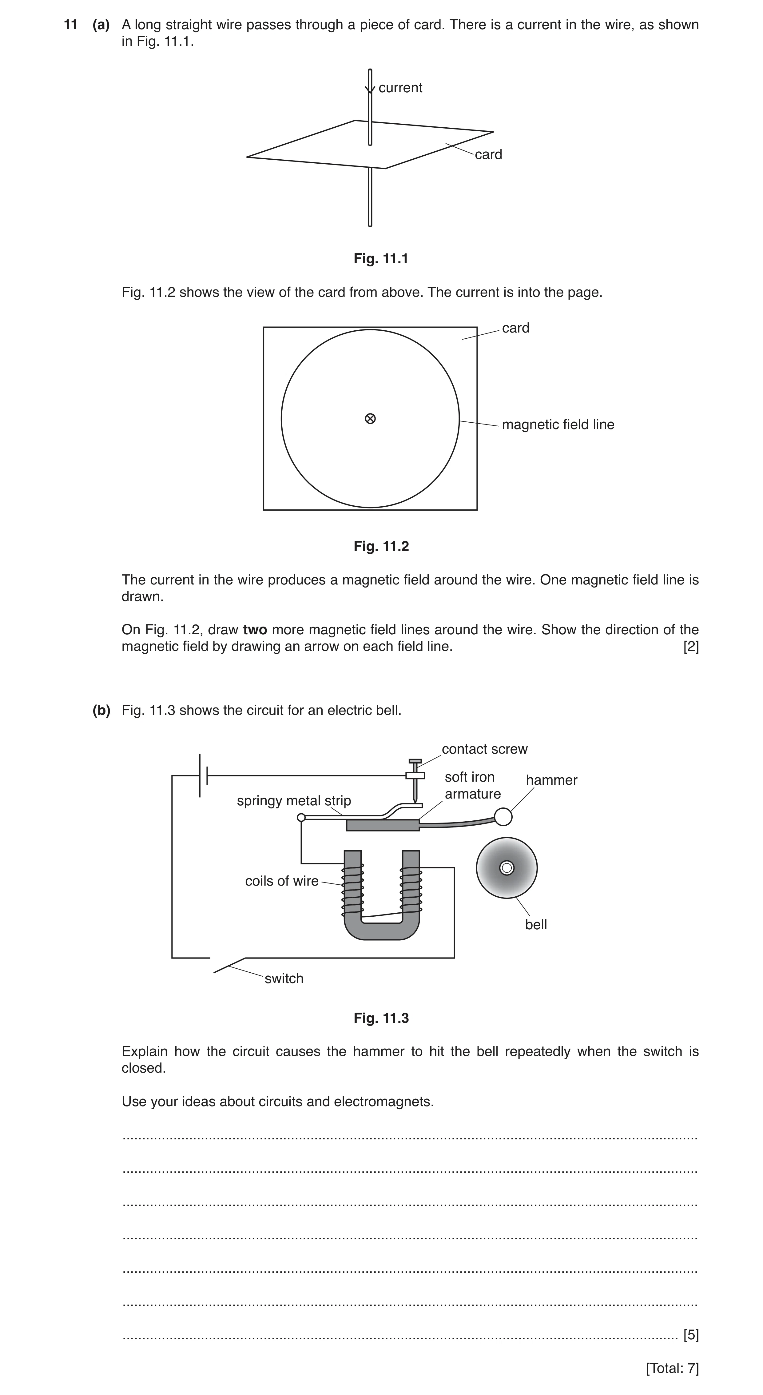
 16 / 70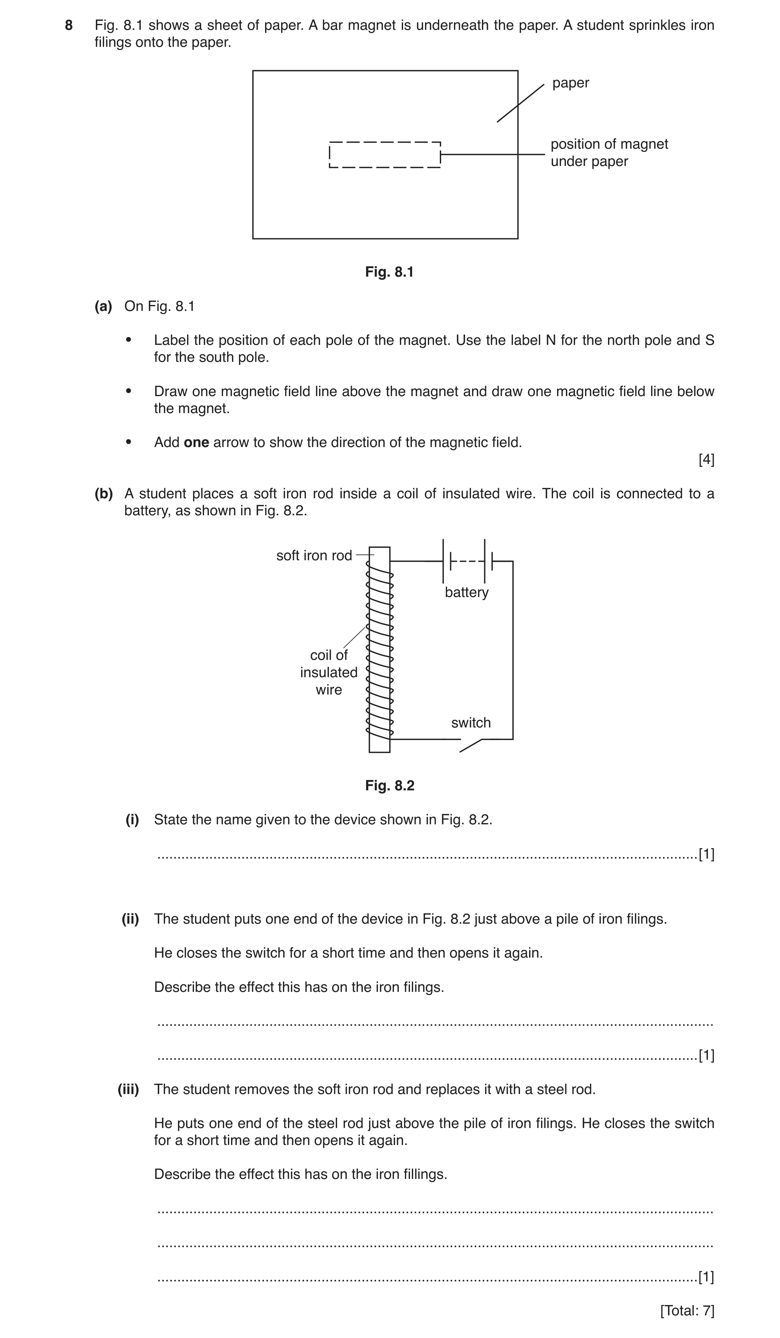
 18 / 70
 19 / 70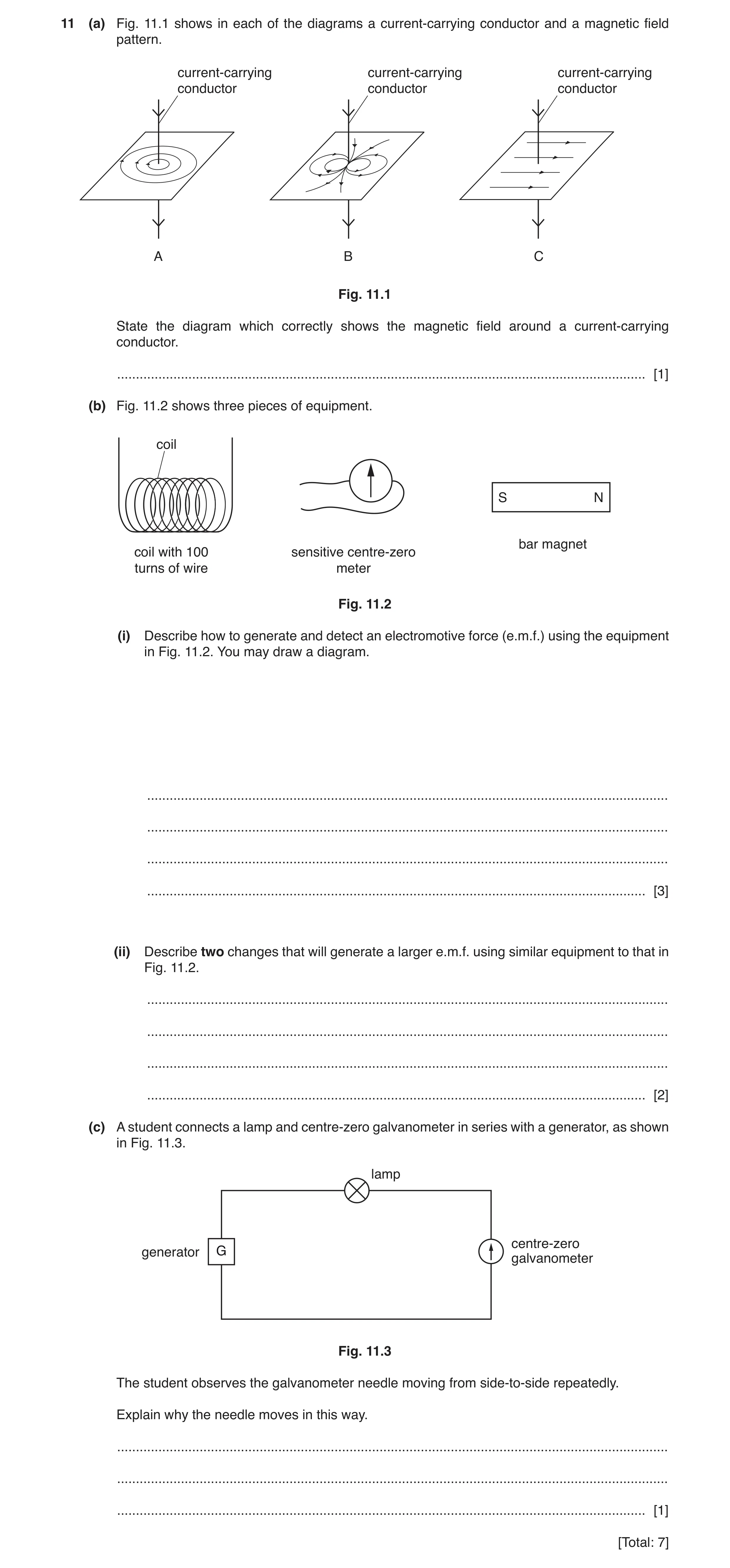
 22 / 70
 23 / 70
 24 / 70
 25 / 70
 26 / 70
 27 / 70
 28 / 70
 29 / 70
 30 / 70
 31 / 70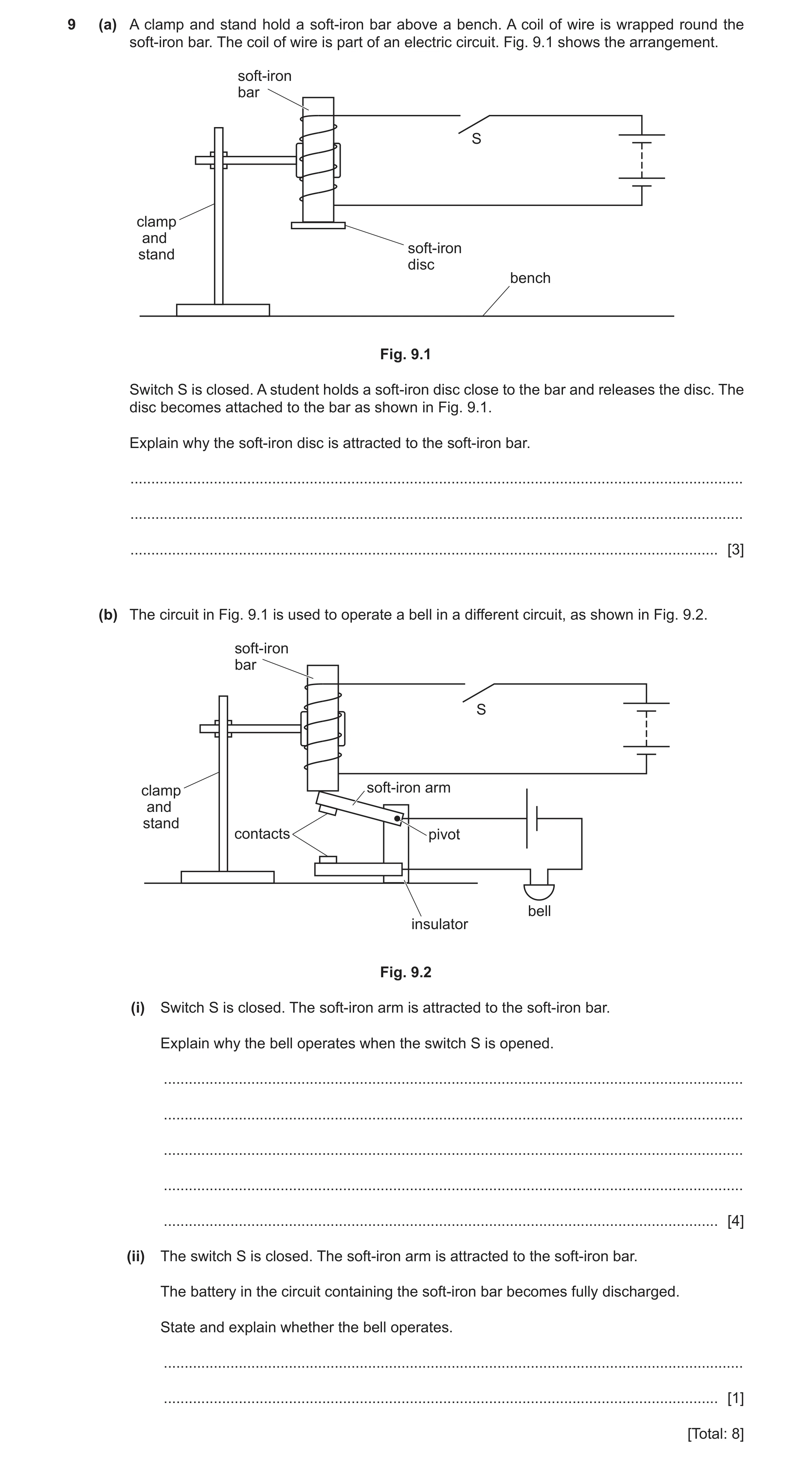
 33 / 70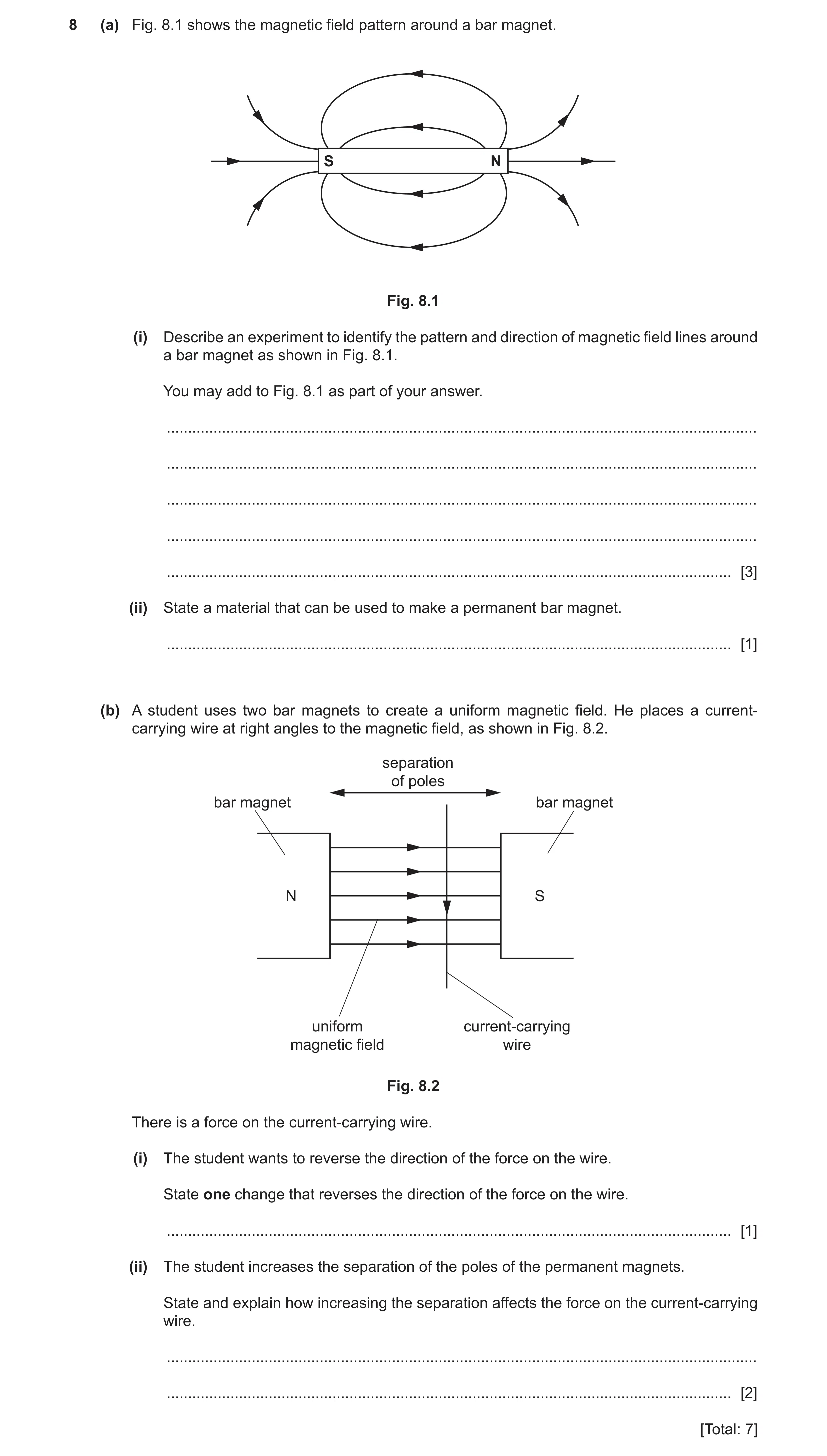
 35 / 70
 36 / 70
 37 / 70
 38 / 70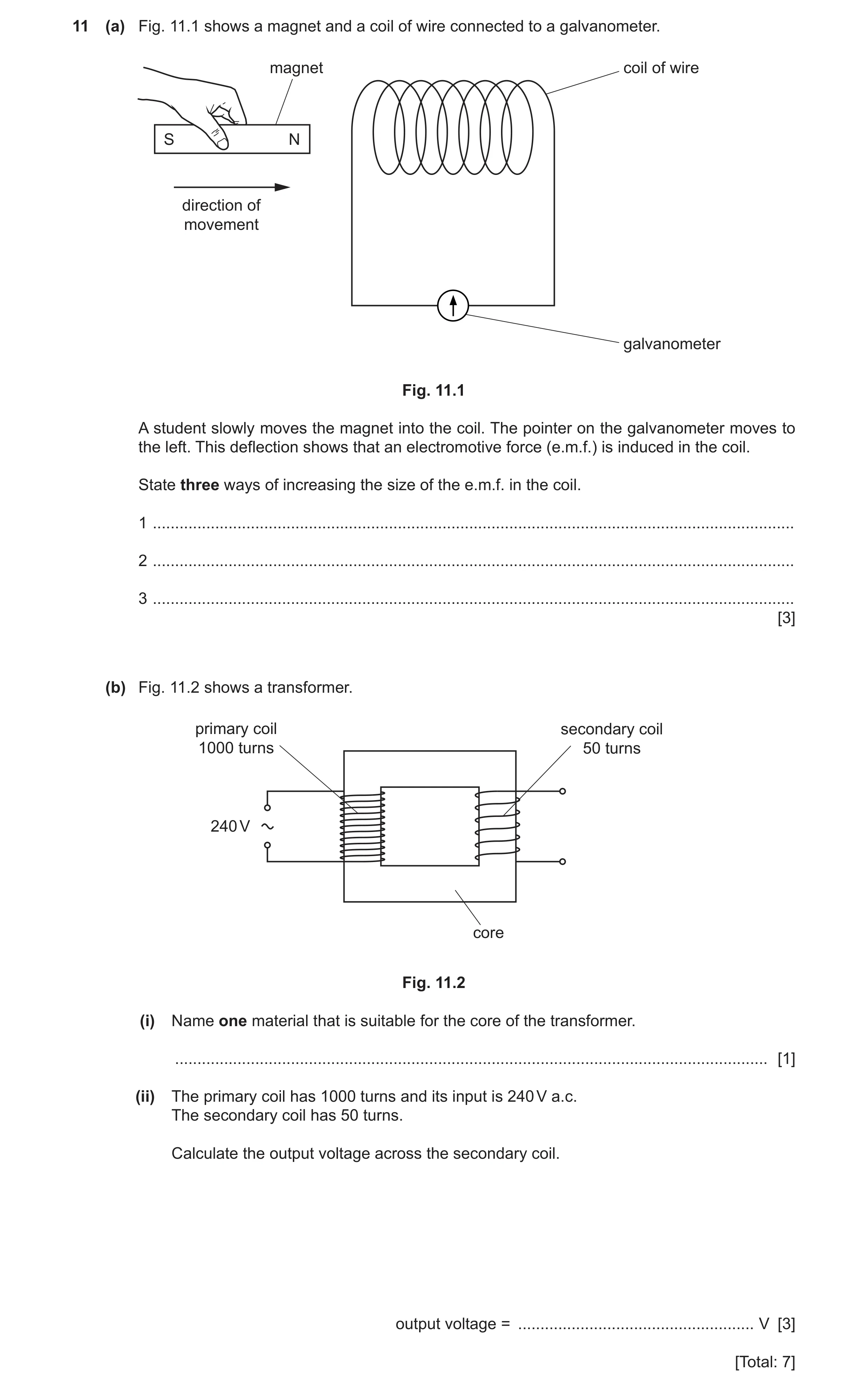
 40 / 70
 41 / 70
 42 / 70
 43 / 70
 44 / 70
 45 / 70
 46 / 70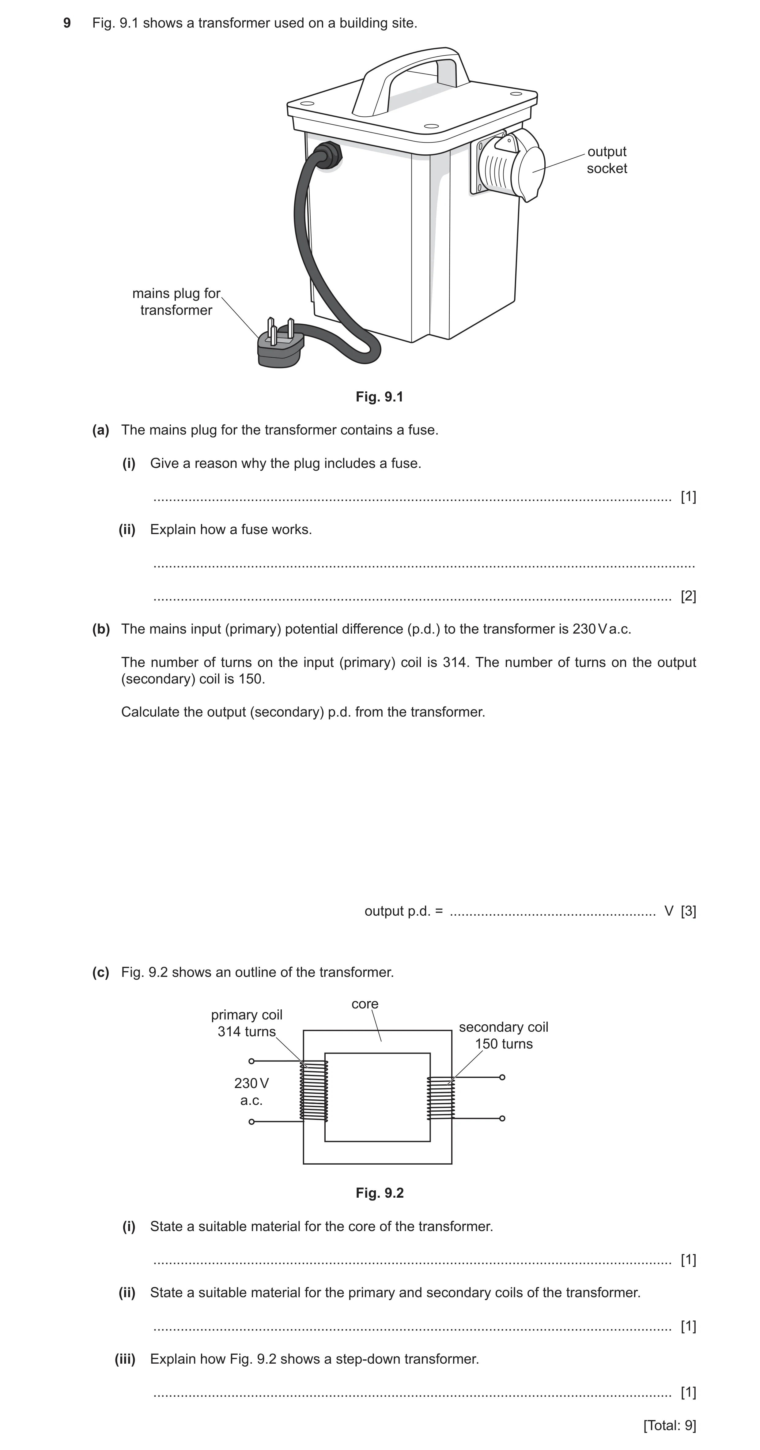
 49 / 70
 50 / 70
 51 / 70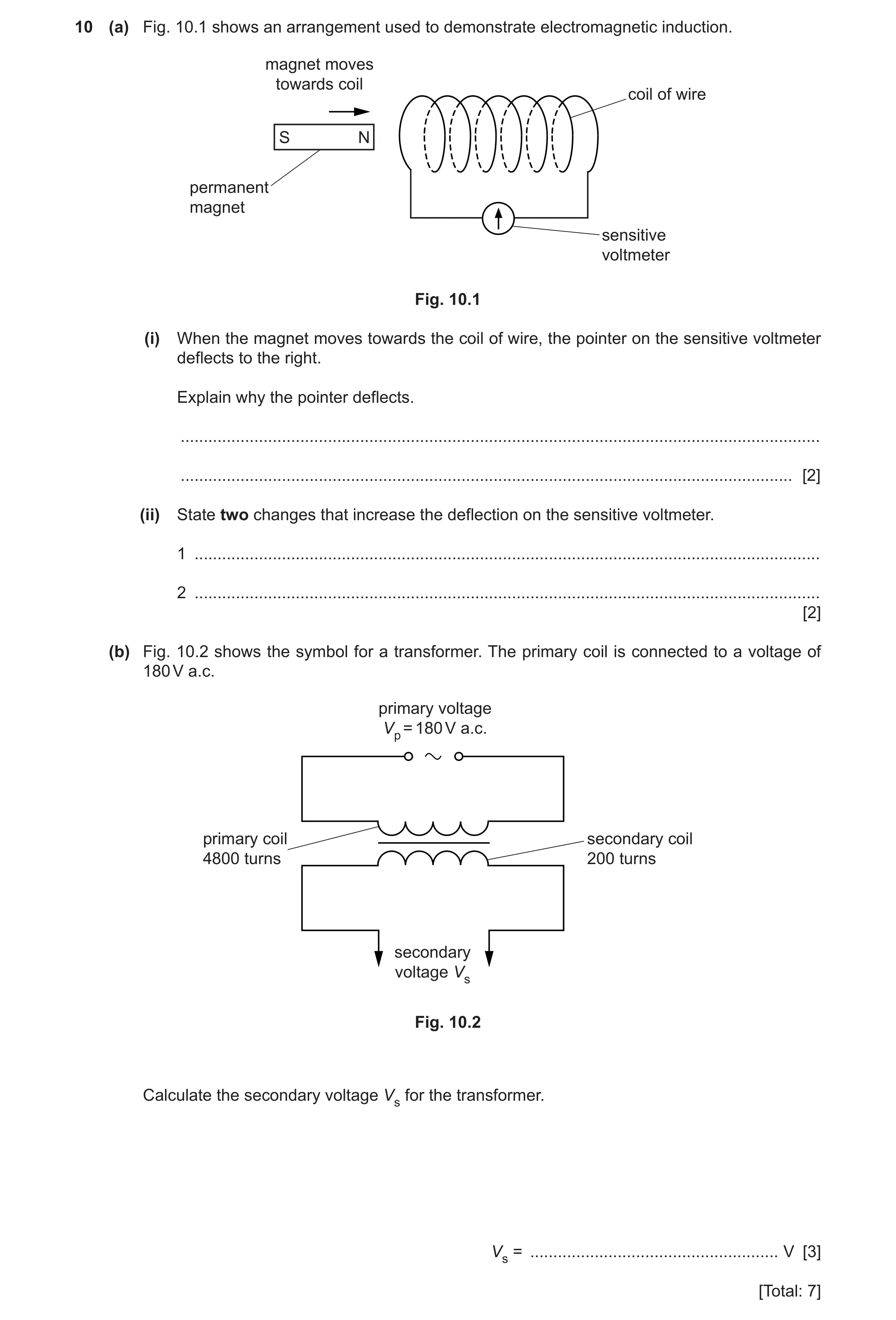
 53 / 70
 54 / 70
 55 / 70
 56 / 70
 57 / 70
 58 / 70
 59 / 70
 60 / 70
 61 / 70
 62 / 70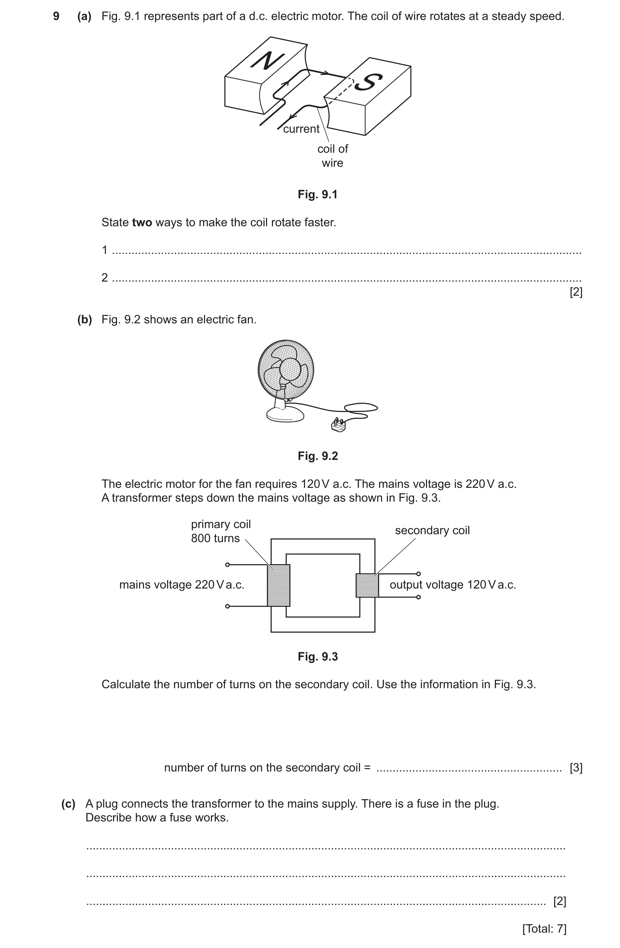
 64 / 70
 65 / 70
 66 / 70
 67 / 70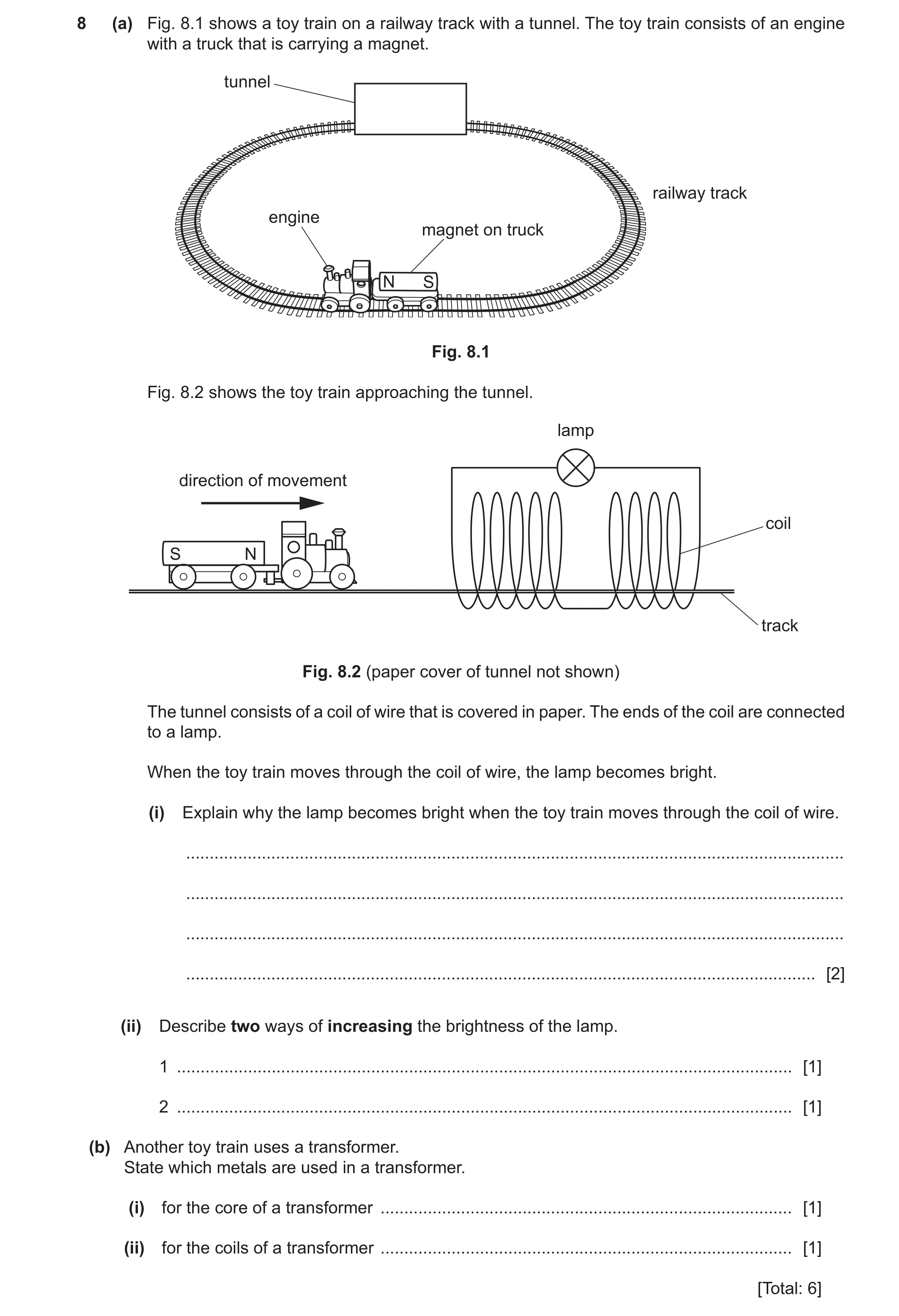
 70 / 70
 7
7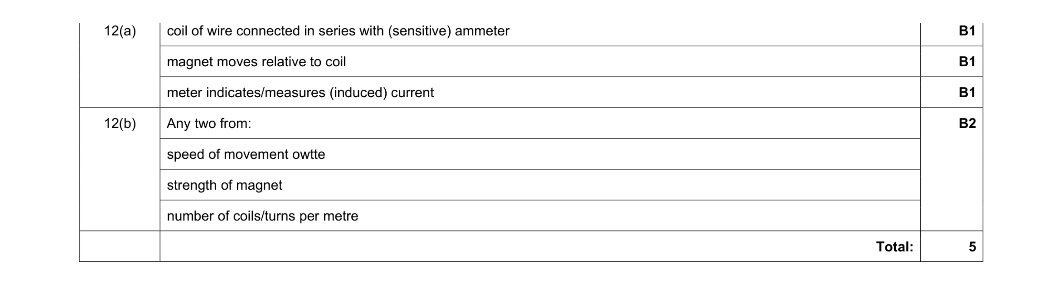 5
5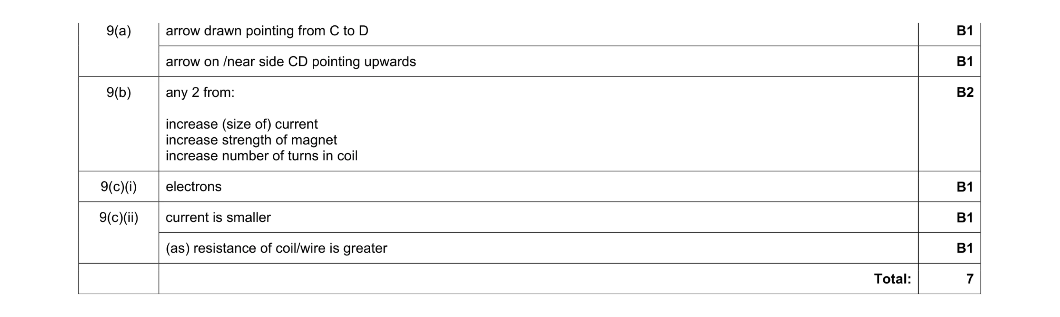 7
7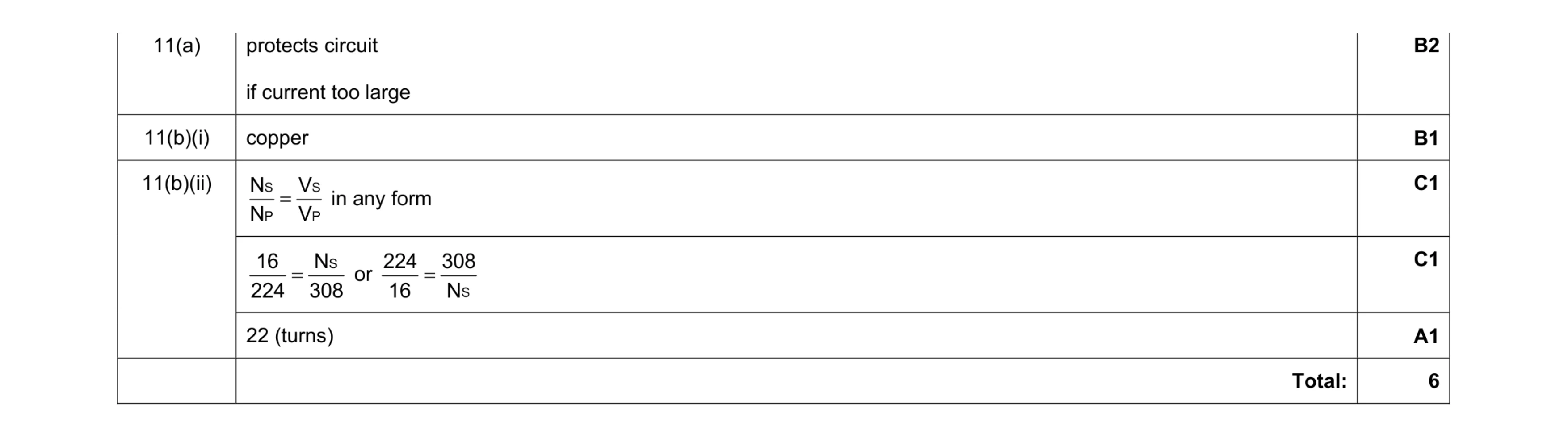 6
6 4
4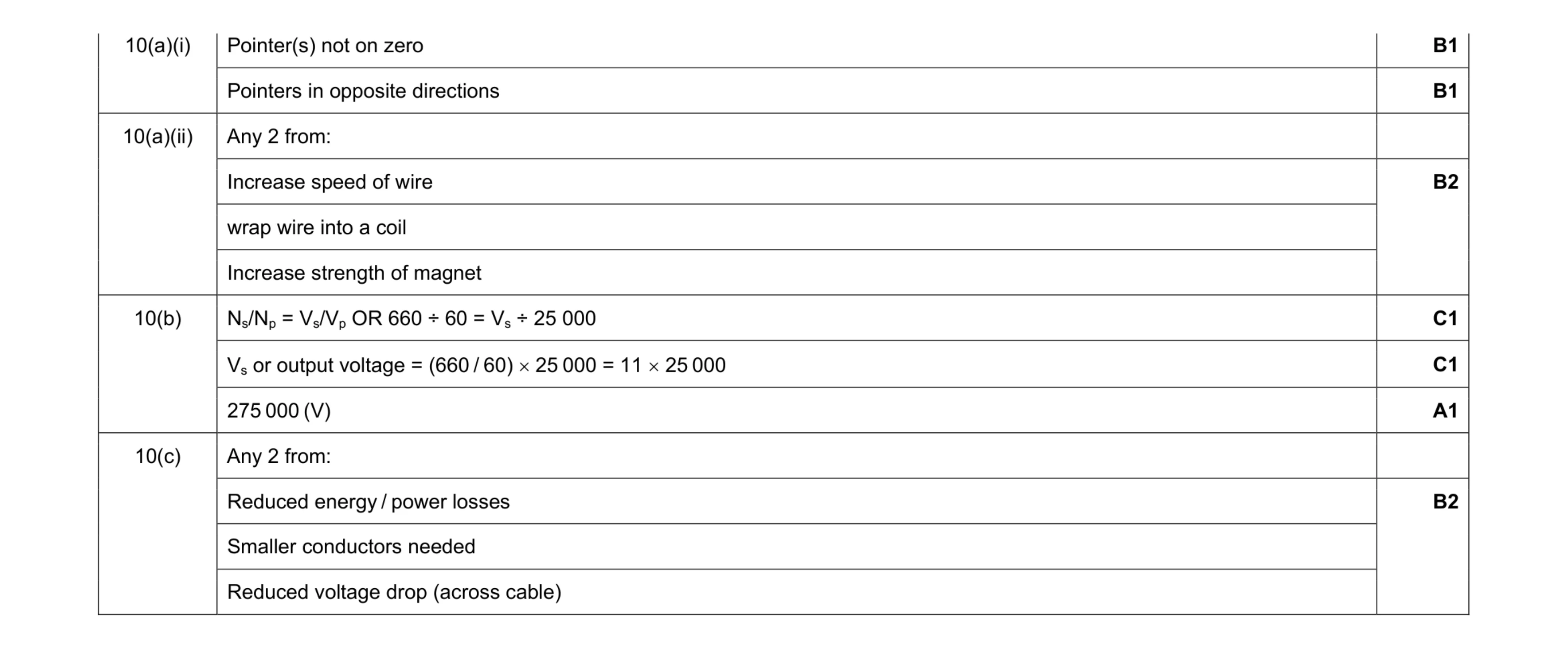 9
9 5
5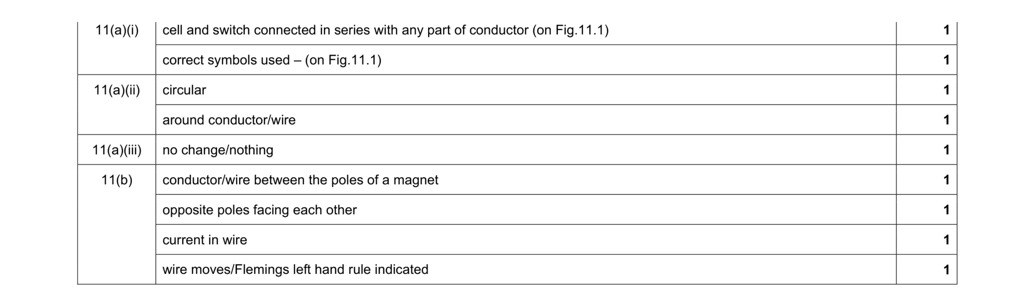 9
9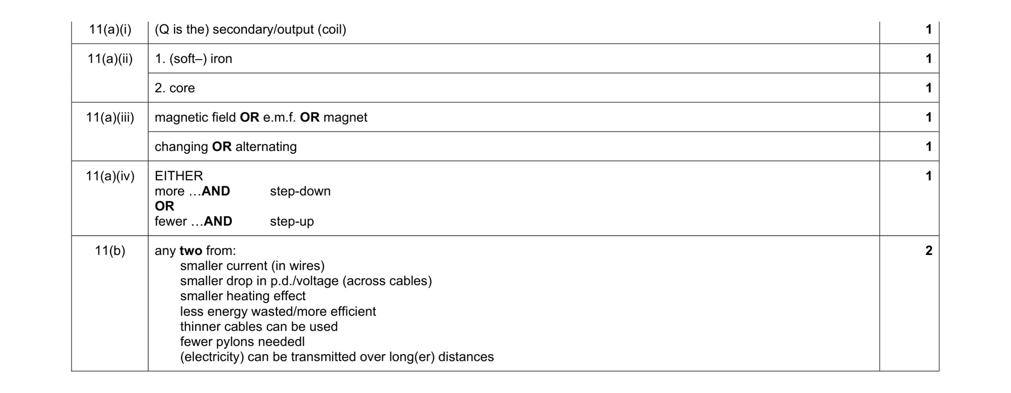 8
8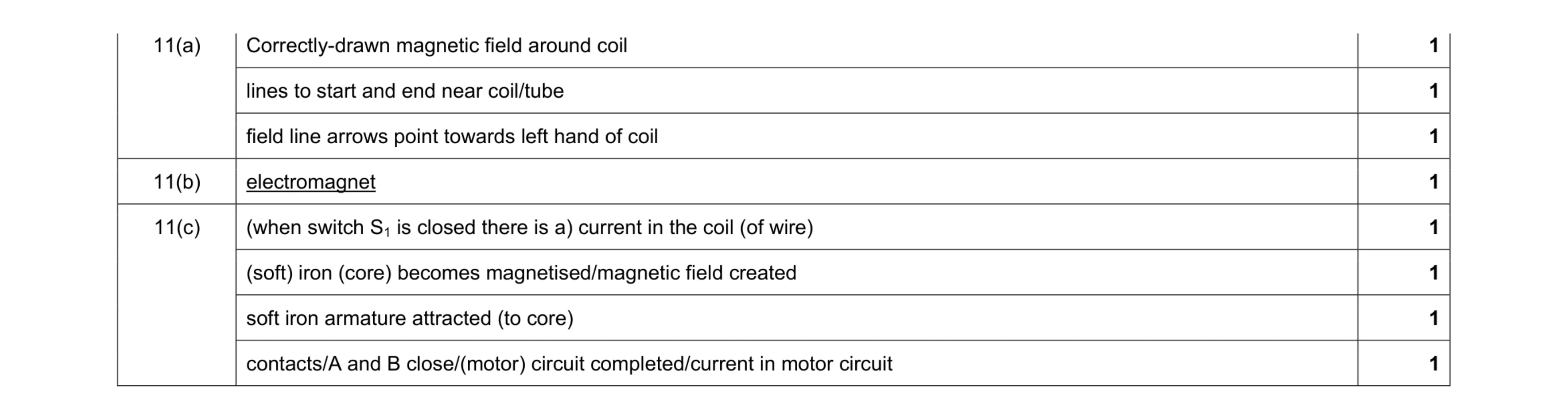 8
8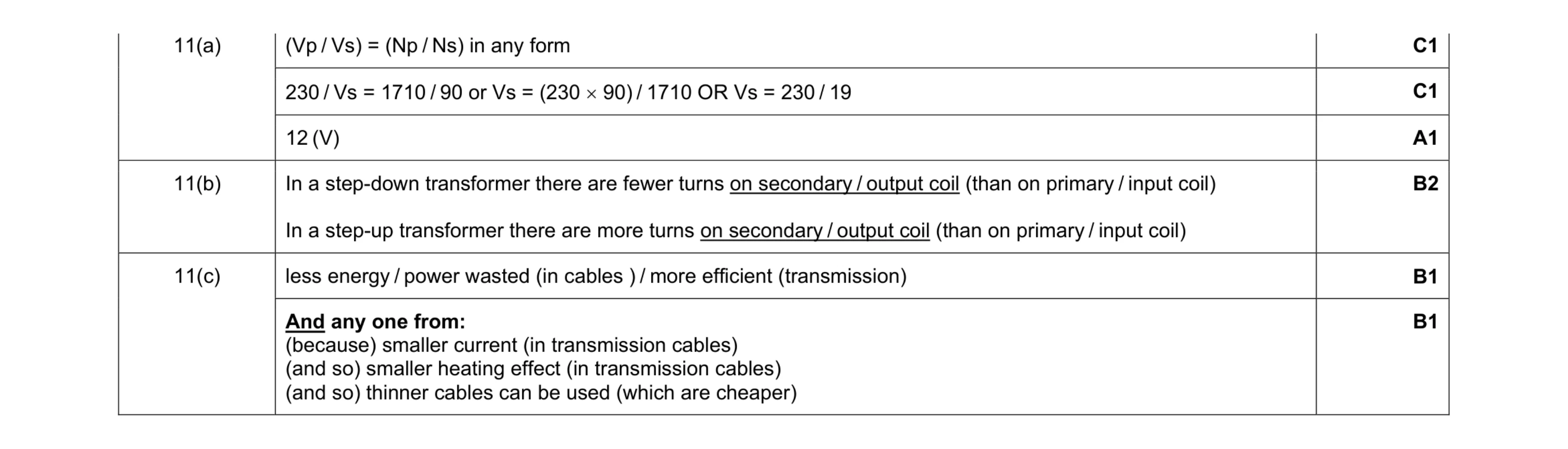 7
7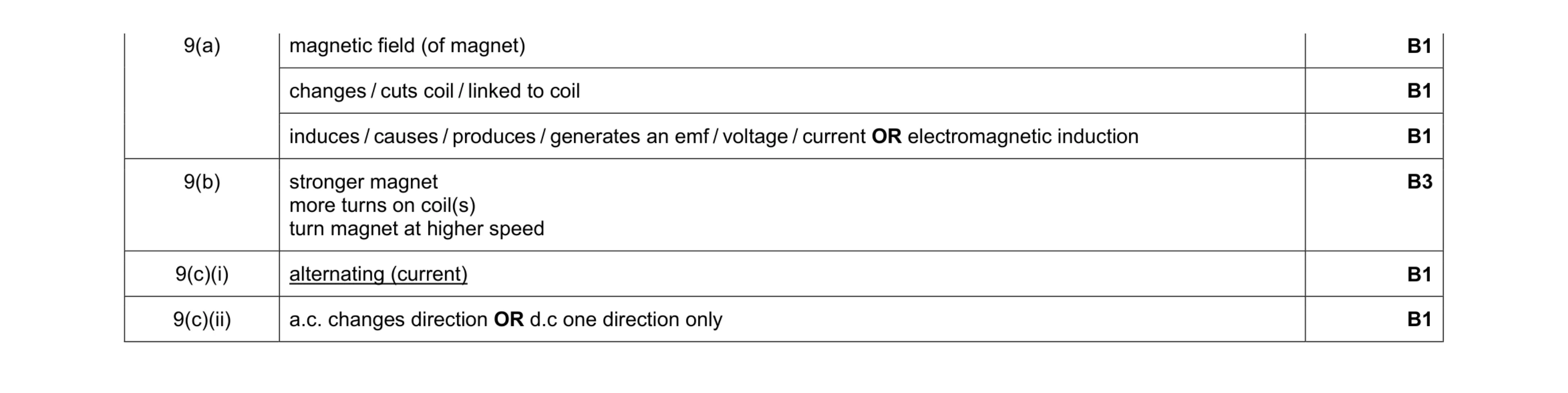 8
8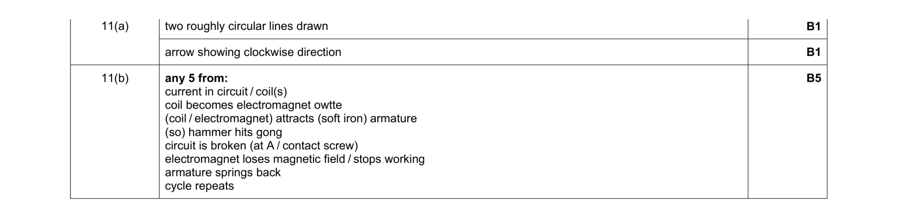 7
7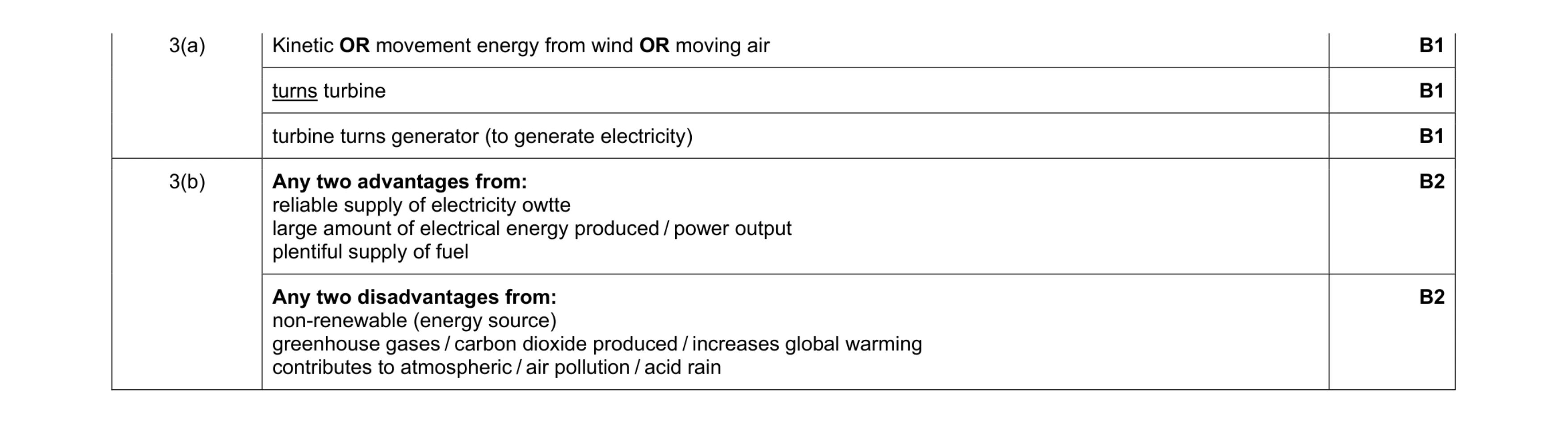 7
7 7
7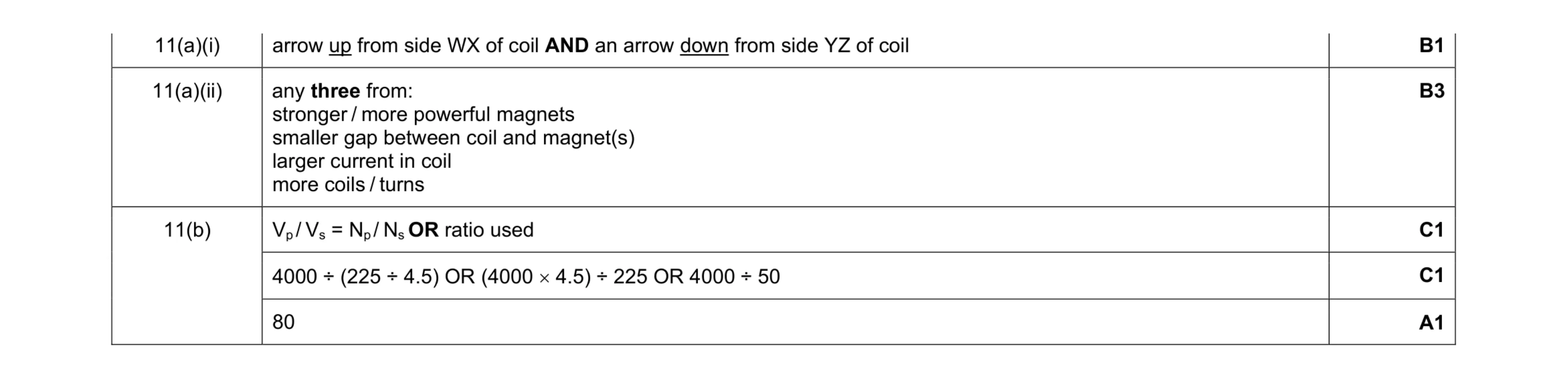 7
7 5
5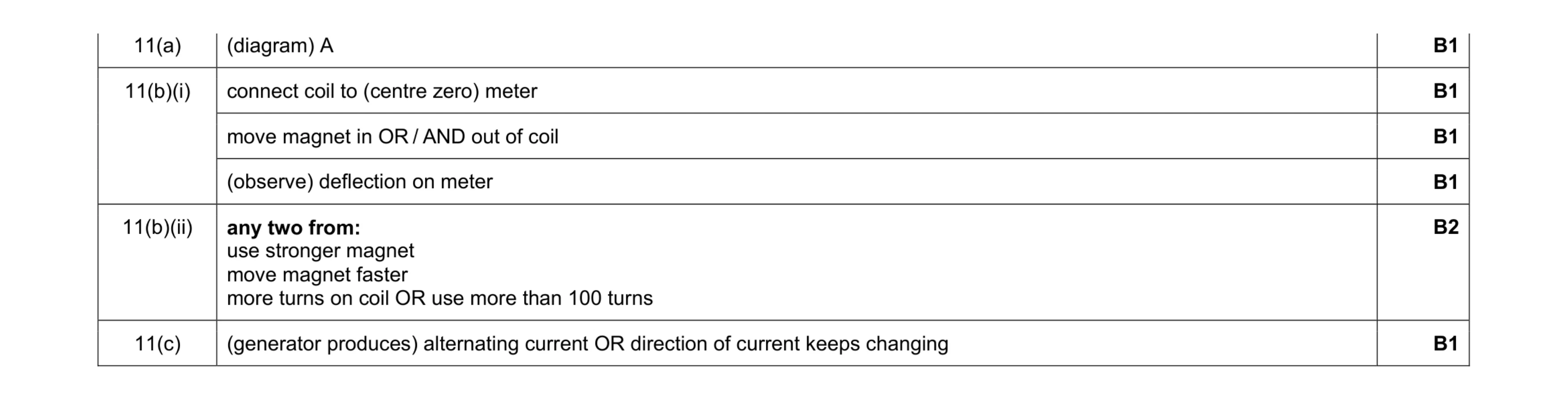 7
7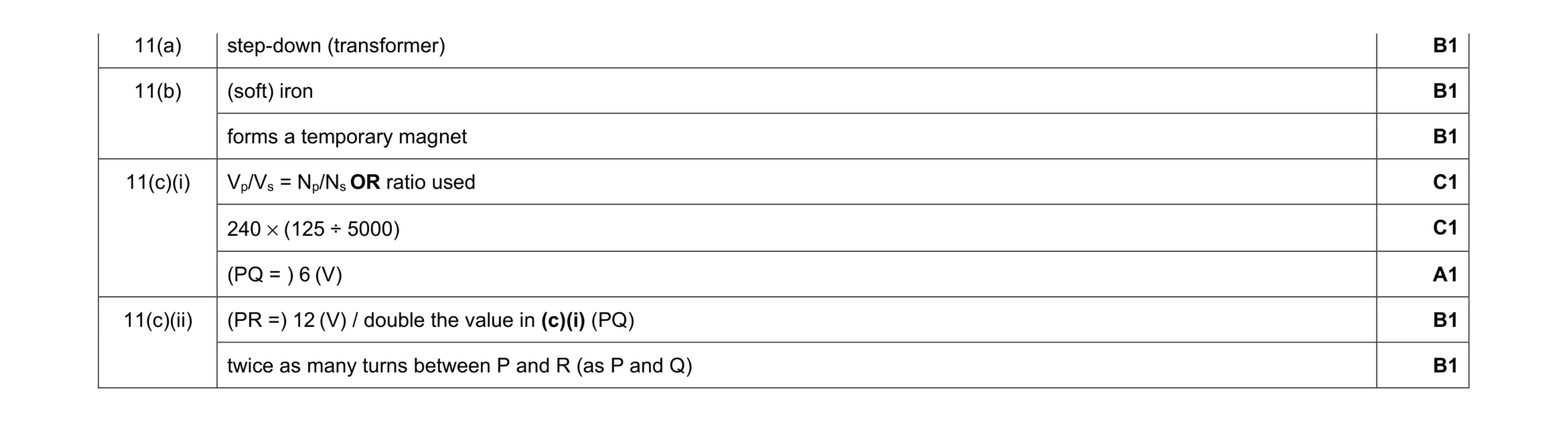 8
8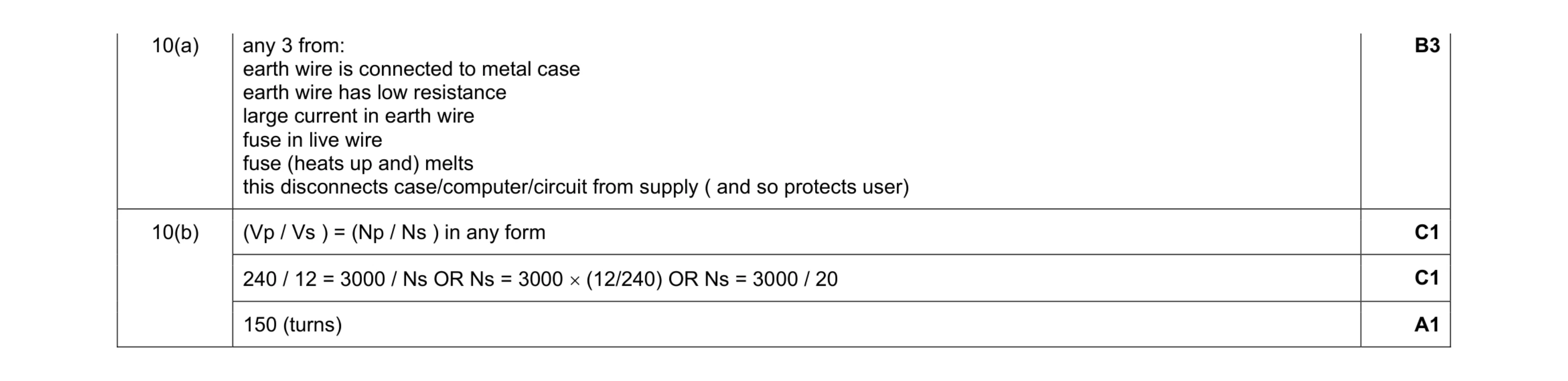 6
6 5
5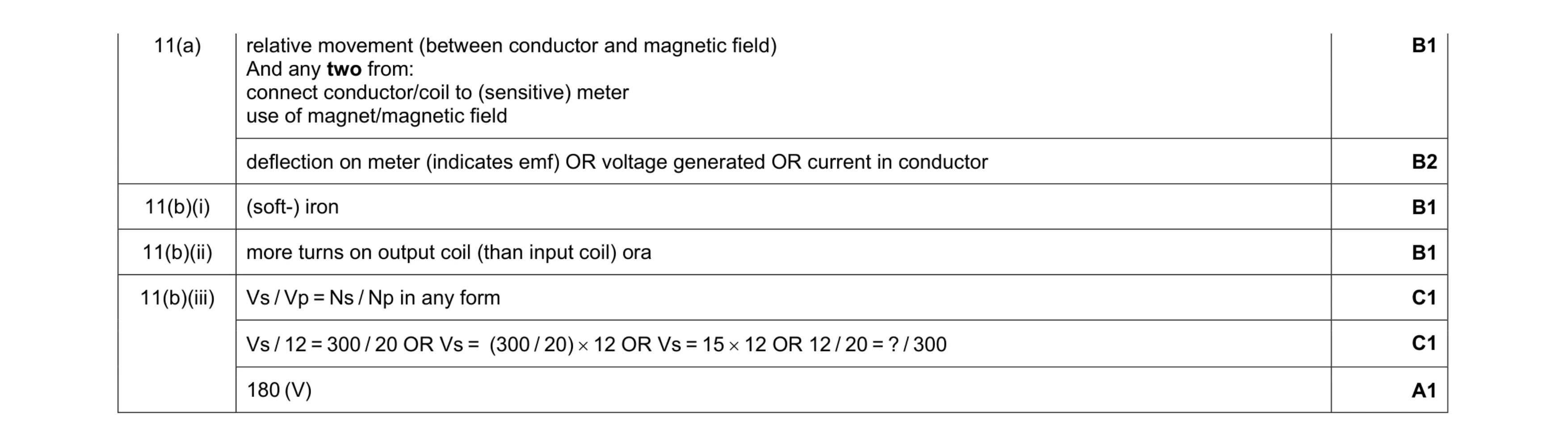 8
8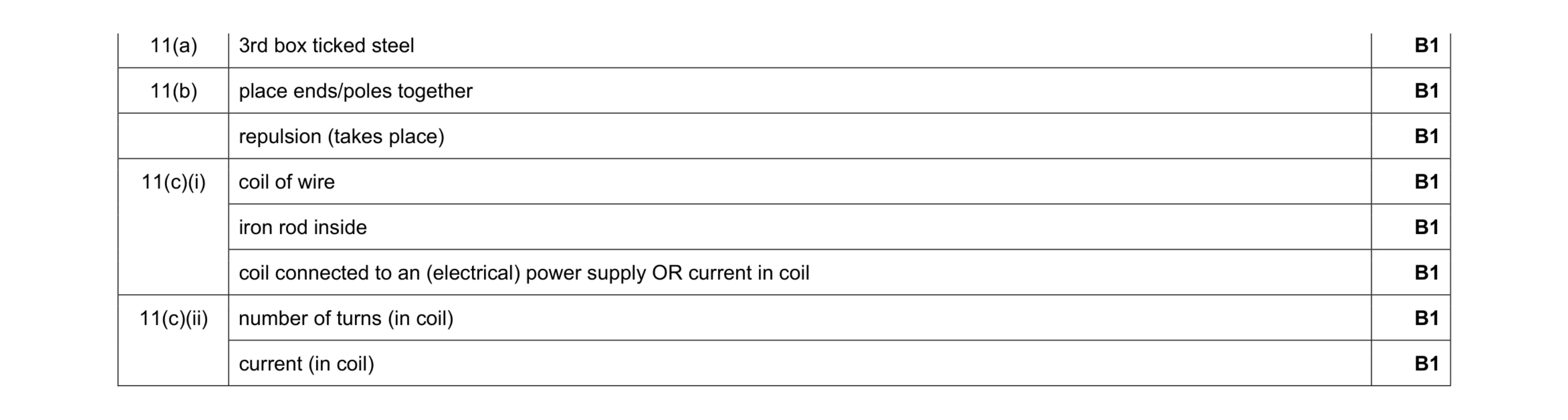 8
8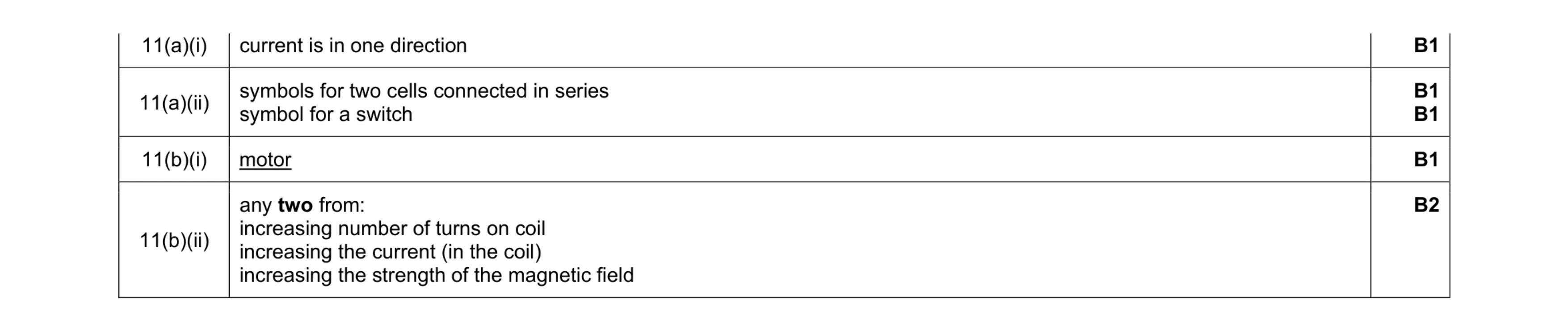 6
6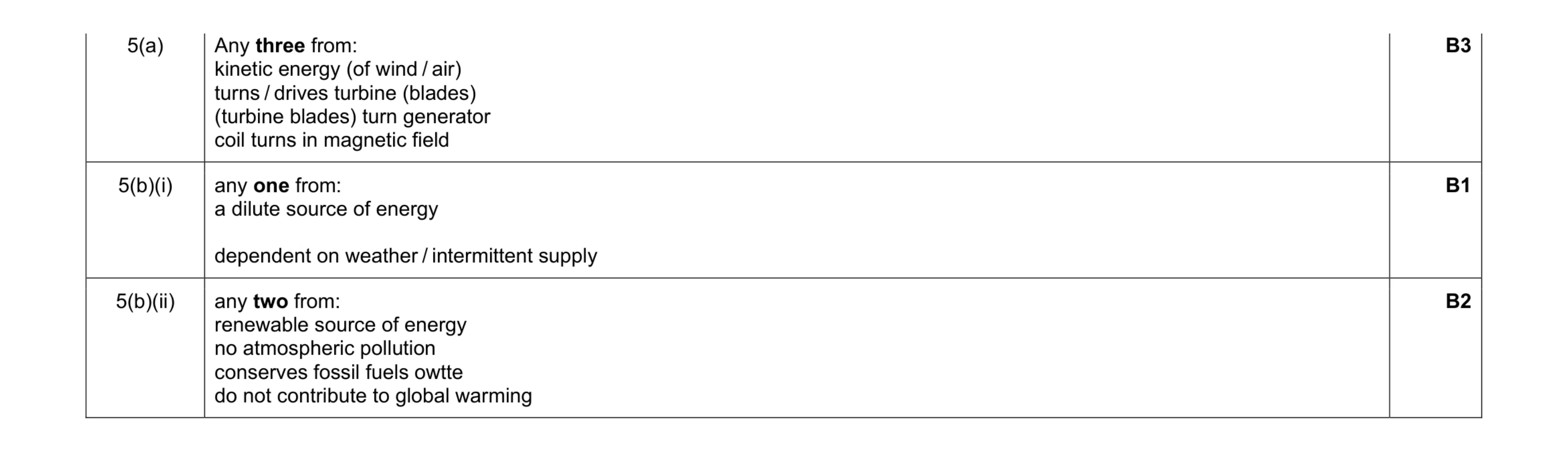 6
6 5
5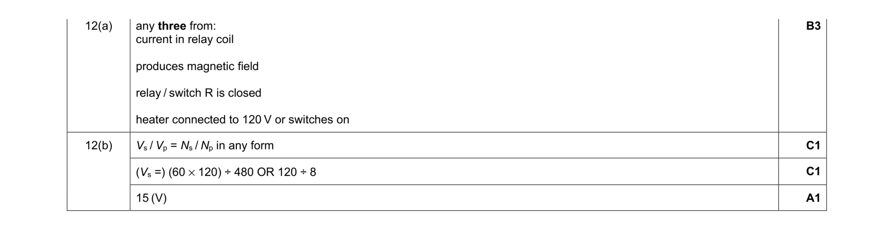 6
6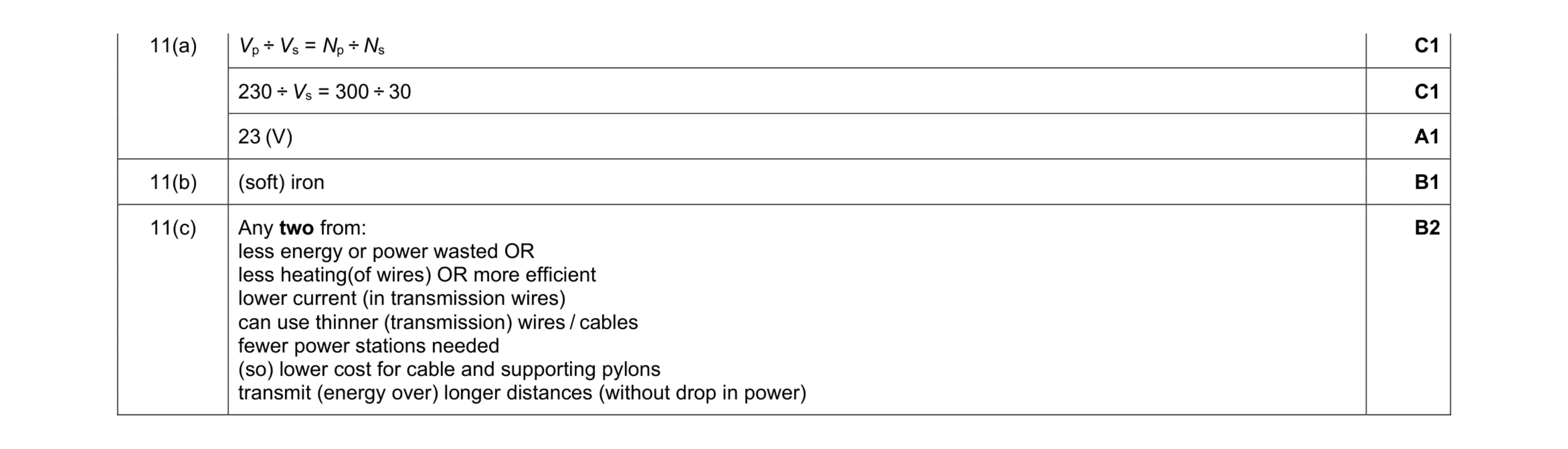 6
6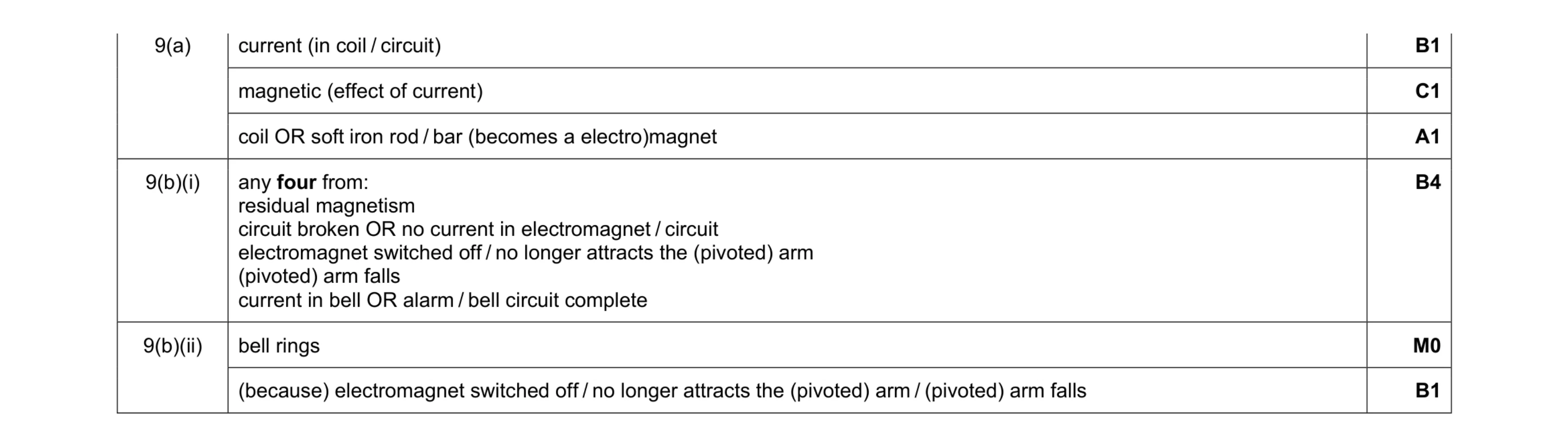 8
8 5
5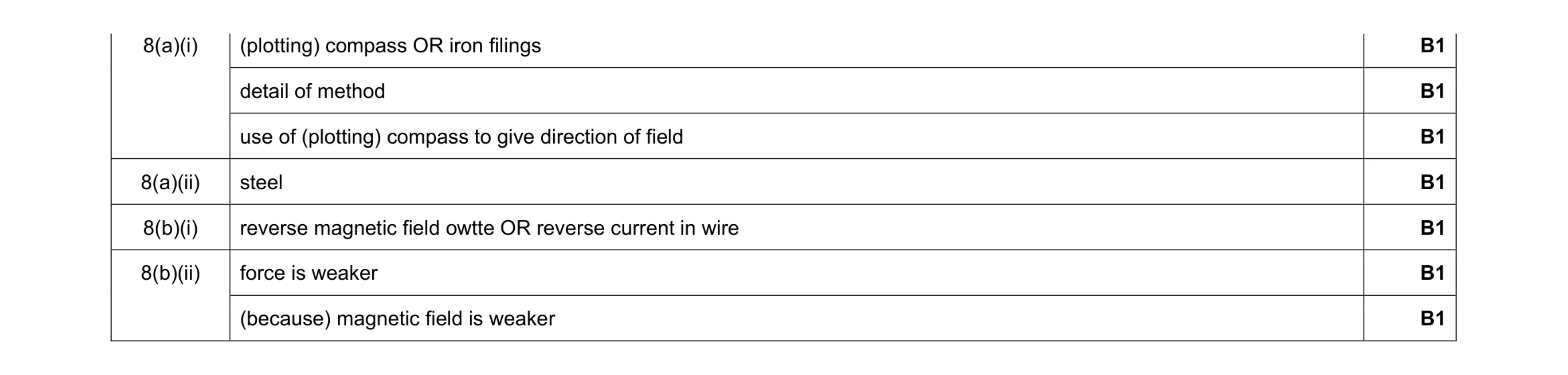 7
7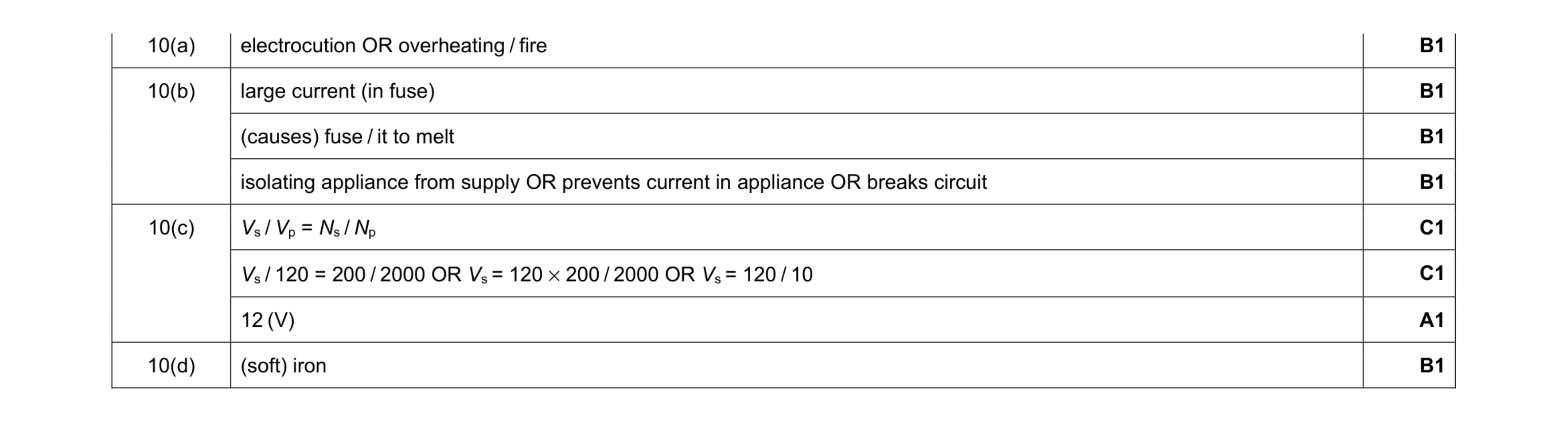 8
8 3
3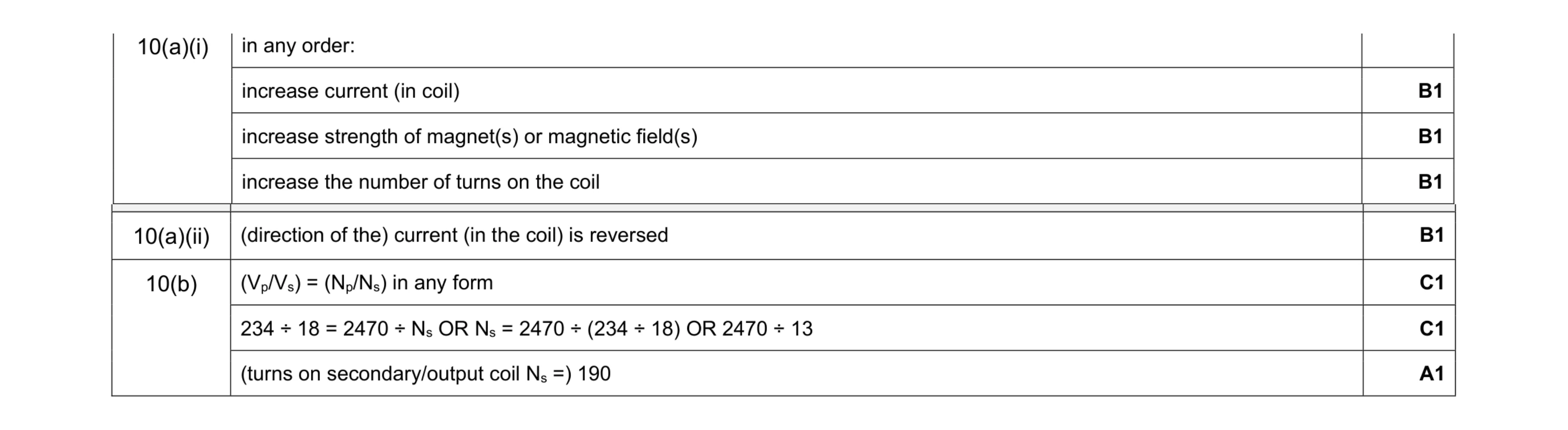 7
7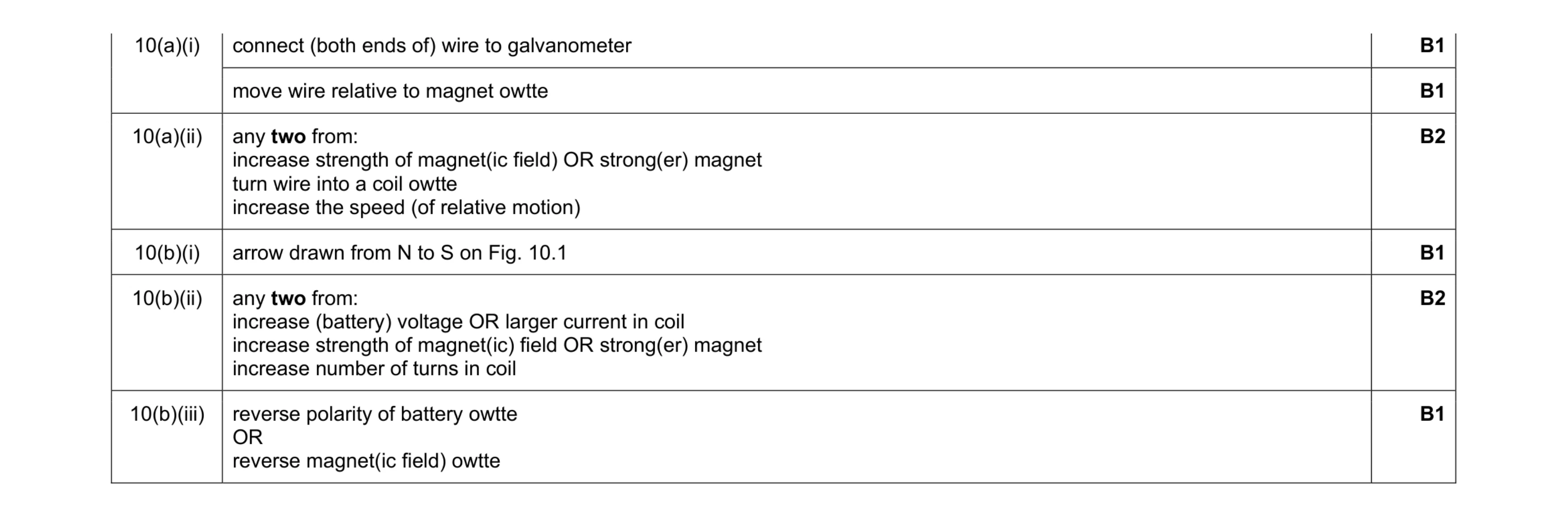 8
8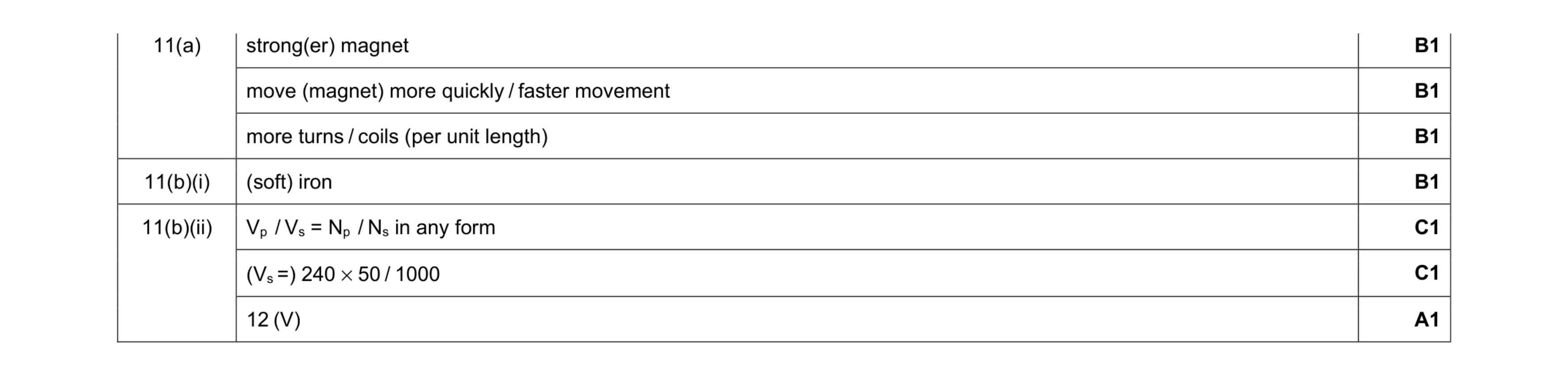 7
7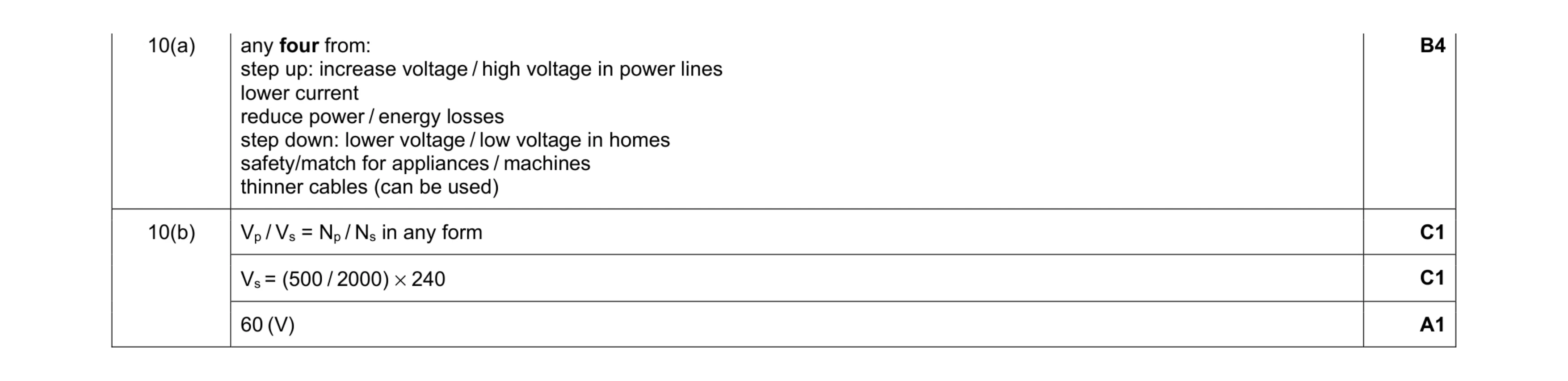 7
7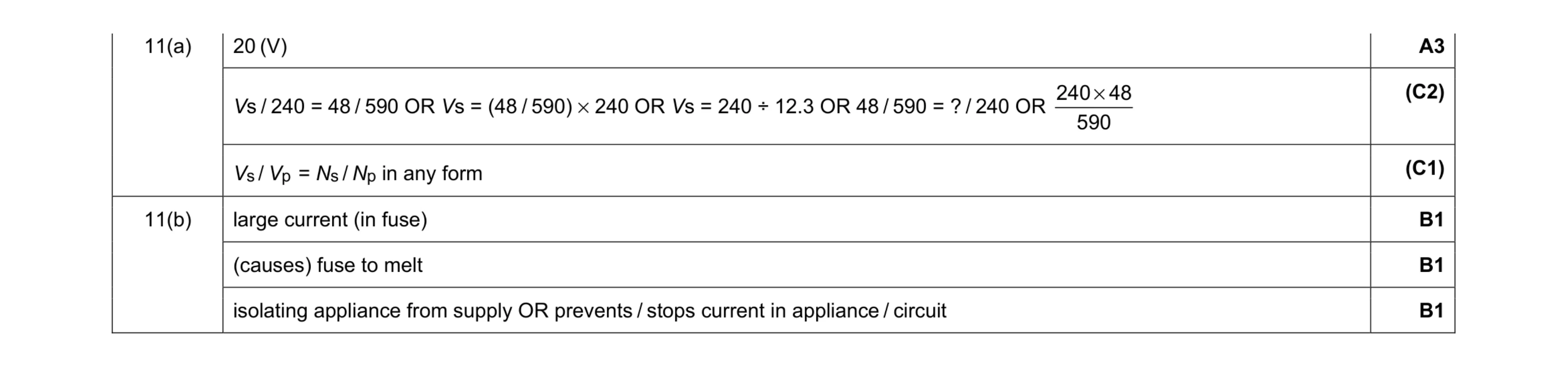 6
6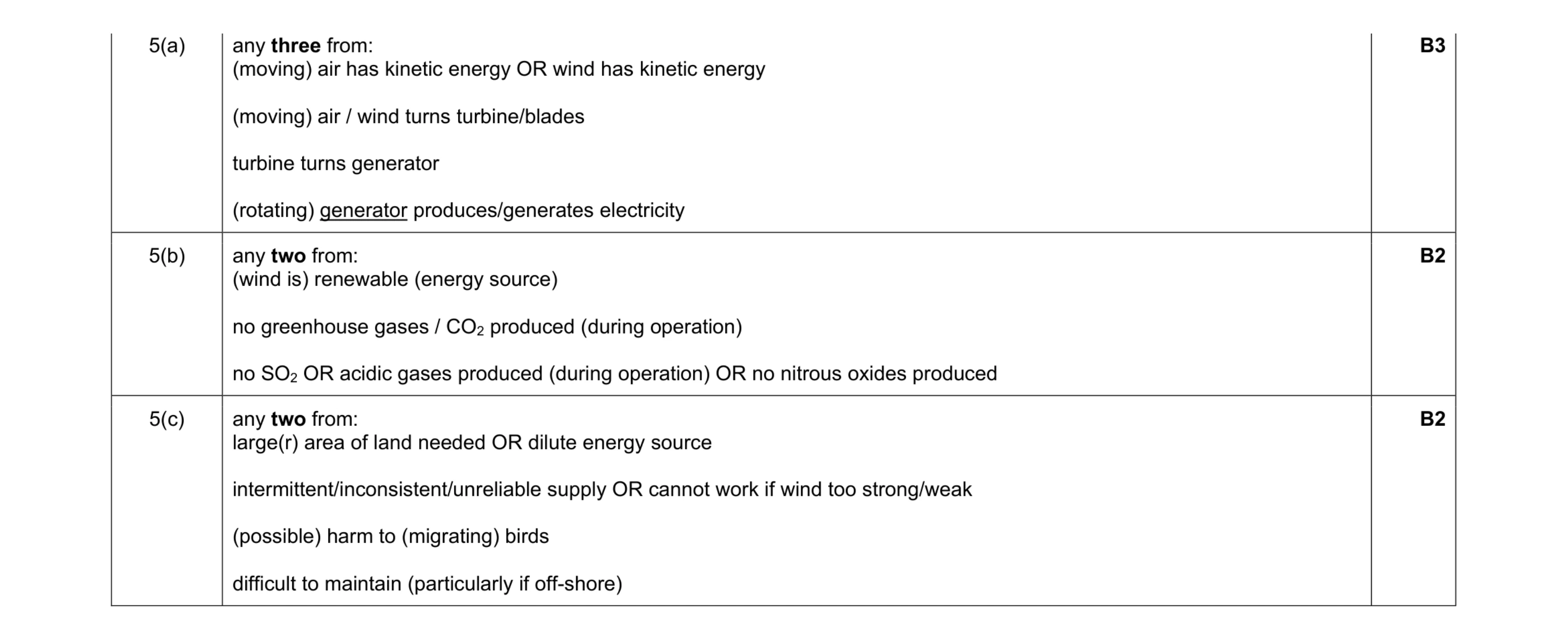 7
7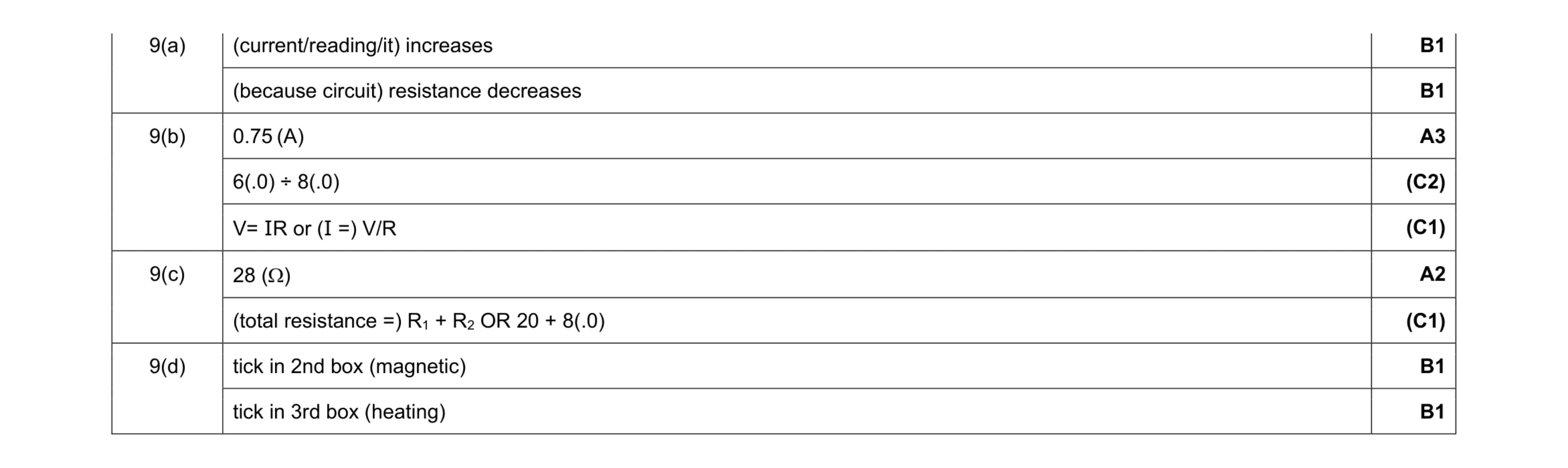 9
9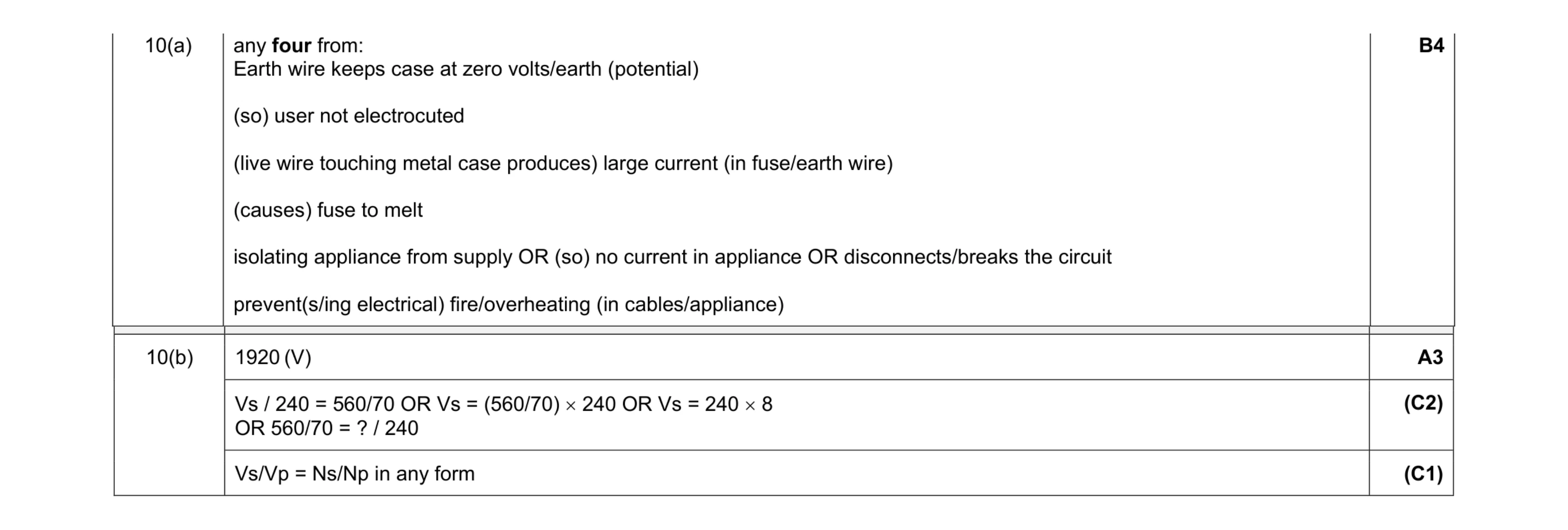 7
7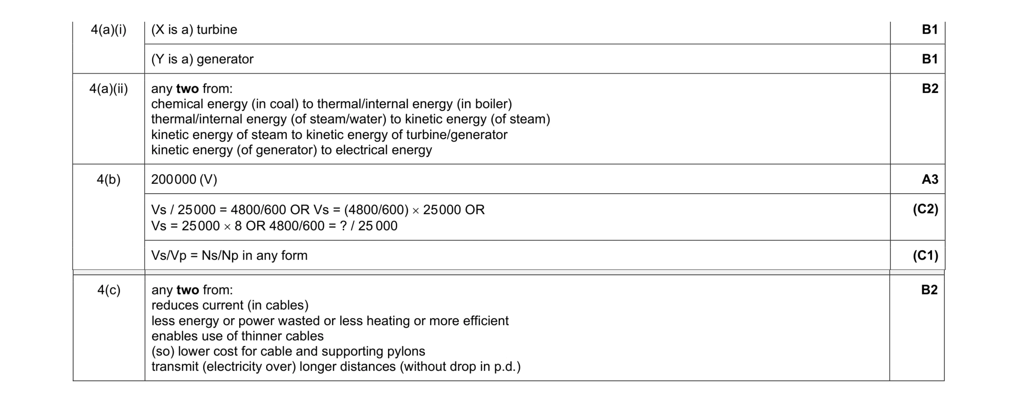 9
9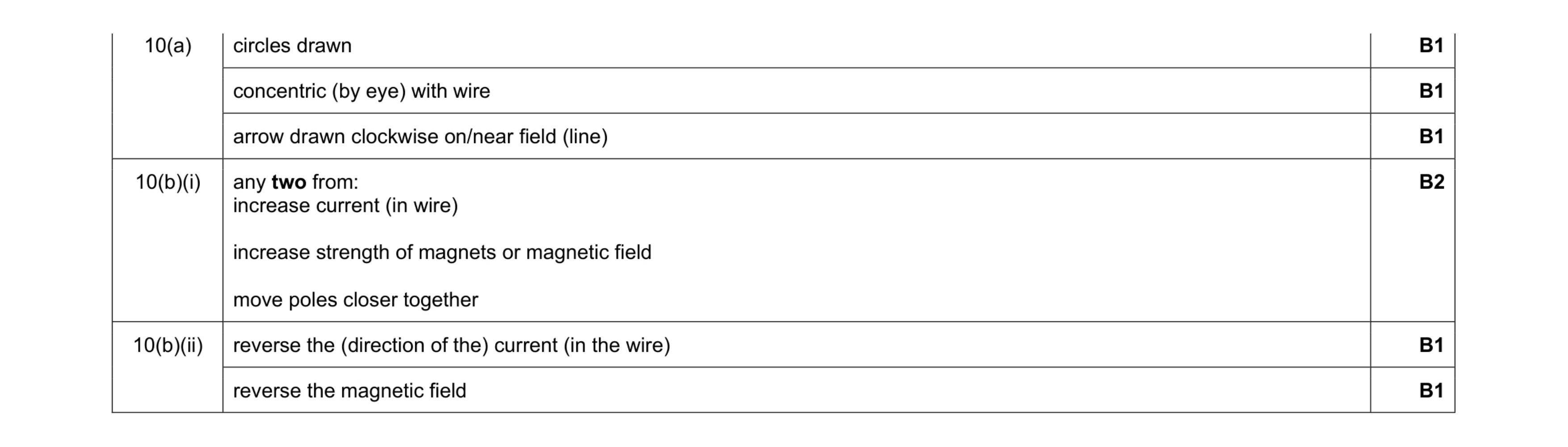 7
7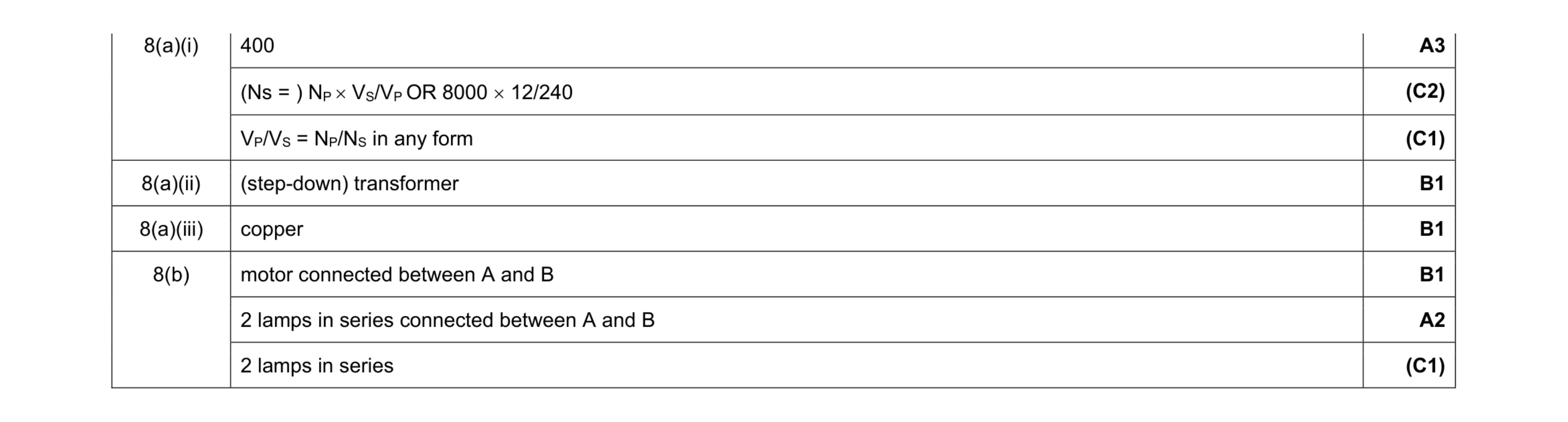 8
8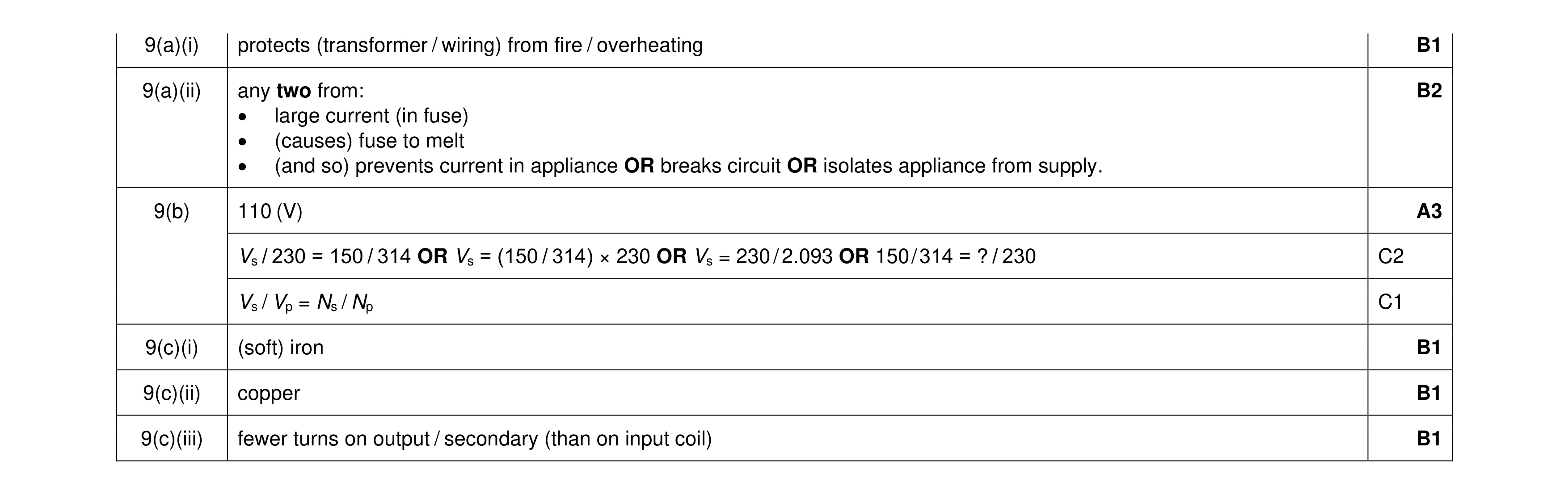 9
9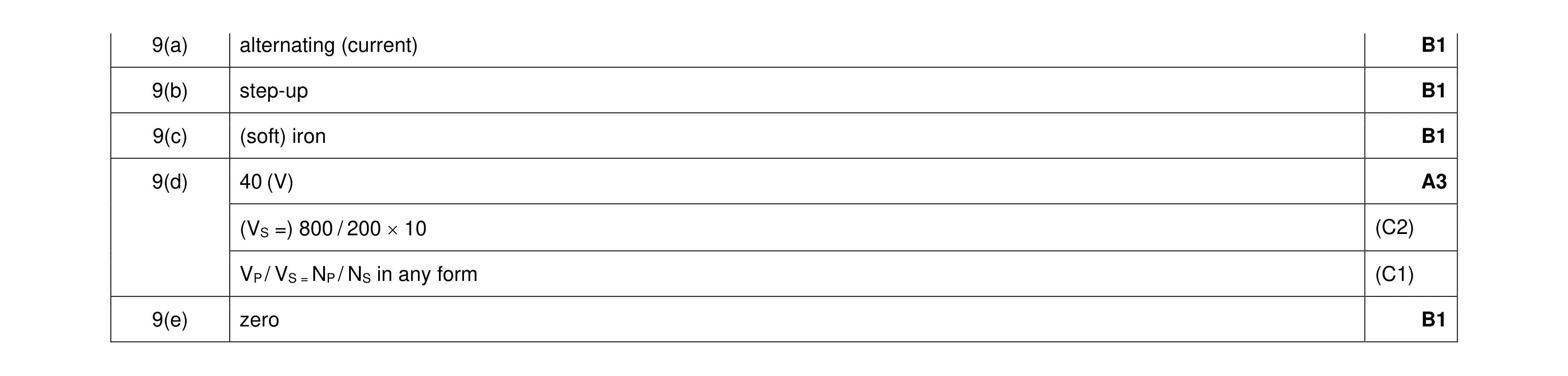 7
7 5
5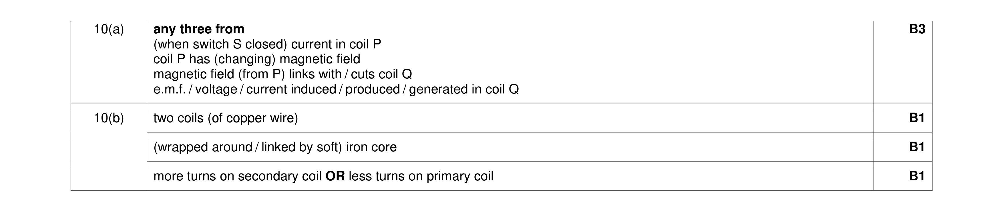 6
6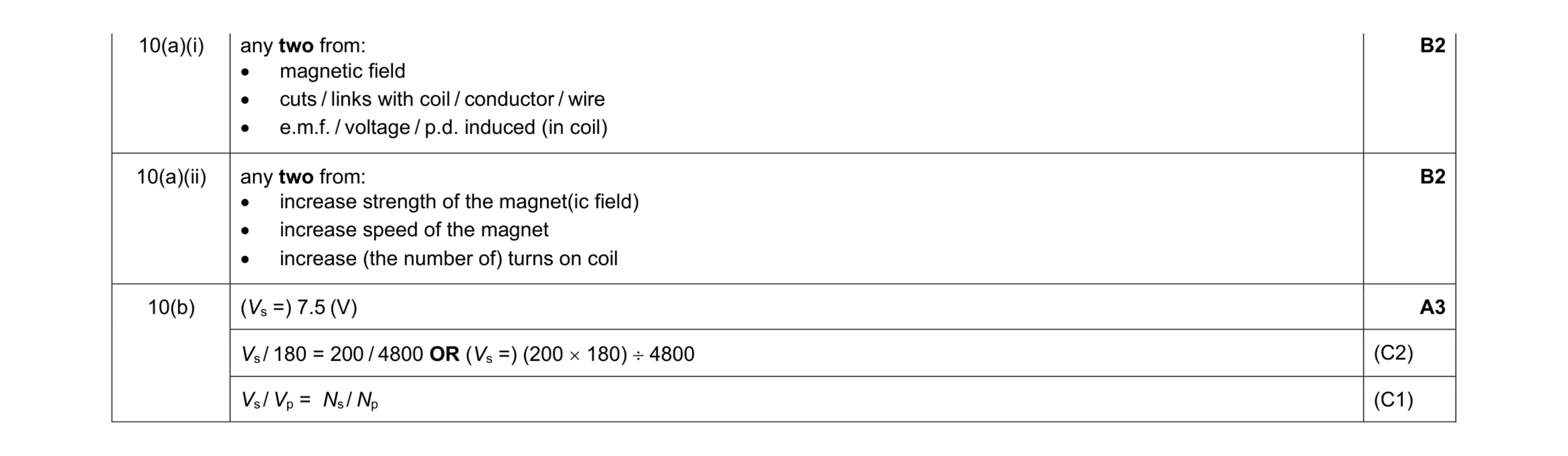 7
7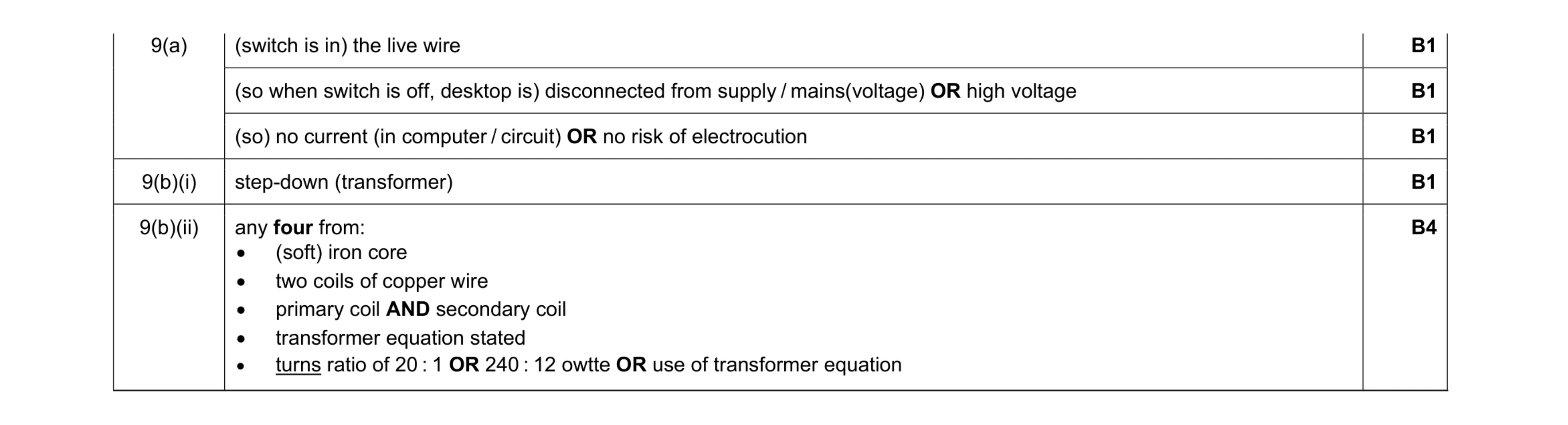 8
8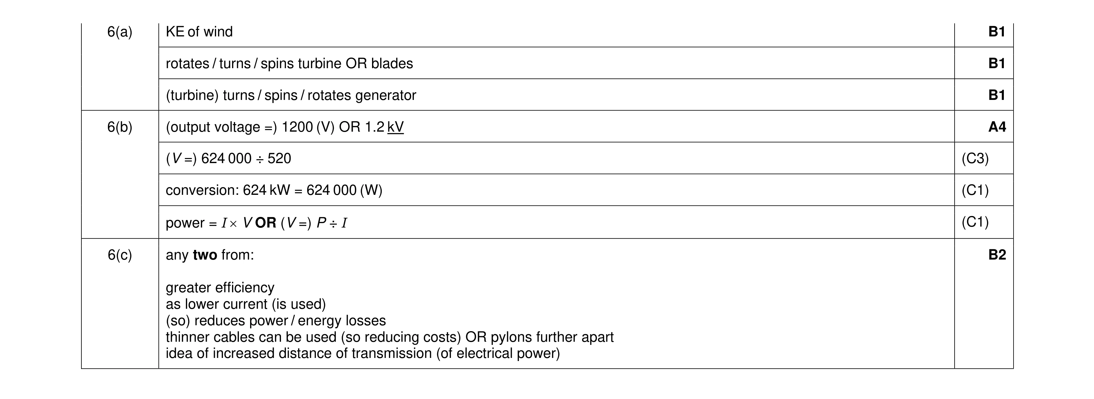 9
9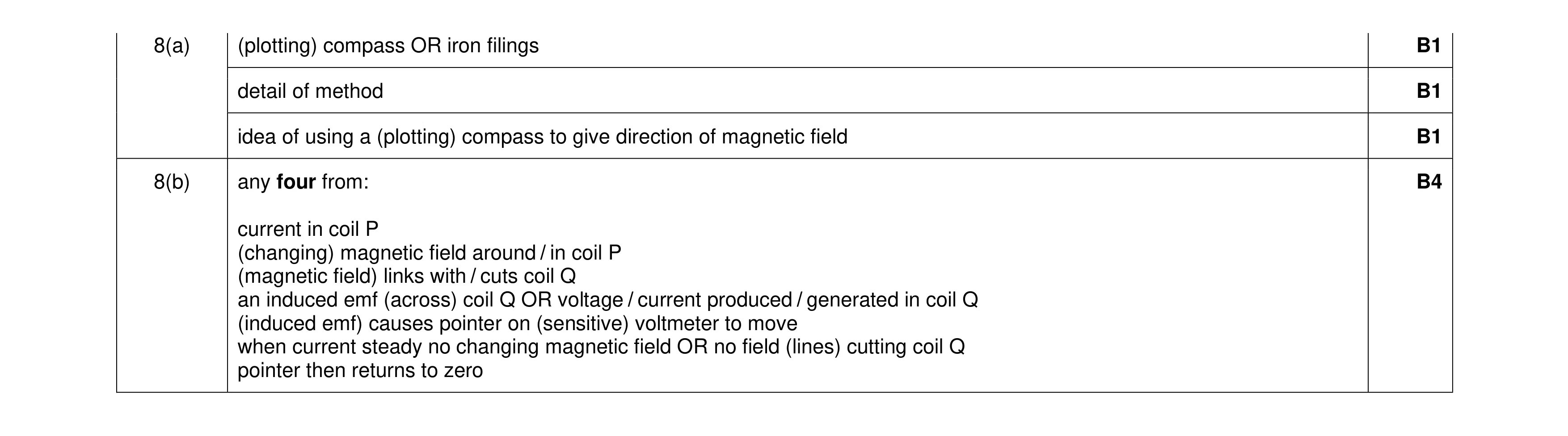 7
7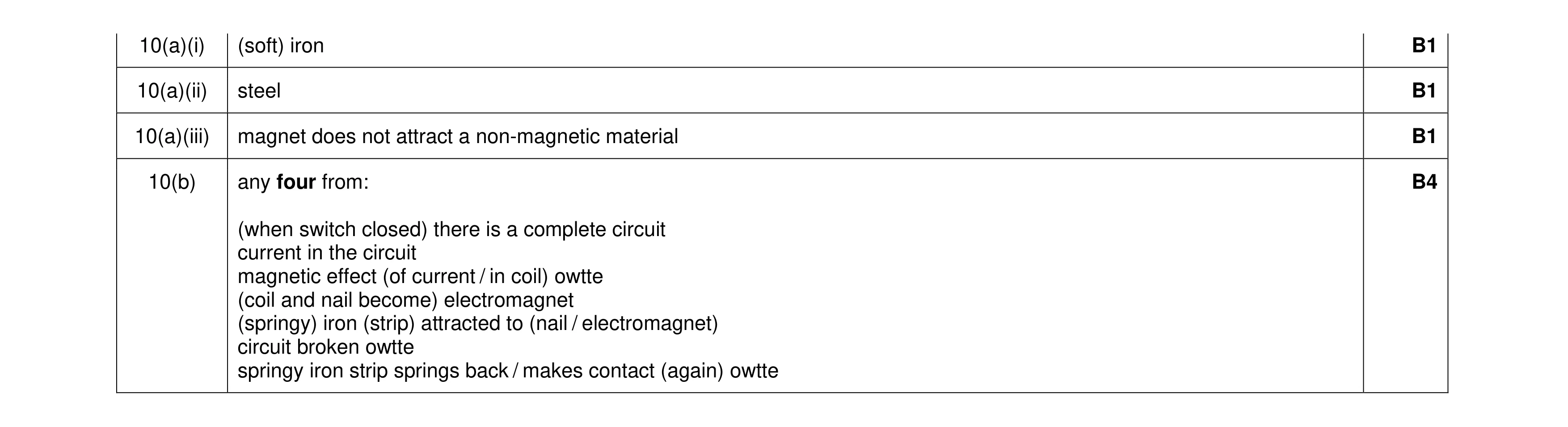 7
7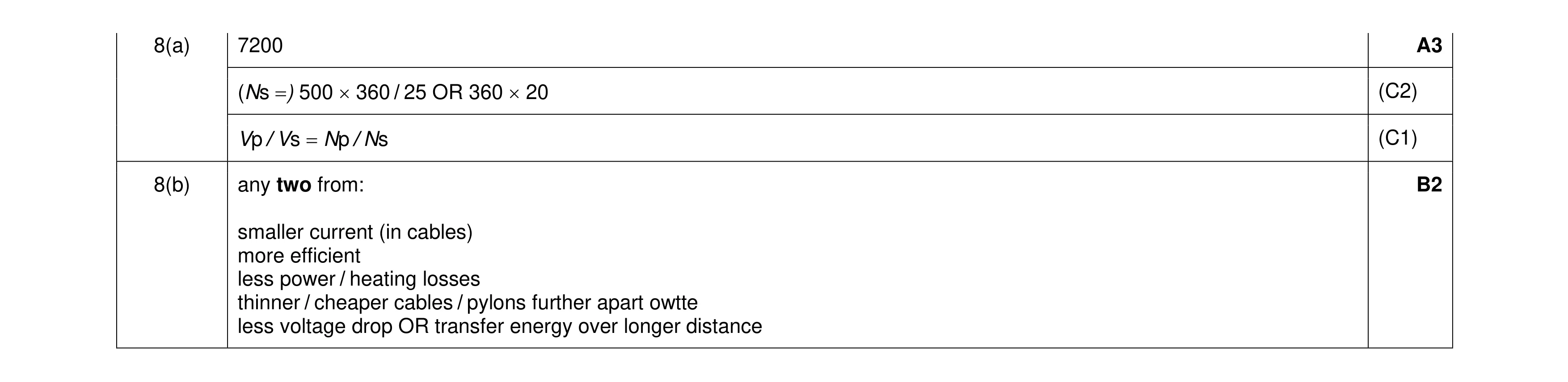 5
5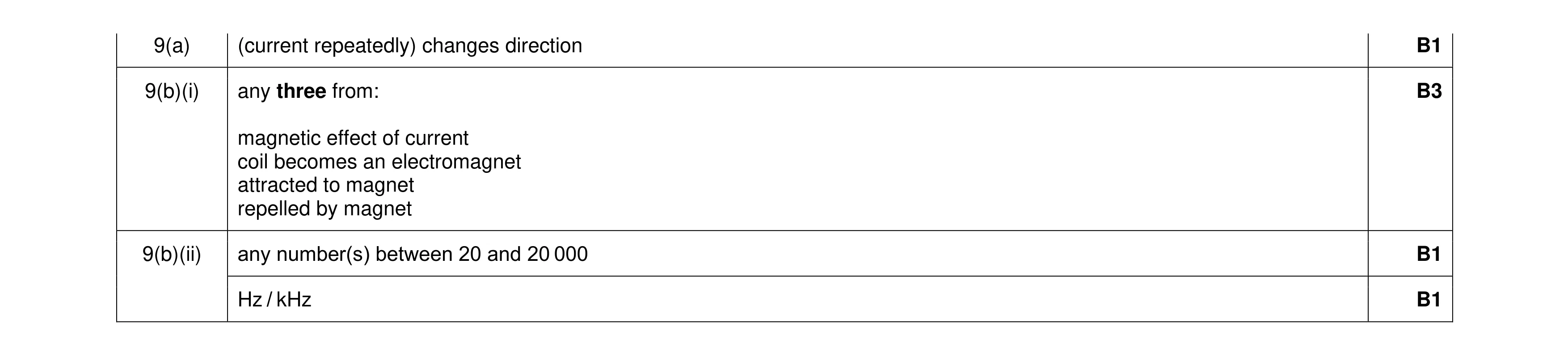 6
6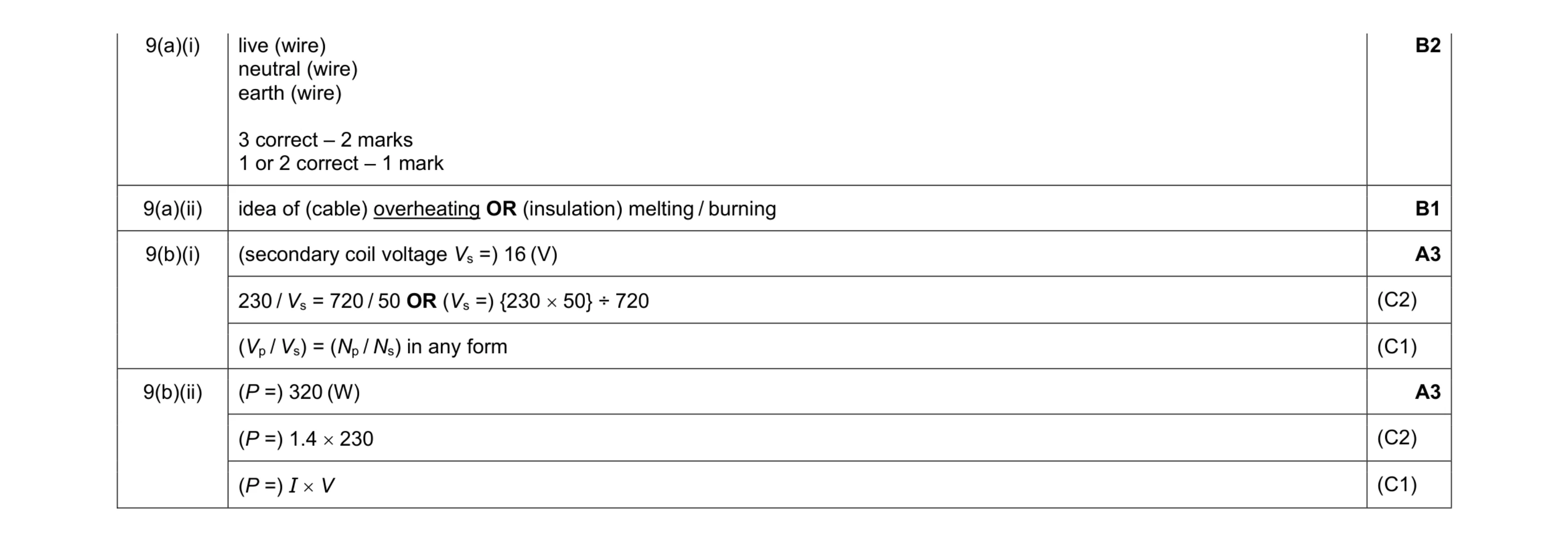 9
9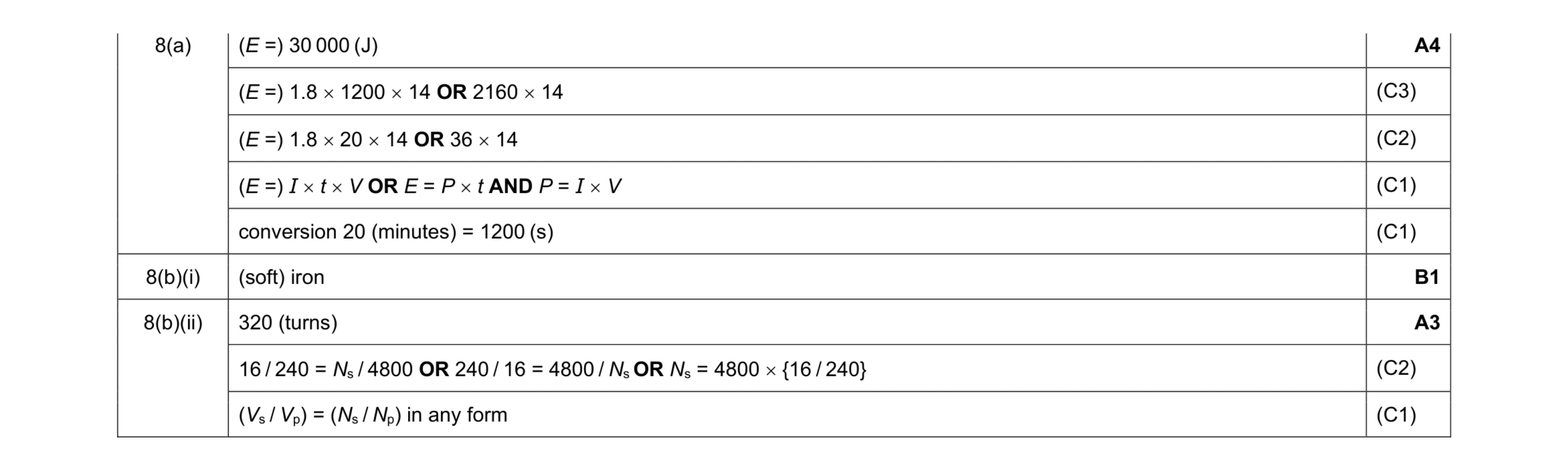 8
8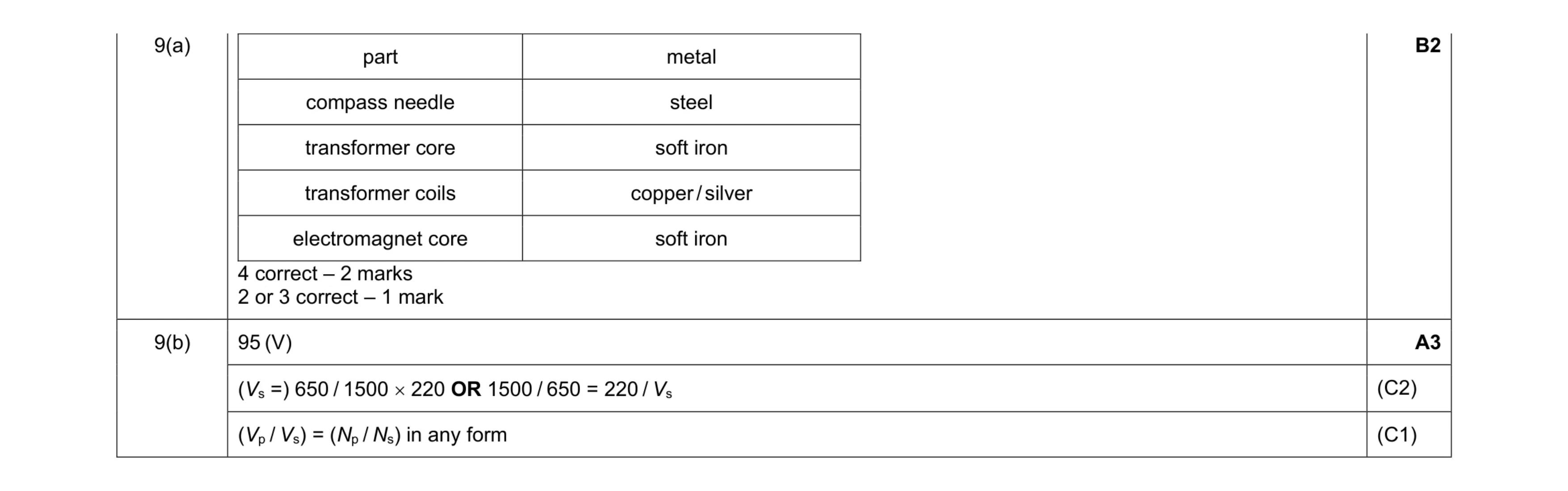 5
5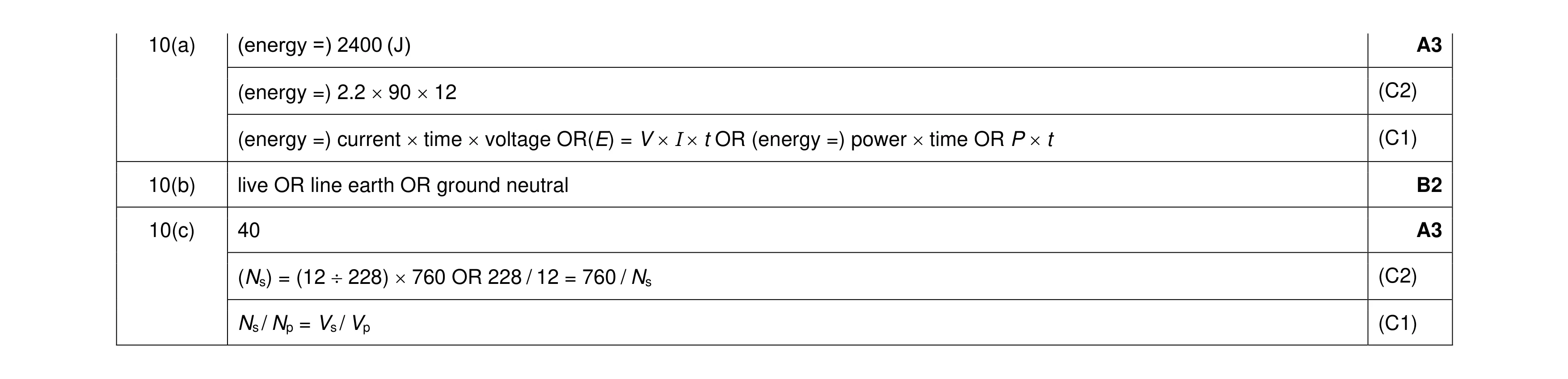 8
8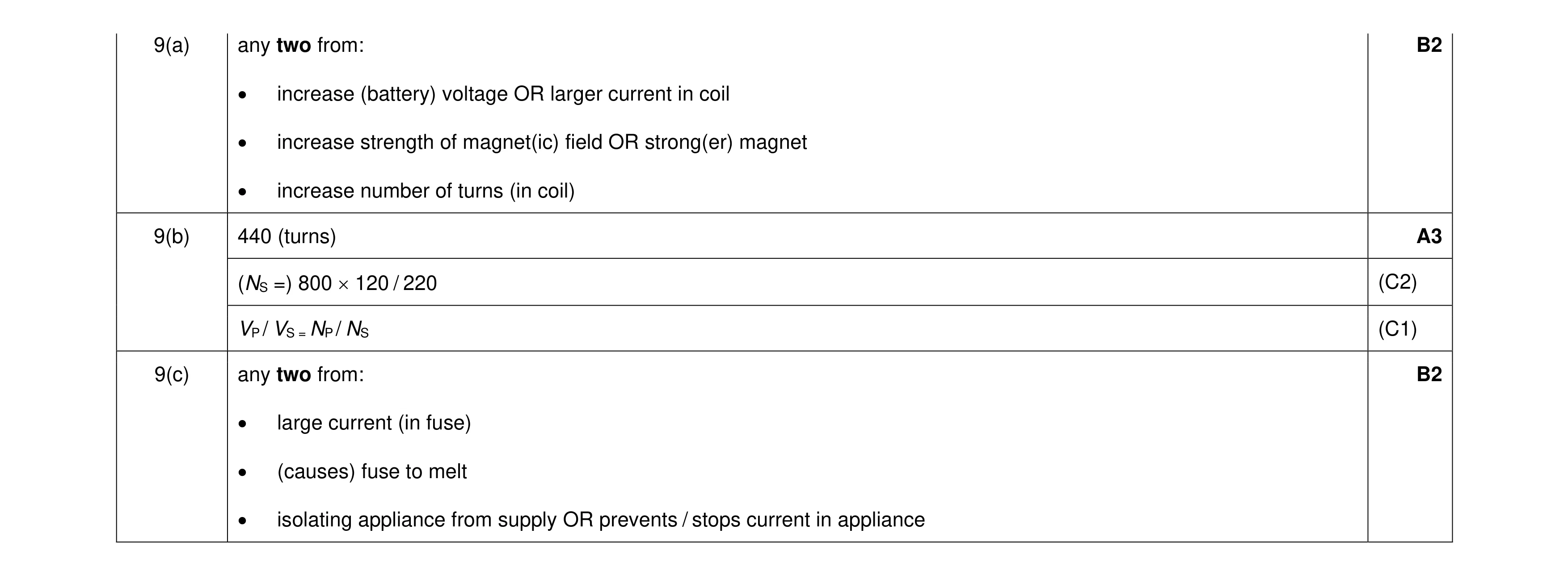 7
7 5
5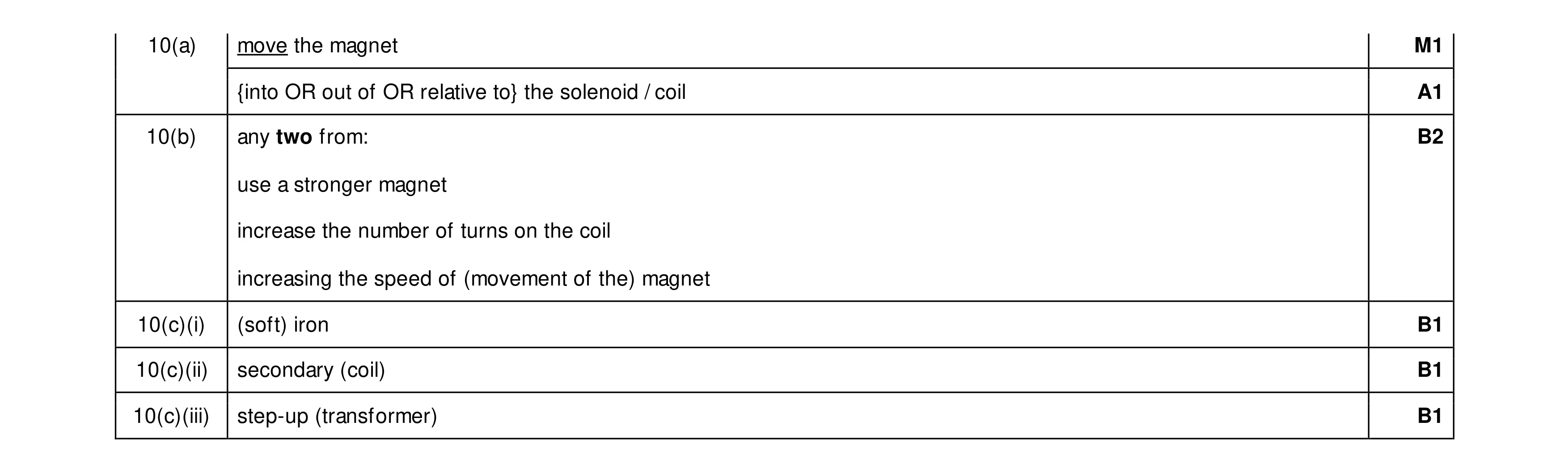 7
7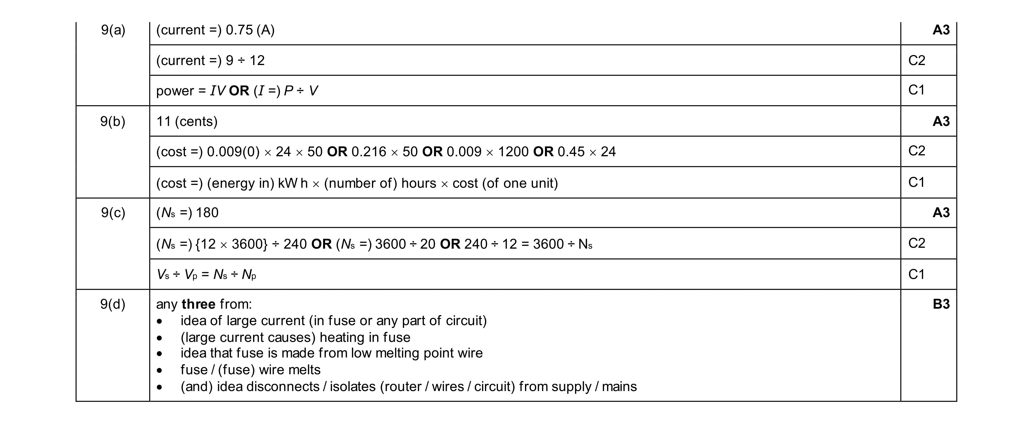 12
12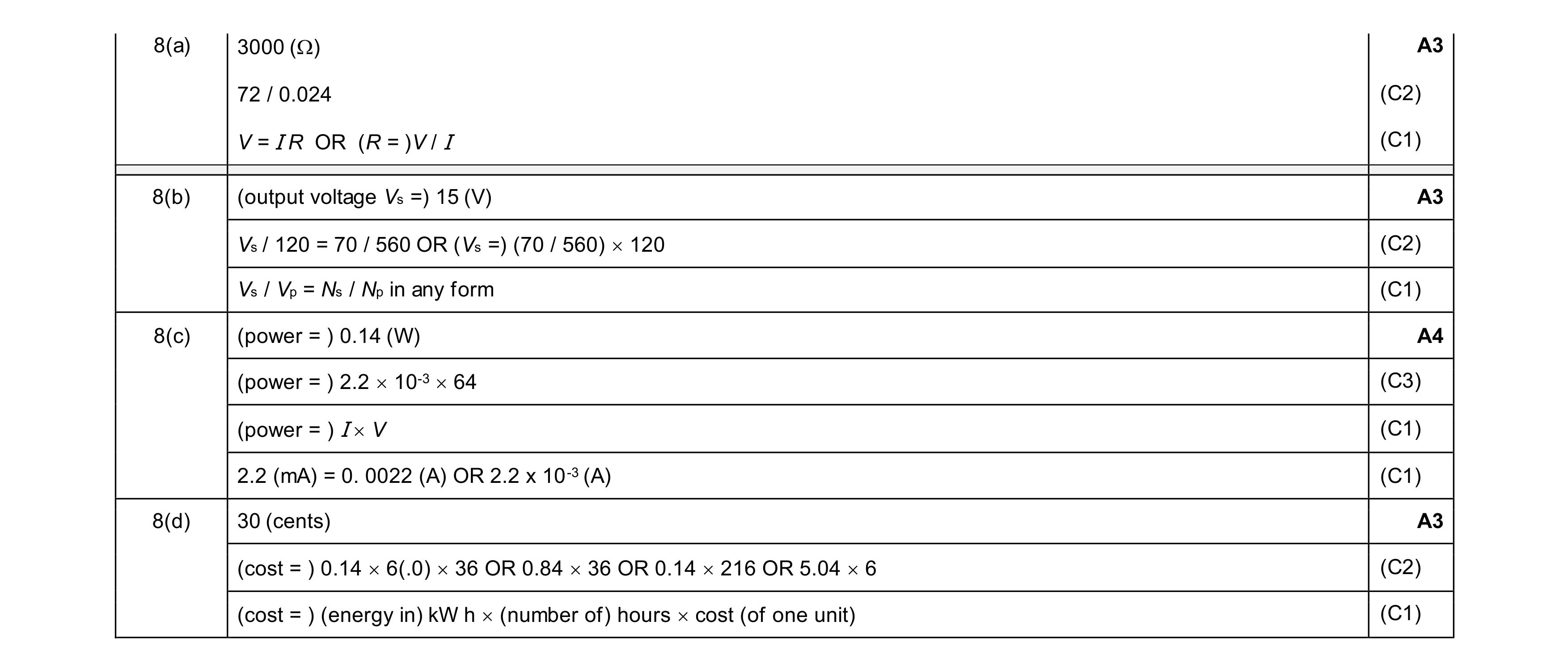 13
13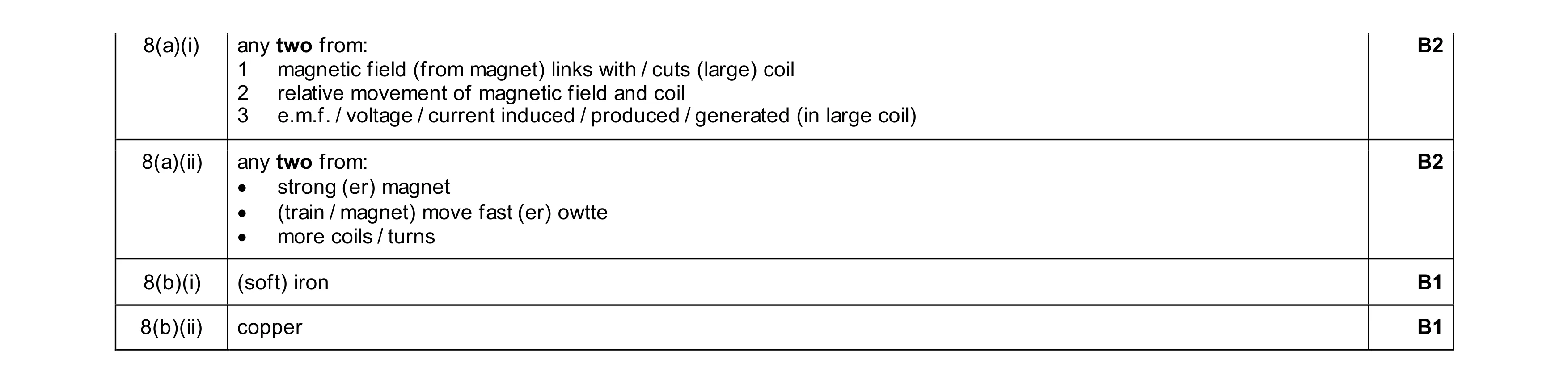 6
6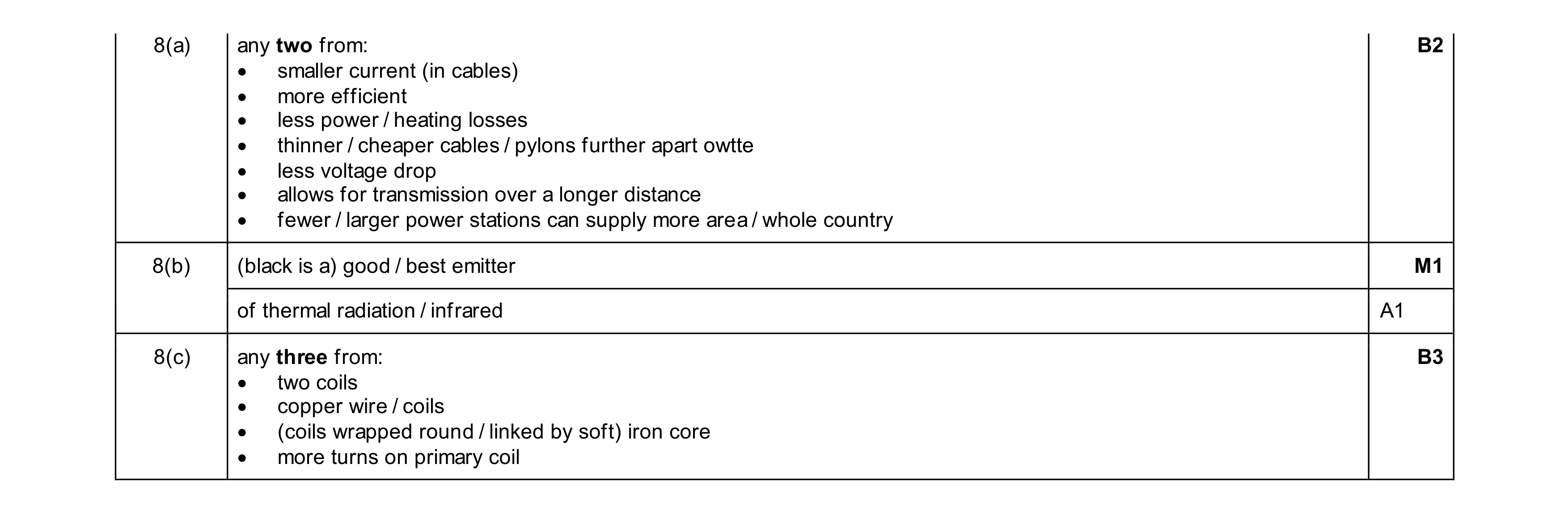 7
7