Questions as text
Q1 · What is designed to change electrical energy into kinetic energy? 0625/11 May/June 2005
9 What is designed to change electrical energy into kinetic energy? A capacitor B generator C motor D transformer
1 marks
Answer: C
This question in 0625/11 May/June 2005
Q2 · Which graph shows the output voltage from a simple a.c 0625/11 May/June 2005
34 Which graph shows the output voltage from a simple a.c. generator? voltage A 0 time voltage B 0 time voltage C 0 time voltage D 0 time
1 marks
Answer: D
This question in 0625/11 May/June 2005
Q3 · A transformer has 50 turns on its primary coil and 100 turns on its secondary coil 0625/11 May/June 2005
35 A transformer has 50 turns on its primary coil and 100 turns on its secondary coil. An a.c. voltage of 25.0 V is connected across the primary coil. 25.0 V primary coil secondary coil 50 turns 100 turns What is the voltage across the secondary coil? A 12.5 V B 50.0 V C 175 V D 200 V
1 marks
Answer: B
This question in 0625/11 May/June 2005
Q4 · Two circuits are set up as shown 0625/11 May/June 2005
36 Two circuits are set up as shown. The iron rods are placed close together, and are free to move. S iron rod iron rod X What happens to the size of the gap at X when switch S is closed? A It decreases. B It decreases then increases. C It increases. D It does not change.
1 marks
Answer: A
This question in 0625/11 May/June 2005
Q5 · The diagram shows a simple cathode-ray tube 0625/11 May/June 2005
37 The diagram shows a simple cathode-ray tube. Which part emits the electrons? – + D A B C
1 marks
Answer: B
This question in 0625/11 May/June 2005
Q6 · Which arrangement may be used to step up a voltage? 0625/11 Oct/Nov 2005
34 Which arrangement may be used to step up a voltage? A iron core B iron core a.c. d.c. output output input input C iron core D iron core a.c. d.c. output output input input
1 marks
Answer: A
This question in 0625/11 Oct/Nov 2005
Q7 · The diagrams show a straight wire carrying a current into the paper 0625/11 Oct/Nov 2005
35 The diagrams show a straight wire carrying a current into the paper. Which diagram shows the magnetic field pattern due to this current? A B C D wire wire wire wire
1 marks
Answer: B
This question in 0625/11 Oct/Nov 2005
Q8 · A magnet is suspended from a spring so that it can move freely inside a coil which is… 0625/11 Oct/Nov 2005
36 A magnet is suspended from a spring so that it can move freely inside a coil which is connected to a sensitive centre-zero ammeter. spring N centre-zero ammeter S What does the ammeter show when the magnet vibrates slowly up and down? A a reading constantly changing from left to right and right to left B a steady reading to the left C a steady reading to the right D a steady zero reading
1 marks
Answer: A
This question in 0625/11 Oct/Nov 2005
Q9 · From which materials are the coil and the core of an electromagnet made? 0625/11 May/June 2006
27 From which materials are the coil and the core of an electromagnet made? coil core A copper copper B copper iron C iron copper D iron iron
1 marks
Answer: B
This question in 0625/11 May/June 2006
Q10 · A current-carrying coil in a magnetic field experiences a turning effect 0625/11 May/June 2006
35 A current-carrying coil in a magnetic field experiences a turning effect. variable power supply N S How can the turning effect be increased? A increase the number of turns on the coil B reduce the size of the current C reverse the direction of the magnetic field D use thinner wire for the coil
1 marks
Answer: A
This question in 0625/11 May/June 2006
Q11 · A transformer is to be used to produce a 6 V output from a 24 V input 0625/11 May/June 2006
36 A transformer is to be used to produce a 6 V output from a 24 V input. coil X coil Y 24 V 6 V What are suitable numbers of turns for coil X and for coil Y? number of turns number of turns on coil X on coil Y A 240 60 B 240 240 C 240 960 D 960 60
1 marks
Answer: A
This question in 0625/11 May/June 2006
Q12 · A cathode-ray tube has an anode and an earthed cathode 0625/11 May/June 2006
37 A cathode-ray tube has an anode and an earthed cathode. Which line in the table shows the charge and the temperature of the anode? anode charge anode temperature A negative cool B negative hot C positive cool D positive hot
1 marks
Answer: C
This question in 0625/11 May/June 2006
Q13 · A strong electromagnet is used to attract pins 0625/11 May/June 2007
26 A strong electromagnet is used to attract pins. core pins coil What happens when the current in the coil is halved? A No pins are attracted. B Fewer pins are attracted. C The same number of pins is attracted. D Many more pins are attracted.
1 marks
Answer: B
This question in 0625/11 May/June 2007
Q14 · The circuit contains a relay 0625/11 May/June 2007
31 The circuit contains a relay. relay lamp 2 switch S lamp 1 When switch S is closed, what is the state of the lamps? lamp 1 lamp 2 A on on B on off C off on D off off
1 marks
Answer: A
This question in 0625/11 May/June 2007
Q15 · A coil is rotated steadily between the poles of a magnet 0625/11 May/June 2007
35 A coil is rotated steadily between the poles of a magnet. The coil is connected to an oscilloscope, which shows a graph of voltage output against time. N S oscilloscope contact contact Which graph shows the voltage output against time? A B C D
1 marks
Answer: A
This question in 0625/11 May/June 2007
Q16 · The diagram shows a lamp connected to a transformer 0625/11 May/June 2007
36 The diagram shows a lamp connected to a transformer. 40 turns 200 turns 12 V a.c. What is the potential difference across the lamp? A 2.4 V B 12 V C 60 V D 240 V
1 marks
Answer: C
This question in 0625/11 May/June 2007
Q17 · Which materials are suitable for making a permanent magnet and the core of an… 0625/11 Oct/Nov 2007
26 Which materials are suitable for making a permanent magnet and the core of an electromagnet? permanent magnet core of an electromagnet A iron iron B iron steel C steel iron D steel steel
1 marks
Answer: C
This question in 0625/11 Oct/Nov 2007
Q18 · How is electricity transmitted over large distances and why is it transmitted in this way? 0625/11 Oct/Nov 2007
35 How is electricity transmitted over large distances and why is it transmitted in this way? how why A at high voltage for safety B at high voltage to reduce energy loss C at low voltage for safety D at low voltage to reduce energy loss
1 marks
Answer: B
This question in 0625/11 Oct/Nov 2007
Q19 · Which parts of an a.c 0625/11 Oct/Nov 2007
36 Which parts of an a.c. generator slide past each other when the generator is working? A brushes and coil B coil and magnets C magnets and slip rings D slip rings and brushes
1 marks
Answer: D
This question in 0625/11 Oct/Nov 2007
Q20 · The diagram shows a cathode-ray tube 0625/11 Oct/Nov 2007
37 The diagram shows a cathode-ray tube. electron top beam screen Y2 X2 heater Y1 X1 cathode anode Y-plates X-plates bottom What must be done to deflect the electron beam upwards? A make X1 more positive than X2 B make X2 more positive than X1 C make Y1 more positive than Y2 D make Y2 more positive than Y1
1 marks
Answer: D
This question in 0625/11 Oct/Nov 2007
Q21 · A solenoid carrying a current is used to demagnetise a bar magnet 0625/11 May/June 2008
28 A solenoid carrying a current is used to demagnetise a bar magnet. solenoid bar magnet power supply Which conditions achieve demagnetisation? current through movement of bar magnet solenoid A a.c. around the solenoid quickly B a.c. through the solenoid slowly C d.c. around the solenoid quickly D d.c. through the solenoid slowly
1 marks
Answer: B
This question in 0625/11 May/June 2008
Q22 · The wire XY shown in the diagram is connected to a sensitive voltmeter with a centre zero 0625/11 May/June 2008
34 The wire XY shown in the diagram is connected to a sensitive voltmeter with a centre zero. XY is then moved quickly once through the magnetic field. X S N V movement Y What is observed on the voltmeter? A The needle moves briefly in one direction and then returns to the centre. B The needle moves quickly in one direction and stays deflected. C The needle vibrates rapidly from side to side whilst XY is moving. D The needle stays still.
1 marks
Answer: A
This question in 0625/11 May/June 2008
Q23 · The diagram shows a transformer connected to a 240 V a.c 0625/11 May/June 2008
35 The diagram shows a transformer connected to a 240 V a.c. supply. soft-iron core primary coil secondary coil 60 turns 30 turns 240 V a.c. What is the potential difference across the secondary coil of the transformer? A 30 V B 120 V C 240 V D 480 V
1 marks
Answer: B
This question in 0625/11 May/June 2008
Q24 · Two different systems are used to transmit equal amounts of electrical power from one… 0625/11 Oct/Nov 2008
34 Two different systems are used to transmit equal amounts of electrical power from one building to another. One system uses low voltage and the other uses high voltage. Both systems use identical wires. Which line in the table is correct about which system wastes least energy and why? least energy wasted why A high voltage system the current in the wires is bigger B high voltage system the current in the wires is smaller C low voltage system the current in the wires is bigger D low voltage system the current in the wires is smaller
1 marks
Answer: B
This question in 0625/11 Oct/Nov 2008
Q25 · When the electric current in wire XY is in the direction shown, there is an upward force… 0625/11 Oct/Nov 2008
35 When the electric current in wire XY is in the direction shown, there is an upward force on the wire. X current force magnet magnet N S Y If the north and south poles of the magnet exchange positions, in which direction will the force on the wire act? A downwards B upwards C to the left D to the right
1 marks
Answer: A
This question in 0625/11 Oct/Nov 2008
Q26 · A wire perpendicular to the page carries an electric current in a direction out of the… 0625/11 May/June 2009
34 A wire perpendicular to the page carries an electric current in a direction out of the page. There are four compasses near the wire. Which compass shows the direction of the magnetic field caused by the current? B A C wire with current out of page D
1 marks
Answer: C
This question in 0625/11 May/June 2009
Q27 · A transformer has 50 turns on its primary coil and 100 turns on its secondary coil 0625/11 May/June 2009
35 A transformer has 50 turns on its primary coil and 100 turns on its secondary coil. An alternating voltage of 25.0 V is connected across the primary coil. 25.0 V primary coil secondary coil 50 turns 100 turns What is the voltage across the secondary coil? A 12.5 V B 50.0 V C 175 V D 200 V
1 marks
Answer: B
This question in 0625/11 May/June 2009
Q28 · In a cathode-ray tube, a hot tungsten cathode releases particles by thermionic emission 0625/11 May/June 2009
36 In a cathode-ray tube, a hot tungsten cathode releases particles by thermionic emission. What are these particles? A α-particles B electrons C protons D tungsten atoms
1 marks
Answer: B
This question in 0625/11 May/June 2009
Q29 · The diagram shows a cathode-ray tube 0625/11 May/June 2009
37 The diagram shows a cathode-ray tube. cathode anode top Y plate P screen bottom Y plate A student wants the cathode rays to make a spot at P on the screen. Which parts of the cathode-ray tube should be positive? A anode and top Y plate B anode and bottom Y plate C cathode and top Y plate D cathode and bottom Y plate
1 marks
Answer: A
This question in 0625/11 May/June 2009
Q30 · Which device is designed to allow a small direct current (d.c.) to control a large direct… 0625/11 Oct/Nov 2009
34 Which device is designed to allow a small direct current (d.c.) to control a large direct current (d.c.)? A a generator B a motor C a relay D a transformer
1 marks
Answer: C
This question in 0625/11 Oct/Nov 2009
Q31 · A transformer is to be used to provide a 10 V output from a 100 V supply 0625/11 Oct/Nov 2009
35 A transformer is to be used to provide a 10 V output from a 100 V supply. 100 V 10 V primary coil secondary coil What are suitable numbers of turns for the primary coil and for the secondary coil? number of turns on number of turns on the primary coil the secondary coil A 100 1000 B 200 110 C 400 490 D 800 80
1 marks
Answer: D
This question in 0625/11 Oct/Nov 2009
Q32 · Which device is designed to allow a small direct current (d.c.) to control a large direct… 0625/12 Oct/Nov 2009
33 Which device is designed to allow a small direct current (d.c.) to control a large direct current (d.c.)? A a generator B a motor C a relay D a transformer
1 marks
Answer: C
This question in 0625/12 Oct/Nov 2009
Q33 · A transformer is to be used to provide a 10 V output from a 100 V supply 0625/12 Oct/Nov 2009
37 A transformer is to be used to provide a 10 V output from a 100 V supply. 100 V 10 V primary coil secondary coil What are suitable numbers of turns for the primary coil and for the secondary coil? number of turns on number of turns on the primary coil the secondary coil A 100 1000 B 200 110 C 400 490 D 800 80
1 marks
Answer: D
This question in 0625/12 Oct/Nov 2009
Q34 · A piece of iron and a piece of steel are picked up by an electromagnet as shown 0625/11 May/June 2010
27 A piece of iron and a piece of steel are picked up by an electromagnet as shown. electromagnet N S steel iron The current to the electromagnet is switched off. What happens? A Both the iron and the steel remain magnetised. B Neither the iron nor the steel remain magnetised. C Only the iron remains magnetised. D Only the steel remains magnetised.
1 marks
Answer: D
This question in 0625/11 May/June 2010
Q35 · A coil is connected to a battery and a soft iron bar is hung near to it 0625/11 May/June 2010
34 A coil is connected to a battery and a soft iron bar is hung near to it. soft iron coil The current is then reversed by reversing the battery connections. How does the soft iron bar behave in the two cases? with the battery as shown with the battery reversed A attracted to the coil attracted to the coil B attracted to the coil repelled from the coil C repelled from the coil attracted to the coil D repelled from the coil repelled from the coil
1 marks
Answer: A
This question in 0625/11 May/June 2010
Q36 · A transformer has 15 000 turns on its primary coil and 750 turns on its secondary coil 0625/11 May/June 2010
35 A transformer has 15 000 turns on its primary coil and 750 turns on its secondary coil. Connected in this way, for what purpose could this transformer be used? A to convert the 8000 V a.c. output of a power station to 160 000 V for long-distance power transmission B to convert the 160 000 V d.c. supply from a power line to 8000 V for local power transmission C to use a 12 V d.c. supply to operate a 240 V razor D to use a 240 V a.c. mains supply to operate a 12 V motor
1 marks
Answer: D
This question in 0625/11 May/June 2010
Q37 · A coil is connected to a battery and a soft iron bar is hung near to it 0625/12 May/June 2010
27 A coil is connected to a battery and a soft iron bar is hung near to it. soft iron coil The current is then reversed by reversing the battery connections. How does the soft iron bar behave in the two cases? with the battery as shown with the battery reversed A attracted to the coil attracted to the coil B attracted to the coil repelled from the coil C repelled from the coil attracted to the coil D repelled from the coil repelled from the coil
1 marks
Answer: A
This question in 0625/12 May/June 2010
Q38 · A transformer has 15 000 turns on its primary coil and 750 turns on its secondary coil 0625/12 May/June 2010
33 A transformer has 15 000 turns on its primary coil and 750 turns on its secondary coil. Connected in this way, for what purpose could this transformer be used? A to convert the 8000 V a.c. output of a power station to 160 000 V for long-distance power transmission B to convert the 160 000 V d.c. supply from a power line to 8000 V for local power transmission C to use a 12 V d.c. supply to operate a 240 V razor D to use a 240 V a.c. mains supply to operate a 12 V motor
1 marks
Answer: D
This question in 0625/12 May/June 2010
Q39 · Which of these is designed to change electrical energy into kinetic energy? 0625/11 Oct/Nov 2010
10 Which of these is designed to change electrical energy into kinetic energy? A a capacitor B a generator C a motor D a transformer
1 marks
Answer: C
This question in 0625/11 Oct/Nov 2010
Q40 · A coil is rotated steadily between the poles of a magnet 0625/11 Oct/Nov 2010
35 A coil is rotated steadily between the poles of a magnet. The coil is connected to an oscilloscope. N S oscilloscope contact contact Which graph shows the output voltage V against time t ? A B C D V V V V t t t t
1 marks
Answer: A
This question in 0625/11 Oct/Nov 2010
Q41 · A village has to be supplied with electricity from a power station that is a long way… 0625/11 Oct/Nov 2010
36 A village has to be supplied with electricity from a power station that is a long way from the village. Which type of current should be used, and at which voltage? type of current voltage A alternating current high voltage B alternating current low voltage C direct current high voltage D direct current low voltage
1 marks
Answer: A
This question in 0625/11 Oct/Nov 2010
Q42 · Which of these is designed to change electrical energy into kinetic energy? 0625/12 Oct/Nov 2010
25 Which of these is designed to change electrical energy into kinetic energy? A a capacitor B a generator C a motor D a transformer
1 marks
Answer: C
This question in 0625/12 Oct/Nov 2010
Q43 · A village has to be supplied with electricity from a power station that is a long way… 0625/12 Oct/Nov 2010
35 A village has to be supplied with electricity from a power station that is a long way from the village. Which type of current should be used, and at which voltage? type of current voltage A alternating current high voltage B alternating current low voltage C direct current high voltage D direct current low voltage
1 marks
Answer: A
This question in 0625/12 Oct/Nov 2010
Q44 · A coil is rotated steadily between the poles of a magnet 0625/12 Oct/Nov 2010
36 A coil is rotated steadily between the poles of a magnet. The coil is connected to an oscilloscope. N S oscilloscope contact contact Which graph shows the output voltage V against time t ? A B C D V V V V t t t t
1 marks
Answer: A
This question in 0625/12 Oct/Nov 2010
Q45 · Which of these is designed to change electrical energy into kinetic energy? 0625/13 Oct/Nov 2010
13 Which of these is designed to change electrical energy into kinetic energy? A a capacitor B a generator C a motor D a transformer
1 marks
Answer: C
This question in 0625/13 Oct/Nov 2010
Q46 · A coil is rotated steadily between the poles of a magnet 0625/13 Oct/Nov 2010
33 A coil is rotated steadily between the poles of a magnet. The coil is connected to an oscilloscope. N S oscilloscope contact contact Which graph shows the output voltage V against time t ? A B C D V V V V t t t t
1 marks
Answer: A
This question in 0625/13 Oct/Nov 2010
Q47 · A village has to be supplied with electricity from a power station that is a long way… 0625/13 Oct/Nov 2010
36 A village has to be supplied with electricity from a power station that is a long way from the village. Which type of current should be used, and at which voltage? type of current voltage A alternating current high voltage B alternating current low voltage C direct current high voltage D direct current low voltage
1 marks
Answer: A
This question in 0625/13 Oct/Nov 2010
Q48 · Which graph shows how the output voltage varies with time for a simple a.c 0625/11 May/June 2011
33 Which graph shows how the output voltage varies with time for a simple a.c. generator? A B voltage voltage 0 0 time time C D voltage voltage 0 0 time time
1 marks
Answer: C
This question in 0625/11 May/June 2011
Q49 · A magnet is suspended from a spring so that it can move freely inside a coil 0625/11 May/June 2011
34 A magnet is suspended from a spring so that it can move freely inside a coil. The coil is connected to a sensitive centre-zero ammeter. spring moving magnet N centre-zero ammeter stationary coil S What does the ammeter show when the magnet repeatedly moves slowly up and down? A a reading constantly changing from left to right and right to left B a steady reading to the left C a steady reading to the right D a steady reading of zero
1 marks
Answer: A
This question in 0625/11 May/June 2011
Q50 · The diagram shows a simple step-down transformer used to decrease a voltage 0625/11 May/June 2011
35 The diagram shows a simple step-down transformer used to decrease a voltage. Which part is the primary coil? A B C D
1 marks
Answer: D
This question in 0625/11 May/June 2011
Q51 · A magnet is suspended from a spring so that it can move freely inside a coil 0625/12 May/June 2011
32 A magnet is suspended from a spring so that it can move freely inside a coil. The coil is connected to a sensitive centre-zero ammeter. spring moving magnet N centre-zero ammeter stationary coil S What does the ammeter show when the magnet repeatedly moves slowly up and down? A a reading constantly changing from left to right and right to left B a steady reading to the left C a steady reading to the right D a steady reading of zero
1 marks
Answer: A
This question in 0625/12 May/June 2011
Q52 · Which graph shows how the output voltage varies with time for a simple a.c 0625/12 May/June 2011
33 Which graph shows how the output voltage varies with time for a simple a.c. generator? A B voltage voltage 0 0 time time C D voltage voltage 0 0 time time
1 marks
Answer: C
This question in 0625/12 May/June 2011
Q53 · The diagram shows a simple step-down transformer used to decrease a voltage 0625/12 May/June 2011
34 The diagram shows a simple step-down transformer used to decrease a voltage. Which part is the primary coil? A B C D
1 marks
Answer: D
This question in 0625/12 May/June 2011
Q54 · A magnet is suspended from a spring so that it can move freely inside a coil 0625/13 May/June 2011
32 A magnet is suspended from a spring so that it can move freely inside a coil. The coil is connected to a sensitive centre-zero ammeter. spring moving magnet N centre-zero ammeter stationary coil S What does the ammeter show when the magnet repeatedly moves slowly up and down? A a reading constantly changing from left to right and right to left B a steady reading to the left C a steady reading to the right D a steady reading of zero
1 marks
Answer: A
This question in 0625/13 May/June 2011
Q55 · Which graph shows how the output voltage varies with time for a simple a.c 0625/13 May/June 2011
33 Which graph shows how the output voltage varies with time for a simple a.c. generator? A B voltage voltage 0 0 time time C D voltage voltage 0 0 time time
1 marks
Answer: C
This question in 0625/13 May/June 2011
Q56 · The diagram shows a simple step-down transformer used to decrease a voltage 0625/13 May/June 2011
34 The diagram shows a simple step-down transformer used to decrease a voltage. Which part is the primary coil? A B C D
1 marks
Answer: D
This question in 0625/13 May/June 2011
Q57 · Which graph shows how the voltage of a simple a.c 0625/11 Oct/Nov 2012
35 Which graph shows how the voltage of a simple a.c. generator varies with time? A B voltage voltage 0 0 0 0 time time C D voltage voltage 0 0 0 0 time time
1 marks
Answer: C
This question in 0625/11 Oct/Nov 2012
Q58 · The diagram shows a wire in the magnetic field between two poles of a magnet 0625/11 Oct/Nov 2012
36 The diagram shows a wire in the magnetic field between two poles of a magnet. magnet N S wire The current in the wire repeatedly changes between a constant value in one direction and a constant value in the opposite direction. This is shown on the graph. current 00 time What is the effect on the wire? A The force on the wire alternates between one direction and the opposite direction. B The force on the wire is constant in size and direction. C There is no force acting on the wire at any time. D There is only a force on the wire when the current reverses.
1 marks
Answer: A
This question in 0625/11 Oct/Nov 2012
Q59 · Which graph shows how the voltage of a simple a.c 0625/12 Oct/Nov 2012
32 Which graph shows how the voltage of a simple a.c. generator varies with time? A B voltage voltage 0 0 0 0 time time C D voltage voltage 0 0 0 0 time time
1 marks
Answer: C
This question in 0625/12 Oct/Nov 2012
Q60 · Some electrical devices require a magnet which may be switched on and off many times in a… 0625/12 Oct/Nov 2012
33 Some electrical devices require a magnet which may be switched on and off many times in a second. Which type of magnet may be used? A an electromagnet only B a permanent magnet only C either a permanent magnet or an electromagnet D neither a permanent magnet nor an electromagnet
1 marks
Answer: A
This question in 0625/12 Oct/Nov 2012
Q61 · The diagram shows a wire in the magnetic field between two poles of a magnet 0625/12 Oct/Nov 2012
35 The diagram shows a wire in the magnetic field between two poles of a magnet. magnet N S wire The current in the wire repeatedly changes between a constant value in one direction and a constant value in the opposite direction. This is shown on the graph. current 00 time What is the effect on the wire? A The force on the wire alternates between one direction and the opposite direction. B The force on the wire is constant in size and direction. C There is no force acting on the wire at any time. D There is only a force on the wire when the current reverses.
1 marks
Answer: A
This question in 0625/12 Oct/Nov 2012
Q62 · A relay allows a small current in one circuit to control a different circuit 0625/13 Oct/Nov 2012
31 A relay allows a small current in one circuit to control a different circuit. Which type of force is produced by the small current to activate the relay? A electrical B frictional C gravitational D magnetic
1 marks
Answer: D
This question in 0625/13 Oct/Nov 2012
Q63 · Which graph shows how the voltage of a simple a.c 0625/13 Oct/Nov 2012
35 Which graph shows how the voltage of a simple a.c. generator varies with time? A B voltage voltage 0 0 0 0 time time C D voltage voltage 0 0 0 0 time time
1 marks
Answer: C
This question in 0625/13 Oct/Nov 2012
Q64 · In the construction of a transformer, which items must be included? 0625/13 Oct/Nov 2012
36 In the construction of a transformer, which items must be included? A an iron core and a permanent magnet B an iron core and two coils of wire C a steel core and a permanent magnet D a steel core and two coils of wire
1 marks
Answer: B
This question in 0625/13 Oct/Nov 2012
Q65 · Two soft-iron rods are placed end to end inside a coil which is connected to a battery 0625/11 May/June 2013
27 Two soft-iron rods are placed end to end inside a coil which is connected to a battery. coil soft-iron rod soft-iron rod The connections from the battery to the coil are now reversed. What happens to the soft-iron rods in each case? battery connections battery connections as shown reversed A rods attract rods attract B rods attract rods repel C rods repel rods attract D rods repel rods repel
1 marks
Answer: A
This question in 0625/11 May/June 2013
Q66 · An electric current can produce a heating effect and a magnetic effect 0625/11 May/June 2013
35 An electric current can produce a heating effect and a magnetic effect. Which row shows the effect that a relay uses, together with one application of a relay? effect used by a relay one application of a relay A heating effect allowing a small current to switch on a large current B heating effect changing the voltage of an alternating current C magnetic effect allowing a small current to switch on a large current D magnetic effect changing the voltage of an alternating current
1 marks
Answer: C
This question in 0625/11 May/June 2013
Q67 · The diagram shows a mains transformer that has an output voltage of 12 V 0625/11 May/June 2013
36 The diagram shows a mains transformer that has an output voltage of 12 V. coil with soft-iron core 1000 turns 240 V a.c. 12 V a.c. input output How many turns of wire are in the secondary coil? A 12 B 20 C 50 D 20 000
1 marks
Answer: C
This question in 0625/11 May/June 2013
Q68 · The diagram shows an experiment to demonstrate electromagnetic induction 0625/11 May/June 2013
37 The diagram shows an experiment to demonstrate electromagnetic induction. X A wire N S Y X and Y are joined, in turn, by four wires, each made of a different material. Each wire is then moved quickly downwards between the magnets. Which material will not give rise to an induced current in the wire? A aluminium B copper C iron D nylon
1 marks
Answer: D
This question in 0625/11 May/June 2013
Q69 · An electromagnet is used to separate magnetic metals from non-magnetic metals 0625/12 May/June 2013
26 An electromagnet is used to separate magnetic metals from non-magnetic metals. Why is steel not suitable as the core of the electromagnet? A It forms a permanent magnet. B It has a high density. C It has a high thermal capacity. D It is a good conductor of electricity.
1 marks
Answer: A
This question in 0625/12 May/June 2013
Q70 · A student wants to make a transformer to step 12 V down to 6.0 V 0625/12 May/June 2013
35 A student wants to make a transformer to step 12 V down to 6.0 V. She winds 60 turns of wire around an iron core as shown in the diagram. soft-iron core 12 V a.c. 6.0 V a.c. primary coil secondary coil 60 turns How many turns of wire should she wind on the secondary coil of her transformer? A 5 B 30 C 60 D 120
1 marks
Answer: B
This question in 0625/12 May/June 2013
Q71 · A toy railway engine is driven around a track by a d.c 0625/12 May/June 2013
36 A toy railway engine is driven around a track by a d.c. electric motor. How can the speed of the motor be increased? A Use a motor made with fewer turns of wire. B Use a smaller d.c. voltage. C Use a stronger magnet in the motor. D Use the supply with its connections reversed.
1 marks
Answer: C
This question in 0625/12 May/June 2013
Q72 · The diagram shows an experiment to demonstrate electromagnetic induction 0625/12 May/June 2013
37 The diagram shows an experiment to demonstrate electromagnetic induction. X A wire N S Y X and Y are joined, in turn, by four wires, each made of a different material. Each wire is then moved quickly downwards between the magnets. Which material will not give rise to an induced current in the wire? A aluminium B copper C iron D nylon
1 marks
Answer: D
This question in 0625/12 May/June 2013
Q73 · Two soft-iron rods are placed end to end inside a coil which is connected to a battery 0625/13 May/June 2013
25 Two soft-iron rods are placed end to end inside a coil which is connected to a battery. coil soft-iron rod soft-iron rod The connections from the battery to the coil are now reversed. What happens to the soft-iron rods in each case? battery connections battery connections as shown reversed A rods attract rods attract B rods attract rods repel C rods repel rods attract D rods repel rods repel
1 marks
Answer: A
This question in 0625/13 May/June 2013
Q74 · The diagram shows a mains transformer that has an output voltage of 12 V 0625/13 May/June 2013
35 The diagram shows a mains transformer that has an output voltage of 12 V. coil with soft-iron core 1000 turns 240 V a.c. 12 V a.c. input output How many turns of wire are in the secondary coil? A 12 B 20 C 50 D 20 000
1 marks
Answer: C
This question in 0625/13 May/June 2013
Q75 · An electric current can produce a heating effect and a magnetic effect 0625/13 May/June 2013
36 An electric current can produce a heating effect and a magnetic effect. Which row shows the effect that a relay uses, together with one application of a relay? effect used by a relay one application of a relay A heating effect allowing a small current to switch on a large current B heating effect changing the voltage of an alternating current C magnetic effect allowing a small current to switch on a large current D magnetic effect changing the voltage of an alternating current
1 marks
Answer: C
This question in 0625/13 May/June 2013
Q76 · The diagram shows an experiment to demonstrate electromagnetic induction 0625/13 May/June 2013
38 The diagram shows an experiment to demonstrate electromagnetic induction. X A wire N S Y X and Y are joined, in turn, by four wires, each made of a different material. Each wire is then moved quickly downwards between the magnets. Which material will not give rise to an induced current in the wire? A aluminium B copper C iron D nylon
1 marks
Answer: D
This question in 0625/13 May/June 2013
Q77 · The circuit shown contains a relay 0625/11 Oct/Nov 2013
33 The circuit shown contains a relay. Both lamps are initially off. lamp 2 switch S relay lamp 1 When switch S is closed, the relay operates. What is the state of the lamps? lamp 1 lamp 2 A on on B on off C off on D off off
1 marks
Answer: A
This question in 0625/11 Oct/Nov 2013
Q78 · Which diagram shows a movement that will not produce the changing magnetic field needed… 0625/11 Oct/Nov 2013
35 Which diagram shows a movement that will not produce the changing magnetic field needed to induce an e.m.f. in the coil? N S A moving a magnet and a coil towards each other at the same speed N S moving a magnet and a coil in the same direction B at the same speed N S C moving a magnet away from a fixed coil N S D moving a coil away from a fixed magnet
1 marks
Answer: B
This question in 0625/11 Oct/Nov 2013
Q79 · The diagram shows a simple d.c 0625/11 Oct/Nov 2013
36 The diagram shows a simple d.c. electric motor which is rotating. coil magnet S N magnet Which change will make the motor rotate more quickly? A increasing the number of turns on the coil B removing the magnets C reversing the battery D reversing the polarity of the magnets
1 marks
Answer: A
This question in 0625/11 Oct/Nov 2013
Q80 · A transformer is needed to convert a supply of 240 V a.c 0625/11 Oct/Nov 2013
37 A transformer is needed to convert a supply of 240 V a.c. into 4800 V a.c. NP NS 240 V a.c. 4800 V a.c. Which pair of coils would be suitable for this transformer? number of turns number of turns on primary coil NP on secondary coil NS A 50 1000 B 240 48 000 C 480 24 D 2000 100
1 marks
Answer: A
This question in 0625/11 Oct/Nov 2013
Q81 · The circuit shown contains a relay 0625/12 Oct/Nov 2013
32 The circuit shown contains a relay. Both lamps are initially off. lamp 2 switch S relay lamp 1 When switch S is closed, the relay operates. What is the state of the lamps? lamp 1 lamp 2 A on on B on off C off on D off off
1 marks
Answer: A
This question in 0625/12 Oct/Nov 2013
Q82 · Which diagram shows a movement that will not produce the changing magnetic field needed… 0625/12 Oct/Nov 2013
34 Which diagram shows a movement that will not produce the changing magnetic field needed to induce an e.m.f. in the coil? N S A moving a magnet and a coil towards each other at the same speed N S moving a magnet and a coil in the same direction B at the same speed N S C moving a magnet away from a fixed coil N S D moving a coil away from a fixed magnet
1 marks
Answer: B
This question in 0625/12 Oct/Nov 2013
Q83 · A transformer is needed to convert a supply of 240 V a.c 0625/12 Oct/Nov 2013
36 A transformer is needed to convert a supply of 240 V a.c. into 4800 V a.c. NP NS 240 V a.c. 4800 V a.c. Which pair of coils would be suitable for this transformer? number of turns number of turns on primary coil NP on secondary coil NS A 50 1000 B 240 48 000 C 480 24 D 2000 100
1 marks
Answer: A
This question in 0625/12 Oct/Nov 2013
Q84 · The diagram shows a simple d.c 0625/12 Oct/Nov 2013
37 The diagram shows a simple d.c. electric motor which is rotating. coil magnet S N magnet Which change will make the motor rotate more quickly? A increasing the number of turns on the coil B removing the magnets C reversing the battery D reversing the polarity of the magnets
1 marks
Answer: A
This question in 0625/12 Oct/Nov 2013
Q85 · The circuit shown contains a relay 0625/13 Oct/Nov 2013
33 The circuit shown contains a relay. Both lamps are initially off. lamp 2 switch S relay lamp 1 When switch S is closed, the relay operates. What is the state of the lamps? lamp 1 lamp 2 A on on B on off C off on D off off
1 marks
Answer: A
This question in 0625/13 Oct/Nov 2013
Q86 · The diagram shows a transformer 0625/13 Oct/Nov 2013
35 The diagram shows a transformer. core wire coil Which materials are suitable to use in its construction? core wire coil A copper iron B iron copper C steel copper D steel iron
1 marks
Answer: B
This question in 0625/13 Oct/Nov 2013
Q87 · The direction of the current flowing in a straight wire X is into the paper 0625/13 Oct/Nov 2013
36 The direction of the current flowing in a straight wire X is into the paper. Which diagram shows the shape of the magnetic field pattern around the wire? A B C D X X X X
1 marks
Answer: A
This question in 0625/13 Oct/Nov 2013
Q88 · A metal rod PQ rests on two horizontal metal wires that are attached to a battery 0625/13 Oct/Nov 2013
37 A metal rod PQ rests on two horizontal metal wires that are attached to a battery. The rod lies between the poles of a magnet. magnet N Q metal rod P S magnet When the switch is closed, the rod moves to the right. What could be changed so that the rod moves to the left? A Open the switch. B Reverse the battery terminals and exchange the poles of the magnet. C Reverse the battery terminals but without exchanging the poles of the magnet. D Turn the metal rod around (P and Q exchanged).
1 marks
Answer: C
This question in 0625/13 Oct/Nov 2013
Q89 · An electric current is passed through a coil of wire 0625/11 May/June 2014
34 An electric current is passed through a coil of wire. coil of wire Which diagram shows the shape of the magnetic field produced in the middle of the coil? A B C D
1 marks
Answer: A
This question in 0625/11 May/June 2014
Q90 · When a wire is moved upwards between the poles of a magnet, an electromotive force… 0625/11 May/June 2014
35 When a wire is moved upwards between the poles of a magnet, an electromotive force (e.m.f.) is induced across the ends of the wire. motion of wire S N wire Which device uses a moving wire to induce an e.m.f.? A a cathode-ray tube B a generator C a transformer D an electromagnet
1 marks
Answer: B
This question in 0625/11 May/June 2014
Q91 · An input voltage of 10 V is supplied to the primary coil of a transformer 0625/11 May/June 2014
36 An input voltage of 10 V is supplied to the primary coil of a transformer. An output voltage of 40 V is produced across the secondary coil. The 10 V supply at the primary coil is now replaced with a 40 V supply. What is the new output voltage across the secondary coil? A 10 V B 40 V C 70 V D 160 V
1 marks
Answer: D
This question in 0625/11 May/June 2014
Q92 · A metal wire is placed between the poles of a magnet 0625/12 May/June 2014
35 A metal wire is placed between the poles of a magnet. The wire can be moved in each of three directions OP, QR and ST. metal wire O R N pole S pole S T Q P In which direction or directions must the wire be moved to induce an e.m.f. across the ends of the wire? A OP only B OP or ST C QR D ST only
1 marks
Answer: A
This question in 0625/12 May/June 2014
Q93 · A transformer has 100 turns on its primary coil and 25 turns on its secondary coil 0625/12 May/June 2014
36 A transformer has 100 turns on its primary coil and 25 turns on its secondary coil. The primary coil is connected to a 12 V a.c. supply. 100 25 turns turns primary coil 12 V secondary coil What is the voltage induced across the secondary coil? A 3.0 V B 4.0 V C 48 V D 300 V
1 marks
Answer: A
This question in 0625/12 May/June 2014
Q94 · When a wire is moved upwards between the poles of a magnet, an electromotive force… 0625/13 May/June 2014
34 When a wire is moved upwards between the poles of a magnet, an electromotive force (e.m.f.) is induced across the ends of the wire. motion of wire S N wire Which device uses a moving wire to induce an e.m.f.? A a cathode-ray tube B a generator C a transformer D an electromagnet
1 marks
Answer: B
This question in 0625/13 May/June 2014
Q95 · An electric current is passed through a coil of wire 0625/13 May/June 2014
35 An electric current is passed through a coil of wire. coil of wire Which diagram shows the shape of the magnetic field produced in the middle of the coil? A B C D
1 marks
Answer: A
This question in 0625/13 May/June 2014
Q96 · An input voltage of 10 V is supplied to the primary coil of a transformer 0625/13 May/June 2014
36 An input voltage of 10 V is supplied to the primary coil of a transformer. An output voltage of 40 V is produced across the secondary coil. The 10 V supply at the primary coil is now replaced with a 40 V supply. What is the new output voltage across the secondary coil? A 10 V B 40 V C 70 V D 160 V
1 marks
Answer: D
This question in 0625/13 May/June 2014
Q97 · A permanent magnet is made from metal and an electromagnet uses a metal core 0625/11 Oct/Nov 2014
27 A permanent magnet is made from metal and an electromagnet uses a metal core. Which metal is suitable for each of these purposes? permanent core of magnet electromagnet A iron iron B iron steel C steel iron D steel steel
1 marks
Answer: C
This question in 0625/11 Oct/Nov 2014
Q98 · The diagram shows cables used in the transmission of electrical energy 0625/11 Oct/Nov 2014
34 The diagram shows cables used in the transmission of electrical energy. High voltages are used for the transmission. transmission cables power station Why are high voltages used for the transmission of electrical energy? A Fear of high voltages stops people from interfering with the cables. B Heat loss in the cables is smaller than if low voltages are used. C High voltages increase the current in the cables. D High voltages produce large magnetic fields, so less insulation is needed.
1 marks
Answer: B
This question in 0625/11 Oct/Nov 2014
Q99 · Which diagram shows the magnetic field pattern around a wire that is carrying a current… 0625/11 Oct/Nov 2014
35 Which diagram shows the magnetic field pattern around a wire that is carrying a current perpendicular to the page? A B C D wire wire
1 marks
Answer: B
This question in 0625/11 Oct/Nov 2014
Q100 · The diagram shows a simple transformer with an input of 240 V and an output of 40 V 0625/11 Oct/Nov 2014
36 The diagram shows a simple transformer with an input of 240 V and an output of 40 V. There are 600 turns on the primary coil. primary coil secondary coil 600 input 240 V 40 V output turns How many turns are there on the secondary coil? A 100 B 320 C 400 D 3600
1 marks
Answer: A
This question in 0625/11 Oct/Nov 2014
Q101 · The diagram shows cables used in the transmission of electrical energy 0625/12 Oct/Nov 2014
20 The diagram shows cables used in the transmission of electrical energy. High voltages are used for the transmission. transmission cables power station Why are high voltages used for the transmission of electrical energy? A Fear of high voltages stops people from interfering with the cables. B Heat loss in the cables is smaller than if low voltages are used. C High voltages increase the current in the cables. D High voltages produce large magnetic fields, so less insulation is needed.
1 marks
Answer: B
This question in 0625/12 Oct/Nov 2014
Q102 · Which diagram shows the magnetic field pattern around a wire that is carrying a current… 0625/12 Oct/Nov 2014
22 Which diagram shows the magnetic field pattern around a wire that is carrying a current perpendicular to the page? A B C D wire wire
1 marks
Answer: B
This question in 0625/12 Oct/Nov 2014
Q103 · The diagram shows a simple transformer with an input of 240 V and an output of 40 V 0625/12 Oct/Nov 2014
23 The diagram shows a simple transformer with an input of 240 V and an output of 40 V. There are 600 turns on the primary coil. primary coil secondary coil 600 input 240 V 40 V output turns How many turns are there on the secondary coil? A 100 B 320 C 400 D 3600
1 marks
Answer: A
This question in 0625/12 Oct/Nov 2014
Q104 · The diagram shows a thin copper wire in a magnetic field 0625/13 Oct/Nov 2014
34 The diagram shows a thin copper wire in a magnetic field. The current in the wire is from right to left. This causes an upward force on the wire. current force on wire The direction of the current and the direction of the magnetic field are both reversed. In which direction does the force act on the wire, after these changes are made? A downwards B into the page C out of the page D upwards
1 marks
Answer: D
This question in 0625/13 Oct/Nov 2014
Q105 · A solenoid is connected to a very sensitive ammeter 0625/13 Oct/Nov 2014
35 A solenoid is connected to a very sensitive ammeter. A rod is inserted into one end of the solenoid. The ammeter shows that there is a small electric current in the circuit while the rod is moving. solenoid rod A Which rod is being inserted? A a heated copper rod B a magnetised steel rod C an uncharged nylon rod D a radioactive uranium rod
1 marks
Answer: B
This question in 0625/13 Oct/Nov 2014
Q106 · The diagram shows the structure of a transformer 0625/13 Oct/Nov 2014
36 The diagram shows the structure of a transformer. core primary coil Which row shows a suitable material for the primary coil and a suitable material for the core? primary coil core A copper copper B copper iron C iron copper D iron iron
1 marks
Answer: B
This question in 0625/13 Oct/Nov 2014
Q107 · Which device uses slip rings? 0625/12 Feb/March 2015
34 Which device uses slip rings? A a d.c. electric motor B a relay C a transformer D an a.c. generator
1 marks
Answer: D
This question in 0625/12 Feb/March 2015
Q108 · The diagram shows a coil of wire connected to a voltmeter 0625/12 Feb/March 2015
35 The diagram shows a coil of wire connected to a voltmeter. coil of wire V A student has a magnet and an unmagnetised iron rod. How can an e.m.f. be induced across the coil? A holding the magnet inside the coil B holding the iron rod inside the coil C pushing the magnet into the coil D pushing the iron rod into the coil
1 marks
Answer: C
This question in 0625/12 Feb/March 2015
Q109 · A step-down transformer is used to light a 12 V lamp from a 240 V mains supply 0625/12 Feb/March 2015
36 A step-down transformer is used to light a 12 V lamp from a 240 V mains supply. The lamp lights at normal brightness. The primary coil has 600 turns. primary coil secondary coil 600 turns 240 V 12 V lamp How many turns are in the secondary coil? A 12 B 20 C 30 D 50
1 marks
Answer: C
This question in 0625/12 Feb/March 2015
Q110 · An electromagnet with a soft-iron core is connected to a battery and an open switch 0625/11 May/June 2015
26 An electromagnet with a soft-iron core is connected to a battery and an open switch. The soft-iron core is just above some small soft-iron nails. electromagnet soft-iron core soft-iron nails The switch is now closed, left closed for a few seconds, and then opened. What do the soft-iron nails do as the switch is closed, and what do they do when the switch is then opened? as switch is closed as switch is opened A nails jump up nails fall down B nails jump up nails stay up C nails stay down nails jump up D nails stay down nails stay down
1 marks
Answer: A
This question in 0625/11 May/June 2015
Q111 · Which diagram shows the pattern of the magnetic field produced by a current-carrying… 0625/11 May/June 2015
34 Which diagram shows the pattern of the magnetic field produced by a current-carrying solenoid? A B C D solenoid solenoid solenoid solenoid
1 marks
Answer: D
This question in 0625/11 May/June 2015
Q112 · What is an advantage of transmitting electricity at a high voltage? 0625/11 May/June 2015
35 What is an advantage of transmitting electricity at a high voltage? A It is faster. B It is safer. C Less energy is wasted. D Less equipment is needed.
1 marks
Answer: C
This question in 0625/11 May/June 2015
Q113 · A transformer has 1200 turns on its primary coil and 400 turns on its secondary coil 0625/11 May/June 2015
36 A transformer has 1200 turns on its primary coil and 400 turns on its secondary coil. An output voltage of 90 V is induced across the secondary coil. primary coil secondary coil 1200 turns 400 turns output voltage 90 V What is the input voltage of the transformer? A 30 V B 90 V C 270 V D 1200 V
1 marks
Answer: C
This question in 0625/11 May/June 2015
Q114 · An electromagnet with a soft-iron core is connected to a battery and an open switch 0625/12 May/June 2015
26 An electromagnet with a soft-iron core is connected to a battery and an open switch. The soft-iron core is just above some small soft-iron nails. electromagnet soft-iron core soft-iron nails The switch is now closed, left closed for a few seconds, and then opened. What do the soft-iron nails do as the switch is closed, and what do they do when the switch is then opened? as switch is closed as switch is opened A nails jump up nails fall down B nails jump up nails stay up C nails stay down nails jump up D nails stay down nails stay down
1 marks
Answer: A
This question in 0625/12 May/June 2015
Question 115 0625/12 May/June 2015
34 An e.m.f. is induced across a wire when it moves through the magnetic field between the poles of a magnet. Which electrical device operates because of this effect? A a battery B a cathode-ray tube C a generator D a motor
1 marks
Answer: C
This question in 0625/12 May/June 2015
Q116 · The diagram shows a flat, rectangular coil placed between the poles of a magnet 0625/12 May/June 2015
35 The diagram shows a flat, rectangular coil placed between the poles of a magnet. There is a current in the coil that makes it turn in the direction shown in the diagram. direction coil of turning N S current Which change would make the coil turn in the opposite direction? A decreasing the current in the coil B increasing the number of turns on the coil C reversing both the direction of the current in the coil and the poles of the magnet D reversing only the direction of the current in the coil
1 marks
Answer: D
This question in 0625/12 May/June 2015
Q117 · A transformer has 1000 turns on its primary coil 0625/12 May/June 2015
36 A transformer has 1000 turns on its primary coil. An input voltage of 12 V is applied to the primary coil, and an output voltage of 120 V is induced across the secondary coil. primary coil 1000 turns secondary coil input voltage output voltage 12 V 120 V How many turns are on the secondary coil of the transformer? A 100 B 120 C 1000 D 10 000
1 marks
Answer: D
This question in 0625/12 May/June 2015
Q118 · An electromagnet with a soft-iron core is connected to a battery and an open switch 0625/13 May/June 2015
26 An electromagnet with a soft-iron core is connected to a battery and an open switch. The soft-iron core is just above some small soft-iron nails. electromagnet soft-iron core soft-iron nails The switch is now closed, left closed for a few seconds, and then opened. What do the soft-iron nails do as the switch is closed, and what do they do when the switch is then opened? as switch is closed as switch is opened A nails jump up nails fall down B nails jump up nails stay up C nails stay down nails jump up D nails stay down nails stay down
1 marks
Answer: A
This question in 0625/13 May/June 2015
Q119 · A student investigates the force on a bar magnet placed near a current-carrying coil 0625/13 May/June 2015
34 A student investigates the force on a bar magnet placed near a current-carrying coil. She carries out three different experiments. N S N S S N magnet attracted to coil experiment 1 experiment 2 experiment 3 In experiment 1, the magnet is attracted to the coil. Which row shows what happens in the other two experiments? experiment 2 experiment 3 A magnet attracted magnet attracted B magnet attracted magnet repelled C magnet repelled magnet attracted D magnet repelled magnet repelled
1 marks
Answer: C
This question in 0625/13 May/June 2015
Q120 · Which diagram represents the voltage output of a simple a.c 0625/13 May/June 2015
35 Which diagram represents the voltage output of a simple a.c. generator? A B voltage voltage 0 0 time time C D voltage voltage 0 0 time time
1 marks
Answer: B
This question in 0625/13 May/June 2015
Q121 · A transformer has 400 turns on its secondary coil 0625/13 May/June 2015
36 A transformer has 400 turns on its secondary coil. An input voltage of 12 V is applied to the primary coil, and an output voltage of 120 V is induced across the secondary coil. primary coil secondary coil 400 turns input voltage output voltage 12 V 120 V How many turns are on the primary coil of the transformer? A 12 B 40 C 400 D 4000
1 marks
Answer: B
This question in 0625/13 May/June 2015
Q122 · A student investigates the force on a bar magnet placed near a current-carrying coil 0625/14 May/June 2015
28 A student investigates the force on a bar magnet placed near a current-carrying coil. She carries out three different experiments. N S N S S N magnet attracted to coil experiment 1 experiment 2 experiment 3 In experiment 1, the magnet is attracted to the coil. Which row shows what happens in the other two experiments? experiment 2 experiment 3 A magnet attracted magnet attracted B magnet attracted magnet repelled C magnet repelled magnet attracted D magnet repelled magnet repelled
1 marks
Answer: C
This question in 0625/14 May/June 2015
Q123 · Three cores of different metals, P, Q and R, are placed inside identical coils of wire 0625/14 May/June 2015
33 Three cores of different metals, P, Q and R, are placed inside identical coils of wire. At least one of the metals is non-ferrous. The cores are held above some iron nails. The three diagrams below show what happens when there is a current in the coils. coil + + + – – – core P Q R iron nails The three diagrams below show what happens when the current is then switched off. + + + – – – P Q R Which row identifies whether the core metals are ferrous or non-ferrous? ferrous non-ferrous A P Q and R B P and Q R C Q and R P D R P and Q
1 marks
Answer: C
This question in 0625/14 May/June 2015
Q124 · Which diagram represents the voltage output of a simple a.c 0625/14 May/June 2015
34 Which diagram represents the voltage output of a simple a.c. generator? A B voltage voltage 0 0 time time C D voltage voltage 0 0 time time
1 marks
Answer: B
This question in 0625/14 May/June 2015
Q125 · The diagram shows a cathode-ray tube 0625/14 May/June 2015
36 The diagram shows a cathode-ray tube. cathode-rays cathode anode Which electrode should be heated, and which electrode should be positive? heated electrode positive electrode A anode anode B anode cathode C cathode anode D cathode cathode
1 marks
Answer: C
This question in 0625/14 May/June 2015
Q126 · A step-up transformer is used before electricity is transmitted by overhead cables 0625/11 Oct/Nov 2015
34 A step-up transformer is used before electricity is transmitted by overhead cables. Which statement explains why the step-up transformer is used? A It increases the current to increase the speed at which the electricity travels. B It increases the current to reduce energy loss in the cables. C It increases the voltage to increase the speed at which the electricity travels. D It increases the voltage to reduce energy loss in the cables.
1 marks
Answer: D
This question in 0625/11 Oct/Nov 2015
Q127 · A current-carrying wire XY lies in the magnetic field between the two poles of a U-shaped… 0625/11 Oct/Nov 2015
35 A current-carrying wire XY lies in the magnetic field between the two poles of a U-shaped electromagnet. A force acts on the wire XY because of the magnetic field. Y electromagnet current-carrying wire X Each of the following actions is carried out separately. ● The current in the wire XY is reversed. ● The magnetic field is reversed. ● Both the current in the wire XY and the magnetic field are reversed at the same time. How many of these actions cause the direction of the force on the wire XY to be reversed? A 0 B 1 C 2 D 3
1 marks
Answer: C
This question in 0625/11 Oct/Nov 2015
Q128 · A current-carrying coil in a magnetic field experiences a turning effect 0625/11 Oct/Nov 2015
36 A current-carrying coil in a magnetic field experiences a turning effect. power supply + – N S coil How can the turning effect be increased? A Increase the number of turns on the coil. B Reduce the size of the current. C Reverse the direction of the magnetic field. D Use thinner wire for the coil.
1 marks
Answer: A
This question in 0625/11 Oct/Nov 2015
Q129 · A transformer has 2400 turns on its primary coil and 200 turns on its secondary coil 0625/12 Oct/Nov 2015
35 A transformer has 2400 turns on its primary coil and 200 turns on its secondary coil. primary coil secondary coil 2400 turns 200 turns output voltage 240 V What input voltage is needed to give an output voltage of 240 V? A 12 V B 20 V C 240 V D 2880 V
1 marks
Answer: D
This question in 0625/12 Oct/Nov 2015
Q130 · A current-carrying coil in a magnetic field experiences a turning effect 0625/12 Oct/Nov 2015
36 A current-carrying coil in a magnetic field experiences a turning effect. power supply + – N S coil How can the turning effect be increased? A Increase the number of turns on the coil. B Reduce the size of the current. C Reverse the direction of the magnetic field. D Use thinner wire for the coil.
1 marks
Answer: A
This question in 0625/12 Oct/Nov 2015
Q131 · Which metal could be used for a permanent magnet and which metal could be used for the… 0625/13 Oct/Nov 2015
25 Which metal could be used for a permanent magnet and which metal could be used for the core of an electromagnet? permanent core of magnet electromagnet A iron copper B iron steel C steel copper D steel iron
1 marks
Answer: D
This question in 0625/13 Oct/Nov 2015
Q132 · A student investigates electromagnetic induction 0625/13 Oct/Nov 2015
34 A student investigates electromagnetic induction. She has a bar magnet and a coil of wire that is connected to a sensitive ammeter. sensitive ammeter A N S coil of wire magnet Which movement does not cause a reading on the ammeter? A moving the coil to the right B moving both the magnet and the coil to the left at the same speed C moving both the magnet and the coil towards each other at the same speed D moving the magnet to the left
1 marks
Answer: B
This question in 0625/13 Oct/Nov 2015
Q133 · The primary coil of a transformer has 200 turns 0625/13 Oct/Nov 2015
35 The primary coil of a transformer has 200 turns. This primary coil is connected to an a.c. power supply of 25 V. A voltmeter connected across the secondary coil reads 50 V. primary coil 200 turns secondary coil 25 V V 50 V a.c. How many turns are on the secondary coil? A 25 B 100 C 200 D 400
1 marks
Answer: D
This question in 0625/13 Oct/Nov 2015
Q134 · A current-carrying coil in a magnetic field experiences a turning effect 0625/13 Oct/Nov 2015
36 A current-carrying coil in a magnetic field experiences a turning effect. power supply + – N S coil How can the turning effect be increased? A Increase the number of turns on the coil. B Reduce the size of the current. C Reverse the direction of the magnetic field. D Use thinner wire for the coil.
1 marks
Answer: A
This question in 0625/13 Oct/Nov 2015
Q135 · A coil carries a current in a magnetic field 0625/12 Feb/March 2016
35 A coil carries a current in a magnetic field. The coil experiences a turning effect. Which device uses this effect? A a d.c. motor B an electromagnet C a relay D a transformer
1 marks
Answer: A
This question in 0625/12 Feb/March 2016
Q136 · A magnet is suspended from a spring so that it can move freely inside a stationary coil 0625/12 Feb/March 2016
36 A magnet is suspended from a spring so that it can move freely inside a stationary coil. The coil is connected to a sensitive centre-zero galvanometer. spring moving magnet N S centre-zero galvanometer stationary coil The magnet repeatedly moves slowly up and down. What does the galvanometer show? A a constantly changing reading B a steady reading to the left C a steady reading to the right D a steady reading of zero
1 marks
Answer: A
This question in 0625/12 Feb/March 2016
Q137 · What is the function of a relay? 0625/11 May/June 2016
31 What is the function of a relay? A to allow a current in one circuit to operate a switch in another circuit B to prevent an electric shock by earthing a metal case C to protect a circuit by melting if the current becomes too large D to transform a d.c. voltage to a different value
1 marks
Answer: A
This question in 0625/11 May/June 2016
Q138 · A strong electromagnet is used to attract pins 0625/11 May/June 2016
35 A strong electromagnet is used to attract pins. core current coil pins What happens when the current in the coil is halved? A No pins are attracted. B Some pins are attracted, but not as many. C The same number of pins is attracted. D More pins are attracted.
1 marks
Answer: B
This question in 0625/11 May/June 2016
Q139 · The diagram shows a transformer 0625/11 May/June 2016
36 The diagram shows a transformer. input output voltage voltage primary coil secondary coil 800 turns 40 turns The input voltage is 240 V. What is the output voltage? A 6.0 V B 12 V C 20 V D 40 V
1 marks
Answer: B
This question in 0625/11 May/June 2016
Q140 · A strong electromagnet is used to attract pins 0625/12 May/June 2016
35 A strong electromagnet is used to attract pins. core current coil pins What happens when the current in the coil is halved? A No pins are attracted. B Some pins are attracted, but not as many. C The same number of pins is attracted. D More pins are attracted.
1 marks
Answer: B
This question in 0625/12 May/June 2016
Q141 · The diagram shows a transformer 0625/12 May/June 2016
36 The diagram shows a transformer. input output voltage voltage primary coil secondary coil 800 turns 40 turns The input voltage is 240 V. What is the output voltage? A 6.0 V B 12 V C 20 V D 40 V
1 marks
Answer: B
This question in 0625/12 May/June 2016
Q142 · A strong electromagnet is used to attract pins 0625/13 May/June 2016
35 A strong electromagnet is used to attract pins. core current coil pins What happens when the current in the coil is halved? A No pins are attracted. B Some pins are attracted, but not as many. C The same number of pins is attracted. D More pins are attracted.
1 marks
Answer: B
This question in 0625/13 May/June 2016
Q143 · The diagram shows a transformer 0625/13 May/June 2016
36 The diagram shows a transformer. input output voltage voltage primary coil secondary coil 800 turns 40 turns The input voltage is 240 V. What is the output voltage? A 6.0 V B 12 V C 20 V D 40 V
1 marks
Answer: B
This question in 0625/13 May/June 2016
Q144 · The diagram represents a transformer 0625/11 Oct/Nov 2016
35 The diagram represents a transformer. core primary coil Which row shows materials suitable for making the core and the primary coil? core primary coil A iron copper B iron plastic C steel copper D steel plastic
1 marks
Answer: A
This question in 0625/11 Oct/Nov 2016
Q145 · An electric current can produce a heating effect and a magnetic effect 0625/11 Oct/Nov 2016
36 An electric current can produce a heating effect and a magnetic effect. Which row shows the effect that a relay uses and one application of a relay? effect used by a relay one application of a relay A heating effect allowing a small current to switch on a large current B heating effect changing the voltage of an a.c. supply C magnetic effect allowing a small current to switch on a large current D magnetic effect changing the voltage of an a.c. supply
1 marks
Answer: C
This question in 0625/11 Oct/Nov 2016
Q146 · A transformer has an input voltage of 240 V and an output voltage of 12 V 0625/12 Oct/Nov 2016
35 A transformer has an input voltage of 240 V and an output voltage of 12 V. input voltage output voltage 240 V 12 V What is a possible pair of values for the number of turns in the primary coil and the number of turns in the secondary coil? number of turns number of turns in primary coil in secondary coil A 12 4800 B 240 4800 C 4800 12 D 4800 240
1 marks
Answer: D
This question in 0625/12 Oct/Nov 2016
Q147 · An electric current can produce a heating effect and a magnetic effect 0625/12 Oct/Nov 2016
36 An electric current can produce a heating effect and a magnetic effect. Which row shows the effect that a relay uses and one application of a relay? effect used by a relay one application of a relay A heating effect allowing a small current to switch on a large current B heating effect changing the voltage of an a.c. supply C magnetic effect allowing a small current to switch on a large current D magnetic effect changing the voltage of an a.c. supply
1 marks
Answer: C
This question in 0625/12 Oct/Nov 2016
Q148 · Which transformer can change a 240 V a.c 0625/13 Oct/Nov 2016
35 Which transformer can change a 240 V a.c. input into a 15 V a.c. output? A B 800 turns 40 turns 1000 turns 25 turns C D 2400 turns 15 turns 1200 turns 75 turns
1 marks
Answer: D
This question in 0625/13 Oct/Nov 2016
Q149 · An electric current can produce a heating effect and a magnetic effect 0625/13 Oct/Nov 2016
36 An electric current can produce a heating effect and a magnetic effect. Which row shows the effect that a relay uses and one application of a relay? effect used by a relay one application of a relay A heating effect allowing a small current to switch on a large current B heating effect changing the voltage of an a.c. supply C magnetic effect allowing a small current to switch on a large current D magnetic effect changing the voltage of an a.c. supply
1 marks
Answer: C
This question in 0625/13 Oct/Nov 2016
Q150 · The diagram shows a simple transformer with an input of 240 V and an output of 40 V 0625/12 Feb/March 2017
36 The diagram shows a simple transformer with an input of 240 V and an output of 40 V. There are 600 turns on the primary coil. primary coil secondary coil 600 input 240 V 40 V output turns How many turns are there on the secondary coil? A 100 B 320 C 400 D 3600
1 marks
Answer: A
This question in 0625/12 Feb/March 2017
Q151 · A wire is placed between the poles of a horseshoe magnet 0625/12 Feb/March 2017
37 A wire is placed between the poles of a horseshoe magnet. There is a current in the wire in the direction shown, and this causes a force to act on the wire. magnet current N wire S force Three other arrangements P, Q and R of the wire and magnet are set up as shown. P Q R S N S N S N magnet turned around current direction reversed current direction reversed and magnet turned around Which arrangements cause a force in the same direction as the original arrangement? A P, Q and R B P and Q only C P only D R only
1 marks
Answer: D
This question in 0625/12 Feb/March 2017
Q152 · The diagram shows a transformer with primary coil P and secondary coil S 0625/11 May/June 2017
35 The diagram shows a transformer with primary coil P and secondary coil S. The input potential difference across coil P is VP. The output potential difference across coil S is VS. The number of turns in coil P is NP. The number of turns in coil S is NS. core input P S output Which equation relates the input and output voltages to the numbers of turns in P and in S? V = N A P P V N S S B VP × VS = NP × NS V = N C P S V N S P V = N D P P V ( N + N ) S P S
1 marks
Answer: A
This question in 0625/11 May/June 2017
Q153 · What is the purpose of a relay? 0625/11 May/June 2017
36 What is the purpose of a relay? A to change a large voltage into a small voltage B to change a small voltage into a large voltage C to use a large current to switch on a small current D to use a small current to switch on a large current
1 marks
Answer: D
This question in 0625/11 May/June 2017
Q154 · What is the purpose of a relay? 0625/12 May/June 2017
35 What is the purpose of a relay? A to change a large voltage into a small voltage B to change a small voltage into a large voltage C to use a large current to switch on a small current D to use a small current to switch on a large current
1 marks
Answer: D
This question in 0625/12 May/June 2017
Q155 · A coil of four loops of wire is placed in a magnetic field 0625/12 May/June 2017
36 A coil of four loops of wire is placed in a magnetic field. When there is a current, the coil experiences a turning effect. Some extra loops of wire are wound on the coil but the current is unchanged. How does this affect the turning effect? A It is unchanged. B Its direction changes. C It decreases. D It increases.
1 marks
Answer: D
This question in 0625/12 May/June 2017
Q156 · From which materials are the coil and the core of an electromagnet made? 0625/13 May/June 2017
26 From which materials are the coil and the core of an electromagnet made? coil core A copper soft iron B copper steel C soft iron copper D steel soft iron
1 marks
Answer: A
This question in 0625/13 May/June 2017
Q157 · In which way are a bar magnet and an electromagnet similar? 0625/13 May/June 2017
27 In which way are a bar magnet and an electromagnet similar? A A bar magnet and an electromagnet are always magnetised when stored. B A bar magnet and an electromagnet can both be used to separate magnetic and non-magnetic materials. C A bar magnet can be made of steel and an electromagnet uses a steel core. D The magnetic field strength of a bar magnet and of an electromagnet can both be varied.
1 marks
Answer: B
This question in 0625/13 May/June 2017
Q158 · A wire moves in the direction shown between the poles of a magnet 0625/13 May/June 2017
35 A wire moves in the direction shown between the poles of a magnet. wire N S movement of wire Which change increases the magnitude of the induced electromotive force (e.m.f.) across the ends of the wire? A increasing the gap between the poles of the magnet B moving the wire faster C using a shorter wire D using a thinner wire
1 marks
Answer: B
This question in 0625/13 May/June 2017
Q159 · What is the purpose of a relay? 0625/13 May/June 2017
36 What is the purpose of a relay? A to change a large voltage into a small voltage B to change a small voltage into a large voltage C to use a large current to switch on a small current D to use a small current to switch on a large current
1 marks
Answer: D
This question in 0625/13 May/June 2017
Q160 · There is an electric current in a straight wire in the direction into the page 0625/11 Oct/Nov 2017
36 There is an electric current in a straight wire in the direction into the page. This produces a magnetic field around the wire. All the field lines are circles but only one field line is shown. magnetic field line wire with current into the page Which row describes the magnetic field? direction of spacing of the field lines the field lines A anti-clockwise evenly spaced over the whole field B anti-clockwise more widely spaced further from the wire C clockwise evenly spaced over the whole field D clockwise more widely spaced further from the wire
1 marks
Answer: D
This question in 0625/11 Oct/Nov 2017
Q161 · A wire carrying a current is placed in a magnetic field 0625/11 Oct/Nov 2017
37 A wire carrying a current is placed in a magnetic field. The wire experiences a force due to the field. Which action does not change the direction of the force? A increasing the current and reversing the field direction B increasing the current, keeping the field direction constant C reversing the current and increasing the field strength D reversing the current, keeping the field direction constant
1 marks
Answer: B
This question in 0625/11 Oct/Nov 2017
Q162 · Two circuits are set up as shown 0625/12 Oct/Nov 2017
29 Two circuits are set up as shown. The iron rods are placed close together and are able to move. S iron rod iron rod X What happens to the size of the gap at X when switch S is closed? A It decreases. B It decreases then increases. C It increases. D It does not change.
1 marks
Answer: C
This question in 0625/12 Oct/Nov 2017
Q163 · The diagram shows a bar magnet and a coil of wire 0625/12 Oct/Nov 2017
36 The diagram shows a bar magnet and a coil of wire. The bar magnet is moved at the same speed in each experiment. In which situation is the largest electromotive force (e.m.f.) induced? A B moves right stationary moves left stationary bar magnet coil bar magnet coil C D moves left at same moves left at same moves right speed as bar magnet moves left speed as bar magnet bar magnet coil bar magnet coil
1 marks
Answer: C
This question in 0625/12 Oct/Nov 2017
Q164 · A wire carrying an electric current 0625/12 Oct/Nov 2017
37 Diagram 1 shows a wire carrying an electric current. The wire is between the poles of a magnet. The current and the magnetic field produce a force on the wire which is upwards, as shown. force current N S S N current diagram 1 diagram 2 The magnetic poles and the current are now both reversed, as in diagram 2. In which direction is the force on the wire in diagram 2? A downwards B towards the North pole of the magnet C towards the South pole of the magnet D upwards
1 marks
Answer: D
This question in 0625/12 Oct/Nov 2017
Q165 · An electrical device requires a voltage of 5.0 V to operate normally 0625/13 Oct/Nov 2017
35 An electrical device requires a voltage of 5.0 V to operate normally. The mains supply voltage is 250 V. Which row shows a transformer that provides output voltage that enables the device to operate normally when connected to the mains supply? number of turns on number of turns on the primary coil the secondary coil A 500 2500 B 500 25 000 C 2500 500 D 25 000 500
1 marks
Answer: D
This question in 0625/13 Oct/Nov 2017
Q166 · A straight current-carrying wire has a magnetic field around it 0625/13 Oct/Nov 2017
36 A straight current-carrying wire has a magnetic field around it. Which diagram best shows the magnetic field pattern around the wire? A B C D
1 marks
Answer: C
This question in 0625/13 Oct/Nov 2017
Q167 · Which statement about electromagnetic induction is correct? 0625/11 May/June 2018
35 Which statement about electromagnetic induction is correct? A A strong magnet that is held stationary near a stationary conductor causes a greater effect than a weak magnet. B The effect occurs when a magnet and a conductor are both moved with the same speed and in the same direction. C The effect occurs when a magnet is moved away from a nearby conductor. D The effect only occurs when a magnet is moved towards a conductor.
1 marks
Answer: C
This question in 0625/11 May/June 2018
Q168 · An electrical device changes the voltage of an electrical supply from 240 V a.c 0625/11 May/June 2018
36 An electrical device changes the voltage of an electrical supply from 240 V a.c. to 20 V a.c. What is this device? A a generator B a relay C a transformer D a voltmeter
1 marks
Answer: C
This question in 0625/11 May/June 2018
Q169 · A simple electric generator induces an electromotive force (e.m.f.) 0625/12 May/June 2018
34 A simple electric generator induces an electromotive force (e.m.f.). Which modification would increase the induced e.m.f.? A Increase the number of turns in the coil of the generator. B Increase the distance between the magnetic poles. C Reduce the strength of the magnetic field around the coil. D Reverse the direction of the magnetic field.
1 marks
Answer: A
This question in 0625/12 May/June 2018
Q170 · A transformer has Np turns in the primary coil and Ns turns in the secondary coil 0625/12 May/June 2018
35 A transformer has Np turns in the primary coil and Ns turns in the secondary coil. Which row gives the values of Np and Ns for a transformer that steps up a voltage of 1200 V to 36 000 V? Np Ns A 2 000 60 000 B 2 000 600 000 C 60 000 2 000 D 600 000 2 000
1 marks
Answer: A
This question in 0625/12 May/June 2018
Q171 · A straight wire is perpendicular to the paper 0625/12 May/June 2018
36 A straight wire is perpendicular to the paper. It carries a current into the paper. What is the magnetic field pattern and its direction near the wire? A B C D key wire with current into the page
1 marks
Answer: C
This question in 0625/12 May/June 2018
Q172 · The diagram shows a transformer 0625/13 May/June 2018
34 The diagram shows a transformer. core primary coil secondary coil Which materials are the most suitable for the core and for the coils? core material coil material A copper copper B copper iron C iron copper D iron iron
1 marks
Answer: C
This question in 0625/13 May/June 2018
Q173 · A current-carrying conductor placed in a magnetic field experiences a force 0625/13 May/June 2018
35 A current-carrying conductor placed in a magnetic field experiences a force. Which changes result in reversing the direction of the force? A Decrease the current, keeping the field direction constant. B Increase the current and reverse the field direction. C Increase the current, keeping the field direction constant. D Reverse the current and reverse the field direction.
1 marks
Answer: B
This question in 0625/13 May/June 2018
Q174 · A solenoid is connected to a battery 0625/13 May/June 2018
36 A solenoid is connected to a battery. axis of solenoid solenoid Which statement about the magnetic field at the centre of the solenoid is correct? A The magnetic field along the axis is zero. B The direction of the magnetic field is at an angle of 45° to the axis. C The direction of the magnetic field is parallel to the axis. D The direction of the magnetic field is perpendicular to the axis.
1 marks
Answer: C
This question in 0625/13 May/June 2018
Q175 · Which electrical device uses the turning effect produced by a current-carrying coil in a… 0625/11 Oct/Nov 2018
35 Which electrical device uses the turning effect produced by a current-carrying coil in a magnetic field? A a.c. generator B d.c. motor C relay D transformer
1 marks
Answer: B
This question in 0625/11 Oct/Nov 2018
Q176 · A wire is placed in a strong magnetic field 0625/11 Oct/Nov 2018
36 A wire is placed in a strong magnetic field. When a current is passed through the wire it moves upwards, as shown. S N movement The current is reversed. In which direction does the wire move? A downwards B towards the north pole C towards the south pole D upwards
1 marks
Answer: A
This question in 0625/11 Oct/Nov 2018
Q177 · The diagram shows a horizontal wire between the two magnetic poles of a U-shaped magnet 0625/12 Oct/Nov 2018
35 The diagram shows a horizontal wire between the two magnetic poles of a U-shaped magnet. The U-shaped magnet is on a balance. When the switch closed, the reading on the balance decreases. switch switch open closed magnetic magnetic poles poles 125.20 g 123.49 g The experiment is carried out three more times with the following changes made. 1 Only the current is reversed. 2 Only the magnetic field is reversed. 3 Both the current and the magnetic field are reversed at the same time. Which changes cause an increase in the reading on the balance? A 1 only B 2 only C 3 only D 1 and 2 only
1 marks
Answer: D
This question in 0625/12 Oct/Nov 2018
Q178 · The diagram shows a coil of wire between the poles of a magnet 0625/12 Oct/Nov 2018
36 The diagram shows a coil of wire between the poles of a magnet. 20 turns N S + – power supply The coil consists of 20 turns of insulated wire. The coil is connected to a variable resistor and a power supply. How can the turning effect on the coil be increased? A by moving the poles of the magnet closer to the coil B by reducing the number of turns on the coil while keeping the current constant C by increasing the resistance of the variable resistor D by reversing the terminals of the power supply
1 marks
Answer: A
This question in 0625/12 Oct/Nov 2018
Q179 · There is an electric current in a wire 0625/13 Oct/Nov 2018
35 There is an electric current in a wire. The wire is placed in a magnetic field. A force acts on the wire due to the current. Which statement is correct? A The magnetic field must be produced by a permanent magnet and not by an electromagnet. B The wire must be made from a magnetic material. C When both the current and the magnetic field are reversed, the direction of the force is unchanged. D When the current is reversed, but not the magnetic field, there will be no force on the wire.
1 marks
Answer: C
This question in 0625/13 Oct/Nov 2018
Q180 · Which diagram shows the pattern and direction of the magnetic field due to a current in a… 0625/13 Oct/Nov 2018
36 Which diagram shows the pattern and direction of the magnetic field due to a current in a straight wire? A B current current C D current current
1 marks
Answer: C
This question in 0625/13 Oct/Nov 2018
Q181 · Which action will not magnetise a rod? 0625/12 Feb/March 2019
26 Which action will not magnetise a rod? A placing a copper rod inside a coil carrying a direct current B stroking a steel rod with a permanent magnet C hammering a steel rod aligned with the Earth’s magnetic field D placing a soft-iron rod close to a permanent magnet
1 marks
Answer: A
This question in 0625/12 Feb/March 2019
Q182 · A student wishes to demonstrate electromagnetic induction 0625/12 Feb/March 2019
34 A student wishes to demonstrate electromagnetic induction.
He has a magnet and connecting wires.
Which other apparatus does he need?
voltmeter battery
v v key
Jv = needed
X = not needed
0 OD >
«x « &
«x < x
1 marks
Answer: B
This question in 0625/12 Feb/March 2019
Q183 · The diagram shows a transformer connected to a 240 V a.c 0625/12 Feb/March 2019
35 The diagram shows a transformer connected to a 240 V a.c. supply. soft-iron core primary coil secondary coil 60 turns 30 turns 240 V a.c. What is the potential difference across the secondary coil of the transformer? A 30 V B 120 V C 240 V D 480 V
1 marks
Answer: B
This question in 0625/12 Feb/March 2019
Q184 · A current-carrying coil is placed in a magnetic field 0625/12 Feb/March 2019
36 A current-carrying coil is placed in a magnetic field. view from above coil magnetic field lines Which effect does the coil experience? A a change in shape B a change in weight C a resultant force D a turning effect
1 marks
Answer: D
This question in 0625/12 Feb/March 2019
Q185 · Why is soft iron used for the core of an electromagnet? 0625/11 May/June 2019
28 Why is soft iron used for the core of an electromagnet? A Soft iron easily becomes a permanent magnet. B Soft iron is a good electrical conductor. C Soft iron is a poor thermal conductor. D Soft iron loses its magnetism when the current in the coil is switched off.
1 marks
Answer: D
This question in 0625/11 May/June 2019
Q186 · A bar magnet is held near a coil of wire 0625/11 May/June 2019
36 A bar magnet is held near a coil of wire. The coil is connected to a sensitive voltmeter. coil of wire bar magnet N V The N-pole of the magnet is moved quickly towards the coil. The voltmeter shows a reading of +10 mV. The N-pole of the magnet is then moved slowly away from the same end of the coil. The reading on the voltmeter is observed. Which voltmeter reading is possible? A –15 mV B –5 mV C 0 mV D +5 mV
1 marks
Answer: B
This question in 0625/11 May/June 2019
Q187 · Four small compasses are placed around a solenoid 0625/11 May/June 2019
37 Four small compasses are placed around a solenoid. solenoid A current is now switched on in the solenoid. Which diagram shows possible new directions of the compass needles? A B C D
1 marks
Answer: D
This question in 0625/11 May/June 2019
Q188 · The circuit shows a relay being used to operate a mains lamp 0625/12 May/June 2019
33 The circuit shows a relay being used to operate a mains lamp. Two ammeters are labelled P and Q. P Q A A mains lamp The variable resistor is used to vary the current in the relay coil. The mains lamp switches on when there is a large enough current in the relay coil. The graph shows how the reading on ammeter Q changes as the reading on ammeter P increases. 0.20 reading on 0.15 ammeter Q / A 0.10 0.05 0.00 0.00 0.10 0.20 0.30 0.40 0.50 0.60 reading on ammeter P / A What is the minimum current needed in the relay coil to switch on the mains lamp? A 0.15 A B 0.20 A C 0.35 A D 0.60 A
1 marks
Answer: B
This question in 0625/12 May/June 2019
Q189 · A bar magnet is held near a solenoid 0625/12 May/June 2019
36 A bar magnet is held near a solenoid. The coil is connected to a galvanometer. solenoid bar magnet The magnet is moved into the coil of wire and then held stationary inside the coil. Which graph shows how the induced electromotive force (e.m.f.) varies with time? A B C D e.m.f. e.m.f. e.m.f. e.m.f. 0 0 0 0 0 time 0 time 0 time 0 time
1 marks
Answer: C
This question in 0625/12 May/June 2019
Q190 · A wire XY lies between the poles of a magnet 0625/12 May/June 2019
37 A wire XY lies between the poles of a magnet. The diagram shows the upward force on the wire XY caused when there is an electric current in the direction XY as shown. X current force N S Y Three tests are made using this apparatus. 1 The current direction is reversed. 2 The N and S poles are swapped around. 3 The current is switched off. Which will result in no change in the size of the force on the wire? A 1 and 2 only B 1 only C 2 only D 3 only
1 marks
Answer: A
This question in 0625/12 May/June 2019
Q191 · A metal bar is placed inside a current-carrying coil, as shown in diagram 1 0625/13 May/June 2019
28 A metal bar is placed inside a current-carrying coil, as shown in diagram 1. There is a small current in the coil. The bar holds a few nails, as shown in diagram 2. nails diagram 1 diagram 2 When there is no current in the coil, the nails drop off. Which row is correct? metal from which effect of a larger the bar is made current in the coil A soft iron it makes no difference B soft iron the bar holds more nails C steel it makes no difference D steel the bar holds more nails
1 marks
Answer: B
This question in 0625/13 May/June 2019
Q192 · In an experiment, a wire is held above a compass needle as shown 0625/13 May/June 2019
36 In an experiment, a wire is held above a compass needle as shown. N S An electric current is switched on in the wire and the compass needle is deflected. Which row explains why this happens and then describes what happens when the current is reversed? what happens when why this happens the current is reversed A there is a magnetic the compass needle deflects field inside the wire in the opposite direction B there is a magnetic there is no effect on field inside the wire the compass needle C there is a magnetic the compass needle deflects field around the wire in the opposite direction D there is a magnetic there is no effect on field around the wire the compass needle
1 marks
Answer: C
This question in 0625/13 May/June 2019
Q193 · Which device relies upon the magnetic effect of an electric current? 0625/13 May/June 2019
37 Which device relies upon the magnetic effect of an electric current? A fuse B relay C thermistor D variable resistor
1 marks
Answer: B
This question in 0625/13 May/June 2019
Q194 · Two soft-iron rods are placed end-to-end inside a coil 0625/11 Oct/Nov 2019
28 Two soft-iron rods are placed end-to-end inside a coil. The coil is connected to a battery. coil soft-iron rod soft-iron rod The connections from the battery to the coil are now reversed. What happens to the soft-iron rods in each case? battery connections battery connections as shown reversed A rods attract rods attract B rods attract rods repel C rods repel rods attract D rods repel rods repel
1 marks
Answer: A
This question in 0625/11 Oct/Nov 2019
Q195 · A student investigates the output voltage induced across a coil of wire by a bar magnet 0625/11 Oct/Nov 2019
35 A student investigates the output voltage induced across a coil of wire by a bar magnet. When will the induced voltage have the greatest value? A The student slowly moves the bar magnet into the coil of wire. B The student leaves the bar magnet stationary in the coil of wire. C The student quickly removes the bar magnet from the coil of wire. D The student places the bar magnet at rest outside the coil of wire.
1 marks
Answer: C
This question in 0625/11 Oct/Nov 2019
Q196 · There is a current in a wire 0625/11 Oct/Nov 2019
36 There is a current in a wire. The direction of the current is out of the page. Which diagram shows the magnetic field pattern produced? A B key wire carrying a current out of the page C D
1 marks
Answer: B
This question in 0625/11 Oct/Nov 2019
Q197 · Two soft-iron rods are placed end-to-end inside a coil 0625/12 Oct/Nov 2019
28 Two soft-iron rods are placed end-to-end inside a coil. The coil is connected to a battery. coil soft-iron rod soft-iron rod The connections from the battery to the coil are now reversed. What happens to the soft-iron rods in each case? battery connections battery connections as shown reversed A rods attract rods attract B rods attract rods repel C rods repel rods attract D rods repel rods repel
1 marks
Answer: A
This question in 0625/12 Oct/Nov 2019
Q198 · The N-pole of a magnet is moved into a coil of wire connected to a galvanometer 0625/12 Oct/Nov 2019
35 The N-pole of a magnet is moved into a coil of wire connected to a galvanometer. coil S N The needle of the galvanometer moves. Which situation must give a smaller galvanometer reading? A Use a coil with fewer turns and a stronger magnet. B Use a coil with fewer turns and a weaker magnet. C Use a coil with more turns and a stronger magnet. D Use a coil with more turns and a weaker magnet.
1 marks
Answer: B
This question in 0625/12 Oct/Nov 2019
Q199 · The diagram shows a conductor carrying current in a direction out of the plane of the page 0625/12 Oct/Nov 2019
36 The diagram shows a conductor carrying current in a direction out of the plane of the page. Which set of arrows represents the direction of the magnetic field due to this current? A B key wire carrying a current out of the paper C D
1 marks
Answer: A
This question in 0625/12 Oct/Nov 2019
Q200 · Two soft-iron rods are placed end-to-end inside a coil 0625/13 Oct/Nov 2019
28 Two soft-iron rods are placed end-to-end inside a coil. The coil is connected to a battery. coil soft-iron rod soft-iron rod The connections from the battery to the coil are now reversed. What happens to the soft-iron rods in each case? battery connections battery connections as shown reversed A rods attract rods attract B rods attract rods repel C rods repel rods attract D rods repel rods repel
1 marks
Answer: A
This question in 0625/13 Oct/Nov 2019
Q201 · A step-up transformer produces a 60 V a.c 0625/13 Oct/Nov 2019
35 A step-up transformer produces a 60 V a.c. output from a 12 V a.c. input. There are 50 turns on the secondary coil. How many turns are there on the primary coil? A 5 B 10 C 50 D 250
1 marks
Answer: B
This question in 0625/13 Oct/Nov 2019
Q202 · A student uses a balance, a magnet and a power supply to determine the force on a wire in… 0625/13 Oct/Nov 2019
36 A student uses a balance, a magnet and a power supply to determine the force on a wire in a magnetic field. The wire is held between the poles of the magnet. The student switches on the power supply. The diagrams show the readings with and without a current in the wire. power supply power supply off on wire wire N N S S magnet 108 g 107 g balance no current in wire current in wire The student reverses the current in the wire. The magnitude of the current does not change. What is the new reading on the balance? A 106 g B 107 g C 108 g D 109 g
1 marks
Answer: D
This question in 0625/13 Oct/Nov 2019
Q203 · A transformer has 200 turns on its primary coil and is connected to a 240 V a.c 0625/11 May/June 2020
35 A transformer has 200 turns on its primary coil and is connected to a 240 V a.c. supply. The output voltage of the transformer is 60 V a.c.. How many turns are on the secondary coil of the transformer? A 20 B 50 C 72 D 800
1 marks
Answer: B
This question in 0625/11 May/June 2020
Q204 · A conducting wire is placed between the poles of a magnet 0625/11 May/June 2020
36 A conducting wire is placed between the poles of a magnet. When an electric current in the wire is in the direction shown, then the force on the wire acts out of the page. wire N S Three statements of different conditions and how the wire is affected are given. 1 The current is towards the top of the page and the direction of the magnetic field is unchanged then the force produced acts into the page. 2 The current is towards the bottom of the page and the magnetic field is reversed then the force produced acts into the page. 3 The current in the wire is alternating and the wire vibrates into and out of the page. Which statements are correct? A 1 and 2 only B 1 and 3 only C 2 and 3 only D 1, 2 and 3
1 marks
Answer: D
This question in 0625/11 May/June 2020
Q205 · The diagrams P, Q and R show three voltage–time graphs 0625/12 May/June 2020
35 The diagrams P, Q and R show three voltage–time graphs. diagram P diagram Q + + voltage voltage 0 0 0 time 0 time – – diagram R + voltage 0 0 time – Which graphs show an alternating voltage? A P and Q only B P and R only C Q and R only D P, Q and R
1 marks
Answer: D
This question in 0625/12 May/June 2020
Q206 · The diagram shows a transformer 0625/12 May/June 2020
36 The diagram shows a transformer. core primary coil secondary coil 40 turns 40 000 turns Which statement about this transformer is correct? A It can operate from a 12 V battery. B It has a core which is made of steel. C It steps the input voltage up by a factor of 1000. D It steps the input voltage down by a factor of 1000.
1 marks
Answer: C
This question in 0625/12 May/June 2020
Q207 · The diagram represents the transmission of electricity from a power station to homes that… 0625/13 May/June 2020
36 The diagram represents the transmission of electricity from a power station to homes that are many kilometres away. Two transformers are labelled X and Y. transmission pylon cables pylon cables large houses power ground station X distance Y What type of transformers are X and Y? X Y A step-down transformer step-down transformer B step-down transformer step-up transformer C step-up transformer step-down transformer D step-up transformer step-up transformer
1 marks
Answer: C
This question in 0625/13 May/June 2020
Q208 · An electromagnet is positioned close to a coil of wire 0625/11 Oct/Nov 2020
34 An electromagnet is positioned close to a coil of wire. electromagnet coil The electromagnet is switched on, remains on for a short time, and is then switched off. Three statements about the pointer on the galvanometer during this sequence are given. 1 The pointer kicks to one side as the electromagnet is switched on. 2 The pointer records a steady non-zero value while the electromagnet remains switched on. 3 The pointer kicks to the other side as the electromagnet is switched off. Which statements are correct? A 1 and 2 only B 1 and 3 only C 2 and 3 only D 1, 2 and 3
1 marks
Answer: B
This question in 0625/11 Oct/Nov 2020
Q209 · A transformer is needed to convert a supply of 240 V a.c 0625/11 Oct/Nov 2020
35 A transformer is needed to convert a supply of 240 V a.c. into 4800 V a.c.. NP NS 240 V a.c. 4800 V a.c. Which pair of coils would be suitable for this transformer? number of turns number of turns on primary coil NP on secondary coil NS A 50 1 000 B 240 48 000 C 480 24 D 2000 100
1 marks
Answer: A
This question in 0625/11 Oct/Nov 2020
Q210 · The diagrams show a current-carrying wire with an arrow in the direction of the current 0625/11 Oct/Nov 2020
36 The diagrams show a current-carrying wire with an arrow in the direction of the current. Which diagram shows the magnetic field produced by the current? A B magnetic magnetic field lines field lines wire wire C D magnetic magnetic field lines field lines wire wire
1 marks
Answer: B
This question in 0625/11 Oct/Nov 2020
Q211 · A student investigates electromagnetic induction 0625/12 Oct/Nov 2020
34 A student investigates electromagnetic induction. She moves the N pole of a magnet quickly towards a coil of wire. There is a reading on the galvanometer. coil of wire bar magnet S N What can she do to get a greater reading on the galvanometer? A Hold the bar magnet stationary inside the coil. B Move the bar magnet slowly away from the coil. C Use a coil of wire with fewer turns on it. D Use a stronger bar magnet.
1 marks
Answer: D
This question in 0625/12 Oct/Nov 2020
Q212 · A transformer is needed to convert a supply of 240 V a.c 0625/12 Oct/Nov 2020
35 A transformer is needed to convert a supply of 240 V a.c. into 4800 V a.c.. NP NS 240 V a.c. 4800 V a.c. Which pair of coils would be suitable for this transformer? number of turns number of turns on primary coil NP on secondary coil NS A 50 1 000 B 240 48 000 C 480 24 D 2000 100
1 marks
Answer: A
This question in 0625/12 Oct/Nov 2020
Q213 · The diagram shows a wire carrying a current in the direction shown 0625/12 Oct/Nov 2020
36 The diagram shows a wire carrying a current in the direction shown. The wire is between the poles of a magnet. A force is produced on the wire out of the page. wire N S direction of current The wire and magnet are now put into different arrangements X, Y and Z. The arrow shows the direction of the current in each case. X Y Z N S S N S N In which arrangements is the force on the wire out of the page? A X only B X and Y C X and Z D Z only
1 marks
Answer: D
This question in 0625/12 Oct/Nov 2020
Q214 · Three statements about a relay are given 0625/13 Oct/Nov 2020
32 Three statements about a relay are given. 1 A relay has a coil that becomes a temporary magnet when in operation. 2 A large current in a relay coil is used to switch off a smaller current. 3 A small current in a relay coil is used to switch on a larger current. Which statements are correct? A 1 and 2 only B 2 and 3 only C 1 and 3 only D 1, 2 and 3
1 marks
Answer: C
This question in 0625/13 Oct/Nov 2020
Q215 · When a metal wire moves up, cutting a magnetic field, an electromotive force (e.m.f.) is… 0625/13 Oct/Nov 2020
34 When a metal wire moves up, cutting a magnetic field, an electromotive force (e.m.f.) is induced across the wire. Which change affects the magnitude of the induced e.m.f.? A moving the wire down at the same speed B moving the wire up at a faster speed C using a thicker wire D using a wire made from a different metal
1 marks
Answer: B
This question in 0625/13 Oct/Nov 2020
Q216 · A transformer is needed to convert a supply of 240 V a.c 0625/13 Oct/Nov 2020
35 A transformer is needed to convert a supply of 240 V a.c. into 4800 V a.c.. NP NS 240 V a.c. 4800 V a.c. Which pair of coils would be suitable for this transformer? number of turns number of turns on primary coil NP on secondary coil NS A 50 1 000 B 240 48 000 C 480 24 D 2000 100
1 marks
Answer: A
This question in 0625/13 Oct/Nov 2020
Q217 · The diagram shows a wire carrying a current in the direction shown 0625/13 Oct/Nov 2020
36 The diagram shows a wire carrying a current in the direction shown. There is a magnetic field acting from left to right. The wire experiences a force acting out of the page. direction of current wire direction of magnetic field The current is now reversed. In which direction does the force on the wire now act? A into the page B out of the page C to the left D to the right
1 marks
Answer: A
This question in 0625/13 Oct/Nov 2020
Q218 · Three cores of different metals P, Q and R are placed inside identical coils of wire 0625/12 Feb/March 2021
30 Three cores of different metals P, Q and R are placed inside identical coils of wire. At least one of the metals is non-magnetic. The cores are held above some iron nails. The three diagrams show what happens when there is a current in the coils. coil + + + – – – core P Q R iron nails The three diagrams below show what happens when the current is then switched off. + + + – – – P Q R Which core metals are magnetic? A P only B R only C P and Q D Q and R
1 marks
Answer: D
This question in 0625/12 Feb/March 2021
Q219 · The diagram shows an electromagnet near a coil of wire connected to a voltmeter 0625/12 Feb/March 2021
35 The diagram shows an electromagnet near a coil of wire connected to a voltmeter. The reading on the voltmeter is zero. electromagnet coil soft iron switch V + – The switch is closed. The electromagnet magnetises quickly. What happens to the reading on the voltmeter? A It keeps increasing. B It quickly increases and stays at maximum. C It quickly increases and then decreases. D It stays on zero.
1 marks
Answer: C
This question in 0625/12 Feb/March 2021
Q220 · Which diagram represents the voltage output of a simple a.c 0625/12 Feb/March 2021
36 Which diagram represents the voltage output of a simple a.c. generator? A B voltage voltage 0 0 0 time 0 time C D voltage voltage 0 0 0 time 0 time
1 marks
Answer: B
This question in 0625/12 Feb/March 2021
Q221 · Three piles of small nails, P, Q and R, are placed on a bench below three electromagnets 0625/12 May/June 2021
28 Three piles of small nails, P, Q and R, are placed on a bench below three electromagnets. One set of nails is made of copper, one of soft iron and one of steel. Diagram 1 shows the situation when the electromagnets are switched on. Diagram 2 shows the situation when the electromagnets are then switched off. diagram 1 the switches are closed Q R P bench small nails diagram 2 the switches are open small nails R bench P Q Which row correctly identifies the materials from which the nails are made? copper soft iron steel A P Q R B P R Q C Q P R D Q R P
1 marks
Answer: A
This question in 0625/12 May/June 2021
Q222 · A solenoid is connected to a very sensitive ammeter 0625/12 May/June 2021
34 A solenoid is connected to a very sensitive ammeter. A rod is inserted into one end of the solenoid. The ammeter shows that there is a small electric current in the solenoid while the rod is moving. solenoid rod A Which rod is being inserted? A a heated copper rod B a magnetised steel rod C an uncharged nylon rod D a radioactive uranium rod
1 marks
Answer: B
This question in 0625/12 May/June 2021
Q223 · The diagram shows a transformer 0625/12 May/June 2021
35 The diagram shows a transformer. iron core 550 turns 115 turns output 22 000 V voltage What is the output voltage? A 0.35 V B 2.9 V C 4600 V D 105 000 V
1 marks
Answer: C
This question in 0625/12 May/June 2021
Q224 · The diagram shows a d.c 0625/12 May/June 2021
36 The diagram shows a d.c. motor. coil magnet N S split-ring commutator carbon brush battery Which two changes together will always make the coil spin more slowly? A Decrease the current in the coil and use a magnet of less strength. B Decrease the current in the coil and increase the number of turns on the coil. C Increase the current in the coil and use a magnet of less strength. D Increase the current in the coil and decrease the number of turns on the coil.
1 marks
Answer: A
This question in 0625/12 May/June 2021
Q225 · The step-down transformer shown reduces mains voltage to 12 V 0625/11 Oct/Nov 2021
29 The step-down transformer shown reduces mains voltage to 12 V. copper wire soft-iron core mains 12 V voltage When the transformer is used, some energy is transferred to the surroundings. Which type of energy is transferred to the surroundings? A chemical energy B light energy C thermal energy D elastic energy
1 marks
Answer: C
This question in 0625/11 Oct/Nov 2021
Q226 · Which graph represents an alternating current (a.c.)? 0625/11 Oct/Nov 2021
35 Which graph represents an alternating current (a.c.)? A B current current 0 0 0 time 0 time C D current current 0 0 0 time 0 time
1 marks
Answer: A
This question in 0625/11 Oct/Nov 2021
Q227 · Electrical energy may be obtained from nuclear fission 0625/12 Oct/Nov 2021
8 Electrical energy may be obtained from nuclear fission. In which order is the energy transferred in this process? A nuclear fuel generator reactor and boiler turbines B nuclear fuel generator turbines reactor and boiler C nuclear fuel reactor and boiler generator turbines D nuclear fuel reactor and boiler turbines generator
1 marks
Answer: D
This question in 0625/12 Oct/Nov 2021
Q228 · Four positions of a current-carrying coil in a magnetic field, as in a d.c 0625/12 Oct/Nov 2021
35 Four positions of a current-carrying coil in a magnetic field, as in a d.c. motor, are shown. In diagrams 2 and 4, the coil is at an angle of 45 to the field lines. 1 2 3 4 N S N S N S N S coil Which row is correct? turning effect of the forces turning effect of the forces in positions 1 and 3 in positions 2 and 4 A different different B different same C same different D same same
1 marks
Answer: B
This question in 0625/12 Oct/Nov 2021
Q229 · Which diagram shows the magnetic field around a straight, current-carrying wire? 0625/13 Oct/Nov 2021
35 Which diagram shows the magnetic field around a straight, current-carrying wire? A B current current C D current current
1 marks
Answer: A
This question in 0625/13 Oct/Nov 2021
Q230 · Two magnets are placed near a current-carrying coil 0625/12 Feb/March 2022
35 Two magnets are placed near a current-carrying coil. The diagram shows this experimental arrangement and the current direction in the coil. X Y N S N S Which statement is correct? A Both X and Y are attracted to the coil. B Both X and Y are repelled by the coil. C X is attracted to the coil and Y is repelled. D X is repelled by the coil and Y is attracted.
1 marks
Answer: B
This question in 0625/12 Feb/March 2022
Q231 · Which arrangement can be used to step up a voltage? 0625/12 Feb/March 2022
36 Which arrangement can be used to step up a voltage? A B iron core iron core a.c. d.c. output output input input C D iron core iron core a.c. d.c. output output input input
1 marks
Answer: A
This question in 0625/12 Feb/March 2022
Q232 · A student counts how many iron pins an electromagnet picks up when its power supply is… 0625/11 May/June 2022
27 A student counts how many iron pins an electromagnet picks up when its power supply is switched on. Then, she counts how many pins are picked up when the power supply is switched off. core d.c. power d.c. power supply on supply off iron pins She repeats the experiment using cores made of different materials. The results are shown. Which core is made out of soft iron? pins picked up with pins picked up with the power supply on the power supply off A 0 0 B 2 7 C 8 5 D 12 0
1 marks
Answer: D
This question in 0625/11 May/June 2022
Q233 · Which transformer can change a 240 V a.c 0625/11 May/June 2022
35 Which transformer can change a 240 V a.c. input into a 15 V a.c. output? A B 800 turns 40 turns 1000 turns 25 turns C D 2400 turns 15 turns 1200 turns 75 turns
1 marks
Answer: D
This question in 0625/11 May/June 2022
Q234 · The diagrams show patterns around a straight wire carrying a current perpendicularly out… 0625/11 May/June 2022
36 The diagrams show patterns around a straight wire carrying a current perpendicularly out of the page. Which pattern represents the magnetic field due to the current in the wire? A B C D
1 marks
Answer: B
This question in 0625/11 May/June 2022
Q235 · A current-carrying coil in a magnetic field experiences a turning effect 0625/11 May/June 2022
37 A current-carrying coil in a magnetic field experiences a turning effect. Three suggestions for increasing the turning effect are given. 1 Increase the number of turns on the coil. 2 Increase the current in the coil. 3 Increase the strength of the magnetic field. Which suggestions are correct? A 1 and 2 only B 1 and 3 only C 2 and 3 only D 1, 2 and 3
1 marks
Answer: D
This question in 0625/11 May/June 2022
Q236 · Electrical power is transmitted from power stations to homes using the National Grid 0625/12 May/June 2022
35 Electrical power is transmitted from power stations to homes using the National Grid. In which part of the National Grid is the voltage highest? B A C D step-up step-down step-down transformer transformer transformer power houses station
1 marks
Answer: B
This question in 0625/12 May/June 2022
Q237 · Which transformer can change a 240 V a.c 0625/12 May/June 2022
36 Which transformer can change a 240 V a.c. input into a 15 V a.c. output? A B 800 turns 40 turns 1000 turns 25 turns C D 2400 turns 15 turns 1200 turns 75 turns
1 marks
Answer: D
This question in 0625/12 May/June 2022
Q238 · The coils in two electric motors are identical in size, but motor 1 is observed to spin… 0625/12 May/June 2022
37 The coils in two electric motors are identical in size, but motor 1 is observed to spin more quickly than motor 2. Three suggestions are made to explain this observation. 1 The current in the coil of motor 1 is greater than the current in the coil of motor 2. 2 The number of turns on the coil of motor 1 is greater than on the coil of motor 2. 3 The magnets in motor 1 are stronger than the magnets in motor 2. Which suggestions give a possible explanation for this observation? A 1 only B 1 and 3 only C 2 and 3 only D 1, 2 and 3
1 marks
Answer: D
This question in 0625/12 May/June 2022
Q239 · Which transformer can change a 240 V a.c 0625/13 May/June 2022
36 Which transformer can change a 240 V a.c. input into a 15 V a.c. output? A B 800 turns 40 turns 1000 turns 25 turns C D 2400 turns 15 turns 1200 turns 75 turns
1 marks
Answer: D
This question in 0625/13 May/June 2022
Q240 · The diagram shows a wire hanging from a metal loop P and dipping into a bath of mercury 0625/13 May/June 2022
37 The diagram shows a wire hanging from a metal loop P and dipping into a bath of mercury. P N S mercury The wire is hanging vertically between the N and S poles of a magnet. The loop P is then connected to the positive terminal of a battery and the mercury is connected to the negative terminal. The wire swings out of the page. In which direction does the wire move when P is connected to the negative terminal of the battery and the mercury is connected to the positive terminal? A The wire swings into the page. B The wire swings out of the page. C The wire swings to the left. D The wire swings to the right.
1 marks
Answer: A
This question in 0625/13 May/June 2022
Q241 · Four small compasses are placed around a solenoid 0625/12 Oct/Nov 2022
34 Four small compasses are placed around a solenoid. solenoid A current is now switched on in the solenoid. Which diagram shows possible new directions of the compass needles? A B C D
1 marks
Answer: D
This question in 0625/12 Oct/Nov 2022
Q242 · Transformers are used in the transmission of electrical power to houses 0625/12 Oct/Nov 2022
35 Transformers are used in the transmission of electrical power to houses. Which type of transformer is used at the power station prior to connection to the power lines and which type is used prior to delivery to the houses? power station before houses A step-down step-down B step-down step-up C step-up step-down D step-up step-up
1 marks
Answer: C
This question in 0625/12 Oct/Nov 2022
Q243 · The diagrams show the coils of two simple direct current (d.c.) motors 0625/12 Oct/Nov 2022
36 The diagrams show the coils of two simple direct current (d.c.) motors. Coil P has three turns of wire and coil Q has two turns. Coil P has the same dimensions as coil Q. The coils are in identical magnet fields. coil P coil Q What produces the greatest turning effect? coil current / A A P 2 B P 4 C Q 2 D Q 4
1 marks
Answer: B
This question in 0625/12 Oct/Nov 2022
Q244 · Four small compasses are placed around a solenoid 0625/13 Oct/Nov 2022
34 Four small compasses are placed around a solenoid. solenoid A current is now switched on in the solenoid. Which diagram shows possible new directions of the compass needles? A B C D
1 marks
Answer: D
This question in 0625/13 Oct/Nov 2022
Q245 · Which metal is used for the core of a transformer? 0625/13 Oct/Nov 2022
35 Which metal is used for the core of a transformer? A aluminium B copper C soft iron D steel
1 marks
Answer: C
This question in 0625/13 Oct/Nov 2022
Q246 · The diagram shows the design of a type of relay 0625/13 Oct/Nov 2022
36 The diagram shows the design of a type of relay. pivot spring N P terminals for external circuit Two parts are labelled N and P. From which metal is N made and from which metal is P made? N P A soft iron soft iron B soft iron steel C steel soft iron D steel steel
1 marks
Answer: A
This question in 0625/13 Oct/Nov 2022
Q247 · A wire is moved down in a direction perpendicular to the magnetic field 0625/12 Feb/March 2023
31 A wire is moved down in a direction perpendicular to the magnetic field. N S Three changes are suggested. 1 The speed of the movement of the wire is increased. 2 The magnetic field strength is decreased. 3 The direction of the magnetic field is reversed. Which changes increase the electromotive force (e.m.f.) induced in the wire? A 1 and 3 B 1 only C 2 and 3 D 3 only
1 marks
Answer: B
This question in 0625/12 Feb/March 2023
Q248 · In an experiment, a wire is held above a compass needle as shown 0625/12 Feb/March 2023
32 In an experiment, a wire is held above a compass needle as shown. N S An electric current is switched on in the wire and the compass needle is deflected. Which row explains why this happens and then describes what happens when the current is reversed? what happens when why this happens the current is reversed A there is a magnetic the compass needle deflects field inside the wire in the opposite direction B there is a magnetic the compass needle remains field inside the wire deflected in the same direction C there is a magnetic the compass needle deflects field around the wire in the opposite direction D there is a magnetic the compass needle remains field around the wire deflected in the same direction
1 marks
Answer: C
This question in 0625/12 Feb/March 2023
Q249 · Over time, the strength of the magnets in an electric motor decreases 0625/12 Feb/March 2023
33 Over time, the strength of the magnets in an electric motor decreases. Which row describes two ways to keep the motor running at its original speed? current in number of turns the coil on the coil A decrease decrease B decrease increase C increase decrease D increase increase
1 marks
Answer: D
This question in 0625/12 Feb/March 2023
Q250 · A simple electric generator induces an electromotive force (e.m.f.) 0625/11 May/June 2023
31 A simple electric generator induces an electromotive force (e.m.f.). Which modification would increase the induced e.m.f.? A Increase the number of turns in the coil of the generator. B Increase the distance between the magnetic poles. C Reduce the strength of the magnetic field around the coil. D Reverse the direction of the magnetic field.
1 marks
Answer: A
This question in 0625/11 May/June 2023
Q251 · The diagram shows a vertical wire carrying a current I placed between the poles of a… 0625/11 May/June 2023
32 The diagram shows a vertical wire carrying a current I placed between the poles of a magnet. I N S What is the direction of the force on the wire exerted by the magnetic field? A from N to S B from S to N C horizontal and at right angles to the direction from N to S D parallel to the wire
1 marks
Answer: C
This question in 0625/11 May/June 2023
Q252 · What is an advantage of transmitting electricity at a high voltage? 0625/11 May/June 2023
33 What is an advantage of transmitting electricity at a high voltage? A It is faster. B It is safer. C Less energy is wasted. D Less equipment is needed.
1 marks
Answer: C
This question in 0625/11 May/June 2023
Q253 · A student investigates the output voltage induced across a coil of wire by a bar magnet 0625/12 May/June 2023
31 A student investigates the output voltage induced across a coil of wire by a bar magnet. When will the induced voltage have the greatest value? A The student slowly moves the bar magnet into the coil of wire. B The student leaves the bar magnet stationary in the coil of wire. C The student quickly removes the bar magnet from the coil of wire. D The student places the bar magnet at rest outside the coil of wire.
1 marks
Answer: C
This question in 0625/12 May/June 2023
Q254 · In which device is the magnetic effect of a current not used? 0625/12 May/June 2023
32 In which device is the magnetic effect of a current not used? A electromagnet B loudspeaker C potential divider D relay
1 marks
Answer: C
This question in 0625/12 May/June 2023
Q255 · The diagram represents the transmission of electricity from a power station to homes that… 0625/12 May/June 2023
33 The diagram represents the transmission of electricity from a power station to homes that are many kilometres away. Two transformers are labelled X and Y. transmission pylon cables pylon cables large houses power ground station X distance Y What type of transformers are X and Y? X Y A step-down transformer step-down transformer B step-down transformer step-up transformer C step-up transformer step-down transformer D step-up transformer step-up transformer
1 marks
Answer: C
This question in 0625/12 May/June 2023
Q256 · Which row gives the metal used to make the core of an electromagnet and one property of… 0625/13 May/June 2023
23 Which row gives the metal used to make the core of an electromagnet and one property of the electromagnet? metal property A iron permanent magnet B iron temporary magnet C steel permanent magnet D steel temporary magnet
1 marks
Answer: B
This question in 0625/13 May/June 2023
Q257 · Which electrical device uses the turning effect produced by a current-carrying coil in a… 0625/13 May/June 2023
30 Which electrical device uses the turning effect produced by a current-carrying coil in a magnetic field? A a.c. generator B d.c. motor C relay D transformer
1 marks
Answer: B
This question in 0625/13 May/June 2023
Q258 · Four appliances all use an electric current to operate 0625/13 May/June 2023
31 Four appliances all use an electric current to operate. Which appliance uses the magnetic effect of the current? A a heater B a light bulb C a relay D a remote controller
1 marks
Answer: C
This question in 0625/13 May/June 2023
Q259 · A student makes four different types of transformer 0625/13 May/June 2023
32 A student makes four different types of transformer. She counts the number of turns on the primary and secondary coils. She labels each transformer as either step-up or step-down. Which row shows the correct labels? number of number of step-up or turns on the turns on the step-down primary coil secondary coil transformer A 5 5 step-up B 10 5 step-up C 10 20 step-down D 20 10 step-down
1 marks
Answer: D
This question in 0625/13 May/June 2023
Q260 · How is electricity transmitted over large distances and why is it transmitted in this way? 0625/13 May/June 2023
33 How is electricity transmitted over large distances and why is it transmitted in this way? how why A at high voltage for safety B at high voltage to reduce energy loss C at low voltage for safety D at low voltage to reduce energy loss
1 marks
Answer: B
This question in 0625/13 May/June 2023
Q261 · Which metal could be used for a permanent magnet and which metal could be used for the… 0625/11 Oct/Nov 2023
24 Which metal could be used for a permanent magnet and which metal could be used for the core of an electromagnet? permanent core of magnet electromagnet A iron copper B iron steel C steel copper D steel iron
1 marks
Answer: D
This question in 0625/11 Oct/Nov 2023
Q262 · A teacher sets up the equipment for three demonstrations, P, Q and R 0625/11 Oct/Nov 2023
31 A teacher sets up the equipment for three demonstrations, P, Q and R. P Q magnet coil soft-iron rod coil 1 coil 2 S N V V R copper rod S N V In demonstration P, the magnet is moved to the right. In demonstration Q, the switch is closed. In demonstration R, the copper rod is moved vertically upwards. Which demonstrations can be used to demonstrate electromagnetic induction? A P and Q only B P and R only C Q and R only D P, Q and R
1 marks
Answer: D
This question in 0625/11 Oct/Nov 2023
Q263 · A metal rod PQ rests on two horizontal metal wires that are attached to a battery 0625/11 Oct/Nov 2023
32 A metal rod PQ rests on two horizontal metal wires that are attached to a battery. The rod lies between the poles of a magnet. magnet N Q metal rod P S magnet When the switch is closed, the rod moves to the right. What could be changed so that the rod moves to the left? A Open the switch. B Reverse the battery terminals and exchange the poles of the magnet. C Reverse the battery terminals but without exchanging the poles of the magnet. D Turn the metal rod around (P and Q exchanged).
1 marks
Answer: C
This question in 0625/11 Oct/Nov 2023
Q264 · A transformer in a computer is used to transform the mains voltage of 240 V to 12 V 0625/11 Oct/Nov 2023
33 A transformer in a computer is used to transform the mains voltage of 240 V to 12 V. The number of turns on the secondary coil is 2000. Which statement about the transformer is correct? A It is a step-down transformer and has 100 turns on its primary coil. B It is a step-down transformer and has 40 000 turns on its primary coil. C It is a step-up transformer and has 100 turns on its primary coil. D It is a step-up transformer and has 40 000 turns on its primary coil.
1 marks
Answer: B
This question in 0625/11 Oct/Nov 2023
Q265 · The diagram shows a wire in the magnetic field between two poles of a magnet 0625/12 Oct/Nov 2023
32 The diagram shows a wire in the magnetic field between two poles of a magnet. magnet N S wire The current in the wire repeatedly changes between a constant value in one direction and a constant value in the opposite direction, as shown in the graph. current 0 0 time What is the effect on the wire? A The force on the wire alternates between one direction and the opposite direction. B The force on the wire is constant in size and direction. C There is no force acting on the wire at any time. D There is only a force on the wire when the current reverses.
1 marks
Answer: A
This question in 0625/12 Oct/Nov 2023
Q266 · A transformer has Np turns on its primary coil and Ns turns on its secondary coil 0625/12 Oct/Nov 2023
33 A transformer has Np turns on its primary coil and Ns turns on its secondary coil. The voltage across the primary coil is Vp and the voltage across the secondary coil is Vs. What is the relationship between these four quantities? A Vp Vs = Np Ns V N B p = p V N s s V N C p = s V N s p V D p = Np Ns V s
1 marks
Answer: B
This question in 0625/12 Oct/Nov 2023
Q267 · A generator uses the principle of electromagnetic induction 0625/13 Oct/Nov 2023
31 A generator uses the principle of electromagnetic induction. axis of rotation coil of copper wire magnet N S V Which change would increase the induced electromotive force (e.m.f.) in the coil? A increasing the number of turns in the coil B placing the magnets further apart C using a coil made from steel wire D reversing one of the magnets
1 marks
Answer: A
This question in 0625/13 Oct/Nov 2023
Q268 · A current passes along a wire placed between the poles of a permanent magnet 0625/13 Oct/Nov 2023
32 A current passes along a wire placed between the poles of a permanent magnet. The wire experiences a force due to the magnetic field. N S What will change the direction of this force? A increasing the current B reversing the current C increasing the strength of the magnetic field D using an electromagnet with the same polarity as the permanent magnet
1 marks
Answer: B
This question in 0625/13 Oct/Nov 2023
Q269 · What is a transformer used for? 0625/13 Oct/Nov 2023
33 What is a transformer used for? A changing a direct current into an alternating current B changing the magnitude of an alternating voltage C reducing the frequency of an alternating current D switching off the current in a circuit when there is a fault
1 marks
Answer: B
This question in 0625/13 Oct/Nov 2023
Q270 · Which device uses the magnetic effect of an electric current? 0625/12 Feb/March 2024
28 Which device uses the magnetic effect of an electric current? A heater B lamp C relay D thermistor
1 marks
Answer: C
This question in 0625/12 Feb/March 2024
Q271 · A transformer has 200 turns on its primary coil and is connected to a 240 V a.c 0625/12 Feb/March 2024
29 A transformer has 200 turns on its primary coil and is connected to a 240 V a.c. supply. The output voltage of the transformer is 60 V a.c. How many turns are on the secondary coil of the transformer? A 20 B 50 C 72 D 800
1 marks
Answer: B
This question in 0625/12 Feb/March 2024
Q272 · A student moves a magnet into a coil, as shown 0625/11 May/June 2024
30 A student moves a magnet into a coil, as shown. The voltmeter measures the magnitude of the electromotive force (e.m.f.) induced in the coil. coil S N magnet V Which quantity does not affect the magnitude of the induced e.m.f.? A the number of turns per unit length in the coil B the polarity of the magnet C the speed of the magnet D the strength of the magnet
1 marks
Answer: B
This question in 0625/11 May/June 2024
Q273 · A student makes a small d.c 0625/11 May/June 2024
31 A student makes a small d.c. motor. The teacher supplies the following equipment. ● battery ● ammeter ● voltmeter ● coil of wire ● magnets ● resistor The student is also able to use other equipment if he wishes. Which equipment must be used? A ammeter, battery and resistor B ammeter, coil of wire and voltmeter C battery, coil of wire and magnets D magnets, resistor and voltmeter
1 marks
Answer: C
This question in 0625/11 May/June 2024
Q274 · A transformer has 400 turns on the primary coil connected to the 240 V mains supply 0625/13 May/June 2024
30 A transformer has 400 turns on the primary coil connected to the 240 V mains supply. There are two secondary coils to serve different parts of a television. Secondary coil 1 has 2500 turns and secondary coil 2 has 20 turns. Which row is correct? p.d. across p.d. across secondary coil 1 / V secondary coil 2 / V A 12 3.2 B 1500 12 C 4200 12 D 4200 33
1 marks
Answer: B
This question in 0625/13 May/June 2024
Q275 · A class is designing a d.c 0625/13 May/June 2024
31 A class is designing a d.c. motor. To achieve a greater turning effect, three suggestions are made. 1 Have a larger current in the coil of the motor. 2 Have a stronger magnet in the motor. 3 Put a larger number of turns on the coil. Which suggestions will help to increase the turning effect? A 1, 2 and 3 B 1 and 2 only C 1 and 3 only D 2 and 3 only
1 marks
Answer: A
This question in 0625/13 May/June 2024
Q276 · The diagrams show a strong magnet and a weak magnet moving into the same coil of wire at… 0625/11 Oct/Nov 2024
31 The diagrams show a strong magnet and a weak magnet moving into the same coil of wire at different speeds. arrangement X arrangement Y strong magnet weak magnet N S N S moving moving slowly slowly arrangement Z strong magnet N S moving quickly Which arrangement induces the largest electromotive force (e.m.f.) and which arrangement induces the smallest e.m.f.? largest smallest e.m.f. e.m.f. A X Y B Y Z C Z X D Z Y
1 marks
Answer: D
This question in 0625/11 Oct/Nov 2024
Q277 · The diagrams show a current-carrying wire with an arrow in the direction of the current 0625/11 Oct/Nov 2024
32 The diagrams show a current-carrying wire with an arrow in the direction of the current. Which diagram shows the magnetic field produced by the current? A B magnetic magnetic field lines field lines wire wire C D magnetic magnetic field lines field lines wire wire
1 marks
Answer: B
This question in 0625/11 Oct/Nov 2024
Q278 · What are the best materials to use for the construction of a transformer? 0625/11 Oct/Nov 2024
33 What are the best materials to use for the construction of a transformer? A copper for the core and steel for the coils wound around it B copper for the core and copper for the coils wound around it C soft iron for the core and copper for the coils wound around it D steel for the core and copper for the coils wound around it
1 marks
Answer: C
This question in 0625/11 Oct/Nov 2024
Q279 · A straight wire is stationary between the poles of a magnet 0625/12 Oct/Nov 2024
31 A straight wire is stationary between the poles of a magnet. It lies perpendicular to the magnetic field. wire magnet pole magnet pole Which action does not induce an e.m.f. in the wire? A moving the magnet up towards the top of the page and the wire down towards the bottom of the page B moving the magnet up towards the top of the page only C moving the wire and the magnet up towards the top of the page at the same speed D moving the wire down towards the bottom of the page only
1 marks
Answer: C
This question in 0625/12 Oct/Nov 2024
Q280 · The diagram shows a wire hanging vertically between the poles of a magnet 0625/12 Oct/Nov 2024
32 The diagram shows a wire hanging vertically between the poles of a magnet. N S There is a current in the wire in the direction shown. The wire moves into the plane of the page away from the observer. In which direction does the wire move when the current is reversed? A The wire moves into the plane of the page, away from the observer. B The wire moves to the left. C The wire moves to the right. D The wire moves out of the plane of the page, towards the observer.
1 marks
Answer: D
This question in 0625/12 Oct/Nov 2024
Q281 · A current-carrying coil in a magnetic field experiences a turning effect 0625/12 Oct/Nov 2024
33 A current-carrying coil in a magnetic field experiences a turning effect. Students are asked how the turning effect can be increased. Three suggestions are listed. 1 decreasing the number of turns on the coil 2 increasing the current 3 increasing the strength of the magnetic field Which suggestions will increase the turning effect? A 1, 2 and 3 B 1 and 2 only C 1 and 3 only D 2 and 3 only
1 marks
Answer: D
This question in 0625/12 Oct/Nov 2024
Q282 · Which symbol represents a device that contains a current-carrying coil in a magnetic… 0625/13 Oct/Nov 2024
29 Which symbol represents a device that contains a current-carrying coil in a magnetic field? A B C D M
1 marks
Answer: B
This question in 0625/13 Oct/Nov 2024
Q283 · A student investigates electromagnetic induction 0625/13 Oct/Nov 2024
31 A student investigates electromagnetic induction. She moves the N pole of a magnet quickly towards a coil of wire. There is a reading on the sensitive voltmeter. coil of wire bar magnet S N V What can she do to get a greater reading on the sensitive voltmeter? A Hold the bar magnet stationary inside the coil. B Move the bar magnet slowly away from the coil. C Use a coil of wire with fewer turns on it. D Use a stronger bar magnet.
1 marks
Answer: D
This question in 0625/13 Oct/Nov 2024
Q284 · What does a step-up transformer increase? 0625/13 Oct/Nov 2024
33 What does a step-up transformer increase? A current B energy C power D voltage
1 marks
Answer: D
This question in 0625/13 Oct/Nov 2024
Q285 · A copper wire rests in a uniform magnetic field 0625/12 Feb/March 2025
35 A copper wire rests in a uniform magnetic field. Which change causes an induced electromotive force (e.m.f.) in the wire? A connecting the wire to a power supply B connecting the wire to earth C heating the wire D moving the wire
1 marks
Answer: D
This question in 0625/12 Feb/March 2025
Q286 · A student investigates the turning effect on a current-carrying coil placed in a magnetic… 0625/11 May/June 2025
32 A student investigates the turning effect on a current-carrying coil placed in a magnetic field. The student changes the current in the coil and the number of turns on the coil. Which two changes together must increase the turning effect? A decreasing the current and decreasing the number of turns B decreasing the current and increasing the number of turns C increasing the current and decreasing the number of turns D increasing the current and increasing the number of turns
1 marks
Answer: D
This question in 0625/11 May/June 2025
Q287 · There is a current of 3.0 A in a conductor 0625/11 May/June 2025
33 There is a current of 3.0 A in a conductor. The current is changed to 6.0 A in the opposite direction. Which effect does this have on the magnetic field around the conductor? A It decreases and it acts in the opposite direction. B It decreases and it acts in the same direction. C It increases and it acts in the opposite direction. D It increases and it acts in the same direction.
1 marks
Answer: C
This question in 0625/11 May/June 2025
Q288 · The transformer in a laptop power supply is used to change mains voltage from 240 V to 20… 0625/12 May/June 2025
32 The transformer in a laptop power supply is used to change mains voltage from 240 V to 20 V. The transformer has 600 turns on the secondary coil. Which type of transformer is it and how many turns does the transformer have on the primary coil? number of turns transformer type on primary coil A step-down 50 B step-down 7200 C step-up 50 D step-up 7200
1 marks
Answer: B
This question in 0625/12 May/June 2025
Q289 · The transformer in a laptop power supply is used to change mains voltage from 240 V to 20… 0625/13 May/June 2025
32 The transformer in a laptop power supply is used to change mains voltage from 240 V to 20 V. The transformer has 600 turns on the secondary coil. Which type of transformer is it and how many turns does the transformer have on the primary coil? number of turns transformer type on primary coil A step-down 50 B step-down 7200 C step-up 50 D step-up 7200
1 marks
Answer: B
This question in 0625/13 May/June 2025
Q290 · The diagram shows a coil of insulated wire wrapped around a soft-iron rod 0625/12 Oct/Nov 2025
32 The diagram shows a coil of insulated wire wrapped around a soft-iron rod. The wire is connected to a d.c. power supply as indicated. The apparatus is in a region which is totally shielded from the Earth’s magnetic field. + – soft-iron rod P A small compass needle is placed at point P. In which direction does the N pole of the compass needle point? A towards the bottom of the page B towards the left of the page C towards the right of the page D towards the top of the page
1 marks
Answer: C
This question in 0625/12 Oct/Nov 2025
Q291 · Which components are used to construct an efficient simple transformer? 0625/12 Oct/Nov 2025
33 Which components are used to construct an efficient simple transformer? A two insulated copper wire coils wound on a copper core B two insulated copper wire coils wound on an iron core C two insulated iron wire coils wound on a copper core D two insulated iron wire coils wound on an iron core
1 marks
Answer: B
This question in 0625/12 Oct/Nov 2025
Q292 · A vertical wire passes through a hole in a piece of card 0625/13 Oct/Nov 2025
34 A vertical wire passes through a hole in a piece of card. A plotting compass is placed on the card. There is no current in the circuit. wire card plotting compass Which diagram shows the plotting compass when the switch is closed? A B C D
1 marks
Answer: C
This question in 0625/13 Oct/Nov 2025

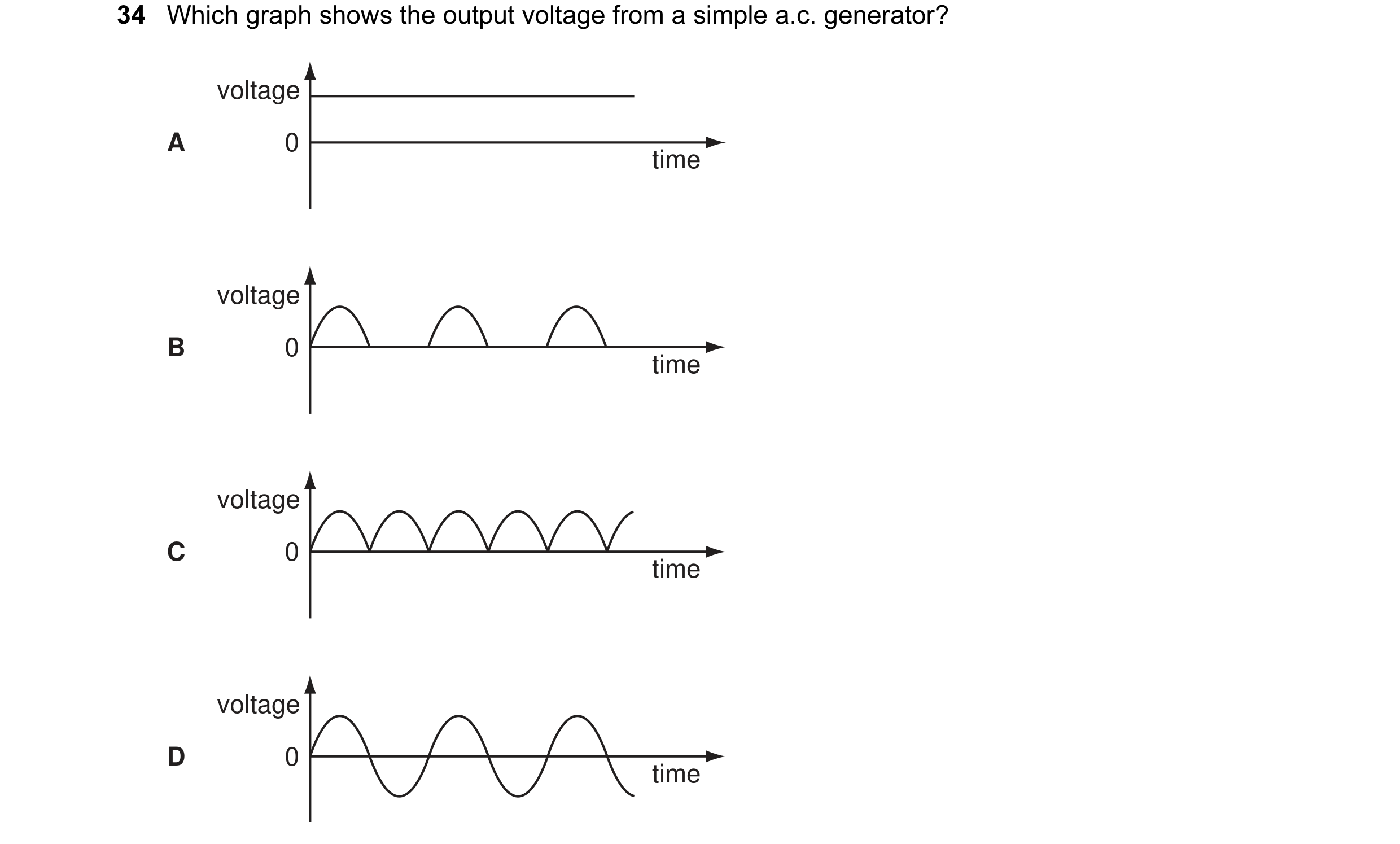
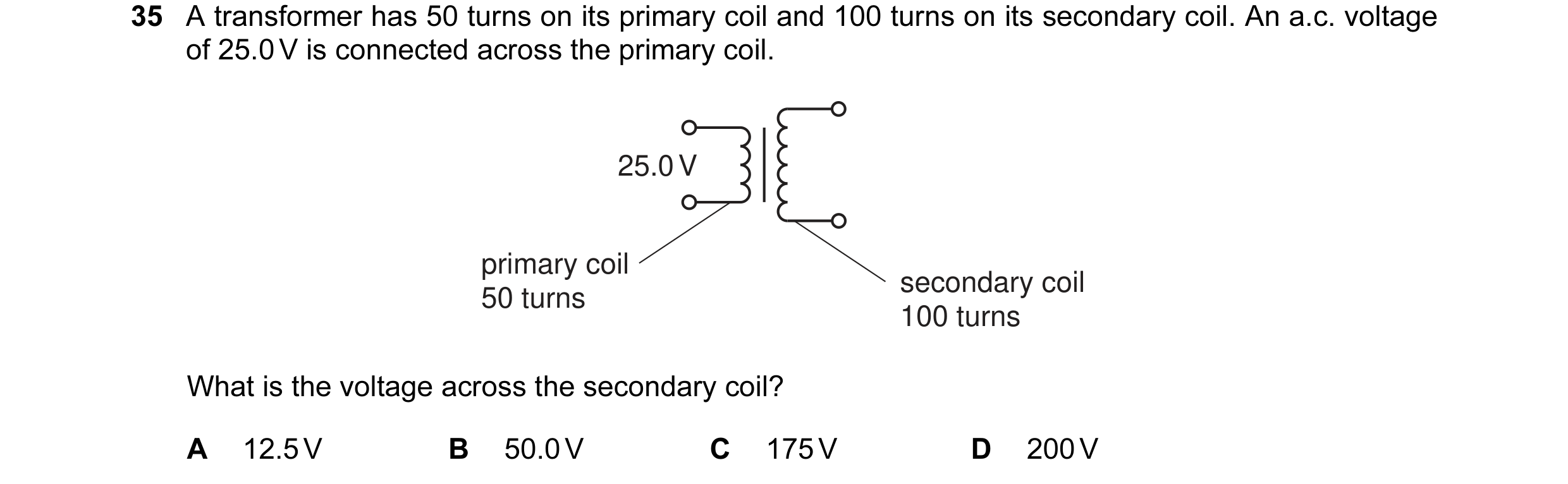 1 / 108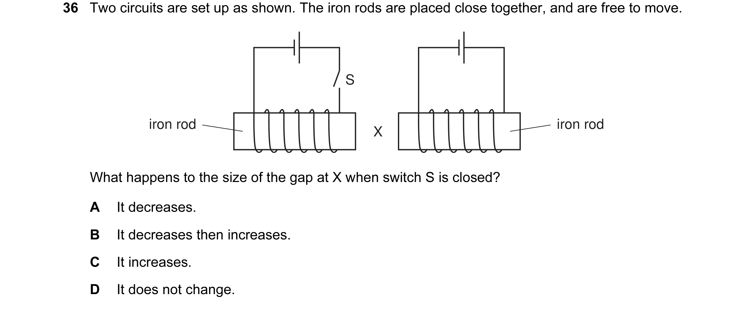
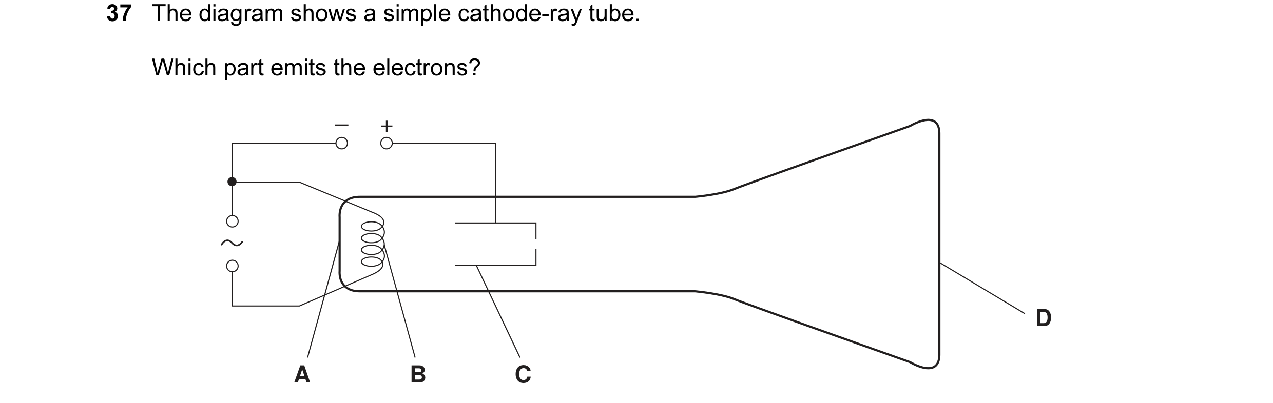
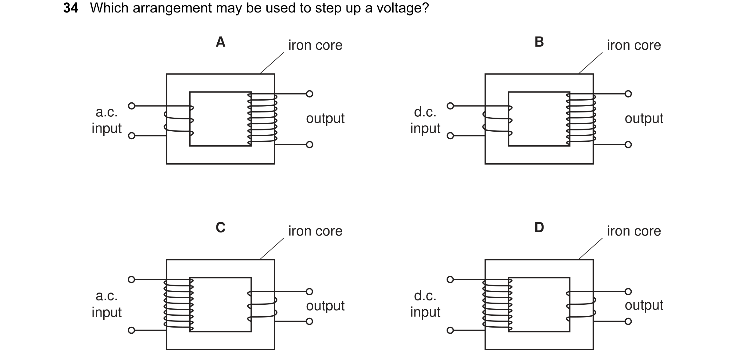 2 / 108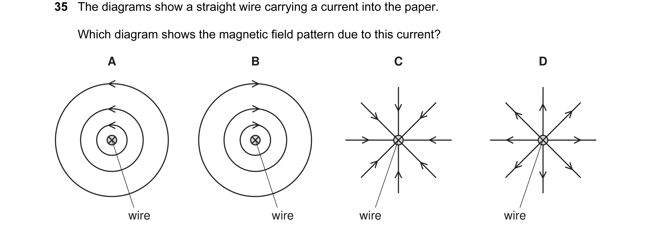
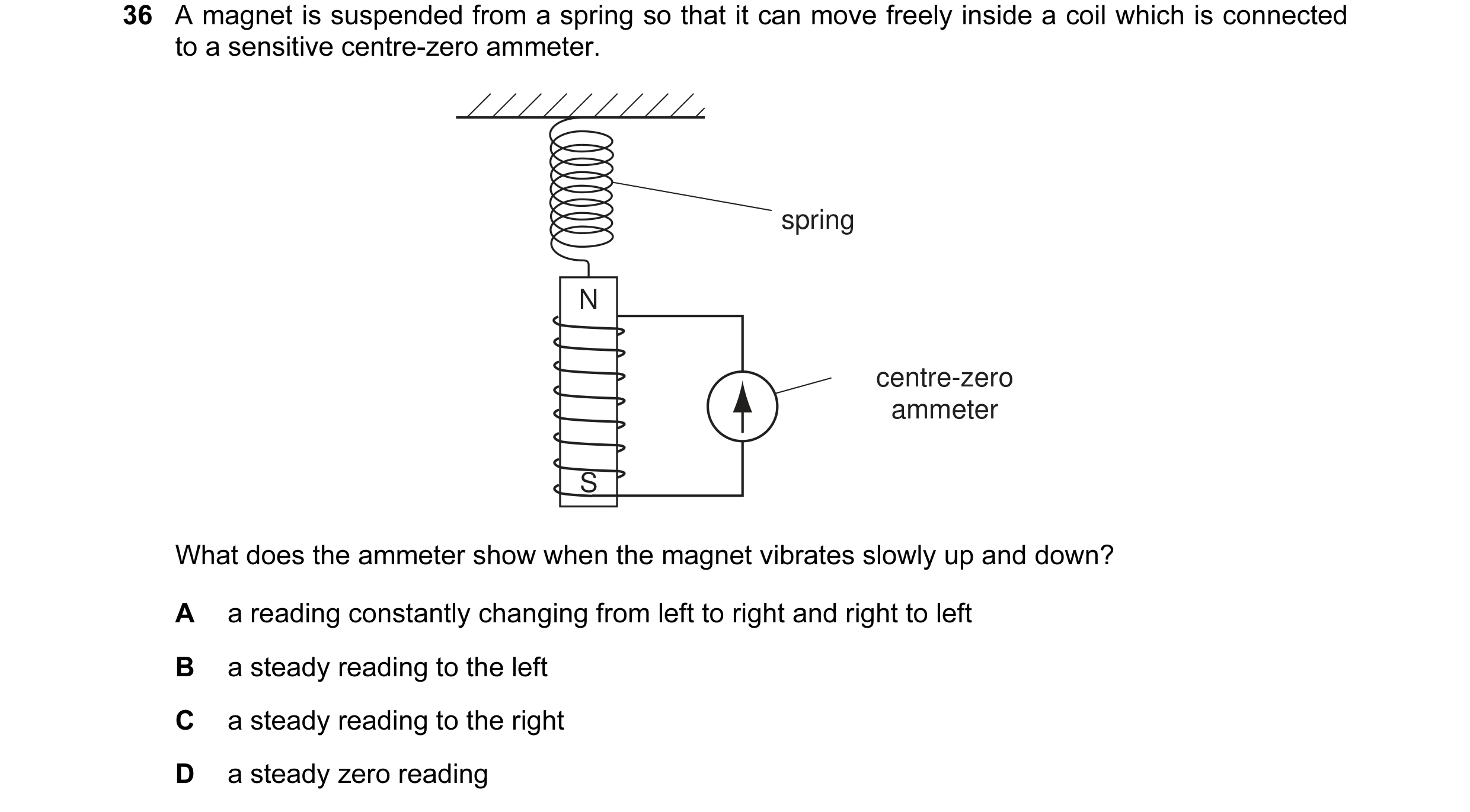
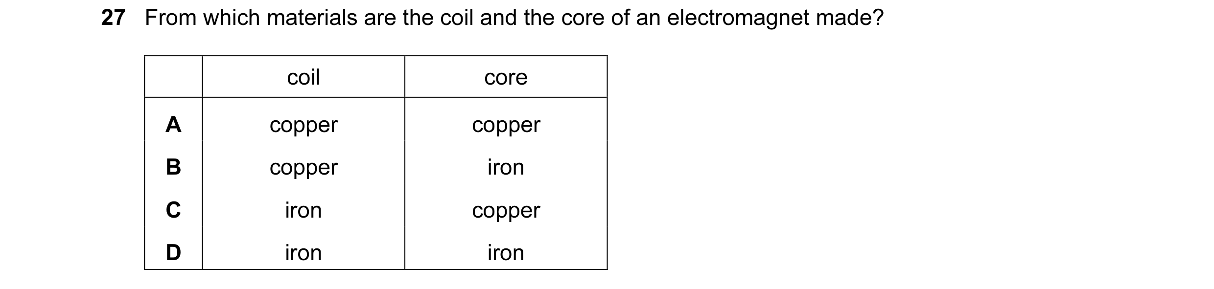 3 / 108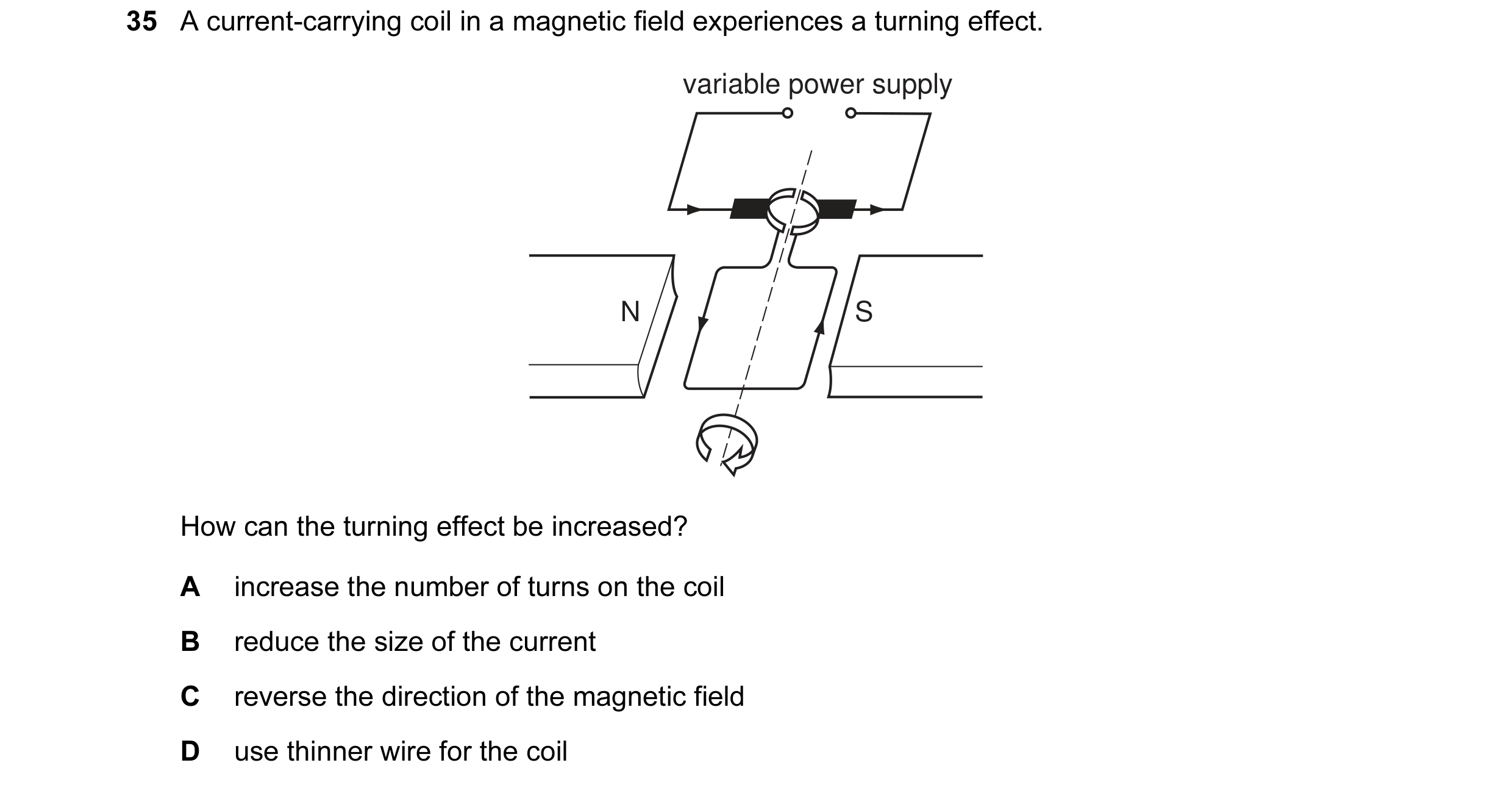
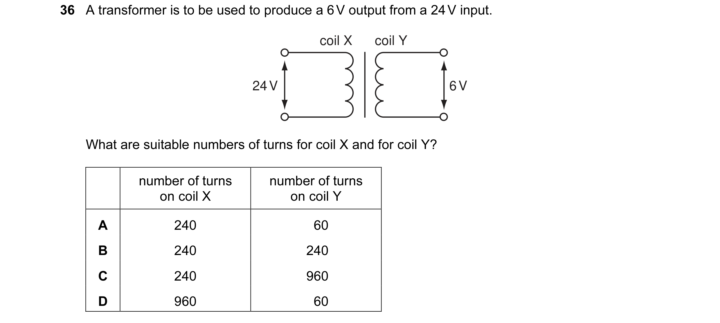
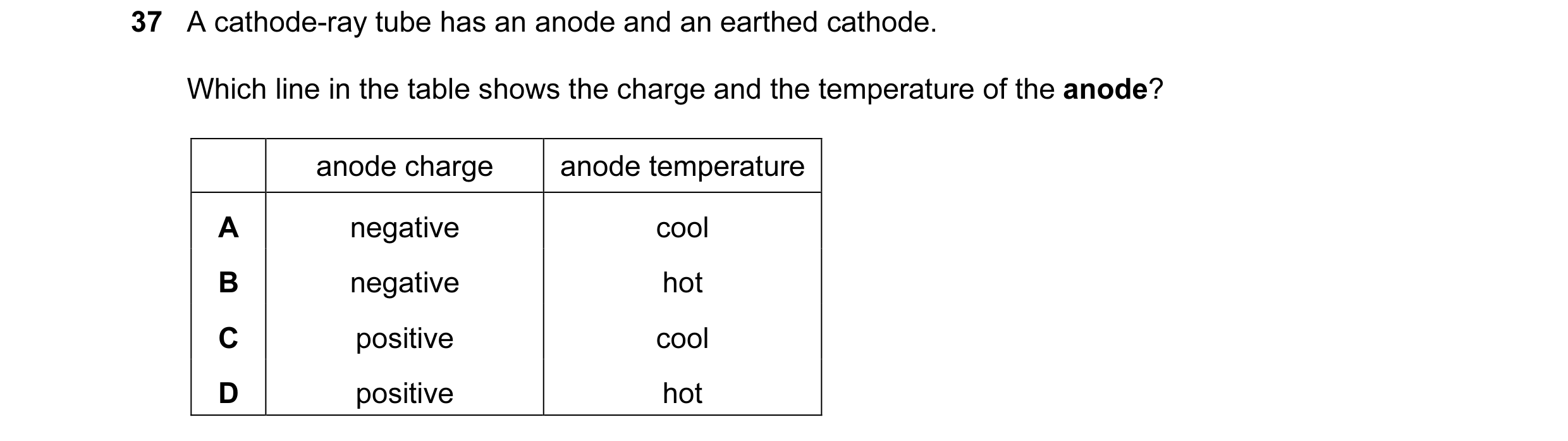 4 / 108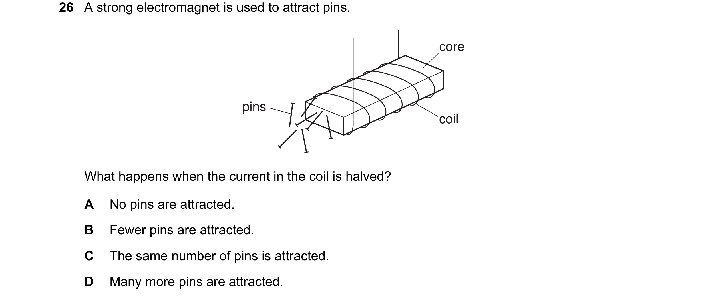
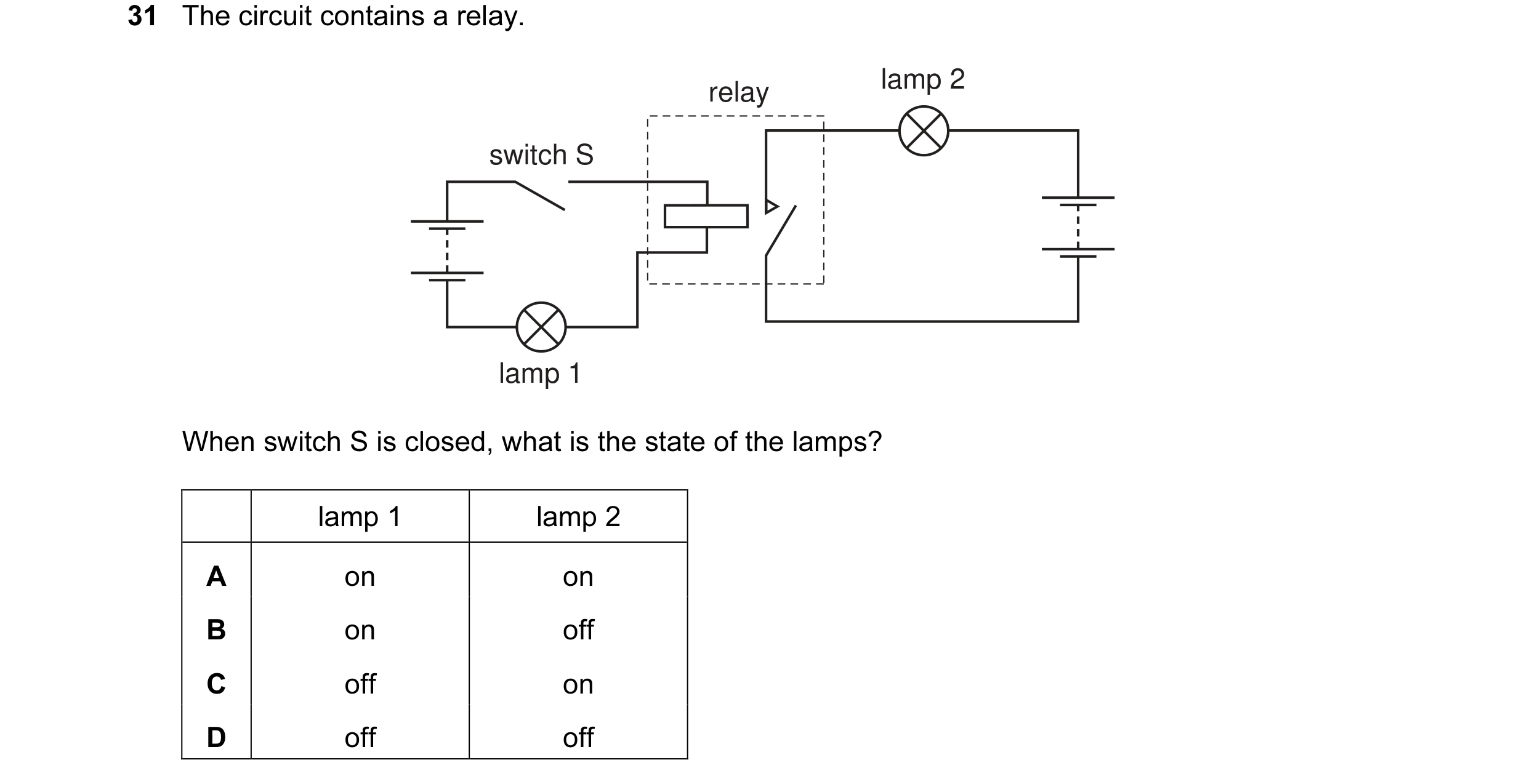 5 / 108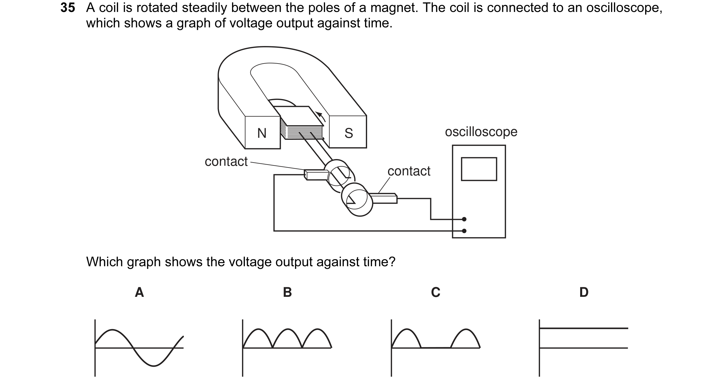
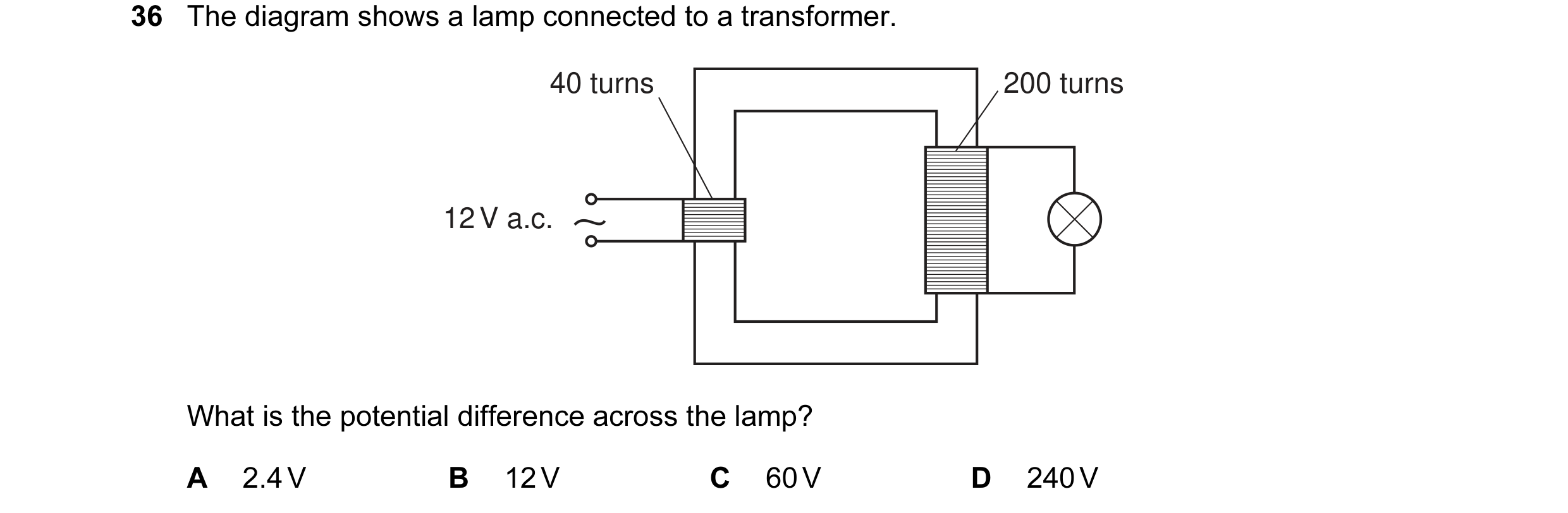
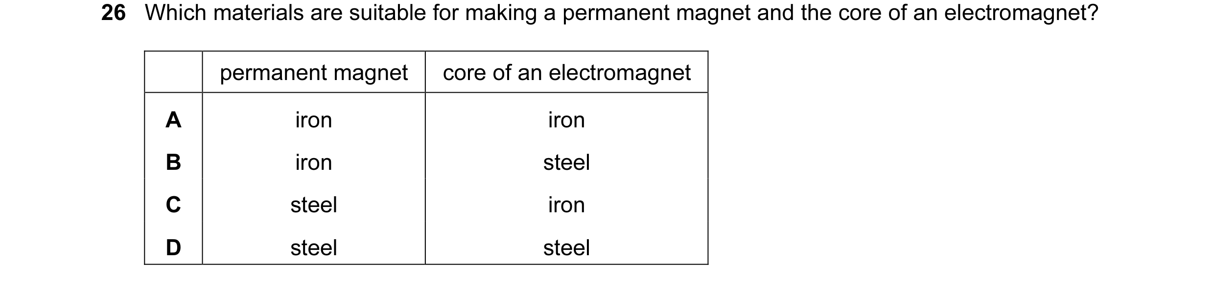
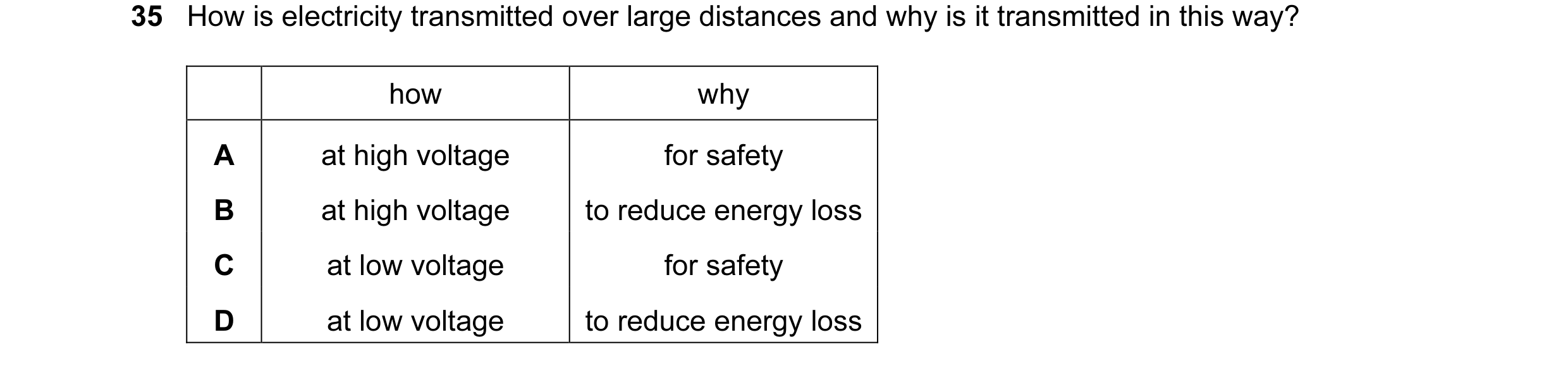 6 / 108
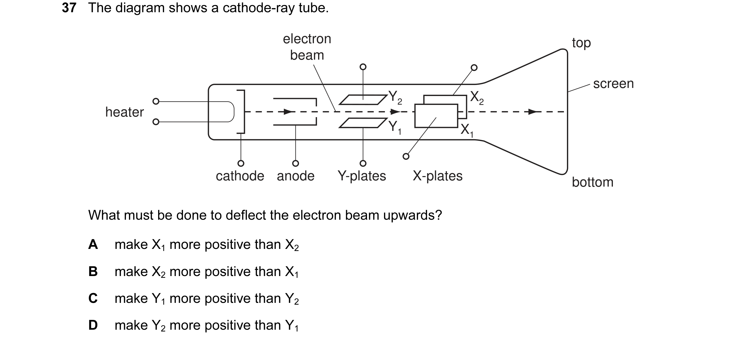
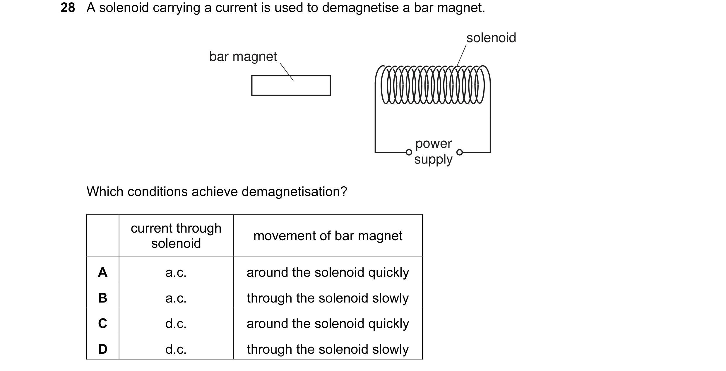 7 / 108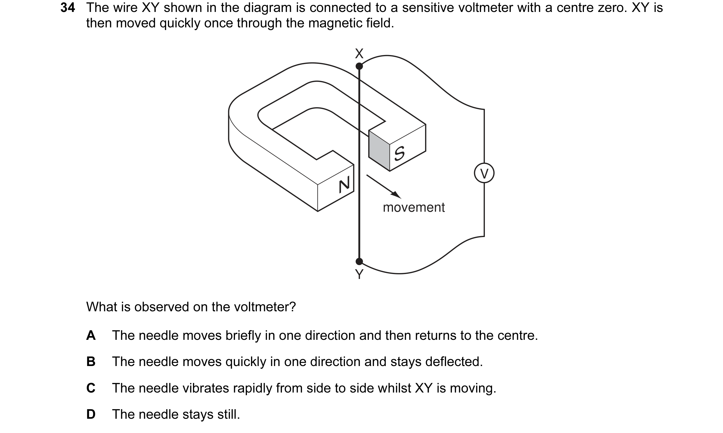
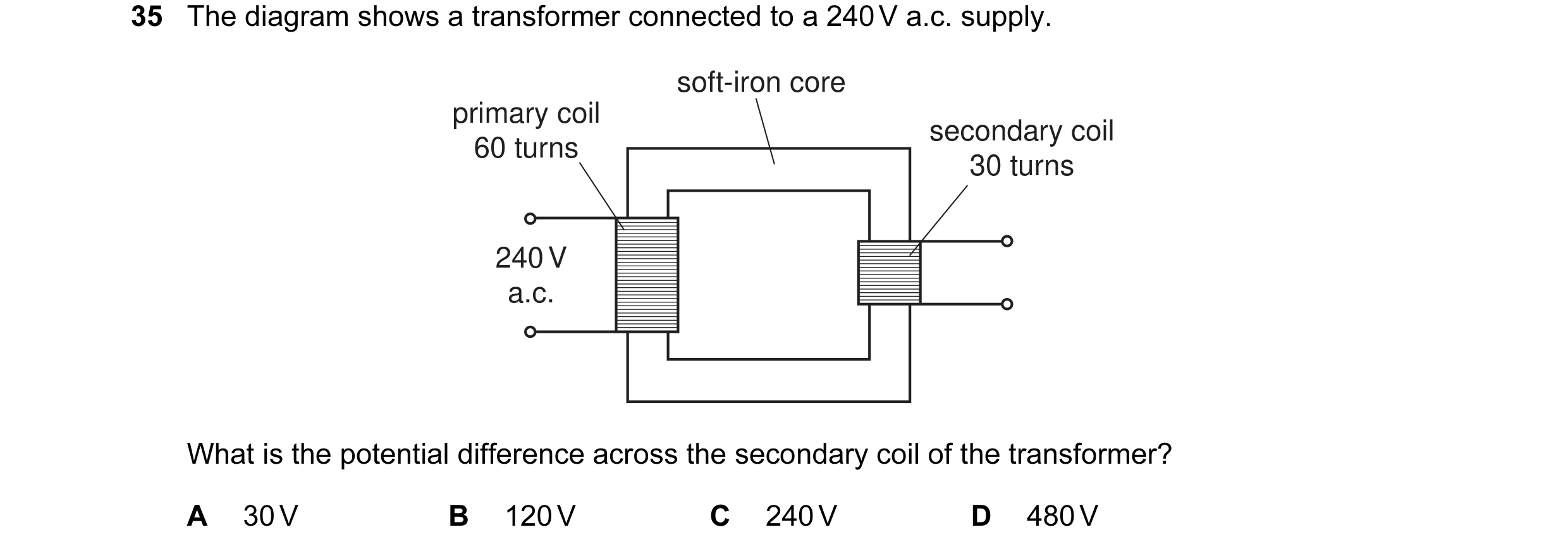
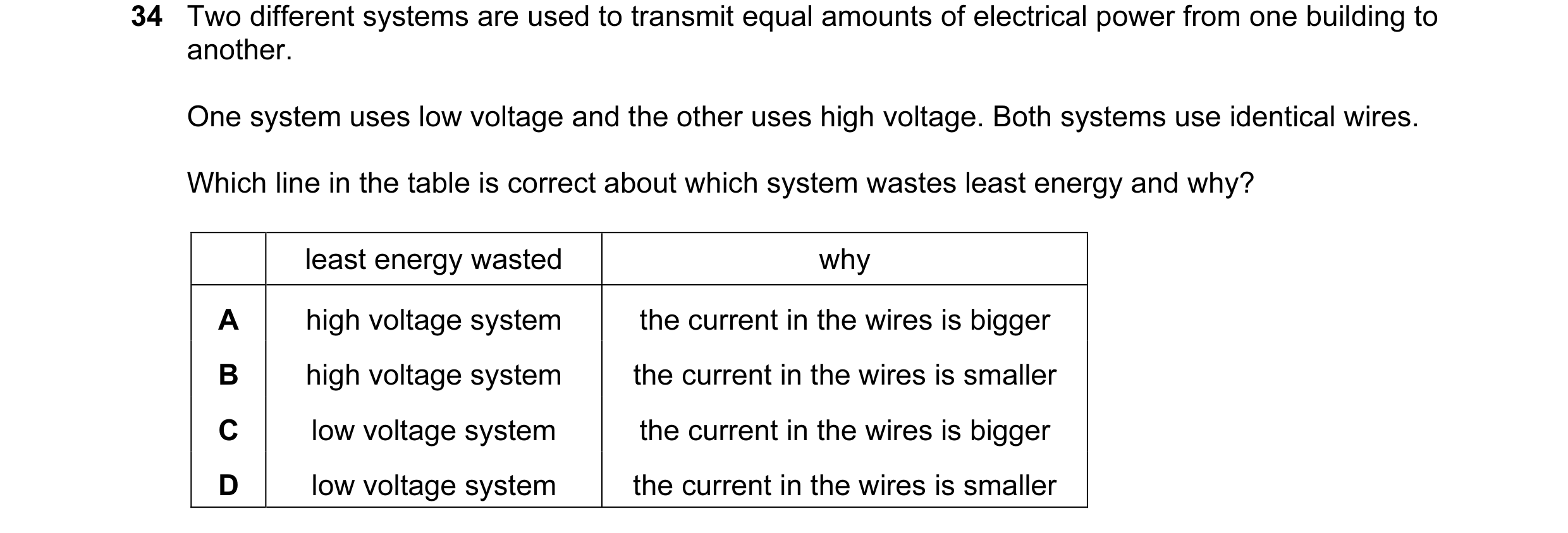 8 / 108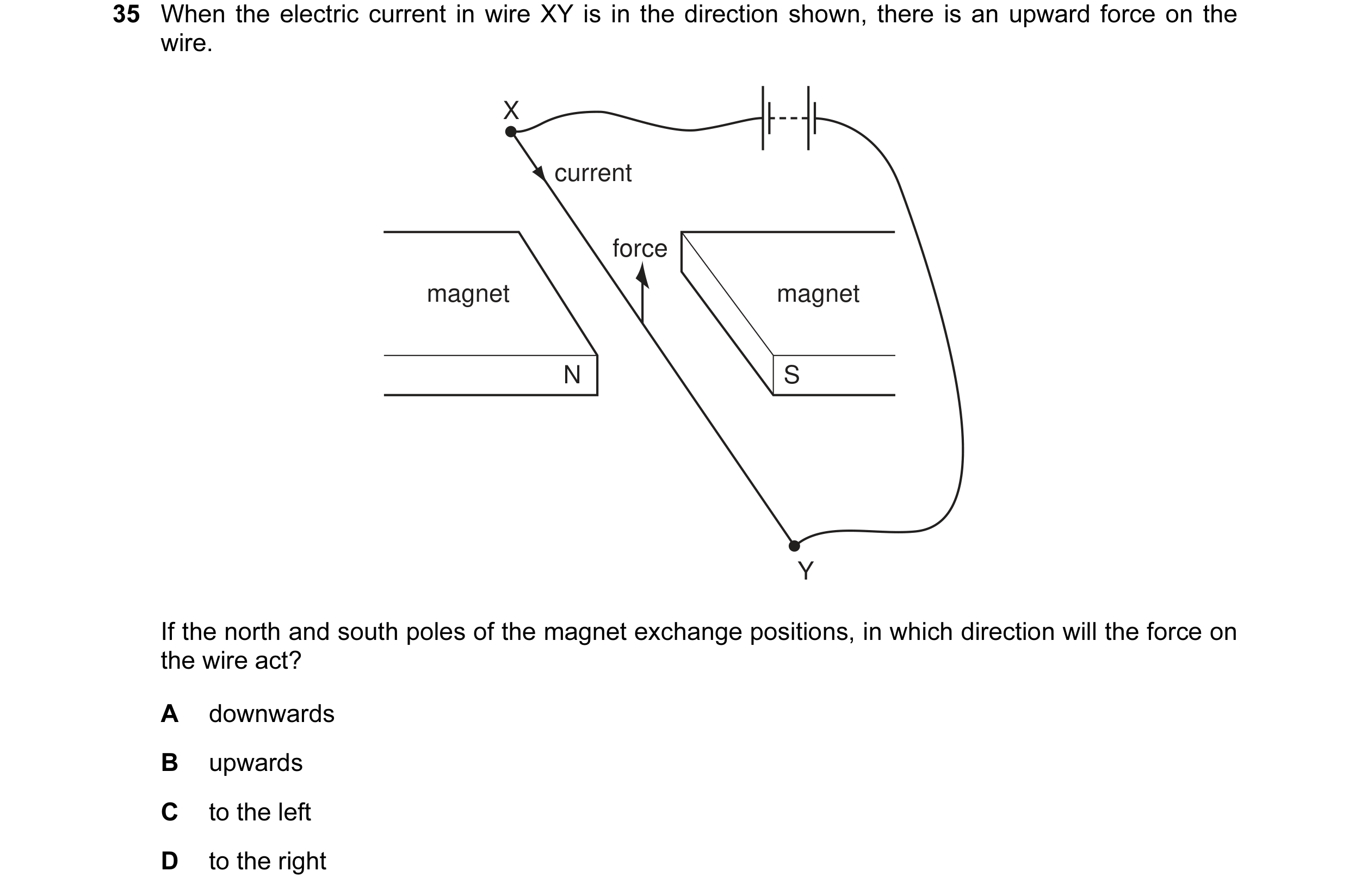
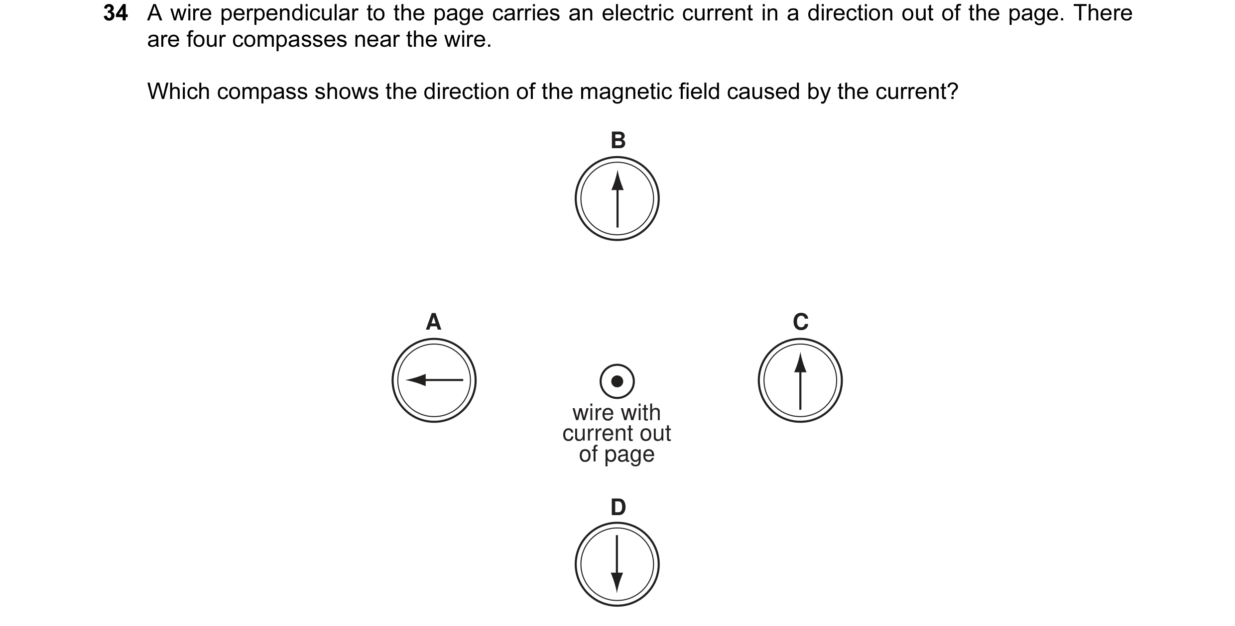 9 / 108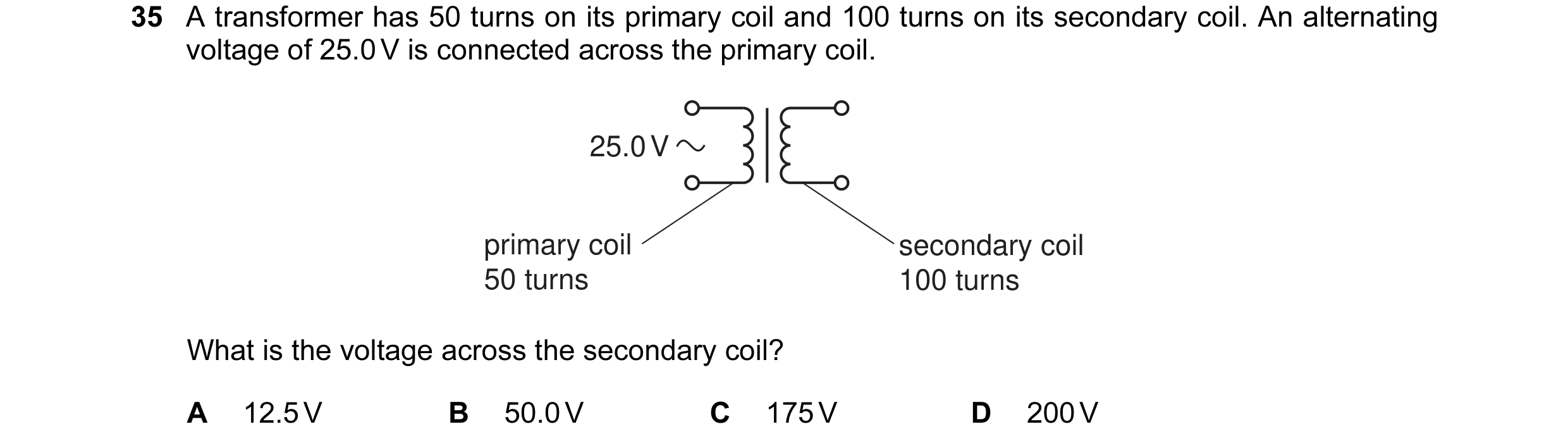
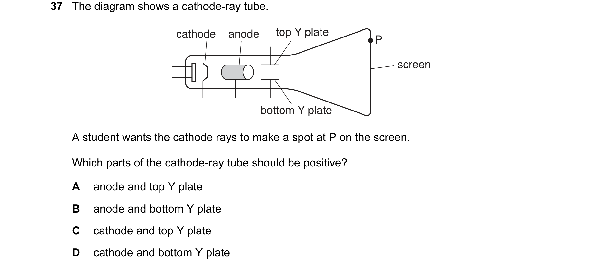
 10 / 108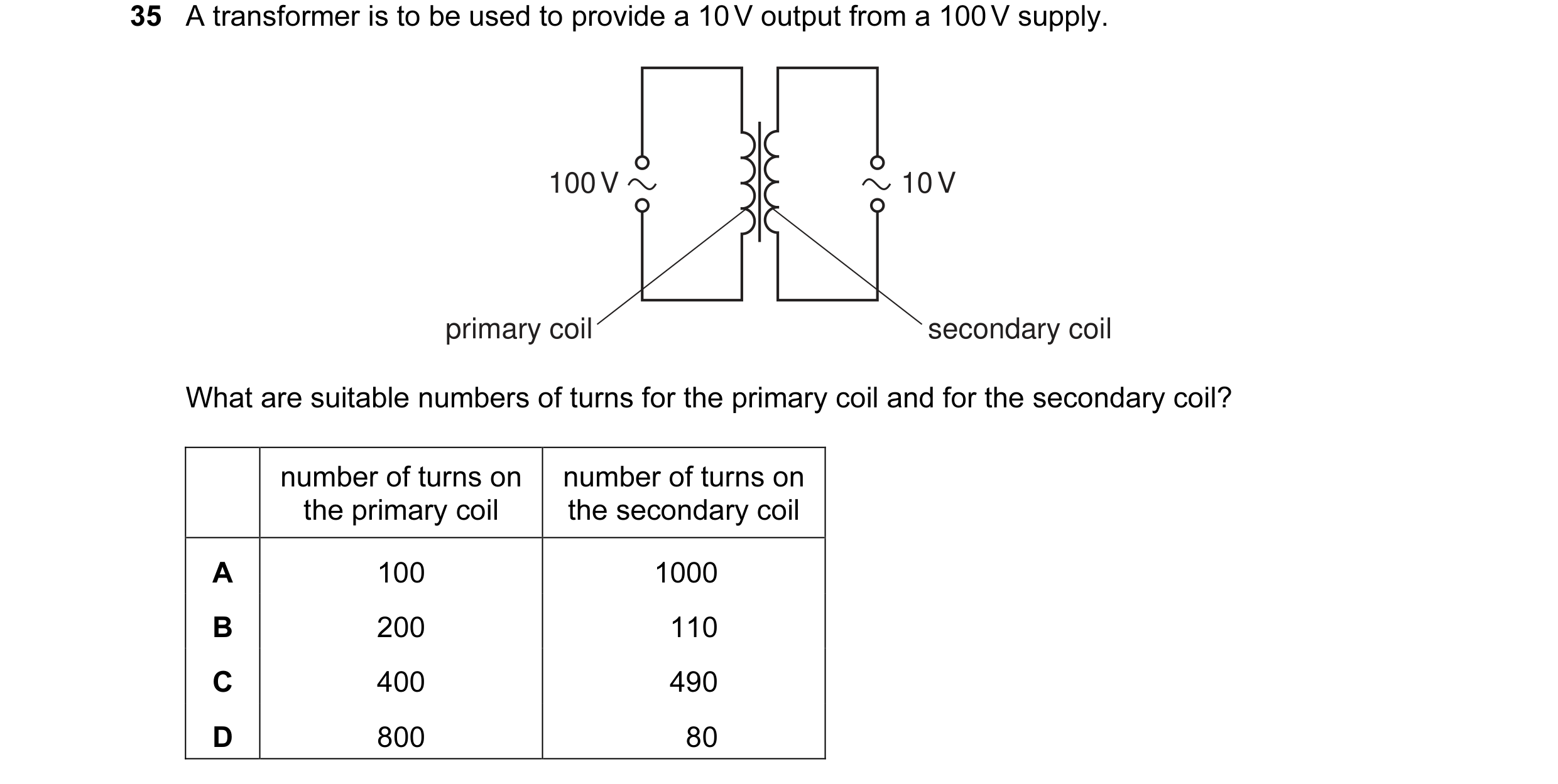
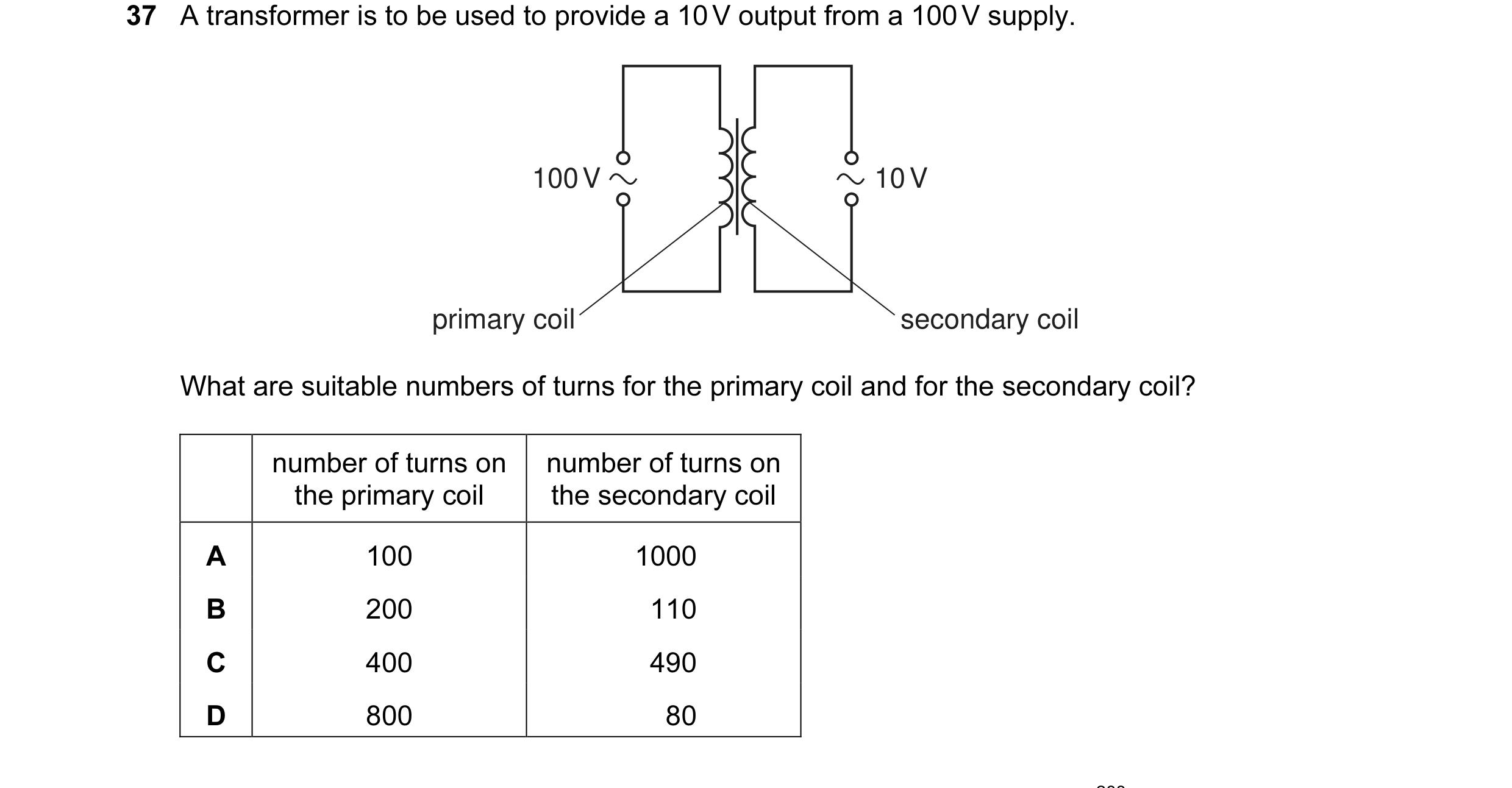 11 / 108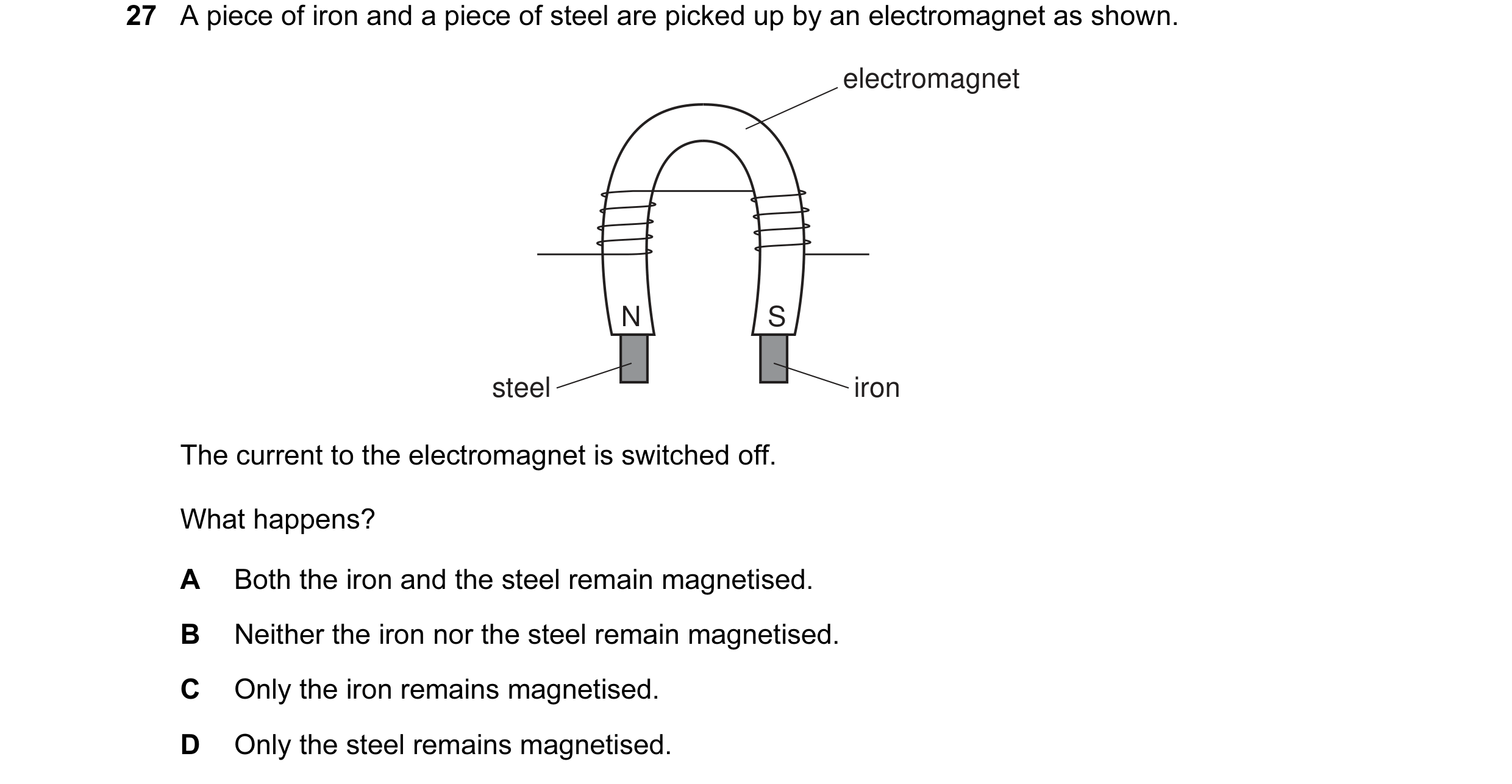
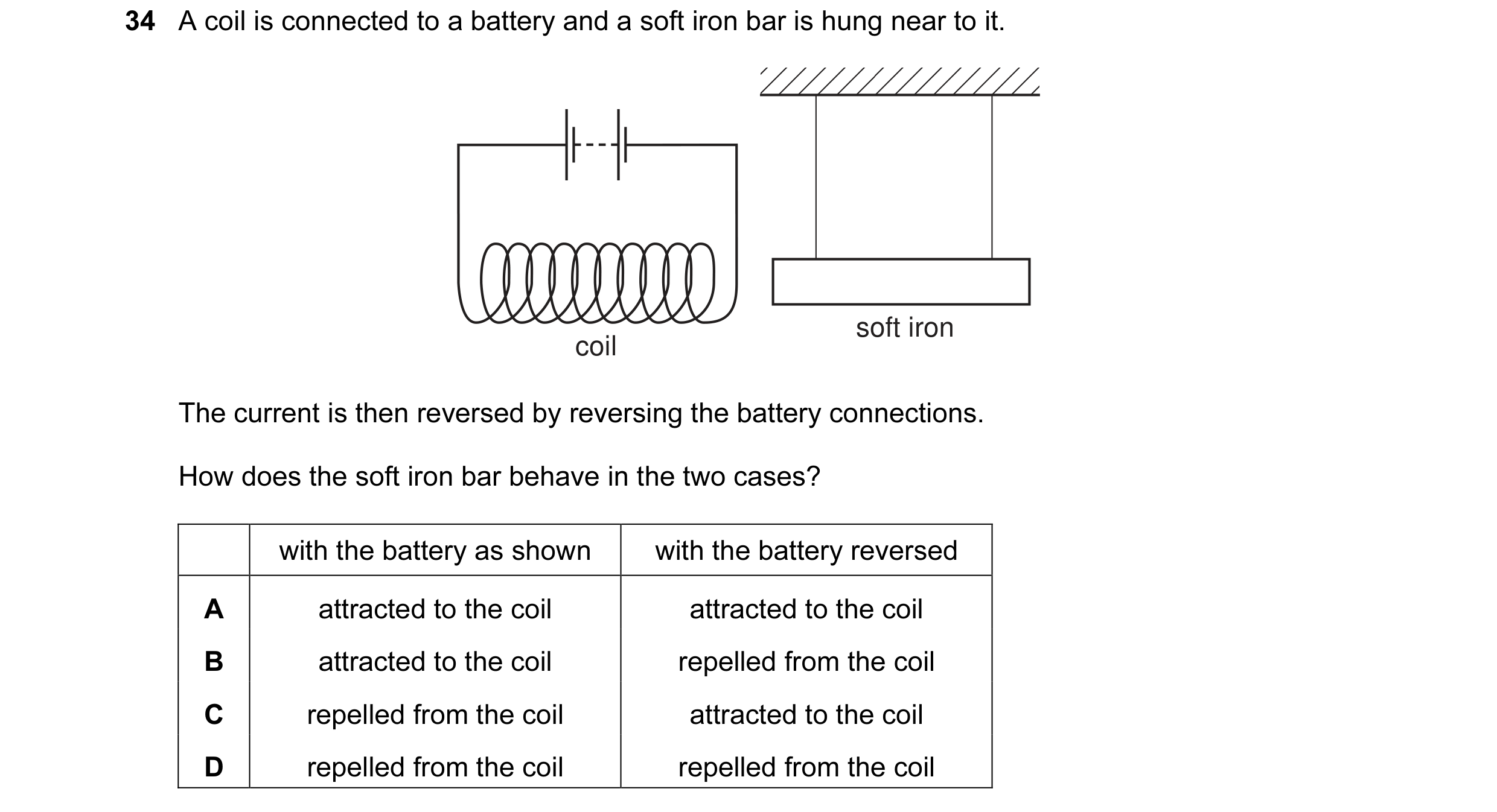
 12 / 108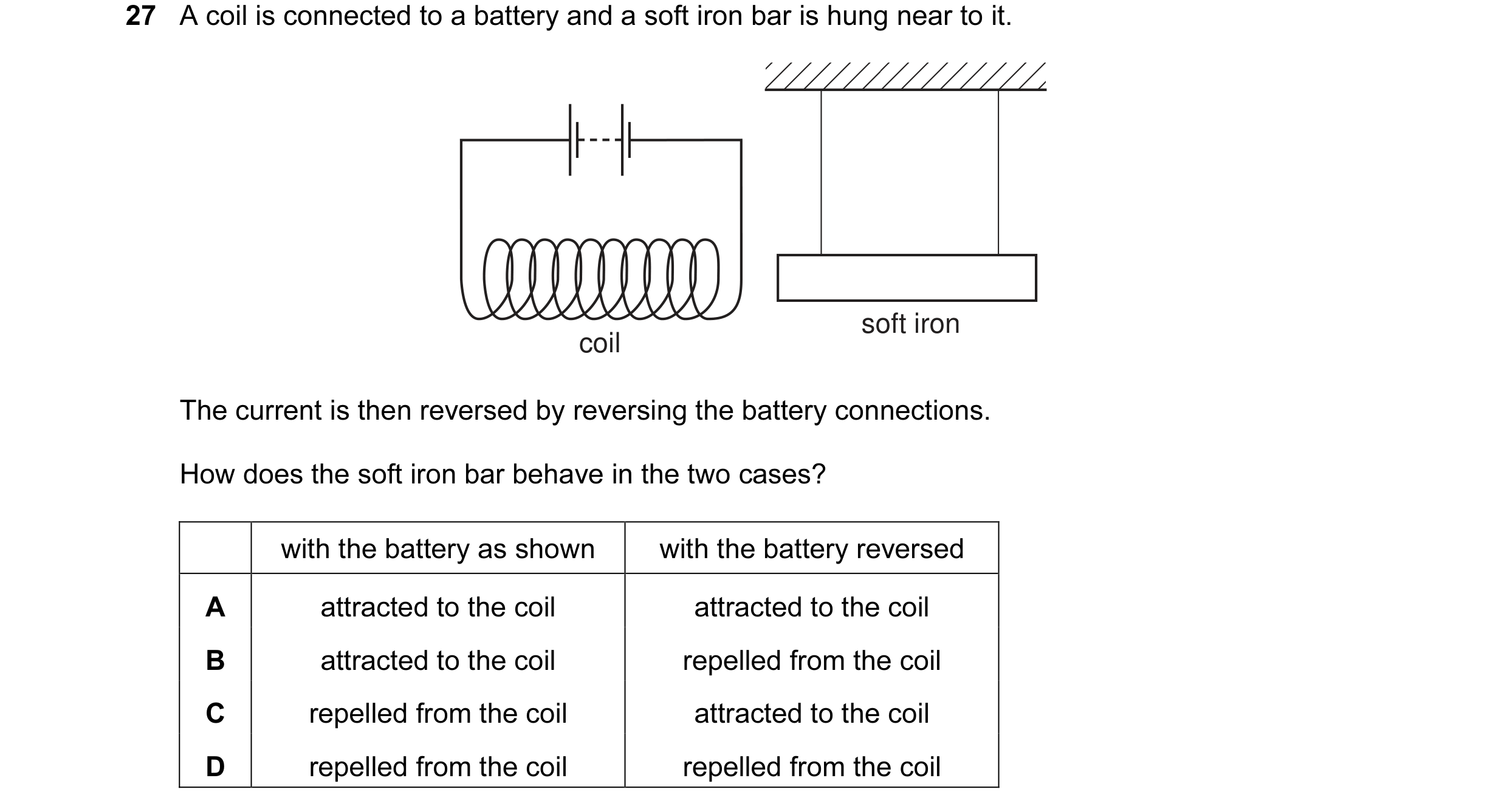
 13 / 108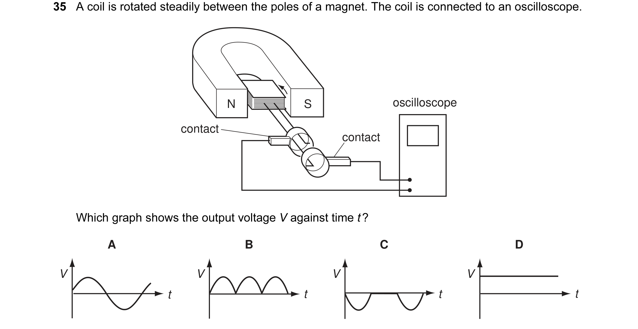
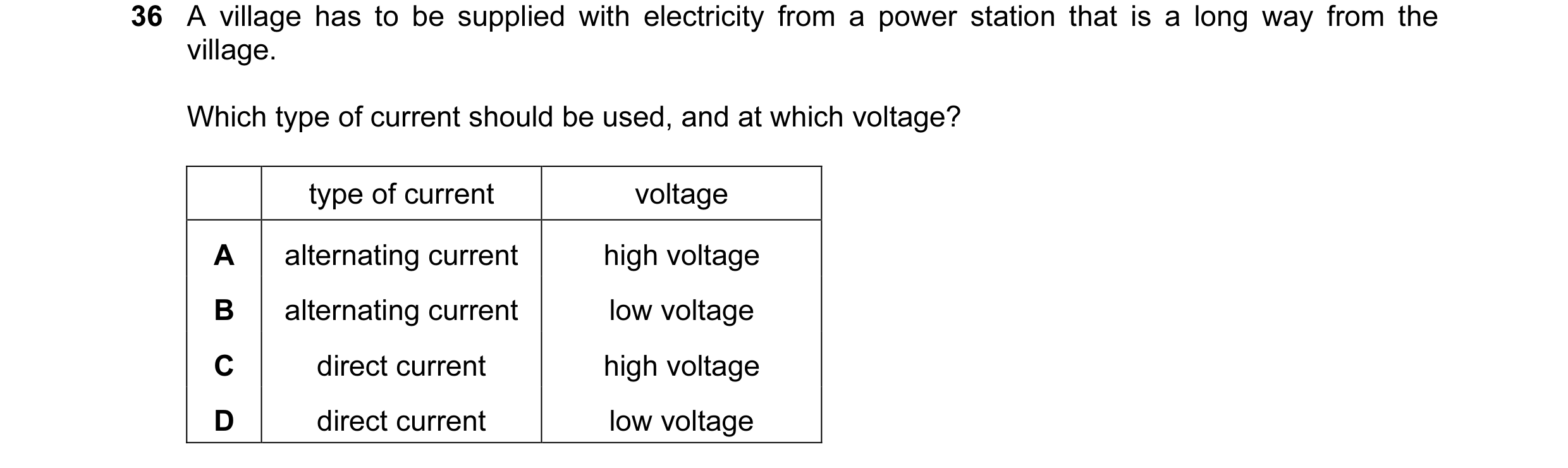

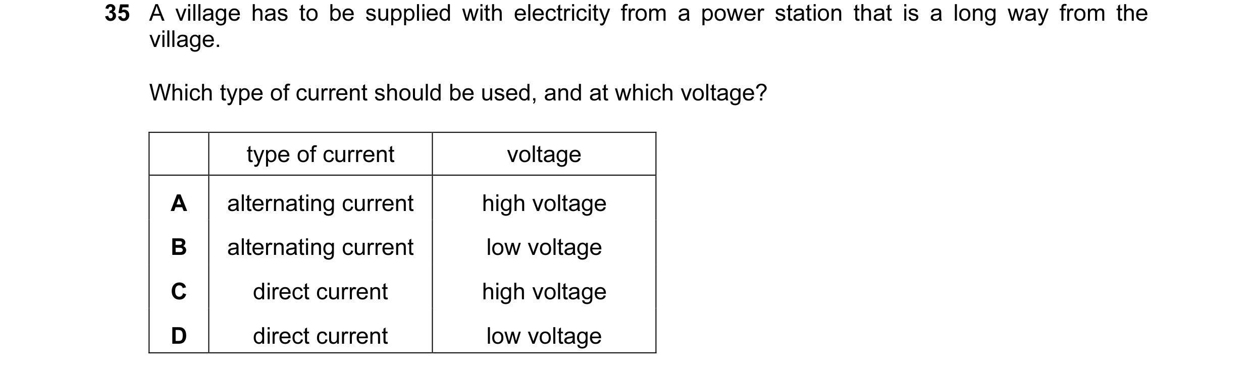 14 / 108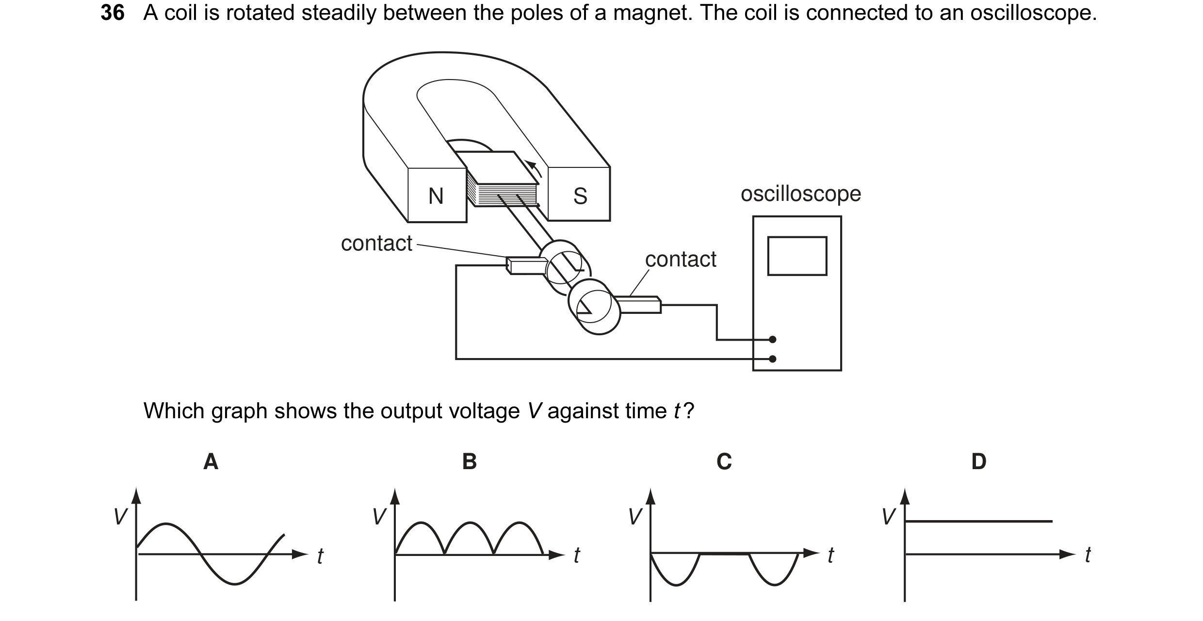

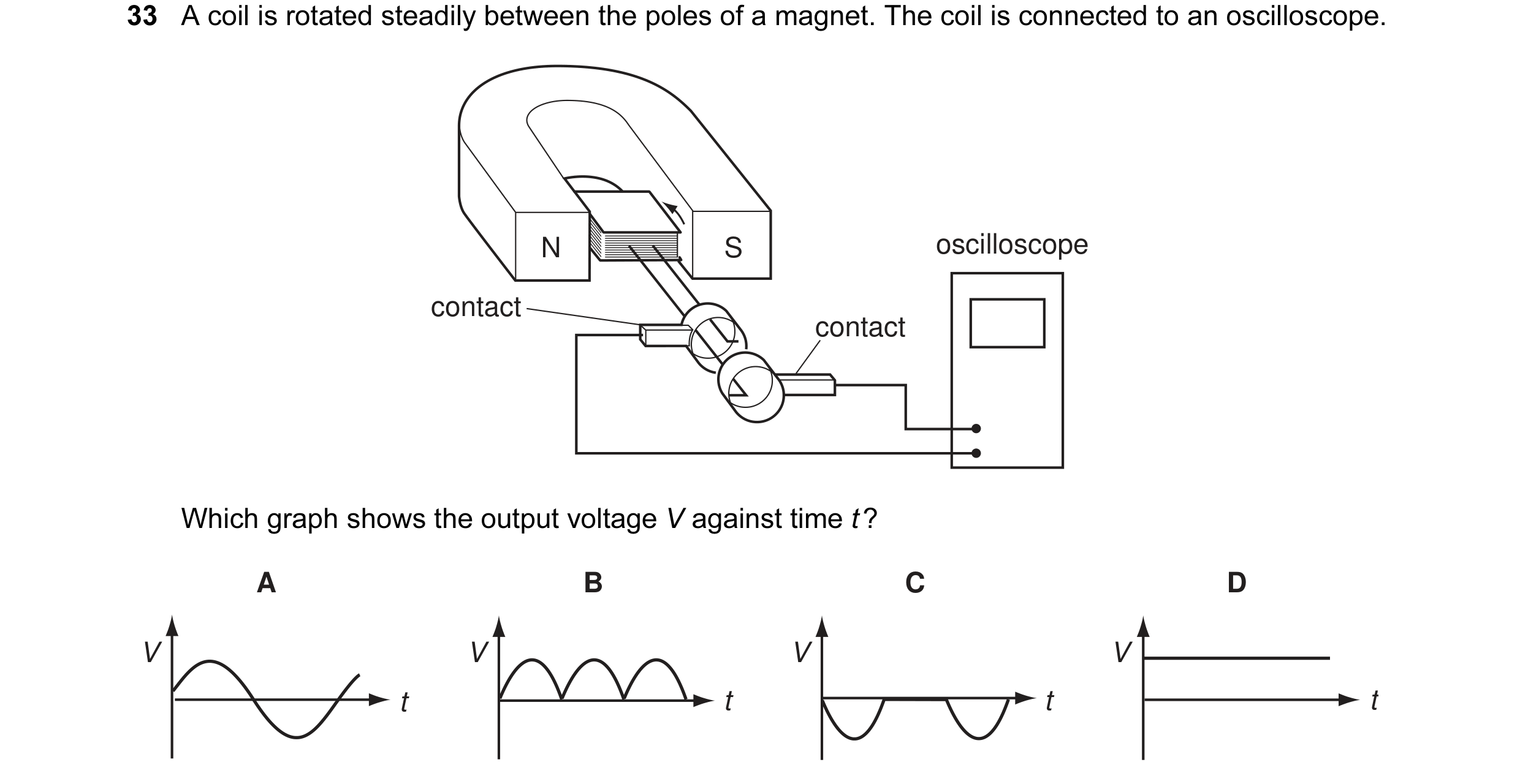 15 / 108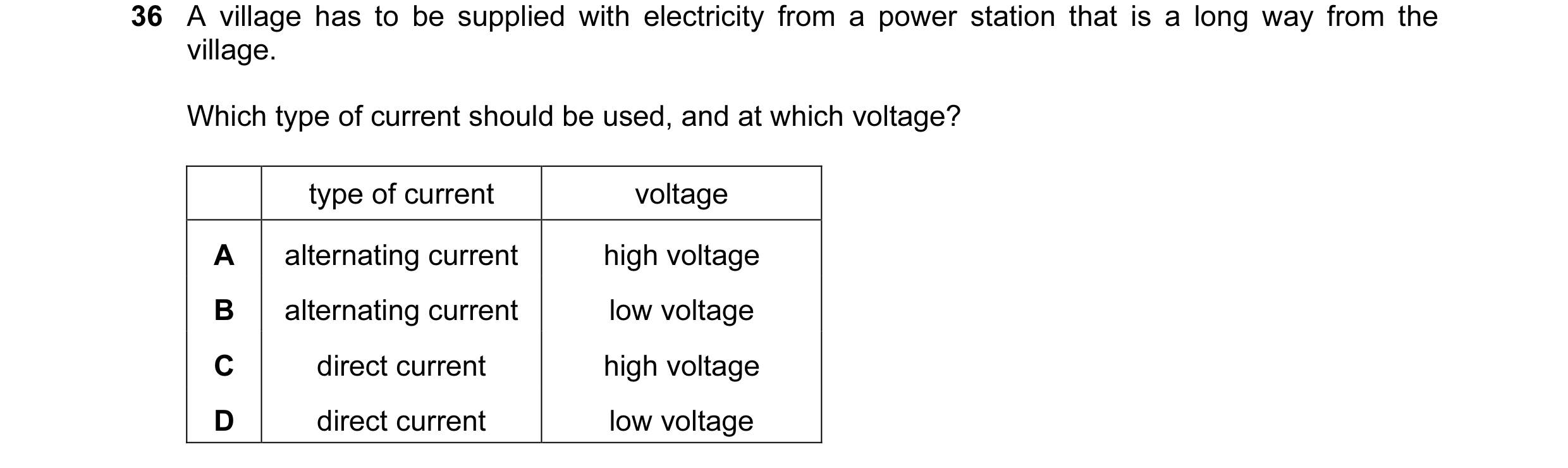
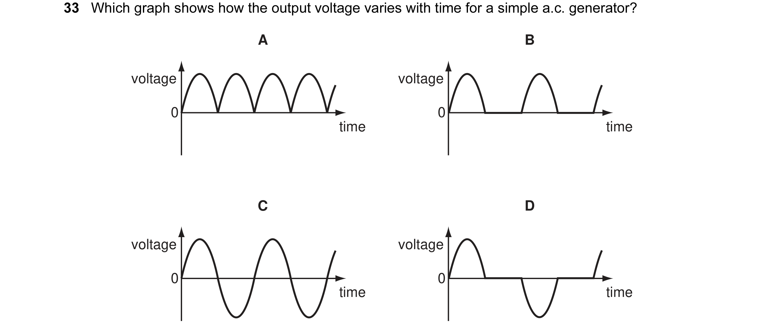
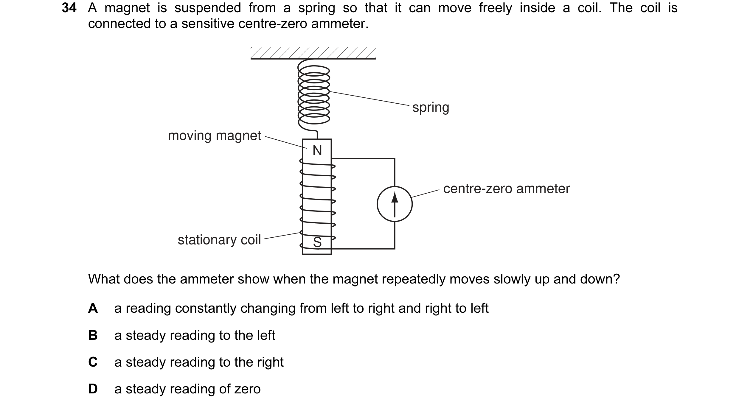 16 / 108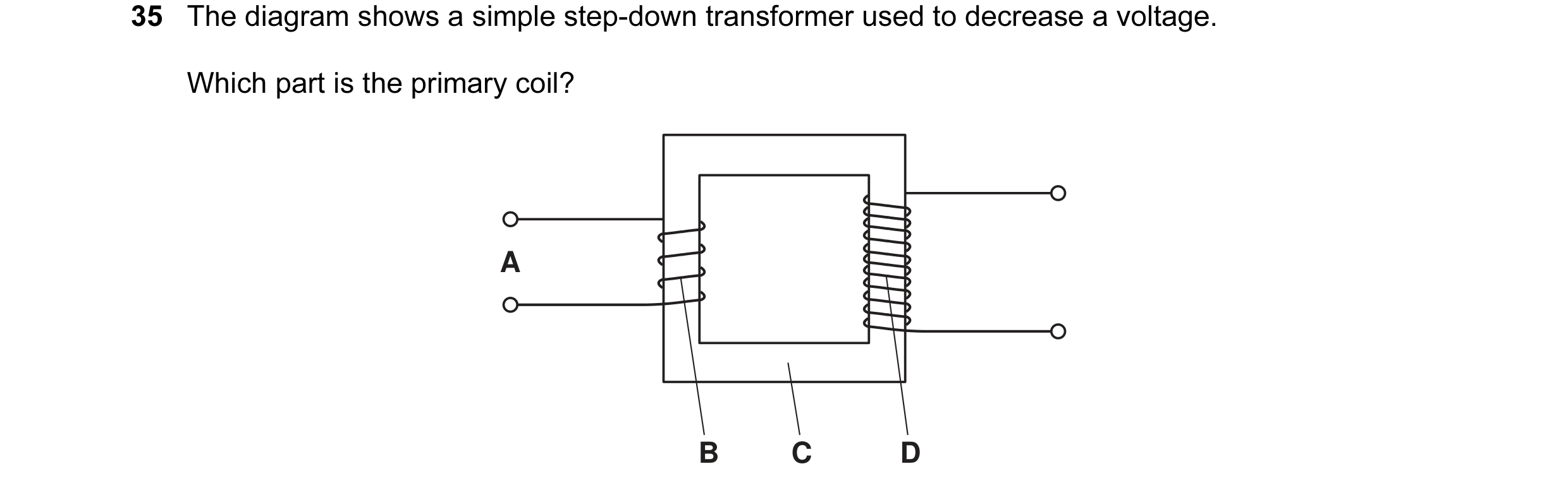
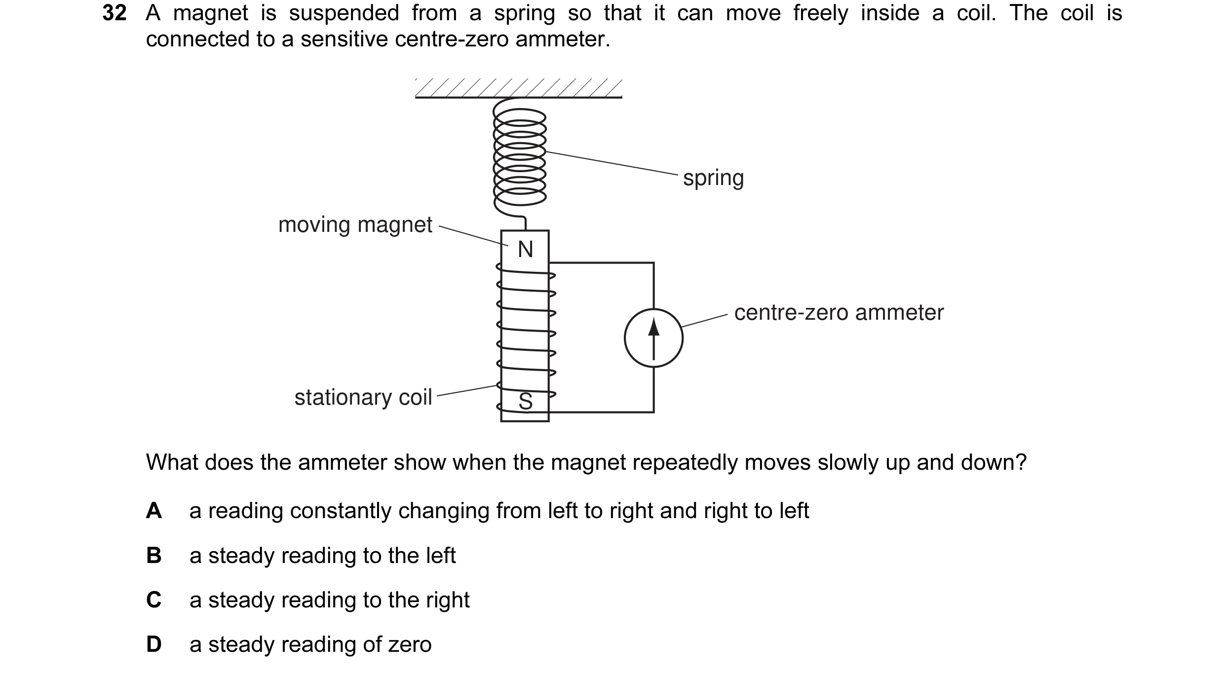
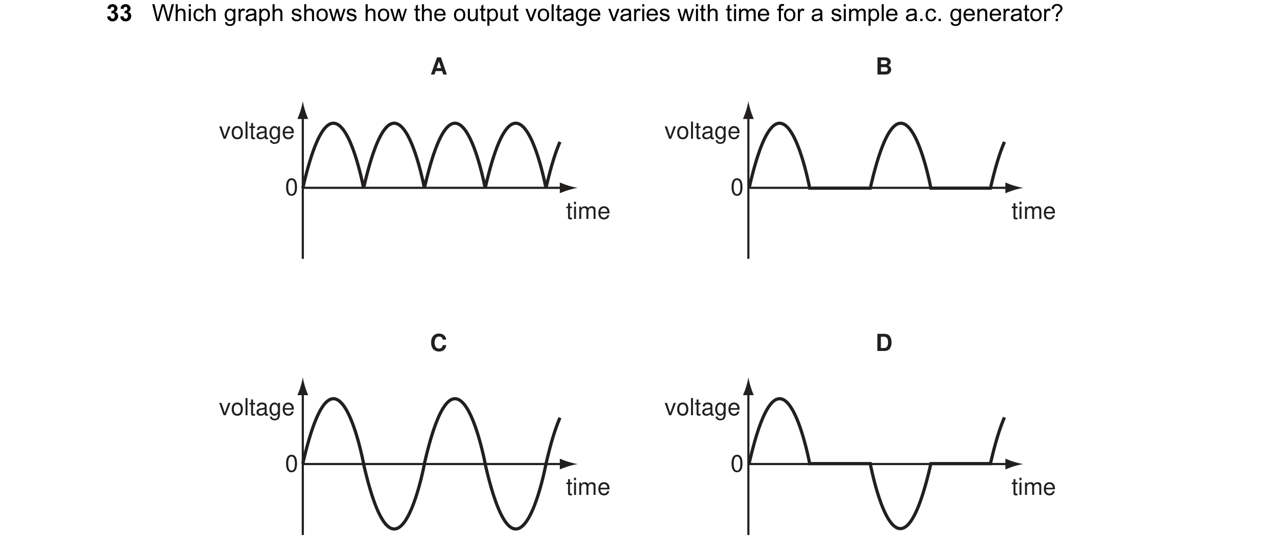 17 / 108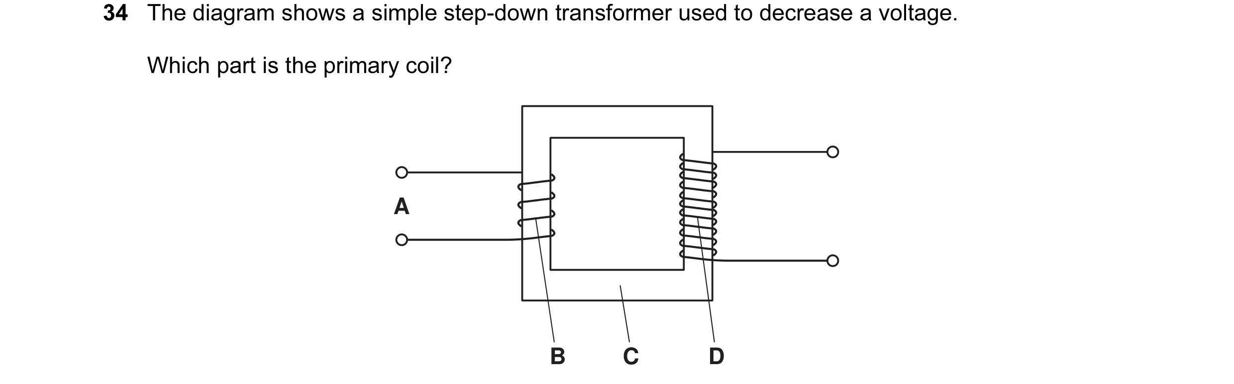
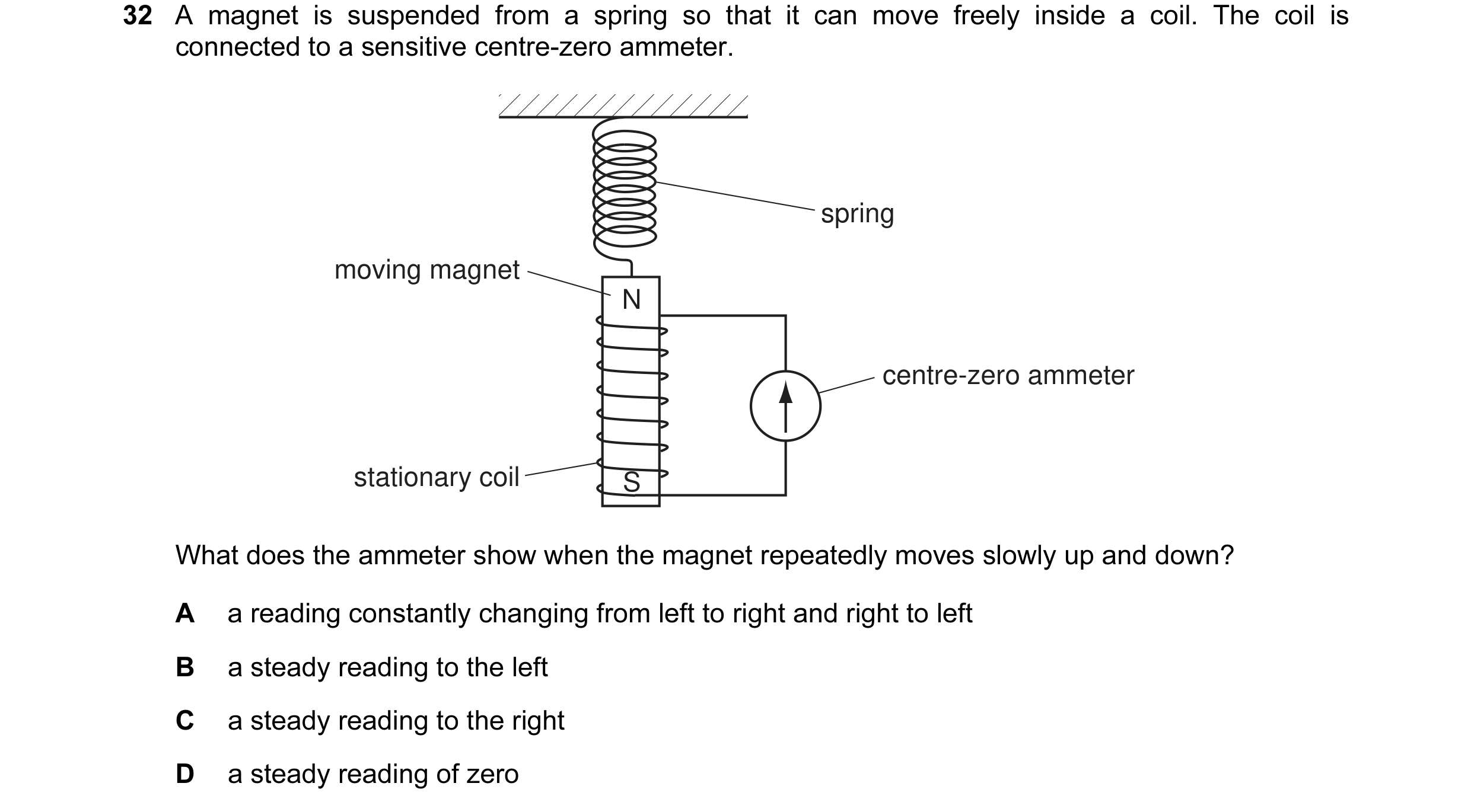
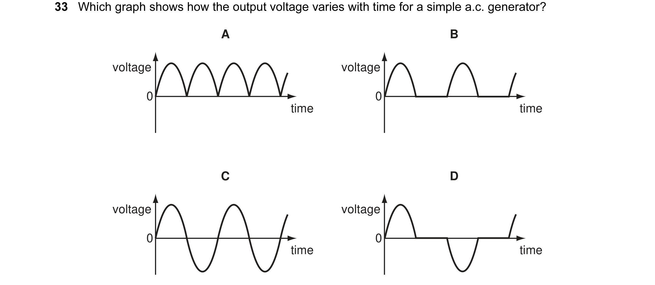 18 / 108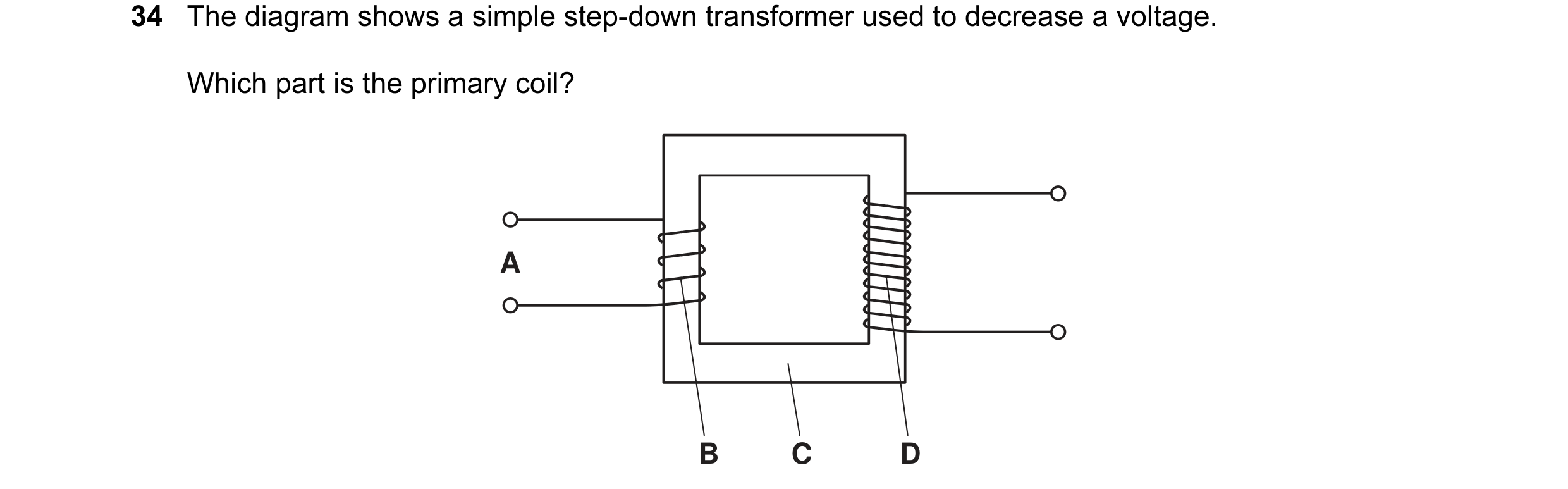
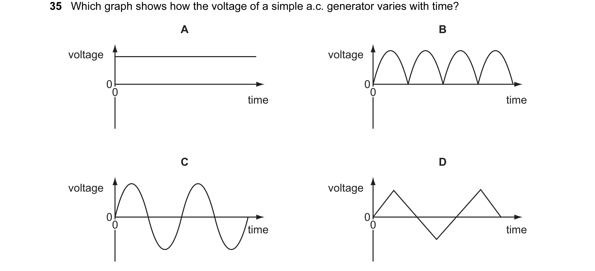 19 / 108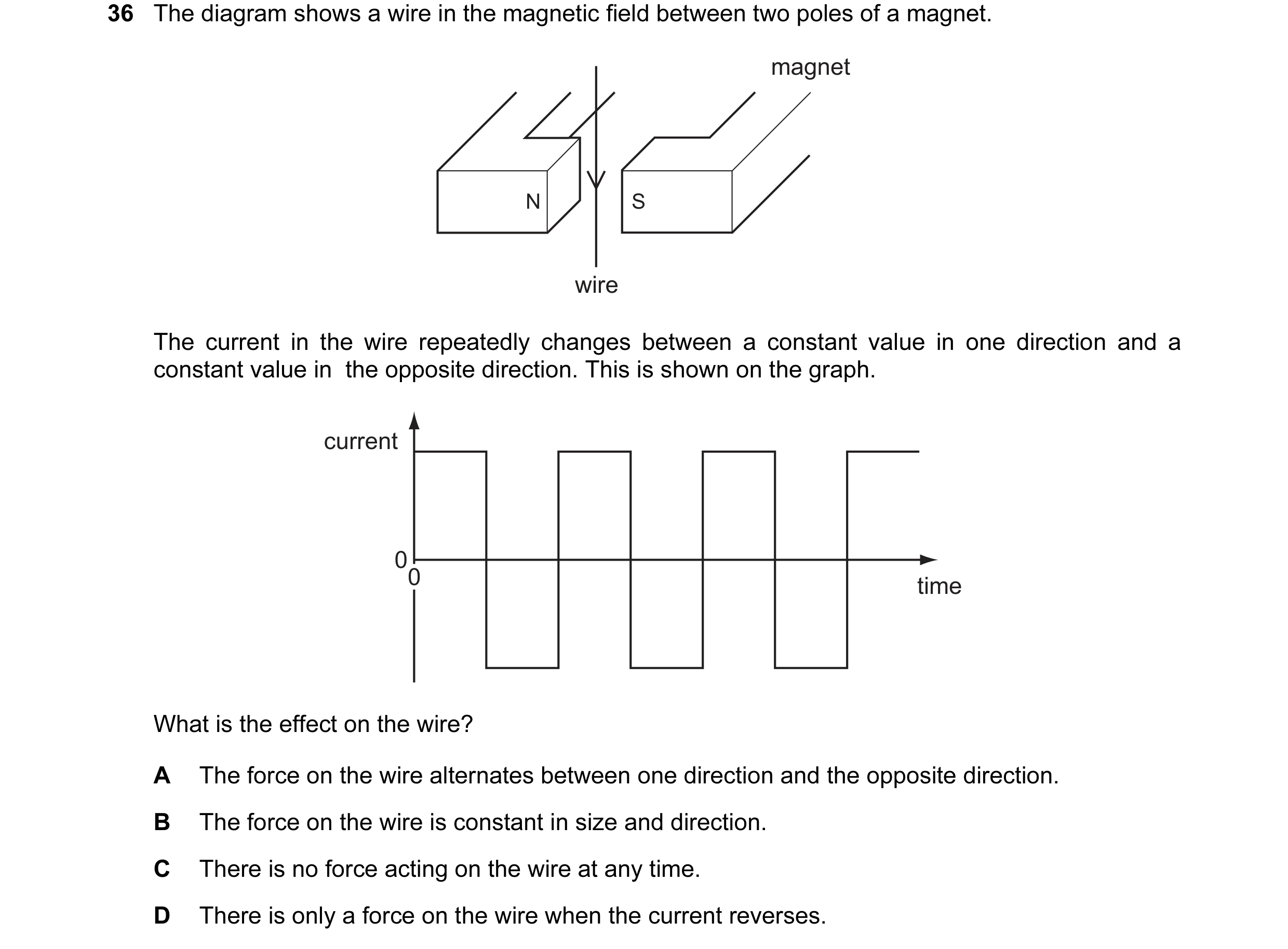
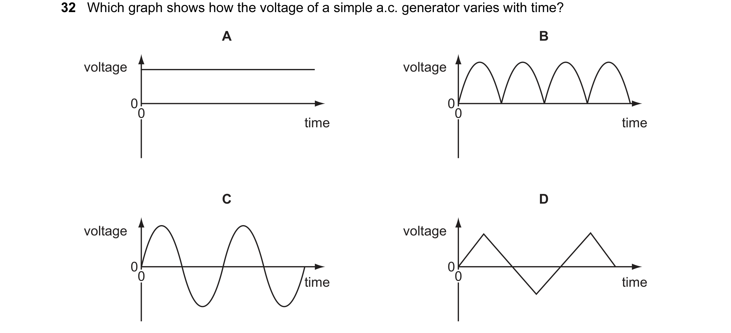 20 / 108
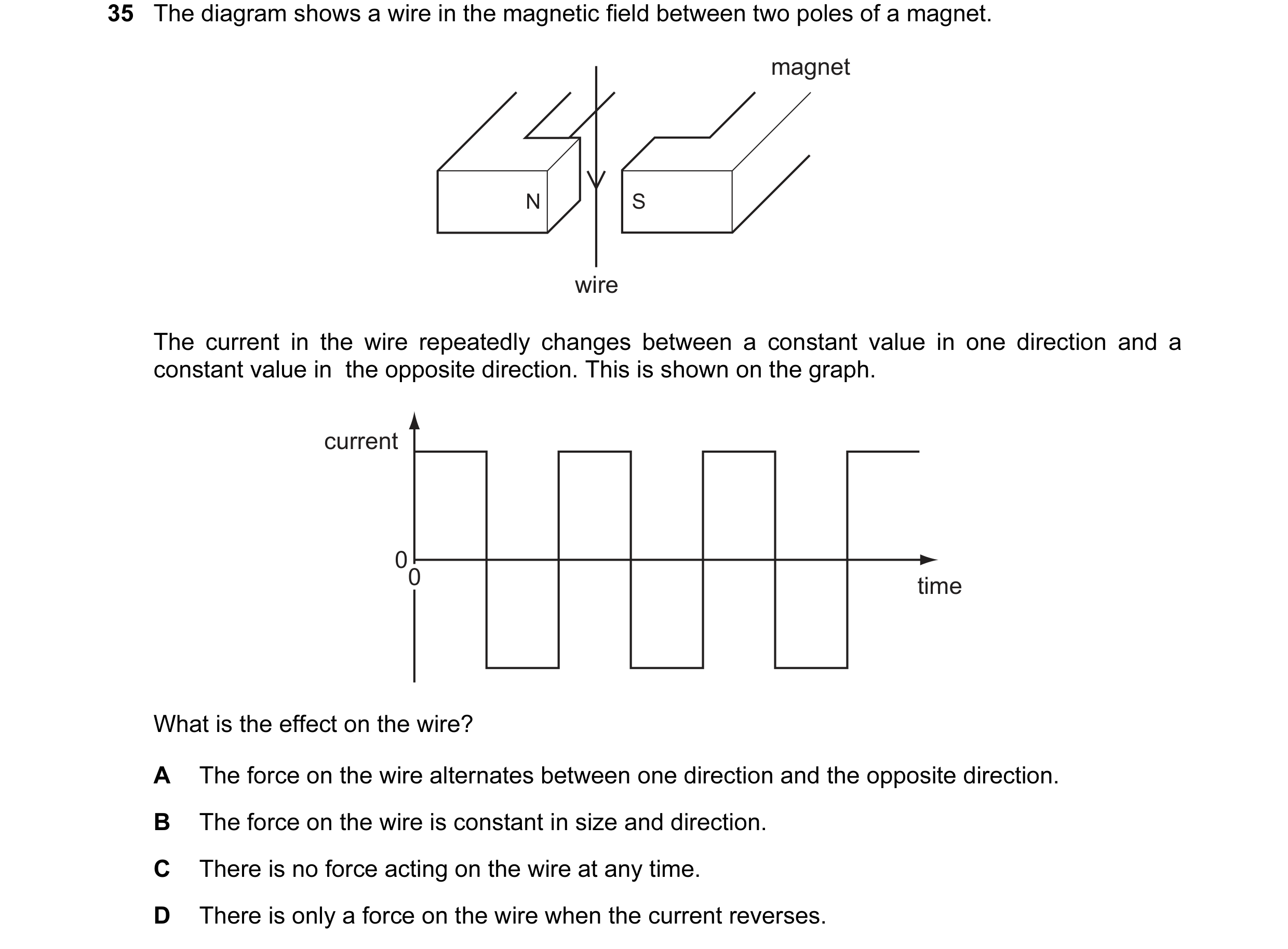
 21 / 108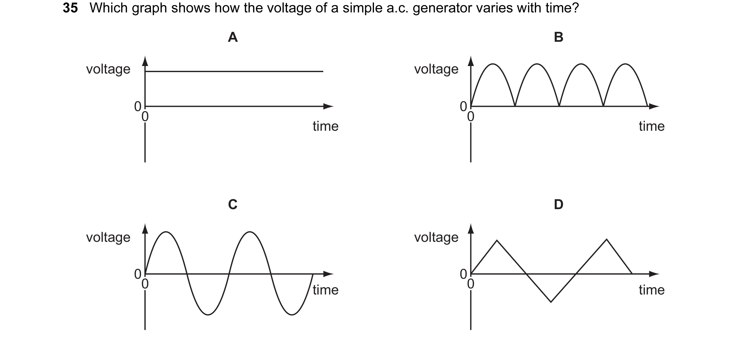

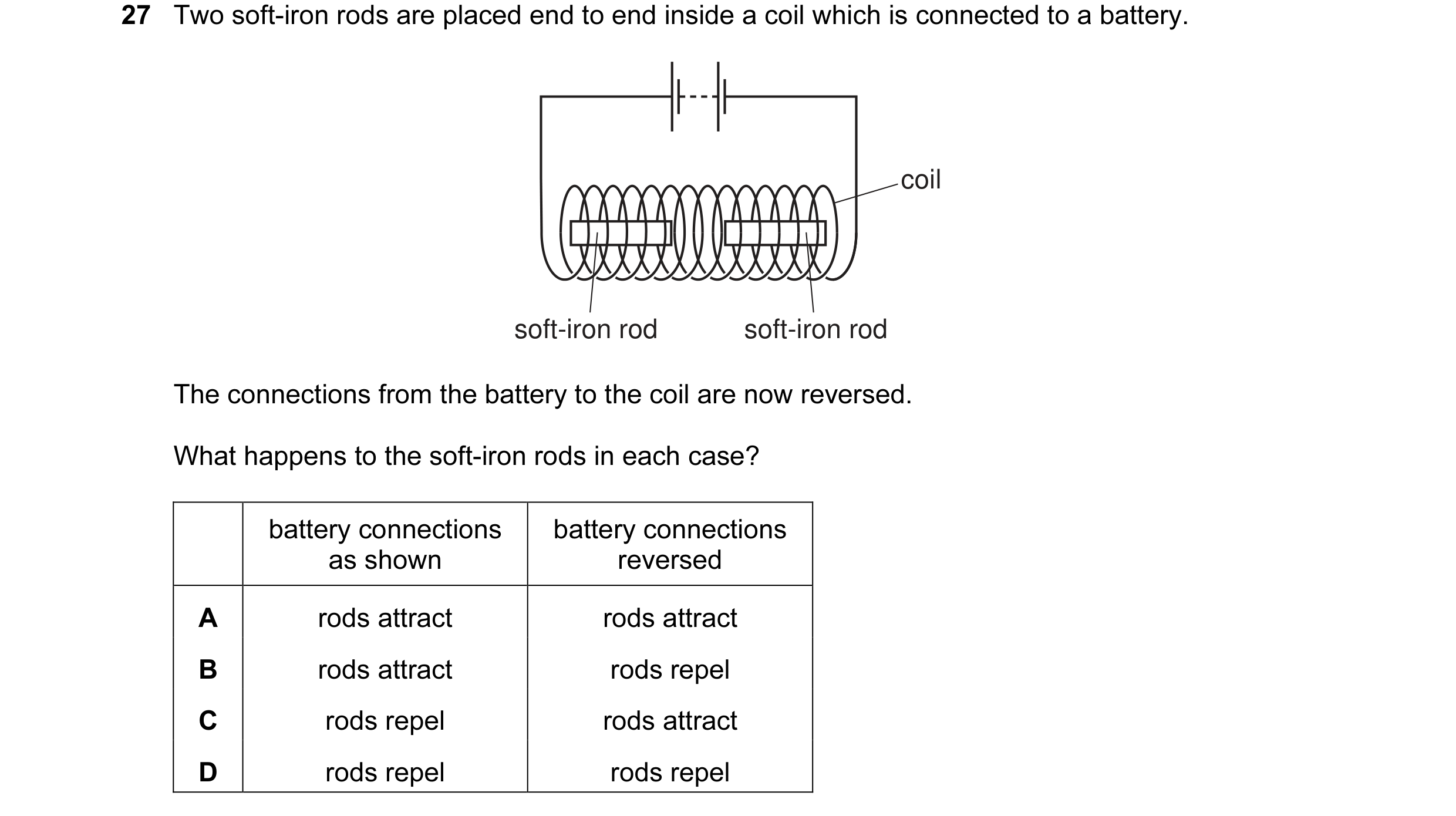 22 / 108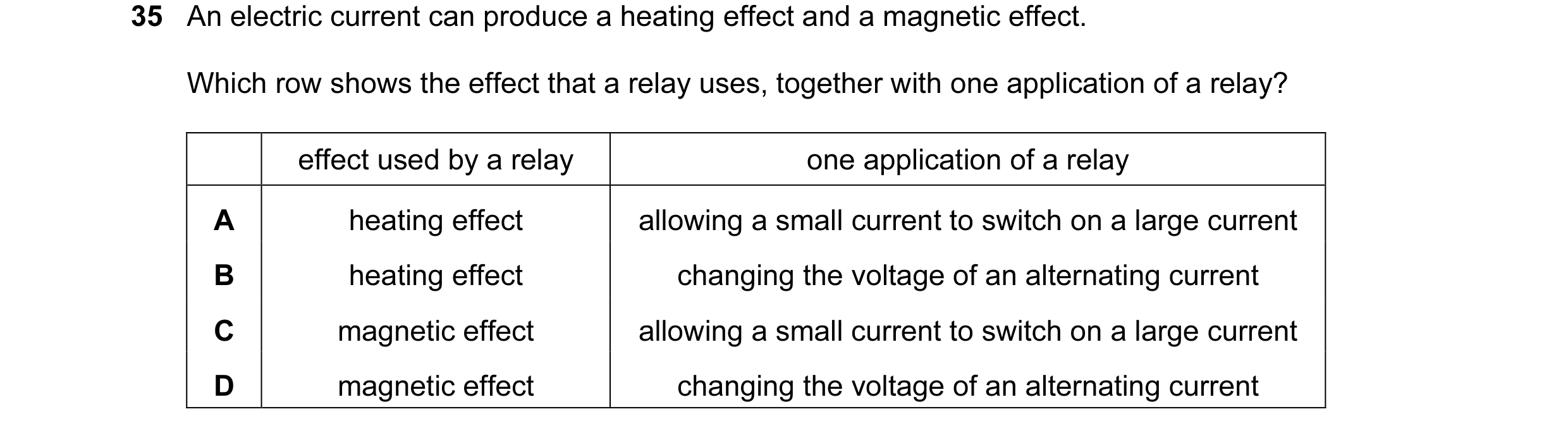
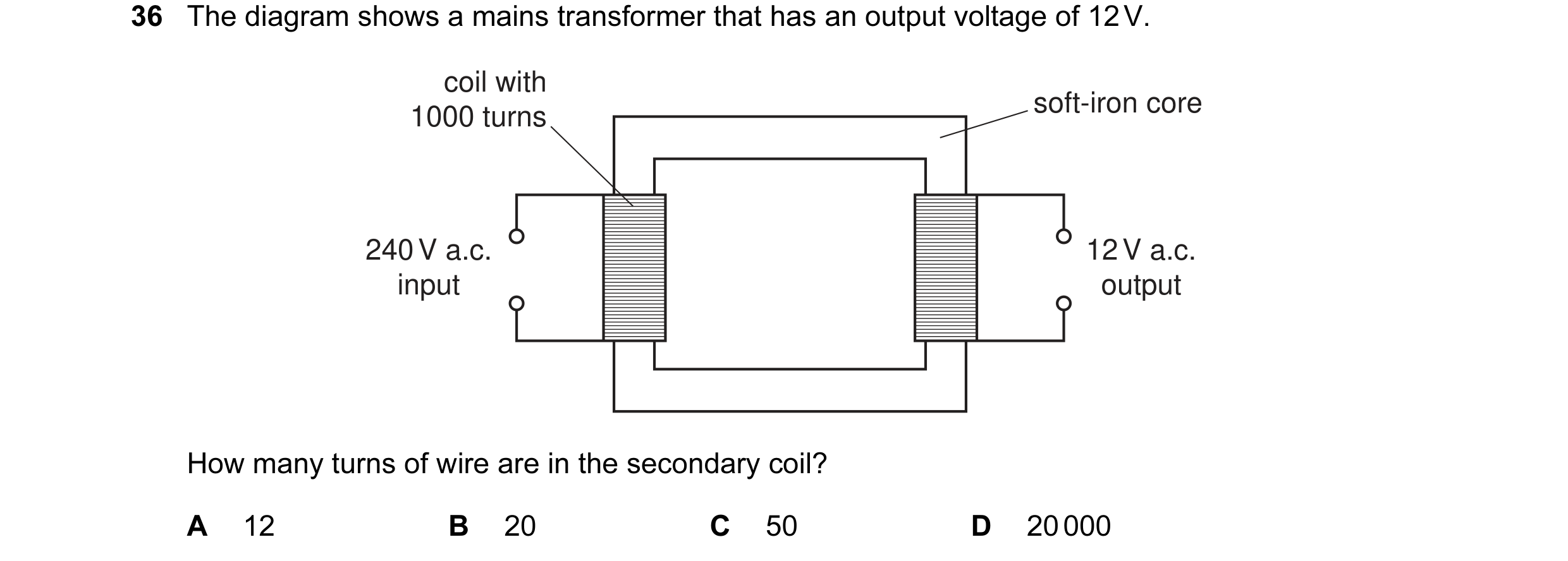
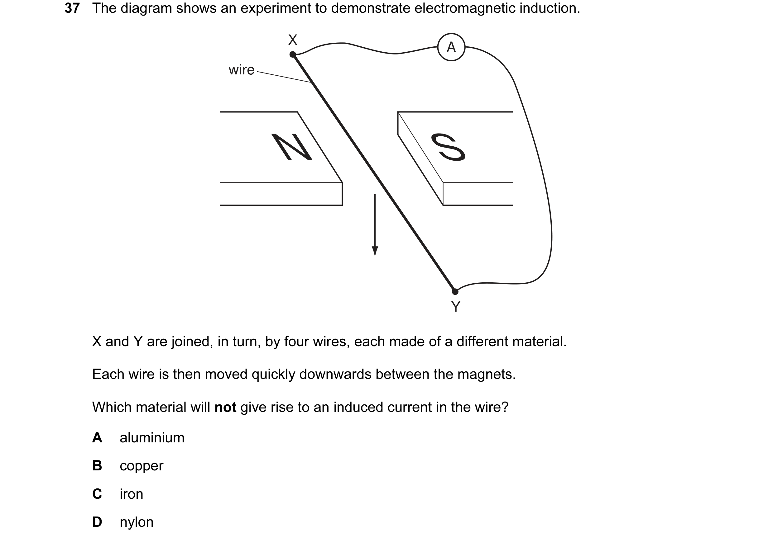 23 / 108
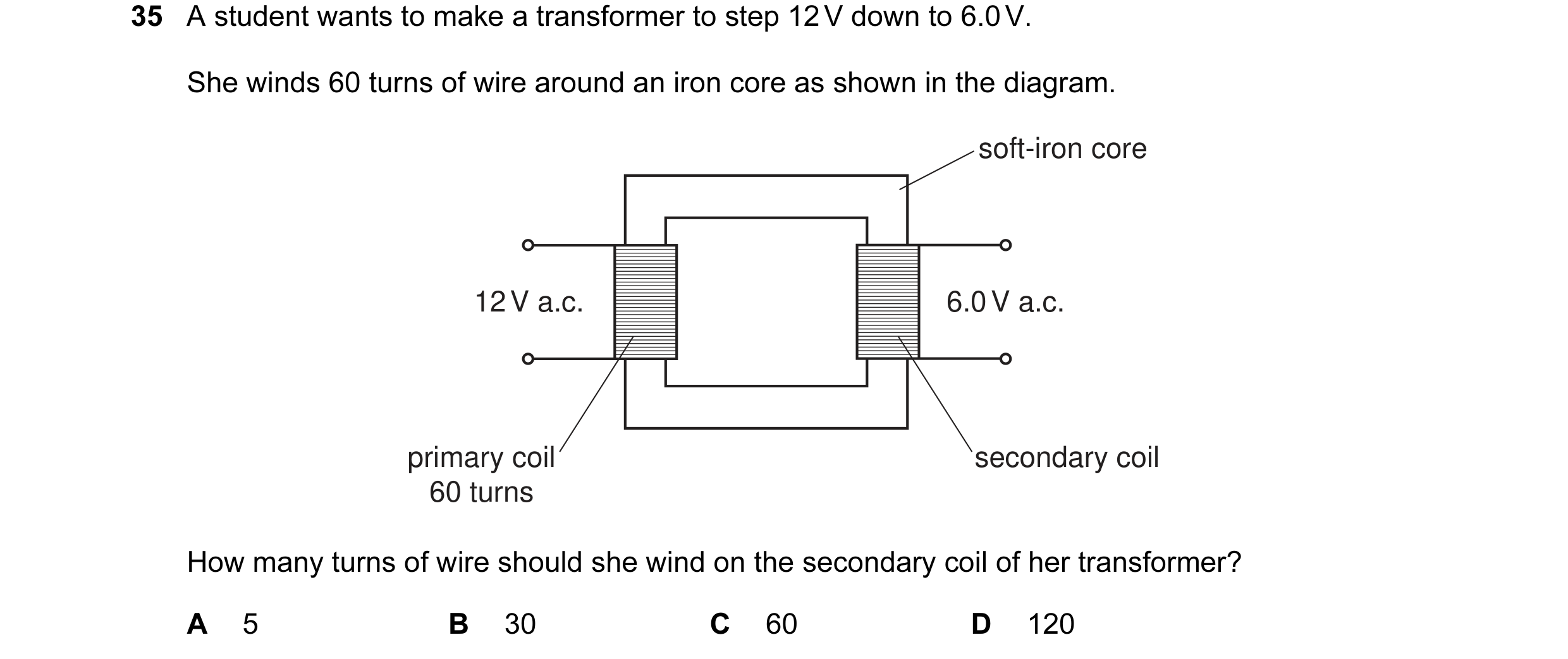
 24 / 108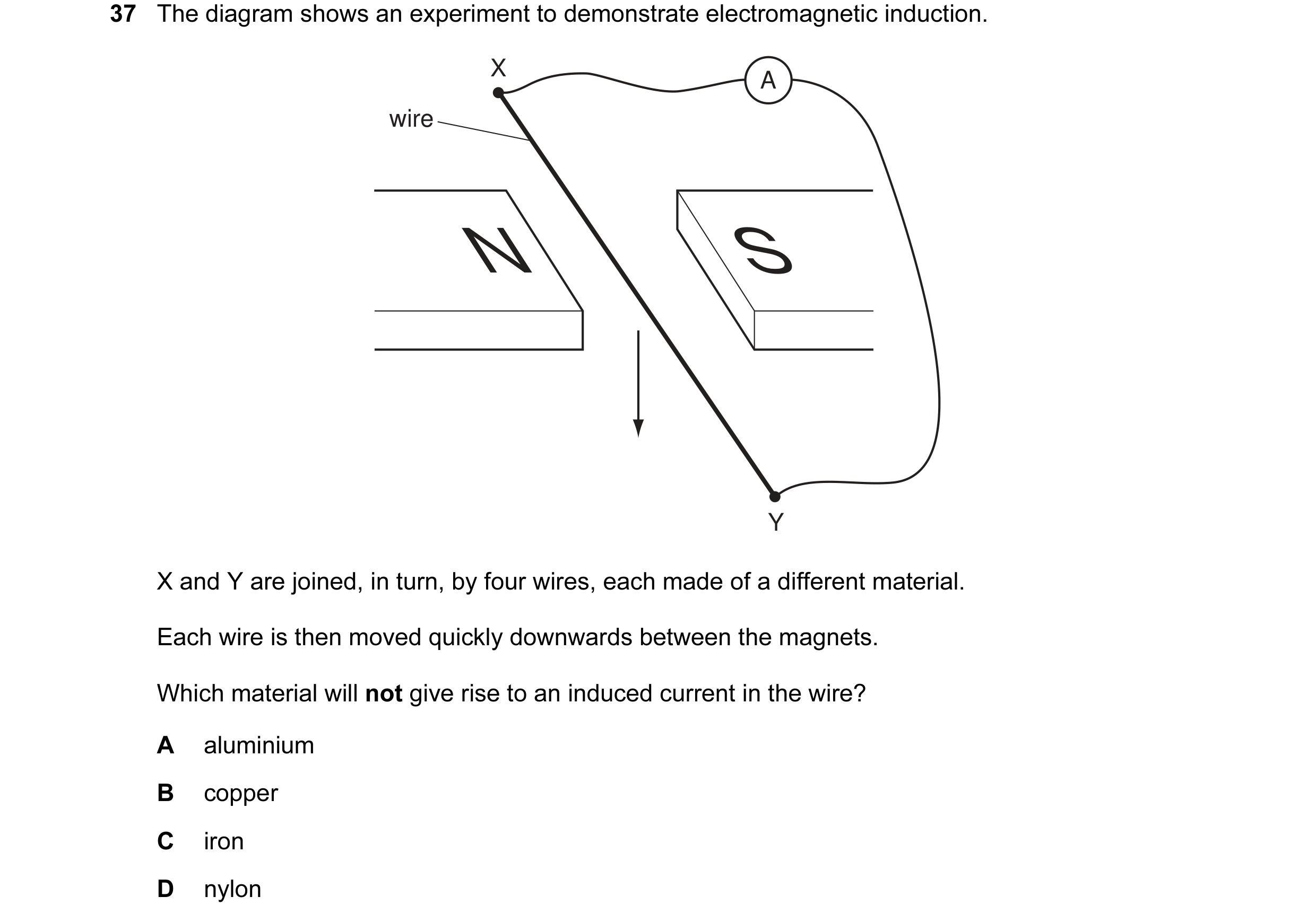
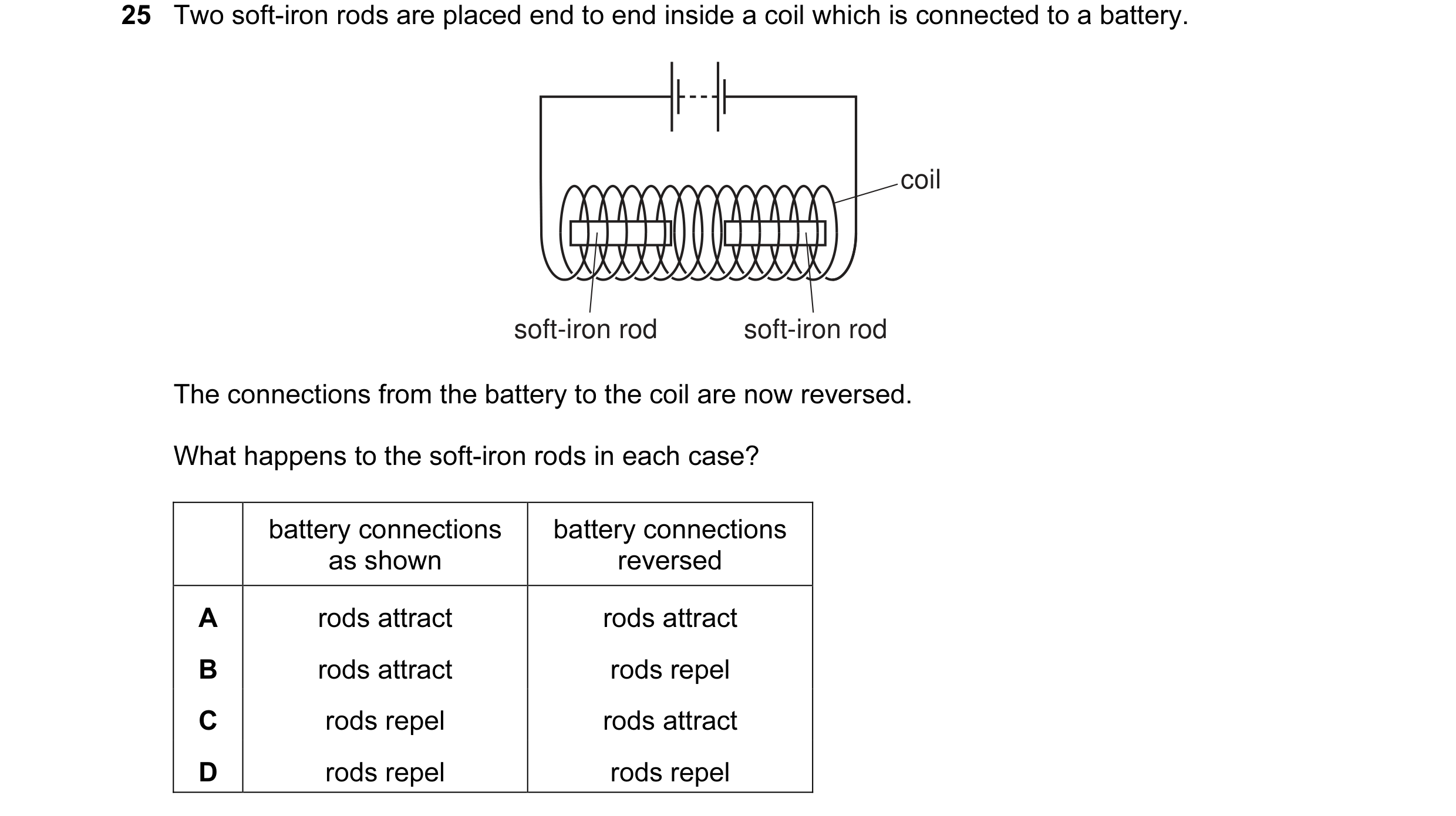 25 / 108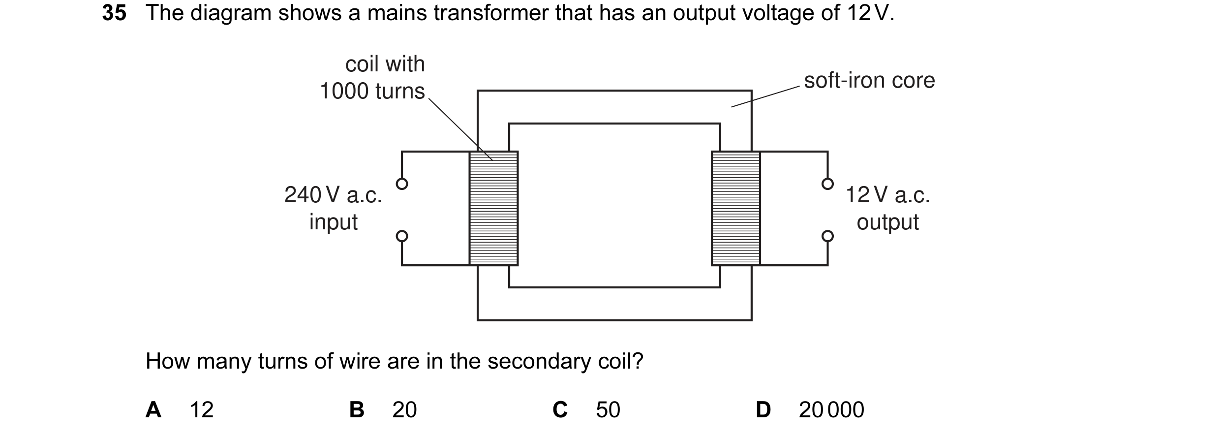
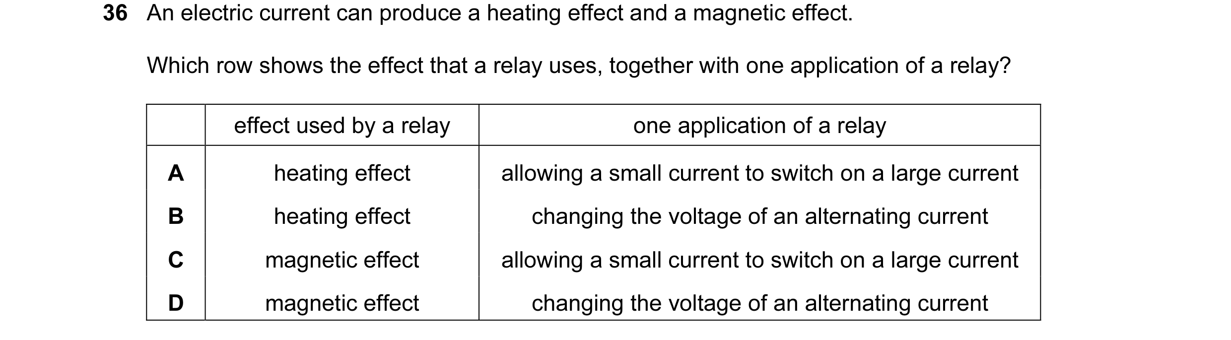
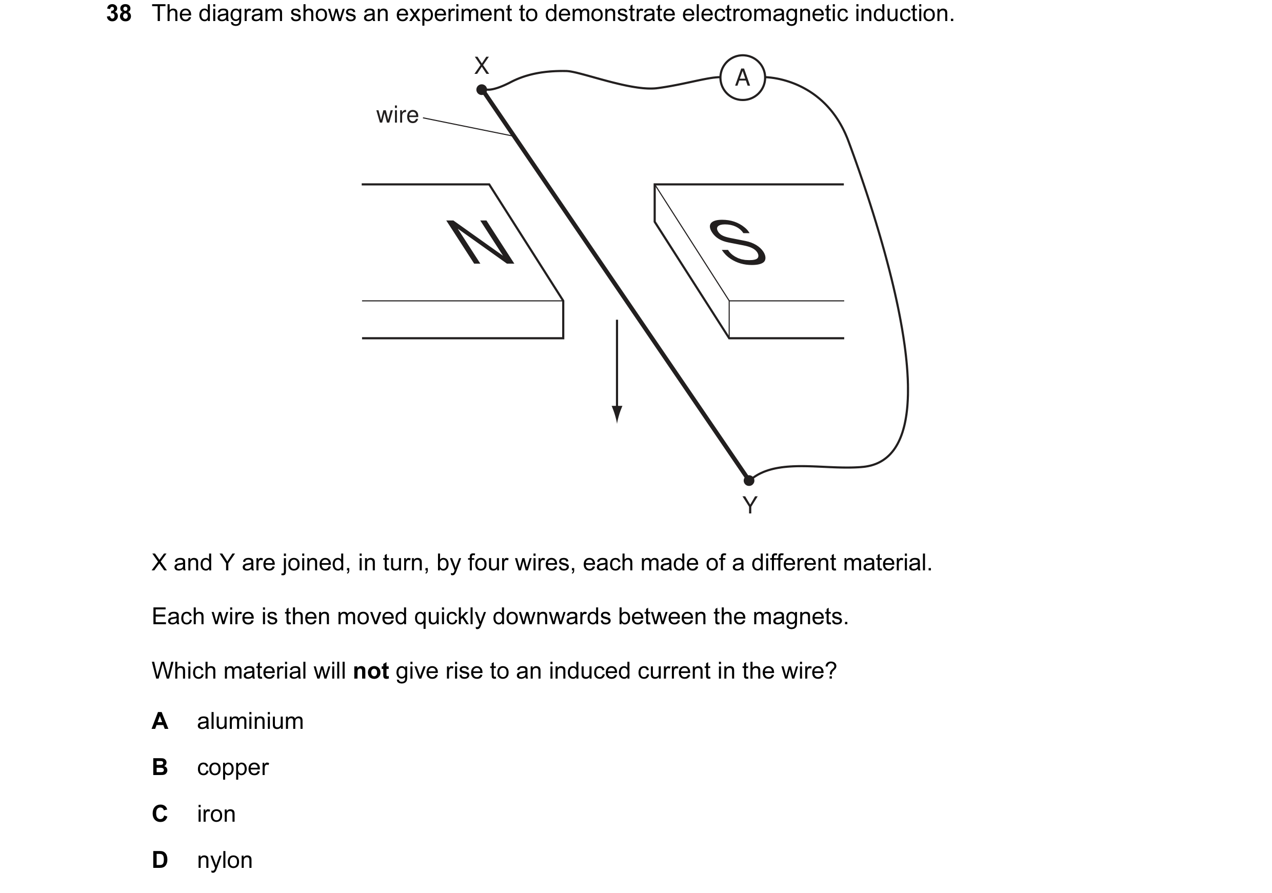 26 / 108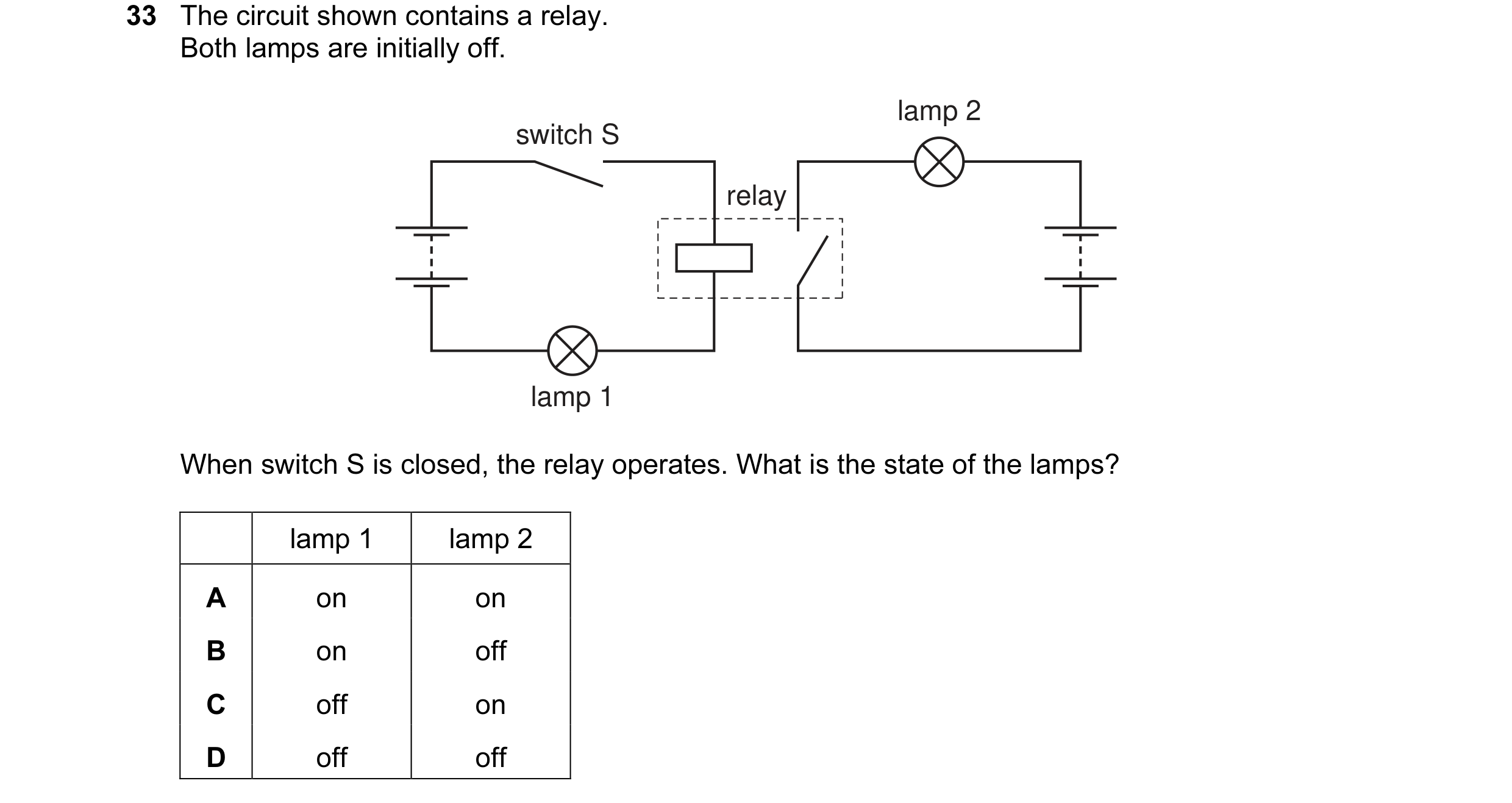
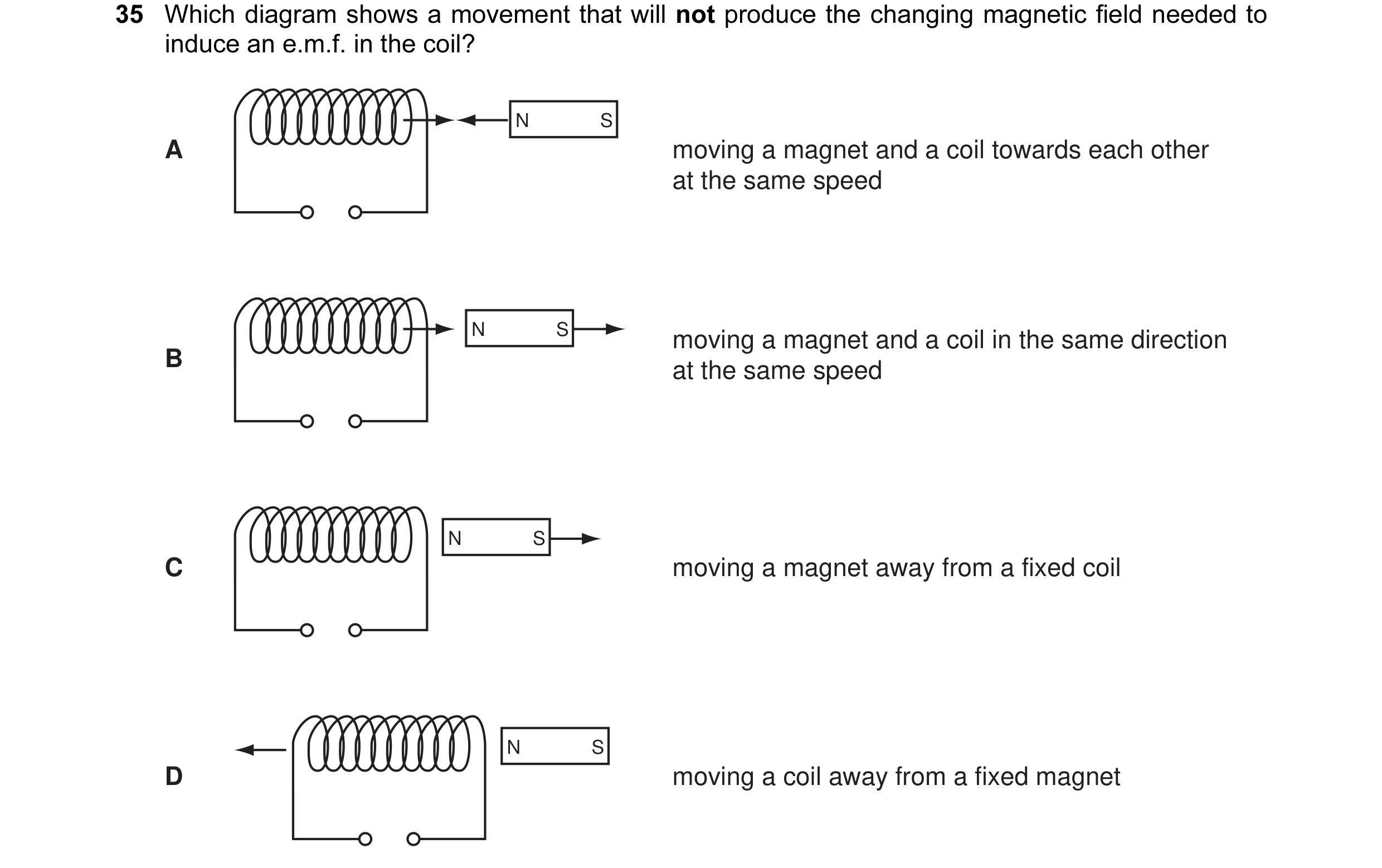 27 / 108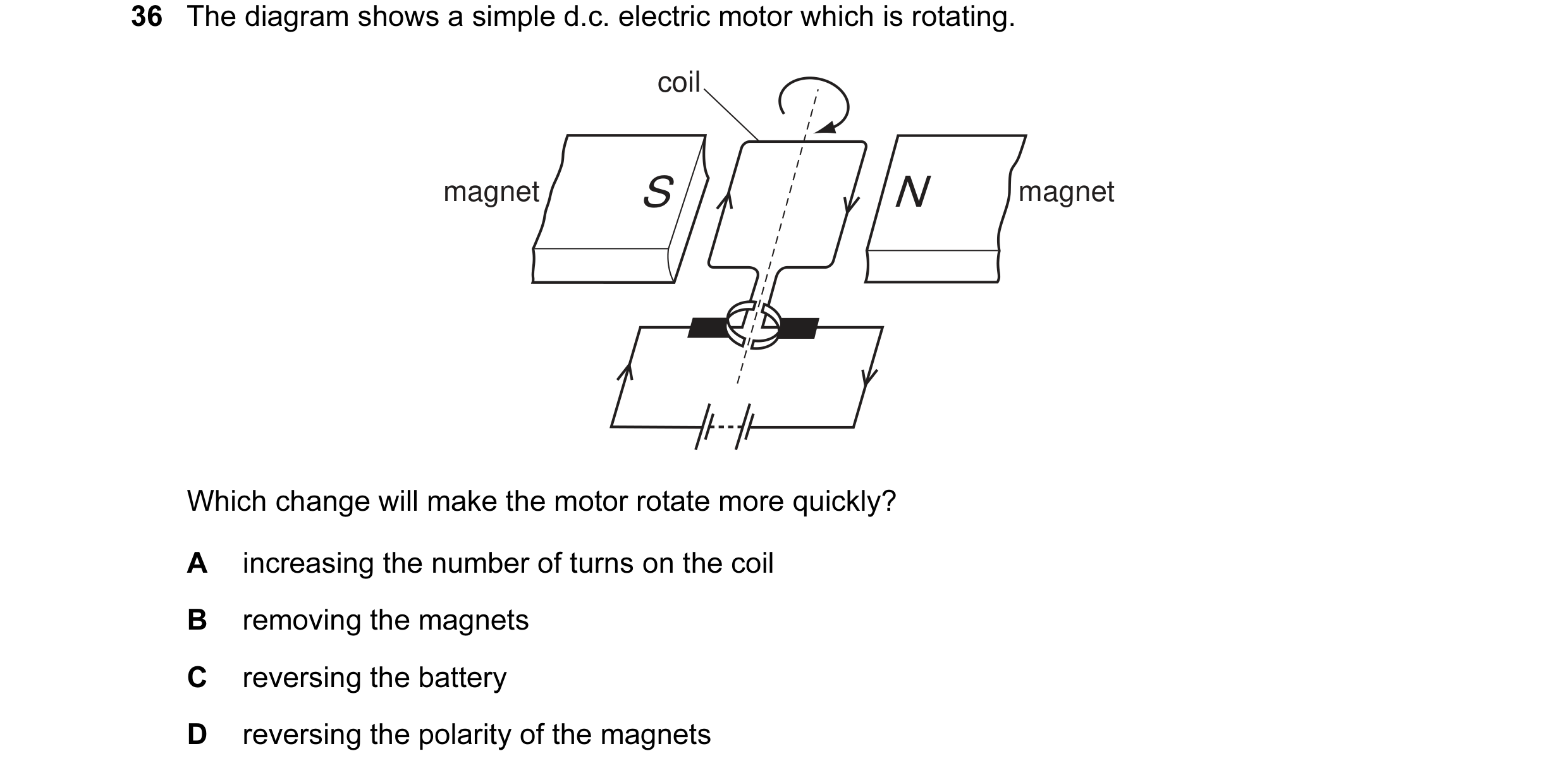
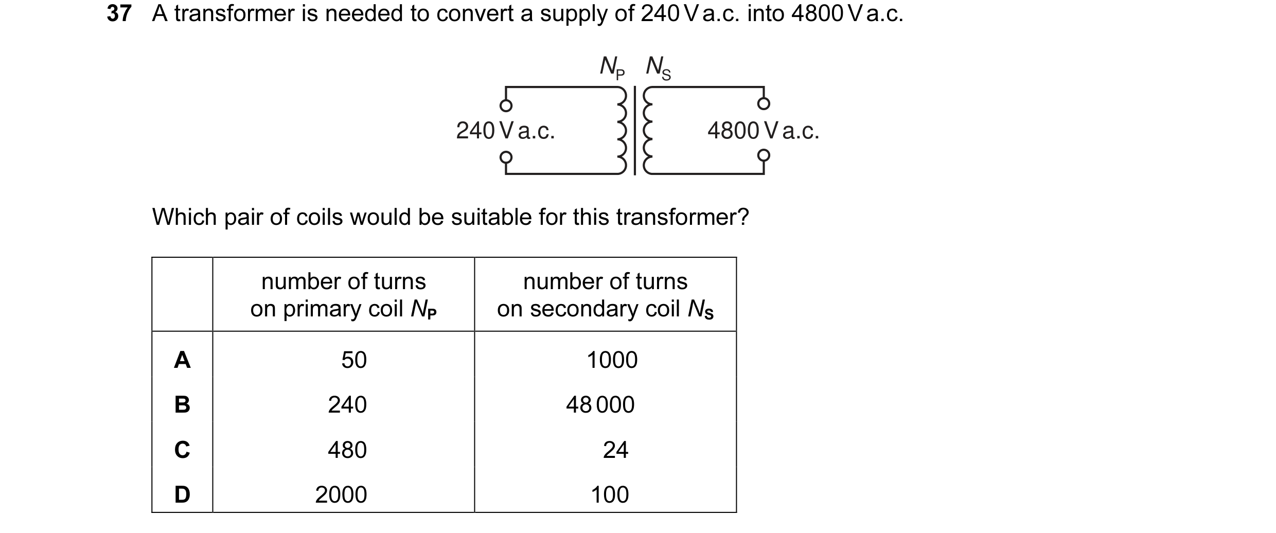 28 / 108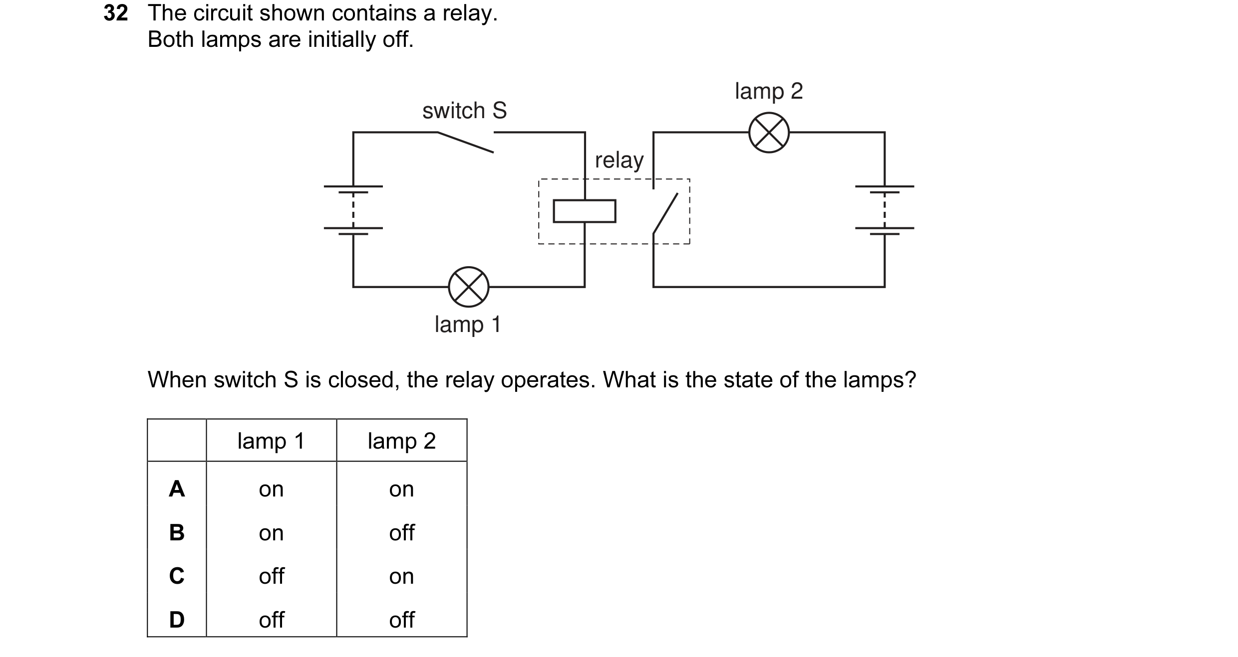
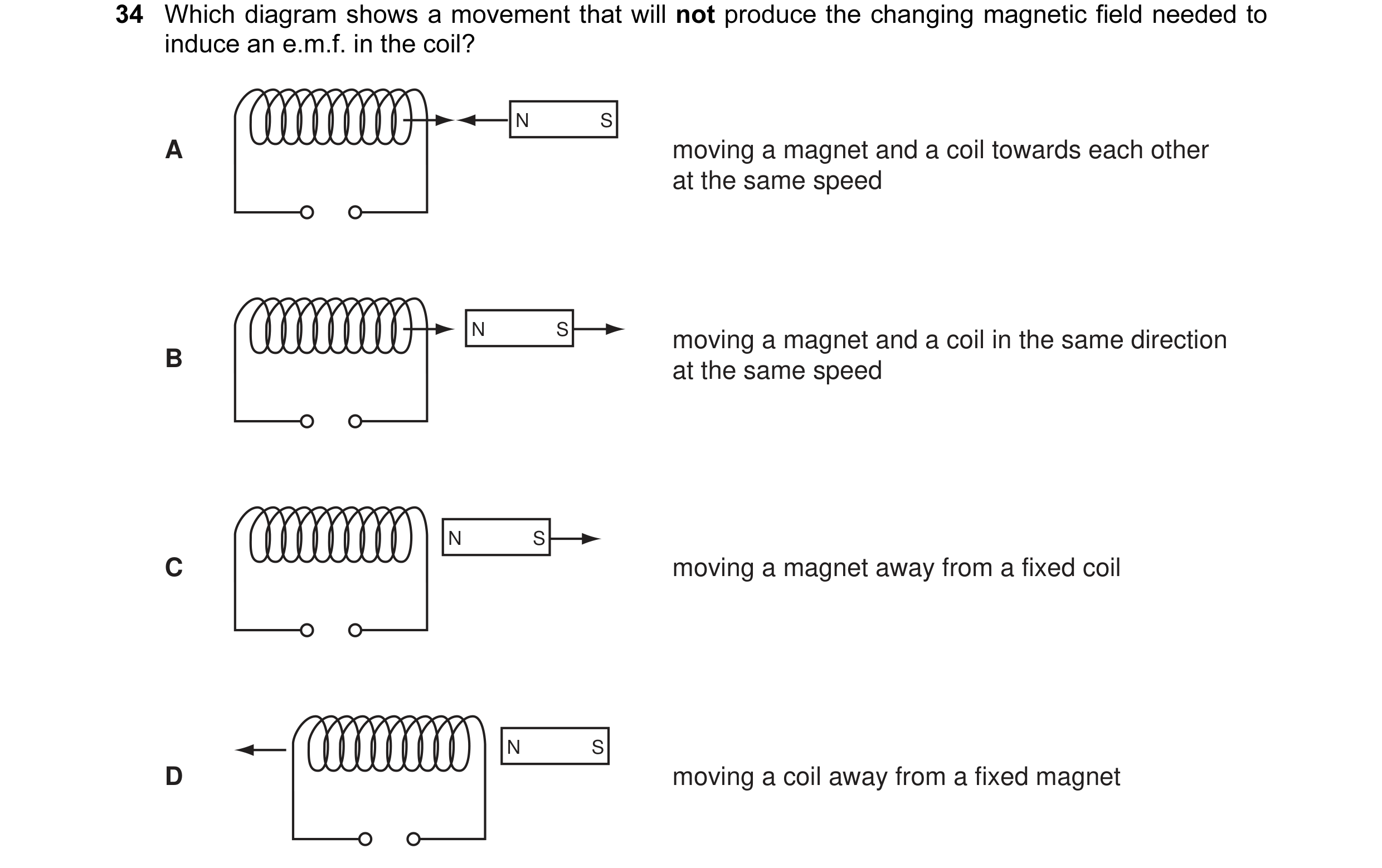 29 / 108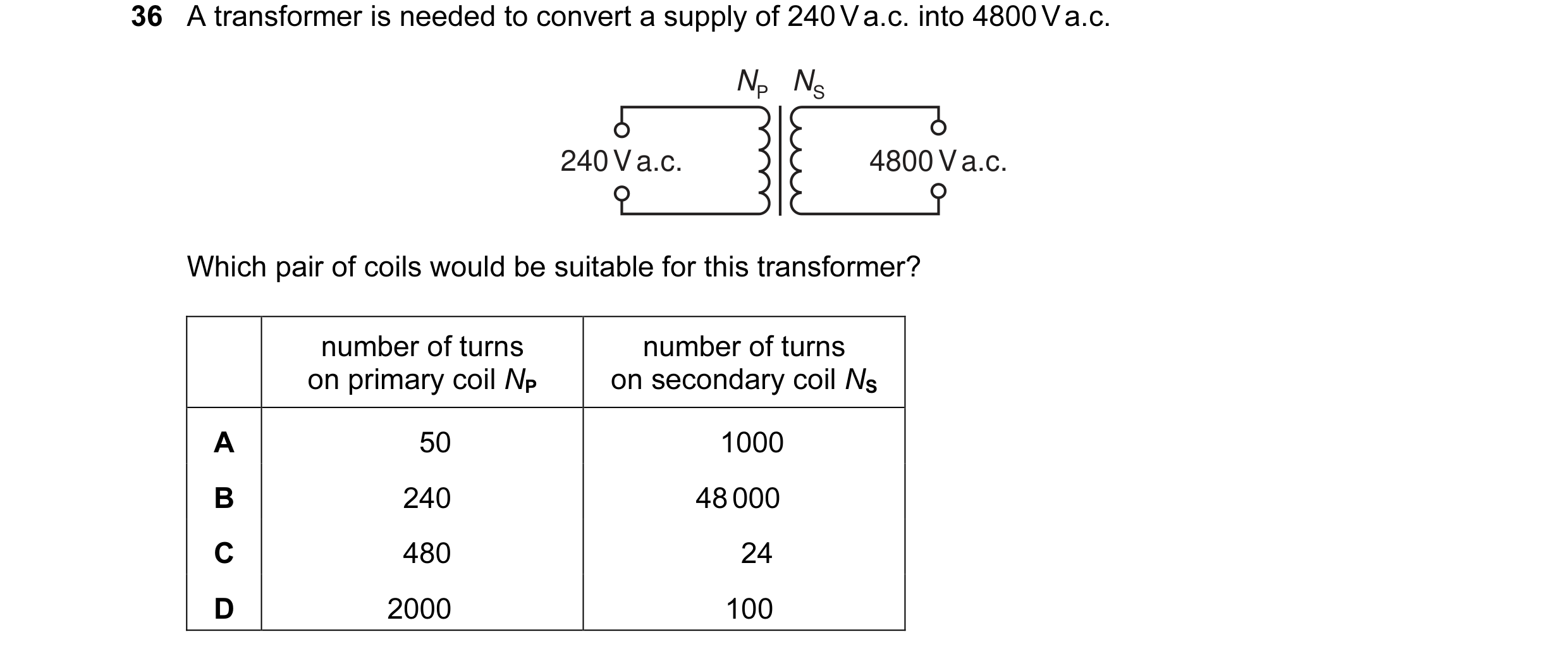
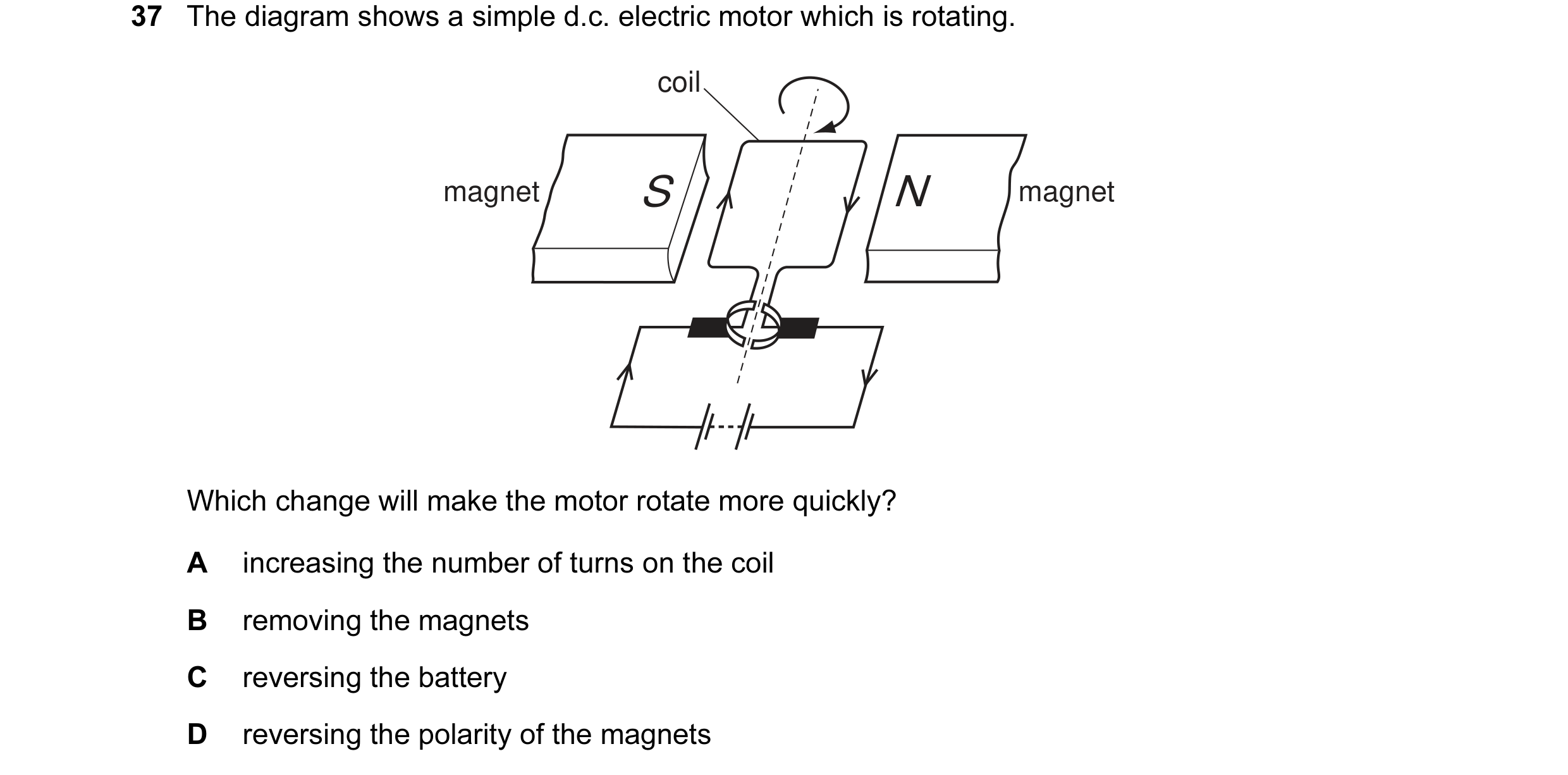 30 / 108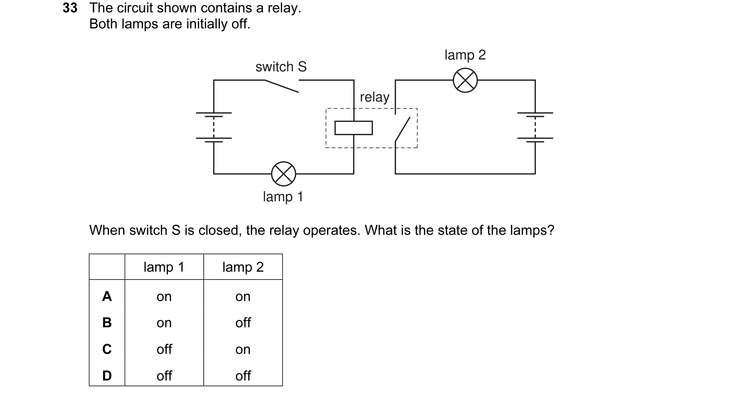
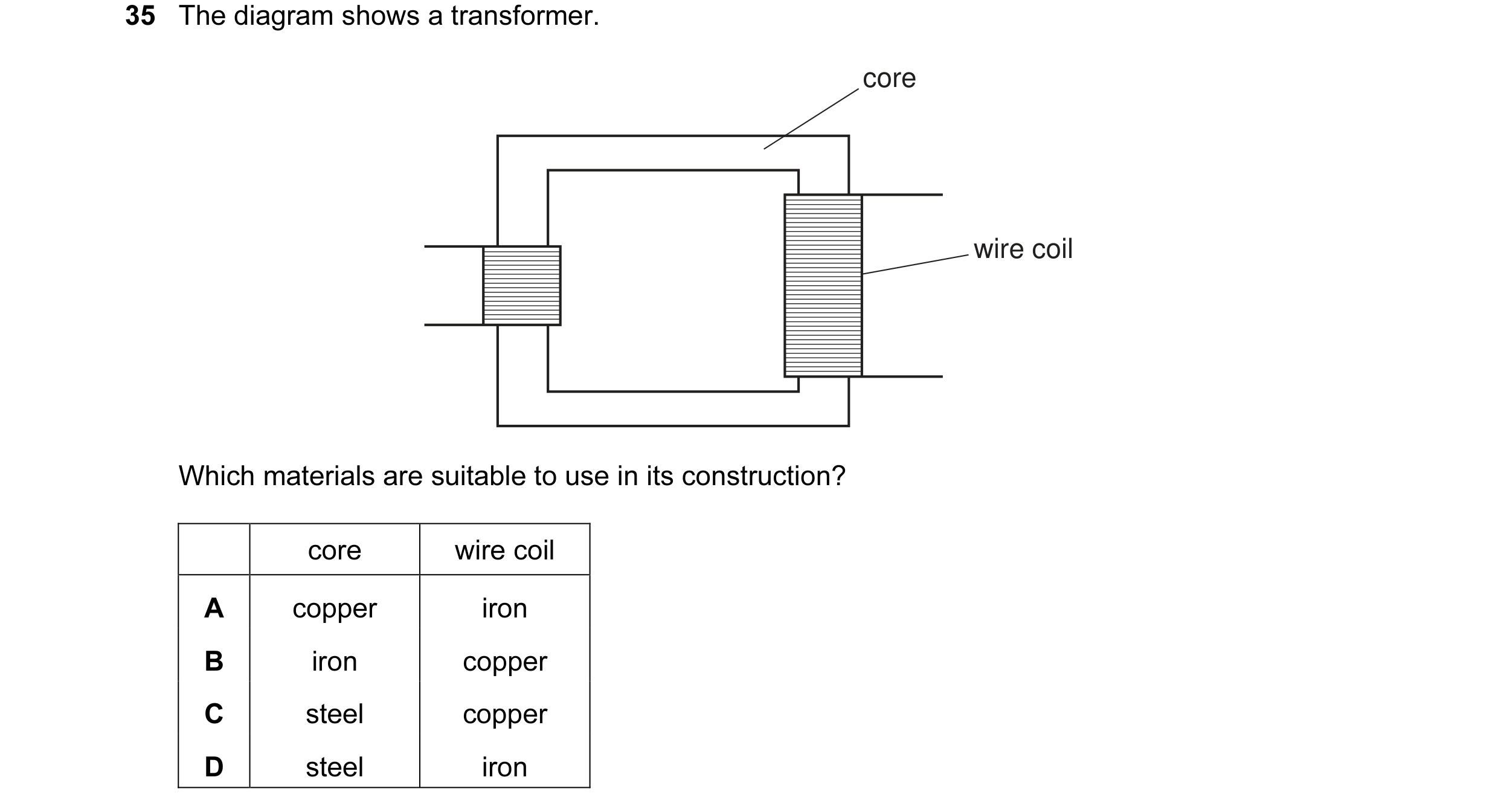 31 / 108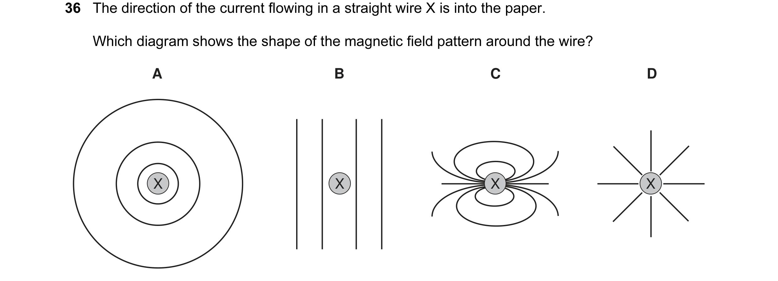
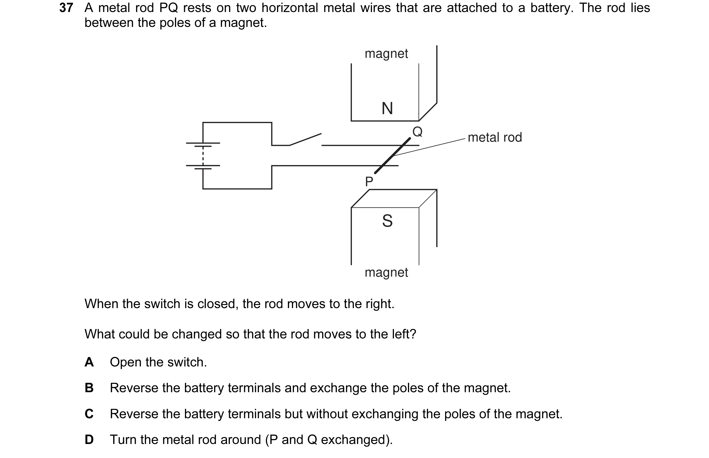 32 / 108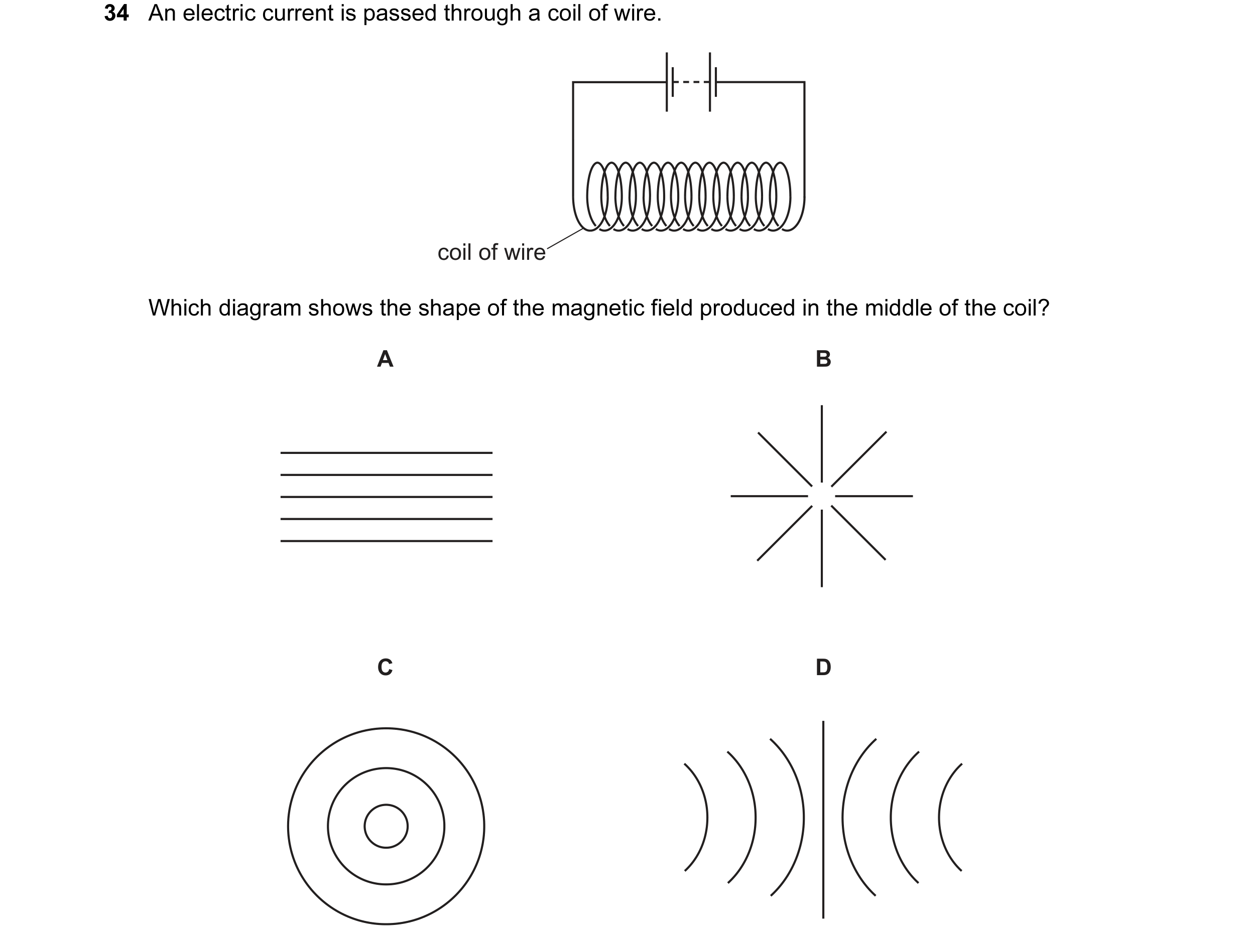
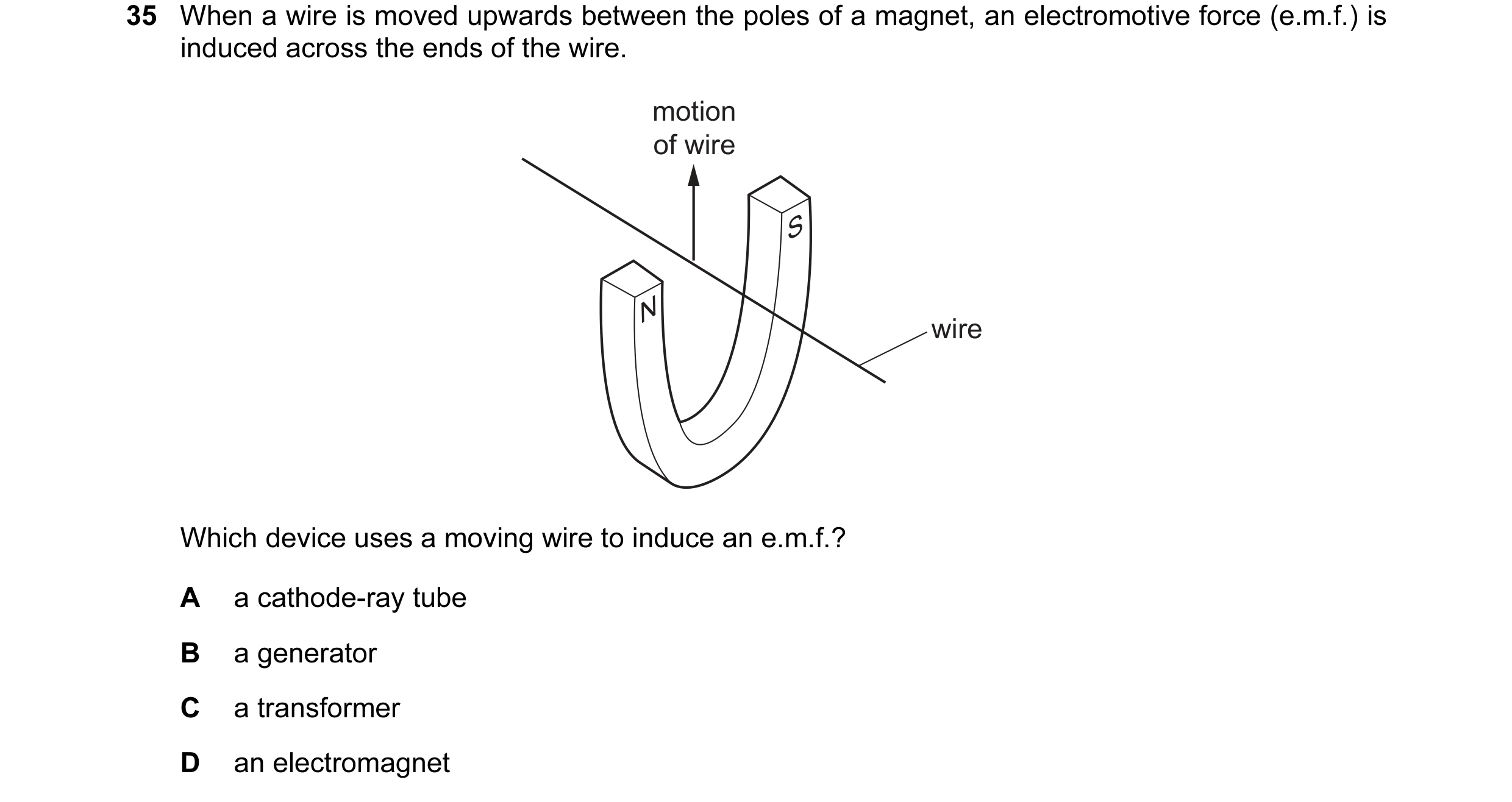 33 / 108
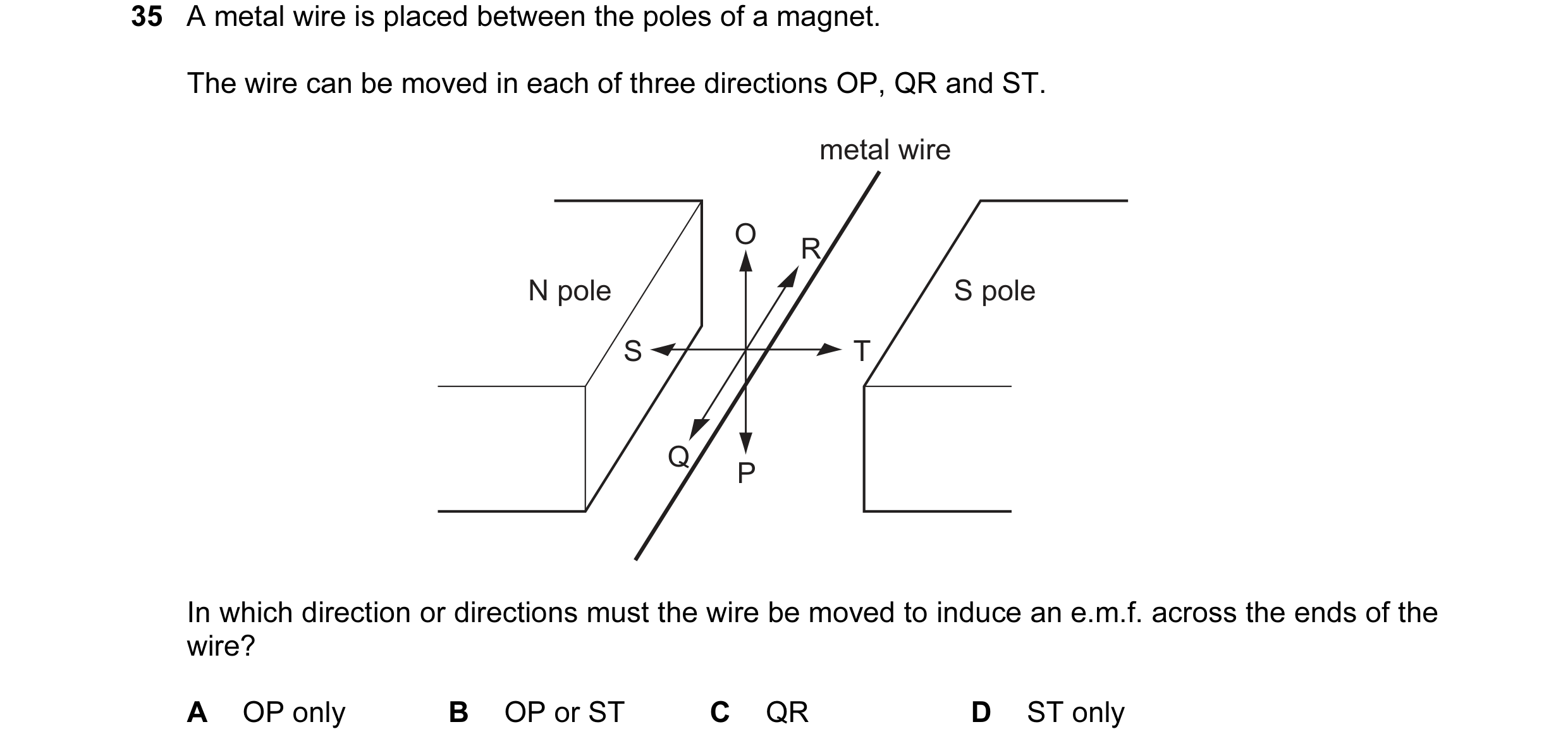
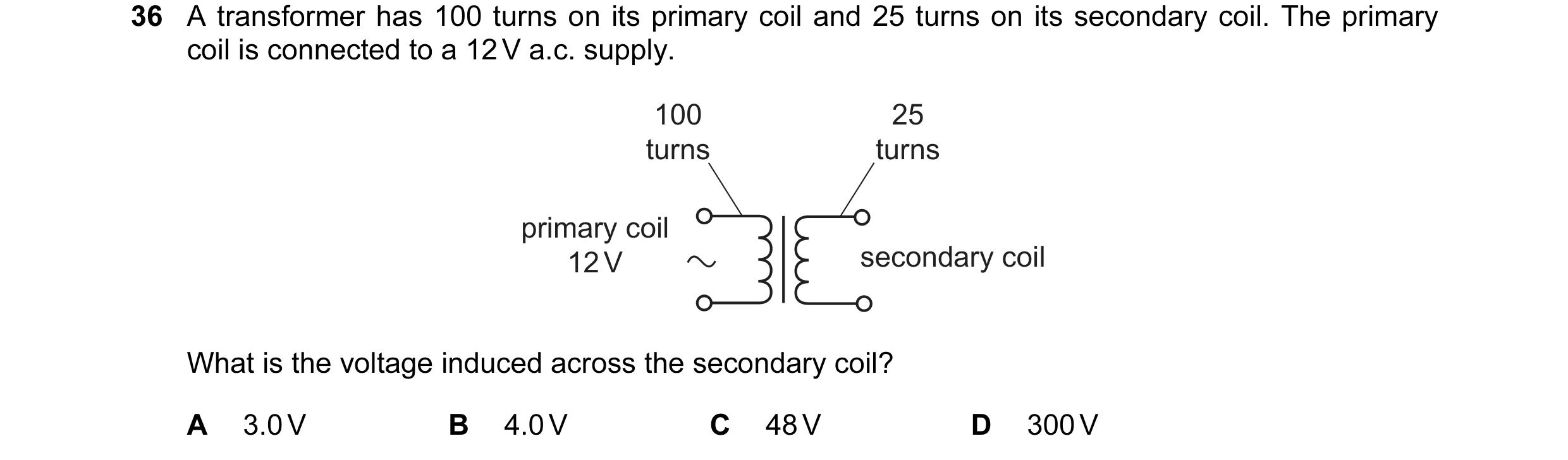 34 / 108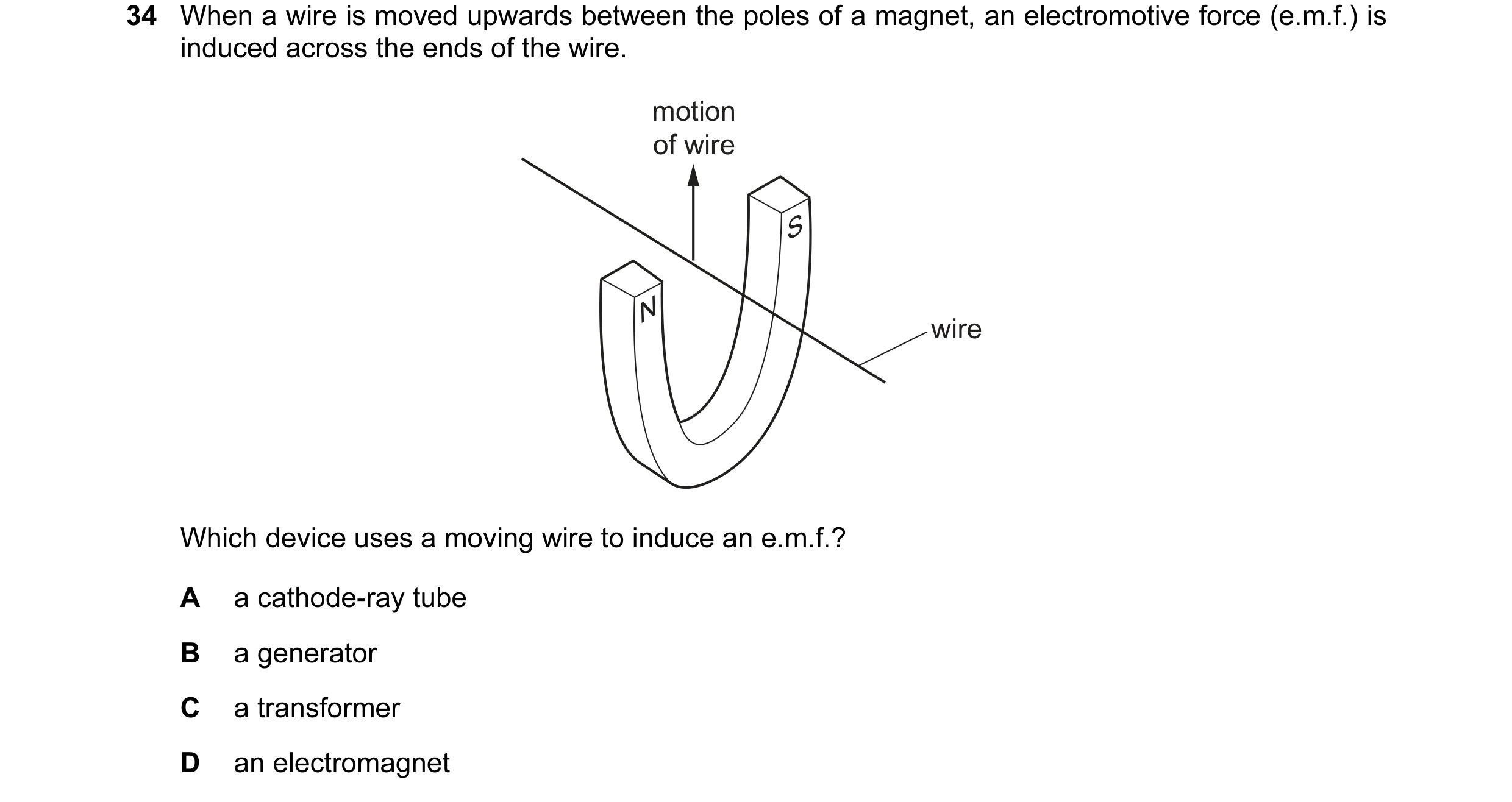
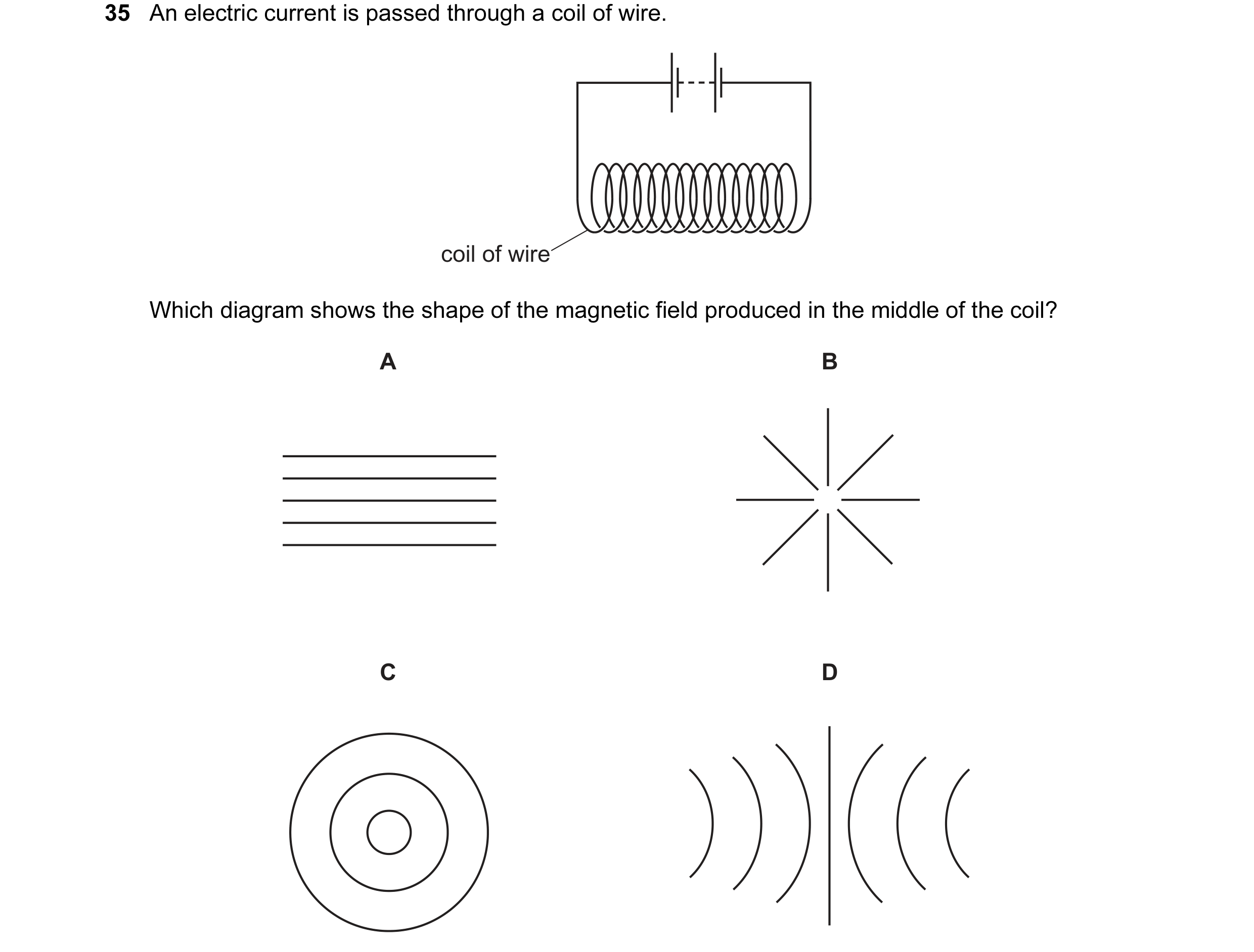 35 / 108
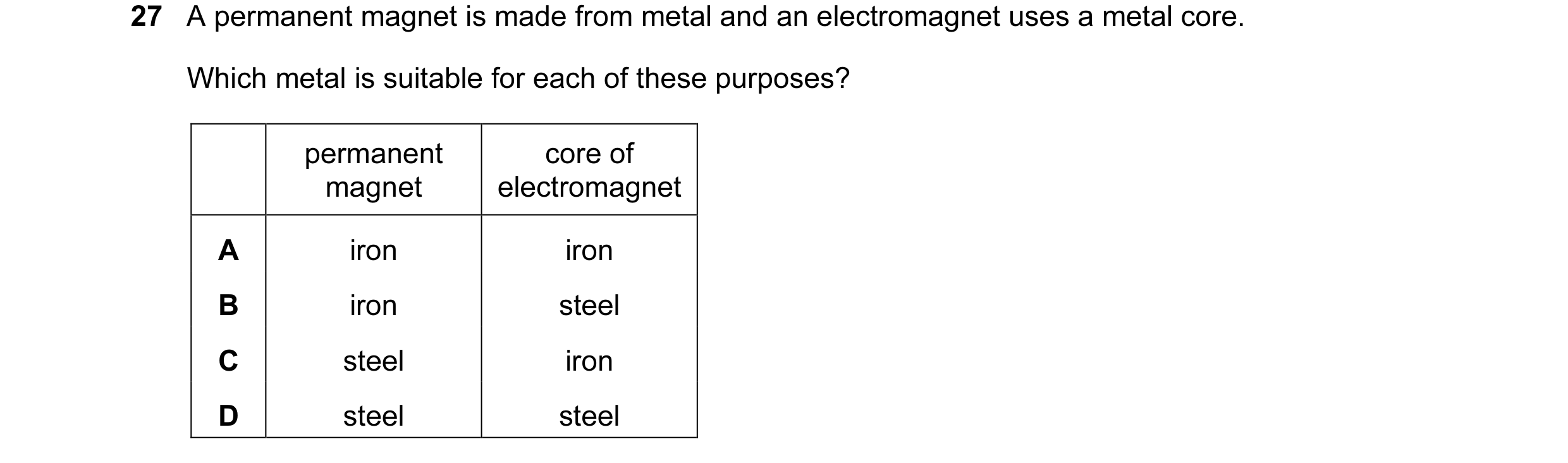
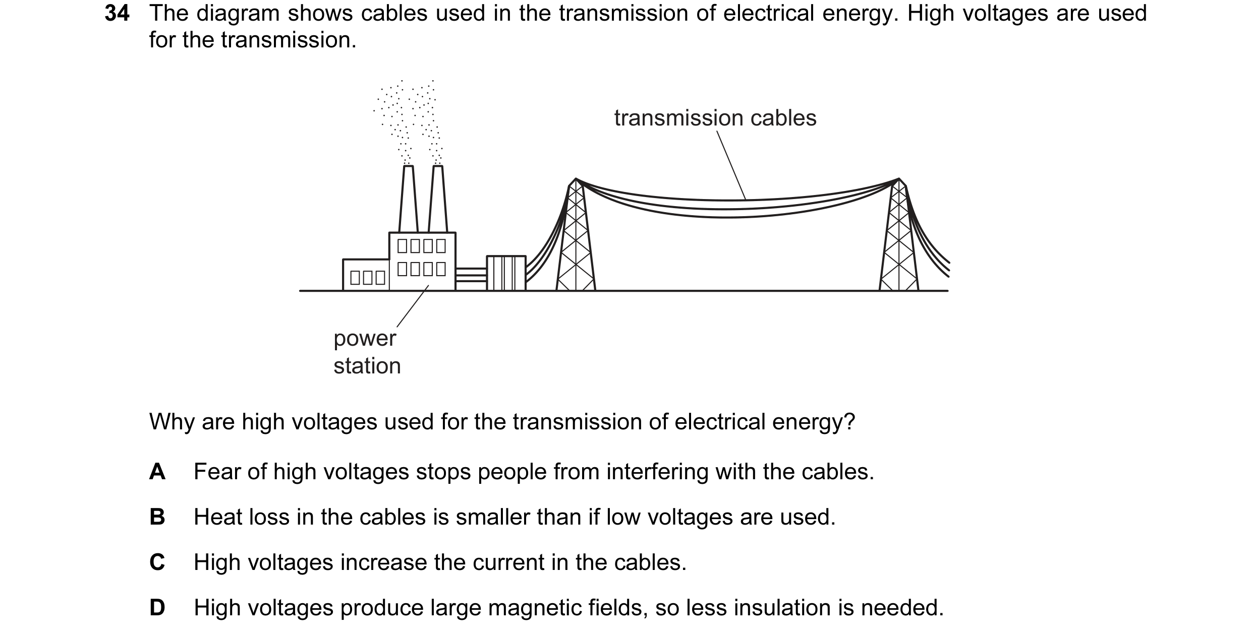
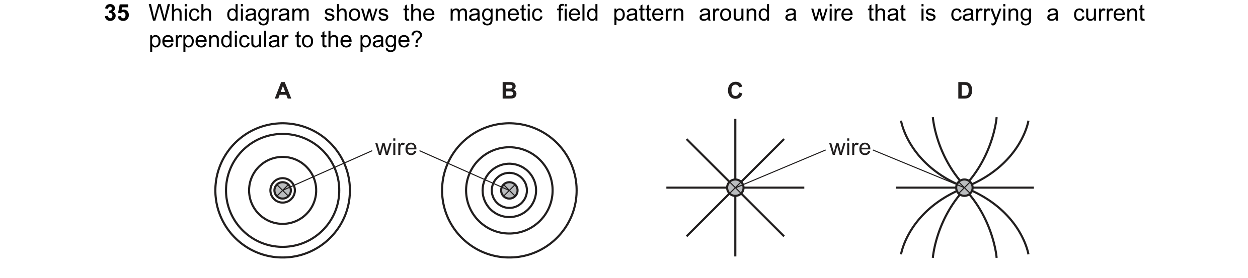 36 / 108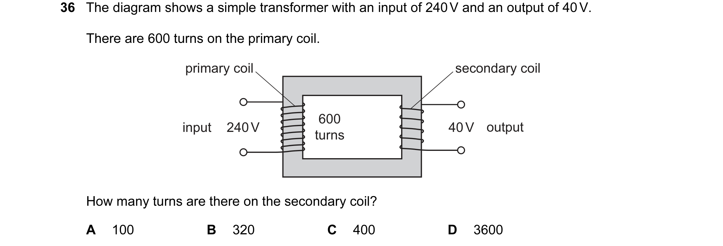
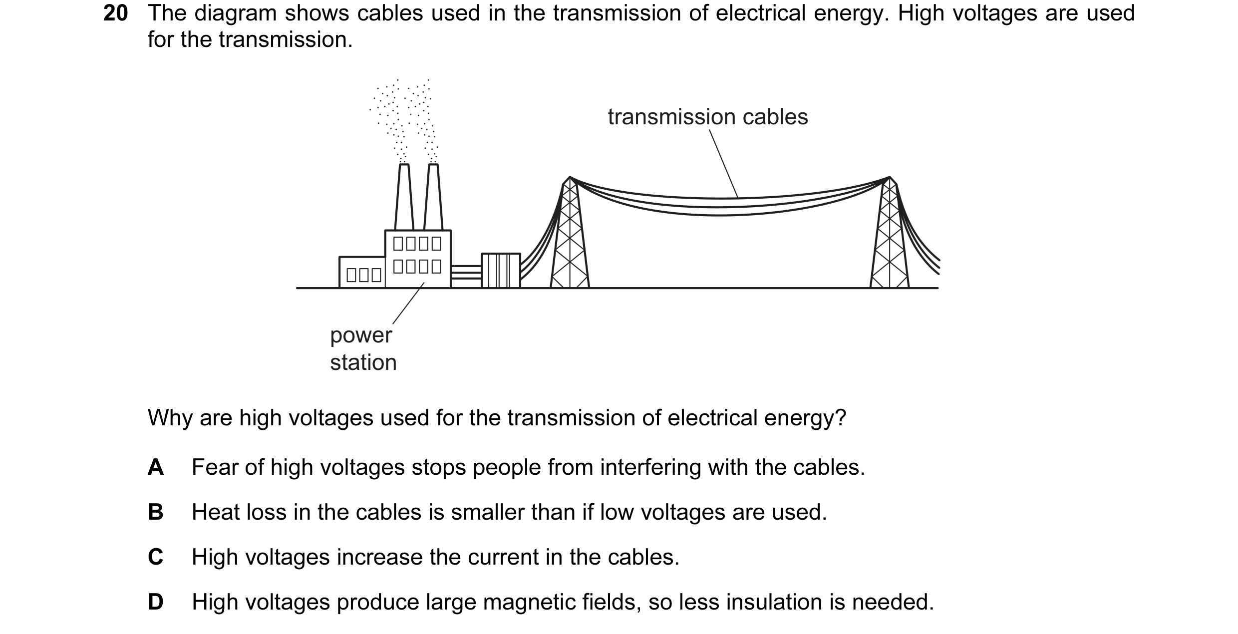
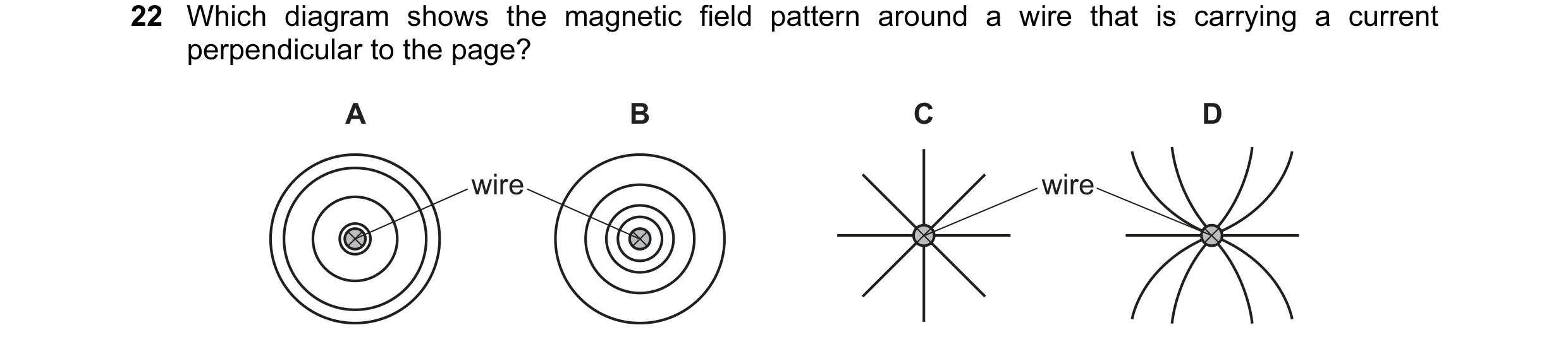 37 / 108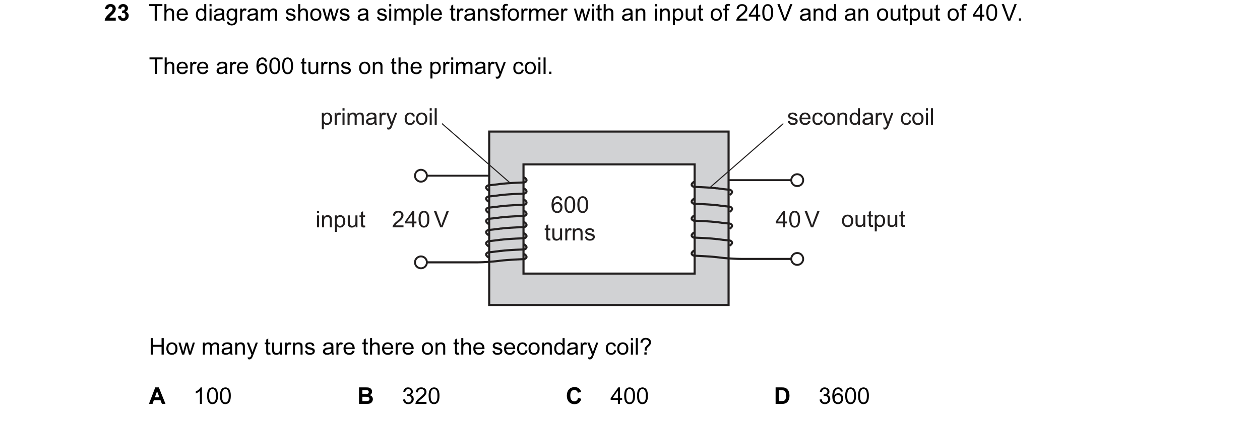
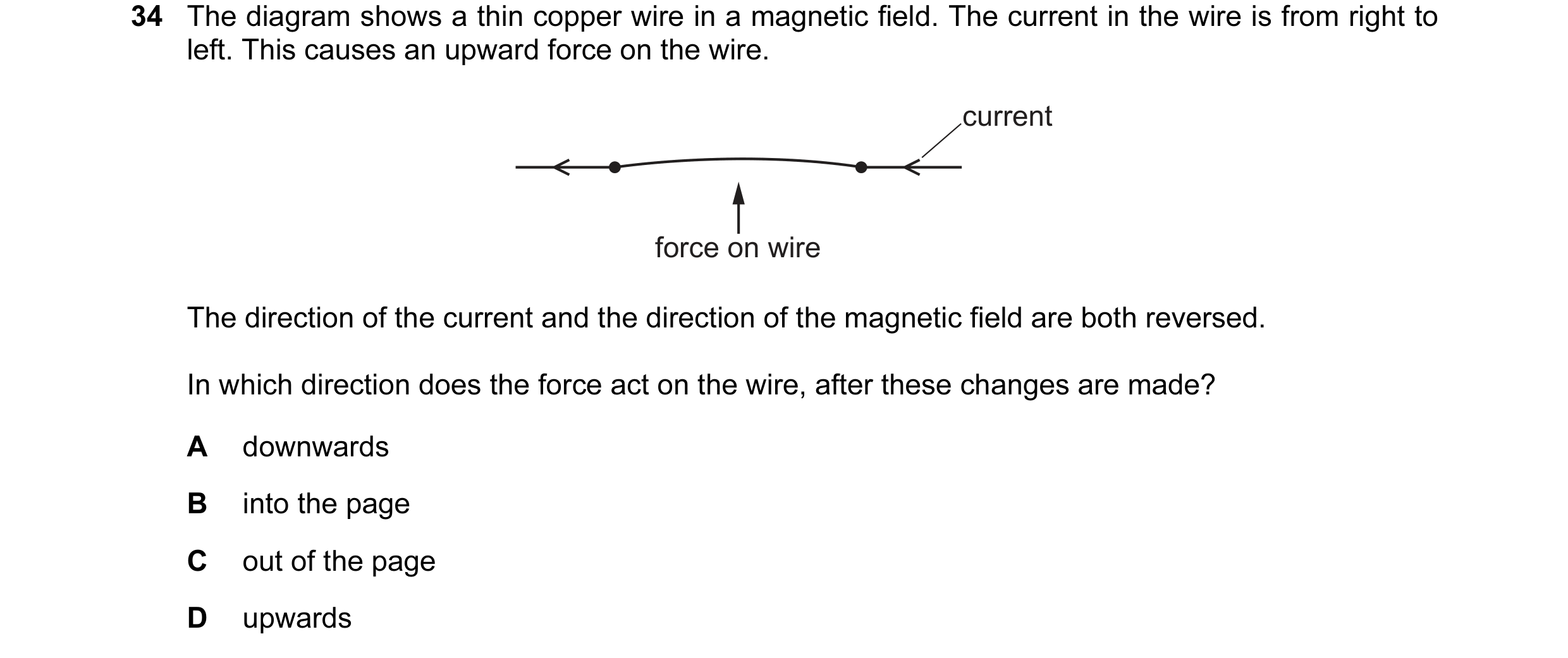
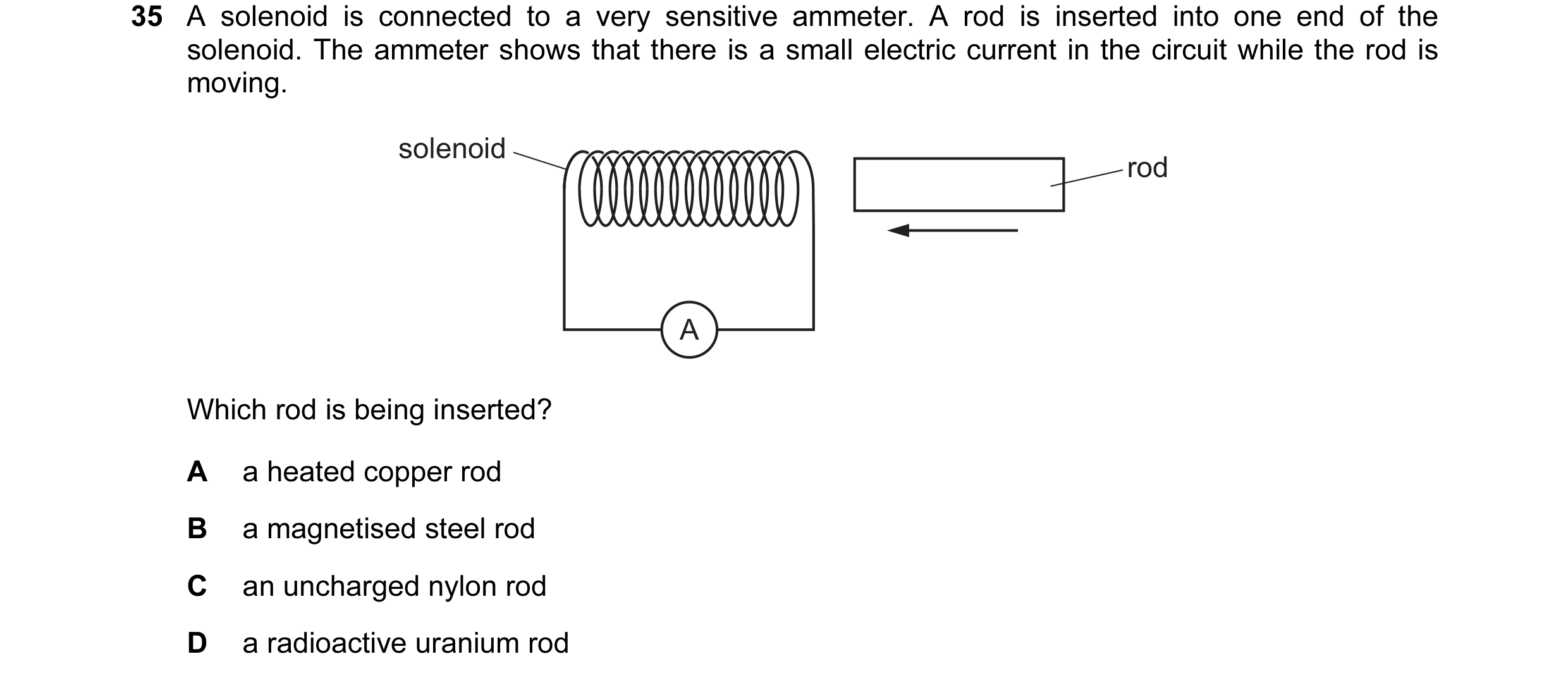 38 / 108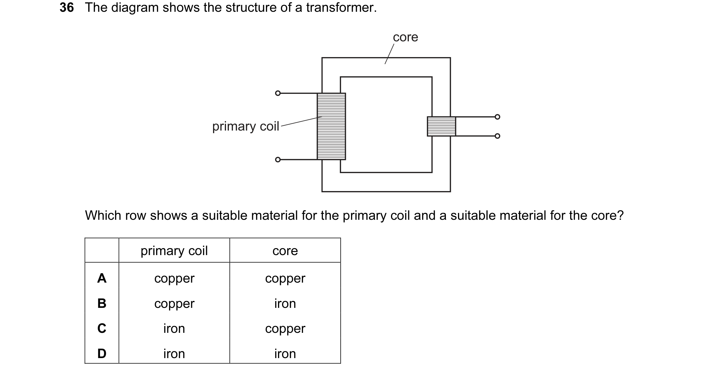

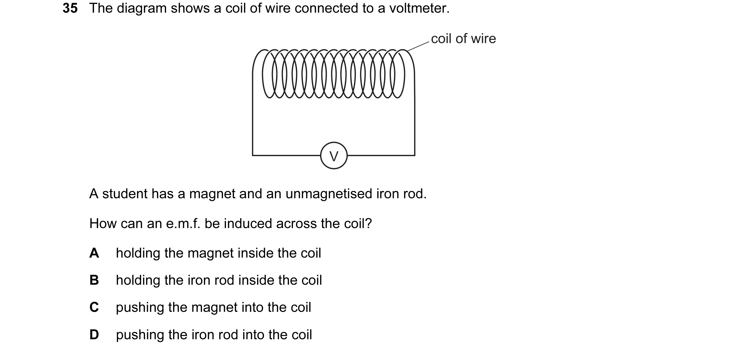 39 / 108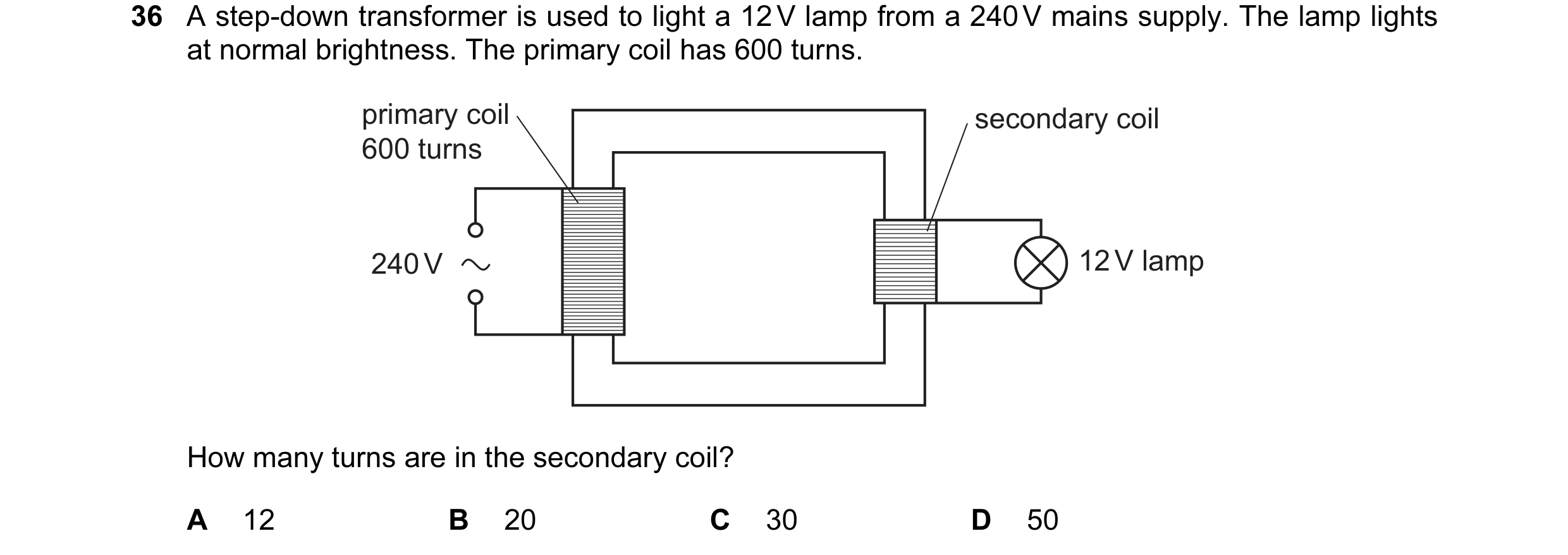
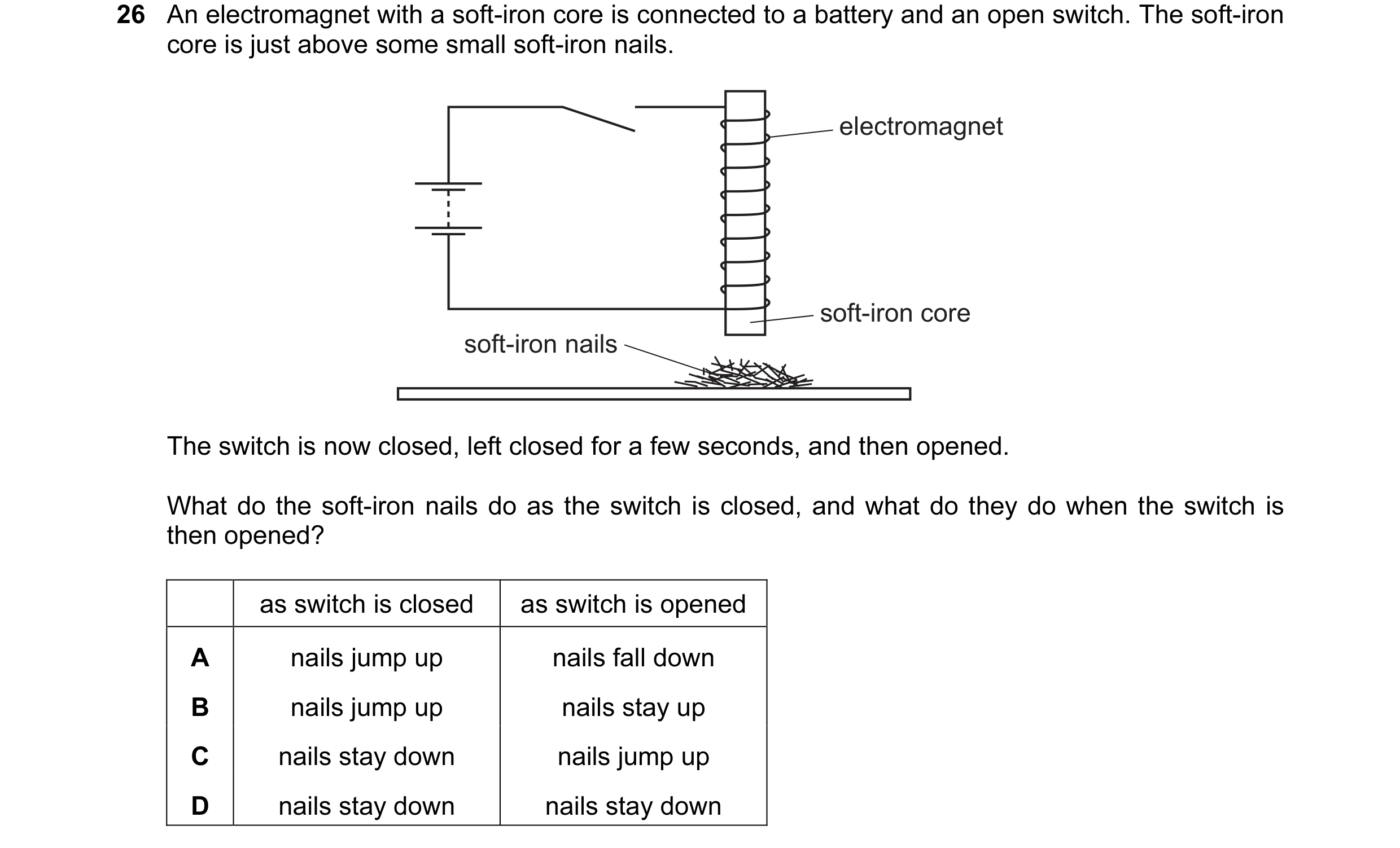
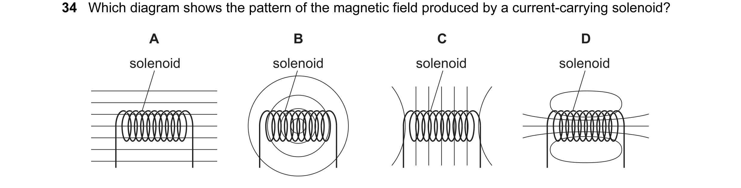 40 / 108
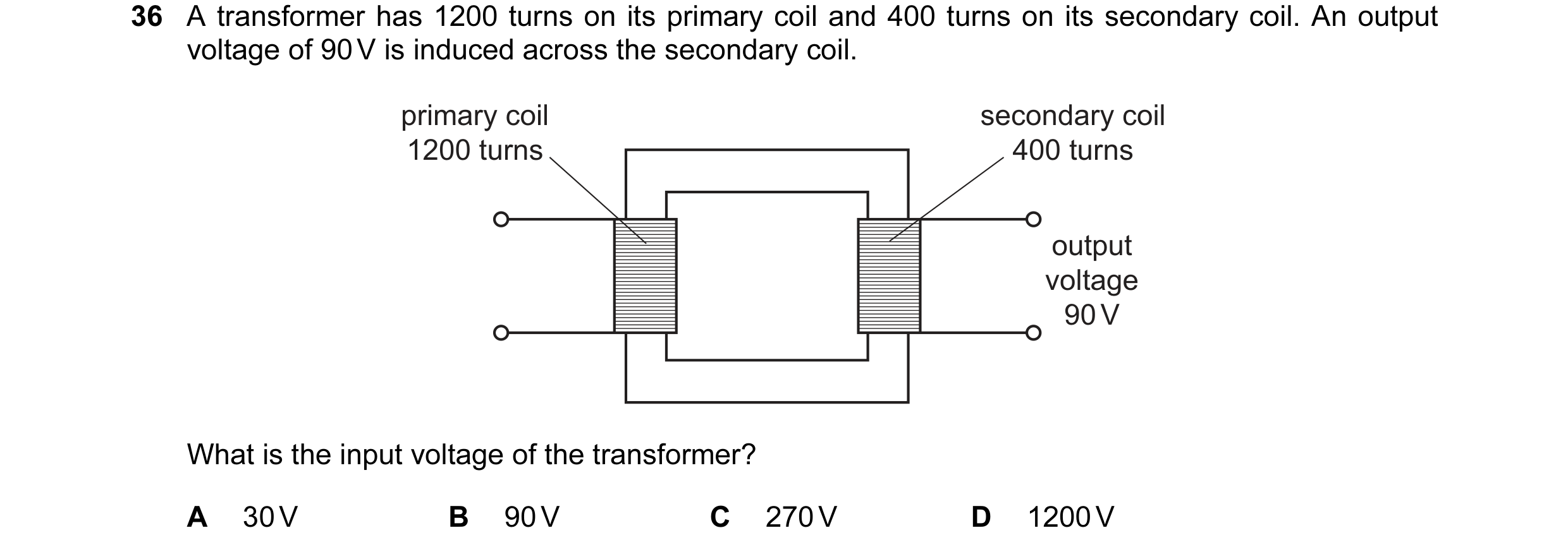
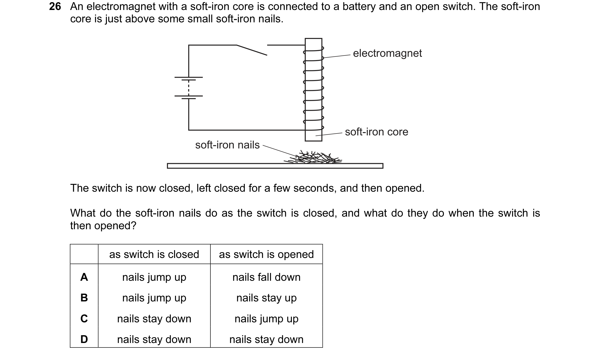 41 / 108
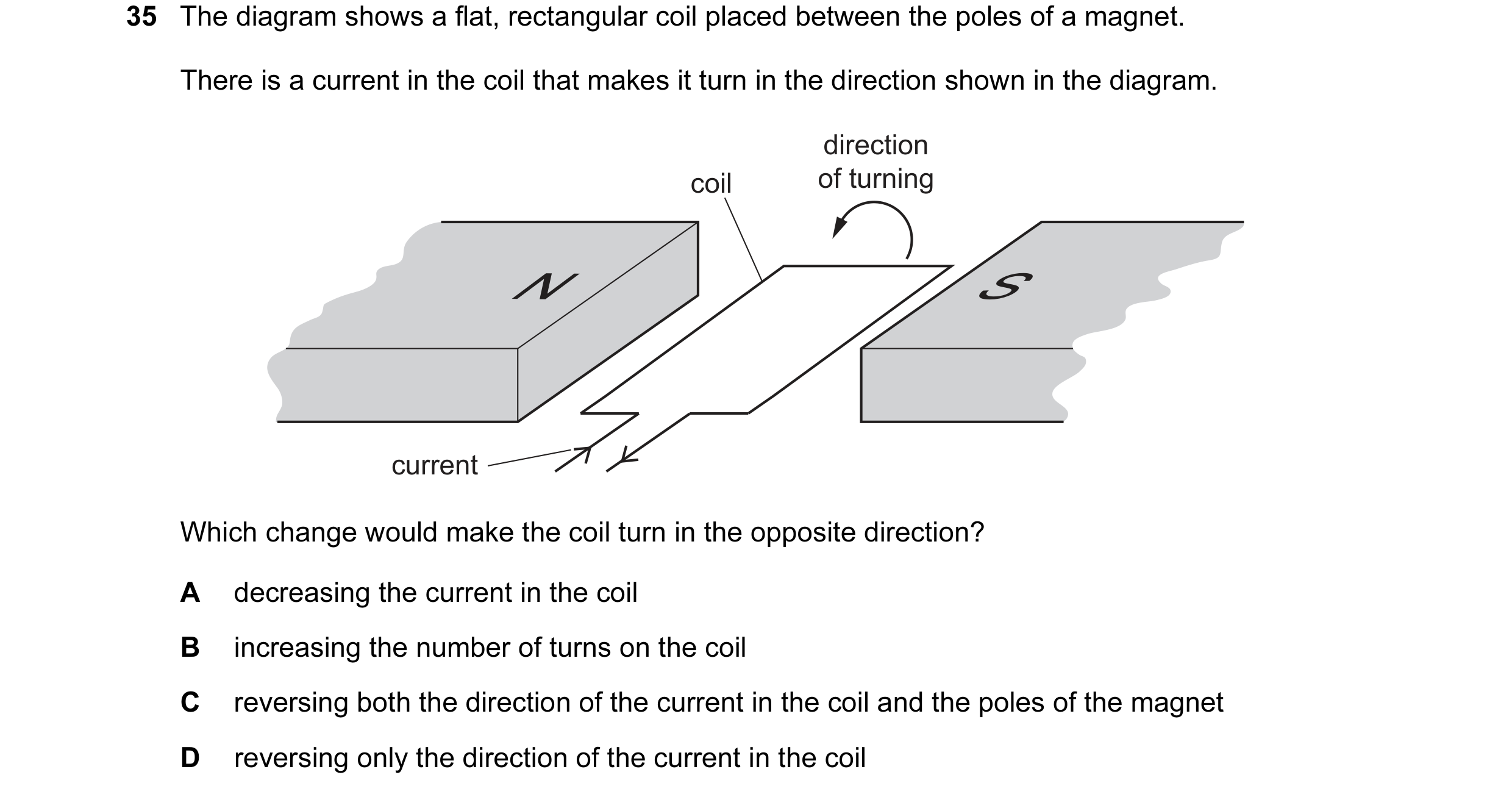
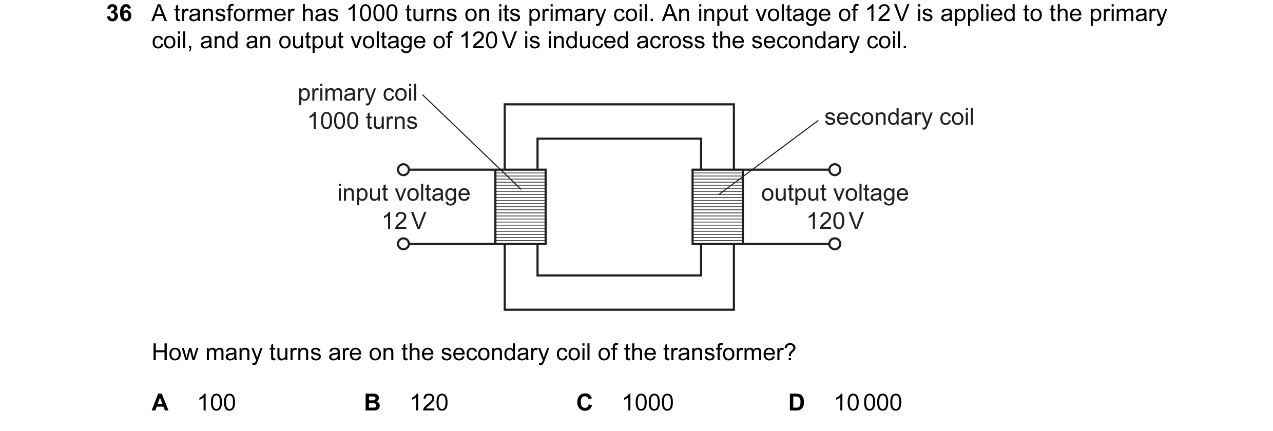 42 / 108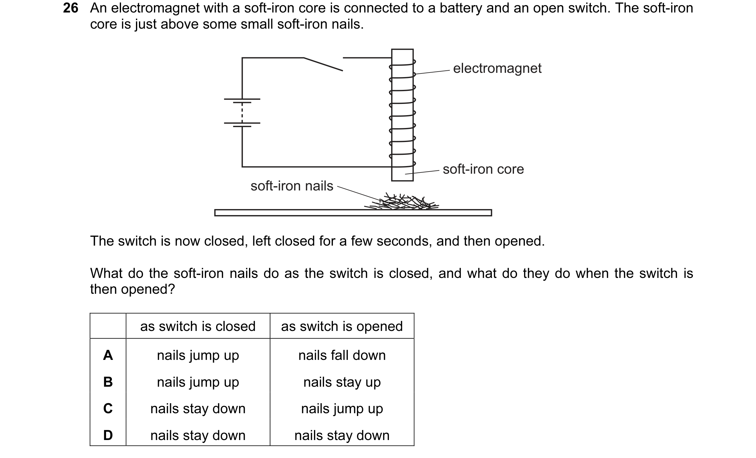
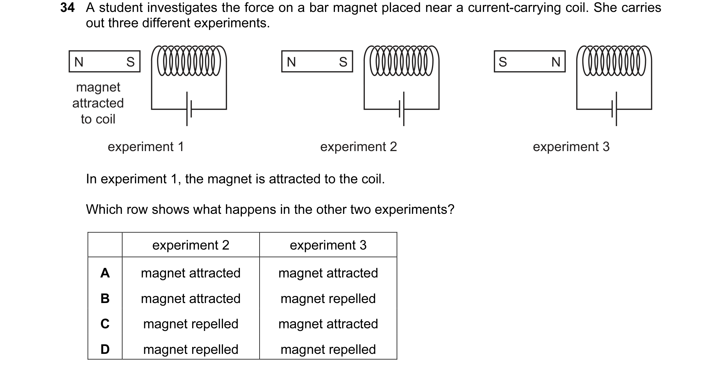 43 / 108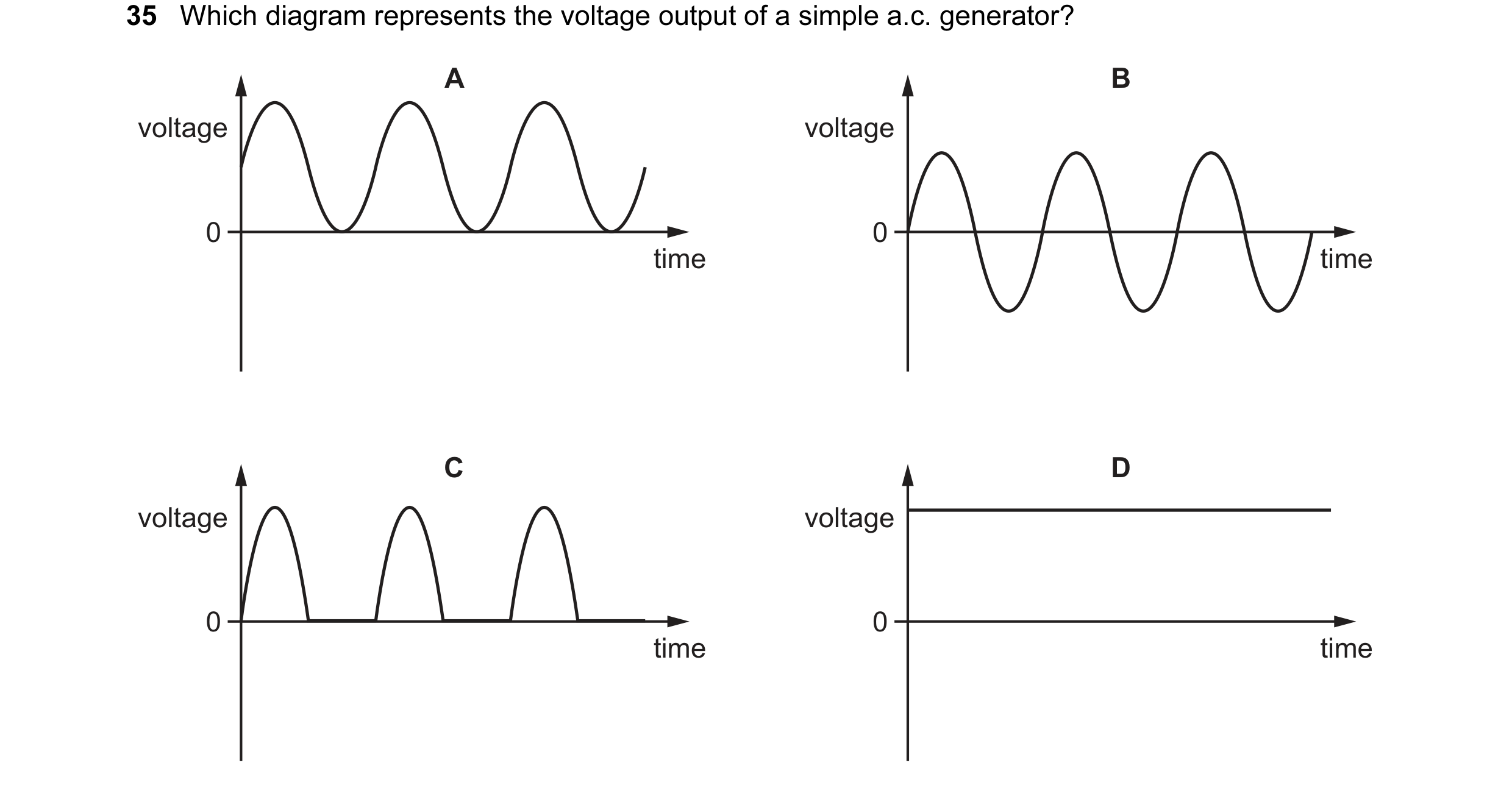
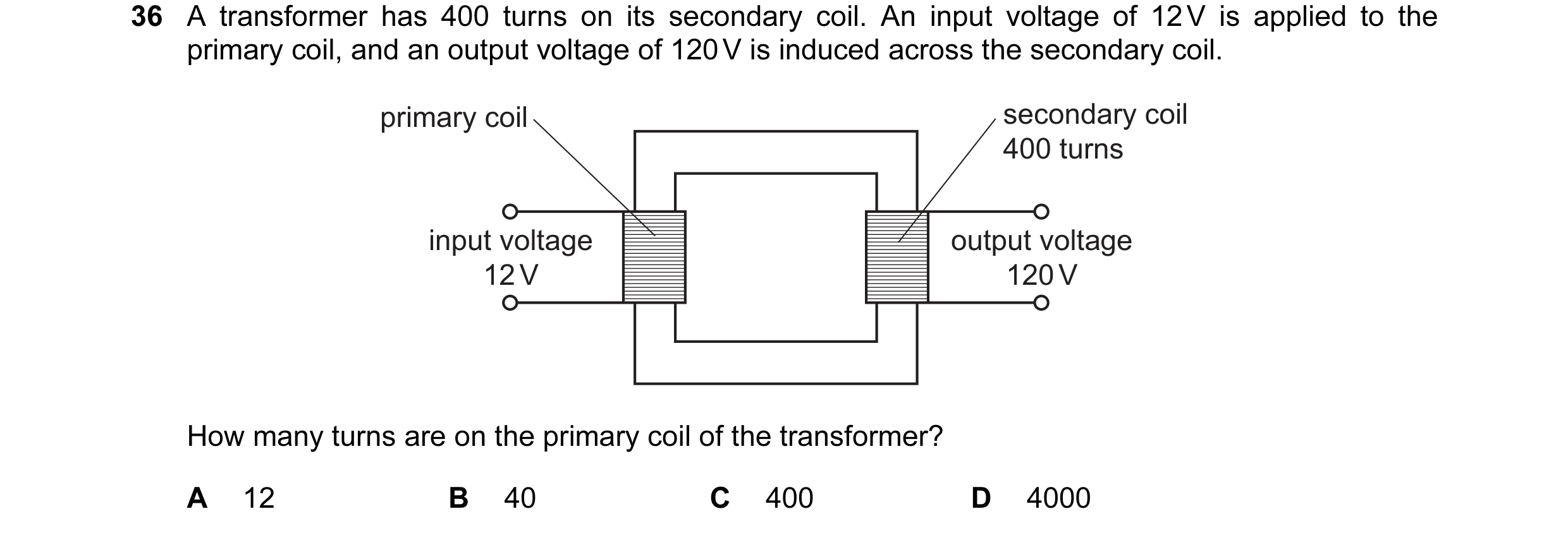
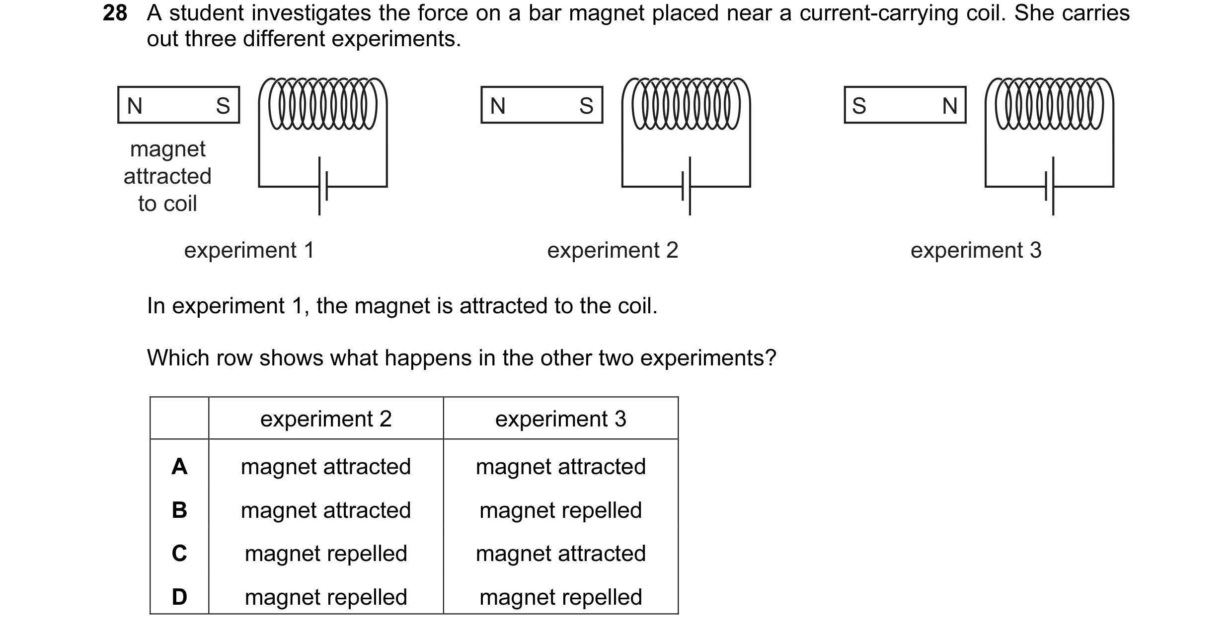 44 / 108
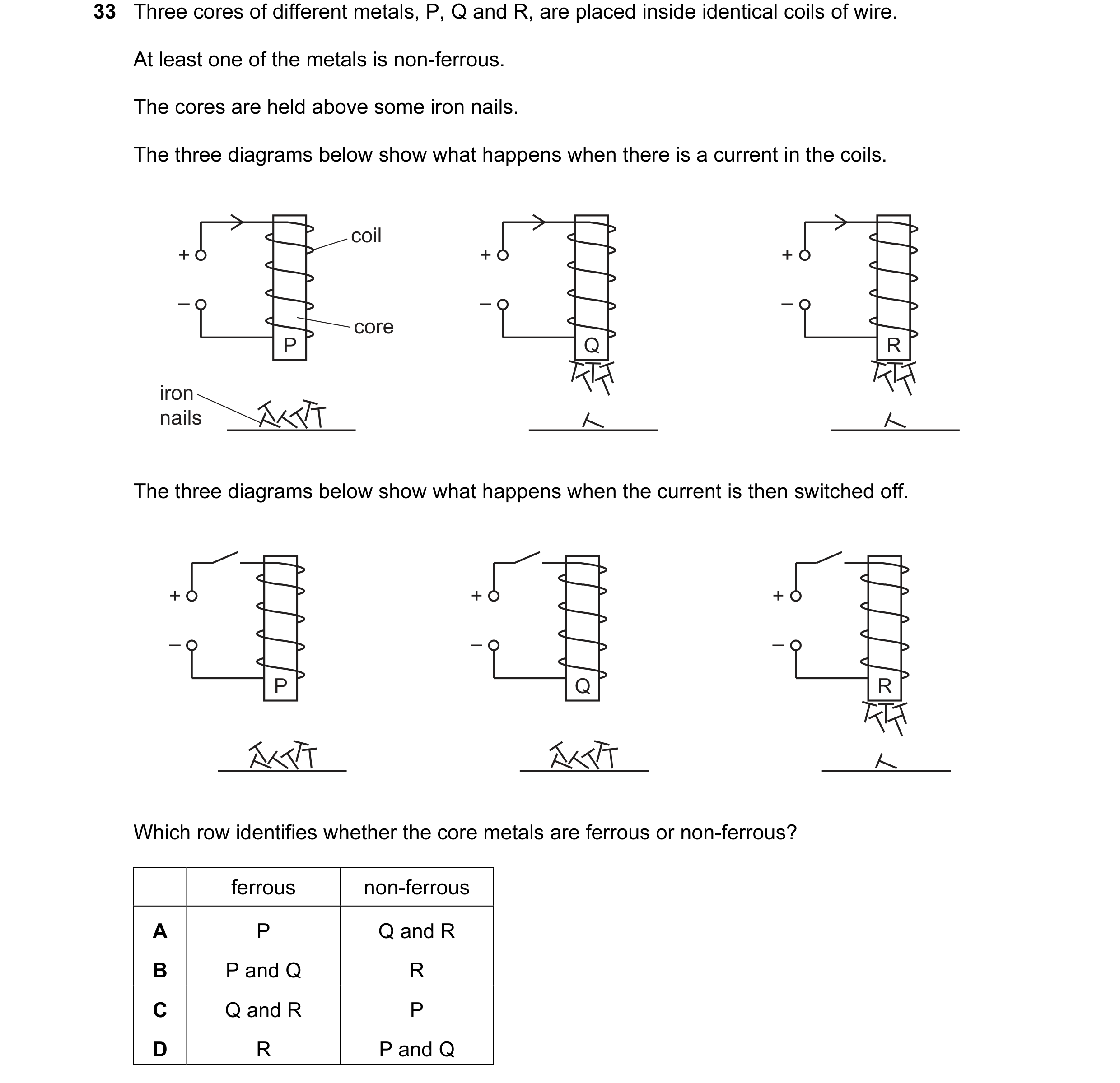 45 / 108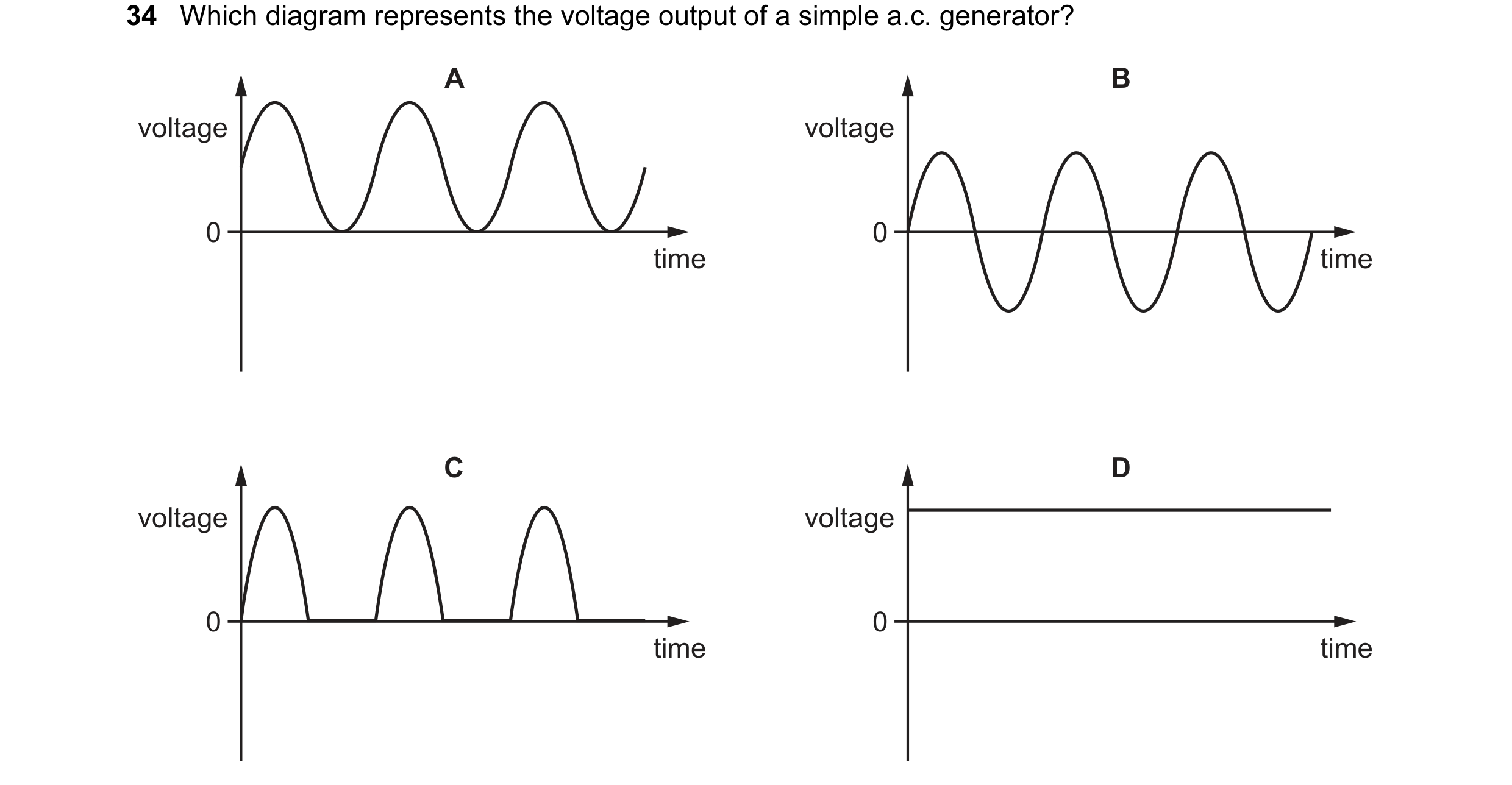
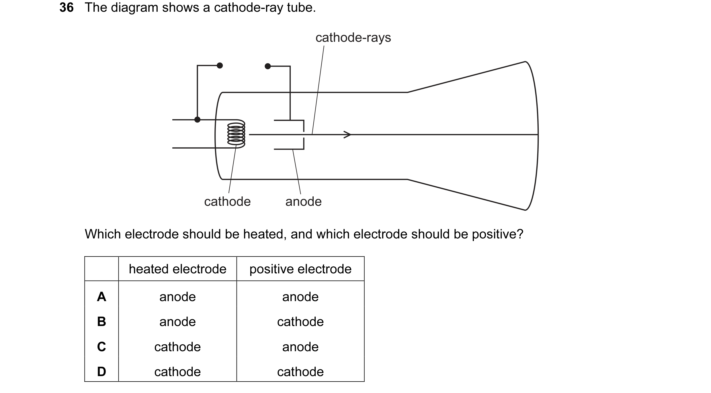
 46 / 108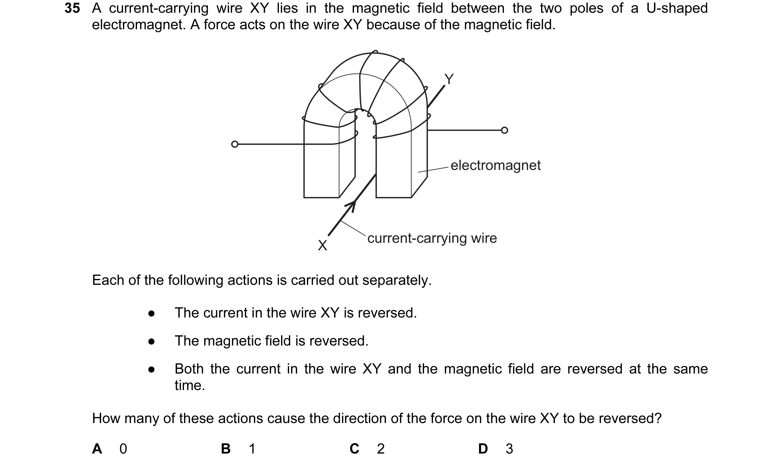
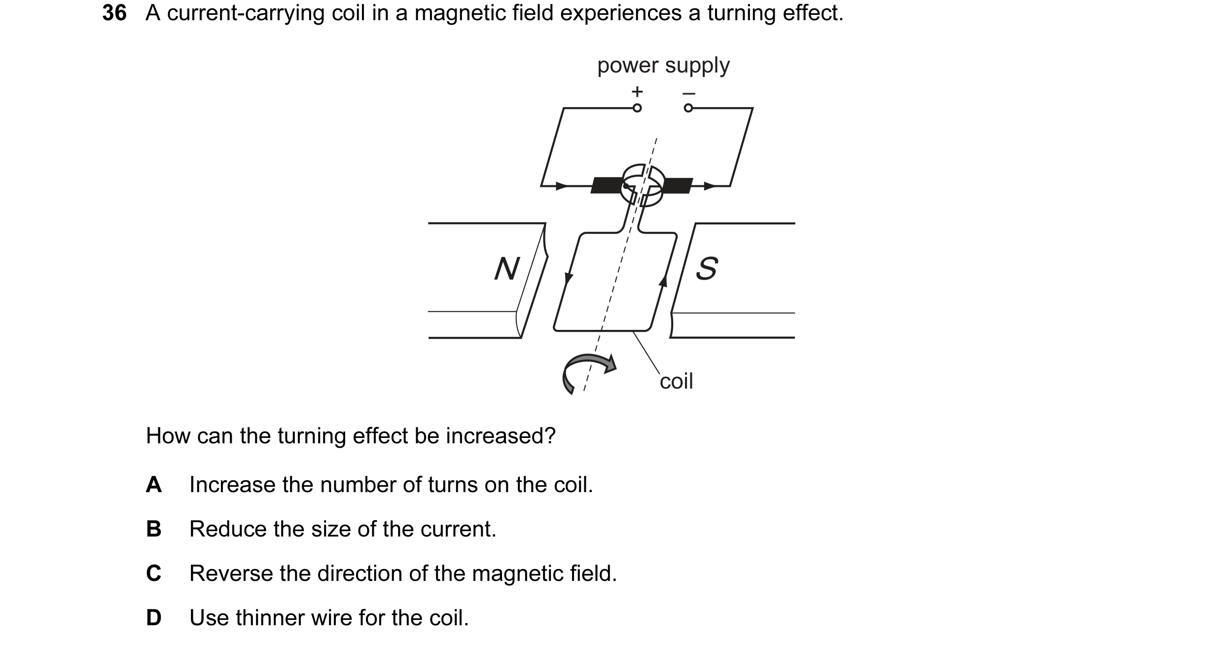 47 / 108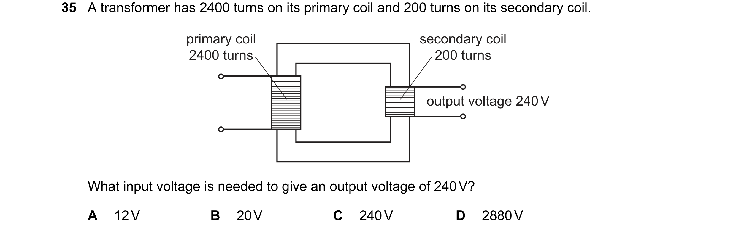
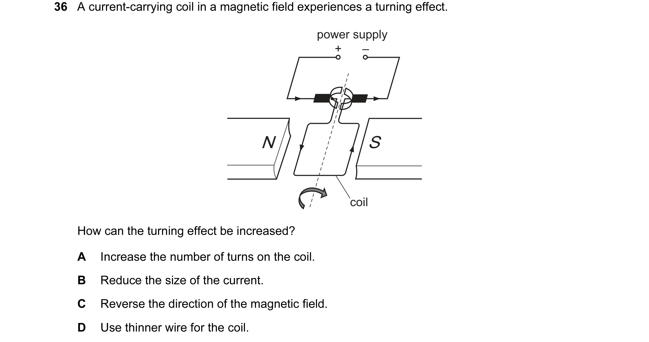
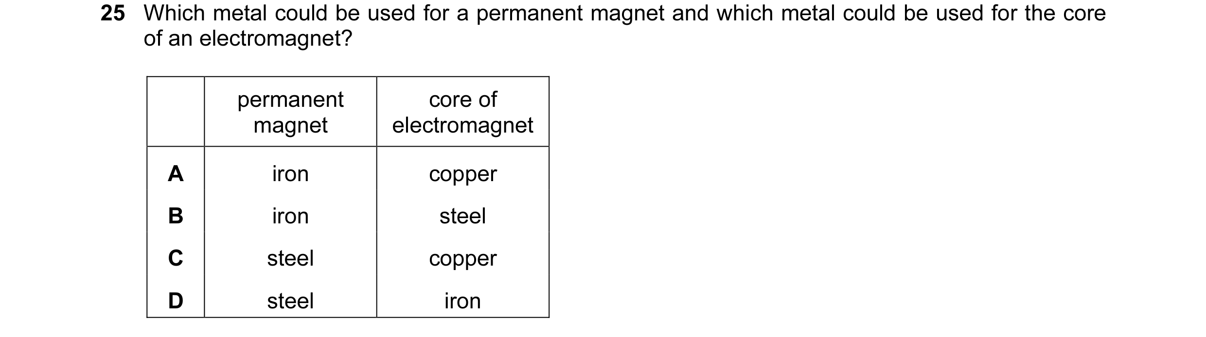 48 / 108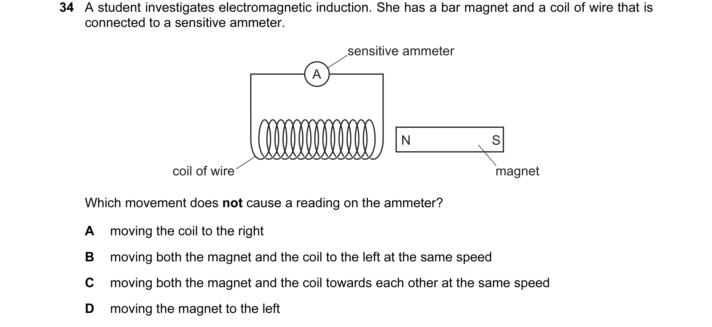
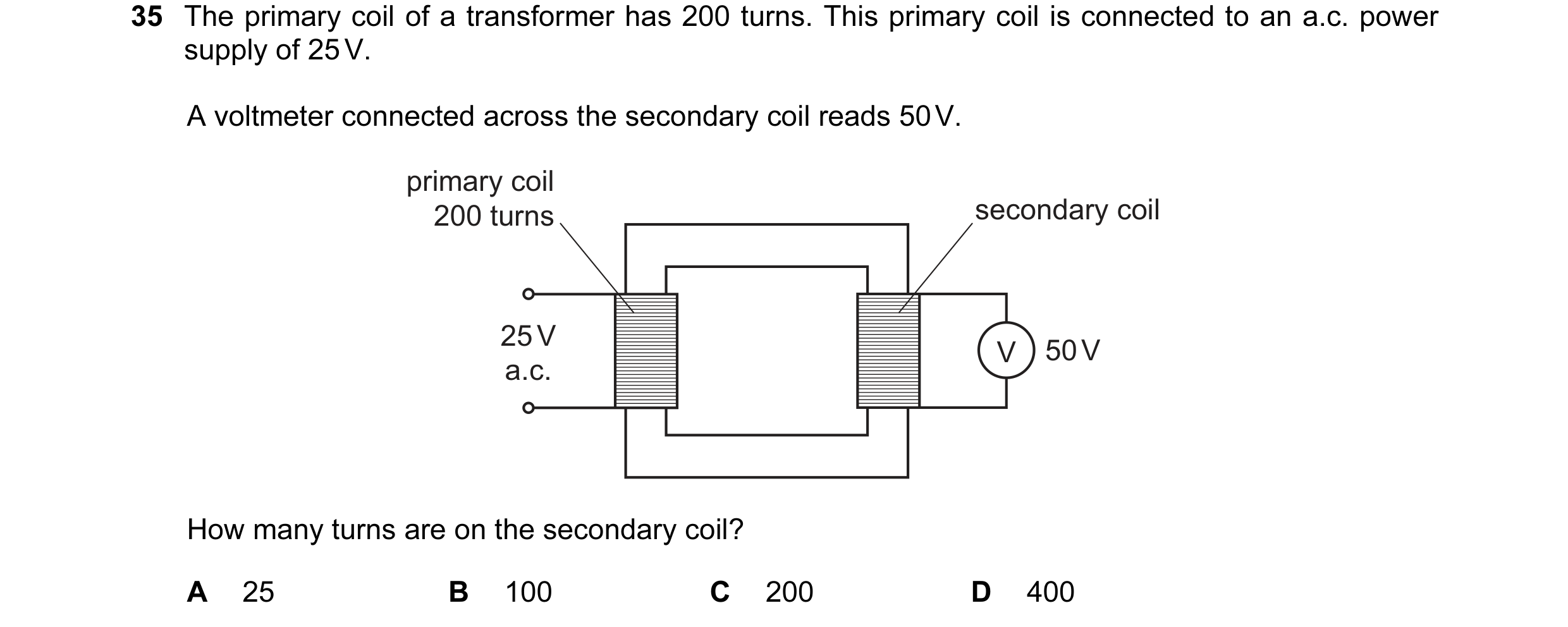 49 / 108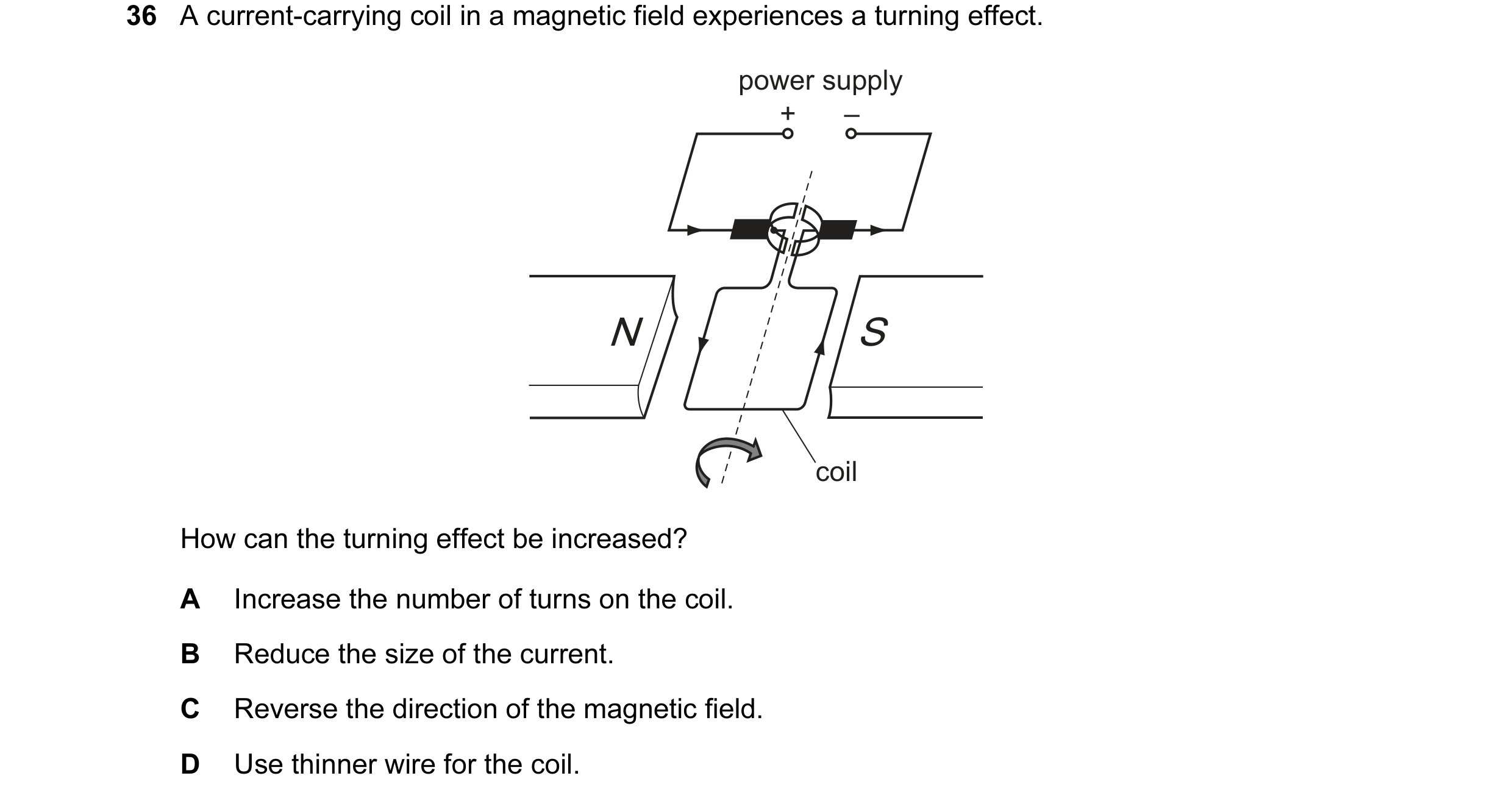
 50 / 108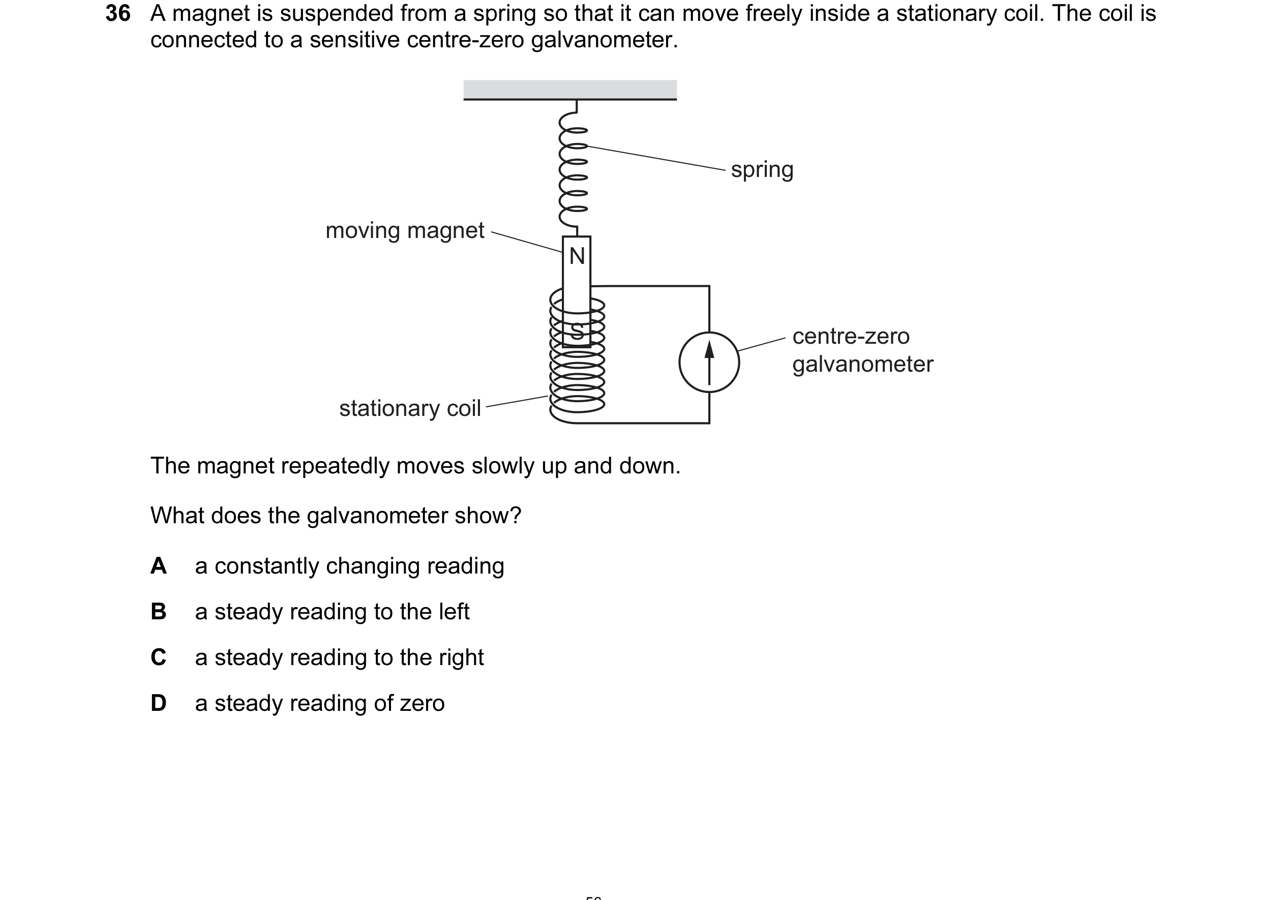

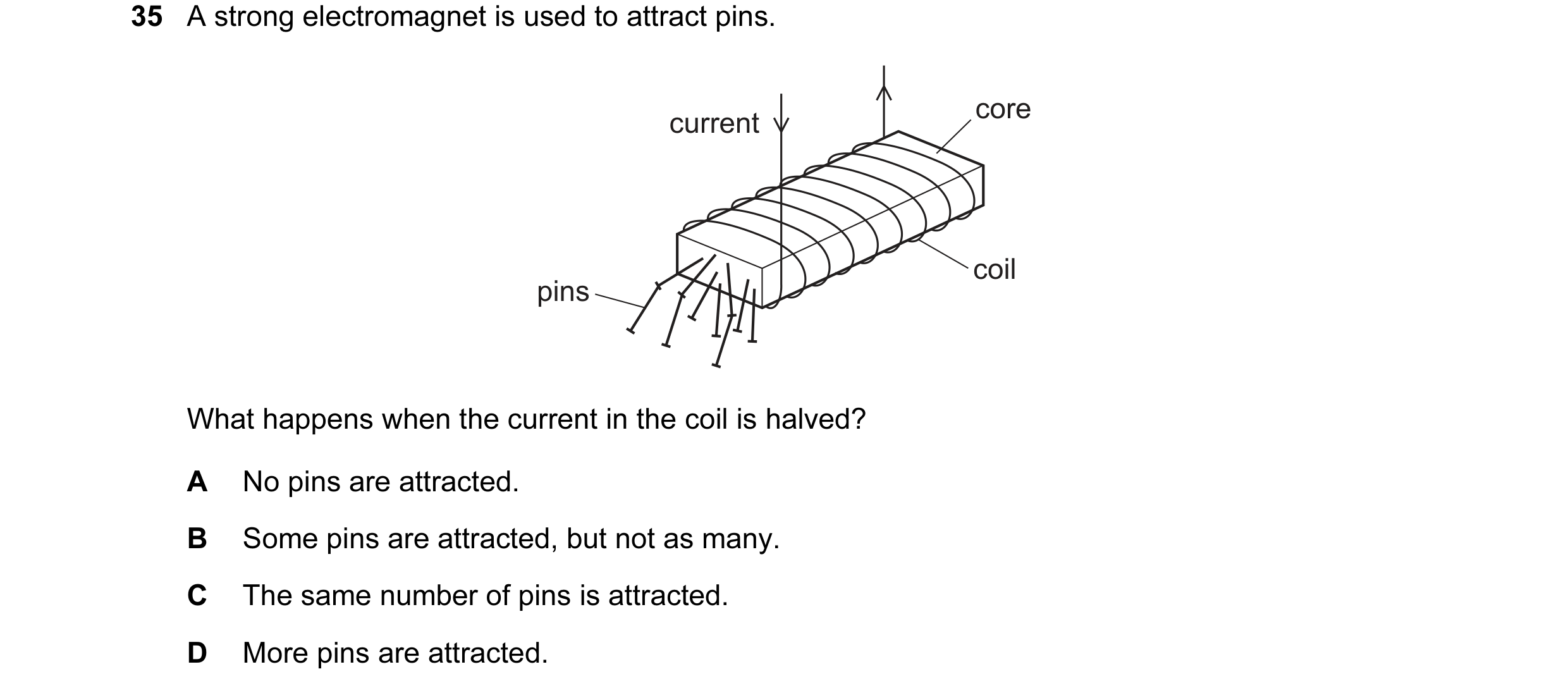 51 / 108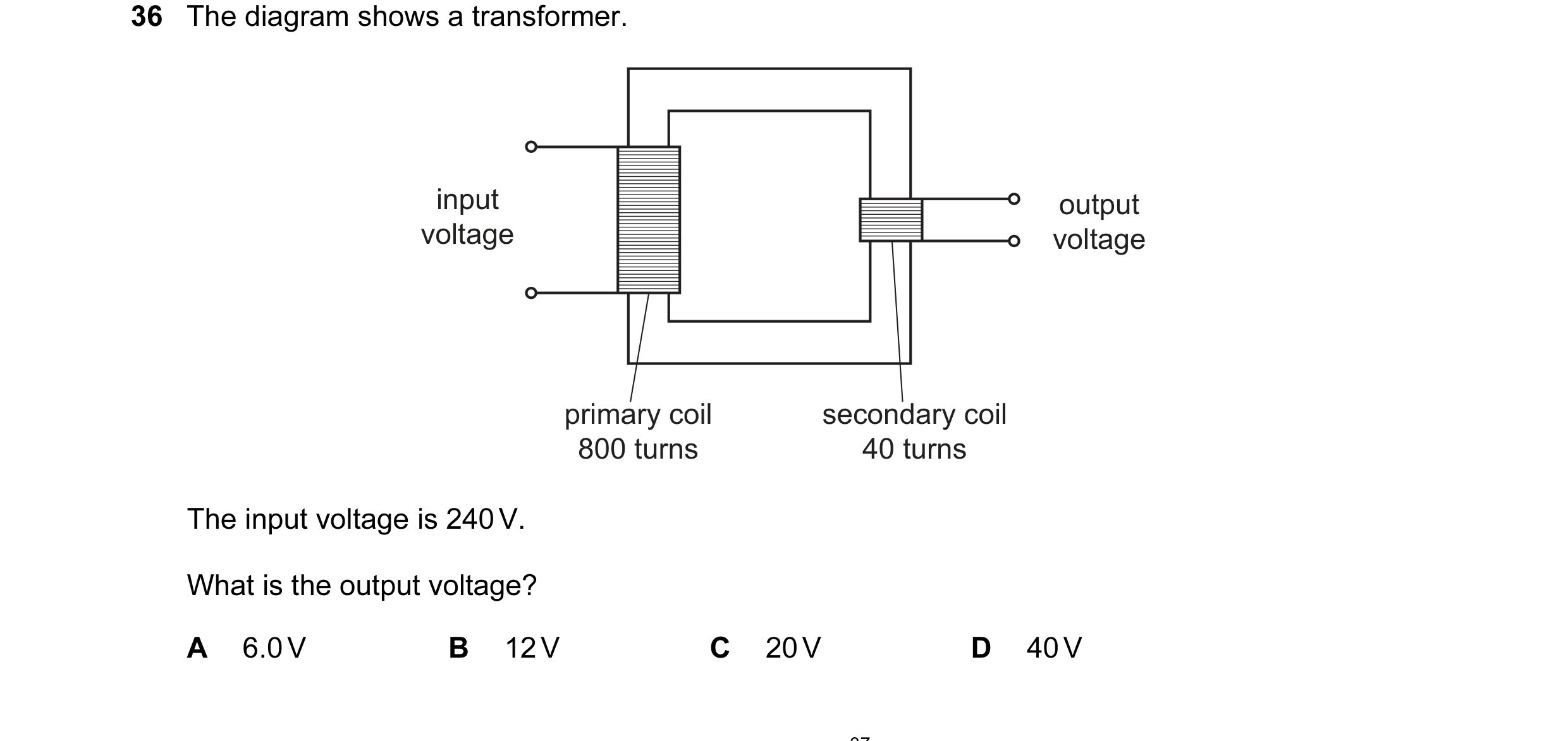
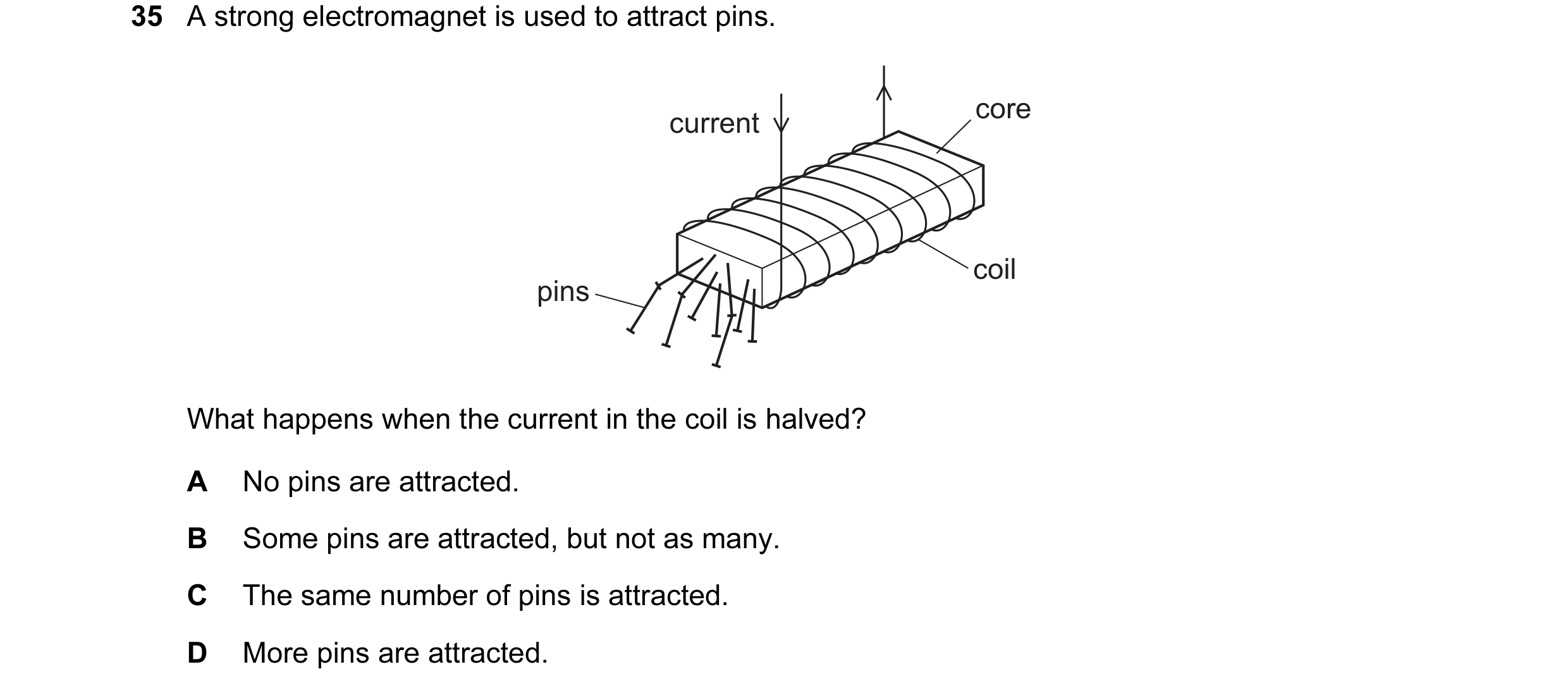
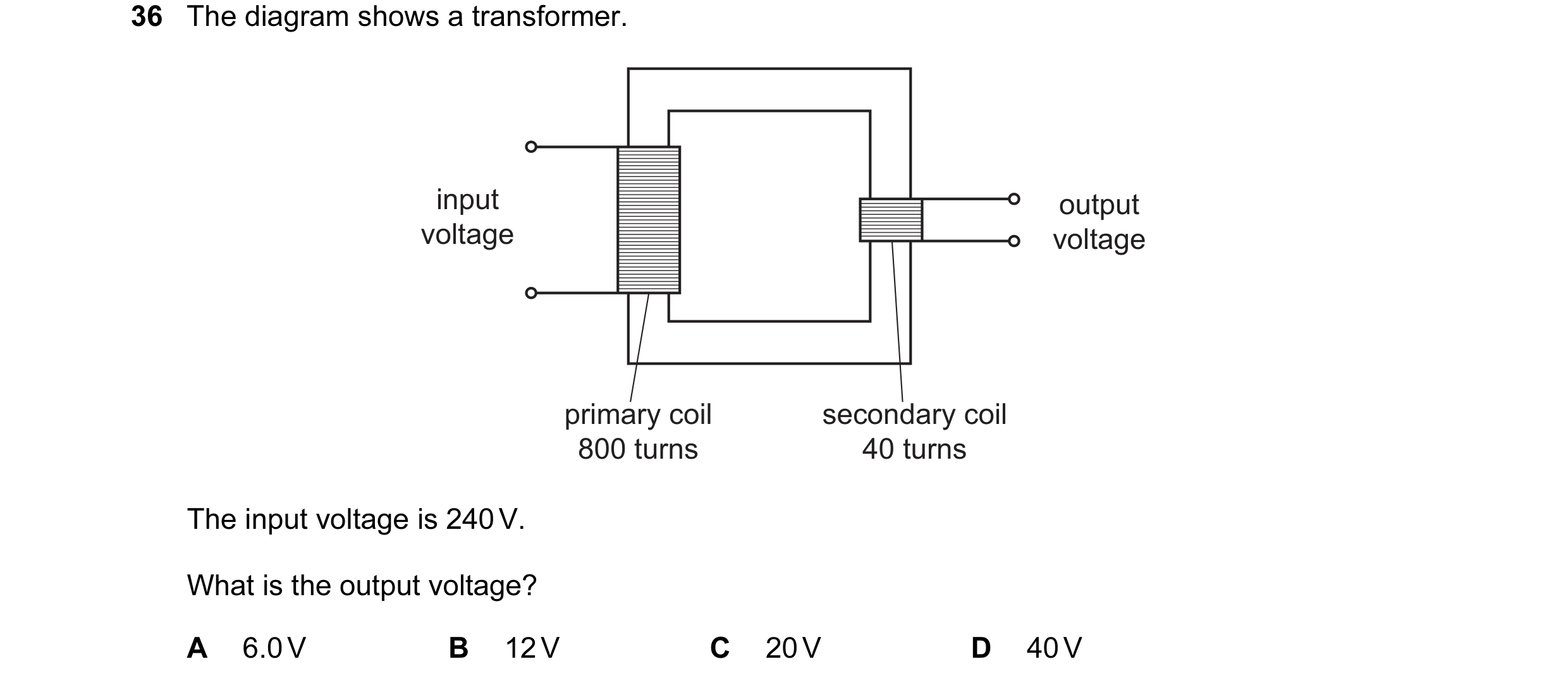 52 / 108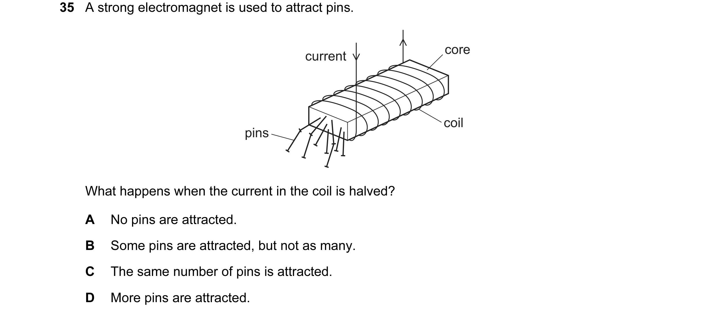
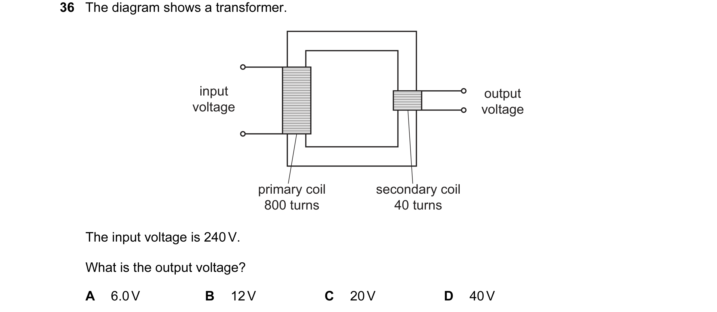 53 / 108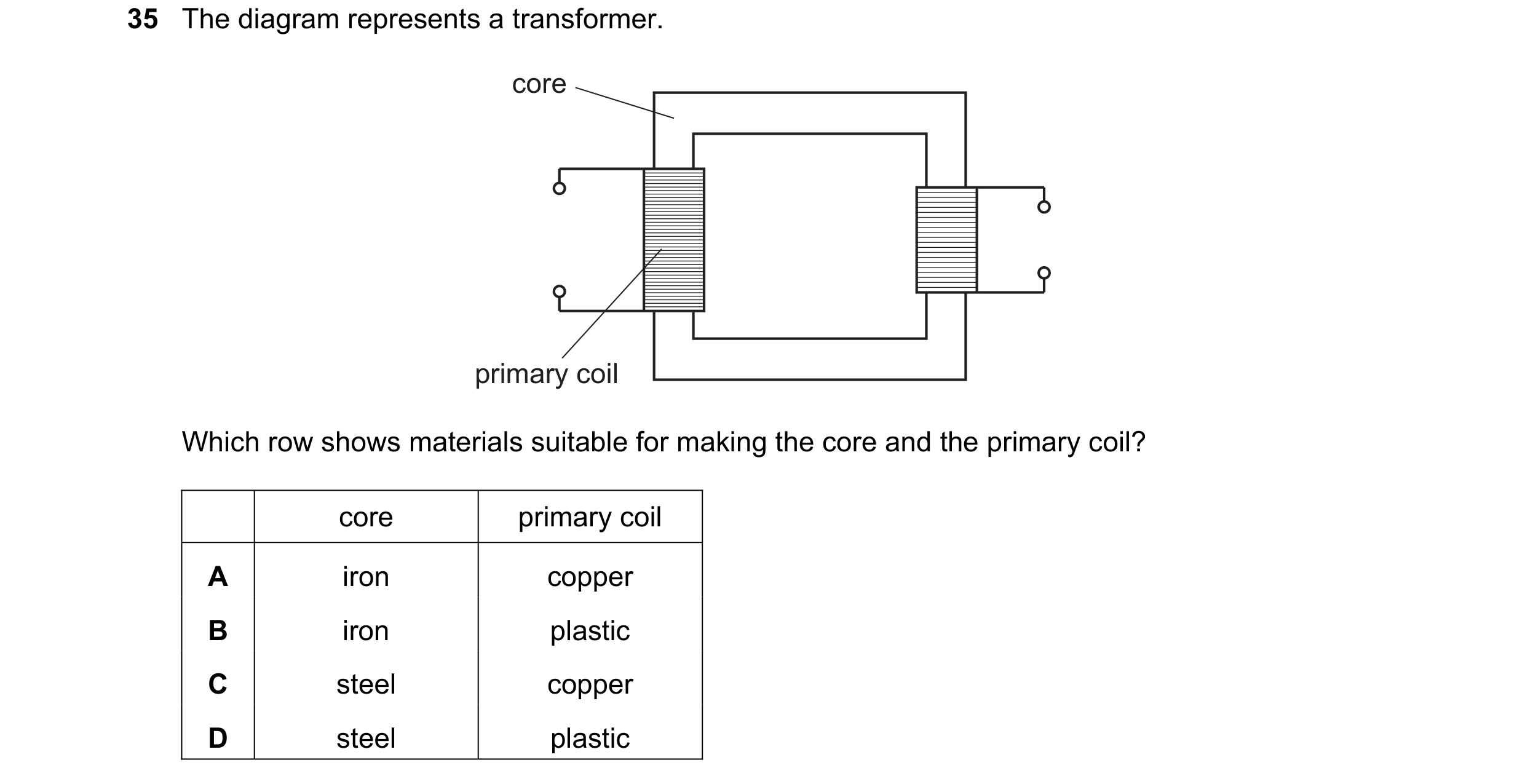
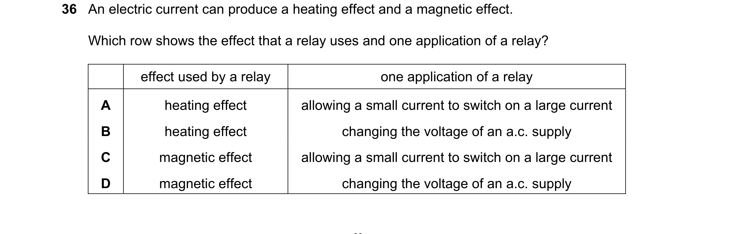
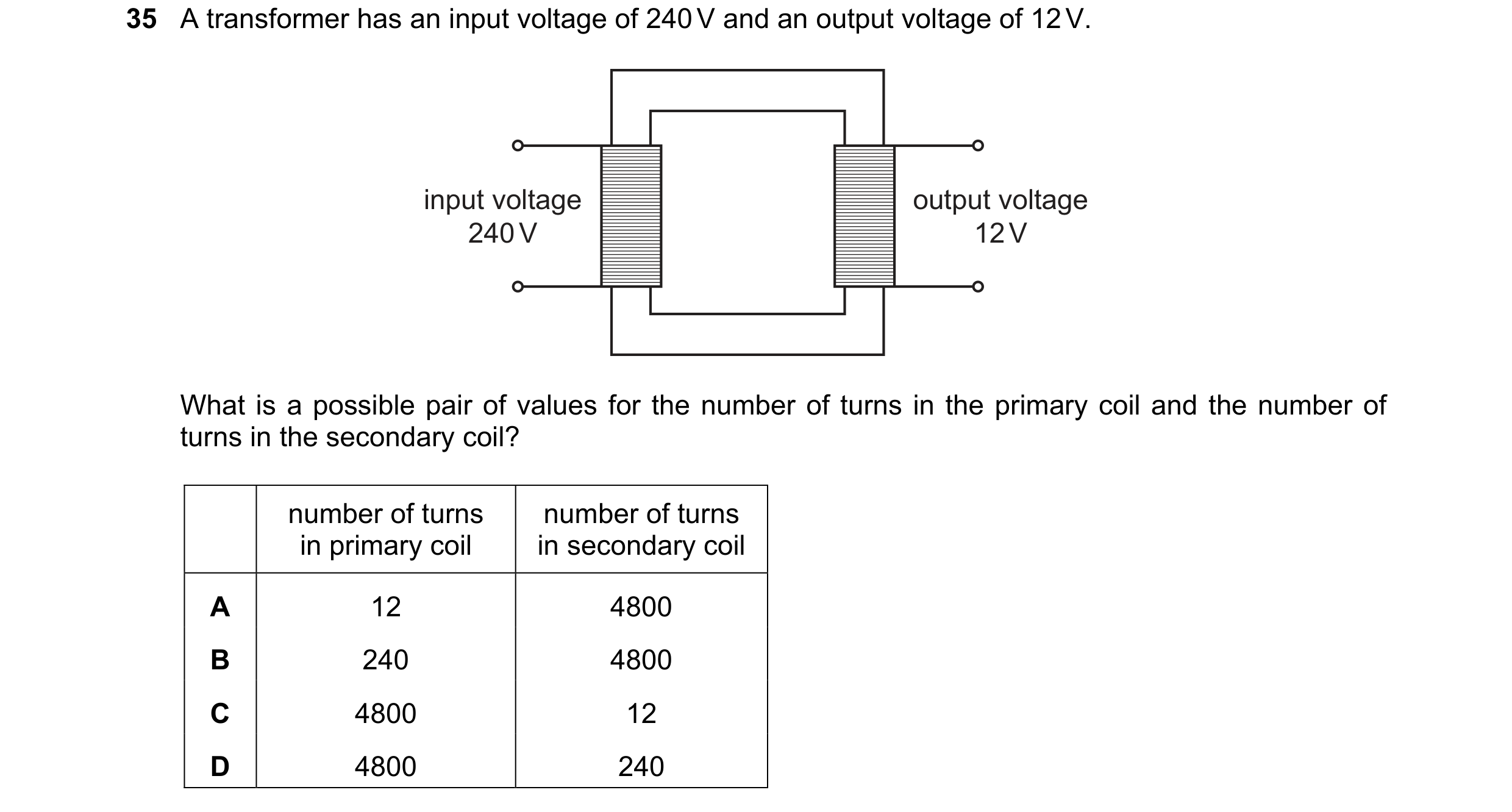 54 / 108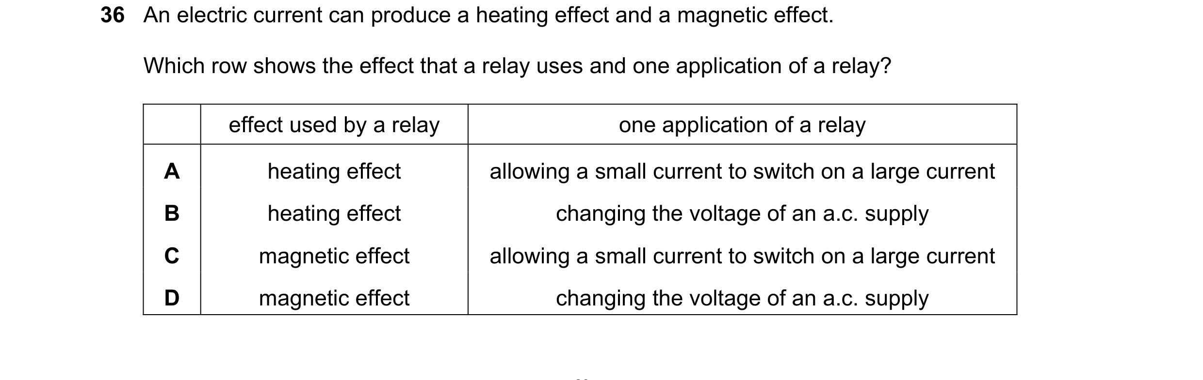
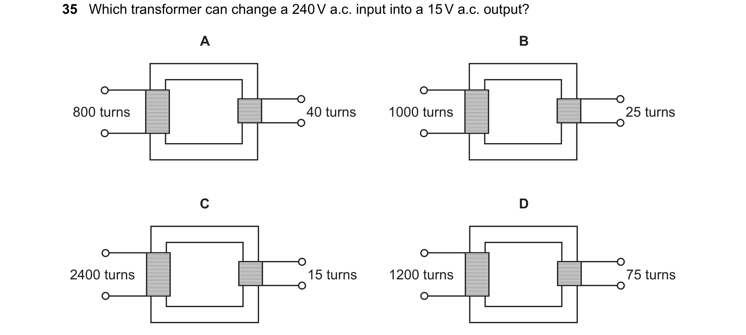
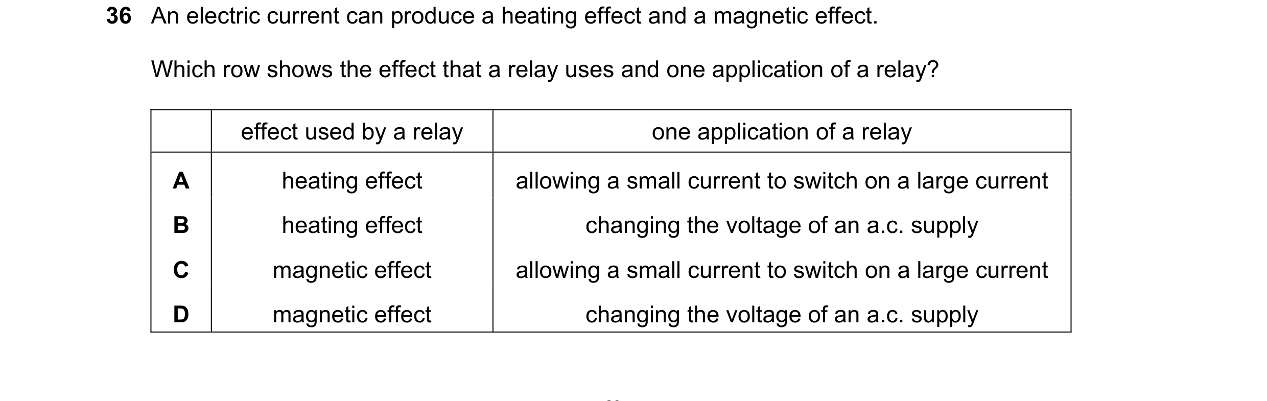 55 / 108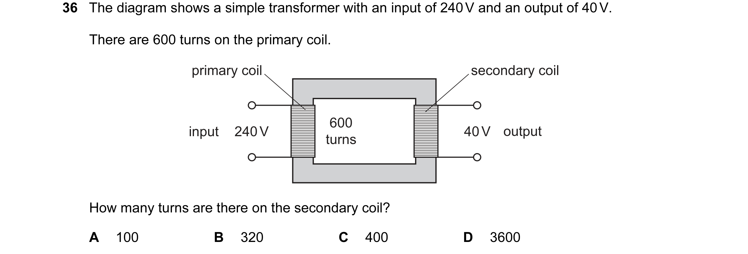
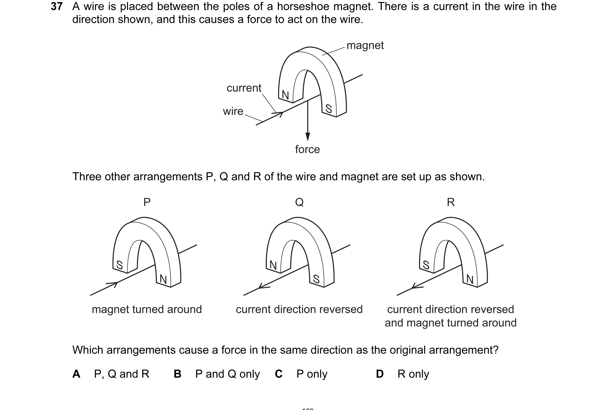 56 / 108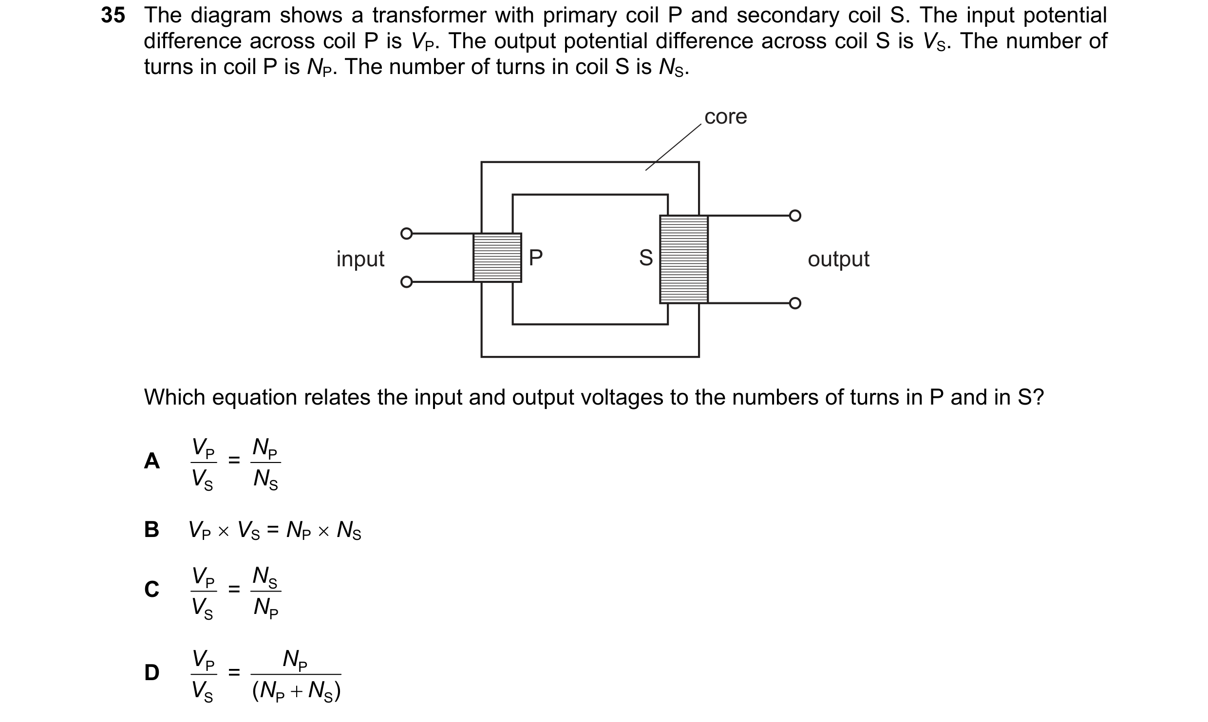


 57 / 108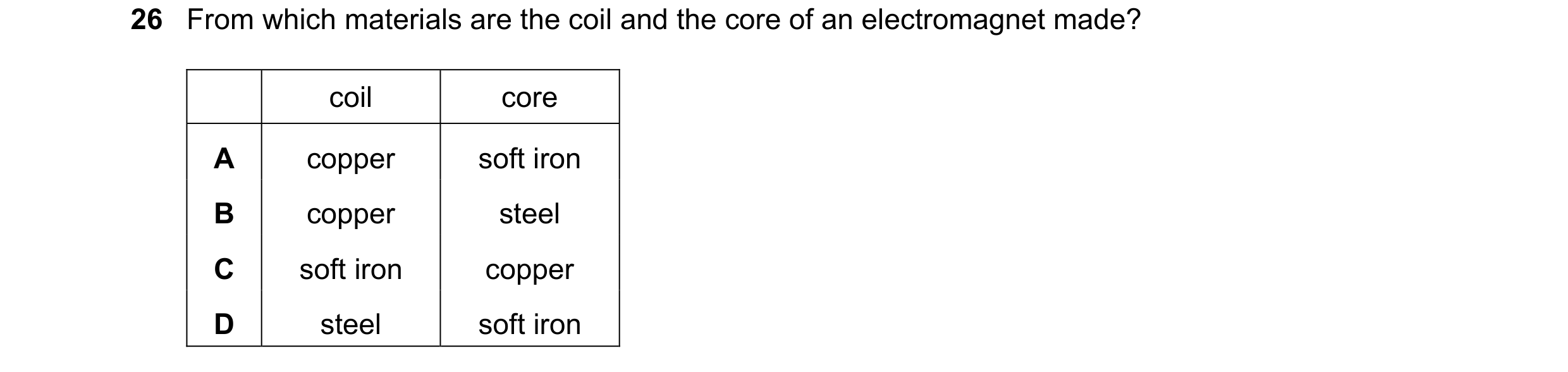
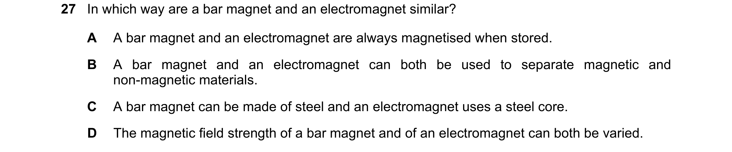
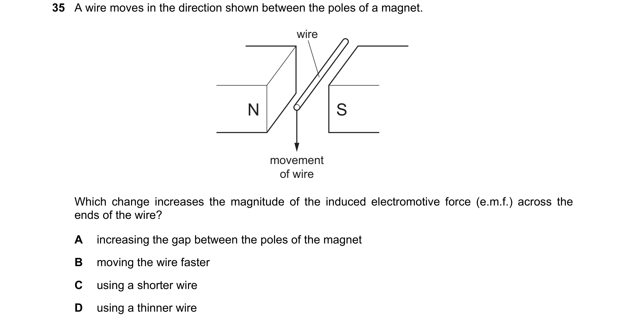
 58 / 108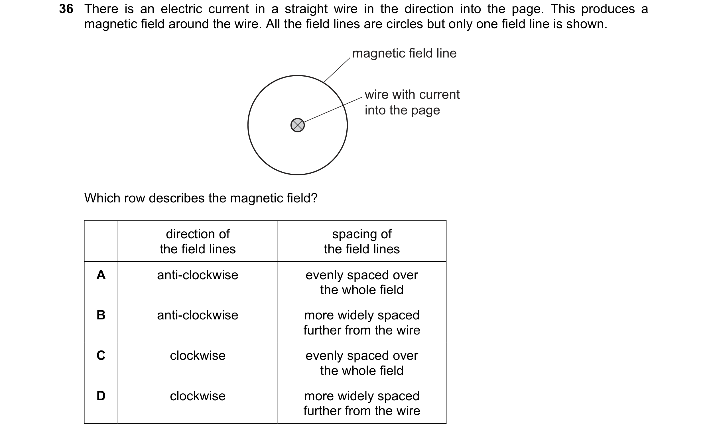
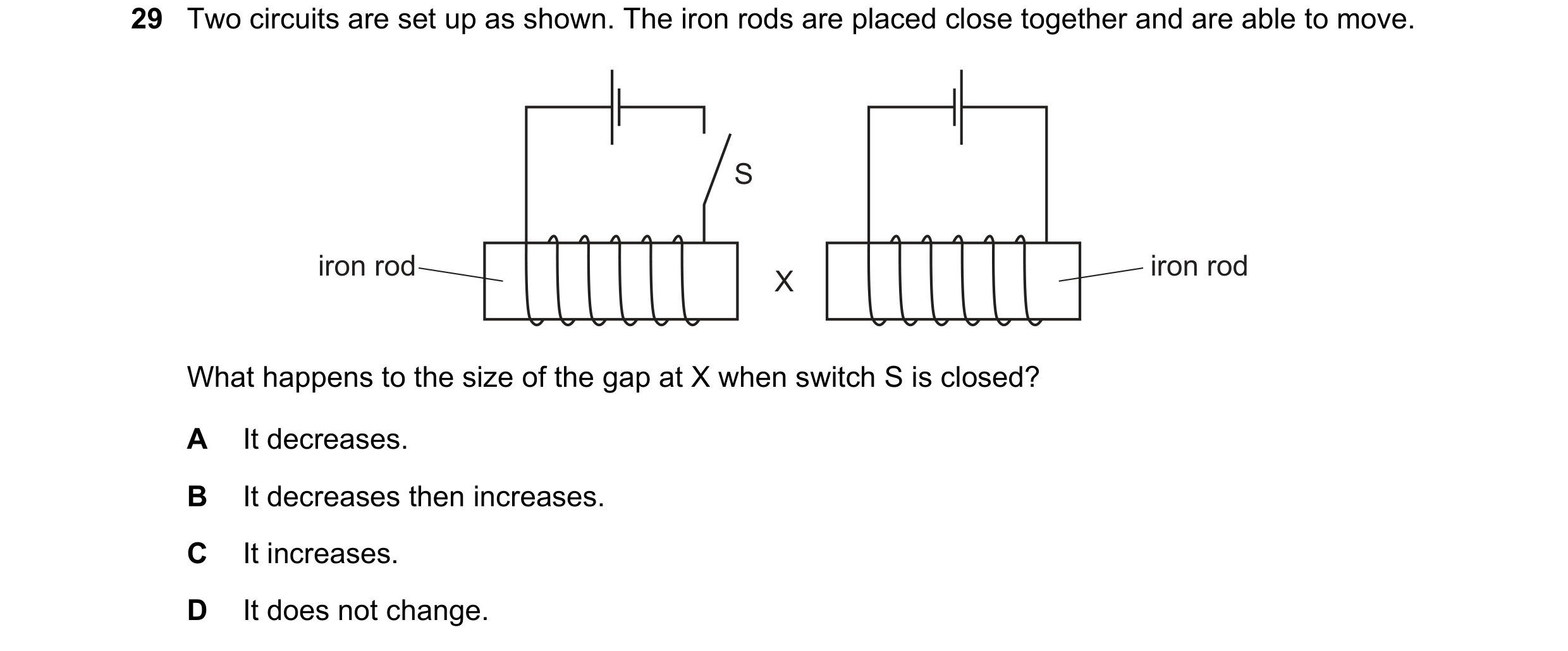 59 / 108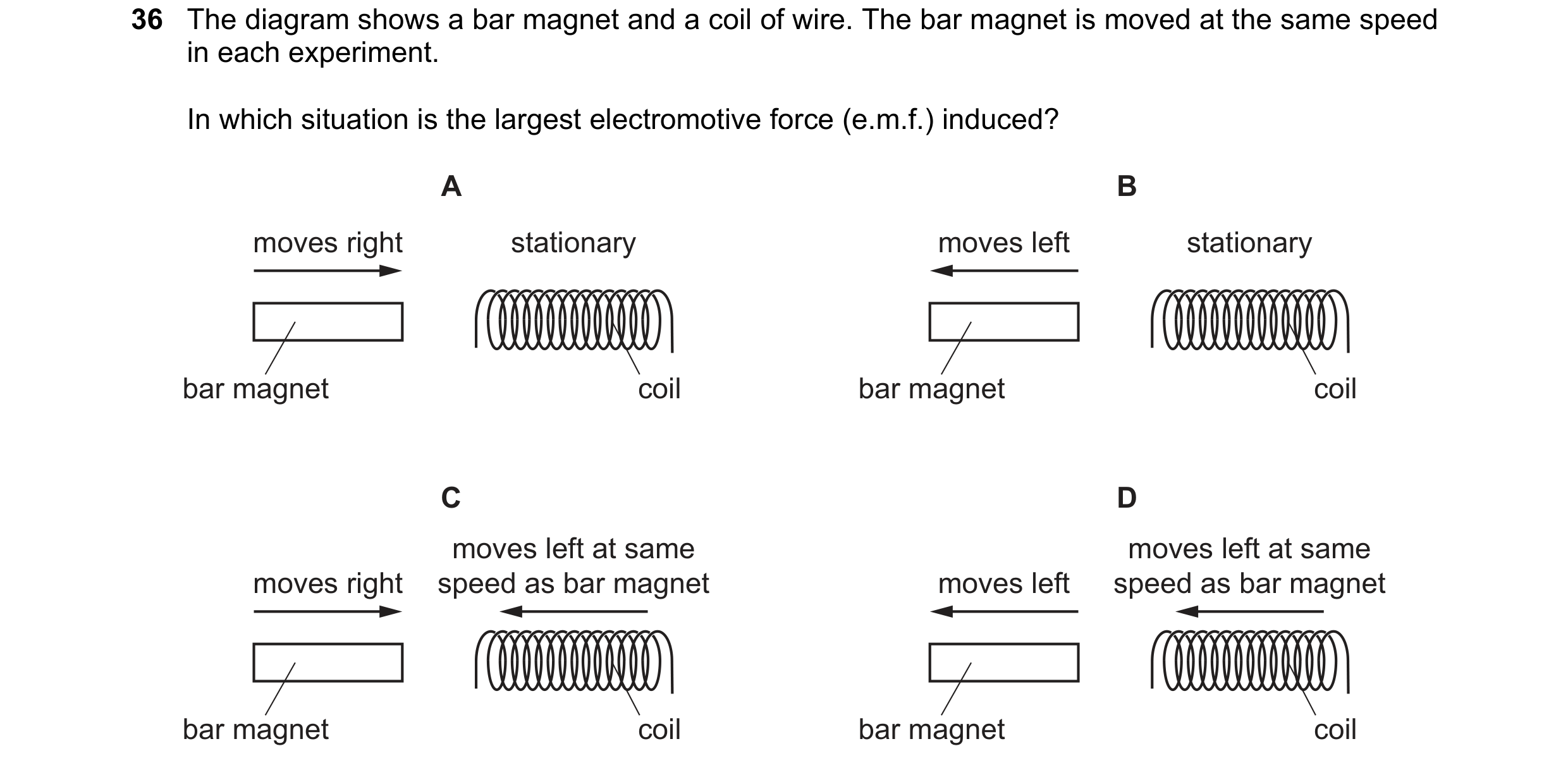
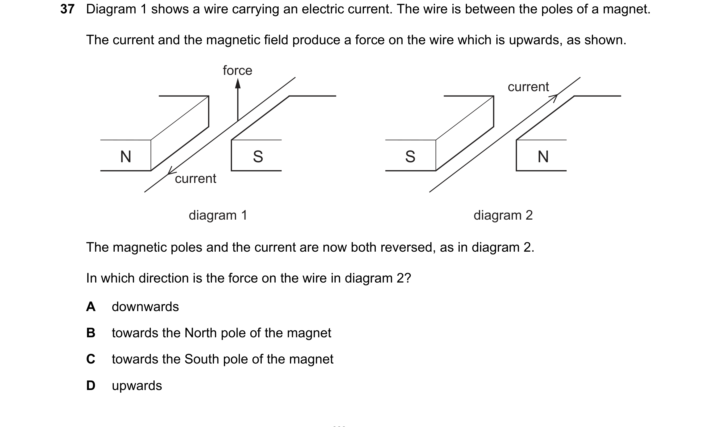 60 / 108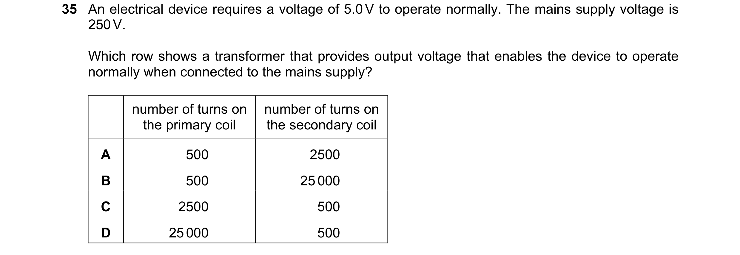
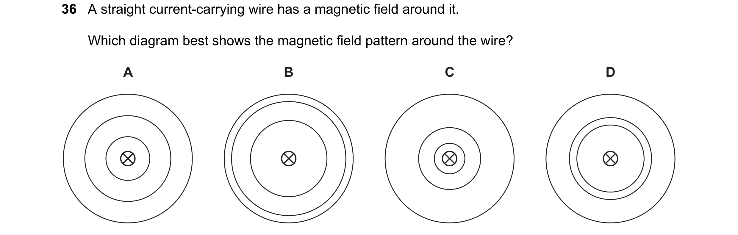
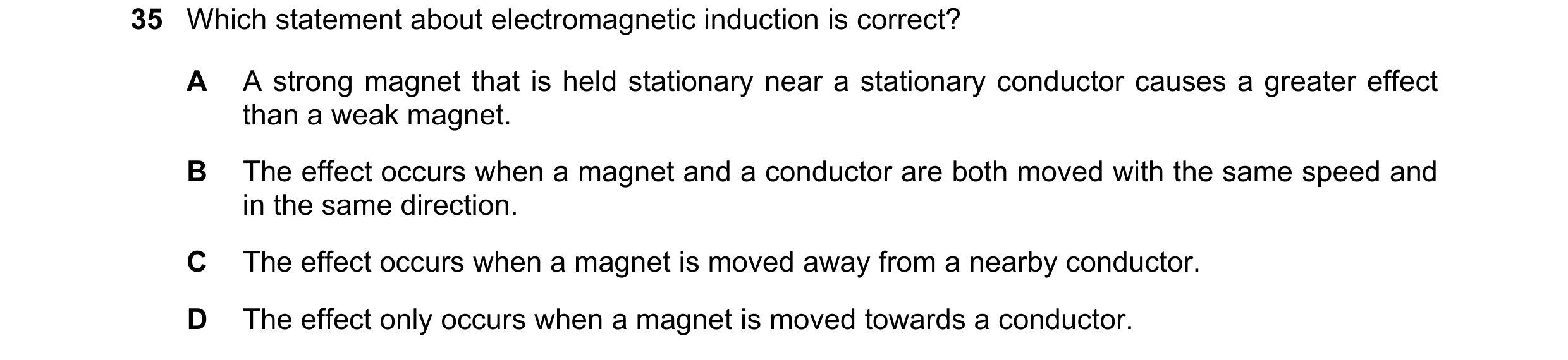
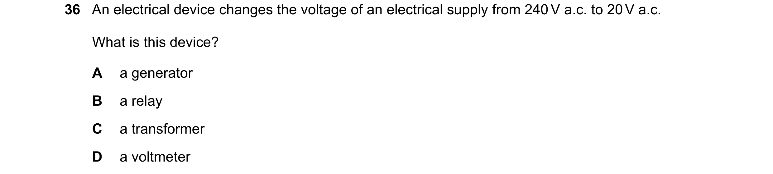 61 / 108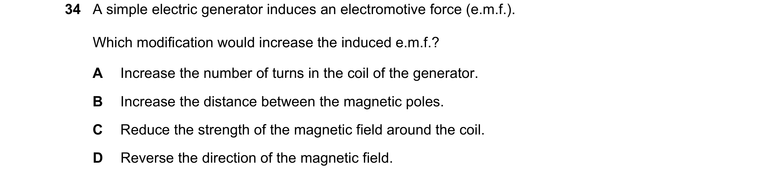
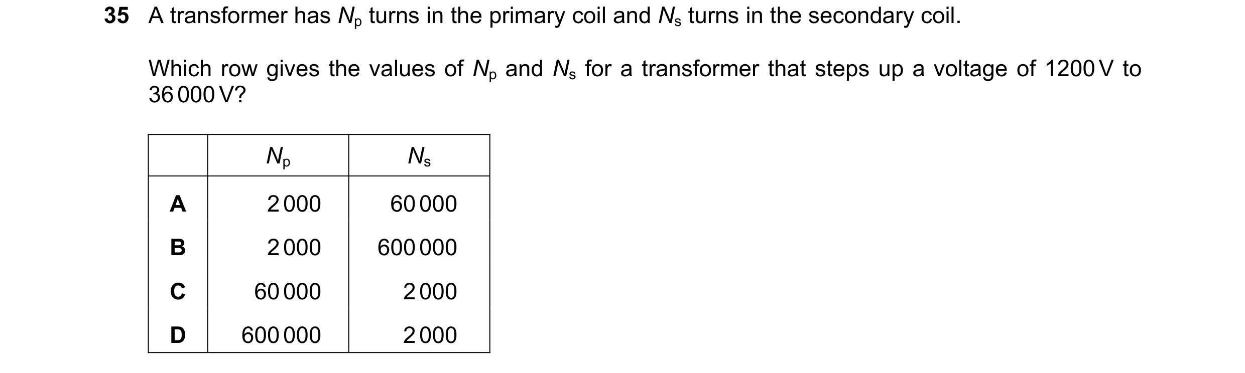
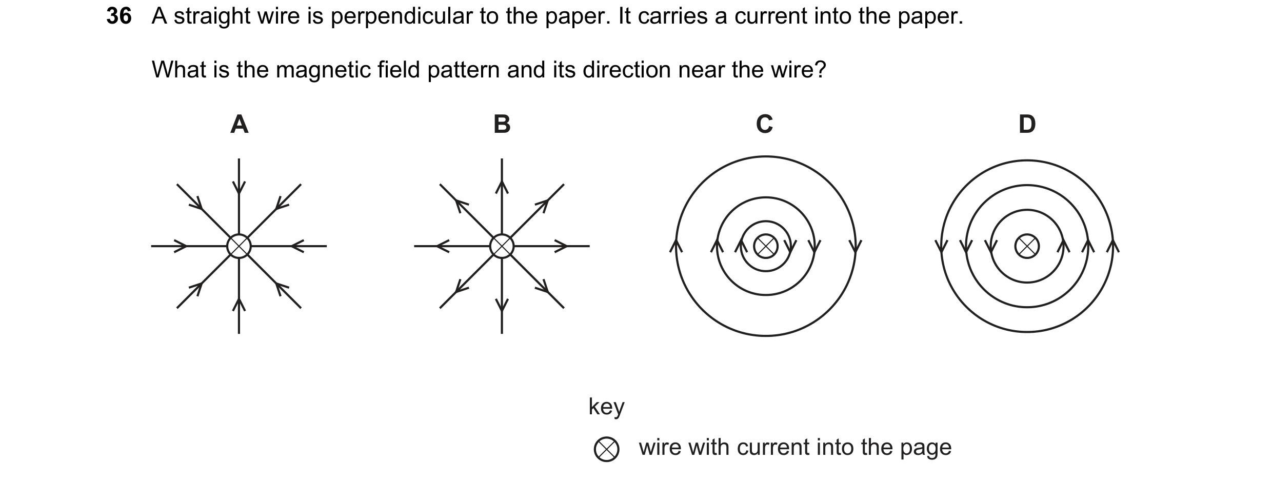 62 / 108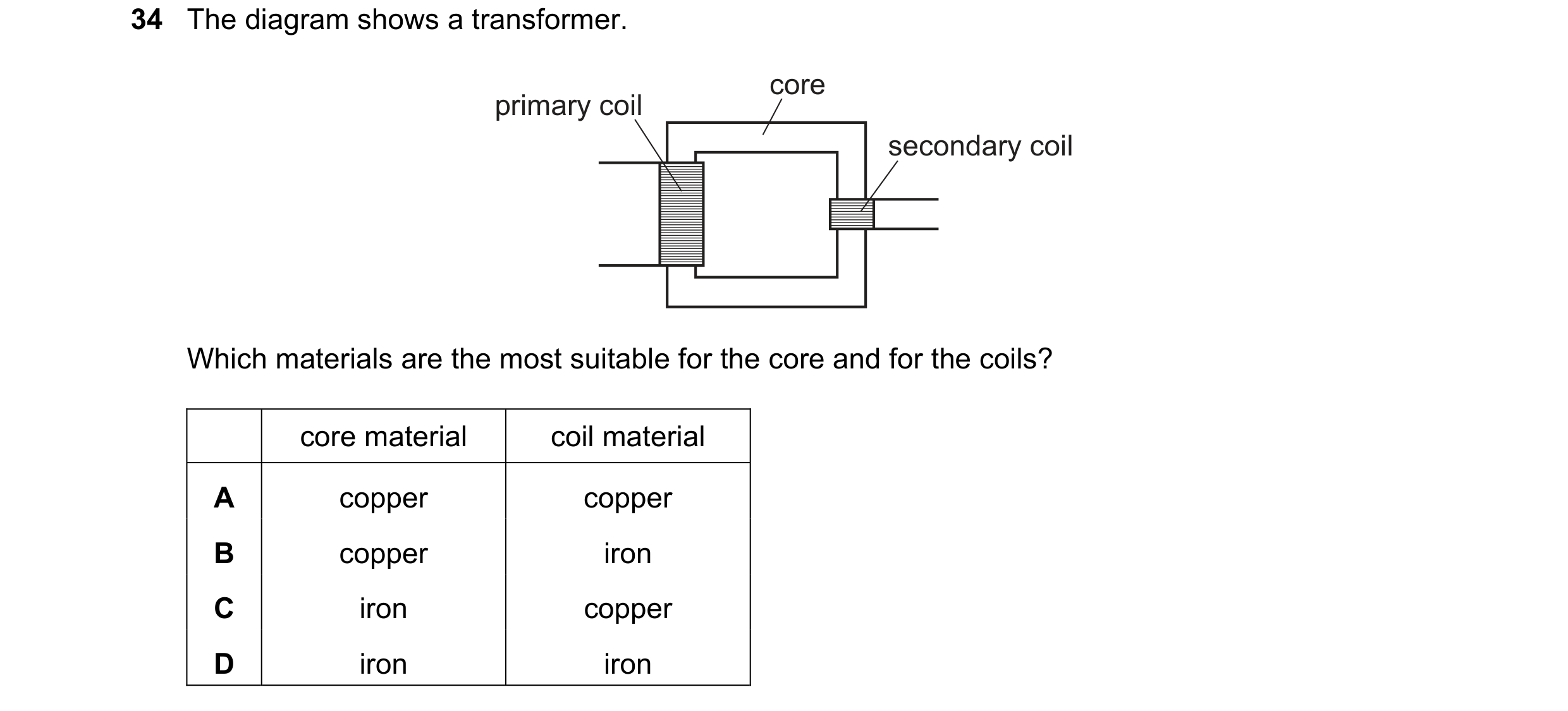
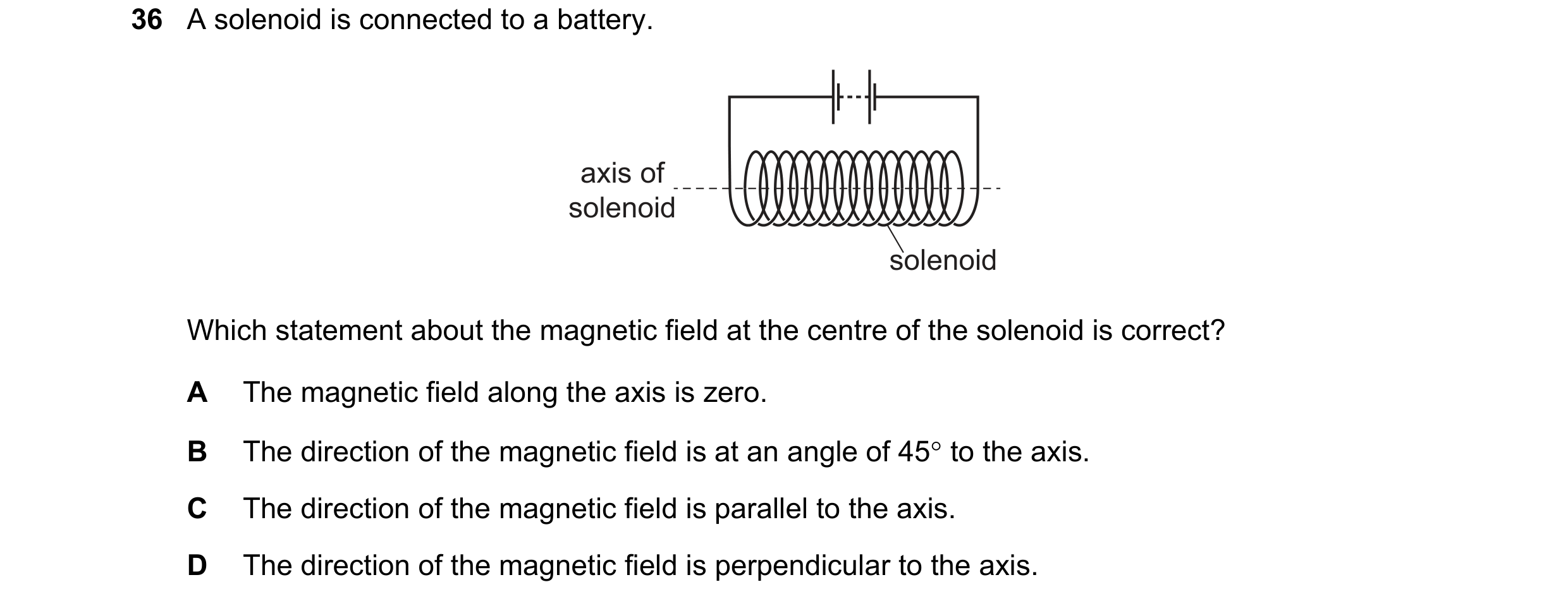
 63 / 108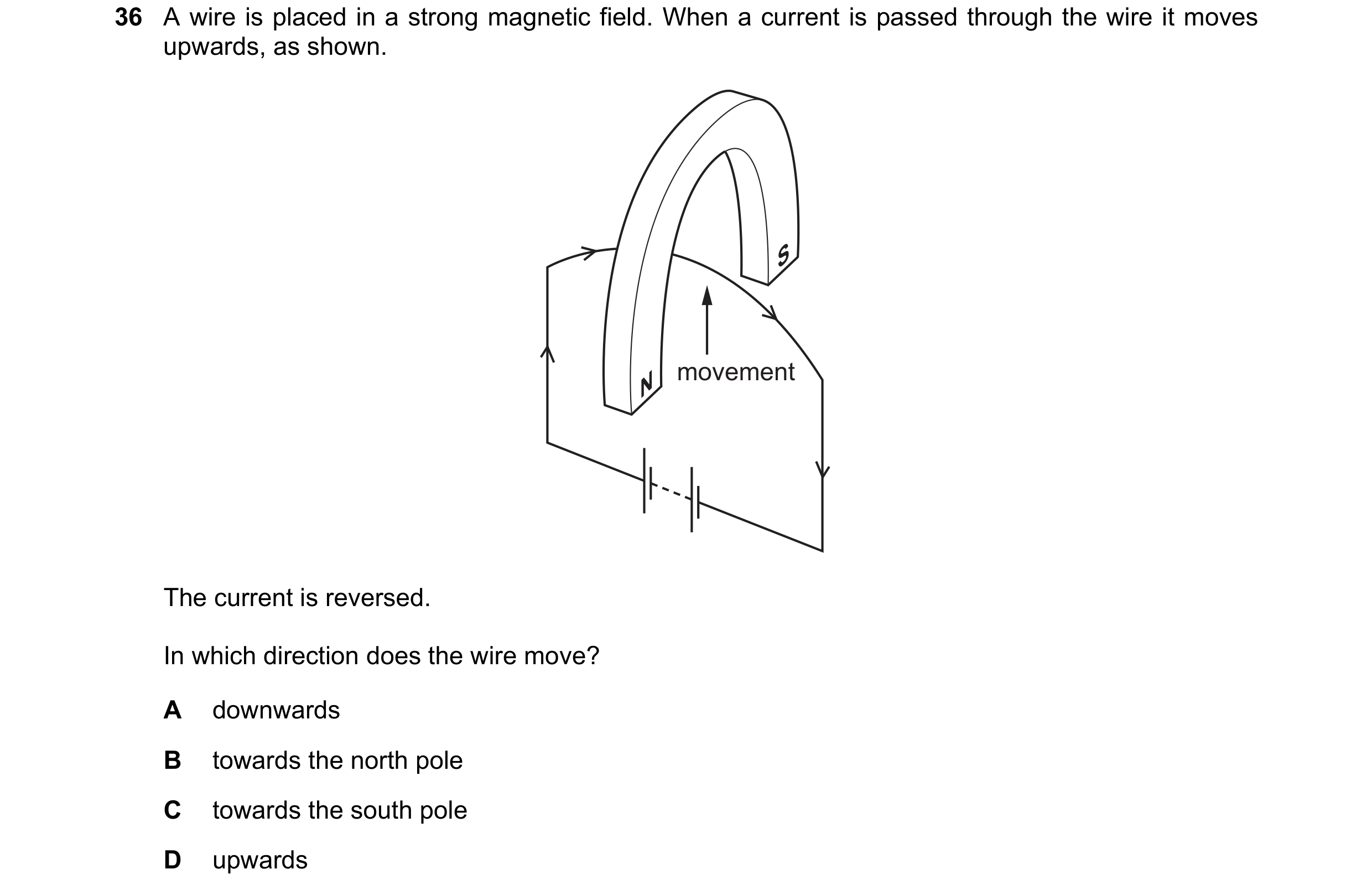
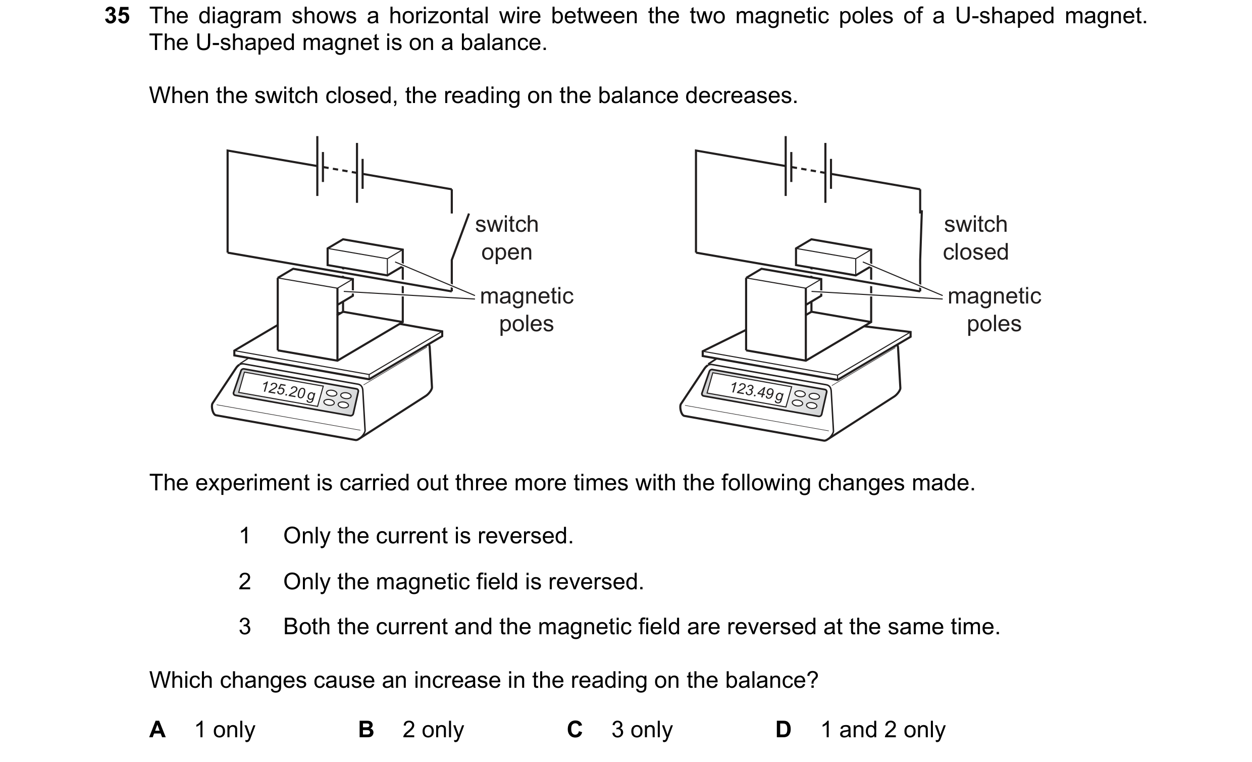 64 / 108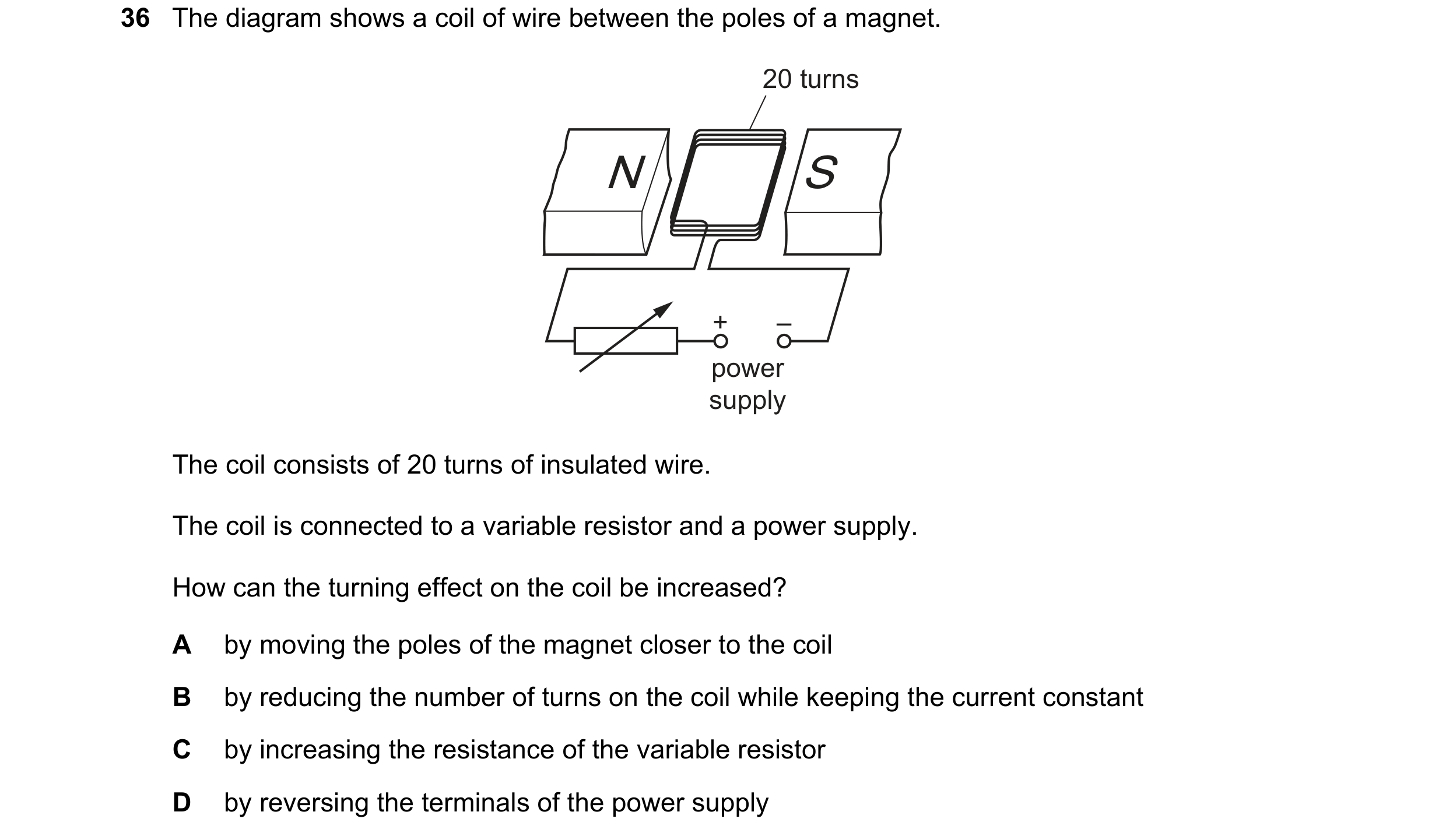
 65 / 108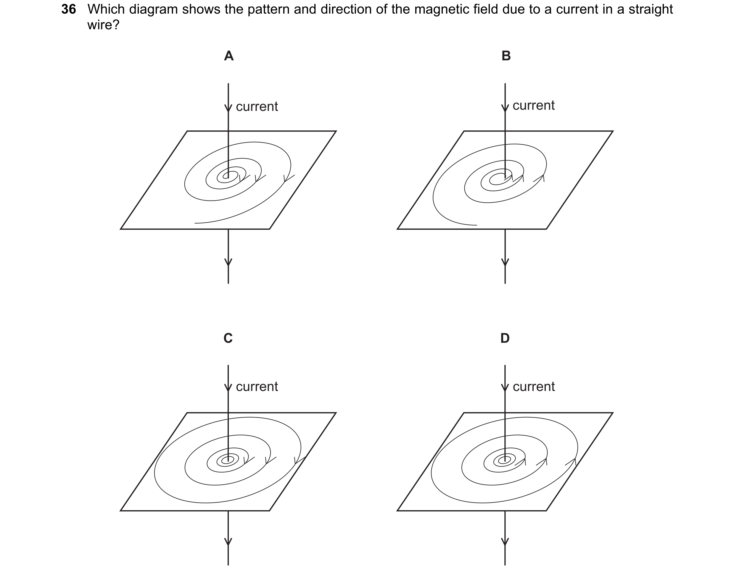

 66 / 108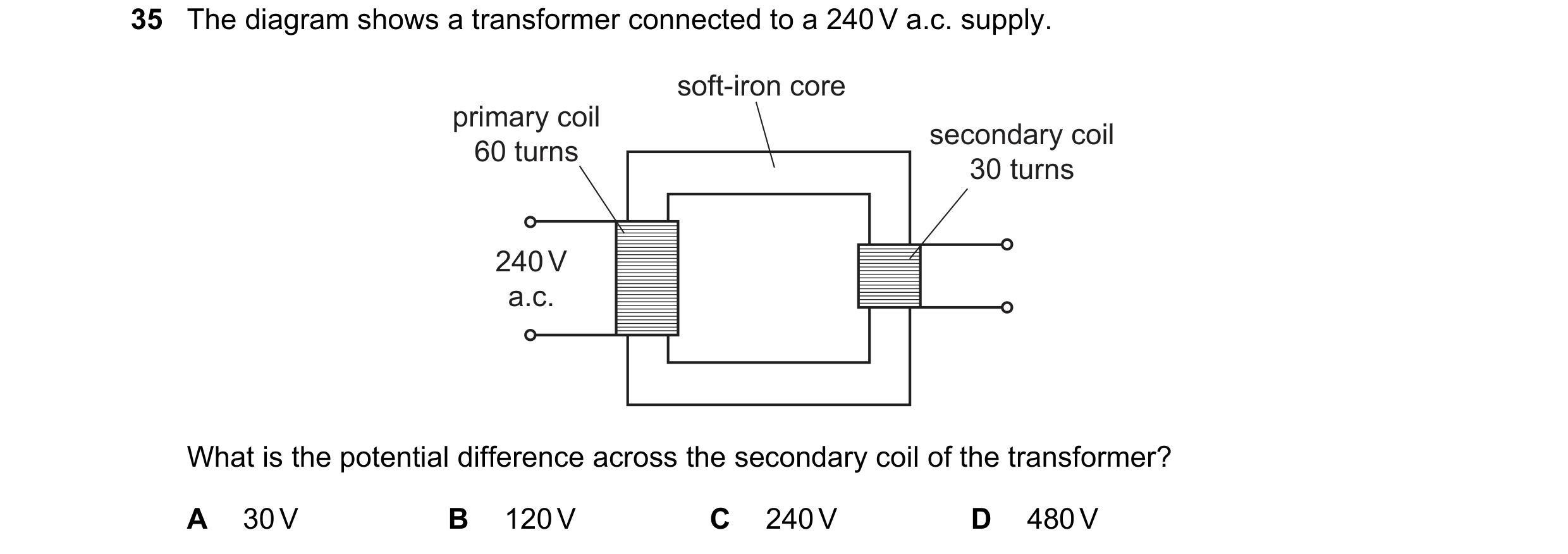
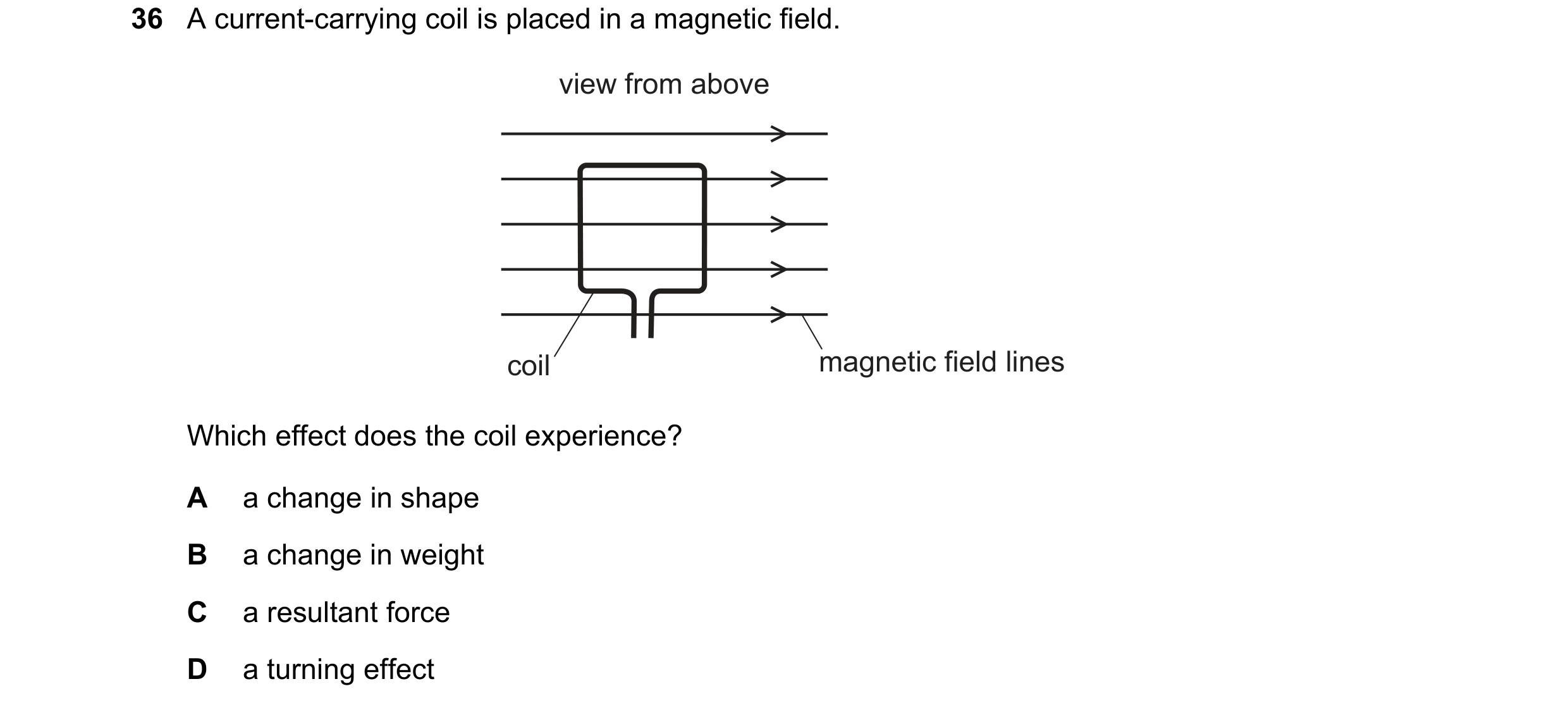
 67 / 108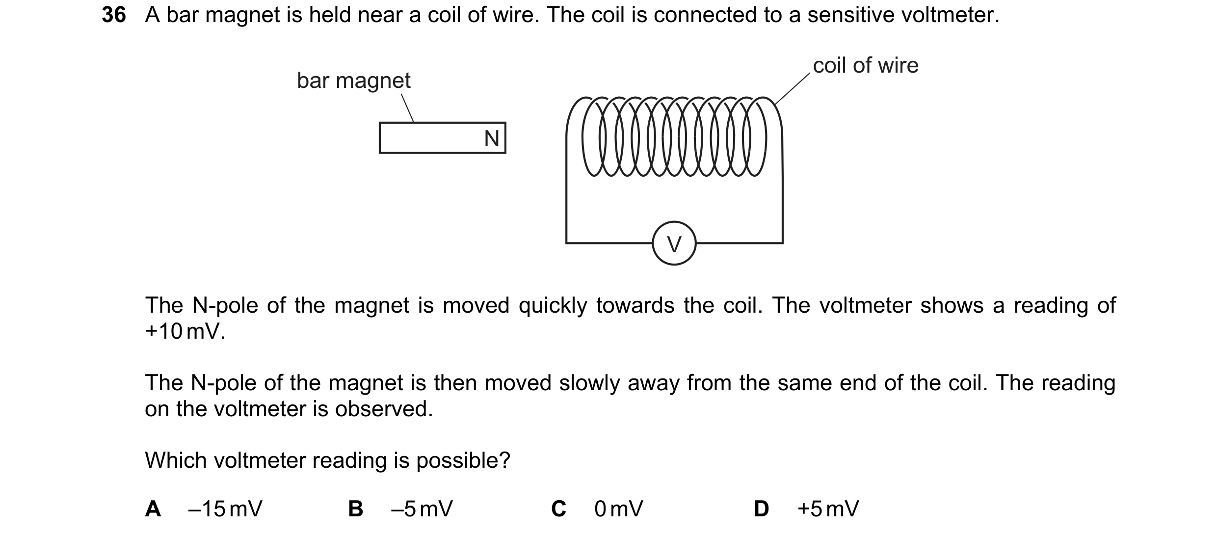
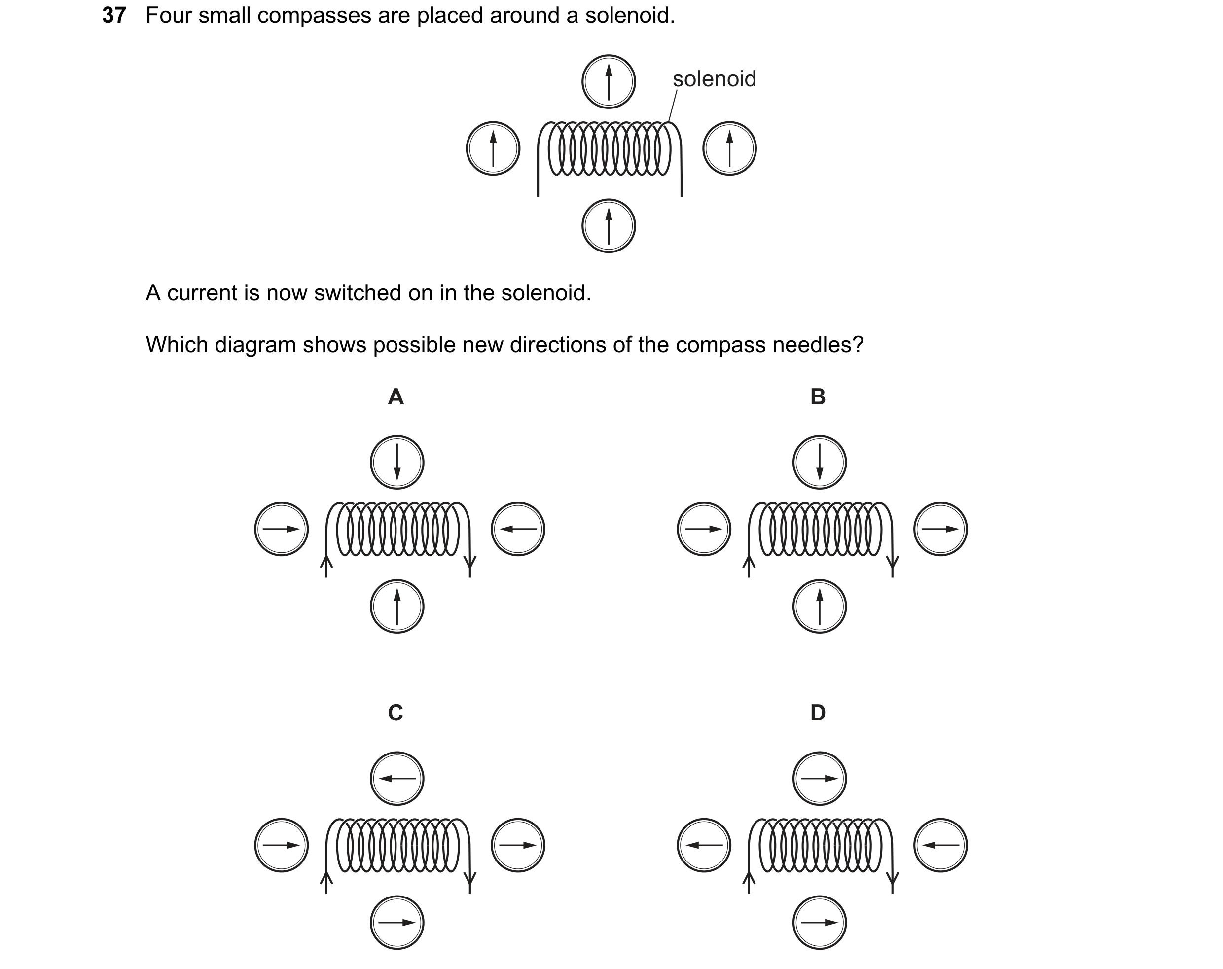 68 / 108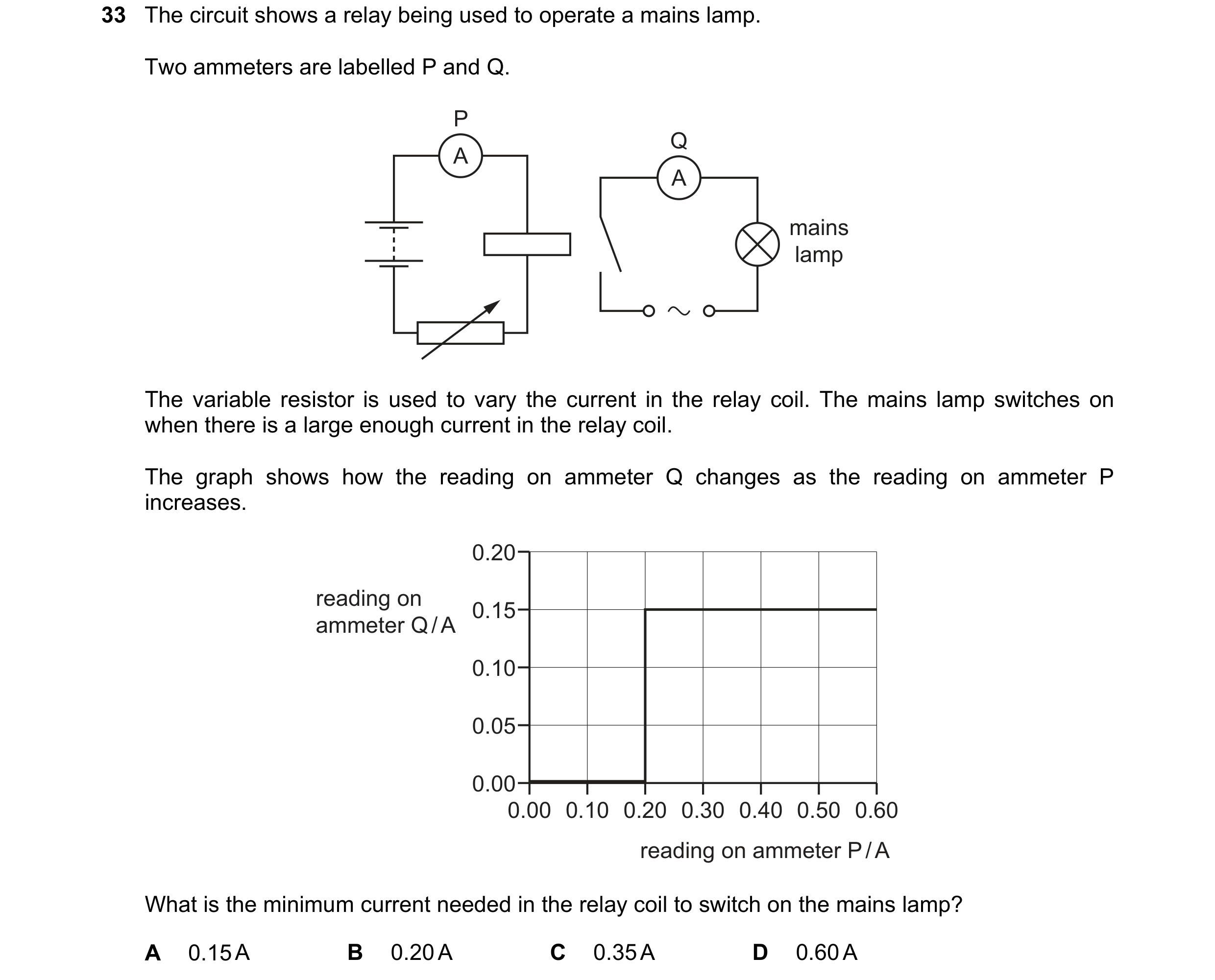
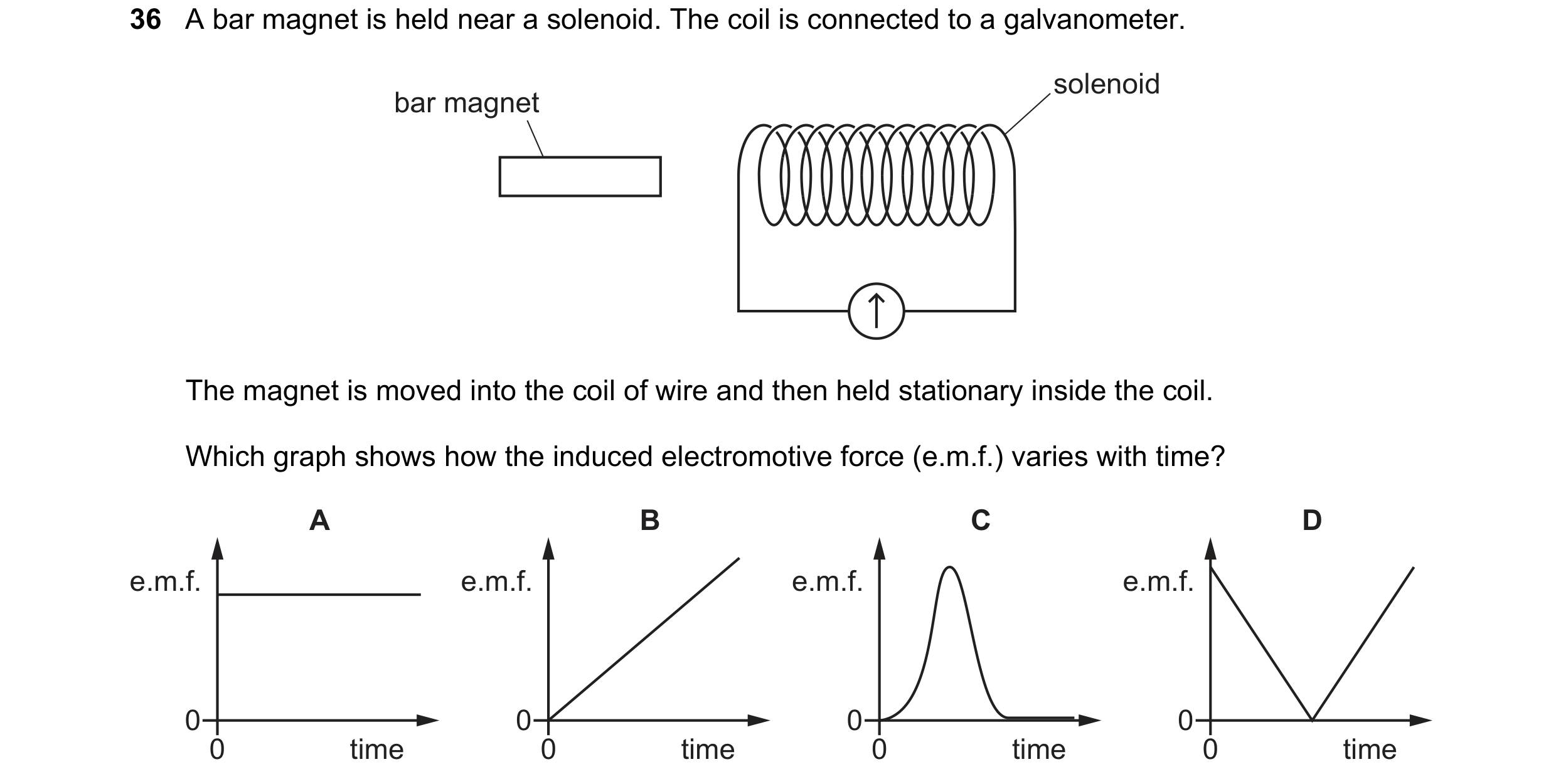 69 / 108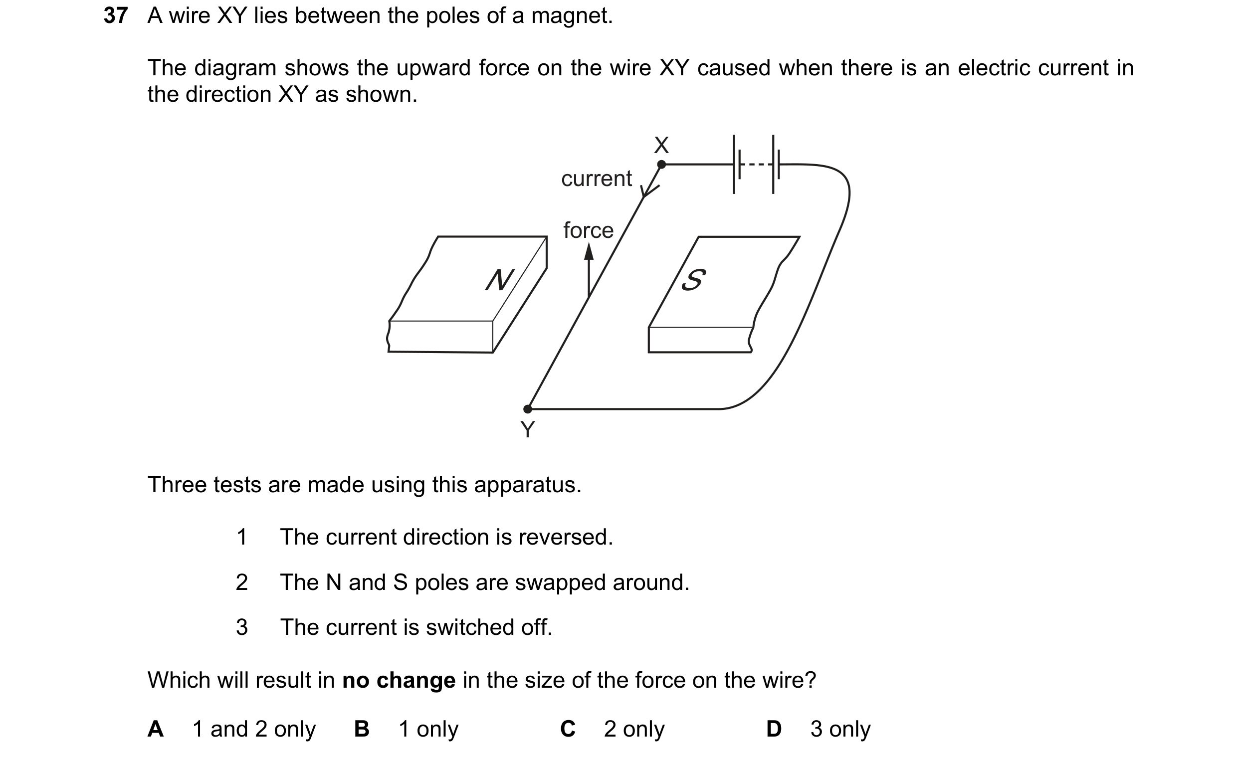
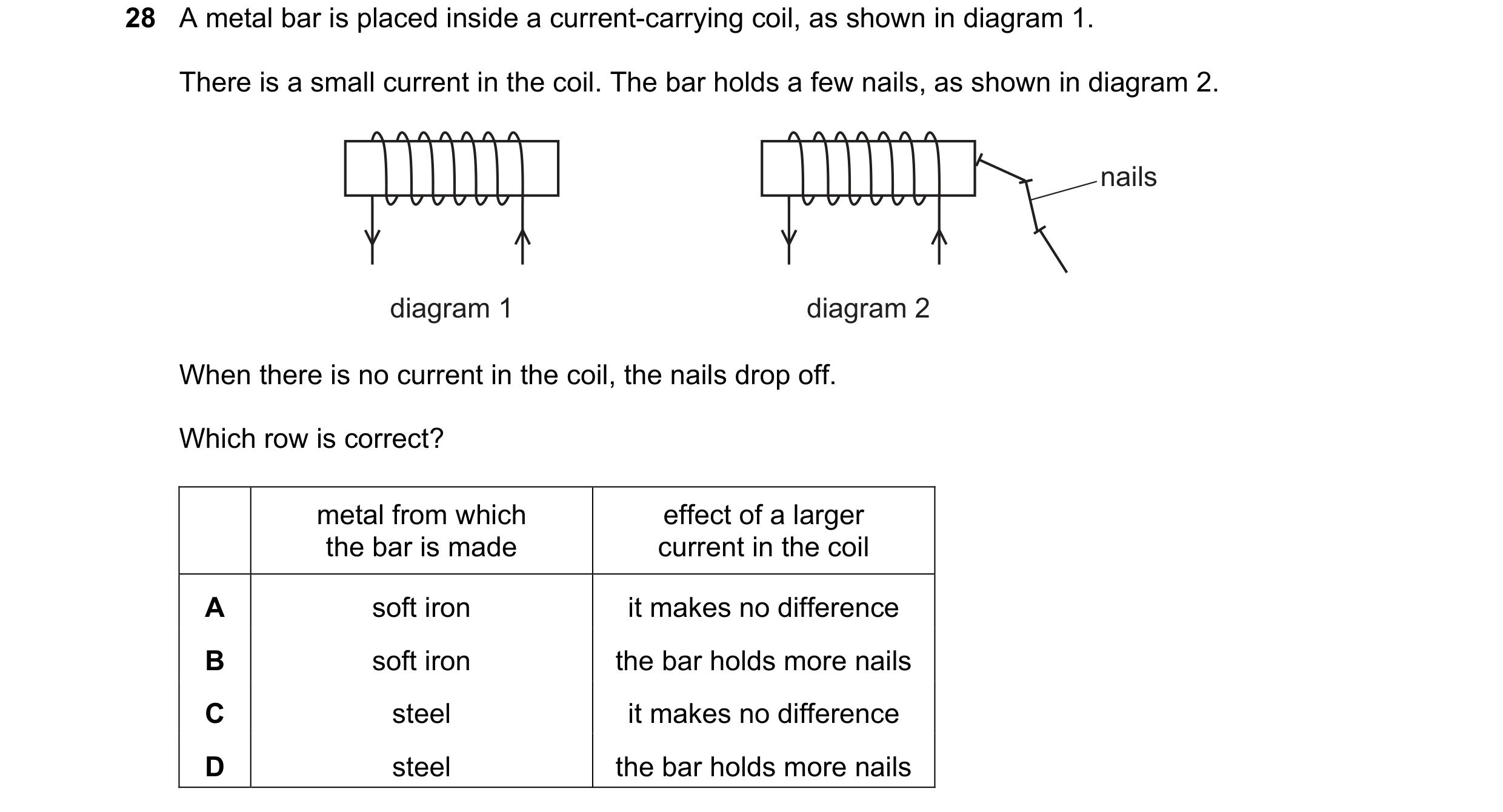 70 / 108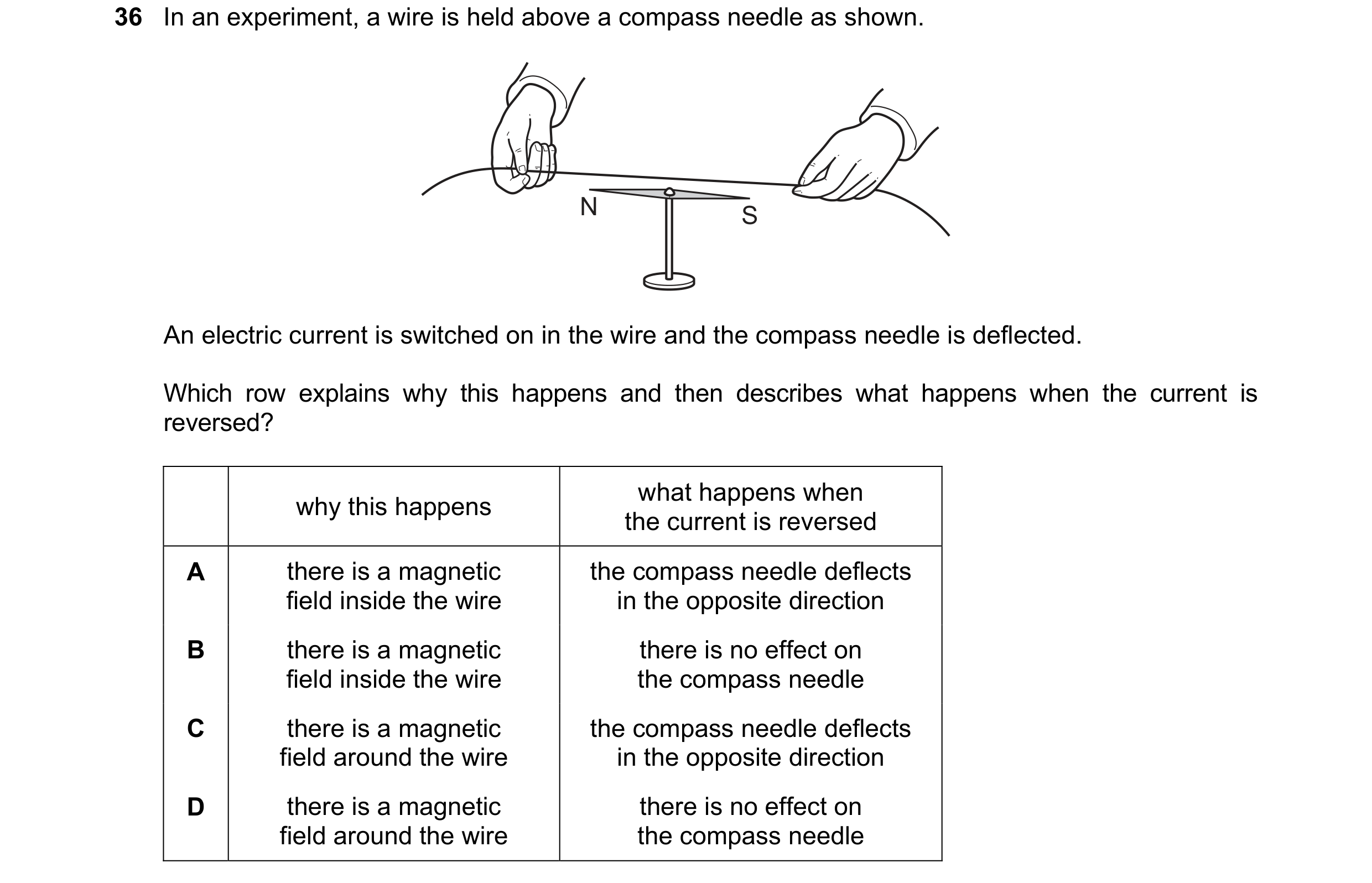
 71 / 108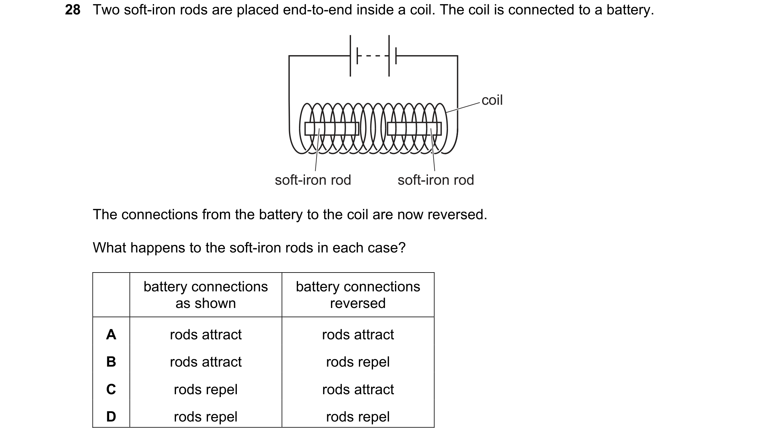
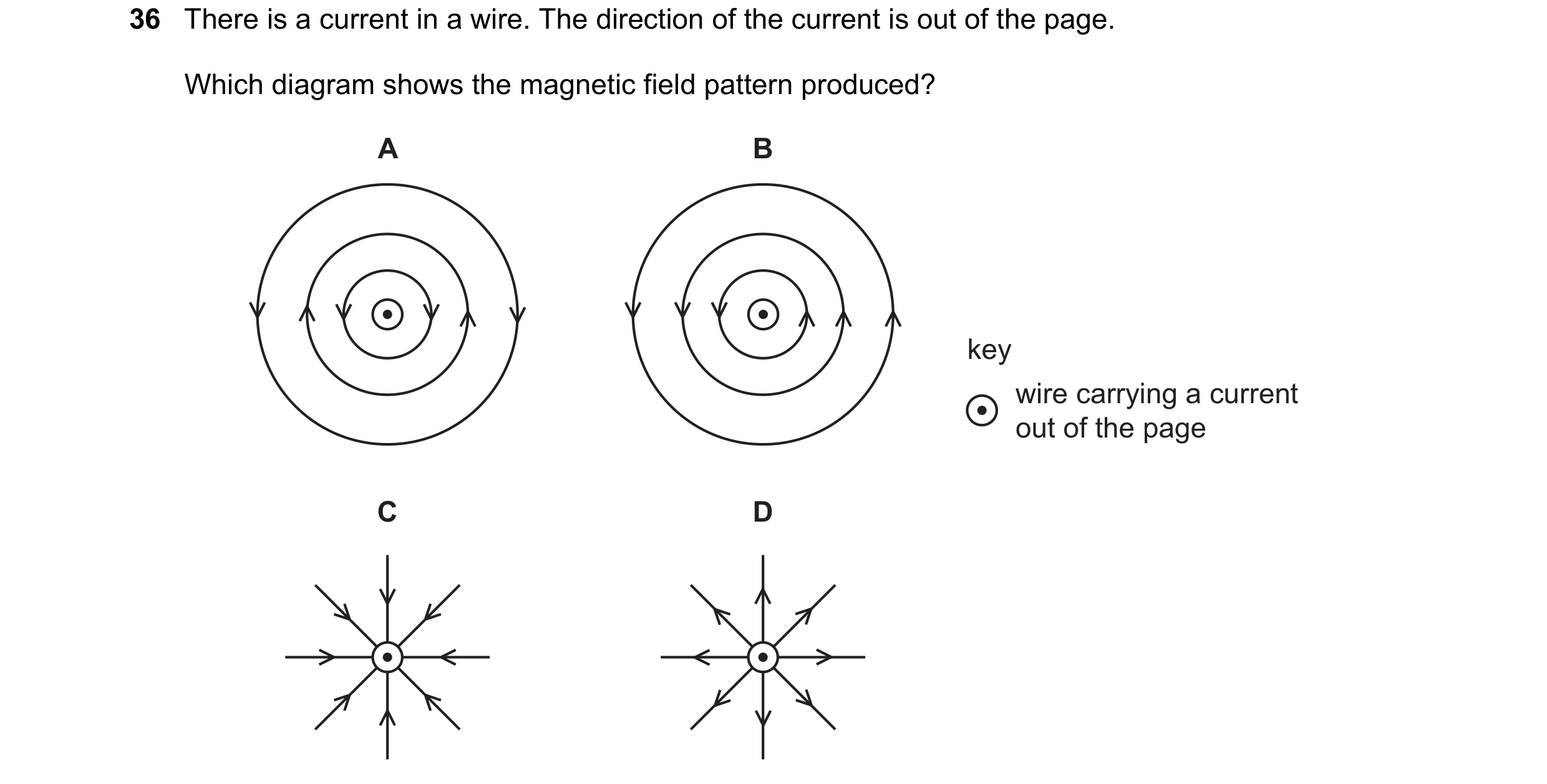 72 / 108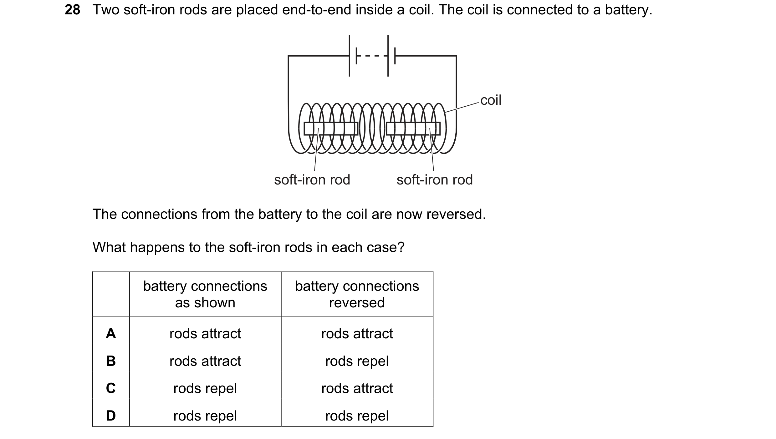
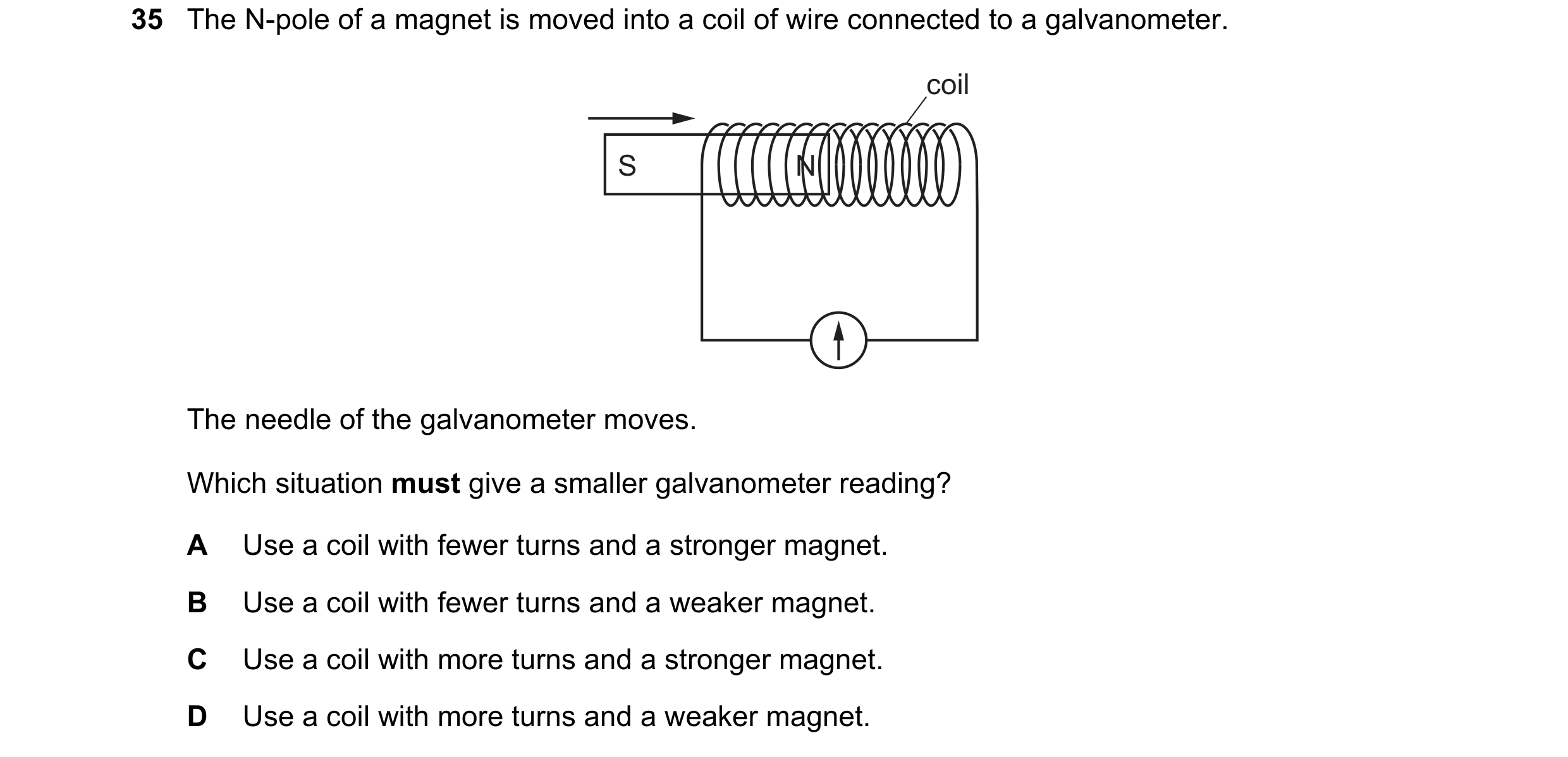 73 / 108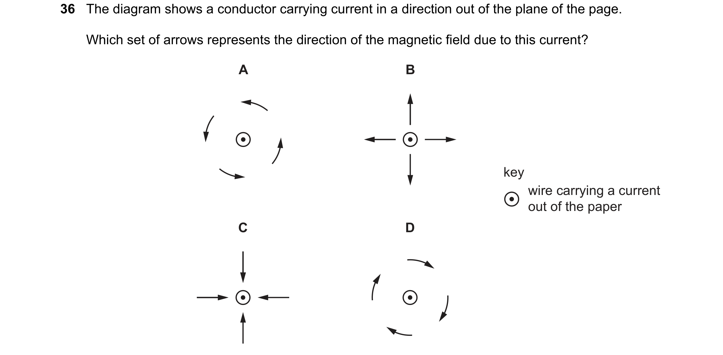
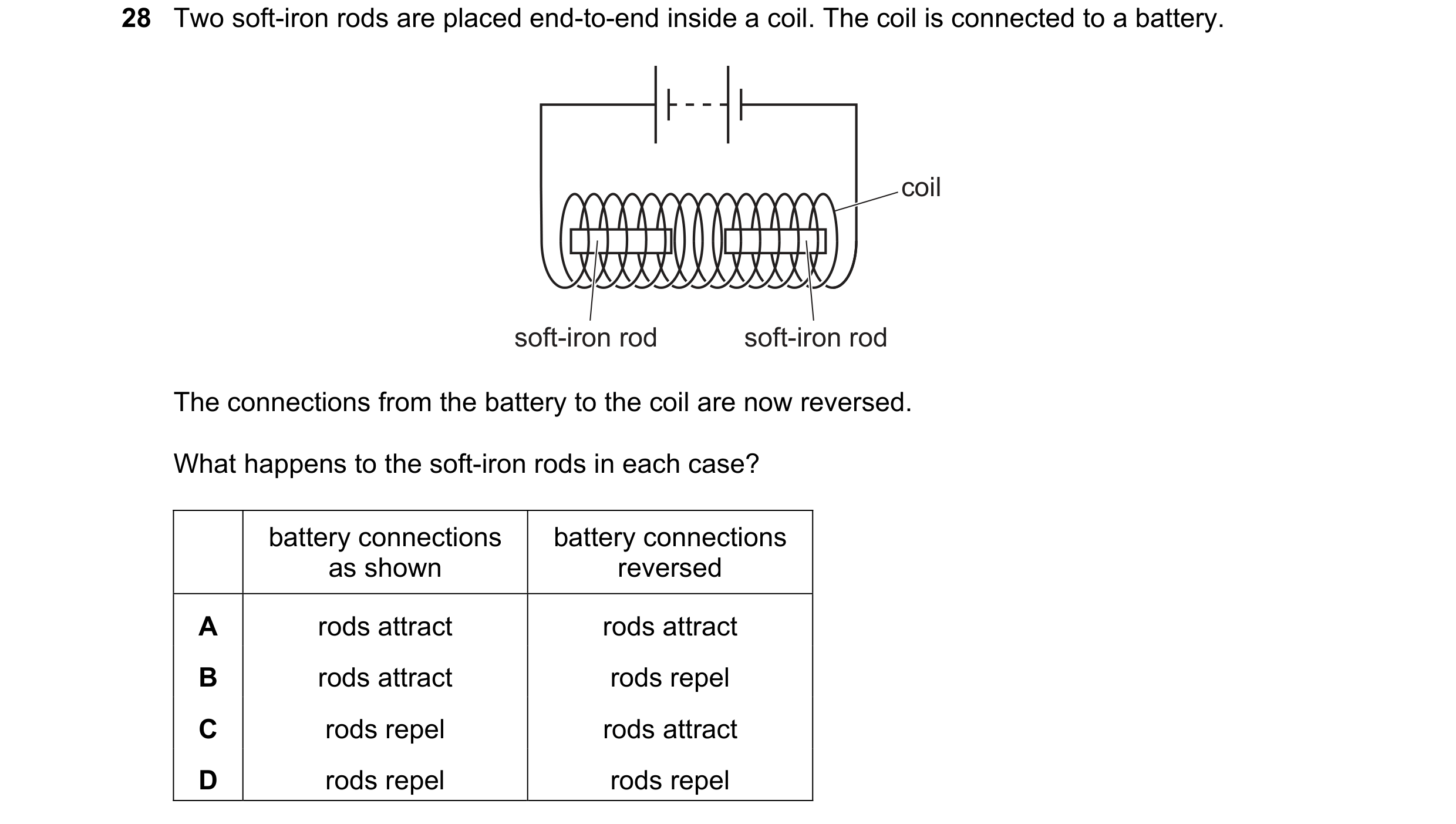
 74 / 108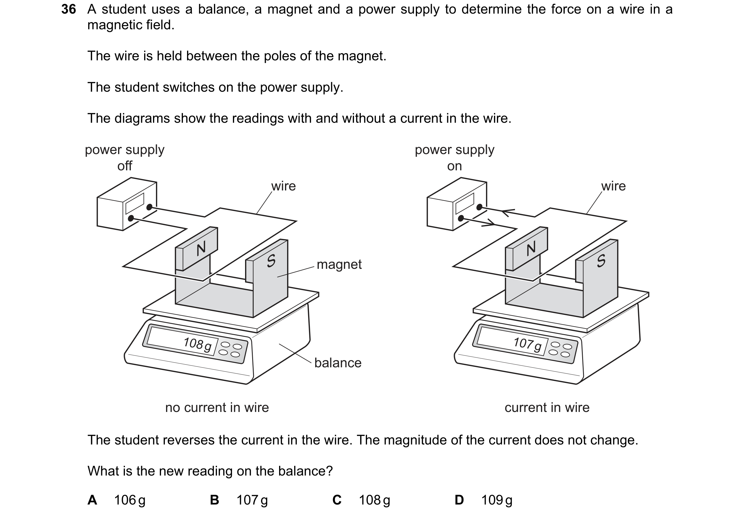

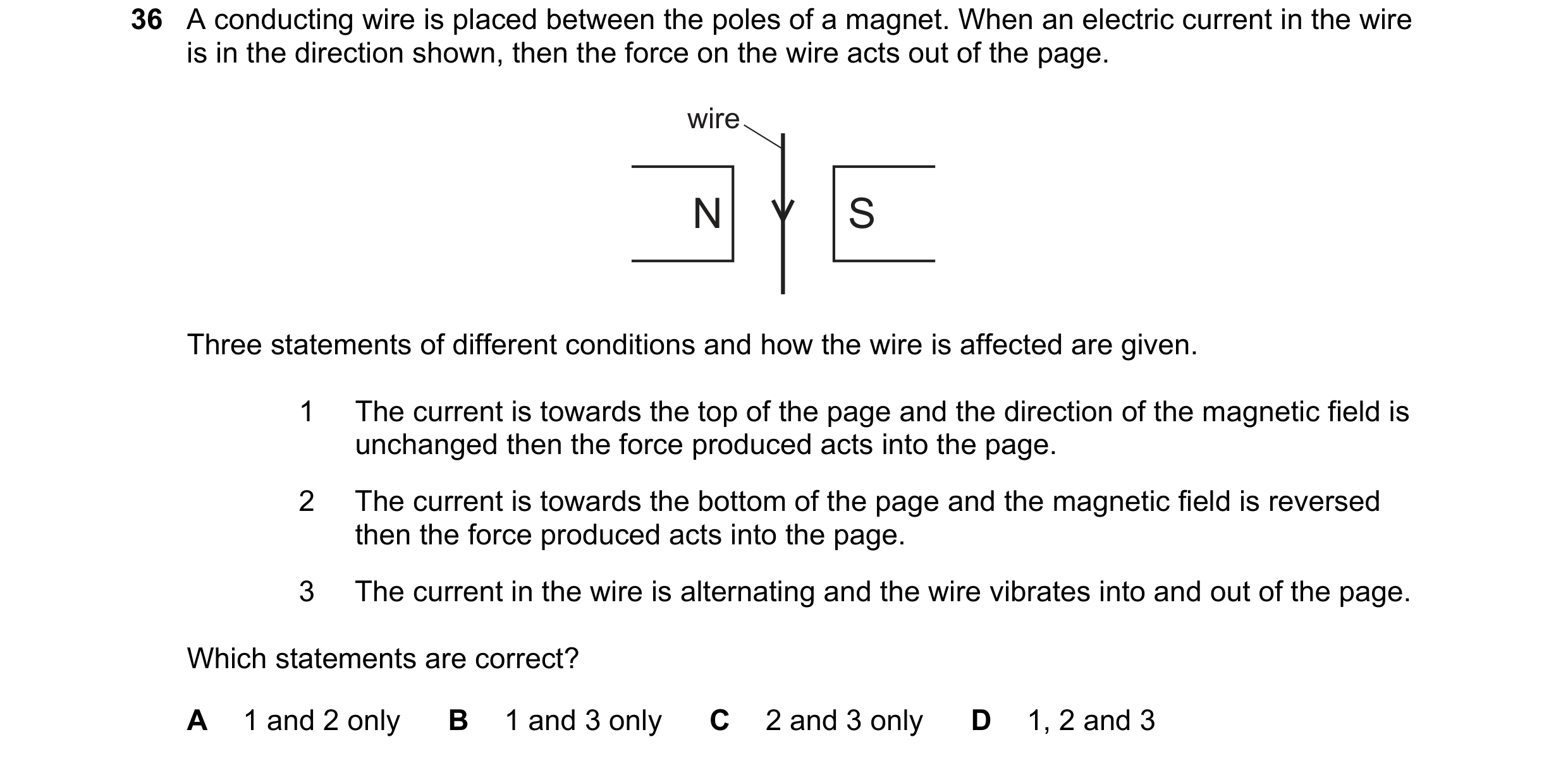 75 / 108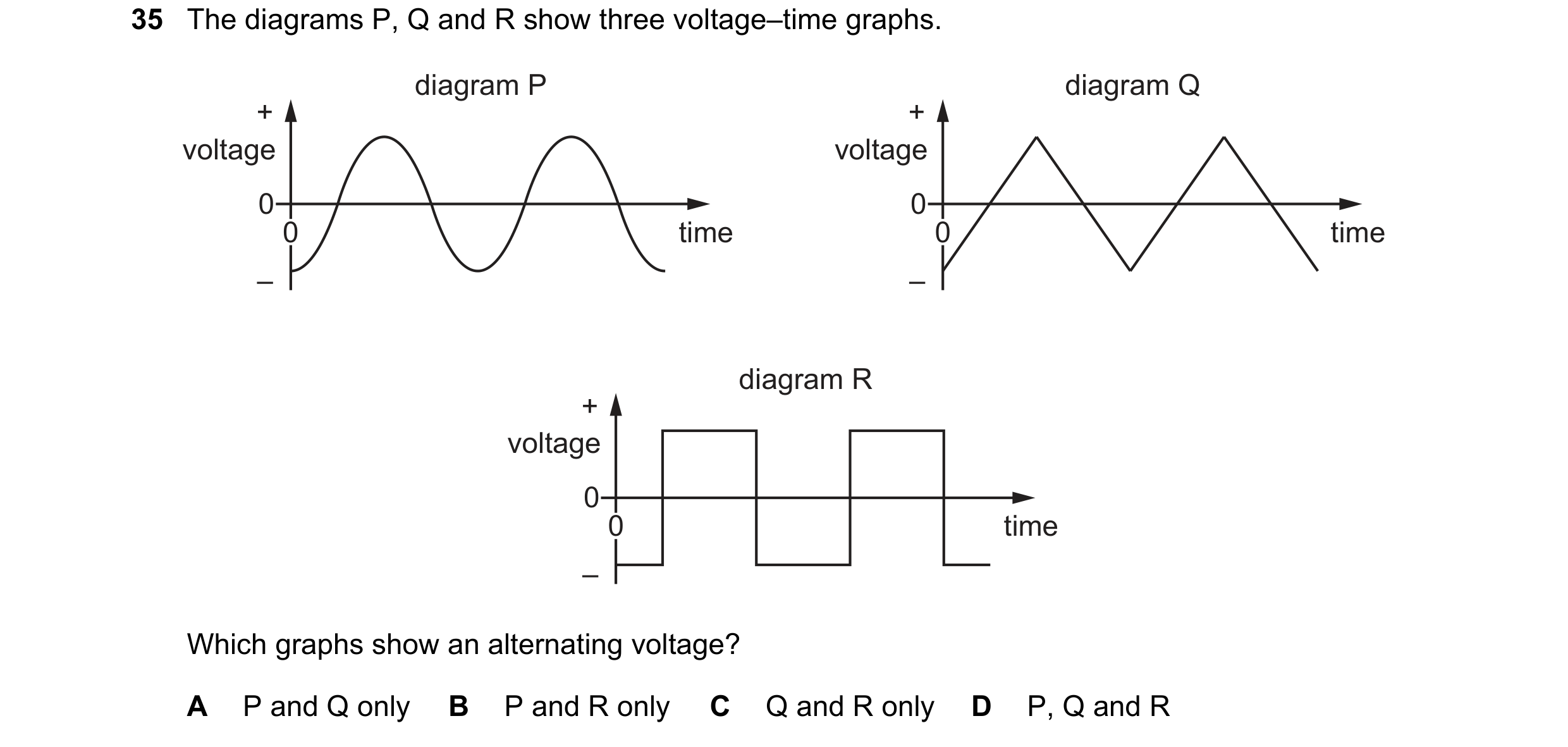
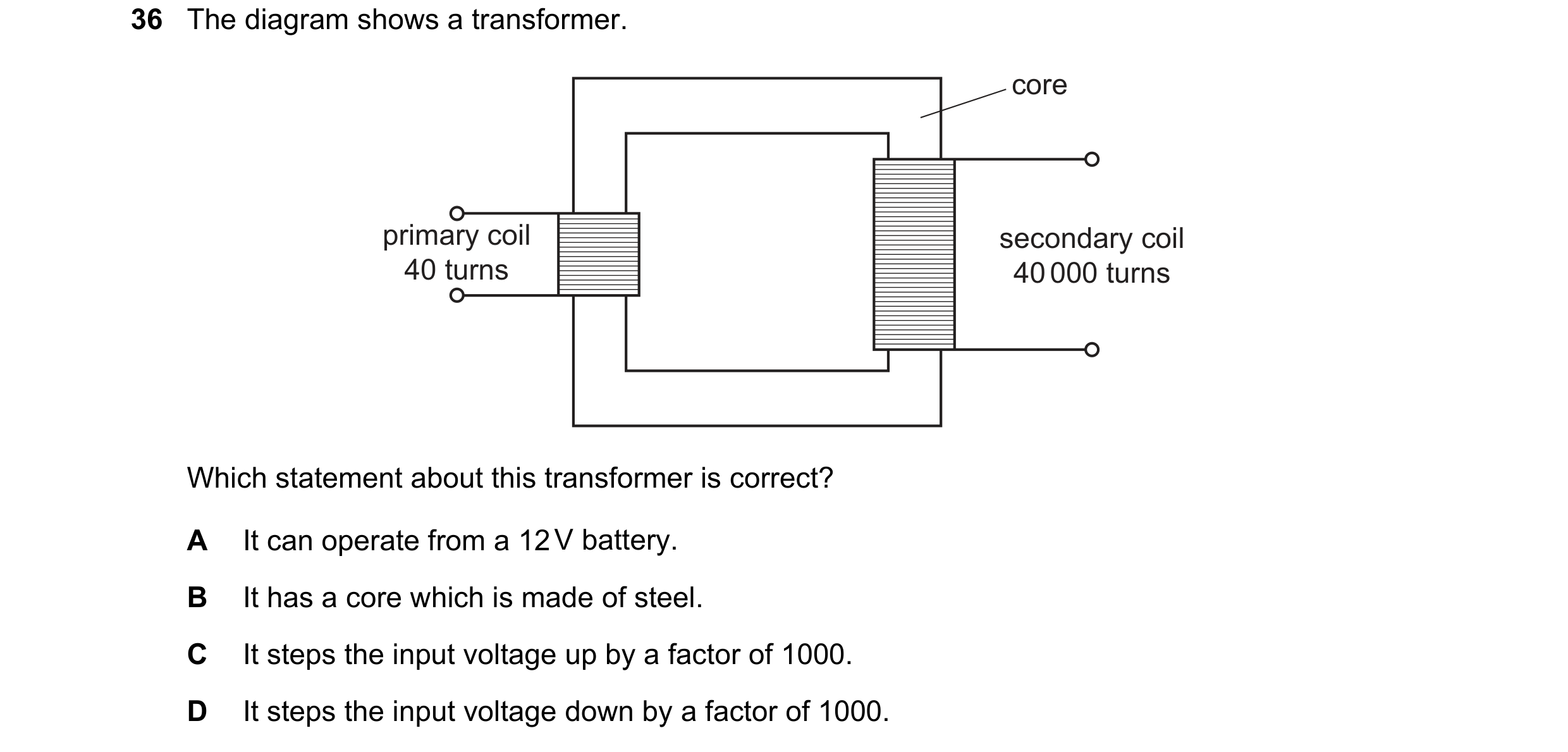 76 / 108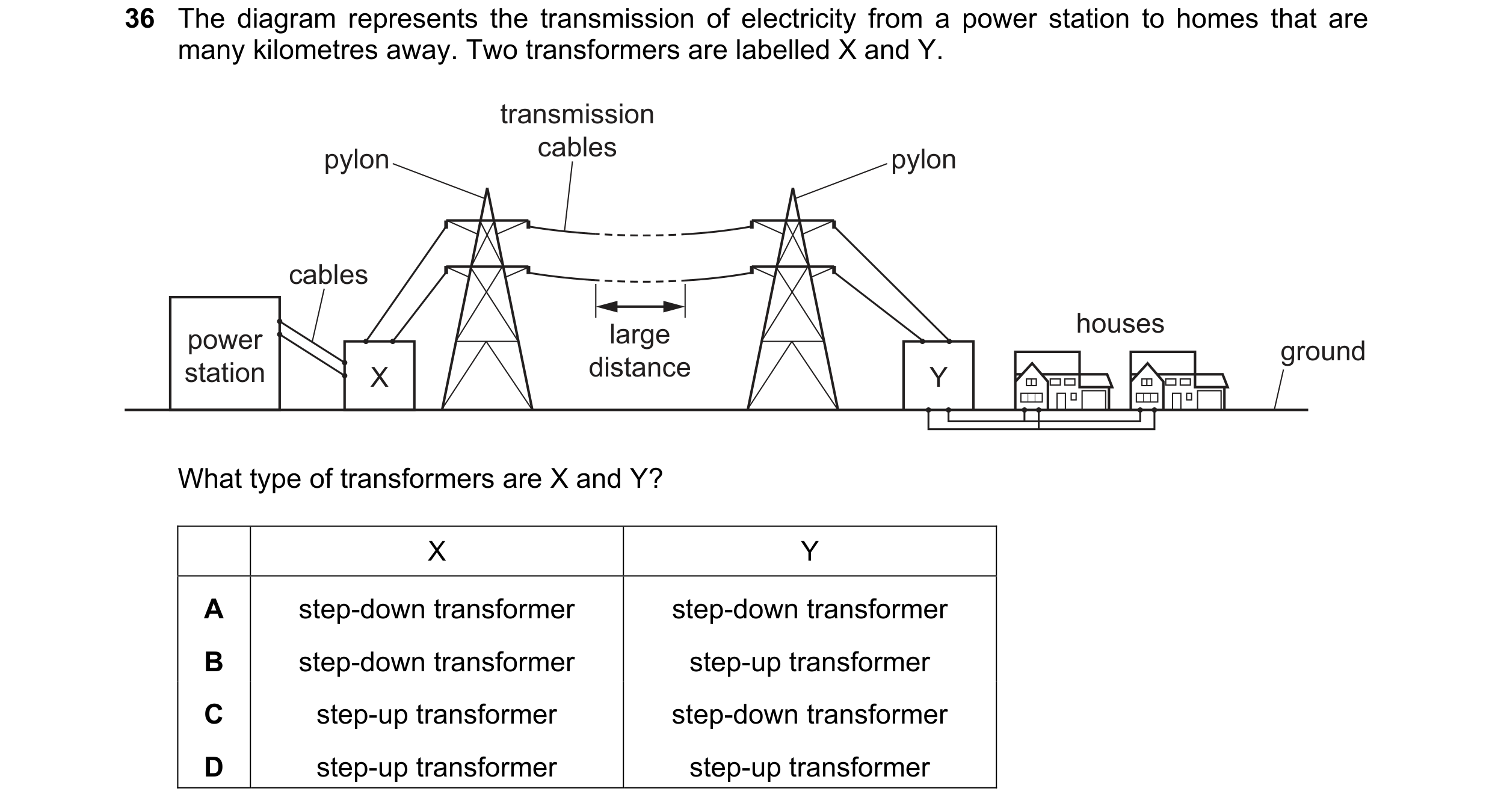
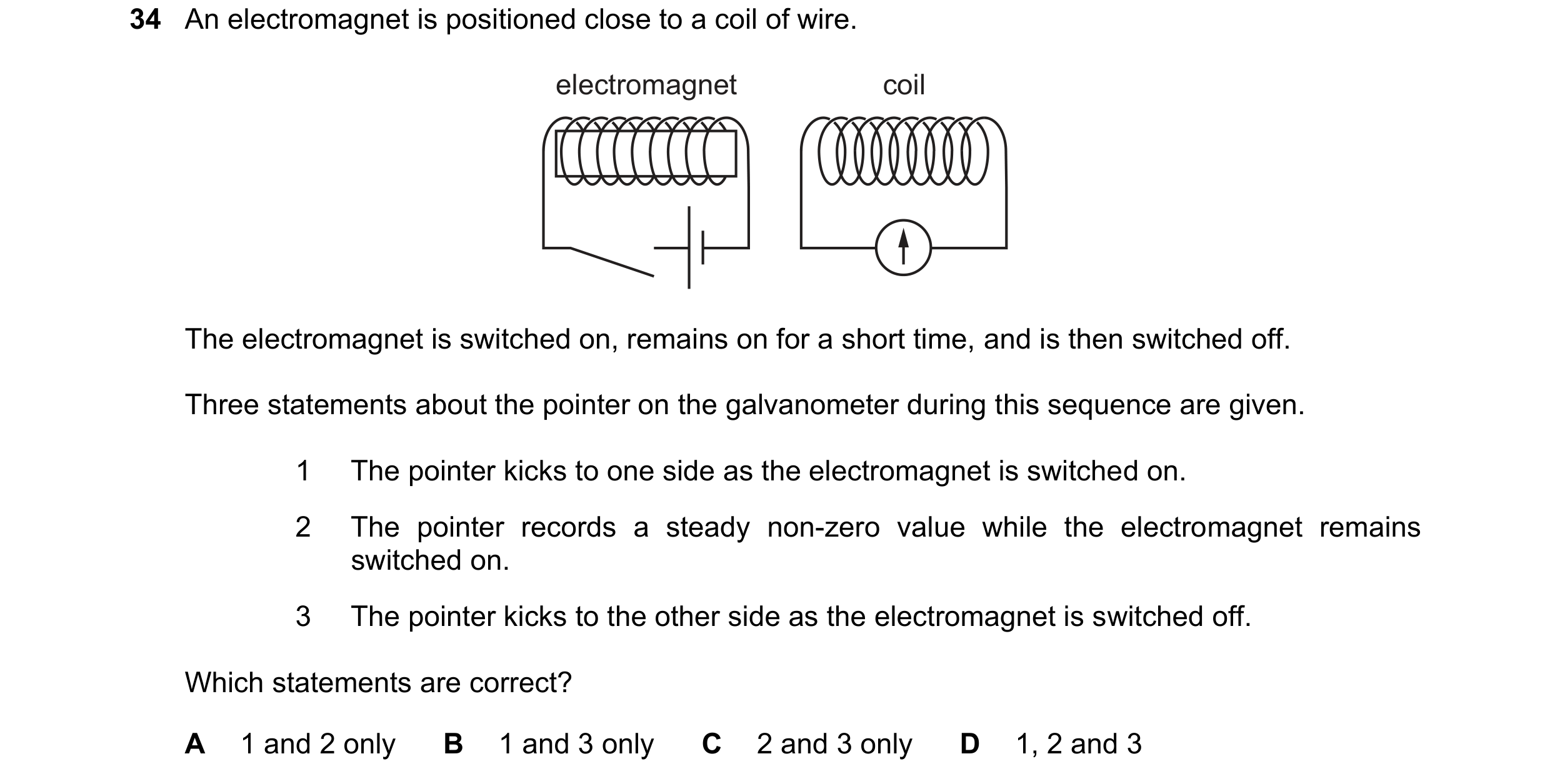 77 / 108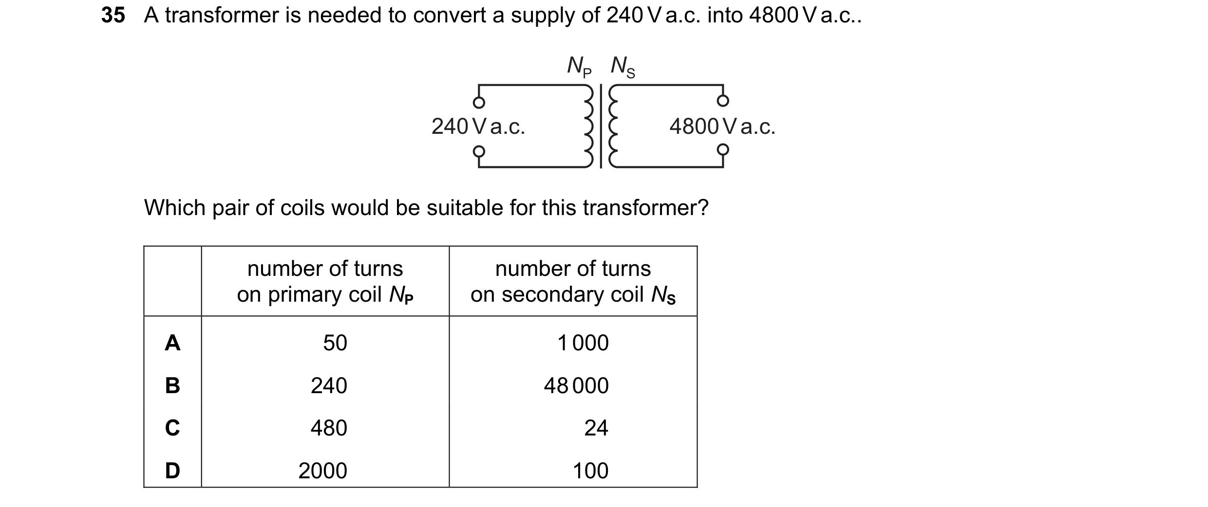
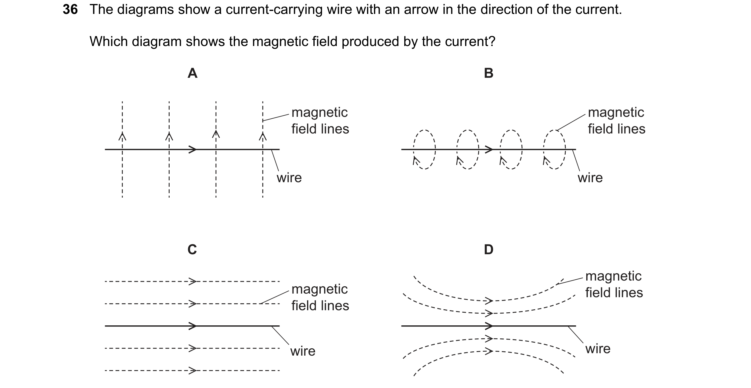 78 / 108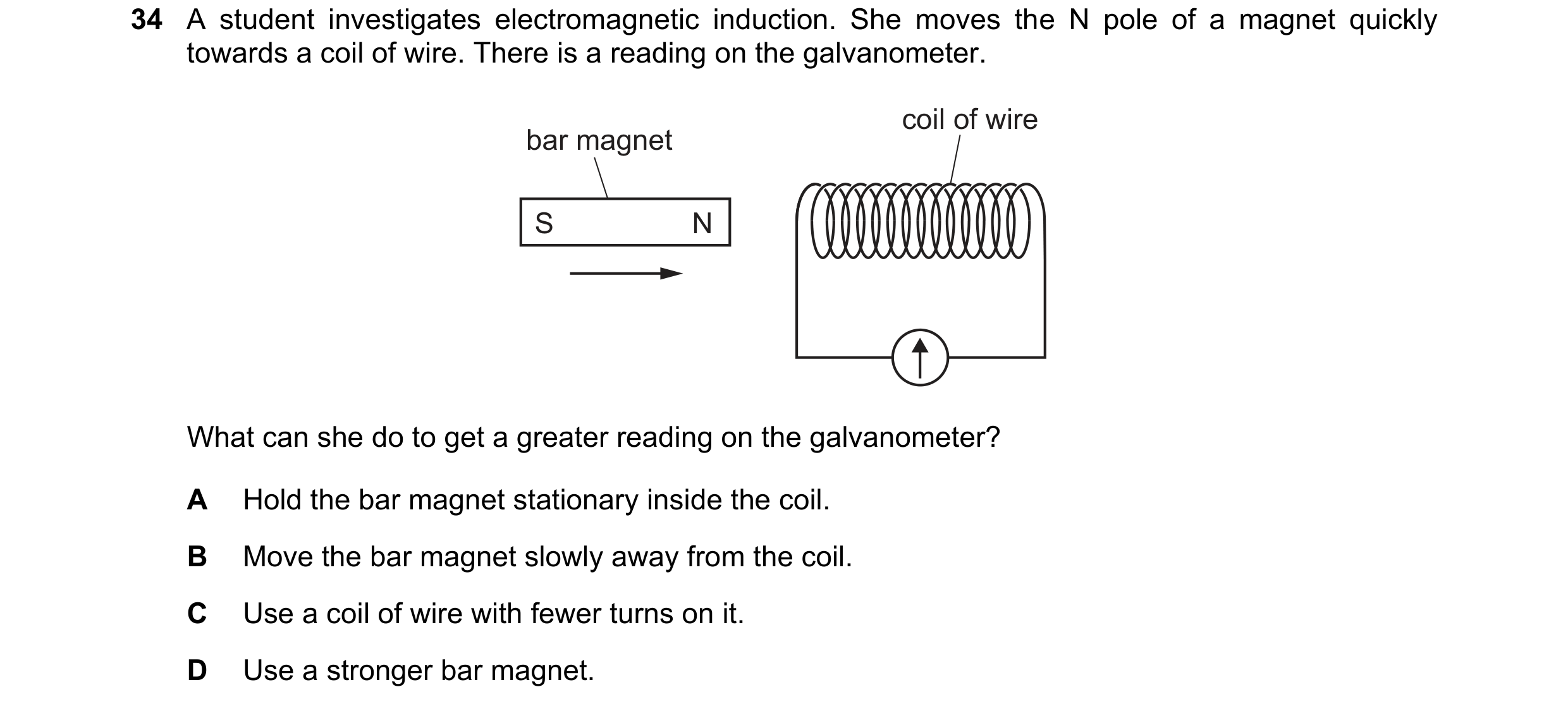
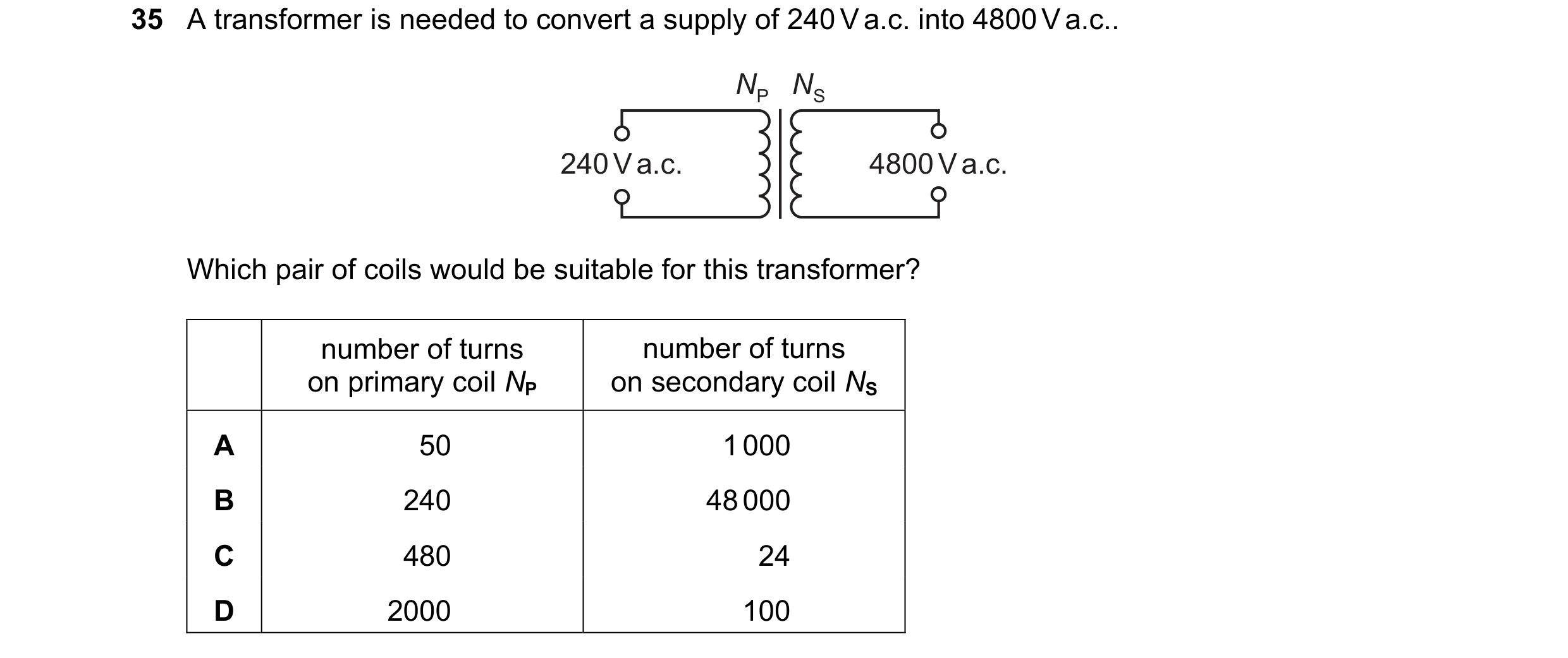 79 / 108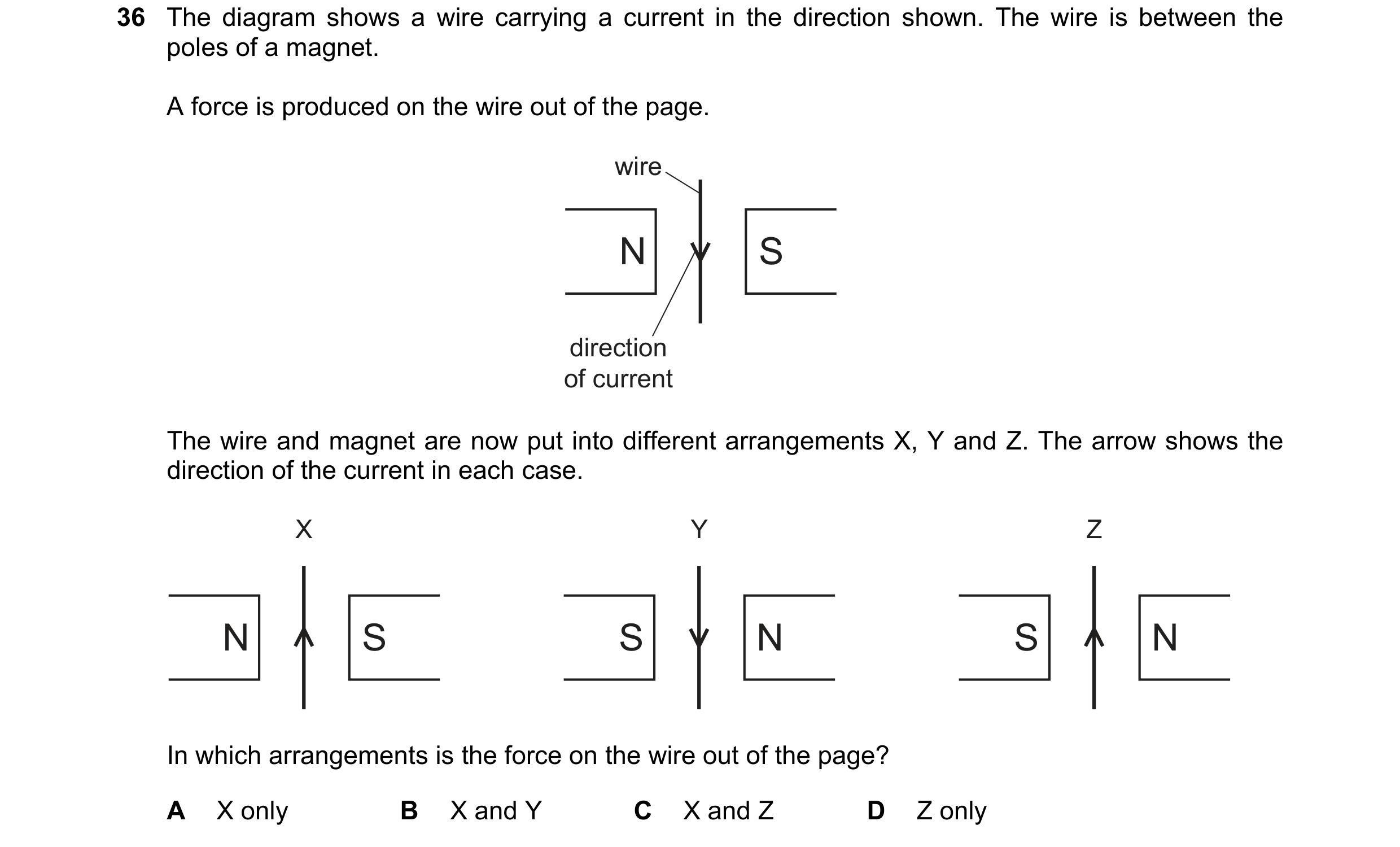
 80 / 108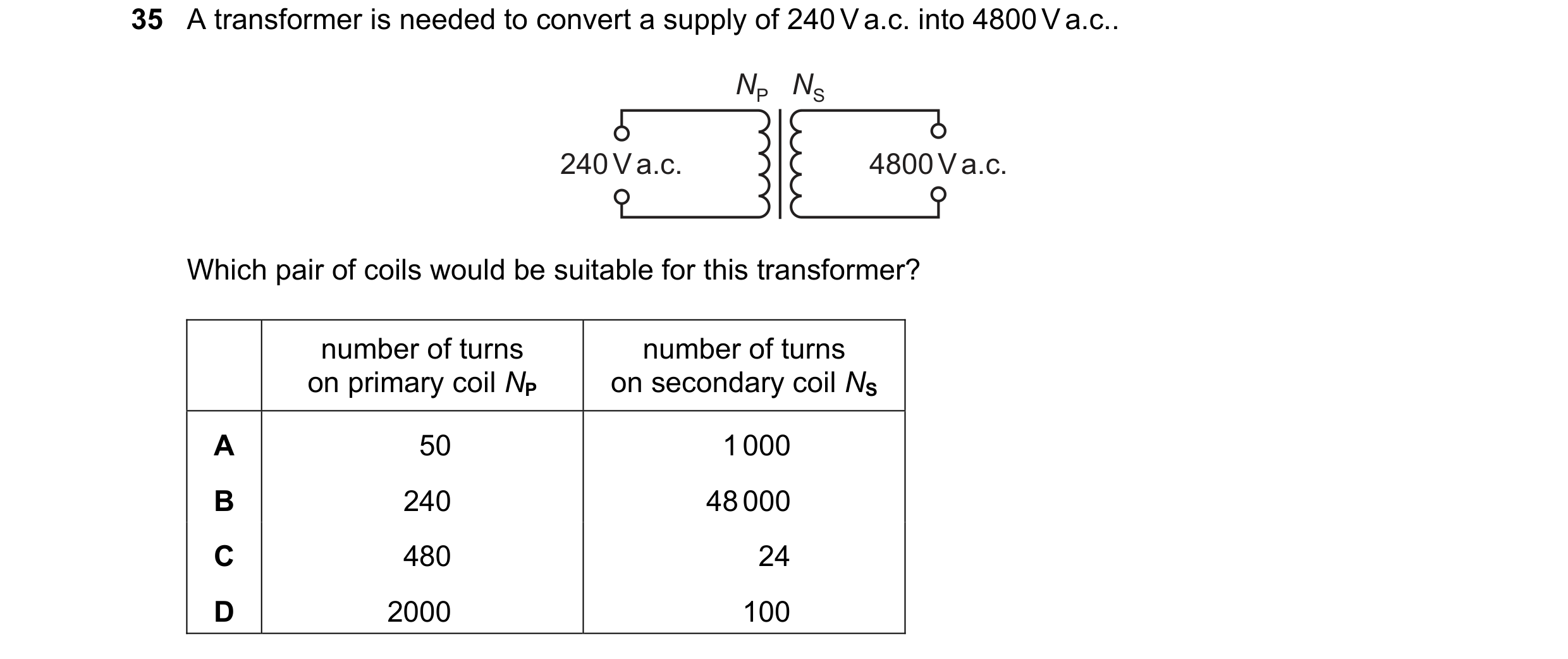
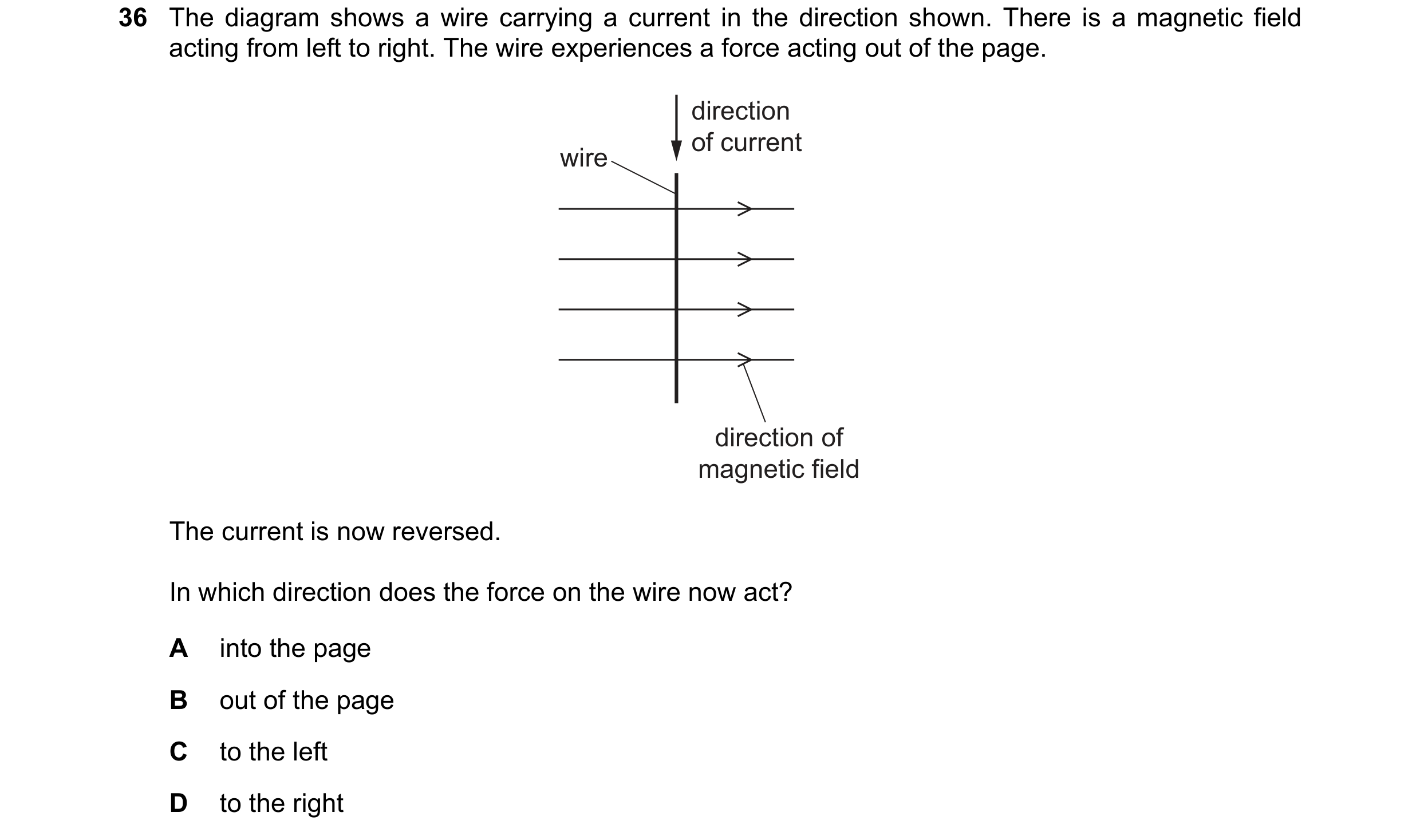 81 / 108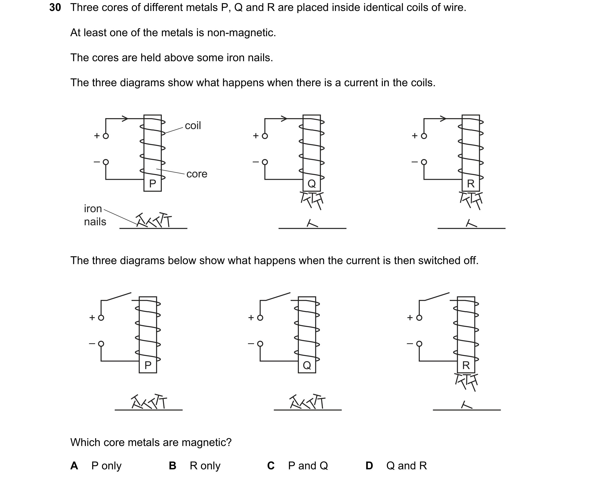
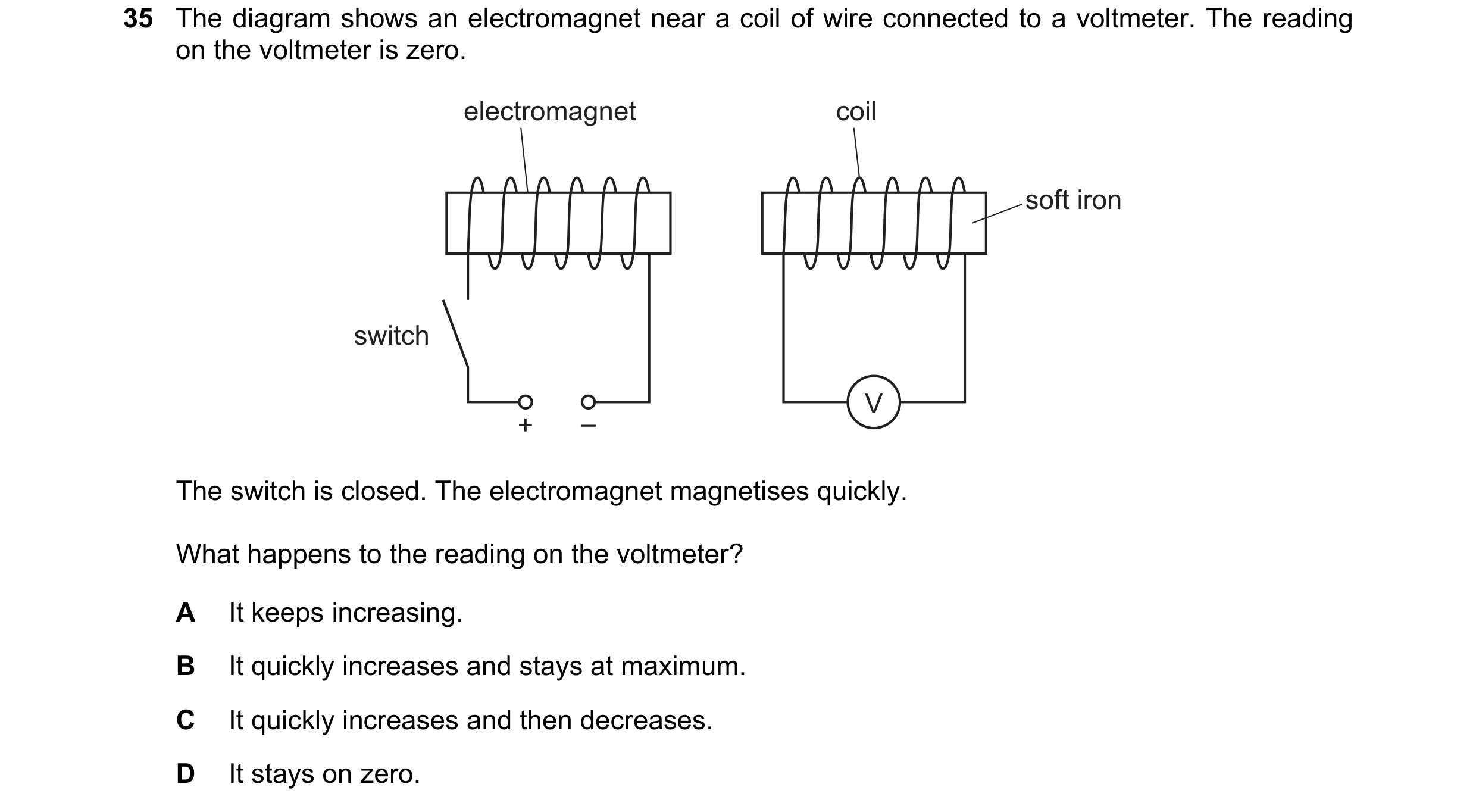 82 / 108
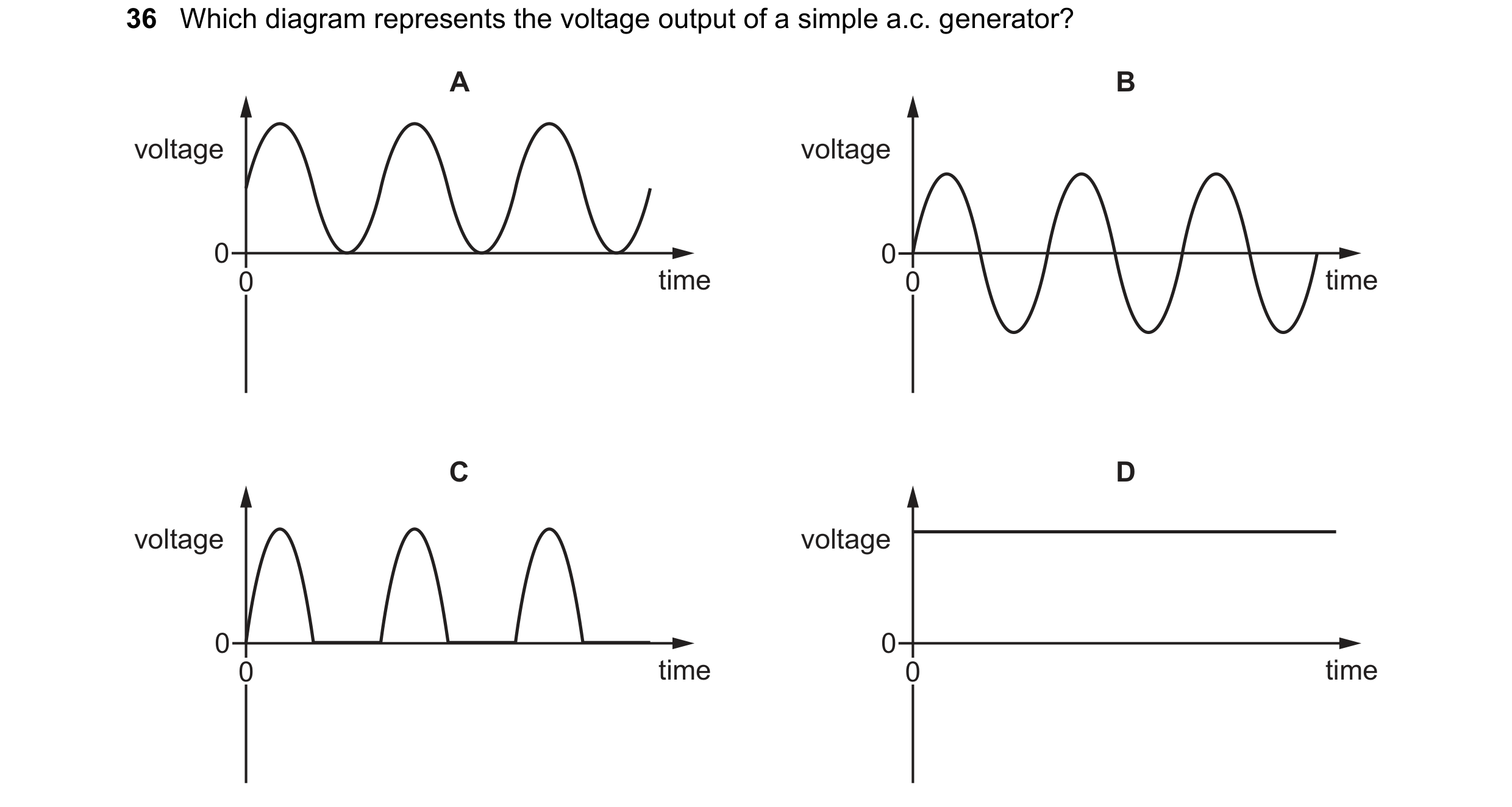 83 / 108
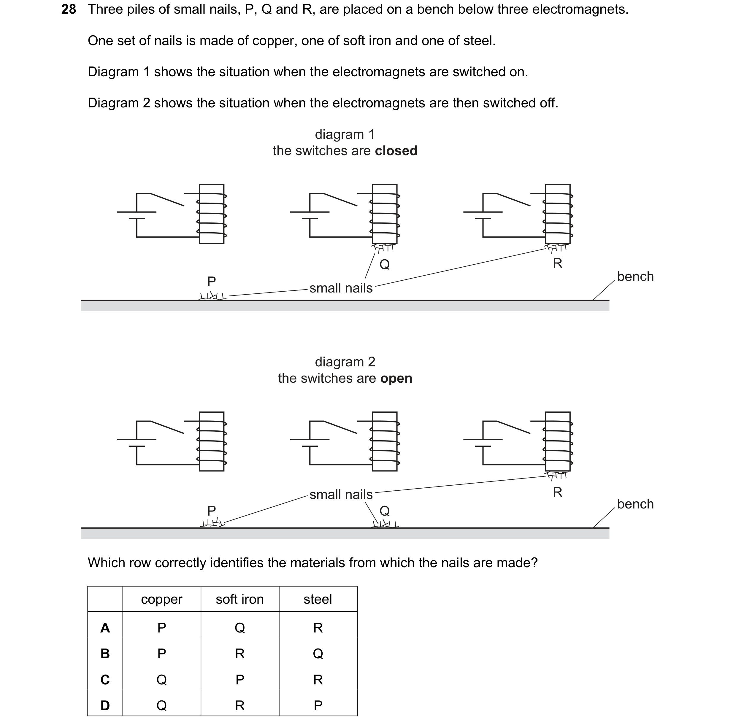 84 / 108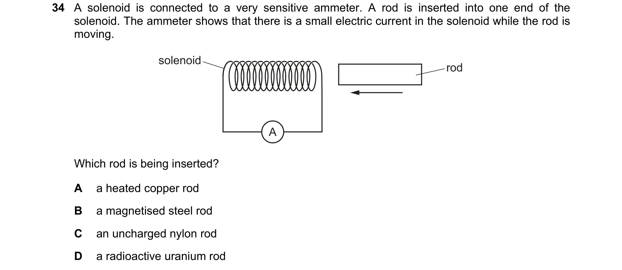
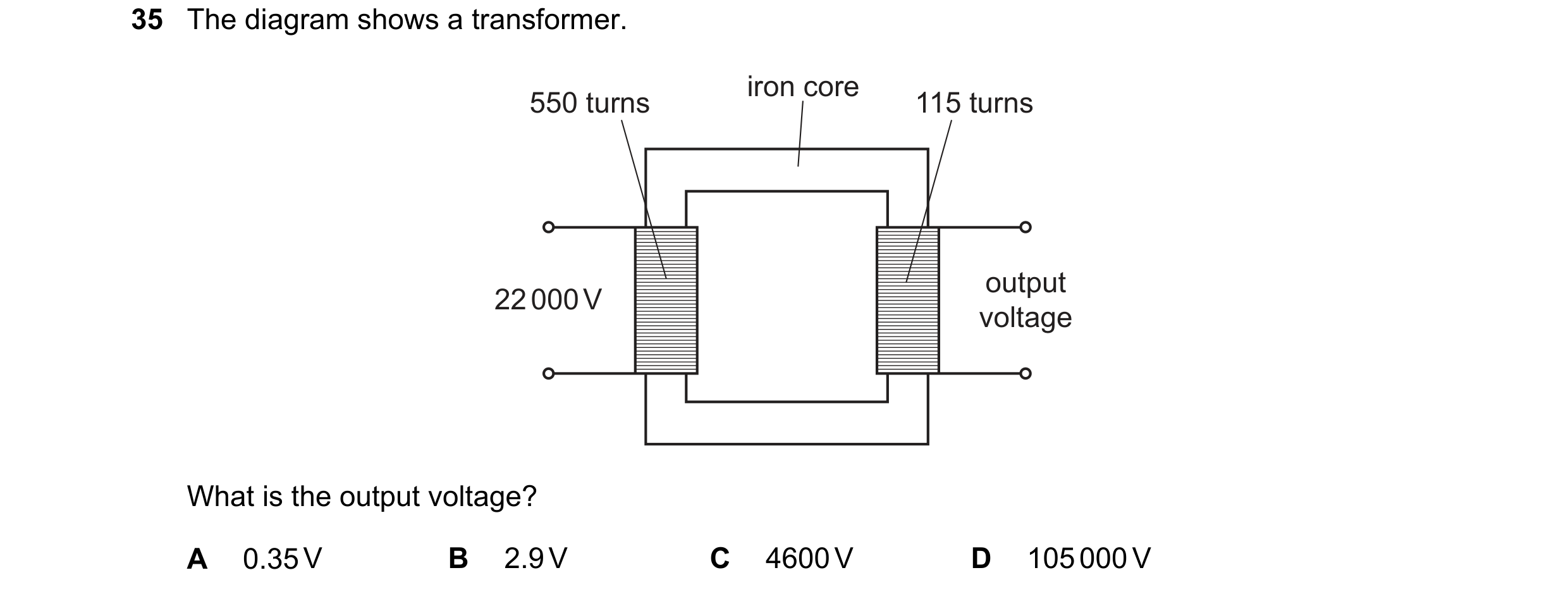
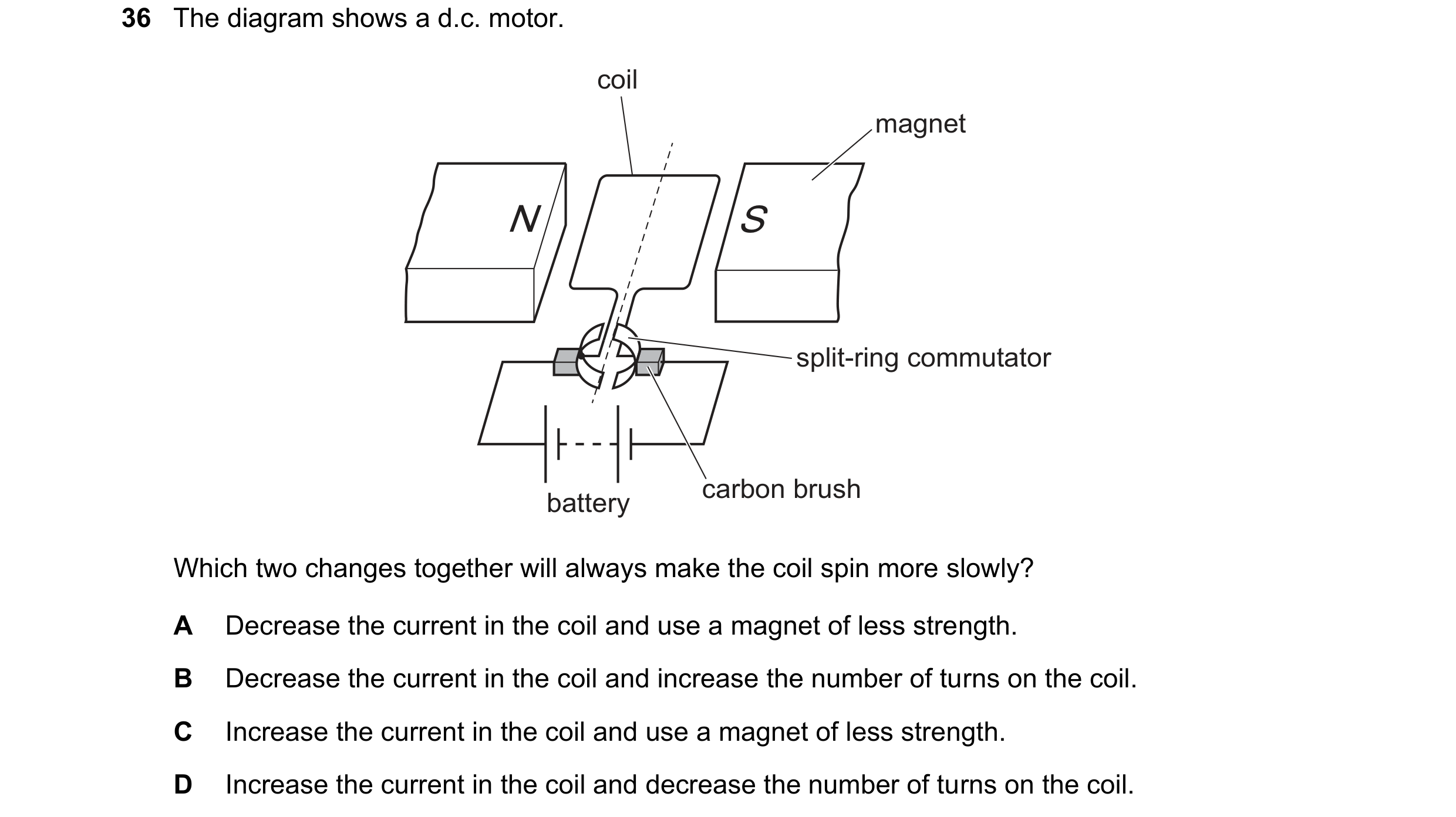 85 / 108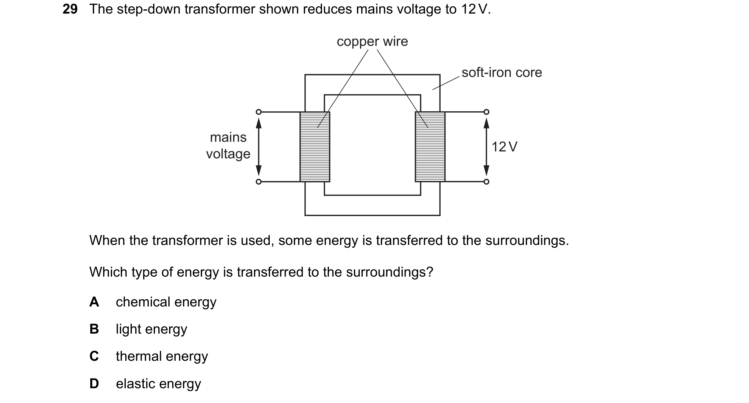
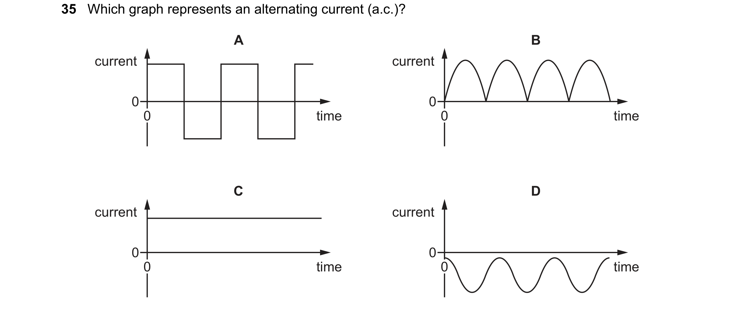
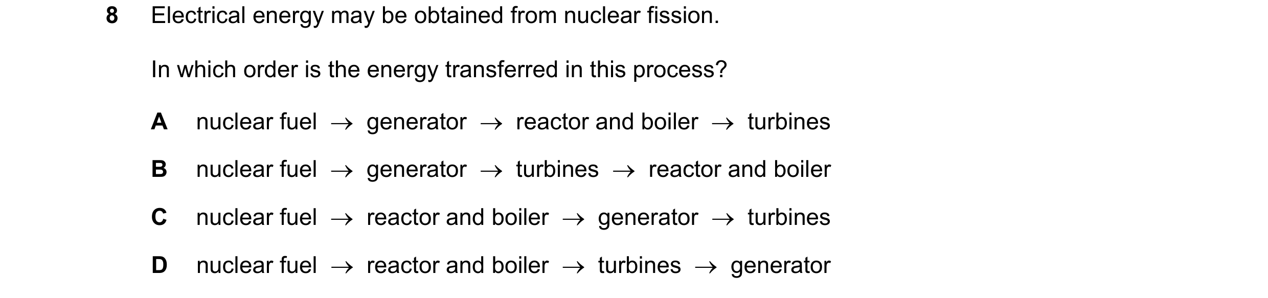 86 / 108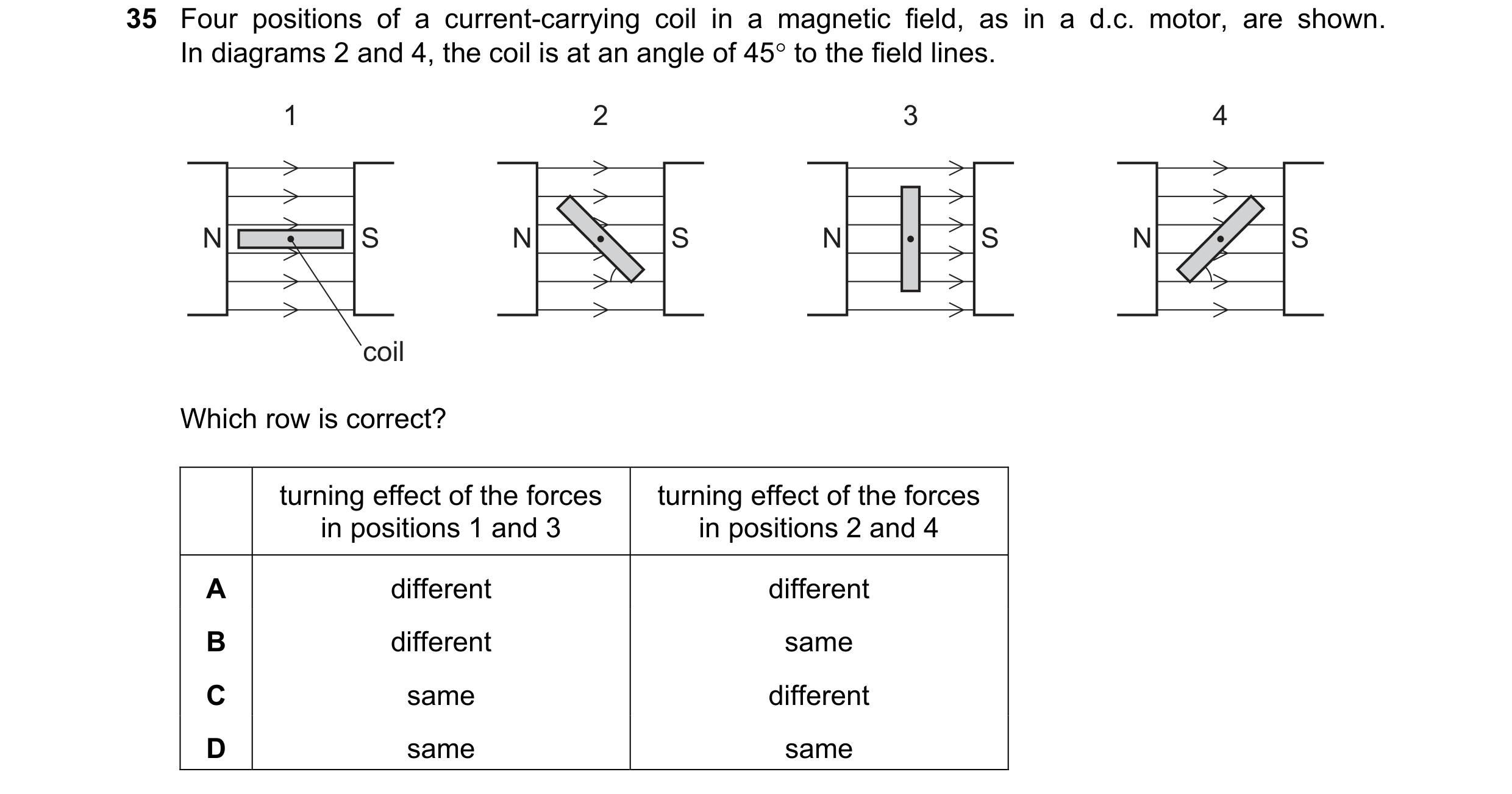
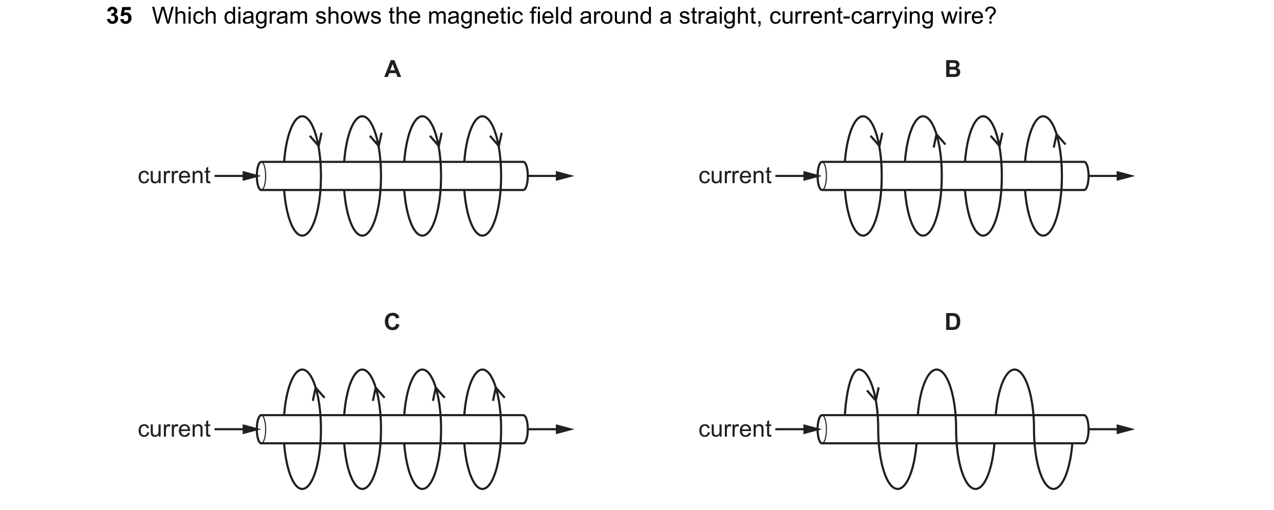
 87 / 108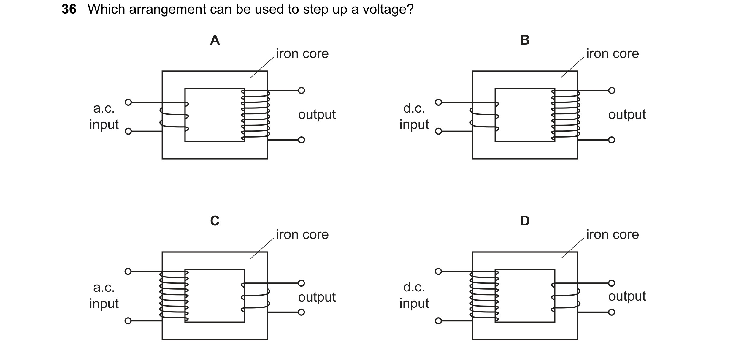
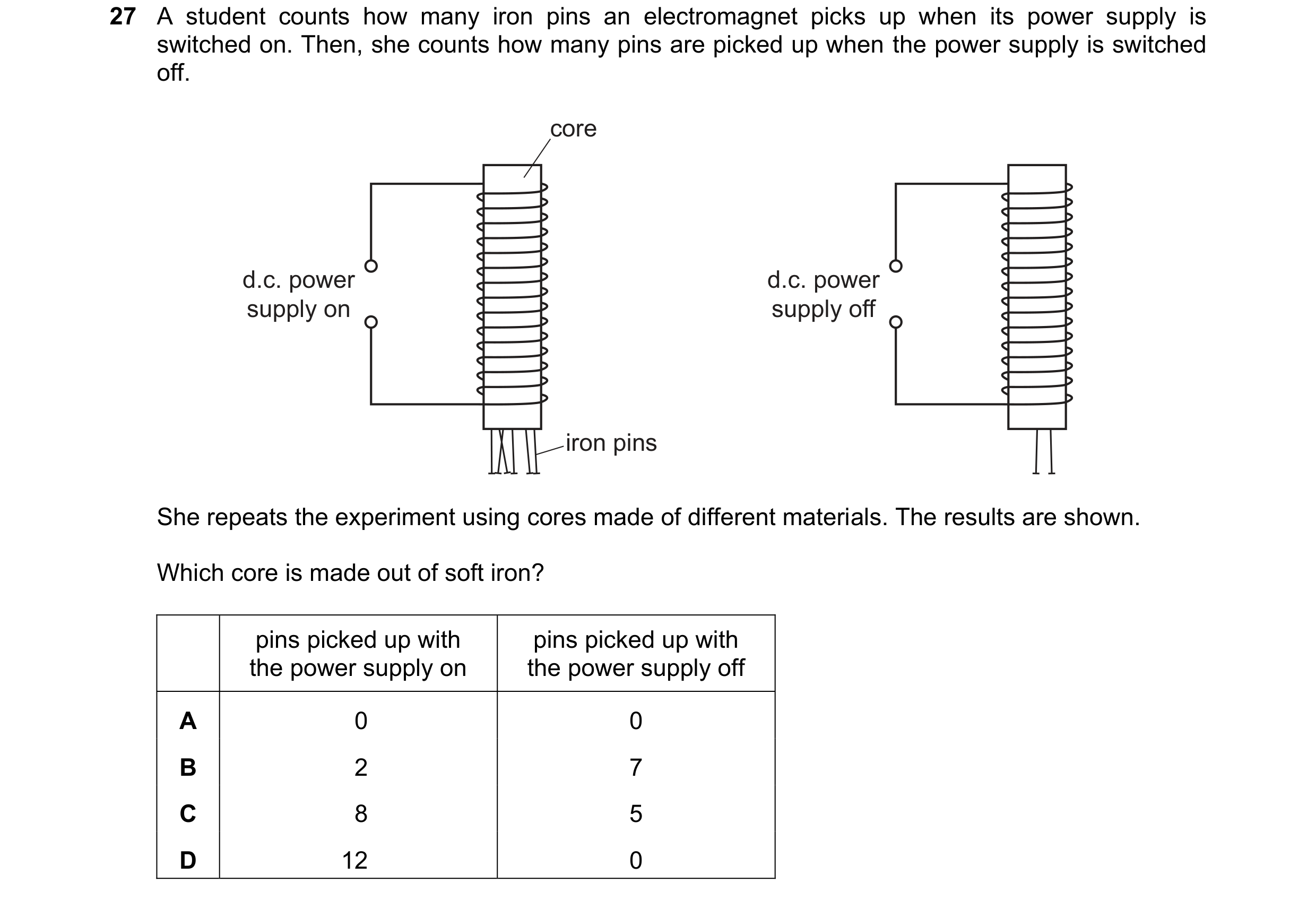 88 / 108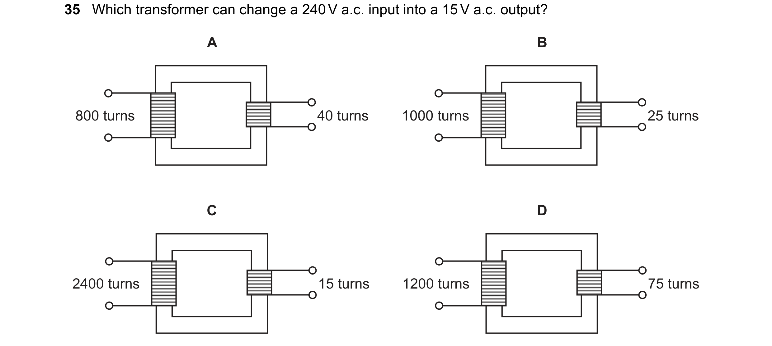
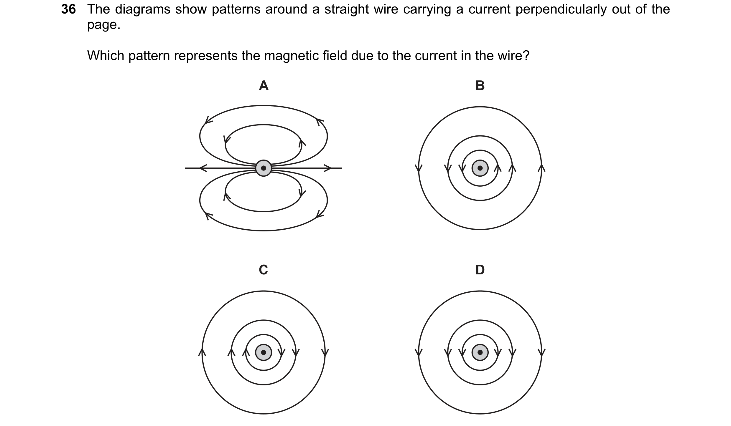
 89 / 108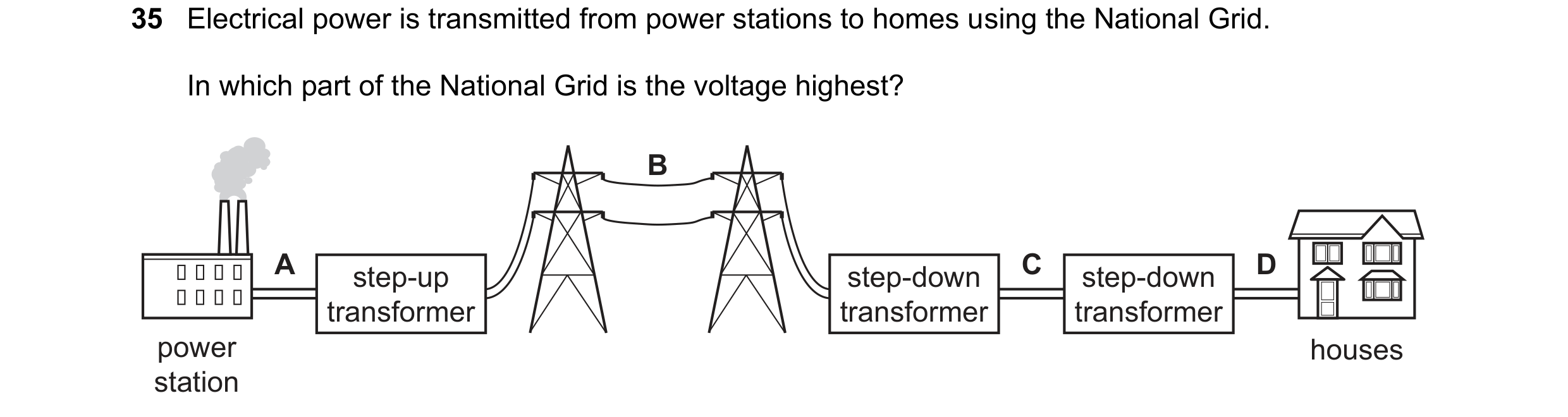
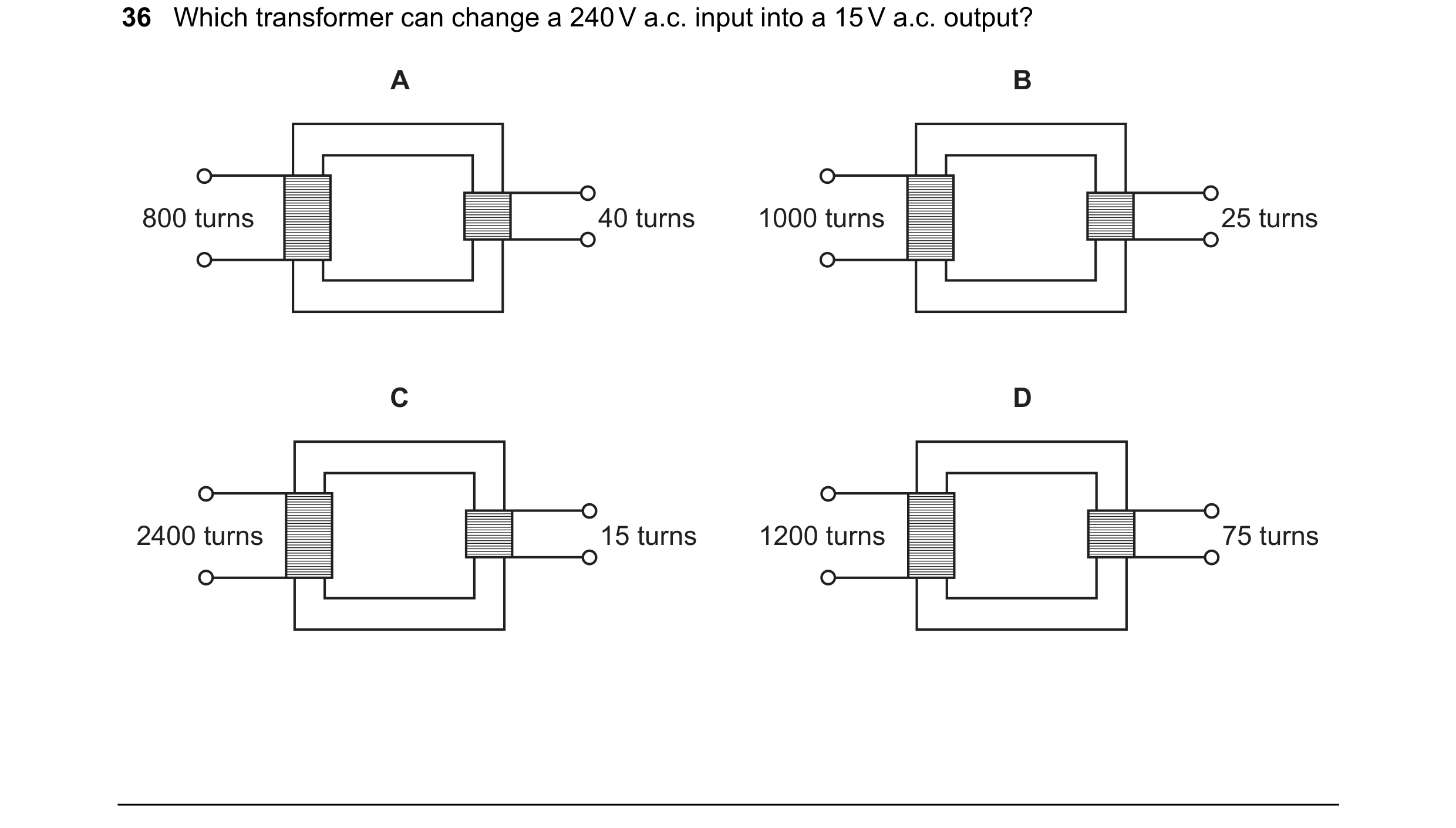
 90 / 108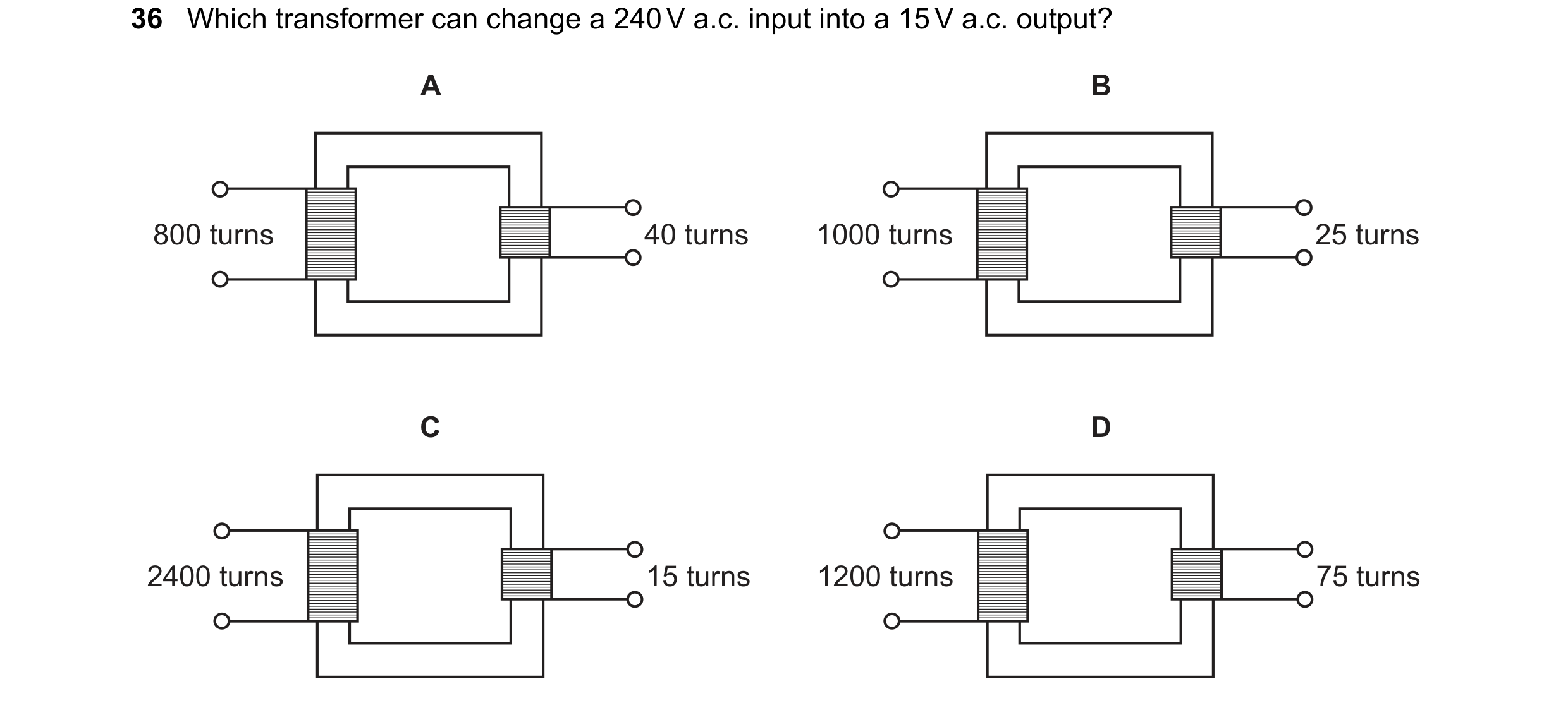
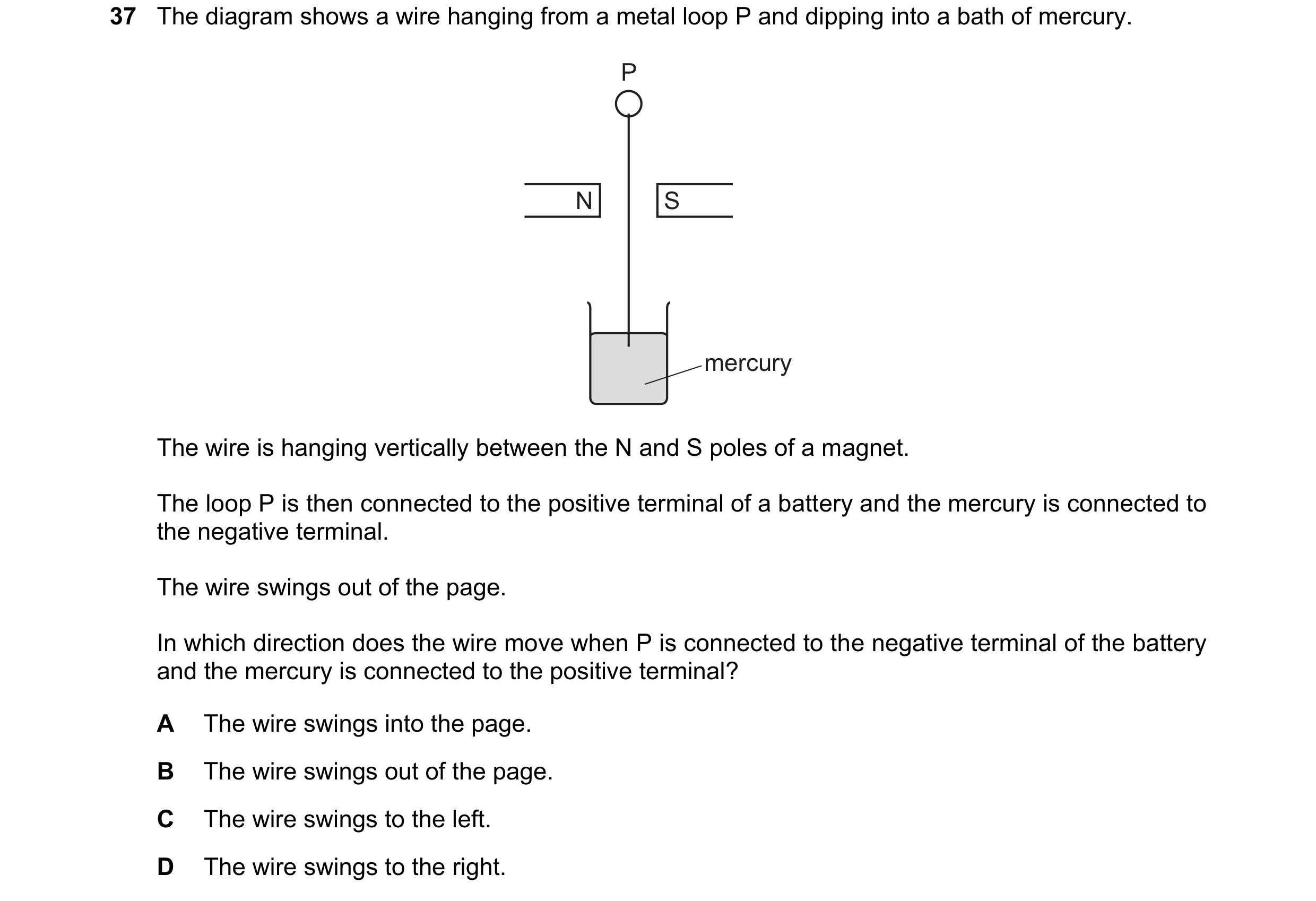 91 / 108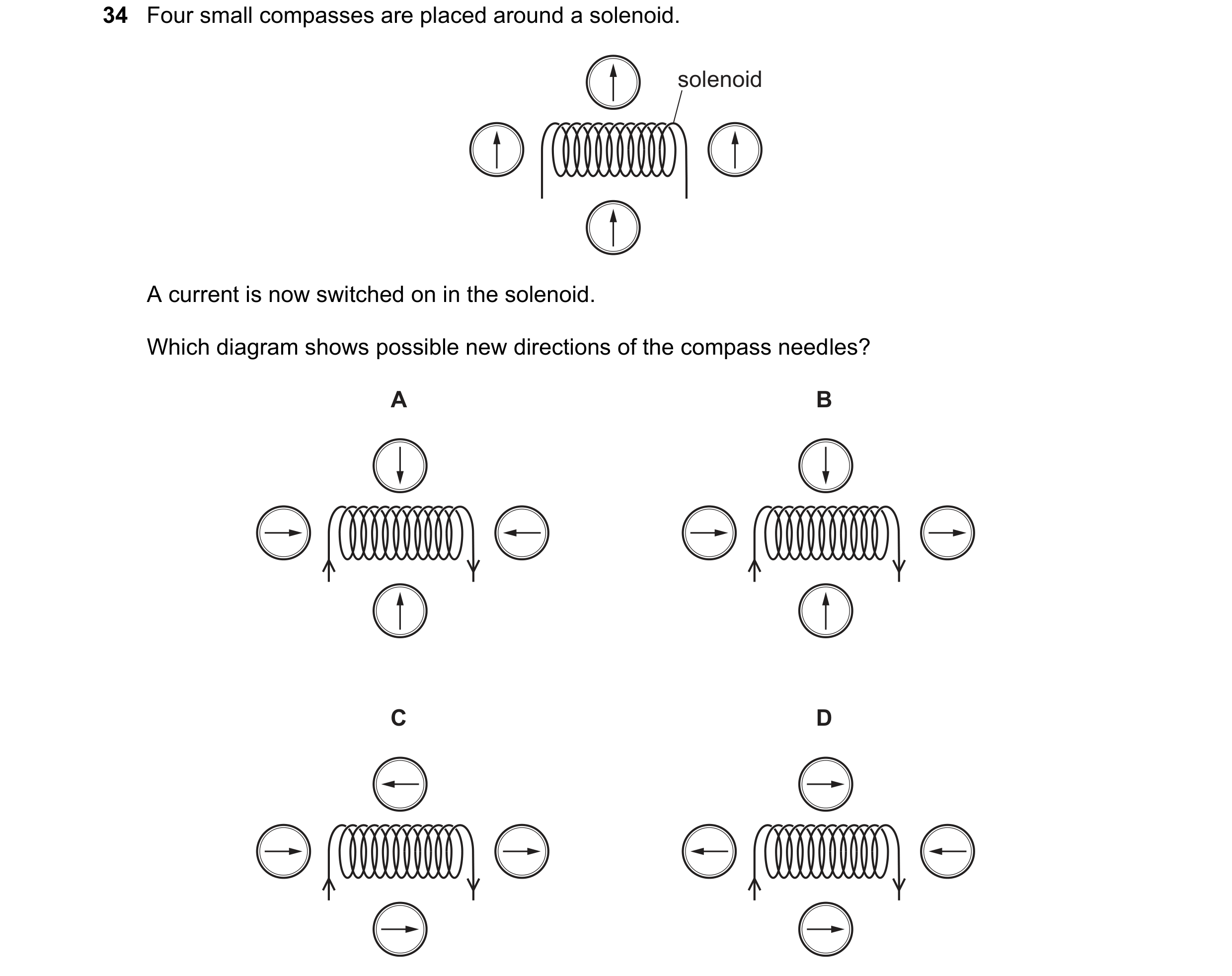
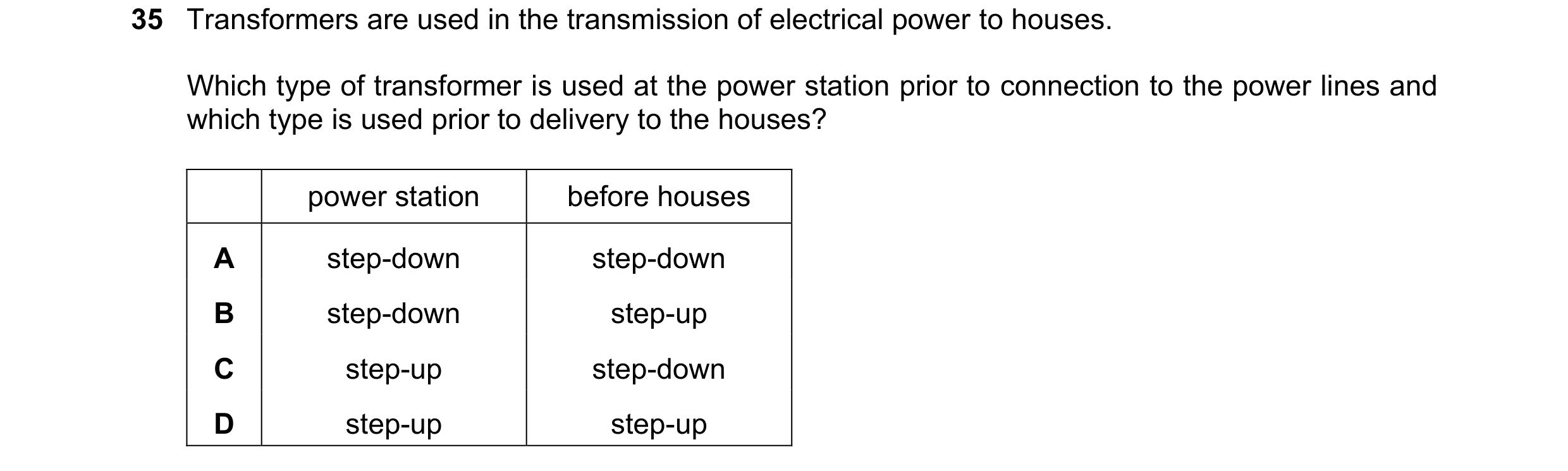 92 / 108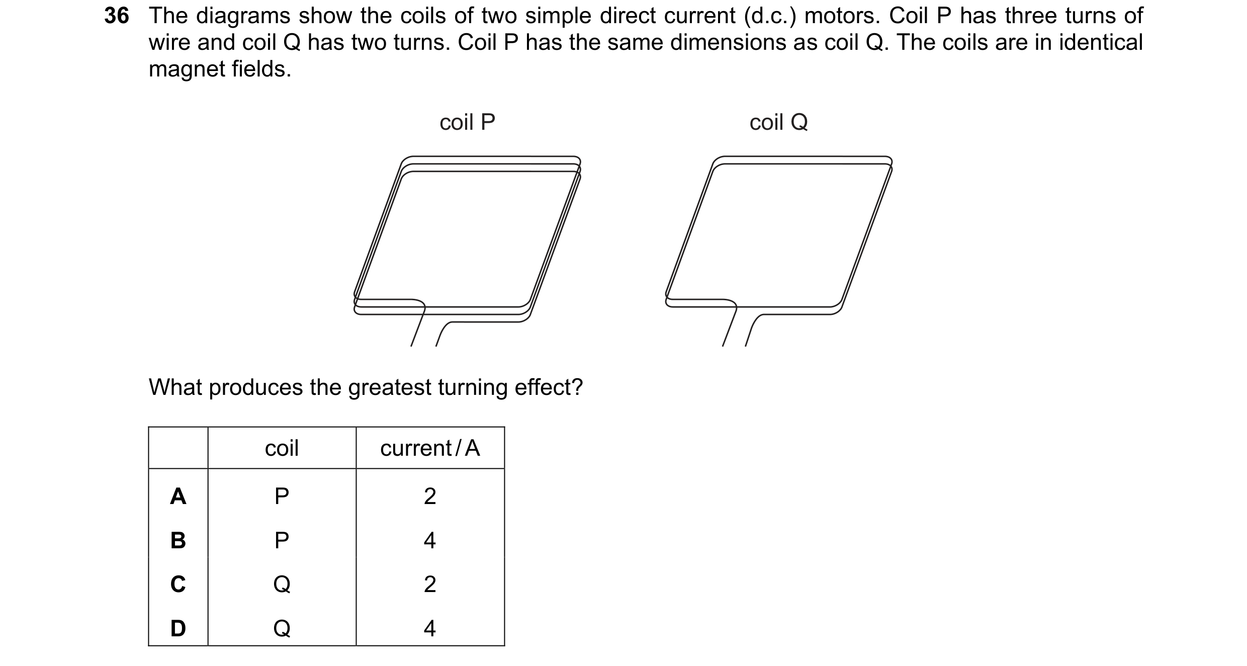
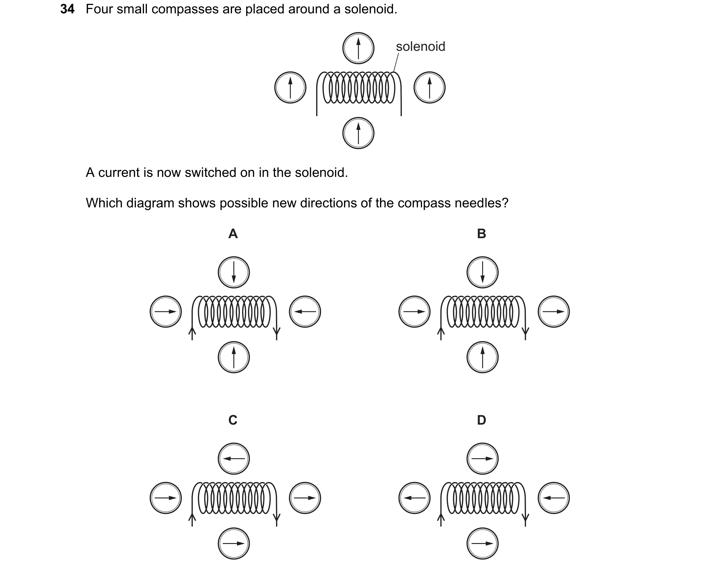 93 / 108
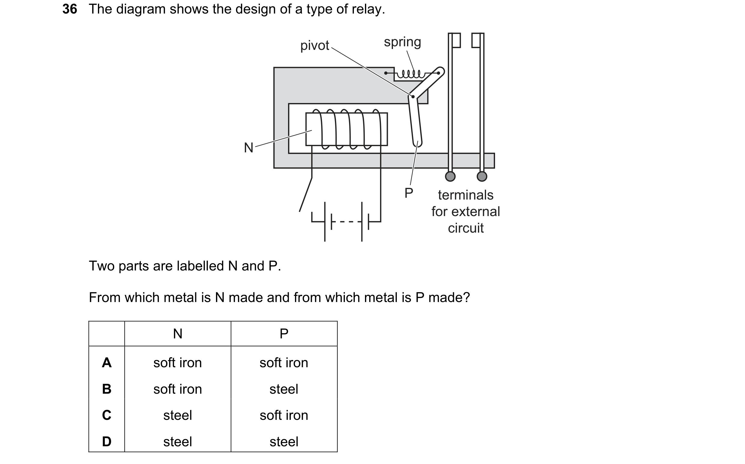
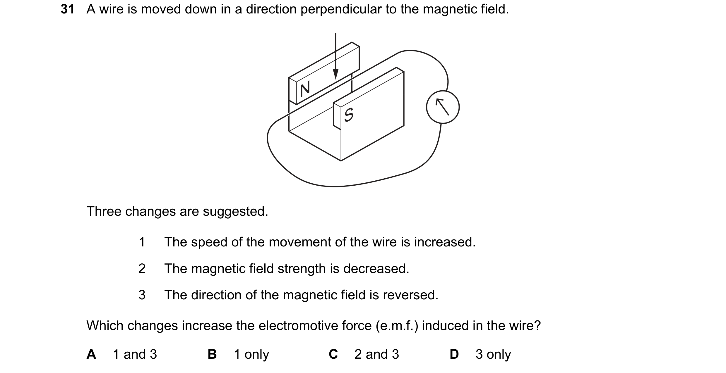 94 / 108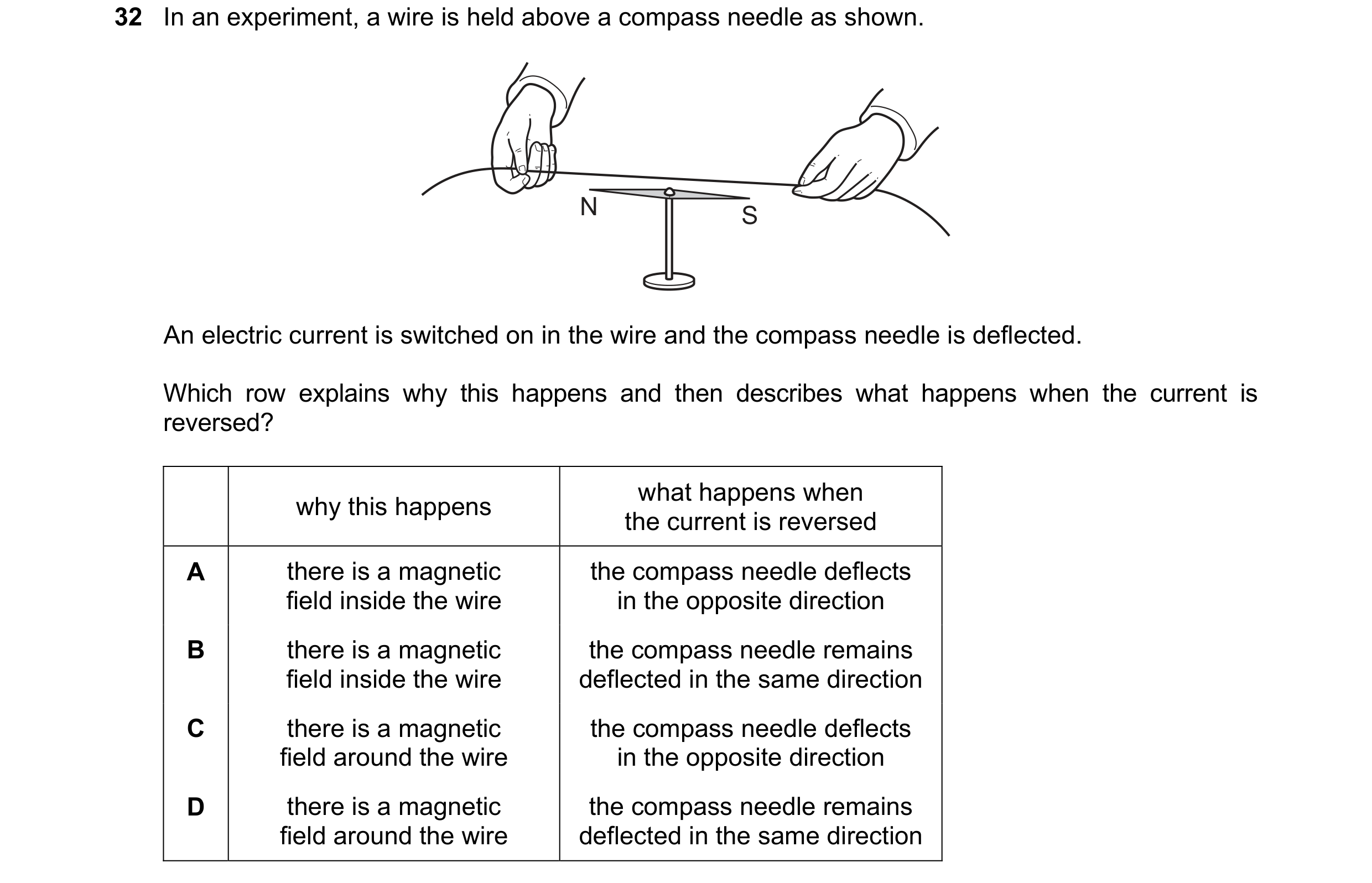
 95 / 108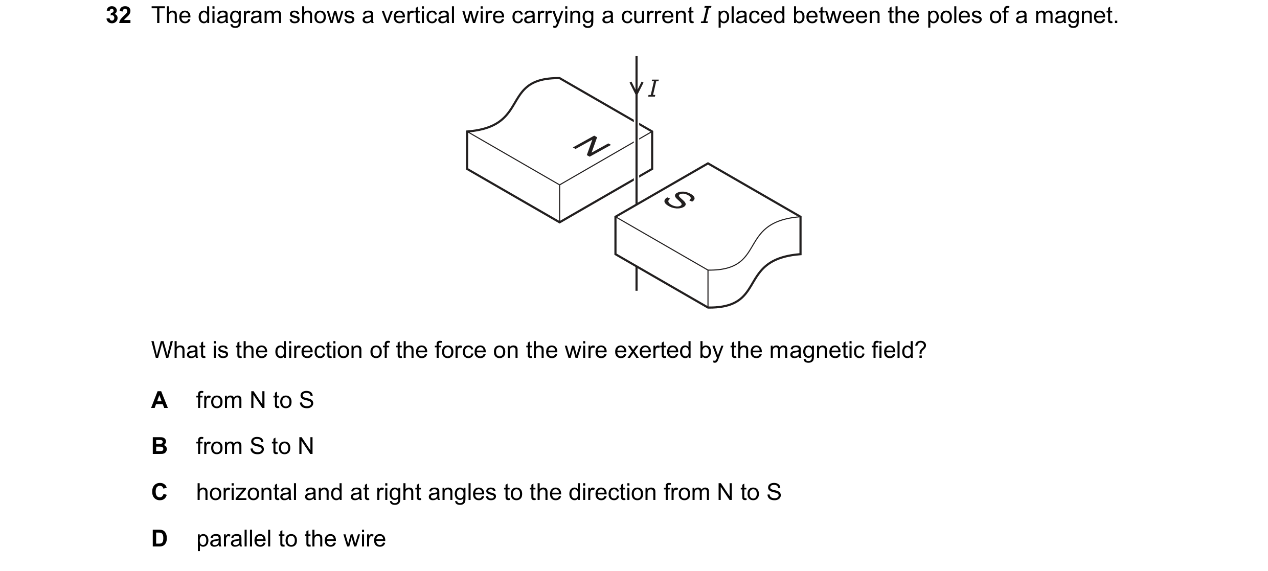

 96 / 108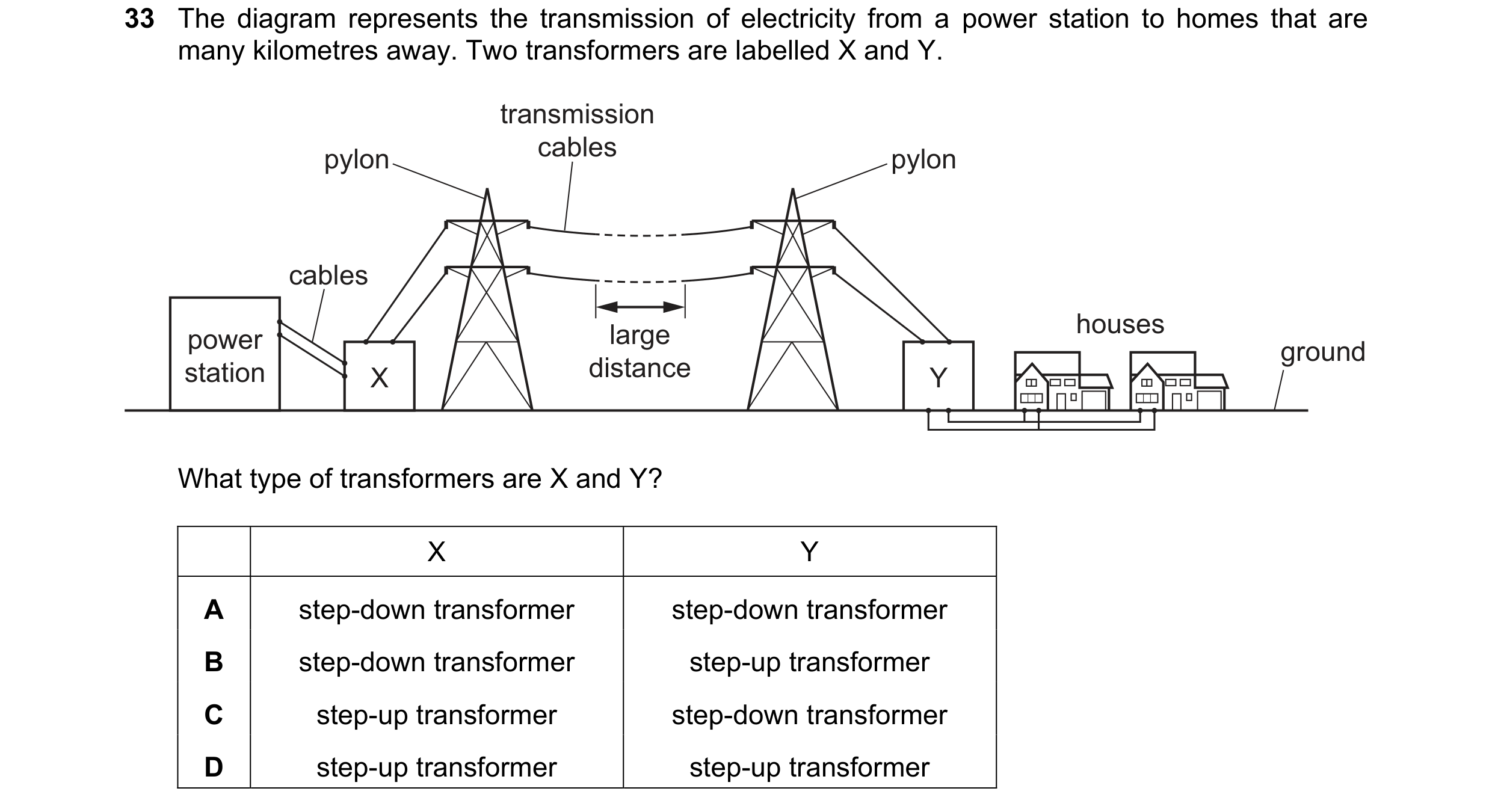
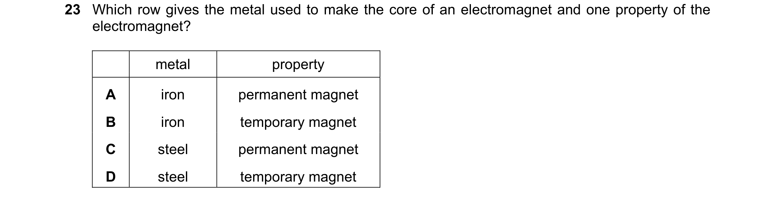
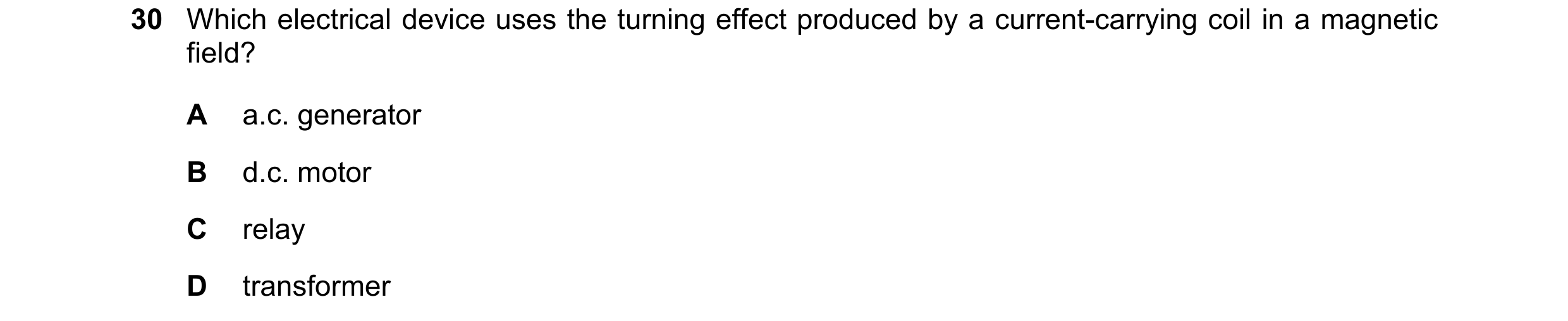
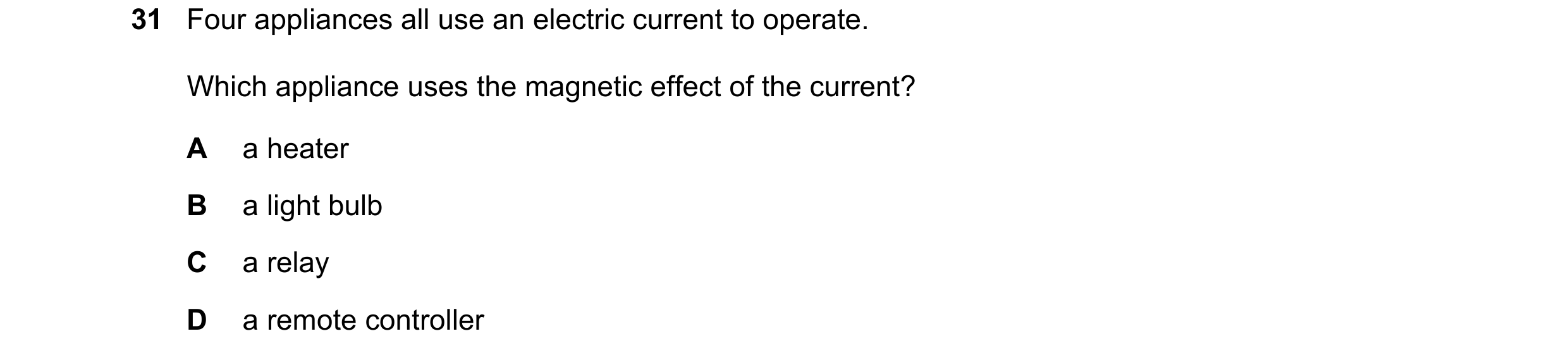 97 / 108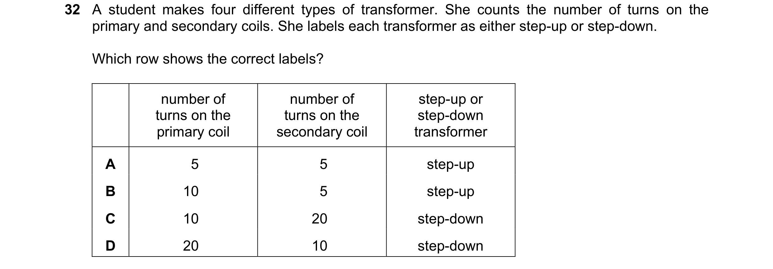
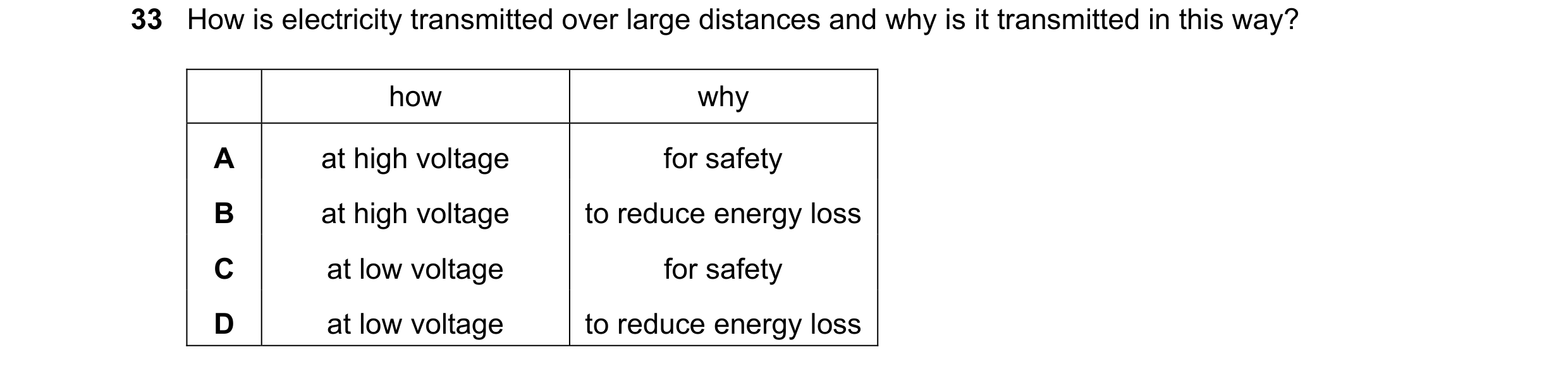
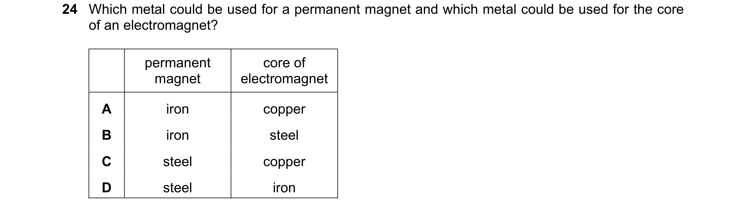 98 / 108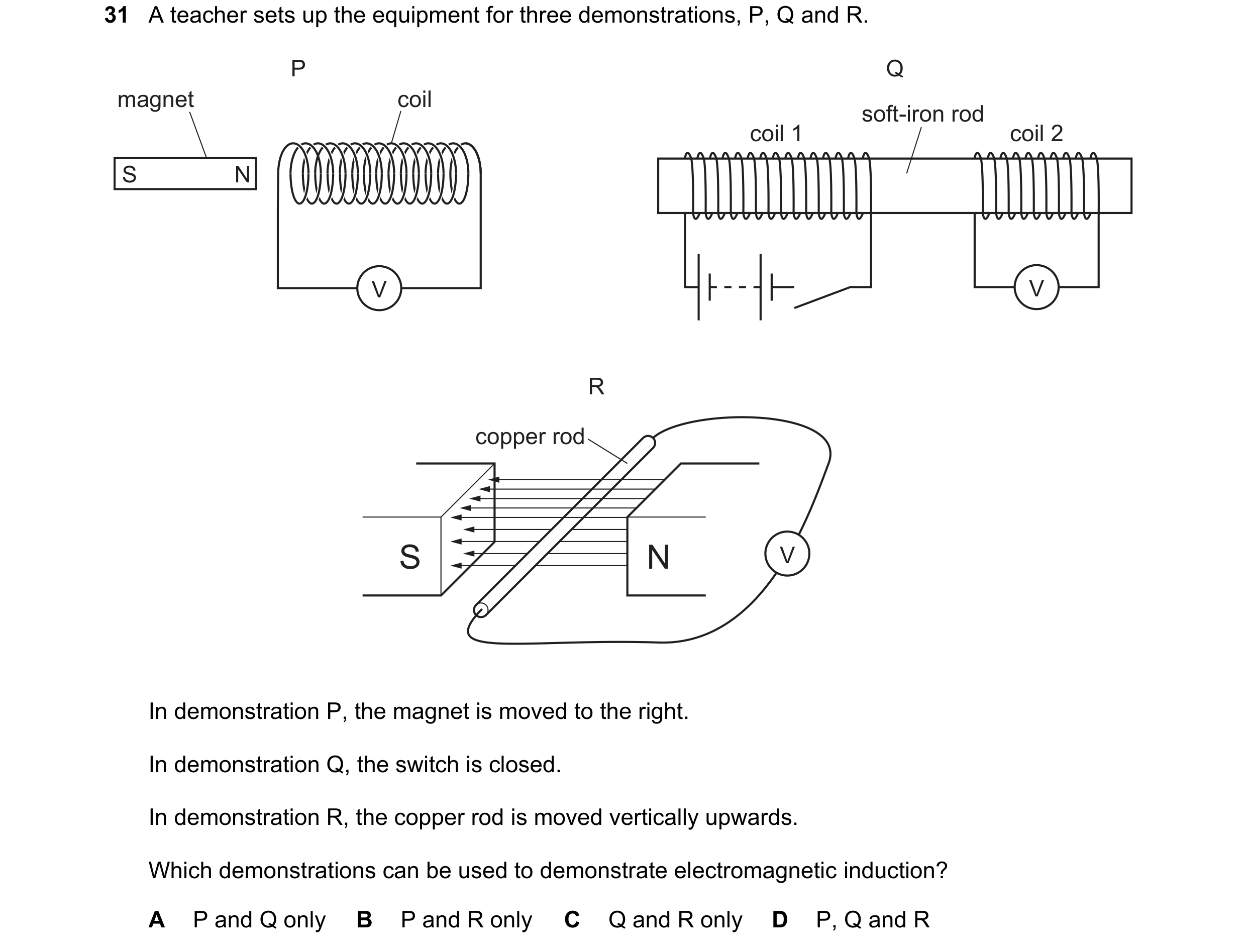
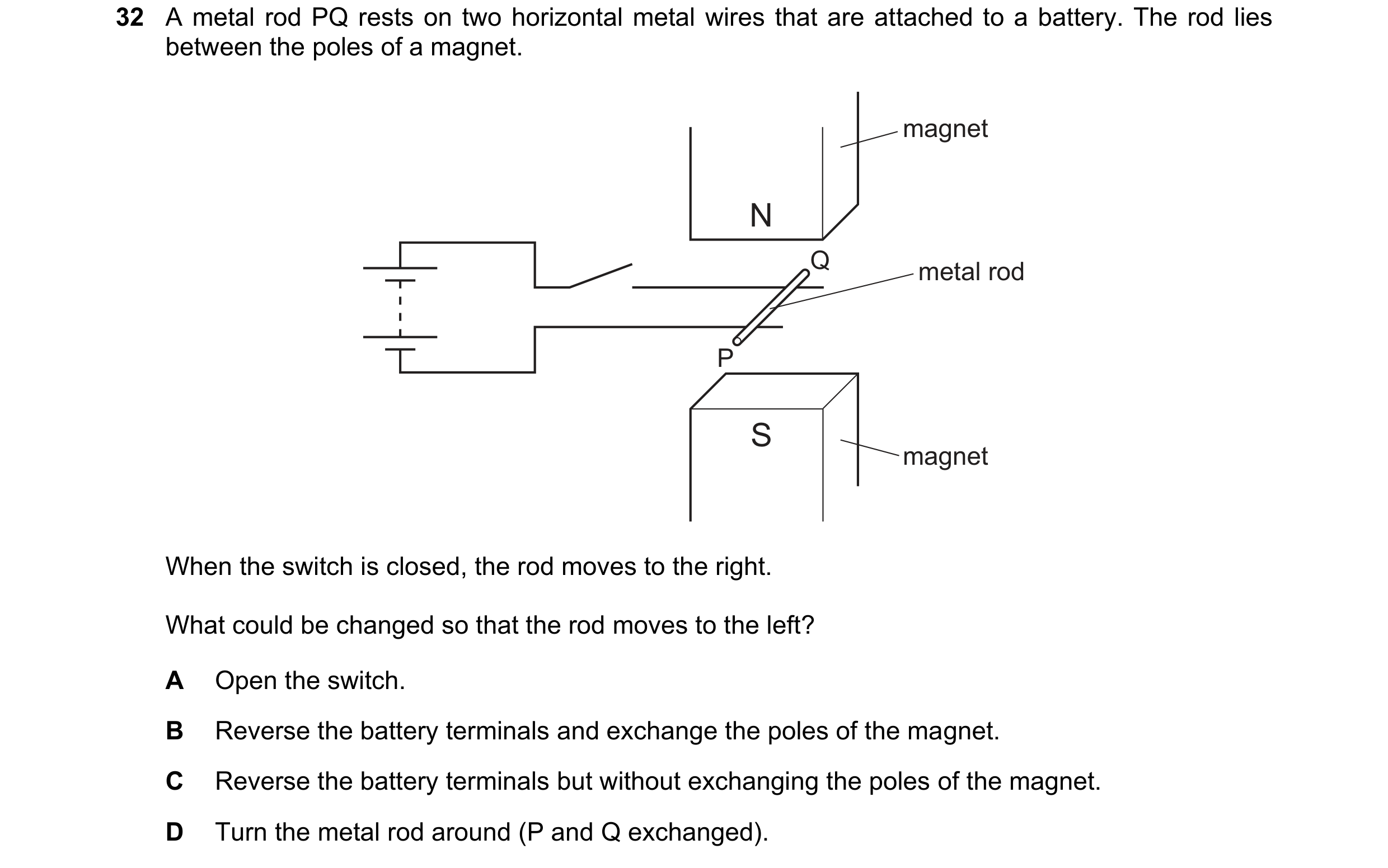 99 / 108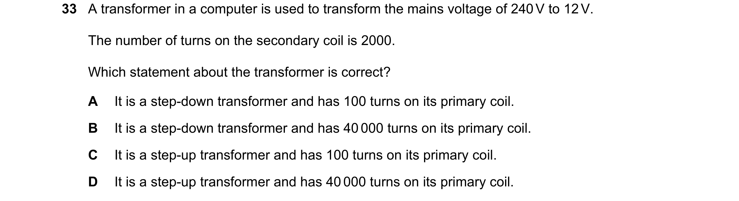
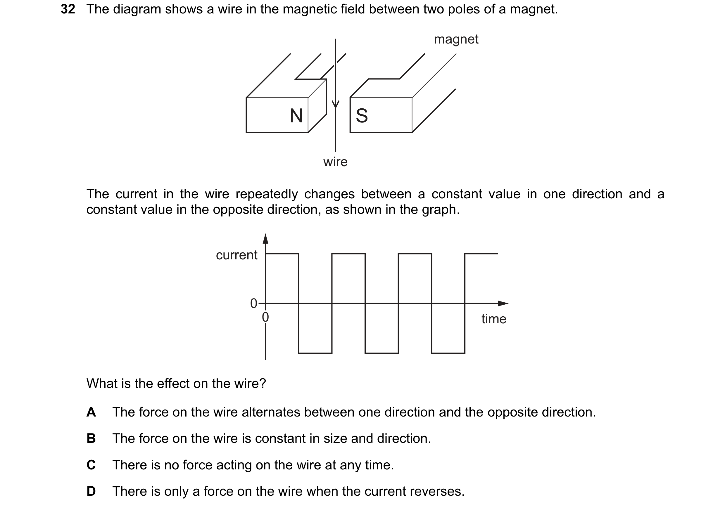
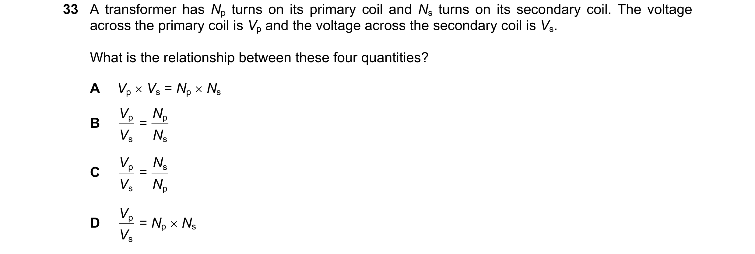 100 / 108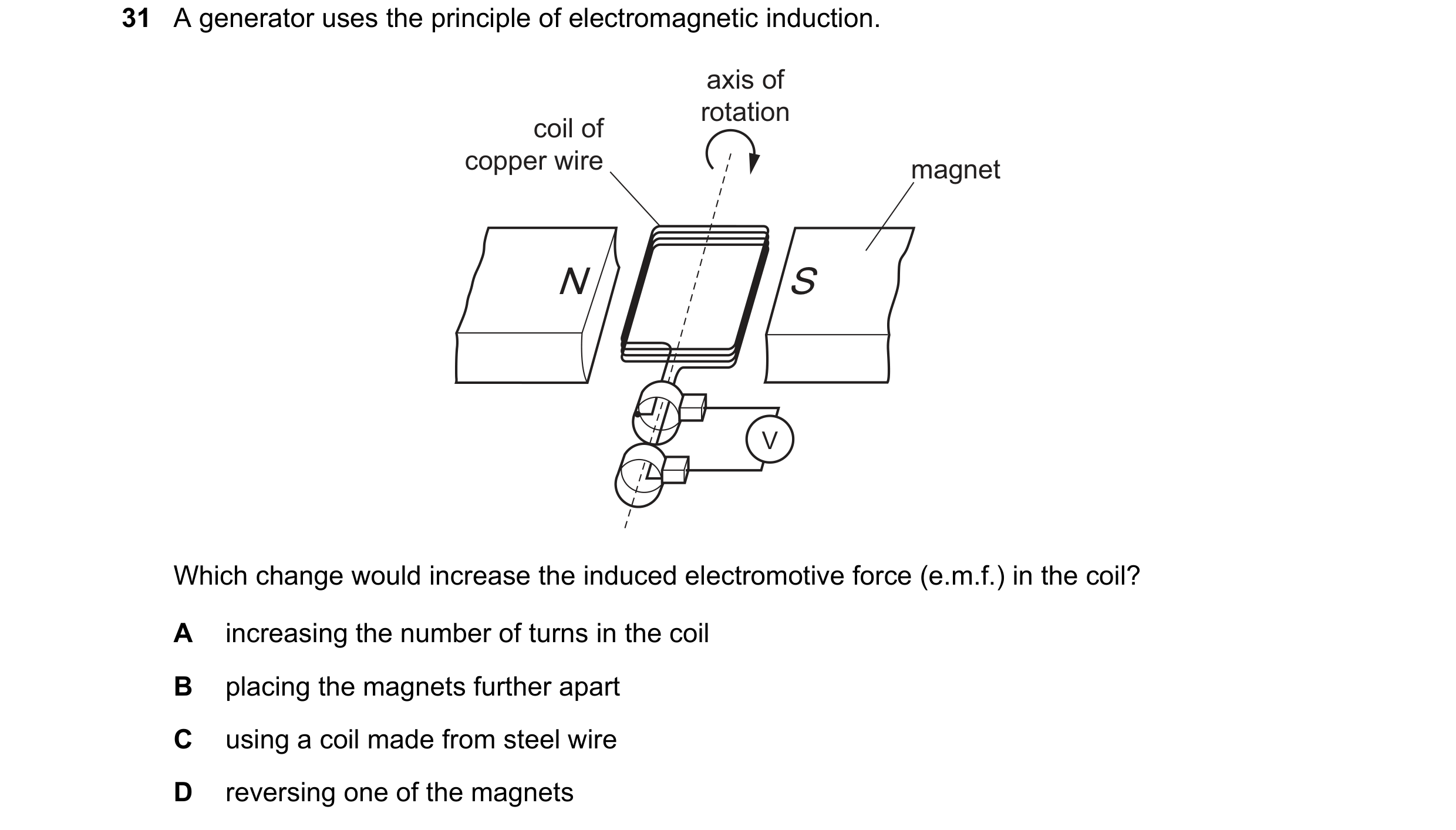
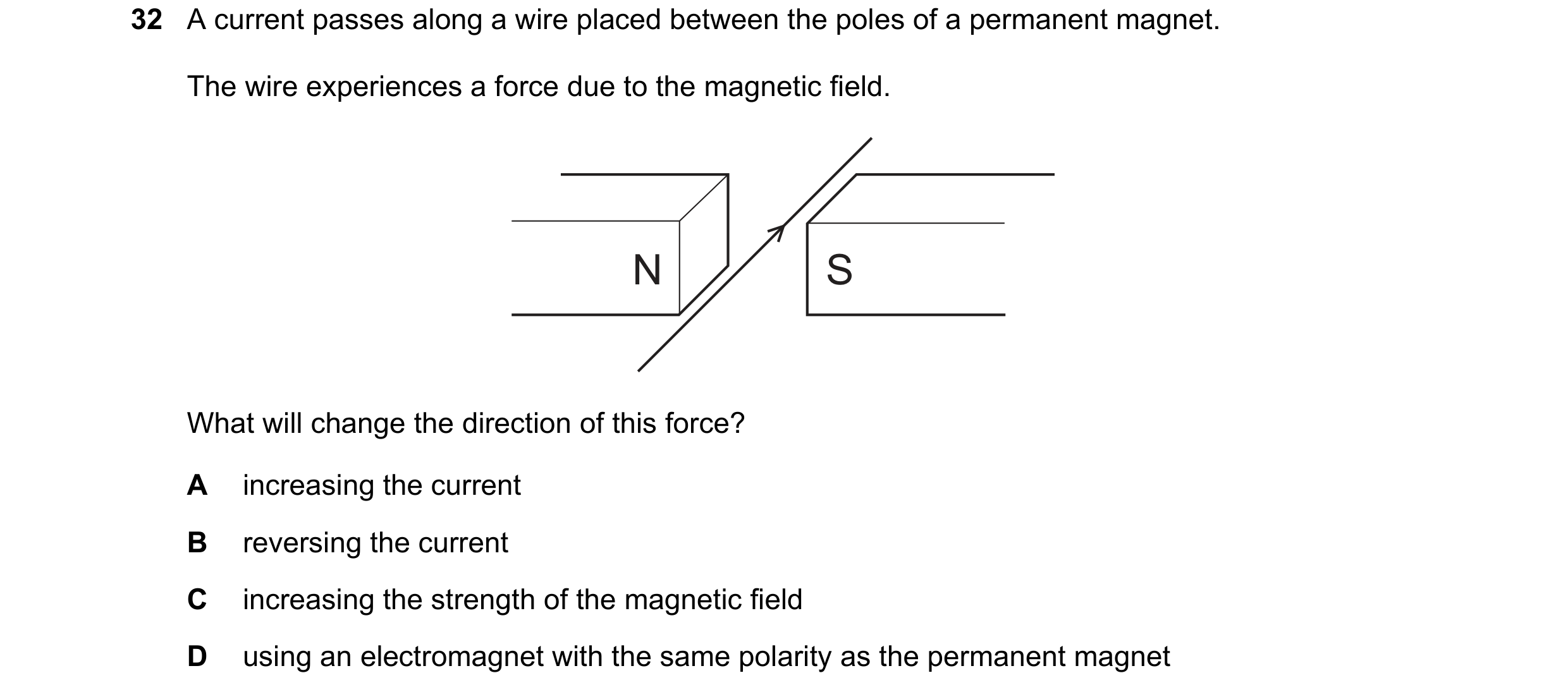
 101 / 108

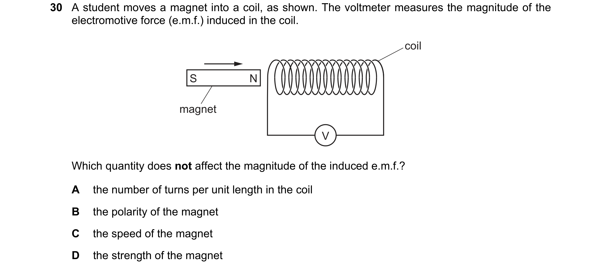
 102 / 108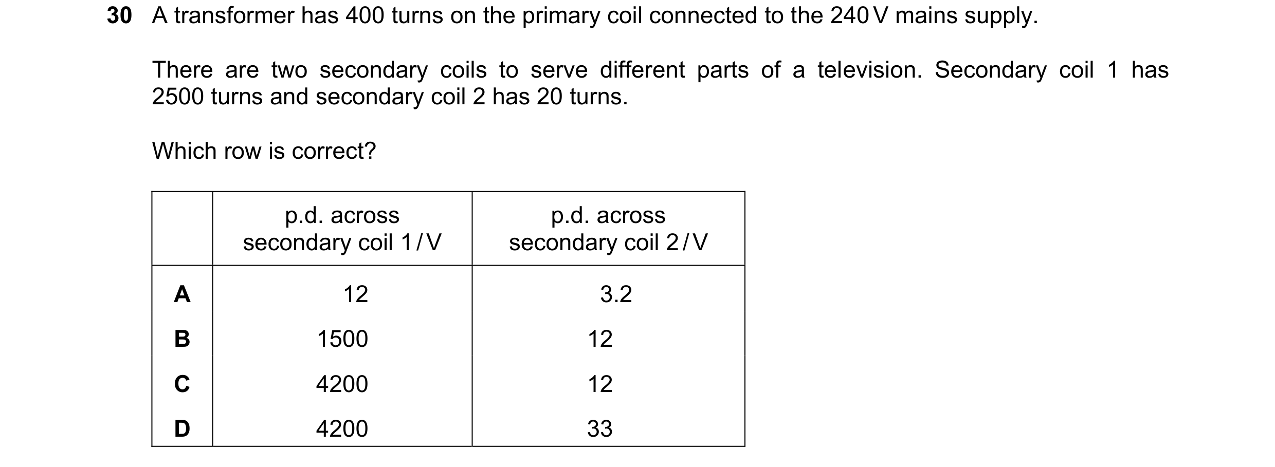
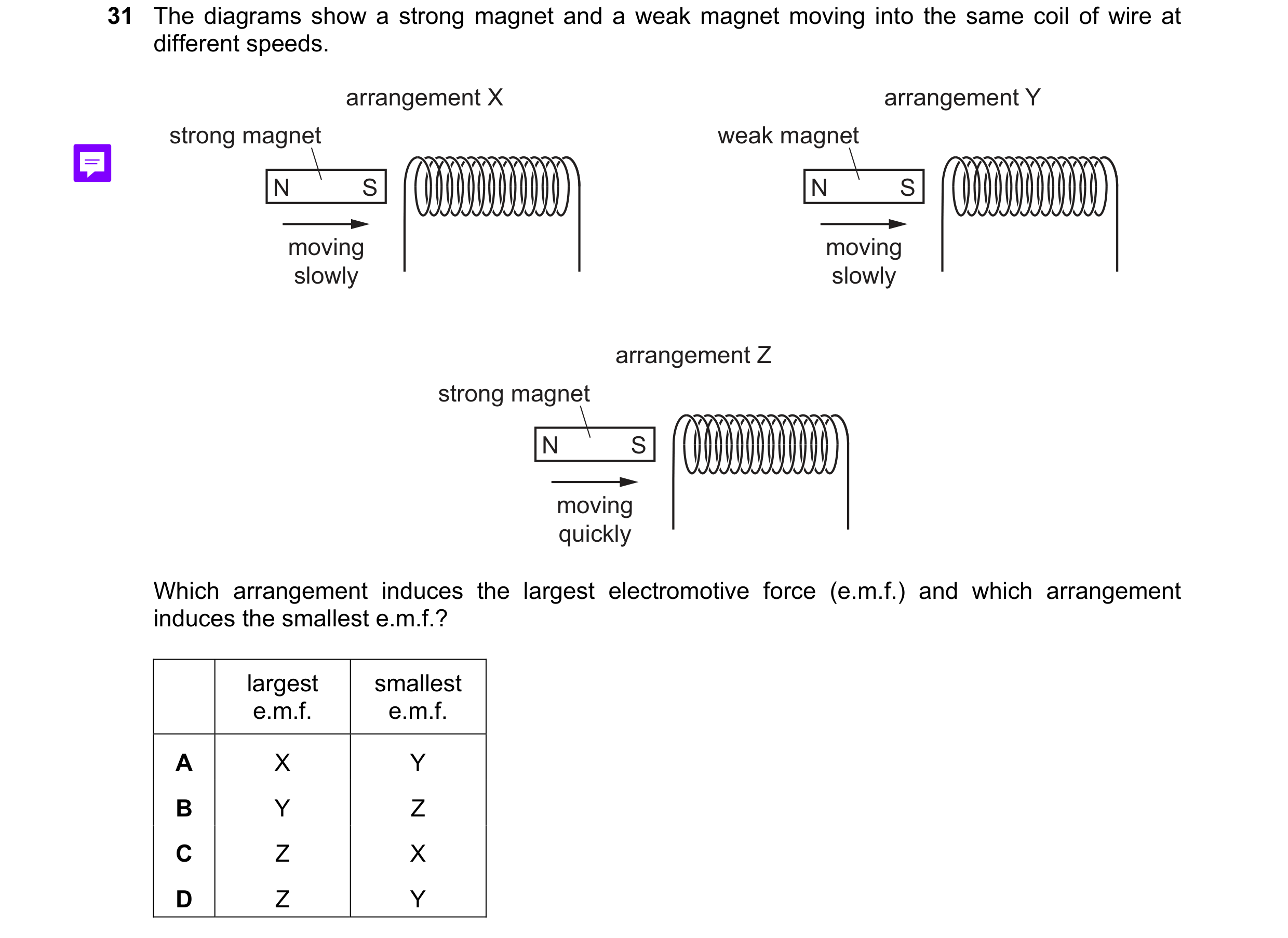 103 / 108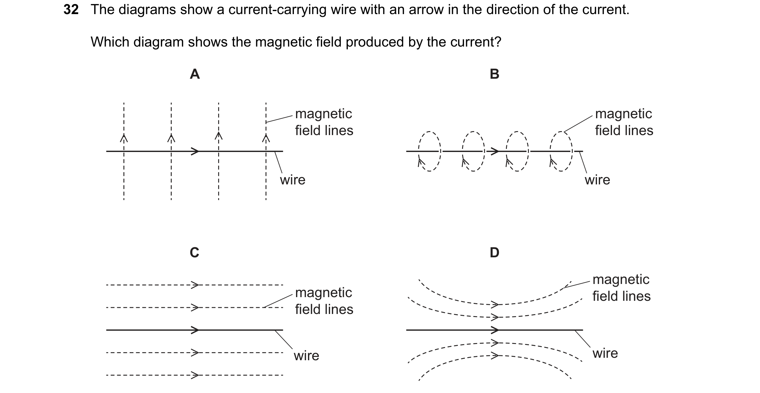

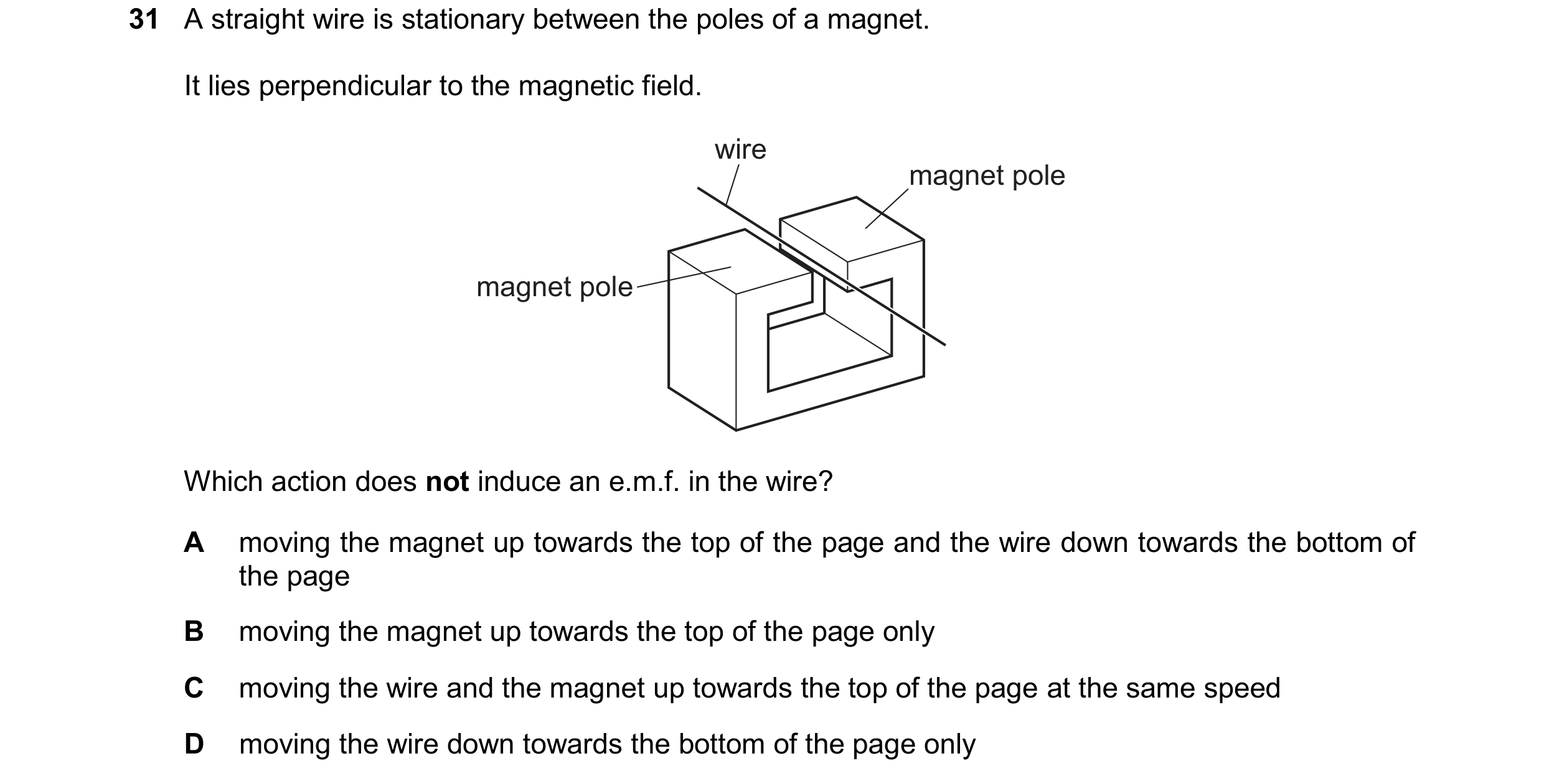 104 / 108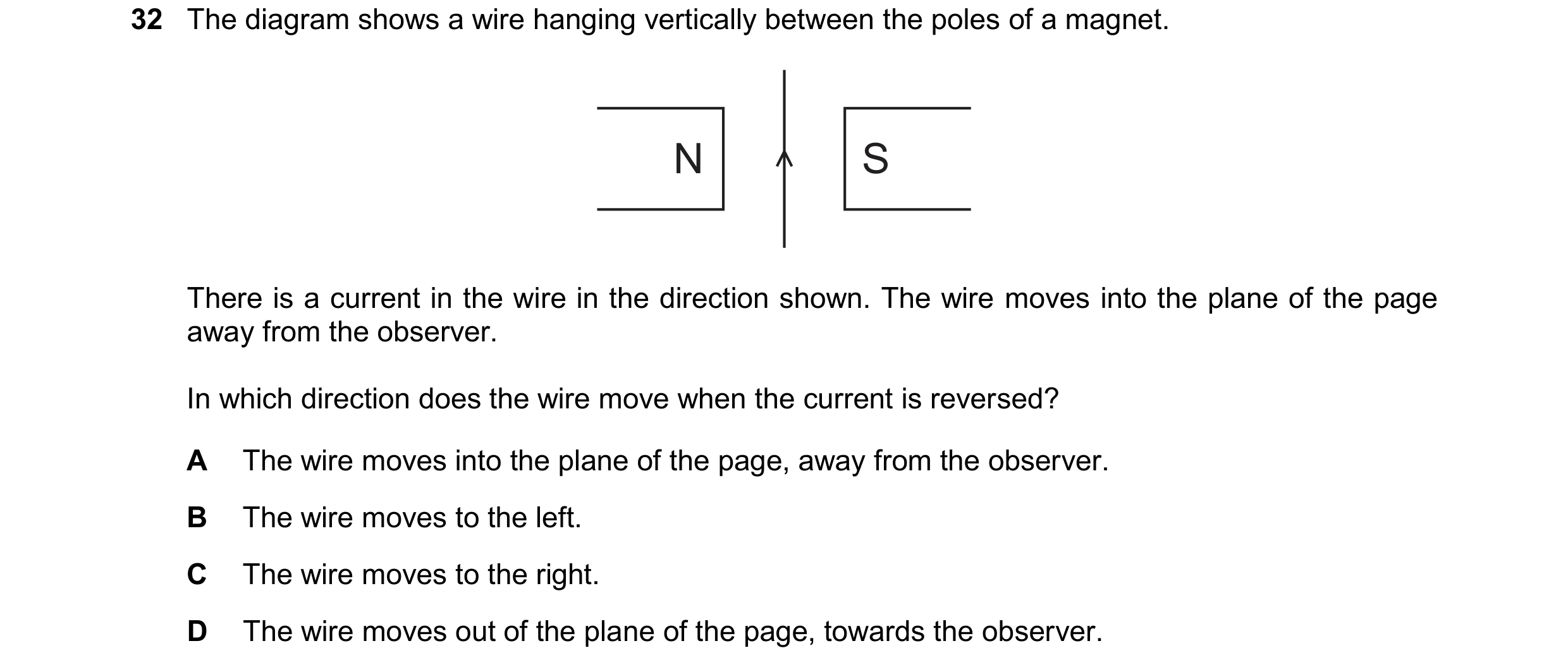

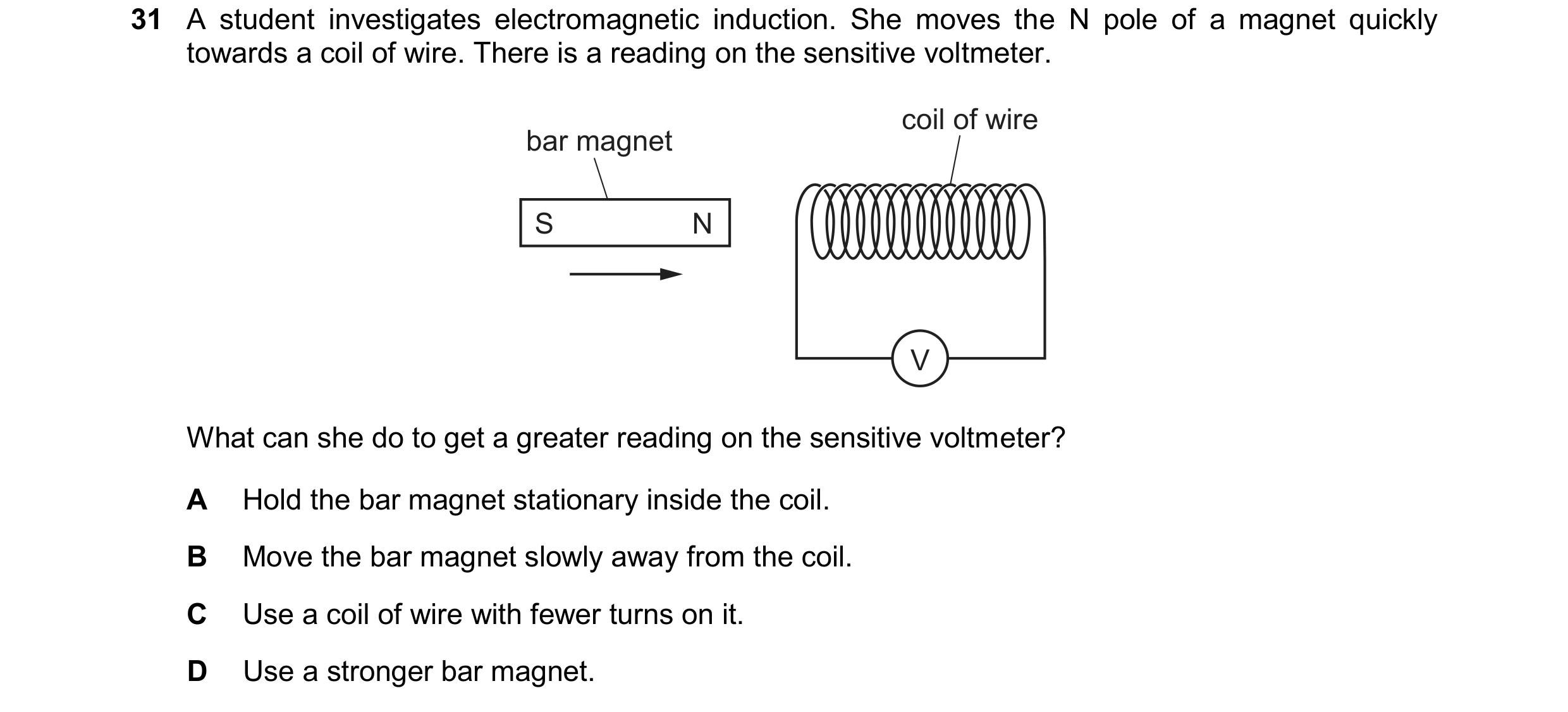 105 / 108
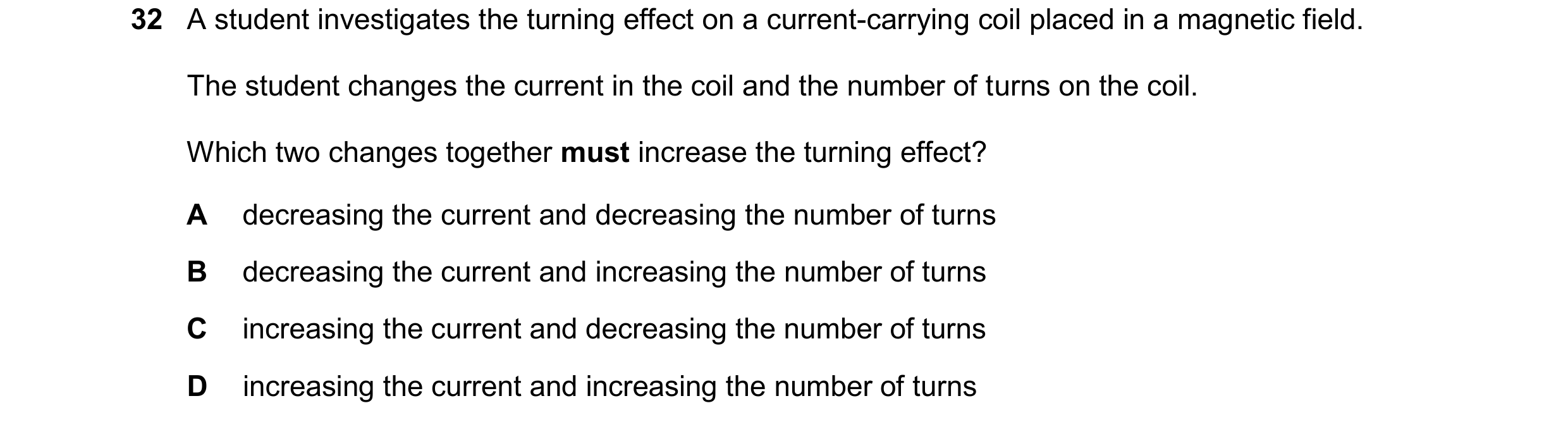
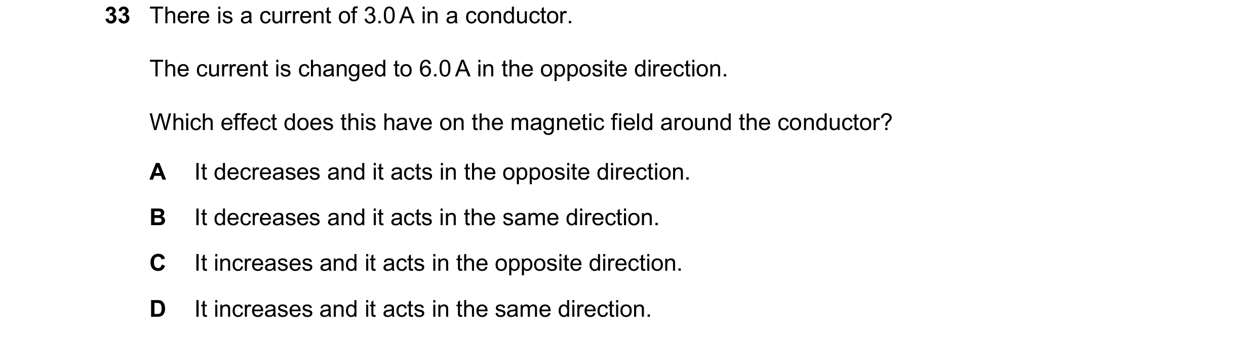 106 / 108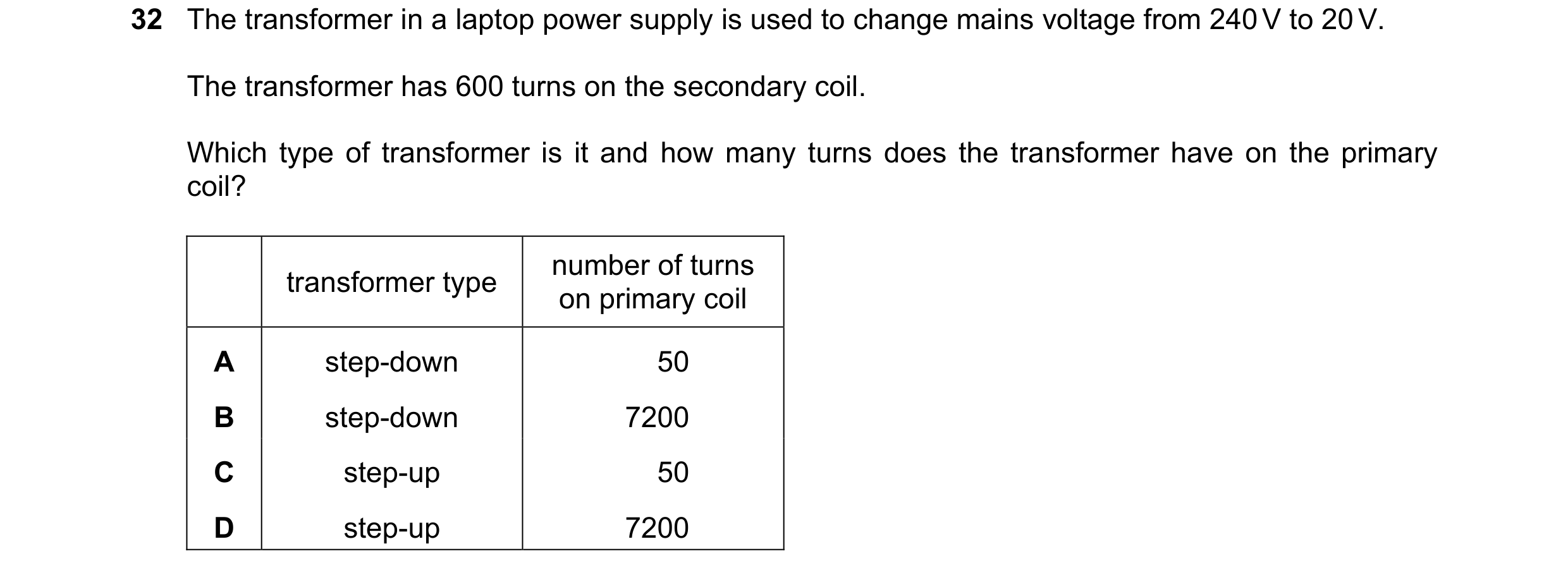
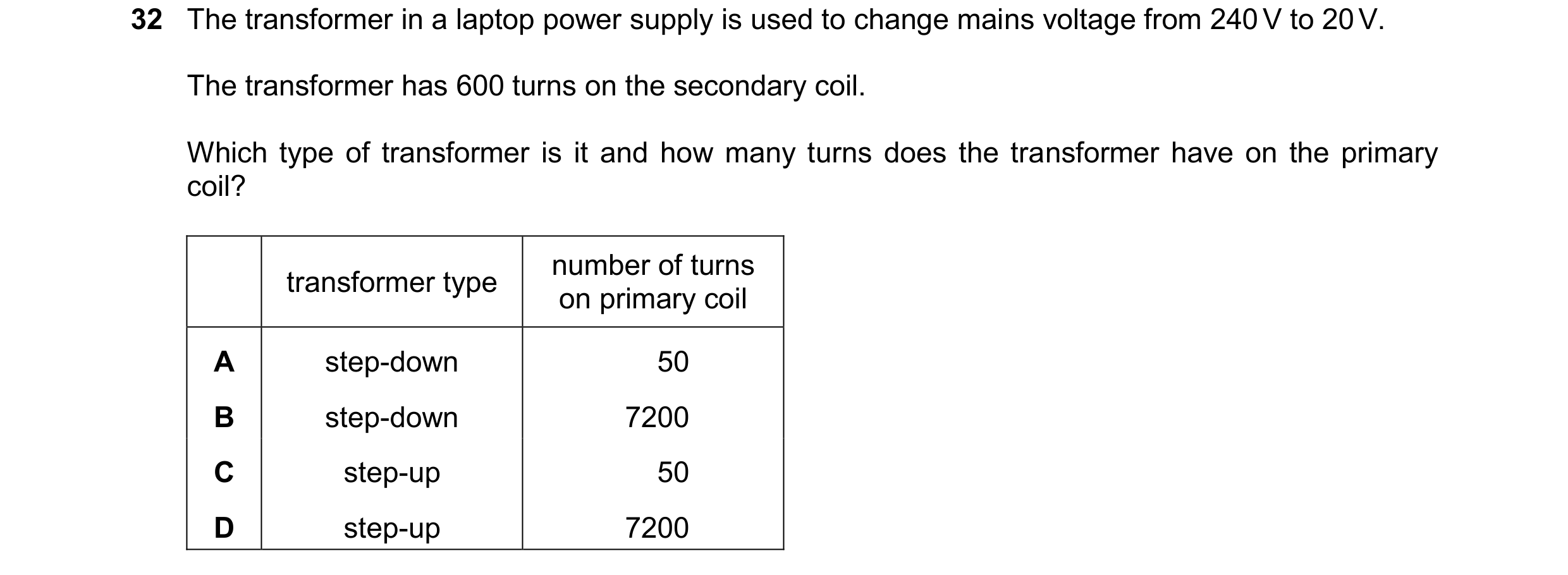
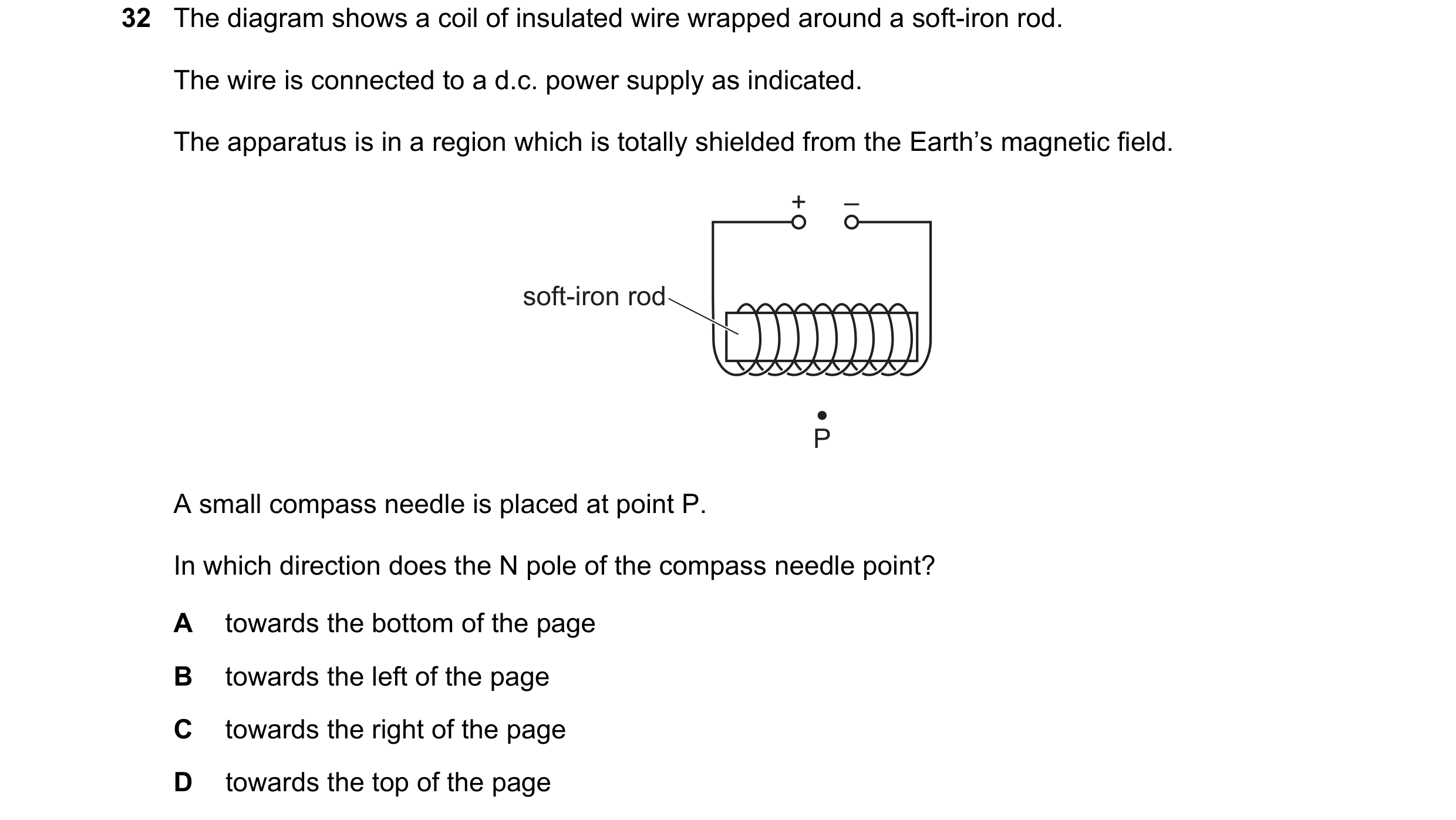 107 / 108
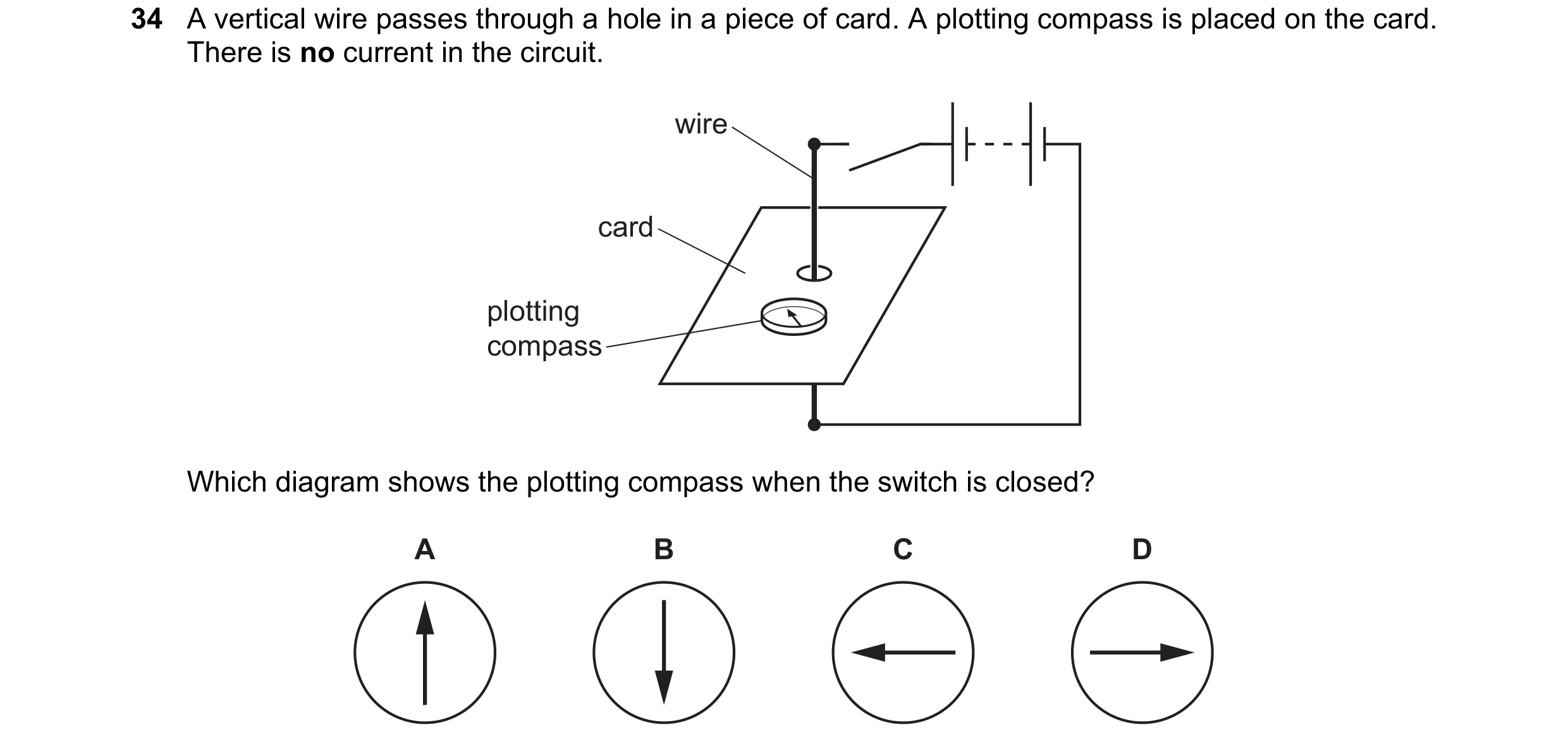 108 / 108