Questions as text
Q1 · A transformer consists of two coils of wire wound on a core 0625/42 Feb/March 2017
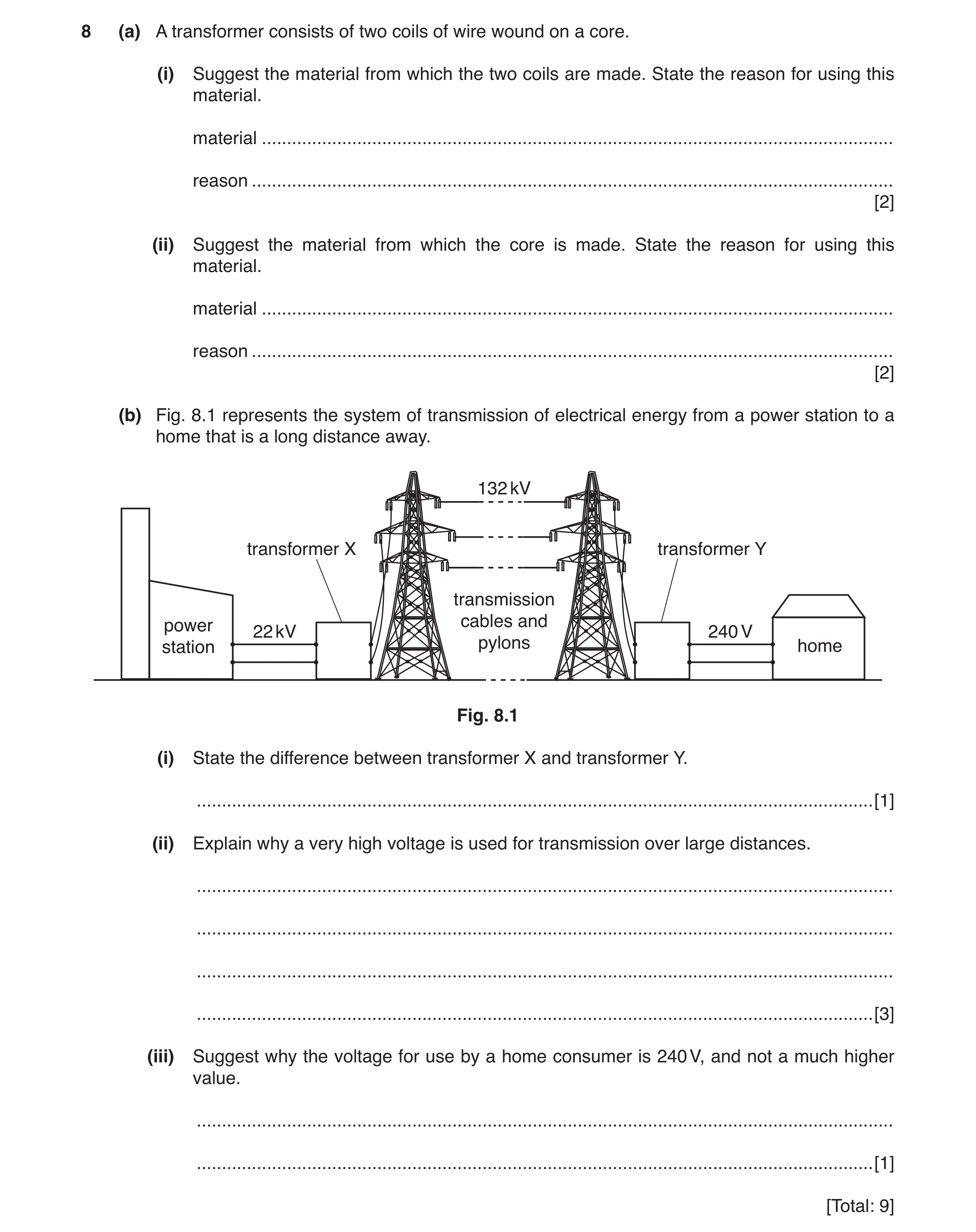
8 (a) A transformer consists of two coils of wire wound on a core. (i) Suggest the material from which the two coils are made. State the reason for using this material. material … reason … [2] (ii) Suggest the material from which the core is made. State the reason for using this material. material … reason … [2] (b) Fig. 8.1 represents the system of transmission of electrical energy from a power station to a home that is a long distance away. 132 kV transformer X transformer Y transmission power cables and 22 kV 240 V station pylons home Fig. 8.1 (i) State the difference between transformer X and transformer Y. … [1] (ii) Explain why a very high voltage is used for transmission over large distances. … … … … [3] (iii) Suggest why the voltage for use by a home consumer is 240 V, and not a much higher value. … … [1] [Total: 9]
9 marks
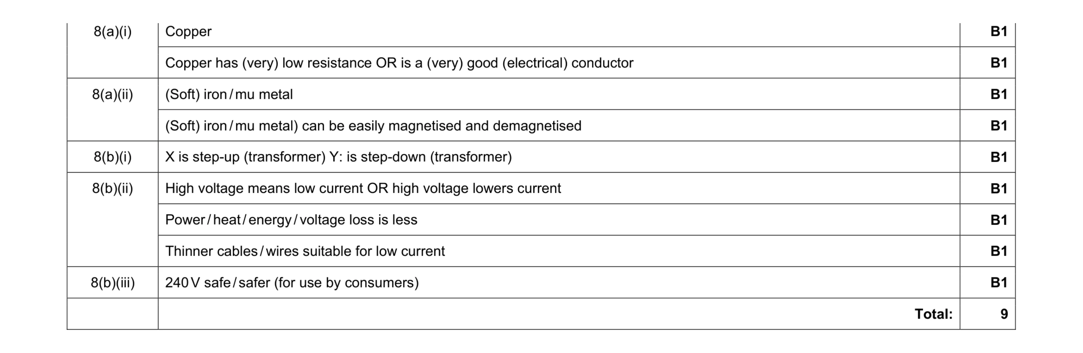
Mark scheme: 8(a)(i) Copper B1 Copper has (very) low resistance OR is a (very) good (electrical) conductor B1 8(a)(ii) (Soft) iron / mu metal B1 (Soft) iron / mu metal) can be easily magnetised and demagnetised B1 8(b)(i) X is step-up (transformer) Y: is step-down (transformer) B1 8(b)(ii) High voltage means low current OR high voltage lowers current B1 Power / heat / energy / voltage loss is less B1 Thinner cables / wires suitable for low current B1 8(b)(iii) 240 V safe / safer (for use by consumers) B1 Total: 9
This question in 0625/42 Feb/March 2017
Q2 · A bar magnet is made of metal 0625/41 May/June 2017
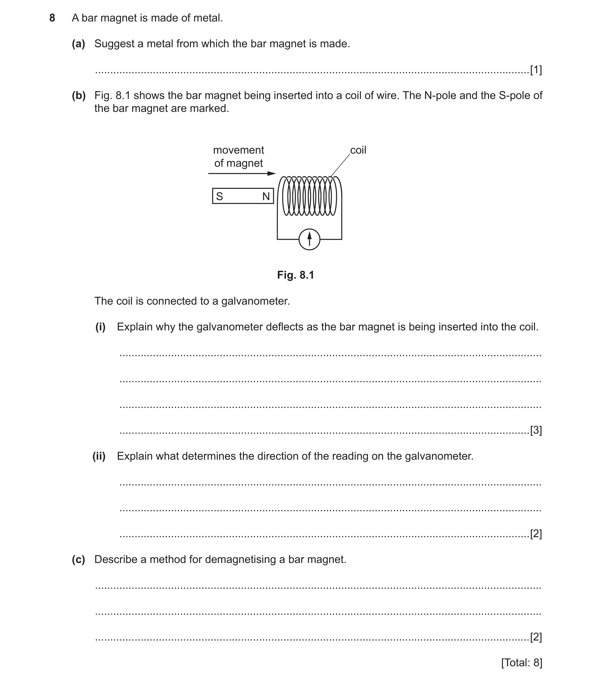
8 A bar magnet is made of metal. (a) Suggest a metal from which the bar magnet is made. … [1] (b) Fig. 8.1 shows the bar magnet being inserted into a coil of wire. The N-pole and the S-pole of the bar magnet are marked. movement coil of magnet S N Fig. 8.1 The coil is connected to a galvanometer. (i) Explain why the galvanometer deflects as the bar magnet is being inserted into the coil. … … … … [3] (ii) Explain what determines the direction of the reading on the galvanometer. … … … [2] (c) Describe a method for demagnetising a bar magnet. … … … [2] [Total: 8]
8 marks
Mark scheme: 8(a) Steel/aluminium/nickel/cobalt/alnico/neodymium/ferrite/alcomax B1 8(b)(i) Mention of magnetic field or magnetic flux OR field created by bar magnet B1 (Magnetic) field (lines) of magnet cut by coil OR (magnetic) field (lines) linked with/through/in the coil changes OR(magnetic) flux (through coil) changes B1 e.m.f. induced B1 8(b)(ii) Direction of movement of magnet through the coil OR which pole of magnet enters the coil B1 Direction of induced e.m.f. opposes change producing it OR (coil) end near magnet/left-hand end becomes a N-pole OR (coil) repels magnet (when moved in) B1 8(c) Hammer the magnet M1 repeatedly/until demagnetised/in E/W direction A1 OR Heat the magnet (M1) high temperature/red hot/in E-W direction (A1) OR Place magnet in coil carrying A.C. (M1) Remove magnet from coil OR decrease the current (slowly) to zero (A1) Total: 8
This question in 0625/41 May/June 2017
Q3 · A transformer that consists of two coils P and Q, and an iron core 0625/43 May/June 2017
10 Fig. 10.1 shows a transformer that consists of two coils P and Q, and an iron core. iron core coil P coil Q 200 turns 340 turns Fig. 10.1 There are 200 turns on coil P and 340 turns on coil Q. A 4.0 V a.c. power supply is connected to coil P. (a) (i) Explain why there is a voltage between the two terminals of coil Q. … … … … … [3] (ii) Explain why the core of the transformer is made of soft iron. … … [1] (b) (i) Calculate the voltage between the two terminals of coil Q. voltage = … [2] (ii) A heater is connected to coil Q. The current in the heater is 3.5 A. The transformer is 100% efficient. Calculate the current in coil P. current = … [2] (c) A transformer is used to step up the voltage before electrical energy is transmitted over long distances. State and explain one economic effect of transmitting electrical energy at a high voltage. … … … … [2] [Total: 10]
10 marks
Mark scheme: 10(a)(i) magnetic field mentioned B1 changing (magnetic) field in core/Q B1 induction in Q B1 10(a)(ii) (iron is) magnetic and temporary magnetic B1 10(b)(i) (VS = )VP × NS ÷ NP OR 4.0 × 340 ÷ 200 C1 6.8 V A1 10(b)(ii) (IP = )IS VS / VP OR 3.5 × 6.8 ÷ 4.0 C1 6.0 A A1 10(c) less energy wasted (in cables) B1 cheaper and one from: thinner cables fewer pylons fewer power stations/less fuel required B1 Total: 10
This question in 0625/43 May/June 2017
Q4 · A wire that carries a current into the page 0625/42 Oct/Nov 2017
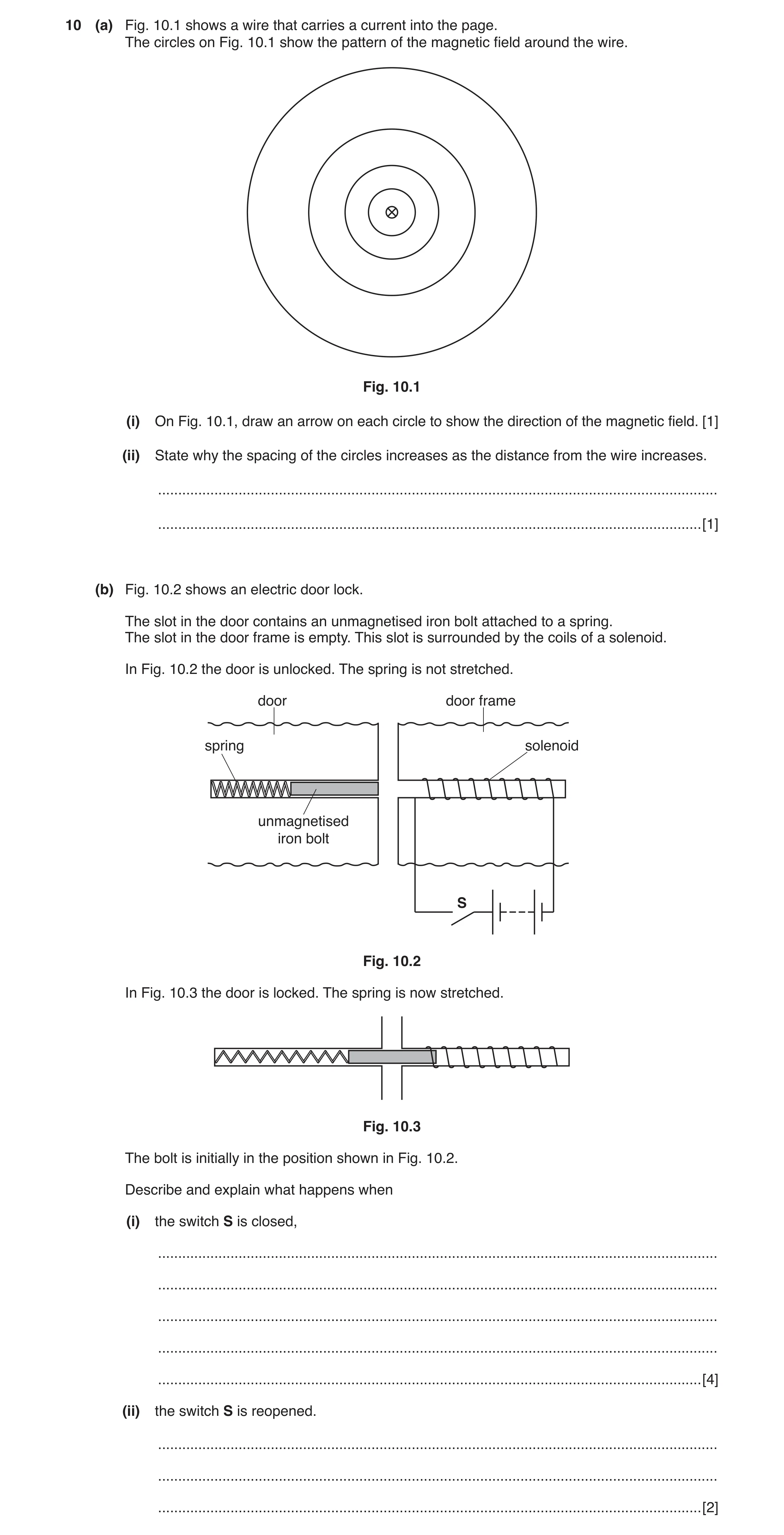
10 (a) Fig. 10.1 shows a wire that carries a current into the page. The circles on Fig. 10.1 show the pattern of the magnetic field around the wire. Fig. 10.1 (i) On Fig. 10.1, draw an arrow on each circle to show the direction of the magnetic field. [1] (ii) State why the spacing of the circles increases as the distance from the wire increases. … … [1] (b) Fig. 10.2 shows an electric door lock. The slot in the door contains an unmagnetised iron bolt attached to a spring. The slot in the door frame is empty. This slot is surrounded by the coils of a solenoid. In Fig. 10.2 the door is unlocked. The spring is not stretched. door door frame spring solenoid unmagnetised iron bolt S Fig. 10.2 In Fig. 10.3 the door is locked. The spring is now stretched. Fig. 10.3 The bolt is initially in the position shown in Fig. 10.2. Describe and explain what happens when (i) the switch S is closed, … … … … … [4] (ii) the switch S is reopened. … … … [2]
8 marks
Mark scheme: 10(a)(i) clockwise arrows on at least 3 circles B1 10(a)(ii) (magnetic) field becomes weaker / decreases (as distance from wire increases) B1 10(b)(i) any four from these six: • charge flows OR current in solenoid / wire / circuit • solenoid becomes magnet / magnetised • bolt becomes magnet / magnetised • (such that) unlike poles (of solenoid and bolt are) facing o.w.t.t.e. • bolt is attracted • bolt moves / (door) locks / spring stretched B4 10(b)(ii) solenoid OR bolt no longer magnetised OR bolt no longer attracted B1 (spring contracts and pulls) bolt back / bolt returns (to original position) / (door) unlocked B1
This question in 0625/42 Oct/Nov 2017
Q5 · The structure of an alternating current (a.c.) generator 0625/43 Oct/Nov 2017
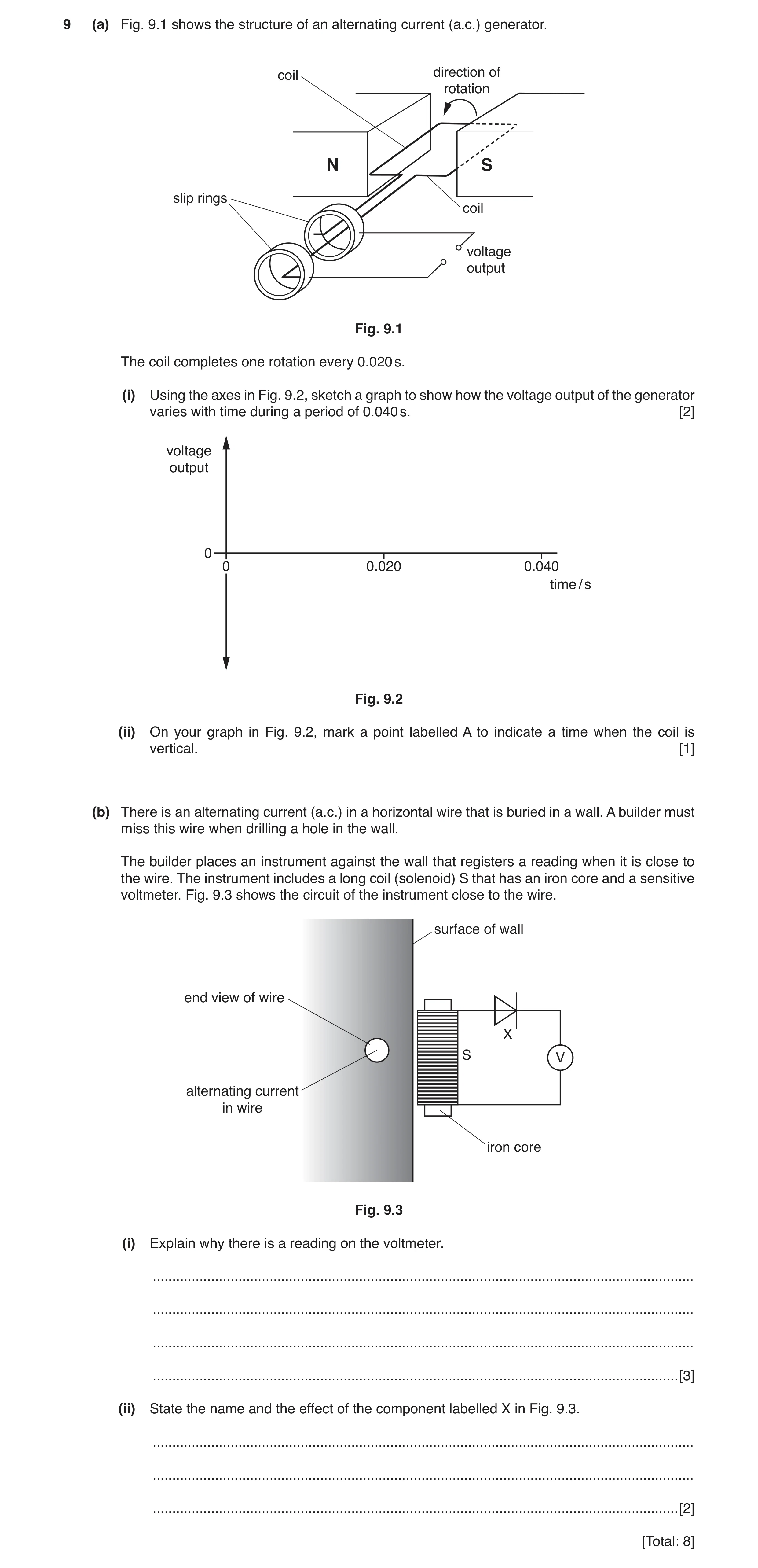
9 (a) Fig. 9.1 shows the structure of an alternating current (a.c.) generator. coil direction of rotation N S slip rings coil voltage output Fig. 9.1 The coil completes one rotation every 0.020 s. (i) Using the axes in Fig. 9.2, sketch a graph to show how the voltage output of the generator varies with time during a period of 0.040 s. [2] voltage output 0 0 0.020 0.040 time / s Fig. 9.2 (ii) On your graph in Fig. 9.2, mark a point labelled A to indicate a time when the coil is vertical. [1] (b) There is an alternating current (a.c.) in a horizontal wire that is buried in a wall. A builder must miss this wire when drilling a hole in the wall. The builder places an instrument against the wall that registers a reading when it is close to the wire. The instrument includes a long coil (solenoid) S that has an iron core and a sensitive voltmeter. Fig. 9.3 shows the circuit of the instrument close to the wire. surface of wall end view of wire X S V alternating current in wire iron core Fig. 9.3 (i) Explain why there is a reading on the voltmeter. … … … … [3] (ii) State the name and the effect of the component labelled X in Fig. 9.3. … … … [2] [Total: 8]
8 marks
Mark scheme: 9(a)(i) cosine or sine curve and maximum value equal to |minimum value| B1 two complete cycles of 0.02 s between 0 and 0.040 s B1 9(a)(ii) point marked A where output voltage is zero B1 9(b)(i) magnetic field (due to a.c.) mentioned B1 changing / alternating (magnetic) field or field lines cut solenoid B1 e.m.f. / voltage induced (in coil) B1 9(b)(ii) diode B1 prevents / stops the backward current or allows only one direction of current B1
This question in 0625/43 Oct/Nov 2017
Q6 · A student wants to demagnetise a permanent bar magnet 0625/41 May/June 2018
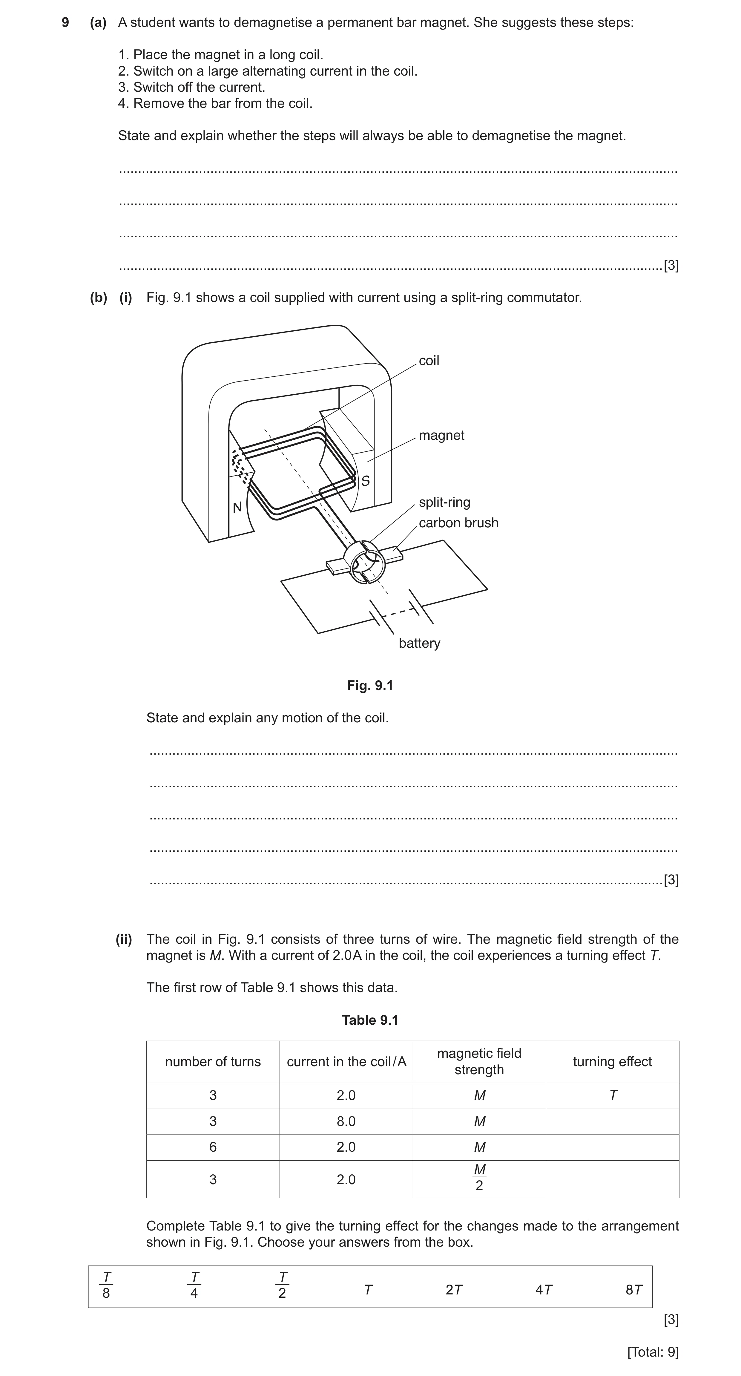
9 (a) A student wants to demagnetise a permanent bar magnet. She suggests these steps: 1. Place the magnet in a long coil. 2. Switch on a large alternating current in the coil. 3. Switch off the current. 4. Remove the bar from the coil. State and explain whether the steps will always be able to demagnetise the magnet. … … … … [3] (b) (i) Fig. 9.1 shows a coil supplied with current using a split-ring commutator. coil magnet S split-ring N carbon brush battery Fig. 9.1 State and explain any motion of the coil. … … … … … [3] (ii) The coil in Fig. 9.1 consists of three turns of wire. The magnetic field strength of the magnet is M. With a current of 2.0 A in the coil, the coil experiences a turning effect T. The first row of Table 9.1 shows this data. Table 9.1 magnetic field number of turns current in the coil / A turning effect strength 3 2.0 M T 3 8.0 M 6 2.0 M M 3 2.0 2 Complete Table 9.1 to give the turning effect for the changes made to the arrangement shown in Fig. 9.1. Choose your answers from the box. T T T 8 4 2 T 2T 4T 8T [3] [Total: 9]
9 marks
Mark scheme: 9(a) Would not be effective OR No 1 With current on OR the (alternating) current should not be switched off 1 Magnet should be withdrawn from the coil 1 OR Magnet would be alternately magnetised in different directions (1) Would remain magnetised in the direction occurring at the moment of switching off (1) 9(b)(i) Coil turns 1 Clockwise/continuously 1 Current (in coil) reverses every half turn/when coil is in vertical position OR force on current in a magnetic field 1 9(b)(ii) 1 × (4 × T) 1 2 × (2 × T) 1 3 × (T ÷ 2) 1
This question in 0625/41 May/June 2018
Q7 · Explain why the voltage of the supply to the primary coil of a transformer must be… 0625/41 May/June 2018
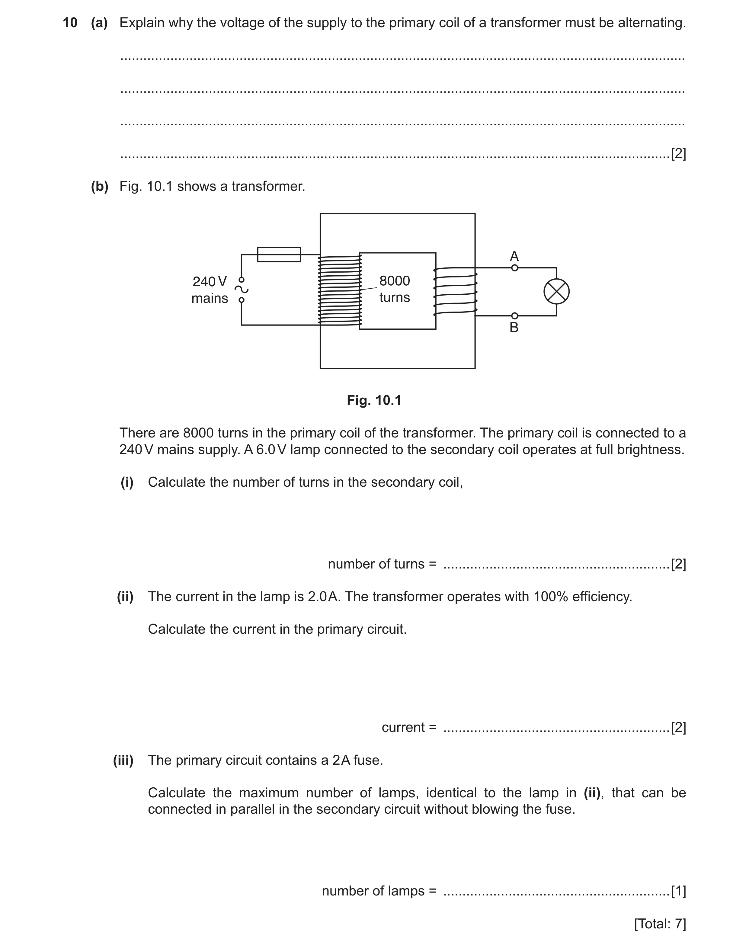
10 (a) Explain why the voltage of the supply to the primary coil of a transformer must be alternating. … … … … [2] (b) Fig. 10.1 shows a transformer. A 240 V 8000 mains turns B Fig. 10.1 There are 8000 turns in the primary coil of the transformer. The primary coil is connected to a 240 V mains supply. A 6.0 V lamp connected to the secondary coil operates at full brightness. (i) Calculate the number of turns in the secondary coil, number of turns = … [2] (ii) The current in the lamp is 2.0 A. The transformer operates with 100% efficiency. Calculate the current in the primary circuit. current = … [2] (iii) The primary circuit contains a 2 A fuse. Calculate the maximum number of lamps, identical to the lamp in (ii), that can be connected in parallel in the secondary circuit without blowing the fuse. number of lamps = … [1] [Total: 7]
7 marks
Mark scheme: 10(a) To produce an alternating/changing magnetic field 1 so that current/voltage is induced (continuously) in the secondary coil OR secondary circuit 1 10(b)(i) Ns ÷ Np = Vs ÷ Vp in any form OR (Ns =) Np × Vs÷ Vp OR 8000 × 6 ÷ 240 1 200 1 10(b)(ii) IpVp = IsVs in any form OR (Ip =) Is × Vs ÷ Vp OR 2.0 × 6 ÷ 240 1 0.050 A 1 10(b)(iii) (Number of lamps =) 2 ÷ 0.05 = 40 1
This question in 0625/41 May/June 2018
Q8 · A coil ABCD with two turns 0625/42 May/June 2018
9 (a) Fig. 9.1 shows a coil ABCD with two turns. The coil is in a magnetic field. B C N S D A Fig. 9.1 When there is a current in the coil, the coil experiences a turning effect. (i) Explain why there is a turning effect. … … … [1] (ii) The value of the current is 3 A. Place one tick in each column of the table to indicate how the turning effect changes with the change described. turning effect number of turns on coil current strength of magnetic increased to six increased to 9 A field decreased by a factor of 2 decreased by factor of 4 decreased by factor of 3 decreased by factor of 2 no change increased by factor of 2 increased by factor of 3 increased by factor of 4 [3] (b) Fig. 9.2 shows a magnet held just below a vertical coil connected to a galvanometer. N S Fig. 9.2 The magnet is released. (i) State any effect on the galvanometer. … … … [2] (ii) State any effect on the magnetic field produced by the coil. … … … [2] [Total: 8]
8 marks
Mark scheme: 9(a)(i) forces on AB and CD in opposite (vertical) directions 1 9(a)(ii) Column 2 increased by factor 3 Box 6 1 Column 3 increased by factor 3 Box 6 1 Column 4 decreased by factor 2 Box 3 1 9(b)(i) deflects OR shows I/V/p.d. 1 returns to zero 1 9(b)(ii) produces/changes magnetic field 1 S pole at bottom OR magnetic field opposes motion/(magnetic) field of magnet 1
This question in 0625/42 May/June 2018
Q9 · A bar magnet is held with its N-pole just inside one end of a coil 0625/43 May/June 2018
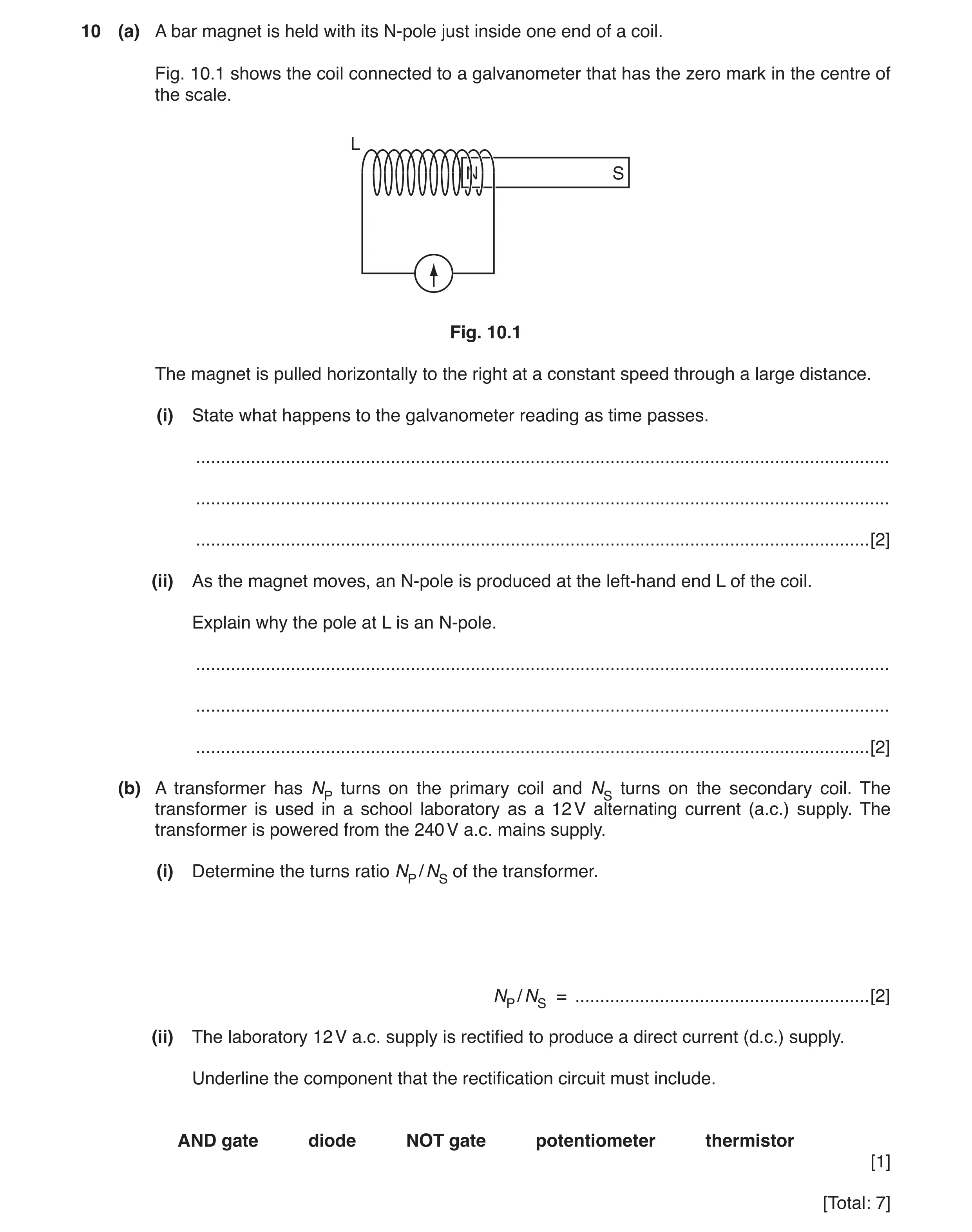
10 (a) A bar magnet is held with its N-pole just inside one end of a coil. Fig. 10.1 shows the coil connected to a galvanometer that has the zero mark in the centre of the scale. L N S Fig. 10.1 The magnet is pulled horizontally to the right at a constant speed through a large distance. (i) State what happens to the galvanometer reading as time passes. … … … [2] (ii) As the magnet moves, an N-pole is produced at the left-hand end L of the coil. Explain why the pole at L is an N-pole. … … … [2] (b) A transformer has NP turns on the primary coil and NS turns on the secondary coil. The transformer is used in a school laboratory as a 12 V alternating current (a.c.) supply. The transformer is powered from the 240 V a.c. mains supply. (i) Determine the turns ratio NP / NS of the transformer. NP / NS = … [2] (ii) The laboratory 12 V a.c. supply is rectified to produce a direct current (d.c.) supply. Underline the component that the rectification circuit must include. AND gate diode NOT gate potentiometer thermistor [1] [Total: 7]
7 marks
Mark scheme: 10(a)(i) there is a reading OR shows I/V/p.d. M1 then returns to zero/centre A1 10(a)(ii) S/south-pole at the right-hand end which attracts the magnet B1 opposes the change (causing the deflection) B1 10(b)(i) (turns ratio or NP ÷ NS =) VP ÷ VS OR 240 ÷ 12 C1 20 OR 20 ÷ 1 OR 20:1 A1 10(b)(ii) diode underlined B1
This question in 0625/43 May/June 2018
Q10 · A transformer consists of two coils of wire wound on a metal core 0625/41 Oct/Nov 2018
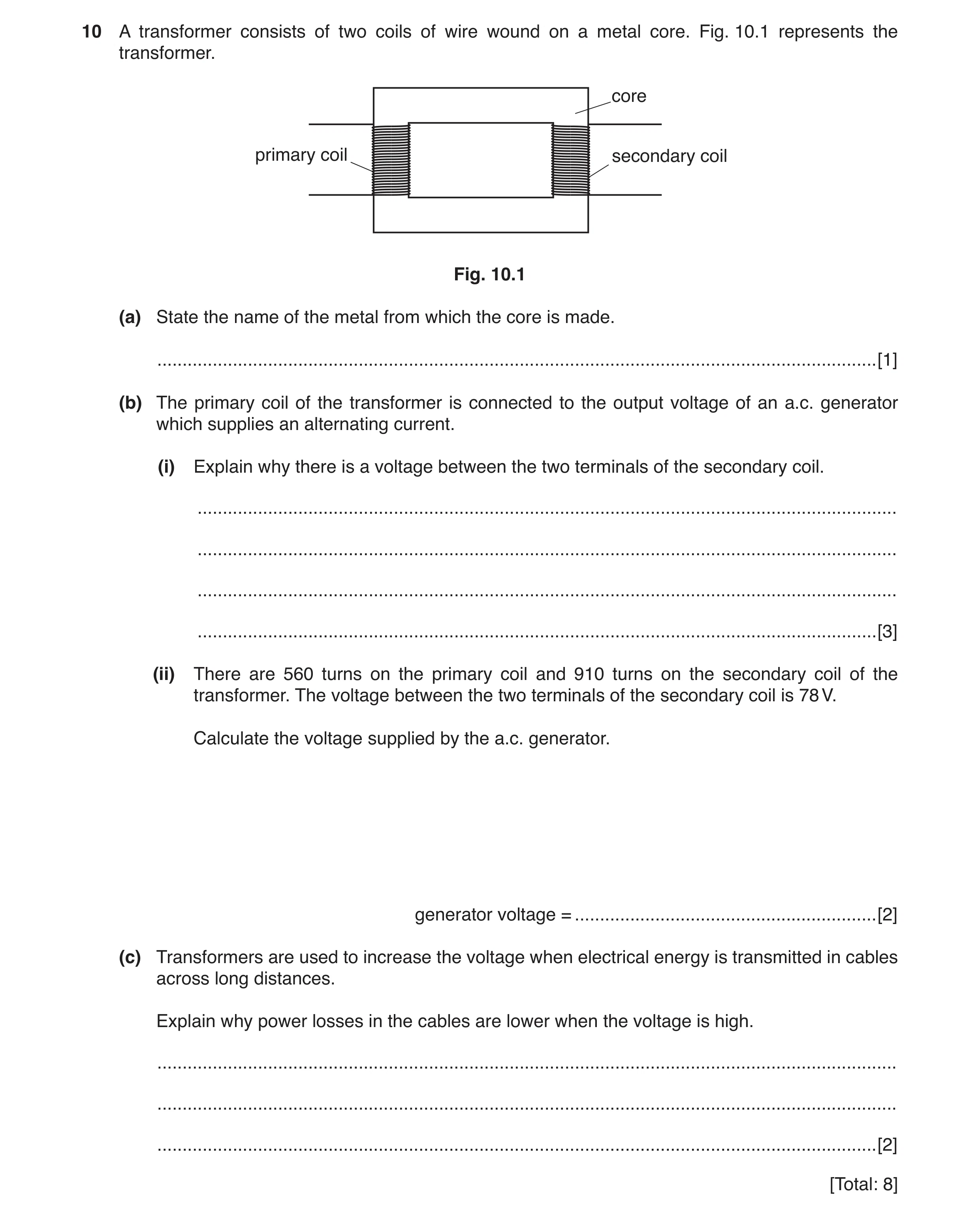
10 A transformer consists of two coils of wire wound on a metal core. Fig. 10.1 represents the transformer. core primary coil secondary coil Fig. 10.1 (a) State the name of the metal from which the core is made. … [1] (b) The primary coil of the transformer is connected to the output voltage of an a.c. generator which supplies an alternating current. (i) Explain why there is a voltage between the two terminals of the secondary coil. … … … … [3] (ii) There are 560 turns on the primary coil and 910 turns on the secondary coil of the transformer. The voltage between the two terminals of the secondary coil is 78 V. Calculate the voltage supplied by the a.c. generator. generator voltage = … [2] (c) Transformers are used to increase the voltage when electrical energy is transmitted in cables across long distances. Explain why power losses in the cables are lower when the voltage is high. … … … [2] [Total: 8]
8 marks
Mark scheme: 10(a) (soft) iron B1 10(b)(i) Alternating / changing magnetic field in primary (coil) B1 Alternating / changing (magnetic) field in core (and in secondary coil) OR (magnetic) field lines / flux link secondary B1 e.m.f / voltage induced (in secondary coil) B1 10(b)(ii) VP / VS = NP / NS in any form OR (VP =) VS × NP / NS OR 78 × 560 / 910 C1 48 V A1 10(c) Lower current B1 (Power loss from cables =) I2R so lower current means less power loss OR less heat loss B1
This question in 0625/41 Oct/Nov 2018
Q11 · A permanent bar magnet next to a circuit that contains a coil and a galvanometer 0625/42 Oct/Nov 2018
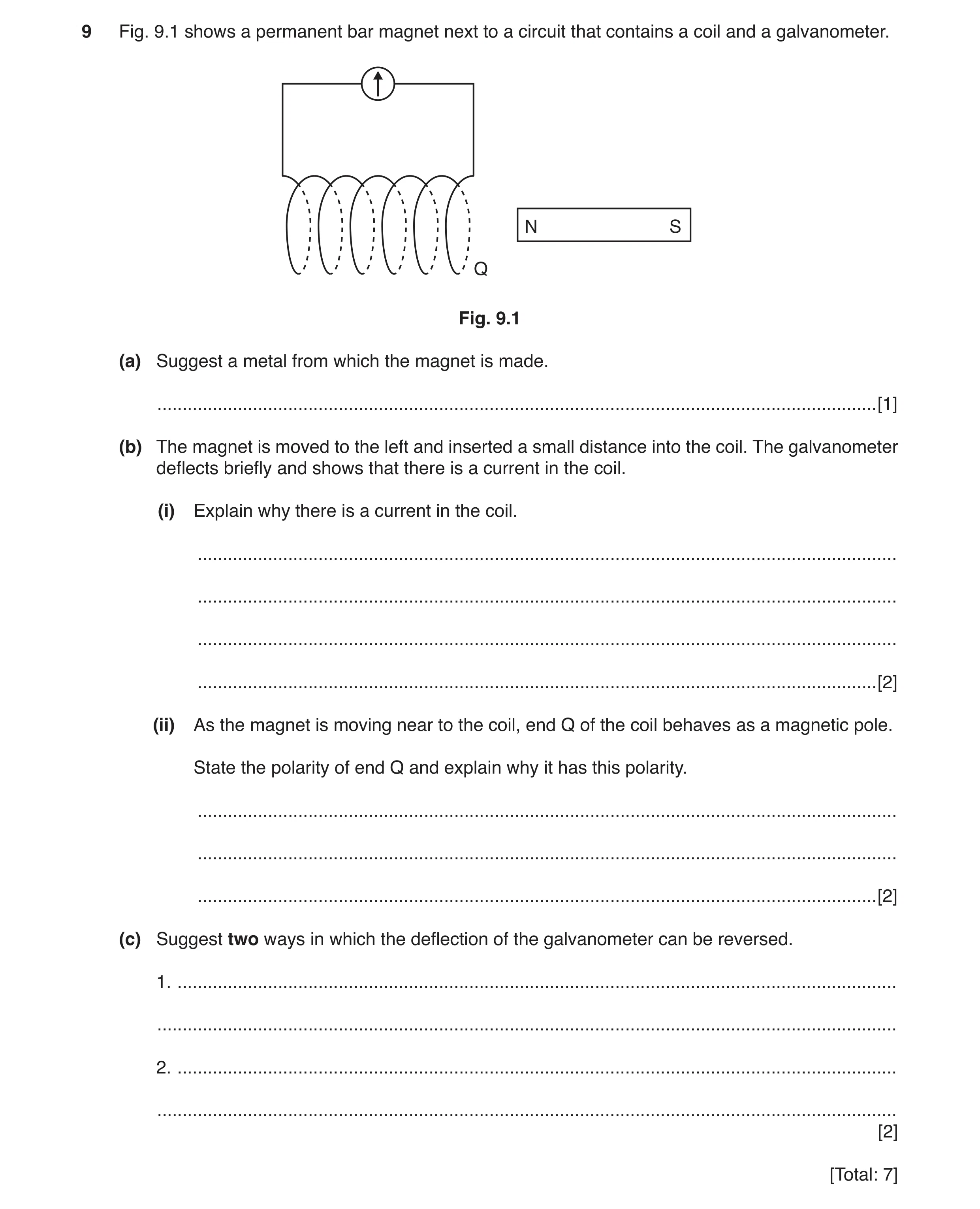
9 Fig. 9.1 shows a permanent bar magnet next to a circuit that contains a coil and a galvanometer. N S Q Fig. 9.1 (a) Suggest a metal from which the magnet is made. … [1] (b) The magnet is moved to the left and inserted a small distance into the coil. The galvanometer deflects briefly and shows that there is a current in the coil. (i) Explain why there is a current in the coil. … … … … [2] (ii) As the magnet is moving near to the coil, end Q of the coil behaves as a magnetic pole. State the polarity of end Q and explain why it has this polarity. … … … [2] (c) Suggest two ways in which the deflection of the galvanometer can be reversed. 1. … … 2. … … [2] [Total: 7]
7 marks
Mark scheme: 9(a) B1 9b(i) magnetic field (lines) cut OR changing magnetic field / flux linkage (in coil) B1 e.m.f. / voltage induced B1 9(b)(ii) (end Q) is an N-pole B1 repels / opposes (approaching) N-pole / magnet B1 9(c) any two from: withdraw N-pole (from end Q) OR move magnet to the right insert S-pole (into end Q) insert N-pole into other end withdraw S-pole from other end or carry on past mid-point B2
This question in 0625/42 Oct/Nov 2018
Q12 · Describe how a direct current (d.c.) differs from an alternating current (a.c.) 0625/43 Oct/Nov 2018
9 (a) Describe how a direct current (d.c.) differs from an alternating current (a.c.). … … [1] (b) Fig. 9.1 shows how the voltage output of an a.c. generator varies with time. 8.0 voltage / V 6.0 4.0 2.0 0 0 0.20.2 0.40.4 0.60.6 0.80.8 1.01.0 1.21.2 timetime // ss –2.0 –4.0 –6.0 –8.0 Fig. 9.1 A heater is connected directly to the a.c. generator and the maximum current in the heater is 0.75 A. (i) On Fig. 9.2, sketch a graph to indicate how the current in the heater varies with time. 1.00 current / A 0.75 0.50 0.25 0 0 0.20.2 0.40.4 0.60.6 0.80.8 1.01.0 1.21.2 timetime // ss –0.25 –0.50 –0.75 –1.00 [1] Fig. 9.2 (ii) Calculate the power produced by the heater when the current is 0.75 A. power = … [2] (c) Fig. 9.3 shows the coil ABCD of the a.c. generator between two magnetic poles. rotation direction B C N A D S Fig. 9.3 (i) On Fig. 9.3, draw a straight arrow to indicate the direction in which side AB of the coil is moving. Label this arrow M. [1] (ii) Deduce the direction of the current induced in side AB of the coil and explain your reasoning. … … … … [2] (iii) The rate at which the coil of the a.c. generator rotates increases. State two ways in which the alternating voltage changes. 1. … … 2. … … [2] [Total: 9]
9 marks
Mark scheme: 9(a) (a d.c. has) constant value / magnitude or direction does not change or has only one direction B1 9(b)(i) sinusoidal curve in phase with voltage and maximum value of 0.75 A and same frequency B1 9(b)(ii) (P =) VI or 7.2 × 0.75 C1 5.4 W A1 9(c)(i) vertical, upward arrow labelled M on side AB B1 9(c)(ii) A to B and (Fleming’s) right-hand rule (in some way) B1 rule explained (i.e. fingers explained or labelled 3D diagram) B1 9(c)(iii) greater (maximum) voltage B1 greater frequency or smaller time period or changes direction more often or alternates faster B1
This question in 0625/43 Oct/Nov 2018
Q13 · The electrical energy produced by a power station is transmitted over long distances at a… 0625/42 Feb/March 2019
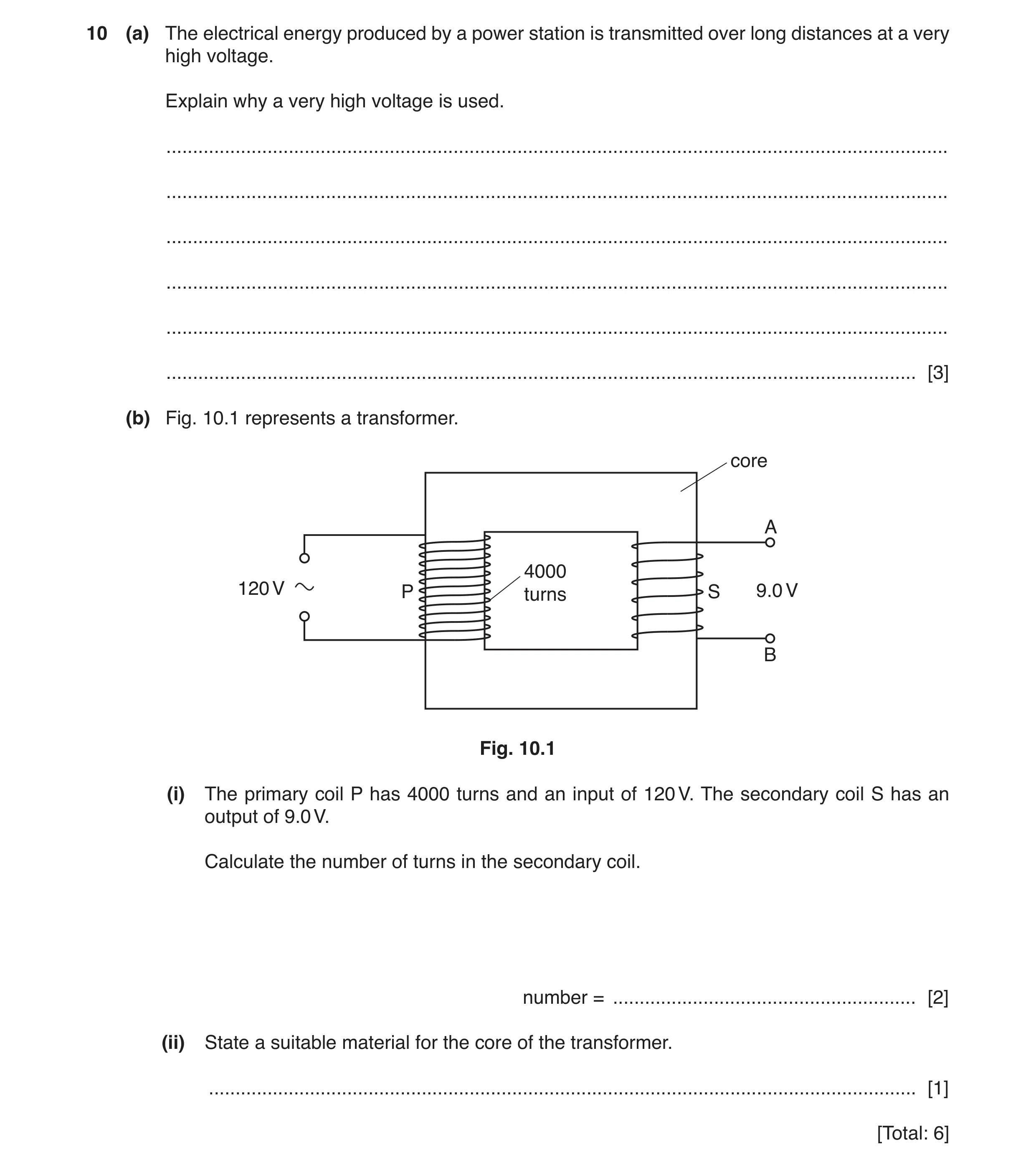
10 (a) The electrical energy produced by a power station is transmitted over long distances at a very high voltage. Explain why a very high voltage is used. … … … … … … [3] (b) Fig. 10.1 represents a transformer. core A 4000 120 V P turns S 9.0 V B Fig. 10.1 (i) The primary coil P has 4000 turns and an input of 120 V. The secondary coil S has an output of 9.0 V. Calculate the number of turns in the secondary coil. number = … [2] (ii) State a suitable material for the core of the transformer. … [1] [Total: 6]
6 marks
Mark scheme: 10(a) If voltage is (very) high, current is (very) low NOT if resistance is low B1 (If current is low,)thermal energy generated / power loss is low B1 (If current is low:) thinner / lighter / cheaper transmission cables / cables with less resistance / cheaper pylons can be used / cheaper B1 10(b)(i) Vp / Vs = Np / Ns in any form OR (Ns =) Np Vs / Vp OR 4000 × 9 / 120 C1 (Ns = ) 300 A1 10(b)(ii) Iron or soft iron B1
This question in 0625/42 Feb/March 2019
Q14 · A student turns the handle of an alternating current (a.c.) generator and the coil rotates 0625/41 May/June 2019
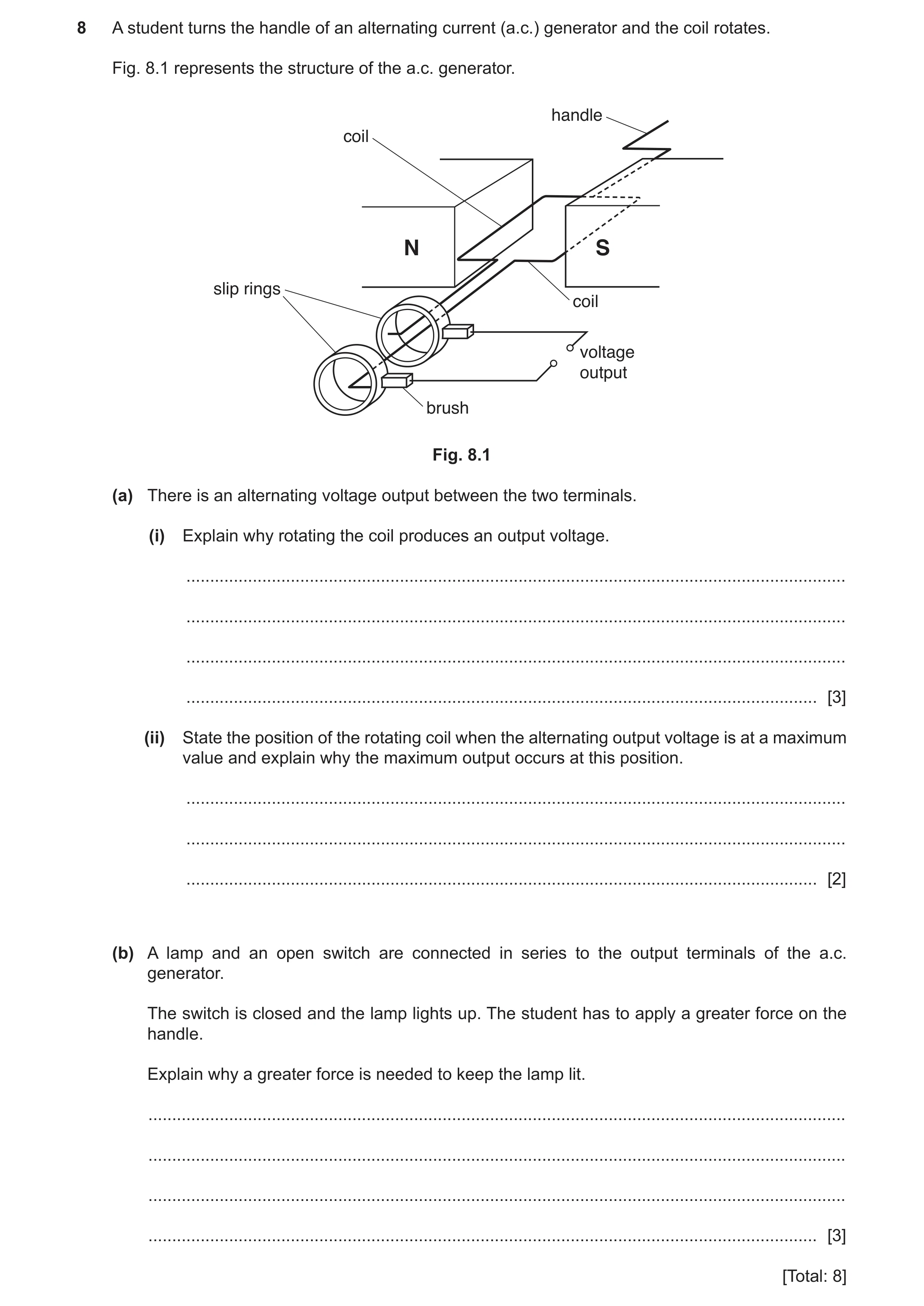
8 A student turns the handle of an alternating current (a.c.) generator and the coil rotates. Fig. 8.1 represents the structure of the a.c. generator. handle coil N S slip rings coil voltage output brush Fig. 8.1 (a) There is an alternating voltage output between the two terminals. (i) Explain why rotating the coil produces an output voltage. … … … … [3] (ii) State the position of the rotating coil when the alternating output voltage is at a maximum value and explain why the maximum output occurs at this position. … … … [2] (b) A lamp and an open switch are connected in series to the output terminals of the a.c. generator. The switch is closed and the lamp lights up. The student has to apply a greater force on the handle. Explain why a greater force is needed to keep the lamp lit. … … … … [3] [Total: 8]
8 marks
Mark scheme: 8(a)(i) magnetic field mentioned B1 coil / wire cuts (magnetic) field OR changing (magnetic) field (through coil) B1 e.m.f. / voltage induced OR produced by electromagnetic induction B1 8(a)(ii) (plane of coil) horizontal OR in position shown in diagram coil cutting magnetic field the fastest B1 B1 8(b) current in coil OR energy supplied to / lost from lamp B1 current in (magnetic) field experiences a force student must do more work / supply more energy / more energy needed B1 opposes the change causing it greater force to do more work B1
This question in 0625/41 May/June 2019
Q15 · Describe how to demagnetise a bar magnet using alternating current (a.c.) in a coil 0625/42 May/June 2019
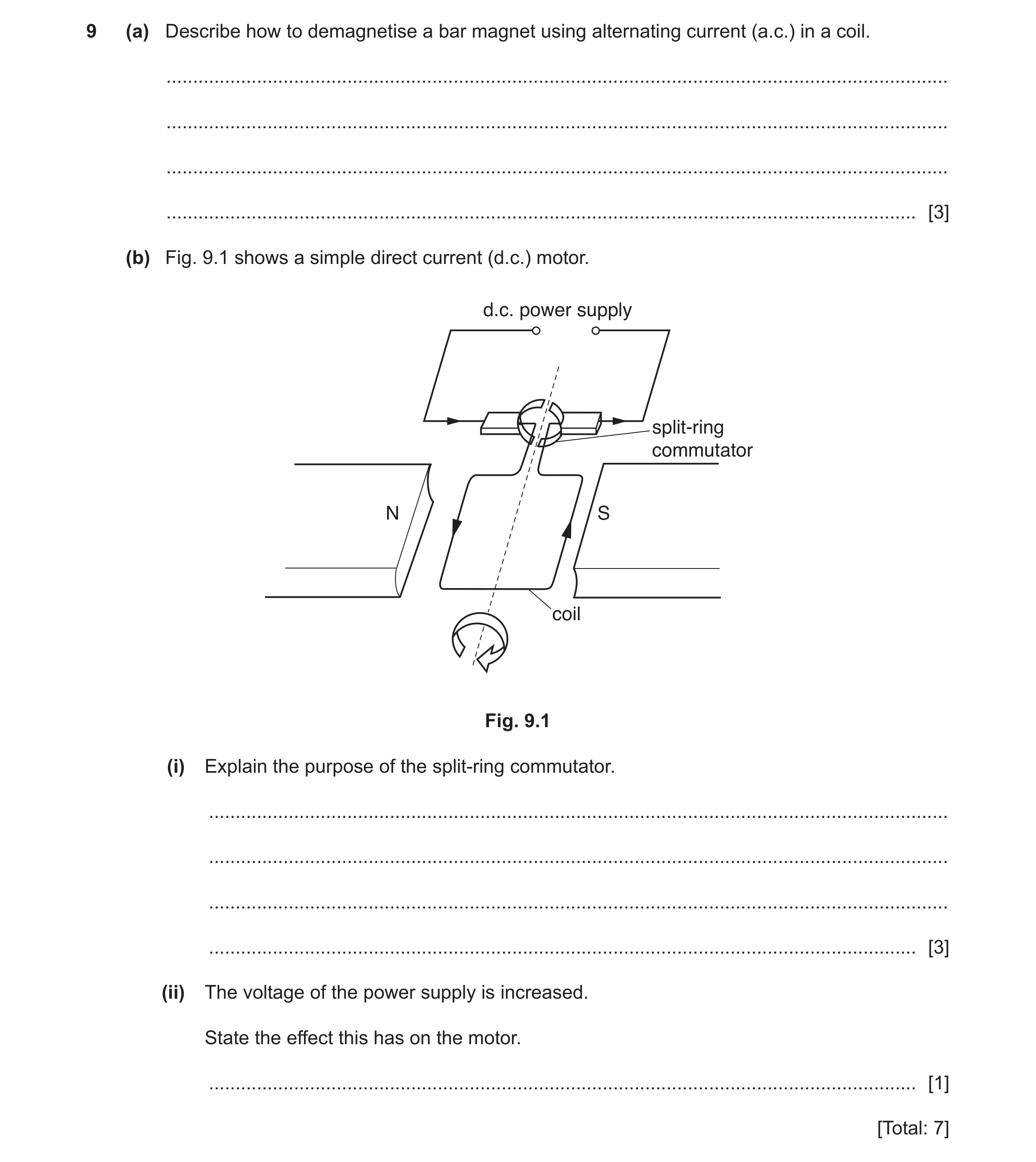
9 (a) Describe how to demagnetise a bar magnet using alternating current (a.c.) in a coil. … … … … [3] (b) Fig. 9.1 shows a simple direct current (d.c.) motor. d.c. power supply split-ring commutator N S coil Fig. 9.1 (i) Explain the purpose of the split-ring commutator. … … … … [3] (ii) The voltage of the power supply is increased. State the effect this has on the motor. … [1] [Total: 7]
7 marks
Mark scheme: 9(a) place magnet in coil B1 EITHER (gradually) withdraw magnet« B1 «with ac (in coil) switched on B1 OR reduce current« (B1) «to zero (B1) 9(b)(i) keeps coil rotating (in the same direction) o.w.t.t.e. B1 by changing direction of current (in the coil) B1 every half cycle/180 degrees B1 9(b)(ii) (coil rotates) faster B1
This question in 0625/42 May/June 2019
Q16 · A simple alternating current generator 0625/43 May/June 2019
10 Fig. 10.1 shows a simple alternating current generator. rotation of coil coil N S P output Q Fig. 10.1 (a) On Fig. 10.2, sketch a graph to show how the electromotive force (e.m.f.) induced varies with time for one revolution of the coil. Assume that the coil starts in the horizontal position, as shown in Fig. 10.1. Label the points on the time axis where the coil has completed 1/4 revolution and 3/4 revolution. [3] e.m.f. 0 0 time Fig. 10.2 (b) Explain why an e.m.f. is induced only when the coil is turning. … … … [1] (c) State the name of the components labelled P and Q and state their purpose. Name: … Purpose: … … [2] (d) State two possible changes that cause a larger e.m.f. to be induced. 1. … 2. … [2] [Total: 8]
8 marks
Mark scheme: 10(a) Correct shape of graph showing one rotation B1 Graph starts from maximum voltage (positive or negative) (labelled horizontal) B1 Graph passes through zero twice, labelled 1 / 4 and 3 / 4 revolution B1 10(b) induced e.m.f. caused by coil cutting magnetic field OR coil moving in magnetic field B1 10(c) slip rings B1 (provide) continuous connection while coil rotating B1 10(d) Any two of: increase strength of magnetic field increase speed of rotation of the coil increase numbers of turns of coil B2
This question in 0625/43 May/June 2019
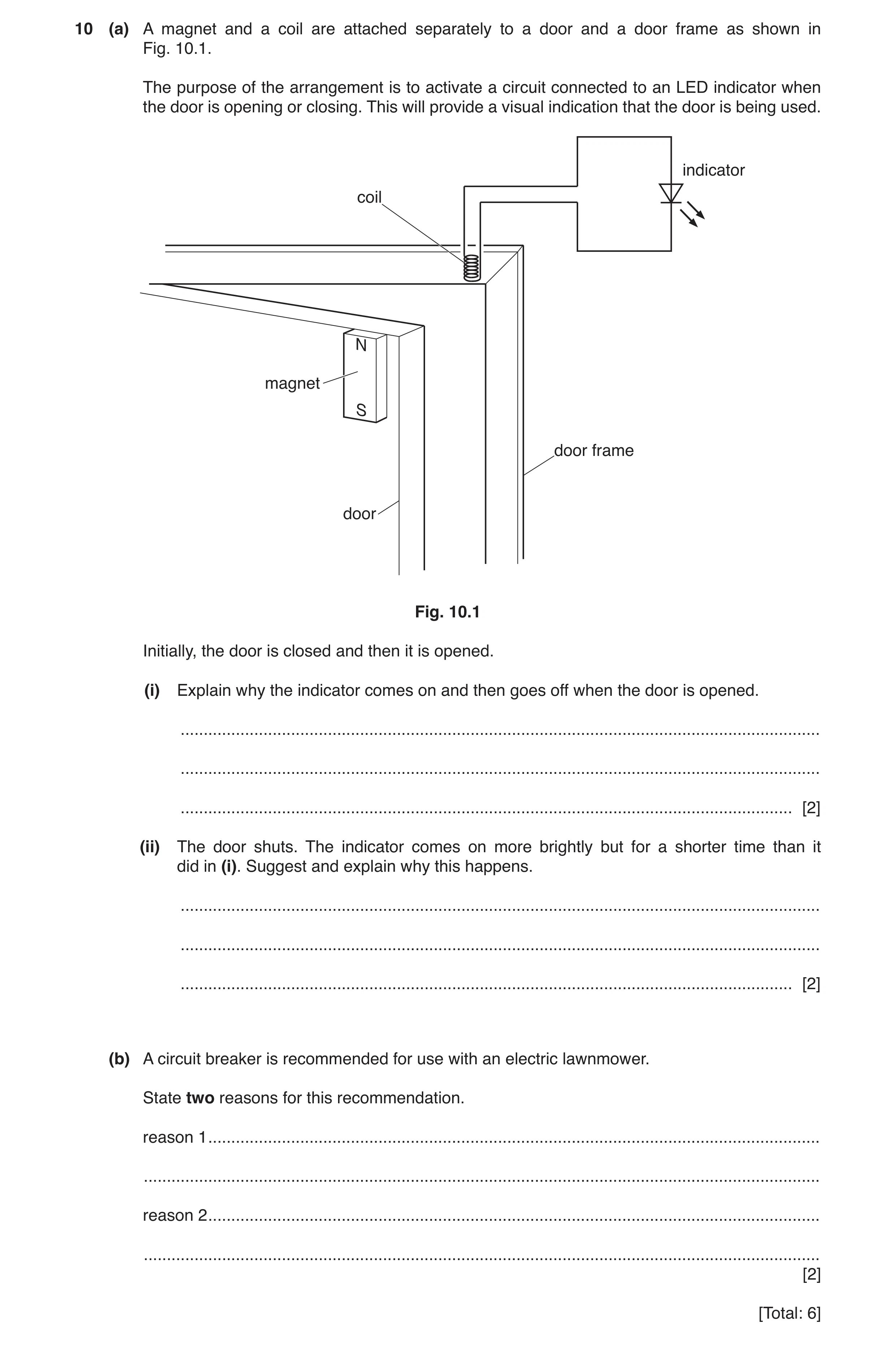
Q17 · A magnet and a coil are attached separately to a door and a door frame as shown in Fig 0625/43 Oct/Nov 2019
10 (a) A magnet and a coil are attached separately to a door and a door frame as shown in Fig. 10.1. The purpose of the arrangement is to activate a circuit connected to an LED indicator when the door is opening or closing. This will provide a visual indication that the door is being used. indicator coil N magnet S door frame door Fig. 10.1 Initially, the door is closed and then it is opened. (i) Explain why the indicator comes on and then goes off when the door is opened. … … … [2] (ii) The door shuts. The indicator comes on more brightly but for a shorter time than it did in (i). Suggest and explain why this happens. … … … [2] (b) A circuit breaker is recommended for use with an electric lawnmower. State two reasons for this recommendation. reason 1 … … reason 2 … … [2] [Total: 6]
6 marks
Mark scheme: 10(a)(i) induces emf / pd / current (across / in LED) light goes off when magnet no longer directly below coil B1 10(a)(ii) door closes more quickly than it was opened so higher current in LED B1 door / magnet moving for shorter length of time B1 10(b) Any two from: • quick response • protects against electric shock • protects against overheating • (easily) re-settable • avoids damage to lawnmower B2
This question in 0625/43 Oct/Nov 2019
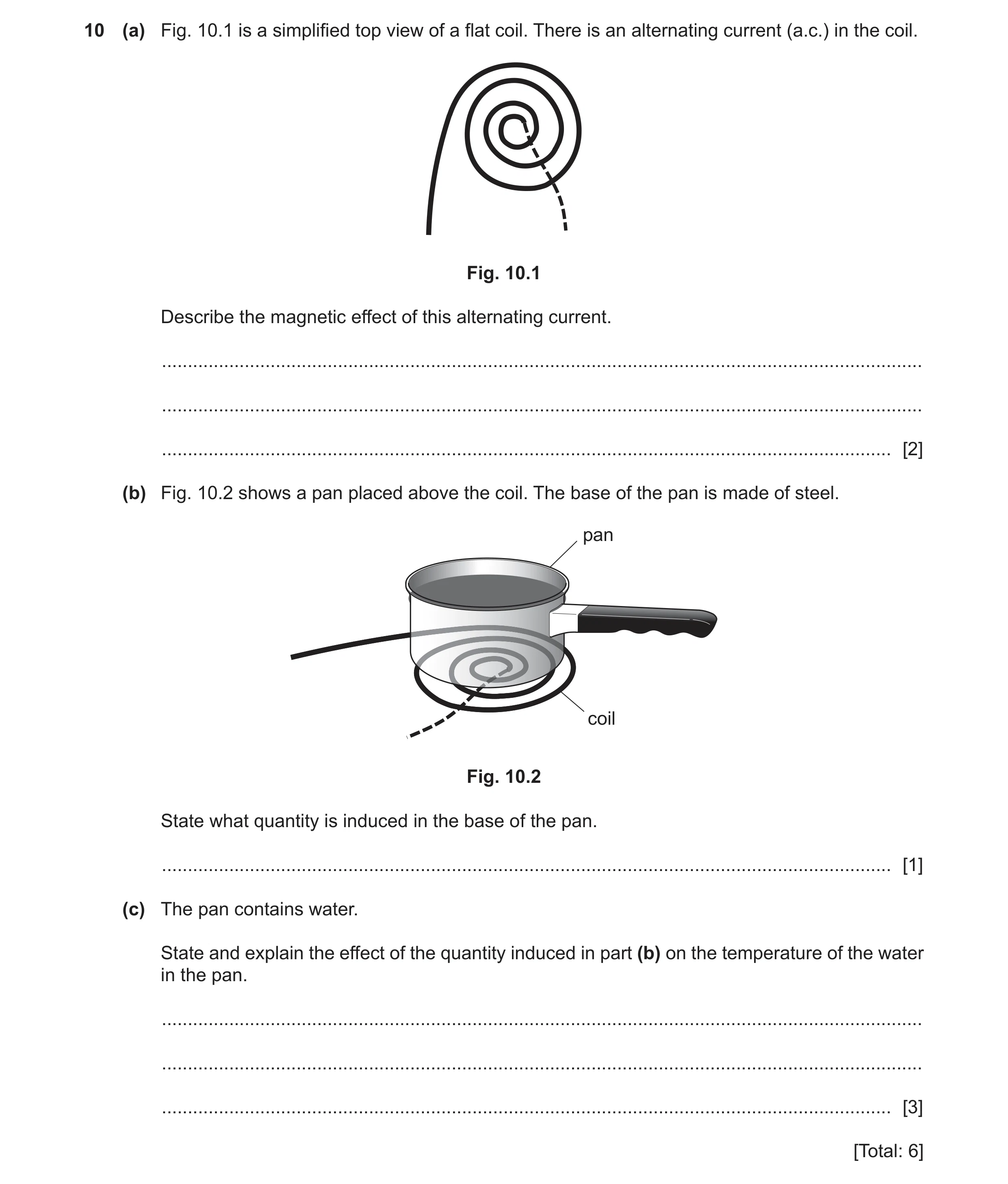
Q18 · A simplified top view of a flat coil 0625/42 Feb/March 2020
10 (a) Fig. 10.1 is a simplified top view of a flat coil. There is an alternating current (a.c.) in the coil. Fig. 10.1 Describe the magnetic effect of this alternating current. … … … [2] (b) Fig. 10.2 shows a pan placed above the coil. The base of the pan is made of steel. pan coil Fig. 10.2 State what quantity is induced in the base of the pan. … [1] (c) The pan contains water. State and explain the effect of the quantity induced in part (b) on the temperature of the water in the pan. … … … [3] [Total: 6]
6 marks
Mark scheme: 10(a) magnetic field (produced) B1 (magnetic field / magnetic flux / magnetic effect / magnetism) (it) alternates / changes direction / reverses B1 10(b) e.m.f. / p.d. / voltage B1 10(c) (temperature) increased B1 current in base of pan o.w.t.t.e. B1 thermal energy (produced in base of pan) B1
This question in 0625/42 Feb/March 2020
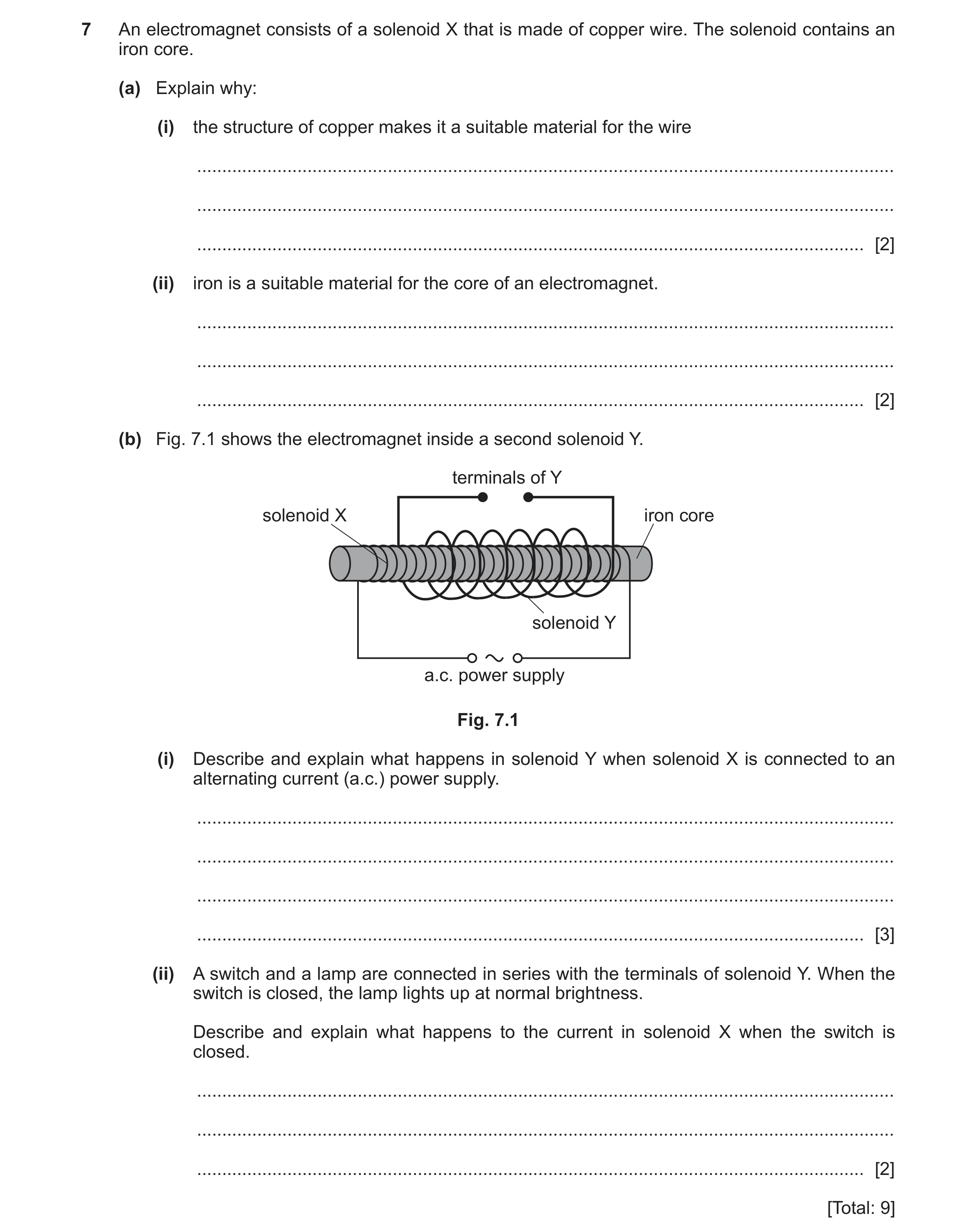
Q19 · An electromagnet consists of a solenoid X that is made of copper wire 0625/41 May/June 2020
7 An electromagnet consists of a solenoid X that is made of copper wire. The solenoid contains an iron core. (a) Explain why: (i) the structure of copper makes it a suitable material for the wire … … … [2] (ii) iron is a suitable material for the core of an electromagnet. … … … [2] (b) Fig. 7.1 shows the electromagnet inside a second solenoid Y. terminals of Y solenoid X iron core solenoid Y a.c. power supply Fig. 7.1 (i) Describe and explain what happens in solenoid Y when solenoid X is connected to an alternating current (a.c.) power supply. … … … … [3] (ii) A switch and a lamp are connected in series with the terminals of solenoid Y. When the switch is closed, the lamp lights up at normal brightness. Describe and explain what happens to the current in solenoid X when the switch is closed. … … … [2] [Total: 9]
9 marks
Mark scheme: 7(a)(i) (copper) contains free electrons B1 good electrical conductor B1 7(a)(ii) magnetic material OR easily magnetised B1 temporary magnetic material OR easily demagnetised B1 7(b)(i) alternating / changing / varying magnetic field (produced by X) B1 (electromagnetic) induction in Y B1 (alternating) electromotive force (e.m.f.) between terminals of Y / in Y B1 7(b)(ii) current in X increases B1 to supply the power used in Y / the lamp B1
This question in 0625/41 May/June 2020
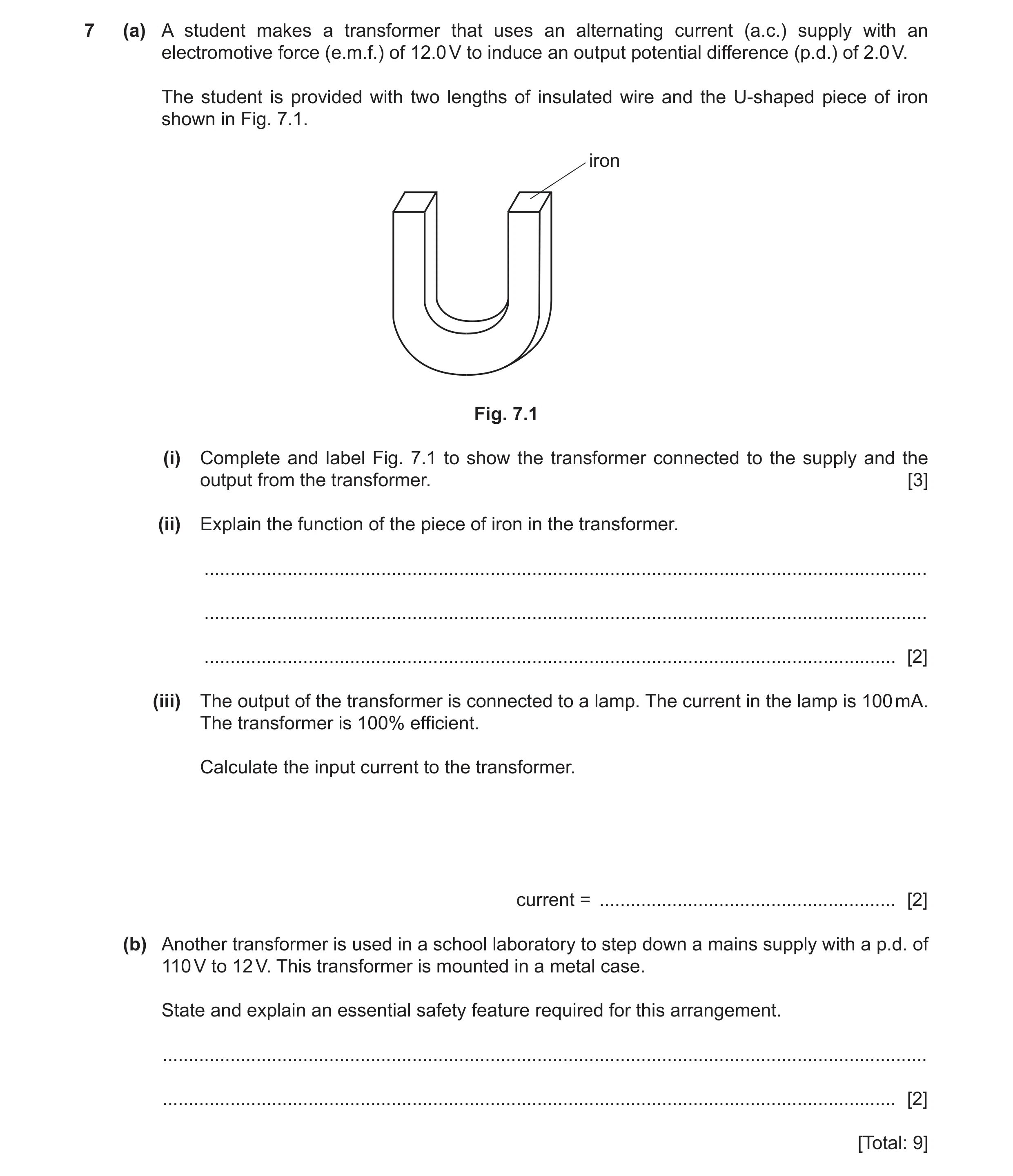
Q20 · A student makes a transformer that uses an alternating current (a.c.) supply with an… 0625/42 May/June 2020
7 (a) A student makes a transformer that uses an alternating current (a.c.) supply with an electromotive force (e.m.f.) of 12.0 V to induce an output potential difference (p.d.) of 2.0 V. The student is provided with two lengths of insulated wire and the U-shaped piece of iron shown in Fig. 7.1. iron Fig. 7.1 (i) Complete and label Fig. 7.1 to show the transformer connected to the supply and the output from the transformer. [3] (ii) Explain the function of the piece of iron in the transformer. … … … [2] (iii) The output of the transformer is connected to a lamp. The current in the lamp is 100 mA. The transformer is 100% efficient. Calculate the input current to the transformer. current = … [2] (b) Another transformer is used in a school laboratory to step down a mains supply with a p.d. of 110 V to 12 V. This transformer is mounted in a metal case. State and explain an essential safety feature required for this arrangement. … … [2] [Total: 9]
9 marks
Mark scheme: 7(a)(i) primary coil wound round iron AND (labelled primary or coil OR connected to labelled supply / 12 V) B1 secondary coil wound round iron AND (labelled secondary OR connected to labelled output / 2 V) B1 significantly more coils around primary B1 Question Answer Marks 7(a)(ii) two from three • links magnetic fields of coils / primary and secondary • stronger magnetic field in secondary • better induction owtte B2 7(a)(iii) V1I1 = V2I2 in any form OR (I1 =) V2I2 / V1 OR (I1 =) 2 × 0.10 / 12 C1 (I1 =) 0.017 A A1 7(b) metal case earthed B1 in case wire falls off / insulation fails / live(wire) touches case B1
This question in 0625/42 May/June 2020
Q21 · A simple direct current (d.c.) electric motor 0625/43 May/June 2020
9 Fig. 9.1 shows a simple direct current (d.c.) electric motor. The coil rotates about the axis when there is a current in the coil. The coil is connected to the rest of the circuit by the brushes. axis coil S N brush brush – + Fig. 9.1 (a) (i) On Fig. 9.1, draw a pair of arrows to show which way the coil rotates. Explain the direction you have chosen. … … … [3] (ii) On Fig. 9.1, draw an arrow to show the direction in which electrons flow through the coil. [1] (iii) Explain why the electrons flow in the direction you have shown in (a)(ii). … … [1] (b) State any difference each of the following changes makes to the rotation of the coil in Fig. 9.1: (i) changing the polarity of the power supply to that shown in Fig. 9.2 – + Fig. 9.2 … [1] (ii) changing the coil to the new coil shown in Fig. 9.3 original coil new coil Fig. 9.3 … [1] (iii) using a stronger magnetic field. … [1] [Total: 8]
8 marks
Mark scheme: 9(a)(i) anti-clockwise (seen from brushes) M1 I correctly described A1 F down on left / up on right A1 9(a)(ii) arrow labelled correct direction on coil B1 9(a)(iii) electrons –ve OR repelled from –ve connection of supply B1 9(b)(i) rotates in opposite direction B1 9(b)(ii) turns faster OR greater moment / turning effect B1 9(b)(iii) turns faster OR greater moment / turning effect B1
This question in 0625/43 May/June 2020
Q22 · A permanent magnet is made from only one material 0625/41 Oct/Nov 2020
7 (a) A permanent magnet is made from only one material. Underline the material from which it is possible to make a permanent magnet. [1] aluminium copper soft iron mercury plastic steel uranium (b) An electron source produces a narrow beam of electrons that all travel at the same speed. The electron source is placed in a vacuum and the beam of electrons travels vertically downwards. Fig. 7.1 shows the beam of electrons before it passes between the N-pole and the S-pole of a magnet. electron source beam of electrons N-pole S-pole Fig. 7.1 (i) Describe what is meant by the direction of a magnetic field. State the direction of the magnetic field between the two poles in Fig. 7.1. … … … [1] (ii) Describe and explain what happens to the beam of electrons in the magnetic field between the poles of the magnet in Fig. 7.1. … … … … [3] (c) A beam consists of α-particles, β-particles and γ-rays. Explain how a uniform magnetic field may be used to separate the α-particles, the β-particles and the γ-rays. … … … … [3] [Total: 8]
8 marks
Mark scheme: 7(a) steel (underlined) B1 7(b)(i) the direction of the force on a N-pole and left to right / N to S B1 7(b)(ii) beam deflects B1 beam deflects into the page B1 moving electrons / charges constitute a current or left-hand rule or moving electrons / current in a magnetic field experiences a force B1 7(b) (part of) beam deflects B1 α-particles deflect in opposite / different direction to β-particles / electrons or all α-particles have similar deflections or α- particles deflect less B1 γ-rays do not deflect B1
This question in 0625/41 Oct/Nov 2020
Q23 · A bar magnet and four plotting compasses A, B, C and D 0625/42 Oct/Nov 2020
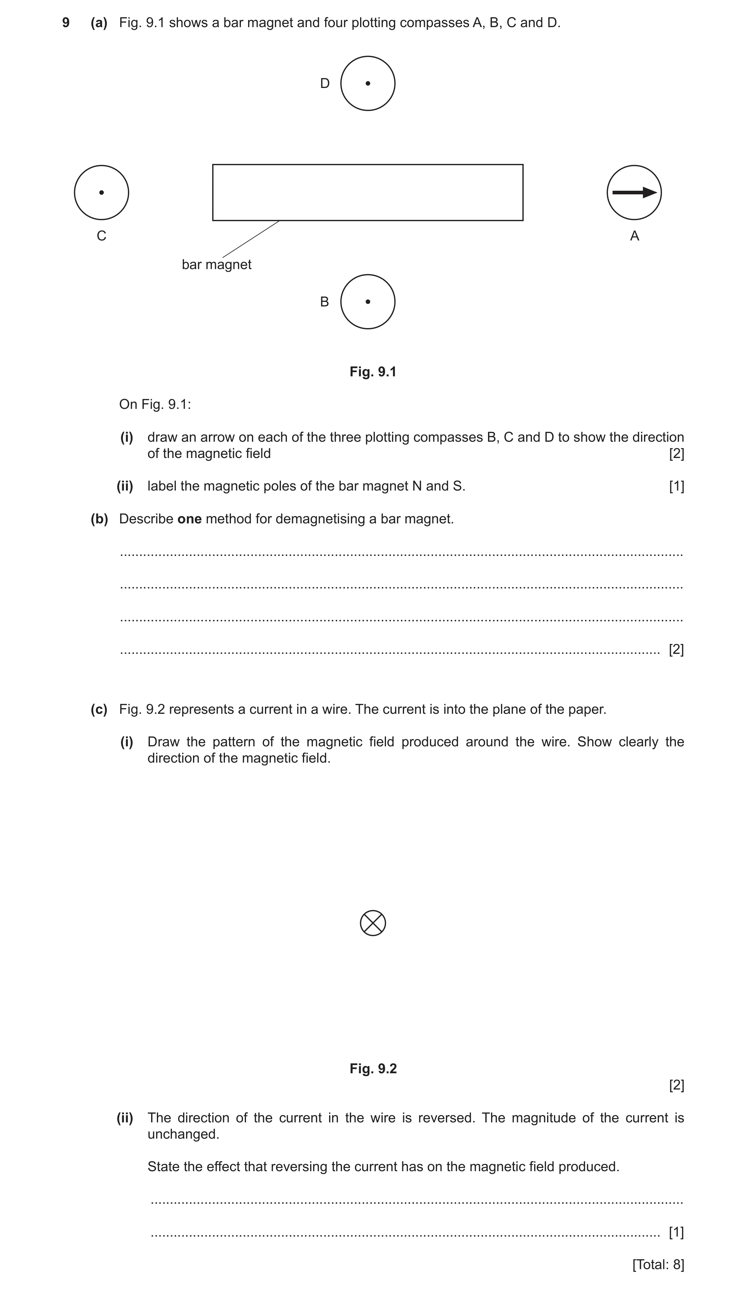
9 (a) Fig. 9.1 shows a bar magnet and four plotting compasses A, B, C and D. D C A bar magnet B Fig. 9.1 On Fig. 9.1: (i) draw an arrow on each of the three plotting compasses B, C and D to show the direction of the magnetic field [2] (ii) label the magnetic poles of the bar magnet N and S. [1] (b) Describe one method for demagnetising a bar magnet. … … … … [2] (c) Fig. 9.2 represents a current in a wire. The current is into the plane of the paper. (i) Draw the pattern of the magnetic field produced around the wire. Show clearly the direction of the magnetic field. Fig. 9.2 [2] (ii) The direction of the current in the wire is reversed. The magnitude of the current is unchanged. State the effect that reversing the current has on the magnetic field produced. … … [1] [Total: 8]
8 marks
Mark scheme: 9(a)(i) C pointing horizontally to right B1 B AND D pointing horizontally to left B1 9(a)(ii) S on left AND N on right B1 9(b) any one of the following methods: 1 heat magnet C1 to high temperature / red hot A1 2 hammer the magnet (B1) repeatedly / in E–W direction (B1) 3 (place) magnet in a coil / solenoid carrying a.c. (M1) remove magnet from coil OR decrease current (slowly) to zero (A1) 9(c)(i) at least 3 concentric circles B1 closer together near the wire AND clockwise arrow B1 9(c)(ii) arrows OR field reverses / is in opposite direction B1
This question in 0625/42 Oct/Nov 2020
Q24 · Electrical power is produced in a power station by an alternating current (a.c.) generator 0625/43 Oct/Nov 2020
9 (a) Electrical power is produced in a power station by an alternating current (a.c.) generator. The output of the generator has a voltage of 22 000 V. The electrical power is transmitted at a voltage of 400 000 V. Explain why electrical power is transmitted at a voltage of 400 000 V and not 22 000 V. … … … … … … [3] (b) A computer contains a transformer. The input voltage to the transformer is 240 V. The output voltage from the transformer is 20 V and the output current is 2.3 A. The efficiency of the transformer is 90%. Calculate the input current to the transformer. current = … [5] [Total: 8]
8 marks
Mark scheme: 9(a) high voltage results in low current (for same power) B1 Any two from: • heat loss depends on current • less power / energy loss (in transmission) • thinner wires can be used B2 Question Answer Marks 9(b) Efficiency = (useful) power output (total) power input C1 P = VI in any form C1 power output = (20 × 2.3) = 46 (W) C1 power input = 46 ÷ 0.9 = 51 (W) C1 input current = (51 ÷ 240=) 0.21 A A1
This question in 0625/43 Oct/Nov 2020
Question 25 0625/43 Oct/Nov 2020
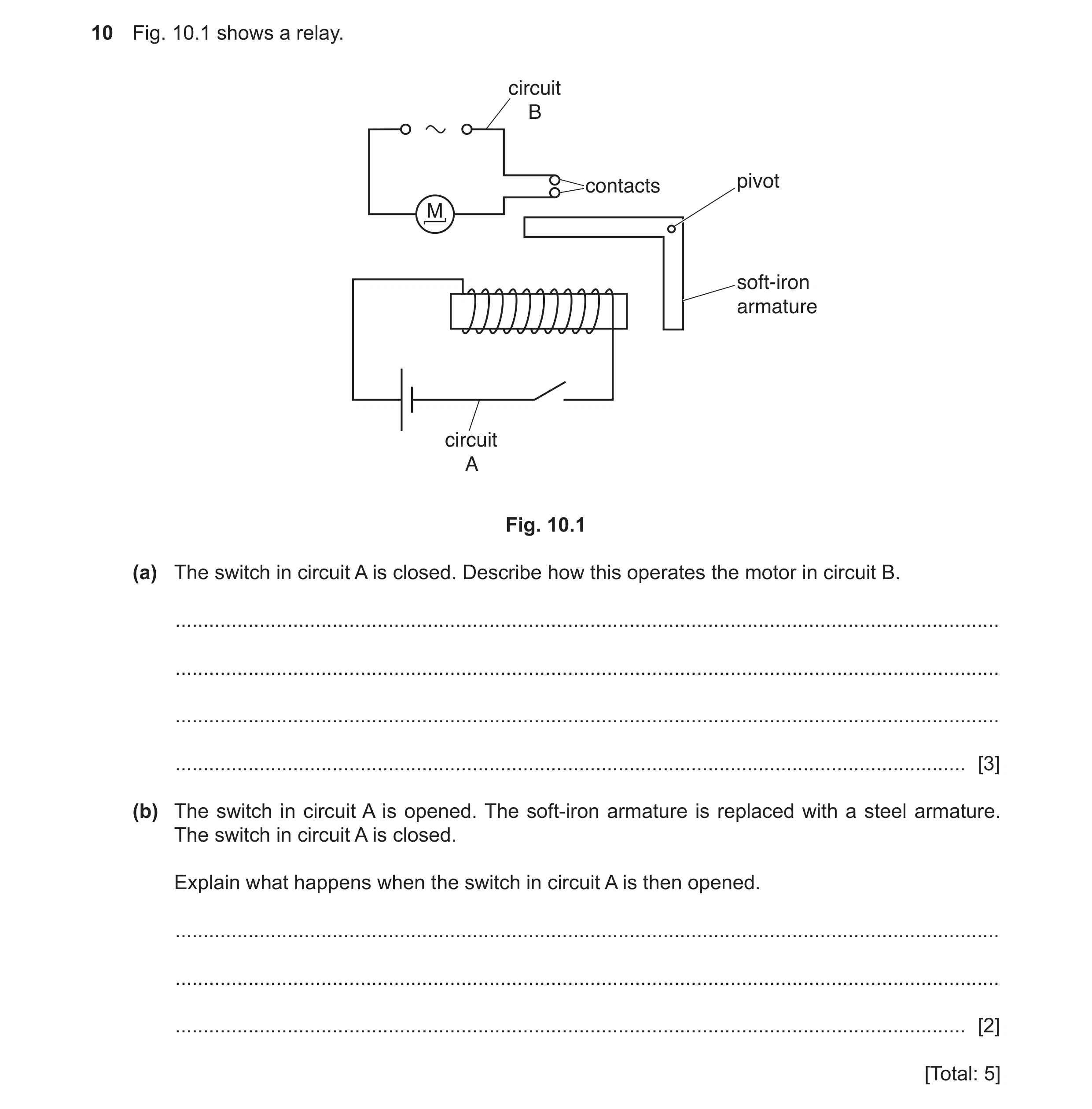
10 Fig. 10.1 shows a relay. circuit B contacts pivot M soft-iron armature circuit A Fig. 10.1 (a) The switch in circuit A is closed. Describe how this operates the motor in circuit B. … … … … [3] (b) The switch in circuit A is opened. The soft-iron armature is replaced with a steel armature. The switch in circuit A is closed. Explain what happens when the switch in circuit A is then opened. … … … [2] [Total: 5]
5 marks
Mark scheme: 10(a) iron core / coil / solenoid becomes a magnet B1 iron core / coil / solenoid attracts iron armature B1 armature pivots/moves and contacts touch / there is a current in circuit B B1 10(b) current in circuit B does not stop when switch in circuit A is opened B1 steel remains magnetised when there is no current in the coil B1
This question in 0625/43 Oct/Nov 2020
Q26 · An alternating current (a.c.) generator 0625/41 May/June 2021
7 Fig. 7.1 represents an alternating current (a.c.) generator. S N direction of rotation H X Y Fig. 7.1 (a) A student rotates the handle H, as shown in Fig. 7.1. (i) On Fig. 7.2, sketch a graph to show how the electromotive force (e.m.f.) between terminals X and Y varies with time during two complete revolutions of the coil. Fig. 7.2 [3] (ii) On Fig. 7.2, mark and label a point P, for the e.m.f. when the coil is horizontal, as shown in Fig. 7.1. [1] (iii) The student turns the handle more quickly. State two ways in which the e.m.f. between terminals X and Y changes. 1. … 2. … [2] (b) Terminals X and Y are connected to the primary coil of a transformer. State and explain what happens in the transformer as the student turns the handle of the a.c. generator. … … … … [3] (c) Explain why the power losses in transmission cables are lower when electrical energy is transmitted at higher voltages. … … … [2] [Total: 11]
11 marks
Mark scheme: 7(a)(i) any three from: • y-axis labelled e.m.f. and x-axis labelled time • at least one cycle of a sinusoidal wave • only two complete cycles of a sinusoidal wave • constant amplitude and constant period for first two periods of a sinusoidal wave 7(a)(ii) peak or trough or corresponding time labelled P B1 7(a)(iii) (amplitude / maximum e.m.f.) increases B1 (e.m.f.) changes direction more often or greater frequency B1 7(b) alternating current in primary coil B1 alternating / changing magnetic field or magnetic field cuts secondary coil (continuously) B1 (alternating) e.m.f. induced in the secondary coil B1 Question Answer Marks 7(c) smaller current (and same resistance when the power is transmitted and an equal rate) B1 less thermal energy loss / produced (in cables) B1
This question in 0625/41 May/June 2021
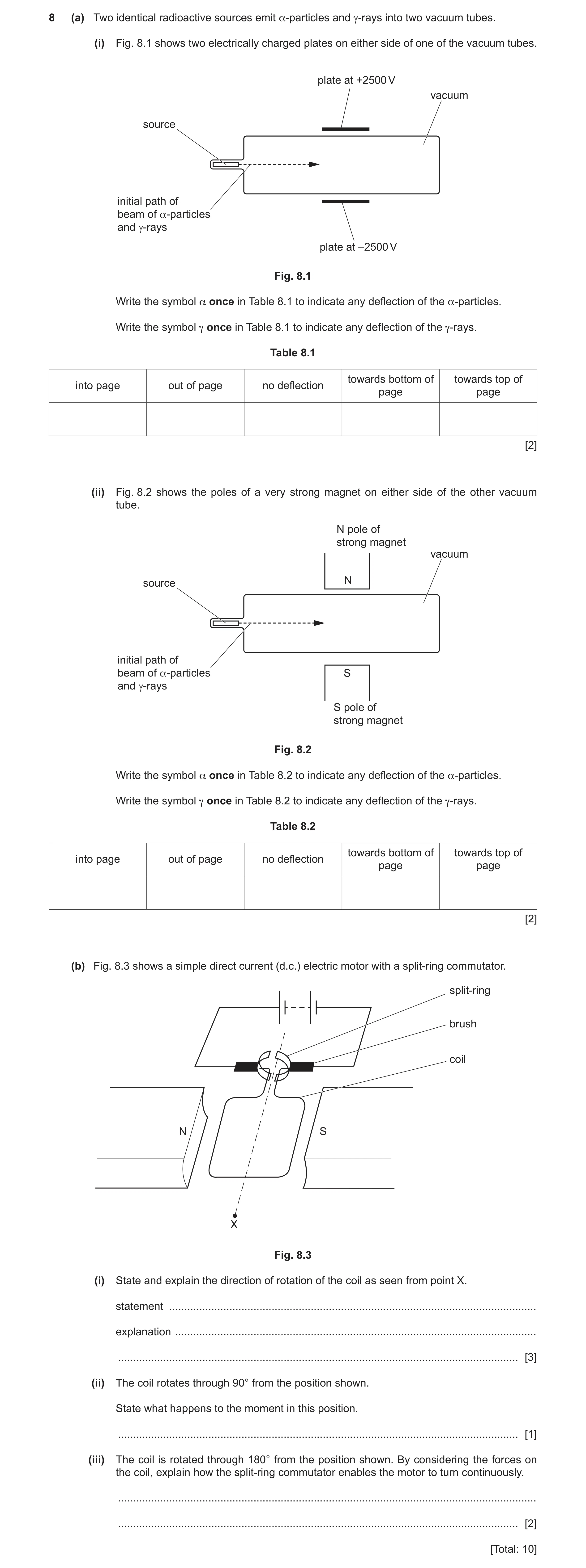
Q27 · Two identical radioactive sources emit α-particles and γ-rays into two vacuum tubes 0625/42 May/June 2021
8 (a) Two identical radioactive sources emit α-particles and γ-rays into two vacuum tubes. (i) Fig. 8.1 shows two electrically charged plates on either side of one of the vacuum tubes. plate at +2500 V vacuum source initial path of beam of α-particles and γ-rays plate at –2500 V Fig. 8.1 Write the symbol α once in Table 8.1 to indicate any deflection of the α-particles. Write the symbol γ once in Table 8.1 to indicate any deflection of the γ-rays. Table 8.1 towards bottom of towards top of into page out of page no deflection page page [2] (ii) Fig. 8.2 shows the poles of a very strong magnet on either side of the other vacuum tube. N pole of strong magnet vacuum source N initial path of beam of α-particles S and γ-rays S pole of strong magnet Fig. 8.2 Write the symbol α once in Table 8.2 to indicate any deflection of the α-particles. Write the symbol γ once in Table 8.2 to indicate any deflection of the γ-rays. Table 8.2 towards bottom of towards top ofinto page out of page no deflection page page [2] (b) Fig. 8.3 shows a simple direct current (d.c.) electric motor with a split-ring commutator. split-ring brush coil N S X Fig. 8.3 (i) State and explain the direction of rotation of the coil as seen from point X. statement … explanation … … [3] (ii) The coil rotates through 90° from the position shown. State what happens to the moment in this position. … [1] (iii) The coil is rotated through 180° from the position shown. By considering the forces on the coil, explain how the split-ring commutator enables the motor to turn continuously. … … [2] [Total: 10]
10 marks
Mark scheme: 8(a)(i) α in Box 4 / towards bottom of page B1 γ in Box 3 / no deflection B1 8(a)(ii) α in Box 1 / into page B1 γ in Box 3 / no deflection B1 Question Answer Marks 8(b)(i) clockwise accept rotation arrow on diagram B1 force on L wire up / up arrow on L wire labelled force on diagram B1 force on RH wire down / down arrow on R wire labelled force on diagram B1 8(b)(ii) none / zero (moment) B1 8(b)(iii) current in coil reverses OR changes direction B1 force(s) (on wires in new positions) still up on L OR down on R owtte B1
This question in 0625/42 May/June 2021
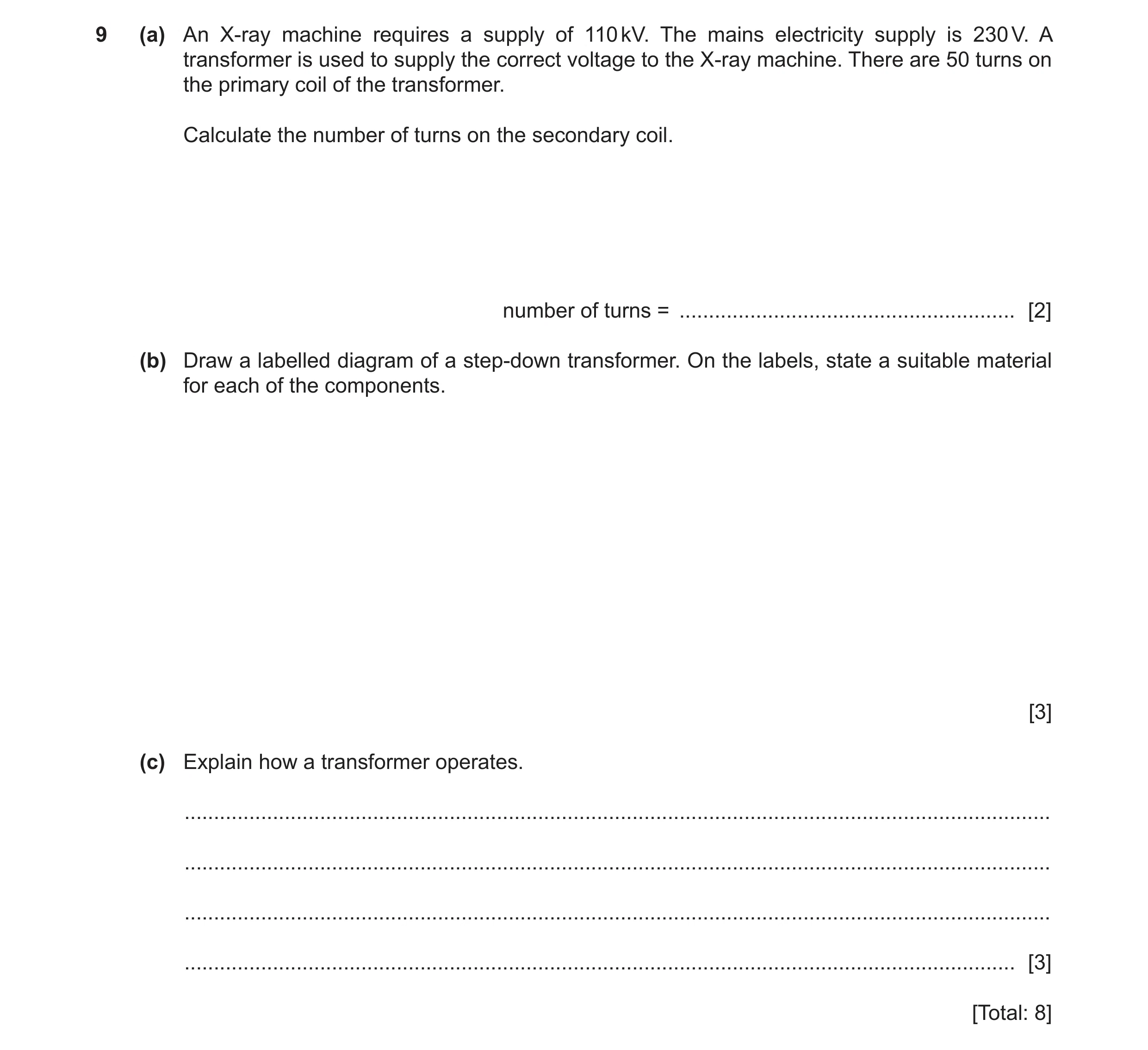
Q28 · An X-ray machine requires a supply of 110 kV 0625/43 May/June 2021
9 (a) An X-ray machine requires a supply of 110 kV. The mains electricity supply is 230 V. A transformer is used to supply the correct voltage to the X-ray machine. There are 50 turns on the primary coil of the transformer. Calculate the number of turns on the secondary coil. number of turns = … [2] (b) Draw a labelled diagram of a step-down transformer. On the labels, state a suitable material for each of the components. [3] (c) Explain how a transformer operates. … … … … [3] [Total: 8]
8 marks
Mark scheme: 9(a) (NS =) 24 000 A2 NS = NP × VS /VP OR 50 × 110 × 103 / 230 in any form C1 9(b) labelled diagram showing: • (soft)-iron core • copper coils • fewer coils on secondary than primary B3 9(c) alternating voltage in primary B1 alternating / varying / changing magnetic field (in iron core) B1 voltage is induced in the secondary coil B1
This question in 0625/43 May/June 2021
Q29 · A transformer has 500 turns on the primary coil and 25 turns on the secondary coil 0625/43 Oct/Nov 2021
10 (a) A transformer has 500 turns on the primary coil and 25 turns on the secondary coil. The input voltage is 120 V. (i) Calculate the output voltage. output voltage = … [2] (ii) The current in the primary coil is 125 mA. The transformer is 100% efficient. Calculate the output current. output current = … [2] (b) Fig. 10.1 shows a loose wire connected in a circuit with a d.c. (direct current) power supply and a switch. The length of the wire between the two supports is in the magnetic field of a horseshoe magnet. S support support N magnet d.c. power supply switch Fig. 10.1 The power supply is switched on and the wire moves down. (i) On Fig. 10.1, draw an arrow on the wire to show the direction of the current. [1] (ii) The power supply is switched off and the wire returns to its original position. The power supply is then switched on so that the current is in the opposite direction. State and explain what happens to the wire. … … [2] (c) A split-ring commutator is an important feature of a d.c. motor. Suggest one reason why the d.c. motor cannot operate without a split-ring commutator. … [1] [Total: 8]
8 marks
Mark scheme: 10(a)(i) 6.0 V A2 (VS =) NSVP / NP in any form or (VS =) (25 × 120) / 500 C1 10(a)(ii) 2.5 A OR 2500 mA A2 (IS =) IP VP / VS in any form OR (0.125 × 120) / 6.0 C1 10(b)(i) arrow right to left along loose part of wire or any other correct position B1 10(b)(ii) B2 wire moves up B1 (reversing direction of the current) reverses the direction of force B1 10(c) coil does not continue to rotate in the same direction B1
This question in 0625/43 Oct/Nov 2021
Q30 · Two vertical, cylindrical tubes and a cylindrical magnet all held in a vacuum 0625/41 May/June 2022
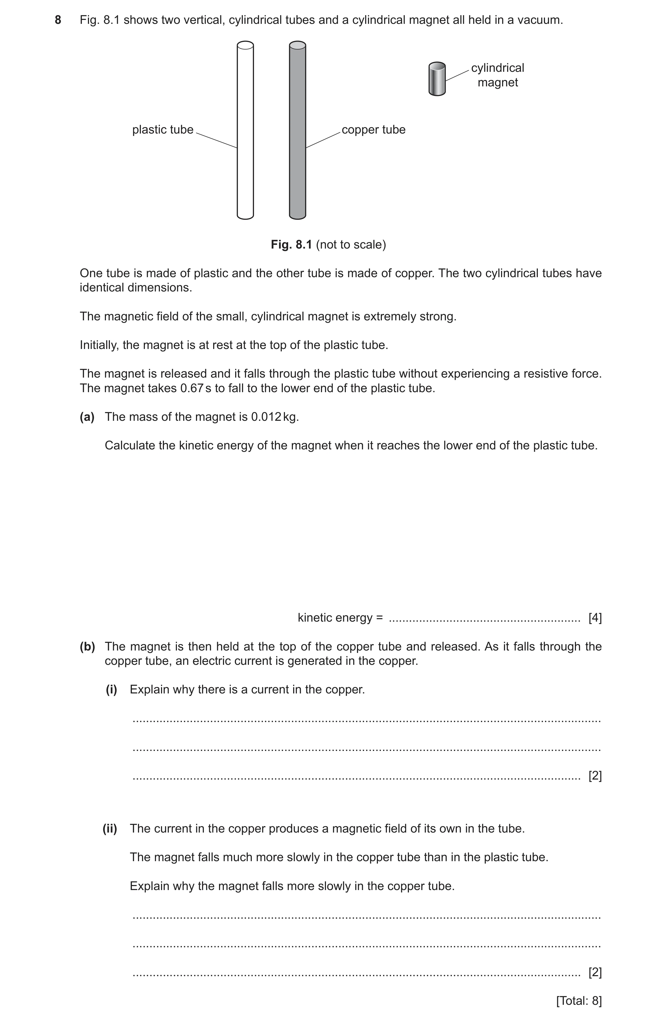
8 Fig. 8.1 shows two vertical, cylindrical tubes and a cylindrical magnet all held in a vacuum. cylindrical magnet plastic tube copper tube Fig. 8.1 (not to scale) One tube is made of plastic and the other tube is made of copper. The two cylindrical tubes have identical dimensions. The magnetic field of the small, cylindrical magnet is extremely strong. Initially, the magnet is at rest at the top of the plastic tube. The magnet is released and it falls through the plastic tube without experiencing a resistive force. The magnet takes 0.67 s to fall to the lower end of the plastic tube. (a) The mass of the magnet is 0.012 kg. Calculate the kinetic energy of the magnet when it reaches the lower end of the plastic tube. kinetic energy = … [4] (b) The magnet is then held at the top of the copper tube and released. As it falls through the copper tube, an electric current is generated in the copper. (i) Explain why there is a current in the copper. … … … [2] (ii) The current in the copper produces a magnetic field of its own in the tube. The magnet falls much more slowly in the copper tube than in the plastic tube. Explain why the magnet falls more slowly in the copper tube. … … … [2] [Total: 8]
8 marks
Mark scheme: 8(a) 0.27 J A4 (v =) at (in any form) or 10 0.67 or 6.7 (m / s) C1 6.7 (m / s) C1 (KE =) ½mv 2 (in any form) or ½ 0.012 (10 0.67)2 or ½ 0.012 6.72 C1 8(b)(i) magnetic field / magnetic field lines cut the copper / tube / it (or vv.) B1 electromagnetic induction occurs or e.m.f. induced B1 Question Answer Marks 8(b)(ii) (upwards / opposing) force on magnet B1 force / magnetic field / e.m.f. / current opposes the change (producing it) / opposes motion or force on magnet due to magnetic field caused by current in tube B1
This question in 0625/41 May/June 2022
Q31 · A small plotting compass which is aligned with the magnetic field between magnetic poles… 0625/42 May/June 2022
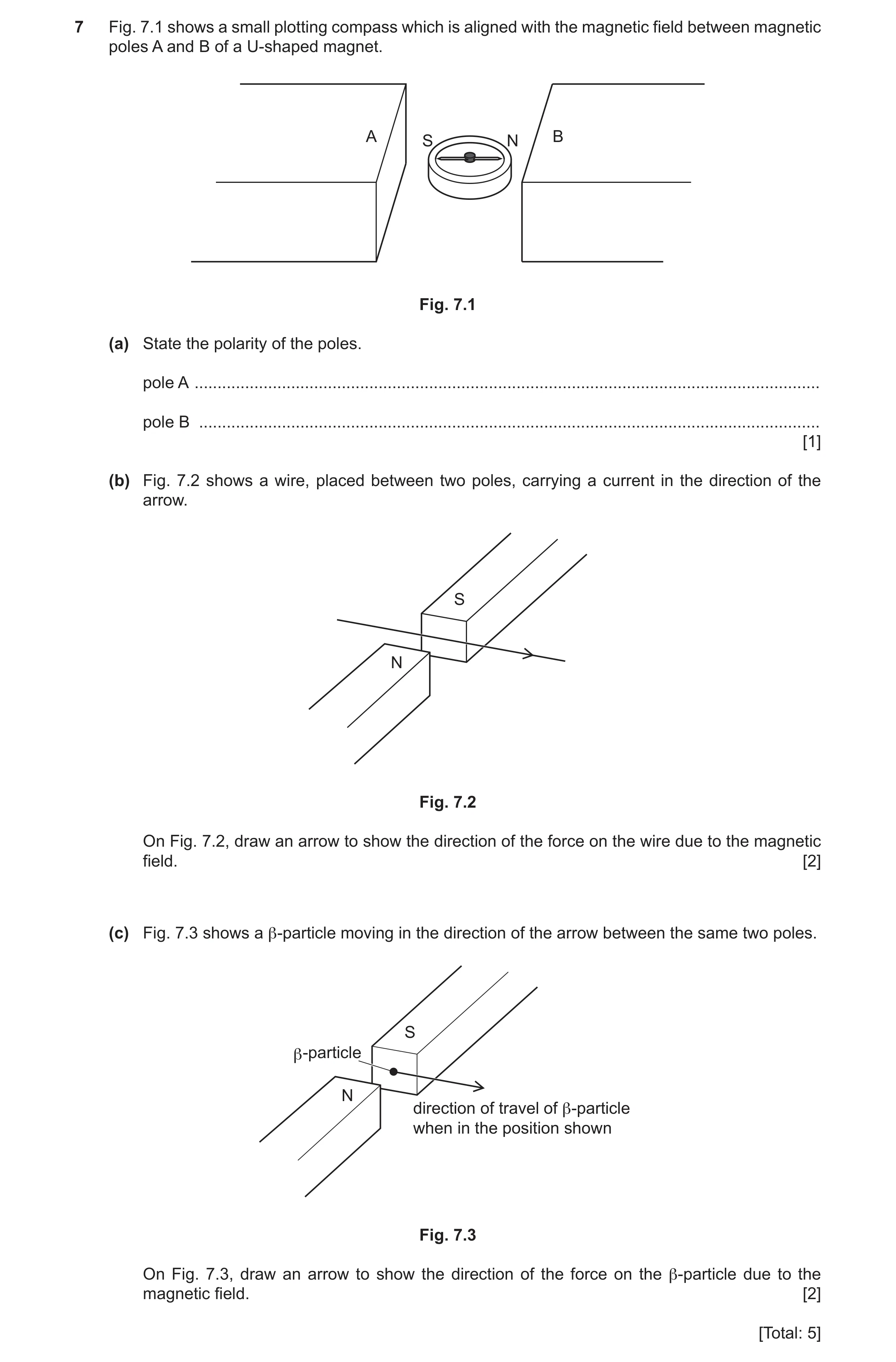
7 Fig. 7.1 shows a small plotting compass which is aligned with the magnetic field between magnetic poles A and B of a U-shaped magnet. A B S N Fig. 7.1 (a) State the polarity of the poles. pole A … pole B … [1] (b) Fig. 7.2 shows a wire, placed between two poles, carrying a current in the direction of the arrow. S N Fig. 7.2 On Fig. 7.2, draw an arrow to show the direction of the force on the wire due to the magnetic field. [2] (c) Fig. 7.3 shows a β-particle moving in the direction of the arrow between the same two poles. S β -particle N direction of travel of β-particle when in the position shown Fig. 7.3 On Fig. 7.3, draw an arrow to show the direction of the force on the β-particle due to the magnetic field. [2] [Total: 5]
5 marks
Mark scheme: 7(a) (pole A:) N AND (pole B:) S B1 7(b) vertical B1 up B1 7(c) vertical B1 down B1
This question in 0625/42 May/June 2022
Q32 · A magnet on the end of a spring and a coil of wire connected to a sensitive centre-zero… 0625/43 May/June 2022
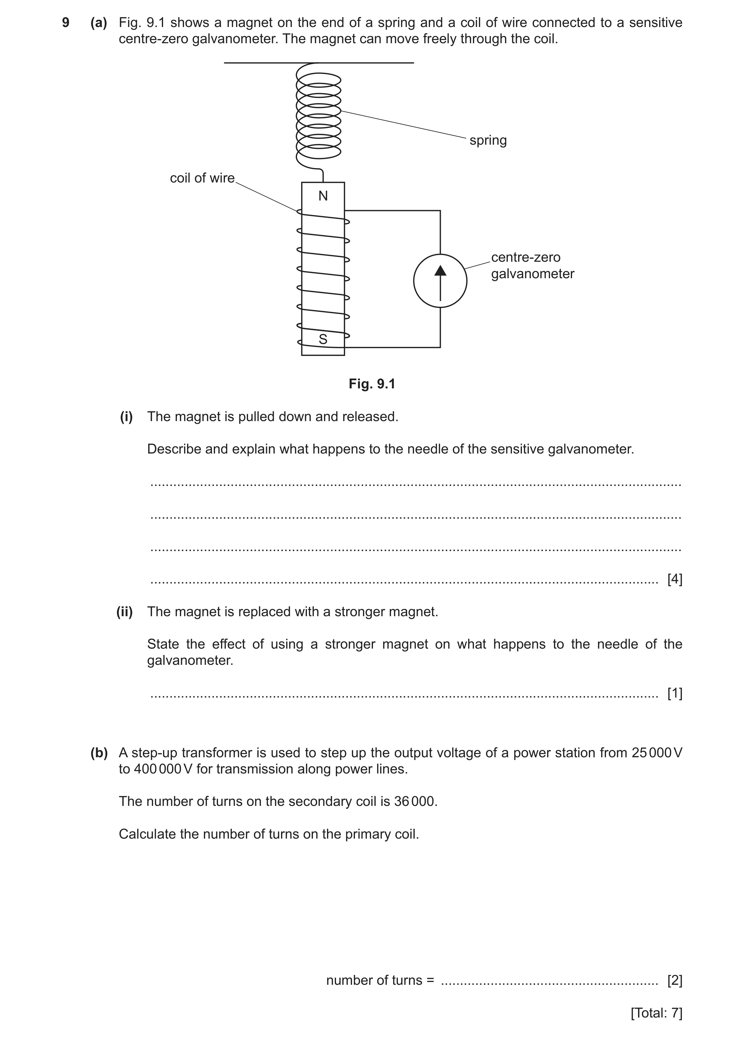
9 (a) Fig. 9.1 shows a magnet on the end of a spring and a coil of wire connected to a sensitive centre-zero galvanometer. The magnet can move freely through the coil. spring coil of wire N centre-zero galvanometer S Fig. 9.1 (i) The magnet is pulled down and released. Describe and explain what happens to the needle of the sensitive galvanometer. … … … … [4] (ii) The magnet is replaced with a stronger magnet. State the effect of using a stronger magnet on what happens to the needle of the galvanometer. … [1] (b) A step-up transformer is used to step up the output voltage of a power station from 25 000 V to 400 000 V for transmission along power lines. The number of turns on the secondary coil is 36 000. Calculate the number of turns on the primary coil. number of turns = … [2] [Total: 7]
7 marks
Mark scheme: 9(a)(i) any four from: needle oscillates (as magnet moves up and down) coil cuts magnetic field / magnetic field changes (as magnet moves) changing (magnetic) field induces voltage/current induced voltage/current opposes the motion/change causing it force, magnetic field and induced current are mutually perpendicular 9(a)(ii) larger (maximum) deflection B1 9(b) 2300 A2 (NP =) VP NS / VS in any form OR (NP =) 25000 36000 400000 C1
This question in 0625/43 May/June 2022
Q33 · The electric starter motor in a car is switched on and off using a relay 0625/41 Oct/Nov 2022
7 The electric starter motor in a car is switched on and off using a relay. The relay consists of a plastic case and two flexible springy strips, X and Y, which are made of soft iron. These iron strips act as the switch when a circuit is connected between the terminals W and Z. Fig. 7.1 shows X, Y and the plastic case. W W S springy iron X strips X 12 V car battery Y Y magnetising coil plastic case Z Z Fig. 7.1 Fig. 7.2 Fig. 7.2 shows the equipment from Fig. 7.1 inside a magnetising coil. The magnetising coil is in series with the 12 V car battery and switch S, which is open. (a) Switch S is now closed. Explain what happens to the springy iron strips X and Y. … … … … [3] (b) The power of the starter motor is 1.8 kW and it is also operated by the car battery. (i) Calculate the current in the starter motor when it is used. current = … [2] (ii) The starter motor circuit is connected between terminals W and Z. Explain why copper wires with a large cross-sectional area are used for this circuit. … … … [2] (c) Fig. 7.3 shows the relay and the symbols for the car battery and the starter motor. W S X 12 V car battery Y Z M starter motor Fig. 7.3 The springy iron strips X and Y act as the switch for the starter motor circuit. Complete the circuit diagram for the motor circuit. [2] [Total: 9]
9 marks
Mark scheme: 7(a) B3 X and Y / they become magnetised or they / strips have poles B1 strips in the centre have opposite (magnetic) poles or X and Y attract B1 X and Y touch / close switch / activate relay / complete circuit B1 7(b)(i) 150 A A2 I = P / V in any form or 1.8 / 12 or 1800 / 12 or 1800 / 12 or 0.15 C1 7(b)(ii) B2 small(er) resistance mentioned B1 less thermal energy produced or wires do not melt or large current mentioned B1 7(c) B2 flexible strips in series with motor B1 power supply in series with motor B1 expected answer: W flexible iron S strips X 12 V car battery Y magnetising coil plastic case Z M starter motor
This question in 0625/41 Oct/Nov 2022
Q34 · A solenoid connected to a battery 0625/43 Oct/Nov 2022
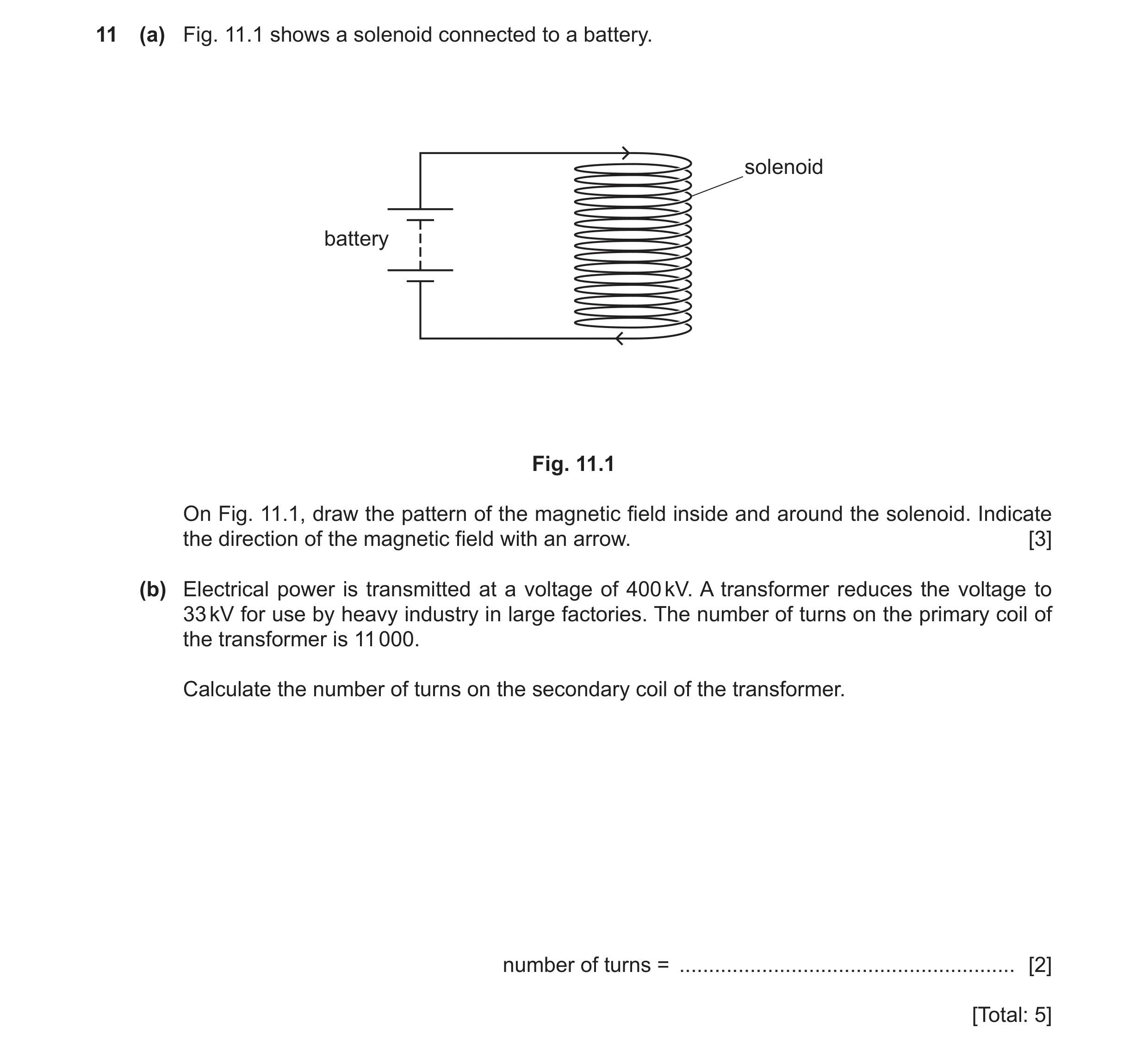
11 (a) Fig. 11.1 shows a solenoid connected to a battery. solenoid battery Fig. 11.1 On Fig. 11.1, draw the pattern of the magnetic field inside and around the solenoid. Indicate the direction of the magnetic field with an arrow. [3] (b) Electrical power is transmitted at a voltage of 400 kV. A transformer reduces the voltage to 33 kV for use by heavy industry in large factories. The number of turns on the primary coil of the transformer is 11 000. Calculate the number of turns on the secondary coil of the transformer. number of turns = … [2] [Total: 5]
5 marks
Mark scheme: 11(a) at least one line on the left and one line on the right, outside coil B1 AND curved back over the top and under the base of the coil, towards the central core of the coil at least two (straight vertical) lines inside coil B1 direction of arrow correct on at least one line and none wrong B1 11(b) 910 A2 NP / NS = VP / VS OR (NS =) (VS / VP) NP C1 11000 33 000 11000 33 OR (NS =) OR (NS =) 400 000 400
This question in 0625/43 Oct/Nov 2022
Q35 · A horizontal, flat coil in a magnetic field coil axis B N A S Fig 0625/42 Feb/March 2023
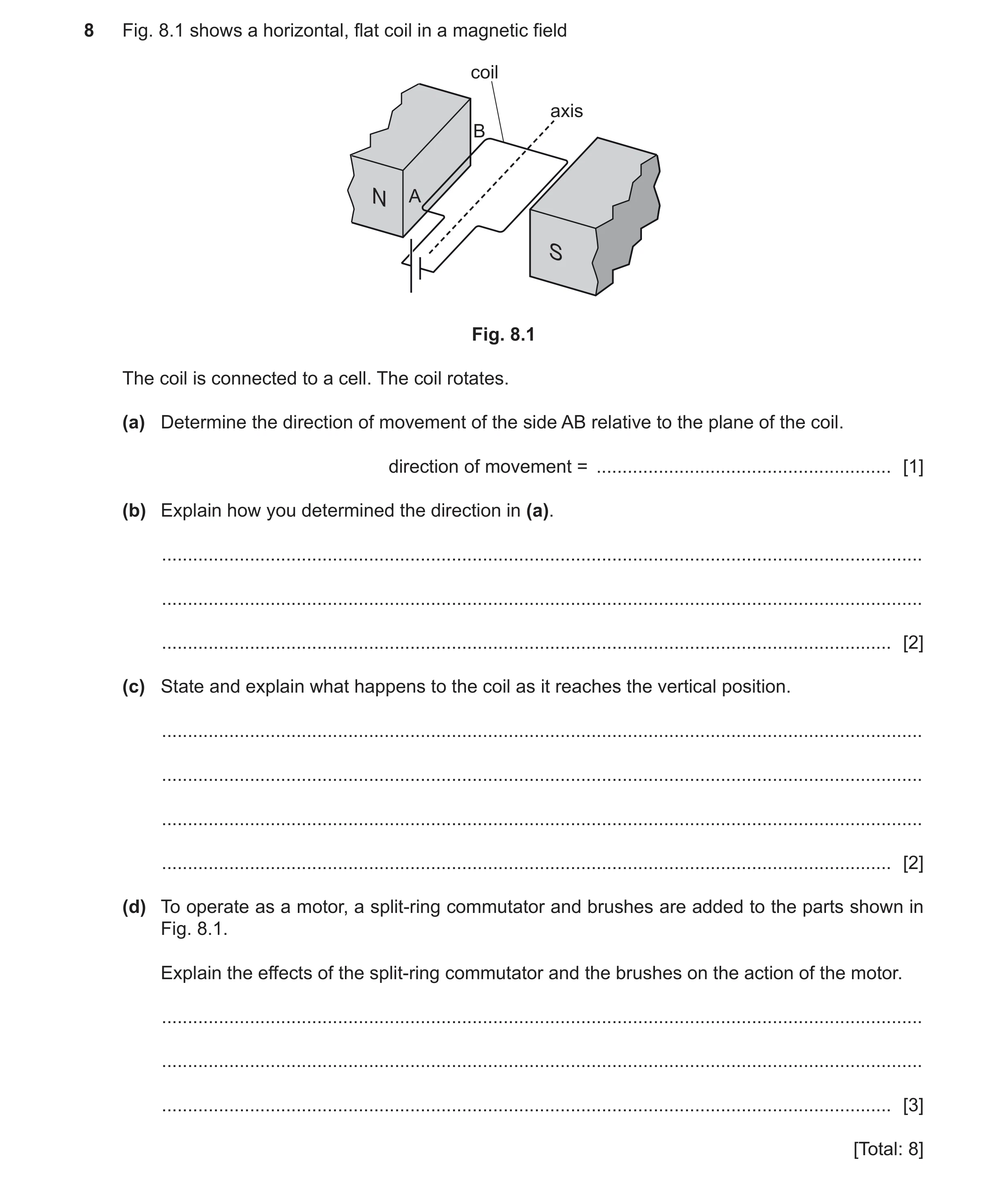
8 Fig. 8.1 shows a horizontal, flat coil in a magnetic field coil axis B N A S Fig. 8.1 The coil is connected to a cell. The coil rotates. (a) Determine the direction of movement of the side AB relative to the plane of the coil. direction of movement = … [1] (b) Explain how you determined the direction in (a). … … … [2] (c) State and explain what happens to the coil as it reaches the vertical position. … … … … [2] (d) To operate as a motor, a split‑ring commutator and brushes are added to the parts shown in Fig. 8.1. Explain the effects of the split‑ring commutator and the brushes on the action of the motor. … … … [3] [Total: 8]
8 marks
Mark scheme: 8(a) downwards / into the page / anti-clockwise B1 8(b) current, (magnetic) field, motion at right angles to each other B1 magnetic field from left to right / N to S AND current is from A to B / positive to negative B1 8(c) (at vertical) the coil stops OR (at vertical) the coil overshoots and comes back OR the coil vibrates (about the vertical) B1 any one from: B1 • (as the coil approaches vertical) the turning effect decreases • (at vertical) the turning effect is zero • (past vertical) the turning effect reverses / changes direction 8(d) reverses the current B1 any two from: B2 • (brushes) ensure current is maintained / owtte • coil rotates continuously / continues to move in the same direction • (allows current to change direction) without wires getting tangled • (reverses the current) every half turn / 180 degrees / OR (reverses the current) when the coil is vertical / at right angles to the magnetic field
This question in 0625/42 Feb/March 2023
Q36 · The electricity supplied to a town is transmitted using a high-voltage cable 0625/41 May/June 2023
8 The electricity supplied to a town is transmitted using a high-voltage cable. A transformer in the town has a soft-iron core. (a) Explain the principle of operation of a simple iron-cored transformer. … … … … … [4] (b) The transformer steps the supply voltage down from 220 000 V to 33 000 V. (i) There are 450 turns on the secondary coil. Calculate the number of turns on the primary coil. number of turns = … [2] (ii) The electrical power transferred to the transformer by the high-voltage cable is 77 MW. Calculate the current in the primary coil. current = … [3] [Total: 9]
9 marks
Mark scheme: 8(a) any four from: alternating current in (primary coil) (current in primary generates) changing magnetic field iron core concentrates (magnetic) field OR iron core transfers (magnetic) field (to secondary coil) secondary coil is in alternating / changing (magnetic) field OR secondary coil cuts (magnetic) field e.m.f. induced (in secondary coil) B4 8(b)(i) (number of turns =) 3000 A2 Np/ Ns = Vp/ Vs OR (Np =) Ns Vp/ Vs OR (Np =) 450 220 000 / 33 000 C1 8(b)(ii) (current =) 350 A A3 P = IV OR (I =) P / V OR (I =) 7.7 107 / 220 000 C1 (I =) 3.5 10N C1
This question in 0625/41 May/June 2023
Q37 · The isotope thallium-208 (20881Tl ) is radioactive 0625/41 May/June 2024
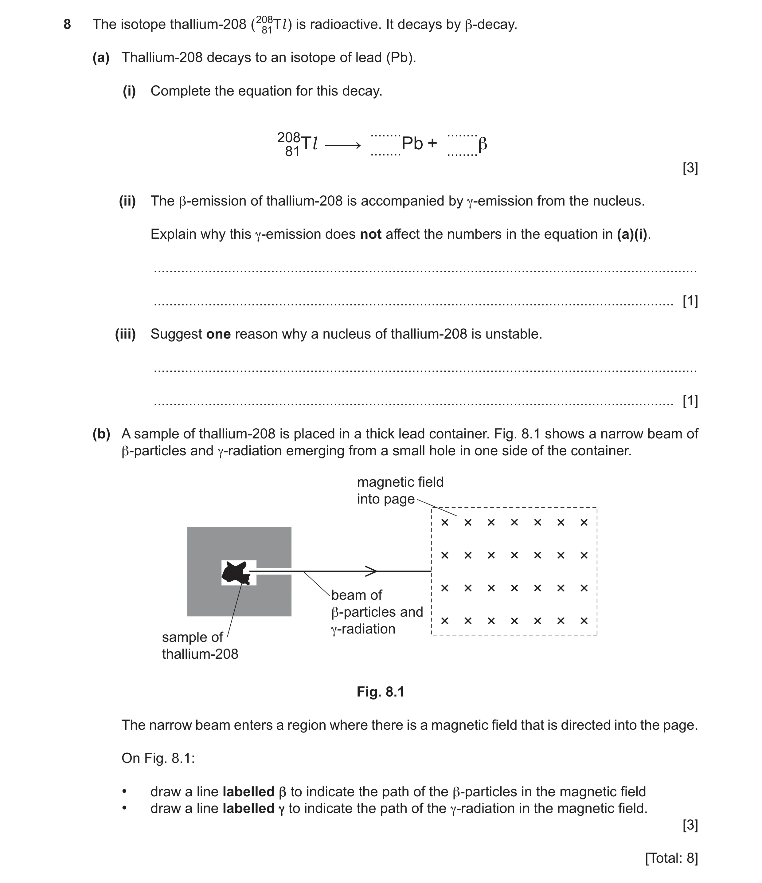
8 The isotope thallium-208 (20881Tl ) is radioactive. It decays by β-decay. (a) Thallium-208 decays to an isotope of lead (Pb). (i) Complete the equation for this decay. … … 20881Tl … Pb + … β [3] (ii) The β-emission of thallium-208 is accompanied by γ-emission from the nucleus. Explain why this γ-emission does not affect the numbers in the equation in (a)(i). … … [1] (iii) Suggest one reason why a nucleus of thallium-208 is unstable. … … [1] (b) A sample of thallium-208 is placed in a thick lead container. Fig. 8.1 shows a narrow beam of β-particles and γ-radiation emerging from a small hole in one side of the container. magnetic field into page beam of β-particles and γ-radiation sample of thallium-208 Fig. 8.1 The narrow beam enters a region where there is a magnetic field that is directed into the page. On Fig. 8.1: • draw a line labelled β to indicate the path of the β-particles in the magnetic field • draw a line labelled γ to indicate the path of the γ-radiation in the magnetic field. [3] [Total: 8]
8 marks
Mark scheme: 8(a)(i) –1 Pb ….. 208 B1 Pb 82 ….. B1 8(a)(ii) -emission / it consists of waves / rays OR -emission has no mass / charge B1 8(a)(iii) (it contains) too many / excess of neutrons OR (nucleus is) too heavy B1 8(b) smooth curve (through magnetic field) AND labelled B1 path towards bottom of page AND no upward component AND labelled B1 (continuation of beam along) horizontal line through magnetic field AND labelled B1
This question in 0625/41 May/June 2024
Q38 · Three bars of steel, A, B and C 0625/42 May/June 2024
7 (a) Fig. 7.1 shows three bars of steel, A, B and C. A B C Fig. 7.1 A student is given the three pieces of steel. Two of the pieces are magnetised and one piece is unmagnetised. Describe and explain how the student determines which piece is unmagnetised using only the three pieces of steel. … … … … … … … … [4] (b) Fig. 7.2 shows a circuit diagram of a step‑down transformer. output Fig. 7.2 (i) The mains voltage supplied to the transformer is 240 V. The output power of the transformer is 45 W. The transformer is 100% efficient. Calculate the input current to the transformer. input current = … [3] (ii) Draw a labelled diagram of a step‑down transformer. On the labels, state a suitable material for each of the components. [3] [Total: 10]
10 marks
Mark scheme: 7(a) (end of) one piece of steel brought close to (the end of) another piece owtte B1 look to see if there is repulsion/attraction AND test between different ends/poles owtte B1 any two from: repeat a valid test between the other pieces only magnets repel each other OR the pieces that repel are magnets attractions at both ends indicates one of them is unmagnetised OR the piece that only attracts is unmagnetised OR the piece that does not repel (at both ends) is unmagnetised B2 7(b)(i) 0.19 A A3 Ip Vp = Is Vs OR (Ip =) Is Vs / Vp OR (Ip =) 45 / 240 OR Ip Vp = 45 OR power in primary = power in secondary C1 (Ip= ) 45 / 240 C1 7(b)(ii) labelled diagram showing: (soft) iron core copper (coils) primary and secondary (coils) labelled AND fewer coils on secondary than on primary B3
This question in 0625/42 May/June 2024
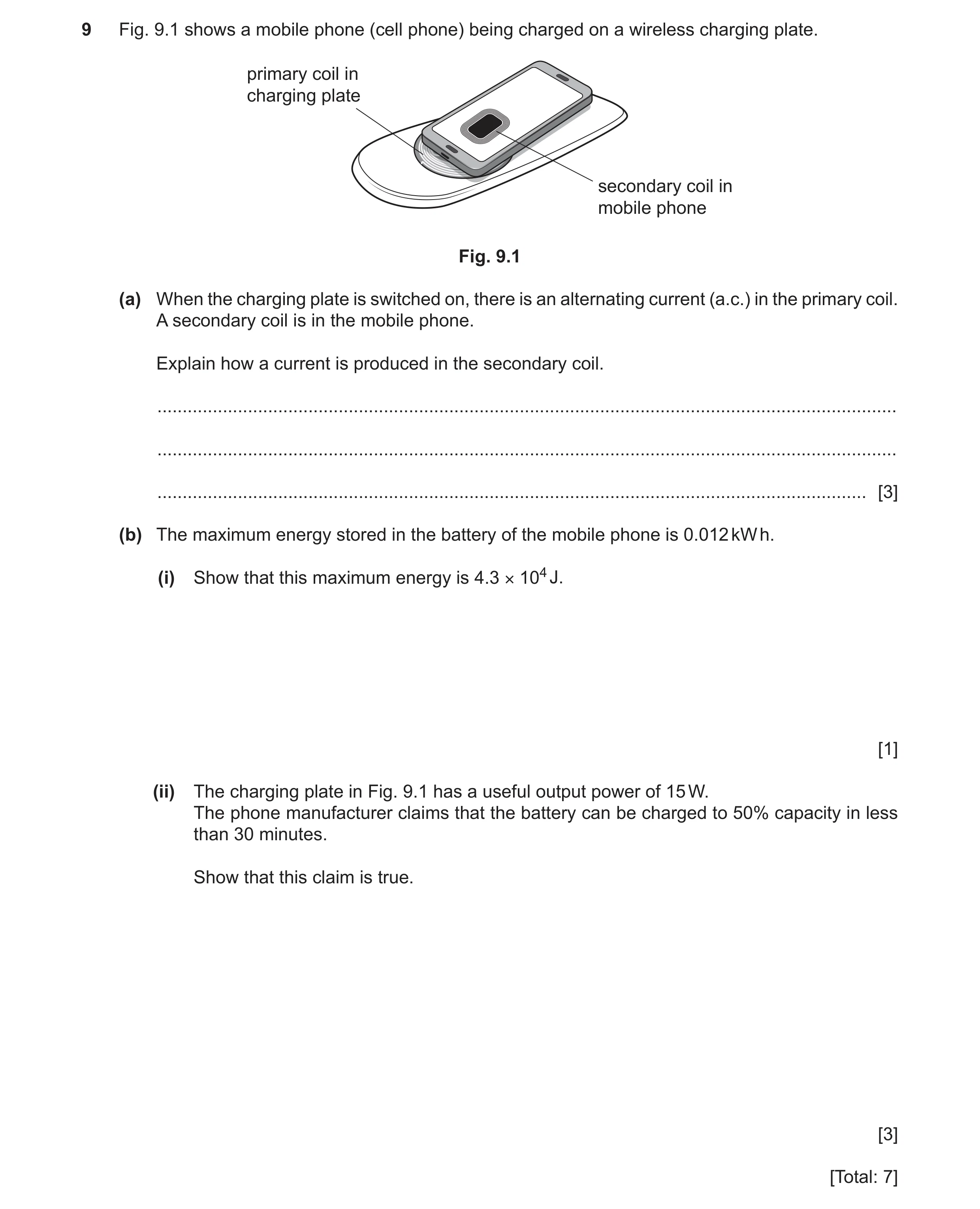
Q39 · A mobile phone (cell phone) being charged on a wireless charging plate 0625/43 May/June 2024
9 Fig. 9.1 shows a mobile phone (cell phone) being charged on a wireless charging plate. primary coil in charging plate secondary coil in mobile phone Fig. 9.1 (a) When the charging plate is switched on, there is an alternating current (a.c.) in the primary coil. A secondary coil is in the mobile phone. Explain how a current is produced in the secondary coil. … … … [3] (b) The maximum energy stored in the battery of the mobile phone is 0.012 kW h. (i) Show that this maximum energy is 4.3 × 10⁴ J. [1] (ii) The charging plate in Fig. 9.1 has a useful output power of 15 W. The phone manufacturer claims that the battery can be charged to 50% capacity in less than 30 minutes. Show that this claim is true. [3] [Total: 7]
7 marks
Mark scheme: 9(a) (alternating current / a.c. in primary coil / plate produces) changing magnetic field (in primary coil) B1 secondary / phone coil cuts (this) magnetic field OR secondary / phone coil is in this / changing magnetic field B1 (changing magnetic field) causes induced current (in secondary coil) B1 9(b)(i) 1 kW h = 1000 60 60 J AND 0.012 3.6 106 (= 4.3 104 J) B1 9(b)(ii) 50% charged = (4.3 104 / 2 =) 2.15 104 (J) OR 63% charged in 30 min OR (50% charged in t =) 24 min B1 P = E / t OR (t =) E / P OR 2.15 104 / 15 (s) OR energy provided in 30 min = (15 30 x 60=) 2.7 104 (J) B1 2.7 104 2.15 104 OR 63% 50% OR 30 min 24 min B1
This question in 0625/43 May/June 2024
Q40 · A solid bar is inside a copper solenoid 0625/41 Oct/Nov 2024
7 A solid bar is inside a copper solenoid. Fig. 7.1 shows that the copper solenoid is connected in series with a battery and a variable resistor. copper solenoid bar Fig. 7.1 The device shown in Fig. 7.1 is an electromagnet. (a) Suggest a suitable material for the bar. … [1] (b) The right-hand end of the bar is the S pole. (i) Fig. 7.2 shows the bar viewed from above. On Fig. 7.2, draw at least six field lines to show the pattern and direction of the magnetic field surrounding the bar. S Fig. 7.2 [3] (ii) The resistance of the variable resistor increases. Explain what happens to the magnetic field surrounding the bar and state how the pattern of field lines that represents the field changes. … … … … [3] (c) A square coil of many turns is placed close to the bar. Fig. 7.3 shows the plane of the square coil parallel to the flat circular surface at the right-hand end of the bar. terminals copper solenoid square coil bar Fig. 7.3 The resistance of the variable resistor is alternately increased and decreased. Explain what happens in the wires of the square coil. … … … … [3] [Total: 10]
10 marks
Mark scheme: 7(a) (soft) iron B1 7(b)(i) (at least) one complete field line between the poles of the bar (either above or below the bar) B1 no crossing AND attempt at correct shape AND at least six lines from / to poles B1 at least one arrowhead towards S pole B1 7(b)(ii) current (in the coil) decreases B1 (current decreases so magnetic field) strength decreases B1 (field strength decreases so) fewer field lines (in same area) OR (field strength decreases so) field lines further apart B1 7(c) Any two from: B2 1 (changing resistance causes) changing current (through solenoid) 2 (changing current causes) changing magnetic field (around solenoid) 3 (square) coil cuts (changing) magnetic field OR coil in changing magnetic field e.m.f. induced (between terminals) B1
This question in 0625/41 Oct/Nov 2024
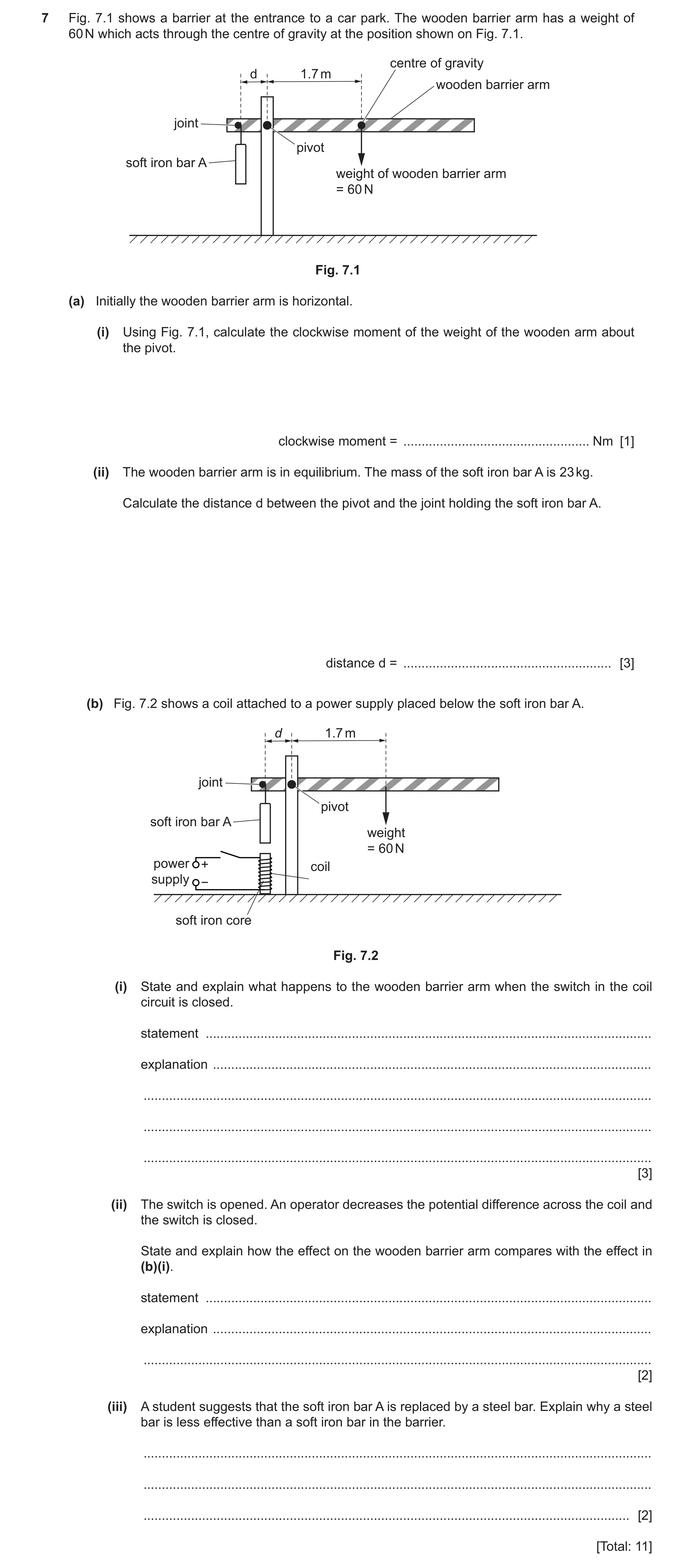
Q41 · A barrier at the entrance to a car park 0625/43 Oct/Nov 2024
7 Fig. 7.1 shows a barrier at the entrance to a car park. The wooden barrier arm has a weight of 60 N which acts through the centre of gravity at the position shown on Fig. 7.1. centre of gravity d 1.7 m wooden barrier arm joint pivot soft iron bar A weight of wooden barrier arm = 60 N Fig. 7.1 (a) Initially the wooden barrier arm is horizontal. (i) Using Fig. 7.1, calculate the clockwise moment of the weight of the wooden arm about the pivot. clockwise moment = … Nm [1] (ii) The wooden barrier arm is in equilibrium. The mass of the soft iron bar A is 23 kg. Calculate the distance d between the pivot and the joint holding the soft iron bar A. distance d = … [3] (b) Fig. 7.2 shows a coil attached to a power supply placed below the soft iron bar A. d 1.7 m joint pivot soft iron bar A weight = 60 N power + coil supply − soft iron core Fig. 7.2 (i) State and explain what happens to the wooden barrier arm when the switch in the coil circuit is closed. statement … explanation … … … … [3] (ii) The switch is opened. An operator decreases the potential difference across the coil and the switch is closed. State and explain how the effect on the wooden barrier arm compares with the effect in (b)(i). statement … explanation … … [2] (iii) A student suggests that the soft iron bar A is replaced by a steel bar. Explain why a steel bar is less effective than a soft iron bar in the barrier. … … … [2] [Total: 11]
11 marks
Mark scheme: 7(a)(i) 100 (Nm) B1 7(a)(ii) 0.44 m OR 0.45 m A3 total clockwise moment = total anticlockwise moment C1 (d =) 100 / 225 OR (d =) 100 / (23 9.8) OR 100 / (23 g d) C1 7(b)(i) (barrier arm) rotates anticlockwise OR (RHS of barrier arm) moves upwards B1 (when the switch is closed) coil produces a magnetic field OR coil / core becomes an (electro)magnet B1 (coil/core/electromagnet) attracts (iron) bar (downwards) B1 7(b)(ii) statement: (barrier arm) moves slower / goes up (more) slowly B1 explanation: decreases strength of (magnetic) field / smaller force / smaller moment B1 7(b)(iii) steel would become permanently magnetised B1 (so when switch is opened) barrier would stay up or bar A will stay attracted (to soft iron core) B1
This question in 0625/43 Oct/Nov 2024
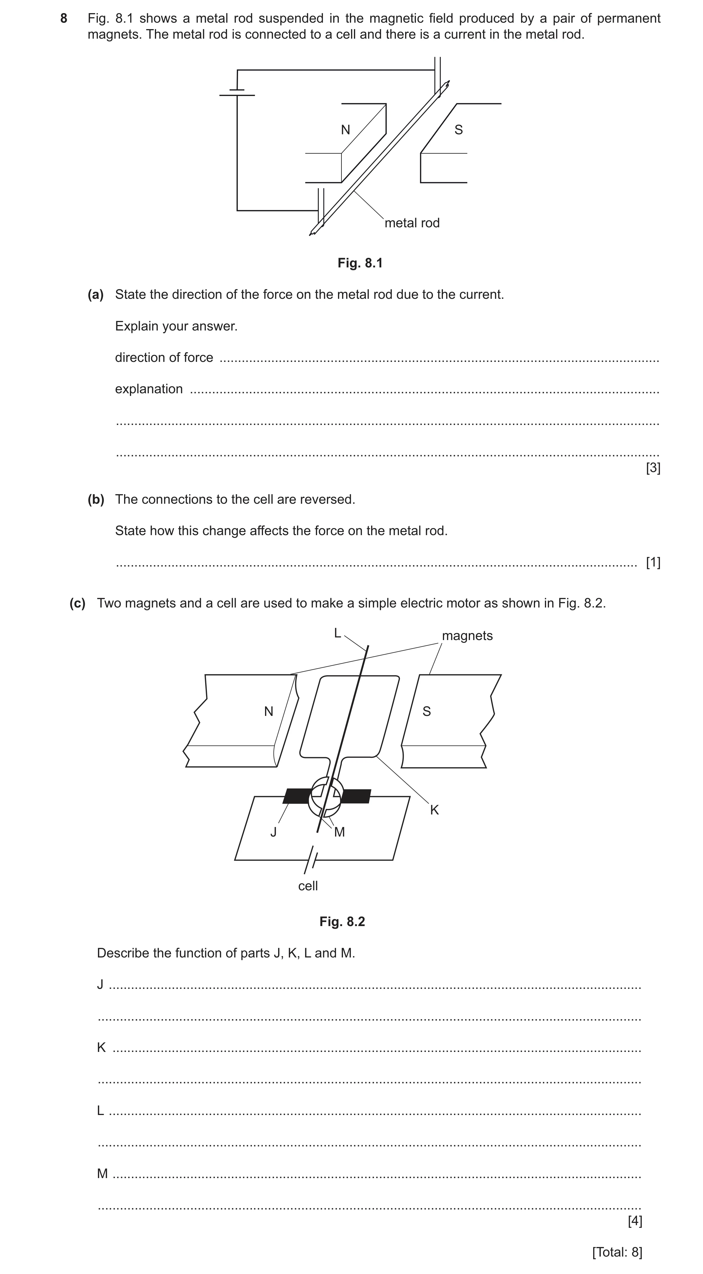
Q42 · A metal rod suspended in the magnetic field produced by a pair of permanent magnets 0625/42 Feb/March 2025
8 Fig. 8.1 shows a metal rod suspended in the magnetic field produced by a pair of permanent magnets. The metal rod is connected to a cell and there is a current in the metal rod. N S metal rod Fig. 8.1 (a) State the direction of the force on the metal rod due to the current. Explain your answer. direction of force … explanation … … … [3] (b) The connections to the cell are reversed. State how this change affects the force on the metal rod. … [1] (c) Two magnets and a cell are used to make a simple electric motor as shown in Fig. 8.2. L magnets N S K J M cell Fig. 8.2 Describe the function of parts J, K, L and M. J … … K … … L … … M … … [4] [Total: 8]
8 marks
Mark scheme: 8(a) (direction of force) down(wards) B1 magnetic field direction, current direction and force are mutually perpendicular B1 magnetic field is from N to S / left to right AND current flows from positive to negative / anticlockwise / into paper B1 8(b) (direction of force) reverses / changes by 180° B1 8(c) (J carbon brushes) B1 Any one from: • connect cell / circuit to coil / wire / split ring(s) / commutator • maintains (continuous) connection • prevent wires from tangling (as motor rotates) (K coil) B1 Any one from: • rotates / turns • conducts / has a current in it (L axle) B1 Any one from: • allows the coil to rotate / turn • allows motor to turn / spin (M split ring commutator) B1 Any one from: • keeps motor turning in the same direction owtte • reverses the connections to the coil (every half-turn) owtte • prevents wires from tangling (as the motor rotates)
This question in 0625/42 Feb/March 2025
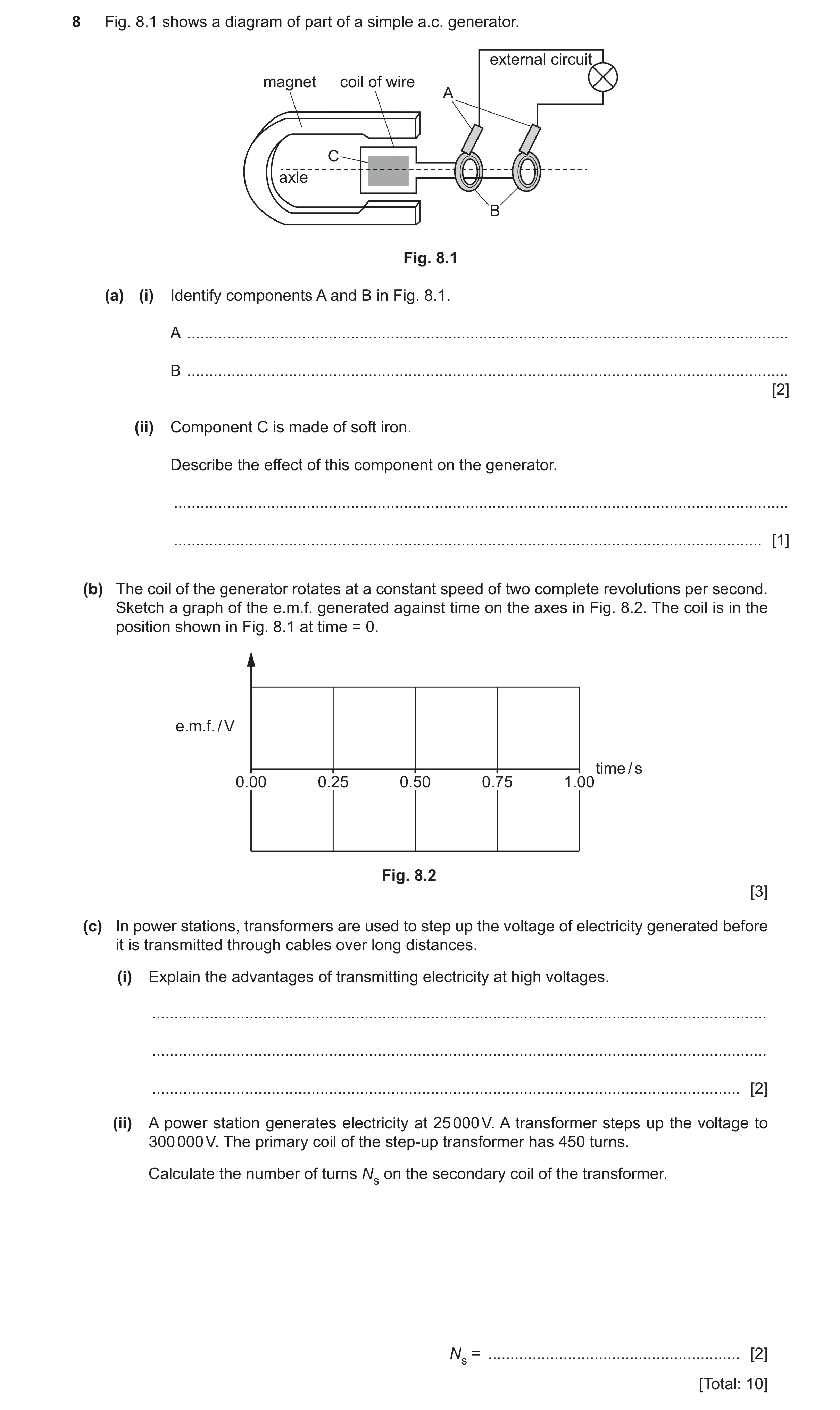
Q43 · A diagram of part of a simple a.c 0625/41 May/June 2025
8 Fig. 8.1 shows a diagram of part of a simple a.c. generator. external circuit magnet coil of wire A C axle B Fig. 8.1 (a) (i) Identify components A and B in Fig. 8.1. A … B … [2] (ii) Component C is made of soft iron. Describe the effect of this component on the generator. … … [1] (b) The coil of the generator rotates at a constant speed of two complete revolutions per second. Sketch a graph of the e.m.f. generated against time on the axes in Fig. 8.2. The coil is in the position shown in Fig. 8.1 at time = 0. e.m.f. / V time / s 0.00 0.25 0.50 0.75 1.00 Fig. 8.2 [3] (c) In power stations, transformers are used to step up the voltage of electricity generated before it is transmitted through cables over long distances. (i) Explain the advantages of transmitting electricity at high voltages. … … … [2] (ii) A power station generates electricity at 25 000 V. A transformer steps up the voltage to 300 000 V. The primary coil of the step-up transformer has 450 turns. Calculate the number of turns Ns on the secondary coil of the transformer. Ns = … [2] [Total: 10]
10 marks
Mark scheme: 8(a)(i) (A is carbon) brushes B1 (B is) slip rings B1 8(a)(ii) strengthens the magnetic field (of the magnet) B1 8(b) graph is sinusoidal with positive and negative e.m.f. B1 graph shows minimum of one cycle completed in 0.5 s B1 e.m.f. is a maximum at 0.00 s, curves to a minimum at 0.25 s and curves to maximum at 0.50 s OR B1 e.m.f. is a minimum at 0.00 s and curves to a maximum at 0.25 s and curves to a minimum at 0.50 s braille: e.m.f. starts at time zero at either maximum or minimum value 8(c)(i) either: A2 less power loss (for same power transmission) AND (because) P = I2R OR low current (for same power transmission) AND (allows) thinner / cheaper cables any one from: C1 • less power loss (for same power transmission) • P = I2R • low current (for same power transmission) • thinner / cheaper cables 8(c)(ii) 5400 A2 Vp Np NpVs C1 = OR (Ns =) OR Vs Ns Vp 450 × 300 000 (Ns =) 25 000
This question in 0625/41 May/June 2025
Q44 · A simplified diagram of an a.c 0625/42 May/June 2025
8 (a) Fig. 8.1 shows a simplified diagram of an a.c. generator. rotation of coil coil N S P X output Q Y Fig. 8.1 (i) State the names of components: P and Q … X and Y. … [2] (ii) Explain why an electromotive force (e.m.f.) is only induced when the coil is turning. … … [1] (iii) State one possible change that causes a larger e.m.f. to be induced. … [1] (b) Fig. 8.2 shows a circuit diagram. I A B C D V Fig. 8.2 Resistors A, B, C and D are identical. The current in resistor A is 2.4 A. (i) State the value of the current in resistor B. Explain your answer. current in resistor B … explanation … … [2] (ii) Calculate the value of the current I. current I = … [1] (iii) The reading on the voltmeter is 5.0 V. Calculate the resistance of resistor A. resistance = … [2] [Total: 9]
9 marks
Mark scheme: 8(a)(i) P and Q: slip rings B1 X and Y: brushes B1 8(a)(ii) coil cuts magnetic field B1 8(a)(iii) any one from: B1 • increase strength of magnetic field • increase speed of rotation of coil • increase number of turns (of coil) 8(b)(i) 1.2 A B1 (total) resistance of two (identical) resistors in series is added / doubled B1 8(b)(ii) 6(.0) A B1 8(b)(iii) 2.1 A2 V = I R OR (R =) V ÷ I OR (R =) 5(.0) ÷ 2.4 C1
This question in 0625/42 May/June 2025
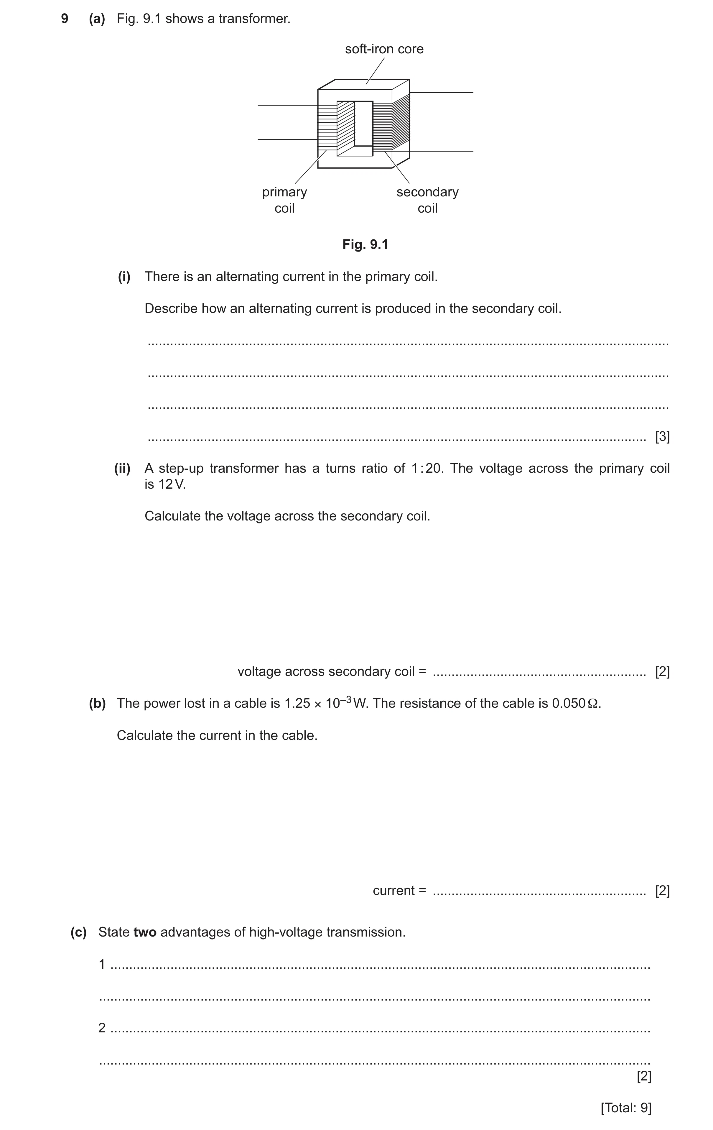
Question 45 0625/43 May/June 2025
9 (a) Fig. 9.1 shows a transformer. soft-iron core primary secondary coil coil Fig. 9.1 (i) There is an alternating current in the primary coil. Describe how an alternating current is produced in the secondary coil. … … … … [3] (ii) A step-up transformer has a turns ratio of 1 : 20. The voltage across the primary coil is 12 V. Calculate the voltage across the secondary coil. voltage across secondary coil = … [2] (b) The power lost in a cable is 1.25 × 10⁻³ W. The resistance of the cable is 0.050 Ω. Calculate the current in the cable. current = … [2] (c) State two advantages of high-voltage transmission. 1 … … 2 … … [2] [Total: 9]
9 marks
Mark scheme: 9(a)(i) any three from: B3 • (current in the primary coil generates a) changing magnetic field (in primary coil) • (iron) core transfers the magnetic field (to the secondary coil) • secondary coil cuts the magnetic field / secondary coil is in (changing) magnetic field • an e.m.f. is induced (in the secondary coil) • (induced) current changes direction because the magnetic field changes direction 9(a)(ii) 240 V A2 Vs ÷ Vp = Ns ÷ Np OR (Vs =) 12 20( ÷ 1) C1 9(b) 0.16 A A2 P = I2R OR I2 = P ÷ R OR I2 = 1.25 10–3 ÷ 0.05(0) OR I2 = 0.025 C1 9(c) any two from: B2 • less power / heating / energy losses • thinner / cheaper cables • pylons further apart / fewer pylons • transfer energy over long(er) distance
This question in 0625/43 May/June 2025
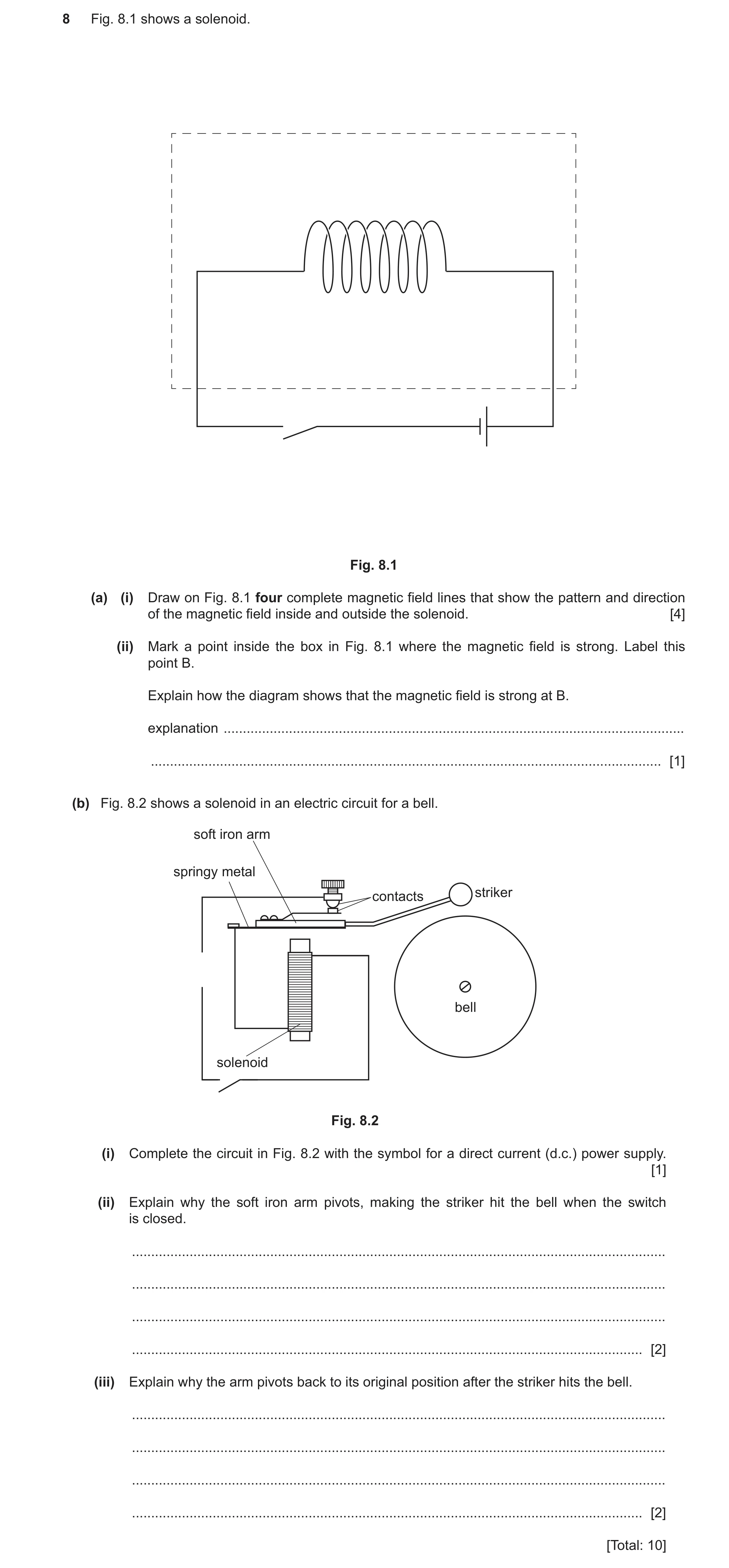
Question 46 0625/41 Oct/Nov 2025
8 Fig. 8.1 shows a solenoid. Fig. 8.1 (a) (i) Draw on Fig. 8.1 four complete magnetic field lines that show the pattern and direction of the magnetic field inside and outside the solenoid. [4] (ii) Mark a point inside the box in Fig. 8.1 where the magnetic field is strong. Label this point B. Explain how the diagram shows that the magnetic field is strong at B. explanation … … [1] (b) Fig. 8.2 shows a solenoid in an electric circuit for a bell. soft iron arm springy metal striker contacts bell solenoid Fig. 8.2 (i) Complete the circuit in Fig. 8.2 with the symbol for a direct current (d.c.) power supply. [1] (ii) Explain why the soft iron arm pivots, making the striker hit the bell when the switch is closed. … … … … [2] (iii) Explain why the arm pivots back to its original position after the striker hits the bell. … … … … [2] [Total: 10]
10 marks
Mark scheme: 8(a)(i) field lines parallel inside solenoid B1 Minimum of 2 magnetic field lines, curved towards end of solenoid, around outside of solenoid B1 Correct symmetrical pattern above and below solenoid AND no field lines crossing AND At least 2 complete lines B1 At least one arrow on a field line outside the solenoid which is away from left end or towards right end of solenoid B1 8(a)(ii) B marked at a place where field lines are close together in Fig. 8.1 AND (magnetic) field lines are close(r) together B1 8(b)(i) B1 8(b)(ii) Any one from: B1 • solenoid becomes an (electro)magnet • there is a magnetic field (around solenoid) Any one from: B1 • attraction between solenoid and the (soft) iron (arm) • (soft) iron becomes an (induced) magnet 8(b)(iii) Any one from: M1 • contacts are broken • circuit is broken (when striker hits bell) • there is no current (in the solenoid) Any one from: A1 • solenoid stops being a magnet • soft iron loses magnetism • soft iron stops being attracted to solenoid • Springy metal moves the soft iron back owtte
This question in 0625/41 Oct/Nov 2025
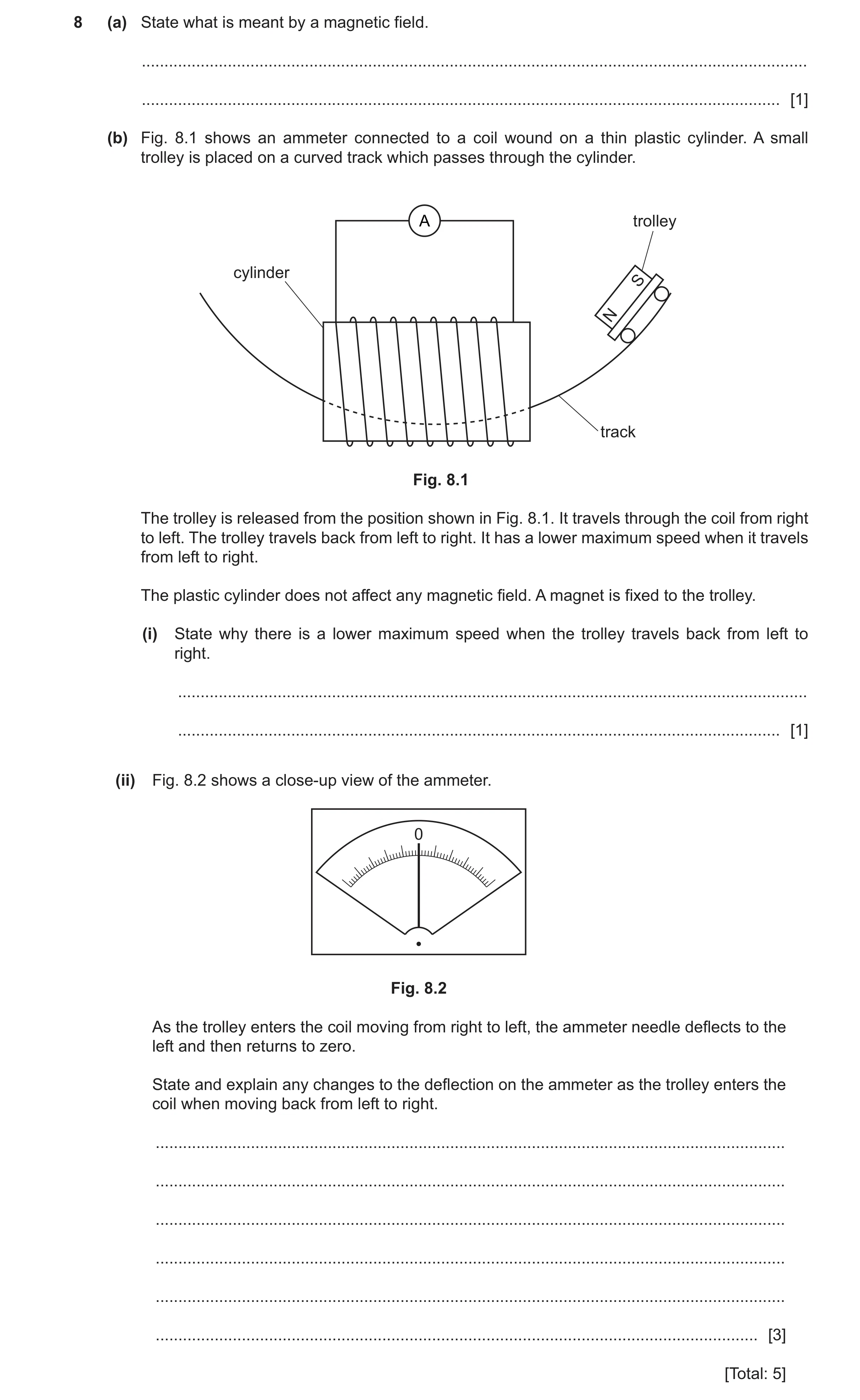
Q47 · State what is meant by a magnetic field 0625/42 Oct/Nov 2025
8 (a) State what is meant by a magnetic field. … … [1] (b) Fig. 8.1 shows an ammeter connected to a coil wound on a thin plastic cylinder. A small trolley is placed on a curved track which passes through the cylinder. A trolley cylinder S N track Fig. 8.1 The trolley is released from the position shown in Fig. 8.1. It travels through the coil from right to left. The trolley travels back from left to right. It has a lower maximum speed when it travels from left to right. The plastic cylinder does not affect any magnetic field. A magnet is fixed to the trolley. (i) State why there is a lower maximum speed when the trolley travels back from left to right. … … [1] (ii) Fig. 8.2 shows a close‑up view of the ammeter. 0 Fig. 8.2 As the trolley enters the coil moving from right to left, the ammeter needle deflects to the left and then returns to zero. State and explain any changes to the deflection on the ammeter as the trolley enters the coil when moving back from left to right. … … … … … … [3] [Total: 5]
5 marks
Mark scheme: 8(a) region in which a (magnetic) pole experiences a force B1 8(b)(i) friction between trolley and track OR the (induced) current produces a magnetic field which opposes the (magnetic) field B1 that causes the (induced) current 8(b)(ii) any three from: B3 • direction will (still) be left OR there is no change of direction • induced current / emf / voltage does not change direction • smaller deflection • smaller (rate of) change of magnetic field • smaller current / emf / voltage induced (in coil)
This question in 0625/42 Oct/Nov 2025
 1 / 62
 2 / 62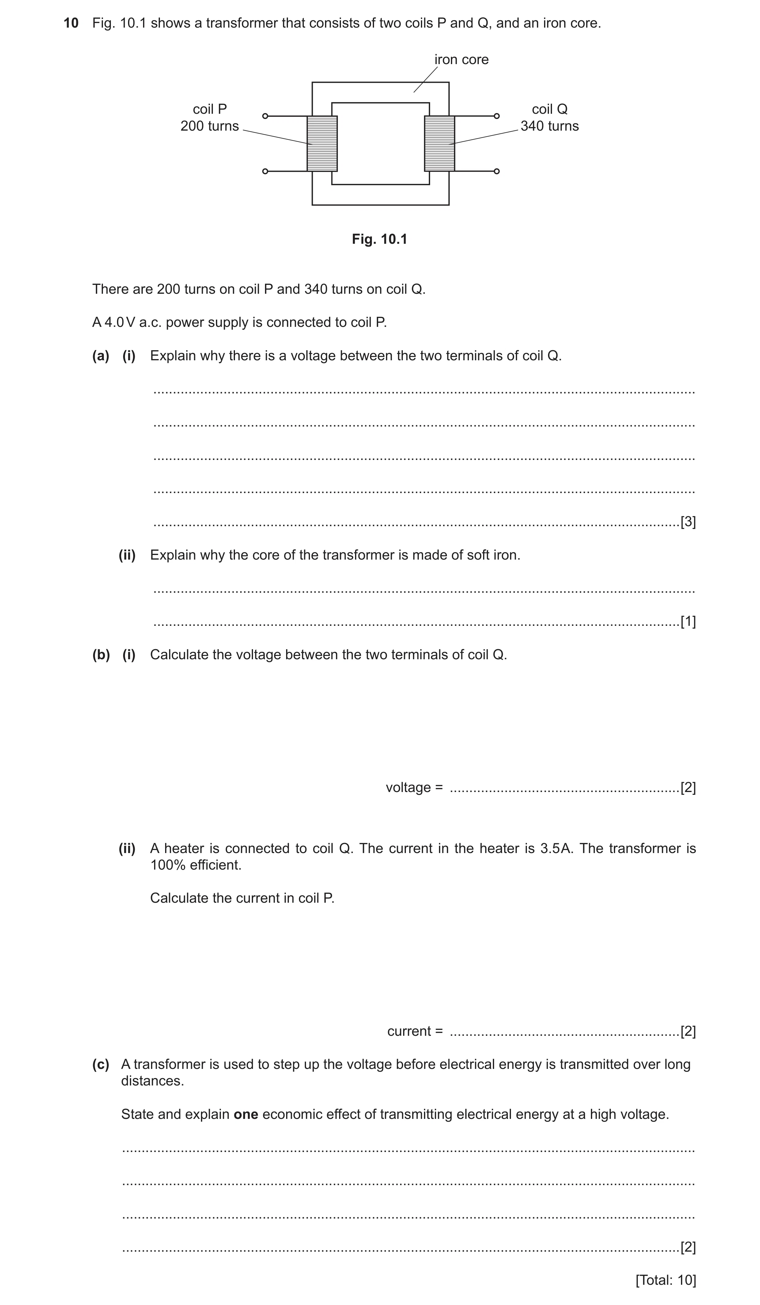
 9 / 62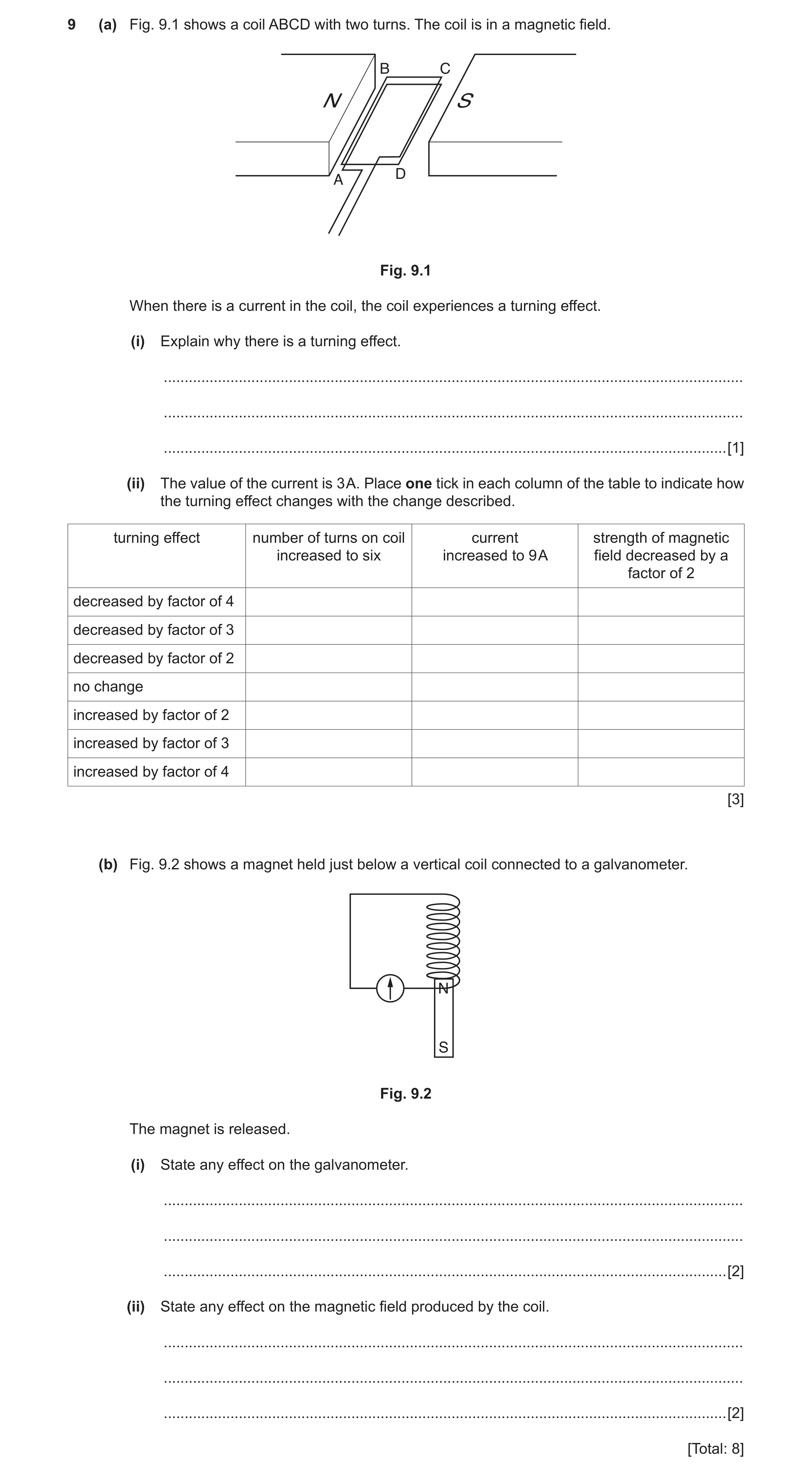
 12 / 62
 13 / 62
 14 / 62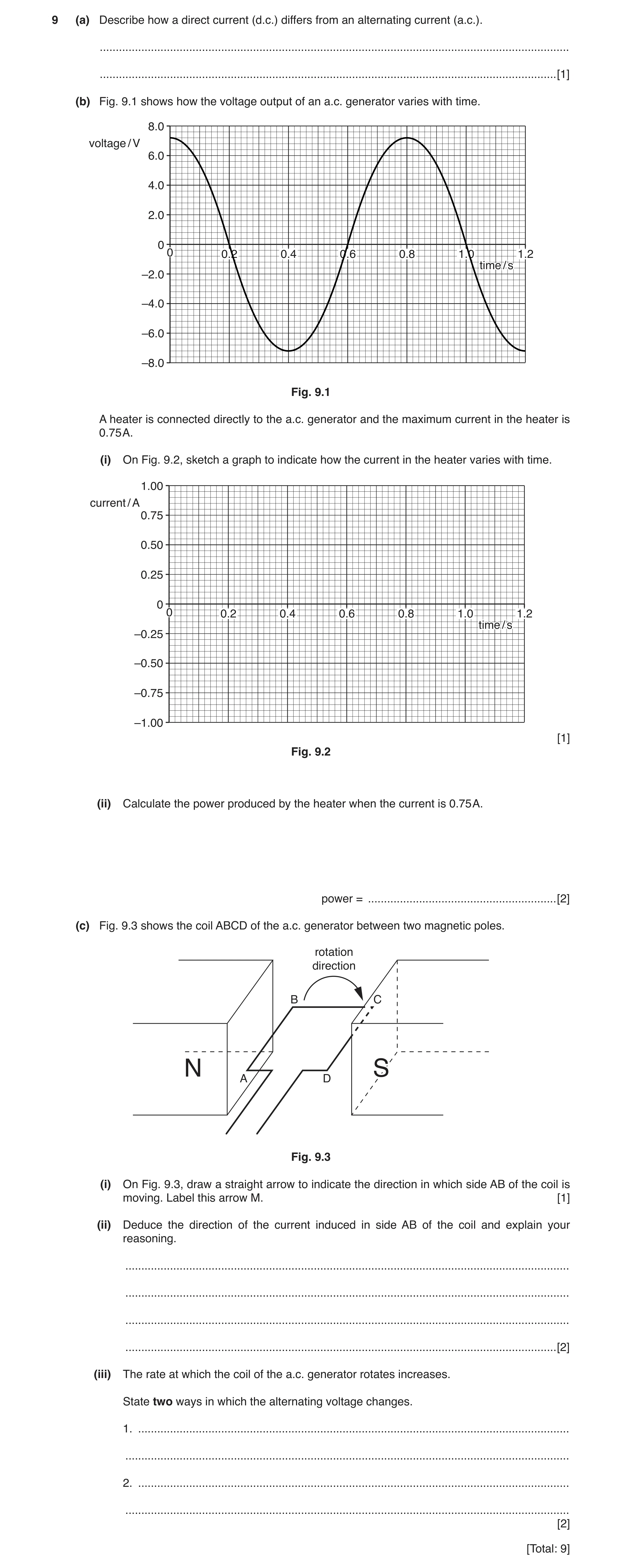
 17 / 62
 18 / 62
 19 / 62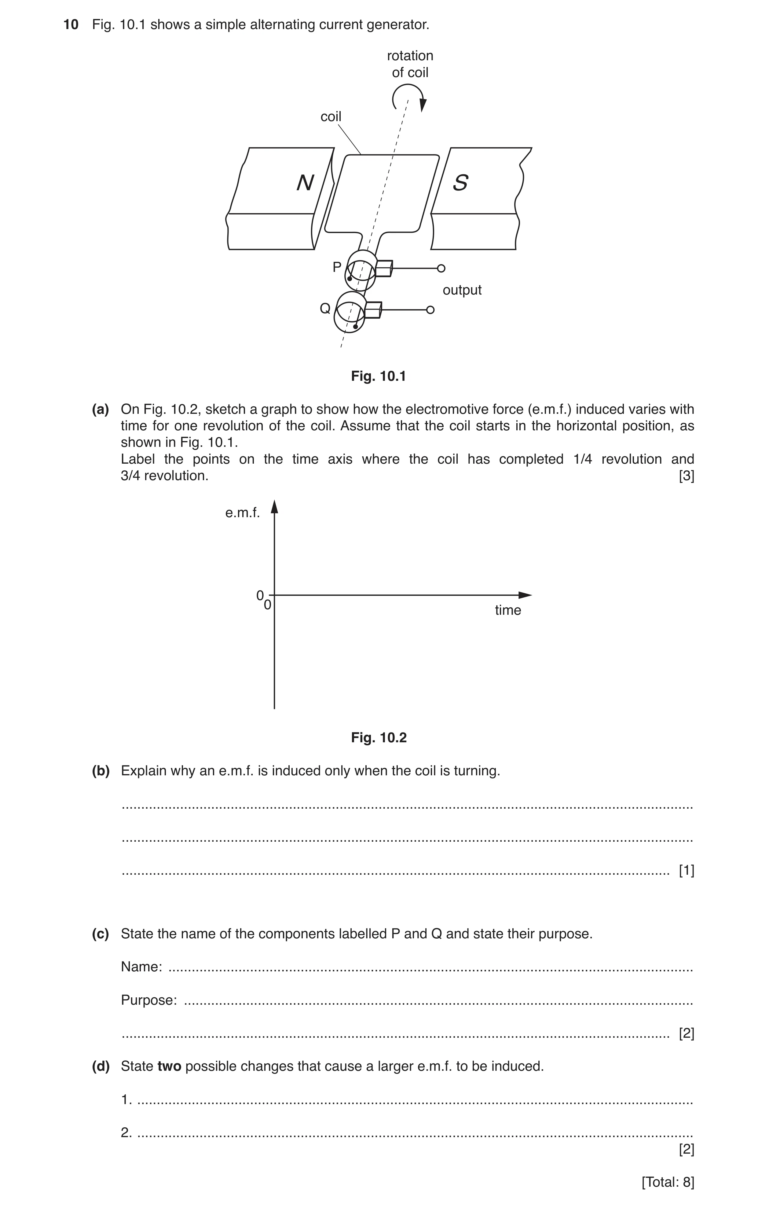
 23 / 62
 24 / 62
 25 / 62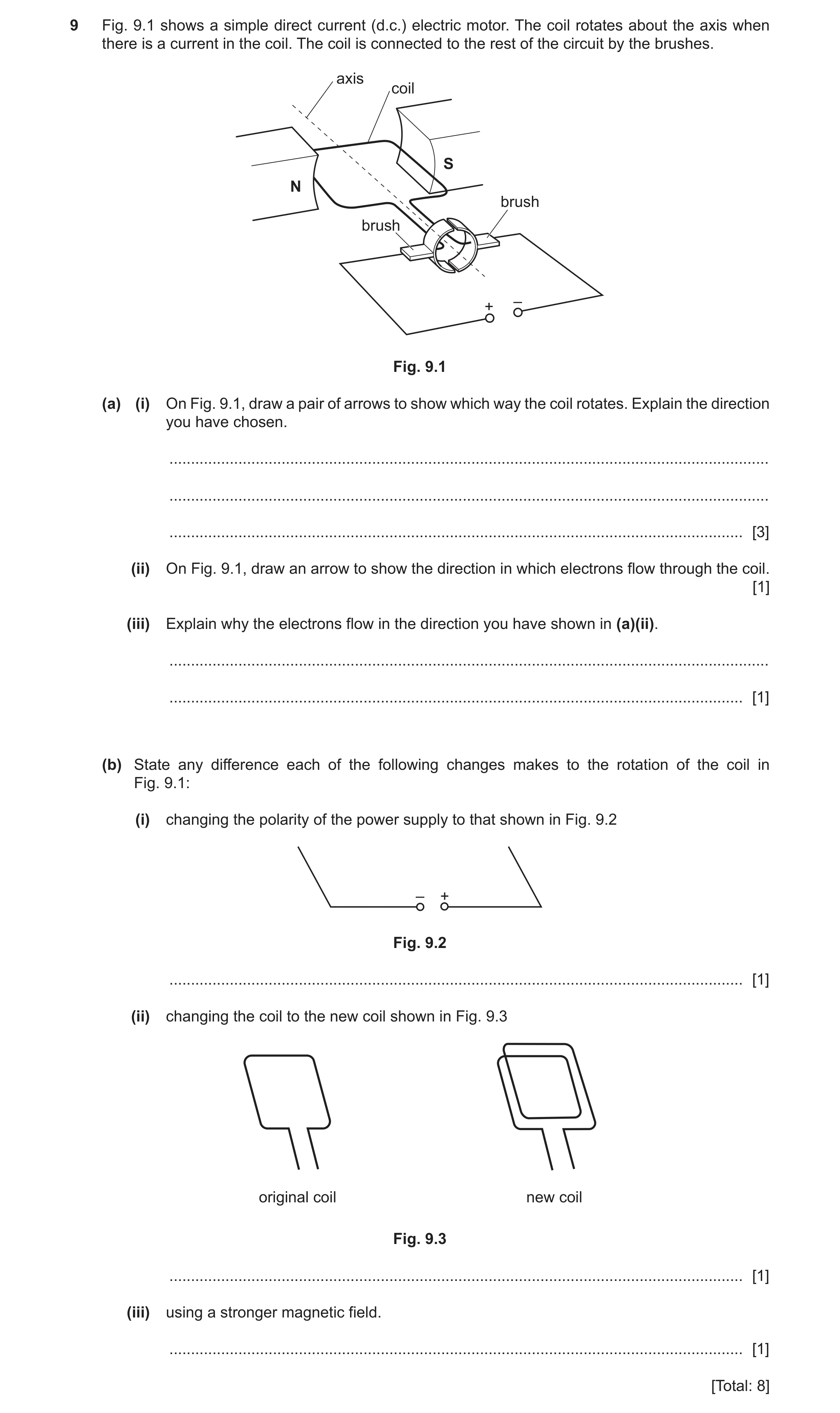
![Question 22: (a) A permanent magnet is made from only one material. Underline the material from which it is possible to make a permanent magnet. [1] alu…](https://img.pastlit.com/crops/1b4bb871-78c9-453b-ad4a-00326c6e572c/q7.webp)
 30 / 62
 31 / 62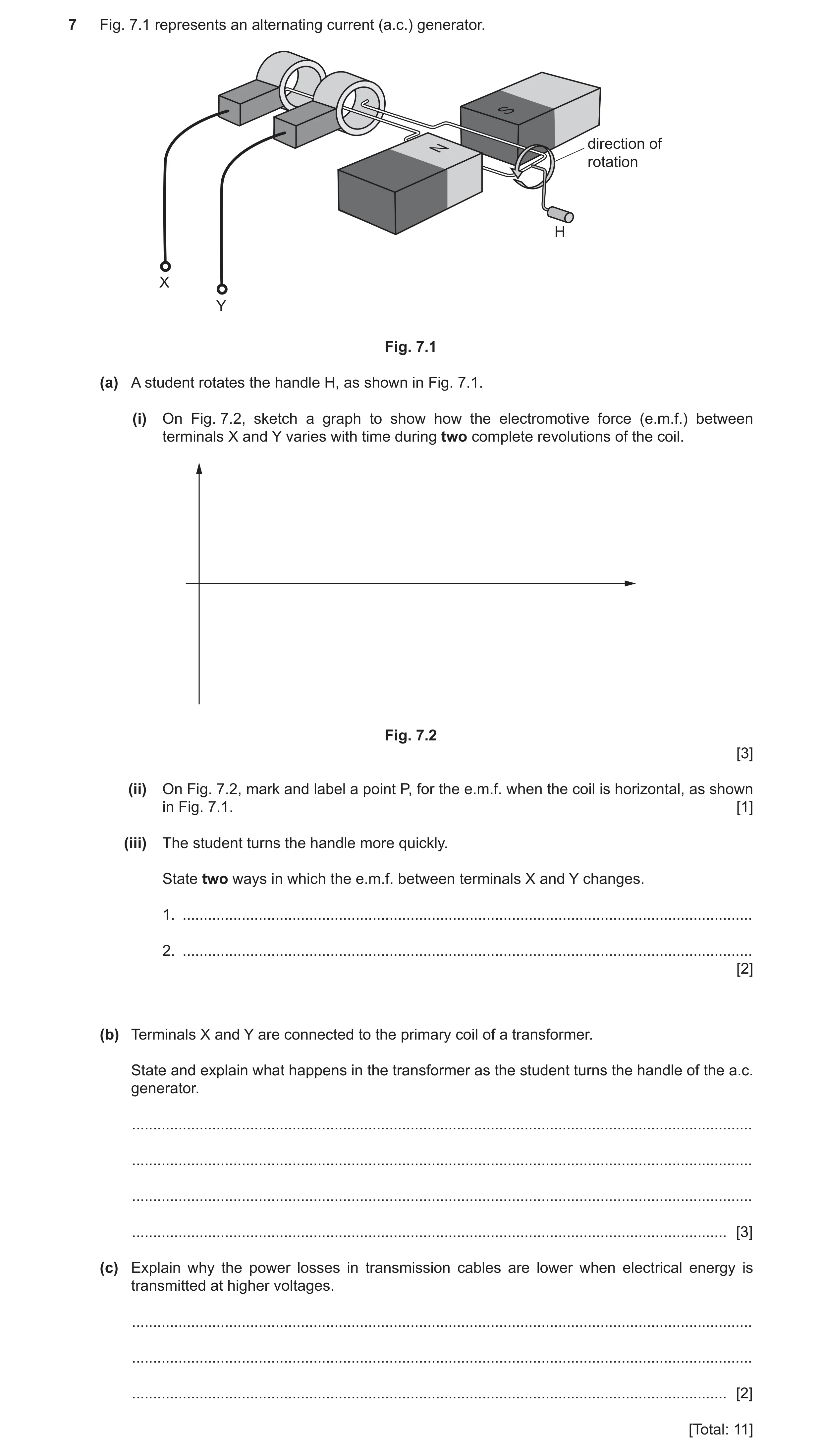
 35 / 62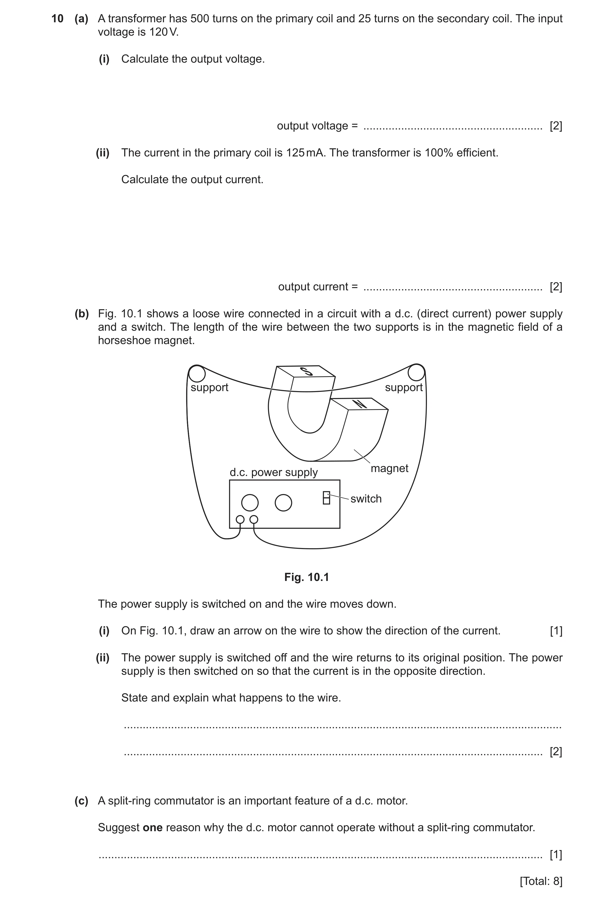
 40 / 62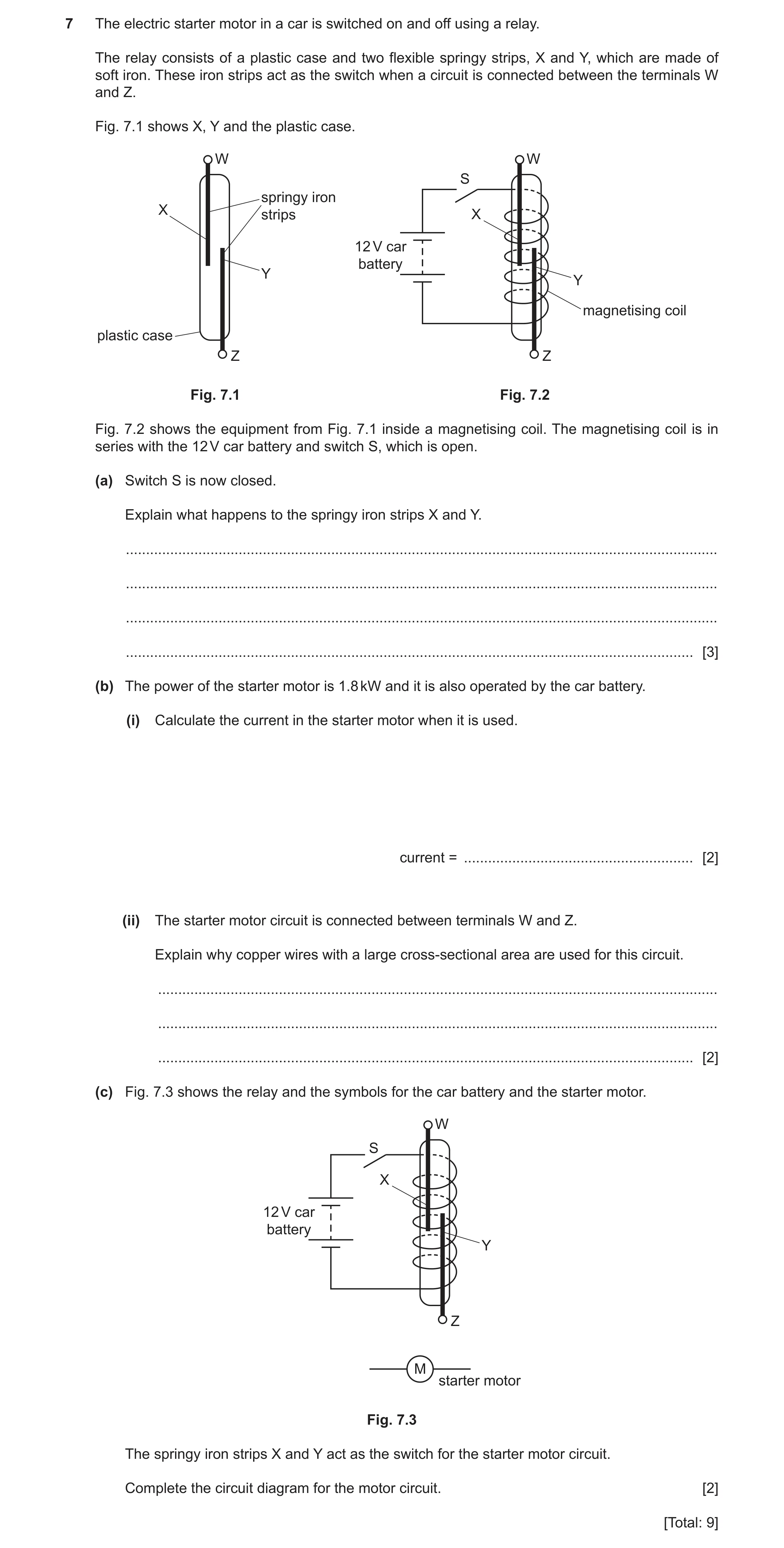
 43 / 62
 44 / 62
 45 / 62
 46 / 62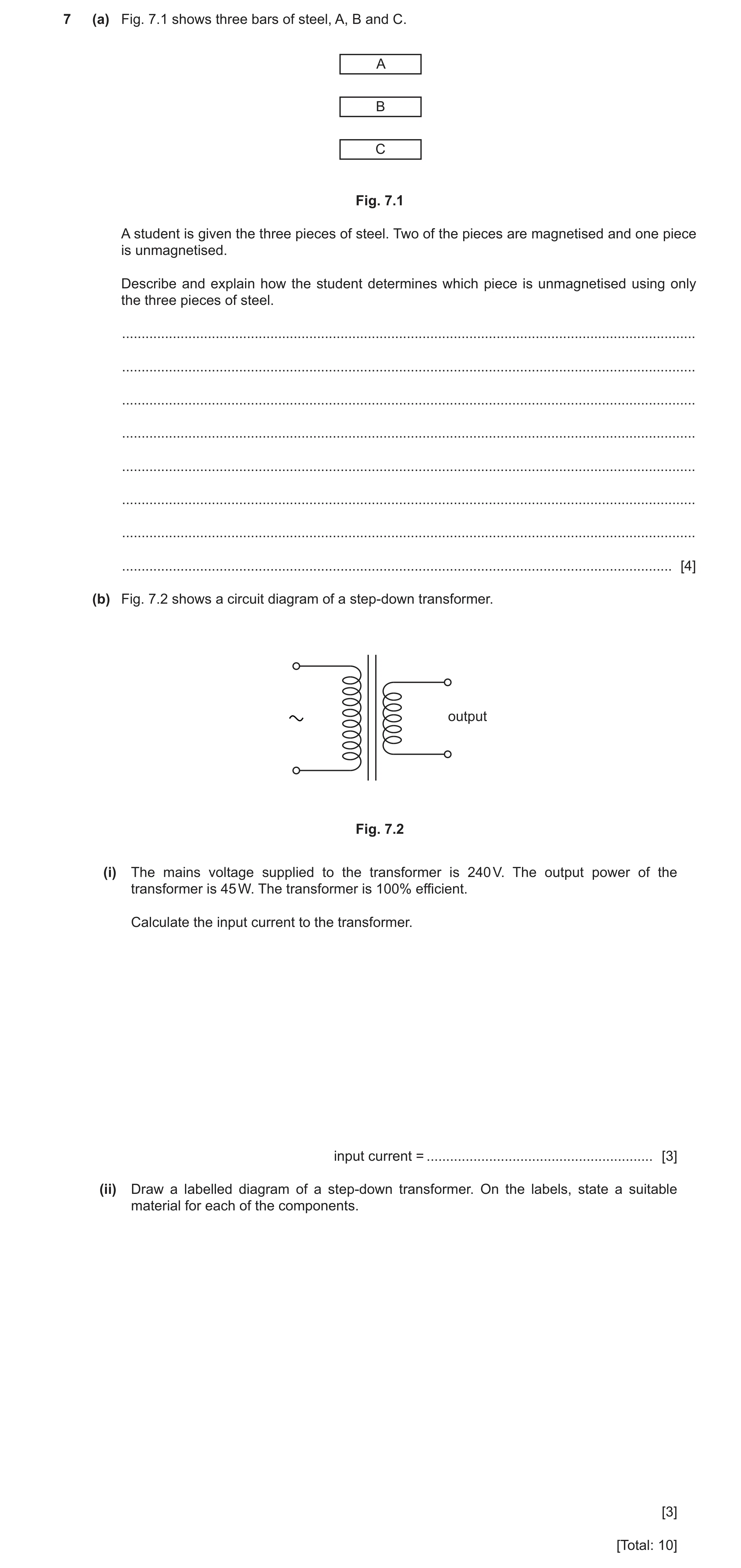
 49 / 62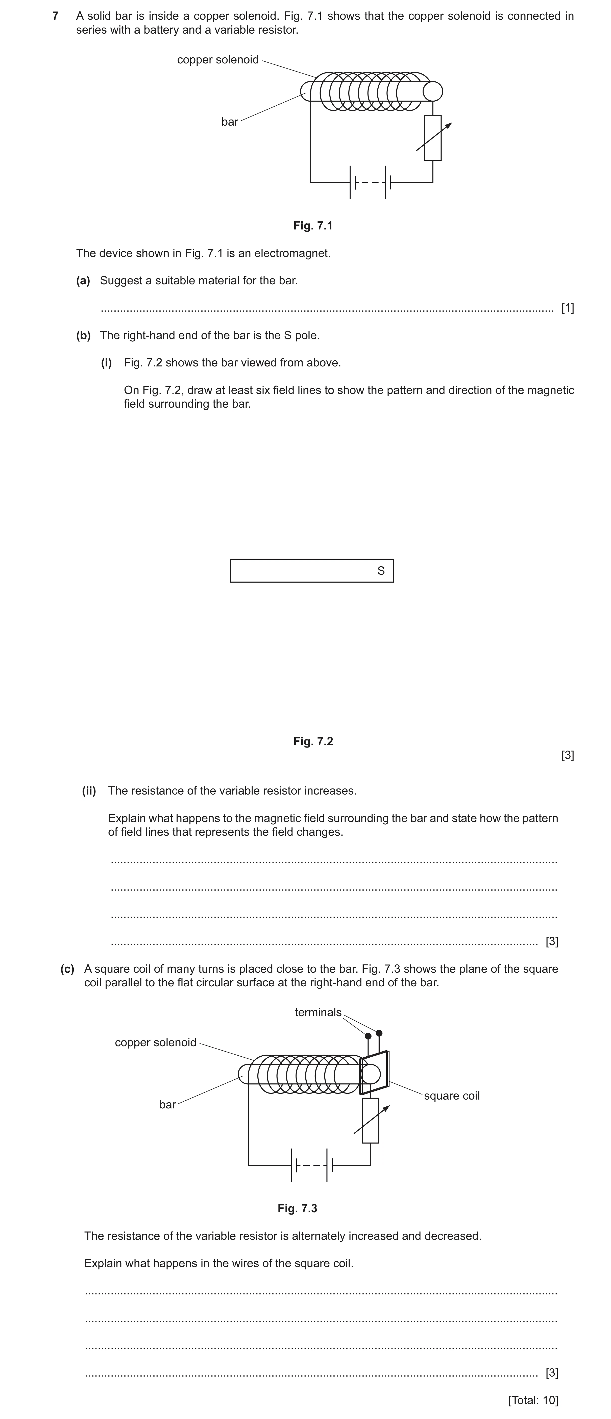

 9
9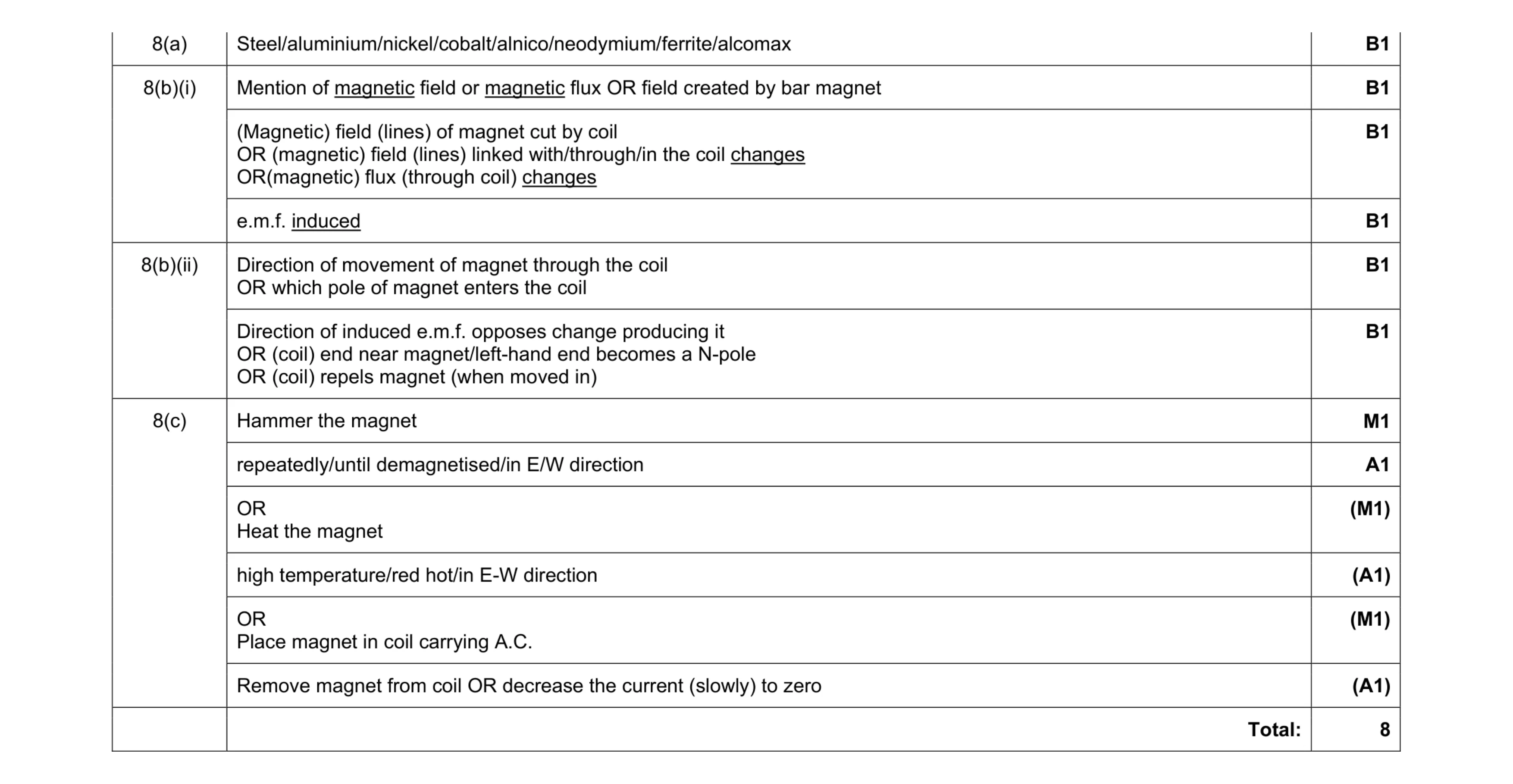 8
8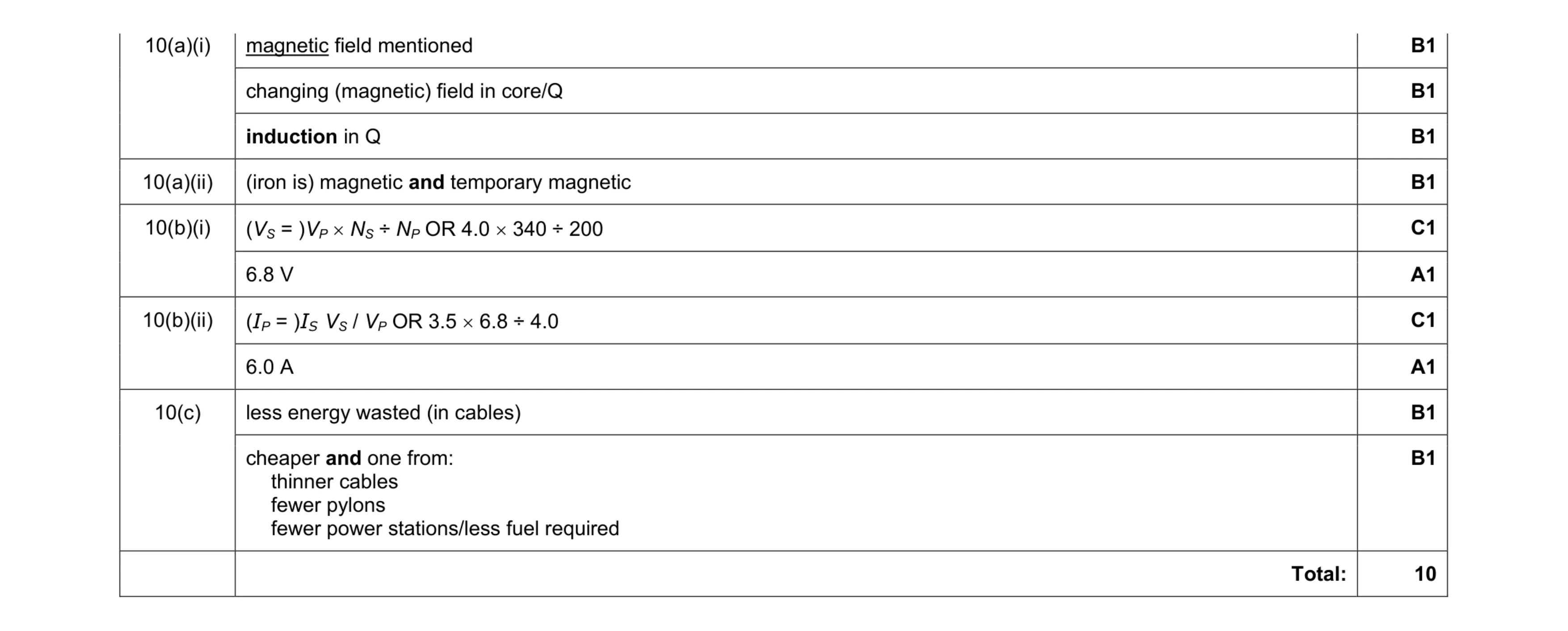 10
10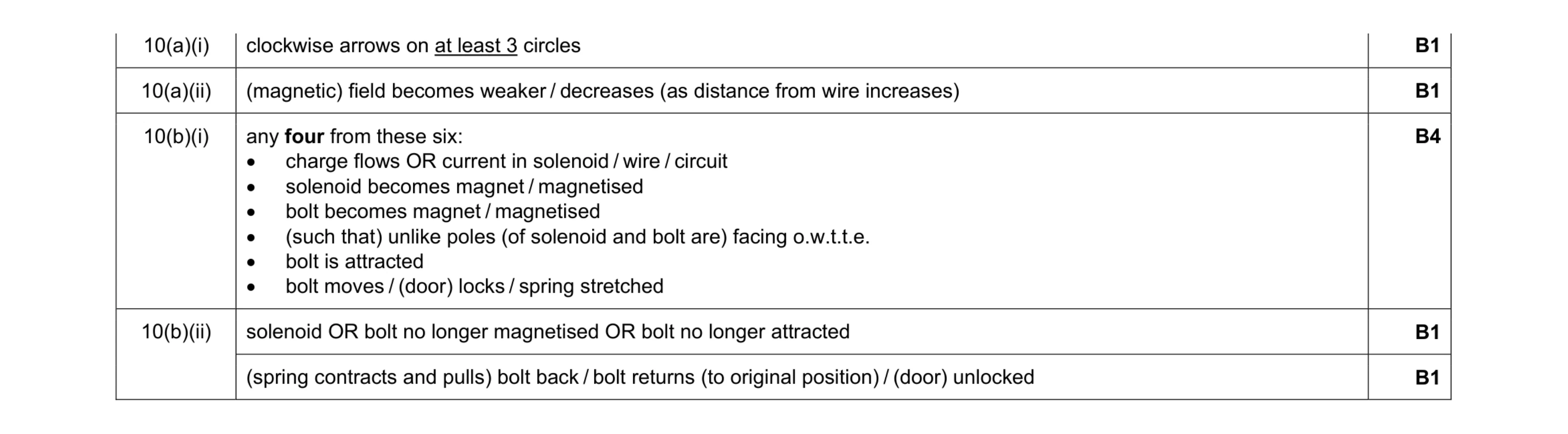 8
8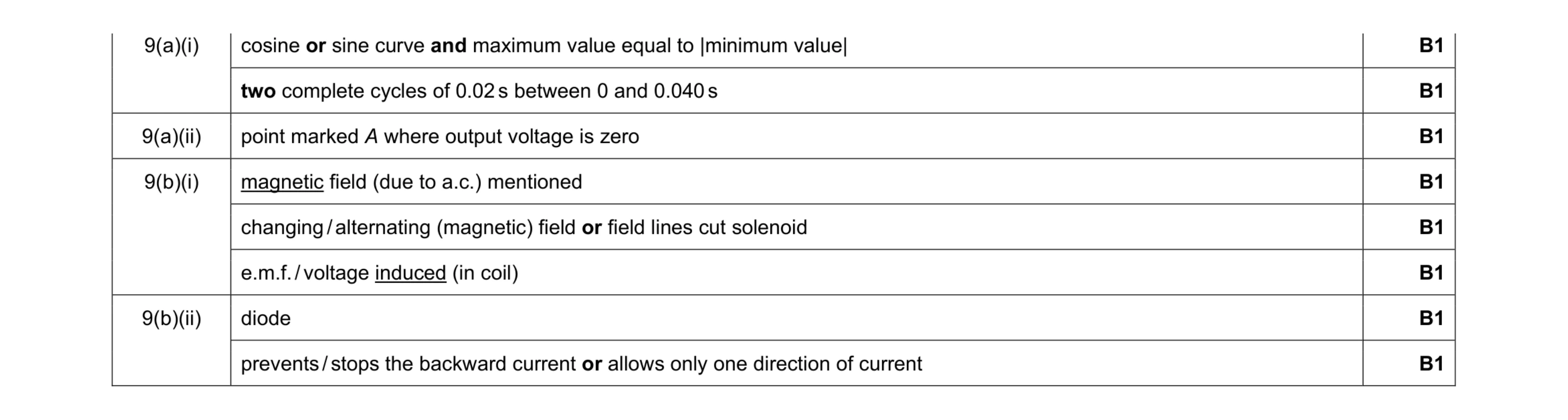 8
8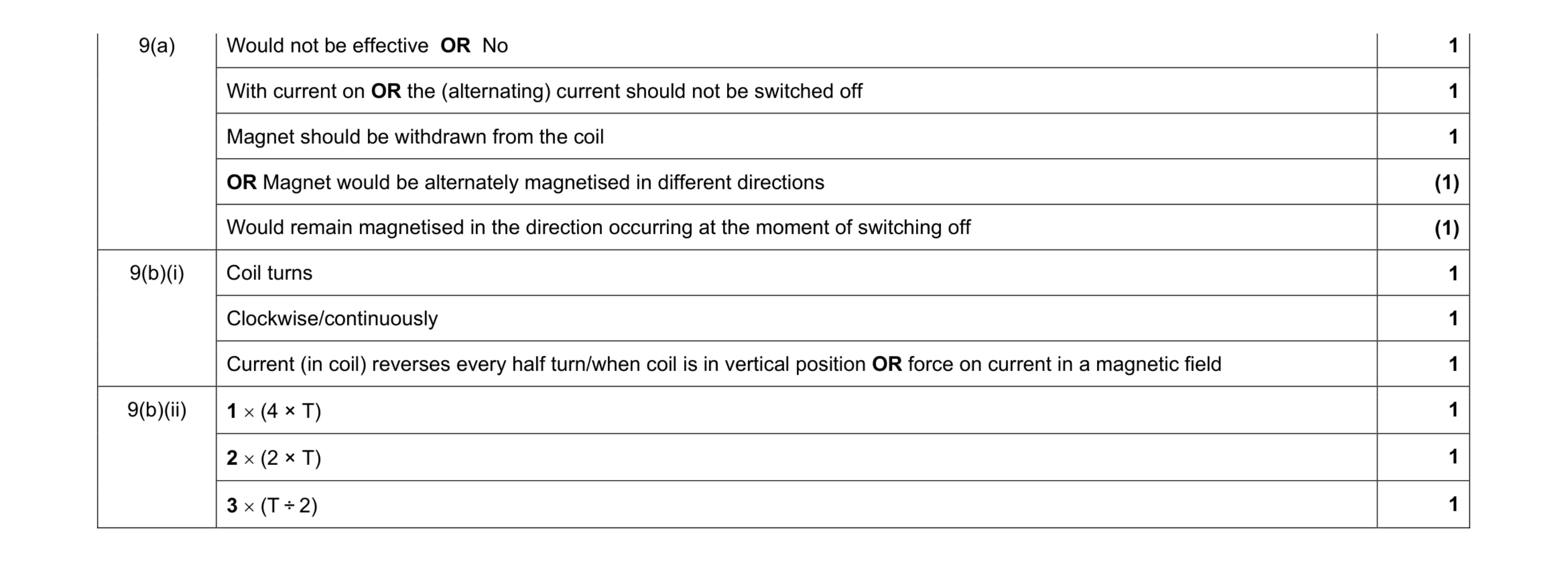 9
9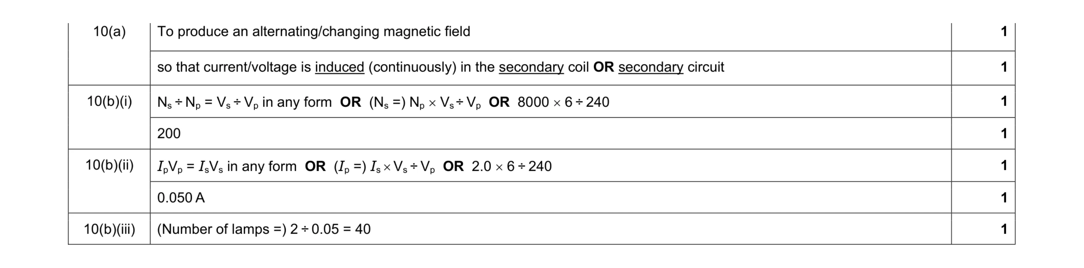 7
7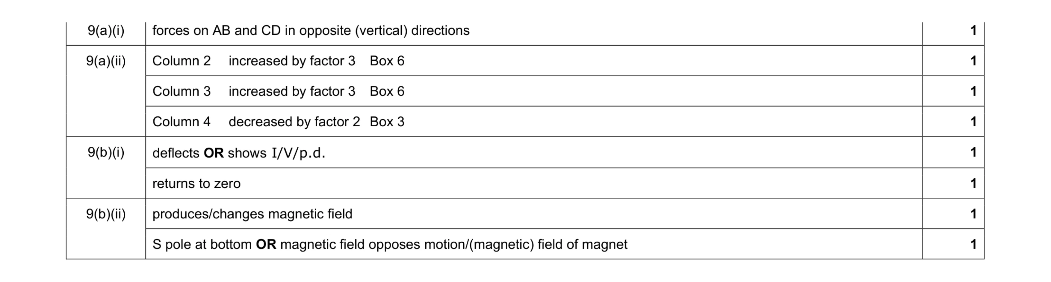 8
8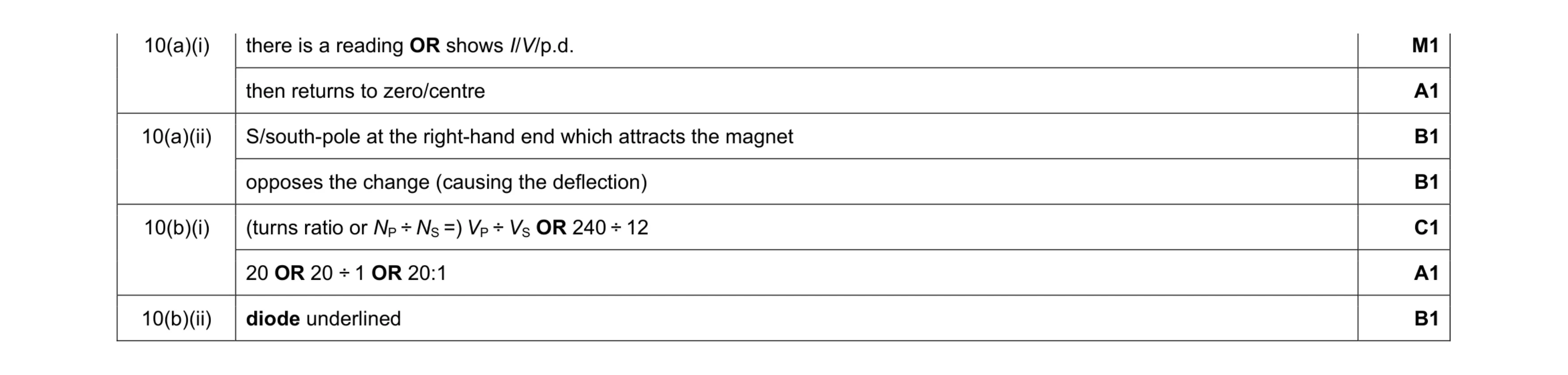 7
7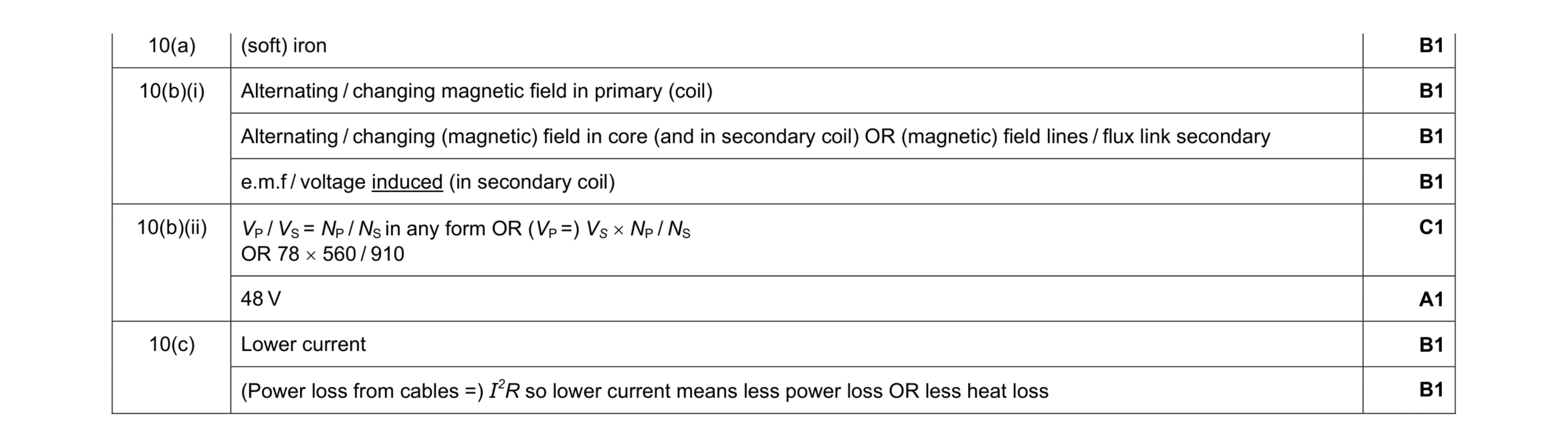 8
8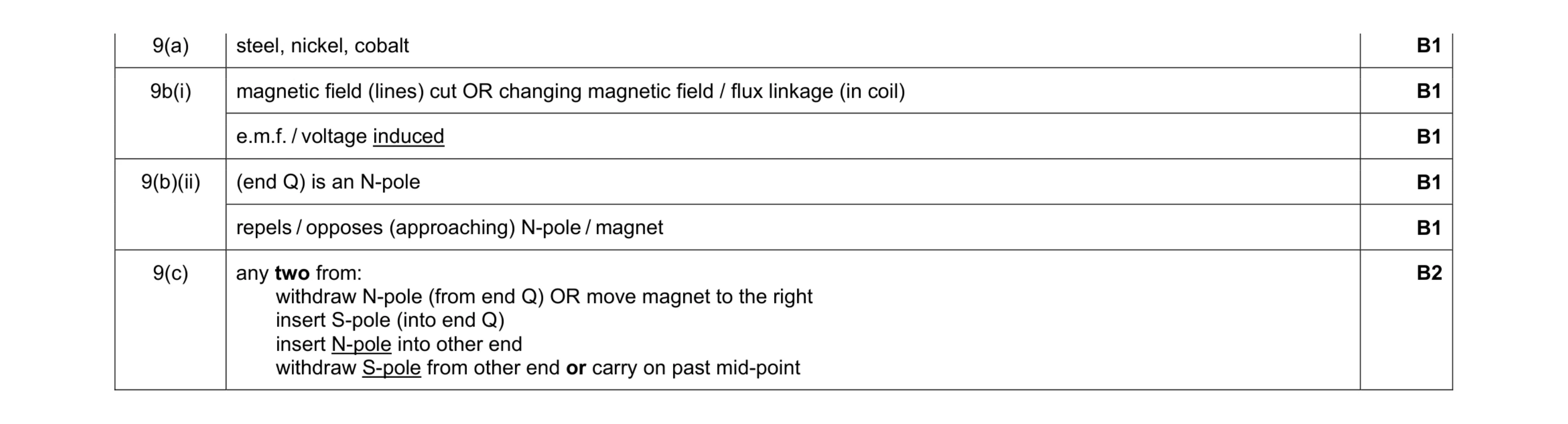 7
7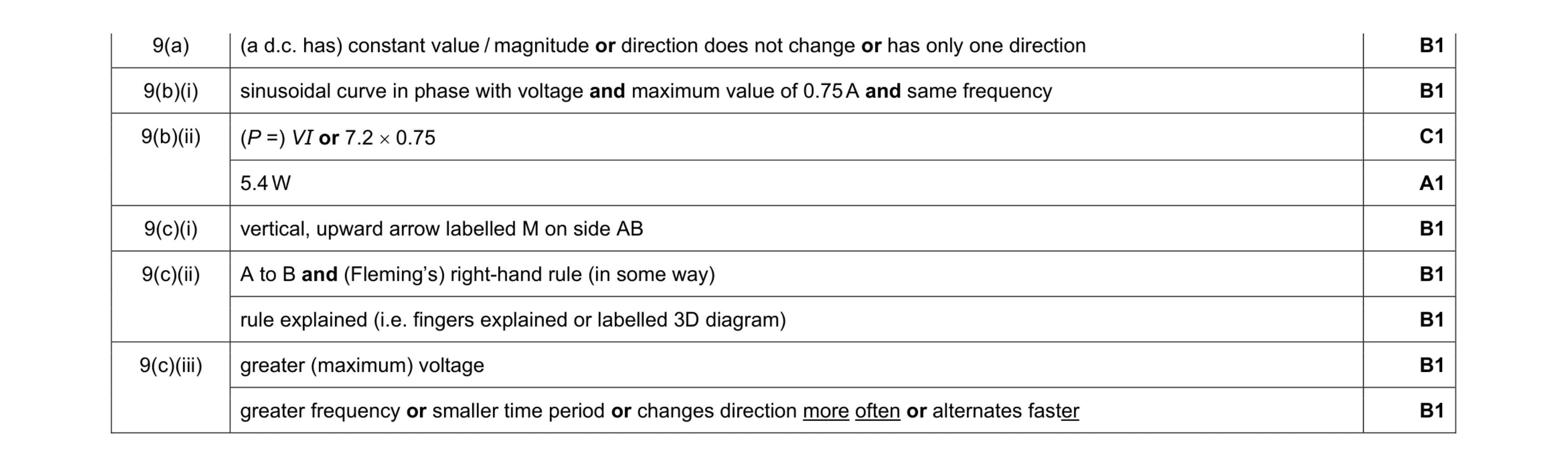 9
9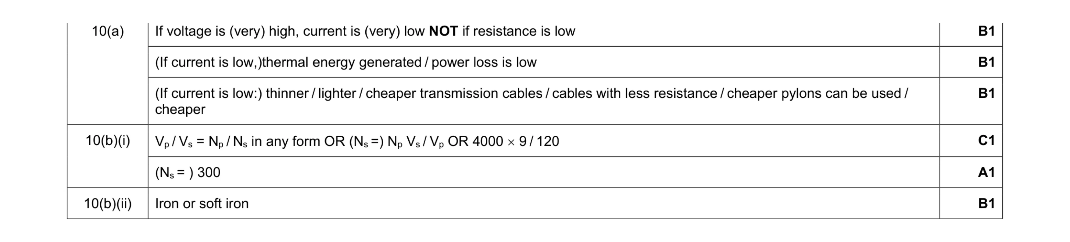 6
6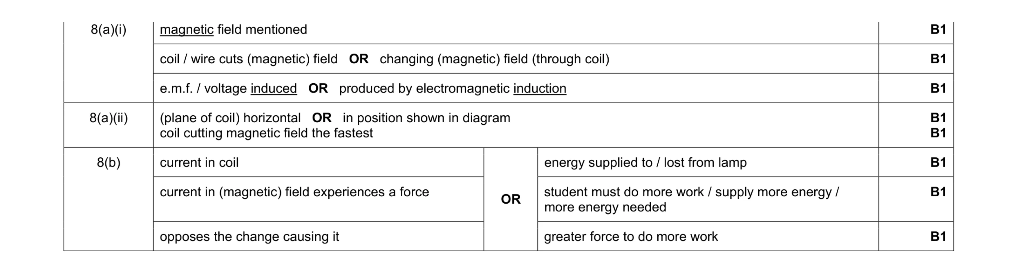 8
8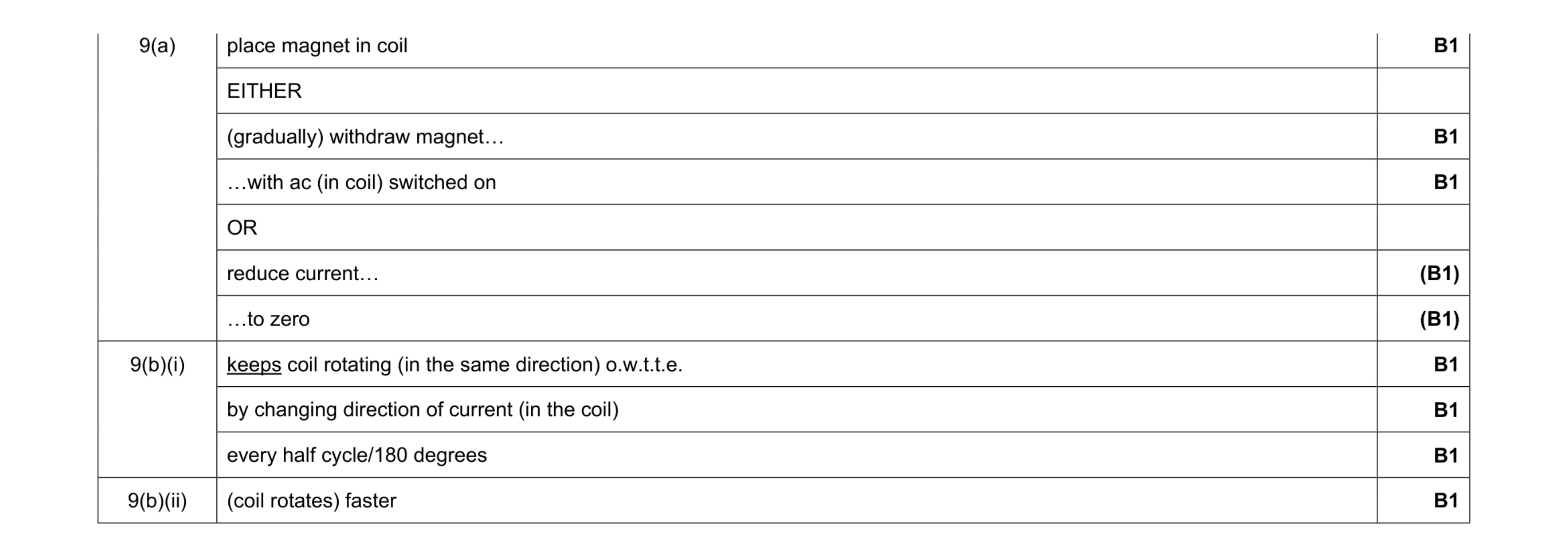 7
7 8
8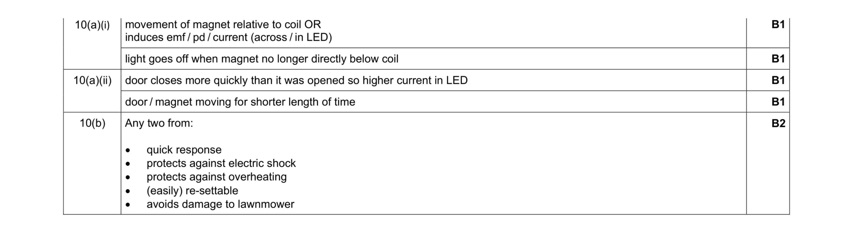 6
6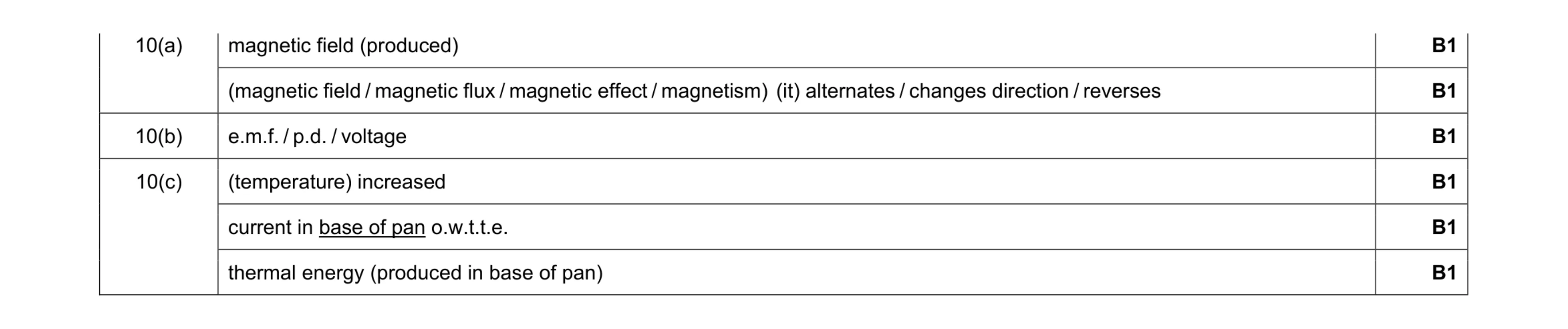 6
6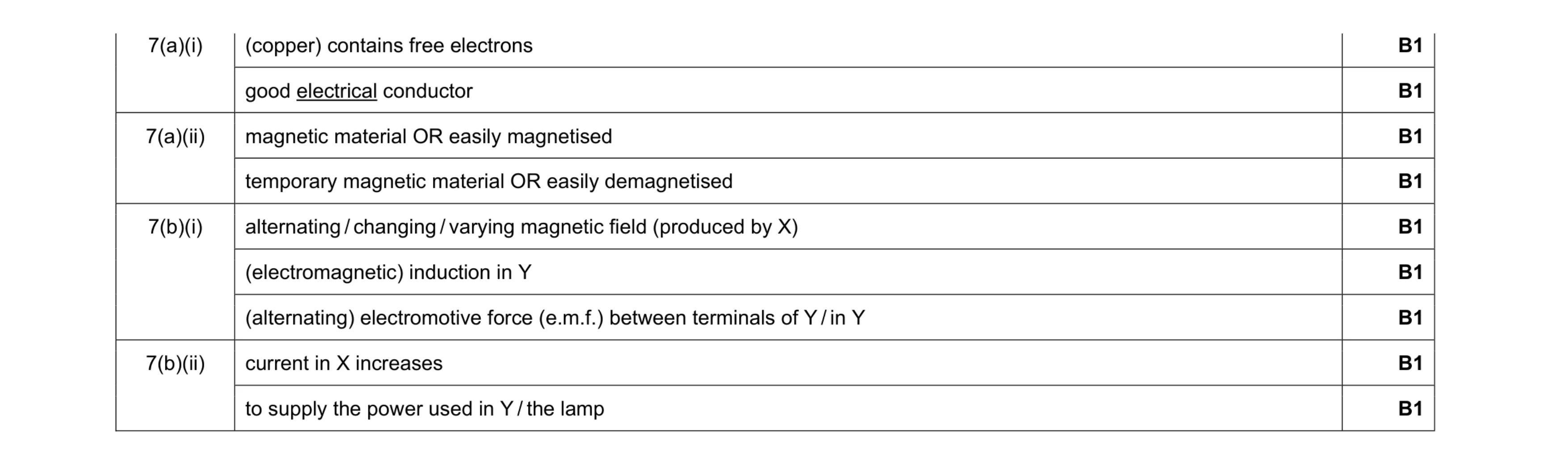 9
9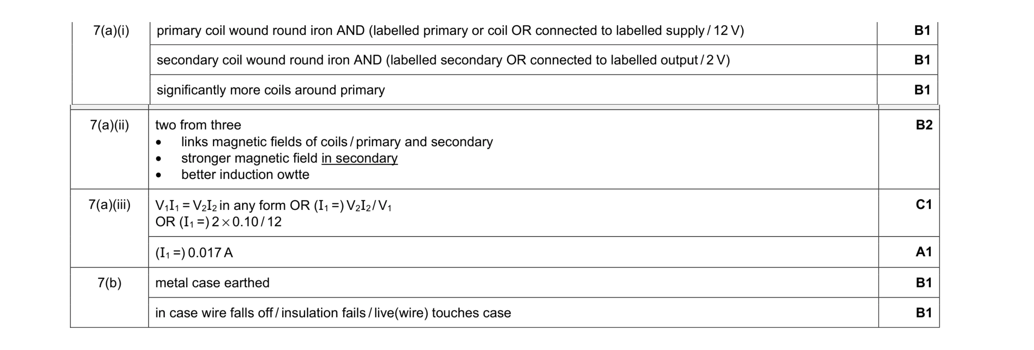 9
9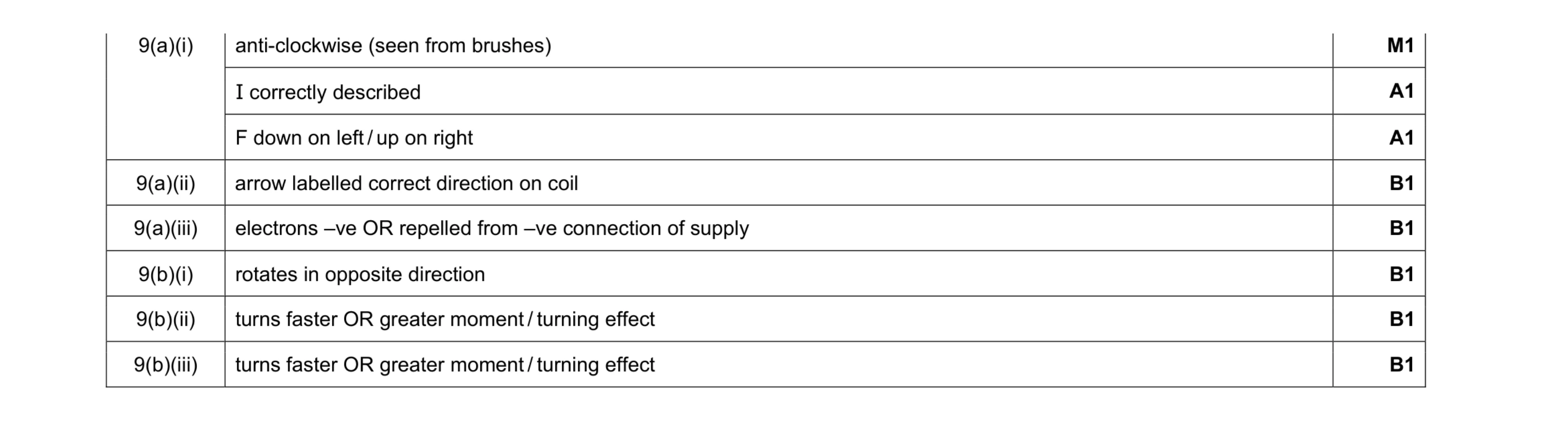 8
8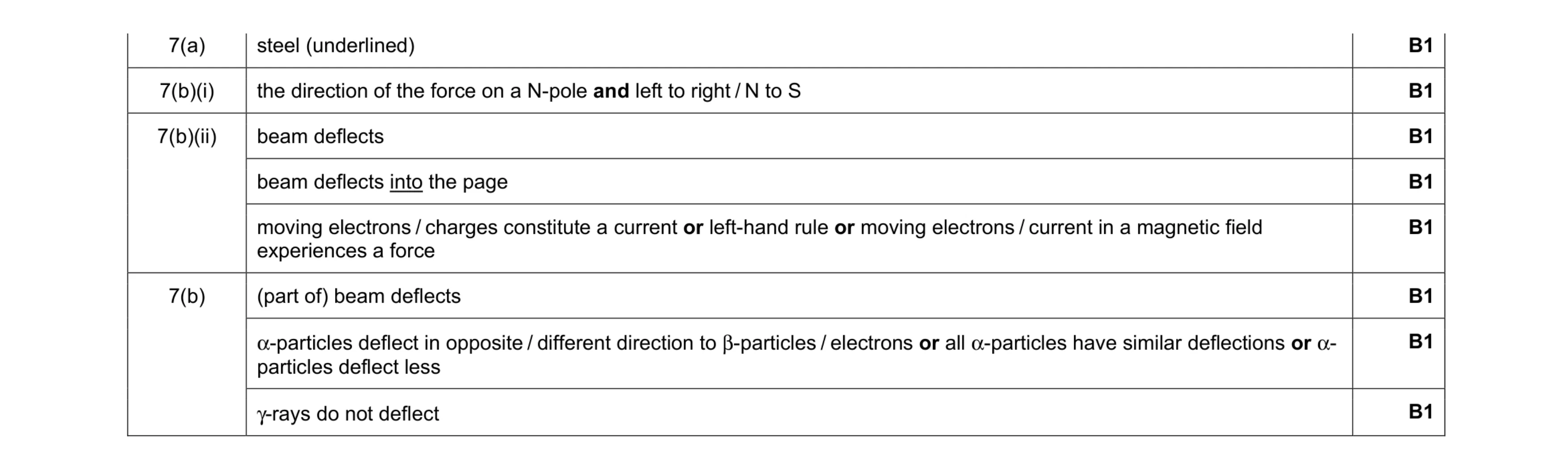 8
8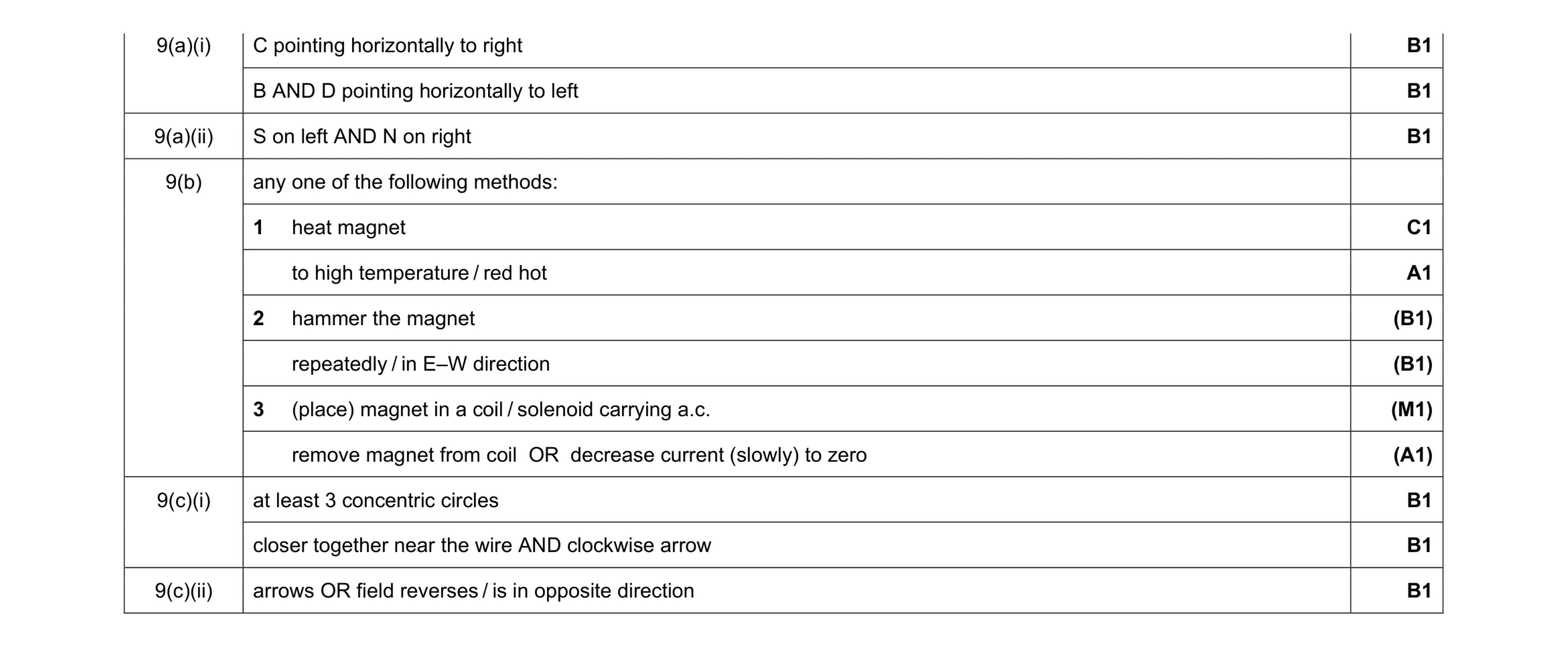 8
8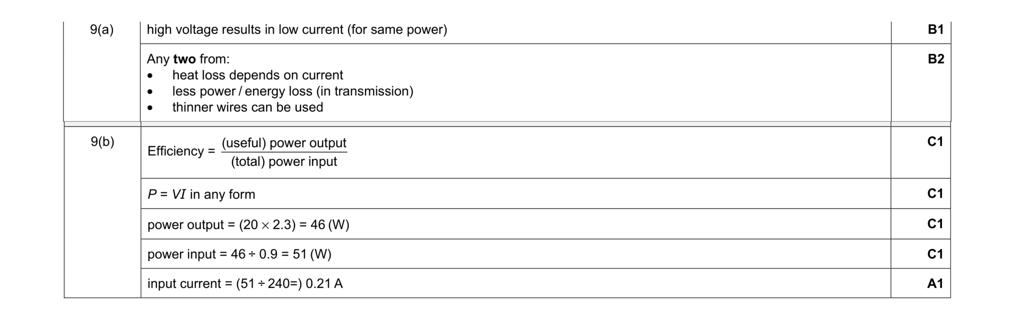 8
8 5
5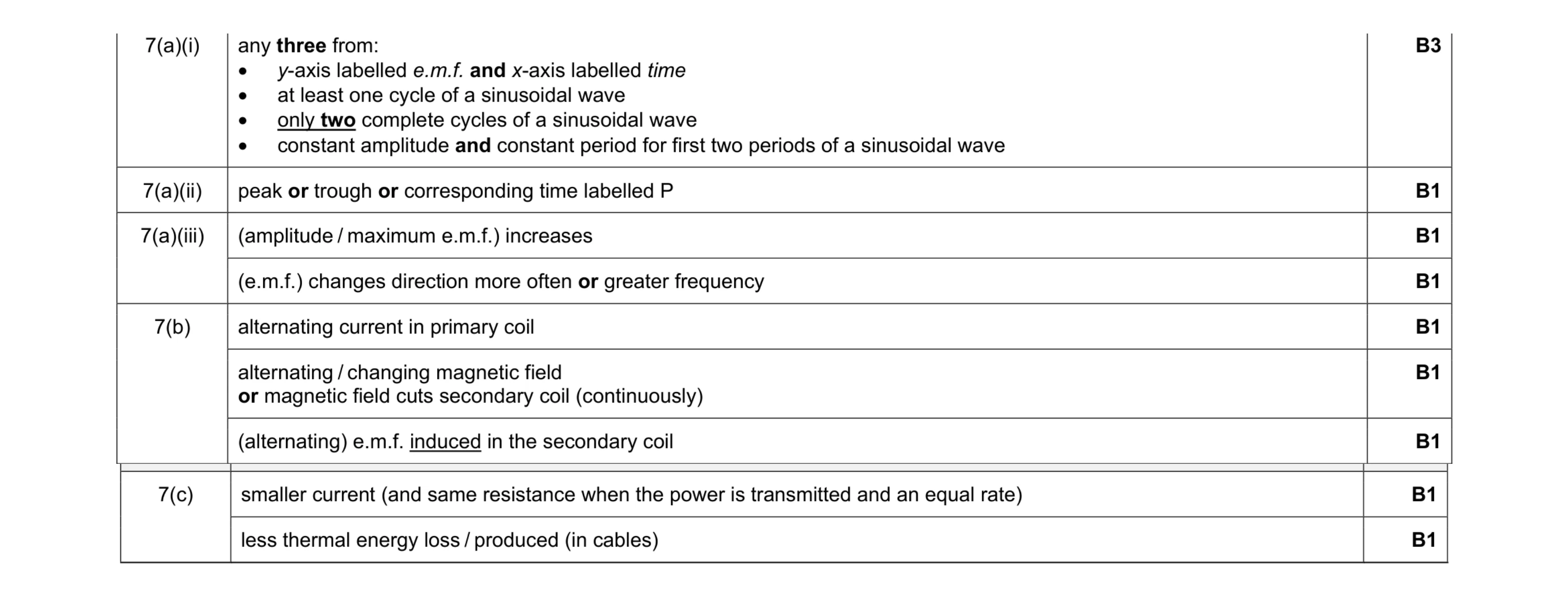 11
11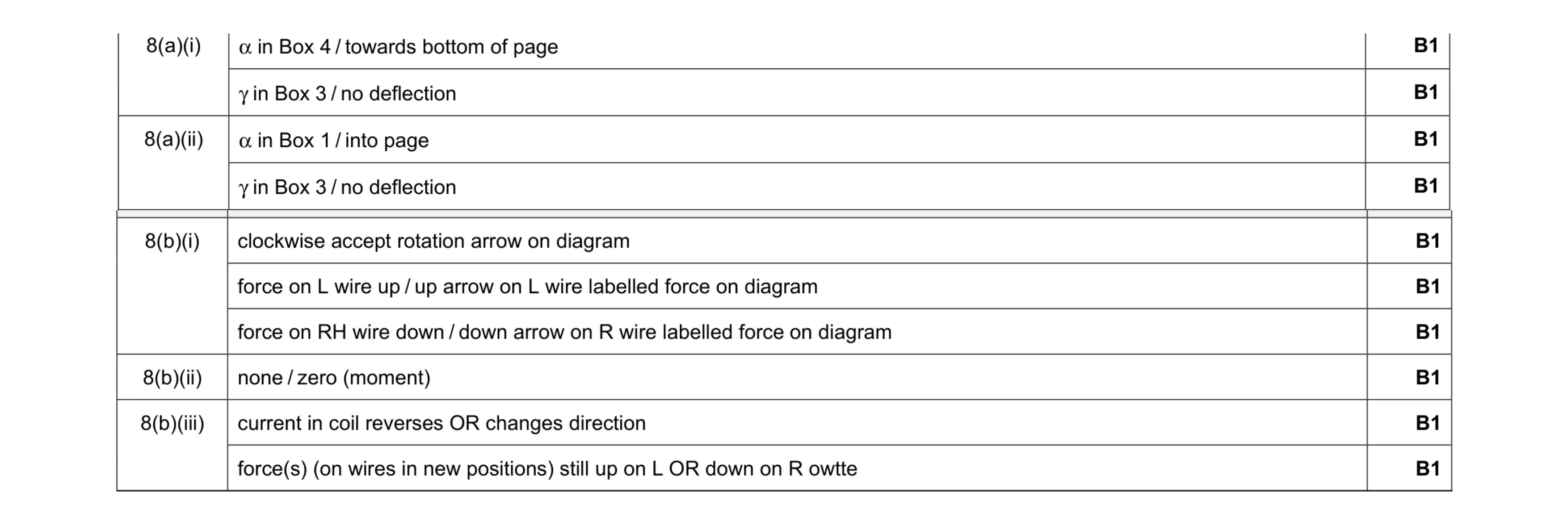 10
10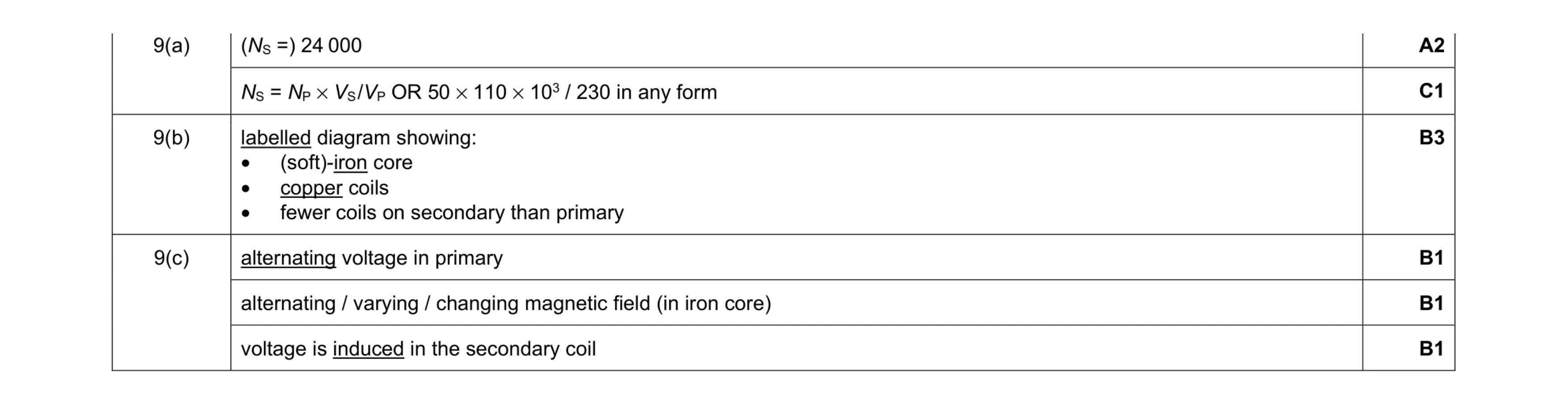 8
8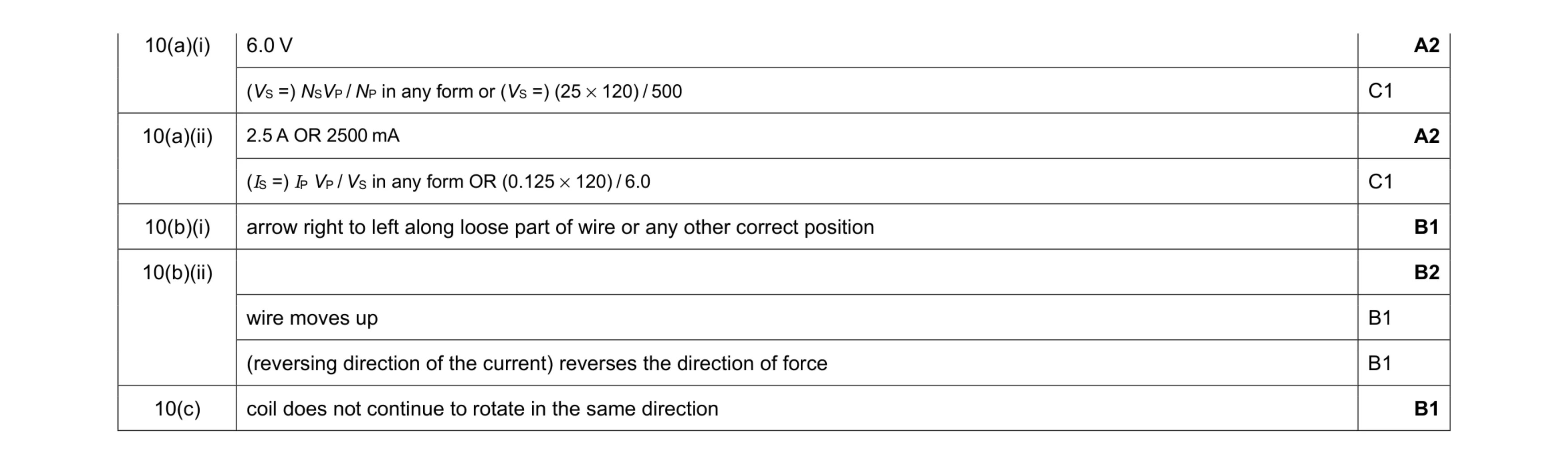 8
8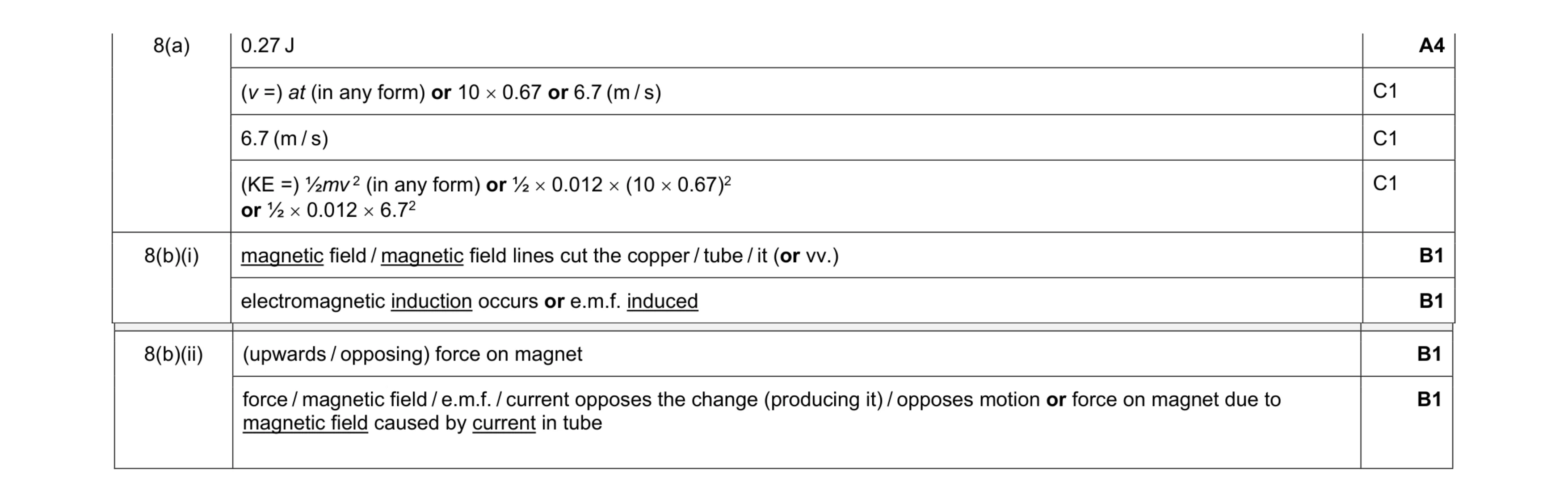 8
8 5
5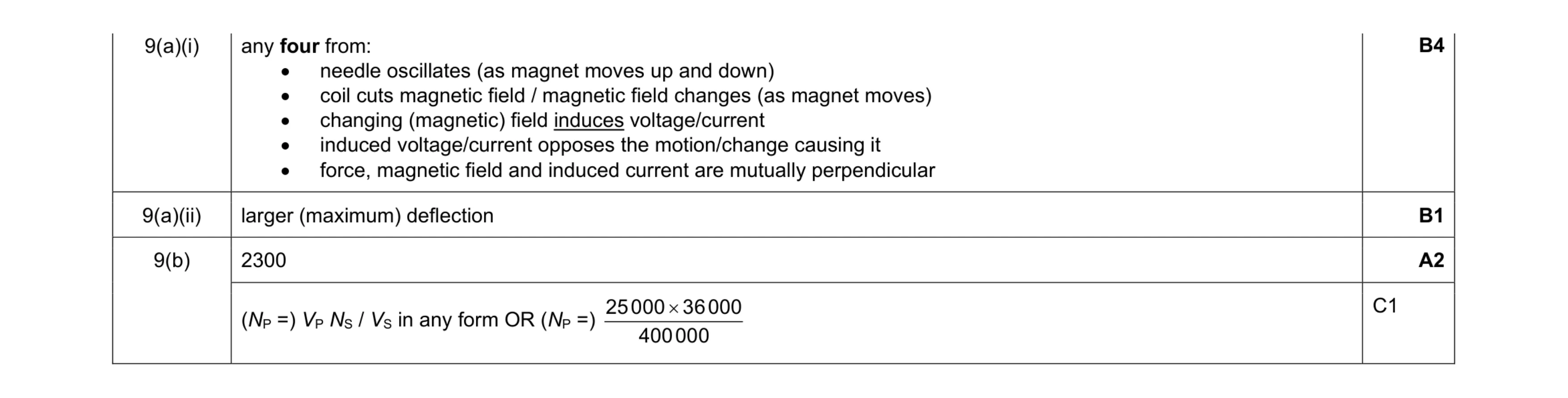 7
7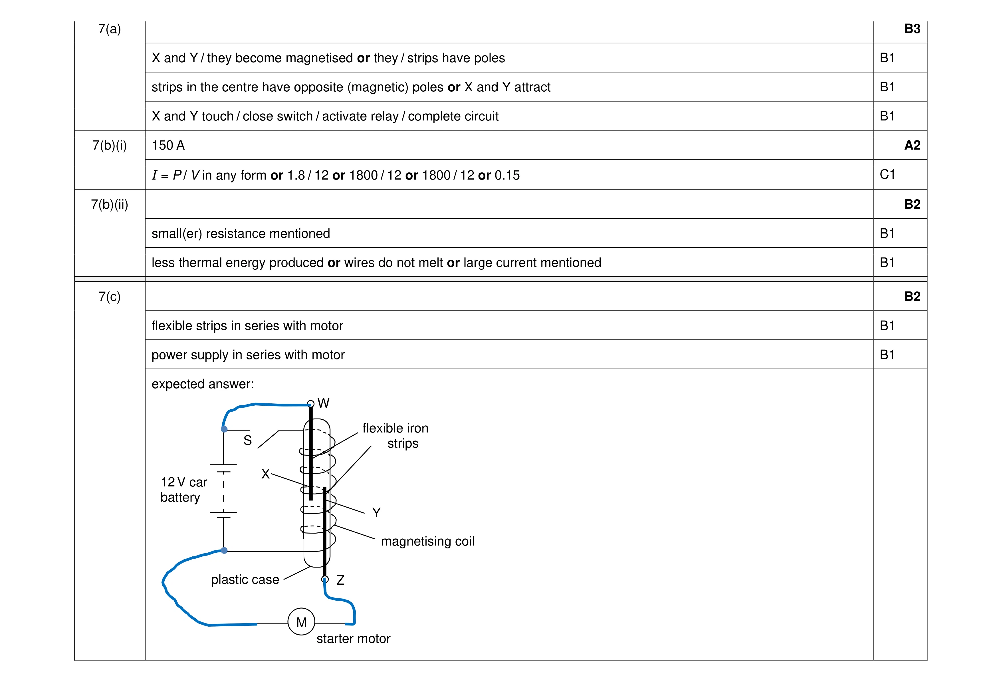 9
9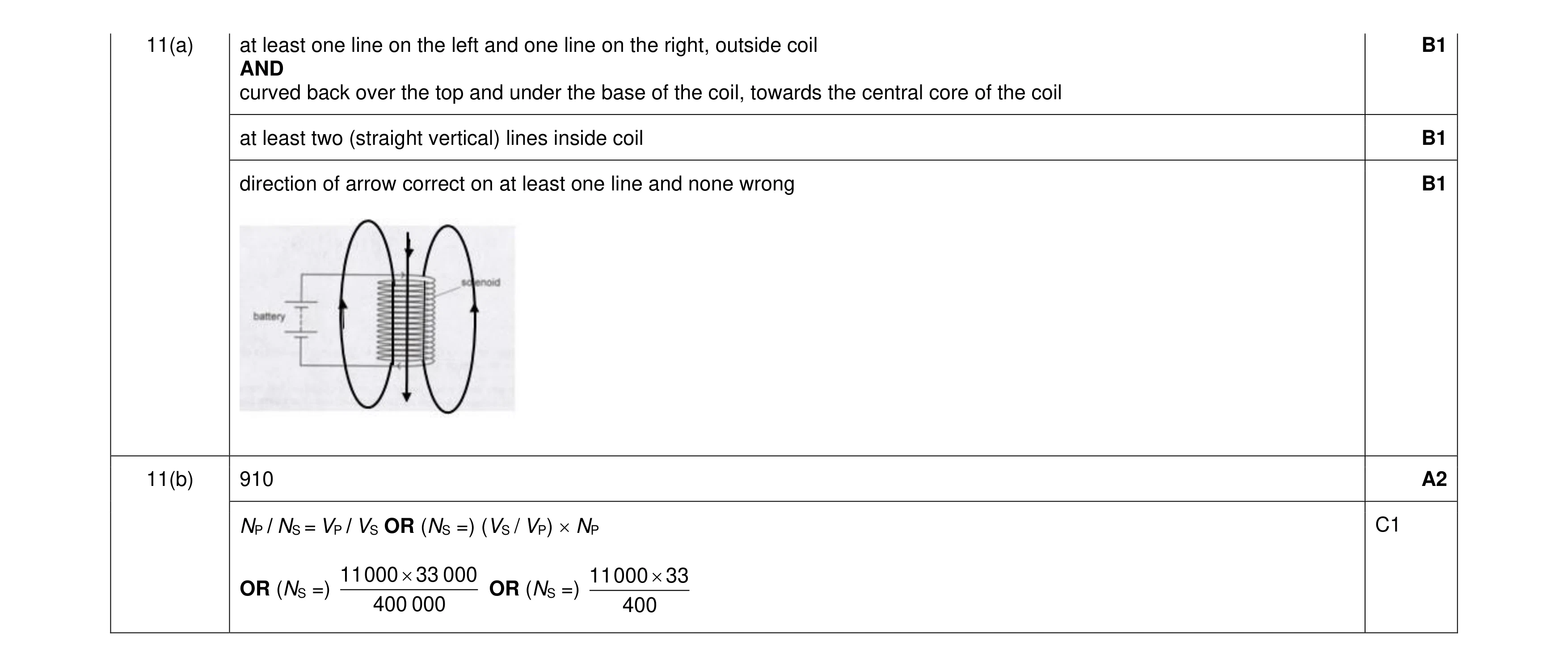 5
5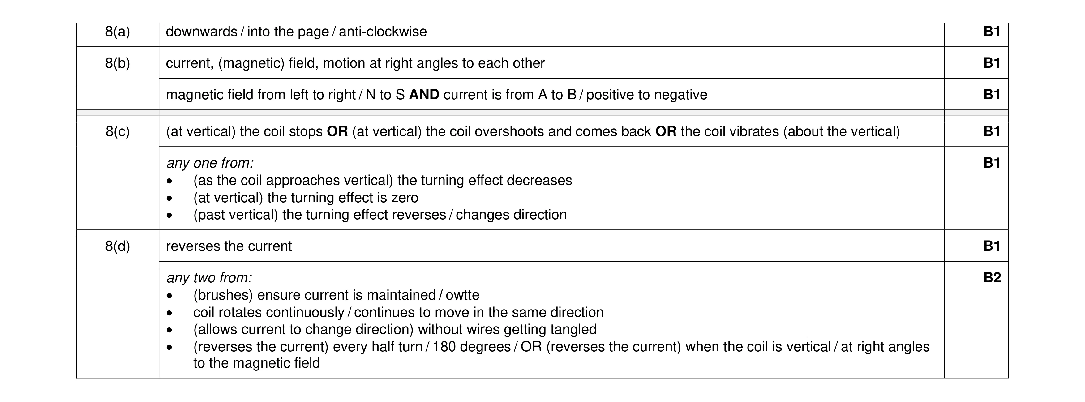 8
8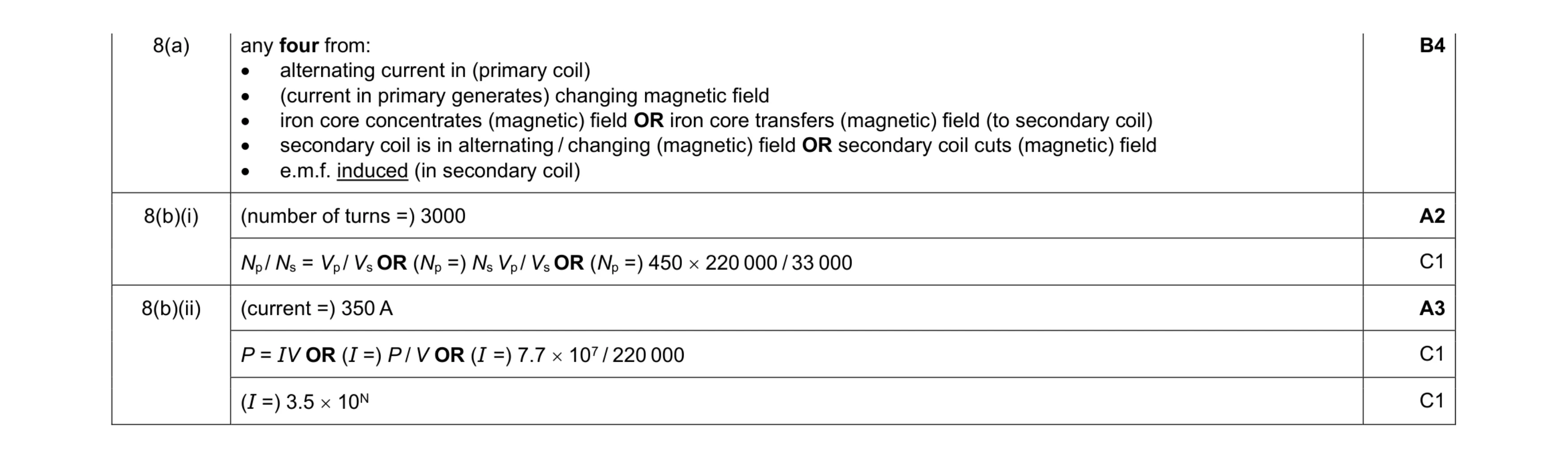 9
9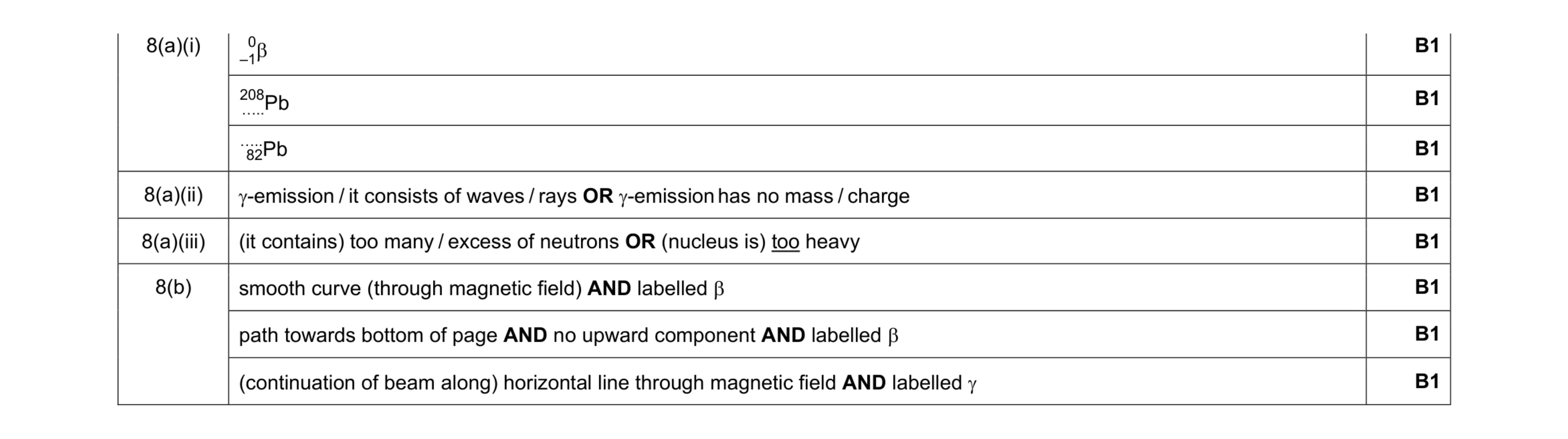 8
8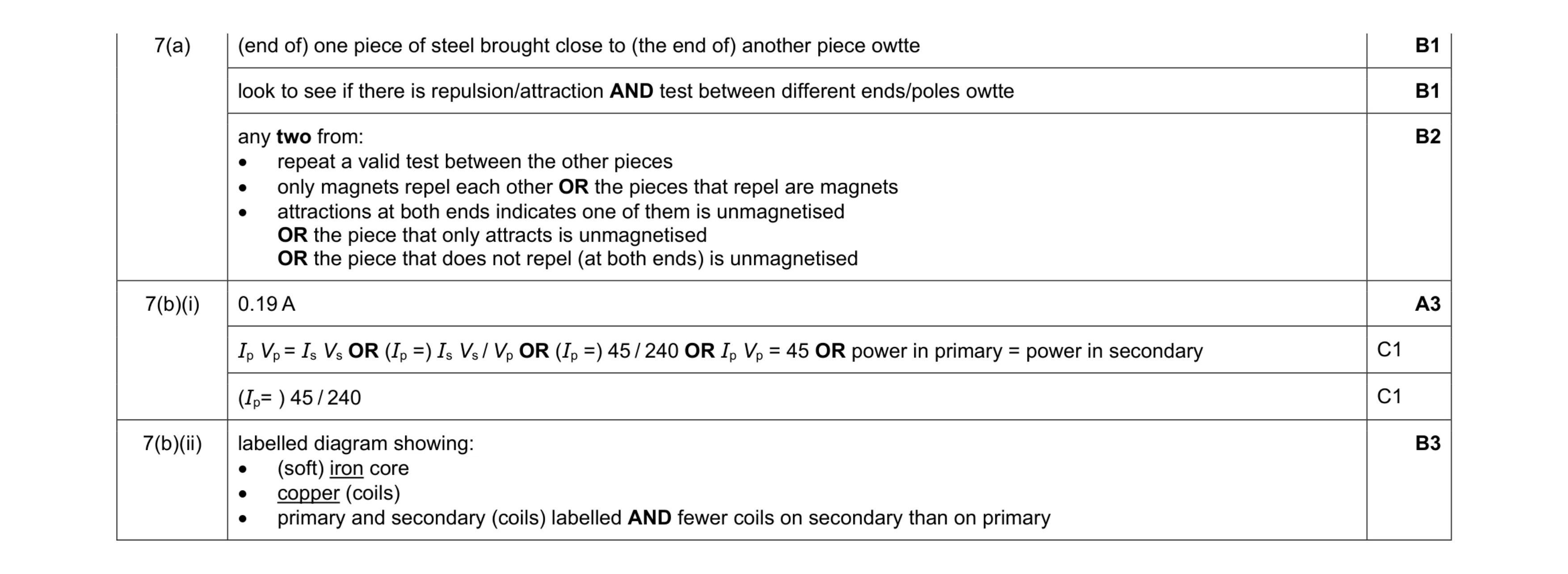 10
10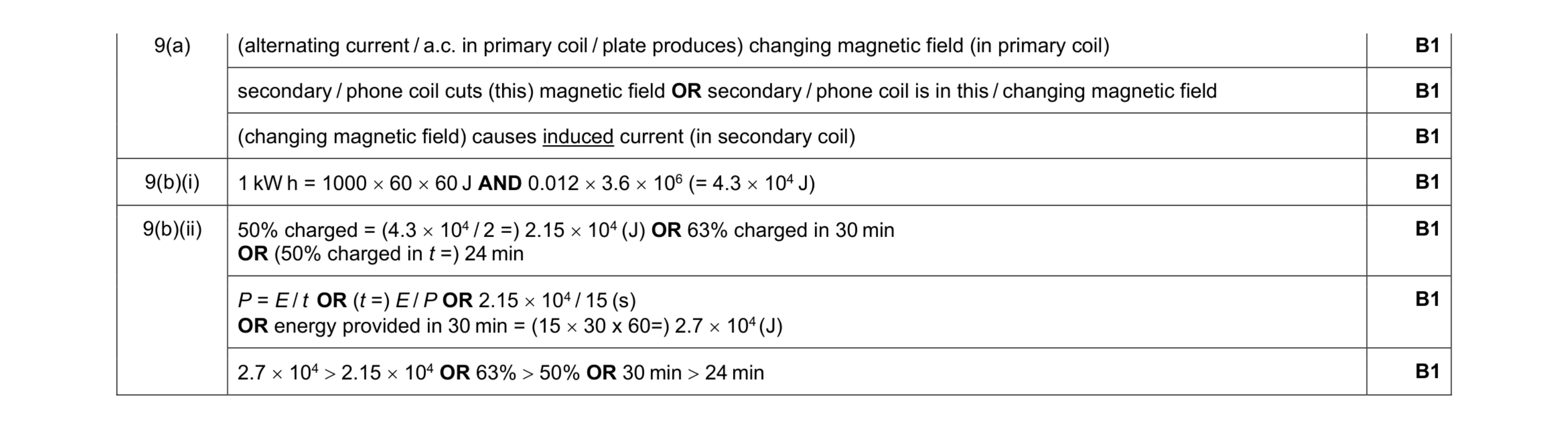 7
7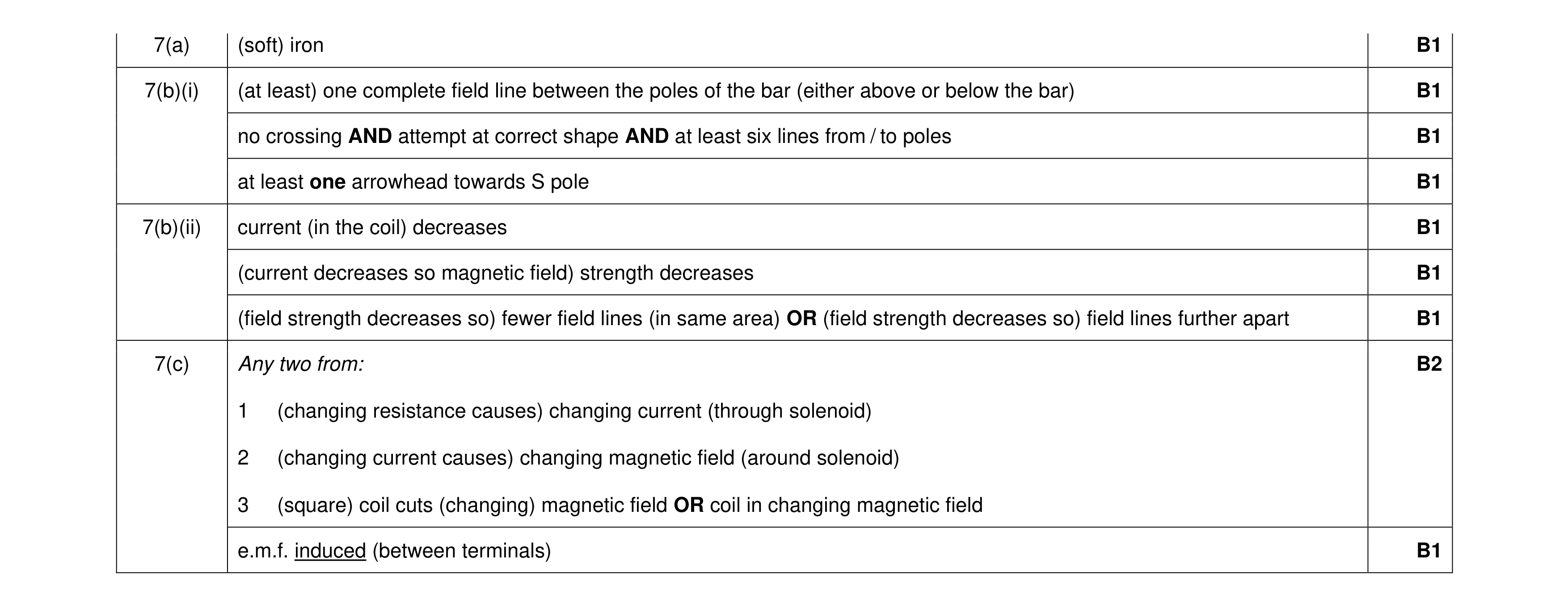 10
10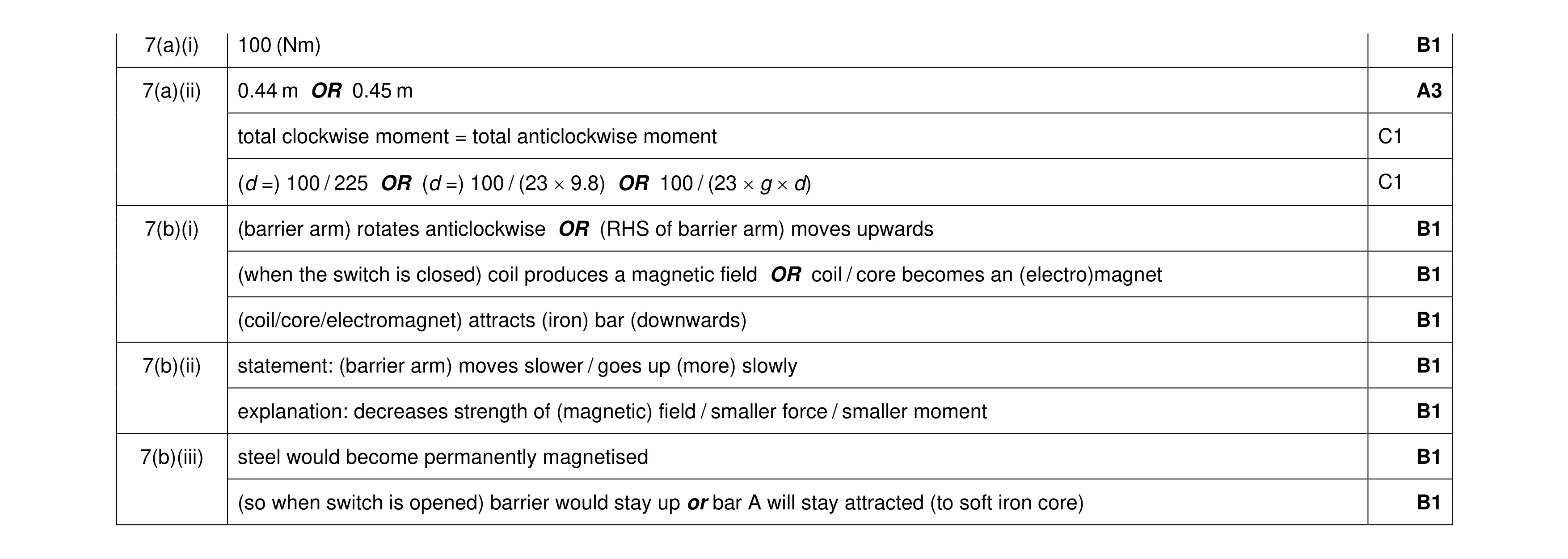 11
11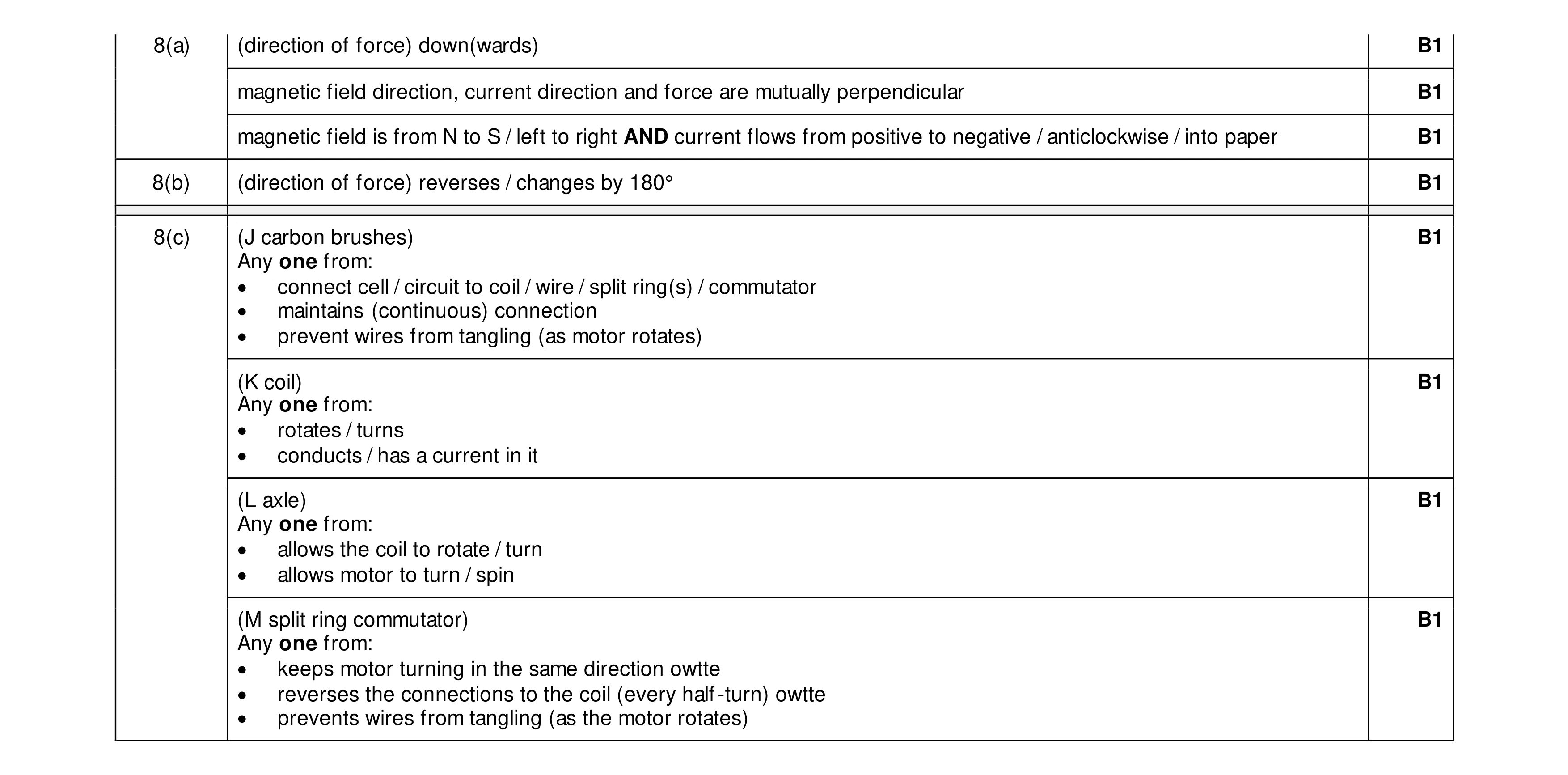 8
8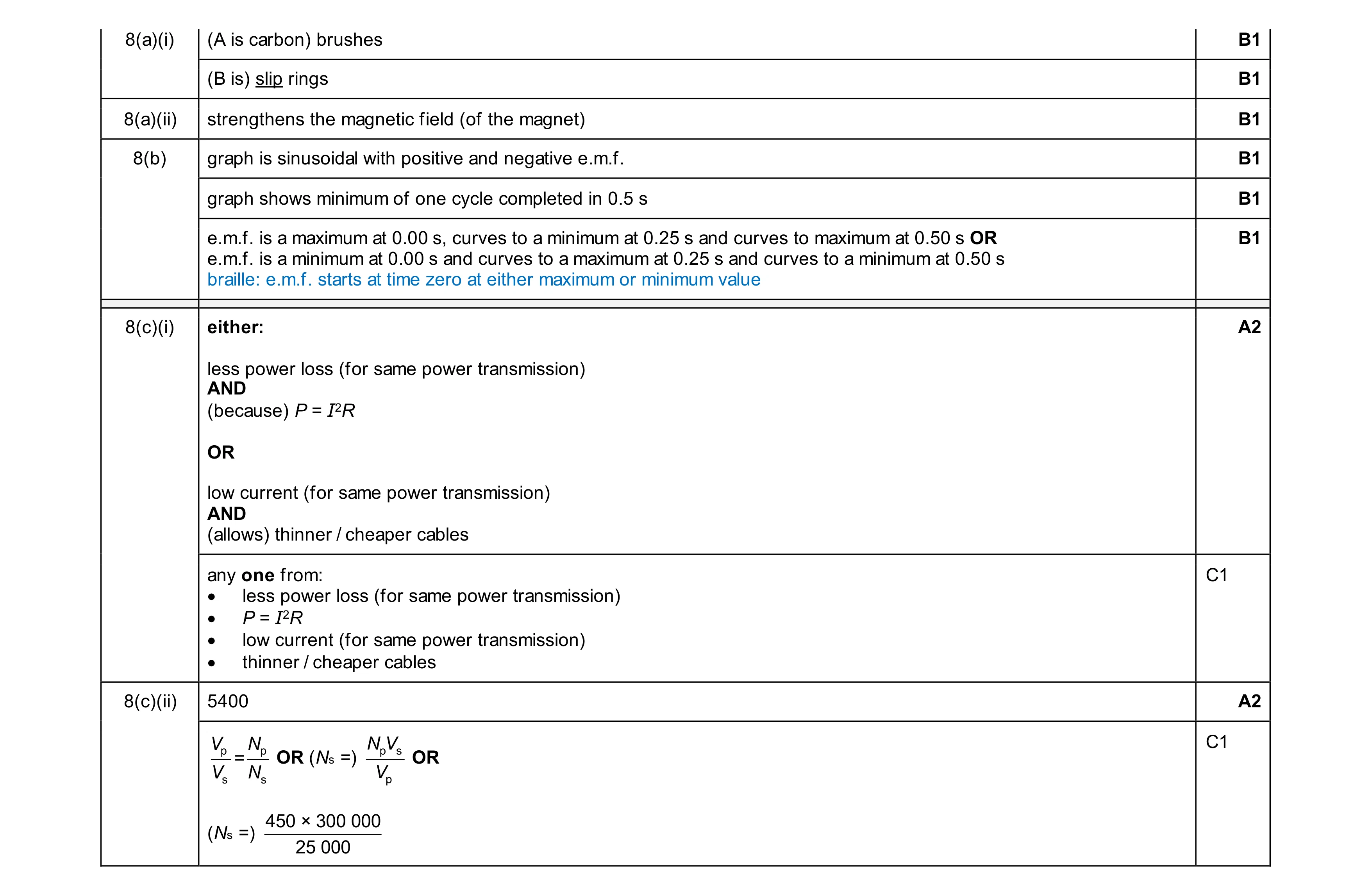 10
10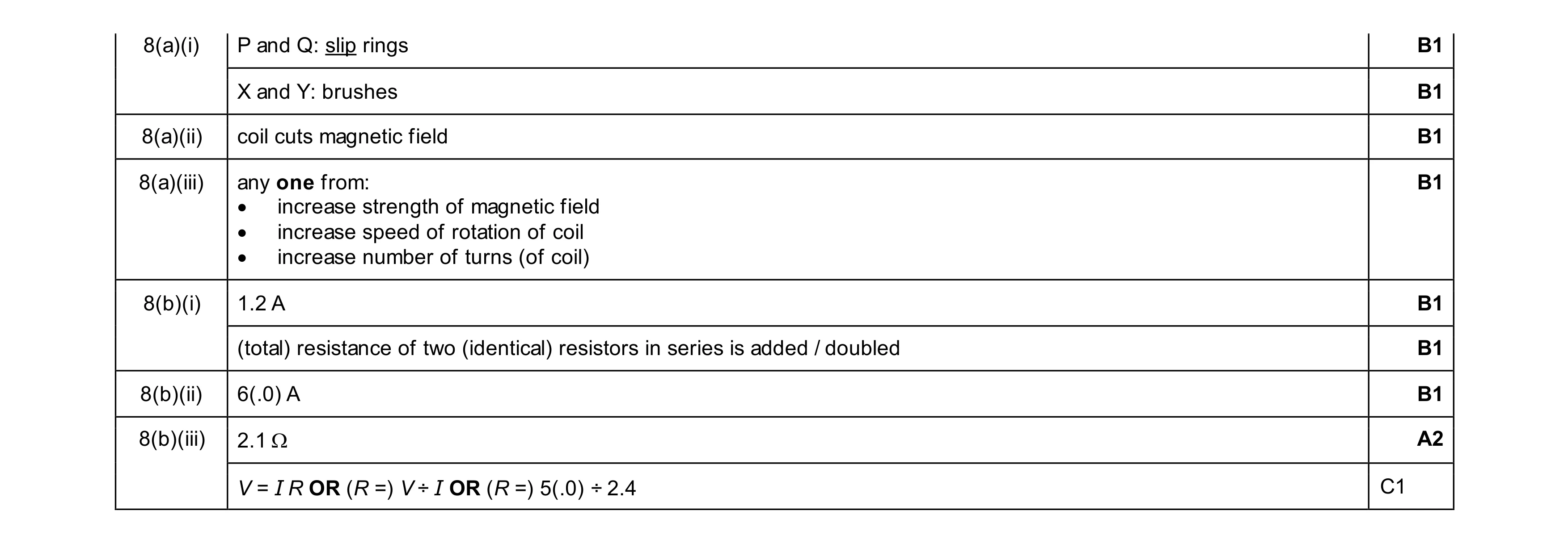 9
9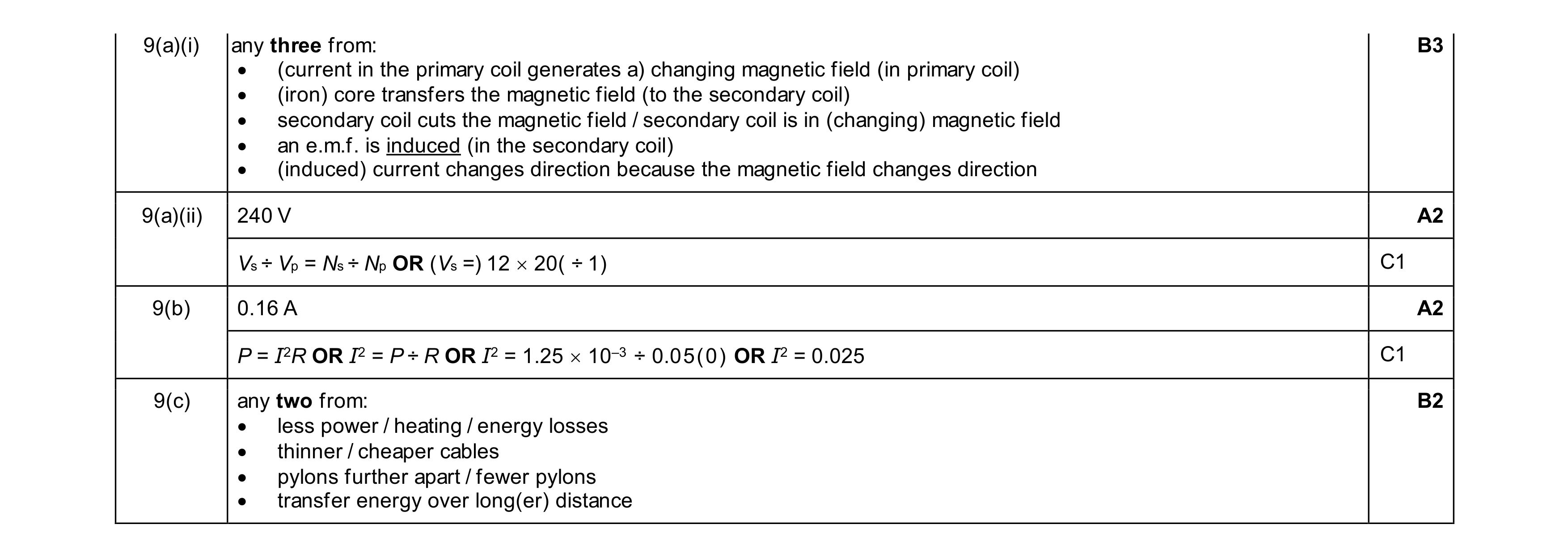 9
9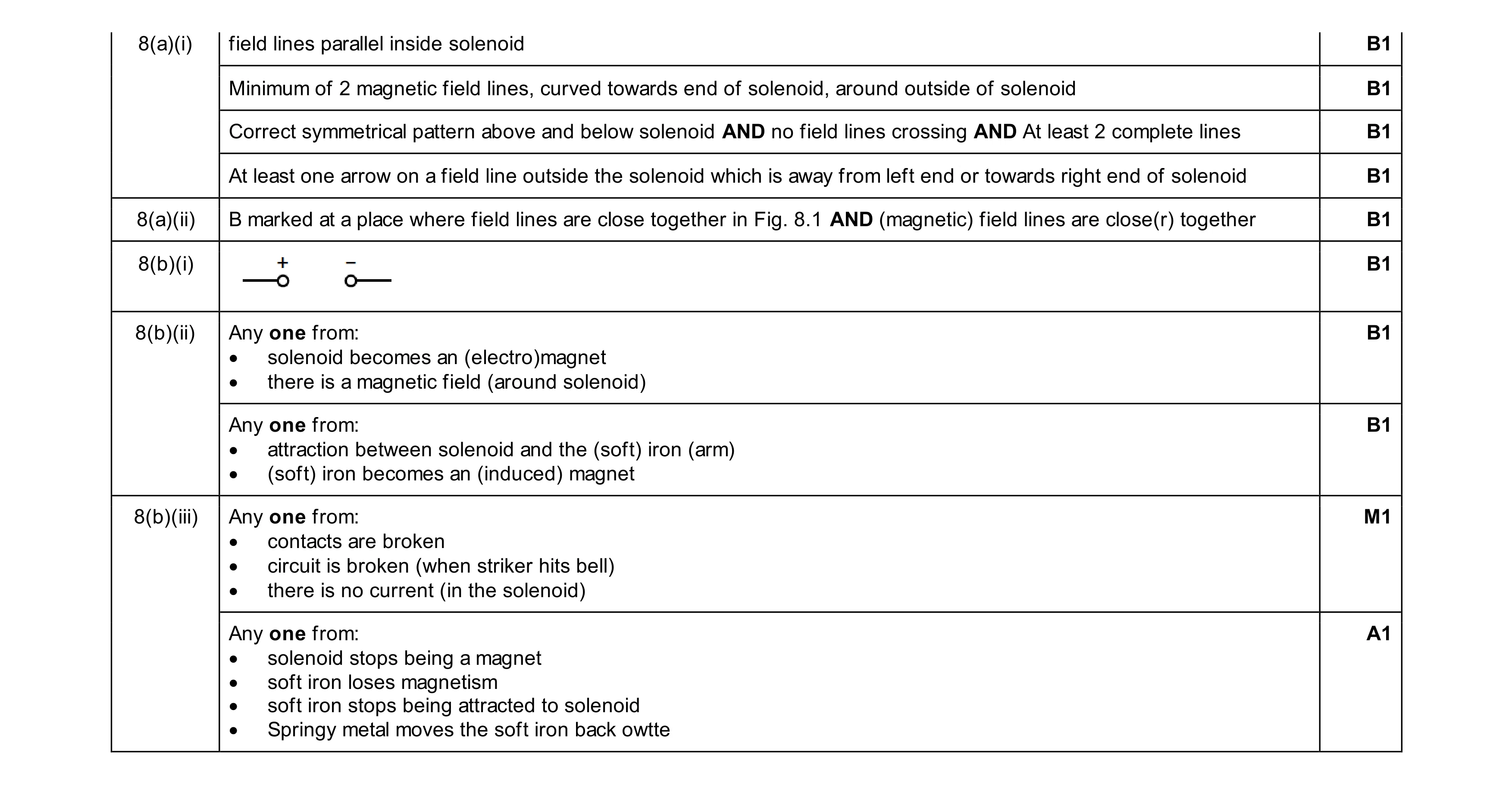 10
10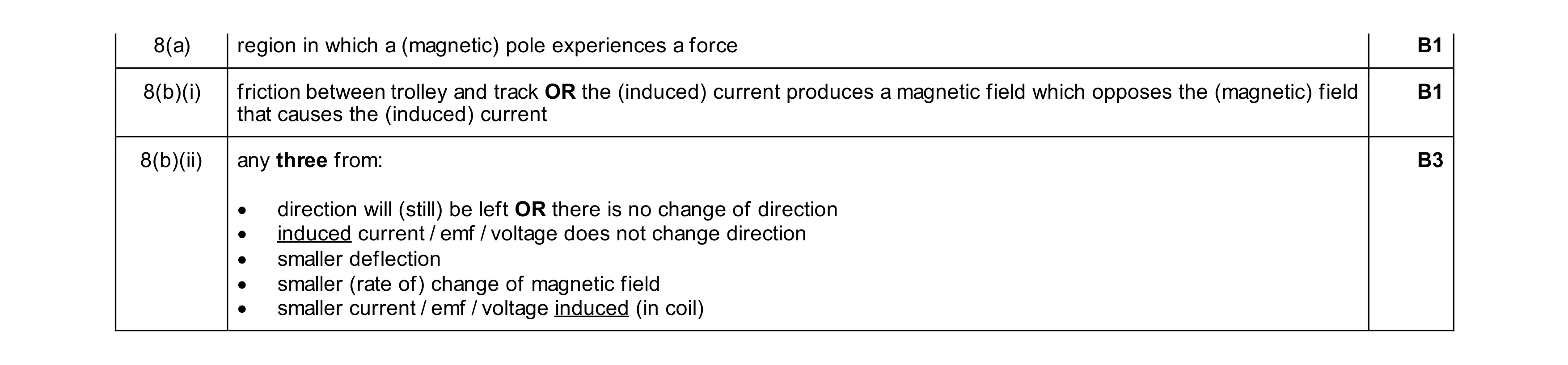 5
5