Cambridge IGCSE Physics 0625 — 2017 May/June Paper 3 · Variant 1
0625/31/M/J/17 · 12 questions · 80 marks · ≈90 min
The question paper and its mark scheme, free to read here and free to download. This is Cambridge’s own paper, exactly as it was sat.
Question paper16 pages


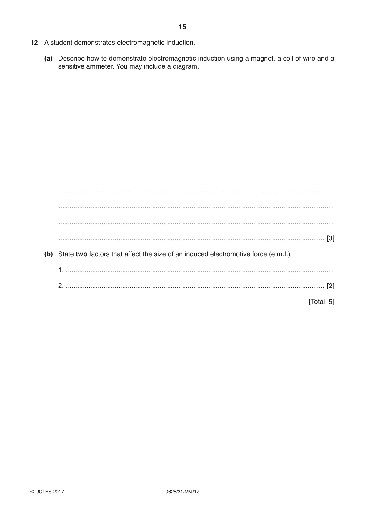
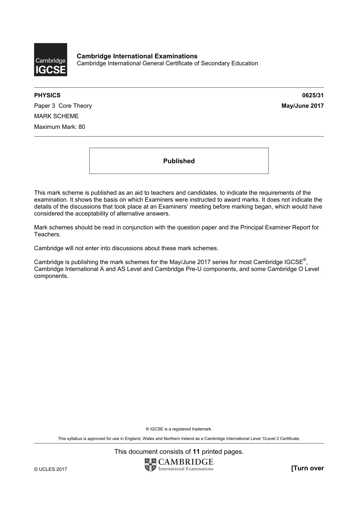
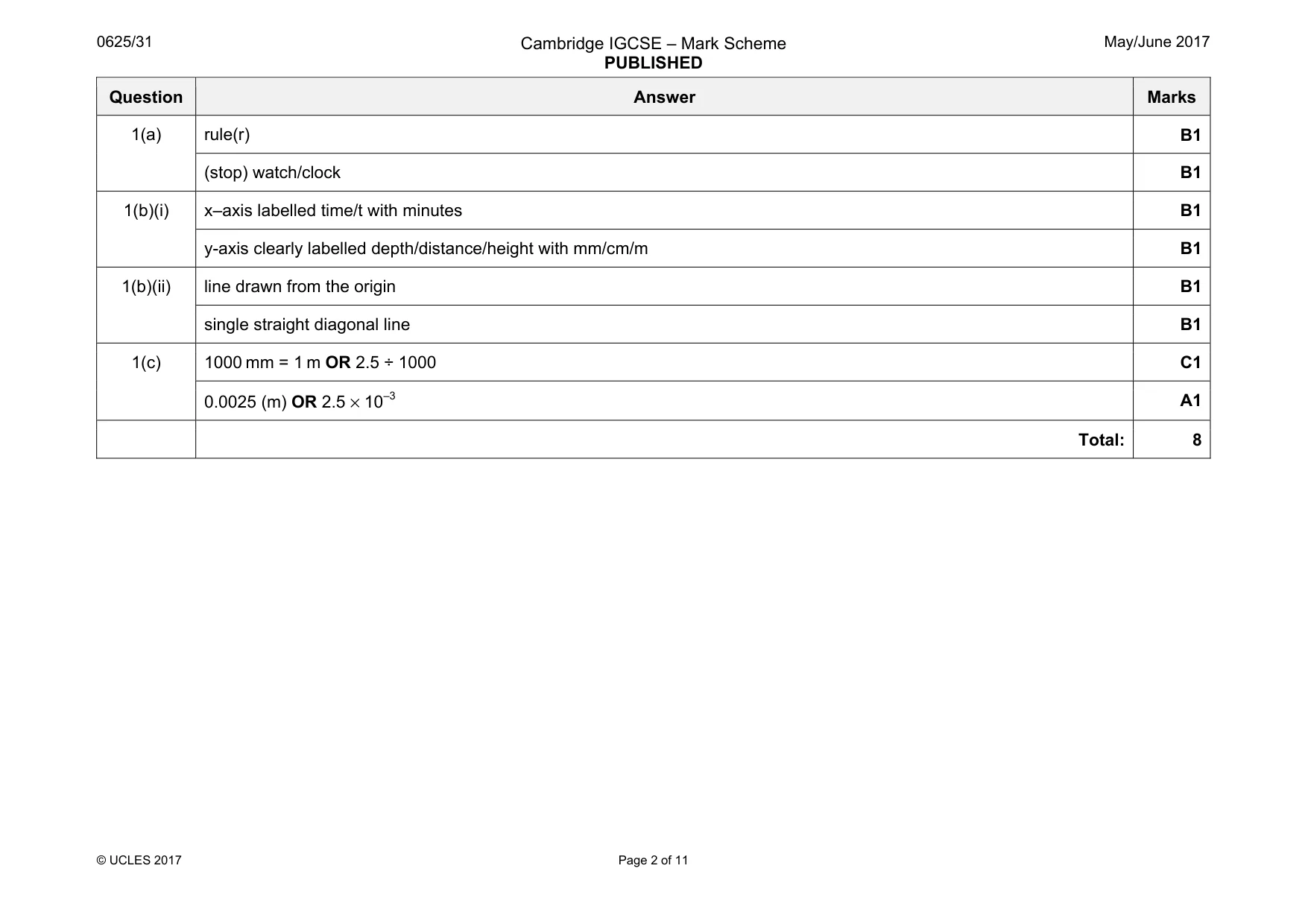
Mark scheme11 pages
Answers below. Sit the paper first if you are practising.
Questions as text
Q1 · A pipe drips water into an empty glass jar
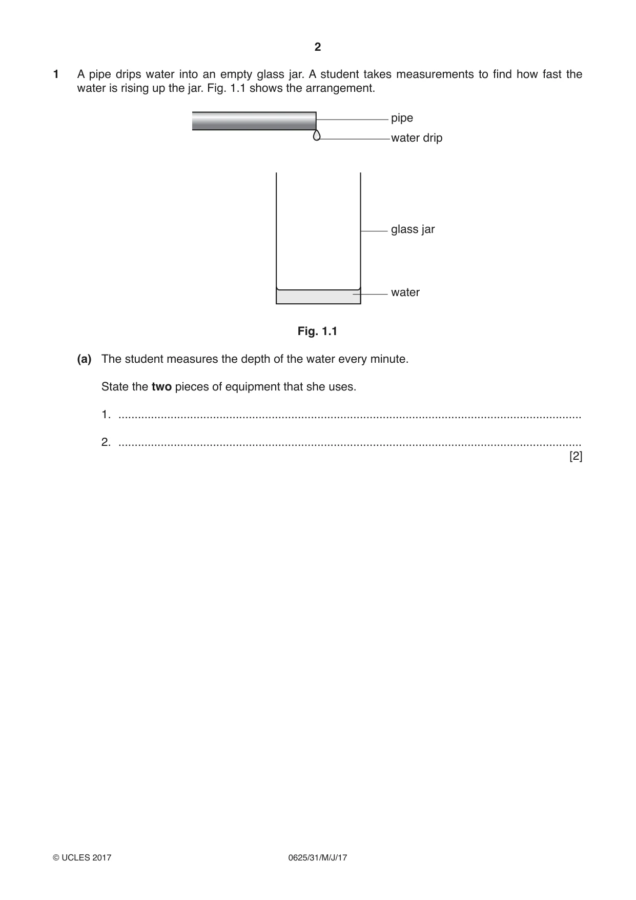
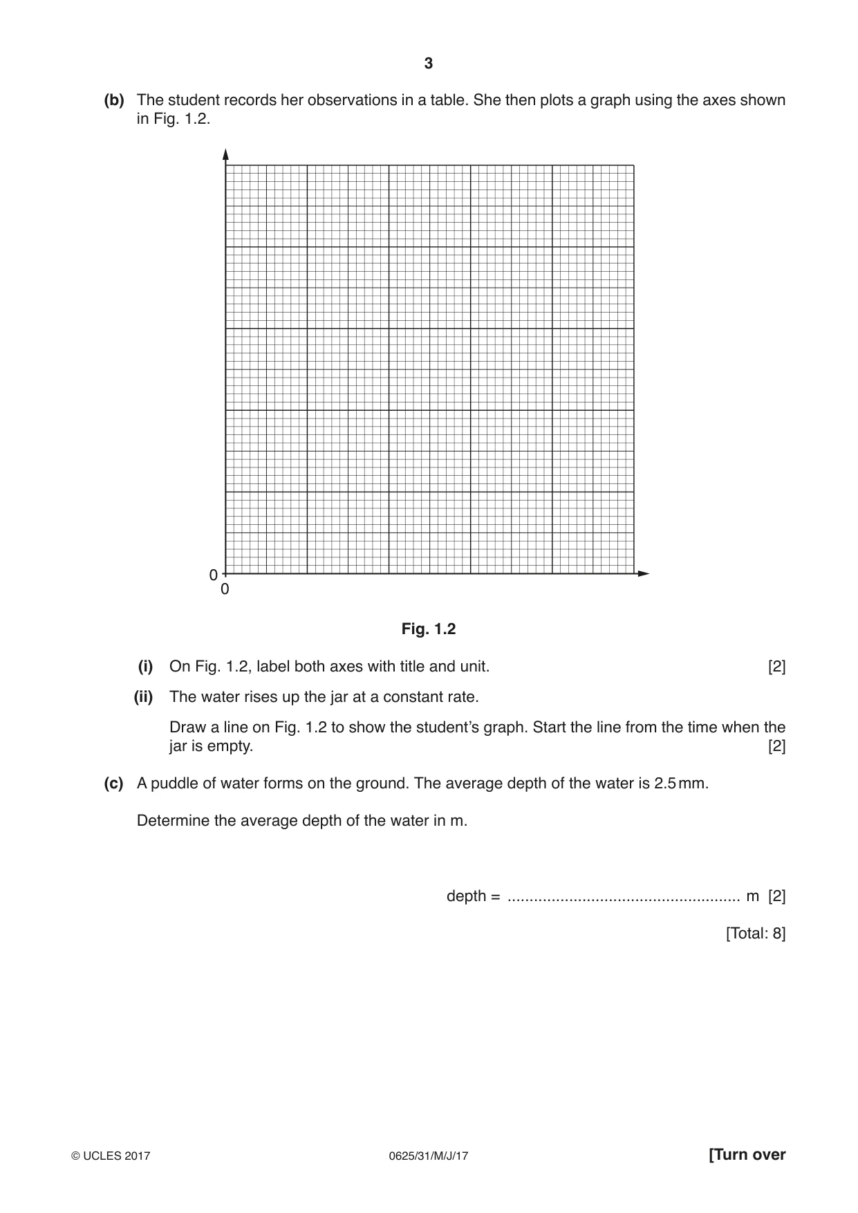
1 A pipe drips water into an empty glass jar. A student takes measurements to find how fast the water is rising up the jar. Fig. 1.1 shows the arrangement. pipe water drip glass jar water Fig. 1.1 (a) The student measures the depth of the water every minute. State the two pieces of equipment that she uses. 1. .............................................................................................................................................. 2. .............................................................................................................................................. [2] (b) The student records her observations in a table. She then plots a graph using the axes shown in Fig. 1.2. 0 0 Fig. 1.2 (i) On Fig. 1.2, label both axes with title and unit. [2] (ii) The water rises up the jar at a constant rate. Draw a line on Fig. 1.2 to show the student’s graph. Start the line from the time when the jar is empty. [2] (c) A puddle of water forms on the ground. The average depth of the water is 2.5 mm. Determine the average depth of the water in m. depth = ..................................................... m [2] [Total: 8]
Mark scheme: 1(a) rule(r) B1 (stop) watch/clock B1 1(b)(i) x–axis labelled time/t with minutes B1 y-axis clearly labelled depth/distance/height with mm/cm/m B1 1(b)(ii) line drawn from the origin B1 single straight diagonal line B1 1(c) 1000 mm = 1 m OR 2.5 ÷ 1000 C1 0.0025 (m) OR 2.5 × 10⁻³ A1 Total: 8
More questions on Physical quantities and measurement techniques
Q2 · Three racing cars, A, B and C, all accelerate steadily and then continue at a constant…
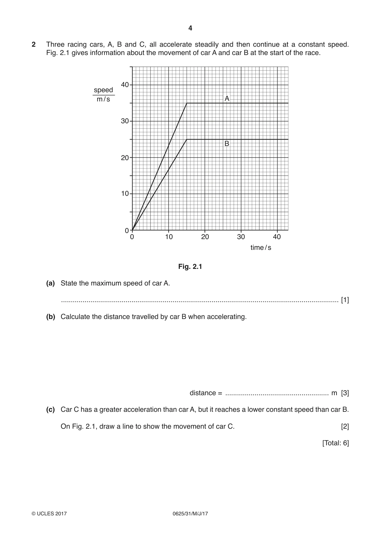
2 Three racing cars, A, B and C, all accelerate steadily and then continue at a constant speed. Fig. 2.1 gives information about the movement of car A and car B at the start of the race. 40 speed m / s A 30 B 20 10 0 0 10 20 30 40 time / s Fig. 2.1 (a) State the maximum speed of car A. .............................................................................................................................................. [1] (b) Calculate the distance travelled by car B when accelerating. distance = ..................................................... m [3] (c) Car C has a greater acceleration than car A, but it reaches a lower constant speed than car B. On Fig. 2.1, draw a line to show the movement of car C. [2] [Total: 6]
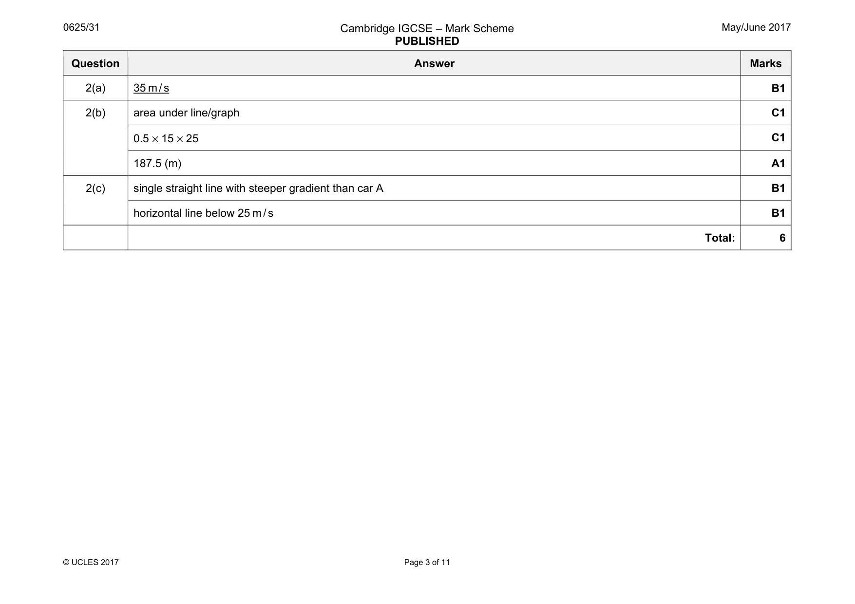
Mark scheme: 2(a) 35 m / s B1 2(b) area under line/graph C1 0.5 × 15 × 25 C1 187.5 (m) A1 2(c) single straight line with steeper gradient than car A B1 horizontal line below 25 m / s B1 Total: 6
Q3 · A tyre hanging from the branch of a tree
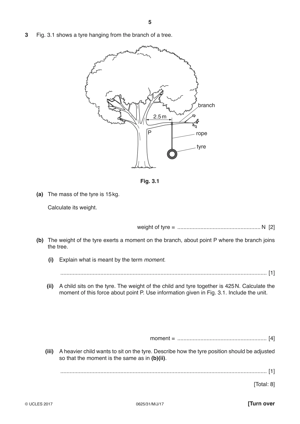
3 Fig. 3.1 shows a tyre hanging from the branch of a tree. branch 2.5 m P rope tyre Fig. 3.1 (a) The mass of the tyre is 15 kg. Calculate its weight. weight of tyre = ...................................................... N [2] (b) The weight of the tyre exerts a moment on the branch, about point P where the branch joins the tree. (i) Explain what is meant by the term moment. ...................................................................................................................................... [1] (ii) A child sits on the tyre. The weight of the child and tyre together is 425 N. Calculate the moment of this force about point P. Use information given in Fig. 3.1. Include the unit. moment = .......................................................... [4] (iii) A heavier child wants to sit on the tyre. Describe how the tyre position should be adjusted so that the moment is the same as in (b)(ii). ...................................................................................................................................... [1] [Total: 8]
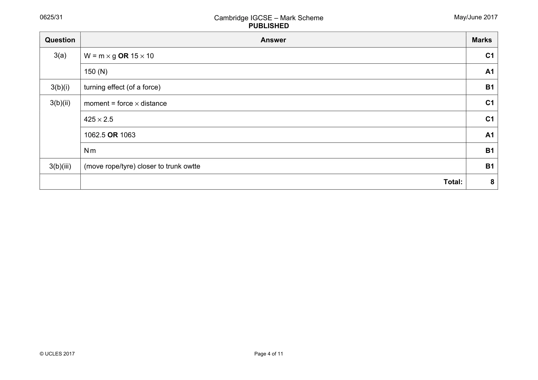
Mark scheme: 3(a) C1 150 (N) A1 3(b)(i) turning effect (of a force) B1 3(b)(ii) moment = force × distance C1 425 × 2.5 C1 1062.5 OR 1063 A1 N m B1 3(b)(iii) (move rope/tyre) closer to trunk owtte B1 Total: 8
Q4 · A hydroelectric power system located in the mountains
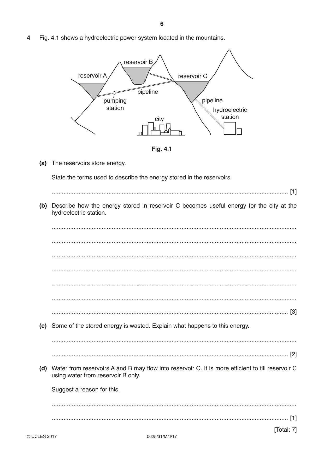
4 Fig. 4.1 shows a hydroelectric power system located in the mountains. reservoir B reservoir A reservoir C pipeline pumping pipeline station hydroelectric station city Fig. 4.1 (a) The reservoirs store energy. State the terms used to describe the energy stored in the reservoirs. .............................................................................................................................................. [1] (b) Describe how the energy stored in reservoir C becomes useful energy for the city at the hydroelectric station. ................................................................................................................................................... ................................................................................................................................................... ................................................................................................................................................... ................................................................................................................................................... ................................................................................................................................................... ................................................................................................................................................... .............................................................................................................................................. [3] (c) Some of the stored energy is wasted. Explain what happens to this energy. ................................................................................................................................................... .............................................................................................................................................. [2] (d) Water from reservoirs A and B may flow into reservoir C. It is more efficient to fill reservoir C using water from reservoir B only. Suggest a reason for this. ................................................................................................................................................... .............................................................................................................................................. [1]
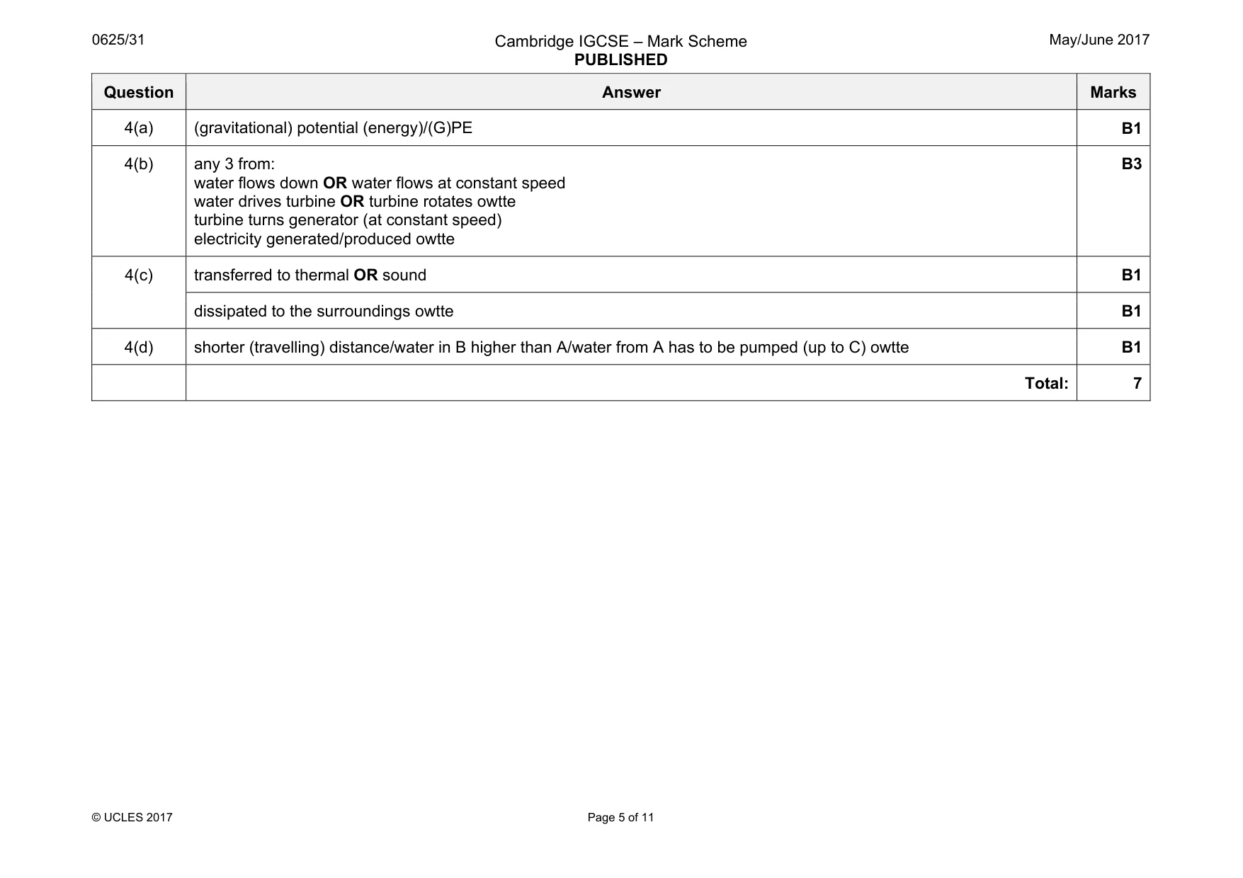
Mark scheme: 4(a) (gravitational) potential (energy)/(G)PE B1 4(b) any 3 from: water flows down OR water flows at constant speed water drives turbine OR turbine rotates owtte turbine turns generator (at constant speed) electricity generated/produced owtte B3 4(c) transferred to thermal OR sound B1 dissipated to the surroundings owtte B1 4(d) shorter (travelling) distance/water in B higher than A/water from A has to be pumped (up to C) owtte B1 Total: 7
Q5 · A laboratory floor has a surface that prevents people from slipping when the floor is wet
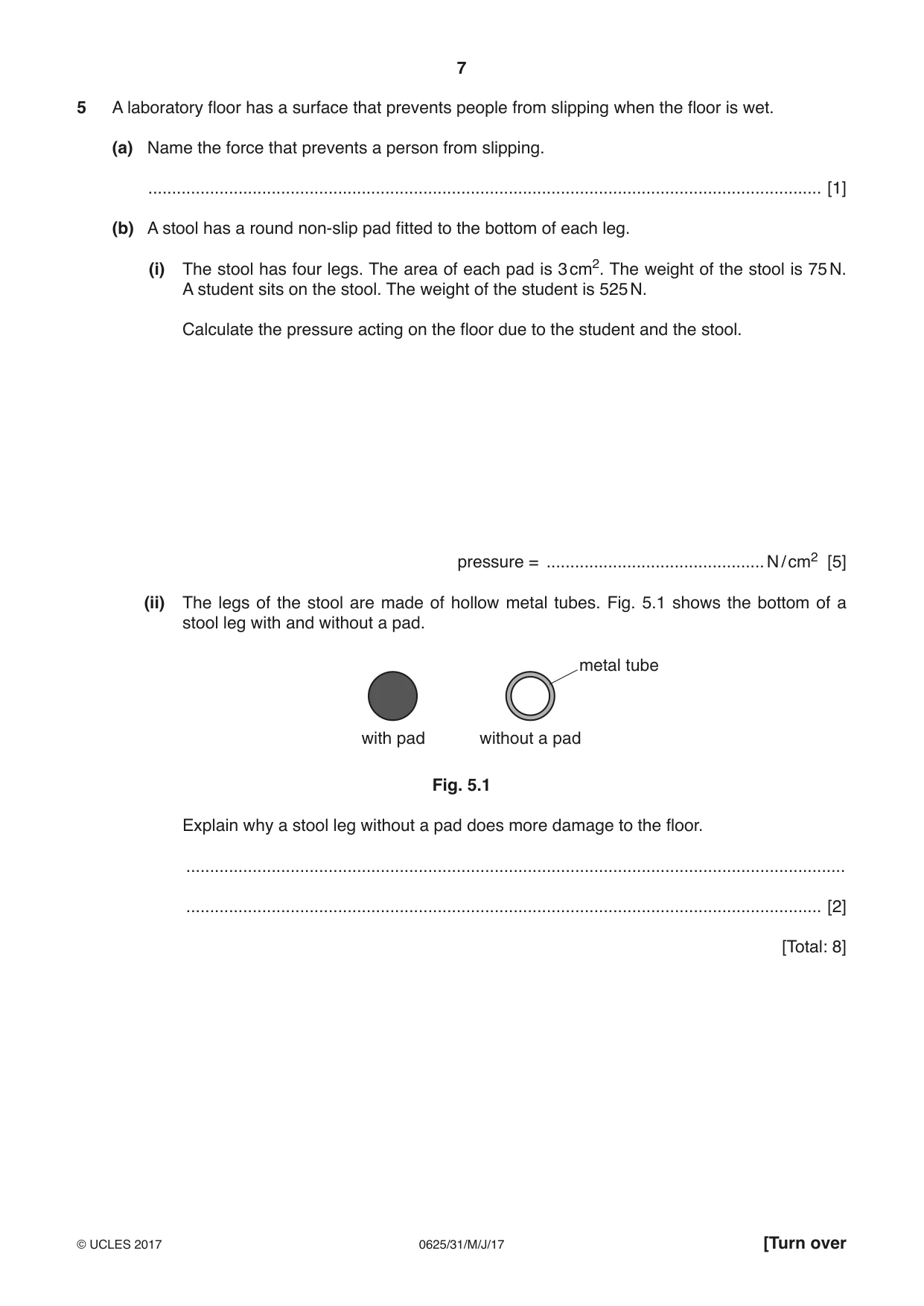
5 A laboratory floor has a surface that prevents people from slipping when the floor is wet. (a) Name the force that prevents a person from slipping. .............................................................................................................................................. [1] (b) A stool has a round non-slip pad fitted to the bottom of each leg. (i) The stool has four legs. The area of each pad is 3 cm2. The weight of the stool is 75 N. A student sits on the stool. The weight of the student is 525 N. Calculate the pressure acting on the floor due to the student and the stool. pressure = .............................................. N / cm2 [5] (ii) The legs of the stool are made of hollow metal tubes. Fig. 5.1 shows the bottom of a stool leg with and without a pad. metal tube with pad without a pad Fig. 5.1 Explain why a stool leg without a pad does more damage to the floor. ........................................................................................................................................... ...................................................................................................................................... [2] [Total: 8]
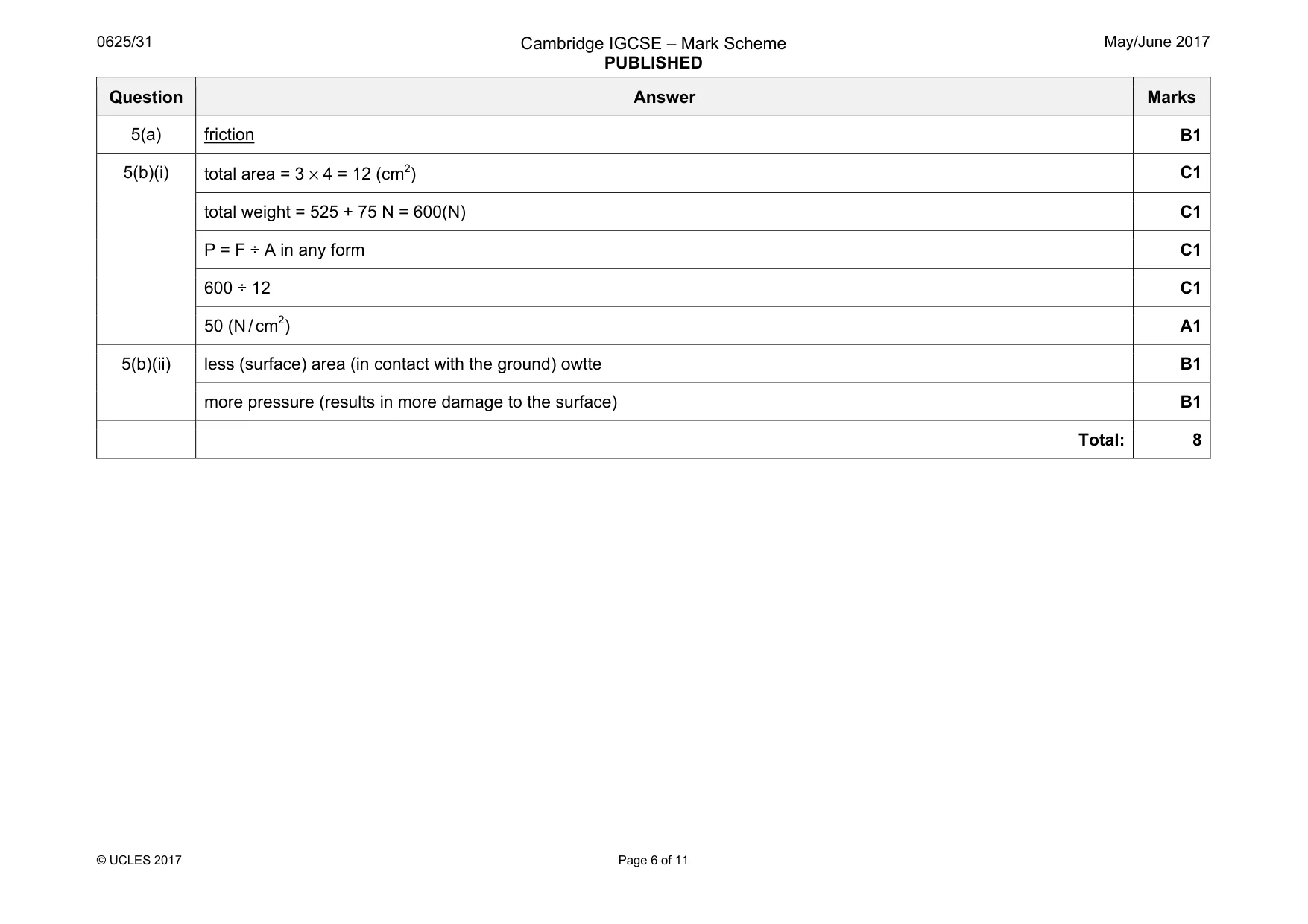
Mark scheme: 5(a) friction B1 5(b)(i) total area = 3 × 4 = 12 (cm2) C1 total weight = 525 + 75 N = 600(N) C1 P = F ÷ A in any form C1 600 ÷ 12 C1 50 (N / cm2) A1 5(b)(ii) less (surface) area (in contact with the ground) owtte B1 more pressure (results in more damage to the surface) B1 Total: 8
Q6 · Workers pouring liquid metal
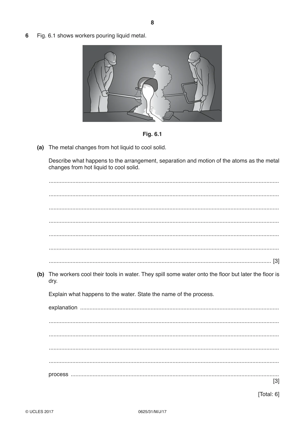
6 Fig. 6.1 shows workers pouring liquid metal. Fig. 6.1 (a) The metal changes from hot liquid to cool solid. Describe what happens to the arrangement, separation and motion of the atoms as the metal changes from hot liquid to cool solid. ................................................................................................................................................... ................................................................................................................................................... ................................................................................................................................................... ................................................................................................................................................... ................................................................................................................................................... ................................................................................................................................................... .............................................................................................................................................. [3] (b) The workers cool their tools in water. They spill some water onto the floor but later the floor is dry. Explain what happens to the water. State the name of the process. explanation ............................................................................................................................... ................................................................................................................................................... ................................................................................................................................................... ................................................................................................................................................... ................................................................................................................................................... process ..................................................................................................................................... [3] [Total: 6]
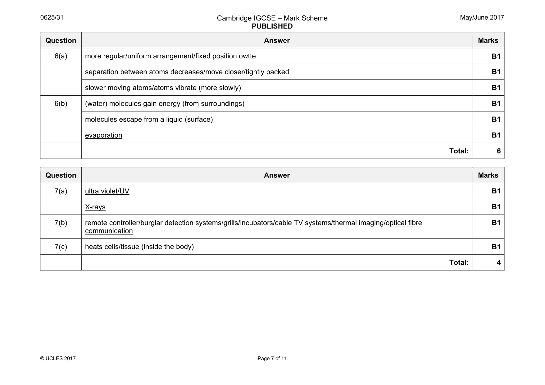
Mark scheme: 6(a) more regular/uniform arrangement/fixed position owtte B1 separation between atoms decreases/move closer/tightly packed B1 slower moving atoms/atoms vibrate (more slowly) B1 6(b) (water) molecules gain energy (from surroundings) B1 molecules escape from a liquid (surface) B1 evaporation B1 Total: 6
Q7 · This question is about the electromagnetic spectrum
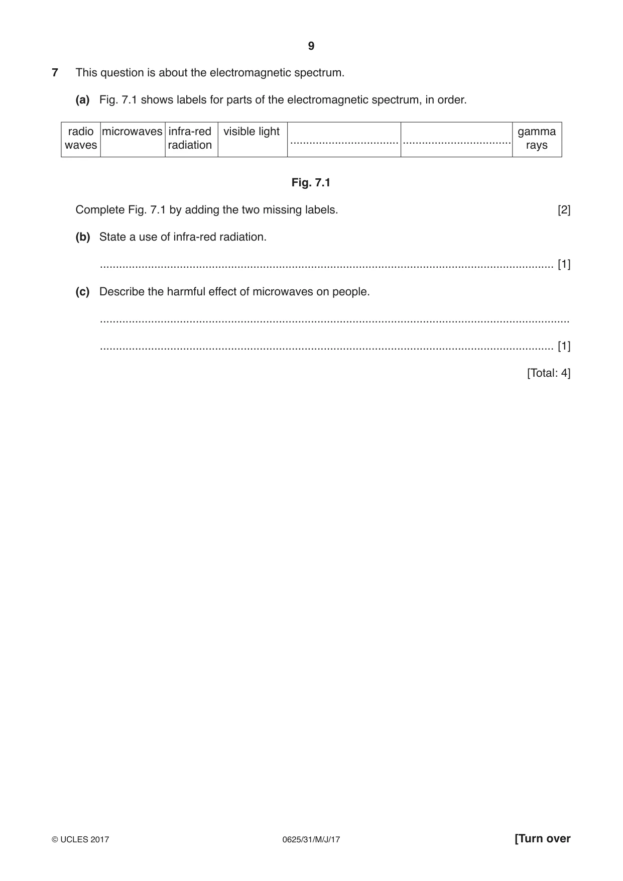
7 This question is about the electromagnetic spectrum. (a) Fig. 7.1 shows labels for parts of the electromagnetic spectrum, in order. radio microwaves infra-red visible light gamma .................................. .................................. waves radiation rays Fig. 7.1 Complete Fig. 7.1 by adding the two missing labels. [2] (b) State a use of infra-red radiation. .............................................................................................................................................. [1] (c) Describe the harmful effect of microwaves on people. ................................................................................................................................................... .............................................................................................................................................. [1] [Total: 4]
Mark scheme: 7(a) ultra violet/UV B1 X-rays B1 7(b) remote controller/burglar detection systems/grills/incubators/cable TV systems/thermal imaging/optical fibre communication B1 7(c) heats cells/tissue (inside the body) B1 Total: 4
Q8 · Iodine-131 is a radioactive isotope of iodine
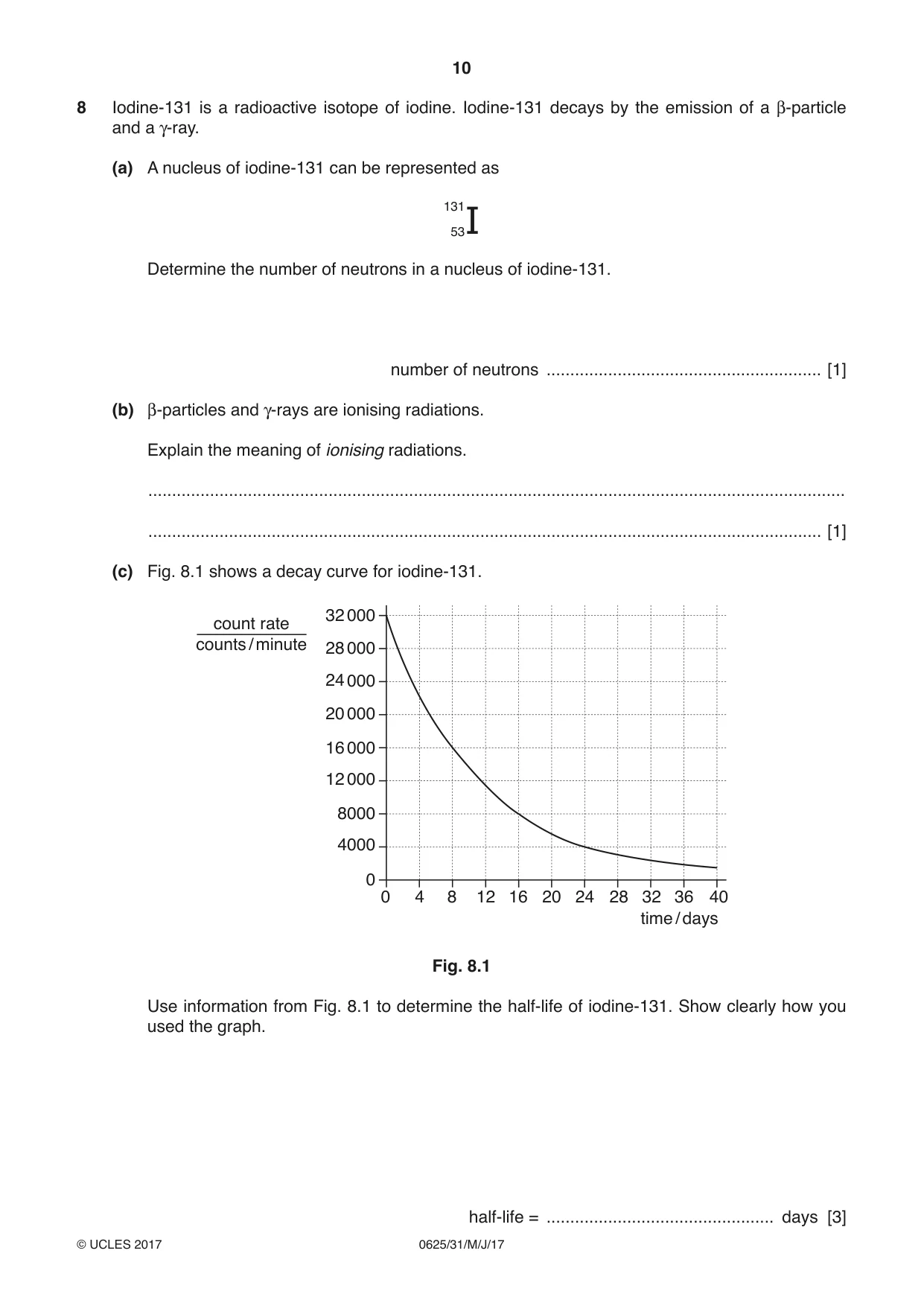
8 Iodine-131 is a radioactive isotope of iodine. Iodine-131 decays by the emission of a β-particle and a γ-ray. (a) A nucleus of iodine-131 can be represented as 13153I Determine the number of neutrons in a nucleus of iodine-131. number of neutrons .......................................................... [1] (b) β-particles and γ-rays are ionising radiations. Explain the meaning of ionising radiations. ................................................................................................................................................... .............................................................................................................................................. [1] (c) Fig. 8.1 shows a decay curve for iodine-131. 32 000 count rate counts / minute 28 000 24 000 20 000 16 000 12 000 8000 4000 0 0 4 8 12 16 20 24 28 32 36 40 time / days Fig. 8.1 Use information from Fig. 8.1 to determine the half-life of iodine-131. Show clearly how you used the graph. half-life = ................................................ days [3] (d) A different radioactive substance has a half-life of 120 hours. Calculate the time for it to decay to 25% of its original amount. time = ............................................... hours [2] [Total: 7]
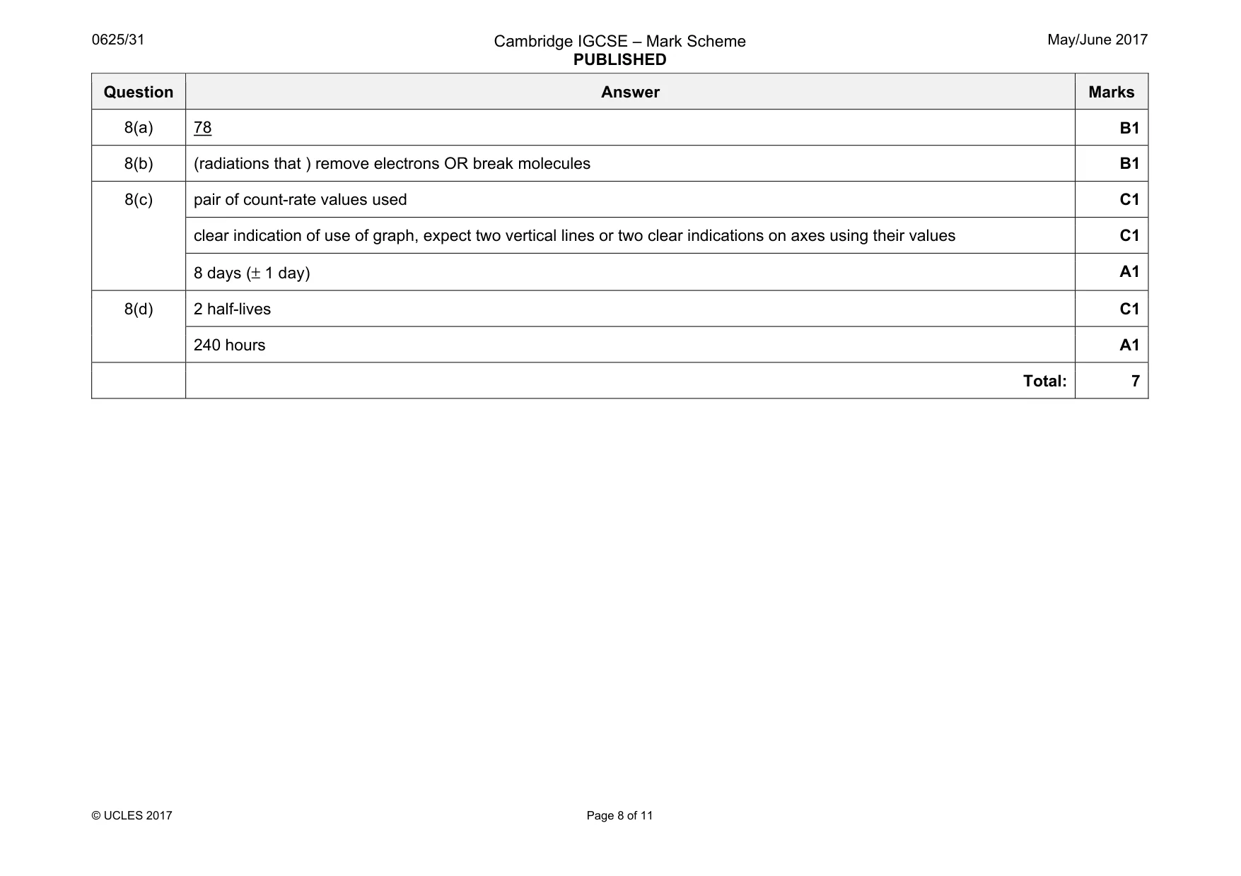
Mark scheme: 8(a) 78 B1 8(b) (radiations that ) remove electrons OR break molecules B1 8(c) pair of count-rate values used C1 clear indication of use of graph, expect two vertical lines or two clear indications on axes using their values C1 8 days (± 1 day) A1 8(d) 2 half-lives C1 240 hours A1 Total: 7
Q9 · The position of a man working in a rock quarry
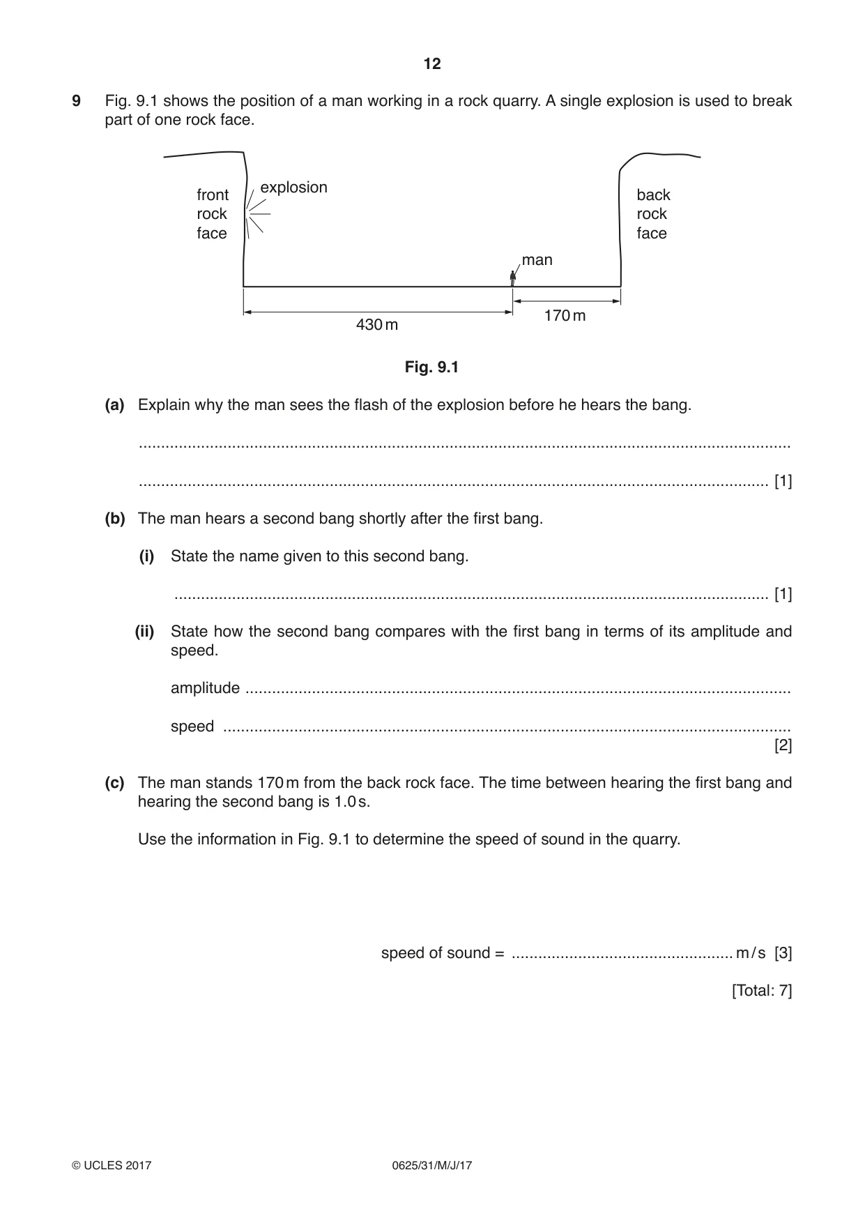
9 Fig. 9.1 shows the position of a man working in a rock quarry. A single explosion is used to break part of one rock face. explosion front back rock rock face face man 170 m 430 m Fig. 9.1 (a) Explain why the man sees the flash of the explosion before he hears the bang. ................................................................................................................................................... .............................................................................................................................................. [1] (b) The man hears a second bang shortly after the first bang. (i) State the name given to this second bang. ...................................................................................................................................... [1] (ii) State how the second bang compares with the first bang in terms of its amplitude and speed. amplitude ........................................................................................................................... speed ................................................................................................................................ [2] (c) The man stands 170 m from the back rock face. The time between hearing the first bang and hearing the second bang is 1.0 s. Use the information in Fig. 9.1 to determine the speed of sound in the quarry. speed of sound = .................................................. m / s [3] [Total: 7]
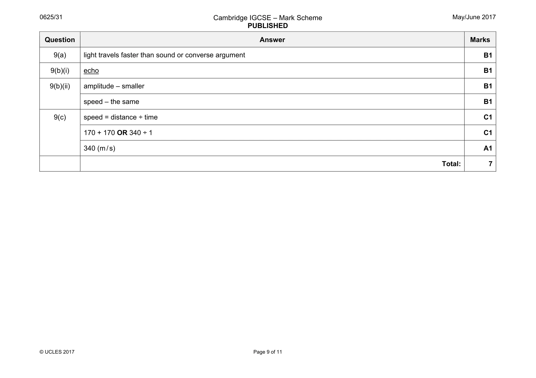
Mark scheme: 9(a) light travels faster than sound or converse argument B1 9(b)(i) echo B1 9(b)(ii) amplitude – smaller B1 speed – the same B1 9(c) speed = distance ÷ time C1 170 + 170 OR 340 ÷ 1 C1 340 (m / s) A1 Total: 7
Q10 · A demonstration with magnets
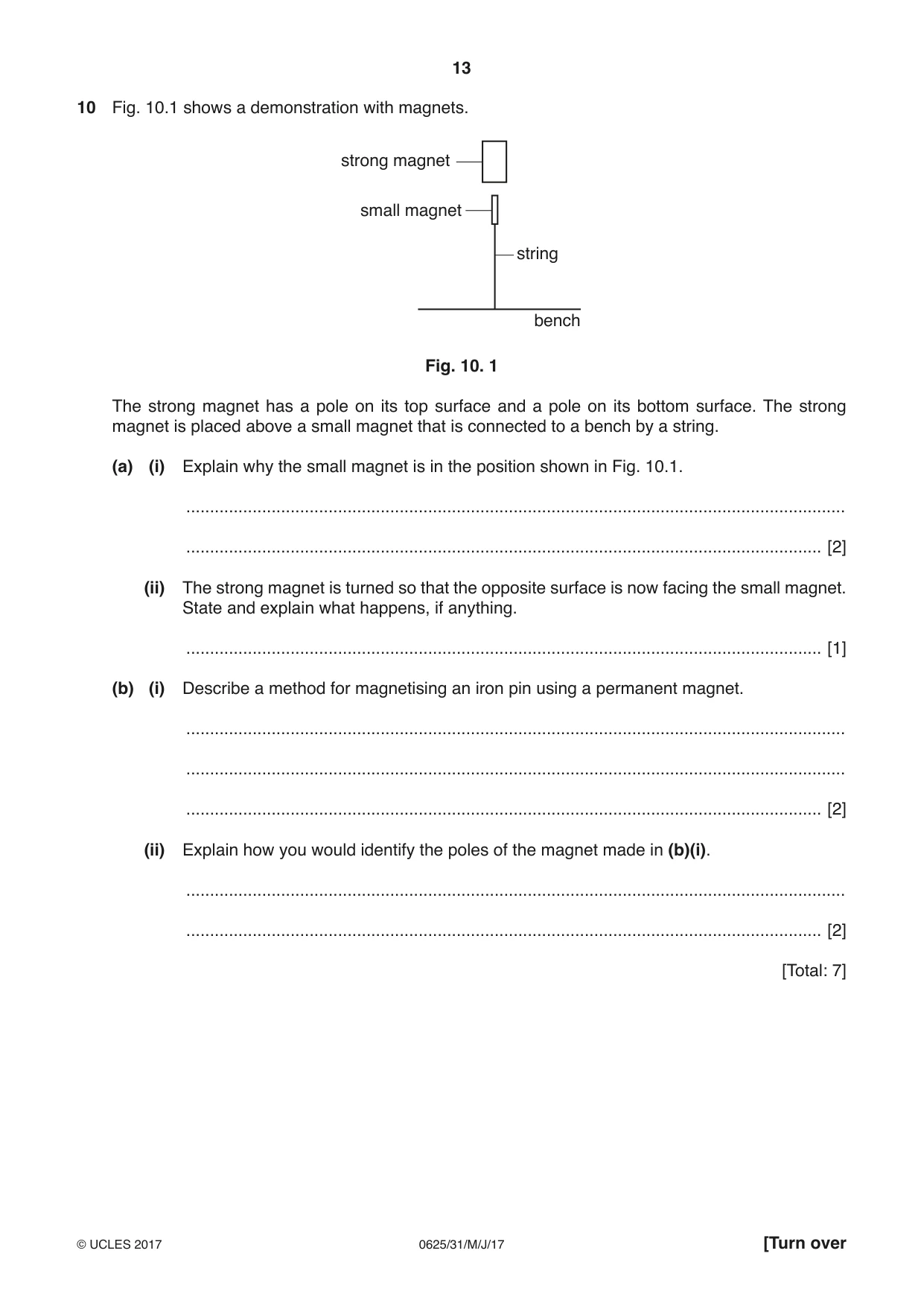
10 Fig. 10.1 shows a demonstration with magnets. strong magnet small magnet string bench Fig. 10. 1 The strong magnet has a pole on its top surface and a pole on its bottom surface. The strong magnet is placed above a small magnet that is connected to a bench by a string. (a) (i) Explain why the small magnet is in the position shown in Fig. 10.1. ........................................................................................................................................... ...................................................................................................................................... [2] (ii) The strong magnet is turned so that the opposite surface is now facing the small magnet. State and explain what happens, if anything. ...................................................................................................................................... [1] (b) (i) Describe a method for magnetising an iron pin using a permanent magnet. ........................................................................................................................................... ........................................................................................................................................... ...................................................................................................................................... [2] (ii) Explain how you would identify the poles of the magnet made in (b)(i). ........................................................................................................................................... ...................................................................................................................................... [2] [Total: 7]
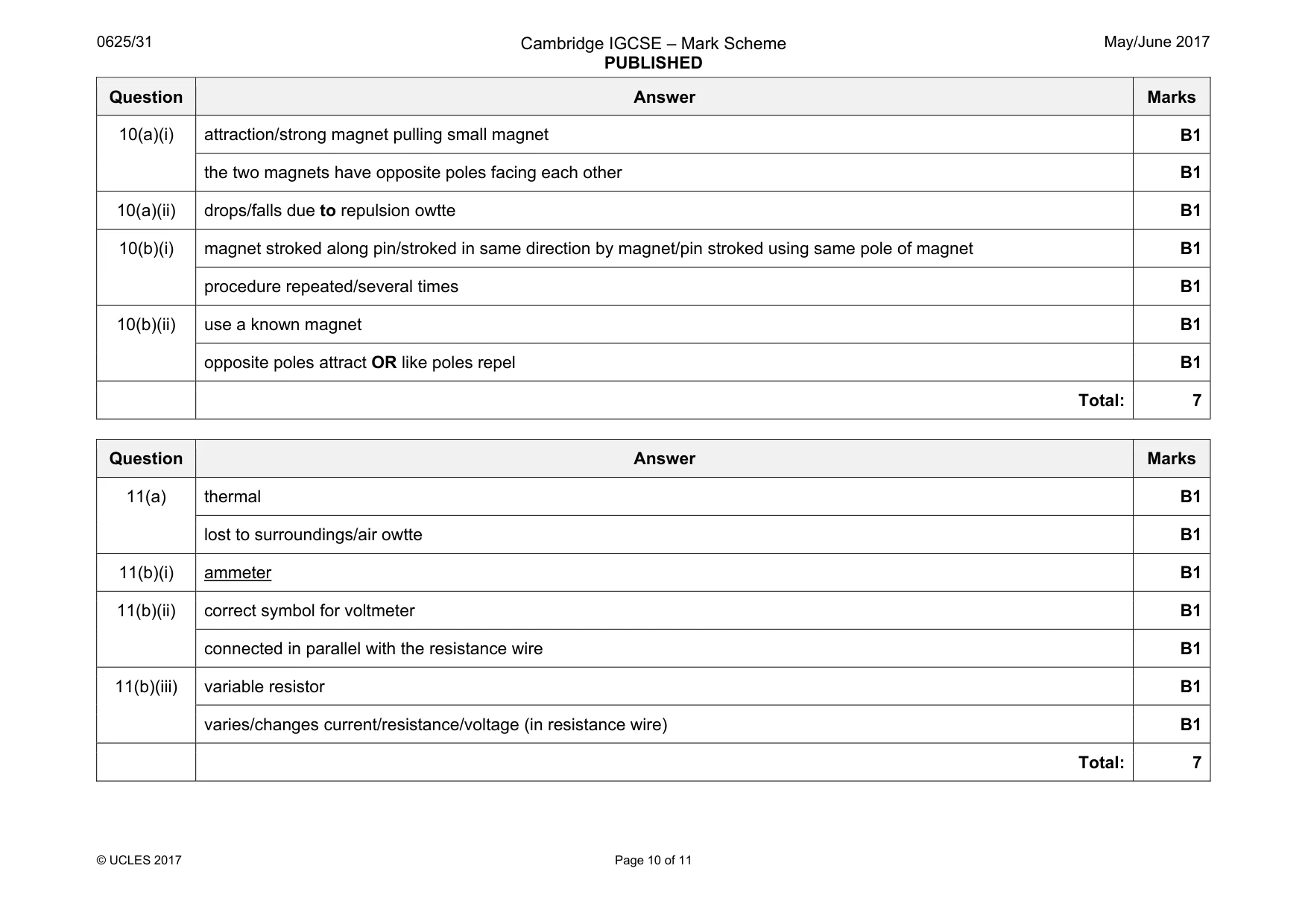
Mark scheme: 10(a)(i) attraction/strong magnet pulling small magnet B1 the two magnets have opposite poles facing each other B1 10(a)(ii) drops/falls due to repulsion owtte B1 10(b)(i) magnet stroked along pin/stroked in same direction by magnet/pin stroked using same pole of magnet B1 procedure repeated/several times B1 10(b)(ii) use a known magnet B1 opposite poles attract OR like poles repel B1 Total: 7
Q11 · A power supply in series with a resistance wire and a switch
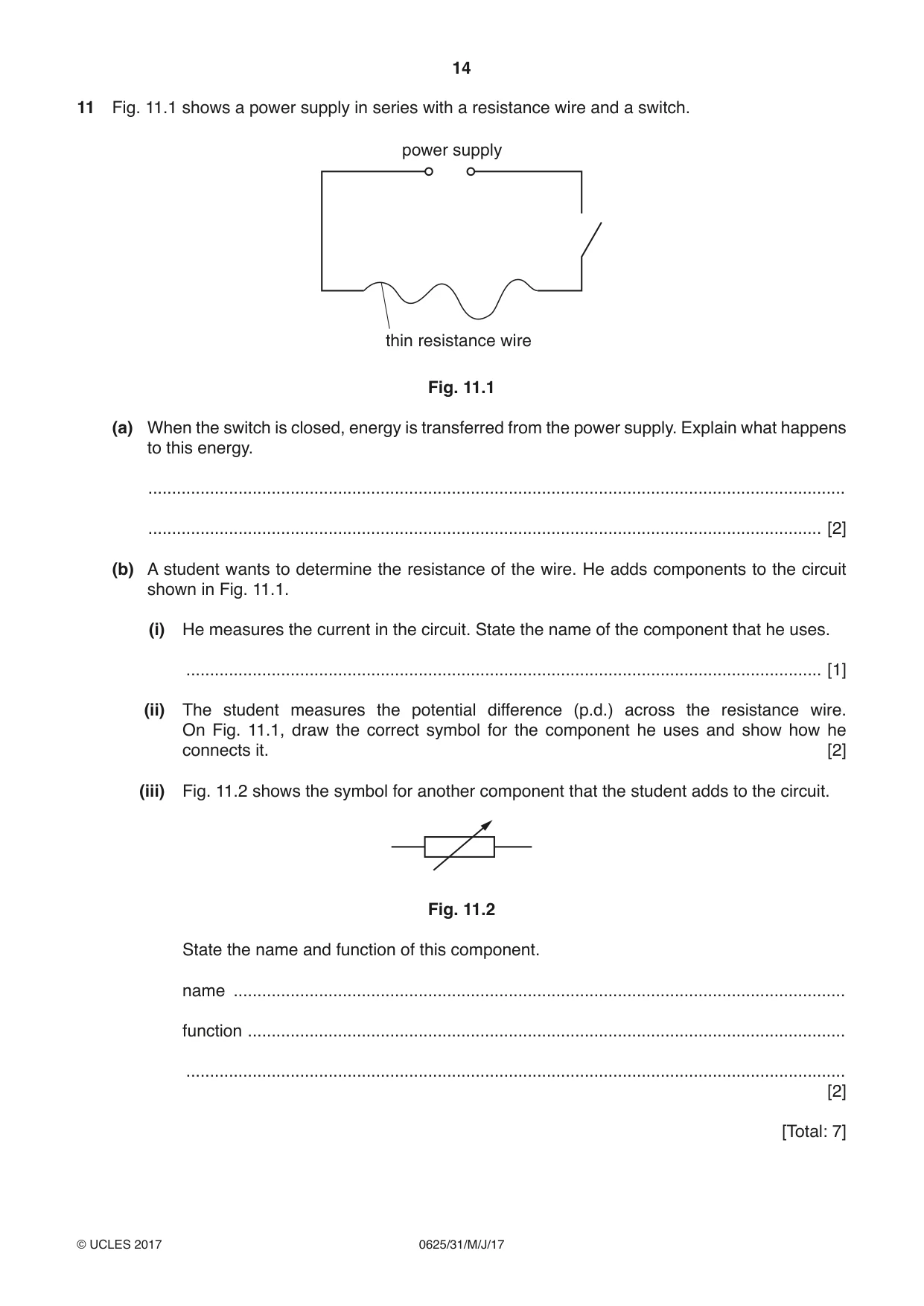
11 Fig. 11.1 shows a power supply in series with a resistance wire and a switch. power supply thin resistance wire Fig. 11.1 (a) When the switch is closed, energy is transferred from the power supply. Explain what happens to this energy. ................................................................................................................................................... .............................................................................................................................................. [2] (b) A student wants to determine the resistance of the wire. He adds components to the circuit shown in Fig. 11.1. (i) He measures the current in the circuit. State the name of the component that he uses. ...................................................................................................................................... [1] (ii) The student measures the potential difference (p.d.) across the resistance wire. On Fig. 11.1, draw the correct symbol for the component he uses and show how he connects it. [2] (iii) Fig. 11.2 shows the symbol for another component that the student adds to the circuit. Fig. 11.2 State the name and function of this component. name ................................................................................................................................. function .............................................................................................................................. ........................................................................................................................................... [2] [Total: 7]
Mark scheme: 11(a) thermal B1 lost to surroundings/air owtte B1 11(b)(i) ammeter B1 11(b)(ii) correct symbol for voltmeter B1 connected in parallel with the resistance wire B1 11(b)(iii) variable resistor B1 varies/changes current/resistance/voltage (in resistance wire) B1 Total: 7
Q12 · A student demonstrates electromagnetic induction
12 A student demonstrates electromagnetic induction. (a) Describe how to demonstrate electromagnetic induction using a magnet, a coil of wire and a sensitive ammeter. You may include a diagram. ................................................................................................................................................... ................................................................................................................................................... ................................................................................................................................................... .............................................................................................................................................. [3] (b) State two factors that affect the size of an induced electromotive force (e.m.f.) 1. ............................................................................................................................................... 2. .......................................................................................................................................... [2] [Total: 5]
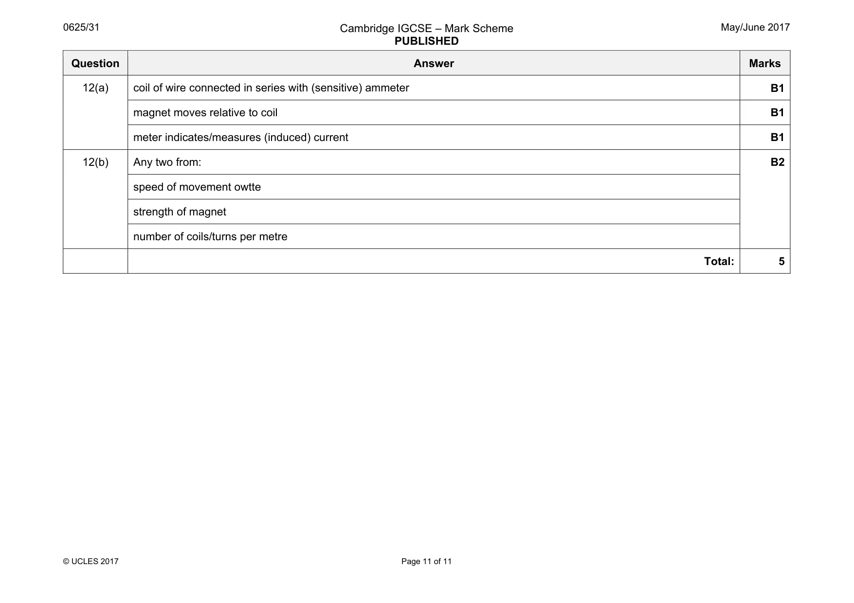
Mark scheme: 12(a) coil of wire connected in series with (sensitive) ammeter B1 magnet moves relative to coil B1 meter indicates/measures (induced) current B1 12(b) Any two from: B2 speed of movement owtte strength of magnet number of coils/turns per metre Total: 5
What was in this paper
The subtopics covered by these 12 questions, and how many questions each got. Open one in a new tab to see every Cambridge question on it.
What you needed in this session
Cambridge’s own grade thresholds for 2017 May/June, Paper 3 · Variant 1. A higher threshold means an easier paper — the bar moves with how the cohort did.