Questions as text
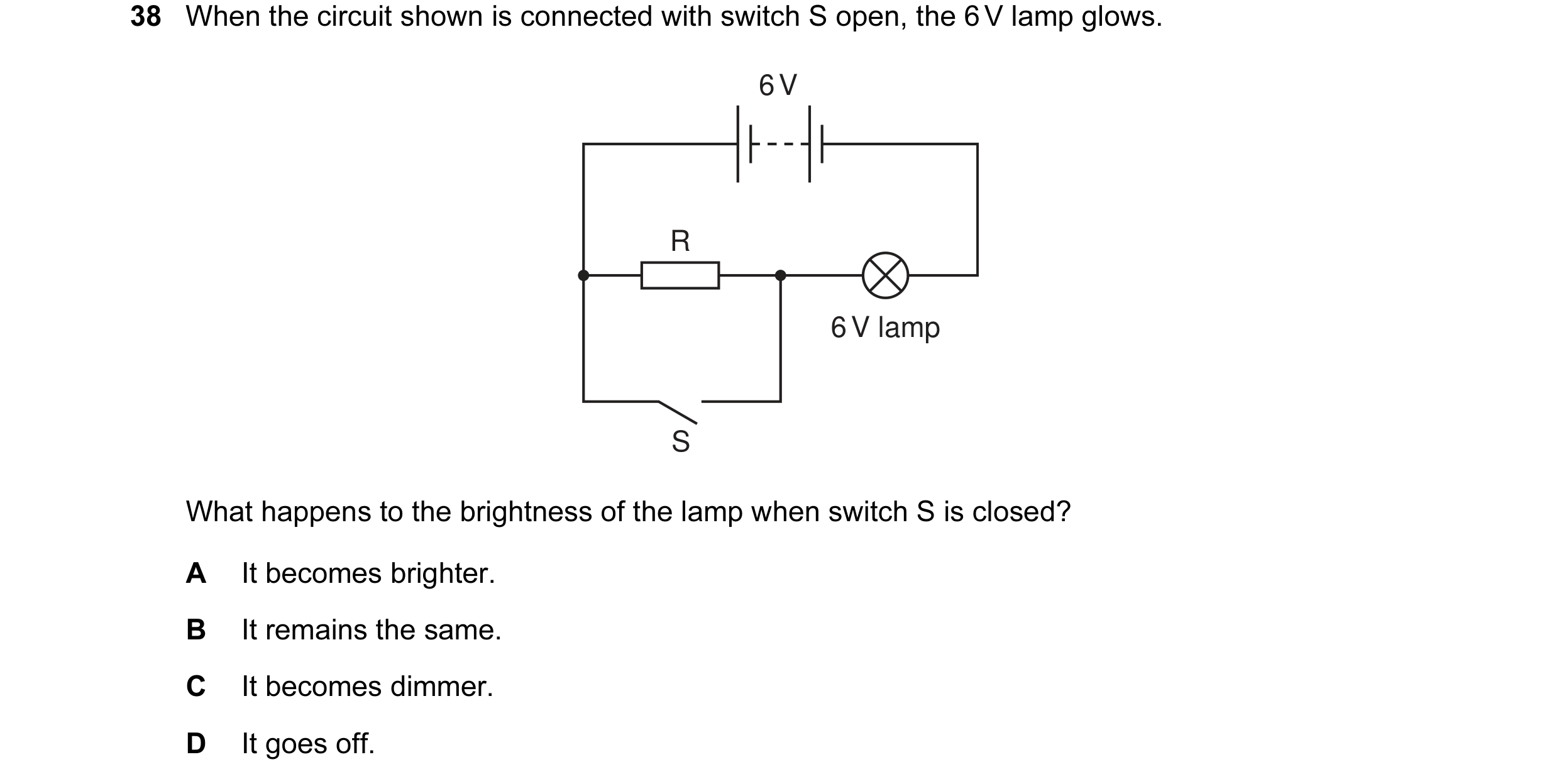
Q1 · When the circuit shown is connected with switch S open, the 6 V lamp glows 0653/11 Oct/Nov 2005
38 When the circuit shown is connected with switch S open, the 6 V lamp glows. 6 V R 6 V lamp S What happens to the brightness of the lamp when switch S is closed? A It becomes brighter. B It remains the same. C It becomes dimmer. D It goes off.
1 marks
Answer: A
This question in 0653/11 Oct/Nov 2005
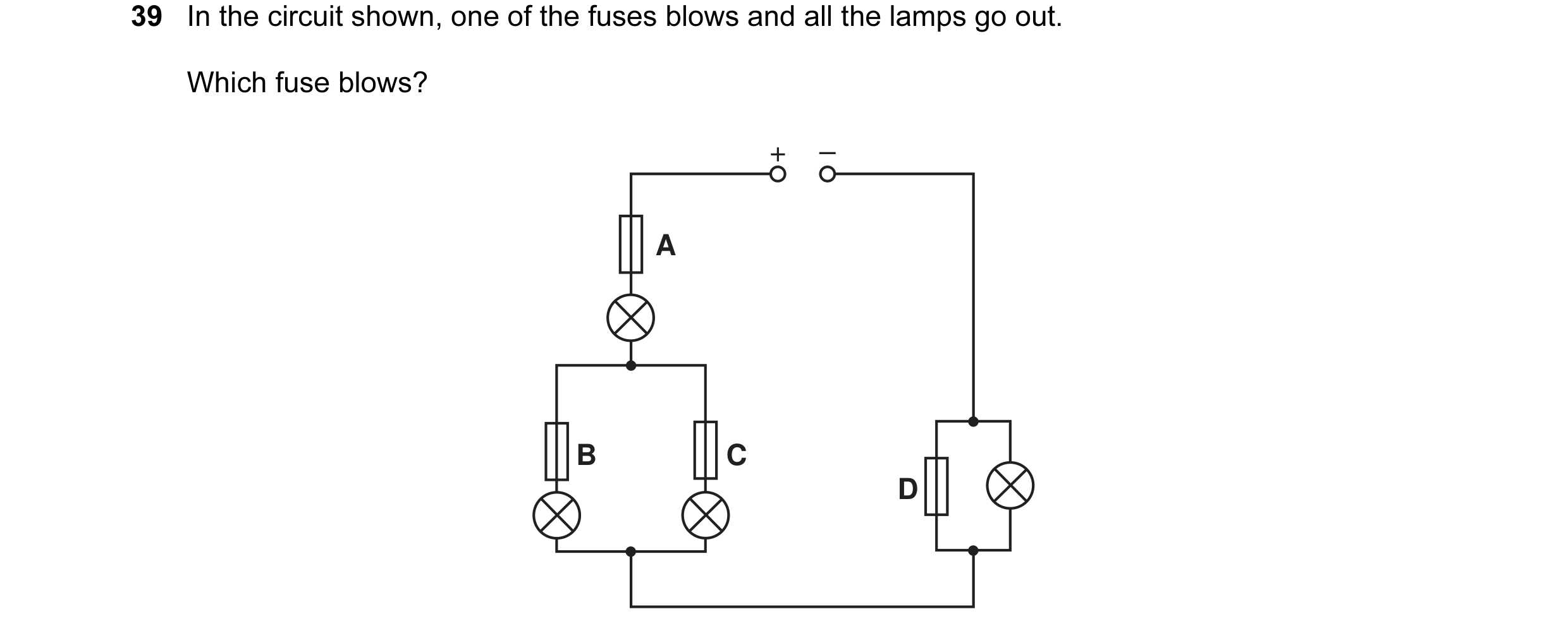
Q2 · In the circuit shown, one of the fuses blows and all the lamps go out 0653/11 Oct/Nov 2005
39 In the circuit shown, one of the fuses blows and all the lamps go out. Which fuse blows? + – A B C D
1 marks
Answer: A
This question in 0653/11 Oct/Nov 2005
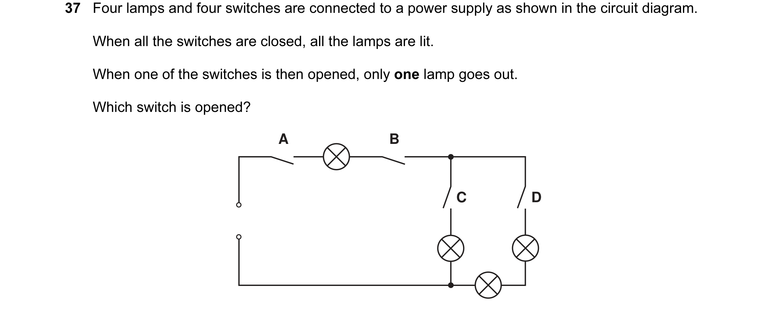
Q3 · Four lamps and four switches are connected to a power supply as shown in the circuit… 0653/11 May/June 2006
37 Four lamps and four switches are connected to a power supply as shown in the circuit diagram. When all the switches are closed, all the lamps are lit. When one of the switches is then opened, only one lamp goes out. Which switch is opened? A B C D
1 marks
Answer: C
This question in 0653/11 May/June 2006
Q4 · When electricity is transmitted over long distances energy is wasted 0653/11 Oct/Nov 2006
36 When electricity is transmitted over long distances energy is wasted. How can the wasted energy be kept as small as possible? A Keep the current in the transmission lines as large as possible. B Keep the power supplied to the transmission lines as large as possible. C Keep the resistance of the transmission lines as large as possible. D Keep the voltage supplied to the transmission lines as large as possible.
1 marks
Answer: D
This question in 0653/11 Oct/Nov 2006
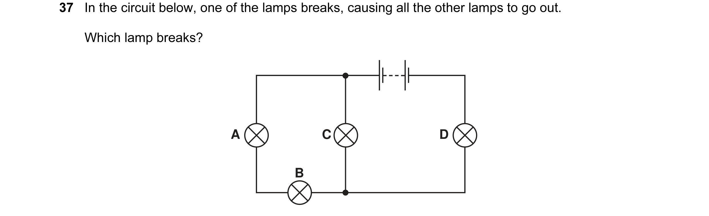
Q5 · In the circuit below, one of the lamps breaks, causing all the other lamps to go out 0653/11 Oct/Nov 2006
37 In the circuit below, one of the lamps breaks, causing all the other lamps to go out. Which lamp breaks? A C D B
1 marks
Answer: D
This question in 0653/11 Oct/Nov 2006
Q6 · An electric heater is connected to the mains using insulated copper wires 0653/11 Oct/Nov 2006
38 An electric heater is connected to the mains using insulated copper wires. The wires become very warm. What can be done to prevent so much heat being produced in the connecting wires? A Use thicker copper wires. B Use thinner copper wires. C Use thicker insulation. D Use thinner insulation.
1 marks
Answer: A
This question in 0653/11 Oct/Nov 2006
Q7 · Which circuit shows the correct use of a voltmeter in measuring the p.d 0653/11 May/June 2007
36 Which circuit shows the correct use of a voltmeter in measuring the p.d. across the resistor? A B V V C D V V
1 marks
Answer: B
This question in 0653/11 May/June 2007
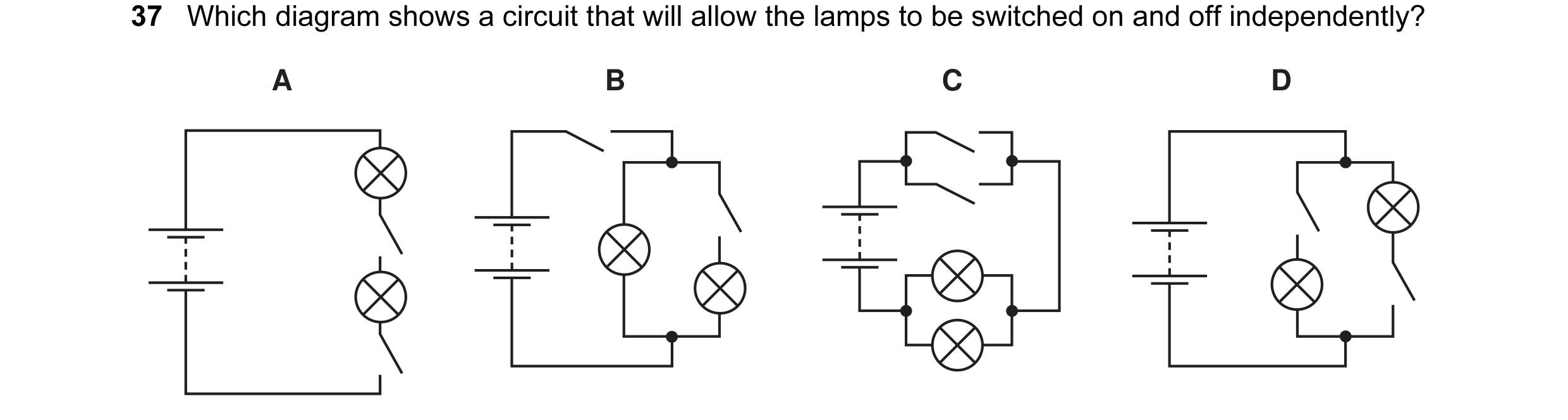
Q8 · Which diagram shows a circuit that will allow the lamps to be switched on and off… 0653/11 May/June 2007
37 Which diagram shows a circuit that will allow the lamps to be switched on and off independently? A B C D
1 marks
Answer: D
This question in 0653/11 May/June 2007
Q9 · The circuit shows a current I in a resistor of resistance R 0653/11 Oct/Nov 2007
36 The circuit shows a current I in a resistor of resistance R. 3.0 V I R Which line gives possible values of I and R? I / A R / Ω A 1.5 1.5 B 1.5 2.0 C 6.0 2.0 D 4.0 12
1 marks
Answer: B
This question in 0653/11 Oct/Nov 2007
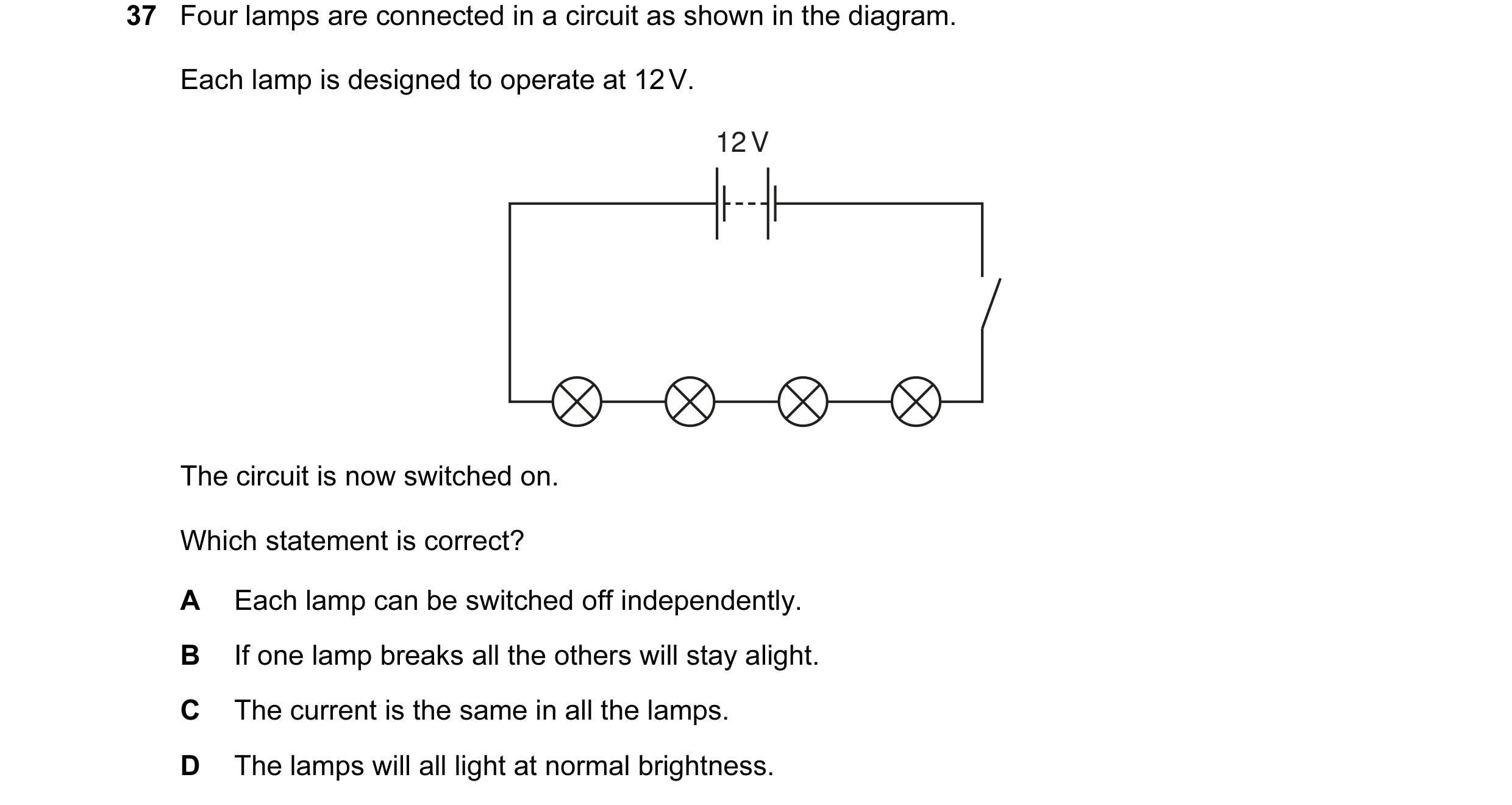
Q10 · Four lamps are connected in a circuit as shown in the diagram 0653/11 Oct/Nov 2007
37 Four lamps are connected in a circuit as shown in the diagram. Each lamp is designed to operate at 12 V. 12 V The circuit is now switched on. Which statement is correct? A Each lamp can be switched off independently. B If one lamp breaks all the others will stay alight. C The current is the same in all the lamps. D The lamps will all light at normal brightness.
1 marks
Answer: C
This question in 0653/11 Oct/Nov 2007
Q11 · In the circuit shown, the switches S1 and S2 may be open (off) or closed (on) 0653/11 May/June 2008
37 In the circuit shown, the switches S1 and S2 may be open (off) or closed (on). V + switches shown 12 V open (off) – S2 S1 Which line in the table shows the voltmeter reading for the switch positions given? S1 S2 voltmeter reading / V A open open 12 B closed closed 12 C open closed 0 D closed open 12
1 marks
Answer: B
This question in 0653/11 May/June 2008
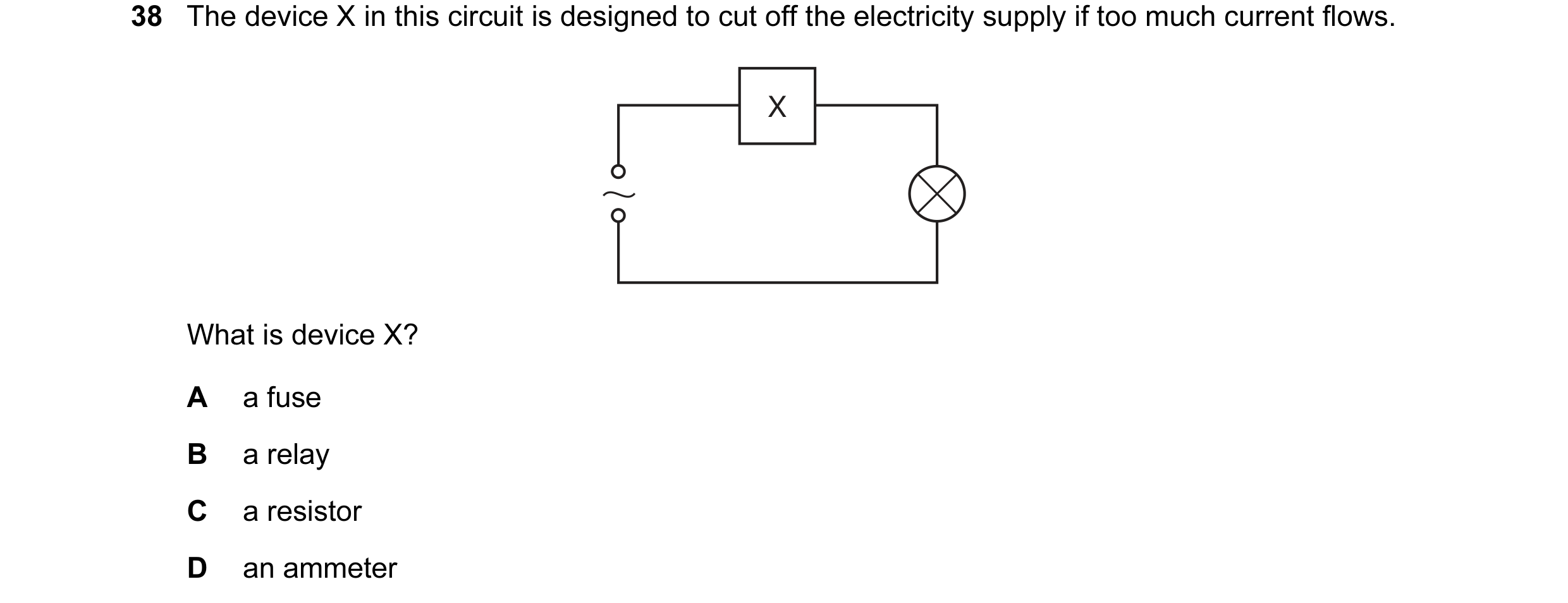
Q12 · The device X in this circuit is designed to cut off the electricity supply if too much… 0653/11 May/June 2008
38 The device X in this circuit is designed to cut off the electricity supply if too much current flows. X What is device X? A a fuse B a relay C a resistor D an ammeter
1 marks
Answer: A
This question in 0653/11 May/June 2008
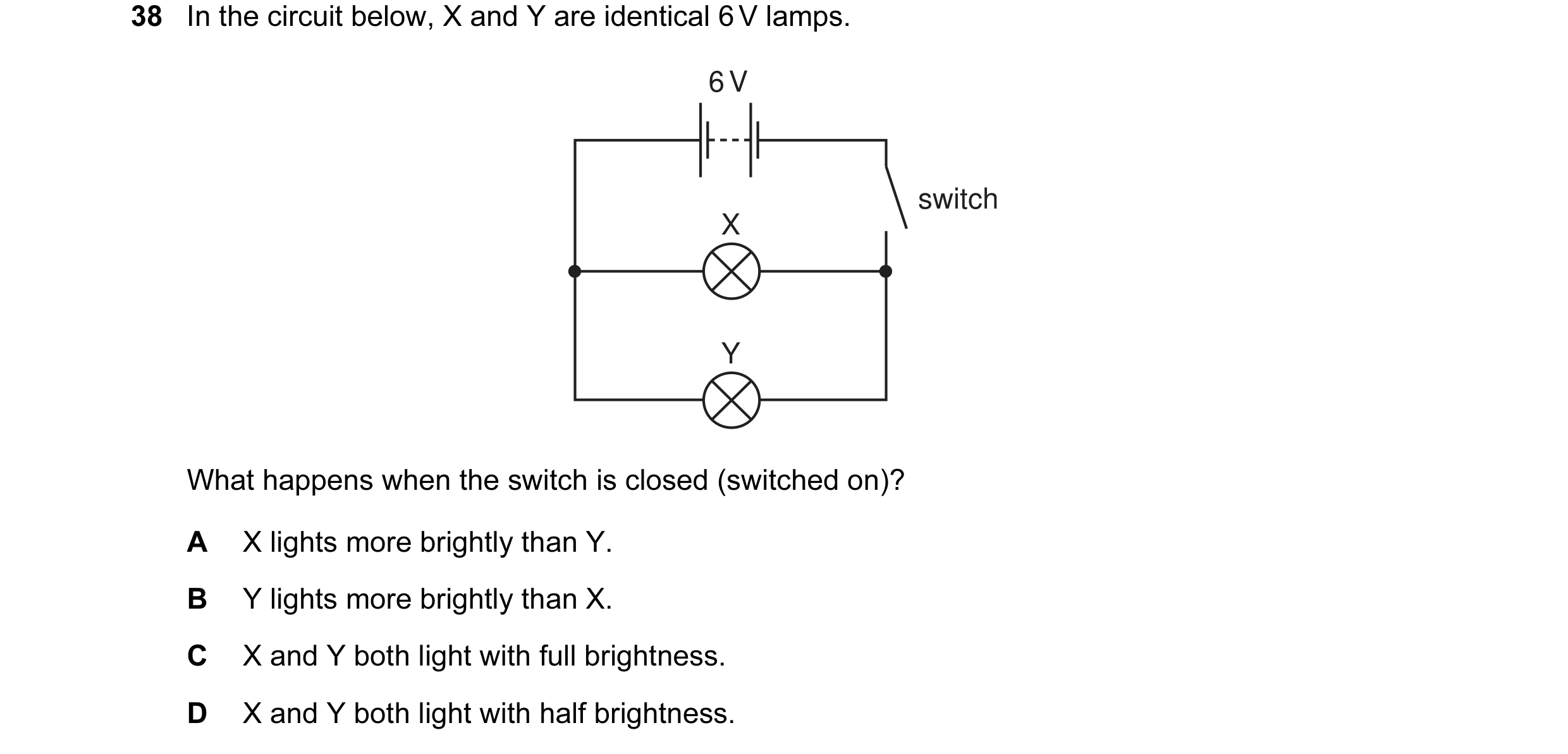
Q13 · In the circuit below, X and Y are identical 6 V lamps 0653/11 Oct/Nov 2008
38 In the circuit below, X and Y are identical 6 V lamps. 6 V switch X Y What happens when the switch is closed (switched on)? A X lights more brightly than Y. B Y lights more brightly than X. C X and Y both light with full brightness. D X and Y both light with half brightness.
1 marks
Answer: C
This question in 0653/11 Oct/Nov 2008
Q14 · Two different systems are used to transmit equal amounts of electrical power from one… 0653/11 Oct/Nov 2008
39 Two different systems are used to transmit equal amounts of electrical power from one building to another. One system uses low voltage and the other uses high voltage. Which line in the table is correct about which system wastes least energy and why? least energy wasted why A high voltage system the current in the wires is bigger B high voltage system the current in the wires is smaller C low voltage system the current in the wires is bigger D low voltage system the current in the wires is smaller
1 marks
Answer: B
This question in 0653/11 Oct/Nov 2008
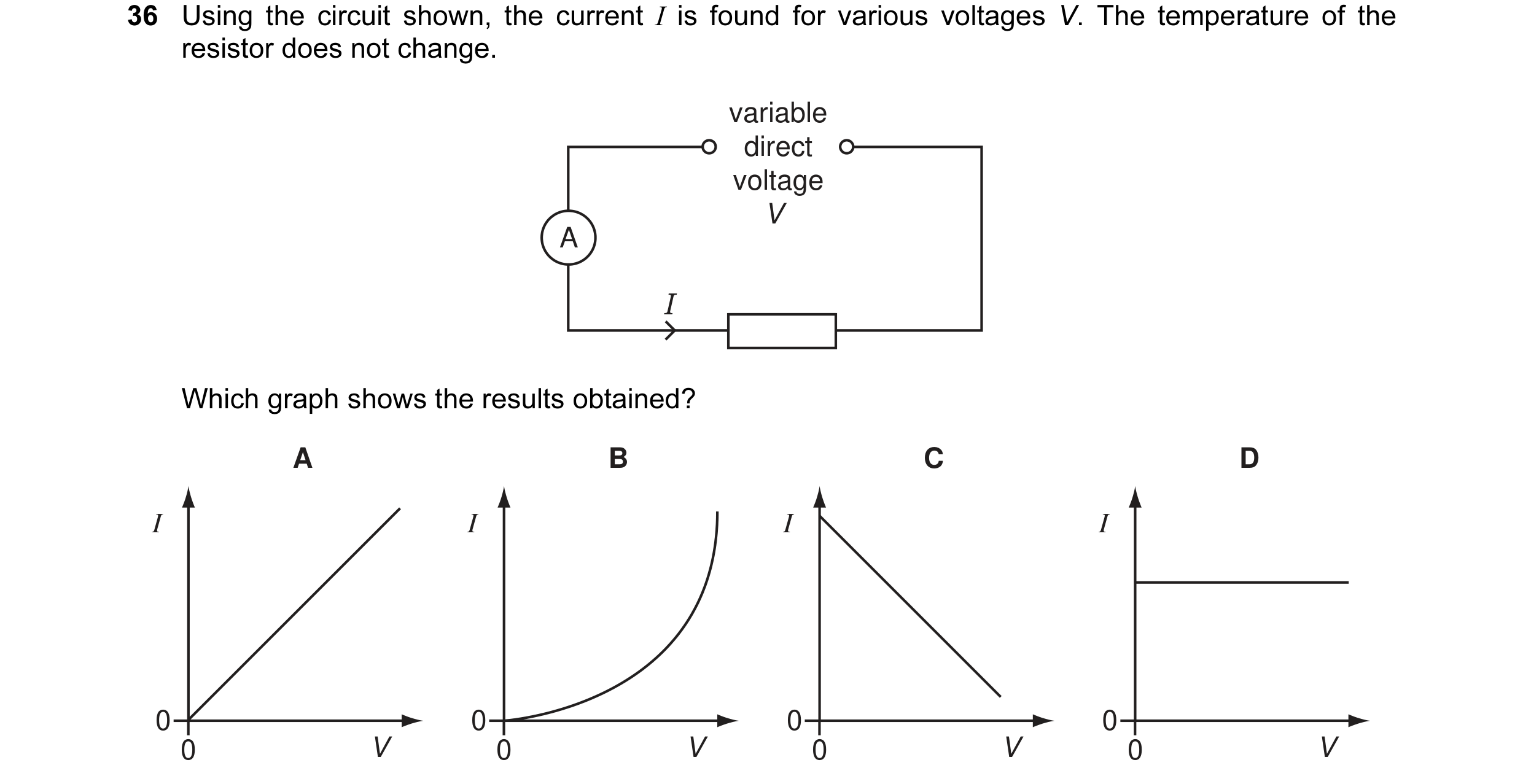
Q15 · Using the circuit shown, the current I is found for various voltages V 0653/11 May/June 2009
36 Using the circuit shown, the current I is found for various voltages V. The temperature of the resistor does not change. variable direct voltage V A I Which graph shows the results obtained? A B C D I I I I 0 0 0 0 0 V 0 V 0 V 0 V
1 marks
Answer: A
This question in 0653/11 May/June 2009
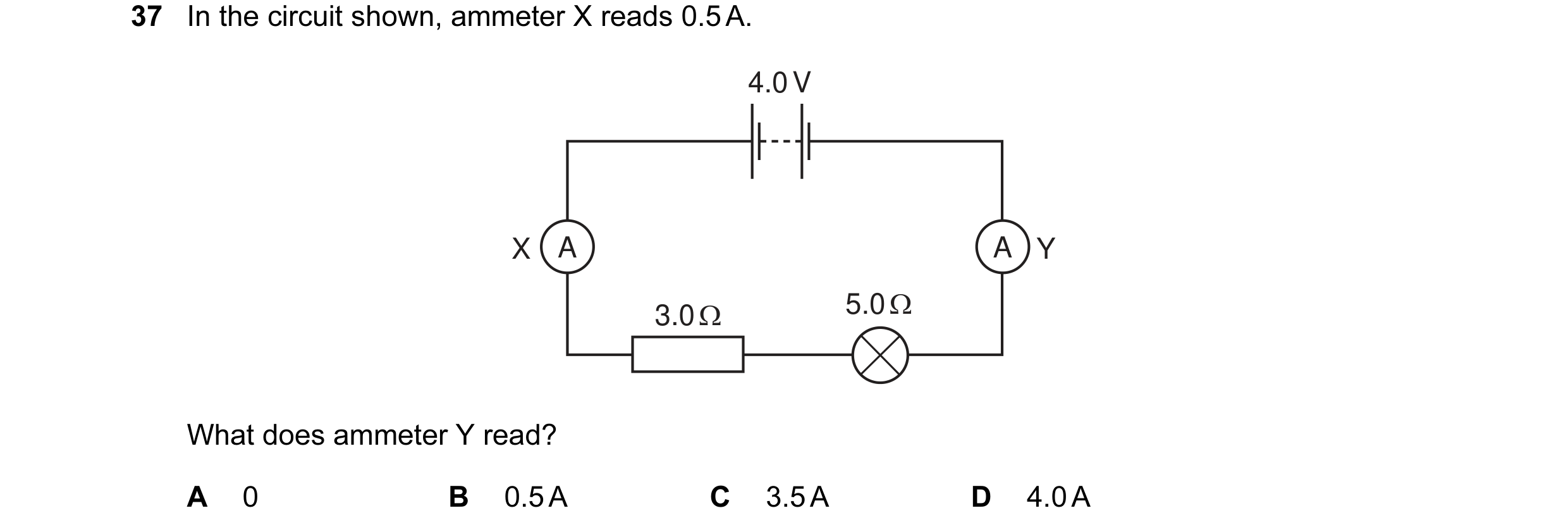
Q16 · In the circuit shown, ammeter X reads 0.5 A 0653/11 May/June 2009
37 In the circuit shown, ammeter X reads 0.5 A. 4.0 V X A A Y 3.0 Ω 5.0 Ω What does ammeter Y read? A 0 B 0.5 A C 3.5 A D 4.0 A
1 marks
Answer: B
This question in 0653/11 May/June 2009
Q17 · In the circuits shown, all the resistors are identical 0653/11 May/June 2009
38 In the circuits shown, all the resistors are identical. Which circuit has the least resistance? A B C D
1 marks
Answer: C
This question in 0653/11 May/June 2009
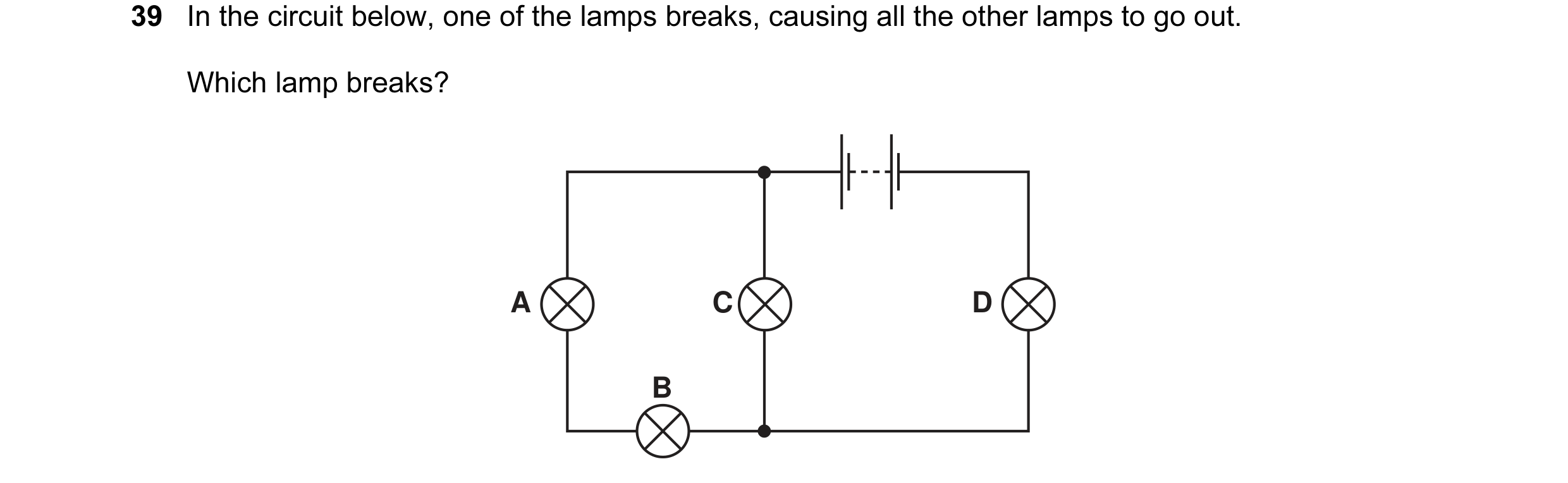
Q18 · In the circuit below, one of the lamps breaks, causing all the other lamps to go out 0653/11 May/June 2009
39 In the circuit below, one of the lamps breaks, causing all the other lamps to go out. Which lamp breaks? A C D B
1 marks
Answer: D
This question in 0653/11 May/June 2009
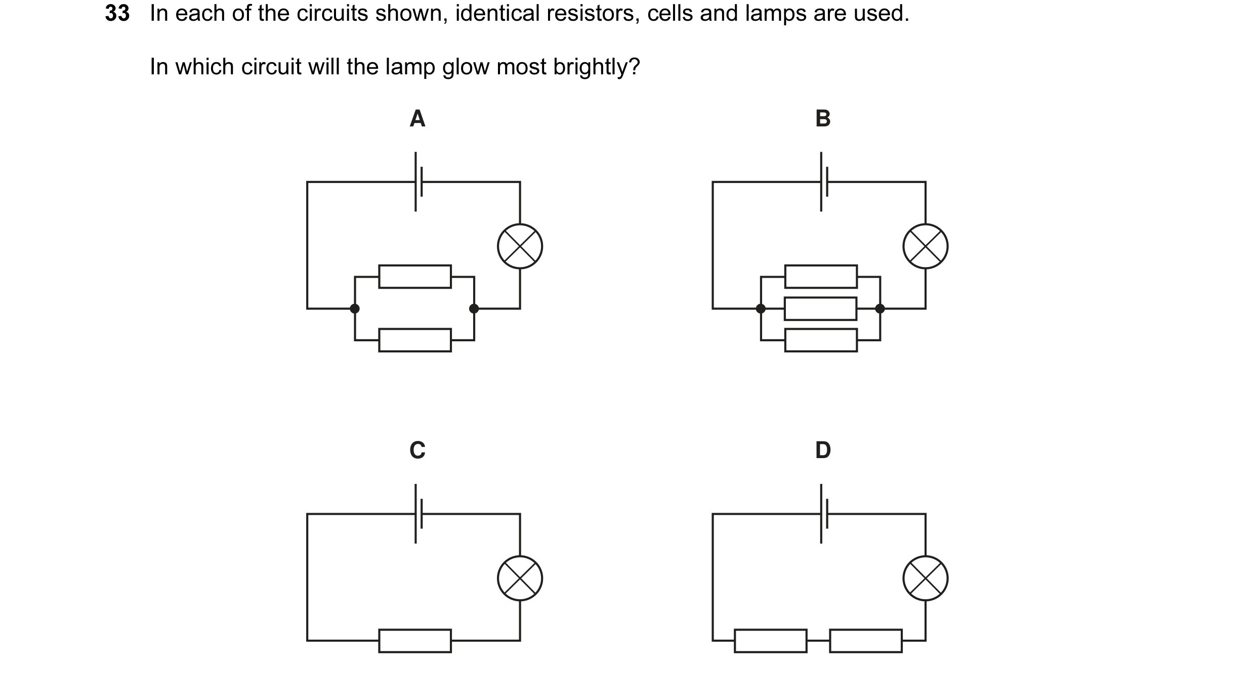
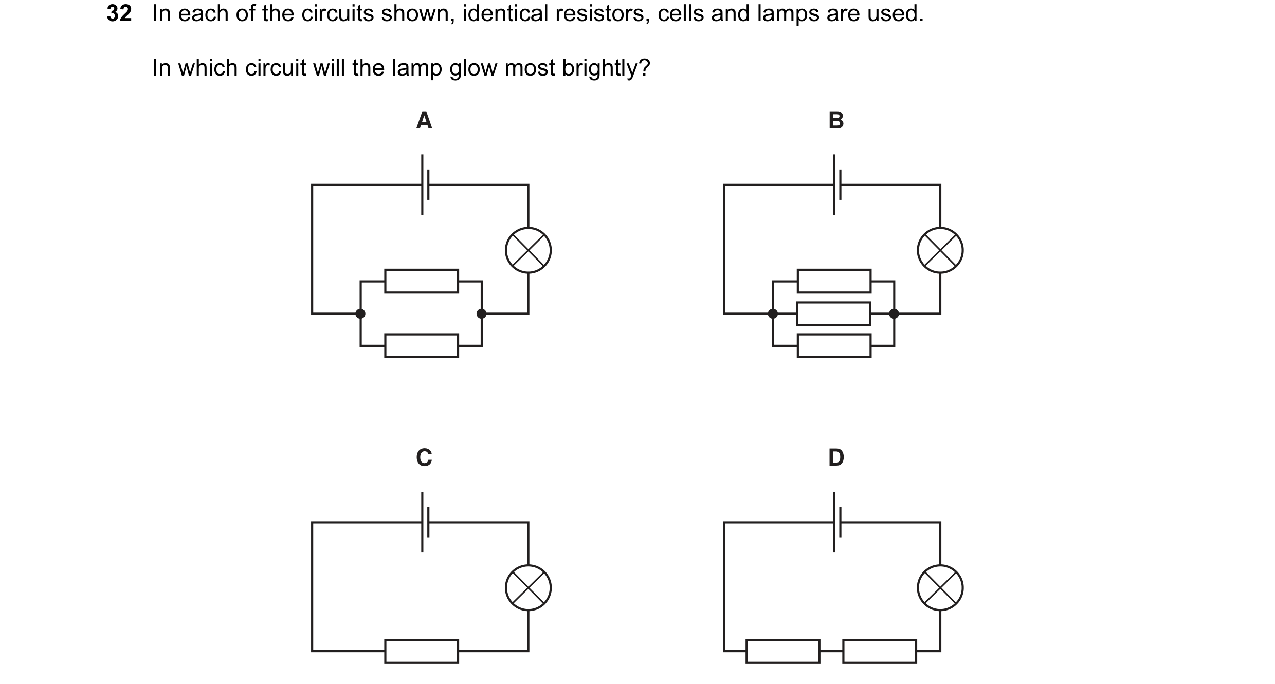
Q19 · In each of the circuits shown, identical resistors, cells and lamps are used 0653/11 May/June 2010
33 In each of the circuits shown, identical resistors, cells and lamps are used. In which circuit will the lamp glow most brightly? A B C D
1 marks
Answer: B
This question in 0653/11 May/June 2010
Q20 · In each of the circuits shown, identical resistors, cells and lamps are used 0653/12 May/June 2010
32 In each of the circuits shown, identical resistors, cells and lamps are used. In which circuit will the lamp glow most brightly? A B C D
1 marks
Answer: B
This question in 0653/12 May/June 2010
Q21 · Electrical appliances are often fitted with a fuse 0653/12 May/June 2010
33 Electrical appliances are often fitted with a fuse. What is the purpose of the fuse? A to adjust the voltage supplied to the correct value B to allow the appliance to be switched on by a small current C to cut the power supply if the appliance is used too often D to cut the power supply if the current becomes too large
1 marks
Answer: D
This question in 0653/12 May/June 2010
Q22 · In each of the circuits shown, identical resistors, cells and lamps are used 0653/13 May/June 2010
32 In each of the circuits shown, identical resistors, cells and lamps are used. In which circuit will the lamp glow most brightly? A B C D
1 marks
Answer: B
This question in 0653/13 May/June 2010
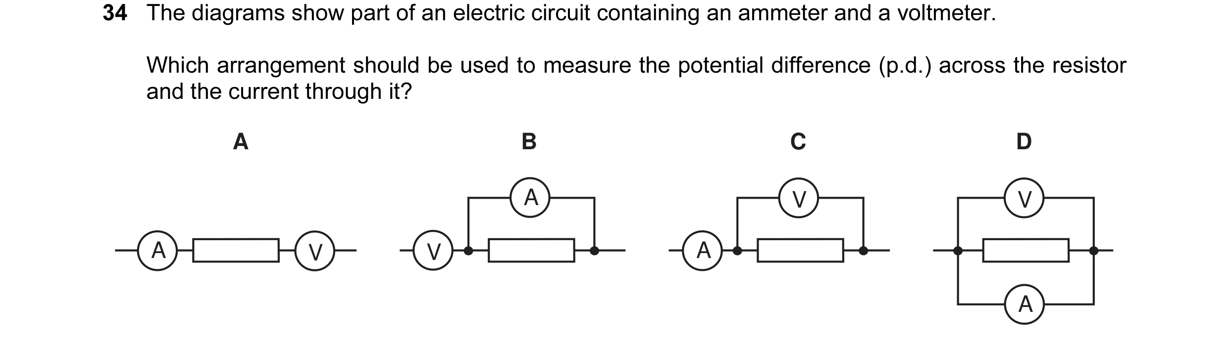
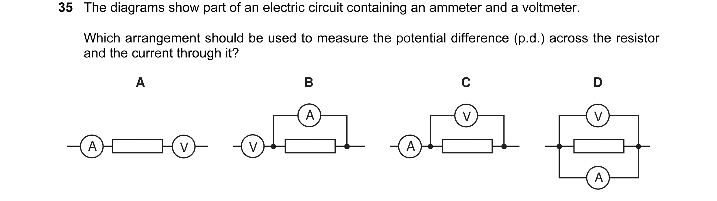
Q23 · The diagrams show part of an electric circuit containing an ammeter and a voltmeter 0653/11 Oct/Nov 2010
33 The diagrams show part of an electric circuit containing an ammeter and a voltmeter. Which arrangement should be used to measure the potential difference (p.d.) across the resistor and the current through it? A B C D A V V A V V A A
1 marks
Answer: C
This question in 0653/11 Oct/Nov 2010
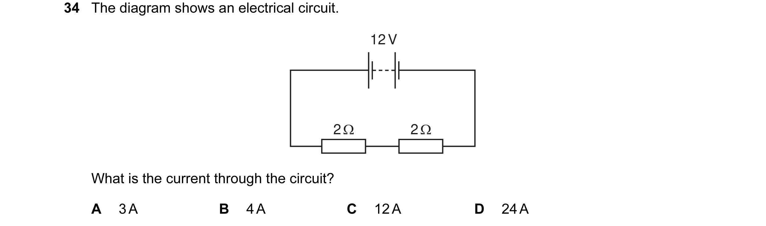
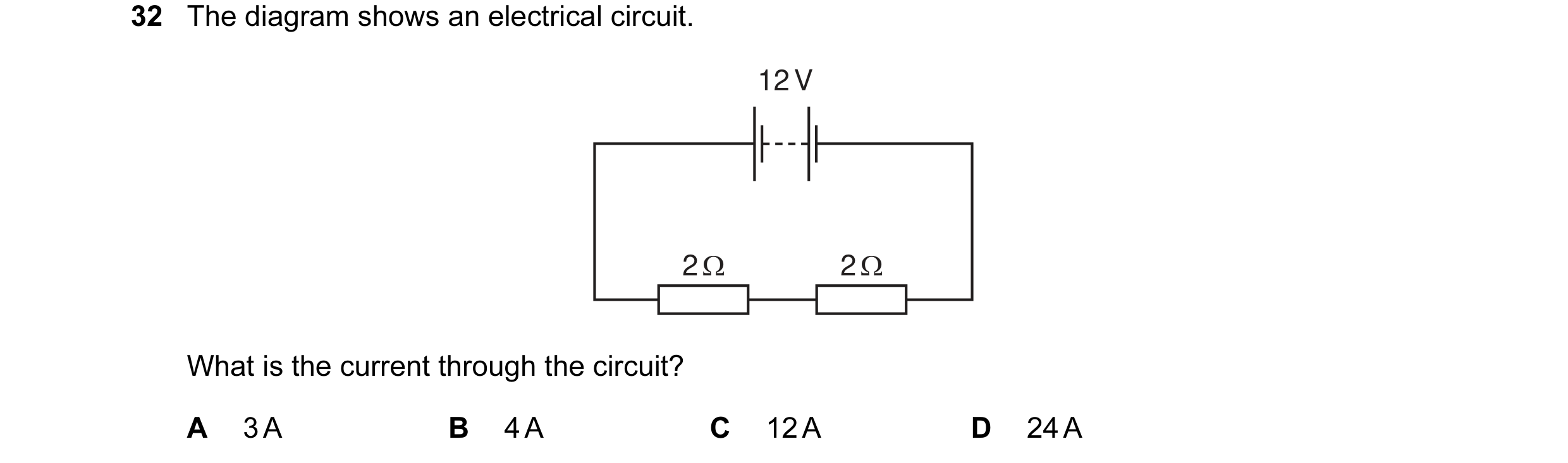
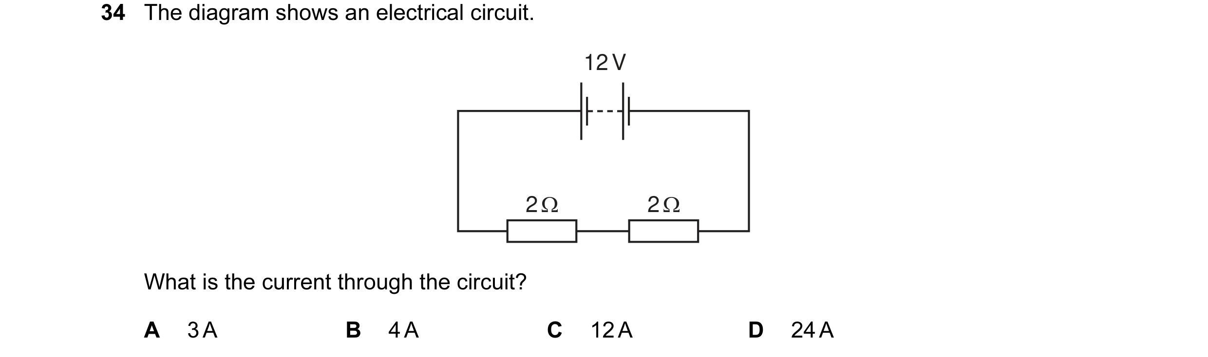
Q24 · The diagram shows an electrical circuit 0653/11 Oct/Nov 2010
34 The diagram shows an electrical circuit. 12 V 2 Ω 2 Ω What is the current through the circuit? A 3 A B 4 A C 12 A D 24 A
1 marks
Answer: A
This question in 0653/11 Oct/Nov 2010
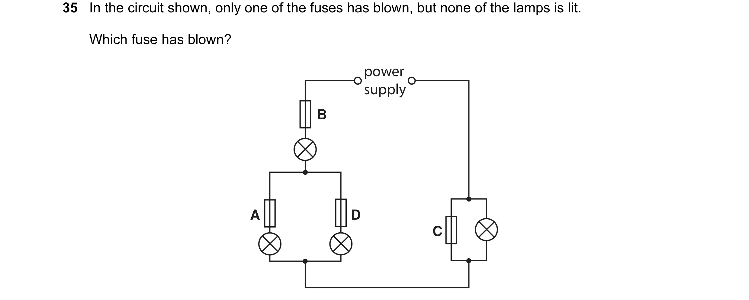
Q25 · In the circuit shown, only one of the fuses has blown, but none of the lamps is lit 0653/11 Oct/Nov 2010
35 In the circuit shown, only one of the fuses has blown, but none of the lamps is lit. Which fuse has blown? power supply B A D C
1 marks
Answer: B
This question in 0653/11 Oct/Nov 2010
Q26 · The diagram shows an electrical circuit 0653/12 Oct/Nov 2010
32 The diagram shows an electrical circuit. 12 V 2 Ω 2 Ω What is the current through the circuit? A 3 A B 4 A C 12 A D 24 A
1 marks
Answer: A
This question in 0653/12 Oct/Nov 2010
Q27 · In the circuit shown, only one of the fuses has blown, but none of the lamps is lit 0653/12 Oct/Nov 2010
33 In the circuit shown, only one of the fuses has blown, but none of the lamps is lit. Which fuse has blown? power supply B A D C
1 marks
Answer: B
This question in 0653/12 Oct/Nov 2010
Q28 · The diagrams show part of an electric circuit containing an ammeter and a voltmeter 0653/12 Oct/Nov 2010
34 The diagrams show part of an electric circuit containing an ammeter and a voltmeter. Which arrangement should be used to measure the potential difference (p.d.) across the resistor and the current through it? A B C D A V V A V V A A
1 marks
Answer: C
This question in 0653/12 Oct/Nov 2010
Q29 · The diagram shows an electrical circuit 0653/13 Oct/Nov 2010
34 The diagram shows an electrical circuit. 12 V 2 Ω 2 Ω What is the current through the circuit? A 3 A B 4 A C 12 A D 24 A
1 marks
Answer: A
This question in 0653/13 Oct/Nov 2010
Q30 · The diagrams show part of an electric circuit containing an ammeter and a voltmeter 0653/13 Oct/Nov 2010
35 The diagrams show part of an electric circuit containing an ammeter and a voltmeter. Which arrangement should be used to measure the potential difference (p.d.) across the resistor and the current through it? A B C D A V V A V V A A
1 marks
Answer: C
This question in 0653/13 Oct/Nov 2010
Q31 · In the circuit shown, only one of the fuses has blown, but none of the lamps is lit 0653/13 Oct/Nov 2010
36 In the circuit shown, only one of the fuses has blown, but none of the lamps is lit. Which fuse has blown? power supply B A D C
1 marks
Answer: B
This question in 0653/13 Oct/Nov 2010
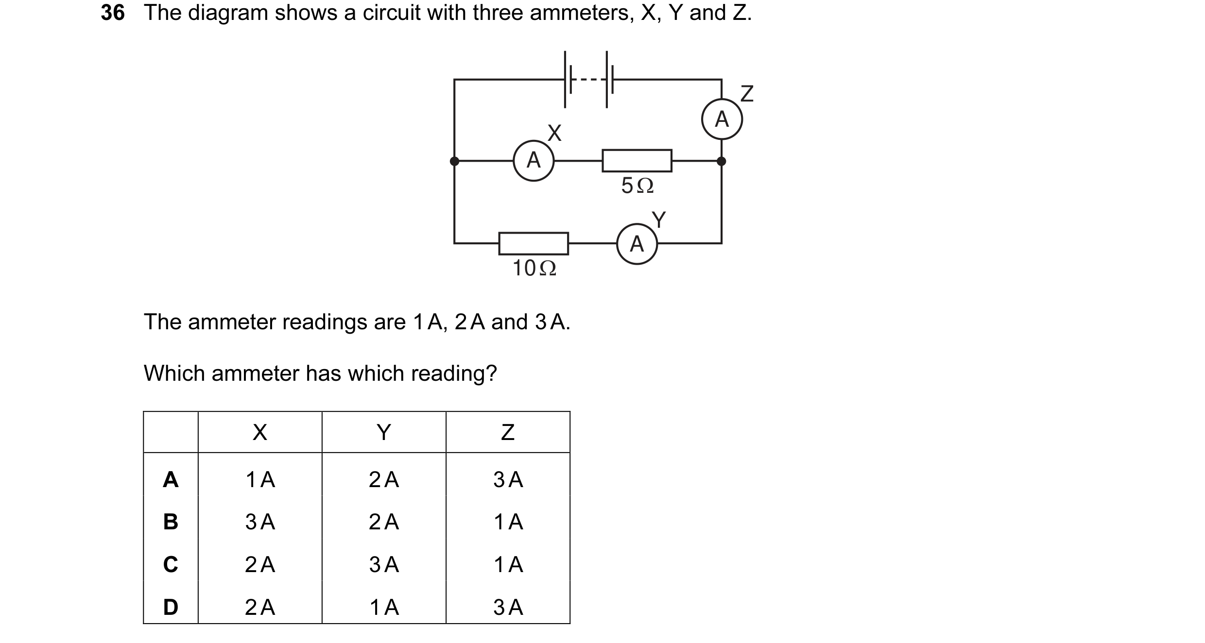
Q32 · The diagram shows a circuit with three ammeters, X, Y and Z 0653/11 May/June 2011
36 The diagram shows a circuit with three ammeters, X, Y and Z. Z A X A 5 Ω Y A 10 Ω The ammeter readings are 1 A, 2 A and 3 A. Which ammeter has which reading? X Y Z A 1 A 2 A 3 A B 3 A 2 A 1 A C 2 A 3 A 1 A D 2 A 1 A 3 A
1 marks
Answer: D
This question in 0653/11 May/June 2011
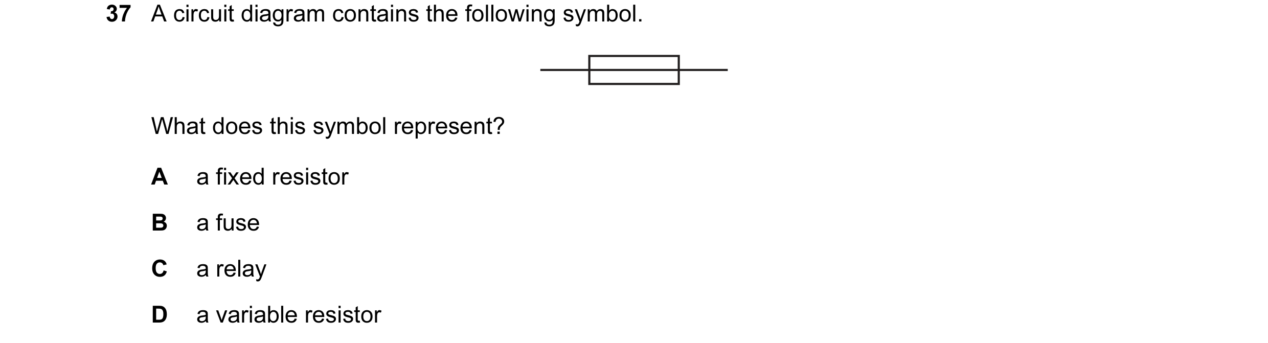
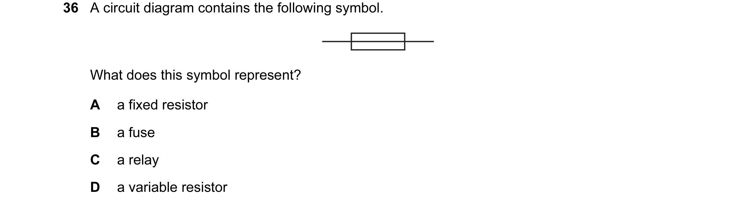
Q33 · A circuit diagram contains the following symbol 0653/11 May/June 2011
37 A circuit diagram contains the following symbol. What does this symbol represent? A a fixed resistor B a fuse C a relay D a variable resistor
1 marks
Answer: B
This question in 0653/11 May/June 2011
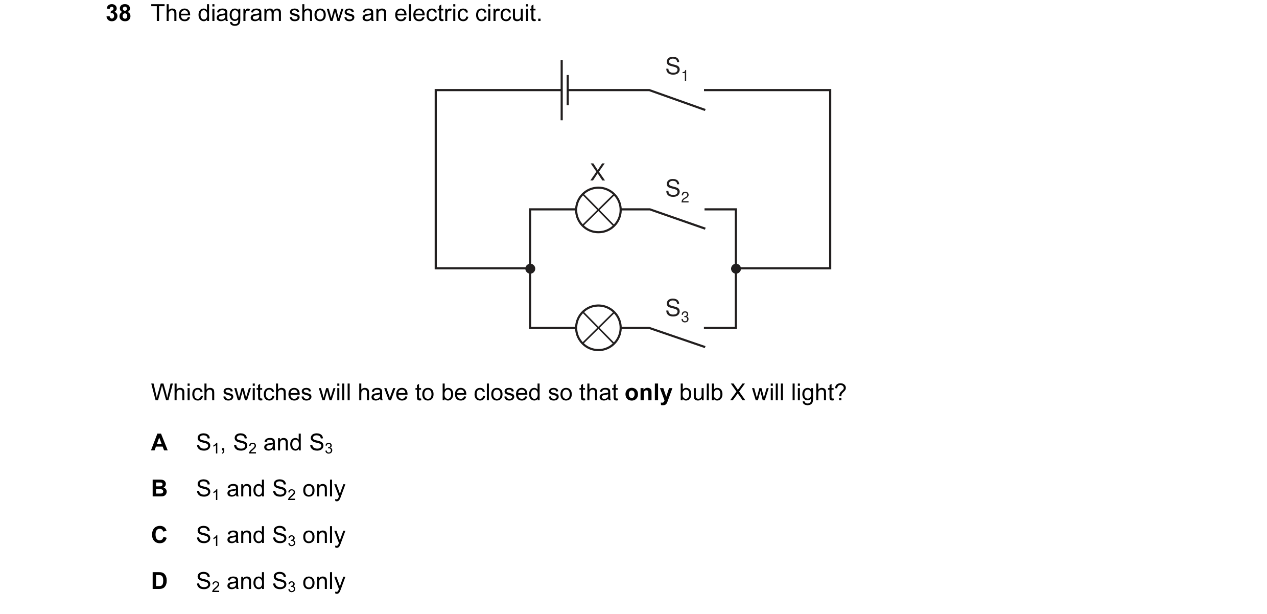
Q34 · The diagram shows an electric circuit 0653/11 May/June 2011
38 The diagram shows an electric circuit. S1 X S2 S3 Which switches will have to be closed so that only bulb X will light? A S1, S2 and S3 B S1 and S2 only C S1 and S3 only D S2 and S3 only
1 marks
Answer: B
This question in 0653/11 May/June 2011
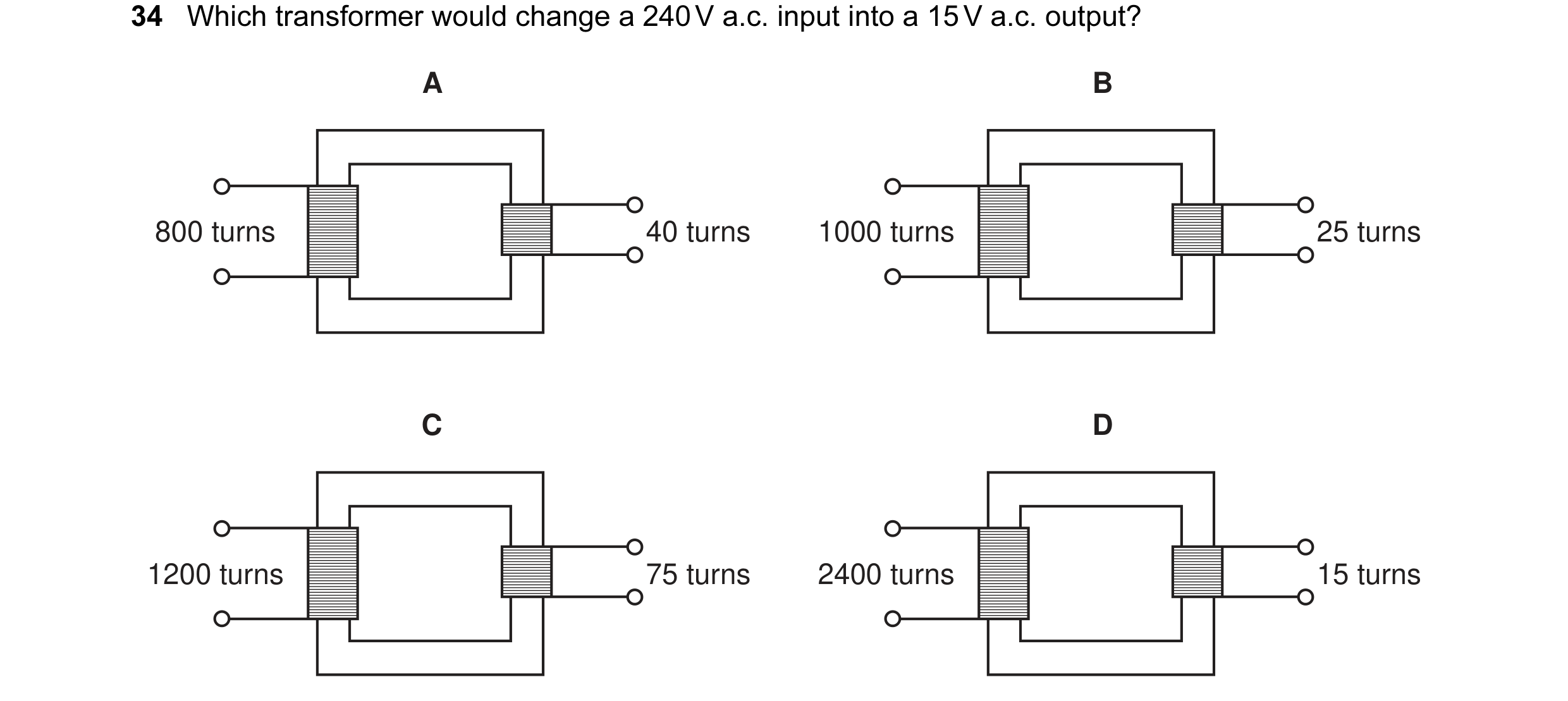
Q35 · Which transformer would change a 240 V a.c 0653/12 May/June 2011
34 Which transformer would change a 240 V a.c. input into a 15 V a.c. output? A B 800 turns 40 turns 1000 turns 25 turns C D 1200 turns 75 turns 2400 turns 15 turns
1 marks
Answer: C
This question in 0653/12 May/June 2011
Q36 · A circuit diagram contains the following symbol 0653/12 May/June 2011
36 A circuit diagram contains the following symbol. What does this symbol represent? A a fixed resistor B a fuse C a relay D a variable resistor
1 marks
Answer: B
This question in 0653/12 May/June 2011
Q37 · The diagram shows a circuit with three ammeters, X, Y and Z 0653/12 May/June 2011
37 The diagram shows a circuit with three ammeters, X, Y and Z. Z A X A 5 Ω Y A 10 Ω The ammeter readings are 1 A, 2 A and 3 A. Which ammeter has which reading? X Y Z A 1 A 2 A 3 A B 3 A 2 A 1 A C 2 A 3 A 1 A D 2 A 1 A 3 A
1 marks
Answer: D
This question in 0653/12 May/June 2011
Q38 · The diagram shows an electric circuit 0653/12 May/June 2011
38 The diagram shows an electric circuit. S1 X S2 S3 Which switches will have to be closed so that only bulb X will light? A S1, S2 and S3 B S1 and S2 only C S1 and S3 only D S2 and S3 only
1 marks
Answer: B
This question in 0653/12 May/June 2011
Q39 · Two identical resistors R1 and R2 connected in series in a circuit 0653/11 Oct/Nov 2011
34 Diagram 1 shows two identical resistors R1 and R2 connected in series in a circuit. R2 is then removed, as shown in diagram 2. diagram 1 diagram 2 A A R1 R2 R1 V V How do the readings on the ammeter and the voltmeter change when R2 is removed? ammeter voltmeter A decreases decreases B decreases increases C increases decreases D increases increases
1 marks
Answer: D
This question in 0653/11 Oct/Nov 2011
Q40 · Two identical resistors R1 and R2 connected in series in a circuit 0653/12 Oct/Nov 2011
34 Diagram 1 shows two identical resistors R1 and R2 connected in series in a circuit. R2 is then removed, as shown in diagram 2. diagram 1 diagram 2 A A R1 R2 R1 V V How do the readings on the ammeter and the voltmeter change when R2 is removed? ammeter voltmeter A decreases decreases B decreases increases C increases decreases D increases increases
1 marks
Answer: D
This question in 0653/12 Oct/Nov 2011
Q41 · Two identical resistors R1 and R2 connected in series in a circuit 0653/13 Oct/Nov 2011
35 Diagram 1 shows two identical resistors R1 and R2 connected in series in a circuit. R2 is then removed, as shown in diagram 2. diagram 1 diagram 2 A A R1 R2 R1 V V How do the readings on the ammeter and the voltmeter change when R2 is removed? ammeter voltmeter A decreases decreases B decreases increases C increases decreases D increases increases
1 marks
Answer: D
This question in 0653/13 Oct/Nov 2011
Q42 · The diagram represents a circuit which includes a battery, an ammeter, a voltmeter and a… 0653/11 May/June 2012
38 The diagram represents a circuit which includes a battery, an ammeter, a voltmeter and a variable resistor. A V What happens to the readings on the meters as the resistance of the variable resistor is increased? ammeter reading voltmeter reading A decreases decreases B decreases stays constant C increases decreases D increases stays constant
1 marks
This question in 0653/11 May/June 2012
Q43 · The diagram shows a circuit 0653/11 May/June 2012
40 The diagram shows a circuit. S What happens to the lamp when switch S is closed? A It does not light at all. B It lights and then blows. C It lights more brightly. D It lights more dimly.
1 marks
This question in 0653/11 May/June 2012
Q44 · A battery is connected to a resistor 0653/12 May/June 2012
38 A battery is connected to a resistor. current Which changes to potential difference across the resistor, and to the resistance of the resistor, will produce the smallest current? potential resistance difference A decrease decrease B decrease increase C increase decrease D increase increase
1 marks
Answer: B
This question in 0653/12 May/June 2012
Q45 · How are lamps usually connected in a lighting circuit, and what is one advantage of this? 0653/12 May/June 2012
40 How are lamps usually connected in a lighting circuit, and what is one advantage of this? how lamps are advantage connected A in parallel they each receive the full supply voltage B in parallel they share the supply voltage equally C in series they each receive the full supply voltage D in series they share the supply voltage equally
1 marks
Answer: A
This question in 0653/12 May/June 2012
Q46 · A battery is connected to a resistor 0653/13 May/June 2012
38 A battery is connected to a resistor. current Which changes to potential difference across the resistor, and to the resistance of the resistor, will produce the smallest current? potential resistance difference A decrease decrease B decrease increase C increase decrease D increase increase
1 marks
Answer: B
This question in 0653/13 May/June 2012
Q47 · How are lamps usually connected in a lighting circuit, and what is one advantage of this? 0653/13 May/June 2012
40 How are lamps usually connected in a lighting circuit, and what is one advantage of this? how lamps are advantage connected A in parallel they each receive the full supply voltage B in parallel they share the supply voltage equally C in series they each receive the full supply voltage D in series they share the supply voltage equally
1 marks
Answer: A
This question in 0653/13 May/June 2012
Q48 · The circuit shows a mains supply connected to a heater 0653/12 May/June 2013
39 The circuit shows a mains supply connected to a heater. P Q live mains heater supply neutral S R Between which labelled points should a fuse be connected in the circuit? A between P and Q B between Q and R C between R and S D between S and P
1 marks
Answer: A
This question in 0653/12 May/June 2013
Q49 · Four ammeters V, W, X and Y are connected in the circuit shown 0653/12 May/June 2013
40 Four ammeters V, W, X and Y are connected in the circuit shown. V W A A Y X A A Which ammeters have the same reading as each other? A V and W only B V and Y only C X and Y only D V, W, X and Y
1 marks
Answer: D
This question in 0653/12 May/June 2013
Q50 · An electrician wishes to connect three lamps in a circuit so that each lamp can be… 0653/13 May/June 2013
39 An electrician wishes to connect three lamps in a circuit so that each lamp can be switched on and off separately. Which circuit should be used? A B C D
1 marks
Answer: B
This question in 0653/13 May/June 2013
Q51 · A student wishes to find the resistance of resistor R 0653/13 May/June 2013
40 A student wishes to find the resistance of resistor R. The diagrams show four possible circuits which the student could use. Which circuit can be used to find the resistance of resistor R? A B R R V A A V C D R A V R V A
1 marks
Answer: B
This question in 0653/13 May/June 2013
Q52 · There is an electric current in the circuit shown 0653/11 Oct/Nov 2013
38 There is an electric current in the circuit shown. Which two changes will each increase the current? change 1 change 2 A decrease the voltage of the battery decrease the resistance of the resistor B decrease the voltage of the battery increase the resistance of the resistor C increase the voltage of the battery decrease the resistance of the resistor D increase the voltage of the battery increase the resistance of the resistor
1 marks
Answer: C
This question in 0653/11 Oct/Nov 2013
Q53 · The circuit shown contains four labelled switches 0653/11 Oct/Nov 2013
40 The circuit shown contains four labelled switches. All the switches are closed. Which switch can be opened without changing the brightness of either bulb? A B C D
1 marks
Answer: B
This question in 0653/11 Oct/Nov 2013
Q54 · The circuit shown contains four labelled switches 0653/12 Oct/Nov 2013
40 The circuit shown contains four labelled switches. All the switches are closed. Which switch can be opened without changing the brightness of either bulb? A B C D
1 marks
Answer: B
This question in 0653/12 Oct/Nov 2013
Q55 · A student wishes to measure the potential difference across a resistor 0653/13 Oct/Nov 2013
38 A student wishes to measure the potential difference across a resistor. The circuits show two different positions in which a meter can be connected. position X position Y What meter is used, and where is it connected in the circuit? A an ammeter in position X B an ammeter in position Y C a voltmeter in position X D a voltmeter in position Y
1 marks
Answer: D
This question in 0653/13 Oct/Nov 2013
Q56 · A circuit contains two lamps and a variable resistor 0653/13 Oct/Nov 2013
40 A circuit contains two lamps and a variable resistor. lamp 1 lamp 2 The resistance of the variable resistor is increased. What happens to the brightness of lamp 1 and what happens to the brightness of lamp 2? brightness of lamp 1 brightness of lamp 2 A decreases decreases B decreases increases C no change decreases D no change increases
1 marks
Answer: A
This question in 0653/13 Oct/Nov 2013
Q57 · Which circuit can be used to determine the resistance of resistor R? 0653/11 May/June 2014
39 Which circuit can be used to determine the resistance of resistor R? A B R R A A V V C D R R V V A A
1 marks
Answer: A
This question in 0653/11 May/June 2014
Q58 · The diagram shows a circuit containing three lamps P, Q and R 0653/11 May/June 2014
40 The diagram shows a circuit containing three lamps P, Q and R. All the lamps are lit. P Q R The fuse melts (blows). Which lamps go out? A P and Q B P only C Q and R D Q only
1 marks
Answer: C
This question in 0653/11 May/June 2014
Q59 · A circuit diagram contains the following symbol 0653/12 May/June 2014
39 A circuit diagram contains the following symbol. What does this symbol represent? A a fixed resistor B a fuse C a lamp D a variable resistor
1 marks
Answer: B
This question in 0653/12 May/June 2014
Q60 · In the circuit shown the switch is open 0653/12 May/June 2014
40 In the circuit shown the switch is open. A A student closes the switch. What happens to the ammeter reading, and what happens to the total resistance of the circuit? ammeter reading total resistance A decreases decreases B decreases increases C increases decreases D increases increases
1 marks
Answer: C
This question in 0653/12 May/June 2014
Q61 · The diagram shows a circuit containing three lamps P, Q and R 0653/13 May/June 2014
39 The diagram shows a circuit containing three lamps P, Q and R. All the lamps are lit. P Q R The fuse melts (blows). Which lamps go out? A P and Q B P only C Q and R D Q only
1 marks
Answer: C
This question in 0653/13 May/June 2014
Q62 · Which circuit can be used to determine the resistance of resistor R? 0653/13 May/June 2014
40 Which circuit can be used to determine the resistance of resistor R? A B R R A A V V C D R R V V A A
1 marks
Answer: A
This question in 0653/13 May/June 2014
Q63 · Two resistors of resistance 6.0 ohms and 3.0 ohms are combined first in series and then… 0653/11 Oct/Nov 2014
40 Two resistors of resistance 6.0 ohms and 3.0 ohms are combined first in series and then in parallel. 6.0 Ω 6.0 Ω 3.0 Ω 3.0 Ω arrangement 1 arrangement 2 Which row shows the resistance of arrangement 1 and the resistance of arrangement 2? resistance of resistance of arrangement 1 arrangement 2 A 9 Ω 2 Ω B 9 Ω 9 Ω C 18 Ω 2 Ω D 18 Ω 9 Ω
1 marks
Answer: A
This question in 0653/11 Oct/Nov 2014
Q64 · Two resistors of resistance 6.0 ohms and 3.0 ohms are combined first in series and then… 0653/12 Oct/Nov 2014
39 Two resistors of resistance 6.0 ohms and 3.0 ohms are combined first in series and then in parallel. 6.0 Ω 6.0 Ω 3.0 Ω 3.0 Ω arrangement 1 arrangement 2 Which row shows the resistance of arrangement 1 and the resistance of arrangement 2? resistance of resistance of arrangement 1 arrangement 2 A 9 Ω 2 Ω B 9 Ω 9 Ω C 18 Ω 2 Ω D 18 Ω 9 Ω
1 marks
Answer: A
This question in 0653/12 Oct/Nov 2014
Q65 · A circuit is set up to pass a current through a solution 0653/13 Oct/Nov 2014
20 A circuit is set up to pass a current through a solution. What is added to the circuit to show that a current flows? A an anode B a battery C a cathode D a lamp
1 marks
Answer: D
This question in 0653/13 Oct/Nov 2014
Q66 · The diagram shows an electric circuit 0653/13 Oct/Nov 2014
38 The diagram shows an electric circuit. S1 X S2 Y S3 Which switches should be closed so that lamp X is lit but lamp Y is not lit? A S1, S2 and S3 B S1 and S2 only C S1 and S3 only D S2 and S3 only
1 marks
Answer: B
This question in 0653/13 Oct/Nov 2014
Q67 · Two identical resistors R1 and R2 connected in series in a circuit 0653/13 Oct/Nov 2014
40 Diagram 1 shows two identical resistors R1 and R2 connected in series in a circuit. In diagram 2, R2 has been removed. A A R1 R2 R1 V V diagram 1 diagram 2 What has happened to the reading on the ammeter and what has happened to the reading on the voltmeter in diagram 2? ammeter voltmeter A decreases decreases B decreases increases C increases decreases D increases increases
1 marks
Answer: D
This question in 0653/13 Oct/Nov 2014
Q68 · A voltmeter and an ammeter are used to determine the resistance of a lamp 0653/11 May/June 2015
39 A voltmeter and an ammeter are used to determine the resistance of a lamp. Which circuit shows the meters connected to take the necessary measurements? A B A V V A C D V A A V
1 marks
Answer: A
This question in 0653/11 May/June 2015
Q69 · The diagram shows a circuit with four identical bulbs P, Q, R and S 0653/11 May/June 2015
40 The diagram shows a circuit with four identical bulbs P, Q, R and S. P Q R S Which statement about the brightness of the bulbs is correct? A P is the same brightness as Q. B P is the same brightness as S. C Q is brighter than S. D R is brighter than P.
1 marks
Answer: B
This question in 0653/11 May/June 2015
Q70 · A student connects a battery to a lamp 0653/12 May/June 2015
39 A student connects a battery to a lamp. She wishes to measure the current in the lamp and the potential difference across the lamp. Which circuit is used to do this? A B C D V A A A V V A V
1 marks
Answer: D
This question in 0653/12 May/June 2015
Q71 · In the circuit shown, the switch is open 0653/12 May/June 2015
40 In the circuit shown, the switch is open. What happens to the lamp when the switch is closed? A It becomes brighter. B It becomes dimmer. C It becomes dimmer at first, then brighter. D Its brightness does not change.
1 marks
Answer: A
This question in 0653/12 May/June 2015
Q72 · An air conditioner and a television are both connected to the same electrical circuit 0653/13 May/June 2015
38 An air conditioner and a television are both connected to the same electrical circuit. X power air television supply conditioner The current in the air conditioner is 9.0 A and the current in the television is 2.0 A. Several different fuses are available. Which fuse should be connected at X? A 1 A B 3 A C 7 A D 13 A
1 marks
Answer: D
This question in 0653/13 May/June 2015
Q73 · A student wishes to determine the resistance of a resistor 0653/13 May/June 2015
39 A student wishes to determine the resistance of a resistor. He sets up the circuit shown. A Y X V Which statement about the circuit is true? A The ammeter and the voltmeter should change places. B The circuit is correct. C The voltmeter should be in position X. D The voltmeter should be in position Y.
1 marks
Answer: B
This question in 0653/13 May/June 2015
Q74 · The diagrams show different arrangements of identical resistors 0653/13 May/June 2015
40 The diagrams show different arrangements of identical resistors. Which arrangement has the least resistance? A B C D
1 marks
Answer: C
This question in 0653/13 May/June 2015
Q75 · The circuit diagram includes two resistors connected in parallel 0653/11 Oct/Nov 2015
39 The circuit diagram includes two resistors connected in parallel. wire P wire S A wire Q 2 Ω 4 Ω wire R Which statement is correct? A The current in wire P is equal to the current in wire Q. B The current in wire P is greater than the current in wire R. C The current in wire Q is greater than the current in wire S. D The current in wire R is equal to the current in wire S.
1 marks
Answer: B
This question in 0653/11 Oct/Nov 2015
Q76 · Two identical lamps P and Q are connected in a circuit as shown in the diagram 0653/11 Oct/Nov 2015
40 Two identical lamps P and Q are connected in a circuit as shown in the diagram. P Q The circuit is now switched on. Which statement is correct? A Each lamp can be switched off independently. B If lamp Q breaks, lamp P stays alight. C Lamp P is brighter than lamp Q. D The current is the same in both lamps.
1 marks
Answer: D
This question in 0653/11 Oct/Nov 2015
Q77 · The diagrams show four arrangements of resistors 0653/12 Oct/Nov 2015
39 The diagrams show four arrangements of resistors. Which arrangement has the smallest total resistance? A B 4 Ω 2 Ω 2 Ω 4 Ω C D 4 Ω 4 Ω 4 Ω
1 marks
Answer: A
This question in 0653/12 Oct/Nov 2015
Q78 · Two identical lamps P and Q are connected in a circuit as shown in the diagram 0653/12 Oct/Nov 2015
40 Two identical lamps P and Q are connected in a circuit as shown in the diagram. P Q The circuit is now switched on. Which statement is correct? A Each lamp can be switched off independently. B If lamp Q breaks, lamp P stays alight. C Lamp P is brighter than lamp Q. D The current is the same in both lamps.
1 marks
Answer: D
This question in 0653/12 Oct/Nov 2015
Q79 · The diagram shows a circuit with three ammeters X, Y and Z 0653/13 Oct/Nov 2015
39 The diagram shows a circuit with three ammeters X, Y and Z. A X Y A Z A Which set of readings on the ammeters is possible? X Y Z A 2 A 3 A 5 A B 3 A 2 A 5 A C 3 A 3 A 3 A D 5 A 2 A 3 A
1 marks
Answer: D
This question in 0653/13 Oct/Nov 2015
Q80 · Two identical lamps P and Q are connected in a circuit as shown in the diagram 0653/13 Oct/Nov 2015
40 Two identical lamps P and Q are connected in a circuit as shown in the diagram. P Q The circuit is now switched on. Which statement is correct? A Each lamp can be switched off independently. B If lamp Q breaks, lamp P stays alight. C Lamp P is brighter than lamp Q. D The current is the same in both lamps.
1 marks
Answer: D
This question in 0653/13 Oct/Nov 2015
Q81 · A battery is connected to a resistor 0653/11 May/June 2016
38 A battery is connected to a resistor. current Which changes to the resistance of the resistor, and to the potential difference across the resistor, must produce a smaller current? potential resistance difference A decrease decrease B decrease increase C increase decrease D increase increase
1 marks
Answer: C
This question in 0653/11 May/June 2016
Q82 · The circuit shown contains a component X and two meters Y and Z 0653/11 May/June 2016
40 The circuit shown contains a component X and two meters Y and Z. meter Y X meter Z Which unit is used when stating the value of X, and which units are used when stating the readings on Y and Z? X Y Z A amp ohm volt B amp volt ohm C ohm amp volt D ohm volt amp
1 marks
Answer: D
This question in 0653/11 May/June 2016
Q83 · A battery is connected to a resistor 0653/12 May/June 2016
38 A battery is connected to a resistor. current Which changes to the resistance of the resistor, and to the potential difference across the resistor, must produce a smaller current? potential resistance difference A decrease decrease B decrease increase C increase decrease D increase increase
1 marks
Answer: C
This question in 0653/12 May/June 2016
Q84 · In the circuit shown, three identical resistors are connected with four ammeters P, Q, R… 0653/12 May/June 2016
40 In the circuit shown, three identical resistors are connected with four ammeters P, Q, R and S. R A A A P S A Q Which two ammeters have the same reading? A P and Q B P and R C P and S D Q and S
1 marks
Answer: C
This question in 0653/12 May/June 2016
Q85 · The diagram shows two resistors in a circuit with three ammeters P, Q and R 0653/13 May/June 2016
40 The diagram shows two resistors in a circuit with three ammeters P, Q and R. Ammeter P reads 6.0 A. A R 6.0 A A P Q A Which row gives the reading on ammeter Q and the reading on ammeter R? ammeter Q ammeter R / A / A A 3.0 0 B 3.0 3.0 C 4.0 2.0 D 6.0 6.0
1 marks
Answer: D
This question in 0653/13 May/June 2016
Q86 · The diagram shows four different circuits containing either one or two resistors 0653/11 Oct/Nov 2016
40 The diagram shows four different circuits containing either one or two resistors. P Q 3.0 Ω 5.0 Ω R S 3.0 Ω 3.0 Ω 5.0 Ω 5.0 Ω What is the order of increasing resistance of these circuits? lowest highest resistance resistance A P Q R S B R S P Q C S P Q R D P R Q S
1 marks
Answer: C
This question in 0653/11 Oct/Nov 2016
Q87 · An ammeter and a voltmeter are correctly connected in a circuit so that the resistance of… 0653/12 Oct/Nov 2016
38 An ammeter and a voltmeter are correctly connected in a circuit so that the resistance of the resistor can be calculated. The ammeter reads 2.0 A and the voltmeter reads 4.0 V. meter 1 meter 2 Which row correctly identifies the voltmeter and gives the resistance of the resistor? resistance of voltmeter resistor / Ω A meter 1 0.50 B meter 1 2.0 C meter 2 0.50 D meter 2 2.0
1 marks
Answer: D
This question in 0653/12 Oct/Nov 2016
Q88 · The diagram shows a circuit with a battery connected to three resistors P, Q and R 0653/12 Oct/Nov 2016
40 The diagram shows a circuit with a battery connected to three resistors P, Q and R. In different parts of the circuit the currents are I1, I2 and I3, as shown. I2 Q I1 I3 P R Which is correct? A I1 is equal to I2 and I2 is equal to I3. B I1 is larger than I2 and I2 is larger than I3. C I1 is larger than I2 and I2 is smaller than I3. D I1 is smaller than I2 and I2 is larger than I3.
1 marks
Answer: C
This question in 0653/12 Oct/Nov 2016
Q89 · The diagrams show the circuits connected by four students to determine the resistance of… 0653/13 Oct/Nov 2016
38 The diagrams show the circuits connected by four students to determine the resistance of a resistor R. Which circuit is correct? A B V R R V A A + – + – C D A A R R V V + – + –
1 marks
Answer: B
This question in 0653/13 Oct/Nov 2016
Q90 · The circuit shows a lamp, four identical cells and four switches P, Q, R and S 0653/13 Oct/Nov 2016
40 The circuit shows a lamp, four identical cells and four switches P, Q, R and S. All the switches are open. Q P R S Two switches are now closed, and the lamp lights. Which switches could have been closed to cause the lamp to light? A P and R B Q and R C Q and S D R and S
1 marks
Answer: D
This question in 0653/13 Oct/Nov 2016
Q91 · The diagrams show four circuits 0653/12 Feb/March 2017
38 The diagrams show four circuits. Which circuit can be used to find the resistance of resistor R? A B R R V A A V C D R A V R V A
1 marks
Answer: B
This question in 0653/12 Feb/March 2017
Q92 · The diagram shows a battery connected to three 6.0 Ω resistors 0653/12 Feb/March 2017
40 The diagram shows a battery connected to three 6.0 Ω resistors. Two points X and Y are marked on the circuit. 6.0 Ω 6.0 Ω 6.0 Ω X Y What is the combined resistance of the three resistors, and how does the current at point Y compare with the current at point X? combined current at point Y resistance / Ω A 6.0 less than current at point X B 6.0 the same as current at point X C 18 less than current at point X D 18 the same as current at point X
1 marks
Answer: D
This question in 0653/12 Feb/March 2017
Q93 · A power supply causes a current in a circuit 0653/11 May/June 2017
39 A power supply causes a current in a circuit. The potential difference (p.d.) of the power supply and the resistance of the circuit are both changed. Which pair of changes must result in a smaller current in the circuit? p.d. resistance A decreased decreased B decreased increased C increased decreased D increased increased
1 marks
Answer: B
This question in 0653/11 May/June 2017
Q94 · Which circuit can be used when determining the resistance of resistor R? 0653/12 May/June 2017
39 Which circuit can be used when determining the resistance of resistor R? A B C D A V V A A R R R R A V V
1 marks
Answer: C
This question in 0653/12 May/June 2017
Q95 · The circuit shown includes two identical lamps and an open switch 0653/12 May/June 2017
40 The circuit shown includes two identical lamps and an open switch. lamp 1 lamp 2 The switch is now closed. Which statement is now correct? A Lamp 1 is brighter than lamp 2. B The brightness of lamp 1 increases. C The p.d. across each lamp is the same. D The total resistance of the circuit is greater.
1 marks
Answer: C
This question in 0653/12 May/June 2017
Q96 · Which circuit can be used when determining the resistance of resistor R? 0653/13 May/June 2017
39 Which circuit can be used when determining the resistance of resistor R? A B C D A V V A A R R R R A V V
1 marks
Answer: C
This question in 0653/13 May/June 2017
Q97 · The circuit shown includes two identical lamps and an open switch 0653/13 May/June 2017
40 The circuit shown includes two identical lamps and an open switch. lamp 1 lamp 2 The switch is now closed. Which statement is now correct? A Lamp 1 is brighter than lamp 2. B The brightness of lamp 1 increases. C The p.d. across each lamp is the same. D The total resistance of the circuit is greater.
1 marks
Answer: C
This question in 0653/13 May/June 2017
Q98 · Four resistors are connected in the arrangement shown 0653/11 Oct/Nov 2017
40 Four resistors are connected in the arrangement shown. 3.0 Ω 3.0 Ω 6.0 Ω 6.0 Ω What is a possible value of the combined resistance of this arrangement? A 11 Ω B 12 Ω C 15 Ω D 18 Ω
1 marks
Answer: A
This question in 0653/11 Oct/Nov 2017
Q99 · The diagram shows a circuit used to find the resistance of lamp L 0653/12 Oct/Nov 2017
39 The diagram shows a circuit used to find the resistance of lamp L. Blocks P, Q and R represent the different components used. 12 V P R L Q Which is a possible choice of components to use for P, Q and R? P Q R A ammeter variable resistor voltmeter B variable resistor voltmeter ammeter C voltmeter ammeter variable resistor D voltmeter variable resistor ammeter
1 marks
Answer: B
This question in 0653/12 Oct/Nov 2017
Q100 · A circuit contains a battery and three identical resistors 0653/12 Oct/Nov 2017
40 A circuit contains a battery and three identical resistors. The current at one point in the circuit is 9.0 A, as shown. P and Q are points in the connecting wires. Q 9.0 A P What is the current at point P and what is the current at point Q? current current at P / A at Q / A A 3.0 3.0 B 6.0 0 C 6.0 9.0 D 9.0 9.0
1 marks
Answer: D
This question in 0653/12 Oct/Nov 2017
Q101 · Which circuit is used to determine the resistance of the resistor R? 0653/13 Oct/Nov 2017
39 Which circuit is used to determine the resistance of the resistor R? A B V A R R A V C D V A R R V A
1 marks
Answer: B
This question in 0653/13 Oct/Nov 2017
Q102 · Three 3.0 Ω resistors are connected in a circuit as shown 0653/13 Oct/Nov 2017
40 Three 3.0 Ω resistors are connected in a circuit as shown. 3.0 Ω 3.0 Ω 3.0 Ω What is the combined resistance of the three resistors in this circuit? A less than 3.0 Ω B between 3.0 Ω and 6.0 Ω C between 6.0 Ω and 9.0 Ω D 9.0 Ω
1 marks
Answer: B
This question in 0653/13 Oct/Nov 2017
Q103 · The diagrams show four circuits, each containing an ammeter and two lamps with different… 0653/12 Feb/March 2018
39 The diagrams show four circuits, each containing an ammeter and two lamps with different resistances. Which circuit shows an ammeter with a reading equal to the current in each lamp? A B C D A A A A
1 marks
Answer: A
This question in 0653/12 Feb/March 2018
Q104 · Three 4.0 Ω resistors are connected as shown 0653/12 Feb/March 2018
40 Three 4.0 Ω resistors are connected as shown. 4.0 Ω 4.0 Ω 4.0 Ω What is the combined resistance of this arrangement? A less than 4.0 Ω B between 4.0 Ω and 8.0 Ω C between 8.0 Ω and 12 Ω D 12 Ω
1 marks
Answer: B
This question in 0653/12 Feb/March 2018
Q105 · A student determines the resistance of resistor R 0653/11 May/June 2018
40 A student determines the resistance of resistor R. Which circuit is used to obtain the readings needed? A B + – + – V R R A A V C D + – + – A R R V A V
1 marks
Answer: A
This question in 0653/11 May/June 2018
Q106 · A lamp can be dimmed or switched off 0653/12 May/June 2018
39 A lamp can be dimmed or switched off. Its circuit is protected by a fuse. Which diagram shows this circuit? A B C D
1 marks
Answer: A
This question in 0653/12 May/June 2018
Q107 · The diagram shows a circuit containing three identical resistors and three ammeters X, Y… 0653/12 May/June 2018
40 The diagram shows a circuit containing three identical resistors and three ammeters X, Y and Z. A Z 6.0 A A X A Y The reading on ammeter X is 6.0 A. What are the readings on ammeters Y and Z? reading on reading on ammeter Y / A ammeter Z / A A 2.0 4.0 B 3.0 3.0 C 4.0 2.0 D 6.0 6.0
1 marks
Answer: D
This question in 0653/12 May/June 2018
Q108 · A lamp can be dimmed or switched off 0653/13 May/June 2018
39 A lamp can be dimmed or switched off. Its circuit is protected by a fuse. Which diagram shows this circuit? A B C D
1 marks
Answer: A
This question in 0653/13 May/June 2018
Q109 · The diagram shows a circuit containing three identical resistors and three ammeters X, Y… 0653/13 May/June 2018
40 The diagram shows a circuit containing three identical resistors and three ammeters X, Y and Z. A Z 6.0 A A X A Y The reading on ammeter X is 6.0 A. What are the readings on ammeters Y and Z? reading on reading on ammeter Y / A ammeter Z / A A 2.0 4.0 B 3.0 3.0 C 4.0 2.0 D 6.0 6.0
1 marks
Answer: D
This question in 0653/13 May/June 2018
Q110 · Two lamps and two ammeters are connected in the circuit shown 0653/11 Oct/Nov 2018
40 Two lamps and two ammeters are connected in the circuit shown. Each ammeter reads 1.0 A. A A Which is the most suitable rating for the fuse in this circuit? A 0.5 A B 1 A C 3 A D 13 A
1 marks
Answer: C
This question in 0653/11 Oct/Nov 2018
Q111 · The circuit shown includes a 4.0 Ω resistor 0653/12 Oct/Nov 2018
38 The circuit shown includes a 4.0 Ω resistor. A 4.0 Ω V Which pair of meter readings in the table is possible? voltmeter ammeter reading reading / V / A A 0.50 2.0 B 1.0 4.0 C 2.0 0.5 D 2.5 1.5
1 marks
Answer: C
This question in 0653/12 Oct/Nov 2018
Q112 · The circuit contains four ammeters P, Q, R and S 0653/12 Oct/Nov 2018
40 The circuit contains four ammeters P, Q, R and S. 60 Ω A S 60 Ω Q P A A A 30 Ω R Which statement about the readings on the ammeters is correct? A The reading on S is less than the reading on P. B The reading on Q is greater than the reading on S. C The reading on R is greater than the reading on S. D The reading on Q is less than the reading on P.
1 marks
Answer: D
This question in 0653/12 Oct/Nov 2018
Q113 · The diagram shows two circuits each containing two 10 Ω resistors 0653/13 Oct/Nov 2018
40 The diagram shows two circuits each containing two 10 Ω resistors. 10 Ω 10 Ω 10 Ω 10 Ω circuit 1 circuit 2 What is the resistance of each circuit? circuit 1 circuit 2 A greater than 10 Ω greater than 10 Ω B greater than 10 Ω less than 10 Ω C less than 10 Ω greater than 10 Ω D less than 10 Ω less than 10 Ω
1 marks
Answer: C
This question in 0653/13 Oct/Nov 2018
Q114 · A variable power supply is connected to a resistor and there is a current in the resistor 0653/12 Feb/March 2019
37 A variable power supply is connected to a resistor and there is a current in the resistor. variable power supply current The potential difference across the resistor is decreased. The temperature of the resistor does not change. What happens to the current in the resistor and what happens to the resistance of the resistor? current resistance A decreases increases B decreases stays the same C increases decreases D increases stays the same
1 marks
Answer: B
This question in 0653/12 Feb/March 2019
Q115 · The diagram shows a circuit used to light a lamp in a torch 0653/12 Feb/March 2019
38 The diagram shows a circuit used to light a lamp in a torch. The user wants a torch in which the brightness of the lamp can be varied. Which component is connected in series with the lamp to do this? A B C D
1 marks
Answer: B
This question in 0653/12 Feb/March 2019
Q116 · The diagram shows a circuit with three switches P, Q and R 0653/12 Feb/March 2019
39 The diagram shows a circuit with three switches P, Q and R. P Q R Which switches must be closed so that both lamps light? A P and Q only B P and R only C Q and R only D P, Q and R
1 marks
Answer: B
This question in 0653/12 Feb/March 2019
Q117 · The diagram shows a circuit set up by a student 0653/11 May/June 2019
38 The diagram shows a circuit set up by a student. A V How is the resistance of the resistor calculated? ammeter reading A voltmeter reading B ammeter reading × voltmeter reading voltmeter reading C ammeter reading D voltmeter reading + ammeter reading
1 marks
Answer: C
This question in 0653/11 May/June 2019
Q118 · A circuit contains four ammeters P, Q, R and S 0653/11 May/June 2019
39 A circuit contains four ammeters P, Q, R and S. A Q P A A R A S Which of these ammeters show the greatest reading? A P only B P and Q C R only D R and S
1 marks
Answer: B
This question in 0653/11 May/June 2019
Q119 · The diagrams show two ways in which three lamps X, Y and Z may be connected 0653/12 May/June 2019
39 The diagrams show two ways in which three lamps X, Y and Z may be connected. X Y X Y Z Z circuit 1 circuit 2 Which statement is correct? A If lamp Y breaks in circuit 1, both the other lamps go off. B If lamp Y breaks in circuit 2, both the other lamps go off. C If lamp Y breaks in circuit 1, lamp Z goes off, but lamp X remains on. D If lamp Y breaks in circuit 2, lamp Z goes off, but lamp X remains on.
1 marks
Answer: A
This question in 0653/12 May/June 2019
Q120 · In which circuit is there a current of 2.0 A? 0653/13 May/June 2019
39 In which circuit is there a current of 2.0 A? A B C D 1.5 V 0.50 V 3.0 V 6.0 V 0.50 Ω 1.5 Ω 6.0 Ω 3.0 Ω
1 marks
Answer: D
This question in 0653/13 May/June 2019
Q121 · A student wants to measure the potential difference across a resistor 0653/11 Oct/Nov 2019
38 A student wants to measure the potential difference across a resistor. The circuits show two different positions in which a meter can be connected. position Y position X What meter is used, and where is it connected in the circuit? A an ammeter in position X B an ammeter in position Y C a voltmeter in position X D a voltmeter in position Y
1 marks
Answer: C
This question in 0653/11 Oct/Nov 2019
Q122 · Four ammeters V, W, X and Y are connected in the circuit shown 0653/11 Oct/Nov 2019
39 Four ammeters V, W, X and Y are connected in the circuit shown. V W A A Y X A A Which ammeters have the same reading as each other? A V and W only B V and Y only C X and Y only D V, W, X and Y
1 marks
Answer: D
This question in 0653/11 Oct/Nov 2019
Q123 · A student wants to measure the potential difference across a resistor 0653/12 Oct/Nov 2019
39 A student wants to measure the potential difference across a resistor. The circuits show two different positions in which a meter can be connected. position Y position X What meter is used, and where is it connected in the circuit? A an ammeter in position X B an ammeter in position Y C a voltmeter in position X D a voltmeter in position Y
1 marks
Answer: C
This question in 0653/12 Oct/Nov 2019
Q124 · Four ammeters V, W, X and Y are connected in the circuit shown 0653/12 Oct/Nov 2019
40 Four ammeters V, W, X and Y are connected in the circuit shown. V W A A Y X A A Which ammeters have the same reading as each other? A V and W only B V and Y only C X and Y only D V, W, X and Y
1 marks
Answer: D
This question in 0653/12 Oct/Nov 2019
Q125 · A student wants to measure the potential difference across a resistor 0653/13 Oct/Nov 2019
39 A student wants to measure the potential difference across a resistor. The circuits show two different positions in which a meter can be connected. position Y position X What meter is used, and where is it connected in the circuit? A an ammeter in position X B an ammeter in position Y C a voltmeter in position X D a voltmeter in position Y
1 marks
Answer: C
This question in 0653/13 Oct/Nov 2019
Q126 · Four ammeters V, W, X and Y are connected in the circuit shown 0653/13 Oct/Nov 2019
40 Four ammeters V, W, X and Y are connected in the circuit shown. V W A A Y X A A Which ammeters have the same reading as each other? A V and W only B V and Y only C X and Y only D V, W, X and Y
1 marks
Answer: D
This question in 0653/13 Oct/Nov 2019
Q127 · A 3.0 Ω resistor and a 6.0 Ω resistor are connected in series 0653/12 Feb/March 2020
39 A 3.0 Ω resistor and a 6.0 Ω resistor are connected in series. What is their combined resistance? A less than 3.0 Ω B between 3.0 Ω and 6.0 Ω C exactly 9.0 Ω D exactly 18 Ω
1 marks
Answer: C
This question in 0653/12 Feb/March 2020
Q128 · Four circuits contain identical cells, identical lamps and identical resistors 0653/11 May/June 2020
39 Four circuits contain identical cells, identical lamps and identical resistors. Which lamp glows most brightly? A B C D
1 marks
Answer: D
This question in 0653/11 May/June 2020
Q129 · A power supply causes a current in a circuit 0653/11 Oct/Nov 2020
38 A power supply causes a current in a circuit. The electromotive force (e.m.f.) of the power supply and the resistance of the circuit are both changed. Which pair of changes must result in a smaller current in the circuit? e.m.f. resistance A decreased decreased B decreased increased C increased decreased D increased increased
1 marks
Answer: B
This question in 0653/11 Oct/Nov 2020
Q130 · The diagram shows a cell connected to a resistor and two meters, X and Y 0653/11 Oct/Nov 2020
39 The diagram shows a cell connected to a resistor and two meters, X and Y. The circuit is used when determining the resistance of the resistor. X Y What are the quantities measured by meters X and Y, and what are their correct units? meter X meter Y quantity unit quantity unit A current A p.d. V B current V p.d. A C p.d. A current V D p.d. V current A
1 marks
Answer: D
This question in 0653/11 Oct/Nov 2020
Q131 · A power supply causes a current in a circuit 0653/12 Oct/Nov 2020
38 A power supply causes a current in a circuit. The electromotive force (e.m.f.) of the power supply and the resistance of the circuit are both changed. Which pair of changes must result in a smaller current in the circuit? e.m.f. resistance A decreased decreased B decreased increased C increased decreased D increased increased
1 marks
Answer: B
This question in 0653/12 Oct/Nov 2020
Q132 · The diagram shows an electric circuit 0653/12 Oct/Nov 2020
39 The diagram shows an electric circuit. The switch is closed and both lamps are lit. A X Y Lamp Y is now switched off. Lamp X remains lit. What happens to the reading on the ammeter? A It decreases to zero. B It decreases but to a value greater than zero. C It stays the same. D It increases.
1 marks
Answer: B
This question in 0653/12 Oct/Nov 2020
Q133 · The diagrams show four identical resistors connected in different combinations 0653/12 Oct/Nov 2020
40 The diagrams show four identical resistors connected in different combinations. Which combination has the greatest combined resistance? A B C D
1 marks
Answer: A
This question in 0653/12 Oct/Nov 2020
Q134 · A power supply causes a current in a circuit 0653/13 Oct/Nov 2020
39 A power supply causes a current in a circuit. The electromotive force (e.m.f.) of the power supply and the resistance of the circuit are both changed. Which pair of changes must result in a smaller current in the circuit? e.m.f. resistance A decreased decreased B decreased increased C increased decreased D increased increased
1 marks
Answer: B
This question in 0653/13 Oct/Nov 2020
Q135 · Which electrical component is represented by the symbol shown? 0653/12 Feb/March 2021
39 Which electrical component is represented by the symbol shown? A a fixed resistor B a fuse C a lamp D a variable resistor
1 marks
Answer: D
This question in 0653/12 Feb/March 2021
Q136 · The diagrams show four arrangements of resistors 0653/12 Feb/March 2021
40 The diagrams show four arrangements of resistors. Which arrangement has the smallest total resistance? A B 4 Ω 2 Ω 2 Ω 4 Ω C D 4 Ω 4 Ω 4 Ω
1 marks
Answer: A
This question in 0653/12 Feb/March 2021
Q137 · The diagram represents a circuit that includes a battery, an ammeter, a voltmeter and a… 0653/11 May/June 2021
37 The diagram represents a circuit that includes a battery, an ammeter, a voltmeter and a variable resistor. A V What happens to the readings on the meters as the resistance of the variable resistor is increased? ammeter reading voltmeter reading A decreases decreases B decreases stays constant C increases decreases D increases stays constant
1 marks
Answer: B
This question in 0653/11 May/June 2021
Q138 · Which circuit allows each lamp to be switched on and off independently of the other lamp? 0653/11 May/June 2021
38 Which circuit allows each lamp to be switched on and off independently of the other lamp? A B C D
1 marks
Answer: A
This question in 0653/11 May/June 2021
Q139 · Lamp P is connected to a cell 0653/11 May/June 2021
39 Lamp P is connected to a cell. A second lamp is then connected in parallel with lamp P. P P How does this change affect the brightness of lamp P and how does it affect the current in the cell? brightness of lamp P current in cell A less bright greater B less bright unchanged C unchanged greater D unchanged unchanged
1 marks
Answer: C
This question in 0653/11 May/June 2021
Q140 · The diagram represents a circuit that includes a battery, an ammeter, a voltmeter and a… 0653/12 May/June 2021
37 The diagram represents a circuit that includes a battery, an ammeter, a voltmeter and a variable resistor. A V What happens to the readings on the meters as the resistance of the variable resistor is increased? ammeter reading voltmeter reading A decreases decreases B decreases stays constant C increases decreases D increases stays constant
1 marks
Answer: B
This question in 0653/12 May/June 2021
Q141 · Two lamps are connected in the circuit shown 0653/12 May/June 2021
38 Two lamps are connected in the circuit shown. The currents at three points are labelled I1, I2 and I3. I1 I2 I3 How are I1, I2 and I3 related? Use the key to help you. key < less than > greater than = equal to A I1 < I2 < I3 B I1 = I2 = I3 C I1 > I2 and I1 = I3 D I1 > I2 > I3
1 marks
Answer: B
This question in 0653/12 May/June 2021
Q142 · Two resistors are connected as shown 0653/12 May/June 2021
39 Two resistors are connected as shown. 3.0 Ω 3.0 Ω What is the combined resistance of the two resistors? A less than 3.0 B 3.0 C 6.0 D 9.0
1 marks
Answer: A
This question in 0653/12 May/June 2021
Q143 · An air conditioner and a television are both connected to the same electrical circuit 0653/12 May/June 2021
40 An air conditioner and a television are both connected to the same electrical circuit. X power air television supply conditioner The current in the air conditioner is 9.0 A and the current in the television is 2.0 A. Several different fuses are available. Which fuse should be connected at X? A 1 A B 3 A C 7 A D 13 A
1 marks
Answer: D
This question in 0653/12 May/June 2021
Q144 · The diagram represents a circuit that includes a battery, an ammeter, a voltmeter and a… 0653/13 May/June 2021
38 The diagram represents a circuit that includes a battery, an ammeter, a voltmeter and a variable resistor. A V What happens to the readings on the meters as the resistance of the variable resistor is increased? ammeter reading voltmeter reading A decreases decreases B decreases stays constant C increases decreases D increases stays constant
1 marks
Answer: B
This question in 0653/13 May/June 2021
Q145 · A 20 resistor and a 15 resistor are connected in parallel 0653/13 May/June 2021
39 A 20 resistor and a 15 resistor are connected in parallel. 20 Ω 15 Ω What is the combined resistance of the two resistors? A less than 15 B between 15 and 20 C 35 D greater than 35
1 marks
Answer: A
This question in 0653/13 May/June 2021
Q146 · An air conditioner and a television are both connected to the same electrical circuit 0653/13 May/June 2021
40 An air conditioner and a television are both connected to the same electrical circuit. X power air television supply conditioner The current in the air conditioner is 9.0 A and the current in the television is 2.0 A. Several different fuses are available. Which fuse should be connected at X? A 1 A B 3 A C 7 A D 13 A
1 marks
Answer: D
This question in 0653/13 May/June 2021
Q147 · A circuit contains a battery connected to a resistor 0653/11 Oct/Nov 2021
38 A circuit contains a battery connected to a resistor. Which values of electromotive force (e.m.f.) and resistance produce the smallest current in the circuit? e.m.f. / V resistance / A 6.0 10 B 6.0 20 C 24 80 D 24 160
1 marks
Answer: D
This question in 0653/11 Oct/Nov 2021
Q148 · The diagrams show four circuits, each containing an ammeter and two lamps with different… 0653/11 Oct/Nov 2021
39 The diagrams show four circuits, each containing an ammeter and two lamps with different resistances. Which circuit shows an ammeter with a reading equal to the current in each lamp? A B C D A A A A
1 marks
Answer: A
This question in 0653/11 Oct/Nov 2021
Q149 · Two 3.0Q resistors are connected in series to a 1.5V cell 0653/12 Feb/March 2022
38 Two 3.0Q resistors are connected in series to a 1.5V cell.
1.5V
3.0Q 3.00
What is the current in the circuit?
A 0.25A B 0.50A C 4.0A D 9.0A
1 marks
Answer: A
This question in 0653/12 Feb/March 2022
Q150 · The diagram shows a power supply, three lamps and three switches, S1, S2 and S3, in a… 0653/12 Feb/March 2022
39 The diagram shows a power supply, three lamps and three switches, S1, S2 and S3, in a circuit. + – S2 S1 S3 All the lamps are lit. Which row gives the states of the switches? S1 S2 S3 A closed closed open B closed open closed C open closed open D open open closed
1 marks
Answer: B
This question in 0653/12 Feb/March 2022
Q151 · The diagram shows a circuit with three ammeters 0653/12 Feb/March 2022
40 The diagram shows a circuit with three ammeters. The readings on the ammeters are X, Y and Z. A X Y A Z A Which set of readings on the ammeters is possible? X / A Y / A Z / A A 2 3 5 B 3 2 5 C 3 3 3 D 5 2 3
1 marks
Answer: D
This question in 0653/12 Feb/March 2022
Q152 · A student sets up a circuit to measure the current in a lamp and the potential difference… 0653/11 May/June 2022
37 A student sets up a circuit to measure the current in a lamp and the potential difference (p.d.) across it. Which circuit shows the correct connection of the ammeter and the voltmeter? A B A V A V C D V V A A
1 marks
Answer: B
This question in 0653/11 May/June 2022
Q153 · A circuit contains two lamps and a variable resistor 0653/11 May/June 2022
39 A circuit contains two lamps and a variable resistor. lamp 1 lamp 2 The resistance of the variable resistor is increased. What happens to the brightness of lamp 1 and what happens to the brightness of lamp 2? brightness of lamp 1 brightness of lamp 2 A decreases decreases B decreases increases C no change decreases D no change increases
1 marks
Answer: A
This question in 0653/11 May/June 2022
Q154 · Identical resistors are connected together in different arrangements 0653/11 May/June 2022
40 Identical resistors are connected together in different arrangements. Which arrangement has the greatest resistance between points X and Y? A B X Y X Y C D X Y X Y
1 marks
Answer: A
This question in 0653/11 May/June 2022
Q155 · The diagrams show three identical resistors connected in different arrangements 0653/12 May/June 2022
39 The diagrams show three identical resistors connected in different arrangements. Which arrangement has the greatest resistance? A B C D
1 marks
Answer: A
This question in 0653/12 May/June 2022
Q156 · A circuit contains two lamps and a variable resistor 0653/12 May/June 2022
40 A circuit contains two lamps and a variable resistor. lamp 1 lamp 2 The resistance of the variable resistor is increased. What happens to the brightness of lamp 1 and what happens to the brightness of lamp 2? brightness of lamp 1 brightness of lamp 2 A decreases decreases B decreases increases C no change decreases D no change increases
1 marks
Answer: A
This question in 0653/12 May/June 2022
Q157 · A 2.0 resistor and a 4.0 resistor are connected in series to a 12 V power supply 0653/13 May/June 2022
38 A 2.0 resistor and a 4.0 resistor are connected in series to a 12 V power supply. 12 V 2.0 Ω 4.0 Ω What is the current in the 2.0 resistor? A 0.50 A B 2.0 A C 3.0 A D 6.0 A
1 marks
Answer: B
This question in 0653/13 May/June 2022
Q158 · A circuit contains two lamps and a variable resistor 0653/13 May/June 2022
39 A circuit contains two lamps and a variable resistor. lamp 1 lamp 2 The resistance of the variable resistor is increased. What happens to the brightness of lamp 1 and what happens to the brightness of lamp 2? brightness of lamp 1 brightness of lamp 2 A decreases decreases B decreases increases C no change decreases D no change increases
1 marks
Answer: A
This question in 0653/13 May/June 2022
Q159 · In which circuit is there a current of 2.0 A? 0653/11 Oct/Nov 2022
38 In which circuit is there a current of 2.0 A?
A B Cc D
6.0V 0.50V 3.0V 1.5V
3.0Q 1.50 6.0Q 0.50Q
1 marks
Answer: A
This question in 0653/11 Oct/Nov 2022
Q160 · A circuit contains three switches S1, S2 and S3 and two identical lamps P and Q 0653/11 Oct/Nov 2022
39 A circuit contains three switches S1, S2 and S3 and two identical lamps P and Q. S2 S1 Q P S3 Lamp Q is switched on but lamp P is not switched on. Which switches are closed? A S1 and S2 only B S2 only C S2 and S3 only D S1, S2 and S3
1 marks
Answer: C
This question in 0653/11 Oct/Nov 2022
Q161 · In which circuit is there a current of 2.0 A? 0653/12 Oct/Nov 2022
38 In which circuit is there a current of 2.0 A?
A B Cc D
6.0V 0.50V 3.0V 1.5V
3.0Q 1.50 6.0Q 0.50Q
1 marks
Answer: A
This question in 0653/12 Oct/Nov 2022
Q162 · The diagram shows three identical lamps and four ammeters connected in a circuit 0653/12 Oct/Nov 2022
39 The diagram shows three identical lamps and four ammeters connected in a circuit. ammeter 1 A A ammeter 4 ammeter 3 A A ammeter 2 Which statement about the ammeter readings is correct? A The reading on ammeter 1 is greater than the reading on ammeter 3. B The reading on ammeter 1 is greater than the reading on ammeter 4. C The reading on ammeter 3 is greater than the reading on ammeter 2. D The reading on ammeter 2 is greater than the reading on ammeter 4.
1 marks
Answer: A
This question in 0653/12 Oct/Nov 2022
Q163 · In which circuit is there a current of 2.0 A? 0653/13 Oct/Nov 2022
38 In which circuit is there a current of 2.0 A?
A B Cc D
6.0V 0.50V 3.0V 1.5V
3.00 1.50 6.0Q 0.50Q
1 marks
Answer: A
This question in 0653/13 Oct/Nov 2022
Q164 · The diagram shows three identical lamps and four ammeters connected in a circuit 0653/13 Oct/Nov 2022
39 The diagram shows three identical lamps and four ammeters connected in a circuit. ammeter 1 A A ammeter 4 ammeter 3 A A ammeter 2 Which statement about the ammeter readings is correct? A The reading on ammeter 1 is greater than the reading on ammeter 3. B The reading on ammeter 1 is greater than the reading on ammeter 4. C The reading on ammeter 3 is greater than the reading on ammeter 2. D The reading on ammeter 2 is greater than the reading on ammeter 4.
1 marks
Answer: A
This question in 0653/13 Oct/Nov 2022
Q165 · Which circuit is used to measure the current in a lamp and the potential difference… 0653/12 Feb/March 2023
39 Which circuit is used to measure the current in a lamp and the potential difference (p.d.) across the lamp? A B A V A V C D A A V V
1 marks
Answer: B
This question in 0653/12 Feb/March 2023
Q166 · Which circuit is used to determine the resistance of resistor R? 0653/11 May/June 2023
39 Which circuit is used to determine the resistance of resistor R? A B R R A A V V C D V R V R A A
1 marks
Answer: A
This question in 0653/11 May/June 2023
Q167 · Which arrangement of resistors has the smallest combined resistance? 0653/11 May/June 2023
40 Which arrangement of resistors has the smallest combined resistance?
A B
2.0Q
Cc D
2.00
|
2.00 3.00 400
a oe oe of}
1 marks
Answer: C
This question in 0653/11 May/June 2023
Q168 · The diagram shows a cell connected to a resistor and two meters, X and Y 0653/12 May/June 2023
38 The diagram shows a cell connected to a resistor and two meters, X and Y. The circuit is used when determining the resistance of the resistor. X Y What are the quantities measured by meters X and Y, and what are their correct units? meter X meter Y quantity unit quantity unit A current A p.d. V B current V p.d. A C p.d. A current V D p.d. V current A
1 marks
Answer: D
This question in 0653/12 May/June 2023
Q169 · A circuit contains two lamps connected in parallel 0653/12 May/June 2023
39 A circuit contains two lamps connected in parallel. One fuse protects both lamps and one switch operates both lamps. Which circuit diagram shows this arrangement? A B C D
1 marks
Answer: A
This question in 0653/12 May/June 2023
Q170 · The diagram shows a power supply connected to a 4.0Q resistor, a 6.0Q resistor and a 2.0Q… 0653/13 May/June 2023
39 The diagram shows a power supply connected to a 4.0Q resistor, a 6.0Q resistor and a 2.0Q
resistor.
4.09 6.02 2.09
Which statement about current is correct?
A_ The current is greatest in the 2.0 resistor.
The current is greatest in the 4.0 resistor.
The current is greatest in the 6.0 resistor.
0 oO DW
The current is the same in each of the resistors.
1 marks
Answer: D
This question in 0653/13 May/June 2023
Q171 · Which circuit is used to measure the current in the lamp and the potential difference… 0653/11 Oct/Nov 2023
38 Which circuit is used to measure the current in the lamp and the potential difference (p.d.) across it? A B A V V A C D A V V A
1 marks
Answer: D
This question in 0653/11 Oct/Nov 2023
Q172 · An electric heater has a resistance of 50 0653/11 Oct/Nov 2023
39 An electric heater has a resistance of 50 . It is connected to a power supply with a potential difference (p.d.) of 240 V. What is the current in the heater? A 0.21 A B 4.8 A C 190 A D 290 A
1 marks
Answer: B
This question in 0653/11 Oct/Nov 2023
Q173 · Which symbol is used to represent a fixed resistor in an electrical circuit? 0653/11 Oct/Nov 2023
40 Which symbol is used to represent a fixed resistor in an electrical circuit? A B C D
1 marks
Answer: C
This question in 0653/11 Oct/Nov 2023
Q174 · A battery is connected to a heater, an ammeter and a voltmeter 0653/12 Oct/Nov 2023
38 A battery is connected to a heater, an ammeter and a voltmeter. The ammeter measures the current in the heater. The voltmeter measures the potential difference across the heater. Which diagram shows this circuit? A B C D A A A V V V V A
1 marks
Answer: C
This question in 0653/12 Oct/Nov 2023
Q175 · A battery is connected to a heater, an ammeter and a voltmeter 0653/13 Oct/Nov 2023
38 A battery is connected to a heater, an ammeter and a voltmeter. The ammeter measures the current in the heater. The voltmeter measures the potential difference across the heater. Which diagram shows this circuit? A B C D A A A V V V V A
1 marks
Answer: C
This question in 0653/13 Oct/Nov 2023
Q176 · What is the circuit symbol for a component whose only purpose is to protect an electric… 0653/13 Oct/Nov 2023
39 What is the circuit symbol for a component whose only purpose is to protect an electric circuit? A B C D
1 marks
Answer: C
This question in 0653/13 Oct/Nov 2023
Q177 · The diagram shows a cell connected to two resistors 0653/12 Feb/March 2024
37 The diagram shows a cell connected to two resistors. W X R Z Y A voltmeter that measures the potential difference (p.d.) across resistor R is connected into the circuit. Between which two labelled points is the voltmeter connected? A W and X B W and Y C X and Y D Y and Z
1 marks
Answer: D
This question in 0653/12 Feb/March 2024
Q178 · The diagram shows a circuit that includes a variable resistor, a voltmeter and an ammeter 0653/12 Feb/March 2024
38 The diagram shows a circuit that includes a variable resistor, a voltmeter and an ammeter. V A The resistance of the variable resistor is increased. What happens to the readings on the two meters? ammeter reading voltmeter reading A decreases increases B decreases stays the same C increases increases D increases stays the same
1 marks
Answer: B
This question in 0653/12 Feb/March 2024
Q179 · Four identical lamps are connected in two different circuits 0653/12 Feb/March 2024
39 Four identical lamps are connected in two different circuits. Two of the lamps are connected in series to a suitable power supply so that they receive their correct working voltage. The other two lamps are connected in parallel to a different power supply so that they also receive their correct working voltage. What is an advantage of connecting the lamps in parallel rather than in series? A A smaller length of wire is required. B The lamps produce more light. C The lamps use less energy. D When one lamp fails, the other lamp stays on.
1 marks
Answer: D
This question in 0653/12 Feb/March 2024
Q180 · Two lamps can be connected to a power supply either in series or in parallel 0653/12 May/June 2024
40 Two lamps can be connected to a power supply either in series or in parallel. Which statement is correct? A In a series circuit, the current from the power supply is greater than the current in each lamp. B Lamps connected in parallel can be controlled separately by using switches. C The combined resistance of lamps in series is less than when they are connected in parallel. D When one lamp in a series circuit stops working, the other lamp always remains lit.
1 marks
Answer: B
This question in 0653/12 May/June 2024
Q181 · The current in a resistor and the potential difference (p.d.) across it are recorded 0653/13 May/June 2024
39 The current in a resistor and the potential difference (p.d.) across it are recorded. Which expression is used to calculate the resistance of the resistor? current A p.d. B current (p.d.)2 C p.d. current p.d. D current
1 marks
Answer: D
This question in 0653/13 May/June 2024
Q182 · The diagram shows a circuit 0653/11 Oct/Nov 2024
40 The diagram shows a circuit. What is a description of this circuit? A a lamp that can be switched on and off, protected by a fuse B a lamp that can have its brightness continuously varied C a motor that can be switched on and off, protected by a fuse D a motor that can have the current in it measured
1 marks
Answer: A
This question in 0653/11 Oct/Nov 2024
Q183 · A student sets up a circuit to find the resistance of a length of wire 0653/12 Oct/Nov 2024
38 A student sets up a circuit to find the resistance of a length of wire. A wire V When the switch is closed, the ammeter reads 2.0 A and the voltmeter reads 10 V. What is the resistance of the length of wire? A 0.20 B 5.0 C 8.0 D 20
1 marks
Answer: B
This question in 0653/12 Oct/Nov 2024
Q184 · What is the circuit symbol for a fuse? 0653/12 Oct/Nov 2024
39 What is the circuit symbol for a fuse? A B C D
1 marks
Answer: D
This question in 0653/12 Oct/Nov 2024
Q185 · What is the circuit symbol for a fuse? 0653/13 Oct/Nov 2024
39 What is the circuit symbol for a fuse? A B C D
1 marks
Answer: D
This question in 0653/13 Oct/Nov 2024
Q186 · A student connects a meter into the circuit shown to measure the current in heater H 0653/12 Feb/March 2025
38 A student connects a meter into the circuit shown to measure the current in heater H. H Which row shows the name of the meter and how it is connected into the circuit? meter how it is connected A ammeter in series with H B ammeter in parallel with H C voltmeter in series with H D voltmeter in parallel with H
1 marks
Answer: A
This question in 0653/12 Feb/March 2025
Q187 · Which electrical component is represented by the symbol shown? 0653/12 Feb/March 2025
39 Which electrical component is represented by the symbol shown? A fixed resistor B fuse C lamp D variable resistor
1 marks
Answer: D
This question in 0653/12 Feb/March 2025
Q188 · Which equation relates the resistance R of a resistor to the current I in the resistor… 0653/11 May/June 2025
38 Which equation relates the resistance R of a resistor to the current I in the resistor and the voltage V across the resistor? I 1 V A R = B R = IV C R = D R = V ( I V ) I
1 marks
Answer: D
This question in 0653/11 May/June 2025
Q189 · The diagram shows a circuit containing three identical lamps, P, Q and R 0653/12 May/June 2025
39 The diagram shows a circuit containing three identical lamps, P, Q and R. All the lamps are shining. P Q R The fuse melts (blows). Which lamps stop shining? A P and Q B P only C Q and R D Q only
1 marks
Answer: C
This question in 0653/12 May/June 2025
Q190 · When the switch in the circuit shown is closed, the lamp glows dimly 0653/13 May/June 2025
38 When the switch in the circuit shown is closed, the lamp glows dimly. Which labelled component is adjusted to make the lamp glow more brightly? A A B D C
1 marks
Answer: D
This question in 0653/13 May/June 2025
Q191 · Which circuit allows the lamps to be switched on and off separately? 0653/11 Oct/Nov 2025
38 Which circuit allows the lamps to be switched on and off separately? A B C D
1 marks
Answer: B
This question in 0653/11 Oct/Nov 2025
Q192 · In which circuit does operating the switch not affect the lamp? 0653/12 Oct/Nov 2025
39 In which circuit does operating the switch not affect the lamp? A B C D
1 marks
Answer: D
This question in 0653/12 Oct/Nov 2025
Q193 · In which circuit does operating the switch not affect the lamp? 0653/13 Oct/Nov 2025
39 In which circuit does operating the switch not affect the lamp? A B C D
1 marks
Answer: D
This question in 0653/13 Oct/Nov 2025
 1 / 77
 2 / 77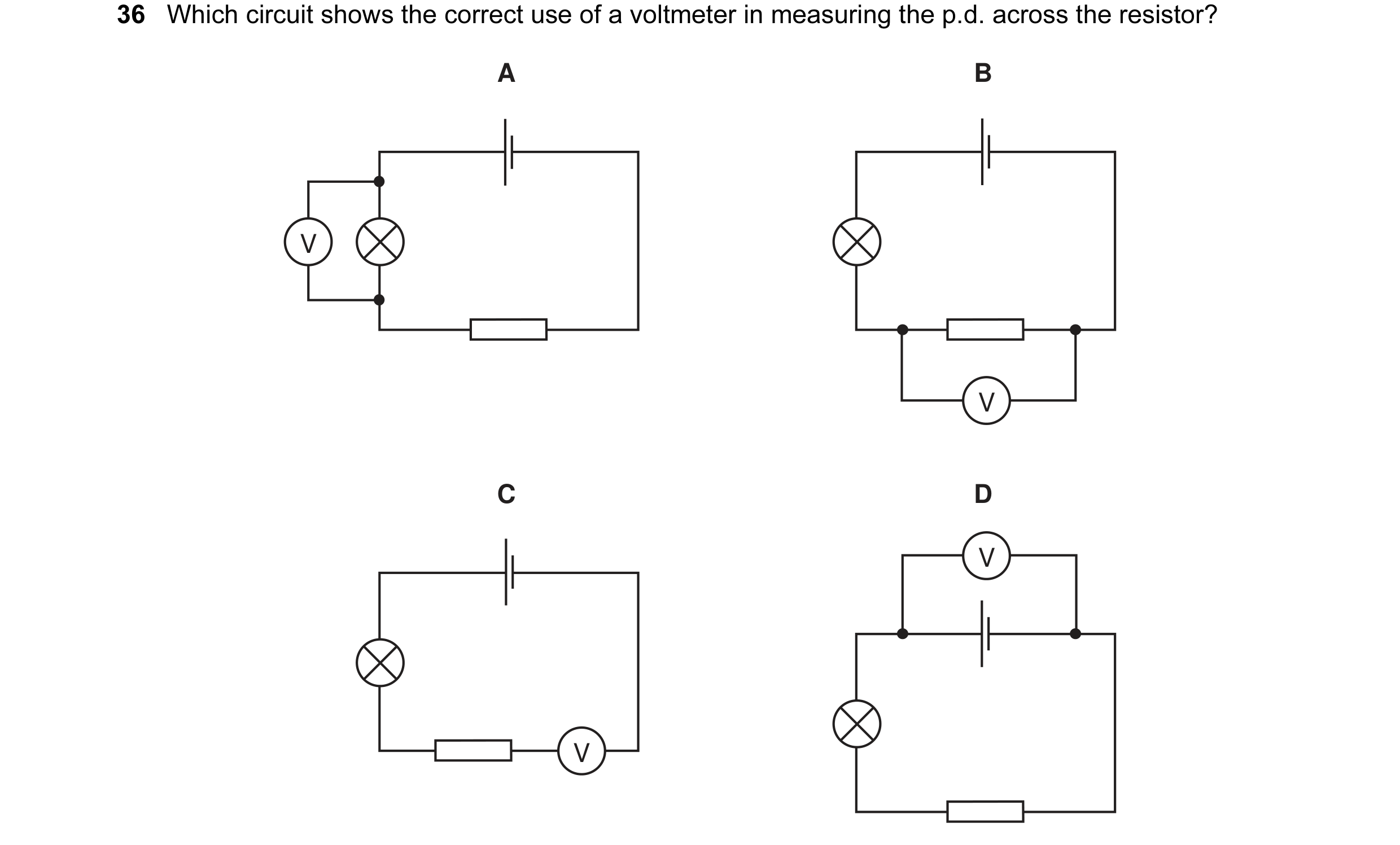
 3 / 77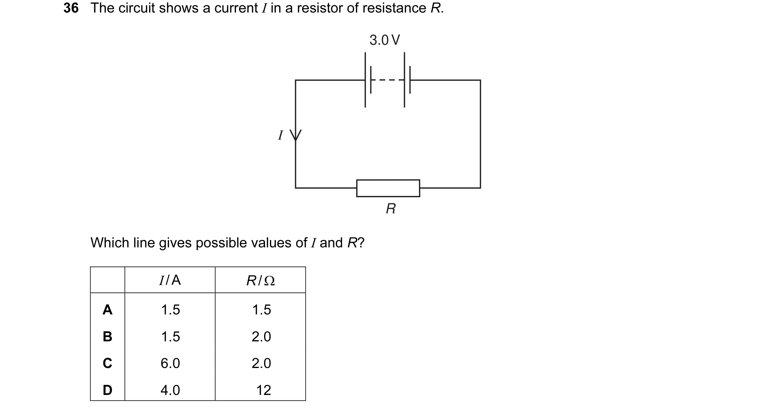
 4 / 77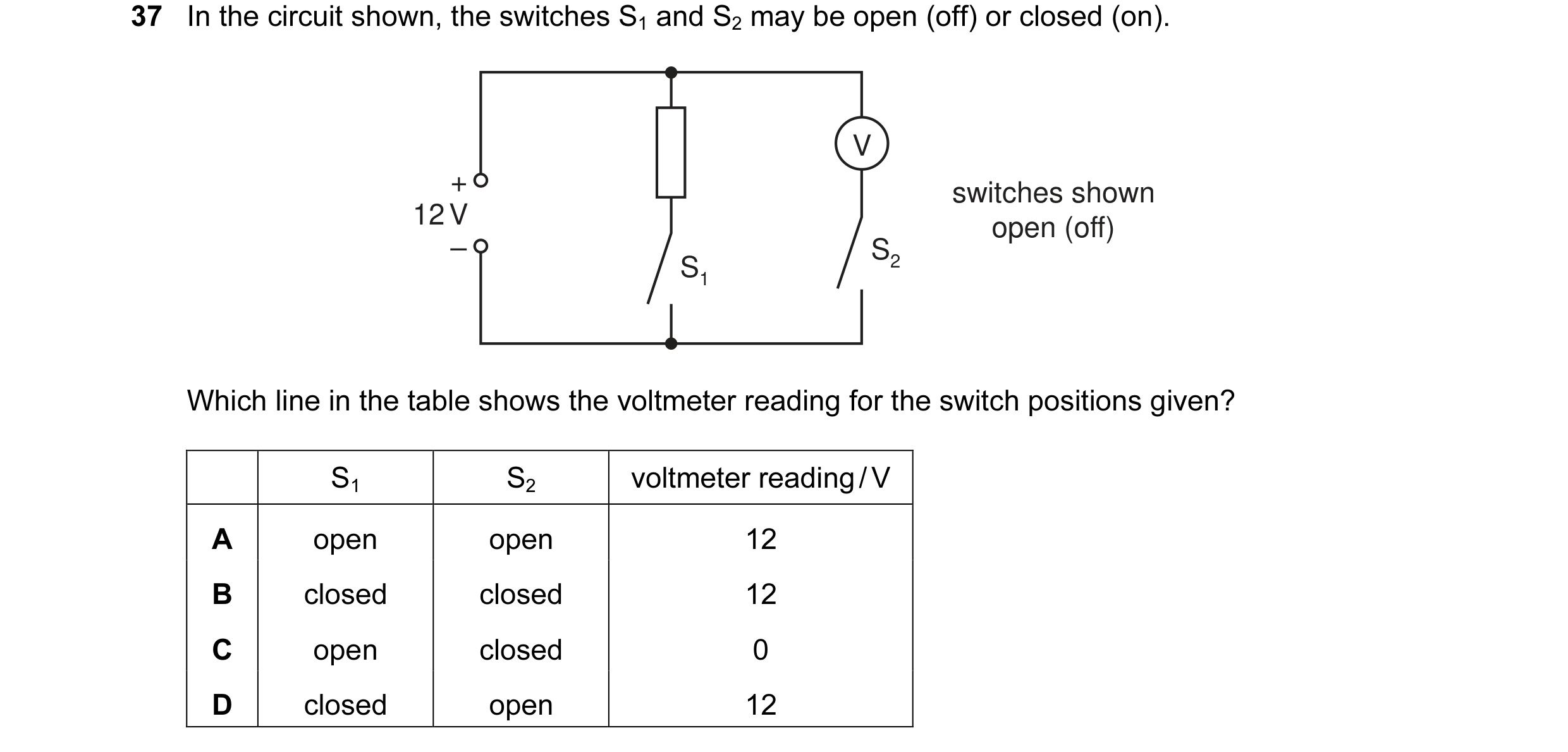
 5 / 77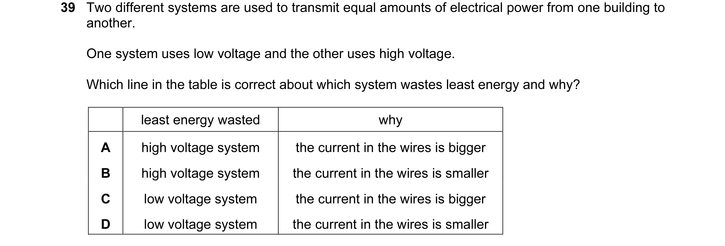
 6 / 77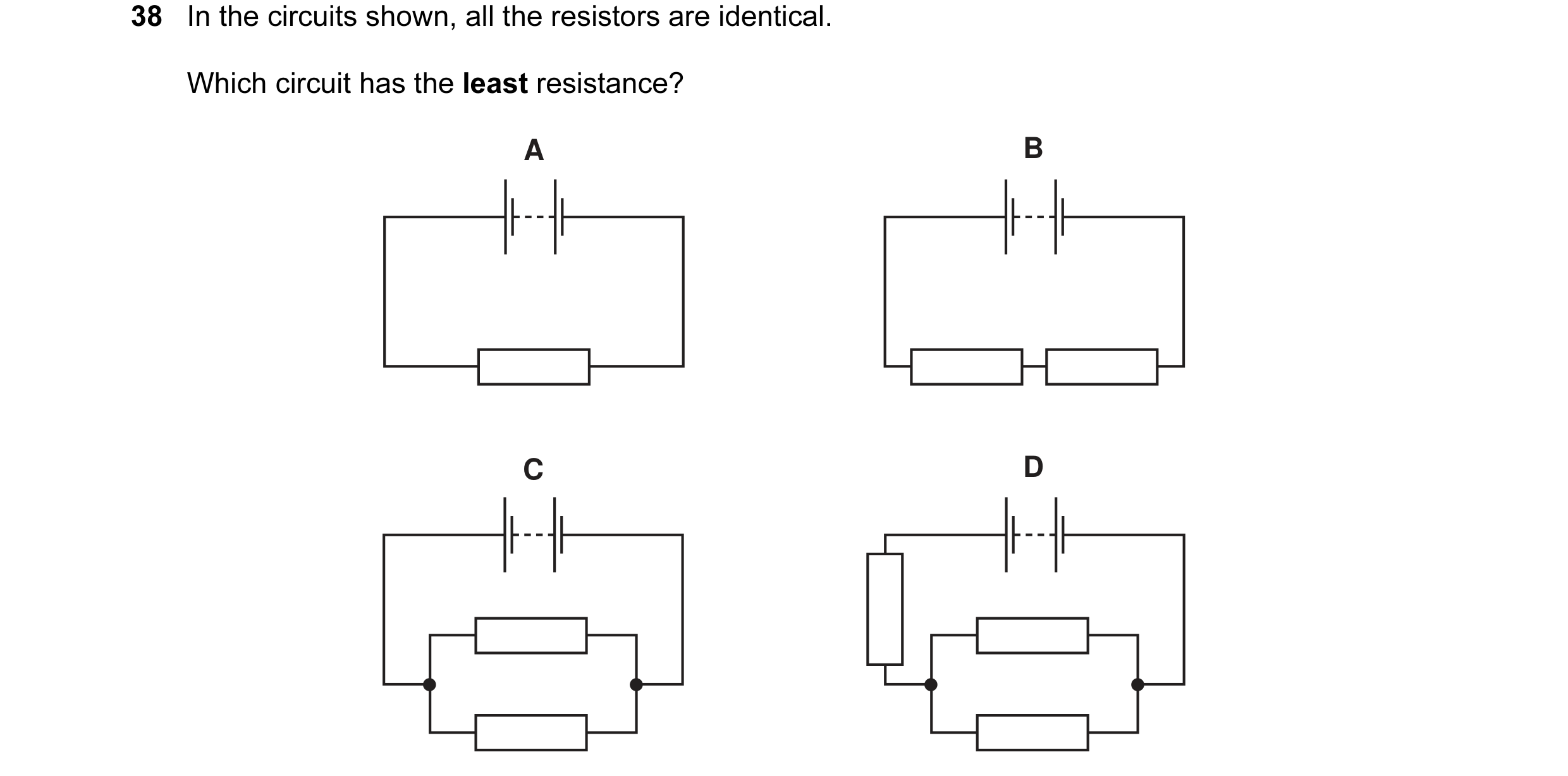
 7 / 77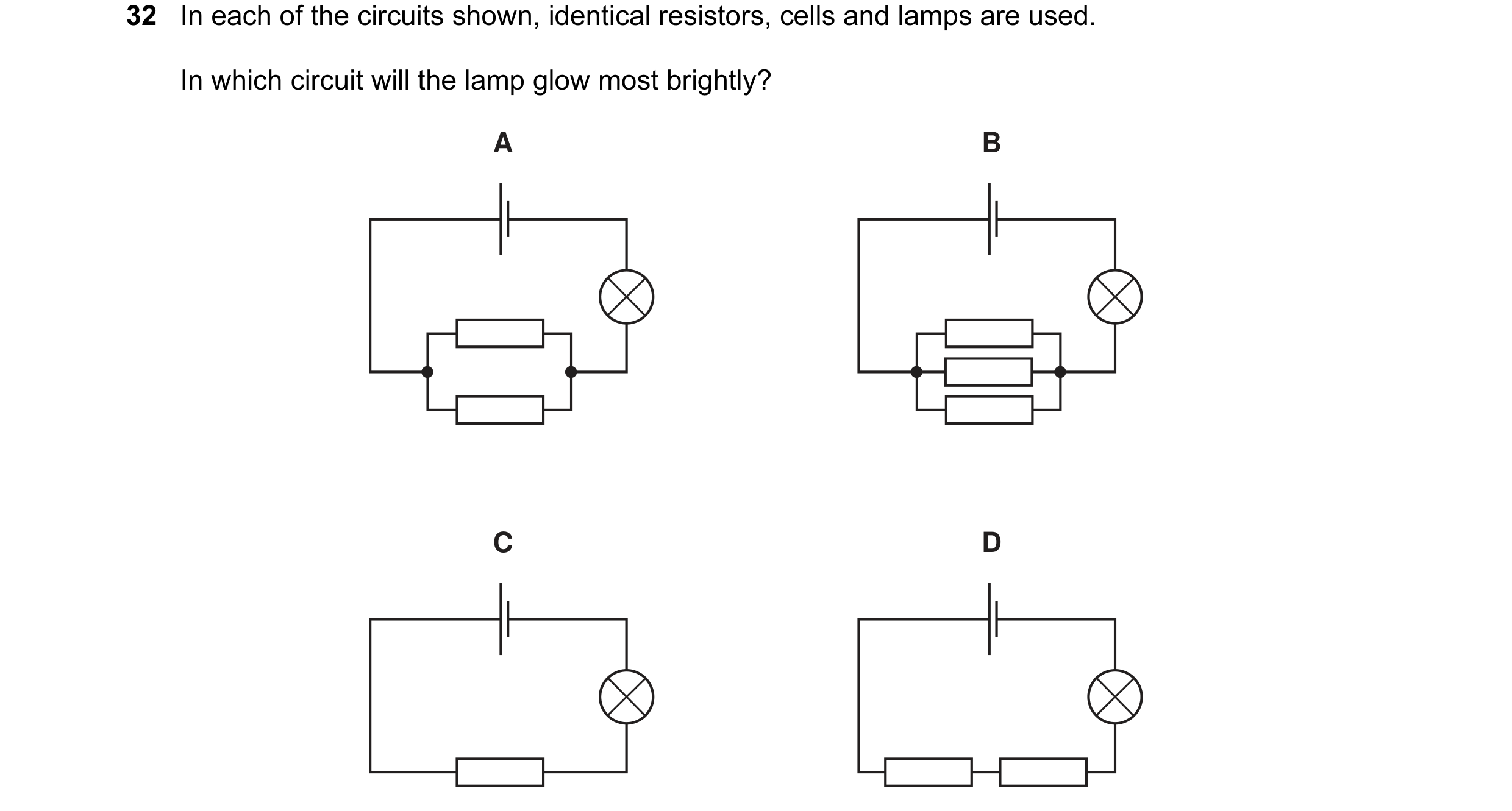

 8 / 77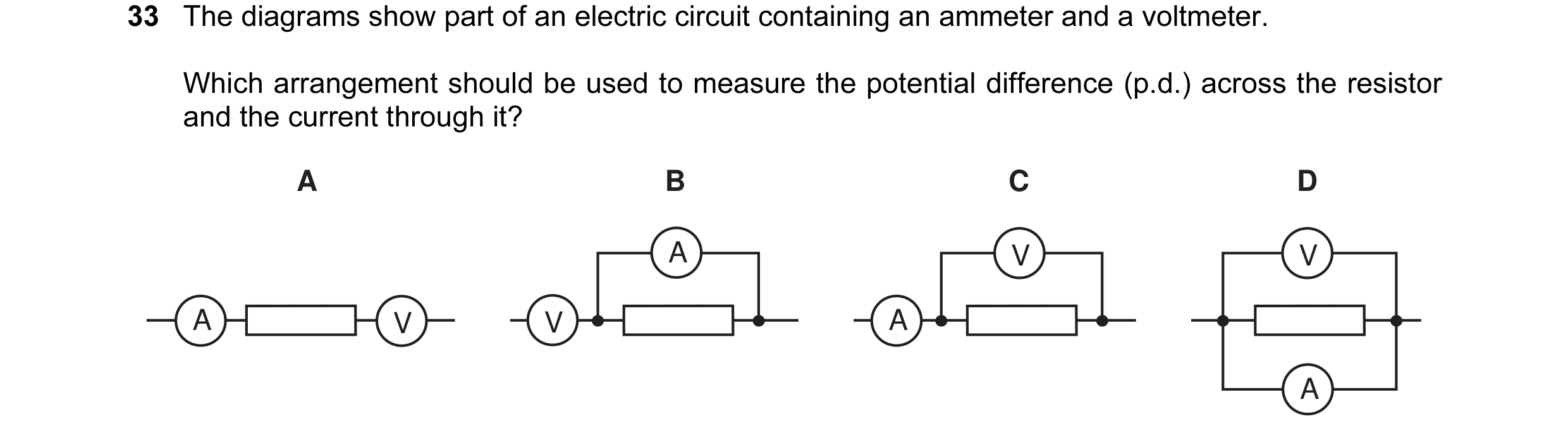
 9 / 77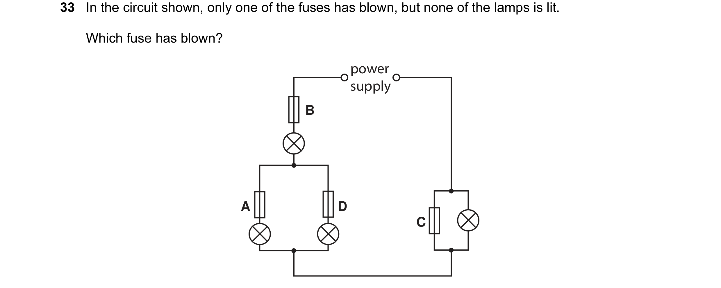
 10 / 77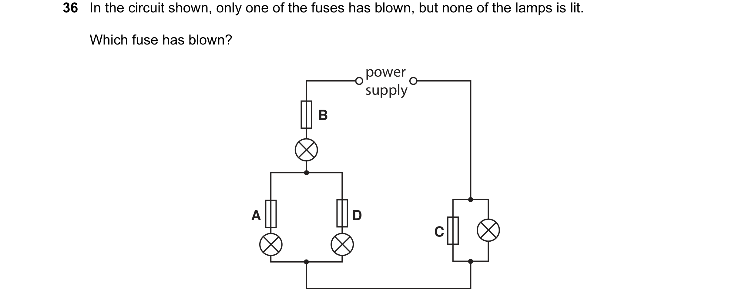
 11 / 77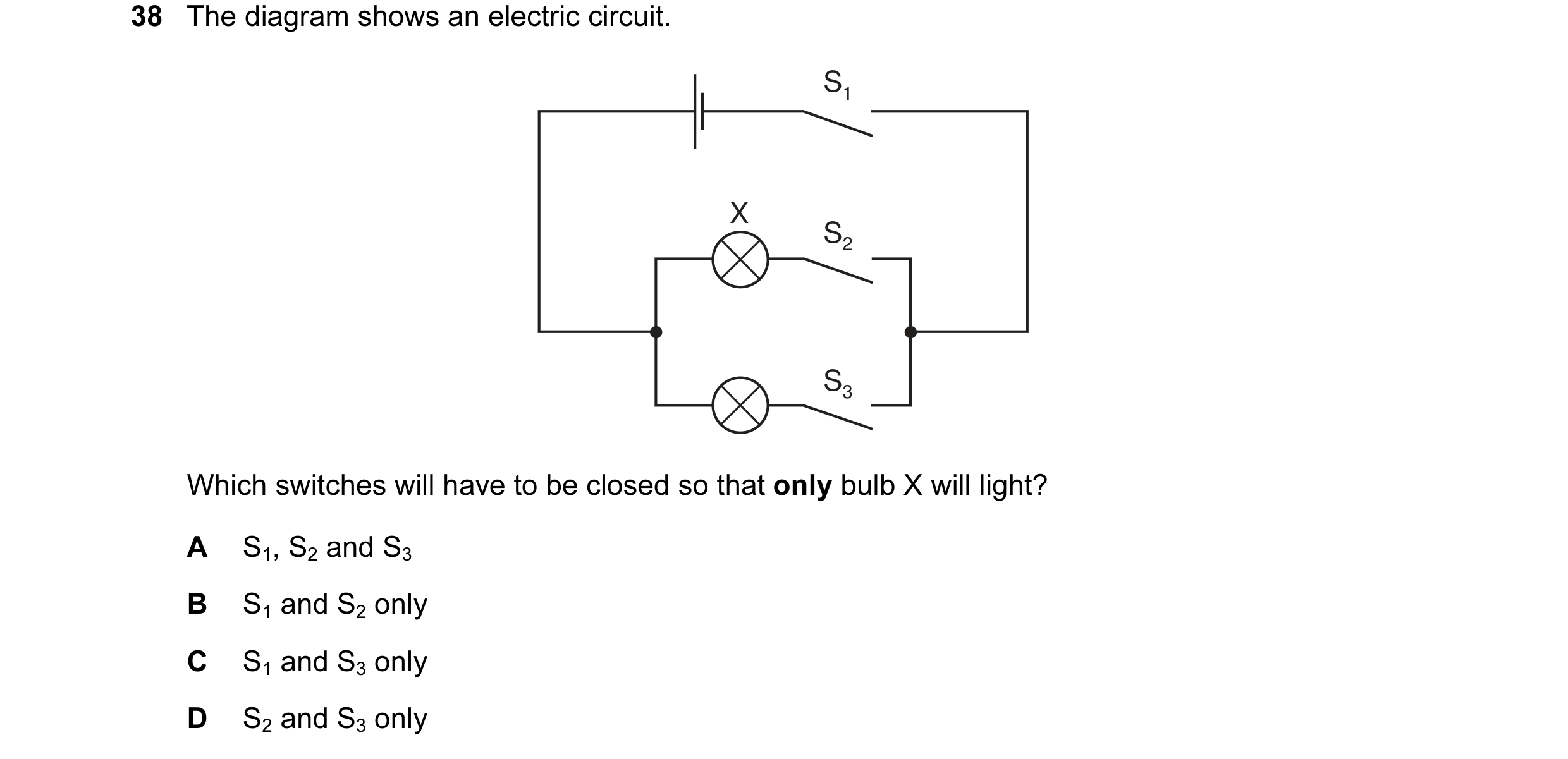
 12 / 77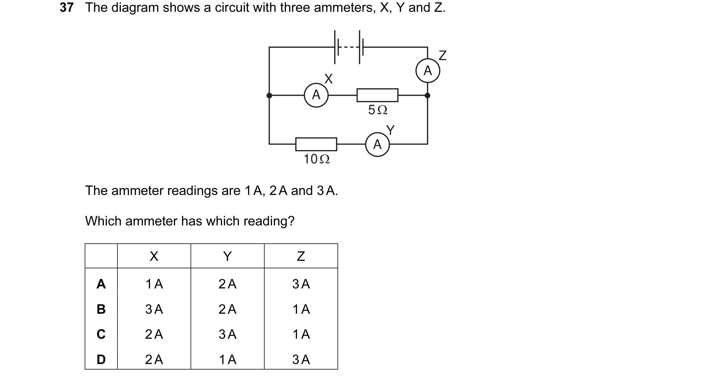
 13 / 77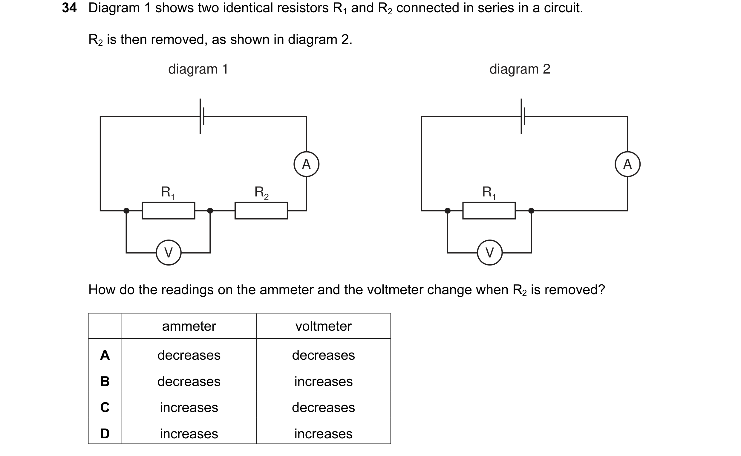
 14 / 77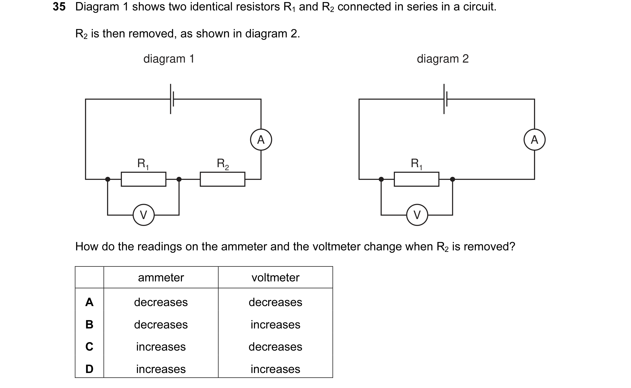
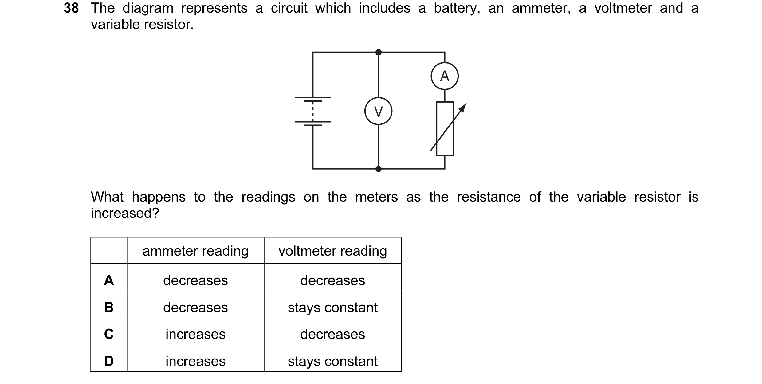 15 / 77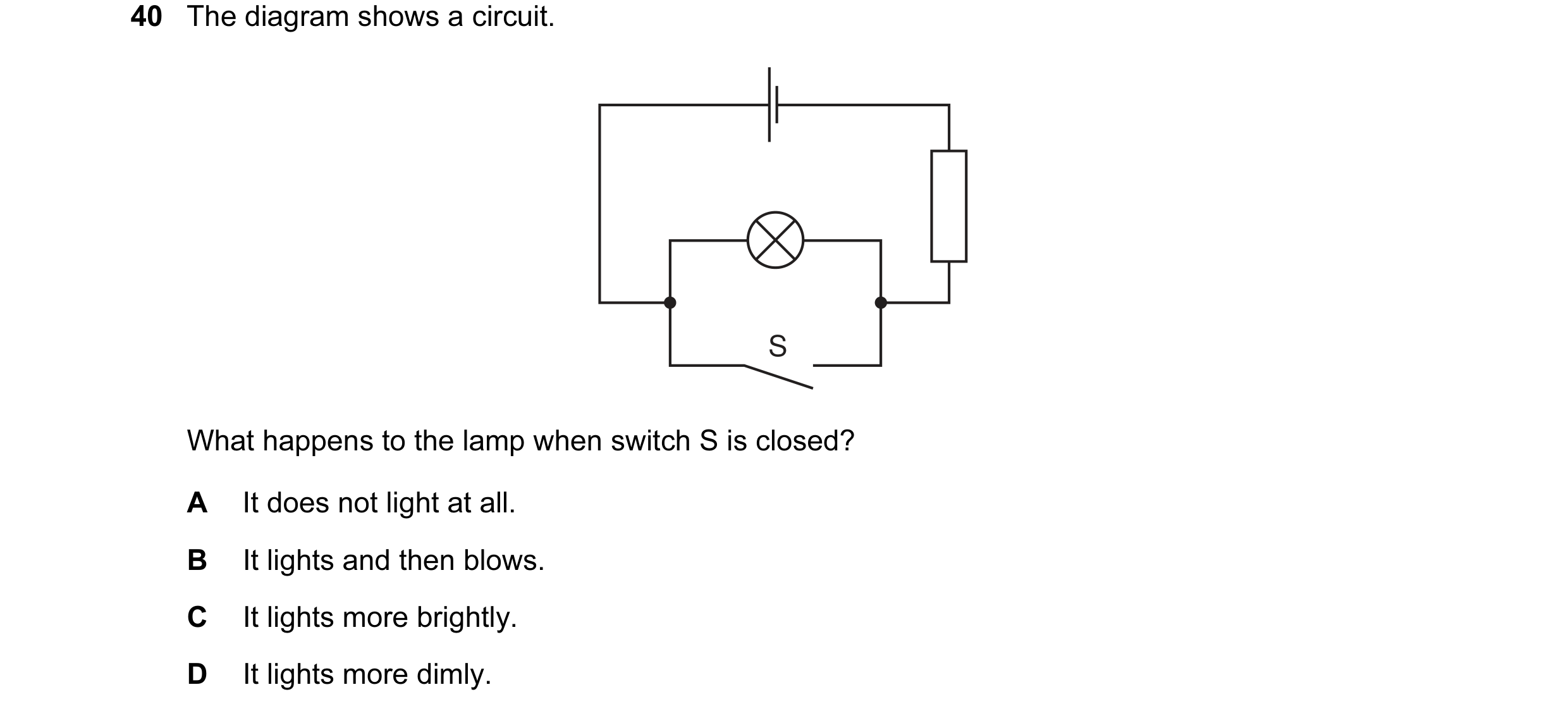
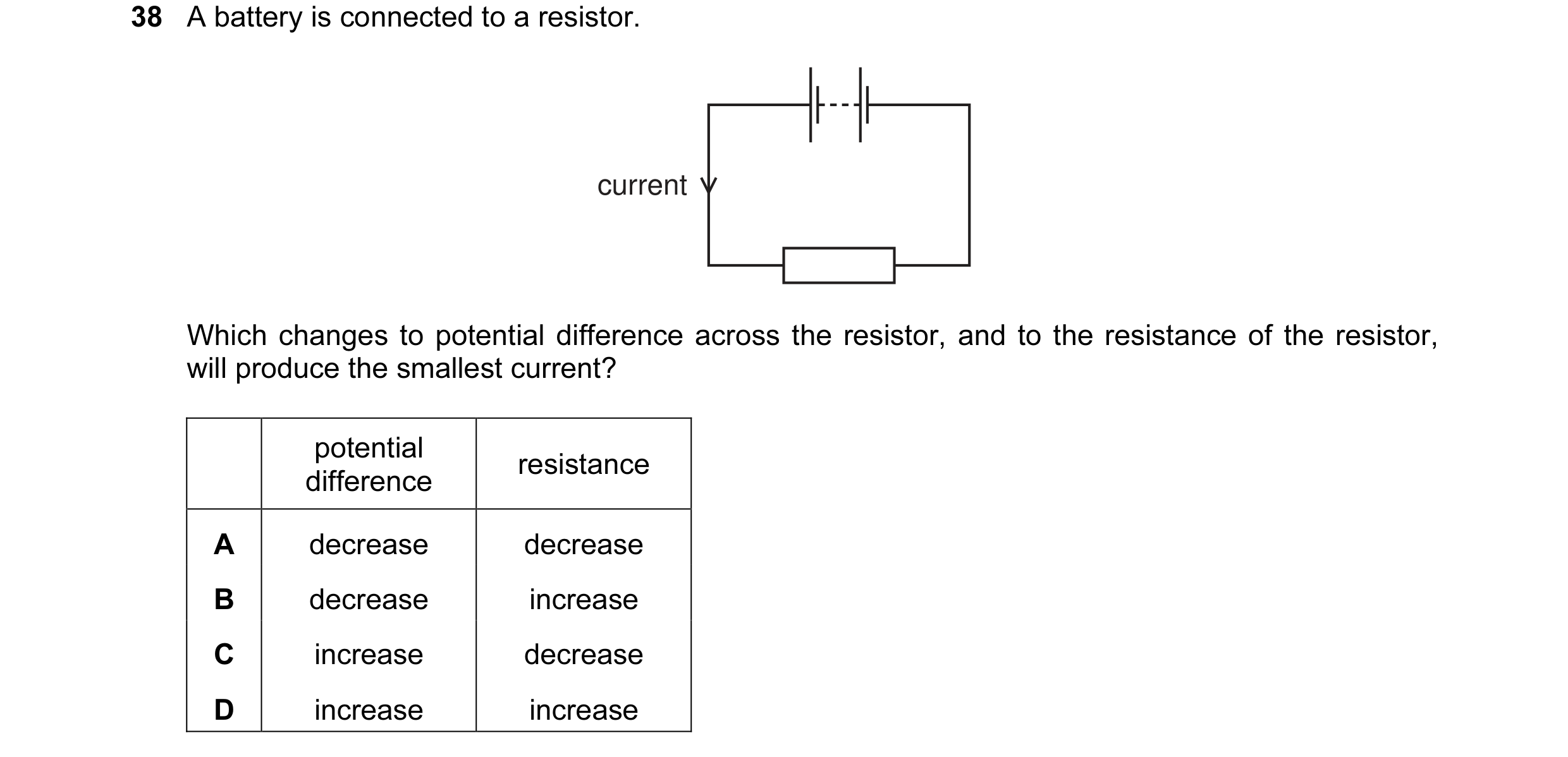
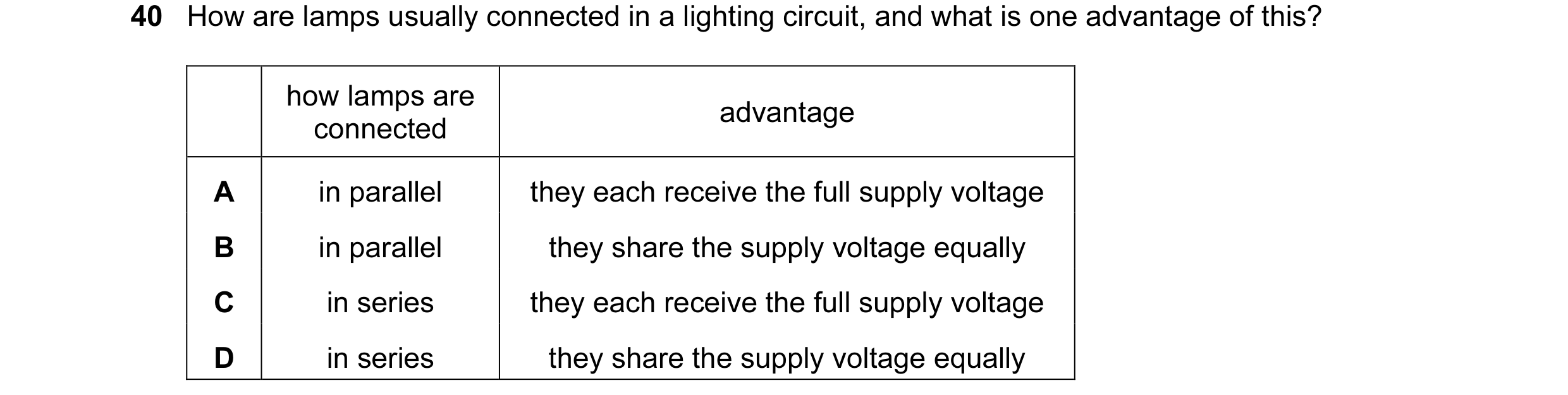 16 / 77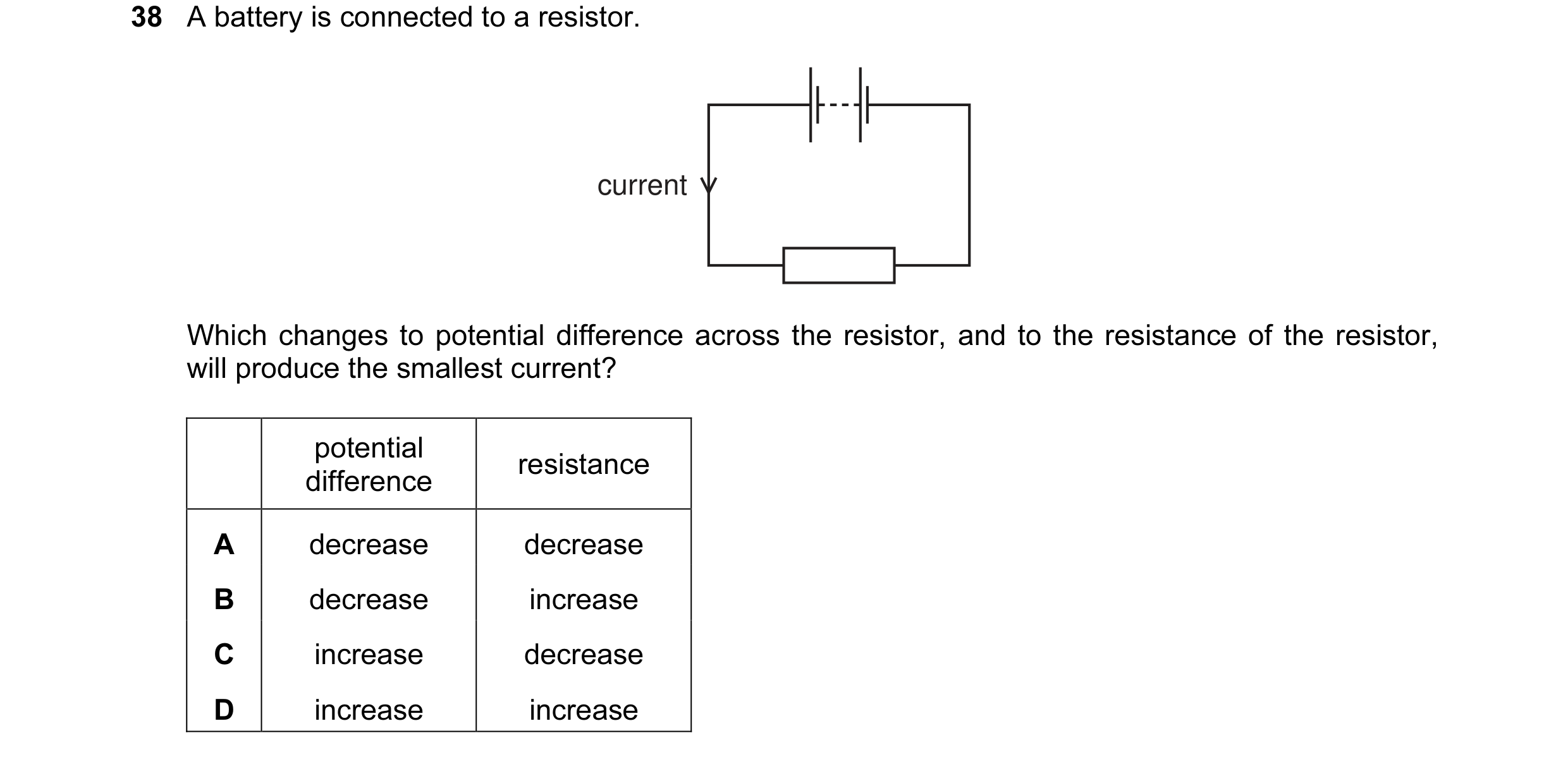
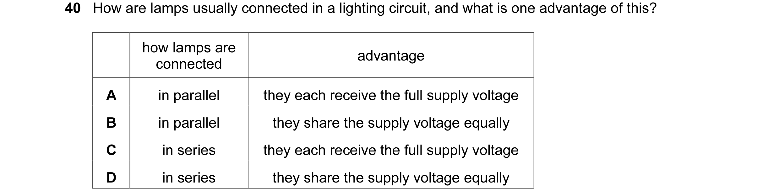
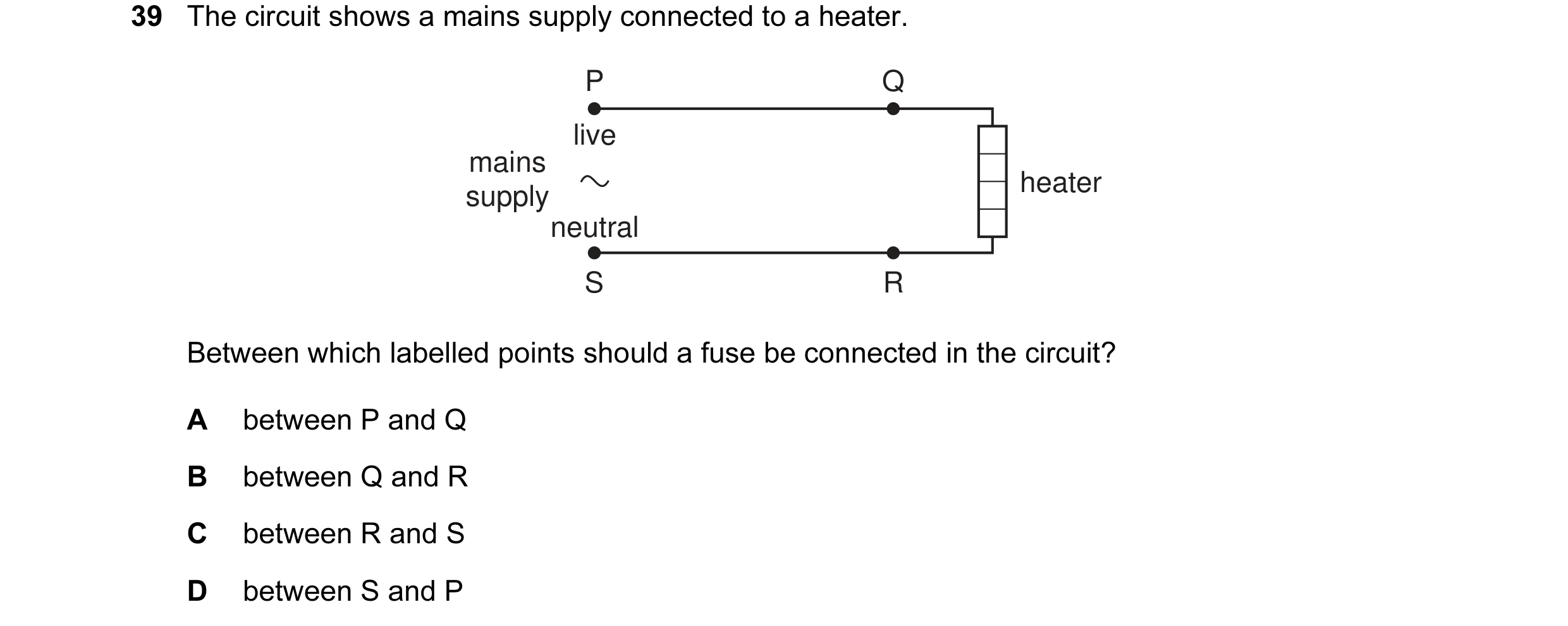 17 / 77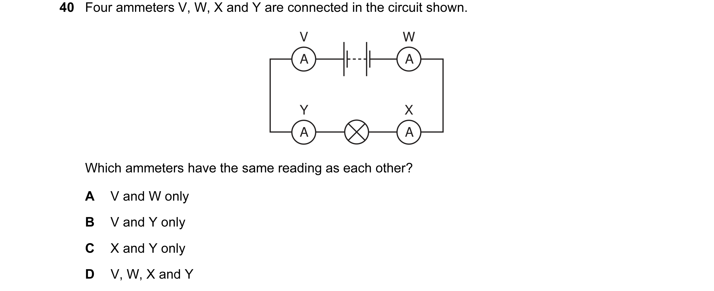
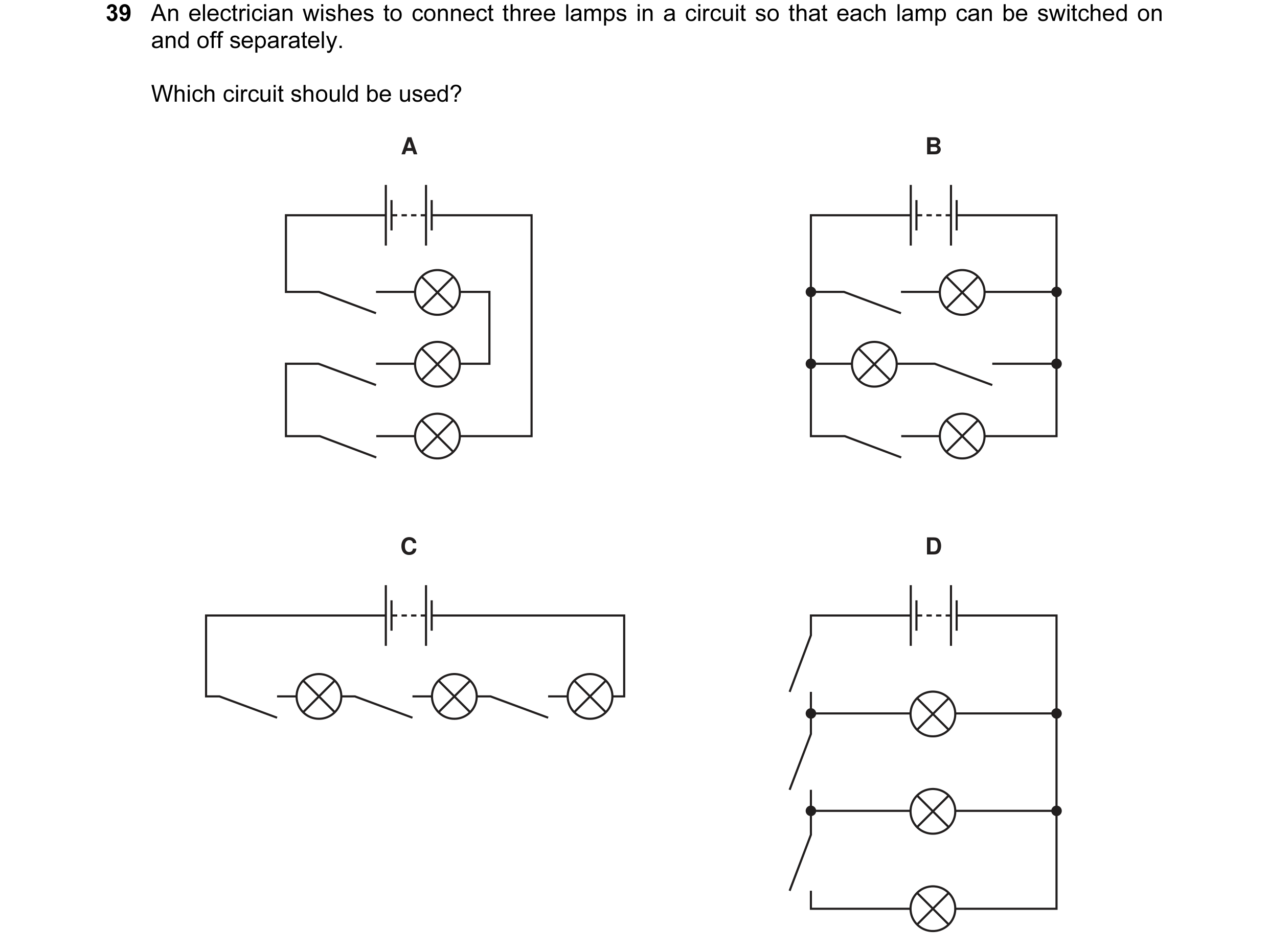 18 / 77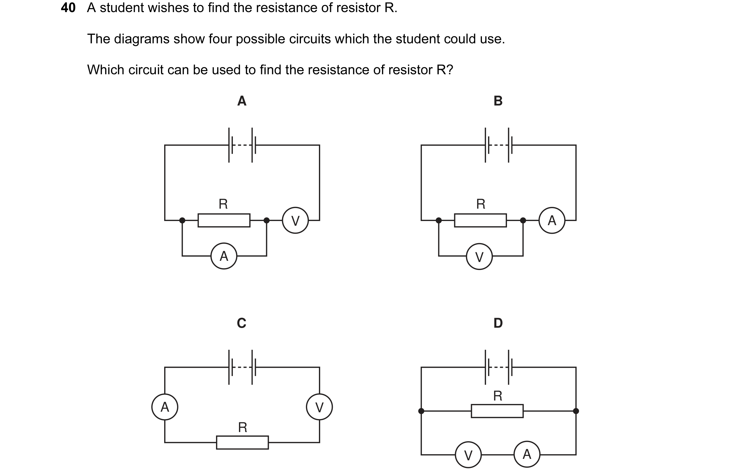
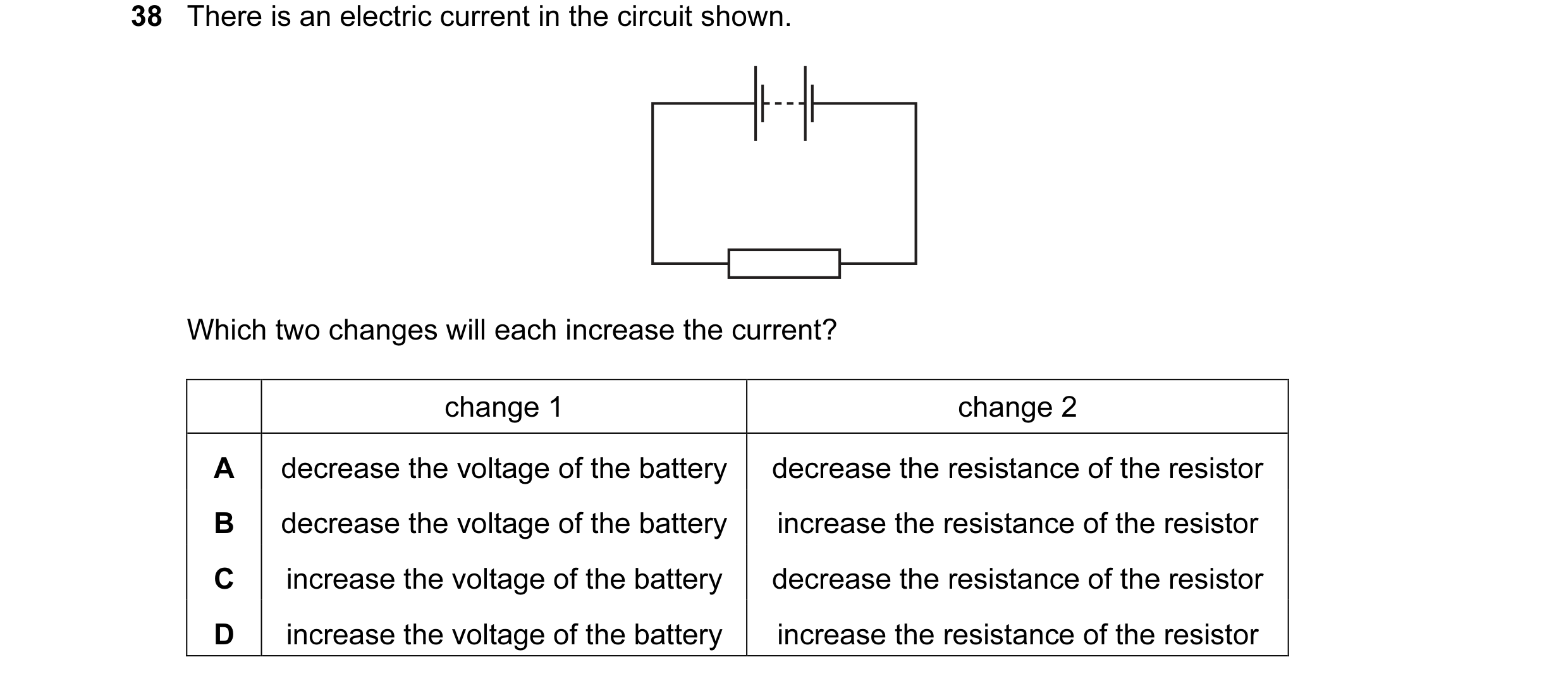 19 / 77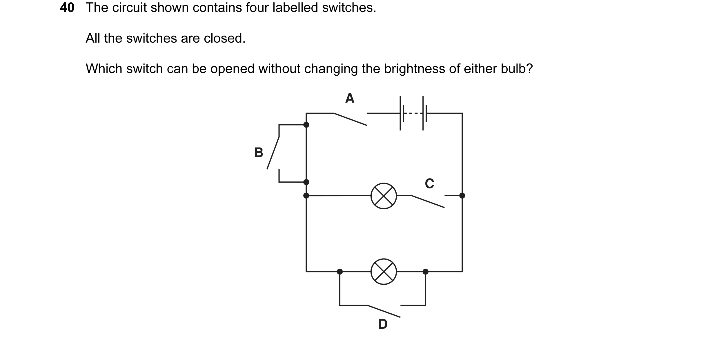
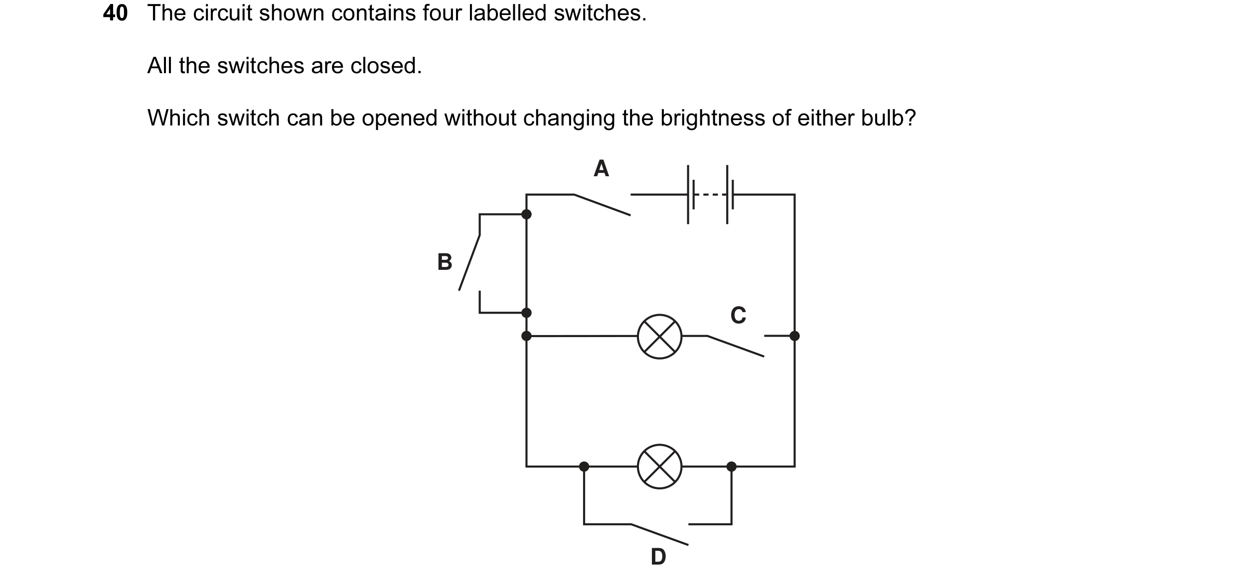 20 / 77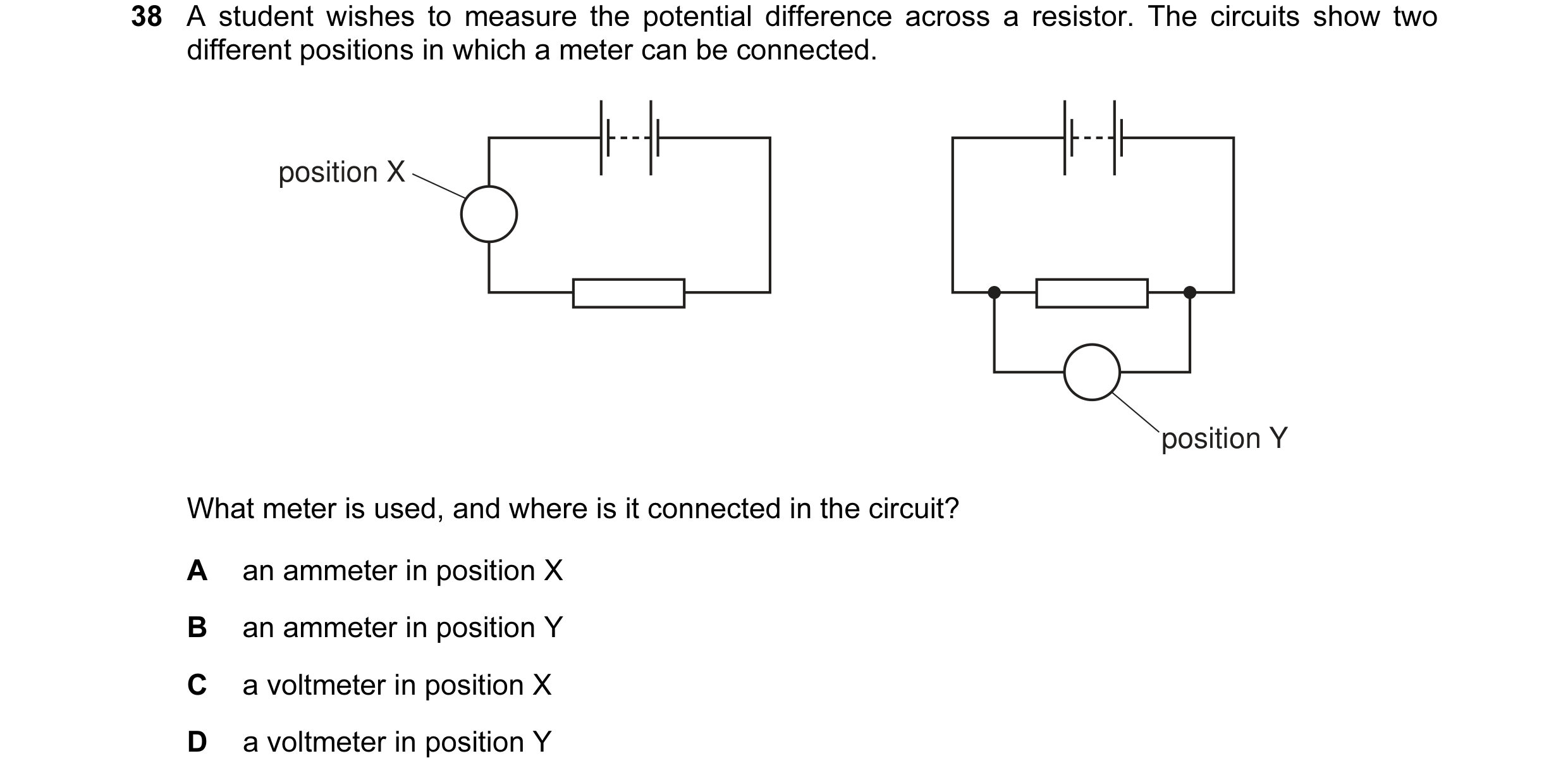
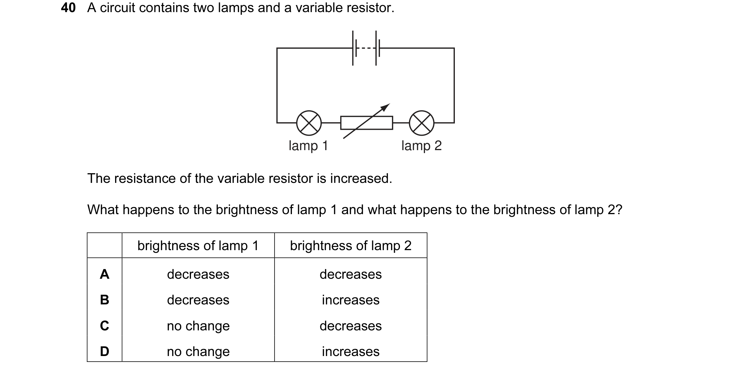 21 / 77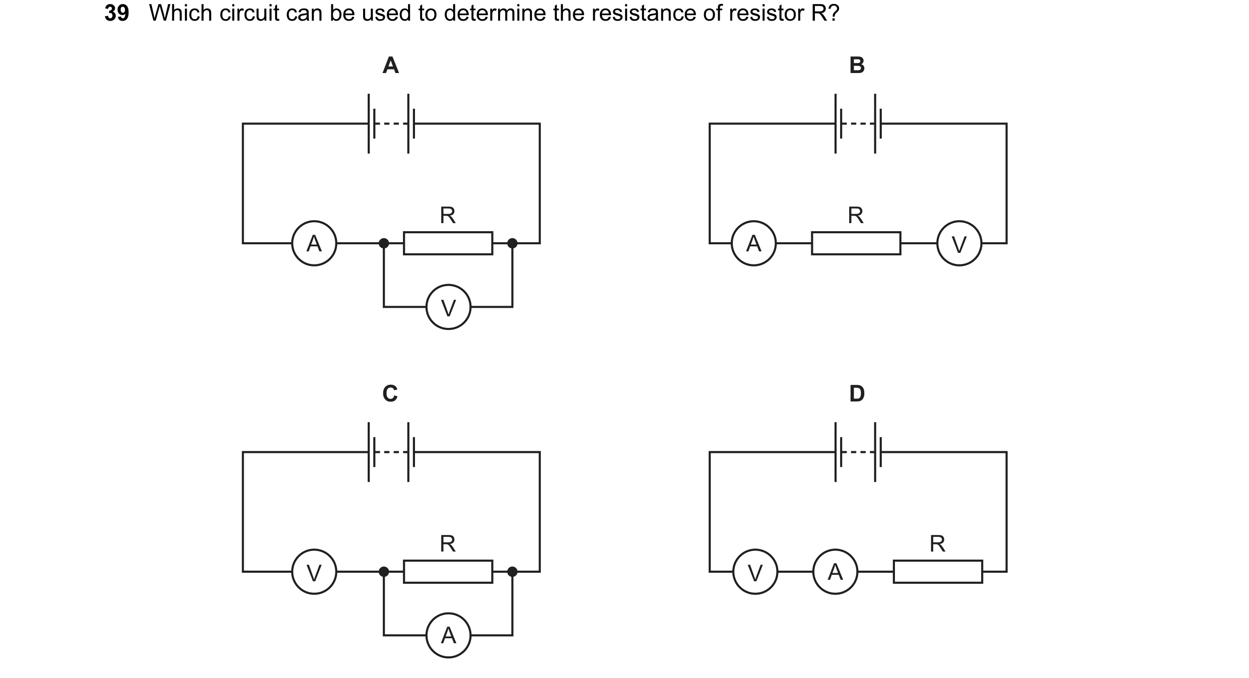
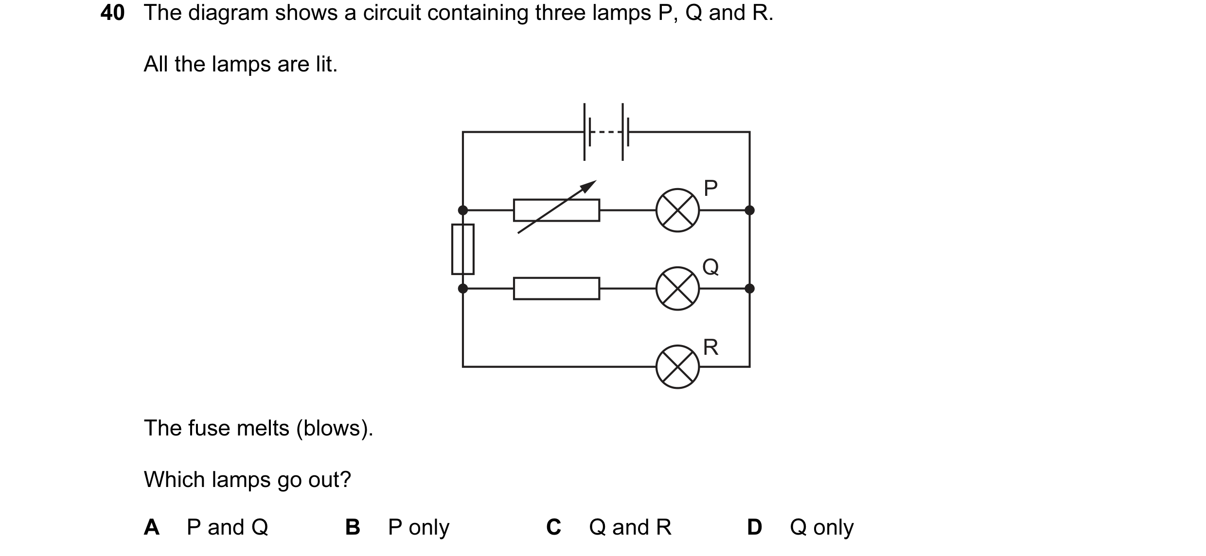
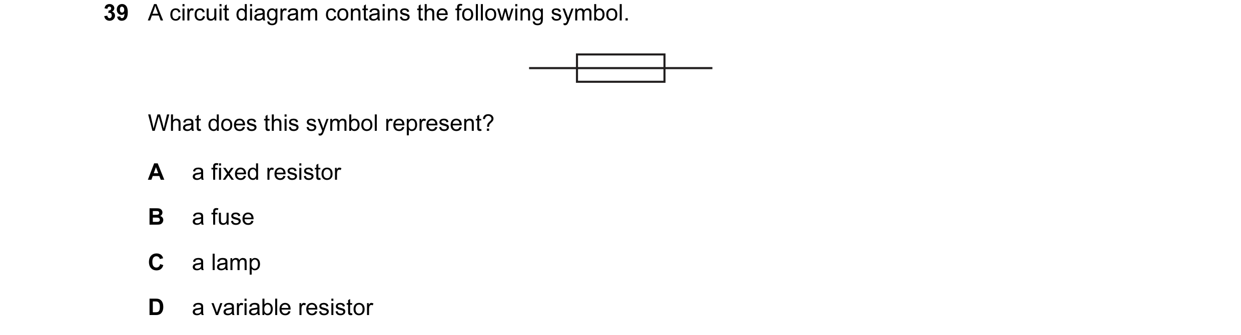 22 / 77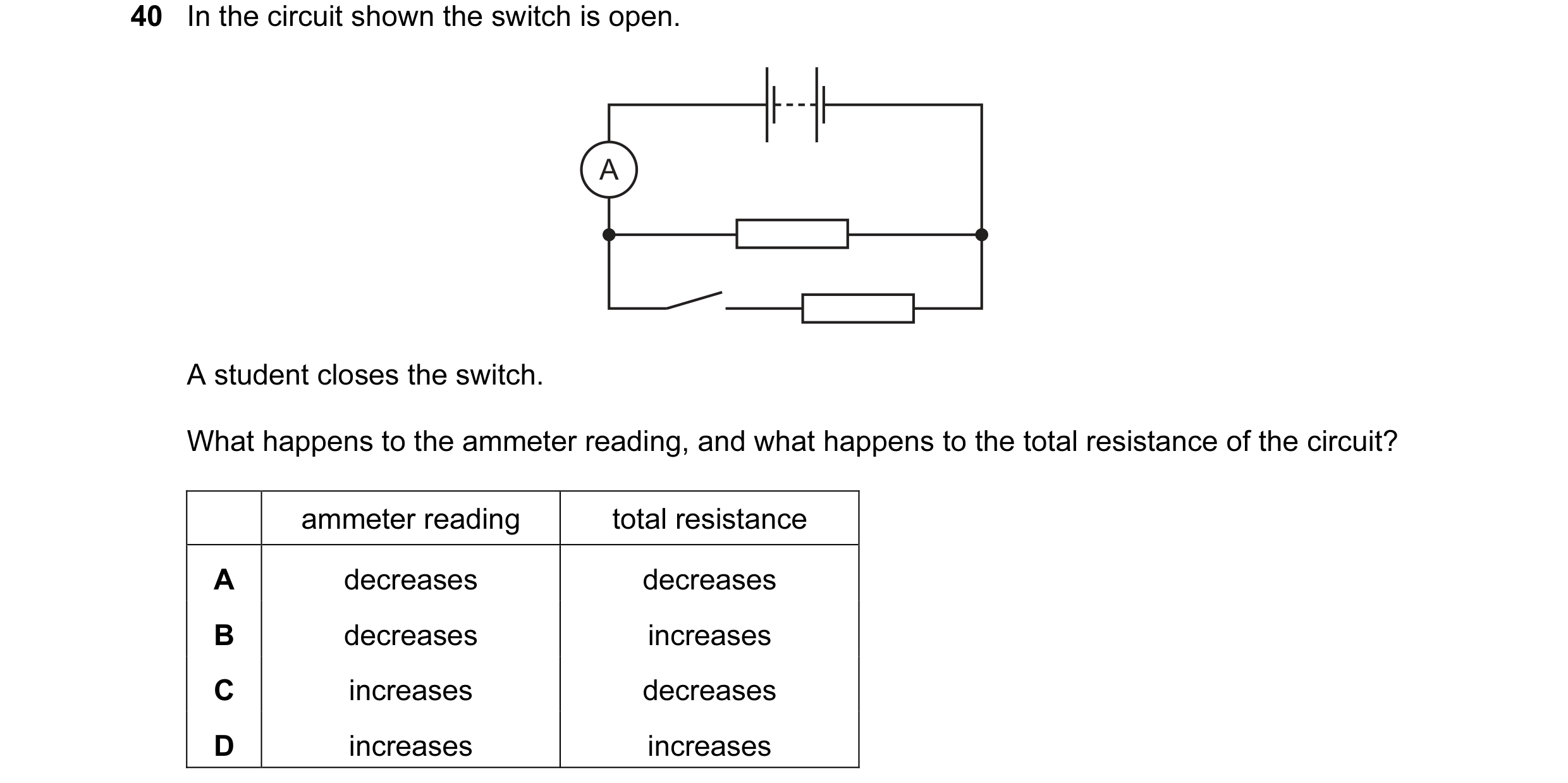
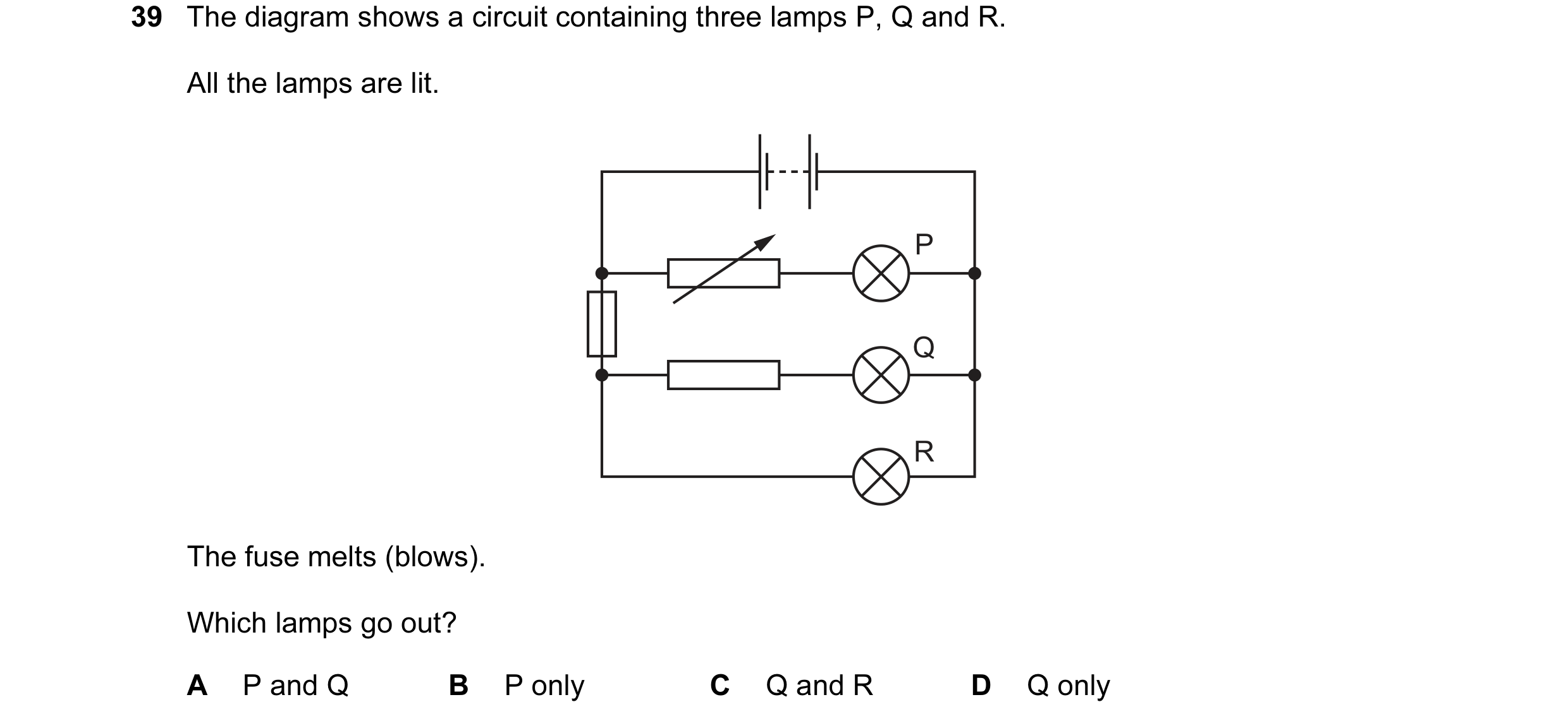 23 / 77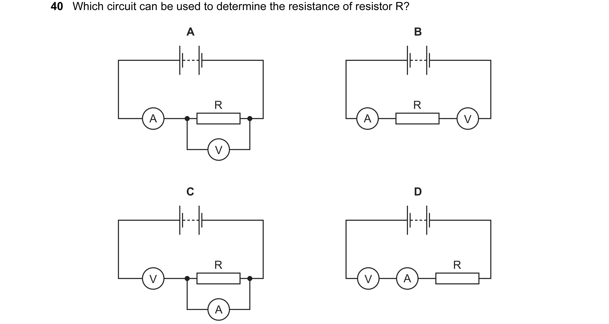
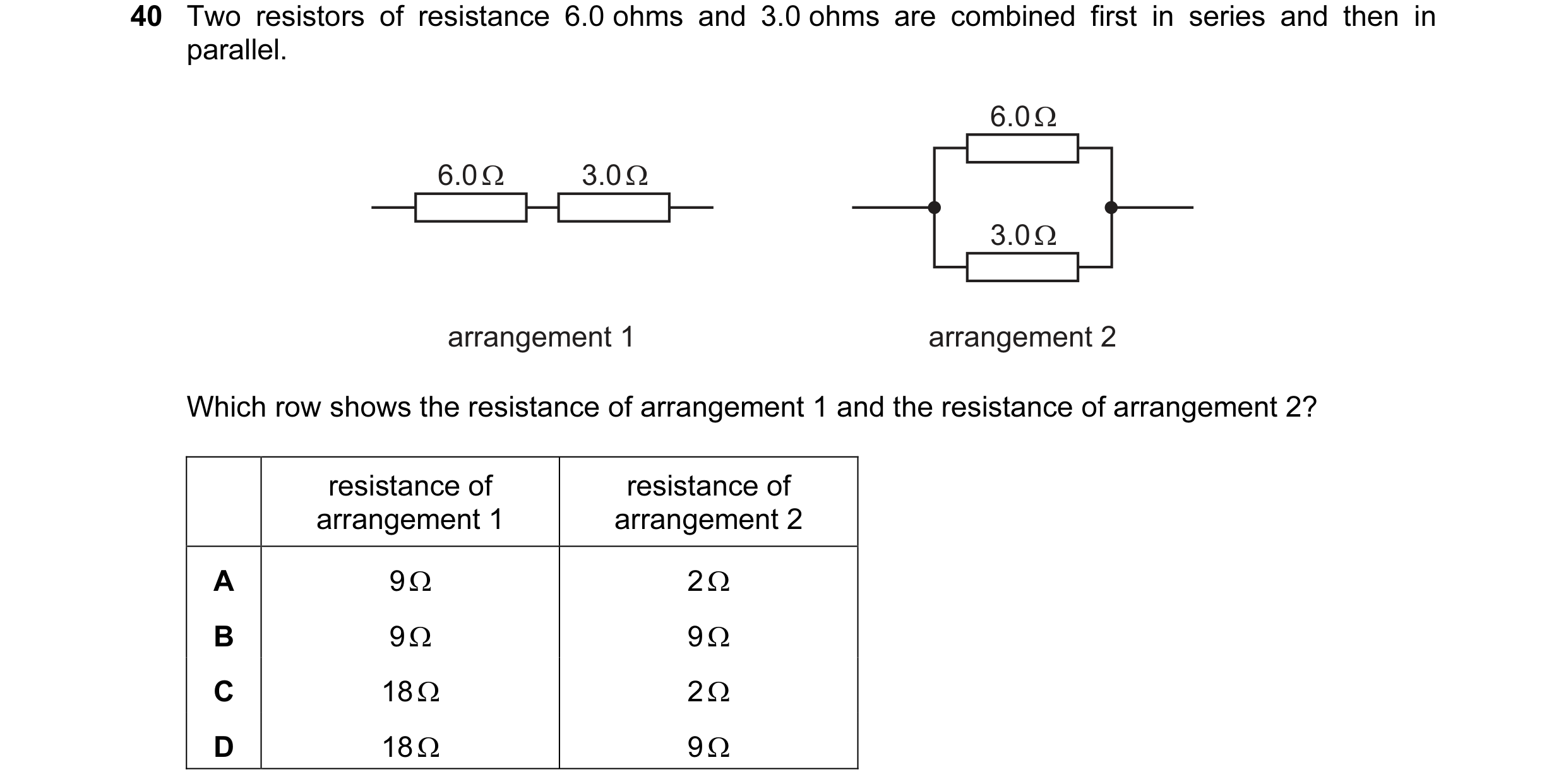 24 / 77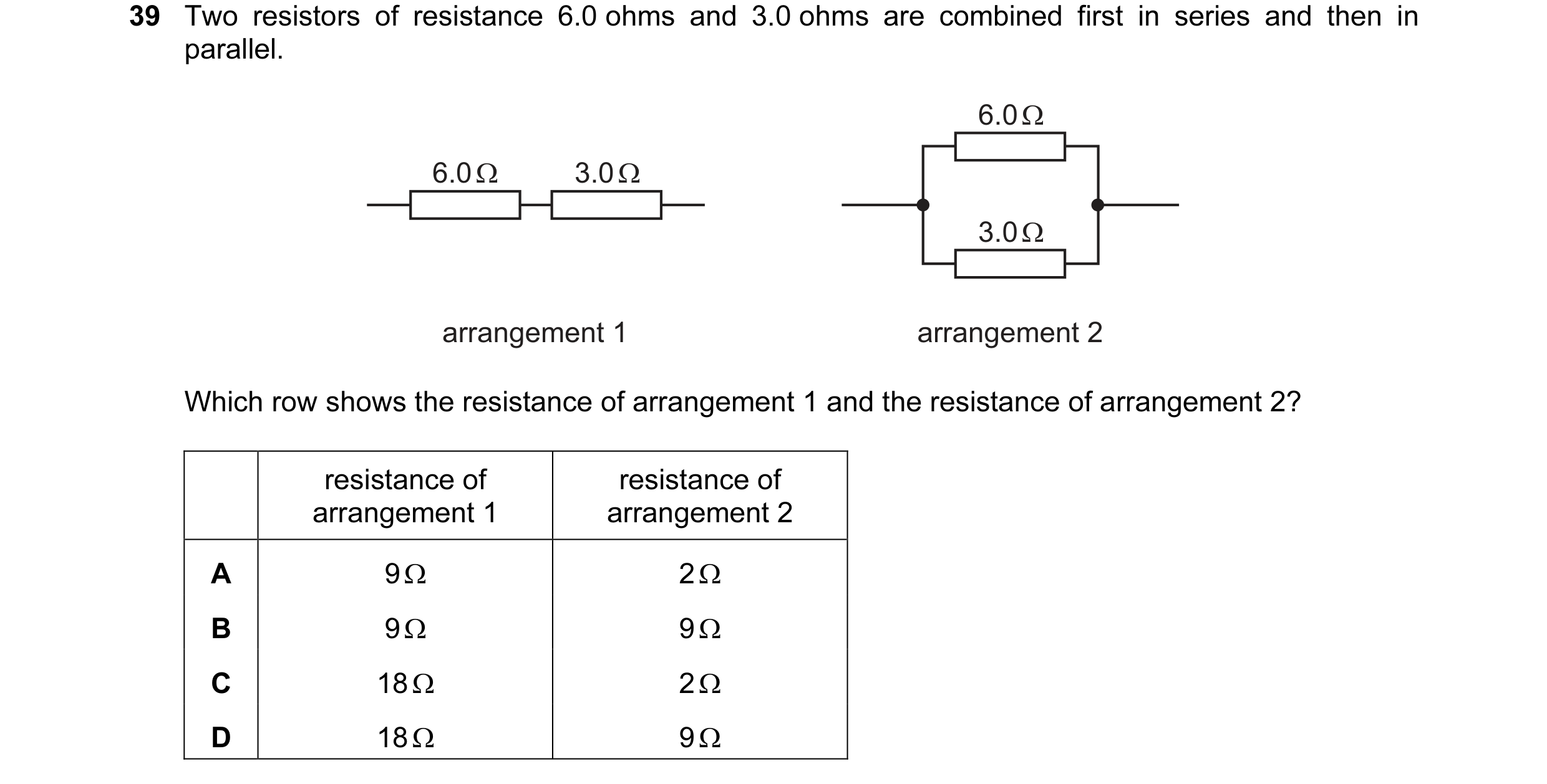
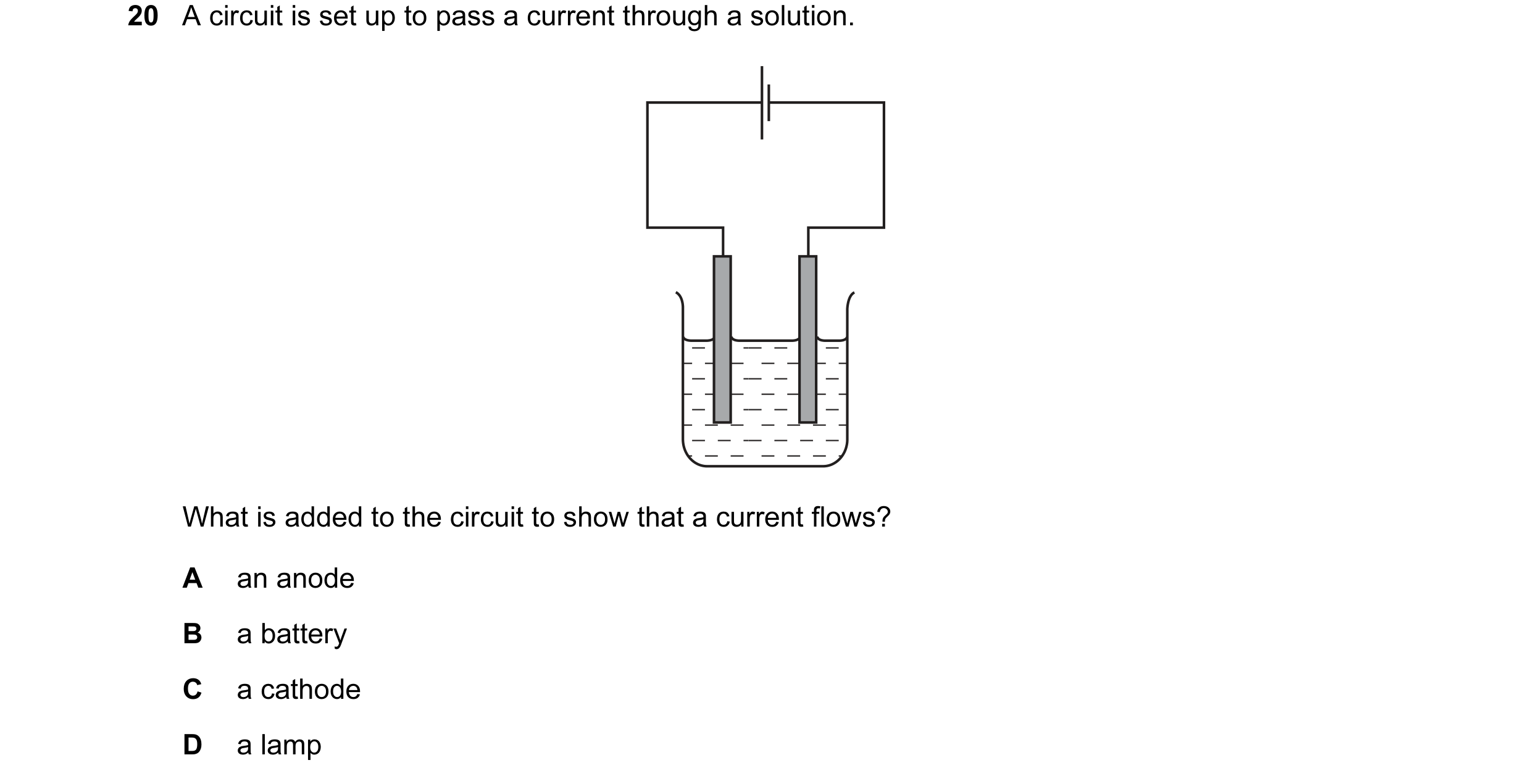 25 / 77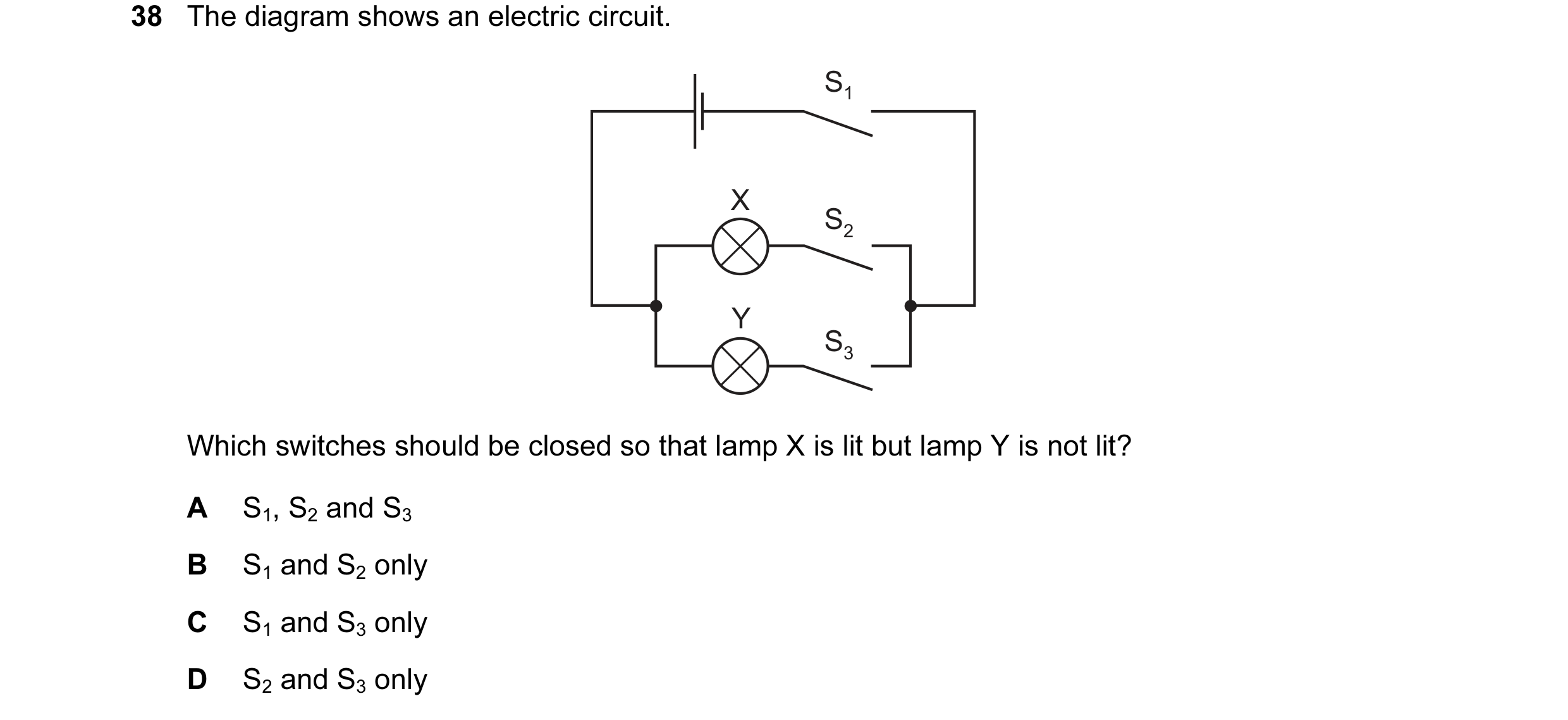
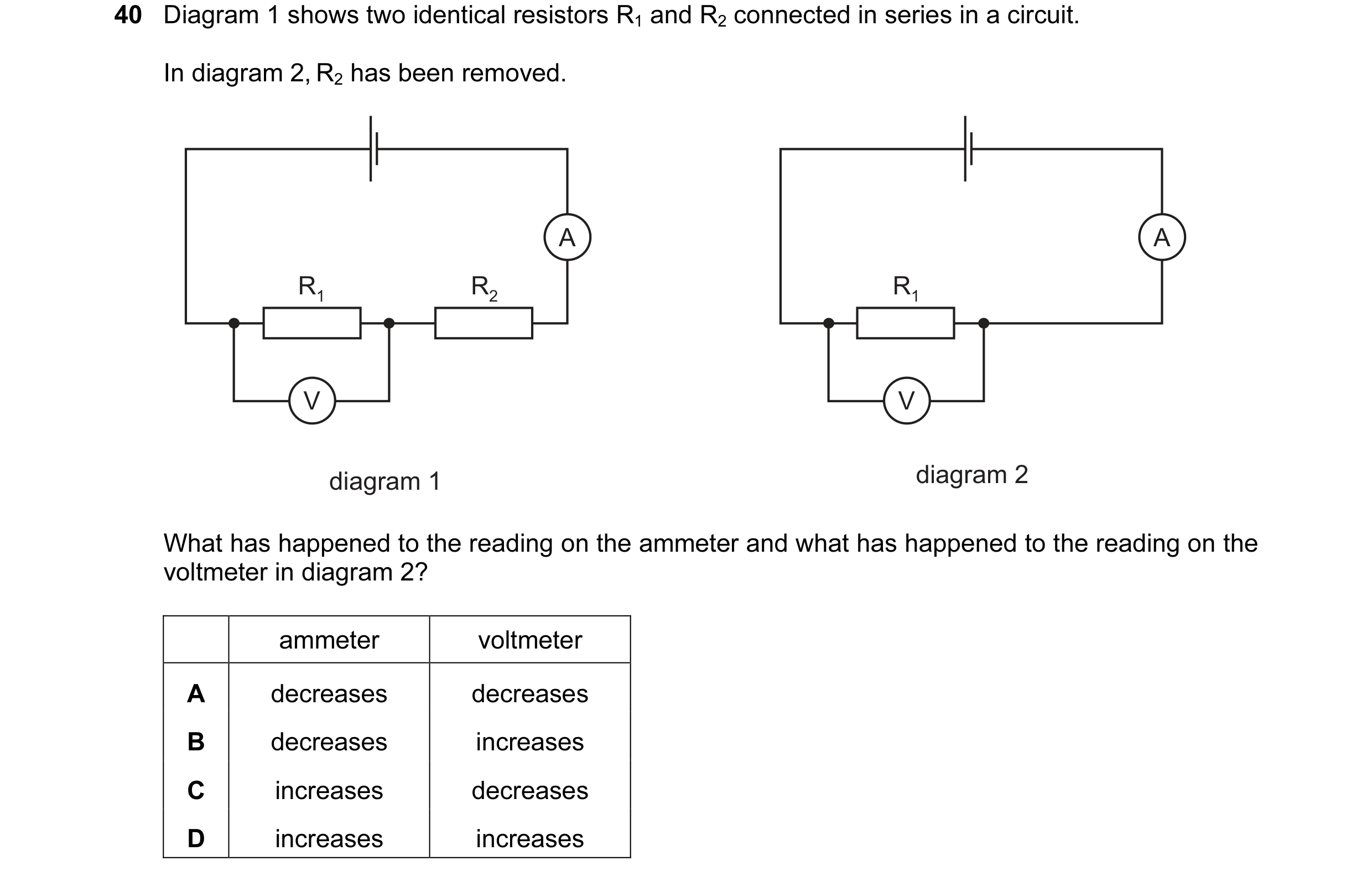 26 / 77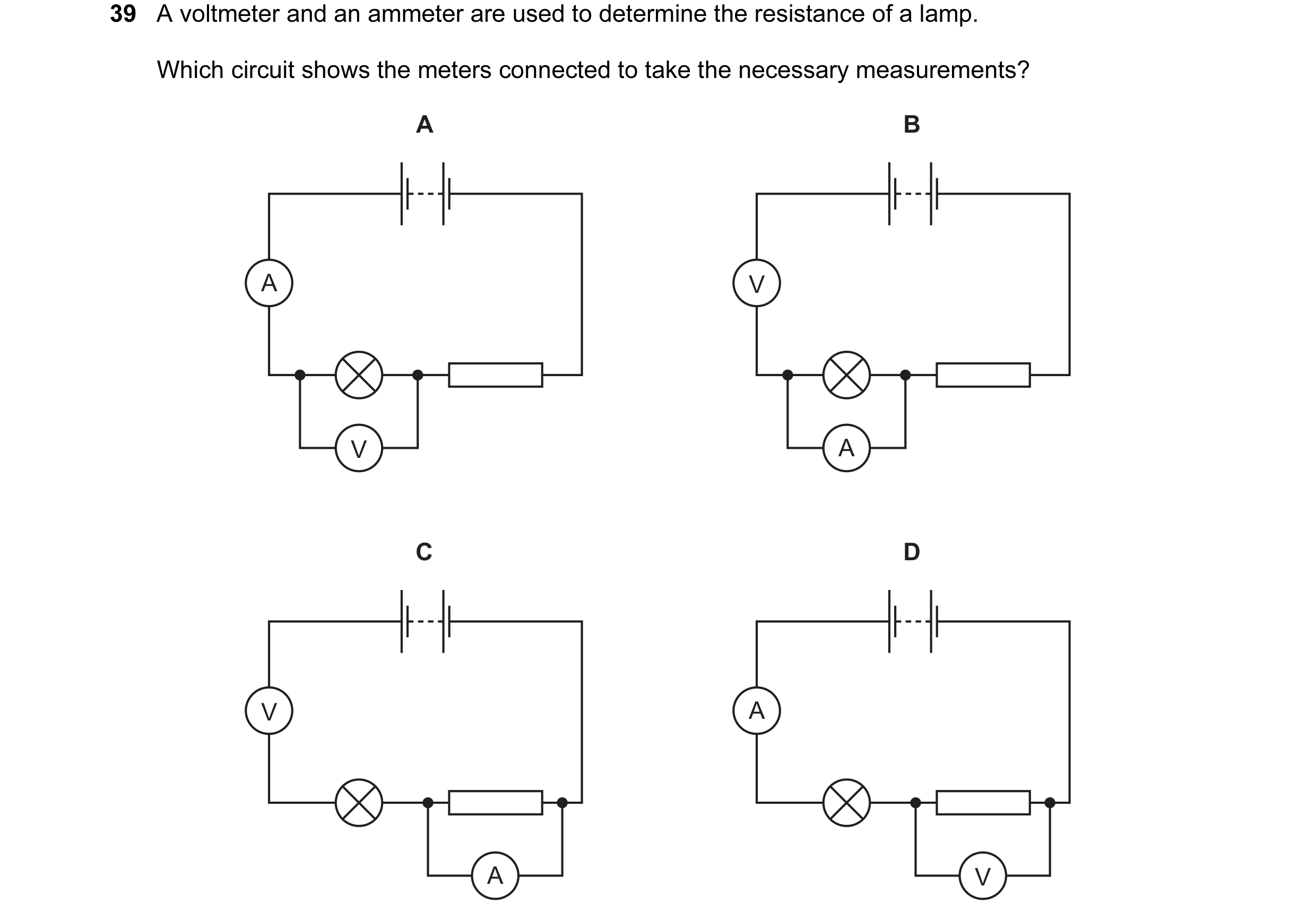
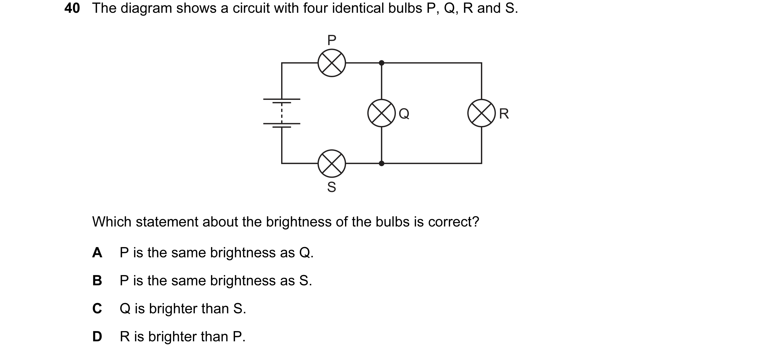 27 / 77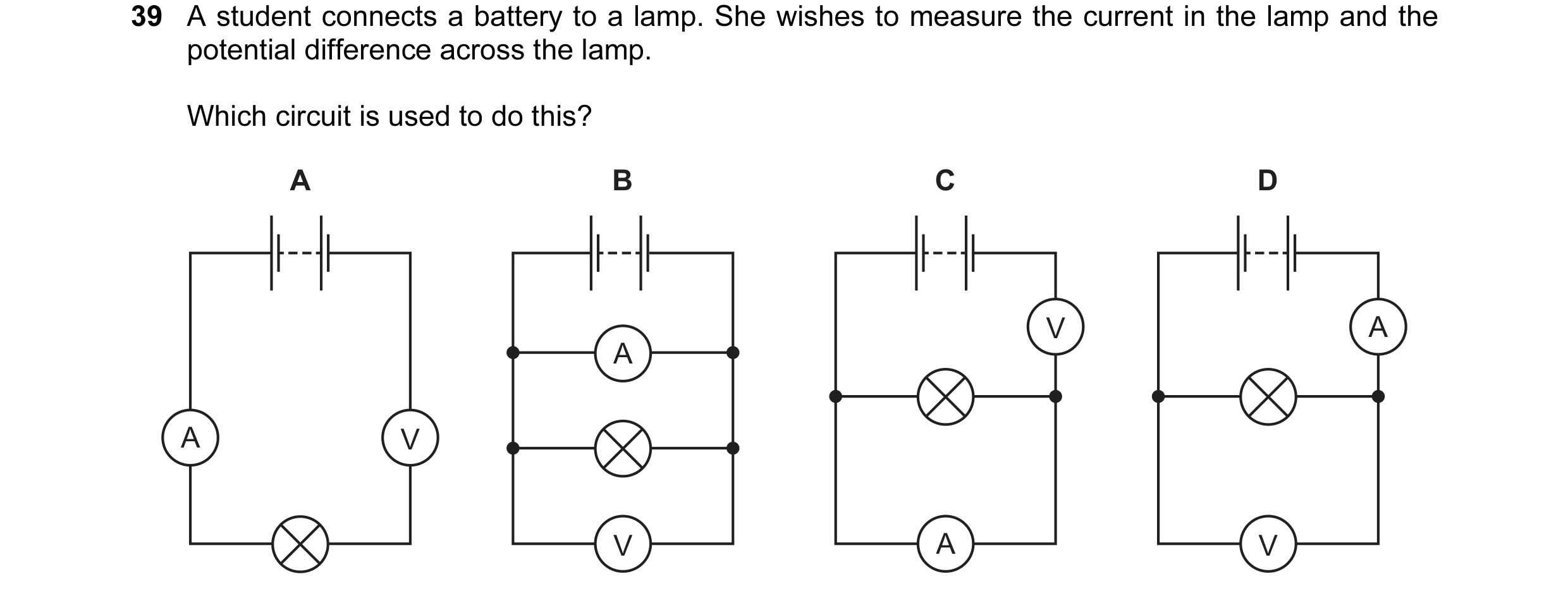
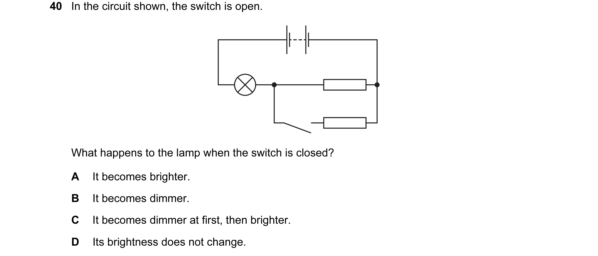
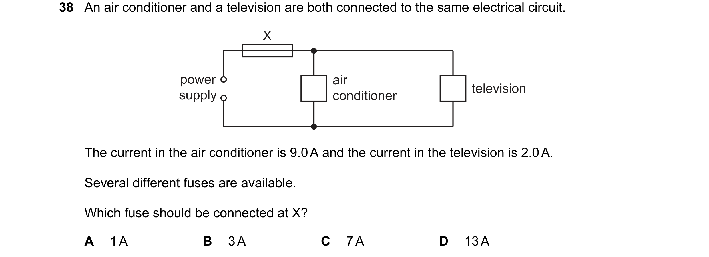 28 / 77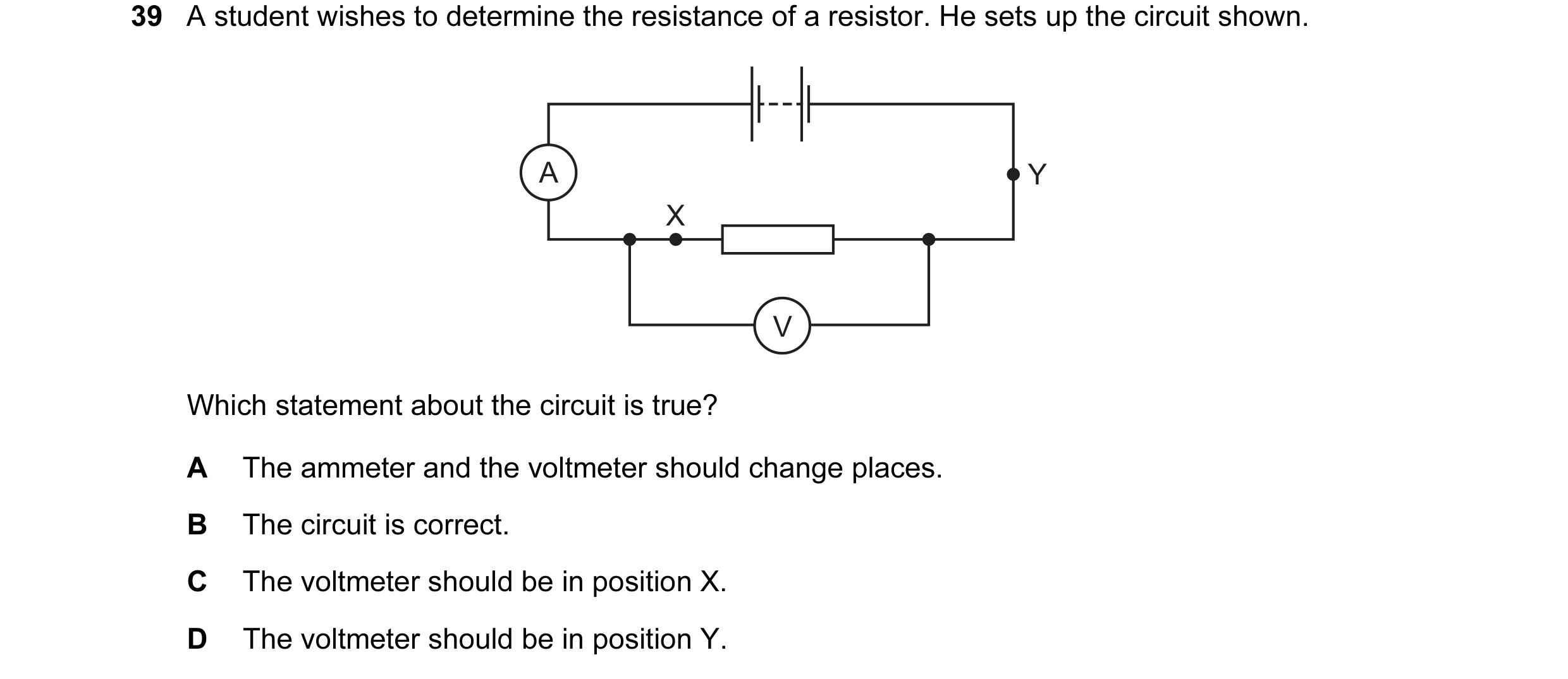
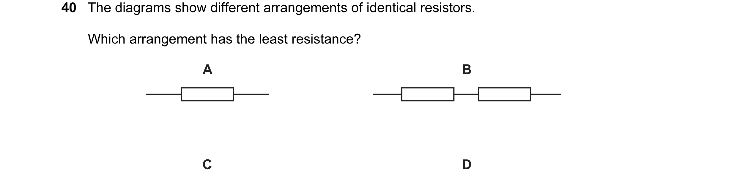
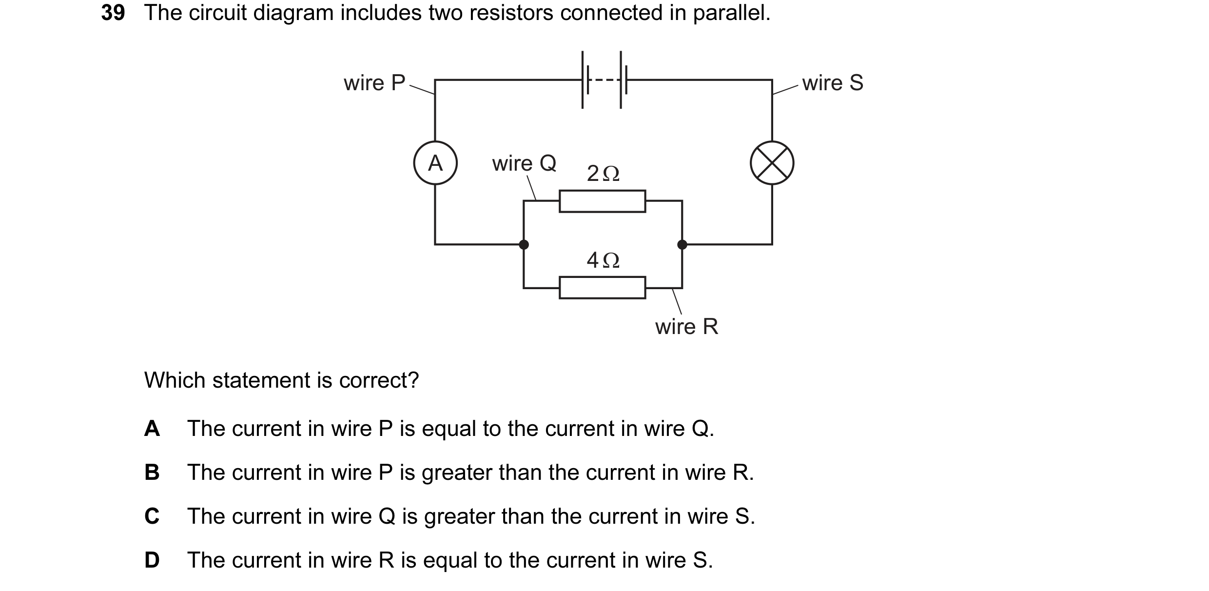 29 / 77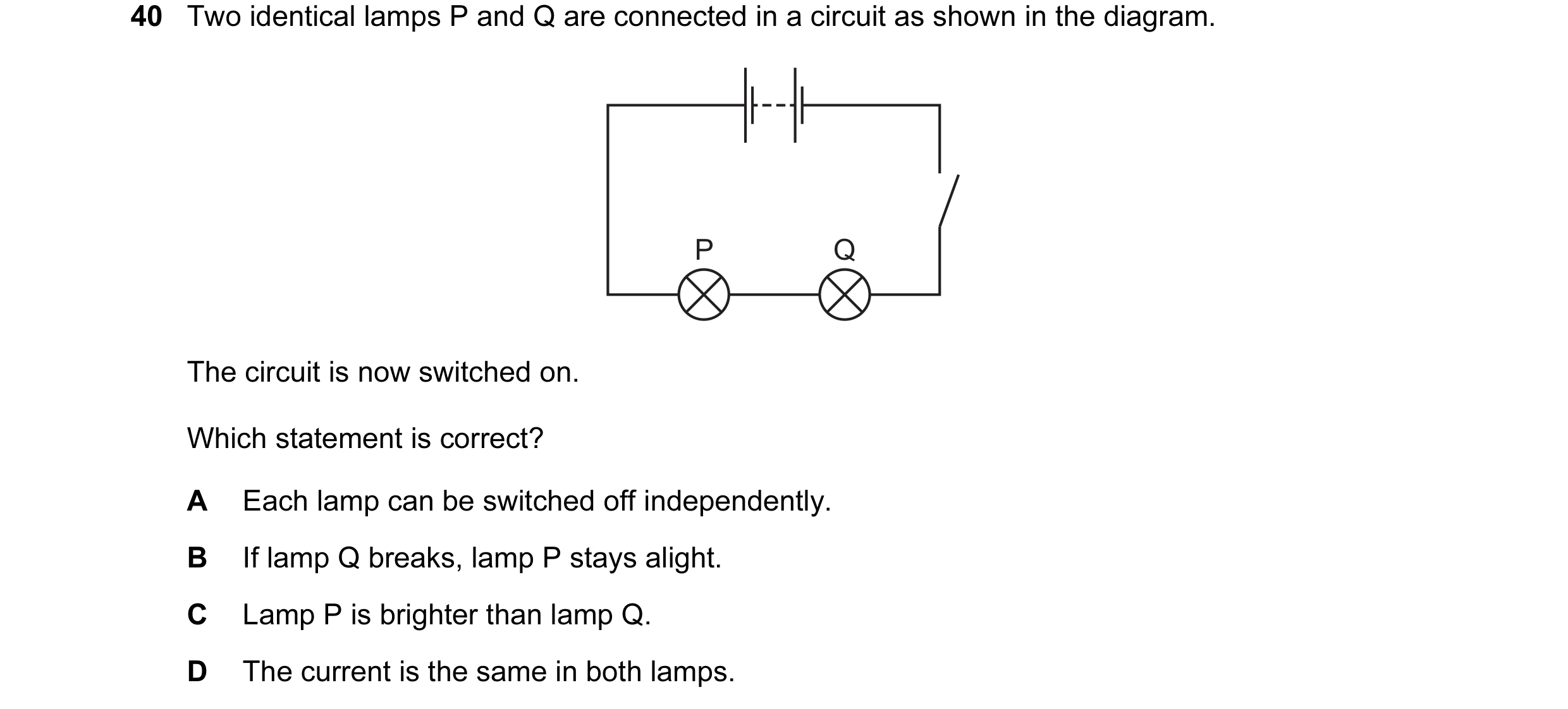
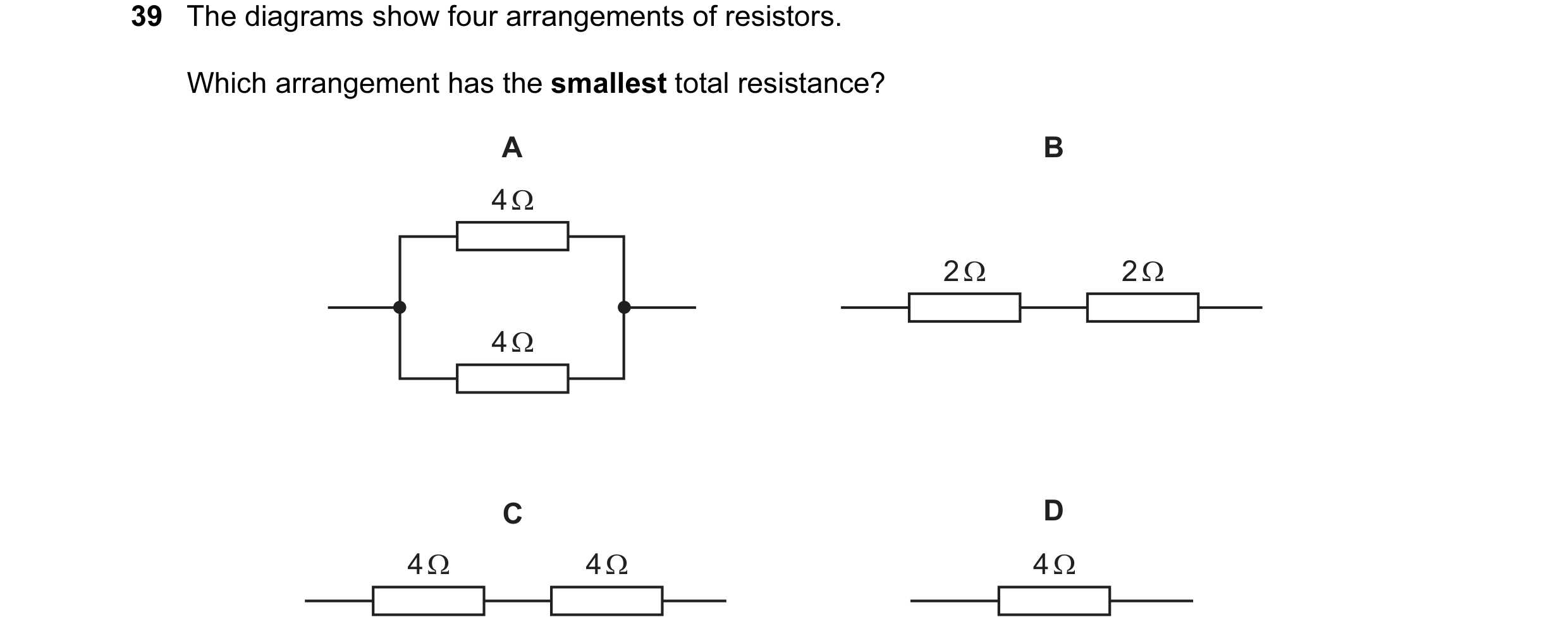
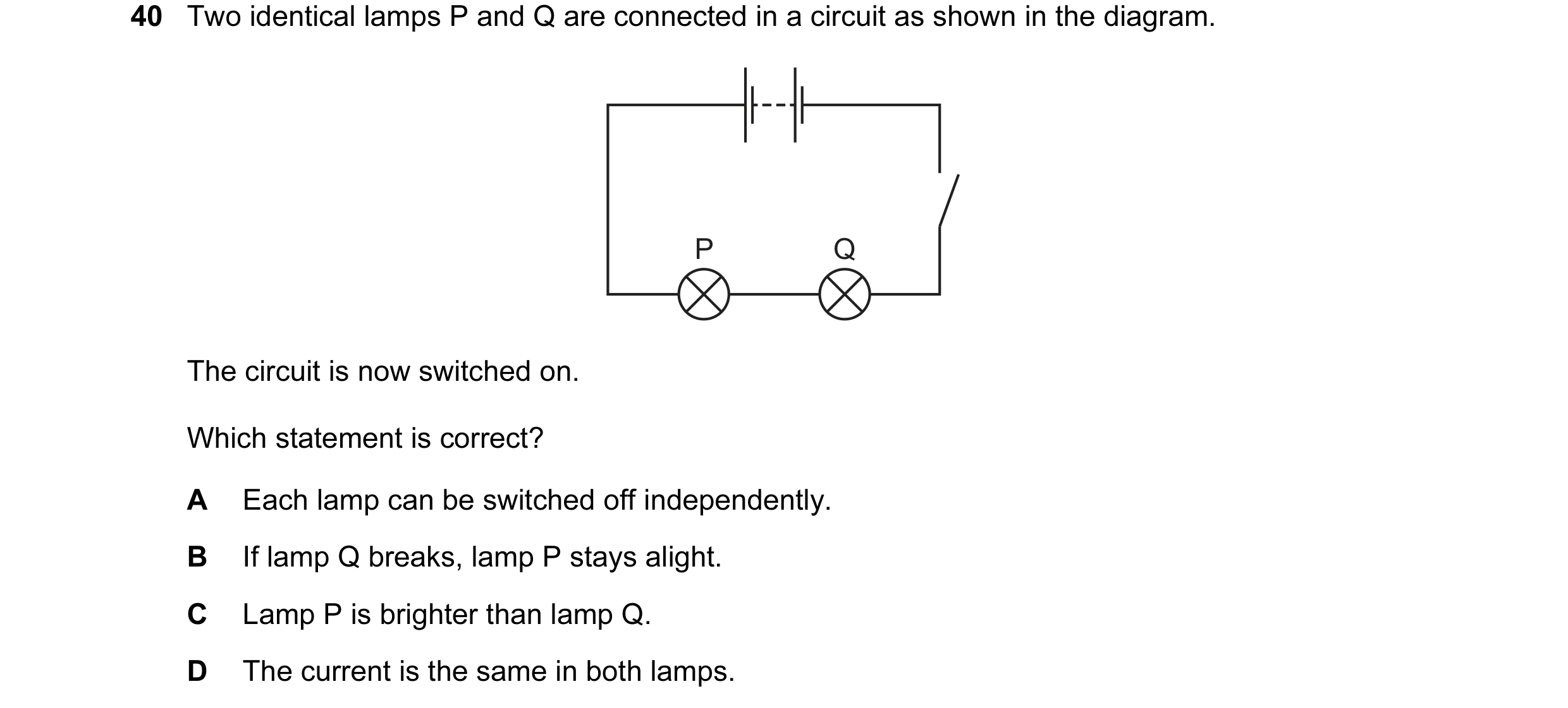 30 / 77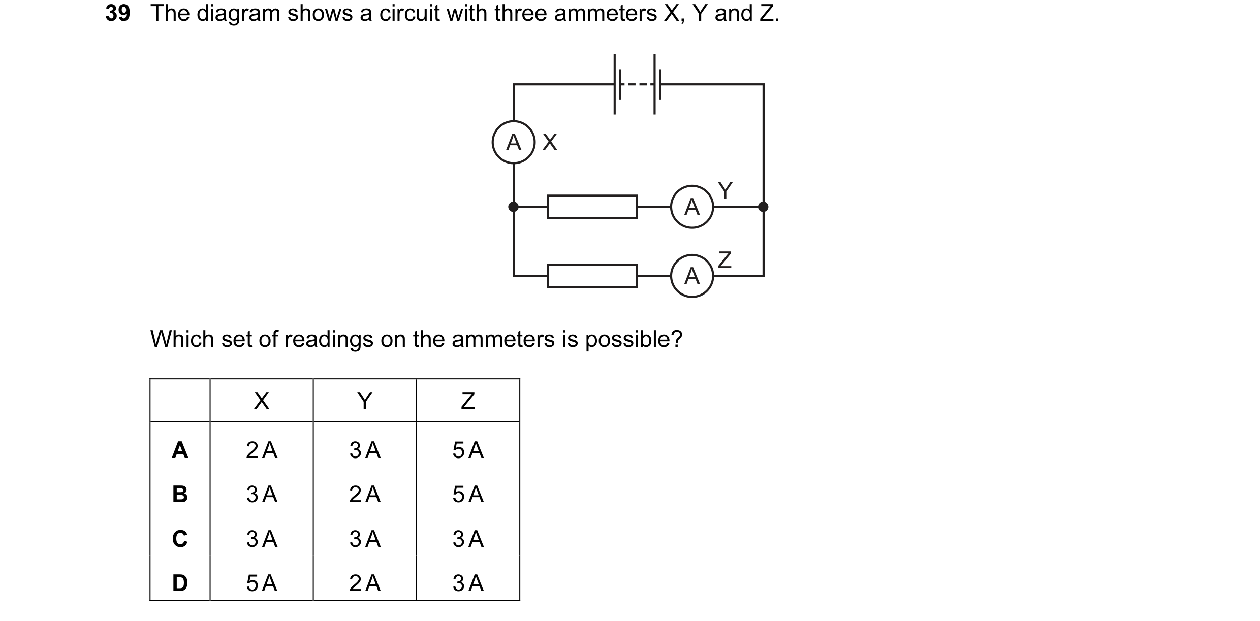
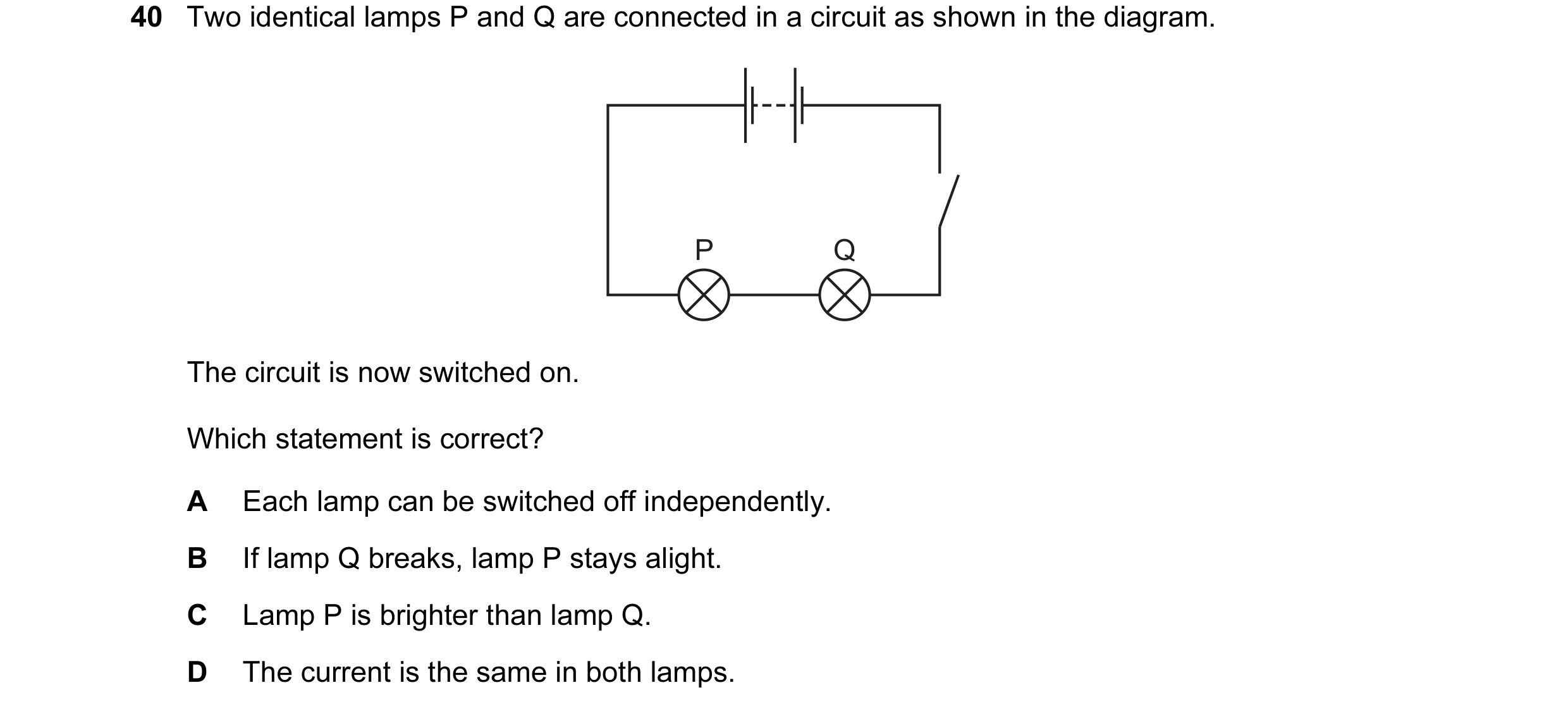 31 / 77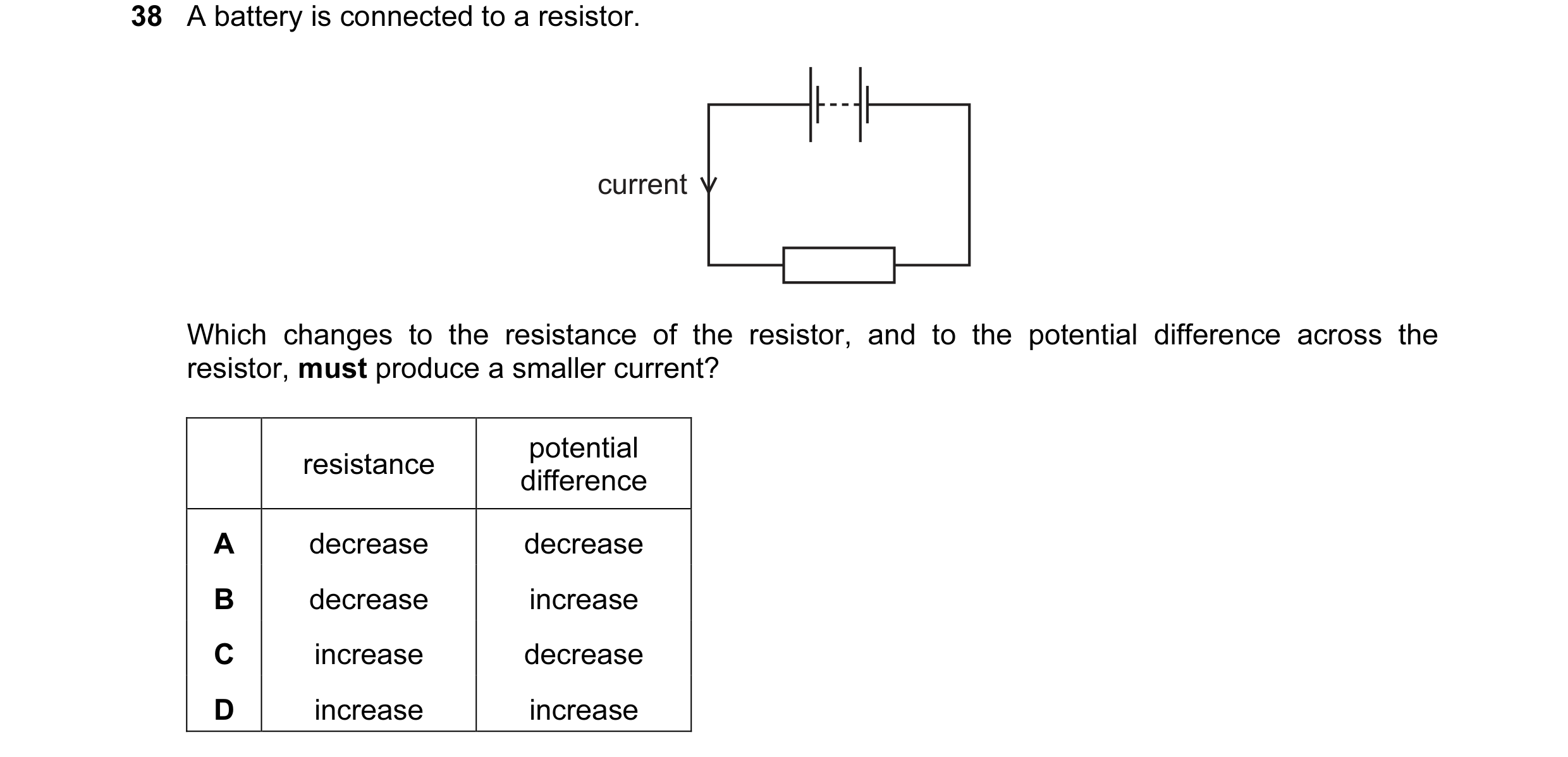
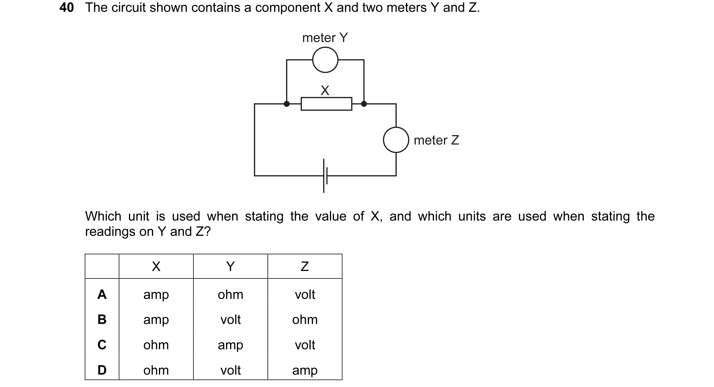 32 / 77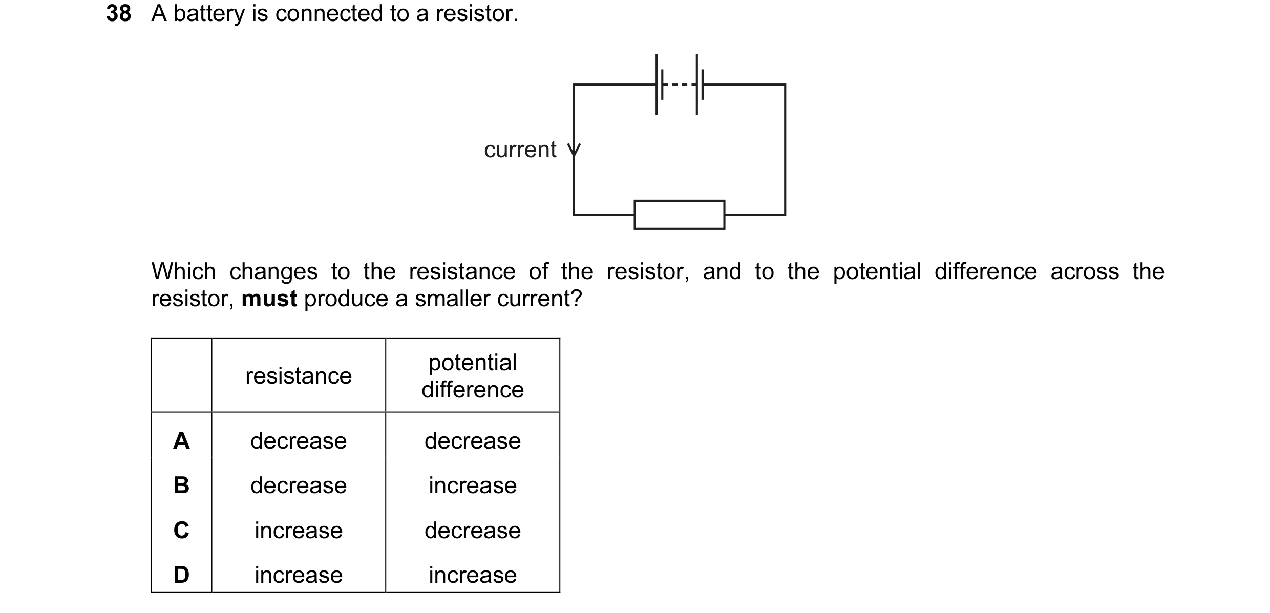
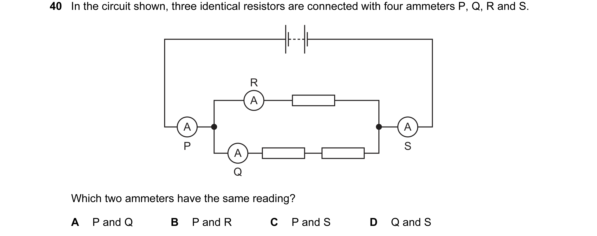 33 / 77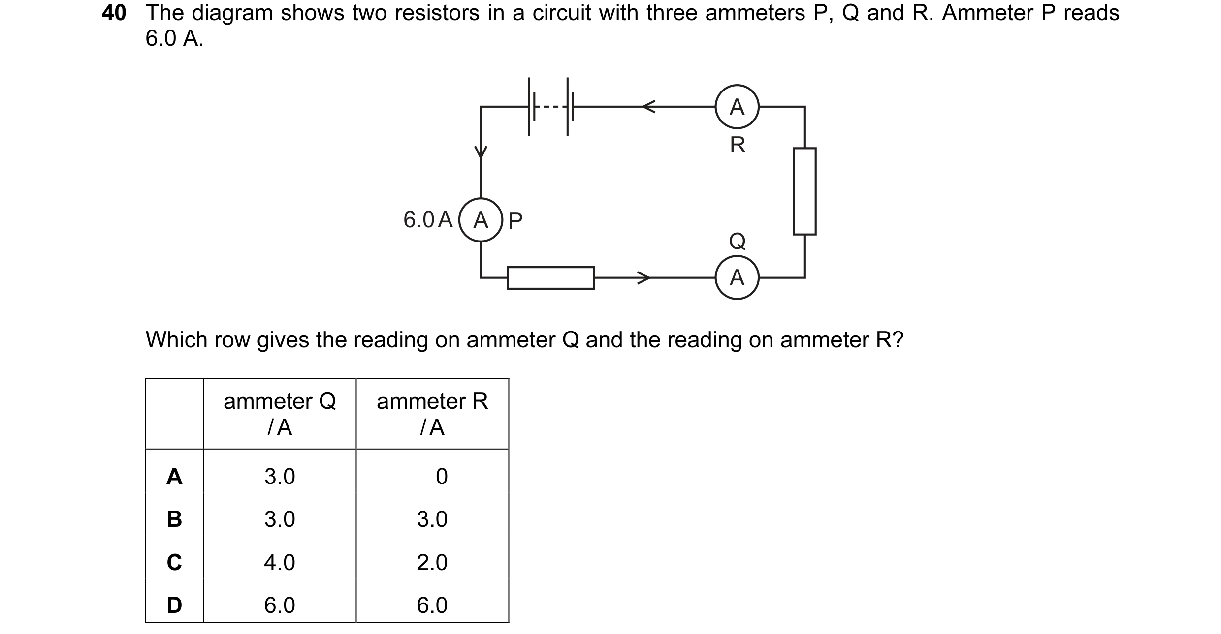
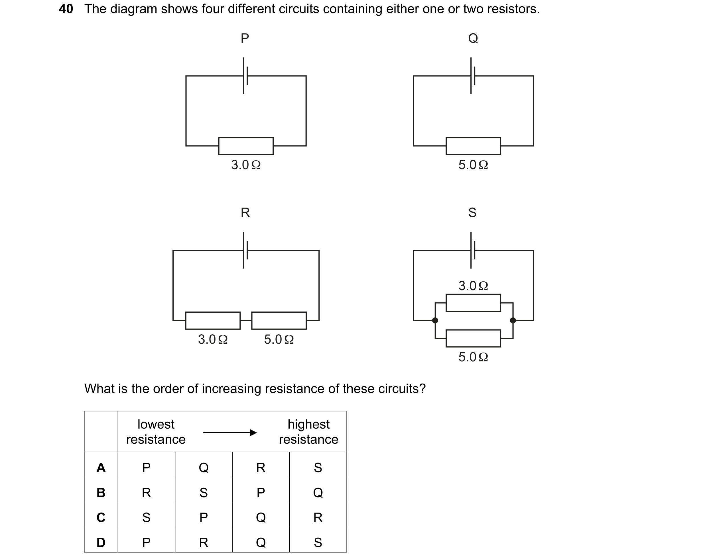 34 / 77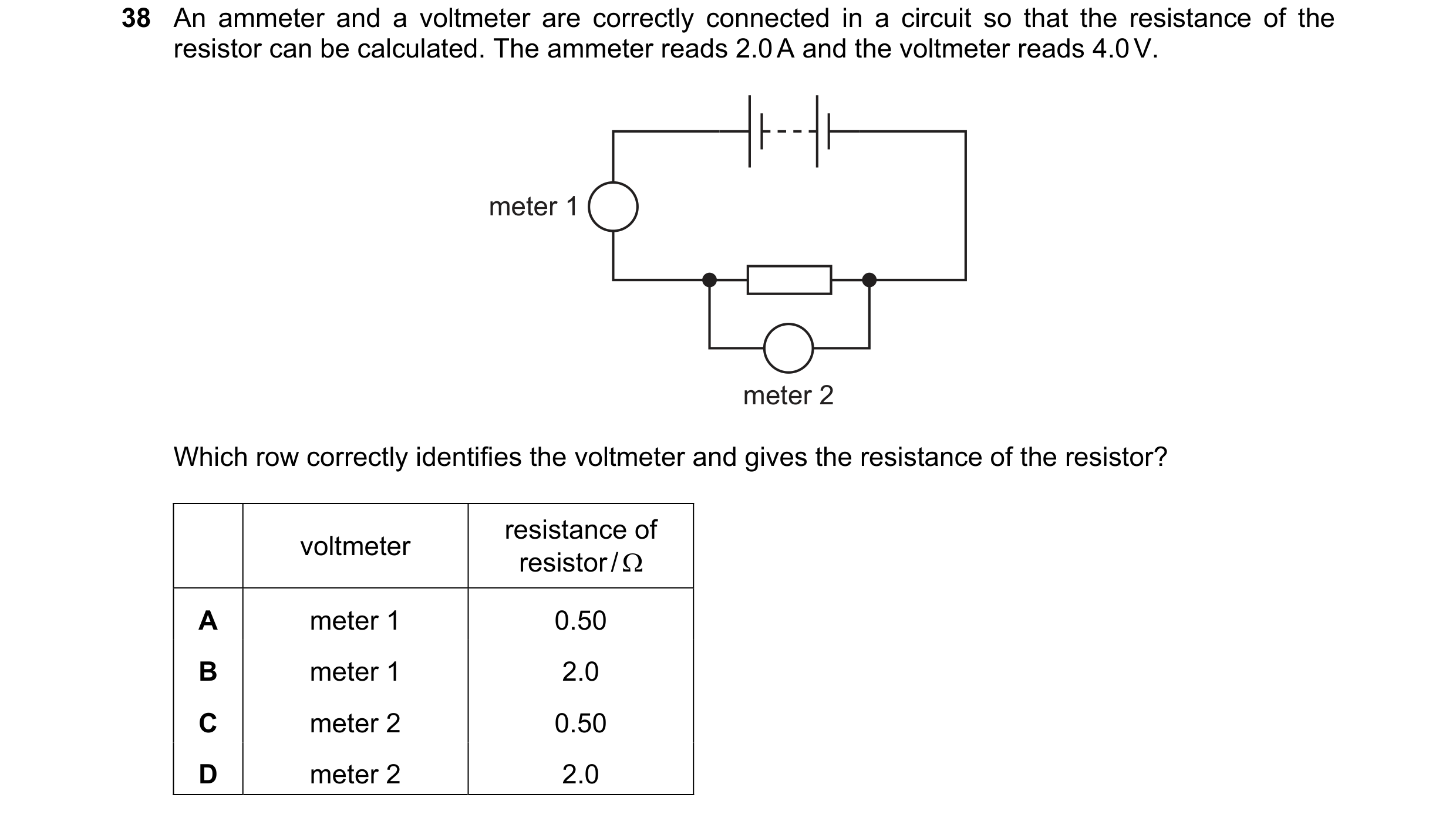
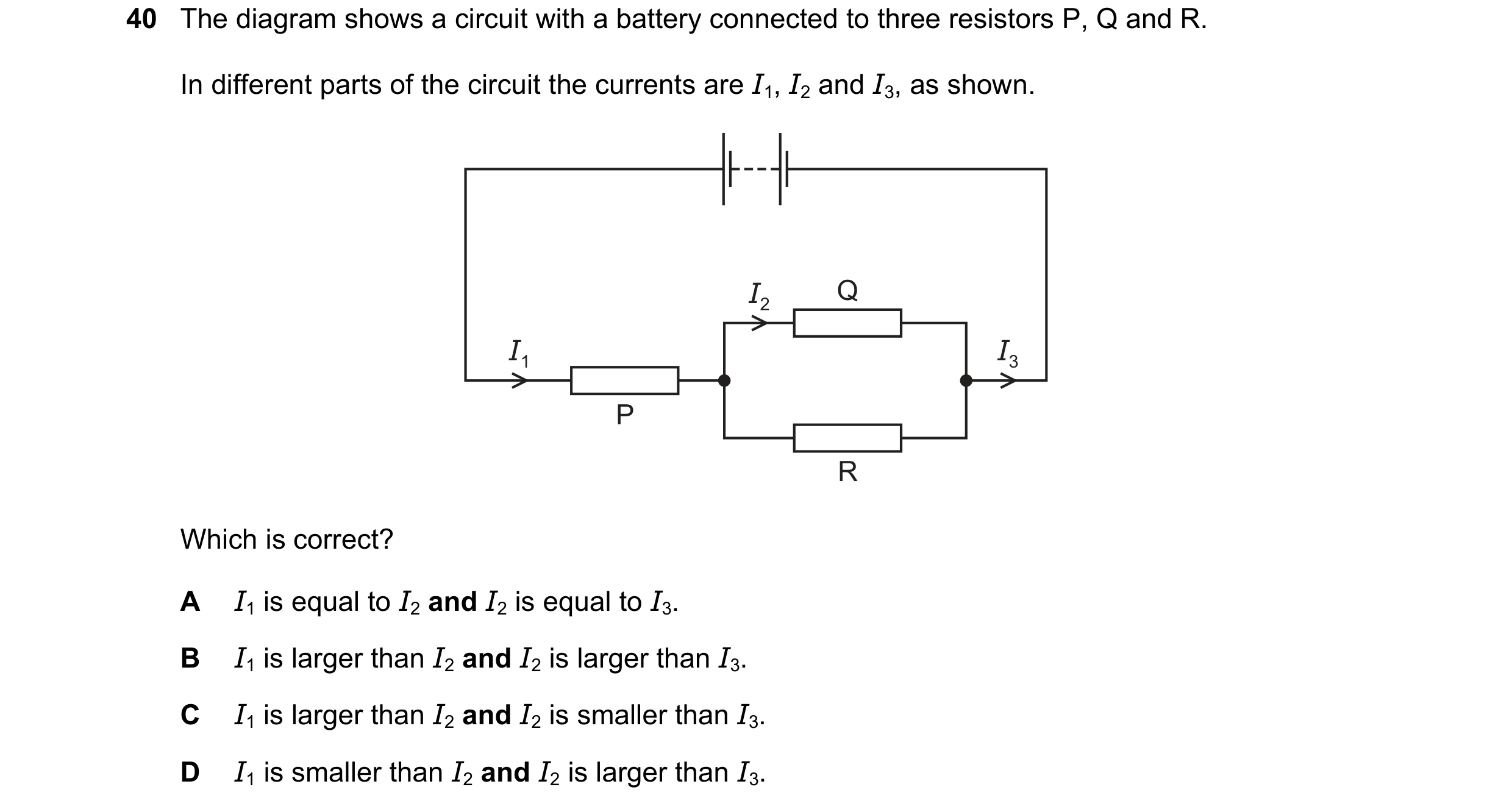 35 / 77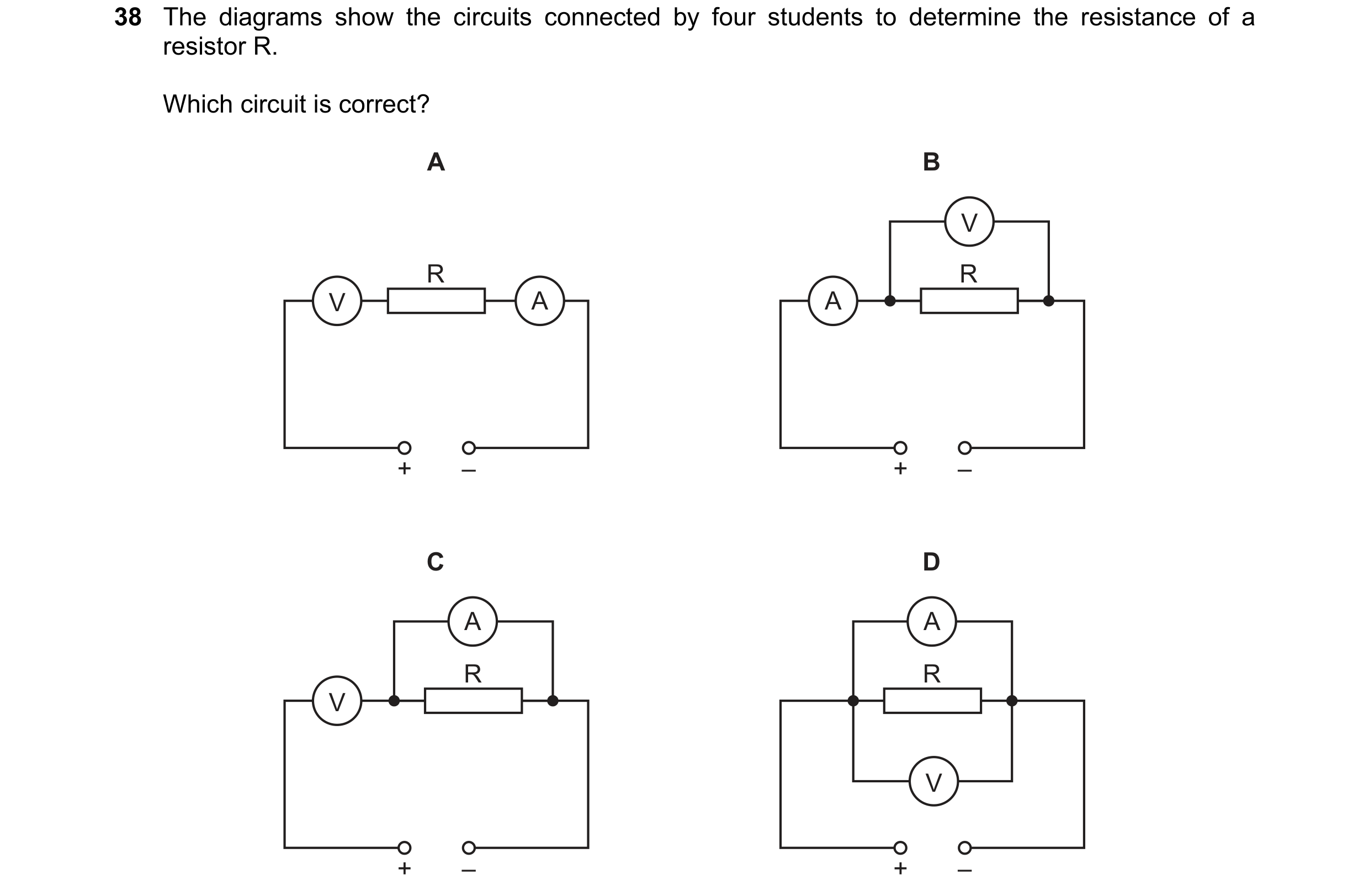
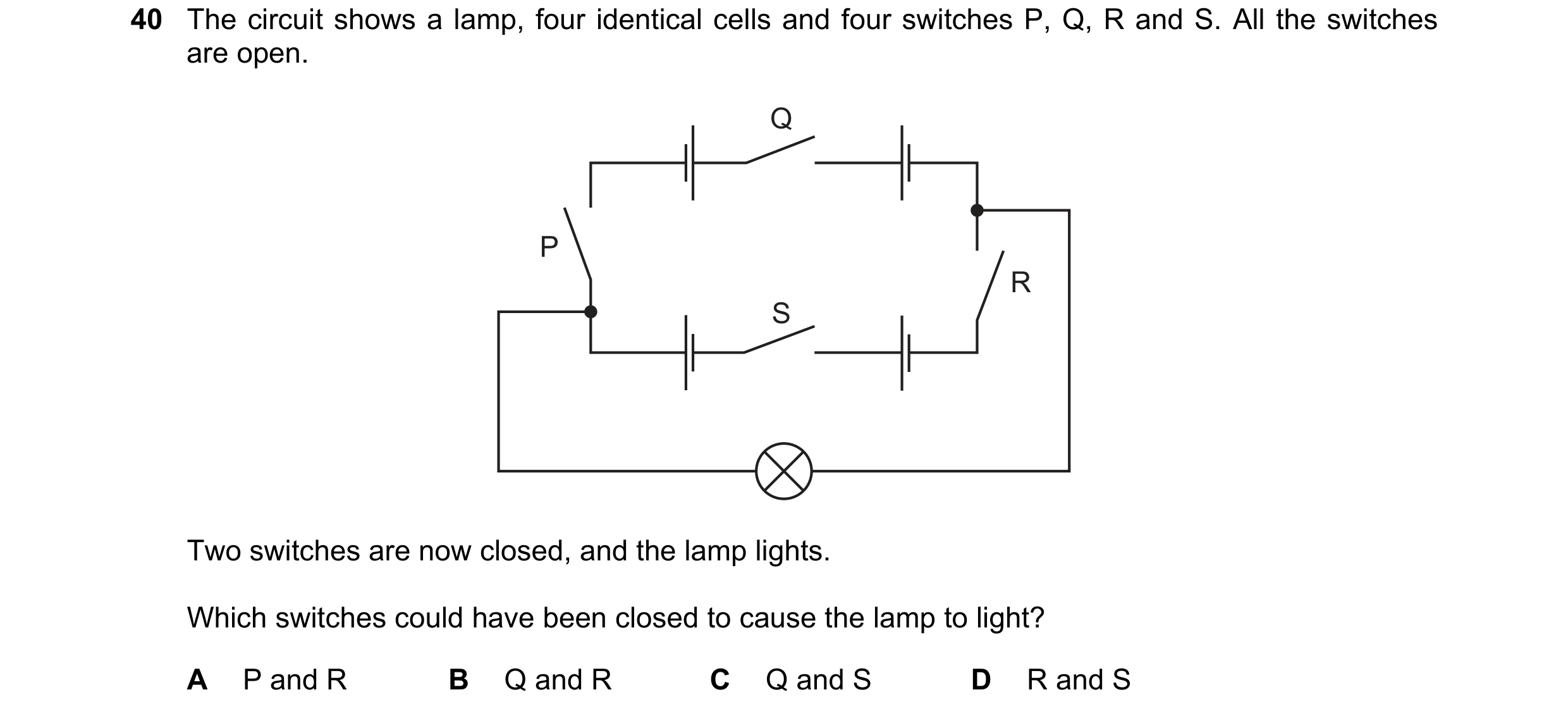 36 / 77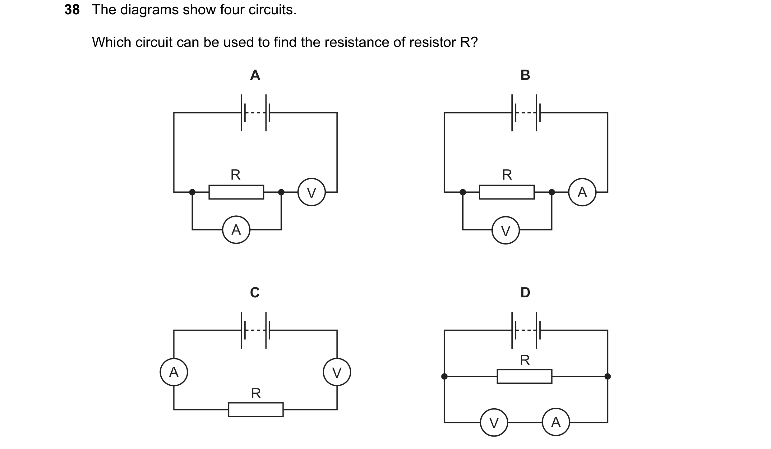
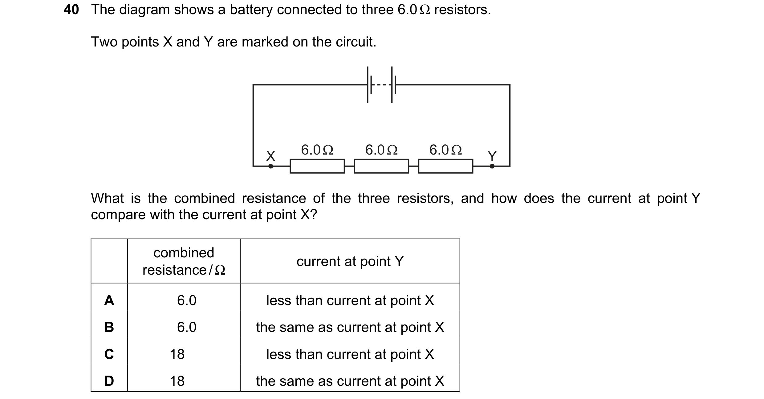 37 / 77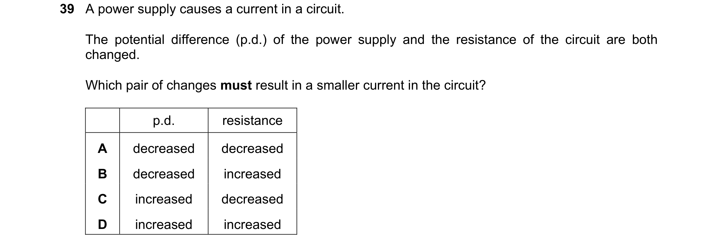
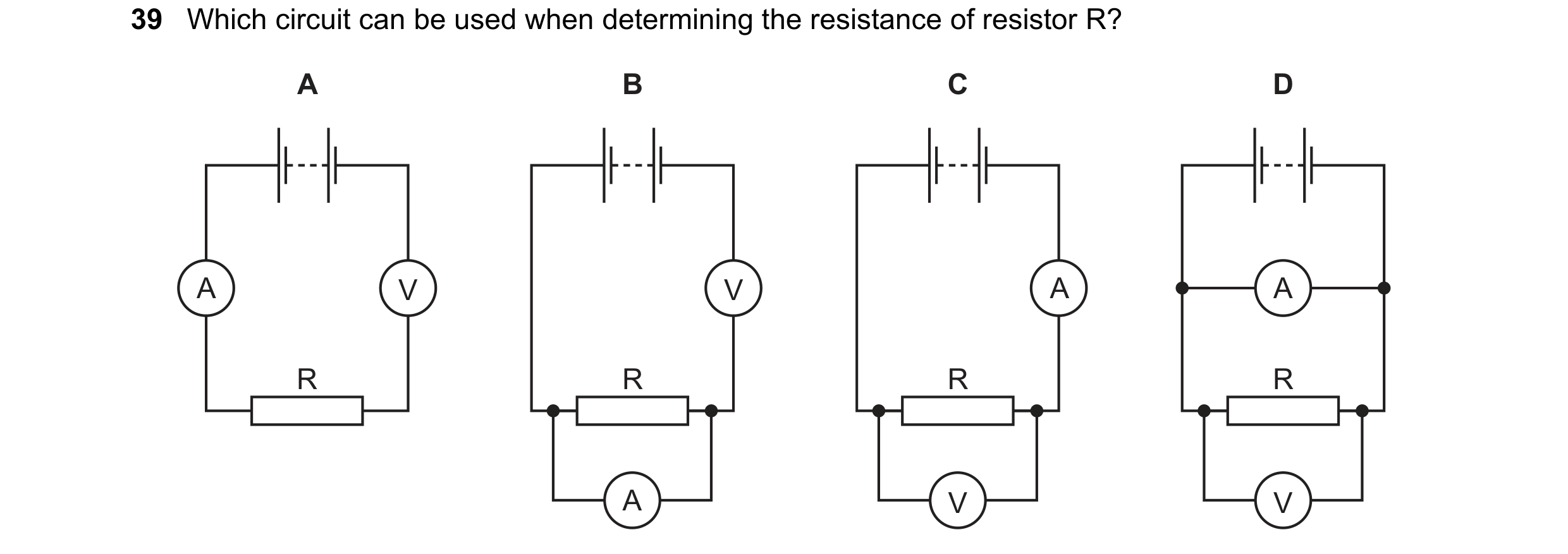
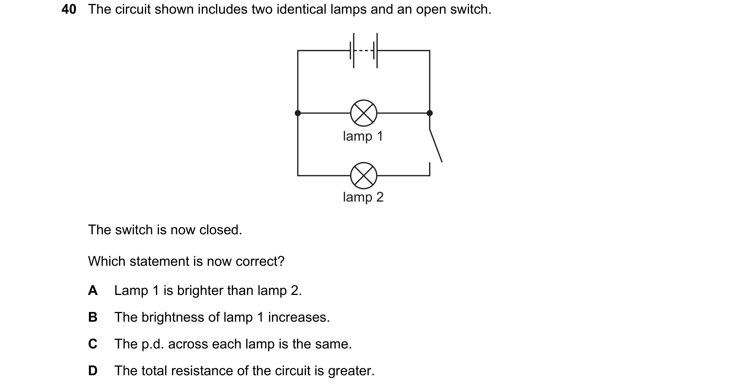 38 / 77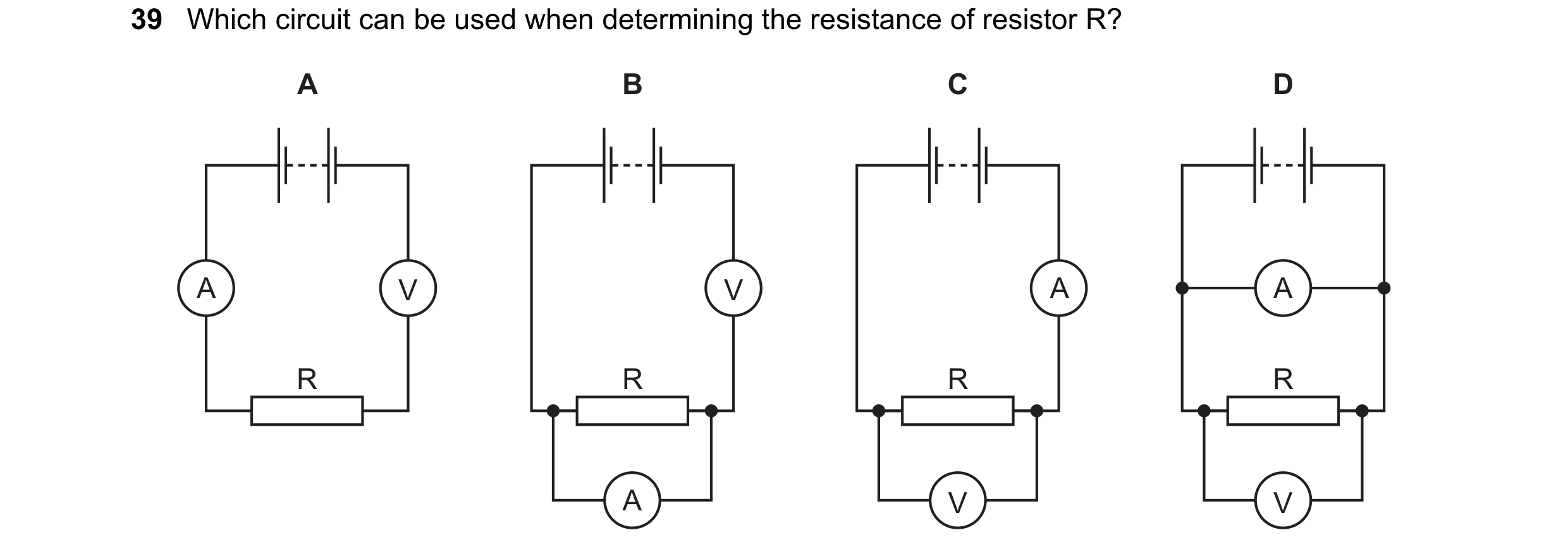
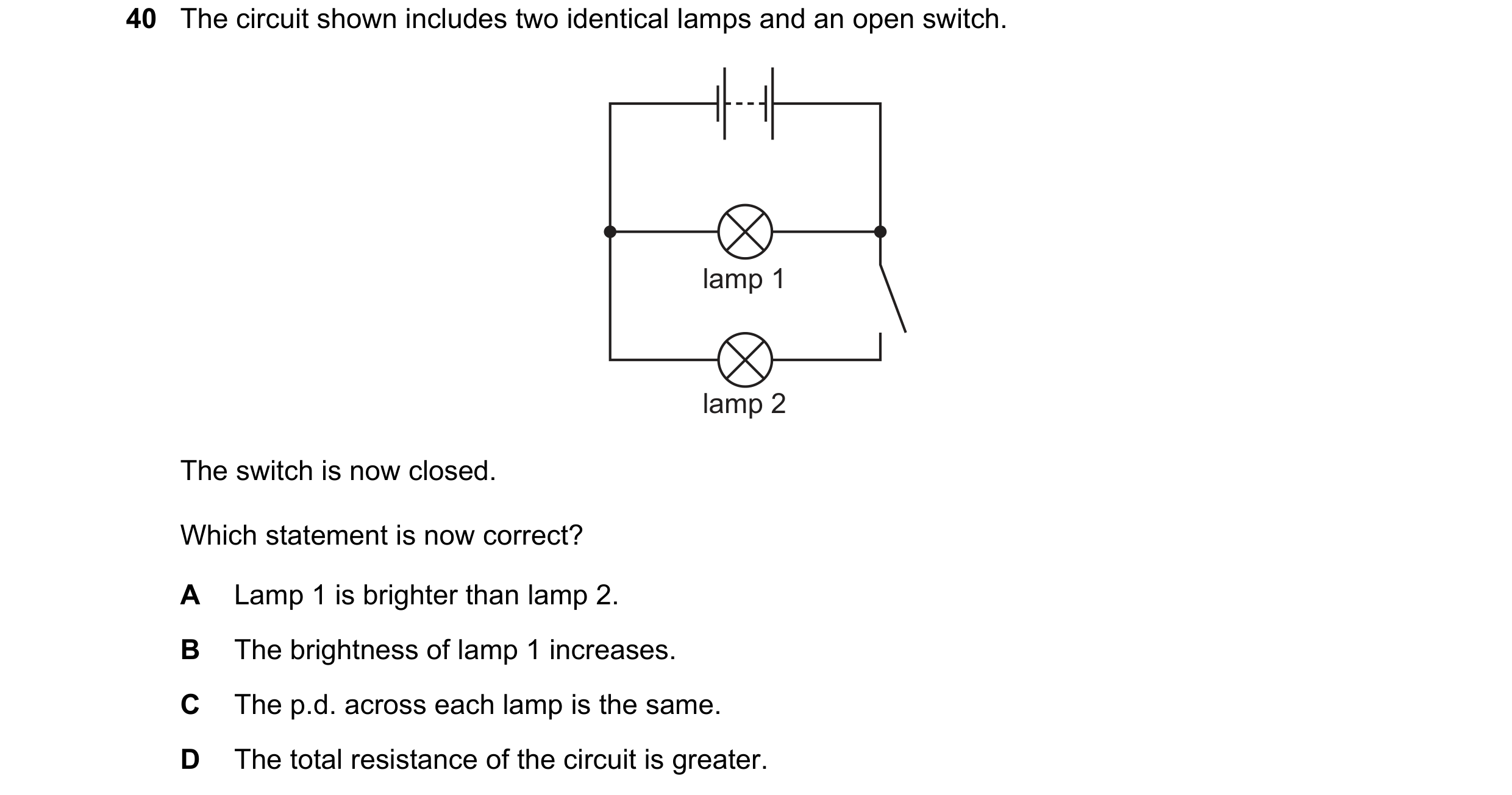
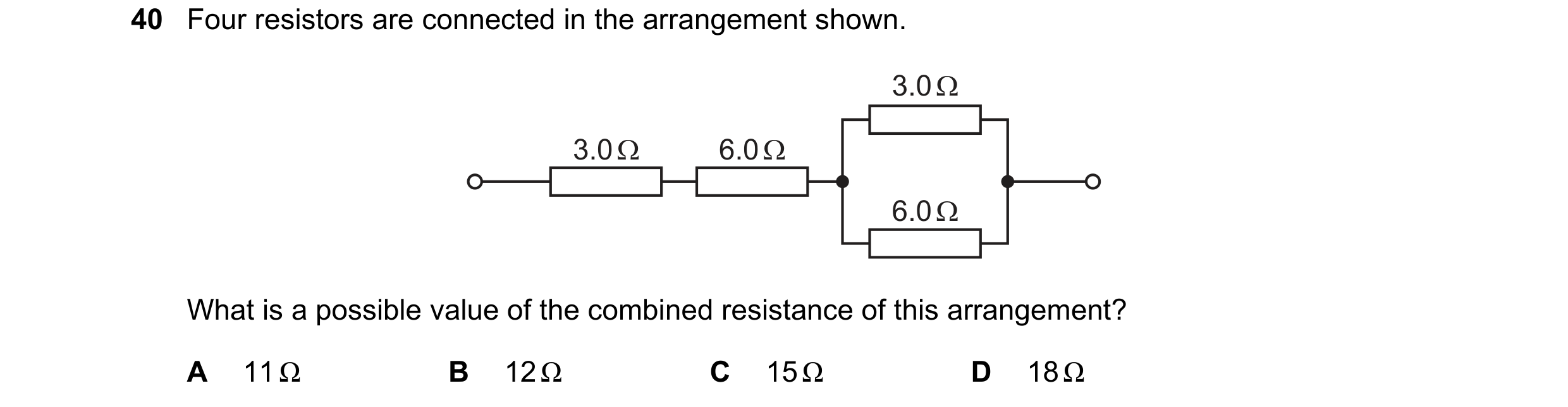 39 / 77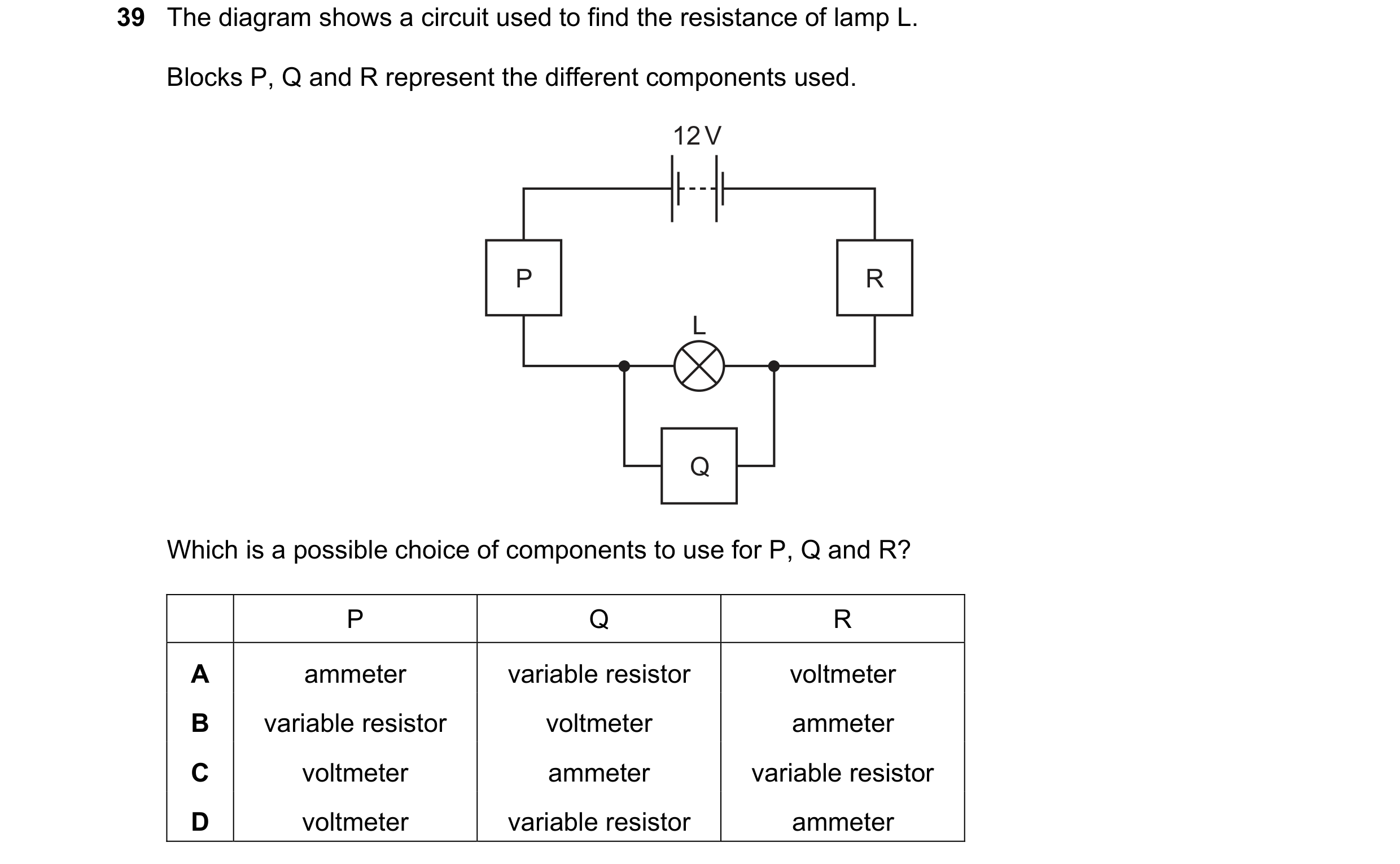
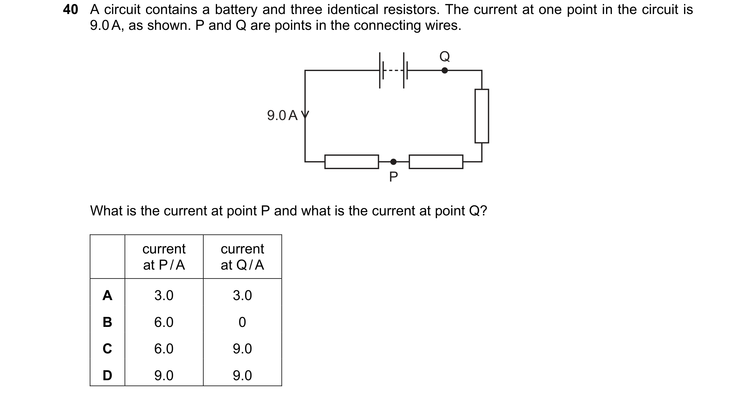 40 / 77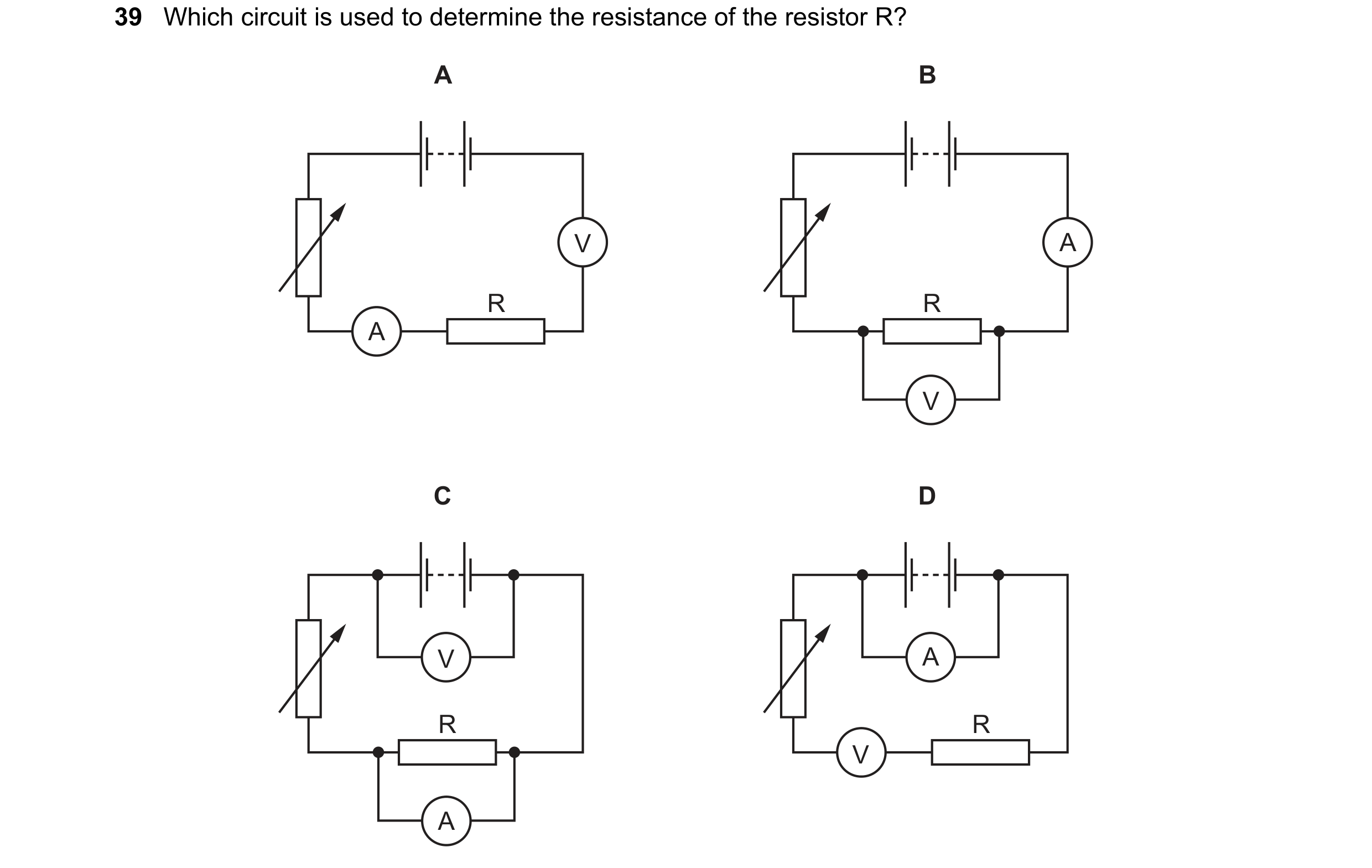
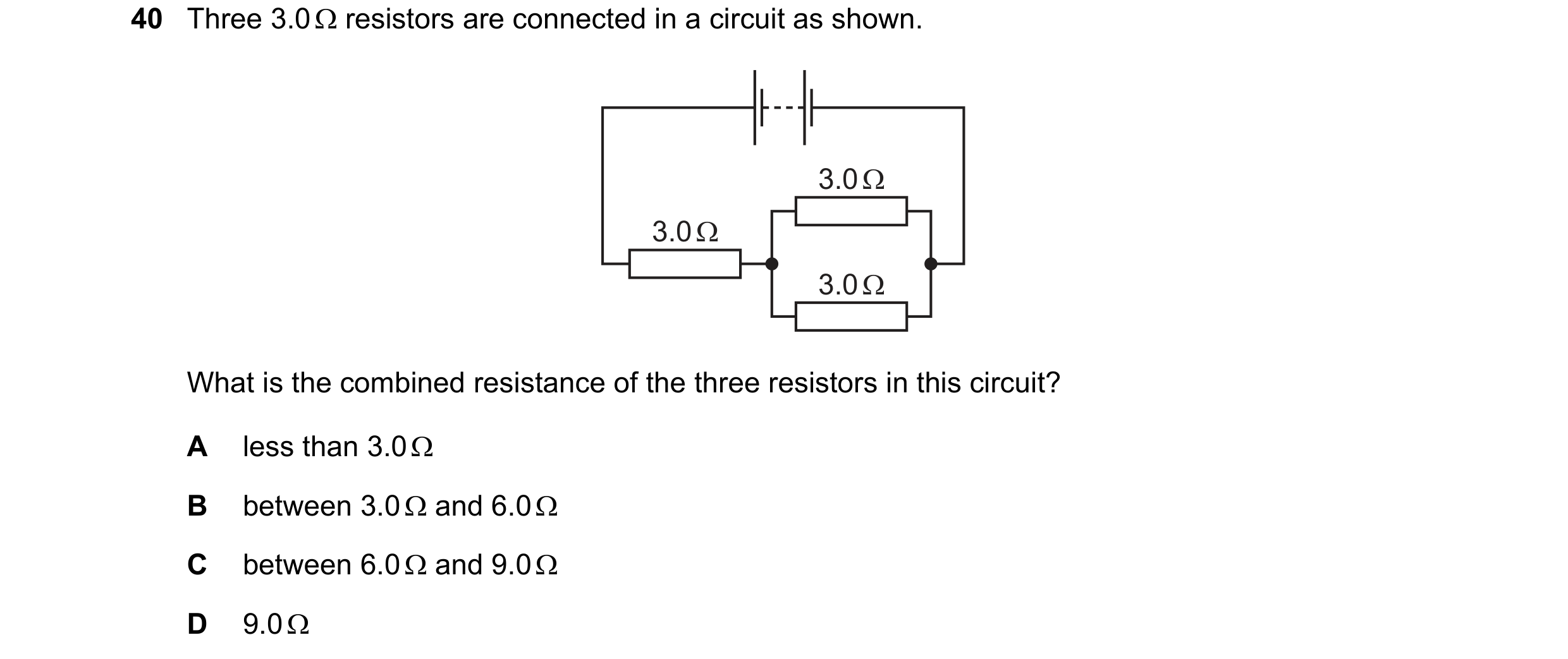 41 / 77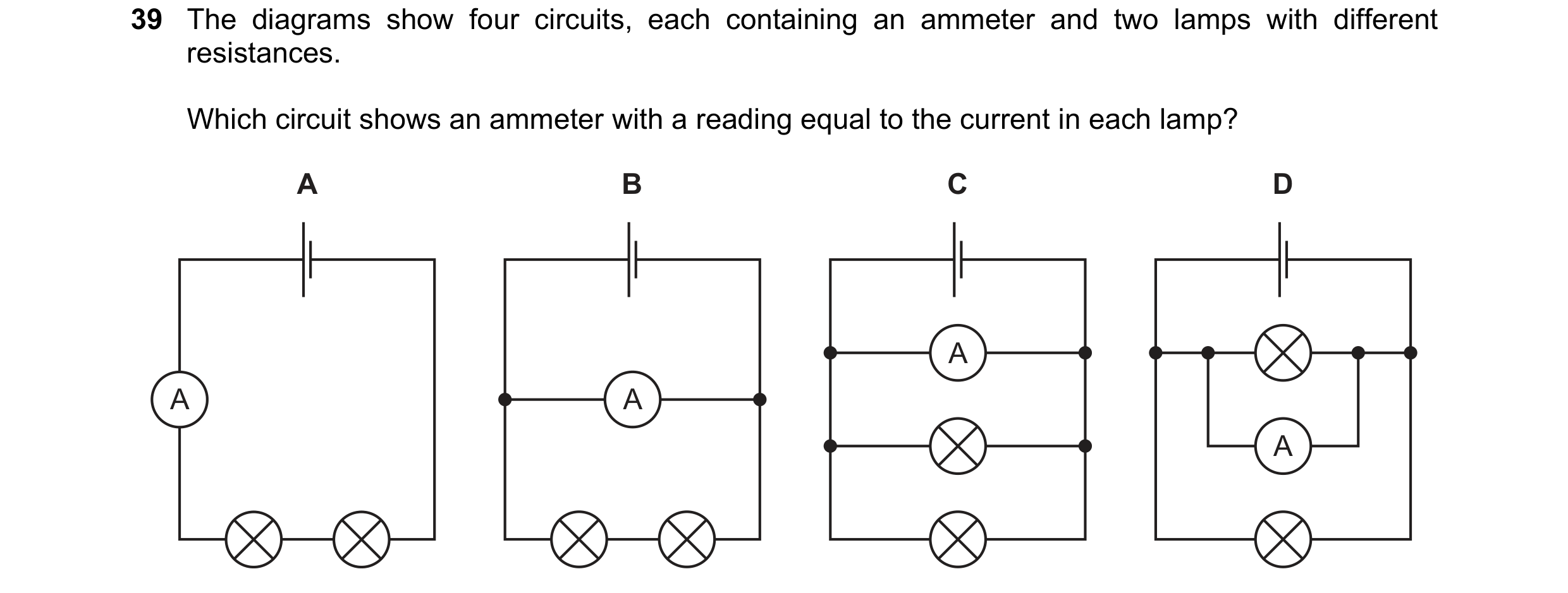
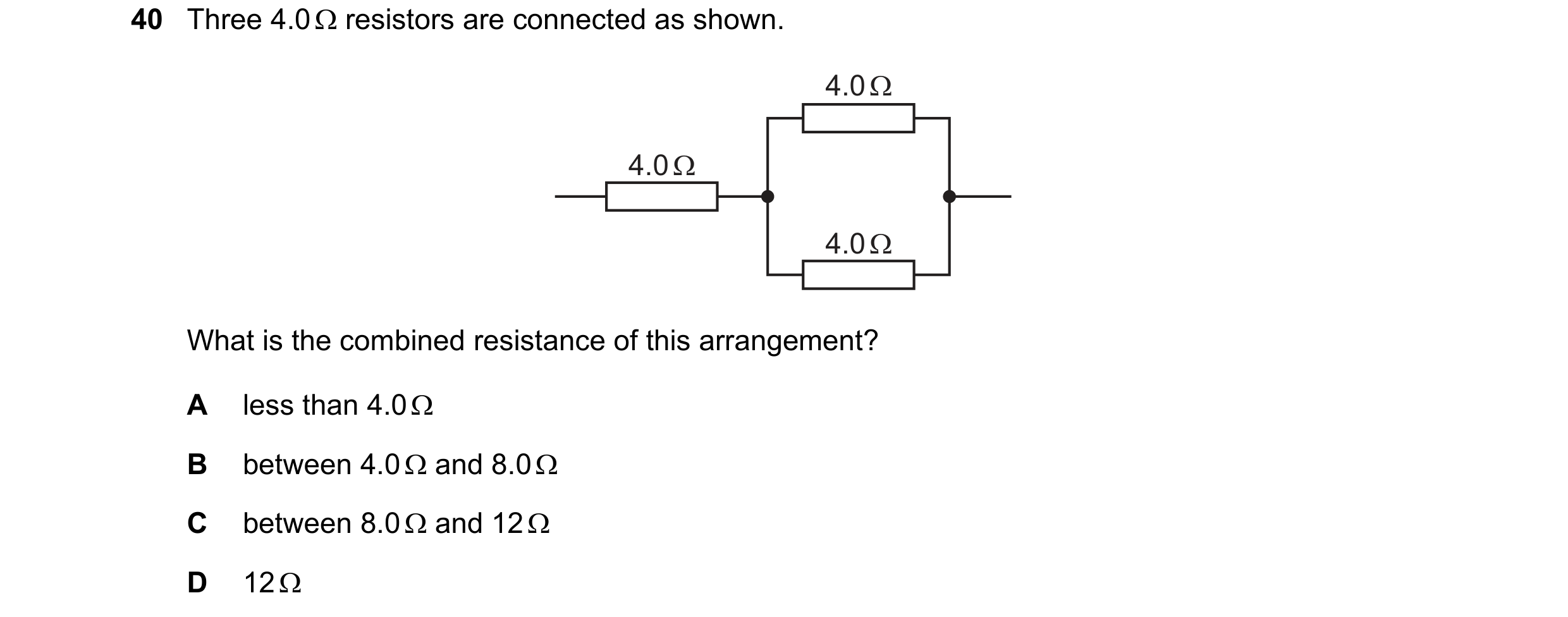
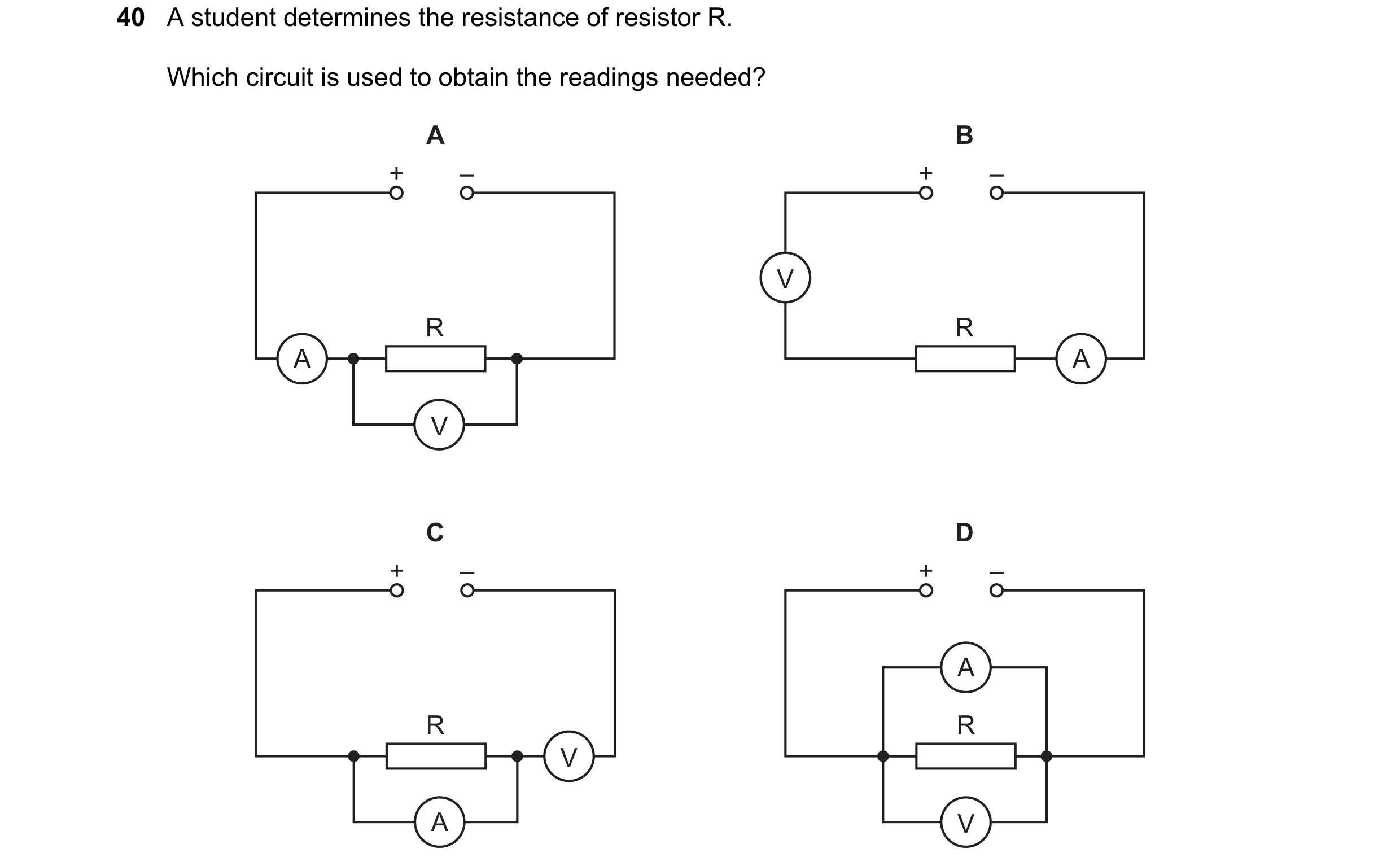 42 / 77
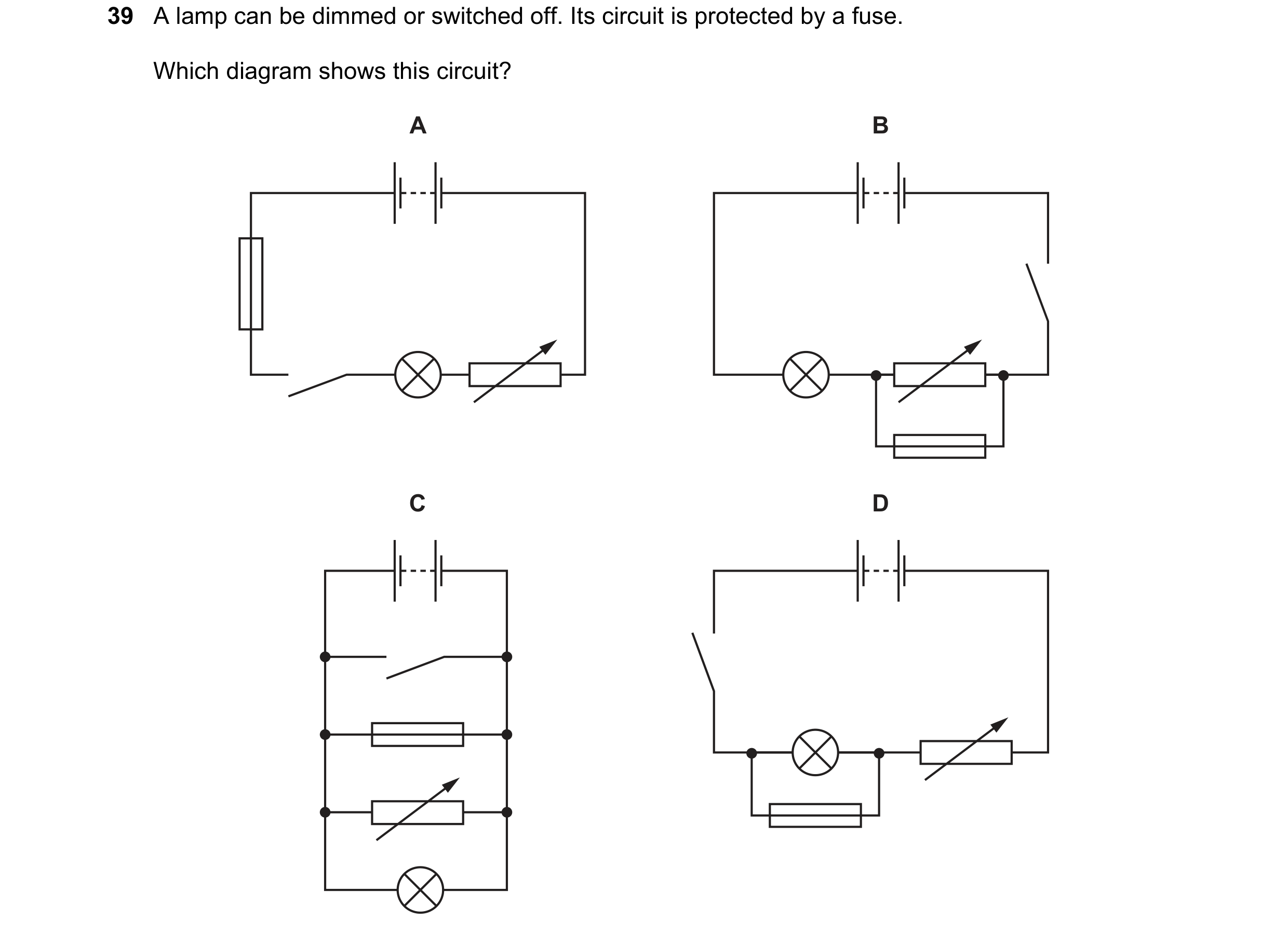 43 / 77
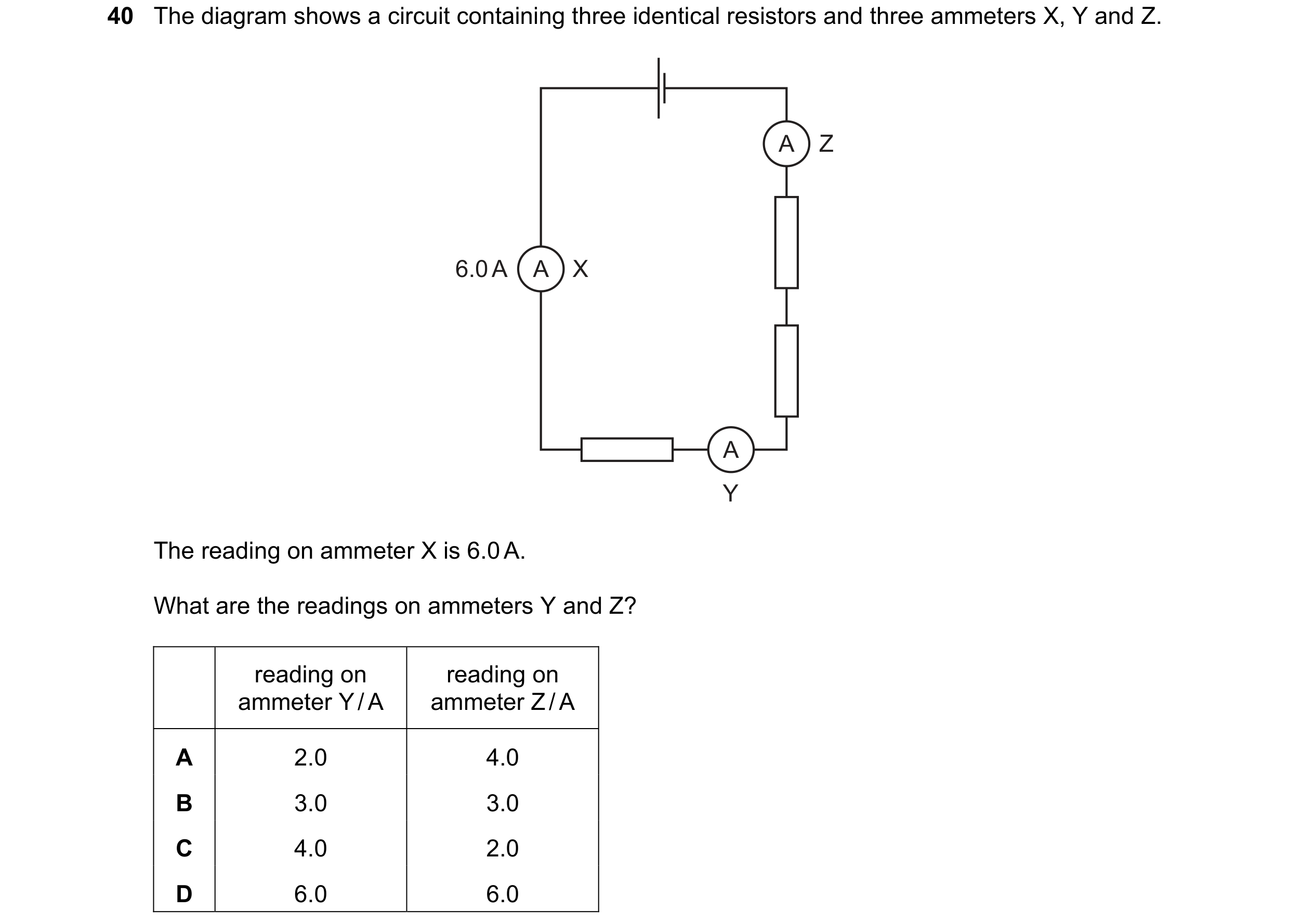 44 / 77
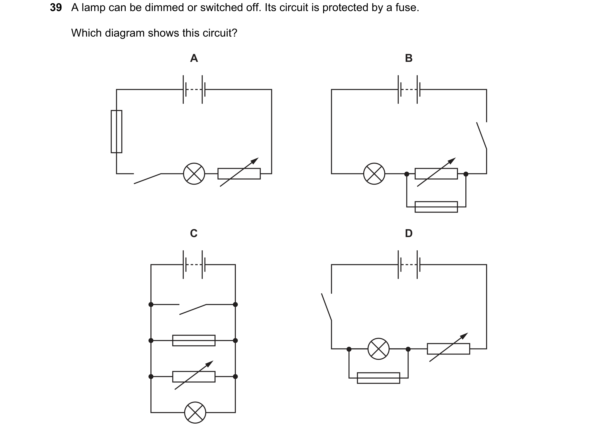 45 / 77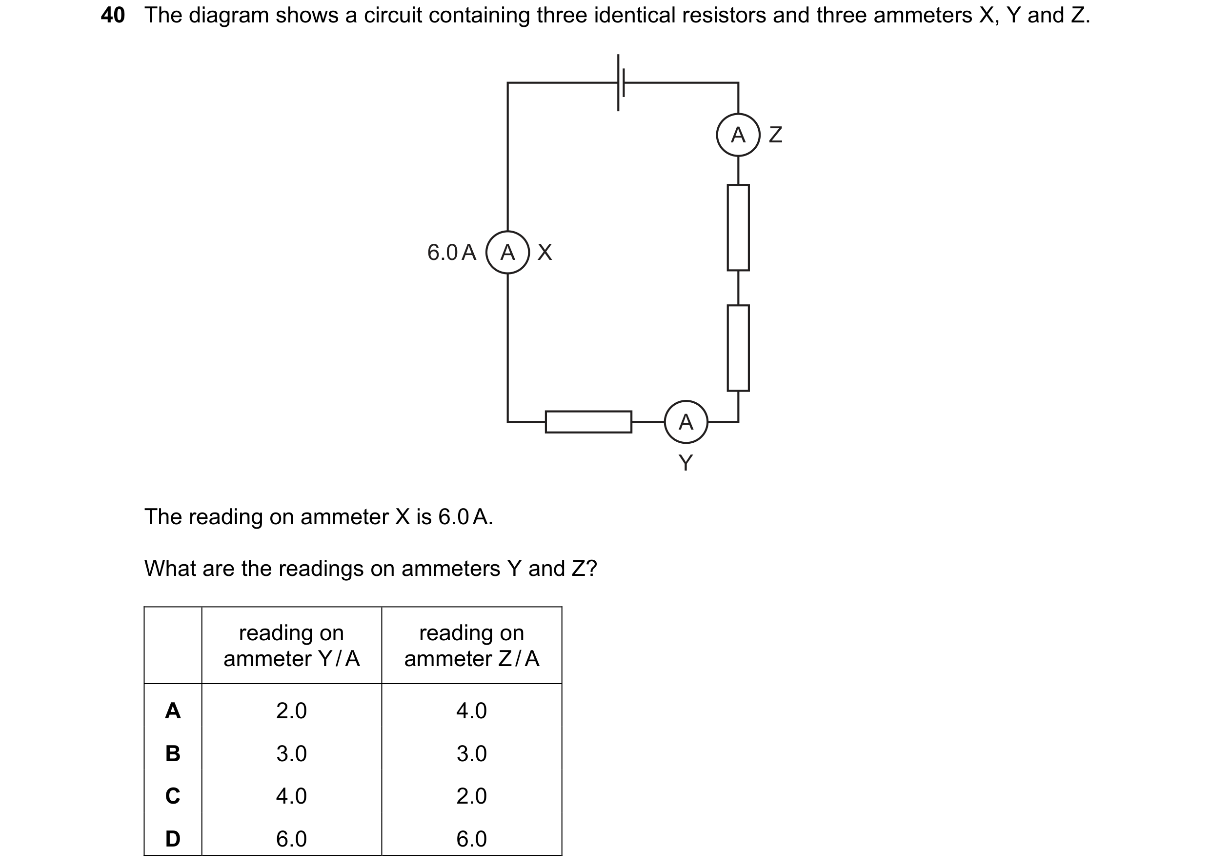
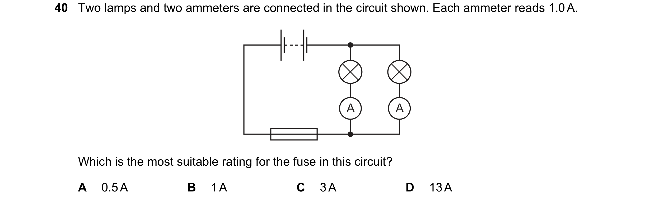 46 / 77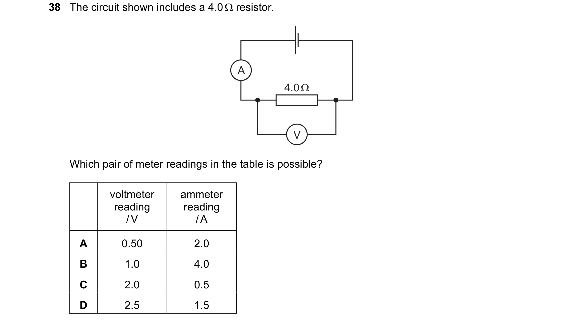
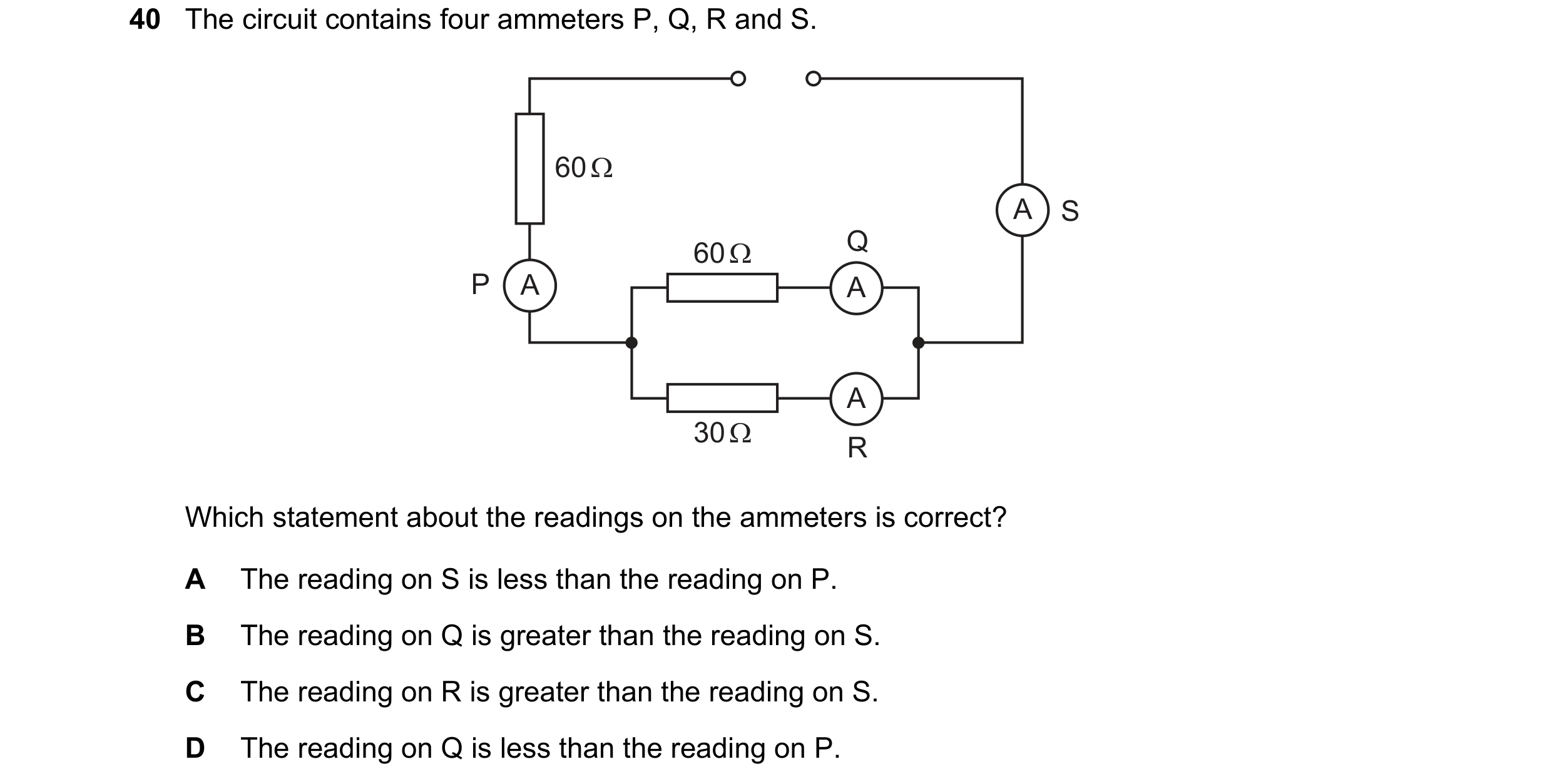 47 / 77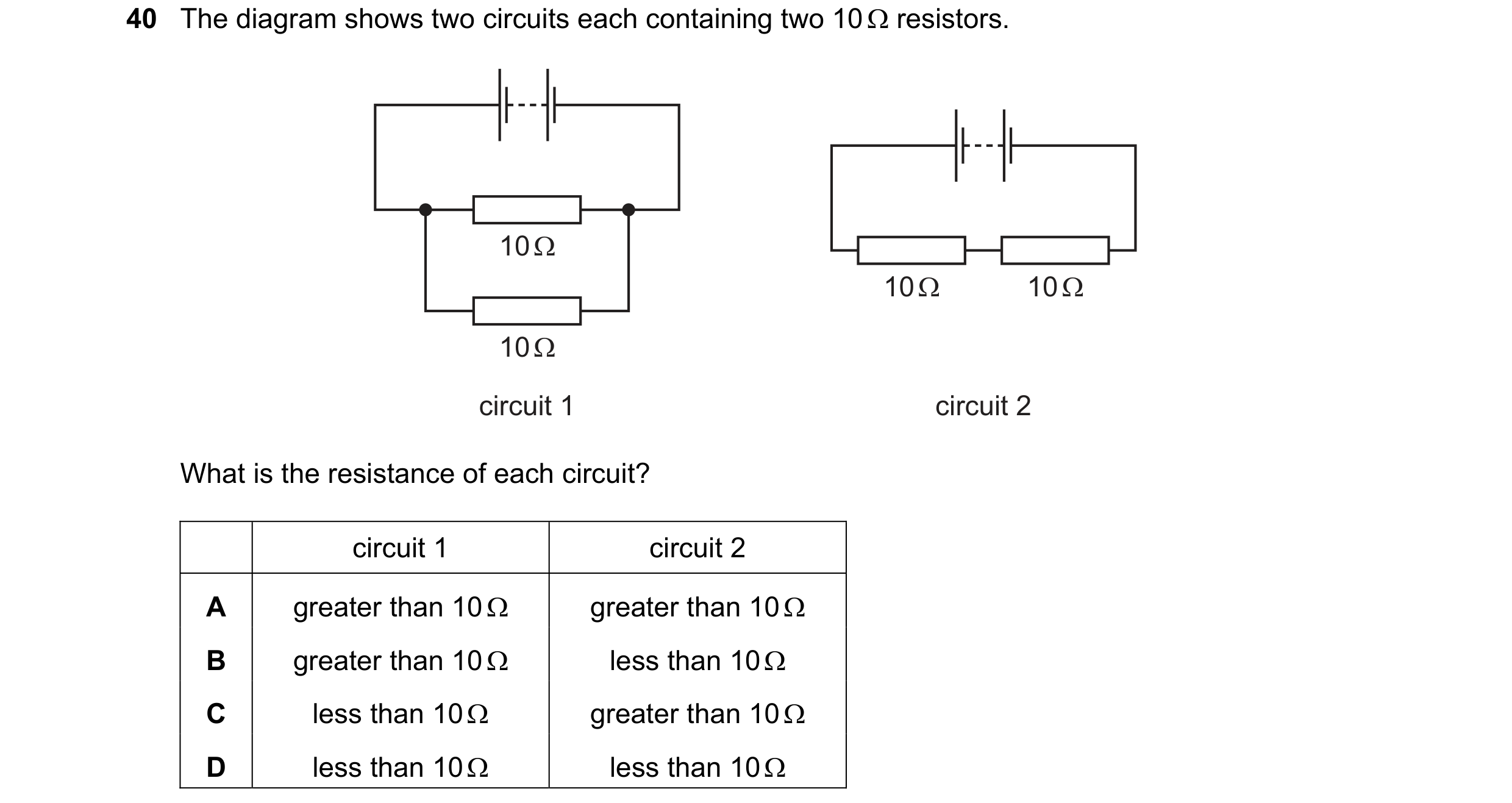
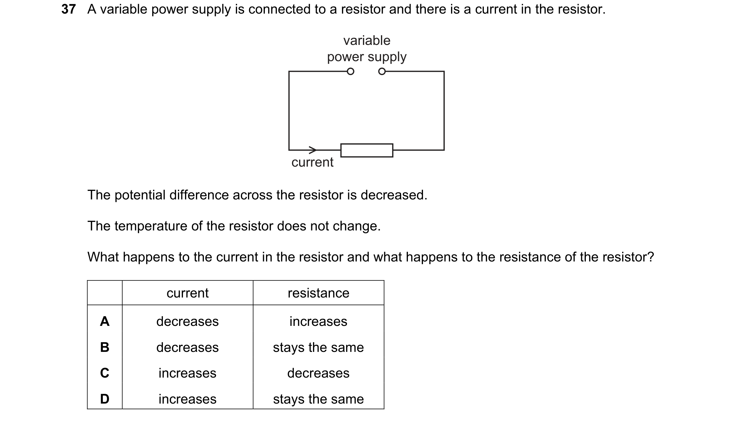 48 / 77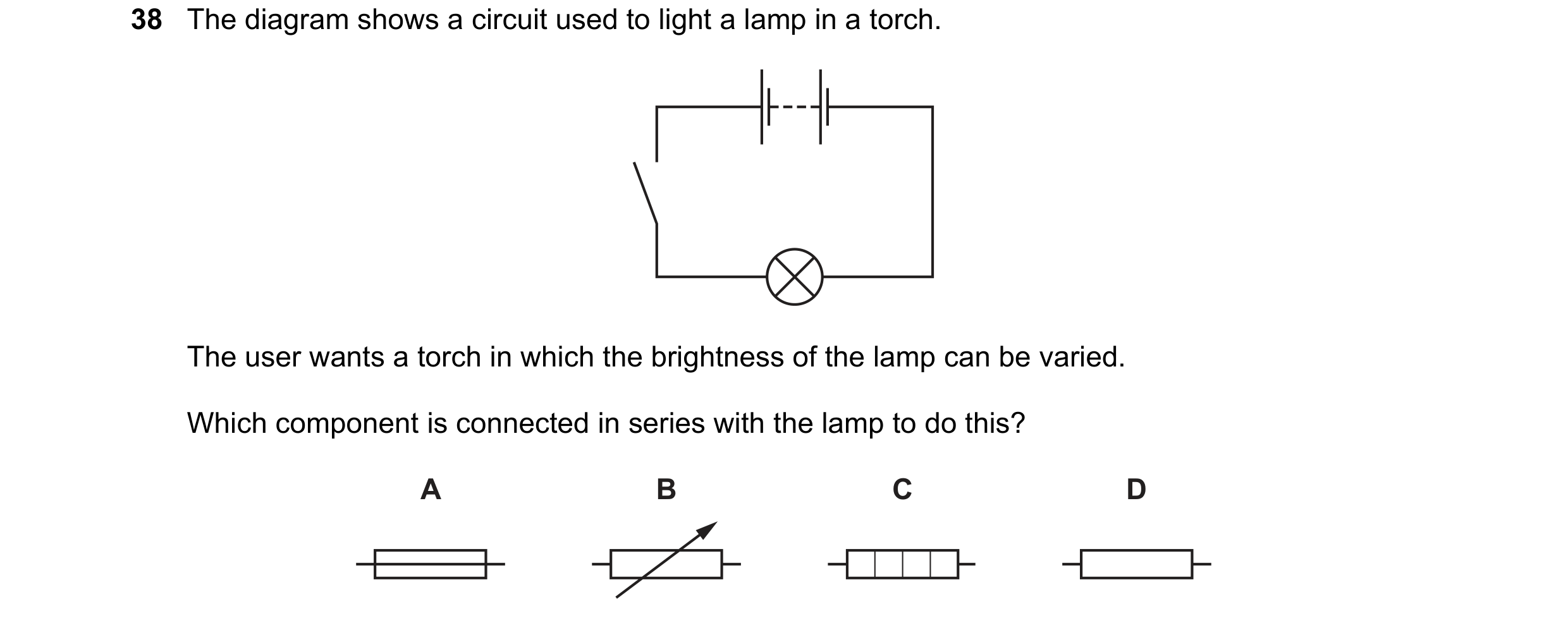
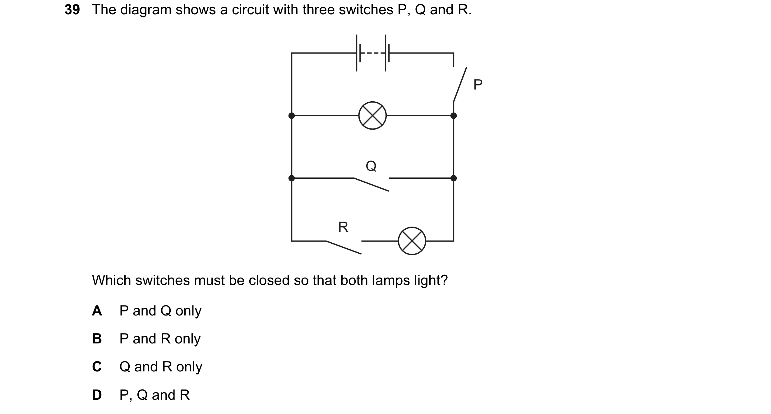 49 / 77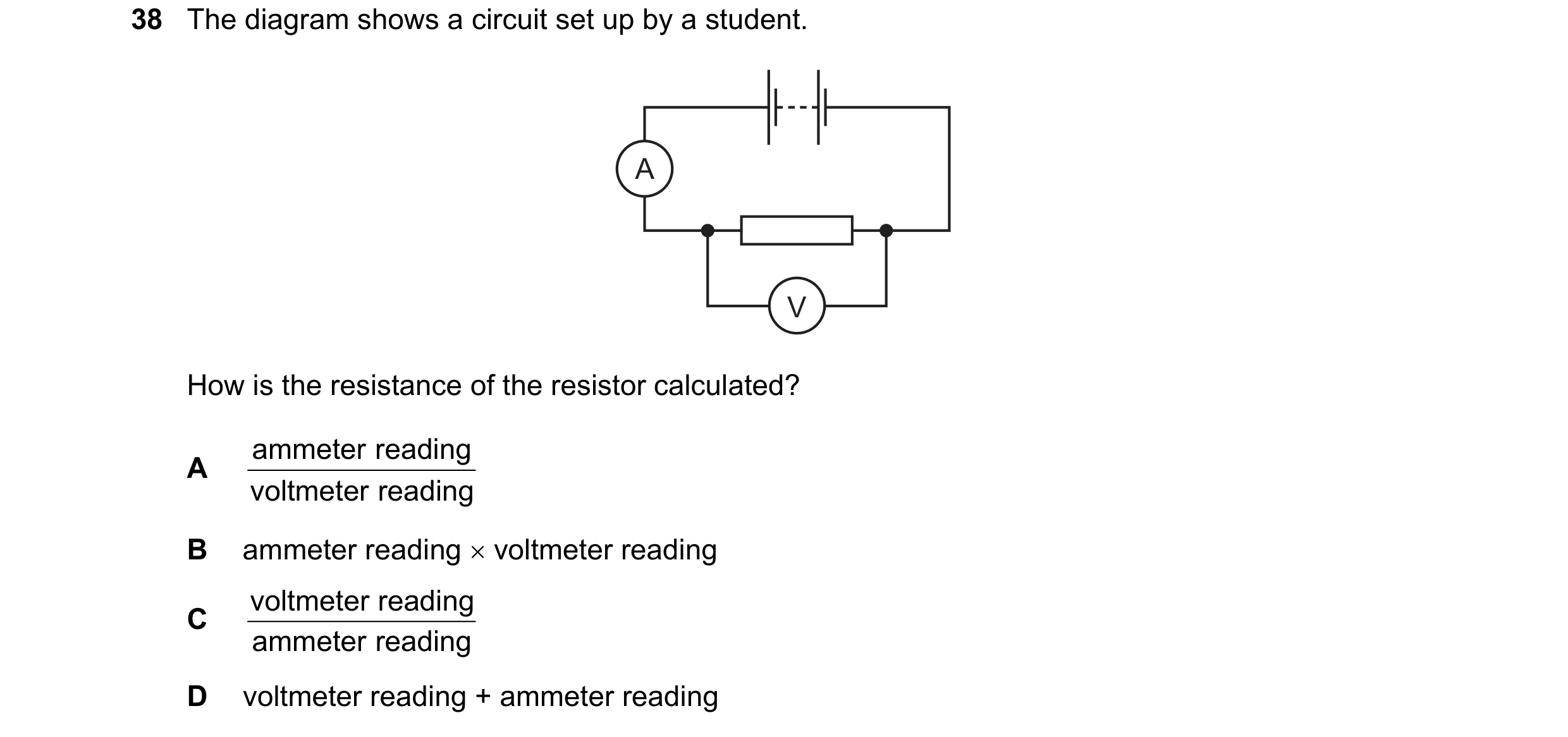
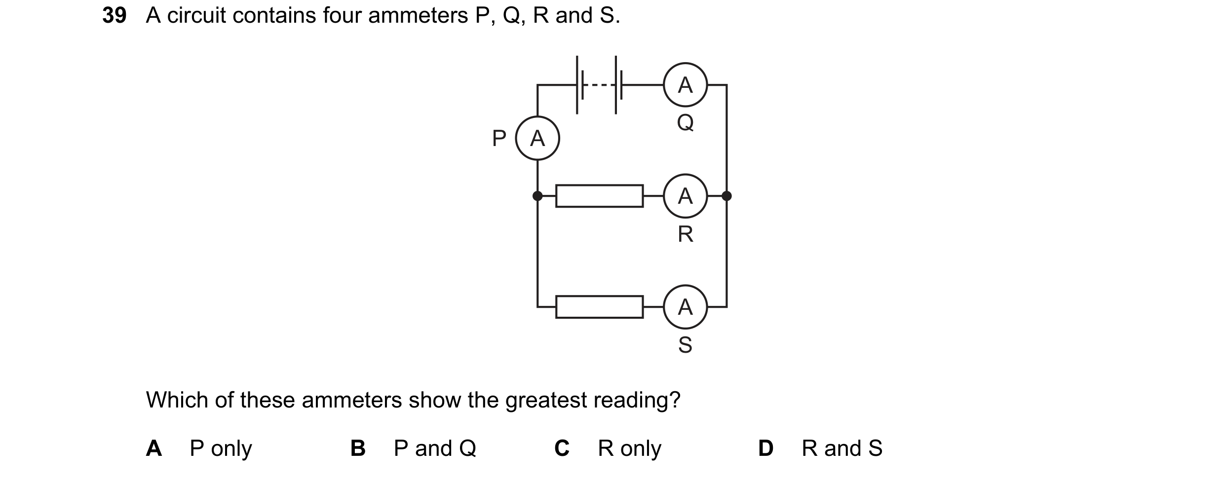
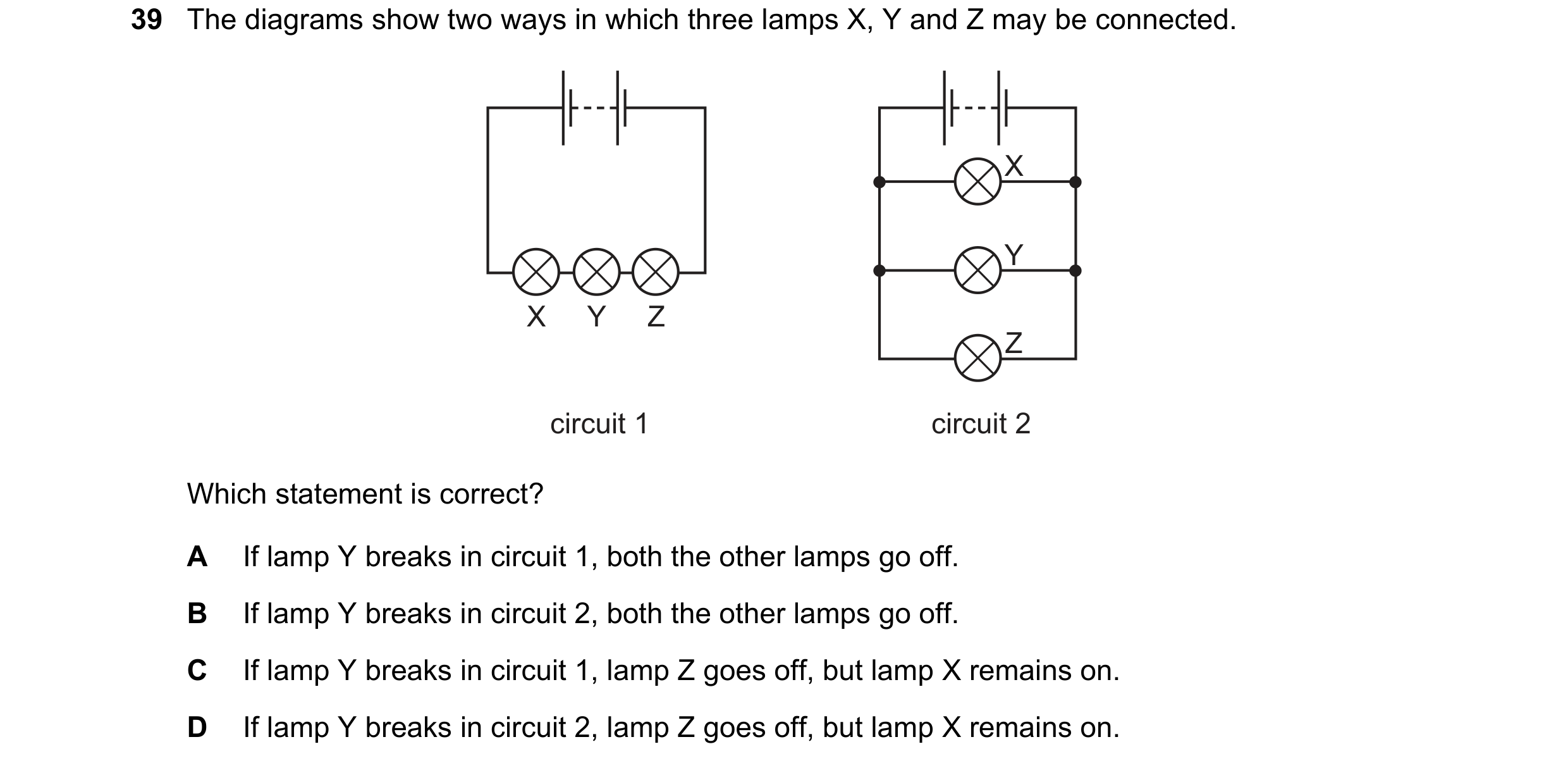 50 / 77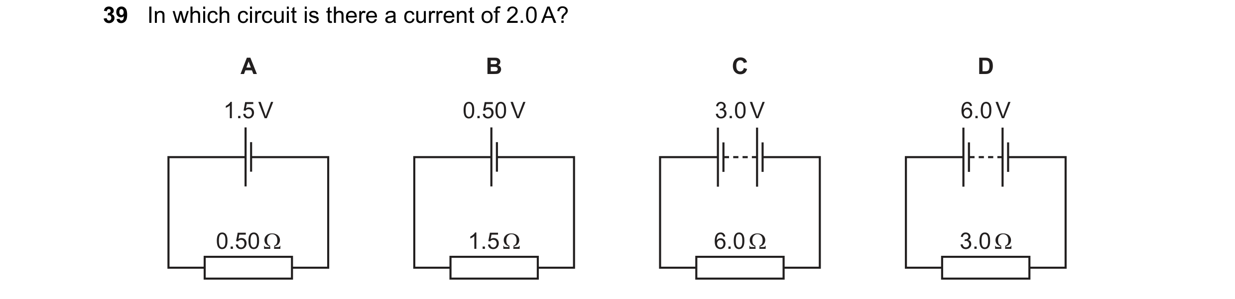
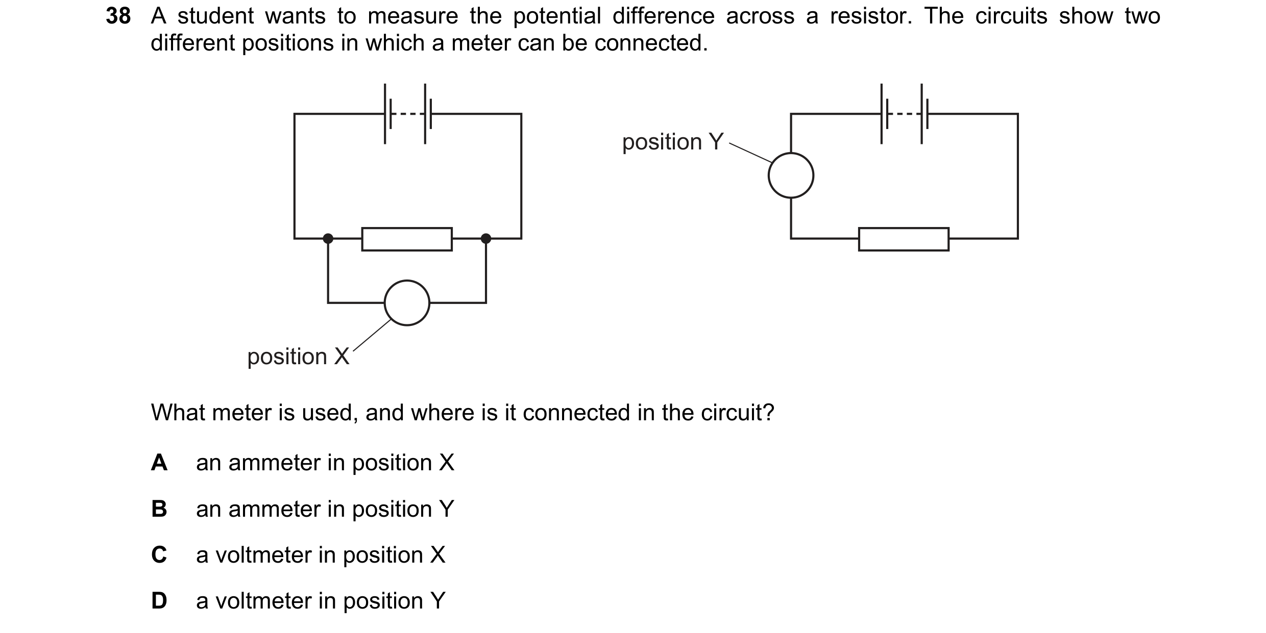
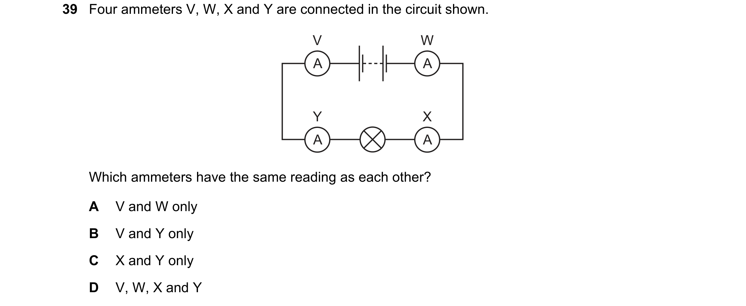 51 / 77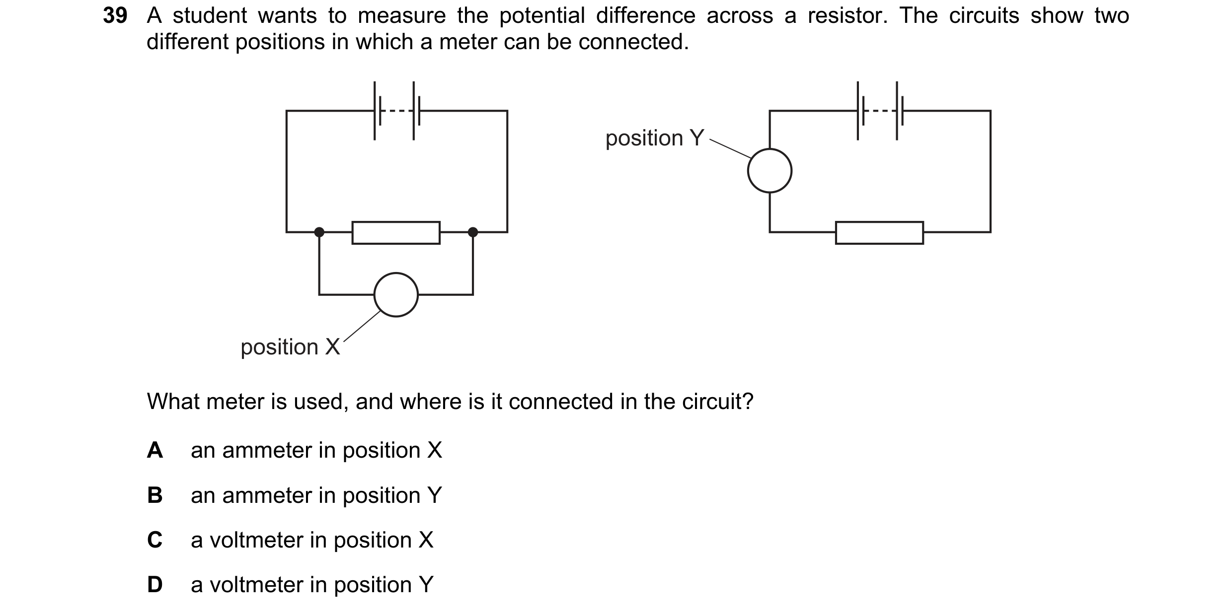
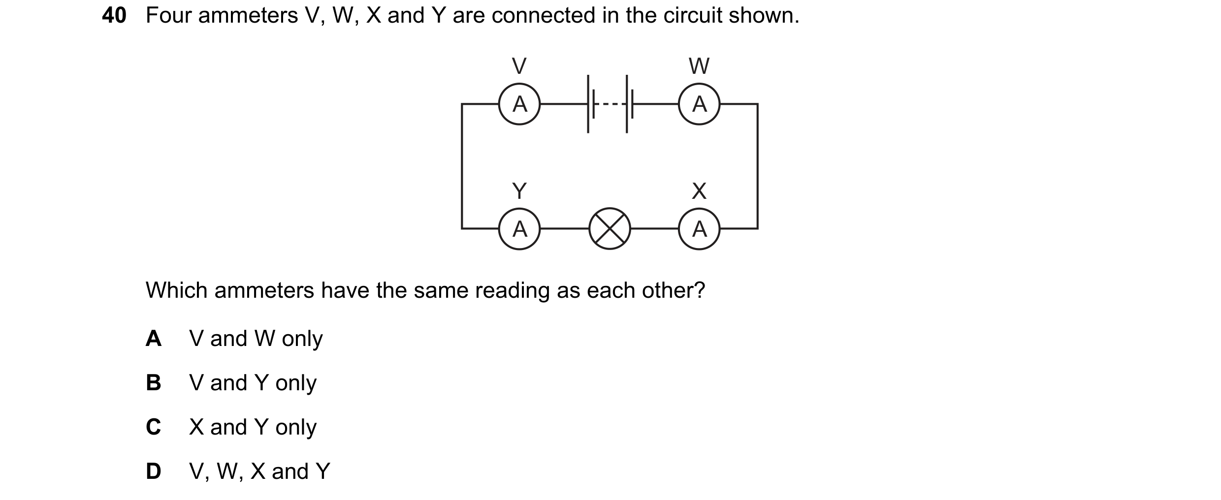 52 / 77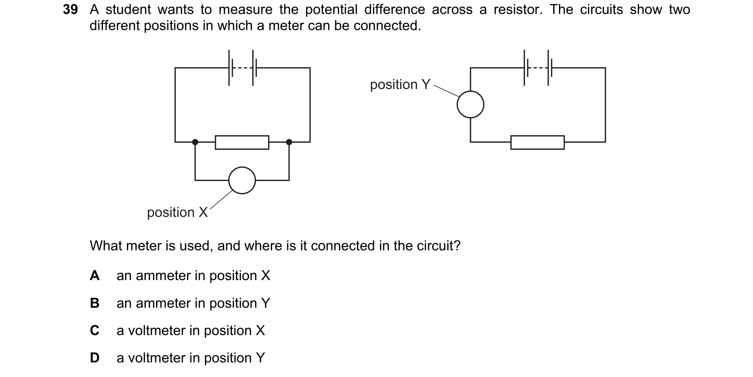
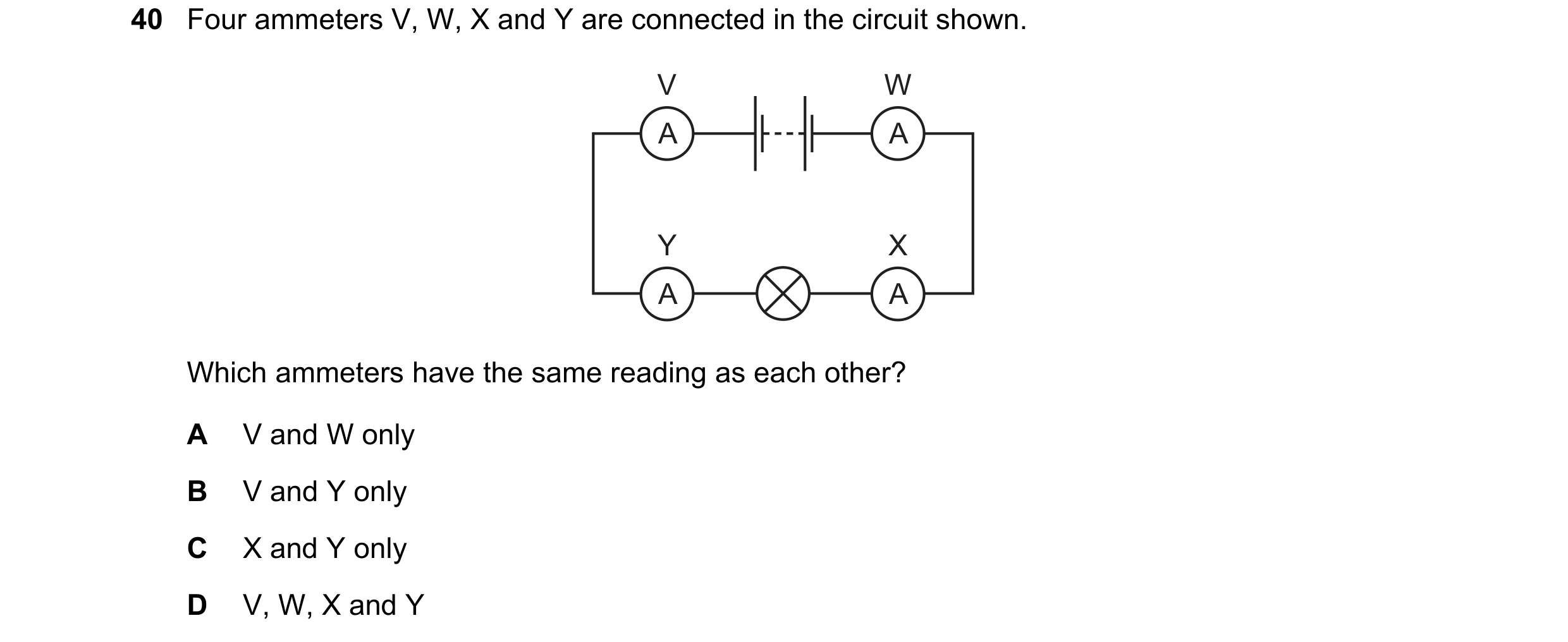
 53 / 77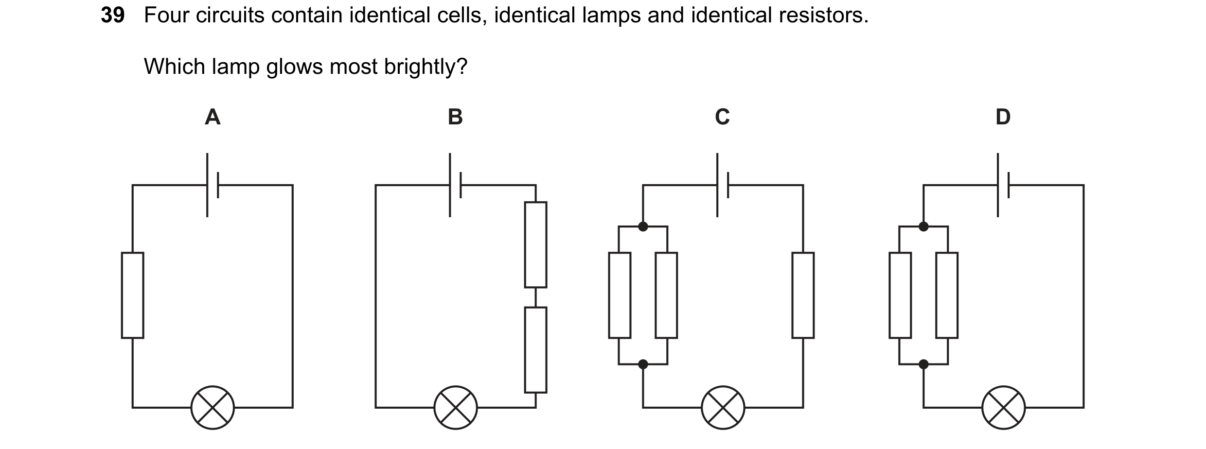
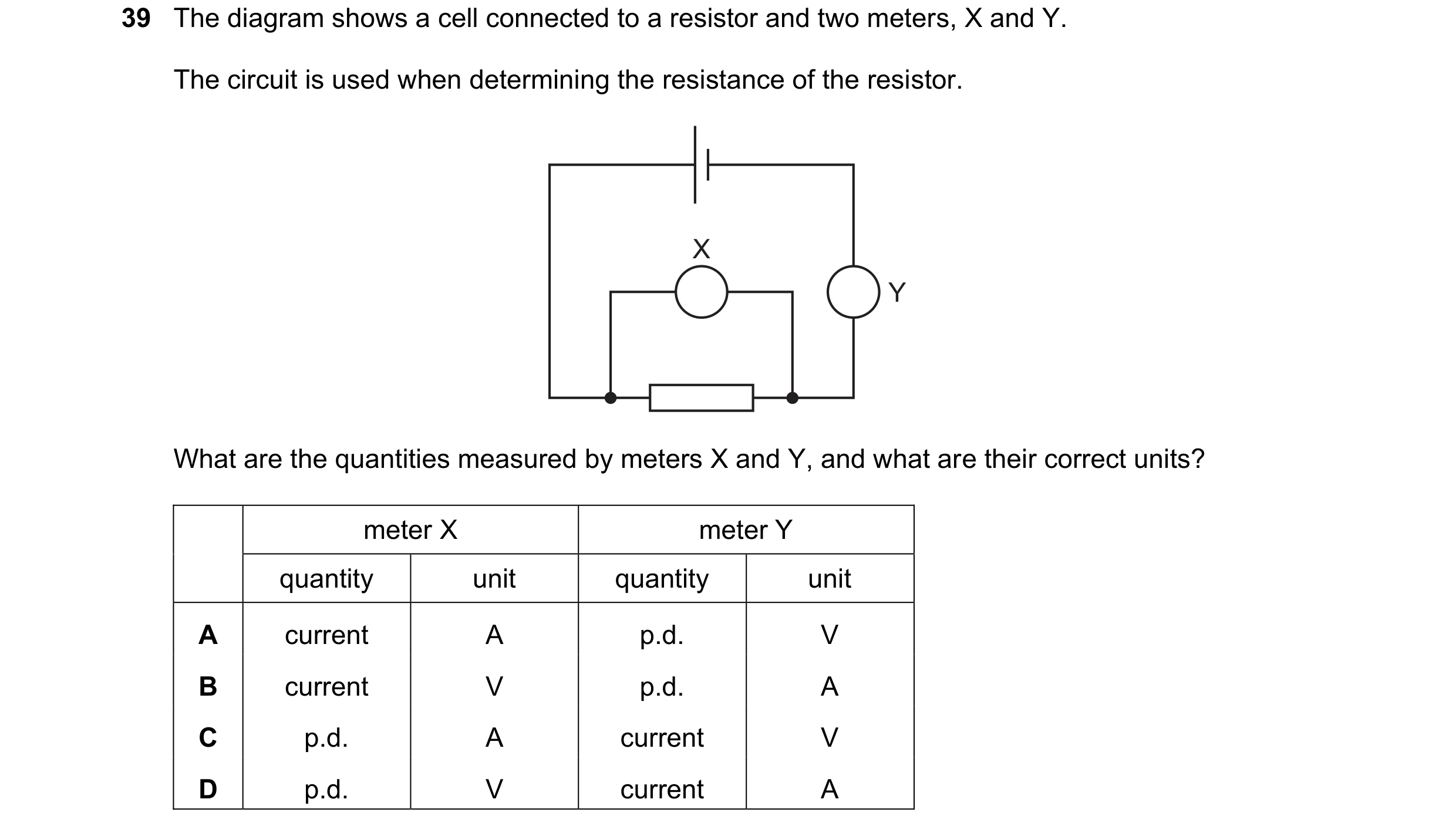 54 / 77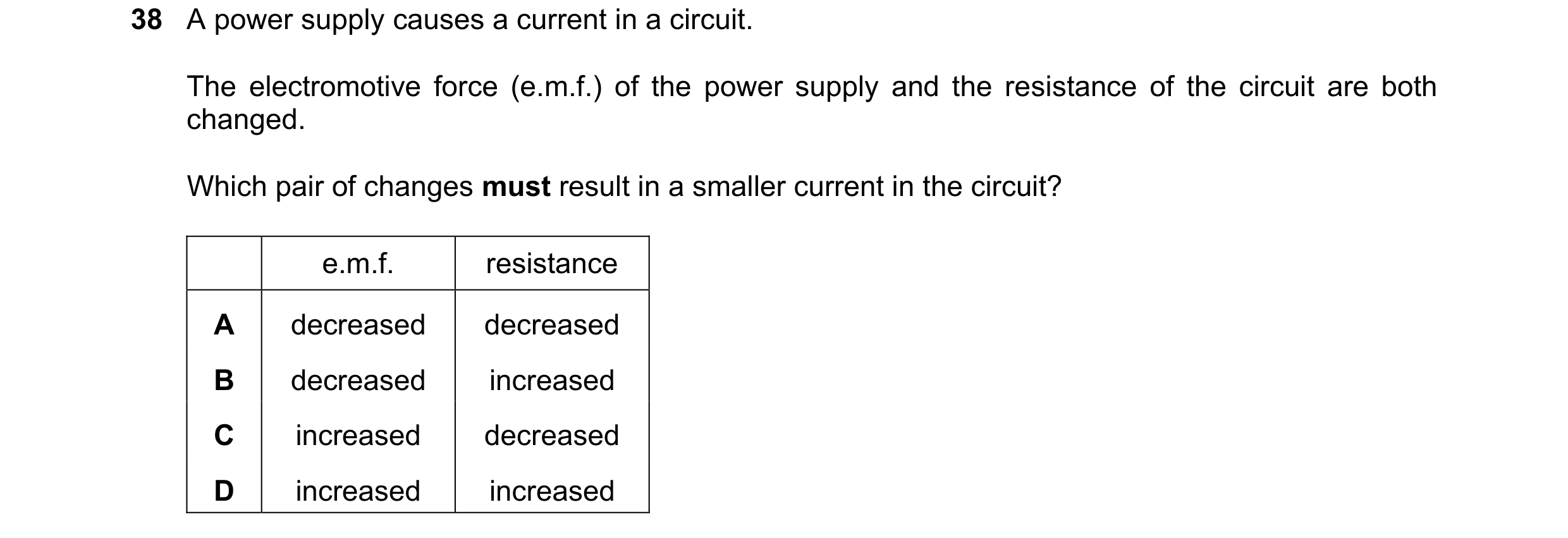
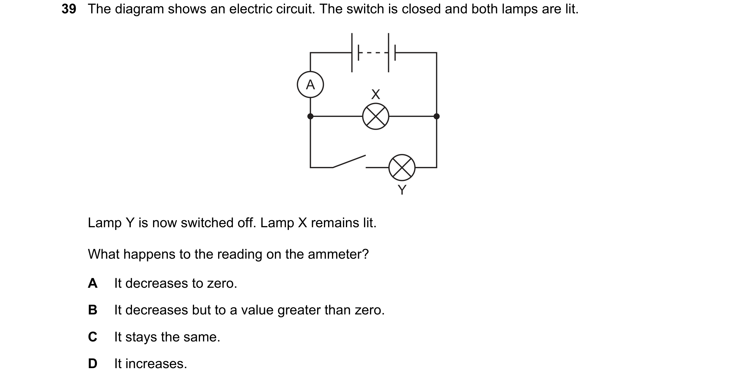
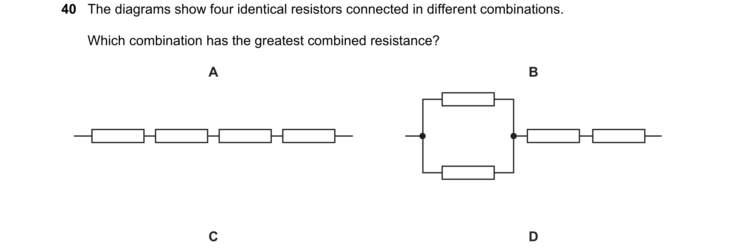 55 / 77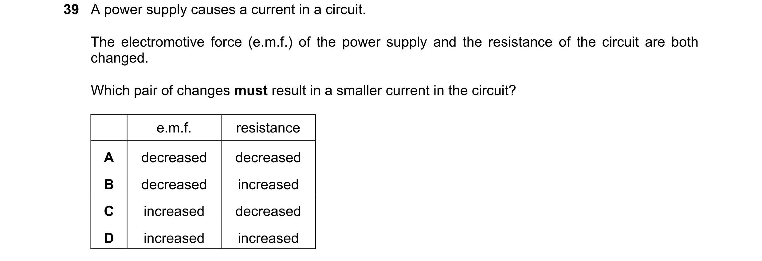
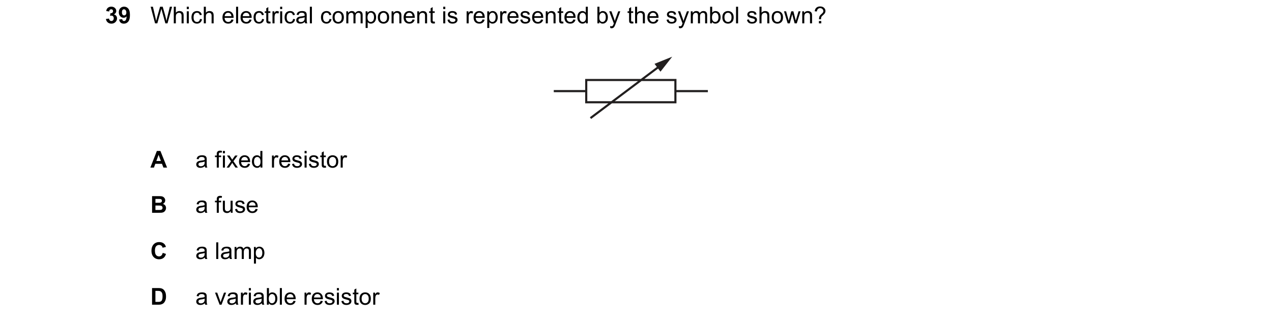
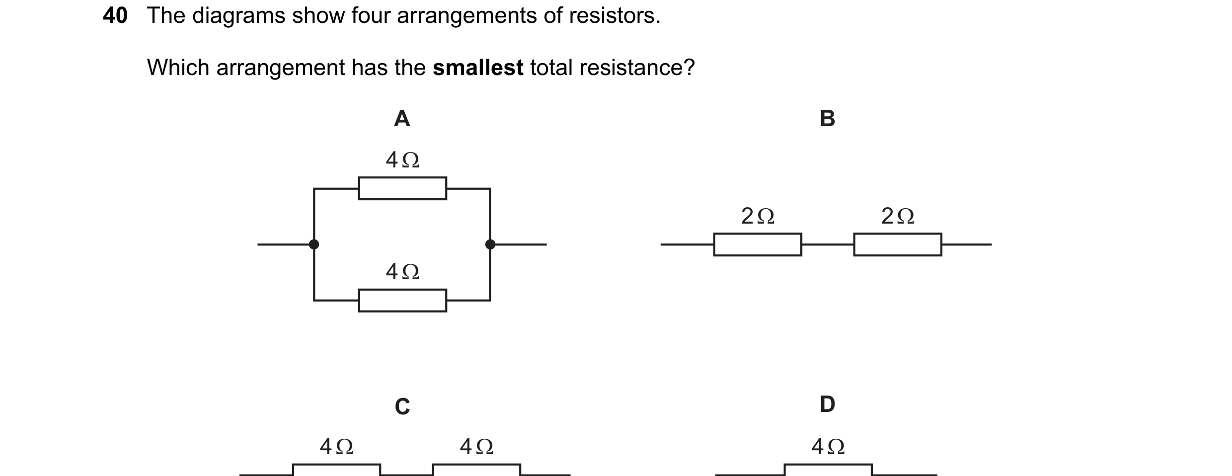 56 / 77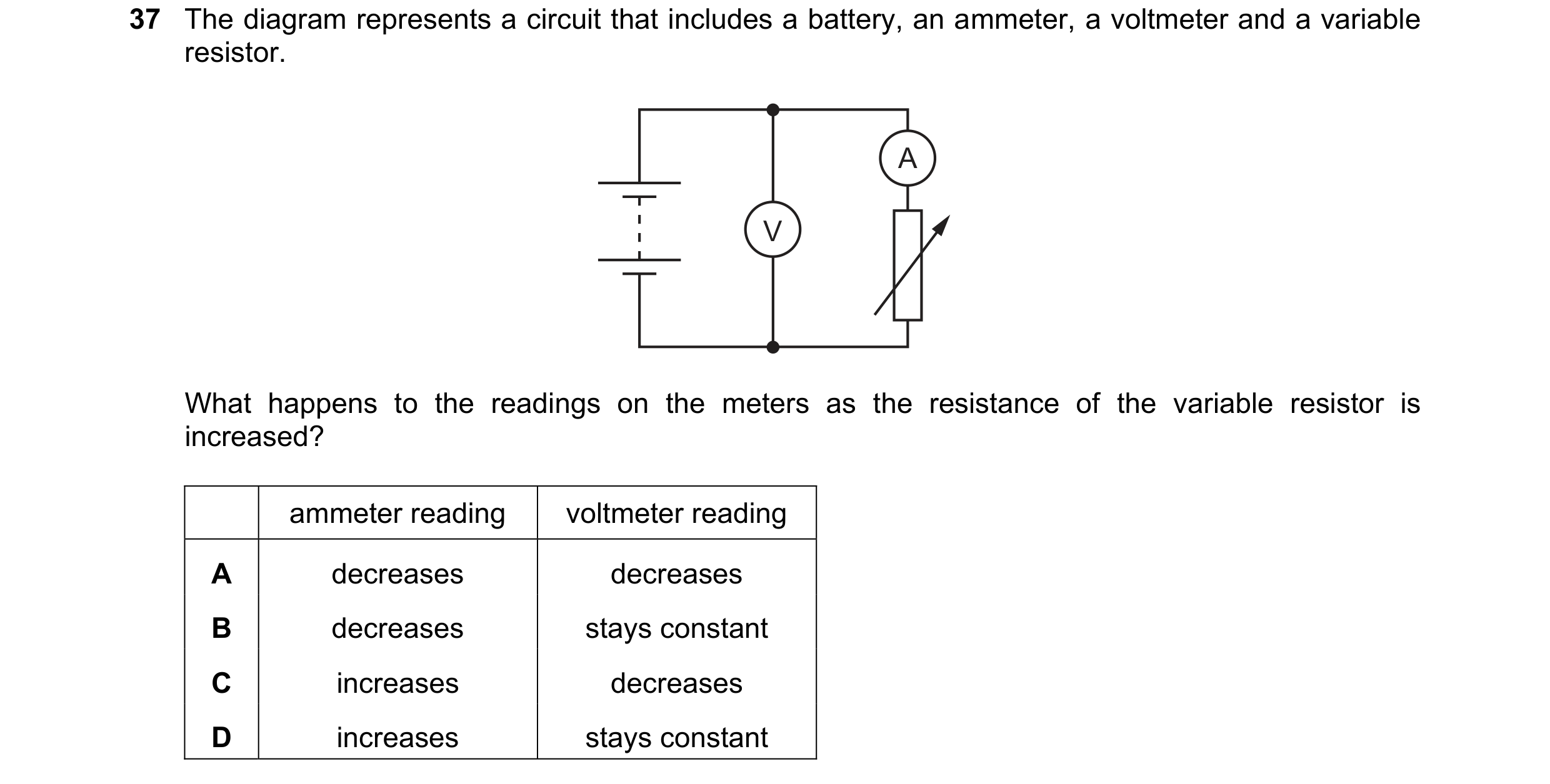
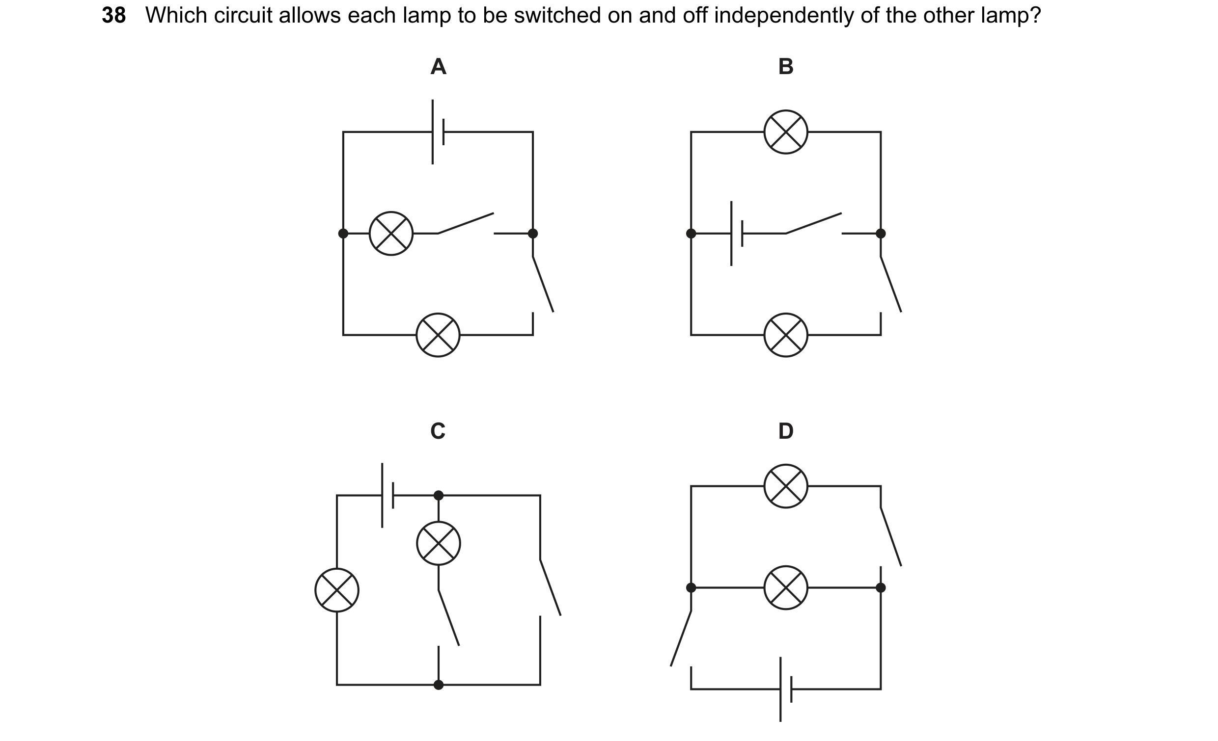 57 / 77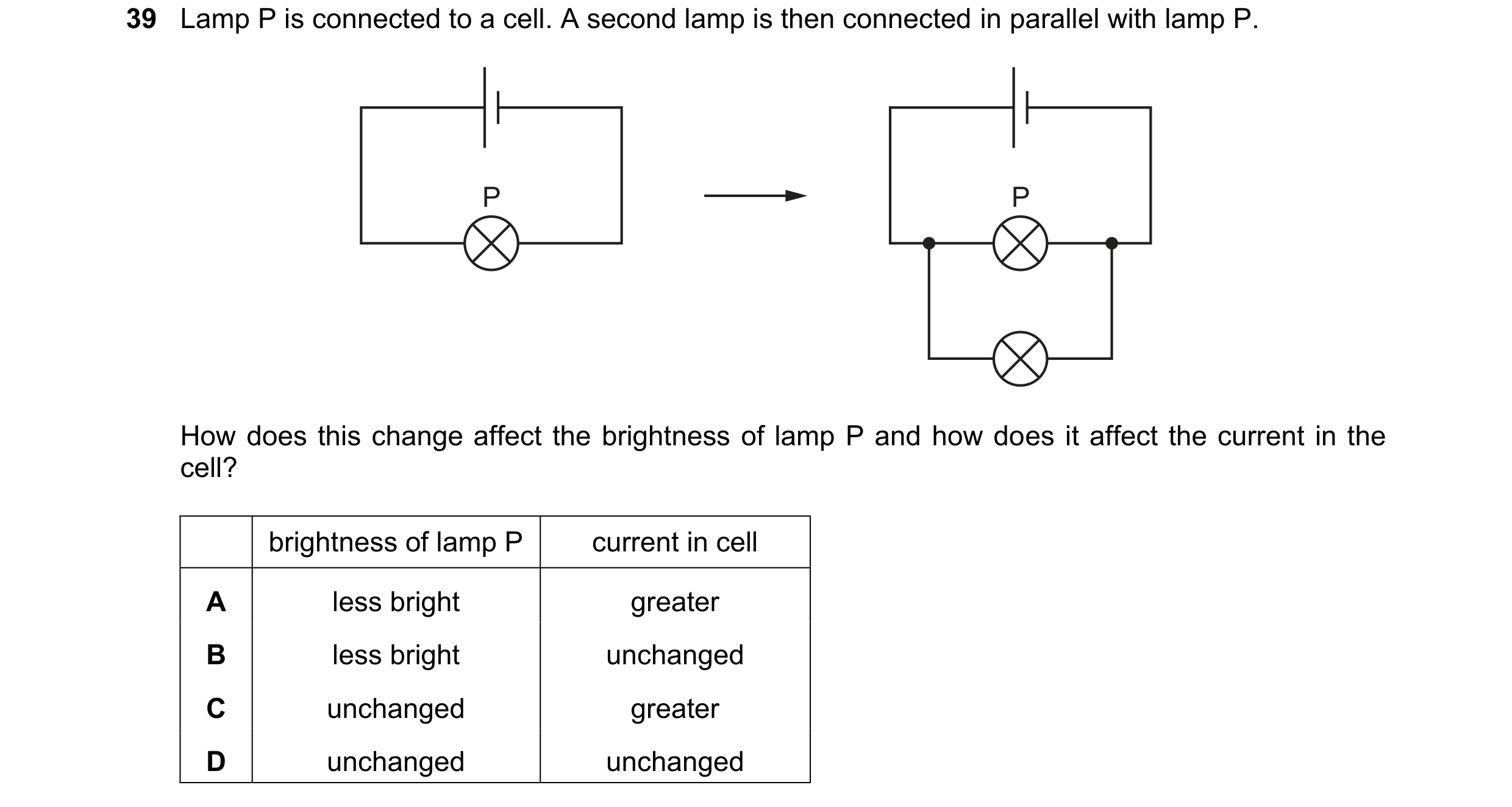
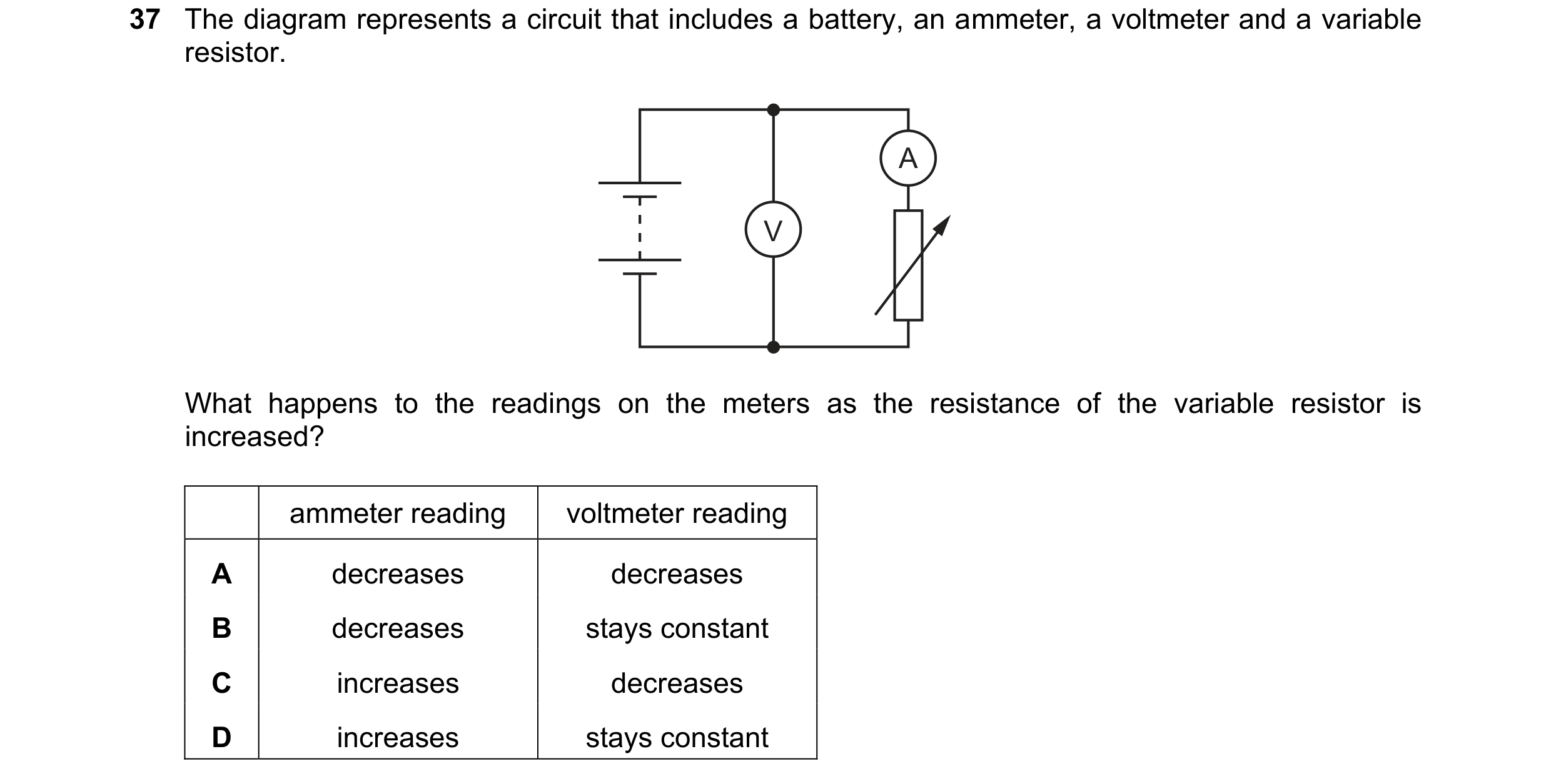 58 / 77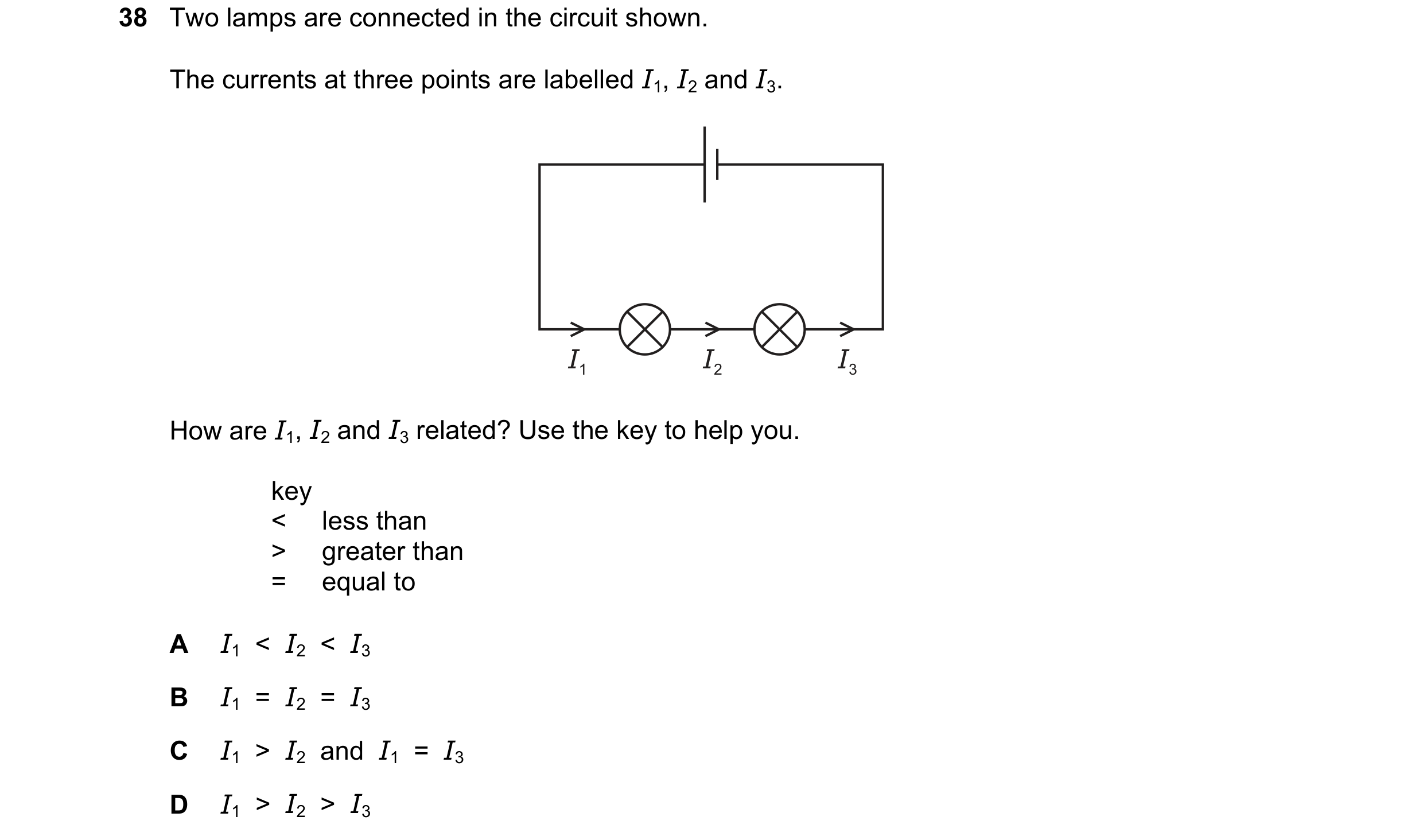
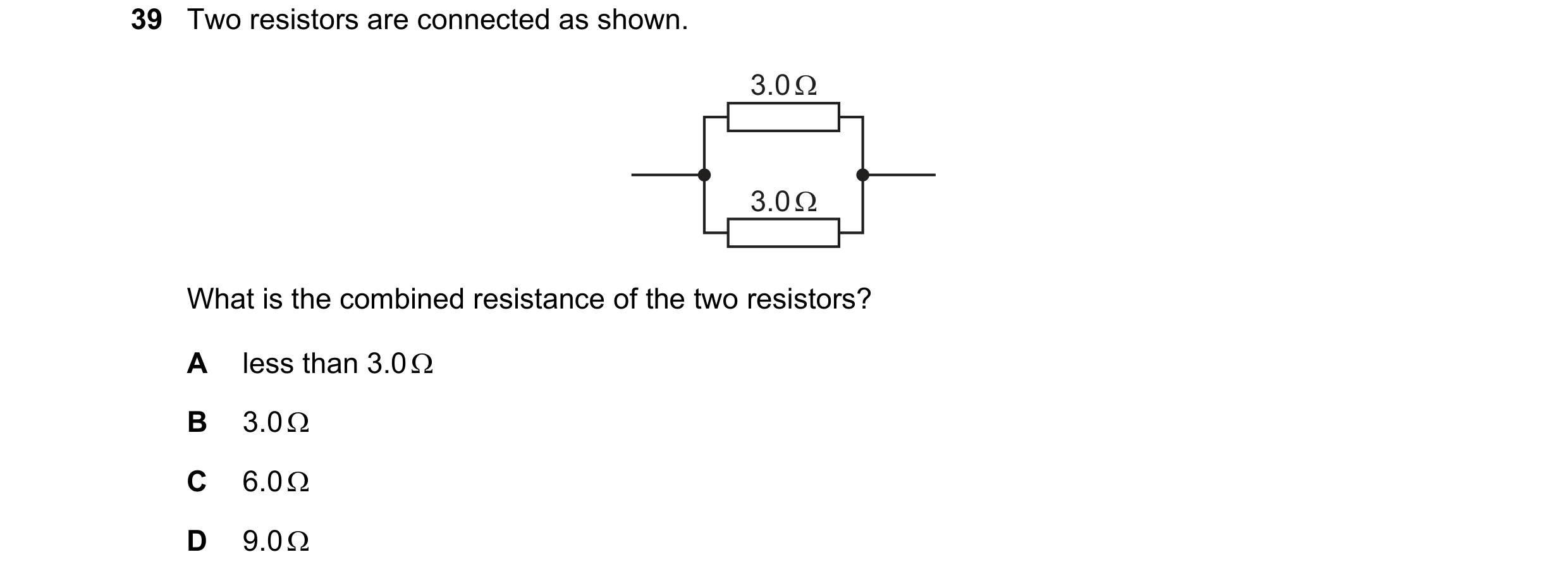
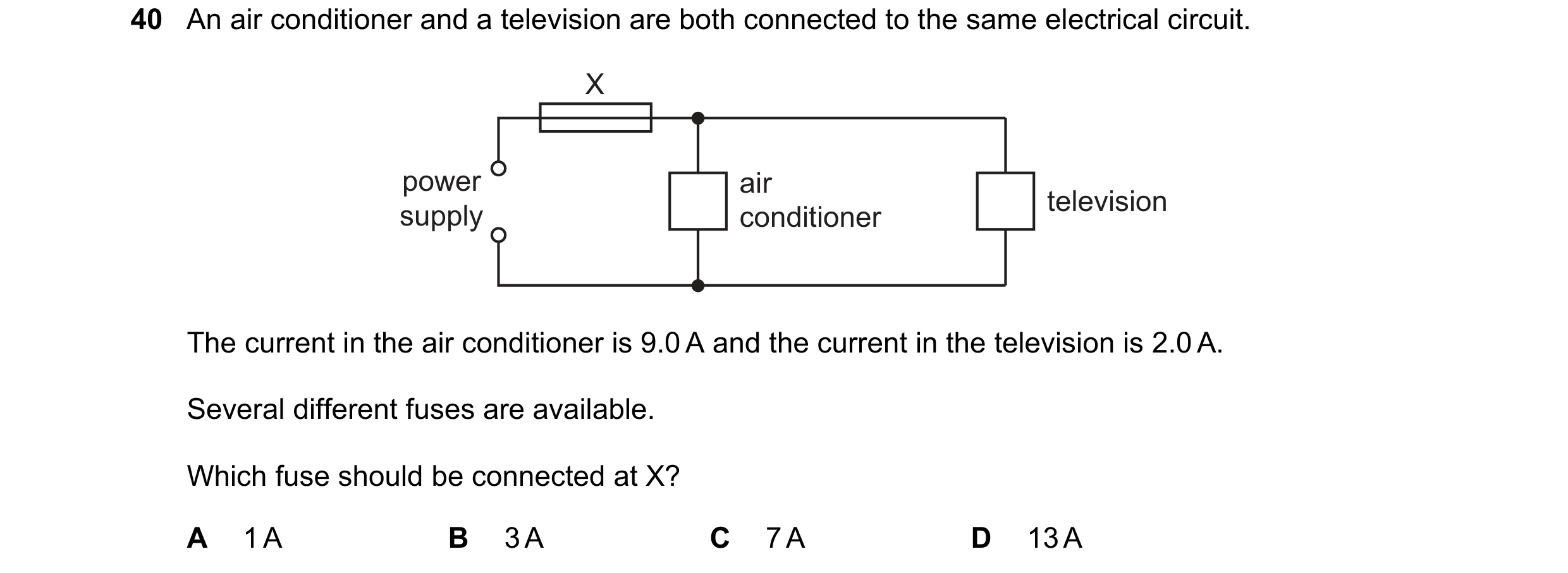 59 / 77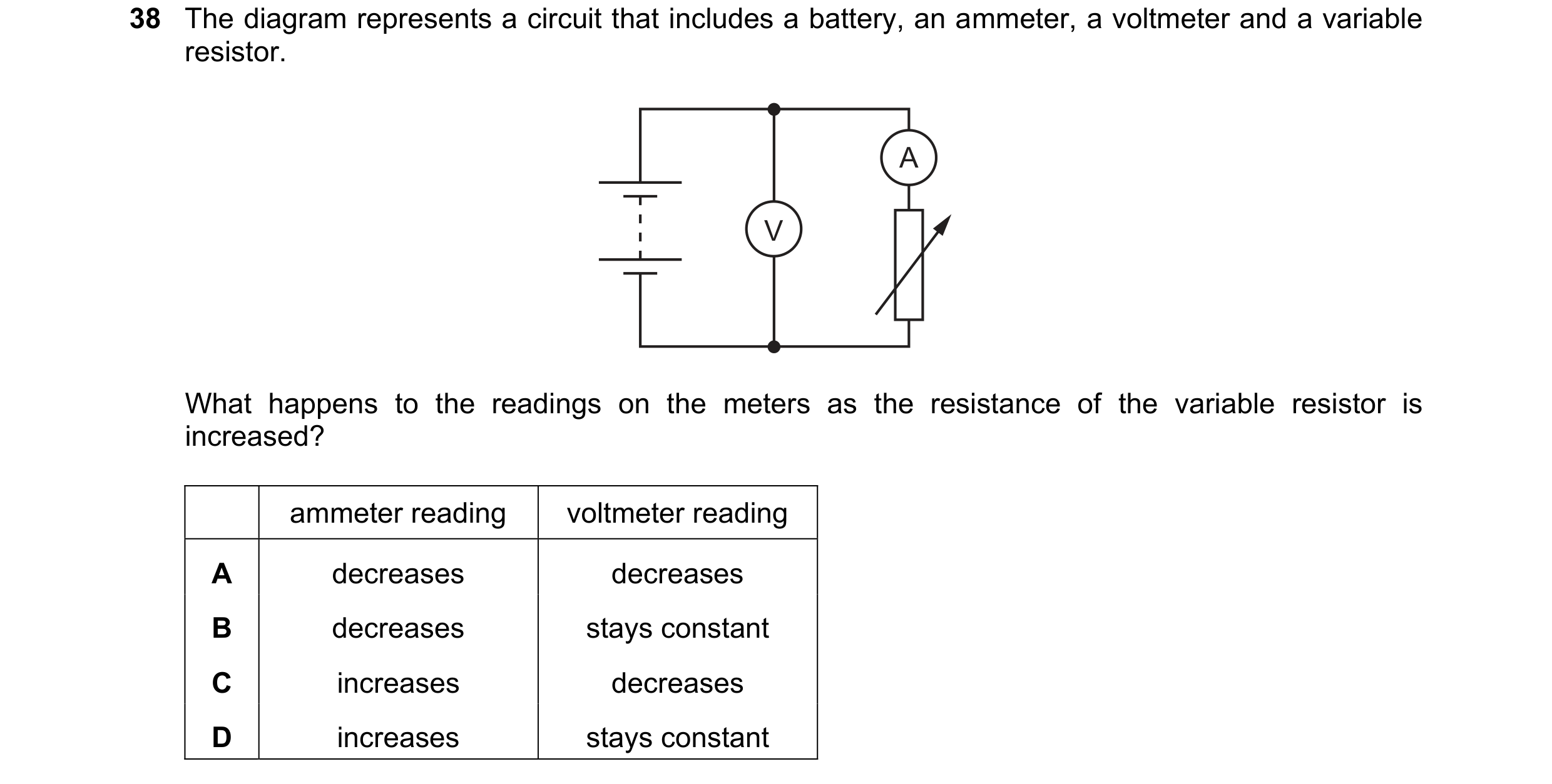
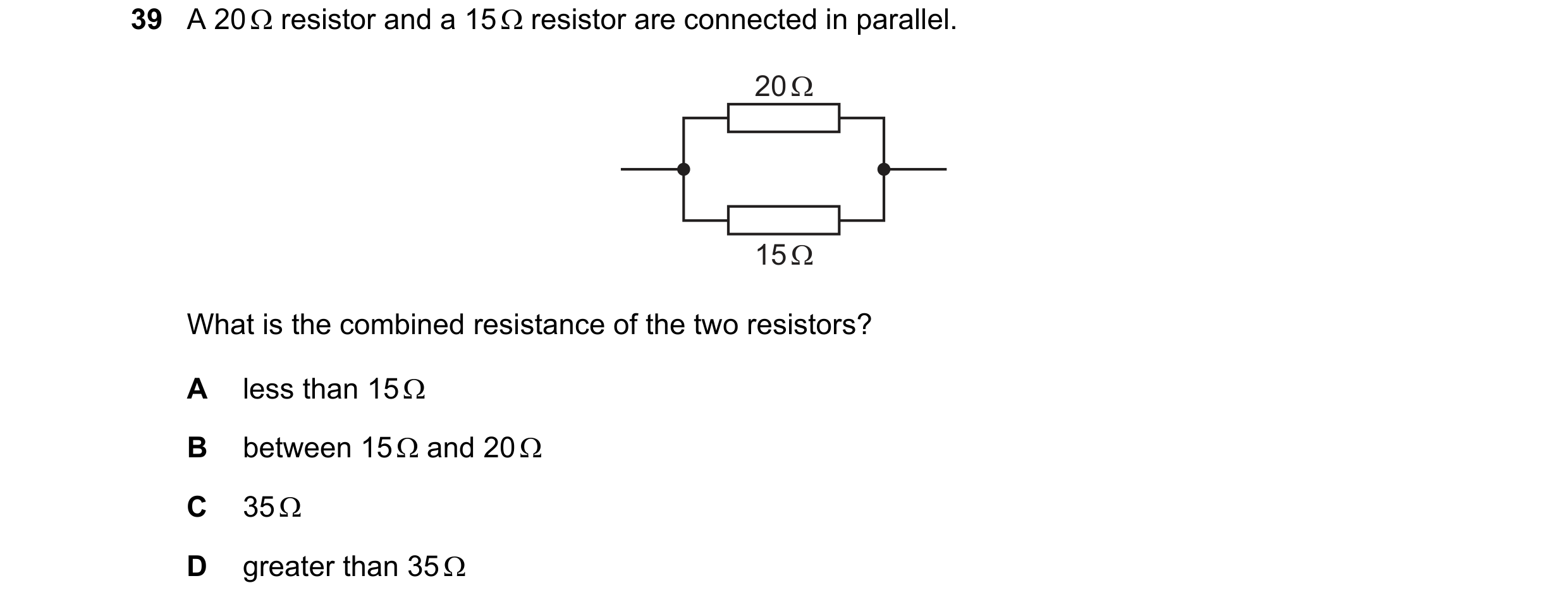
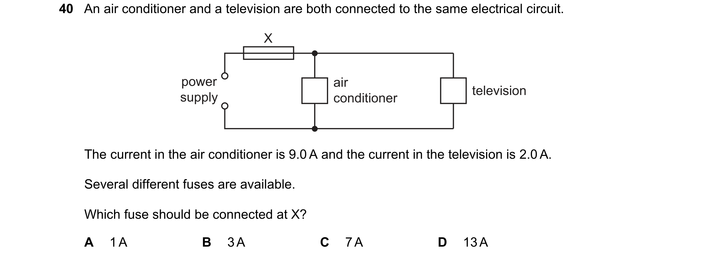 60 / 77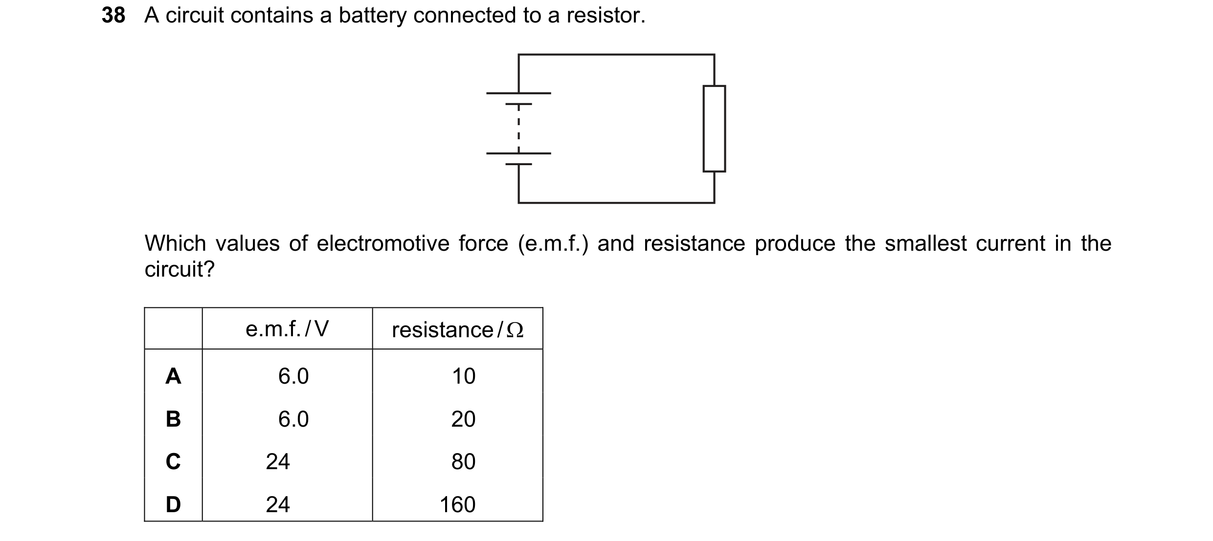
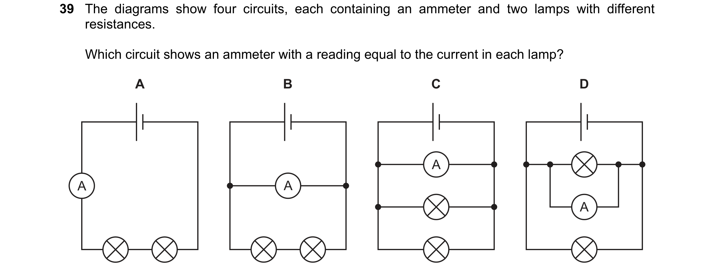
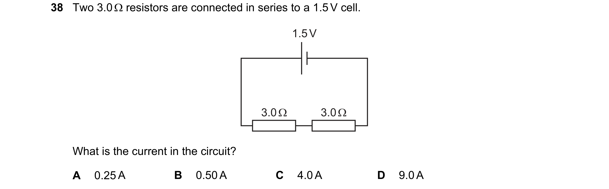 61 / 77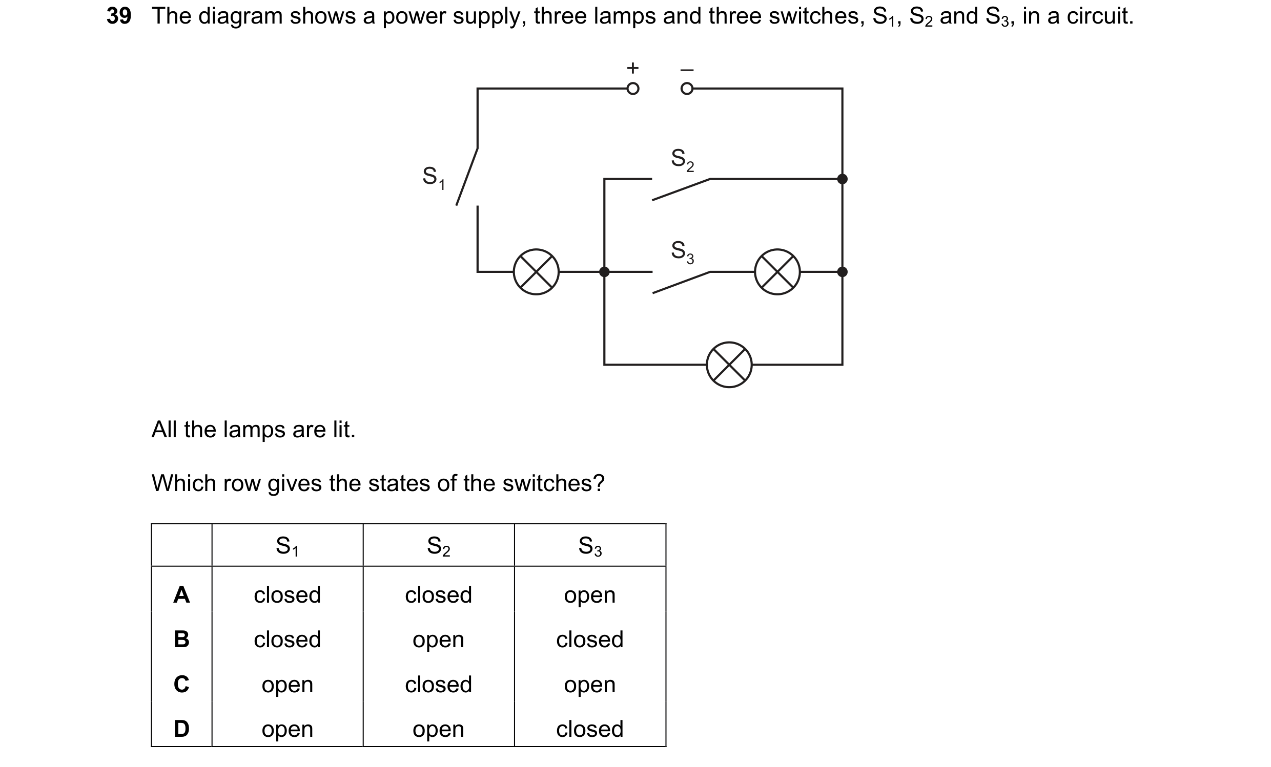
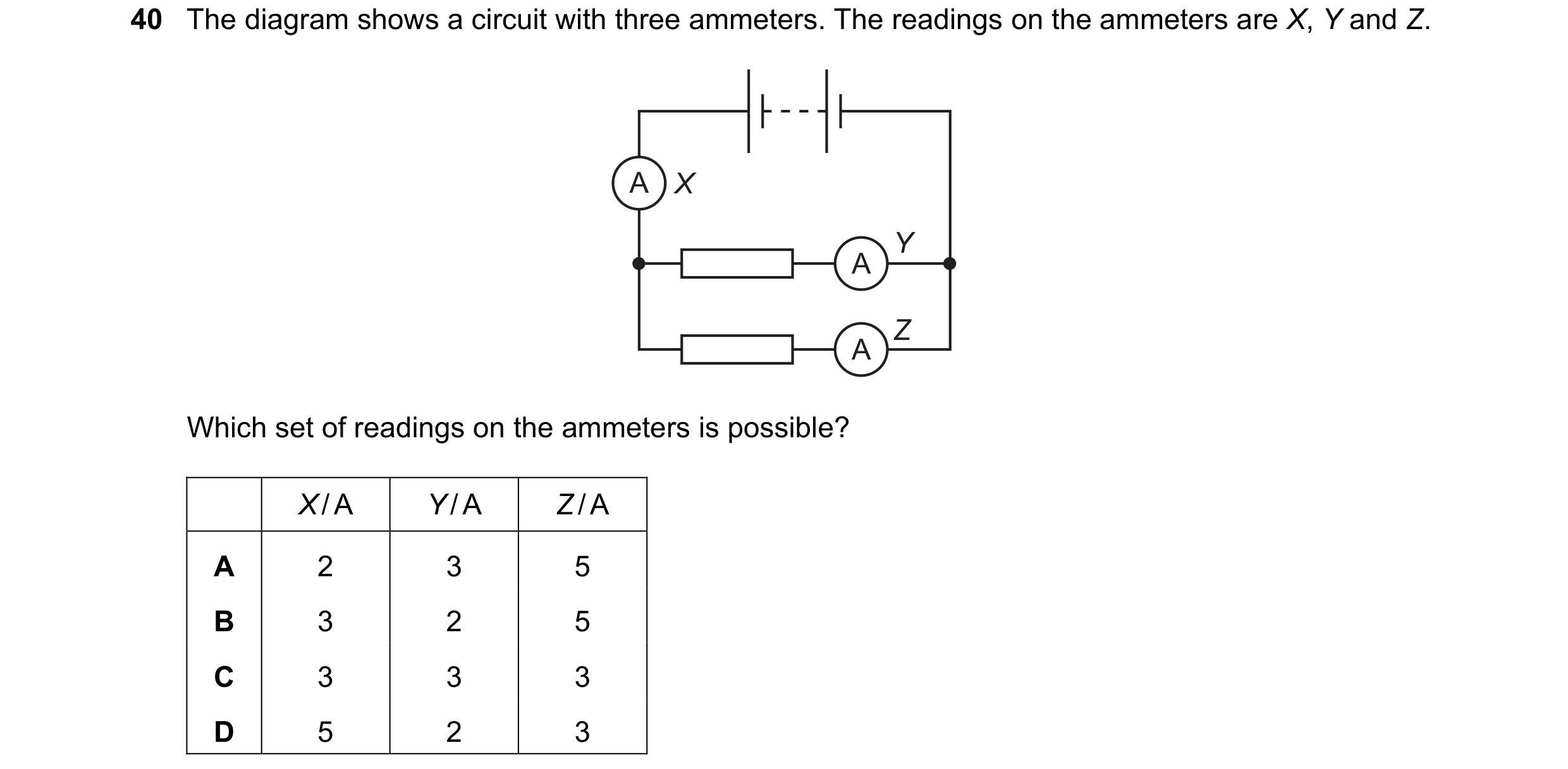 62 / 77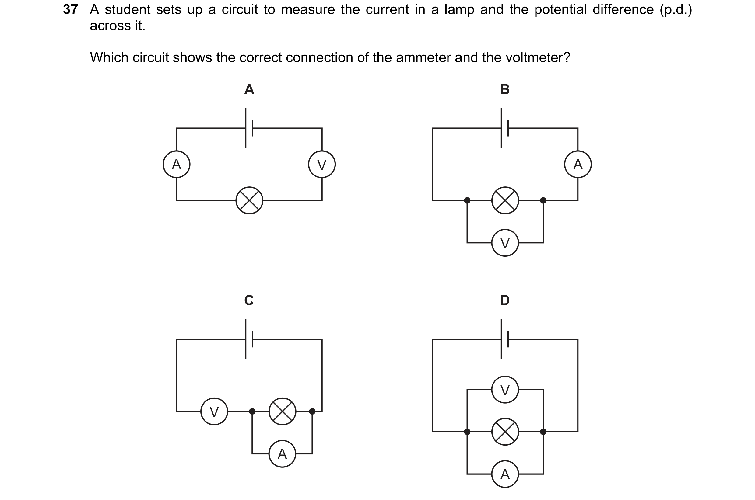
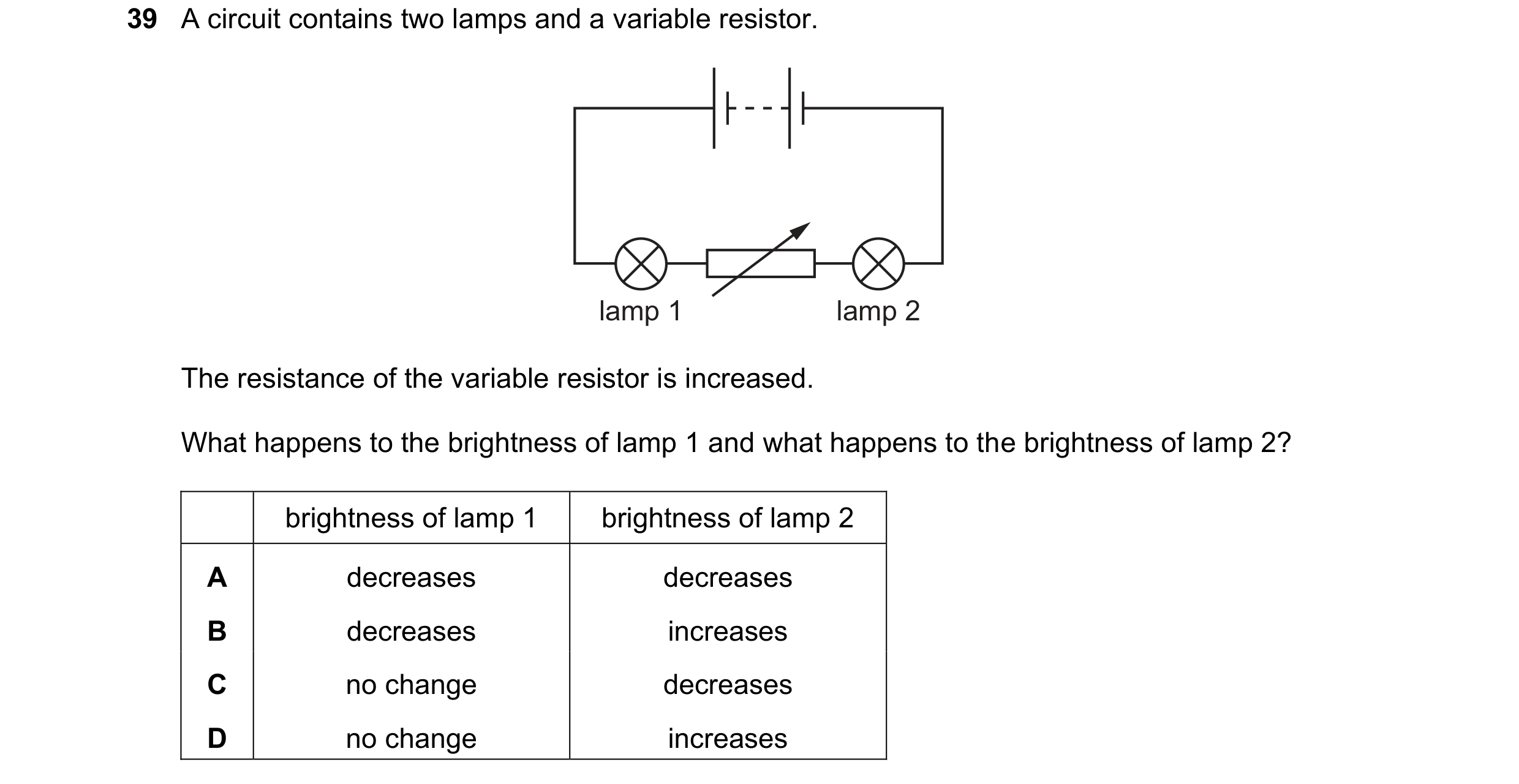 63 / 77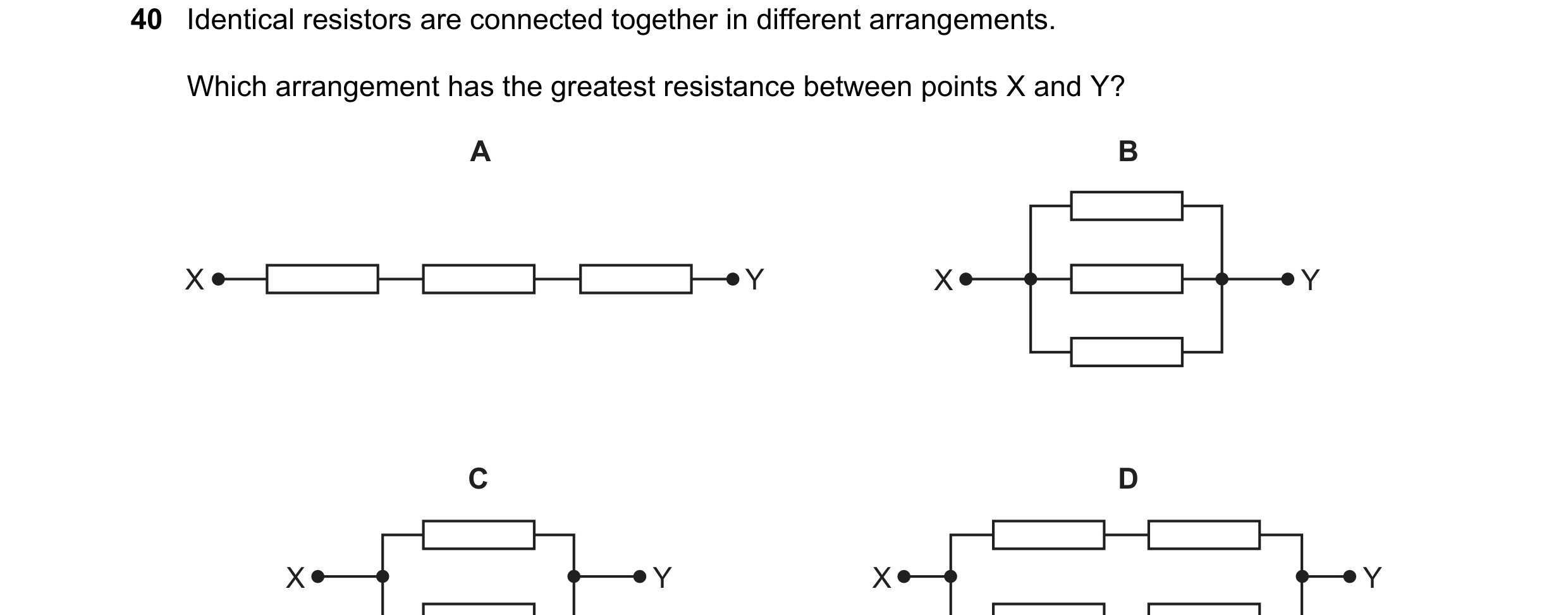
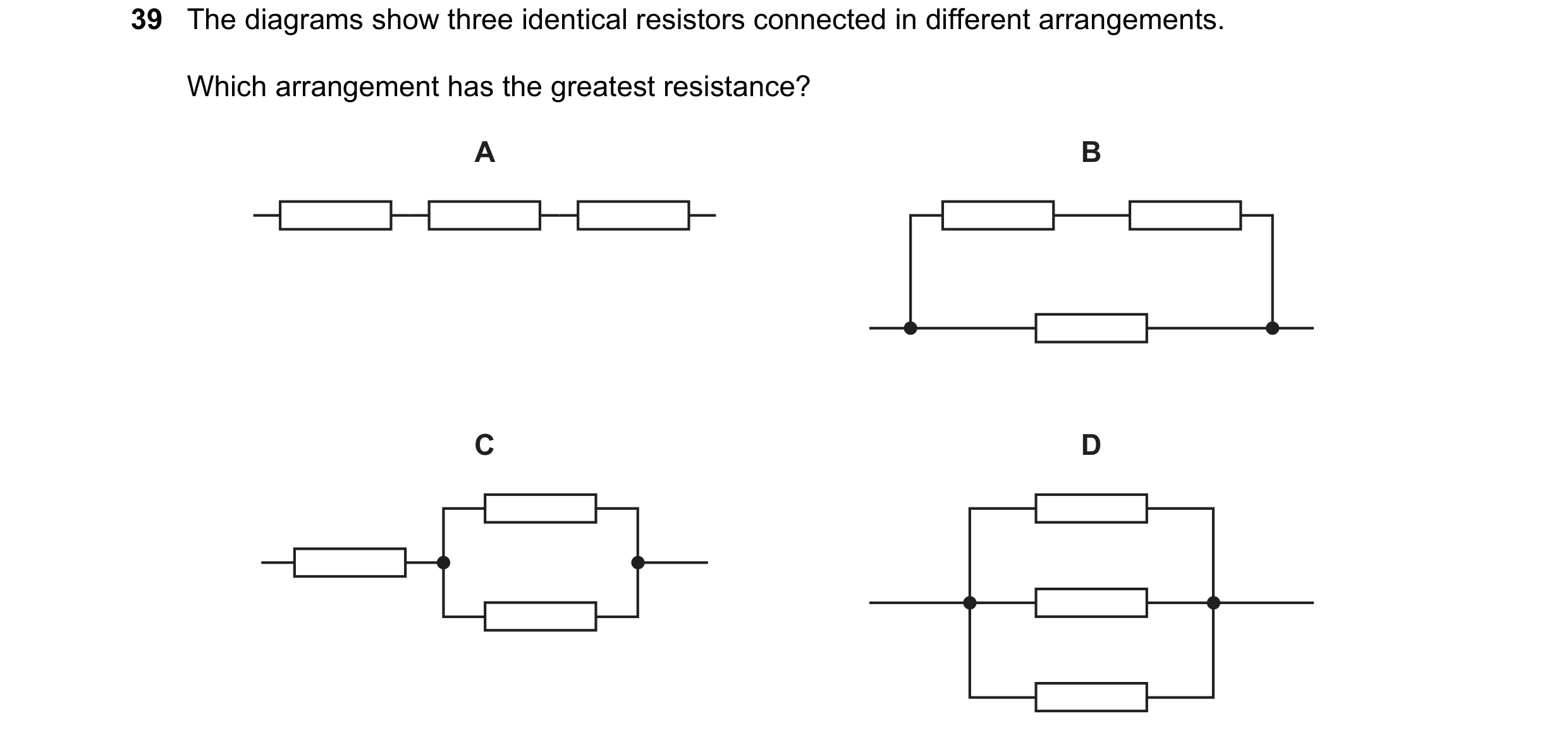
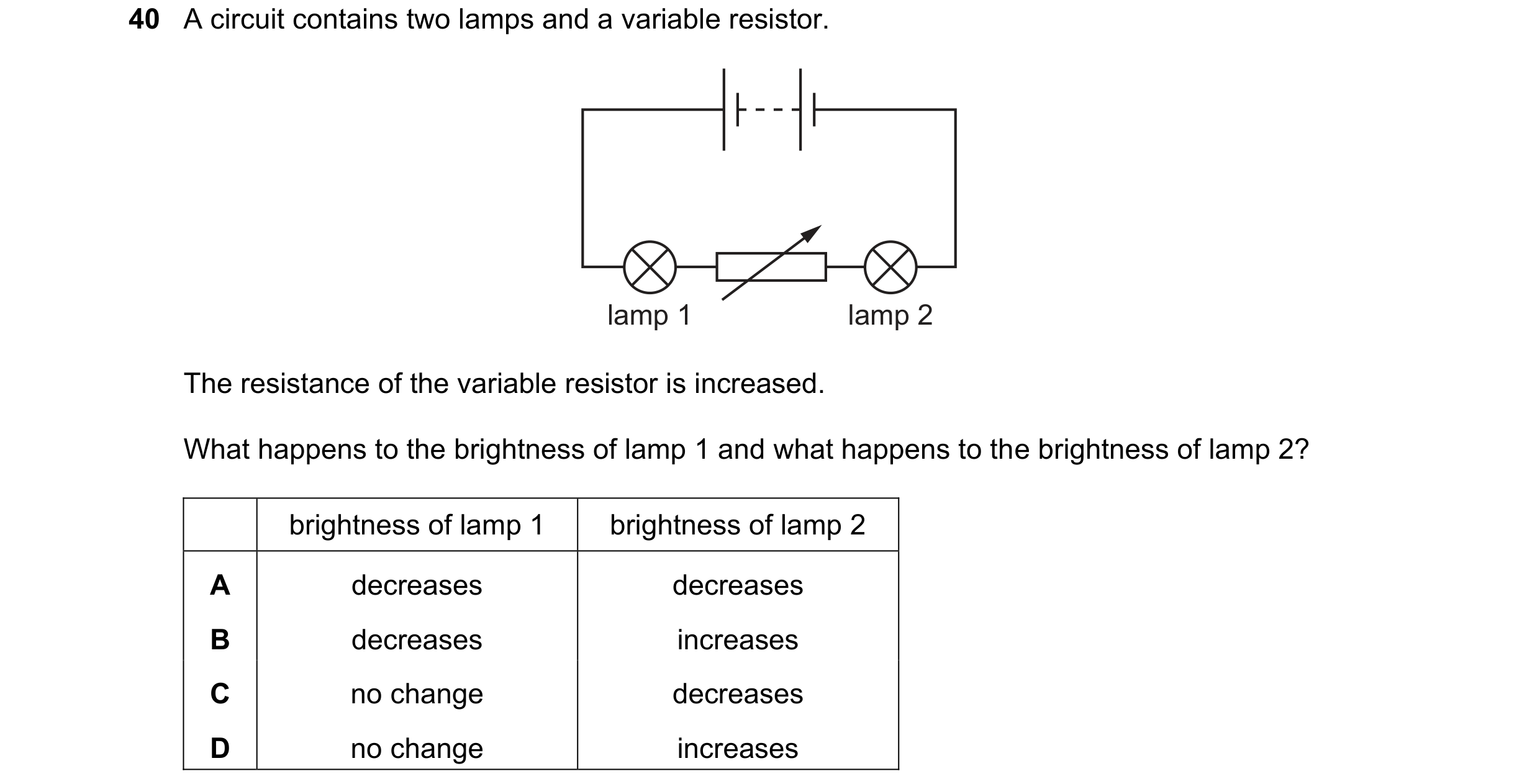 64 / 77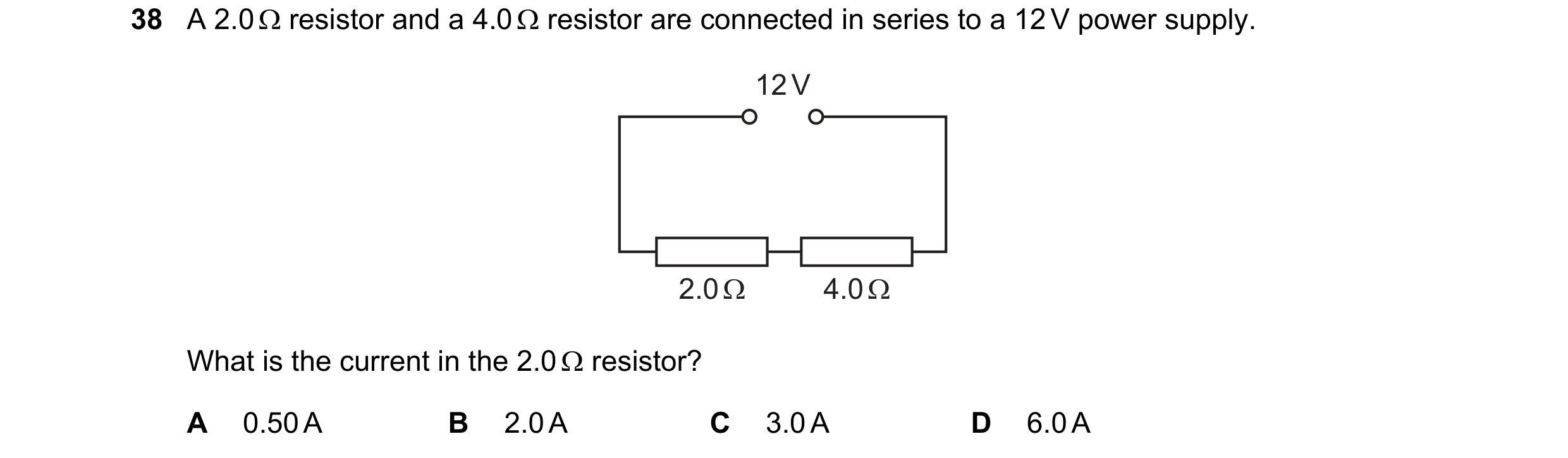
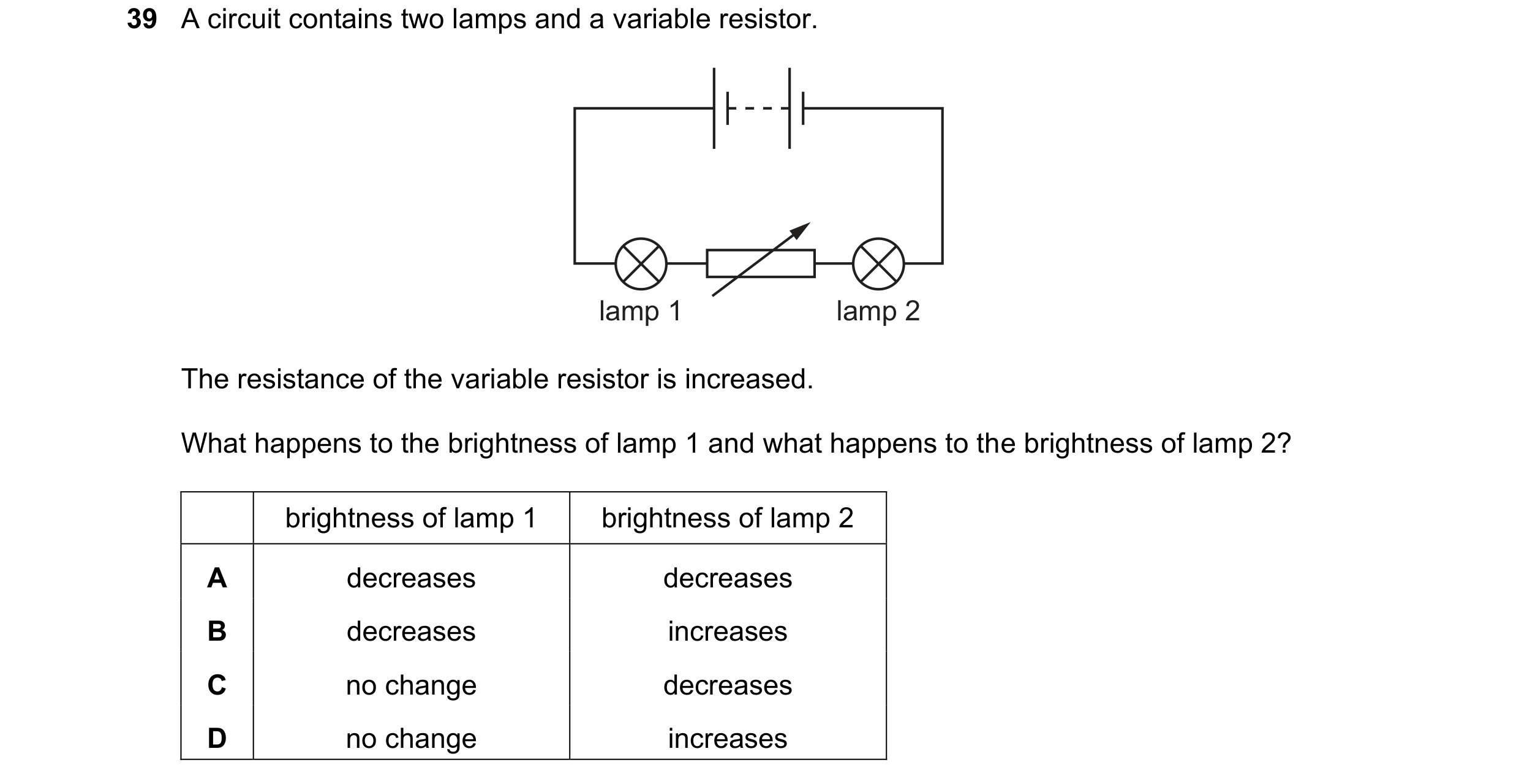
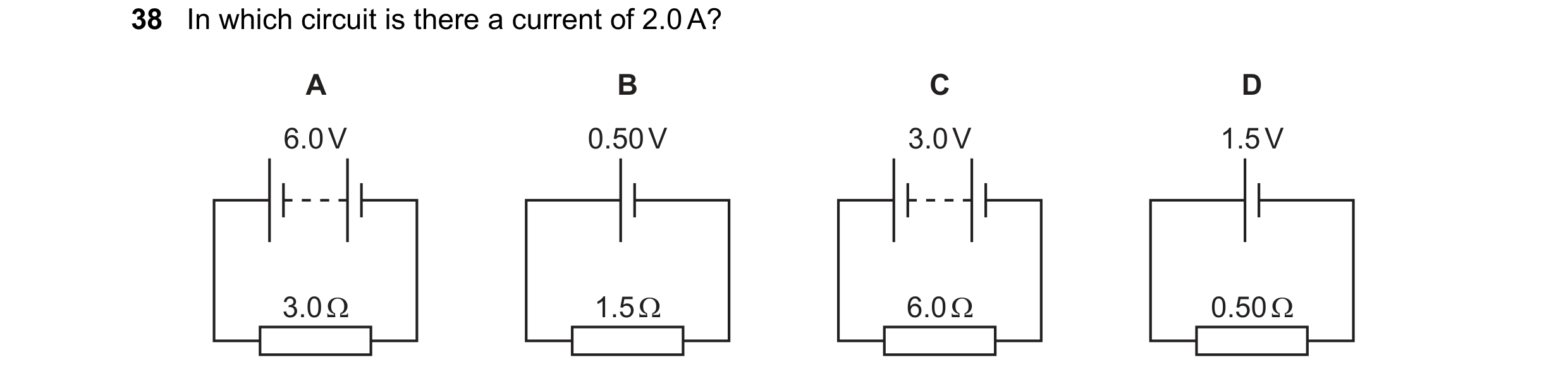 65 / 77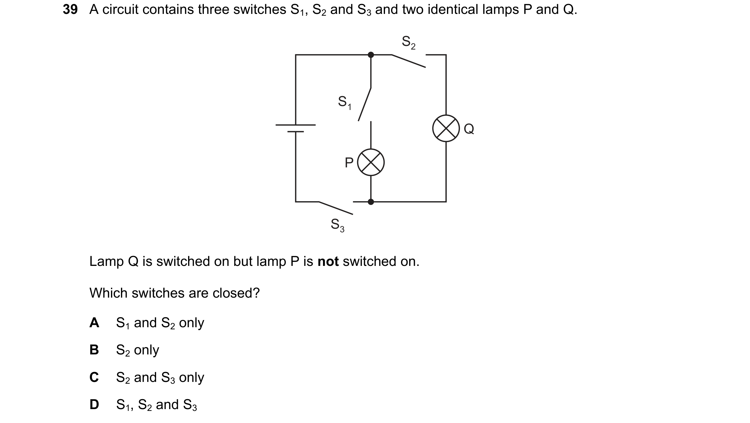
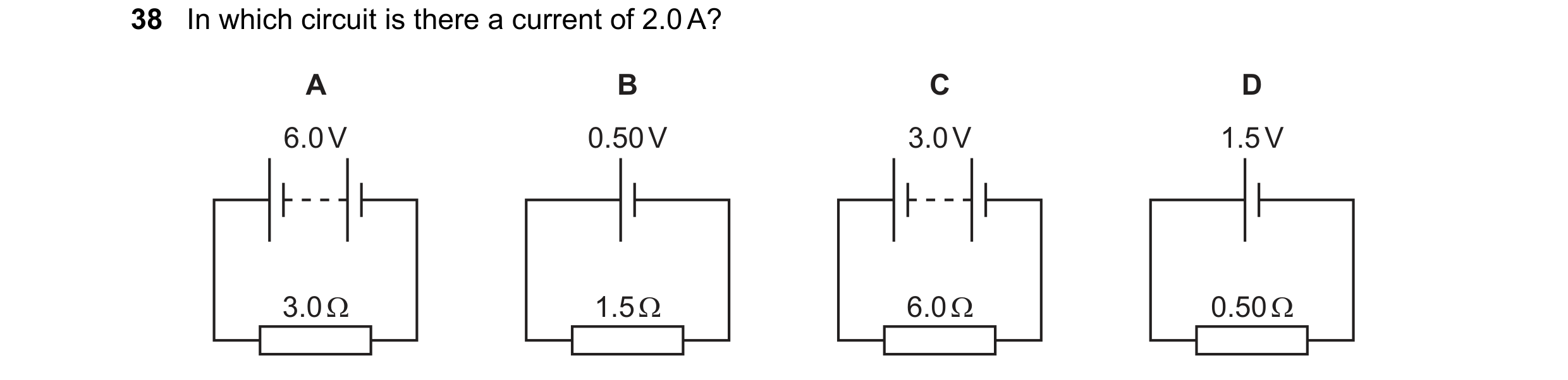
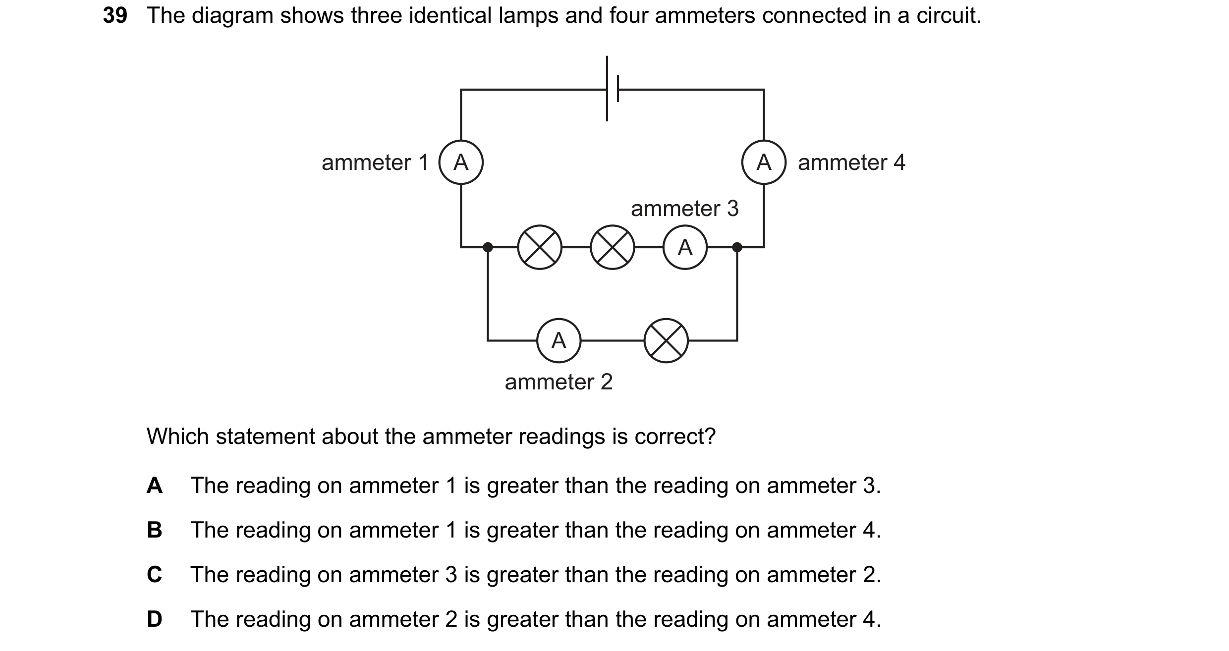 66 / 77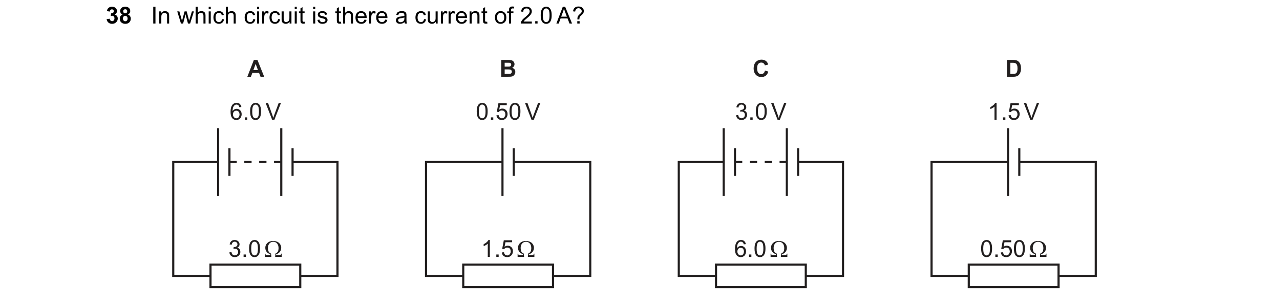
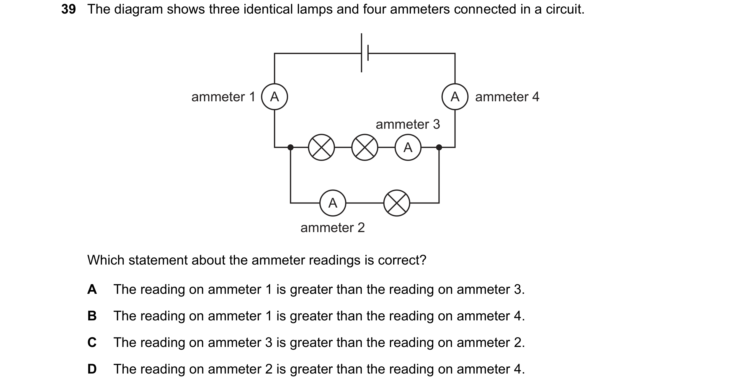
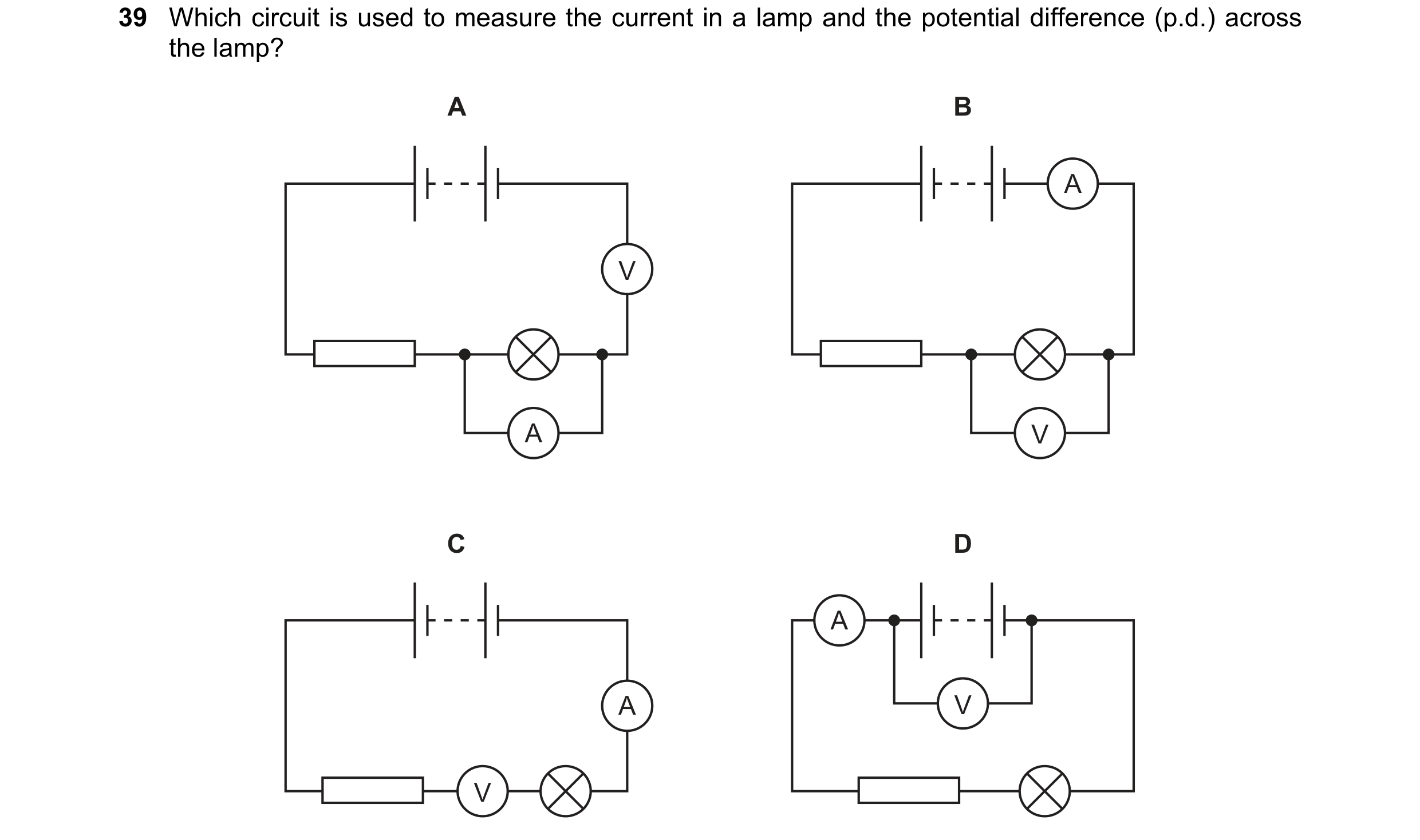 67 / 77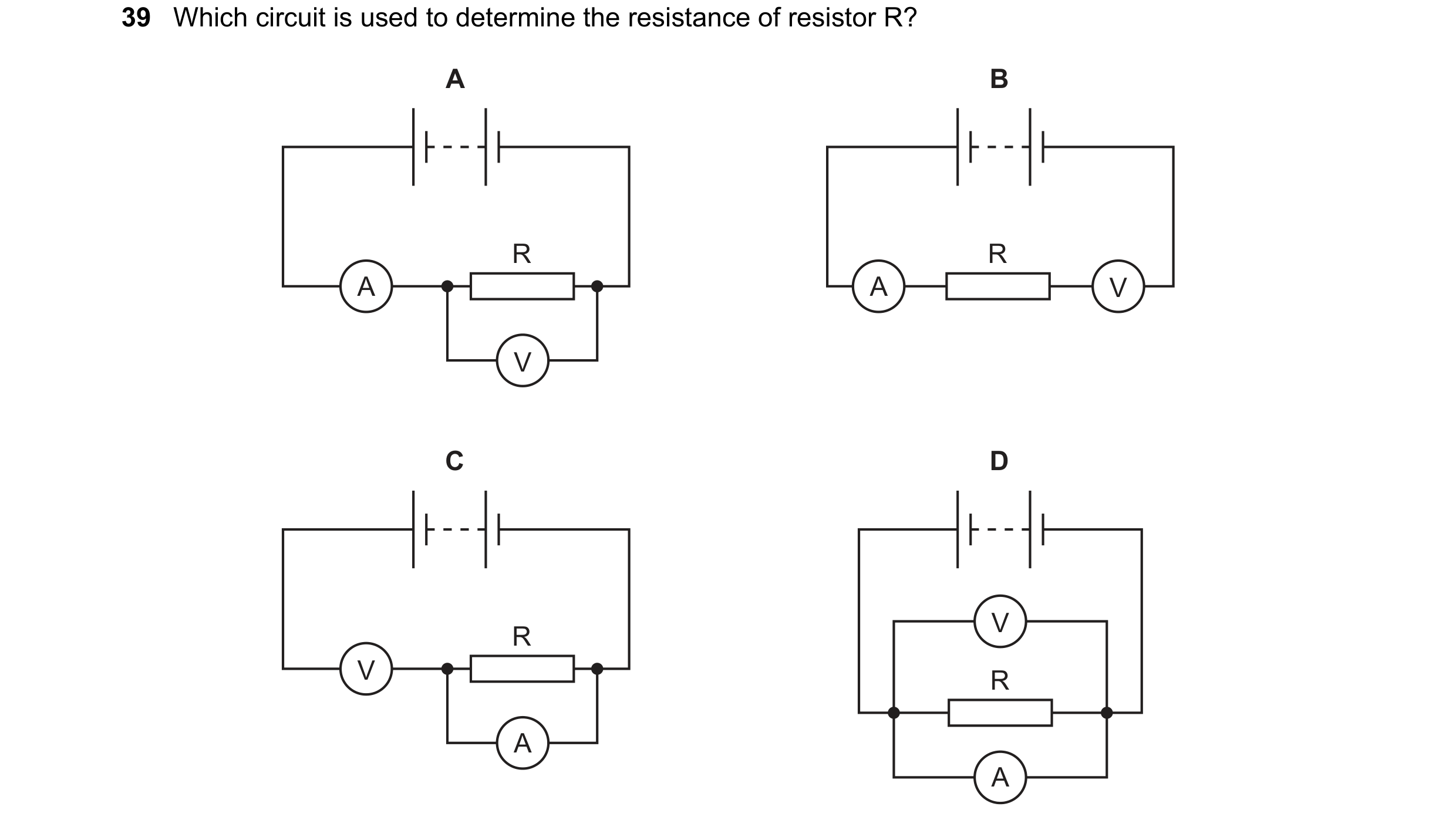
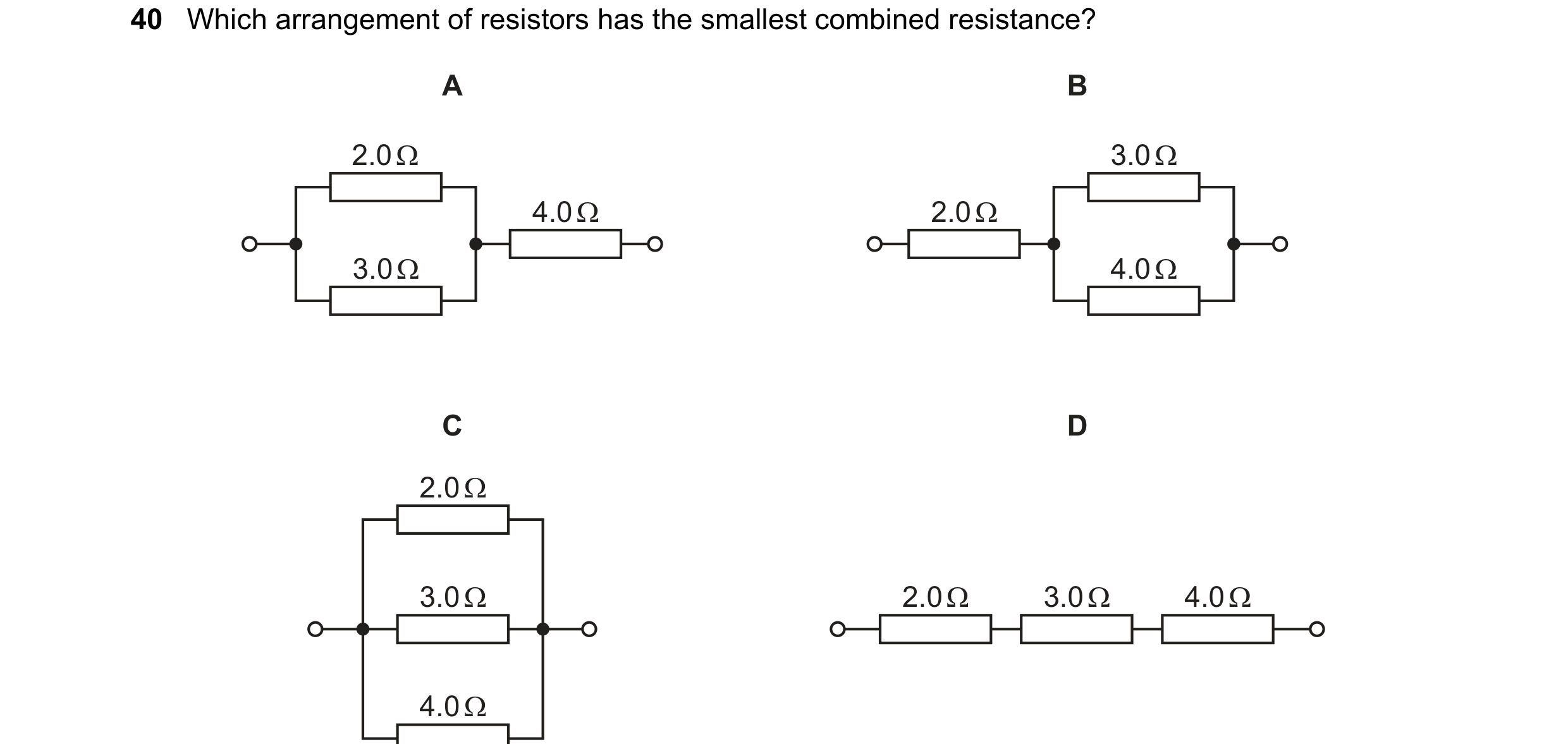 68 / 77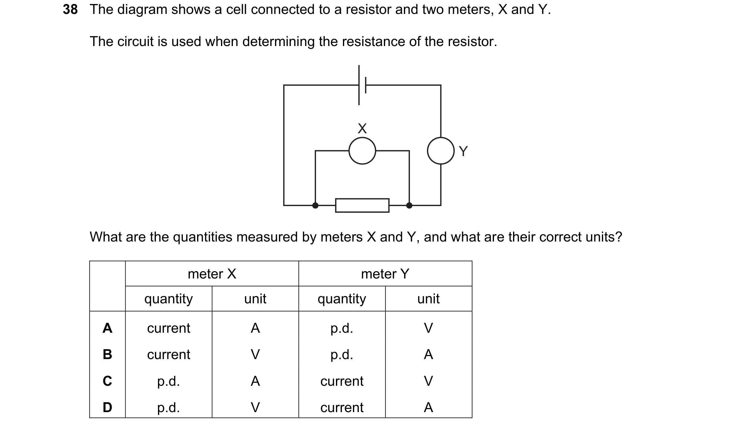
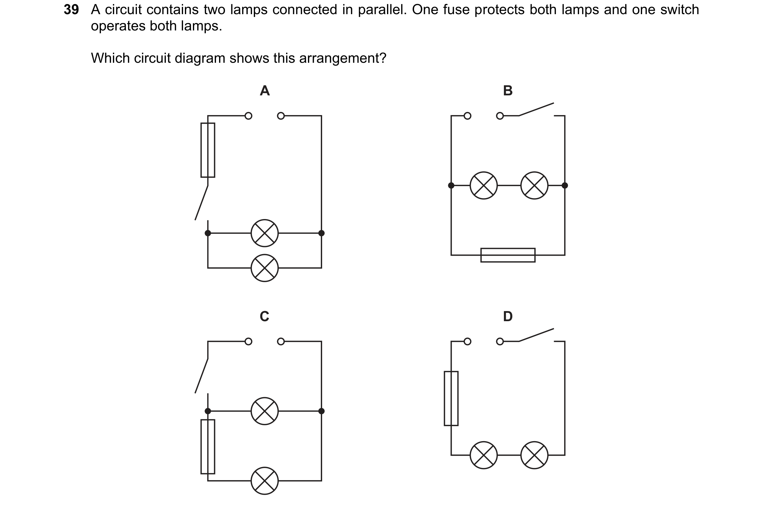 69 / 77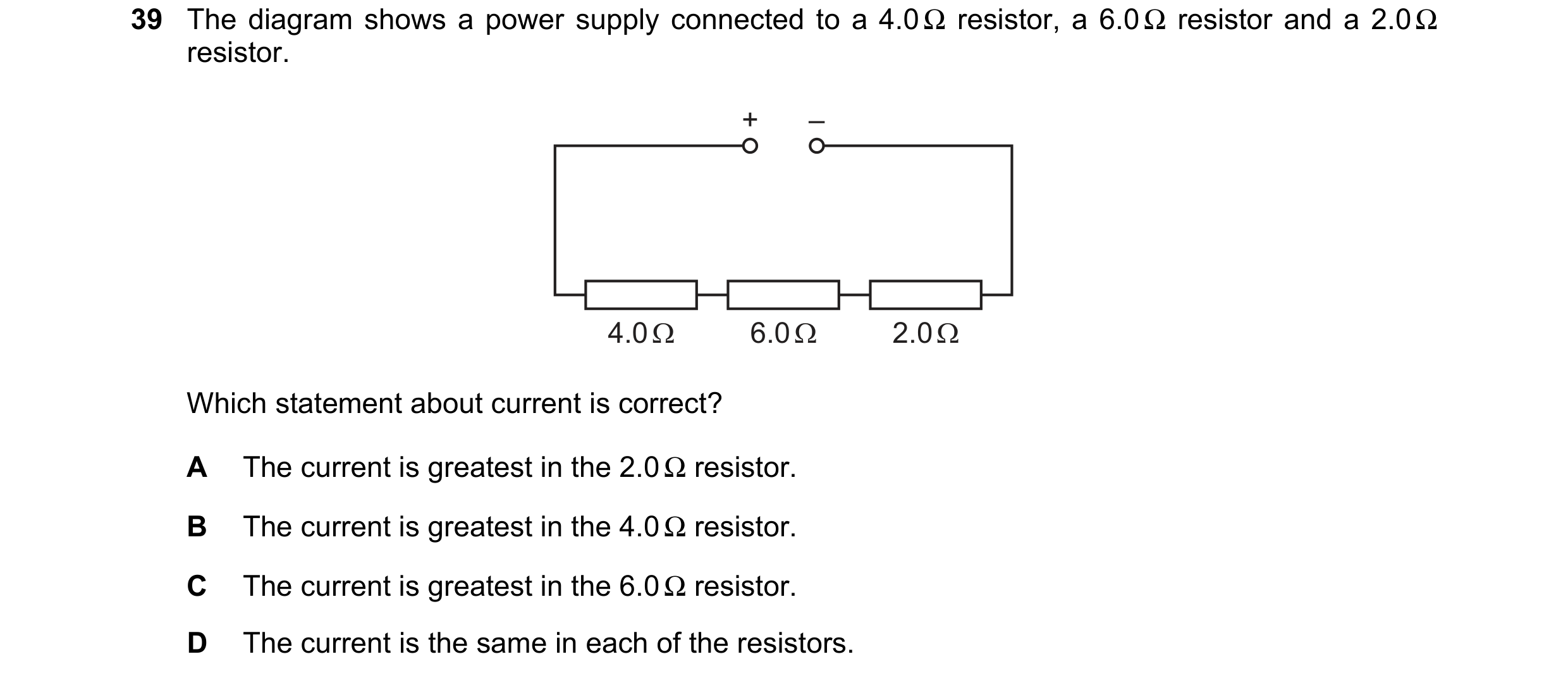
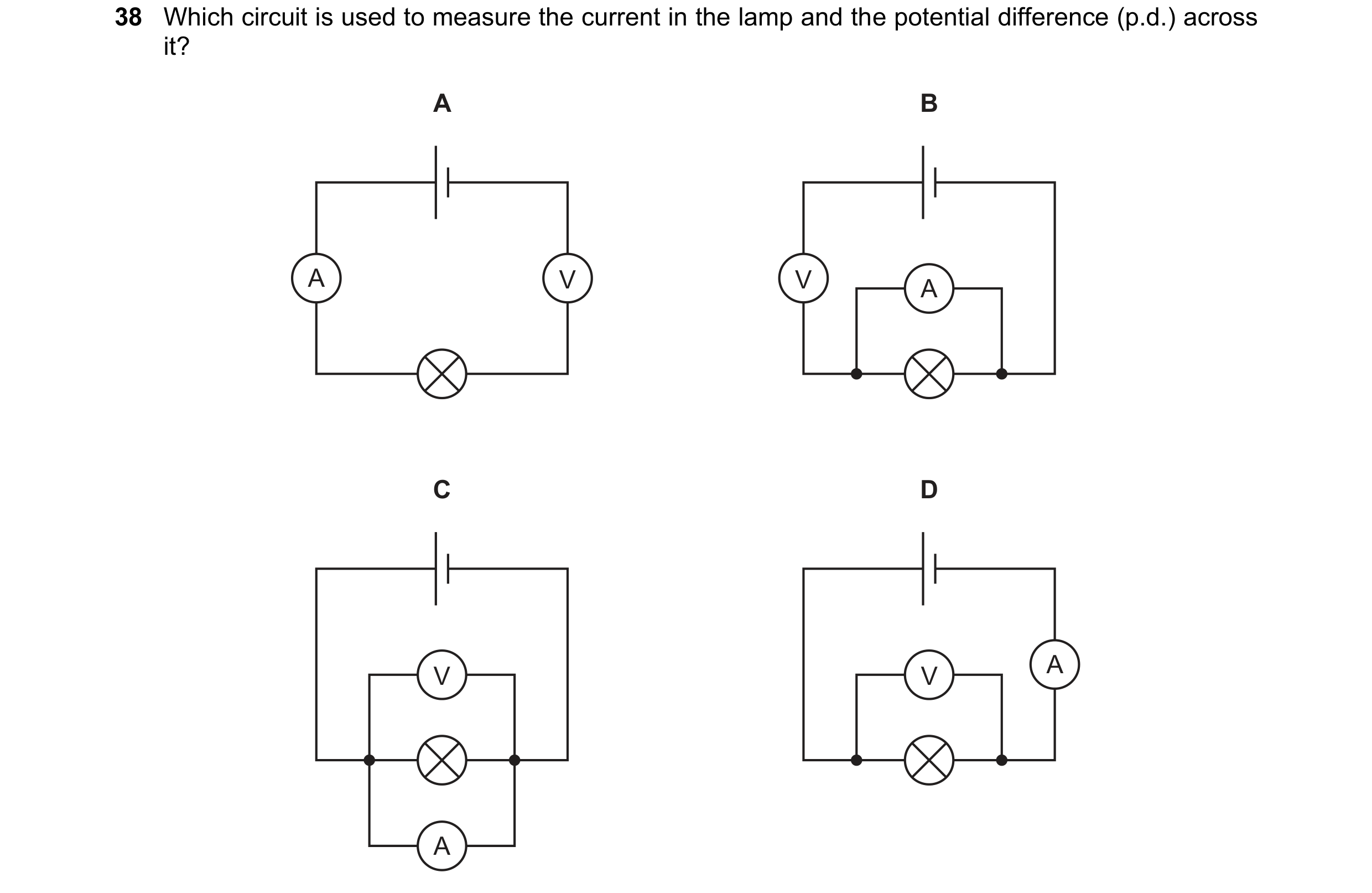

 70 / 77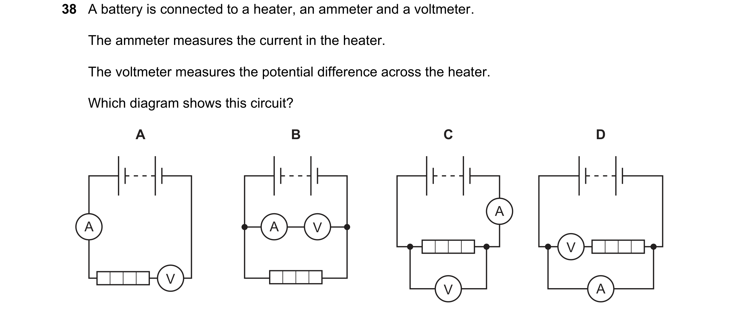
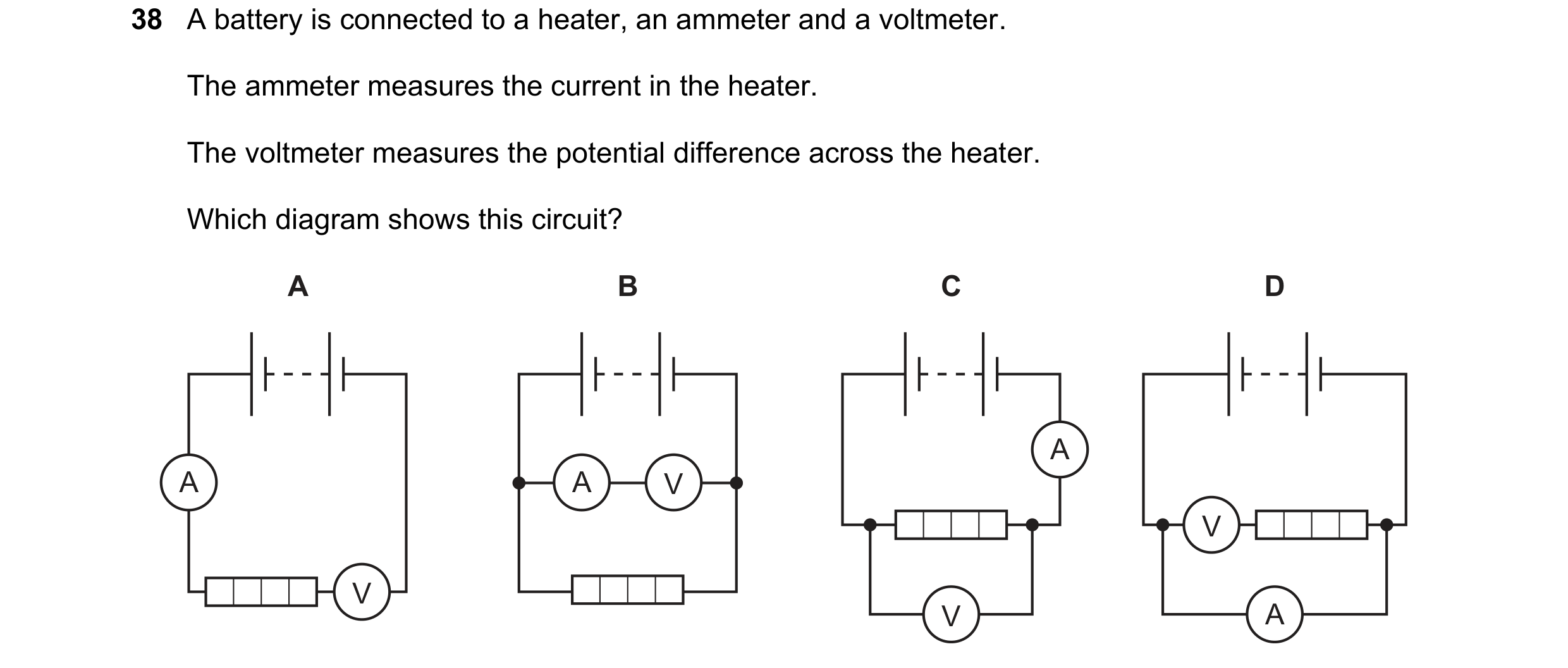

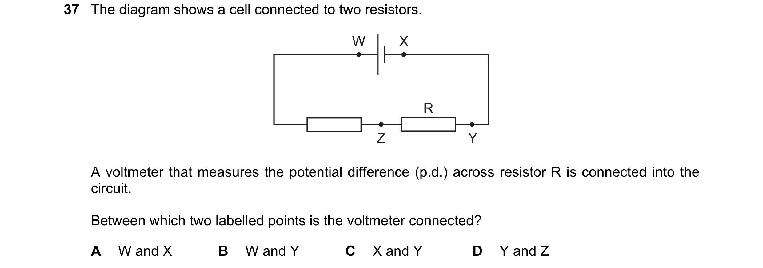 71 / 77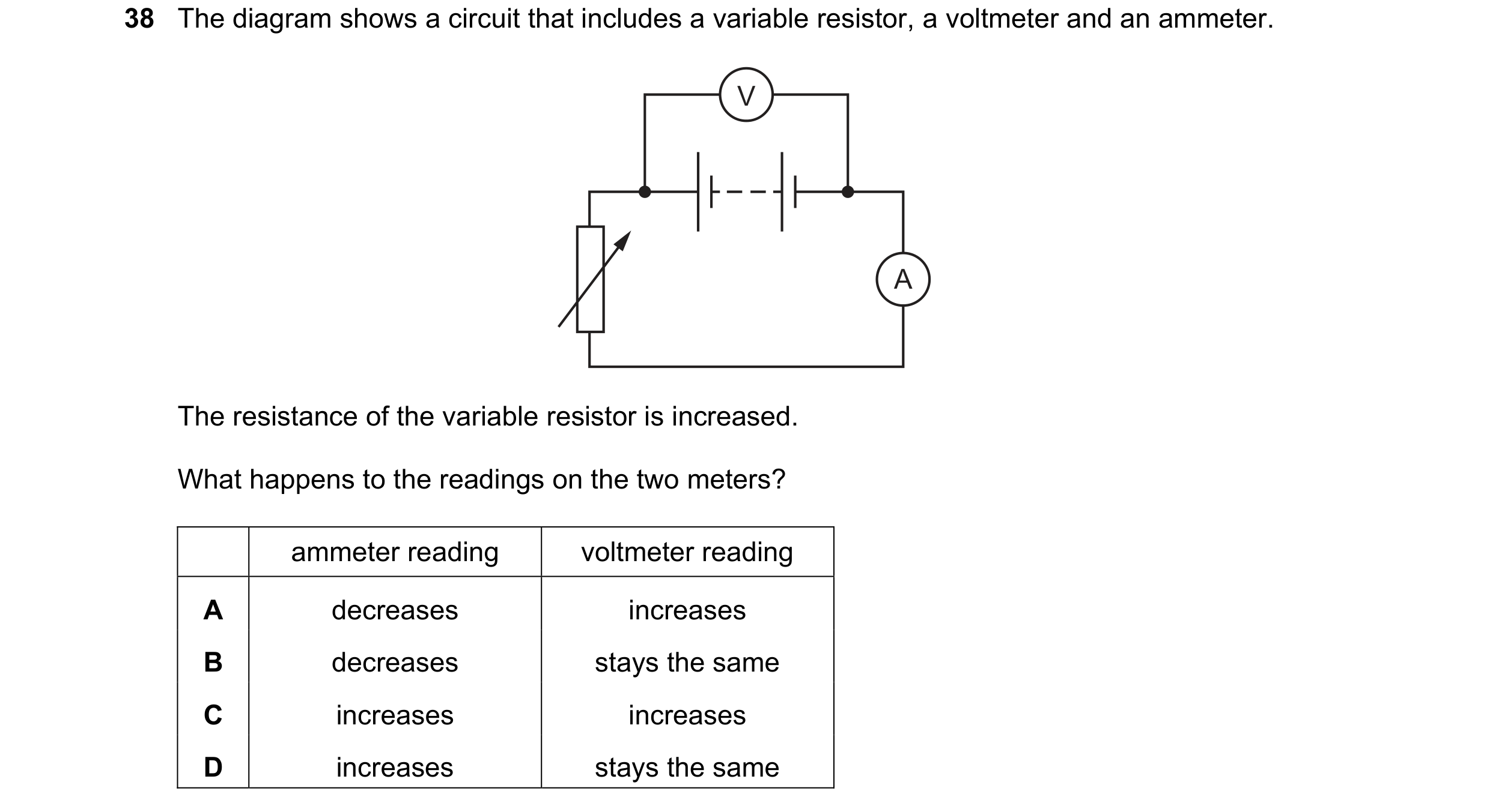
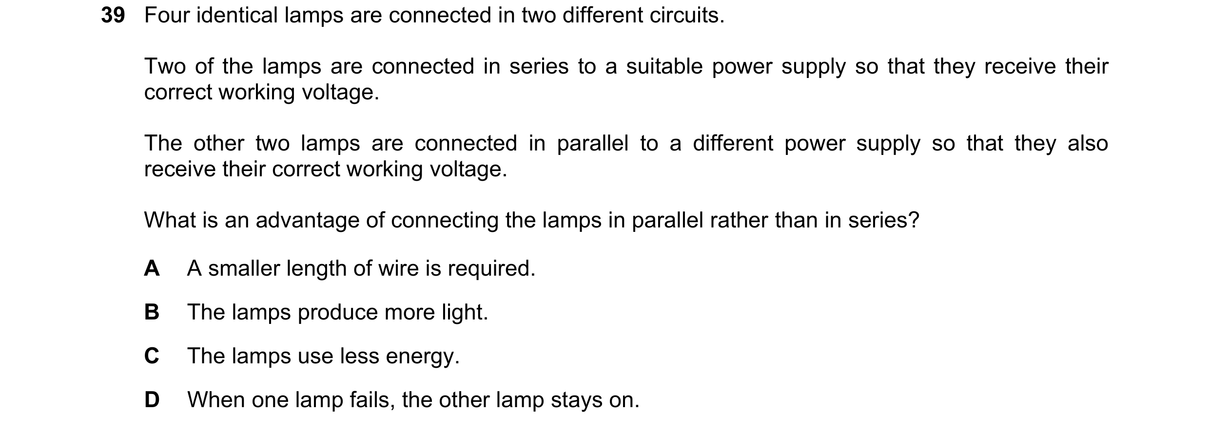
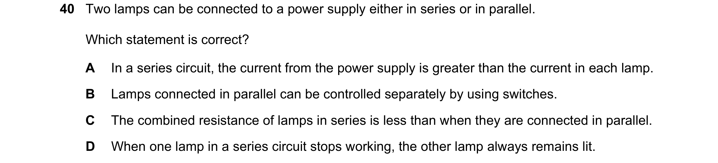 72 / 77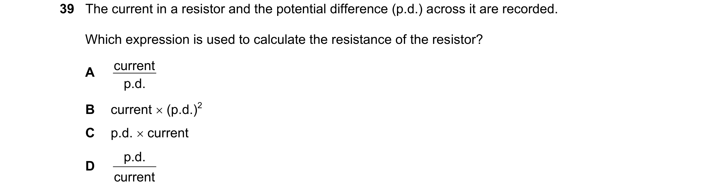
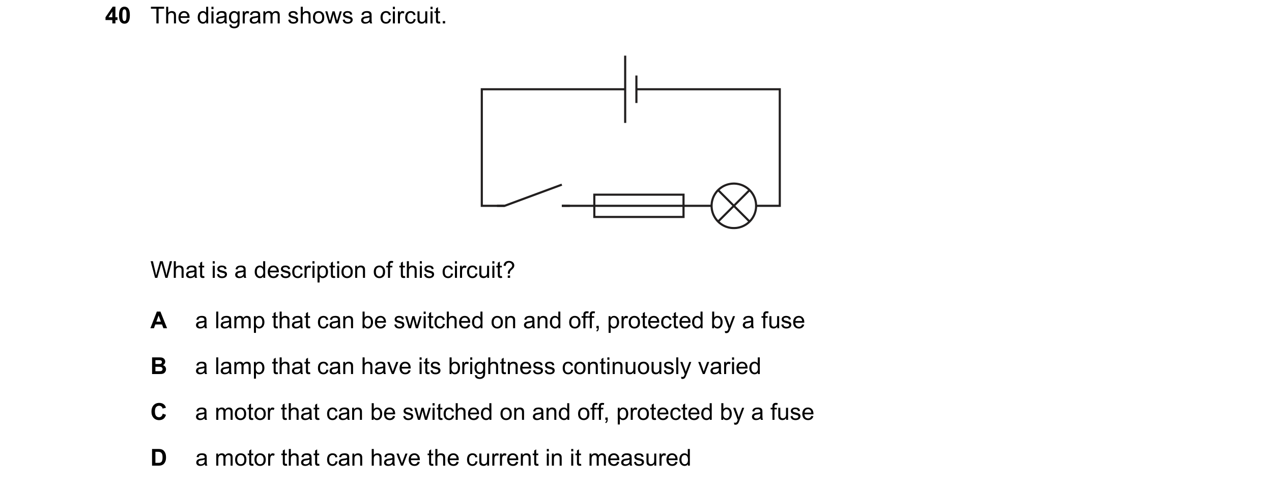
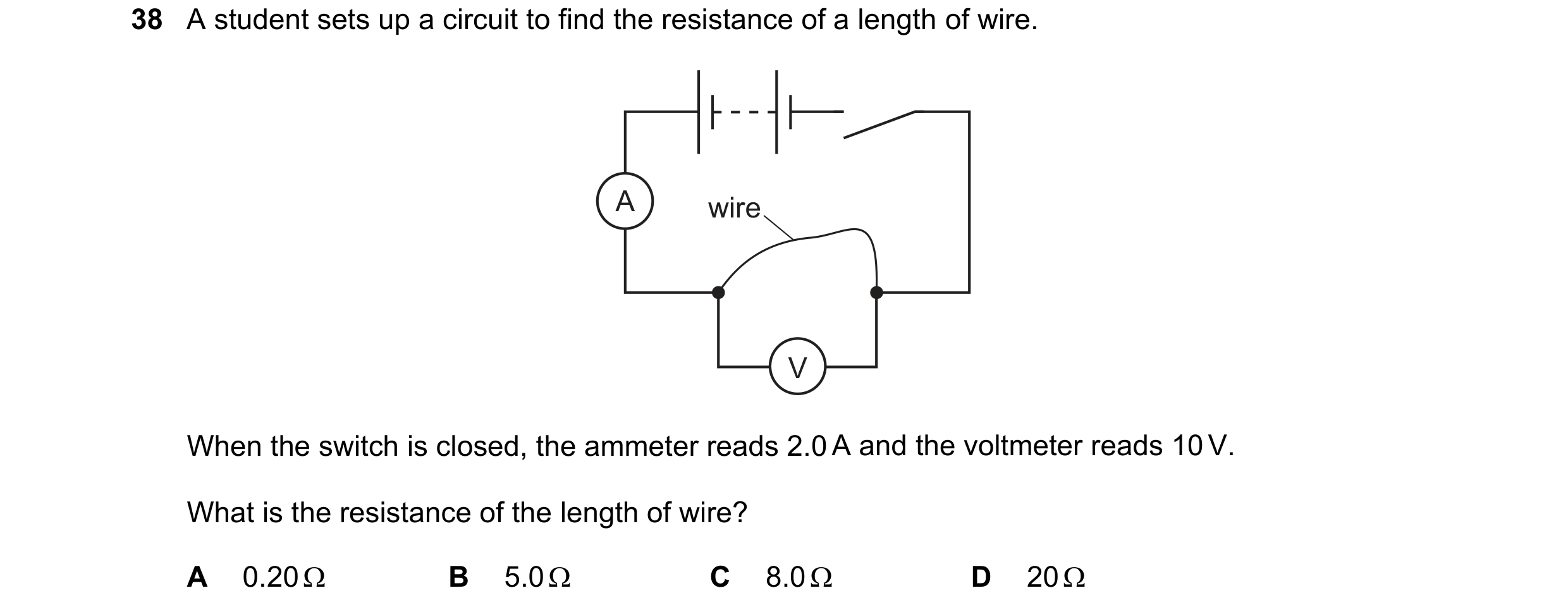
 73 / 77
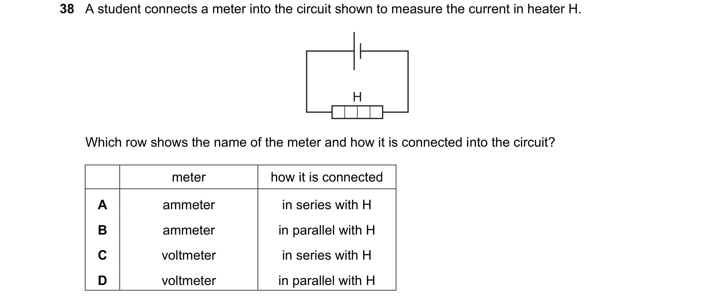
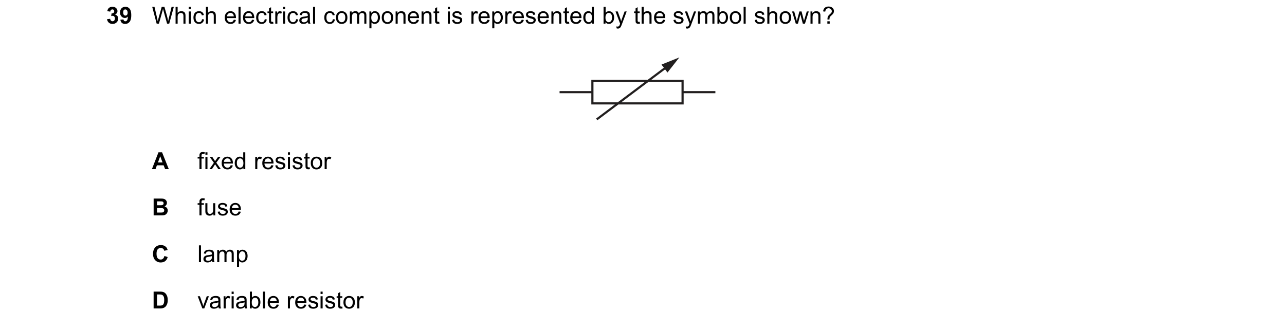
 74 / 77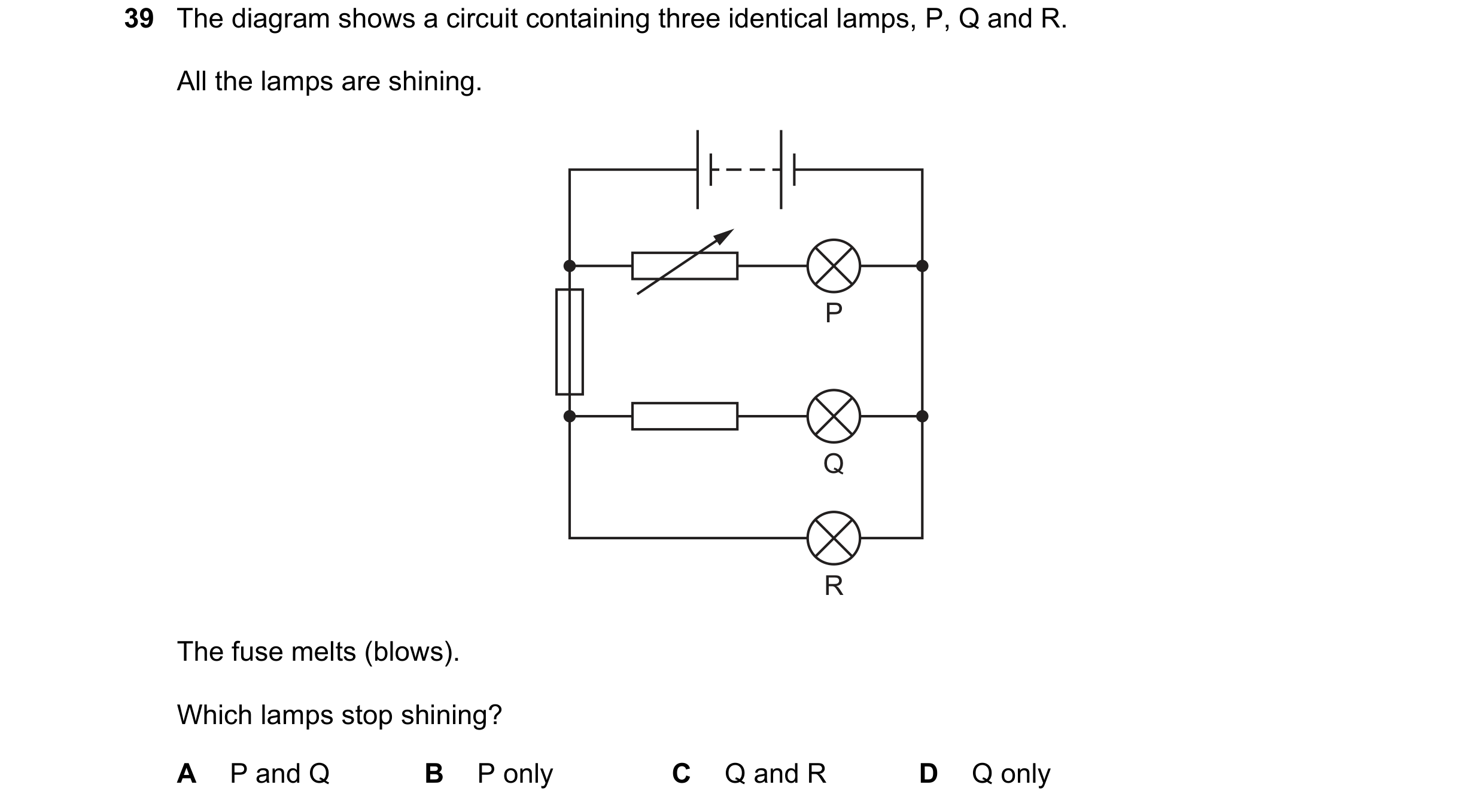
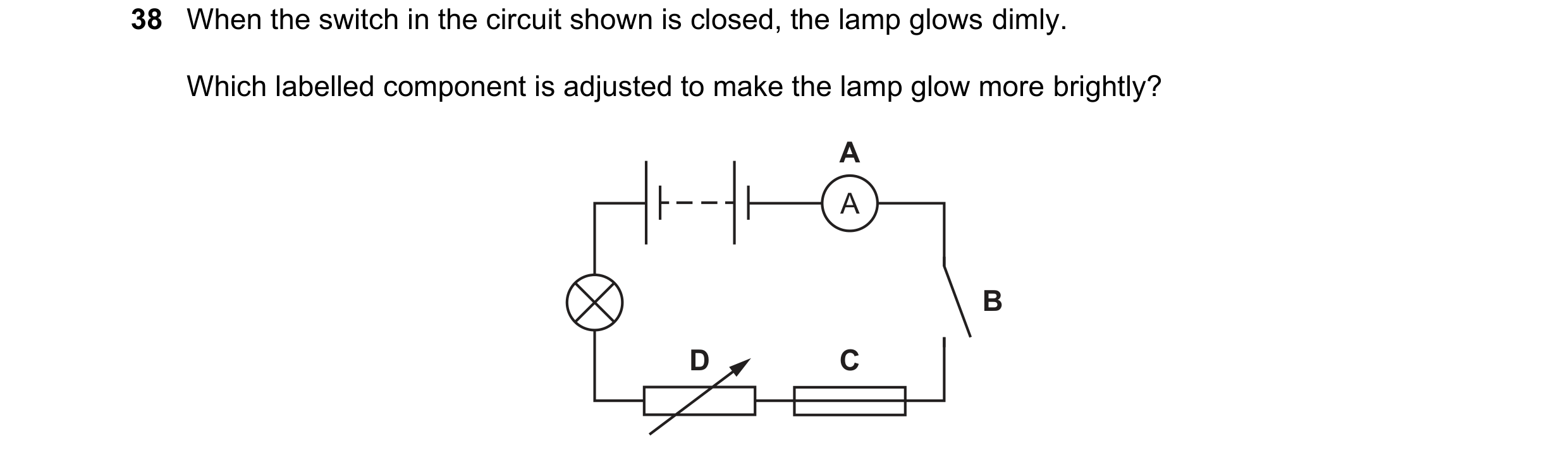 75 / 77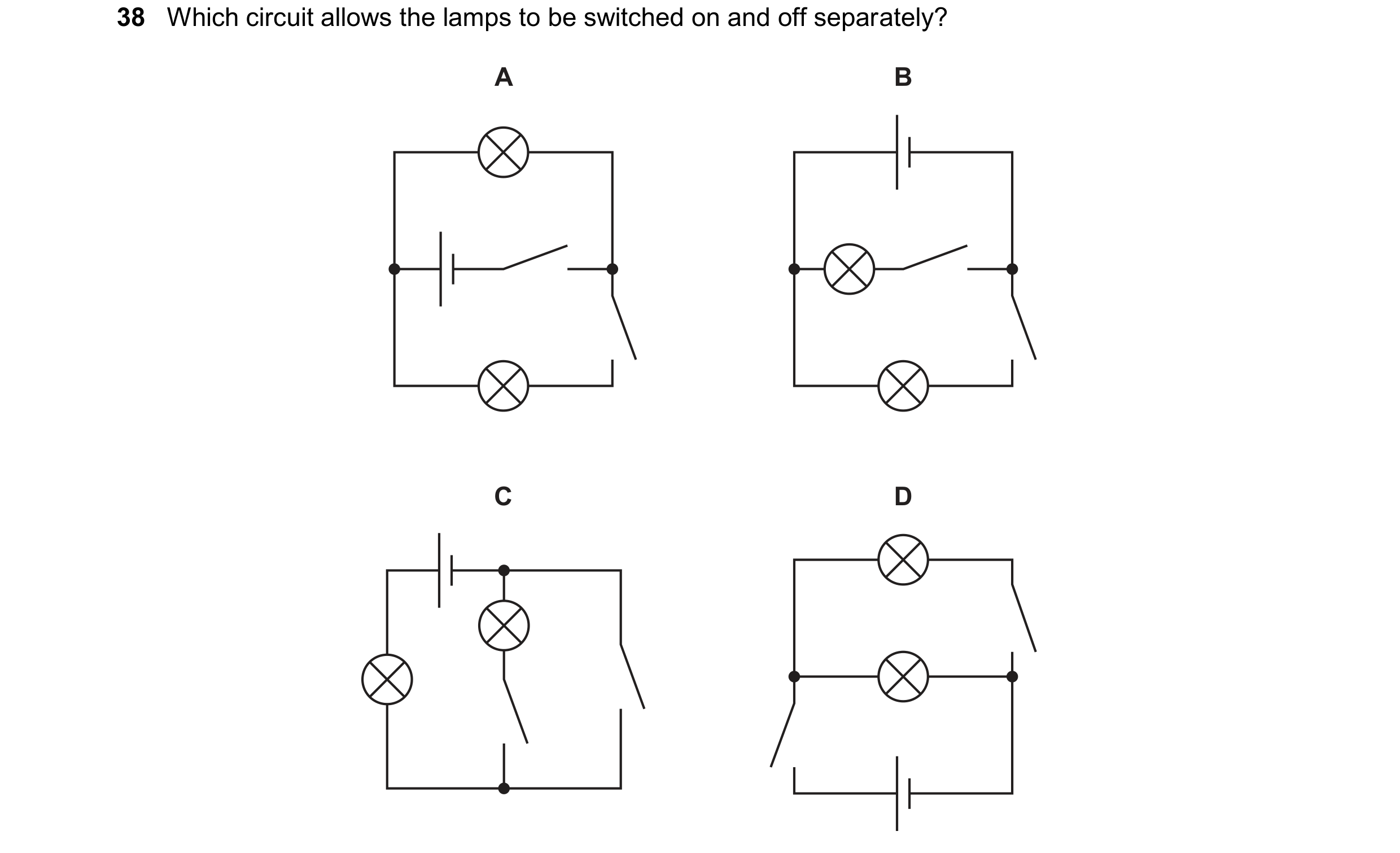
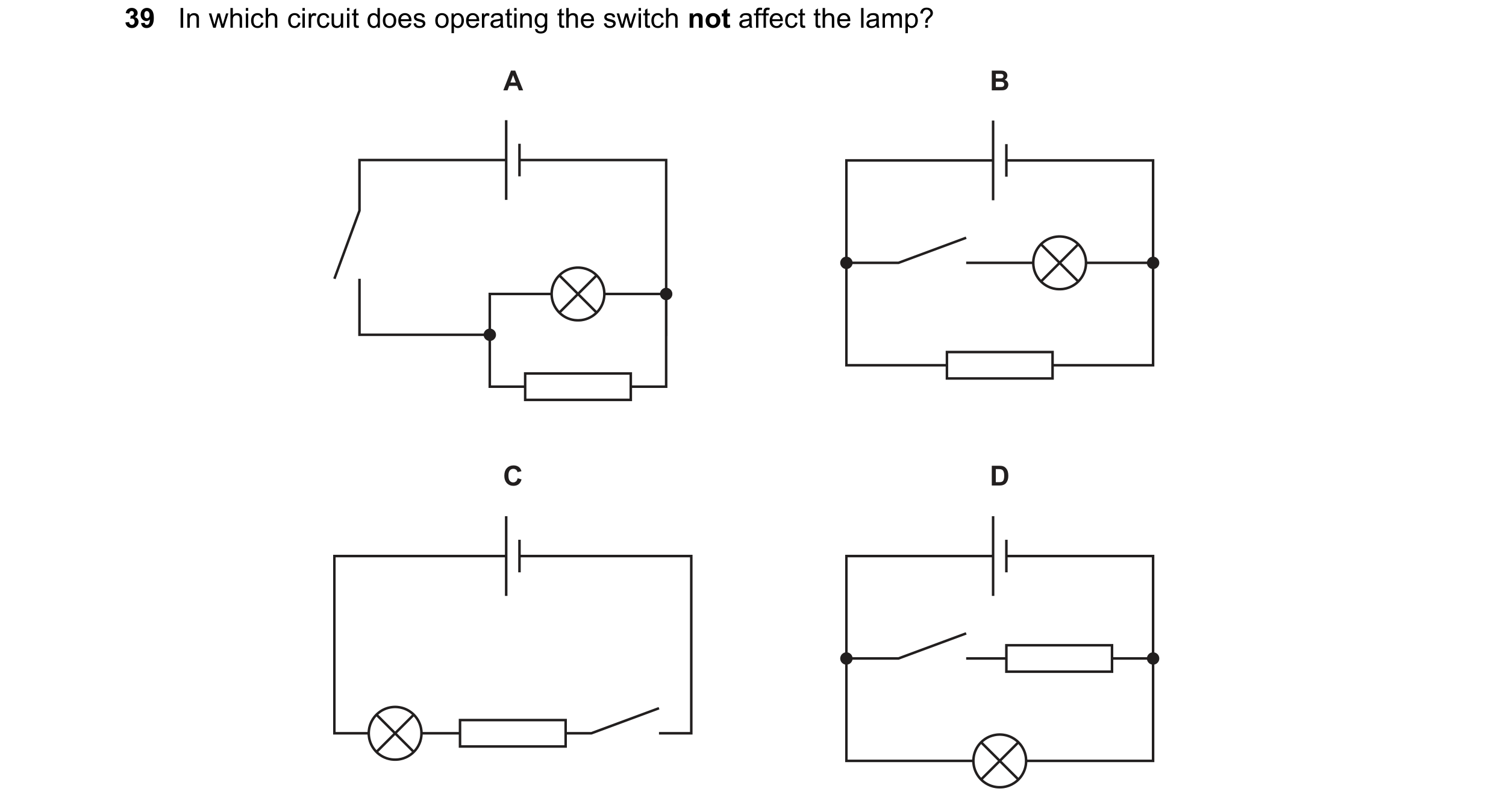 76 / 77
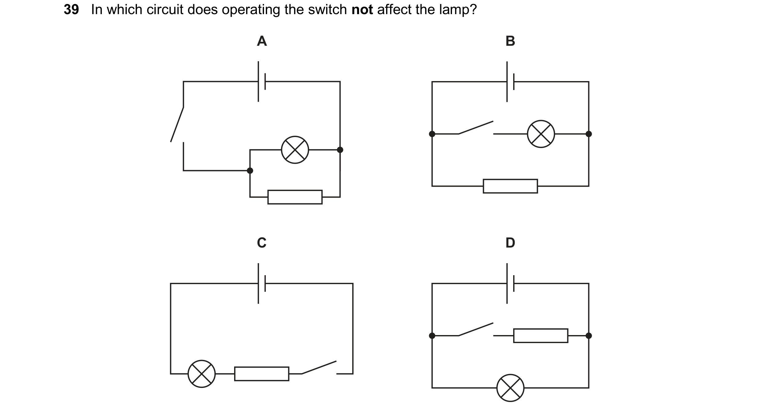 77 / 77