Questions as text
Q1 · A simple circuit set up to investigate the electrical properties of a lamp 0653/32 Feb/March 2017
9 Fig. 9.1 shows a simple circuit set up to investigate the electrical properties of a lamp. + switch cell meter X + lamp Fig. 9.1 (a) (i) On Fig. 9.2 use the correct circuit symbols to complete the circuit diagram for the circuit shown in Fig. 9.1. Fig. 9.2 [2] (ii) On Fig. 9.2 using the correct circuit symbol, connect a meter into the circuit that can measure the potential difference across the lamp. [2] (b) The cell has a voltage of 1.5 V, and the reading on the ammeter is 0.6 A for the circuit shown in Fig. 9.1. (i) Show by calculation that the resistance of the lamp is 2.5 Ω. State the formula that you use and show your working. formula working [1] (ii) A second identical lamp is added in series with the lamp in the circuit in Fig. 9.1. Suggest what happens to the reading on the ammeter. Explain why this happens. … … … … [2]
7 marks
Mark scheme: 9(a)(i) complete series circuit ; 2 9(a)(ii) correct voltmeter symbol ; connected in parallel with lamp ; 2 9(b)(i) R = V / I = 1.5/0.6 (= 2.5 Ω) ; 1 9(b)(ii) reading / current goes down / decreases ; because resistance has been increased ; 2
This question in 0653/32 Feb/March 2017
Q2 · A simple test circuit for testing different materials to see how well they conduct… 0653/31 May/June 2017
9 Fig. 9.1 shows a simple test circuit for testing different materials to see how well they conduct electricity. The material being tested is connected between X and Y. A R X Y Fig. 9.1 (a) (i) Name two materials other than copper that would be found to be good conductors when tested. … and … [1] (ii) Name two materials that would be found to be poor conductors when tested. … and … [1] (iii) State the name given to all materials that are poor conductors. … [1] (b) Explain why it is important to have a resistor, R, in the test circuit as well as the ammeter. … … [1] (c) A piece of copper wire is connected between X and Y, and a voltmeter is connected in parallel to R. (i) On Fig. 9.1, using the correct circuit symbol, show how the voltmeter is connected to the circuit. [2] (ii) The ammeter reads 0.5 A. The voltmeter reads 2 V. Calculate the resistance of R. State the formula you use, show your working and give the unit of your answer. formula working resistance = … unit … [3]
9 marks
Mark scheme: 9(a)(i) any two from one or two metals or alloys (other than copper) ; graphite / carbon ; 1 9(a)(ii) any two non-metallic materials (other than carbon / graphite) ; 1 9(a)(iii) insulators ; 1 9(b) to limit the current / protect the circuit ; 1 9(c)(i) voltmeter symbol ; parallel connection ; 2 9(c)(ii) R = V / I ; = 2 / 0.5 = 4 ; ohms / Ω ; 3
This question in 0653/31 May/June 2017
Q3 · A simple circuit set up to investigate the electrical properties of a lamp 0653/32 May/June 2017
9 Fig. 9.1 shows a simple circuit set up to investigate the electrical properties of a lamp. cells 0 1 A switch ammeter lamps variable resistor Fig. 9.1 (a) On Fig. 9.2 use the correct circuit symbols to complete the circuit diagram for the circuit shown in Fig. 9.1. Fig. 9.2 [3] (b) The two lamps in the circuit are identical. A voltmeter connected across the two lamps reads 2.4 V. The ammeter reads 0.6 A. Calculate the resistance of one lamp. State the formula used and show your working. formula working resistance = … Ω [3] (c) The resistance of the variable resistor is reduced. State the effect this will have on the brightness of the two lamps. Give a reason for your answer. … … … [1]
7 marks
Mark scheme: 9(a) correct symbols for ammeter and lamp ; correct symbol for variable resistor ; all shown components connected in series, any order ; 3 9(b) resistance = V / I ; (total resistance) = 2.4 / 0.6 (= 4 Ω) ; resistance of one lamp = 2 (Ω) ; 3 9(c) (increase – no mark) (total resistance less) so current increases ; 1
This question in 0653/32 May/June 2017
Q4 · A simple circuit set up to investigate the electrical properties of a lamp 0653/33 May/June 2017
9 Fig. 9.1 shows a simple circuit set up to investigate the electrical properties of a lamp. cells 0 1 A switch ammeter lamps variable resistor Fig. 9.1 (a) On Fig. 9.2 use the correct circuit symbols to complete the circuit diagram for the circuit shown in Fig. 9.1. Fig. 9.2 [3] (b) The two lamps in the circuit are identical. A voltmeter connected across the two lamps reads 2.4 V. The ammeter reads 0.6 A. Calculate the resistance of one lamp. State the formula used and show your working. formula working resistance = … Ω [3] (c) The resistance of the variable resistor is reduced. State the effect this will have on the brightness of the two lamps. Give a reason for your answer. … … … [1]
7 marks
Mark scheme: 9(a) correct symbols for ammeter and lamp ; correct symbol for variable resistor ; all shown components connected in series, any order ; 3 9(b) resistance = V / I ; (total resistance) = 2.4 / 0.6 (= 4 Ω) ; resistance of one lamp = 2 (Ω) ; 3 9(c) (increase – no mark) (total resistance less) so current increases ; 1
This question in 0653/33 May/June 2017
Q5 · A fan heater used to heat a room in cold weather 0653/31 Oct/Nov 2017
6 Fig. 6.1 shows a fan heater used to heat a room in cold weather. Fig. 6.1 The fan heater is connected to the mains electricity supply. Fig. 6.2 shows the circuit diagram for the fan heater. 240 V switch 1 heater switch 2 M motor Fig. 6.2 (a) (i) State the name of the circuit component represented by this symbol. … [1] (ii) Explain why it is important for this component to be included in the circuit. … … [1] (iii) Deduce which switch or switches must be closed (on) for the heater to work. … [1] (b) (i) An electrician wants to measure the current through the fan motor. Complete the circuit diagram in Fig. 6.3 to show how the electrician should connect a meter to do this. You should use the correct symbol for the meter to be used, and complete all missing circuit connections. 240 V switch 1 switch 2 M Fig. 6.3 [2] (ii) The current through the fan motor is found to be 0.2 A when connected to a mains electricity supply of 240 V. Calculate the resistance of the fan motor. State the formula you use, show your working and state the unit of your answer. formula working resistance = … unit … [3]
8 marks
Mark scheme: 6(a)(i) fuse 6(a)(ii) to pr 6(a)(iii) (both 6(b)(i) corre amm 6(b)(ii) R = V (=) 1 ohm ; rotect fan heater h) switch 1 and s ect symbol for a meter in fan moto V / I or = 240 / 0 1200 ; m(s) / Ω ; r from overload / switch 2 ; mmeter ; or branch, all cir 0.2 ; / current too high rcuit connections h ; s complete ; 1 1 1 2 3
This question in 0653/31 Oct/Nov 2017
Q6 · In a theatre, spotlights are used to shine a beam of light on one person on the stage 0653/32 Oct/Nov 2017
9 In a theatre, spotlights are used to shine a beam of light on one person on the stage. Fig. 9.1 shows a spotlight shining a parallel beam of light on a singer. Fig. 9.1 (a) Fig. 9.2 shows a powerful lamp shining through a narrow hole in front of a lens inside the spotlight. Fig. 9.2 (i) On Fig. 9.2 use a ruler to draw three rays that come through the narrow hole, pass through the lens and emerge parallel to each other to form a narrow beam of light. One ray has been started for you. [2] (ii) Name the distance from the narrow hole to the lens. … [1] (b) Fig. 9.3a shows the way the lamps in two spotlights are connected to a power supply. The circuit contains a dimmer control so that the brightness of the lights can be changed. Fig. 9.3b shows part of the circuit diagram for this. dimmer control Fig. 9.3a power supply X Y Fig. 9.3b (i) The dimmer control contains a variable resistor. On Fig 9.3b complete the circuit diagram by connecting the variable resistor into the circuit between X and Y using the correct circuit symbol. [1] (ii) The current from the power supply is 20 A. State the conclusion that can be drawn about the size of the current through each lamp. Give a reason for your answer. conclusion … reason … … [2] (iii) The filament of one of the lamps breaks. State what will happen to the other lamp. Give a reason for your answer. … … … [1]
7 marks
Mark scheme: 9 9 9 9(a)(i) two m all ray 9(a)(ii) focal 9(b)(i) correc 9(b)(ii) less t curren 9(b)(iii) remai still a more rays from h ys emerge from length ; ct symbol for va han 20 A ; nt from source is ins lit (no mark) complete circuit hole to lens ; lens parallel ; riable resistor ; s larger than in e t through that br each branch ; ranch owtte ; 2 1 1 2 1
This question in 0653/32 Oct/Nov 2017
Q7 · A toy car powered by batteries 0653/33 Oct/Nov 2017
9 Fig. 9.1 shows a toy car powered by batteries. Fig. 9.1 Fig. 9.2 shows part of the circuit diagram for a circuit in the toy car, including the two headlamps which can be switched on when needed. X Fig. 9.2 (a) The car is driven by an electric motor which must be able to operate whenever the switch shown in Fig. 9.2 is on. On Fig. 9.2 complete the circuit diagram by adding • the electric motor in parallel with the headlamps, with a wire connecting it to point X on the circuit. The symbol for an electric motor is M . • a variable resistor connected to the electric motor to control the speed of the motor. • a separate switch to control both headlamps only. • any wires needed to complete the circuit connections. [4] (b) The resistance of the variable resistor is decreased in order to speed up the motor. Suggest why decreasing the resistance will speed up the motor. … … [1] (c) Complete the sentences below by writing the correct phrase in each space. Each phrase may be used once, more than once or not at all. by an ammeter by an insulator in parallel in series less than more than the same as The headlamps are connected … with each other. When the headlamps are switched off, the current through the motor is … the current through the battery. When the headlamps are switched on, the combined resistance of the motor and headlamps is … the resistance of the motor before the headlamps are switched on. [3] (d) Some modern cars on the road are powered by batteries. Fig. 9.3 shows an electric car being charged by connecting it to the mains supply at an outdoor charging point. Fig. 9.3 Suggest one important electrical hazard for this charging process. Suggest a way to make this safer. hazard … safety improvement … … [2]
10 marks
Mark scheme: 9(a) motor in parallel with headlamps ; variable resistor in motor branch, correct symbol ; switch for headlamps after motor branch, before first headlamp branch ; all wires required for complete circuit ; 4 9(b) (decreasing resistance) increases current (so faster motor) ; 1 9(c) in parallel ; the same as ; less than ; 3 9(d) rain / water / damaged insulation / AVP ; protect from rain or water / use of protective cover / sensible suggestion related to hazard identified ; 2
This question in 0653/33 Oct/Nov 2017
Q8 · A simple circuit set up to investigate the electrical properties of a lamp 0653/32 Feb/March 2018
9 Fig. 9.1 shows a simple circuit set up to investigate the electrical properties of a lamp. ammeter 01234 AMPS 5 lamp switch battery Fig. 9.1 (a) (i) On Fig. 9.2 use the correct symbols to complete the diagram for the circuit shown in Fig. 9.1. Fig. 9.2 [2] (ii) On Fig. 9.2, using the correct circuit symbol, connect a meter into the circuit that can measure the potential difference across the lamp. [2] (b) The battery has a voltage of 1.5 V, and the reading on the ammeter is 0.6 A for the circuit in Fig. 9.1. (i) Calculate the resistance of the lamp and state the units. State the formula you use and show your working. formula working resistance = … unit … [3] (ii) A second identical lamp is added in series with the lamp in the circuit in Fig. 9.1. The reading on the ammeter decreases. Explain why this happens. … … … [2]
9 marks
Mark scheme: 9(a)(i) both ammeter and lamp symbols correct ; complete series circuit ; 9(a)(ii) voltmeter symbol correct ; connected in parallel with lamp ; 2 9(b)(i) R = V / I ; = 1.5 / 0.6 = 2.5 ; Ω / ohm ; 3 9(b)(ii) total resistance in circuit increases ; voltage same, so current must decrease ; 2 A
This question in 0653/32 Feb/March 2018
Q9 · A small electric cooker with two hot plates 0653/31 May/June 2018
9 Fig. 9.1 shows a small electric cooker with two hot plates. hot plates Fig. 9.1 The cooker is connected to a 240 V supply. Each hot plate is controlled by a switch and a variable resistor. Each hot plate can be turned on and off and controlled without affecting the other hot plate. (a) (i) In Table 9.1 draw the circuit symbols for each component used in the cooker circuit. Table 9.1 component fuse switch variable resistor symbol [2] (ii) The two hot plates are connected in parallel, so that each can be controlled separately by a switch and a variable resistor. The whole cooker circuit is protected by a fuse. The circuit symbol for a heater in the hot plate is: Complete the circuit diagram for the cooker, which has been started for you. 240 V [4] (b) For this question you may assume that the resistance of each variable resistor in the circuit is zero and can be ignored. (i) The large hot plate has a resistance of 40 Ω, and the small hot plate has a resistance of 60 Ω. Draw a circle around the correct value for the combined resistance of the two hot plates. 24 Ω 50 Ω 72 Ω 100 Ω [1] (ii) Use your chosen answer in (i) to calculate the current from the supply when both hot plates are switched on. State the formula you use and show your working. formula working current = … A [2]
9 marks
Mark scheme: 9 9 9(a)(i) fuse: switc varia three one o 9(a)(ii) seco each each fuse 9(b)(i) 24 Ω 9(b)(ii) R = V I = 1 ch: able resistor: e correct symbol or two correct sy nd hotplate con hotplate branch hotplate branch in main circuit ; ; V / I or 24 = 240 0A ; s for 2 marks ; ymbols for 1 ma nected in paralle h contains a vari h has a switch in / I or I = V / R o rk ; el ; iable resistor in n series ; or I = 240 / 24 ; series ; 2 4 1 2
This question in 0653/31 May/June 2018
Q10 · A simple circuit set up to investigate the current through an electric motor 0653/32 May/June 2018
9 Fig. 9.1 shows a simple circuit set up to investigate the current through an electric motor. cell meter + off switch electric motor Fig. 9.1 (a) (i) On Fig. 9.2 use the correct circuit symbols to complete the circuit diagram for the circuit arrangement shown in Fig. 9.1. The symbol for an electric motor is shown. M Fig. 9.2 [3] (ii) On Fig. 9.2, using the correct circuit symbol, connect a meter into the circuit that can measure the potential difference across the motor. [2] (b) The cell has a voltage of 1.5 V. The resistance of the motor when turning is 5.0 Ω. (i) Calculate the current through the motor. State the formula you use and show your working. formula working current = … A [2] (ii) Fig. 9.3 shows a second identical cell added in series with the cell in the circuit in Fig. 9.1. cells + + meter off switch electric motor Fig. 9.3 Suggest what happens to the reading on the meter. Explain why this happens. … … … [2] (c) The motor in Fig. 9.3 is placed in front of a mirror and a student tries to look at the reflection of the motor in the mirror, as shown in Fig. 9.4. motor mirror Fig. 9.4 (i) State the law of reflection of light. … … [1] (ii) The student cannot see the motor in the mirror, as shown in Fig. 9.4. On Fig. 9.4 re‑draw the mirror in a position where the student’s eye can see the reflection of the motor in the mirror. [1]
11 marks
Mark scheme: 9(a)(i) correct symbol for cell ; correct symbol for switch ; meter identified as an ammeter and a complete series circuit connected ; 3 9(a)(ii) correct meter selected (V symbol) ; meter connected in parallel with motor ; 2 9(b)(i) I = V / R or I = 1.5 / 5.0 ; = 0.30 (A) ; 2 Question Answer Marks 9(b)(ii) reading on ammeter increases / current increases ; (extra cell) increases pd / voltage (across motor) ; 2 9(c)(i) angle of incidence = angle of reflection ; 1 9(c)(ii) mirror shown at approx. correct angle ; 1
This question in 0653/32 May/June 2018
Q11 · A simple circuit set up to investigate the current through an electric motor 0653/33 May/June 2018
9 Fig. 9.1 shows a simple circuit set up to investigate the current through an electric motor. cell meter + off switch electric motor Fig. 9.1 (a) (i) On Fig. 9.2 use the correct circuit symbols to complete the circuit diagram for the circuit arrangement shown in Fig. 9.1. The symbol for an electric motor is shown. M Fig. 9.2 [3] (ii) On Fig. 9.2, using the correct circuit symbol, connect a meter into the circuit that can measure the potential difference across the motor. [2] (b) The cell has a voltage of 1.5 V. The resistance of the motor when turning is 5.0 Ω. (i) Calculate the current through the motor. State the formula you use and show your working. formula working current = … A [2] (ii) Fig. 9.3 shows a second identical cell added in series with the cell in the circuit in Fig. 9.1. cells + + meter off switch electric motor Fig. 9.3 Suggest what happens to the reading on the meter. Explain why this happens. … … … [2] (c) The motor in Fig. 9.3 is placed in front of a mirror and a student tries to look at the reflection of the motor in the mirror, as shown in Fig. 9.4. motor mirror Fig. 9.4 (i) State the law of reflection of light. … … [1] (ii) The student cannot see the motor in the mirror, as shown in Fig. 9.4. On Fig. 9.4 re‑draw the mirror in a position where the student’s eye can see the reflection of the motor in the mirror. [1]
11 marks
Mark scheme: 9(a)(i) correct symbol for cell ; correct symbol for switch ; meter identified as an ammeter and a complete series circuit connected ; 3 9(a)(ii) correct meter selected (V symbol) ; meter connected in parallel with motor ; 2 9(b)(i) I = V / R or I = 1.5 / 5.0 ; = 0.30 (A) ; 2 Question Answer Marks 9(b)(ii) reading on ammeter increases / current increases ; (extra cell) increases pd / voltage (across motor) ; 2 9(c)(i) angle of incidence = angle of reflection ; 1 9(c)(ii) mirror shown at approx. correct angle ; 1
This question in 0653/33 May/June 2018
Q12 · A dishwasher (an electric dishwashing machine) 0653/31 Oct/Nov 2018
9 Fig. 9.1 shows a dishwasher (an electric dishwashing machine). Fig. 9.1 The dishwasher uses electrical energy to power • a heater to heat the water used, • a motor to pump the hot water through the machine. The circuit symbols for a heater and a motor are: M heater motor Fig. 9.2 shows part of the circuit diagram for the dishwasher. 240 V Fig. 9.2 (a) (i) The heater and the motor are connected in parallel. A switch turns both the heater and the motor on and off. On Fig. 9.2 complete the circuit diagram for the dishwasher. [3] (ii) Name the component in Fig. 9.2 represented by the symbol and state the reason for including it in the circuit. component … reason … … [2] (b) When switched on, the resistance of the heater is 24 Ω and the resistance of the motor is 4 Ω. V (i) Use the formula R = to calculate the current through the heater. I Show your working and give the unit of your answer. working current = … unit … [3] (ii) Put a circle around the likely value of the combined resistance of the heater and motor in this circuit. Give a reason for your choice. 3.4 Ω 28 Ω reason … … [1]
9 marks
Mark scheme: 9(a)(i) correct switch symbol in circuit ; motor and heater in parallel ; switch in series with both motor and heater branches; 3 Question Answer Marks 9(a)(ii) fuse ; protection of machine / wiring / components from excess current / overheating ; 2 9(b)(i) rearrangement to I = V / R or 240 / 24 ; (= )10 ; A ; 3 9(b)(ii) circle round 3.4 Ω (no mark) combined resistance of two resistances in parallel is less than either of these resistances ; 1
This question in 0653/31 Oct/Nov 2018
Q13 · A circuit diagram for an investigation of how the resistance of a lamp changes with the… 0653/32 Oct/Nov 2018
9 Fig. 9.1 shows a circuit diagram for an investigation of how the resistance of a lamp changes with the current in the lamp. V A Fig. 9.1 (a) Name the circuit component with the symbol … [1] (b) Table 9.1 shows some results from the investigation. Table 9.1 experiment voltmeter ammeter resistance of number reading / V reading / A lamp / Ω 1 6.0 0.54 11 2 4.0 0.46 8.7 3 3.0 0.40 4 2.0 0.32 6.3 (i) Complete Table 9.1 by calculating the missing resistance value. State the formula you use and show your working. formula working [2] (ii) Suggest what happens to the lamp as the experiments are carried out in turn from experiment 1 to experiment 4. … [1] (c) (i) On Fig. 9.1 add a second identical lamp in parallel with the first lamp. [1] (ii) Experiment 1 is now repeated with the second lamp in the circuit in parallel with the first lamp. Suggest how the ammeter reading will compare with the reading in the original experiment 1. Give a reason for your answer. effect on ammeter reading … reason … … [2]
7 marks
Mark scheme: 9(a) variable resistor ; 9(b)(i) R = V / I = 3.0 / 0.40 ; = 7.5 (Ω) ; 2 9(b)(ii) Brightness changes / resistance decreases ; 1 9(c)(i) lamp in parallel ; 1 9(c)(ii) higher (current) reading ; combined resistance of two resistances in parallel is less than either of the two resistances ; 2
This question in 0653/32 Oct/Nov 2018
Q14 · A display refrigerator for storing cold drinks 0653/33 Oct/Nov 2018
9 Fig. 9.1 shows a display refrigerator for storing cold drinks. Fig. 9.1 The refrigerator uses electrical energy • for a lamp to light up the inside of the refrigerator • to power an electric motor to run the cooler in the refrigerator. The circuit symbol for an electric motor is: M Fig. 9.2 shows part of the circuit diagram for the refrigerator. Fig. 9.2 (a) (i) The electric motor and lamp are connected in parallel. The lamp has a switch in series so it can be switched off while the motor is switched on. On Fig. 9.2 complete the circuit diagram for the refrigerator. [4] (ii) Suggest why it is an advantage to have the electric motor and lamp connected in parallel. … [1] (iii) Name the circuit component with the symbol … [1] (iv) State why a fuse has been included in the circuit. … … [1] (b) The potential difference across the electric motor is 240 V. When the electric motor is working, a current of 1.25 A flows through it. Calculate the resistance of the electric motor. State the formula you use, show your working and give the unit of your answer. formula working resistance = … unit … [3]
10 marks
Mark scheme: 9(a)(i) correct symbol for lamp ; parallel circuit with motor in one branch, lamp in other branch ; switch in series with lamp only ; complete workable circuit ; 4 9(a)(ii) lamp can be switched off while motor remains on / if one component fails, the other will still work ; 1 9(a)(iii) mains supply / (a.c.) power supply ; 1 9(a)(iv) protection of components / circuit / wiring from excess current / overheating ; 1 9(b) R (= V / I) / 240 / 1.25 ; = 192 ; Ω / ohm ; 3
This question in 0653/33 Oct/Nov 2018
Q15 · The bathroom in a house has an electric heater under the floor 0653/32 Feb/March 2019
6 The bathroom in a house has an electric heater under the floor. (a) Fig. 6.1 shows part of the circuit used for the heater. a.c. supply heater Fig. 6.1 A small lamp is connected in parallel with the heater to show that the circuit is switched on. (i) Complete the circuit diagram in Fig. 6.1 using circuit symbols to show: 1. a fuse to protect the circuit from overload 2. the small lamp connected in parallel with the heater. [3] (ii) When the circuit is switched on, the current in the heater is 3 A. The current in the small lamp is 0.1 A. Draw a circle around the most suitable fuse to use in this circuit. 1 A 3 A 10 A 13 A [1] (b) The heater is placed underneath a wooden floor. The heater is switched on, and the temperature of the heater quickly reaches 70 °C. The temperature of the upper surface of the wooden floor increases slowly from 20 °C to 25 °C. The temperature of the air in the bathroom also increases slowly from 20 °C to 25 °C. Name the method of thermal energy transfer: (i) through the wooden floor … [1] (ii) in the air in the bathroom. … [1] (c) The floor of the bathroom gets wet. When the heater is switched on, the floor dries quickly. Describe in terms of moving molecules how the floor dries. … … … [2] (d) When the heater is switched off and the temperature drops, a small gap slowly appears between the edge of the wooden floor and the walls of the bathroom. Predict what will happen when the heater is switched on again. Explain your answer. prediction … explanation … … [2] [Total: 10]
10 marks
Mark scheme: 6(a)(i) correct symbols ; fuse in series ; lamp in parallel ; 3 6(a)(ii) 10 A ; 1 Question Answer Marks 6(b)(i) conduction ; 1 6(b)(ii) convection ; 1 6(c) faster moving molecules / molecules with greater kinetic energy ; escape surface / leave the liquid / reference to evaporation ; 2 6(d) gap closes (again) ; wooden floor / wood expands on heating ; 2
This question in 0653/32 Feb/March 2019
Q16 · In many cities, sodium street lamps are used at night 0653/32 Feb/March 2019
9 In many cities, sodium street lamps are used at night. These lamps produce an intense yellow light. (a) A sodium lamp is lit using mains voltage of 240 V. The current in the lamp is 0.5 A. Calculate the resistance of the lamp. Show your working, and state the unit of your answer. resistance = … unit … [3] (b) A street is lit by four identical sodium lamps all connected to the same electricity supply. Three of the lamps are working, but one of the lamps is not. Deduce the type of circuit connection used to connect the lamps to the electricity supply. Give a reason for your answer. type of circuit connection: … reason: … … [2] (c) A sodium street lamp emits yellow light with a single wavelength. (i) State the meaning of the term wavelength. … … [1] (ii) Complete the sentences below using phrases from the list. greater than less than the same as Each phrase may be used once, more than once or not at all. The frequency of visible light from the sodium lamp is … than the frequency of infra-red radiation. The speed of this visible light is … the speed of infra-red radiation. [2] (d) Fig. 9.1 shows a man looking at the reflection of a street lamp in a large puddle of water. lamp puddle of water Fig. 9.1 On Fig. 9.1, use a ruler and protractor to draw a light ray travelling from the lamp to the man’s eye to show how the light ray is reflected by the puddle. [2] [Total: 10]
10 marks
Mark scheme: 9(a) = 480 ; ohms / Ω ; 3 9(b) parallel ; if in series, all lamps would have gone out / lamp not working means a break in circuit / if in parallel there is still a complete circuit if one lamp goes out ; 2 Question Answer Marks 9(c)(i) distance between two successive crests / troughs ; 1 9(c)(ii) greater than ; the same as ; 2 9(d) incident ray and reflected ray both drawn with arrows ; angle of incidence and angle of reflection equal, judged by eye ; 2
This question in 0653/32 Feb/March 2019
Q17 · Below is a list of some types of wave 0653/32 May/June 2019
3 (a) Below is a list of some types of wave. gamma infrared microwave sound ultraviolet visible light X-rays State one wave from the list that is: (i) not an electromagnetic wave … [1] (ii) used in the transmission of satellite television … [1] (iii) can cause sunburn. … [1] (b) In some swimming pools a wave machine is used to generate water waves. Fig. 3.1 shows how the machine’s electric motor moves a large paddle backwards and forwards in the water to make the waves. motor paddle waves Fig. 3.1 Fig. 3.2 shows part of the circuit diagram for the electric motor. a.c. supply M motor Fig. 3.2 On Fig. 3.2 complete the circuit diagram by adding the circuit symbols for: 1. an ammeter to measure the current through the motor 2. a circuit component that enables the value of the current in the circuit to be changed 3. a voltmeter to measure the voltage of the a.c. supply. [4] (c) The motor speed is increased so the paddle moves faster. Suggest one effect this will have on the waves produced by the paddle. … [1] [Total: 8]
8 marks
Mark scheme: 3(a)(i) sound ; 1 3(a)(ii) microwave ; 1 3(a)(iii) ultraviolet ; 1 3(b) ammeter symbol ; variable resistor symbol ; voltmeter symbol ; voltmeter in parallel across a.c. supply only ; 4 3(c) increase frequency / decrease wavelength ; 1
This question in 0653/32 May/June 2019
Q18 · An electricity line supplying a voltage of 11 000 V 0653/33 May/June 2019
9 Fig. 9.1 shows an electricity line supplying a voltage of 11 000 V. Fig. 9.2 shows a battery which supplies a voltage of 24 V. Fig. 9.1 Fig. 9.2 (a) The electricity supply line has a warning notice about the 11 000 V, but there is no warning on the 24 V battery. (i) State the electromotive force (e.m.f.) of the battery. e.m.f. = … [1] (ii) Suggest why the electricity supply line has a warning notice, but the battery does not. … … … [2] (b) A man’s hand touches a live electric cable at a voltage of 240 V. A current of 0.0050 A flows through his body to the ground, and he receives an electric shock. (i) Calculate the electrical resistance of the man’s body. Show your working. (ii) Explain why he might not have received a shock if he had been wearing rubber gloves. … … [1] (c) The battery in Fig. 9.2 is used to power two lamps and an electric motor that drives a vehicle. The vehicle can be driven by the motor without switching on the lamps. Fig. 9.3 shows part of the circuit in the vehicle. Fig. 9.3 Complete the circuit by adding the correct symbols and connecting wires for: • the battery • an electric motor with a switch to control the motor only • a switch that will turn both lamps on and off but not affect the motor. The symbol for an electric motor is M . [4]
10 marks
Mark scheme: 9(a)(i) 24 V ; 1 9(a)(ii) must not touch the electricity line ; 11 000 V / the electricity line (can produce a current which) is fatal ; 2 9(b)(i) R = V / I or R = 240 / 0.005 ; = 48 000 (Ω) ; 2 9(b)(ii) (rubber is a) good insulator ; 1 Question Answer Marks 9(c) battery symbol ; motor symbol and additional switch symbol (anywhere) in circuit ; switch to lamps in correct place ; motor and switch connected in parallel with lamps ; 4
This question in 0653/33 May/June 2019
Question 19 0653/31 Oct/Nov 2019
9 (a) Fig. 9.1 shows a circuit diagram. heater Fig. 9.1 On Fig. 9.1, add a suitable meter to measure the e.m.f. of the battery. [2] (b) The current in a heater circuit is 10.0 A. Select from the list below the correct rating for a fuse to use in this circuit. Put a circle around your choice. 3 A 5 A 10 A 13 A [1] (c) Fig. 9.2 shows a heater fixed to a wall in a room. wall heater floor Fig. 9.2 On Fig. 9.2 draw arrows to show the direction in which air flows from the heater as the air is heated. [1] (d) On Fig. 9.3, complete the circuit by adding: • a lamp in parallel with the motor • a variable resistor to change the current through the motor, but not through the lamp. a.c. supply M motor Fig. 9.3 [3] [Total: 7]
7 marks
Mark scheme: 9(a) 2 9(b) 13 A ; 1 9(c) arrow(s) from heater going upwards ; 1 9(d) 3 correct choice of meter with symbol ; connection in parallel with cells ; lamp in parallel with motor (above or below) ; variable resistor symbol ; variable resistor in series with motor only ;
This question in 0653/31 Oct/Nov 2019
Q20 · An electric hair dryer 0653/32 Oct/Nov 2019
6 Fig. 6.1 shows an electric hair dryer. Fig. 6.1 The hair dryer contains: • an electrical heater to heat the air used to dry the hair • a fan driven by the electric motor in the circuit to blow the air over the wet hair. When the heater is switched off, the fan blows cool air over the hair. When the heater is switched on, hot air is blown over the hair. (a) Fig. 6.2 shows an incomplete circuit diagram for the hair dryer. fan motor M Fig. 6.2 The circuit symbol for a heater is On Fig. 6.2 complete the circuit diagram to show: • how the heater is connected • how the heater can be switched off so the fan only blows cool air. [2] (b) The hair dryer operates from a 240 V supply. The current through the hair dryer is 3.0 A. (i) Calculate the total resistance of the circuit. Show your working and state the unit of your answer. resistance = … unit … [3] (ii) Circle the correct fuse value to use in the hair dryer. 1 A 3 A 5 A 10 A 13 A [1] (c) Wet hair will dry without the use of a hair dryer. (i) Name the process by which hair dries. … [1] (ii) Describe in terms of water molecules how this process causes wet hair to dry. … … [1] (iii) When hair is dried without using a dryer, the head feels colder as the hair dries. Explain why the head feels colder. … … … [2] [Total: 10]
10 marks
Mark scheme: 6(a) 2 6(b)(i) use of R = V / I or R = 240 / 3 ; = 80 ; Ω / ohm(s) ; 3 6(b)(ii) 5 A ; 1 6(c)(i) evaporation ; 1 6(c)(ii) escape of faster (water) molecules ; 1 6(c)(iii) any two from: thermal energy transferred from body (to water molecules) ; remaining molecules slower (on average) ; slower molecules means lower temperature ; 2 heater inserted in a parallel branch ; second switch in series with heater in same branch ;
This question in 0653/32 Oct/Nov 2019
Q21 · An electric hair dryer 0653/33 Oct/Nov 2019
6 Fig. 6.1 shows an electric hair dryer. Fig. 6.1 The hair dryer contains: • an electrical heater to heat the air used to dry the hair • a fan driven by the electric motor in the circuit to blow the air over the wet hair. When the heater is switched off, the fan blows cool air over the hair. When the heater is switched on, hot air is blown over the hair. (a) Fig. 6.2 shows an incomplete circuit diagram for the hair dryer. fan motor M Fig. 6.2 The circuit symbol for a heater is On Fig. 6.2 complete the circuit diagram to show: • how the heater is connected • how the heater can be switched off so the fan only blows cool air. [2] (b) The hair dryer operates from a 240 V supply. The current through the hair dryer is 3.0 A. (i) Calculate the total resistance of the circuit. Show your working and state the unit of your answer. resistance = … unit … [3] (ii) Circle the correct fuse value to use in the hair dryer. 1 A 3 A 5 A 10 A 13 A [1] (c) Wet hair will dry without the use of a hair dryer. (i) Name the process by which hair dries. … [1] (ii) Describe in terms of water molecules how this process causes wet hair to dry. … … [1] (iii) When hair is dried without using a dryer, the head feels colder as the hair dries. Explain why the head feels colder. … … … [2] [Total: 10]
10 marks
Mark scheme: 6(a) 2 6(b)(i) use of R = V / I or R = 240 / 3 ; = 80 ; Ω / ohm(s) ; 3 6(b)(ii) 5 A ; 1 6(c)(i) evaporation ; 1 6(c)(ii) escape of faster (water) molecules ; 1 6(c)(iii) any two from: thermal energy transferred from body (to water molecules) ; remaining molecules slower (on average) ; slower molecules means lower temperature ; 2 heater inserted in a parallel branch ; second switch in series with heater in same branch ;
This question in 0653/33 Oct/Nov 2019
Q22 · A mobile (cell) phone and a loudspeaker 0653/31 May/June 2020
9 Fig. 9.1 shows a mobile (cell) phone and a loudspeaker. The mobile phone transmits a signal to the loudspeaker. The loudspeaker converts the signal into sound. electromagnetic waves carry signal to loudspeaker loudspeaker mobile phone Fig. 9.1 (a) Electromagnetic waves of frequency 2.4 × 10⁹ Hz are used to carry the signal from the mobile phone to the loudspeaker. (i) Fig. 9.2 shows the approximate ranges of frequency for each type of electromagnetic wave. more than 1019 to 1017 to 1015 to 1014 to 1011 to less than 1019 Hz 1017 Hz 1015 Hz 1014 Hz 1011 Hz 109 Hz 109 Hz gamma visible radio X-rays ultraviolet infrared microwaves radiation light waves Fig. 9.2 Use the information in Fig. 9.2 to identify the type of electromagnetic wave used to carry the signal to the loudspeaker. … [1] (ii) The loudspeaker can be switched on and off using a remote controller. State the type of electromagnetic wave transmitted by a remote controller. … [1] (b) The loudspeaker is operated by an alternating current (a.c.) supply. A lamp is connected in parallel with the loudspeaker. A switch is used to switch on both the lamp and the loudspeaker. (i) On Fig. 9.3, complete the circuit diagram to show how the loudspeaker, lamp and switch are connected. a.c. supply loudspeaker Fig. 9.3 [3] (ii) The loudspeaker requires a current of 0.80 A. The power supply provides a voltage of 20 V across the loudspeaker. Calculate the resistance of the loudspeaker. Give the unit of your answer. resistance = … unit … [3] (c) The alternating current supply has a frequency of 50 Hz. When the speaker is switched on, but no signal is being received, sound waves of frequency 50 Hz are emitted from the loudspeaker. Suggest whether a person near the loudspeaker will hear these sound waves. Give a reason for your answer. … … … [1]
9 marks
Mark scheme: 9(a)(i) microwaves ; 1 9(a)(ii) infrared ; 1 9(b)(i) 3 9(b)(ii) R = V / I = 20 / 0.80 ; = 25 ; unit: Ω / ohm ; 3 9(c) (yes – no mark) frequency within range of (human) hearing ; 1 all circuit symbols correct ; louspeaker and lamp in parallel ; switch in main circuit ;
This question in 0653/31 May/June 2020
Q23 · A simple circuit containing two identical lamps A and B 0653/32 May/June 2020
9 Fig. 9.1 shows a simple circuit containing two identical lamps A and B. ammeter 1 cell + – lamp A ammeter 2 switch lamp B Fig. 9.1 (a) (i) The switch in Fig. 9.1 is open. Circle the correct configuration of the lamps. lamp A: ON / OFF lamp B: ON / OFF [1] (ii) The switch shown in Fig. 9.1 is now closed. Circle the correct configuration of the lamps. lamp A: ON / OFF lamp B: ON / OFF [1] (b) (i) Name the type of circuit arrangement of the two lamps in this circuit. … [1] (ii) Draw the circuit diagram for the circuit pictured in Fig. 9.1. [3] (c) When both lamps are lit, ammeter 1 shows the total current in the circuit. The reading on ammeter 1 is 0.60 A. (i) Suggest the reading on ammeter 2. Explain your answer. reading = … explanation … … [2] (ii) The combined resistance of lamps A and B when both are lit is 2.5 Ω. Calculate the potential difference (p.d.) across the cell. potential difference = … V [2] [Total: 10]
10 marks
Mark scheme: 9(a)(i) lamp A ON and lamp B OFF ; 1 9(a)(ii) lamp A ON and lamp B ON ; 1 9(b)(i) parallel ; 1 Question Answer Marks 9(b)(ii) 3 9(c)(i) any value less than 0.60 A ; current in branch has to be less than current from the source ; 2 9(c)(ii) R = V/I / V = IR = 0.60 × 2.5 ; = 1.5 (V) ; 2 correct circuit symbols for cell, lamp and ammeter ; two lamps in parallel, ammeters in correct parts of circuit ; switch in same branch as ammeter 2 ;
This question in 0653/32 May/June 2020
Q24 · An electric toaster that is used for toasting slices of bread 0653/31 Oct/Nov 2020
9 Fig. 9.1 shows an electric toaster that is used for toasting slices of bread. Fig. 9.1 (a) The toaster uses a 230 V mains electricity supply as a source of energy. The toaster contains: • two heaters connected in parallel • one switch to turn both heaters on and off • a fuse to protect the circuit. On Fig. 9.2, complete the circuit diagram for the toaster. 230 V heaters Fig. 9.2 [4] (b) A wire in one of the heaters breaks, and that heater stops working. The fuse is not affected. (i) Explain why the other heater continues to work. … … [1] (ii) The potential difference (p.d.) across the working heater is 230 V. The current in the working heater is 2.5 A. Calculate the resistance of the heater. Give the unit of your answer. resistance = … unit … [3] (c) The fuse in the circuit now needs replacing. The current from the source when both heaters are working is 5.0 A. Circle the most appropriate fuse rating for the replacement fuse. Give a reason for your choice. 1 A 5 A 13 A reason … … [1] [Total: 9]
9 marks
Mark scheme: 9(a) switch symbol correct ; fuse symbol correct ; fuse in main circuit ; switch in main circuit ; 4 9(b)(i) (parallel connection means there is) still a completed circuit through the working heater ; 1 9(b)(ii) R = V ÷I in any form / 230 2.5 ÷ ; 92 ; Ω / ohm ; 3 9(c) 13 A AND (because,) fuse gives a suitable margin / 5 A fuse will blow too readily ; 1
This question in 0653/31 Oct/Nov 2020
Q25 · The front door of a house has an electric bell and a lamp 0653/32 Oct/Nov 2020
9 The front door of a house has an electric bell and a lamp. • The electric bell and lamp are connected in parallel to a 6.0 V battery. • One switch controls both the electric bell and the lamp. Fig. 9.1 shows part of the circuit. 6.0 V electric bell Fig. 9.1 (a) (i) On Fig. 9.1, complete the circuit diagram. [2] (ii) Explain why a parallel connection allows the bell to ring even if the lamp is broken. … … [1] (b) A meter is needed to measure the potential difference (p.d.) across the bell. On Fig. 9.1, draw the circuit symbol for this meter and show how the meter is connected to measure the p.d. across the bell. [2] (c) The bell is switched on. There is a potential difference (p.d.) of 6.0 V across the bell. There is a current of 0.48 A in the bell. Calculate the resistance of the bell. Give the unit of your answer. resistance = … unit … [3] [Total: 8]
8 marks
Mark scheme: 9(a)(i) lamp symbol ; parallel connection and complete circuit ; 2 9(a)(ii) still a complete circuit (through bell branch) ; 1 9(b) voltmeter symbol ; connected in parallel to bell (above or below) ; 2 9(c) R = V÷I in any form / 6.0 ÷ 0.48 ; 12.5 ; Ω / ohm(s) ; 3
This question in 0653/32 Oct/Nov 2020
Q26 · Two identical street lamps are connected in parallel to the mains electricity supply 0653/32 Feb/March 2021
9 (a) Two identical street lamps are connected in parallel to the mains electricity supply. Each lamp has its own switch. (i) Complete the circuit diagram for these lamps. electricity supply [3] (ii) The voltage of the electricity supply is 220 V. The current flowing in one lamp when lit is 0.40 A. Calculate the resistance of one lamp. State the unit of your answer. resistance = … unit … [3] (iii) Circle the correct value for the current from the electricity supply when both lamps are lit. Give a reason for your answer. 0.2 A 0.4 A 0.8 A reason … … [1] (b) Fig. 9.1 shows a street lamp seen by a car driver looking at the reflection in the car mirror. Draw a ray diagram to show how a light ray from the lamp is reflected to the driver’s eye. Your drawing should include the normal at the mirror. mirror street lamp driver’s eye Fig. 9.1 [3] [Total: 10]
10 marks
Mark scheme: 9(a)(i) 3 correct symbols for lamp and switch ; one switch in series in each branch ; two lamps in parallel with power supply ; Question Answer Marks 9(a)(ii) R = V ÷ I = 220 ÷ 0.4 ; = 550 ; ohms / Ω ; 3 9(a)(iii) 0.8 A (circled) AND (reason) current from source greater than in branches for parallel circuit ; 1 9(b) 3 incident ray from light and reflected ray to driver’s eye, arrow included ; normal shown, approx. 90° by eye ; angles of incidence and reflection judged equal by eye ;
This question in 0653/32 Feb/March 2021
Q27 · State the name of the particles that flow in an electric current in a metal wire 0653/31 May/June 2021
3 (a) State the name of the particles that flow in an electric current in a metal wire. … [1] (b) Fig. 3.1 shows an incomplete circuit diagram. (i) Complete the circuit diagram by adding: • an ammeter to measure the current in the lamp • a voltmeter to measure the potential difference across the lamp. Fig. 3.1 [3] (ii) When the variable resistor is adjusted, the brightness of the lamp changes. Explain why this happens. … … … … [2] (iii) The lamp has a resistance of 20 Ω. The current in the lamp is 0.5 A. Calculate the potential difference (p.d.) across the lamp. p.d. = … V [2] (iv) A second lamp of resistance 20 Ω is connected in parallel with the first lamp. State the effect this has on the total resistance of the circuit. … [1] [Total: 9]
9 marks
Mark scheme: 3(a) electrons ; 1 3(b)(i) M1 ammeter symbol ; M2 voltmeter symbol ; M3 voltmeter in parallel with lamp only in fully correct circuit ; 3 3(b)(ii) (change in resistance) changes current ; more resistance / less current, means dimmer bulb ; 2 3(b)(iii) R = V / I or V = I R / = 0.5 × 20 ; (p.d. =) 10 (V) ; 2 Question Answer Marks 3(b)(iv) decreases / reduces / lowers / gets less ; 1
This question in 0653/31 May/June 2021
Q28 · A battery-powered electric bus 0653/32 May/June 2021
6 Fig. 6.1 shows a battery-powered electric bus. Fig. 6.1 The batteries are charged from the electricity supply through the cables. When the batteries are fully charged, the cable is unplugged and the bus is driven away. (a) (i) Complete the useful energy change when the batteries are being charged. electrical energy … energy [1] (ii) State the useful form of energy the bus has as it moves along the road. … [1] (b) The bus accelerates. Describe how the driving force on the bus compares with the frictional forces acting on the bus as it accelerates. … … [1] (c) The bus travels 15 km in 20 minutes. Calculate the average speed of the bus in metres per second. speed = … m/s [3] (d) Fig. 6.2 shows the electric circuit in the bus that: • powers the electric motor • lights the headlamps. B A M Fig. 6.2 M is the symbol for an electric motor (i) Name the component at point A. … [1] (ii) State the type of circuit connection for the two lamps. … [1] (iii) Suggest why the component at point A is not connected at point B in the circuit. Include ideas about the motor and the lamps in your answer. … … … … [2] [Total: 10]
10 marks
Mark scheme: 6(a)(i) chemical ; 1 6(a)(ii) kinetic ; 1 6(b) (driving force is) larger / more (than the frictional force) ; 1 6(c) average speed = distance / time taken ; unit conversions = 15 000 m and 1200 s ; (15 000 / 1200 =) 12.5 (m / s) ; 3 6(d)(i) variable resistor ; 1 6(d)(ii) series ; 1 Question Answer Marks 6(d)(iii) (the variable resistor) at point A (only) controls the motors ; (if the variable resistor was) at point B (would) control / affect (brightness of) the headlamps ; 2
This question in 0653/32 May/June 2021
Q29 · Three ammeters, L, M and N, measuring the current in different parts of a circuit… 0653/33 May/June 2021
9 Fig. 9.1 shows three ammeters, L, M and N, measuring the current in different parts of a circuit containing two cells and three identical lamps, X, Y and Z. L + – + – X Y M Z N Fig. 9.1 (a) On Fig. 9.2 complete the circuit diagram for the circuit in Fig. 9.1. Fig. 9.2 [3] (b) (i) The resistance of each lamp when lit is 11 Ω. Calculate the combined resistance of lamps X and Y. resistance = … Ω [1] (ii) State which ammeters will show the largest current and the smallest current. Give reasons for your answers. largest current … reason … … smallest current … reason … … [3] (c) Ammeter N shows a current of 0.31 A. The resistance of lamp Z when lit is 11 Ω. Calculate the potential difference across lamp Z. Give the unit of your answer. p.d. = … unit … [3] [Total: 10]
10 marks
Mark scheme: 9(a) ;;; ammeter symbol ; bulb symbol ; circuit correctly drawn with no gaps ; 9(b)(i) 22 (Ω) ; 1 Question Answer Marks 9(b)(ii) largest current: L AND smallest current: M ; L measures current from combined branches idea ; M measures current in one branch (only) idea ; 3 9(c) p.d. or V = I × R (in any form) / = 0.31 × 11 ; (p.d. =) 3.4(1) ; V / volts ; 3
This question in 0653/33 May/June 2021
Q30 · Three identical resistors, E, F and G, connected to a battery and an ammeter 0653/31 Oct/Nov 2021
9 Fig. 9.1 shows three identical resistors, E, F and G, connected to a battery and an ammeter. A E F G Fig. 9.1 (a) The resistors each have a resistance of 10 Ω. (i) Calculate the combined resistance of resistors E, F and G in this circuit. resistance = … Ω [1] (ii) The ammeter reading is 0.12 A. Calculate the potential difference across the three resistors. State the unit of your answer. potential difference = … unit … [3] (b) State the name of the circuit component with the electrical symbol shown. … [1] (c) Fig. 9.2 shows resistors E, F and G in a different circuit with three ammeters, A1, A2, and A3, and a switch, S. A A1 E A2 F A G S A A3 Fig. 9.2 (i) State the type of circuit arrangement for resistors F and G. … [1] (ii) Switch S is closed. State which ammeter, A1, A2 or A3, shows the highest reading. Give a reason for your answer. ammeter … reason … … [1] (iii) Switch S is opened. Describe how the reading on ammeter A2 compares with the reading on ammeter A1. Give a reason for your answer. description … reason … … [2] [Total: 9]
9 marks
Mark scheme: 9(a)(i) (10 + 10 + 10 =) 30 (Ω) ; 1 9(a)(ii) R = V ÷ I in any form / 0.12 × 30 ; 3.6 ; V / volts ; 3 9(b) variable resistor ; 1 9(c)(i) parallel ; 1 9(c)(ii) A1 AND current from source is larger than current in each branch ; 1 9(c)(iii) same reading ; current at all points in a series circuit is the same ; 2
This question in 0653/31 Oct/Nov 2021
Q31 · Two identical lamps connected to a 1.5 V cell 0653/32 Oct/Nov 2021
9 Fig. 9.1 shows two identical lamps connected to a 1.5 V cell. Fig. 9.1 (a) (i) State the type of circuit arrangement of the lamps in Fig. 9.1. … [1] (ii) The resistance of one lamp is 5.5 Ω. Calculate the current in the circuit. State the unit of your answer. current = … unit … [4] (iii) One of the lamps in Fig. 9.1 breaks. State what happens to the other lamp. Give a reason for your answer. … … [1] (b) Fig. 9.2 shows a different circuit containing the same lamps and 1.5 V cell. Fig. 9.2 State one advantage of the arrangement of lamps shown in Fig. 9.2. … … [1] (c) Fig. 9.3 shows an incomplete circuit. X Fig. 9.3 (i) State the name of the component labelled X on Fig. 9.3. … [1] (ii) A student wants to measure the current in the circuit. On Fig. 9.3: • add the symbol for an instrument to measure the current • complete the circuit. [2] [Total: 10]
10 marks
Mark scheme: 9(a)(i) series ; 1 9(a)(ii) R = V ÷ I in any form ; (total resistance of two resistances in series = 5.5 + 5.5 =) 11 Ω ; 0.13(6) / 0.14 ; amp(s) / A ; 4 9(a)(iii) (goes out – no mark) no longer a complete circuit / break in circuit / gap in circuit ; 1 9(b) if one lamp breaks, the other stays on / each bulb gets the full voltage from the cell / brighter lamps / can control each lamp separately ; 1 9(c)(i) variable resistor ; 1 9(c)(ii) correct ammeter symbol ; completed circuit ; 2
This question in 0653/32 Oct/Nov 2021
Q32 · Two identical lamps connected to a 1.5 V cell 0653/33 Oct/Nov 2021
9 Fig. 9.1 shows two identical lamps connected to a 1.5 V cell. Fig. 9.1 (a) (i) State the type of circuit arrangement of the lamps in Fig. 9.1. … [1] (ii) The resistance of one lamp is 5.5 Ω. Calculate the current in the circuit. State the unit of your answer. current = … unit … [4] (iii) One of the lamps in Fig. 9.1 breaks. State what happens to the other lamp. Give a reason for your answer. … … [1] (b) Fig. 9.2 shows a different circuit containing the same lamps and 1.5 V cell. Fig. 9.2 State one advantage of the arrangement of lamps shown in Fig. 9.2. … … [1] (c) Fig. 9.3 shows an incomplete circuit. X Fig. 9.3 (i) State the name of the component labelled X on Fig. 9.3. … [1] (ii) A student wants to measure the current in the circuit. On Fig. 9.3: • add the symbol for an instrument to measure the current • complete the circuit. [2] [Total: 10]
10 marks
Mark scheme: 9(a)(i) series ; 1 9(a)(ii) R = V ÷ I in any form ; (total resistance of two resistances in series = 5.5 + 5.5 =) 11 Ω ; 0.13(6) / 0.14 ; amp(s) / A ; 4 9(a)(iii) (goes out – no mark) no longer a complete circuit / break in circuit / gap in circuit ; 1 9(b) if one lamp breaks, the other stays on / each bulb gets the full voltage from the cell / brighter lamps / can control each lamp separately ; 1 9(c)(i) variable resistor ; 1 9(c)(ii) correct ammeter symbol ; completed circuit ; 2
This question in 0653/33 Oct/Nov 2021
Q33 · A circuit used to supply a current to an electric motor 0653/32 Feb/March 2022
9 Fig. 9.1 shows a circuit used to supply a current to an electric motor. V A M electric motor Fig. 9.1 (a) State the purpose of the component with the symbol shown. V … … [1] (b) The power supply is 220 V. The current in the motor is 2.4 A. Calculate the resistance of the motor. Give the unit of your answer. resistance = … unit … [3] (c) (i) On Fig. 9.1, draw a lamp connected in parallel with the motor. [2] (ii) The reading on the ammeter in Fig. 9.1 increases when the lamp is connected. Explain why this happens. Use ideas about combined resistances in your answer. … … … [2] (d) The electric motor has a 5 A fuse inside it. Suddenly, the fuse blows and the motor stops. The 5 A fuse is replaced with a 13 A fuse. Give one reason why the 13 A fuse will not protect the motor. … … [1] [Total: 9]
9 marks
Mark scheme: 9(a) measures potential difference / p.d ; 1 Question Answer Marks 9(b) resistance = voltage ÷ current (in any form) / R = V ÷ I / 220 ÷ 2.4 ; 92 ; Ω / ohms ; 3 9(c)(i) 2 9(c)(ii) (combined) resistance decreases ; therefore (for the same voltage) the current increases ; 2 9(d) idea that a 13 A fuse allows too much current to flow before, blowing / damaging, components / motor / circuit ; 1 lamp symbol ; connected in parallel (above or below motor) ;
This question in 0653/32 Feb/March 2022
Q34 · Complete the following sentences using the terms shown 0653/31 May/June 2022
9 (a) Complete the following sentences using the terms shown. Each term may be used once, more than once or not at all. current positive charge ohms resistance series volts A flow of electric charge is called a … . An ammeter is used to measure … . A potential difference is measured in … . [3] (b) Fig. 9.1 shows an electric circuit. cell ammeter variable + – resistor switch Fig. 9.1 (i) Fig. 9.2 shows an incomplete circuit diagram for the circuit in Fig. 9.1. On Fig. 9.2, complete the circuit diagram. Fig. 9.2 [3] (ii) When the switch is off, the reading on the ammeter is 0.5 A. When the switch is on, the reading on the ammeter increases. Explain why the reading on the ammeter increases. … … … [2] [Total: 8]
8 marks
Mark scheme: 9(a) current ; current ; volts ; 3 9(b)(i) variable resistor symbol correct; all other symbols correct ; correct circuit ; 3 Question Answer Marks 9(b)(ii) resistors / lamps in parallel mean total resistance less than either component ; total resistance decreased, so current increases / current from source larger than current in each branch ; 2
This question in 0653/31 May/June 2022
Q35 · A heat lamp used to keep newborn chicks warm 0653/32 May/June 2022
6 (a) Fig. 6.1 shows a heat lamp used to keep newborn chicks warm. heat lamp chick Fig. 6.1 The heat lamp emits radiation in the visible light and infrared regions of the electromagnetic spectrum. Fig. 6.2 shows an incomplete electromagnetic spectrum. On Fig. 6.2, write visible light and infrared radiation in the correct places. increasing frequency gamma radio radiation waves Fig. 6.2 [2] (b) The heat lamp is connected to a 230 V electricity supply. The current in the lamp when it is switched on is 1.1 A. (i) Calculate the resistance of the lamp. Give the unit of your answer. resistance = … unit … [3] (ii) A farmer connects two identical heat lamps in parallel. State two advantages of connecting the heat lamps in parallel. 1 … 2 … [2] (c) A newborn chick emits a sound with a frequency of 3.5 kHz. As the chick grows, the frequency of the sound changes. After 36 weeks, the sound emitted is 1.5 kHz. (i) Describe how the pitch of the sound emitted by the chick changes over 36 weeks. … … [1] (ii) State whether all the sounds made by the chick as it grows over 36 weeks can be heard by a healthy human ear. Give a reason for your answer. … … [1] [Total: 9]
9 marks
Mark scheme: 6(a) (gamma radiation) visible light ; Infrared radiation ; (radio waves) 2 6(b)(i) R = V ÷ I (in any form) / 230 ÷ 1.1 ; 209 ; / ohm(s) ; 3 6(b)(ii) any two of: if one lamp fails, the other remains lit owtte ; more light / heat ; can be controlled independently ; 2 6(c)(i) (pitch) decreases / gets lower / goes down ; 1 6(c)(ii) yes – AND sounds made by chicks all lie within range of 20 Hz – 20 000 Hz ; 1
This question in 0653/32 May/June 2022
Q36 · Two 1.5 V cells are connected to two lamps and a switch 0653/33 May/June 2022
9 Two 1.5 V cells are connected to two lamps and a switch. Fig. 9.1 shows the circuit. 1.5 V 1.5 V A Fig. 9.1 (a) On Fig. 9.1, draw a voltmeter to measure the potential difference across one cell. [2] (b) (i) The current in each lamp is 1.2 A. The potential difference across each lamp is 3.0 V. Calculate the resistance of each lamp. resistance = … Ω [2] (ii) The lamps operate at 3.0 V. Suggest why two cells are needed to light the lamps. … … … [2] (iii) State which of these values could be the reading on the ammeter. 0.3 A 0.6 A 1.2 A 2.4 A current = … A Give a reason for your answer. … … [1] [Total: 7]
7 marks
Mark scheme: 9(a) voltmeter symbol correct ; connection in parallel across one cell ; 9(b)(i) R = V ÷ I (in any form) OR = 3.0 ÷ 1.2 ; 2.5 () ; 2 Question Answer Marks 9(b)(ii) the p.d. of the two (1.5 V) cells adds to give 3.0 V ; idea that 3.0 V is available for each lamp (in the parallel circuit) ; 2 9(b)(iii) (2.4 A – no mark) current from source greater than current in each branch ; 1
This question in 0653/33 May/June 2022
Question 37 0653/31 Oct/Nov 2022
6 Fig. 6.1 shows a hairdryer. plastic casing switch 1 switch 2 Fig. 6.1 The hairdryer has an electric motor to blow air. A heater is used to heat the air. Fig. 6.2 shows the circuit diagram for the hairdryer. 240 V fuse a.c. power supply switch 1 heater switch 2 M motor Fig. 6.2 (a) When both switch 1 and switch 2 are closed, the hairdryer blows out heated air. Describe what the hairdryer does when switch 1 is closed and switch 2 is open. … [1] (b) Switch 1 and switch 2 are both closed. (i) The current in the heater is 9.5 A. The hairdryer is connected to a 240 V supply. Calculate the resistance of the heater. Give the unit of your answer. resistance = … unit … [3] (ii) State the purpose of a fuse. … … [1] (iii) The total current in the circuit is 10 A. Circle the appropriate rating for the fuse. 3 A 5 A 10 A 13 A 30 A [1] (c) The hairdryer casing is made of plastic. The electric motor and heater are inside the hairdryer casing. State two properties of plastic that make it a suitable material for the hairdryer casing. 1 … 2 … [2] [Total: 8]
8 marks
Mark scheme: 6(a) (the hairdryer) blows out unheated air ; 1 6(b)(i) evidence of, R = V ÷ I / 240 ÷ 9.5 ; 3 25 ; / ohm(s) ; 6(b)(ii) to protect the circuit / to break the circuit if the current gets too high ; 1 6(b)(iii) 13 A ; 1 6(c) good electrical insulator / bad electrical conductor ; 2 good thermal insulator / bad thermal conductor ;
This question in 0653/31 Oct/Nov 2022
Q38 · An electric heater with two heating elements connected in series to a 240 V supply 0653/32 Oct/Nov 2022
6 (a) Fig. 6.1 shows an electric heater with two heating elements connected in series to a 240 V supply. heating ON element 1 OFF heating element 2 plug Fig. 6.1 Fig. 6.2 shows the circuit diagram for the heater with two ammeters added into the circuit. 240 V a.c. power supply A ammeter 1 ammeter 2 A heating heating element 1 element 2 Fig. 6.2 (i) The plug to the heater has a fuse. Draw the circuit symbol for a fuse. [1] (ii) Ammeters are used to measure current. State the name of the unit of current. … [1] (iii) Ammeter 1 shows a reading of 5.4 A. Circle the reading that is shown on ammeter 2. Give a reason for your answer. 2.7 A 5.4 A 10.8 A reason … … [1] (iv) Heating element 1 has a resistance of 30 Ω. Heating element 2 has a resistance of 15 Ω. Calculate the combined resistance of the two heating elements. resistance = … Ω [1] (b) Fig. 6.3 shows the circuit diagram for a different electric heater. 240 V a.c. power supply switch 1 variable resistor heating element 2 switch 2 heating element 1 Fig. 6.3 Heating element 1 is switched ON. Heating element 2 is switched OFF. The variable resistor is set to zero resistance. (i) State whether switch 1 and switch 2 are OPEN or CLOSED. switch 1 … switch 2 … [1] (ii) The resistance of the variable resistor is increased from zero. State the effect this has on the current in heating element 1. Explain your answer. current … explanation … … [1] (iii) Heating element 2 is now also switched ON. The variable resistor is not changed. Explain why the current from the source increases. … … [1] (iv) The two heating elements are connected in parallel with the 240 V supply. Suggest one advantage of connecting the heating elements in parallel in the circuit. … … [1] [Total: 8]
8 marks
Mark scheme: 6(a)(i) correct symbol drawn ; 1 6(a)(ii) amp(s) / ampere(s) ; 1 6(a)(iii) 5.4 A circled AND 1 current at every point in a series circuit is the same / AW ; 6(a)(iv) 45 () ; 1 6(b)(i) switch 1 CLOSED AND 1 switch 2 OPEN ; 6(b)(ii) (current) decreases AND 1 total resistance (in the circuit) increases ; 6(b)(iii) the combined resistance of two resistors / heating elements in parallel is less than that of either resistor / heating element 1 by itself ; 6(b)(iv) if one heating element breaks, the other still works / AVP ; 1
This question in 0653/32 Oct/Nov 2022
Q39 · An electric heater with two heating elements connected in series to a 240 V supply 0653/33 Oct/Nov 2022
6 (a) Fig. 6.1 shows an electric heater with two heating elements connected in series to a 240 V supply. heating ON element 1 OFF heating element 2 plug Fig. 6.1 Fig. 6.2 shows the circuit diagram for the heater with two ammeters added into the circuit. 240 V a.c. power supply A ammeter 1 ammeter 2 A heating heating element 1 element 2 Fig. 6.2 (i) The plug to the heater has a fuse. Draw the circuit symbol for a fuse. [1] (ii) Ammeters are used to measure current. State the name of the unit of current. … [1] (iii) Ammeter 1 shows a reading of 5.4 A. Circle the reading that is shown on ammeter 2. Give a reason for your answer. 2.7 A 5.4 A 10.8 A reason … … [1] (iv) Heating element 1 has a resistance of 30 Ω. Heating element 2 has a resistance of 15 Ω. Calculate the combined resistance of the two heating elements. resistance = … Ω [1] (b) Fig. 6.3 shows the circuit diagram for a different electric heater. 240 V a.c. power supply switch 1 variable resistor heating element 2 switch 2 heating element 1 Fig. 6.3 Heating element 1 is switched ON. Heating element 2 is switched OFF. The variable resistor is set to zero resistance. (i) State whether switch 1 and switch 2 are OPEN or CLOSED. switch 1 … switch 2 … [1] (ii) The resistance of the variable resistor is increased from zero. State the effect this has on the current in heating element 1. Explain your answer. current … explanation … … [1] (iii) Heating element 2 is now also switched ON. The variable resistor is not changed. Explain why the current from the source increases. … … [1] (iv) The two heating elements are connected in parallel with the 240 V supply. Suggest one advantage of connecting the heating elements in parallel in the circuit. … … [1] [Total: 8]
8 marks
Mark scheme: 6(a)(i) correct symbol drawn ; 1 6(a)(ii) amp(s) / ampere(s) ; 1 6(a)(iii) 5.4 A circled AND 1 current at every point in a series circuit is the same / AW ; 6(a)(iv) 45 () ; 1 6(b)(i) switch 1 CLOSED AND 1 switch 2 OPEN ; 6(b)(ii) (current) decreases AND 1 total resistance (in the circuit) increases ; 6(b)(iii) the combined resistance of two resistors / heating elements in parallel is less than that of either resistor / heating element 1 by itself ; 6(b)(iv) if one heating element breaks, the other still works / AVP ; 1
This question in 0653/33 Oct/Nov 2022
Question 40 0653/32 Feb/March 2023
9 Fig. 9.1 shows an electrical circuit. + – + – ammeter 1 A lamp P switch A lamp Q ammeter 2 Fig. 9.1 The two lamps P and Q are identical. When the switch shown in Fig. 9.1 is closed, both lamps P and Q are equally bright. (a) State the type of circuit arrangement of the two lamps in this circuit. … [1] (b) When the switch shown in Fig. 9.1 is open, lamp P does not light up. State whether lamp Q lights up or not. … Ammeter 1 shows a current of 0.6 A. State the reading on ammeter 2. … A [1] (c) A variable resistor is used to control the current in a circuit. On Fig. 9.1, mark with an R a point where the variable resistor is included in the circuit to control the current through both lamps P and Q. [1] (d) The resistance of a different lamp is 8.0 Ω. A voltage of 3.0 V is applied across the lamp. Calculate the current in this lamp. current = … A [2] (e) Fig. 9.2 shows part of the circuit diagram for the circuit shown in Fig. 9.1. On Fig. 9.2, use standard symbols to complete the circuit diagram. lamp Q Fig. 9.2 [3] [Total: 8]
8 marks
Mark scheme: 9(a) parallel ; 1 9(b) yes and 0.6 (A) ; 1 9(c) R marked alongside wiring from battery, either side of battery ; 1 9(d) resistance = voltage current in any form ; 2 3 8 = 0.37(5) / 0.38 (A) ; 9(e) correct symbols for ammeter and switch and a complete circuit ; 3 lamps in parallel connection ; both ammeters and switch in correct positions ;
This question in 0653/32 Feb/March 2023
Q41 · A student using a laptop computer 0653/31 May/June 2023
9 Fig. 9.1 shows a student using a laptop computer. There is a lamp beside the student. Fig. 9.1 (a) The student sees the light from the lamp reflected in the computer screen. Fig. 9.2 is a diagram of the student, lamp and computer from the same viewpoint as Fig. 9.1. computer screen eye lamp Fig. 9.2 On Fig. 9.2, • Draw a ray from the lamp to the screen and the reflected ray to the student’s eye. • Draw and label the normal at the point of reflection. • The ray you draw should follow the law of reflection at the screen. [3] (b) The lamp is connected to the laptop computer by a cable with a switch. This supplies power to the lamp circuit at 5.0 V. The total resistance of the lamp circuit is 250 Ω. (i) Calculate the current in the lamp circuit. Include the unit in your answer. current = … unit … [3] (ii) The lamp circuit consists of a 70 Ω resistor and an LED (light-emitting diode) in series with the power supply. Calculate the resistance of the LED. resistance = … Ω [2] (c) Use information from (b) to complete the circuit diagram for the lamp circuit. Draw the correct circuit symbols on Fig. 9.3. power supply LED Fig. 9.3 [2] [Total: 10]
10 marks
Mark scheme: 9(a) path of ray drawn from lamp to computer screen to eye using straight lines ; normal drawn at 90° to screen at point of reflection ; angles of incidence and reflection equal ; 9(b)(i) resistance = voltage current (in any form) / I = 5 250 ; 0.02(0) ; A / amp(ere) ; 3 9(b)(ii) resistances in series add to give total resistance (in any form) / resistance of LED = 250 – 70 ; 180 () ; 2 9(c) circuit symbol for resistor ; complete series circuit including switch, resistor and no additional components ; 2
This question in 0653/31 May/June 2023
Question 42 0653/32 May/June 2023
9 Fig. 9.1 shows an electrical circuit. X loudspeaker Fig. 9.1 (a) The potential difference across the loudspeaker is 9 V. The current in the loudspeaker is 1.5 A. Calculate the resistance of the loudspeaker. Give the unit of your answer. resistance = … unit … [3] (b) (i) State the name of component X with the symbol . … [1] (ii) Increasing the current in the loudspeaker increases the loudness. Explain why increasing the resistance of component X decreases the loudness of the sound emitted. … … [1] (iii) The loudness of the sound emitted decreases. State the property of the sound waves that changes. … [1] (c) A lamp is added to the circuit in parallel with the loudspeaker to show when the loudspeaker is switched on. The lamp is connected so that it is not affected by altering the resistance of component X. On Fig. 9.2, add the lamp to the circuit diagram, using the circuit symbol for a lamp. X loudspeaker Fig. 9.2 [2] [Total: 8]
8 marks
Mark scheme: 9(a) (R = ) 6 ; ohms / ; 9(b)(i) variable resistor ; 1 9(b)(ii) current decreases ; 1 Question Answer Marks 9(b)(iii) amplitude ; 1 9(c) lamp symbol ; connected in parallel above or below loudspeaker, but below switch ; 2
This question in 0653/32 May/June 2023
Q43 · A car battery connected to an electric heater used in a caravan 0653/33 May/June 2023
6 Fig. 6.1 shows a car battery connected to an electric heater used in a caravan. The heater has two identical heating elements connected as shown. car battery switch heating elements Fig. 6.1 (a) State the type of circuit connection for the heating elements. … [1] (b) The two heating elements get hot. A hand held 20 cm in front of the heater feels warm. A hand held 20 cm above the heater feels hot from heated air rising. State two methods of thermal energy transfer from the heater that keep the people in the caravan warm. … and … [2] (c) State the form of energy stored in the car battery. … [1] (d) State the name of the circuit component with the symbol: … [1] (e) The switch shown in Fig. 6.1 turns both heating elements on and off. Another switch is used to turn only one of the heating elements on and off. There is also a fuse to protect the complete circuit. Fig. 6.2 shows an incomplete circuit diagram for the heater circuit. heating elements Fig. 6.2 On Fig. 6.2, complete the circuit diagram by including the fuse, the second switch and all connecting wires. [3] (f) The battery provides a potential difference of 12 V across one heating element. The current in the heating element is 8.0 A. (i) Show that the resistance of the heating element is 1.5 Ω. [1] (ii) Explain why the current in the main circuit is larger than 8.0 A when both heaters are switched on. … … [1] [Total: 10]
10 marks
Mark scheme: 6(a) parallel ; 1 6(b) radiation ; convection ; in any order 2 6(c) chemical (potential) ; 1 6(d) variable resistor ; 1 6(e) symbol for fuse ; second switch placed between heating elements ; fuse in main circuit and all connections completed ; 3 6(f)(i) (R =) V I / R = 12 8.0 (= 1.5) ; 1 6(f)(ii) current from source is (always) larger than current in either branch ; 1
This question in 0653/33 May/June 2023
Q44 · A student determines the resistance of resistor R 0653/31 Oct/Nov 2023
6 A student determines the resistance of resistor R. Fig. 6.1 shows resistor R connected in series with a battery and an ammeter. A R Fig. 6.1 (a) The reading on the ammeter is 0.24 A. (i) State the name of the quantity measured by the ammeter. … [1] (ii) The student connects a voltmeter to measure the potential difference (p.d.) across resistor R. On Fig. 6.1, draw a voltmeter symbol and show how the student connects the voltmeter to take this measurement. [2] (iii) The potential difference across resistor R is 3.6 V. Calculate the resistance of resistor R. Give the unit of your answer. resistance = … unit … [3] (b) Resistor S has the same resistance as resistor R. (i) The student connects resistor S in series with resistor R. Fig. 6.2 shows the circuit. A R S Fig. 6.2 State the reading on the ammeter. reading = … A [1] (ii) The student connects resistor S in parallel with resistor R. Fig. 6.3 shows the circuit. A R S Fig. 6.3 Describe how the reading on the ammeter compares to the reading in (a). Give a reason for your answer. description … reason … … … [2] [Total: 9]
9 marks
Mark scheme: 6(a)(i) current ; 1 6(a)(ii) correct symbol for voltmeter ; 2 connected in parallel across R ; 6(a)(iii) evidence of, R = V ÷ I / 3.6 ÷ 0.24 ; 3 15 ; ohms / ; 6(b)(i) 0.12 (A) ; 1 6(b)(ii) increases / greater ; 2 the combined resistance of two resistors in parallel is less than that of either resistor by itself ;
This question in 0653/31 Oct/Nov 2023
Q45 · A nuclear power station 0653/32 Feb/March 2024
3 (a) Fig. 3.1 shows a nuclear power station. nuclear power station Fig. 3.1 State the process in the nuclear power station that releases energy from nuclear fuel. … [1] (b) Fig. 3.2 shows four fuses connected to wires in a house. X fuse Fig. 3.2 (i) Draw the circuit symbol for a fuse. [1] (ii) State the purpose of a fuse in an electrical circuit. … … [1] (iii) Identify the electrical hazard labelled X in Fig. 3.2. … … [1] (c) An electric kettle is used to boil water in a house. The supply voltage to the house is 240 V. The current in the kettle when switched on is 13 A. (i) Calculate the resistance of the kettle. Give the unit for your answer. resistance = … unit … [3] (ii) Fig. 3.3 shows a circuit diagram for the kettle and a lamp in the same room. 240 V kettle Fig. 3.3 When connected in parallel, the lamp and the kettle can be switched on and off independently. If one component breaks, the other component will still work. When they are working correctly, the current in the lamp is 1 A and the current in the kettle is 13 A. Explain why the kettle and the lamp must be connected in parallel and not in series for both to work correctly. … … … … [2]
9 marks
Mark scheme: 3(a) (nuclear) fission ; 1 3(b)(i) 1 ; 3(b)(ii) protects the circuit ; 1 3(b)(iii) damaged insulation OR 1 bare wires ; 3(c)(i) R = V I in any form ; 3 240 13 = 18 OR 18.5 ; / ohms ; 3(c)(ii) lamp and kettle need / take, (very) different currents ; 2 in series would have the same current / cannot have different currents ;
This question in 0653/32 Feb/March 2024
Q46 · An electrical circuit with components labelled E, F, G, H and J 0653/31 May/June 2024
9 Fig. 9.1 shows an electrical circuit with components labelled E, F, G, H and J. E J V H A F G Fig. 9.1 (a) State the letter of the component that: (i) is the energy source for the circuit. … [1] (ii) is connected in parallel with another component. … [1] (iii) measures the current in the circuit. … [1] (iv) can be used to vary the current in the circuit. … [1] (b) The potential difference across the battery is 3.0 V. The current in the circuit is 0.6 A. Calculate the total resistance in the circuit. Give the unit of your answer. resistance = … unit … [3] [Total: 7]
7 marks
Mark scheme: 9(a)(i) E ; 1 9(a)(ii) H / J ; 1 9(a)(iii) F ; 1 9(a)(iv) G ; 1 9(b) R = V I in any form / 3(.0) 0.6 ; 5(.0) ; ; 3
This question in 0653/31 May/June 2024
Q47 · A student investigates the current in different resistors by connecting them in a circuit… 0653/32 May/June 2024
9 A student investigates the current in different resistors by connecting them in a circuit with a battery and an ammeter. (a) When a 4.0 Ω resistor is connected in this circuit, the reading on the ammeter is 1.5 A. Calculate the potential difference (p.d.) across the resistor. Give the unit of your answer. p.d. = … unit … [3] (b) The student then connects a 6.0 Ω resistor and a 2.0 Ω resistor in series with the 4.0 Ω resistor and the battery. Calculate the total resistance connected to the battery. resistance = … Ω [1] (c) Next, the student connects a different circuit. The 6.0 Ω resistor is connected in parallel with the 4.0 Ω resistor. Both are connected to the battery and the ammeter. The reading on the ammeter is greater than 1.5 A. (i) Fig. 9.1 shows part of this circuit. Fig. 9.1 On Fig. 9.1, complete the circuit diagram to show the two resistors and the ammeter connected in the circuit. [3] (ii) Explain why the reading on the ammeter is greater than 1.5 A. … … … … [2] [Total: 9]
9 marks
Mark scheme: 9(a) 6.0 ; V / volts ; 9(b) 6.0 + 2.0 + 4.0 = 12 () ; 1 9(c)(i) correct symbols for both resistors and ammeter ; connection of parallel resistors to battery ; ammeter in main series circuit ; 3 9(c)(ii) combined resistance of two resistors in parallel less than either alone ; resistance less, so current / ammeter reading more (than 1.5 A / than in 4.0 resistor alone) ; 2
This question in 0653/32 May/June 2024
Q48 · A circuit containing two identical lamps 0653/33 May/June 2024
9 Fig. 9.1 shows a circuit containing two identical lamps. cells 0 1 A switch ammeter lamps variable resistor Fig. 9.1 (a) The variable resistor is at its minimum resistance and the voltage across the battery is 3.1 V. When the switch is closed, both lamps are brightly lit. (i) The ammeter reads 0.55 A. Calculate the total resistance of the circuit. Give the unit of your answer. resistance = … unit … [3] (ii) When the variable resistor is at minimum resistance, its resistance is zero. Use your answer to (a)(i) to calculate the value of the resistance of each lamp. resistance = … [1] (b) The circuit remains switched on for a long time. The lamps become less bright. (i) Predict what happens to the reading on the ammeter during this time. … [1] (ii) The lamps become less bright because the cells are ‘running down’ and need replacing. Suggest what measurement is made to check that the cells are ‘running down’. … [1] (c) On Fig. 9.2, complete the circuit diagram for the circuit shown in Fig. 9.1. Fig. 9.2 [3] [Total: 9]
9 marks
Mark scheme: 9(a)(i) 5.6(4) ; ; 3 9(a)(ii) half answer to (a)(i) / 2.8 () ; 1 9(b)(i) decreasing / going down ; 1 9(b)(ii) voltage / p.d. / e.m.f. (across cells) ; 1 9(c) correct ammeter symbol in series ; correct variable resistor symbol in series ; correct symbol for second lamp and completion of circuit wiring ; 3
This question in 0653/33 May/June 2024
Q49 · An electrical circuit used to investigate the resistance of a lamp 0653/31 Oct/Nov 2024
9 Fig. 9.1 shows an electrical circuit used to investigate the resistance of a lamp. cell 0 1 voltmeter A switch ammeter variable lamp resistor Fig. 9.1 (a) Complete Fig. 9.2 to show the circuit diagram for the electrical circuit in Fig. 9.1. A Fig. 9.2 [3] (b) State the name of the component in the circuit that: • is used to change the current in the circuit … • measures potential difference (p.d.) … • provides an electromotive force (e.m.f.) for the circuit. … [3] (c) The switch is closed. The reading on the voltmeter is 1.3 V. The reading on the ammeter is 0.38 A. Calculate the resistance of the lamp. Give the unit of your answer. resistance = … unit … [3] [Total: 9]
9 marks
Mark scheme: 9(a) 3 two correct symbols ; three correct symbols ; correct connections ; 9(b) variable resistor ; 3 voltmeter ; cell ; 9(c) evidence of R = V ÷ I / 1.3 ÷ 0.38 ; 3 3.4 ; / ohm(s) ;
This question in 0653/31 Oct/Nov 2024
Q50 · The electrical symbol for a circuit component 0653/32 Oct/Nov 2024
3 (a) Fig. 3.1 shows the electrical symbol for a circuit component. M Fig. 3.1 State the name of the component. … [1] (b) Fig. 3.2 shows a circuit used to determine the resistance of resistor X. A X V Fig. 3.2 The reading on the ammeter is 0.16 A. The reading on the voltmeter is 2.4 V. Calculate the resistance of resistor X. Give the unit of your answer. resistance = … unit … [3] (c) (i) Resistor Y is connected in series with resistor X, as shown in Fig. 3.3. Y A X V Fig. 3.3 Describe how the reading on the ammeter in Fig. 3.3 compares with the reading on the ammeter in (b). Give a reason for your answer. reading … reason … … [1] (ii) Resistor Y is now connected in parallel with resistor X, as shown in Fig. 3.4. Y A X V Fig. 3.4 Describe how the reading on the ammeter in Fig. 3.4 compares with the reading on the ammeter in (b). Give a reason for your answer. reading … reason … … [2] [Total: 7]
7 marks
Mark scheme: 3(a) (electric) motor ; 1 3(b) evidence of, R = V I / 2.4 0.16 ; 3 15 ; / ohm(s) ; 3(c)(i) reading decreases AND 1 reason combined resistance of two resistors in series increases the total resistance / AW ; 3(c)(ii) reading increases ; 2 reason combined resistance of two resistors in parallel decreases the total resistance / AW ;
This question in 0653/32 Oct/Nov 2024
Q51 · The electrical symbol for a circuit component 0653/33 Oct/Nov 2024
3 (a) Fig. 3.1 shows the electrical symbol for a circuit component. M Fig. 3.1 State the name of the component. … [1] (b) Fig. 3.2 shows a circuit used to determine the resistance of resistor X. A X V Fig. 3.2 The reading on the ammeter is 0.16 A. The reading on the voltmeter is 2.4 V. Calculate the resistance of resistor X. Give the unit of your answer. resistance = … unit … [3] (c) (i) Resistor Y is connected in series with resistor X, as shown in Fig. 3.3. Y A X V Fig. 3.3 Describe how the reading on the ammeter in Fig. 3.3 compares with the reading on the ammeter in (b). Give a reason for your answer. reading … reason … … [1] (ii) Resistor Y is now connected in parallel with resistor X, as shown in Fig. 3.4. Y A X V Fig. 3.4 Describe how the reading on the ammeter in Fig. 3.4 compares with the reading on the ammeter in (b). Give a reason for your answer. reading … reason … … [2] [Total: 7]
7 marks
Mark scheme: 3(a) (electric) motor ; 1 3(b) evidence of, R = V I / 2.4 0.16 ; 3 15 ; / ohm(s) ; 3(c)(i) reading decreases AND 1 reason combined resistance of two resistors in series increases the total resistance / AW ; 3(c)(ii) reading increases ; 2 reason combined resistance of two resistors in parallel decreases the total resistance / AW ;
This question in 0653/33 Oct/Nov 2024
Q52 · A spacecraft is on a journey to the planet Saturn 0653/31 May/June 2025
9 A spacecraft is on a journey to the planet Saturn. (a) Fig. 9.1 shows a circuit for an electric motor used in the spacecraft. C D M Fig. 9.1 (i) State the name and purpose of component C. name … purpose … … [2] (ii) Describe how component D is used to control the current in the motor. … … … [2] (iii) The voltage across the lamp is 6.3 V. The current in the lamp is 0.45 A. Calculate the resistance of the lamp. resistance = … Ω [2] (b) Complete the sentences about the journey of the spacecraft. The spacecraft travels directly from the Earth to the planet Saturn. On the way to Saturn, the spacecraft first crosses the orbit of the planet … and then crosses the orbit of the planet … . [2] (c) Explain why the planets orbit around the Sun. … … … … [2] [Total: 10]
10 marks
Mark scheme: 9(a)(i) fuse ; 2 stops current getting too high ; 9(a)(ii) it varies / changes, the resistance ; 2 the higher the resistance, the lower the current (for a fixed voltage) ORA ; 9(a)(iii) R = V÷I / 6.3 ÷ 0.45 ; 2 14 () ; 9(b) Mars ; 2 Jupiter ; 9(c) explanation should include correct references to: 2 gravitational attraction by the Sun ; as a result of the Sun having most of the mass of Solar System ;
This question in 0653/31 May/June 2025
Q53 · An electric heater that heats a room 0653/32 May/June 2025
8 Fig. 8.1 shows an electric heater that heats a room. warm air rises Fig. 8.1 (a) (i) Circle the correct word in bold to complete the sentence. The warm air above the electric heater rises. Thermal energy is mainly transferred around the room by conduction / convection / radiation . [1] (ii) When air is heated, its temperature and volume increase. Explain why this happens. Use ideas about particle motion and separation in your answer. temperature increases because … … volume increases because … … [2] (b) Fig. 8.2 shows a circuit diagram for the electric heater. X A Fig. 8.2 The current in the electric heater is 3.2 A. (i) Name component X. … [1] (ii) The resistance of the heater is 35 Ω. Calculate the voltage of the power supply. voltage = … V [2] (iii) The current in the lamp is 0.20 A. Determine the reading on the ammeter. reading = … A [1] (c) State the difference between direct current (d.c.) and alternating current (a.c.). … … … [2] [Total: 9]
9 marks
Mark scheme: 8(a)(i) convection ; 1 8(a)(ii) particles move faster ; 2 particles (move) further apart ; 8(b)(i) fuse ; 1 8(b)(ii) V = R I / voltage = current resistance / 3.2 35 ; 2 112 (V) ; 8(b)(iii) (3.2 + 0.20 =) 3.4 (A) ; 1 8(c) d.c. current goes in one direction only all the time ; 2 a.c. current reverses direction repeatedly ;
This question in 0653/32 May/June 2025
Q54 · A large telescope used for studying the Solar System 0653/33 May/June 2025
9 Fig. 9.1 shows a large telescope used for studying the Solar System. Fig. 9.1 (a) Fig. 9.2 shows the Sun and the eight planets in the Solar System. Sun Earth Jupiter not to scale Fig. 9.2 (i) Name the planet between Earth and Jupiter. … [1] (ii) State two other types of objects in the Solar System that are not shown in Fig. 9.2. 1 … 2 … [2] (iii) The Sun is a small mass star. Complete the labels in Fig. 9.3 to show the stages in the life cycle of a small mass star. small mass red planetary white star nebula … … + Fig. 9.3 [2] (b) The telescope contains an electric motor that is powered by a battery. Fig. 9.4 shows the circuit diagram. V A M Fig. 9.4 The circuit is switched on. The voltmeter reading is 3.2 V. The ammeter reading is 0.080 A. (i) Calculate the resistance of the electric motor. resistance = ……………………….. Ω [2] (ii) When fully charged, the battery stores 4600 J of energy. Calculate the time, in hours, that the battery can supply energy to the motor. time = …………………….. h [3] [Total: 10]
10 marks
Mark scheme: 9(a)(i) Mars ; 1 9(a)(ii) any two from: 2 minor planet ; dwarf planet ; asteroid ; moon ; 9(a)(iii) (red) giant ; 2 (white) dwarf ; 9(b)(i) R = V ÷ I / resistance = voltage ÷ current / 3.2 ÷ 0.080 ; 2 40 (Ω) ; 9(b)(ii) t = E÷V I / time = energy ÷ (voltage × current) / 4600 ÷ (3.2 × 0.080) ; 3 17 968.75 s ; conversion of units from seconds to hours / 5(.0) (h) ;
This question in 0653/33 May/June 2025
Q55 · A student writes some statements about the arrangement, separation and motion of… 0653/31 Oct/Nov 2025
8 (a) A student writes some statements about the arrangement, separation and motion of particles in the kinetic particle model of matter. Tick (✓) four boxes to identify the statements that describe particles in a solid. The particles are very closely packed together. The particles are widely spaced apart. The particles have a random arrangement. The particles have a regular arrangement. The particles are in fixed positions. The particles move around freely at high speeds. The particles vibrate only. The particles move in random directions. [3] (b) The student sets up the experiment in Fig. 8.1 to show convection in air. splint (smoking) glass tube A smoke from splint hole in box glass tube B glass box burning candle Fig. 8.1 The splint produces smoke but has no heating effect. The arrows in Fig. 8.1 show the direction of movement of the smoke. The smoke is used to show the movement of air through the box. Describe how convection causes the smoke to move in this way. … … … … [2] (c) (i) Some solids are electrical insulators. Describe what is meant by an electrical insulator. … … [1] (ii) The student assembles the electrical circuit in Fig. 8.2 to determine the current in a resistor and the voltage across the resistor. A V Fig. 8.2 The student makes one error when connecting the components. Identify the error and state how the student corrects the error. error … correction … … [2] (iii) The student connects a lamp in parallel with the resistor in the circuit. Draw on Fig. 8.2 to show the lamp connected in parallel with the resistor. [2] [Total: 10]
10 marks
Mark scheme: 8(a) The particles are very closely packed together. 3 The particles have a regular arrangement. The particles are in fixed positions. The particles vibrate only. 1 correct = 1 mark; 2 correct or 3 correct = 2 marks ; 4 correct = 3 marks ; 8(b) any two from: 2 (burning candle) warms the air (above it) ; the warm(er) air / smoke rises ; the cold(er) air / smoke sinks ; convection current set up ; 8(c)(i) idea that, does not allow charge / current to flow / pass ; 1 8(c)(ii) error voltmeter position / connection (is in series) ; 2 correction connect voltmeter in parallel (with the resistor) ; 8(c)(iii) correct symbol for lamp ; 2 connected in parallel across resistor ;
This question in 0653/31 Oct/Nov 2025
Q56 · An electric kettle used to boil water 0653/32 Oct/Nov 2025
9 (a) Fig. 9.1 shows an electric kettle used to boil water. plug Fig. 9.1 The kettle is connected to a mains supply of 230 V. The kettle has a fuse in its plug. (i) Complete the sentences to describe how the fuse protects the kettle against a large current. Use words from the list. boil circuit cooling freeze heating kettle melt The large current causes a … effect in the wire in the fuse. This causes the wire to … and the fuse ‘blows’. This breaks the … and prevents the large current damaging the kettle. [2] (ii) The power input to the kettle is 2300 W. Calculate the current in the kettle under normal working conditions. current = … A [2] (iii) Use your answer to (a)(ii) to suggest a suitable rating for the fuse in the kettle. Circle the correct answer. 1 A 3 A 5 A 10 A 13 A 30 A [1] (b) Fig. 9.2 shows an electrical circuit with two resistors in series. A1 A A A2 20 Ω 40 Ω Fig. 9.2 (i) The reading on ammeter A1 is 0.10 A. State the reading on ammeter A2. reading on ammeter A2 = … A [1] (ii) Calculate the voltage of the battery in Fig. 9.2. voltage = … V [3] [Total: 9]
9 marks
Mark scheme: 9(a)(i) heating 2 melt circuit one or two correct ; three correct ; 9(a)(ii) P = IV / 2300 ÷ 230 ; 2 10 (A) ; 9(a)(iii) 13 A ; 1 9(b)(i) 0.1(0) A ; 1 9(b)(ii) (combined resistance =20 + 40 =) 60 () ; 3 R = V ÷ I / 0.10 60 ; 6(.0) V ;
This question in 0653/32 Oct/Nov 2025
Q57 · An electric kettle used to boil water 0653/33 Oct/Nov 2025
9 (a) Fig. 9.1 shows an electric kettle used to boil water. plug Fig. 9.1 The kettle is connected to a mains supply of 230 V. The kettle has a fuse in its plug. (i) Complete the sentences to describe how the fuse protects the kettle against a large current. Use words from the list. boil circuit cooling freeze heating kettle melt The large current causes a … effect in the wire in the fuse. This causes the wire to … and the fuse ‘blows’. This breaks the … and prevents the large current damaging the kettle. [2] (ii) The power input to the kettle is 2300 W. Calculate the current in the kettle under normal working conditions. current = … A [2] (iii) Use your answer to (a)(ii) to suggest a suitable rating for the fuse in the kettle. Circle the correct answer. 1 A 3 A 5 A 10 A 13 A 30 A [1] (b) Fig. 9.2 shows an electrical circuit with two resistors in series. A1 A A A2 20 Ω 40 Ω Fig. 9.2 (i) The reading on ammeter A1 is 0.10 A. State the reading on ammeter A2. reading on ammeter A2 = … A [1] (ii) Calculate the voltage of the battery in Fig. 9.2. voltage = … V [3] [Total: 9]
9 marks
Mark scheme: 9(a)(i) heating 2 melt circuit one or two correct ; three correct ; 9(a)(ii) P = IV / 2300 ÷ 230 ; 2 10 (A) ; 9(a)(iii) 13 A ; 1 9(b)(i) 0.1(0) A ; 1 9(b)(ii) (combined resistance =20 + 40 =) 60 () ; 3 R = V ÷ I / 0.10 60 ; 6(.0) V ;
This question in 0653/33 Oct/Nov 2025
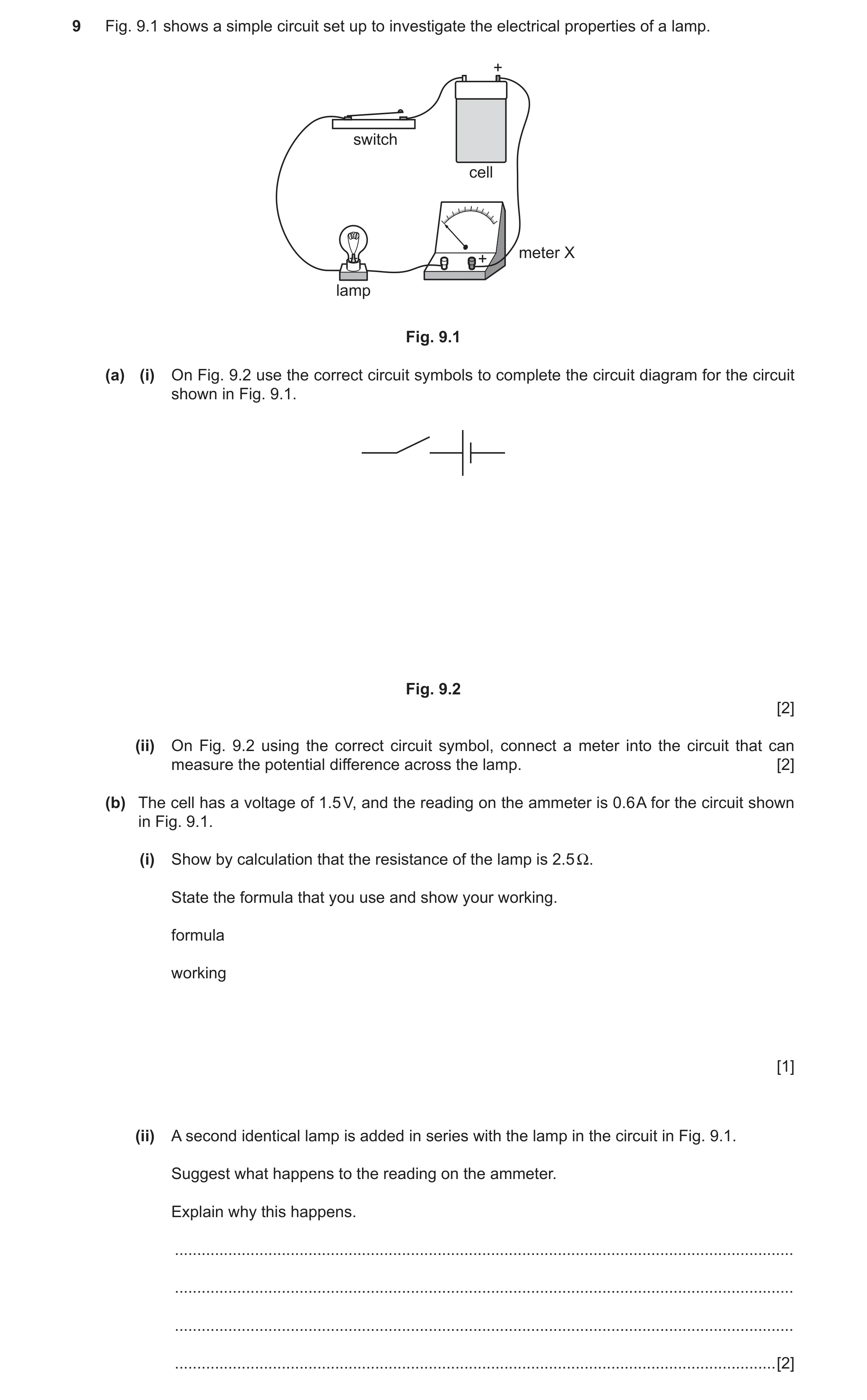
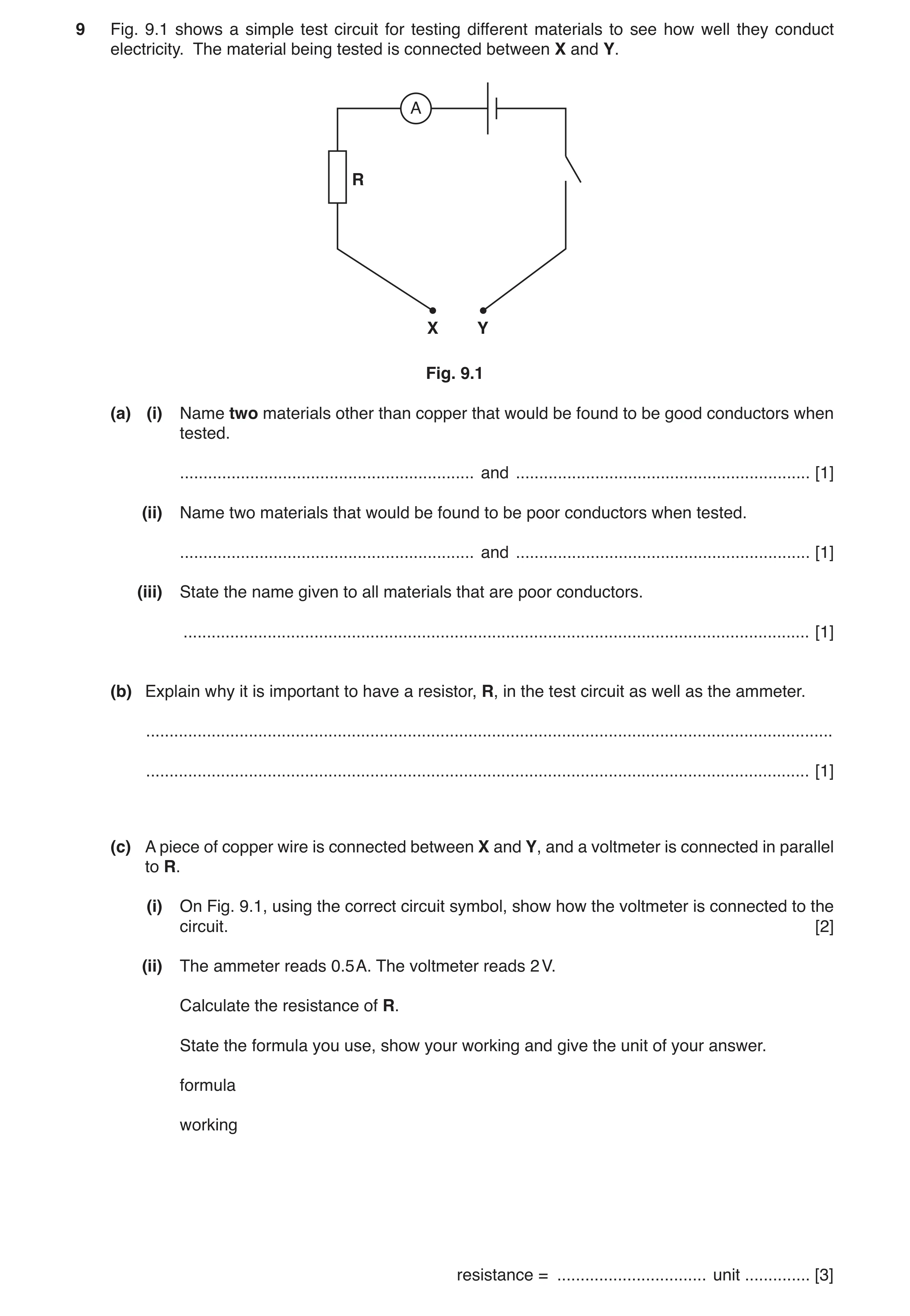 3 / 90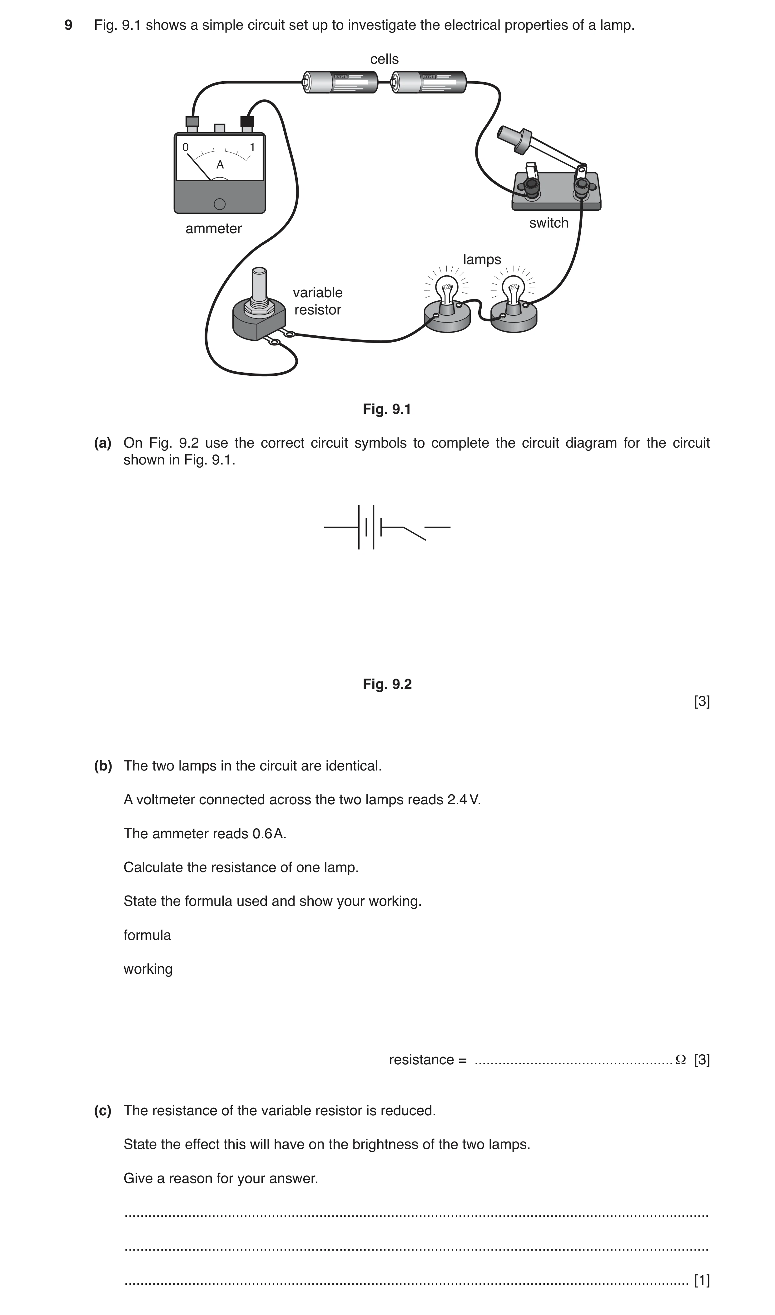
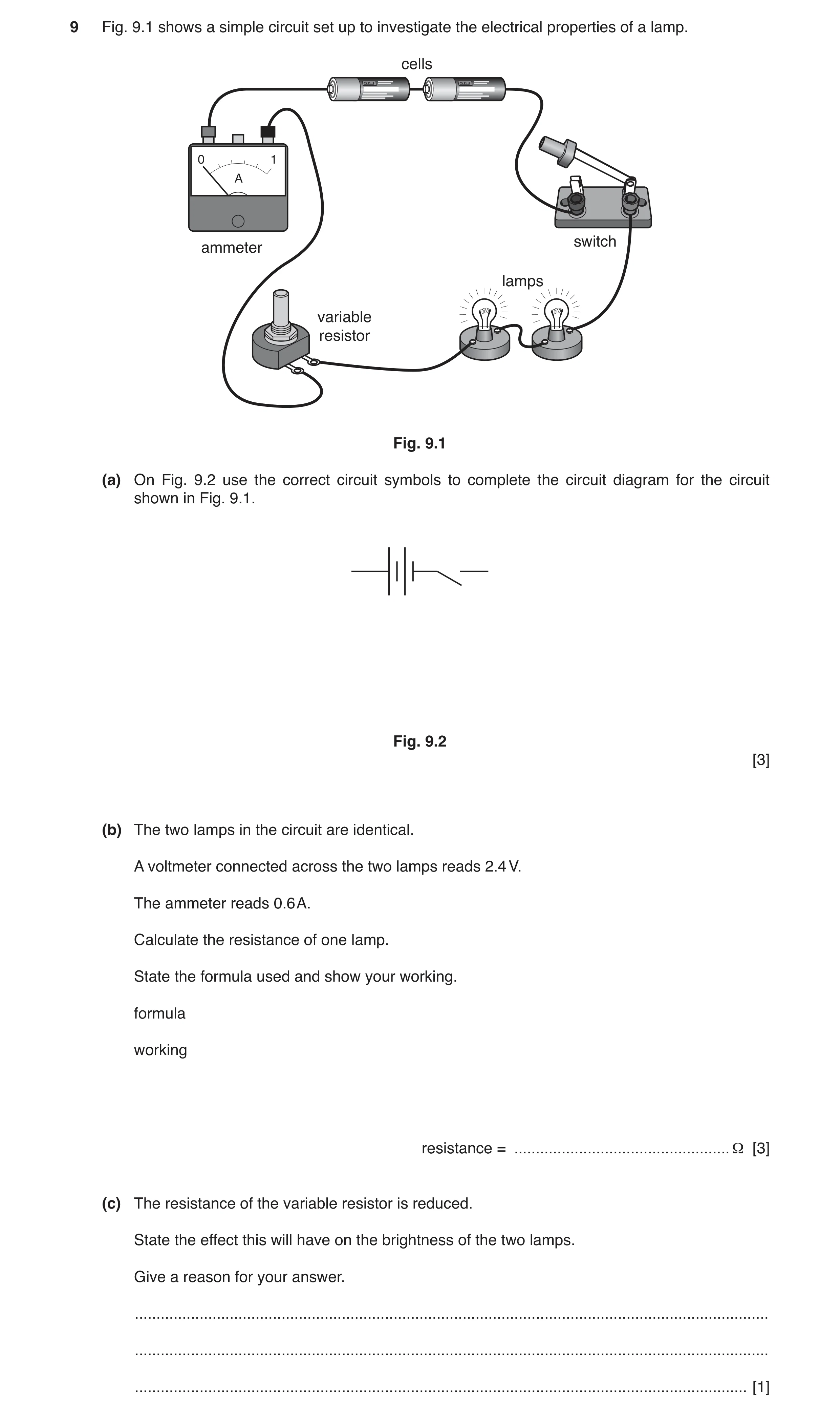
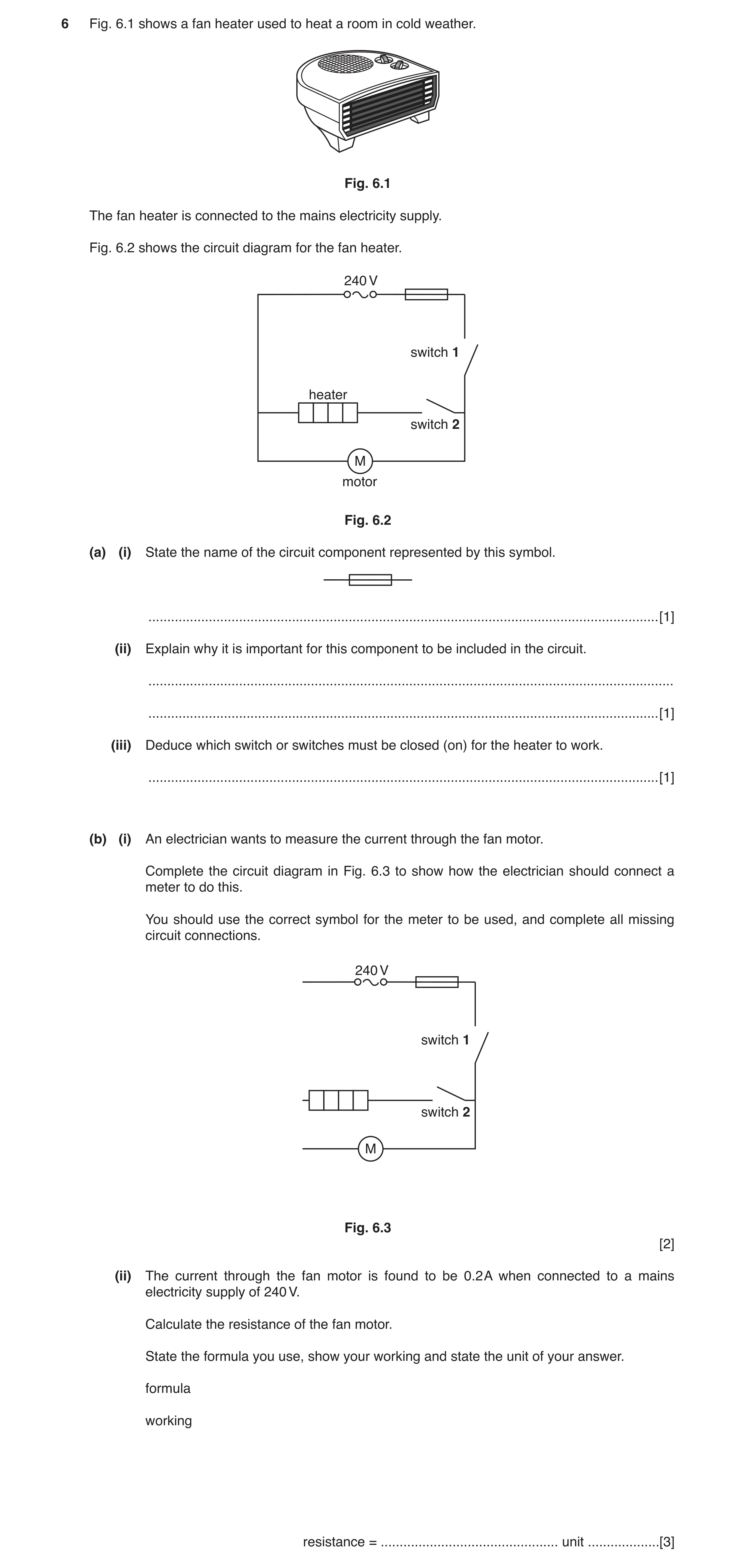
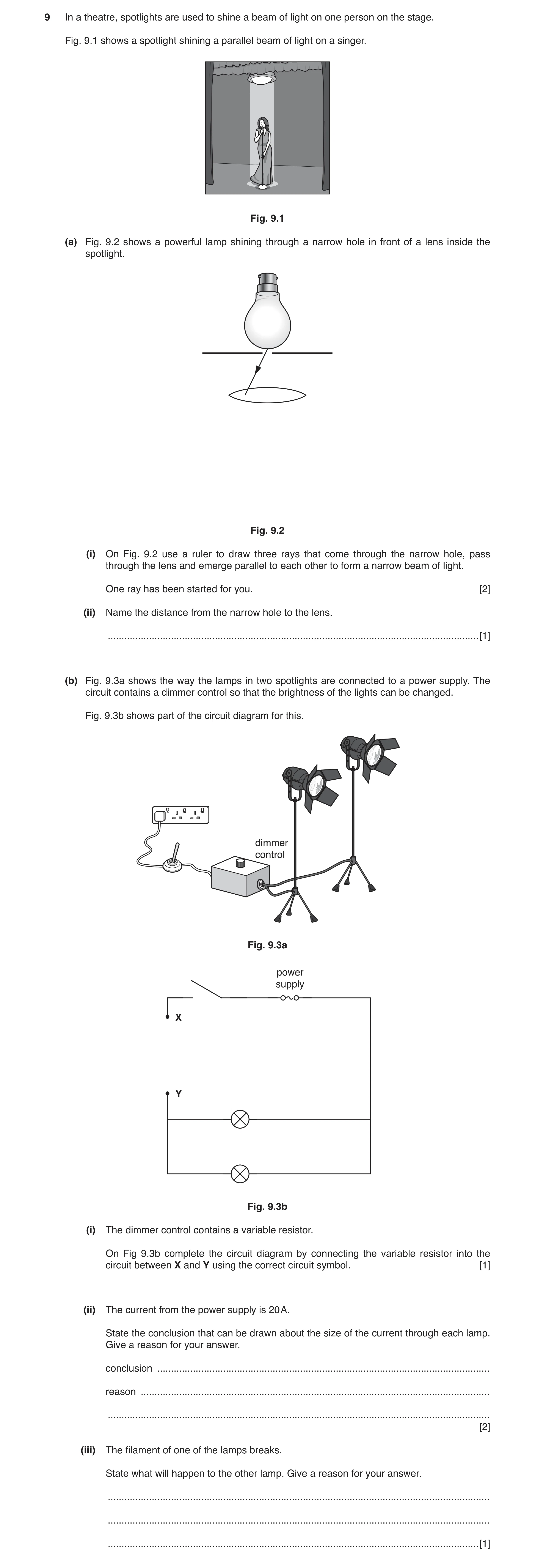
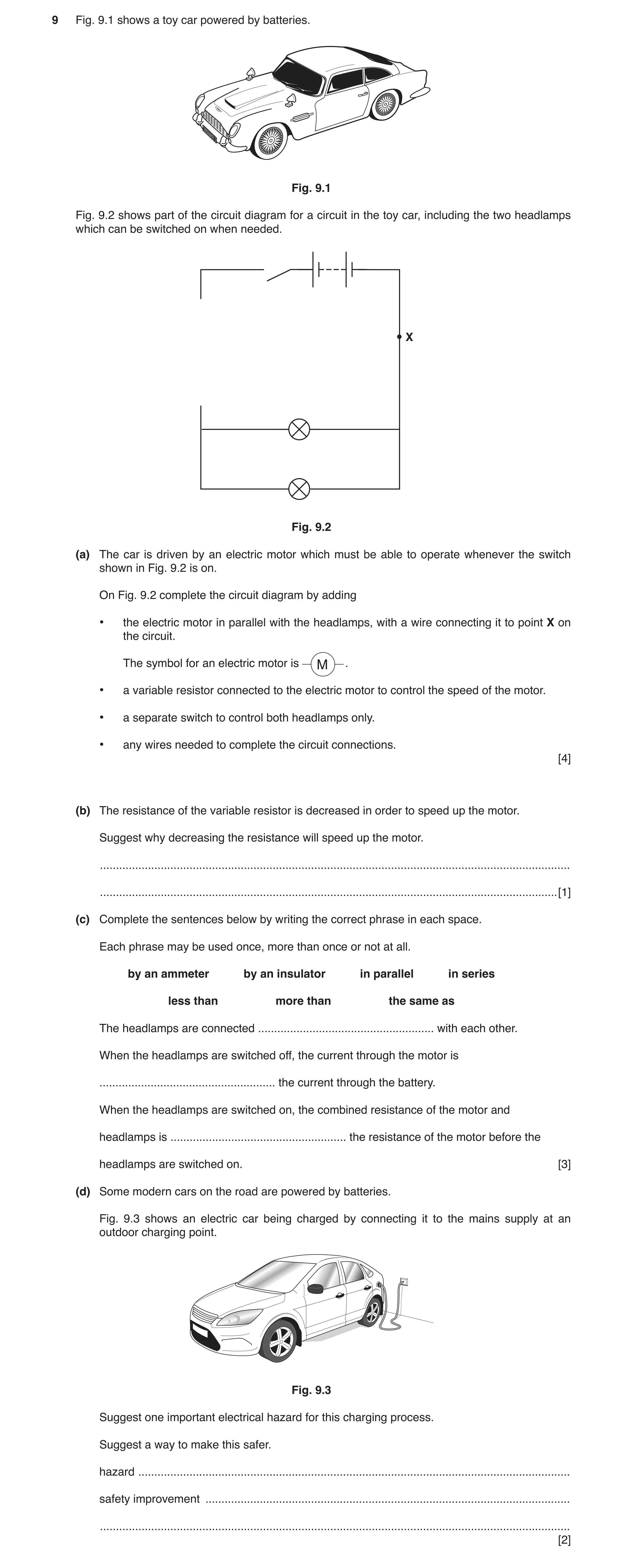
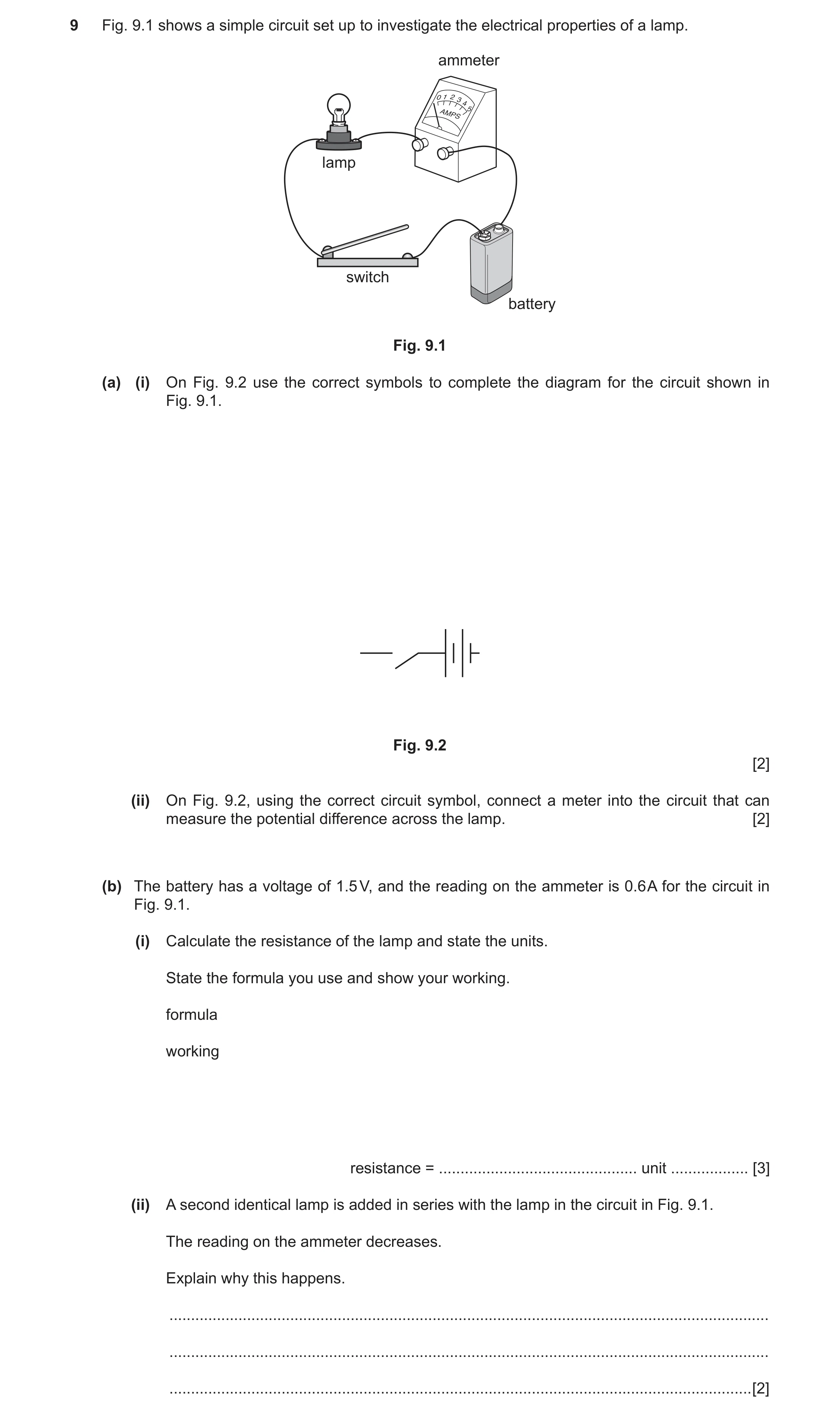
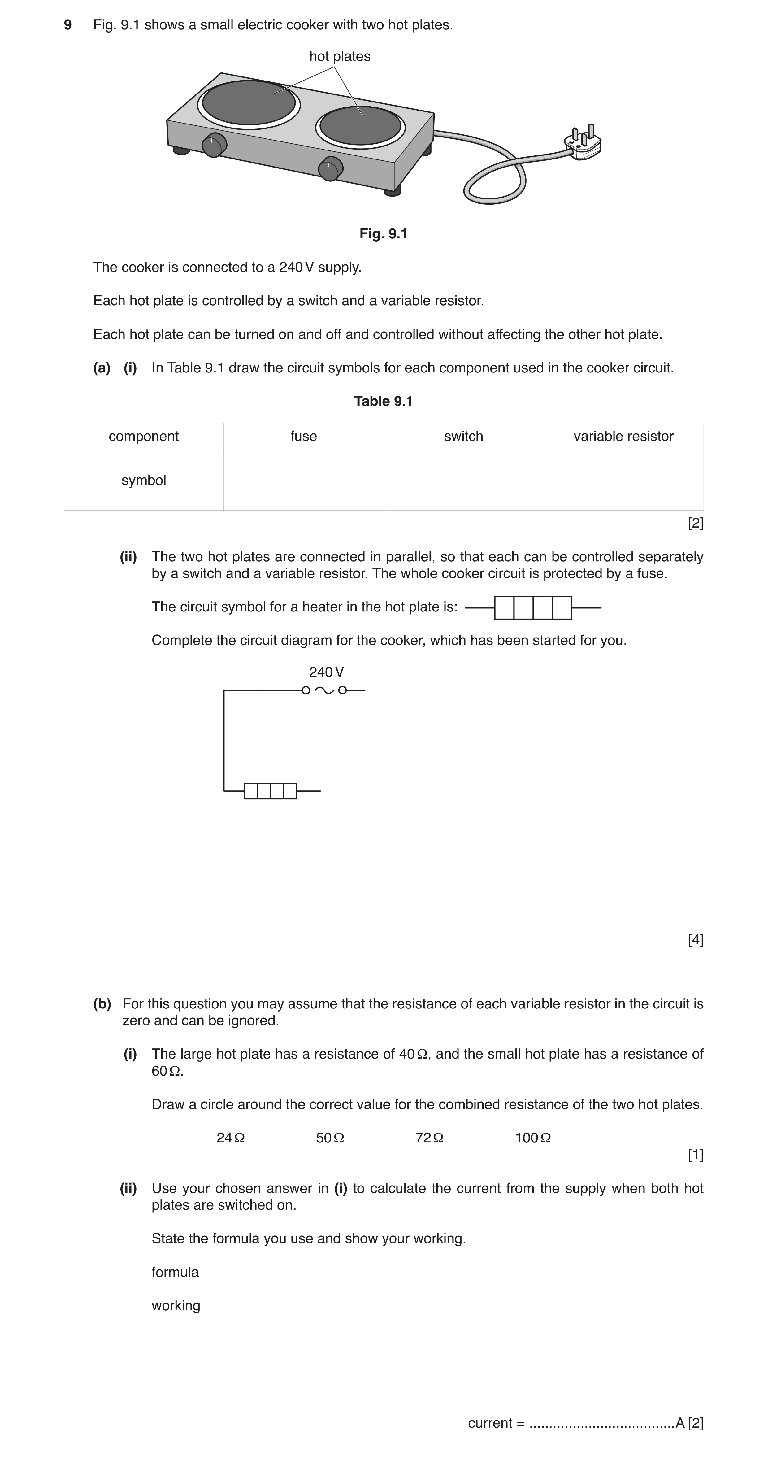
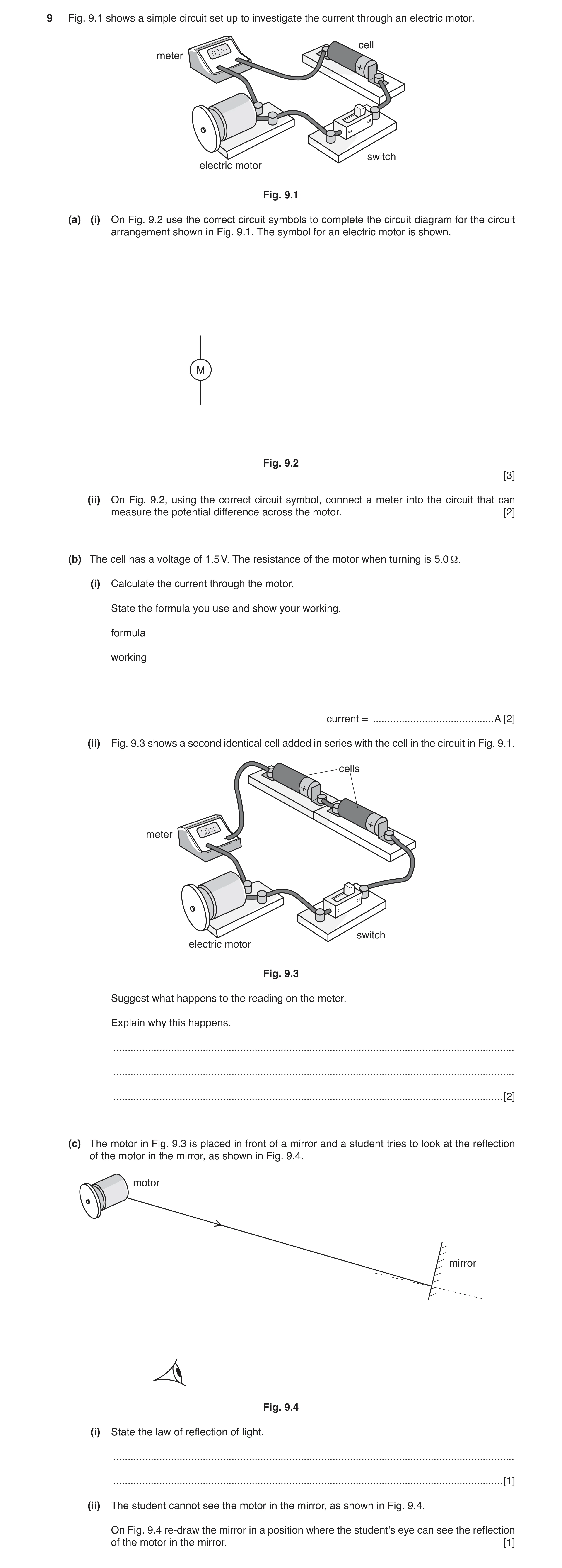
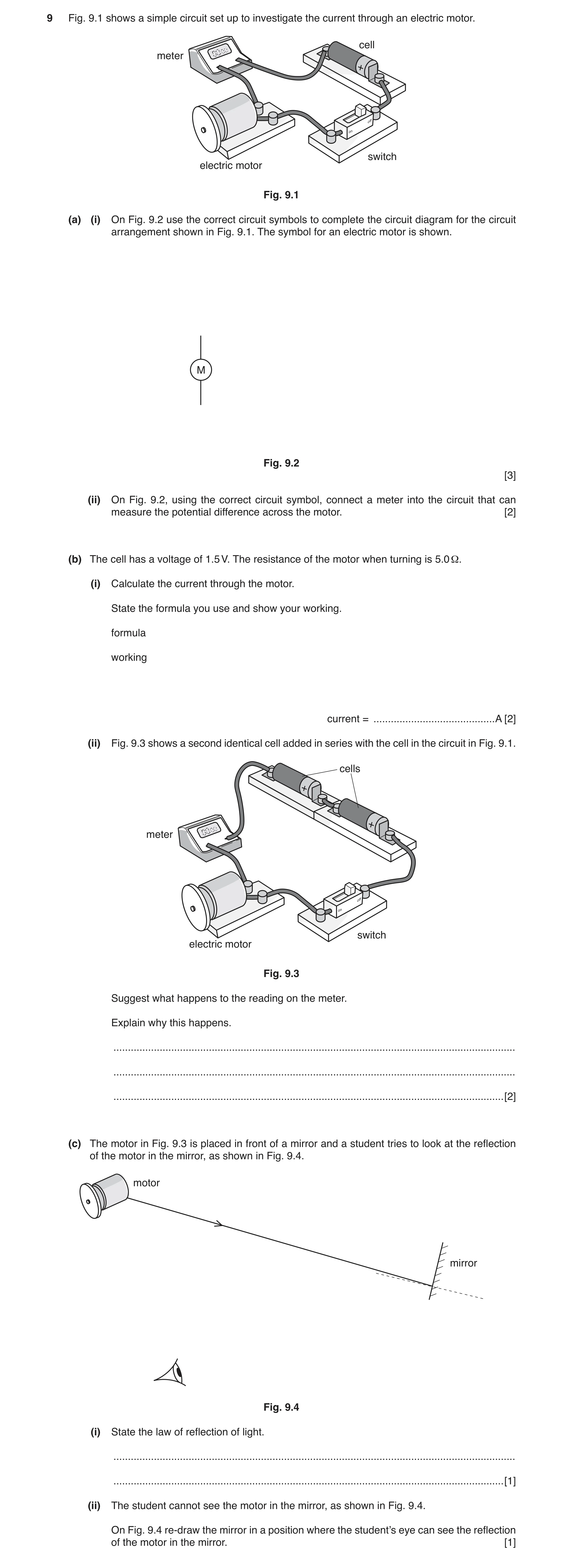
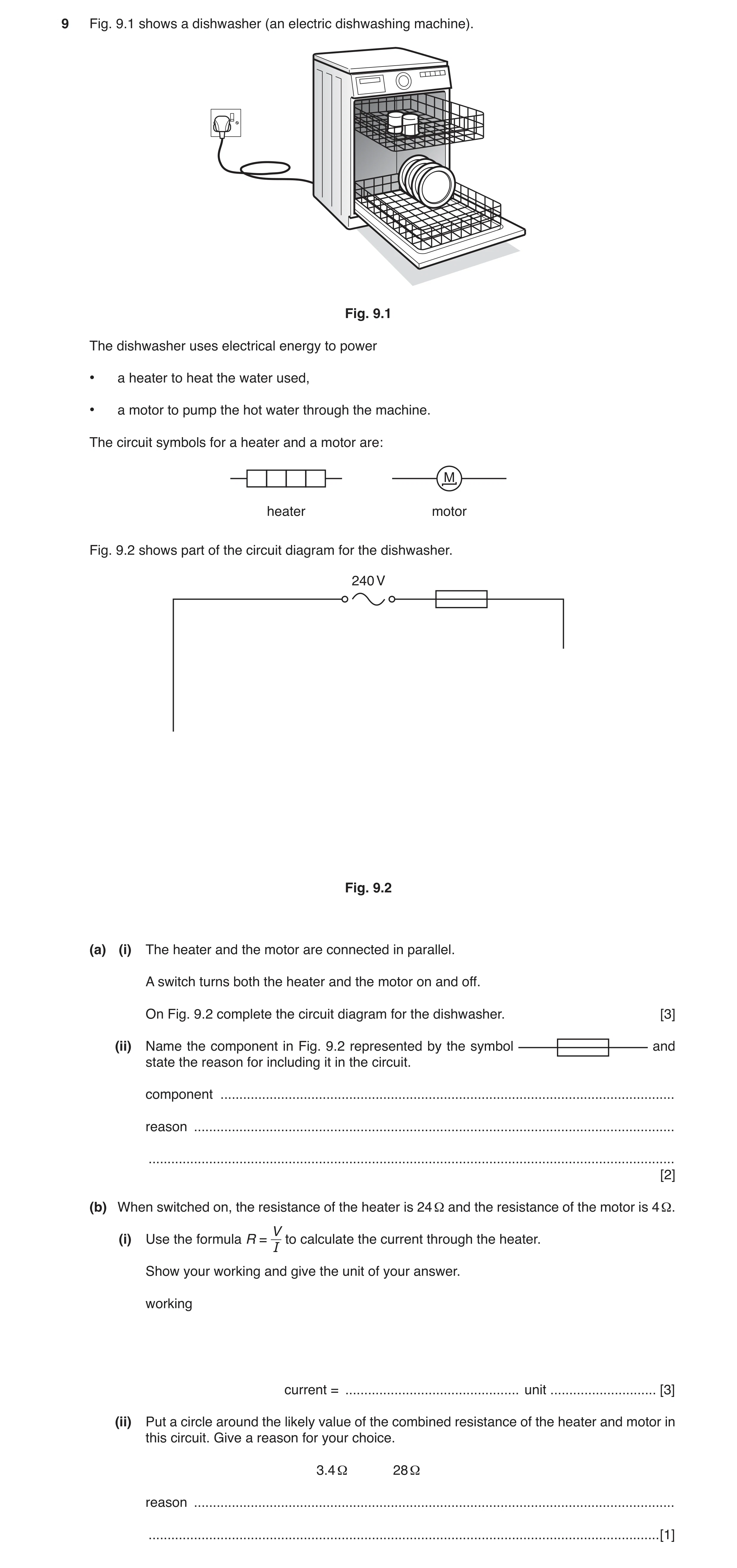
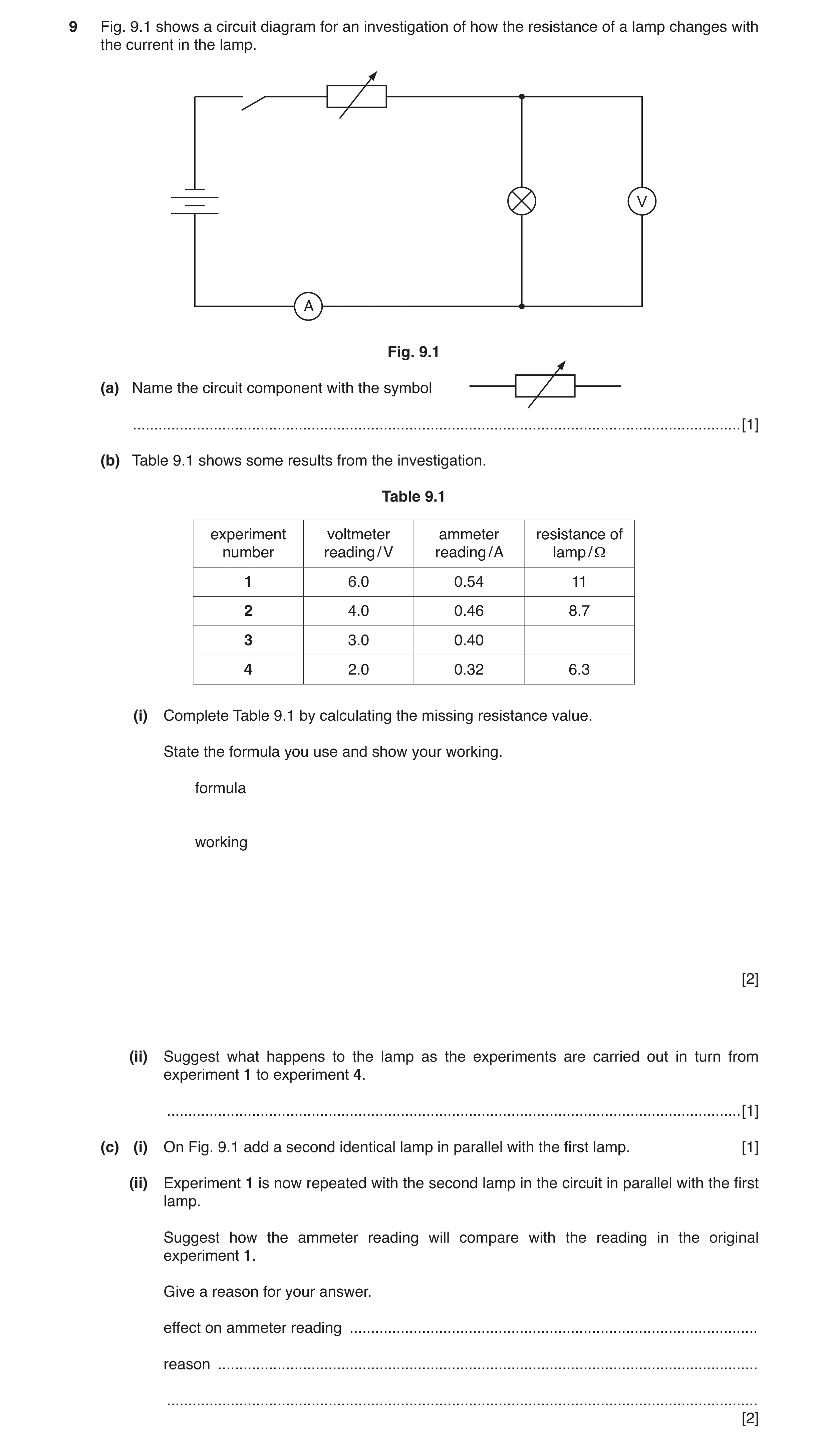
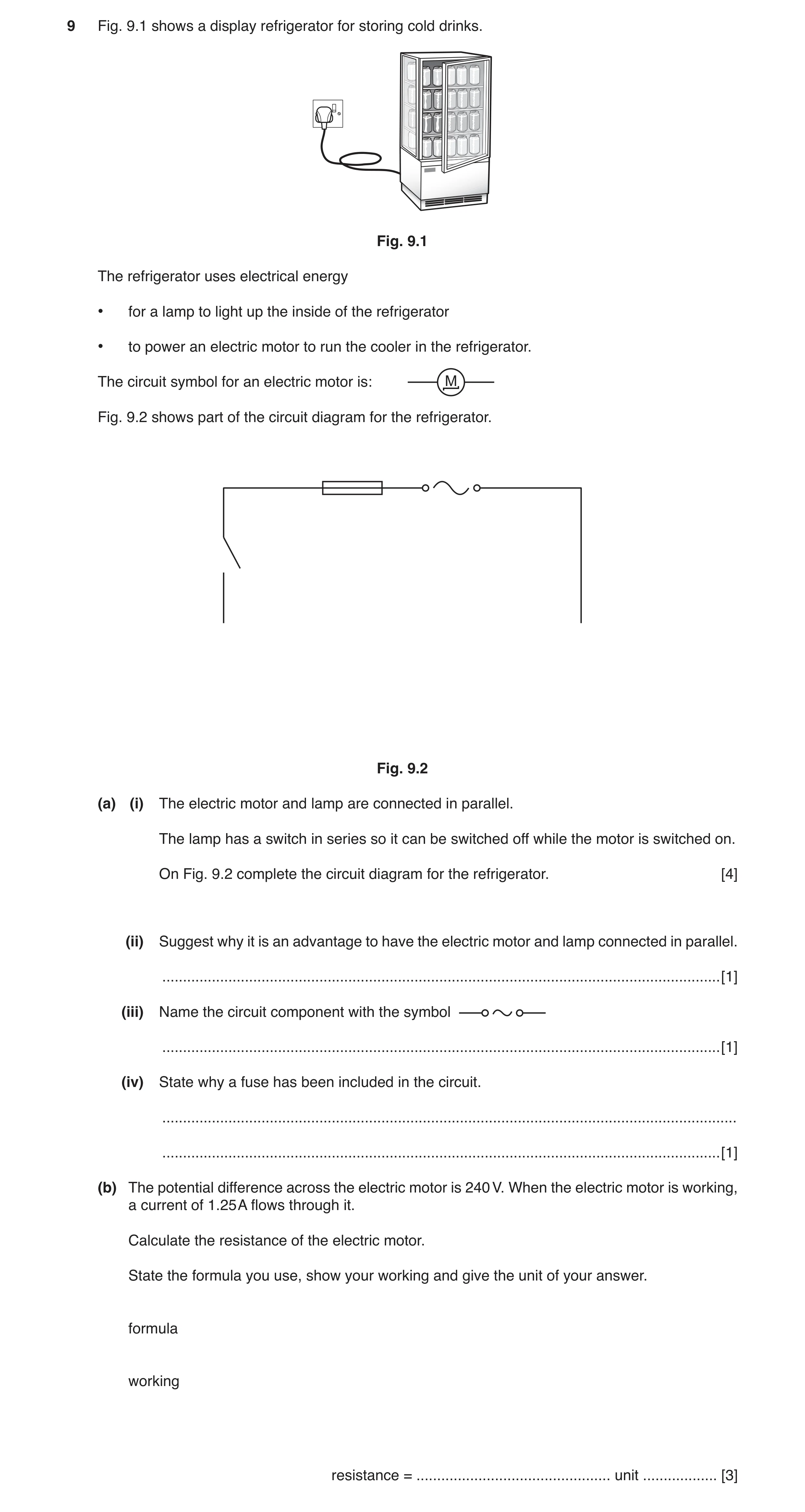
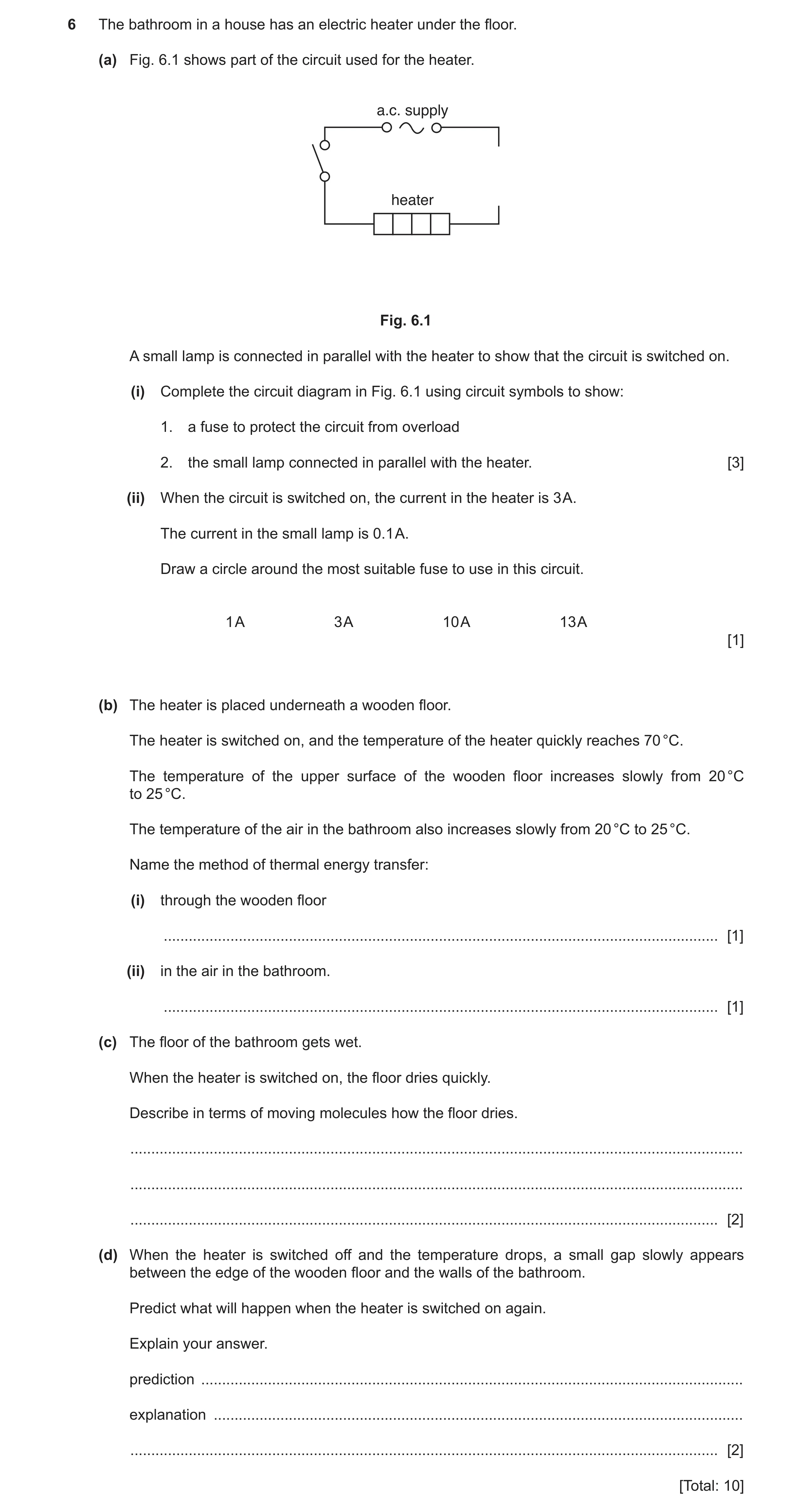
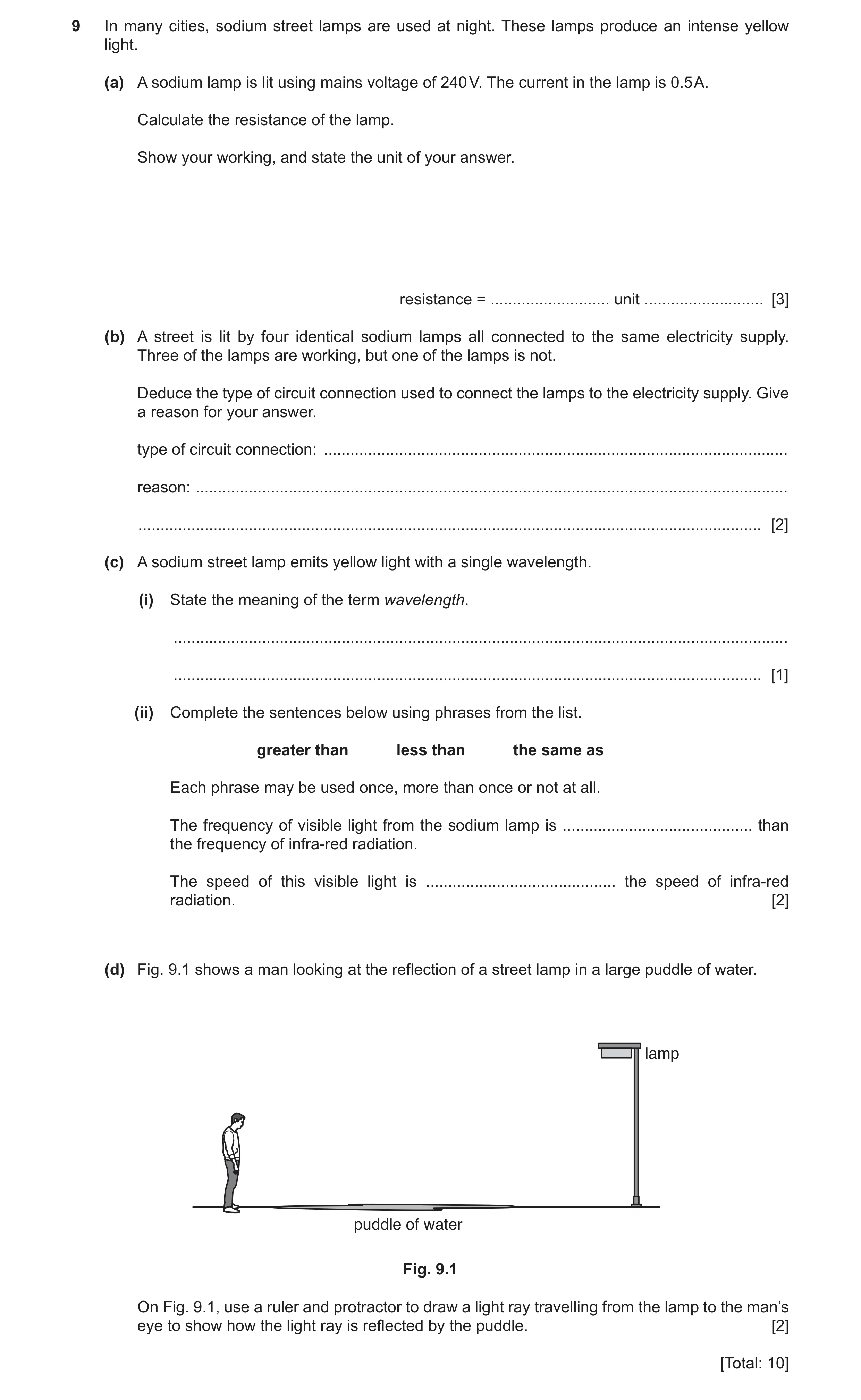
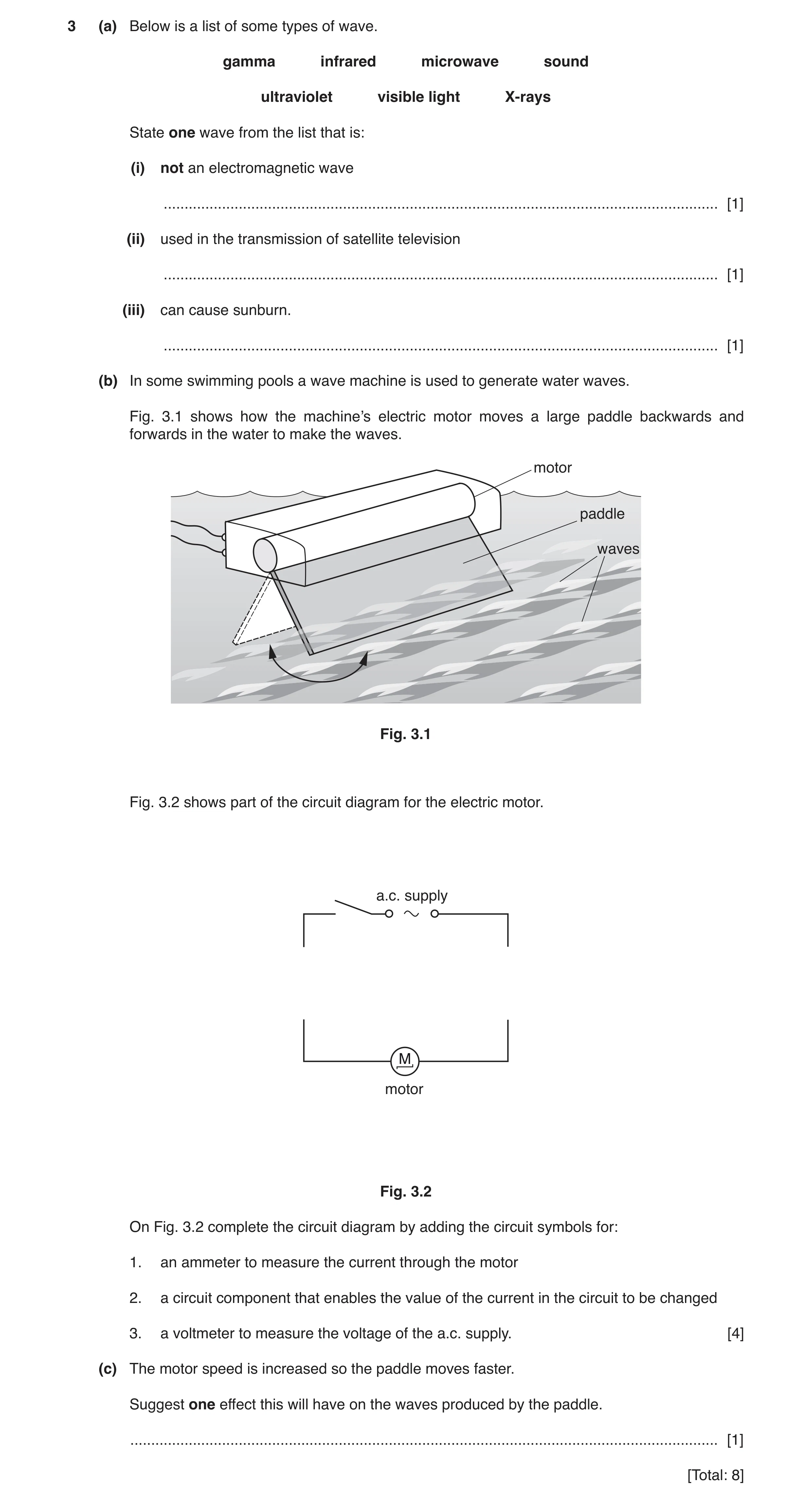
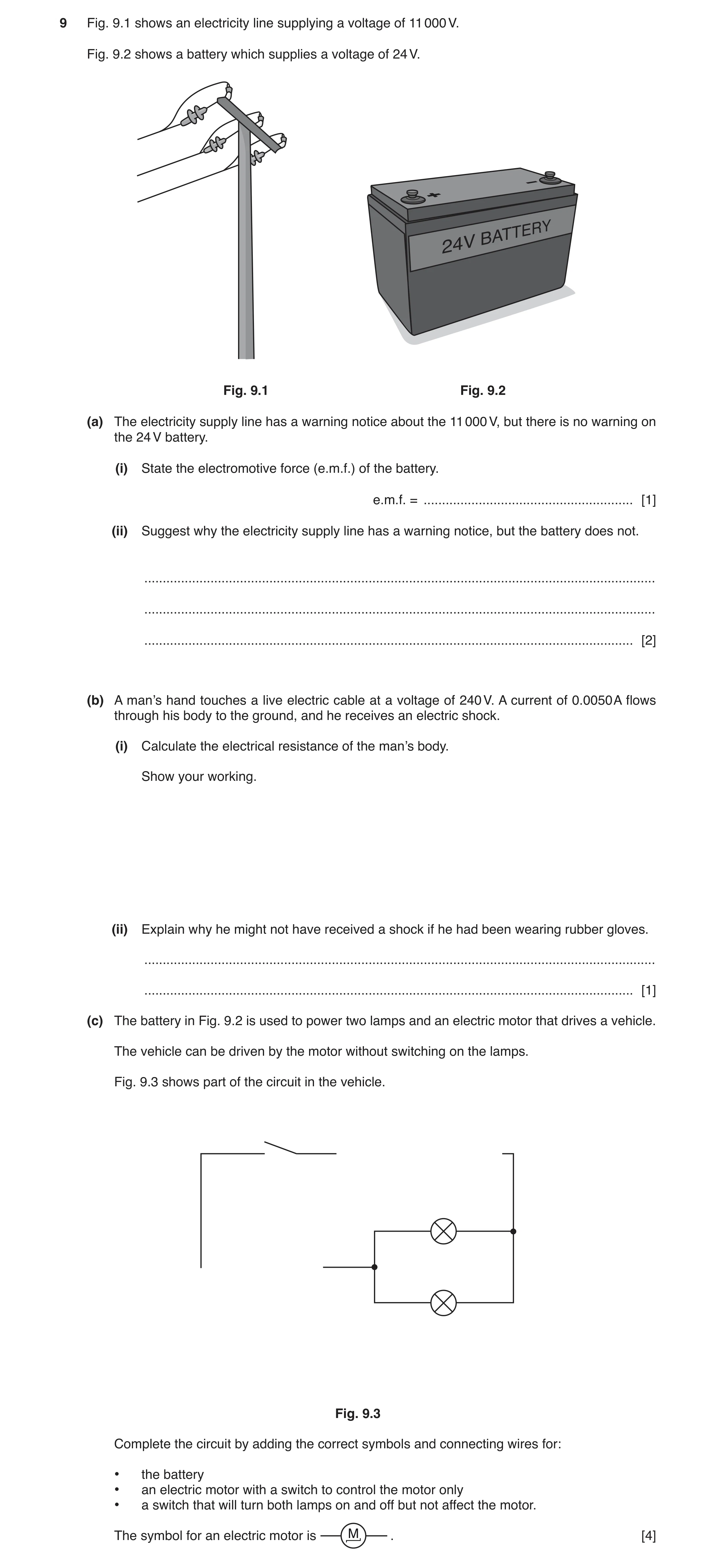
![Question 19: (a) Fig. 9.1 shows a circuit diagram. heater Fig. 9.1 On Fig. 9.1, add a suitable meter to measure the e.m.f. of the battery. [2] (b) The c…](https://img.pastlit.com/crops/422f7162-5998-476e-86d9-d8c460d476ed/q9.webp)
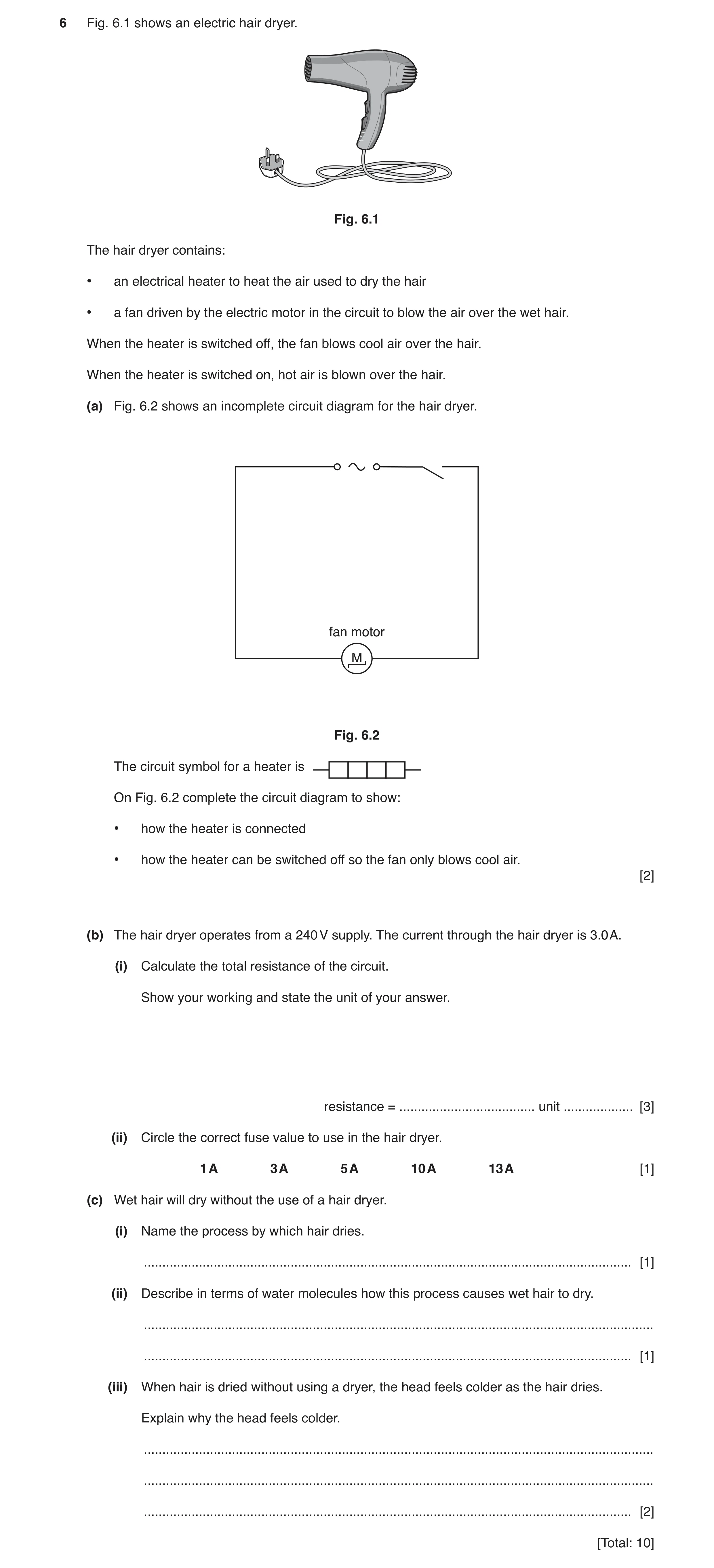
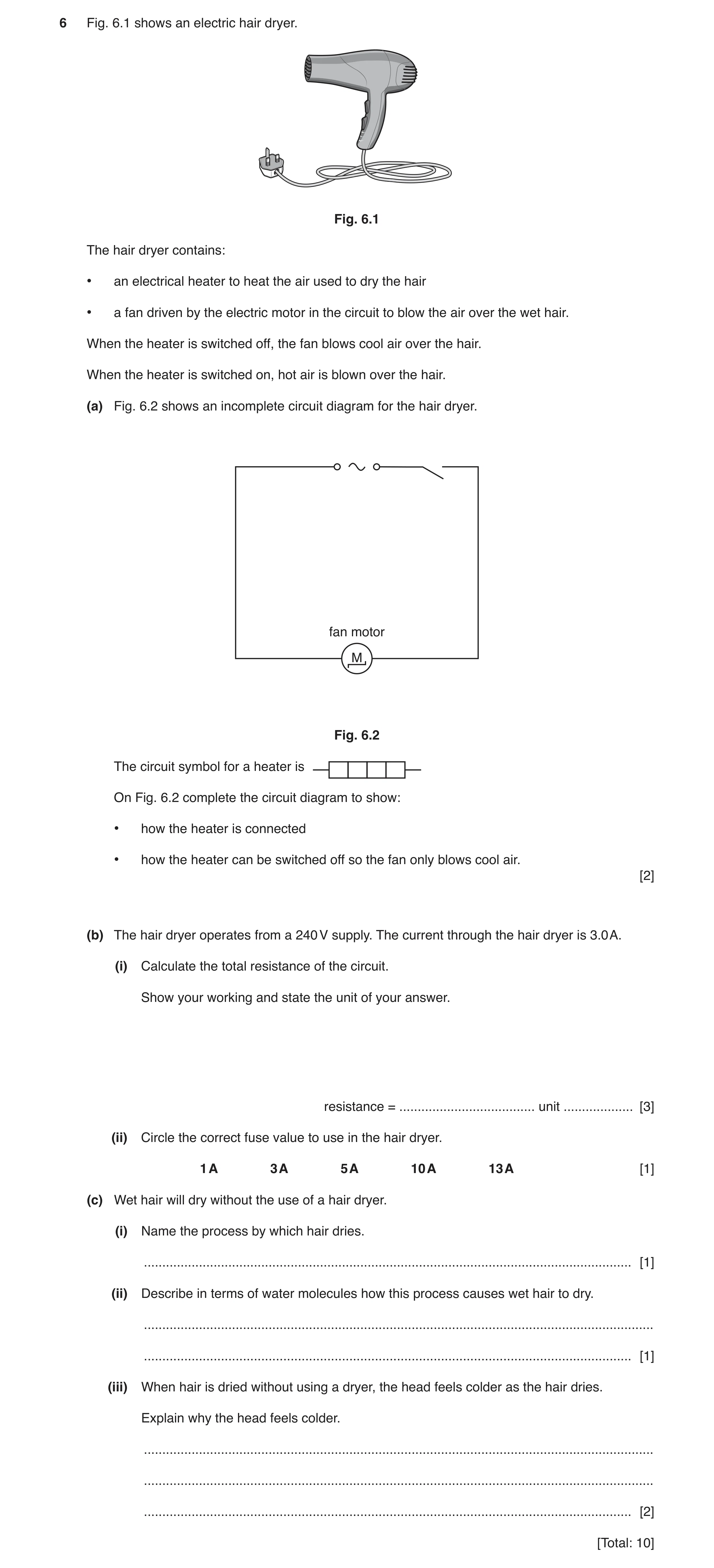
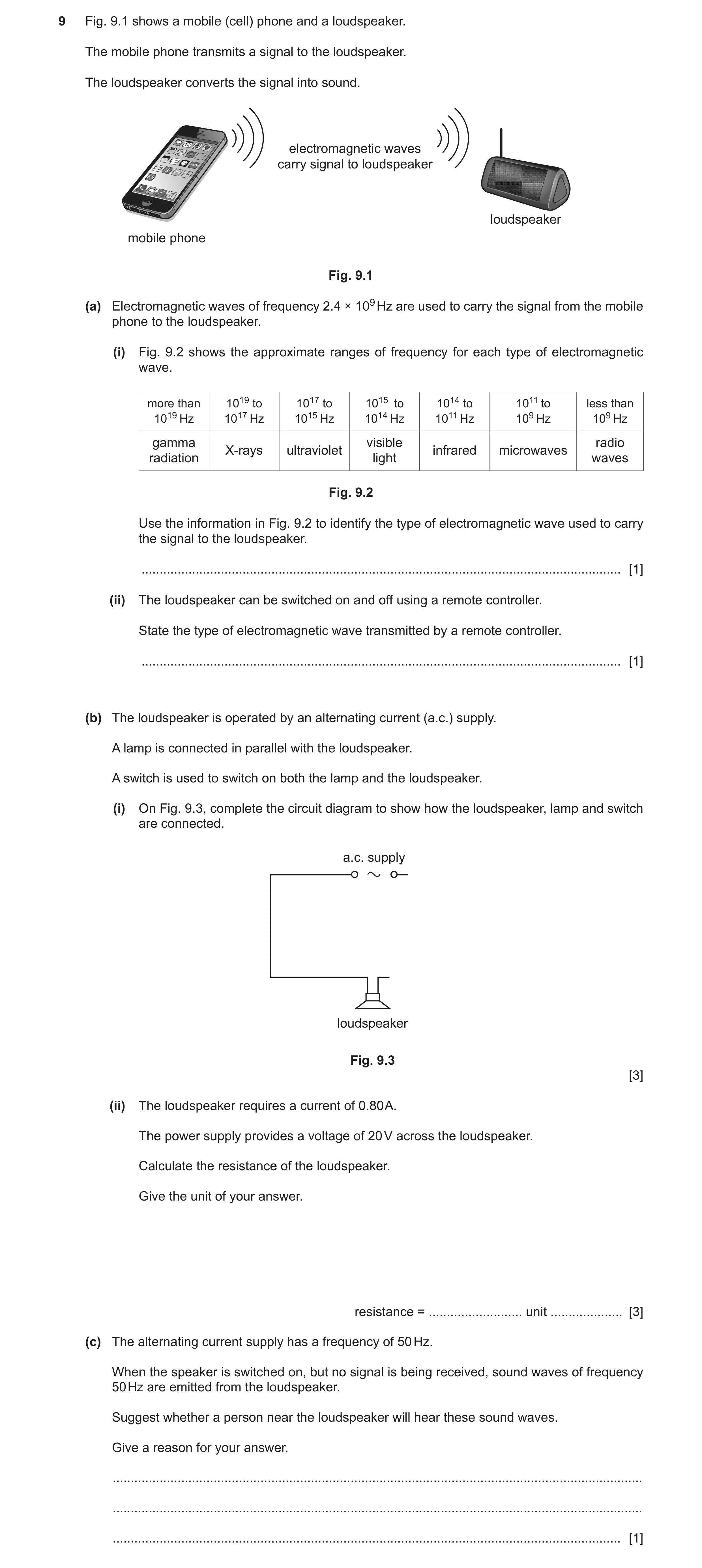
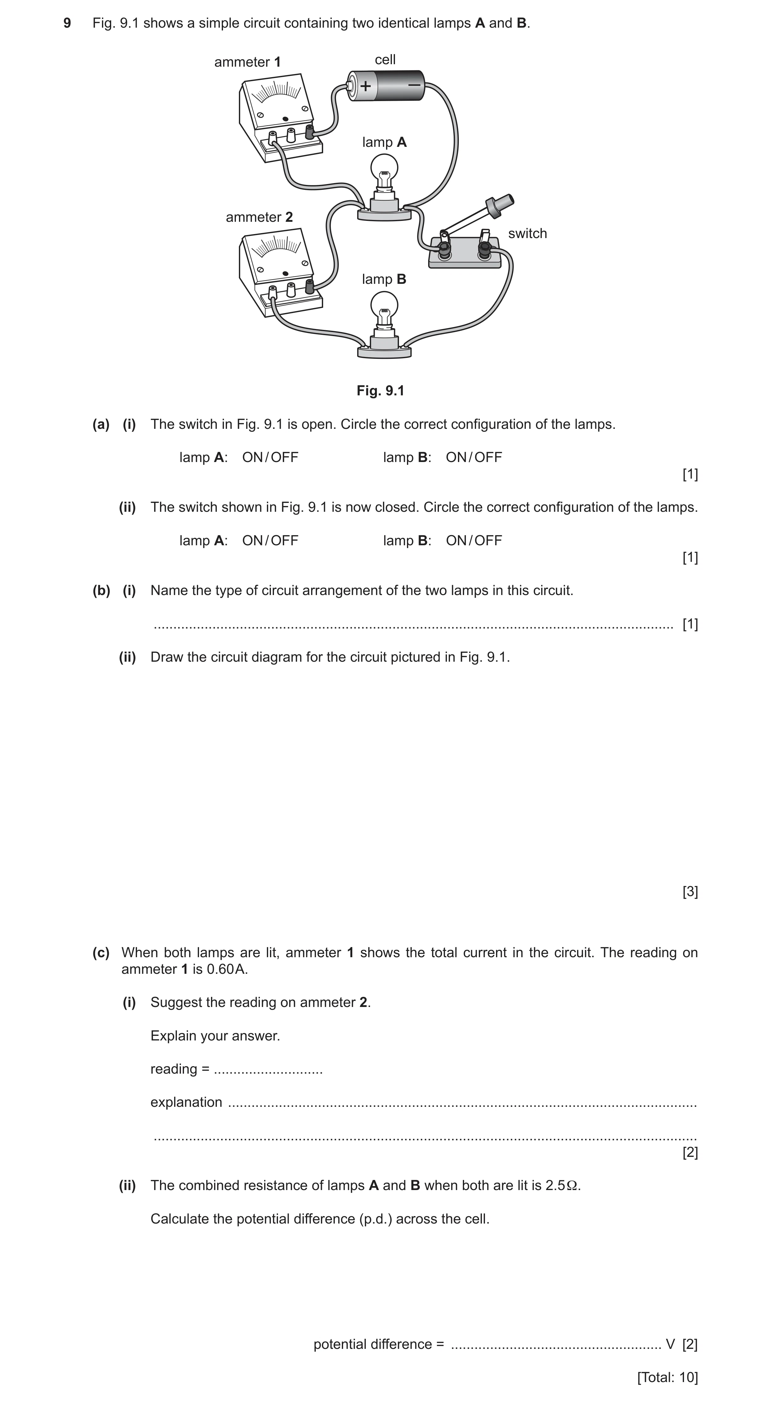
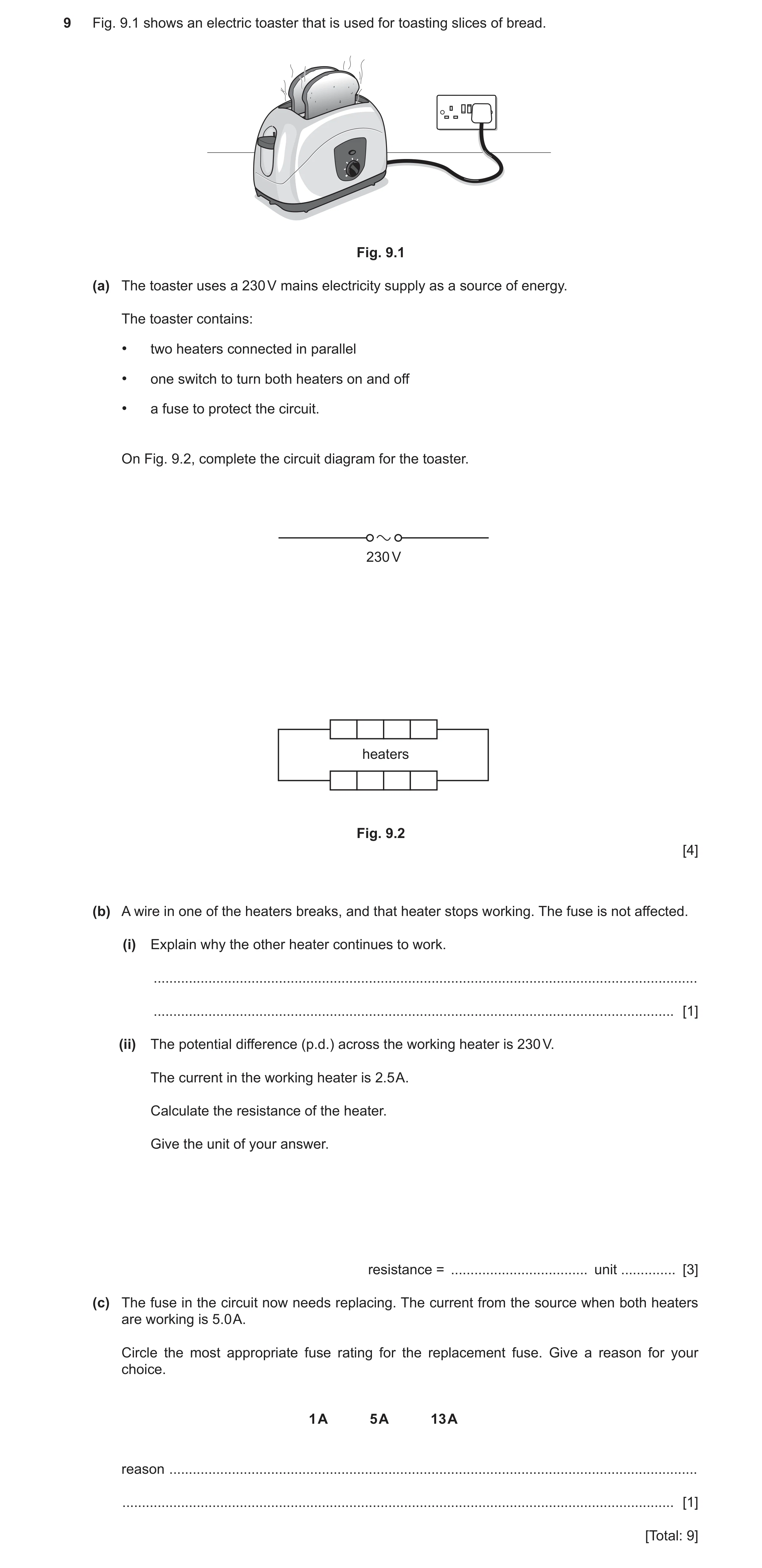
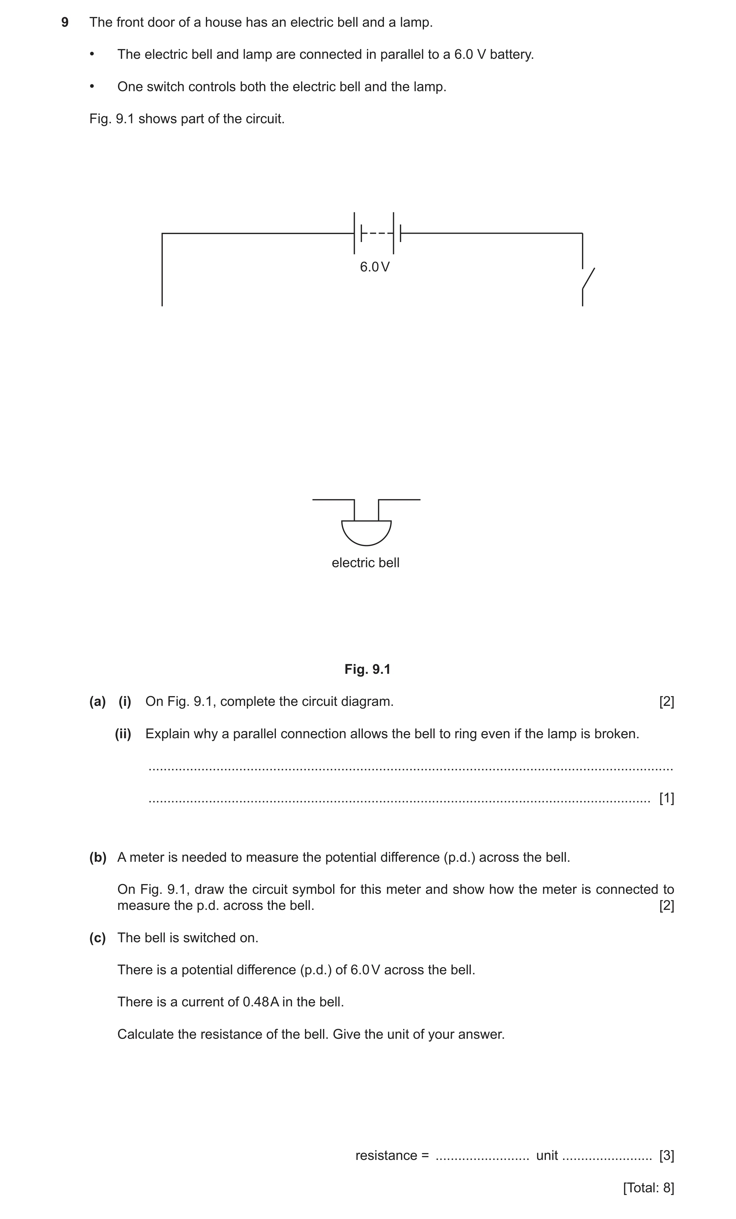
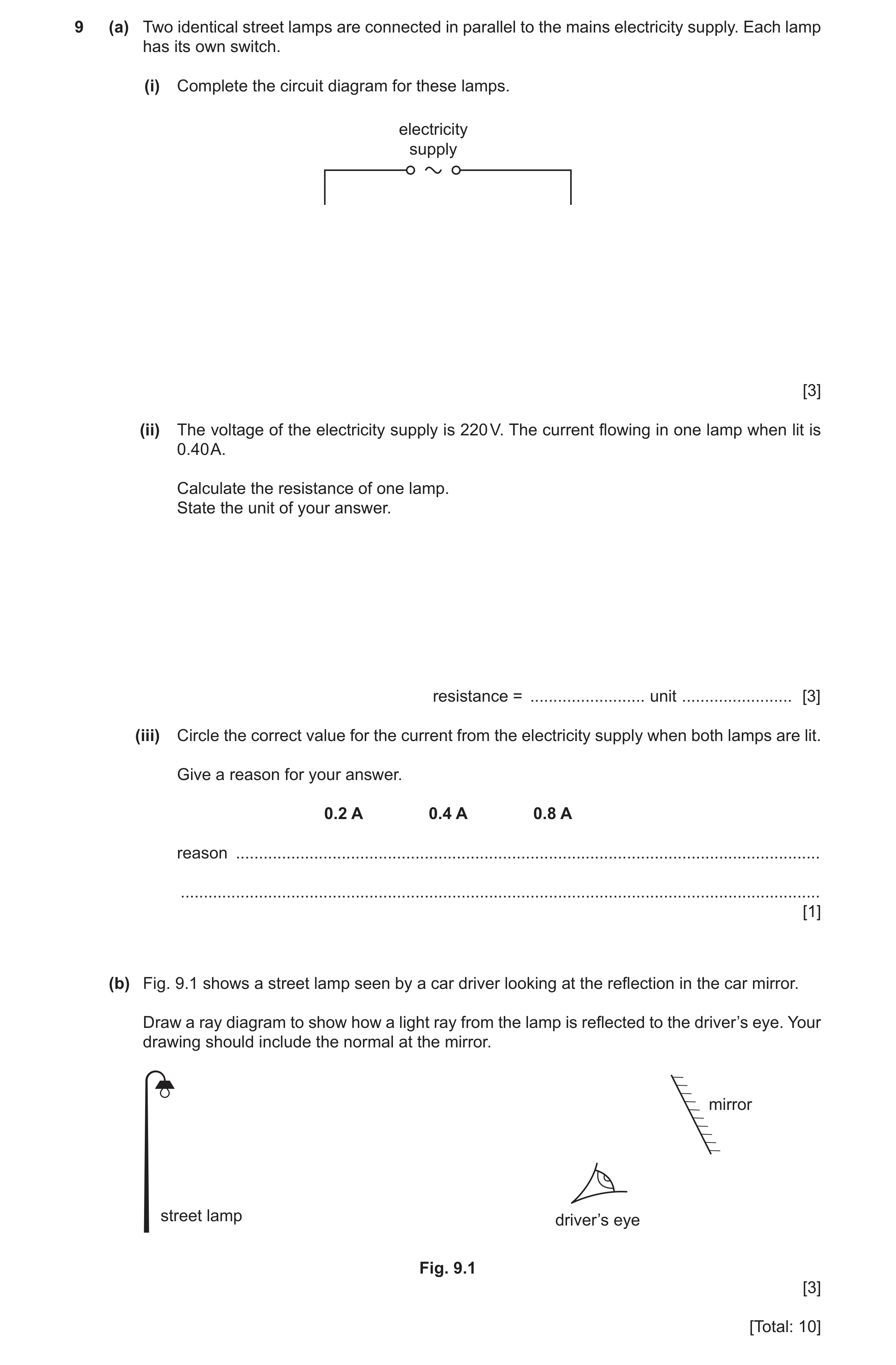
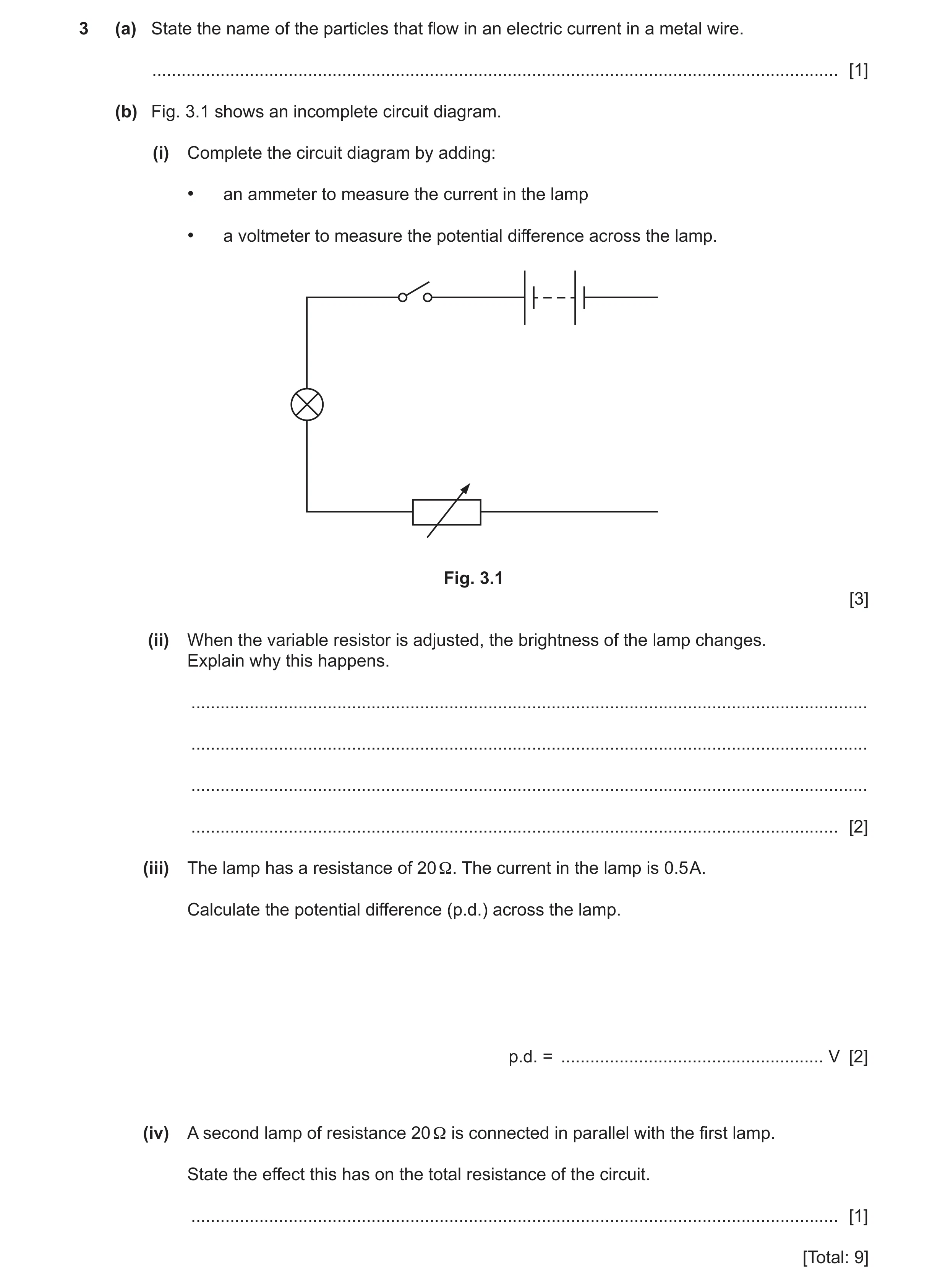 42 / 90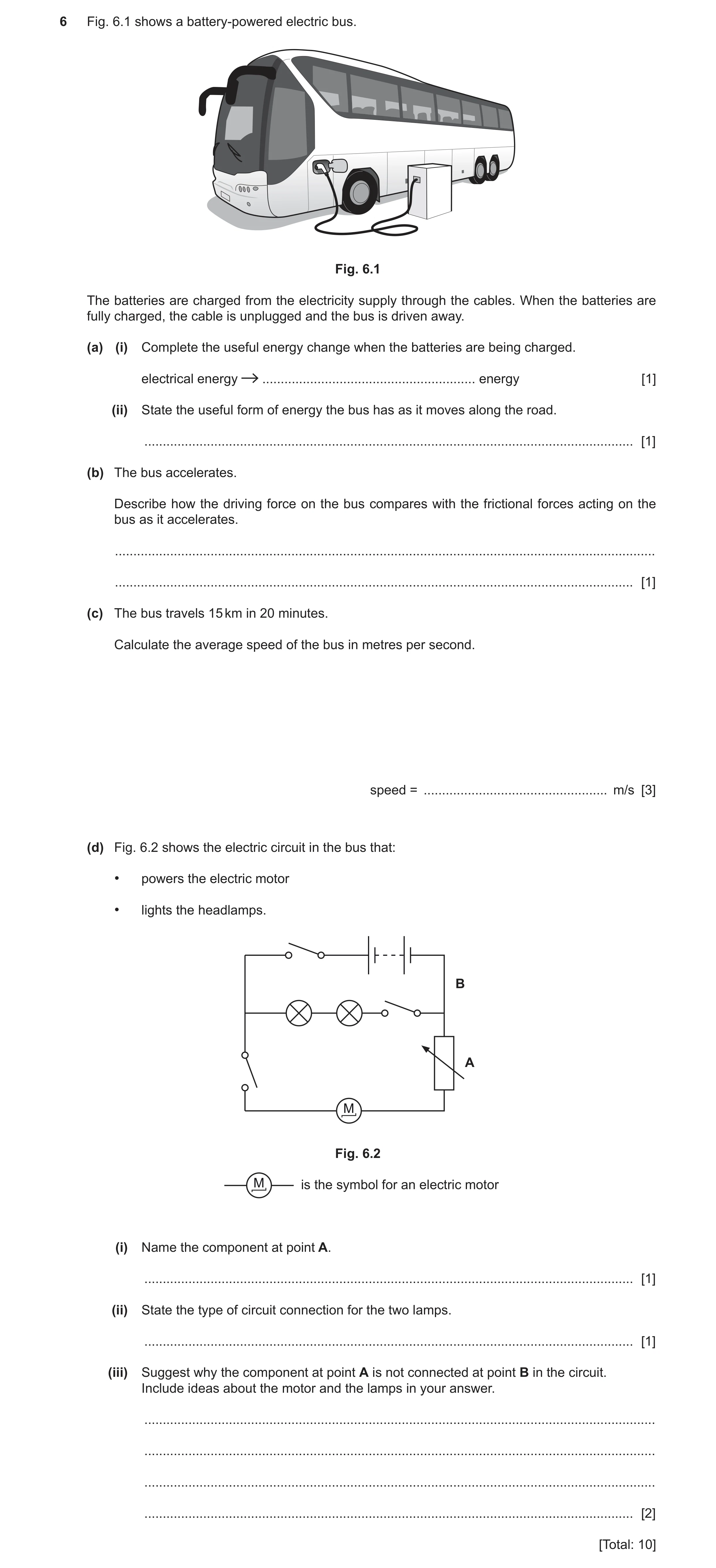
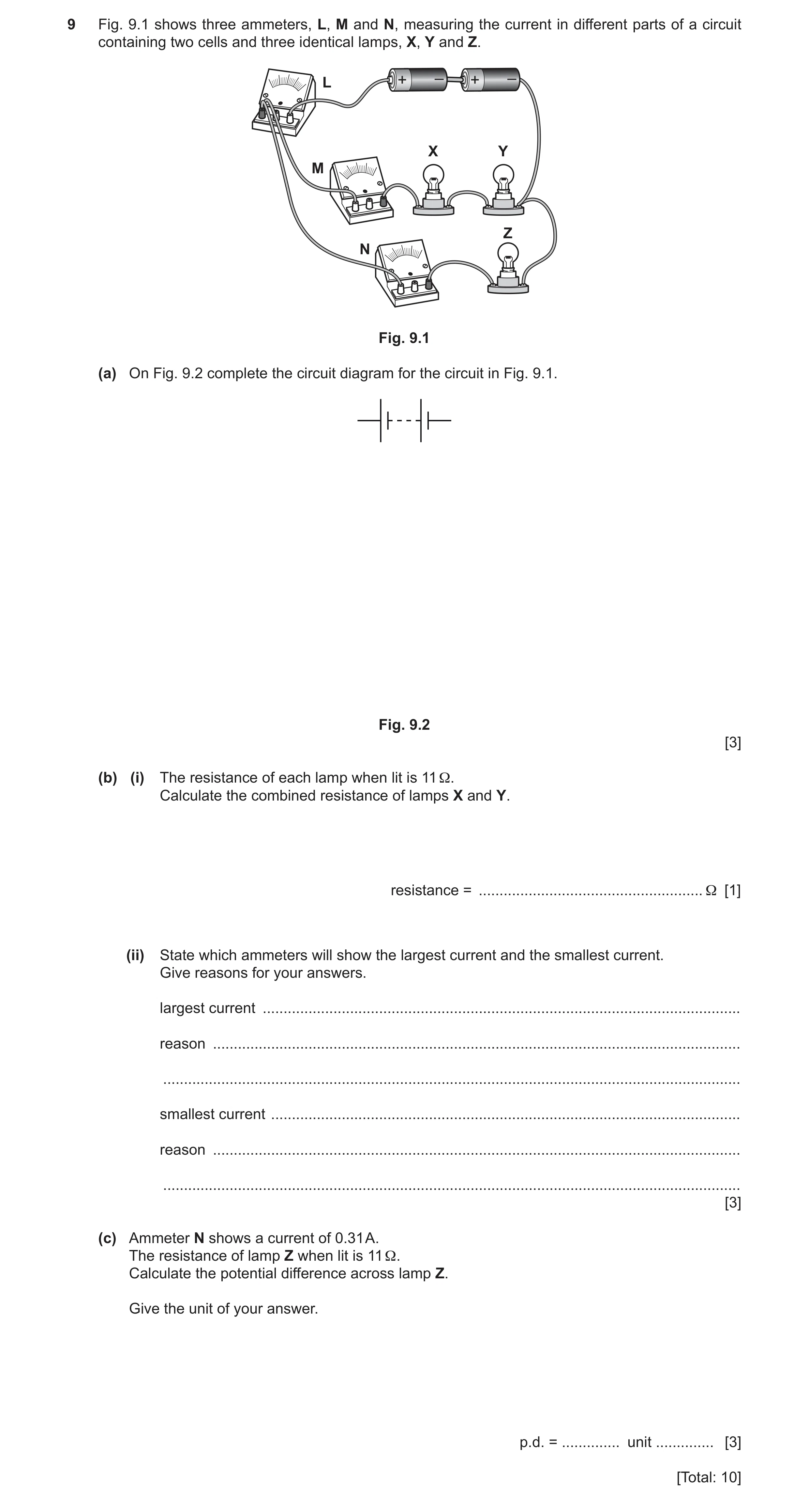
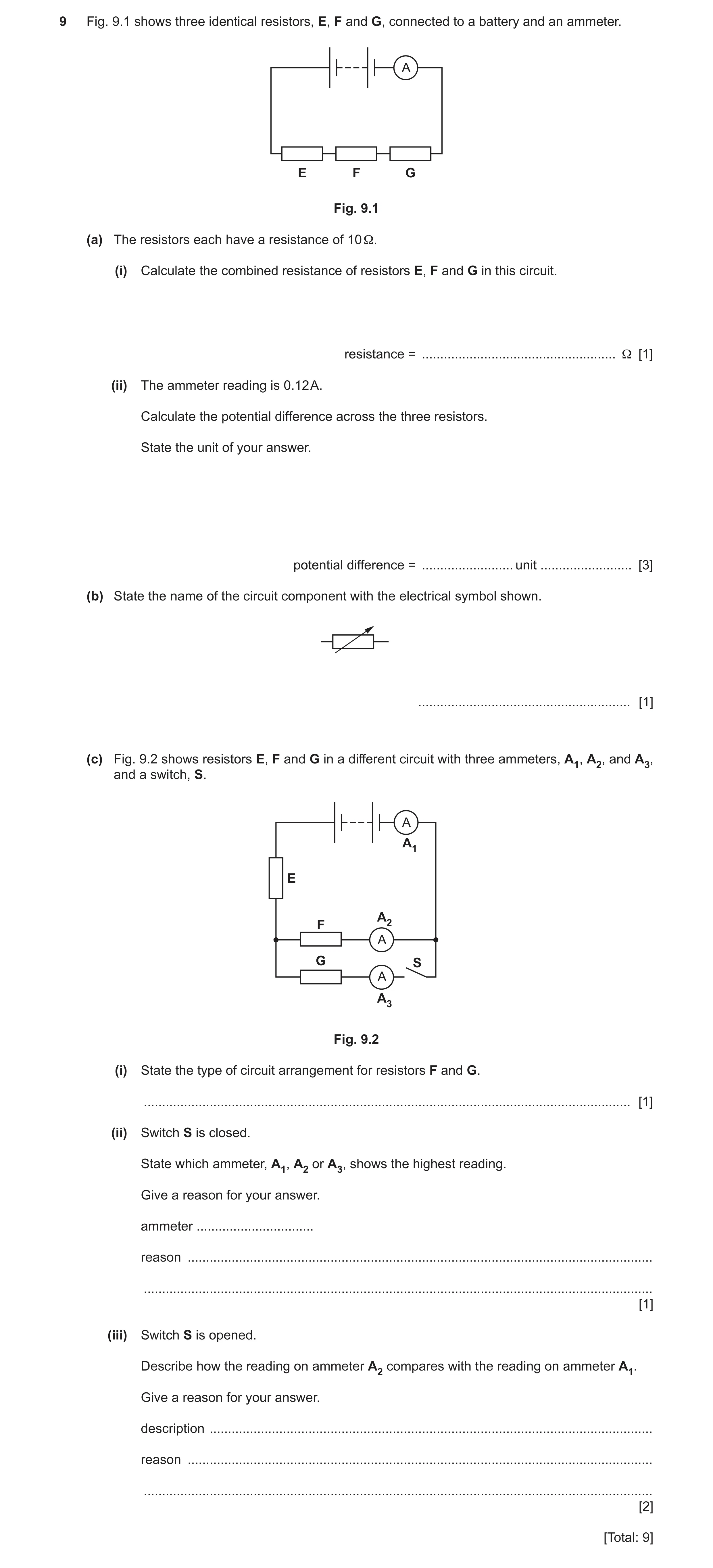
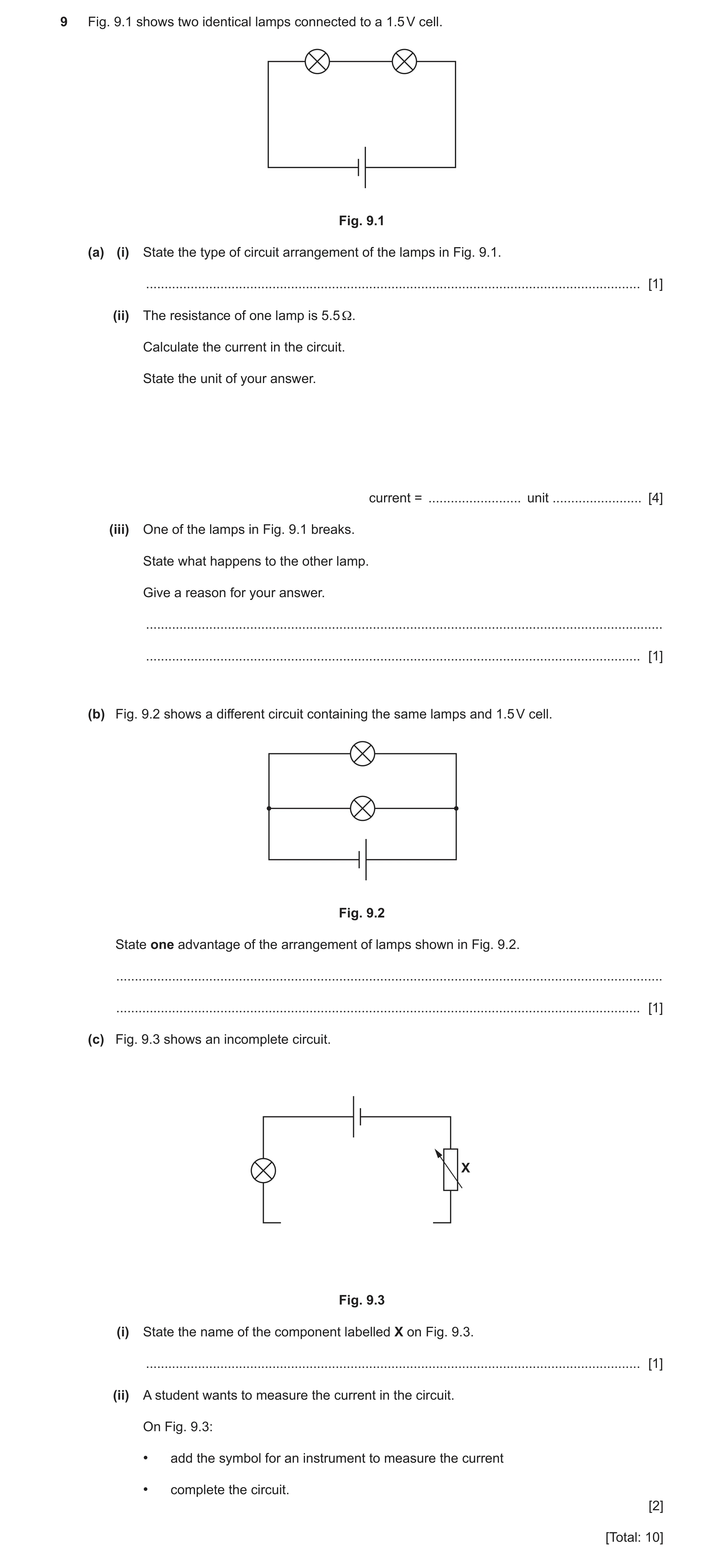
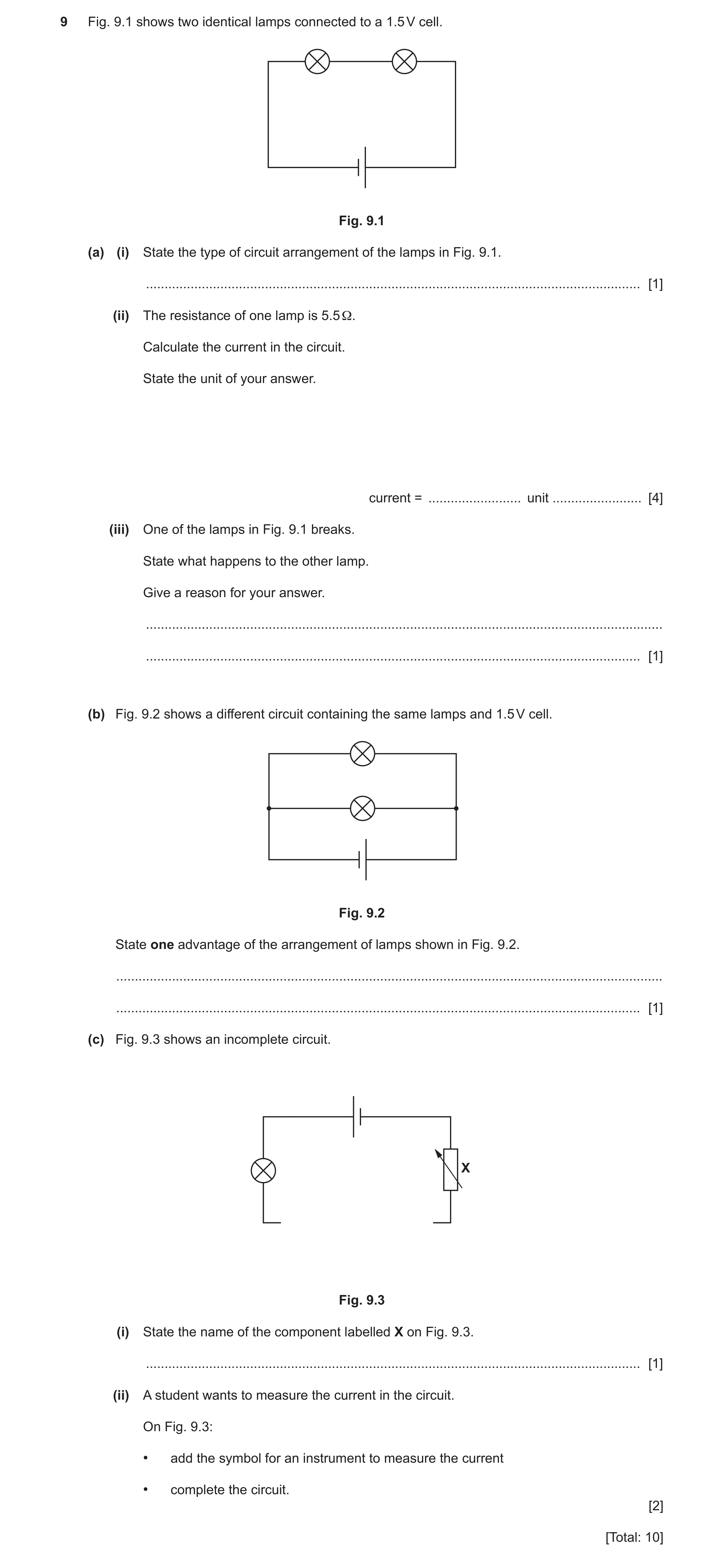
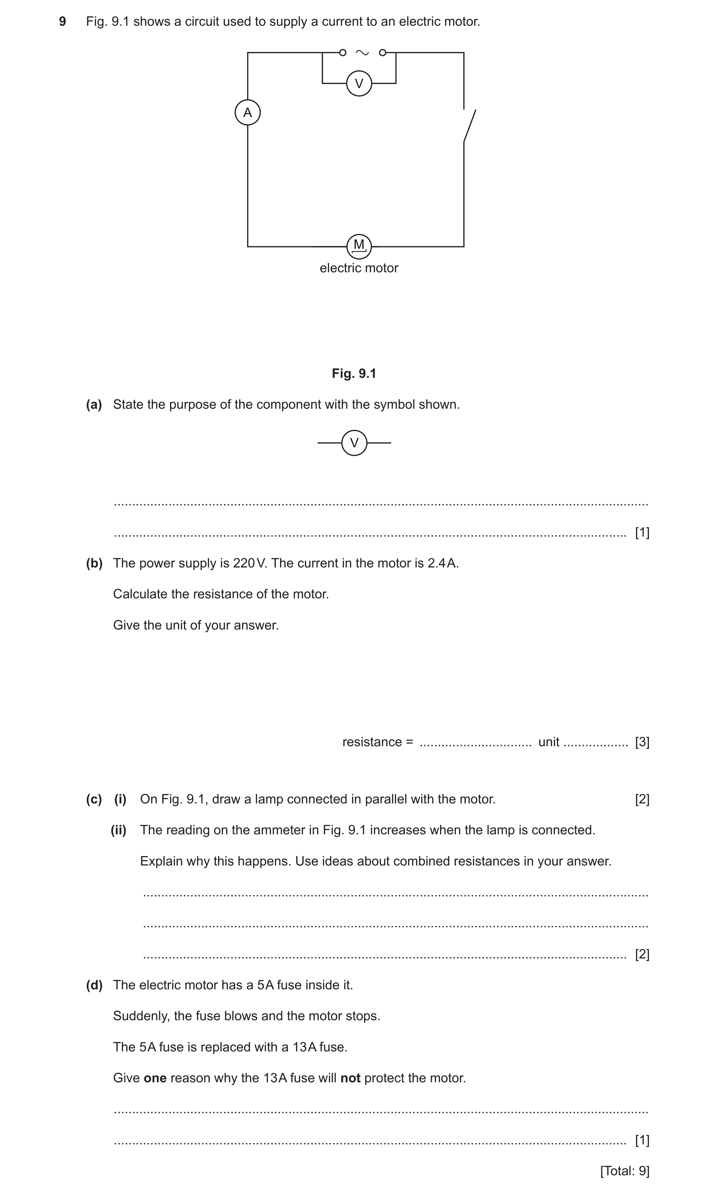
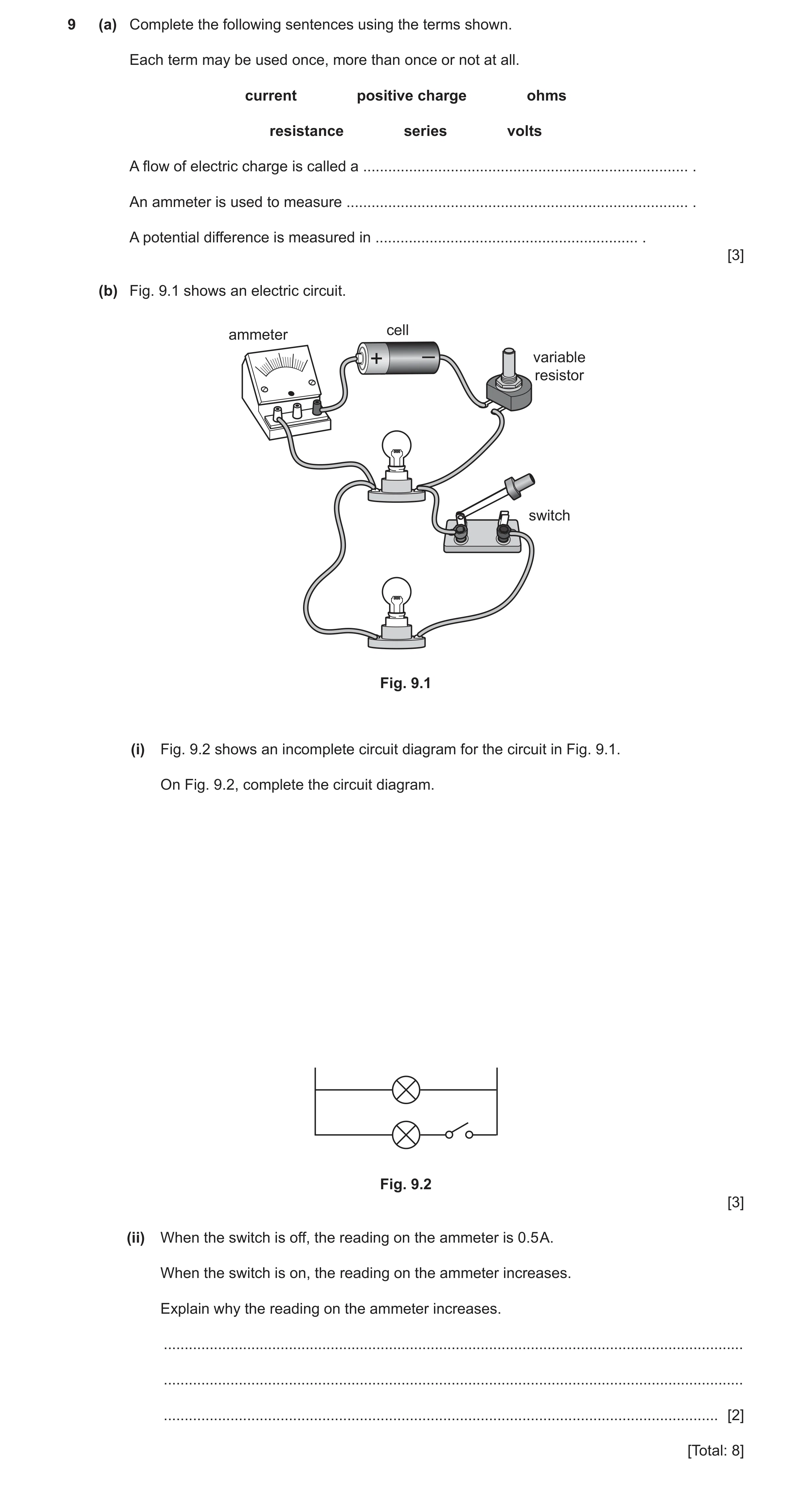
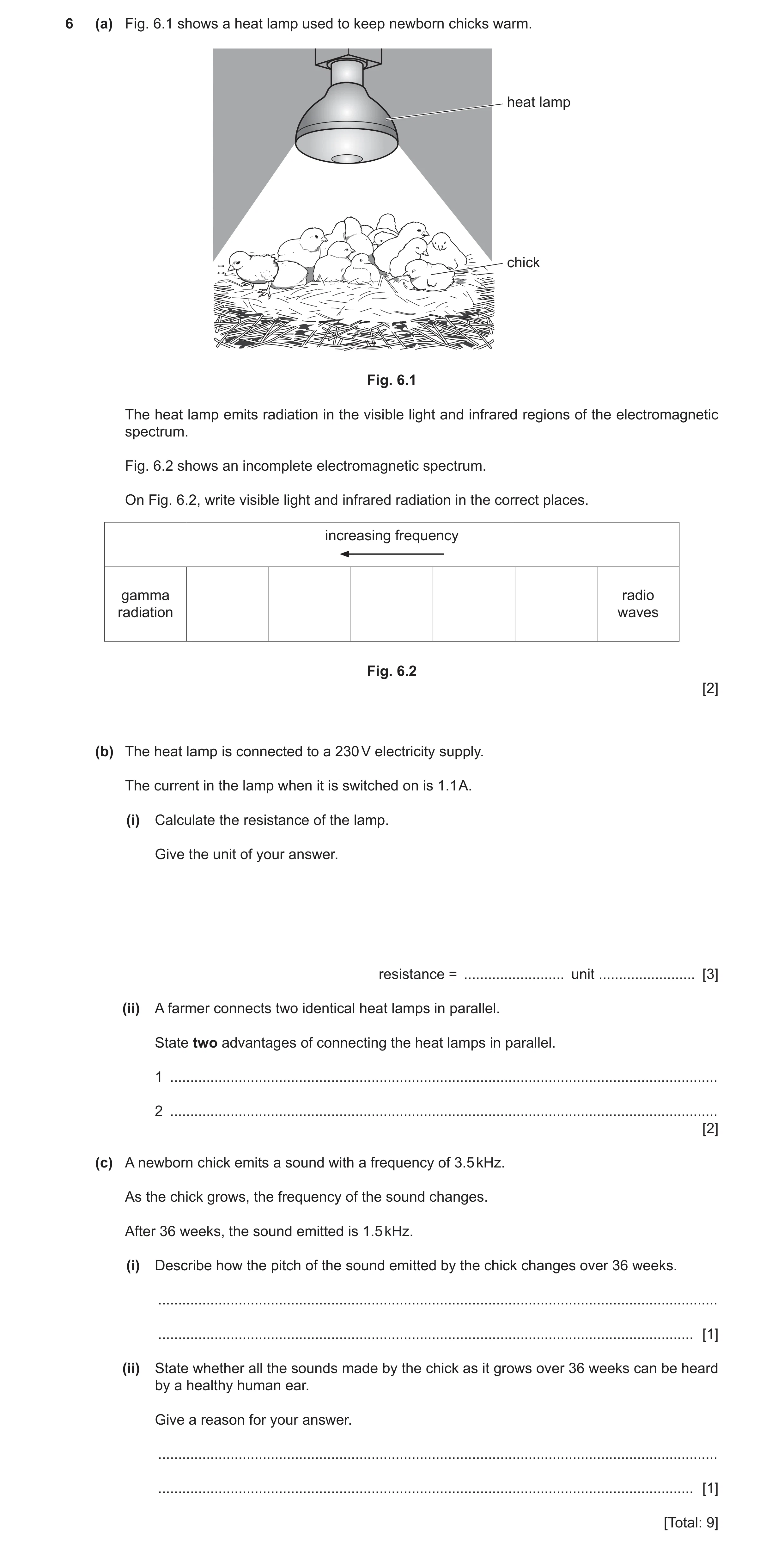
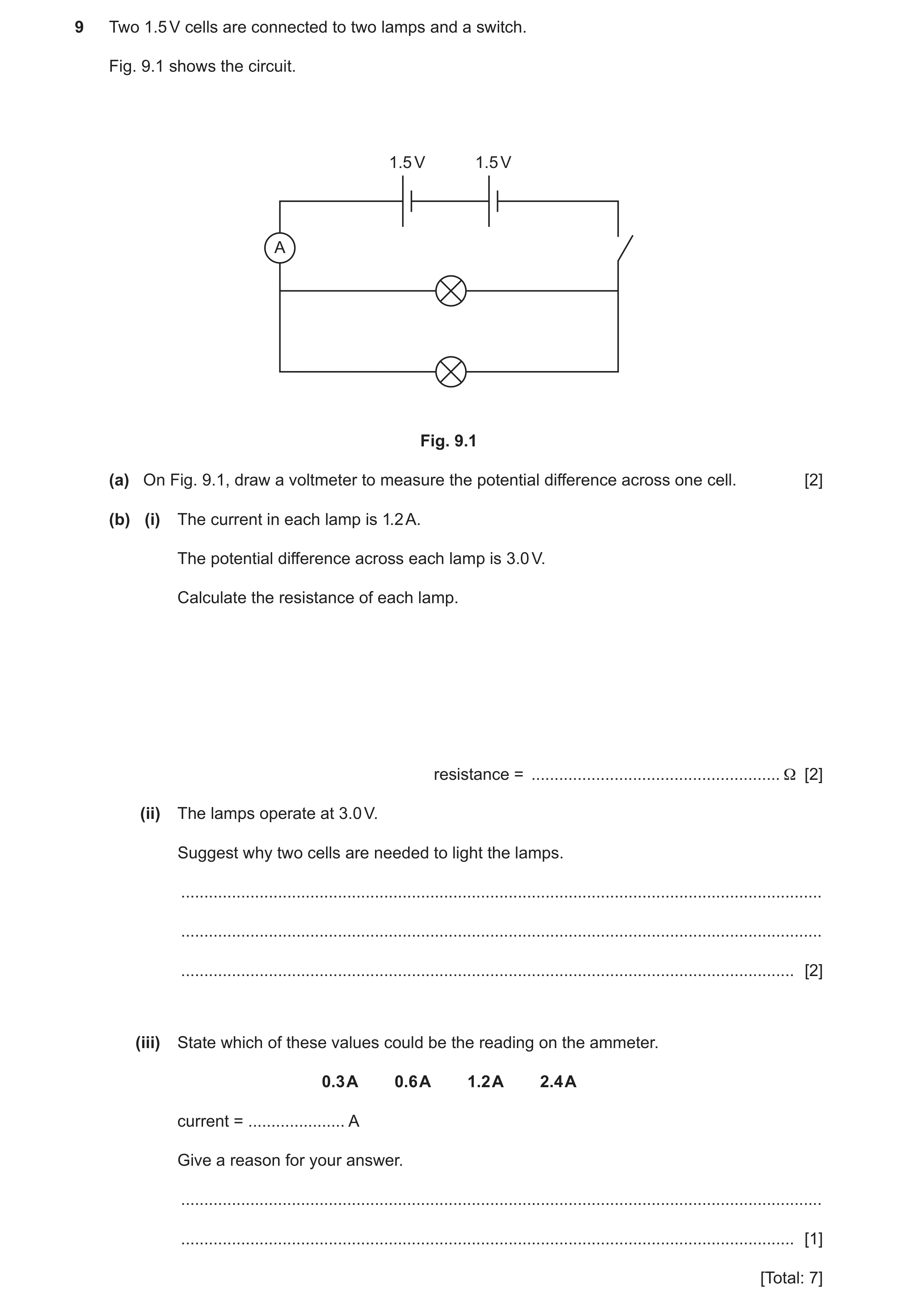
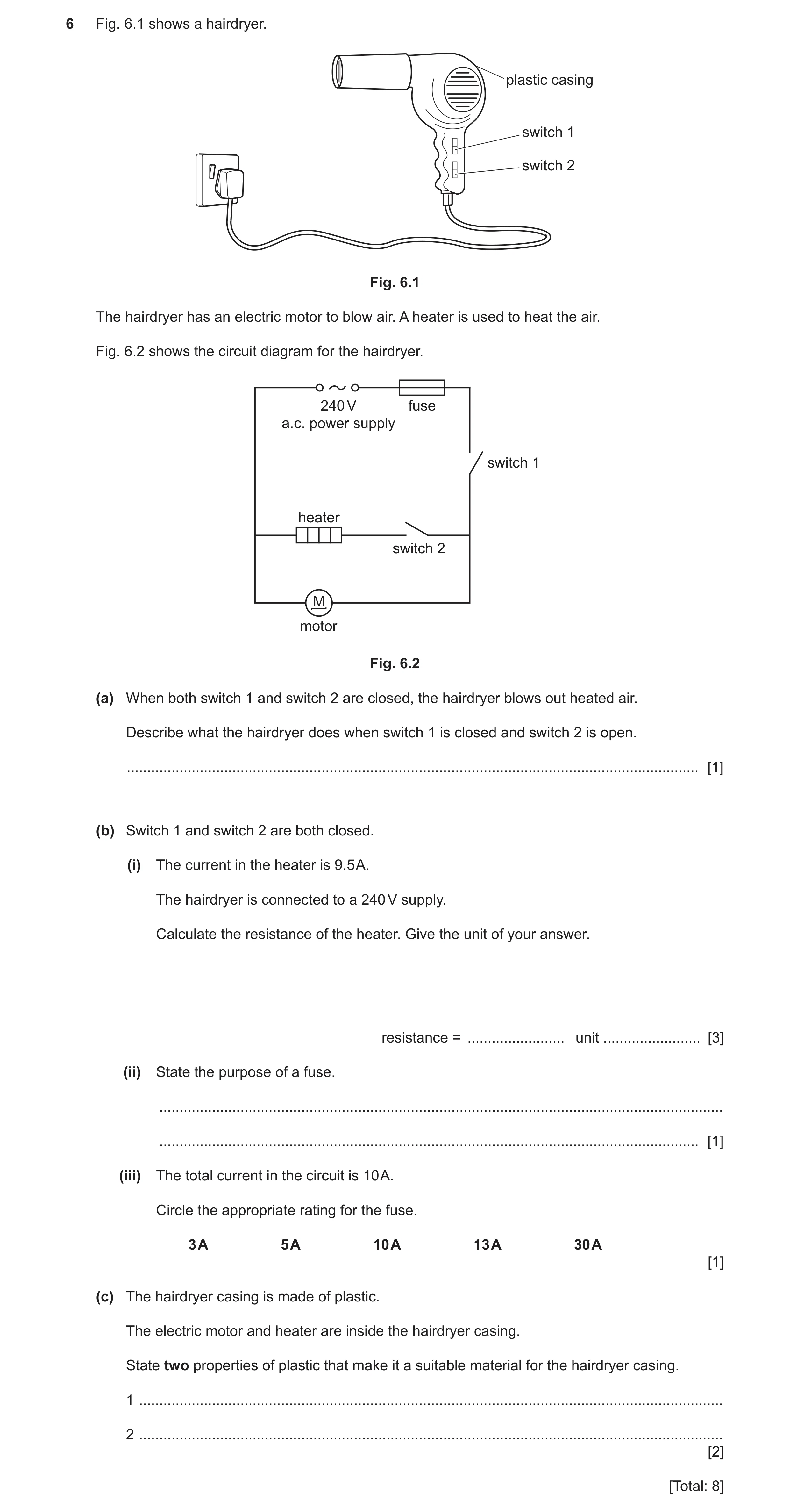
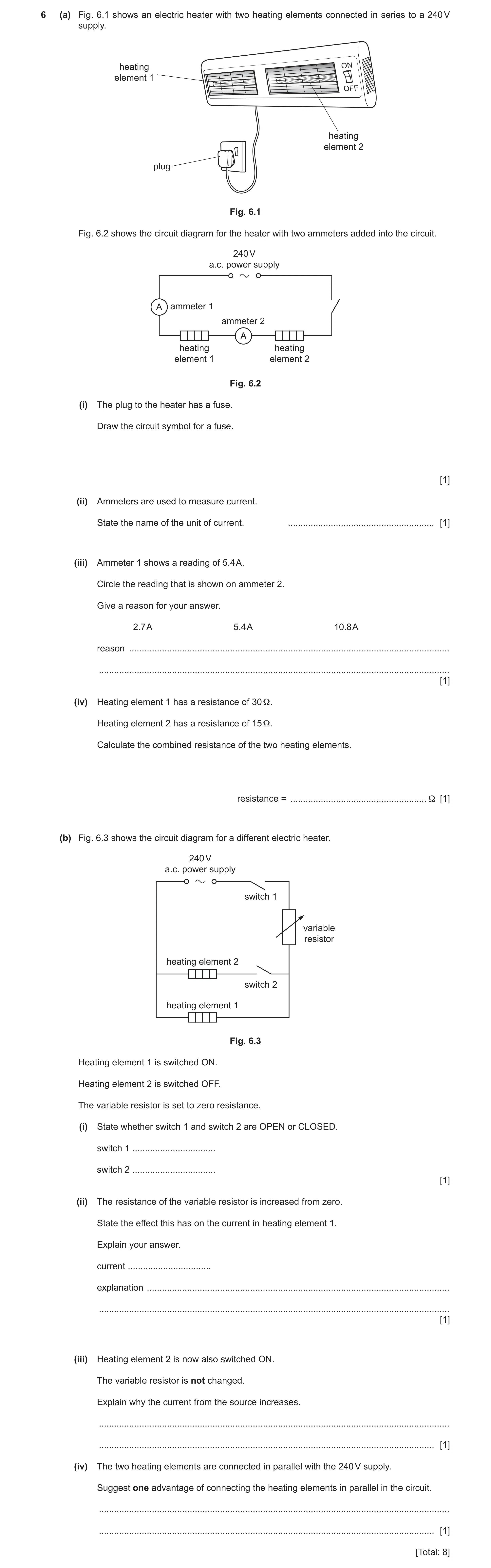
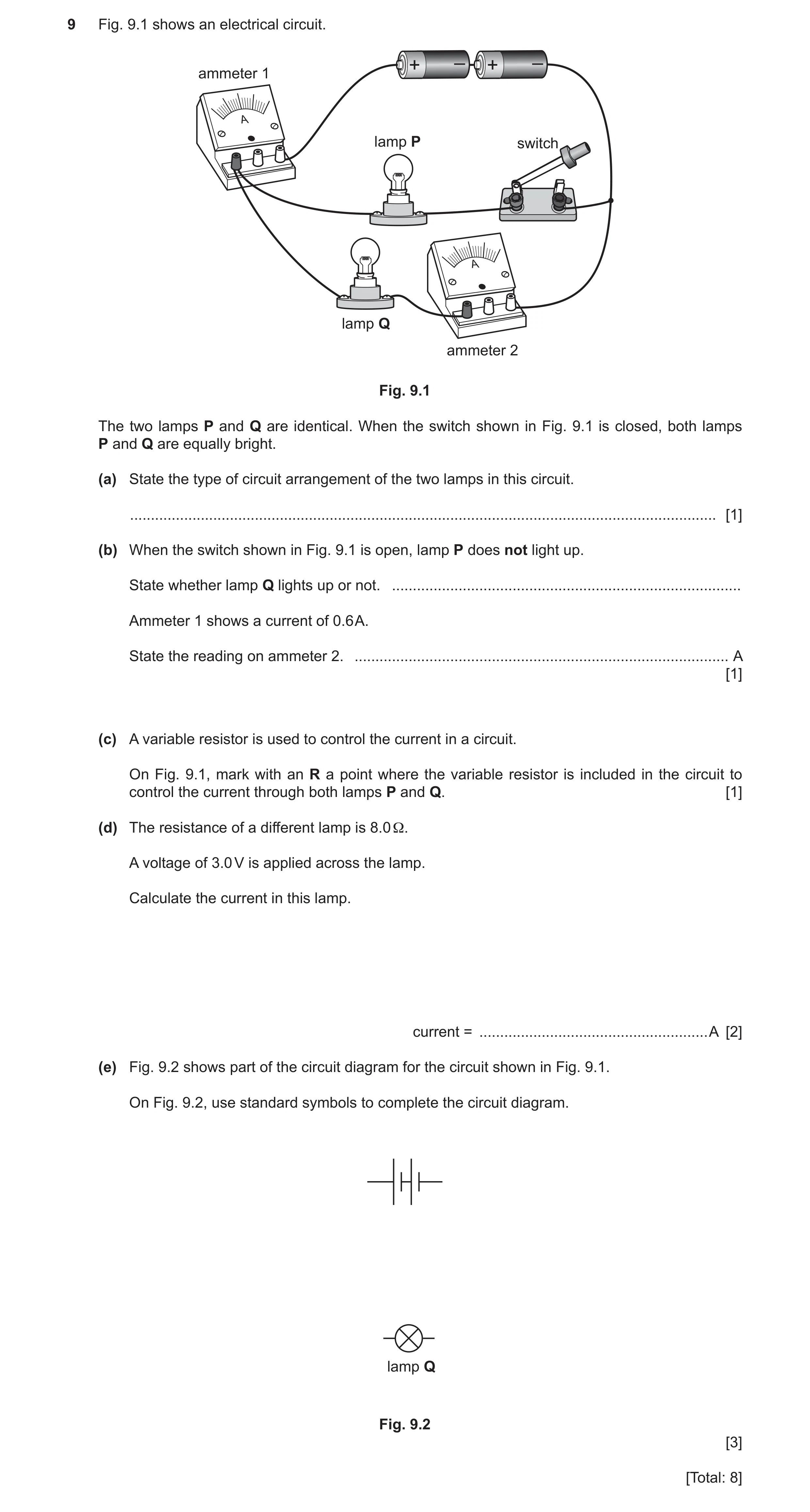
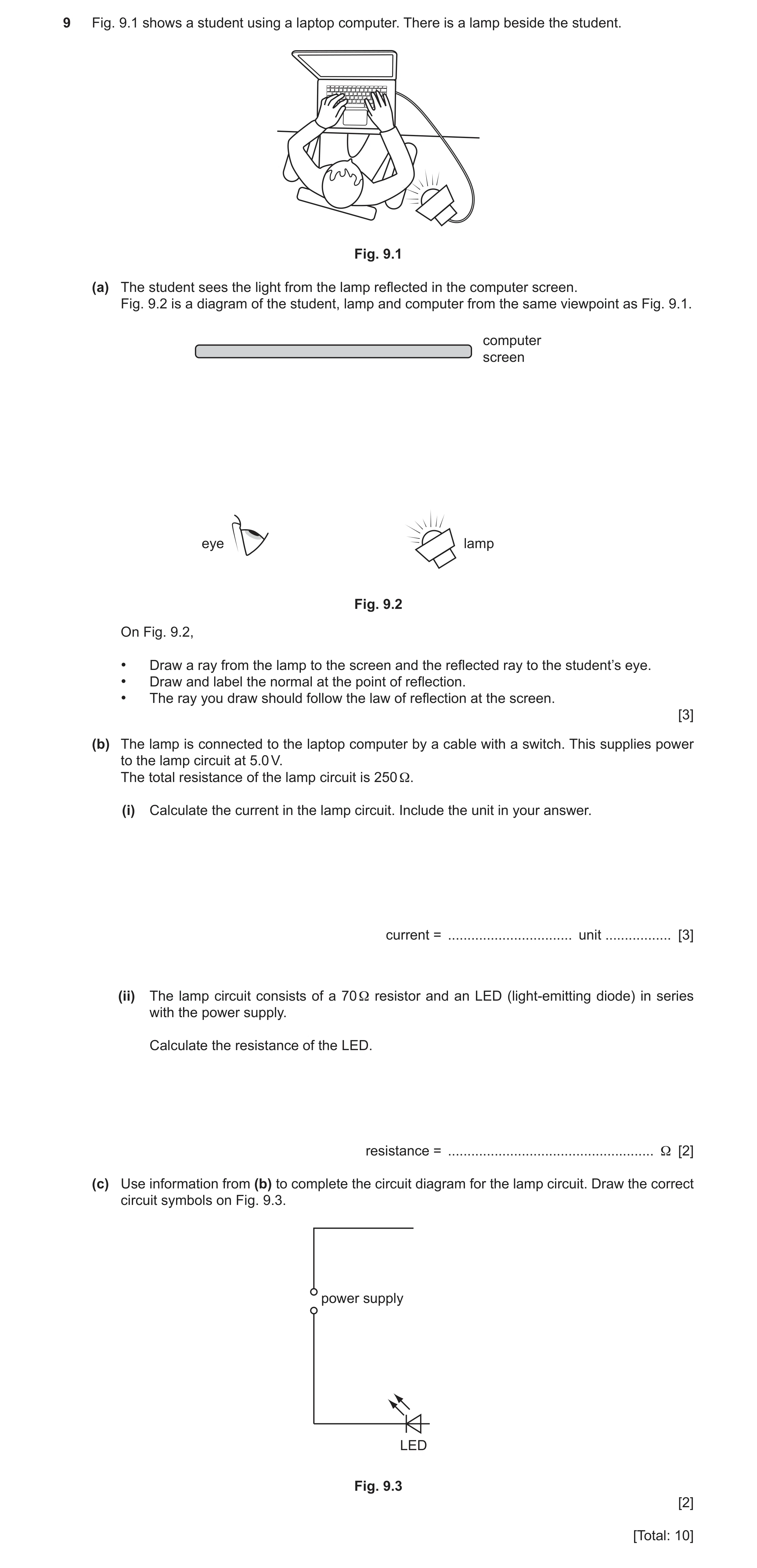
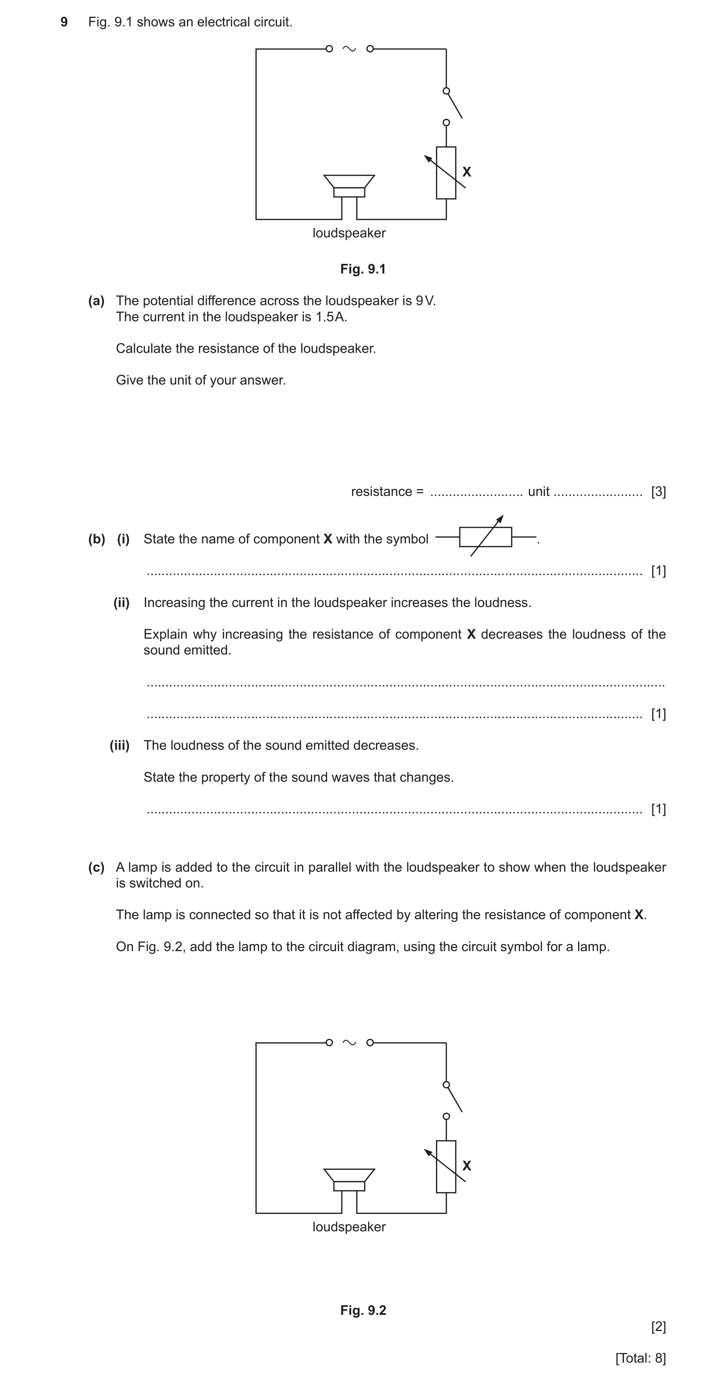
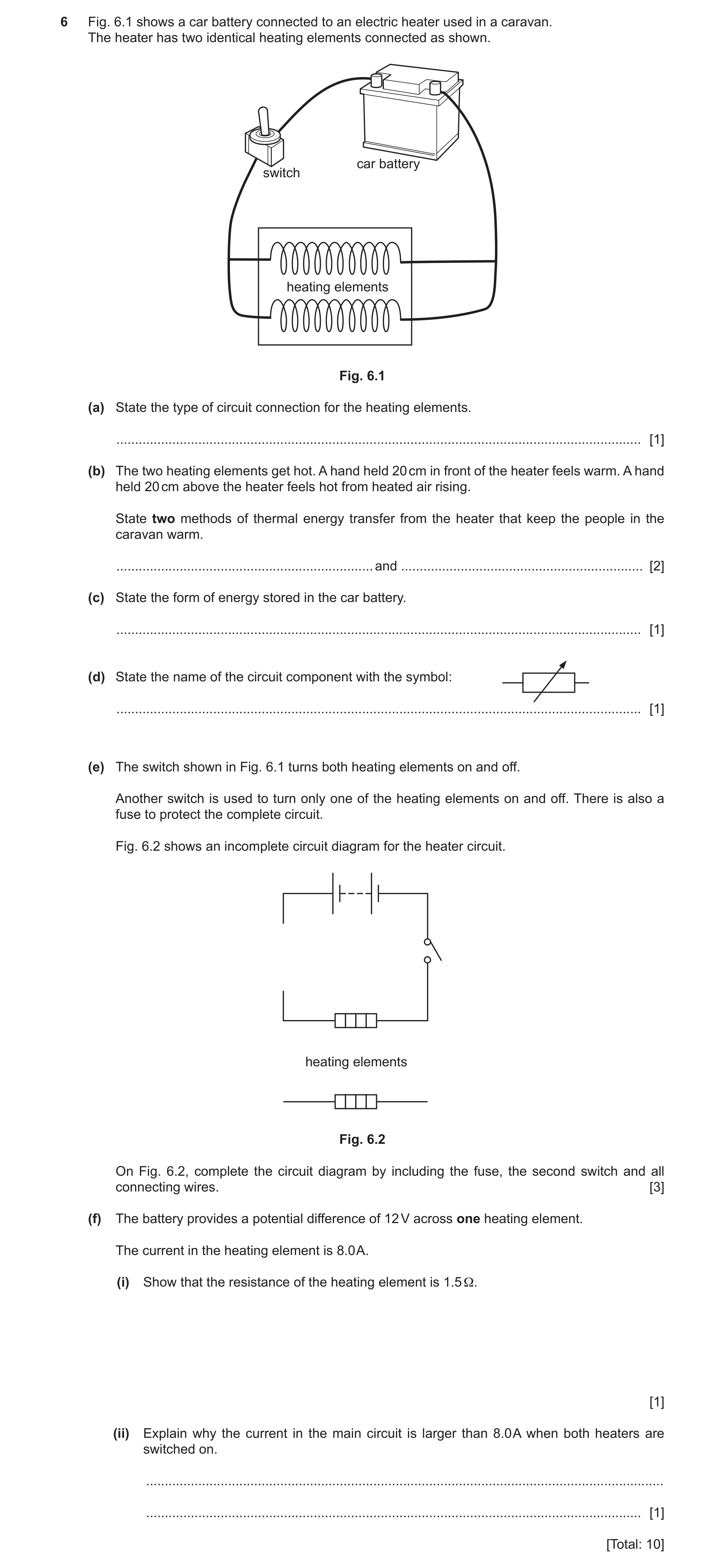

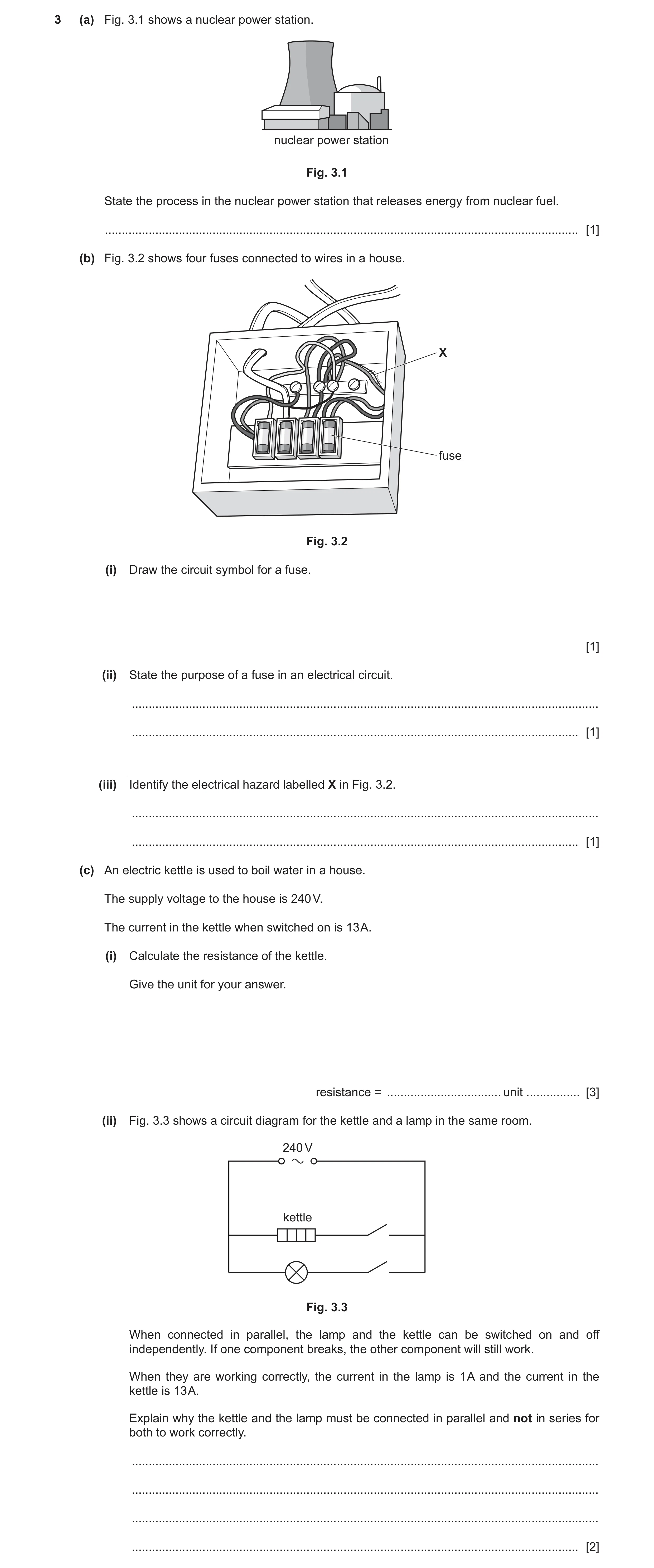
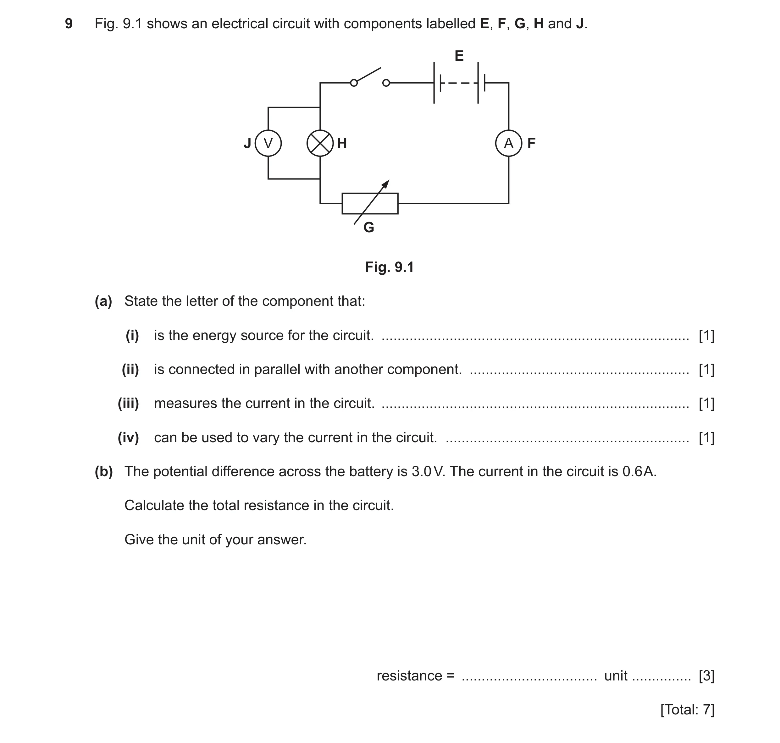 73 / 90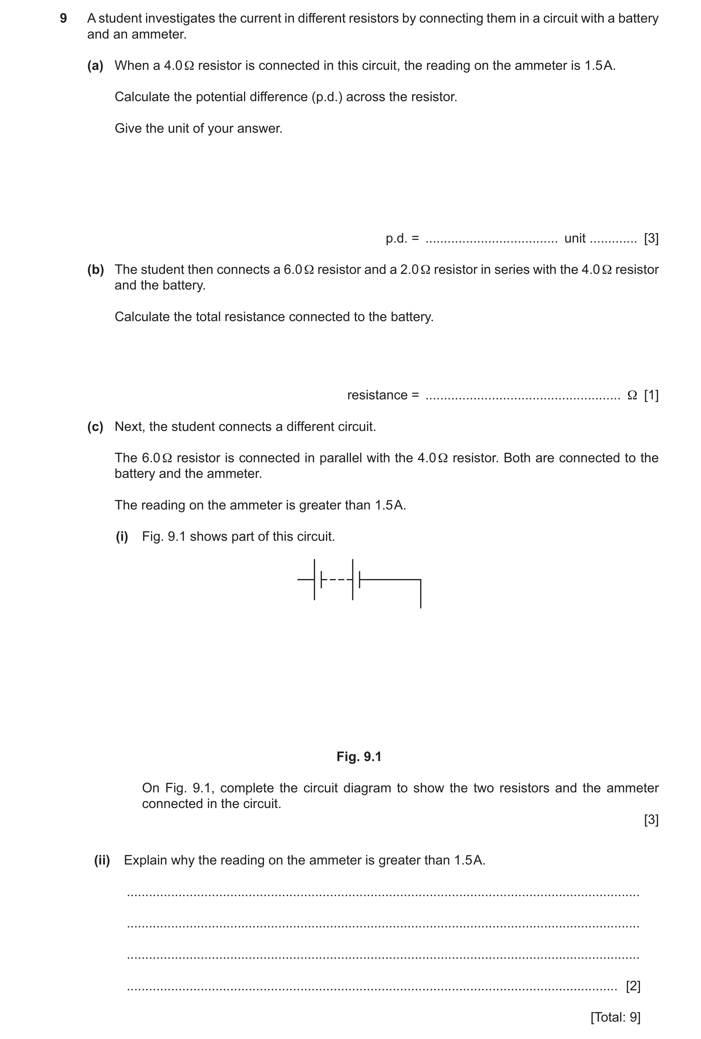
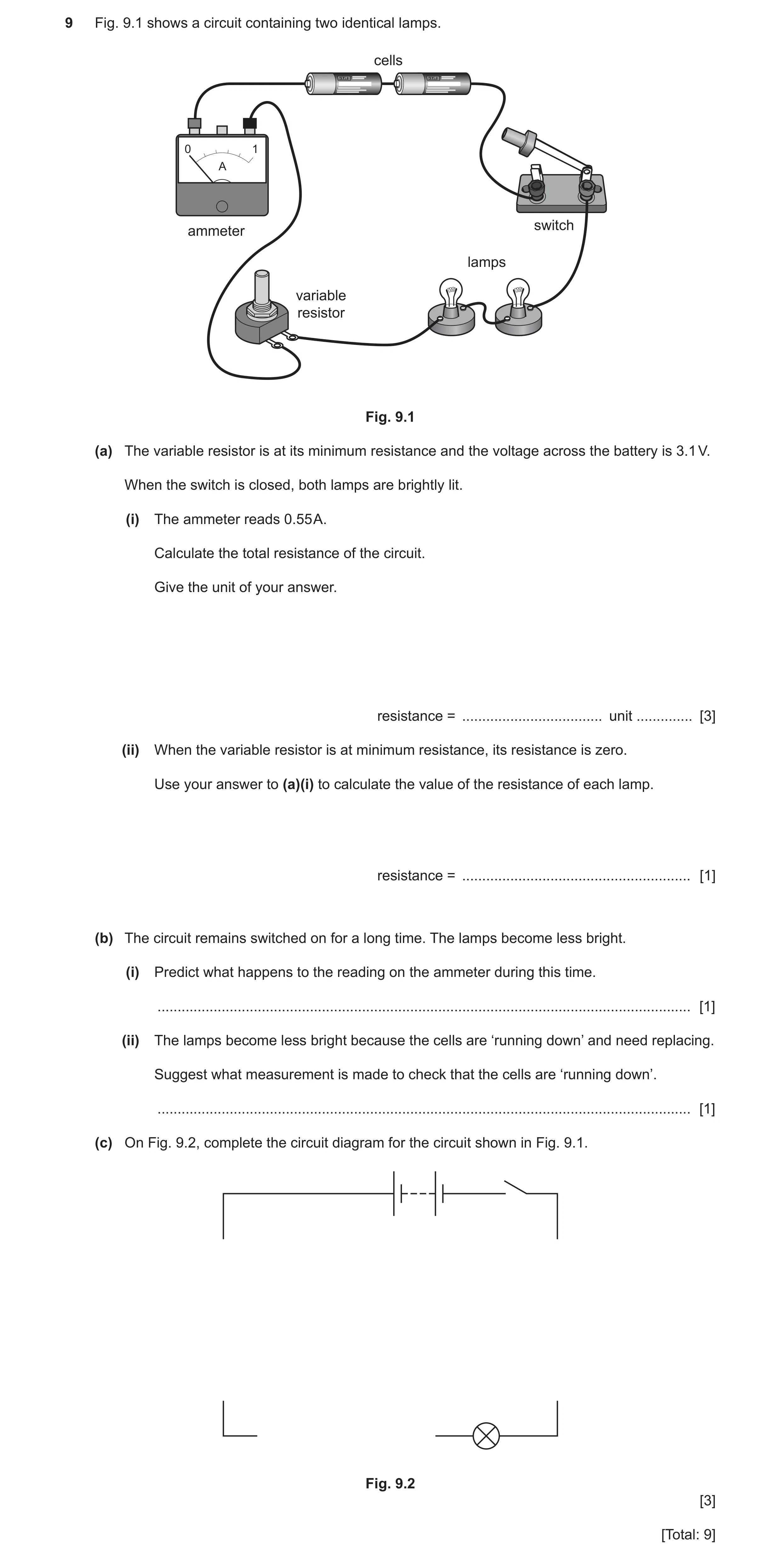
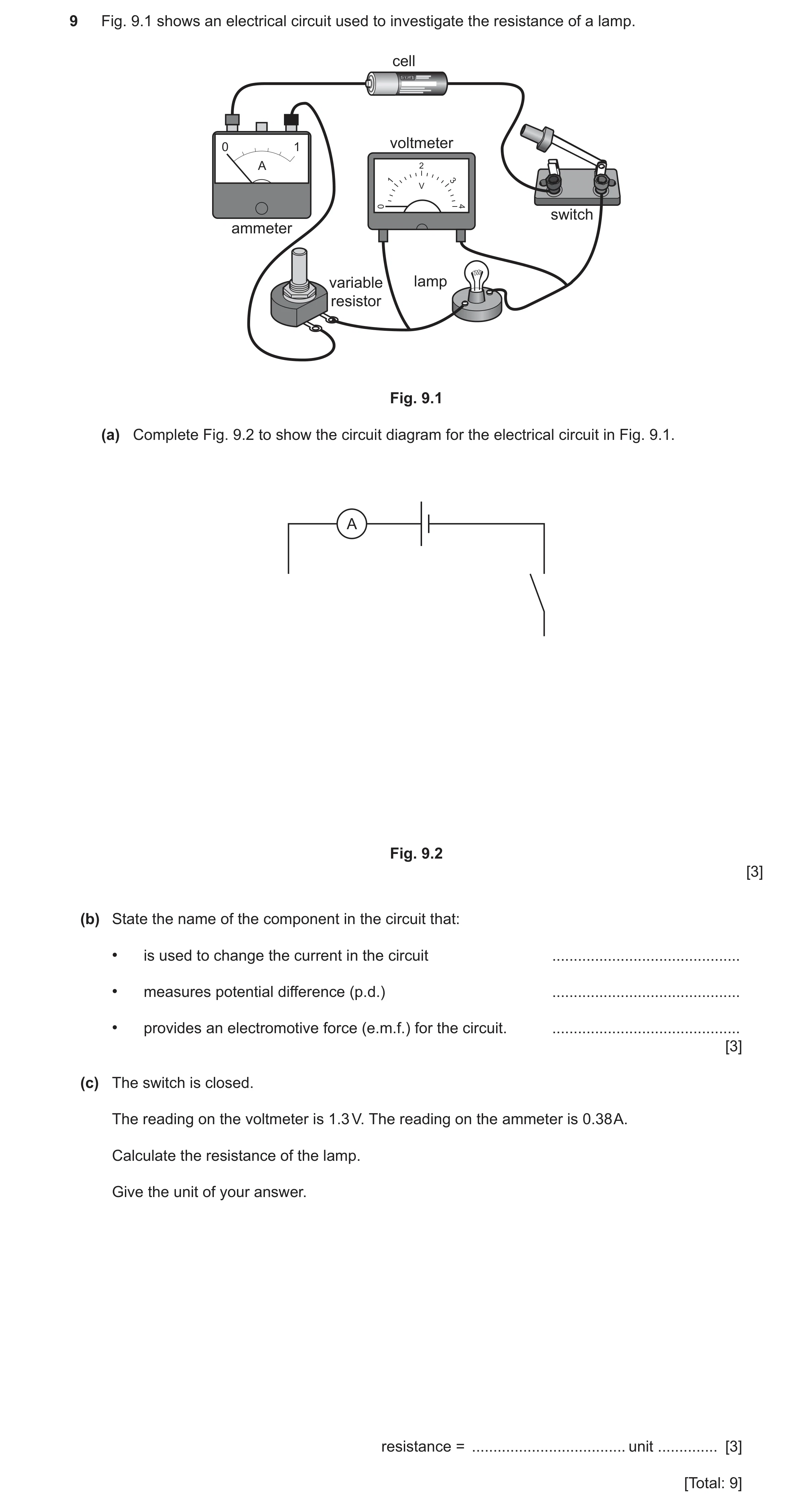
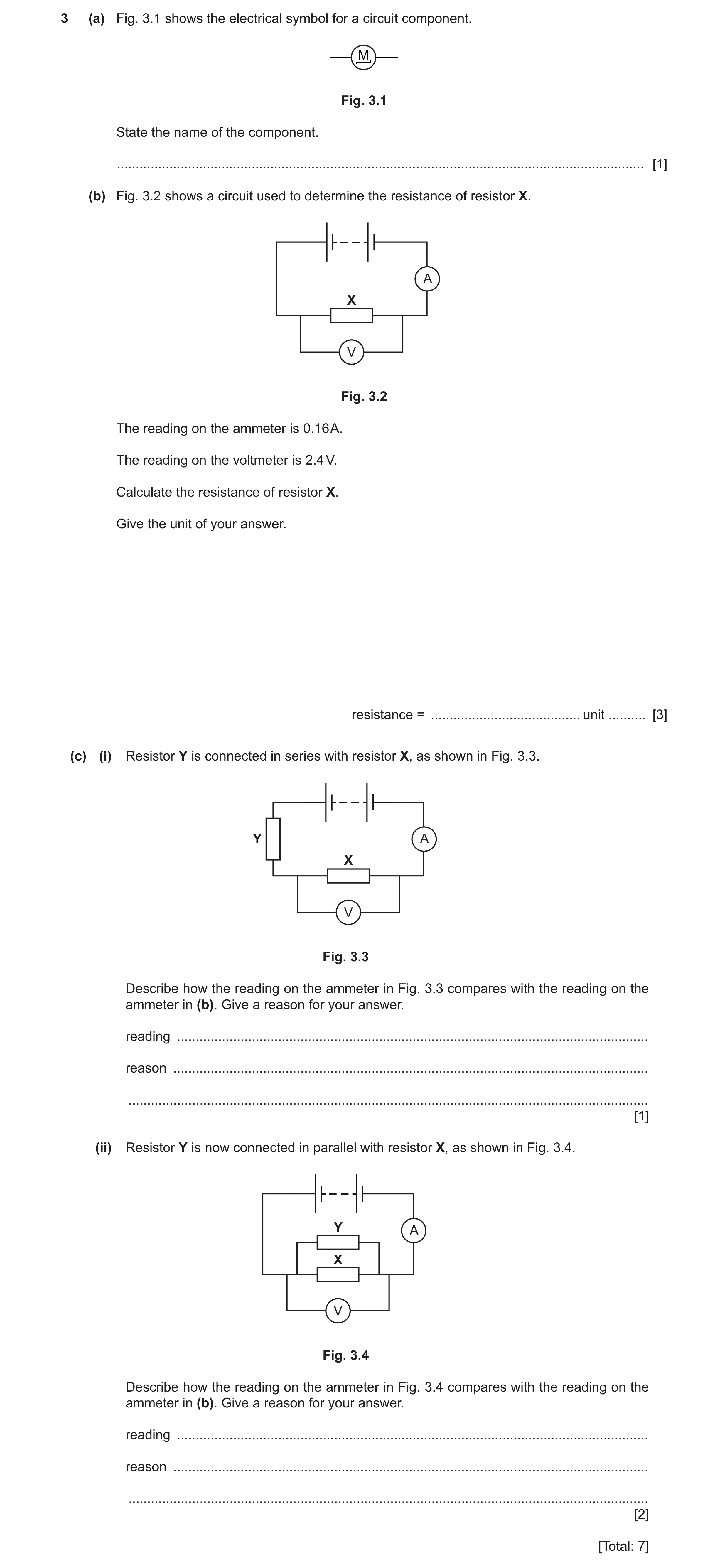
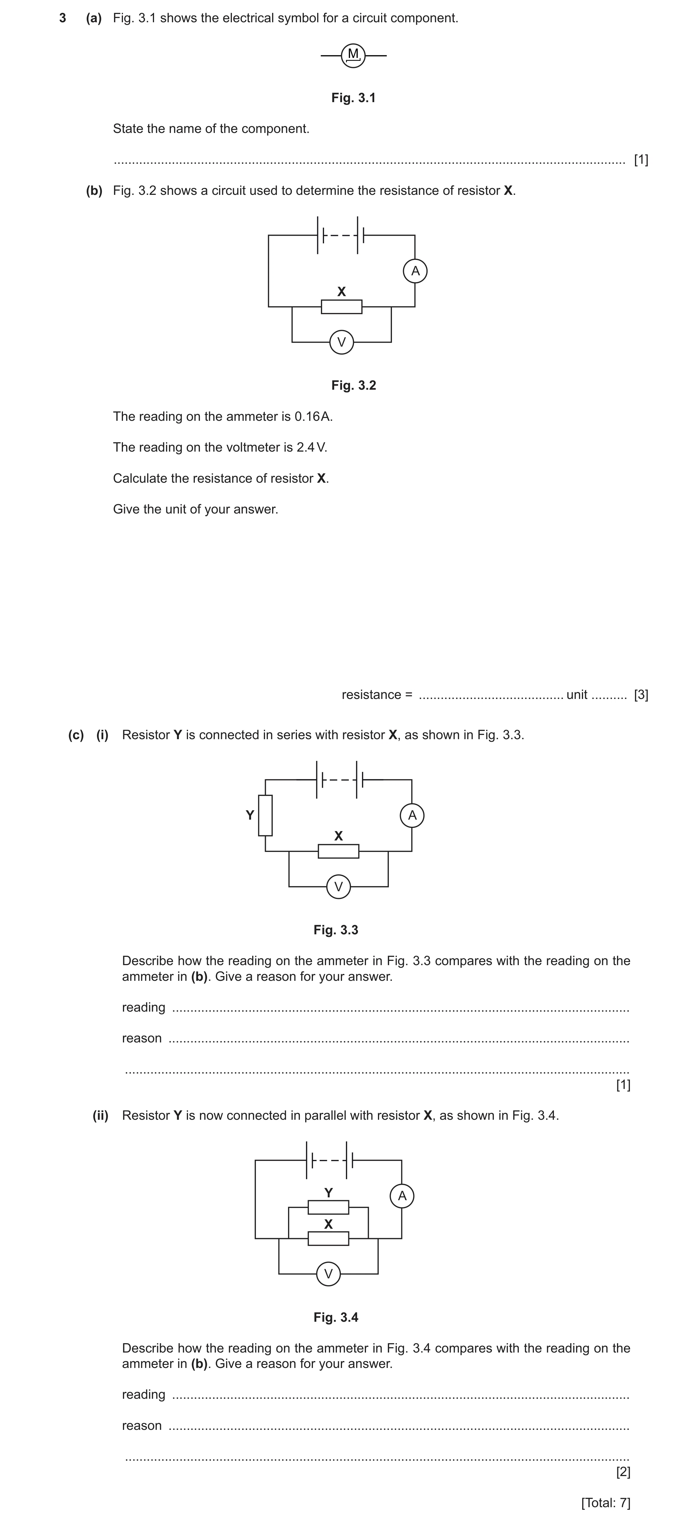
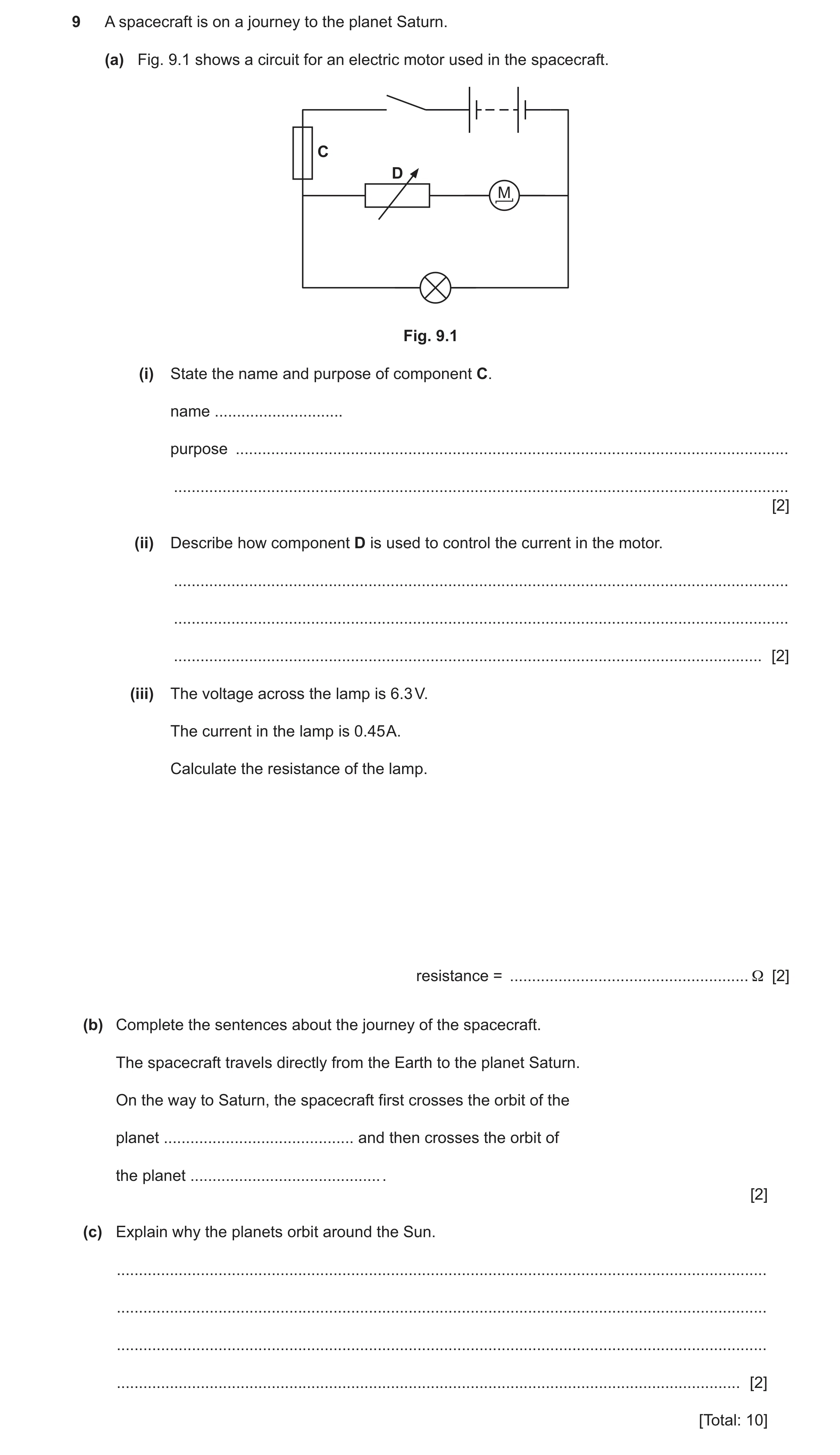
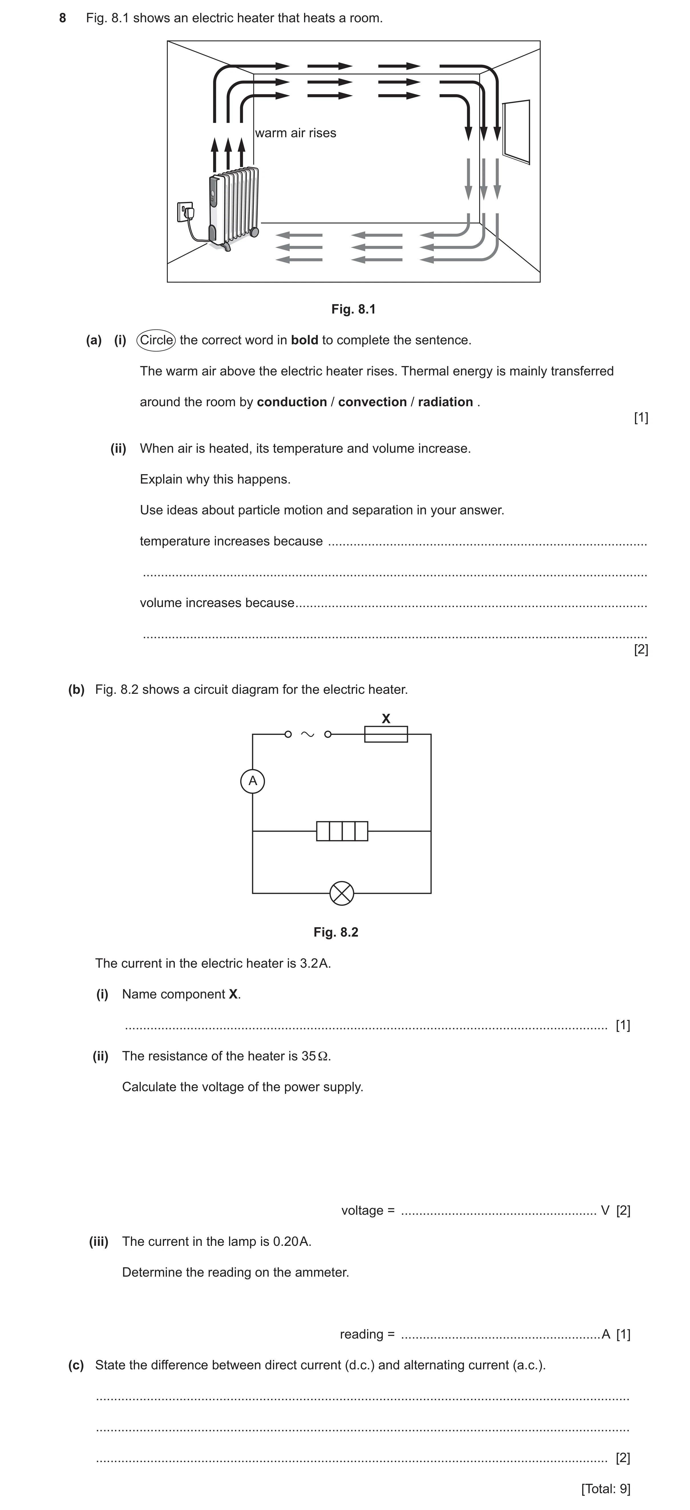
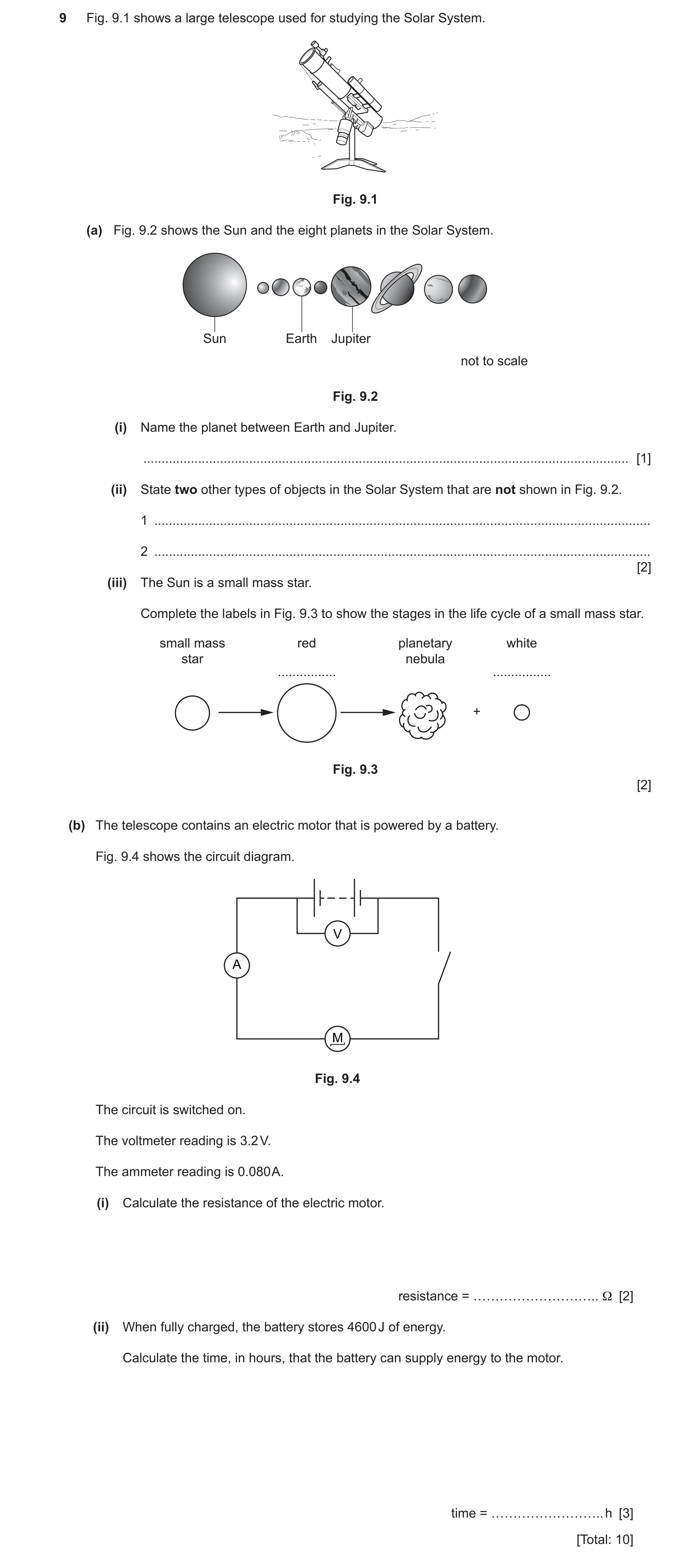
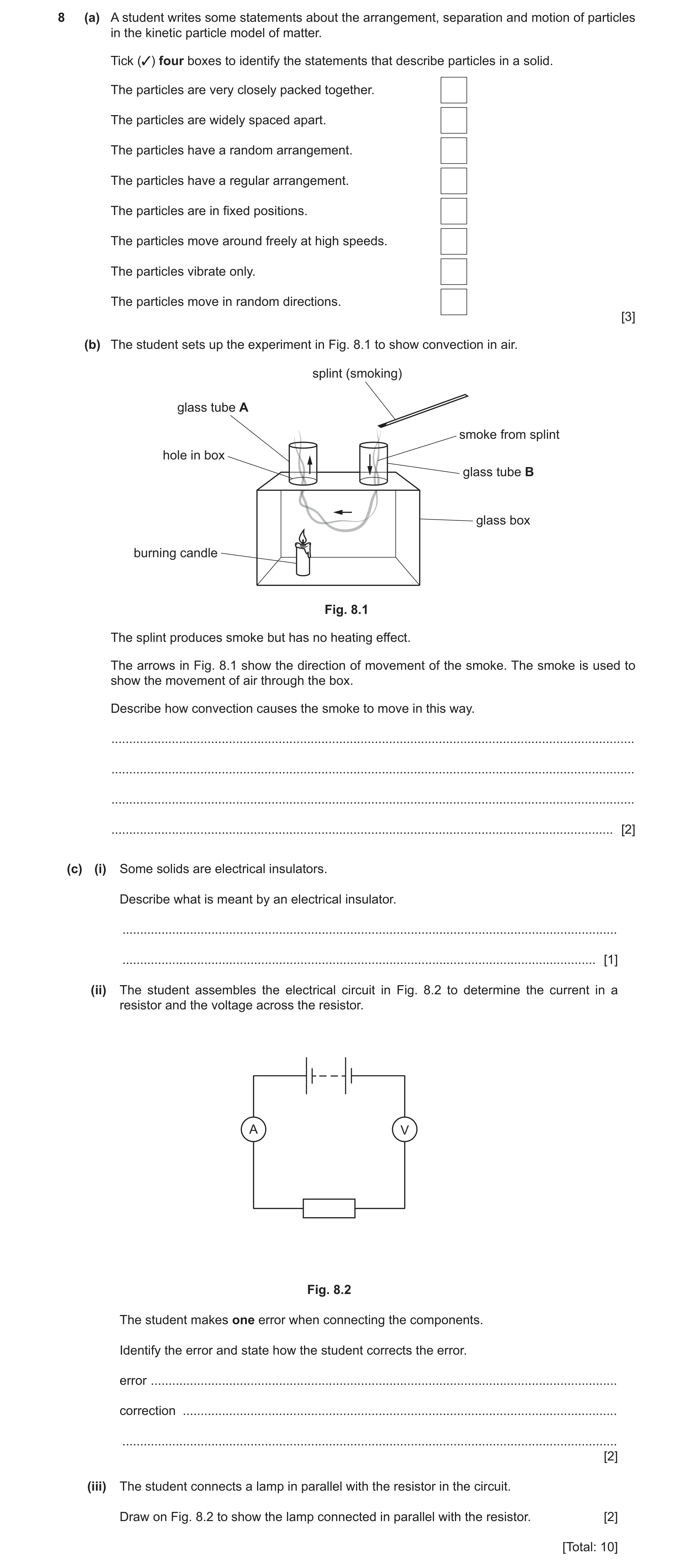
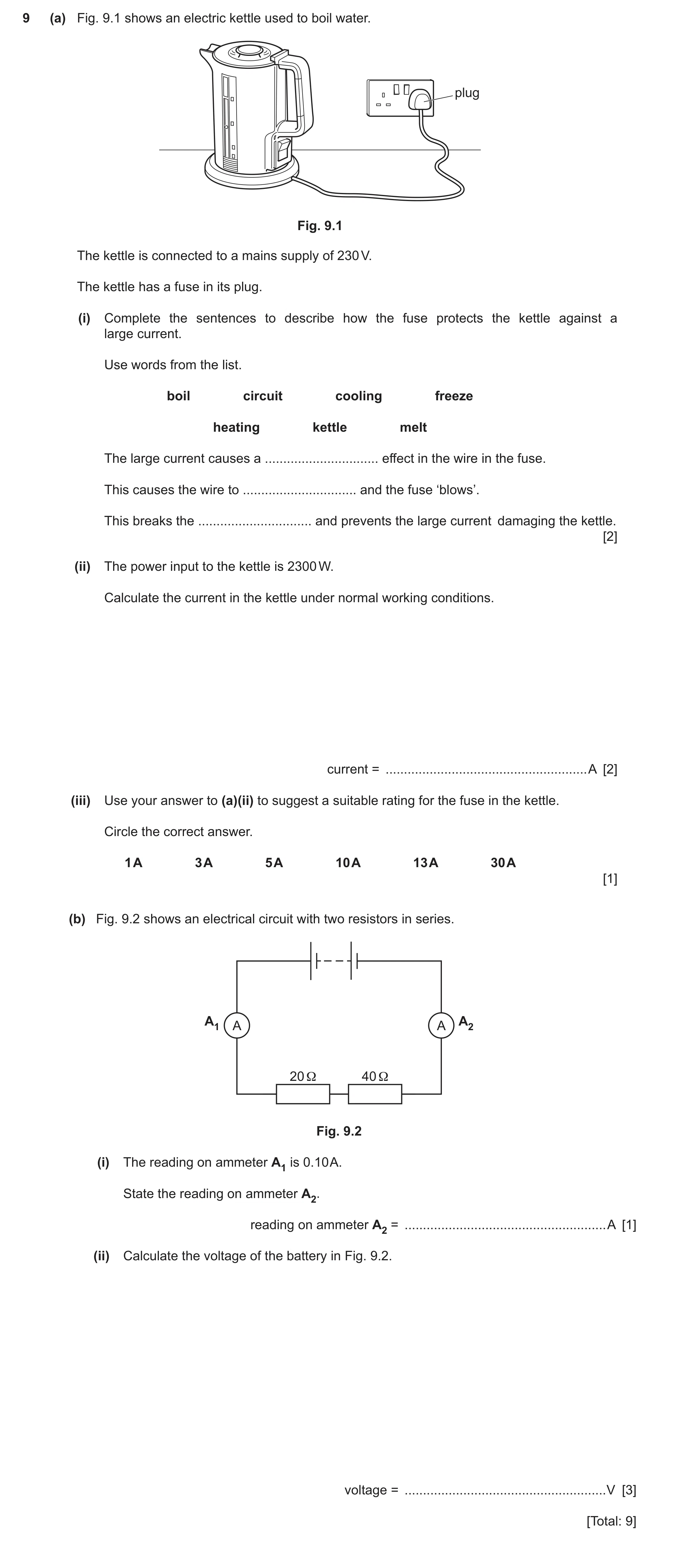
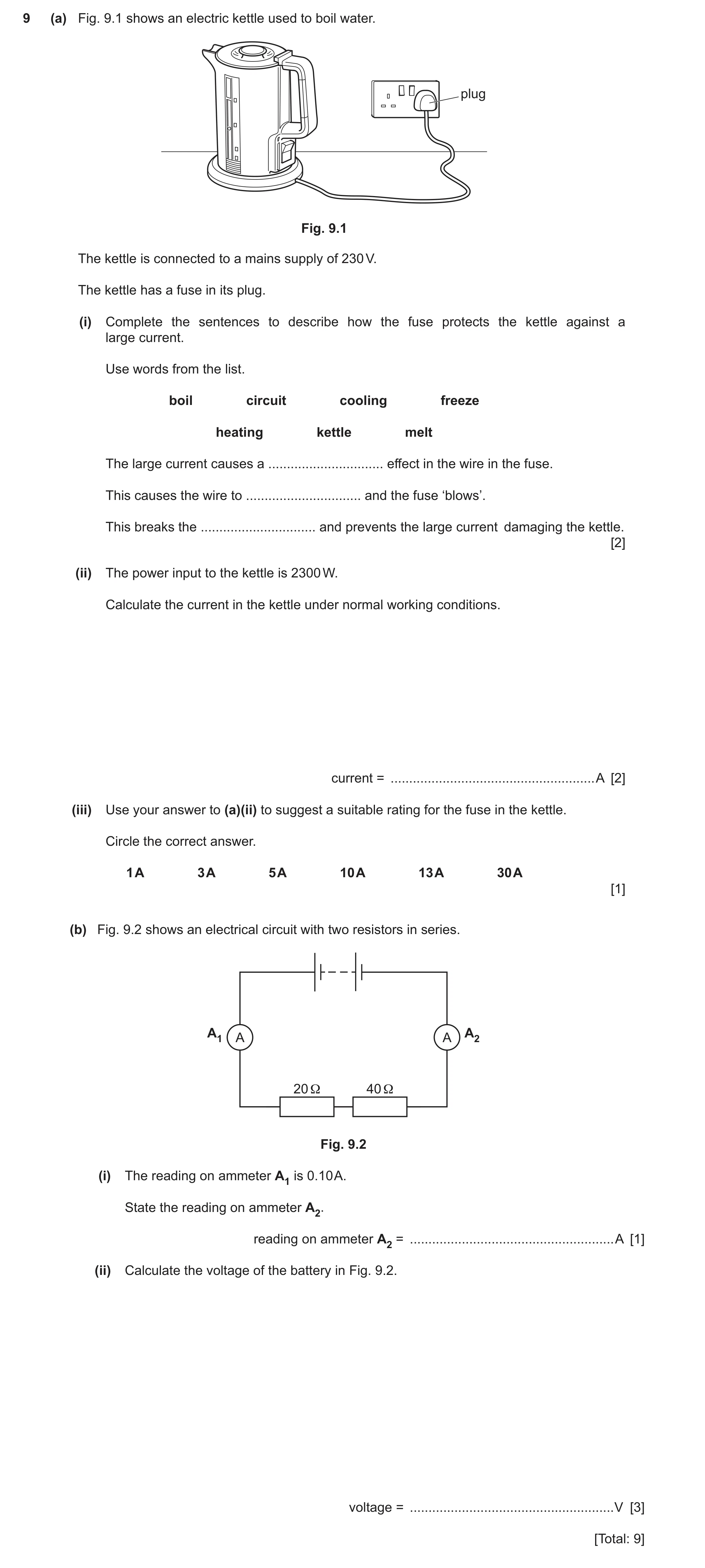
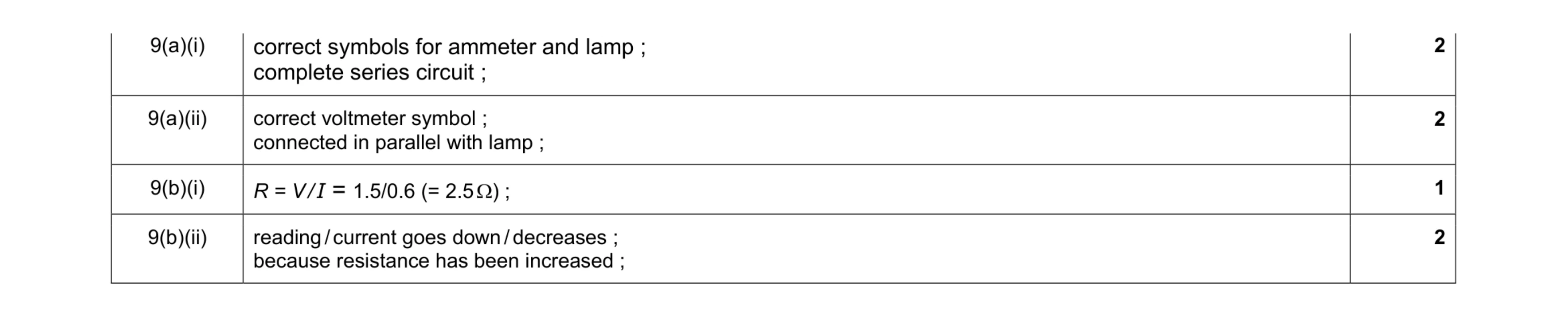 7
7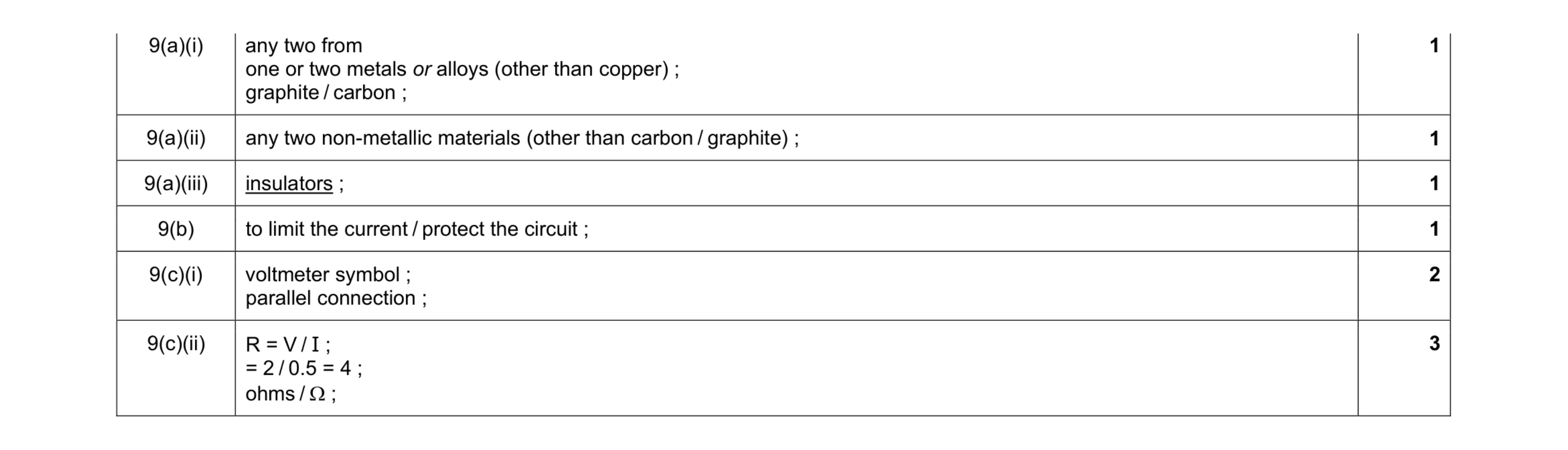 9
9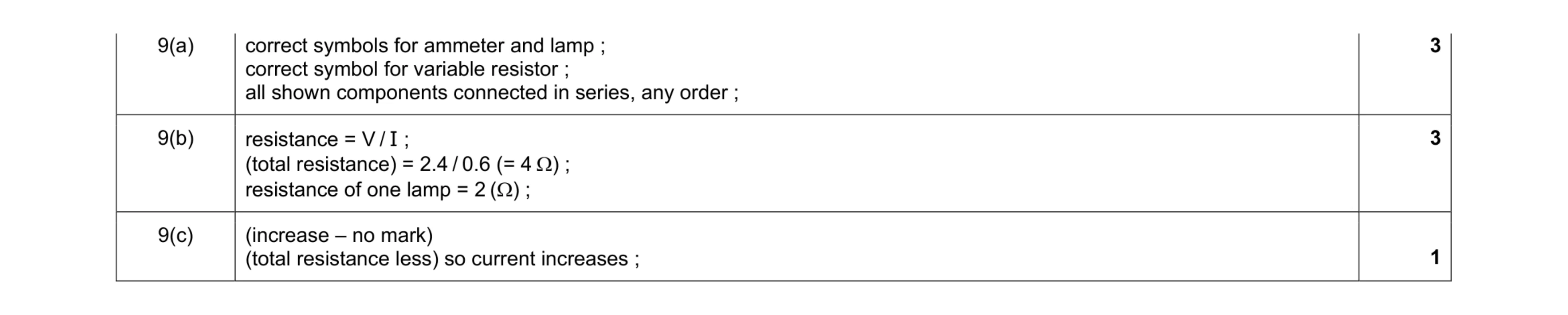 7
7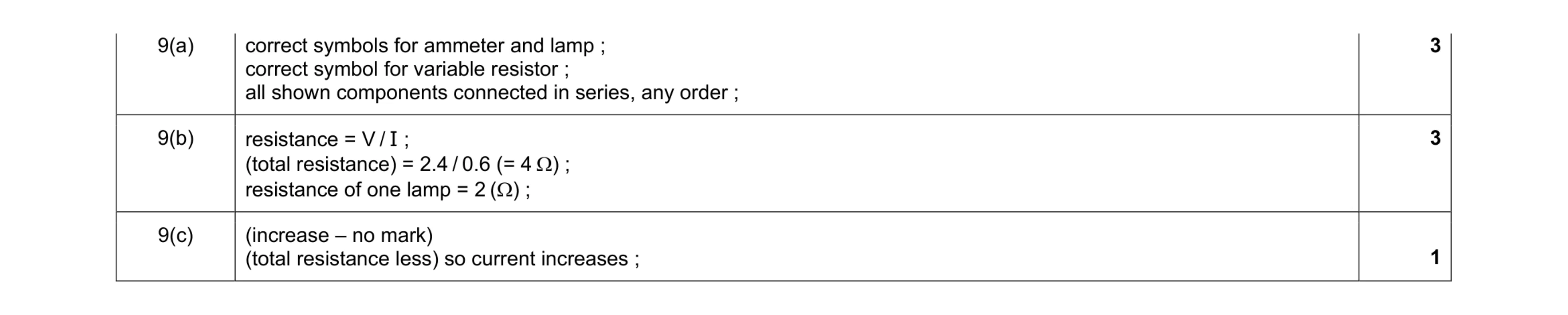 7
7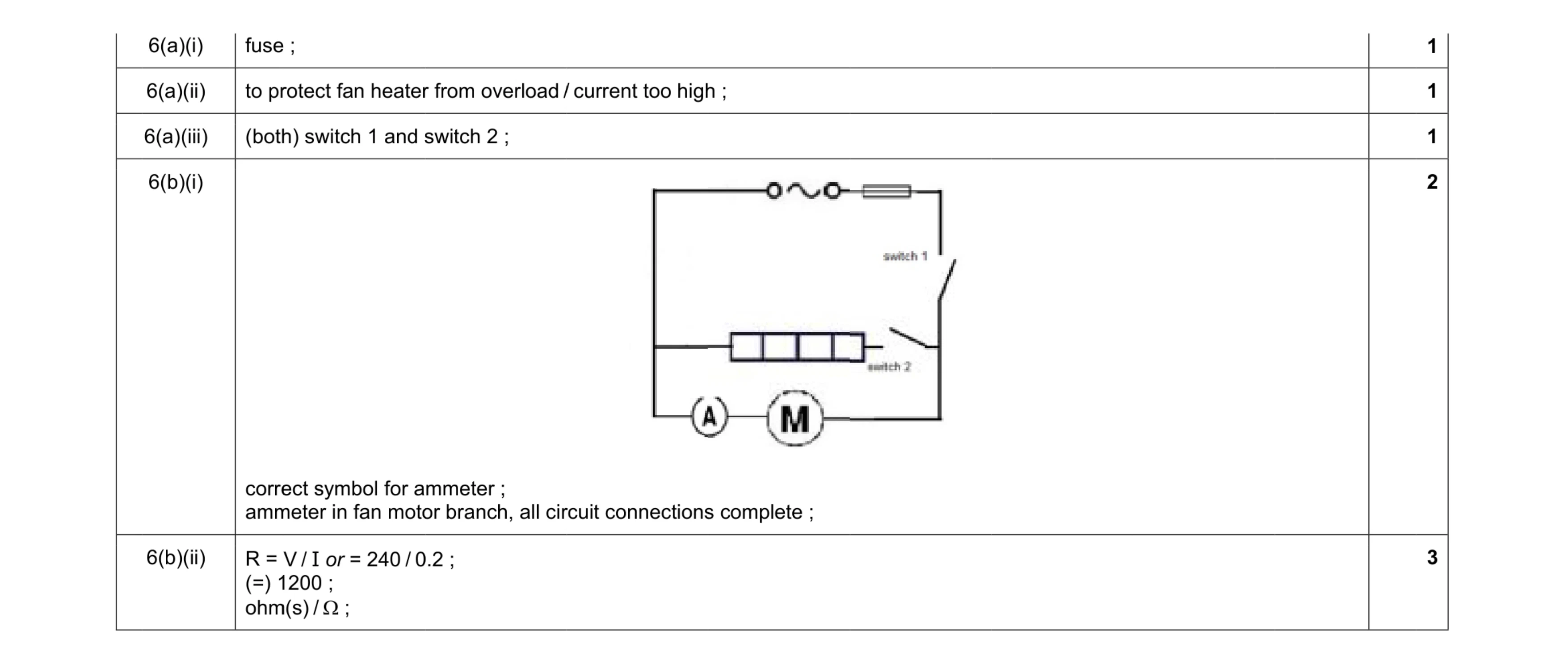 8
8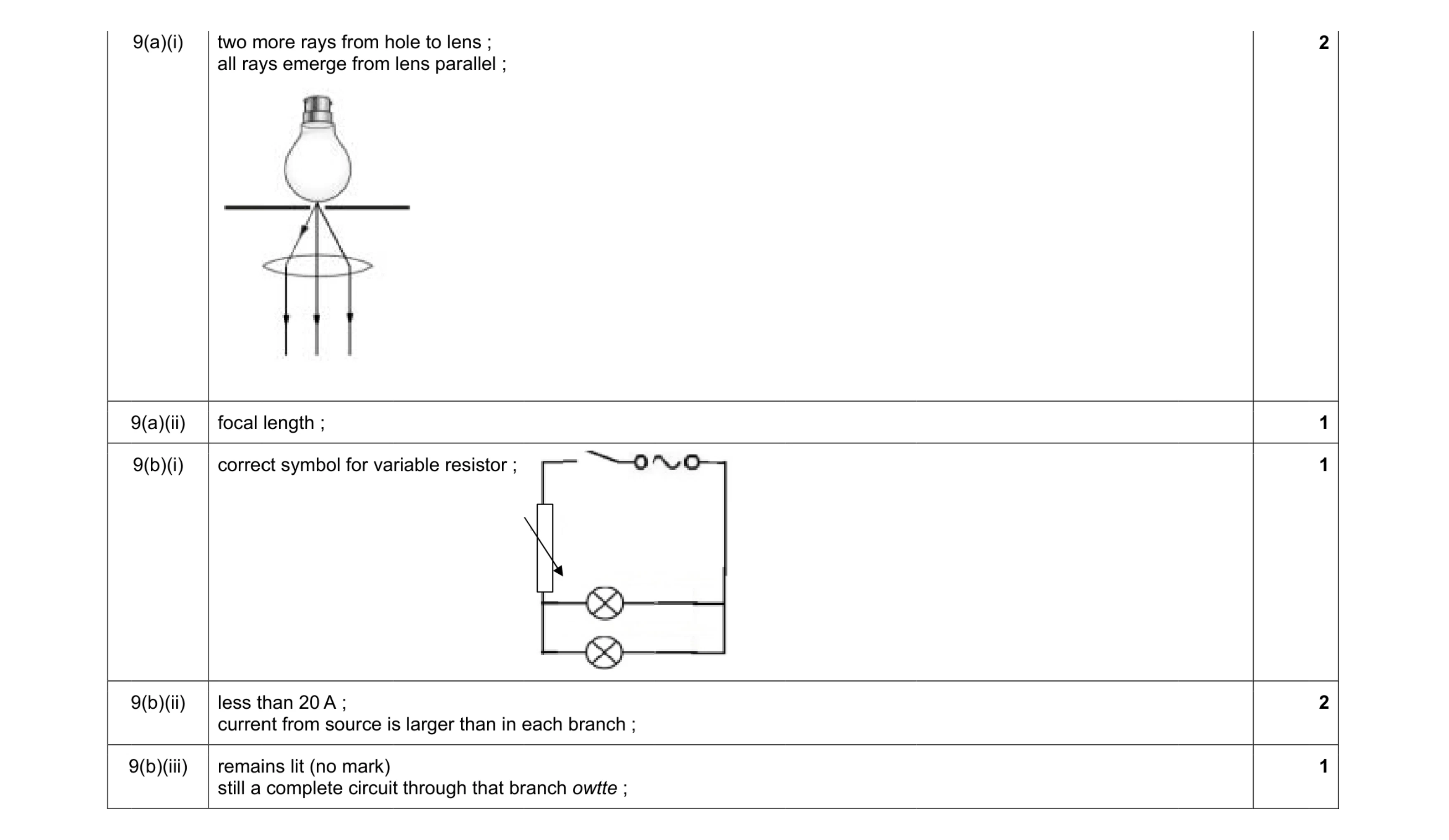 7
7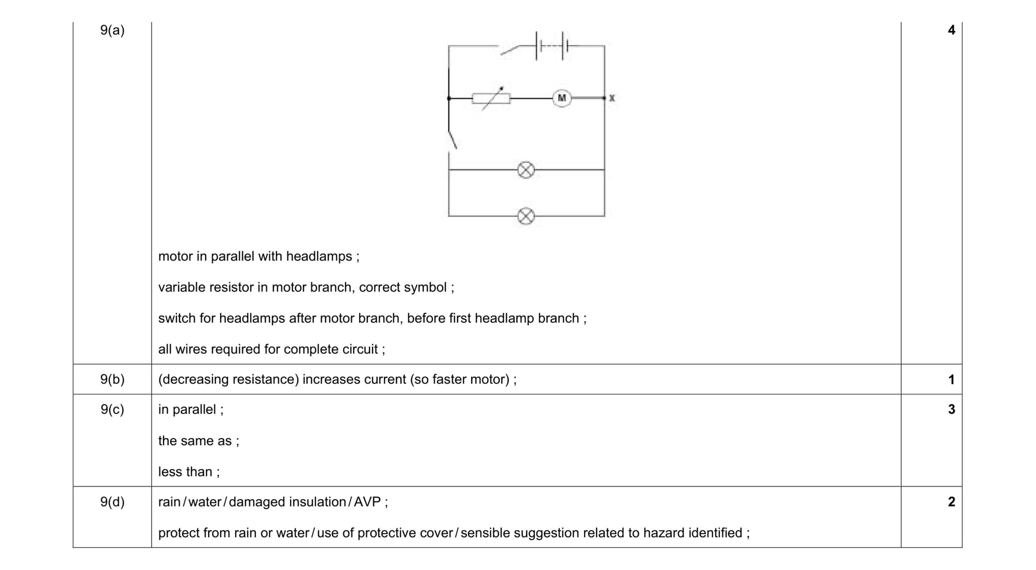 10
10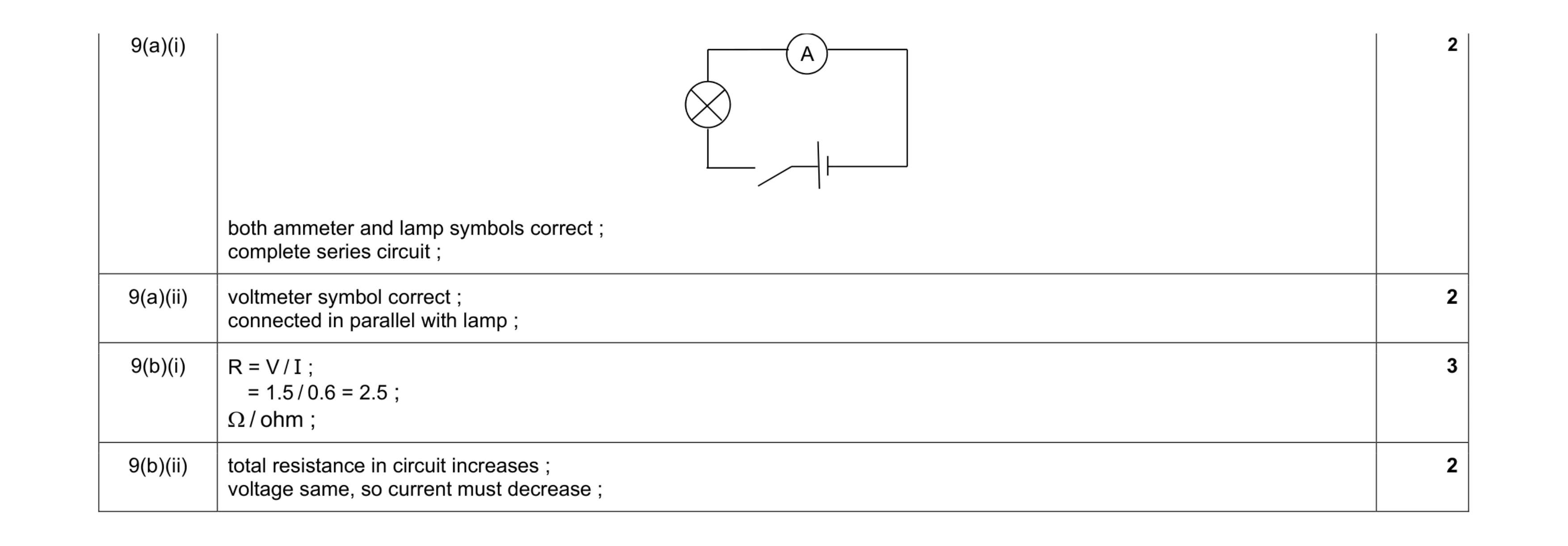 9
9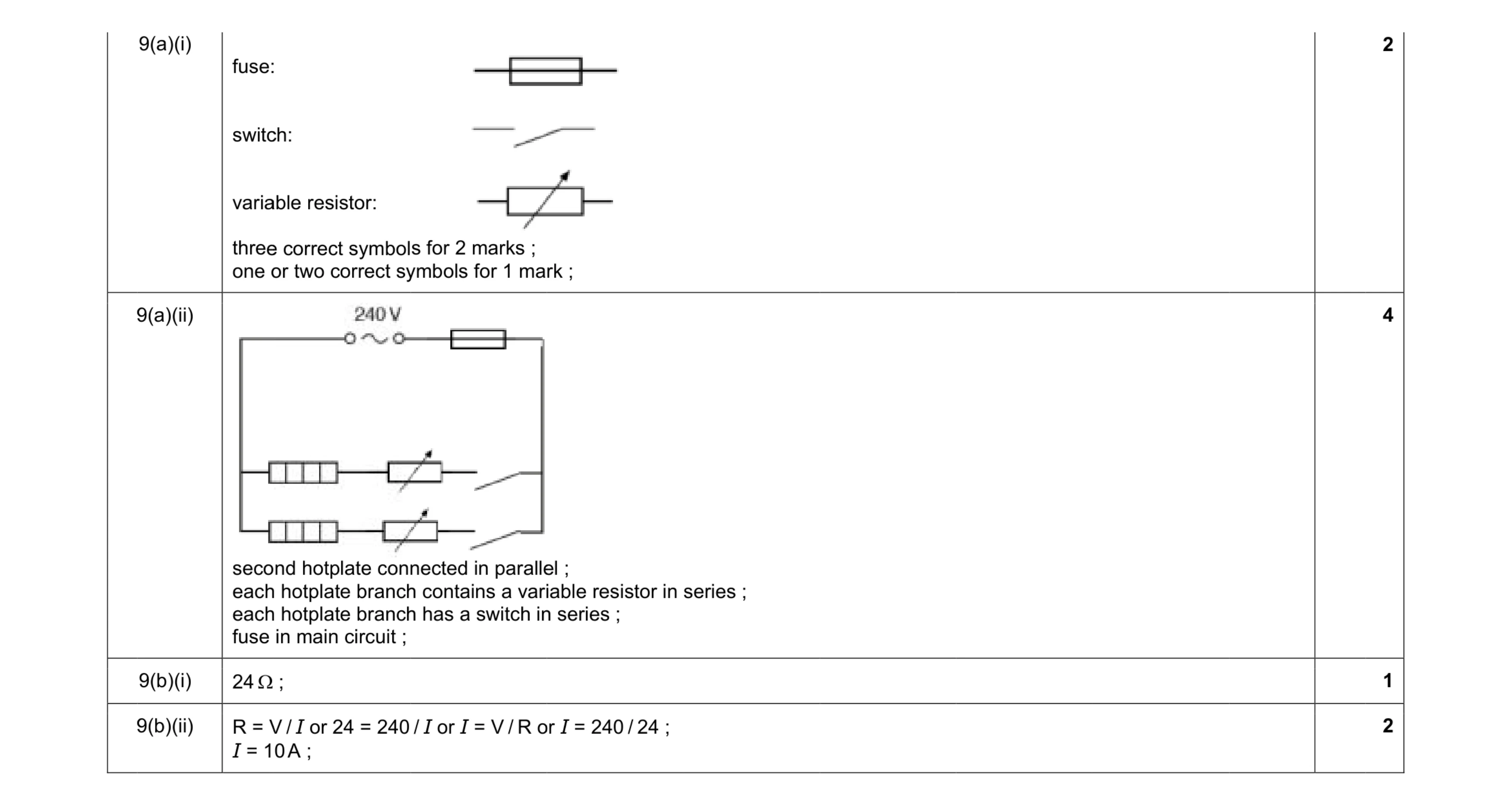 9
9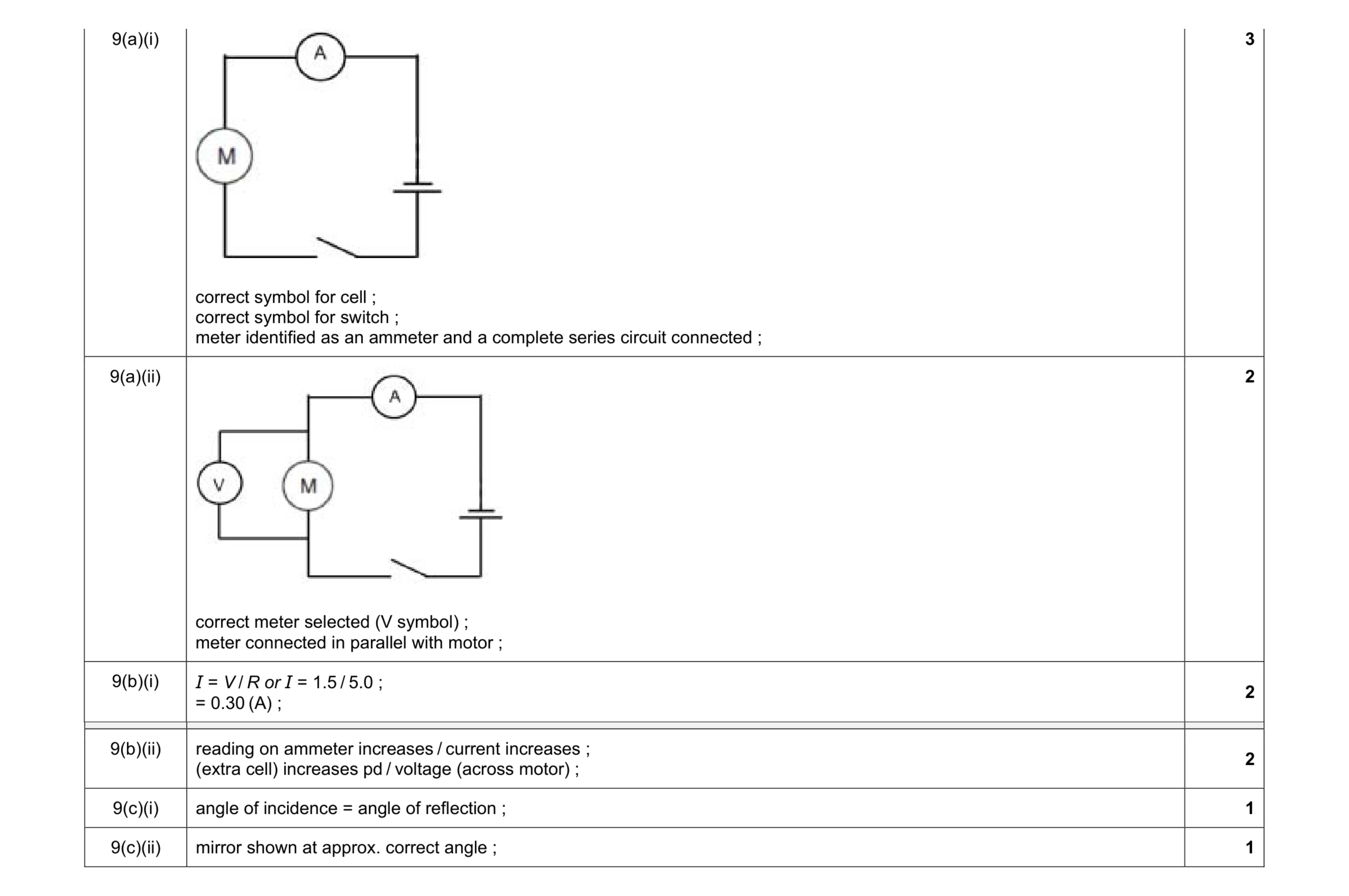 11
11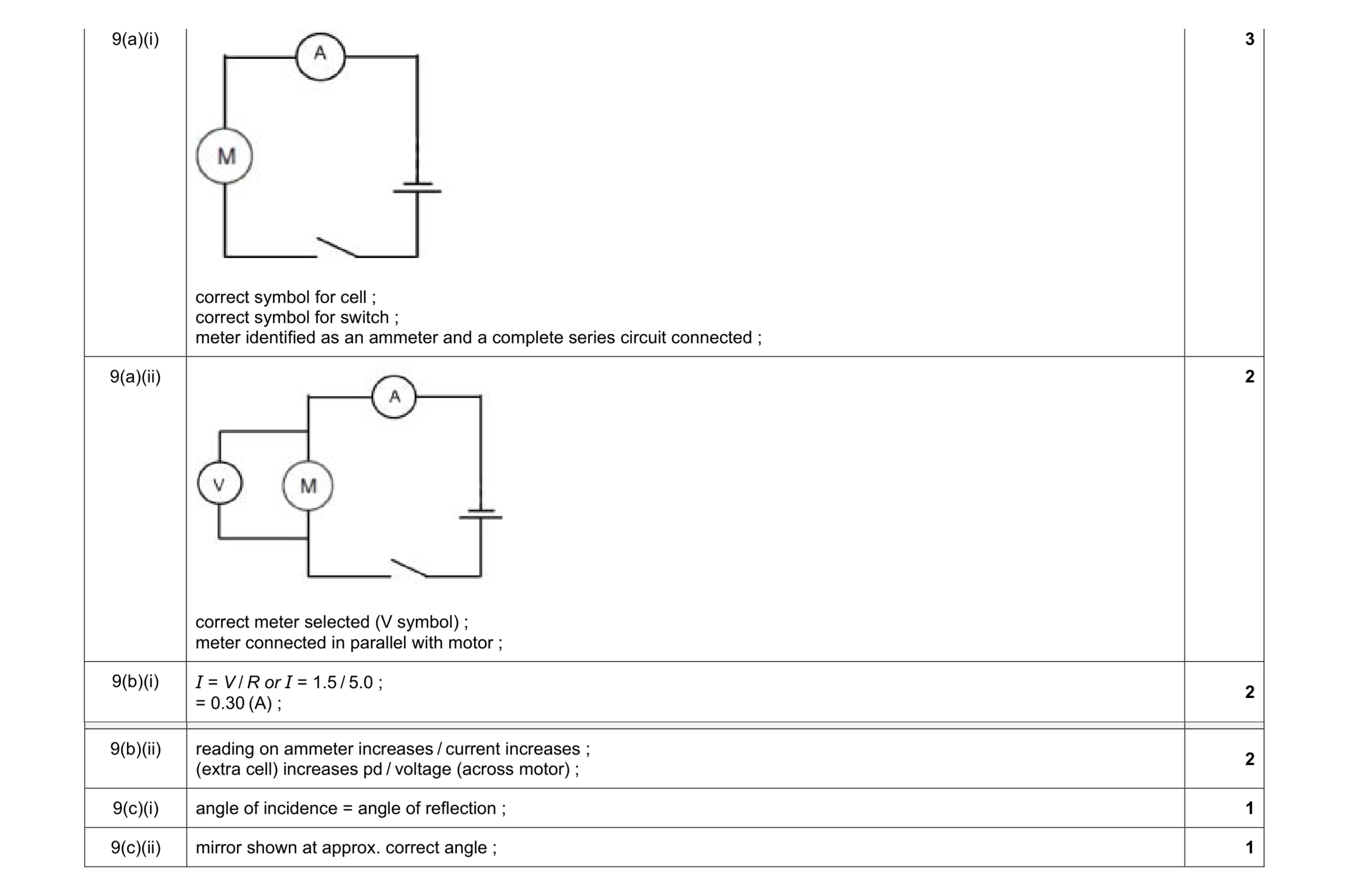 11
11 9
9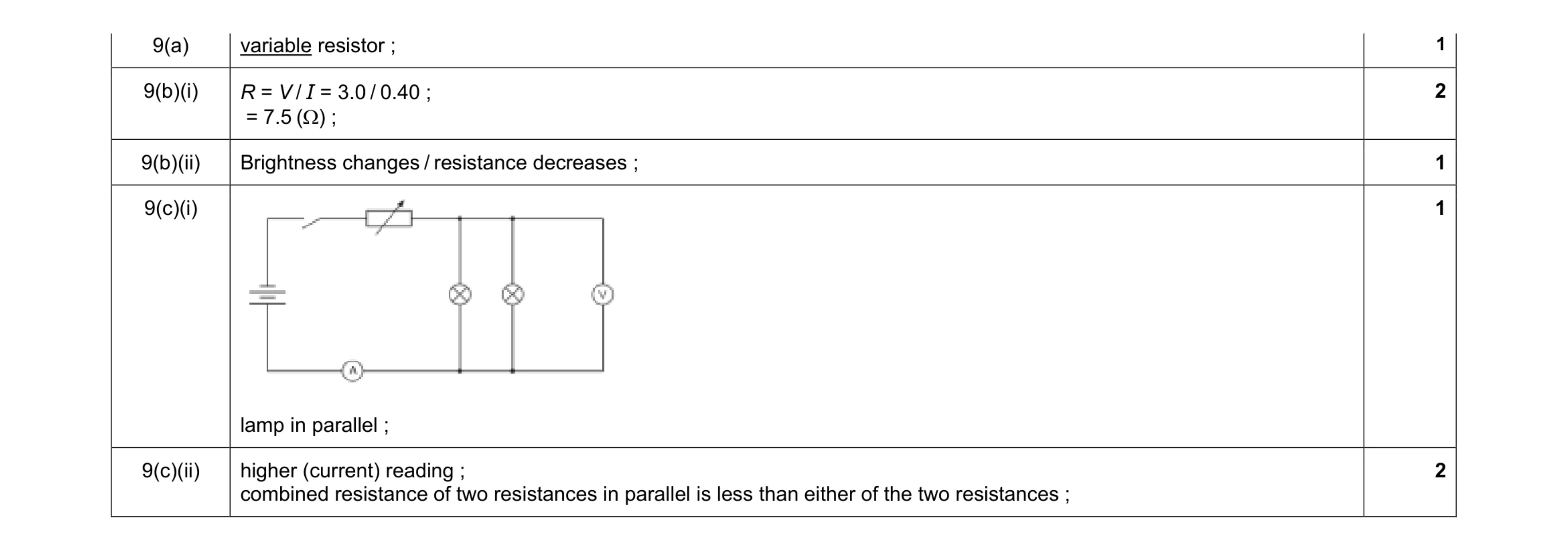 7
7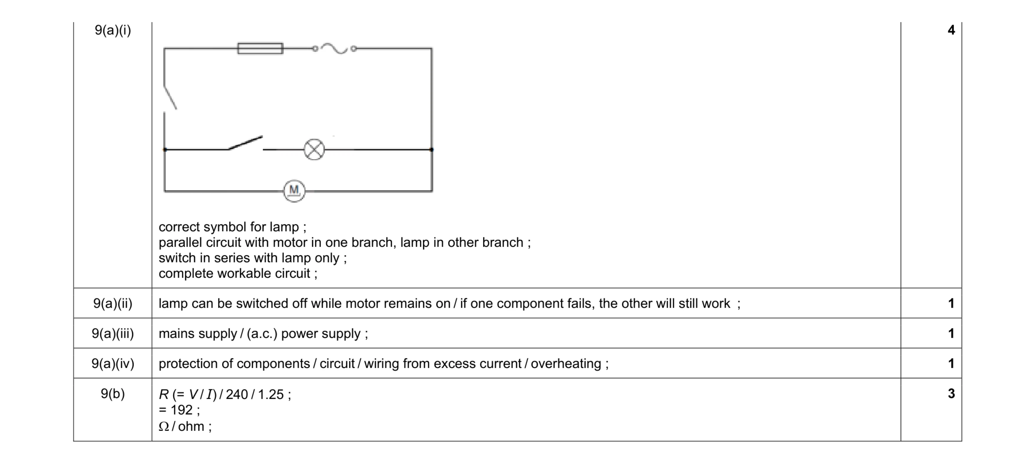 10
10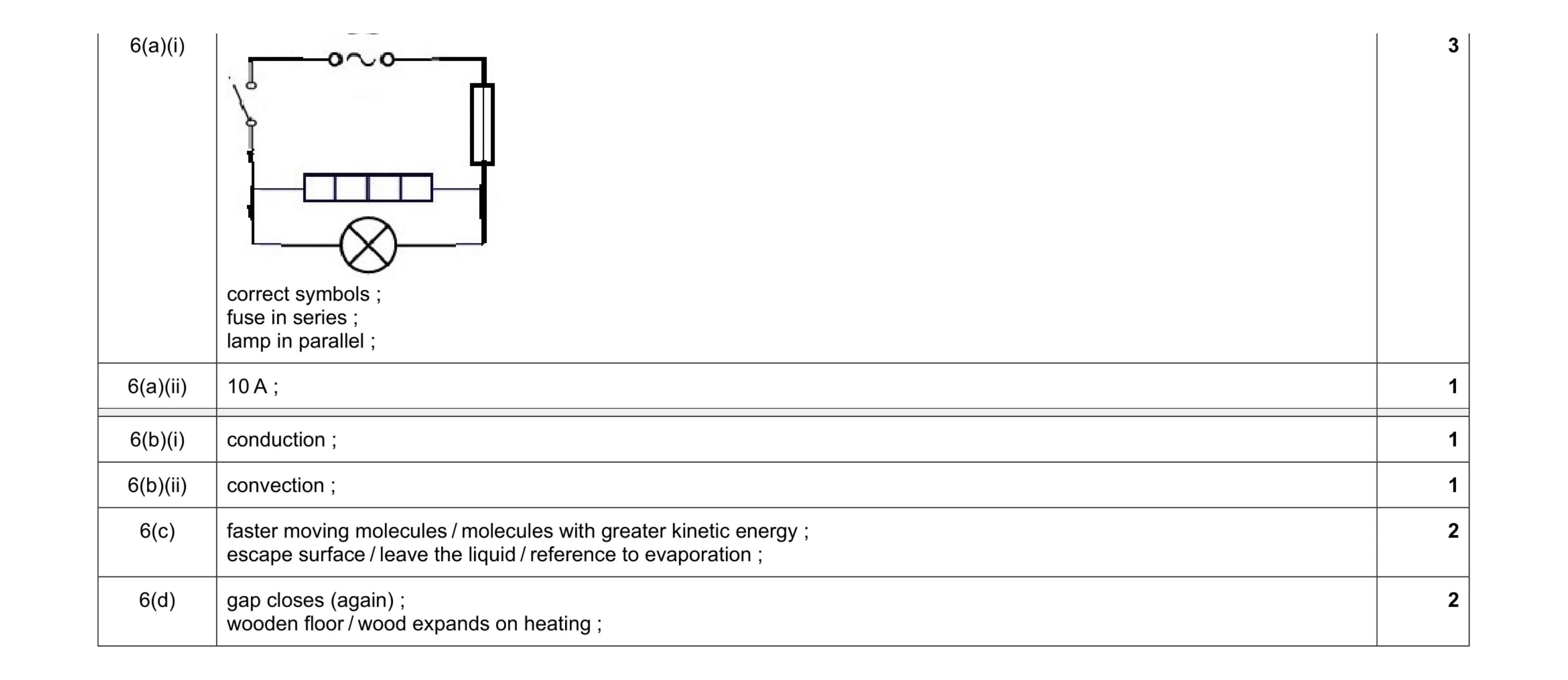 10
10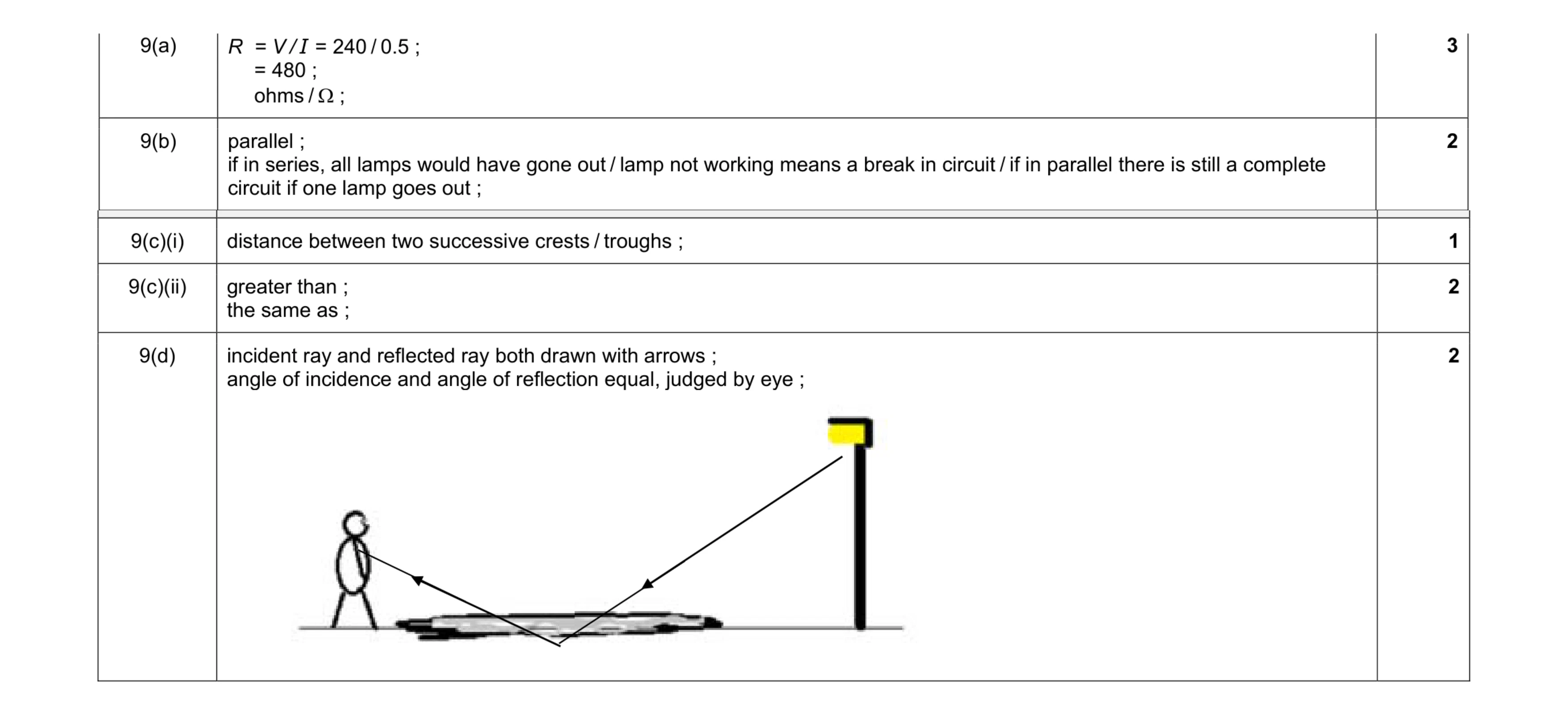 10
10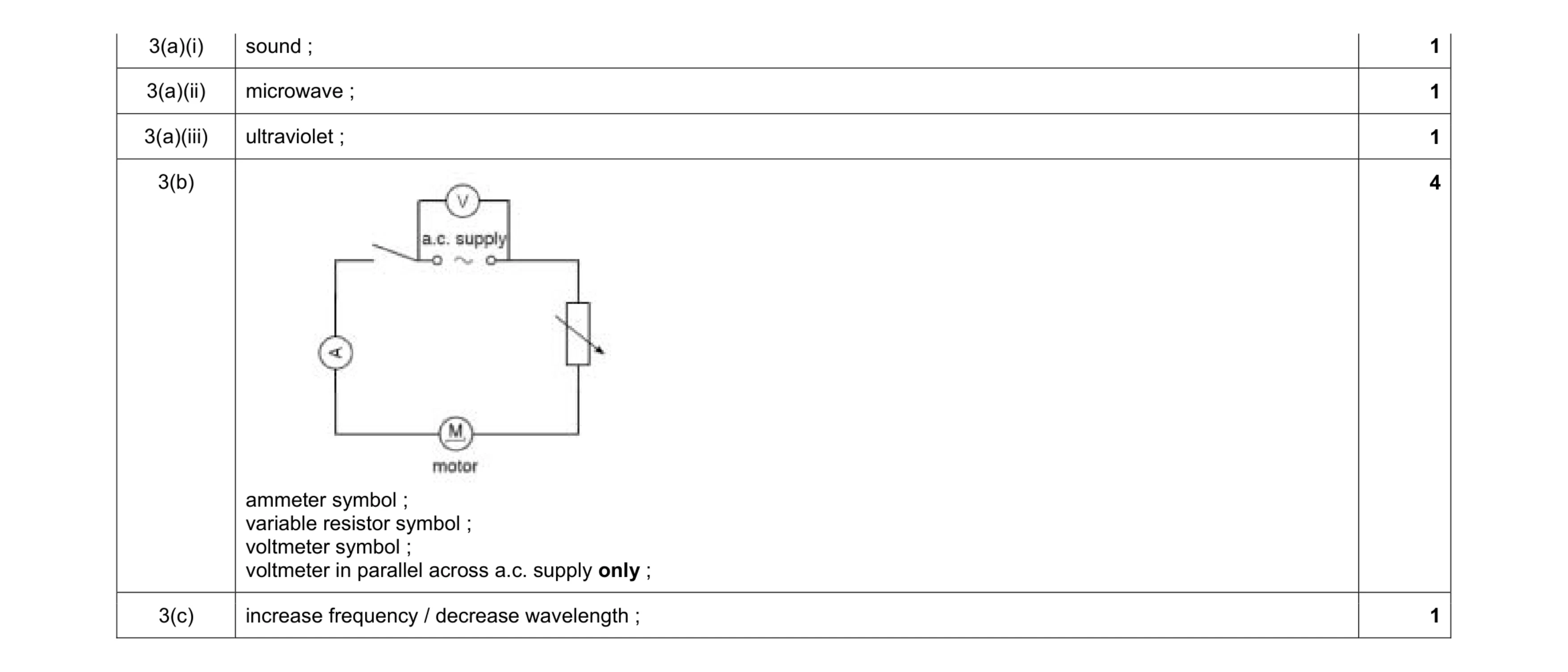 8
8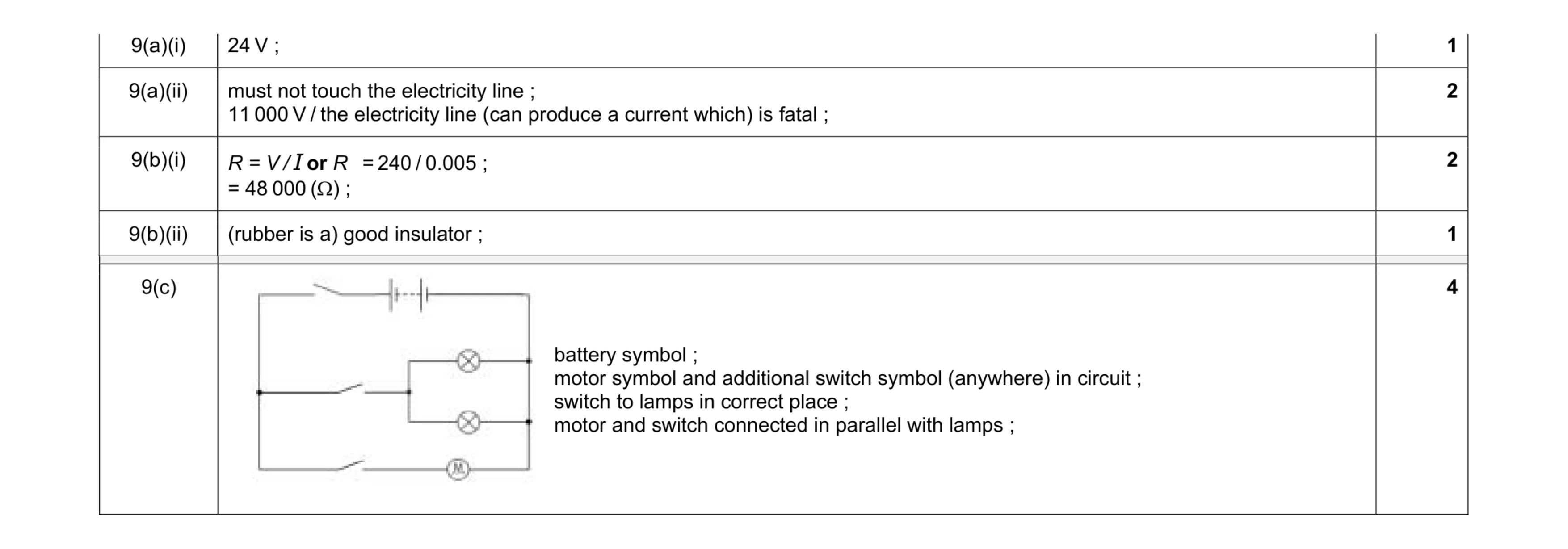 10
10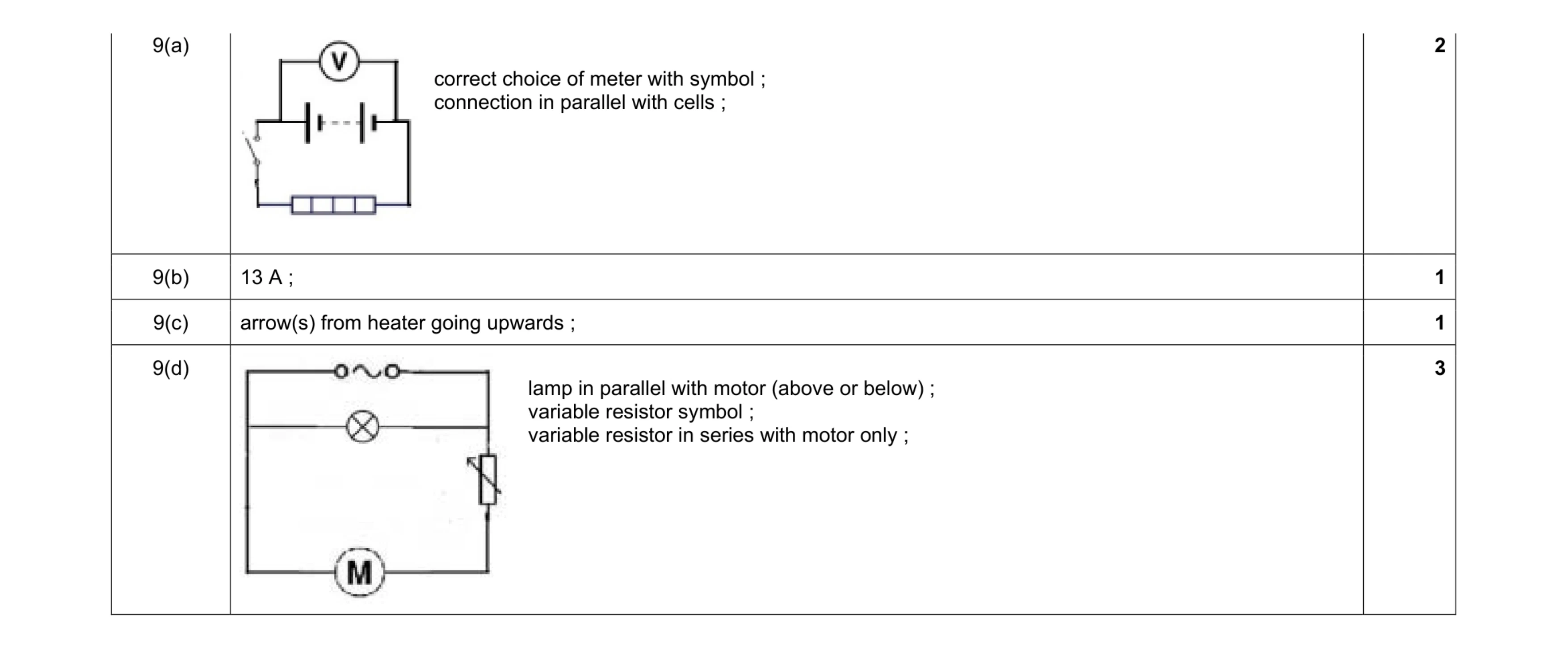 7
7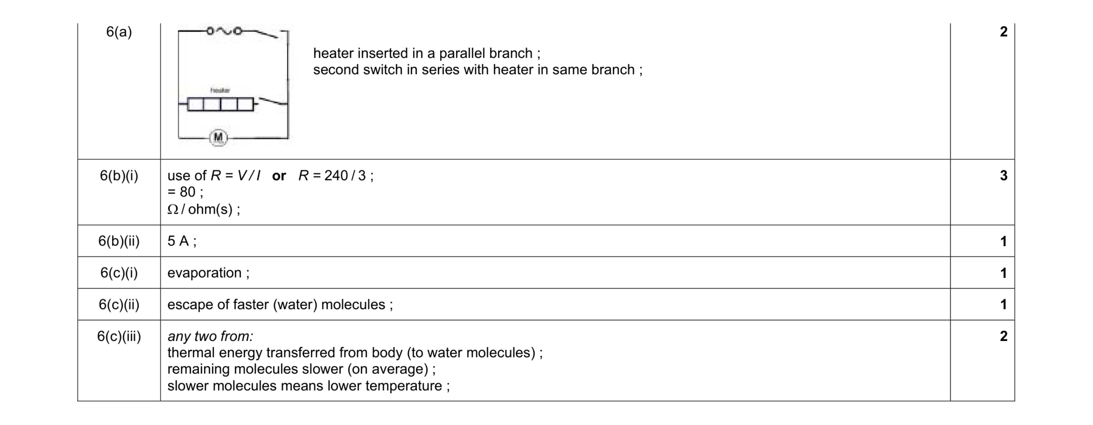 10
10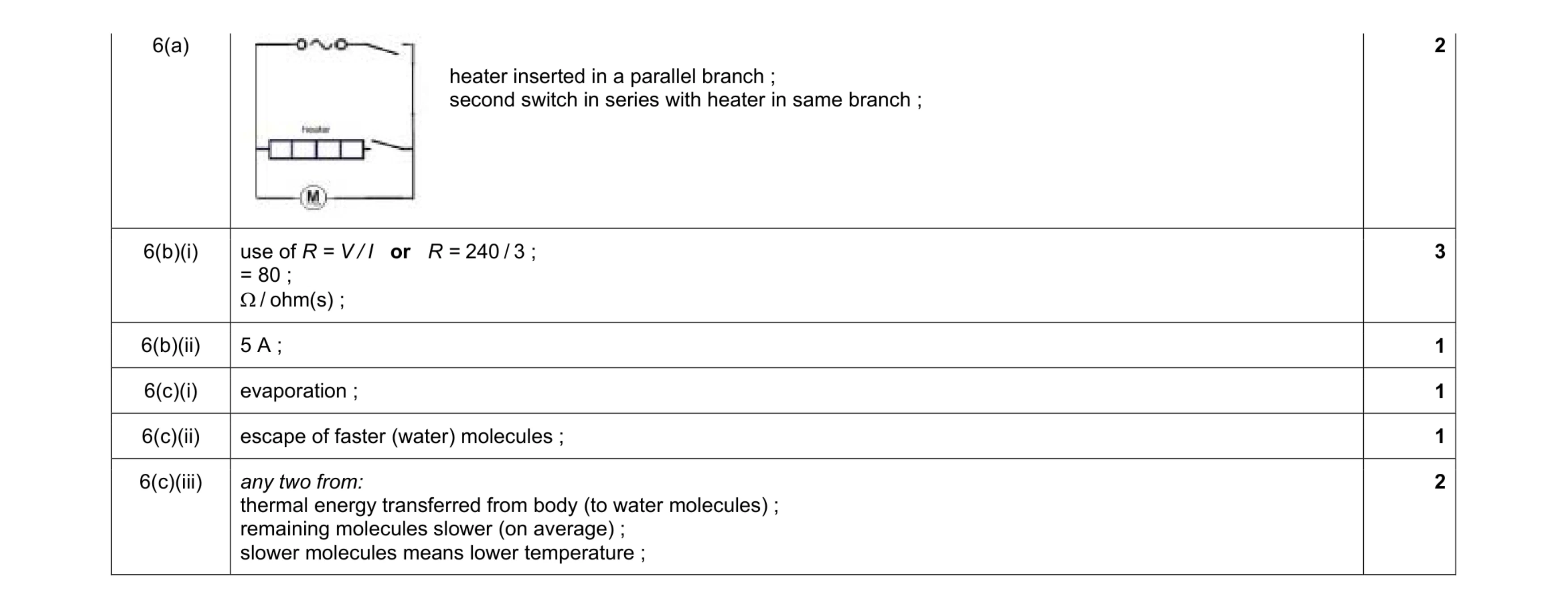 10
10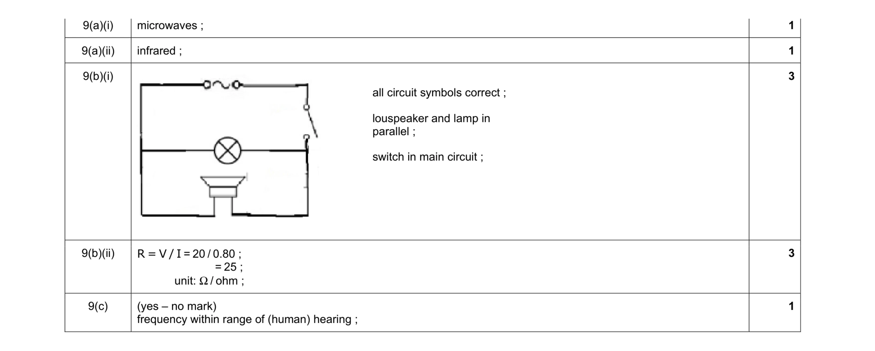 9
9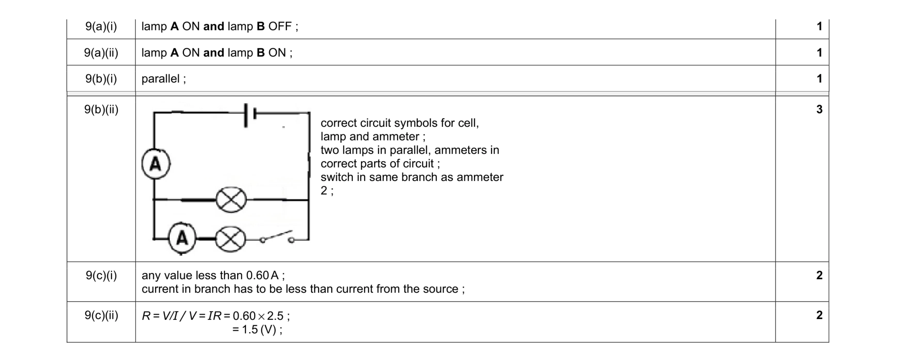 10
10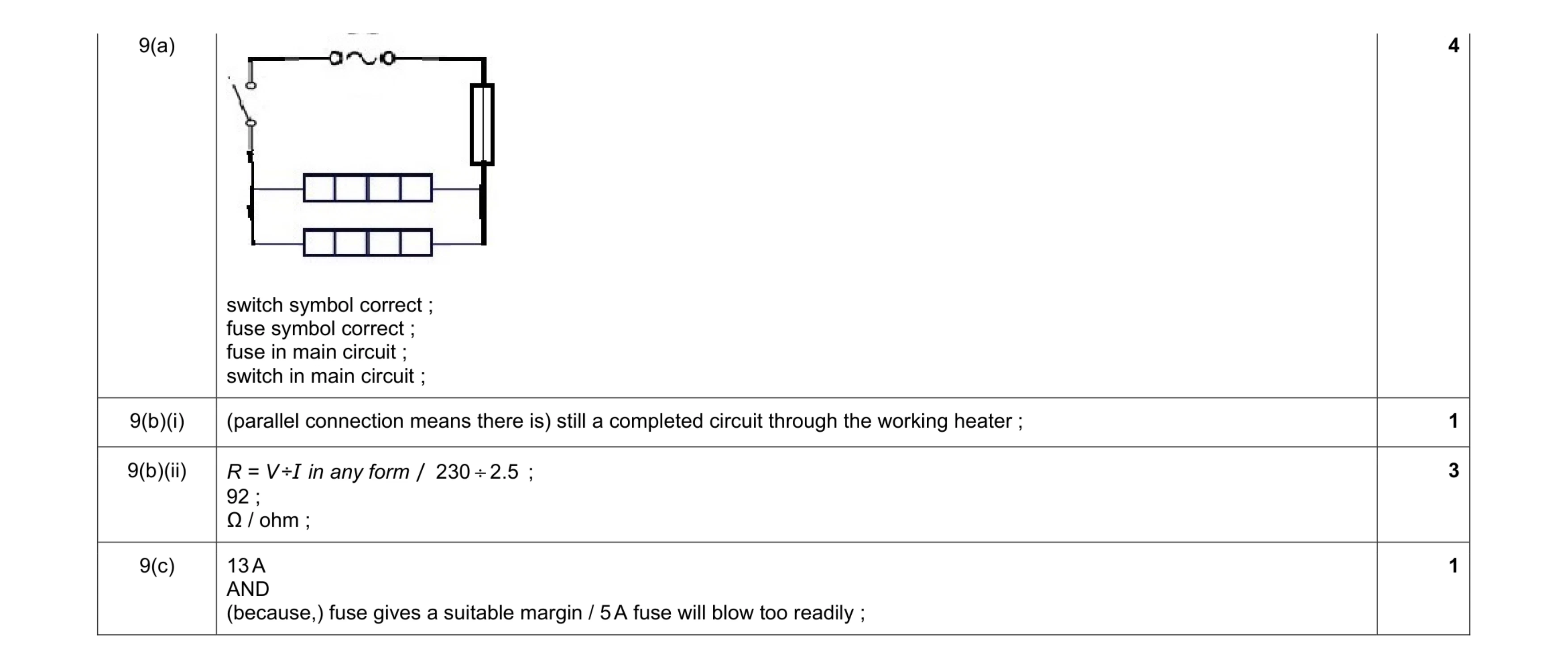 9
9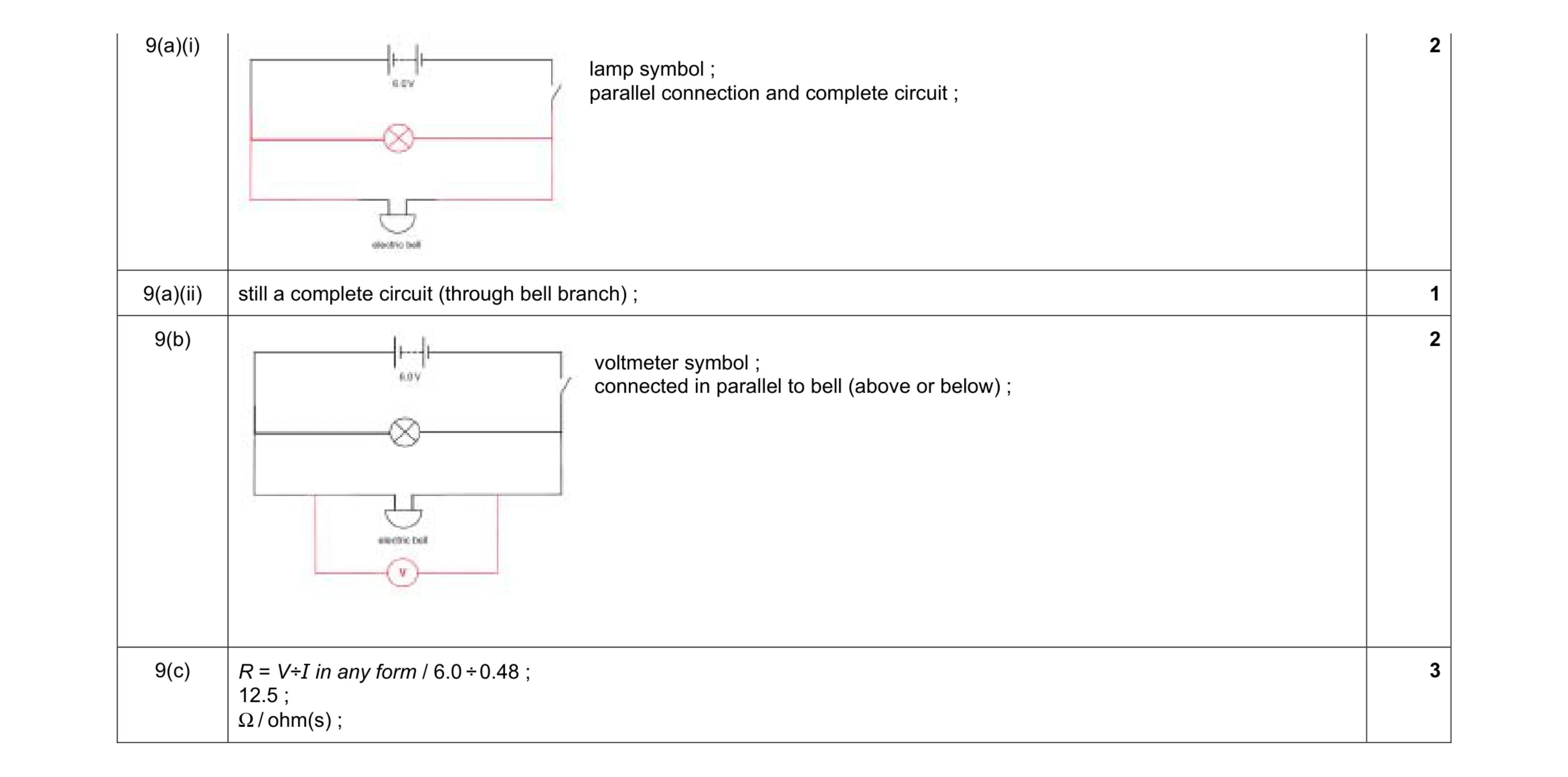 8
8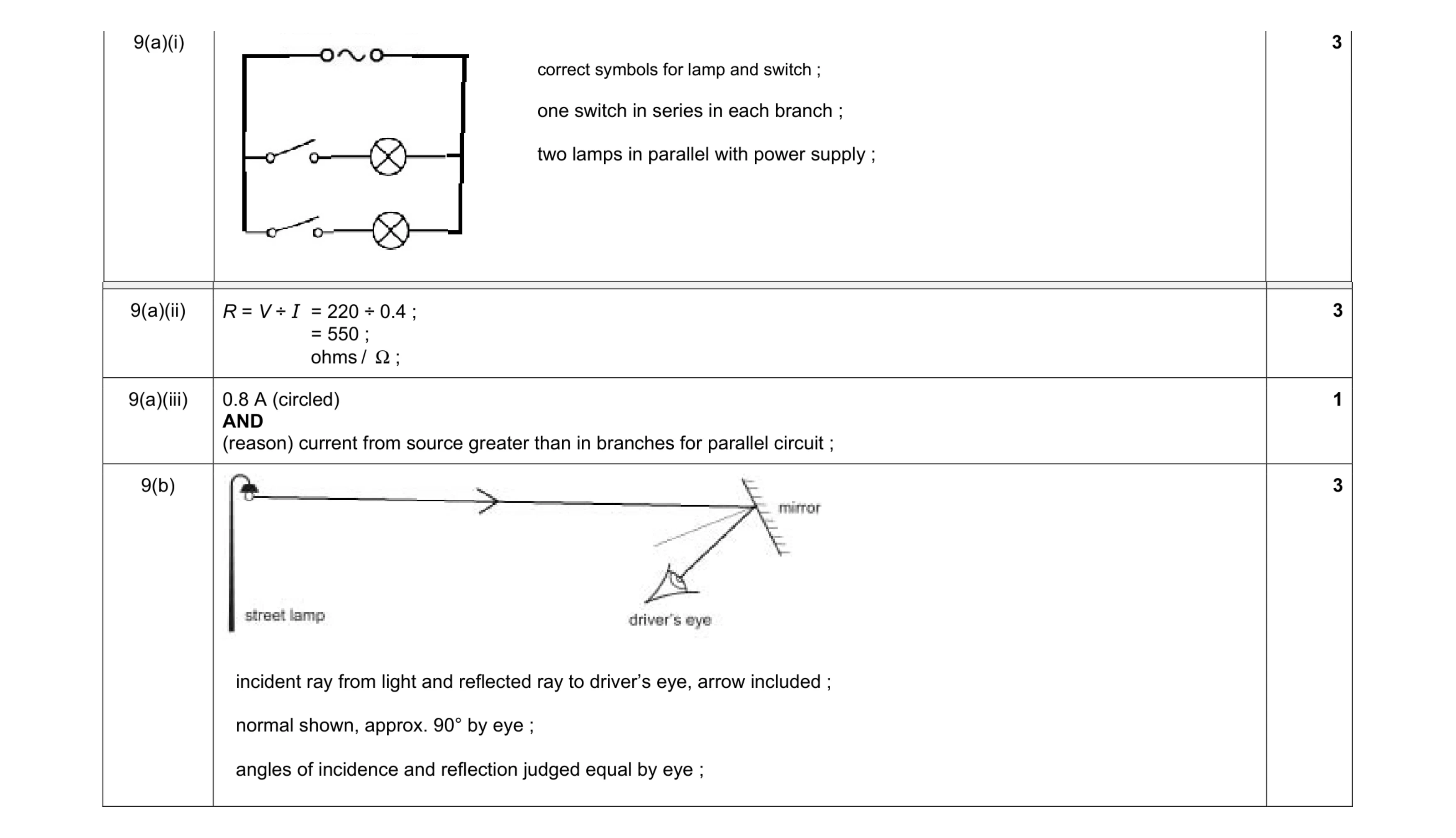 10
10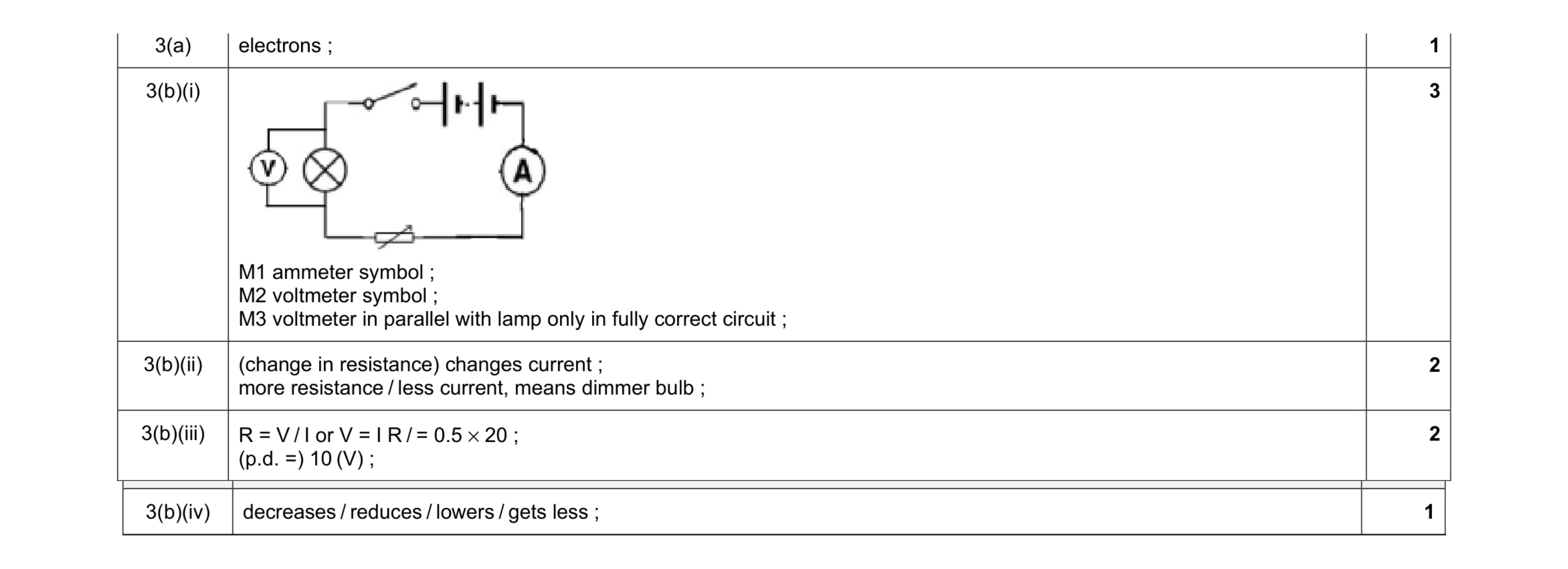 9
9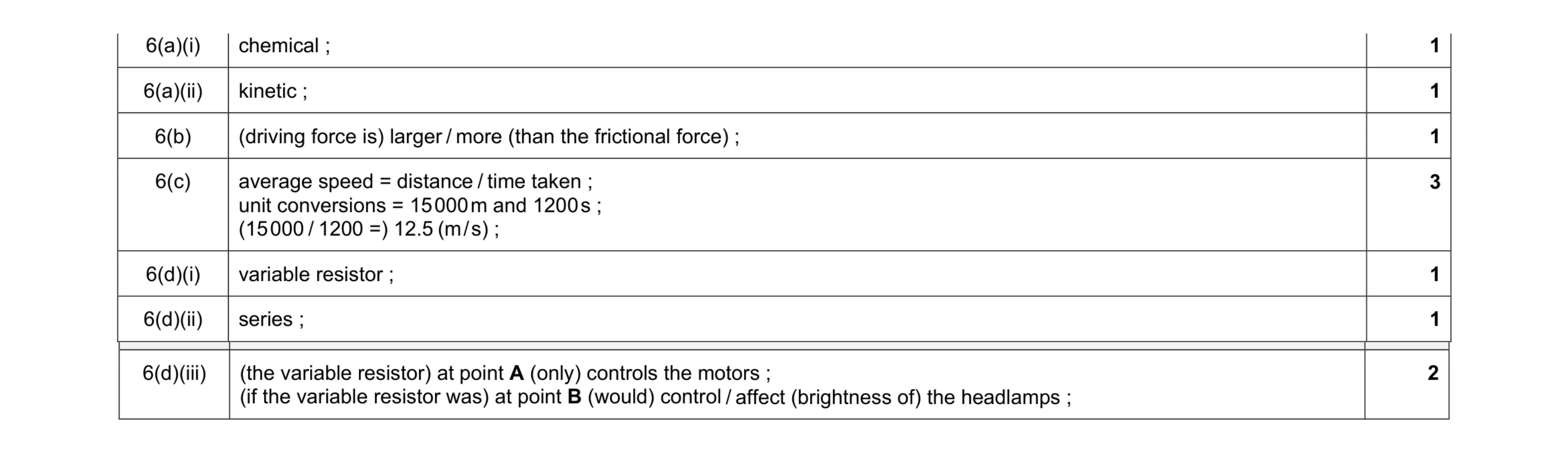 10
10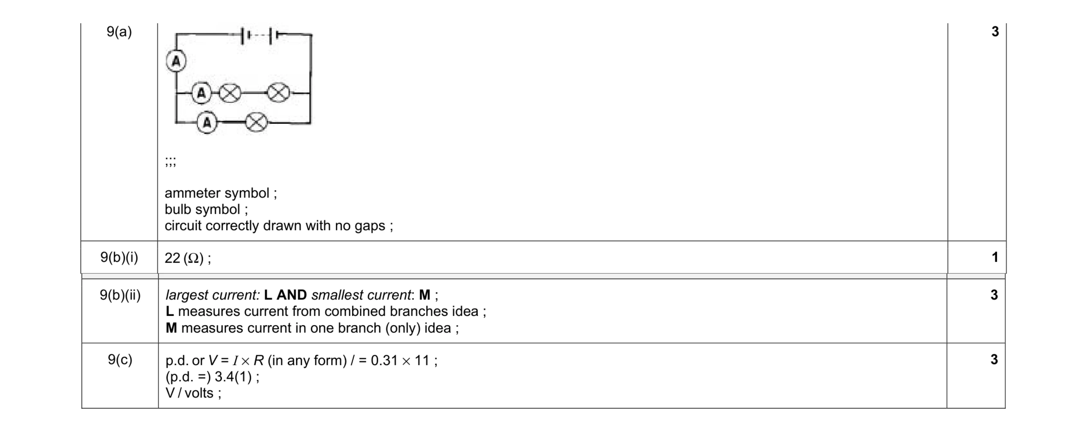 10
10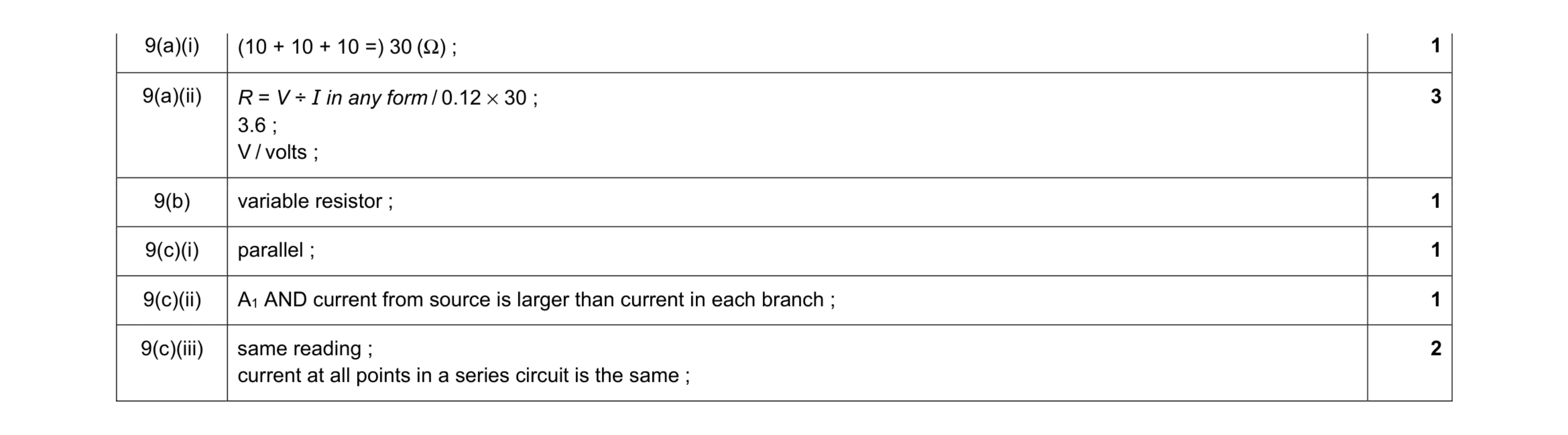 9
9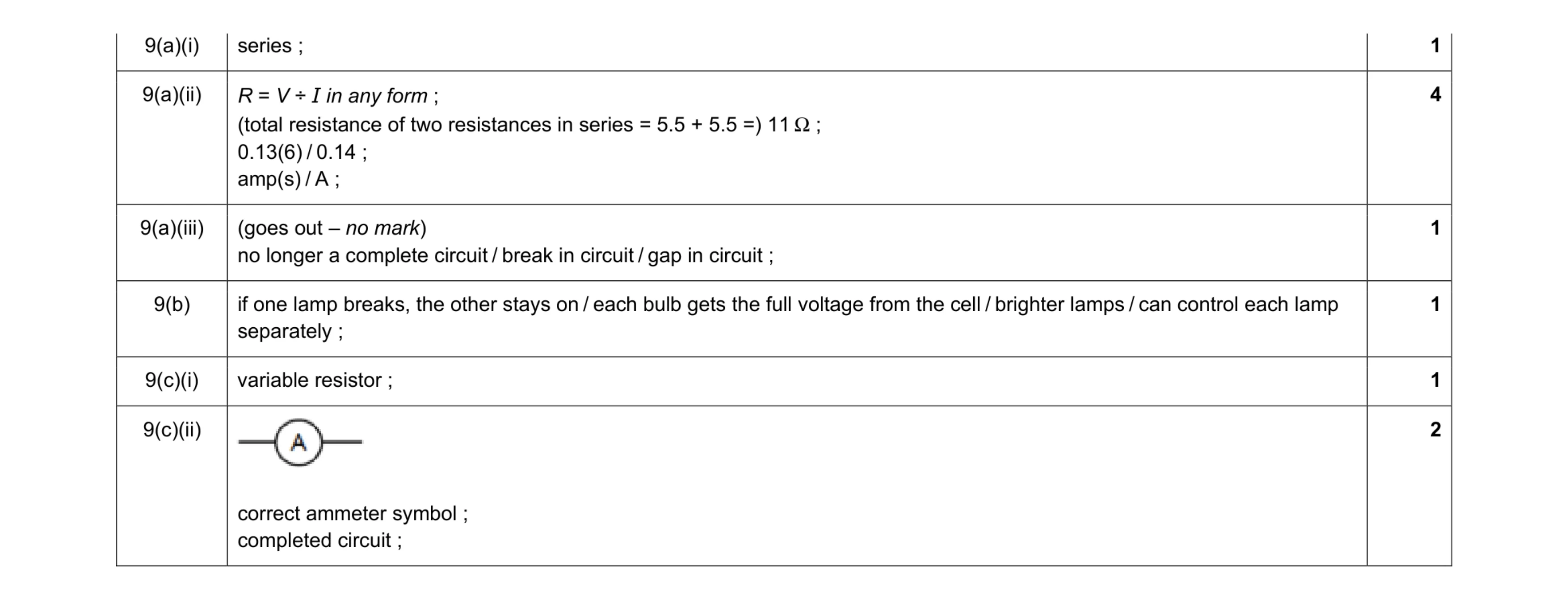 10
10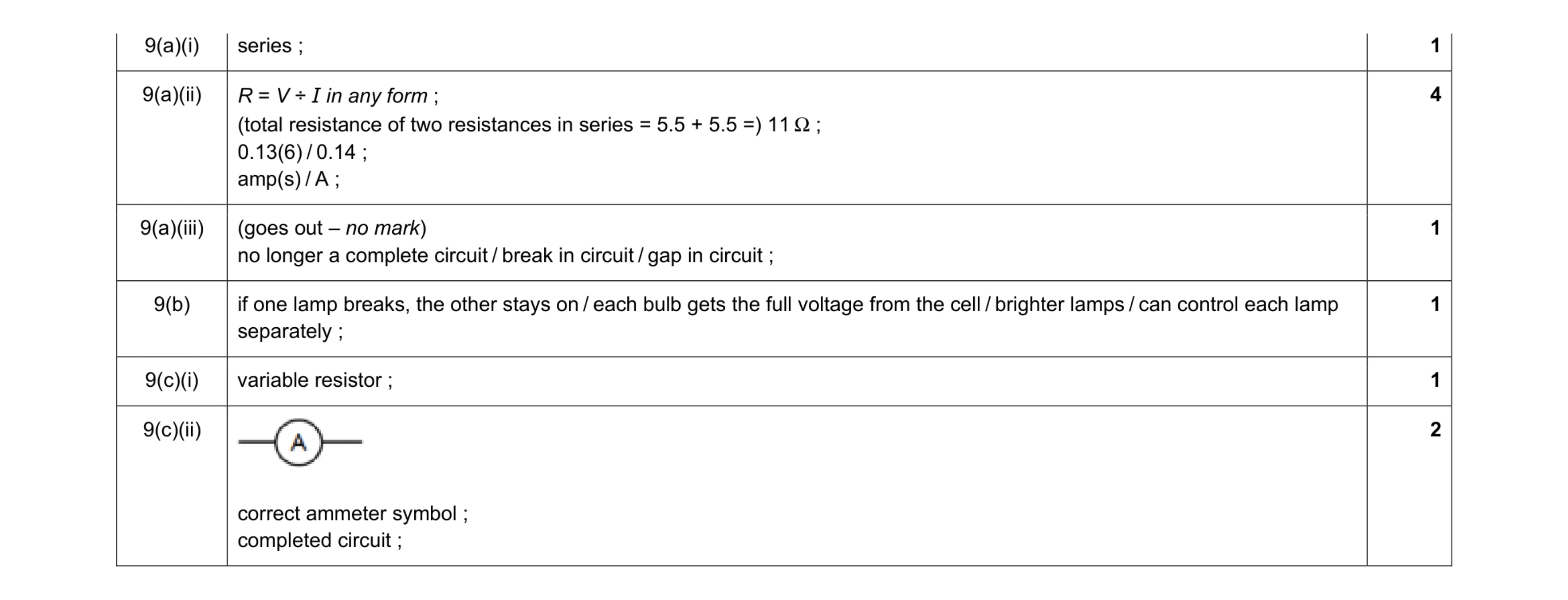 10
10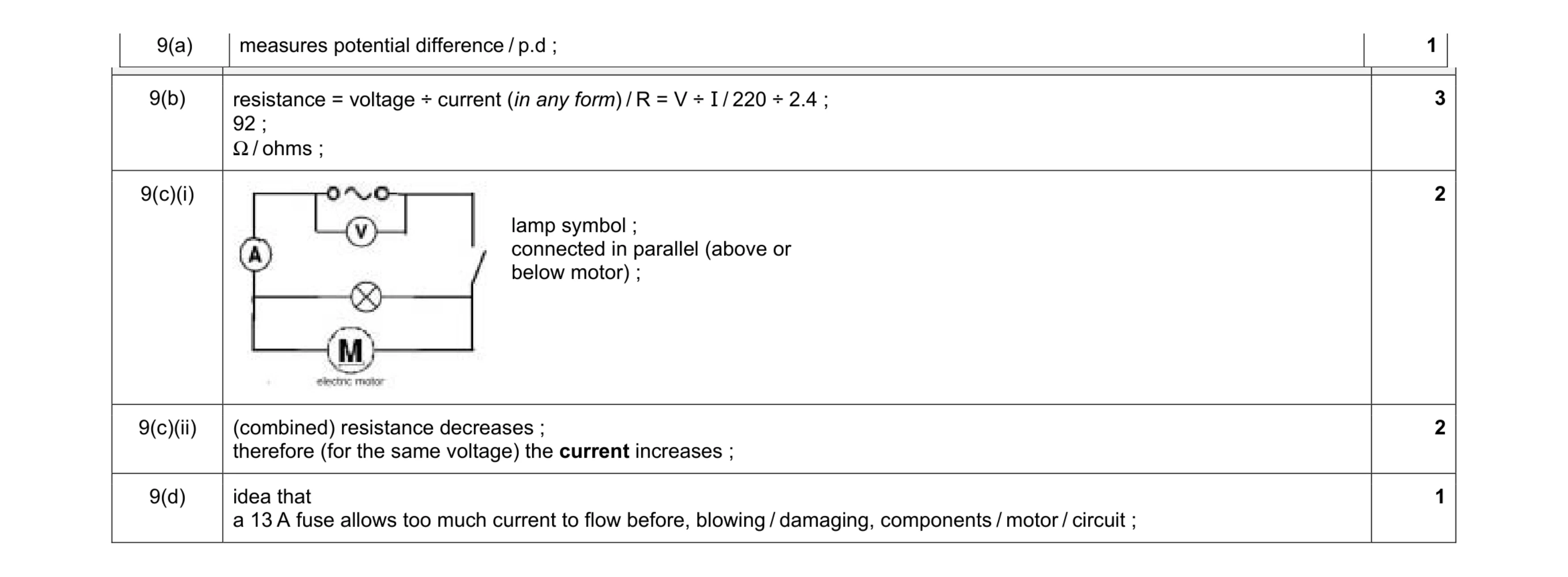 9
9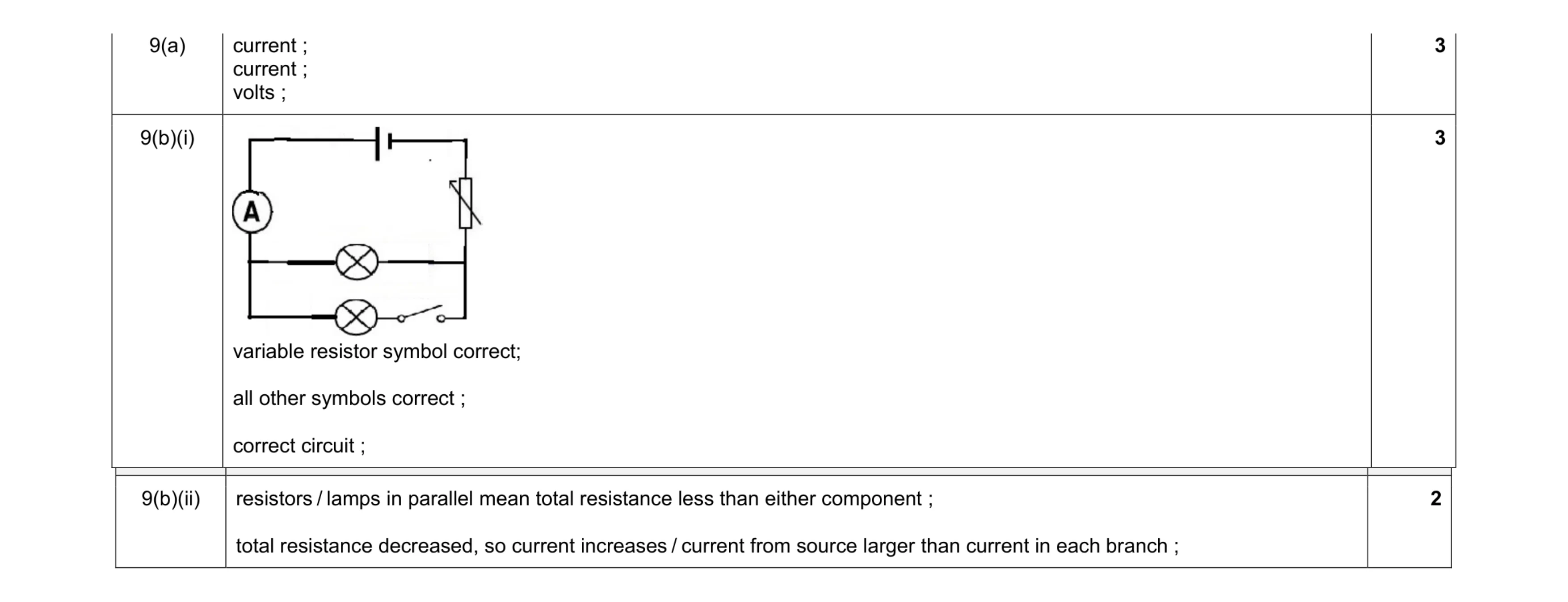 8
8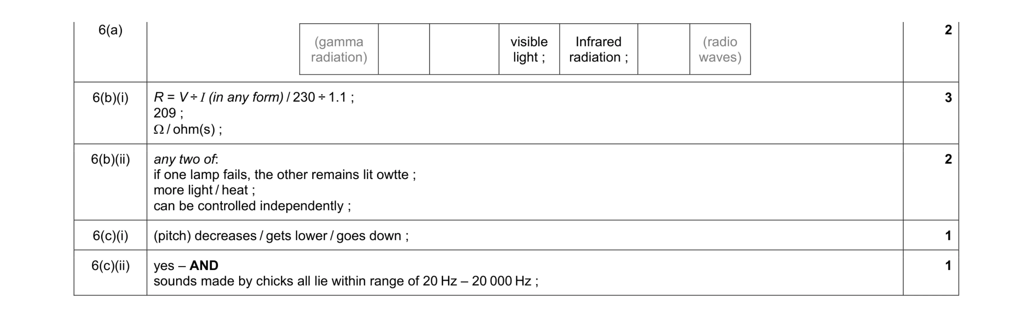 9
9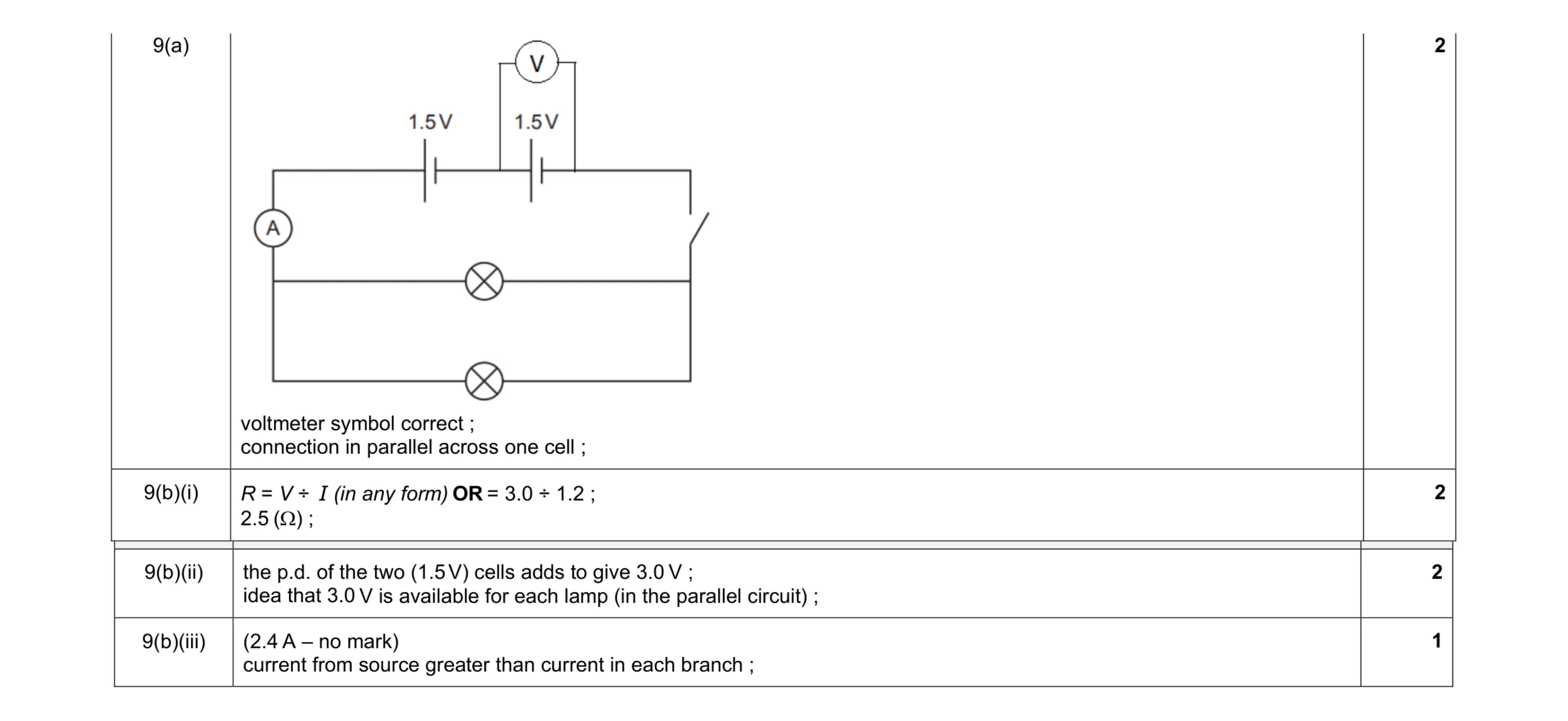 7
7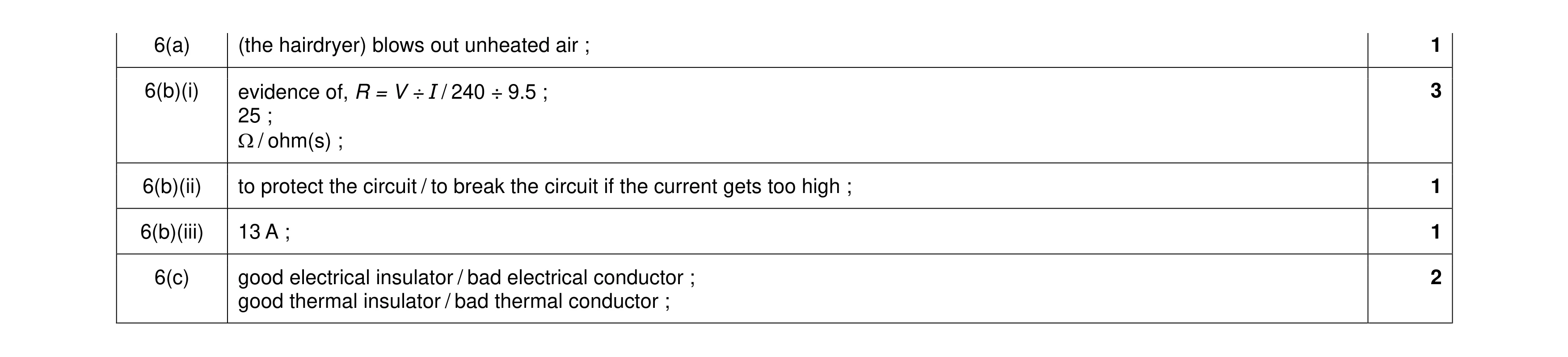 8
8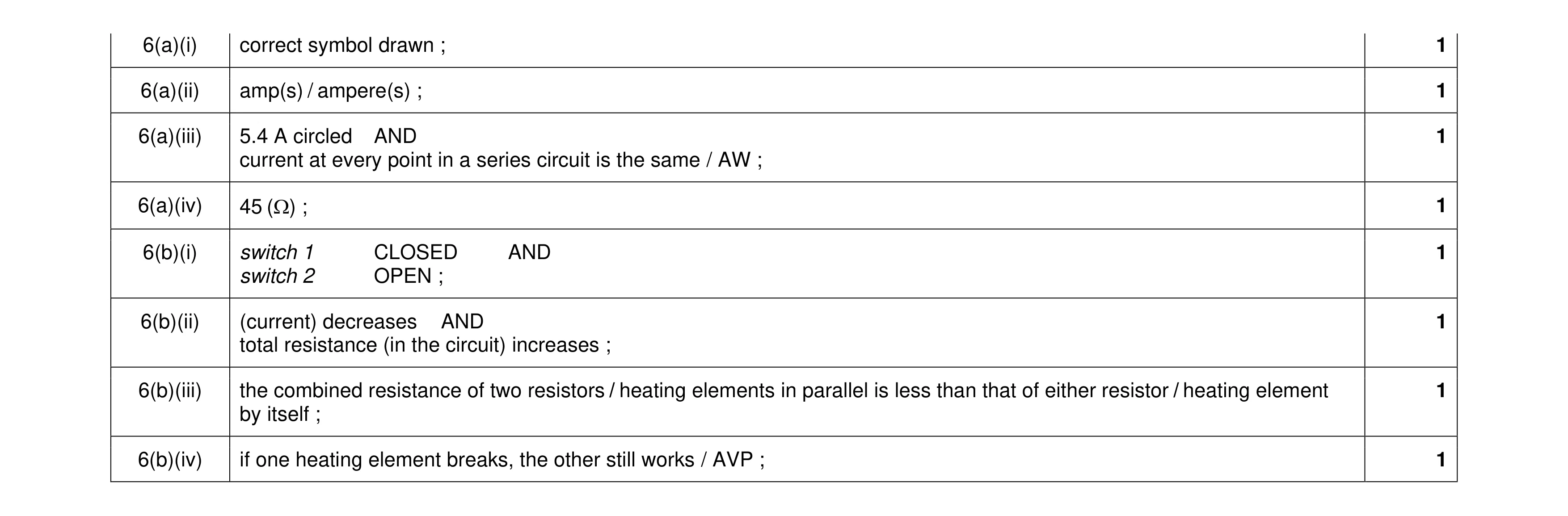 8
8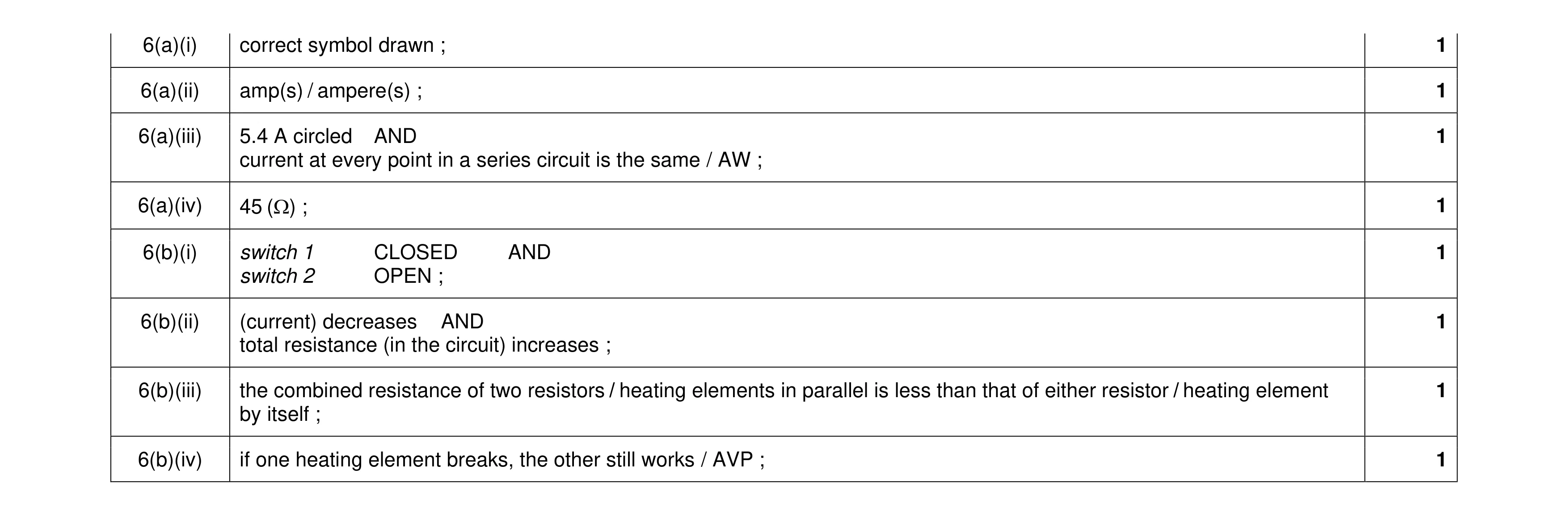 8
8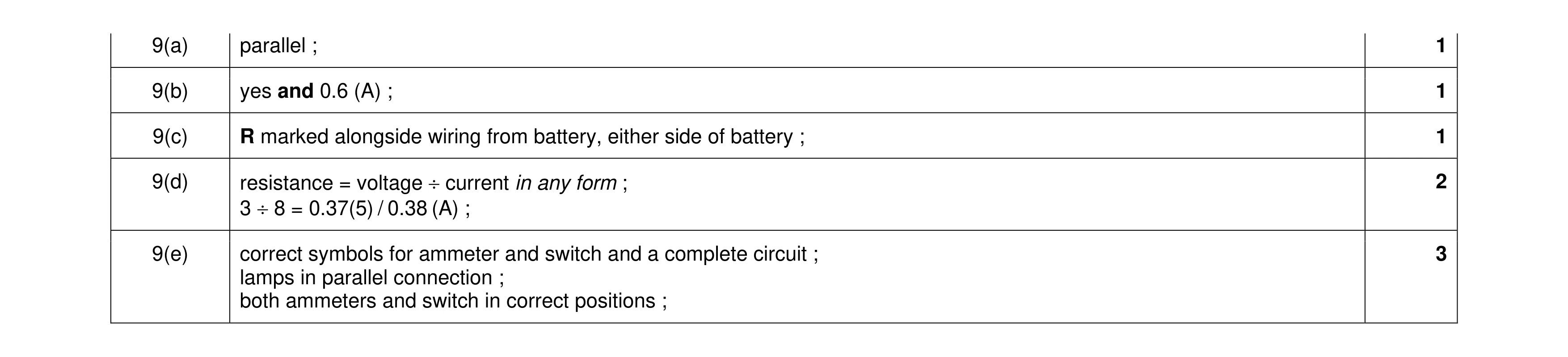 8
8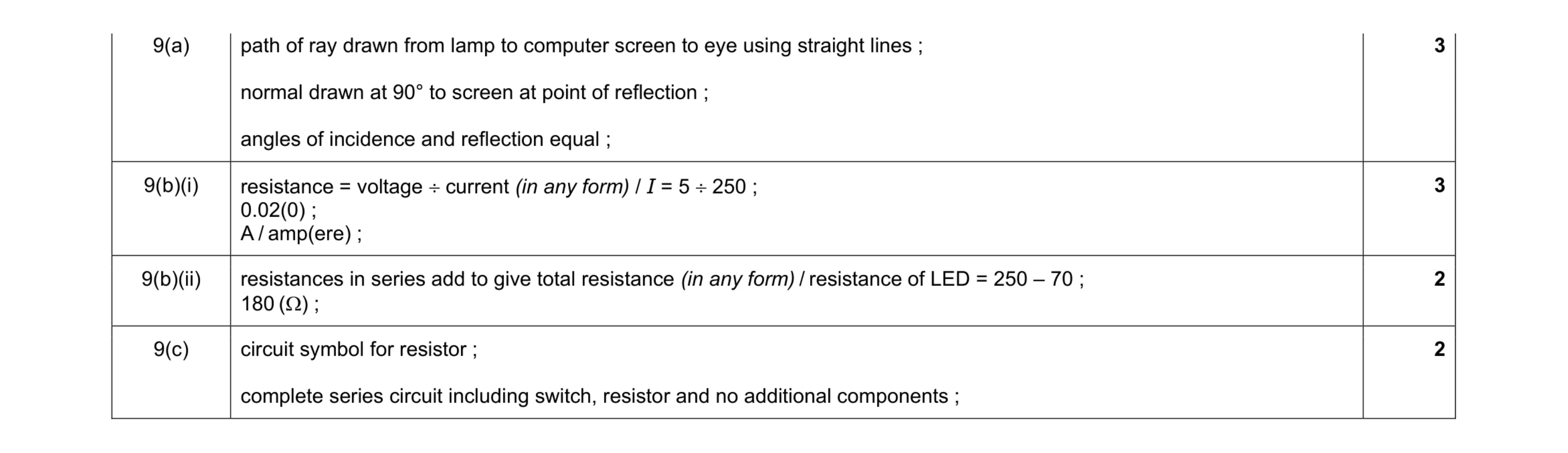 10
10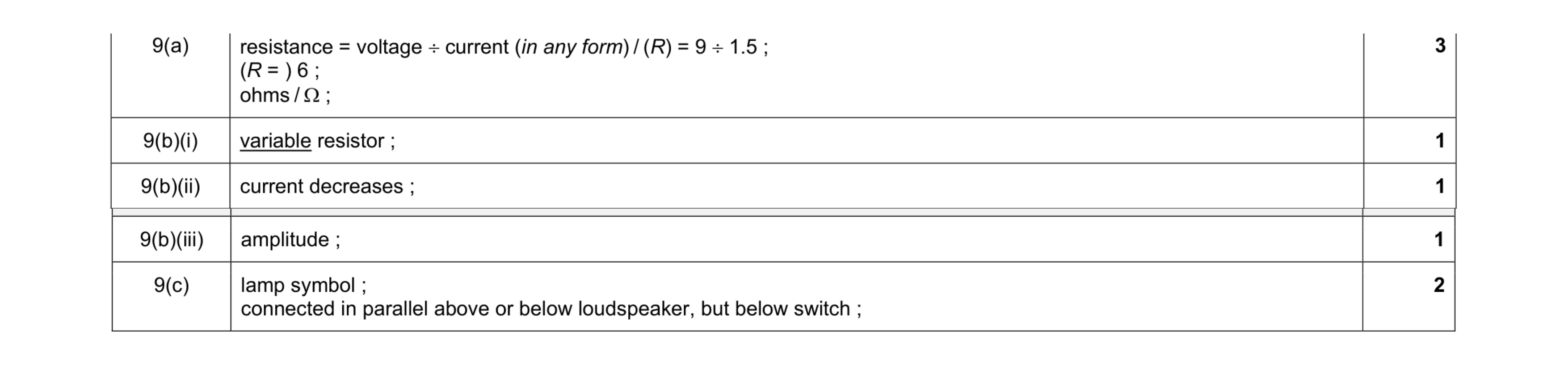 8
8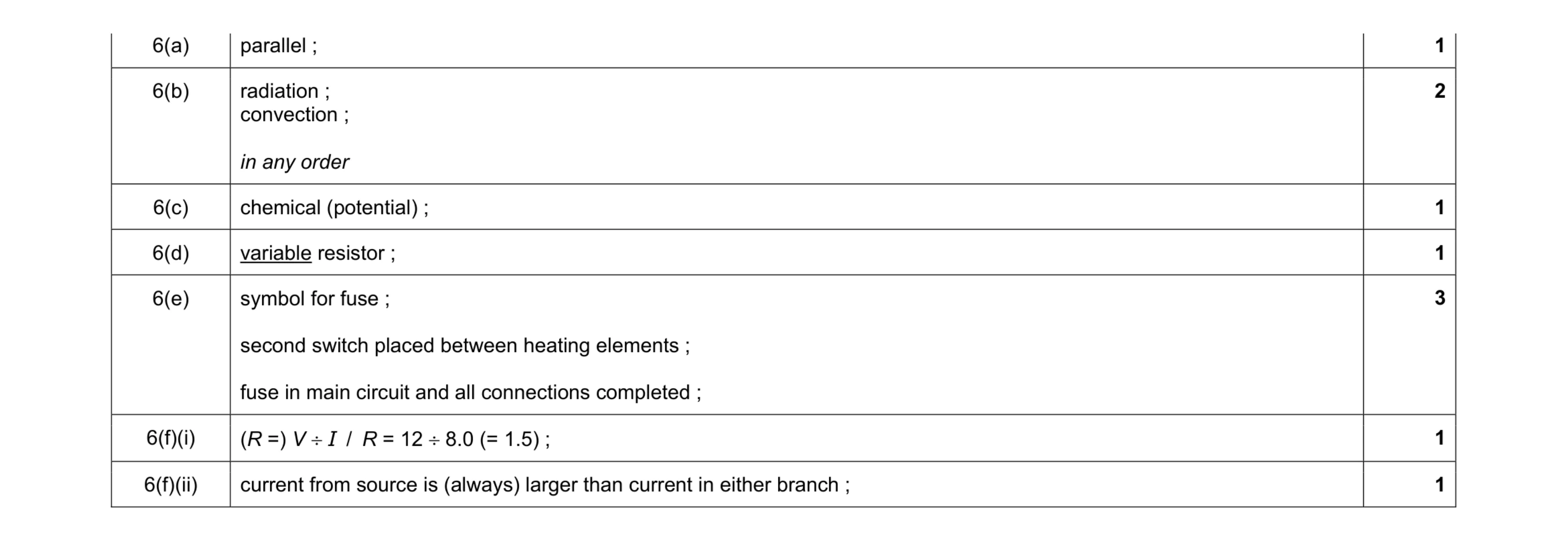 10
10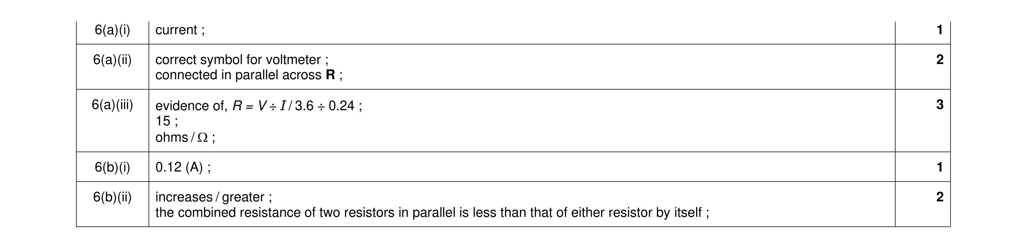 9
9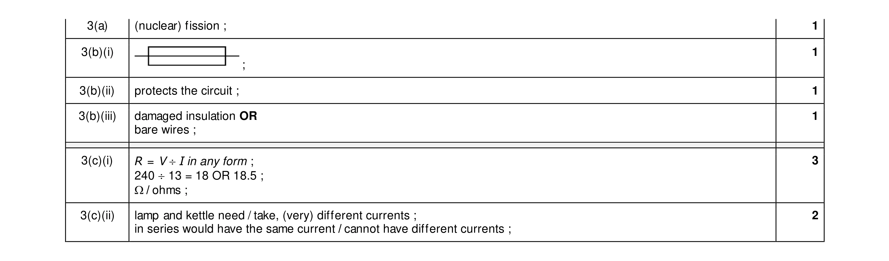 9
9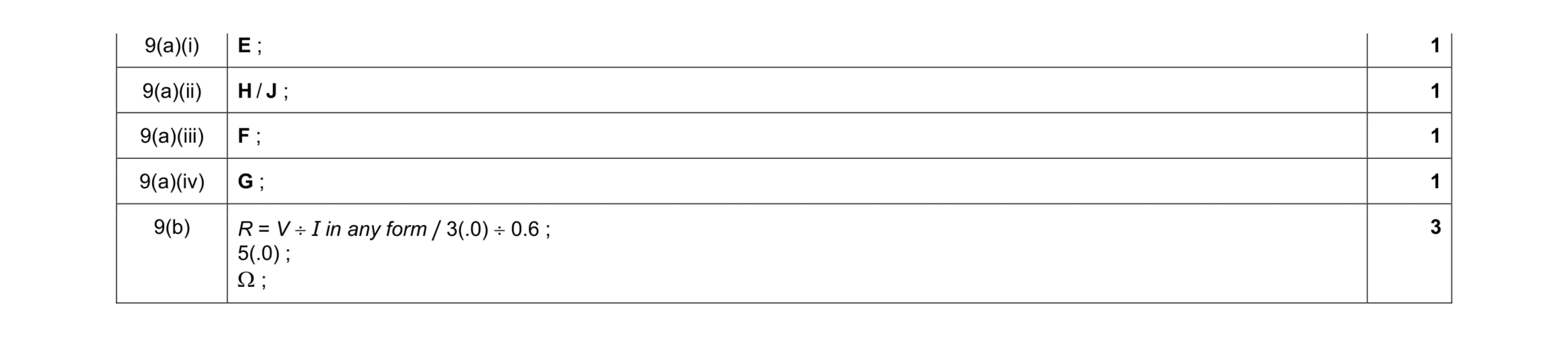 7
7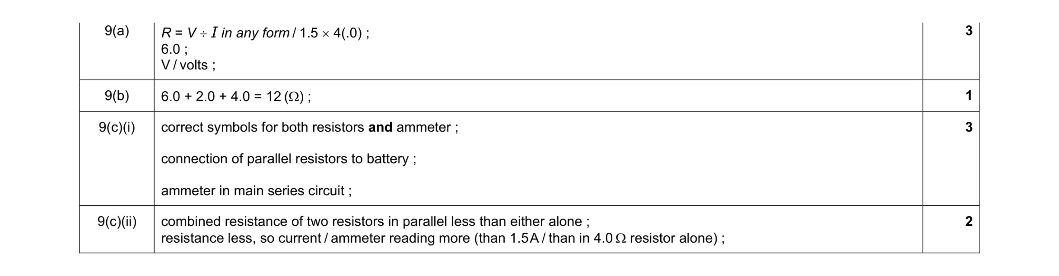 9
9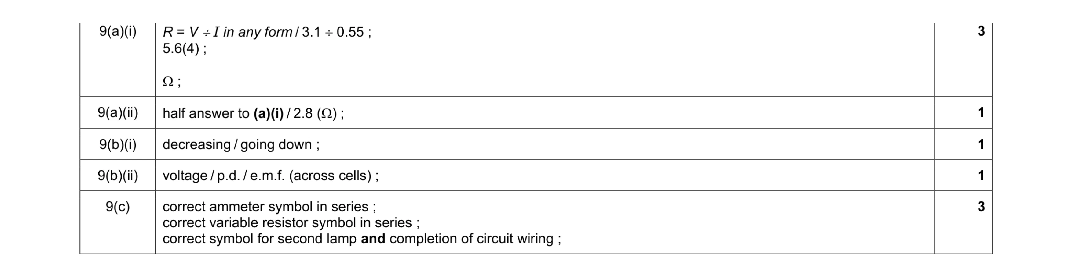 9
9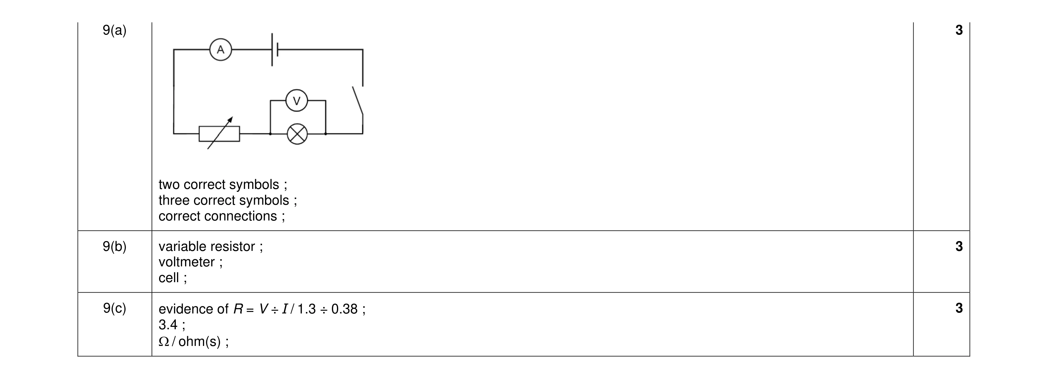 9
9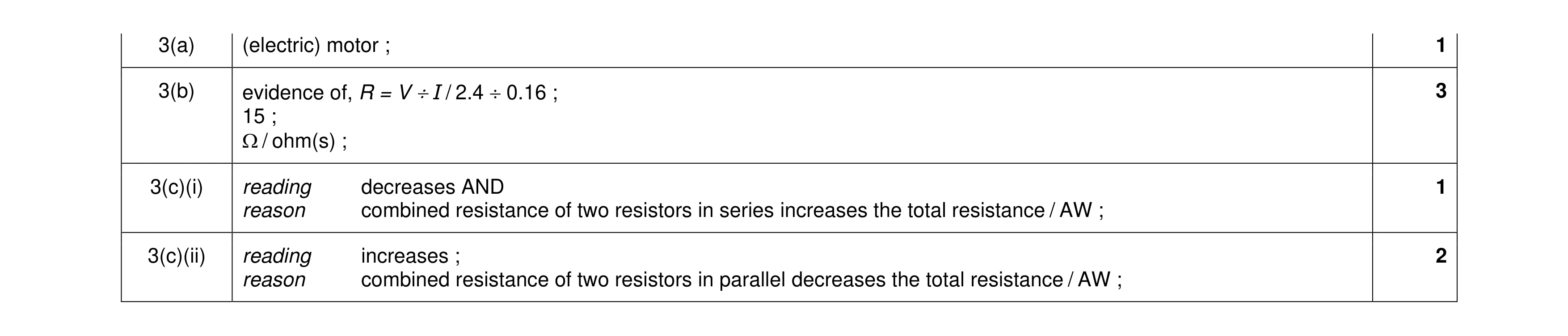 7
7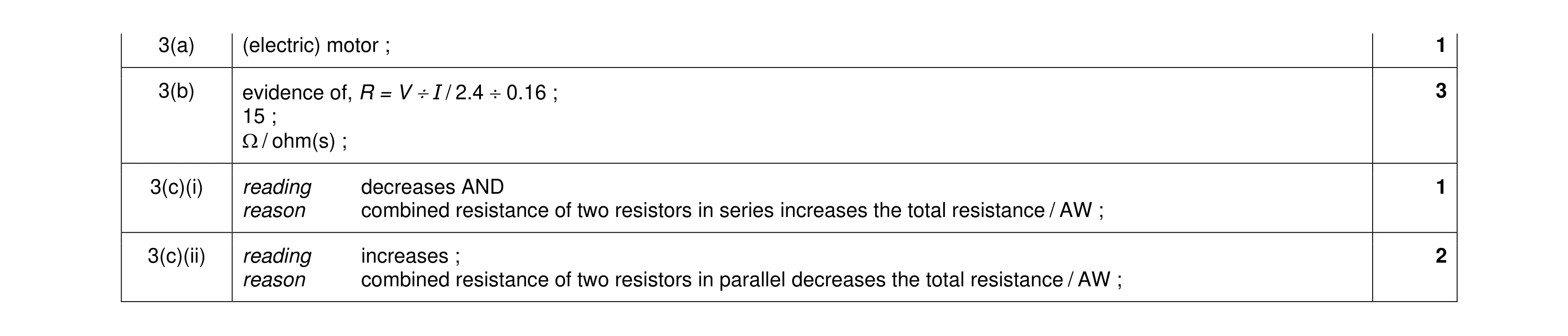 7
7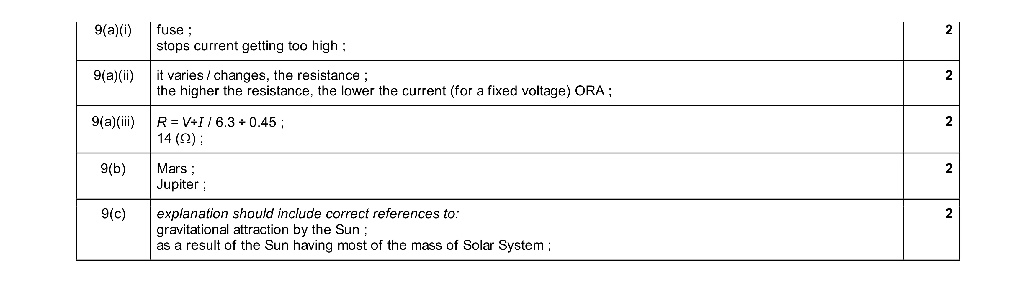 10
10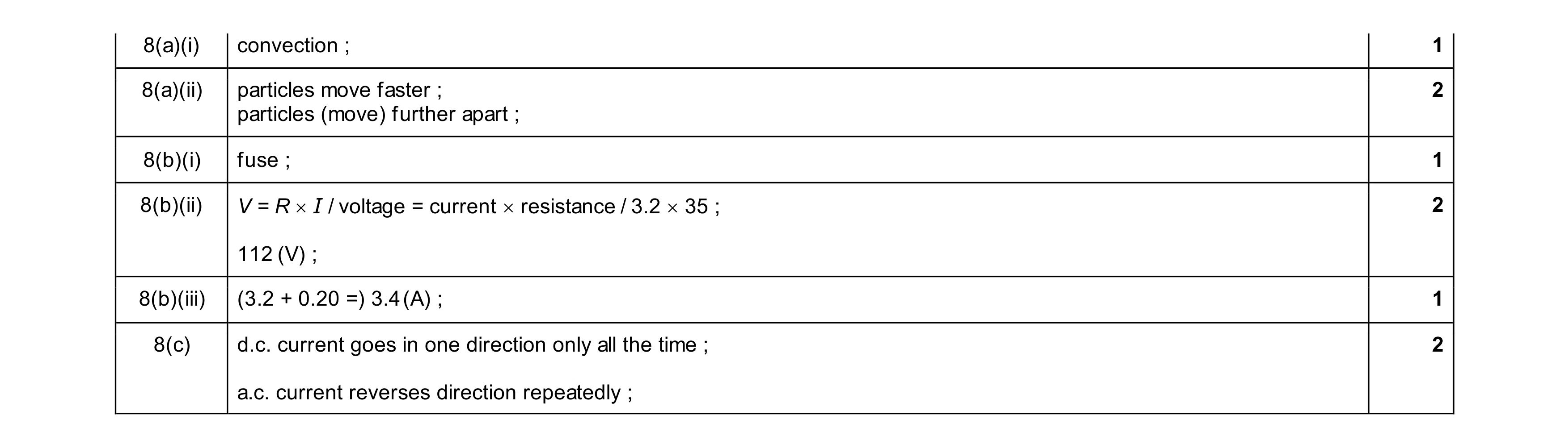 9
9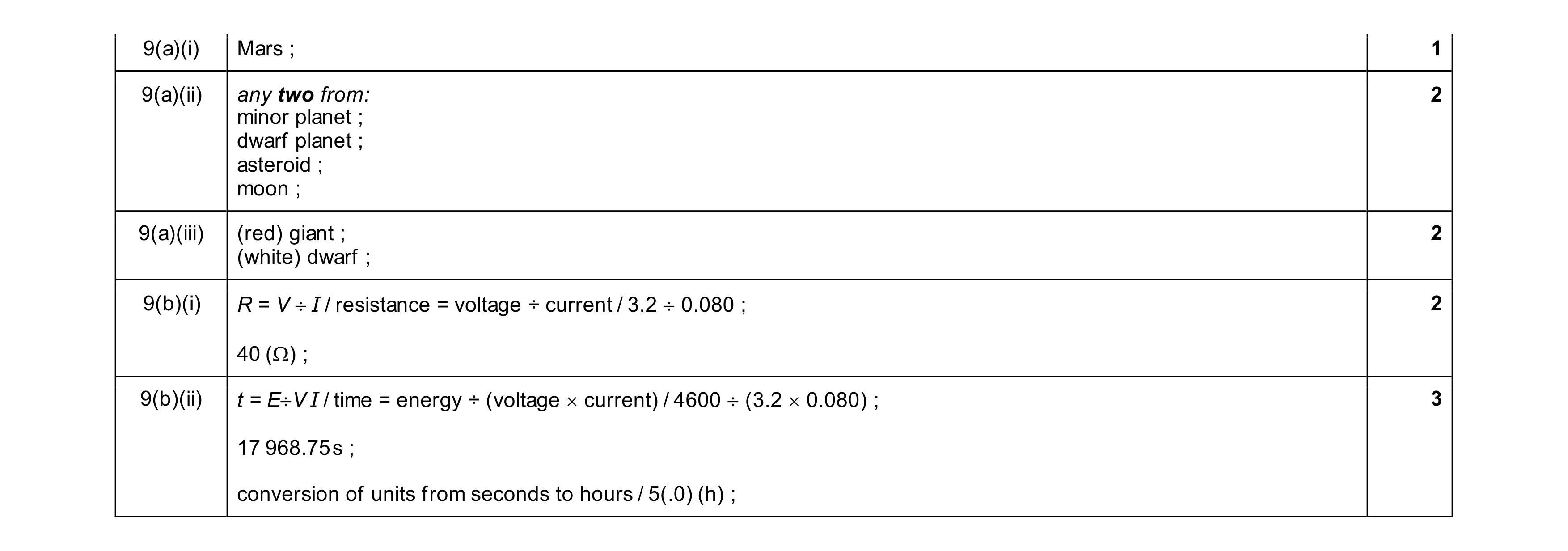 10
10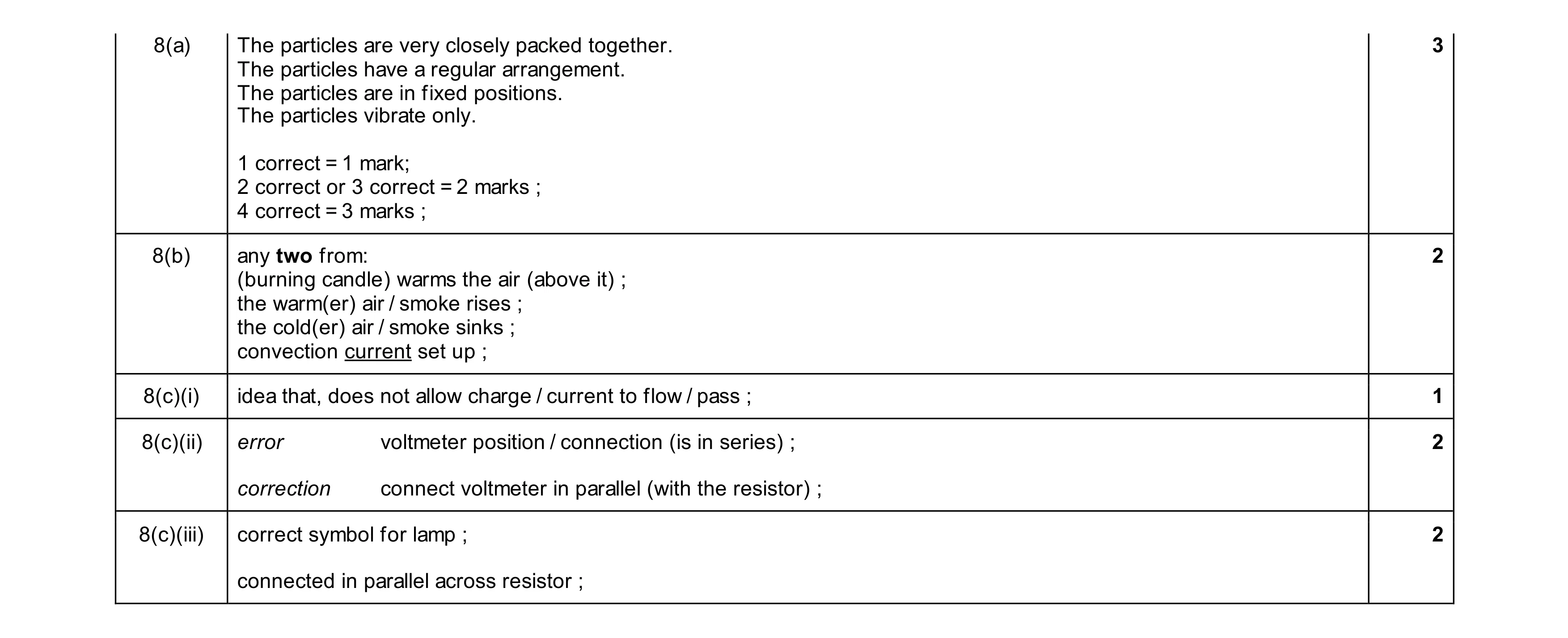 10
10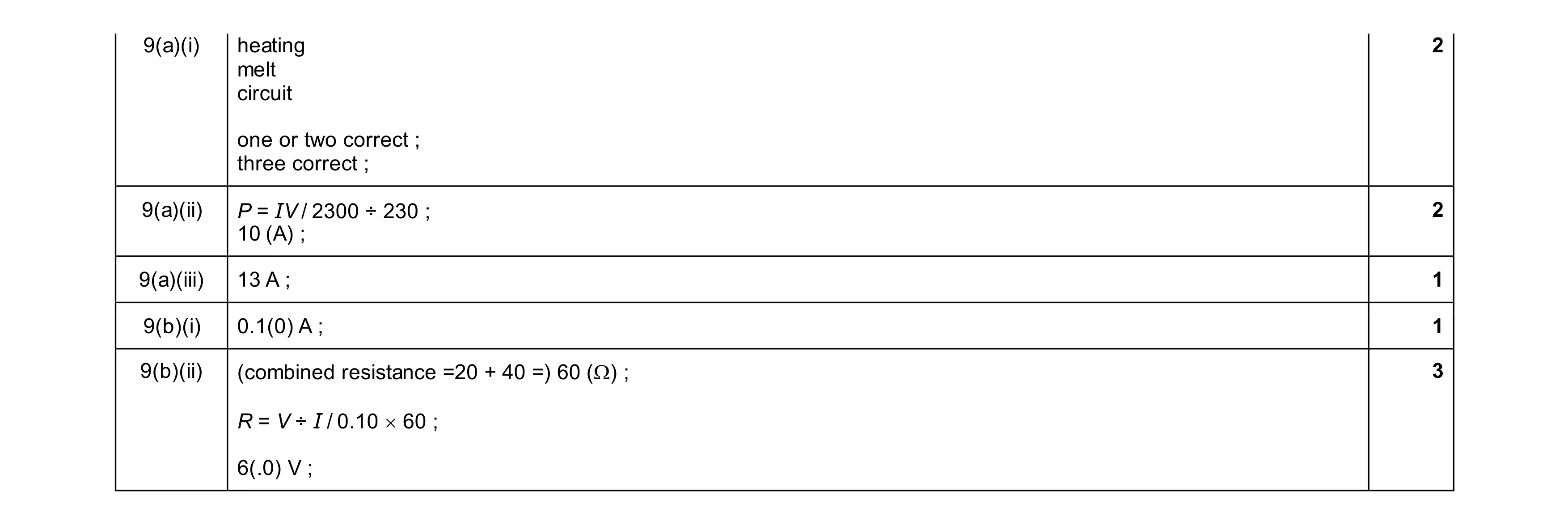 9
9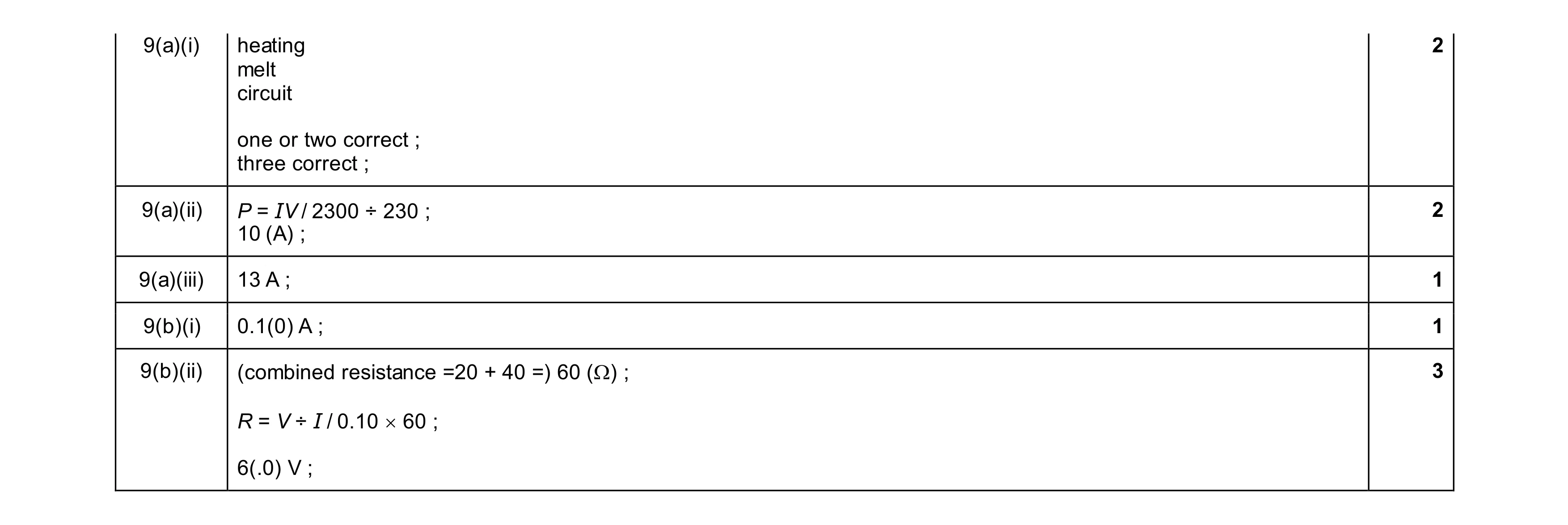 9
9