Questions as text
Q1 · A simple circuit set up to investigate the electrical properties of a lamp 0653/42 Feb/March 2017
9 Fig. 9.1 shows a simple circuit set up to investigate the electrical properties of a lamp. + switch cell meter X + lamp Fig. 9.1 (a) On Fig. 9.2 use the correct circuit symbols to complete the circuit diagram for the circuit shown in Fig. 9.1. Fig. 9.2 [2] (b) The lamp in Fig. 9.1 has a filament made of a long length of very thin wire. The lamp is replaced in the circuit in Fig. 9.1 by another lamp with a filament wire of half the length but the same diameter. Predict the effect on the meter reading. Explain your answer. … … … [2] (c) The voltage across the lamp is 1.5 V, and the current through the lamp is 0.6 A. (i) Use the equation P = IV to calculate the power consumption when the lamp is lit. Show your working and give the unit of your answer. power = … unit … [2] (ii) The cell transfers a total of 540 J of energy to the lamp before the cell runs down and the lamp goes out. Calculate the time for which the cell will keep the lamp lit. State any formula you use, show your working and state the unit of your answer. formula working time = … unit … [2]
8 marks
Mark scheme: 9(a) correct symbols for ammeter and lamp ; complete series circuit ; 2 9(b) half length lowers resistance ; (same voltage, so) current / ammeter reading increases ; 2 9(c)(i) (P = IV) = 0.6 × 1.5 = 0.9 ; W / watts ; 2 9(c)(ii) E = Pt ; t = 540/0.9 = 600 s / 10 minutes ; allow ecf 2
This question in 0653/42 Feb/March 2017
Q2 · A simple test circuit for testing different materials to see how well they conduct… 0653/41 May/June 2017
9 Fig 9.1 shows a simple test circuit for testing different materials to see how well they conduct electricity. The material being tested is connected between X and Y. A R X Y Fig. 9.1 (a) Name two materials other than copper that would be found to be good conductors when tested. … and … [1] (b) A piece of copper wire is connected between X and Y, and a voltmeter is connected in parallel to resistor R. The ammeter reads 0.5 A. The voltmeter reads 2 V. V Use the formula R = to calculate the resistance of R. I Give the unit of your answer. working resistance = … unit … [2] (c) Two pieces of wire, P and Q, with the same length and made of the same alloy, are connected in parallel between X and Y. The current in wire P is 5 A. The ammeter reading is 7 A. (i) Predict the current in wire Q. Give a reason for your answer. current in wire Q = … A reason … … [1] (ii) Deduce why different currents flow in wires P and Q. Give reasons for your answer. … … … … [2]
6 marks
Mark scheme: 9(a) any two from one or two metals or alloys (other than copper) graphite / carbon 1 9(b) = 2 / 0.5 = 4 ; ohms / Ω ; 2 9(c)(i) (2 A) sum of currents in parallel branches = current from source ; 1 9(c)(ii) P and Q have different resistances / thicknesses ; P less resistance than Q / P is thicker than Q ; 2
This question in 0653/41 May/June 2017
Q3 · A circuit set up to measure the current in different parts of a circuit 0653/43 May/June 2017
9 Fig. 9.1 shows a circuit set up to measure the current in different parts of a circuit. A A1 R1 A2 R2 S2 X A Y R3 S3 A A3 Fig. 9.1 (a) When both switches are closed, ammeter A1 reads 6 A and ammeter A2 reads 1.5 A. (i) Predict the reading on ammeter A3. Give a reason for your answer. Reading on A3 = … A reason … … … [1] (ii) Deduce why different currents are recorded on ammeters A2 and A3. Give reasons for your answer. … … … … [2] (b) A voltmeter is connected across the battery. The reading is 12 V. Switch S2 is closed, but switch S3 is left open. Ammeter A1 reads 3 A. The voltmeter is now connected between points X and Y. The reading is 3 V. (i) State the reading on ammeter A2. reading = … A [1] (ii) Deduce the value of resistance R1. Show your working. value of R1 = … Ω [2]
6 marks
Mark scheme: 9(a)(i) (4.5 A) idea that current in main circuit = sum of currents in branches ; 1 9(a)(ii) (because) same p.d. across both resistors ; (so) R2 and R3 must have different values ; R2 greater than R3 ; max2 9(b)(i) 3 A 1 9(b)(ii) voltage across R1 = 12 – 3 = 9V ; R1 = V / I = 9 / 3 = 3 Ω ; 2
This question in 0653/43 May/June 2017
Q4 · A fan heater used to heat a room in cold weather 0653/41 Oct/Nov 2017
6 Fig. 6.1 shows a fan heater used to heat a room in cold weather. Fig. 6.1 The fan heater is connected to the mains electricity supply. Fig. 6.2 shows the circuit diagram for the fan heater. The fan heater has two heating elements, heater 1 and heater 2, and a motor to drive the fan, connected to a 240 V mains electricity supply. 240 V switch 3 heater 1 switch 1 heater 2 switch 2 M motor Fig. 6.2 (a) Deduce which switch or switches must be closed (on) for heater 1 and the motor to work without heater 2. … [1] (b) (i) Each heating element has a power consumption of 1100 W. Calculate the current through one heating element when switched on. State the formula that you use and show your working. formula working current = … A [2] (ii) The fan motor is rated at 50 W. The fuse in the circuit is rated at 10 A. Explain whether this fuse provides good protection if an overload happens. … … … [2] (c) An electrician wants to measure the current through the fan motor. Complete the circuit diagram in Fig. 6.3 to show how the electrician should connect a meter to do this. You should use the correct symbol for the meter to be used, and complete all missing circuit connections. 240 V switch 3 heater 1 switch 1 heater 2 switch 2 M motor Fig. 6.3 [2]
7 marks
Mark scheme: 6(a) (both) switch 1 and switch 3 ; 1 6(b)(i) P = V × I (or rearranged) / 1100 / 240 ; = 4.58 or 4.6 A ; 2 6(b)(ii) (if everything switched on) then 9.4 A / 2250 W / 0.21 A seen in calculation ; correct comparison of total current with fuse rating ; 2 Q Question 6(c) correc amme ct symbol for am eter in fan motor mmeter ; r branch, all circ cuit connections Answer complete ; Mar ks 2
This question in 0653/41 Oct/Nov 2017
Q5 · In a theatre, spotlights are used to shine a beam of light on one person on the stage 0653/42 Oct/Nov 2017
9 In a theatre, spotlights are used to shine a beam of light on one person on the stage. Fig. 9.1 shows a spotlight shining a parallel beam of light on a singer. Fig. 9.1 (a) Fig. 9.2 shows a powerful lamp shining through a narrow hole in front of a lens inside the spotlight. Fig. 9.2 On Fig. 9.2 use a ruler to draw three rays that come through the narrow hole, pass through the lens and emerge parallel to each other to form a narrow beam of light. One ray has been started for you. [2] (b) Fig. 9.3a shows the way the lamps in two identical spotlights are connected to the electricity supply. The circuit contains a dimmer control so that the brightness of the lights can be changed. Fig. 9.3b shows part of the circuit diagram for this. dimmer control Fig. 9.3a power supply X Y Fig. 9.3b (i) The dimmer control contains a variable resistor. On Fig. 9.3b complete the circuit diagram by connecting the variable resistor into the circuit between X and Y using the correct circuit symbol. [1] (ii) The dimmer control is set so that the current through one of the lamps is 10 A. State the current in the main circuit. Explain your answer. current = … A explanation … … [2] (iii) The filament of one of the lamps breaks. State what will happen to the other lamp. Give a reason for your answer. … … … [1] (c) One lamp has a label as shown in Fig. 9.4. Voltage = 240 V Maximum power = 3000 W Fig. 9.4 (i) Use the formula P = IV to calculate the maximum current through the lamp. Show your working. current = … A [1] (ii) Describe how to set the variable resistor in the dimmer control to provide maximum power in the lamp. … … [1]
8 marks
Mark scheme: 9 9 9(a) two m all ray 9(b)(i) correc 9(b)(ii) 20 A ; becau 9(b)(iii) remai still a 9(c)(i) I = P 9(c)(ii) the id more rays from h ys emerge from ct symbol showi ; use lamps in par ins lit (no mark) complete circuit / V = 3000 / 240 dea that the resis hole to lens with lens reasonably ing variable resis rallel / current is t through that br 0 = 12.5 (A) ; stance in the dim at least one add y parallel ; stor ; shared / current ranch / reference mmer must be de ditional arrow co t in main circuit = e to parallel circu ecreased / turn c orrectly shown ; = sum ; uit / owtte ; control to minimu um resistance ; 2 1 2 1 1 1
This question in 0653/42 Oct/Nov 2017
Q6 · A toy car powered by batteries 0653/43 Oct/Nov 2017
3 Fig. 3.1 shows a toy car powered by batteries. Fig. 3.1 Fig. 3.2 shows part of the circuit diagram for a circuit in the toy car, including the two headlamps which can be switched on when needed. M motor Fig. 3.2 (a) The car is driven by an electric motor which must be able to operate whenever the switch shown in Fig. 3.2 is on. The speed of the electric motor is controlled by a variable resistor. The two headlamps are only switched on when needed, so a separate switch controls both headlamps. On Fig. 3.2, using the correct symbols, complete the circuit diagram by adding • a variable resistor that controls the electric motor. • the switch that controls both headlamps. • any wires needed to complete the circuit connections. [2] (b) The resistance of the variable resistor is decreased in order to speed up the motor. Suggest why decreasing the resistance will speed up the motor. … … [1] (c) Complete the sentences below by writing the correct phrase in each space. Each phrase may be used once, more than once or not at all. by an ammeter by an insulator in parallel in series less than more than the same as The electric motor and the headlamps are connected … . When the car is travelling by day, the headlamps are switched off. The current through the motor is then … the current through the battery. When the car is travelling at night, the headlamps are switched on. The combined resistance of the motor and headlamps is … the resistance of the motor before the headlamps are switched on. [3] (d) The toy car travels at 5.0 km / h for 10 min before the battery runs out. Calculate the distance travelled by the car during this 10 minute period. Show your working. distance = … km [2]
8 marks
Mark scheme: 3(a) variable resistor in motor branch, correct symbol ; switch for headlamps after motor branch, before first headlamp branch ; 2 3(b) (decreasing resistance) increases current, (so faster motor) ; 1 3(c) in parallel ; the same as ; less than ; 3 3(d) 10 min = 1 / 6 h / 5 / 60 = 0.083 (km / min) ; distance = speed × time = 5 × 1 / 6 = 0.83 km / distance = speed × time = 0.083 × 10 = 0.83 km ; 2
This question in 0653/43 Oct/Nov 2017
Q7 · The circuit for an immersion heater using electrical energy to heat water 0653/42 Feb/March 2018
9 Fig. 9.1 shows the circuit for an immersion heater using electrical energy to heat water. Two electric heating elements are immersed in water inside a large tank. hot water out heater 1 A ammeter 1 fuse 240 V supply A ammeter 2 heater 2 cold water supply Fig. 9.1 The electrical energy is supplied at 240 V. When both heaters are switched on, ammeter 1 reads 4 A, and ammeter 2 reads 10 A, giving a total current of 14 A through the fuse. (a) The fuse in the supply circuit has a value of 20 A printed on it. Explain why a 20 A fuse is used in this circuit. … … [1] (b) Calculate the total resistance of the two heaters. State the formula you use, and show your working. formula working resistance = … Ω [2] (c) Calculate the electrical energy supplied by heater 2 when it is switched on for 8 hours. State any formula you use, and show your working. formula working energy = … J [2] (d) Heater 2 is used to provide a full tank of hot water, while heater 1 is used to provide a small amount of hot water quickly when the water in the tank is cold. Explain why heater 1 is able to provide a small amount of hot water quickly without heating the whole tankful of water. You may wish to draw a diagram to help your answer. … … … … [3]
8 marks
Mark scheme: 9(a) total current of 14 A needs higher value fuse / reference to the safety margin / owtte ; 1 9(b) (R = ) V / I ; (R = ) 240 / 14 = 17.1 (Ω) ; OR 1 / R = 1 / R1 + 1 / R2 ; R1 = 240 /4 = 60 Ω and R2 = 240 / 10 = 24 Ω and so 1/R = 1/60 + 1/24 = 7/120, so R = 17.1 Ω ; 2 Question Answer Marks 9(c) E = IVt ; = 10 × 240 × 8 × 60 ×60 = 69 120 000 (J) ; 2 9(d) reference to convection ; the idea that water at higher temperature rises / has a lower density ; the idea that the convection current from heater 1 does not affect the water in the lower part of the tank / water below heater 1 has greater density and so does not mix with heated water / owtte ; 3
This question in 0653/42 Feb/March 2018
Q8 · A small electric cooker with two hot plates 0653/41 May/June 2018
9 Fig. 9.1 shows a small electric cooker with two hot plates. hot plates Fig. 9.1 The cooker is connected to a 240 V supply. The plug contains a fuse with a rating of 13 A. Each hot plate is controlled by a switch and a variable resistor. Each hot plate can be turned on and off and controlled without affecting the other hot plate. (a) (i) In Table 9.1 draw the circuit symbols for each component used in the cooker circuit. Table 9.1 component fuse switch variable resistor symbol [2] (ii) Name the type of circuit connection that will allow each hot plate to be controlled separately by its own switch. … [1] (iii) Use the information about the cooker to draw a circuit diagram for the cooker. Use the circuit symbol for a heater to represent a hot plate: The circuit diagram has been started for you. 240 V supply [4] (b) The larger hot plate is rated at a maximum of 1.5 kW, and the smaller hot plate is rated at a maximum of 1.0 kW. Show by calculation that the 13 A fuse in the plug will not blow when the cooker is used with both hot plates at maximum rating. State the formula you use and show your working. formula working [3]
10 marks
Mark scheme: 9 9( 9( (a)(i) fuse switch variab 3 corre Any 1 (a)(ii) paralle (a)(iii) two ho each h each h fuse in le resistor ect for 2 marks correct for 1 ma el ; otplates connect hotplate branch hotplate branch n main circuit ; ark ted in parallel ; contains a varia contains a switc able resistor in se ch in series ; eries ; 2 1 4 Question Answer Marks 9(b) P = V × I ; EITHER larger hotplate: I = 1500 / 240 = 6.25 A smaller hotplate: I = 1000 / 240 = 4.17 A ; total current = 10(.4 A), (safely less than 13 A ) ; or total power = 1.5 (kW) + 1.0 (kW) = 2.5 (kW) ; P = V × I or I = P / V or total current = 2500 / 240 ; = 10(.4 A) (safely less than 13 A) ; 3
This question in 0653/41 May/June 2018
Q9 · An electric toaster used for toasting bread slices in a hotel dining room 0653/43 May/June 2018
9 Fig. 9.1 shows an electric toaster used for toasting bread slices in a hotel dining room. control knobs for heating elements control knob for electric motor Fig. 9.1 The two heating elements inside, one to toast each side of the bread, are connected in parallel. They are each controlled by a switch. An electric motor carries the bread slices on a moving rack between the heating elements. The motor is controlled by a third switch and is connected in parallel with the heating elements. The plug at the end of the cable has a fuse inside, and is plugged into a 240 V mains supply. (a) The circuit symbols for each of these components used in the toaster circuit are: electric motor fuse heating element switch M Use the information about the toaster to draw a circuit diagram for the toaster. The circuit diagram has been started for you. 240 V [4] (b) The two heating elements are each rated at 240 V, 1.2 kW. The electric motor is rated at 240 V, 100 W. The plug has a 10 A fuse fitted. Show by calculation that the fuse in the plug is not adequate when both heating elements and the motor are in operation. Show your working. [3] (c) A smoke alarm is fitted in the dining room in case the toaster causes a fire. When it goes off, the smoke alarm has to make a loud high-pitched sound that everyone can hear. The highest frequency of sound some older residents can hear is 5 kHz below the top of the normal human hearing range. Suggest a frequency for the high-pitched sound from the smoke alarm that all residents should be able to hear. Give a reason for your answer. suggested frequency … kHz reason … … … [2]
9 marks
Mark scheme: 9(a) fuse in main circuit ; heating elements in parallel with each other and supply ; motor in parallel with heating elements (and supply) ; switches in series with both heaters and motor ; 4 9(b) total power supply required = 1200 × 2 + 100 = 2500 W ; use of P = I × V e.g. current through one heater = 5 A / total current = 2500 ÷ 240 ; = 10.4 A (which is above fuse rating) ; 3 Question Answer Marks 9(c) value within range 10–15 kHz ; top end of normal range is 20 kHz / older residents can hear up to 15 kHz ; 2
This question in 0653/43 May/June 2018
Q10 · A dishwasher (an electric dishwashing machine) 0653/41 Oct/Nov 2018
9 Fig. 9.1 shows a dishwasher (an electric dishwashing machine). water in dirty water out Fig. 9.1 The dishwasher uses electrical energy to • power a heater to heat the water used, • power two motors, one to wash the dishes, and another to pump water out of the machine, • light a small lamp to indicate that the heater is switched on. The circuit symbols for a heater and a motor are: M heater motor Fig. 9.2 shows part of the circuit diagram for the dishwasher. 240 V Fig. 9.2 Each of the motors and the heater has a switch in series. The heater and each motor are turned on at different times. (a) (i) Name the type of circuit connection needed. … [1] (ii) On Fig. 9.2 complete the circuit diagram for the dishwasher. [4] (b) (i) The heater is rated at 2.4 kW. The power consumption in the indicator lamp can be ignored. Calculate the current through the heater. State the formula you use and show your working. formula working current = … A [2] (ii) Each motor running at maximum power takes a current of 1.2 A. Find the maximum current taken from the 240 V mains when the heater and both motors are working at maximum power. The current in the indicator lamp can be ignored. current = … A [1] (iii) Suggest a suitable value for the fuse in the main circuit. Give a reason for your answer. value = … A reason … … … [2]
10 marks
Mark scheme: 9(a)(i) parallel ; 1 9(a)(ii) correct lamp symbol ; heater in one branch, a motor in at least one other branch ; switch in series with the component in each branch ; lamp in series with heater only and no short circuits ; 4 9(b)(i) power = voltage x current / P = V x I / I = P / V = 2400 / 240 ; = 10 (A) ; 2 9(b)(ii) total current = 10 + 1.2 + 1.2 = 12.4 (A) or 12 (A) ; 1 9(b)(iii) any value from 13 A to 20 A ; fuse value needs to be above max working current of machine, but not too large to put machine components at risk ; 2
This question in 0653/41 Oct/Nov 2018
Q11 · A circuit diagram for an investigation into how the resistance of a lamp changes with the… 0653/42 Oct/Nov 2018
9 Fig. 9.1 shows a circuit diagram for an investigation into how the resistance of a lamp changes with the current in the lamp. V A Fig. 9.1 (a) Explain why the variable resistor has been included in the circuit. … … [1] (b) Table 9.1 shows some results from the investigation. Table 9.1 voltmeter ammeter resistance of experiment reading / V reading / A lamp / Ω 1 6.0 0.54 11 2 4.0 0.46 8.7 3 3.0 0.40 7.5 4 2.0 0.32 6.3 The lamp becomes less bright as the voltage reading decreases from 6.0 V to 2.0 V. Explain why this happens. … … … [2] (c) (i) On Fig. 9.1 add a second identical lamp in parallel with the first. [1] (ii) Experiment 5 is now carried out with the second identical lamp in the circuit in parallel with the first lamp. The total current in the circuit is now 0.76 A. State the current in the first lamp. Give a reason for your answer. current = … A reason … … … [2]
6 marks
Mark scheme: 9(a) to control / vary the current through / voltage across the lamp ; 1 9(b) the idea that lamp less bright because lower power / energy output ; use of power = V × I e.g. V × I reduces in value from expt. 1 to expt. 4 ; 2 9(c)(i) lamp in parallel as shown ; 1 9(c)(ii) 0.38 A ; because lamps are identical current divides equally / they have the same / equal resistance ; 2
This question in 0653/42 Oct/Nov 2018
Q12 · A display refrigerator for storing cold drinks in a shop 0653/43 Oct/Nov 2018
9 Fig. 9.1 shows a display refrigerator for storing cold drinks in a shop. Fig. 9.1 The refrigerator uses electrical energy • for a lamp to light up the inside of the refrigerator • to power an electric motor to run the cooler in the refrigerator. The circuit symbol for an electric motor is: M Fig. 9.2 shows part of the circuit diagram for the refrigerator. Fig. 9.2 (a) When the shop is closed, the lamp is switched off, but the electric motor needs to continue to run the refrigerator to keep the contents cool. (i) On Fig. 9.2 complete the circuit diagram for the refrigerator that will allow the lamp to be switched off while the electric motor remains on. [3] (ii) Name the circuit component with the symbol … [1] (b) The potential difference across the lamp is 240 V, and its power consumption is 40 W. The potential difference across the motor is 240 V and its power consumption is 300 W. Calculate the total current from the supply through the refrigerator. State the formula you use and show your working. formula working current = … A [3]
7 marks
Mark scheme: 9(a)(i) correct symbol for lamp ; parallel circuit with motor in one branch, lamp in other branch and no short circuit and no additional components ; switch in series with lamp only ; 3 9(a)(ii) mains supply / (a.c.) power supply ; 1 9(b) use of P = IV / I = P / V ; (total) P = 40 + 300 = 340 W ; (I = 340 / 240) = 1.42 / 1.4 (A) ; or use of P = IV / I = P / V ; 40 / 240 + 300 / 240 ; = (0.17 + 1.25) = 1.42 (A) / 1.4 (A) ; 3
This question in 0653/43 Oct/Nov 2018
Q13 · The bathroom in a house has electric heating under the floor 0653/42 Feb/March 2019
6 The bathroom in a house has electric heating under the floor. (a) Fig. 6.1 shows part of the heating circuit, with two identical heaters, heater 1 and heater 2. a.c. supply fuse heater 1 heater 2 Fig. 6.1 When the circuit is switched on, the current in heater 1 is 4 A. State the current in the fuse. current = … A Explain your answer. … … [2] (b) The heaters are placed underneath a wooden floor. The heating circuit is switched on, and the temperature of the heaters quickly reaches 70 °C. Thermal energy conducted through the wood causes the temperature of the upper surface of the floor to increase slowly from 20 °C to 25 °C. Air in contact with the floor is heated and warms the bathroom by convection. Describe in terms of molecules: (i) how thermal energy passes through the wood by conduction … … … [2] (ii) how thermal energy is transferred from the surface of the floor to the ceiling of the bathroom. … … … … [3] (c) When the heaters are switched on, a small gap between the edge of the wooden floor and the walls of the bathroom slowly disappears. Predict what will happen when the heaters are switched off again. Explain your answer. prediction … explanation … … [2] [Total: 9]
9 marks
Mark scheme: 6(a) 8 (A) ; 4 A in each identical heater in parallel adds to 8 A ; 2 6(b)(i) (warmer) molecules vibrate faster / gain kinetic energy ; the idea that energy is passed from molecule to molecule ; 2 6(b)(ii) molecules in air gain (kinetic) energy (from collisions with wood) ; (faster) molecules transfer energy to more molecules by collision ; (faster) molecules move further apart ; so (warmer) air has lower density ; max 3 6(c) gap opens again / re-appears ; solids contract on cooling / as temperature falls ; 2
This question in 0653/42 Feb/March 2019
Q14 · The heating element inside an electric kettle 0653/41 May/June 2019
9 Fig. 9.1 shows the heating element inside an electric kettle. electric heating kettle element Fig. 9.1 (a) The kettle is filled with cold water at 10 °C. The heating element is turned on to boil the water. State the temperature of the water inside the kettle when the water is boiling. temperature = … °C [1] (b) The electrical circuit in the kettle contains a switch, the heating element and a fuse. On Fig. 9.2 complete the circuit diagram for the kettle, including the symbol for a fuse. The symbol for the heating element is: a.c. power supply Fig. 9.2 [2] (c) Fig. 9.3 shows the structure inside the tube of the heating element. powder filling metal tube resistance wire heating coil Fig. 9.3 (i) Describe in terms of molecules and other particles how thermal energy is transferred from the powder filling through the metal tube to the water in the kettle. … … … … … [2] (ii) Table 9.1 gives the properties of four substances in the form of powders. The higher the value of the electrical conductivity of a powder, the better an electrical conductor it is. The higher the value of the thermal conductivity of a powder, the better a thermal conductor it is. Table 9.1 electrical conductivity thermal conductivity name of powder / units / units aluminium oxide 10–14 30 carbon 104 100 magnesium oxide 10–11 45 sulfur 10–15 0.21 Use Table 9.1 to suggest the best choice of powder for the powder filling. Give reasons for your choice. … … … [2] (iii) The resistance wire in the heating coil is replaced by a wire of the same material and length. The new wire has a greater cross-sectional area than the original wire. State how the resistance of the new wire compares to the resistance of the original wire. Explain your answer. resistance is … explanation … … [1] [Total: 8]
8 marks
Mark scheme: 9(a) 100 °C ; 1 9(b) fuse symbol ; switch symbol + completed circuit ; 2 9(c)(i) transfer from powder to metal tube by molecular vibrations ; transfer through metal by mobile electrons ; transfer of molecular vibrations from metal tube to vibration / movement of water molecules ; reference to the transfer of energy through the water for example by particle collisions / or by convection ; max 2 Question Answer Marks 9(c)(ii) magnesium oxide or aluminium oxide ; the idea that these materials are poor electrical conductors and good thermal conductors / owtte ; 2 9(c)(iii) (less) resistance inversely proportional (to cross-sectional area) / the greater the cross section the lower the resistance ; 1
This question in 0653/41 May/June 2019
Question 15 0653/42 May/June 2019
9 Fig. 9.1 shows an electrically-powered bicycle. battery front lamp rear lamp electric motor Fig. 9.1 (a) The battery has to supply power to the electric motor, and to both front and rear lamps. A switch controls the whole circuit. The rider controls the speed of the bicycle by changing the current in the electric motor. The two lamps are controlled by one more switch. However, if one lamp fails the other lamp is still lit. (i) Name a circuit component that can be used to change the current in a circuit. … [1] (ii) On Fig. 9.2 complete the circuit diagram for this electric bicycle. Include the component you have named in (a)(i) to change the speed of the motor. Fig. 9.2 [4] (b) The battery has an output voltage of 36 V, and the current in the motor at maximum speed is 7.0 A. (i) Calculate the power output of the electric motor at maximum speed. Show your working and give the unit of your answer. power = … unit … [3] (ii) The cyclist rides the bicycle at maximum speed for a journey. State one further quantity required to calculate the total energy provided by the battery on this journey. … [1] [Total: 9]
9 marks
Mark scheme: 9(a)(i) variable resistor ; 1 9(a)(ii) at least three symbols correct ; variable resistor and motor in series in same branch ; lamps in parallel with motor and each other ; only two switches and both correctly located ; 4 9(b)(i) P = V × I / 36 × 7.0 ; = 252 / 250 ; watt(s) / W ; 3 9(b)(ii) time / t ; 1
This question in 0653/42 May/June 2019
Q16 · Complete the sentence: An electric current in a metal is a flow of … , which carry… 0653/43 May/June 2019
8 (a) Complete the sentence: An electric current in a metal is a flow of … , which carry negative … . [2] (b) A battery has an e.m.f. of 24 V. (i) Use the formula E = IVt to calculate the energy E transferred from the battery when a current of 50 A flows for 1 hour. Show your working. energy = … J [2] (ii) Calculate the electric charge that flows when a current of 25 A flows for 60 s. Show your working and state the unit of your answer. charge = … unit … [3] (c) The battery is used to operate the starter motor on a truck. The battery is also used to operate the lights on the truck. The starter motor must have its own switch and operate independently from the lights. Fig. 8.1 shows part of the electrical circuit of the truck. Fig. 8.1 The symbol for the starter motor is M On Fig. 8.1, complete the circuit diagram to show how the starter motor and a switch should be included in this circuit. [1] [Total: 8]
8 marks
Mark scheme: 8(a) electrons ; charges ; 2 8(b)(i) 1 hour = 3600 s / (E =) 50 × 24 × 3600 ; 4 320 000 (J) ; 2 8(b)(ii) (Q=) I × t or (Q =) 25 × 60 ; = 1500 ; coulombs / C ; 3 8(c) motor symbol with switch connected in parallel with lamps ; 1
This question in 0653/43 May/June 2019
Q17 · A circuit containing three resistors, R1, R2 and R3 0653/41 Oct/Nov 2019
9 (a) Fig. 9.1 shows a circuit containing three resistors, R1, R2 and R3. V R1 R3 A R2 Fig. 9.1 (i) R1 has a value of 8.0 Ω. R2 has a value of 3.0 Ω. R3 has a value of 6.0 Ω. Complete steps 1 and 2 to calculate the value of the combined resistance of the three resistors in this circuit. Show your working. Step 1: Calculate the combined resistance of R2 and R3. Ω combined resistance of R2 and R3 = … Step 2: Calculate the total resistance of the three resistors. total resistance = … Ω [3] (ii) The reading on the ammeter is 2.7 A. The current in R2 is 1.8 A Determine the current in R3. Show your working. current = … A [1] (iii) Explain your answer to (a)(ii). … … [1] (iv) With the switch closed and the current flowing in the circuit, the reading on the voltmeter is 27 V. The switch is opened, so no current flows in the circuit. The reading on the voltmeter increases to 30 V. Suggest an explanation for this observation. … … [1] (b) A circuit with a total resistance of 5.0 Ω has a current of 9.0 A. Calculate the power consumed in the circuit. Show your working. power = … W [2] [Total: 8]
8 marks
Mark scheme: 9(a)(i) (1/3 + 1/6 or 3/6 Æ) combined R = (6/3) = 2 Ω ; total R = 8 + 2 = 10 Ω ; 3 9(a)(ii) 2.7 – 1.8 = 0.9 (A) ; 1 9(a)(iii) current from the source (ammeter reading) is the sum of the currents in the separate branches (in R2 and R3) of a parallel circuit / owtte ; 1 9(a)(iv) must be resistance inside the battery / resistance of connecting wires / the idea of greater resistance ; 1 9(b) use of P = VI or P = I2R ; (45 × 9 or 92 × 5) = 405 W ; 2
This question in 0653/41 Oct/Nov 2019
Q18 · An electric hair dryer 0653/42 Oct/Nov 2019
6 Fig. 6.1 shows an electric hair dryer. Fig. 6.1 (a) Fig. 6.2 shows a label on the hair dryer. 240 V 750 W Use only a 5 A replacement fuse. Fig. 6.2 Use data from Fig. 6.2 to explain why a 5 A fuse is the correct fuse rating to be used in the hair dryer when replacing the fuse. Show your working. explanation … … [3] (b) The hair dryer contains: • an electrical heater to heat the air used to dry the hair • a fan driven by an electric motor to blow the air over the wet hair • a two-way switch that enables the motor to drive the fan at slow speed or high speed. Fig. 6.3 shows the circuit diagram for the hair dryer with the two-way switch in two different positions. 240 V 240 V heater two-way switch M M fan motor speed of motor is fast speed of motor is slow Fig. 6.3 The two-way switch changes the speed of the motor between fast and slow. Suggest why use of the two-way switch in this circuit changes the speed of the motor. Use the term potential difference in your answer. … … … … [3] (c) When the hair dryer blows air over wet hair, the water evaporates. Explain in terms of water molecules why wet hair dries faster when air is blown across it, and even faster if the air is heated. … … … [2] [Total: 8]
8 marks
Mark scheme: 6(a) Use of P = IV ; (750 / 240 =) I = 3.1 (25) (A) ; 5 A fuse just higher than required operating current so appropriate / 3 A fuse too low and would blow under normal working conditions / 13 A fuse too high and would not blow until much higher than operating current ; 3 6(b) (when the switch is down) additional resistor (in motor branch of circuit) ; potential difference across motor decreases (because some p.d. across resistor) ; current (in motor) decreases (so motor speed is slow) ; ora 3 6(c) hairdryer blows evaporated water molecules away so they cannot fall back onto the hair again ; hairdryer heats the water molecules on the hair so they have increased KE and can evaporate faster ; 2
This question in 0653/42 Oct/Nov 2019
Q19 · In hot climates, some foods such as milk must be kept cool to ensure they stay fresh 0653/43 Oct/Nov 2019
7 (a) In hot climates, some foods such as milk must be kept cool to ensure they stay fresh. Fig. 7.1 shows a cooler made of pottery used to keep a bottle of milk cool. pottery air cooler glass bottle milk Fig. 7.1 The cooler is soaked with cold water and placed over the glass bottle containing milk. The cooler slowly dries. As the water evaporates, the temperature of the cooler falls below the temperature of the surroundings. (i) Describe in terms of molecules of water how this process results in the temperature of the cooler decreasing. … … … … [2] (ii) Explain in terms of the motion of the molecules why the water evaporates more quickly when the temperature of the surroundings is higher. … … … … … [2] (iii) The temperature of the milk in the glass bottle also decreases. Describe in terms of molecular movement how thermal energy is transferred from the milk through the glass bottle by conduction. … … … … [2] (b) Fig. 7.2 shows a solar-powered freezer used in sunny climates. The freezer can also use a mains supply at night. solar panel freezer a.c. mains supply Fig. 7.2 The solar panel provides a 12 V supply to power the freezer. At night, the mains supply powers the appliance at 240 V instead of the solar panel. The power supplied is only 80 W when operating at 240 V and is 90 W when operating at 12 V. The freezer has two fuses, one marked 10 A, the other marked 1 A. Suggest why the freezer needs two separate fuses with these different values. Show calculations as part of your answer. … … … [4] [Total: 10]
10 marks
Mark scheme: 7(a)(i) faster / more energetic molecules escape ; (average) speed / KE of remaining molecules is lower (results in lower temperature) ; 2 7(a)(ii) molecules in air moving faster / more KE ; transfer more energy to water molecules by collision (so more escape) ; 2 7(a)(iii) collisions of faster milk molecules with slower glass molecules causes glass molecules to gain energy and vibrate faster ; energy then passed from molecule to molecule through glass ; 2 7(b) use of P = V × I ; 12 V circuit current = 90 / 12 = 7.5 A ; 240 V circuit current = 80 / 240 = 0.33 A ; 10 A fuse appropriate for 12 V circuit, 1 A fuse for 240 V circuit ; 4
This question in 0653/43 Oct/Nov 2019
Question 20 0653/43 Oct/Nov 2019
9 Fig. 9.1 shows an electrically-powered bicycle. battery front lamp rear lamp electric motor Fig. 9.1 Fig. 9.2 shows part of the circuit diagram for the lamps and electric motor on the bicycle. The switch shown on the diagram controls only the motor and a variable resistor. M motor Fig. 9.2 (a) A second switch controls the two lamps, which are connected in parallel with the motor. The two lamps are also connected in parallel with each other. Complete the circuit diagram on Fig. 9.2 to show how the second switch and the two lamps are connected into the circuit. [3] (b) When both lamps are fully lit, the front lamp has a current of 2.0 A and the rear lamp has a current of 1.0 A. The battery consists of eight cells, each with an e.m.f. of 1.5 V. Use the data to calculate the combined resistance of the lamps when both are fully lit. Show your working. resistance = … Ω [3] [Total: 6]
6 marks
Mark scheme: 9(a) 3 9(b) use of R = V / I ; identification of emf of battery as 12 V and total current as 3 A ; (R = 12 / 3) = 4 (Ω) ; 3 use of correct symbols ; lamps in parallel with motor and variable resistor ; lamps in parallel with each other and in series with switch ;
This question in 0653/43 Oct/Nov 2019
Question 21 0653/42 Feb/March 2020
9 Fig. 9.1 shows an ambulance. On the roof it has a flashing blue lamp and a siren. Fig. 9.1 (a) A car driver sees the ambulance appear in the far distance. The driver hears the siren 3 s after seeing the blue light. Explain why the driver sees the blue light before he hears the siren. … … [1] (b) The siren emits sounds at two frequencies, 600 Hz and 1500 Hz. The siren has a plastic casing. The sound travels through the plastic casing at a speed of 2200 m / s. Calculate the wavelength of the 600 Hz sound. wavelength = … m [2] (c) An electric motor rotates a mirror around the blue lamp to reflect a bright beam of light. The motor has a power rating of 20 W and the lamp has a power rating of 60 W. The lamp and the motor both operate at a potential difference (p.d.) of 12 V from the 12 V ambulance battery. (i) State the type of circuit arrangement required for the motor and the lamp. … [1] (ii) Calculate the current in the motor when turning the mirror. current = … A [2] (iii) The lamp and motor are switched on by one switch even if the siren is not being used. The siren has its own switch and also operates at 12 V. On Fig. 9.2 complete the diagram for the circuit that operates the lamp, the motor and the siren from the 12 V car battery. The circuit symbol for a siren is M Fig. 9.2 [4] [Total: 10]
10 marks
Mark scheme: 9(a) light travels faster than sound ; 1 9(b) v = fλ / (λ =) v ÷ f / 2200 ÷ 600 ; = 3.67 / 3.7 (m) ; 2 9(c)(i) parallel ; 1 9(c)(ii) P = I V / (I =) P ÷ V / 20 ÷ 12 ; = 1.7 / 1.67 (A) ; 2 Question Answer Marks 9(c)(iii) correct symbols for lamp and switch ; lamp, siren and motor all in parallel ; switch for motor and lamp ; switch for siren only ; 4
This question in 0653/42 Feb/March 2020
Q22 · A microwave oven connected to a mains electricity supply 0653/41 May/June 2020
9 Fig. 9.1 shows a microwave oven connected to a mains electricity supply. food turntable Fig. 9.1 When the door is closed, the oven can be switched on and the food gets hot. (a) State the main useful energy transfer that results in the food getting hot. … energy … energy [2] (b) Microwave radiation is generated inside the oven and absorbed by the food. The microwave radiation has a frequency of 2.45 × 10⁹ Hz. The speed of microwave radiation is 3.00 × 10⁸ m / s. Calculate the wavelength of the microwaves. wavelength = … m [2] (c) When the oven is switched on, the food is rotated on a turntable turned by an electric motor. This ensures the food is heated completely. All the circuit components of the microwave oven are connected in parallel. These components are the microwave generator, the turntable motor and a lamp. (i) The microwave oven has two switches. • the main switch operates all the components, • the other switch operates only the microwave generator and turntable motor. On Fig. 9.2 complete the circuit diagram for the microwave oven, including the symbol for the mains electricity supply (a.c. power supply), the second switch and the lamp. microwave generator M Fig. 9.2 [3] (ii) The current in each of the three components is shown. lamp 0.1 A microwave generator 2.5 A turntable motor 0.2 A Calculate the current supplied from the mains supply. current = … A [1] (iii) The mains electricity supply is 230 V. Calculate the power used by the microwave generator. State the unit of your answer. power = … unit … [3] [Total: 11]
11 marks
Mark scheme: 9(a) electrical (energy) ; (→) thermal (energy) ; 2 9(b) v = fλ so λ = v/f = 3 × 10⁸ / 2.45 × 10⁹ ; wavelength = 0.12 / 0.122 (m) ; 2 9(c)(i) 3 9(c)(ii) (current = 0.1 + 2.5 + 0.2 =) 2.8 (A) ; 1 9(c)(iii) Power = V × I = 230 × 2.5 ; = 575 ; watts / W ; 3 a.c. mains symbol ; microwave generator in parallel with lamp and motor ; second switch in a position where it operates motor and microwave generator only ;
This question in 0653/41 May/June 2020
Question 23 0653/42 May/June 2020
9 Fig. 9.1 shows two circuits. ammeter 2 + – ammeter 1 cell + – ammeter 3 bulbs circuit 1 circuit 2 Fig. 9.1 In circuit 1 the bulbs are connected in series. In circuit 2 the bulbs are connected in parallel. The cells, the ammeters and all the bulbs are identical in both circuits. (a) Complete the circuit diagram for circuit 2 shown in Fig. 9.1. Include in your circuit diagram a switch that will turn off one bulb, but leave the other lit. cell [3] (b) State which of the three ammeters in Fig. 9.1 shows the highest reading. Give reasons for your answer. ammeter … … … … [2] (c) Circuit 1 is switched on. Ammeter 1 shows a current of 2.0 A. A voltmeter connected across the cell in circuit 1 gives a reading of 1.4 V. (i) State the potential difference (p.d.) across one of the lamps in circuit 1. potential difference = … V [1] (ii) Calculate the total energy supplied by the cell in circuit 1 in 300 seconds. energy = … J [2] (d) The resistance of each bulb in circuit 2 when lit is 0.70 Ω. Calculate the combined resistance of the two bulbs. resistance = … Ω [2] [Total: 10]
10 marks
Mark scheme: 9(a) 9(b) (ammeter 2 – no mark) total resistance in circuit 2 lower than in circuit 1 ; ammeter 2 in main circuit ; 2 9(c)(i) 0.7 V ; 1 correct circuit symbols for lamp and ammeter ; two lamps in parallel, ammeters in correct parts of circuit ; switch in lower branch / in series with ammeter 3 ; Question Answer Marks 9(c)(ii) E = IVt = 2 × 1.4 × 300 ; = 840 (J) ; 2 9(d) combined resistance = R1 R2 / (R1 + R2) = 0.49 / 1.4 ; = 0.35 (Ω) ; 2
This question in 0653/42 May/June 2020
Q24 · An electric lawnmower that is used for cutting grass 0653/41 Oct/Nov 2020
9 Fig. 9.1 shows an electric lawnmower that is used for cutting grass. power cable lawnmower grass Fig. 9.1 The lawnmower operates from a 230 V mains electricity supply. The circuit in the lawnmower contains: • an electric motor • a switch to switch the motor on and off • a lamp to show when the motor is switched on • a variable resistor to vary the current in the motor but not the current in the lamp • a fuse to protect the circuit. (a) On Fig. 9.2, complete the circuit diagram for the lawnmower. 230 V supply M motor Fig. 9.2 [4] (b) The current in the lamp is 0.25 A. The potential difference across the lamp is 230 V. Calculate the resistance of the lamp. resistance = … Ω [2] [Total: 6]
6 marks
Mark scheme: 9(a) 9(b) V = IR in any form / 230 ÷ 0.25 ; 920 (Ω) ; 2 switch and fuse symbols correct ; variable resistor symbol correct ; switch and fuse in main circuit ; variable resistor in motor branch ;
This question in 0653/41 Oct/Nov 2020
Q25 · A circuit containing a 6.0 V battery, an electric bell, two identical switches S1 and S2… 0653/42 Oct/Nov 2020
9 Fig. 9.1 shows a circuit containing a 6.0 V battery, an electric bell, two identical switches S1 and S2, and two identical lamps L1 and L2. Both switches are open. 6.0 V S1 S2 L1 L2 electric bell Fig. 9.1 (a) The resistance of each lamp is 4.0 Ω. (i) When switch S1 is closed, lamp L1 lights, and the bell rings. The current in the bell is 0.9 A. Show that the resistance of the bell is 2.7 Ω. [3] (ii) When both switches S1 and S2 are closed at the same time, both lamps L1 and L2 light, and the bell rings. Calculate the current in the bell when both switches are closed. current = … A [3] (b) The lamps in Fig. 9.1 are connected in parallel. State two advantages of connecting lamps in parallel in a circuit. 1 … 2 … [2] [Total: 8]
8 marks
Mark scheme: 9(a)(i) (total resistance =) 6.7 (Ω) ; so resistance of bell = total resistance – resistance of L1 / 6.7 – 4.0 (= 2.7 Ω) ; 9(a)(ii) use of parallel formula Rcombined = R1R2 ÷ R1+R2 / 16 ÷ 8.0 (= 2.0 Ω) ; (calculation of total resistance in circuit Rtotal = 2.7 + 2.0) = 4.7 Ω ; (current in bell = V ÷ Rtotal = 6.0 ÷ 4.7 = 1.28) = 1.3 (A) ; 3 9(b) any two from: if one lamp breaks, the other can still work ; the lamps can be used independently ; each bulb, gets the same voltage / has same brightness ; 2
This question in 0653/42 Oct/Nov 2020
Q26 · An extractor fan in the wall of a bathroom 0653/43 Oct/Nov 2020
9 Fig. 9.1 shows an extractor fan in the wall of a bathroom. The extractor fan is used to remove damp (wet) air from the bathroom. bath extractor fan Fig. 9.1 (a) Compare a gas to a liquid in terms of: • the distances between the molecules • the forces between the molecules • the motion of the molecules. … … … … … … [3] (b) Hot water at the surface of the bath evaporates into water vapour. This makes the air in the bathroom damp. Suggest how using the fan to extract damp air from the bathroom affects the evaporation of water from the bath. Give a reason for your answer. … … … [2] (c) The bathroom light and the electric motor for the extractor fan are controlled by a single switch. A fuse protects the circuit. Fig. 9.2 shows the circuit diagram. bathroom light M electric motor Fig. 9.2 The electric motor for the extractor fan has a power rating of 12 W. The current in the motor is 0.080 A. (i) Calculate the potential difference across the motor. potential difference = … V [2] (ii) The power rating of the bathroom light is 18 W. The fuse in the circuit needs replacing. Show that a fuse rated at 0.5 A is a suitable replacement. … … [2] [Total: 9]
9 marks
Mark scheme: 9(a) (gas compared to a liquid) distances between molecules are larger ; forces between molecules are smaller ; molecules are faster-moving / molecules have more KE / move more freely ; 3 9(b) increases rate of evaporation ; water (vapour) molecules taken away from surface of bath (by moving air, preventing them returning to the bath water) ; 2 9(c)(i) P = IV in any form / 12 ÷ 0.080 ; 150 (V) ; 2 9(c)(ii) (I = P ÷ V = 18 ÷ 150 =) 0.12 A ; (current in main circuit = 0.12 + 0.080 =) 0.20 A (so 0.5 A fuse gives suitable margin) ; 2
This question in 0653/43 Oct/Nov 2020
Question 27 0653/42 Feb/March 2021
9 (a) Fig. 9.1 shows a street light. The street light has two identical lamps connected in series. lamp street light electricity supply cable Fig. 9.1 (i) The street light has one switch to operate both lamps. Complete the circuit diagram for the street light. electricity supply [2] (ii) The filament in one of the two lamps breaks. The other lamp in the street light also goes out. Explain this observation. … … [1] (b) A different street light has three identical lamps connected in parallel. (i) The current flowing in each lamp when lit is 0.4 A. Calculate the current in the electricity supply cable for this street light. current = … A [1] (ii) The voltage of the electricity supply is 220 V. State the potential difference (p.d.) across each lamp. p.d. = … V [1] (iii) Use your answer to (b)(ii) to calculate the power used by each lamp. power = … W [2] [Total: 7]
7 marks
Mark scheme: 9(a)(i) 9(a)(ii) failed lamp means no circuit ; 1 9(b)(i) 1.2 (A) ; 1 9(b)(ii) 220 (V) ; 1 9(b)(iii) P = V × I = 220 × 0.4 ; = 88 (W) ; 2 correct symbol for a switch and a lamp ; one switch and two lamps in series and all else correct ;
This question in 0653/42 Feb/March 2021
Q28 · An incomplete circuit used to determine the resistance of a length of resistance wire 0653/41 May/June 2021
9 (a) Fig. 9.1 shows an incomplete circuit used to determine the resistance of a length of resistance wire. resistance wire Fig. 9.1 (i) Complete the circuit diagram by adding the symbols for the instruments used to measure the current and the potential difference across the resistance wire in the circuit. [2] (ii) The resistance wire is replaced by a new wire made of the same material, but three times the length and half the cross-sectional area. The resistance of the first wire is 5.5 Ω. Calculate the resistance of the new wire. resistance = … Ω [3] (b) Fig. 9.2 shows a circuit with a piece of wire of resistance 5.0 Ω connected in parallel with another piece of wire of resistance 10.0 Ω. 5.0 Ω 10.0 Ω Fig. 9.2 (i) There is a current of 3.0 A from the source. State the current in the 5.0 Ω resistance wire. Explain your answer. current … A explanation … … [2] (ii) Calculate the combined resistance of the two resistance wires in parallel. resistance = … Ω [2] [Total: 9]
9 marks
Mark scheme: 9(a)(i) voltmeter symbol in correct place ; ammeter symbol in correct place ; OR ammeter and voltmeter symbols correct ; both meters in correct place ; 9(a)(ii) 3 × 5.5 / 16.5 / 3 × 11 ; 2 × 5.5 / 11.0 / 2 × 16.5 ; resistance of new wire = 6 × 5.5 / 33 (Ω) ; 3 9(b)(i) 2 (A) ; correct application of Ohm’s Law, e.g. half the resistance means double the current / V ÷ 5 = 2 × V ÷ 10 or equivalent ideas ; 2 9(b)(ii) R = R1 × R2 ÷ (R1 + R2) = 50 ÷ 15 OR equivalent ; = 3.3 (Ω) ; 2
This question in 0653/41 May/June 2021
Q29 · A car powered by a battery 0653/42 May/June 2021
9 Fig. 9.1 shows a car powered by a battery. The battery supplies electrical energy to two identical electric motors, one for each front wheel. Fig. 9.1 The two motors are connected in parallel. Both motors are controlled by the same variable resistor. (a) On Fig. 9.2 complete the circuit diagram with two motors, one switch and one variable resistor. Use M as the symbol for an electric motor. Fig. 9.2 [3] (b) The potential difference (p.d.) across each motor when used at maximum power is 96 V. The maximum power supplied to one motor is 24 kW. (i) Calculate the current through the motor when at maximum power. current = … A [2] (ii) Show that the current supplied by the battery when both motors are at maximum power is 500 A. [1] (c) The car battery is recharged from an electricity supply with a current of 30 A. It takes 4 hours (14 400 seconds) to recharge the battery. Calculate the total electric charge required to recharge the battery. State the unit of your answer. charge = … unit … [3] [Total: 9]
9 marks
Mark scheme: 9(a) switch and variable resistor symbols correct ; variable resistor and switch in main circuit ; parallel connection for two motors ; 3 9(b)(i) Power = I × V OR I = P ÷ V = 24 000 ÷ 96 ; = 250 (A) ; 2 9(b)(ii) the idea that the current in the main circuit = sum of currents in branches ; 1 9(c) Q = It / 30 × 14 400 ; = 432 000 ; coulombs / C ; 3
This question in 0653/42 May/June 2021
Q30 · A student connects a heater and four identical lamps to a battery 0653/41 Oct/Nov 2021
9 A student connects a heater and four identical lamps to a battery. Fig. 9.1 shows the circuit. heater Fig. 9.1 (a) There is a current of 8.5 A in the heater. There is a current of 1.5 A in each lamp. Calculate the total current in the battery. total current = … A [2] (b) State the name of the instrument used to measure current. … [1] (c) A student has two switches, S1 and S2, and a fuse. The student changes the circuit so that: • switch S1 controls the heater but does not control the lamps • switch S2 controls all four lamps but does not control the heater • the fuse protects the whole circuit. On Fig. 9.2, complete the circuit diagram to show how the student connects the circuit. heater Fig. 9.2 [4] [Total: 7]
7 marks
Mark scheme: 9(a) total current = sum of branches / 8.5 + 1.5 + 1.5 ; 11.5 (A) ; 2 9(b) ammeter ; 1 9(c) correct symbols for fuse AND switch ; switch S1 in correct place for heater ; switch S2 in correct place for lamps ; fuse in correct place AND no short circuits, open circuits or additional components ; 4 S1 S2
This question in 0653/41 Oct/Nov 2021
Q31 · An electric kettle used to boil water 0653/42 Oct/Nov 2021
9 Fig. 9.1 shows an electric kettle used to boil water. Fig. 9.1 (a) State the boiling point of water, including the correct unit. … [1] (b) When the water in the kettle is boiling, a switch turns off the kettle. The switch is made of a thin piece of steel joined to a thin piece of brass. Fig. 9.2 shows the switch when it is cold (turned ON) and when it is hot (turned OFF). steel steel brass brass cold (turned ON) hot (turned OFF) Fig. 9.2 Explain why the switch turns off when it is hot. … … … … [2] (c) Fig. 9.3 shows a label on the kettle. Model: X-12 Power: 2.4 kW Voltage: 220 V Frequency: 50 Hz Fig. 9.3 (i) Calculate the current from the source when the kettle is turned on. current = … A [3] (ii) The electric circuit in the kettle contains a heating element, a lamp and a switch. • The heating element has 220 V across it. • The lamp has 220 V across it. • The switch controls both the heating element and the lamp. Fig. 9.4 shows an incomplete circuit diagram for the kettle. 220 V heating element Fig. 9.4 On Fig. 9.4, complete the circuit diagram to include the switch and the lamp. [3] [Total: 9]
9 marks
Mark scheme: 9(a) 100 °C ; 1 9(b) reference to (thermal) expansion (of metal) ; brass expands more (than steel causing the switch to bend / open) ; 2 9(c)(i) conversion of kW to W / 2400 ; P = IV in any form / 2400 ÷ 220 ; 11 (A) ; 3 9(c)(ii) correct symbols for lamp AND switch ; lamp in parallel with heating element ; switch controls both lamp and heater AND no short circuits, open circuits or additional components ; 3
This question in 0653/42 Oct/Nov 2021
Q32 · Some electrical components of a car 0653/43 Oct/Nov 2021
9 Fig. 9.1 shows some electrical components of a car. battery starter motor headlamps Fig. 9.1 Fig. 9.2 shows a circuit diagram for the components. M starter motor headlamps Fig. 9.2 (a) State one advantage of connecting the headlamps in parallel. … … [1] (b) One headlamp requires a current of 5 A. The headlamp is switched on for five hours. Calculate the total charge that flows through the headlamp in this time. charge = … C [3] (c) The circuit is changed to include two switches, S1 and S2. • Switch S1 controls the starter motor but does not control the headlamps. • Switch S2 controls both the headlamps but does not control the starter motor. On Fig. 9.3, complete the circuit diagram to include switches S1 and S2. M starter motor Fig. 9.3 [3] [Total: 7]
7 marks
Mark scheme: 9(a) if one (head)lamp breaks, the other still works / still a complete circuit ; 1 9(b) correct time conversion / 5 × 60 × 60 / 18 000 ; Q = It in any form / 5 × 18 000 / 5 × 5 × 60 × 60 ; 90 000 (C) ; 3 9(c) switch S1 for starter motor in correct position ; switch S2 for headlamps in correct position ; switch symbols correct AND no short circuits, open circuits or additional components ; 3
This question in 0653/43 Oct/Nov 2021
Q33 · Two lamps, A and B, used for lighting in a theatre 0653/42 Feb/March 2022
9 Fig. 9.1 shows two lamps, A and B, used for lighting in a theatre. A B Fig. 9.1 Fig. 9.2 shows the circuit used for the two lamps. A B Fig. 9.2 (a) State the name and purpose of the component with the symbol shown. name … purpose … … [2] (b) The potential difference across the lamps is 220 V. The current in each lamp is 5.0 A. Calculate the combined resistance of lamps A and B. resistance = … Ω [3] (c) (i) During a performance in the theatre, the fuse blows and both lamps go out. There is no damage to the wiring and no short circuit. The fuse in Fig. 9.2 has a rating of 10 A. Suggest what causes the fuse to blow. Explain your answer. … … … [2] (ii) Explain why 13 A is a suitable rating for the replacement fuse. … … … [2] (d) Lamp A emits infrared radiation and red visible light. Lamp B emits blue visible light and ultraviolet radiation. Fig. 9.3 shows an incomplete electromagnetic spectrum. On Fig. 9.3, write infrared, ultraviolet and visible light in their correct places. increasing frequency gamma radio X-rays microwaves radiation waves Fig. 9.3 [1] [Total: 10]
10 marks
Mark scheme: 9(a) variable resistor ; controls current / the idea that it controls the brightness of the lamps ; 2 9(b) resistance of each lamp = V ÷ I / 220 ÷ 5 / 44 (Ω) ; combined resistance = (R1 x R2) ÷ (R1 + R2) (in any form) / 44 × 44 ÷ 88 ; 22 (Ω) ; 3 9(c)(i) the current (through lamps) exceeded 10 A; because the current fluctuates / fuse needs to allow for fluctuations / fuse rating needs to be a little higher than expected current / owtte ; 2 9(c)(ii) the idea that a 13 A fuse allows normal operation / takes 10 A without blowing ; a rating greater than 13 A risks damaging the circuit / lamps / owtte ; 2 9(d) increasing frequency (gamma radiation) (X-rays) ultraviolet (radiation) visible (light) infrared (radiation) (microwaves) (radio waves) 1
This question in 0653/42 Feb/March 2022
Question 34 0653/41 May/June 2022
9 Fig. 9.1 shows an electric circuit. variable resistor switch lamp voltmeter battery ammeter Fig. 9.1 (a) The switch is turned on, and the variable resistor adjusted until the voltmeter reading is 6.0 V. The ammeter reading is 0.75 A. (i) Calculate the resistance of the lamp. resistance = … Ω [2] (ii) Calculate the power of the lamp. power = … W [2] (b) On Fig. 9.2, complete the circuit diagram for the circuit shown in Fig. 9.1. A Fig. 9.2 [3] [Total: 7]
7 marks
Mark scheme: 9(a)(i) 8.0 () ; 2 9(a)(ii) Power = V I (in any form) / = 6.0 0.75 ; 4.5 (W) ; 2 9(b) correct symbols for switch AND voltmeter ; correct symbol for variable resistor ; complete circuit with voltmeter parallel to lamp only and swich correctly positioned; 3
This question in 0653/41 May/June 2022
Q35 · A liquid‑in‑glass thermometer without a scale 0653/42 May/June 2022
9 (a) Fig. 9.1 shows a liquid‑in‑glass thermometer without a scale. liquid Fig. 9.1 The thermometer measures temperatures between –10 °C and +110 °C. Table 9.1 gives some information about four liquids, A, B, C and D. Table 9.1 melting point boiling point liquid / °C / °C A –89 +117 B –117 +79 C –39 +367 D +17 +118 State the letters of the liquids in Table 9.1 that can be used in this thermometer. … [1] (b) Fig. 9.2 shows a circuit used to heat a beaker of water with an electric heater. 12 V battery switch variable resistor beaker of water electric heater Fig. 9.2 (i) The circuit contains a variable resistor. Draw the circuit symbol for the variable resistor. [1] (ii) The variable resistor is adjusted so that the current is 5.0 A. Calculate the energy in kilojoules supplied by the 12 V battery when the circuit is switched on for 5 minutes. energy = … kJ [3] (iii) A voltmeter connected across the variable resistor shows a reading of 4.0 V. Calculate the potential difference across the electric heater. potential difference = … V [1] (iv) Some electrical energy supplied by the battery is not transferred to useful thermal energy in the water. Suggest how electrical energy from the battery is lost in the circuit. … … [2] [Total: 8]
8 marks
Mark scheme: 9(a) A AND C ; 1 9(b)(i) ; 1 9(b)(ii) E = IVt (in any form) or 300 (s) ; 5 12 5 60 / 18 000 (J) ; 18 (kJ) ; 3 9(b)(iii) 8 (V) ; 1 9(b)(iv) (to) thermal energy ; due to resistance (in the circuit) ; 2
This question in 0653/42 May/June 2022
Question 36 0653/43 May/June 2022
9 Fig. 9.1 shows a traffic light. The traffic light has three different-coloured lamps, red, yellow and green. red yellow green Fig. 9.1 (a) (i) Red, yellow and green are all types of visible light. Fig. 9.2 shows an incomplete electromagnetic spectrum. On Fig. 9.2, write visible light in the correct position. increasing frequency gamma radio microwaves radiation waves Fig. 9.2 [1] (ii) The frequency of the visible red light is 4.58 × 10¹⁴ Hz. Calculate the wavelength of the visible red light. wavelength = … m [2] (b) Fig. 9.3 shows the circuit diagram for the traffic light. The voltage of the a.c. power supply is 110 V. Each lamp has a power rating of 60 W. Fig. 9.3 (i) The red lamp is switched on. Calculate the current in the red lamp. current = … A [2] (ii) The red lamp and the yellow lamp are switched on at the same time. The green lamp is still switched off. Calculate the current from the a.c. power supply at this time. current = … A [1] (iii) One advantage of connecting the three lamps in parallel is that each lamp gets the full supply voltage across it. Suggest two other advantages of connecting the three lamps in parallel. 1 … … 2 … … [2] [Total: 8]
8 marks
Mark scheme: 9(a)(i) increasing frequency (gamma radiation) visible light ; (microwaves) (radio waves) 1 9(a)(ii) v = f (in any form) OR ( =) 3 108 ÷ 4.58 1014 ; = 6.55 10–7 (m) ; 2 9(b)(i) P = IV (in any form) OR ( I=) 60 ÷ 110 ; = 0.55 (A) ; 2 9(b)(ii) (0.55 + 0.55 =) 1.1 (A) ; 1 9(b)(iii) if one light breaks, the others still work ; each lamp can be individually / independently switched on and off ; 2
This question in 0653/43 May/June 2022
Question 37 0653/41 Oct/Nov 2022
6 (a) Fig. 6.1 shows a hairdryer. switch plug Fig. 6.1 The hairdryer contains an electric motor to blow air and a heater to heat the air. The plug contains a fuse. Fig. 6.2 shows the circuit diagram for the hairdryer. 240 V fuse a.c. power supply switch heater M motor Fig. 6.2 (i) The electric motor has a power rating of 60 W. The heater has a power rating of 2300 W. Show that the current in the fuse is 9.8 A. [3] (ii) Discuss whether 10 A is an appropriate rating for the fuse. … … … [2] (b) Fig. 6.3 shows a different hairdryer with two switches. switch S1 switch S2 Fig. 6.3 When switch S1 is ON and switch S2 is ON, the hairdryer blows out heated air. When switch S1 is ON and switch S2 is OFF, the hairdryer blows out unheated air. When switch S1 is OFF, both the motor and the heater are switched OFF. Fig. 6.4 shows an incomplete circuit diagram for the hairdryer. 240 V a.c. power supply heater M motor Fig. 6.4 On Fig. 6.4, complete the circuit diagram for the hairdryer by adding switch S1 and switch S2 in the correct positions. Label the switches S1 and S2. [2] [Total: 7]
7 marks
Mark scheme: 6(a)(i) evidence of, power = current voltage ; 3 fan current = 60 ÷ 240 = 0.25 A / heater current = 2300 ÷ 240 = 9.58 A ; current in fuse = 0.25 + 9.58 = 9.83 A ; OR evidence of, power = current voltage ; total power drawn = 2300 + 60 / 2360 W ; current in fuse = 2360 ÷ 240 = 9.83 A ; 6(a)(ii) comparison of fuse rating with operating current, e.g. rating is, higher than / too close to, operating current ; 2 appropriate matching conclusion, e.g. so fuse, does not blow / may blow, under normal operation ; 6(b) 2 switch S1 in main circuit ; switch S2 in heater branch ;
This question in 0653/41 Oct/Nov 2022
Q38 · An electric heater with two heating elements connected to a 240 V supply 0653/42 Oct/Nov 2022
6 Fig. 6.1 shows an electric heater with two heating elements connected to a 240 V supply. heating element 2 heating element 1 Fig. 6.1 Fig. 6.2 shows the circuit diagram for the heater. 240 V a.c. power supply switch variable resistor heating element 2 heating element 1 Fig. 6.2 Heating element 1 has a resistance of 72 Ω. Heating element 2 has a resistance of 36 Ω. (a) The heater is switched on. The variable resistor is set to have zero resistance. (i) Show that the combined resistance of the two heating elements is 24 Ω. [2] (ii) Calculate the current from the supply. current = … A [2] (b) The resistance of the variable resistor is increased. Explain the effect this has on the total thermal energy output from the heater. … … … … [3] (c) Fig. 6.3 shows the structure of a heating element. wire wound into a coil Fig. 6.3 The wire in heating element 2 is the same length as the wire in heating element 1. The wire in heating element 2 is the same material as the wire in heating element 1. Describe how heating element 2 has a lower resistance than heating element 1. … … … [2] [Total: 9]
9 marks
Mark scheme: 6(a)(i) 1 1 1 2 evidence of, = + ; R T R1 R 2 72 × 36 2592 72 1 1 / / / + (= 24 ) ; 72 + 36 108 3 72 36 6(a)(ii) evidence of, R = V ÷ I / 240 ÷ 24 ; 2 10 (A) ; 6(b) (total resistance increases so) current decreases ; 3 current decreases so thermal energy output decreases ; evidence of, P = V I / E = V I t ; 6(c) resistance is inversely proportional to cross-sectional area ; 2 wire in element 2 has greater cross-sectional area ;
This question in 0653/42 Oct/Nov 2022
Q39 · An electric toaster used to toast one slice of bread 0653/43 Oct/Nov 2022
6 Fig. 6.1 shows an electric toaster used to toast one slice of bread. slice of bread switch lever temperature control dial Fig. 6.1 Fig. 6.2 shows the circuit diagram for the toaster. 240 V a.c. power supply heating element Fig. 6.2 (a) Add a voltmeter to the circuit diagram in Fig. 6.2 to measure the potential difference (p.d.) across the heating element. Use the correct circuit symbol. [1] (b) The switch lever is pushed down to switch the toaster on. The temperature control dial adjusts the variable resistor. (i) The resistance of the variable resistor is adjusted to 36 Ω. The resistance of the heating element is 54 Ω. Calculate the total resistance in the circuit. resistance = … Ω [1] (ii) The resistance of the variable resistor is decreased. Explain why the thermal energy output from the heating element increases. … … … … [2] (c) Fig. 6.3 shows the circuit diagram for a different toaster that has two heating elements connected in parallel. 240 V a.c. power supply heating element 2 heating element 1 Fig. 6.3 (i) Heating element 1 has a resistance of 41.0 Ω. Heating element 2 has a resistance of 53.0 Ω. Show that the combined resistance of the two heating elements in parallel is 23.1 Ω. [2] (ii) The variable resistor is adjusted so that the total resistance in the circuit is 60.0 Ω. The toaster is switched on. The current in heating element 1 is 2.3 A. Calculate the current in heating element 2. current = … A [3] [Total: 9]
9 marks
Mark scheme: 6(a) correct voltmeter symbol AND in parallel with heating element ; 1 6(b)(i) (RT = R1 + R2 = 54 + 36 =) 90 () ; 1 6(b)(ii) (total resistance decreases so) current increases ; 2 thermal energy proportional to current / E = VIt ; 6(c)(i) 1 1 1 2 evidence of, = + ; RT R1 R2 1 1 2173 + OR = 23.1(1702128) () ; 41.0 53.0 94 6(c)(ii) evidence of, I = V ÷ R / 240 ÷ 60.0 ; 3 (current in main branch =) 4.0 (A) ; (heater 2 current = 4.0 – 2.3 =) 1.7 (A) ;
This question in 0653/43 Oct/Nov 2022
Q40 · Some components making an electrical circuit 0653/42 Feb/March 2023
9 Fig. 9.1 shows some components making an electrical circuit. + – + – + – + – ammeter 1 A lamp P switch A lamp Q lamp R ammeter 2 Fig. 9.1 (a) State the type of circuit arrangement for the lamps Q and R in Fig. 9.1. … [1] (b) The three lamps are identical. The battery applies a voltage of 6.4 V across the circuit. When all three lamps are lit, ammeter 1 reads 1.28 A. (i) Calculate the total resistance of the circuit. State the unit of your answer. resistance = … unit … [3] (ii) Show that the current reading on ammeter 2 is 0.43 A. [3] (c) The circuit in Fig. 9.1 is changed. • Ammeter 2 is removed. • Lamp Q is replaced by a variable resistor. • A voltmeter is added to measure the potential difference (p.d.) across lamp R. On Fig. 9.2, complete the circuit diagram for this changed circuit. A P R Fig. 9.2 [3] [Total: 10]
10 marks
Mark scheme: 9(a) series ; 1 9(b)(i) resistance = voltage current ; 3 R = 6.4 1.28 = 5.0 () ; ; 9(b)(ii) single lamp branch (P) has half the resistance of two lamps branch (Q + R) ; 3 current in P is 2 current (in Q + R) ; current (in Q + R) / ammeter 2 = 1 / 3 1.28 ; (= 0.43 A to 2 sf) OR algebraic use of resistors in parallel formula to get the resistance of one lamp (n) e.g., 1 / n + 1 / 2n = 1 / 5 ; so n = 7.5 so resistance in branch = 15 ; then V / R = 6.4 ÷ 15 = 0.43 A ; 9(c) correct symbols for variable resistor and voltmeter ; 3 variable resistor in series with lamp R (allow ecf for incorrect symbol) ; voltmeter connected in parallel with R only and all else correct, i.e. no open circuit and no short circuit ;
This question in 0653/42 Feb/March 2023
Q41 · A student using a laptop computer 0653/41 May/June 2023
9 Fig. 9.1 shows a student using a laptop computer. There is a lamp beside the student. Fig. 9.1 (a) Fig. 9.2 is a diagram of the student, lamp and computer from the same viewpoint as Fig. 9.1. The ray in Fig. 9.2 shows how the student sees the light from the lamp reflected in the laptop computer screen. computer screen eye lamp Fig. 9.2 State the law of reflection of light. Your answer should include the word normal. … … … [1] (b) The lamp is connected to the laptop computer by a cable to supply power at 5.0 V. The current in the lamp is 0.020 A. (i) Calculate the resistance of the lamp. resistance = … Ω [2] (ii) Calculate the power rating of the lamp. power = … W [2] (iii) The lamp contains two identical components called LEDs (light-emitting diodes) connected in parallel. A switch and resistor are connected in series with the LEDs. The symbol for an LED is shown in Fig. 9.3. power supply LED Fig. 9.3 On Fig. 9.3, complete the circuit diagram for the lamp circuit using the correct circuit symbols. [3] [Total: 8]
8 marks
Mark scheme: 9(a) angle of incidence = angle of reflection AND angles measured to the normal ; 1 9(b)(i) resistance = voltage current (stated or evidence of use) / 5 0.020 ; 250 () ; 2 9(b)(ii) P = I V (stated or evidence of use) / (P = ) 0.020 5.0 ; 0.1(0) (W) ; 2 9(b)(iii) LEDs in parallel, using LED symbol provided ; circuit symbol for resistor and switch ; resistor and switch in main circuit, circuit completed with no additional components or extra wiring causing a short circuit ; 3
This question in 0653/41 May/June 2023
Q42 · A circuit diagram for an electric doorbell 0653/42 May/June 2023
9 Fig. 9.1 shows a circuit diagram for an electric doorbell. 6.0 V bell push switch electric bell Fig. 9.1 A potential difference of at least 6.0 V is needed to make the bell ring and the lamp light. The wires connecting the bell to the rest of the circuit are 1.0 m long. A battery is included in the circuit giving a voltage of 6.0 V. The current in the bell is 0.75 A when it rings. (a) (i) Calculate the resistance of the bell. resistance = … Ω [2] (ii) The voltage provided by the battery is checked using a voltmeter. The voltmeter is connected so that the bell push does not affect the reading. On Fig. 9.1, add a voltmeter symbol to show how the voltmeter is connected. [2] (b) The length of wire connecting the bell to the rest of the circuit is increased from 1.0 m to 100 m. The lamp lights but the bell does not work. Suggest why the bell no longer works, but the lamp still works. … … … [2] [Total: 6]
6 marks
Mark scheme: 9(a)(i) 8(.0) () ; 9(a)(ii) correct symbol connected in parallel ; connection to right of battery made between battery and bell push ; 2 9(b) resistance of wiring increases with length / idea that resistance in the bell branch is too high ; p.d. across bell now less (than 6.0 V while still 6.0 V across lamp) / current in the bell decreases ; 2
This question in 0653/42 May/June 2023
Q43 · An electric fan and a lighting unit with two lamps, connected to a car battery 0653/43 May/June 2023
6 Fig. 6.1 shows an electric fan and a lighting unit with two lamps, connected to a car battery. The fan blades rotate and blow cool air when the fan is switched on. car battery lighting unit switch fan switch Fig. 6.1 (a) State the type of circuit connection for the fan and lighting unit. … [1] (b) State the form of useful energy output by the working fan. … [1] (c) The battery supplies a voltage of 12.0 V. The current from the battery is 8.0 A. The power rating of the lighting unit is 11 W. (i) Show that the current in the lighting unit is 0.92 A. [1] (ii) Calculate the power rating of the fan. power … W [2] (d) The circuit should also contain a fuse to protect the components. A fuse rated at 10 A is added into the main circuit. Explain why this fuse: • will give protection to the fan • will not give protection to the lighting unit. … … … … [1] (e) Fig. 6.2 shows an incomplete circuit diagram for the circuit in Fig. 6.1. The light fitting contains two lamps in series. The fan contains an electric motor. The complete circuit needs two fuses. M electric motor Fig. 6.2 On Fig. 6.2, complete the circuit diagram to include: • the second lamp • one fuse to protect the fan • one fuse to protect the lamps • the battery and all connecting wires. [3] [Total: 9]
9 marks
Mark scheme: 6(a) parallel ; 1 6(b) kinetic energy (of rotating blades / blown air) ; 1 6(c)(i) power (rating of lamp) = V I / (I =) 11 12 ; 1 6(c)(ii) (power rating of whole circuit = V I =) 12 8.0 / 96 ; (power rating of fan = (12 8) – 11 =) 85 (W) ; OR (current in fan circuit =) 8.0 – 0.92 / 7.1 ; (power rating of fan = 12 7.1 =) 85(.2) (W) ; 2 Question Answer Marks 6(d) rating of fuse (10 A) much higher than lamp current but closer to the fan current OR fuse allows (up to) 10 A to flow with no damage to fan but causes damage to lamp ; 1 6(e) second lamp in series ; two fuse symbols correct, and one in each branch ; battery symbol and connecting wiring complete with no short circuits ; 3
This question in 0653/43 May/June 2023
Q44 · An incomplete circuit diagram for the heater, two headlamps and two rear lamps in a car 0653/41 Oct/Nov 2023
6 (a) Fig. 6.1 shows an incomplete circuit diagram for the heater, two headlamps and two rear lamps in a car. 12 V heater headlamps rear lamps Fig. 6.1 (i) The headlamps and rear lamps are switched on at the same time by one switch, S1. The heater is switched on separately by switch S2. Complete and label the circuit diagram in Fig. 6.1 to show the positions of switches S1 and S2. [3] (ii) Fig. 6.2 shows the four lamps connected together. headlamps rear lamps Fig. 6.2 Each headlamp has a resistance of 7.0 Ω. Each rear lamp has a resistance of 3.5 Ω. Calculate the total resistance of the four lamps connected together. resistance = … Ω [3] (b) Fig. 6.3 shows the circuit for the starter motor of the car. car battery starter switch cable starter motor Fig. 6.3 (i) There is a current of 150 A in the starter motor. Calculate the charge that flows through the starter motor in 30 s. charge = … C [2] (ii) The cables in the circuit contain very thick copper wires. Suggest why the wires are very thick. … … … [2] [Total: 10]
10 marks
Mark scheme: 6(a)(i) one correct switch symbol ; 3 one switch labelled S2 in heater branch / switch labelled S1 between battery and lamps AND not in heater branch ; correct circuit with no extra components or short circuit ; 6(a)(ii) total resistance of rear lamps = 7.0 () / total resistance of headlamps = 14.0 () ; 3 evidence of, R = R1 R2 (R1 + R2) / 7.0 14.0 (7.0 + 14.0) ; 4.7 () ; 6(b)(i) evidence of, Q = I t / 150 30 ; 2 4500 (C) ; 6(b)(ii) large (cross-sectional) area means low resistance ORA ; 2 reference to the need to, carry a (very) high current / avoid overheating ;
This question in 0653/41 Oct/Nov 2023
Q45 · Two identical floodlights, F and G, at a sports ground 0653/42 Oct/Nov 2023
9 Fig. 9.1 shows two identical floodlights, F and G, at a sports ground. floodlight F floodlight G Fig. 9.1 Fig. 9.2 shows a wind turbine used to generate electricity for the two floodlights. cables Fig. 9.2 The wind turbine generates an electromotive force (e.m.f.) of 240 V. There is a current of 18 A in each cable from the wind turbine. (a) Calculate the power output from the turbine. Give the unit of your answer. power = … unit … [3] (b) The two identical floodlights are connected to the wind turbine by cables. Table 9.1 gives information about the current in each floodlight, and the distance of each floodlight from the wind turbine. Table 9.1 current in floodlight distance from wind turbine floodlight / A / m F 12.0 200 G 6.0 400 (i) State the type of circuit connection from the wind turbine to the two floodlights. Give a reason for your answer. type of circuit connection … reason … … [2] (ii) Explain why the current in floodlight G is half the current in floodlight F. … … … … … [3] [Total: 8]
8 marks
Mark scheme: 9(a) evidence of, P =IV / 18 240 ; 3 4300 ; W / watt(s) ; 9(b)(i) parallel ; 2 different currents so two separate branches / series circuit must have same current everywhere / 18 A is split into 12 A and 6 A ; 9(b)(ii) cables to floodlight G are twice as long ; 3 R is proportional to length / R increases with length / R (of the cables / in the branch) is doubled ; idea that R is inversely proportional to I / use of V = IR (in any form) (so the current is halved) ;
This question in 0653/42 Oct/Nov 2023
Q46 · An ultraviolet torch used to kill bacteria and viruses on surfaces 0653/43 Oct/Nov 2023
9 (a) Fig. 9.1 shows an ultraviolet torch used to kill bacteria and viruses on surfaces. Fig. 9.1 When switched on, the torch emits both ultraviolet radiation and visible light. (i) Fig. 9.2 shows an incomplete electromagnetic spectrum. On Fig. 9.2, write ultraviolet and visible light in their correct places. increasing frequency X-rays radio waves Fig. 9.2 [2] (ii) State one danger of ultraviolet radiation. … [1] (iii) The torch uses a 3.7 V battery. The power rating of the torch is 3.0 W. Calculate the current in the torch. current = … A [2] (b) A student has a box of 10 Ω, 15 Ω and 22 Ω resistors. There are at least three resistors of each value in the box. The student takes three resistors and connects them together as shown in Fig. 9.3. R1 R3 A B R2 Fig. 9.3 The total resistance between points A and B is 28 Ω. Find values for R1, R2 and R3 that give a total resistance of 28 Ω. Show calculations to support your values. R1 = … Ω R2 = … Ω R3 = … Ω [3] [Total: 8]
8 marks
Mark scheme: 9(a)(i) 2 (radio (X-rays) ultraviolet ; visible light ; waves) 9(a)(ii) burn (to skin) / damage to eyes / blindness ; 1 9(a)(iii) evidence of, P = IV / 3.0 3.7 ; 2 0.81 (A) ; 9(b) 1 1 1 3 evidence of, R = R1 R2 (R1 + R2) / = + , for R1 and R2 ; R R1 R2 use of series addition of resistors for R3 to result for R1 and R2 ; values for R1 and R2 of 10 and 15 AND R3 = 22 ;
This question in 0653/43 Oct/Nov 2023
Q47 · The Sun is the source of energy for most of our energy resources 0653/42 Feb/March 2024
6 (a) The Sun is the source of energy for most of our energy resources. (i) State the process in the Sun that releases energy. … [1] (ii) State the process that releases energy in a nuclear power station. … [1] (iii) Describe how the process that releases energy you have named in (a)(i) differs from the process you have named in (a)(ii). … … … [1] (b) Fig. 6.1 shows an electrical circuit containing a heater. 240 V Fig. 6.1 The current in the heater is 8.0 A. Calculate the power in kilowatts supplied to the heater. power = … kW [3] (c) Fig. 6.2 shows an electrical circuit for some components inside a house. A1 240 V A A2 A A3 A A4 M A variable component resistor X Fig. 6.2 (i) State the name of component X. … [1] (ii) The reading on ammeter A1 is 14.7 A. The reading on ammeter A2 is 13.0 A and the reading on ammeter A3 is 0.2 A. Determine the reading on ammeter A4. reading = … A [2] (iii) The resistance of the variable resistor is increased. Explain why the reading on ammeter A1 decreases. … … … [1] [Total: 10]
10 marks
Mark scheme: 6(a)(i) (nuclear) fusion ; 1 6(a)(ii) (nuclear) fission ; 1 6(a)(iii) idea that in fusion energy is released by joining (of nuclei) and in fission energy is released by splitting (of nuclei) ; 1 6(b) P = V I / 240 8.0 ; 3 1920 (W) / conversion W to kW seen ; 1.9 (kW) ; 6(c)(i) (electric) motor ; 1 6(c)(ii) use of current from source = sum of currents in branches ; 2 current in motor = 14.7 – 13.0 – 0.2 = 1.5 (A) ; 6(c)(iii) the idea that the total resistance in the circuit increases (and as the potential difference stays the same) so total current 1 decreases ;
This question in 0653/42 Feb/March 2024
Q48 · An electrical circuit with components labelled E, F, G, H and J 0653/41 May/June 2024
9 Fig. 9.1 shows an electrical circuit with components labelled E, F, G, H and J. E F A G J H Fig. 9.1 (a) State the letter of the component that: provides the e.m.f. for the circuit … can be used to vary the brightness of the lamps … . [2] (b) On Fig. 9.1, draw the symbol for the correct meter and show this connected into the circuit to measure the potential difference (p.d.) across the lamps. [2] (c) The two lamps are identical. The p.d. across the lamps is 3.0 V. (i) The p.d. across component F is 5.5 V. Assume that components G and H have no resistance. Find the p.d. across component J. p.d. = … V [1] (ii) The ammeter reads 0.6 A. Calculate the resistance of one of the lamps. resistance = … Ω [2] [Total: 7]
7 marks
Mark scheme: 9(a) F ; J ; 2 9(b) correct symbol for voltmeter ; connected in parallel with lamps ; 2 9(c)(i) (difference between e.m.f. and p.d. across lamps = 5.5 – 3.0 =) 2.5 (V) ; 1 9(c)(ii) (R =) V I in any form OR 0.3 seen OR 3.0 0.6 OR 5(.0) ; 10 () ; 2
This question in 0653/41 May/June 2024
Q49 · A circuit diagram for part of an electric dishwashing machine 0653/42 May/June 2024
9 Fig. 9.1 shows a circuit diagram for part of an electric dishwashing machine. 240 V heater motor M Fig. 9.1 (a) State the circuit component represented by the symbol . … [1] (b) The resistance of the heater is 25 Ω. (i) Calculate the current in the heater. current = … A [2] (ii) Use your answer to (b)(i) to calculate the power required by the heater. power = … W [2] (c) On Fig. 9.1, draw a lamp connected in the circuit that will only be on when the heater is switched on but will not reduce the current in the heater. [2] [Total: 7]
7 marks
Mark scheme: 9(a) a.c. power supply ; 1 9(b)(i) (R =) V I in any form or 240 25 ; 9.6 (A) ; 2 9(b)(ii) (P =) V I in any form or 240 9.6 ; 2300 (W) / 2.3 kW ; 2 9(c) lamp symbol connected in parallel with heater ; lamp symbol in parallel and connected to left of heater and to the left of the heater’s switch ; 2
This question in 0653/42 May/June 2024
Q50 · An electrical circuit that includes three identical lamps and a fixed resistor 0653/41 Oct/Nov 2024
9 Fig. 9.1 shows an electrical circuit that includes three identical lamps and a fixed resistor. 6.0 V A Fig. 9.1 (a) State the name of the component that is the energy source for the circuit. … [1] (b) Draw on Fig. 9.1 to show how a voltmeter is connected to measure the potential difference (p.d.) across the fixed resistor. [2] (c) The switch is closed. The reading on the ammeter is 0.25 A. The resistance of the fixed resistor is 15 Ω. (i) Calculate the total resistance of the circuit. total resistance of circuit = … Ω [2] (ii) Use your answer to (c)(i) to calculate the resistance of one lamp. Show your working. resistance of one lamp = … Ω [3] [Total: 8]
8 marks
Mark scheme: 9(a) battery ; 1 9(b) correct symbol for voltmeter ; 2 connected in parallel across the fixed resistor only ; 9(c)(i) evidence of, R = V ÷ I / 6.0 ÷ 0.25 ; 2 = 24 (); 9(c)(ii) determination of total resistance of three-lamp combination, 3 e.g. by subtraction of fixed resistor from total resistance of circuit / 24 – 15 / 9 ; evidence / use of formula to calculate resistance of two lamps in parallel, 1 1 1 R1 R2 R R R 2 6 6 36 = + / RT = / / / / ; RT R1 R2 R1 + R2 R + R 2R 6 + 6 12 calculation of resistance of three-lamp combination, R R R 2 R 6 6 R R + / R + / R + / 1.5R / 6 + / R + = 9 / 18 = 3R / 1.5R = 9 R + R 2R 2 6 + 6 2 AND R = 6 () ;
This question in 0653/41 Oct/Nov 2024
Q51 · A circuit with two resistors, X and Y, connected in series 0653/42 Oct/Nov 2024
6 (a) Fig. 6.1 shows a circuit with two resistors, X and Y, connected in series. P A X Y V Fig. 6.1 Resistor X has a resistance of 18 Ω. Resistor Y has a resistance of 15 Ω. The reading on ammeter P is 0.20 A. (i) Determine the reading on the voltmeter. reading = … V [3] (ii) Determine the time taken for the battery to supply 330 J of energy. time = … s [2] (b) Fig. 6.2 shows a circuit with two different resistors, F and G, connected in parallel. Q A F R A G S A Fig. 6.2 (i) The reading on ammeter Q is 1.05 A. The reading on ammeter R is 0.41 A. Determine the reading on ammeter S. reading = … A [1] (ii) Resistor F has a resistance of 51 Ω. Resistor G has a resistance of 33 Ω. Calculate the combined resistance of resistors F and G in parallel. resistance = … Ω [2] [Total: 8]
8 marks
Mark scheme: 6(a)(i) (total resistance =) 18 + 15 / 33 () ; 3 V = IR (in any form) / 0.20 33 ; 6.6 (V) ; 6(a)(ii) 330 2 evidence of, E = VIt / / 1.32 (W) ; 6.6 × 0.20 250 (s) ; 6(b)(i) (1.05 – 0.41 =) 0.64 (A) ; 1 6(b)(ii) RF R G 1 1 1 51 33 2 evidence of, RT = OR = + OR ; RF + R G R T R F R G 51+ 33 20 () ;
This question in 0653/42 Oct/Nov 2024
Q52 · State the name of the component with the electrical symbol shown 0653/43 Oct/Nov 2024
9 (a) State the name of the component with the electrical symbol shown. … [1] (b) Fig. 9.1 shows a circuit diagram for the two headlamps and two rear lamps of a car. 12 V A P A headlamps Q A rear lamps R Fig. 9.1 Both headlamps are identical. Both rear lamps are identical but different from the headlamps. Ammeter P reads 11.0 A. Ammeter R reads 1.0 A. (i) Determine the reading on ammeter Q. reading = … A [1] (ii) Use your answer to (b)(i) to determine the resistance of one headlamp. resistance = … Ω [3] (c) A motorcycle has one headlamp and one rear lamp. Each lamp is made from a length of filament wire. The wires in each lamp are made of the same metal. The wire in the rear lamp: • is three times the length of the wire in the headlamp • has half the cross-sectional area of the wire in the headlamp. The resistance of the headlamp of the motorcycle is 3.0 Ω. Determine the resistance of the rear lamp of the motorcycle. resistance = … Ω [3] [Total: 8]
8 marks
Mark scheme: 9(a) fuse ; 1 9(b)(i) (current in headlight branch = 11.0 – 1.0 =) 10.0 (A) ; 1 9(b)(ii) (current in one headlight = ½ 10.0) = 5.0 (A) ; 3 evidence of, R = V ÷ I / 12 ÷ 5.0 ; 2.4 () ; alternative method: evidence of, R = V ÷ I or 12 ÷ 10.0 or 1.2() ; (resistance of parallel arrangement) 1.2 2 OR double the calculated resistance ; 2.4 (Ω) ; 9(c) resistance of wire proportional to length / 3 longer gives 3 resistance / 3 3 or 9 ; 3 resistance of wire inversely proportional to cross-sectional area / half cross-sectional area gives 2 resistance / 2 3 or 6 ; (resistance of rear lamp is 6 resistance of headlamp =) 18 () ;
This question in 0653/43 Oct/Nov 2024
Question 53 0653/42 Feb/March 2025
9 Fig. 9.1 shows a satellite. solar cells solar cells Fig. 9.1 (a) The satellite contains batteries that are charged using energy from the Sun. (i) Complete the following sentences about energy. Energy is released in the Sun by the process of … … . Energy from the Sun is transferred through space by electromagnetic radiation to the solar cells of the satellite. The energy provided by the solar cells is in the … energy store in the batteries of the satellite. [2] (ii) The power input per square metre to the solar cells is 1800 W / m2. The total area of the solar cells on the satellite is 12 m2. The useful power output from the solar cells is 3900 W. Calculate the efficiency of the solar cells. efficiency = … % [3] (b) Fig. 9.2 shows a circuit diagram for an electrical circuit on the satellite. + – X A R Fig. 9.2 The circuit uses a 6.0 V direct current (d.c.) power supply. When the circuit is switched on, both the light-emitting diode (LED) and component X work. (i) State the name of component X. … [1] (ii) The potential difference (p.d.) across the LED is 1.2 V. Determine the p.d. across fixed resistor R. p.d. = … V [1] (iii) The reading on the ammeter is 15 mA. Use your answer to (b)(ii) to calculate the resistance of fixed resistor R. resistance = … Ω [2] [Total: 9]
9 marks
Mark scheme: 9(a)(i) nuclear fusion ; 2 chemical ; 9(a)(ii) total power received by solar cells = 1800 12 / 21 600 W ; 3 efficiency = useful power output ÷ total power input 100 / 3900 ÷ 21 600 100 ; 18 (%) ; 9(b)(i) heater ; 1 9(b)(ii) 4.8 (V) ; 1 9(b)(iii) evidence for use of R = V ÷ I / 4.8 ÷ 0.015 ; 2 320 () ;
This question in 0653/42 Feb/March 2025
Q54 · A circuit that contains an electric motor and a light‑emitting diode (LED) connected to a… 0653/41 May/June 2025
9 Fig. 9.1 shows a circuit that contains an electric motor and a light‑emitting diode (LED) connected to a direct current (d.c.) power supply. A M Fig. 9.1 (a) When the motor is switched on, the LED lights up. (i) On Fig. 9.1, show the polarity of the terminals of the power supply using + and – signs. Give a reason why the + and – signs must be the way you have shown. … … [1] (ii) The power supply is 9.0 V. The reading on the ammeter is 6.6 A. The current in the LED is 0.30 A. Calculate the resistance of the motor. resistance = … Ω [3] (b) (i) State the name of the component with the electrical symbol shown. G ….…… … ………………………………………….………. [1] (ii) Complete the sentence to define electromotive force (e.m.f.). Electromotive force is the electrical …………………… done by a source in moving a unit ………………… around a complete circuit. [2] (c) The circuit in Fig. 9.1 is used in a satellite. (i) The satellite orbits the Earth at a distance of 15 000 km from the centre of the Earth. The orbital speed of the satellite is 17 km / s. Calculate the orbital period T of the satellite. T = … s [2] (ii) The satellite is used to study the Universe. State the approximate age of the Universe. … [1] [Total: 10]
10 marks
Mark scheme: 9(a)(i) 1 AND current only flows in one direction in LED / current only able to flow in this direction through LED ; 9(a)(ii) current in motor = 6.6 – 0.30 = 6.3 A ; 3 R = V÷I / 9.0 ÷ 6.3 ; 1.4 () ; 9(b)(i) generator ; 1 9(b)(ii) work ; 2 charge ; 9(c)(i) v = 2r ÷ T (in any form) / 2 15 000 ÷ 17 ; 2 5500 or 5.5 103 (s) ; 9(c)(ii) 13.8 billion years ; 1
This question in 0653/41 May/June 2025
Q55 · A student constructs an electrical circuit containing a metal heating element 0653/42 May/June 2025
8 A student constructs an electrical circuit containing a metal heating element. Fig. 8.1 shows the circuit diagram. a.c. power supply metal heating X element lamp Fig. 8.1 (a) State the name of component X. … [1] (b) Metal is a good thermal conductor. (i) An insulator is a bad thermal conductor. Give one example of an insulator. … [1] (ii) Describe thermal conduction in a metal. … … … … [2] (c) The student changes the lamp in Fig. 8.1 to a light-emitting diode (LED). This change means that the student must also change the power supply. The rest of the circuit is not changed. Complete the circuit diagram for this new circuit. [3] [Total: 7]
7 marks
Mark scheme: 8(a) variable resistor ; 1 8(b)(i) plastic / wood / AVP ; 1 8(b)(ii) free / delocalised electrons or electrons move ; 2 particle / lattice vibrations or particle collisions or collision of electrons with, particles / the metal / the lattice or electrons / thermal energy, move from hot area to cold area ; 8(c) 3 (LED symbol) ; (d.c. supply symbol) ; LED correctly connected for polarity of supply ;
This question in 0653/42 May/June 2025
Q56 · A pan of water being heated on an electric hotplate 0653/43 May/June 2025
8 Fig. 8.1 shows a pan of water being heated on an electric hotplate. pan hotplate Fig. 8.1 (a) Convection occurs in the water in the pan. Explain convection in the water in terms of density changes. … … … … [2] (b) Some of the liquid water changes to steam. (i) State the term that describes the change in state from liquid water to steam. … [1] (ii) Describe how the forces between particles change when liquid water becomes steam. … … [1] (c) Fig. 8.2 shows a circuit diagram for the electric hotplate. hotplate Fig. 8.2 (i) State the type of power supply used in this circuit. … [1] (ii) The supply voltage is 240 V. The hotplate has a maximum power of 2000 W. Use a calculation to determine whether a fuse rated at 30 A is appropriate for this circuit. Explain your answer. explanation … … [3] [Total: 8]
8 marks
Mark scheme: 8(a) heated water becomes less dense 2 or heated water expands or heated molecules move further apart ; heated water rises ; 8(b)(i) boiling ; 1 8(b)(ii) (forces / they) decrease ; 1 8(c)(i) alternating current / a.c. ; 1 8(c)(ii) P = IV / 2000 240 ; 3 8.3 A ; 30 A fuse is not appropriate AND it would allow too large a current ;
This question in 0653/43 May/June 2025
Q57 · Complete the definition of potential difference (p.d.) 0653/41 Oct/Nov 2025
9 (a) Complete the definition of potential difference (p.d.). Potential difference (p.d.) is the work done by a unit … moving between two points in a circuit. [1] (b) State the names of the electrical components with the symbols shown. … … [2] (c) A student assembles the circuit shown in Fig. 9.1. A Fig. 9.1 The student makes an error in the assembly of the circuit. The light-emitting diode (LED) does not emit light and the ammeter shows there is no current in the circuit. Identify the error in the assembly of the circuit. … … [1] (d) Two wires, A and B, are made of the same metal. Wire A has length 2.5 m, diameter 0.75 mm and resistance 0.16 Ω. Wire B has length 7.5 m and diameter 1.5 mm. Calculate the resistance of wire B. resistance = … Ω [3] (e) A satellite orbits the Earth with an orbital speed of 7800 m / s and an orbital period of 5400 s. The radius of the Earth is 6.38 × 10⁶ m. Calculate the distance of the satellite above the Earth’s surface. distance = … m [3] [Total: 10]
10 marks
Mark scheme: 9(a) charge ; 1 9(b) variable resistor ; 2 heater ; 9(c) LED connected the wrong way round / AW ; 1 9(d) length 3 idea that R L or B is 3 resistance of A seen or 0.48 / 0.16 3 ; seen area idea that R A-1 / R d -2 or B is ¼ / ½ 2 resistance of A or 0.04 / 0.16 0.25 ; seen 0.12 () ; 9(e) M1 v = 2r ÷ T or r = 7800 5400 ÷ 2 ; 3 M2 (radius of orbit of satellite =) 6.7 106 m ; M3 (distance above Earth = 6.7 106 – 6.380 106 =) 3.2 105 (m) ;
This question in 0653/41 Oct/Nov 2025
Q58 · State the names of the electrical components with the symbols shown 0653/42 Oct/Nov 2025
9 (a) State the names of the electrical components with the symbols shown. G … … [2] (b) A student assembles the circuit shown in Fig. 9.1. 15 Ω 12 Ω 24 Ω Fig. 9.1 The battery has an electromotive force (e.m.f.) of 9.0 V. (i) Define e.m.f. … … … [2] (ii) Calculate the combined resistance of the three resistors in the circuit. resistance = … Ω [3] (c) A student stands in front of a vertical plane mirror of length 40 cm, as shown in Fig. 9.2. plane mirror 40 cm NOT TO 130 cm SCALE x cm P Fig. 9.2 The vertical position of the mirror can be adjusted. • P is a point on the ground that is vertically below the student’s eyes. • The vertical distance between the student’s eyes and point P is 130 cm. • The vertical distance between the bottom of the mirror and the ground is x cm. Determine the smallest value of x at which it is possible for the student to see point P in the mirror. x = … cm [3] [Total: 10]
10 marks
Mark scheme: 9(a) generator ; 2 fuse; 9(b)(i) (electrical) work done (by a source) moving charge around a (complete) circuit ; 2 per unit charge / per coulomb ; 9(b)(ii) 1 1 1 1 1 R1 xR 2 12 x 24 288 3 = + / + OR OR OR ; R R1 R2 12 24 R1 + R 2 12 + 24 36 (Rparallel =) 8.0 () ; (combined resistance = 8.0 + 15 =) 23 () ; 9(c) evidence that reflection must occur at halfway point between eyes and 3 point P / 130 ÷ 2 / 65 ; adjustment for length of mirror / subtraction of 40 ; (x =) 25 (cm) ;
This question in 0653/42 Oct/Nov 2025
Q59 · A student assembles the circuit in Fig 0653/43 Oct/Nov 2025
7 A student assembles the circuit in Fig. 7.1. 12 V 12.0 Ω A 6.0 Ω Fig. 7.1 The reading on the ammeter is 0.80 A. The potential difference (p.d.) across the 12.0 Ω resistor is 9.6 V. (a) Determine the p.d. across the lamp. p.d. = … V [1] (b) Determine the current in the 6.0 Ω resistor. current = … A [2] (c) Calculate the charge flowing through the lamp in 2.0 minutes. State the unit of charge. charge = … unit … [5] [Total: 8]
8 marks
Mark scheme: 7(a) (12.0 - 9.6 =) 2.4 (V) ; 1 7(b) (I) = V ÷ R or 9.6 ÷ 6.0 ; 2 1.6 (A) ; 7(c) M1 (unit conversion, 2 minutes) = 120 or 2 60 (s) ; 5 M2 (total current = 0.80 + 1.6) = 2.4 ; M3 (Q) = Ix t / 2.4 120 ; M4 290; M5 independent mark: C / coulomb(s) ;
This question in 0653/43 Oct/Nov 2025
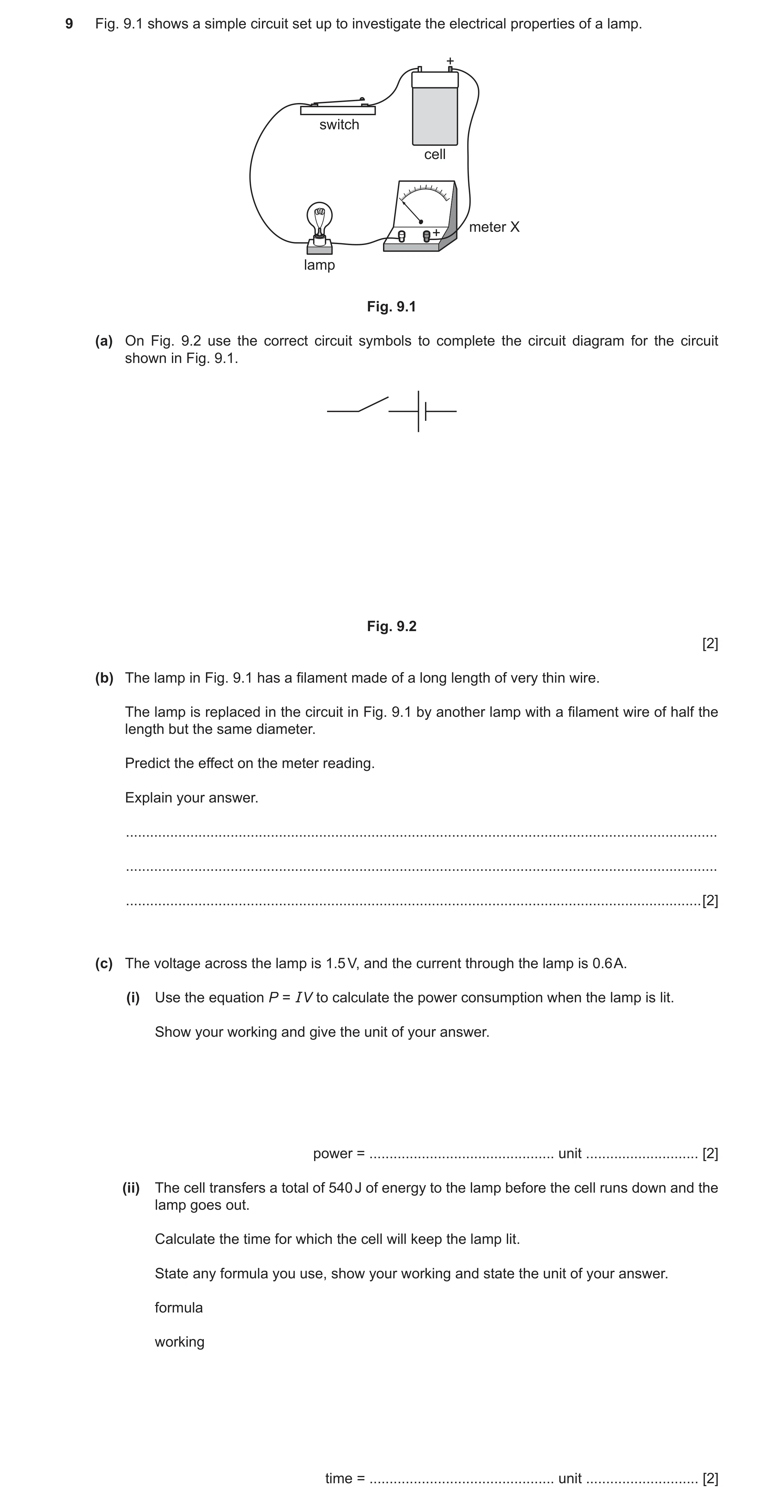
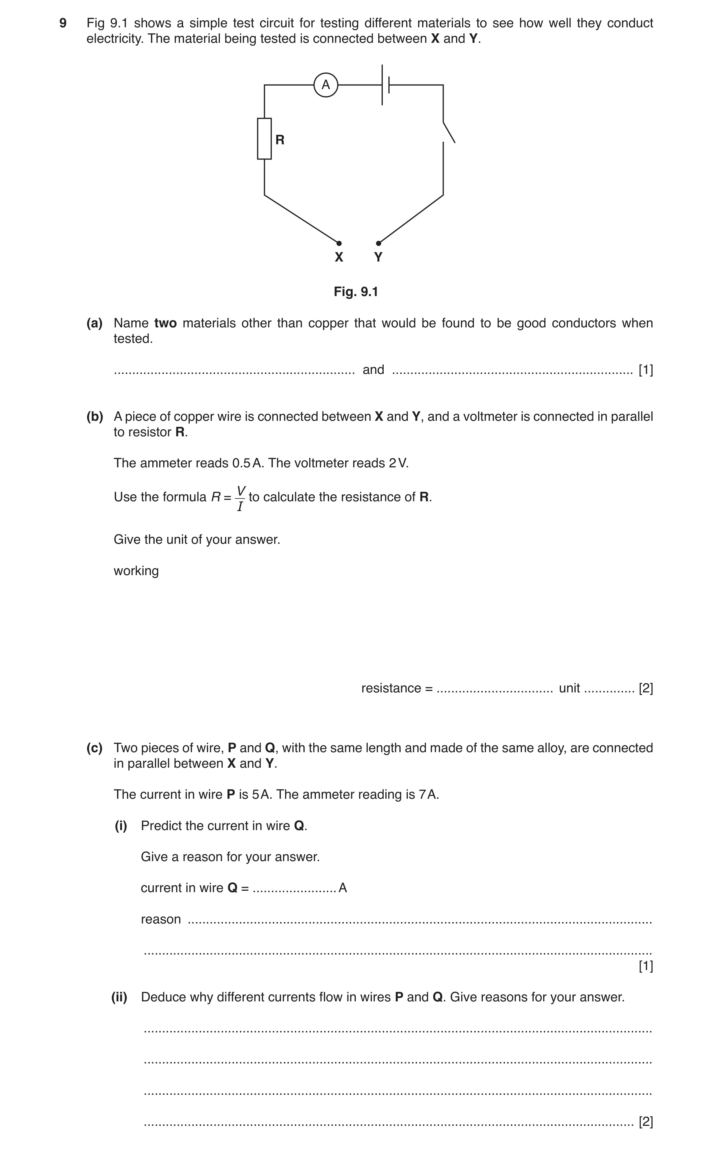
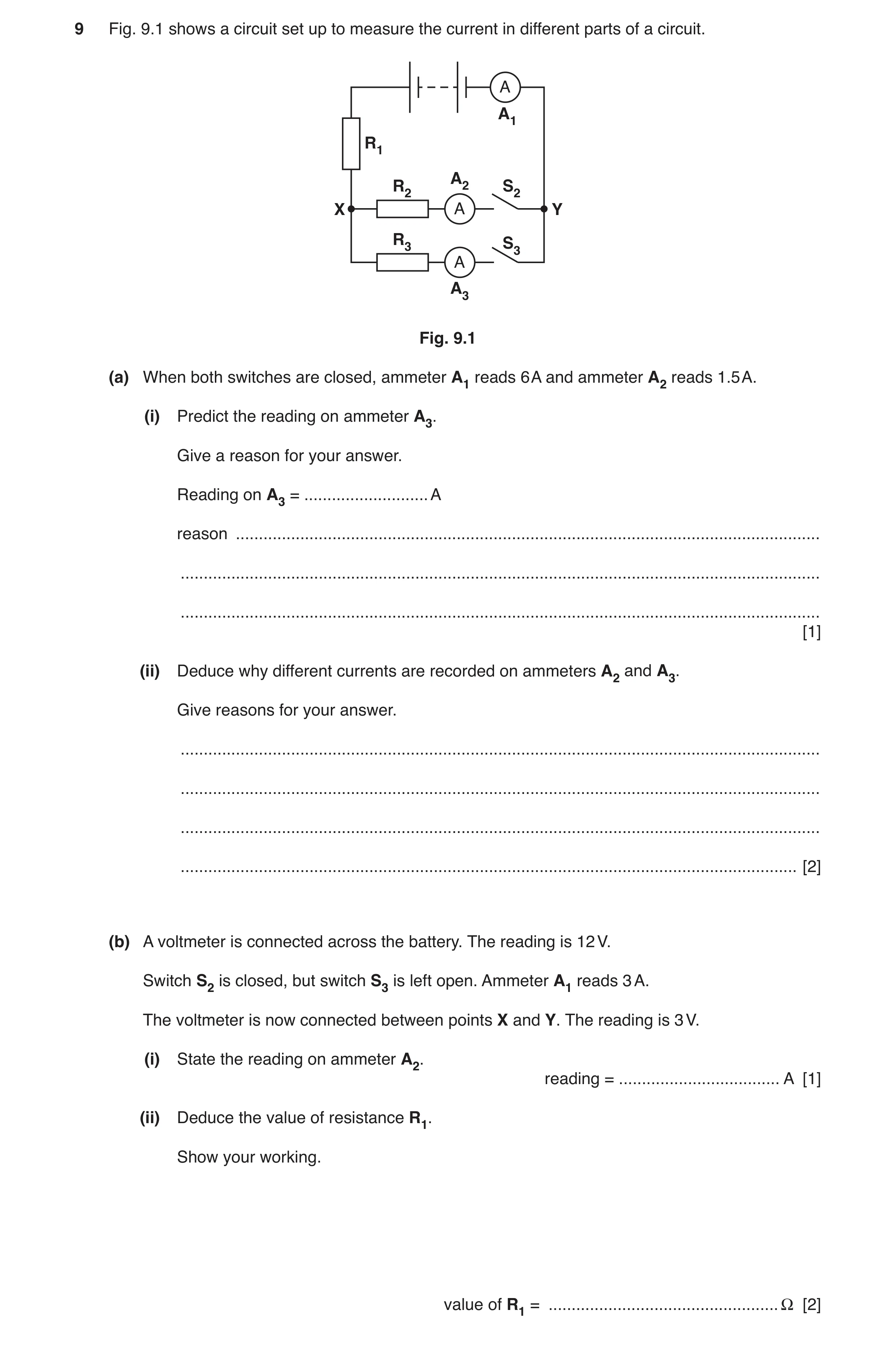
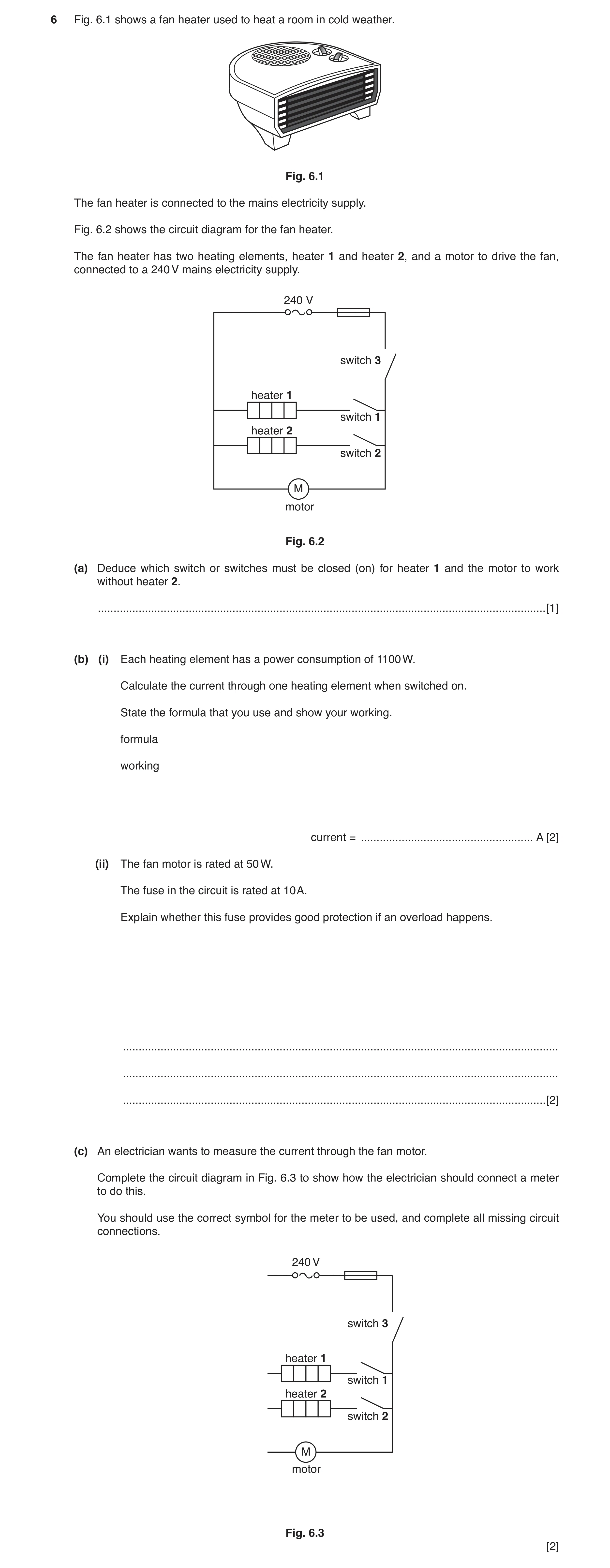
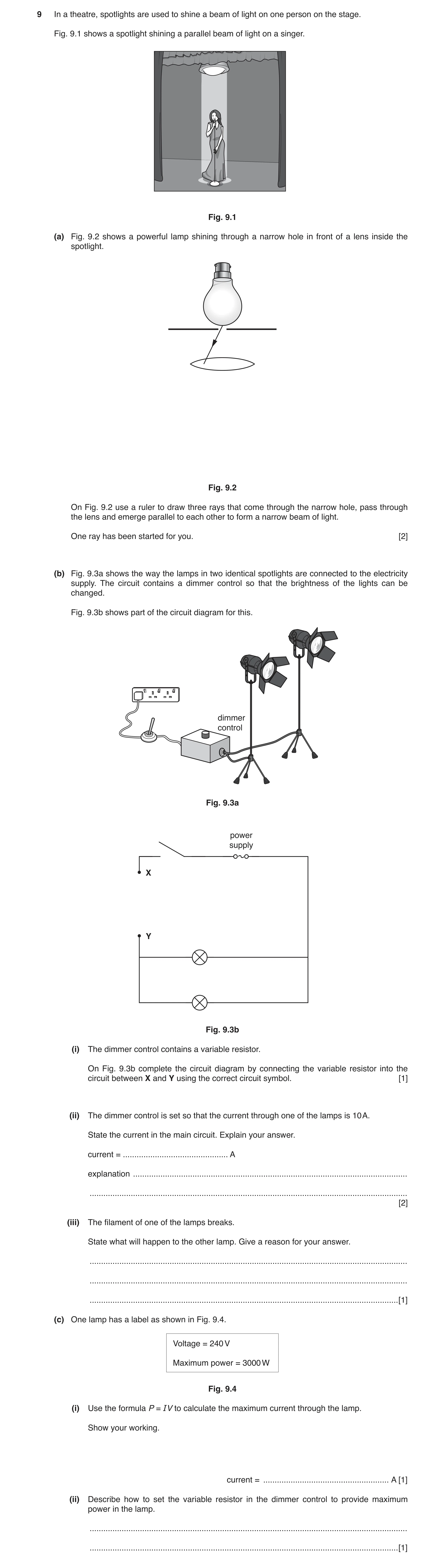
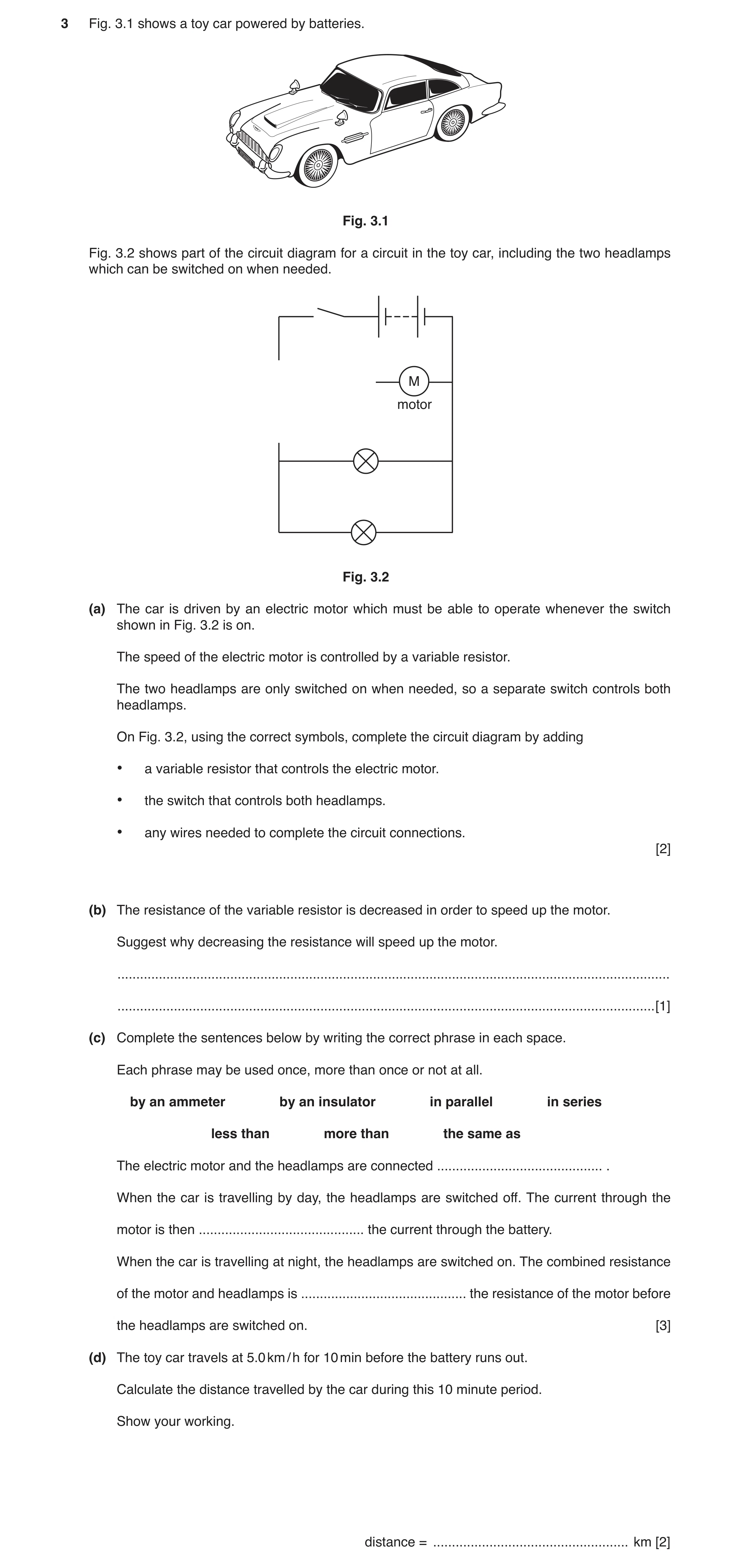
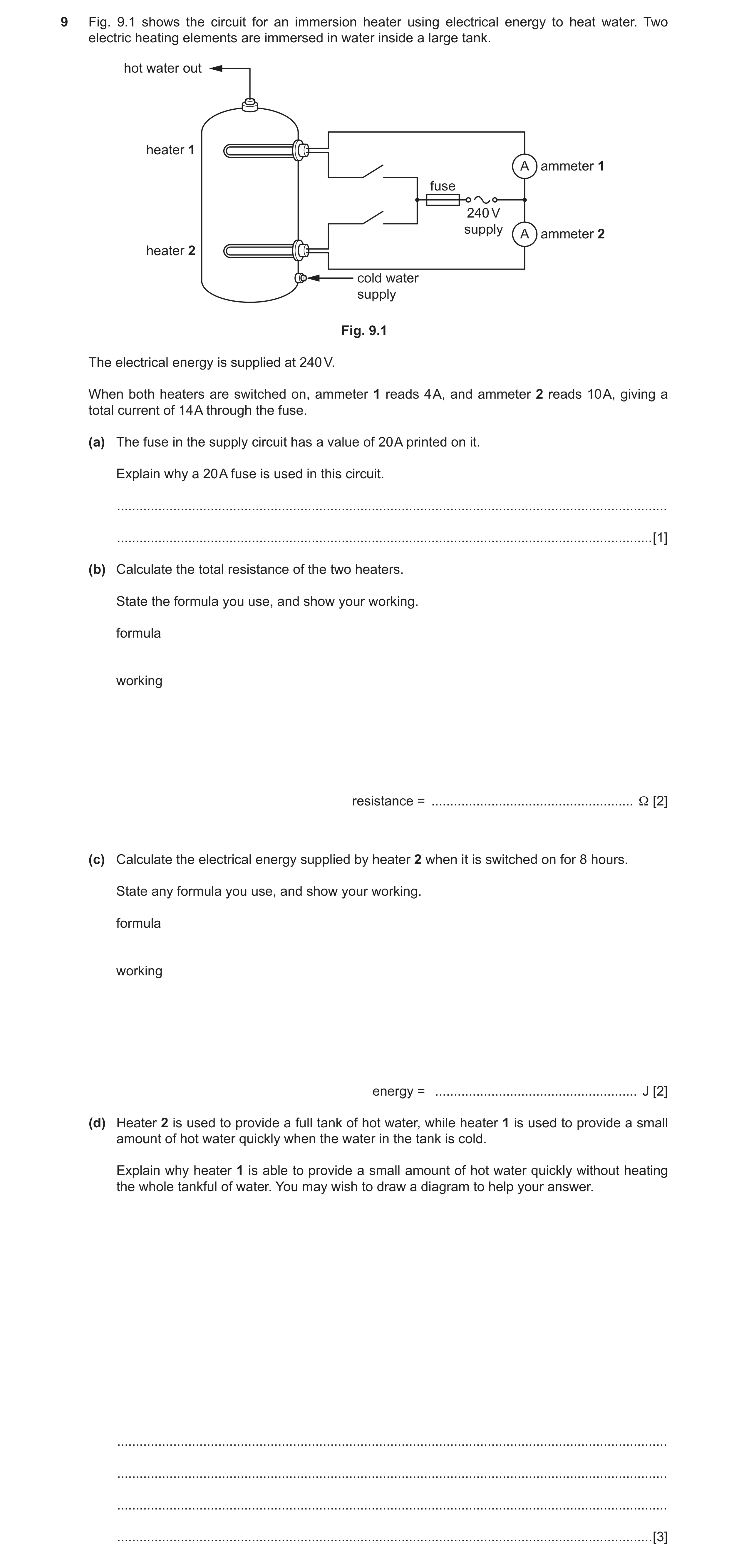
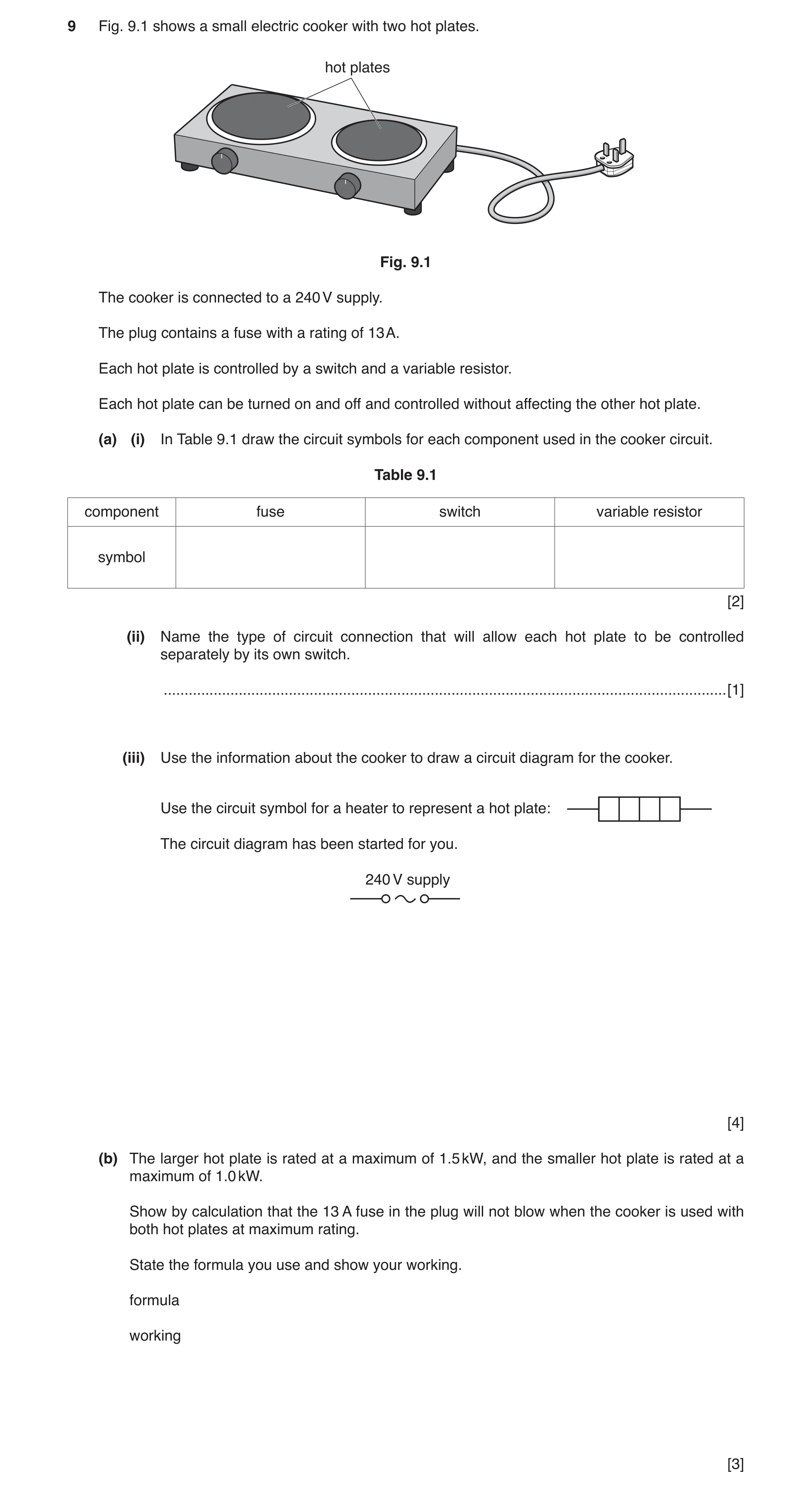
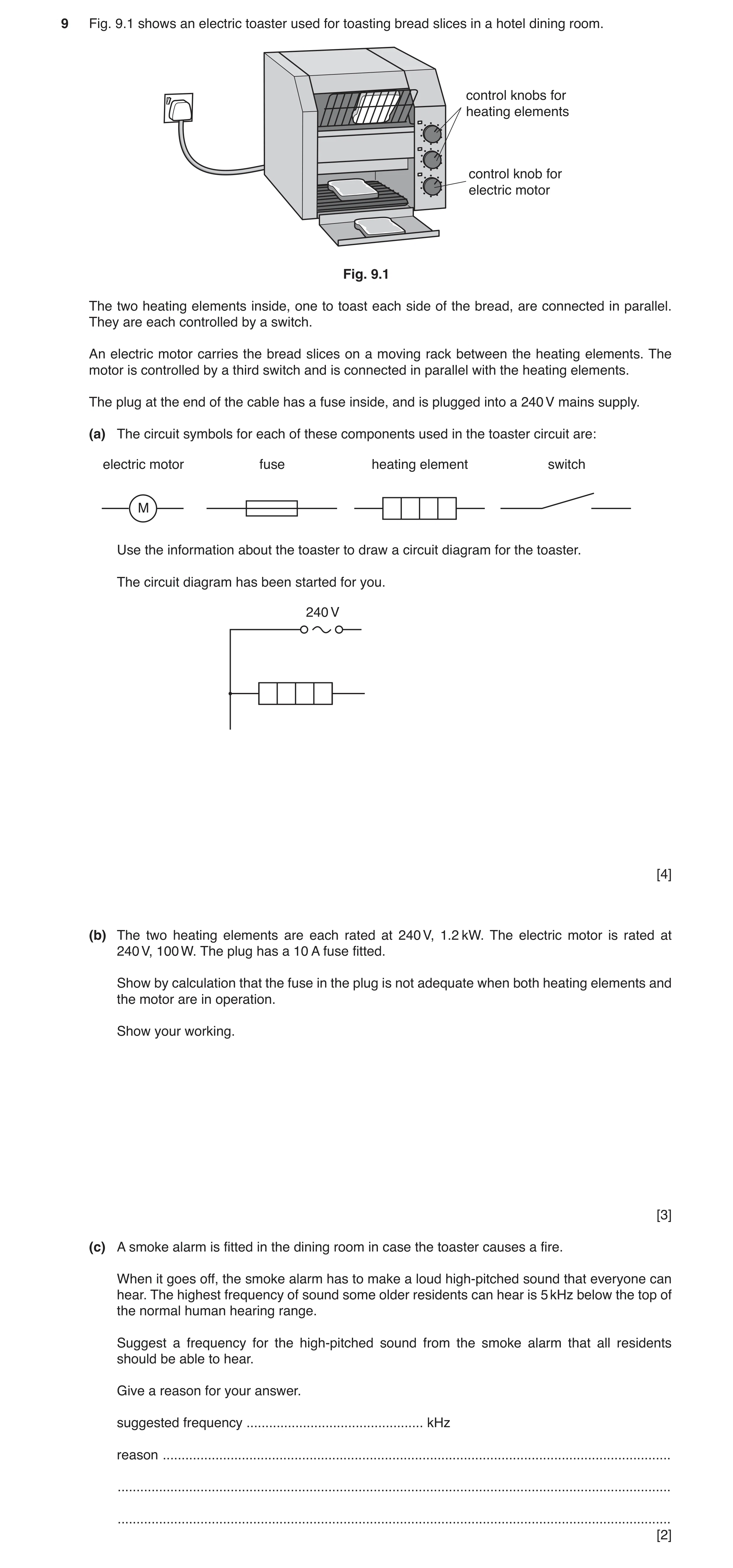
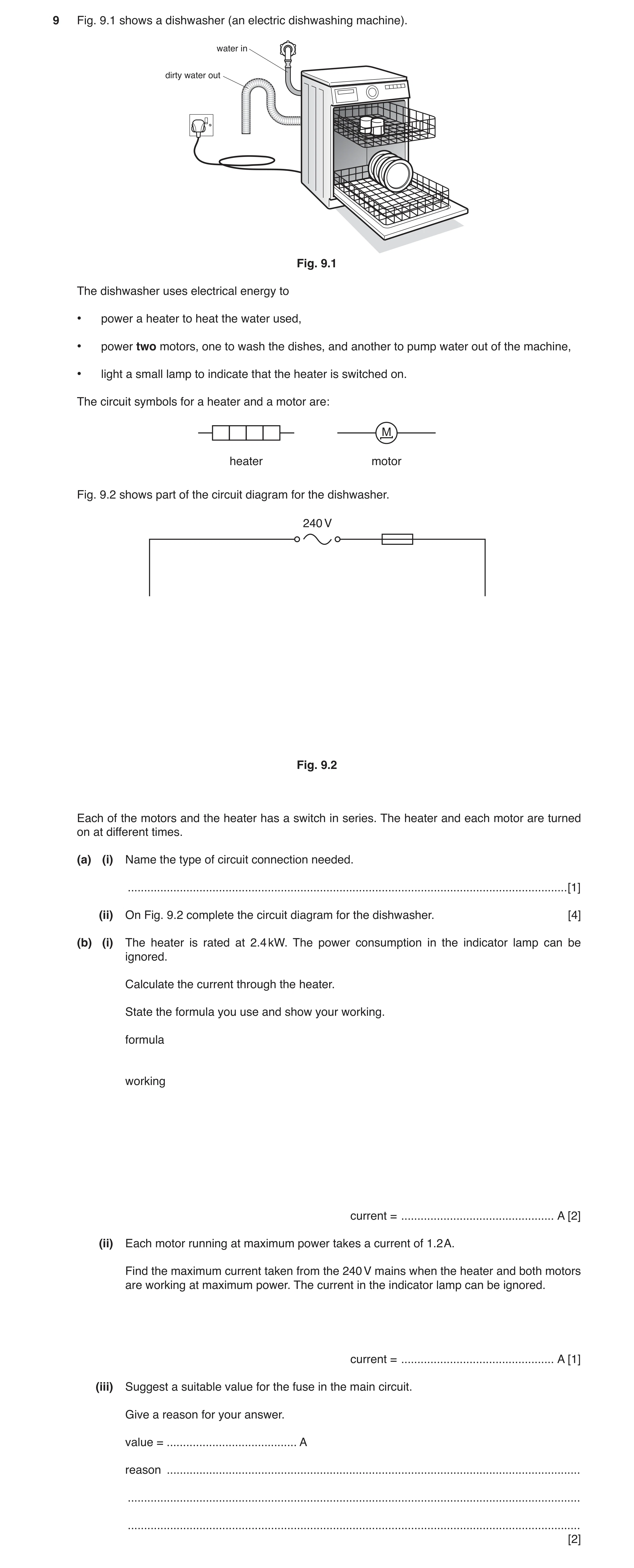
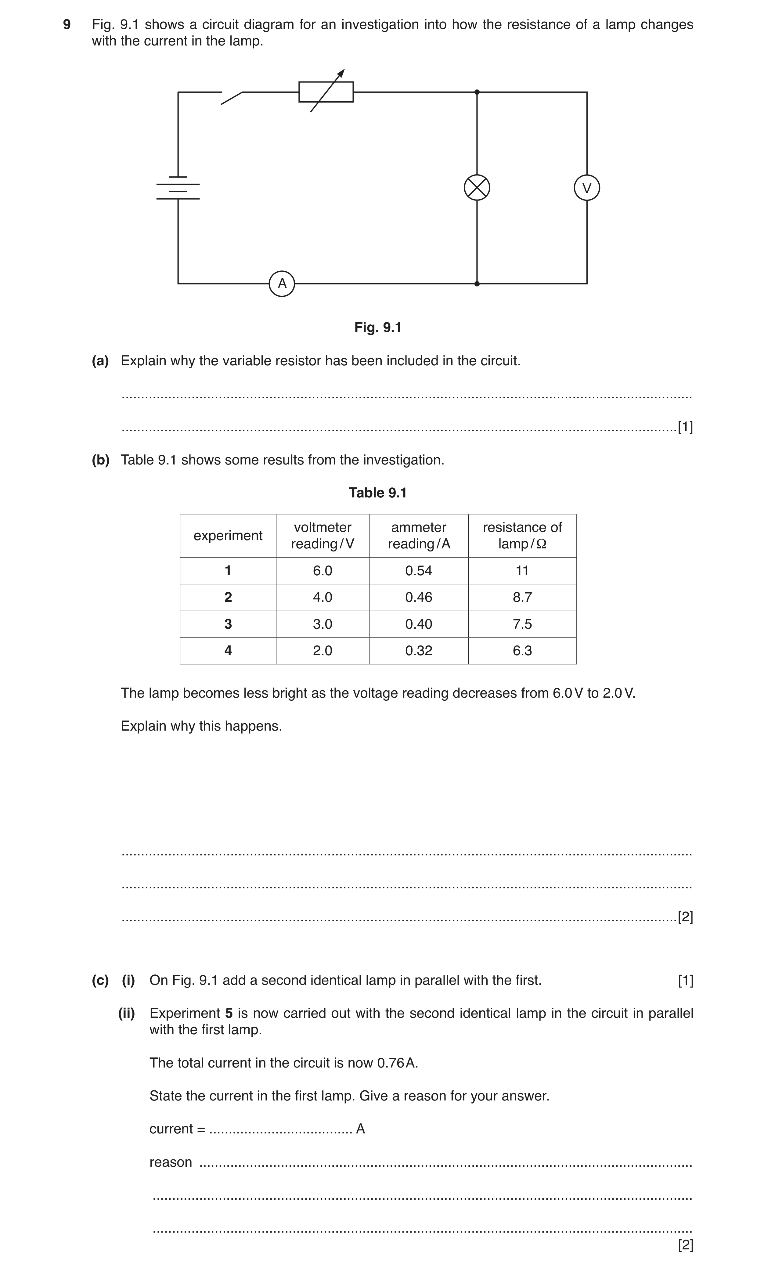
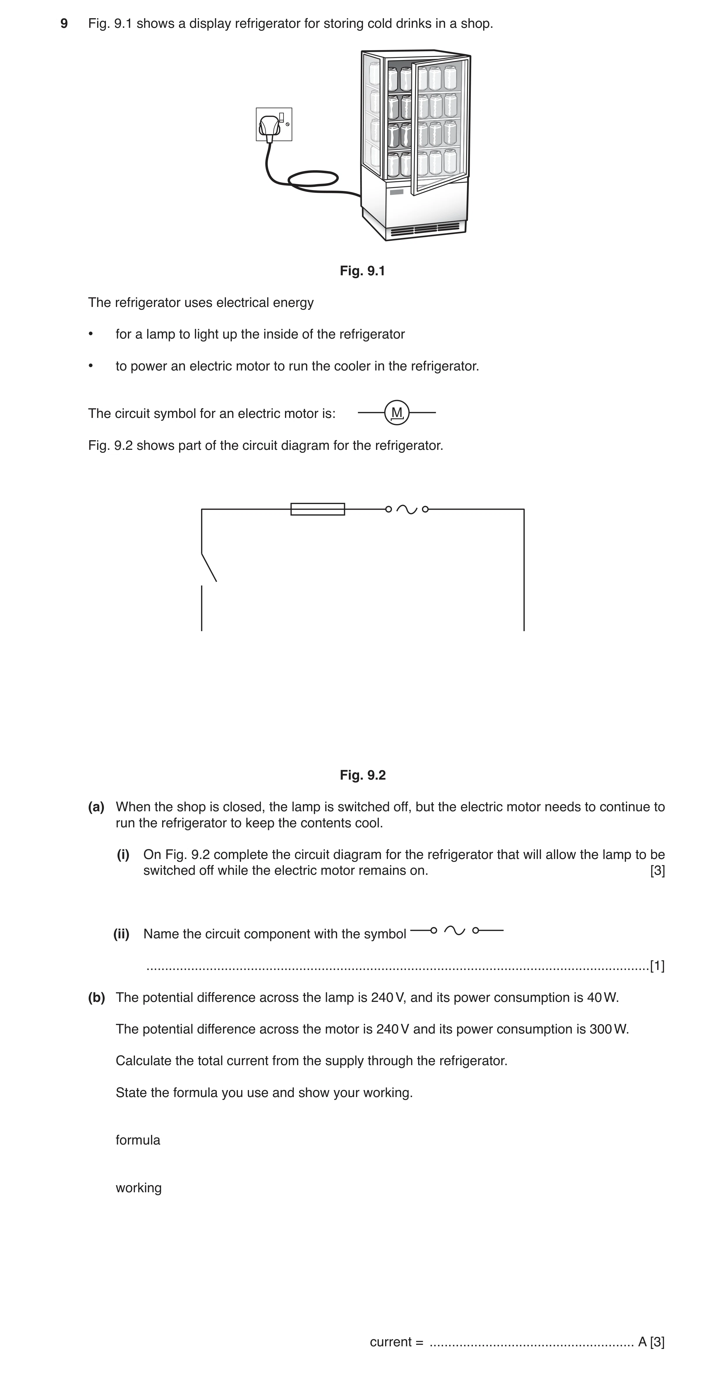
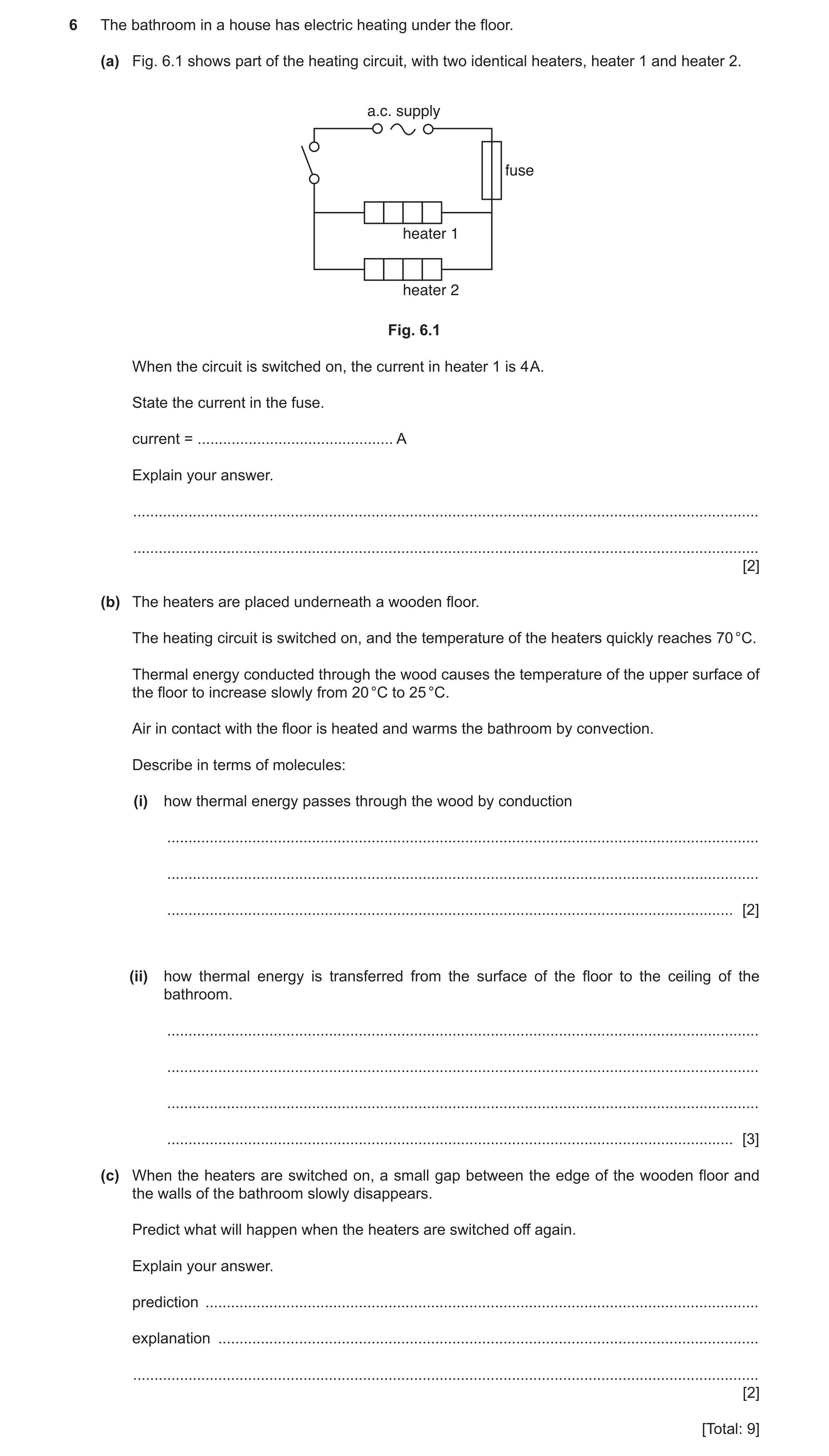
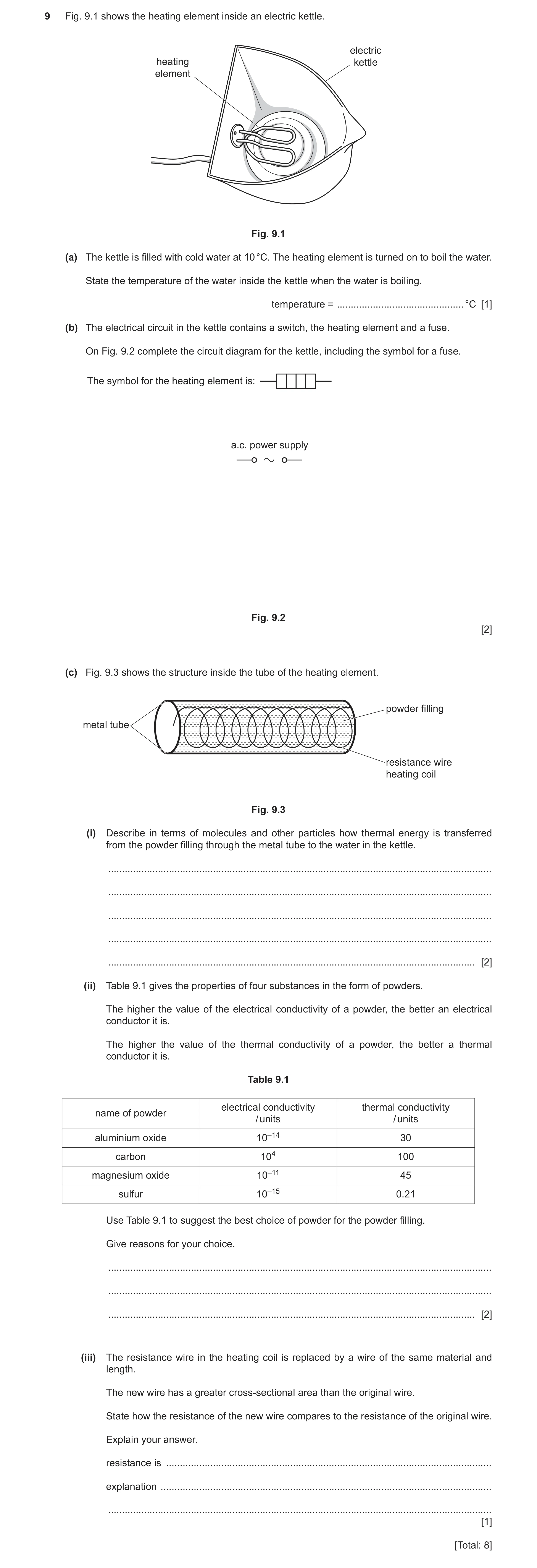
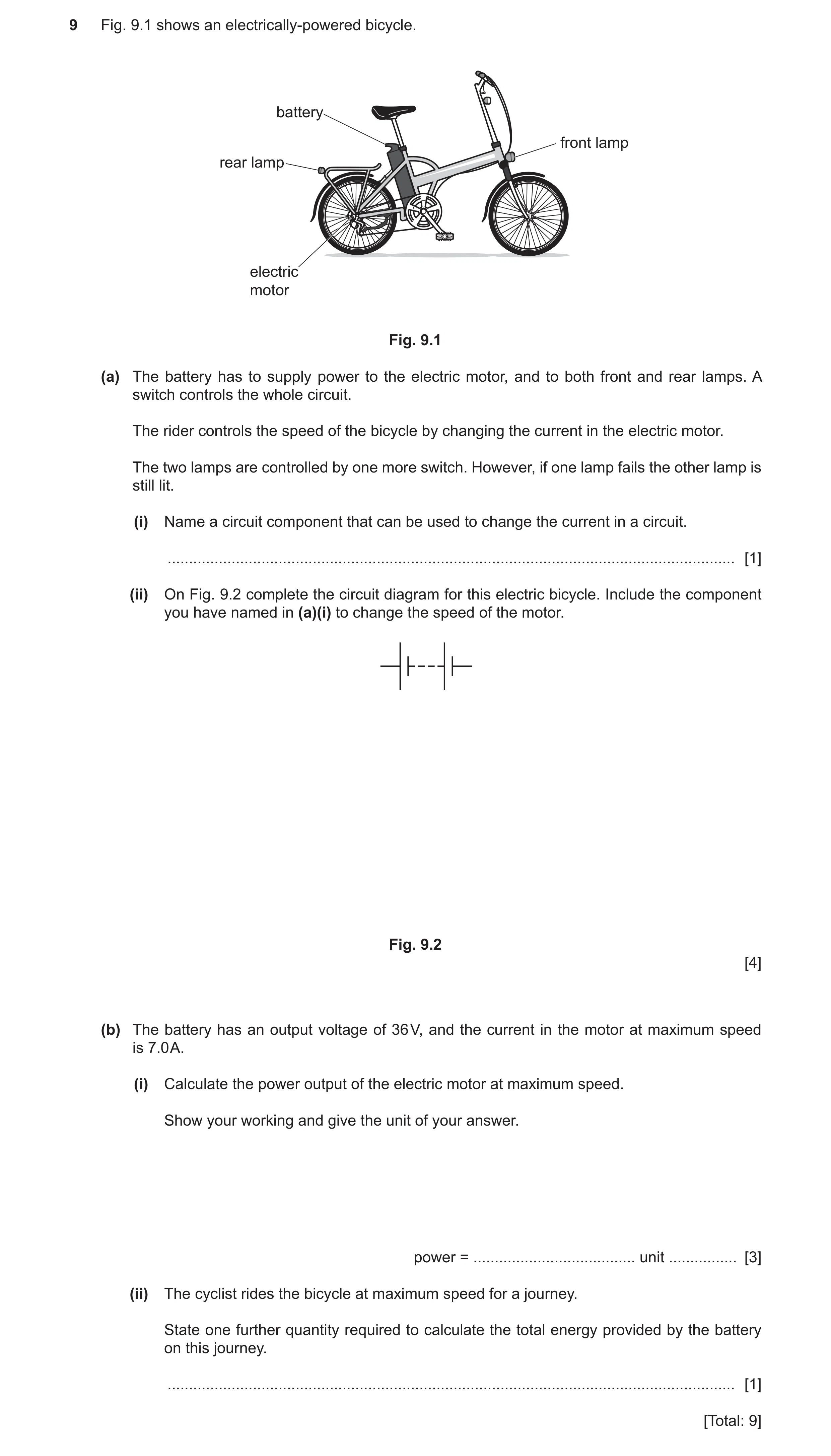
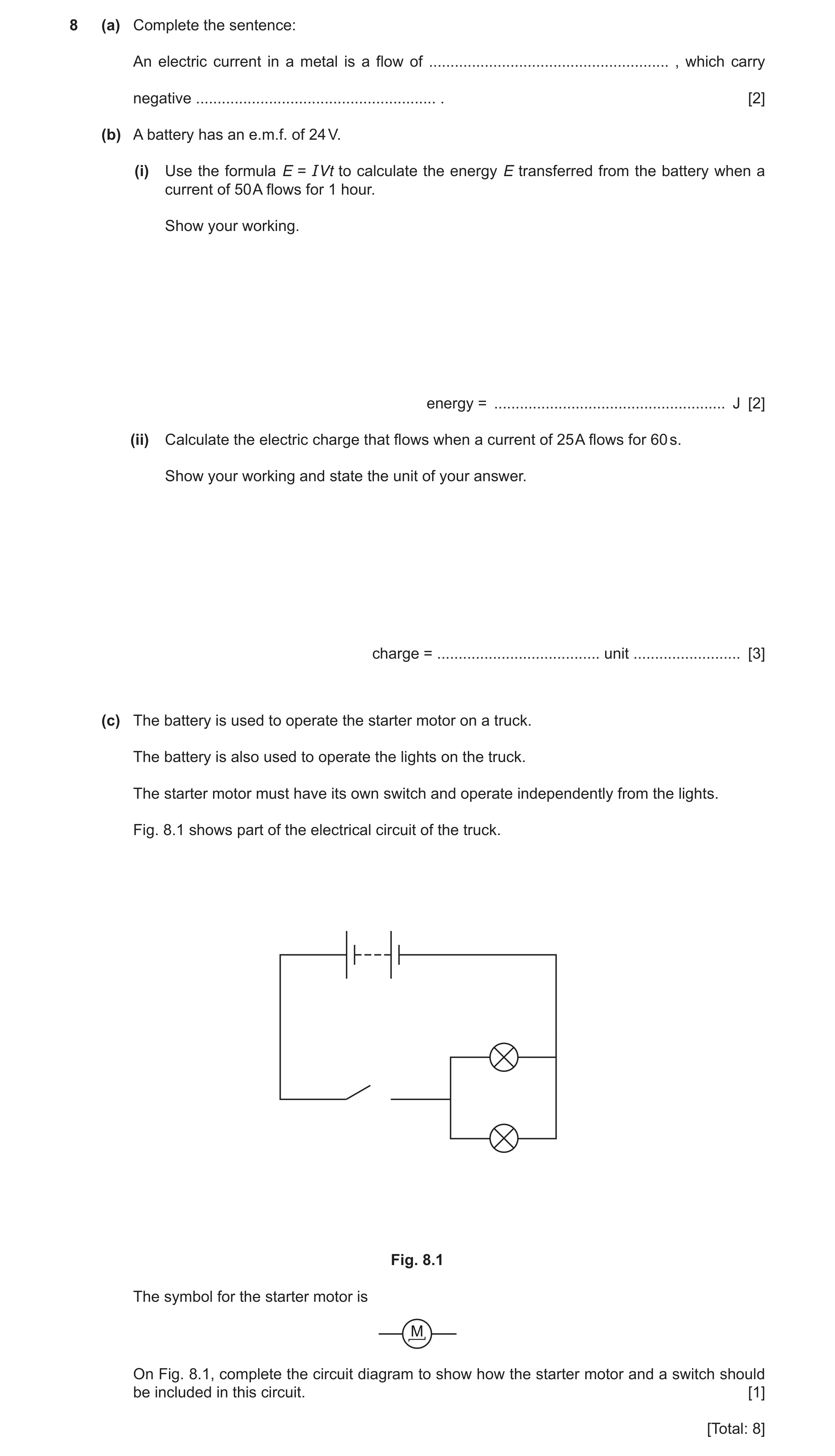
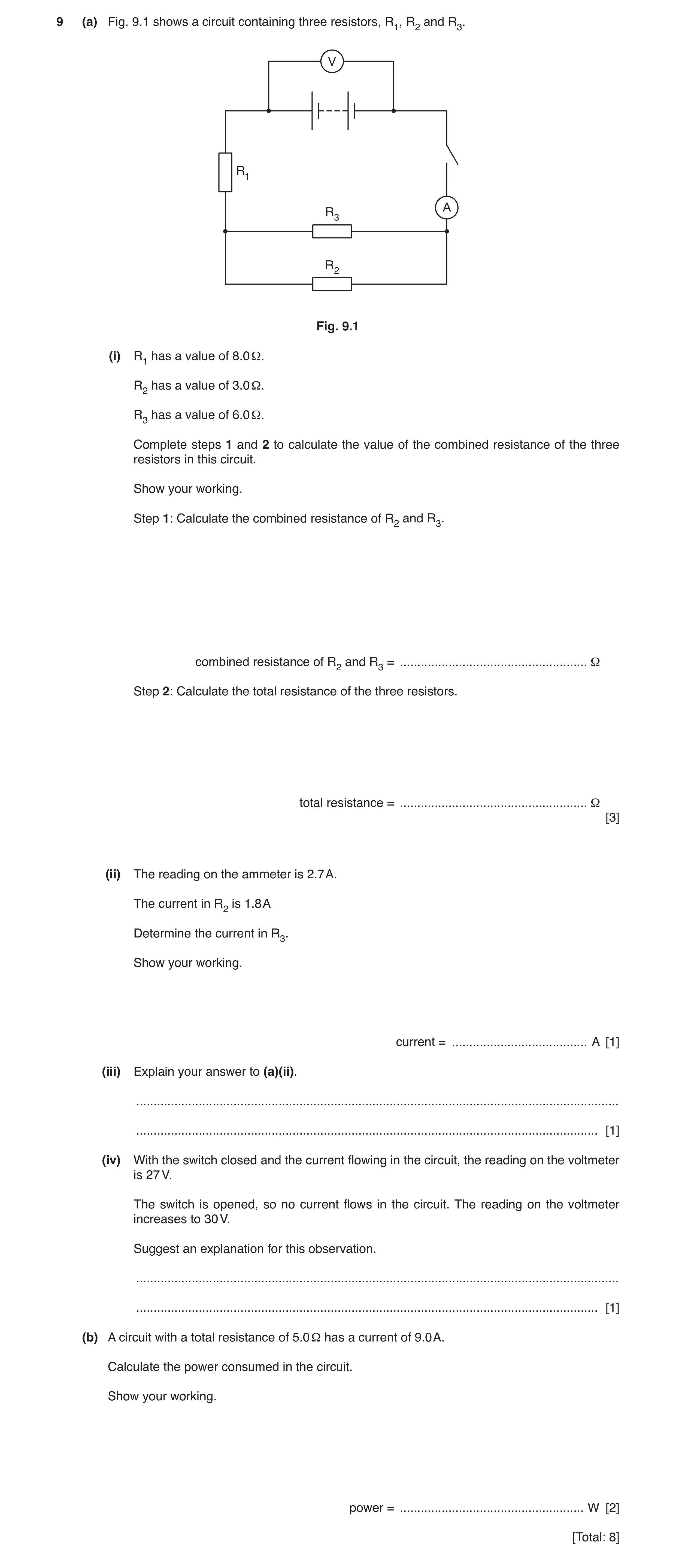
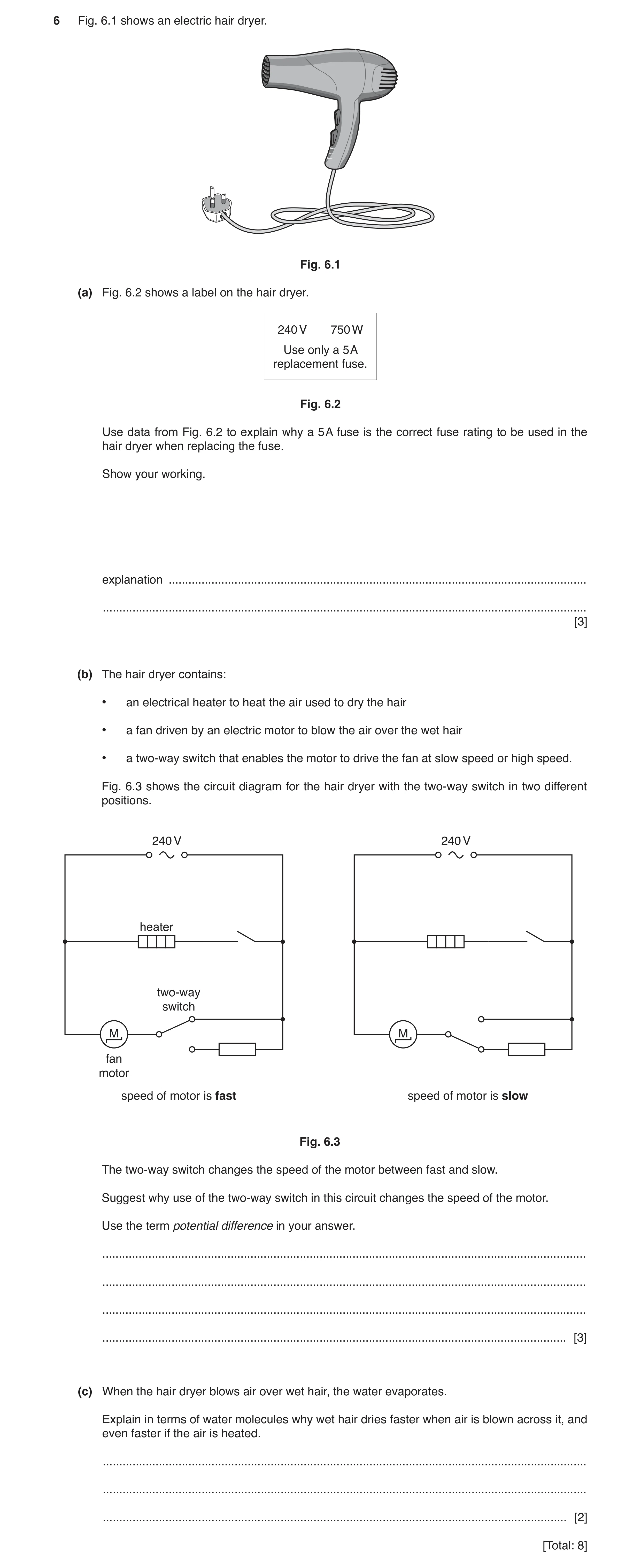
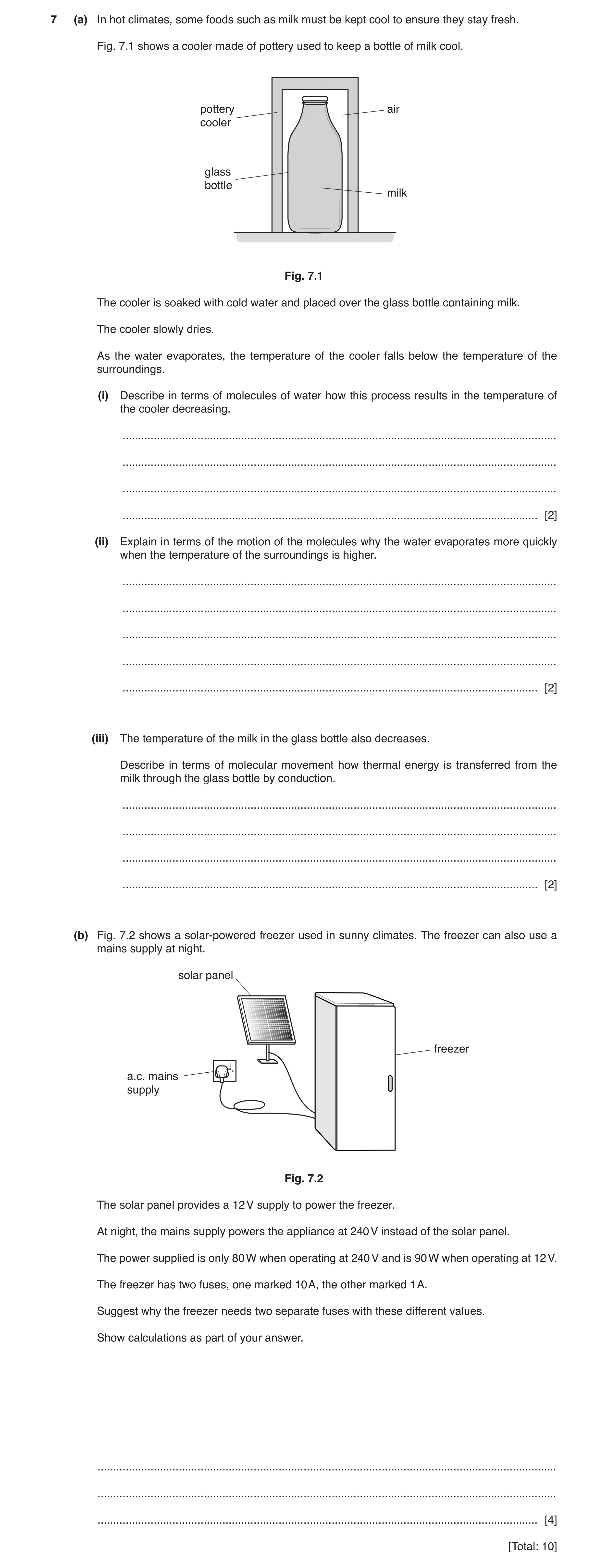
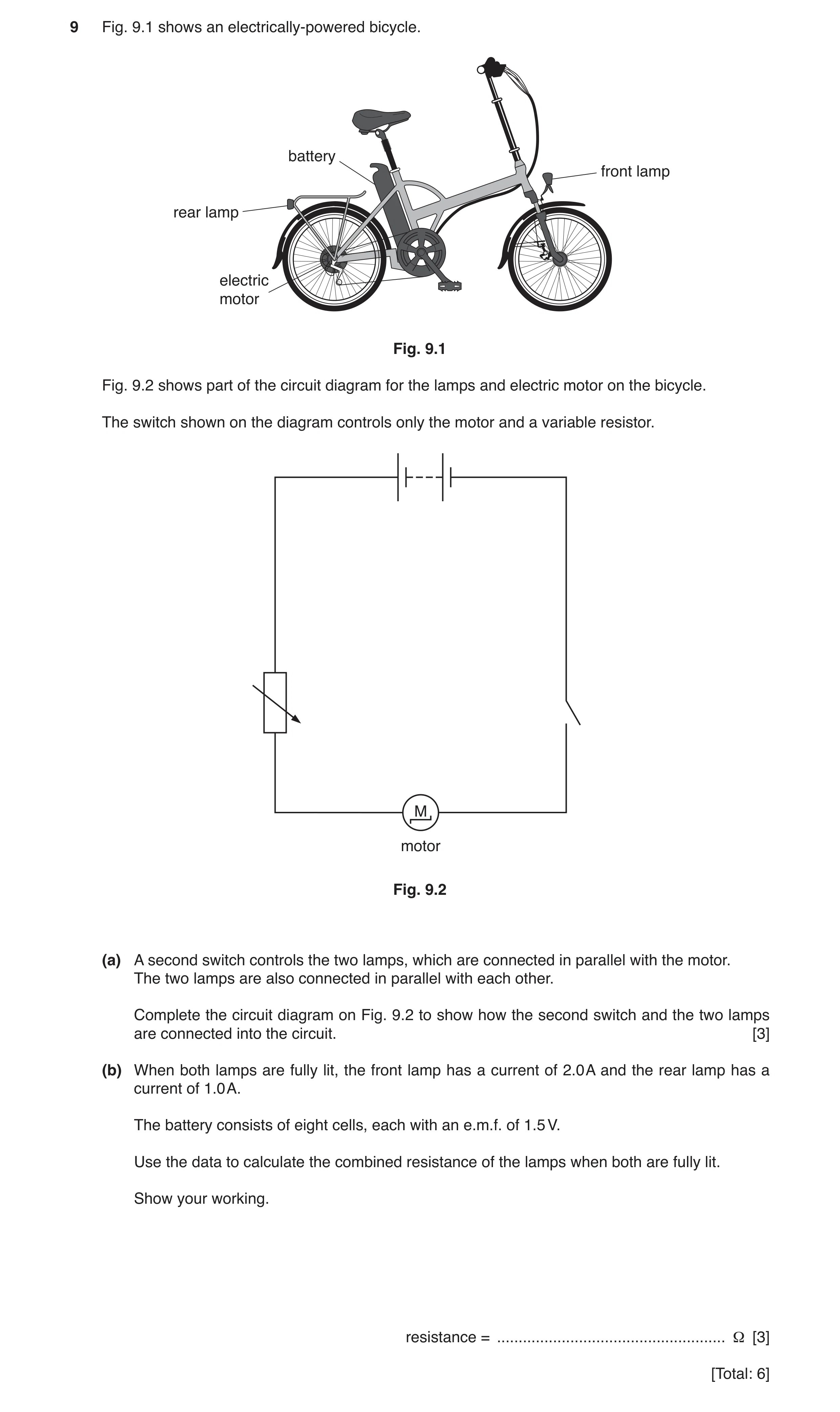
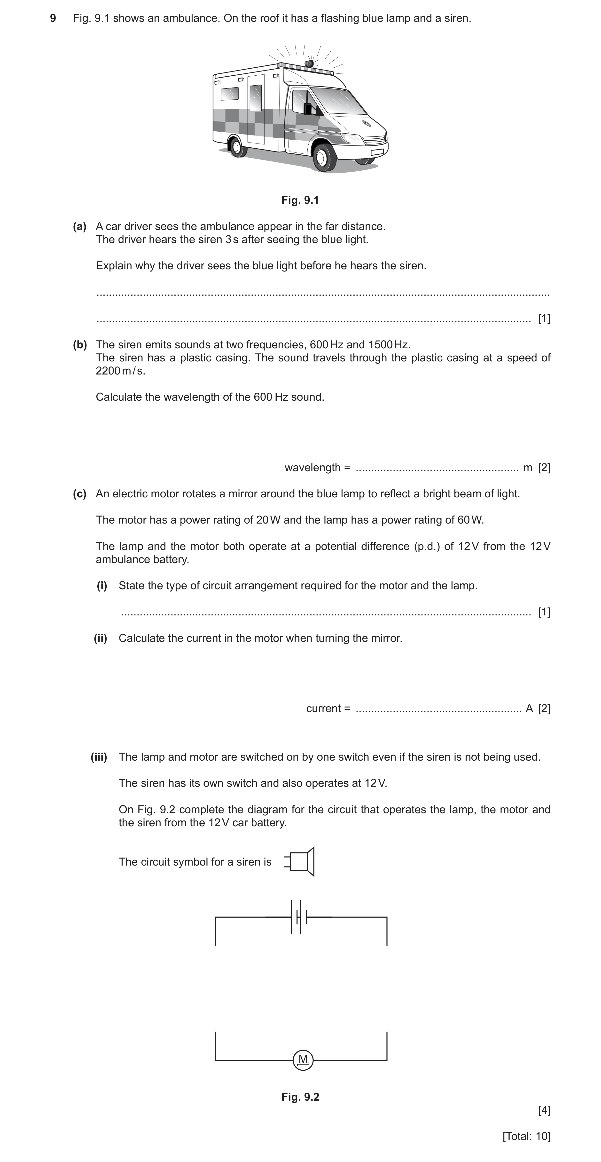
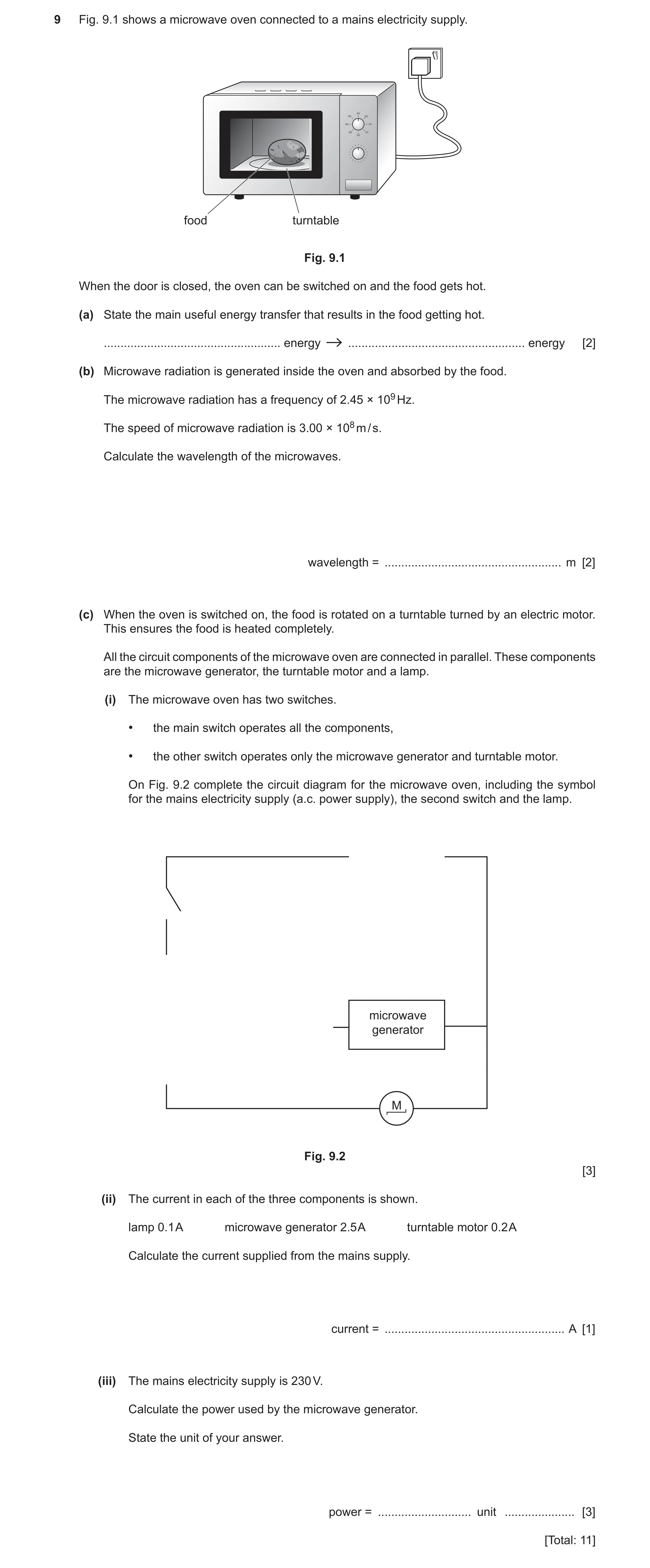
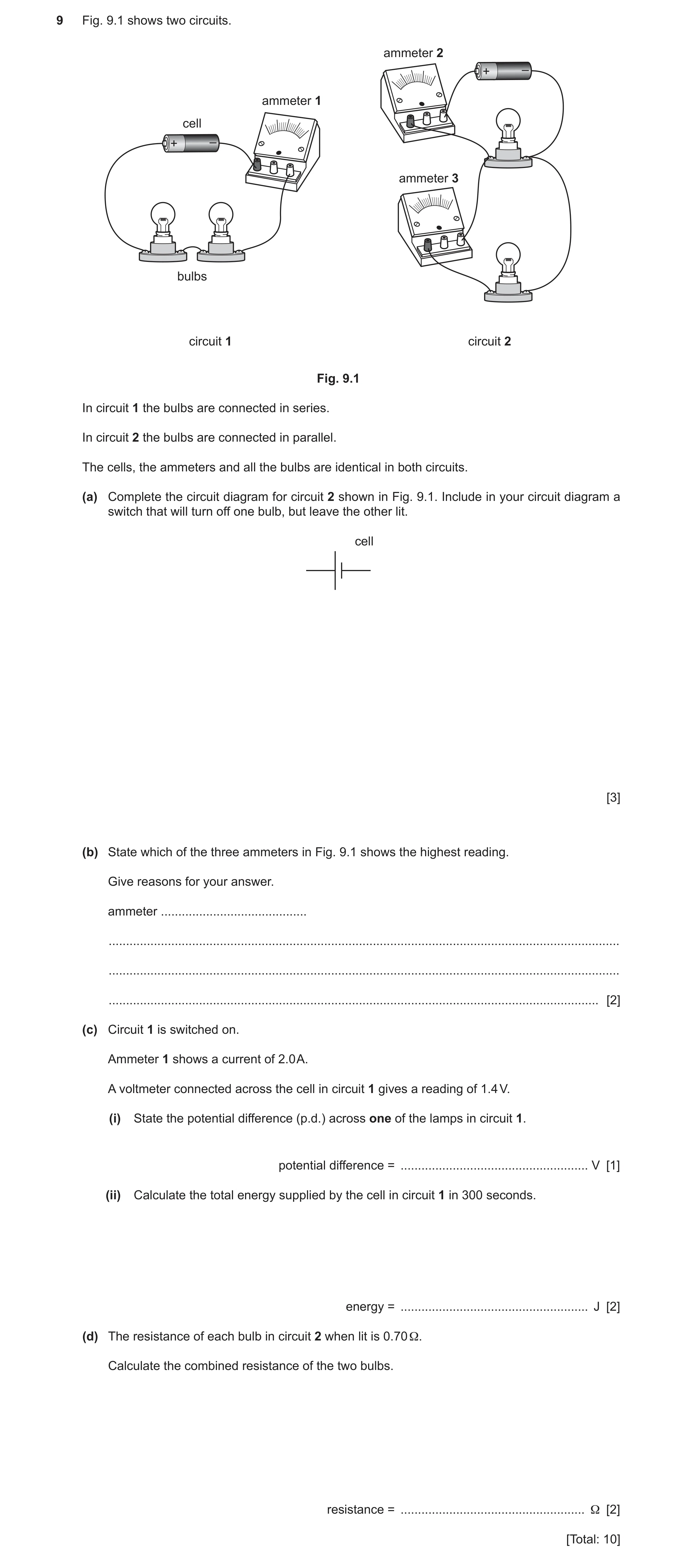
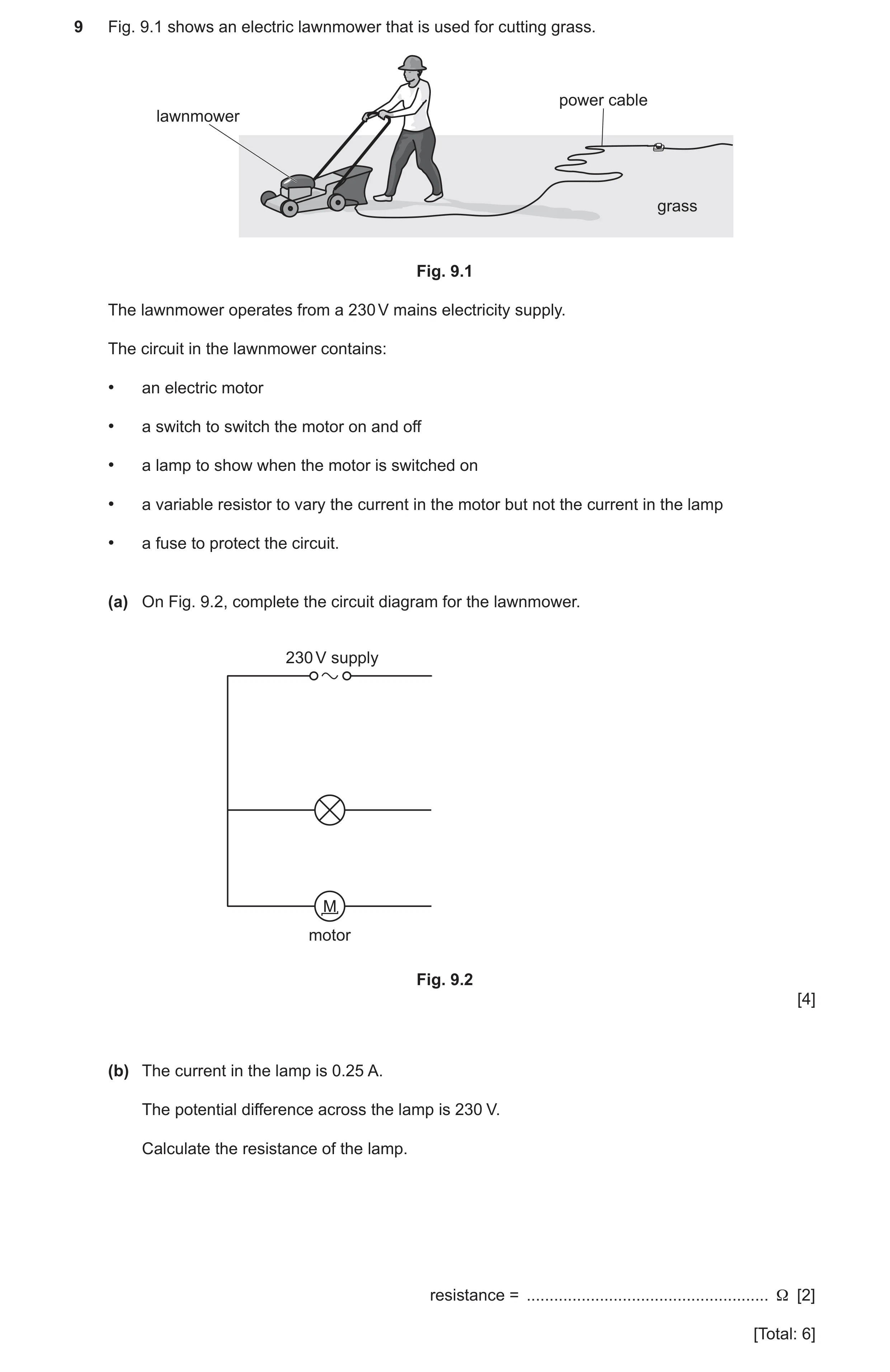
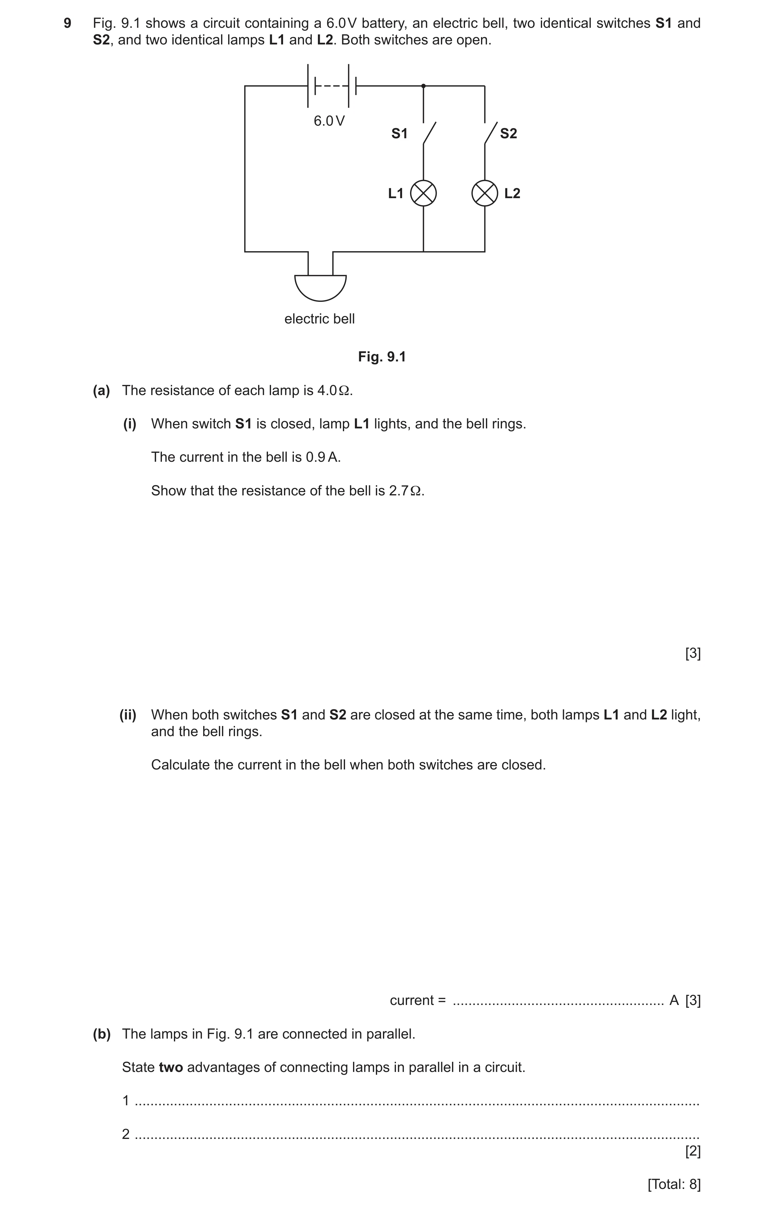
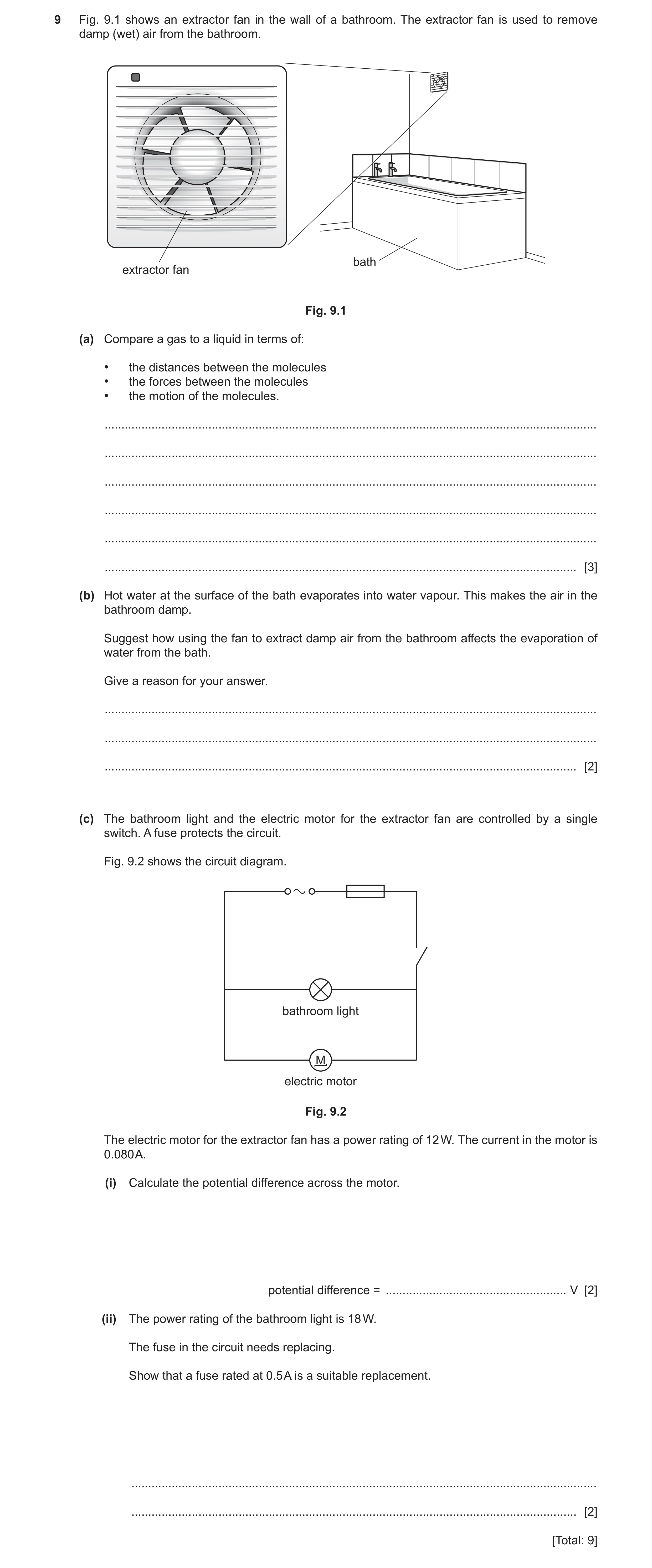
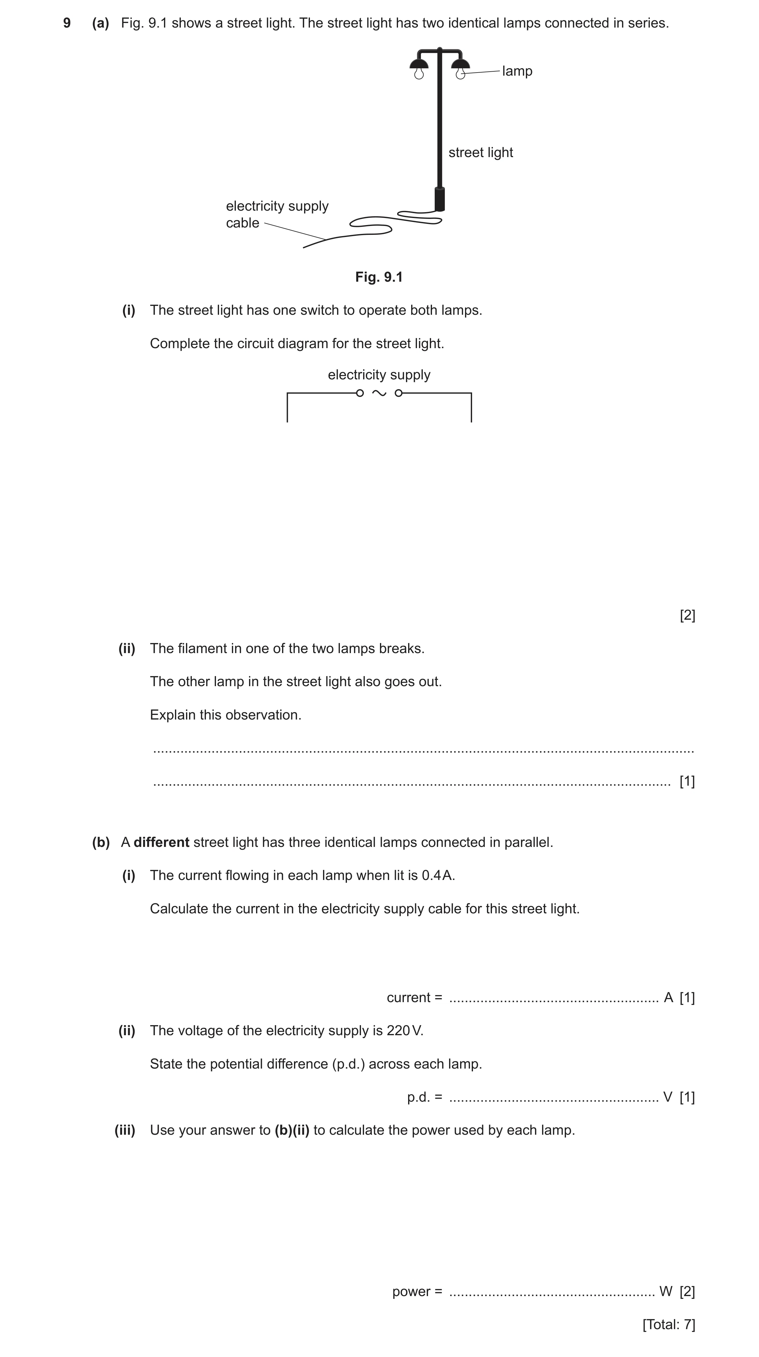
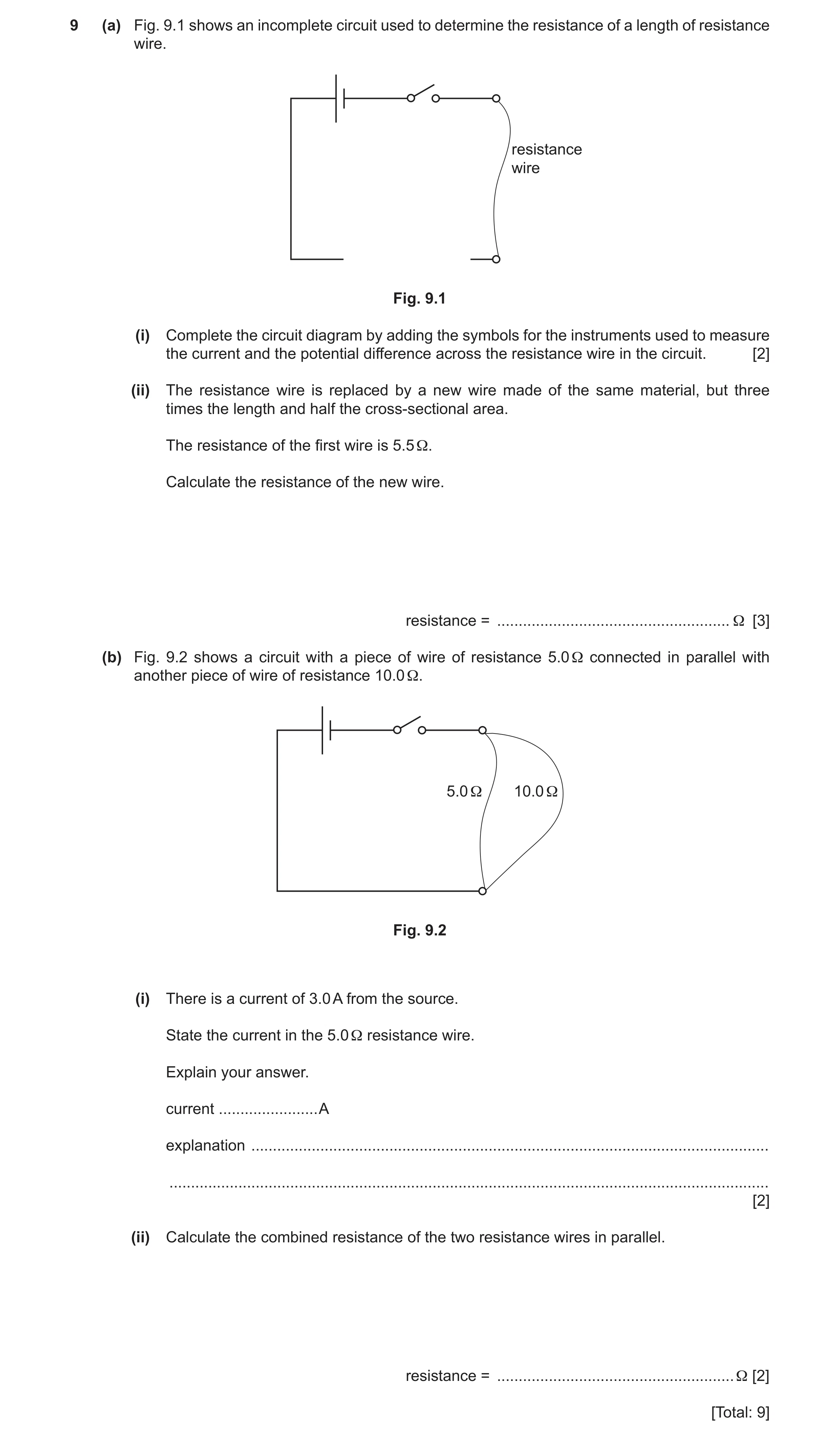
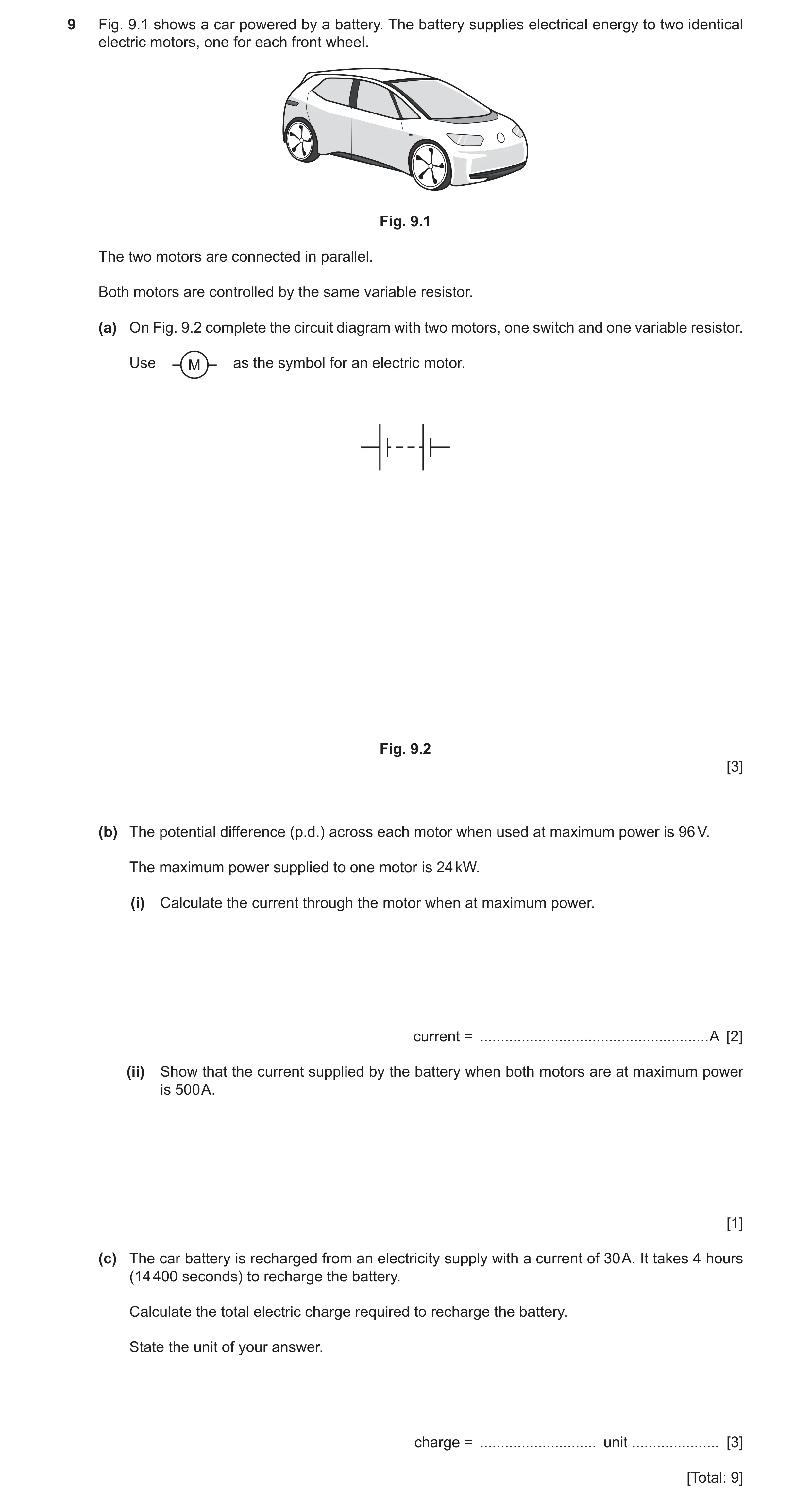
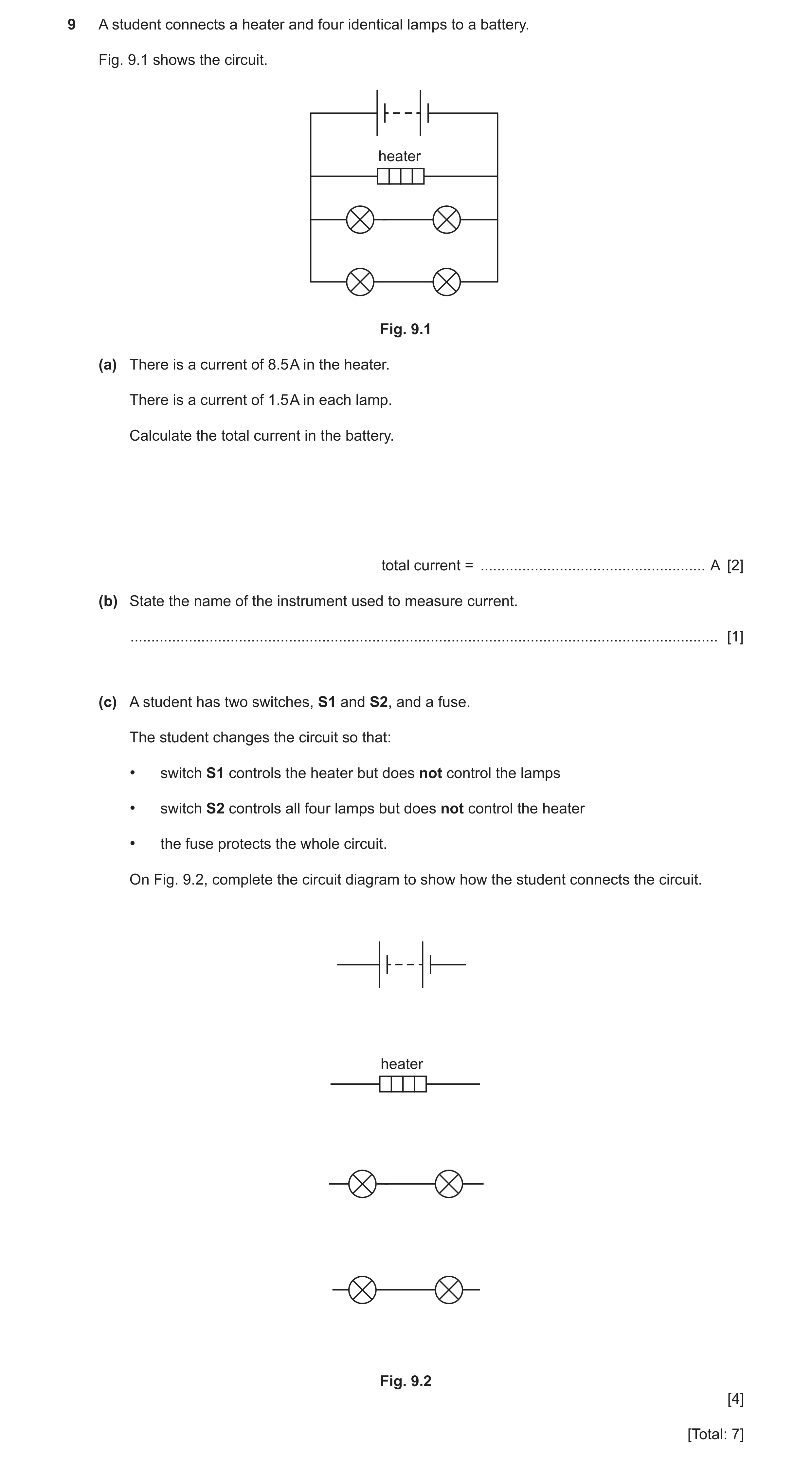
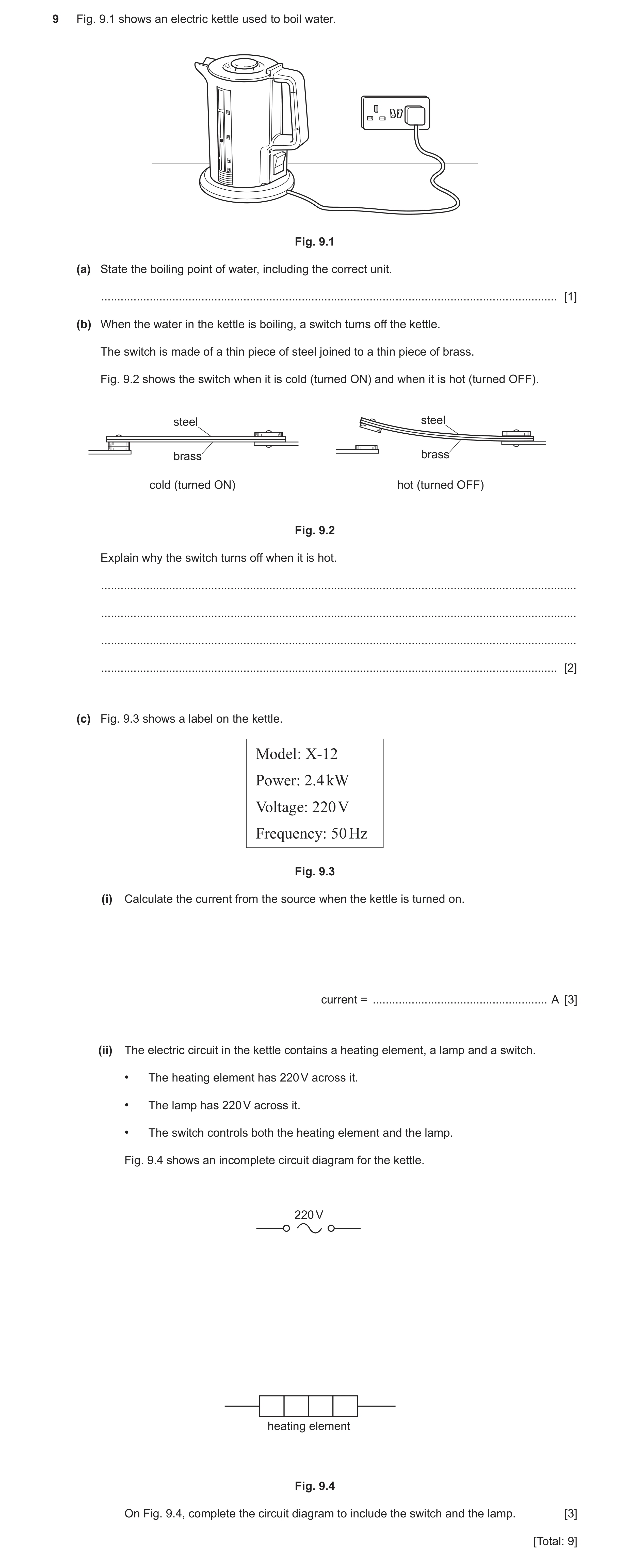
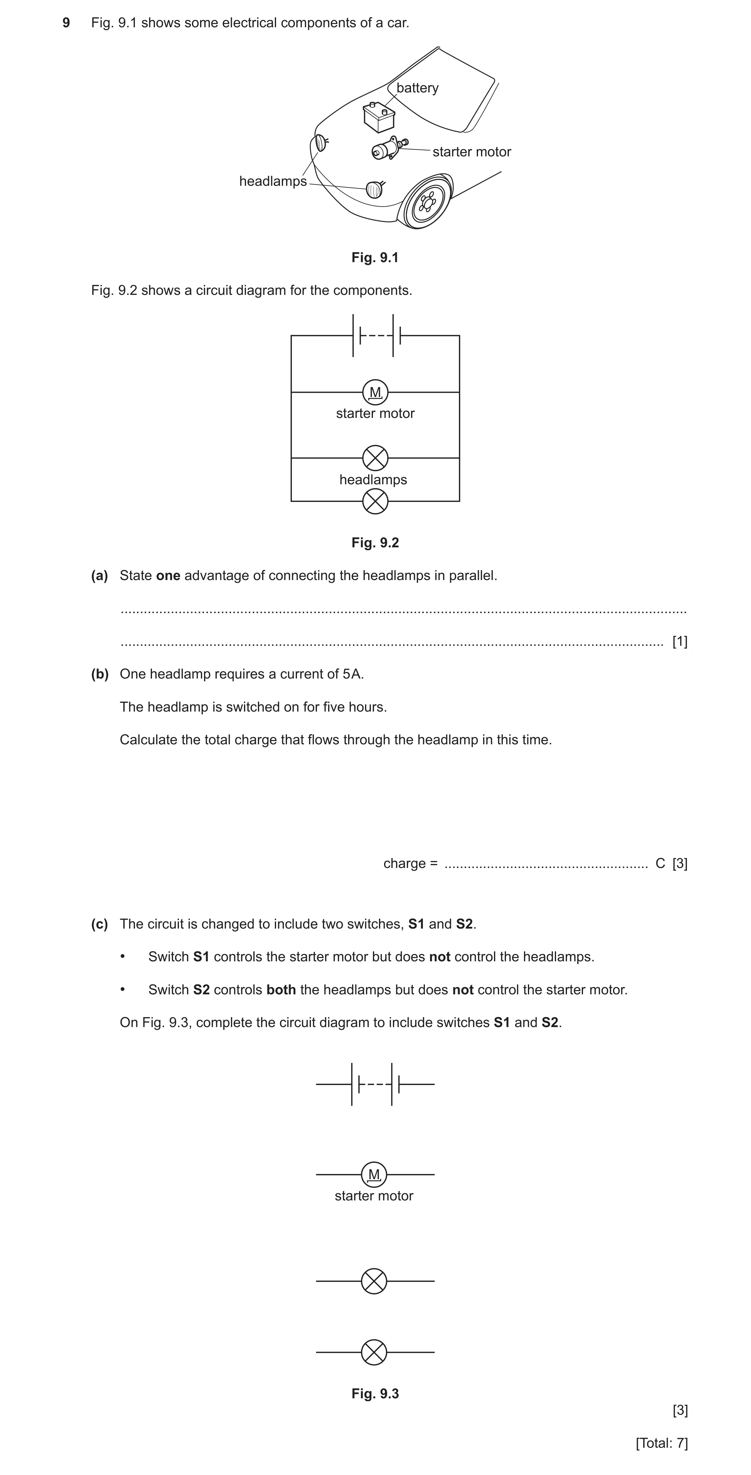
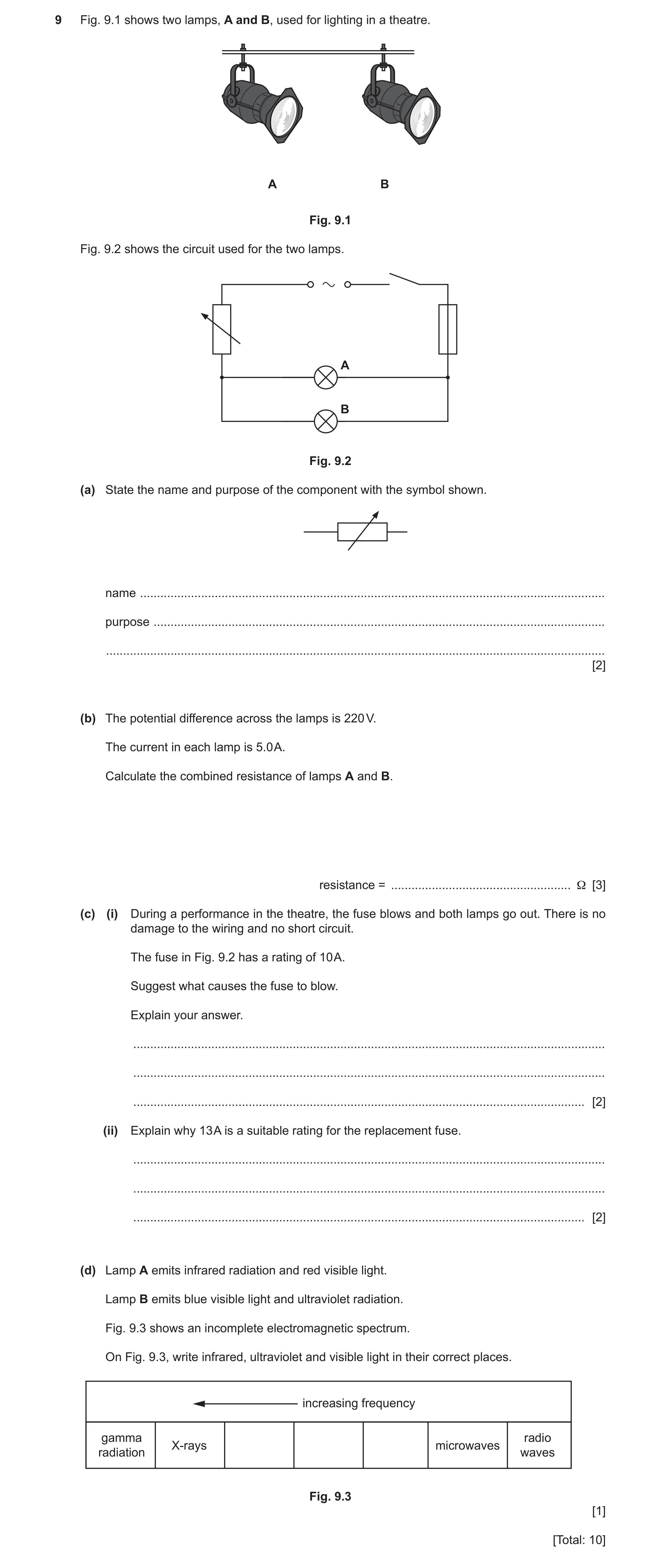
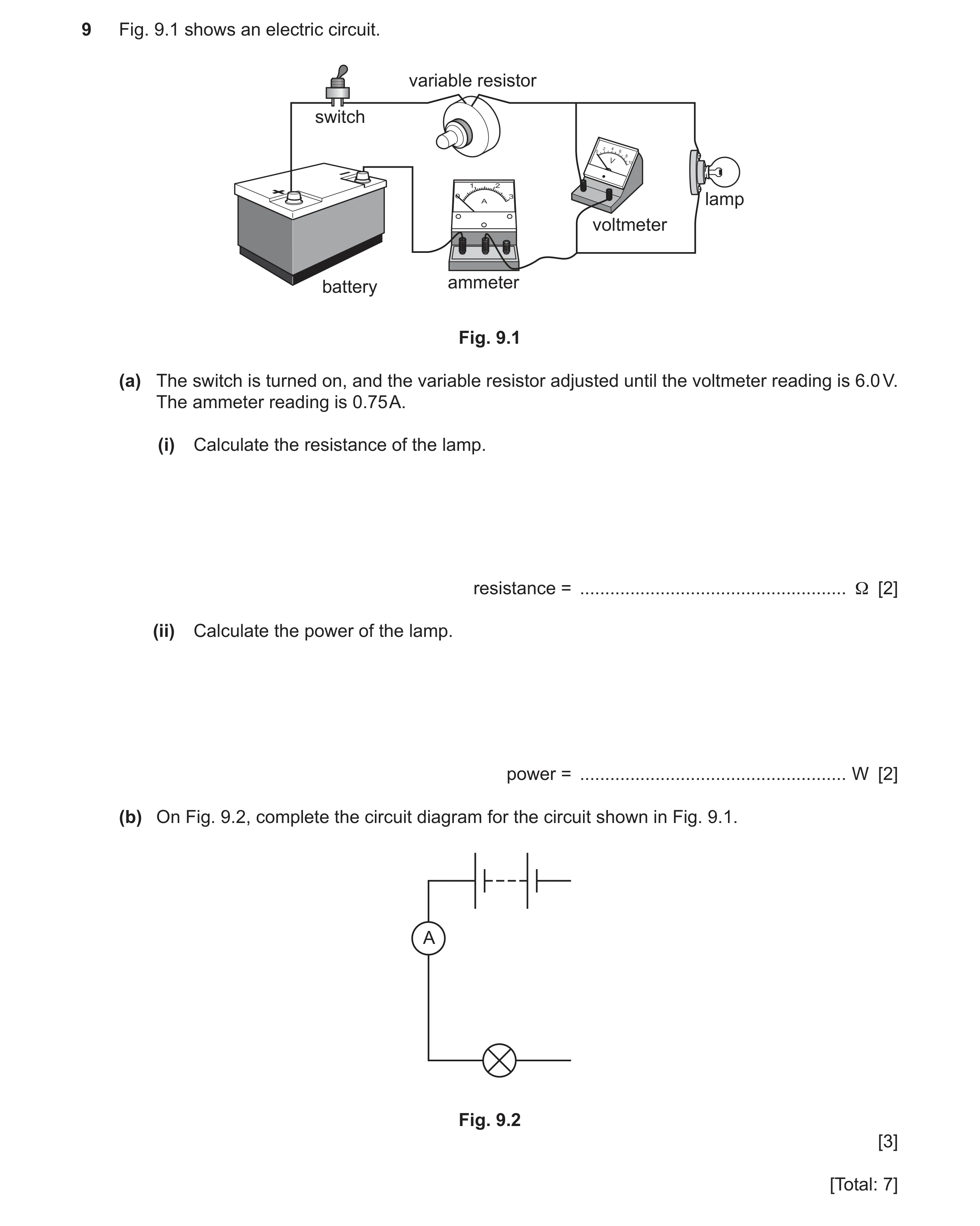 53 / 93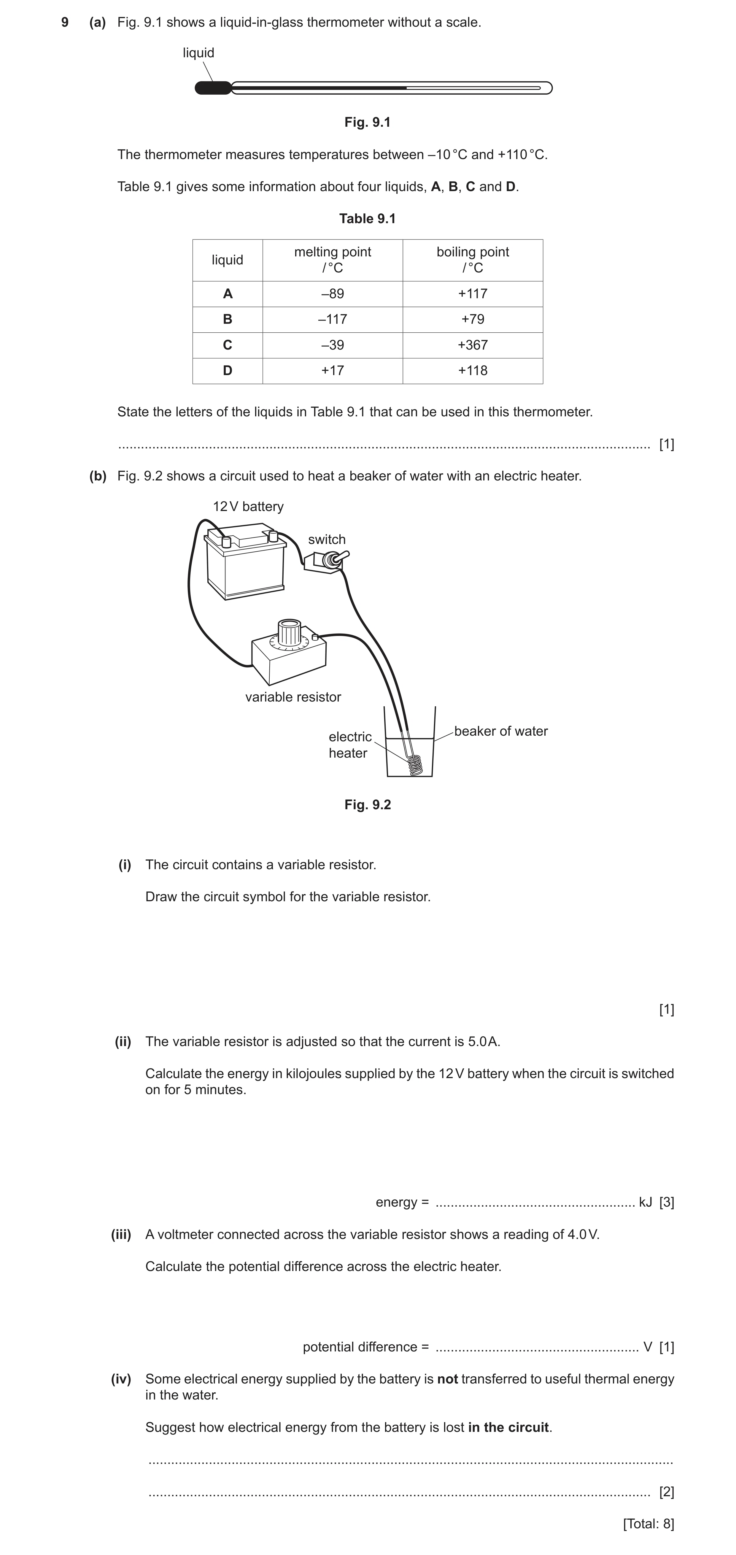
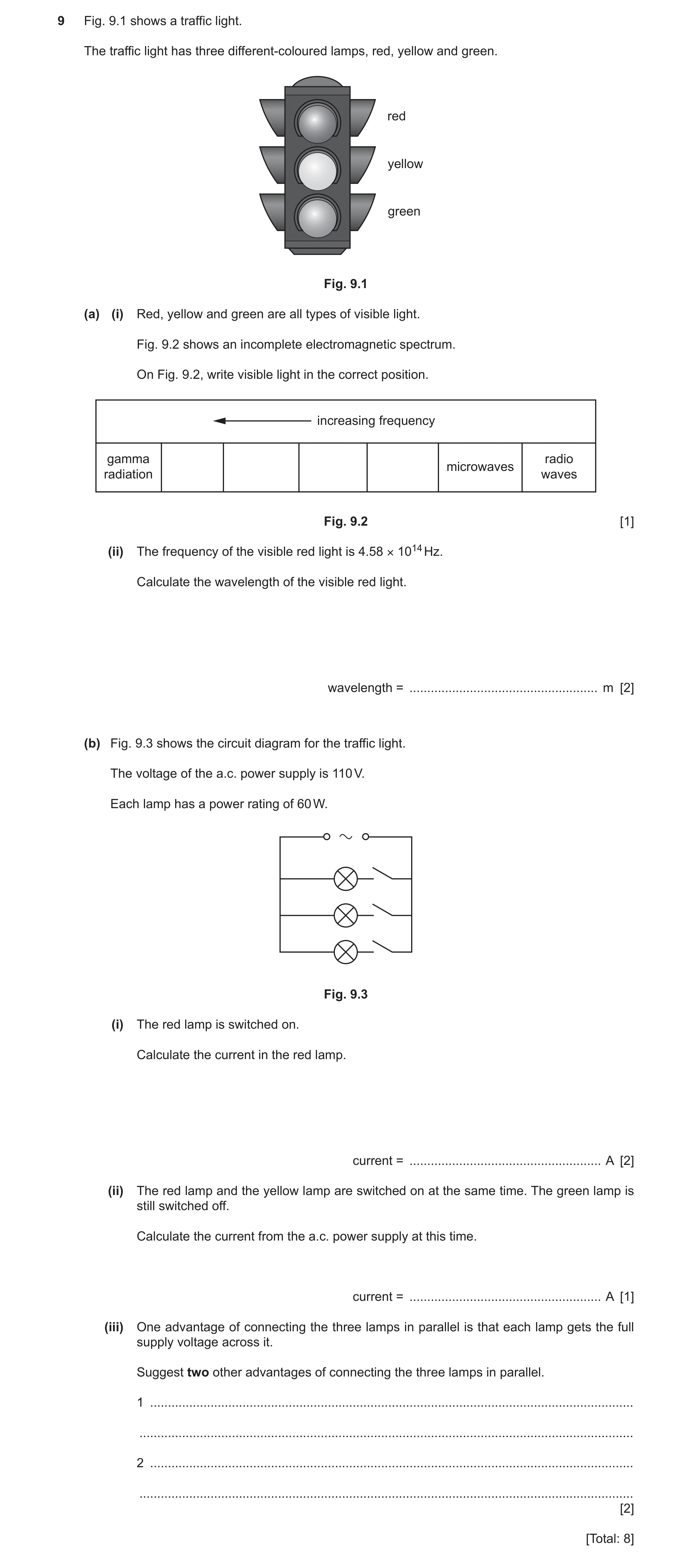
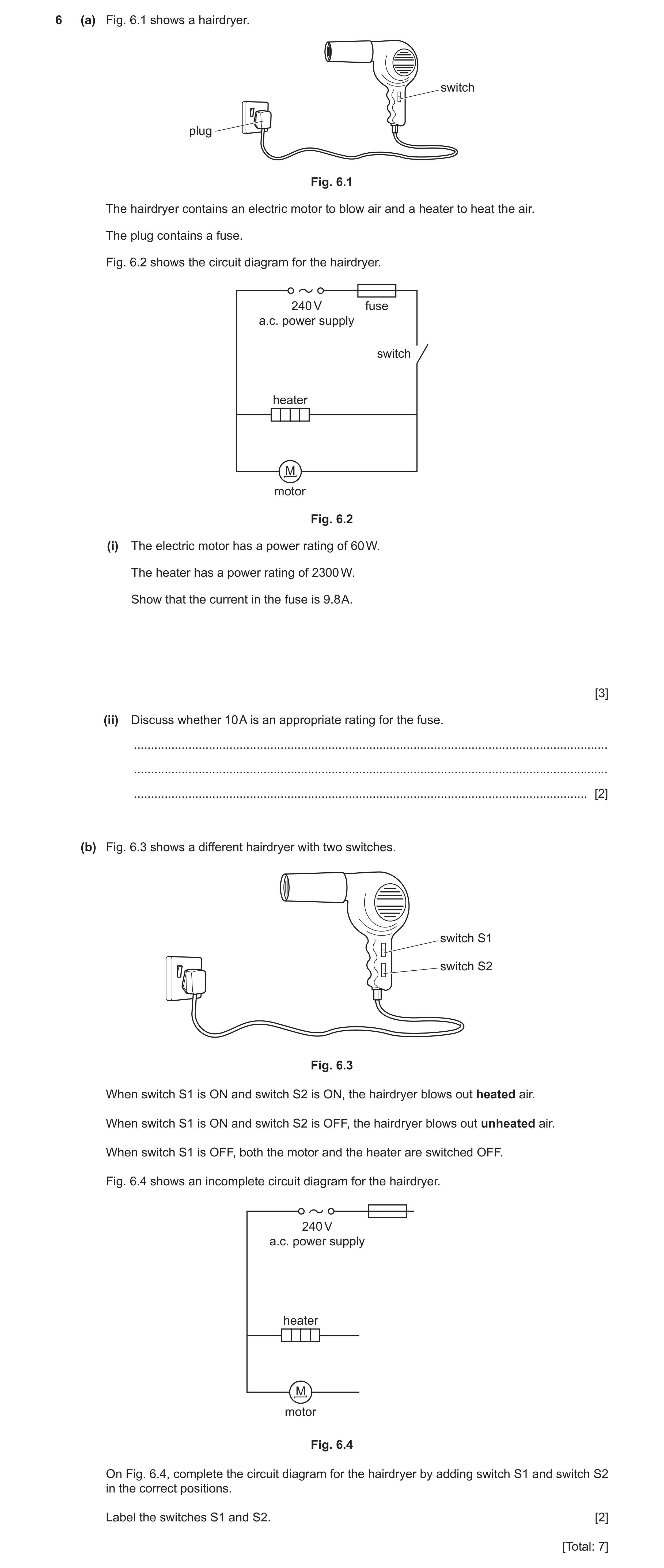
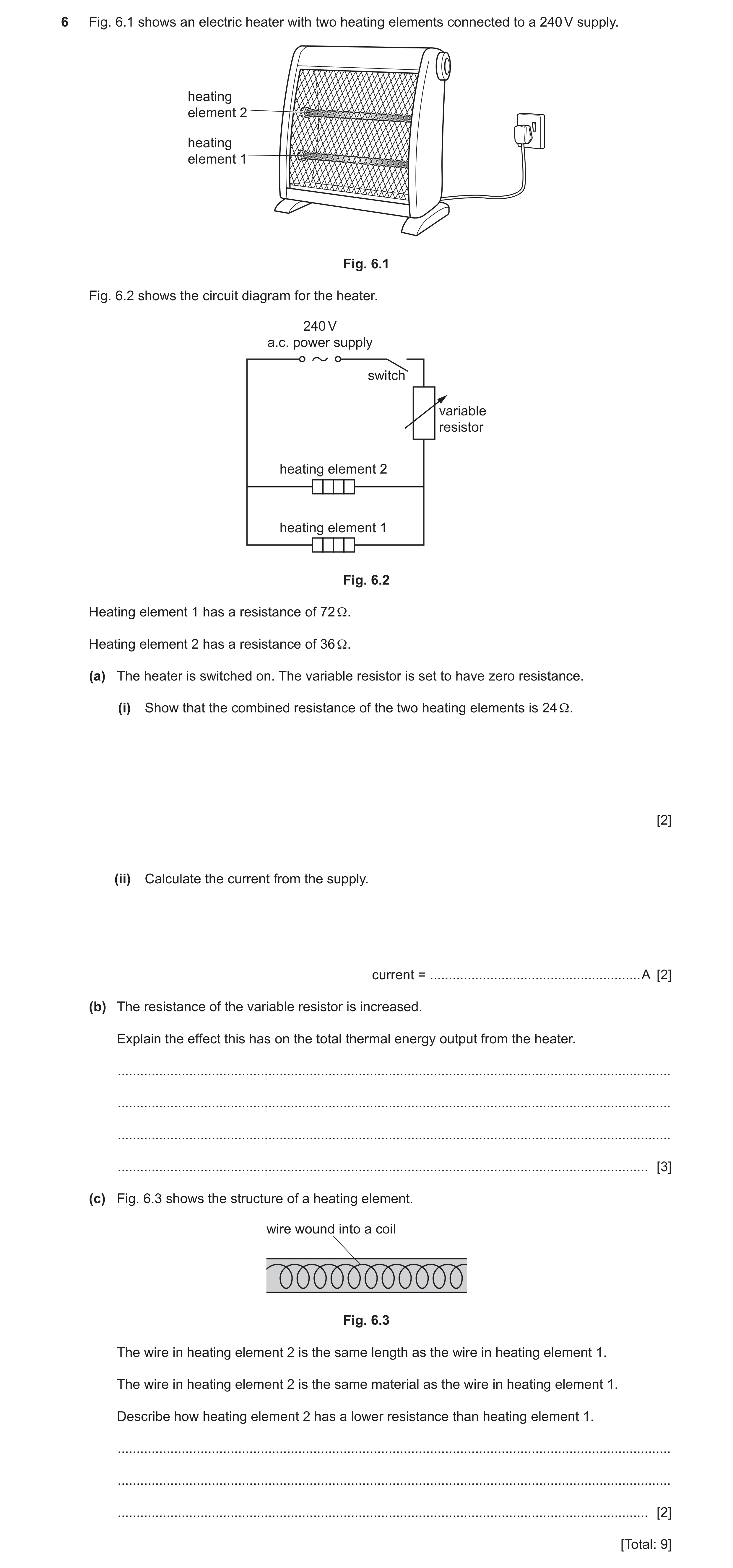
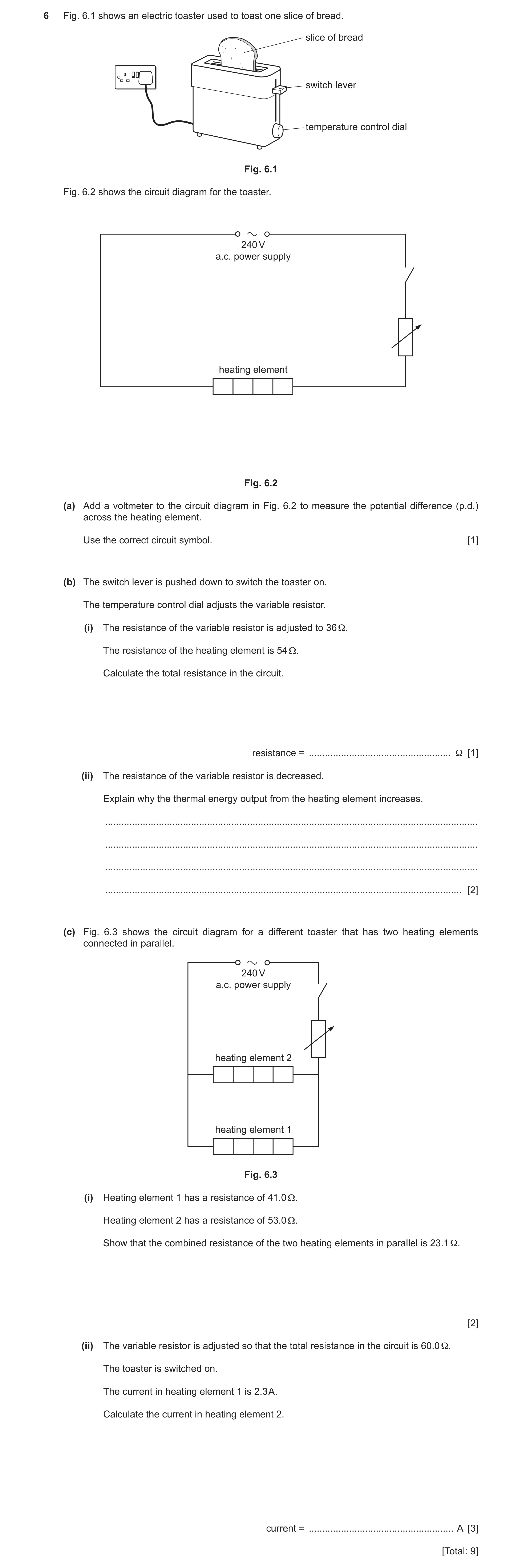
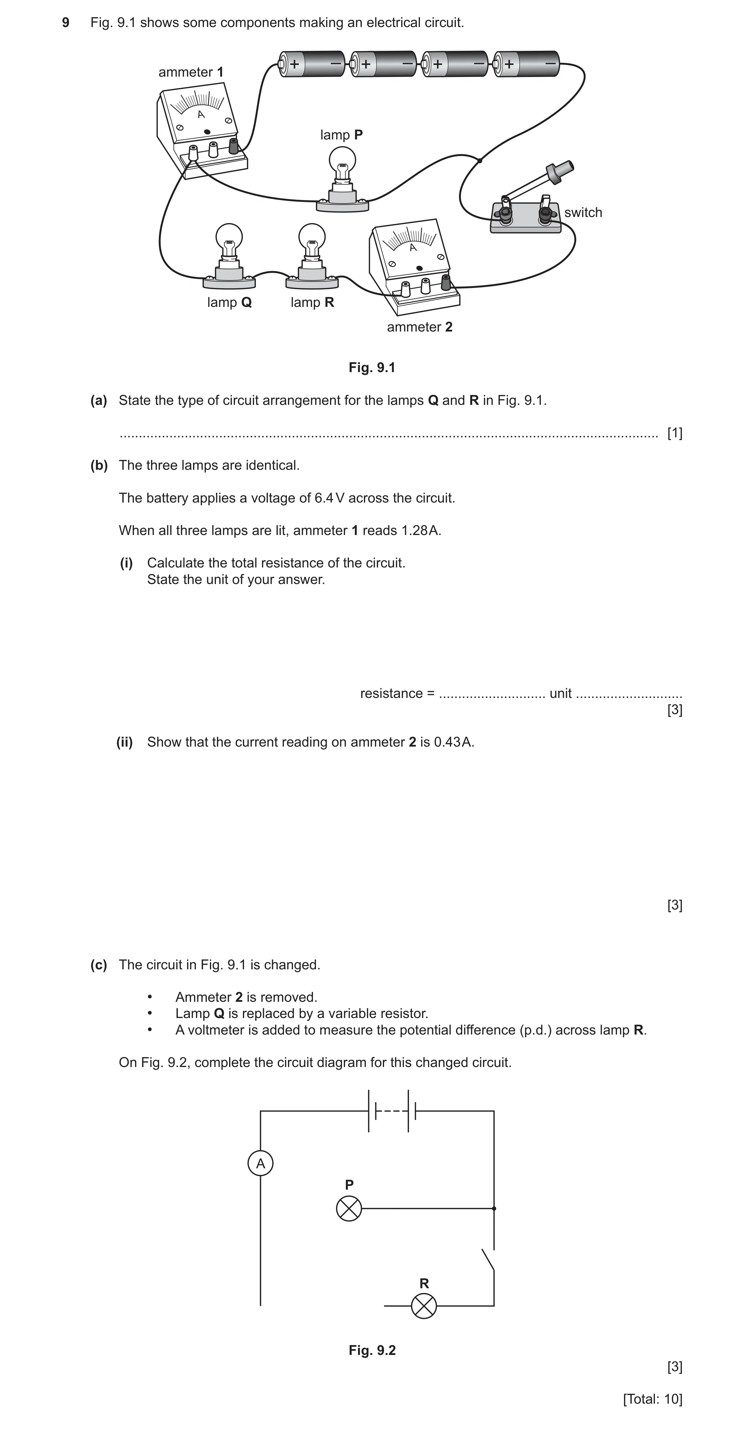
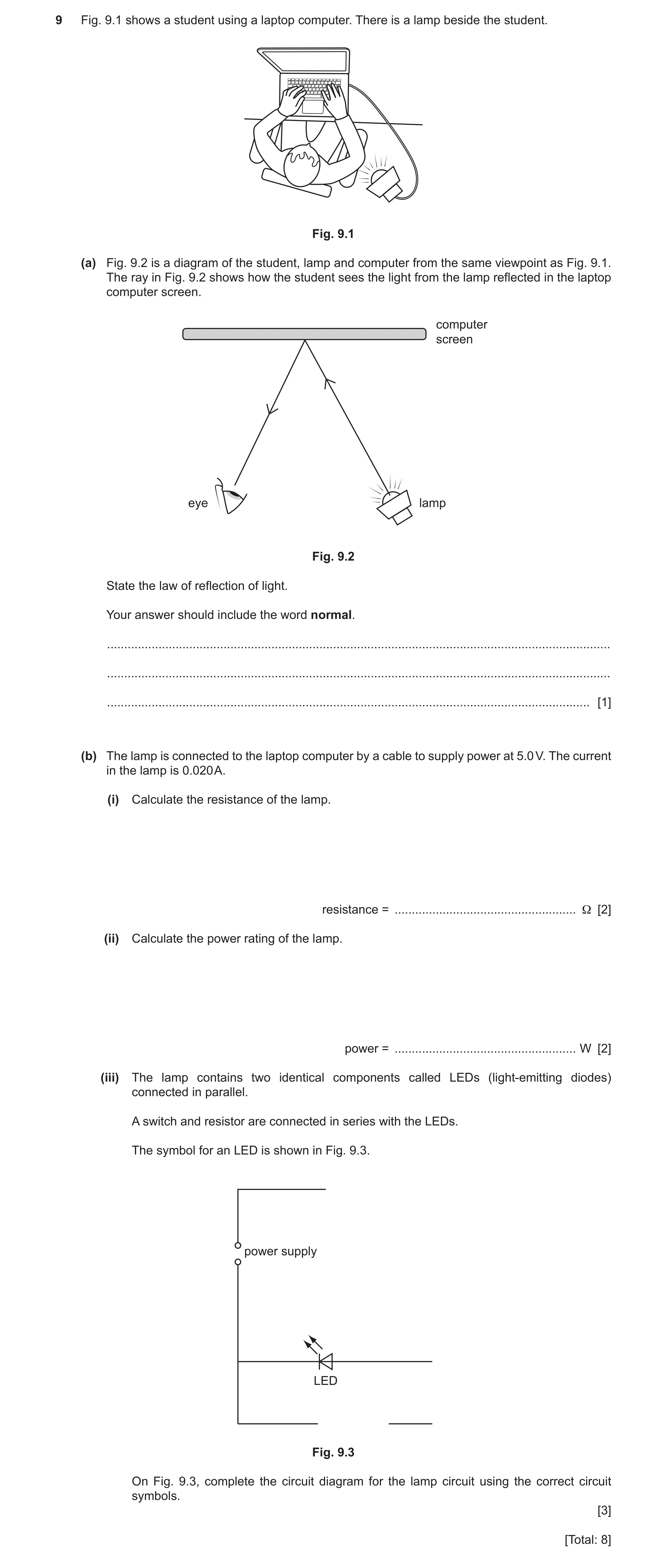
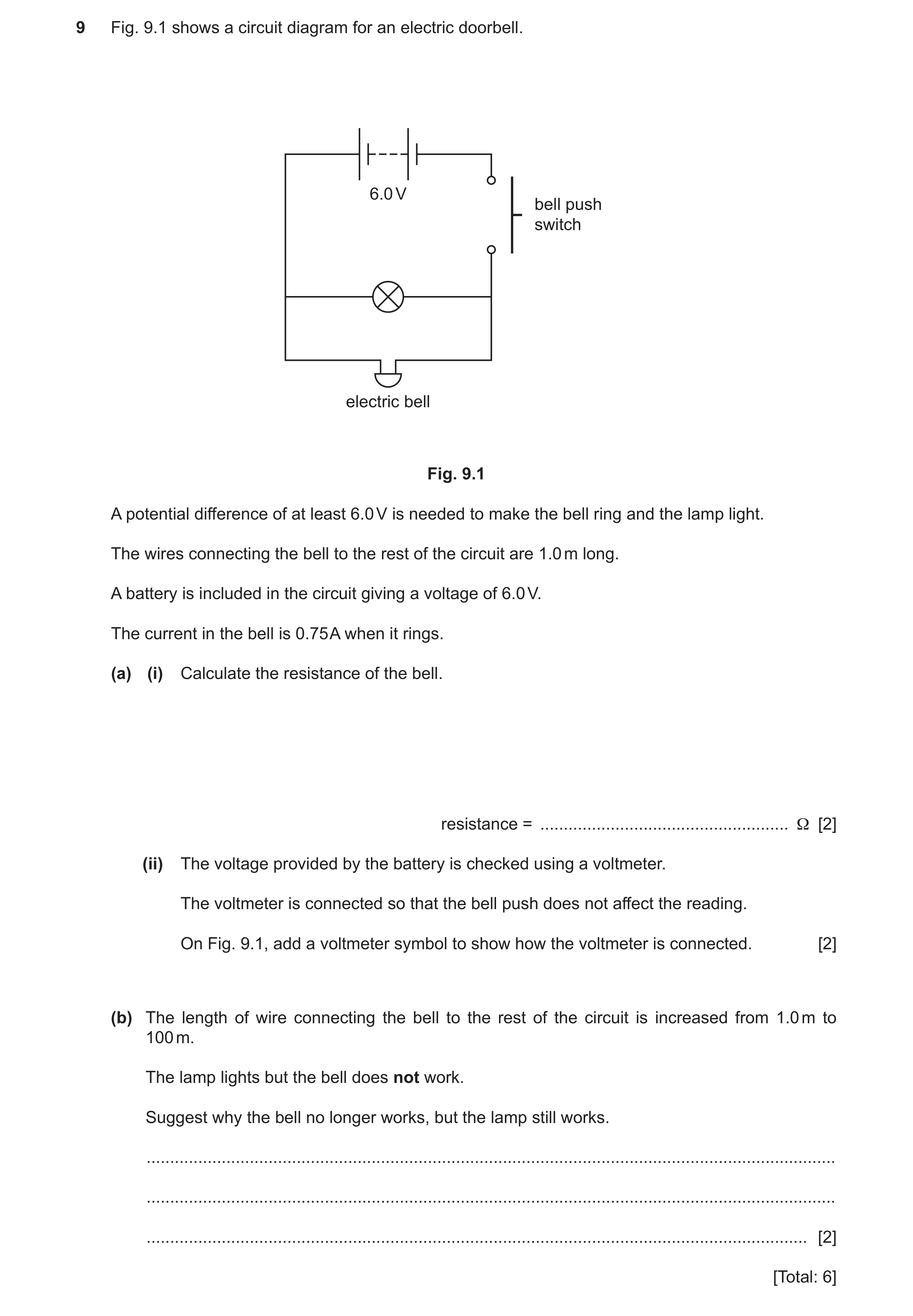 67 / 93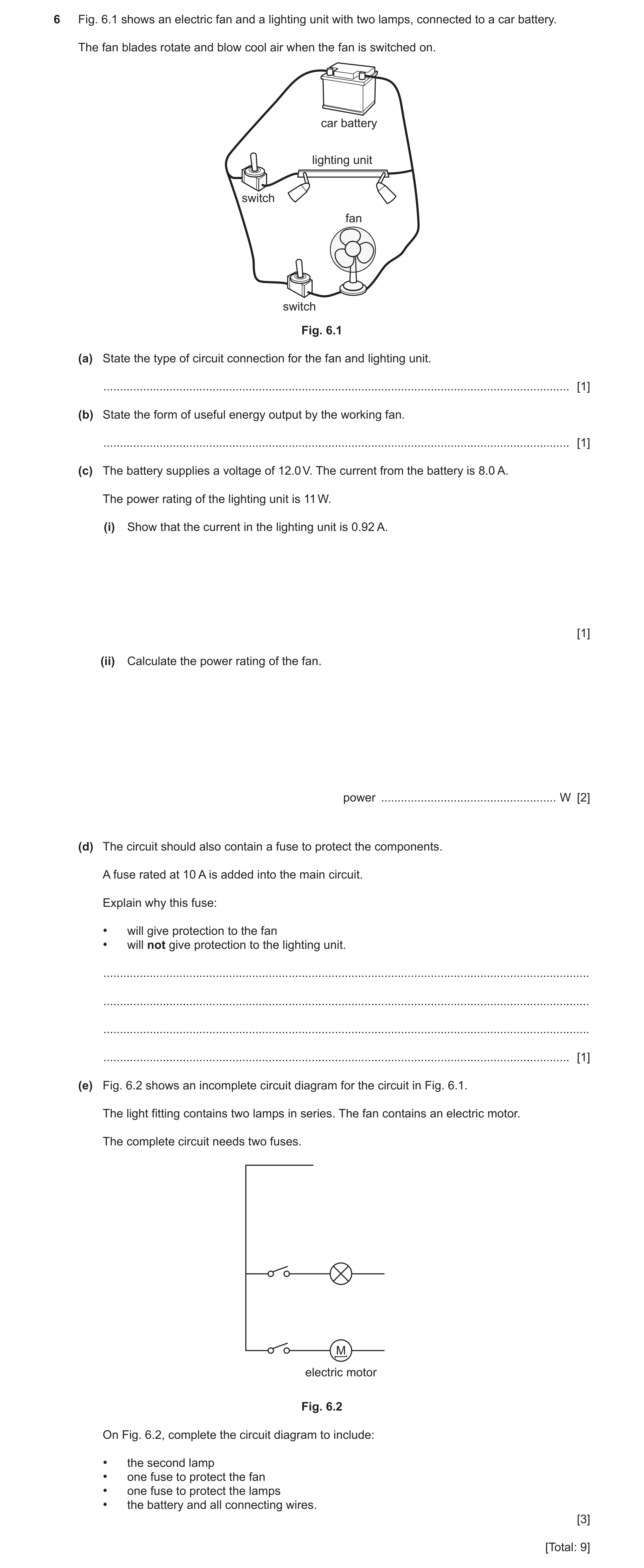
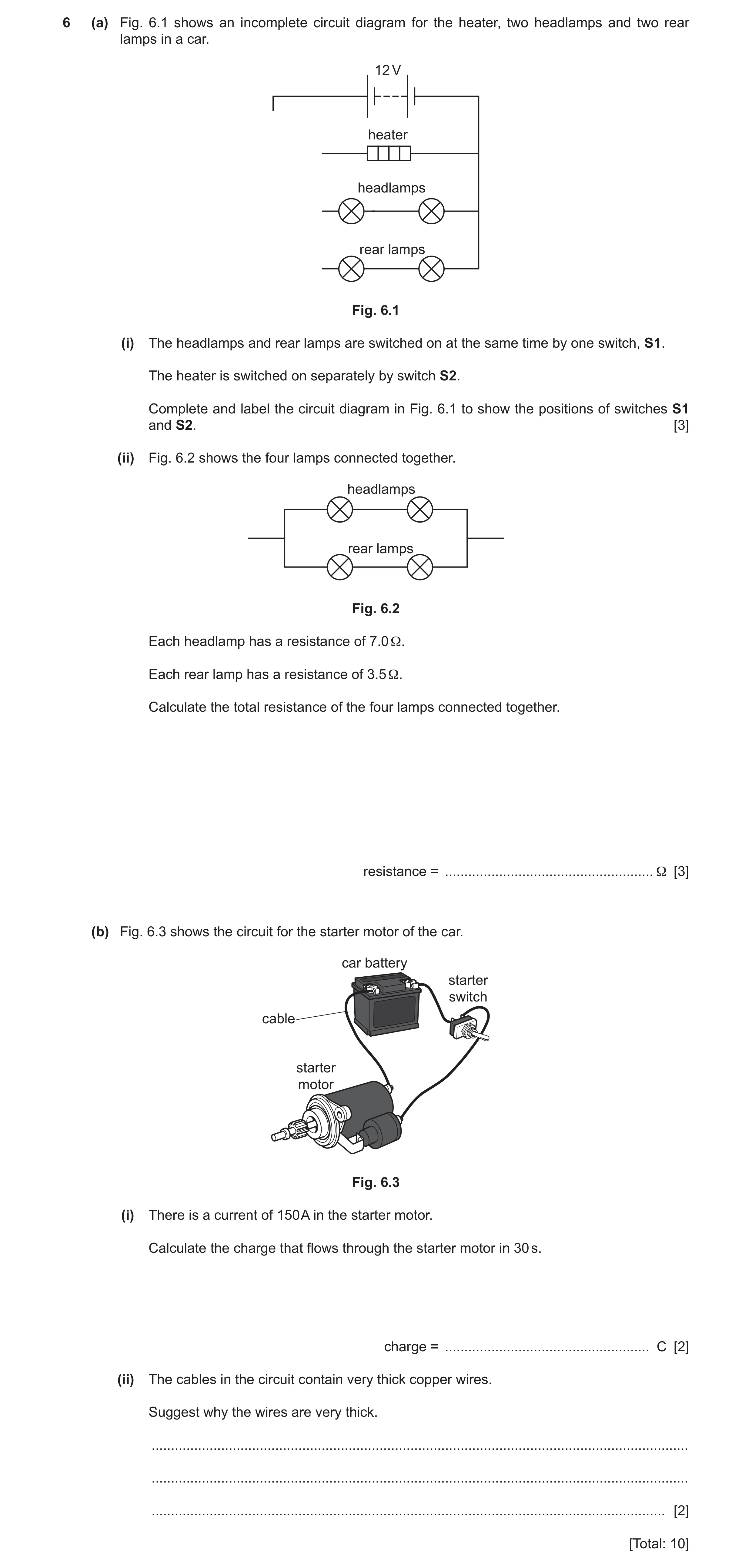
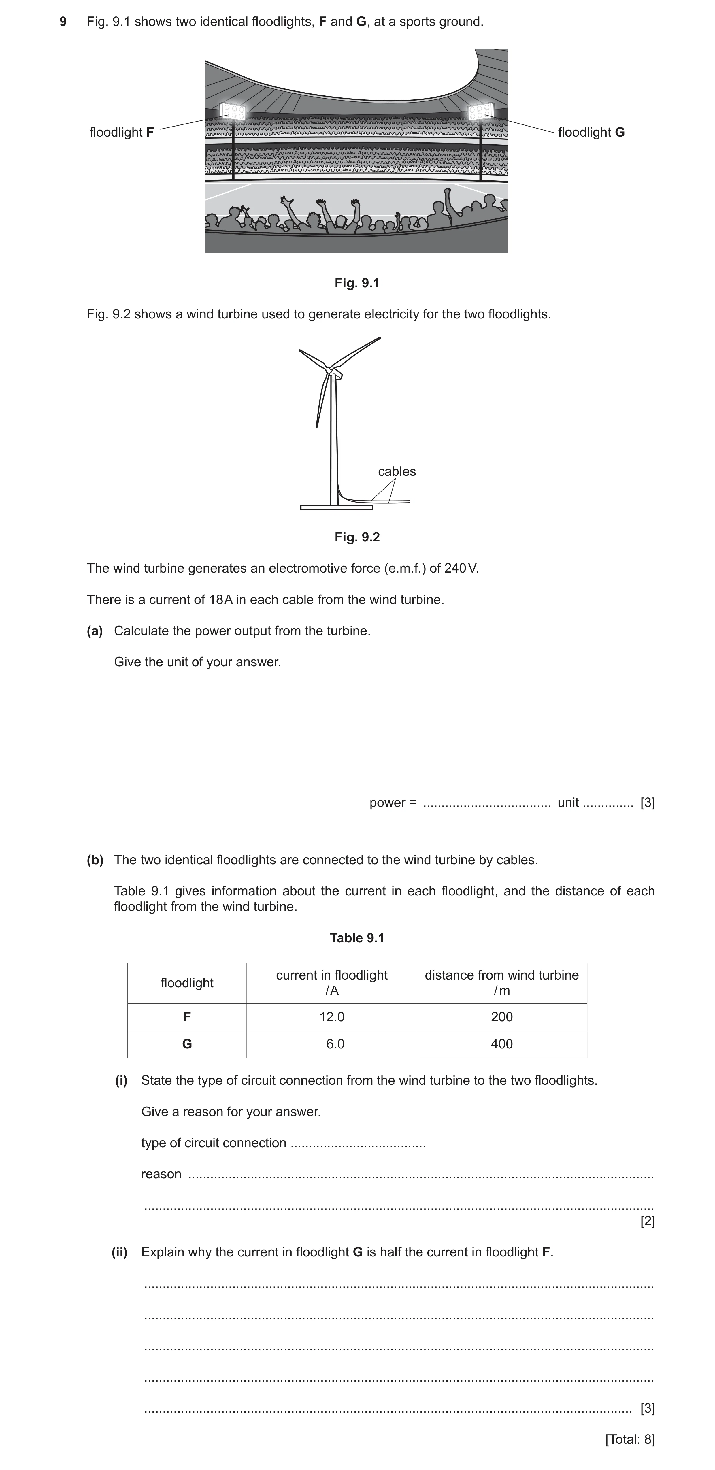
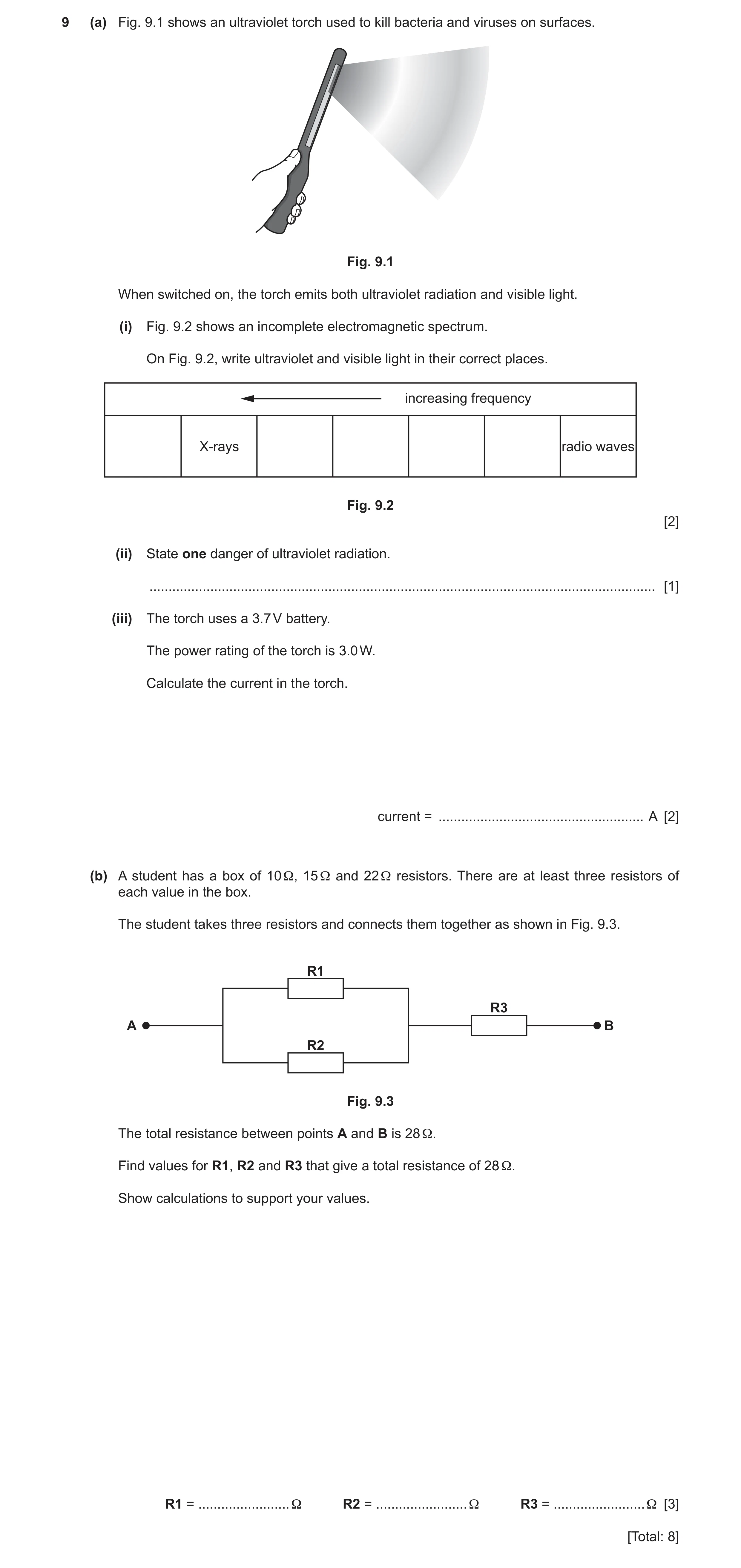
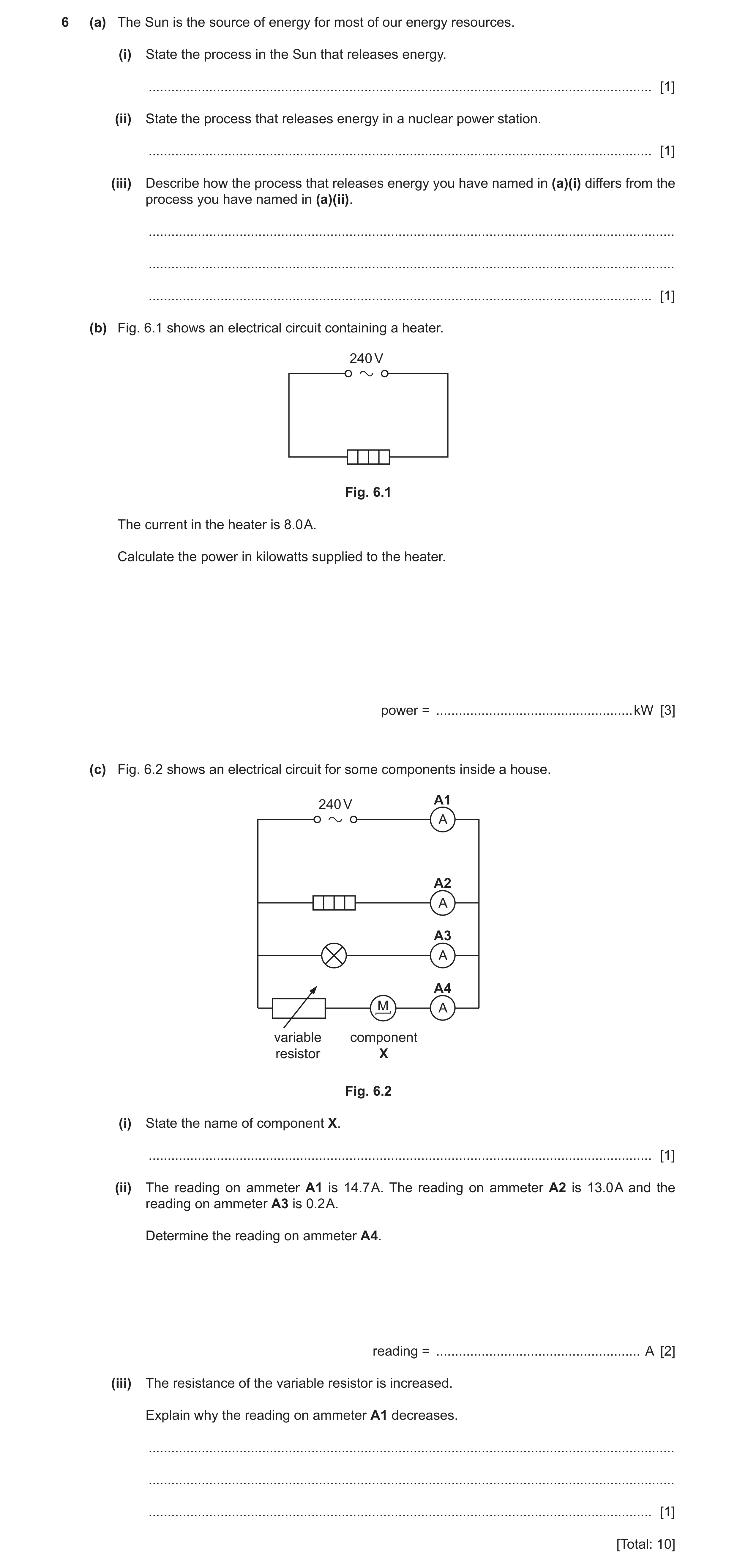
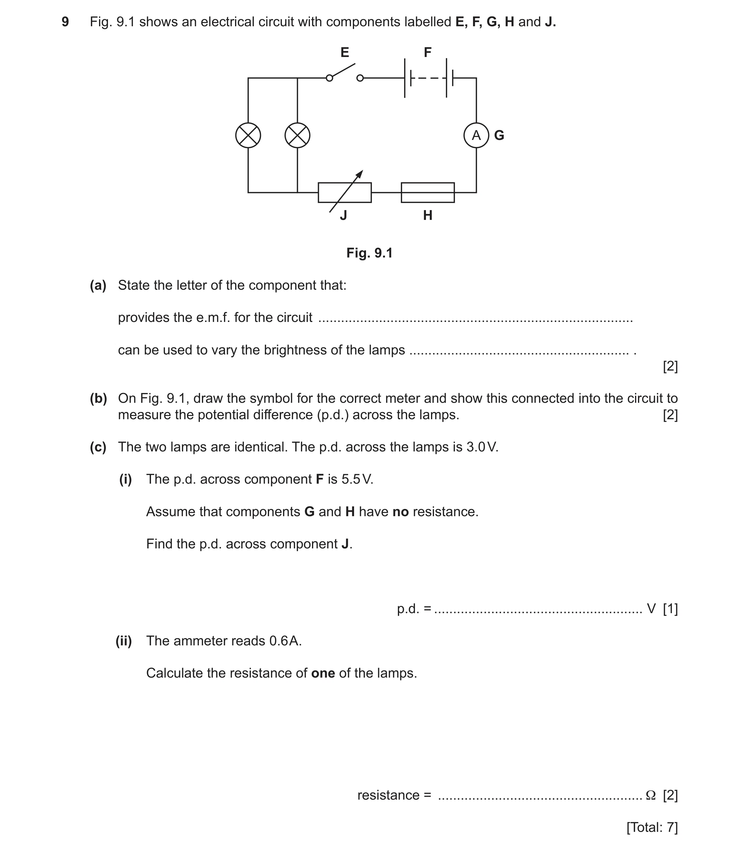 76 / 93
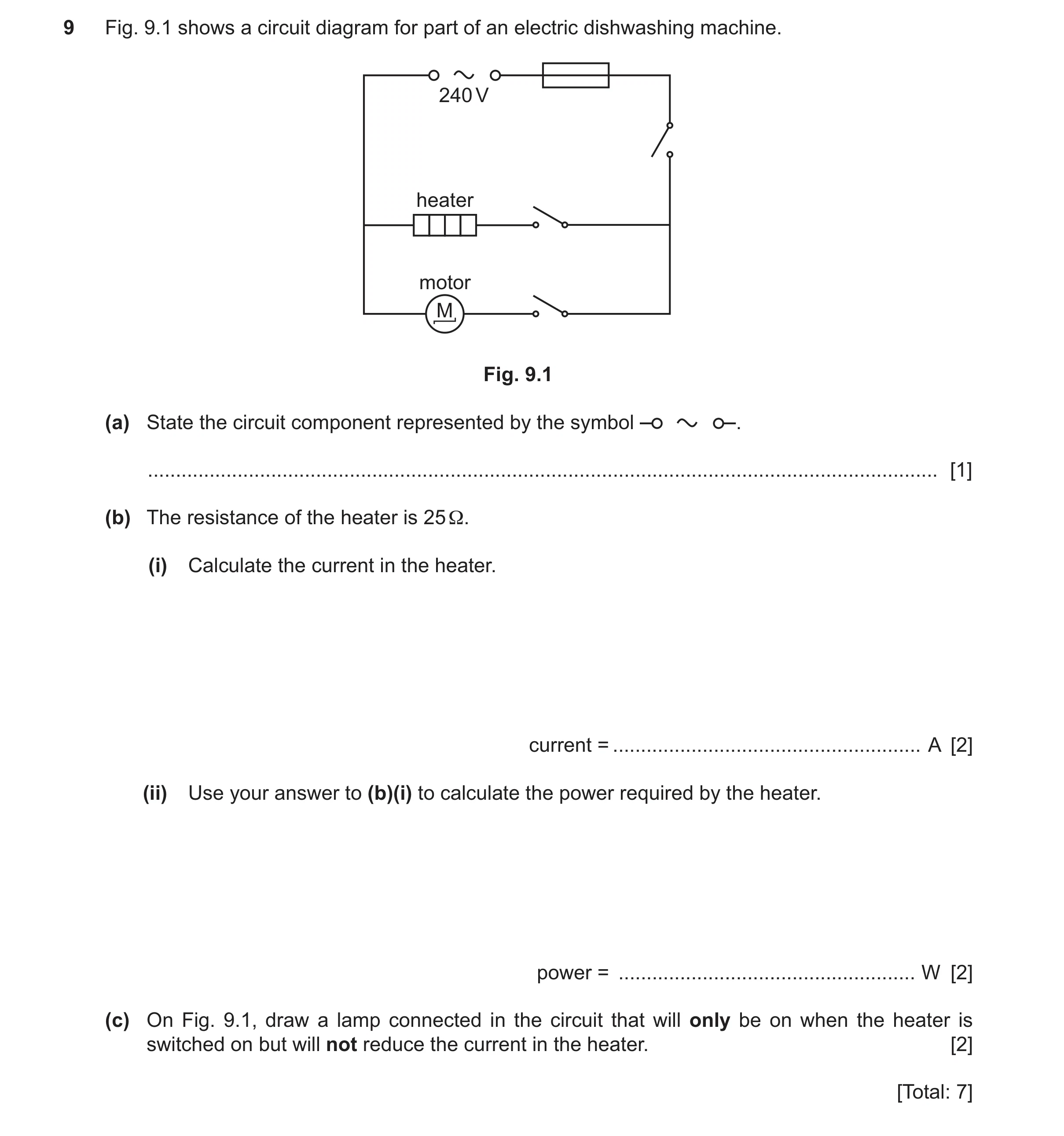 77 / 93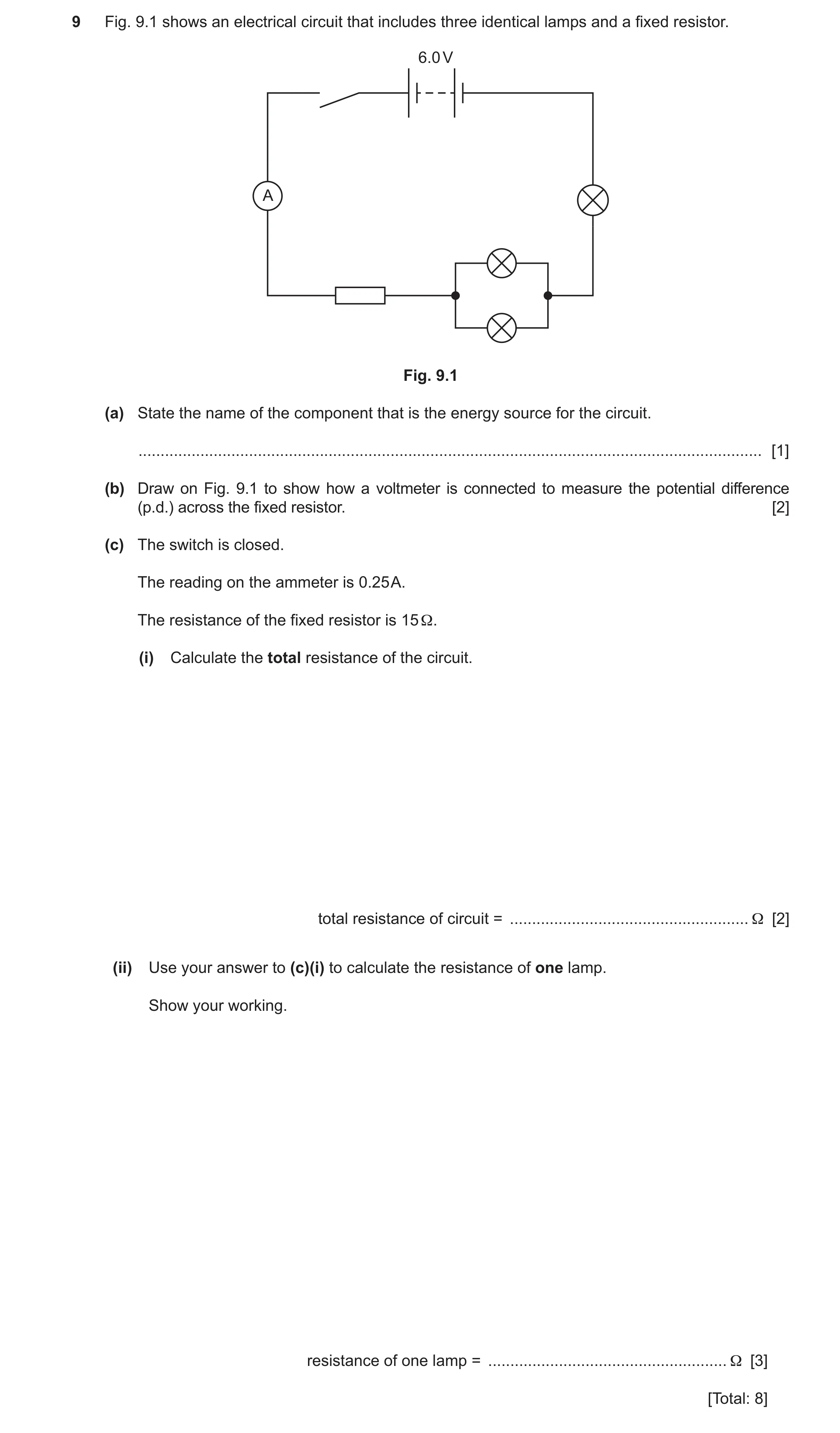
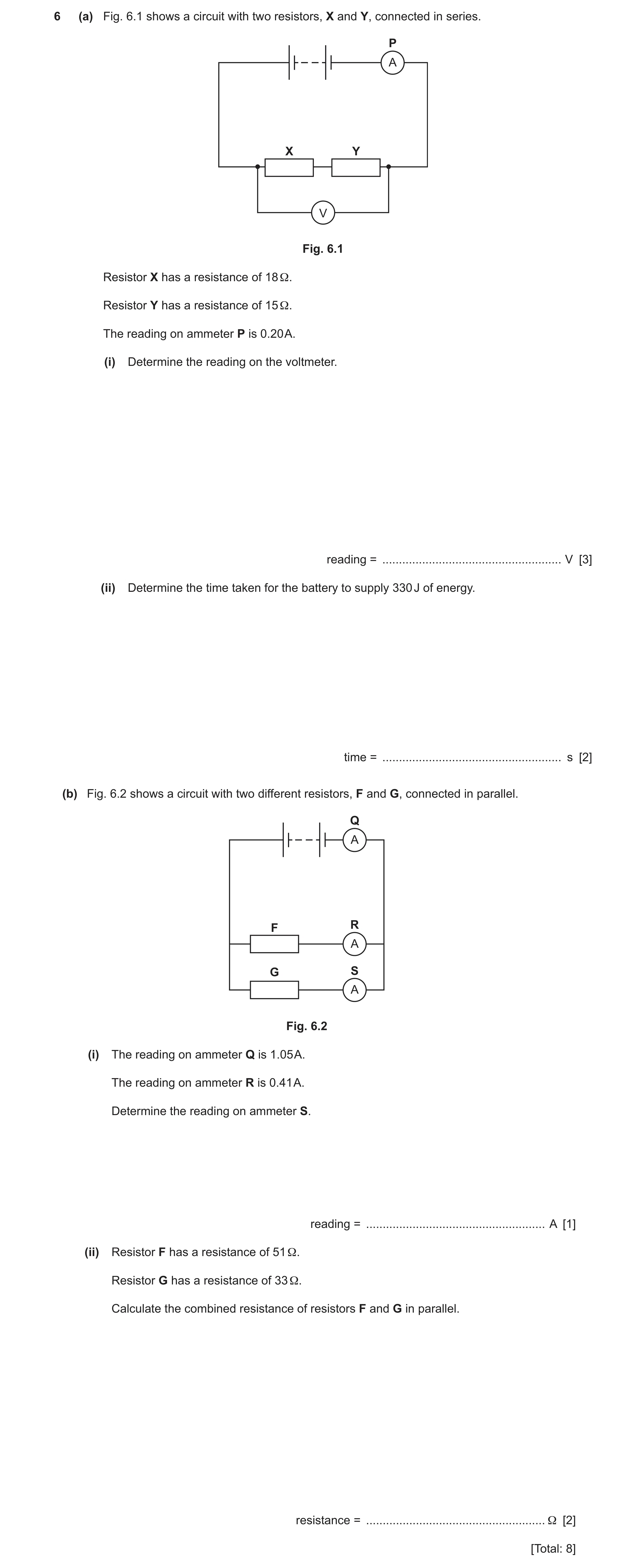
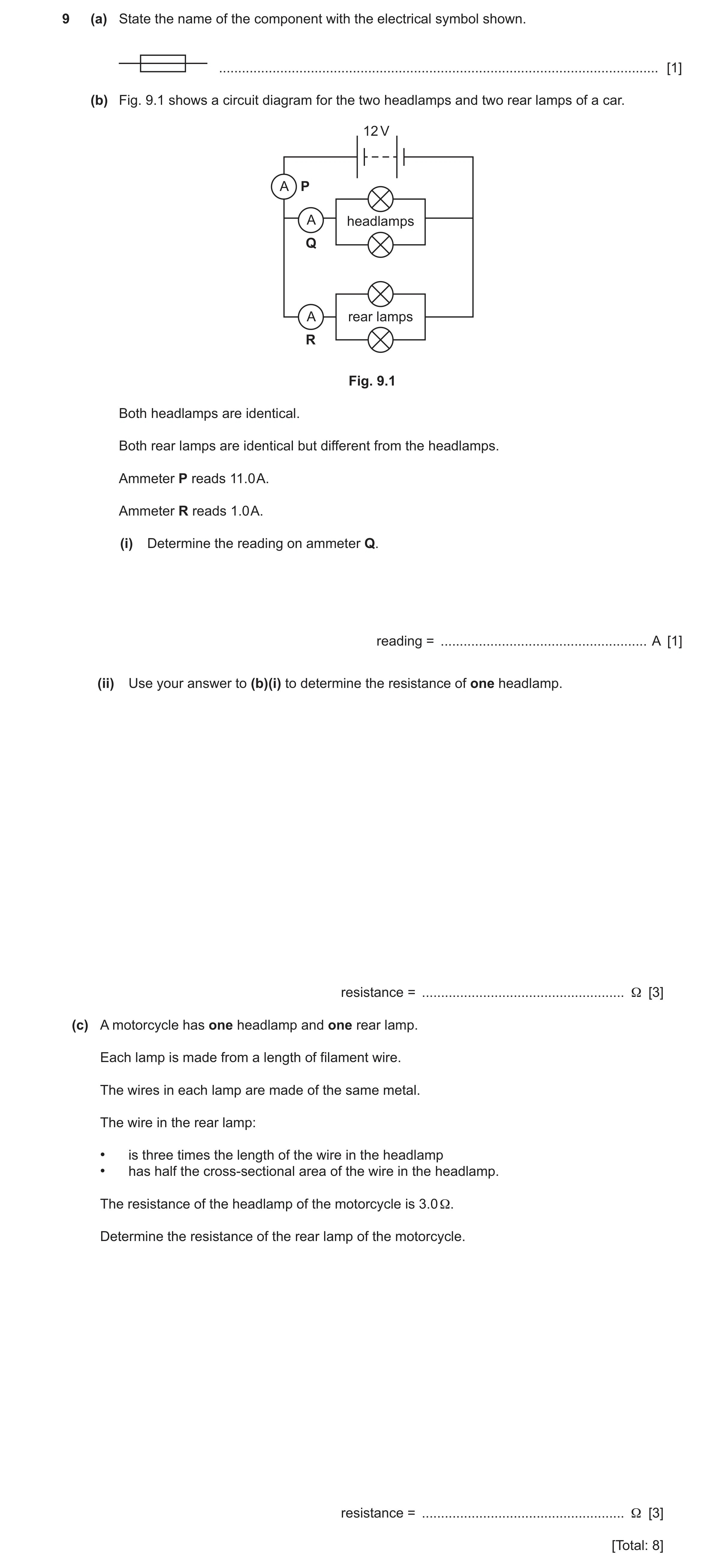
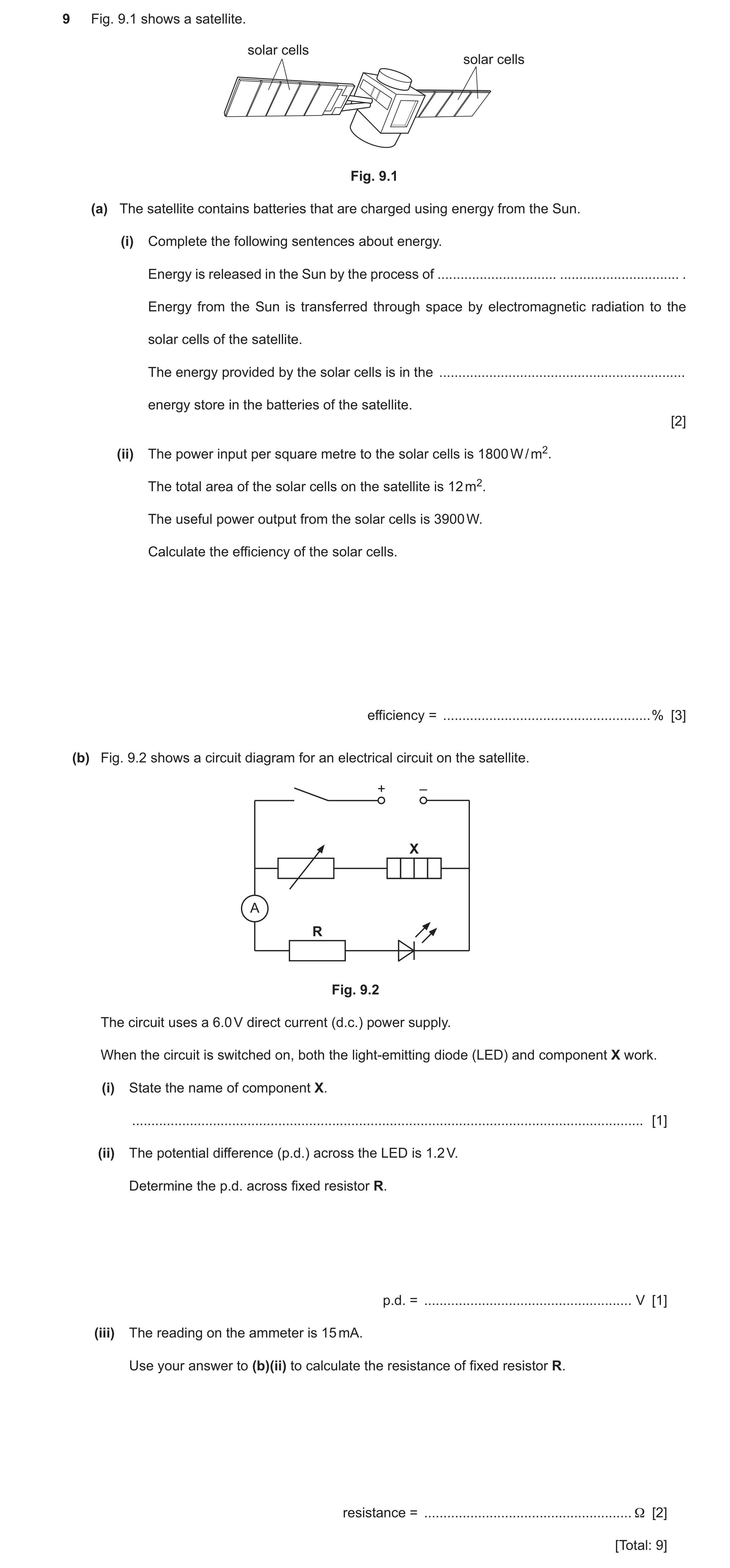
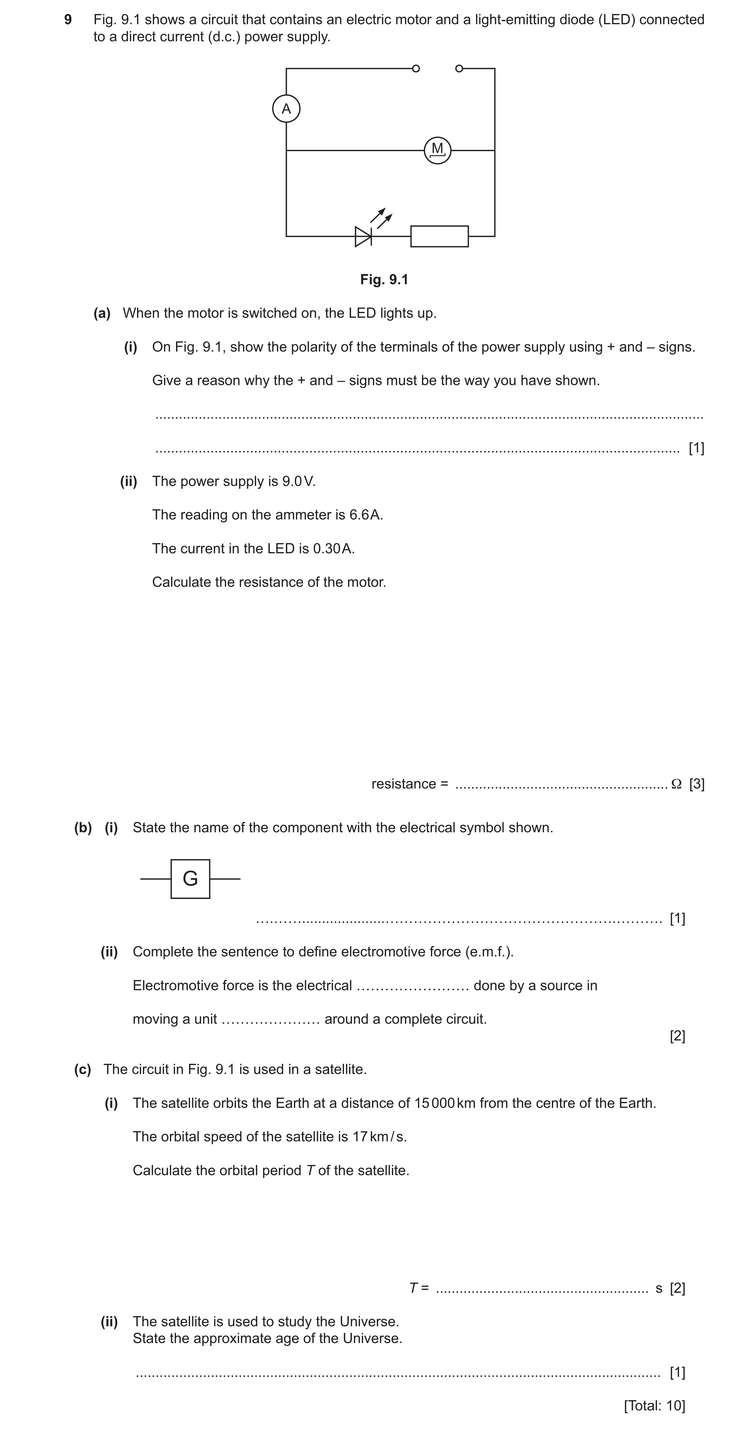
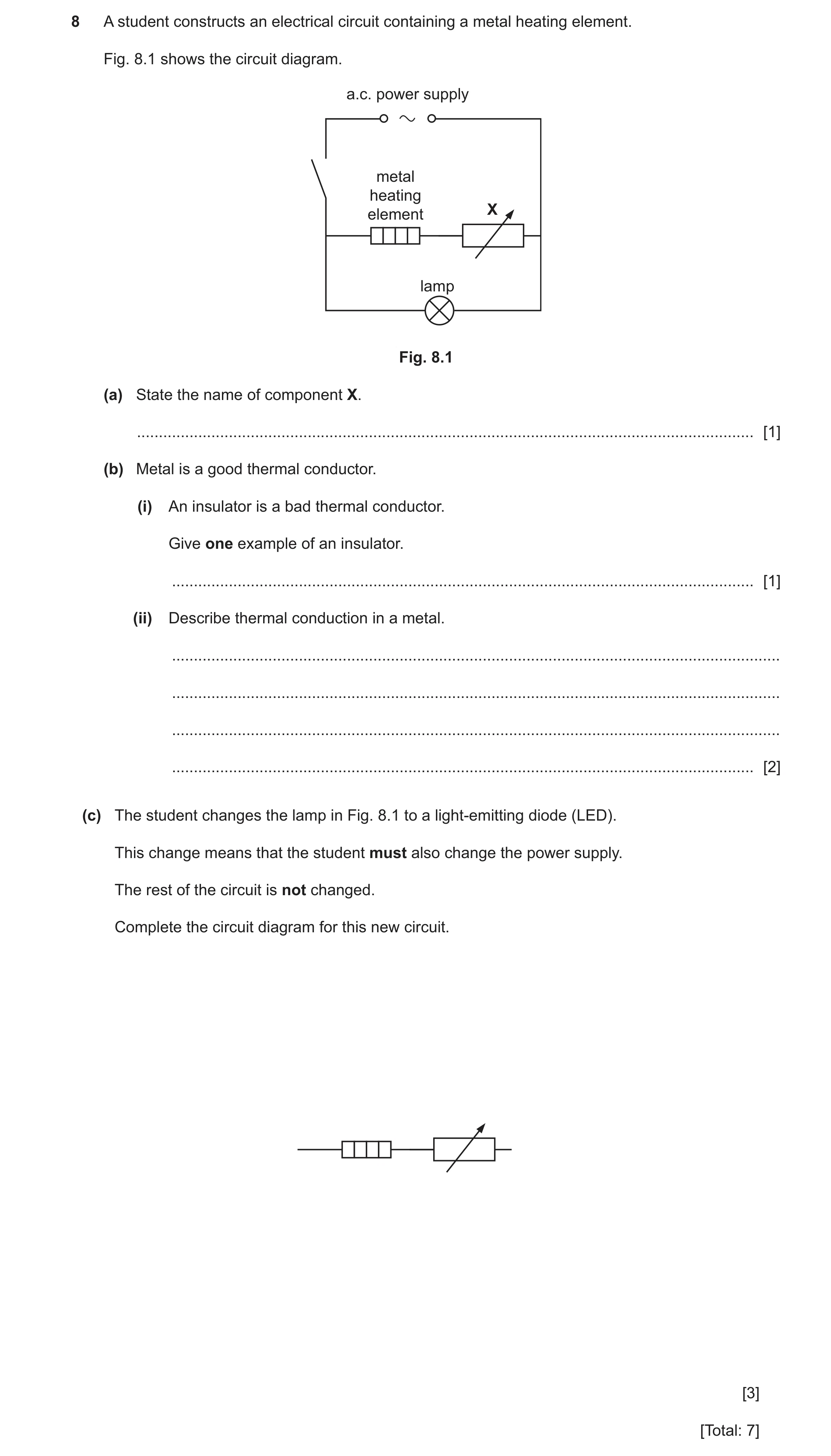
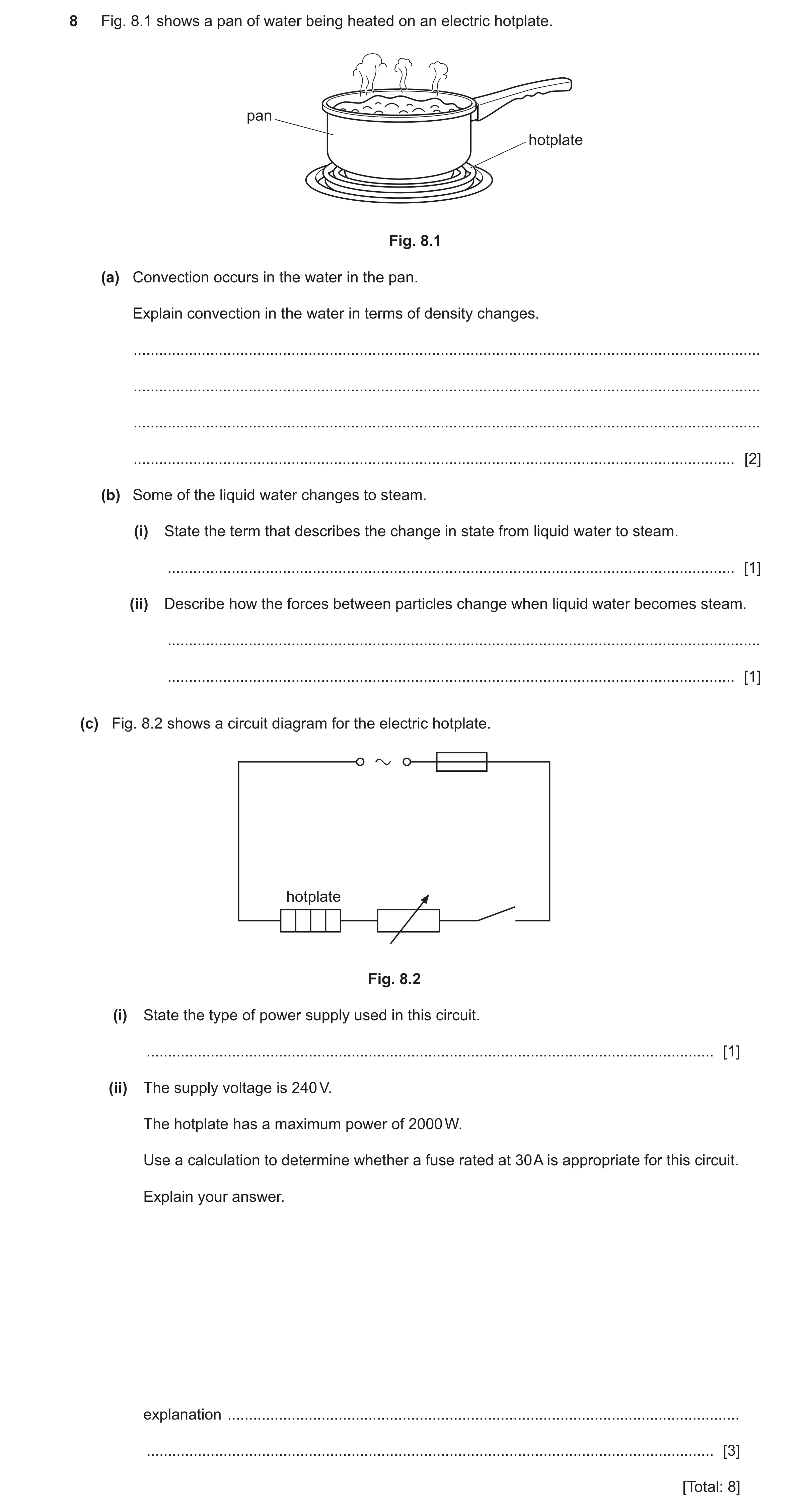
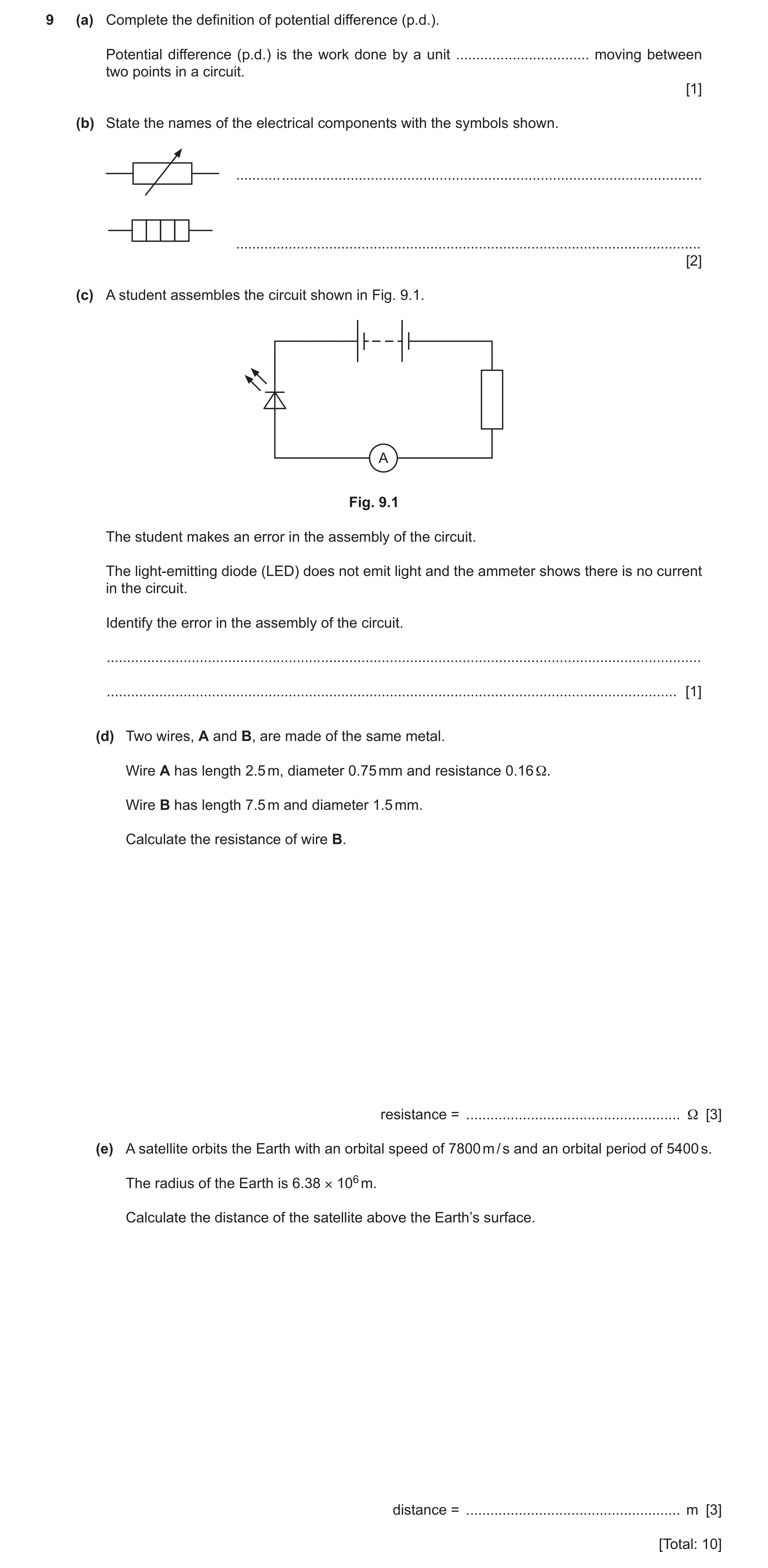
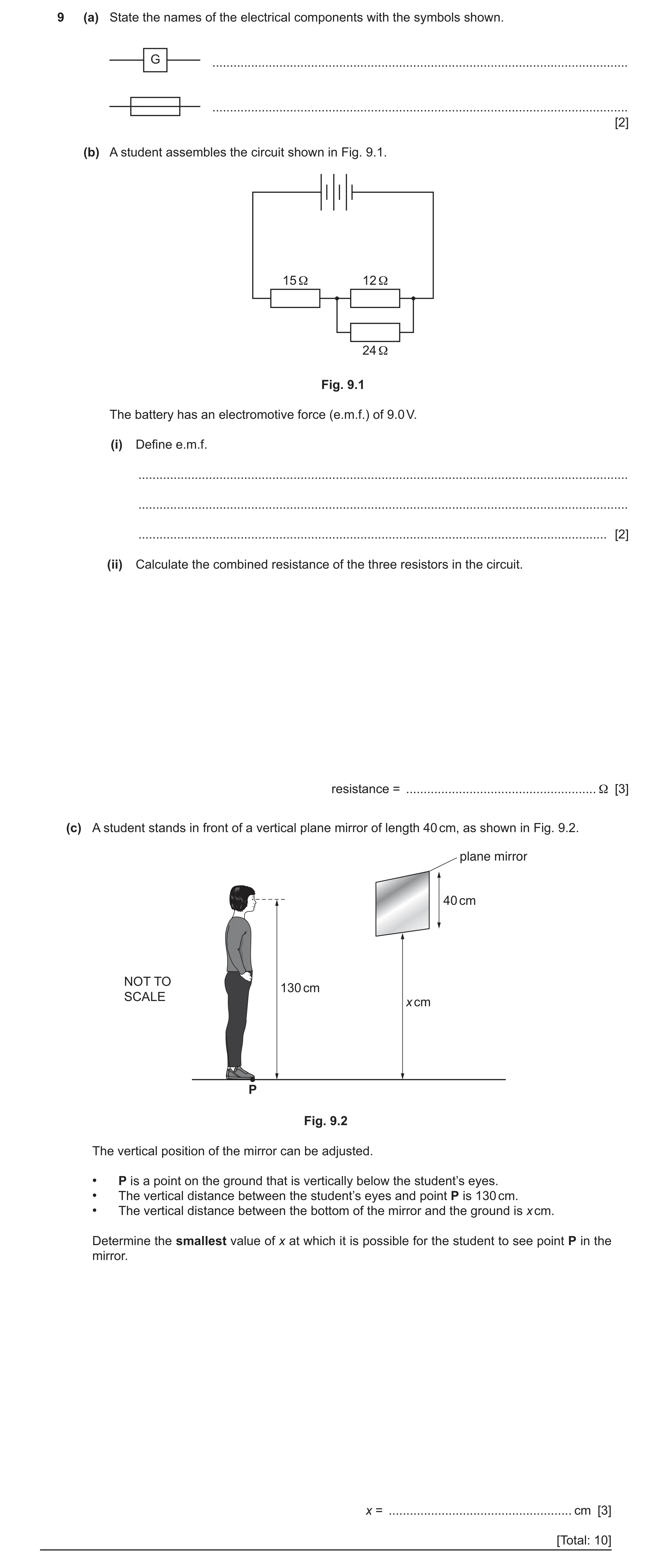
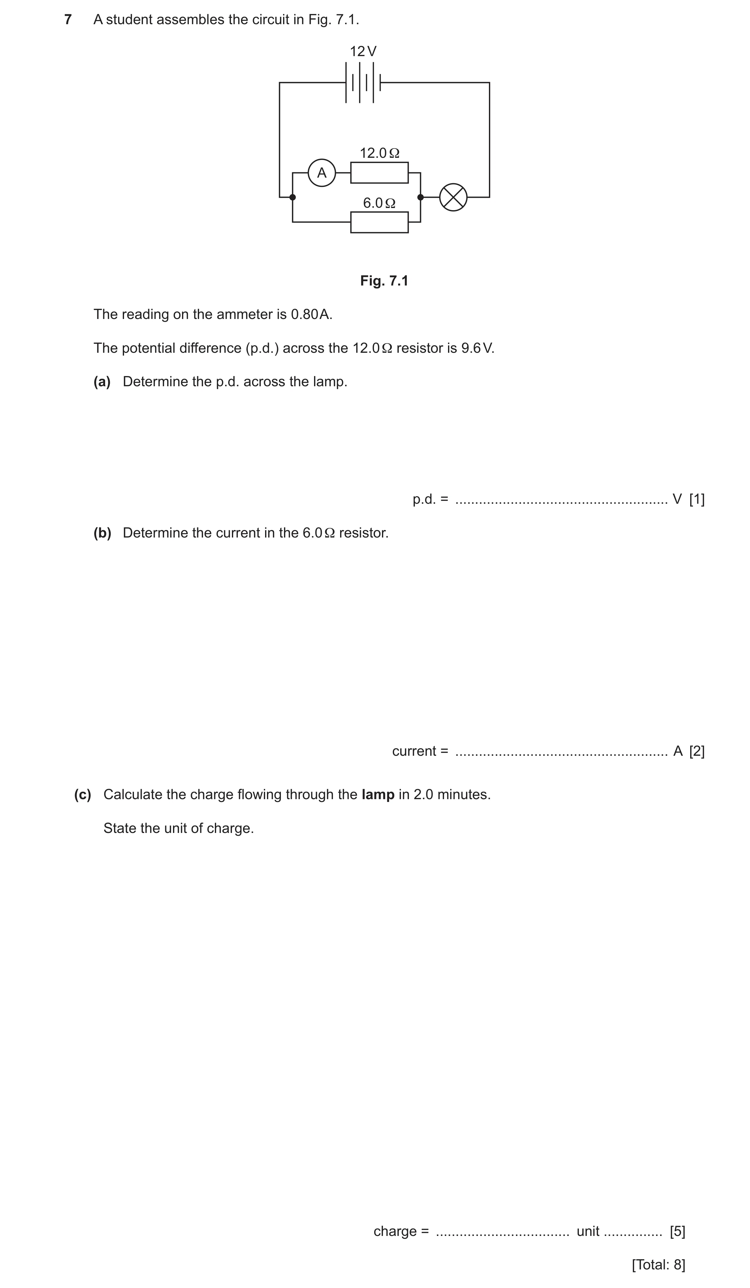
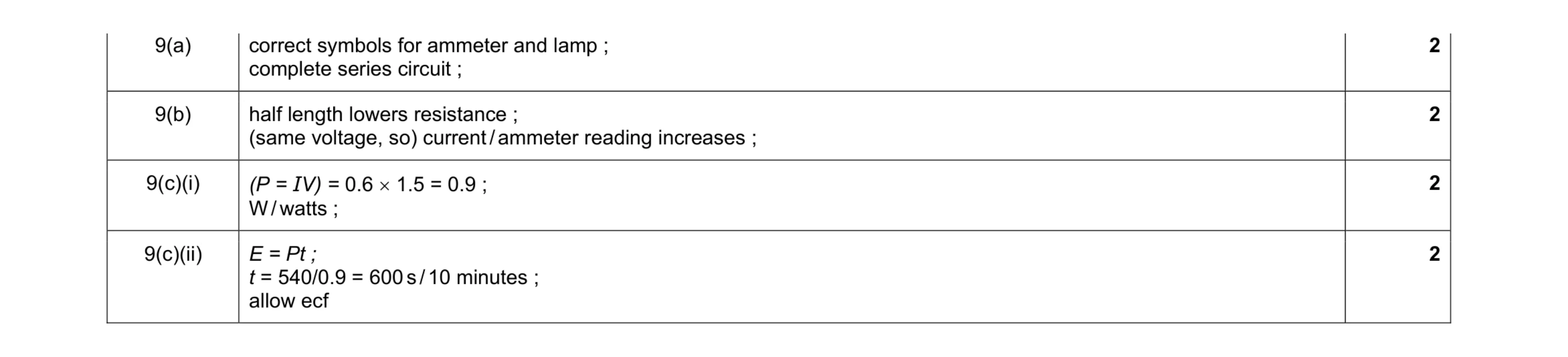 8
8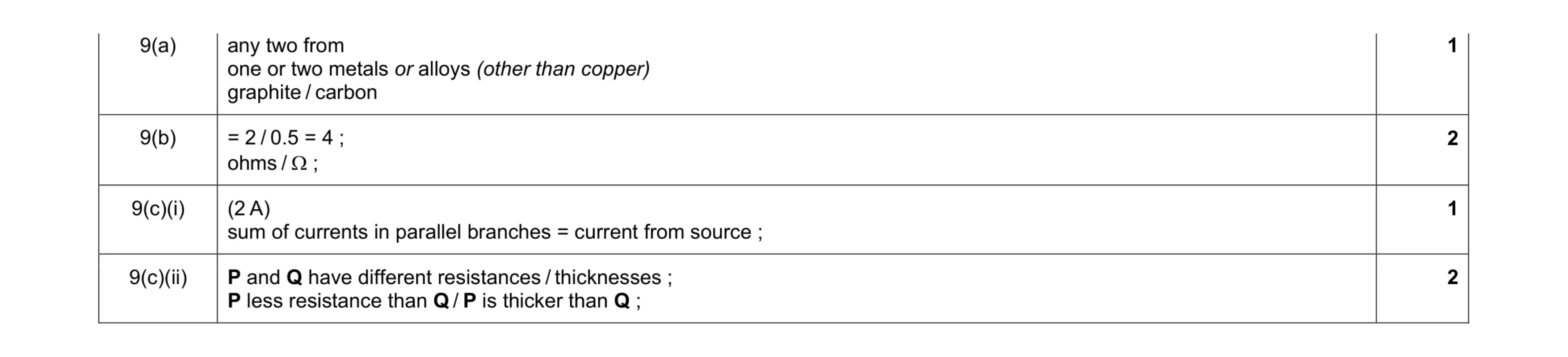 6
6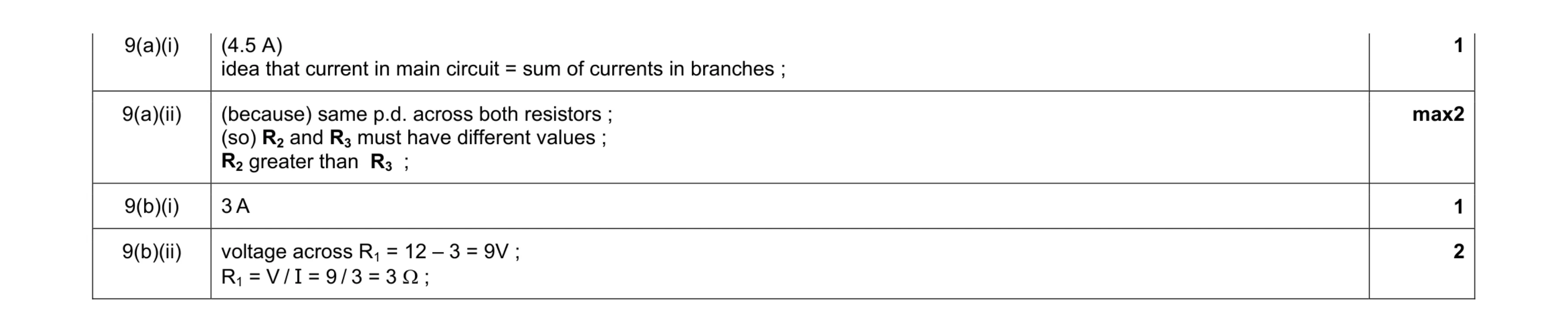 6
6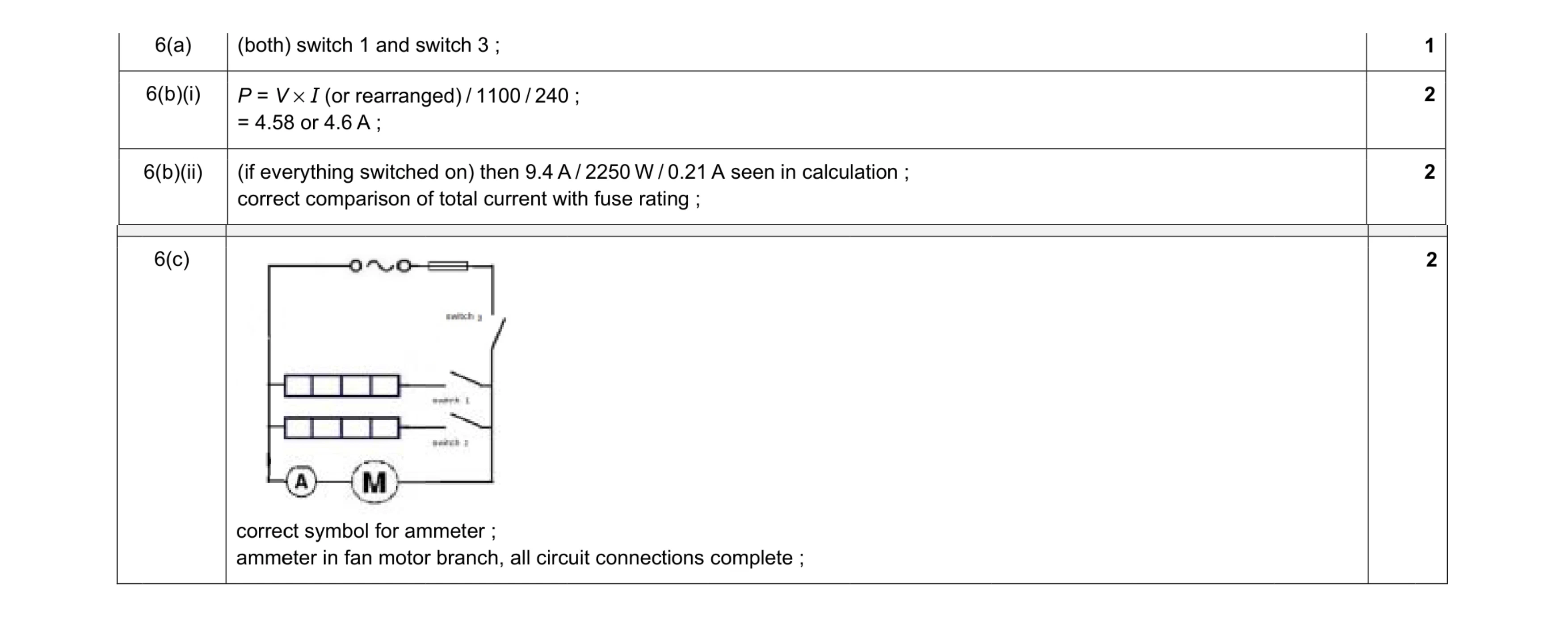 7
7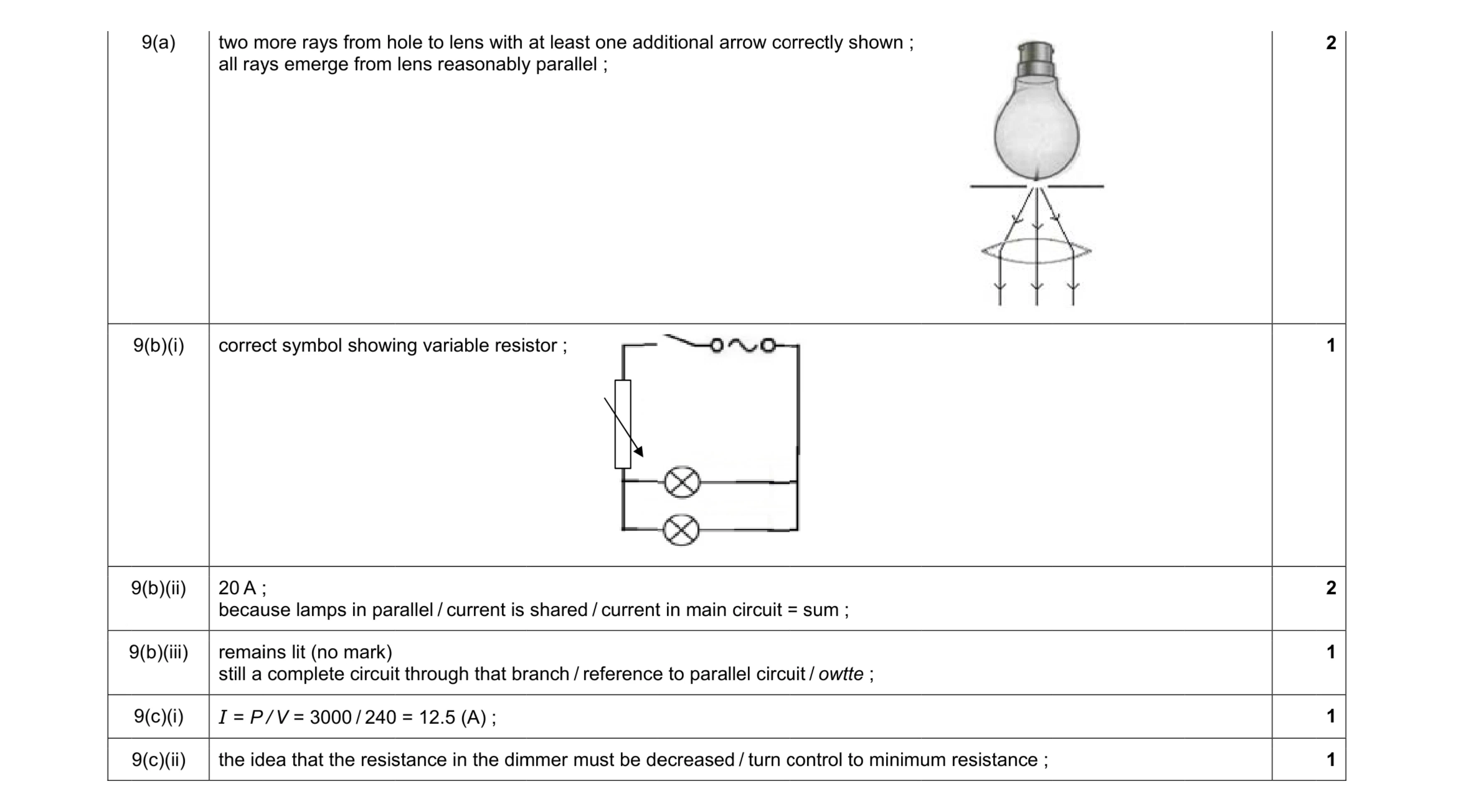 8
8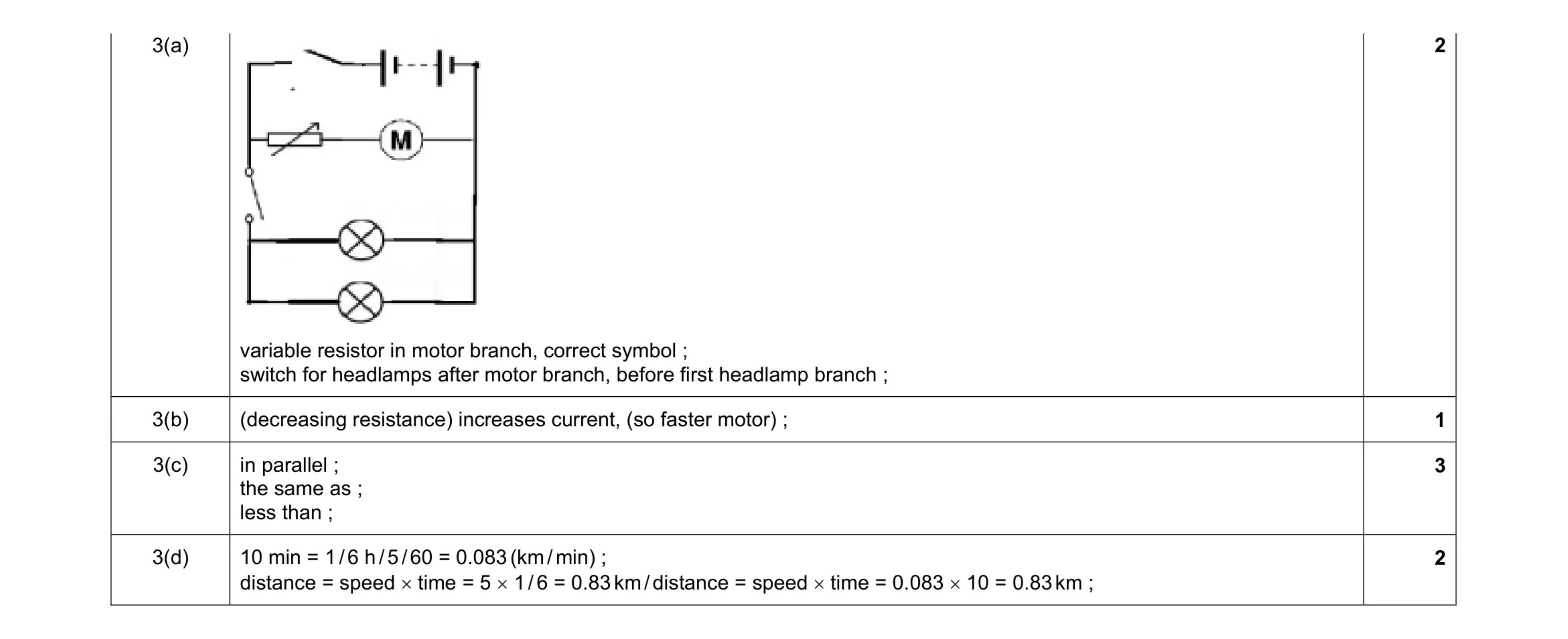 8
8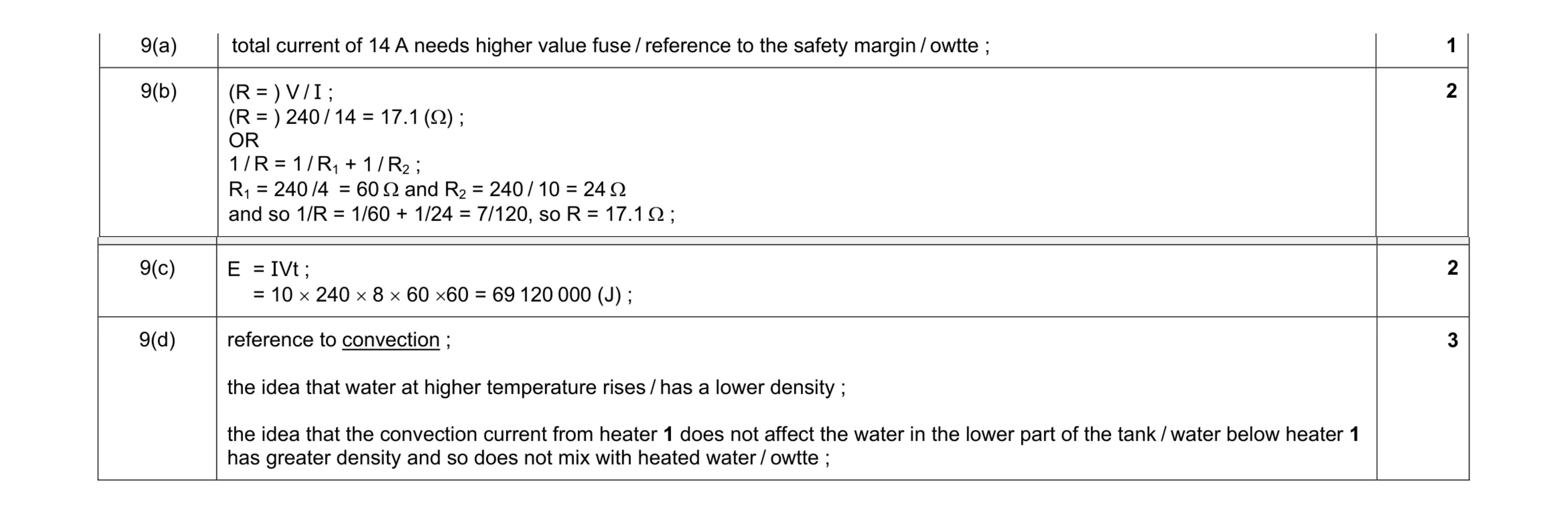 8
8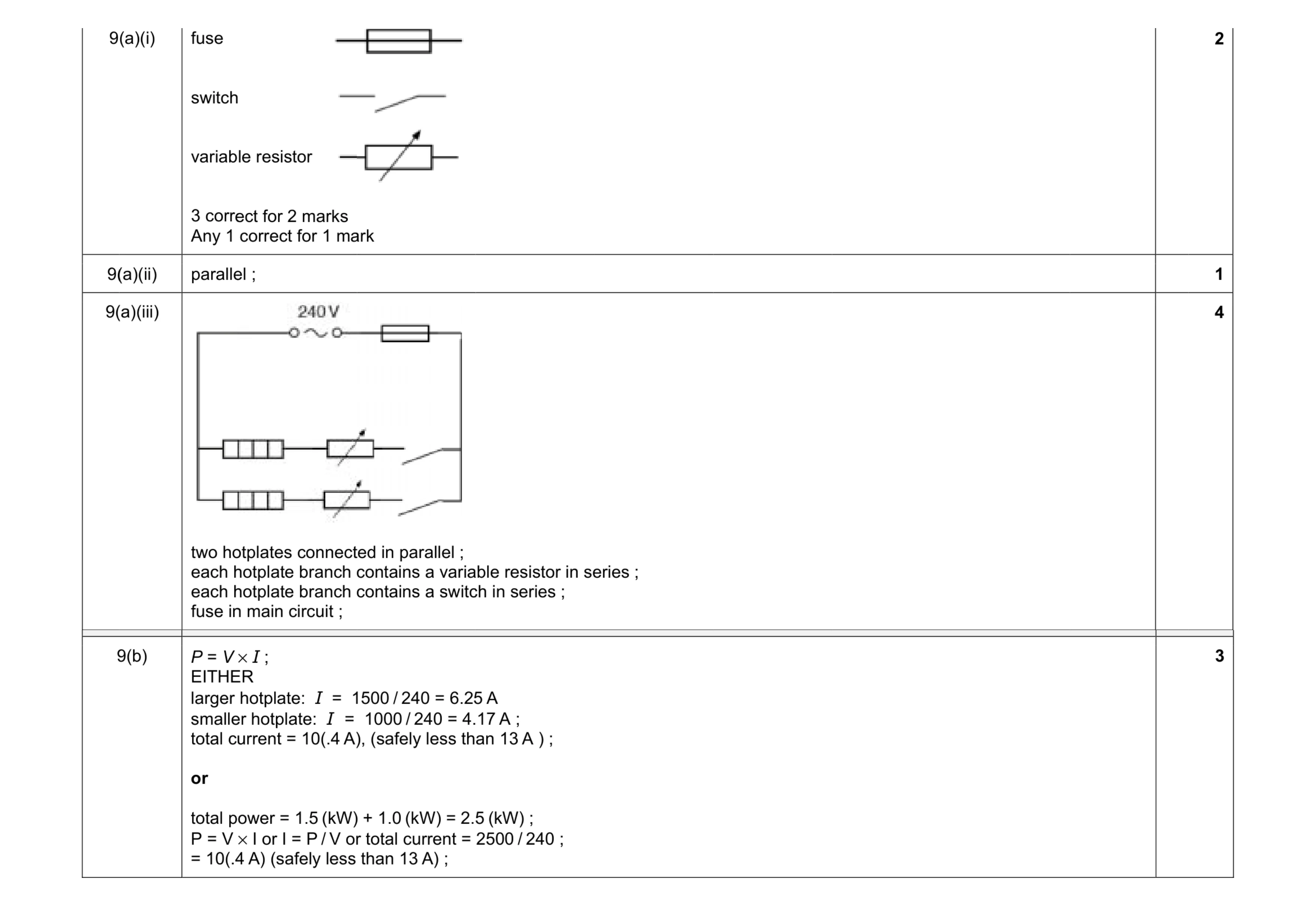 10
10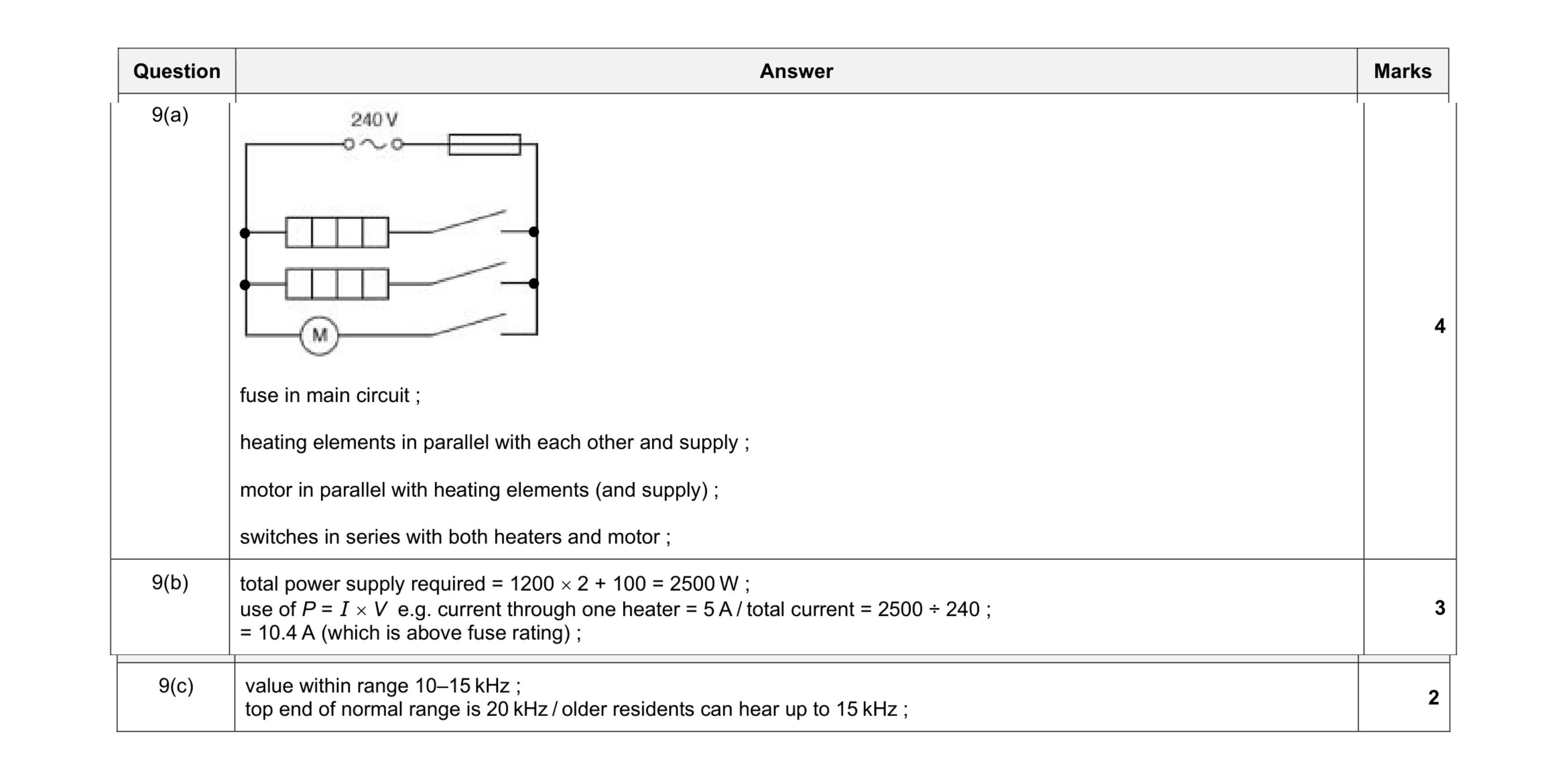 9
9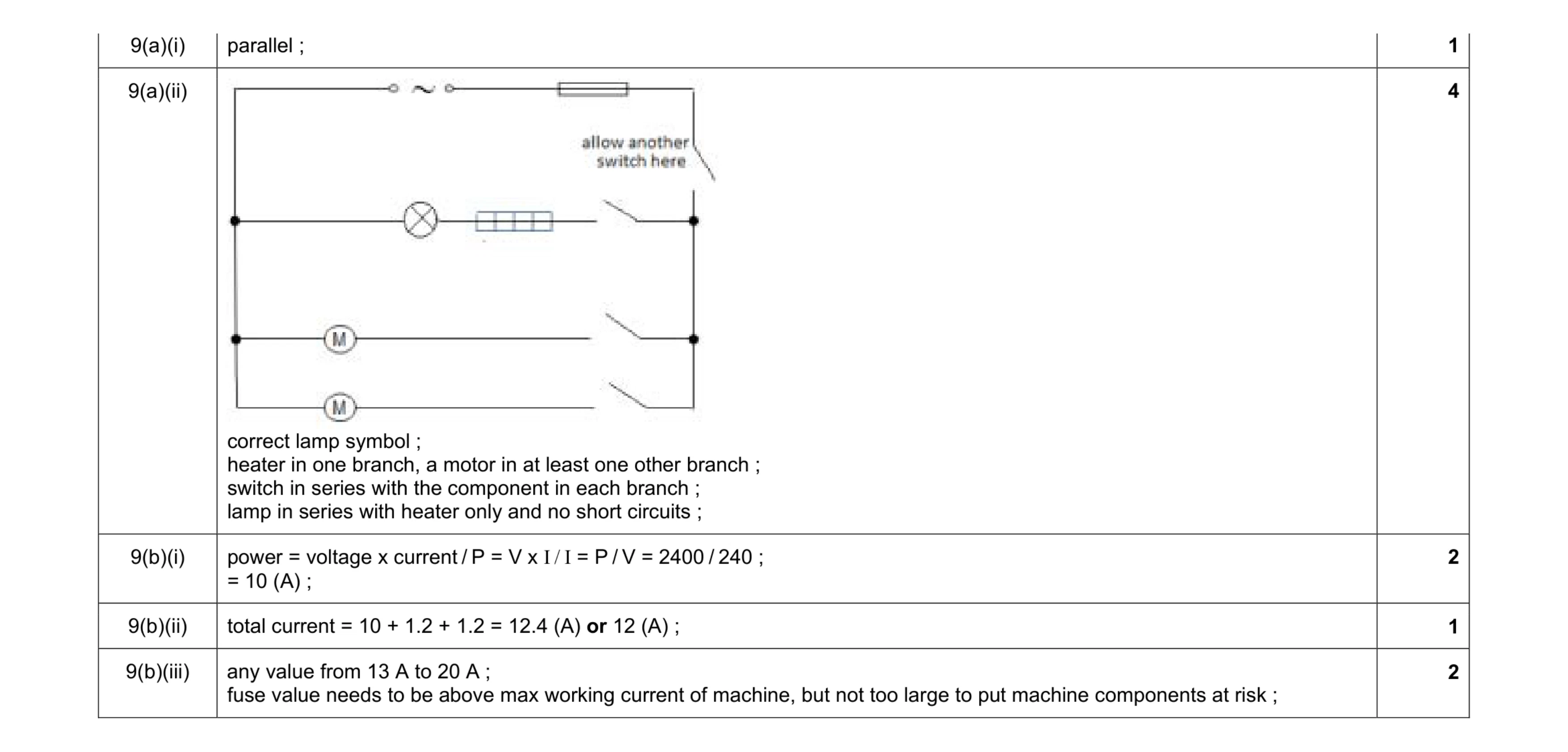 10
10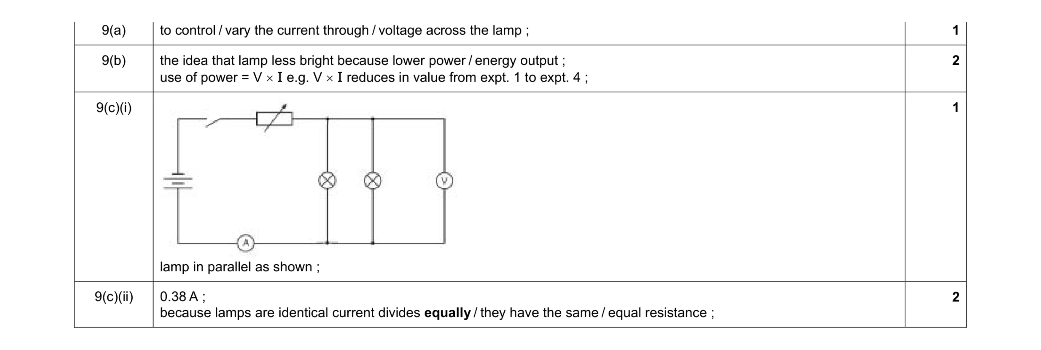 6
6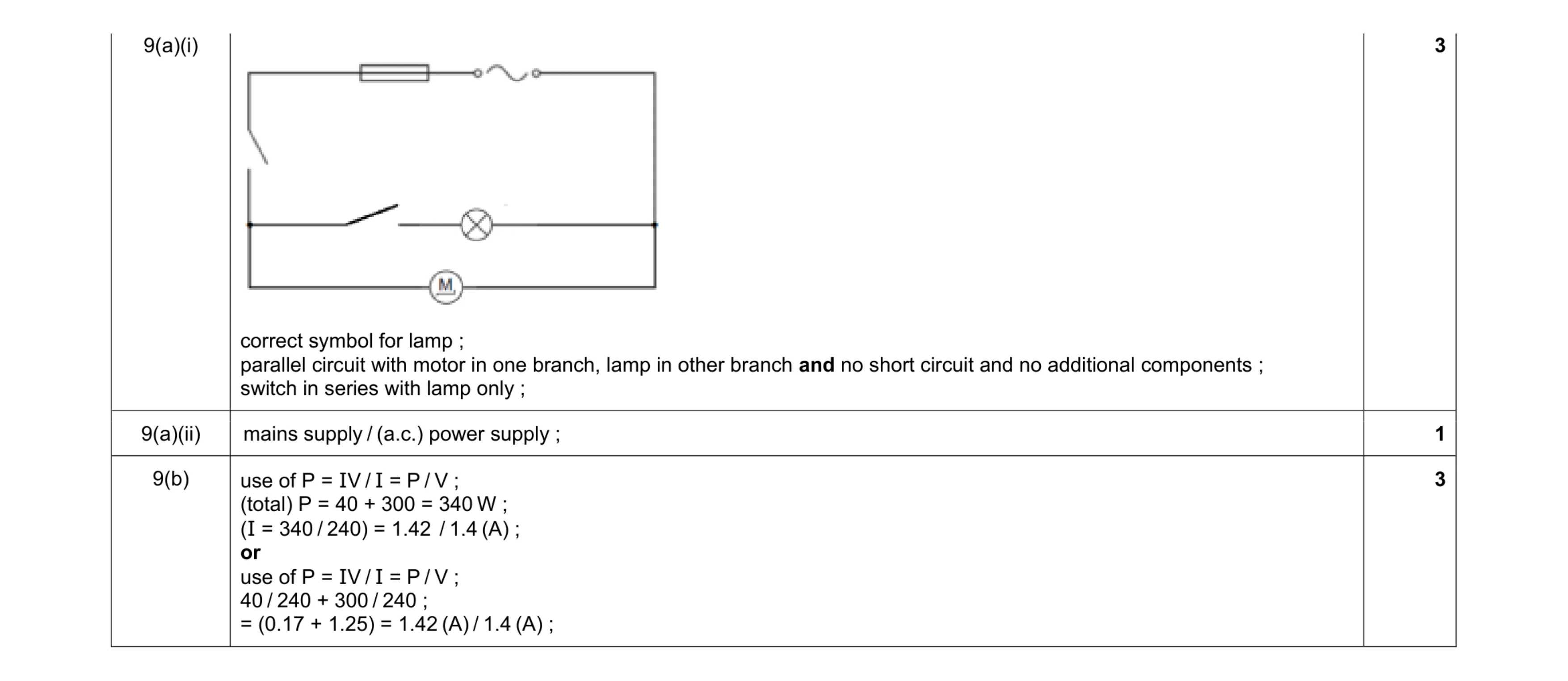 7
7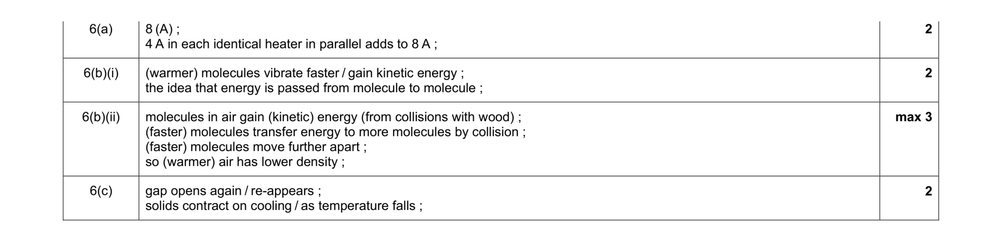 9
9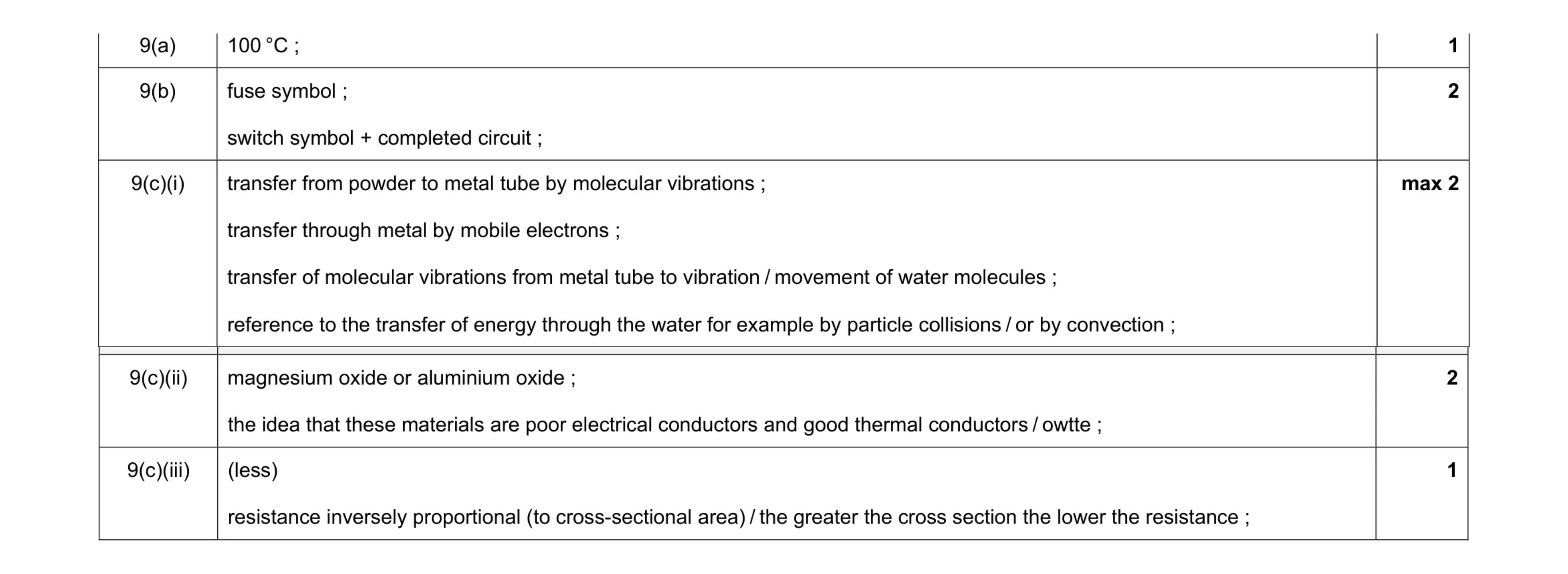 8
8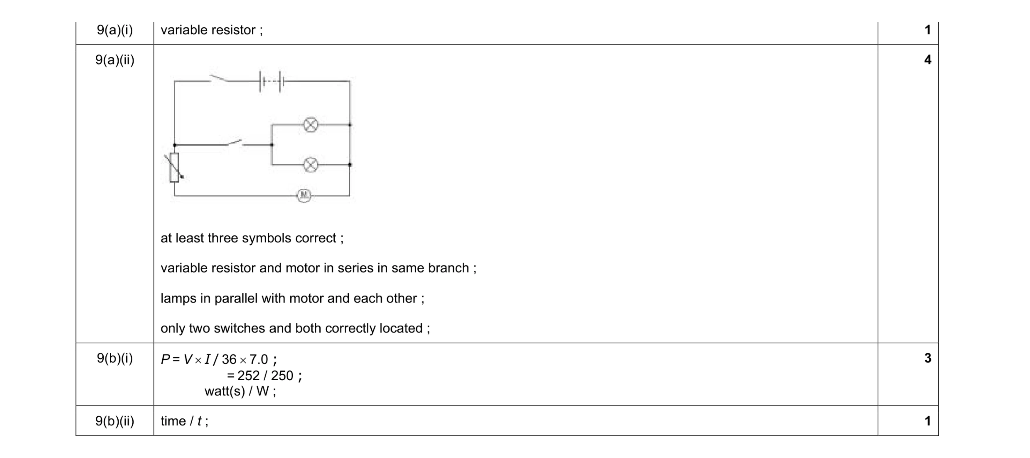 9
9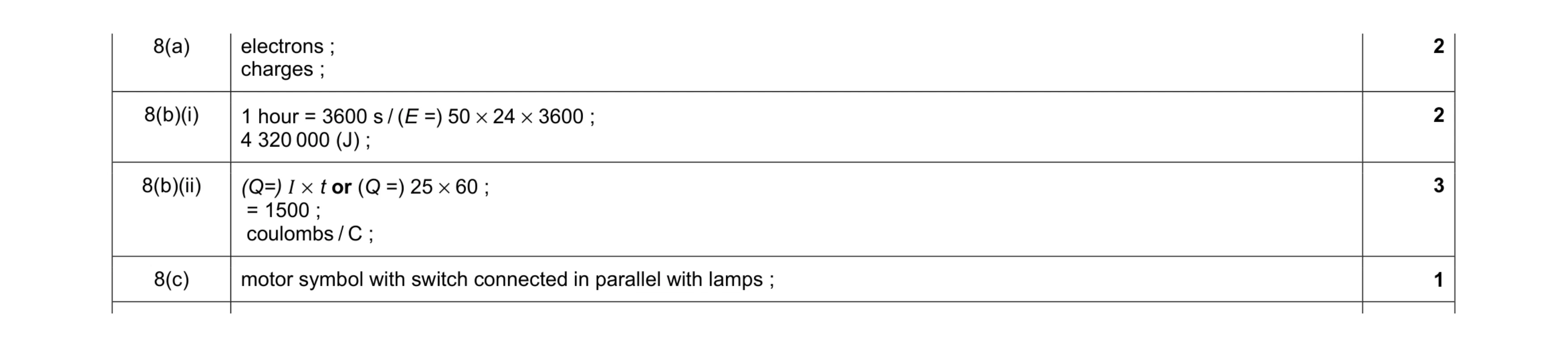 8
8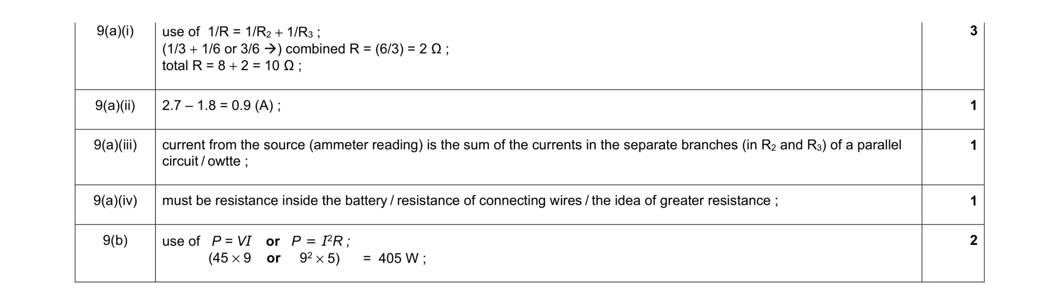 8
8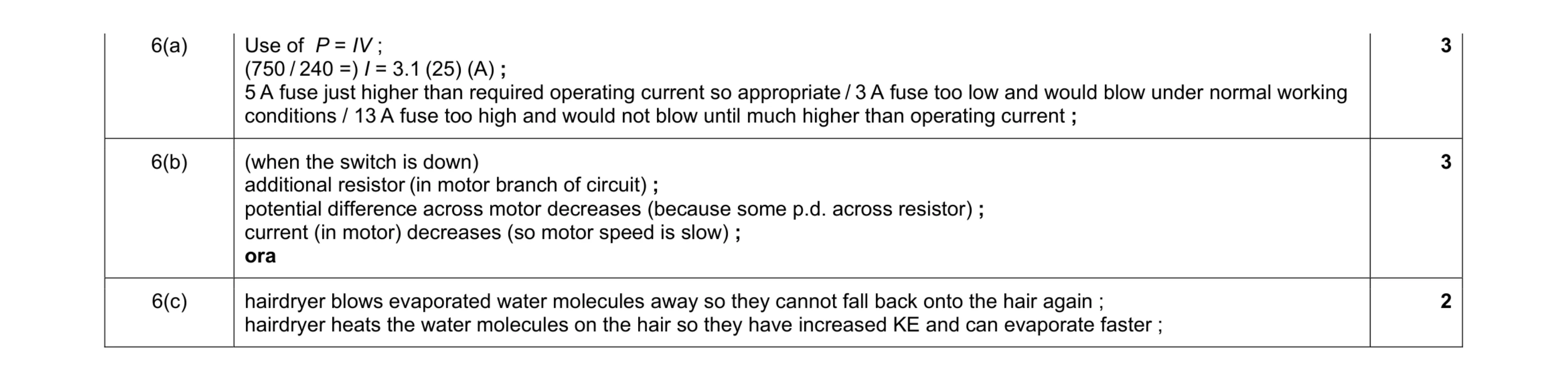 8
8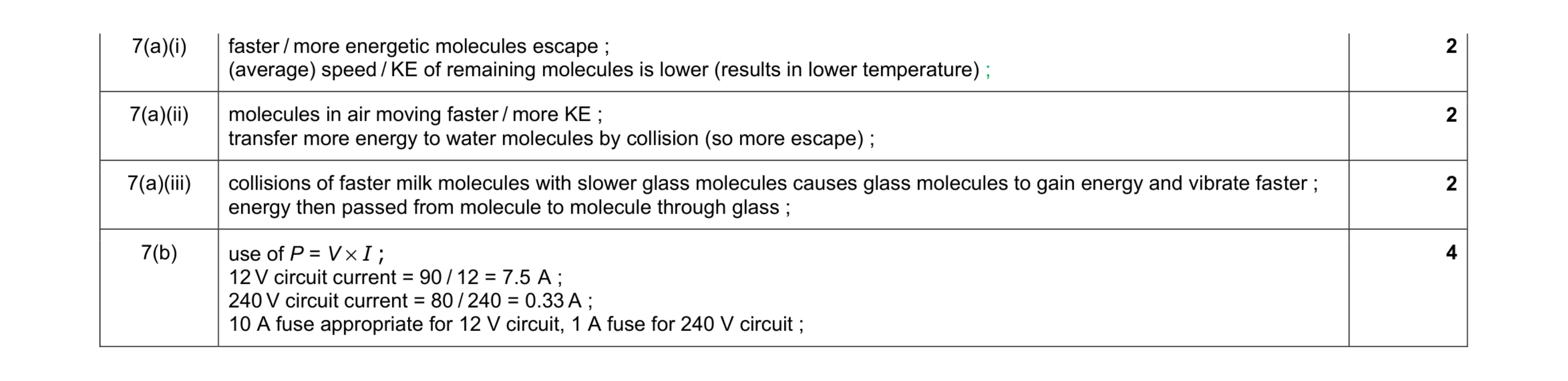 10
10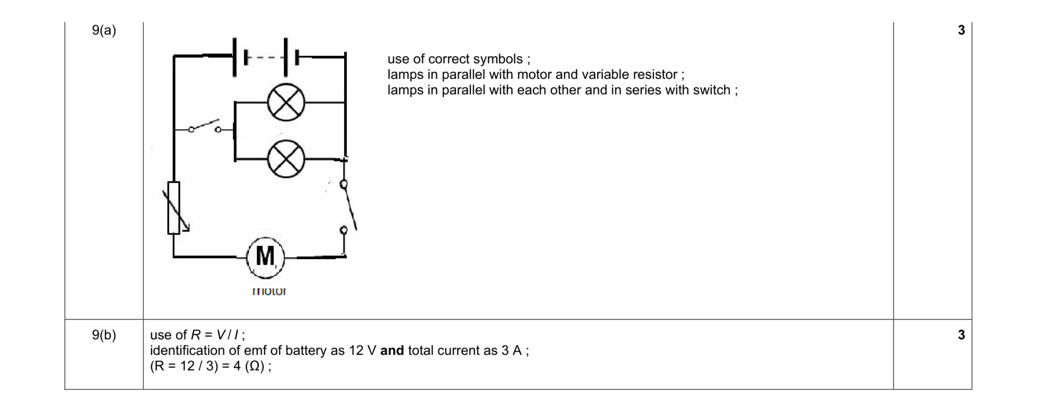 6
6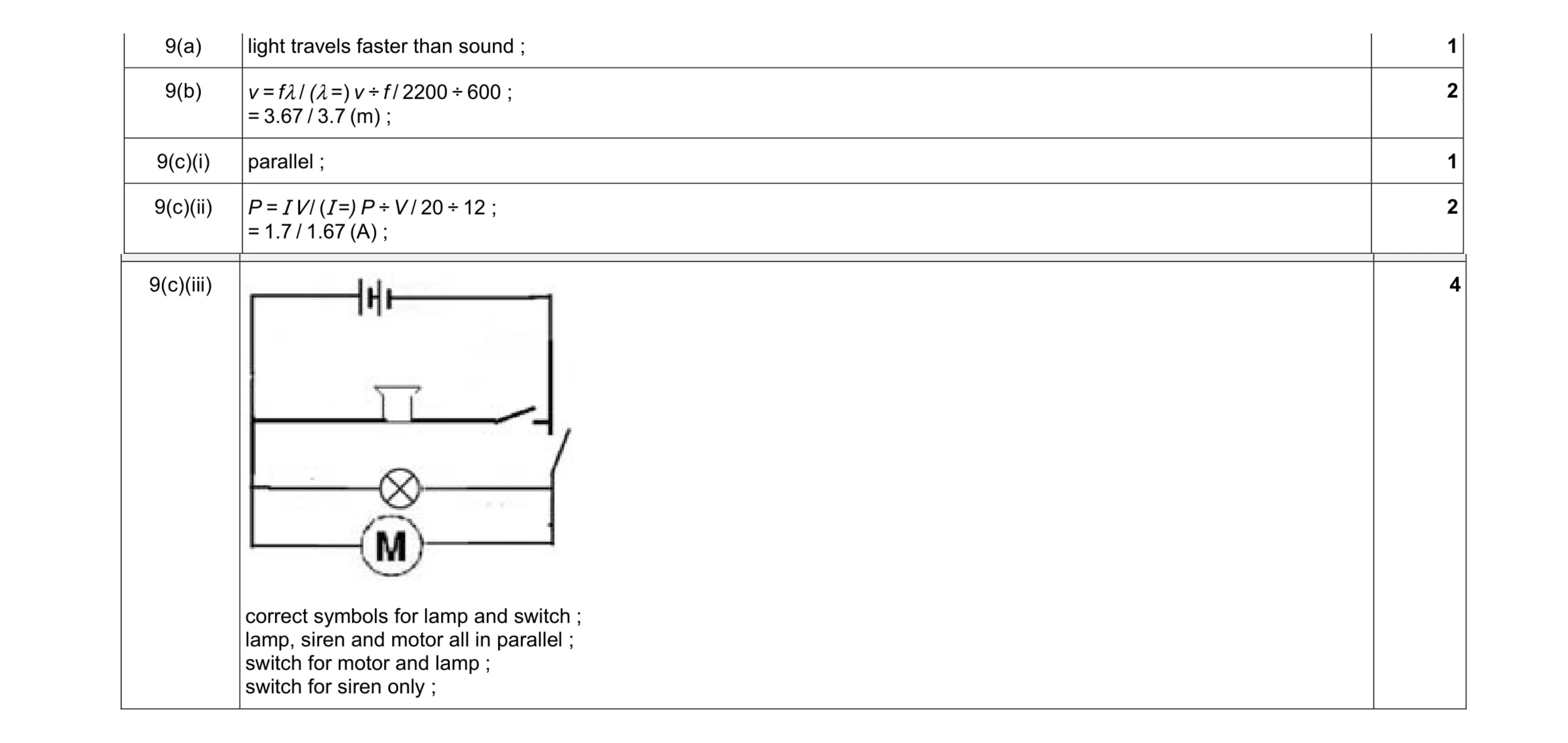 10
10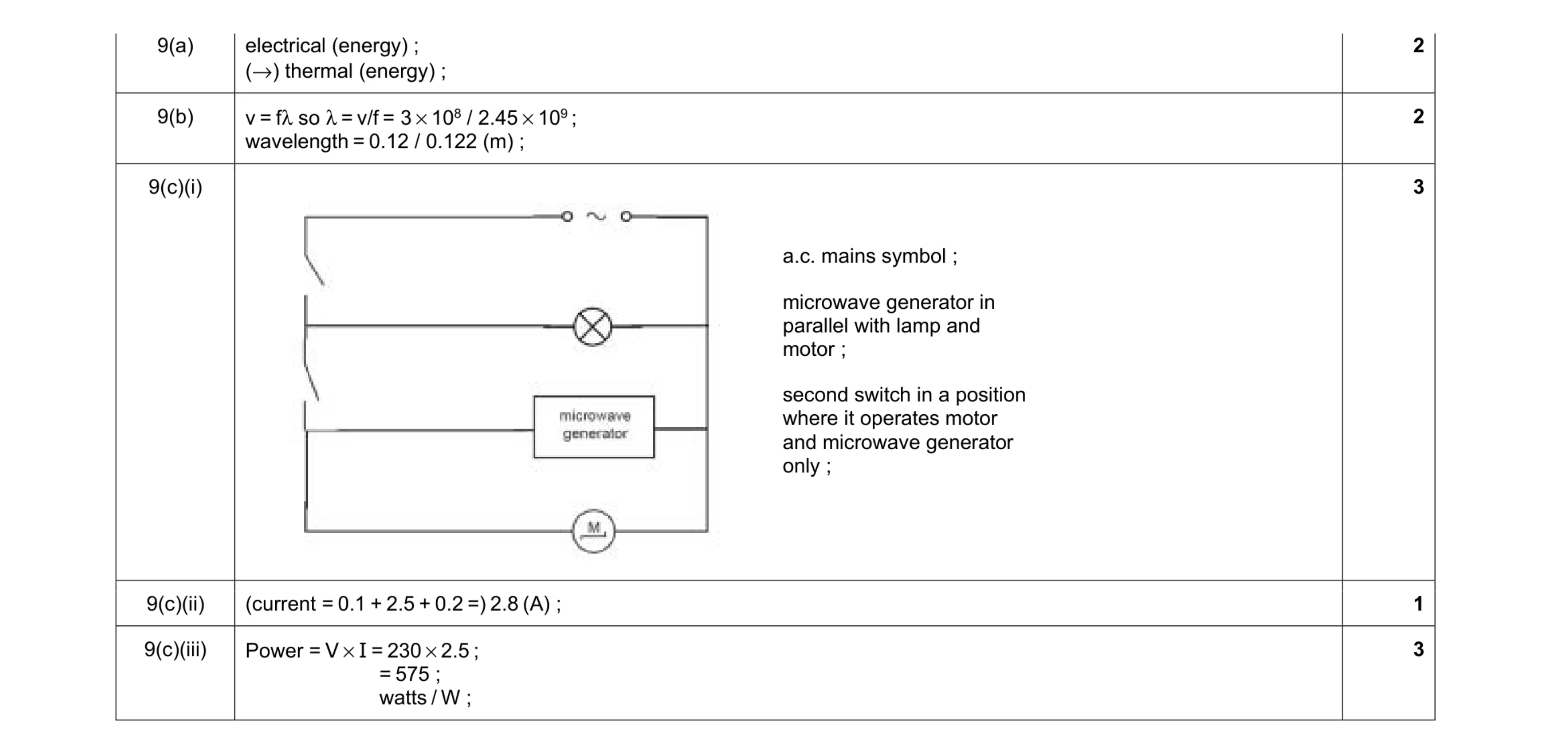 11
11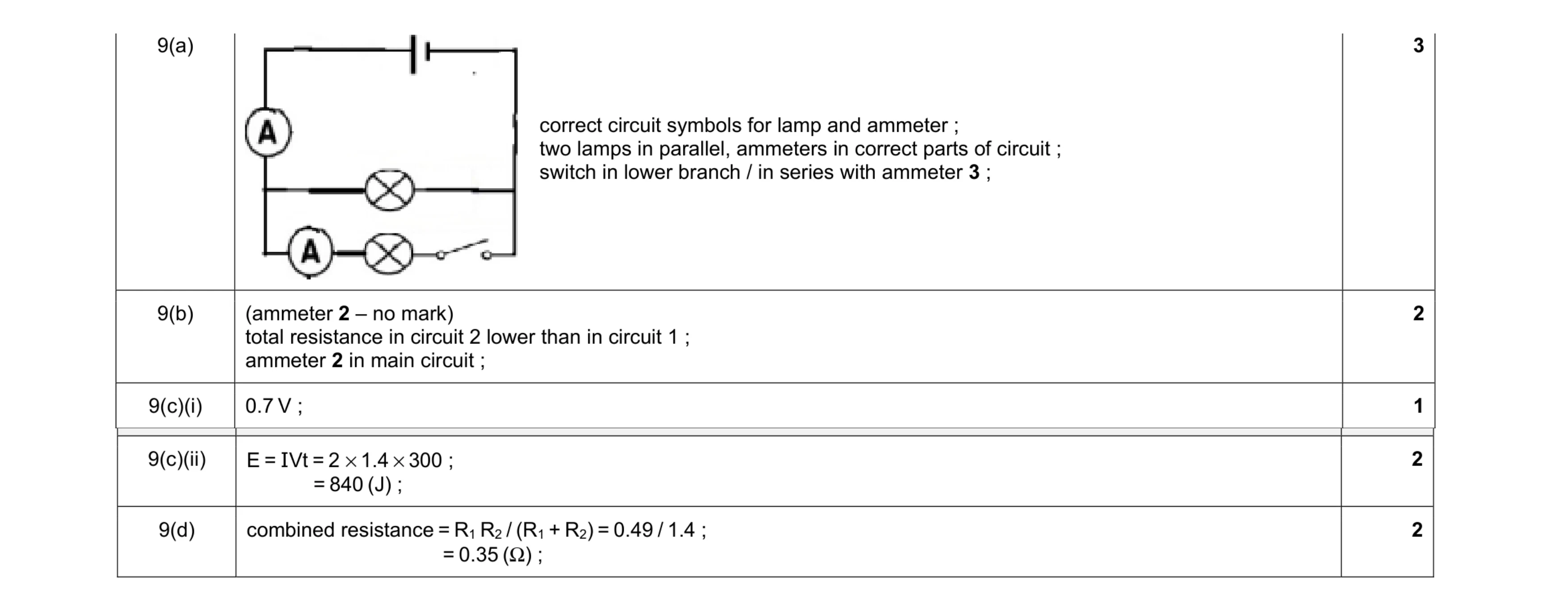 10
10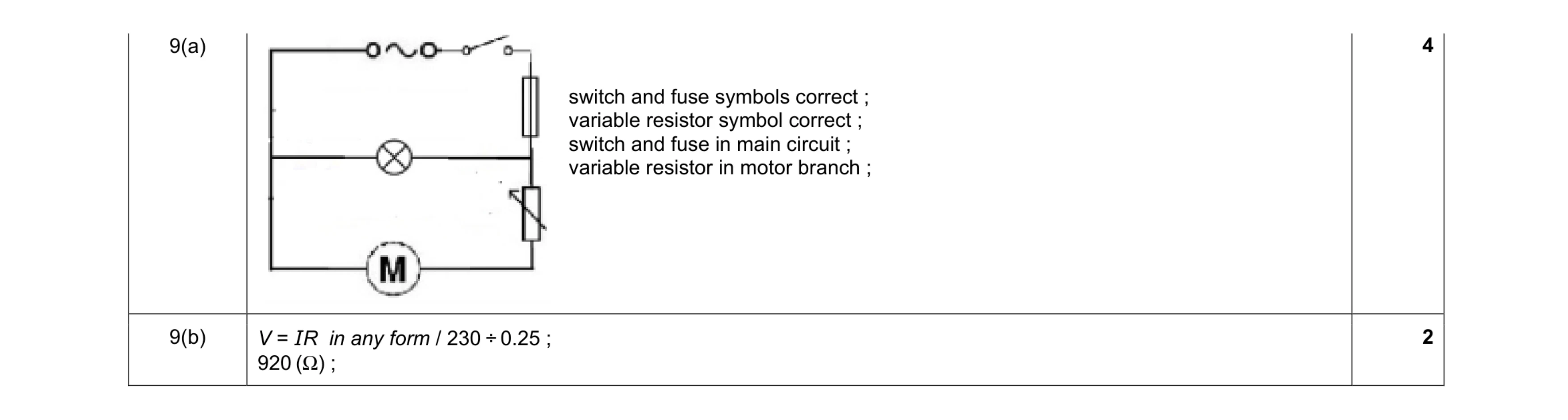 6
6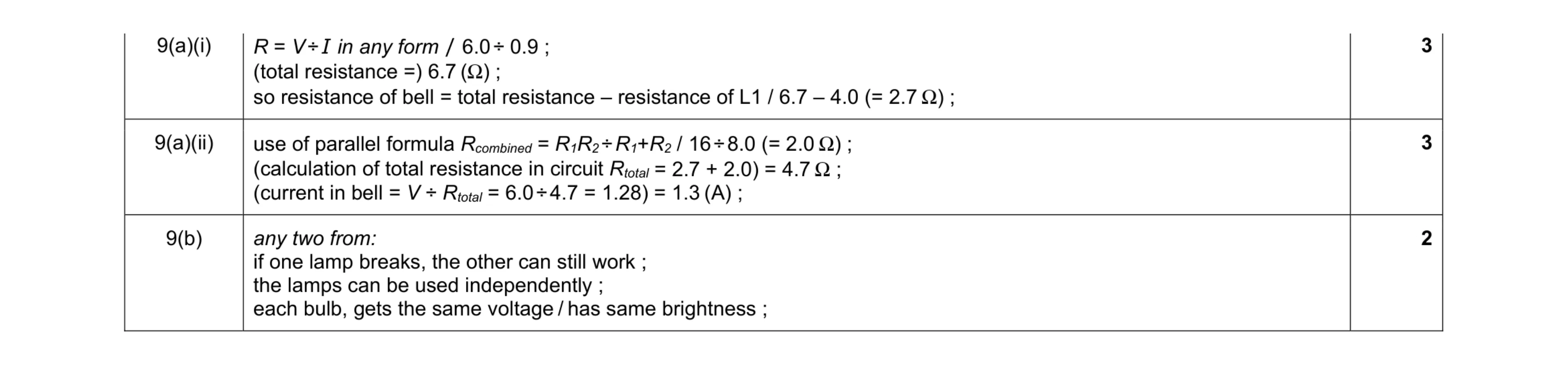 8
8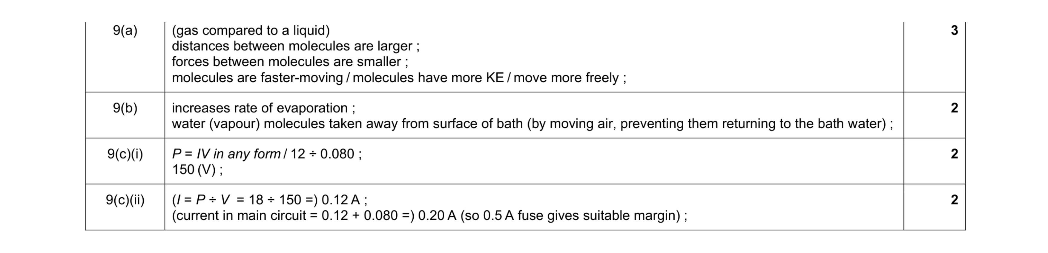 9
9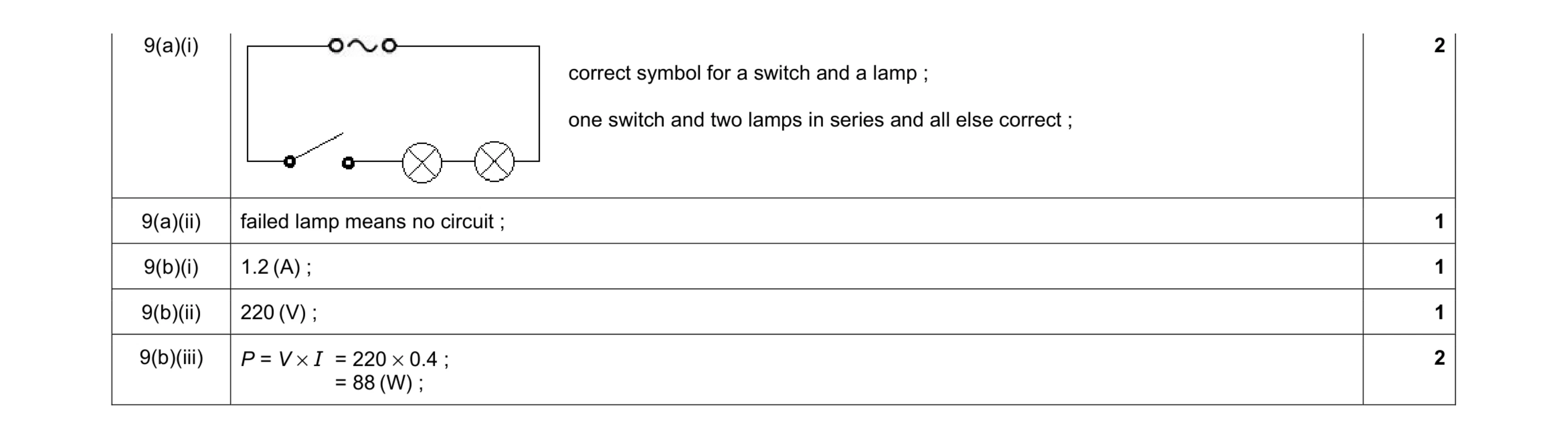 7
7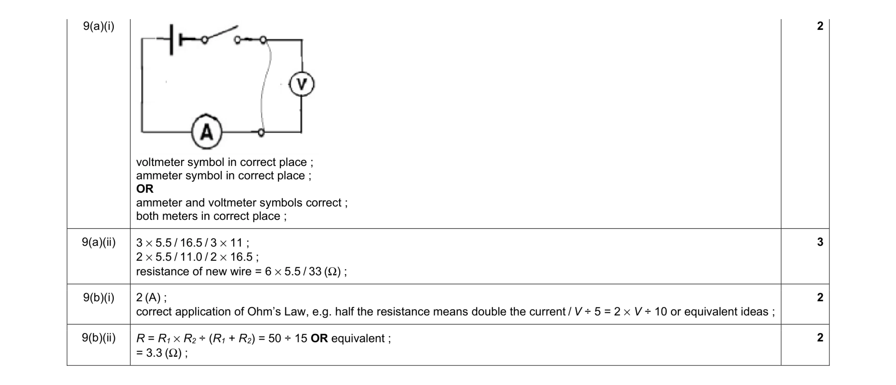 9
9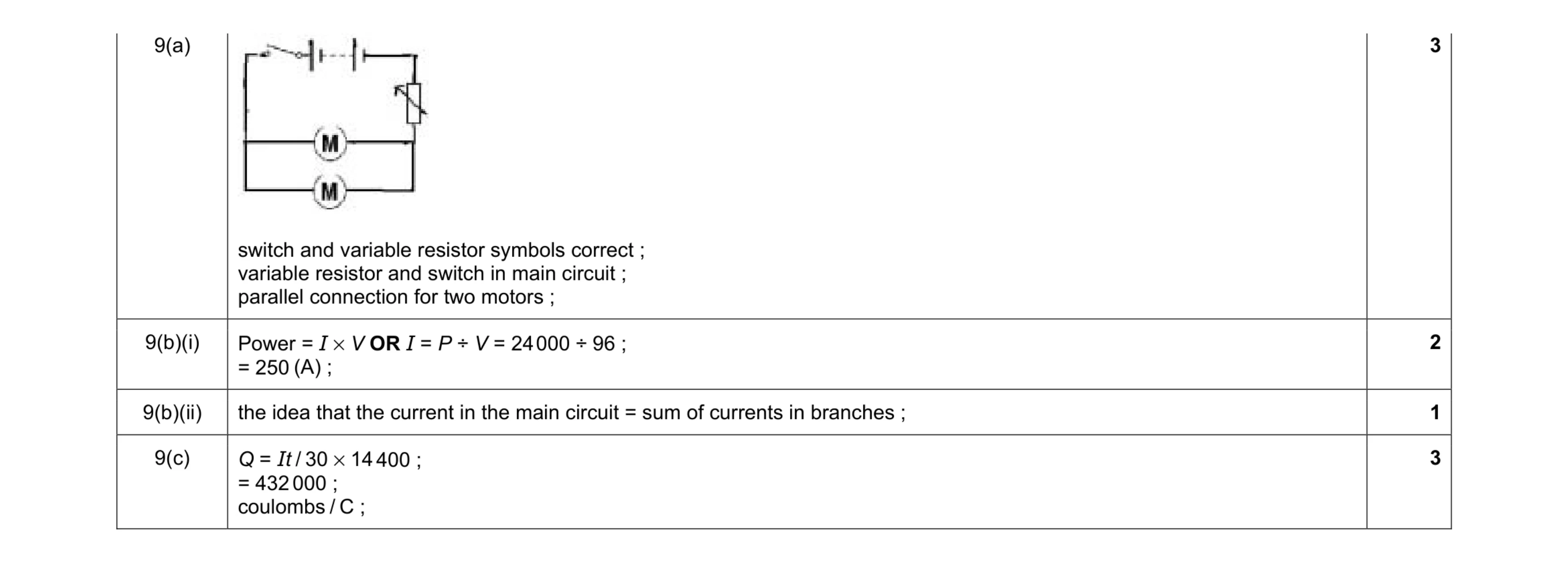 9
9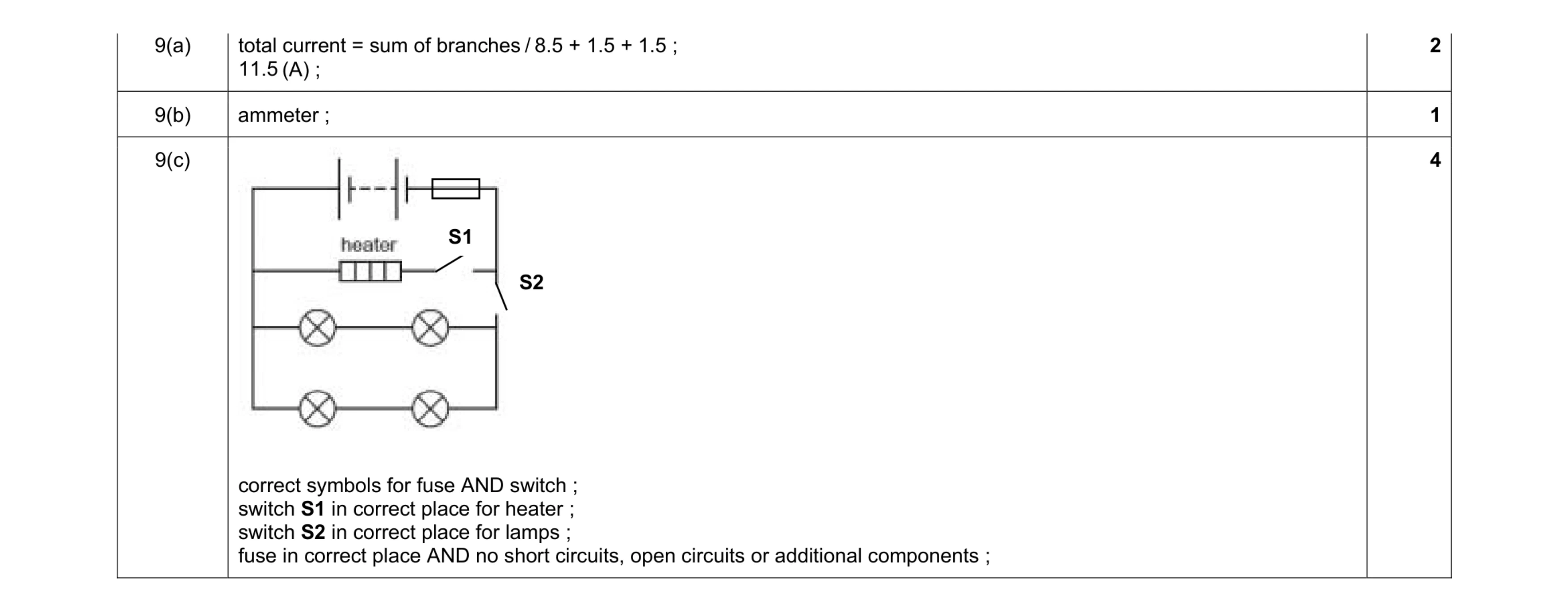 7
7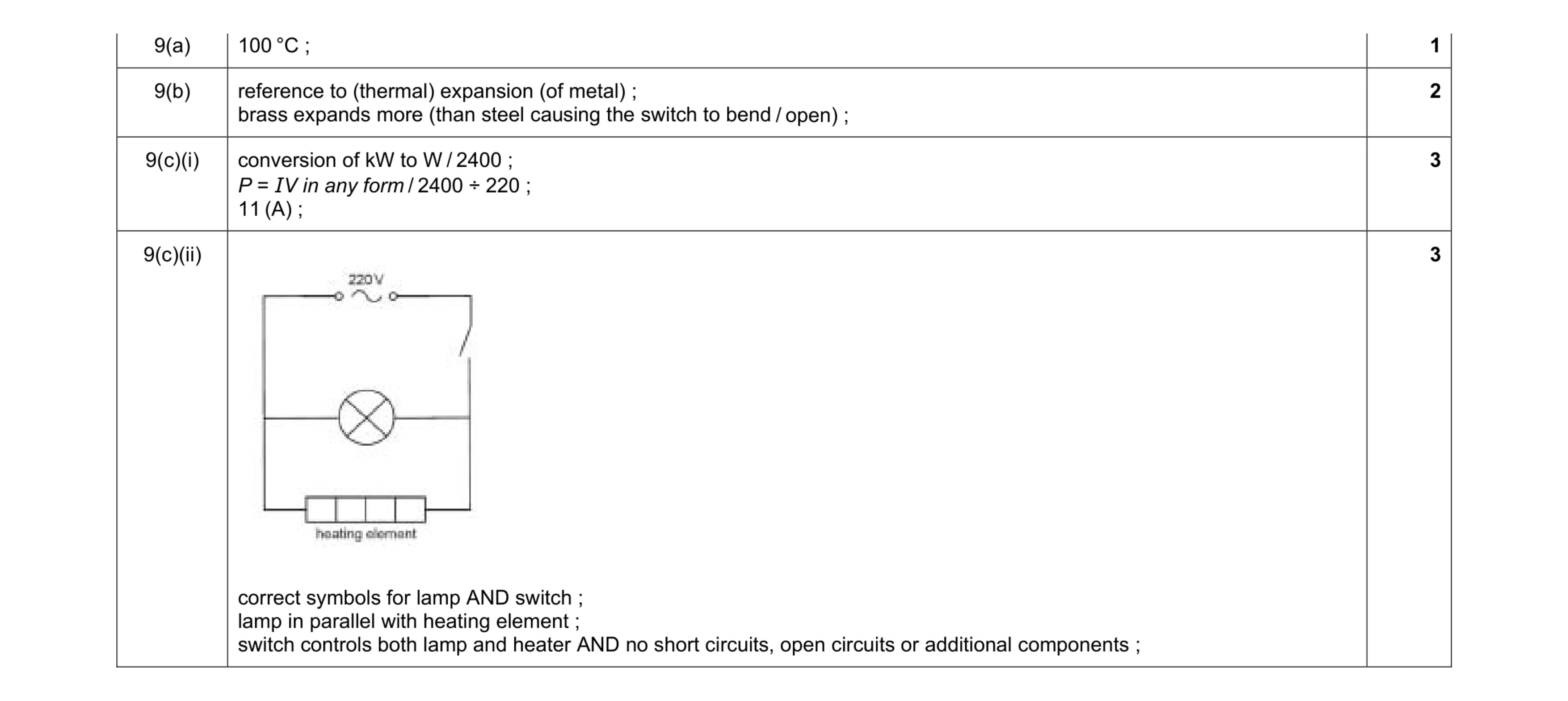 9
9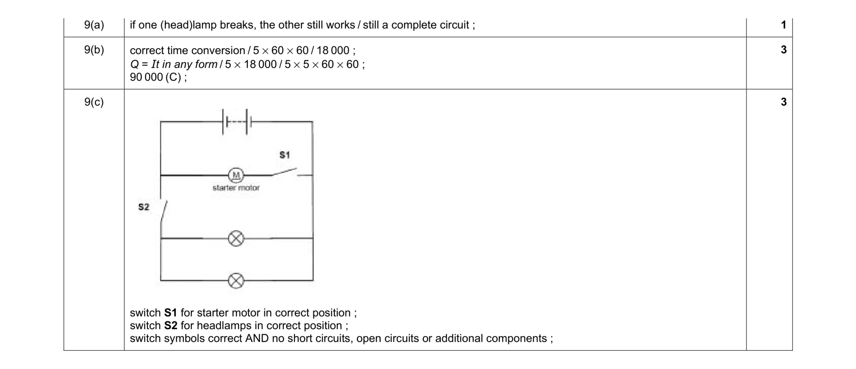 7
7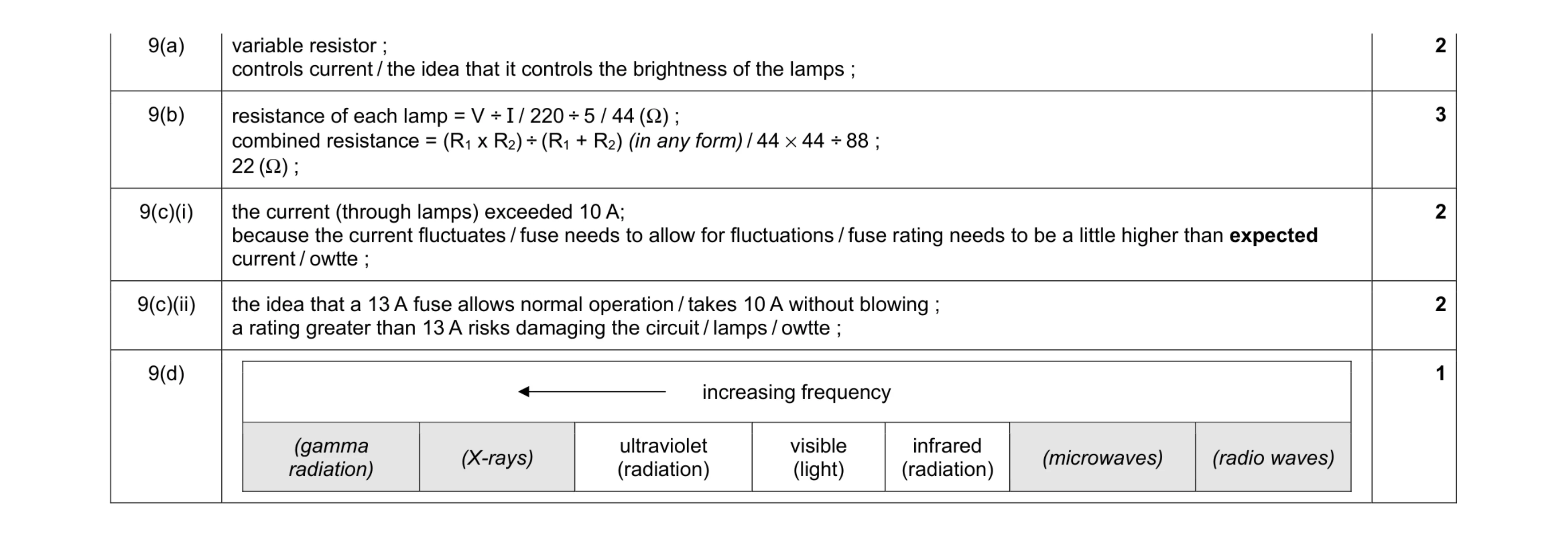 10
10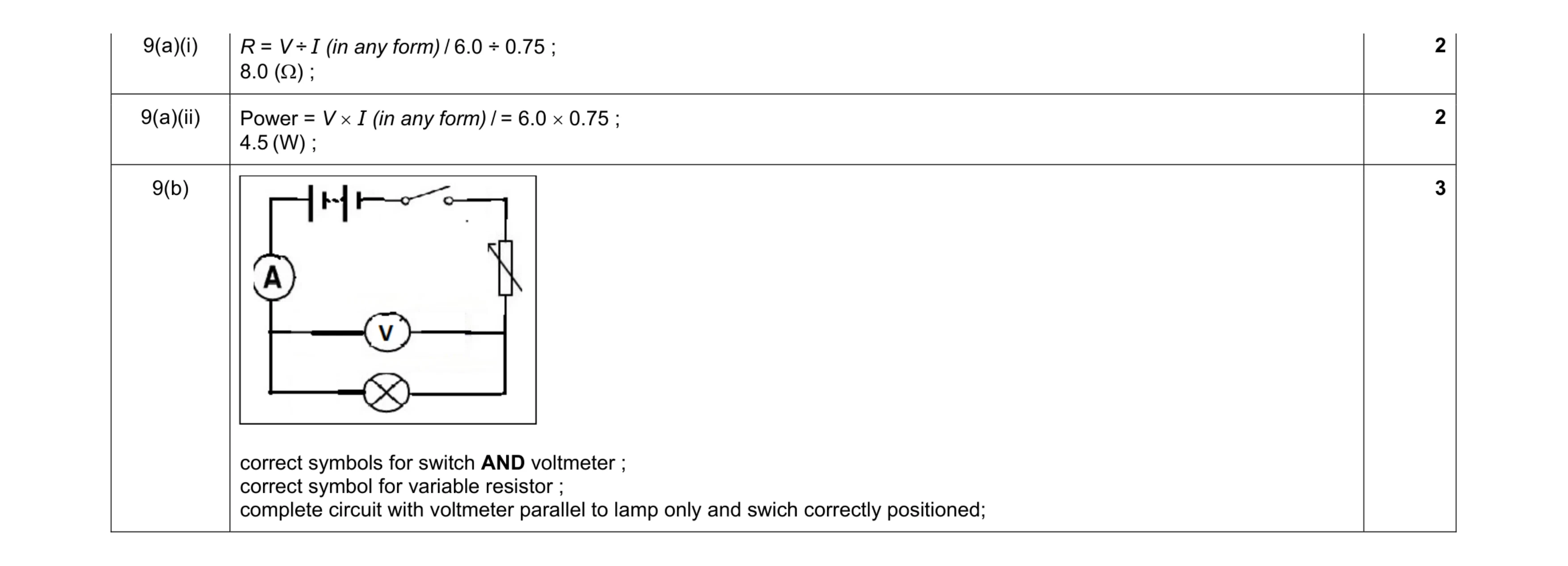 7
7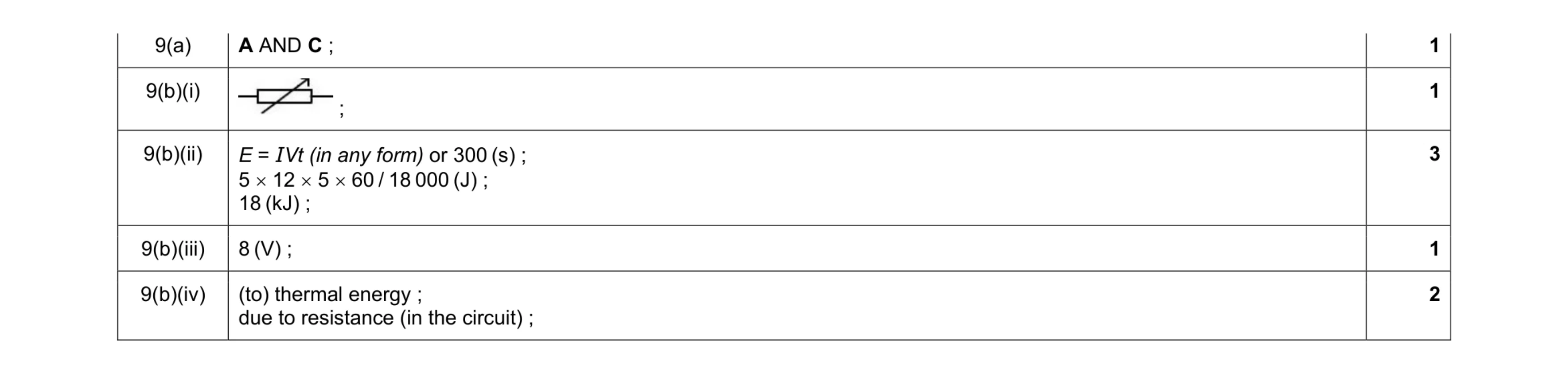 8
8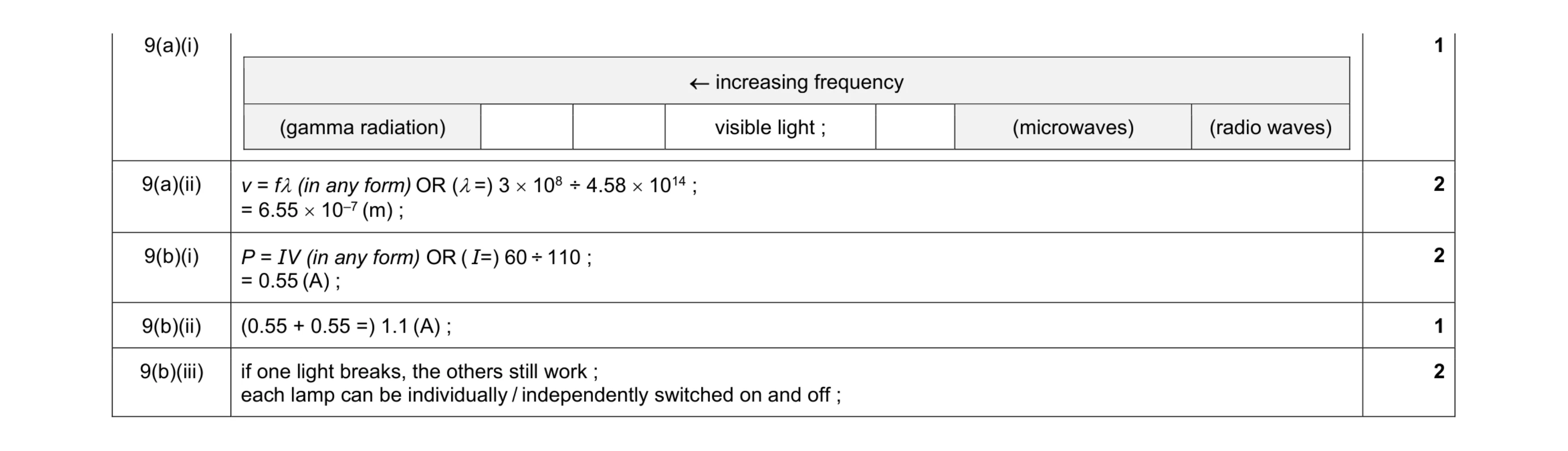 8
8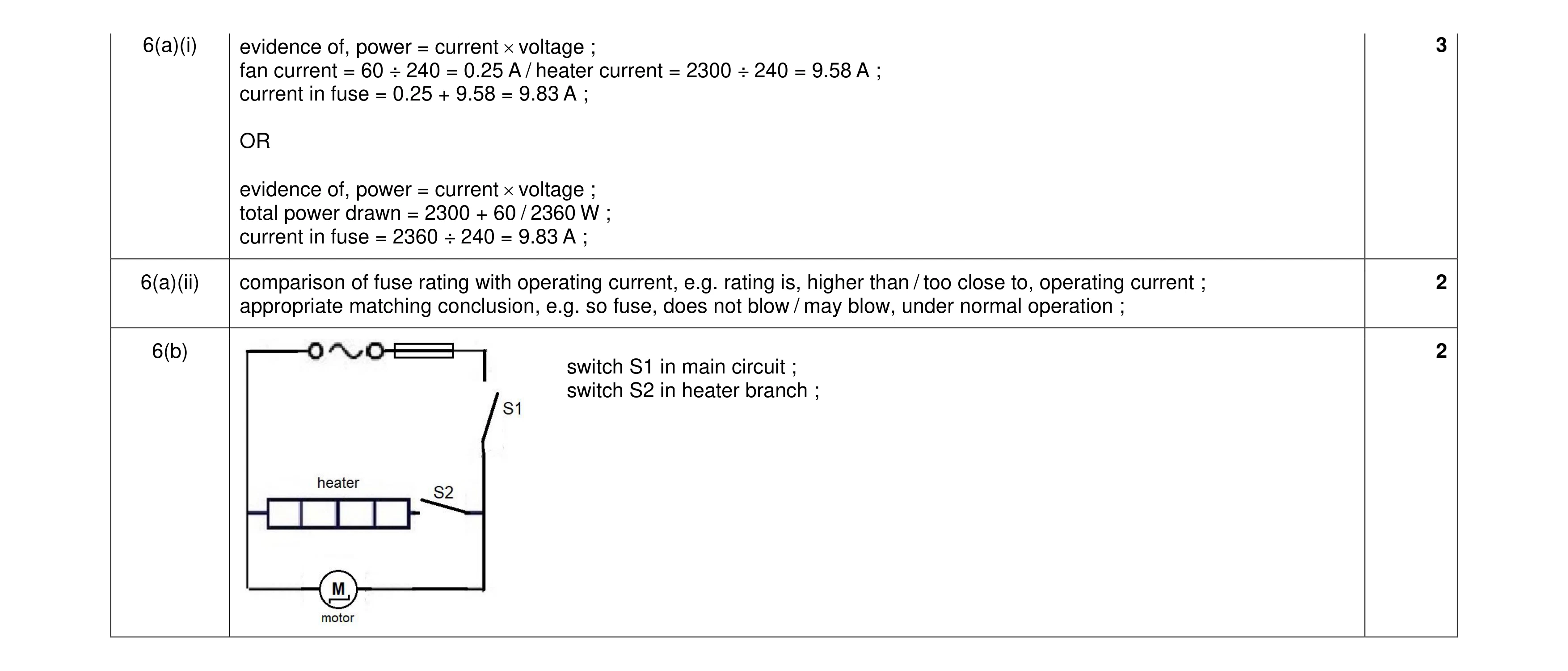 7
7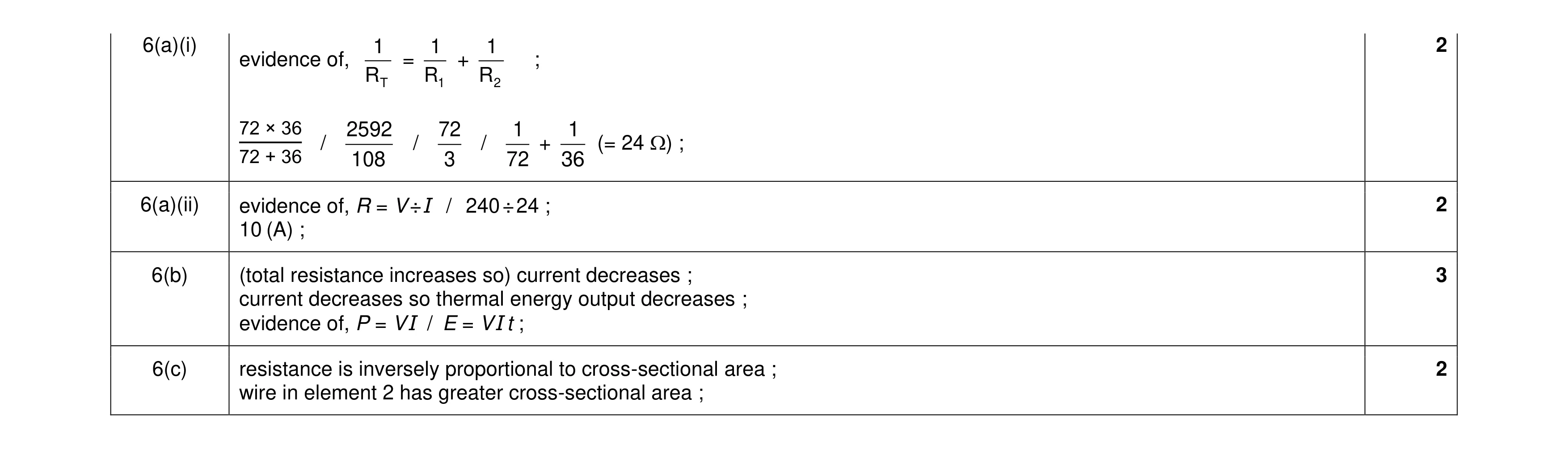 9
9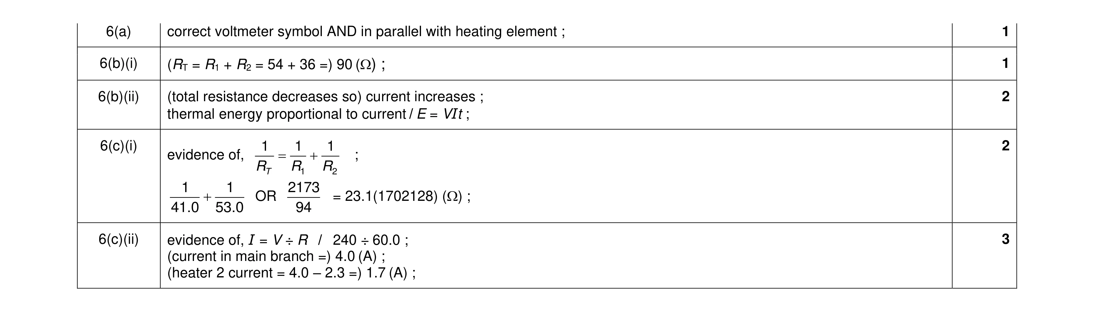 9
9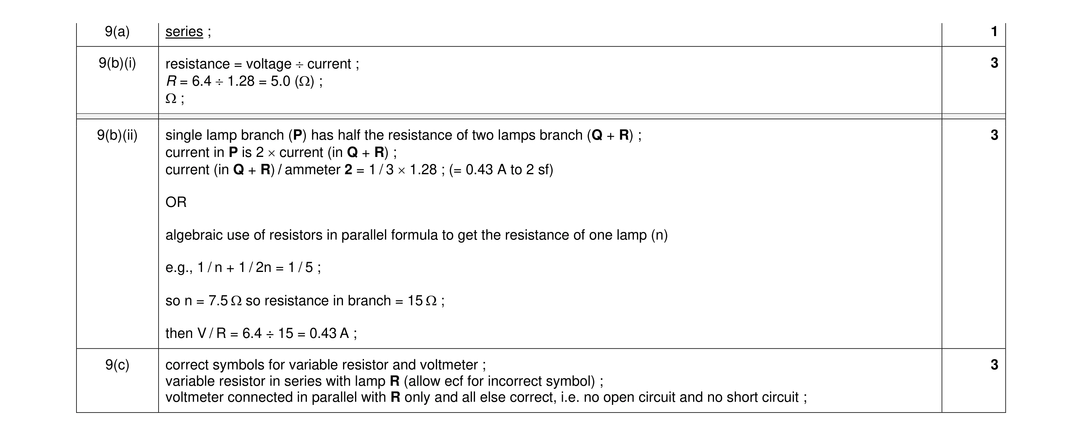 10
10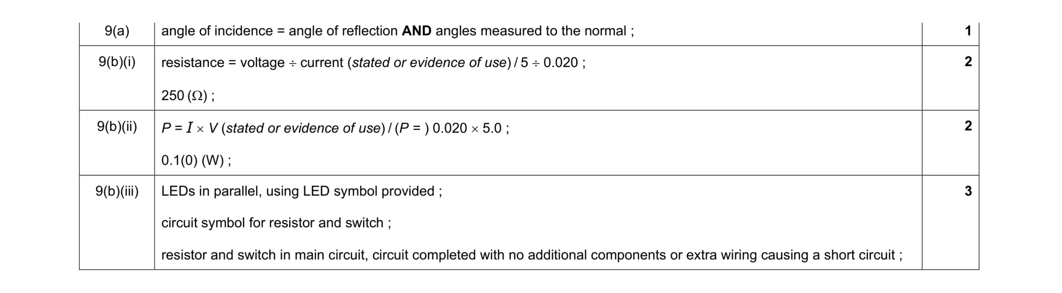 8
8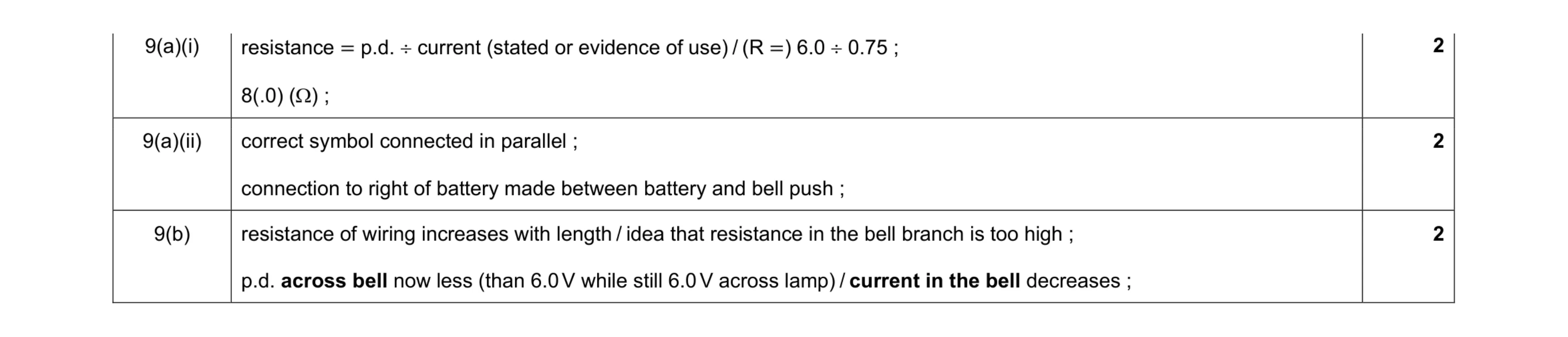 6
6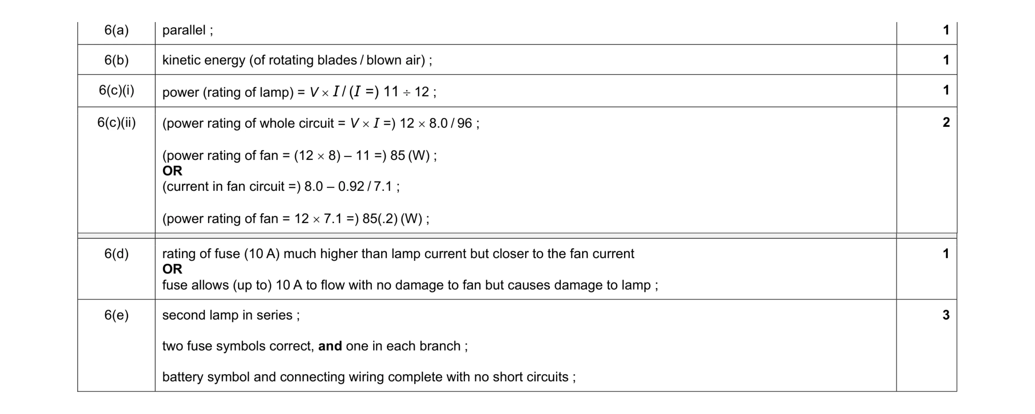 9
9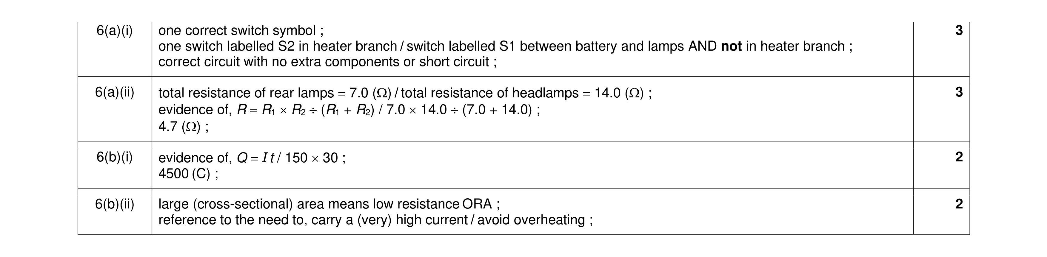 10
10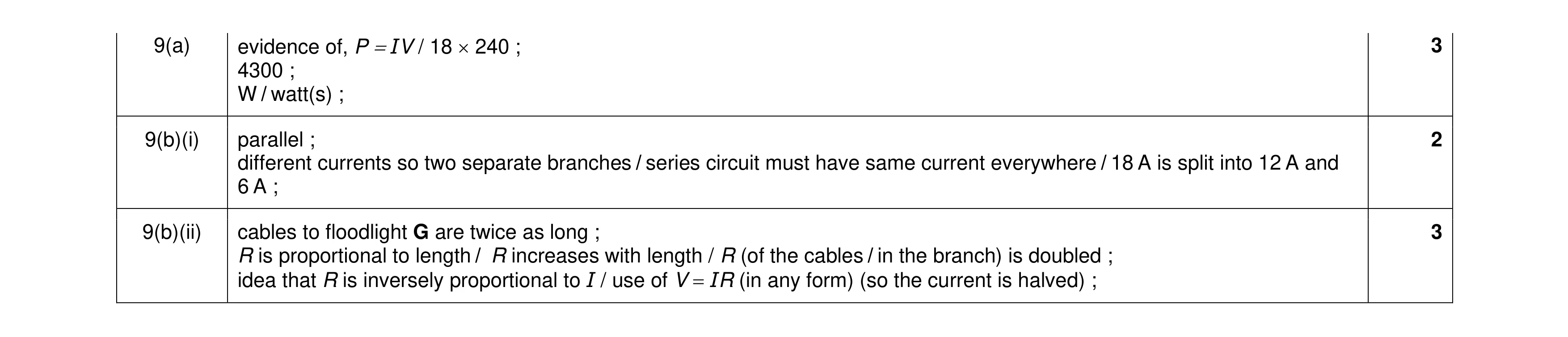 8
8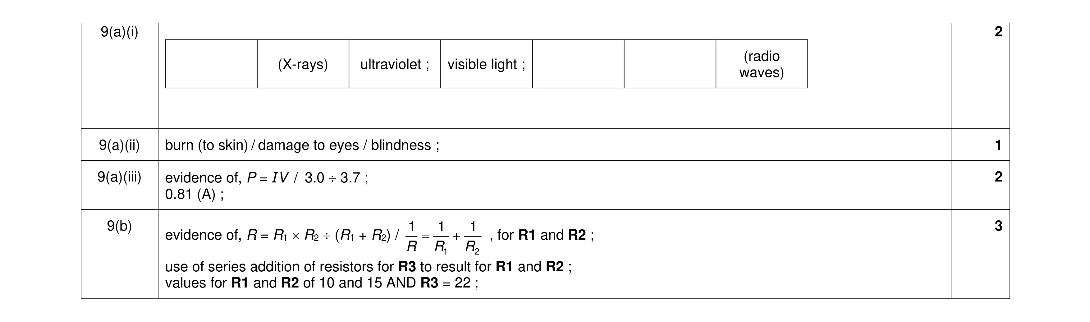 8
8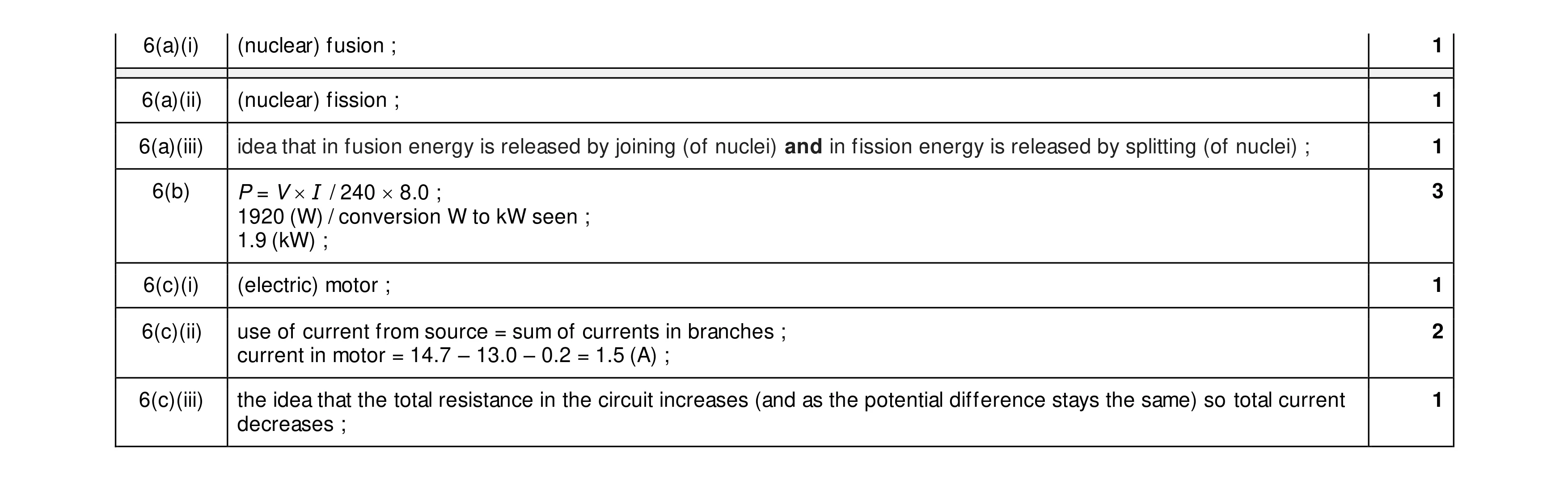 10
10 7
7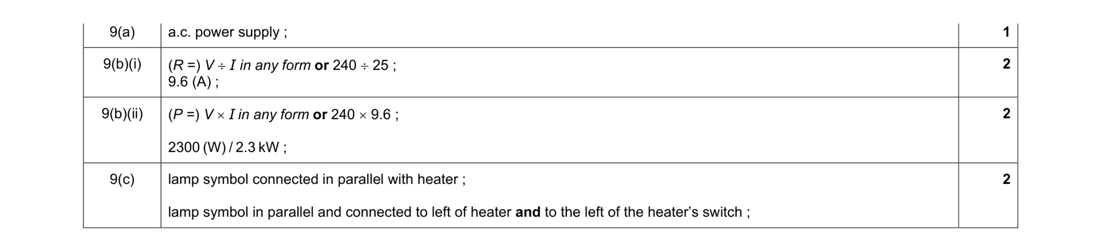 7
7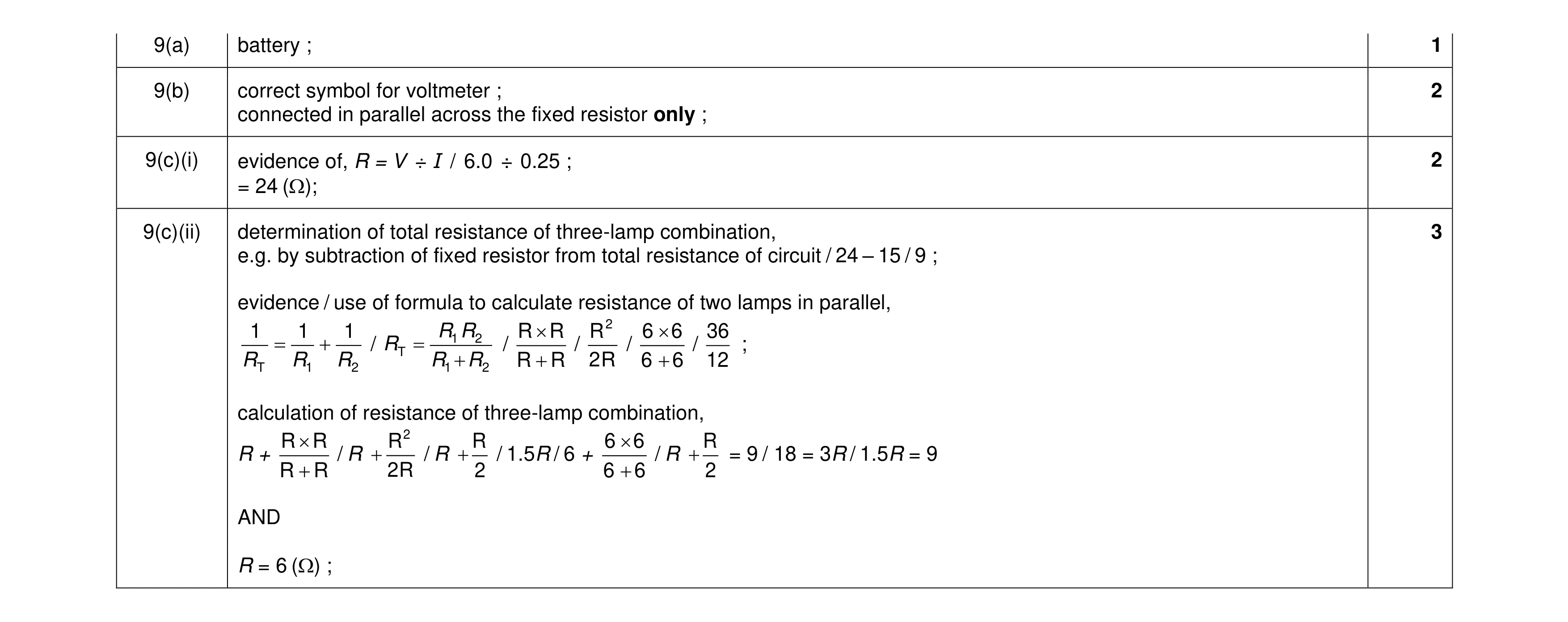 8
8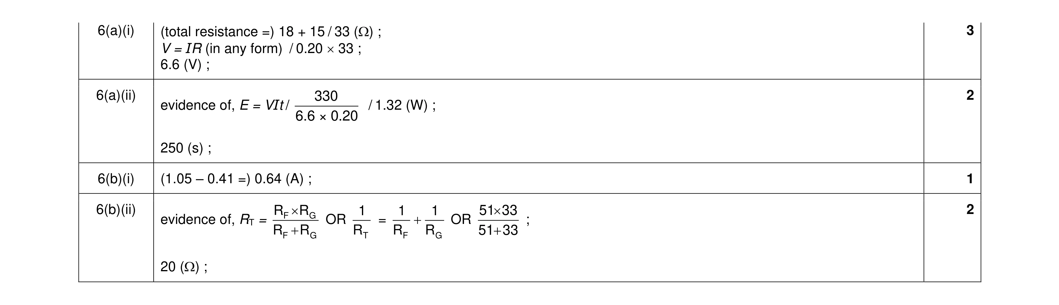 8
8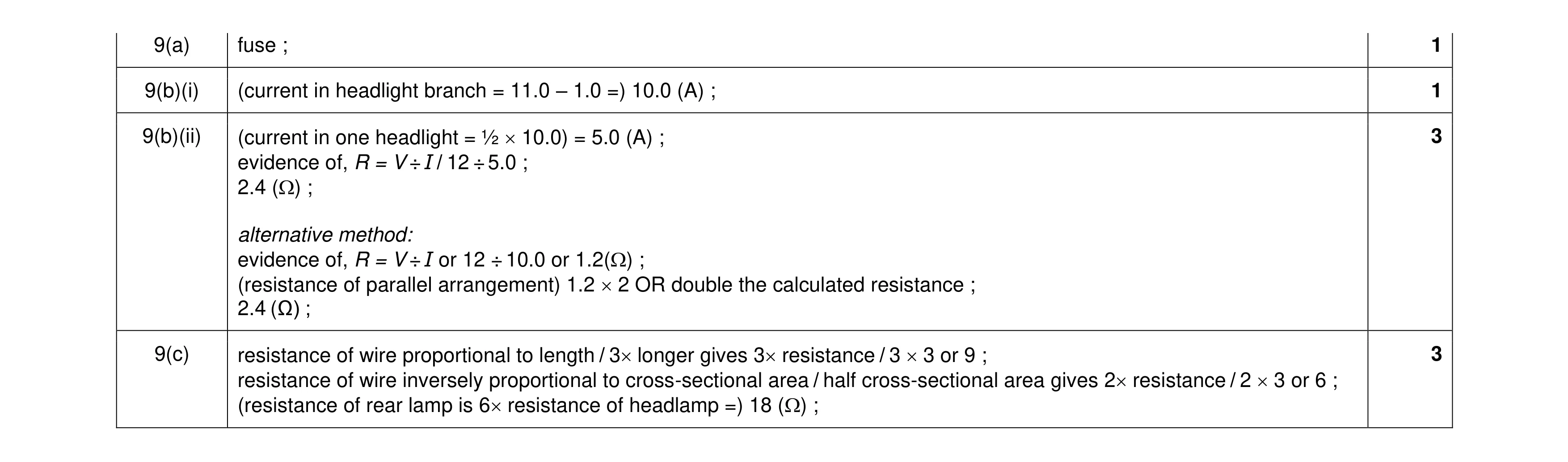 8
8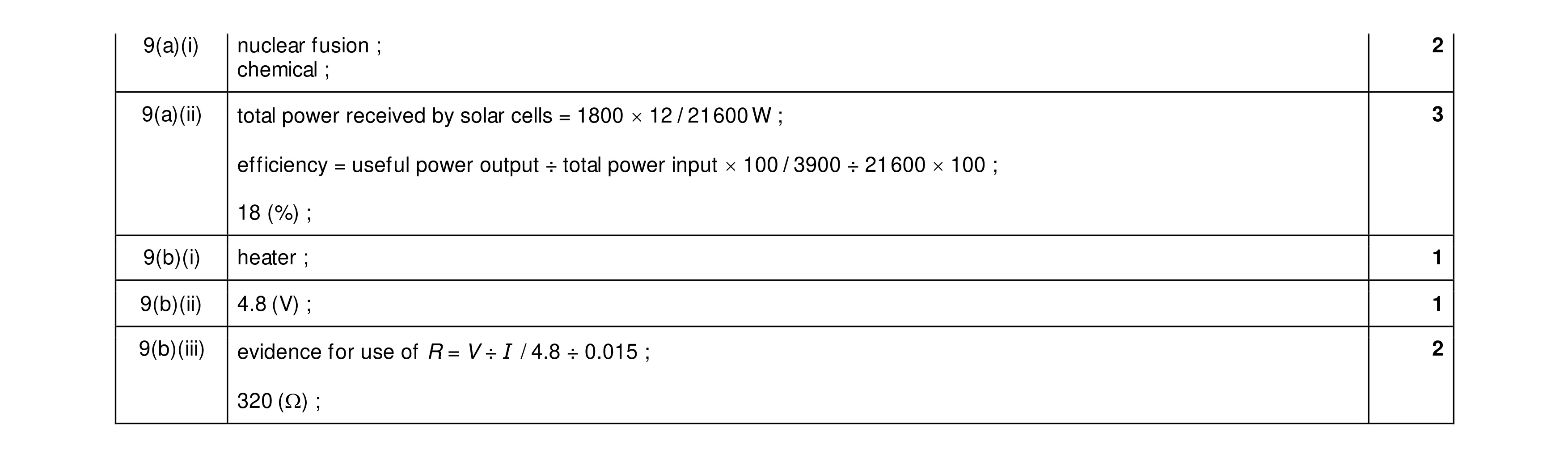 9
9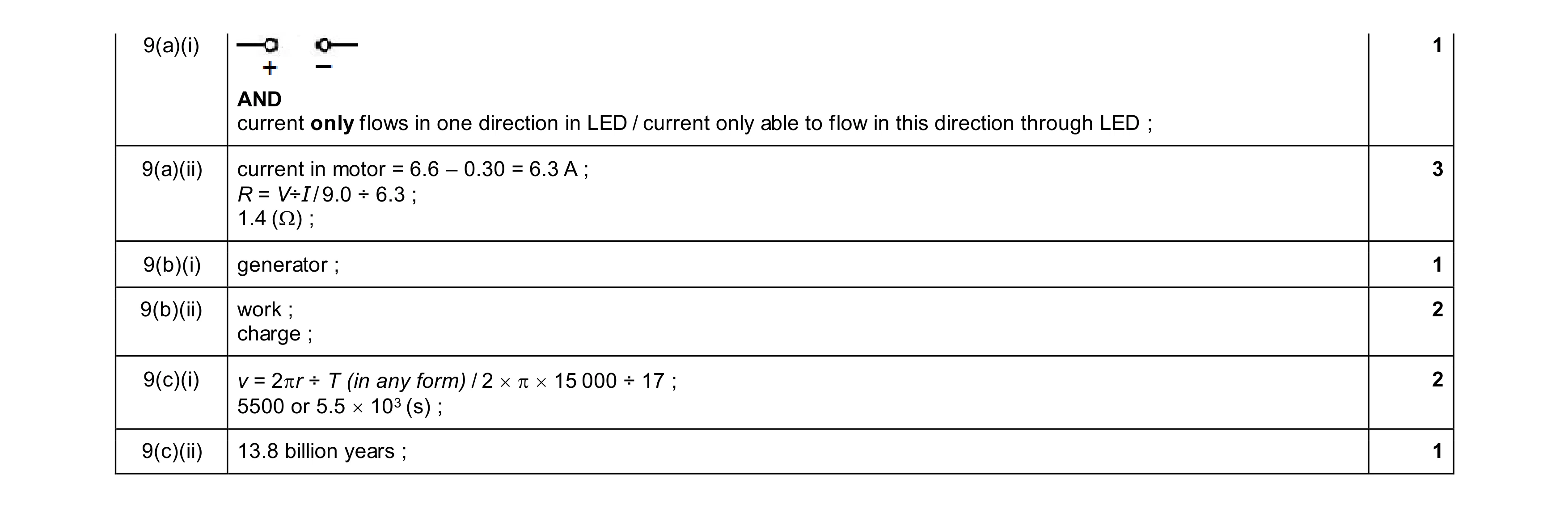 10
10 7
7 8
8 10
10 10
10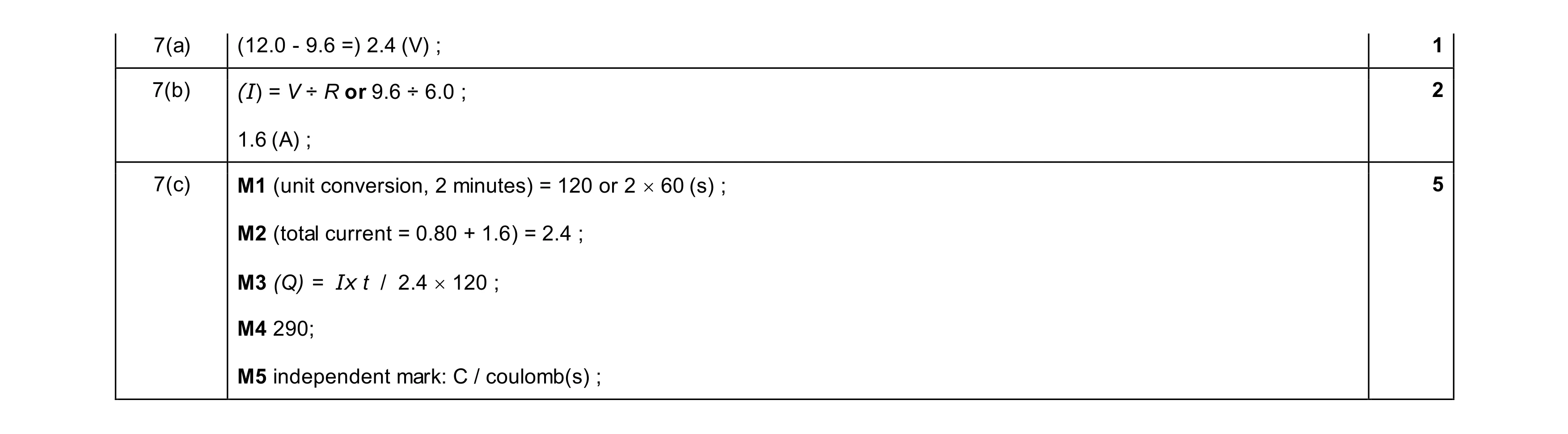 8
8