Questions as text
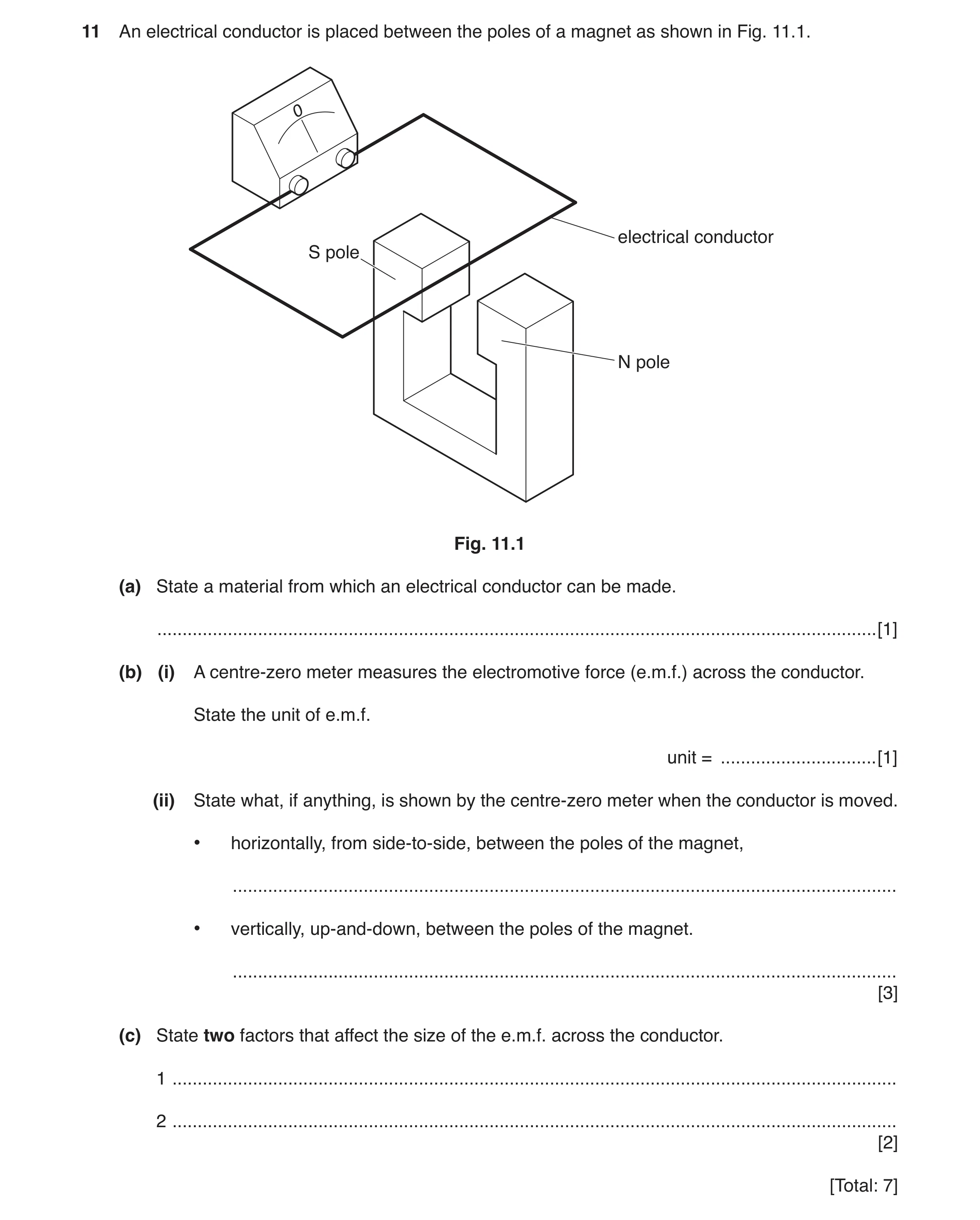
Q1 · An electrical conductor is placed between the poles of a magnet as shown in Fig 0625/32 Feb/March 2017
11 An electrical conductor is placed between the poles of a magnet as shown in Fig. 11.1. 0 electrical conductor S pole N pole Fig. 11.1 (a) State a material from which an electrical conductor can be made. … [1] (b) (i) A centre-zero meter measures the electromotive force (e.m.f.) across the conductor. State the unit of e.m.f. unit = … [1] (ii) State what, if anything, is shown by the centre-zero meter when the conductor is moved. • horizontally, from side-to-side, between the poles of the magnet, … • vertically, up-and-down, between the poles of the magnet. … [3] (c) State two factors that affect the size of the e.m.f. across the conductor. 1 … 2 … [2] [Total: 7]
7 marks
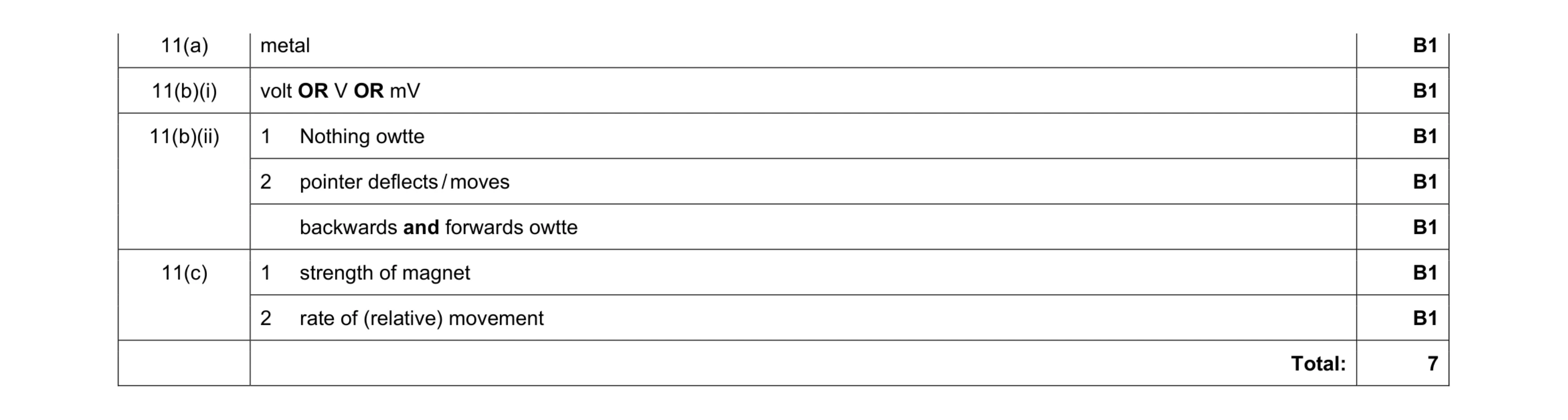
Mark scheme: 11(a) metal B1 11(b)(i) volt OR V OR mV B1 11(b)(ii) 1 Nothing owtte B1 2 pointer deflects / moves B1 backwards and forwards owtte B1 11(c) 1 strength of magnet B1 2 rate of (relative) movement B1 Total: 7
This question in 0625/32 Feb/March 2017
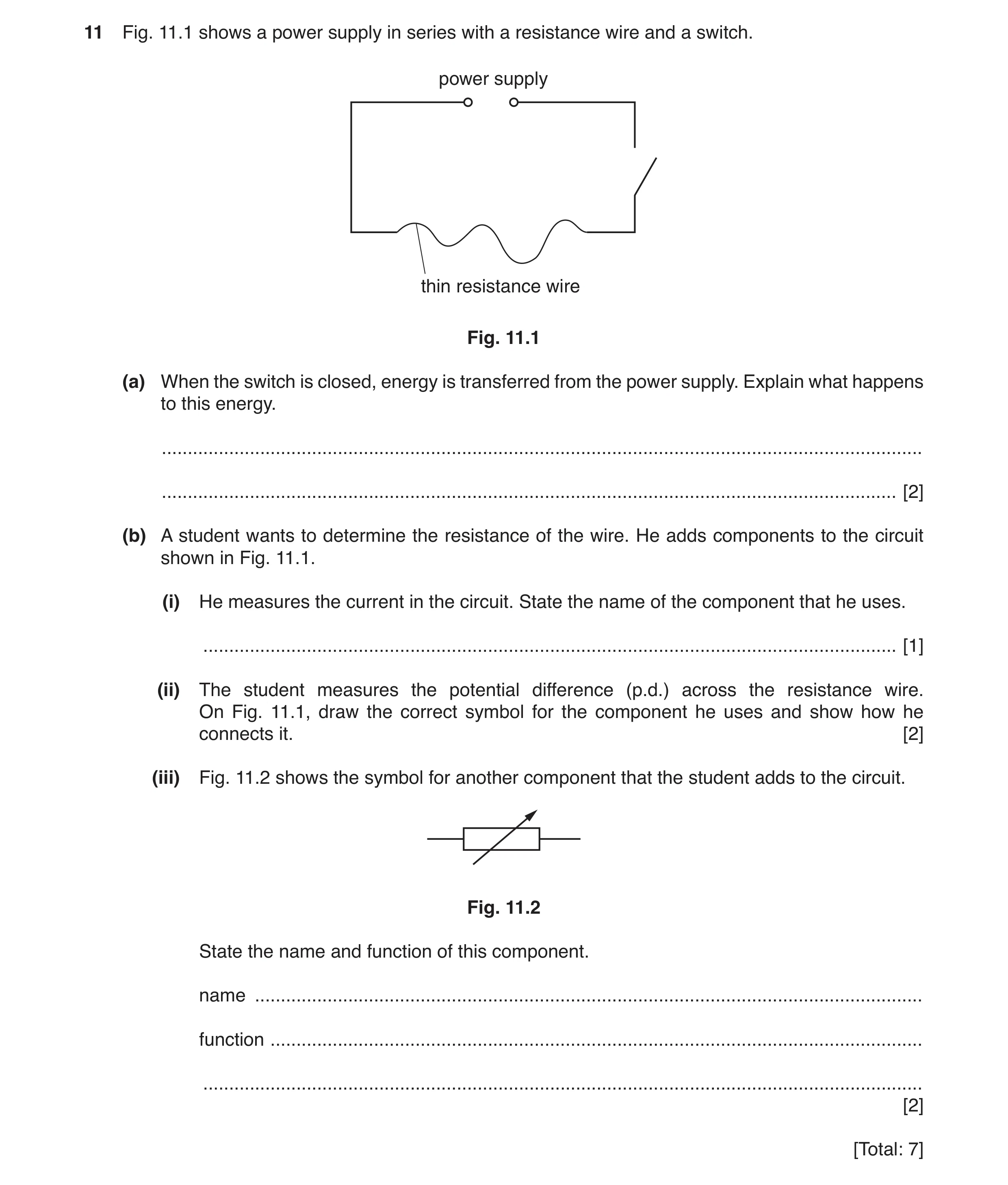
Q2 · A power supply in series with a resistance wire and a switch 0625/31 May/June 2017
11 Fig. 11.1 shows a power supply in series with a resistance wire and a switch. power supply thin resistance wire Fig. 11.1 (a) When the switch is closed, energy is transferred from the power supply. Explain what happens to this energy. … … [2] (b) A student wants to determine the resistance of the wire. He adds components to the circuit shown in Fig. 11.1. (i) He measures the current in the circuit. State the name of the component that he uses. … [1] (ii) The student measures the potential difference (p.d.) across the resistance wire. On Fig. 11.1, draw the correct symbol for the component he uses and show how he connects it. [2] (iii) Fig. 11.2 shows the symbol for another component that the student adds to the circuit. Fig. 11.2 State the name and function of this component. name … function … … [2] [Total: 7]
7 marks
Mark scheme: 11(a) thermal B1 lost to surroundings/air owtte B1 11(b)(i) ammeter B1 11(b)(ii) correct symbol for voltmeter B1 connected in parallel with the resistance wire B1 11(b)(iii) variable resistor B1 varies/changes current/resistance/voltage (in resistance wire) B1 Total: 7
This question in 0625/31 May/June 2017
Q3 · A current-carrying coil in a magnetic field 0625/32 May/June 2017
9 Fig. 9.1 shows a current-carrying coil in a magnetic field. coil B C current N S A D F connections to battery + – battery Fig. 9.1 The direction of the current in side AB of the coil is labelled. The force F on side AB is also labelled. (a) On Fig. 9.1, draw • an arrow labelled X, on side CD, to show the direction of the current in this side of the coil, • an arrow labelled P, to show the direction of the force on CD. [2] (b) Give two ways of increasing the forces F and P on the sides of the coil. 1. … … 2. … … [2] (c) (i) Name the particles that flow in the metal wire of the coil. … [1] (ii) The wire of the coil is replaced by a thinner wire. This wire is the same length and is made of the same metal. State and explain how this changes the current in the coil. … … … [2] [Total: 7]
7 marks
Mark scheme: 9(a) arrow drawn pointing from C to D B1 arrow on /near side CD pointing upwards B1 9(b) any 2 from: increase (size of) current increase strength of magnet increase number of turns in coil B2 9(c)(i) electrons B1 9(c)(ii) current is smaller B1 (as) resistance of coil/wire is greater B1 Total: 7
This question in 0625/32 May/June 2017
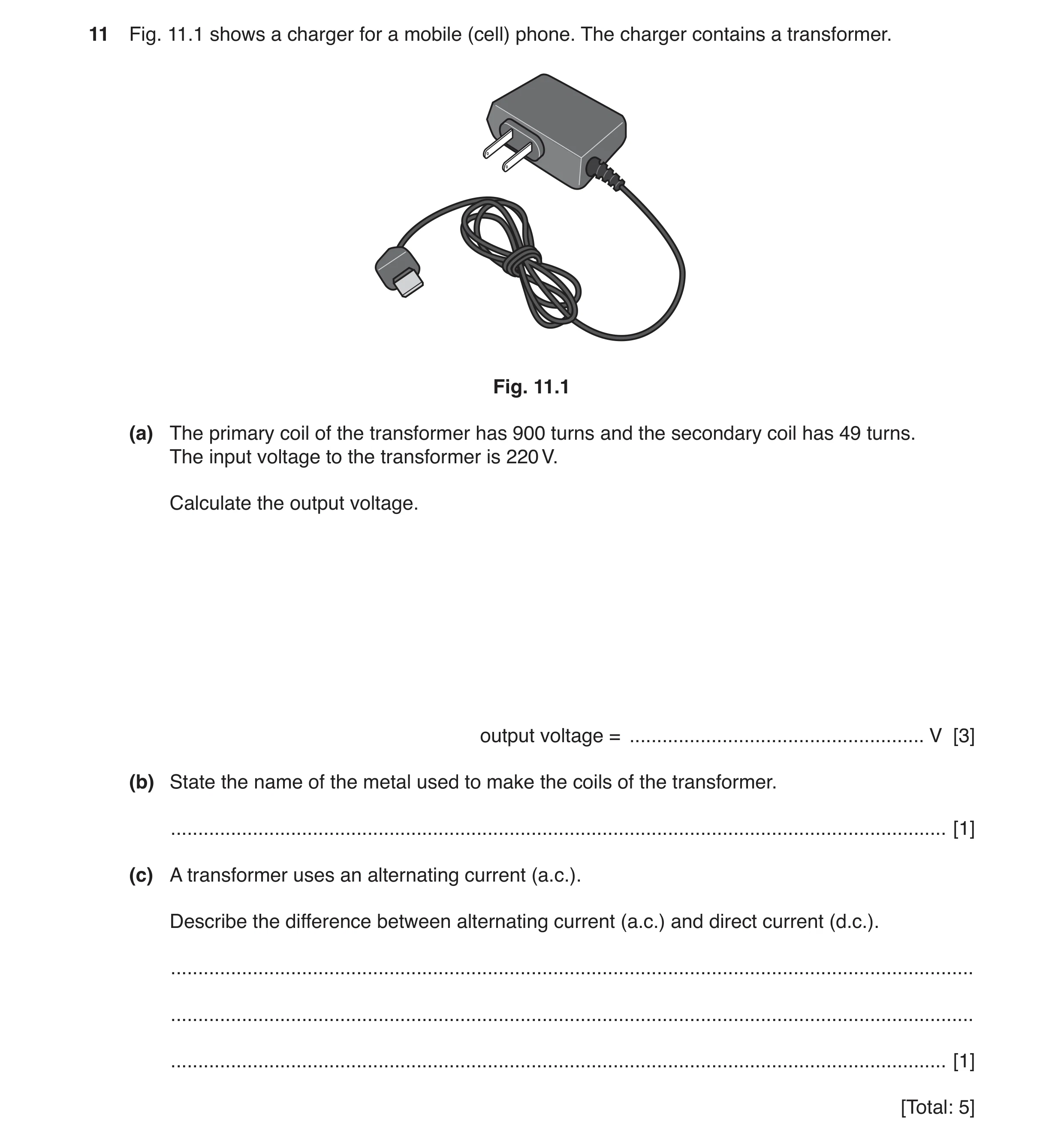
Q4 · A charger for a mobile (cell) phone 0625/32 Oct/Nov 2017
11 Fig. 11.1 shows a charger for a mobile (cell) phone. The charger contains a transformer. Fig. 11.1 (a) The primary coil of the transformer has 900 turns and the secondary coil has 49 turns. The input voltage to the transformer is 220 V. Calculate the output voltage. output voltage = … V [3] (b) State the name of the metal used to make the coils of the transformer. … [1] (c) A transformer uses an alternating current (a.c.). Describe the difference between alternating current (a.c.) and direct current (d.c.). … … … [1] [Total: 5]
5 marks
Mark scheme: 11(a) N1/ N2 = V1 / V2 C1 (49 / 900) × 220 OR use of ratios seen C1 11.98 OR 12 (V) A1 11(b) copper B1 11(c) d.c. is in one direction only / a.c. changes direction B1
This question in 0625/32 Oct/Nov 2017
Q5 · A student wants to find the resistance of a wire 0625/33 Oct/Nov 2017
11 A student wants to find the resistance of a wire. He connects the circuit shown in Fig. 11.1. V wire A Fig. 11.1 (a) A teacher checks the circuit and identifies three errors. Using the components given in Fig. 11.1, carefully draw the correct circuit diagram in the space below. [3] (b) The student uses the correct circuit. The student finds that the current is 0.3 A when the potential difference across the wire is 2.7 V. Calculate the resistance of the wire. resistance = … Ω [3] (c) The student tests two other pieces of wire made of the same metal. He compares each resistance value with that of the first wire. State how the resistance compares with the first wire (i) for a wire that is longer, but of the same thickness, … [1] (ii) for a wire that is thicker, but of the same length. … [1] [Total: 8]
8 marks
Mark scheme: 11(a) ammeter in series B3 voltmeter across wire two cells correctly linked positive to negative 11(b) V = IR in any recognised form C1 R = 2.7 ÷ 0.3 C1 9 (Ω) A1 11(c) 1 higher / more B1 2. lower / less B1
This question in 0625/33 Oct/Nov 2017
Q6 · A circuit for determining the resistance of a component 0625/31 May/June 2018
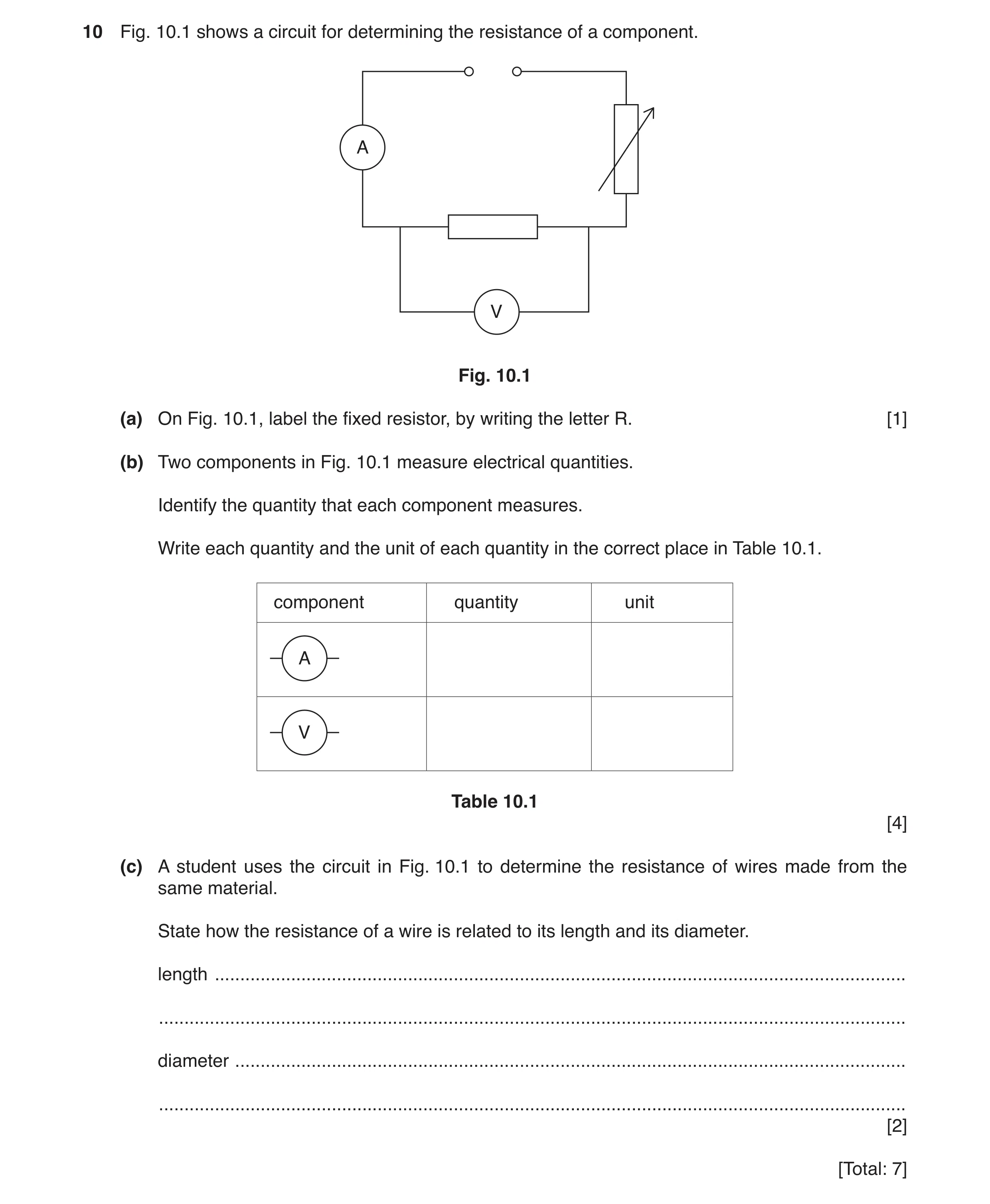
10 Fig. 10.1 shows a circuit for determining the resistance of a component. A V Fig. 10.1 (a) On Fig. 10.1, label the fixed resistor, by writing the letter R. [1] (b) Two components in Fig. 10.1 measure electrical quantities. Identify the quantity that each component measures. Write each quantity and the unit of each quantity in the correct place in Table 10.1. component quantity unit A V Table 10.1 [4] (c) A student uses the circuit in Fig. 10.1 to determine the resistance of wires made from the same material. State how the resistance of a wire is related to its length and its diameter. length … … diameter … … [2] [Total: 7]
7 marks
Mark scheme: 10(a) resistor identified 1 10(b) quantity unit current NOT amps ignore ammeter A/amps/amperes 2 quantity unit potential difference or p.d. or emf V/volts ignore voltmeter 2 10(c) increasing (length) increases resistance owtte 1 increasing (diameter) decreases resistance owtte 1
This question in 0625/31 May/June 2018
Question 7 0625/32 May/June 2018
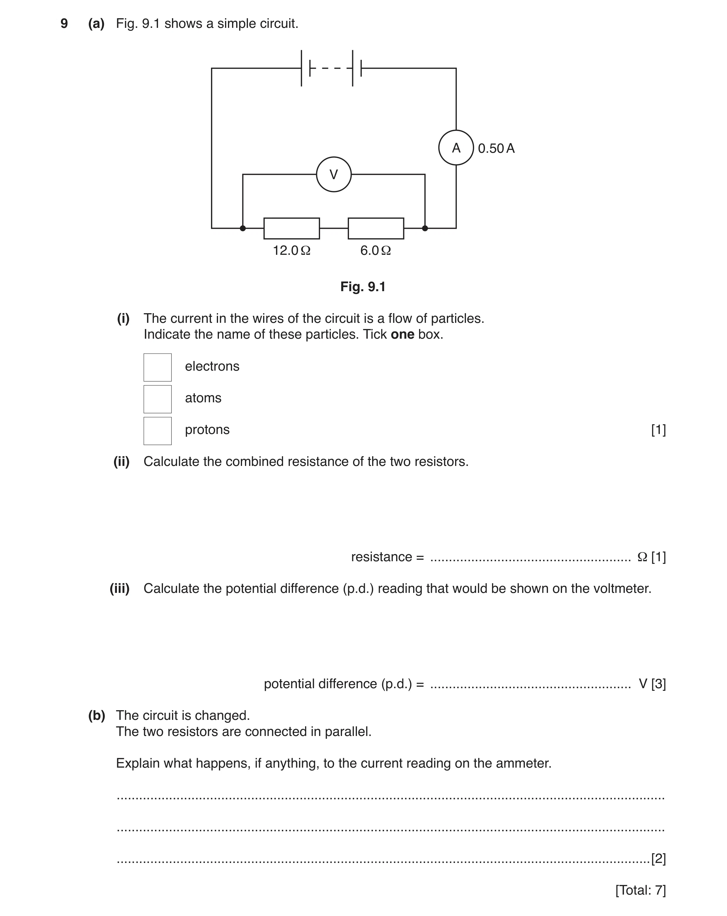
9 (a) Fig. 9.1 shows a simple circuit. A 0.50 A V 12.0 Ω 6.0 Ω Fig. 9.1 (i) The current in the wires of the circuit is a flow of particles. Indicate the name of these particles. Tick one box. electrons atoms protons [1] (ii) Calculate the combined resistance of the two resistors. resistance = … Ω [1] (iii) Calculate the potential difference (p.d.) reading that would be shown on the voltmeter. potential difference (p.d.) = … V [3] (b) The circuit is changed. The two resistors are connected in parallel. Explain what happens, if anything, to the current reading on the ammeter. … … … [2] [Total: 7]
7 marks
Mark scheme: 9(a)(i) top box (electrons) ticked 1 9(a)(ii) 12 + 6 seen or 18 (Ω) 1 9(a)(iii) (V =) I × R 1 (V =) 0.50 × 18(.0) 1 (V =) 9.0 (V) ecf from (a)(ii) 1 9(b) (reading/current) increases 1 (because effective circuit) resistance decreases/resistors in parallel have less resistance 1
This question in 0625/32 May/June 2018
Question 8 0625/33 May/June 2018
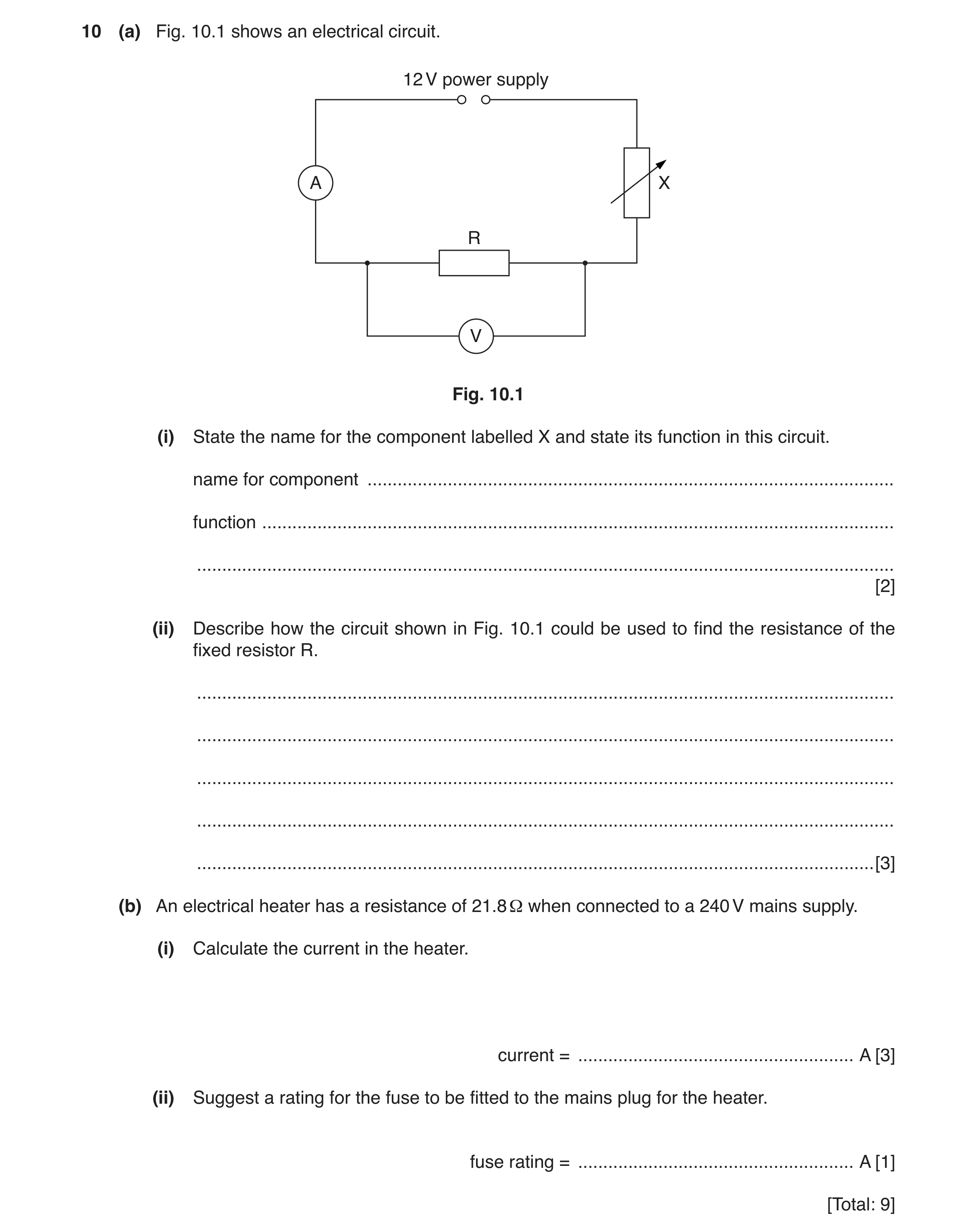
10 (a) Fig. 10.1 shows an electrical circuit. 12 V power supply A X R V Fig. 10.1 (i) State the name for the component labelled X and state its function in this circuit. name for component … function … … [2] (ii) Describe how the circuit shown in Fig. 10.1 could be used to find the resistance of the fixed resistor R. … … … … … [3] (b) An electrical heater has a resistance of 21.8 Ω when connected to a 240 V mains supply. (i) Calculate the current in the heater. current = … A [3] (ii) Suggest a rating for the fuse to be fitted to the mains plug for the heater. fuse rating = … A [1] [Total: 9]
9 marks
Mark scheme: 10(a)(i) variable resistor 1 change the current 1 10(a)(ii) Any three from: use low value of current measure (and record) current measure (and record) voltage repeat other values (of I and V) plot graph of pd against current (and find gradient) OR use V = I × R 3 10(b)(i) V = I × R in any form OR (I =) V ÷ R 1 240 ÷ 21.8 1 11.0 (A) 1 10(b)(ii) Answer in range 12 to 15 (A) 1
This question in 0625/33 May/June 2018
Q9 · A student fits an electrical generator to a bicycle 0625/32 Oct/Nov 2018
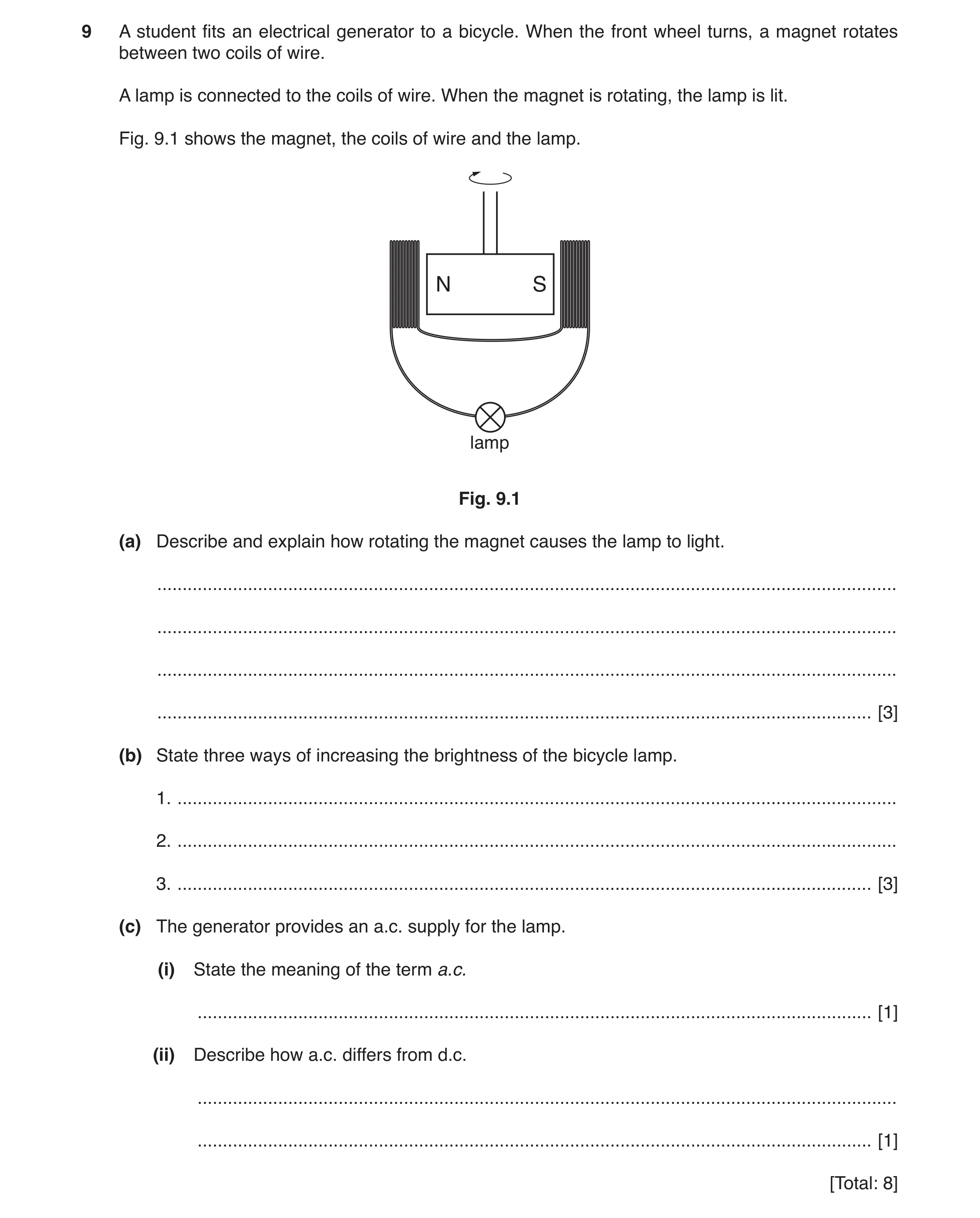
9 A student fits an electrical generator to a bicycle. When the front wheel turns, a magnet rotates between two coils of wire. A lamp is connected to the coils of wire. When the magnet is rotating, the lamp is lit. Fig. 9.1 shows the magnet, the coils of wire and the lamp. N S lamp Fig. 9.1 (a) Describe and explain how rotating the magnet causes the lamp to light. … … … … [3] (b) State three ways of increasing the brightness of the bicycle lamp. 1. … 2. … 3. … [3] (c) The generator provides an a.c. supply for the lamp. (i) State the meaning of the term a.c. … [1] (ii) Describe how a.c. differs from d.c. … … [1] [Total: 8]
8 marks
Mark scheme: 9(a) magnetic field (of magnet) B1 changes / cuts coil / linked to coil B1 induces / causes / produces / generates an emf / voltage / current OR electromagnetic induction B1 9(b) stronger magnet more turns on coil(s) turn magnet at higher speed B3 9(c)(i) alternating (current) B1 9(c)(ii) a.c. changes direction OR d.c one direction only B1
This question in 0625/32 Oct/Nov 2018
Q10 · A circuit used by a student to test a metal wire made of nichrome 0625/32 Oct/Nov 2018
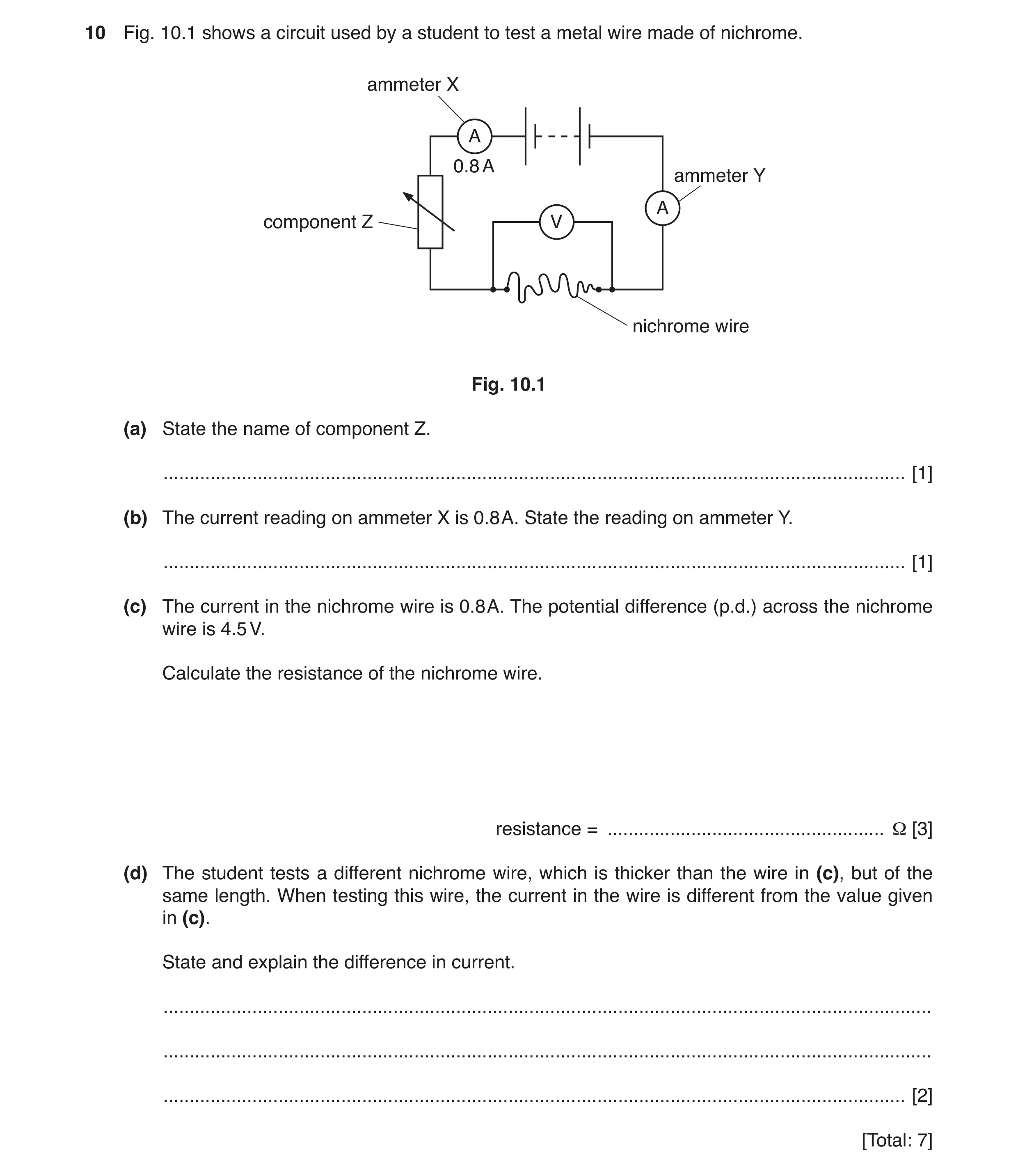
10 Fig. 10.1 shows a circuit used by a student to test a metal wire made of nichrome. ammeter X A 0.8 A ammeter Y A component Z V nichrome wire Fig. 10.1 (a) State the name of component Z. … [1] (b) The current reading on ammeter X is 0.8 A. State the reading on ammeter Y. … [1] (c) The current in the nichrome wire is 0.8 A. The potential difference (p.d.) across the nichrome wire is 4.5 V. Calculate the resistance of the nichrome wire. resistance = … Ω [3] (d) The student tests a different nichrome wire, which is thicker than the wire in (c), but of the same length. When testing this wire, the current in the wire is different from the value given in (c). State and explain the difference in current. … … … [2] [Total: 7]
7 marks
Mark scheme: 10(a) variable resistor or rheostat B1 10(b) 0.8 (A) B1 10(c) V = IR OR (R =) V ÷ I C1 4.5 ÷ 0.8 C1 5.6(25) A1 10(d) (current) increases OR larger B1 (as new/thicker wire has) less resistance B1
This question in 0625/32 Oct/Nov 2018
Q11 · A circuit with two lamps and three ammeters connected in series to a power supply 0625/33 Oct/Nov 2018
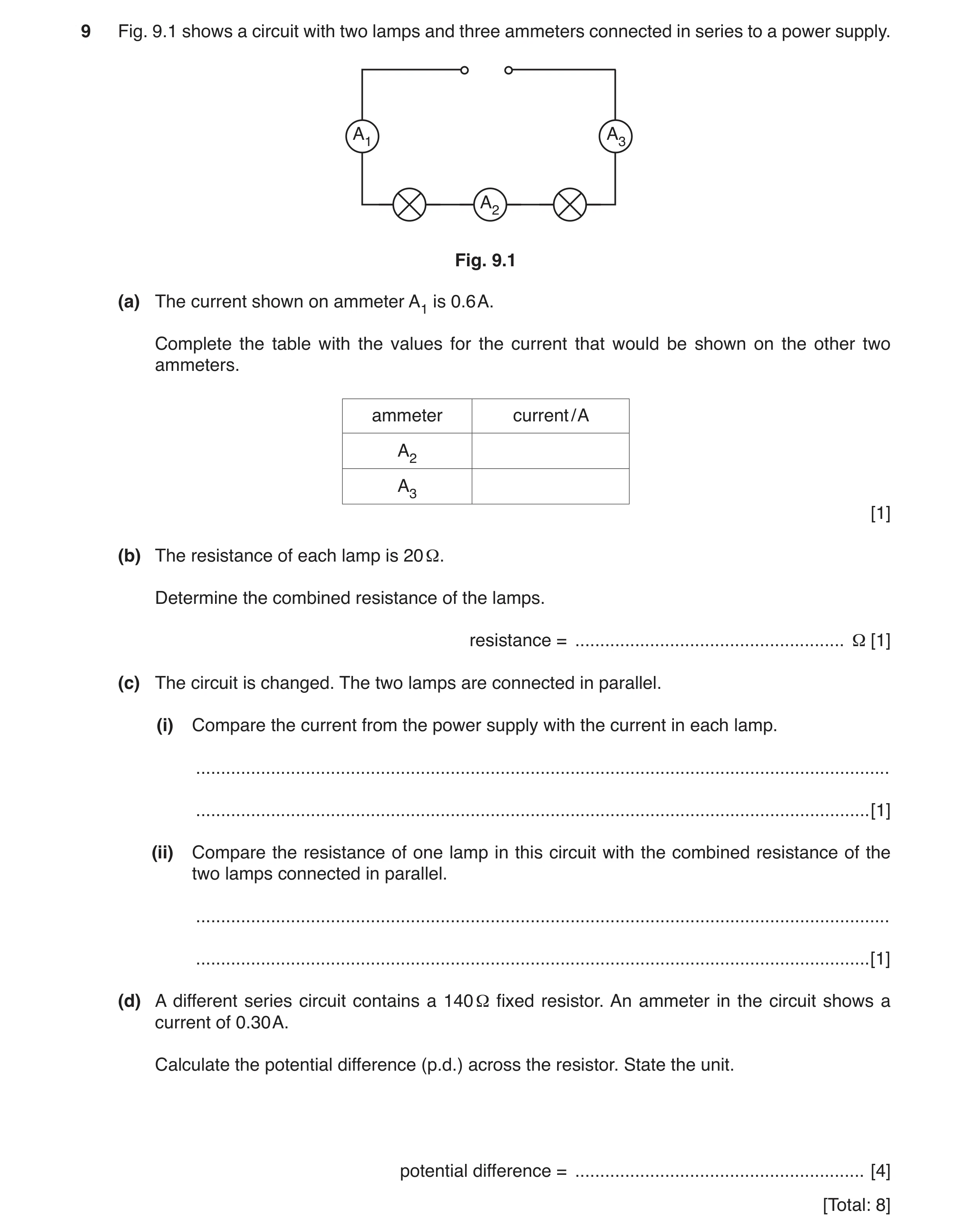
9 Fig. 9.1 shows a circuit with two lamps and three ammeters connected in series to a power supply. A1 A3 A2 Fig. 9.1 (a) The current shown on ammeter A1 is 0.6 A. Complete the table with the values for the current that would be shown on the other two ammeters. ammeter current / A A2 A3 [1] (b) The resistance of each lamp is 20 Ω. Determine the combined resistance of the lamps. resistance = … Ω [1] (c) The circuit is changed. The two lamps are connected in parallel. (i) Compare the current from the power supply with the current in each lamp. … … [1] (ii) Compare the resistance of one lamp in this circuit with the combined resistance of the two lamps connected in parallel. … … [1] (d) A different series circuit contains a 140 Ω fixed resistor. An ammeter in the circuit shows a current of 0.30 A. Calculate the potential difference (p.d.) across the resistor. State the unit. potential difference = … [4] [Total: 8]
8 marks
Mark scheme: 9(a) A2 = 0.6 A AND A3 = 0.6 A B1 9(b) 40 (Ω) B1 9(c)(i) current from source is higher than in each lamp or reverse argument B1 9(c)(ii) (combined) resistance of lamps in parallel is less / lower (than one lamp) B1 9(d) V = IR in any recognisable form C1 V = 0.30 × 140 C1 42 A1 V or volts B1
This question in 0625/33 Oct/Nov 2018
Q12 · The apparatus for an experiment on electrostatics 0625/32 Feb/March 2019
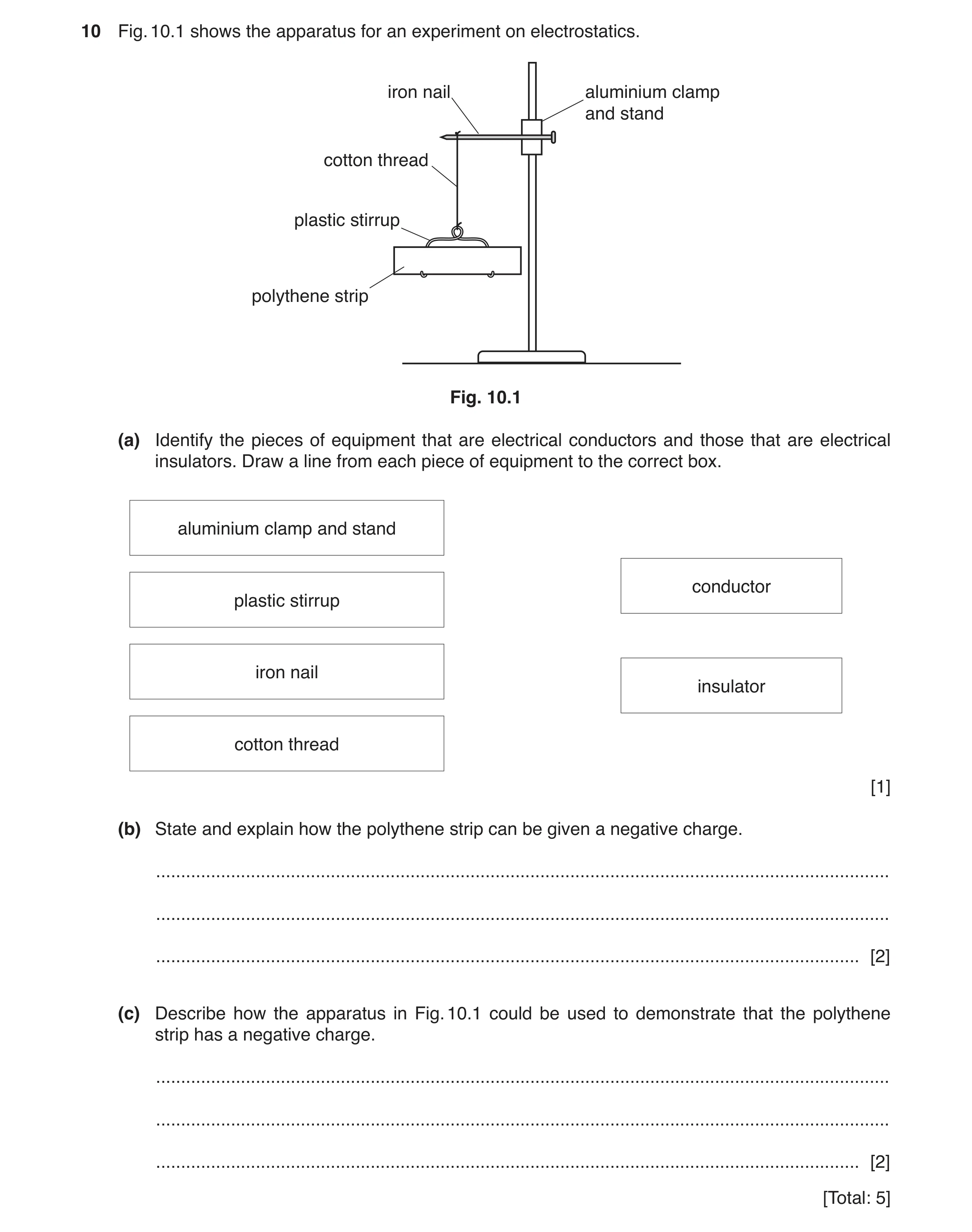
10 Fig. 10.1 shows the apparatus for an experiment on electrostatics. iron nail aluminium clamp and stand cotton thread plastic stirrup polythene strip Fig. 10.1 (a) Identify the pieces of equipment that are electrical conductors and those that are electrical insulators. Draw a line from each piece of equipment to the correct box. aluminium clamp and stand conductor plastic stirrup iron nail insulator cotton thread [1] (b) State and explain how the polythene strip can be given a negative charge. … … … [2] (c) Describe how the apparatus in Fig. 10.1 could be used to demonstrate that the polythene strip has a negative charge. … … … [2] [Total: 5]
5 marks
Mark scheme: 10(a) clamp AND nail to conductor AND stirrup AND thread to insulator B1 10(b) rubbed with a cloth B1 electrons transfer to polythene / from cloth B1 10(c) (bring) a negatively charged rod / strip / object near B1 repulsion B1
This question in 0625/32 Feb/March 2019
Q13 · A student makes a circuit to switch on a 6.0 V lamp from two different switches X and Y 0625/31 May/June 2019
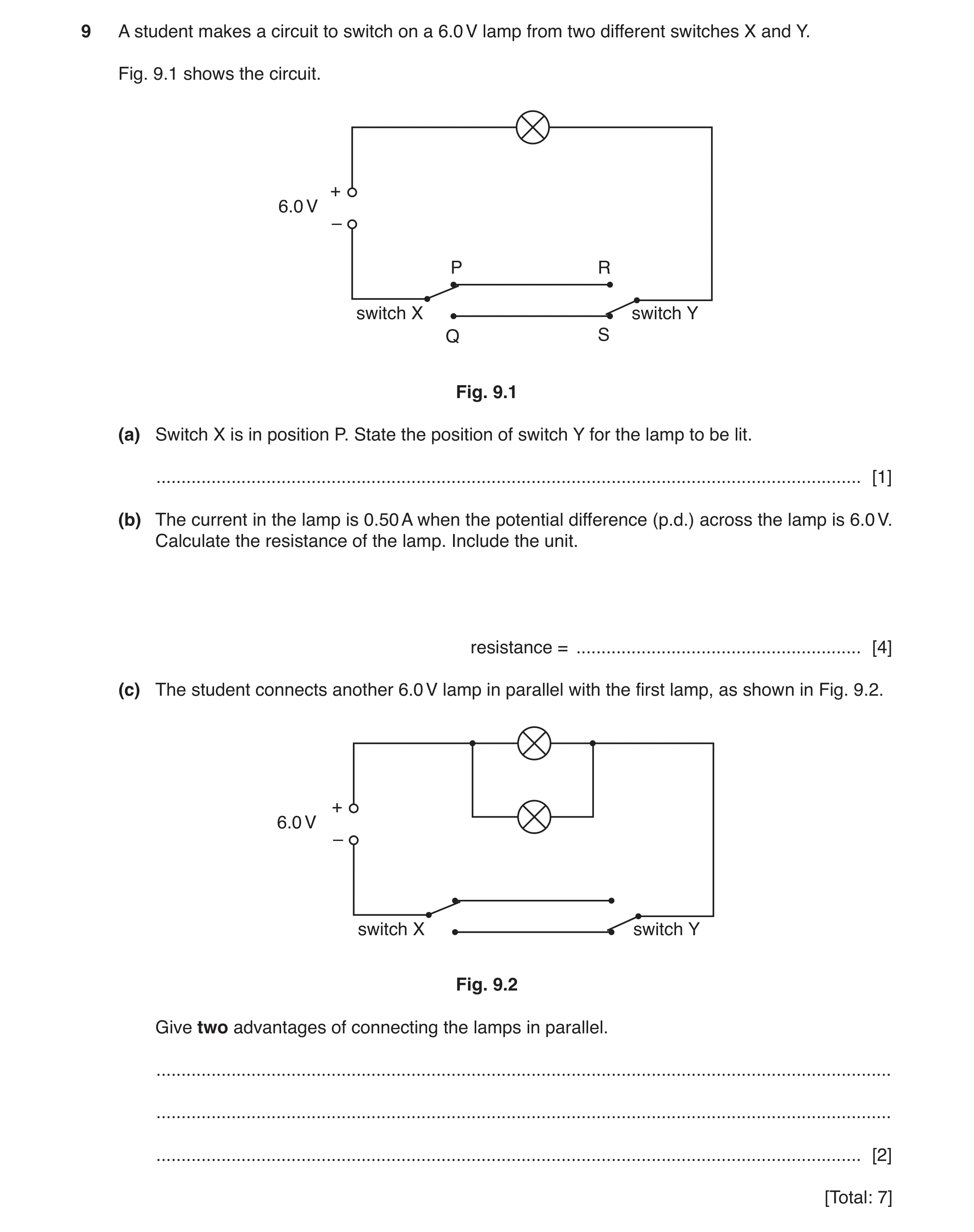
9 A student makes a circuit to switch on a 6.0 V lamp from two different switches X and Y. Fig. 9.1 shows the circuit. + 6.0 V – P R switch X switch Y Q S Fig. 9.1 (a) Switch X is in position P. State the position of switch Y for the lamp to be lit. … [1] (b) The current in the lamp is 0.50 A when the potential difference (p.d.) across the lamp is 6.0 V. Calculate the resistance of the lamp. Include the unit. resistance = … [4] (c) The student connects another 6.0 V lamp in parallel with the first lamp, as shown in Fig. 9.2. + 6.0 V – switch X switch Y Fig. 9.2 Give two advantages of connecting the lamps in parallel. … … … [2] [Total: 7]
7 marks
Mark scheme: 9(a) (position) R B1 9(b) V = IR in any form C1 (R =) 6.0 ÷ 0.5 OR 6.0 = 0.5 × R C1 (R=) 12 A1 Ω or ohms B1 9(c) both lamps have correct p.d. OR voltage (across them) B1 if one lamp fails the other is still lit B1
This question in 0625/31 May/June 2019
Question 14 0625/32 May/June 2019
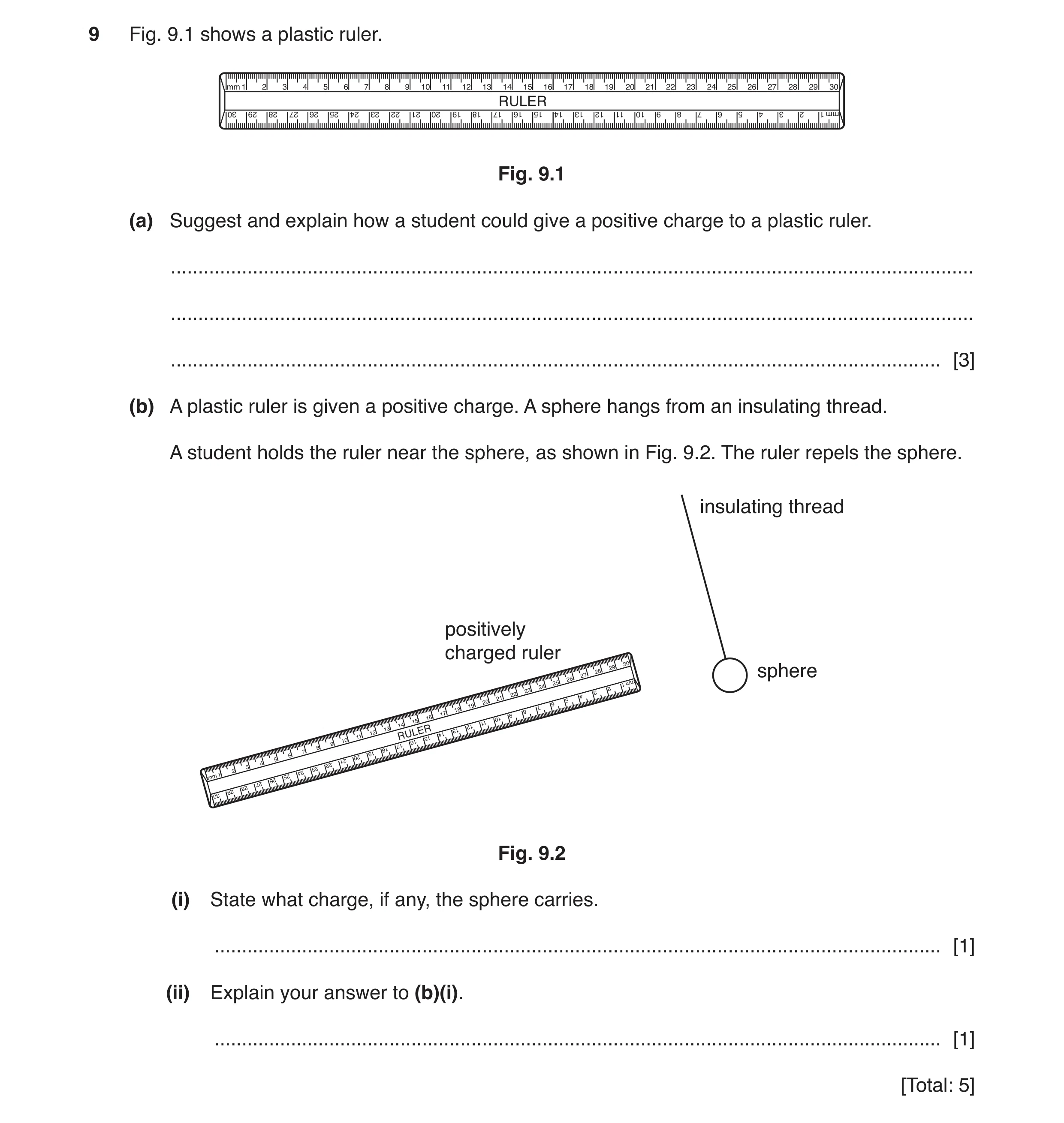
9 Fig. 9.1 shows a plastic ruler. Fig. 9.1 (a) Suggest and explain how a student could give a positive charge to a plastic ruler. … … … [3] (b) A plastic ruler is given a positive charge. A sphere hangs from an insulating thread. A student holds the ruler near the sphere, as shown in Fig. 9.2. The ruler repels the sphere. insulating thread positively charged ruler sphere Fig. 9.2 (i) State what charge, if any, the sphere carries. … [1] (ii) Explain your answer to (b)(i). … [1] [Total: 5]
5 marks
Mark scheme: 9(a) (rule) rubbed with a cloth owtte B1 electrons or negative charges move B1 on to the cloth OR from / off the ruler B1 9(b)(i) positive B1 9(b)(ii) same charges repel B1
This question in 0625/32 May/June 2019
Q15 · A student tests some materials to find which ones are electrical conductors 0625/33 May/June 2019
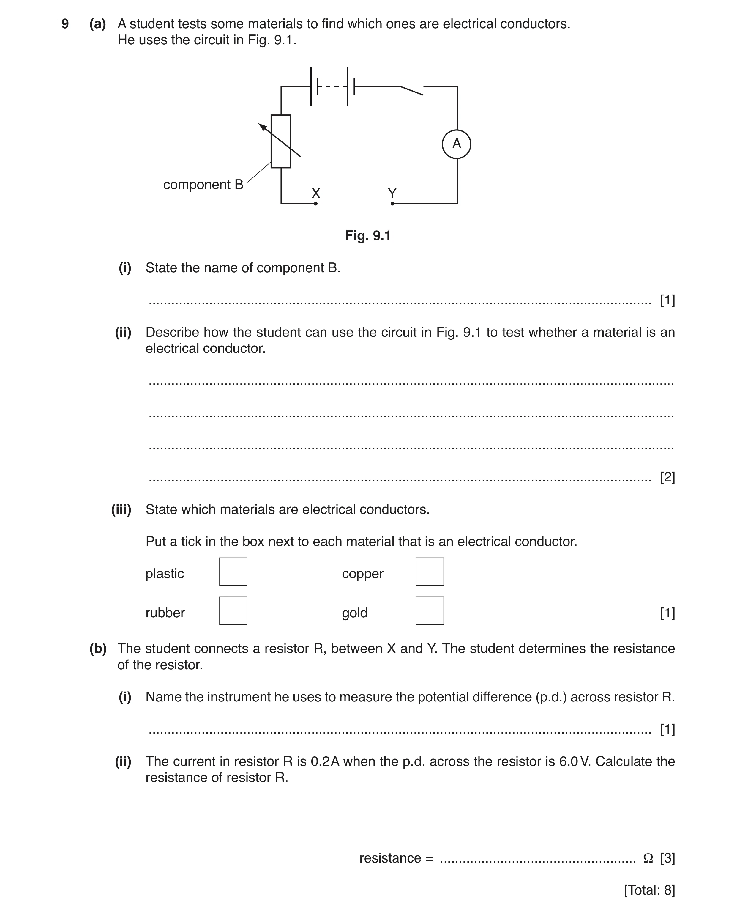
9 (a) A student tests some materials to find which ones are electrical conductors. He uses the circuit in Fig. 9.1. A component B X Y Fig. 9.1 (i) State the name of component B. … [1] (ii) Describe how the student can use the circuit in Fig. 9.1 to test whether a material is an electrical conductor. … … … … [2] (iii) State which materials are electrical conductors. Put a tick in the box next to each material that is an electrical conductor. plastic copper rubber gold [1] (b) The student connects a resistor R, between X and Y. The student determines the resistance of the resistor. (i) Name the instrument he uses to measure the potential difference (p.d.) across resistor R. … [1] (ii) The current in resistor R is 0.2 A when the p.d. across the resistor is 6.0 V. Calculate the resistance of resistor R. resistance = … Ω [3] [Total: 8]
8 marks
Mark scheme: 9(a)(i) variable resistor B1 9(a)(ii) connect material in gap/between X and Y B1 if reading on ammeter material is a(n electrical) conductor B1 9(a)(iii) BOTH copper AND gold ticked i.e. 2nd and 4th boxes B1 9(b)(i) voltmeter B1 9(b)(ii) V = IR OR (R = ) V/I C1 = 6.0 ÷ 0. C1 = 30 (Ω) A1
This question in 0625/33 May/June 2019
Q16 · A student is experimenting with magnets and electric charges 0625/31 Oct/Nov 2019
9 A student is experimenting with magnets and electric charges. (a) The student places a bar magnet on a piece of paper, as shown in Fig. 9.1. N S piece of paper Fig. 9.1 Show the pattern of magnetic field lines around the bar magnet. Draw two lines above the magnet and two lines below the magnet. Start and finish each line at a pole. Include one arrow to show the direction of the magnetic field. [3] (b) The student rubs a plastic rod with a dry cloth. The plastic rod becomes positively charged. Explain why the friction between the plastic and the cloth causes the plastic to become positively charged. … … … … [2] (c) The student investigates the forces between two pairs of objects. Fig. 9.2 and Fig. 9.3 show the pairs of objects. State whether there is a force of attraction, a force of repulsion, or no force between the pairs of objects. Draw a ring around one phrase for each pair of objects. 1. two positively charged spheres thin cotton + + + + + + + + + + + + + + + + Fig. 9.2 force of attraction force of repulsion no force 2. a bar magnet and a bar of copper metal N S bar of copper metal Fig. 9.3 force of attraction force of repulsion no force [2] [Total: 7]
7 marks
Mark scheme: 9(a) correct field pattern for bar magnet B1 no lines crossing and good detail of curvature B1 correct direction of arrow, i.e. out from N pole B1 9(b) electrons M1 move from the rod/to the cloth A1 9(c) 1. force of repulsion circled B1 2. no force circled B1
This question in 0625/31 Oct/Nov 2019
Q17 · The symbol for an electrical component 0625/33 Oct/Nov 2019
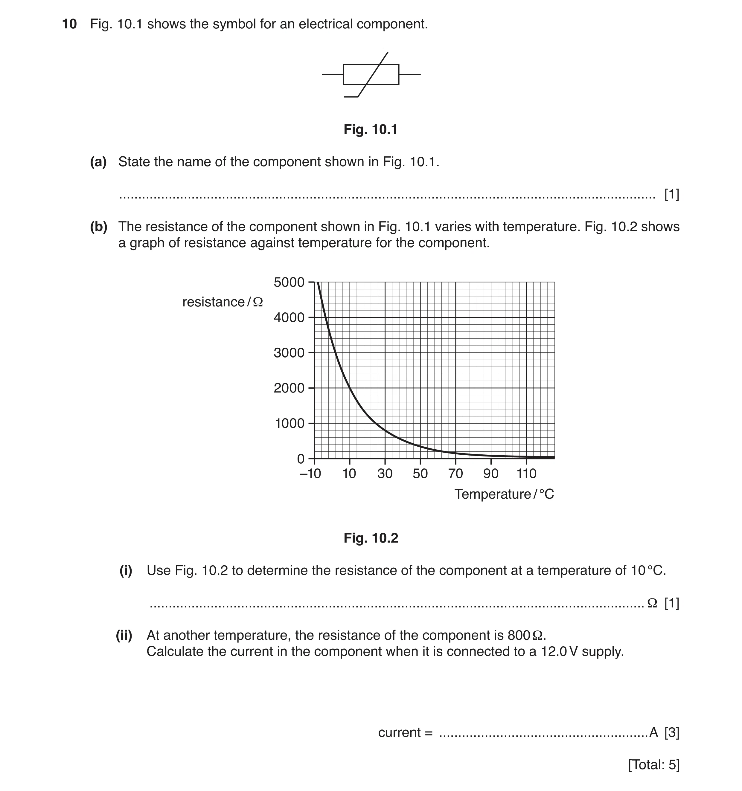
10 Fig. 10.1 shows the symbol for an electrical component. Fig. 10.1 (a) State the name of the component shown in Fig. 10.1. … [1] (b) The resistance of the component shown in Fig. 10.1 varies with temperature. Fig. 10.2 shows a graph of resistance against temperature for the component. 5000 resistance / Ω 4000 3000 2000 1000 0 –10 10 30 50 70 90 110 Temperature / °C Fig. 10.2 (i) Use Fig. 10.2 to determine the resistance of the component at a temperature of 10 °C. … Ω [1] (ii) At another temperature, the resistance of the component is 800 Ω. Calculate the current in the component when it is connected to a 12.0 V supply. current = … A [3] [Total: 5]
5 marks
Mark scheme: 10(a) thermistor B1 10(b)(i) 2000 (Ω) B1 10(b)(ii) (I =) V ÷ R OR V = I × R in any form 12 ÷ 800 0.015 (A) C1 C1 A1
This question in 0625/33 Oct/Nov 2019
Q18 · A diagram of an electrical device 0625/33 Oct/Nov 2019
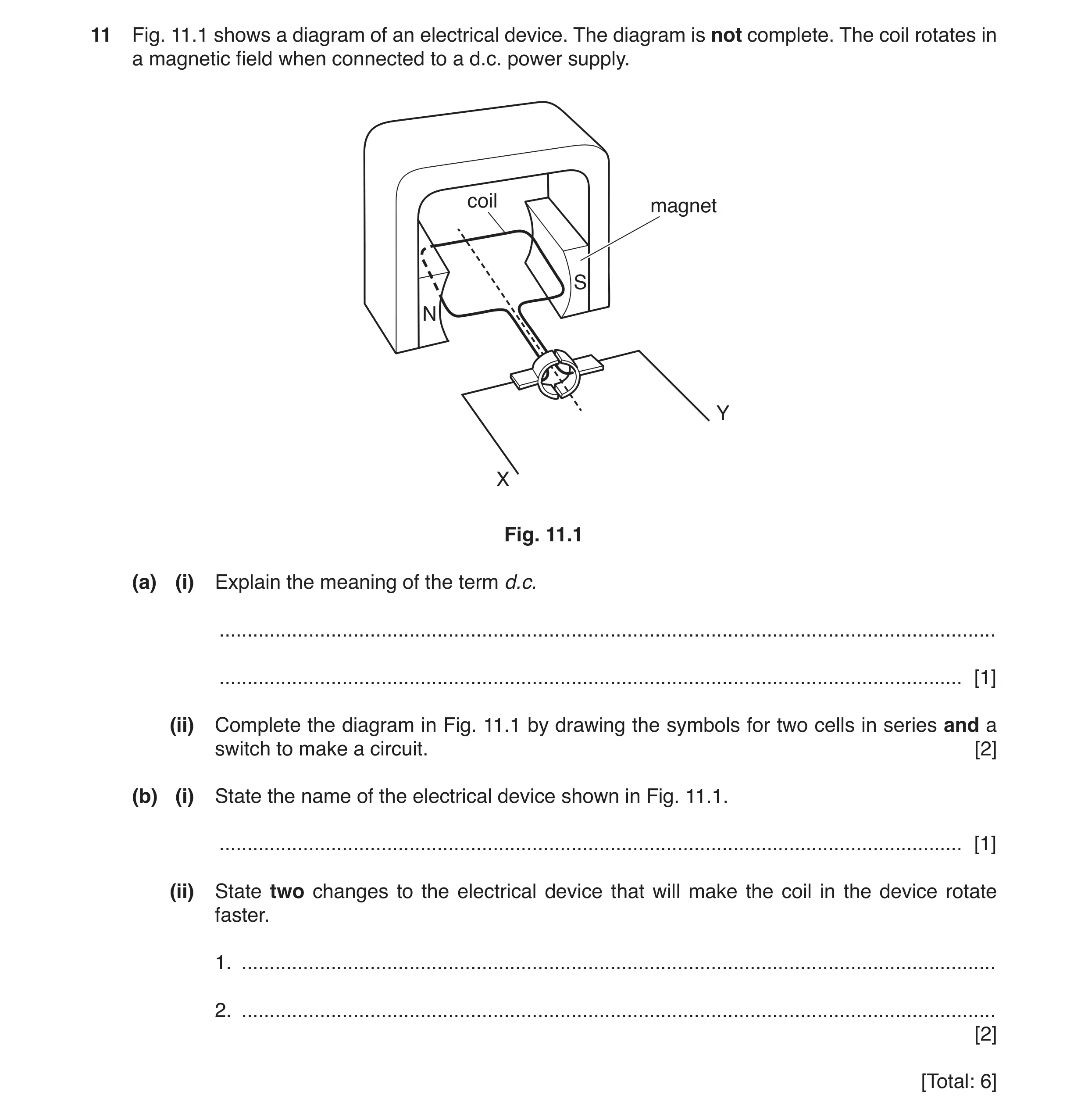
11 Fig. 11.1 shows a diagram of an electrical device. The diagram is not complete. The coil rotates in a magnetic field when connected to a d.c. power supply. coil magnet S N Y X Fig. 11.1 (a) (i) Explain the meaning of the term d.c. … … [1] (ii) Complete the diagram in Fig. 11.1 by drawing the symbols for two cells in series and a switch to make a circuit. [2] (b) (i) State the name of the electrical device shown in Fig. 11.1. … [1] (ii) State two changes to the electrical device that will make the coil in the device rotate faster. 1. … 2. … [2] [Total: 6]
6 marks
Mark scheme: 11(a)(i) current is in one direction B1 11(a)(ii) symbols for two cells connected in series symbol for a switch B1 B1 11(b)(i) motor B1 11(b)(ii) any two from: increasing number of turns on coil increasing the current (in the coil) increasing the strength of the magnetic field B2
This question in 0625/33 Oct/Nov 2019
Q19 · The magnetic field pattern around a bar magnet 0625/31 May/June 2020
9 (a) Fig. 9.1 shows the magnetic field pattern around a bar magnet. bar magnet Fig. 9.1 (i) On Fig. 9.1, write the letters N and S to indicate the north and south poles of the magnet. [1] (ii) Fig. 9.2 shows a soft-iron bar placed close to a permanent magnet. permanent magnet soft-iron bar Fig. 9.2 State and explain what happens to the soft-iron bar. You may draw on Fig. 9.2. … … … [3] (b) Three balls P, Q and R are electrically charged. The balls are suspended by threads of insulating material. Fig. 9.3 shows the arrangement. insulated thread – ball P ball R ball Q Fig. 9.3 Ball P is negatively charged. (i) State the charge on ball Q and the charge on ball R. ball Q … ball R … [2] (ii) Explain your answer for part (i) for the charge on ball Q. … … … [2] [Total: 8]
8 marks
Mark scheme: 9(a)(i) N and S poles correctly labelled B1 9(a)(ii) (iron bar and magnet) attract (each other) B1 (iron) bar becomes an induced magnet B1 with opposite pole next to pole of magnet B1 Question Answer Marks 9(b)(i) (charge on Q is) negative B1 (charge on R is) positive B1 9(b)(ii) (ball) Q is repelled (by negative charge on P) B1 has same charge (as on P) B1
This question in 0625/31 May/June 2020
Q20 · A student connects three identical lamps J, K and L in a circuit, as shown in Fig 0625/32 May/June 2020
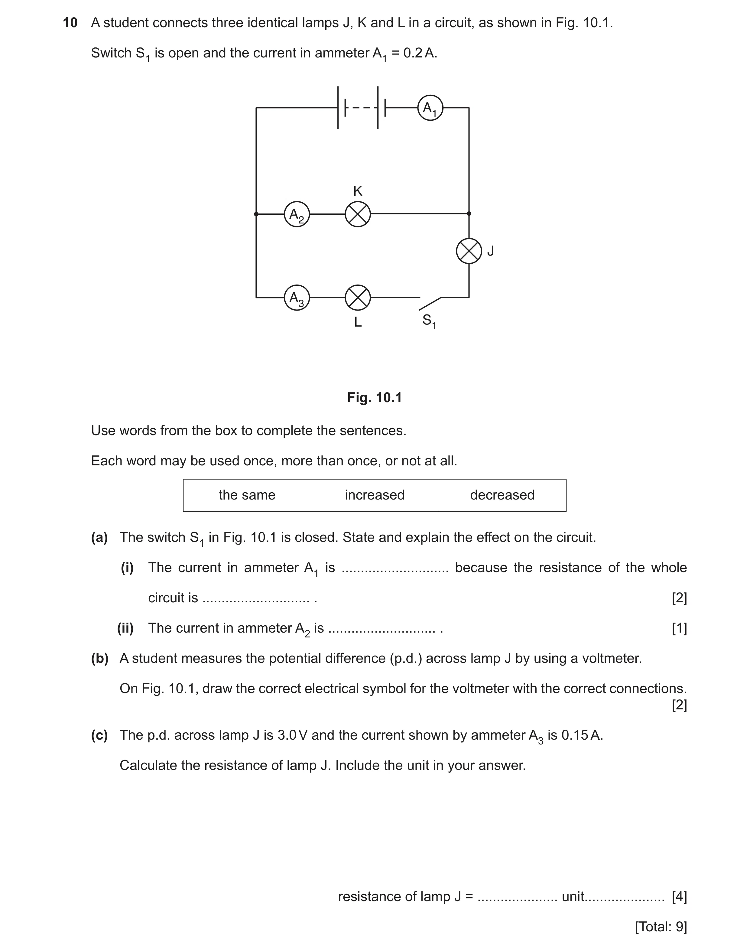
10 A student connects three identical lamps J, K and L in a circuit, as shown in Fig. 10.1. Switch S1 is open and the current in ammeter A1 = 0.2 A. A1 K A2 J A3 L S1 Fig. 10.1 Use words from the box to complete the sentences. Each word may be used once, more than once, or not at all. the same increased decreased (a) The switch S1 in Fig. 10.1 is closed. State and explain the effect on the circuit. (i) The current in ammeter A1 is … because the resistance of the whole circuit is … . [2] (ii) The current in ammeter A2 is … . [1] (b) A student measures the potential difference (p.d.) across lamp J by using a voltmeter. On Fig. 10.1, draw the correct electrical symbol for the voltmeter with the correct connections. [2] (c) The p.d. across lamp J is 3.0 V and the current shown by ammeter A3 is 0.15 A. Calculate the resistance of lamp J. Include the unit in your answer. resistance of lamp J = … unit … [4] [Total: 9]
9 marks
Mark scheme: 10(a)(i) increased B1 decreased B1 10(a)(ii) the same B1 10(b) correct voltmeter symbol B1 in parallel with battery B1 10(c) R = V ÷ I in any form C1 3(.0) ÷ 0.15 C1 20 A1 Ω / ohms B1
This question in 0625/32 May/June 2020
Q21 · A student tests whether a bar magnet affects three different materials 0625/32 Oct/Nov 2020
9 A student tests whether a bar magnet affects three different materials. Fig. 9.1 shows the bar magnet and a sample of each material A, B and C. A N S B C Fig. 9.1 The student tests each sample by holding each pole of the magnet close to one end of the sample. Table 9.1 shows his observations. Table 9.1 sample effect of N pole effect of S pole A attraction attraction B no effect no effect C attraction repulsion (a) Using the information in Table 9.1, draw a straight line from each sample to its correct property. Draw three lines. sample property A magnetic and magnetised B magnetic but not magnetised C non-magnetic [2] (b) Describe one method of producing a magnet from a bar of unmagnetised steel. … … … [2] (c) Another student does an experiment with some electrostatically charged plastic rods. Fig. 9.2 shows the student’s arrangement. negatively charged nylon plastic thread rod negatively charged plastic rod Fig. 9.2 Describe and explain what happens as the student brings one negatively charged rod close to the other negatively charged rod. … … … [2] [Total: 6]
6 marks
Mark scheme: 9(a) sample A magnetic and magnetised sample B magnetic but not magnetised sample C non-magnetic 9(b) use (same pole) of (permanent) magnet stroke bar (repeatedly) in same / one direction owtte OR place (bar / steel) in coil / solenoid current in coil OR connect coil to battery / power supply B2 9(c) rods repel OR move apart / away B1 like / same (type of) charges on both rods B1
This question in 0625/32 Oct/Nov 2020
Q22 · A metal kettle used for heating water 0625/32 Oct/Nov 2020
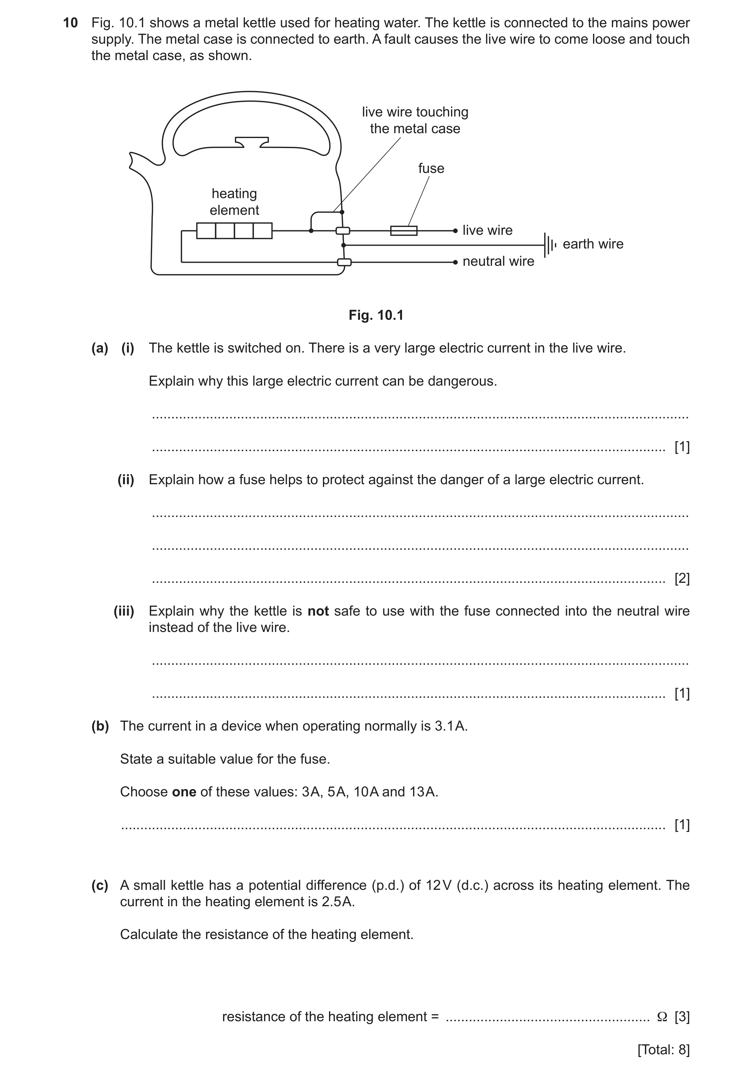
10 Fig. 10.1 shows a metal kettle used for heating water. The kettle is connected to the mains power supply. The metal case is connected to earth. A fault causes the live wire to come loose and touch the metal case, as shown. live wire touching the metal case fuse heating element live wire earth wire neutral wire Fig. 10.1 (a) (i) The kettle is switched on. There is a very large electric current in the live wire. Explain why this large electric current can be dangerous. … … [1] (ii) Explain how a fuse helps to protect against the danger of a large electric current. … … … [2] (iii) Explain why the kettle is not safe to use with the fuse connected into the neutral wire instead of the live wire. … … [1] (b) The current in a device when operating normally is 3.1 A. State a suitable value for the fuse. Choose one of these values: 3 A, 5 A, 10 A and 13 A. … [1] (c) A small kettle has a potential difference (p.d.) of 12 V (d.c.) across its heating element. The current in the heating element is 2.5 A. Calculate the resistance of the heating element. resistance of the heating element = … Ω [3] [Total: 8]
8 marks
Mark scheme: 10(a)(i) (large current produces large) heating effect OR overheating OR (could) cause fire. B1 10(a)(ii) fuse melts B1 breaks circuit OR stops current in circuit B1 10(a)(iii) (metal case / kettle) would still be live OR connected to 240 V / mains (when fuse has melted) B1 10(b) 5 A B1 10(c) (R =) V ÷ I OR V = IR C1 12 ÷ 2.5 C1 4.8 (Ω) A1
This question in 0625/32 Oct/Nov 2020
Q23 · Describe an experiment to show that a force acts on a current-carrying conductor placed… 0625/33 Oct/Nov 2020
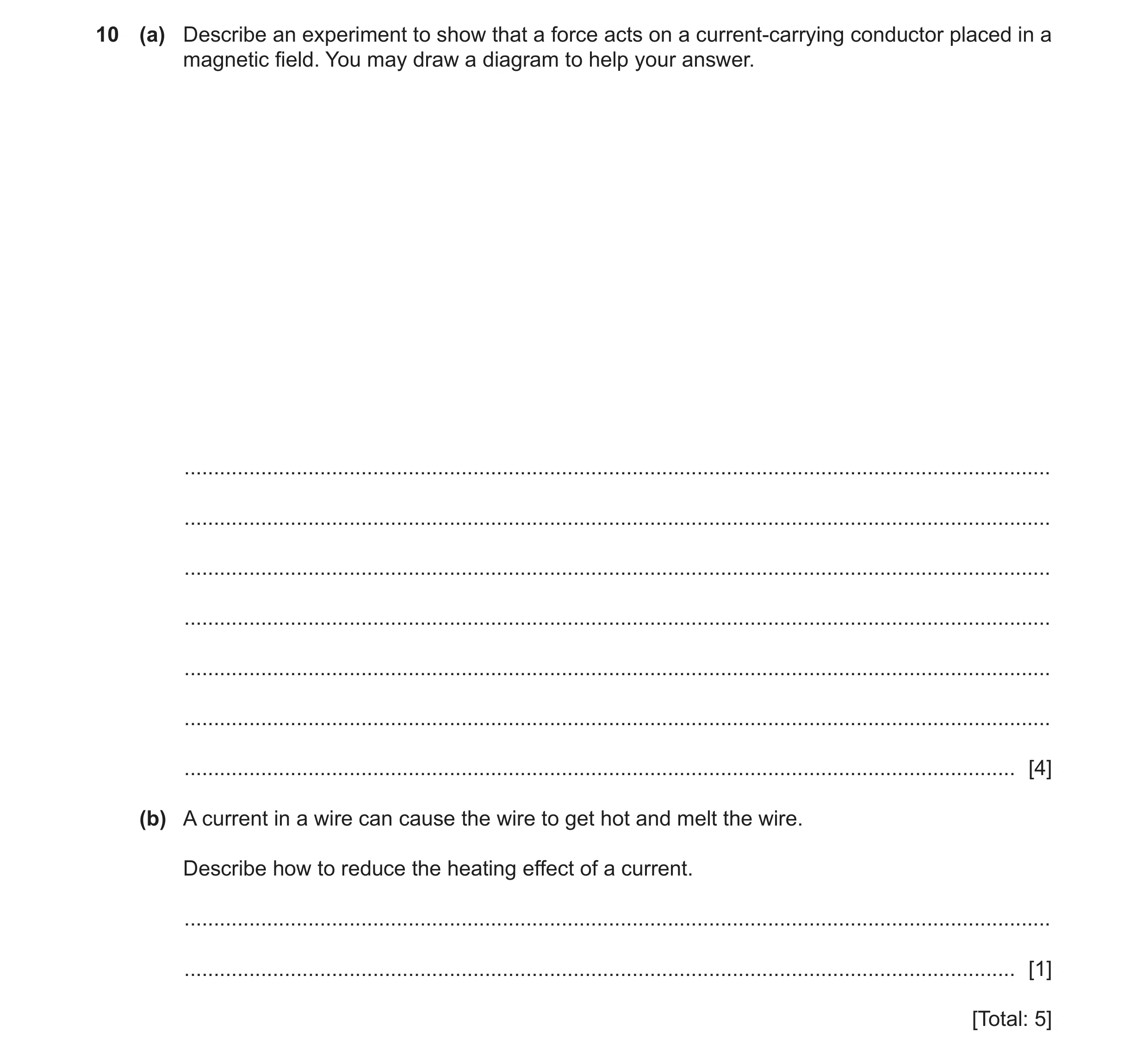
10 (a) Describe an experiment to show that a force acts on a current-carrying conductor placed in a magnetic field. You may draw a diagram to help your answer. … … … … … … … [4] (b) A current in a wire can cause the wire to get hot and melt the wire. Describe how to reduce the heating effect of a current. … … [1] [Total: 5]
5 marks
Mark scheme: 10(a) wire or rod positioned between magnetic poles B1 diagram or description of working circuit B1 current in circuit OR switch circuit on B1 wire / rod moves owtte B1 10(b) use resistor in series / only allow current to flow for a short time / use a smaller current / use a smaller p.d. / reduce the pd of the power supply B1
This question in 0625/33 Oct/Nov 2020
Question 24 0625/32 Feb/March 2021
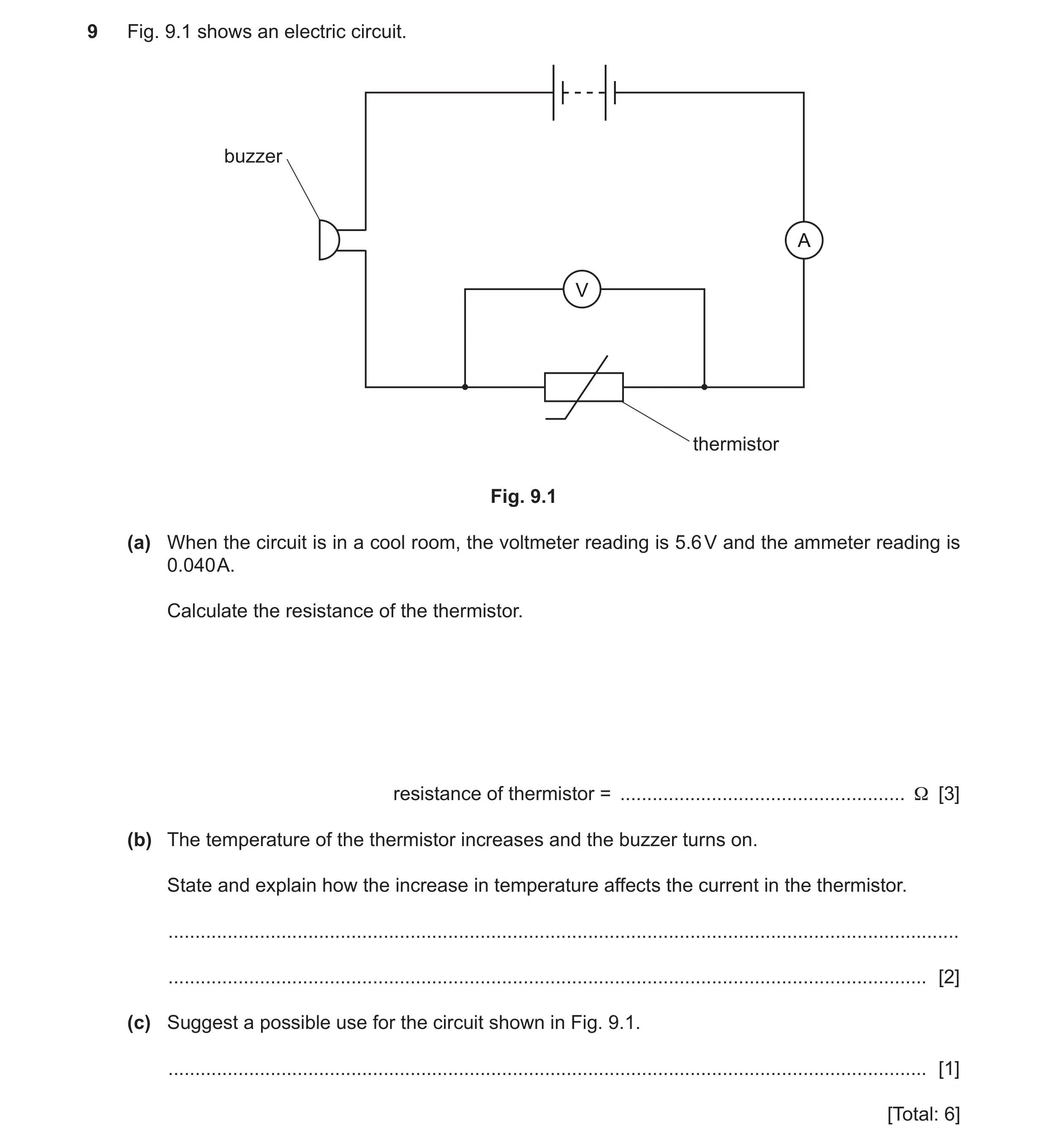
9 Fig. 9.1 shows an electric circuit. buzzer A V thermistor Fig. 9.1 (a) When the circuit is in a cool room, the voltmeter reading is 5.6 V and the ammeter reading is 0.040 A. Calculate the resistance of the thermistor. resistance of thermistor = … Ω [3] (b) The temperature of the thermistor increases and the buzzer turns on. State and explain how the increase in temperature affects the current in the thermistor. … … [2] (c) Suggest a possible use for the circuit shown in Fig. 9.1. … [1] [Total: 6]
6 marks
Mark scheme: 9(a) C1 5.6 ÷ 0.04 C1 140 (Ω) A1 9(b) (current in thermistor) increases B1 (because) resistance of thermistor decreases B1 9(c) fire / high temperature alarm / warning B1
This question in 0625/32 Feb/March 2021
Q25 · The box lists four materials 0625/31 May/June 2021
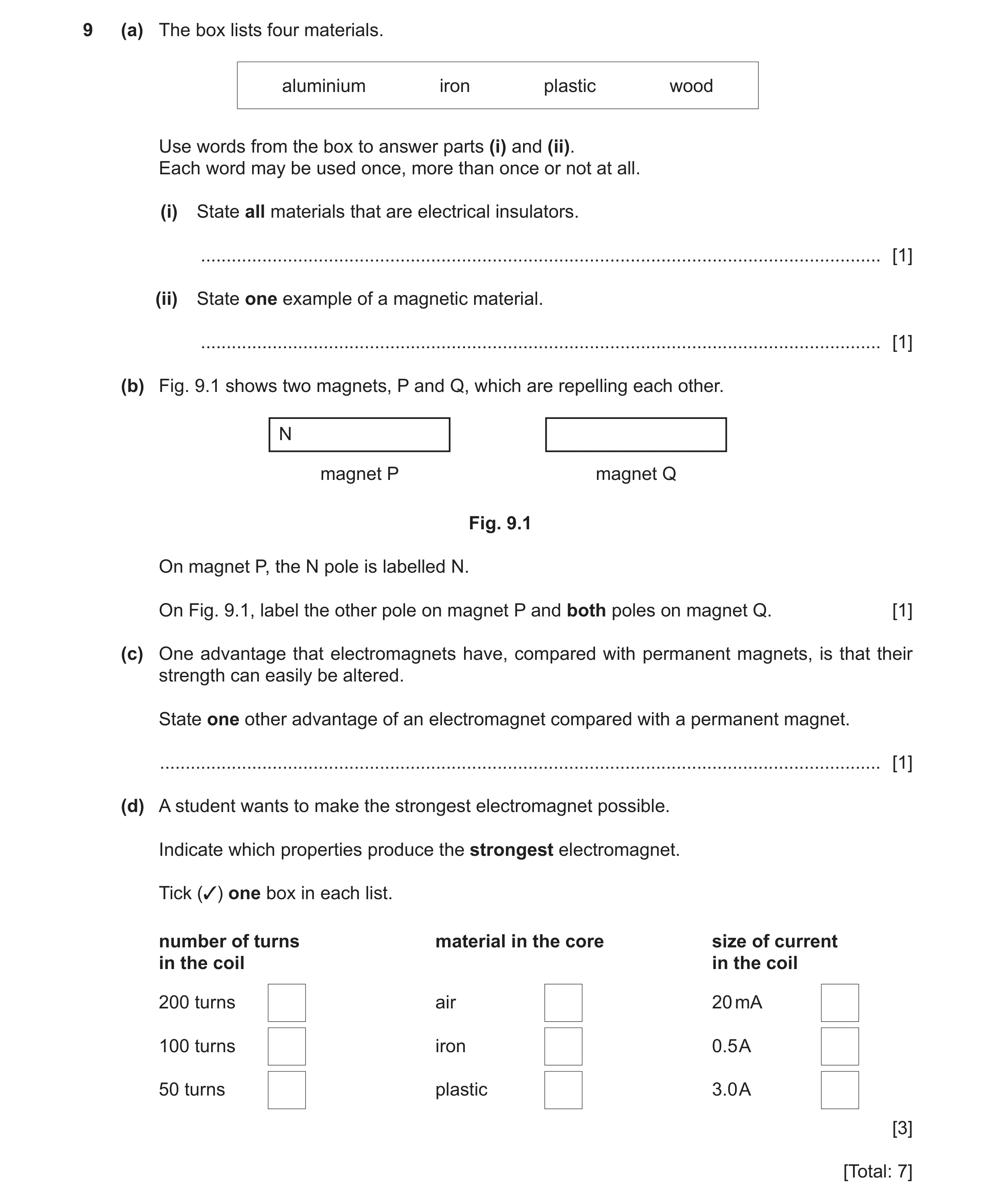
9 (a) The box lists four materials. aluminium iron plastic wood Use words from the box to answer parts (i) and (ii). Each word may be used once, more than once or not at all. (i) State all materials that are electrical insulators. … [1] (ii) State one example of a magnetic material. … [1] (b) Fig. 9.1 shows two magnets, P and Q, which are repelling each other. N magnet P magnet Q Fig. 9.1 On magnet P, the N pole is labelled N. On Fig. 9.1, label the other pole on magnet P and both poles on magnet Q. [1] (c) One advantage that electromagnets have, compared with permanent magnets, is that their strength can easily be altered. State one other advantage of an electromagnet compared with a permanent magnet. … [1] (d) A student wants to make the strongest electromagnet possible. Indicate which properties produce the strongest electromagnet. Tick (3) one box in each list. number of turns material in the core size of current in the coil in the coil 200 turns air 20 mA 100 turns iron 0.5 A 50 turns plastic 3.0 A [3] [Total: 7]
7 marks
Mark scheme: 9(a)(i) plastic AND wood B1 9(a)(ii) iron B1 9(b) B1 9(c) (electromagnet can be) switched off OR switched on B1 N S S N Question Answer Marks 9(d) feature 1: top box ticked (200 turns) B1 feature 2: middle box ticked (iron) B1 feature 3: bottom box ticked (3.0 A) B1
This question in 0625/31 May/June 2021
Question 26 0625/32 May/June 2021
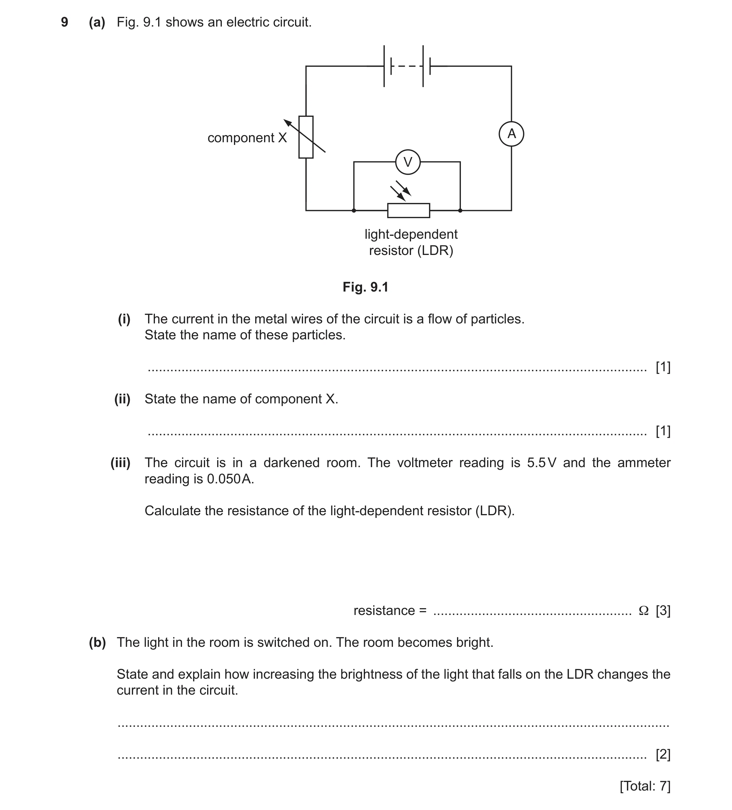
9 (a) Fig. 9.1 shows an electric circuit. component X A V light-dependent resistor (LDR) Fig. 9.1 (i) The current in the metal wires of the circuit is a flow of particles. State the name of these particles. … [1] (ii) State the name of component X. … [1] (iii) The circuit is in a darkened room. The voltmeter reading is 5.5 V and the ammeter reading is 0.050 A. Calculate the resistance of the light-dependent resistor (LDR). resistance = … Ω [3] (b) The light in the room is switched on. The room becomes bright. State and explain how increasing the brightness of the light that falls on the LDR changes the current in the circuit. … … [2] [Total: 7]
7 marks
Mark scheme: 9(a)(i) 9(a)(ii) (component X is a) variable resistor B1 9(a)(iii) V= IR or (R =) V/I C1 5.5 ÷ 0.05 (0) C1 110 (Ω) A1 9(b) (current in circuit) increases B1 (because) resistance of LDR decreases B1
This question in 0625/32 May/June 2021
Q27 · Two uncharged balloons suspended from a beam by light thread 0625/33 May/June 2021
9 (a) Fig. 9.1 shows two uncharged balloons suspended from a beam by light thread. beam light thread balloons Fig. 9.1 The balloons are close to each other but not touching. In the box below, draw the position of the balloons when they both have a positive charge. beam [1] (b) Table 9.1 includes a list of materials. State whether each material is an electrical conductor or an electrical insulator. The first example is done for you. Table 9.1 material conductor or insulator copper conductor rubber wood iron gold [2] (c) An uncharged cloth rubs an uncharged plastic rod. The cloth becomes positively charged and the plastic rod becomes negatively charged. Explain how the cloth becomes positively charged. … … … … [3] [Total: 6]
6 marks
Mark scheme: 9(a) showing repulsion B1 9(b) insulators: rubber AND wood B1 conductors: iron AND gold B1 9(c) electrons / negative charges B1 move / transfer B1 from cloth to rod B1
This question in 0625/33 May/June 2021
Q28 · The magnetic field pattern around a bar magnet 0625/31 Oct/Nov 2021
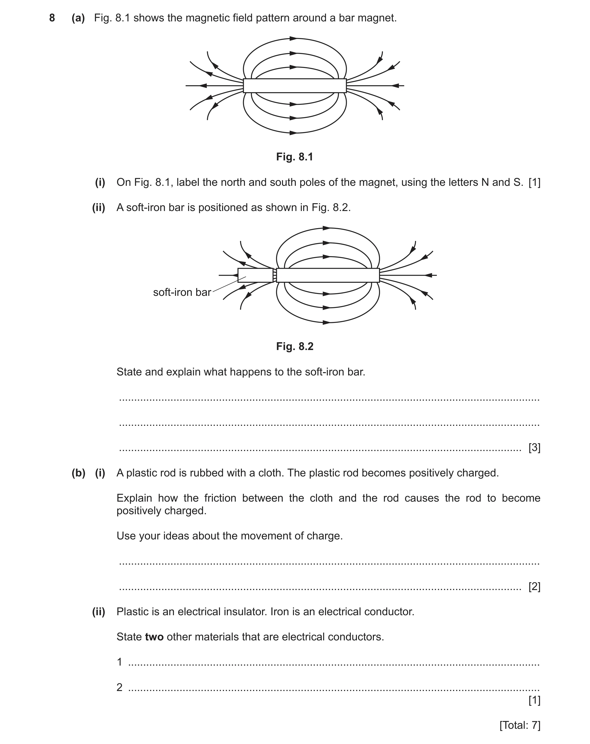
8 (a) Fig. 8.1 shows the magnetic field pattern around a bar magnet. Fig. 8.1 (i) On Fig. 8.1, label the north and south poles of the magnet, using the letters N and S. [1] (ii) A soft‑iron bar is positioned as shown in Fig. 8.2. soft-iron bar Fig. 8.2 State and explain what happens to the soft‑iron bar. … … … [3] (b) (i) A plastic rod is rubbed with a cloth. The plastic rod becomes positively charged. Explain how the friction between the cloth and the rod causes the rod to become positively charged. Use your ideas about the movement of charge. … … [2] (ii) Plastic is an electrical insulator. Iron is an electrical conductor. State two other materials that are electrical conductors. 1 … 2 … [1] [Total: 7]
7 marks
Mark scheme: 8(a)(i) N marked on left AND S on the right of magnet B1 8(a)(ii) (soft-iron / bar / it) is attracted to the (N pole of the) magnet B1 (soft-iron / bar / it) becomes induced magnet B1 with opposite pole nearest to magnet B1 8(b)(i) electrons move M1 from the rod OR to the cloth A1 8(b)(ii) TWO electrical conductors named B1
This question in 0625/31 Oct/Nov 2021
Q29 · This question is about electric circuits 0625/31 Oct/Nov 2021
9 This question is about electric circuits. (a) (i) State the name of the instrument used to measure potential difference (p.d.) in an electric circuit. … [1] (ii) State the unit for the electromotive force (e.m.f.) of a battery. … [1] (b) (i) A student connects a circuit to determine the resistance of a wire. The current in the wire is 0.20 A when the potential difference across the wire is 6.4 V. Calculate the resistance of the wire. resistance = … Ω [3] (ii) The student has some wires of the same material as those in (b)(i) but of various lengths and thicknesses. He wants a wire with higher resistance than the wire in (b)(i). State two ways of identifying a wire with a higher resistance by comparing its length and thickness with the wire in (b)(i). 1 … 2 … [2] [Total: 7]
7 marks
Mark scheme: 9(a)(i) voltmeter B1 9(a)(ii) volts B1 9(b)(i) (R=) V ÷ I or V = I × R or in any form C1 6.4 ÷ 0.2 C1 32 (Ω) A1 9(b)(ii) increase the length (of the wire using the same thickness) B1 smaller diameter (of wire using the same length) B1
This question in 0625/31 Oct/Nov 2021
Q30 · Two resistors connected in series with a cell and three ammeters 0625/32 Oct/Nov 2021
10 (a) Fig. 10.1 shows two resistors connected in series with a cell and three ammeters. reading = A1 A A reading = A3 reading = A2 A Fig. 10.1 (i) State the physical quantity that an ammeter measures. … [1] (ii) Indicate the correct statement about the readings A1, A2 and A3 on the ammeters in Fig. 10.1. Tick one box. A2 is greater than A1 A2 is less than A3 A1 is equal to A3 A1 is equal to (A2 + A3) [1] (b) (i) Draw a circuit diagram for a battery connected to two resistors in parallel. [2] (ii) State one advantage of connecting lamps in parallel. … [1] (c) Fig. 10.2 shows another circuit. component X Fig. 10.2 The circuit consists of a power supply, a lamp and component X. (i) Name component X in Fig. 10.2. … [1] (ii) Suggest one use of the circuit. … [1] (iii) Describe how to use component X and explain its effect on the circuit. … … … [2] [Total: 9]
9 marks
Mark scheme: 10(a)(i) (electric) current B1 10(a)(ii) tick in third box A1 is equal to A3 B1 10(b)(i) resistors in parallel B1 connected to battery AND correct circuit symbol for battery B1 10(b)(ii) same brightness / if one fails the rest are still lit / lamps can be switched off independently / same p.d. across owtte B1 10(c)(i) potential divider / potentiometer B1 10(c)(ii) dimmer / change light output / intensity B1 10(c)(iii) move the slider B1 varies p.d. (across lamp) B1
This question in 0625/32 Oct/Nov 2021
Q31 · The circuit diagrams in Fig 0625/33 Oct/Nov 2021
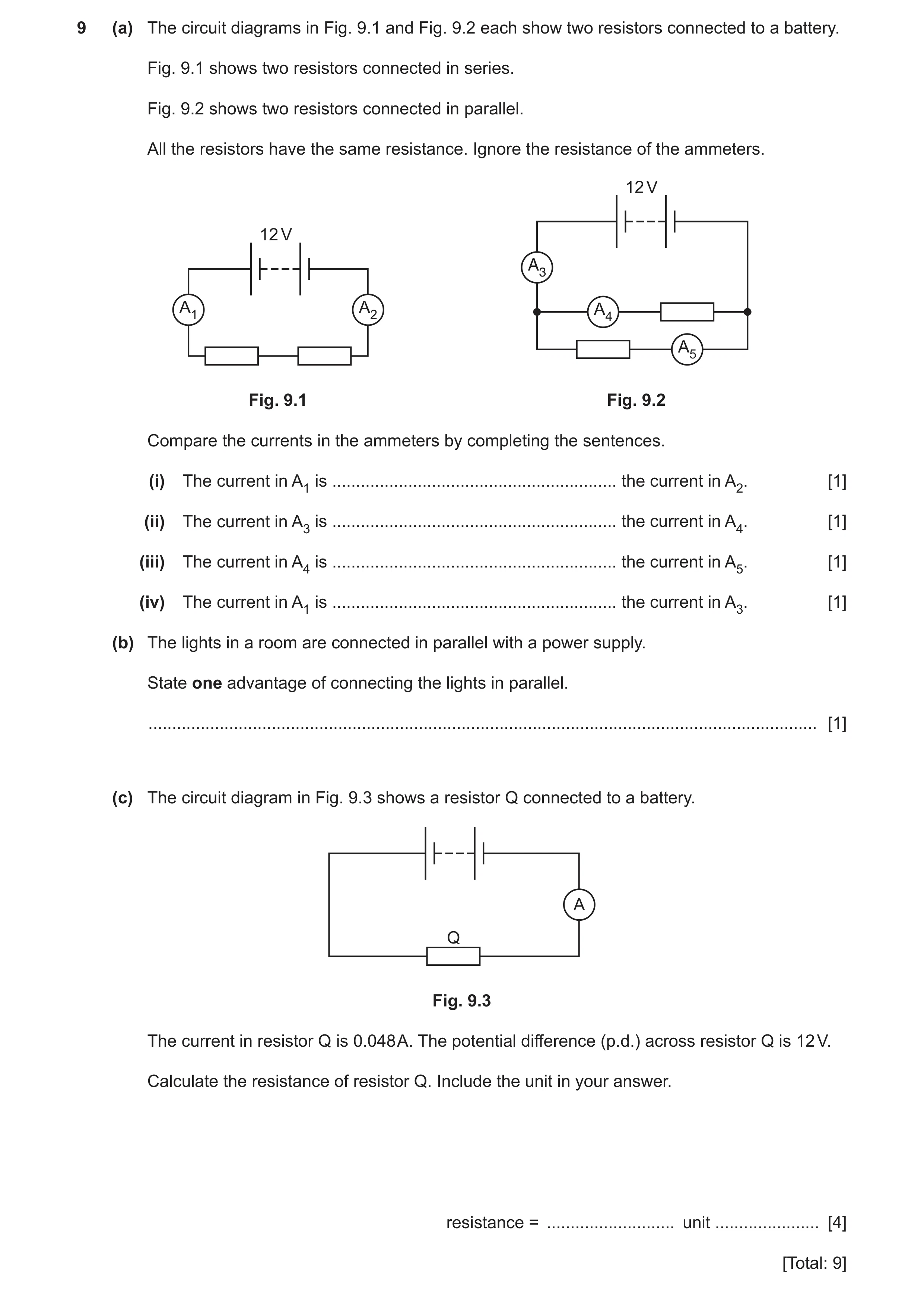
9 (a) The circuit diagrams in Fig. 9.1 and Fig. 9.2 each show two resistors connected to a battery. Fig. 9.1 shows two resistors connected in series. Fig. 9.2 shows two resistors connected in parallel. All the resistors have the same resistance. Ignore the resistance of the ammeters. 12 V 12 V A3 A1 A2 A4 A5 Fig. 9.1 Fig. 9.2 Compare the currents in the ammeters by completing the sentences. (i) The current in A1 is … the current in A2. [1] (ii) The current in A3 is … the current in A4. [1] (iii) The current in A4 is … the current in A5. [1] (iv) The current in A1 is … the current in A3. [1] (b) The lights in a room are connected in parallel with a power supply. State one advantage of connecting the lights in parallel. … [1] (c) The circuit diagram in Fig. 9.3 shows a resistor Q connected to a battery. A Q Fig. 9.3 The current in resistor Q is 0.048 A. The potential difference (p.d.) across resistor Q is 12 V. Calculate the resistance of resistor Q. Include the unit in your answer. resistance = … unit … [4] [Total: 9]
9 marks
Mark scheme: 9(a)(i) the same as B1 9(a)(ii) larger than B1 9(a)(iii) the same as B1 9(a)(iv) smaller than B1 9(b) same brightness / if one fails the rest are still lit / lamps can be switched off independently / same p.d. across owtte B1 9(c) V = I × R in any form (R =) V ÷ I C1 12 ÷ 0.048 C1 250 A1 Ω / ohms B1
This question in 0625/33 Oct/Nov 2021
Q32 · A student has a box containing objects made of different materials 0625/32 May/June 2022
8 (a) A student has a box containing objects made of different materials. The objects are: aluminium foil a silver ring an iron bar a plastic strip a glass lens (i) State which objects are made of electrically insulating materials. … [1] (ii) State which object is made of a magnetic material. … [1] (b) Fig. 8.1 shows two magnets, X and Y. The magnets are attracting each other. N attraction magnet X magnet Y Fig. 8.1 On magnet X, the N pole is labelled N. On Fig. 8.1, complete the labelling for the magnetic poles of each magnet. [1] (c) The student attaches a thin cotton thread to each of two light metal spheres, P and Q. She suspends the spheres as shown in Fig. 8.2. thin cotton support thread P Q Fig. 8.2 (i) The student puts a positive charge on sphere P only. Complete the diagram in Fig. 8.3 to show the positions of the spheres. support Fig. 8.3 [1] (ii) The student puts a positive charge on sphere P and on sphere Q. Complete the diagram in Fig. 8.4 to show the positions of the spheres. support Fig. 8.4 [2] [Total: 6]
6 marks
Mark scheme: 8(a)(i) plastic strip AND glass lens B1 8(a)(ii) iron bar B1 Question Answer Marks 8(b) end of magnet X labelled S (pole) AND end of magnet Y nearest magnet X labelled N (pole) AND other end is S (pole) B1 8(c)(i) spheres drawn closer together B1 8(c)(ii) spheres drawn further apart M1 both strings at an angle to vertical A1
This question in 0625/32 May/June 2022
Q33 · A student has a battery-operated torch 0625/32 May/June 2022
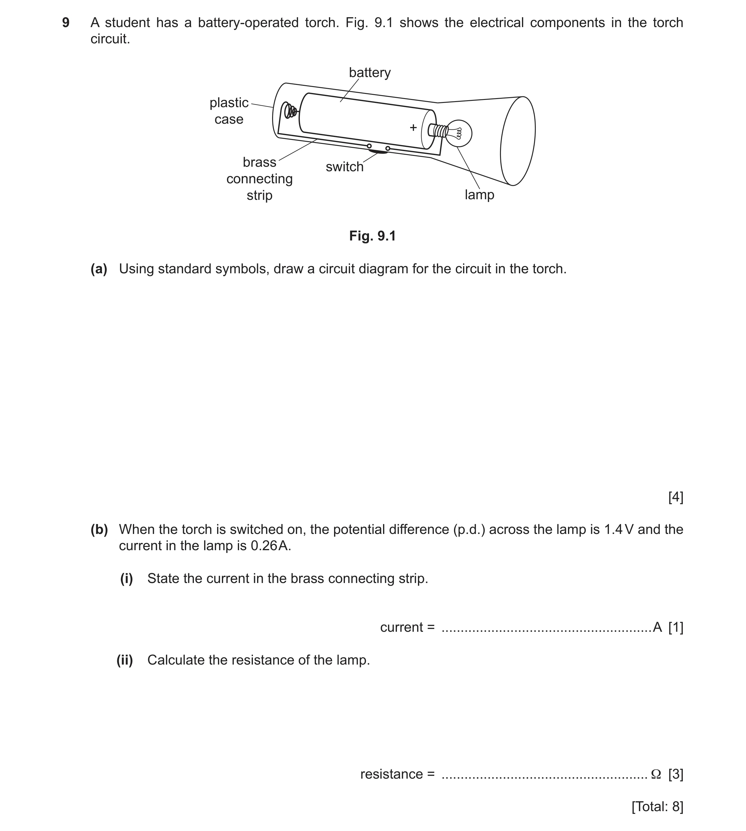
9 A student has a battery-operated torch. Fig. 9.1 shows the electrical components in the torch circuit. battery plastic case + brass switch connecting strip lamp Fig. 9.1 (a) Using standard symbols, draw a circuit diagram for the circuit in the torch. [4] (b) When the torch is switched on, the potential difference (p.d.) across the lamp is 1.4 V and the current in the lamp is 0.26 A. (i) State the current in the brass connecting strip. current = … A [1] (ii) Calculate the resistance of the lamp. resistance = … Ω [3] [Total: 8]
8 marks
Mark scheme: 9(a) correct symbol for battery B1 correct symbol for switch B1 correct symbol for lamp B1 all 3 components connected in series B1 9(b)(i) 0.26 (A) B1 9(b)(ii) 5.4 () A3 1.4 ÷ 0.26 (C2) V= IR or (R =) V/I (C1)
This question in 0625/32 May/June 2022
Q34 · The circuit in Fig 0625/33 May/June 2022
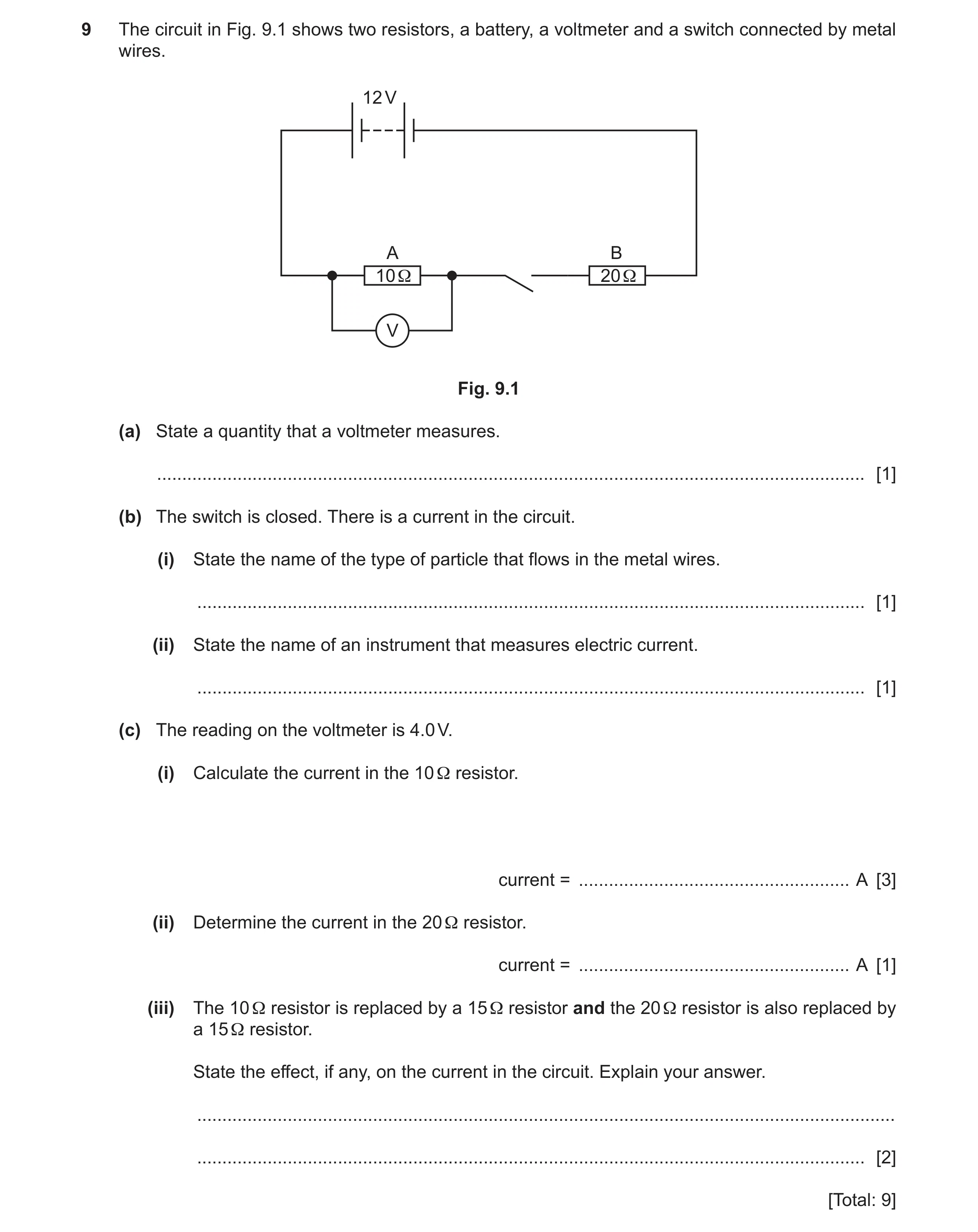
9 The circuit in Fig. 9.1 shows two resistors, a battery, a voltmeter and a switch connected by metal wires. 12 V A B 10Ω 20Ω V Fig. 9.1 (a) State a quantity that a voltmeter measures. … [1] (b) The switch is closed. There is a current in the circuit. (i) State the name of the type of particle that flows in the metal wires. … [1] (ii) State the name of an instrument that measures electric current. … [1] (c) The reading on the voltmeter is 4.0 V. (i) Calculate the current in the 10 Ω resistor. current = … A [3] (ii) Determine the current in the 20 Ω resistor. current = … A [1] (iii) The 10 Ω resistor is replaced by a 15 Ω resistor and the 20 Ω resistor is also replaced by a 15 Ω resistor. State the effect, if any, on the current in the circuit. Explain your answer. … … [2] [Total: 9]
9 marks
Mark scheme: 9(a) electromotive force/e. m. f./ potential difference/p. d./ voltage B1 Question Answer Marks 9(b)(i) electron(s) B1 9(b)(ii) ammeter B1 9(c)(i) 0.4(0) (A) A3 4(.0) ÷ 10 (C2) (I = ) V ÷ R in any form (C1) 9(c)(ii) 0.4(0) (A) OR same as (c)(i) B1 9(c)(iii) no change/same M1 resultant/total/combined resistance does not change A1
This question in 0625/33 May/June 2022
Q35 · An electric circuit set up by a student 0625/31 Oct/Nov 2022
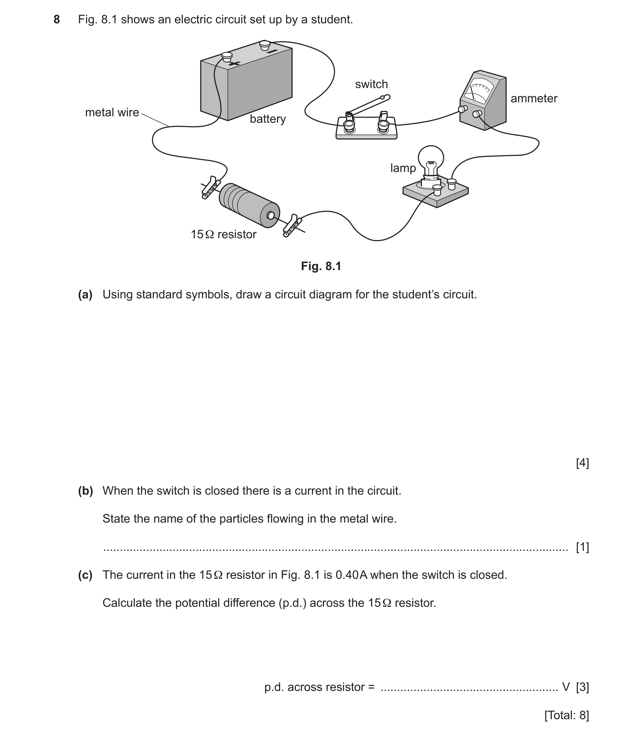
8 Fig. 8.1 shows an electric circuit set up by a student. switch ammeter metal wire battery lamp 15 Ω resistor Fig. 8.1 (a) Using standard symbols, draw a circuit diagram for the student’s circuit. [4] (b) When the switch is closed there is a current in the circuit. State the name of the particles flowing in the metal wire. … [1] (c) The current in the 15 Ω resistor in Fig. 8.1 is 0.40 A when the switch is closed. Calculate the potential difference (p.d.) across the 15 Ω resistor. p.d. across resistor = … V [3] [Total: 8]
8 marks
Mark scheme: 8(a) 5 correct symbols for 3 marks B3 3 or 4 correct symbols for 2 marks 1 or 2 correct symbols for 1 mark any from: • correct symbol for battery • correct symbol for ammeter • correct symbol for lamp • correct symbol for fixed resistor • correct symbol for switch. all components drawn connected in a series circuit B1 8(b) electrons B1 8(c) 6(.0) (V) A3 0.40 15 C2 (V =) I R OR R = V / I C1
This question in 0625/31 Oct/Nov 2022
Q36 · A student uses the circuit in Fig 0625/32 Oct/Nov 2022
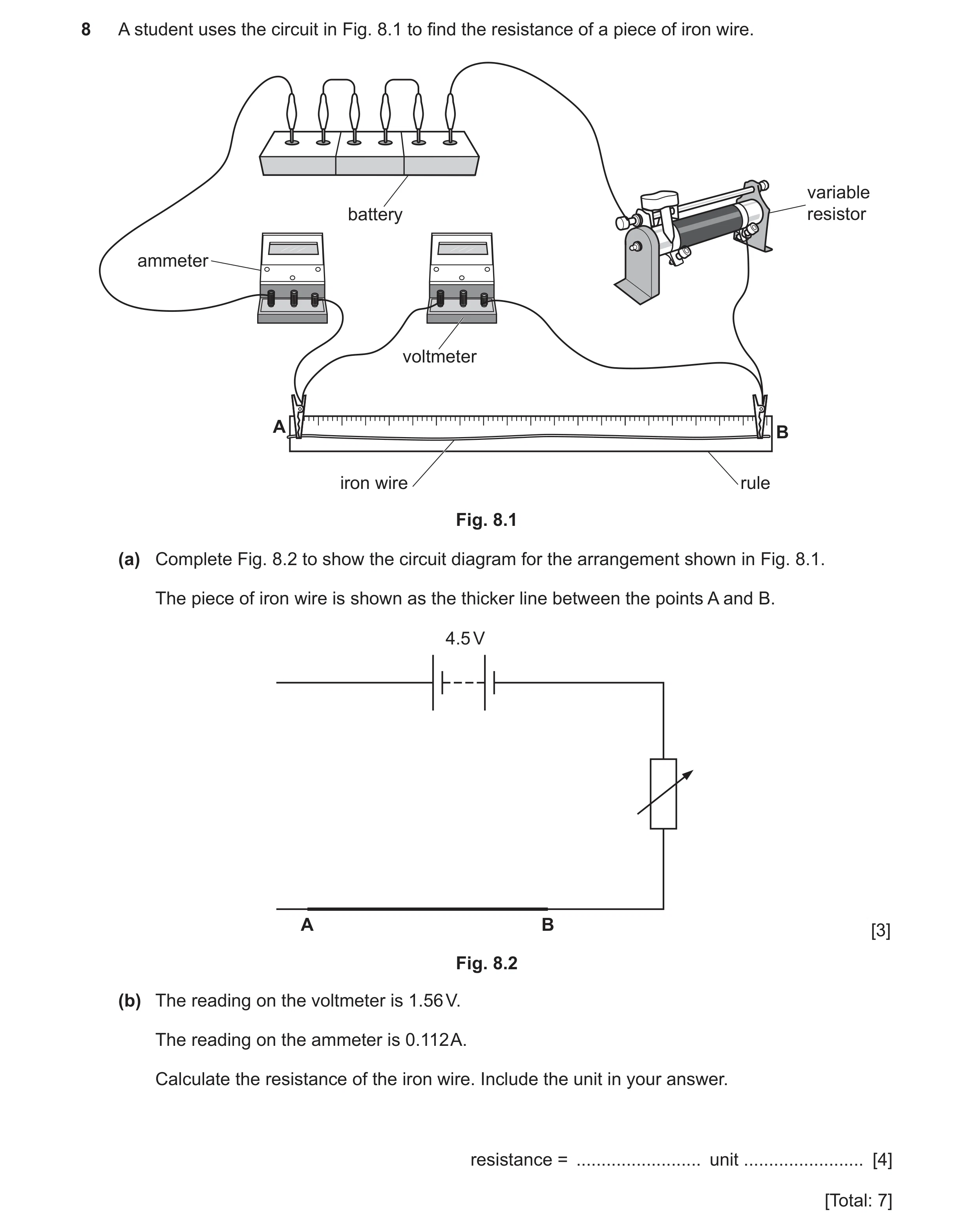
8 A student uses the circuit in Fig. 8.1 to find the resistance of a piece of iron wire. variable battery resistor ammeter voltmeter A B iron wire rule Fig. 8.1 (a) Complete Fig. 8.2 to show the circuit diagram for the arrangement shown in Fig. 8.1. The piece of iron wire is shown as the thicker line between the points A and B. 4.5 V A B [3] Fig. 8.2 (b) The reading on the voltmeter is 1.56 V. The reading on the ammeter is 0.112 A. Calculate the resistance of the iron wire. Include the unit in your answer. resistance = … unit … [4] [Total: 7]
7 marks
Mark scheme: 8(a) ammeter, battery and test wire in complete series circuit B1 voltmeter in parallel with AB B1 correct circuit symbols for ammeter AND voltmeter B1 8(b) 14 A3 1.56 ÷ 0.112 (C2) (R =) V ÷ I in any form OR V = I R (C1) / ohm(s) B1
This question in 0625/32 Oct/Nov 2022
Question 37 0625/32 Oct/Nov 2022
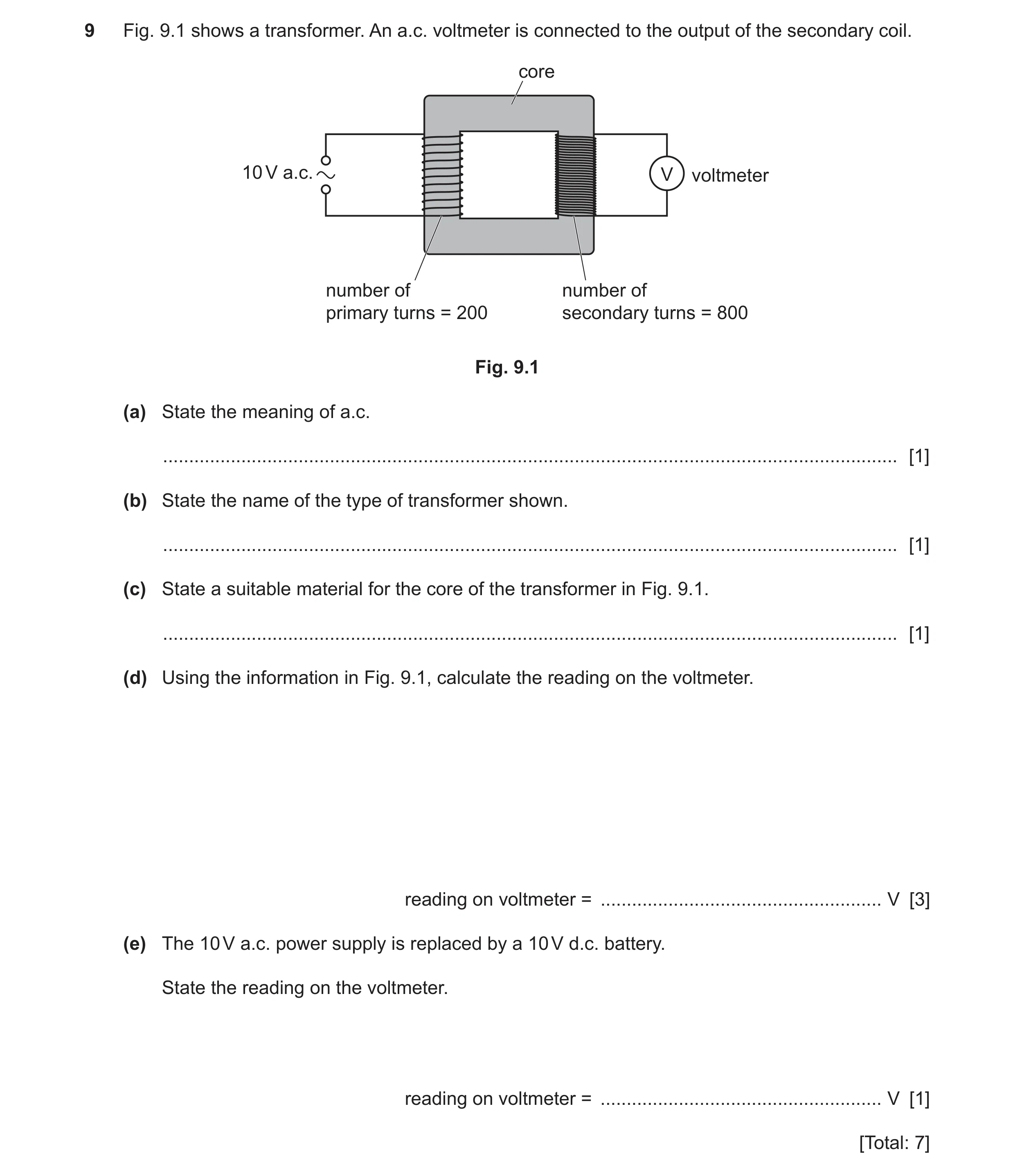
9 Fig. 9.1 shows a transformer. An a.c. voltmeter is connected to the output of the secondary coil. core 10 V a.c. V voltmeter number of number of primary turns = 200 secondary turns = 800 Fig. 9.1 (a) State the meaning of a.c. … [1] (b) State the name of the type of transformer shown. … [1] (c) State a suitable material for the core of the transformer in Fig. 9.1. … [1] (d) Using the information in Fig. 9.1, calculate the reading on the voltmeter. reading on voltmeter = … V [3] (e) The 10 V a.c. power supply is replaced by a 10 V d.c. battery. State the reading on the voltmeter. reading on voltmeter = … V [1] [Total: 7]
7 marks
Mark scheme: 9(a) alternating (current) B1 9(b) step-up B1 9(c) (soft) iron B1 9(d) 40 (V) A3 (VS =) 800 / 200 10 (C2) VP / VS = NP / NS in any form (C1) 9(e) zero B1
This question in 0625/32 Oct/Nov 2022
Q38 · A student uses a dry cloth to rub a plastic rod 0625/32 Feb/March 2023
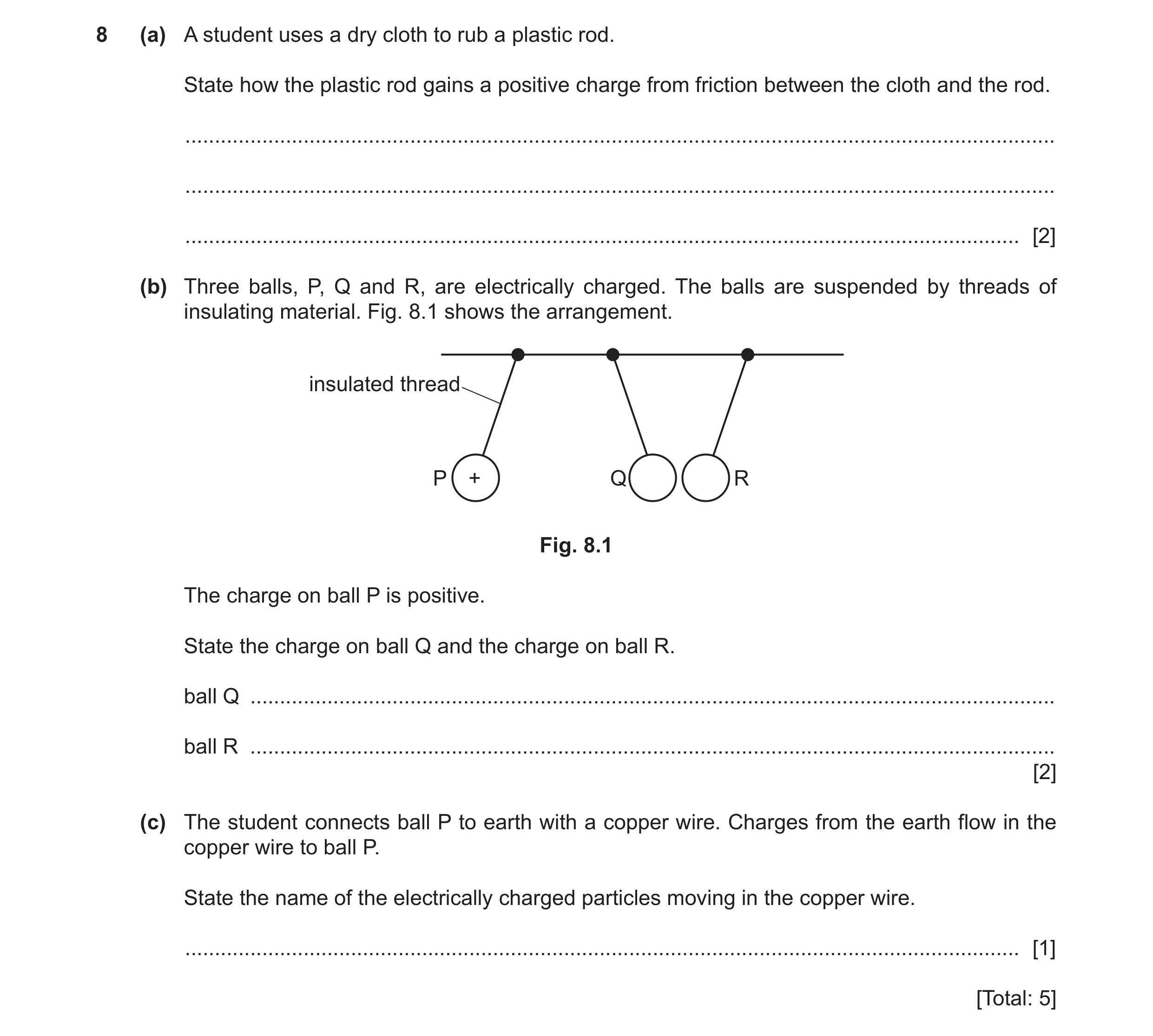
8 (a) A student uses a dry cloth to rub a plastic rod. State how the plastic rod gains a positive charge from friction between the cloth and the rod. … … … [2] (b) Three balls, P, Q and R, are electrically charged. The balls are suspended by threads of insulating material. Fig. 8.1 shows the arrangement. insulated thread P + Q R Fig. 8.1 The charge on ball P is positive. State the charge on ball Q and the charge on ball R. ball Q … ball R … [2] (c) The student connects ball P to earth with a copper wire. Charges from the earth flow in the copper wire to ball P. State the name of the electrically charged particles moving in the copper wire. … [1] [Total: 5]
5 marks
Mark scheme: 8(a) negative charges OR electrons B1 move from rod OR move to cloth B1 8(b) (ball Q is) positive B1 (ball R is) negative B1 8(c) (free) electrons B1
This question in 0625/32 Feb/March 2023
Question 39 0625/32 Feb/March 2023
9 Fig. 9.1 shows an electric kettle. Fig. 9.1 (a) (i) The power input of the kettle is 1.5 kW. The potential difference of the mains electrical supply for the kettle is 220 V. Calculate the current in the kettle when it is switched on. current in kettle = … A [4] (ii) The 1.5 kW kettle is used for a total of 4.0 hours. The cost of 1.0 kW h of electrical energy is 14 pennies (p). Calculate the cost of the energy used by the kettle in 4.0 hours. cost of energy = … p [3] (b) Fig. 9.2 shows an overloaded extension lead. Fig. 9.2 Explain the danger of connecting too many plugs to an extension lead. … … … [2] [Total: 9]
9 marks
Mark scheme: 9(a)(i) (I =) 6.8 (A) A4 (I =) 1500 ÷ 220 (C2) P = I V OR (I =) P ÷ V (C1) 1.5 kW = 1500 W (C1) 9(a)(ii) (cost of energy =) 84 (p) A3 (cost of energy =) 1.5 4(.0) 14 (C2) (cost of energy =) power time cost of 1 kW h (C1) OR number of kW h cost of 1 kW h 9(b) large current (in extension lead / socket) B1 (can cause) overheating / fire B1
This question in 0625/32 Feb/March 2023
Question 40 0625/31 May/June 2023
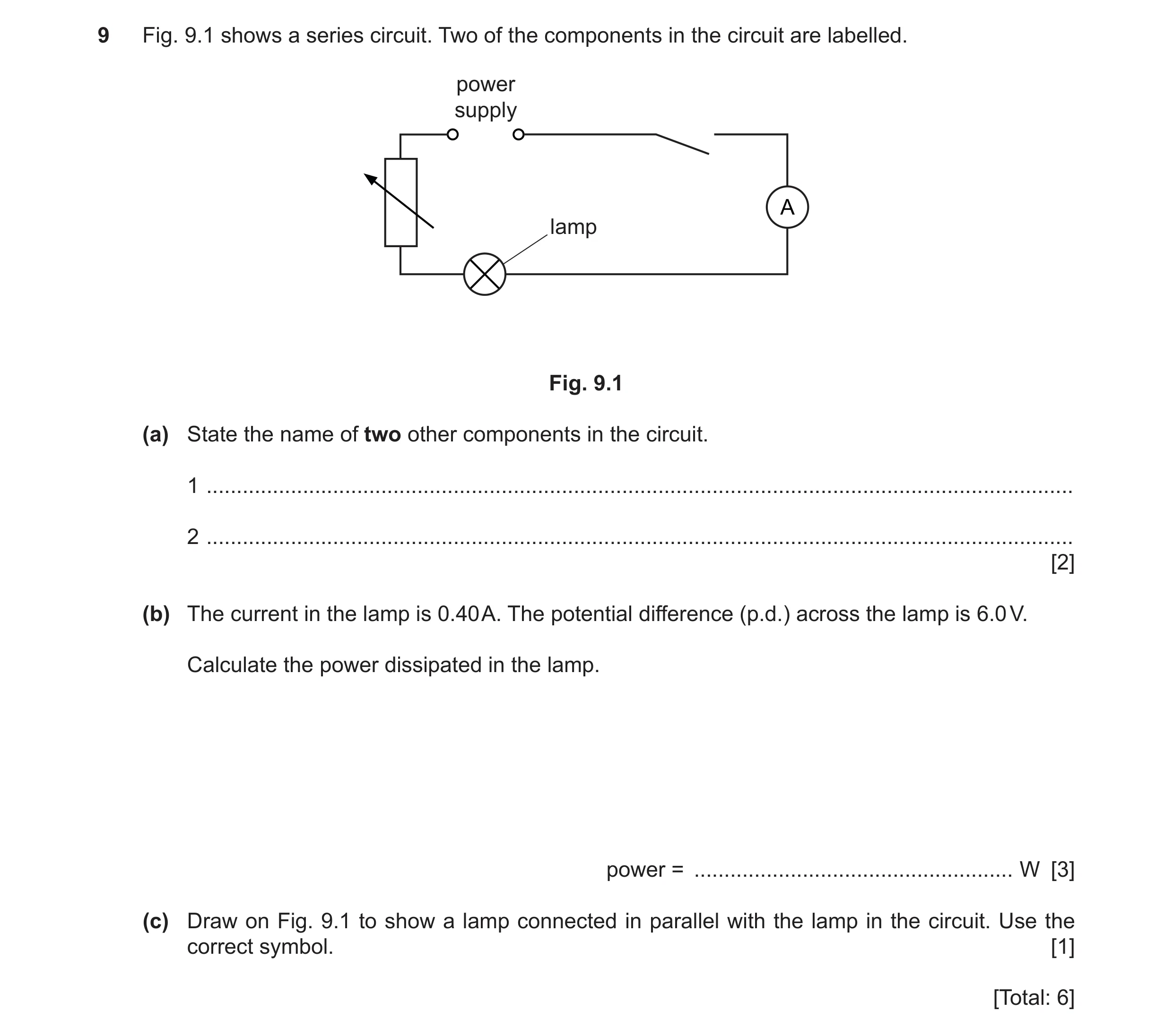
9 Fig. 9.1 shows a series circuit. Two of the components in the circuit are labelled. power supply lamp Fig. 9.1 (a) State the name of two other components in the circuit. 1 … 2 … [2] (b) The current in the lamp is 0.40 A. The potential difference (p.d.) across the lamp is 6.0 V. Calculate the power dissipated in the lamp. power = … W [3] (c) Draw on Fig. 9.1 to show a lamp connected in parallel with the lamp in the circuit. Use the correct symbol. [1] [Total: 6]
6 marks
Mark scheme: 9(a) any two from: switch ammeter variable resistor B2 9(b) (power =) 2.4 (W) A3 (power =) 0.4(0) 6(.0) (C2) (power =) I V (C1) 9(c) lamp symbol drawn in parallel with lamp in circuit B1
This question in 0625/31 May/June 2023
Q41 · A student uses the circuit in Fig 0625/32 May/June 2023
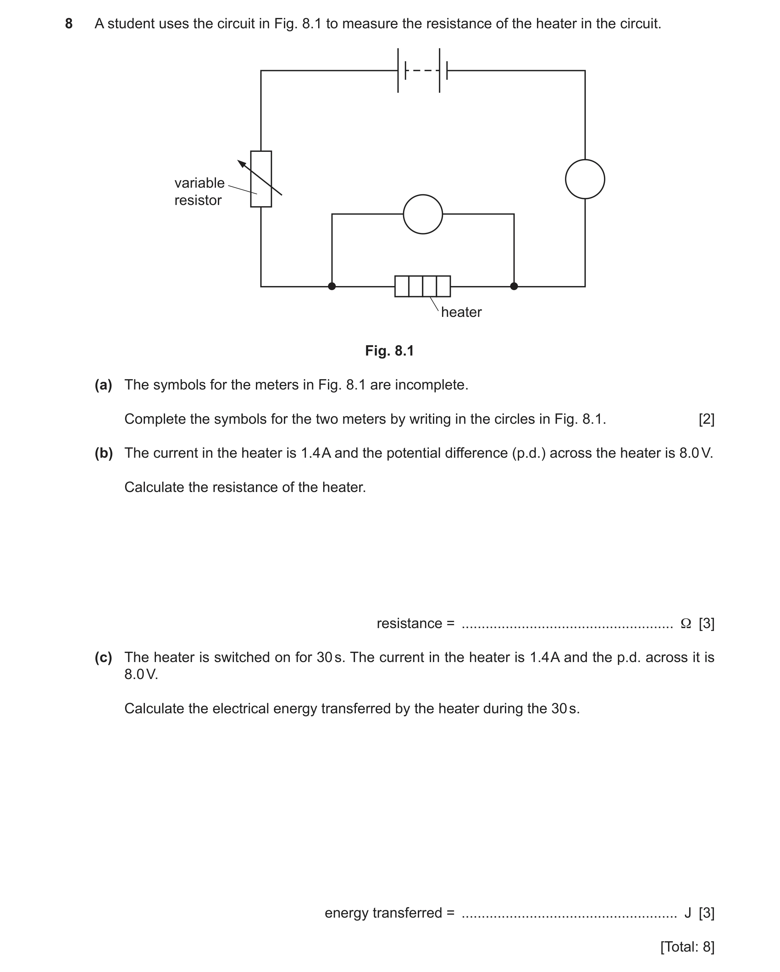
8 A student uses the circuit in Fig. 8.1 to measure the resistance of the heater in the circuit. variable resistor heater Fig. 8.1 (a) The symbols for the meters in Fig. 8.1 are incomplete. Complete the symbols for the two meters by writing in the circles in Fig. 8.1. [2] (b) The current in the heater is 1.4 A and the potential difference (p.d.) across the heater is 8.0 V. Calculate the resistance of the heater. resistance = … Ω [3] (c) The heater is switched on for 30 s. The current in the heater is 1.4 A and the p.d. across it is 8.0 V. Calculate the electrical energy transferred by the heater during the 30 s. energy transferred = … J [3] [Total: 8]
8 marks
Mark scheme: 8(a) ammeter symbol correct B1 voltmeter symbol correct B1 8(b) (R =) 5.7 () A3 (R =) 8(.0) ÷ 1.4 (C2) V = IR in any form OR (R =) V ÷ I (C1) 8(c) (E =) 340 (J) A3 (E =) 8(.0) 1.4 30 (C2) (E =) V I t (C1)
This question in 0625/32 May/June 2023
Q42 · The electrical symbols for some circuit components 0625/33 May/June 2023
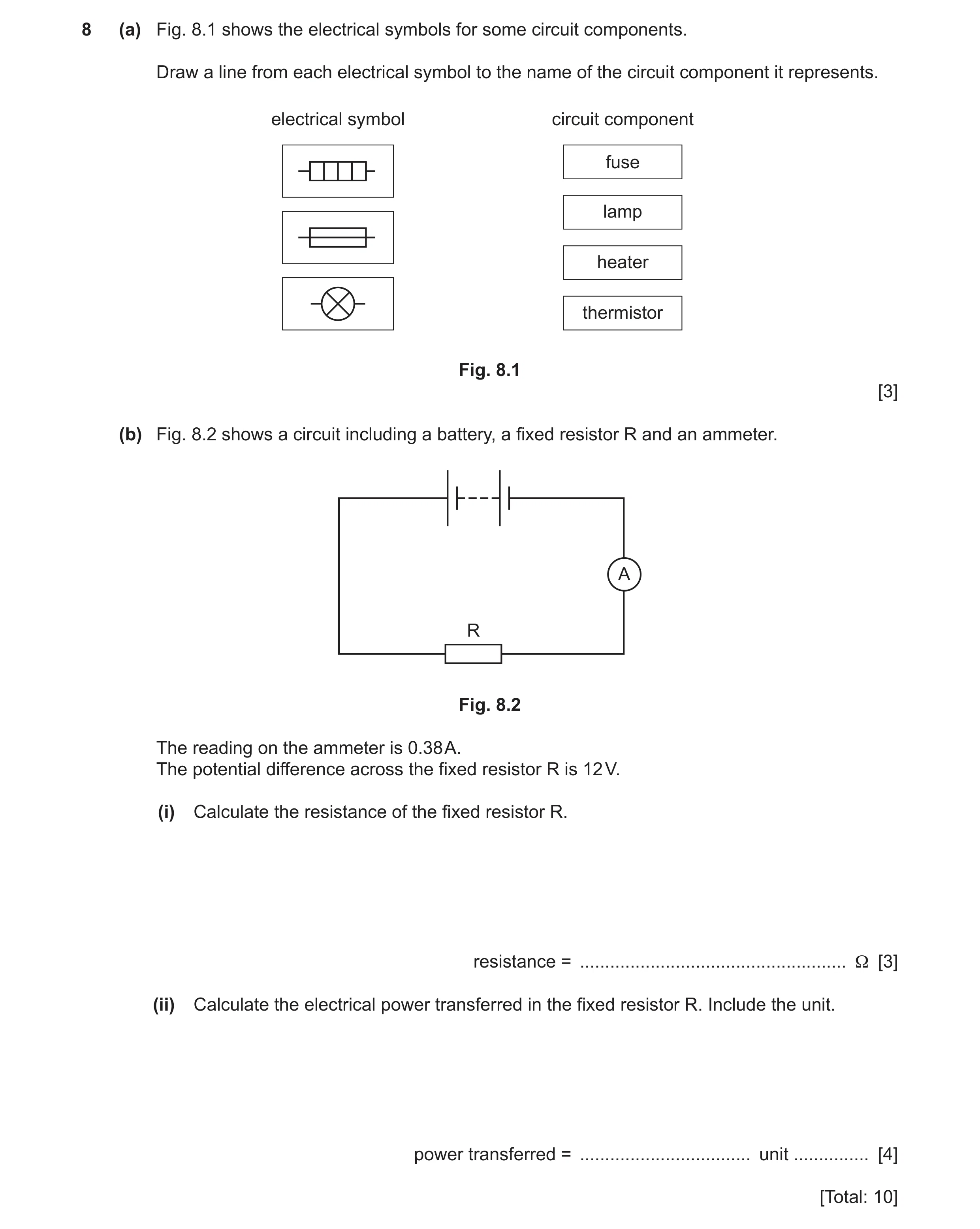
8 (a) Fig. 8.1 shows the electrical symbols for some circuit components. Draw a line from each electrical symbol to the name of the circuit component it represents. electrical symbol circuit component fuse lamp heater thermistor Fig. 8.1 [3] (b) Fig. 8.2 shows a circuit including a battery, a fixed resistor R and an ammeter. A R Fig. 8.2 The reading on the ammeter is 0.38 A. The potential difference across the fixed resistor R is 12 V. (i) Calculate the resistance of the fixed resistor R. resistance = … Ω [3] (ii) Calculate the electrical power transferred in the fixed resistor R. Include the unit. power transferred = … unit … [4] [Total: 10]
10 marks
Mark scheme: 8(a) B1 B1 B1 8(b)(i) (R =) V ÷ I in any form C1 12 ÷ 0.38 C1 32 () A1 8(b)(ii) (P =) IV in any form C1 12 0.38 C1 4.6 A1 W OR watts B1
This question in 0625/33 May/June 2023
Question 43 0625/31 Oct/Nov 2023
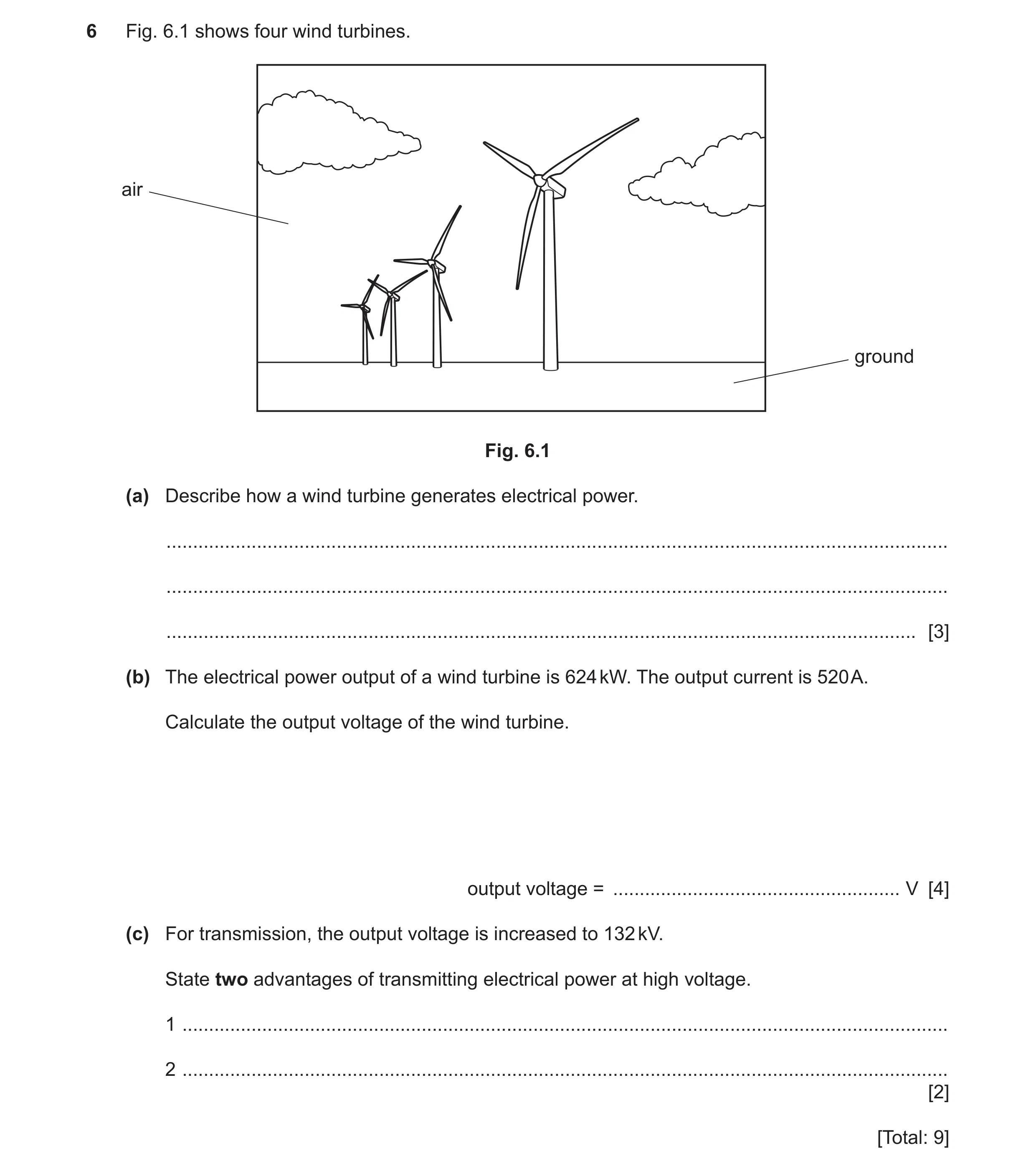
6 Fig. 6.1 shows four wind turbines. air ground Fig. 6.1 (a) Describe how a wind turbine generates electrical power. … … … [3] (b) The electrical power output of a wind turbine is 624 kW. The output current is 520 A. Calculate the output voltage of the wind turbine. output voltage = … V [4] (c) For transmission, the output voltage is increased to 132 kV. State two advantages of transmitting electrical power at high voltage. 1 … 2 … [2] [Total: 9]
9 marks
Mark scheme: 6(a) KE of wind B1 rotates / turns / spins turbine OR blades B1 (turbine) turns / spins / rotates generator B1 6(b) (output voltage =) 1200 (V) OR 1.2 kV A4 (V =) 624 000 ÷ 520 (C3) conversion: 624 kW = 624 000 (W) (C1) power = I V OR (V =) P ÷ I (C1) 6(c) any two from: B2 greater efficiency as lower current (is used) (so) reduces power / energy losses thinner cables can be used (so reducing costs) OR pylons further apart idea of increased distance of transmission (of electrical power)
This question in 0625/31 Oct/Nov 2023
Q44 · An electric water heater 0625/32 Oct/Nov 2023
9 Fig. 9.1 shows an electric water heater. The heater is connected to the mains electrical supply. water heater plastic cover Fig. 9.1 Fig. 9.2 shows the electrical safety label for the heater. Water Heater Model xxxxxx1 230 V (volts) 720 W (watts) Disconnect from the mains supply before removing the plastic cover. Fig. 9.2 (a) (i) Explain why the safety label states, ‘Disconnect from the mains supply before removing the plastic cover.’ … … [1] (ii) The heater is switched on. Calculate the current in the heater. Use the information in Fig. 9.2. current = … A [3] (b) Table 9.1 shows some electrical meter readings for the water heater. Table 9.1 date meter reading / kW h 1st October 3771 31st October 3797 Electrical energy costs 18 cents per kW h. Calculate the cost of using the heater from 1st October until 31st October. cost = … cents [3] [Total: 7]
7 marks
Mark scheme: 9(a)(i) (prevent) risk of (electric) shock / electrocution B1 9(a)(ii) 3.1 (A) A3 720/230 (C2) (current =) power / voltage OR (I =) P / V (C1) 9(b) 468 (cents) A3 26 18 (C2) (cost =) number of kWh cost per kWh (C1) number of kWh = 3797 – 3771 OR 26 (C1)
This question in 0625/32 Oct/Nov 2023
Q45 · Two identical resistors, R1 and R2, are connected to a 24 V battery, as shown in Fig 0625/33 Oct/Nov 2023
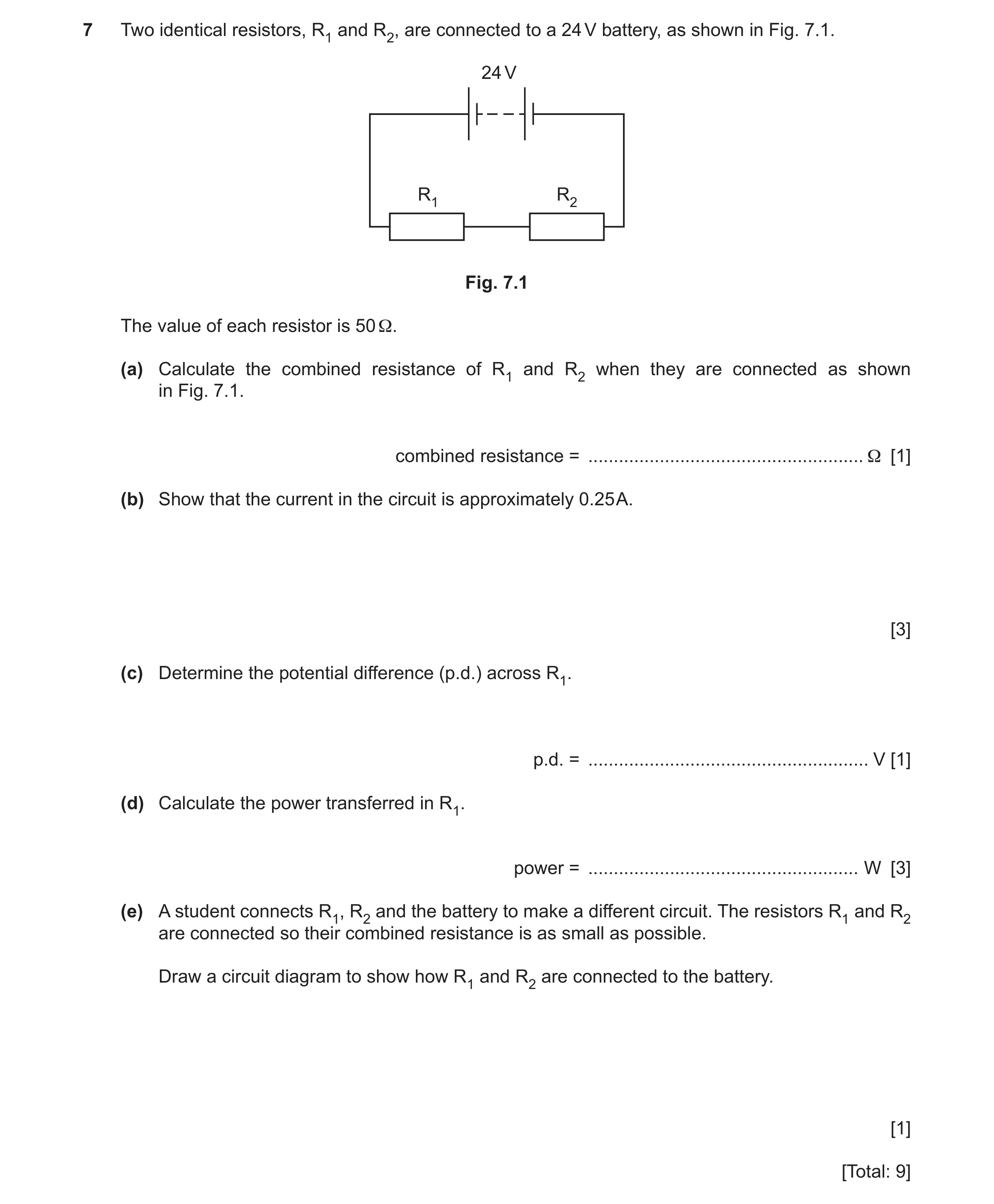
7 Two identical resistors, R1 and R2, are connected to a 24 V battery, as shown in Fig. 7.1. 24 V R1 R2 Fig. 7.1 The value of each resistor is 50 Ω. (a) Calculate the combined resistance of R1 and R2 when they are connected as shown in Fig. 7.1. combined resistance = … Ω [1] (b) Show that the current in the circuit is approximately 0.25 A. [3] (c) Determine the potential difference (p.d.) across R1. p.d. = … V [1] (d) Calculate the power transferred in R1. power = … W [3] (e) A student connects R1, R2 and the battery to make a different circuit. The resistors R1 and R2 are connected so their combined resistance is as small as possible. Draw a circuit diagram to show how R1 and R2 are connected to the battery. [1] [Total: 9]
9 marks
Mark scheme: 7(a) 100 () B1 7(b) 0.24 (A) B1 24 / 100 (current =) voltage / resistance B1 Need to see zone (a) B1 7(c) 12 (V) B1 7(d) 3(.0) (W) OR 2.9 (W) A3 0.25 12 (C2) (power =) current voltage OR (P =) V × I (C1) 7(e) (two) resistors in parallel B1
This question in 0625/33 Oct/Nov 2023
Q46 · Describe what is meant by alternating current (a.c.) 0625/33 Oct/Nov 2023
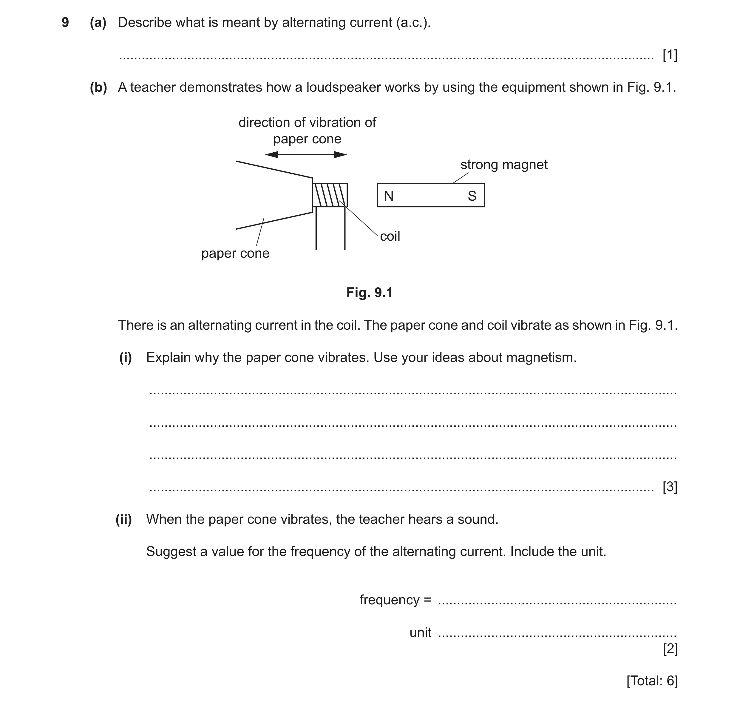
9 (a) Describe what is meant by alternating current (a.c.). … [1] (b) A teacher demonstrates how a loudspeaker works by using the equipment shown in Fig. 9.1. direction of vibration of paper cone strong magnet N S coil paper cone Fig. 9.1 There is an alternating current in the coil. The paper cone and coil vibrate as shown in Fig. 9.1. (i) Explain why the paper cone vibrates. Use your ideas about magnetism. … … … … [3] (ii) When the paper cone vibrates, the teacher hears a sound. Suggest a value for the frequency of the alternating current. Include the unit. frequency = … unit … [2] [Total: 6]
6 marks
Mark scheme: 9(a) (current repeatedly) changes direction B1 9(b)(i) any three from: B3 magnetic effect of current coil becomes an electromagnet attracted to magnet repelled by magnet 9(b)(ii) any number(s) between 20 and 20 000 B1 Hz / kHz B1
This question in 0625/33 Oct/Nov 2023
Q47 · A student connects the electrical circuit shown in Fig 0625/32 Feb/March 2024
9 A student connects the electrical circuit shown in Fig. 9.1. switch ammeter metal wire battery lamp thermistor Fig. 9.1 (a) Fig. 9.2 shows part of the circuit diagram for the circuit in Fig. 9.1. Fig. 9.2 Complete the circuit diagram in Fig. 9.2 to represent the circuit in Fig. 9.1. Use standard electrical symbols. [4] (b) The potential difference across the lamp is 5.4 V and the current in the lamp is 0.20 A. (i) Calculate the resistance of the lamp. resistance = … Ω [3] (ii) The lamp is switched on for 30 s. Calculate the energy transferred in the lamp during this time. energy transferred = … J [3] (c) The student increases the temperature of the thermistor. State and explain what happens to the current in the circuit. … … [2] [Total: 12]
12 marks
Mark scheme: 9(a) correct symbol for: ammeter B1 lamp B1 thermistor B1 symbols connected in series circuit B1 9(b)(i) 27 () A3 5.4 ÷ 0.2(0) (C2) (R=) V ÷ I OR V = I R or in any form (C1) 9(b)(ii) 32 (J) A3 (E =) 5.4 0.2 30 (C2) (E=) VItOR P t OR I2 R t (C1) 9(c) current increases B1 (because) resistance (of thermistor) decreases B1
This question in 0625/32 Feb/March 2024
Q48 · An arrangement for making an electromagnet 0625/31 May/June 2024
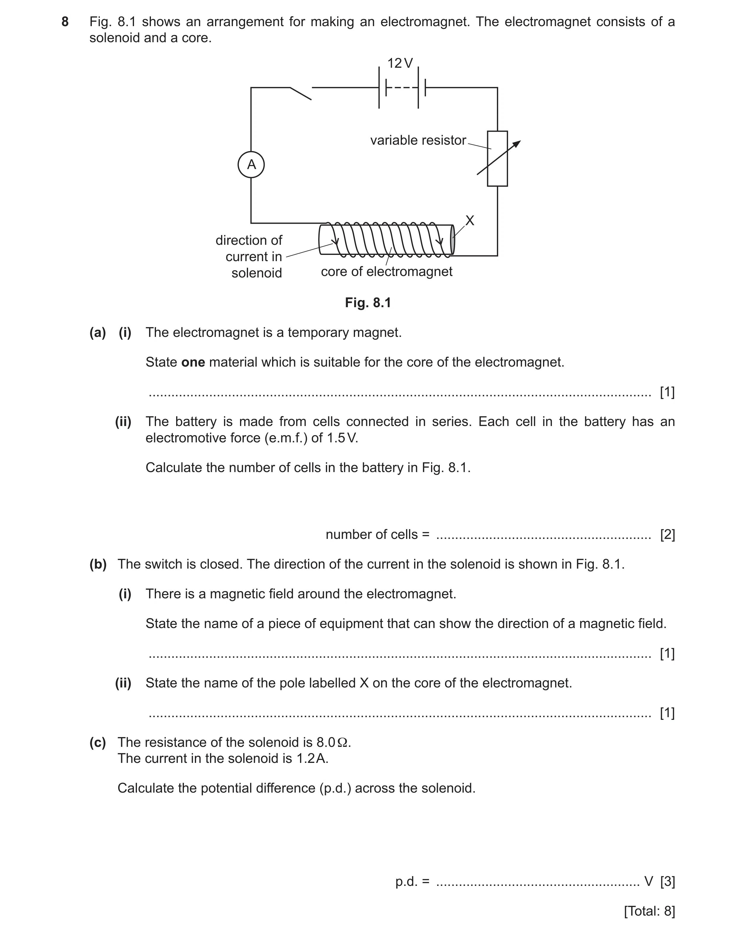
8 Fig. 8.1 shows an arrangement for making an electromagnet. The electromagnet consists of a solenoid and a core. 12 V variable resistor A X direction of current in solenoid core of electromagnet Fig. 8.1 (a) (i) The electromagnet is a temporary magnet. State one material which is suitable for the core of the electromagnet. … [1] (ii) The battery is made from cells connected in series. Each cell in the battery has an electromotive force (e.m.f.) of 1.5 V. Calculate the number of cells in the battery in Fig. 8.1. number of cells = … [2] (b) The switch is closed. The direction of the current in the solenoid is shown in Fig. 8.1. (i) There is a magnetic field around the electromagnet. State the name of a piece of equipment that can show the direction of a magnetic field. … [1] (ii) State the name of the pole labelled X on the core of the electromagnet. … [1] (c) The resistance of the solenoid is 8.0 Ω. The current in the solenoid is 1.2 A. Calculate the potential difference (p.d.) across the solenoid. p.d. = … V [3] [Total: 8]
8 marks
Mark scheme: 8(a)(i) (soft) iron B1 8(a)(ii) 8 (cells) A2 (number of cells =) 12 ÷ 1.5 OR battery e.m.f ÷ e.m.f. of 1 cell (C1) 8(b)(i) (plotting) compass B1 8(b)(ii) north OR N (pole) B1 8(c) (V =) 9.6 (V) A3 (V =) 8(.0) 1.2 (C2) R = V ÷ I in any form OR (V =) I R (C1)
This question in 0625/31 May/June 2024
Q49 · A battery, a lamp L, a fixed resistor R and a switch S are connected as shown in Fig 0625/32 May/June 2024
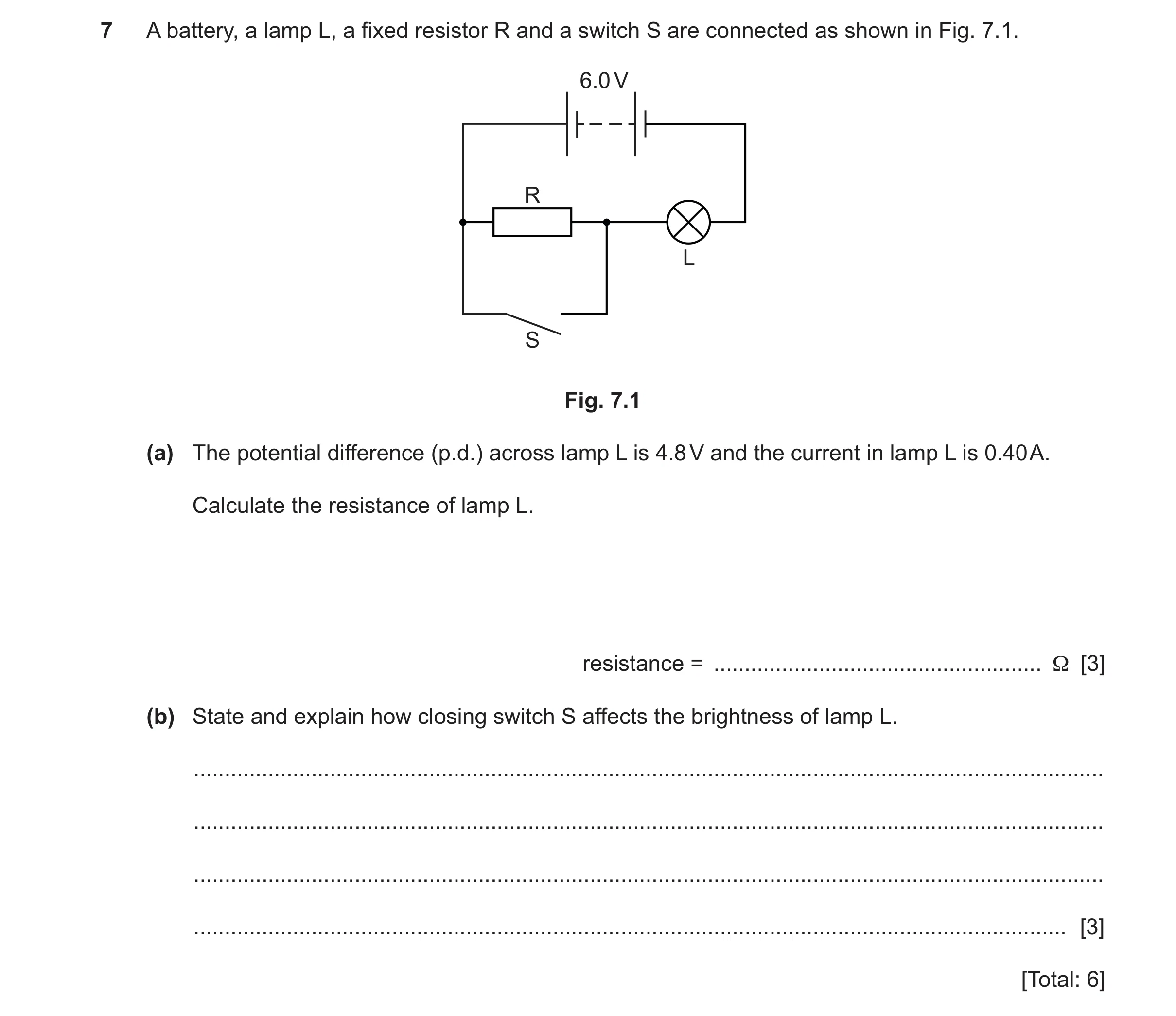
7 A battery, a lamp L, a fixed resistor R and a switch S are connected as shown in Fig. 7.1. 6.0 V R L S Fig. 7.1 (a) The potential difference (p.d.) across lamp L is 4.8 V and the current in lamp L is 0.40 A. Calculate the resistance of lamp L. resistance = … Ω [3] (b) State and explain how closing switch S affects the brightness of lamp L. … … … … [3] [Total: 6]
6 marks
Mark scheme: 7(a) A3 4.8 / 0.4 (C2) V = IR OR (R = ) V / I (C1) 7(b) (lamp is) brighter OR (brightness) increases B1 resistance of wire and resistor in parallel is less than resistance of wire owtte OR voltage across lamp / L increases B1 (so) current in lamp increases B1
This question in 0625/32 May/June 2024
Q50 · Part of a circuit for measuring the resistance of a lamp 0625/33 May/June 2024
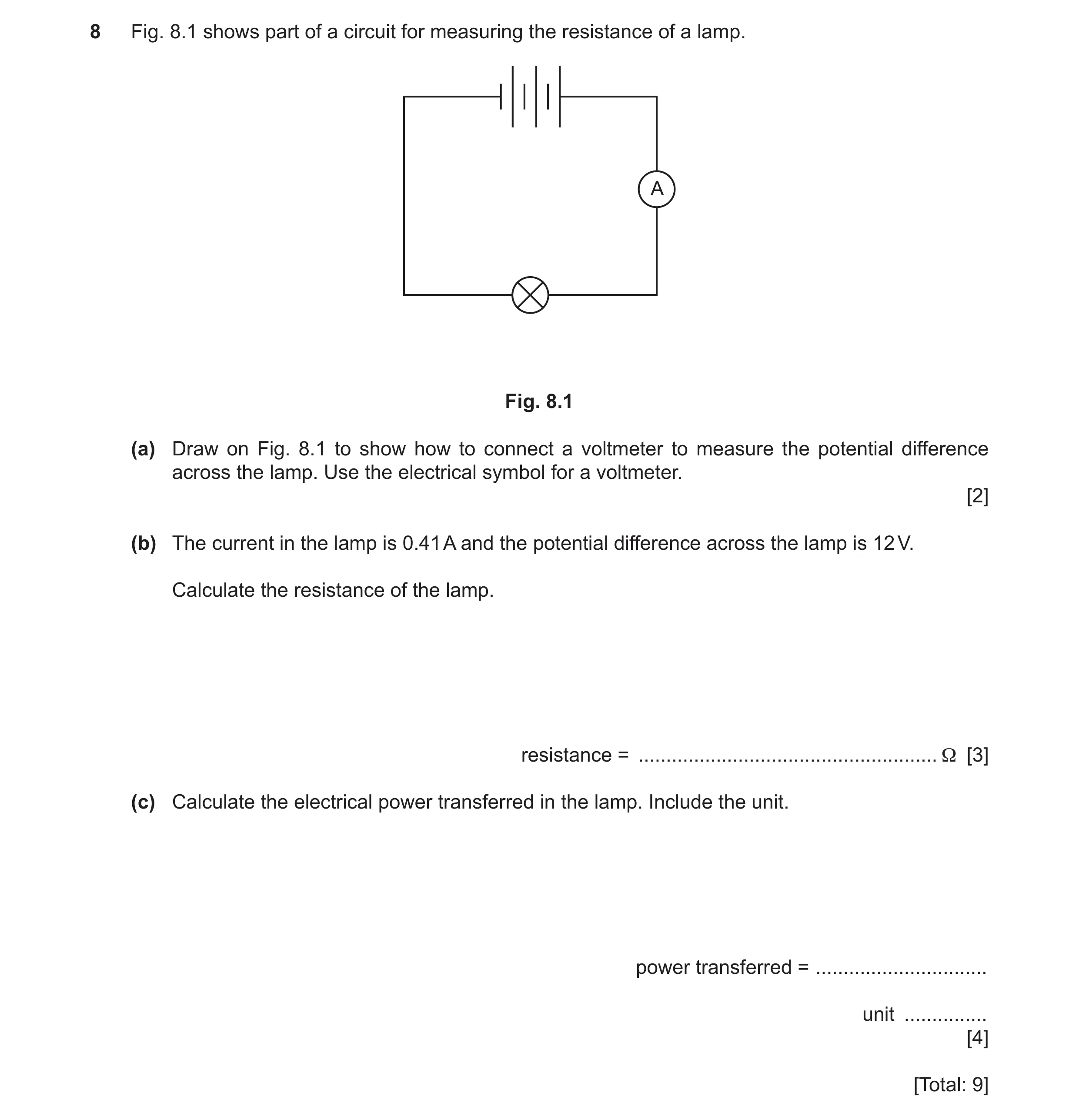
8 Fig. 8.1 shows part of a circuit for measuring the resistance of a lamp. A Fig. 8.1 (a) Draw on Fig. 8.1 to show how to connect a voltmeter to measure the potential difference across the lamp. Use the electrical symbol for a voltmeter. [2] (b) The current in the lamp is 0.41 A and the potential difference across the lamp is 12 V. Calculate the resistance of the lamp. resistance = … Ω [3] (c) Calculate the electrical power transferred in the lamp. Include the unit. power transferred = … unit … [4] [Total: 9]
9 marks
Mark scheme: 8(a) correct symbol B1 voltmeter in parallel with lamp B1 8(b) 29 () A3 12 0.41 (C2) (R =) V I OR V = I R in any form (C1) 8(c) 4.9 A3 0.41 12 OR 0.412 29 (C2) (P =) I V in any form OR (P =) I 2 R (C1) W B1
This question in 0625/33 May/June 2024
Q51 · A student tests various materials to determine whether they are electrical conductors or… 0625/31 Oct/Nov 2024
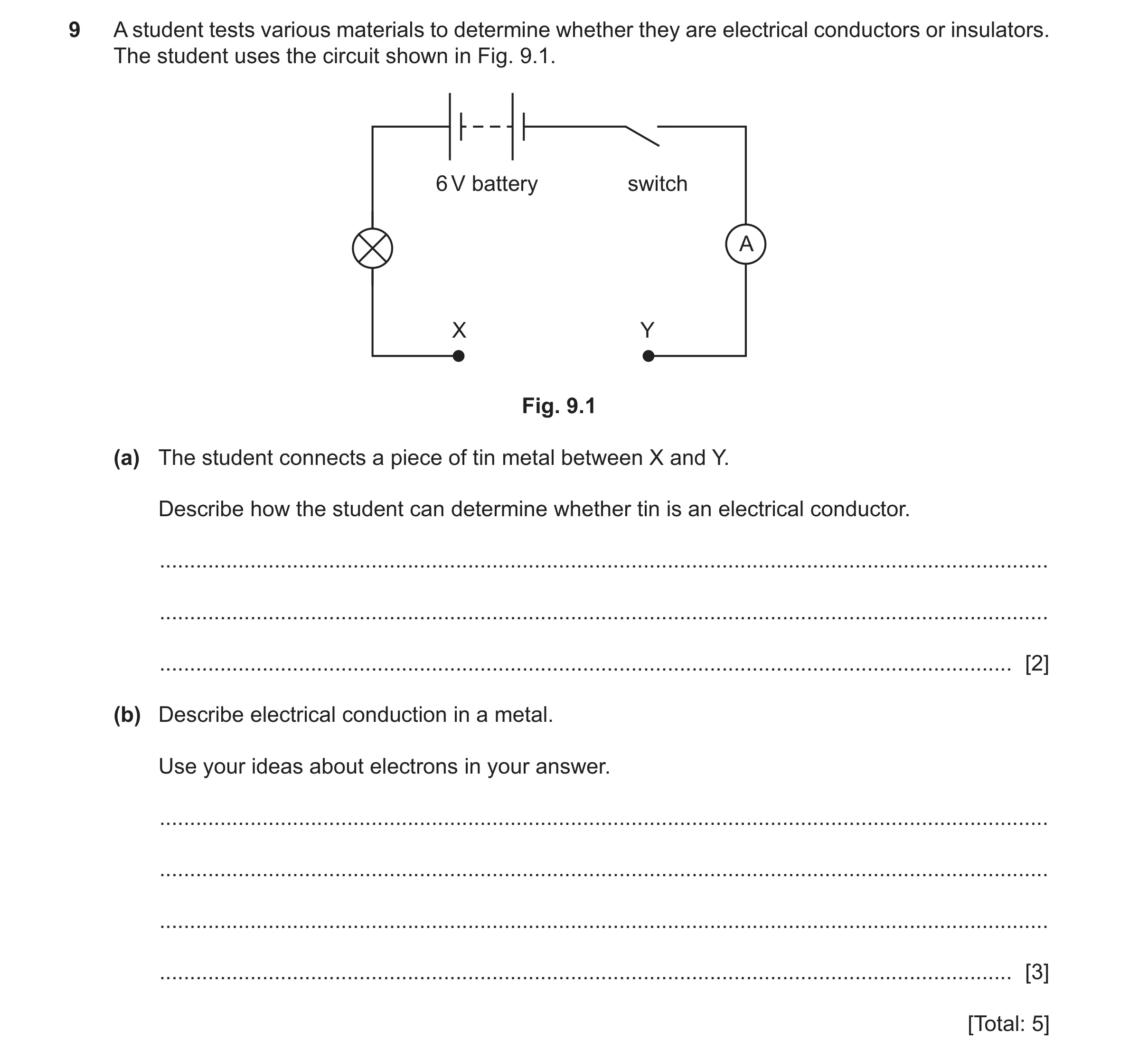
9 A student tests various materials to determine whether they are electrical conductors or insulators. The student uses the circuit shown in Fig. 9.1. 6 V battery switch A X Y Fig. 9.1 (a) The student connects a piece of tin metal between X and Y. Describe how the student can determine whether tin is an electrical conductor. … … … [2] (b) Describe electrical conduction in a metal. Use your ideas about electrons in your answer. … … … … [3] [Total: 5]
5 marks
Mark scheme: 9(a) either: B2 close switch (see if) lamp lights OR reading on ammeter OR lamp lights OR reading on ammeter (so material is (a)) conductor OR lamp lights OR reading on ammeter (so must have electric) current in tin 9(b) mention of free OR de-localised electrons (in the metal) B1 able to move from one atom / ion / particle to another B1 when p.d. OR voltage (applied across the metal / material) B1
This question in 0625/31 Oct/Nov 2024
Q52 · A student connects a circuit with two lamps and three switches, S1, S2 and S3, as shown… 0625/33 Oct/Nov 2024
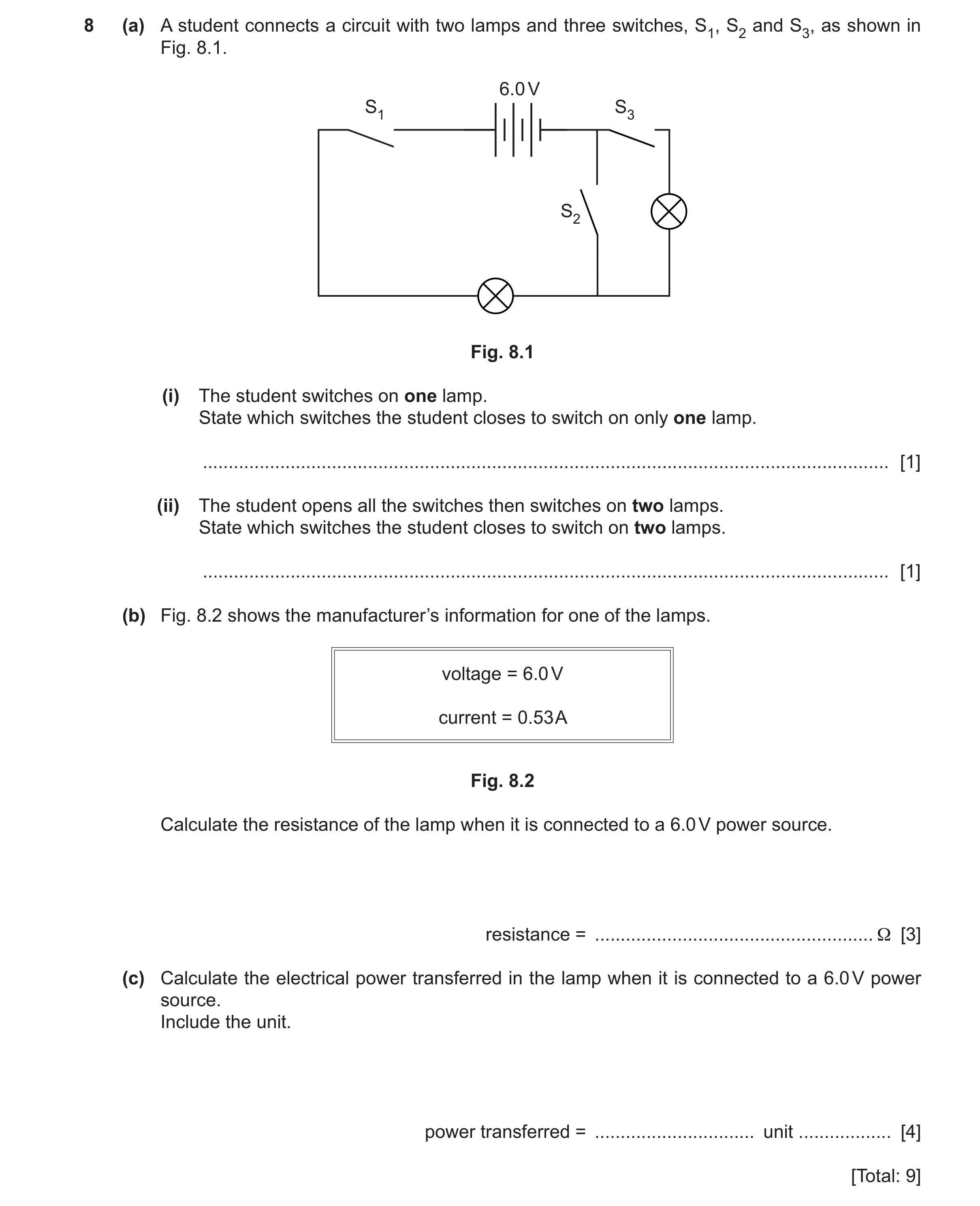
8 (a) A student connects a circuit with two lamps and three switches, S1, S2 and S3, as shown in Fig. 8.1. 6.0 V S1 S3 S2 Fig. 8.1 (i) The student switches on one lamp. State which switches the student closes to switch on only one lamp. … [1] (ii) The student opens all the switches then switches on two lamps. State which switches the student closes to switch on two lamps. … [1] (b) Fig. 8.2 shows the manufacturer’s information for one of the lamps. voltage = 6.0 V current = 0.53 A Fig. 8.2 Calculate the resistance of the lamp when it is connected to a 6.0 V power source. resistance = … Ω [3] (c) Calculate the electrical power transferred in the lamp when it is connected to a 6.0 V power source. Include the unit. power transferred = … unit … [4] [Total: 9]
9 marks
Mark scheme: 8(a)(i) Switch S1 AND Switch S2 B1 8(a)(ii) Switch S1 AND Switch S3 B1 8(b) 11() A3 6(.0) 0.53 (C2) V = I R OR (R =) V I (C1) 8(c) 3.2 A3 0.53 x 6(.0) (C2) (P =) I V (C1) W B1
This question in 0625/33 Oct/Nov 2024
Q53 · A student set up the electrical circuit that is shown in Fig 0625/32 Feb/March 2025
9 A student set up the electrical circuit that is shown in Fig. 9.1. switch ammeter metal wire battery lamp voltmeter variable resistor Fig. 9.1 (a) Fig. 9.2 shows part of the circuit diagram for the circuit in Fig. 9.1. A battery switch ammeter Fig. 9.2 Complete the circuit diagram in Fig. 9.2 to represent the circuit in Fig. 9.1. Use standard circuit symbols. [4] (b) The potential difference (p.d.) across the lamp is 11 V and the current in the lamp is 0.44 A. Calculate the resistance of the lamp. resistance = … Ω [3] (c) The student moves the sliding contact from position A to position B, as shown in Fig. 9.3. metal bar sliding contact in position A connection to lamp connection to battery coil of resistance wire metal bar sliding contact in position B connection to lamp connection to battery coil of resistance wire Fig. 9.3 State and explain any effect on the current in the circuit when the sliding contact is moved from position A to position B. … … … … [2] [Total: 9]
9 marks
Mark scheme: 9(a) correct symbol for: B1 voltmeter lamp B1 variable resistor B1 lamp and variable resistor connected in series circuit AND B1 voltmeter in parallel with lamp 9(b) 25 () A3 11 ÷ 0.44 (C2) (R =) V ÷ I or V = I R or in any form (C1) 9(c) current increases B1 (because) resistance (of variable resistor) decreases OR there is less resistance wire (in the circuit / for current to move B1 through)
This question in 0625/32 Feb/March 2025
Q54 · The circuit diagram for a 16 Ω resistor and an 8.0 Ω resistor connected to a 6.0 V battery 0625/31 May/June 2025
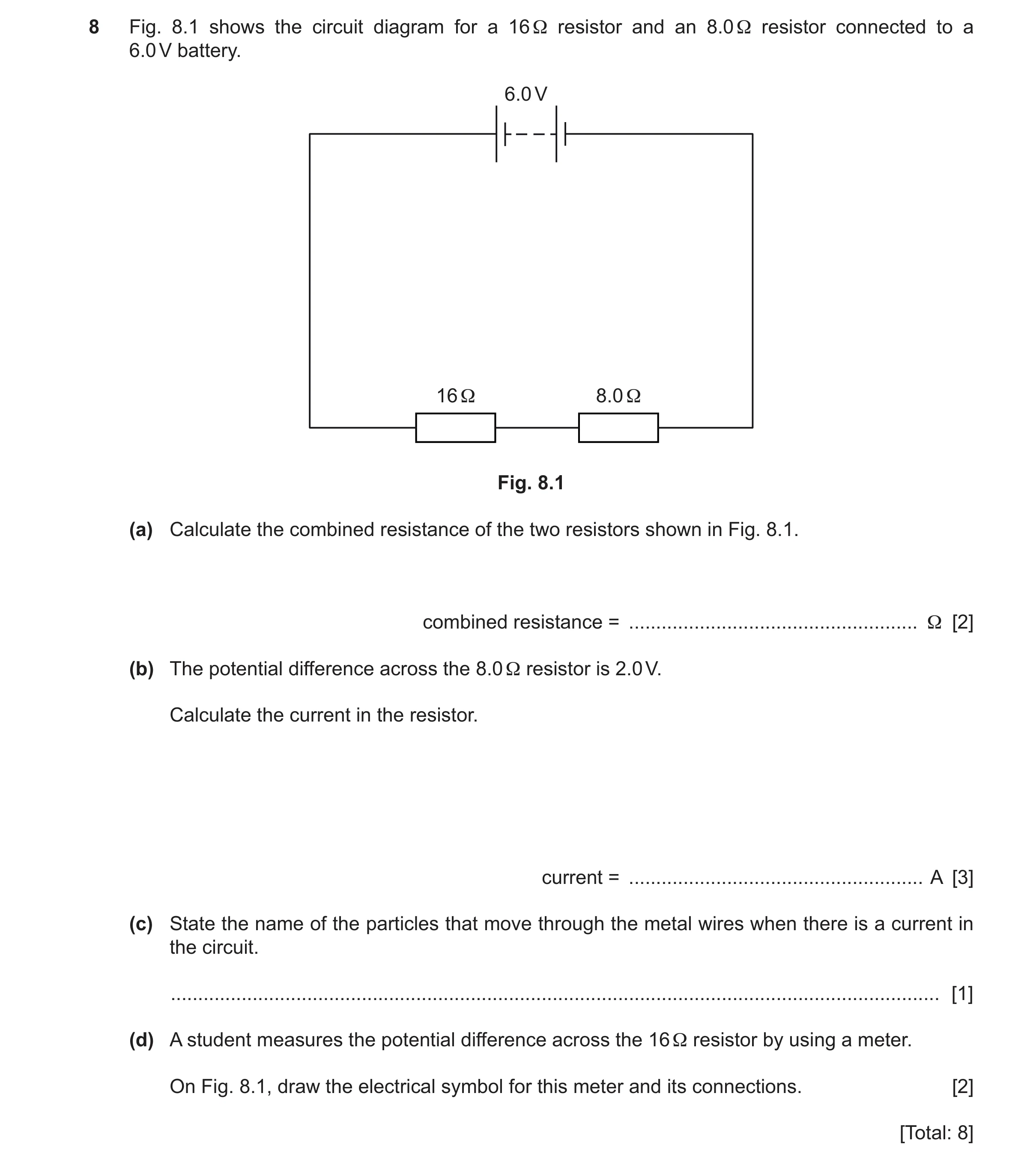
8 Fig. 8.1 shows the circuit diagram for a 16 Ω resistor and an 8.0 Ω resistor connected to a 6.0 V battery. 6.0 V 16 Ω 8.0 Ω Fig. 8.1 (a) Calculate the combined resistance of the two resistors shown in Fig. 8.1. combined resistance = … Ω [2] (b) The potential difference across the 8.0 Ω resistor is 2.0 V. Calculate the current in the resistor. current = … A [3] (c) State the name of the particles that move through the metal wires when there is a current in the circuit. … [1] (d) A student measures the potential difference across the 16 Ω resistor by using a meter. On Fig. 8.1, draw the electrical symbol for this meter and its connections. [2] [Total: 8]
8 marks
Mark scheme: 8(a) 24 () A2 (combined resistance =) R1 + R2 OR 16 + 8(.0) C1 8(b) (I =) 0.25 (A) A3 (I =) 2(.0) ÷ 8(.0) C2 V = IR in any form OR (I =) V ÷ R C1 8(c) electrons B1 8(d) voltmeter correctly connected across 16 resistor A2 correct voltmeter symbol in wrong place OR incorrect meter connected across 16 resistor C1
This question in 0625/31 May/June 2025
Question 55 0625/31 May/June 2025
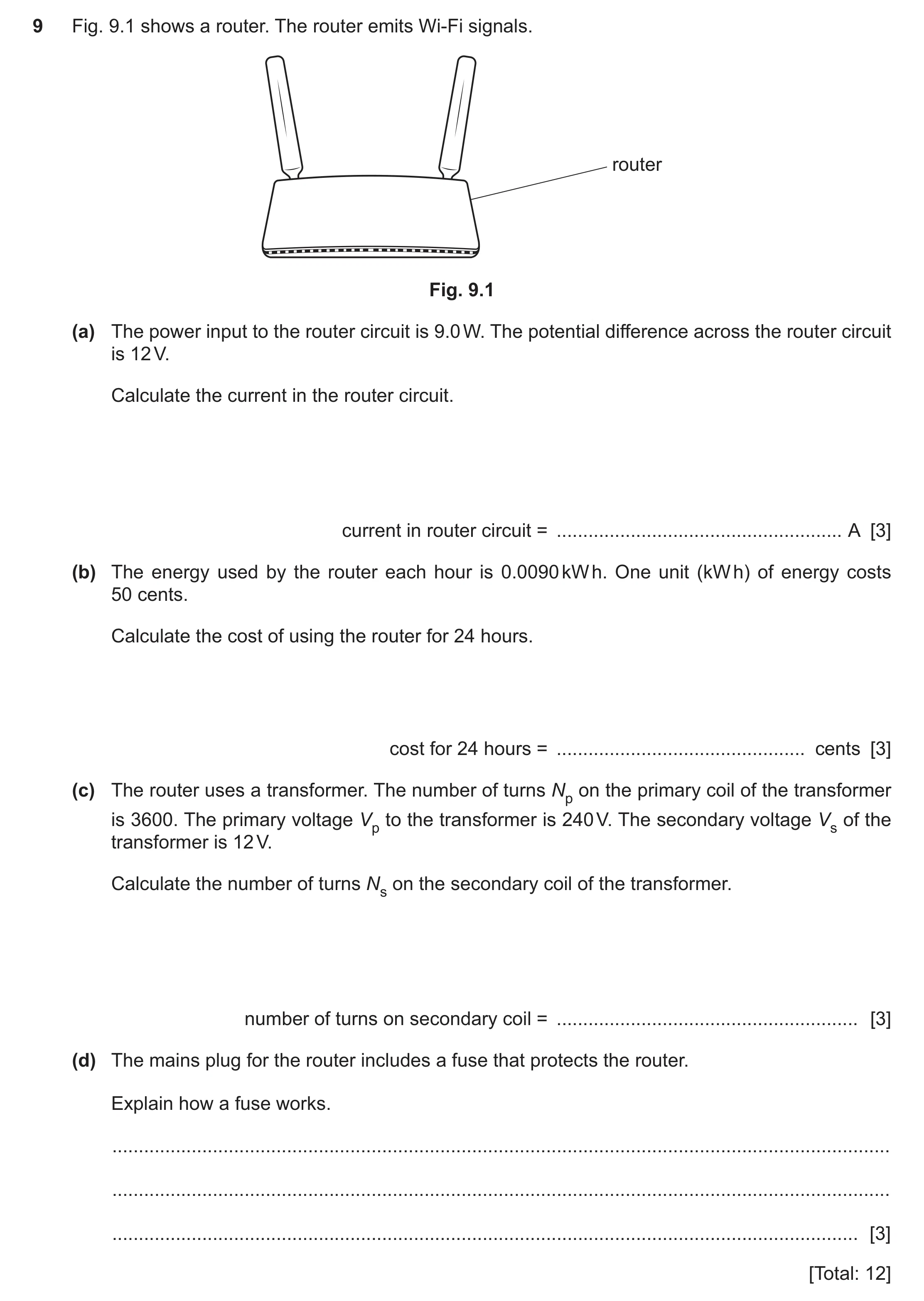
9 Fig. 9.1 shows a router. The router emits Wi-Fi signals. router Fig. 9.1 (a) The power input to the router circuit is 9.0 W. The potential difference across the router circuit is 12 V. Calculate the current in the router circuit. current in router circuit = … A [3] (b) The energy used by the router each hour is 0.0090 kW h. One unit (kW h) of energy costs 50 cents. Calculate the cost of using the router for 24 hours. cost for 24 hours = … cents [3] (c) The router uses a transformer. The number of turns Np on the primary coil of the transformer is 3600. The primary voltage Vp to the transformer is 240 V. The secondary voltage Vs of the transformer is 12 V. Calculate the number of turns Ns on the secondary coil of the transformer. number of turns on secondary coil = … [3] (d) The mains plug for the router includes a fuse that protects the router. Explain how a fuse works. … … … [3] [Total: 12]
12 marks
Mark scheme: 9(a) (current =) 0.75 (A) A3 (current =) 9 ÷ 12 C2 power = IV OR (I =) P ÷ V C1 9(b) 11 (cents) A3 (cost =) 0.009(0) 24 50 OR 0.216 50 OR 0.009 1200 OR 0.45 24 C2 (cost =) (energy in) kW h (number of) hours cost (of one unit) C1 9(c) (Ns =) 180 A3 (Ns =) {12 3600} ÷ 240 OR (Ns =) 3600 ÷ 20 OR 240 ÷ 12 = 3600 ÷ Ns C2 Vs ÷ Vp = Ns ÷ Np C1 9(d) any three from: B3 • idea of large current (in fuse or any part of circuit) • (large current causes) heating in fuse • idea that fuse is made from low melting point wire • fuse / (fuse) wire melts • (and) idea disconnects / isolates (router / wires / circuit) from supply / mains
This question in 0625/31 May/June 2025
Q56 · A mains-powered electric fan heater fixed on a bathroom wall 0625/32 May/June 2025
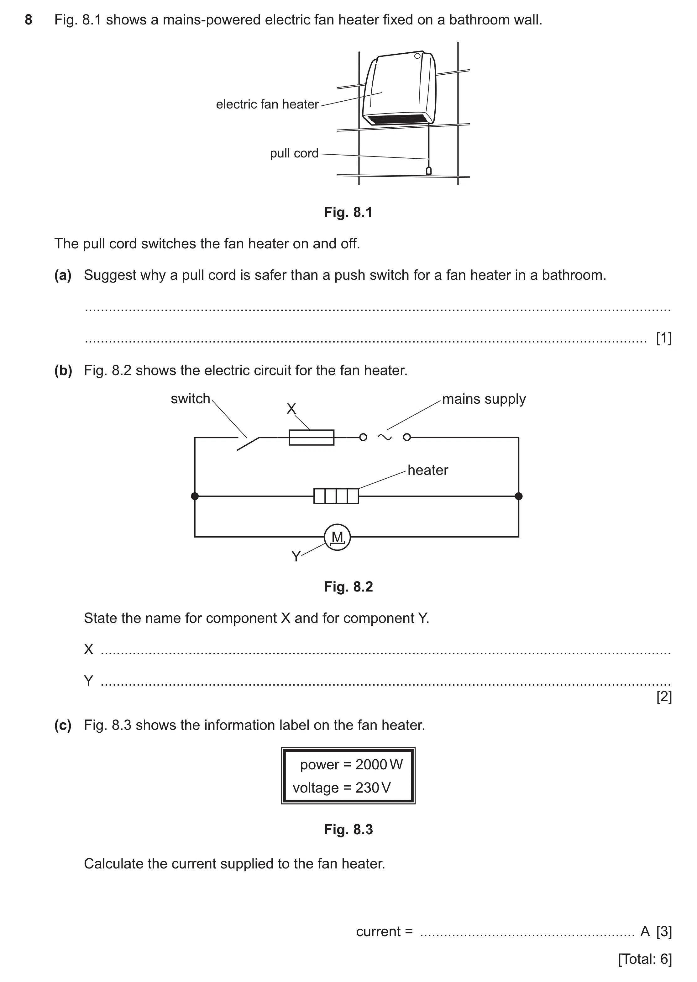
8 Fig. 8.1 shows a mains-powered electric fan heater fixed on a bathroom wall. electric fan heater pull cord Fig. 8.1 The pull cord switches the fan heater on and off. (a) Suggest why a pull cord is safer than a push switch for a fan heater in a bathroom. … … [1] (b) Fig. 8.2 shows the electric circuit for the fan heater. switch mains supply X heater M Y Fig. 8.2 State the name for component X and for component Y. X … Y … [2] (c) Fig. 8.3 shows the information label on the fan heater. power = 2000 W voltage = 230 V Fig. 8.3 Calculate the current supplied to the fan heater. current = … A [3] [Total: 6]
6 marks
Mark scheme: 8(a) reduces risk of electric shock / electrocution OR reference to damp conditions B1 8(b) symbol X: fuse B1 symbol Y: motor B1 8(c) 8.7 (A) A3 2000 ÷ 230 C2 power = current voltage OR (current =) power ÷ voltage C1
This question in 0625/32 May/June 2025
Q57 · A mains-powered electric fan heater fixed on a bathroom wall 0625/33 May/June 2025
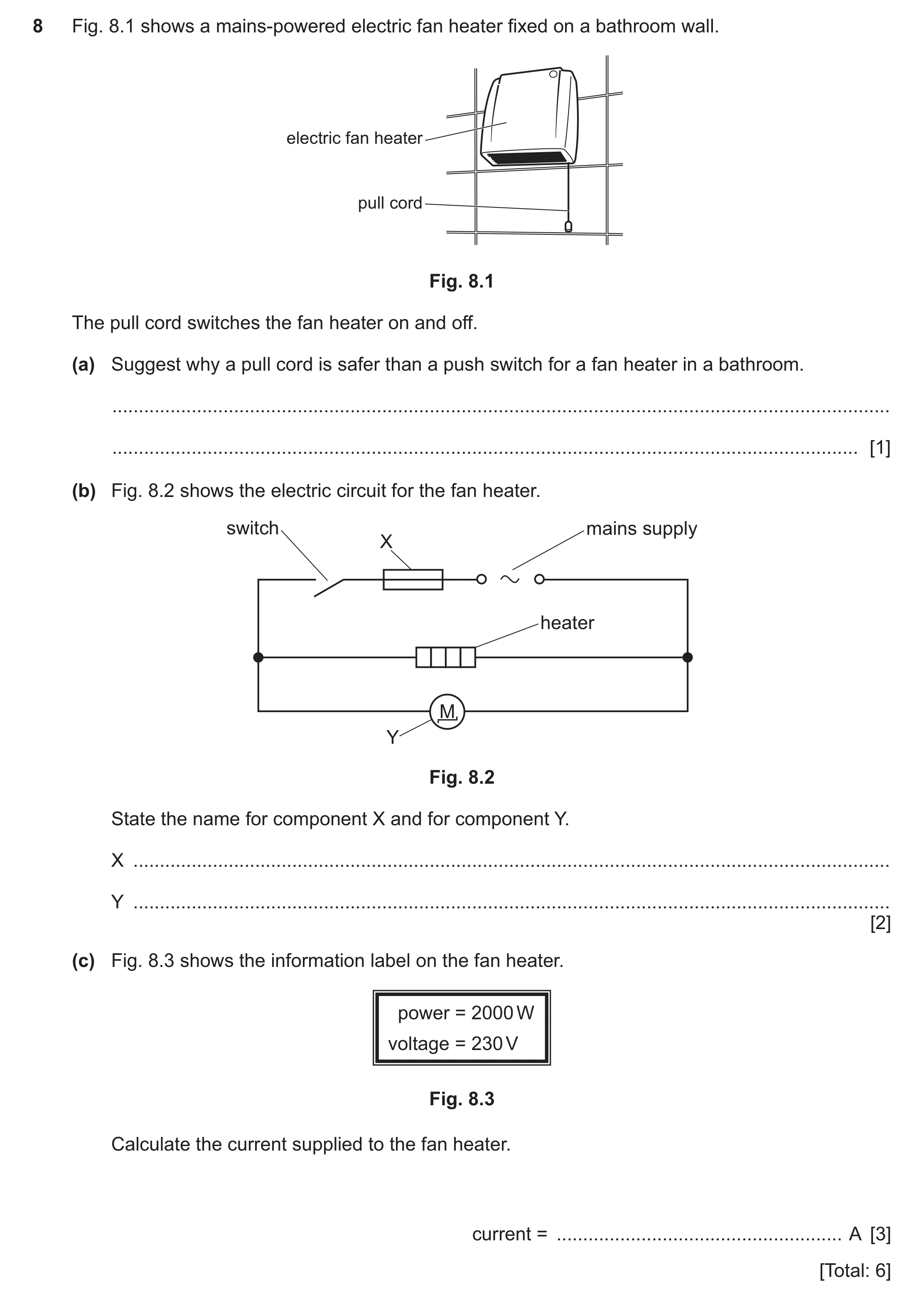
8 Fig. 8.1 shows a mains-powered electric fan heater fixed on a bathroom wall. electric fan heater pull cord Fig. 8.1 The pull cord switches the fan heater on and off. (a) Suggest why a pull cord is safer than a push switch for a fan heater in a bathroom. … … [1] (b) Fig. 8.2 shows the electric circuit for the fan heater. switch mains supply X heater M Y Fig. 8.2 State the name for component X and for component Y. X … Y … [2] (c) Fig. 8.3 shows the information label on the fan heater. power = 2000 W voltage = 230 V Fig. 8.3 Calculate the current supplied to the fan heater. current = … A [3] [Total: 6]
6 marks
Mark scheme: 8(a) reduces risk of electric shock / electrocution OR reference to damp conditions B1 8(b) symbol X: fuse B1 symbol Y: motor B1 8(c) 8.7 (A) A3 2000 ÷ 230 C2 power = current voltage OR (current =) power ÷ voltage C1
This question in 0625/33 May/June 2025
Q58 · A student has six metal bars 0625/31 Oct/Nov 2025
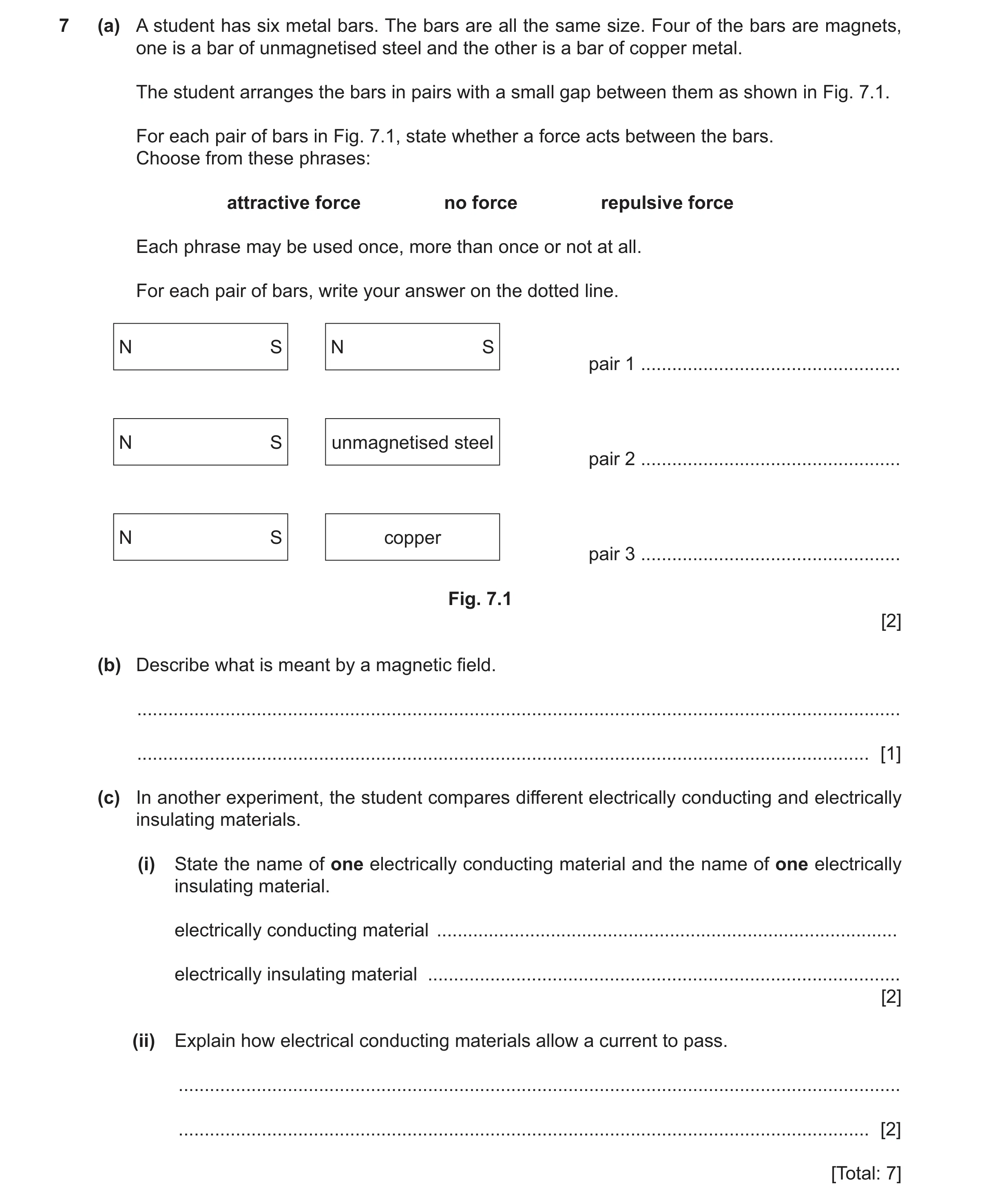
7 (a) A student has six metal bars. The bars are all the same size. Four of the bars are magnets, one is a bar of unmagnetised steel and the other is a bar of copper metal. The student arranges the bars in pairs with a small gap between them as shown in Fig. 7.1. For each pair of bars in Fig. 7.1, state whether a force acts between the bars. Choose from these phrases: attractive force no force repulsive force Each phrase may be used once, more than once or not at all. For each pair of bars, write your answer on the dotted line. N S N S pair 1 … N S unmagnetised steel pair 2 … N S copper pair 3 … Fig. 7.1 [2] (b) Describe what is meant by a magnetic field. … … [1] (c) In another experiment, the student compares different electrically conducting and electrically insulating materials. (i) State the name of one electrically conducting material and the name of one electrically insulating material. electrically conducting material … electrically insulating material … [2] (ii) Explain how electrical conducting materials allow a current to pass. … … [2] [Total: 7]
7 marks
Mark scheme: 7(a) (pair 1) attractive force B2 (pair 2) attractive force (pair 3) no force 7(b) region/area in which a magnet(ic pole) experiences a force B1 OR region/area in which a magnetic material experiences a force 7(c)(i) name of an electrically conducting material B1 name of an electrically insulating material B1 7(c)(ii) idea (they have) electrons/charges/ions M1 (that) can move (from ion to ion OR freely in conducting materials) A1
This question in 0625/31 Oct/Nov 2025
Q59 · A television uses many electrical components 0625/31 Oct/Nov 2025
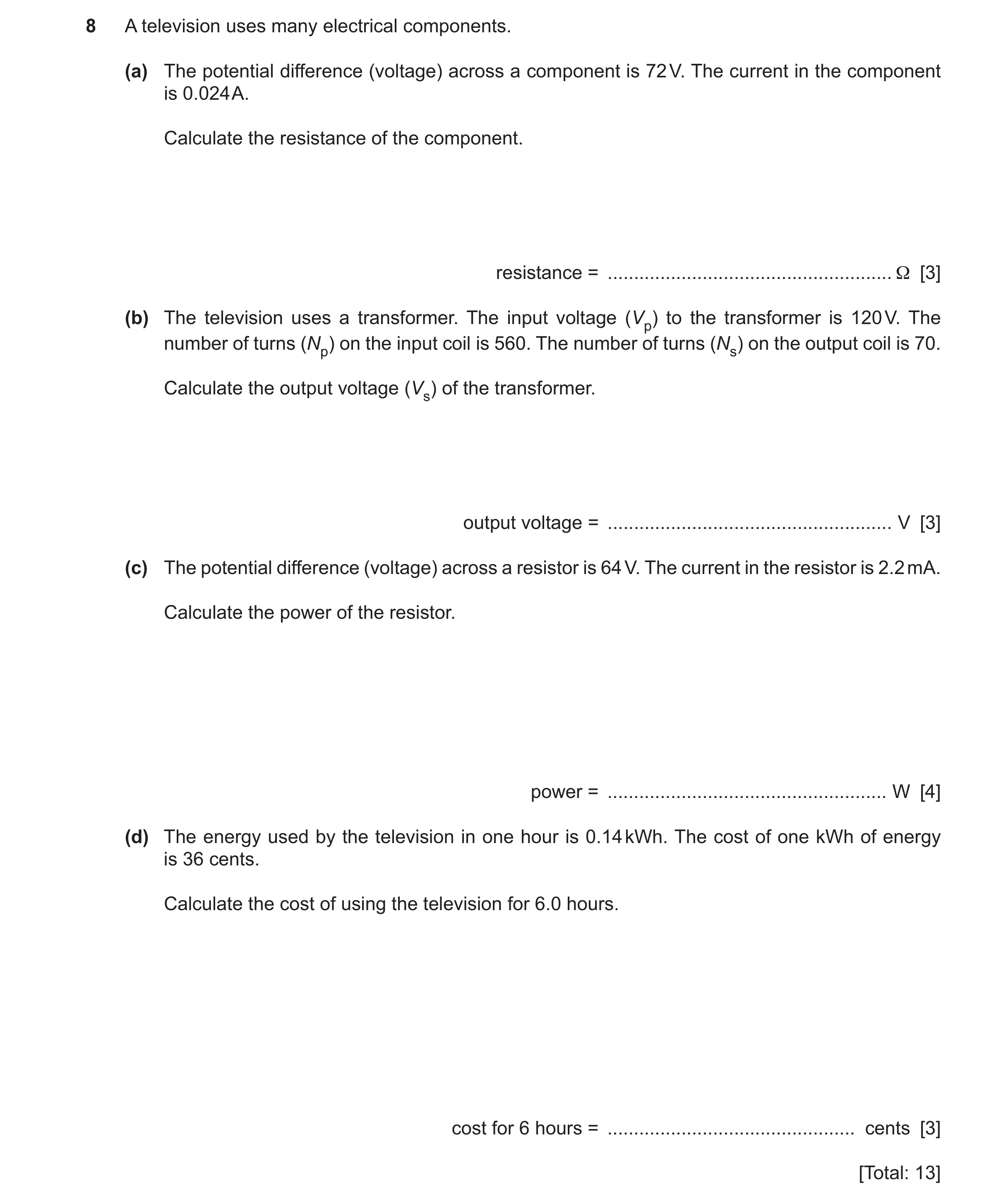
8 A television uses many electrical components. (a) The potential difference (voltage) across a component is 72 V. The current in the component is 0.024 A. Calculate the resistance of the component. resistance = … Ω [3] (b) The television uses a transformer. The input voltage (Vp) to the transformer is 120 V. The number of turns (Np) on the input coil is 560. The number of turns (Ns) on the output coil is 70. Calculate the output voltage (Vs) of the transformer. output voltage = … V [3] (c) The potential difference (voltage) across a resistor is 64 V. The current in the resistor is 2.2 mA. Calculate the power of the resistor. power = … W [4] (d) The energy used by the television in one hour is 0.14 kWh. The cost of one kWh of energy is 36 cents. Calculate the cost of using the television for 6.0 hours. cost for 6 hours = … cents [3] [Total: 13]
13 marks
Mark scheme: 8(a) 3000 () A3 72 / 0.024 (C2) V = IR OR (R = )V / I (C1) 8(b) (output voltage Vs =) 15 (V) A3 Vs / 120 = 70 / 560 OR (Vs =) (70 / 560) 120 (C2) Vs / Vp = Ns / Np in any form (C1) 8(c) (power = ) 0.14 (W) A4 (power = ) 2.2 10-3 64 (C3) (power = ) I V (C1) 2.2 (mA) = 0. 0022 (A) OR 2.2 x 10⁻³ (A) (C1) 8(d) 30 (cents) A3 (cost = ) 0.14 6(.0) 36 OR 0.84 36 OR 0.14 216 OR 5.04 6 (C2) (cost = ) (energy in) kW h (number of) hours cost (of one unit) (C1)
This question in 0625/31 Oct/Nov 2025
Q60 · A lamp connected in series with four 1.5 V cells and an ammeter 0625/32 Oct/Nov 2025
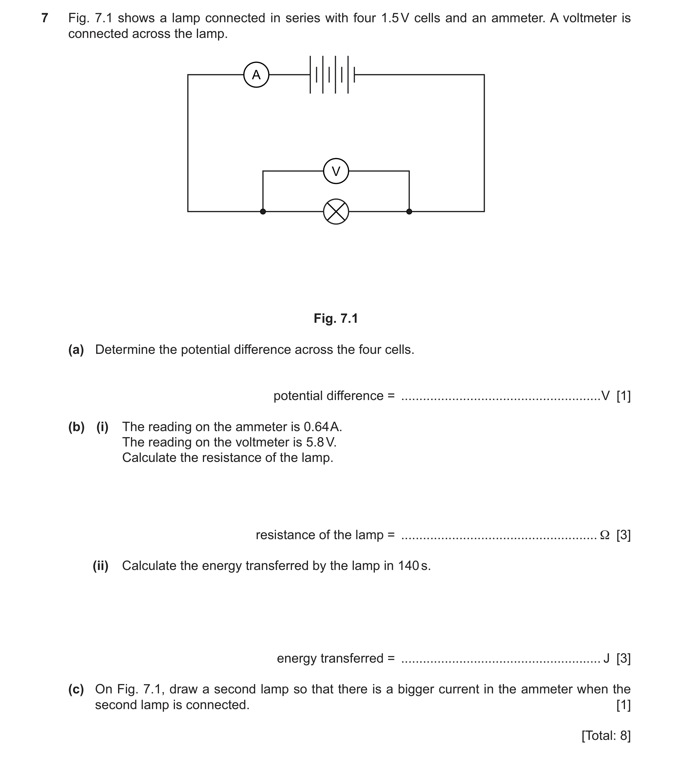
7 Fig. 7.1 shows a lamp connected in series with four 1.5 V cells and an ammeter. A voltmeter is connected across the lamp. A V Fig. 7.1 (a) Determine the potential difference across the four cells. potential difference = … V [1] (b) (i) The reading on the ammeter is 0.64 A. The reading on the voltmeter is 5.8 V. Calculate the resistance of the lamp. resistance of the lamp = … Ω [3] (ii) Calculate the energy transferred by the lamp in 140 s. energy transferred = … J [3] (c) On Fig. 7.1, draw a second lamp so that there is a bigger current in the ammeter when the second lamp is connected. [1] [Total: 8]
8 marks
Mark scheme: 7(a) 6(.0) (V) B1 7(b)(i) 9.1 () A3 5.8 ÷ 0.64 C2 (resistance =) potential difference ÷ current C1 7(b)(ii) 520 (J) A3 5.8 0.64 140 or 3.712 140 or 5.8 89.6 or 0.64 812 C2 (energy transferred =) potential difference current time C1 7(c) lamp in parallel with original lamp B1
This question in 0625/32 Oct/Nov 2025
Q61 · A student is making a torch 0625/33 Oct/Nov 2025
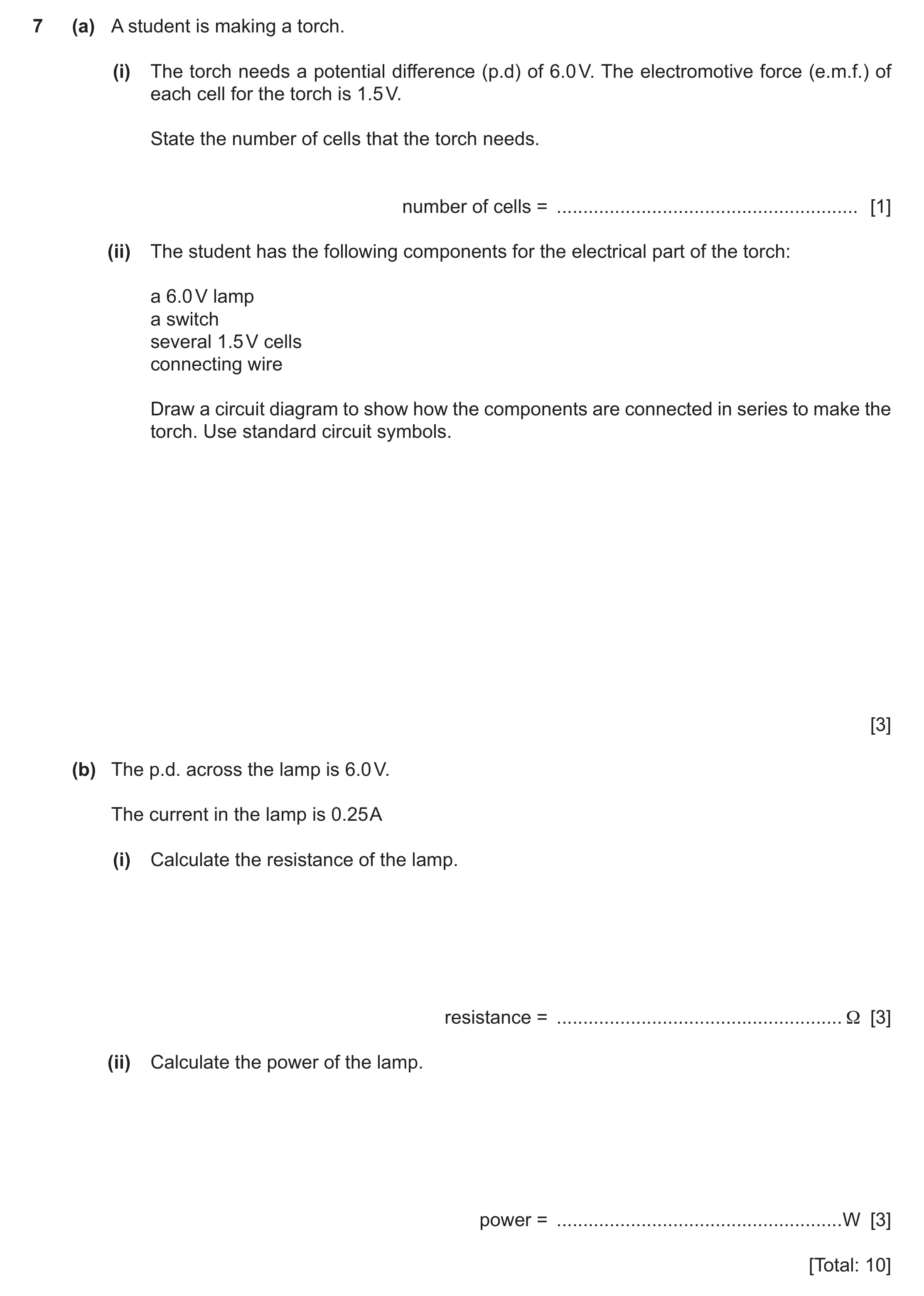
7 (a) A student is making a torch. (i) The torch needs a potential difference (p.d) of 6.0 V. The electromotive force (e.m.f.) of each cell for the torch is 1.5 V. State the number of cells that the torch needs. number of cells = … [1] (ii) The student has the following components for the electrical part of the torch: a 6.0 V lamp a switch several 1.5 V cells connecting wire Draw a circuit diagram to show how the components are connected in series to make the torch. Use standard circuit symbols. [3] (b) The p.d. across the lamp is 6.0 V. The current in the lamp is 0.25 A (i) Calculate the resistance of the lamp. resistance = … Ω [3] (ii) Calculate the power of the lamp. power = … W [3] [Total: 10]
10 marks
Mark scheme: 7(a)(i) 4 (cells) B1 7(a)(ii) three (cell (s) / battery, lamp and switch) circuit symbols correct A2 one or two (from cell(s) / battery, lamp and switch) circuit symbols correct C1 a complete circuit with cell (s), lamp and switch in series B1 7(b)(i) 24 () A3 6(.0) ÷ 0.25 C2 (resistance =) potential difference ÷ current C1 7(b)(ii) 1.5 (W) A3 6(.0) 0.25 C2 (power =) potential difference current C1
This question in 0625/33 Oct/Nov 2025
 1 / 69
 2 / 69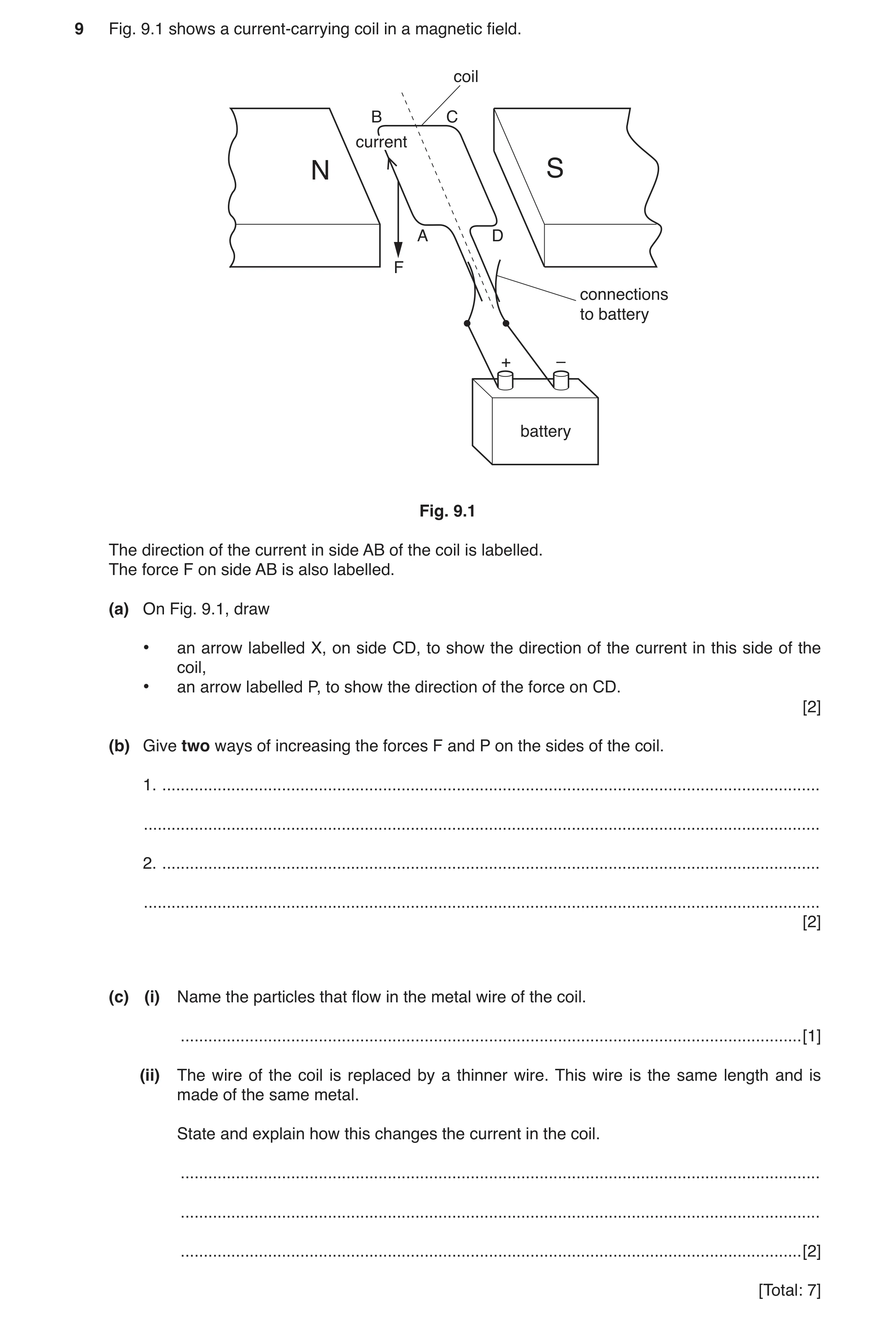
 4 / 69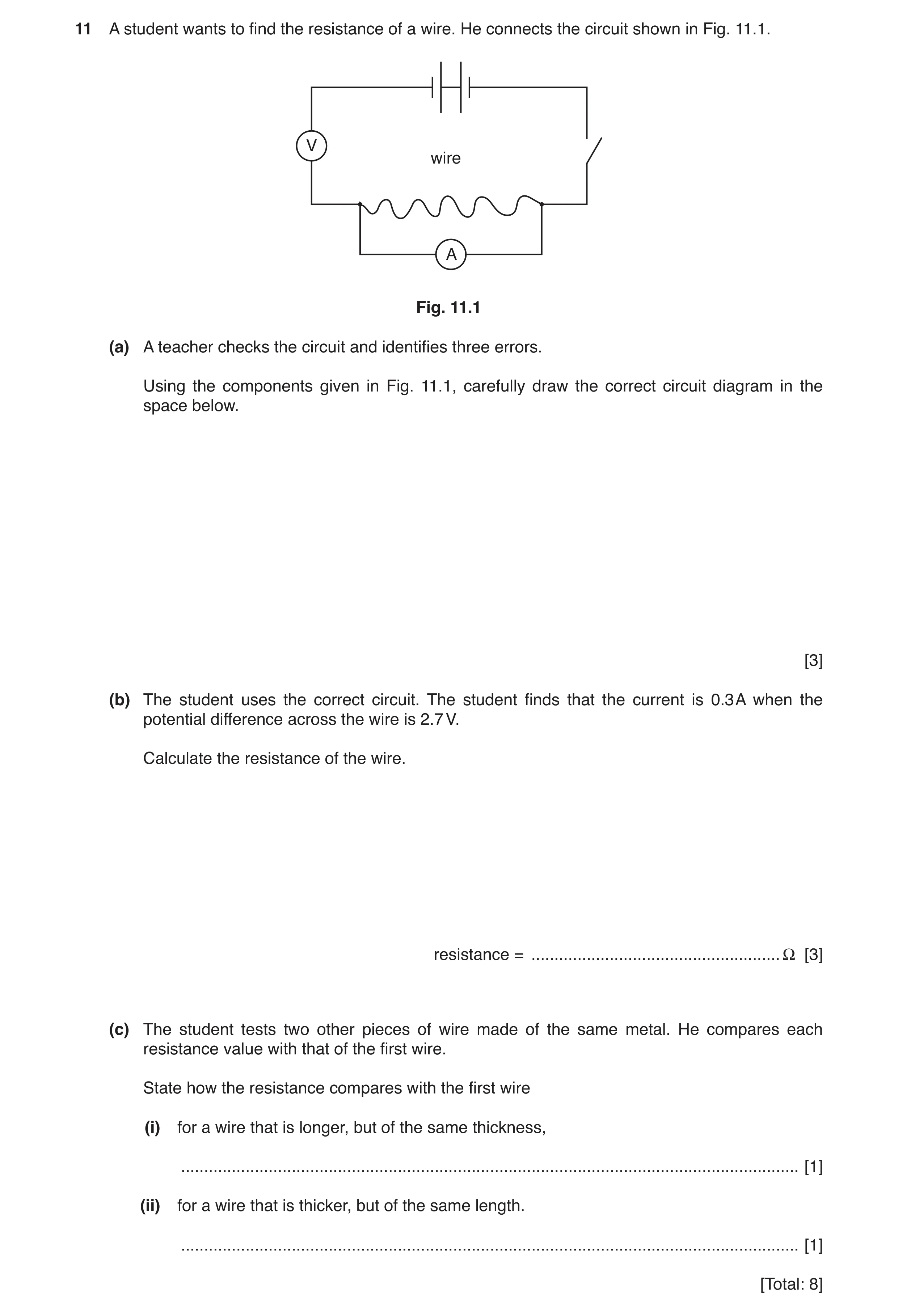
 7 / 69
 8 / 69
 9 / 69
 10 / 69
 11 / 69
 12 / 69
 13 / 69
 14 / 69
 15 / 69
 16 / 69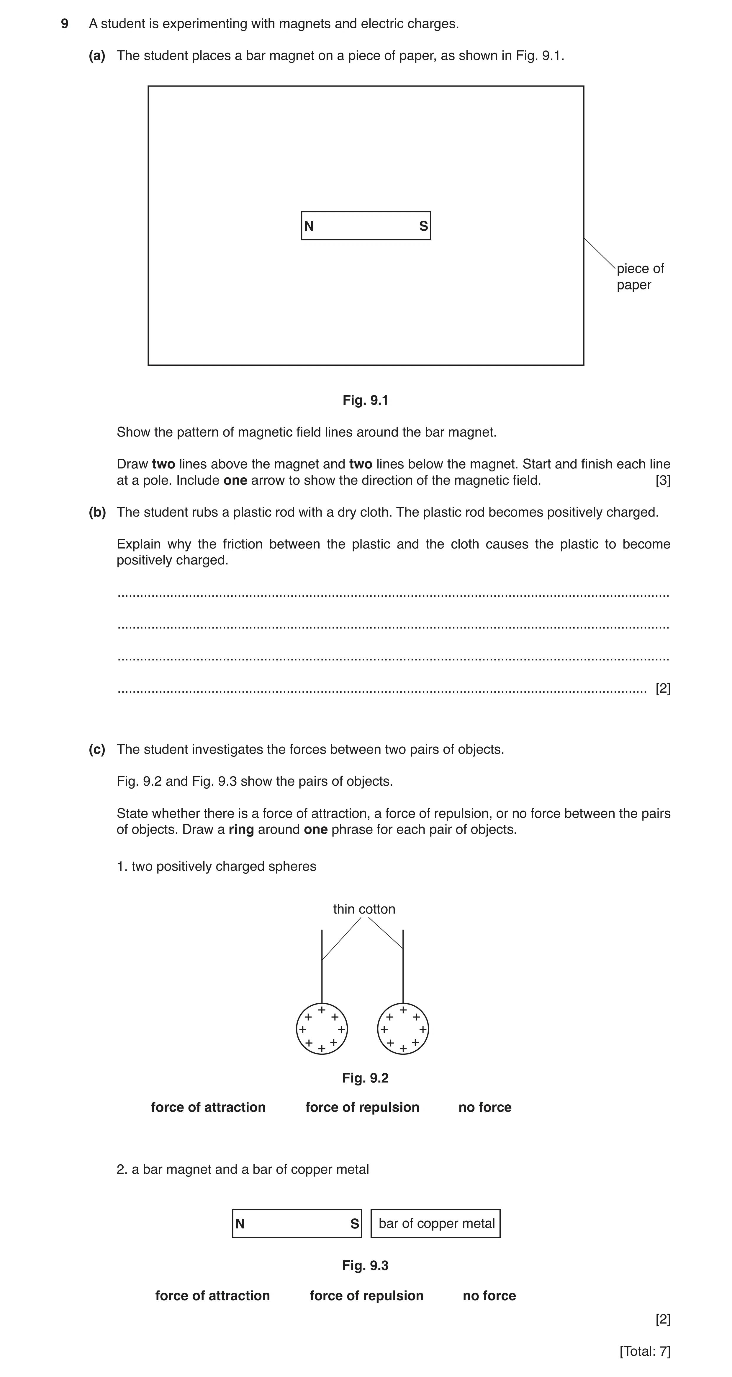
 19 / 69
 20 / 69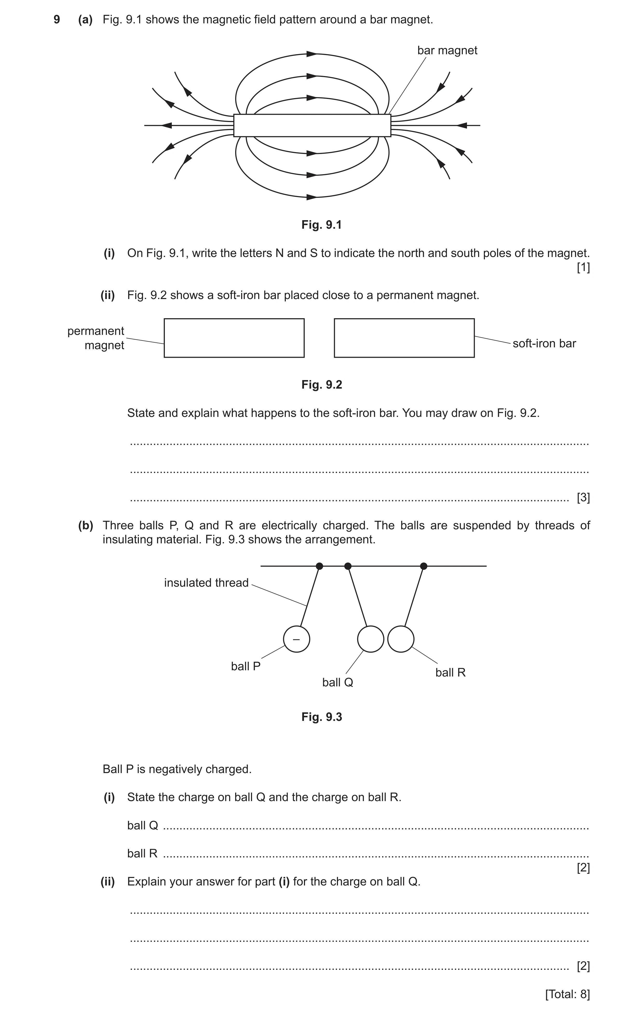
 22 / 69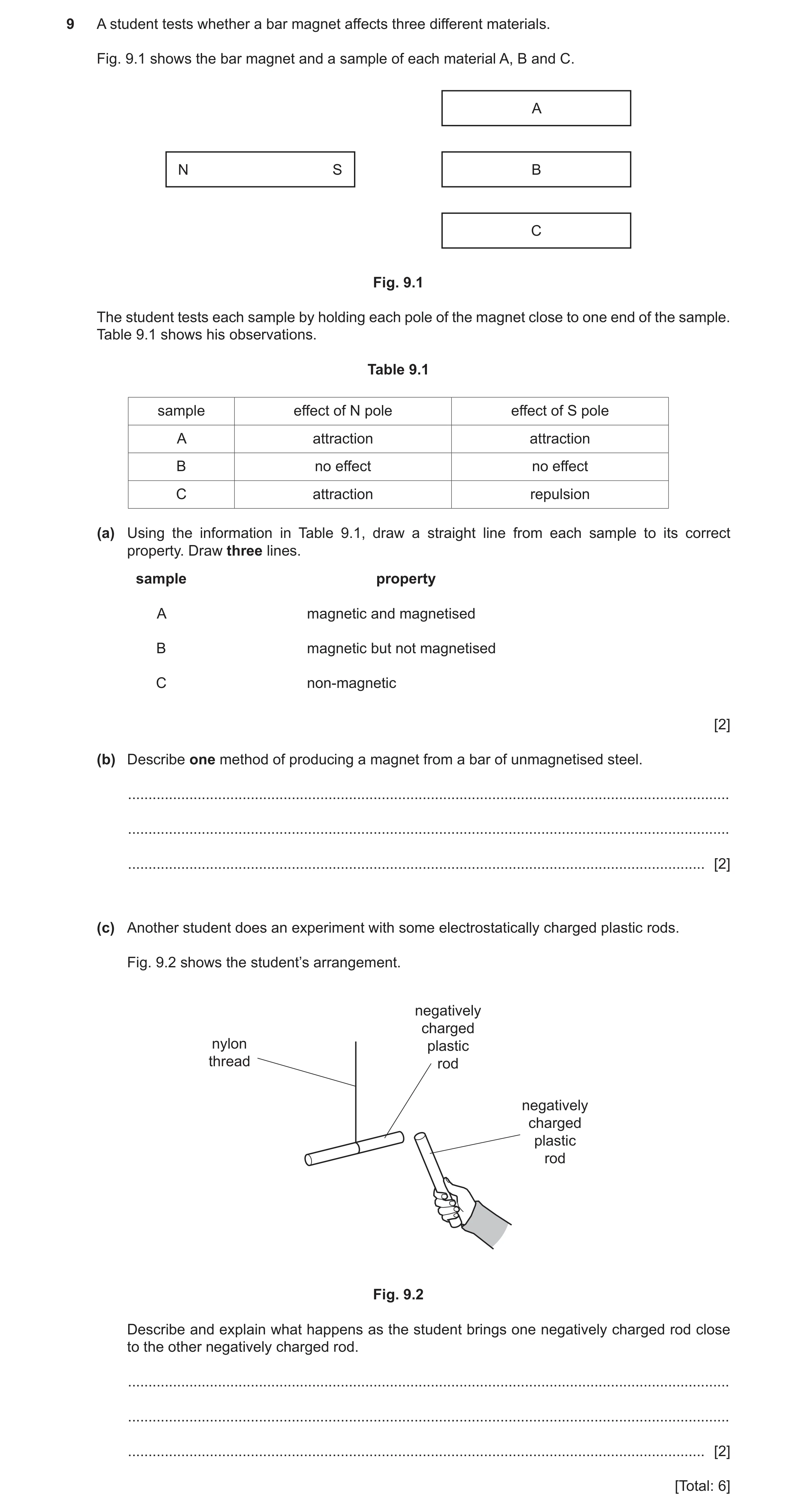
 25 / 69
 26 / 69
 27 / 69
 28 / 69
 29 / 69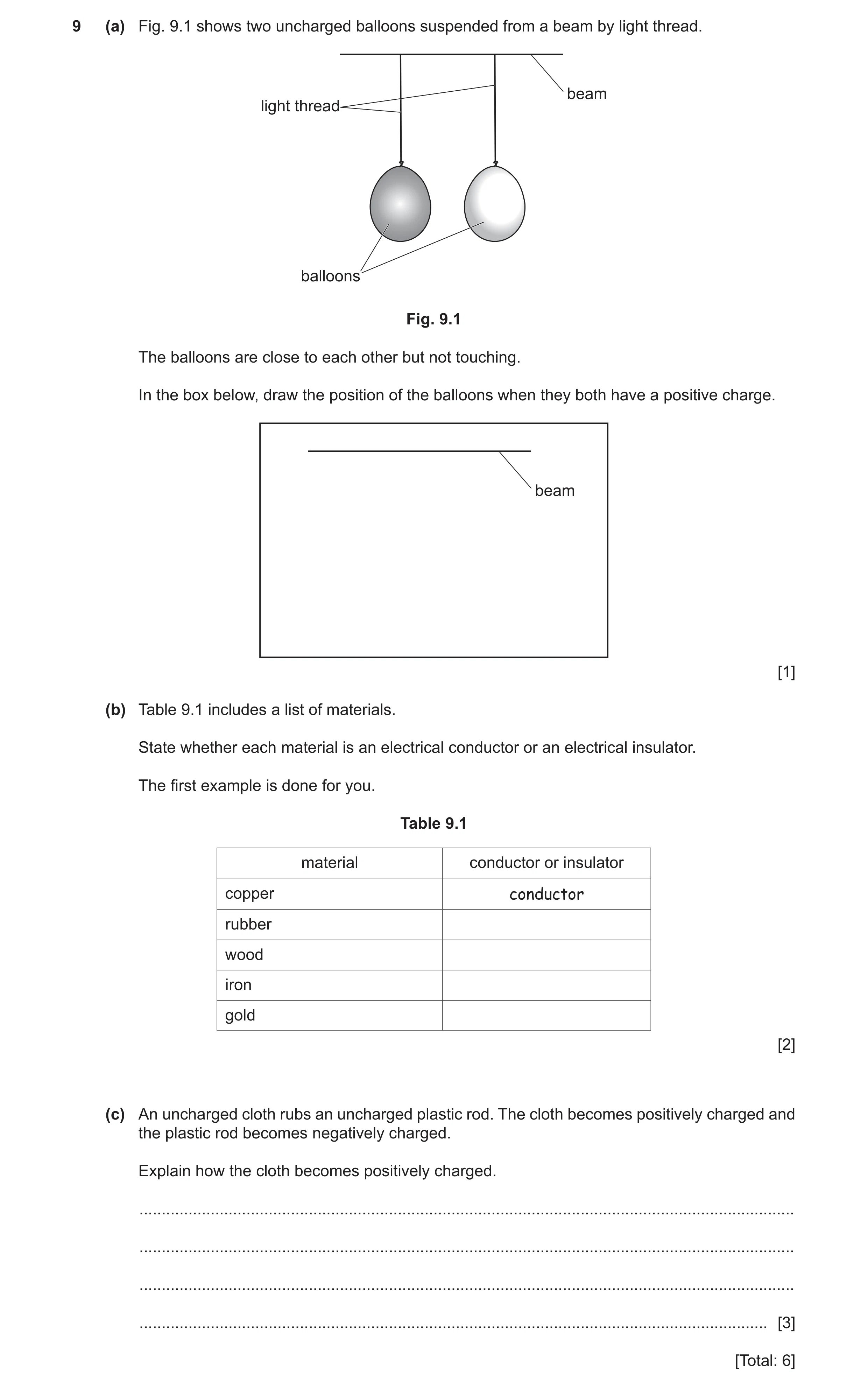
 32 / 69
 33 / 69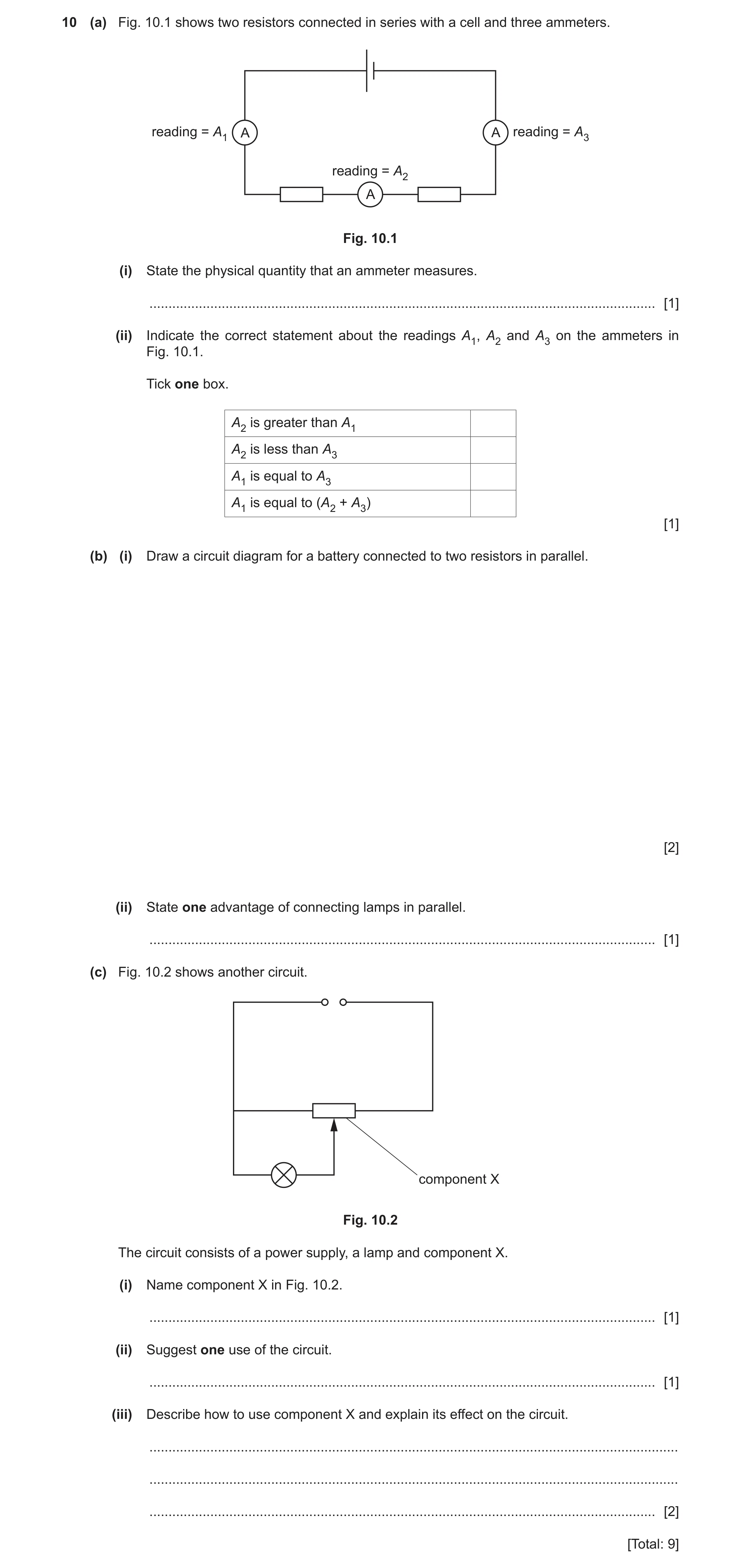
 36 / 69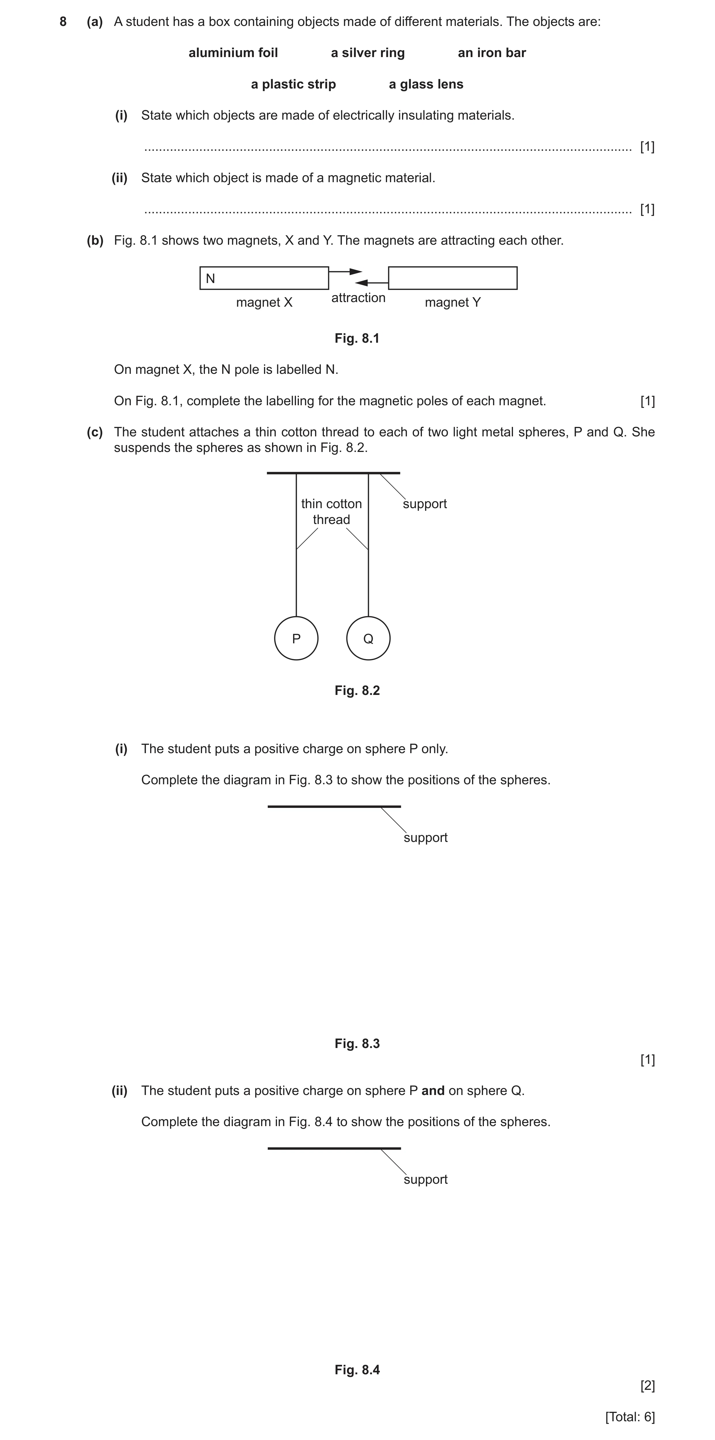
 39 / 69
 40 / 69
 41 / 69
 42 / 69
 43 / 69
 44 / 69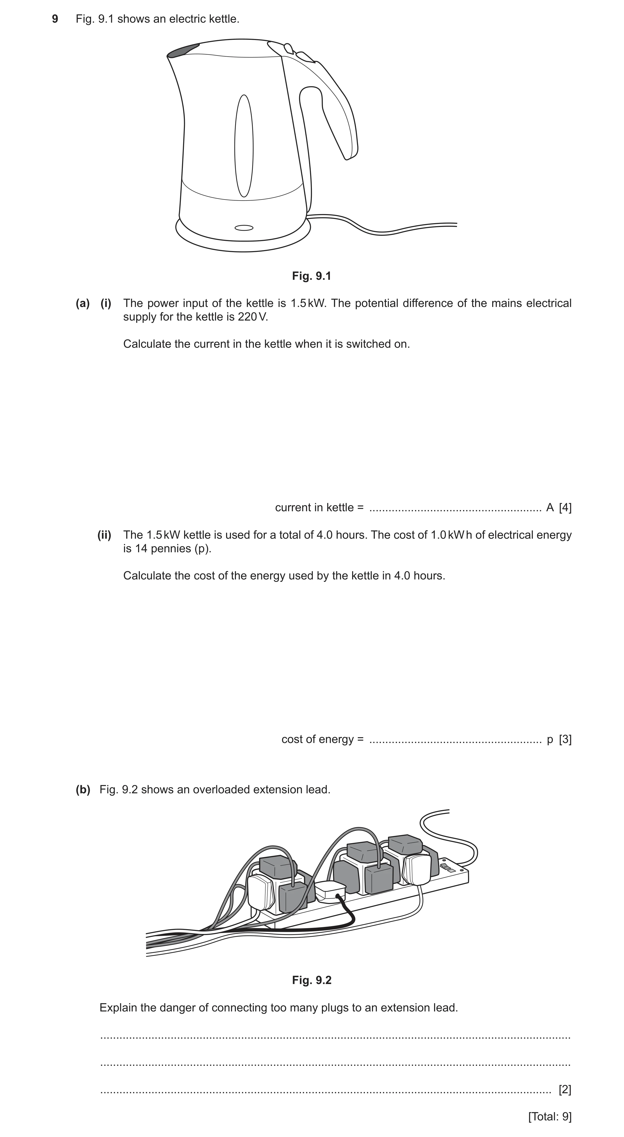
 46 / 69
 47 / 69
 48 / 69
 49 / 69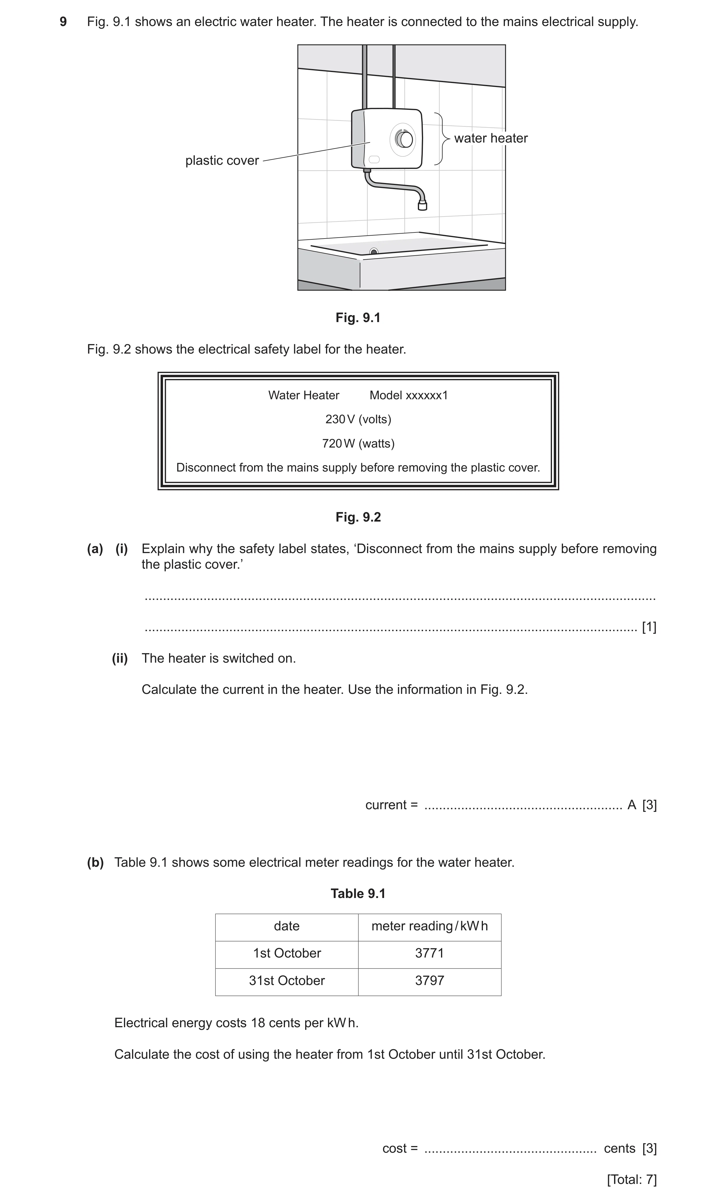
 52 / 69
 53 / 69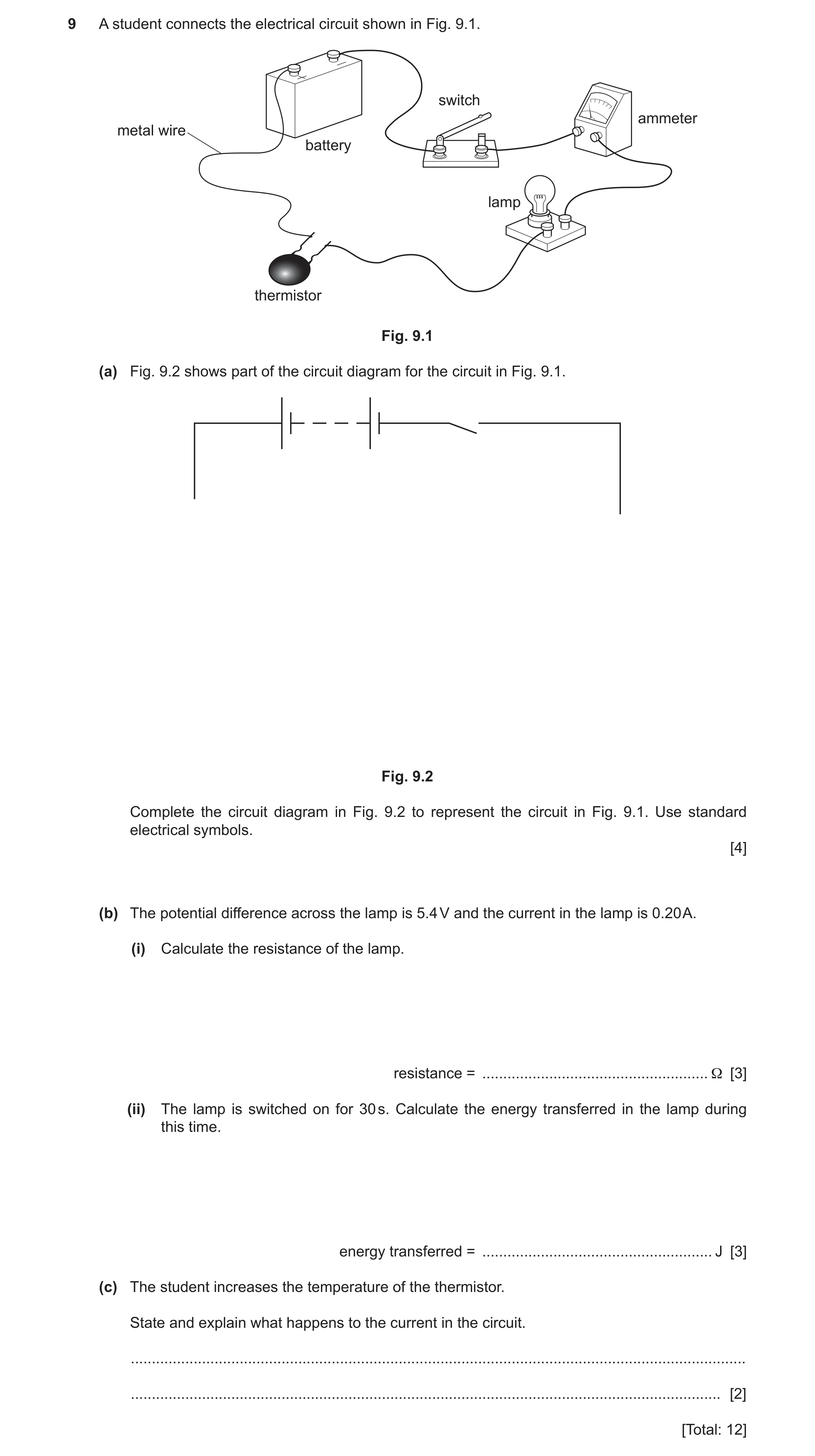
 55 / 69
 56 / 69
 57 / 69
 58 / 69
 59 / 69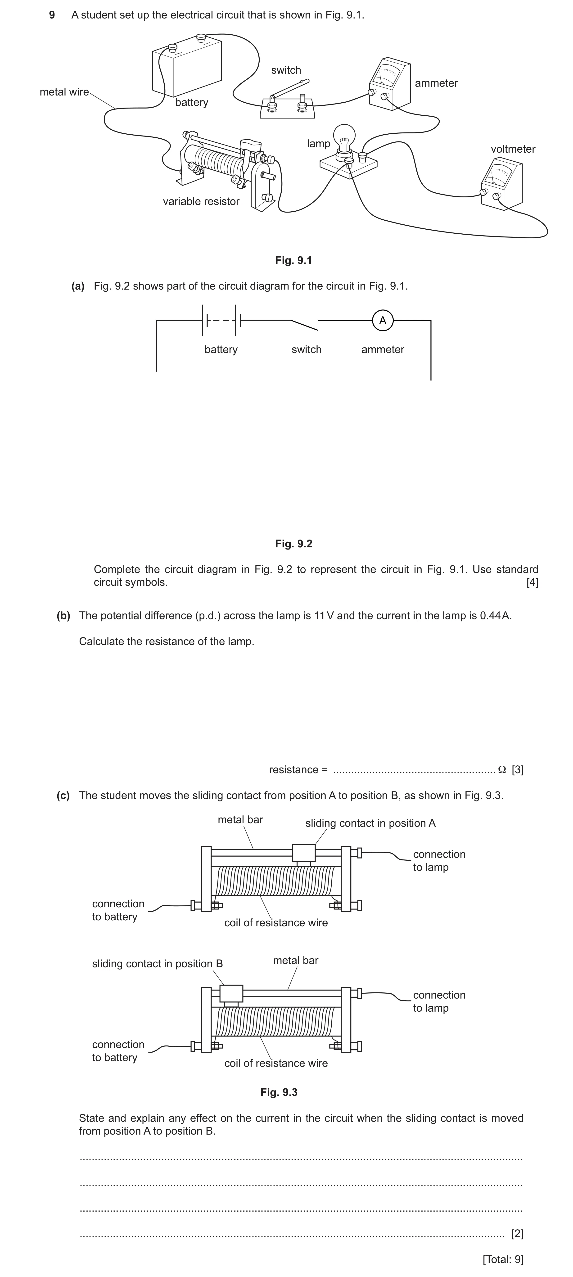
 62 / 69
 63 / 69
 64 / 69
 65 / 69
 66 / 69
 67 / 69
 68 / 69
 69 / 69
 7
7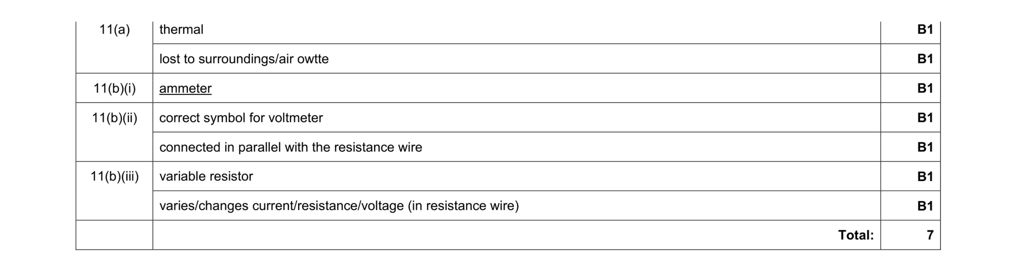 7
7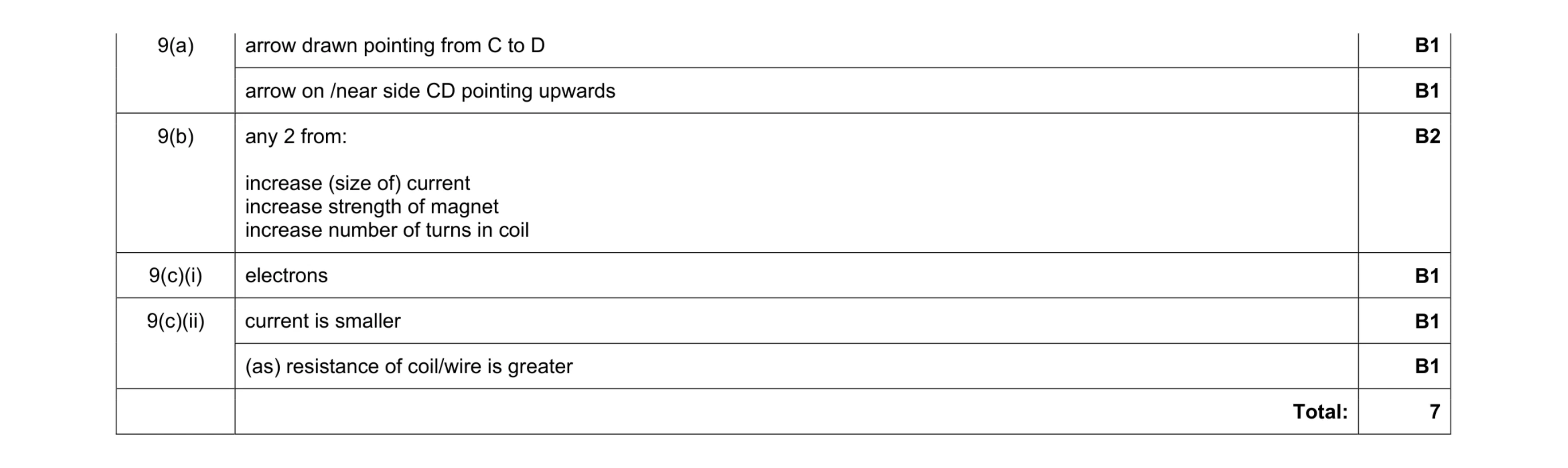 7
7 5
5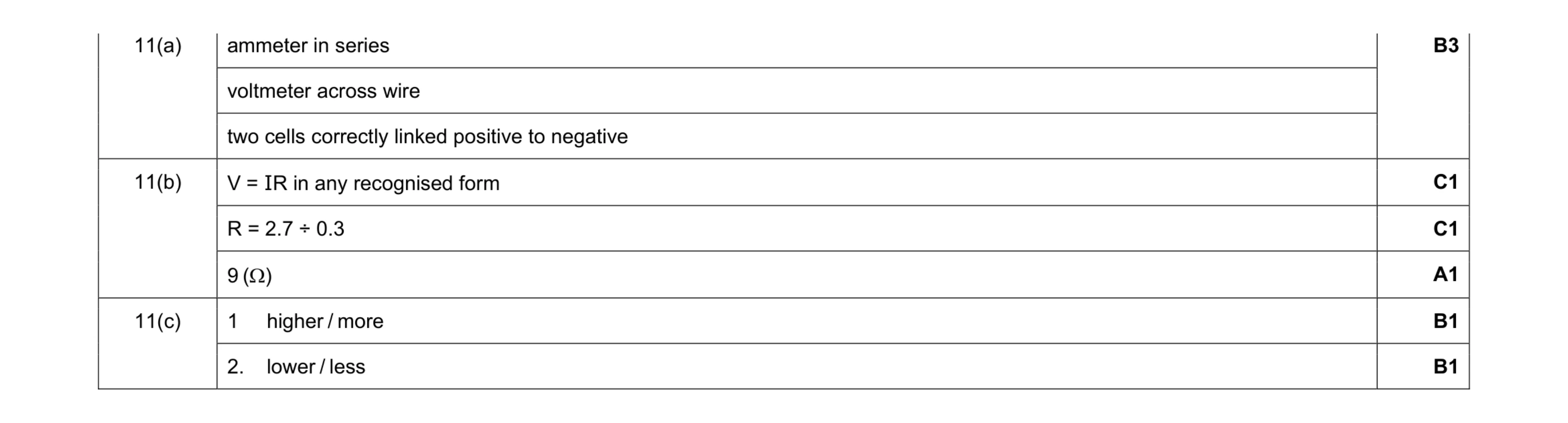 8
8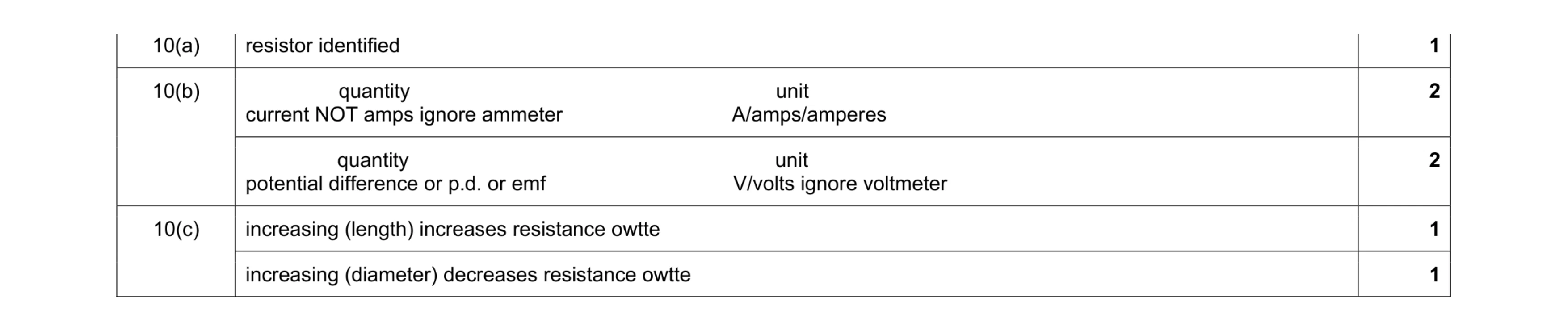 7
7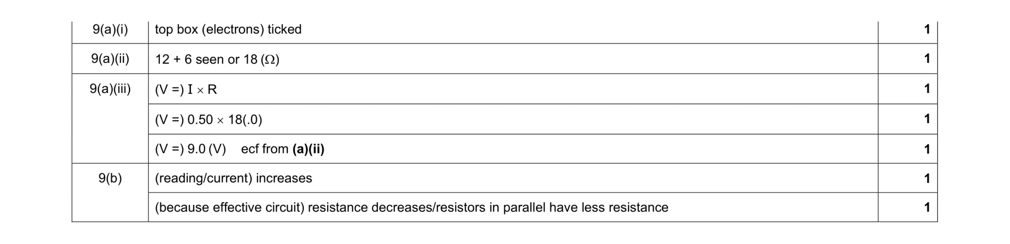 7
7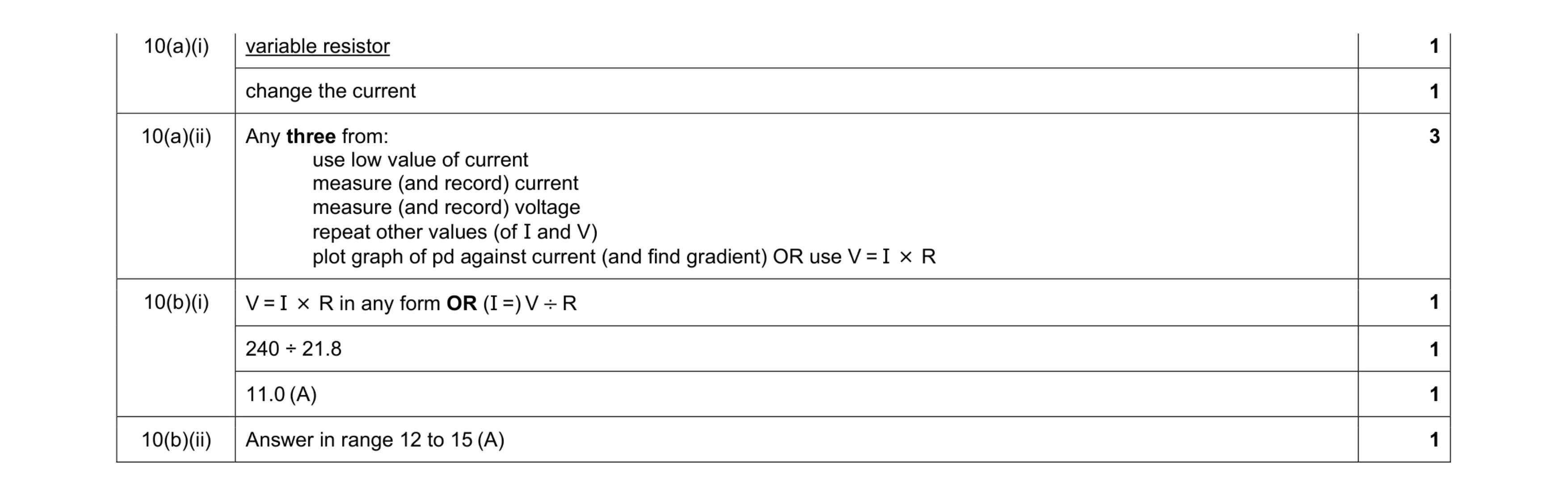 9
9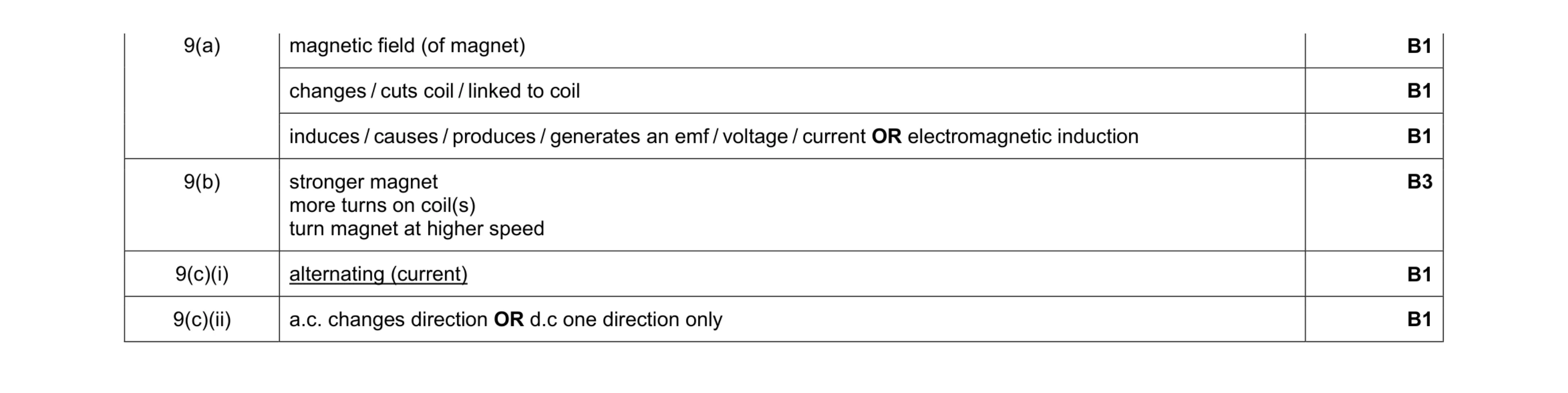 8
8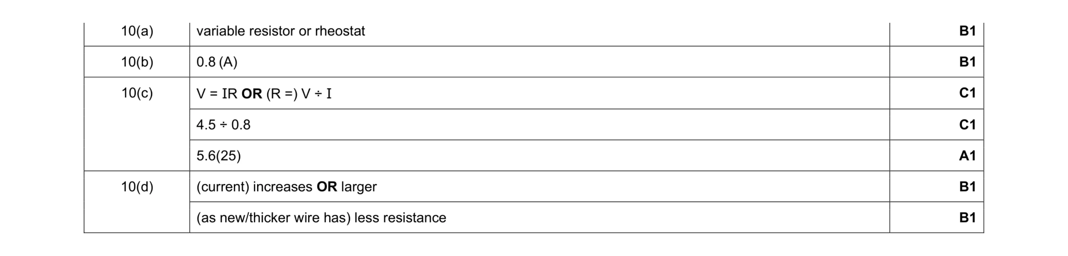 7
7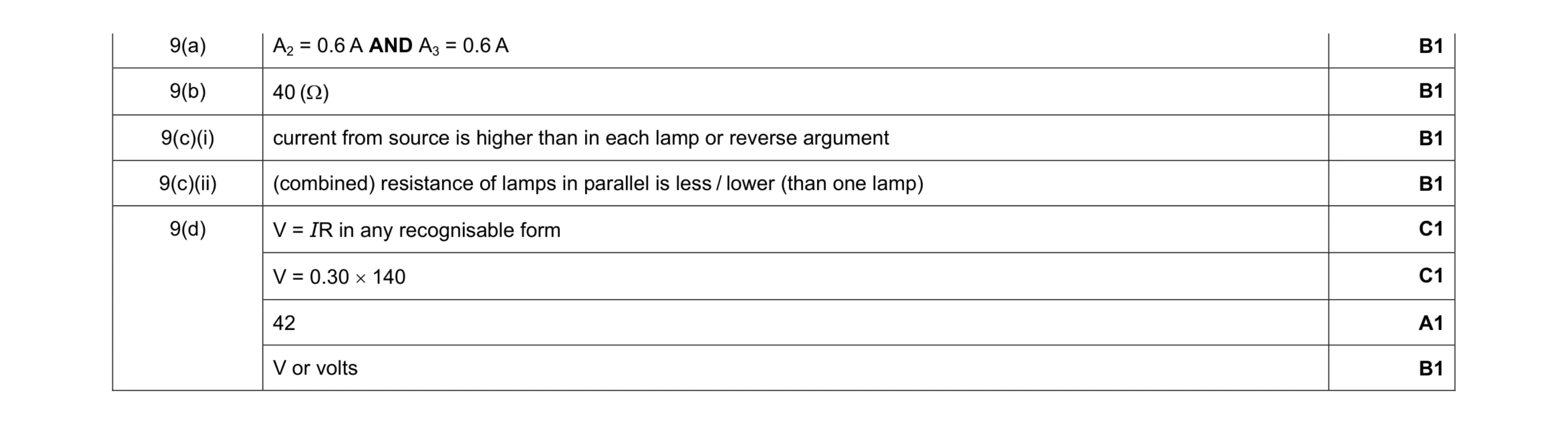 8
8 5
5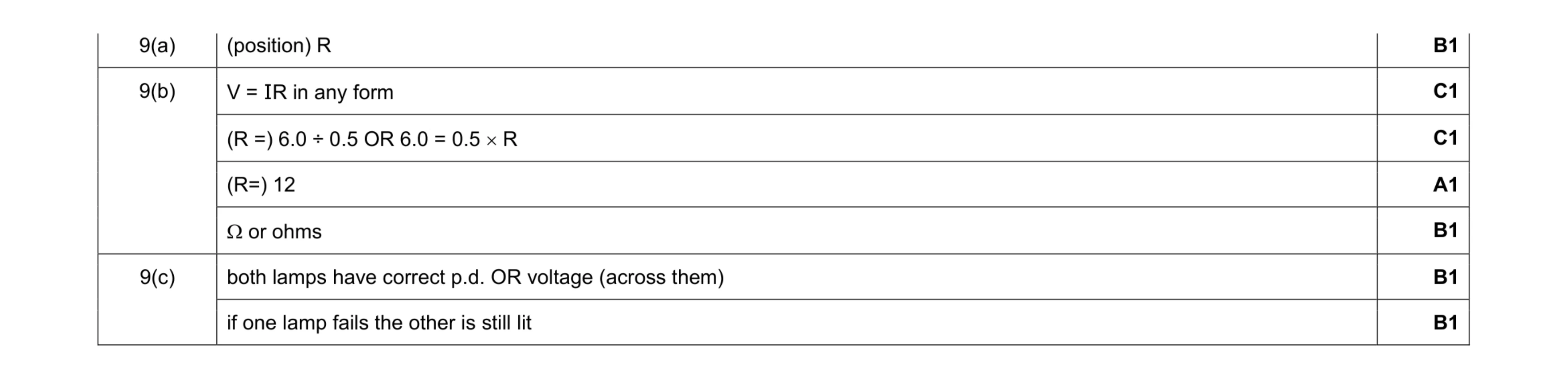 7
7 5
5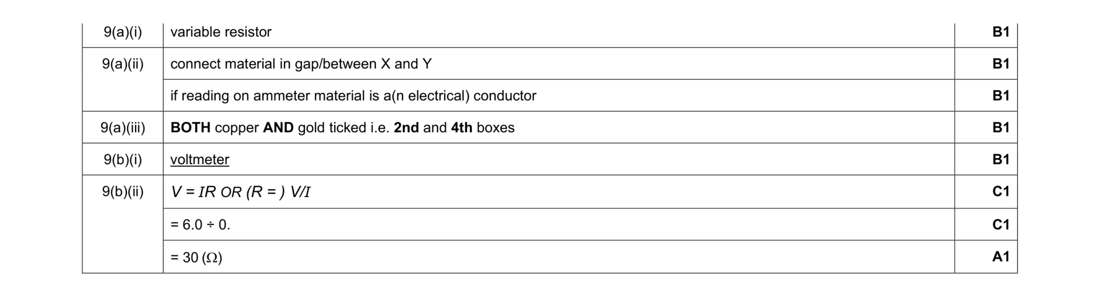 8
8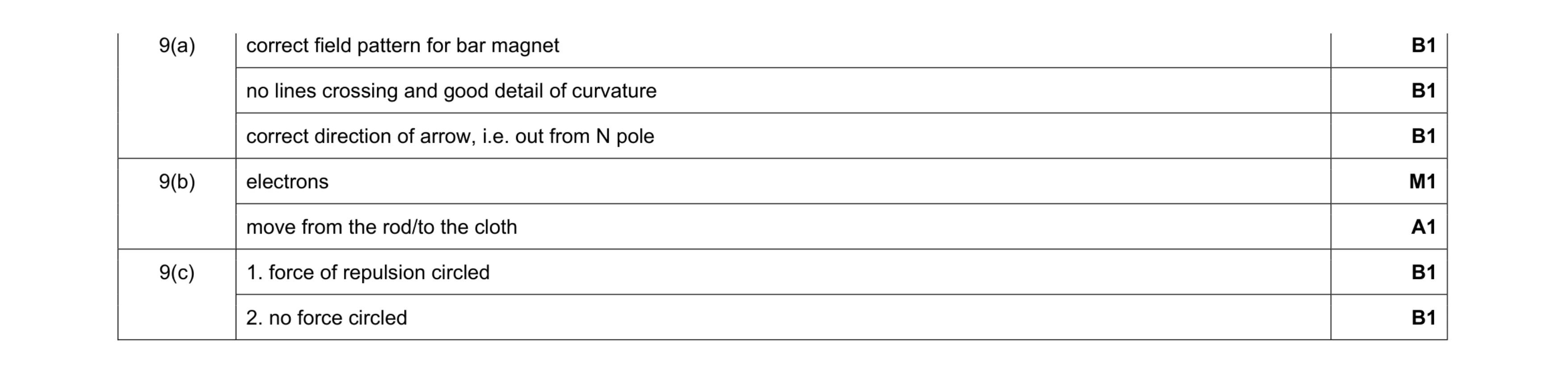 7
7 5
5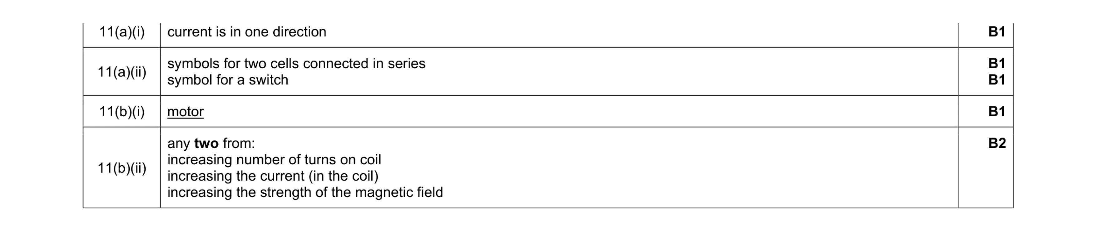 6
6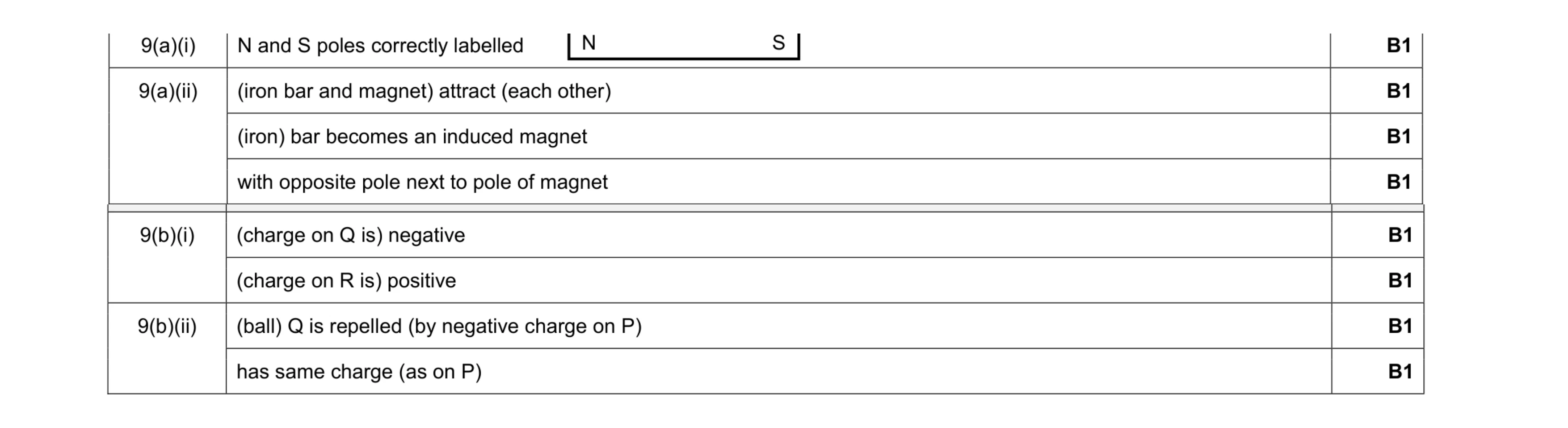 8
8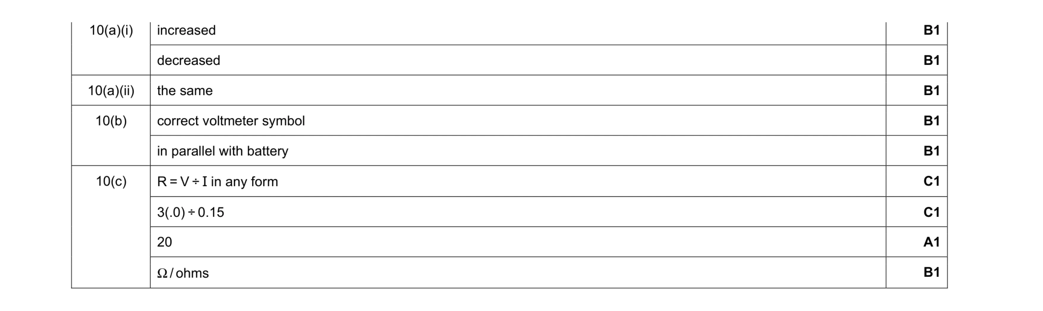 9
9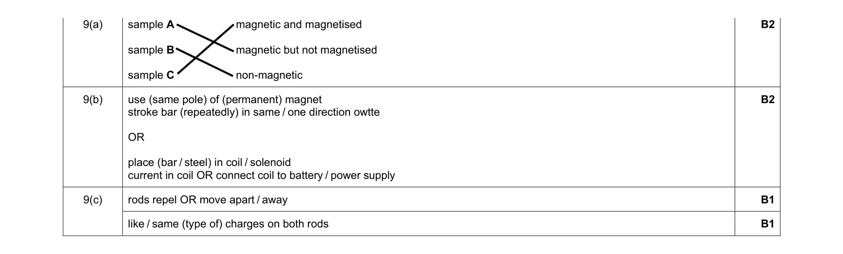 6
6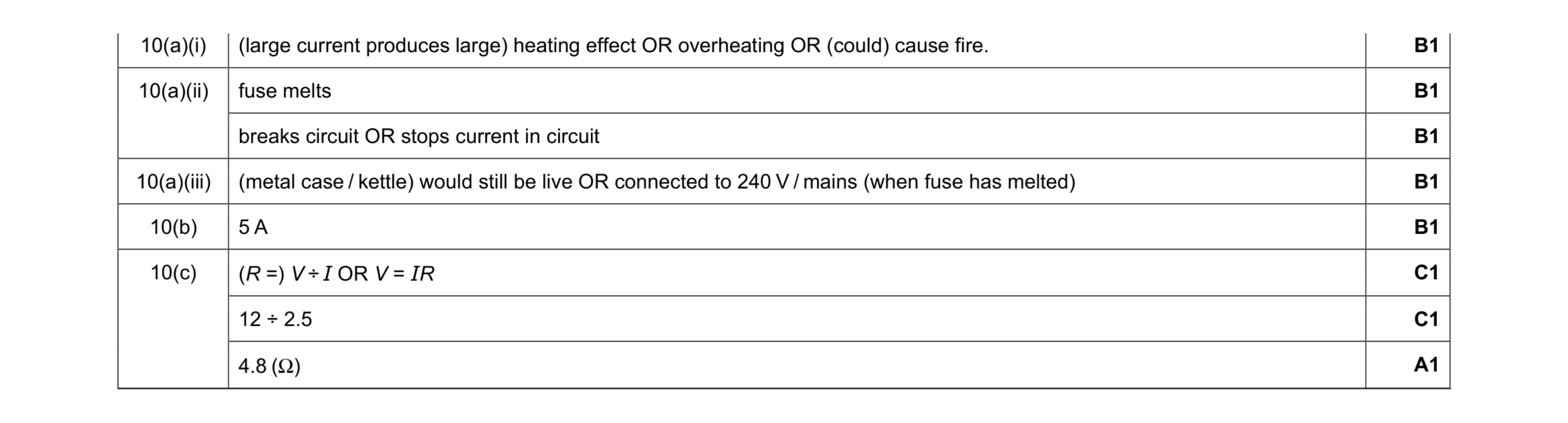 8
8 5
5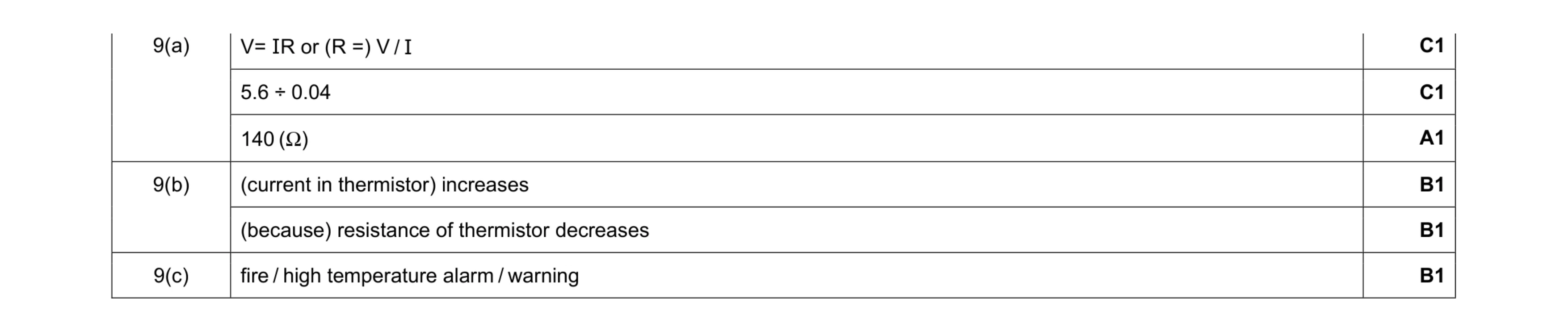 6
6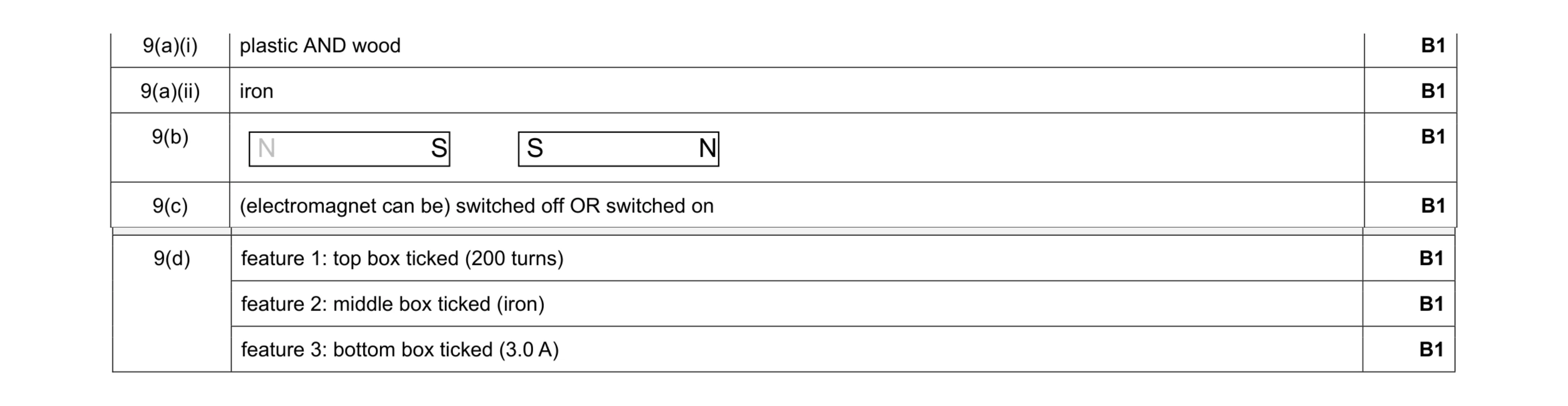 7
7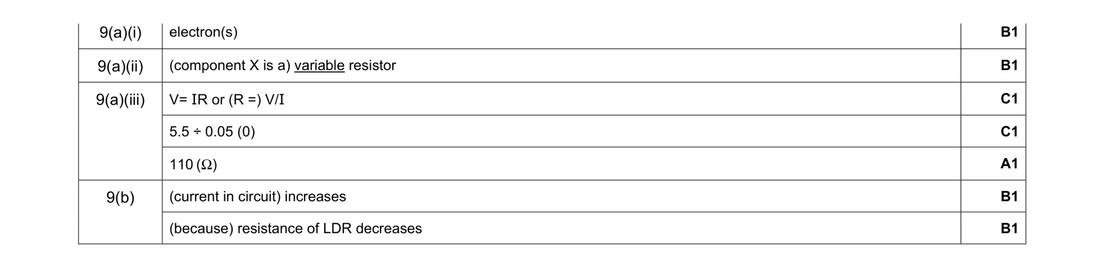 7
7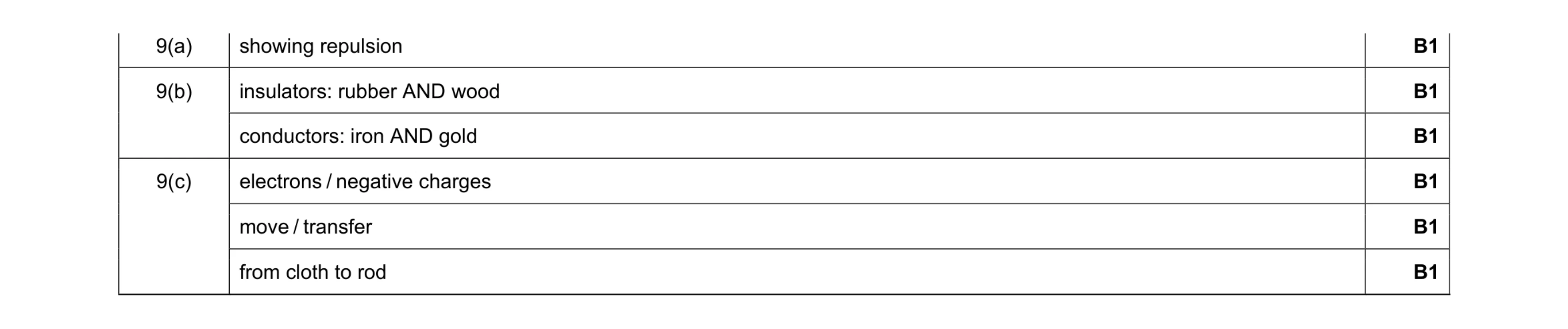 6
6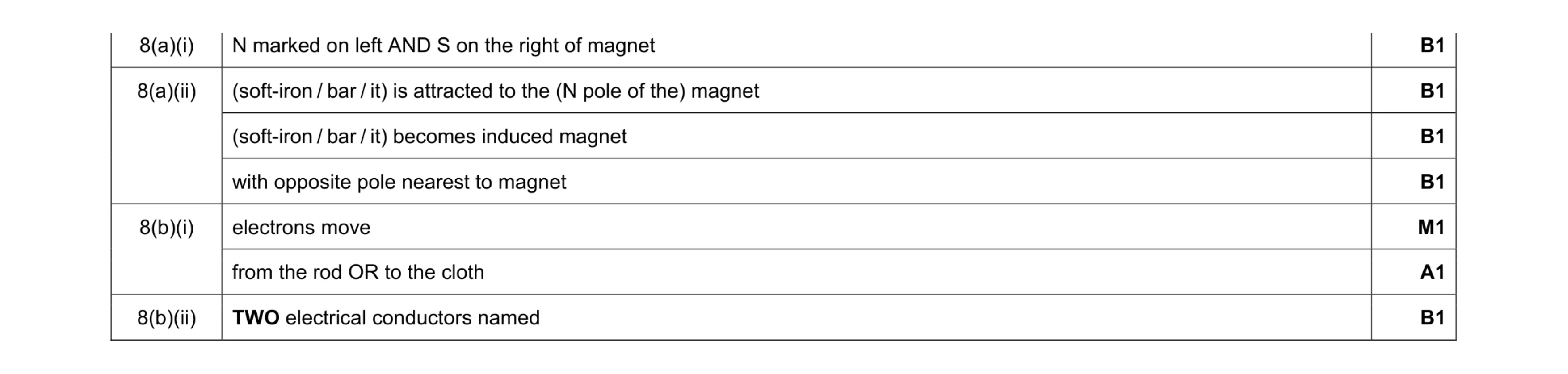 7
7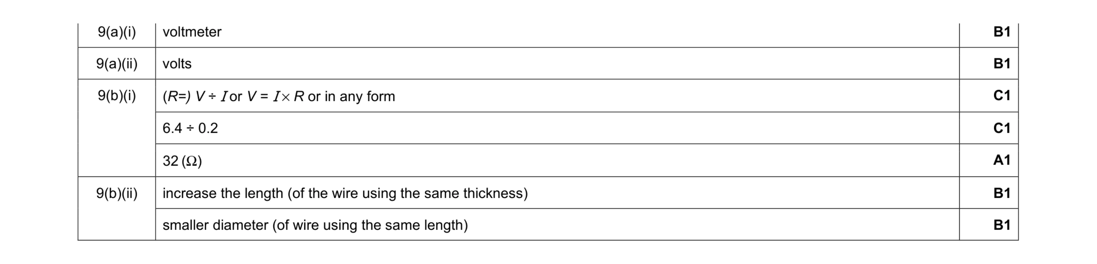 7
7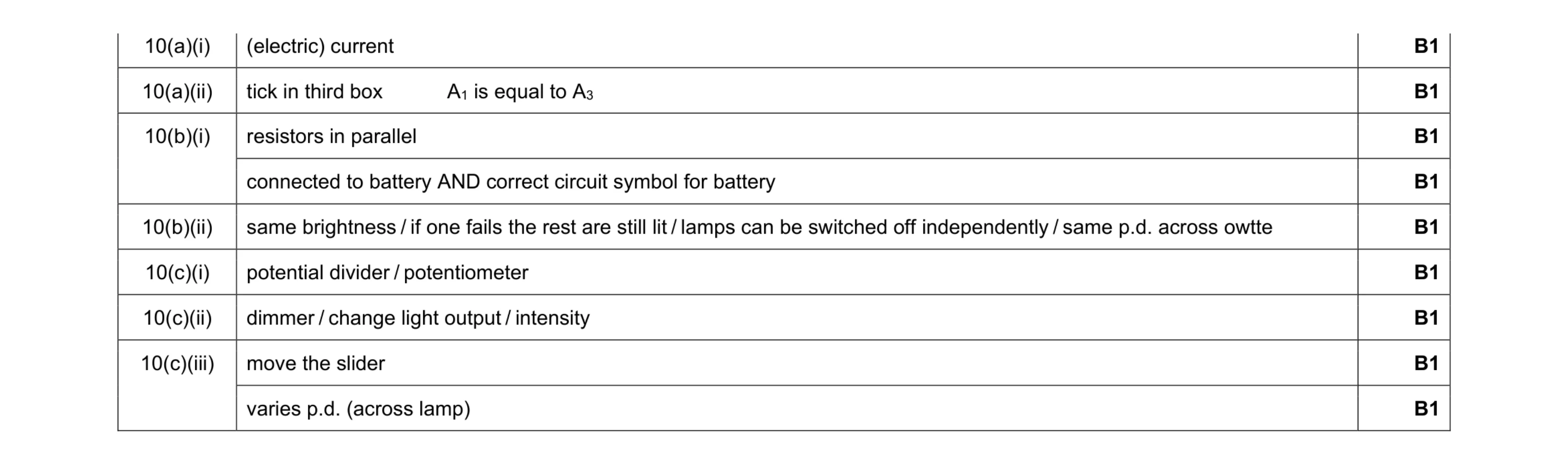 9
9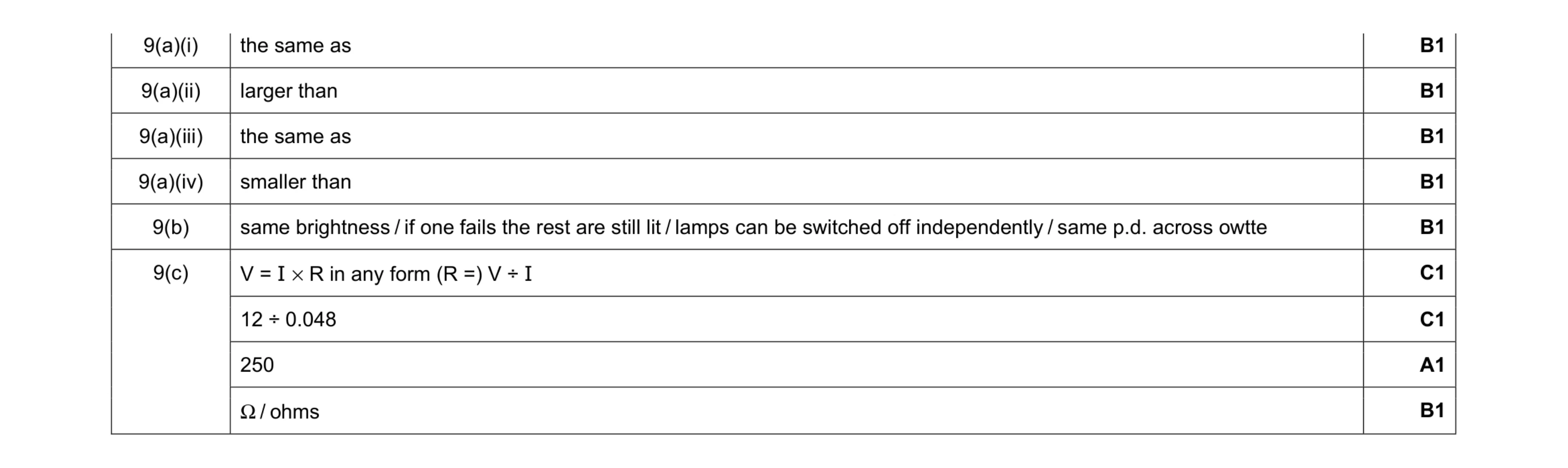 9
9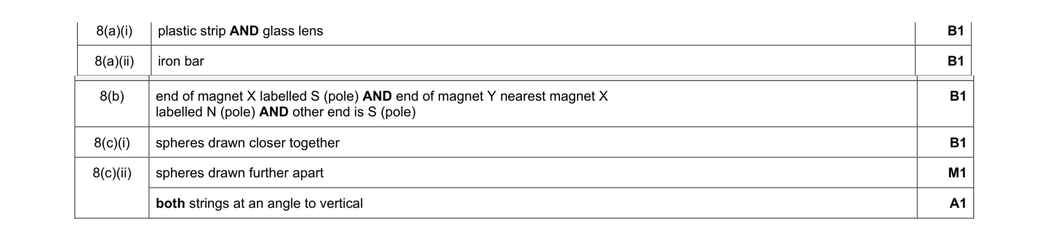 6
6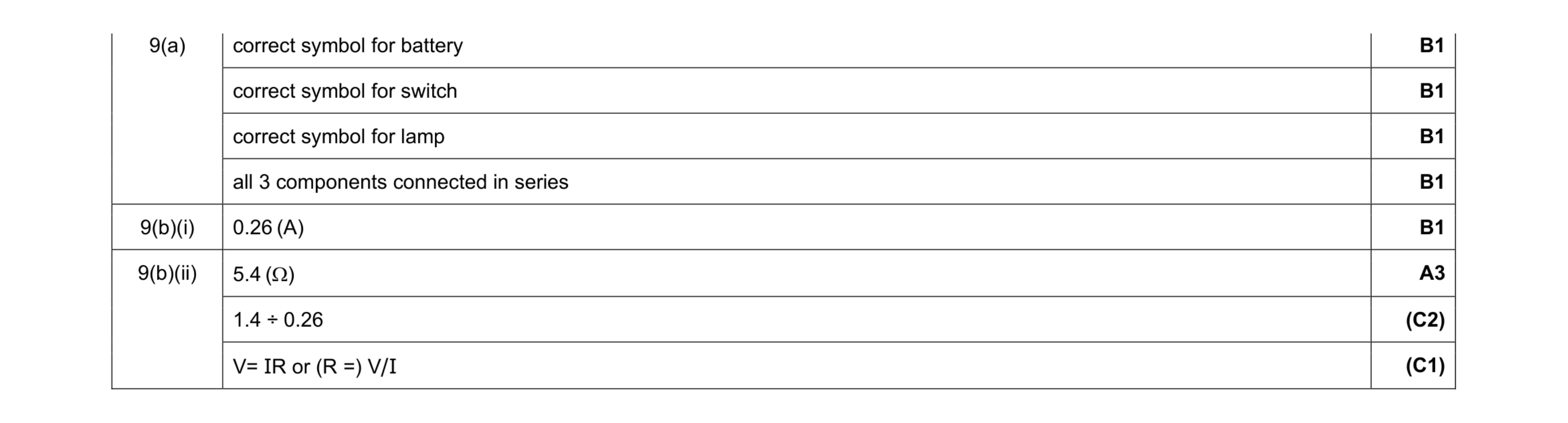 8
8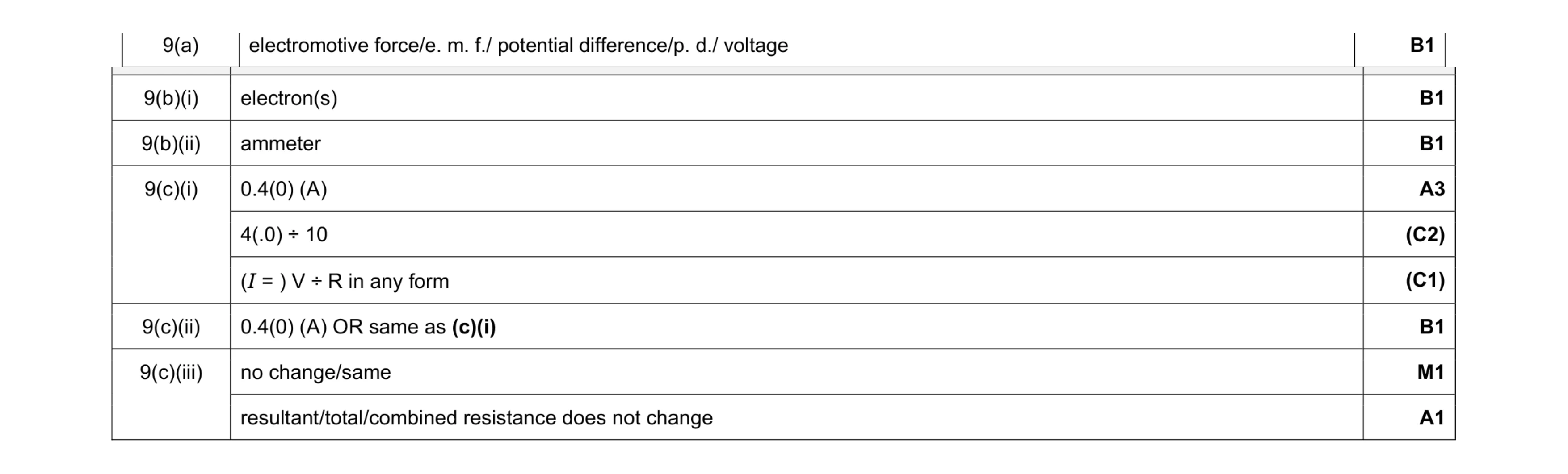 9
9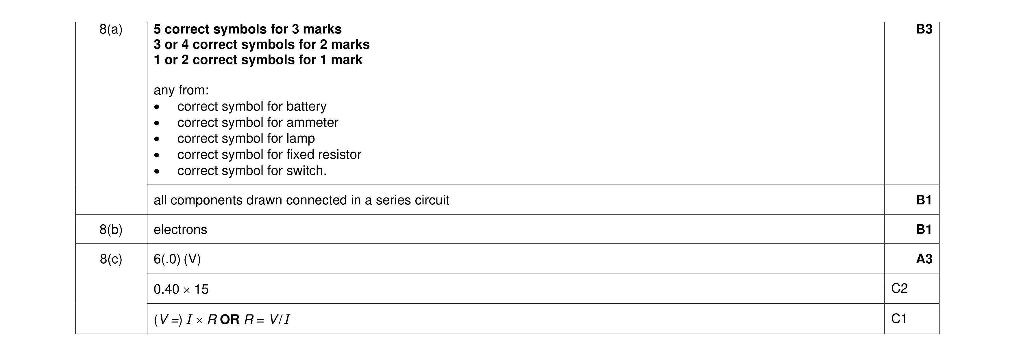 8
8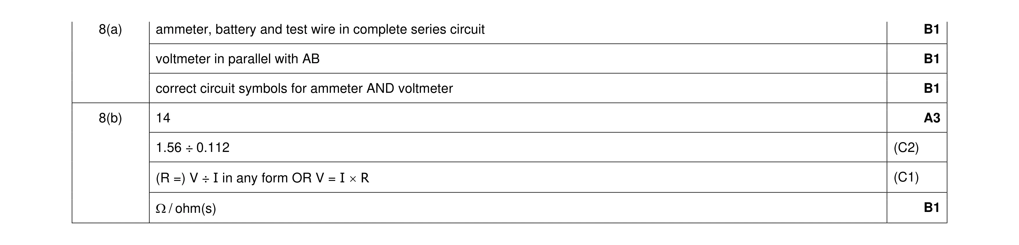 7
7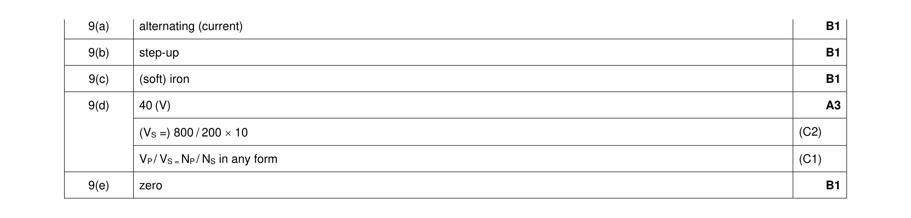 7
7 5
5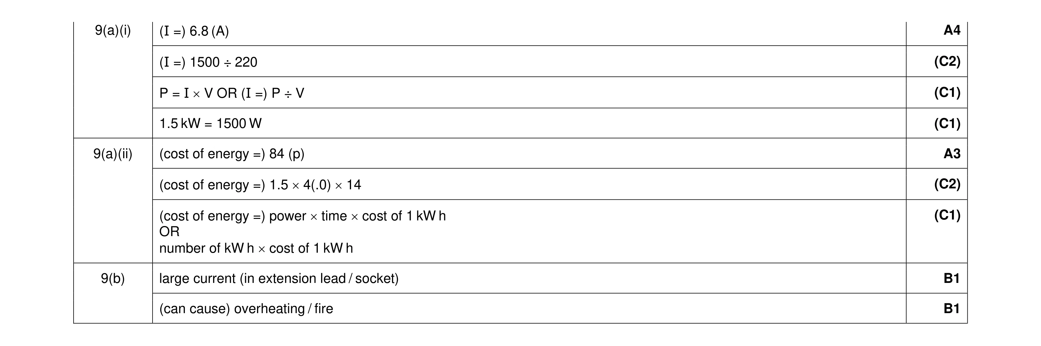 9
9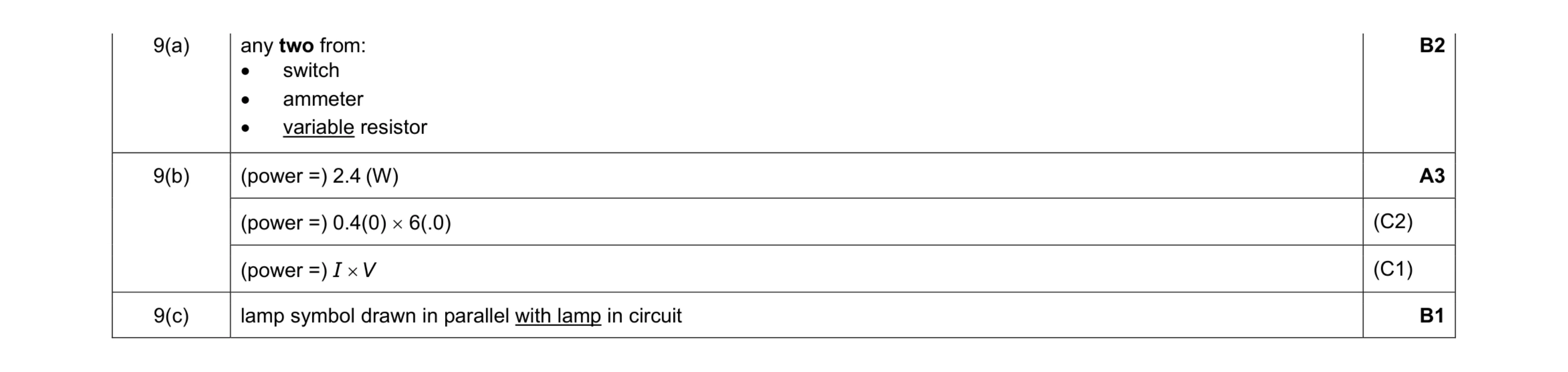 6
6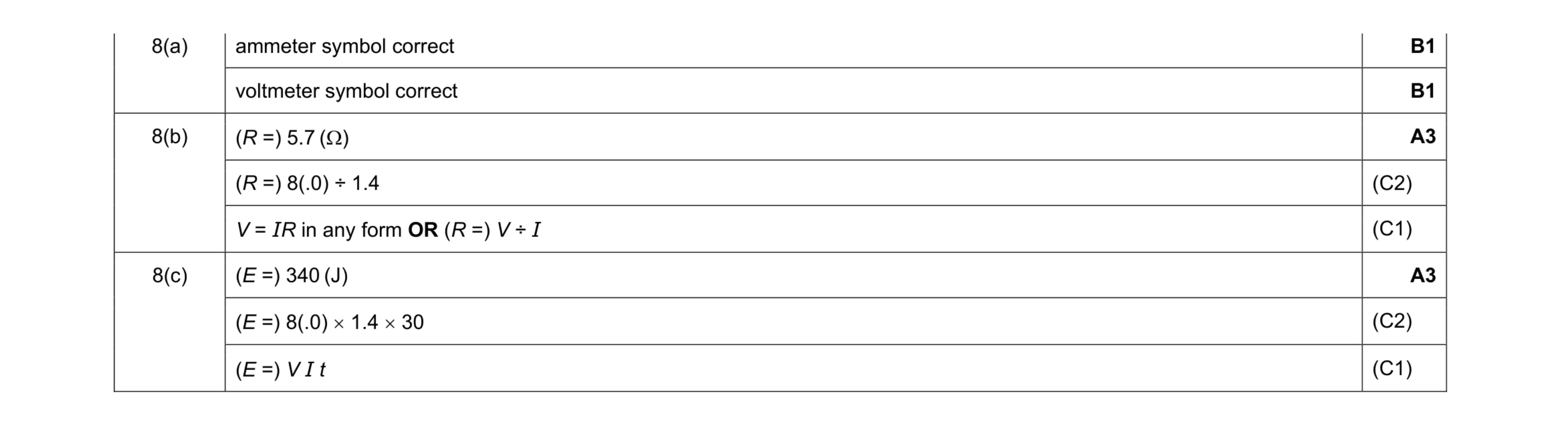 8
8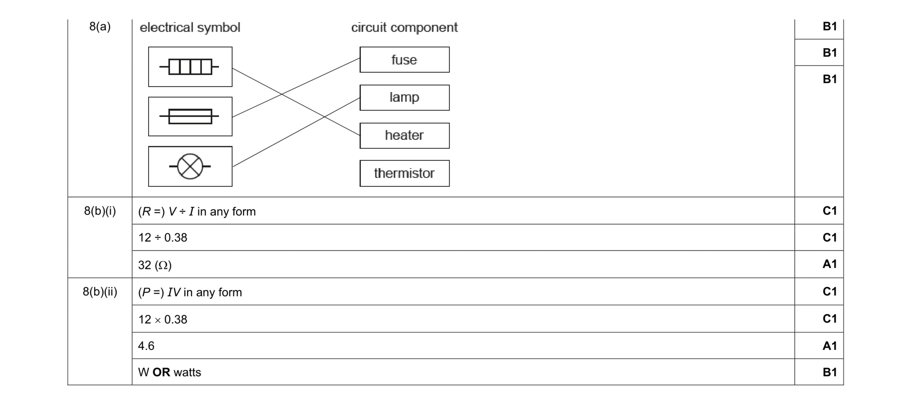 10
10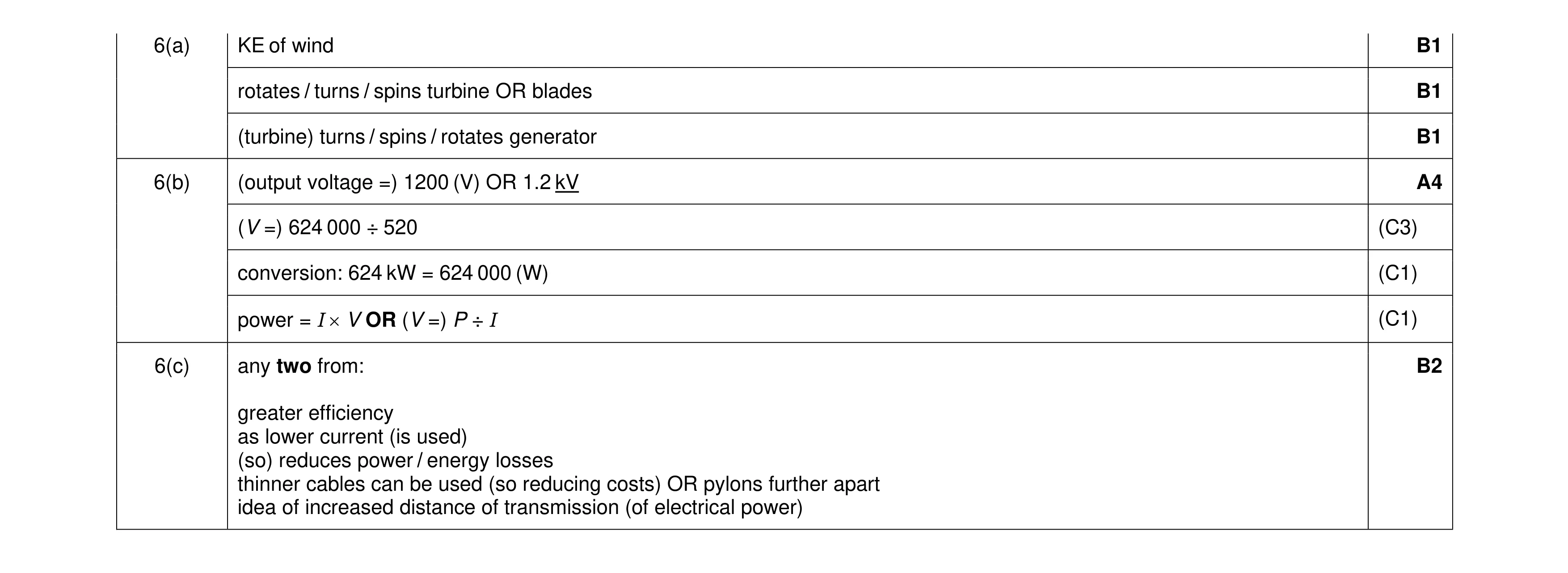 9
9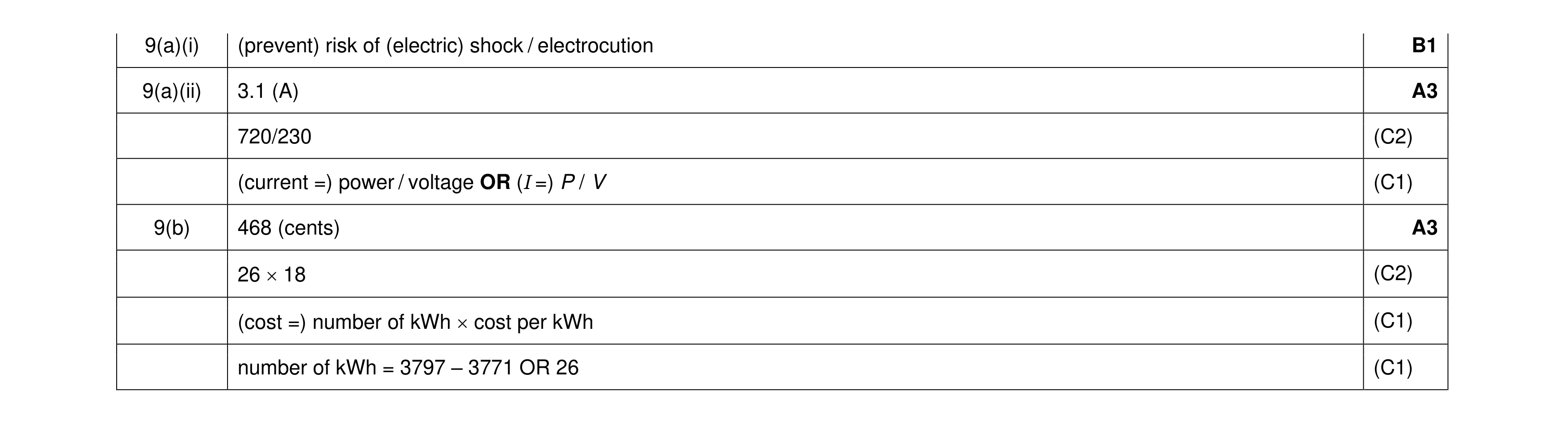 7
7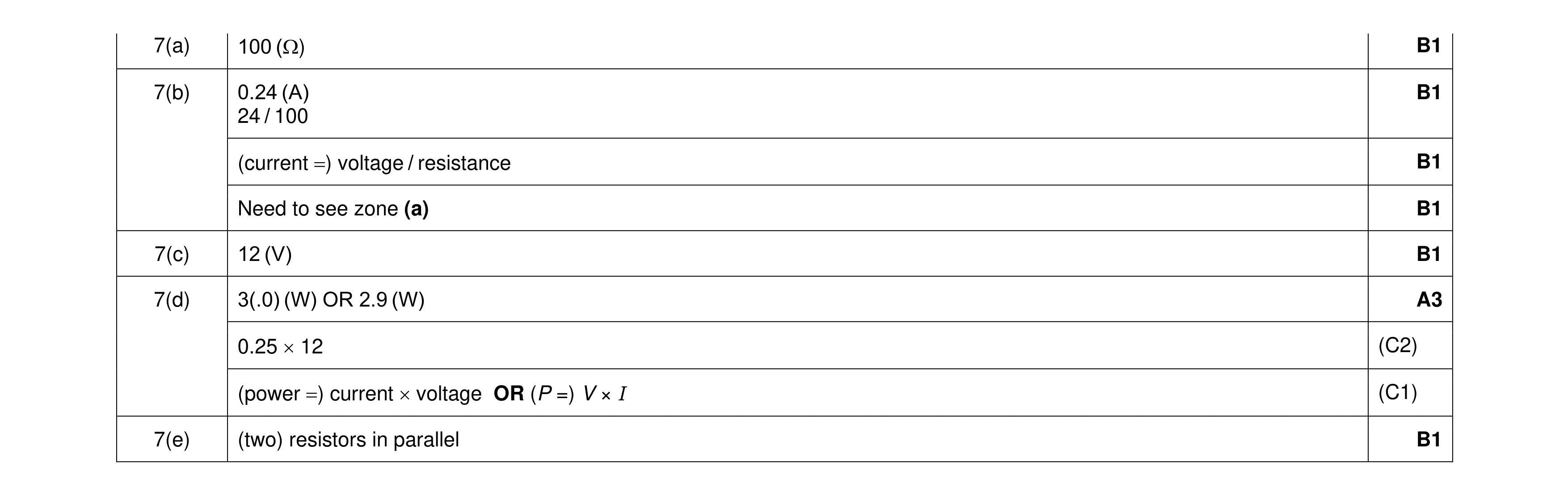 9
9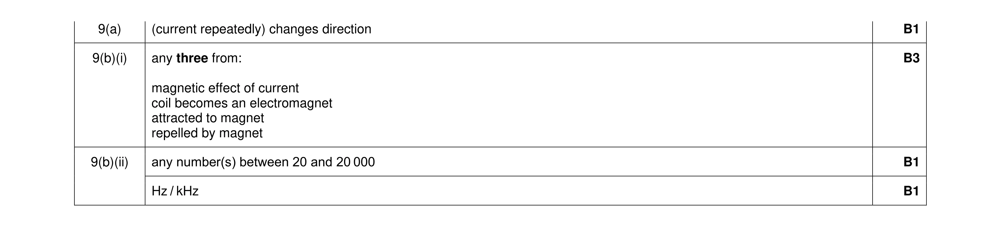 6
6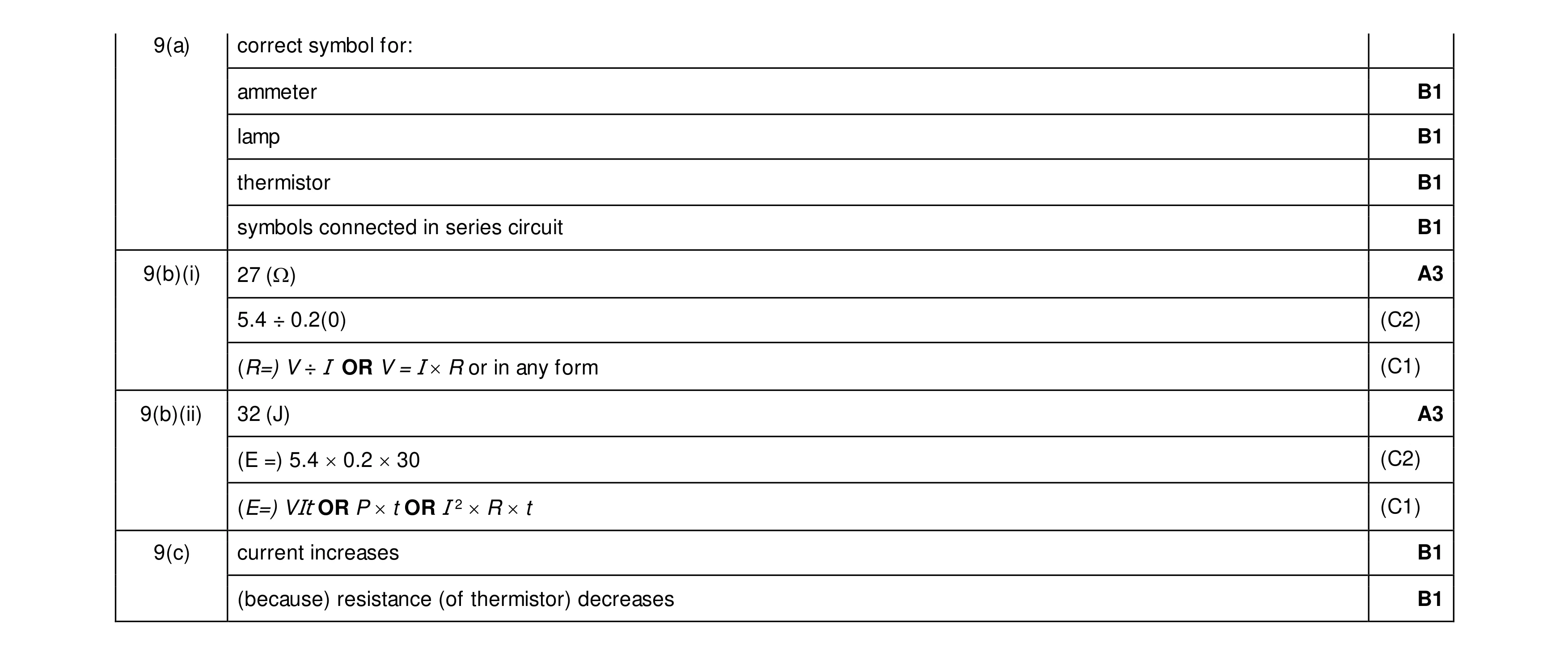 12
12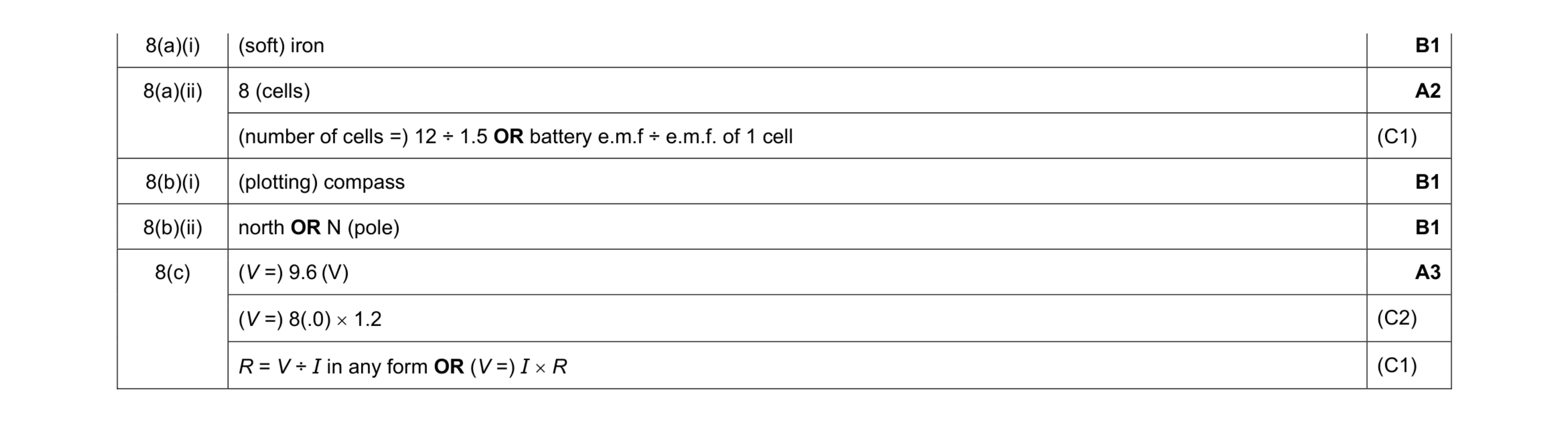 8
8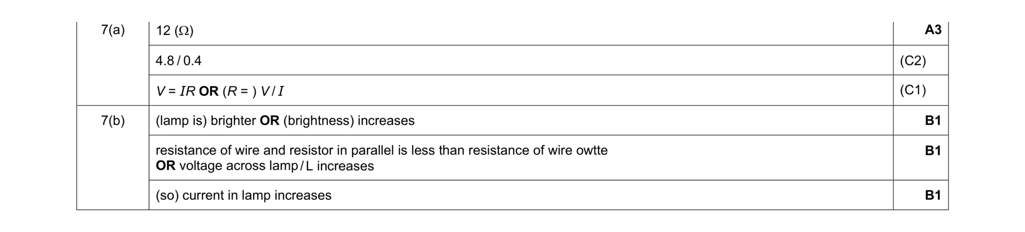 6
6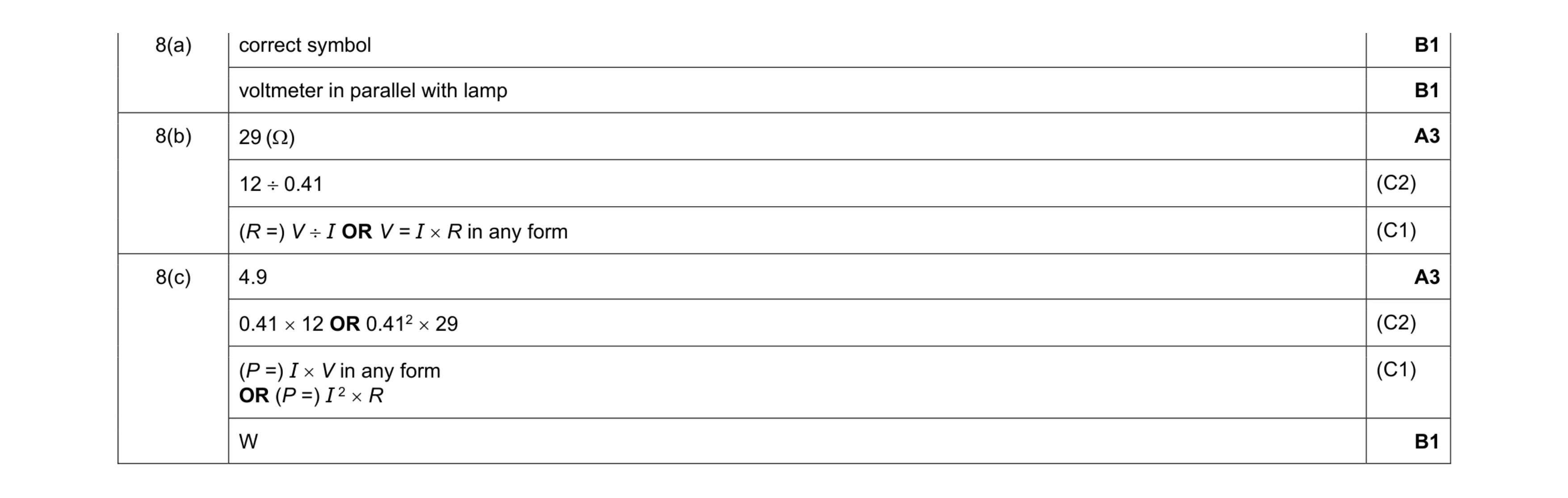 9
9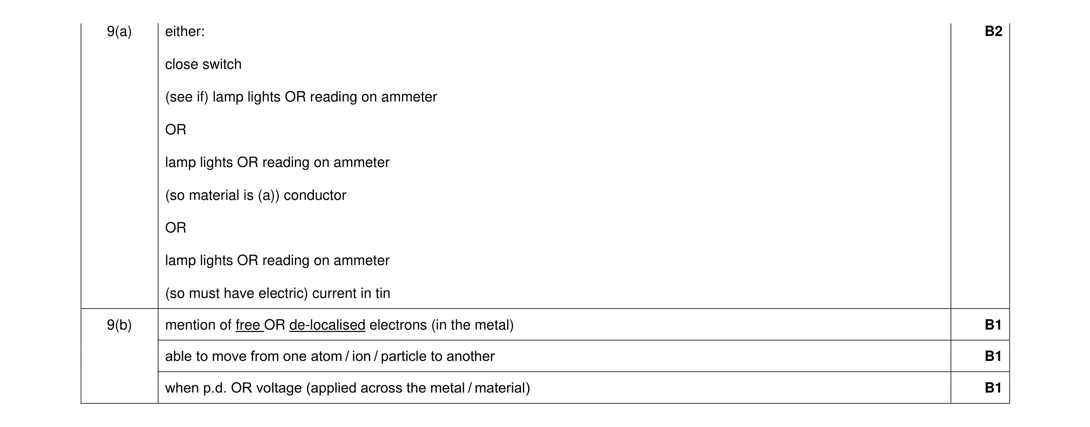 5
5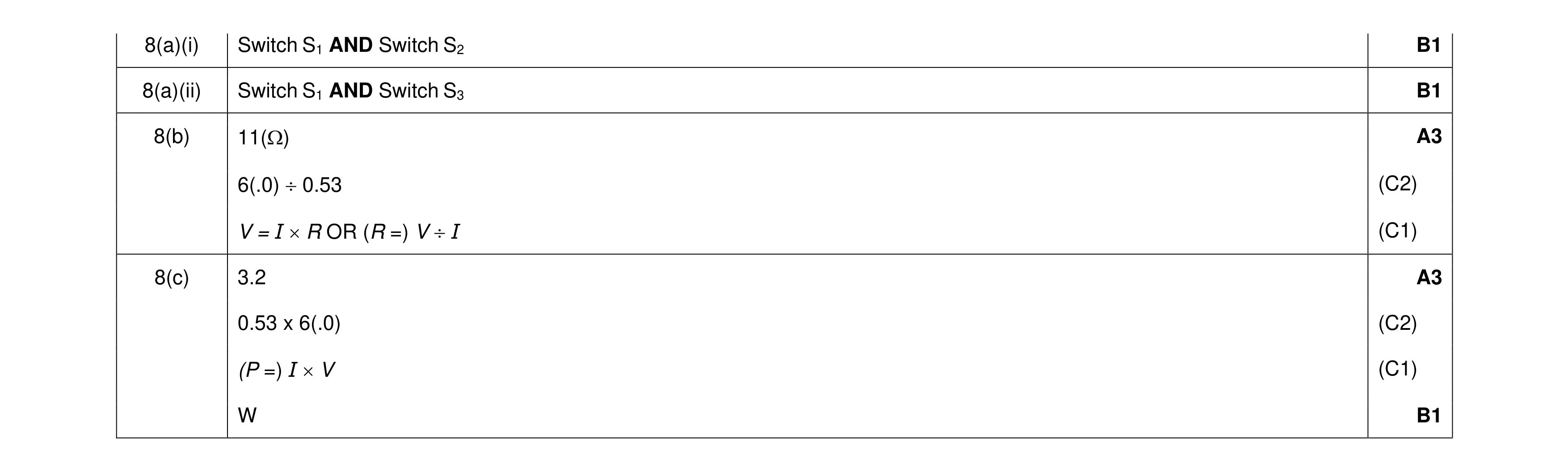 9
9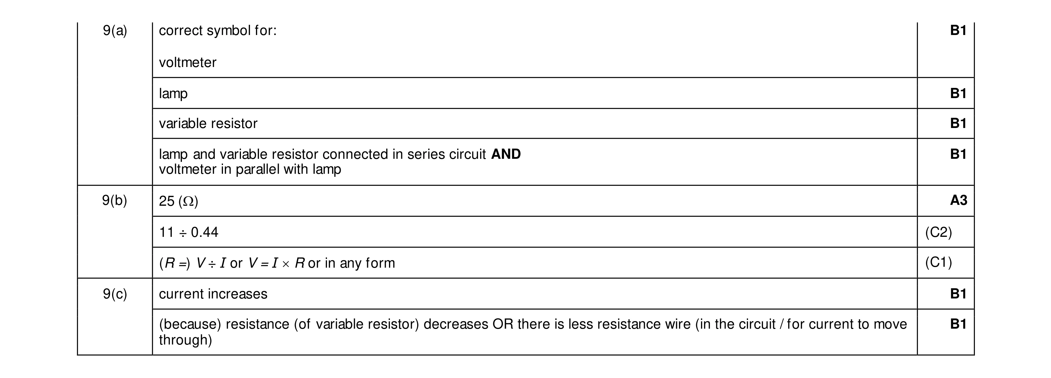 9
9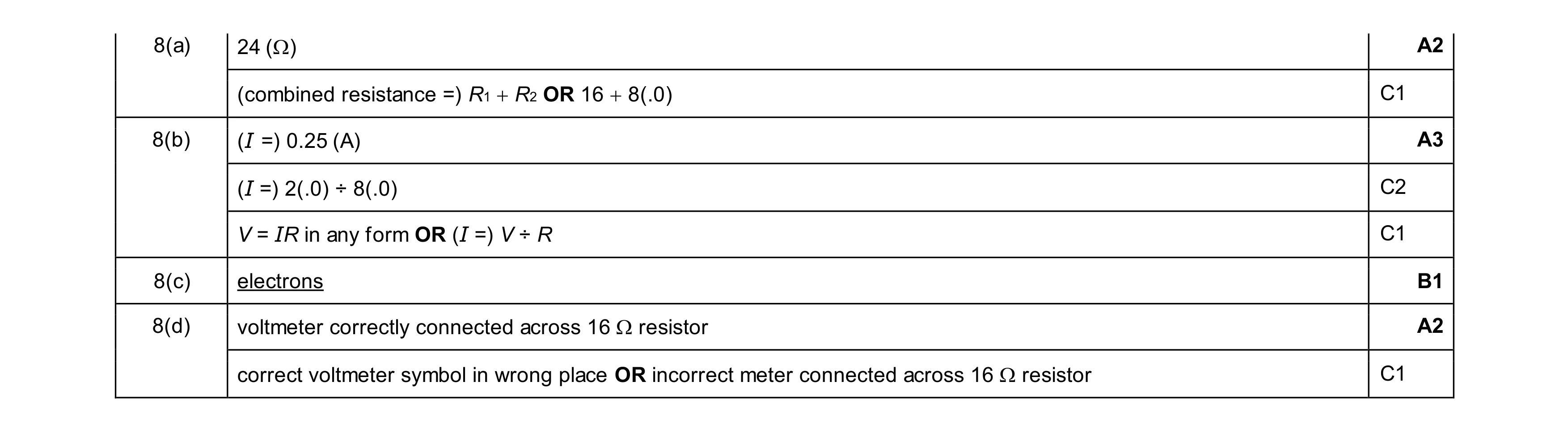 8
8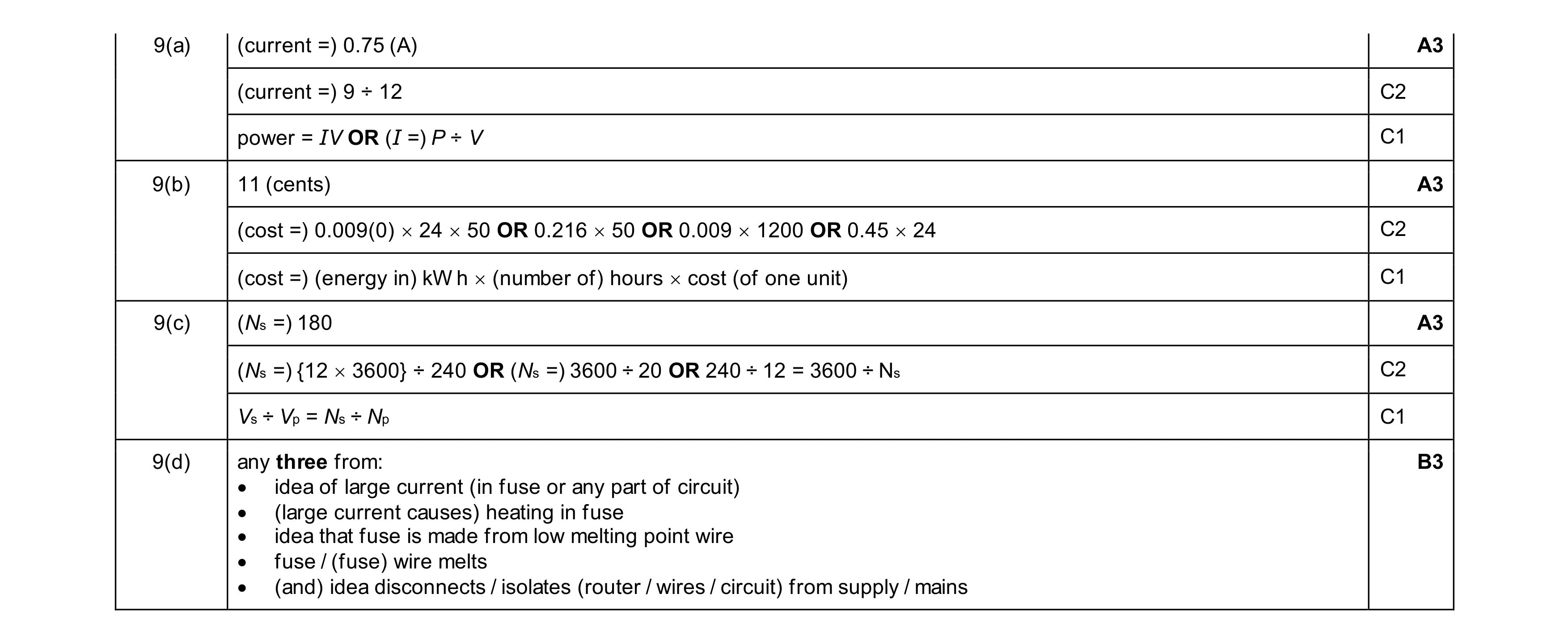 12
12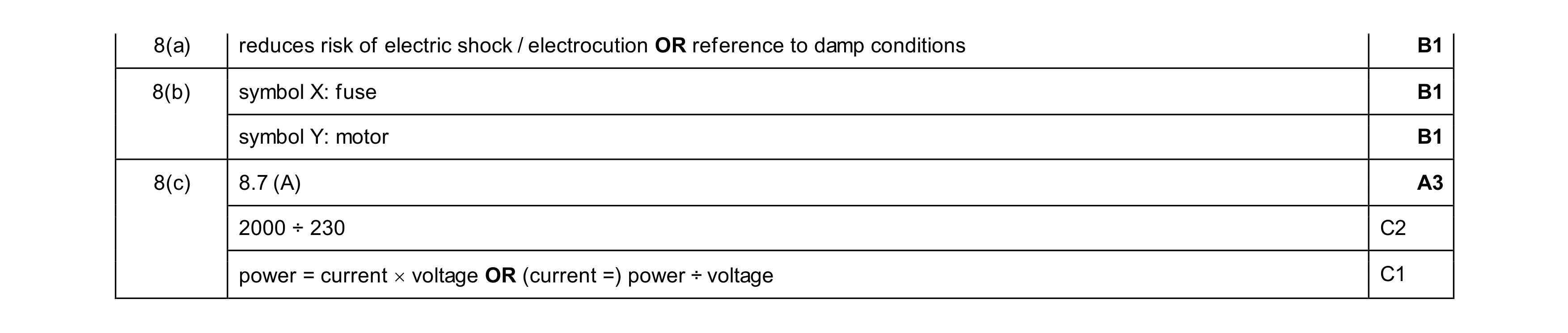 6
6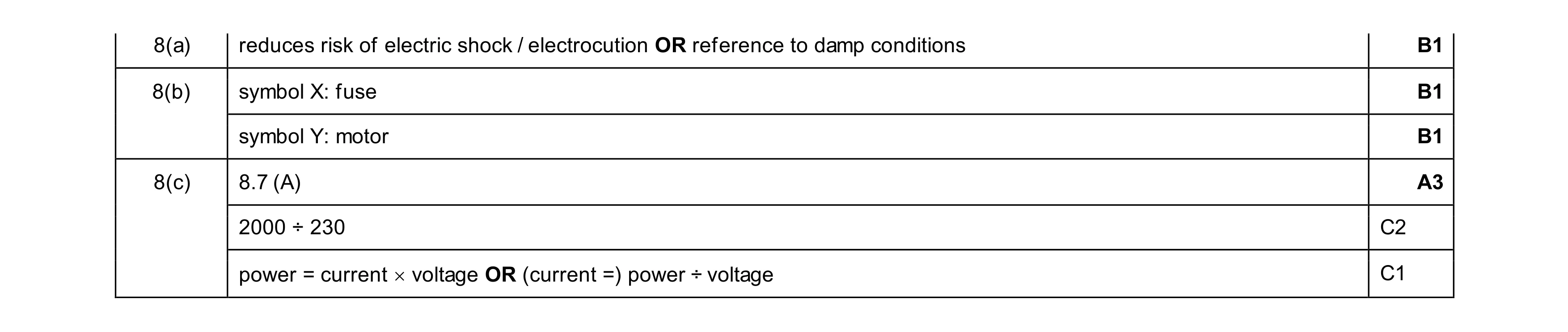 6
6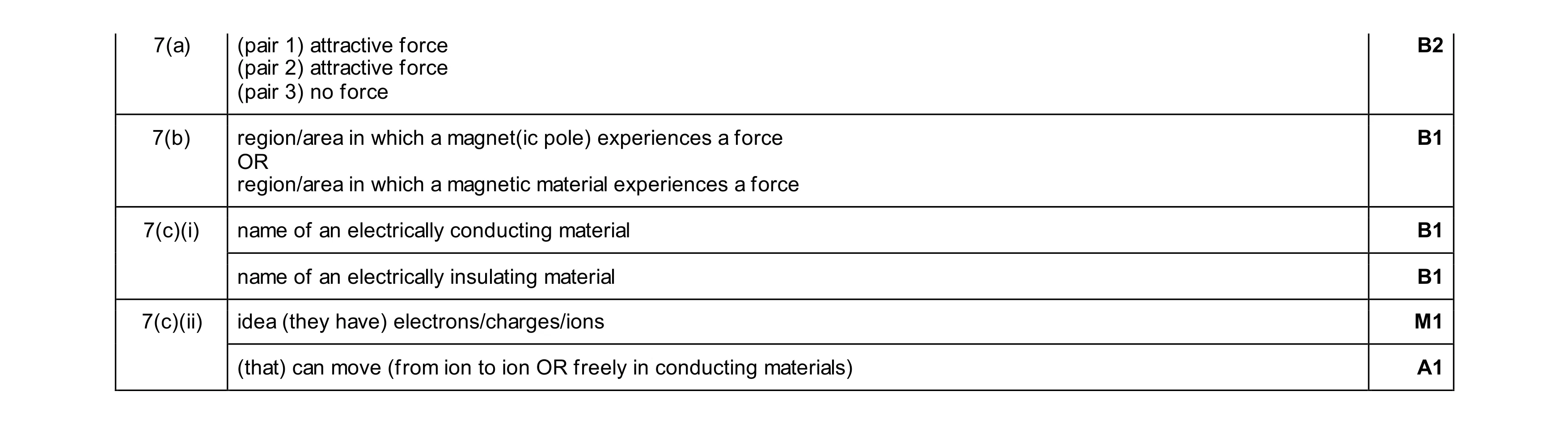 7
7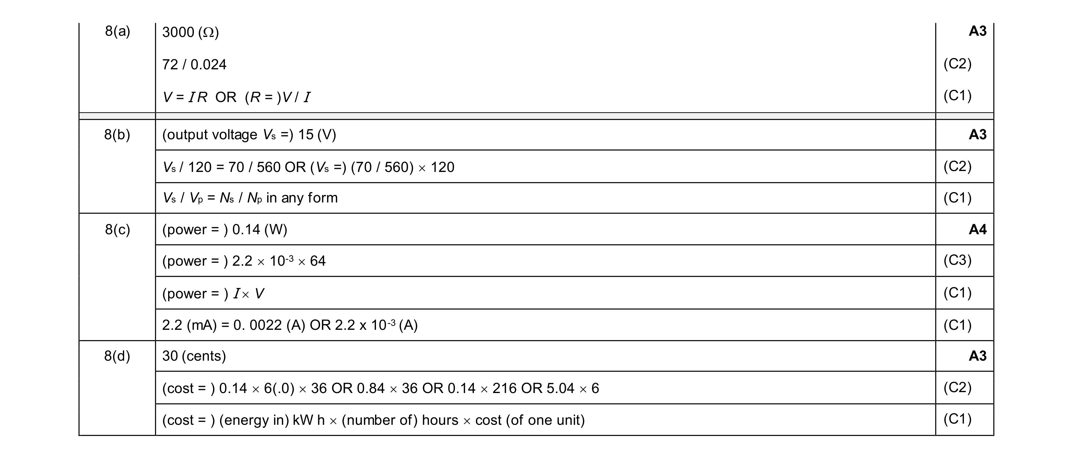 13
13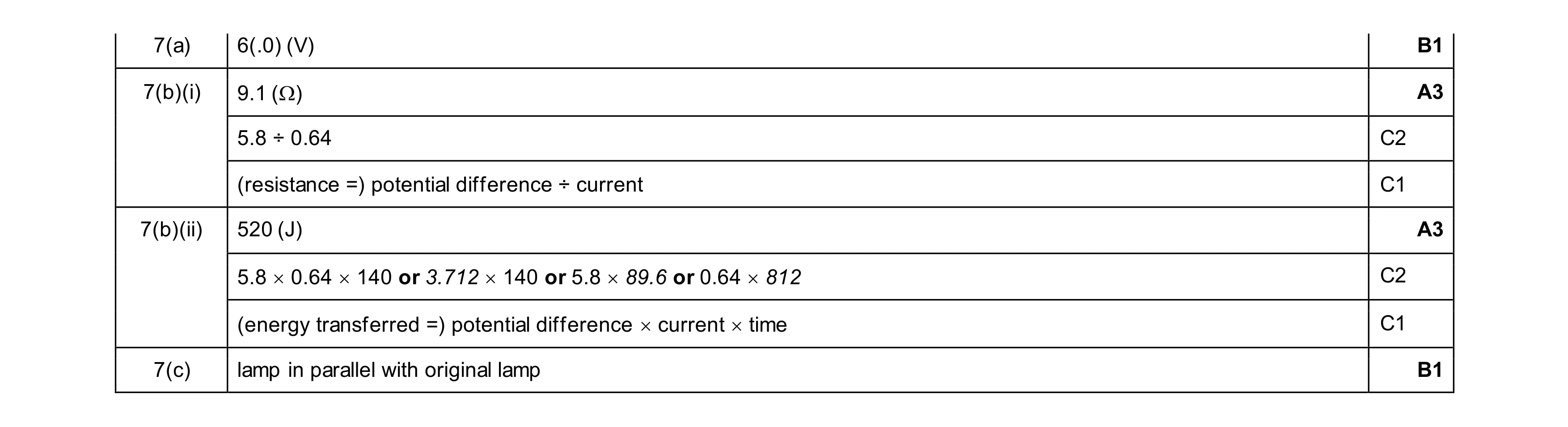 8
8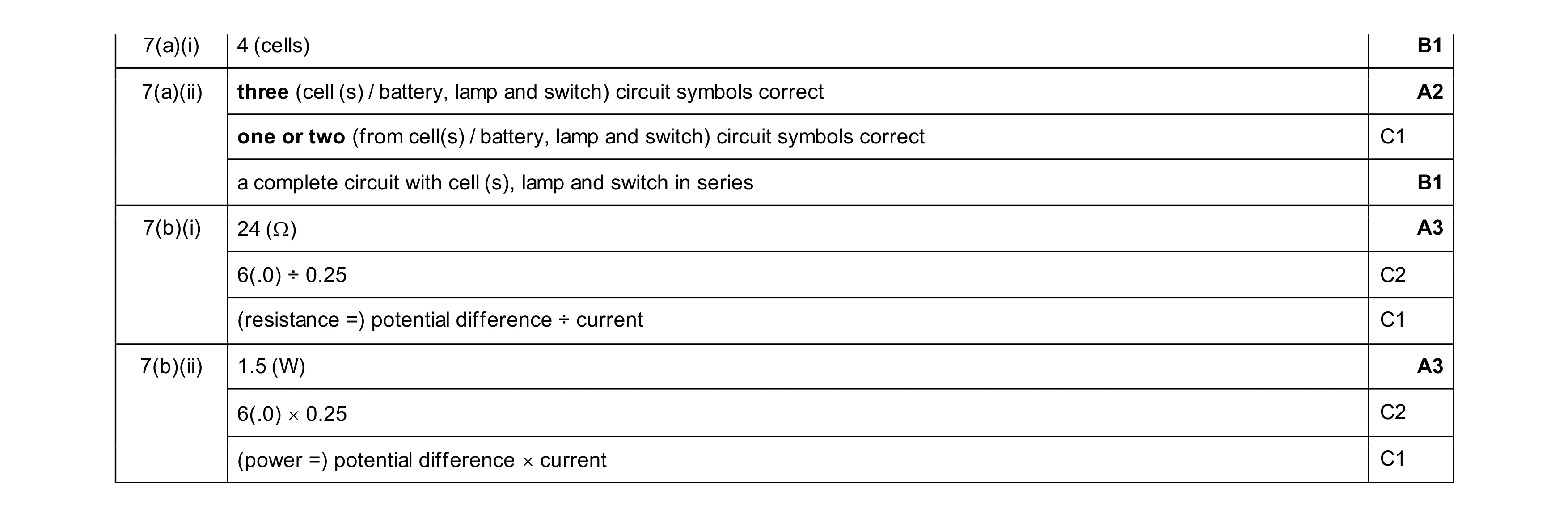 10
10