Questions as text
Q1 · In which circuit does the voltmeter read the potential difference across the lamp? 0625/11 May/June 2005
29 In which circuit does the voltmeter read the potential difference across the lamp? A B V V C D V V
1 marks
Answer: D
This question in 0625/11 May/June 2005
Q2 · In the circuit below, X and Y are identical 6 V lamps 0625/11 May/June 2005
30 In the circuit below, X and Y are identical 6 V lamps. 6 V switch X Y What happens when the switch is closed? A X lights more brightly than Y. B Y lights more brightly than X. C X and Y light with equal brightness. D Neither X nor Y light.
1 marks
Answer: C
This question in 0625/11 May/June 2005
Q3 · The diagram shows a circuit with three ammeters, X, Y and Z 0625/11 May/June 2005
31 The diagram shows a circuit with three ammeters, X, Y and Z. A X Y A Z A Which set of readings is possible? X Y Z A 2 A 3 A 5 A B 3 A 2 A 5 A C 3 A 3 A 3 A D 5 A 2 A 3 A
1 marks
Answer: D
This question in 0625/11 May/June 2005
Q4 · A lamp is to be connected in a circuit so that the p.d 0625/11 May/June 2005
32 A lamp is to be connected in a circuit so that the p.d. across it can be varied from 0 to 6 V. Which circuit would be most suitable? A B 6 V 6 V C D 6 V 6 V
1 marks
Answer: B
This question in 0625/11 May/June 2005
Q5 · A student makes the circuit shown 0625/11 May/June 2005
33 A student makes the circuit shown. 5 A fuse The fuse has blown and stopped the current. What could have caused this? A The current rating of the fuse was too high. B The current was too large. C The lamp was loose. D The voltage was too small.
1 marks
Answer: B
This question in 0625/11 May/June 2005
Q6 · Which circuit should be used to find the resistance of a lamp? 0625/11 Oct/Nov 2005
28 Which circuit should be used to find the resistance of a lamp? A B A V A V C D V V A A
1 marks
Answer: C
This question in 0625/11 Oct/Nov 2005
Q7 · Which component can store energy for use in time delay circuits? 0625/11 Oct/Nov 2005
30 Which component can store energy for use in time delay circuits? A capacitor B potentiometer C resistor D thermistor
1 marks
Answer: A
This question in 0625/11 Oct/Nov 2005
Q8 · When the circuit shown is connected with switch S open, the 6 V lamp glows 0625/11 Oct/Nov 2005
31 When the circuit shown is connected with switch S open, the 6 V lamp glows. 6 V R 6 V lamp S What happens to the brightness of the lamp when switch S is closed? A It becomes brighter. B It remains the same. C It becomes dimmer. D It goes off.
1 marks
Answer: A
This question in 0625/11 Oct/Nov 2005
Q9 · Why are the electric lamps in a house lighting circuit normally connected in parallel? 0625/11 Oct/Nov 2005
32 Why are the electric lamps in a house lighting circuit normally connected in parallel? A The current in every circuit must be the same. B The lamps are always switched on and off at the same time. C The voltage across each lamp must be the mains voltage. D When one of the lamps blows, all the others go out.
1 marks
Answer: C
This question in 0625/11 Oct/Nov 2005
Q10 · In the circuit shown, one of the fuses blows and all the lamps go out 0625/11 Oct/Nov 2005
33 In the circuit shown, one of the fuses blows and all the lamps go out. Which fuse blows? A B C D
1 marks
Answer: A
This question in 0625/11 Oct/Nov 2005
Q11 · Which symbol represents an electrical component used to store energy? 0625/11 May/June 2006
30 Which symbol represents an electrical component used to store energy? A B C D
1 marks
Answer: A
This question in 0625/11 May/June 2006
Q12 · Four lamps and four switches are connected to a power supply as shown in the circuit… 0625/11 May/June 2006
31 Four lamps and four switches are connected to a power supply as shown in the circuit diagram. When all the switches are closed, all the lamps are lit. When one of the switches is then opened, only one lamp goes out. Which switch is opened? A B C D
1 marks
Answer: C
This question in 0625/11 May/June 2006
Q13 · Four resistors and an ammeter are connected to a battery as shown 0625/11 May/June 2006
32 Four resistors and an ammeter are connected to a battery as shown. The ammeter reads 2 A. Which of the four labelled points in the circuit is the only one where the current is less than 2 A? A A C D B
1 marks
Answer: C
This question in 0625/11 May/June 2006
Q14 · Which circuit is a variable potential divider (potentiometer)? 0625/11 May/June 2007
30 Which circuit is a variable potential divider (potentiometer)? A B output output C D output output
1 marks
Answer: B
This question in 0625/11 May/June 2007
Q15 · The circuit contains a relay 0625/11 May/June 2007
31 The circuit contains a relay. relay lamp 2 switch S lamp 1 When switch S is closed, what is the state of the lamps? lamp 1 lamp 2 A on on B on off C off on D off off
1 marks
Answer: A
This question in 0625/11 May/June 2007
Q16 · Which diagram shows a circuit that will allow the lamps to be switched on and off… 0625/11 May/June 2007
32 Which diagram shows a circuit that will allow the lamps to be switched on and off independently? A B C D
1 marks
Answer: D
This question in 0625/11 May/June 2007
Q17 · What is the symbol for a fuse? 0625/11 May/June 2007
33 What is the symbol for a fuse? A B C D
1 marks
Answer: B
This question in 0625/11 May/June 2007
Q18 · The circuit shows a current I in a resistor of resistance R 0625/11 Oct/Nov 2007
28 The circuit shows a current I in a resistor of resistance R. 3.0 V I R Which line gives possible values of I and of R? I / A R / Ω A 1.5 1.5 B 1.5 2.0 C 6.0 2.0 D 4.0 12.0
1 marks
Answer: B
This question in 0625/11 Oct/Nov 2007
Q19 · The circuit shown in the diagram contains an unknown component X, hidden in a box 0625/11 Oct/Nov 2007
29 The circuit shown in the diagram contains an unknown component X, hidden in a box. The voltage-current graph for X is as shown. variable voltage supply + – voltage A X 0 V 0 current What is the component X? A a capacitor B a closed switch C a metallic resistor D an open switch
1 marks
Answer: C
This question in 0625/11 Oct/Nov 2007
Q20 · Four lamps are connected in a circuit as shown in the diagram 0625/11 Oct/Nov 2007
30 Four lamps are connected in a circuit as shown in the diagram. Each lamp is designed to operate at 12 V. 12 V The circuit is now switched on. Which statement is correct? A Each lamp can be switched off independently. B If one lamp breaks all the others will stay alight. C The current is the same in all the lamps. D The lamps will all light at normal brightness.
1 marks
Answer: C
This question in 0625/11 Oct/Nov 2007
Q21 · The diagram shows a battery connected to three identical resistors 0625/11 Oct/Nov 2007
31 The diagram shows a battery connected to three identical resistors. Four ammeters A, B, C and D are connected in the circuit. Which ammeter shows the smallest reading? A A A D A B A C
1 marks
Answer: B
This question in 0625/11 Oct/Nov 2007
Q22 · In the circuit shown, the switch is closed for a long time, then opened 0625/11 Oct/Nov 2007
32 In the circuit shown, the switch is closed for a long time, then opened. voltmeter 1 V V V voltmeter 2 voltmeter 3 Immediately after the switch is opened, which voltmeters will read zero? A voltmeter 1 only B voltmeter 2 only C voltmeter 3 only D voltmeter 1, voltmeter 2 and voltmeter 3
1 marks
Answer: B
This question in 0625/11 Oct/Nov 2007
Q23 · Which circuit symbol represents a component used to store energy? 0625/11 May/June 2008
30 Which circuit symbol represents a component used to store energy? A B C D
1 marks
Answer: A
This question in 0625/11 May/June 2008
Q24 · In the circuit shown, the switches S1 and S2 may be open (off) or closed (on) 0625/11 May/June 2008
31 In the circuit shown, the switches S1 and S2 may be open (off) or closed (on). V + switches shown 12 V open (off) – S2 S1 Which line in the table shows the voltmeter reading for the switch positions given? S1 S2 voltmeter reading / V A open open 12 B closed closed 12 C open closed 0 D closed open 12
1 marks
Answer: B
This question in 0625/11 May/June 2008
Q25 · The device X in this circuit is designed to cut off the electricity supply automatically… 0625/11 May/June 2008
32 The device X in this circuit is designed to cut off the electricity supply automatically if too much current flows. X What is device X? A a fuse B a switch C a resistor D an ammeter
1 marks
Answer: A
This question in 0625/11 May/June 2008
Q26 · The diagrams show two ways in which three lamps may be connected 0625/11 May/June 2008
33 The diagrams show two ways in which three lamps may be connected. X Y X Y Z Z circuit 1 circuit 2 Which statement is correct? A If lamp Y breaks in circuit 1, both the other lamps will go out. B If lamp Y breaks in circuit 2, both the other lamps will go out. C If lamp Y breaks in circuit 1, lamp Z will go out, but lamp X will remain on. D If lamp Y breaks in circuit 2, lamp Z will go out, but lamp X will remain on.
1 marks
Answer: B
This question in 0625/11 May/June 2008
Q27 · A potential divider circuit containing two 100 Ω resistors 0625/11 May/June 2008
37 Diagram 1 shows a potential divider circuit containing two 100 Ω resistors. One of the resistors is changed to 90 Ω, as shown in diagram 2. diagram 1 diagram 2 100 Ω 90 Ω 100 Ω V 100 Ω V How does the reading on the voltmeter change when this is done? A It becomes zero. B It decreases a little. C It increases a little. D It stays the same.
1 marks
Answer: C
This question in 0625/11 May/June 2008
Q28 · In the circuit below, X and Y are identical 6 V lamps 0625/11 Oct/Nov 2008
30 In the circuit below, X and Y are identical 6 V lamps. 6 V switch X Y What happens when the switch is closed (the current is switched on)? A X lights more brightly than Y. B Y lights more brightly than X. C X and Y both light with full brightness. D X and Y both light with half brightness.
1 marks
Answer: C
This question in 0625/11 Oct/Nov 2008
Q29 · The diagram shows four different circuits 0625/11 Oct/Nov 2008
31 The diagram shows four different circuits. P Q 3 Ω 5 Ω R S 3 Ω 3 Ω 5 Ω 5 Ω What is the order of increasing resistance of these circuits? lowest highest resistance resistance A P Q R S B R S P Q C S P Q R D P R Q S
1 marks
Answer: C
This question in 0625/11 Oct/Nov 2008
Q30 · A student makes four circuits 0625/11 Oct/Nov 2008
32 A student makes four circuits. In which circuit are both lamps protected by the fuse? A B C D
1 marks
Answer: D
This question in 0625/11 Oct/Nov 2008
Q31 · When the thermistor in the circuit below is heated, the lamp becomes brighter 0625/11 Oct/Nov 2008
37 When the thermistor in the circuit below is heated, the lamp becomes brighter. Why does this happen? A The resistance of the lamp decreases. B The resistance of the lamp increases. C The resistance of the thermistor decreases. D The resistance of the thermistor increases.
1 marks
Answer: C
This question in 0625/11 Oct/Nov 2008
Q32 · Using the circuit shown, the current I is found for various voltages V 0625/11 May/June 2009
28 Using the circuit shown, the current I is found for various voltages V. The temperature of the resistor does not change. variable direct voltage V A I Which graph shows the results obtained? A B C D I I I I 0 0 0 0 0 V 0 V 0 V 0 V
1 marks
Answer: A
This question in 0625/11 May/June 2009
Q33 · In the circuit shown, ammeter X reads 0.5 A 0625/11 May/June 2009
29 In the circuit shown, ammeter X reads 0.5 A. 4.0 V X A A Y 3.0 Ω 5.0 Ω What does ammeter Y read? A 0 B 0.5 A C 3.5 A D 4.0 A
1 marks
Answer: B
This question in 0625/11 May/June 2009
Q34 · In the circuits shown, all the resistors are identical 0625/11 May/June 2009
30 In the circuits shown, all the resistors are identical. Which circuit has the least resistance? A B C D
1 marks
Answer: C
This question in 0625/11 May/June 2009
Q35 · In the circuit below, one of the lamps breaks, causing all the other lamps to go out 0625/11 May/June 2009
31 In the circuit below, one of the lamps breaks, causing all the other lamps to go out. Which lamp breaks? A C D B
1 marks
Answer: D
This question in 0625/11 May/June 2009
Q36 · Either a fuse or a circuit-breaker can be used to protect electrical cables from large… 0625/11 May/June 2009
32 Either a fuse or a circuit-breaker can be used to protect electrical cables from large currents that could cause overheating. X cable live electrical Y Y Y appliance supply neutral cable If a fuse is used, in which position in the circuit should it be connected, and if a circuit-breaker is used, in which position should it be connected? position position of of fuse circuit-breaker A X X B X Y C Y X D Y Y
1 marks
Answer: A
This question in 0625/11 May/June 2009
Q37 · The diagram shows a battery connected to two identical resistors 0625/11 Oct/Nov 2009
29 The diagram shows a battery connected to two identical resistors. Three ammeters M1, M2 and M3 are connected in the circuit. M1 A A M3 A M2 Meter M1 reads 1.0 A. What are the readings on M2 and on M3? reading on M2 / A reading on M3 / A A 0.5 0.0 B 0.5 0.5 C 0.5 1.0 D 1.0 1.0
1 marks
Answer: D
This question in 0625/11 Oct/Nov 2009
Q38 · The diagram shows a torch containing two cells, a switch and a lamp 0625/11 Oct/Nov 2009
30 The diagram shows a torch containing two cells, a switch and a lamp. plastic case brass connecting switch strip lamp What is the circuit diagram for the torch? A B C D
1 marks
Answer: A
This question in 0625/11 Oct/Nov 2009
Q39 · An electrical component X is placed in water, as shown 0625/11 Oct/Nov 2009
31 An electrical component X is placed in water, as shown. A thermometer X water When the temperature of the water is increased, the reading on the ammeter increases. What is component X? A a capacitor B a light-dependent resistor C a relay D a thermistor
1 marks
Answer: D
This question in 0625/11 Oct/Nov 2009
Q40 · A certain electrical appliance is powered from a mains supply 0625/11 Oct/Nov 2009
32 A certain electrical appliance is powered from a mains supply. The appliance normally uses a current of 3 A, but the current briefly rises to 4 A at the instant the appliance is switched on. The cable to the appliance is designed for currents up to 6 A. The fuses available to protect the cable are rated at 1 A, 3 A, 5 A and 13 A. Which fuse should be used? A 1 A B 3 A C 5 A D 13 A
1 marks
Answer: C
This question in 0625/11 Oct/Nov 2009
Q41 · The diagram shows a torch containing two cells, a switch and a lamp 0625/12 Oct/Nov 2009
29 The diagram shows a torch containing two cells, a switch and a lamp. plastic case brass connecting switch strip lamp What is the circuit diagram for the torch? A B C D
1 marks
Answer: A
This question in 0625/12 Oct/Nov 2009
Q42 · The diagram shows a battery connected to two identical resistors 0625/12 Oct/Nov 2009
30 The diagram shows a battery connected to two identical resistors. Three ammeters M1, M2 and M3 are connected in the circuit. M1 A A M3 A M2 Meter M1 reads 1.0 A. What are the readings on M2 and on M3? reading on M2 / A reading on M3 / A A 0.5 0.0 B 0.5 0.5 C 0.5 1.0 D 1.0 1.0
1 marks
Answer: D
This question in 0625/12 Oct/Nov 2009
Q43 · An electrical component X is placed in water, as shown 0625/12 Oct/Nov 2009
32 An electrical component X is placed in water, as shown. A thermometer X water When the temperature of the water is increased, the reading on the ammeter increases. What is component X? A a capacitor B a light-dependent resistor C a relay D a thermistor
1 marks
Answer: D
This question in 0625/12 Oct/Nov 2009
Q44 · Which device is designed to allow a small direct current (d.c.) to control a large direct… 0625/12 Oct/Nov 2009
33 Which device is designed to allow a small direct current (d.c.) to control a large direct current (d.c.)? A a generator B a motor C a relay D a transformer
1 marks
Answer: C
This question in 0625/12 Oct/Nov 2009
Q45 · A circuit is set up to measure the resistance of a resistor R 0625/11 May/June 2010
29 A circuit is set up to measure the resistance of a resistor R. The meter readings are 2.0 A and 3.0 V. A V R What is the resistance of the resistor R? A 0.67 Ω B 1.5 Ω C 5.0 Ω D 6.0 Ω
1 marks
Answer: B
This question in 0625/11 May/June 2010
Q46 · The circuit shown is a potential divider 0625/11 May/June 2010
30 The circuit shown is a potential divider. X output What is component X? A a light-dependent resistor B a relay C a thermistor D a variable resistor
1 marks
Answer: D
This question in 0625/11 May/June 2010
Q47 · A lamp is connected in four circuits in turn, each using identical batteries 0625/11 May/June 2010
31 A lamp is connected in four circuits in turn, each using identical batteries. The resistors are all identical. In which circuit will the lamp be brightest? A B C D
1 marks
Answer: C
This question in 0625/11 May/June 2010
Q48 · Which diagram shows the correct positions for both the switch and the fuse? 0625/11 May/June 2010
32 Which diagram shows the correct positions for both the switch and the fuse? live wire switch A lamp neutral wire fuse fuse live wire switch B lamp neutral wire fuse live wire C lamp neutral wire switch live wire D lamp neutral wire fuse switch
1 marks
Answer: B
This question in 0625/11 May/June 2010
Q49 · A lamp is connected in four circuits in turn, each using identical batteries 0625/12 May/June 2010
29 A lamp is connected in four circuits in turn, each using identical batteries. The resistors are all identical. In which circuit will the lamp be brightest? A B C D
1 marks
Answer: C
This question in 0625/12 May/June 2010
Q50 · A circuit is set up to measure the resistance of a resistor R 0625/12 May/June 2010
30 A circuit is set up to measure the resistance of a resistor R. The meter readings are 2.0 A and 3.0 V. A V R What is the resistance of the resistor R? A 0.67 Ω B 1.5 Ω C 5.0 Ω D 6.0 Ω
1 marks
Answer: B
This question in 0625/12 May/June 2010
Q51 · The circuit shown is a potential divider 0625/12 May/June 2010
32 The circuit shown is a potential divider. X output What is component X? A a light-dependent resistor B a relay C a thermistor D a variable resistor
1 marks
Answer: D
This question in 0625/12 May/June 2010
Q52 · Which diagram shows the correct positions for both the switch and the fuse? 0625/12 May/June 2010
35 Which diagram shows the correct positions for both the switch and the fuse? live wire switch A lamp neutral wire fuse fuse live wire switch B lamp neutral wire fuse live wire C lamp neutral wire switch live wire D lamp neutral wire fuse switch
1 marks
Answer: B
This question in 0625/12 May/June 2010
Q53 · A potential difference (p.d.) across a resistor causes a current in it 0625/11 Oct/Nov 2010
28 A potential difference (p.d.) across a resistor causes a current in it. resistor current p.d. The p.d. and the resistance of the resistor can both be changed. Which row shows two changes that will both increase the current in the resistor? change change A decrease p.d. decrease resistance B decrease p.d. increase resistance C increase p.d. decrease resistance D increase p.d. increase resistance
1 marks
Answer: C
This question in 0625/11 Oct/Nov 2010
Q54 · The diagram shows a circuit containing two ammeters and three resistors 0625/11 Oct/Nov 2010
29 The diagram shows a circuit containing two ammeters and three resistors. ammeter ammeter A A X Y R1 R2 R3 Which of the ammeters will show the current in resistor R2? A ammeter X only B ammeter Y only C both ammeter X and ammeter Y D neither ammeter X nor ammeter Y
1 marks
Answer: C
This question in 0625/11 Oct/Nov 2010
Q55 · Which component can store energy and can be used in time-delay circuits? 0625/11 Oct/Nov 2010
30 Which component can store energy and can be used in time-delay circuits? A a capacitor B a potentiometer C a resistor D a thermistor
1 marks
Answer: A
This question in 0625/11 Oct/Nov 2010
Q56 · A circuit contains two resistors connected in parallel with a battery 0625/11 Oct/Nov 2010
31 A circuit contains two resistors connected in parallel with a battery. R P 2 Ω Q 4 Ω Which of the following statements about the currents at P, Q and R is true? A The current at P is the greatest. B The current at Q is the greatest. C The current at R is the greatest. D The current is the same at points P, Q and R.
1 marks
Answer: C
This question in 0625/11 Oct/Nov 2010
Q57 · The potential divider shown is connected across a constant 12 V supply 0625/11 Oct/Nov 2010
32 The potential divider shown is connected across a constant 12 V supply. V1 20 Ω 12 V V2 R When R has a value of 20 Ω, the voltmeter readings are equal. How do these readings change when the value of R is reduced to 10 Ω? reading on V1 reading on V2 A decreases decreases B decreases increases C increases decreases D increases increases
1 marks
Answer: C
This question in 0625/11 Oct/Nov 2010
Q58 · A fuse is a safety device for use in an electrical appliance 0625/11 Oct/Nov 2010
33 A fuse is a safety device for use in an electrical appliance. How does a fuse affect a circuit when the current in it becomes higher than the correct value for the appliance? A It completely stops the current. B It reduces the current to the correct value for the appliance. C It sends the current to the outer case of the appliance. D It sends the excess current to the earth wire.
1 marks
Answer: A
This question in 0625/11 Oct/Nov 2010
Q59 · The diagram shows a circuit containing two ammeters and three resistors 0625/12 Oct/Nov 2010
26 The diagram shows a circuit containing two ammeters and three resistors. ammeter ammeter A A X Y R1 R2 R3 Which of the ammeters will show the current in resistor R2? A ammeter X only B ammeter Y only C both ammeter X and ammeter Y D neither ammeter X nor ammeter Y
1 marks
Answer: C
This question in 0625/12 Oct/Nov 2010
Q60 · A potential difference (p.d.) across a resistor causes a current in it 0625/12 Oct/Nov 2010
27 A potential difference (p.d.) across a resistor causes a current in it. resistor current p.d. The p.d. and the resistance of the resistor can both be changed. Which row shows two changes that will both increase the current in the resistor? change change A decrease p.d. decrease resistance B decrease p.d. increase resistance C increase p.d. decrease resistance D increase p.d. increase resistance
1 marks
Answer: C
This question in 0625/12 Oct/Nov 2010
Q61 · The potential divider shown is connected across a constant 12 V supply 0625/12 Oct/Nov 2010
29 The potential divider shown is connected across a constant 12 V supply. V1 20 Ω 12 V V2 R When R has a value of 20 Ω, the voltmeter readings are equal. How do these readings change when the value of R is reduced to 10 Ω? reading on V1 reading on V2 A decreases decreases B decreases increases C increases decreases D increases increases
1 marks
Answer: C
This question in 0625/12 Oct/Nov 2010
Q62 · A circuit contains two resistors connected in parallel with a battery 0625/12 Oct/Nov 2010
30 A circuit contains two resistors connected in parallel with a battery. R P 2 Ω Q 4 Ω Which of the following statements about the currents at P, Q and R is true? A The current at P is the greatest. B The current at Q is the greatest. C The current at R is the greatest. D The current is the same at points P, Q and R.
1 marks
Answer: C
This question in 0625/12 Oct/Nov 2010
Q63 · A fuse is a safety device for use in an electrical appliance 0625/12 Oct/Nov 2010
32 A fuse is a safety device for use in an electrical appliance. How does a fuse affect a circuit when the current in it becomes higher than the correct value for the appliance? A It completely stops the current. B It reduces the current to the correct value for the appliance. C It sends the current to the outer case of the appliance. D It sends the excess current to the earth wire.
1 marks
Answer: A
This question in 0625/12 Oct/Nov 2010
Q64 · The diagram shows a circuit containing two ammeters and three resistors 0625/13 Oct/Nov 2010
28 The diagram shows a circuit containing two ammeters and three resistors. ammeter ammeter A A X Y R1 R2 R3 Which of the ammeters will show the current in resistor R2? A ammeter X only B ammeter Y only C both ammeter X and ammeter Y D neither ammeter X nor ammeter Y
1 marks
Answer: C
This question in 0625/13 Oct/Nov 2010
Q65 · A circuit contains two resistors connected in parallel with a battery 0625/13 Oct/Nov 2010
29 A circuit contains two resistors connected in parallel with a battery. R P 2 Ω Q 4 Ω Which of the following statements about the currents at P, Q and R is true? A The current at P is the greatest. B The current at Q is the greatest. C The current at R is the greatest. D The current is the same at points P, Q and R.
1 marks
Answer: C
This question in 0625/13 Oct/Nov 2010
Q66 · A potential difference (p.d.) across a resistor causes a current in it 0625/13 Oct/Nov 2010
30 A potential difference (p.d.) across a resistor causes a current in it. resistor current p.d. The p.d. and the resistance of the resistor can both be changed. Which row shows two changes that will both increase the current in the resistor? change change A decrease p.d. decrease resistance B decrease p.d. increase resistance C increase p.d. decrease resistance D increase p.d. increase resistance
1 marks
Answer: C
This question in 0625/13 Oct/Nov 2010
Q67 · The potential divider shown is connected across a constant 12 V supply 0625/13 Oct/Nov 2010
31 The potential divider shown is connected across a constant 12 V supply. V1 20 Ω 12 V V2 R When R has a value of 20 Ω, the voltmeter readings are equal. How do these readings change when the value of R is reduced to 10 Ω? reading on V1 reading on V2 A decreases decreases B decreases increases C increases decreases D increases increases
1 marks
Answer: C
This question in 0625/13 Oct/Nov 2010
Q68 · Which component can store energy and can be used in time-delay circuits? 0625/13 Oct/Nov 2010
32 Which component can store energy and can be used in time-delay circuits? A a capacitor B a potentiometer C a resistor D a thermistor
1 marks
Answer: A
This question in 0625/13 Oct/Nov 2010
Q69 · An ammeter and an 18 Ω resistor are connected in series with a battery 0625/11 May/June 2011
27 An ammeter and an 18 Ω resistor are connected in series with a battery. The reading on the ammeter is 0.50 A. The resistance of the battery and the ammeter can be ignored. A 18 Ω What is the electromotive force (e.m.f.) of the battery? A 9.0 N B 9.0 V C 36 N D 36 V
1 marks
Answer: B
This question in 0625/11 May/June 2011
Q70 · Which circuit includes a capacitor and what does the capacitor do in this circuit? 0625/11 May/June 2011
29 Which circuit includes a capacitor and what does the capacitor do in this circuit? what the circuit capacitor does A potential divider stores current B potential divider stores energy C time delay stores current D time delay stores energy
1 marks
Answer: D
This question in 0625/11 May/June 2011
Q71 · A student sets up the circuit shown 0625/11 May/June 2011
30 A student sets up the circuit shown. The switch is open (off). X Y Z Which lamps are on and which lamps are off? lamp X lamp Y lamp Z A off off off B on off off C on off on D on on on
1 marks
Answer: D
This question in 0625/11 May/June 2011
Q72 · The diagram shows a thermistor in a potential divider 0625/11 May/June 2011
31 The diagram shows a thermistor in a potential divider. A voltmeter is connected across the thermistor. V The graph shows how the resistance of the thermistor changes with temperature. resistance temperature As the thermistor becomes warmer, what happens to its resistance and what happens to the reading on the voltmeter? resistance voltmeter reading A decreases decreases B decreases increases C increases decreases D increases increases
1 marks
Answer: A
This question in 0625/11 May/June 2011
Q73 · In this circuit, a component at X automatically protects the wiring from overheating if… 0625/11 May/June 2011
32 In this circuit, a component at X automatically protects the wiring from overheating if there is a fault. X electrical supply Which components are suitable to use at X? A a circuit-breaker, a fuse or a switch B only a circuit-breaker or a fuse C only a circuit-breaker or a switch D only a fuse
1 marks
Answer: B
This question in 0625/11 May/June 2011
Q74 · An ammeter and an 18 Ω resistor are connected in series with a battery 0625/12 May/June 2011
25 An ammeter and an 18 Ω resistor are connected in series with a battery. The reading on the ammeter is 0.50 A. The resistance of the battery and the ammeter can be ignored. A 18 Ω What is the electromotive force (e.m.f.) of the battery? A 9.0 N B 9.0 V C 36 N D 36 V
1 marks
Answer: B
This question in 0625/12 May/June 2011
Q75 · Which circuit includes a capacitor and what does the capacitor do in this circuit? 0625/12 May/June 2011
27 Which circuit includes a capacitor and what does the capacitor do in this circuit? what the circuit capacitor does A potential divider stores current B potential divider stores energy C time delay stores current D time delay stores energy
1 marks
Answer: D
This question in 0625/12 May/June 2011
Q76 · The diagram shows a thermistor in a potential divider 0625/12 May/June 2011
29 The diagram shows a thermistor in a potential divider. A voltmeter is connected across the thermistor. V The graph shows how the resistance of the thermistor changes with temperature. resistance temperature As the thermistor becomes warmer, what happens to its resistance and what happens to the reading on the voltmeter? resistance voltmeter reading A decreases decreases B decreases increases C increases decreases D increases increases
1 marks
Answer: A
This question in 0625/12 May/June 2011
Q77 · A student sets up the circuit shown 0625/12 May/June 2011
31 A student sets up the circuit shown. The switch is open (off). X Y Z Which lamps are on and which lamps are off? lamp X lamp Y lamp Z A off off off B on off off C on off on D on on on
1 marks
Answer: D
This question in 0625/12 May/June 2011
Q78 · An ammeter and an 18 Ω resistor are connected in series with a battery 0625/13 May/June 2011
25 An ammeter and an 18 Ω resistor are connected in series with a battery. The reading on the ammeter is 0.50 A. The resistance of the battery and the ammeter can be ignored. A 18 Ω What is the electromotive force (e.m.f.) of the battery? A 9.0 N B 9.0 V C 36 N D 36 V
1 marks
Answer: B
This question in 0625/13 May/June 2011
Q79 · Which circuit includes a capacitor and what does the capacitor do in this circuit? 0625/13 May/June 2011
27 Which circuit includes a capacitor and what does the capacitor do in this circuit? what the circuit capacitor does A potential divider stores current B potential divider stores energy C time delay stores current D time delay stores energy
1 marks
Answer: D
This question in 0625/13 May/June 2011
Q80 · The diagram shows a thermistor in a potential divider 0625/13 May/June 2011
29 The diagram shows a thermistor in a potential divider. A voltmeter is connected across the thermistor. V The graph shows how the resistance of the thermistor changes with temperature. resistance temperature As the thermistor becomes warmer, what happens to its resistance and what happens to the reading on the voltmeter? resistance voltmeter reading A decreases decreases B decreases increases C increases decreases D increases increases
1 marks
Answer: A
This question in 0625/13 May/June 2011
Q81 · A student sets up the circuit shown 0625/13 May/June 2011
31 A student sets up the circuit shown. The switch is open (off). X Y Z Which lamps are on and which lamps are off? lamp X lamp Y lamp Z A off off off B on off off C on off on D on on on
1 marks
Answer: D
This question in 0625/13 May/June 2011
Q82 · The diagram shows a circuit used to find the resistance of lamp L 0625/11 Oct/Nov 2012
30 The diagram shows a circuit used to find the resistance of lamp L. Blocks P, Q and R represent the different components used. 12 V P R L Q Which is a correct possible choice of components to use for P, Q and R? P Q R A ammeter variable resistor voltmeter B variable resistor voltmeter ammeter C voltmeter ammeter variable resistor D voltmeter variable resistor ammeter
1 marks
Answer: B
This question in 0625/11 Oct/Nov 2012
Q83 · A student connects the circuit shown 0625/11 Oct/Nov 2012
31 A student connects the circuit shown. 1 2 3 4 Which switches must be closed for the bell to ring without lighting the lamp? A 1 and 2 only B 1 and 3 only C 1, 3 and 4 only D 2, 3 and 4 only
1 marks
Answer: B
This question in 0625/11 Oct/Nov 2012
Q84 · Which row shows a use of a capacitor and a use of a relay? 0625/11 Oct/Nov 2012
32 Which row shows a use of a capacitor and a use of a relay? use of a capacitor use of a relay A switching circuit voltage transformation B time-delay circuit switching circuit C voltage transformation switching circuit D voltage transformation time-delay circuit
1 marks
Answer: B
This question in 0625/11 Oct/Nov 2012
Q85 · The diagram shows two voltmeters, P and Q, connected to a potential divider 0625/11 Oct/Nov 2012
33 The diagram shows two voltmeters, P and Q, connected to a potential divider. V voltmeter P X V voltmeter Q The sliding connection at point X is moved towards the top of the diagram. What happens to the reading on P and to the reading on Q? reading on P reading on Q A decreases decreases B decreases increases C increases decreases D increases increases
1 marks
Answer: B
This question in 0625/11 Oct/Nov 2012
Q86 · A student connects the circuit shown 0625/12 Oct/Nov 2012
28 A student connects the circuit shown. 1 2 3 4 Which switches must be closed for the bell to ring without lighting the lamp? A 1 and 2 only B 1 and 3 only C 1, 3 and 4 only D 2, 3 and 4 only
1 marks
Answer: B
This question in 0625/12 Oct/Nov 2012
Q87 · The diagram shows two voltmeters, P and Q, connected to a potential divider 0625/12 Oct/Nov 2012
29 The diagram shows two voltmeters, P and Q, connected to a potential divider. V voltmeter P X V voltmeter Q The sliding connection at point X is moved towards the top of the diagram. What happens to the reading on P and to the reading on Q? reading on P reading on Q A decreases decreases B decreases increases C increases decreases D increases increases
1 marks
Answer: B
This question in 0625/12 Oct/Nov 2012
Q88 · The diagram shows a circuit used to find the resistance of lamp L 0625/12 Oct/Nov 2012
30 The diagram shows a circuit used to find the resistance of lamp L. Blocks P, Q and R represent the different components used. 12 V P R L Q Which is a correct possible choice of components to use for P, Q and R? P Q R A ammeter variable resistor voltmeter B variable resistor voltmeter ammeter C voltmeter ammeter variable resistor D voltmeter variable resistor ammeter
1 marks
Answer: B
This question in 0625/12 Oct/Nov 2012
Q89 · Which row shows a use of a capacitor and a use of a relay? 0625/12 Oct/Nov 2012
31 Which row shows a use of a capacitor and a use of a relay? use of a capacitor use of a relay A switching circuit voltage transformation B time-delay circuit switching circuit C voltage transformation switching circuit D voltage transformation time-delay circuit
1 marks
Answer: B
This question in 0625/12 Oct/Nov 2012
Q90 · The circuit shows a 24 V battery connected to two resistors in series 0625/13 Oct/Nov 2012
30 The circuit shows a 24 V battery connected to two resistors in series. A R V The reading on the ammeter is 2.0 A and the reading on the voltmeter is 8.0 V. What is the resistance of resistor R? A 0.25 Ω B 4.0 Ω C 10 Ω D 16 Ω
1 marks
Answer: B
This question in 0625/13 Oct/Nov 2012
Q91 · A relay allows a small current in one circuit to control a different circuit 0625/13 Oct/Nov 2012
31 A relay allows a small current in one circuit to control a different circuit. Which type of force is produced by the small current to activate the relay? A electrical B frictional C gravitational D magnetic
1 marks
Answer: D
This question in 0625/13 Oct/Nov 2012
Q92 · The diagram shows a circuit containing two identical lamps 0625/13 Oct/Nov 2012
32 The diagram shows a circuit containing two identical lamps. P Q R Which switches must be closed to light both of the lamps? A P and Q only B P and R only C Q and R only D P, Q and R
1 marks
Answer: D
This question in 0625/13 Oct/Nov 2012
Q93 · The diagram shows a potential divider circuit 0625/13 Oct/Nov 2012
33 The diagram shows a potential divider circuit. V The temperature of the thermistor increases. What happens to the resistance of the thermistor, and what happens to the reading on the voltmeter? resistance of voltmeter thermistor reading A decreases decreases B decreases increases C increases decreases D increases increases
1 marks
Answer: A
This question in 0625/13 Oct/Nov 2012
Q94 · Which circuit could be used to determine the resistance of the resistor R? 0625/11 May/June 2013
29 Which circuit could be used to determine the resistance of the resistor R? A B V A R R A V C D V A R R V A
1 marks
Answer: B
This question in 0625/11 May/June 2013
Q95 · The diagram shows an electrical circuit 0625/11 May/June 2013
31 The diagram shows an electrical circuit. L M N P O Between which two points must a voltmeter be connected to find the potential difference across the bell? A L and M B M and N C N and O D O and P
1 marks
Answer: D
This question in 0625/11 May/June 2013
Q96 · The reading on the ammeter in the circuit is 1.0 A 0625/11 May/June 2013
32 The reading on the ammeter in the circuit is 1.0 A. A second ammeter is connected in the circuit. It also reads 1.0 A. At which labelled point is it connected? 1.0 A A A D B C
1 marks
Answer: D
This question in 0625/11 May/June 2013
Q97 · The circuit shows a battery and four lamps 0625/11 May/June 2013
33 The circuit shows a battery and four lamps. All the lamps are lit. One lamp fails and all the lamps go out. Which lamp failed? A B D C
1 marks
Answer: A
This question in 0625/11 May/June 2013
Q98 · An electric current can produce a heating effect and a magnetic effect 0625/11 May/June 2013
35 An electric current can produce a heating effect and a magnetic effect. Which row shows the effect that a relay uses, together with one application of a relay? effect used by a relay one application of a relay A heating effect allowing a small current to switch on a large current B heating effect changing the voltage of an alternating current C magnetic effect allowing a small current to switch on a large current D magnetic effect changing the voltage of an alternating current
1 marks
Answer: C
This question in 0625/11 May/June 2013
Q99 · A student investigates a circuit that contains two parallel resistors 0625/12 May/June 2013
30 A student investigates a circuit that contains two parallel resistors. The circuit includes meters R, S and T which are all connected correctly. R S T resistors Which types of meter are R, S and T? meter R meter S meter T A ammeter ammeter ammeter B ammeter voltmeter voltmeter C voltmeter ammeter ammeter D voltmeter voltmeter voltmeter
1 marks
Answer: A
This question in 0625/12 May/June 2013
Q100 · A circuit contains the component shown by the following symbol 0625/12 May/June 2013
31 A circuit contains the component shown by the following symbol. Which change would the component detect? A change in A light level. B potential difference. C radioactivity. D temperature.
1 marks
Answer: D
This question in 0625/12 May/June 2013
Q101 · The diagram shows a circuit which includes a switch and a capacitor 0625/12 May/June 2013
32 The diagram shows a circuit which includes a switch and a capacitor. capacitor P switch Q What happens to the capacitor when the switch is at P and when it is at Q? switch at P switch at Q A charging charging B charging discharging C discharging charging D discharging discharging
1 marks
Answer: C
This question in 0625/12 May/June 2013
Q102 · The circuit diagram shows a cell connected to three identical lamps X, Y and Z 0625/12 May/June 2013
33 The circuit diagram shows a cell connected to three identical lamps X, Y and Z. All the lamps are lit. X Z Y Lamp Y is removed by unscrewing it from its holder. What happens to lamp Z? A It goes out completely. B It becomes dimmer but stays lit. C It stays the same brightness. D It becomes brighter.
1 marks
Answer: B
This question in 0625/12 May/June 2013
Q103 · Each branch of a domestic circuit often includes a circuit-breaker 0625/12 May/June 2013
34 Each branch of a domestic circuit often includes a circuit-breaker. This protects the wiring if too much current flows in the circuit. In which wire is the circuit-breaker placed and what does it do when it operates? circuit-breaker in when the circuit-breaker operates it A live wire disconnects the circuit B live wire reduces the current to a safe value (not zero) C neutral wire disconnects the circuit D neutral wire reduces the current to a safe value (not zero)
1 marks
Answer: A
This question in 0625/12 May/June 2013
Q104 · A student wants to make a transformer to step 12 V down to 6.0 V 0625/12 May/June 2013
35 A student wants to make a transformer to step 12 V down to 6.0 V. She winds 60 turns of wire around an iron core as shown in the diagram. soft-iron core 12 V a.c. 6.0 V a.c. primary coil secondary coil 60 turns How many turns of wire should she wind on the secondary coil of her transformer? A 5 B 30 C 60 D 120
1 marks
Answer: B
This question in 0625/12 May/June 2013
Q105 · The diagram shows an electrical circuit 0625/13 May/June 2013
30 The diagram shows an electrical circuit. L M N P O Between which two points must a voltmeter be connected to find the potential difference across the bell? A L and M B M and N C N and O D O and P
1 marks
Answer: D
This question in 0625/13 May/June 2013
Q106 · Which circuit could be used to determine the resistance of the resistor R? 0625/13 May/June 2013
31 Which circuit could be used to determine the resistance of the resistor R? A B V A R R A V C D V A R R V A
1 marks
Answer: B
This question in 0625/13 May/June 2013
Q107 · The circuit shows a battery and four lamps 0625/13 May/June 2013
32 The circuit shows a battery and four lamps. All the lamps are lit. One lamp fails and all the lamps go out. Which lamp failed? A B D C
1 marks
Answer: A
This question in 0625/13 May/June 2013
Q108 · The reading on the ammeter in the circuit is 1.0 A 0625/13 May/June 2013
33 The reading on the ammeter in the circuit is 1.0 A. A second ammeter is connected in the circuit. It also reads 1.0 A. At which labelled point is it connected? 1.0 A A A D B C
1 marks
Answer: D
This question in 0625/13 May/June 2013
Q109 · A student wishes to measure first the electromotive force (e.m.f.) of a battery, and then… 0625/11 Oct/Nov 2013
29 A student wishes to measure first the electromotive force (e.m.f.) of a battery, and then the potential difference (p.d.) across a resistor. She has the resistor, the battery and some connecting wires. What else does she need? A a force meter (newton meter) and a voltmeter B an ammeter and a voltmeter C an ammeter only D a voltmeter only
1 marks
Answer: D
This question in 0625/11 Oct/Nov 2013
Q110 · When the thermistor in the circuit below is heated, the current in the lamp increases 0625/11 Oct/Nov 2013
31 When the thermistor in the circuit below is heated, the current in the lamp increases. Why does this happen? A The resistance of the lamp decreases. B The resistance of the lamp increases. C The resistance of the thermistor decreases. D The resistance of the thermistor increases.
1 marks
Answer: C
This question in 0625/11 Oct/Nov 2013
Q111 · A student connects various resistors in parallel pairs 0625/11 Oct/Nov 2013
32 A student connects various resistors in parallel pairs. Underneath each diagram is a statement about the total resistance of each pair of resistors. Which statement is correct? A B 2 Ω 5 Ω 2 Ω 1 Ω The total resistance is 4 Ω. The total resistance is between 1 Ω and 5 Ω. C D 10 Ω 20 Ω 5 Ω 10 Ω The total resistance is less than 5 Ω. The total resistance is more than 20 Ω.
1 marks
Answer: C
This question in 0625/11 Oct/Nov 2013
Q112 · The circuit shown contains a relay 0625/11 Oct/Nov 2013
33 The circuit shown contains a relay. Both lamps are initially off. lamp 2 switch S relay lamp 1 When switch S is closed, the relay operates. What is the state of the lamps? lamp 1 lamp 2 A on on B on off C off on D off off
1 marks
Answer: A
This question in 0625/11 Oct/Nov 2013
Q113 · The diagram shows the connections to an electric heater 0625/11 Oct/Nov 2013
34 The diagram shows the connections to an electric heater. Three fuses have been added to the circuit. heating element plastic fuse 1 case live fuse 3 fuse 2 neutral heater Which of the fuses are correctly placed? A fuse 1, fuse 2 and fuse 3 B fuse 1 and fuse 2 only C fuse 1 only D fuse 2 only
1 marks
Answer: C
This question in 0625/11 Oct/Nov 2013
Q114 · A student wishes to measure first the electromotive force (e.m.f.) of a battery, and then… 0625/12 Oct/Nov 2013
29 A student wishes to measure first the electromotive force (e.m.f.) of a battery, and then the potential difference (p.d.) across a resistor. She has the resistor, the battery and some connecting wires. What else does she need? A a force meter (newton meter) and a voltmeter B an ammeter and a voltmeter C an ammeter only D a voltmeter only
1 marks
Answer: D
This question in 0625/12 Oct/Nov 2013
Q115 · When the thermistor in the circuit below is heated, the current in the lamp increases 0625/12 Oct/Nov 2013
30 When the thermistor in the circuit below is heated, the current in the lamp increases. Why does this happen? A The resistance of the lamp decreases. B The resistance of the lamp increases. C The resistance of the thermistor decreases. D The resistance of the thermistor increases.
1 marks
Answer: C
This question in 0625/12 Oct/Nov 2013
Q116 · The circuit shown contains a relay 0625/12 Oct/Nov 2013
32 The circuit shown contains a relay. Both lamps are initially off. lamp 2 switch S relay lamp 1 When switch S is closed, the relay operates. What is the state of the lamps? lamp 1 lamp 2 A on on B on off C off on D off off
1 marks
Answer: A
This question in 0625/12 Oct/Nov 2013
Q117 · A student connects various resistors in parallel pairs 0625/12 Oct/Nov 2013
33 A student connects various resistors in parallel pairs. Underneath each diagram is a statement about the total resistance of each pair of resistors. Which statement is correct? A B 2 Ω 5 Ω 2 Ω 1 Ω The total resistance is 4 Ω. The total resistance is between 1 Ω and 5 Ω. C D 10 Ω 20 Ω 5 Ω 10 Ω The total resistance is less than 5 Ω. The total resistance is more than 20 Ω.
1 marks
Answer: C
This question in 0625/12 Oct/Nov 2013
Q118 · A student wishes to measure first the electromotive force (e.m.f.) of a battery, and then… 0625/13 Oct/Nov 2013
29 A student wishes to measure first the electromotive force (e.m.f.) of a battery, and then the potential difference (p.d.) across a resistor. She has the resistor, the battery and some connecting wires. What else does she need? A a force meter (newton meter) and a voltmeter B an ammeter and a voltmeter C an ammeter only D a voltmeter only
1 marks
Answer: D
This question in 0625/13 Oct/Nov 2013
Q119 · The diagram shows an electrical component 0625/13 Oct/Nov 2013
31 The diagram shows an electrical component. What is it? A a capacitor B a light-dependent resistor C a thermistor D a variable resistor
1 marks
Answer: B
This question in 0625/13 Oct/Nov 2013
Q120 · The diagram shows a circuit 0625/13 Oct/Nov 2013
32 The diagram shows a circuit. A What should be increased to increase the current in the circuit? A the e.m.f. of the battery B the length of the connecting wires C the resistance of the resistor D the temperature of the resistor
1 marks
Answer: A
This question in 0625/13 Oct/Nov 2013
Q121 · The circuit shown contains a relay 0625/13 Oct/Nov 2013
33 The circuit shown contains a relay. Both lamps are initially off. lamp 2 switch S relay lamp 1 When switch S is closed, the relay operates. What is the state of the lamps? lamp 1 lamp 2 A on on B on off C off on D off off
1 marks
Answer: A
This question in 0625/13 Oct/Nov 2013
Q122 · The diagram shows an incomplete circuit 0625/11 May/June 2014
28 The diagram shows an incomplete circuit. X Y A Four wires of different length and thickness are connected in turn between point X and point Y. All four wires are made of the same metal. Which wire will cause the greatest reading on the ammeter? A long and thick B long and thin C short and thick D short and thin
1 marks
Answer: C
This question in 0625/11 May/June 2014
Q123 · The diagram shows a circuit containing a battery, a lamp, a switch and another component X 0625/11 May/June 2014
29 The diagram shows a circuit containing a battery, a lamp, a switch and another component X. The switch is initially closed and the lamp is lit. The switch is now opened and the lamp remains lit for several seconds before slowly going out. component X What is component X? A a capacitor B a light-dependent resistor C a thermistor D a variable resistor
1 marks
Answer: A
This question in 0625/11 May/June 2014
Q124 · The diagram shows a circuit containing three lamps and three switches S1, S2 and S3 0625/11 May/June 2014
30 The diagram shows a circuit containing three lamps and three switches S1, S2 and S3. lamp 1 S1 S2 lamp 2 S3 lamp 3 Lamp 1 and lamp 3 are lit, but lamp 2 is not lit. Which switch or switches is/are closed? A S1 only B S1 and S2 C S1 and S3 D S2 and S3
1 marks
Answer: C
This question in 0625/11 May/June 2014
Q125 · The diagram shows part of an electric circuit 0625/11 May/June 2014
31 The diagram shows part of an electric circuit. 12 V V 0 V The light falling on the light-dependent resistor (LDR) increases in brightness. What happens to the resistance of the LDR and what happens to the reading on the voltmeter? resistance of reading on LDR voltmeter A decreases decreases B decreases increases C increases decreases D increases increases
1 marks
Answer: B
This question in 0625/11 May/June 2014
Q126 · Which labelled component in the circuit shown controls the brightness of lamp X? 0625/11 May/June 2014
32 Which labelled component in the circuit shown controls the brightness of lamp X? A V X B C D
1 marks
Answer: B
This question in 0625/11 May/June 2014
Q127 · An appliance is connected to a mains supply 0625/11 May/June 2014
33 An appliance is connected to a mains supply. Its circuit also contains a switch and a fuse. Which circuit shows the fuse in the correct position? A B appliance appliance live live neutral neutral C D appliance appliance live live neutral neutral
1 marks
Answer: B
This question in 0625/11 May/June 2014
Q128 · The diagram shows a lamp and a resistor connected in a circuit 0625/12 May/June 2014
30 The diagram shows a lamp and a resistor connected in a circuit. The lamp is too bright. Which change to the circuit will decrease the current in the lamp and make it less bright? A connecting another resistor in parallel with the one in the circuit B connecting another resistor in series with the one in the circuit C exchanging the positions of the lamp and the resistor in the circuit D increasing the e.m.f. of the battery in the circuit
1 marks
Answer: B
This question in 0625/12 May/June 2014
Q129 · Which statement is not correct for lamps connected in parallel? 0625/12 May/June 2014
31 Which statement is not correct for lamps connected in parallel? A They can be switched on and off separately. B They will remain bright if another lamp is connected in parallel. C They share the supply voltage equally between them. D They still operate if one lamp is removed.
1 marks
Answer: C
This question in 0625/12 May/June 2014
Q130 · A student connects a circuit using an uncharged capacitor C, with a large capacitance… 0625/12 May/June 2014
32 A student connects a circuit using an uncharged capacitor C, with a large capacitance, and a resistor R, with a high resistance. The switch is closed. The reading on the voltmeter P rises immediately to a maximum value, then starts to fall gradually. R V P C V Q What happens to the reading on the voltmeter Q and what happens to the energy stored in the capacitor? reading on energy stored voltmeter Q in capacitor A falls decreases B falls increases C rises decreases D rises increases
1 marks
Answer: D
This question in 0625/12 May/June 2014
Q131 · Which labelled component in the circuit shown controls the brightness of lamp X? 0625/12 May/June 2014
33 Which labelled component in the circuit shown controls the brightness of lamp X? A V X B C D
1 marks
Answer: B
This question in 0625/12 May/June 2014
Q132 · In the circuit shown, the current from the battery divides equally between the two lamps 0625/12 May/June 2014
34 In the circuit shown, the current from the battery divides equally between the two lamps. Each ammeter reads 6.0 A. A A What is a suitable rating for the fuse in this circuit? A 3.0 A B 6.0 A C 10.0 A D 13.0 A
1 marks
Answer: D
This question in 0625/12 May/June 2014
Q133 · The diagram shows a circuit containing three lamps and three switches S1, S2 and S3 0625/13 May/June 2014
26 The diagram shows a circuit containing three lamps and three switches S1, S2 and S3. lamp 1 S1 S2 lamp 2 S3 lamp 3 Lamp 1 and lamp 3 are lit, but lamp 2 is not lit. Which switch or switches is/are closed? A S1 only B S1 and S2 C S1 and S3 D S2 and S3
1 marks
Answer: C
This question in 0625/13 May/June 2014
Q134 · Which labelled component in the circuit shown controls the brightness of lamp X? 0625/13 May/June 2014
27 Which labelled component in the circuit shown controls the brightness of lamp X? A V X B C D
1 marks
Answer: B
This question in 0625/13 May/June 2014
Q135 · The diagram shows part of an electric circuit 0625/13 May/June 2014
28 The diagram shows part of an electric circuit. 12 V V 0 V The light falling on the light-dependent resistor (LDR) increases in brightness. What happens to the resistance of the LDR and what happens to the reading on the voltmeter? resistance of reading on LDR voltmeter A decreases decreases B decreases increases C increases decreases D increases increases
1 marks
Answer: B
This question in 0625/13 May/June 2014
Q136 · The diagram shows an incomplete circuit 0625/13 May/June 2014
29 The diagram shows an incomplete circuit. X Y A Four wires of different length and thickness are connected in turn between point X and point Y. All four wires are made of the same metal. Which wire will cause the greatest reading on the ammeter? A long and thick B long and thin C short and thick D short and thin
1 marks
Answer: C
This question in 0625/13 May/June 2014
Q137 · The diagram shows a circuit containing a battery, a lamp, a switch and another component X 0625/13 May/June 2014
30 The diagram shows a circuit containing a battery, a lamp, a switch and another component X. The switch is initially closed and the lamp is lit. The switch is now opened and the lamp remains lit for several seconds before slowly going out. component X What is component X? A a capacitor B a light-dependent resistor C a thermistor D a variable resistor
1 marks
Answer: A
This question in 0625/13 May/June 2014
Q138 · An appliance is connected to a mains supply 0625/13 May/June 2014
31 An appliance is connected to a mains supply. Its circuit also contains a switch and a fuse. Which circuit shows the fuse in the correct position? A B appliance appliance live live neutral neutral C D appliance appliance live live neutral neutral
1 marks
Answer: B
This question in 0625/13 May/June 2014
Q139 · A student carries out an experiment to investigate the resistance of a resistor R 0625/11 Oct/Nov 2014
29 A student carries out an experiment to investigate the resistance of a resistor R. She takes a series of readings of potential difference (p.d.) and current, and plots a graph of her results. Which circuit should she use? A B V A A R R V C D A V A R R V
1 marks
Answer: A
This question in 0625/11 Oct/Nov 2014
Q140 · The diagram shows a circuit with a 3.0 Ω resistor and a 2.0 Ω resistor connected in… 0625/11 Oct/Nov 2014
30 The diagram shows a circuit with a 3.0 Ω resistor and a 2.0 Ω resistor connected in parallel. 6.0 V A 3.0 Ω 2.0 Ω The switch is open, and the ammeter reads 2.0 A. The switch is now closed and the ammeter reads the total current in both resistors. What is the ammeter reading with the switch closed? A 1.2 A B 3.0 A C 4.0 A D 5.0 A
1 marks
Answer: D
This question in 0625/11 Oct/Nov 2014
Q141 · The diagram shows a torch containing two cells, a switch and a lamp 0625/11 Oct/Nov 2014
31 The diagram shows a torch containing two cells, a switch and a lamp. cells plastic case brass connecting switch strip lamp Which is the circuit diagram for the torch? A B C D
1 marks
Answer: A
This question in 0625/11 Oct/Nov 2014
Q142 · An engineer uses the potential divider shown in the diagram 0625/11 Oct/Nov 2014
32 An engineer uses the potential divider shown in the diagram. He needs the output voltage to be one tenth ( 10 1 ) of the input voltage. X input voltage output Y voltage Which pair of values could he use for the two resistors X and Y? X / kΩ Y / kΩ A 1.0 9.0 B 1.0 10.0 C 9.0 1.0 D 10.0 1.0
1 marks
Answer: C
This question in 0625/11 Oct/Nov 2014
Q143 · The current in a kettle is 10 A and it is protected by a 13 A fuse 0625/11 Oct/Nov 2014
33 The current in a kettle is 10 A and it is protected by a 13 A fuse. The owner of the kettle replaces the 13 A fuse with a 3 A fuse. What happens when the kettle is switched on? A The fuse blows and the kettle is damaged. B The fuse blows and the kettle is undamaged. C The fuse does not blow and the kettle works correctly. D The fuse does not blow but the kettle fails to work.
1 marks
Answer: B
This question in 0625/11 Oct/Nov 2014
Q144 · The diagram shows a circuit with a 3.0 Ω resistor and a 2.0 Ω resistor connected in… 0625/12 Oct/Nov 2014
19 The diagram shows a circuit with a 3.0 Ω resistor and a 2.0 Ω resistor connected in parallel. 6.0 V A 3.0 Ω 2.0 Ω The switch is open, and the ammeter reads 2.0 A. The switch is now closed and the ammeter reads the total current in both resistors. What is the ammeter reading with the switch closed? A 1.2 A B 3.0 A C 4.0 A D 5.0 A
1 marks
Answer: D
This question in 0625/12 Oct/Nov 2014
Q145 · The diagram shows a torch containing two cells, a switch and a lamp 0625/12 Oct/Nov 2014
21 The diagram shows a torch containing two cells, a switch and a lamp. cells plastic case brass connecting switch strip lamp Which is the circuit diagram for the torch? A B C D
1 marks
Answer: A
This question in 0625/12 Oct/Nov 2014
Q146 · An engineer uses the potential divider shown in the diagram 0625/12 Oct/Nov 2014
24 An engineer uses the potential divider shown in the diagram. He needs the output voltage to be one tenth ( 10 1 ) of the input voltage. X input voltage output Y voltage Which pair of values could he use for the two resistors X and Y? X / kΩ Y / kΩ A 1.0 9.0 B 1.0 10.0 C 9.0 1.0 D 10.0 1.0
1 marks
Answer: C
This question in 0625/12 Oct/Nov 2014
Q147 · A student carries out an experiment to investigate the resistance of a resistor R 0625/12 Oct/Nov 2014
36 A student carries out an experiment to investigate the resistance of a resistor R. She takes a series of readings of potential difference (p.d.) and current, and plots a graph of her results. Which circuit should she use? A B V A A R R V C D A V A R R V
1 marks
Answer: A
This question in 0625/12 Oct/Nov 2014
Q148 · A 30 Ω resistor is connected in series with another resistor and a 6.0 V battery 0625/13 Oct/Nov 2014
29 A 30 Ω resistor is connected in series with another resistor and a 6.0 V battery. The current in the circuit is 0.12 A. A voltmeter is connected across the other resistor. 6.0 V 0.12 A 30 Ω V What is the reading on the voltmeter? A 2.4 V B 3.6 V C 6.0 V D 9.6 V
1 marks
Answer: A
This question in 0625/13 Oct/Nov 2014
Q149 · A circuit contains four ammeters A, B, C and D, and three resistors with different values 0625/13 Oct/Nov 2014
30 A circuit contains four ammeters A, B, C and D, and three resistors with different values. Which ammeter shows the largest reading? A A D 10 Ω A B A 20 Ω 30 Ω A C
1 marks
Answer: D
This question in 0625/13 Oct/Nov 2014
Q150 · The diagram shows a torch containing two cells, a switch and a lamp 0625/13 Oct/Nov 2014
31 The diagram shows a torch containing two cells, a switch and a lamp. cells plastic case brass connecting switch strip lamp Which is the circuit diagram for the torch? A B C D
1 marks
Answer: A
This question in 0625/13 Oct/Nov 2014
Q151 · The diagram shows a circuit with a fixed resistor connected in series with a… 0625/13 Oct/Nov 2014
32 The diagram shows a circuit with a fixed resistor connected in series with a light-dependent resistor (LDR). A voltmeter is connected across the LDR. V A bright lamp shines light onto the LDR. The lamp is then switched off and this causes the voltmeter reading to change. Which row shows the change in the resistance of the LDR and the change in the voltmeter reading when the lamp is switched off? resistance of voltmeter LDR reading A decreases decreases B decreases increases C increases decreases D increases increases
1 marks
Answer: D
This question in 0625/13 Oct/Nov 2014
Q152 · A student wishes to determine the resistance of a resistor 0625/12 Feb/March 2015
28 A student wishes to determine the resistance of a resistor. She uses an ammeter and a voltmeter in a circuit. In which circuit are the ammeter and voltmeter connected correctly? A B A A V V C D V A A V
1 marks
Answer: B
This question in 0625/12 Feb/March 2015
Q153 · A battery is connected to two crocodile clips and a lamp 0625/12 Feb/March 2015
29 A battery is connected to two crocodile clips and a lamp. There is a gap between the crocodile clips. crocodile clips Four cylinders W, X, Y and Z are made of the same metal but have different dimensions. The cylinders are connected in turn, by their ends, between the crocodile clips. The diagrams of the cylinders are all drawn to the same scale. W X Y Z Which cylinder makes the lamp glow most brightly and which cylinder makes the lamp glow least brightly? most brightly least brightly A W Y B W Z C X Y D X Z
1 marks
Answer: C
This question in 0625/12 Feb/March 2015
Q154 · In which circuit can the lamps be switched on and off independently? 0625/12 Feb/March 2015
30 In which circuit can the lamps be switched on and off independently? A B C D
1 marks
Answer: A
This question in 0625/12 Feb/March 2015
Q155 · Two resistors, with resistances R1 and R2, are connected in parallel 0625/12 Feb/March 2015
31 Two resistors, with resistances R1 and R2, are connected in parallel. The resistance R1 is greater than the resistance R2. R1 R2 What is the resistance of the parallel combination? A less than either R1 or R2 B equal to R1 C equal to R2 D the average of R1 and R2
1 marks
Answer: A
This question in 0625/12 Feb/March 2015
Q156 · In the circuit shown, the switch is closed for a long time, then opened 0625/12 Feb/March 2015
32 In the circuit shown, the switch is closed for a long time, then opened. voltmeter 1 V resistor capacitor V V voltmeter 2 voltmeter 3 Immediately after the switch is opened, which of the voltmeters reads zero? A voltmeter 1 only B voltmeter 2 only C voltmeter 3 only D voltmeter 1, voltmeter 2 and voltmeter 3
1 marks
Answer: B
This question in 0625/12 Feb/March 2015
Q157 · The circuit diagram shows a 4.0 Ω resistor and an 8.0 Ω resistor connected to a 6.0 V… 0625/11 May/June 2015
29 The circuit diagram shows a 4.0 Ω resistor and an 8.0 Ω resistor connected to a 6.0 V battery. 6.0 V 4.0 Ω 8.0 Ω What is the current in the battery? A 0.50 A B 0.75 A C 1.5 A D 2.0 A
1 marks
Answer: A
This question in 0625/11 May/June 2015
Q158 · The diagram shows a circuit which includes an uncharged capacitor and a switch 0625/11 May/June 2015
30 The diagram shows a circuit which includes an uncharged capacitor and a switch. Y X switch capacitor The switch can be moved between position X and position Y. What happens to the capacitor when the switch is moved to position X, and what happens when the switch is then moved to position Y? switch at X switch at Y A capacitor charges capacitor charges B capacitor charges capacitor discharges C capacitor discharges capacitor charges D capacitor discharges capacitor discharges
1 marks
Answer: B
This question in 0625/11 May/June 2015
Q159 · The diagram shows a 3.0 Ω resistor and a 6.0 Ω resistor connected in parallel 0625/11 May/June 2015
31 The diagram shows a 3.0 Ω resistor and a 6.0 Ω resistor connected in parallel. 3.0 Ω 6.0 Ω What is the total resistance of this arrangement? A less than 3.0 Ω B 3.0 Ω C 4.5 Ω D more than 6.0 Ω
1 marks
Answer: A
This question in 0625/11 May/June 2015
Q160 · The diagram shows a 10 Ω resistor and a 20 Ω resistor connected in a potential divider… 0625/11 May/June 2015
32 The diagram shows a 10 Ω resistor and a 20 Ω resistor connected in a potential divider circuit. 10 Ω 12.0 V 20 Ω V What is the reading on the voltmeter? A 4.0 V B 6.0 V C 8.0 V D 12.0 V
1 marks
Answer: C
This question in 0625/11 May/June 2015
Q161 · In the circuit shown, only one of the fuses has blown, but none of the lamps is lit 0625/11 May/June 2015
33 In the circuit shown, only one of the fuses has blown, but none of the lamps is lit. Which fuse has blown? power supply A B C D
1 marks
Answer: A
This question in 0625/11 May/June 2015
Q162 · The circuit diagram shows a 4.0 Ω resistor and an 8.0 Ω resistor connected to a 6.0 V… 0625/12 May/June 2015
28 The circuit diagram shows a 4.0 Ω resistor and an 8.0 Ω resistor connected to a 6.0 V battery. 6.0 V 4.0 Ω 8.0 Ω What is the potential difference (p.d.) across the 4.0 Ω resistor? A 0.5 V B 2.0 V C 4.0 V D 6.0 V
1 marks
Answer: D
This question in 0625/12 May/June 2015
Q163 · The diagram shows a circuit which includes an uncharged capacitor and a switch 0625/12 May/June 2015
30 The diagram shows a circuit which includes an uncharged capacitor and a switch. Y X switch capacitor The switch can be moved between position X and position Y. What happens to the capacitor when the switch is moved to position X, and what happens when the switch is then moved to position Y? switch at X switch at Y A capacitor charges capacitor charges B capacitor charges capacitor discharges C capacitor discharges capacitor charges D capacitor discharges capacitor discharges
1 marks
Answer: B
This question in 0625/12 May/June 2015
Q164 · Two 5.0 Ω resistors are connected as shown in the diagram 0625/12 May/June 2015
31 Two 5.0 Ω resistors are connected as shown in the diagram. 5.0 Ω 5.0 Ω What is the total resistance of this combination? A less than 5.0 Ω B 5.0 Ω C more than 5.0 Ω but less than 10.0 Ω D 10.0 Ω
1 marks
Answer: A
This question in 0625/12 May/June 2015
Q165 · The diagram shows a 10 Ω resistor and a 20 Ω resistor connected in a potential divider… 0625/12 May/June 2015
32 The diagram shows a 10 Ω resistor and a 20 Ω resistor connected in a potential divider circuit. 10 Ω 12.0 V 20 Ω V What is the reading on the voltmeter? A 4.0 V B 6.0 V C 8.0 V D 12.0 V
1 marks
Answer: C
This question in 0625/12 May/June 2015
Q166 · In the circuit shown, only one of the fuses has blown, but none of the lamps is lit 0625/12 May/June 2015
33 In the circuit shown, only one of the fuses has blown, but none of the lamps is lit. Which fuse has blown? power supply A B C D
1 marks
Answer: A
This question in 0625/12 May/June 2015
Q167 · The circuit diagram shows a 4.0 Ω resistor and an 8.0 Ω resistor connected to a 6.0 V… 0625/13 May/June 2015
29 The circuit diagram shows a 4.0 Ω resistor and an 8.0 Ω resistor connected to a 6.0 V battery. 6.0 V 4.0 Ω 8.0 Ω What is the current in the 8.0 Ω resistor? A 0 A B 0.50 A C 0.75 A D 1.0 A
1 marks
Answer: C
This question in 0625/13 May/June 2015
Q168 · The diagram shows a circuit which includes an uncharged capacitor and a switch 0625/13 May/June 2015
30 The diagram shows a circuit which includes an uncharged capacitor and a switch. Y X switch capacitor The switch can be moved between position X and position Y. What happens to the capacitor when the switch is moved to position X, and what happens when the switch is then moved to position Y? switch at X switch at Y A capacitor charges capacitor charges B capacitor charges capacitor discharges C capacitor discharges capacitor charges D capacitor discharges capacitor discharges
1 marks
Answer: B
This question in 0625/13 May/June 2015
Q169 · Which component is represented by this circuit symbol? 0625/13 May/June 2015
31 Which component is represented by this circuit symbol? A a bell B a fuse C a relay D a transformer
1 marks
Answer: C
This question in 0625/13 May/June 2015
Q170 · The diagram shows a 10 Ω resistor and a 20 Ω resistor connected in a potential divider… 0625/13 May/June 2015
32 The diagram shows a 10 Ω resistor and a 20 Ω resistor connected in a potential divider circuit. 10 Ω 12.0 V 20 Ω V What is the reading on the voltmeter? A 4.0 V B 6.0 V C 8.0 V D 12.0 V
1 marks
Answer: C
This question in 0625/13 May/June 2015
Q171 · In the circuit shown, only one of the fuses has blown, but none of the lamps is lit 0625/13 May/June 2015
33 In the circuit shown, only one of the fuses has blown, but none of the lamps is lit. Which fuse has blown? power supply A B C D
1 marks
Answer: A
This question in 0625/13 May/June 2015
Q172 · A student uses the circuit shown to determine the resistance of the two identical… 0625/14 May/June 2015
30 A student uses the circuit shown to determine the resistance of the two identical resistors. A V The voltmeter reading is 2.2 V and the ammeter reading is 0.25 A. What is the resistance of each resistor? A 0.275 Ω B 0.55 Ω C 4.4 Ω D 8.8 Ω
1 marks
Answer: C
This question in 0625/14 May/June 2015
Q173 · Which component is represented by this circuit symbol? 0625/14 May/June 2015
31 Which component is represented by this circuit symbol? A a bell B a fuse C a relay D a transformer
1 marks
Answer: C
This question in 0625/14 May/June 2015
Q174 · A student sets up this circuit 0625/14 May/June 2015
32 A student sets up this circuit. What is the purpose of the circuit? A to allow a lamp to be made dimmer or brighter as required B to amplify the sound of a voice C to light a lamp in the dark D to sound a bell when the temperature rises
1 marks
Answer: D
This question in 0625/14 May/June 2015
Q175 · In an electrical circuit, what is the purpose of a fuse? 0625/14 May/June 2015
35 In an electrical circuit, what is the purpose of a fuse? A to connect the metal case of an appliance to the earth B to cut off the electrical supply if the current is too large C to keep an electrical appliance dry in damp conditions D to maintain a steady voltage as the current varies
1 marks
Answer: B
This question in 0625/14 May/June 2015
Q176 · What is the circuit symbol for a variable resistor? 0625/11 Oct/Nov 2015
30 What is the circuit symbol for a variable resistor? A B C D
1 marks
Answer: B
This question in 0625/11 Oct/Nov 2015
Q177 · The diagram shows a circuit containing three ammeters P, Q and R 0625/11 Oct/Nov 2015
31 The diagram shows a circuit containing three ammeters P, Q and R. P A Q A R A Which statement about the readings on the ammeters is correct? A The reading on P is equal to the reading on Q. B The reading on P is equal to the reading on R. C The reading on Q is greater than the reading on P. D The reading on Q is greater than the reading on R.
1 marks
Answer: B
This question in 0625/11 Oct/Nov 2015
Q178 · The diagram shows a light-dependent resistor (LDR) connected in a potential divider… 0625/11 Oct/Nov 2015
32 The diagram shows a light-dependent resistor (LDR) connected in a potential divider circuit. V The brightness of the light falling on the LDR is increased. Which row shows what happens to the resistance of the LDR, and what happens to the reading on the voltmeter? resistance of LDR reading on voltmeter A decreases decreases B decreases increases C increases decreases D increases increases
1 marks
Answer: A
This question in 0625/11 Oct/Nov 2015
Q179 · Four lamps are each labelled '60 W 230 V' 0625/11 Oct/Nov 2015
33 Four lamps are each labelled '60 W 230 V'. In which circuit are the lamps connected so that they operate at normal brightness? A B C D 230 V 230 V 230 V 230 V
1 marks
Answer: B
This question in 0625/11 Oct/Nov 2015
Q180 · Which circuit shows a voltmeter measuring the p.d 0625/12 Oct/Nov 2015
28 Which circuit shows a voltmeter measuring the p.d. across a resistor? A B V V C D V V
1 marks
Answer: B
This question in 0625/12 Oct/Nov 2015
Q181 · A student has four pieces of resistance wire made of the same material 0625/12 Oct/Nov 2015
29 A student has four pieces of resistance wire made of the same material. Each piece is connected in turn between the terminals X and Y in the circuit. X Y In which wire is the current the largest? length of wire / m diameter of wire / mm A 0.5 0.5 B 0.5 1.0 C 1.0 0.5 D 1.0 1.0
1 marks
Answer: B
This question in 0625/12 Oct/Nov 2015
Q182 · A student connects the circuit shown 0625/12 Oct/Nov 2015
30 A student connects the circuit shown. 1 2 3 4 Which switches must be closed for both the bell to ring and the lamp to light? A 1 and 4 only B 2 and 3 only C 1, 2 and 3 only D 1, 2, 3 and 4
1 marks
Answer: C
This question in 0625/12 Oct/Nov 2015
Q183 · Two resistors are connected in parallel 0625/12 Oct/Nov 2015
31 Two resistors are connected in parallel. 20 Ω 30 Ω Which value could be the resistance of the combination? A 12 Ω B 20 Ω C 25 Ω D 50 Ω
1 marks
Answer: A
This question in 0625/12 Oct/Nov 2015
Q184 · The circuit contains a variable potential divider PQ, a lamp and a voltmeter 0625/12 Oct/Nov 2015
32 The circuit contains a variable potential divider PQ, a lamp and a voltmeter. power supply + – P Q sliding contact V The sliding contact of the potential divider is moved towards end Q. What happens to the brightness of the lamp and what happens to the voltmeter reading? brightness of lamp voltmeter reading A becomes brighter decreases B becomes brighter increases C does not change decreases D does not change increases
1 marks
Answer: C
This question in 0625/12 Oct/Nov 2015
Q185 · Four lamps are each labelled '60 W 230 V' 0625/12 Oct/Nov 2015
33 Four lamps are each labelled '60 W 230 V'. In which circuit are the lamps connected so that they operate at normal brightness? A B C D 230 V 230 V 230 V 230 V
1 marks
Answer: B
This question in 0625/12 Oct/Nov 2015
Q186 · The circuit shown contains a battery, a 6.0 Ω resistor and two meters X and Y 0625/13 Oct/Nov 2015
29 The circuit shown contains a battery, a 6.0 Ω resistor and two meters X and Y. One meter records current and one meter records potential difference. meter X 6.0 Ω meter Y Which row shows possible values for the readings on the meters? meter X meter Y A 2.0 A 12 V B 2.0 V 12 A C 12 A 2.0 V D 12 V 2.0 A
1 marks
Answer: A
This question in 0625/13 Oct/Nov 2015
Q187 · A student designs a circuit to switch on a lamp after a time delay 0625/13 Oct/Nov 2015
30 A student designs a circuit to switch on a lamp after a time delay. Which components are used in a time-delay circuit? A a light-dependent resistor and a relay B a resistor and a capacitor C a resistor and a transformer D a thermistor and a variable resistor
1 marks
Answer: B
This question in 0625/13 Oct/Nov 2015
Q188 · Identical resistors are connected together to form arrangements X, Y and Z 0625/13 Oct/Nov 2015
31 Identical resistors are connected together to form arrangements X, Y and Z. arrangement X arrangement Y arrangement Z What is the correct order of the resistances of the arrangements from the largest to the smallest? A X → Y → Z B Y → X → Z C Z → X → Y D Z → Y → X
1 marks
Answer: D
This question in 0625/13 Oct/Nov 2015
Q189 · The diagram shows a potential divider circuit 0625/13 Oct/Nov 2015
32 The diagram shows a potential divider circuit. V P V Q The resistance of the variable resistor is increased. Which row shows what happens to the readings on voltmeter P and on voltmeter Q? reading on voltmeter P reading on voltmeter Q A decreases decreases B decreases increases C increases decreases D increases increases
1 marks
Answer: C
This question in 0625/13 Oct/Nov 2015
Q190 · Four lamps are each labelled '60 W 230 V' 0625/13 Oct/Nov 2015
33 Four lamps are each labelled '60 W 230 V'. In which circuit are the lamps connected so that they operate at normal brightness? A B C D 230 V 230 V 230 V 230 V
1 marks
Answer: B
This question in 0625/13 Oct/Nov 2015
Q191 · Four lamps are each labelled 240 V 0625/12 Feb/March 2016
31 Four lamps are each labelled 240 V. In which circuit do all four lamps have normal brightness? A B 240 V 240 V C D 240 V 240 V
1 marks
Answer: C
This question in 0625/12 Feb/March 2016
Q192 · The diagram shows a 40 Ω resistor and a 60 Ω resistor connected in parallel 0625/12 Feb/March 2016
32 The diagram shows a 40 Ω resistor and a 60 Ω resistor connected in parallel. 60 Ω P Q 40 Ω What is the total resistance between points P and Q? A less than 40 Ω B 50 Ω C between 60 Ω and 100 Ω D 100 Ω
1 marks
Answer: A
This question in 0625/12 Feb/March 2016
Q193 · The diagram shows a potential divider connected to two voltmeters P and Q 0625/12 Feb/March 2016
33 The diagram shows a potential divider connected to two voltmeters P and Q. V voltmeter P V voltmeter Q The resistance of the variable resistor is decreased. Which row shows what happens to the reading on each voltmeter? reading on reading on voltmeter P voltmeter Q A decreases decreases B decreases increases C increases decreases D increases increases
1 marks
Answer: B
This question in 0625/12 Feb/March 2016
Q194 · The circuit shown includes two meters X and Y, connected correctly 0625/11 May/June 2016
29 The circuit shown includes two meters X and Y, connected correctly. X Y Which row gives the unit of the quantity measured by X and the unit of the quantity measured by Y? meter X meter Y A ampere ampere B ampere volt C volt ampere D volt volt
1 marks
Answer: D
This question in 0625/11 May/June 2016
Q195 · What is the function of a relay? 0625/11 May/June 2016
31 What is the function of a relay? A to allow a current in one circuit to operate a switch in another circuit B to prevent an electric shock by earthing a metal case C to protect a circuit by melting if the current becomes too large D to transform a d.c. voltage to a different value
1 marks
Answer: A
This question in 0625/11 May/June 2016
Q196 · The circuit shown contains three ammeters X, Y and Z 0625/11 May/June 2016
32 The circuit shown contains three ammeters X, Y and Z. X A Z A 10 Ω A 20 Ω Y Which ammeter has the largest reading? A X B Y C Z D They all have the same reading.
1 marks
Answer: C
This question in 0625/11 May/June 2016
Q197 · The diagram shows part of a circuit used to switch street lamps on and off automatically 0625/11 May/June 2016
33 The diagram shows part of a circuit used to switch street lamps on and off automatically. + LDR – In the evening it gets dark. Which row shows the effect on the resistance of the light-dependent resistor (LDR) and on the potential difference (p.d.) across it? resistance of LDR p.d. across LDR A decreases decreases B decreases increases C increases decreases D increases increases
1 marks
Answer: D
This question in 0625/11 May/June 2016
Q198 · A domestic circuit includes a 30 A fuse 0625/11 May/June 2016
34 A domestic circuit includes a 30 A fuse. This protects the wiring if there is too much current in the circuit. In which wire is the 30 A fuse positioned, and what does it do when it operates? position operation A live wire disconnects the circuit B live wire reduces the current to 30 A C neutral wire disconnects the circuit D neutral wire reduces the current to 30 A
1 marks
Answer: A
This question in 0625/11 May/June 2016
Q199 · Two meters are connected in a circuit to measure the current in a component and the… 0625/12 May/June 2016
29 Two meters are connected in a circuit to measure the current in a component and the potential difference across the component. Which meters are used and how are they connected to the component? A an ammeter in parallel for current, a voltmeter in series for potential difference B an ammeter in series for current, a voltmeter in parallel for potential difference C a voltmeter in parallel for current, an ammeter in series for potential difference D a voltmeter in series for current, an ammeter in parallel for potential difference
1 marks
Answer: B
This question in 0625/12 May/June 2016
Q200 · P and Q are the circuit symbols for two electrical components 0625/12 May/June 2016
31 P and Q are the circuit symbols for two electrical components. P Q Which components are represented by P and by Q? P Q A thermistor fuse B thermistor relay C variable resistor fuse D variable resistor relay
1 marks
Answer: A
This question in 0625/12 May/June 2016
Q201 · The diagram shows two resistors connected in a circuit 0625/12 May/June 2016
32 The diagram shows two resistors connected in a circuit. 6.0 Ω 12 Ω What could be the combined resistance of this arrangement of resistors? A 4.0 Ω B 6.0 Ω C 9.0 Ω D 18 Ω
1 marks
Answer: A
This question in 0625/12 May/June 2016
Q202 · The diagram shows part of a circuit used to switch street lamps on and off automatically 0625/12 May/June 2016
33 The diagram shows part of a circuit used to switch street lamps on and off automatically. + LDR – In the evening it gets dark. Which row shows the effect on the resistance of the light-dependent resistor (LDR) and on the potential difference (p.d.) across it? resistance of LDR p.d. across LDR A decreases decreases B decreases increases C increases decreases D increases increases
1 marks
Answer: D
This question in 0625/12 May/June 2016
Q203 · A domestic circuit includes a 30 A fuse 0625/12 May/June 2016
34 A domestic circuit includes a 30 A fuse. This protects the wiring if there is too much current in the circuit. In which wire is the 30 A fuse positioned, and what does it do when it operates? position operation A live wire disconnects the circuit B live wire reduces the current to 30 A C neutral wire disconnects the circuit D neutral wire reduces the current to 30 A
1 marks
Answer: A
This question in 0625/12 May/June 2016
Q204 · The diagram shows a battery connected to two resistors 0625/13 May/June 2016
30 The diagram shows a battery connected to two resistors. R Four students separately measure the electromotive force (e.m.f.) of the battery, the current in the resistors, and the potential difference (p.d.) across resistor R. Their results are shown in the table below. Which row shows values with their correct units? e.m.f. current p.d. A 3.0 A 0.30 V 1.5 A B 3.0 A 0.30 A 1.5 V C 3.0 V 0.30 V 1.5 A D 3.0 V 0.30 A 1.5 V
1 marks
Answer: D
This question in 0625/13 May/June 2016
Q205 · Why are lamps in a house lighting circuit connected in parallel rather than in series? 0625/13 May/June 2016
31 Why are lamps in a house lighting circuit connected in parallel rather than in series? A If one lamp stops working, the remaining lamps become brighter. B Less current is taken from the power supply. C The lamps can be turned off independently using switches. D When more lamps are added, their brightness decreases.
1 marks
Answer: C
This question in 0625/13 May/June 2016
Q206 · The diagram shows a cell connected to two 6.0 Ω resistors 0625/13 May/June 2016
32 The diagram shows a cell connected to two 6.0 Ω resistors. Three currents, I1, I2 and I3, are labelled. I1 6.0 Ω I2 6.0 Ω I3 Which row correctly compares I2 and I3 with I1? I2 I3 A same as I1 same as I1 B same as I1 smaller than I1 C smaller than I1 same as I1 D smaller than I1 smaller than I1
1 marks
Answer: D
This question in 0625/13 May/June 2016
Q207 · The diagram shows part of a circuit used to switch street lamps on and off automatically 0625/13 May/June 2016
33 The diagram shows part of a circuit used to switch street lamps on and off automatically. + LDR – In the evening it gets dark. Which row shows the effect on the resistance of the light-dependent resistor (LDR) and on the potential difference (p.d.) across it? resistance of LDR p.d. across LDR A decreases decreases B decreases increases C increases decreases D increases increases
1 marks
Answer: D
This question in 0625/13 May/June 2016
Q208 · The diagram shows a lamp in a circuit 0625/11 Oct/Nov 2016
29 The diagram shows a lamp in a circuit. P Which change to the circuit would increase the current in the lamp? A adding another resistor in parallel with the one in the circuit B adding another resistor in series with the one in the circuit C decreasing the electromotive force (e.m.f.) of the battery in the circuit D moving the lamp to point P in the circuit
1 marks
Answer: A
This question in 0625/11 Oct/Nov 2016
Q209 · An ammeter and an 18 Ω resistor are connected in series with a battery 0625/11 Oct/Nov 2016
30 An ammeter and an 18 Ω resistor are connected in series with a battery. The reading on the ammeter is 0.50 A. A 18 Ω What is the electromotive force (e.m.f.) of the battery? A 9.0 N B 9.0 V C 36 N D 36 V
1 marks
Answer: B
This question in 0625/11 Oct/Nov 2016
Q210 · A source of constant electromotive force (e.m.f.) is connected across a thermistor 0625/11 Oct/Nov 2016
31 A source of constant electromotive force (e.m.f.) is connected across a thermistor. There is an electric current in the thermistor. current The temperature of the thermistor is reduced. Which row shows what happens to the resistance of the thermistor and what happens to the current? resistance current A increases decreases B increases increases C stays the same decreases D stays the same increases
1 marks
Answer: A
This question in 0625/11 Oct/Nov 2016
Q211 · The diagram shows a circuit containing a battery, a resistor with high resistance, a… 0625/11 Oct/Nov 2016
32 The diagram shows a circuit containing a battery, a resistor with high resistance, a switch and a lamp. 12 V battery 12 V resistor lamp Initially the switch is open. What happens to the lamp when the switch is closed? A It glows more brightly. B It glows less brightly. C It goes out. D Its brightness does not change.
1 marks
Answer: A
This question in 0625/11 Oct/Nov 2016
Q212 · The diagram shows a circuit containing two identical lamps and three ammeters 0625/11 Oct/Nov 2016
33 The diagram shows a circuit containing two identical lamps and three ammeters. ammeter 1 A A ammeter 3 A ammeter 2 The current in ammeter 1 is 0.30 A. Which row gives possible values for the currents in ammeters 2 and 3? ammeter 2 ammeter 3 / A / A A 0.15 0.00 B 0.15 0.30 C 0.30 0.00 D 0.30 0.30
1 marks
Answer: B
This question in 0625/11 Oct/Nov 2016
Q213 · The diagram shows a lamp in a circuit 0625/12 Oct/Nov 2016
29 The diagram shows a lamp in a circuit. P Which change to the circuit would increase the current in the lamp? A adding another resistor in parallel with the one in the circuit B adding another resistor in series with the one in the circuit C decreasing the electromotive force (e.m.f.) of the battery in the circuit D moving the lamp to point P in the circuit
1 marks
Answer: A
This question in 0625/12 Oct/Nov 2016
Q214 · An ammeter and an 18 Ω resistor are connected in series with a battery 0625/12 Oct/Nov 2016
30 An ammeter and an 18 Ω resistor are connected in series with a battery. The reading on the ammeter is 0.50 A. A 18 Ω What is the electromotive force (e.m.f.) of the battery? A 9.0 N B 9.0 V C 36 N D 36 V
1 marks
Answer: B
This question in 0625/12 Oct/Nov 2016
Q215 · A source of constant electromotive force (e.m.f.) is connected across a light-dependent… 0625/12 Oct/Nov 2016
31 A source of constant electromotive force (e.m.f.) is connected across a light-dependent resistor (LDR). There is an electric current in the LDR. current The brightness of the light falling on the LDR is reduced. Which row shows what happens to the resistance of the LDR and what happens to the current? resistance current A decreases decreases B decreases increases C increases decreases D increases increases
1 marks
Answer: C
This question in 0625/12 Oct/Nov 2016
Q216 · The diagram shows an electric circuit 0625/12 Oct/Nov 2016
32 The diagram shows an electric circuit. R S T switch When the switch is open, which lamp or lamps are not lit? A R only B S only C R, S and T D S and T only
1 marks
Answer: D
This question in 0625/12 Oct/Nov 2016
Q217 · In which circuit does the ammeter read 2.0 A? 0625/12 Oct/Nov 2016
33 In which circuit does the ammeter read 2.0 A? A B 12 V 12 V A A 6.0 Ω 6.0 Ω 3.0 Ω 3.0 Ω C D 6.0 V 18 V A A 6.0 Ω 6.0 Ω 3.0 Ω 3.0 Ω
1 marks
Answer: B
This question in 0625/12 Oct/Nov 2016
Q218 · The diagram shows a lamp in a circuit 0625/13 Oct/Nov 2016
29 The diagram shows a lamp in a circuit. P Which change to the circuit would increase the current in the lamp? A adding another resistor in parallel with the one in the circuit B adding another resistor in series with the one in the circuit C decreasing the electromotive force (e.m.f.) of the battery in the circuit D moving the lamp to point P in the circuit
1 marks
Answer: A
This question in 0625/13 Oct/Nov 2016
Q219 · An ammeter and an 18 Ω resistor are connected in series with a battery 0625/13 Oct/Nov 2016
30 An ammeter and an 18 Ω resistor are connected in series with a battery. The reading on the ammeter is 0.50 A. A 18 Ω What is the electromotive force (e.m.f.) of the battery? A 9.0 N B 9.0 V C 36 N D 36 V
1 marks
Answer: B
This question in 0625/13 Oct/Nov 2016
Q220 · In which circuit will the ammeter reading be greatest? 0625/13 Oct/Nov 2016
31 In which circuit will the ammeter reading be greatest? A B C D 2.0 V 2.0 V 2.0 V 2.0 V A A 2.0 Ω A 2.0 Ω A 2.0 Ω 2.0 Ω 2.0 Ω 2.0 Ω 2.0 Ω 2.0 Ω
1 marks
Answer: B
This question in 0625/13 Oct/Nov 2016
Q221 · The diagram shows a potential divider 0625/13 Oct/Nov 2016
33 The diagram shows a potential divider. 6 V 0 V When brighter light falls on the light-dependent resistor (LDR), its resistance changes. What happens to the resistance of the LDR and what happens to the current in it? resistance of LDR current in LDR A decreases decreases B decreases increases C increases decreases D increases increases
1 marks
Answer: B
This question in 0625/13 Oct/Nov 2016
Q222 · In the circuits shown, each of the resistors has a resistance of 1.0 Ω 0625/12 Feb/March 2017
32 In the circuits shown, each of the resistors has a resistance of 1.0 Ω. Which circuit has the greatest resistance? A B C D
1 marks
Answer: C
This question in 0625/12 Feb/March 2017
Q223 · The diagram shows an electric circuit 0625/12 Feb/March 2017
33 The diagram shows an electric circuit. V The light falling on the light-dependent resistor (LDR) increases in brightness. What happens to the resistance of the LDR, the current in the fixed resistor and the reading on the voltmeter? resistance of current in reading on LDR fixed resistor voltmeter A decreases increases decreases B decreases increases increases C increases decreases decreases D increases decreases increases
1 marks
Answer: B
This question in 0625/12 Feb/March 2017
Q224 · The diagram shows two linked circuits to control when a bell is switched on 0625/12 Feb/March 2017
34 The diagram shows two linked circuits to control when a bell is switched on. The conditions are altered and only one pair of conditions causes the bell to ring. Which pair causes the bell to ring? A bright light and high temperature B bright light and low temperature C dim light and high temperature D dim light and low temperature
1 marks
Answer: A
This question in 0625/12 Feb/March 2017
Q225 · In this circuit, a component at X automatically protects the wiring from overheating if… 0625/12 Feb/March 2017
35
In this circuit, a component at X automatically protects the wiring from overheating if there is a
fault.
electrical supply
Which row indicates components that are suitable?
circuit .
breaker fuse switch
JV key
JY = suitable
X = not suitable
0 ONO DW >
~~ KOM
Kk 4 4
~*~ {Kw K&
1 marks
Answer: B
This question in 0625/12 Feb/March 2017
Q226 · The circuit shows a 2.0 Ω resistor and a 1.0 Ω resistor connected to a 12 V battery 0625/11 May/June 2017
29 The circuit shows a 2.0 Ω resistor and a 1.0 Ω resistor connected to a 12 V battery. 12 V 2.0 Ω 1.0 Ω What is the current in the 2.0 Ω resistor? A 4.0 A B 6.0 A C 24 A D 36 A
1 marks
Answer: A
This question in 0625/11 May/June 2017
Q227 · A computer engineer wants the speed of a fan to increase automatically when the… 0625/11 May/June 2017
30 A computer engineer wants the speed of a fan to increase automatically when the temperature inside a computer rises. The engineer knows that a larger current causes the fan to turn more quickly. fan motor power M supply X computer Which component should be placed at X to make this happen? A a relay B a thermistor C a transformer D a variable resistor
1 marks
Answer: B
This question in 0625/11 May/June 2017
Q228 · The diagram shows a power supply with a constant electromotive force (e.m.f.) 0625/11 May/June 2017
31 The diagram shows a power supply with a constant electromotive force (e.m.f.). It is connected to a voltmeter, a variable resistor and two identical lamps, P and Q. Both lamps are lit. V P Q The resistance of the variable resistor is increased. The voltmeter reading remains unchanged. What happens to the brightness of the lamps? lamp P lamp Q A brighter brighter B dimmer dimmer C dimmer unchanged D unchanged unchanged
1 marks
Answer: D
This question in 0625/11 May/June 2017
Q229 · A student connects a variable potential divider (potentiometer) circuit 0625/11 May/June 2017
32 A student connects a variable potential divider (potentiometer) circuit. R T V 12 V S As the sliding terminal T is moved from R to S, what happens to the reading on the voltmeter? A It decreases from 12 V to 0 V. B It increases from 0 V to 12 V. C It remains at 0 V. D It remains at 12 V.
1 marks
Answer: B
This question in 0625/11 May/June 2017
Q230 · A light-dependent resistor (LDR) and a resistor R are connected in a series circuit 0625/11 May/June 2017
33 A light-dependent resistor (LDR) and a resistor R are connected in a series circuit. Light falls on the LDR. A R The brightness of the light falling on the LDR decreases. What happens to the resistance of the LDR and what happens to the reading on the ammeter? resistance reading on of LDR ammeter A decreases decreases B decreases increases C increases decreases D increases increases
1 marks
Answer: C
This question in 0625/11 May/June 2017
Q231 · The circuit diagram shows three resistors connected in series across a 6.0 V supply 0625/12 May/June 2017
29 The circuit diagram shows three resistors connected in series across a 6.0 V supply. 6.0 V 3.0 Ω 4.0 Ω 5.0 Ω What is the potential difference (p.d.) across the 4.0 Ω resistor? A 0.67 V B 1.5 V C 2.0 V D 6.0 V
1 marks
Answer: C
This question in 0625/12 May/June 2017
Q232 · A thermistor is connected in series with a sensitive ammeter and a battery 0625/12 May/June 2017
30 A thermistor is connected in series with a sensitive ammeter and a battery. thermistor A Which change will give a larger ammeter reading? A adding another thermistor in series B cooling the thermistor C heating the thermistor D reducing the number of cells in the battery
1 marks
Answer: C
This question in 0625/12 May/June 2017
Q233 · Three ammeters measure the currents in different parts of the circuit shown 0625/12 May/June 2017
31 Three ammeters measure the currents in different parts of the circuit shown. The diagram indicates the reading on the ammeters. 18 Ω A 3.0 A A 2.0 A 6 Ω A 1.5 A How do we know that at least one of the ammeters must be faulty? A All three ammeters must read the same value. B All the current takes the easier path through the 6 Ω resistor. C The current from the battery must be equal to the sum of the currents in the two resistors. D The current in the two parallel resistors must be the same.
1 marks
Answer: C
This question in 0625/12 May/June 2017
Q234 · A student connects a variable potential divider (potentiometer) circuit 0625/12 May/June 2017
32 A student connects a variable potential divider (potentiometer) circuit. R T V 12 V S What happens to the reading on the voltmeter as the sliding terminal T is moved from R to S? A It decreases from 12 V to 0 V. B It increases from 0 V to 12 V. C It remains at 0 V. D It remains at 12 V.
1 marks
Answer: B
This question in 0625/12 May/June 2017
Q235 · The diagram shows an electric circuit 0625/12 May/June 2017
33 The diagram shows an electric circuit. 20 Ω 0.40 A 10 Ω What is the potential difference (p.d.) across the LDR? A 4.0 V B 8.0 V C 25 V D 50 V
1 marks
Answer: B
This question in 0625/12 May/June 2017
Q236 · The diagram shows a circuit containing two resistors of resistance 1.0 Ω and 2.0 Ω 0625/13 May/June 2017
29 The diagram shows a circuit containing two resistors of resistance 1.0 Ω and 2.0 Ω. A voltmeter is connected across the 1.0 Ω resistor by connecting P to X. The reading on the voltmeter is 6.0 V. 1.0 Ω X 2.0 Ω Y P V P is moved to point Y in the circuit. What is the new reading on the voltmeter? A 3.0 V B 6.0 V C 12 V D 18 V
1 marks
Answer: D
This question in 0625/13 May/June 2017
Q237 · The circuit diagram shows a simple circuit with a battery of electromotive force (e.m.f.)… 0625/13 May/June 2017
30 The circuit diagram shows a simple circuit with a battery of electromotive force (e.m.f.) 6.0 V and two bulbs each of resistance 2.0 Ω. ammeter 1 A A ammeter 2 Which row gives the readings on the ammeters? reading on reading on ammeter 1 / A ammeter 2 / A A 1.5 0 B 1.5 1.5 C 3.0 0 D 3.0 1.5
1 marks
Answer: B
This question in 0625/13 May/June 2017
Q238 · The diagram shows three identical heating elements connected to a power supply 0625/13 May/June 2017
31 The diagram shows three identical heating elements connected to a power supply. switch 1 switch 2 switch 3 power supply Which arrangement of switches causes most power to be used? switch 1 switch 2 switch 3 A closed closed closed B closed open closed C closed open open D open closed closed
1 marks
Answer: A
This question in 0625/13 May/June 2017
Q239 · A student connects a variable potential divider (potentiometer) circuit 0625/13 May/June 2017
32 A student connects a variable potential divider (potentiometer) circuit. R T V 12 V S What happens to the reading on the voltmeter as the sliding terminal T is moved from R to S? A It decreases from 12 V to 0 V. B It increases from 0 V to 12 V. C It remains at 0 V. D It remains at 12 V.
1 marks
Answer: B
This question in 0625/13 May/June 2017
Q240 · The diagram shows a circuit used to make a light detector 0625/13 May/June 2017
33 The diagram shows a circuit used to make a light detector. A X Y One component is connected between X and Y. Which component causes the ammeter reading to increase when the light gets brighter? A B C D
1 marks
Answer: A
This question in 0625/13 May/June 2017
Q241 · What is the purpose of a relay? 0625/13 May/June 2017
36 What is the purpose of a relay? A to change a large voltage into a small voltage B to change a small voltage into a large voltage C to use a large current to switch on a small current D to use a small current to switch on a large current
1 marks
Answer: D
This question in 0625/13 May/June 2017
Q242 · A student connects a circuit with a power supply, a lamp and an ammeter 0625/11 Oct/Nov 2017
31 A student connects a circuit with a power supply, a lamp and an ammeter. Where must the ammeter be connected? A in parallel with the lamp to measure current in the lamp B in parallel with the lamp to measure potential difference across the lamp C in series with the lamp to measure current in the lamp D in series with the lamp to measure potential difference across the lamp
1 marks
Answer: C
This question in 0625/11 Oct/Nov 2017
Q243 · Two 3.0 Ω resistors are connected in parallel 0625/11 Oct/Nov 2017
32 Two 3.0 Ω resistors are connected in parallel. Which statement about their combined resistance is correct? A The combined resistance is less than 3.0 Ω. B The combined resistance is 3.0 Ω. C The combined resistance is more than 3.0 Ω but less than 6.0 Ω. D The combined resistance is 6.0 Ω.
1 marks
Answer: A
This question in 0625/11 Oct/Nov 2017
Q244 · The diagram shows a potential divider circuit 0625/11 Oct/Nov 2017
33 The diagram shows a potential divider circuit. X Z slider V Y How does the movement of the slider affect the voltmeter reading? movement voltmeter of slider reading A Z to X falls to zero B Z to X increases C Z to Y falls to zero D Z to Y increases
1 marks
Answer: B
This question in 0625/11 Oct/Nov 2017
Q245 · The diagram shows a circuit with a fixed resistor connected in series with a thermistor… 0625/11 Oct/Nov 2017
34 The diagram shows a circuit with a fixed resistor connected in series with a thermistor and an ammeter. A Which row shows how temperature change affects the resistance of the thermistor and the current in the circuit? resistance of temperature current in circuit thermistor A decreases decreases increases B decreases increases decreases C increases decreases decreases D increases increases increases
1 marks
Answer: B
This question in 0625/11 Oct/Nov 2017
Q246 · An appliance is connected to a mains supply 0625/11 Oct/Nov 2017
35 An appliance is connected to a mains supply. Its circuit also contains a switch and a fuse. Which circuit shows the fuse in the correct position? A B appliance appliance live live neutral neutral C D appliance appliance live live neutral neutral
1 marks
Answer: C
This question in 0625/11 Oct/Nov 2017
Q247 · Which circuit can be used to determine the resistance of resistor R? 0625/12 Oct/Nov 2017
30 Which circuit can be used to determine the resistance of resistor R? A B C D V V A A V R R R V R A A
1 marks
Answer: C
This question in 0625/12 Oct/Nov 2017
Q248 · The circuit diagram shows a 4.0 Ω resistor and an 8.0 Ω resistor connected to a 6.0 V… 0625/12 Oct/Nov 2017
32 The circuit diagram shows a 4.0 Ω resistor and an 8.0 Ω resistor connected to a 6.0 V battery. 6.0 V 4.0 Ω 8.0 Ω What is the potential difference (p.d.) across the 4.0 Ω resistor? A 0.5 V B 2.0 V C 4.0 V D 6.0 V
1 marks
Answer: B
This question in 0625/12 Oct/Nov 2017
Q249 · The diagram shows a motor and a light-dependent resistor (LDR) connected in a circuit 0625/12 Oct/Nov 2017
33 The diagram shows a motor and a light-dependent resistor (LDR) connected in a circuit. M Which change decreases the current in the motor so that it turns more slowly? A connecting a resistor in parallel with the LDR B connecting a resistor in series with the LDR C exchanging the positions of the motor and the LDR in the circuit D increasing the brightness of the light falling on the LDR
1 marks
Answer: B
This question in 0625/12 Oct/Nov 2017
Q250 · The diagram shows a circuit with a fixed resistor connected in series with a thermistor… 0625/12 Oct/Nov 2017
34 The diagram shows a circuit with a fixed resistor connected in series with a thermistor and an ammeter. A Which row shows how temperature change affects the resistance of the thermistor and the current in the circuit? resistance of temperature current in circuit thermistor A decreases decreases increases B decreases increases decreases C increases decreases decreases D increases increases increases
1 marks
Answer: B
This question in 0625/12 Oct/Nov 2017
Q251 · The diagram shows a circuit symbol for a component that can be used as an input transducer 0625/13 Oct/Nov 2017
30 The diagram shows a circuit symbol for a component that can be used as an input transducer. Which graph shows how the resistance of the component varies with its intended input variable? A B resistance resistance 0 0 0 temperature 0 temperature C D resistance resistance 0 0 0 light intensity 0 light intensity
1 marks
Answer: C
This question in 0625/13 Oct/Nov 2017
Q252 · Which statement is not correct for two identical lamps connected in parallel? 0625/13 Oct/Nov 2017
31 Which statement is not correct for two identical lamps connected in parallel? A The potential difference across each lamp is half the supply voltage. B The remaining lamp still operates when one lamp is removed. C They can be switched on and off separately. D They remain bright if another lamp is connected in parallel.
1 marks
Answer: A
This question in 0625/13 Oct/Nov 2017
Q253 · Only one of the ammeters in the circuit is showing an incorrect reading 0625/13 Oct/Nov 2017
32 Only one of the ammeters in the circuit is showing an incorrect reading. Which ammeter is showing the incorrect reading? ammeter A: reading = 0.30 A A A ammeter B: reading = 0.10 A ammeter D: A reading = 0.20 A A ammeter C: reading = 0.25 A
1 marks
Answer: C
This question in 0625/13 Oct/Nov 2017
Q254 · The diagram shows a circuit with a fixed resistor connected in series with a thermistor… 0625/13 Oct/Nov 2017
33 The diagram shows a circuit with a fixed resistor connected in series with a thermistor and an ammeter. A Which row shows how temperature change affects the resistance of the thermistor and the current in the circuit? resistance of temperature current in circuit thermistor A decreases decreases increases B decreases increases decreases C increases decreases decreases D increases increases increases
1 marks
Answer: B
This question in 0625/13 Oct/Nov 2017
Q255 · The diagram shows a cell connected to three resistors R1, R2 and R3 0625/11 May/June 2018
29 The diagram shows a cell connected to three resistors R1, R2 and R3. position 1 position 4 R1 R2 position 2 position 3 R3 A student connects an ammeter first in position 1, then in position 2, 3 and 4 in turn. In which positions does the ammeter show the current in R1? A 1, 2 and 4 B 1 and 2 only C 3 only D 4 only
1 marks
Answer: A
This question in 0625/11 May/June 2018
Q256 · The diagram shows three identical resistors, three ammeters and a battery, connected in a… 0625/11 May/June 2018
32 The diagram shows three identical resistors, three ammeters and a battery, connected in a circuit. ammeter 1 A ammeter 2 A A ammeter 3 What is the order of the magnitudes of the readings on the ammeters from smallest to largest? smallest intermediate largest A ammeter 1 ammeter 2 ammeter 3 B ammeter 1 ammeter 3 ammeter 2 C ammeter 2 ammeter 3 ammeter 1 D ammeter 3 ammeter 2 ammeter 1
1 marks
Answer: D
This question in 0625/11 May/June 2018
Q257 · A student sets up this circuit 0625/11 May/June 2018
33 A student sets up this circuit. What is the purpose of the circuit? A to allow a lamp to be made dimmer or brighter as required B to amplify the sound of a voice C to light a lamp in the dark D to sound a bell when the temperature rises
1 marks
Answer: D
This question in 0625/11 May/June 2018
Q258 · The diagram shows two voltmeters P and Q connected to a potential divider 0625/11 May/June 2018
34 The diagram shows two voltmeters P and Q connected to a potential divider. V voltmeter P X V voltmeter Q The sliding connection at point X is moved towards the top of the diagram. What happens to the reading on P and to the reading on Q? reading on P reading on Q A decreases decreases B decreases increases C increases decreases D increases increases
1 marks
Answer: B
This question in 0625/11 May/June 2018
Q259 · A lamp is connected across one cell, then across two cells 0625/12 May/June 2018
29 A lamp is connected across one cell, then across two cells. The potential difference (p.d.) across the lamp and the current in it are measured in each case. The results are shown. number p.d. / V current / A of cells 1 2.8 0.25 2 5.4 0.40 What is the change in the resistance of the lamp when the number of cells is increased from one to two? A It decreases by 0.015 Ω. B It increases by 1.5 Ω. C It increases by 2.3 Ω. D It increases by 17 Ω.
1 marks
Answer: C
This question in 0625/12 May/June 2018
Q260 · Which electrical component does the symbol represent? 0625/12 May/June 2018
31 Which electrical component does the symbol represent? A a fuse B a relay coil C a thermistor D a variable resistor
1 marks
Answer: D
This question in 0625/12 May/June 2018
Q261 · A student sets up this circuit 0625/12 May/June 2018
32 A student sets up this circuit. What is the purpose of the circuit? A to allow a lamp to be made dimmer or brighter as required B to amplify the sound of a voice C to light a lamp in the dark D to sound a bell when the temperature rises
1 marks
Answer: D
This question in 0625/12 May/June 2018
Q262 · The diagram shows two voltmeters P and Q connected to a potential divider 0625/12 May/June 2018
33 The diagram shows two voltmeters P and Q connected to a potential divider. V voltmeter P X V voltmeter Q The sliding connection at point X is moved towards the top of the diagram. What happens to the reading on P and to the reading on Q? reading on P reading on Q A decreases decreases B decreases increases C increases decreases D increases increases
1 marks
Answer: B
This question in 0625/12 May/June 2018
Q263 · A battery in an electric circuit is connected to a lamp 0625/13 May/June 2018
29 A battery in an electric circuit is connected to a lamp. Chemical energy in the battery is transferred to which other types of energy? A internal energy only B kinetic energy and sound energy C light energy and thermal energy D light energy only
1 marks
Answer: C
This question in 0625/13 May/June 2018
Q264 · Which component is represented by the symbol shown? 0625/13 May/June 2018
30 Which component is represented by the symbol shown? A fixed resistor B fuse C thermistor D variable resistor
1 marks
Answer: B
This question in 0625/13 May/June 2018
Q265 · A student sets up a circuit which she calls circuit 1 0625/13 May/June 2018
31 A student sets up a circuit which she calls circuit 1. She records the value of the current I1, and calculates the resistance R1 of the circuit. A A V V circuit 1 circuit 2 She then connects an identical resistor in parallel with the original resistor. She calls this circuit 2. She records current I2 and calculates the total resistance R2 of this circuit. Which row correctly compares the two currents and the two resistances in the circuits? I2 R2 A greater than I1 greater than R1 B greater than I1 less than R1 C less than I1 greater than R1 D less than I1 less than R1
1 marks
Answer: B
This question in 0625/13 May/June 2018
Q266 · A student sets up this circuit 0625/13 May/June 2018
32 A student sets up this circuit. What is the purpose of the circuit? A to allow a lamp to be made dimmer or brighter as required B to amplify the sound of a voice C to light a lamp in the dark D to sound a bell when the temperature rises
1 marks
Answer: D
This question in 0625/13 May/June 2018
Q267 · The diagram shows two voltmeters P and Q connected to a potential divider 0625/13 May/June 2018
33 The diagram shows two voltmeters P and Q connected to a potential divider. V voltmeter P X V voltmeter Q The sliding connection at point X is moved towards the top of the diagram. What happens to the reading on P and to the reading on Q? reading on P reading on Q A decreases decreases B decreases increases C increases decreases D increases increases
1 marks
Answer: B
This question in 0625/13 May/June 2018
Q268 · The resistance of a component in a circuit is found using an ammeter and a voltmeter 0625/11 Oct/Nov 2018
30 The resistance of a component in a circuit is found using an ammeter and a voltmeter. How are the ammeter and the voltmeter connected? A the voltmeter and ammeter in parallel with the component B the voltmeter and ammeter in series with the component C the voltmeter in parallel with the component and the ammeter in series with the component D the voltmeter in series with the component and the ammeter in parallel with the component
1 marks
Answer: C
This question in 0625/11 Oct/Nov 2018
Q269 · The diagram shows a circuit with a power supply and four components 0625/11 Oct/Nov 2018
31 The diagram shows a circuit with a power supply and four components. + – N What is component N? A fixed resistor B fuse C thermistor D variable resistor
1 marks
Answer: B
This question in 0625/11 Oct/Nov 2018
Q270 · Two lamps are connected in parallel 0625/11 Oct/Nov 2018
32 Two lamps are connected in parallel. S1 S2 S3 Which switches must be closed so that both lamps light? A S1 and S2 only B S1 and S3 only C S2 and S3 only D S1, S2 and S3
1 marks
Answer: D
This question in 0625/11 Oct/Nov 2018
Q271 · The circuit diagram shows a variable potential divider 0625/11 Oct/Nov 2018
33 The circuit diagram shows a variable potential divider. P Q slider V The slider is moved from P towards Q. What happens to the reading on the voltmeter and to the brightness of the lamp? reading on brightness voltmeter of lamp A decreases decreases B decreases increases C increases decreases D increases increases
1 marks
Answer: D
This question in 0625/11 Oct/Nov 2018
Q272 · A student investigates the resistance of a lamp 0625/12 Oct/Nov 2018
30 A student investigates the resistance of a lamp. Which row states how the meters must be connected? ammeter voltmeter A in parallel with the lamp in parallel with the lamp B in parallel with the lamp in series with the lamp C in series with the lamp in parallel with the lamp D in series with the lamp in series with the lamp
1 marks
Answer: C
This question in 0625/12 Oct/Nov 2018
Q273 · A lamp is connected into a circuit so that the potential difference across it can be… 0625/12 Oct/Nov 2018
31 A lamp is connected into a circuit so that the potential difference across it can be varied from 0 to 12 V. Which circuit is suitable? A B C D 12 V 12 V 12 V 12 V
1 marks
Answer: C
This question in 0625/12 Oct/Nov 2018
Q274 · The diagram shows a circuit 0625/12 Oct/Nov 2018
32 The diagram shows a circuit. A Which statement describes and explains how the circuit behaves? A The ammeter reading decreases when the light intensity decreases. B The ammeter reading decreases when the temperature decreases. C The ammeter reading increases when the light intensity decreases. D The ammeter reading increases when the temperature decreases.
1 marks
Answer: B
This question in 0625/12 Oct/Nov 2018
Q275 · Which component uses a small direct current (d.c.) in one circuit to switch on a much… 0625/12 Oct/Nov 2018
33 Which component uses a small direct current (d.c.) in one circuit to switch on a much larger current in a second circuit? A potential divider B relay C transformer D variable resistor
1 marks
Answer: B
This question in 0625/12 Oct/Nov 2018
Q276 · The diagram shows part of a circuit which contains an ammeter, a voltmeter and a resistor… 0625/13 Oct/Nov 2018
27 The diagram shows part of a circuit which contains an ammeter, a voltmeter and a resistor R. The ammeter and the voltmeter are in the correct positions to determine the resistance of R. meter P R meter Q Which expression gives the value of R? A reading of meter P ÷ reading of meter Q B (reading of meter P)2 × reading of meter Q C reading of meter Q × reading of meter P D reading of meter Q ÷ reading of meter P
1 marks
Answer: D
This question in 0625/13 Oct/Nov 2018
Q277 · The diagram shows a potential divider used to control the brightness of a lamp 0625/13 Oct/Nov 2018
31 The diagram shows a potential divider used to control the brightness of a lamp. What happens as the slider on the potential divider is moved to the right? A The potential difference across the lamp decreases and the lamp gets brighter. B The potential difference across the lamp decreases and the lamp gets dimmer. C The potential difference across the lamp increases and the lamp gets brighter. D The potential difference across the lamp increases and the lamp gets dimmer.
1 marks
Answer: C
This question in 0625/13 Oct/Nov 2018
Q278 · The diagram shows three identical resistors connected to a battery 0625/13 Oct/Nov 2018
32 The diagram shows three identical resistors connected to a battery. ammeter 1 A ammeter 3 A ammeter 2 A Which row gives the possible readings on the three ammeters? ammeter 1 / A ammeter 2 / A ammeter 3 / A A 1.5 3.0 4.5 B 3.0 1.5 4.5 C 3.0 4.5 1.5 D 4.5 1.5 3.0
1 marks
Answer: D
This question in 0625/13 Oct/Nov 2018
Q279 · A 4 Ω resistor and a 2 Ω resistor are connected to a 12 V battery in a circuit 0625/13 Oct/Nov 2018
33 A 4 Ω resistor and a 2 Ω resistor are connected to a 12 V battery in a circuit. 4 Ω 12 V 2 Ω What is the current in the 2 Ω resistor? A 0.5 A B 2.0 A C 3.0 A D 6.0 A
1 marks
Answer: B
This question in 0625/13 Oct/Nov 2018
Q280 · Which statement about a voltmeter is correct? 0625/12 Feb/March 2019
28 Which statement about a voltmeter is correct? A A voltmeter measures the current in a component and is connected in series with the component. B A voltmeter measures the current in a component and is connected in parallel with the component. C A voltmeter measures the potential difference (p.d.) across a component and is connected in series with the component. D A voltmeter measures the potential difference (p.d.) across a component and is connected in parallel with the component.
1 marks
Answer: D
This question in 0625/12 Feb/March 2019
Q281 · Four wires are made from the same metal 0625/12 Feb/March 2019
29 Four wires are made from the same metal. Which wire has the lowest resistance? length of diameter of wire / cm wire / mm A 20 0.20 B 20 0.40 C 40 0.20 D 40 0.40
1 marks
Answer: B
This question in 0625/12 Feb/March 2019
Q282 · A student sets up a circuit containing a battery of two cells and three lamps, as shown 0625/12 Feb/March 2019
30 A student sets up a circuit containing a battery of two cells and three lamps, as shown. – + – + What is the circuit diagram for this arrangement? A B C D
1 marks
Answer: A
This question in 0625/12 Feb/March 2019
Q283 · The diagrams show different resistor arrangements 0625/12 Feb/March 2019
31 The diagrams show different resistor arrangements. Which arrangement has the smallest combined resistance? A B C D 10 Ω 10 Ω 10 Ω 10 Ω 10 Ω 5 Ω 5 Ω 10 Ω
1 marks
Answer: A
This question in 0625/12 Feb/March 2019
Q284 · The diagram shows a potential divider circuit 0625/12 Feb/March 2019
32 The diagram shows a potential divider circuit. V P V Q The resistance of the variable resistor is increased. Which row shows what happens to the reading on voltmeter P and on voltmeter Q? reading on voltmeter P reading on voltmeter Q A decreases decreases B decreases increases C increases decreases D increases increases
1 marks
Answer: C
This question in 0625/12 Feb/March 2019
Q285 · The diagram shows a transformer connected to a 240 V a.c 0625/12 Feb/March 2019
35 The diagram shows a transformer connected to a 240 V a.c. supply. soft-iron core primary coil secondary coil 60 turns 30 turns 240 V a.c. What is the potential difference across the secondary coil of the transformer? A 30 V B 120 V C 240 V D 480 V
1 marks
Answer: B
This question in 0625/12 Feb/March 2019
Q286 · A voltmeter and an ammeter are used to measure the resistance of a resistor 0625/11 May/June 2019
31 A voltmeter and an ammeter are used to measure the resistance of a resistor. Which diagram shows the voltmeter and the ammeter correctly connected? A B C D A V A V A V A V
1 marks
Answer: B
This question in 0625/11 May/June 2019
Q287 · A student sets up four circuits 0625/11 May/June 2019
32 A student sets up four circuits. In which circuit is there a heater in series with a fuse? A B C D
1 marks
Answer: C
This question in 0625/11 May/June 2019
Q288 · The diagram shows a circuit containing a d.c 0625/11 May/June 2019
33 The diagram shows a circuit containing a d.c. power supply, a motor and a variable resistor. Three ammeters X, Y and Z show the current in different parts of the circuit. + – X A A Z A M Y The reading on X is 4.0 A. Which statement is correct? A The readings on Y and Z are both less than 4.0 A. B The readings on Y and Z are both equal to 4.0 A. C The readings on Y and Z are both greater than 4.0 A. D The reading on Z is zero.
1 marks
Answer: B
This question in 0625/11 May/June 2019
Q289 · A lamp is to be connected in a circuit so that the potential difference (p.d.) across it… 0625/11 May/June 2019
34 A lamp is to be connected in a circuit so that the potential difference (p.d.) across it can be varied from 0 to 6 V. Which circuit would be most suitable? A B 6 V 6 V C D 6 V 6 V
1 marks
Answer: B
This question in 0625/11 May/June 2019
Q290 · An ammeter and a voltmeter are used to determine the resistance of a resistor 0625/12 May/June 2019
31 An ammeter and a voltmeter are used to determine the resistance of a resistor. Which circuit diagram shows the ammeter and the voltmeter correctly connected? A B C D V A V V A R R R A R A V
1 marks
Answer: B
This question in 0625/12 May/June 2019
Q291 · The diagram shows a circuit 0625/12 May/June 2019
32 The diagram shows a circuit. What is connected in parallel with the thermistor? A heater B lamp C light-dependent resistor D variable resistor
1 marks
Answer: A
This question in 0625/12 May/June 2019
Q292 · The circuit shows a relay being used to operate a mains lamp 0625/12 May/June 2019
33 The circuit shows a relay being used to operate a mains lamp. Two ammeters are labelled P and Q. P Q A A mains lamp The variable resistor is used to vary the current in the relay coil. The mains lamp switches on when there is a large enough current in the relay coil. The graph shows how the reading on ammeter Q changes as the reading on ammeter P increases. 0.20 reading on 0.15 ammeter Q / A 0.10 0.05 0.00 0.00 0.10 0.20 0.30 0.40 0.50 0.60 reading on ammeter P / A What is the minimum current needed in the relay coil to switch on the mains lamp? A 0.15 A B 0.20 A C 0.35 A D 0.60 A
1 marks
Answer: B
This question in 0625/12 May/June 2019
Q293 · A lamp is to be connected in a circuit so that the potential difference (p.d.) across it… 0625/12 May/June 2019
34 A lamp is to be connected in a circuit so that the potential difference (p.d.) across it can be varied from 0 to 6 V. Which circuit would be most suitable? A B 6 V 6 V C D 6 V 6 V
1 marks
Answer: B
This question in 0625/12 May/June 2019
Q294 · A battery stores chemical potential energy 0625/13 May/June 2019
31 A battery stores chemical potential energy. The battery is connected to a resistor. As the battery runs down, what happens to its chemical energy? The energy is transferred by and ends up as A electrical working internal energy in the resistor B electrical working potential energy in the resistor C mechanical working internal energy in the resistor D mechanical working potential energy in the resistor
1 marks
Answer: A
This question in 0625/13 May/June 2019
Q295 · The diagram shows a circuit including a lamp, an electric bell and three switches S1, S2… 0625/13 May/June 2019
32 The diagram shows a circuit including a lamp, an electric bell and three switches S1, S2 and S3. The lamp and bell are not faulty. S1 S2 S3 The bell is ringing but the lamp is not lit. Which switches are closed? A S1 only B S1 and S2 only C S1 and S3 only D S1, S2 and S3
1 marks
Answer: C
This question in 0625/13 May/June 2019
Q296 · A student is designing a lighting circuit for a dolls’ house 0625/13 May/June 2019
33 A student is designing a lighting circuit for a dolls’ house. He sets up two different circuits. Each circuit contains a 12 V power supply and three identical lamps. Each lamp is designed to operate at normal brightness when connected individually to a 12 V supply. 12 V power 12 V power supply supply 12 12 circuit 1 circuit 2 Which statement is correct? A In circuit 1, each of the lamps is at normal brightness. B In circuit 1, if one lamp fails, the other lamps remain lit. C In circuit 2, if one lamp fails, the other lamps remain lit. D In circuit 2, the current from the power supply is less than in circuit 1.
1 marks
Answer: C
This question in 0625/13 May/June 2019
Q297 · A lamp is to be connected in a circuit so that the potential difference (p.d.) across it… 0625/13 May/June 2019
34 A lamp is to be connected in a circuit so that the potential difference (p.d.) across it can be varied from 0 to 6 V. Which circuit would be most suitable? A B 6 V 6 V C D 6 V 6 V
1 marks
Answer: B
This question in 0625/13 May/June 2019
Q298 · A simple wiring diagram for an electric cooker is shown 0625/13 May/June 2019
35 A simple wiring diagram for an electric cooker is shown. electric cooker metal casing live neutral earth connection to casing Why is there a wire connecting the metal case of the cooker to earth? A It improves the efficiency of the cooker. B It prevents the metal case from becoming too hot when the cooker is left on. C It reduces the risk of an electric shock if the live wire touches the metal case. D The electric cooker will not switch on without it.
1 marks
Answer: C
This question in 0625/13 May/June 2019
Q299 · Which device relies upon the magnetic effect of an electric current? 0625/13 May/June 2019
37 Which device relies upon the magnetic effect of an electric current? A fuse B relay C thermistor D variable resistor
1 marks
Answer: B
This question in 0625/13 May/June 2019
Q300 · The circuit shows two lamps connected to a d.c 0625/11 Oct/Nov 2019
31 The circuit shows two lamps connected to a d.c. supply. The same lamps and power supply are arranged in different ways, as shown. P Q R In which circuits will the lamps be the same brightness as in the original circuit? A Q only B P and Q only C P and R only D P, Q and R
1 marks
Answer: D
This question in 0625/11 Oct/Nov 2019
Q301 · Identical resistors are connected together to form arrangements X, Y and Z 0625/11 Oct/Nov 2019
32 Identical resistors are connected together to form arrangements X, Y and Z. X Y Z What is the correct order of the resistances of the arrangements from the largest to the smallest? A X → Y → Z B Y → X → Z C Z → X → Y D Z → Y → X
1 marks
Answer: D
This question in 0625/11 Oct/Nov 2019
Q302 · A student uses 100 cm of resistance wire XY in a circuit to make a potential divider 0625/11 Oct/Nov 2019
33 A student uses 100 cm of resistance wire XY in a circuit to make a potential divider. X sliding contact l V Y He changes the length of wire l by moving the sliding contact along the resistance wire. Which graph shows how the voltmeter reading changes as the length of wire l is increased from zero to 100 cm? A B voltmeter voltmeter reading / V reading / V 0 0 0 100 0 100 l / cm l / cm C D voltmeter voltmeter reading / V reading / V 0 0 0 100 0 100 l / cm l / cm
1 marks
Answer: A
This question in 0625/11 Oct/Nov 2019
Q303 · Where must a fuse be connected in a mains electric circuit? 0625/11 Oct/Nov 2019
34 Where must a fuse be connected in a mains electric circuit? A the earth wire only B the live wire only C the neutral wire only D the live wire and the earth wire
1 marks
Answer: B
This question in 0625/11 Oct/Nov 2019
Q304 · A student determines the resistance of an electric lamp 0625/12 Oct/Nov 2019
31 A student determines the resistance of an electric lamp. He measures the current in the lamp and the potential difference (p.d.) across it. Which circuit did he use? A B A A V V C D V V A A
1 marks
Answer: D
This question in 0625/12 Oct/Nov 2019
Q305 · Identical resistors are connected together to form arrangements X, Y and Z 0625/12 Oct/Nov 2019
32 Identical resistors are connected together to form arrangements X, Y and Z. X Y Z What is the correct order of the resistances of the arrangements from the largest to the smallest? A X → Y → Z B Y → X → Z C Z → X → Y D Z → Y → X
1 marks
Answer: D
This question in 0625/12 Oct/Nov 2019
Q306 · The circuit shows a wire WX connected to a cell 0625/12 Oct/Nov 2019
33 The circuit shows a wire WX connected to a cell. 100 cm W X V The potential difference (p.d.) between W and X is 1.5 V. What is the reading on the voltmeter? A 0.4 V B 0.6 V C 0.9 V D 4.0 V
1 marks
Answer: B
This question in 0625/12 Oct/Nov 2019
Q307 · A resistor is connected to a battery 0625/13 Oct/Nov 2019
30 A resistor is connected to a battery. There is a current in the resistor. What is the main energy change? A Chemical energy is converted into thermal energy. B Chemical energy is converted into gravitational potential energy. C Nuclear energy is converted into thermal energy. D Nuclear energy is converted into gravitational potential energy.
1 marks
Answer: A
This question in 0625/13 Oct/Nov 2019
Q308 · Lamps X and Y are designed to operate at normal brightness when each are connected to a… 0625/13 Oct/Nov 2019
31 Lamps X and Y are designed to operate at normal brightness when each are connected to a 3.0 V supply. Lamp Z is designed to operate at normal brightness when connected to a 6.0 V supply. In which circuit do all three lamps operate at normal brightness? A B C D 6 V 6 V 3 V 6 V X Y X X X Y Z Y Y Z Z Z
1 marks
Answer: B
This question in 0625/13 Oct/Nov 2019
Q309 · Identical resistors are connected together to form arrangements X, Y and Z 0625/13 Oct/Nov 2019
32 Identical resistors are connected together to form arrangements X, Y and Z. X Y Z What is the correct order of the resistances of the arrangements from the largest to the smallest? A X → Y → Z B Y → X → Z C Z → X → Y D Z → Y → X
1 marks
Answer: D
This question in 0625/13 Oct/Nov 2019
Q310 · Which circuit shows a variable resistor used to control the brightness of a lamp? 0625/13 Oct/Nov 2019
33 Which circuit shows a variable resistor used to control the brightness of a lamp? A B C D
1 marks
Answer: B
This question in 0625/13 Oct/Nov 2019
Q311 · Where must a fuse be connected in a mains electric circuit? 0625/13 Oct/Nov 2019
34 Where must a fuse be connected in a mains electric circuit? A the earth wire only B the live wire only C the neutral wire only D the live wire and the earth wire
1 marks
Answer: B
This question in 0625/13 Oct/Nov 2019
Q312 · A step-up transformer produces a 60 V a.c 0625/13 Oct/Nov 2019
35 A step-up transformer produces a 60 V a.c. output from a 12 V a.c. input. There are 50 turns on the secondary coil. How many turns are there on the primary coil? A 5 B 10 C 50 D 250
1 marks
Answer: B
This question in 0625/13 Oct/Nov 2019
Q313 · A student uses the circuit shown to determine the resistance of two identical resistors 0625/11 May/June 2020
31 A student uses the circuit shown to determine the resistance of two identical resistors. A V The voltmeter reading is 2.2 V and the ammeter reading is 0.25 A. What is the resistance of each resistor? A 0.275 Ω B 0.55 Ω C 4.4 Ω D 8.8 Ω
1 marks
Answer: C
This question in 0625/11 May/June 2020
Q314 · In the circuit shown, A1 and A2 are ammeters 0625/11 May/June 2020
32 In the circuit shown, A1 and A2 are ammeters. A1 A2 S Switch S is closed. Which row is correct? the resistance of reading of A1 reading of A2 the whole circuit A decreases stays the same increases B decreases increases increases C increases stays the same stays the same D increases decreases decreases
1 marks
Answer: B
This question in 0625/11 May/June 2020
Q315 · What happens to the resistance of an LDR when the brightness of light falling on it… 0625/11 May/June 2020
33 What happens to the resistance of an LDR when the brightness of light falling on it increases? A Its resistance decreases. B Its resistance increases. C Its resistance increases then decreases. D Its resistance stays the same.
1 marks
Answer: A
This question in 0625/11 May/June 2020
Q316 · A student constructs four circuits, each containing a fuse 0625/11 May/June 2020
34 A student constructs four circuits, each containing a fuse. The fuse blows in one circuit and both lamps in the circuit go out. In which circuit does the fuse blow and both lamps go out? A B C D
1 marks
Answer: D
This question in 0625/11 May/June 2020
Q317 · The diagram shows a circuit 0625/12 May/June 2020
30 The diagram shows a circuit. The wire between P and Q can be removed and replaced by a circuit component. P Q R S T Where should a voltmeter be connected to measure the potential difference (p.d.) across the lamp? A between P and Q in place of the wire B in parallel with R and S C in parallel with R and T D in parallel with S and T
1 marks
Answer: B
This question in 0625/12 May/June 2020
Q318 · A student uses the circuit shown to determine the resistance of two identical resistors 0625/12 May/June 2020
31 A student uses the circuit shown to determine the resistance of two identical resistors. A V The voltmeter reading is 2.2 V and the ammeter reading is 0.25 A. What is the resistance of each resistor? A 0.275 Ω B 0.55 Ω C 4.4 Ω D 8.8 Ω
1 marks
Answer: C
This question in 0625/12 May/June 2020
Q319 · The circuit shown contains five lamps J, K, L, M and N 0625/12 May/June 2020
32 The circuit shown contains five lamps J, K, L, M and N. All the lamps are glowing. lamp L lamp K lamp J lamp N lamp M One lamp is removed and two other lamps go out. Which lamp is removed? A lamp J B lamp K C lamp L D lamp M
1 marks
Answer: A
This question in 0625/12 May/June 2020
Q320 · The diagram shows a control circuit 0625/12 May/June 2020
33 The diagram shows a control circuit. The lamp is lit. The temperature of the surroundings increases. What will happen to the brightness of the lamp? A It will be brighter. B It will be less bright. C It will not change. D It will become brighter and then less bright.
1 marks
Answer: A
This question in 0625/12 May/June 2020
Q321 · A student constructs four circuits, each containing a fuse 0625/12 May/June 2020
34 A student constructs four circuits, each containing a fuse. The fuse blows in one circuit and both lamps in the circuit go out. In which circuit does the fuse blow and both lamps go out? A B C D
1 marks
Answer: D
This question in 0625/12 May/June 2020
Q322 · A student uses the circuit shown to determine the resistance of two identical resistors 0625/13 May/June 2020
31 A student uses the circuit shown to determine the resistance of two identical resistors. A V The voltmeter reading is 2.2 V and the ammeter reading is 0.25 A. What is the resistance of each resistor? A 0.275 Ω B 0.55 Ω C 4.4 Ω D 8.8 Ω
1 marks
Answer: C
This question in 0625/13 May/June 2020
Q323 · The diagram shows part of a circuit containing three identical lamps 0625/13 May/June 2020
32 The diagram shows part of a circuit containing three identical lamps. X W Z Y At which two points do the currents have the same value? A W and X B W and Z C X and Y D Y and Z
1 marks
Answer: B
This question in 0625/13 May/June 2020
Q324 · Which circuit contains a thermistor and a heater? 0625/13 May/June 2020
33 Which circuit contains a thermistor and a heater? A B C D
1 marks
Answer: D
This question in 0625/13 May/June 2020
Q325 · A student constructs four circuits, each containing a fuse 0625/13 May/June 2020
34 A student constructs four circuits, each containing a fuse. The fuse blows in one circuit and both lamps in the circuit go out. In which circuit does the fuse blow and both lamps go out? A B C D
1 marks
Answer: D
This question in 0625/13 May/June 2020
Q326 · A student uses four ammeters P, Q, R and S to measure the current in different parts of… 0625/11 Oct/Nov 2020
31 A student uses four ammeters P, Q, R and S to measure the current in different parts of the circuit shown. P Q A A R A S A Which two ammeters read the largest current? A P and Q B P and R C R and Q D R and S
1 marks
Answer: A
This question in 0625/11 Oct/Nov 2020
Q327 · A circuit X is set up with two identical lamps 0625/11 Oct/Nov 2020
32 A circuit X is set up with two identical lamps. Circuit Y is then set up, changing the positions of the meters. X Y A A V V On which meters do the readings change? A both the ammeter and the voltmeter B the ammeter only C the voltmeter only D neither the ammeter nor the voltmeter
1 marks
Answer: D
This question in 0625/11 Oct/Nov 2020
Q328 · An electrical appliance is powered from a mains supply 0625/11 Oct/Nov 2020
33 An electrical appliance is powered from a mains supply. The appliance normally uses a current of 3 A, but the current briefly rises to 4 A at the instant the appliance is switched on. The cable to the appliance is designed for currents up to 6 A. A fuse is used to protect the circuit. What should be the rating of the fuse? A 1 A B 3 A C 5 A D 13 A
1 marks
Answer: C
This question in 0625/11 Oct/Nov 2020
Q329 · A transformer is needed to convert a supply of 240 V a.c 0625/11 Oct/Nov 2020
35 A transformer is needed to convert a supply of 240 V a.c. into 4800 V a.c.. NP NS 240 V a.c. 4800 V a.c. Which pair of coils would be suitable for this transformer? number of turns number of turns on primary coil NP on secondary coil NS A 50 1 000 B 240 48 000 C 480 24 D 2000 100
1 marks
Answer: A
This question in 0625/11 Oct/Nov 2020
Q330 · There is a current in a variable resistor when a potential difference (p.d.) is applied… 0625/12 Oct/Nov 2020
30 There is a current in a variable resistor when a potential difference (p.d.) is applied across it. In which situation is the current increased? A Decrease the p.d. and keep the resistance the same. B Decrease the p.d. and increase the resistance. C Keep the p.d. the same and decrease the resistance. D Keep the p.d. the same and increase the resistance.
1 marks
Answer: C
This question in 0625/12 Oct/Nov 2020
Q331 · The circuit shown includes a battery, three lamps X, Y and Z and three switches S1, S2… 0625/12 Oct/Nov 2020
31 The circuit shown includes a battery, three lamps X, Y and Z and three switches S1, S2 and S3. lamp X S1 S2 lamp Y S3 lamp Z Lamp X is off but lamps Y and Z are lit. Which switches are closed? A S1 and S2 only B S1 and S3 only C S2 and S3 only D S1, S2 and S3
1 marks
Answer: C
This question in 0625/12 Oct/Nov 2020
Q332 · A student uses four ammeters P, Q, R and S to measure the current in different parts of… 0625/12 Oct/Nov 2020
32 A student uses four ammeters P, Q, R and S to measure the current in different parts of the circuit shown. P Q A A R A S A Which two ammeters read the largest current? A P and Q B P and R C R and Q D R and S
1 marks
Answer: A
This question in 0625/12 Oct/Nov 2020
Q333 · An electrical appliance is powered from a mains supply 0625/12 Oct/Nov 2020
33 An electrical appliance is powered from a mains supply. The appliance normally uses a current of 3 A, but the current briefly rises to 4 A at the instant the appliance is switched on. The cable to the appliance is designed for currents up to 6 A. A fuse is used to protect the circuit. What should be the rating of the fuse? A 1 A B 3 A C 5 A D 13 A
1 marks
Answer: C
This question in 0625/12 Oct/Nov 2020
Q334 · A transformer is needed to convert a supply of 240 V a.c 0625/12 Oct/Nov 2020
35 A transformer is needed to convert a supply of 240 V a.c. into 4800 V a.c.. NP NS 240 V a.c. 4800 V a.c. Which pair of coils would be suitable for this transformer? number of turns number of turns on primary coil NP on secondary coil NS A 50 1 000 B 240 48 000 C 480 24 D 2000 100
1 marks
Answer: A
This question in 0625/12 Oct/Nov 2020
Q335 · Each diagram shows part of a circuit 0625/13 Oct/Nov 2020
30 Each diagram shows part of a circuit. The circle represents an instrument used to measure the potential difference (p.d.) across the resistor. diagram 1 diagram 2 Which row is correct? diagram which shows the the unit of p.d. meter correctly connected A amperes diagram 1 B amperes diagram 2 C volts diagram 1 D volts diagram 2
1 marks
Answer: D
This question in 0625/13 Oct/Nov 2020
Q336 · A student uses four ammeters P, Q, R and S to measure the current in different parts of… 0625/13 Oct/Nov 2020
31 A student uses four ammeters P, Q, R and S to measure the current in different parts of the circuit shown. P Q A A R A S A Which two ammeters read the largest current? A P and Q B P and R C R and Q D R and S
1 marks
Answer: A
This question in 0625/13 Oct/Nov 2020
Q337 · Three statements about a relay are given 0625/13 Oct/Nov 2020
32 Three statements about a relay are given. 1 A relay has a coil that becomes a temporary magnet when in operation. 2 A large current in a relay coil is used to switch off a smaller current. 3 A small current in a relay coil is used to switch on a larger current. Which statements are correct? A 1 and 2 only B 2 and 3 only C 1 and 3 only D 1, 2 and 3
1 marks
Answer: C
This question in 0625/13 Oct/Nov 2020
Q338 · An electrical appliance is powered from a mains supply 0625/13 Oct/Nov 2020
33 An electrical appliance is powered from a mains supply. The appliance normally uses a current of 3 A, but the current briefly rises to 4 A at the instant the appliance is switched on. The cable to the appliance is designed for currents up to 6 A. A fuse is used to protect the circuit. What should be the rating of the fuse? A 1 A B 3 A C 5 A D 13 A
1 marks
Answer: C
This question in 0625/13 Oct/Nov 2020
Q339 · A length of metal wire is used as a resistor in a circuit 0625/12 Feb/March 2021
31 A length of metal wire is used as a resistor in a circuit. Which change to the wire results in an increase in current in the circuit? A connecting a second identical length of wire in parallel with the original wire B connecting a second identical length of wire in series with the original wire C decreasing the thickness of the wire D increasing the length of the wire
1 marks
Answer: A
This question in 0625/12 Feb/March 2021
Q340 · The diagram shows a circuit containing a power supply, a lamp and a motor 0625/12 Feb/March 2021
32 The diagram shows a circuit containing a power supply, a lamp and a motor. Three ammeters measure the current at different points in the circuit. The readings on the ammeters are I1, I2 and I3. ammeter reading I1 A ammeter reading I2 A ammeter reading I3 M A Which statement about the ammeter readings is correct? A All three readings are the same. B I1 is greater than I2 and is greater than I3. C I2 is greater than I1 and is greater than I3. D I3 is greater than I1 and is greater than I2.
1 marks
Answer: B
This question in 0625/12 Feb/March 2021
Q341 · A student designs a circuit to use as a dimmer switch for a lamp 0625/12 Feb/March 2021
33 A student designs a circuit to use as a dimmer switch for a lamp. X Y What happens to the brightness of the lamp and the potential difference (p.d.) across the lamp, when the slider is moved from X to Y? brightness of lamp p.d. across the lamp A decreases decreases B decreases increases C increases decreases D increases increases
1 marks
Answer: A
This question in 0625/12 Feb/March 2021
Q342 · Which electrical component is connected in series with an electric circuit to protect it… 0625/12 Feb/March 2021
34 Which electrical component is connected in series with an electric circuit to protect it from damage by a very large current? A earth wire B fuse C relay D thermistor
1 marks
Answer: B
This question in 0625/12 Feb/March 2021
Q343 · The diagram shows an electromagnet near a coil of wire connected to a voltmeter 0625/12 Feb/March 2021
35 The diagram shows an electromagnet near a coil of wire connected to a voltmeter. The reading on the voltmeter is zero. electromagnet coil soft iron switch V + – The switch is closed. The electromagnet magnetises quickly. What happens to the reading on the voltmeter? A It keeps increasing. B It quickly increases and stays at maximum. C It quickly increases and then decreases. D It stays on zero.
1 marks
Answer: C
This question in 0625/12 Feb/March 2021
Q344 · A student connects a circuit with a resistor X 0625/12 May/June 2021
30 A student connects a circuit with a resistor X. The reading on the ammeter is 2.0 A. The reading on the voltmeter is 6.0 V. A X V She needs to produce a circuit with a total resistance of 10 . Which resistor should she add in series to the circuit? A 2 B 3 C 7 D 10
1 marks
Answer: C
This question in 0625/12 May/June 2021
Q345 · The diagram shows a circuit containing a battery, an ammeter, three switches, S1, S2 and… 0625/12 May/June 2021
31 The diagram shows a circuit containing a battery, an ammeter, three switches, S1, S2 and S3, and three identical lamps. A S1 S2 S3 With only switch S1 closed, the reading on the ammeter is 0.04 A. Which row states the incorrect ammeter reading for the switch conditions given? ammeter switch S1 switch S2 switch S3 reading / A A open open open 0.00 B open closed open 0.04 C open open closed 0.08 D closed closed closed 0.12
1 marks
Answer: C
This question in 0625/12 May/June 2021
Q346 · Two 10 resistors are connected in series and then in parallel 0625/12 May/June 2021
32 Two 10 resistors are connected in series and then in parallel. What is the combined resistance in each case? resistance in resistance in series / parallel / A 10 5 B 10 10 C 20 5 D 20 10
1 marks
Answer: C
This question in 0625/12 May/June 2021
Q347 · The diagram shows an electric circuit 0625/11 Oct/Nov 2021
9 The diagram shows an electric circuit. When the switch is closed, the lamp is lit. Which row states the type of energy stored in the cell and how this energy is usefully transferred to the lamp? type of energy how this energy is usefully stored in the cell transferred to the lamp A chemical by electric current B chemical by light C electrical by electric current D electrical by light
1 marks
Answer: A
This question in 0625/11 Oct/Nov 2021
Q348 · In which circuit is the ammeter measuring the flow of charge through the lamp? 0625/11 Oct/Nov 2021
26 In which circuit is the ammeter measuring the flow of charge through the lamp? A B C D A A A A
1 marks
Answer: B
This question in 0625/11 Oct/Nov 2021
Q349 · In circuit 1, a negative charge flows in a clockwise direction 0625/11 Oct/Nov 2021
27 In circuit 1, a negative charge flows in a clockwise direction. The bulb is bright. In circuit 2, the battery is reversed as shown. The bulb is equally bright. circuit 1 circuit 2 Which charge flows in circuit 2 and in which direction? charge direction A negative anticlockwise B negative clockwise C positive anticlockwise D positive clockwise
1 marks
Answer: A
This question in 0625/11 Oct/Nov 2021
Q350 · The diagram shows a circuit containing two resistors of resistance 1.0 and 2.0 0625/11 Oct/Nov 2021
28 The diagram shows a circuit containing two resistors of resistance 1.0 and 2.0 . A voltmeter is connected across the 1.0 resistor by connecting P to X. The reading on the voltmeter is 6.0 V. 1.0 Ω X 2.0 Ω Y P V P is moved to point Y in the circuit. What is the new reading on the voltmeter? A 3.0 V B 6.0 V C 12 V D 18 V
1 marks
Answer: D
This question in 0625/11 Oct/Nov 2021
Q351 · Which circuit contains a fuse? 0625/11 Oct/Nov 2021
30 Which circuit contains a fuse? A B A V C D A
1 marks
Answer: C
This question in 0625/11 Oct/Nov 2021
Q352 · The diagram shows an electric circuit 0625/11 Oct/Nov 2021
31 The diagram shows an electric circuit. Which row correctly shows the numbers of different components in the circuit? cells lamps switches A 1 1 4 B 1 4 1 C 3 1 4 D 3 4 1
1 marks
Answer: D
This question in 0625/11 Oct/Nov 2021
Q353 · Two resistors, with resistances R1 and R2, are connected in parallel 0625/11 Oct/Nov 2021
32 Two resistors, with resistances R1 and R2, are connected in parallel. The resistance R1 is greater than the resistance R2. R1 R2 What is the resistance of the parallel combination? A less than either R1 or R2 B equal to R1 C equal to R2 D the average of R1 and R2
1 marks
Answer: A
This question in 0625/11 Oct/Nov 2021
Q354 · The current in a small electric heater is 4.0 A 0625/11 Oct/Nov 2021
36 The current in a small electric heater is 4.0 A. The cable connected to the heater is able to carry currents up to 10 A. Fuses rated 1 A, 3 A, 5 A and 13 A are available. Which fuse should be used? A 1 A B 3 A C 5 A D 13 A
1 marks
Answer: C
This question in 0625/11 Oct/Nov 2021
Q355 · Which circuit symbol represents a component used to measure electric current? 0625/12 Oct/Nov 2021
26 Which circuit symbol represents a component used to measure electric current? A B C D A G V
1 marks
Answer: A
This question in 0625/12 Oct/Nov 2021
Q356 · Four wires made of the same metal have different lengths and different diameters 0625/12 Oct/Nov 2021
27 Four wires made of the same metal have different lengths and different diameters. Which wire has the lowest resistance? length diameter A long large B long small C short large D short small
1 marks
Answer: C
This question in 0625/12 Oct/Nov 2021
Q357 · The diagram shows a circuit containing two resistors of resistance 1.0 and 2.0 0625/12 Oct/Nov 2021
28 The diagram shows a circuit containing two resistors of resistance 1.0 and 2.0 . A voltmeter is connected across the 1.0 resistor by connecting P to X. The reading on the voltmeter is 6.0 V. 1.0 Ω X 2.0 Ω Y P V P is moved to point Y in the circuit. What is the new reading on the voltmeter? A 3.0 V B 6.0 V C 12 V D 18 V
1 marks
Answer: D
This question in 0625/12 Oct/Nov 2021
Q358 · Which device is used to measure the flow of charge in an electrical circuit? 0625/12 Oct/Nov 2021
29 Which device is used to measure the flow of charge in an electrical circuit? A ammeter B voltmeter C battery D newton meter
1 marks
Answer: A
This question in 0625/12 Oct/Nov 2021
Q359 · Which circuit contains a fuse? 0625/12 Oct/Nov 2021
30 Which circuit contains a fuse? A B A V C D A
1 marks
Answer: C
This question in 0625/12 Oct/Nov 2021
Q360 · A student designs a circuit to turn on a fan when the temperature increases 0625/12 Oct/Nov 2021
31 A student designs a circuit to turn on a fan when the temperature increases. Which component does the student need to use in her circuit? A B C D
1 marks
Answer: D
This question in 0625/12 Oct/Nov 2021
Q361 · Two resistors, with resistances R1 and R2, are connected in parallel 0625/12 Oct/Nov 2021
32 Two resistors, with resistances R1 and R2, are connected in parallel. The resistance R1 is greater than the resistance R2. R1 R2 What is the resistance of the parallel combination? A less than either R1 or R2 B equal to R1 C equal to R2 D the average of R1 and R2
1 marks
Answer: A
This question in 0625/12 Oct/Nov 2021
Q362 · The diagram shows a motor connected to an a.c 0625/12 Oct/Nov 2021
33 The diagram shows a motor connected to an a.c. supply. The circuit is incomplete. X Y M Which device needs to be connected between point X and point Y to prevent the wires from overheating if a fault in the motor causes the current to get too high? A an ammeter B a fuse C a transformer D a length of thick copper wire
1 marks
Answer: B
This question in 0625/12 Oct/Nov 2021
Q363 · An electric drill, operating from a supply voltage of 240 V, uses a current of 3.5 A 0625/12 Oct/Nov 2021
36 An electric drill, operating from a supply voltage of 240 V, uses a current of 3.5 A. Which rating of fuse should be used to protect the drill’s cable? A 250 V B 200 V C 5 A D 3 A
1 marks
Answer: C
This question in 0625/12 Oct/Nov 2021
Q364 · The diagram shows a circuit containing two resistors of resistance 1.0 and 2.0 0625/13 Oct/Nov 2021
28 The diagram shows a circuit containing two resistors of resistance 1.0 and 2.0 . A voltmeter is connected across the 1.0 resistor by connecting P to X. The reading on the voltmeter is 6.0 V. 1.0 Ω X 2.0 Ω Y P V P is moved to point Y in the circuit. What is the new reading on the voltmeter? A 3.0 V B 6.0 V C 12 V D 18 V
1 marks
Answer: D
This question in 0625/13 Oct/Nov 2021
Q365 · Which circuit contains a fuse? 0625/13 Oct/Nov 2021
30 Which circuit contains a fuse? A B A V C D A
1 marks
Answer: C
This question in 0625/13 Oct/Nov 2021
Q366 · A student sets up the circuit shown, with a gap XY 0625/13 Oct/Nov 2021
31 A student sets up the circuit shown, with a gap XY. X Y The student wishes to connect a component between X and Y to enable her to vary the brightness of the lamp. Which component should be used? A B C D
1 marks
Answer: B
This question in 0625/13 Oct/Nov 2021
Q367 · Two resistors, with resistances R1 and R2, are connected in parallel 0625/13 Oct/Nov 2021
32 Two resistors, with resistances R1 and R2, are connected in parallel. The resistance R1 is greater than the resistance R2. R1 R2 What is the resistance of the parallel combination? A less than either R1 or R2 B equal to R1 C equal to R2 D the average of R1 and R2
1 marks
Answer: A
This question in 0625/13 Oct/Nov 2021
Q368 · Circuit breakers and fuses are devices used to protect a circuit from overloading 0625/13 Oct/Nov 2021
33 Circuit breakers and fuses are devices used to protect a circuit from overloading. Which statement correctly describes the difference between a circuit breaker and a fuse? A Circuit breakers can be reset if they operate but fuses need to be replaced. B Circuit breakers need to be replaced if they operate but fuses can be reset. C Circuit breakers can be used in an a.c. circuit but fuses cannot. D Circuit breakers cannot be used in an a.c. circuit but fuses can.
1 marks
Answer: A
This question in 0625/13 Oct/Nov 2021
Q369 · Which labelled component in the circuit shown controls the brightness of lamp X? 0625/12 Feb/March 2022
30 Which labelled component in the circuit shown controls the brightness of lamp X? A V X B C D
1 marks
Answer: B
This question in 0625/12 Feb/March 2022
Q370 · A circuit includes a battery, two identical resistors and five ammeters, P, Q, R, S and T 0625/12 Feb/March 2022
31 A circuit includes a battery, two identical resistors and five ammeters, P, Q, R, S and T. P Q A A R A S T A A Which statement about the readings on the ammeters is not correct? A P has a greater reading than Q. B P has a greater reading than R. C P has a greater reading than S. D P has a greater reading than T.
1 marks
Answer: A
This question in 0625/12 Feb/March 2022
Q371 · An electrician sets up a potential divider circuit in a fridge so that when the fridge… 0625/12 Feb/March 2022
32 An electrician sets up a potential divider circuit in a fridge so that when the fridge door is open and light from the room enters the fridge, a warning light turns on. Which component does the electrician need for the potential divider in addition to a variable resistor? A light-dependent resistor B relay C thermistor D motor
1 marks
Answer: A
This question in 0625/12 Feb/March 2022
Q372 · A simple wiring diagram for an electric cooker is shown 0625/12 Feb/March 2022
33 A simple wiring diagram for an electric cooker is shown. electric cooker metal case live neutral earth connection to casing Why is there a wire connecting the metal case of the cooker to earth? A It improves the efficiency of the cooker. B It prevents the metal case from becoming too hot when the cooker is left on. C It reduces the risk of an electric shock if the live wire touches the metal case. D The electric cooker will not switch on without it.
1 marks
Answer: C
This question in 0625/12 Feb/March 2022
Q373 · Three statements about a.c 0625/12 Feb/March 2022
34 Three statements about a.c. and d.c. currents are given. 1 A d.c. current is in one direction only whilst an a.c. current repeatedly changes direction. 2 d.c. is the abbreviation for direct current and a.c. is the abbreviation for amplitude current. 3 An a.c. current is in one direction only whilst a d.c. current repeatedly changes direction. Which statements are correct? A 1 and 2 B 1 only C 2 and 3 D 3 only
1 marks
Answer: B
This question in 0625/12 Feb/March 2022
Q374 · Which arrangement can be used to step up a voltage? 0625/12 Feb/March 2022
36 Which arrangement can be used to step up a voltage? A B iron core iron core a.c. d.c. output output input input C D iron core iron core a.c. d.c. output output input input
1 marks
Answer: A
This question in 0625/12 Feb/March 2022
Q375 · The circuit shown is being used to measure the resistance of resistor Z 0625/11 May/June 2022
30 The circuit shown is being used to measure the resistance of resistor Z. Y Z X What is the correct combination of meters to determine the resistance of resistor Z? meter X meter Y A ammeter ammeter B ammeter voltmeter C voltmeter ammeter D voltmeter voltmeter
1 marks
Answer: C
This question in 0625/11 May/June 2022
Q376 · The diagram shows the circuit diagram symbol of an electrical component 0625/11 May/June 2022
31 The diagram shows the circuit diagram symbol of an electrical component. Which component does the symbol represent? A light-dependent resistor B relay coil C thermistor D variable resistor
1 marks
Answer: C
This question in 0625/11 May/June 2022
Q377 · What is the advantage of connecting lamps in parallel in a lighting circuit? 0625/11 May/June 2022
32 What is the advantage of connecting lamps in parallel in a lighting circuit? A A smaller fuse is needed to protect the lamps. B If the filament of one lamp breaks, the remaining lamps stay lit. C The current taken from the supply is less. D The lamps use less power.
1 marks
Answer: B
This question in 0625/11 May/June 2022
Q378 · The diagram shows a circuit of six identical lamps connected to a battery 0625/11 May/June 2022
33 The diagram shows a circuit of six identical lamps connected to a battery. S Q P T R U Which lamps are brightest? A P only B Q and R only C S, T and U only D P, Q, R, S, T and U are equally bright
1 marks
Answer: A
This question in 0625/11 May/June 2022
Q379 · Why is a fuse used in an electrical circuit? 0625/11 May/June 2022
34 Why is a fuse used in an electrical circuit? A so that the current can have only one value B to prevent the current becoming too large C to provide a path to earth if a fault occurs D to save electrical energy
1 marks
Answer: B
This question in 0625/11 May/June 2022
Q380 · Which transformer can change a 240 V a.c 0625/11 May/June 2022
35 Which transformer can change a 240 V a.c. input into a 15 V a.c. output? A B 800 turns 40 turns 1000 turns 25 turns C D 2400 turns 15 turns 1200 turns 75 turns
1 marks
Answer: D
This question in 0625/11 May/June 2022
Q381 · A current-carrying coil in a magnetic field experiences a turning effect 0625/11 May/June 2022
37 A current-carrying coil in a magnetic field experiences a turning effect. Three suggestions for increasing the turning effect are given. 1 Increase the number of turns on the coil. 2 Increase the current in the coil. 3 Increase the strength of the magnetic field. Which suggestions are correct? A 1 and 2 only B 1 and 3 only C 2 and 3 only D 1, 2 and 3
1 marks
Answer: D
This question in 0625/11 May/June 2022
Q382 · Four circuits are set up 0625/12 May/June 2022
29 Four circuits are set up. In which circuit does the meter measure the potential difference (p.d.) across the resistor? A B C D V A A V
1 marks
Answer: D
This question in 0625/12 May/June 2022
Q383 · Which circuit is correctly labelled? 0625/12 May/June 2022
31 Which circuit is correctly labelled? A B battery cell ammeter galvanometer A light-dependent resistor relay A V ammeter voltmeter C D cell battery heater switch thermistor ammeter fixed resistor A galvanometer
1 marks
Answer: A
This question in 0625/12 May/June 2022
Q384 · The diagram shows an electric circuit 0625/12 May/June 2022
32 The diagram shows an electric circuit. X IX Y IY IX is the current in resistor X. IY is the current in resistor Y. Which statement describes the current from the power supply? A greater than IX and greater than IY B greater than IX and less than IY C less than IX and greater than IY D less than IX and less than IY
1 marks
Answer: A
This question in 0625/12 May/June 2022
Q385 · The diagram shows a battery connected to a potential divider and to two lamps, P and Q 0625/12 May/June 2022
33 The diagram shows a battery connected to a potential divider and to two lamps, P and Q. P X Y Q The slider on the potential divider is moved from end X to end Y of the resistor. Which row shows the effect on the brightness of each lamp? brightness of P brightness of Q A brighter brighter B brighter dimmer C unchanged brighter D unchanged dimmer
1 marks
Answer: C
This question in 0625/12 May/June 2022
Q386 · Which circuit shows a meter being used correctly to measure the current in a resistor? 0625/13 May/June 2022
29 Which circuit shows a meter being used correctly to measure the current in a resistor? A B C D A V A V
1 marks
Answer: A
This question in 0625/13 May/June 2022
Q387 · A resistor and a battery are connected in series 0625/13 May/June 2022
30 A resistor and a battery are connected in series. The value of the resistor is 20 . The potential difference (p.d.) of the battery is 4.0 V. What is the current in the resistor? A 0.20 A B 4.0 A C 5.0 A D 80 A
1 marks
Answer: A
This question in 0625/13 May/June 2022
Q388 · The circuit shown includes a cell 0625/13 May/June 2022
31 The circuit shown includes a cell. Which other components does the circuit contain? A lamp, voltmeter and switch B resistor, thermistor and bell C switch, variable resistor and heater D switch, heater and fuse
1 marks
Answer: C
This question in 0625/13 May/June 2022
Q389 · Two 4 resistors are connected in parallel 0625/13 May/June 2022
32 Two 4 resistors are connected in parallel. 4 Ω X Y 4 Ω What is the combined resistance between X and Y? A less than 4 B 4 C 8 D more than 8
1 marks
Answer: A
This question in 0625/13 May/June 2022
Q390 · Which statement about identical lamps in a parallel circuit is not correct? 0625/13 May/June 2022
33 Which statement about identical lamps in a parallel circuit is not correct? A If one lamp blows, the others remain switched on. B The current in each lamp is different. C The lamps can be switched on and off separately. D The lamps have the same voltage across each of them.
1 marks
Answer: B
This question in 0625/13 May/June 2022
Q391 · Why is a fuse used in an electrical circuit? 0625/13 May/June 2022
34 Why is a fuse used in an electrical circuit? A so that the current can have only one value B to prevent the current becoming too large C to provide a path to earth if a fault occurs D to save electrical energy
1 marks
Answer: B
This question in 0625/13 May/June 2022
Q392 · The information describes the currents in three different circuits 0625/13 May/June 2022
35 The information describes the currents in three different circuits. Circuit P has a steady current of 0.52 A in one direction. Circuit Q has a current that continually changes between 0.25 A and 0.35 A but is always in the same one direction. Circuit R has a peak current of 0.52 A that changes direction periodically. Which circuits contain a direct current? A P only B P and Q C Q and R D R only
1 marks
Answer: B
This question in 0625/13 May/June 2022
Q393 · Which piece of equipment is designed to produce a type of electromagnetic wave? 0625/12 Oct/Nov 2022
16 Which piece of equipment is designed to produce a type of electromagnetic wave? A electric fire B electric generator C electric motor D electromagnet
1 marks
Answer: A
This question in 0625/12 Oct/Nov 2022
Q394 · An electric hairdryer is rated 230 V, 2 A 0625/12 Oct/Nov 2022
25 An electric hairdryer is rated 230 V, 2 A. Which circuit could be used to check that these ratings are correct? A B power power supply supply V A hairdryer A hairdryer V C D power power supply supply V A hairdryer hairdryer A V
1 marks
Answer: D
This question in 0625/12 Oct/Nov 2022
Q395 · The diagram shows a circuit used to control the potential difference (p.d.) across a lamp 0625/12 Oct/Nov 2022
26 The diagram shows a circuit used to control the potential difference (p.d.) across a lamp. The variable resistor is adjusted until the p.d. across the lamp is 6.0 V. The current in the lamp is 0.5 A. V What is the resistance of the lamp? A 0.083 Ω B 3.0 Ω C 6.5 Ω D 12.0 Ω
1 marks
Answer: D
This question in 0625/12 Oct/Nov 2022
Q396 · A circuit containing a cell, a resistor and a lamp is set up as shown 0625/12 Oct/Nov 2022
29 A circuit containing a cell, a resistor and a lamp is set up as shown. A student connects a voltmeter to the circuit in one of the positions shown. In which position does the voltmeter measure the potential difference (p.d.) across the lamp? A V B V V D V C
1 marks
Answer: C
This question in 0625/12 Oct/Nov 2022
Q397 · The diagram shows a potential divider circuit 0625/12 Oct/Nov 2022
30 The diagram shows a potential divider circuit. V The temperature of the thermistor increases. What happens to the resistance of the thermistor, and what happens to the reading on the voltmeter? resistance of voltmeter thermistor reading A decreases decreases B decreases increases C increases decreases D increases increases
1 marks
Answer: A
This question in 0625/12 Oct/Nov 2022
Q398 · A student sets up four circuits using identical batteries and three identical lamps 0625/12 Oct/Nov 2022
31 A student sets up four circuits using identical batteries and three identical lamps. In which circuit will all the lamps be the brightest? A B C D
1 marks
Answer: D
This question in 0625/12 Oct/Nov 2022
Q399 · Which diagram shows the circuit symbol for a fuse? 0625/12 Oct/Nov 2022
32 Which diagram shows the circuit symbol for a fuse? A B C D
1 marks
Answer: D
This question in 0625/12 Oct/Nov 2022
Q400 · If the insulation within a mains cable becomes damaged, two of the wires in it may touch… 0625/12 Oct/Nov 2022
33 If the insulation within a mains cable becomes damaged, two of the wires in it may touch and cause a short circuit. Which row is correct? safety device which the danger when this happens avoids this danger A a large current will overheat a fuse the wiring and lead to a fire B a large current will overheat a relay the wiring and lead to a fire C the appliance at the end a fuse of the cable will be damaged D the appliance at the end a relay of the cable will be damaged
1 marks
Answer: A
This question in 0625/12 Oct/Nov 2022
Q401 · Transformers are used in the transmission of electrical power to houses 0625/12 Oct/Nov 2022
35 Transformers are used in the transmission of electrical power to houses. Which type of transformer is used at the power station prior to connection to the power lines and which type is used prior to delivery to the houses? power station before houses A step-down step-down B step-down step-up C step-up step-down D step-up step-up
1 marks
Answer: C
This question in 0625/12 Oct/Nov 2022
Q402 · A student is investigating a resistance wire 0625/13 Oct/Nov 2022
26 A student is investigating a resistance wire. She measures the current in a 50 cm length of resistance wire. A resistance wire The student repeats the experiment using a 100 cm length of the same resistance wire. What is the effect of this change on the current in the circuit and on the resistance of the wire? effect on effect on current resistance A decreases decreases B decreases increases C increases decreases D increases increases
1 marks
Answer: B
This question in 0625/13 Oct/Nov 2022
Q403 · The diagram shows the circuit that a student uses to determine the resistance of resistor… 0625/13 Oct/Nov 2022
29 The diagram shows the circuit that a student uses to determine the resistance of resistor R. meter 1 R meter 2 Which row describes meter 1 and meter 2? meter 1 meter 2 A ammeter ammeter B ammeter voltmeter C voltmeter ammeter D voltmeter voltmeter
1 marks
Answer: C
This question in 0625/13 Oct/Nov 2022
Q404 · The diagram shows a potential divider circuit 0625/13 Oct/Nov 2022
30 The diagram shows a potential divider circuit. V The temperature of the thermistor increases. What happens to the resistance of the thermistor, and what happens to the reading on the voltmeter? resistance of voltmeter thermistor reading A decreases decreases B decreases increases C increases decreases D increases increases
1 marks
Answer: A
This question in 0625/13 Oct/Nov 2022
Q405 · The diagram shows a series circuit containing a fixed voltage power supply, a thermistor… 0625/13 Oct/Nov 2022
31 The diagram shows a series circuit containing a fixed voltage power supply, a thermistor, a light-dependent resistor (LDR) and a lamp. Which set of conditions makes the lamp brightest? light intensity temperature shining on LDR of thermistor A bright high B bright low C dim high D dim low
1 marks
Answer: A
This question in 0625/13 Oct/Nov 2022
Q406 · The diagram shows a circuit containing a cell, a lamp and two ammeters 0625/13 Oct/Nov 2022
32 The diagram shows a circuit containing a cell, a lamp and two ammeters. ammeter 1 A A ammeter 2 The current reading on ammeter 2 is 0.20 A. What is the name for this type of circuit and what is the reading on ammeter 1? type of circuit reading on ammeter 1 A series 0.20 A B series greater than 0.20 A C parallel 0.20 A D parallel greater than 0.20 A
1 marks
Answer: A
This question in 0625/13 Oct/Nov 2022
Q407 · The circuit connecting a room heater to the mains electricity supply has a fuse in it 0625/13 Oct/Nov 2022
33 The circuit connecting a room heater to the mains electricity supply has a fuse in it. The fuse melts and switches off the circuit. Why does the wire in the fuse melt? A The air in the room becomes too damp. B The air in the room reaches its required temperature. C The insulation around the circuit wire becomes damaged. D The current in the circuit becomes too large.
1 marks
Answer: D
This question in 0625/13 Oct/Nov 2022
Q408 · A laboratory has a standard wire of known resistance 0625/12 Feb/March 2023
26 A laboratory has a standard wire of known resistance. It also has other wires, made from the same material as the standard wire, but of different lengths and diameters. Which wire would definitely have a resistance of less than the standard wire? wire length wire diameter A longer larger B longer smaller C shorter larger D shorter smaller
1 marks
Answer: C
This question in 0625/12 Feb/March 2023
Q409 · The diagram shows a circuit 0625/12 Feb/March 2023
27 The diagram shows a circuit. Which energy transfers occur? A battery → lamp → surrounding air B battery → surrounding air → battery C lamp → surrounding air → battery D surrounding air → lamp → battery
1 marks
Answer: A
This question in 0625/12 Feb/March 2023
Q410 · X, Y and Z are lamps 0625/12 Feb/March 2023
28 X, Y and Z are lamps.
+ 8 + =
2 Y Z
X
In which lamps is there a current?
key
¥ = current in lamp
X = no current in lamp
\ \ *& x |X
~* { & SIN
0 OW D>
~*~ * QL A] x
1 marks
Answer: C
This question in 0625/12 Feb/March 2023
Q411 · The diagram shows a circuit 0625/12 Feb/March 2023
29 The diagram shows a circuit. Which change causes the bulb in the circuit to become brighter? A a decrease in light intensity B a decrease in temperature C an increase in light intensity D an increase in temperature
1 marks
Answer: D
This question in 0625/12 Feb/March 2023
Q412 · The current in a kettle is 10 A and the kettle is protected by a 13 A fuse 0625/12 Feb/March 2023
30 The current in a kettle is 10 A and the kettle is protected by a 13 A fuse. The owner of the kettle replaces the 13 A fuse with a 3 A fuse. What happens when the kettle is switched on? A The fuse melts and the kettle might be damaged. B The fuse melts and the kettle is undamaged. C The fuse does not melt and the kettle works correctly. D The fuse does not melt but the kettle fails to work.
1 marks
Answer: B
This question in 0625/12 Feb/March 2023
Q413 · Over time, the strength of the magnets in an electric motor decreases 0625/12 Feb/March 2023
33 Over time, the strength of the magnets in an electric motor decreases. Which row describes two ways to keep the motor running at its original speed? current in number of turns the coil on the coil A decrease decrease B decrease increase C increase decrease D increase increase
1 marks
Answer: D
This question in 0625/12 Feb/March 2023
Q414 · Which particles move to cause a current in a copper wire? 0625/11 May/June 2023
25 Which particles move to cause a current in a copper wire? A copper atoms B electrons from the copper atoms C protons from the copper nuclei D neutrons from the copper nuclei
1 marks
Answer: B
This question in 0625/11 May/June 2023
Q415 · Four students draw a circuit diagram of the apparatus used to measure the resistance of… 0625/11 May/June 2023
26 Four students draw a circuit diagram of the apparatus used to measure the resistance of resistor R. Which circuit is correct? A B V A R R A V C D V A R R A V
1 marks
Answer: D
This question in 0625/11 May/June 2023
Q416 · The battery on a bicycle is connected in parallel to its lamp and bell 0625/11 May/June 2023
27 The battery on a bicycle is connected in parallel to its lamp and bell. The circuit includes two switches, S1 and S2. S1 bell S2 The cyclist closes S1 to light the lamp. She then also closes S2 to sound the bell. What happens to the current in the battery and the power output from the battery when the cyclist closes S2? current in power output the battery from the battery A increases increases B increases stays the same C stays the same increases D stays the same stays the same
1 marks
Answer: A
This question in 0625/11 May/June 2023
Q417 · Which symbol represents an electric heater? 0625/11 May/June 2023
28 Which symbol represents an electric heater? A B C D
1 marks
Answer: D
This question in 0625/11 May/June 2023
Q418 · A student connects the circuit shown 0625/11 May/June 2023
29 A student connects the circuit shown. 1 bell 2 3 4 Which switches must be closed for the bell to ring without lighting the lamp? A 1 and 2 only B 1 and 3 only C 1, 3 and 4 D 2, 3 and 4
1 marks
Answer: B
This question in 0625/11 May/June 2023
Q419 · A double-insulated electrical appliance must be connected safely to the electricity supply 0625/11 May/June 2023
30 A double-insulated electrical appliance must be connected safely to the electricity supply. Which statement is correct? A It must be connected with a fuse and an earth wire. B It can be connected with a fuse only. C It can be connected with an earth wire only. D It does not need a fuse or an earth wire.
1 marks
Answer: B
This question in 0625/11 May/June 2023
Q420 · What is an advantage of transmitting electricity at a high voltage? 0625/11 May/June 2023
33 What is an advantage of transmitting electricity at a high voltage? A It is faster. B It is safer. C Less energy is wasted. D Less equipment is needed.
1 marks
Answer: C
This question in 0625/11 May/June 2023
Q421 · Which circuit can be used to measure the resistance of a resistor? 0625/12 May/June 2023
26 Which circuit can be used to measure the resistance of a resistor? A B C D V V V V A A A A
1 marks
Answer: B
This question in 0625/12 May/June 2023
Q422 · The circuit diagram shows a battery connected to two resistors 0625/12 May/June 2023
28 The circuit diagram shows a battery connected to two resistors. Four labelled ammeters are
connected into the circuit.
Which ammeter shows the largest reading?
1 marks
Answer: D
This question in 0625/12 May/June 2023
Q423 · Two lamps are connected in parallel 0625/12 May/June 2023
29 Two lamps are connected in parallel. S1 S2 S3 Which switches must be closed so that both lamps light? A S1 and S2 only B S1 and S3 only C S2 and S3 only D S1, S2 and S3
1 marks
Answer: D
This question in 0625/12 May/June 2023
Q424 · The diagram represents the transmission of electricity from a power station to homes that… 0625/12 May/June 2023
33 The diagram represents the transmission of electricity from a power station to homes that are many kilometres away. Two transformers are labelled X and Y. transmission pylon cables pylon cables large houses power ground station X distance Y What type of transformers are X and Y? X Y A step-down transformer step-down transformer B step-down transformer step-up transformer C step-up transformer step-down transformer D step-up transformer step-up transformer
1 marks
Answer: C
This question in 0625/12 May/June 2023
Q425 · A power supply of electromotive force (e.m.f.) 12 V is connected across a 3 resistor 0625/13 May/June 2023
25 A power supply of electromotive force (e.m.f.) 12 V is connected across a 3 resistor. Which ammeter is most suitable to measure the current in the resistor? A an ammeter with a range 0–0.5 A B an ammeter with a range 0–1 A C an ammeter with a range 0–5 A D an ammeter with a range 0–50 A
1 marks
Answer: C
This question in 0625/13 May/June 2023
Q426 · The cost of electrical energy is $0.25 for each unit of 1 kW h 0625/13 May/June 2023
26 The cost of electrical energy is $0.25 for each unit of 1 kW h. A 2200 W heater is switched on for 48 minutes. What is the cost of this use? A $0.44 B $0.55 C $26 D $440
1 marks
Answer: A
This question in 0625/13 May/June 2023
Q427 · The diagram shows six different electrical circuit components 0625/13 May/June 2023
27 The diagram shows six different electrical circuit components. G A V M Which circuit symbol is not present in the diagram? A resistor B voltmeter C generator D thermistor
1 marks
Answer: D
This question in 0625/13 May/June 2023
Q428 · The circuit shown contains three switches and four lamps P, Q, R and S 0625/13 May/June 2023
28 The circuit shown contains three switches and four lamps P, Q, R and S. switch 1 lamp P lamp Q switch 2 lamp R switch 3 lamp S Which switches must be closed to light only lamps P and R? A switch 1 only B switch 1 and switch 2 C switch 1 and switch 3 D switch 2 and switch 3
1 marks
Answer: A
This question in 0625/13 May/June 2023
Q429 · An electric heater has a metal frame 0625/13 May/June 2023
29 An electric heater has a metal frame. The heating element is connected to the live and neutral wires of an a.c. supply. The metal frame is connected to the earth wire. Which row gives the correct connections for the fuse and the switch? fuse switch A in the earth in the live B in the earth in the neutral C in the live in the live D in the live in the neutral
1 marks
Answer: C
This question in 0625/13 May/June 2023
Q430 · Four appliances all use an electric current to operate 0625/13 May/June 2023
31 Four appliances all use an electric current to operate. Which appliance uses the magnetic effect of the current? A a heater B a light bulb C a relay D a remote controller
1 marks
Answer: C
This question in 0625/13 May/June 2023
Q431 · How is electricity transmitted over large distances and why is it transmitted in this way? 0625/13 May/June 2023
33 How is electricity transmitted over large distances and why is it transmitted in this way? how why A at high voltage for safety B at high voltage to reduce energy loss C at low voltage for safety D at low voltage to reduce energy loss
1 marks
Answer: B
This question in 0625/13 May/June 2023
Q432 · Which statement about a voltmeter is correct? 0625/11 Oct/Nov 2023
26 Which statement about a voltmeter is correct? A It has a scale which is marked in amperes (A). B It must be connected in series in a circuit. C It measures potential difference (p.d.). D It must have three terminals.
1 marks
Answer: C
This question in 0625/11 Oct/Nov 2023
Q433 · Two 2.0 resistors are connected in parallel 0625/11 Oct/Nov 2023
29 Two 2.0 resistors are connected in parallel. What is the combined resistance of the resistors? A less than 2.0 B exactly 2.0 C more than 2.0 but less than 4.0 D exactly 4.0
1 marks
Answer: A
This question in 0625/11 Oct/Nov 2023
Q434 · An electric heater is plugged into the mains supply using a fused plug 0625/11 Oct/Nov 2023
30 An electric heater is plugged into the mains supply using a fused plug. The current in the heater is 10 A. The cable attached to the heater is rated at 15 A. The fuses available are rated at 1.0 A, 3.0 A, 5.0 A and 13 A. Which fuse should be used? A 1.0 A B 3.0 A C 5.0 A D 13 A
1 marks
Answer: D
This question in 0625/11 Oct/Nov 2023
Q435 · A battery is connected to an ammeter and a resistor 0625/12 Oct/Nov 2023
25 A battery is connected to an ammeter and a resistor. A The ammeter reading is 0.20 A. An electrical insulator is connected in parallel with the resistor. What is the ammeter reading? A 0 A B between 0 A and 0.20 A C 0.20 A D greater than 0.20 A
1 marks
Answer: C
This question in 0625/12 Oct/Nov 2023
Q436 · Which equation is correct for resistance R, potential difference (p.d.) V and current I ? 0625/12 Oct/Nov 2023
27 Which equation is correct for resistance R, potential difference (p.d.) V and current I ? V I A R = I B R = V + I C R = V D R = V I
1 marks
Answer: A
This question in 0625/12 Oct/Nov 2023
Q437 · In which heating system circuit would thermistors not be useful? 0625/12 Oct/Nov 2023
29 In which heating system circuit would thermistors not be useful? A to keep different rooms at different temperatures B to turn an alarm on if the system overheats C to turn a heating system off at a particular temperature D to turn a heating system on when a sound is detected
1 marks
Answer: D
This question in 0625/12 Oct/Nov 2023
Q438 · Which statement is correct? 0625/12 Oct/Nov 2023
30 Which statement is correct? A A fuse is included in a circuit to prevent the current becoming too high. B A fuse should be connected to the neutral wire in a plug. C An electric circuit will only work if it includes a fuse. D An earth wire is needed to prevent the fuse blowing.
1 marks
Answer: A
This question in 0625/12 Oct/Nov 2023
Q439 · Which graph of current I against time t represents an alternating current (a.c.)? 0625/12 Oct/Nov 2023
31 Which graph of current I against time t represents an alternating current (a.c.)? A B I I 0 0 0 t 0 t C D I I 0 0 0 t 0 t
1 marks
Answer: D
This question in 0625/12 Oct/Nov 2023
Q440 · A transformer has Np turns on its primary coil and Ns turns on its secondary coil 0625/12 Oct/Nov 2023
33 A transformer has Np turns on its primary coil and Ns turns on its secondary coil. The voltage across the primary coil is Vp and the voltage across the secondary coil is Vs. What is the relationship between these four quantities? A Vp Vs = Np Ns V N B p = p V N s s V N C p = s V N s p V D p = Np Ns V s
1 marks
Answer: B
This question in 0625/12 Oct/Nov 2023
Q441 · A student uses an ammeter to measure the current in a resistor 0625/13 Oct/Nov 2023
25 A student uses an ammeter to measure the current in a resistor. He considers three different circuits, as shown. 1 2 3 A A A In which of the circuits does the ammeter measure the current in the resistor? A 1, 2 and 3 B 1 and 2 only C 1 only D 3 only
1 marks
Answer: B
This question in 0625/13 Oct/Nov 2023
Q442 · Resistors of resistance 2.0Q and 3.0Q are connected in two different circuits 0625/13 Oct/Nov 2023
29 Resistors of resistance 2.0Q and 3.0Q are connected in two different circuits.
2.00 3.0Q
What is the total resistance in each circuit?
series parallel
A less than 2.0Q less than 2.00
B less than 2.0Q greater than 3.0Q
Cc greater than 3.0Q less than 2.0Q
D greater than 3.00 greater than 3.0Q
1 marks
Answer: C
This question in 0625/13 Oct/Nov 2023
Q443 · A generator uses the principle of electromagnetic induction 0625/13 Oct/Nov 2023
31 A generator uses the principle of electromagnetic induction. axis of rotation coil of copper wire magnet N S V Which change would increase the induced electromotive force (e.m.f.) in the coil? A increasing the number of turns in the coil B placing the magnets further apart C using a coil made from steel wire D reversing one of the magnets
1 marks
Answer: A
This question in 0625/13 Oct/Nov 2023
Q444 · What is a transformer used for? 0625/13 Oct/Nov 2023
33 What is a transformer used for? A changing a direct current into an alternating current B changing the magnitude of an alternating voltage C reducing the frequency of an alternating current D switching off the current in a circuit when there is a fault
1 marks
Answer: B
This question in 0625/13 Oct/Nov 2023
Q445 · The diagram shows a circuit containing two identical lamps and three ammeters 0625/12 Feb/March 2024
26 The diagram shows a circuit containing two identical lamps and three ammeters. ammeter 1 A A ammeter 3 A ammeter 2 The current in ammeter 1 is 0.30 A. Which row gives possible values for the currents in ammeters 2 and 3? current in current in ammeter 2 / A ammeter 3 / A A 0.15 0.00 B 0.15 0.30 C 0.30 0.00 D 0.30 0.30
1 marks
Answer: B
This question in 0625/12 Feb/March 2024
Q446 · Which material is a good electrical conductor? 0625/11 May/June 2024
25 Which material is a good electrical conductor? A glass B copper C rubber D wood
1 marks
Answer: B
This question in 0625/11 May/June 2024
Q447 · What is an electric current and how is an ammeter positioned in a circuit to measure the… 0625/11 May/June 2024
26 What is an electric current and how is an ammeter positioned in a circuit to measure the current in a resistor? what is an positioning electric current? of an ammeter A a flow of charge in parallel with the resistor B a flow of charge in series with the resistor C a flow of voltage in parallel with the resistor D a flow of voltage in series with the resistor
1 marks
Answer: B
This question in 0625/11 May/June 2024
Q448 · The circuit in the diagram contains four switches, S1, S2, S3 and S4 0625/11 May/June 2024
28 The circuit in the diagram contains four switches, S1, S2, S3 and S4. S1 S2 S4 S3 Which three switches must be closed for the heater to work? A S1, S2 and S3 B S1, S2 and S4 C S1, S3 and S4 D S2, S3 and S4
1 marks
Answer: B
This question in 0625/11 May/June 2024
Q449 · A student makes a small d.c 0625/11 May/June 2024
31 A student makes a small d.c. motor. The teacher supplies the following equipment. ● battery ● ammeter ● voltmeter ● coil of wire ● magnets ● resistor The student is also able to use other equipment if he wishes. Which equipment must be used? A ammeter, battery and resistor B ammeter, coil of wire and voltmeter C battery, coil of wire and magnets D magnets, resistor and voltmeter
1 marks
Answer: C
This question in 0625/11 May/June 2024
Q450 · Which graph of voltage against time shows an a.c 0625/13 May/June 2024
26 Which graph of voltage against time shows an a.c. voltage? A B voltage voltage 0 0 0 time 0 time C D voltage voltage 0 0 0 time 0 time
1 marks
Answer: D
This question in 0625/13 May/June 2024
Q451 · A student designs a circuit to turn on a fan when the temperature increases 0625/13 May/June 2024
28 A student designs a circuit to turn on a fan when the temperature increases. Which component does the student need to use in her circuit? A B C D
1 marks
Answer: D
This question in 0625/13 May/June 2024
Q452 · A class is designing a d.c 0625/13 May/June 2024
31 A class is designing a d.c. motor. To achieve a greater turning effect, three suggestions are made. 1 Have a larger current in the coil of the motor. 2 Have a stronger magnet in the motor. 3 Put a larger number of turns on the coil. Which suggestions will help to increase the turning effect? A 1, 2 and 3 B 1 and 2 only C 1 and 3 only D 2 and 3 only
1 marks
Answer: A
This question in 0625/13 May/June 2024
Q453 · What is a thermistor? 0625/11 Oct/Nov 2024
28 What is a thermistor? A a container to keep a hot liquid warm B a circuit to control room temperature C a temperature-dependent resistor D a heater for a room
1 marks
Answer: C
This question in 0625/11 Oct/Nov 2024
Q454 · The diagram shows a circuit containing two identical resistors connected to a battery 0625/11 Oct/Nov 2024
29 The diagram shows a circuit containing two identical resistors connected to a battery. The current is measured at X and at Y. X Y Which row is correct? current at Y arrangement compared with of resistors current at X A parallel less than X B parallel equal to X C series less than X D series equal to X
1 marks
Answer: D
This question in 0625/11 Oct/Nov 2024
Q455 · The diagram shows the information label on an electric kettle 0625/12 Oct/Nov 2024
27 The diagram shows the information label on an electric kettle. Voltage: 110 V a.c. Power: 1500 W Frequency: 50 Hz What is the value of the current when the kettle is heating water? A 0.073 A B 2.2 A C 3.7 A D 14 A
1 marks
Answer: D
This question in 0625/12 Oct/Nov 2024
Q456 · Which circuit enables the resistance of the thermistor to be determined? 0625/12 Oct/Nov 2024
28 Which circuit enables the resistance of the thermistor to be determined? A B V V A A C D A A V V
1 marks
Answer: C
This question in 0625/12 Oct/Nov 2024
Q457 · A student makes a battery by connecting five cells, as shown 0625/12 Oct/Nov 2024
29 A student makes a battery by connecting five cells, as shown. 2.5 V 2.0 V 1.5 V 2.5 V 2.0 V What is the electromotive force (e.m.f.) of the battery? A 1.0 V B 2.1 V C 3.5 V D 10.5 V
1 marks
Answer: C
This question in 0625/12 Oct/Nov 2024
Q458 · The diagram shows a simple circuit 0625/13 Oct/Nov 2024
26 The diagram shows a simple circuit. A wire V The ammeter reading is 2.0 A and the voltmeter reading is 6.0 V. What is the resistance of the wire? A 0.33 B 3.0 C 8.0 D 12
1 marks
Answer: B
This question in 0625/13 Oct/Nov 2024
Q459 · The diagram shows a torch containing two cells, a switch and a lamp 0625/13 Oct/Nov 2024
28 The diagram shows a torch containing two cells, a switch and a lamp. cells plastic case brass switch connecting strip lamp Which circuit diagram is correct for the torch? A B C D
1 marks
Answer: A
This question in 0625/13 Oct/Nov 2024
Q460 · Which circuit contains a thermistor and a heater? 0625/12 Feb/March 2025
31 Which circuit contains a thermistor and a heater? A B C D
1 marks
Answer: D
This question in 0625/12 Feb/March 2025
Q461 · Four 2.0 V cells are connected together in series to make a battery, as shown 0625/12 Feb/March 2025
32 Four 2.0 V cells are connected together in series to make a battery, as shown. What is the combined electromotive force (e.m.f.) of the battery? A 0.50 V B 2.0 V C 6.0 V D 8.0 V
1 marks
Answer: D
This question in 0625/12 Feb/March 2025
Q462 · A teacher makes a circuit using three 1.5 V cells and two 20 resistors connected in… 0625/11 May/June 2025
31 A teacher makes a circuit using three 1.5 V cells and two 20 resistors connected in series. Which row gives the combined electromotive force (e.m.f.) of the cells and the combined resistance of the resistors? combined combined e.m.f. / V resistance / A 1.5 10 B 1.5 40 C 4.5 10 D 4.5 40
1 marks
Answer: D
This question in 0625/11 May/June 2025
Q463 · A 10 V d.c 0625/12 May/June 2025
28 A 10 V d.c. power supply is connected across a resistor. The current in the resistor is 0.050 A. What is the resistance of the resistor? A 0.0050 B 0.50 C 2.0 D 200
1 marks
Answer: D
This question in 0625/12 May/June 2025
Q464 · A resistor and a thermistor are connected in a series circuit, as shown 0625/12 May/June 2025
29 A resistor and a thermistor are connected in a series circuit, as shown. A V What happens to the readings on the ammeter and the voltmeter when the thermistor is heated? ammeter reading voltmeter reading A decreases decreases B decreases increases C increases decreases D increases increases
1 marks
Answer: D
This question in 0625/12 May/June 2025
Q465 · In which circuit does the ammeter read 2.0 A? 0625/12 May/June 2025
30
In which circuit does the ammeter read 2.0 A?
1 marks
Answer: B
This question in 0625/12 May/June 2025
Q466 · A 10 V d.c 0625/13 May/June 2025
28 A 10 V d.c. power supply is connected across a resistor. The current in the resistor is 0.050 A. What is the resistance of the resistor? A 0.0050 B 0.50 C 2.0 D 200
1 marks
Answer: D
This question in 0625/13 May/June 2025
Q467 · A resistor and a thermistor are connected in a series circuit, as shown 0625/13 May/June 2025
29 A resistor and a thermistor are connected in a series circuit, as shown. A V What happens to the readings on the ammeter and the voltmeter when the thermistor is heated? ammeter reading voltmeter reading A decreases decreases B decreases increases C increases decreases D increases increases
1 marks
Answer: D
This question in 0625/13 May/June 2025
Q468 · In which circuit does the ammeter read 2.0 A? 0625/13 May/June 2025
30
In which circuit does the ammeter read 2.0 A?
6.02 6.02
3.00
3.00
1 marks
Answer: B
This question in 0625/13 May/June 2025
Q469 · A student constructs four circuits, each containing a fuse 0625/12 Oct/Nov 2025
31 A student constructs four circuits, each containing a fuse. The fuse blows in one circuit and both lamps in the circuit go out. In which circuit does the fuse blow and both lamps go out? A B C D
1 marks
Answer: D
This question in 0625/12 Oct/Nov 2025
Q470 · There is a current of 2.0 A in a resistor of resistance 8.0 0625/13 Oct/Nov 2025
30 There is a current of 2.0 A in a resistor of resistance 8.0 . What is the potential difference (p.d.) across the resistor? A 0.25 V B 4.0 V C 8.0 V D 16 V
1 marks
Answer: D
This question in 0625/13 Oct/Nov 2025
Q471 · The circuit symbol for an ammeter is a circle with a letter A in it 0625/13 Oct/Nov 2025
32 The circuit symbol for an ammeter is a circle with a letter A in it. The symbol for a fuse is a rectangle with a central line. Which pair of circuit symbols is also one involving a circle followed by one involving a rectangle? A a lamp and a cell B a motor and a thermistor C a switch and a heater D a voltmeter and a battery
1 marks
Answer: B
This question in 0625/13 Oct/Nov 2025
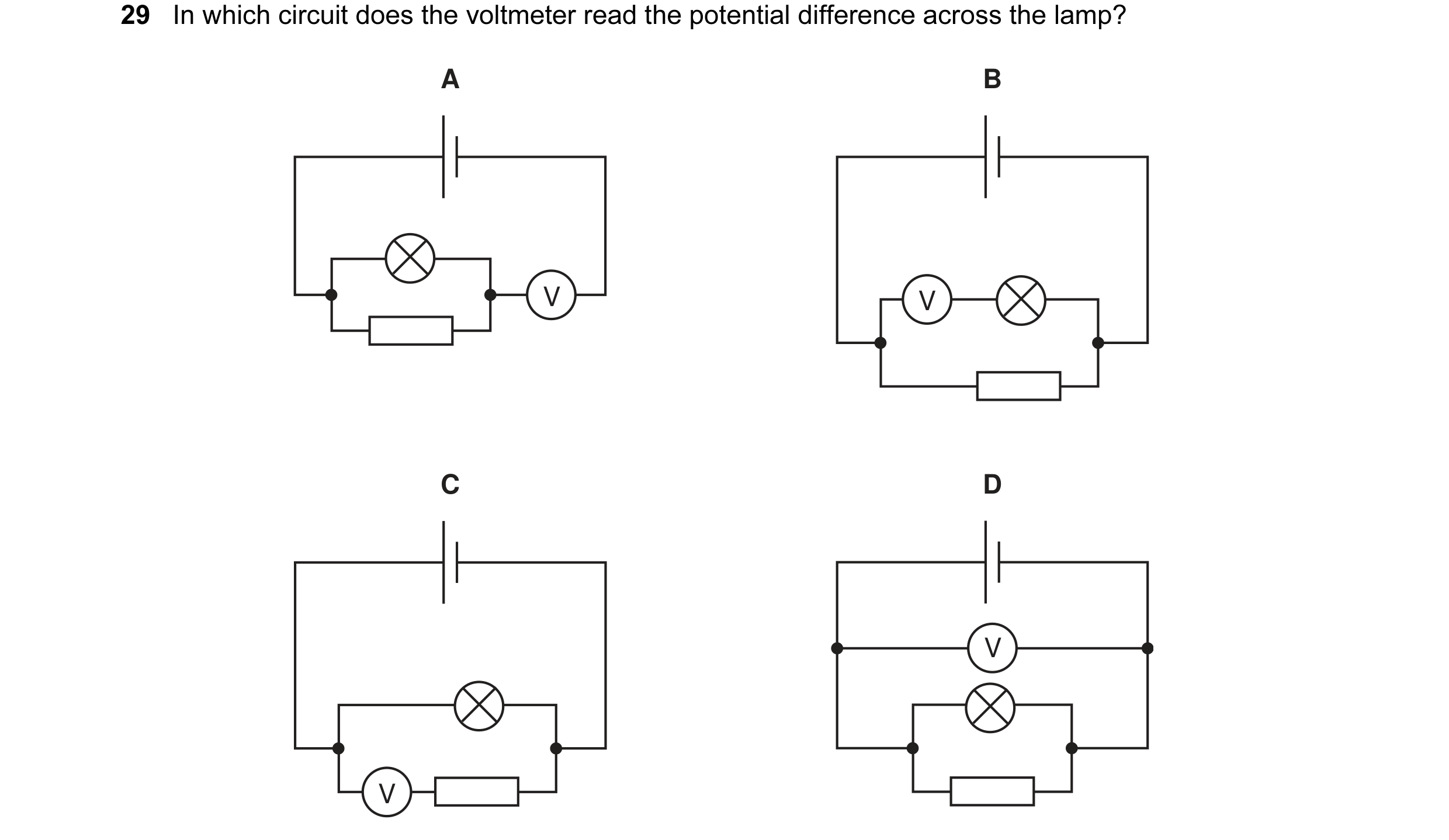
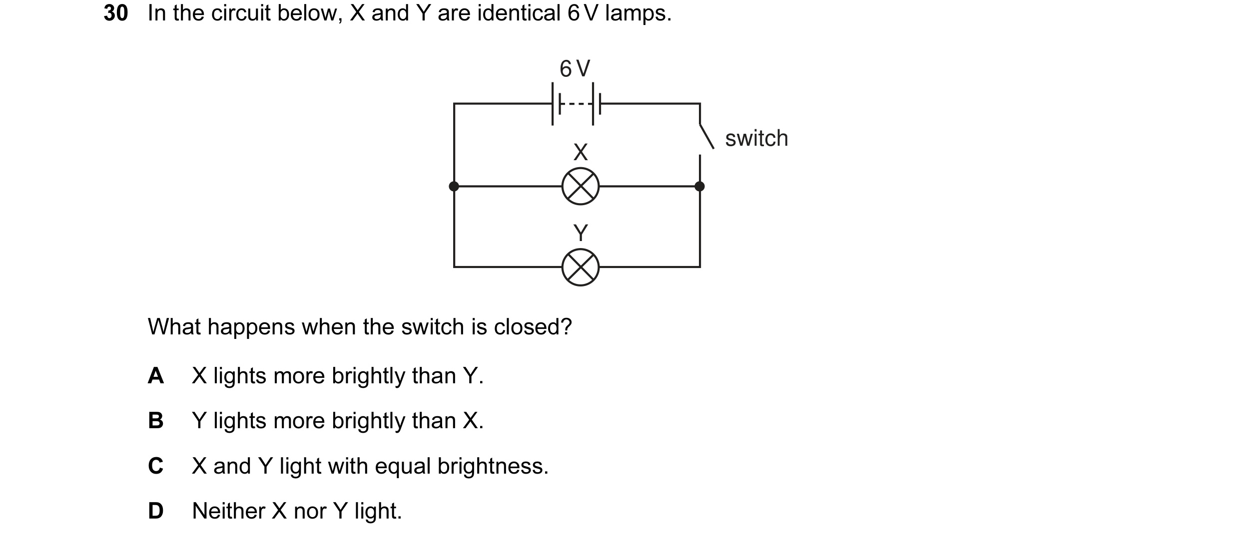 1 / 176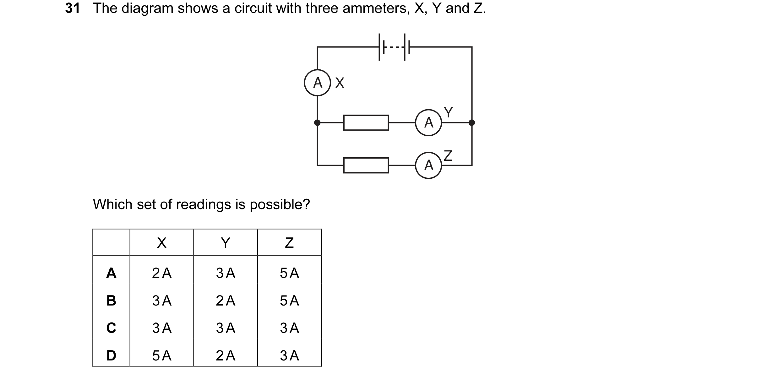
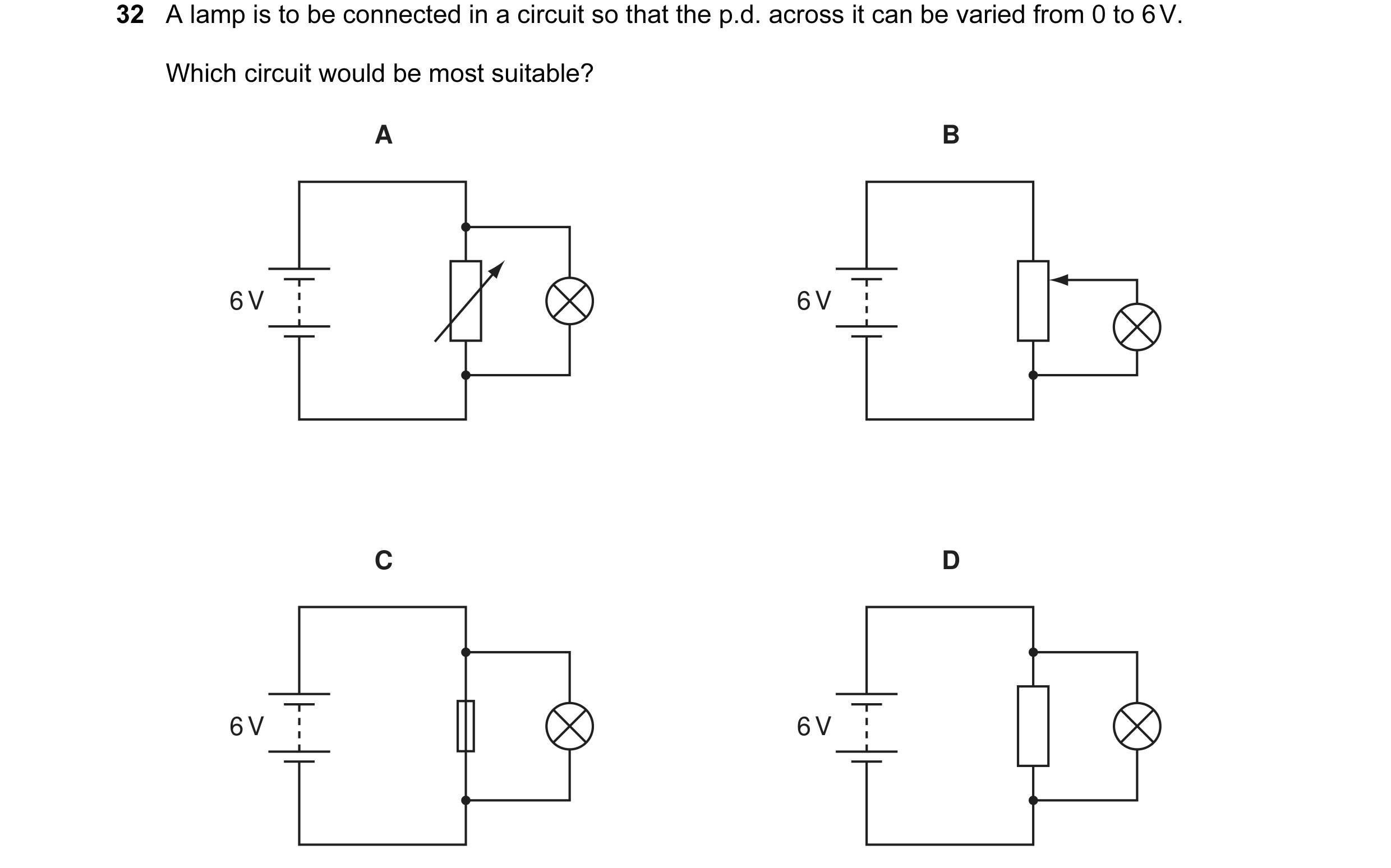 2 / 176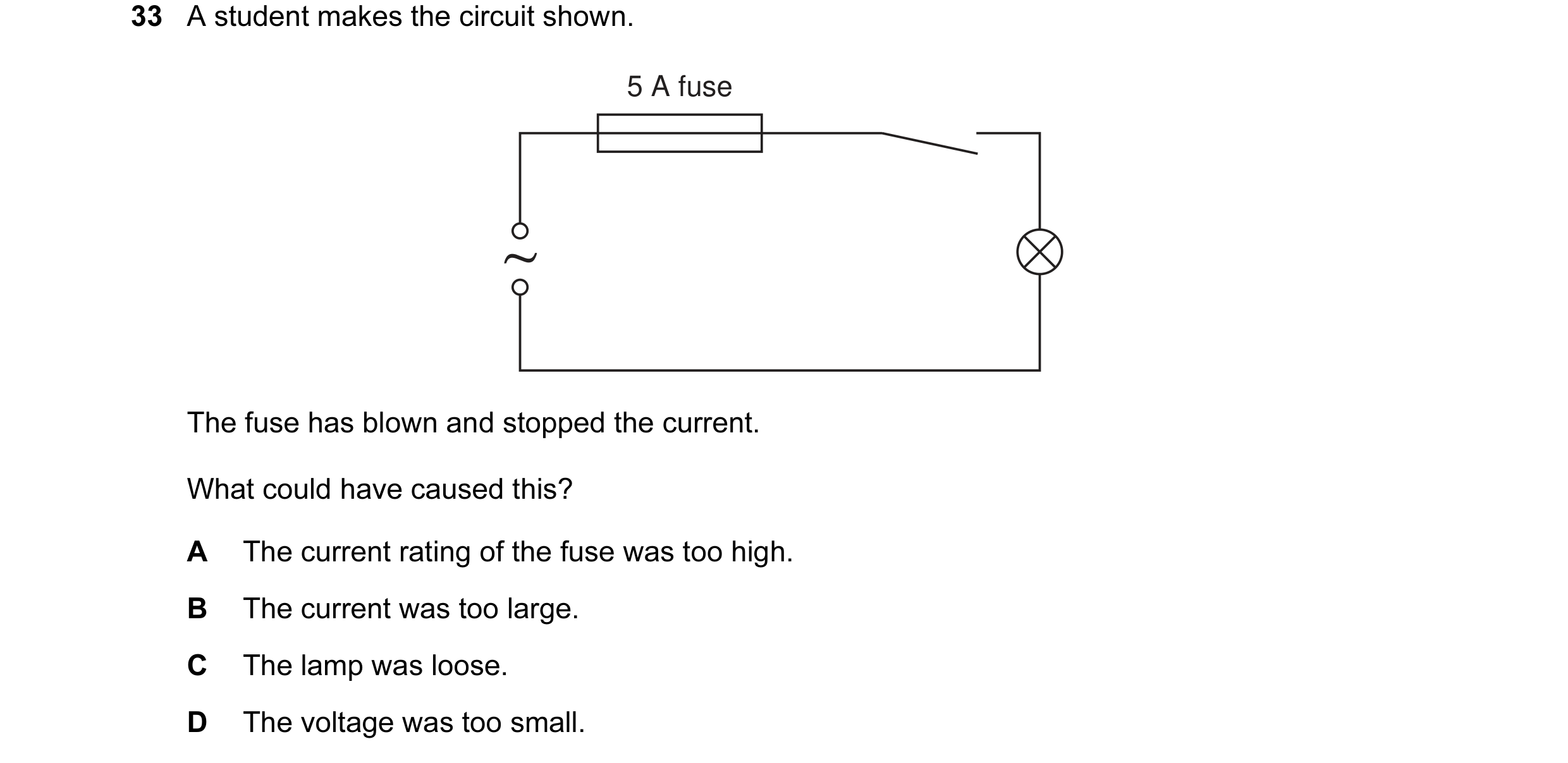
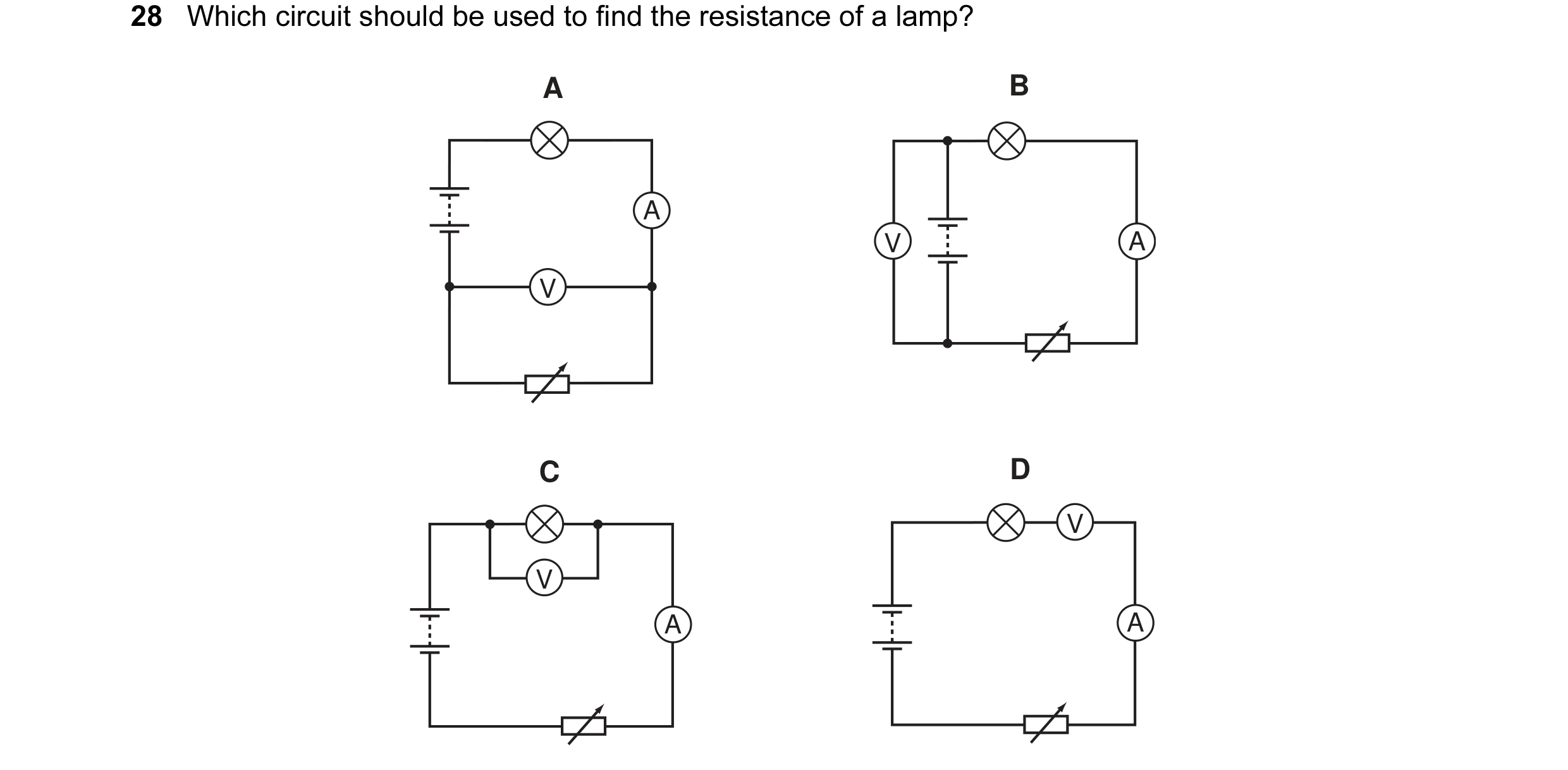
 3 / 176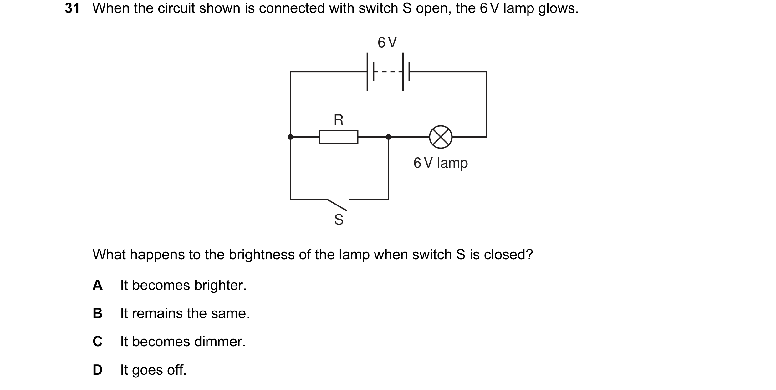

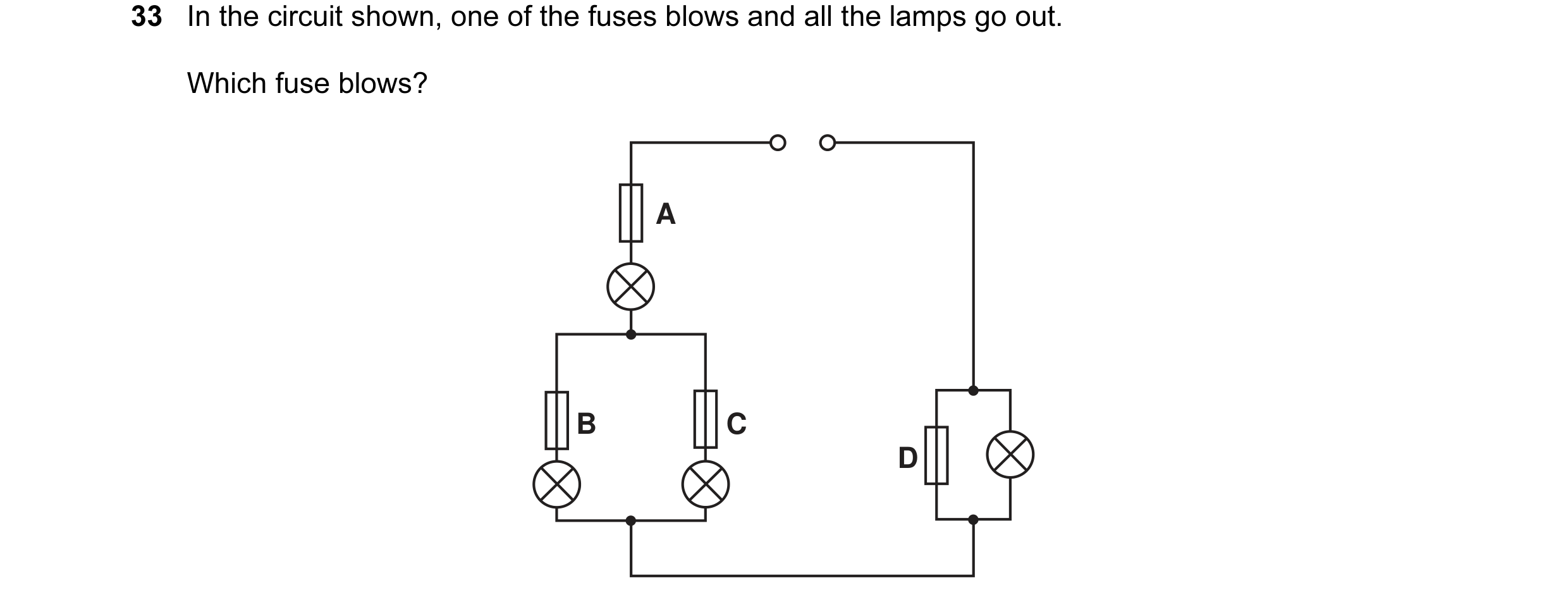
 4 / 176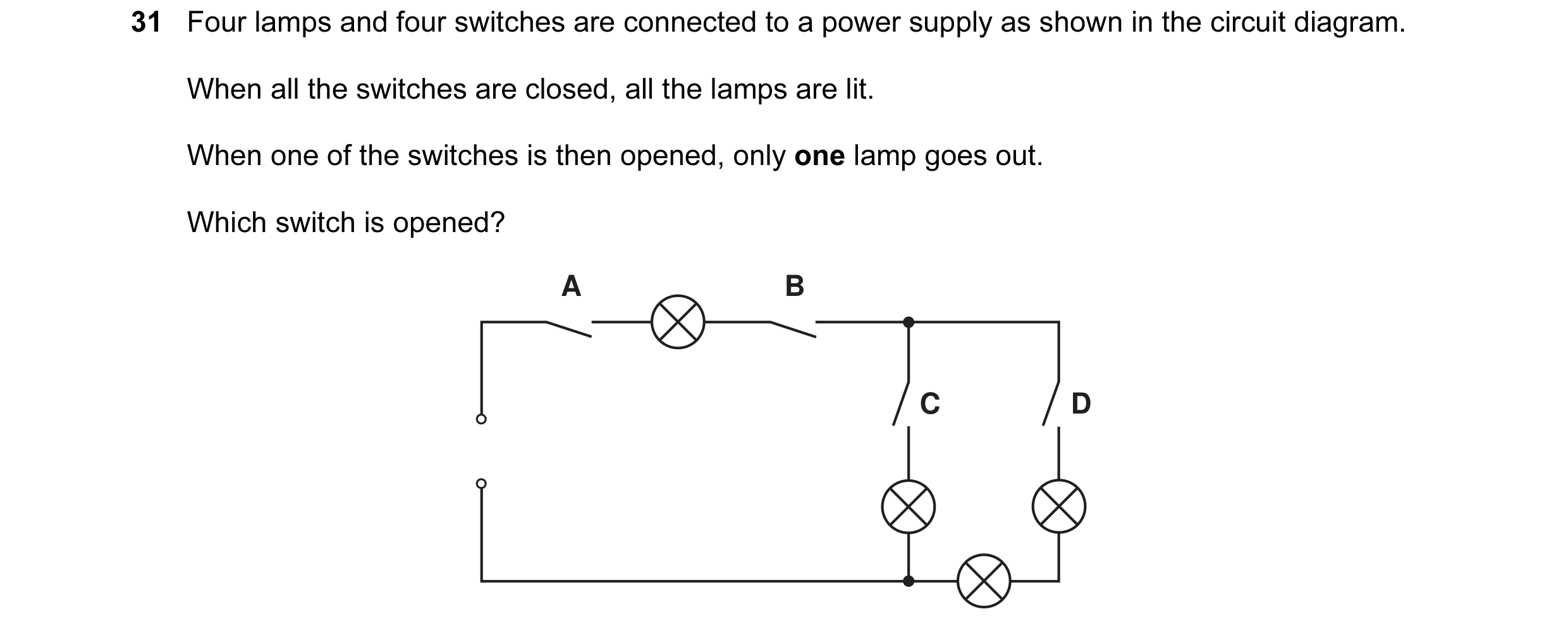
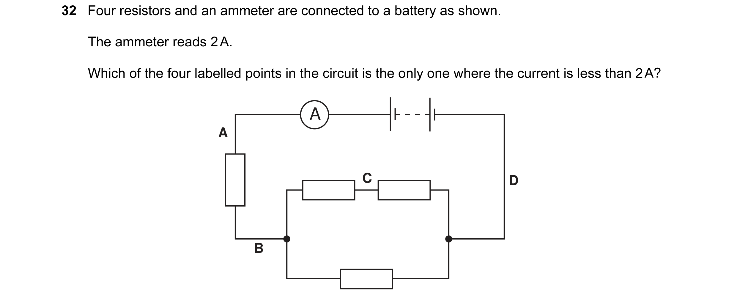
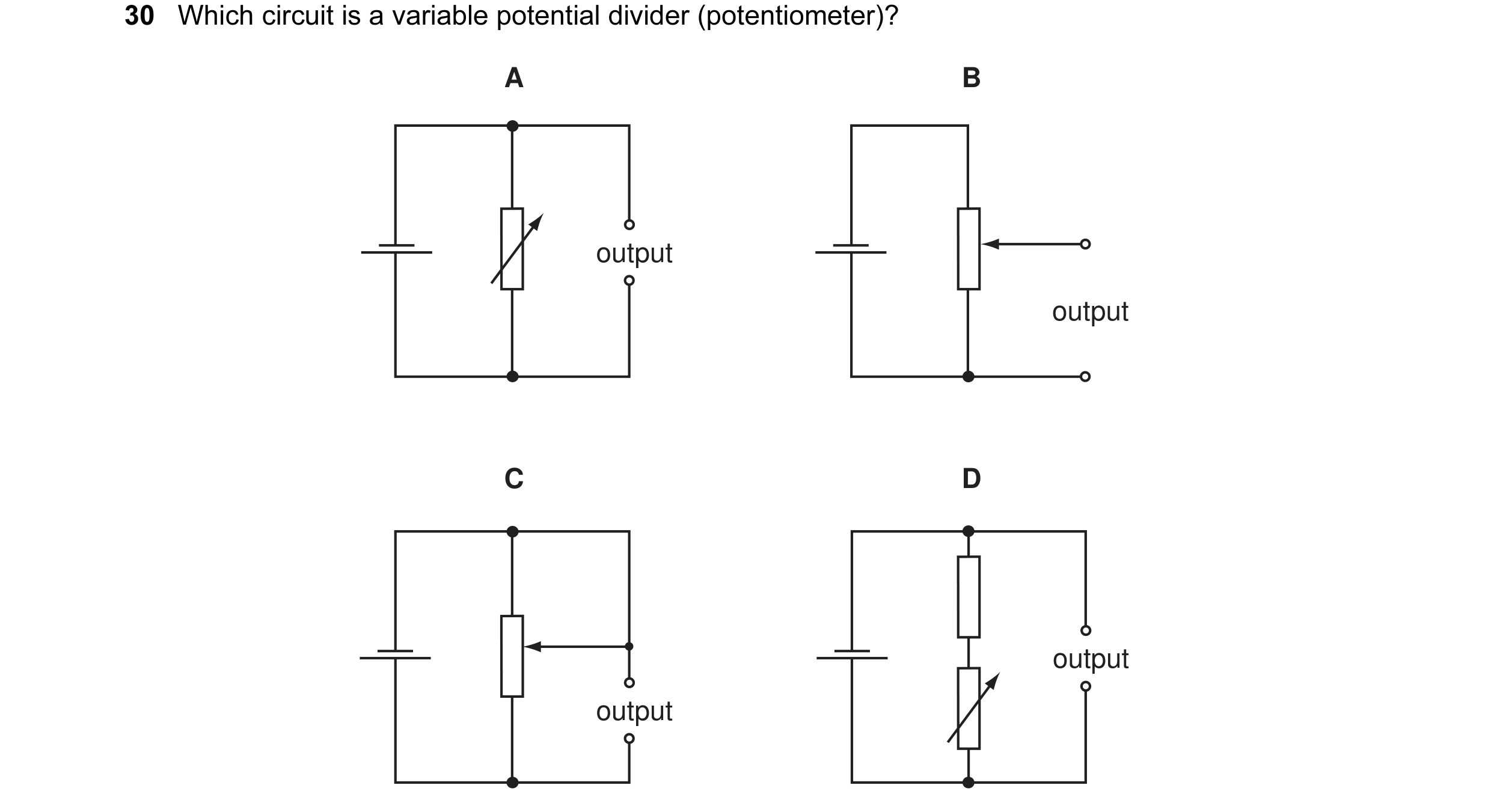 5 / 176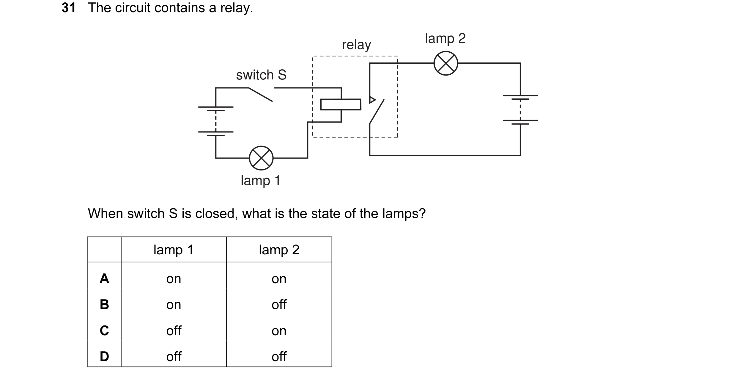
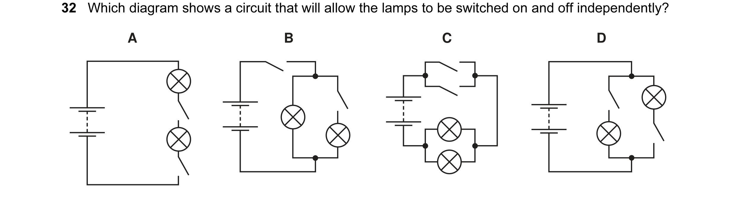
 6 / 176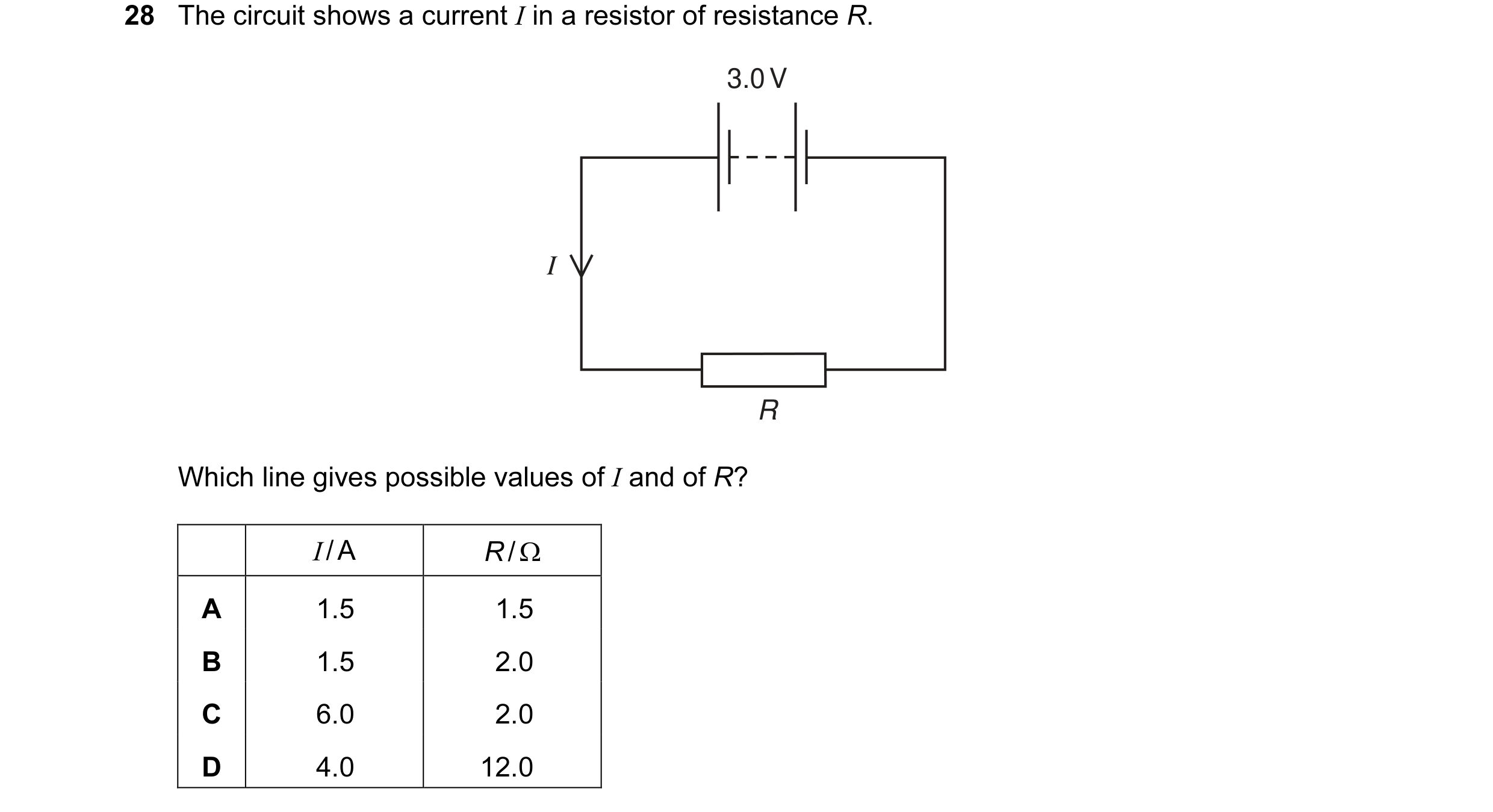
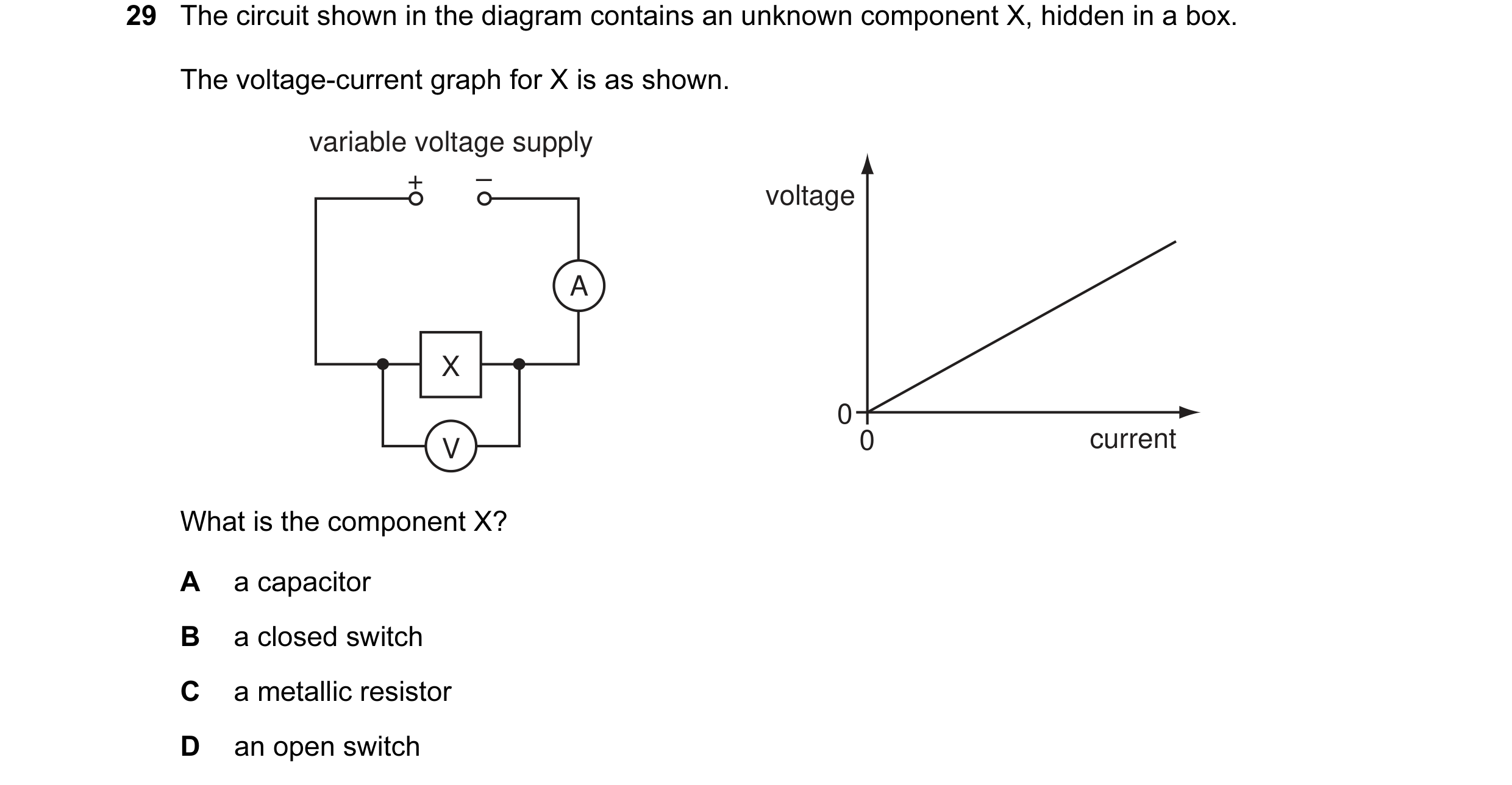 7 / 176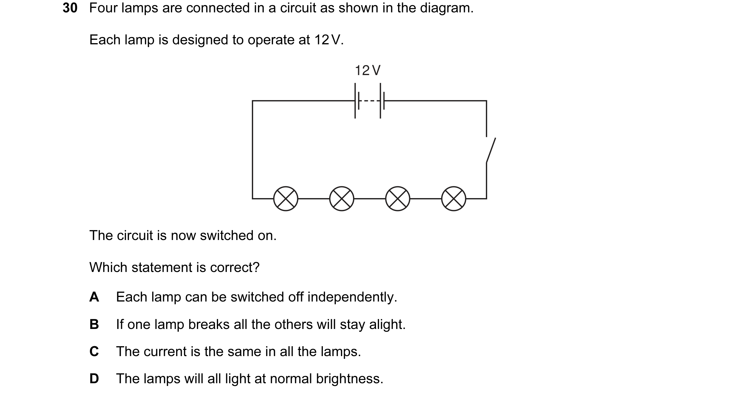
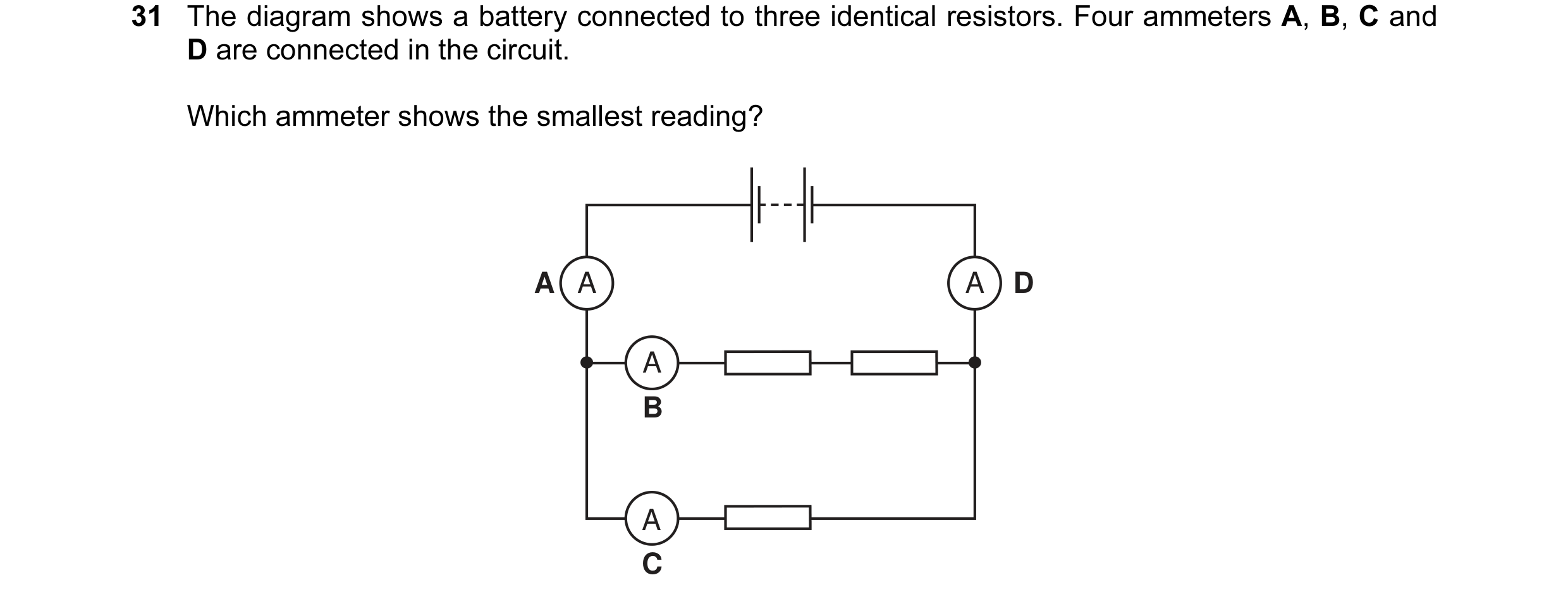 8 / 176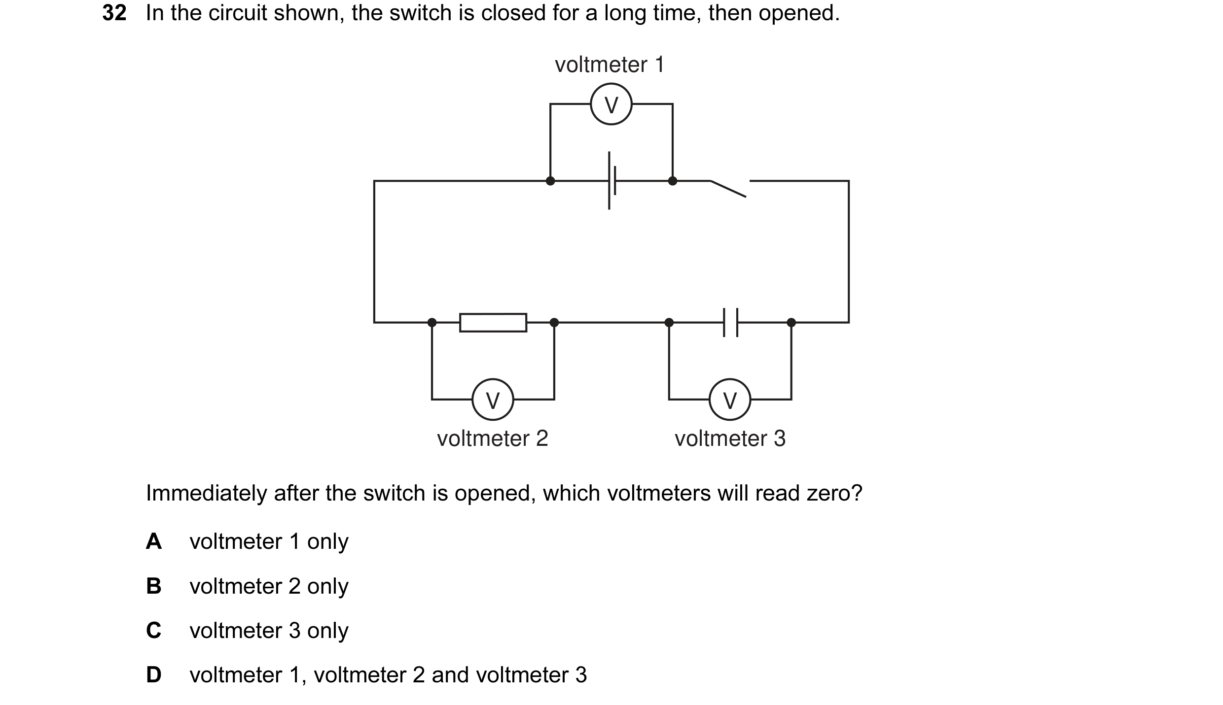

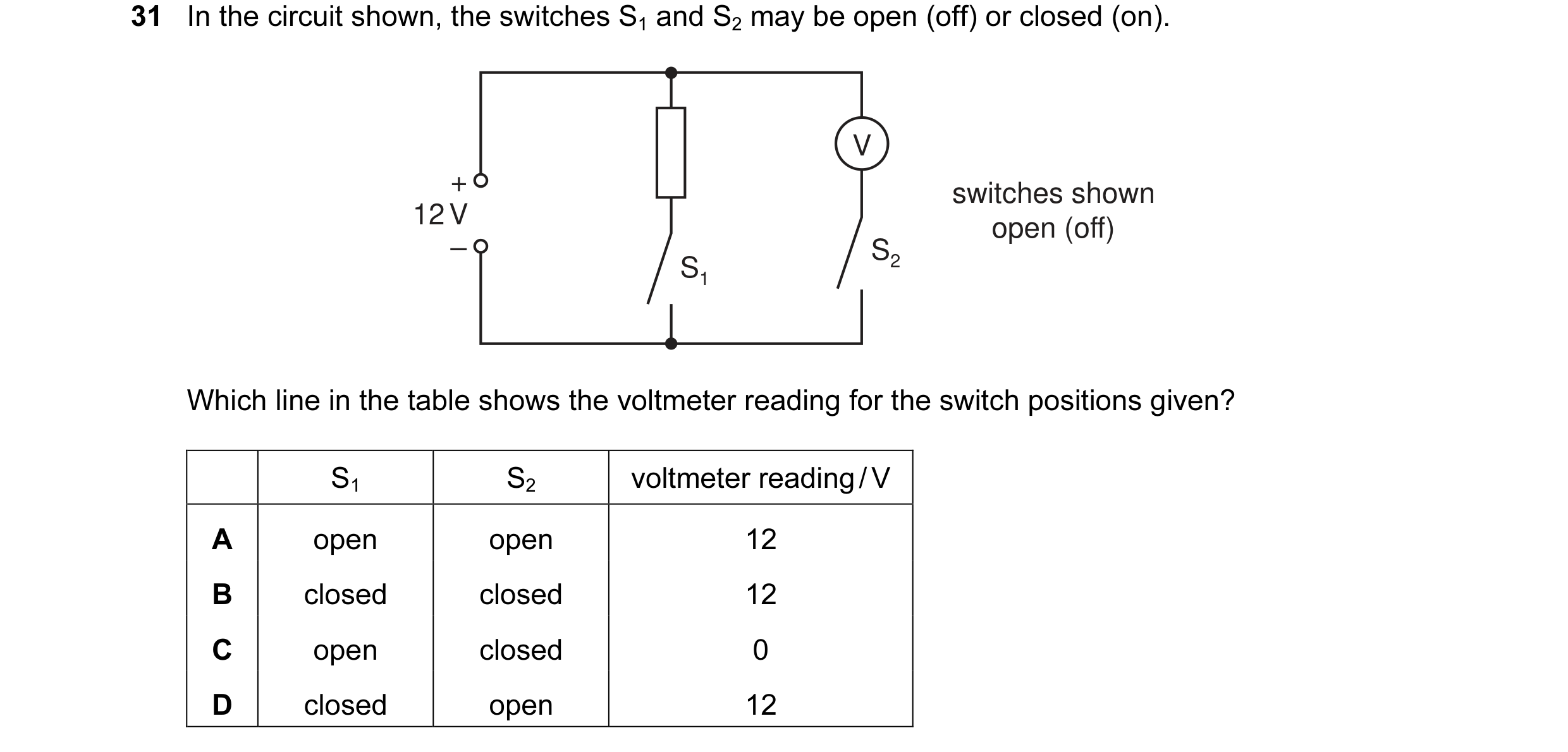 9 / 176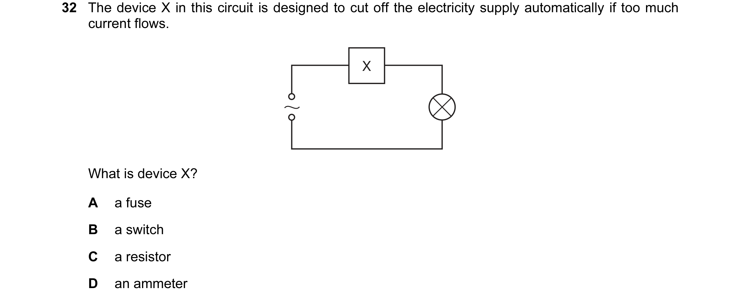
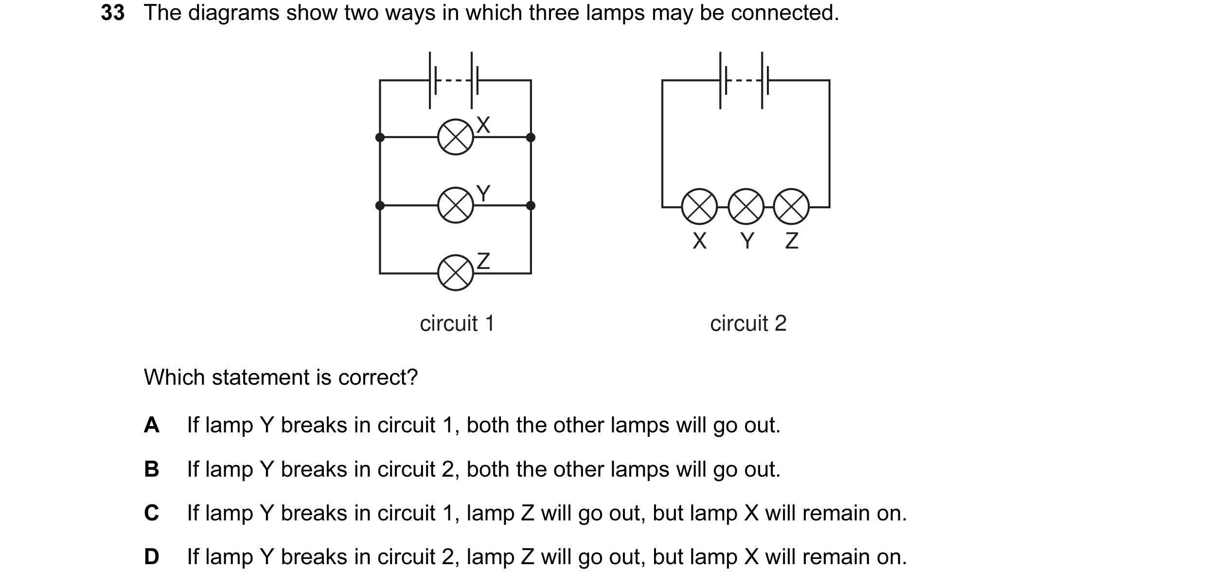 10 / 176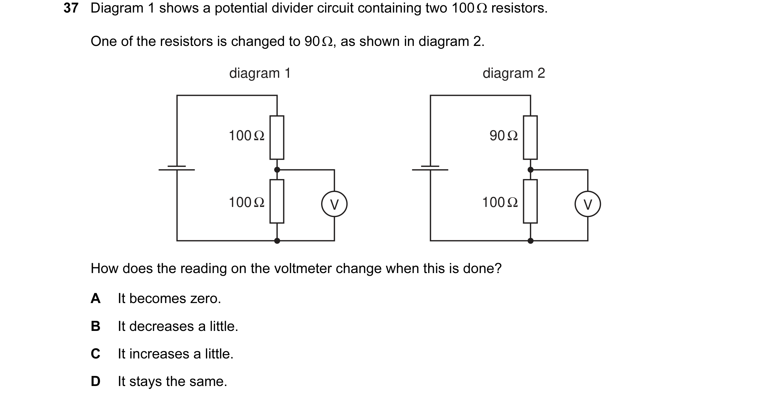
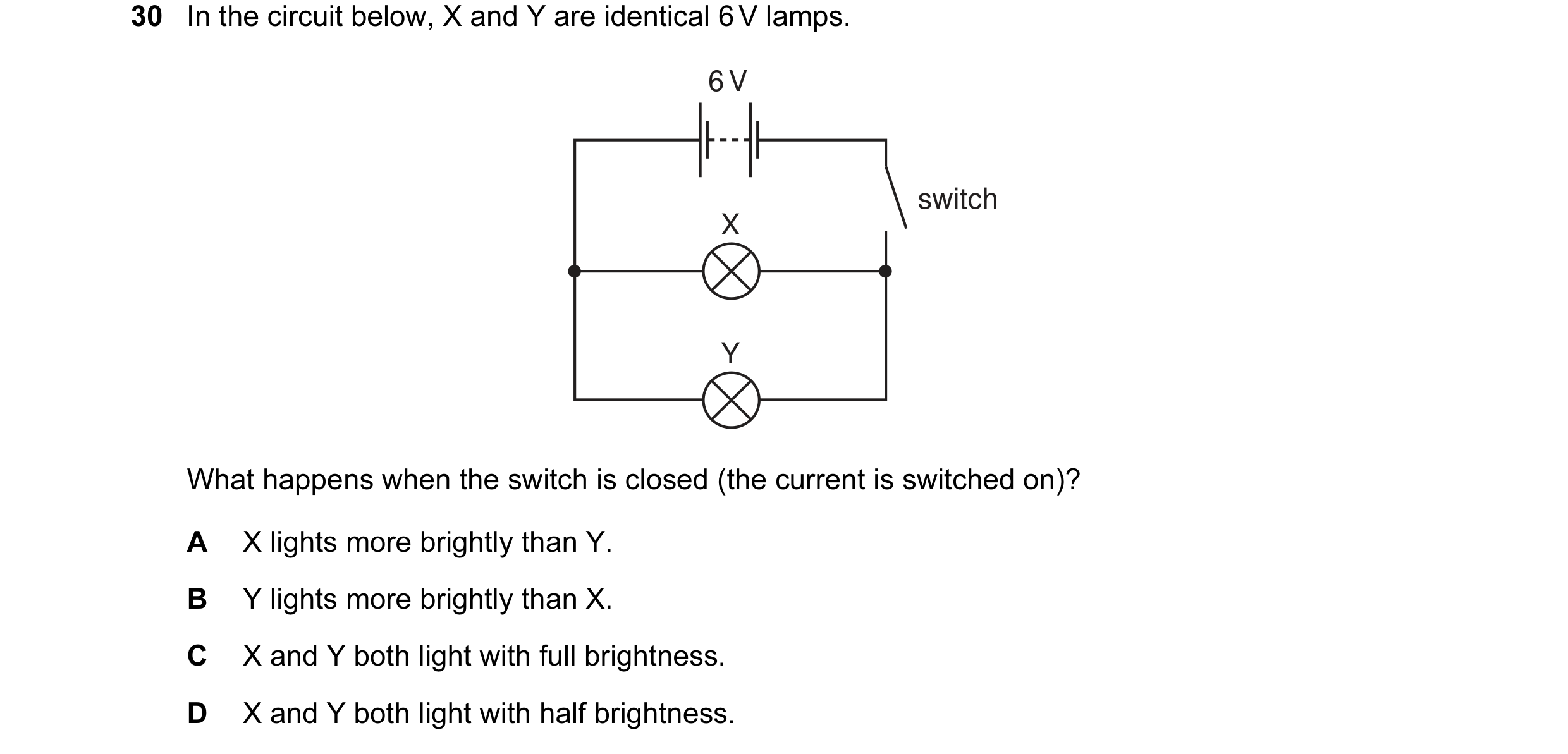 11 / 176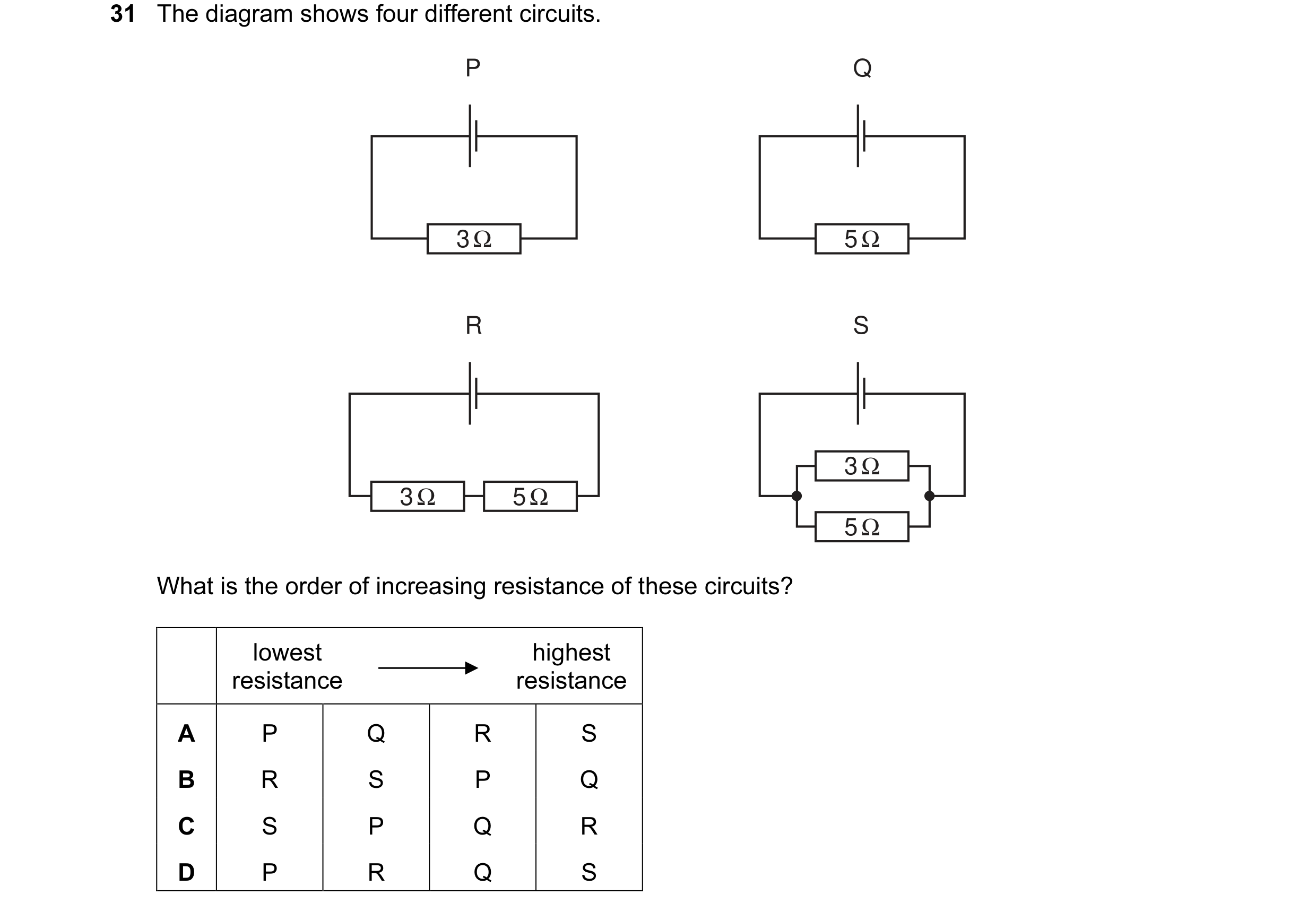
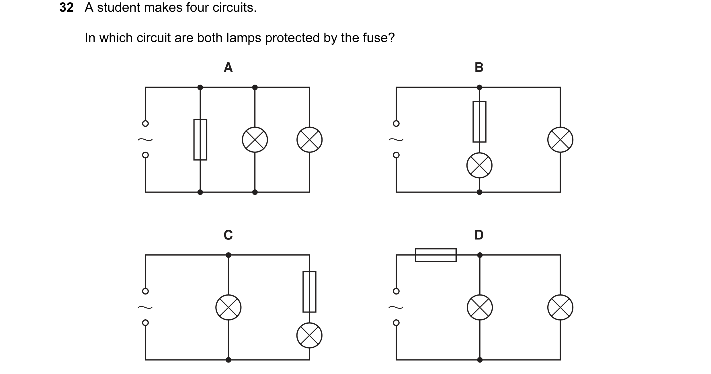 12 / 176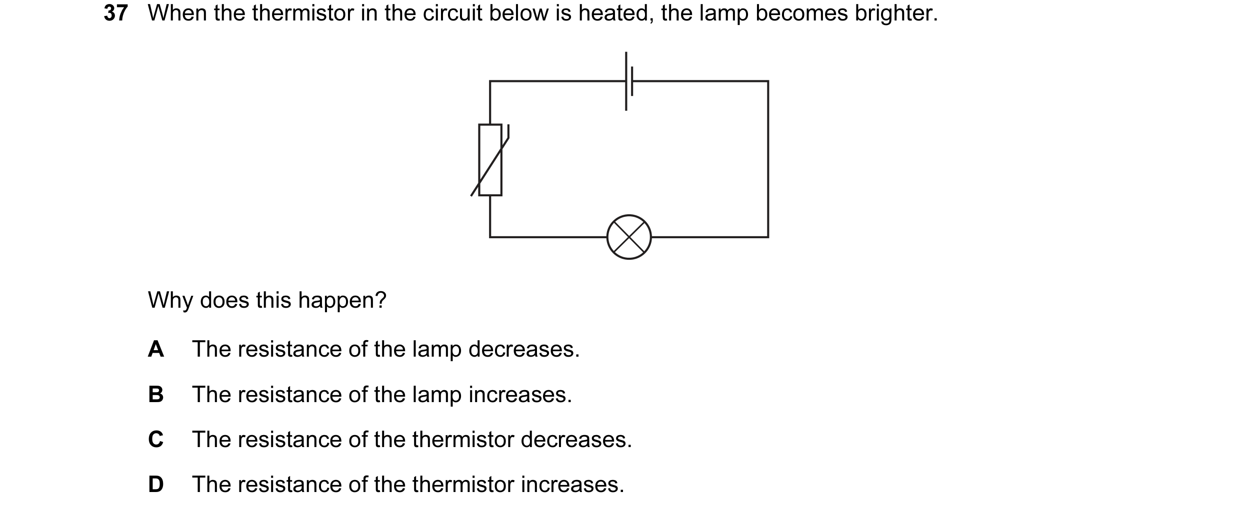
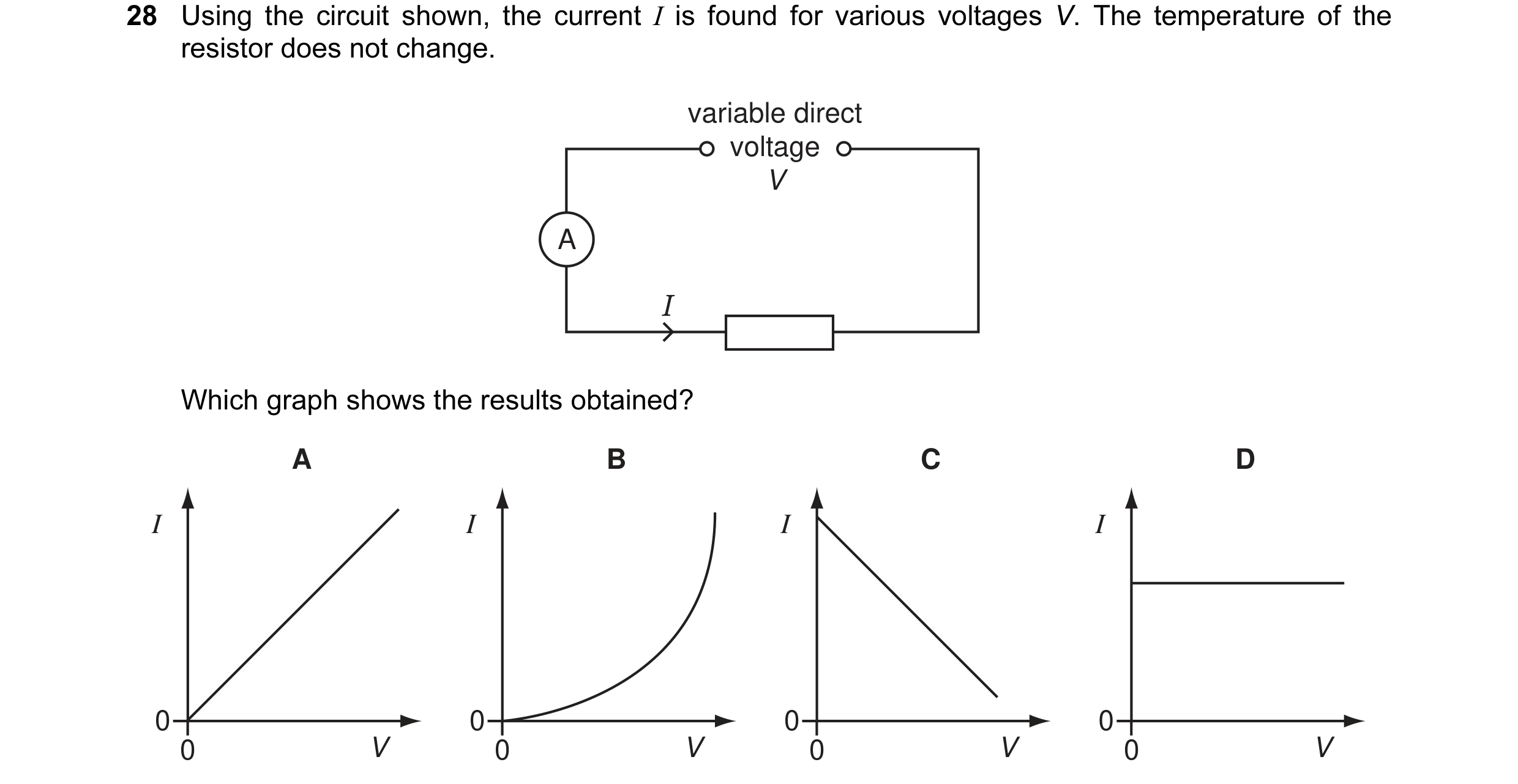
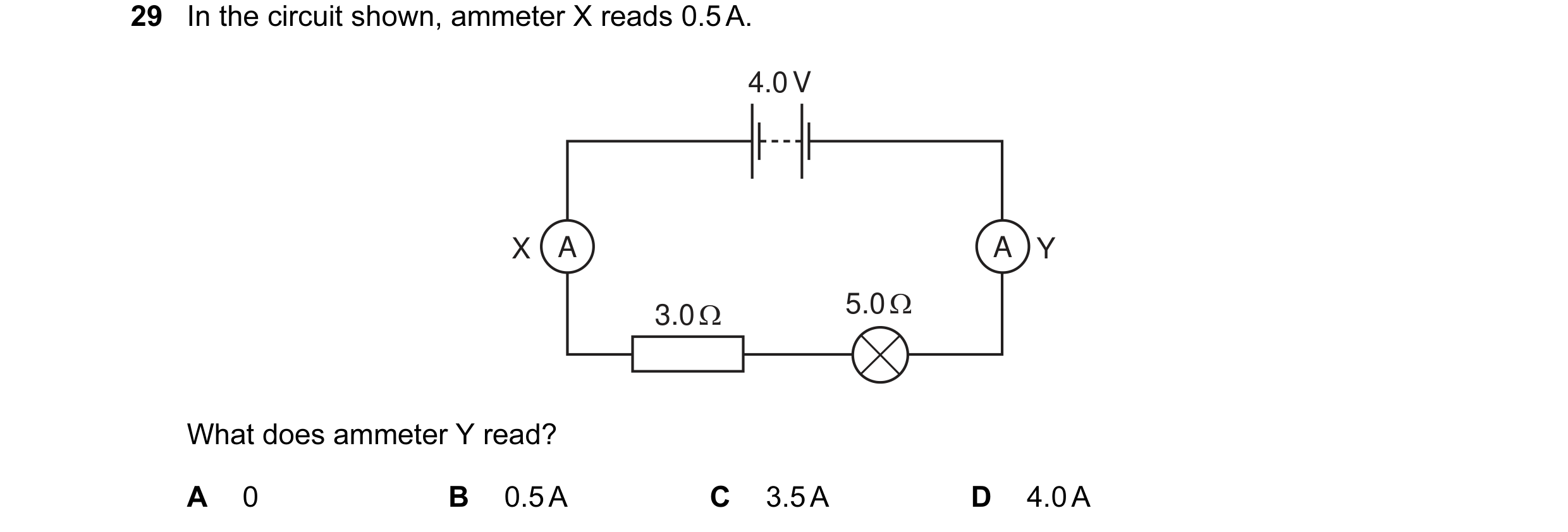 13 / 176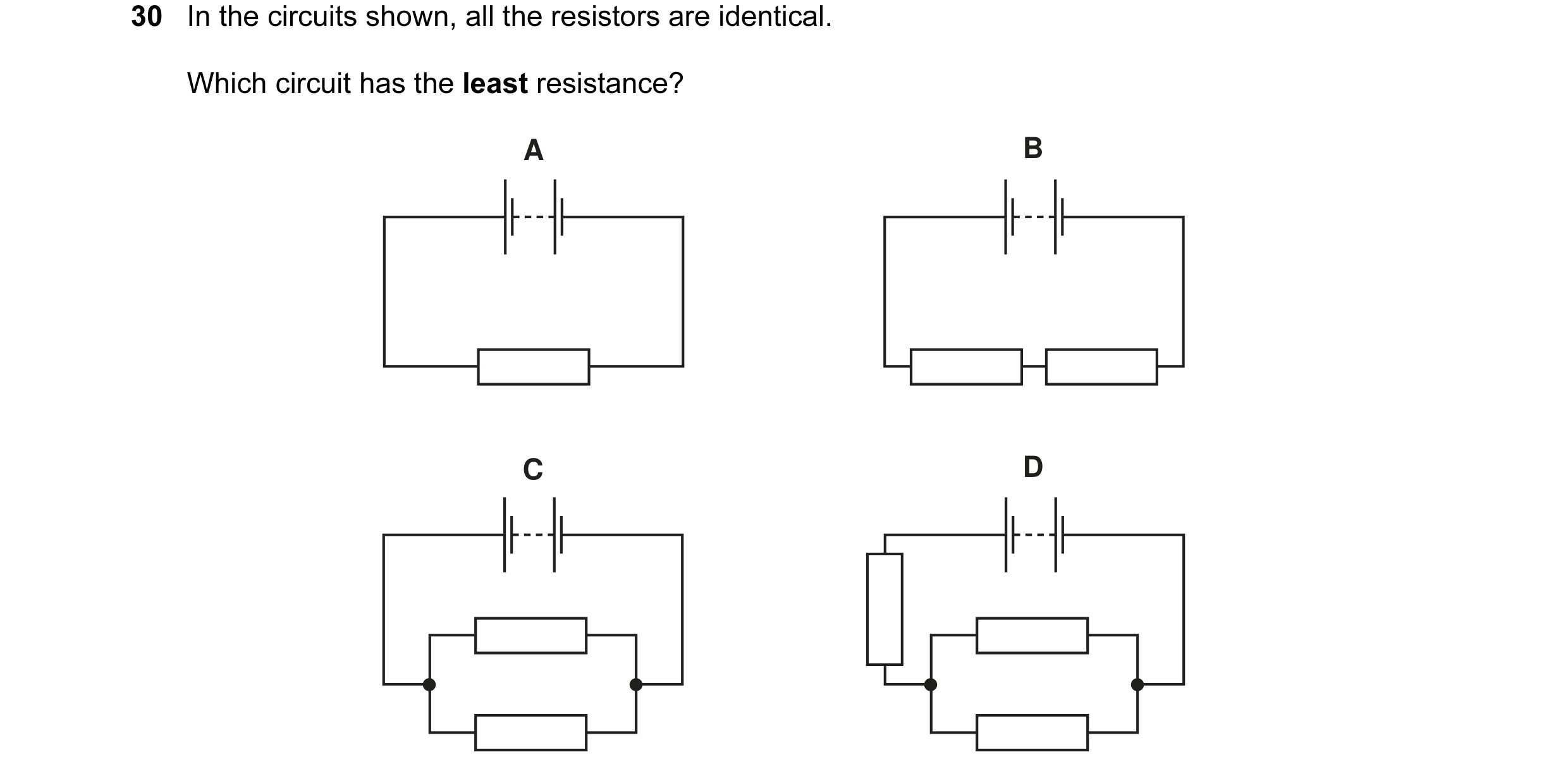
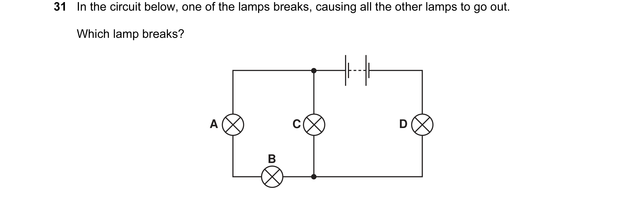
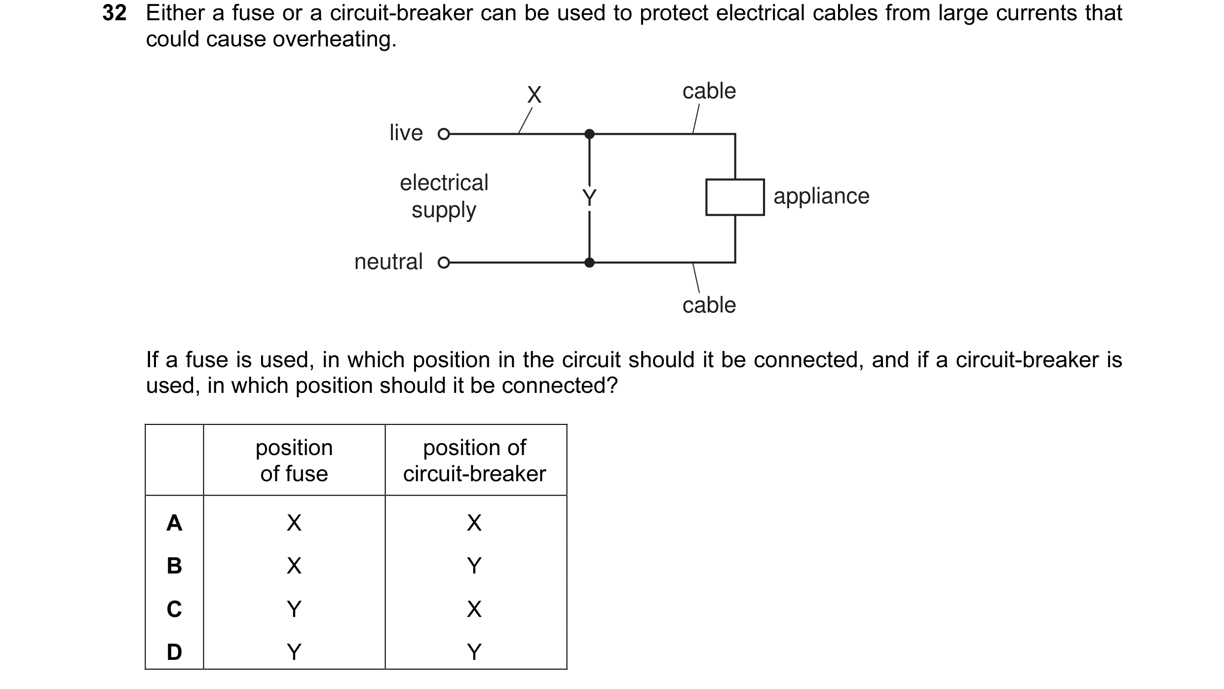 14 / 176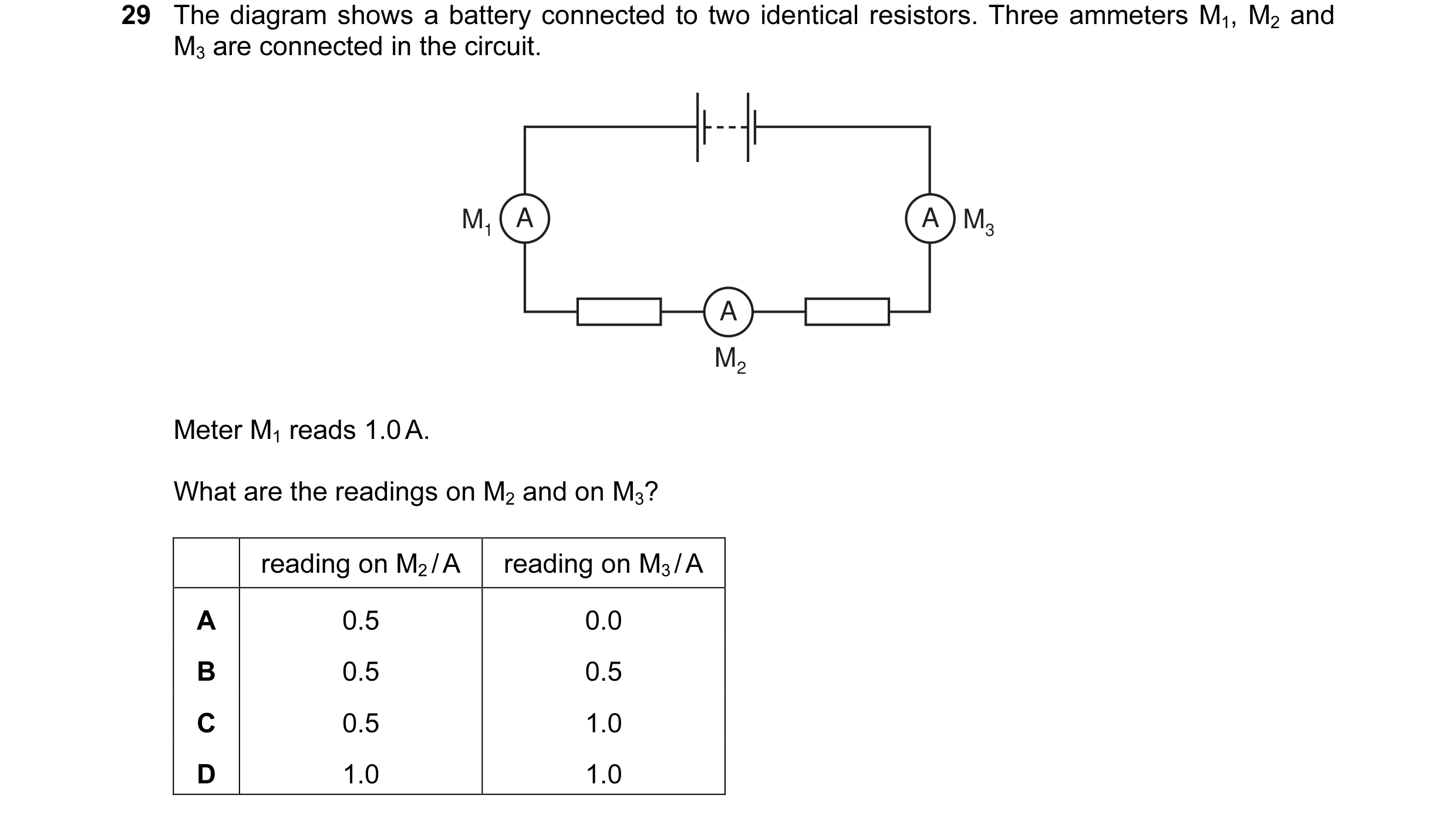
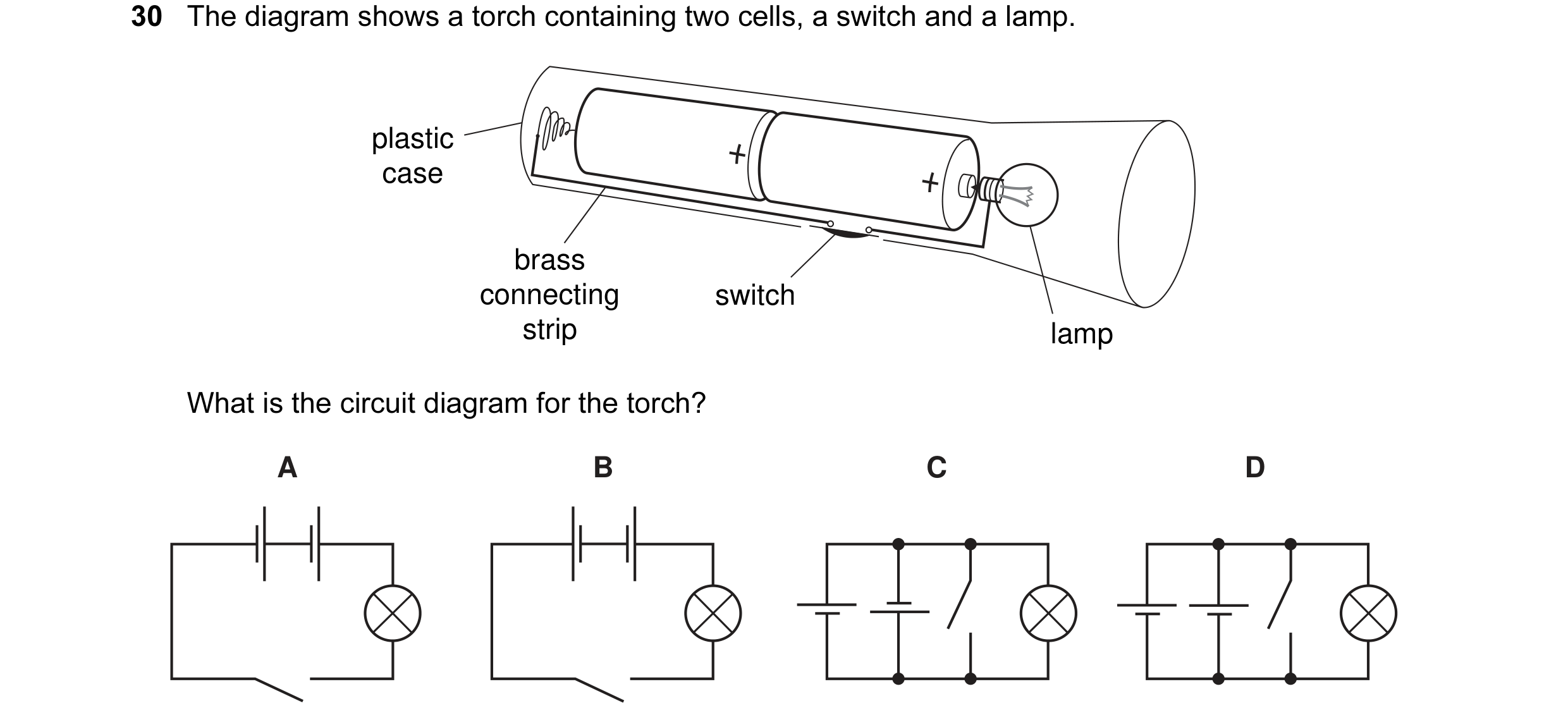 15 / 176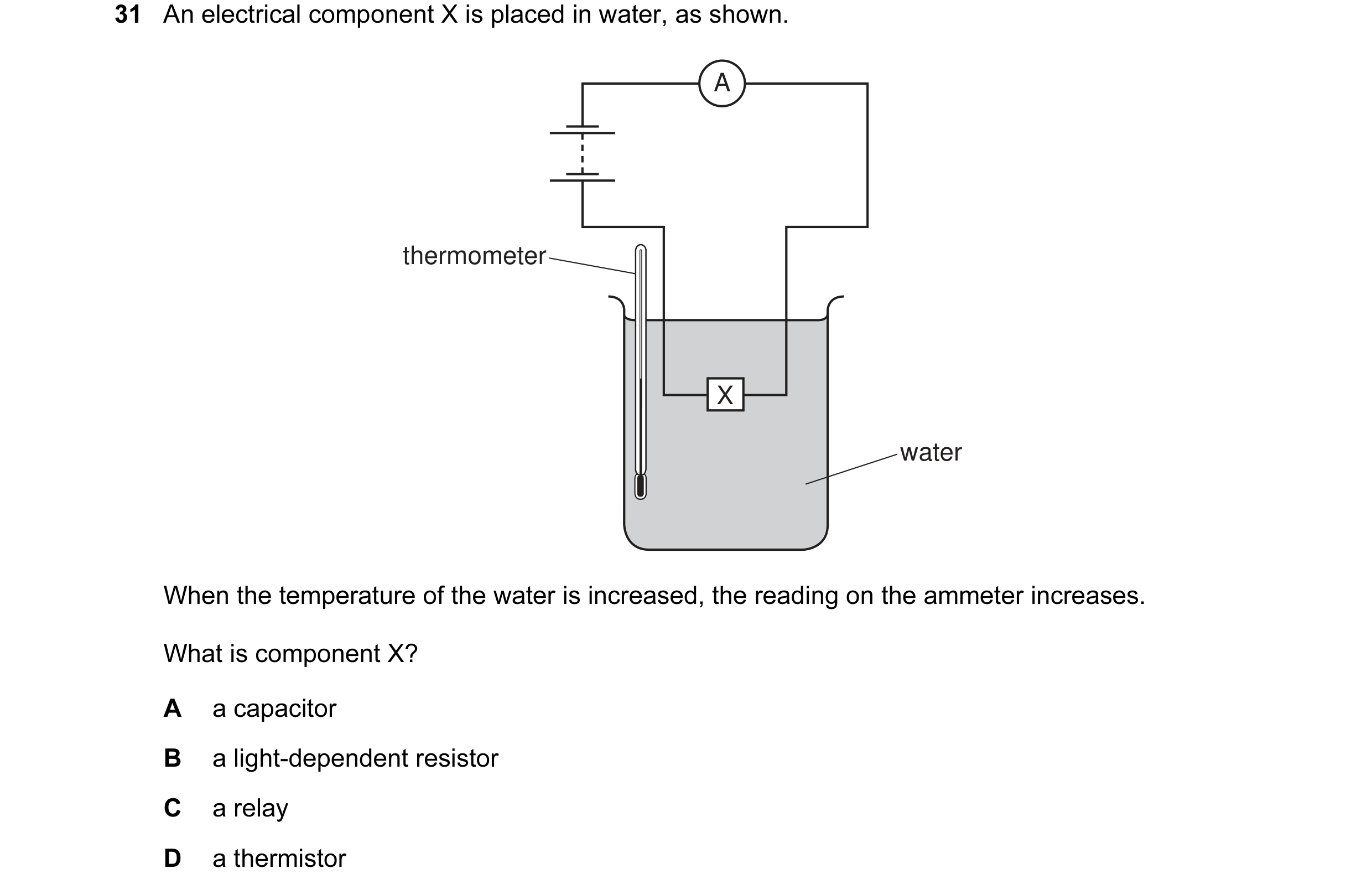
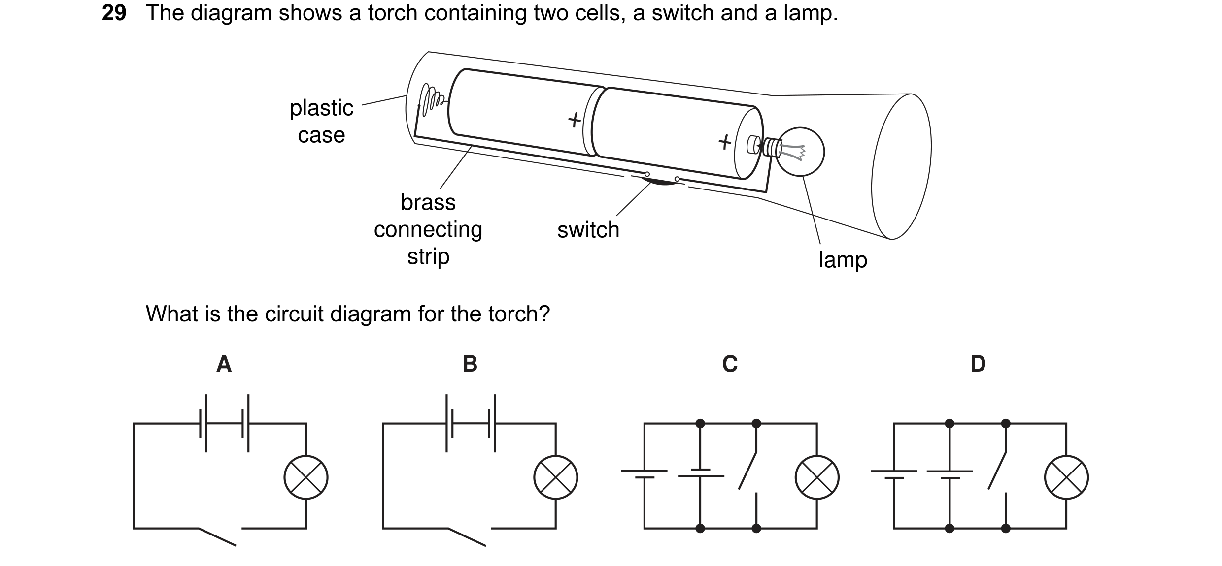 16 / 176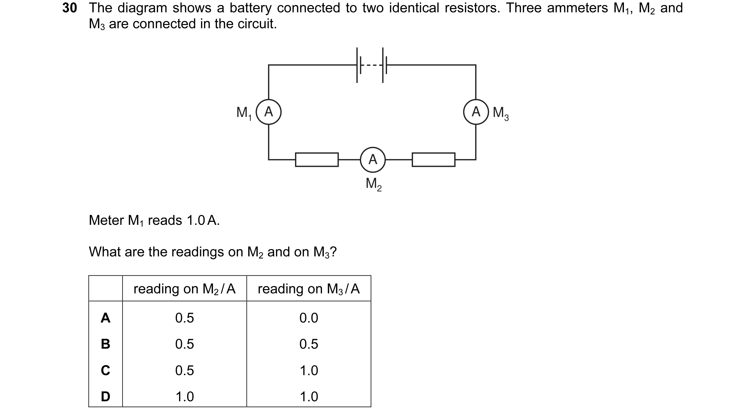
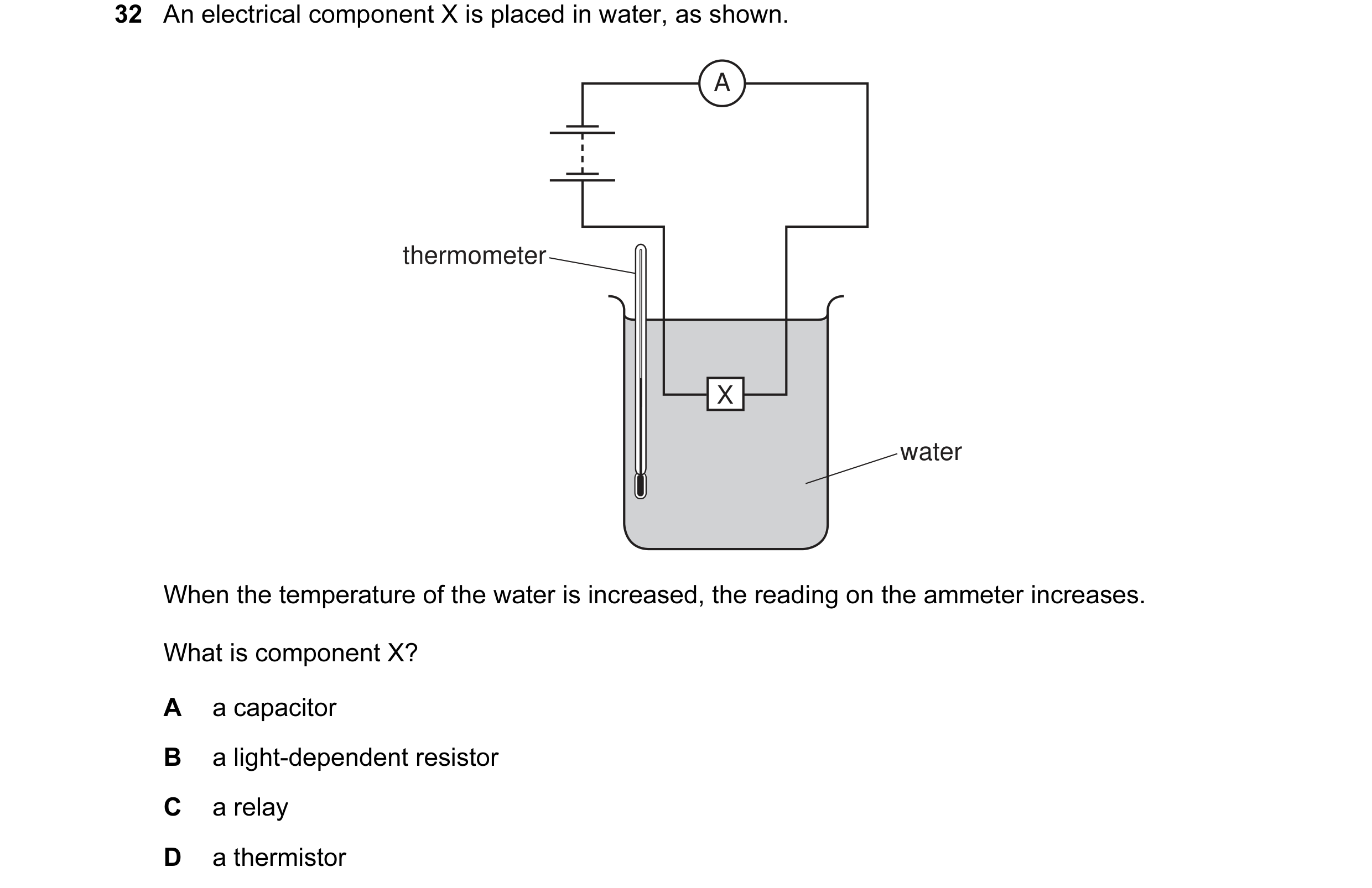 17 / 176
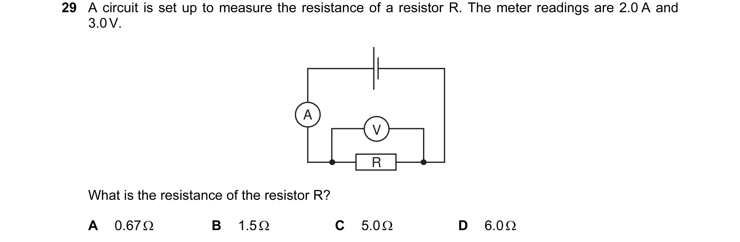
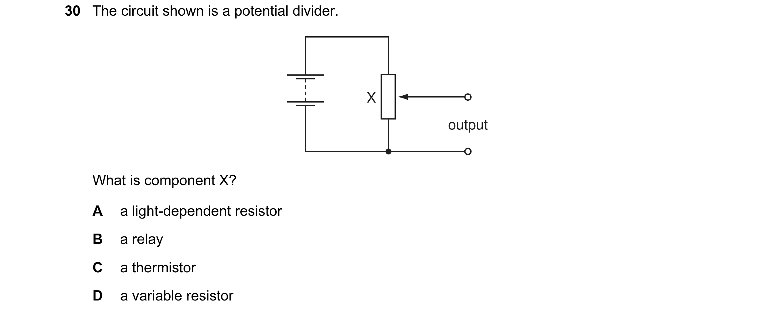 18 / 176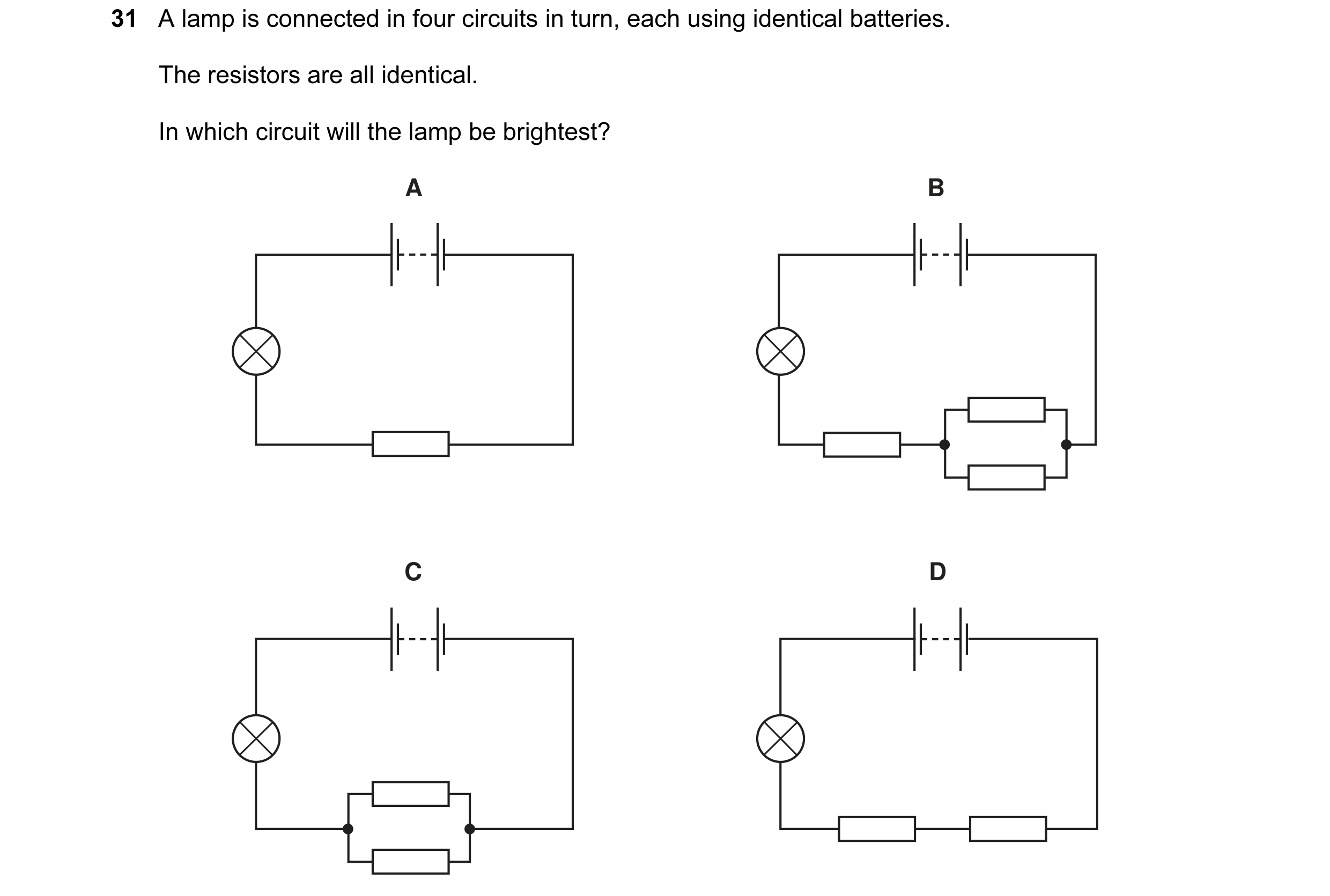
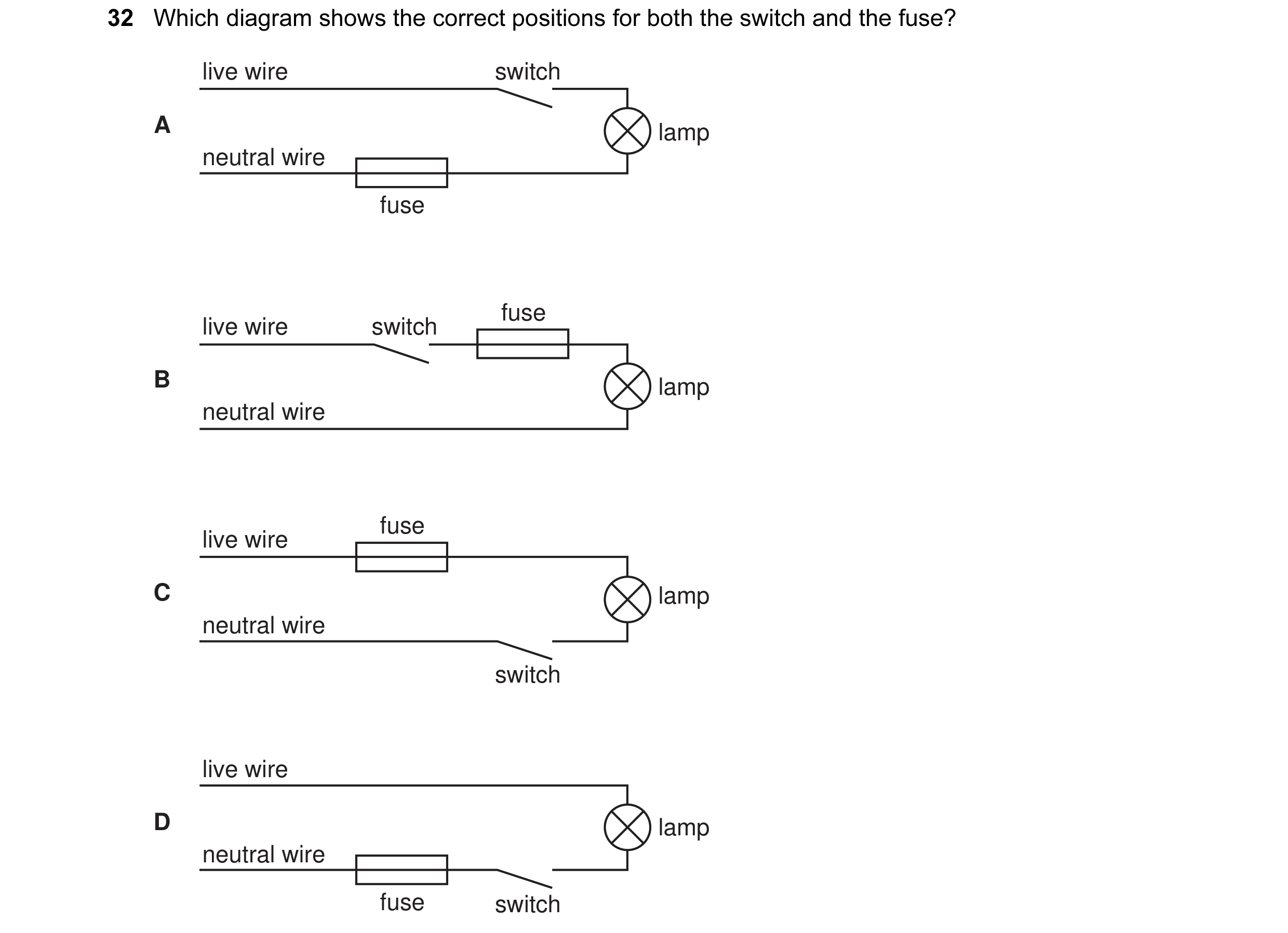 19 / 176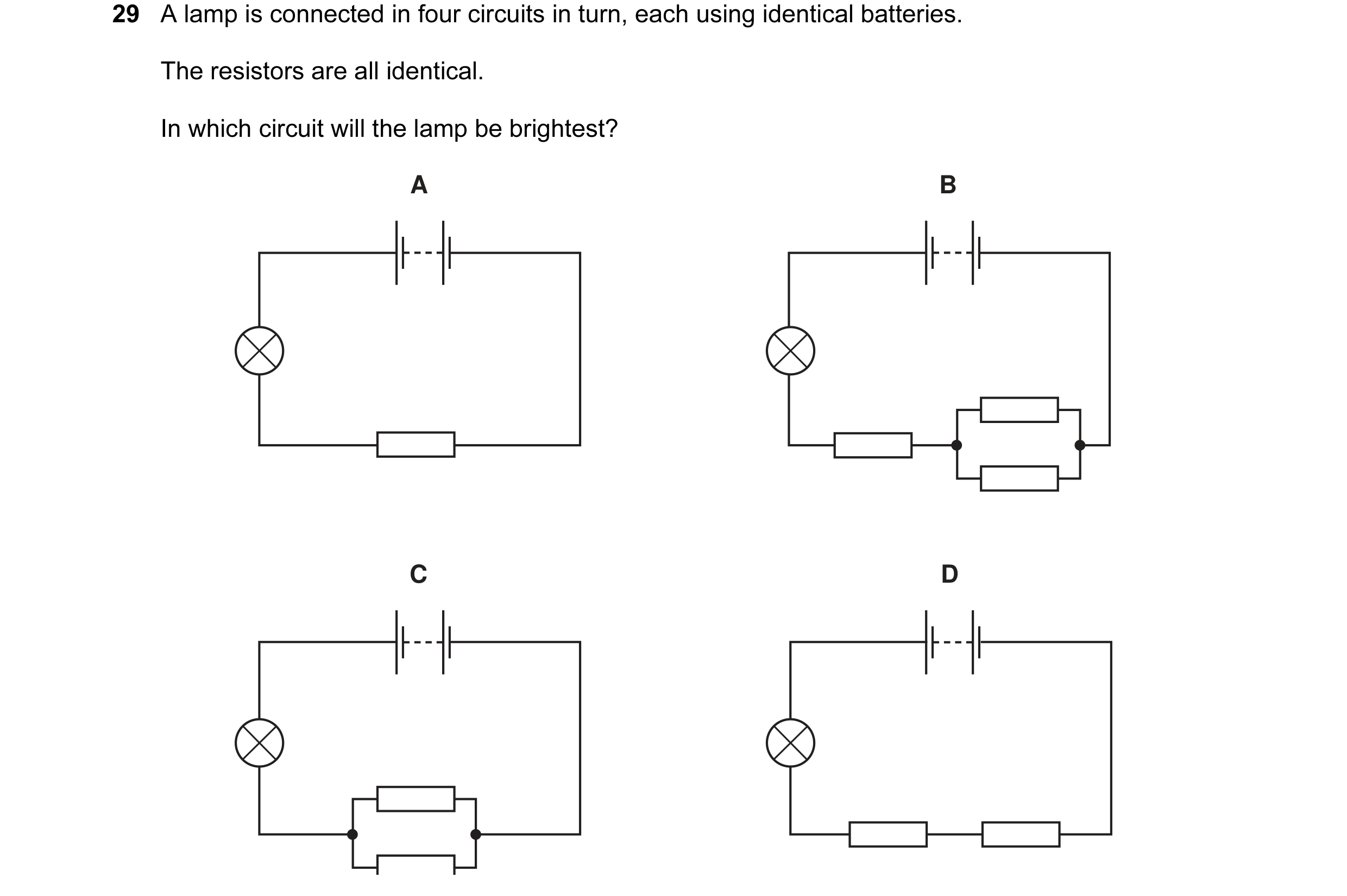
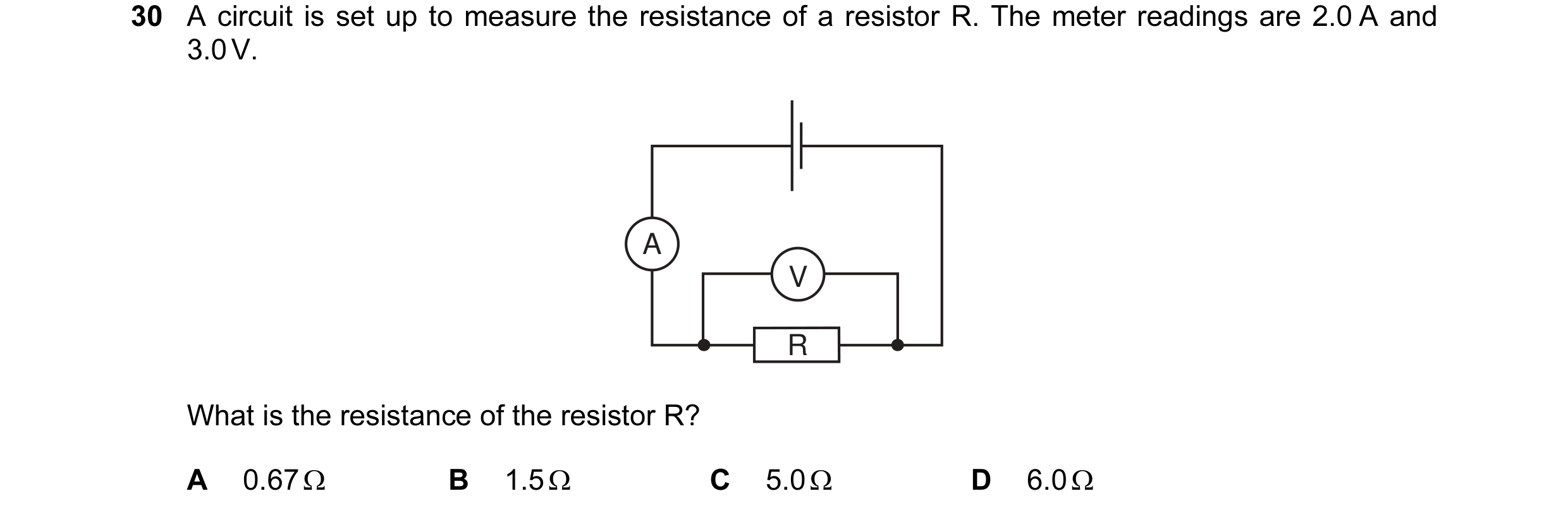 20 / 176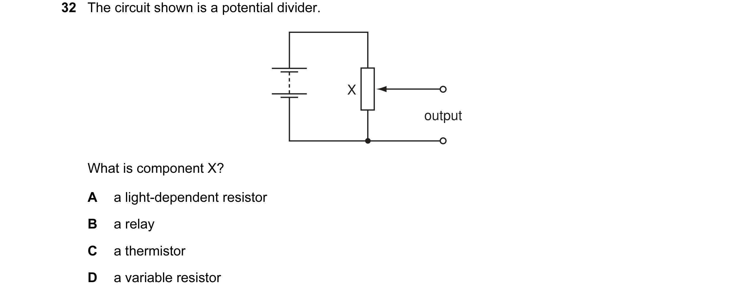
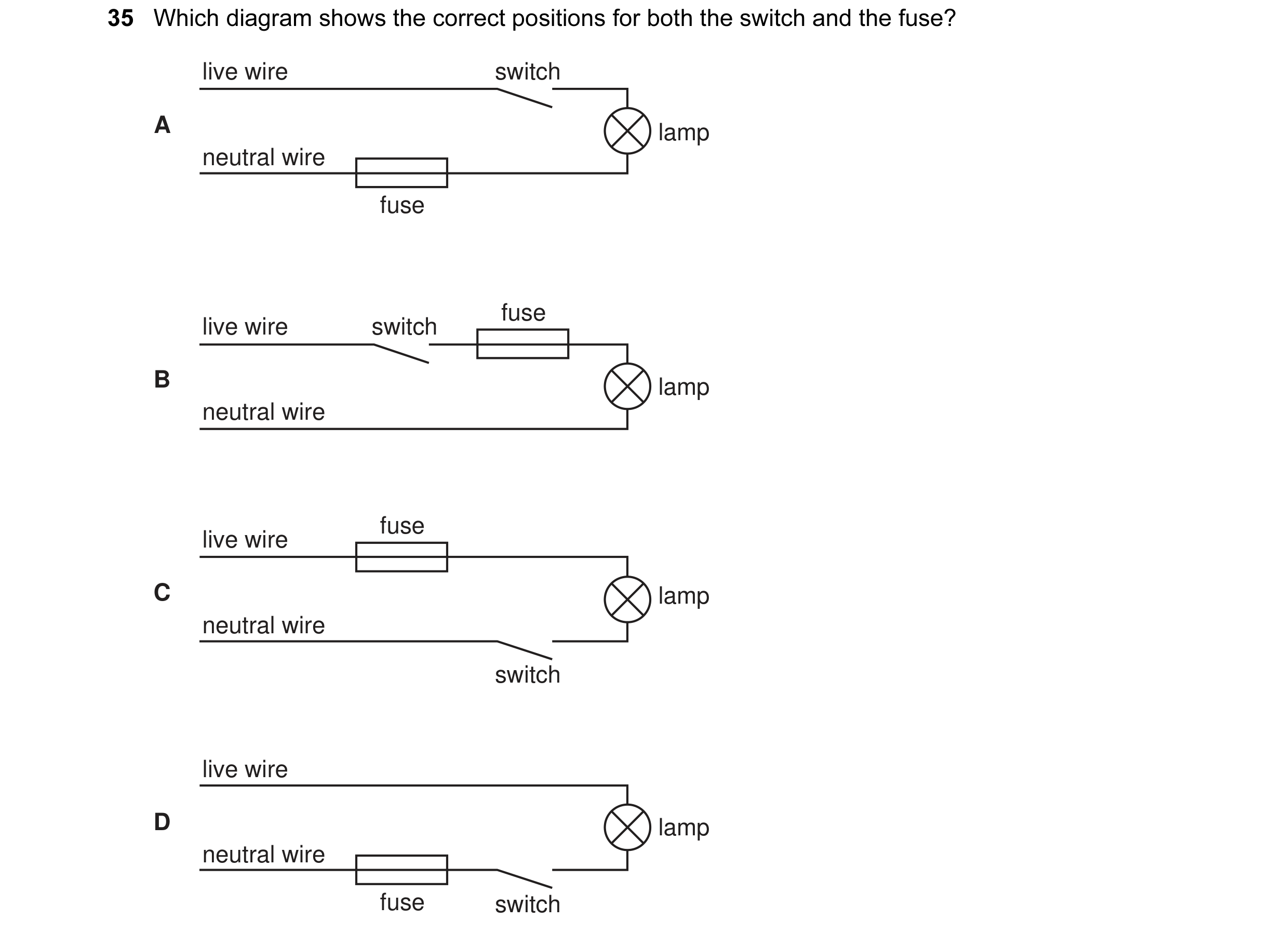 21 / 176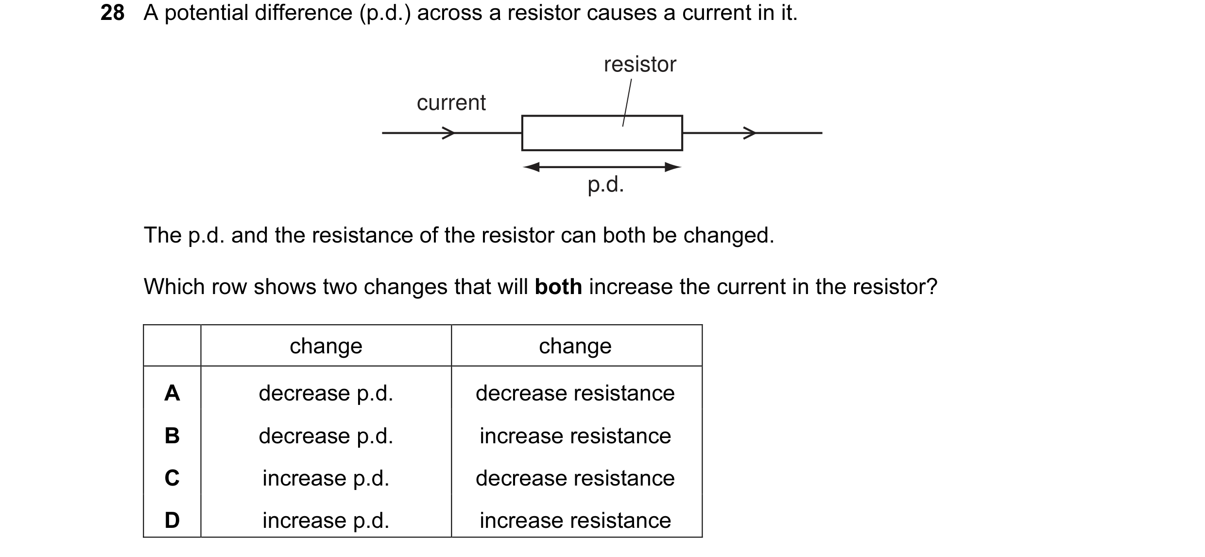
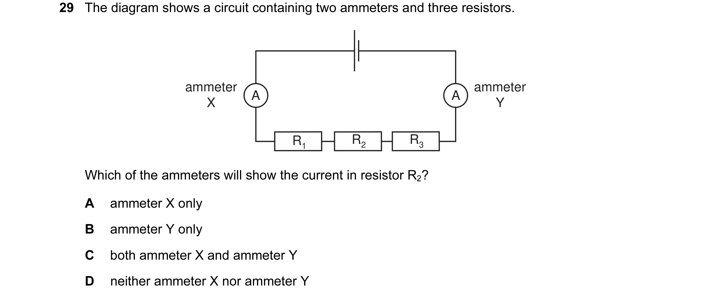
 22 / 176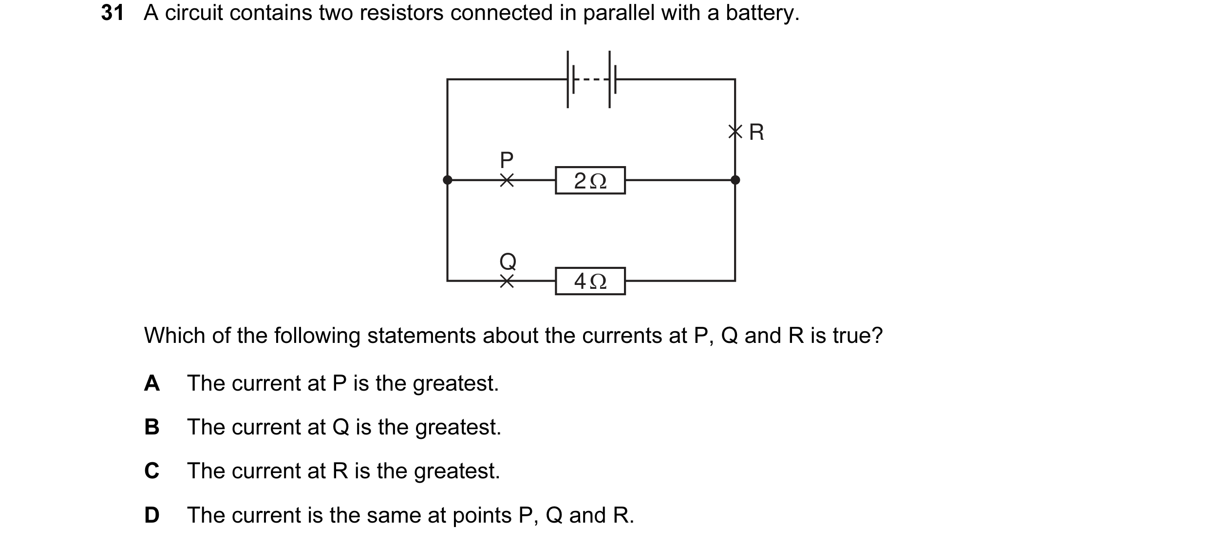
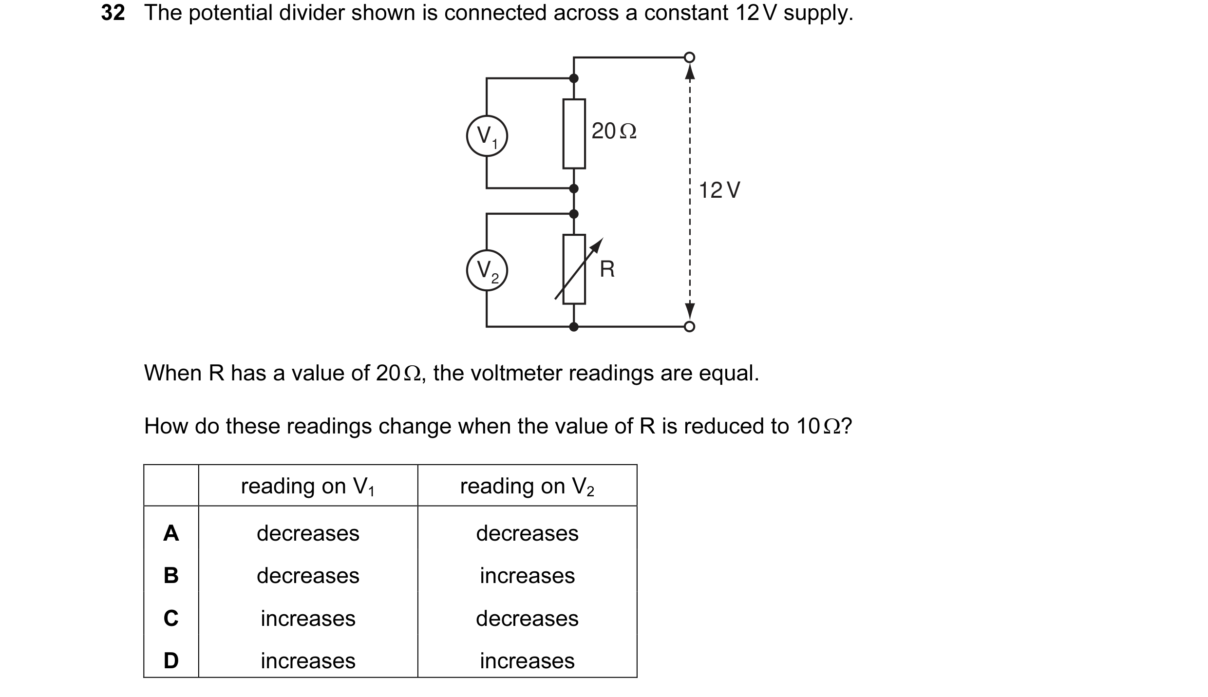
 23 / 176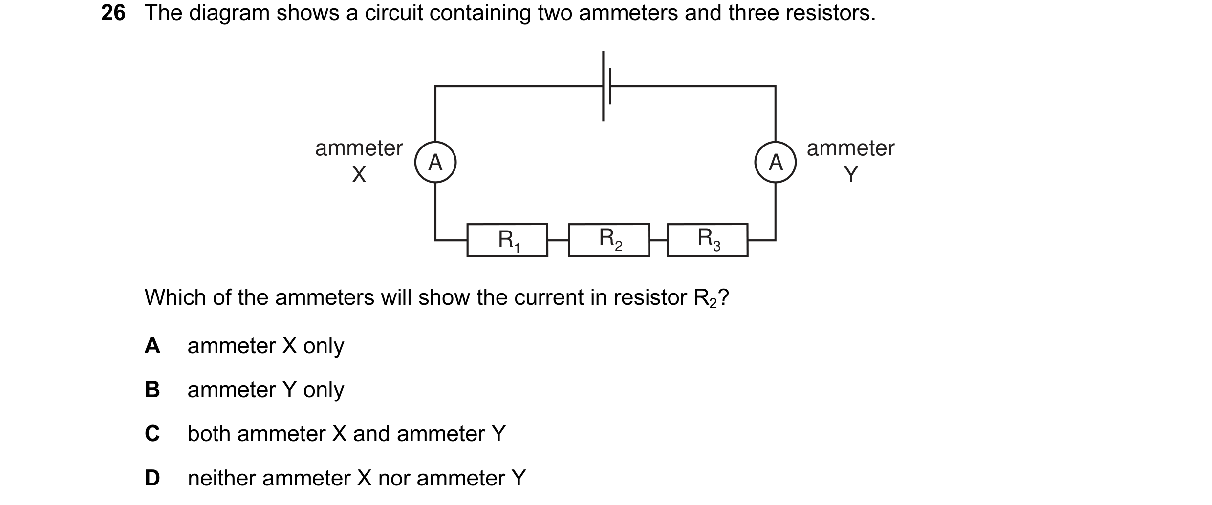
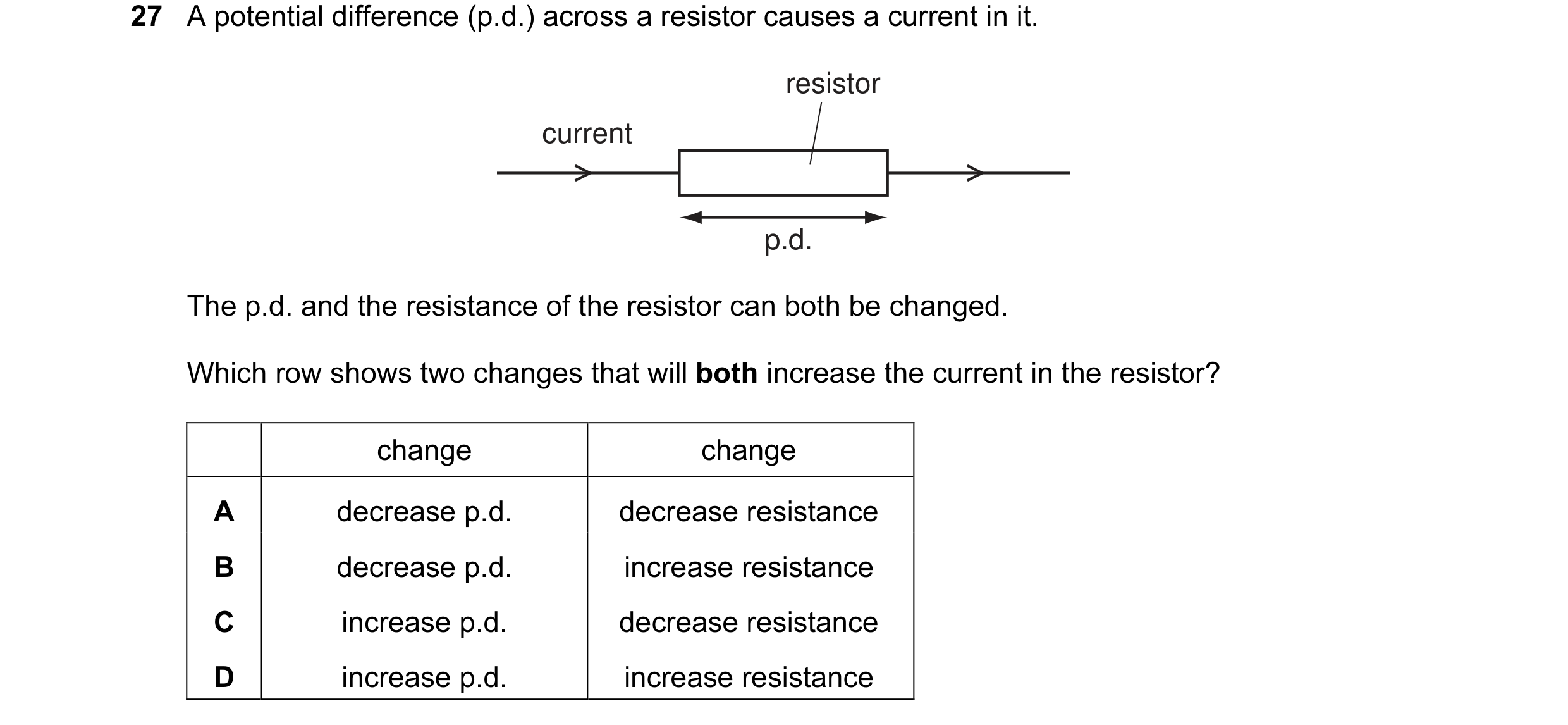 24 / 176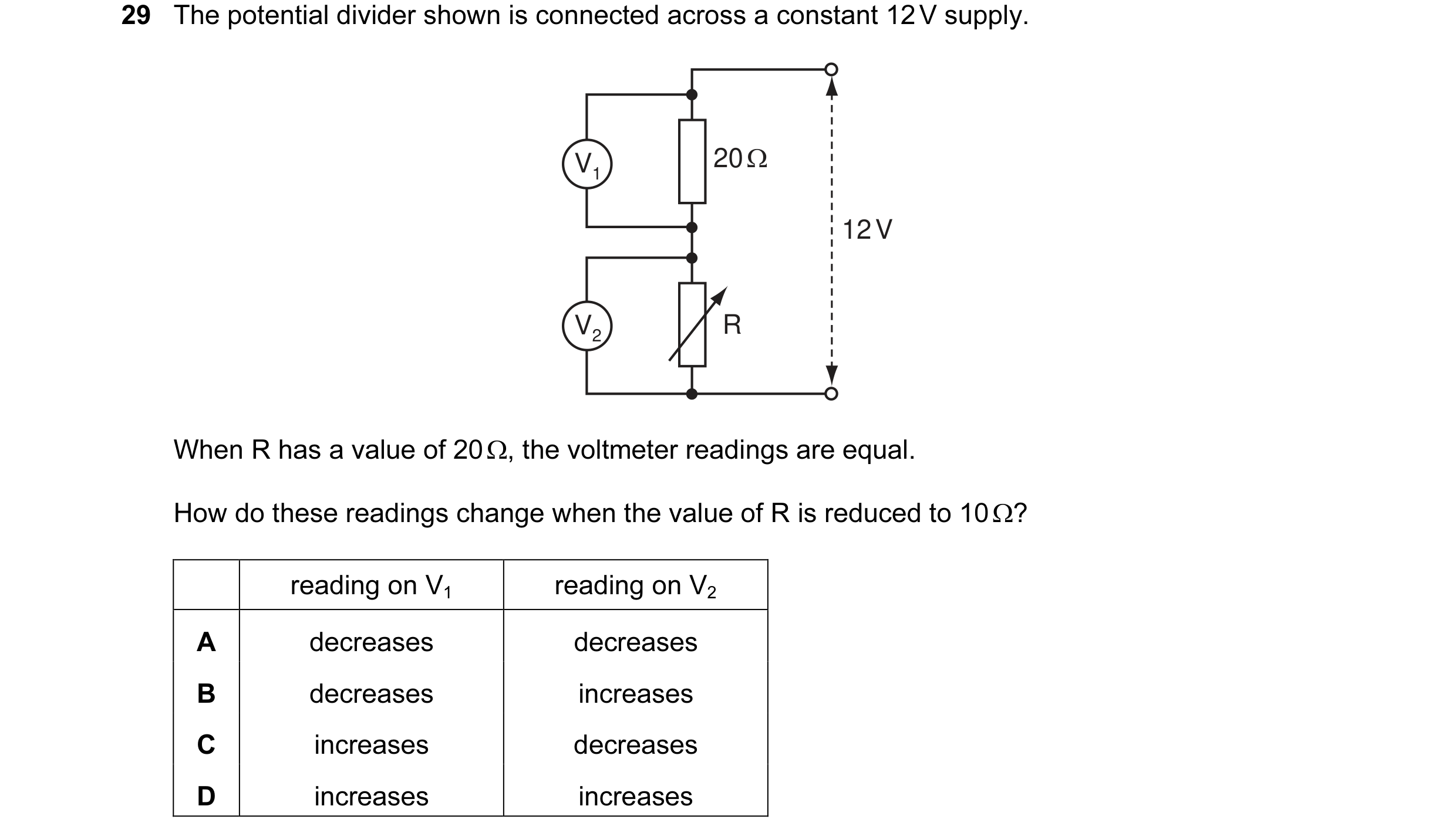
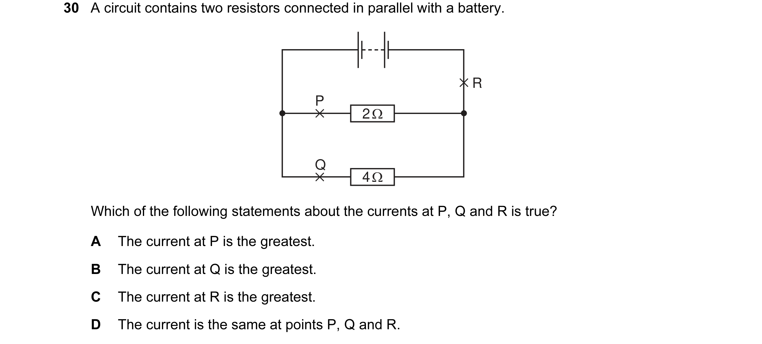
 25 / 176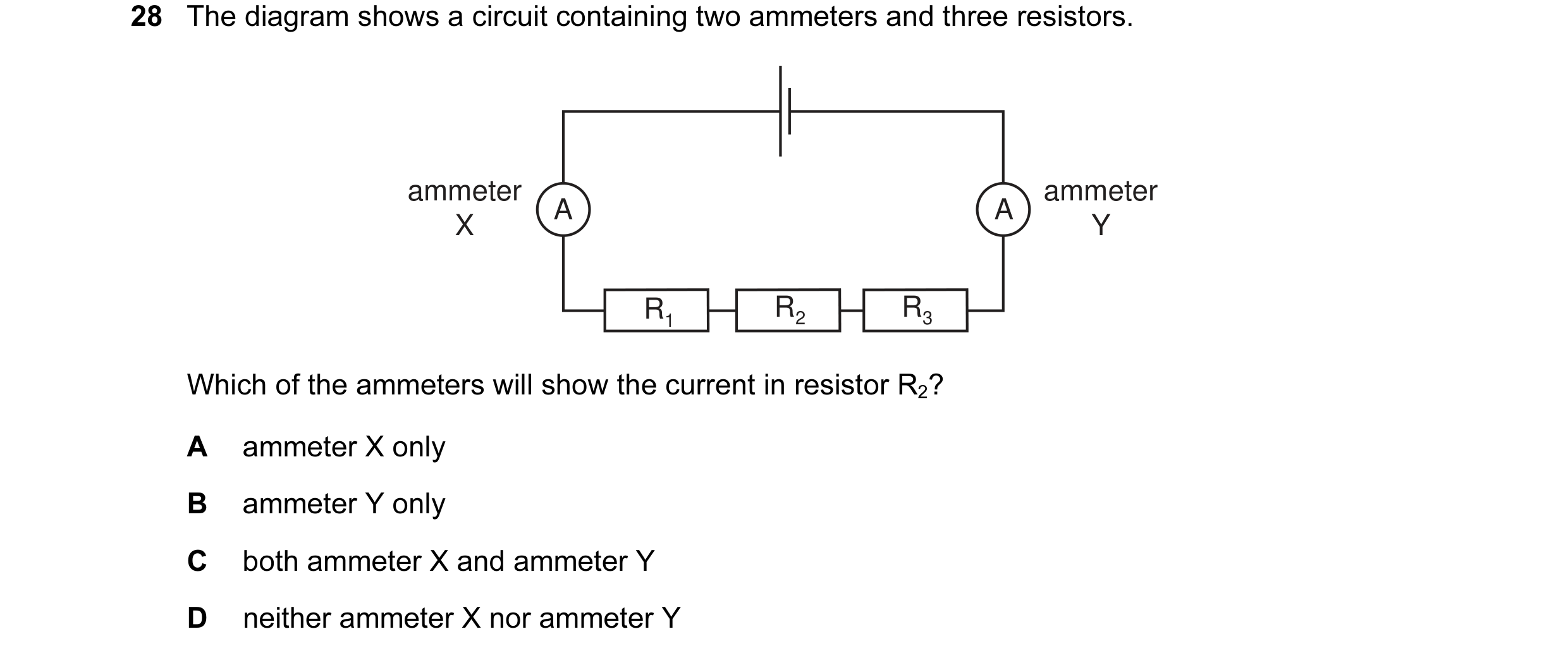
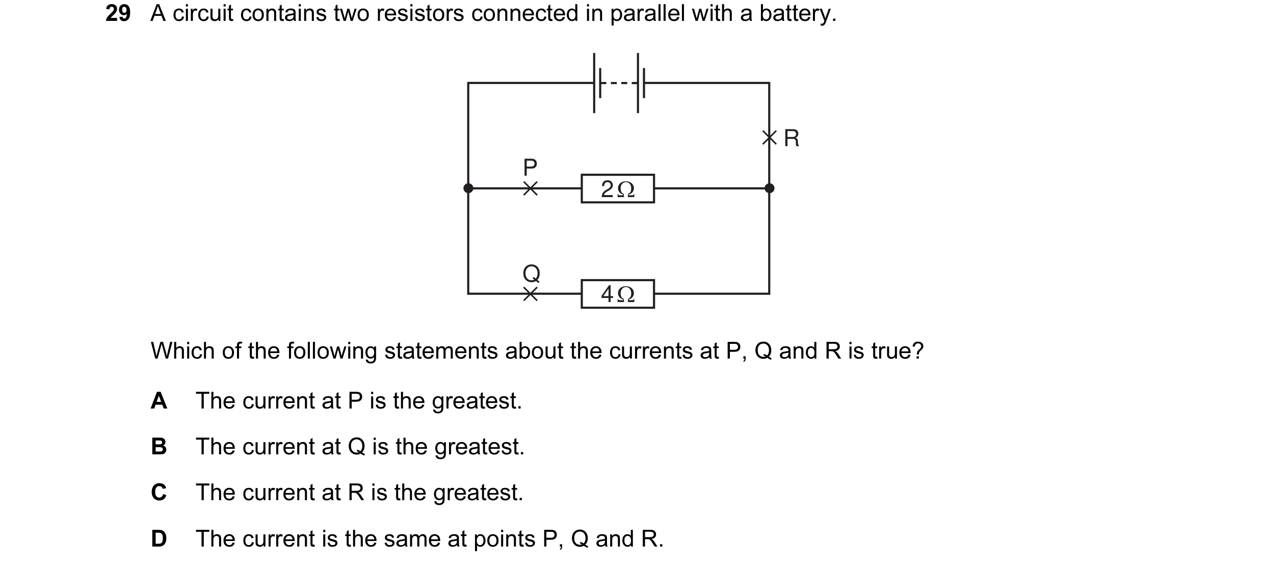
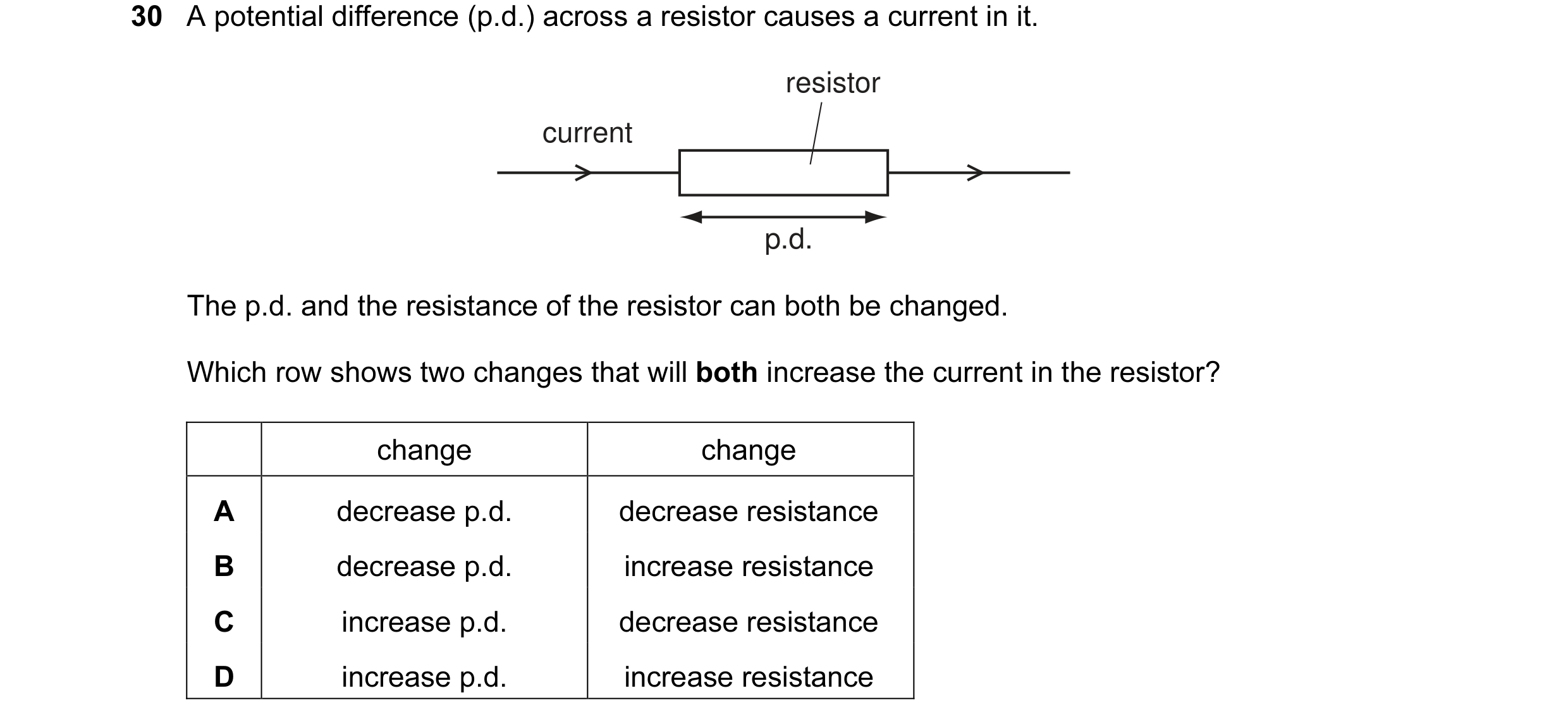 26 / 176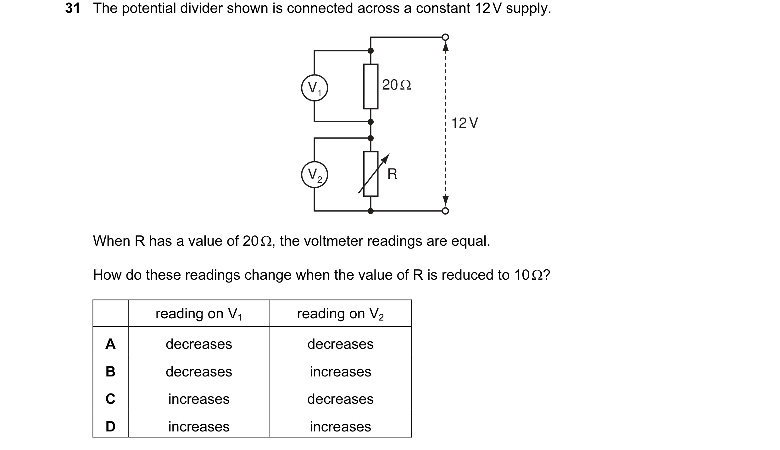

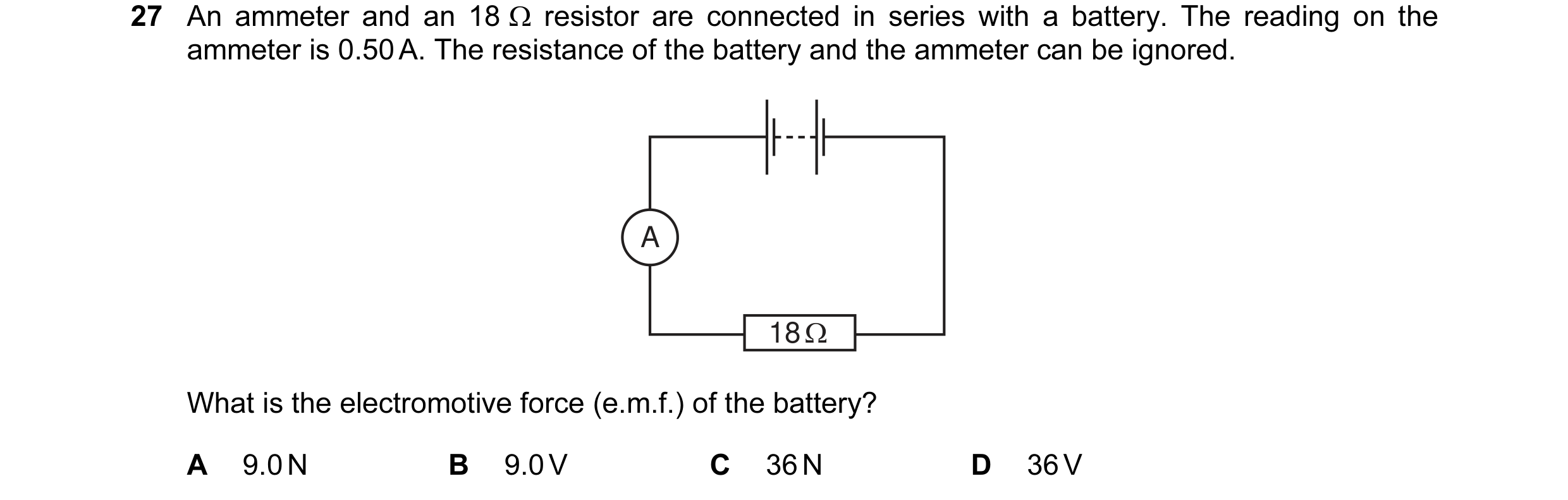
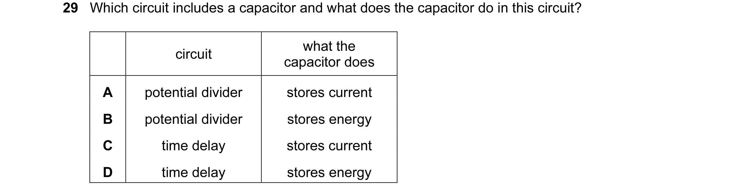 27 / 176
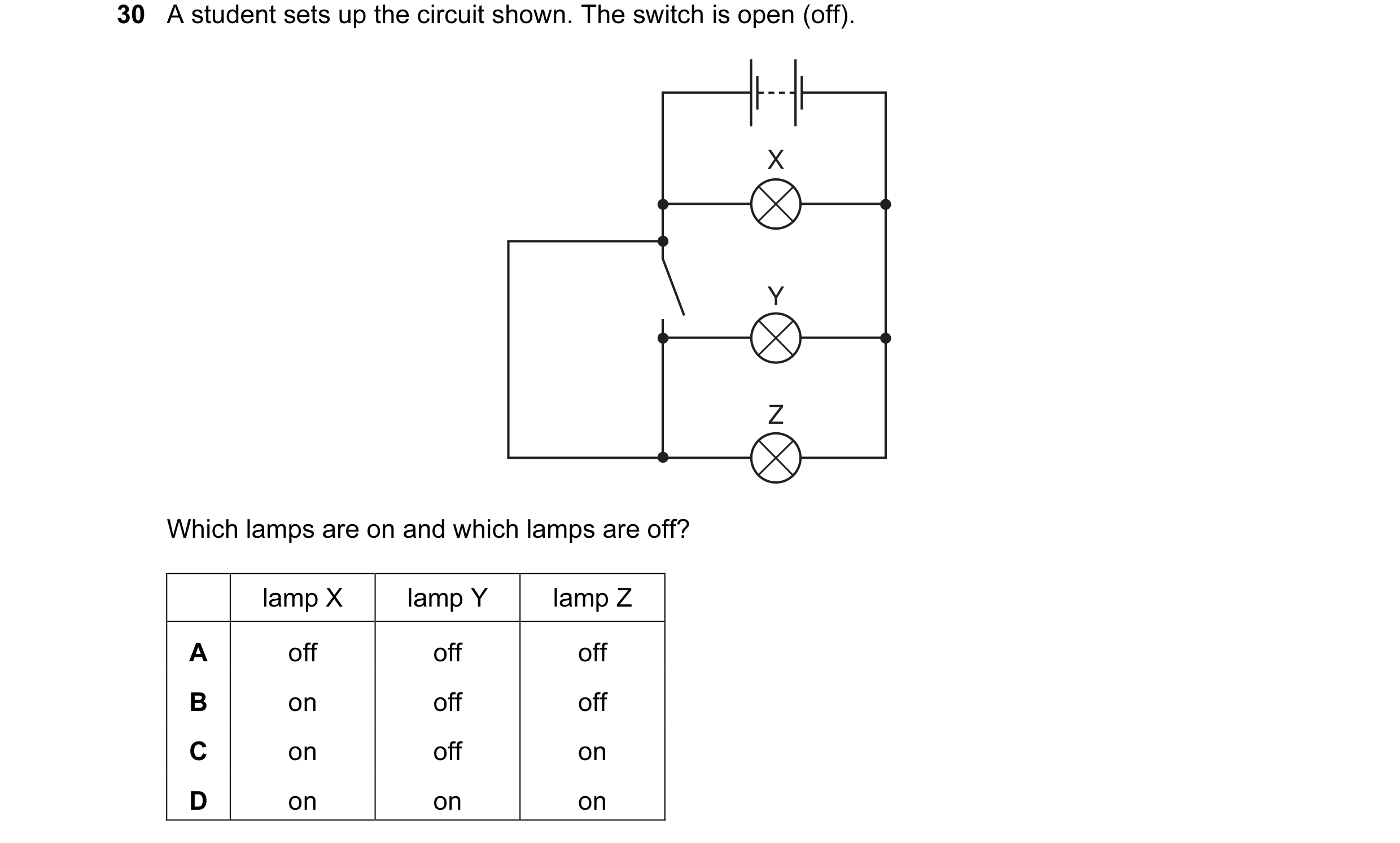 28 / 176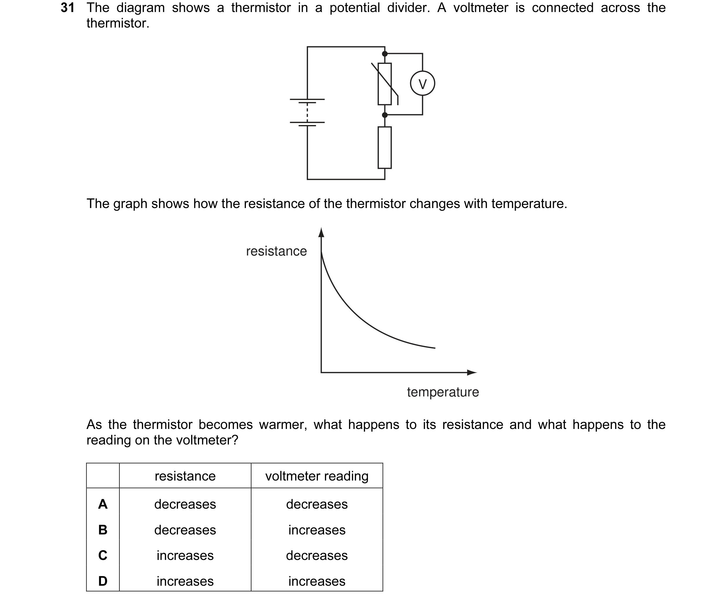
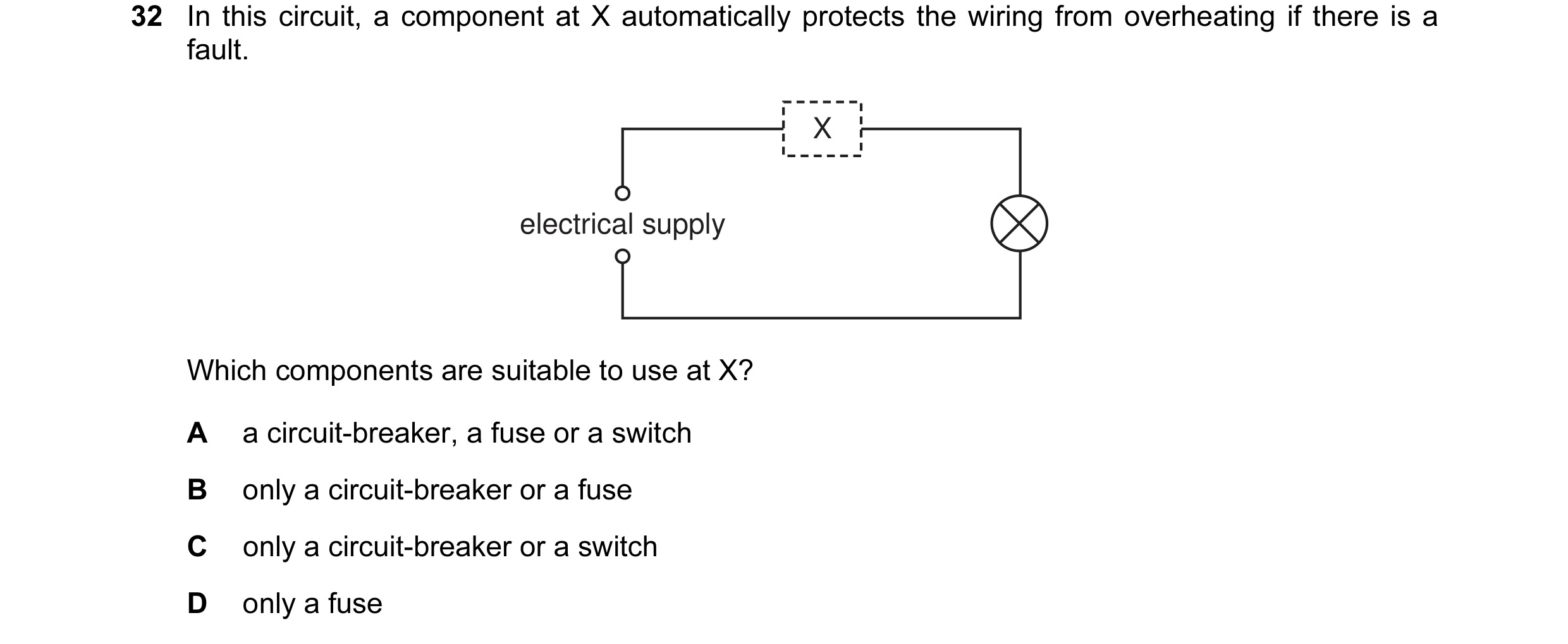 29 / 176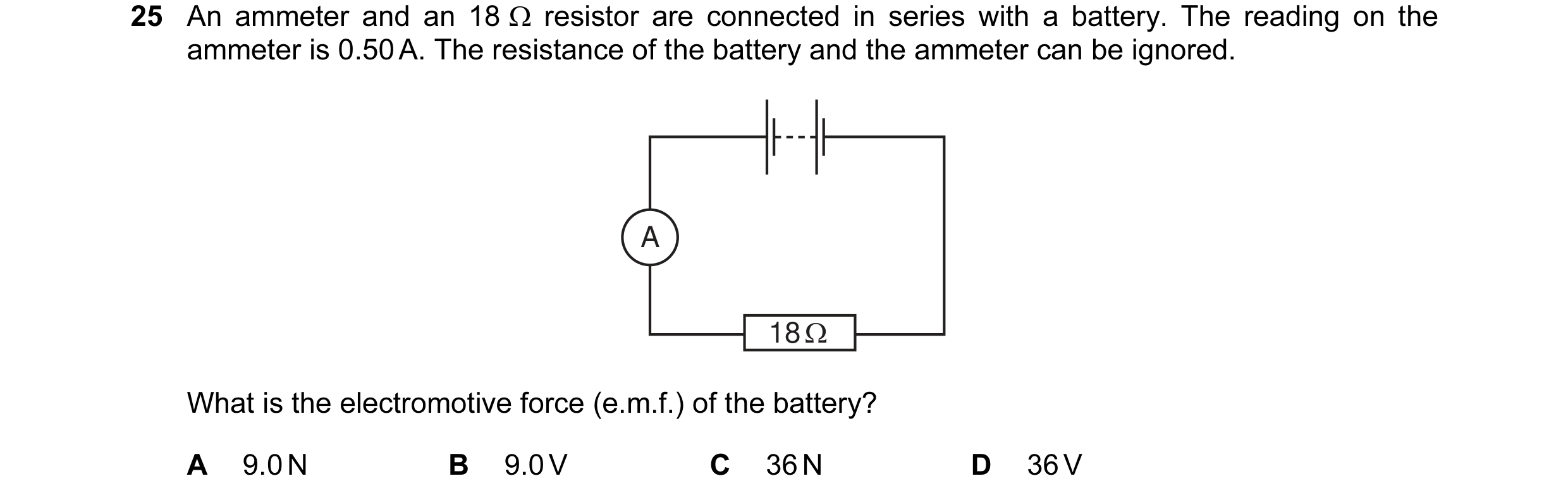
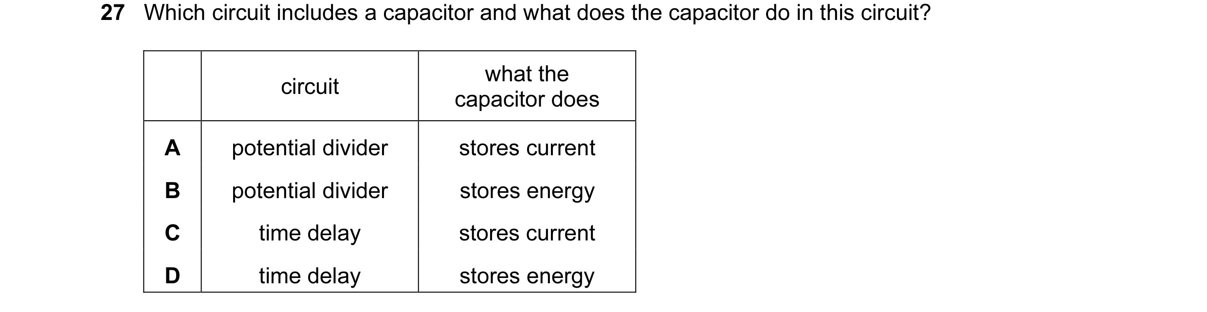 30 / 176
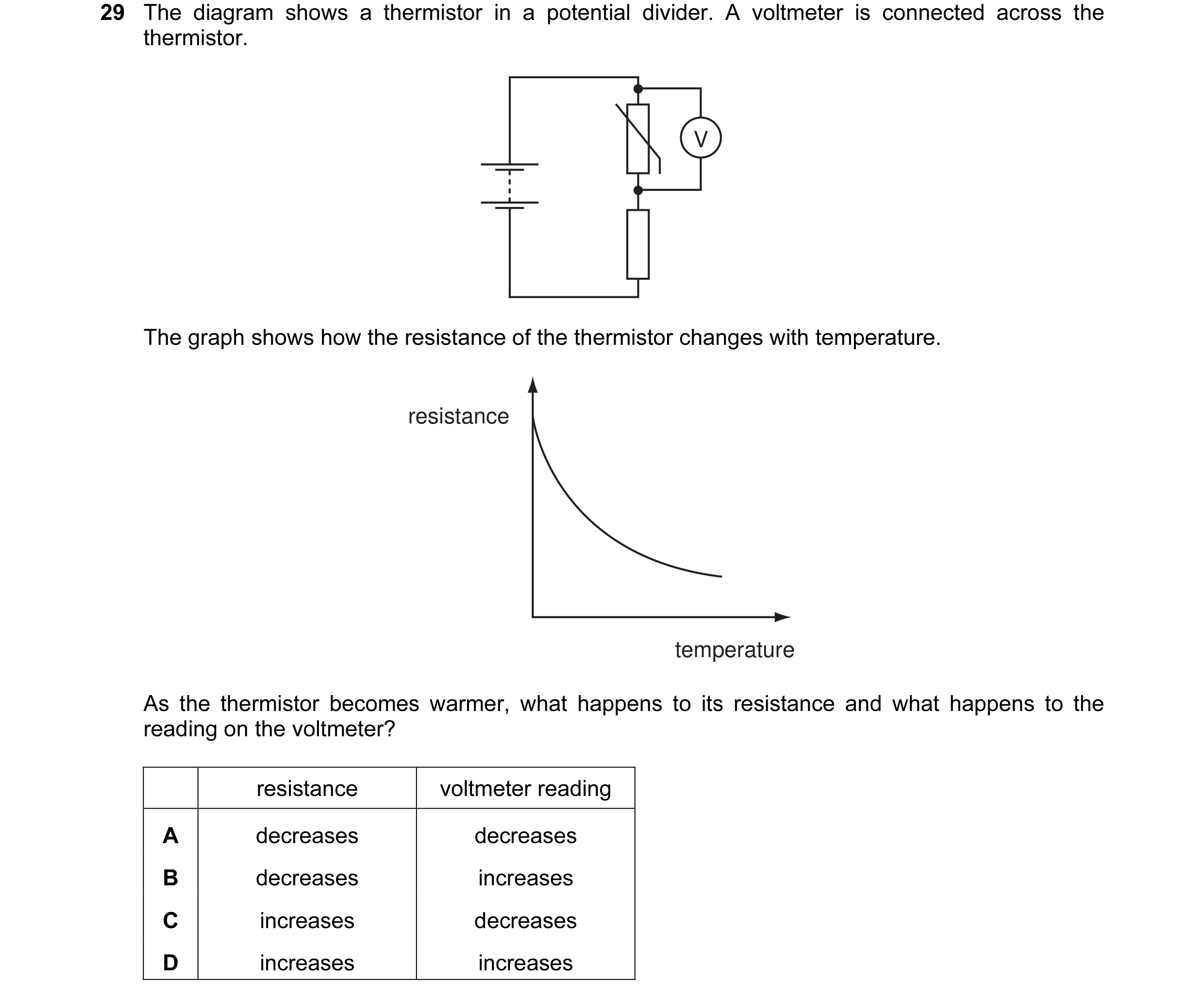 31 / 176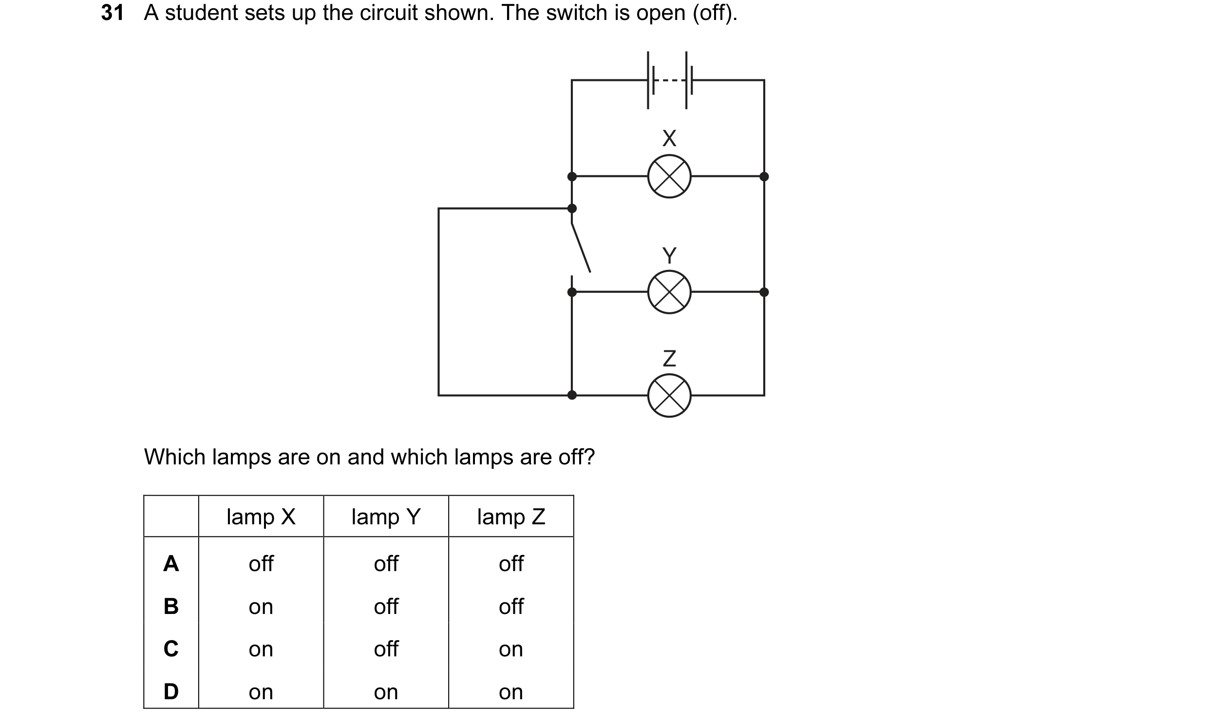
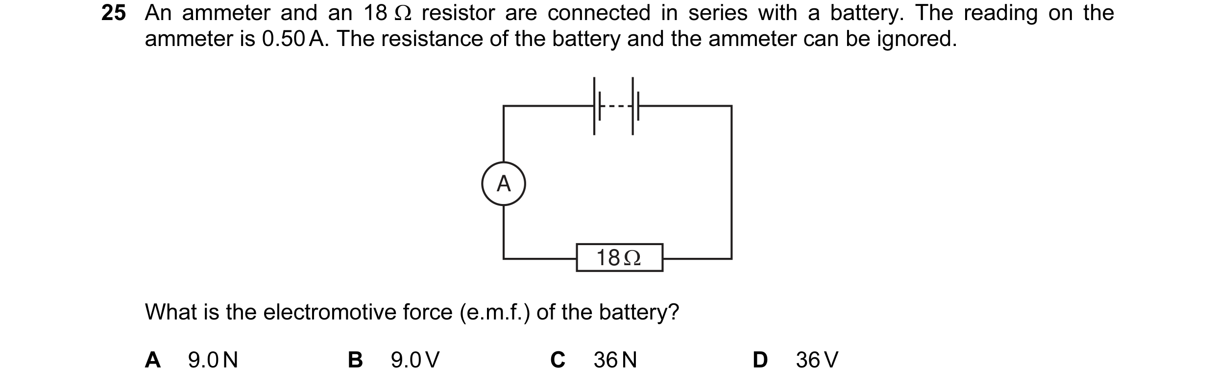
 32 / 176
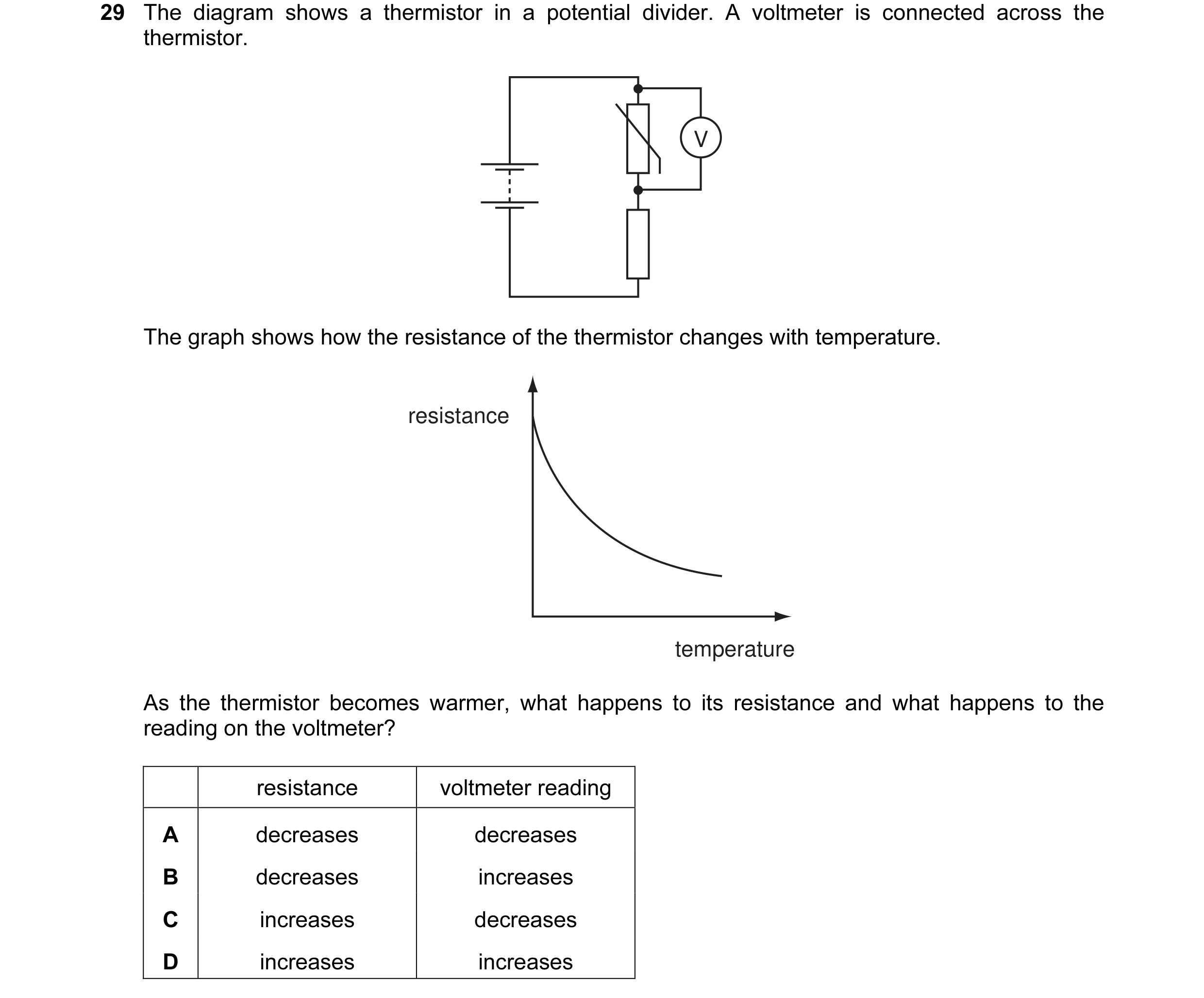 33 / 176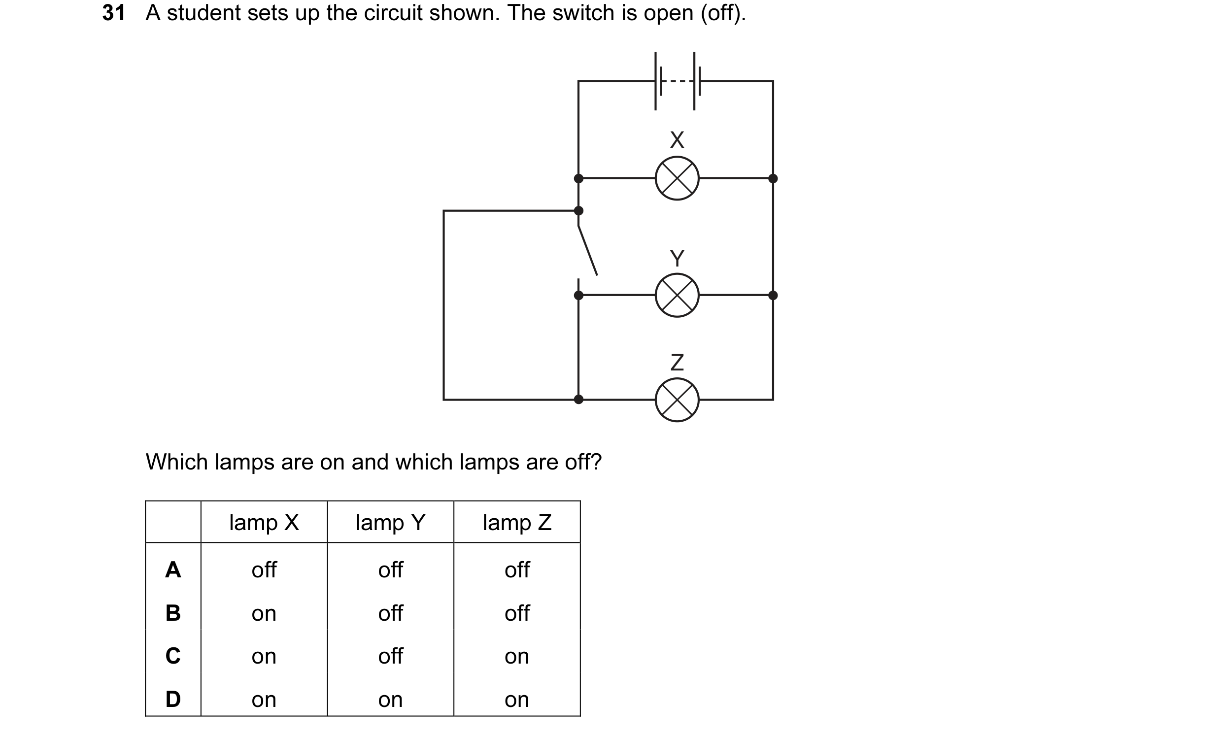
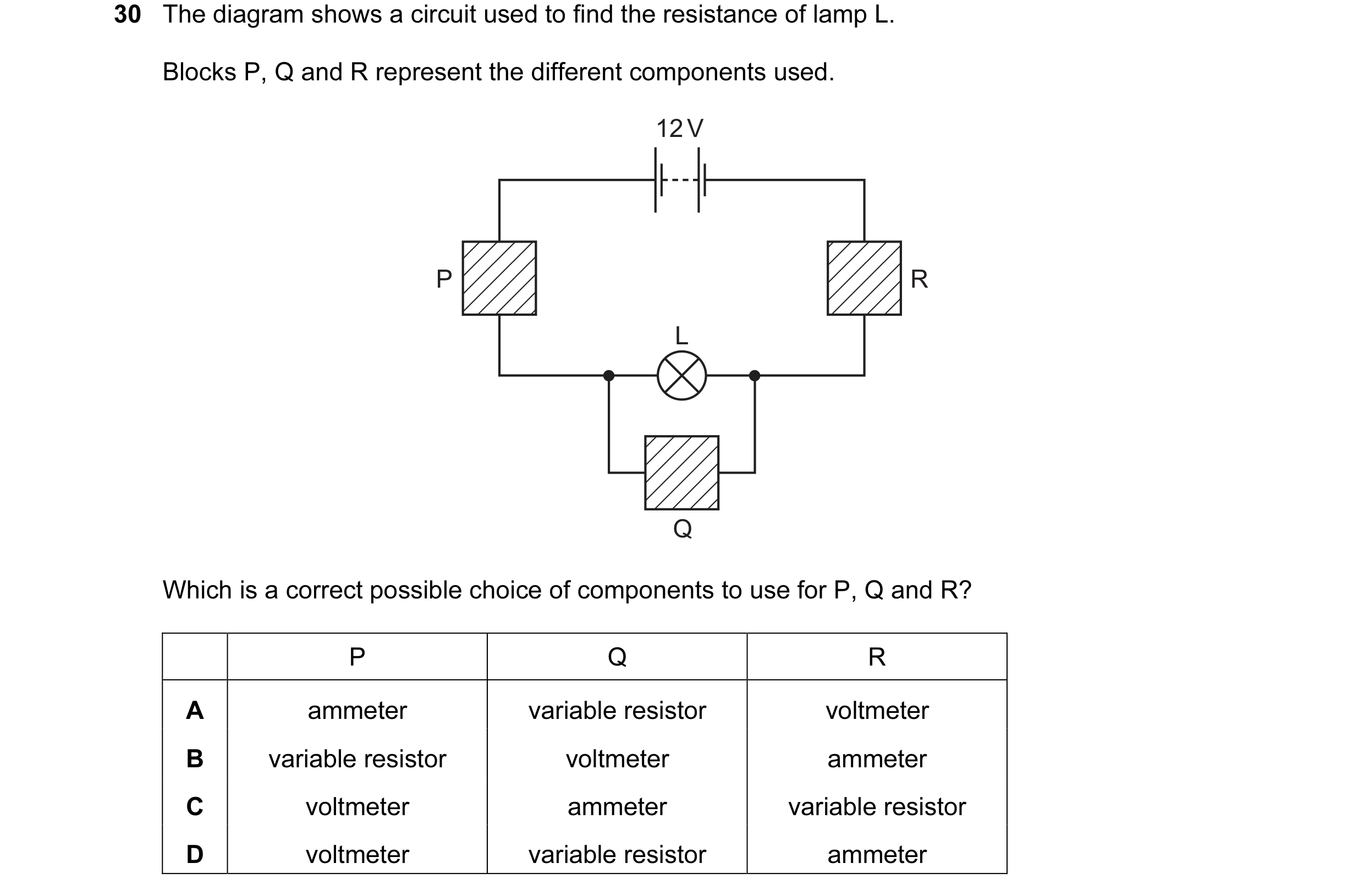 34 / 176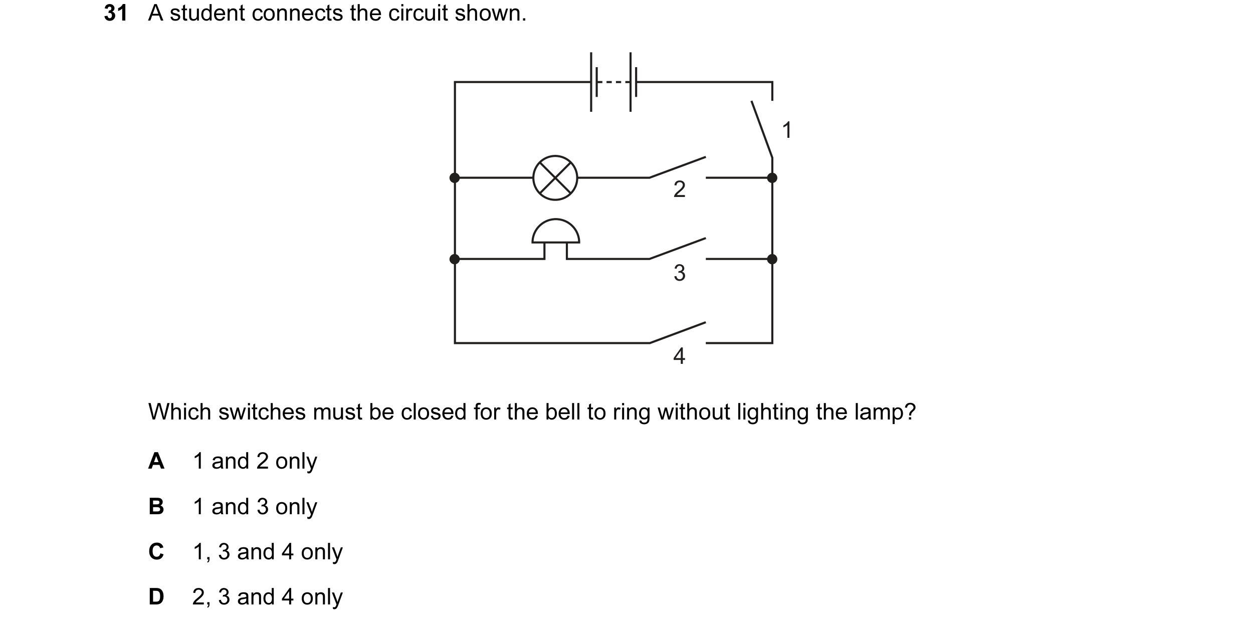
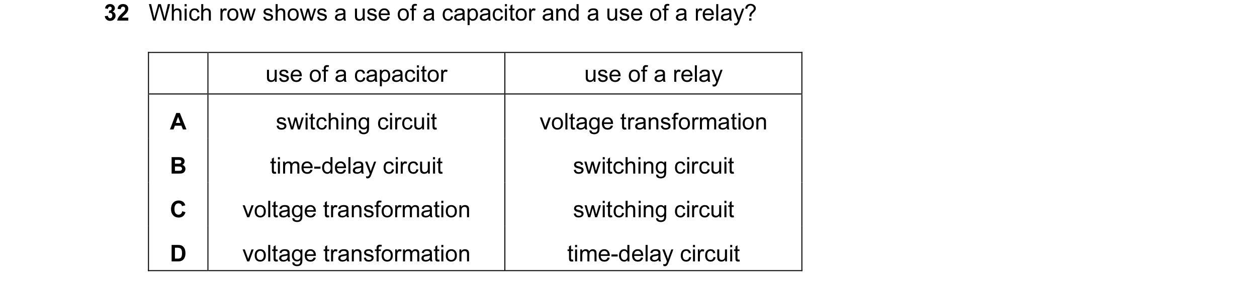
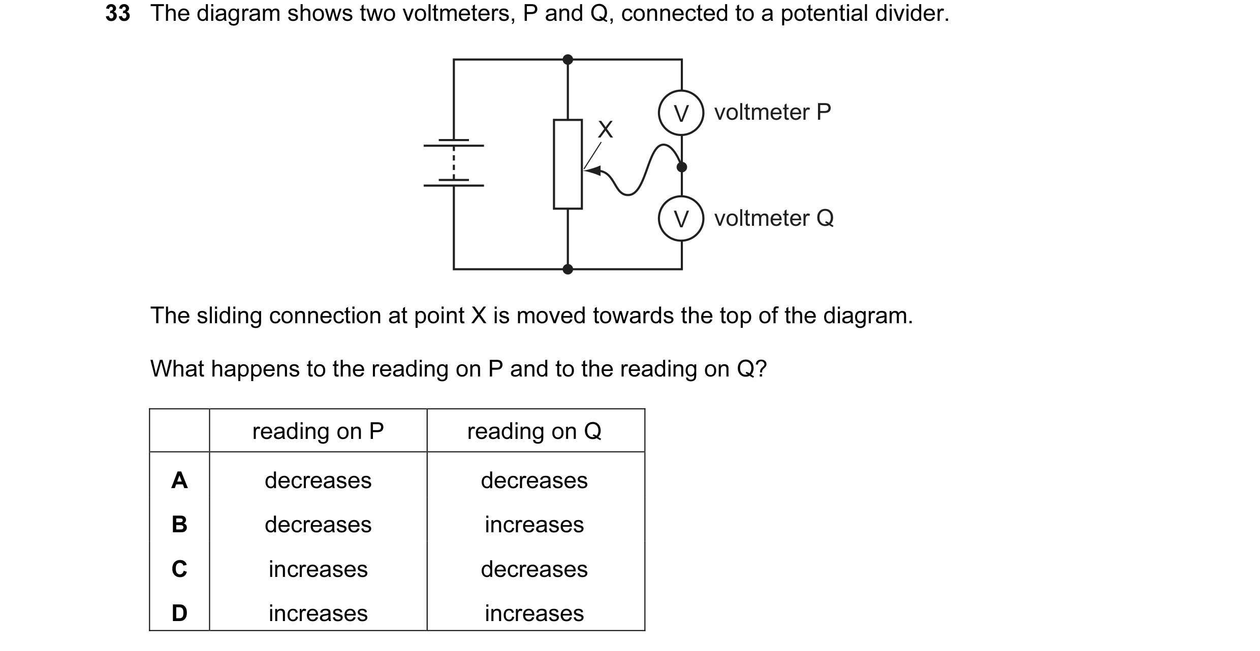 35 / 176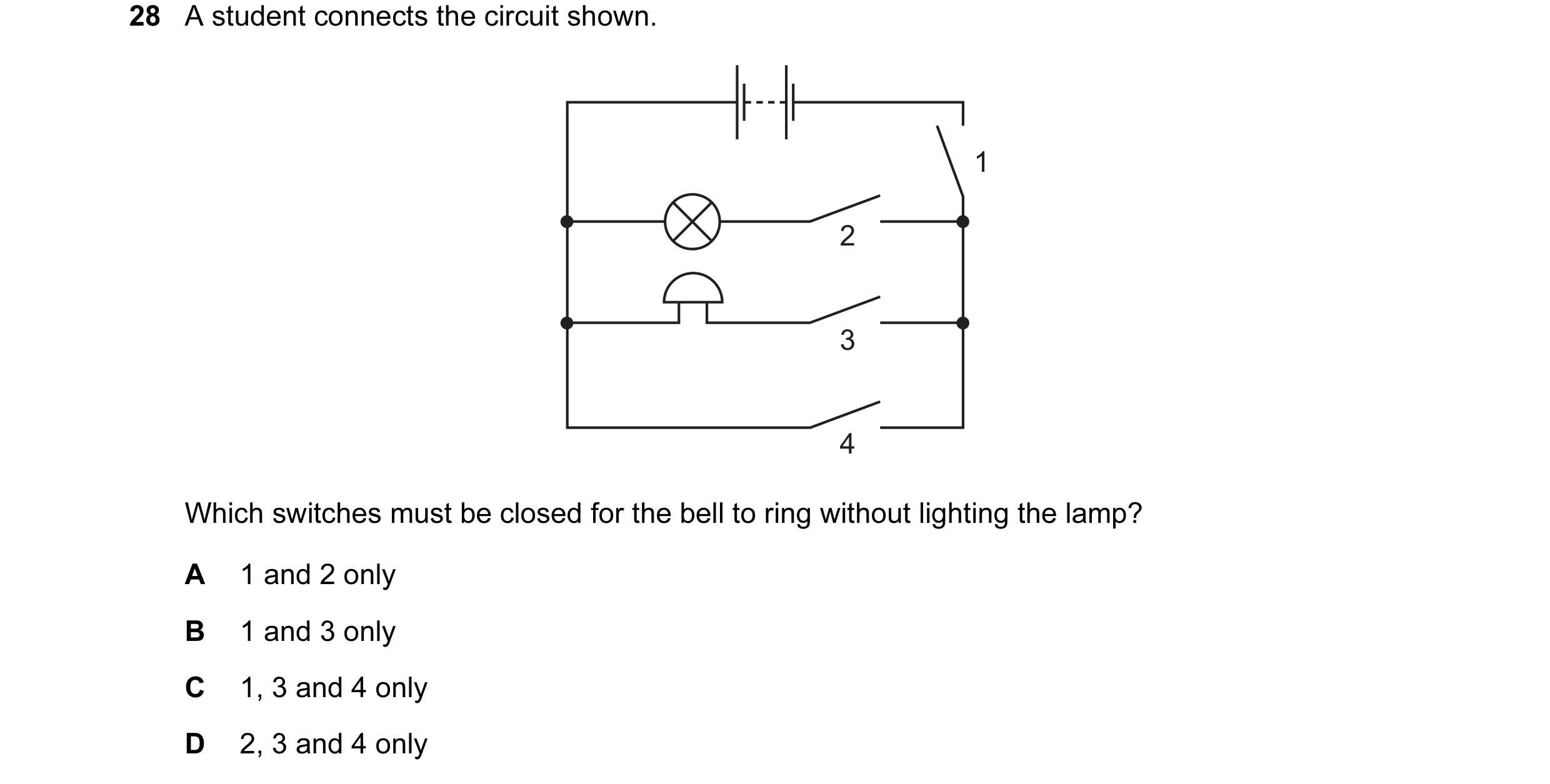
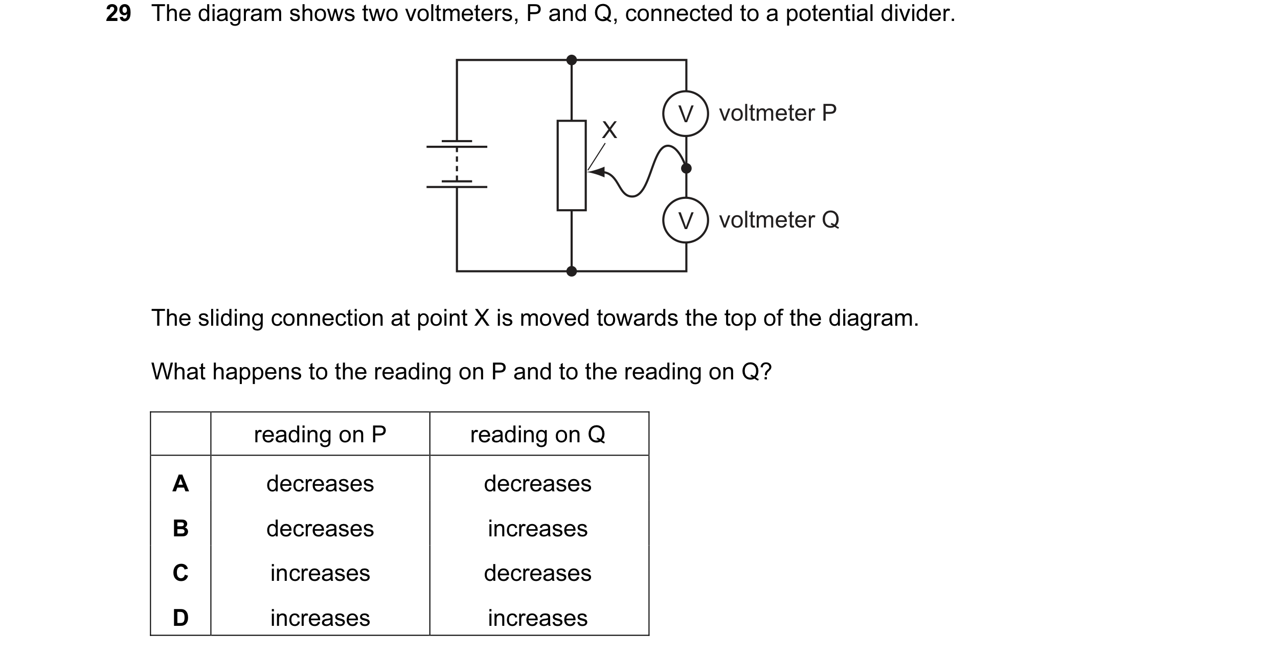 36 / 176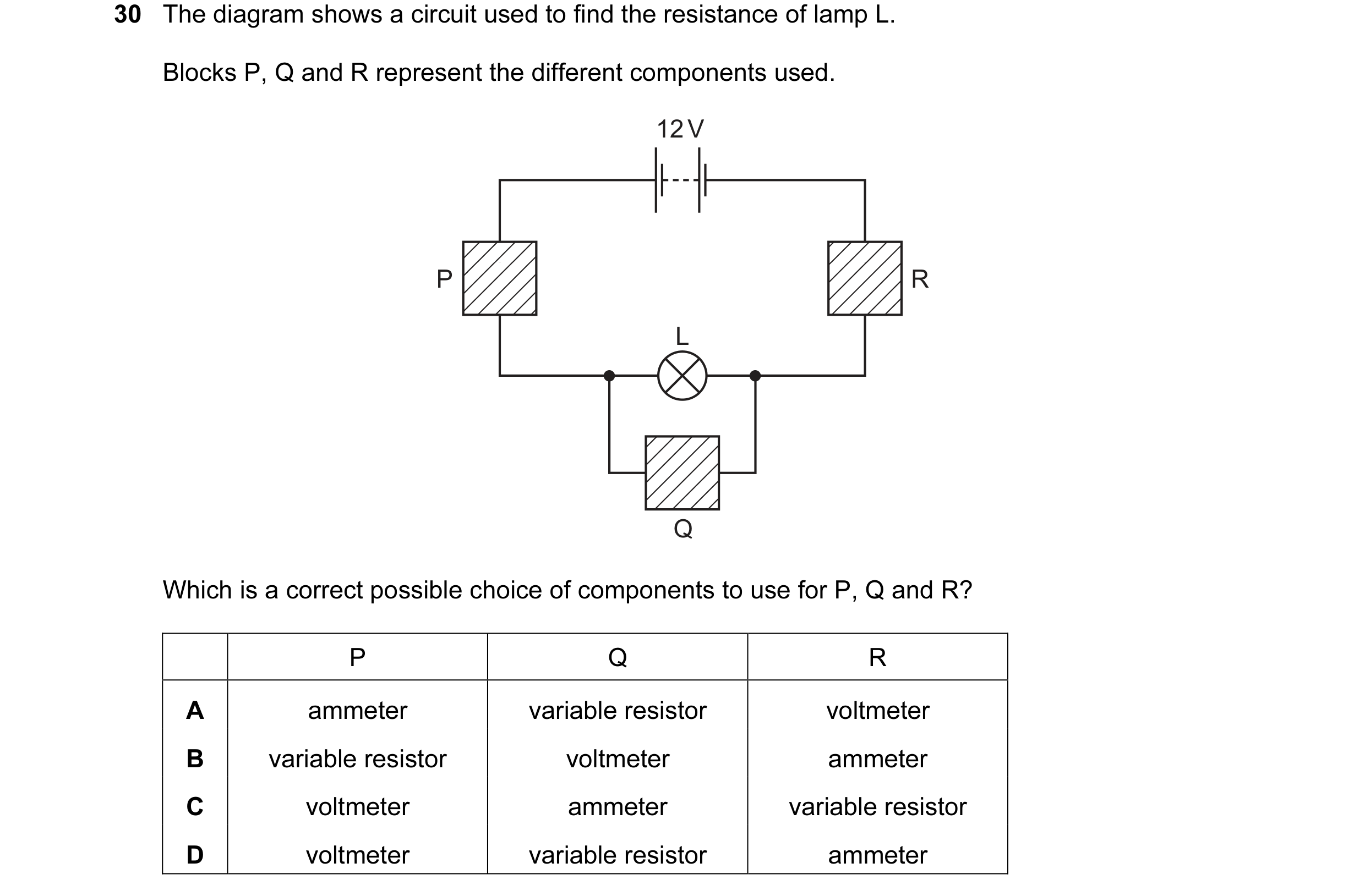
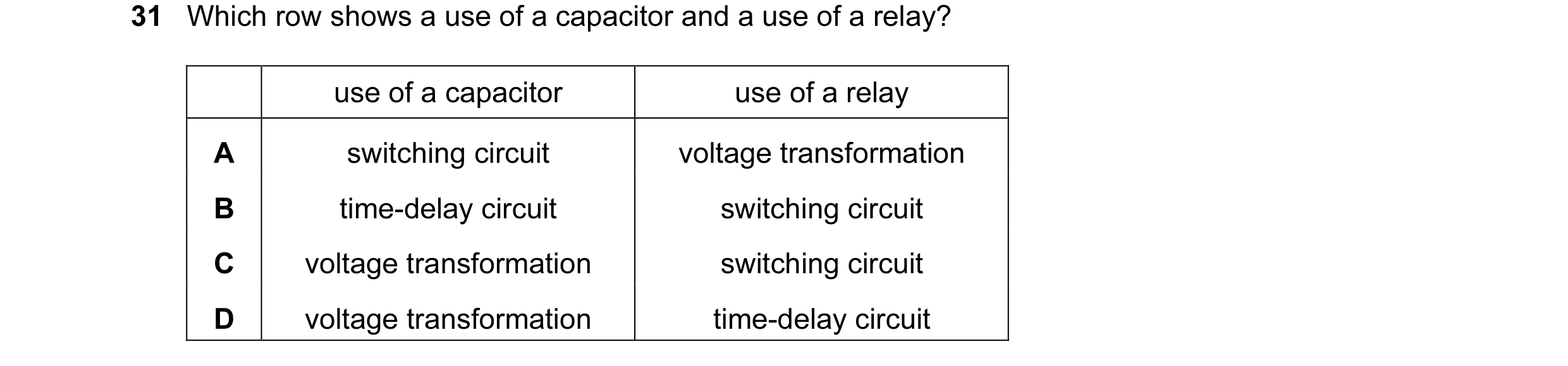
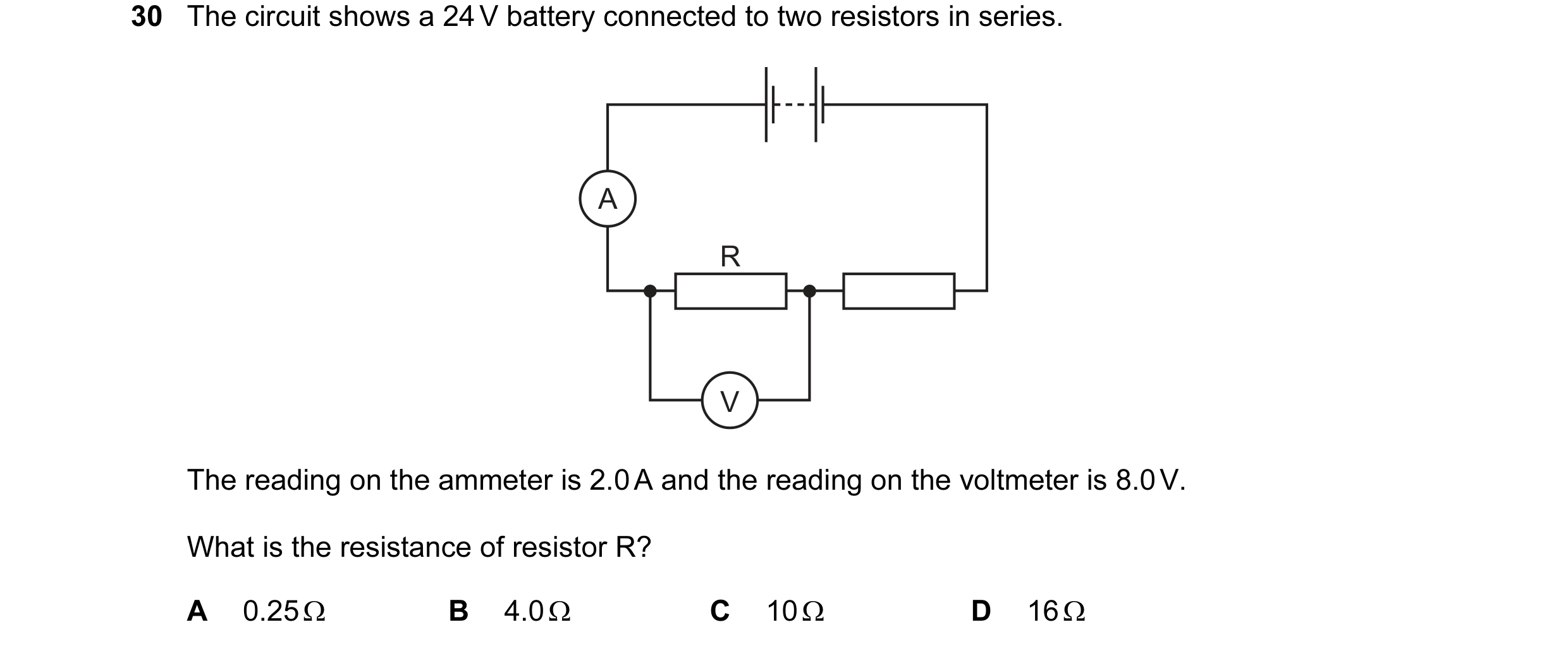 37 / 176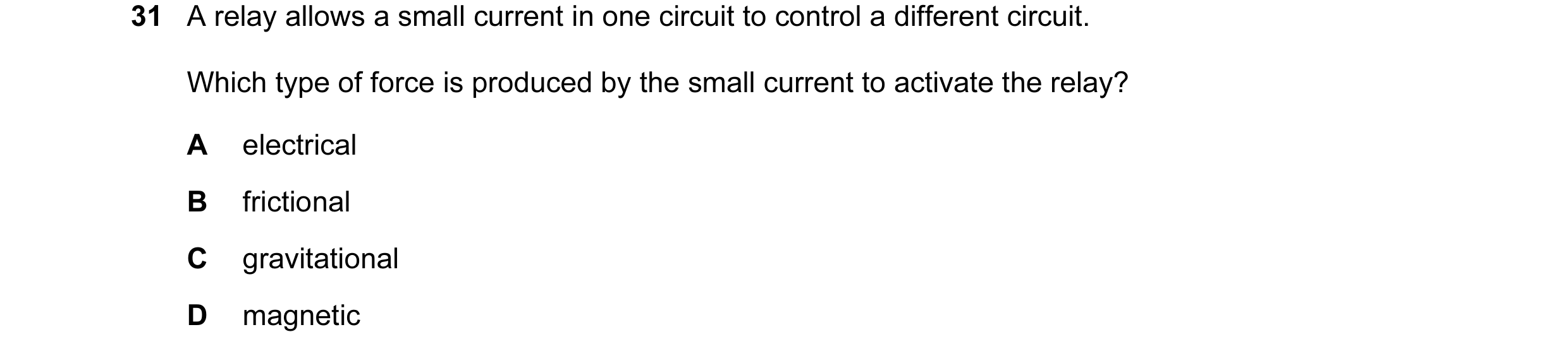
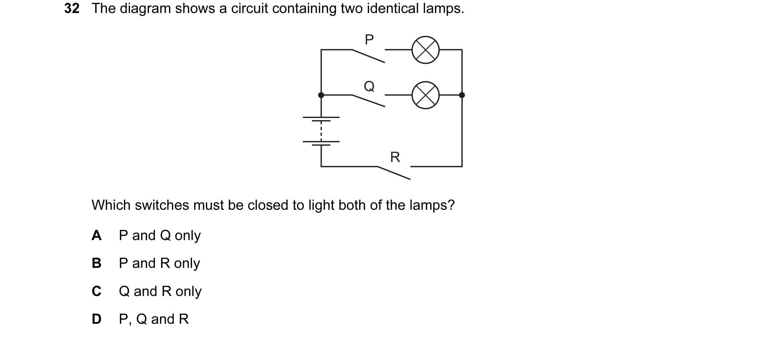
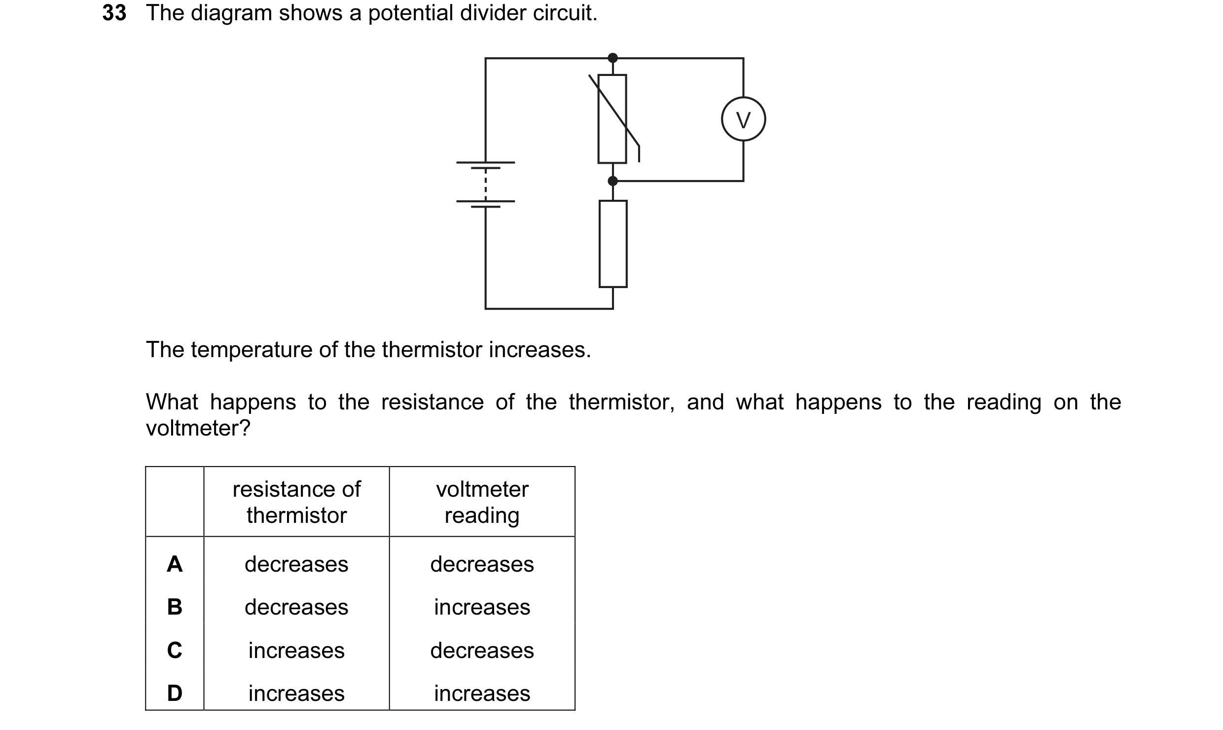 38 / 176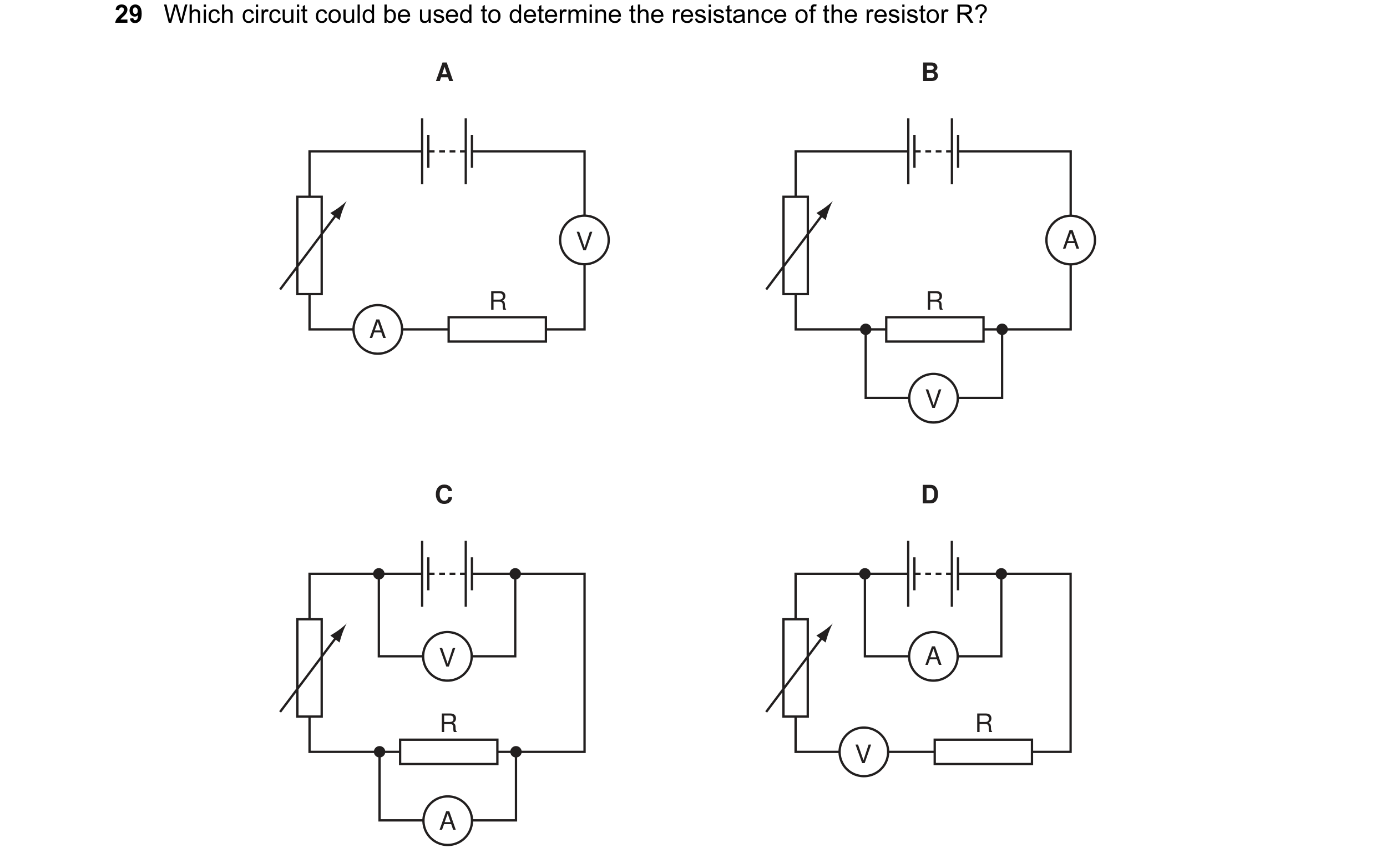
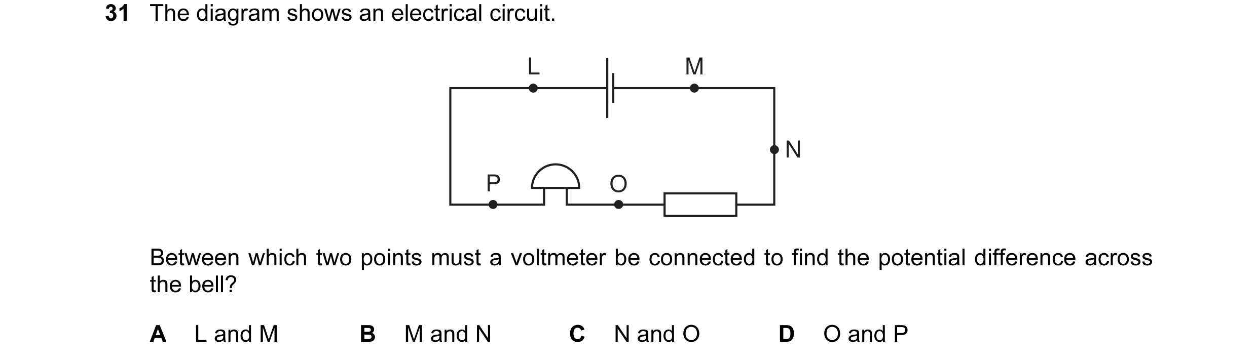
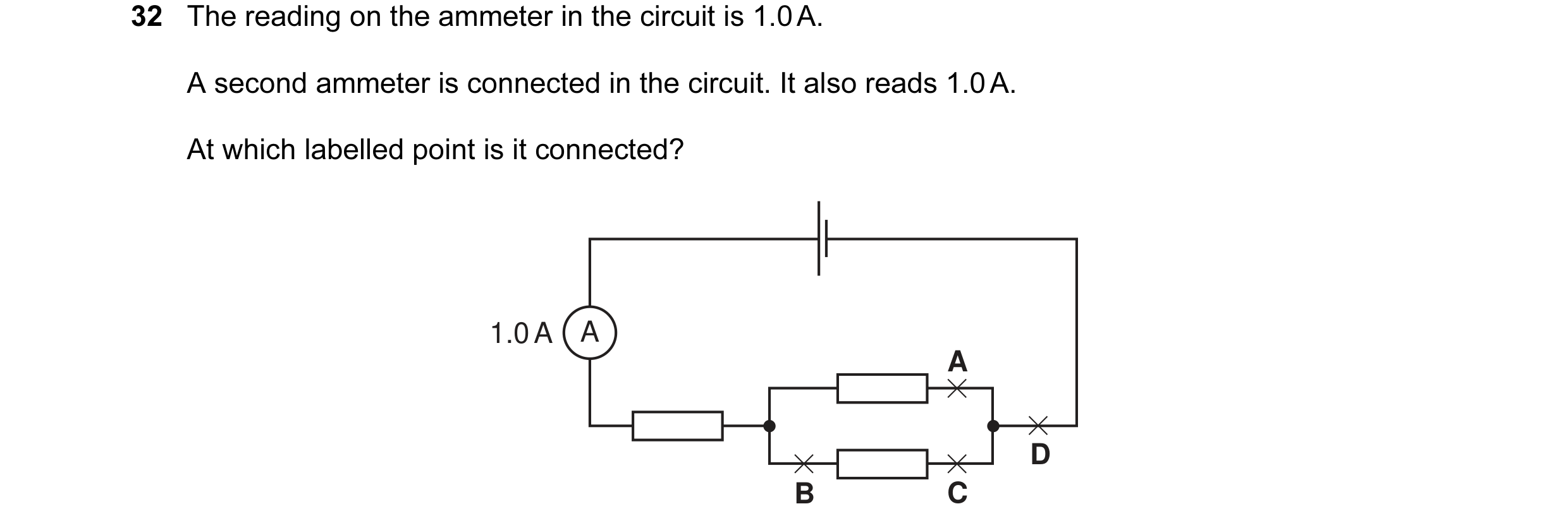 39 / 176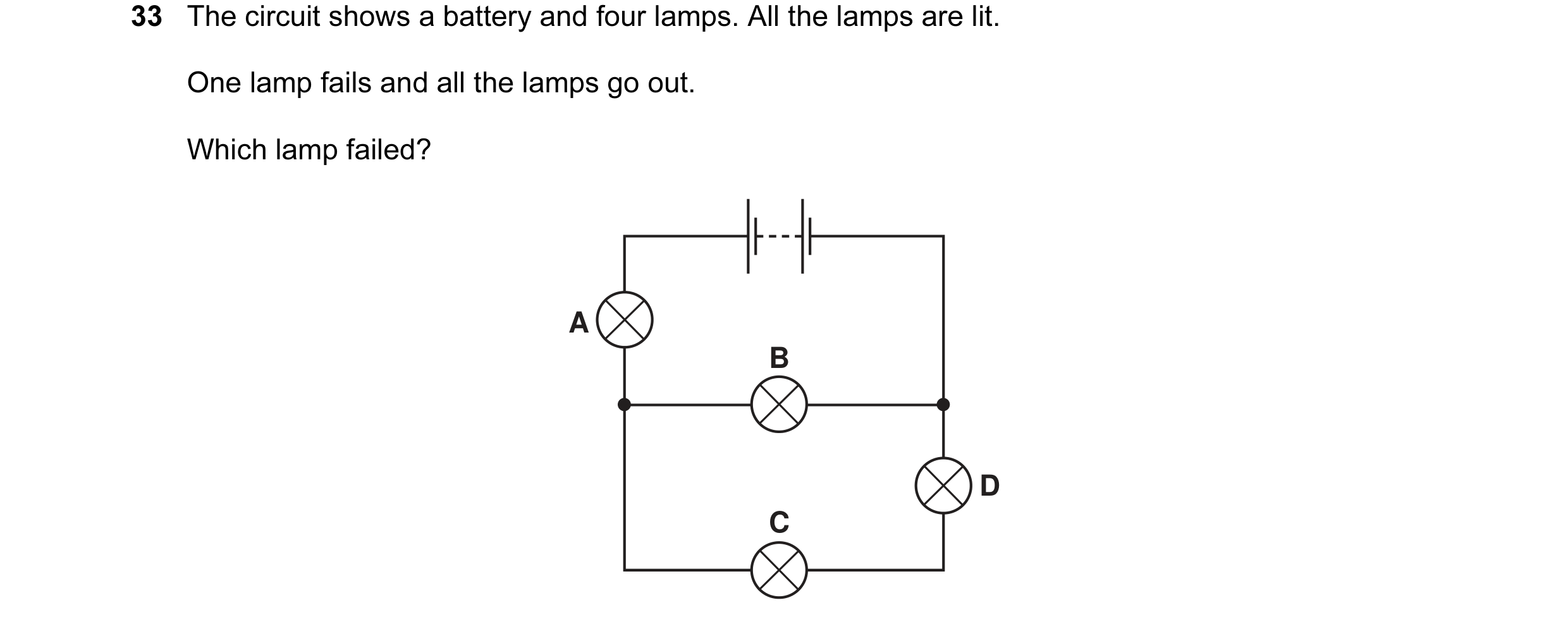
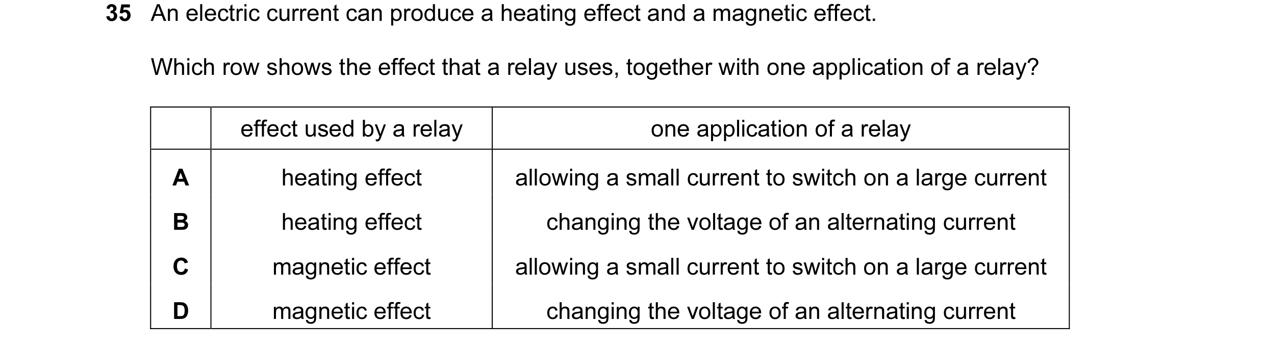
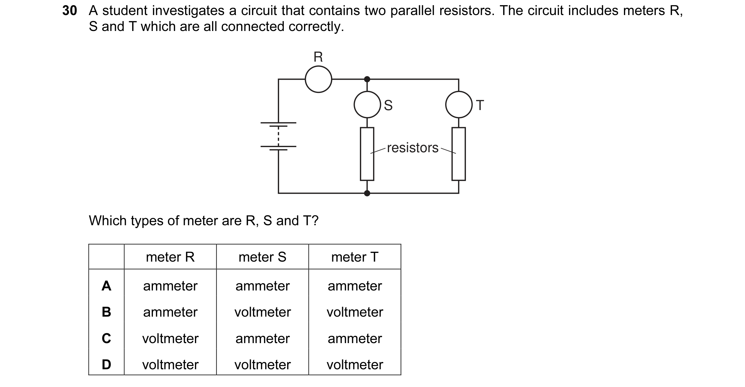 40 / 176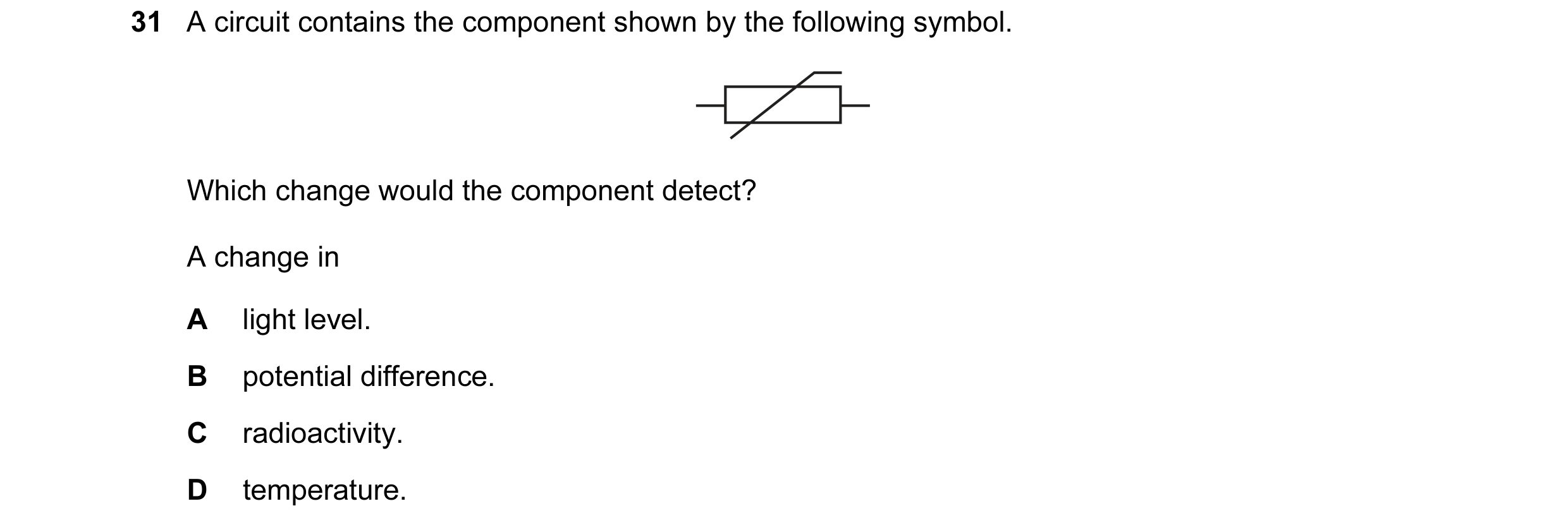
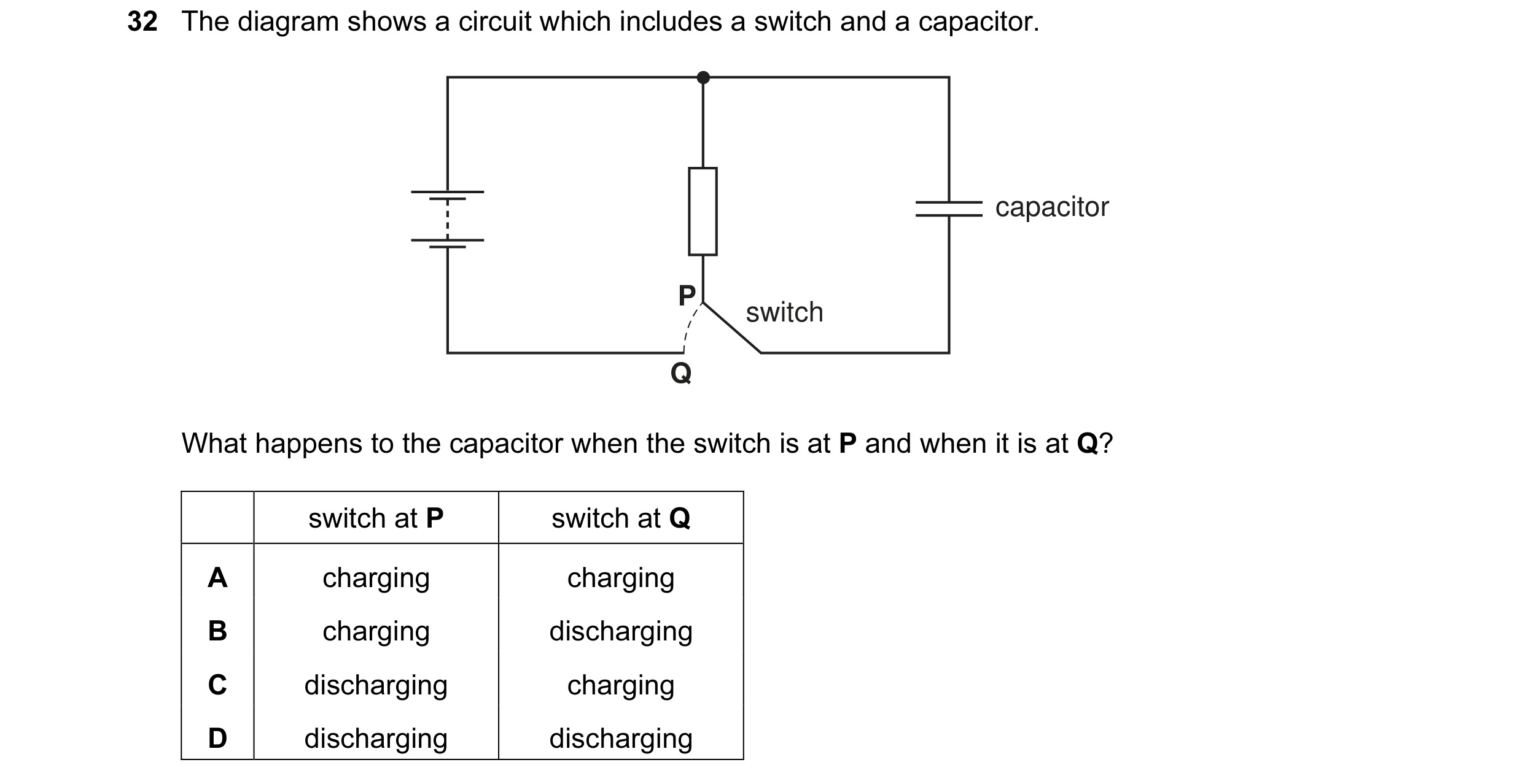
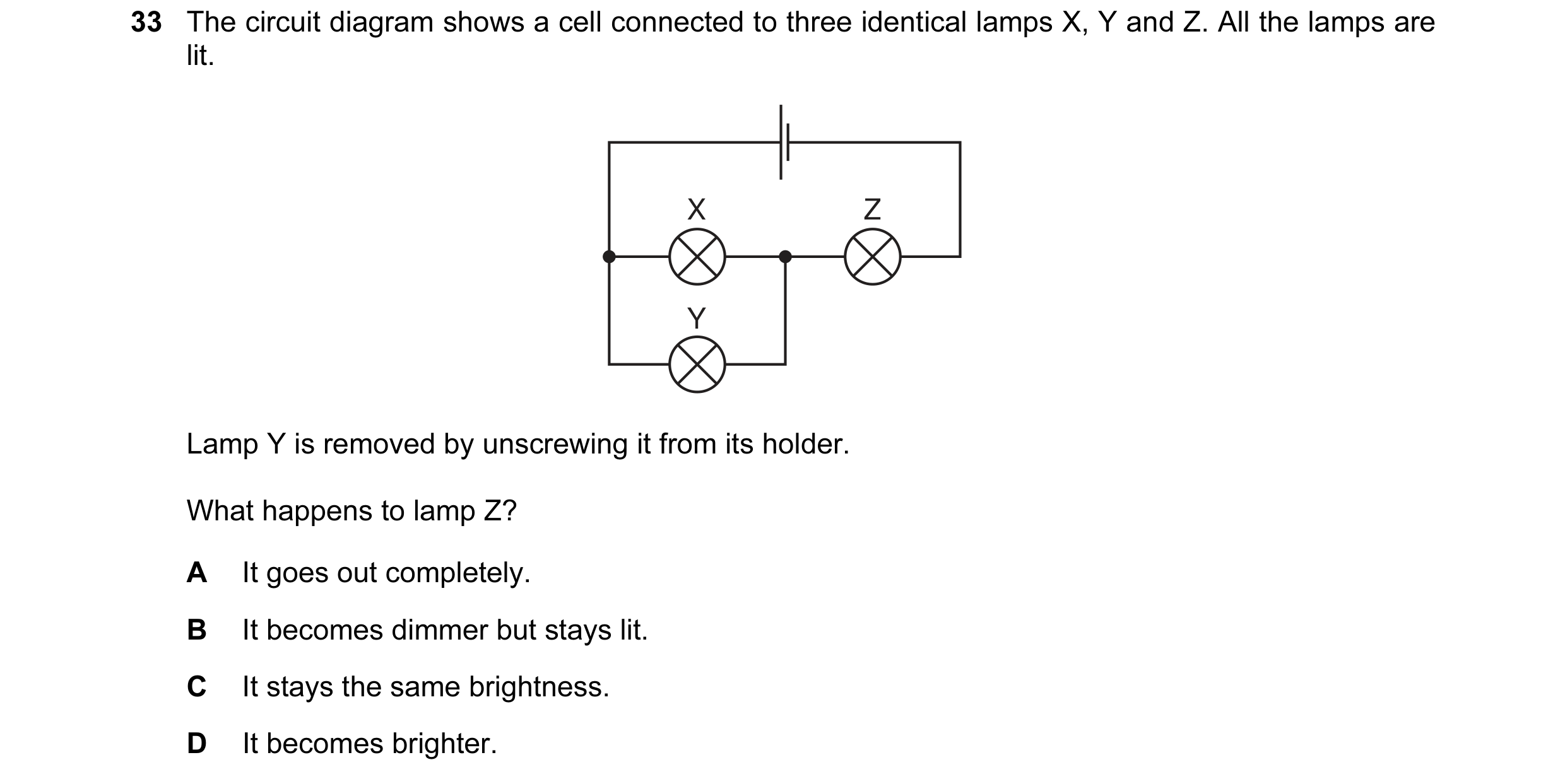 41 / 176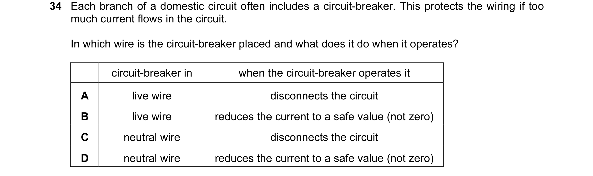
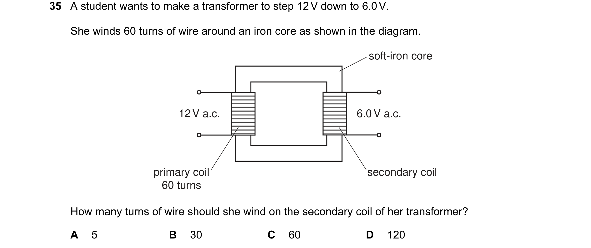
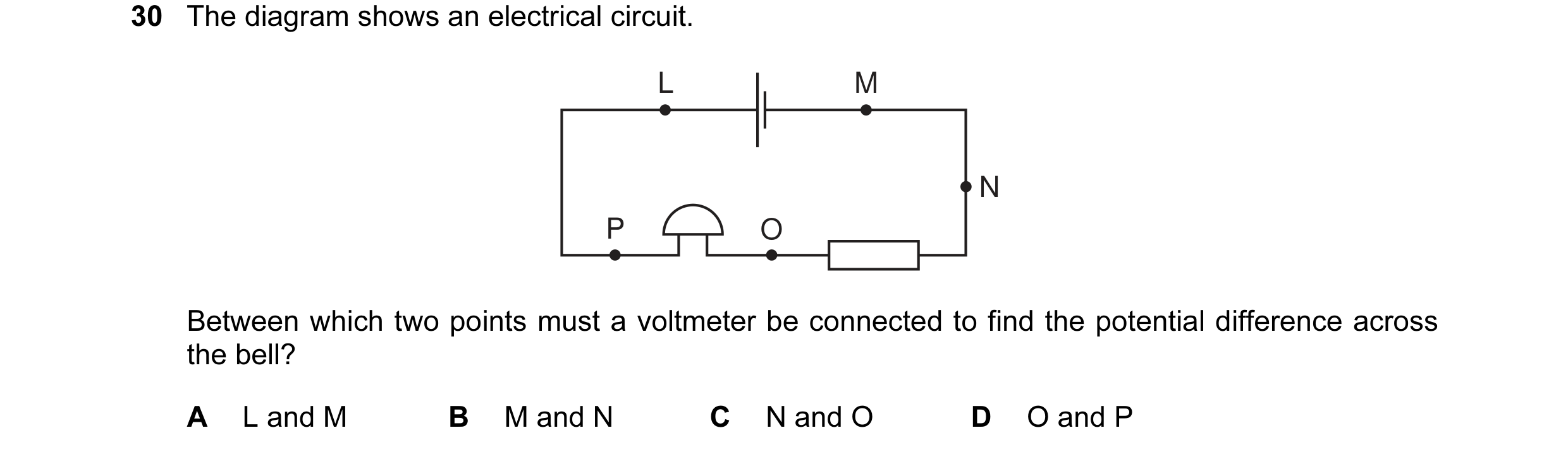 42 / 176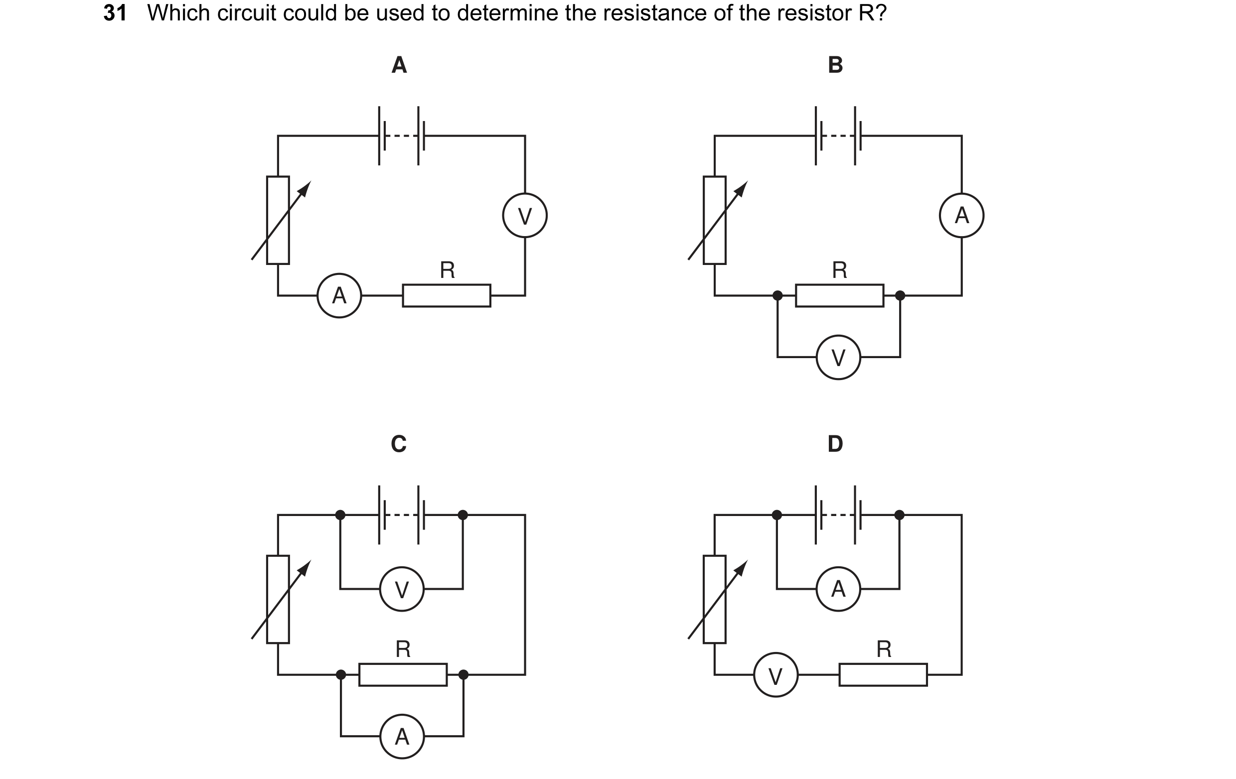
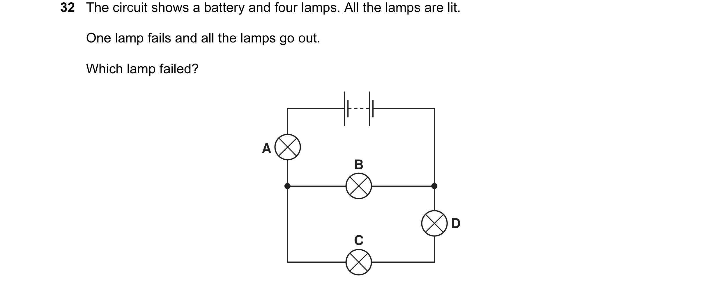
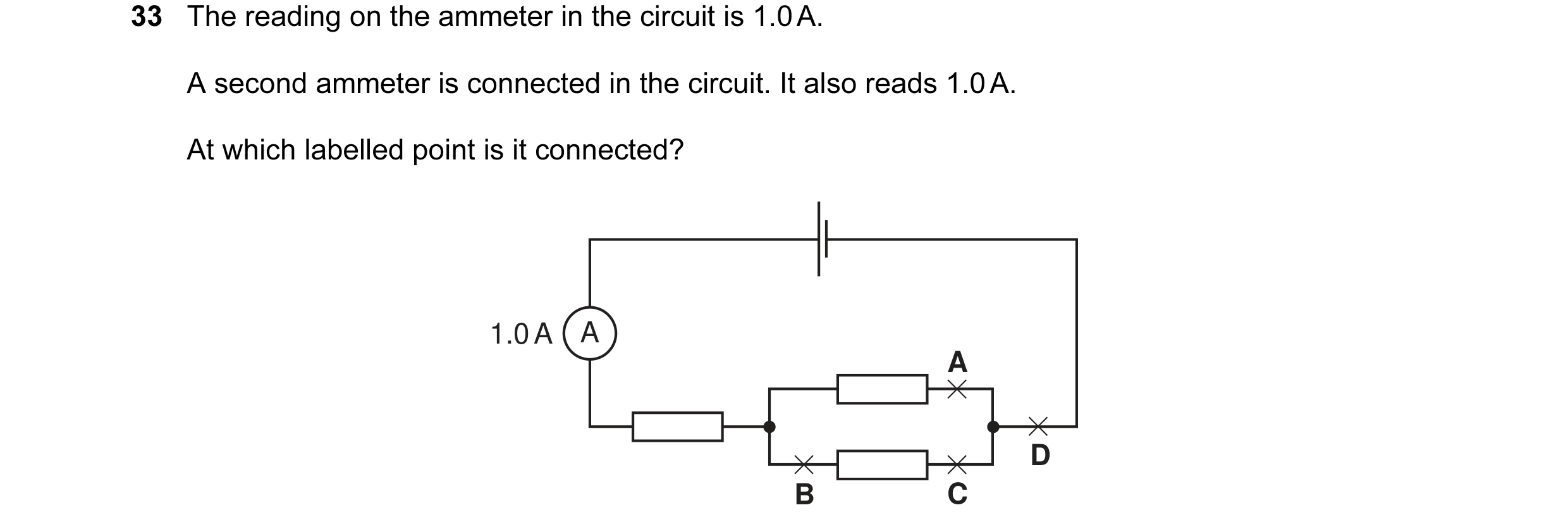 43 / 176
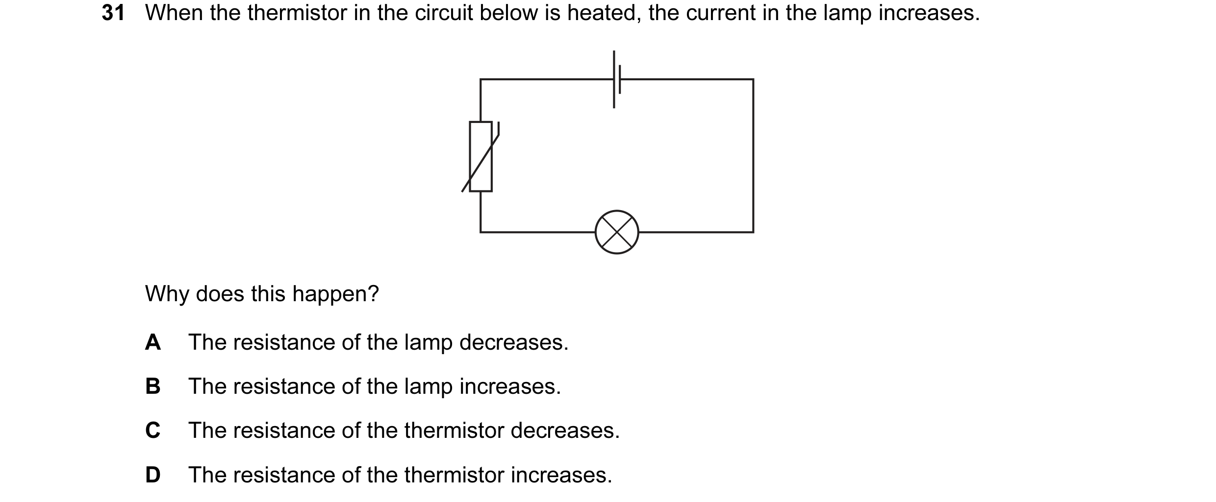
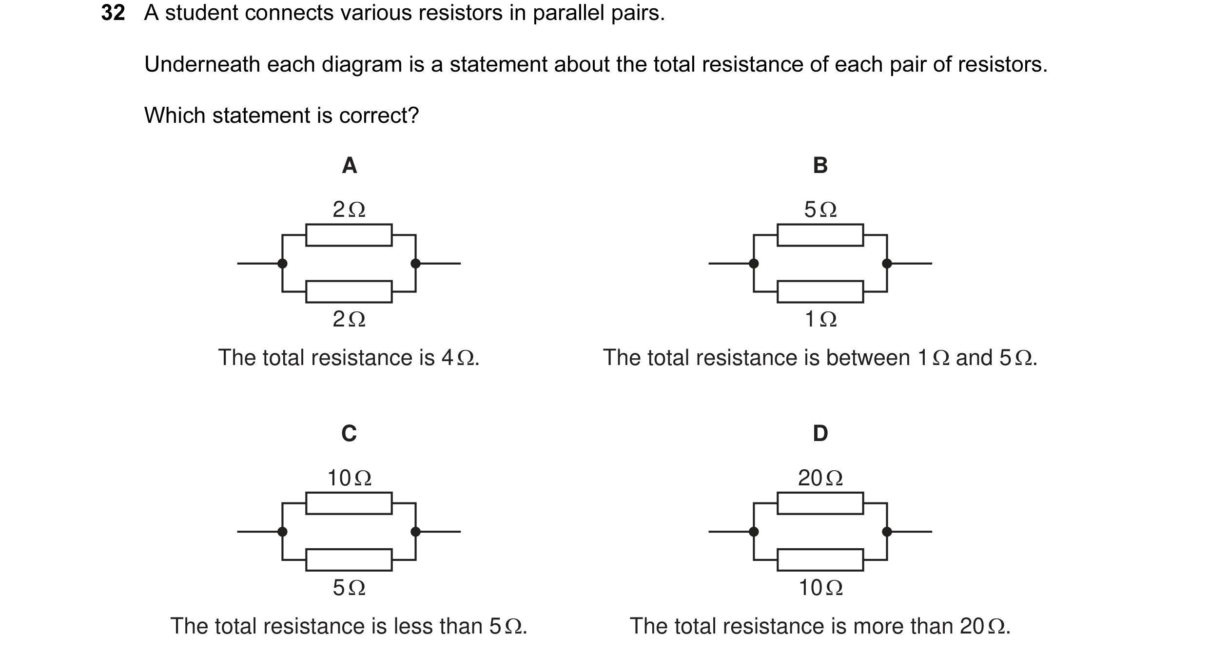 44 / 176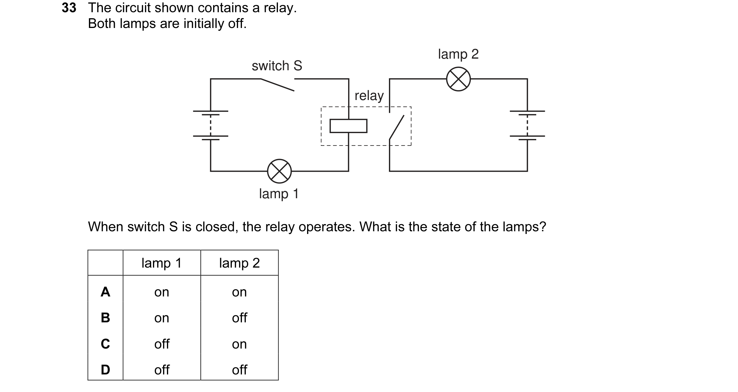
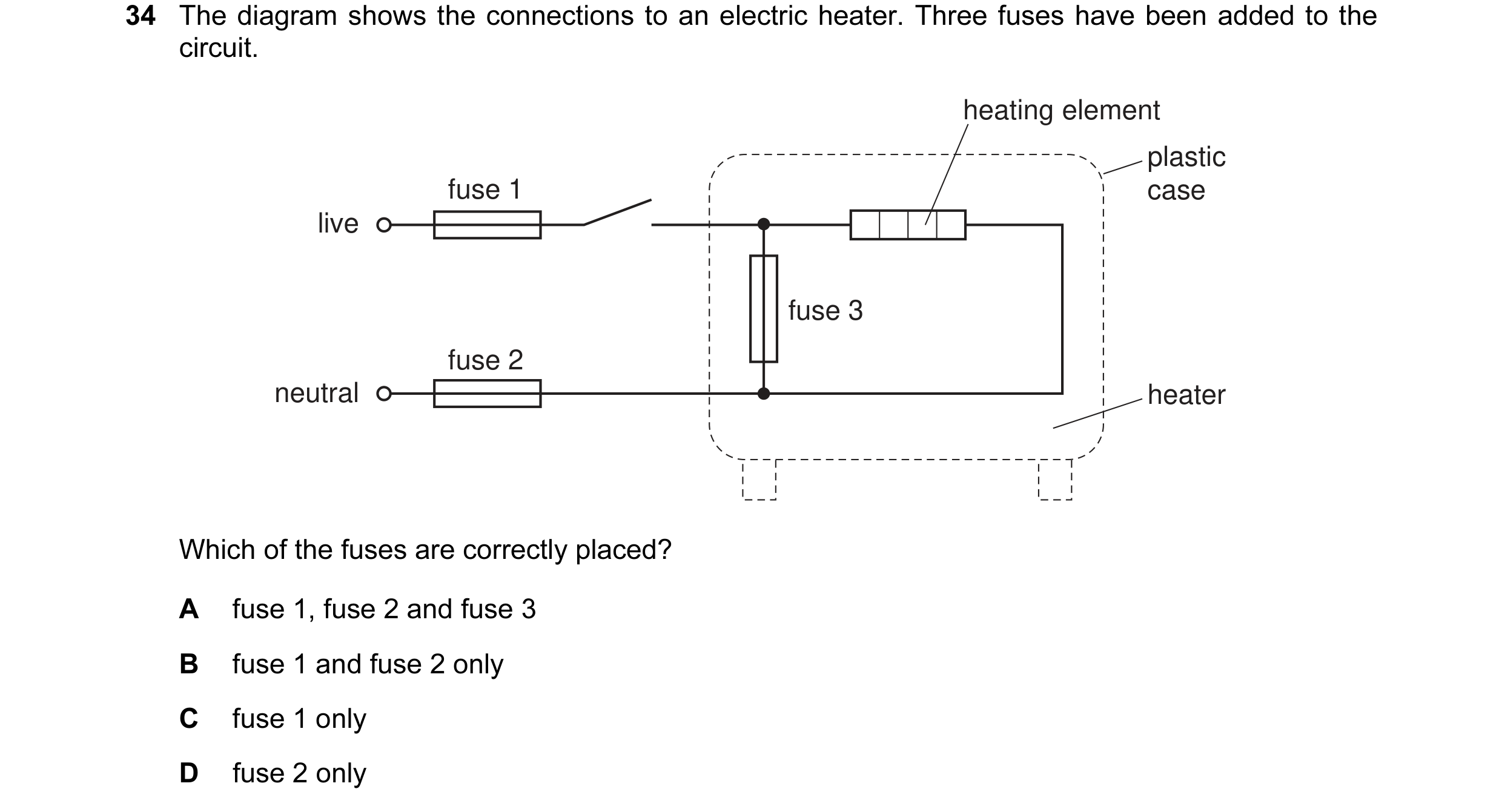
 45 / 176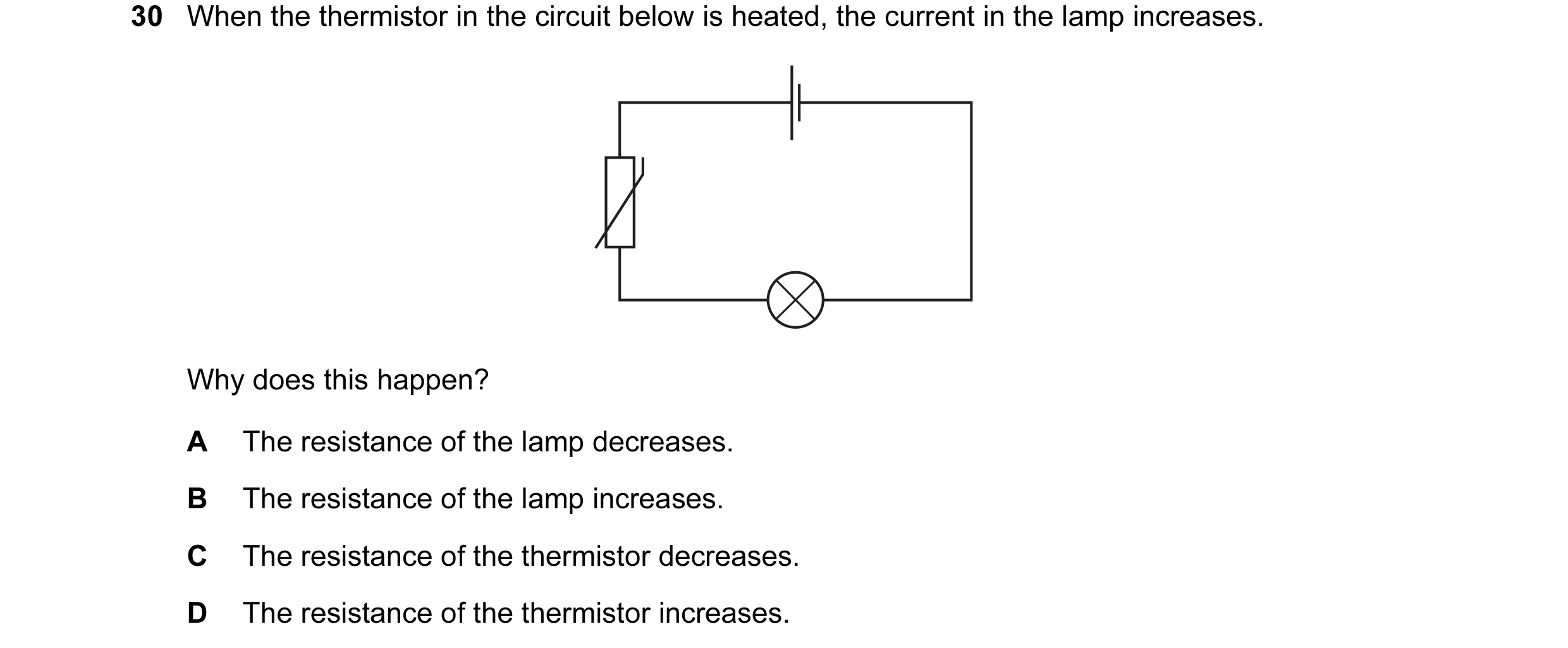
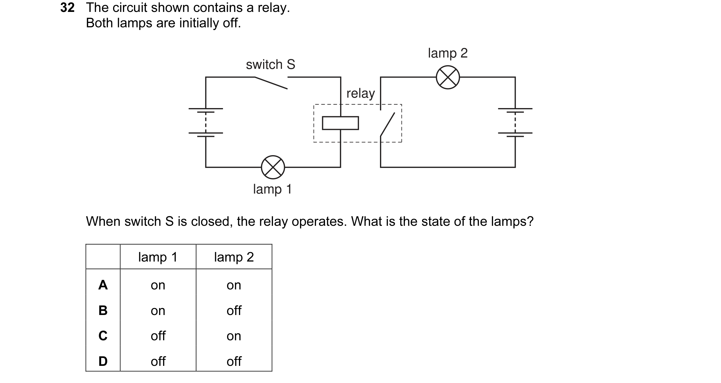 46 / 176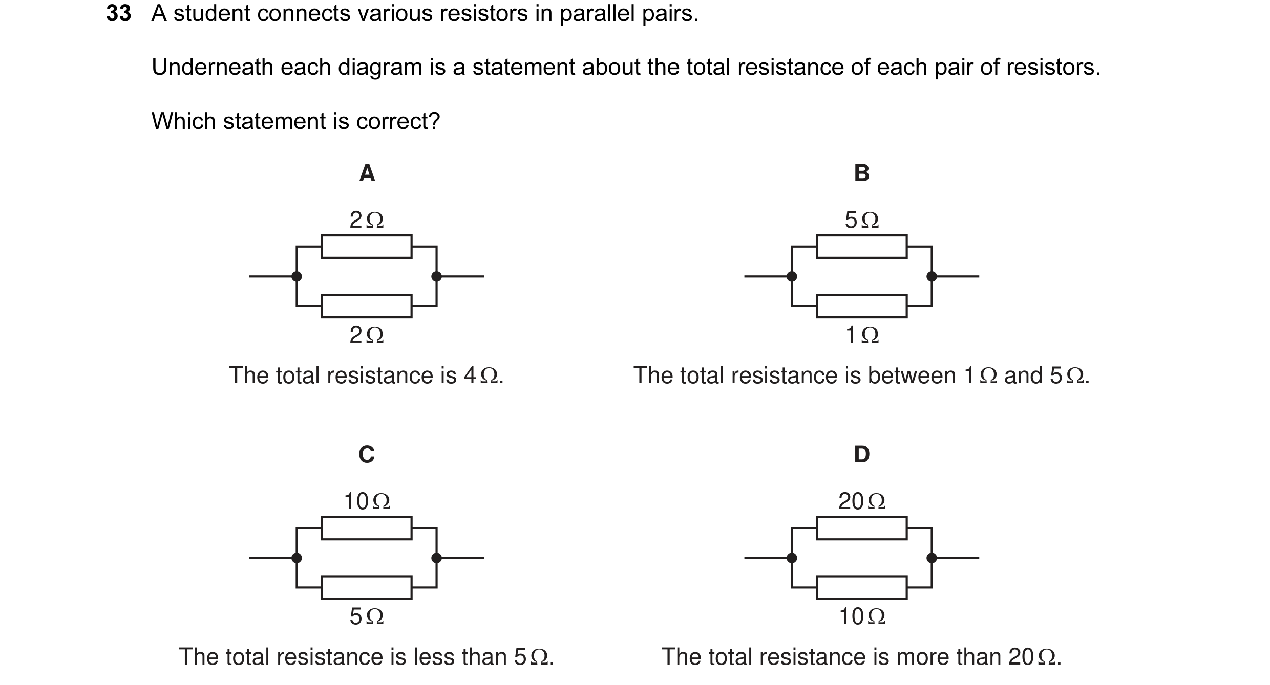
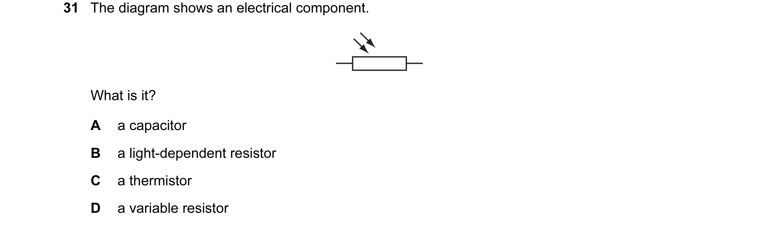 47 / 176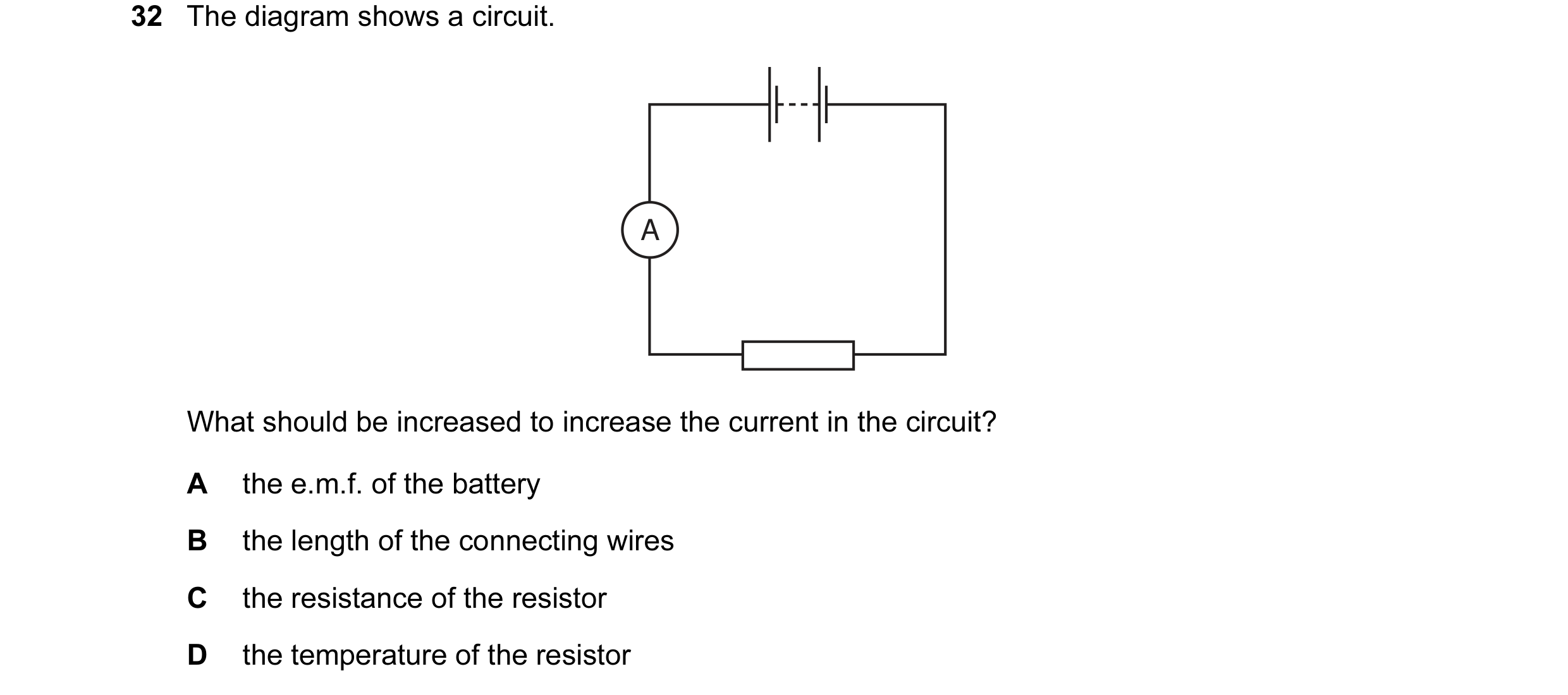
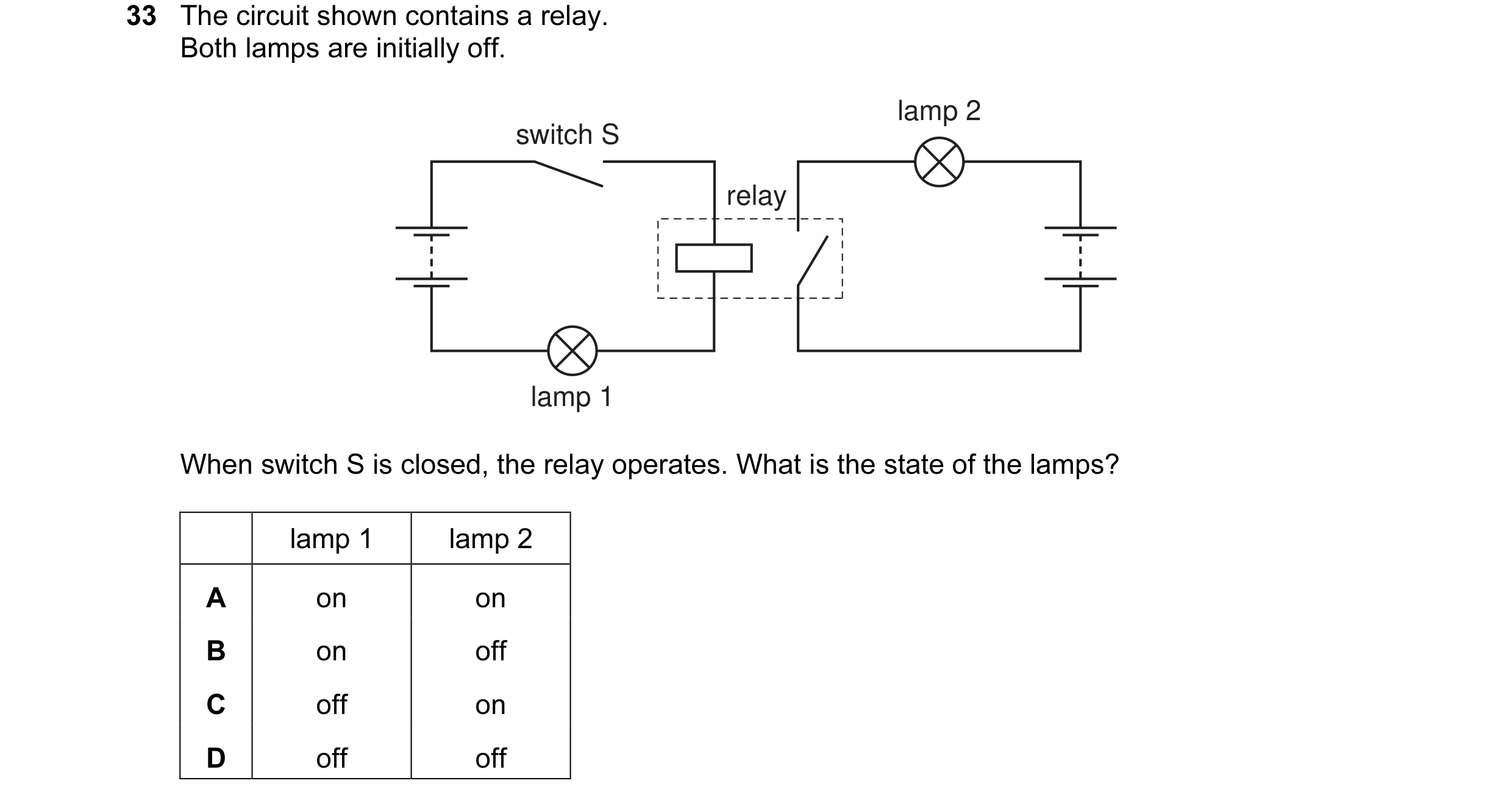 48 / 176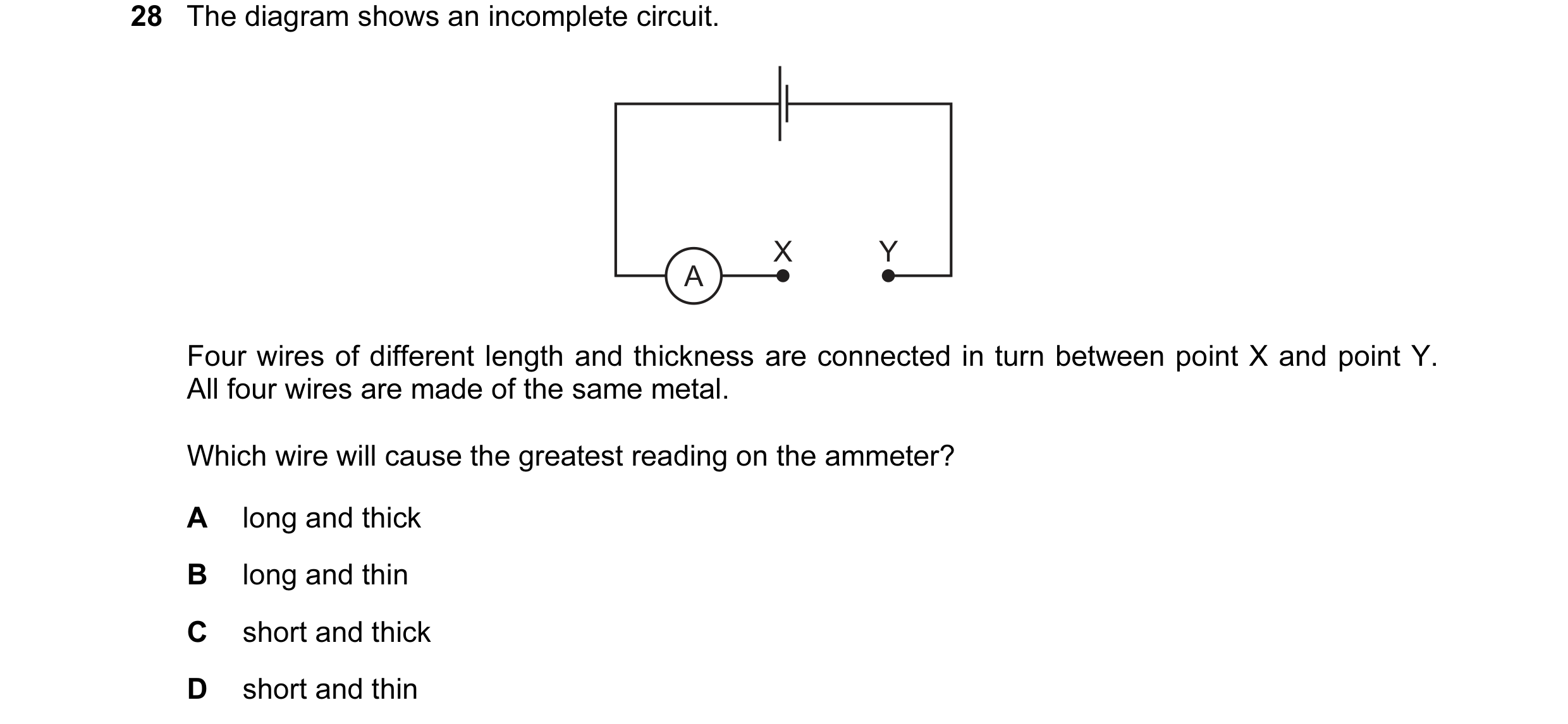
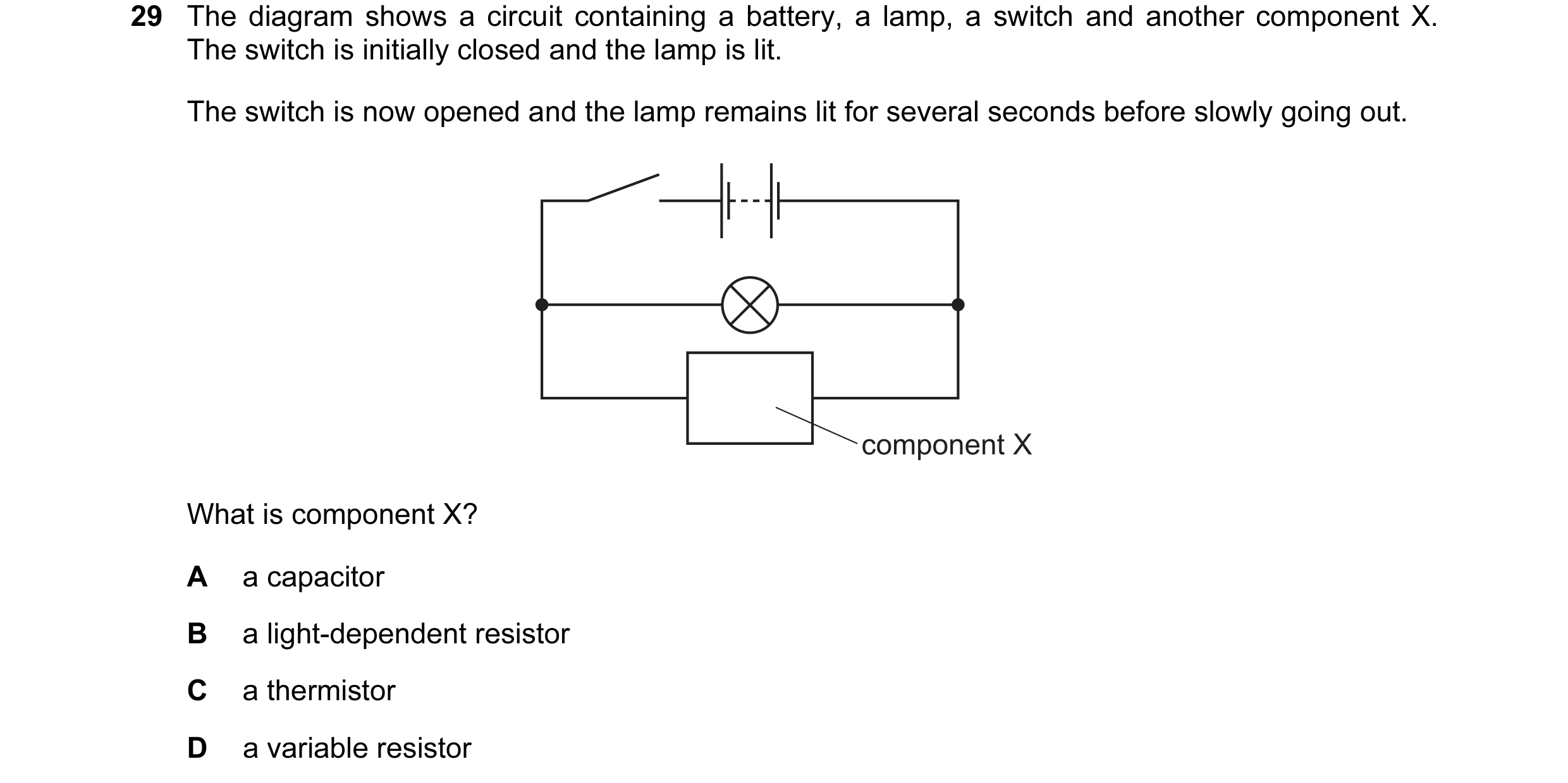 49 / 176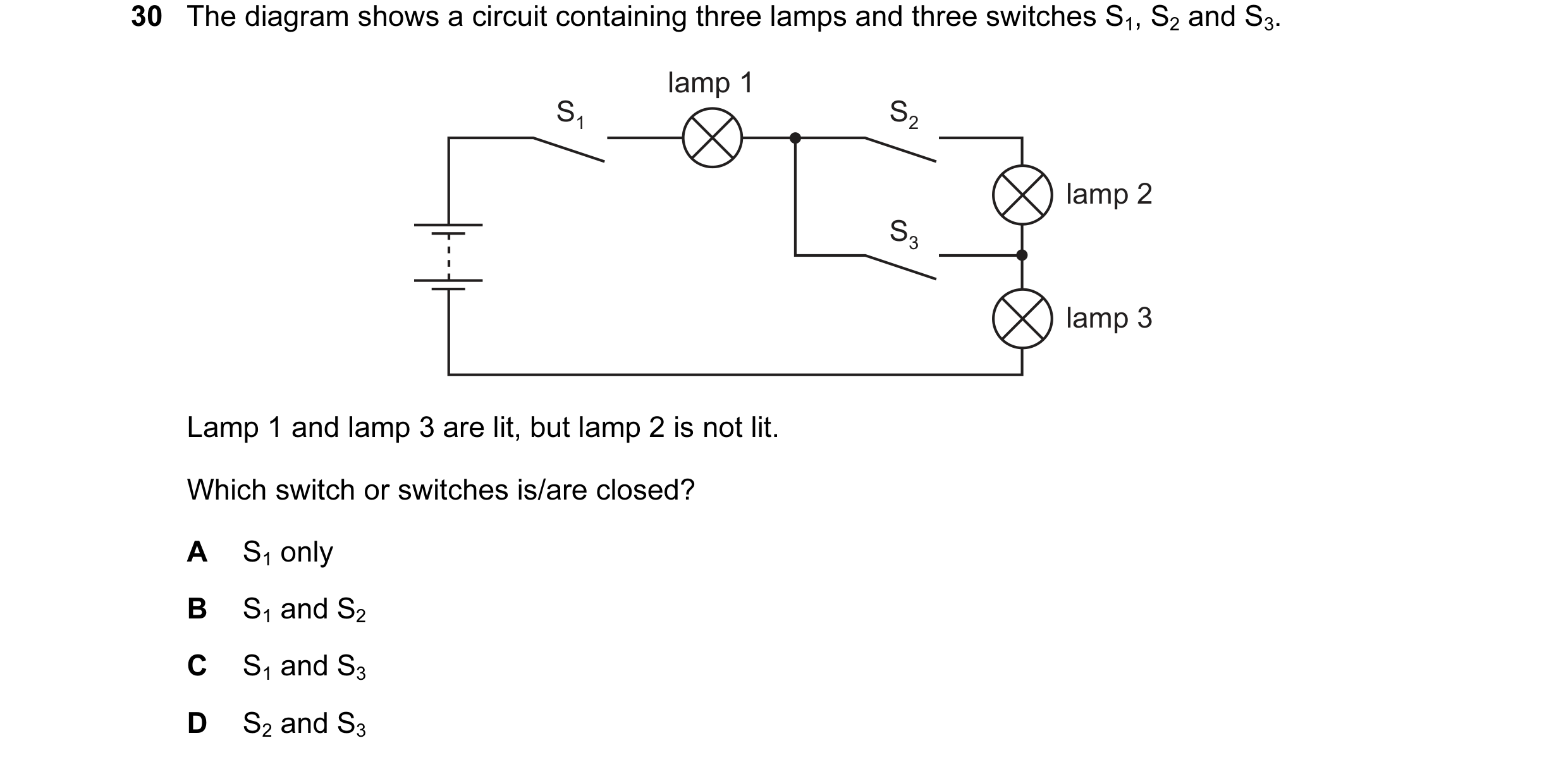
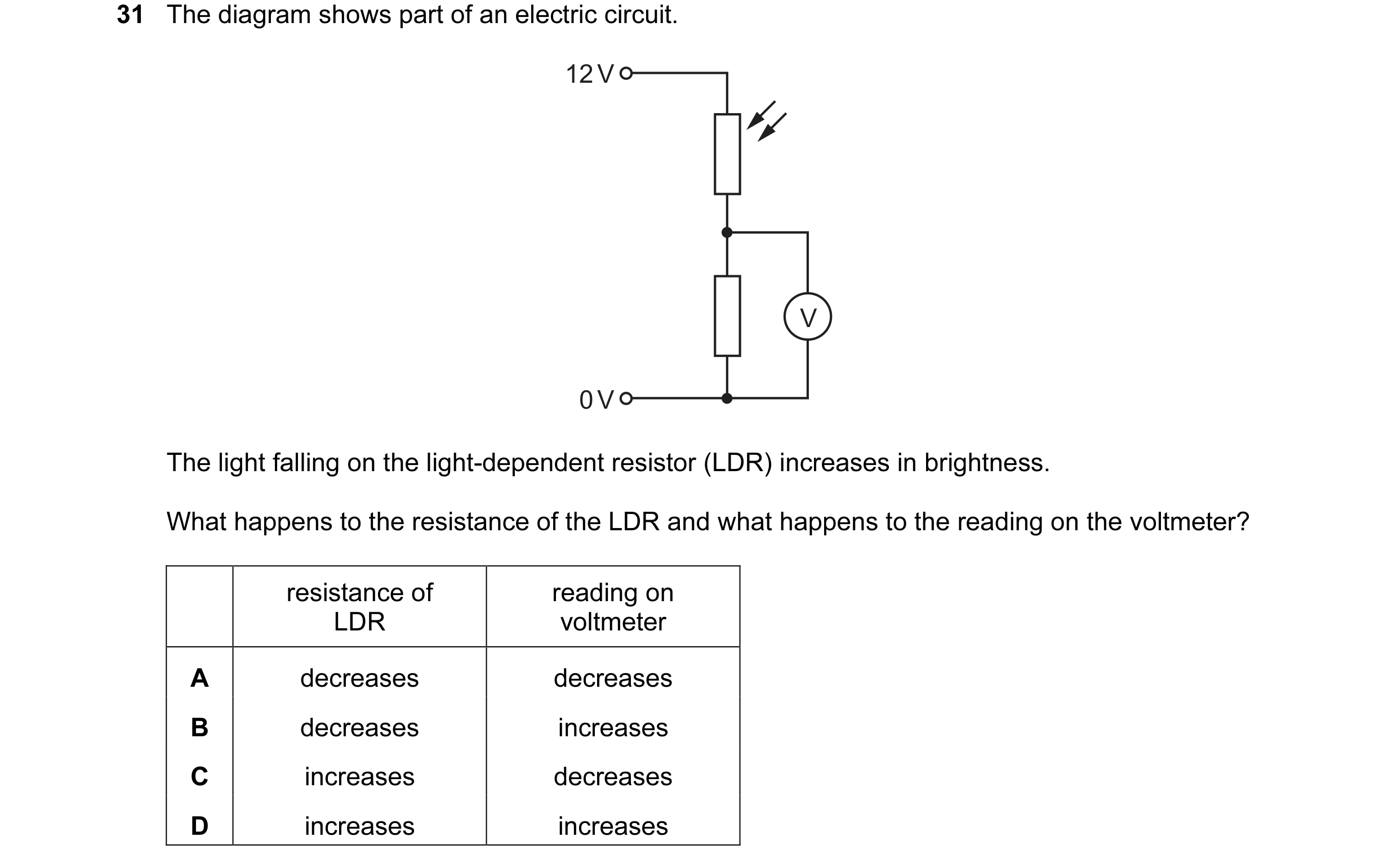 50 / 176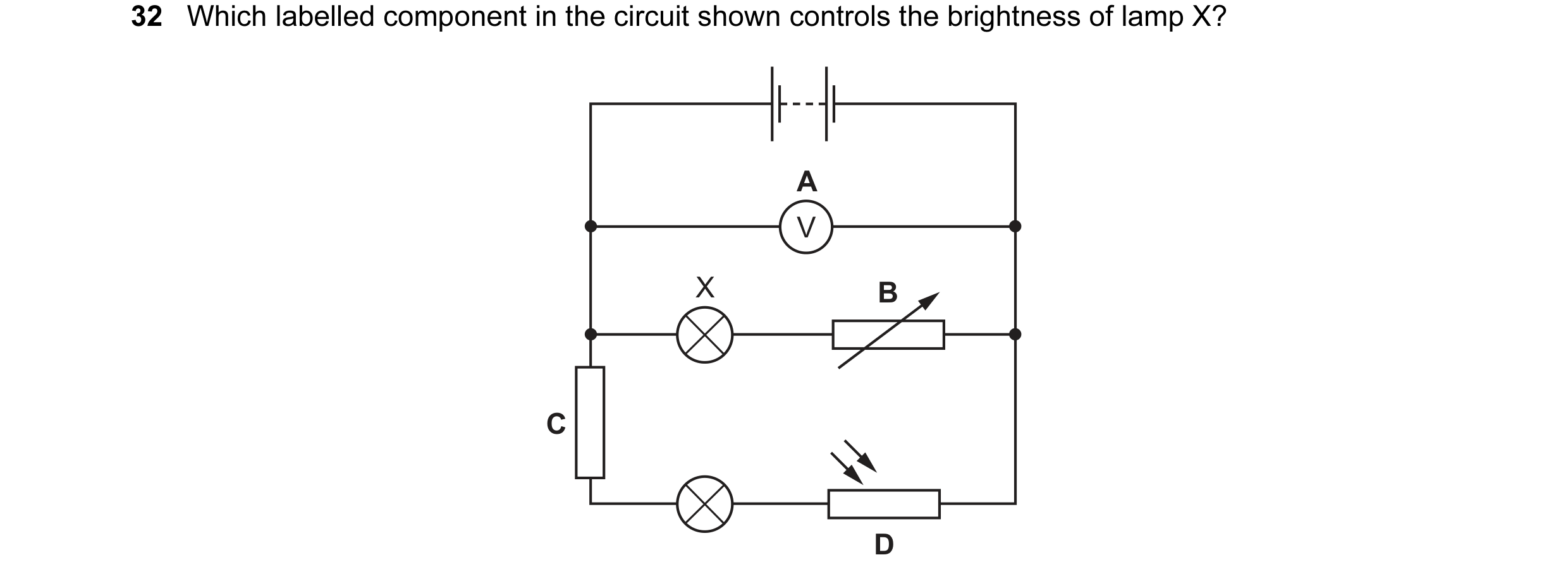
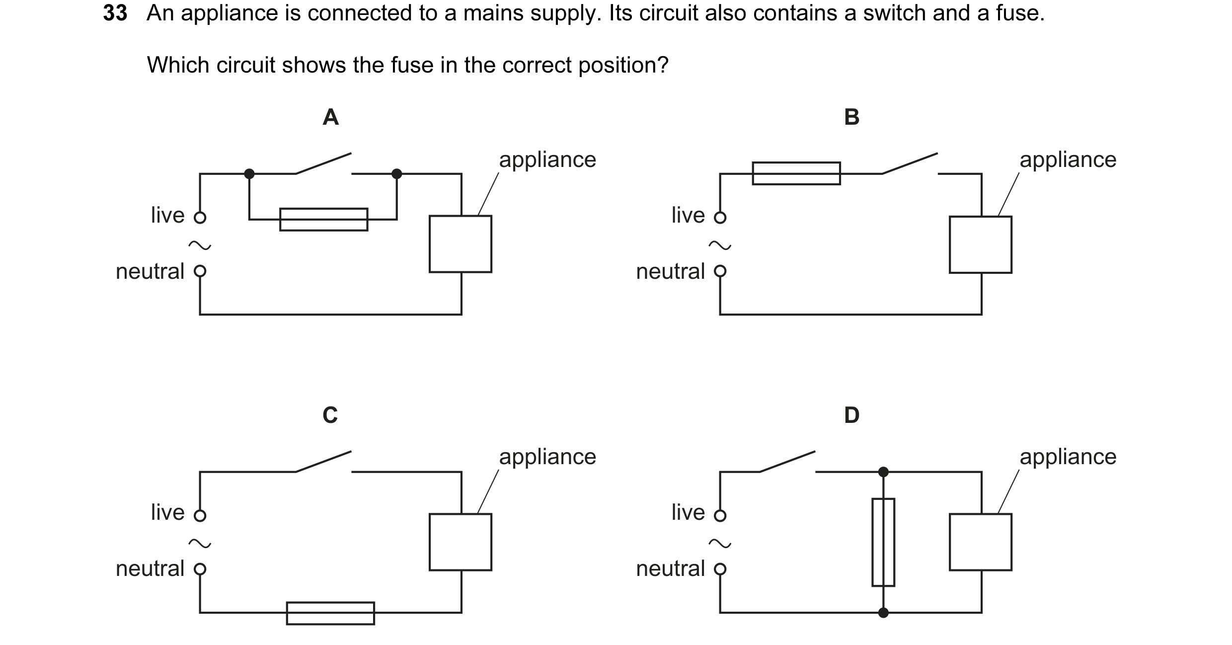
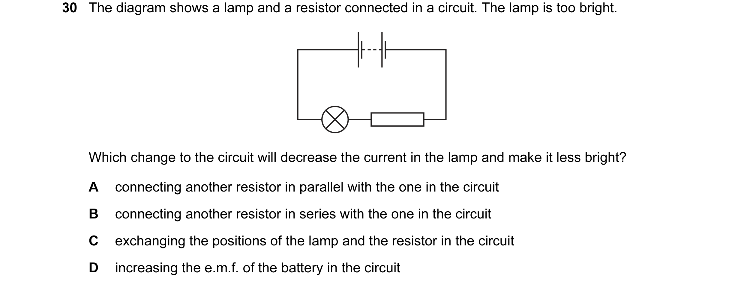 51 / 176
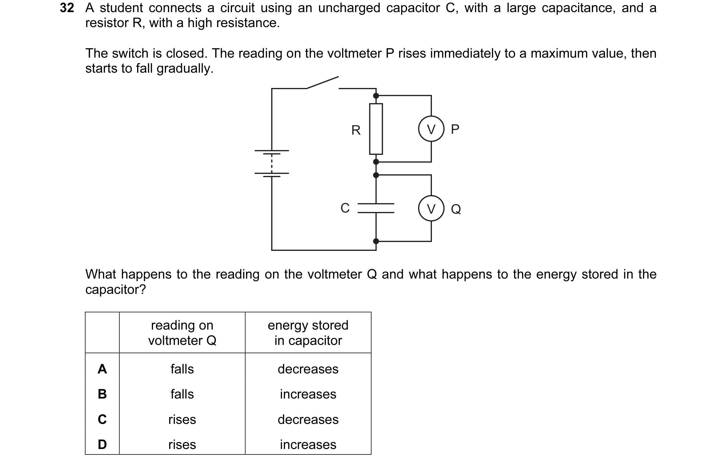
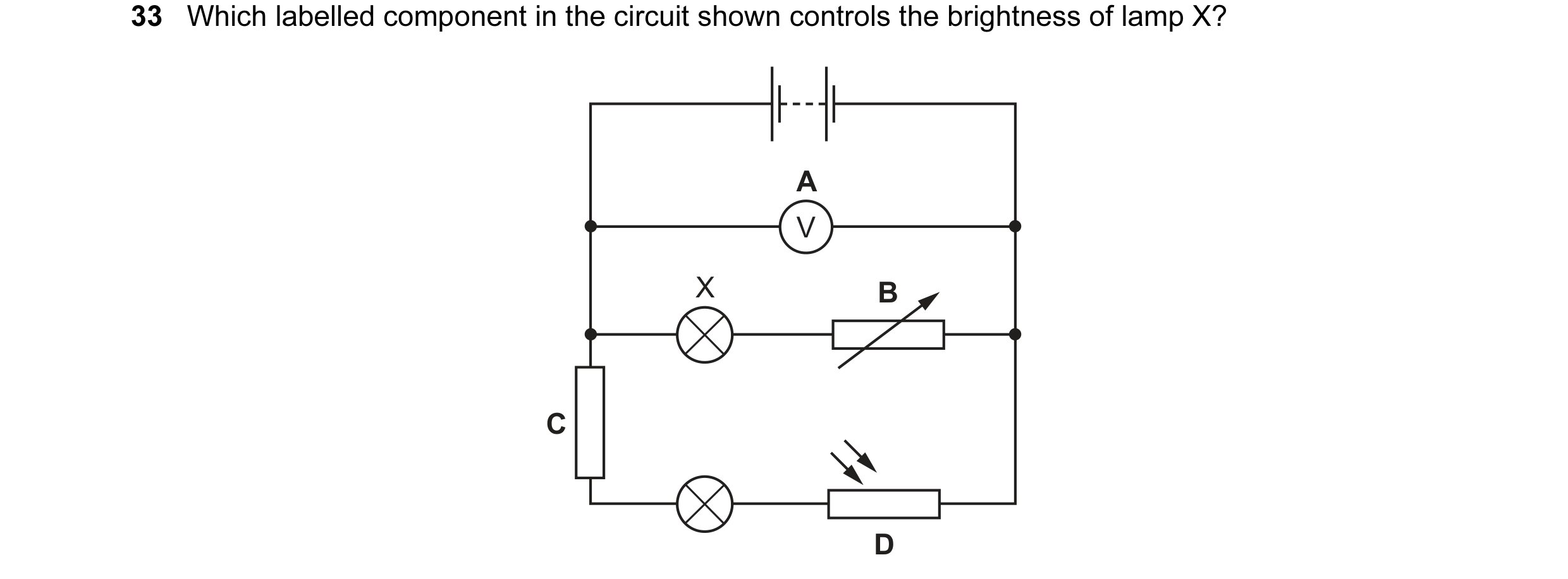 52 / 176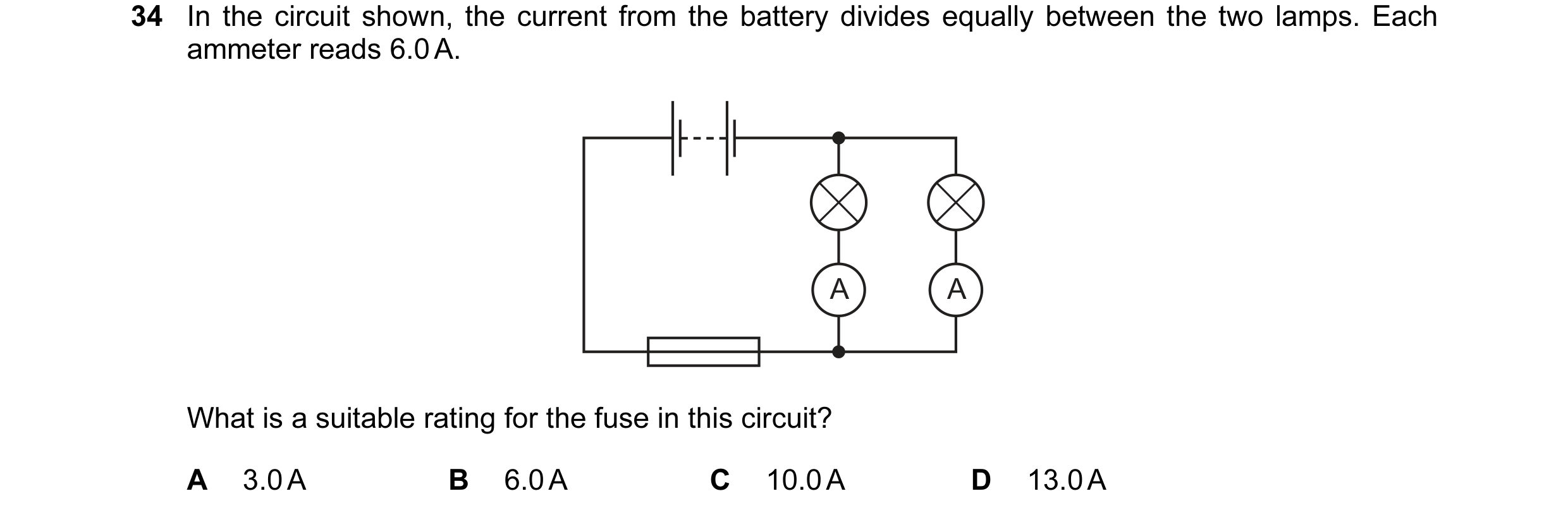
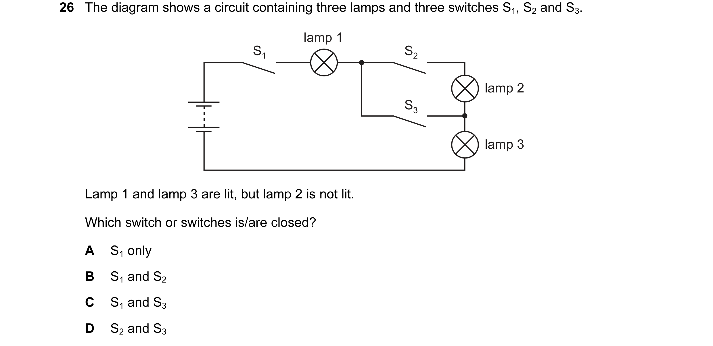
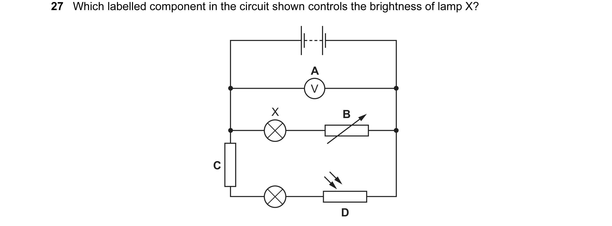 53 / 176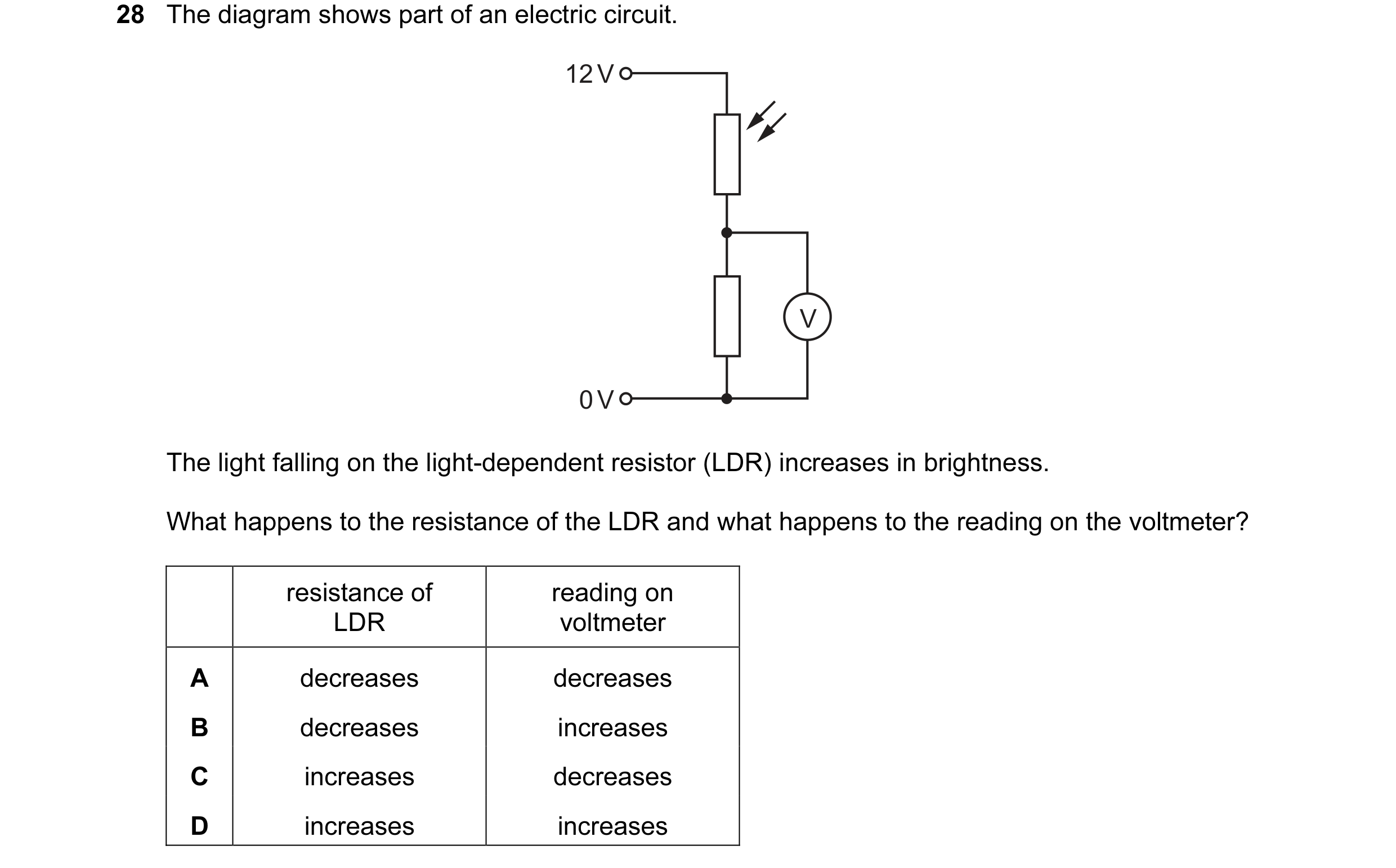
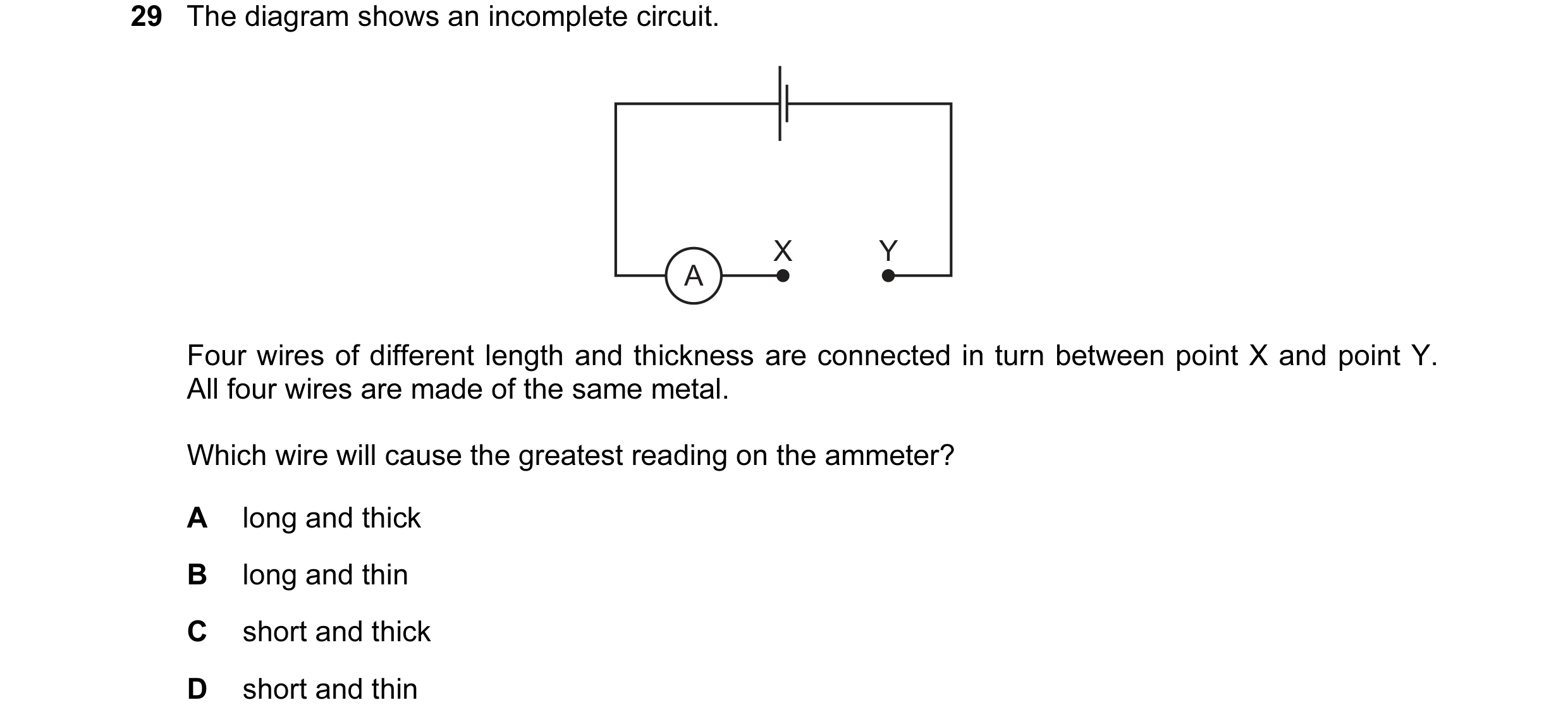 54 / 176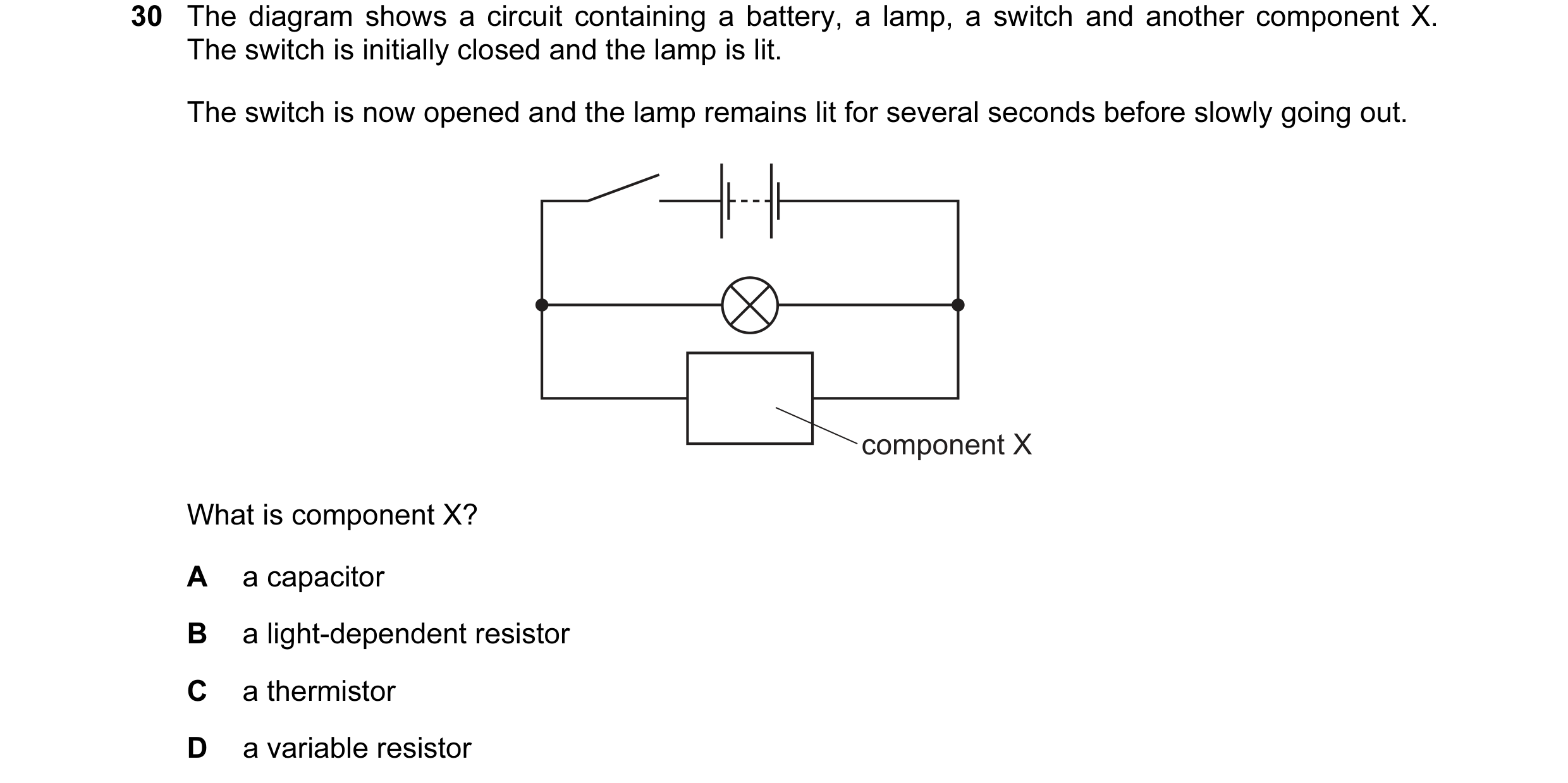
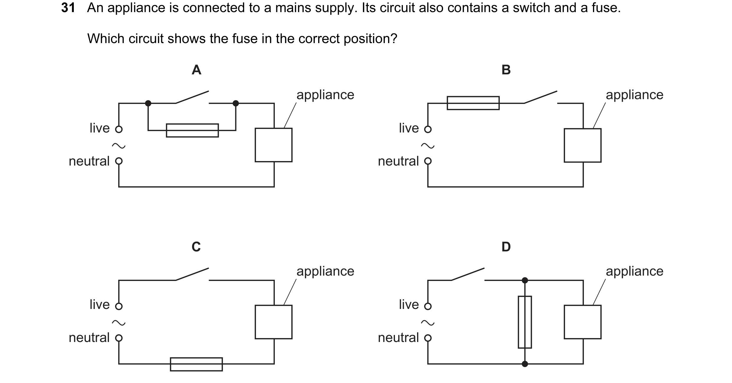 55 / 176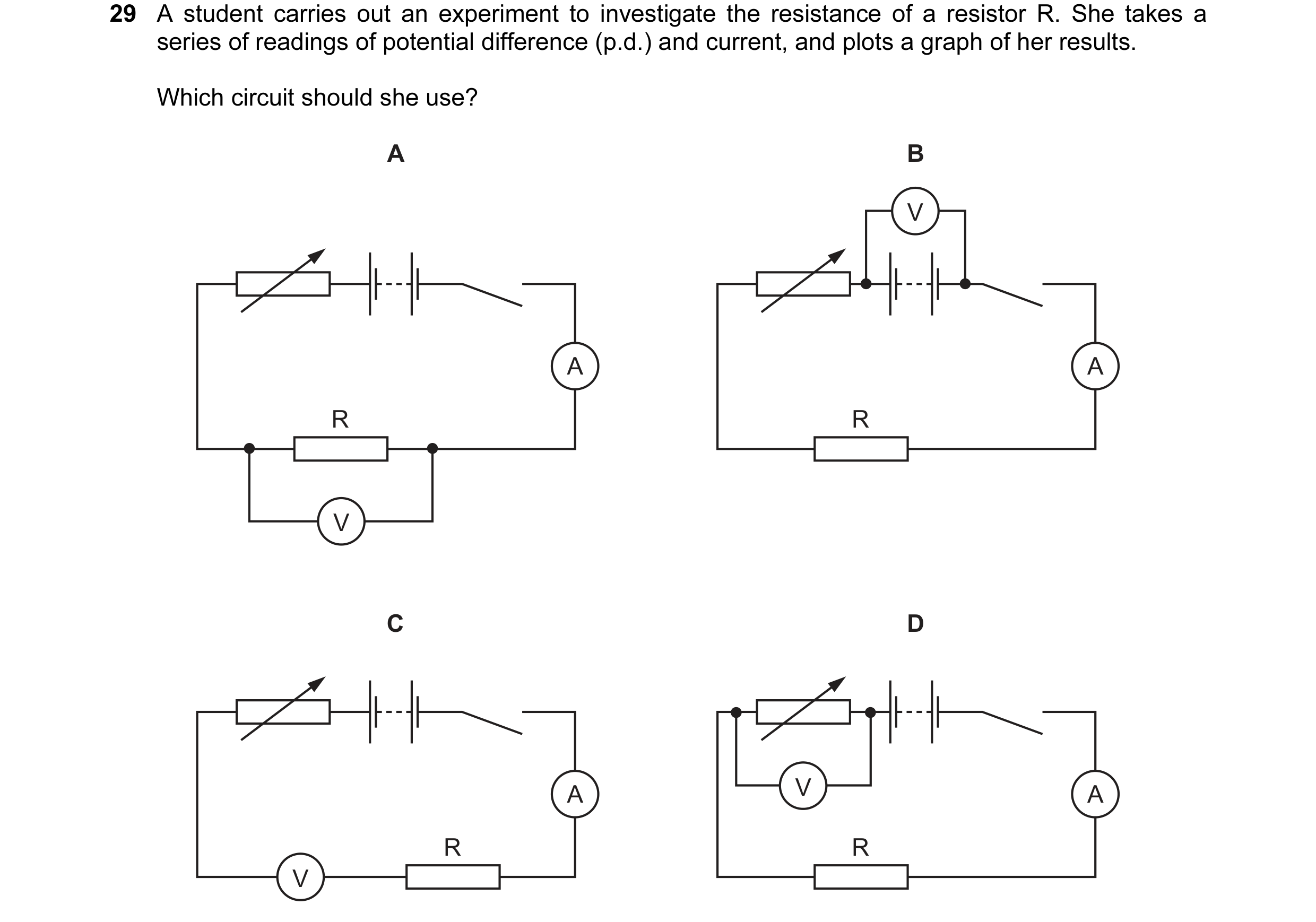
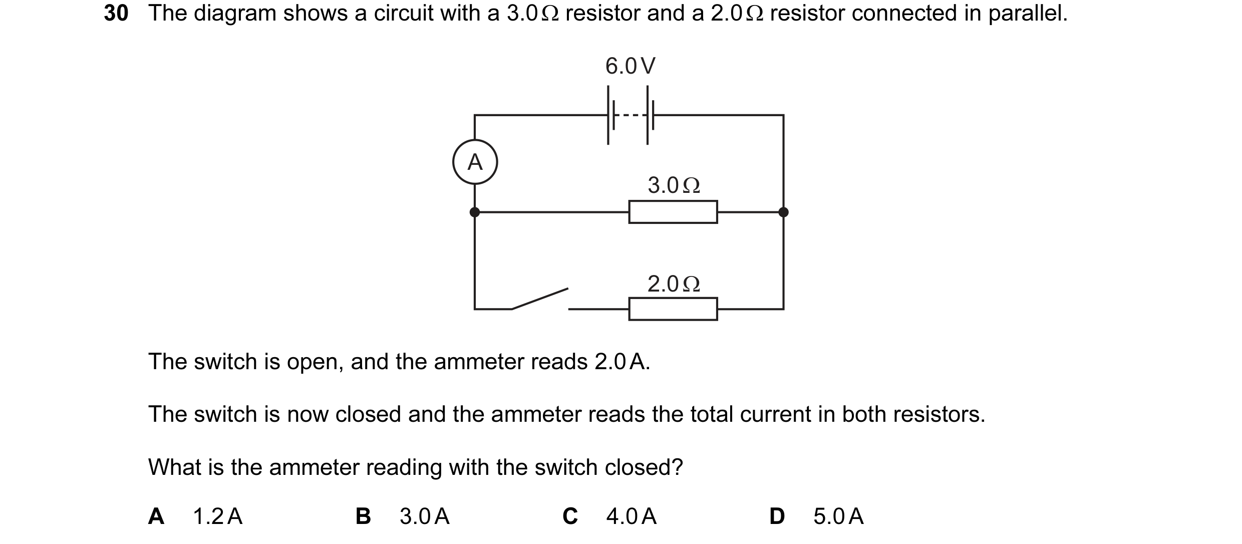 56 / 176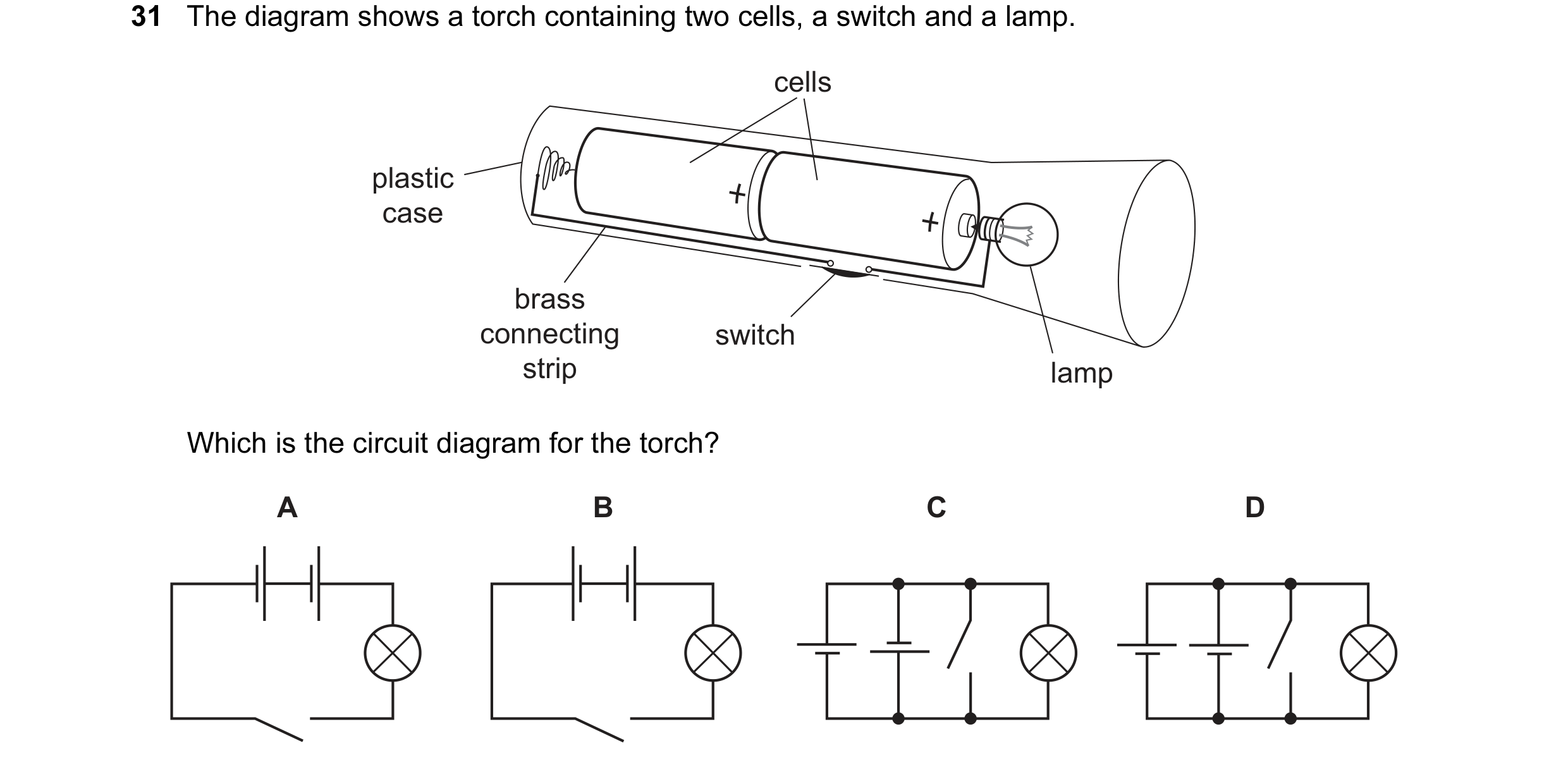
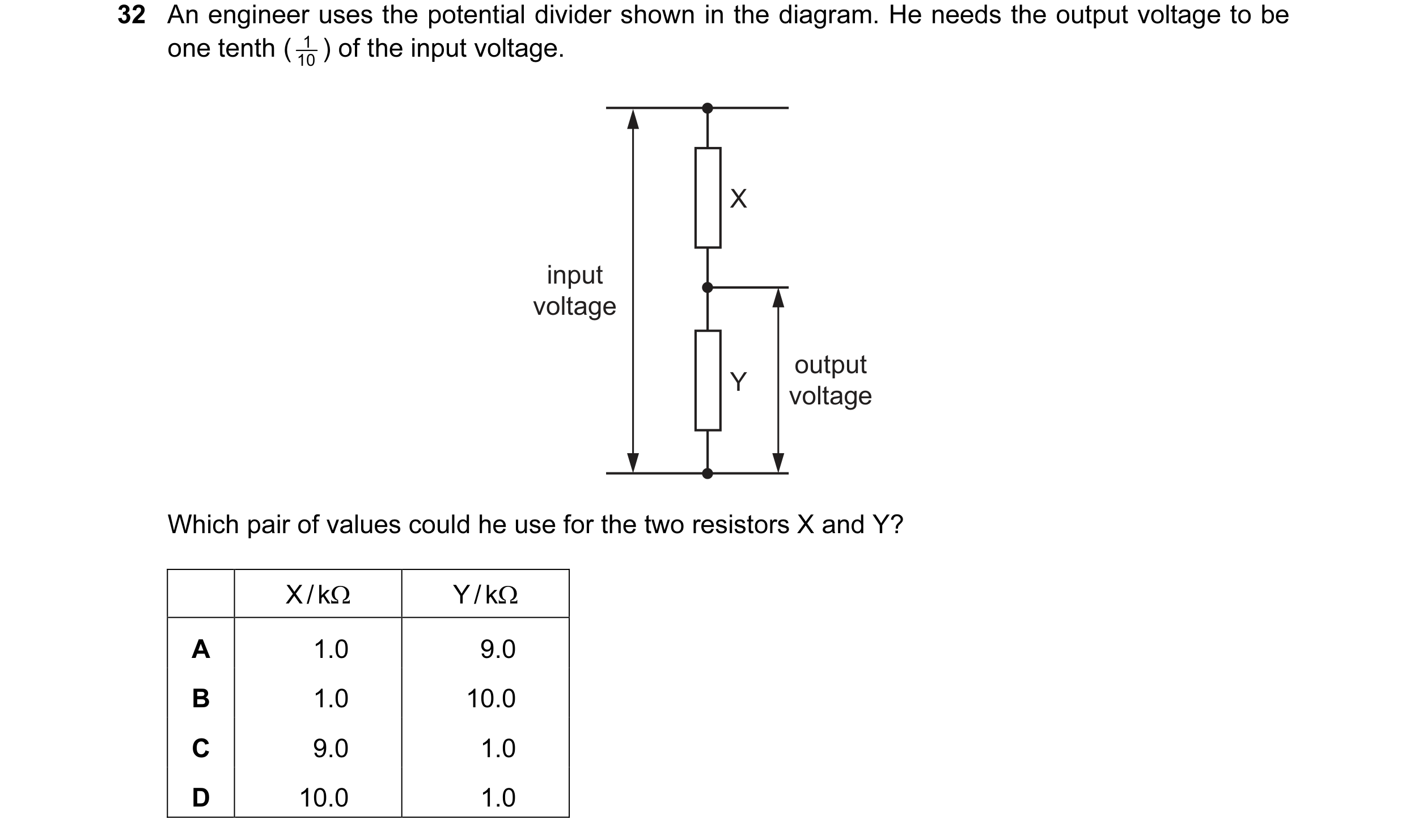
 57 / 176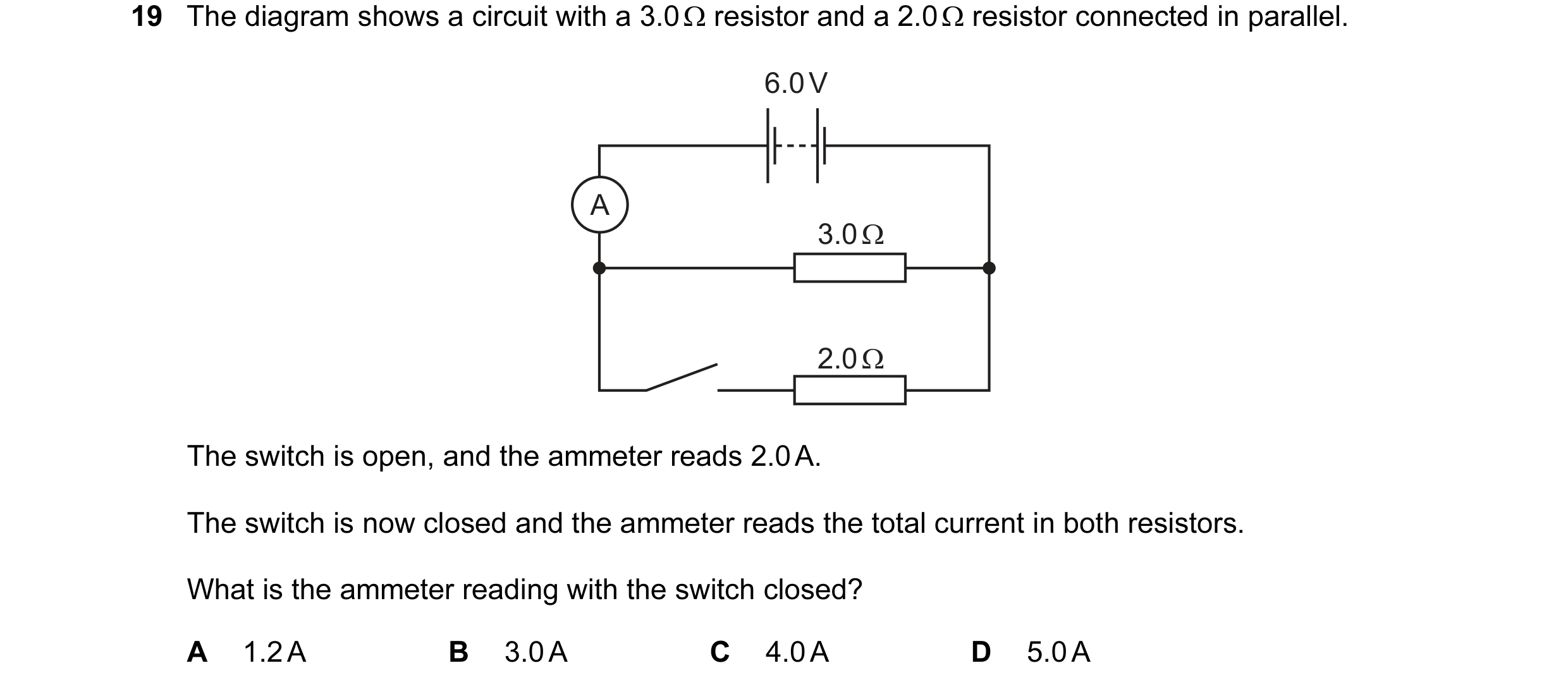
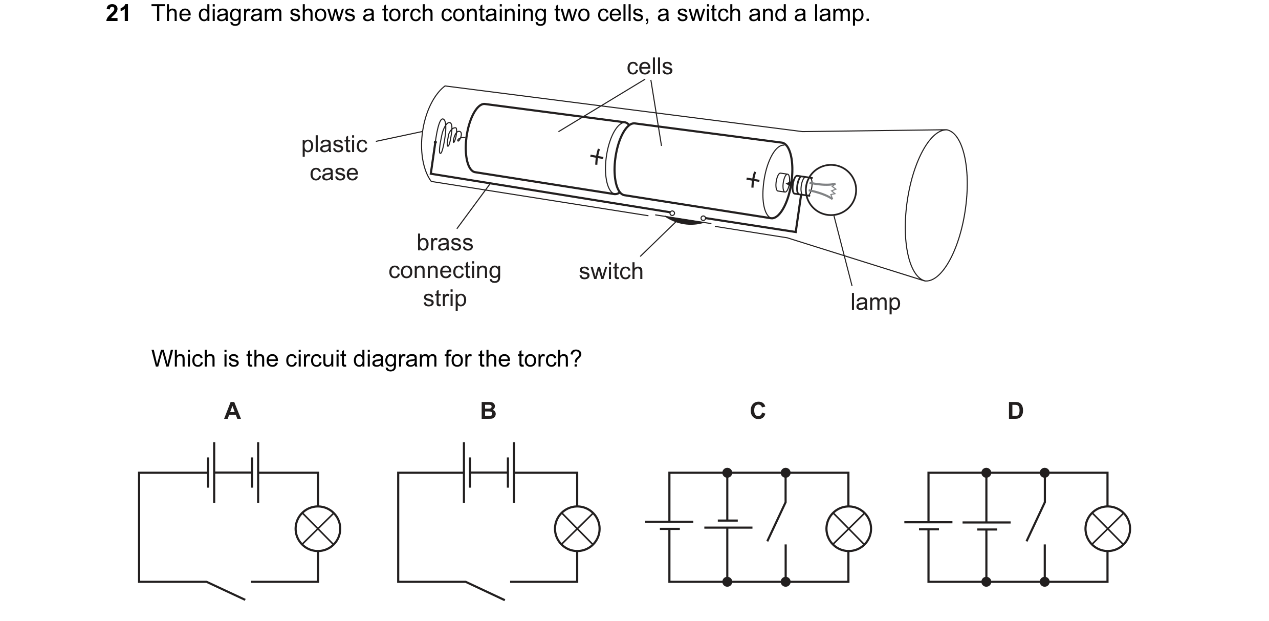 58 / 176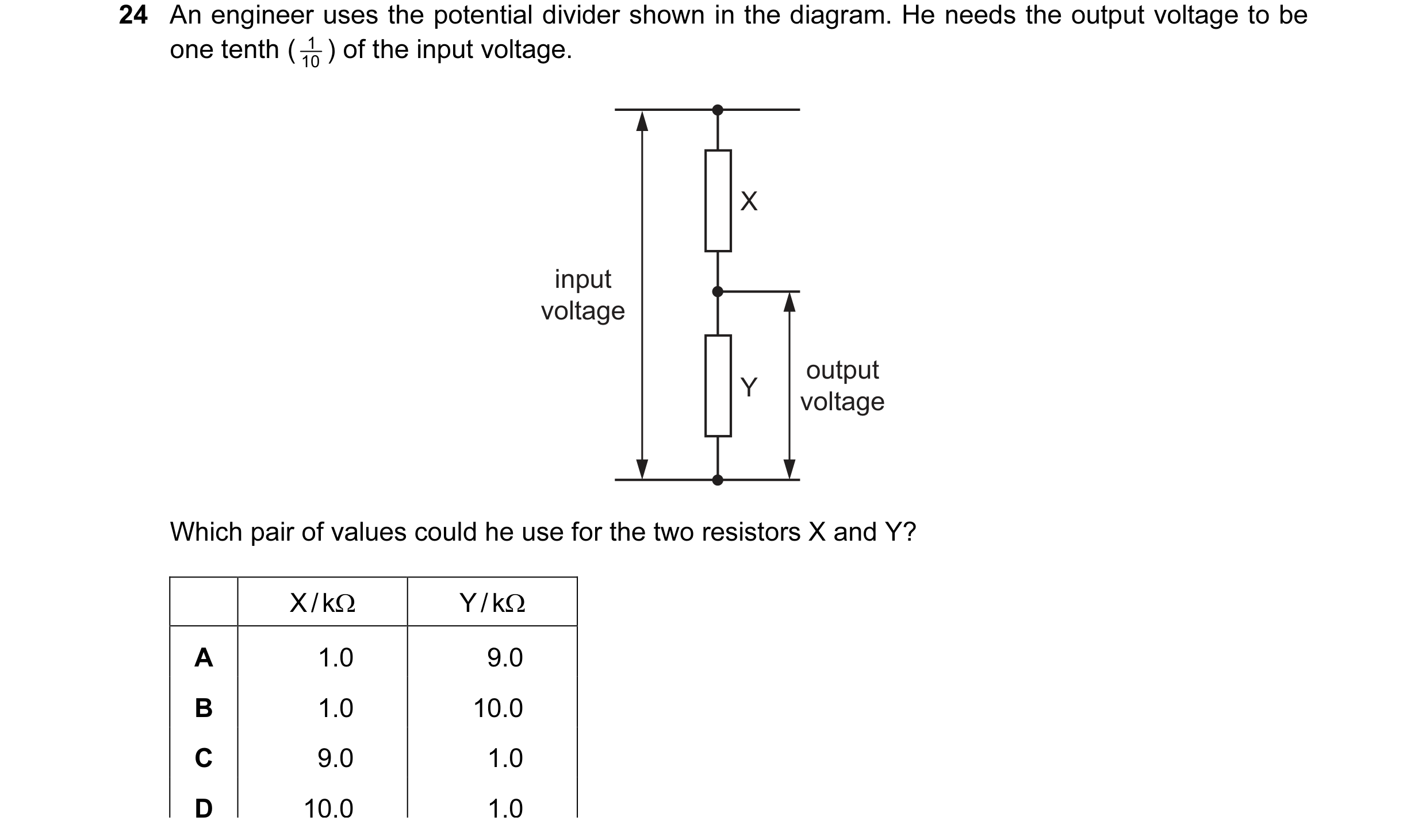
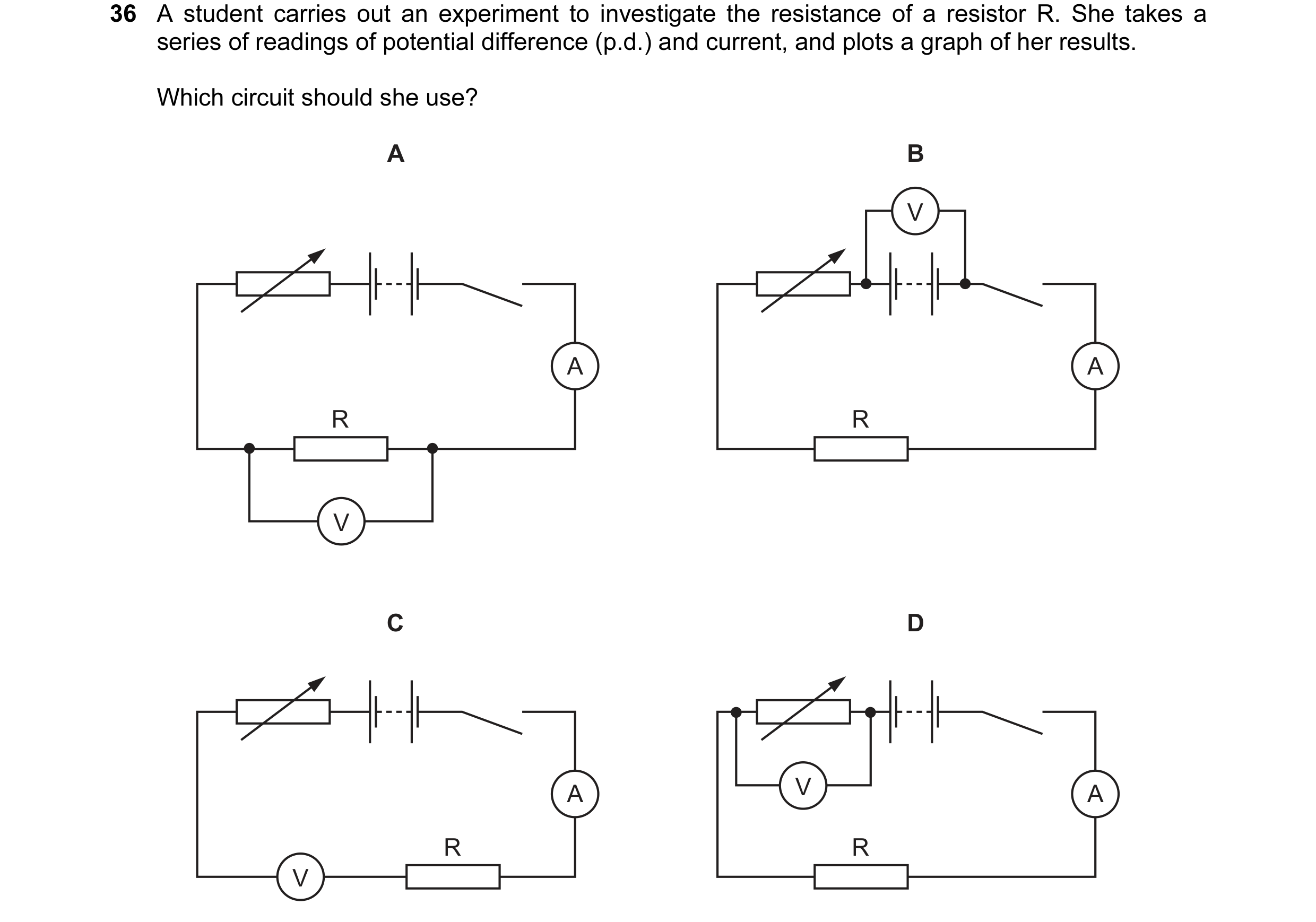 59 / 176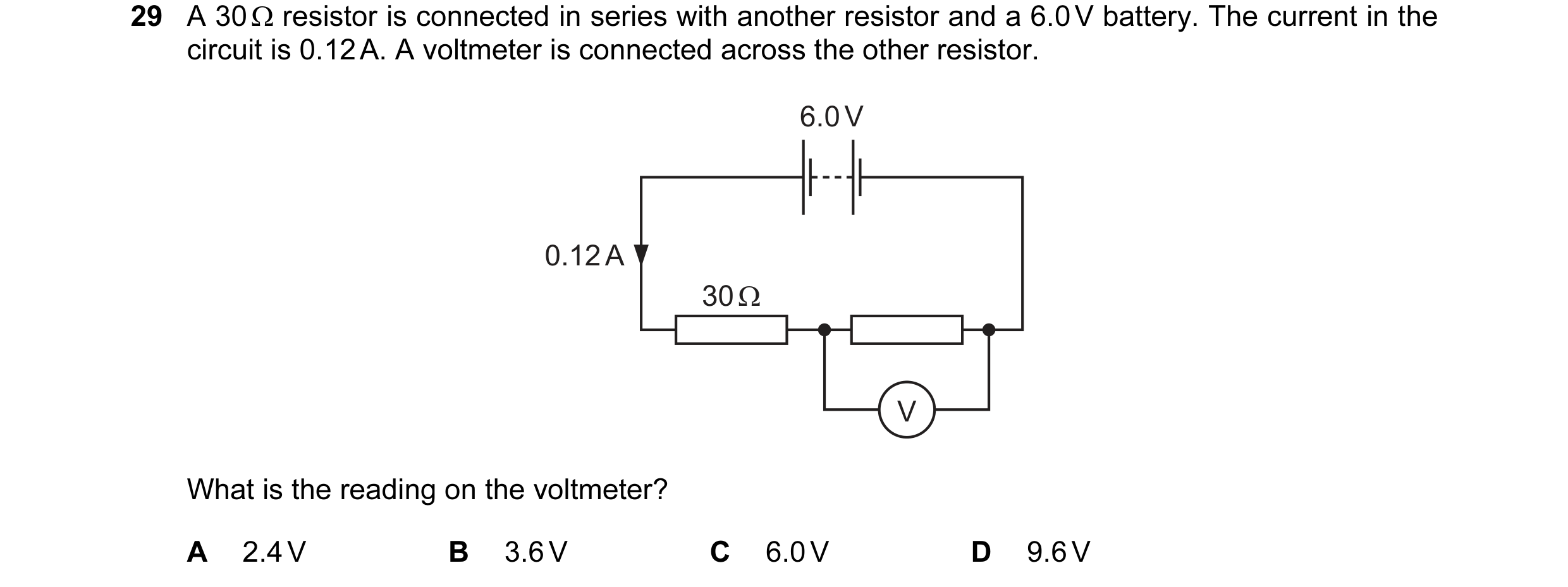
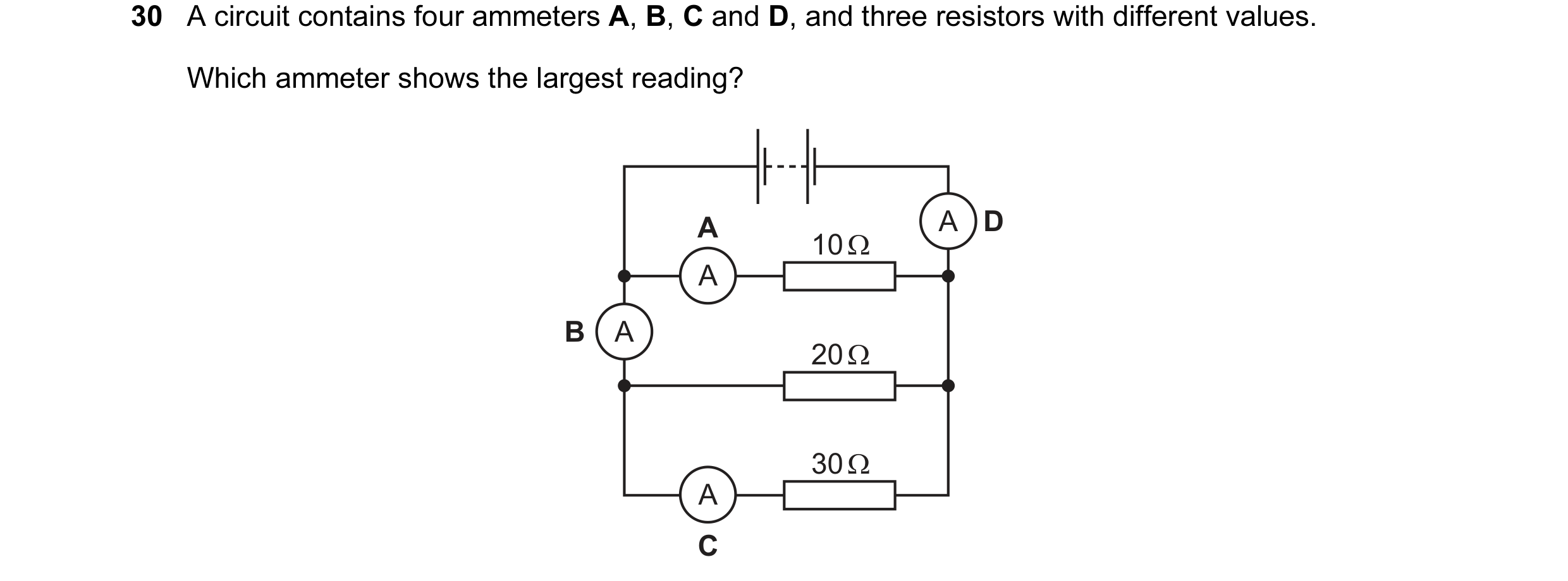
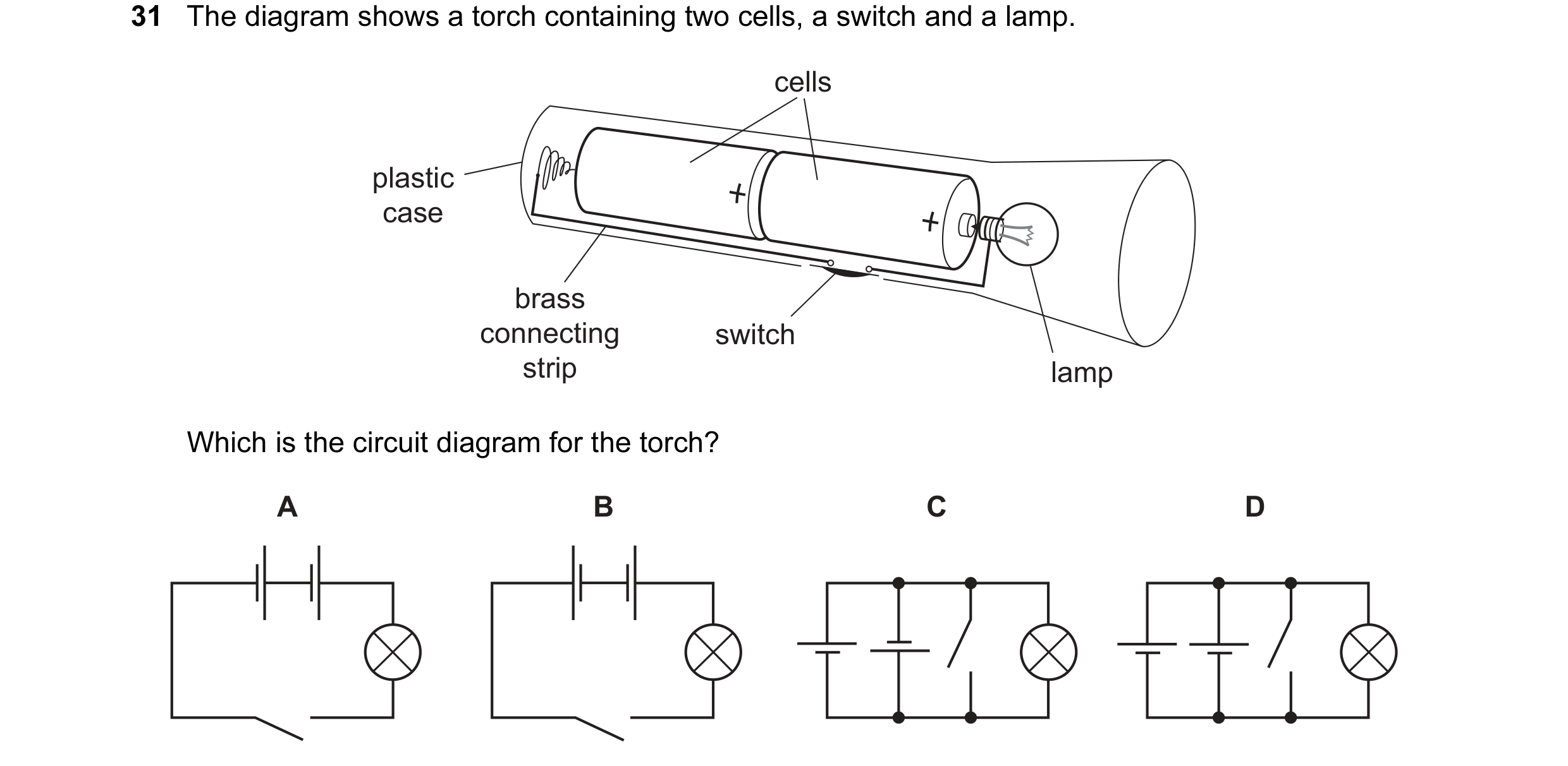 60 / 176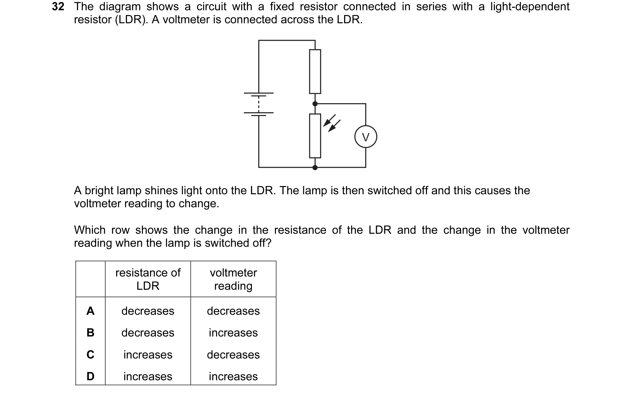
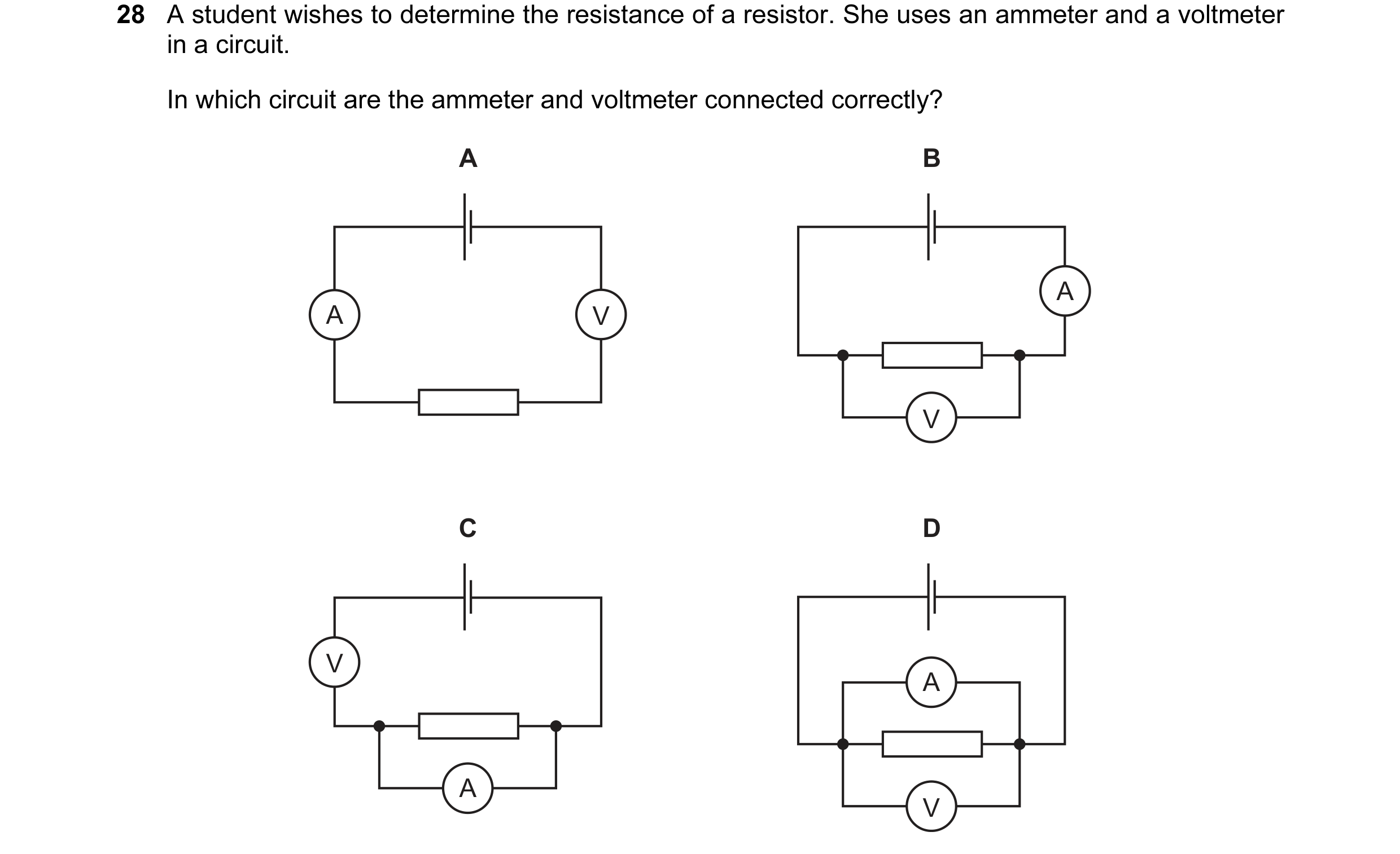 61 / 176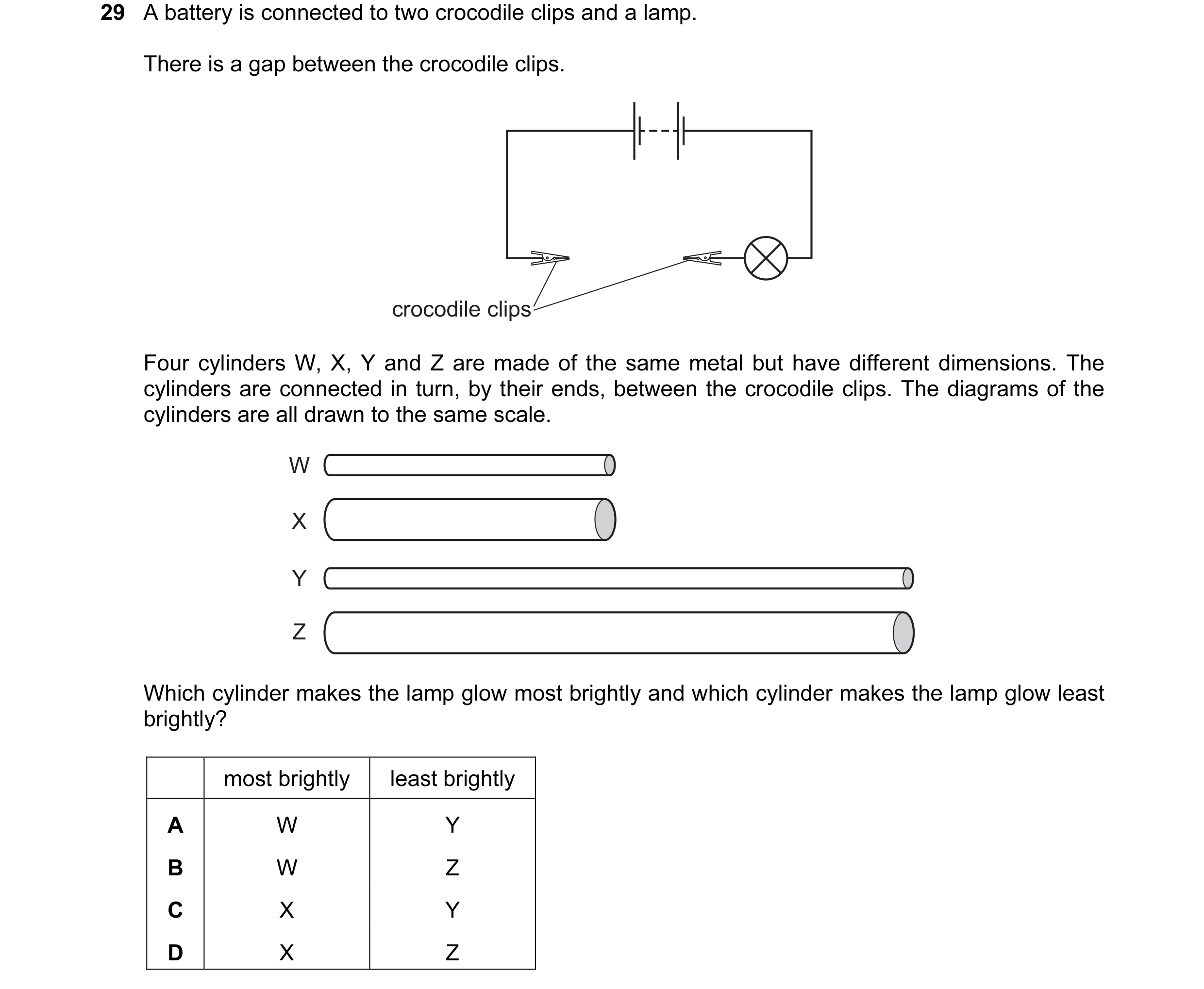
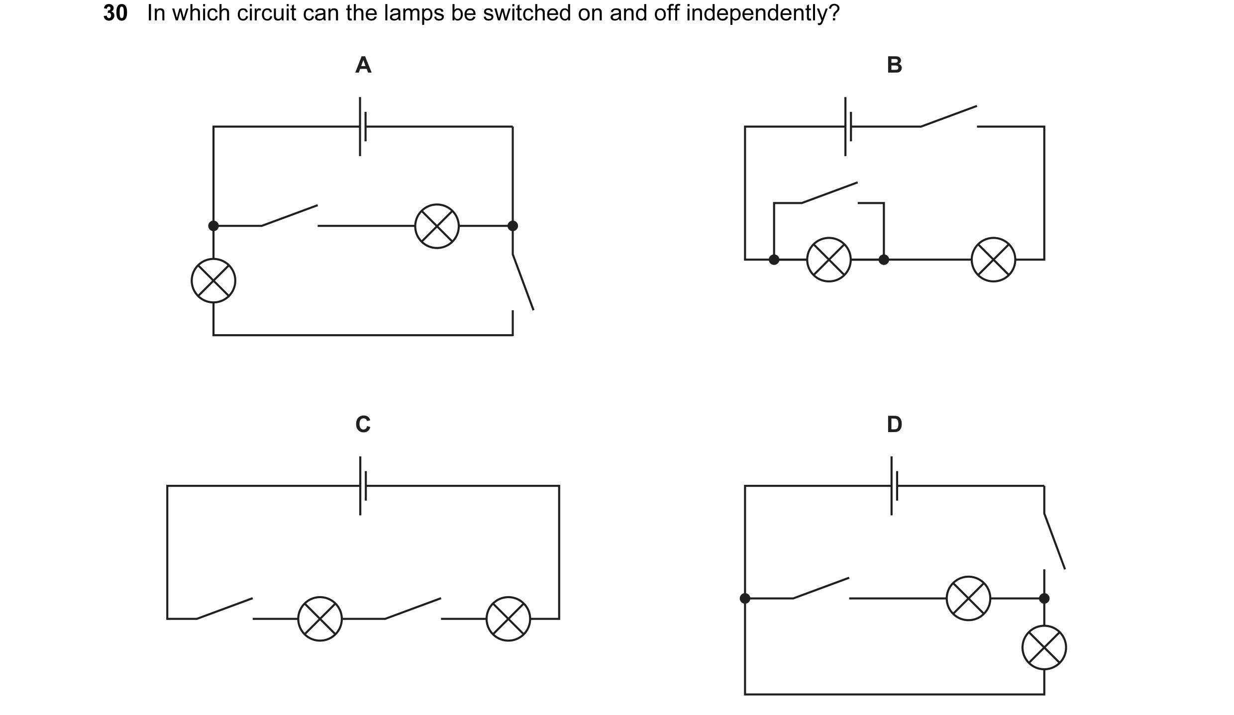 62 / 176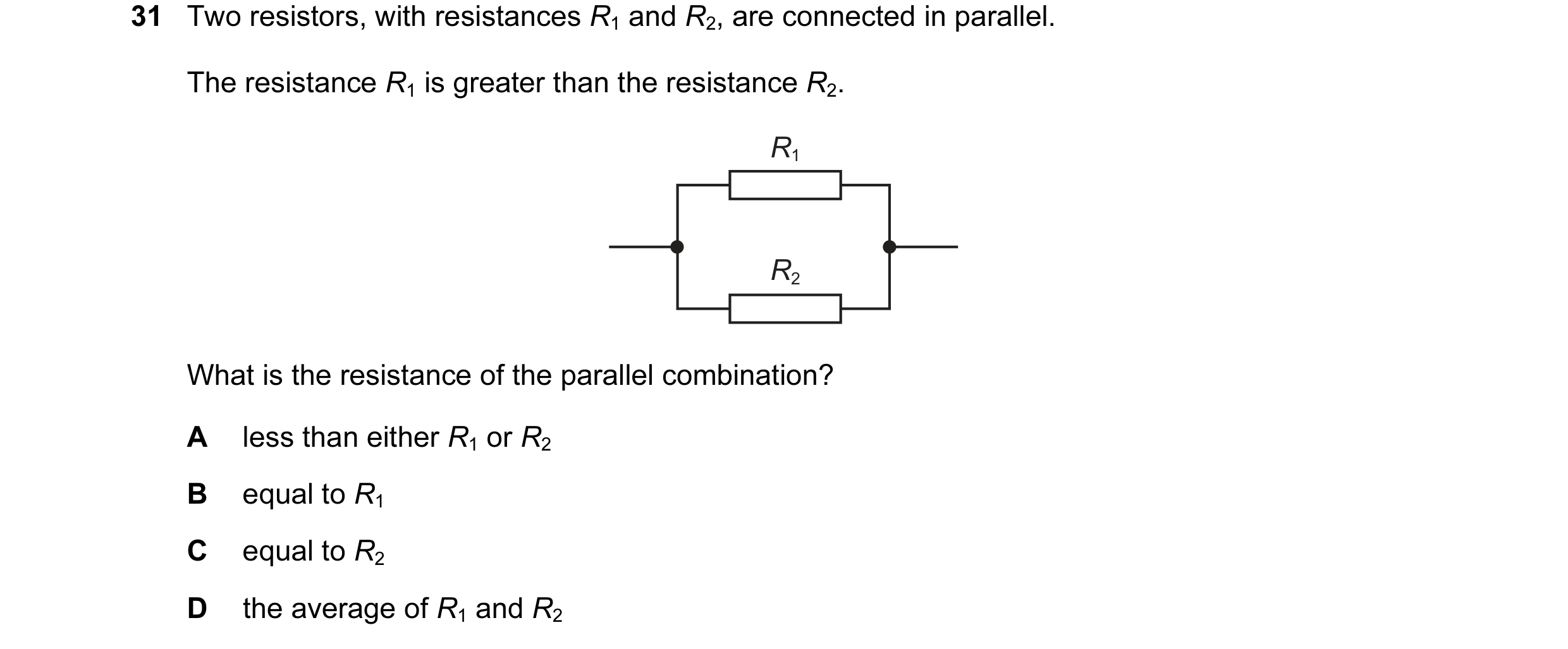
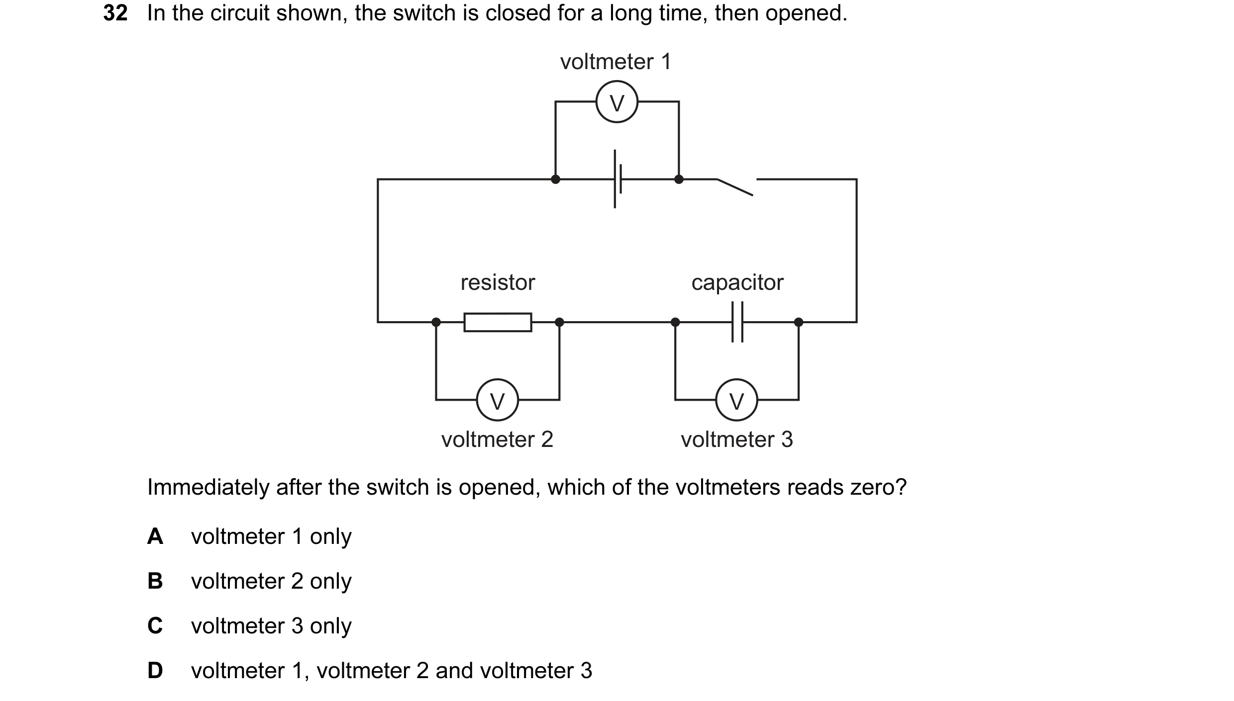
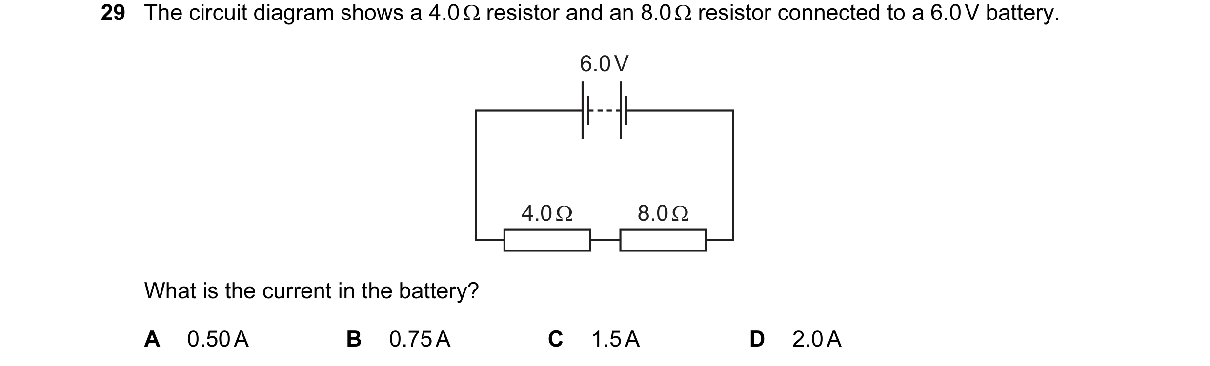 63 / 176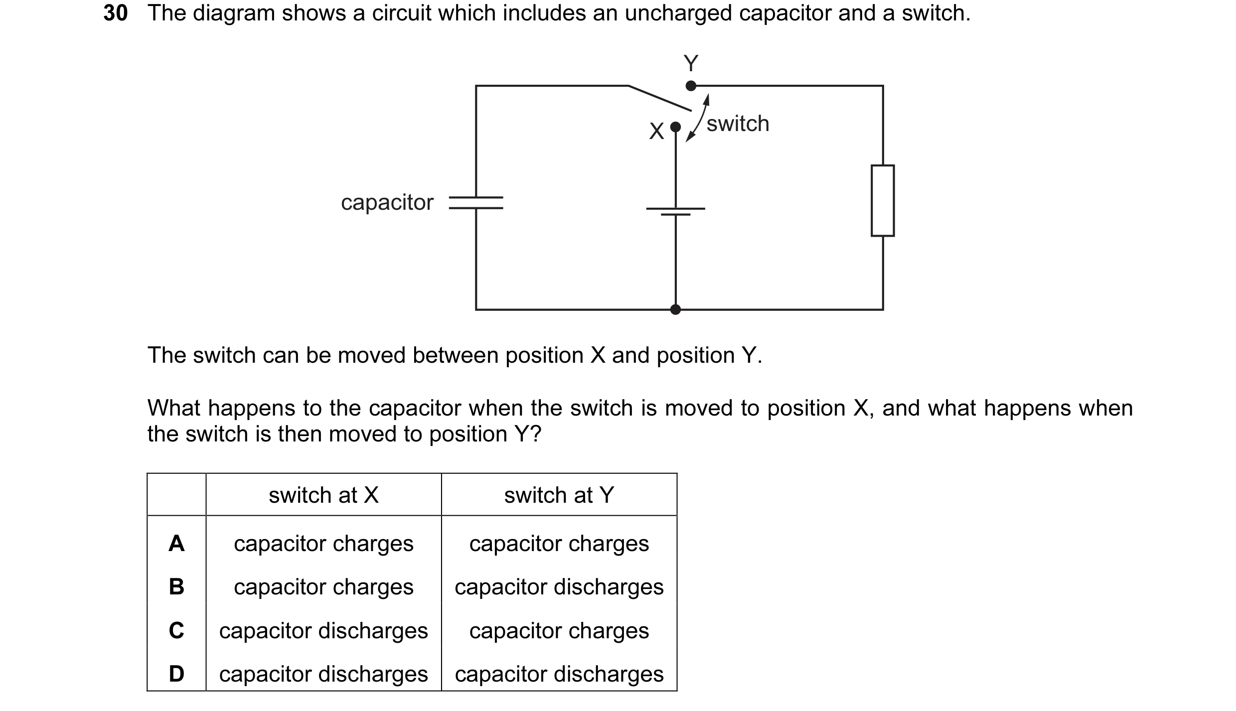
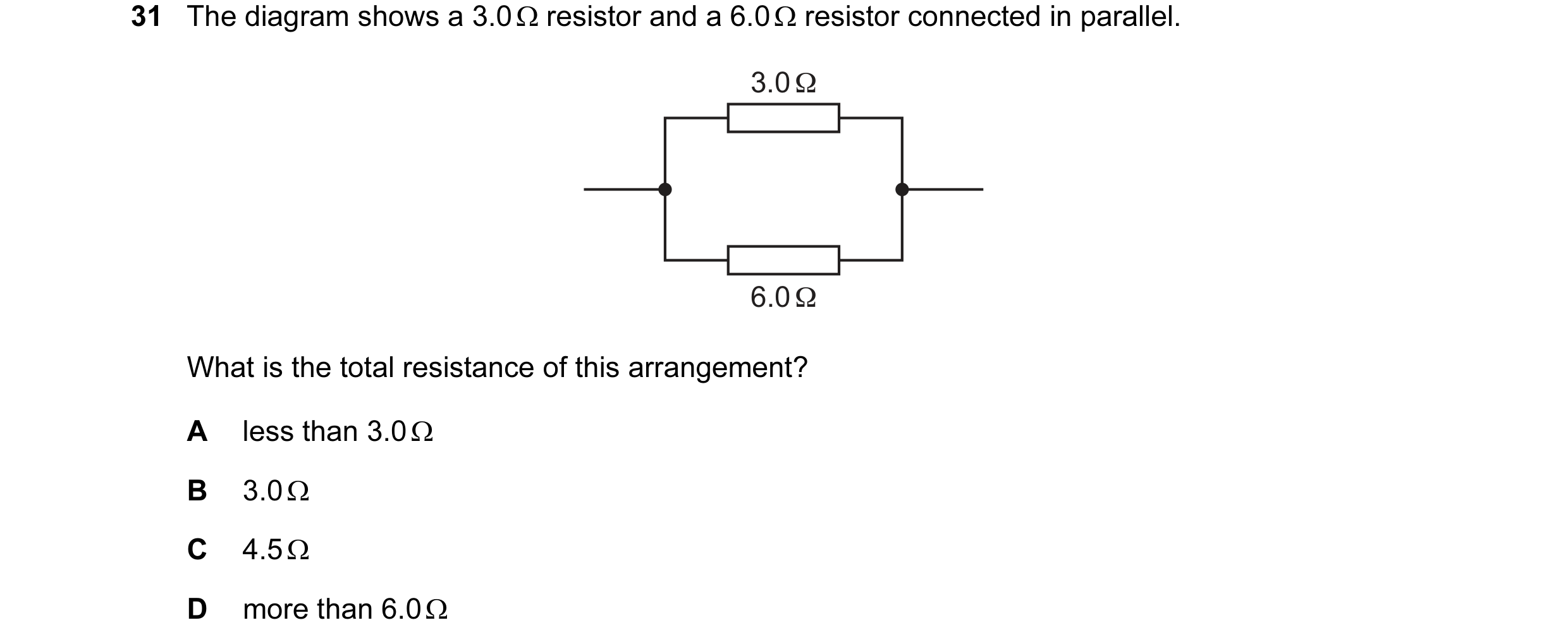
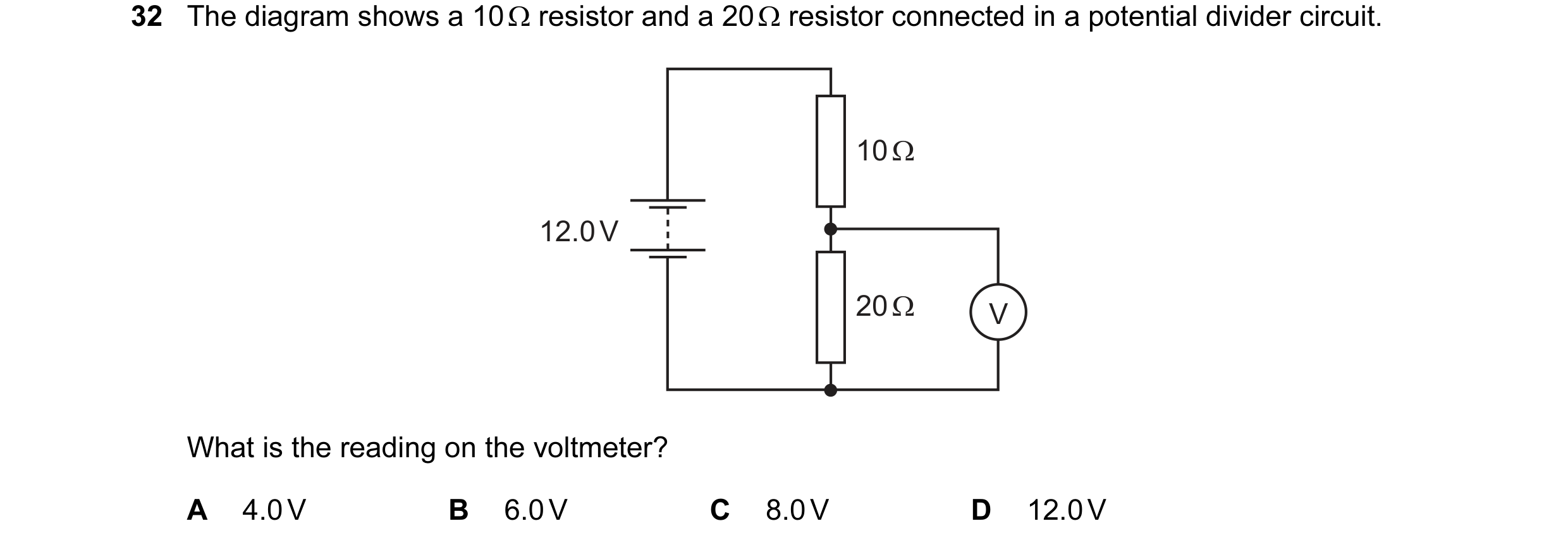 64 / 176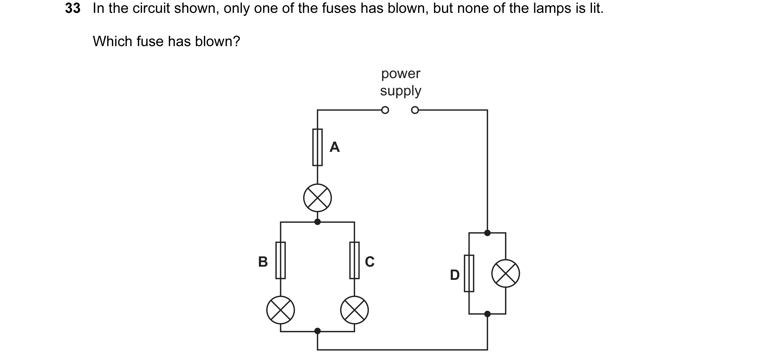
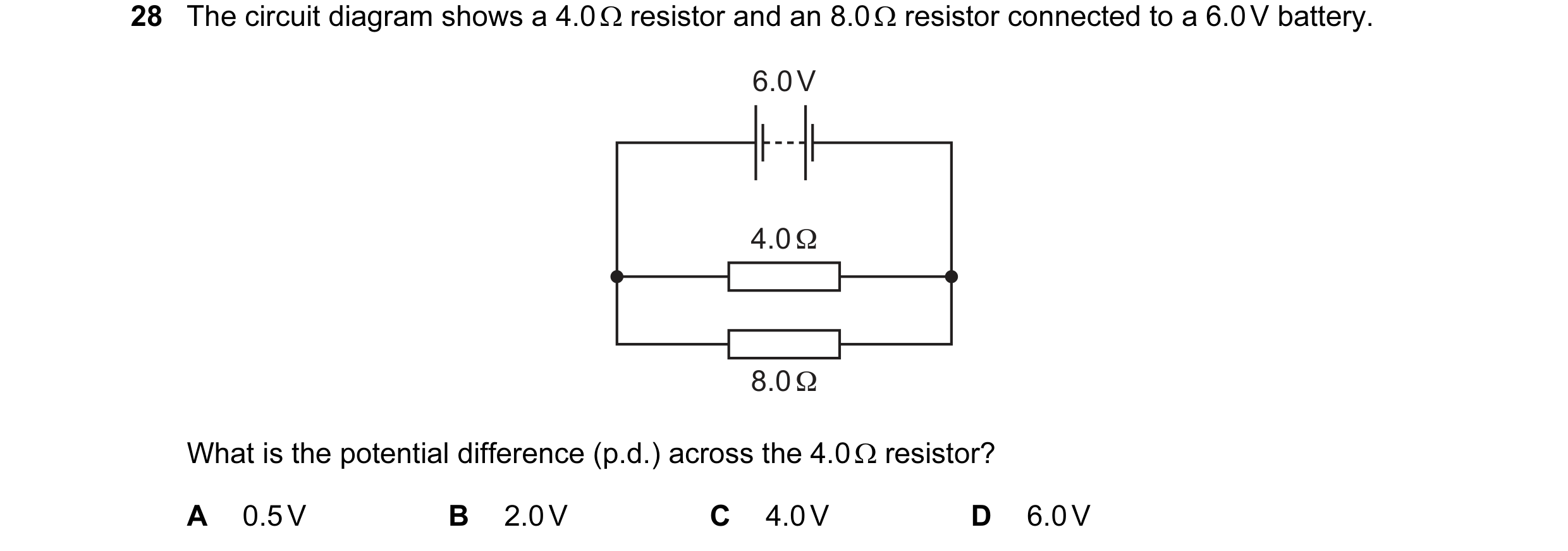 65 / 176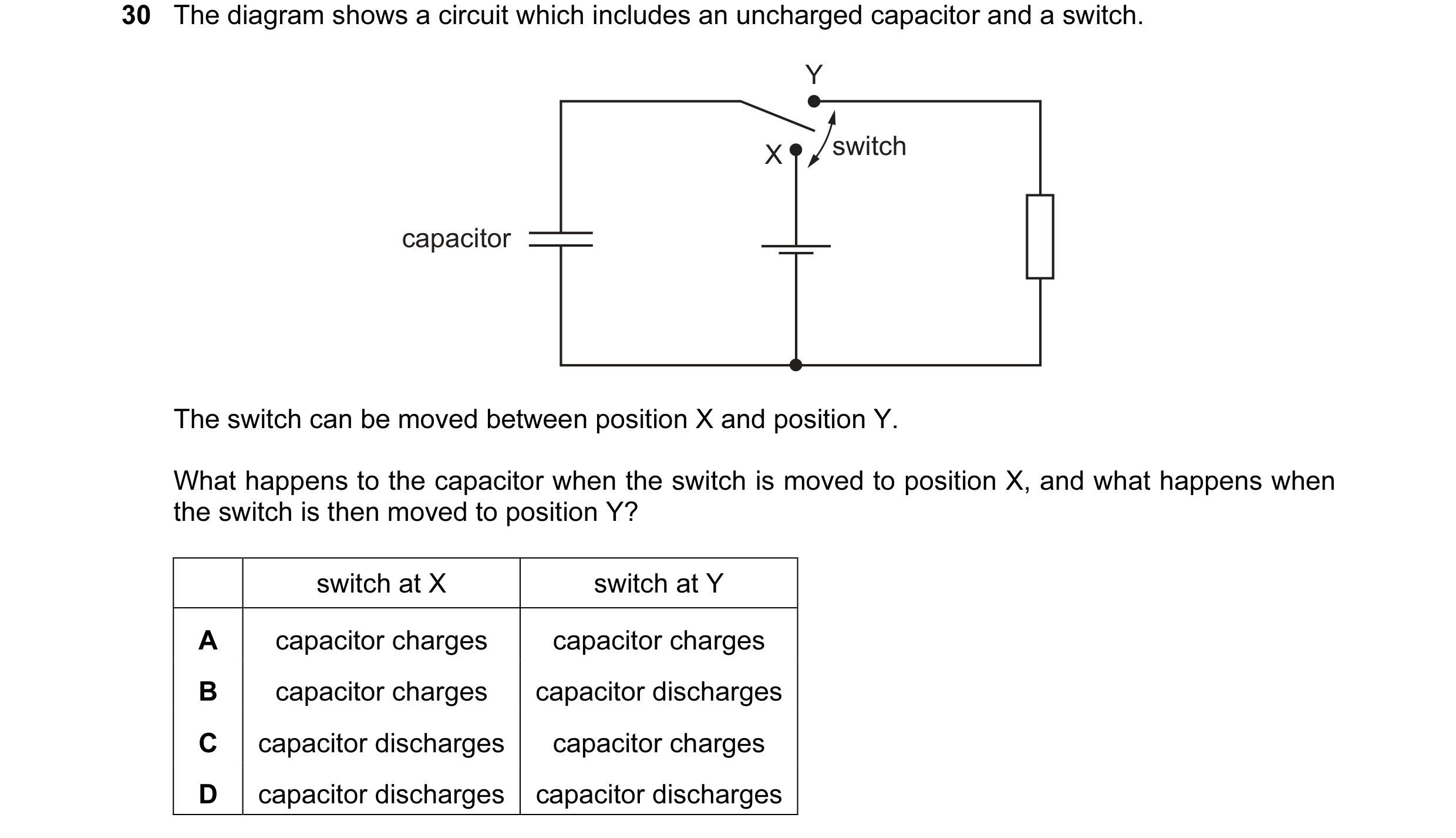
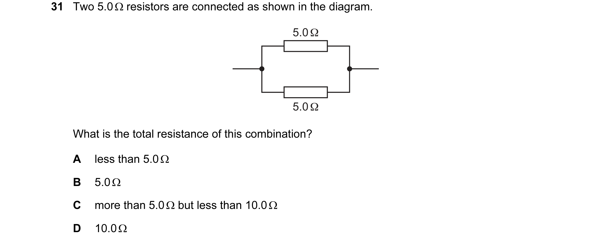
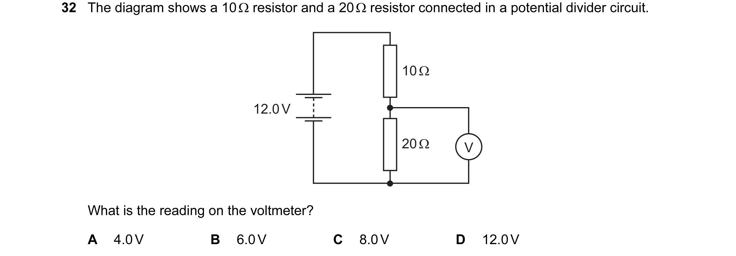 66 / 176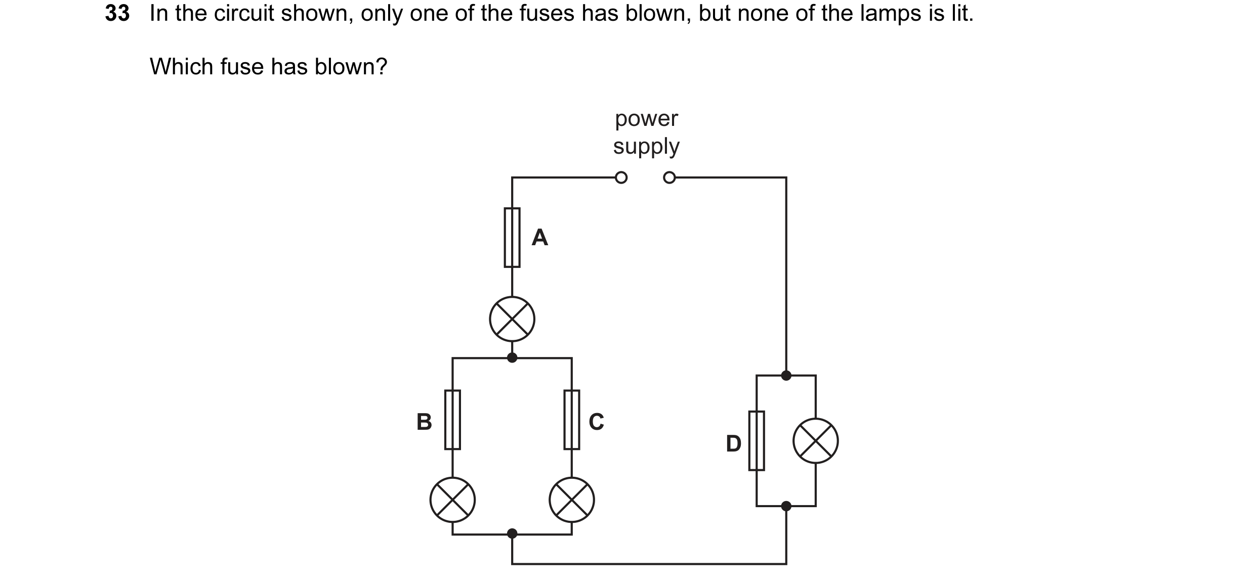
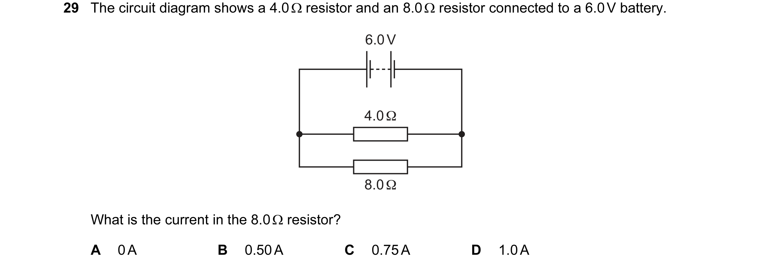 67 / 176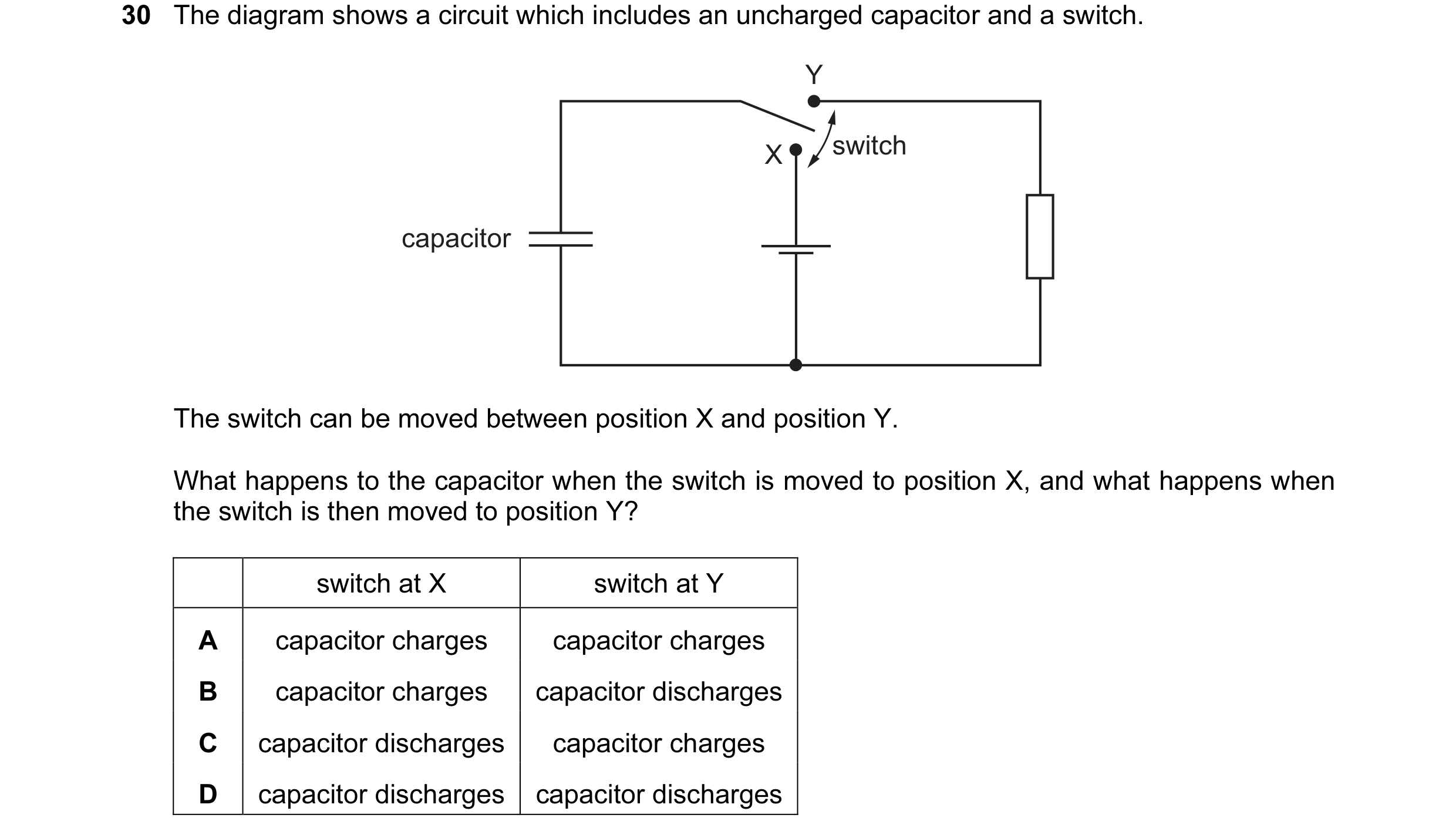
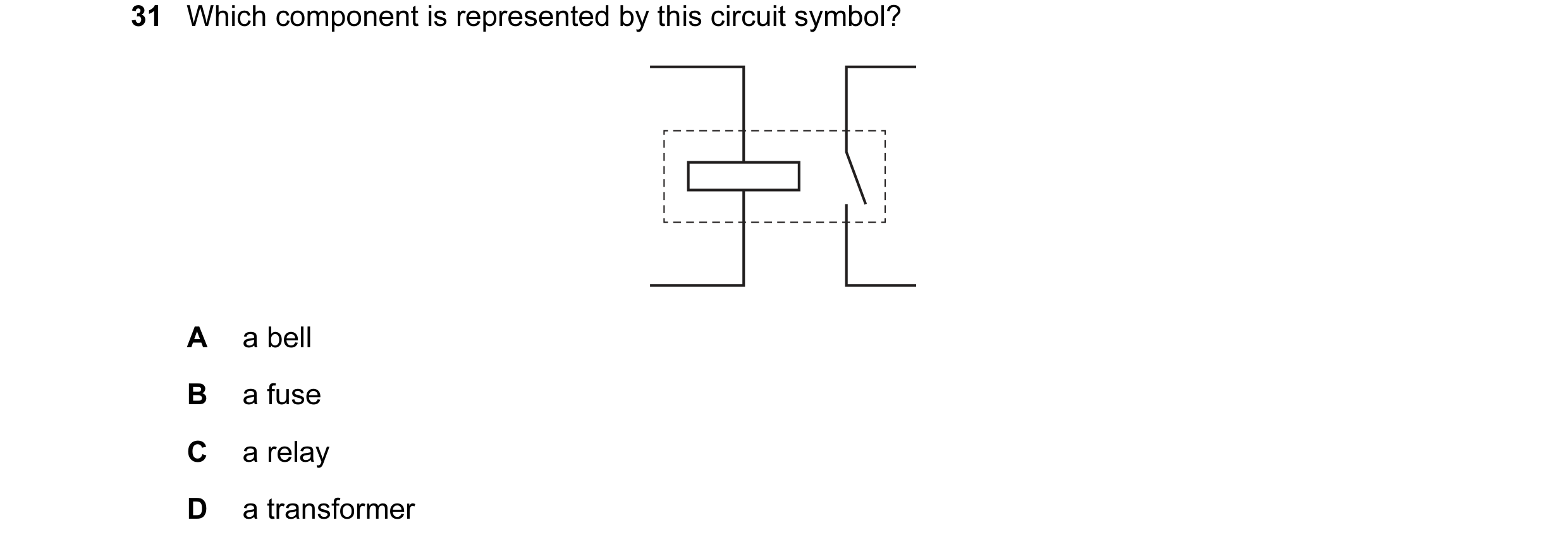
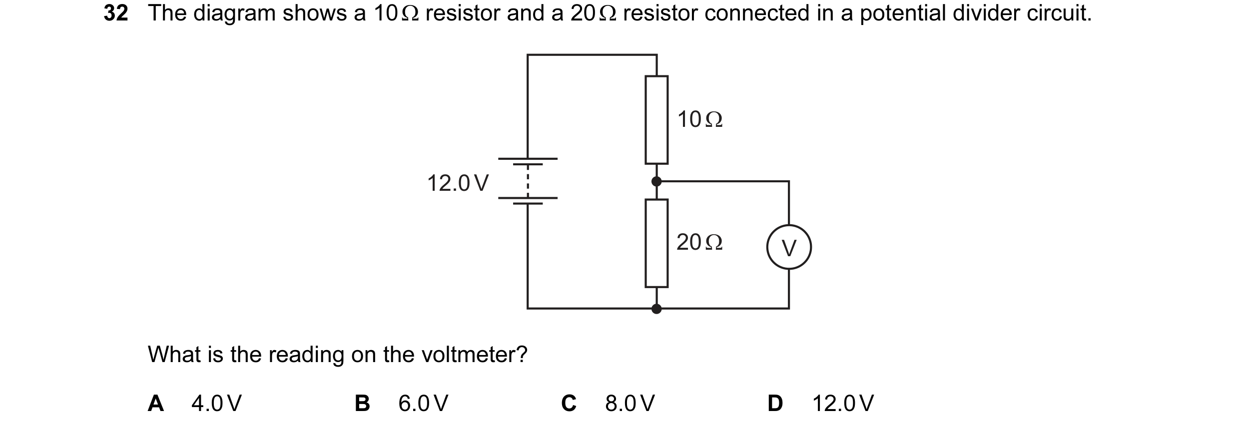 68 / 176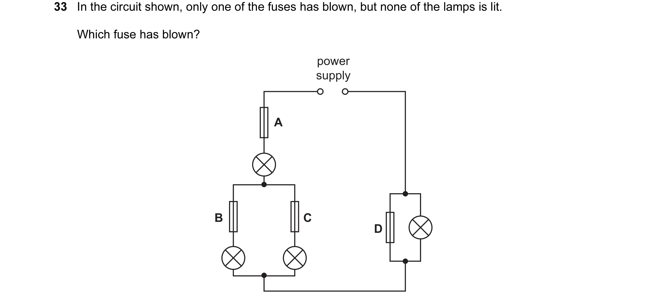
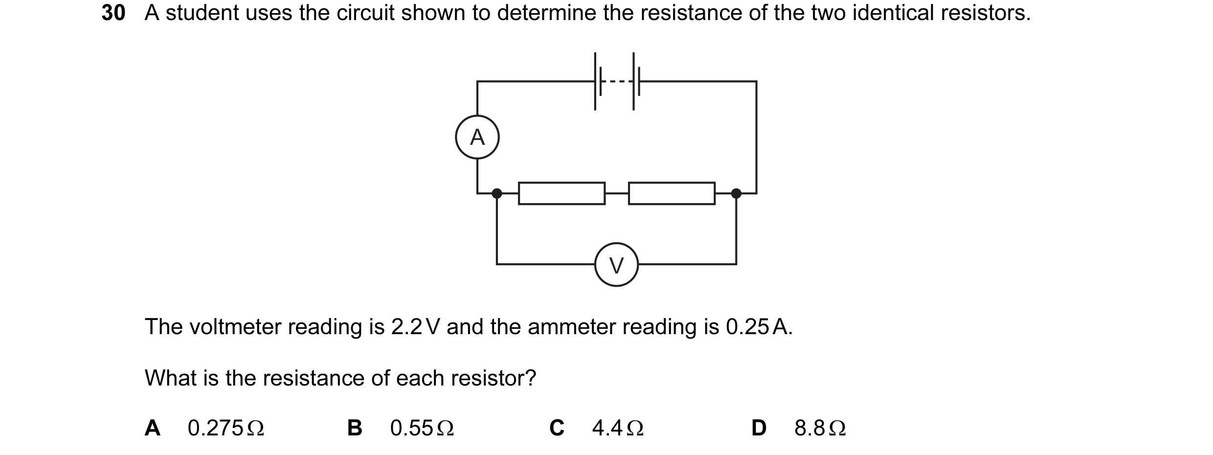
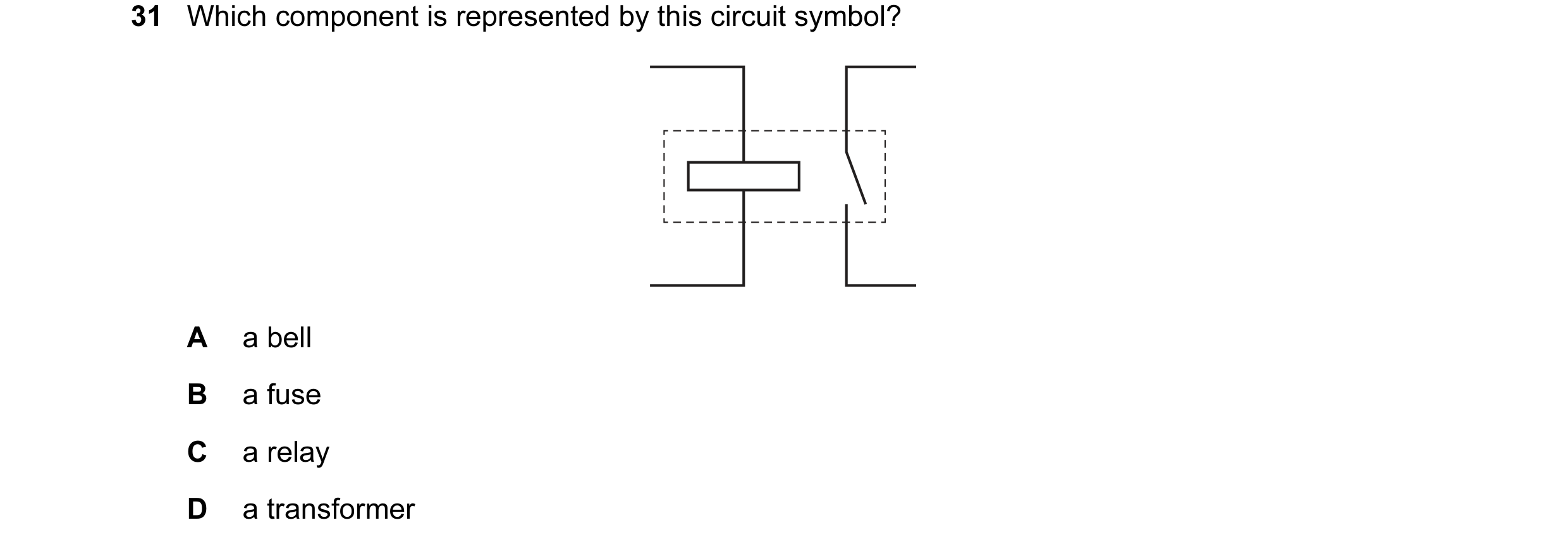 69 / 176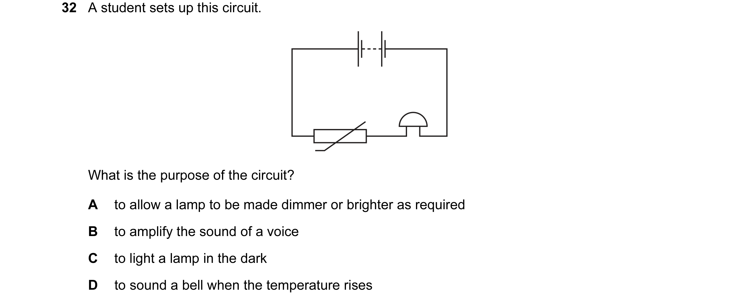


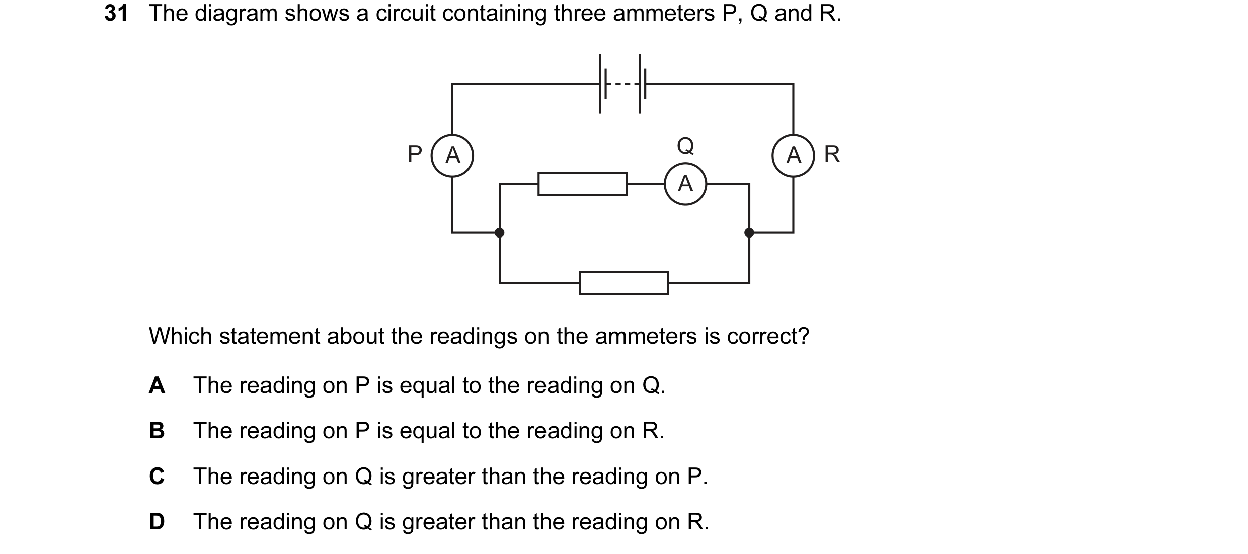 70 / 176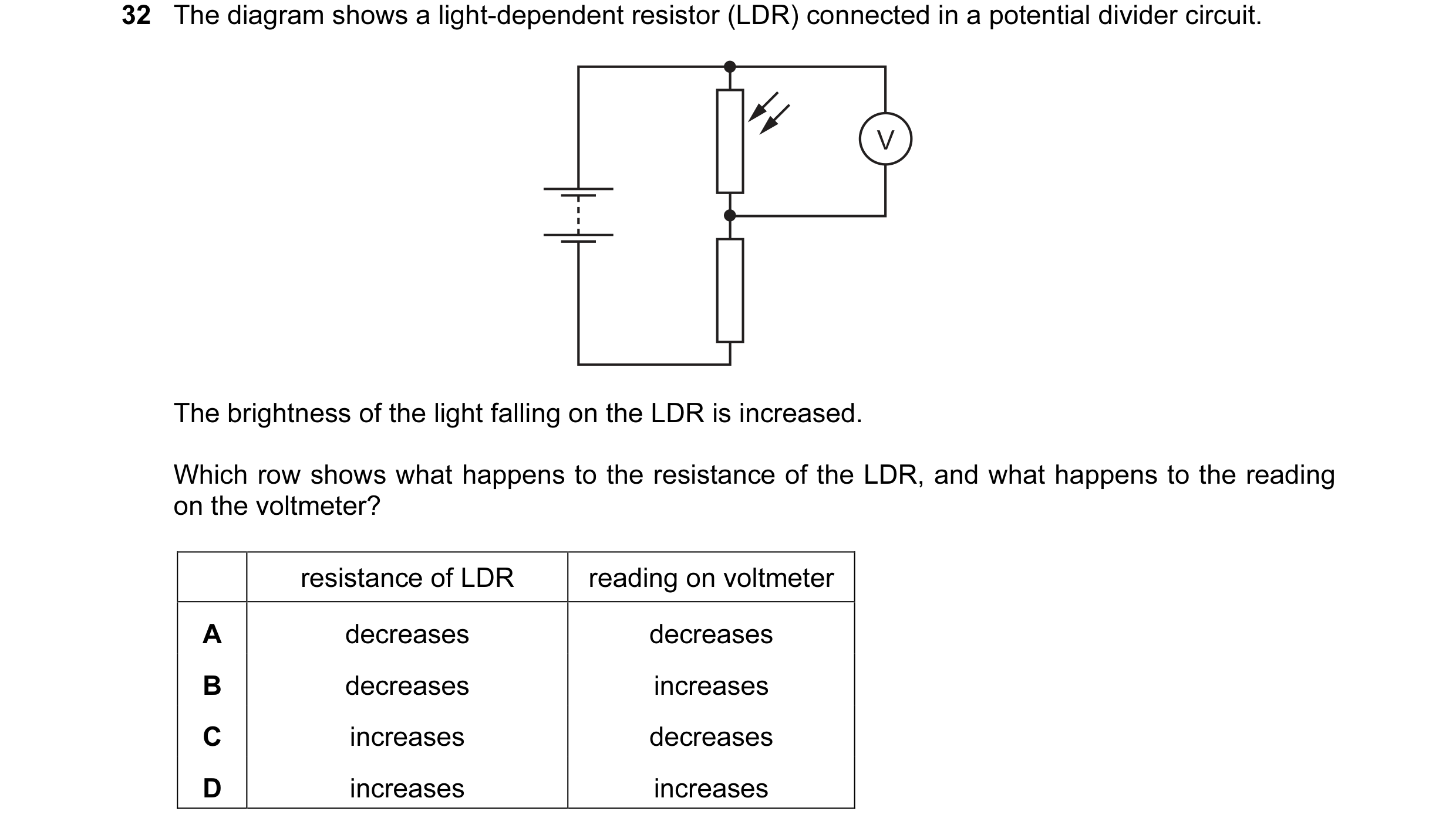
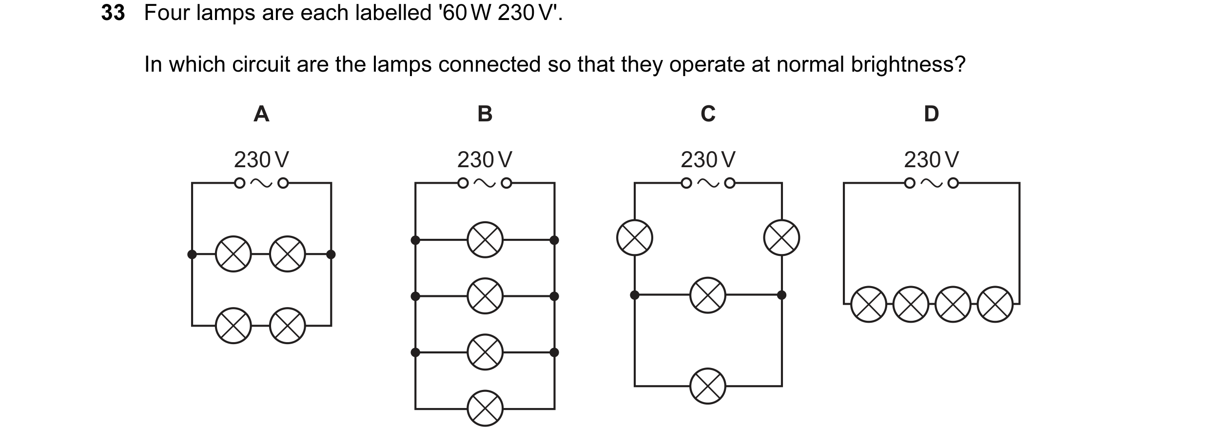 71 / 176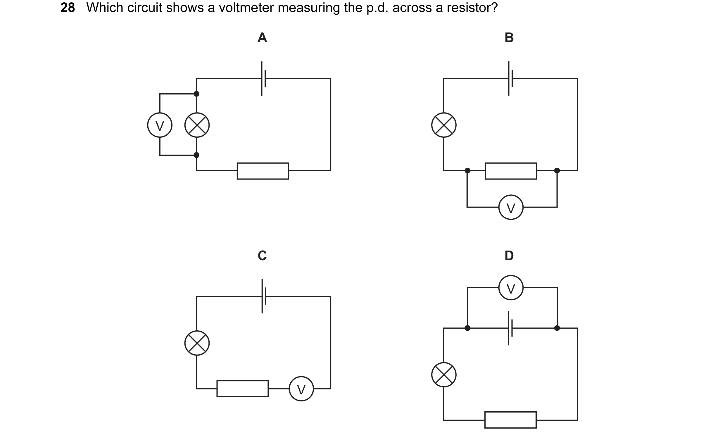
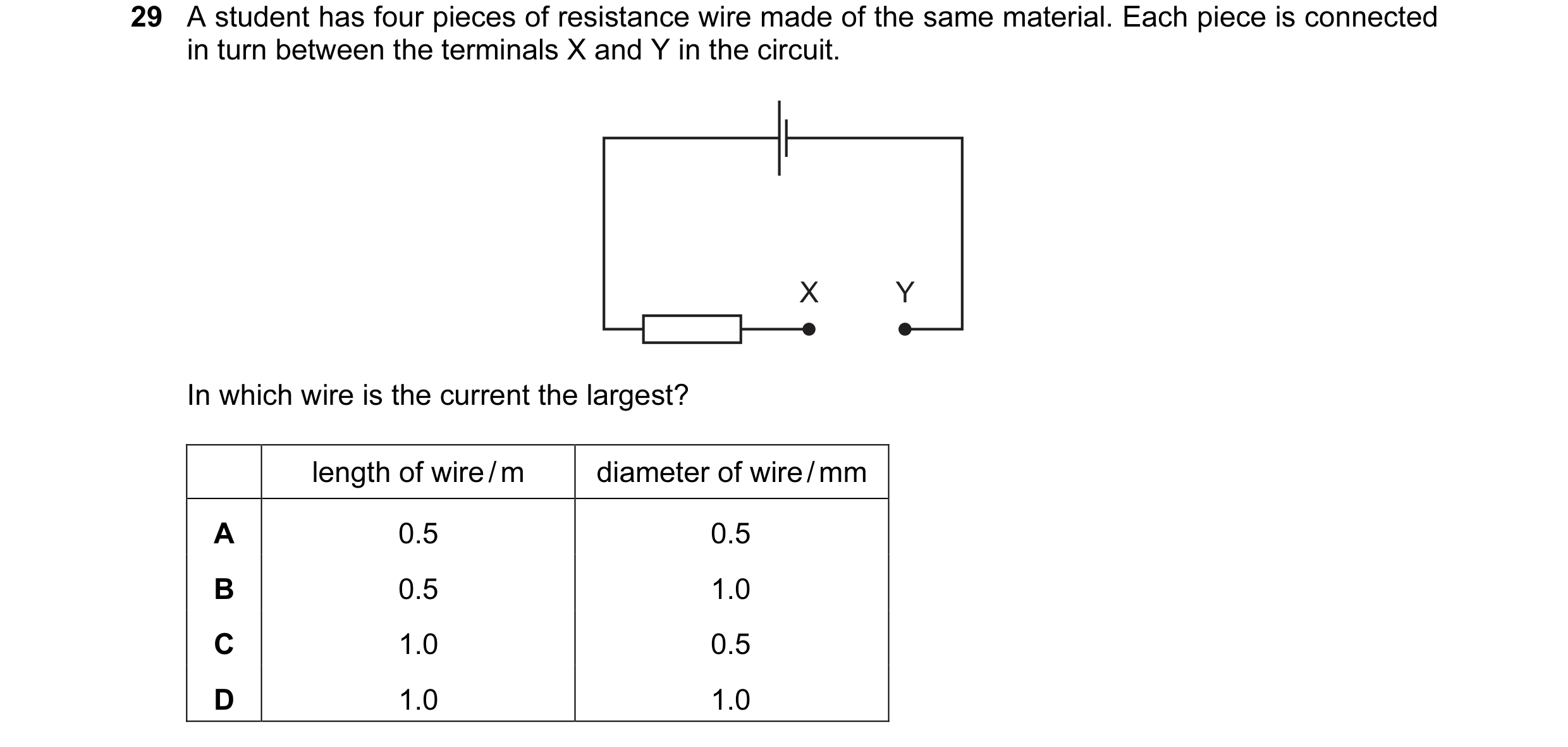 72 / 176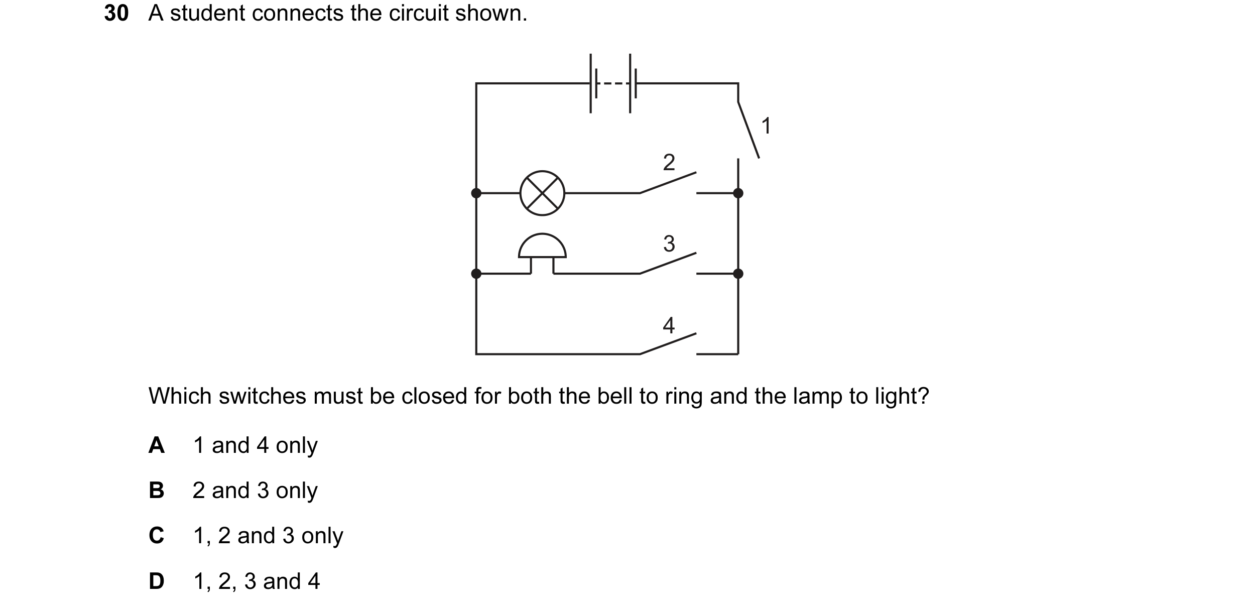
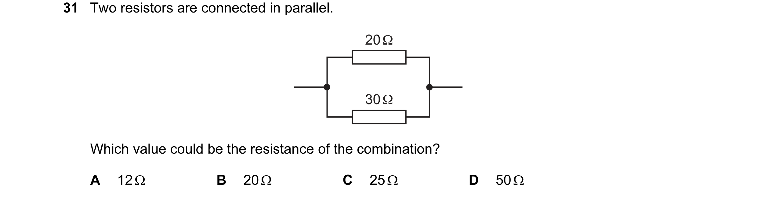
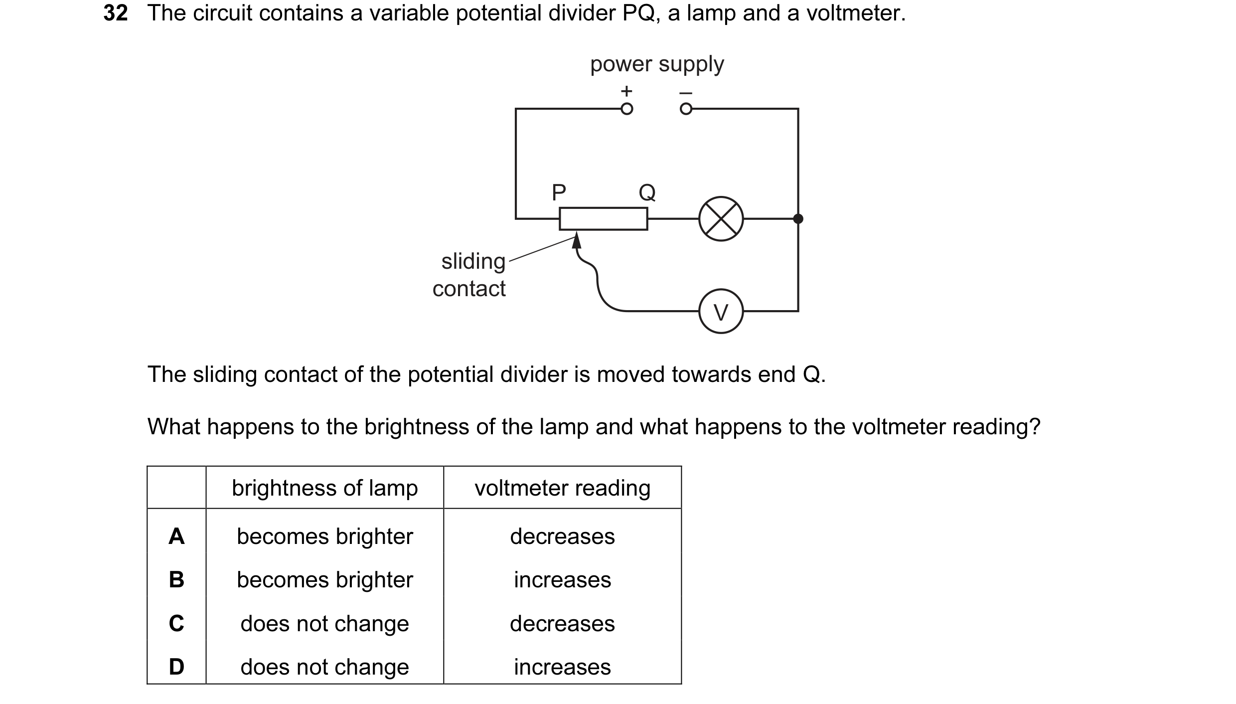 73 / 176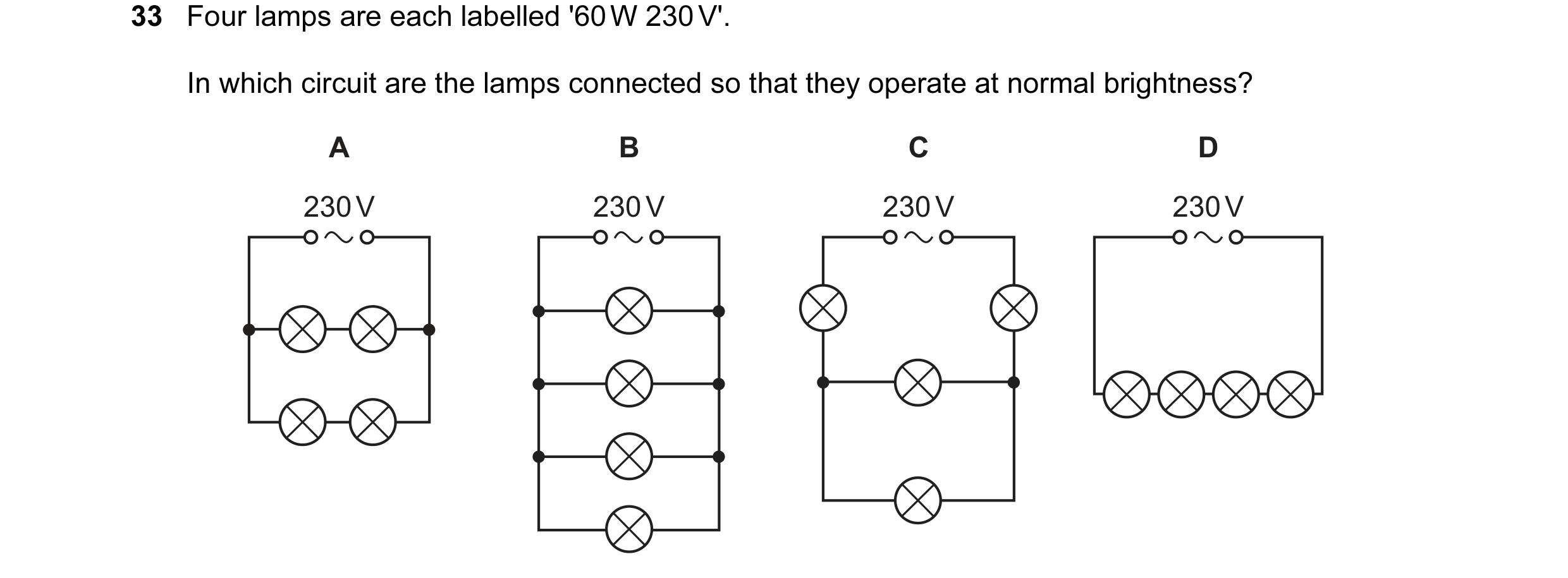
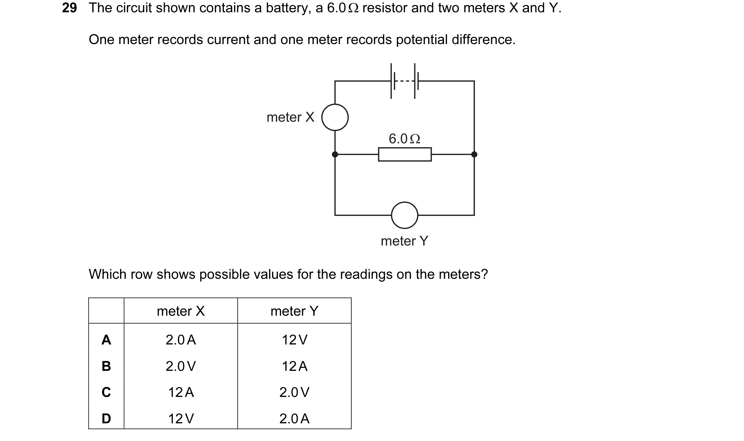
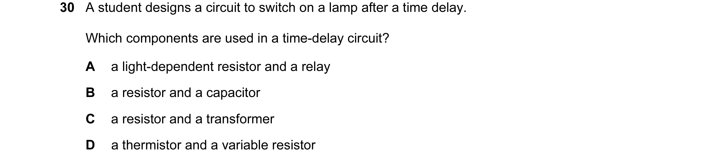 74 / 176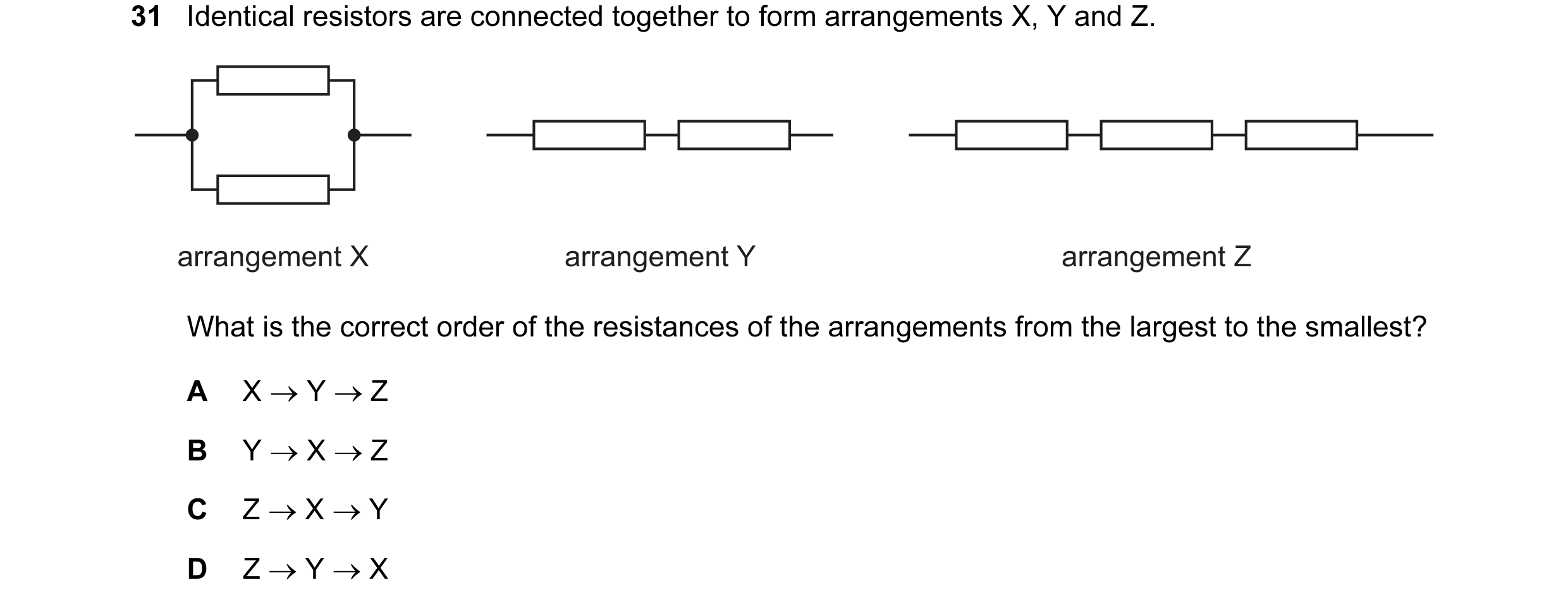
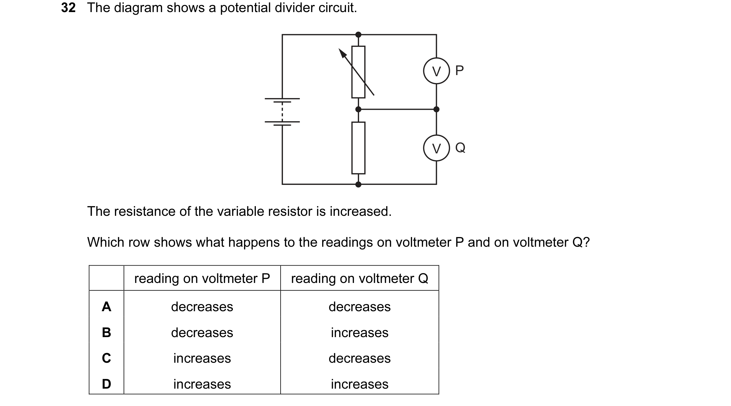
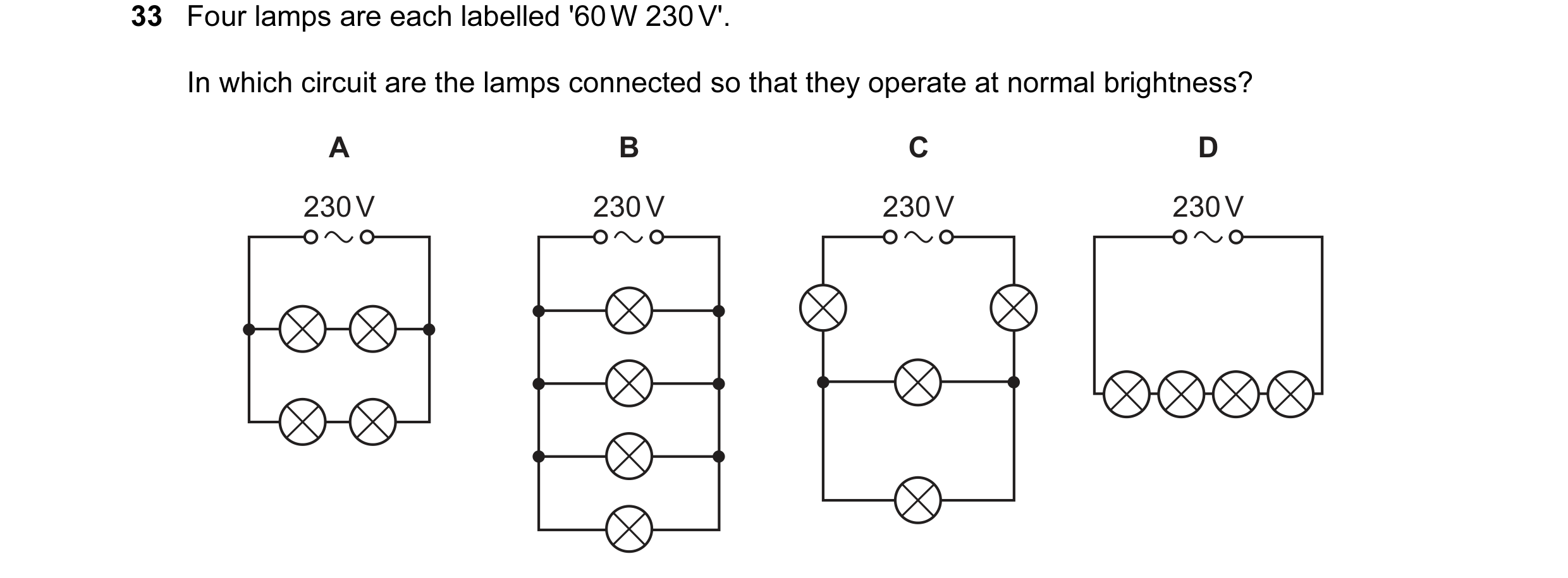 75 / 176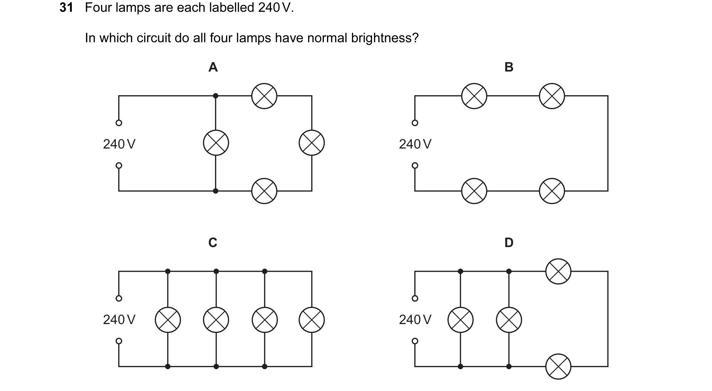
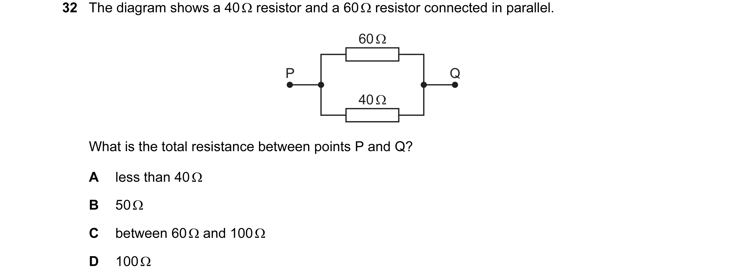 76 / 176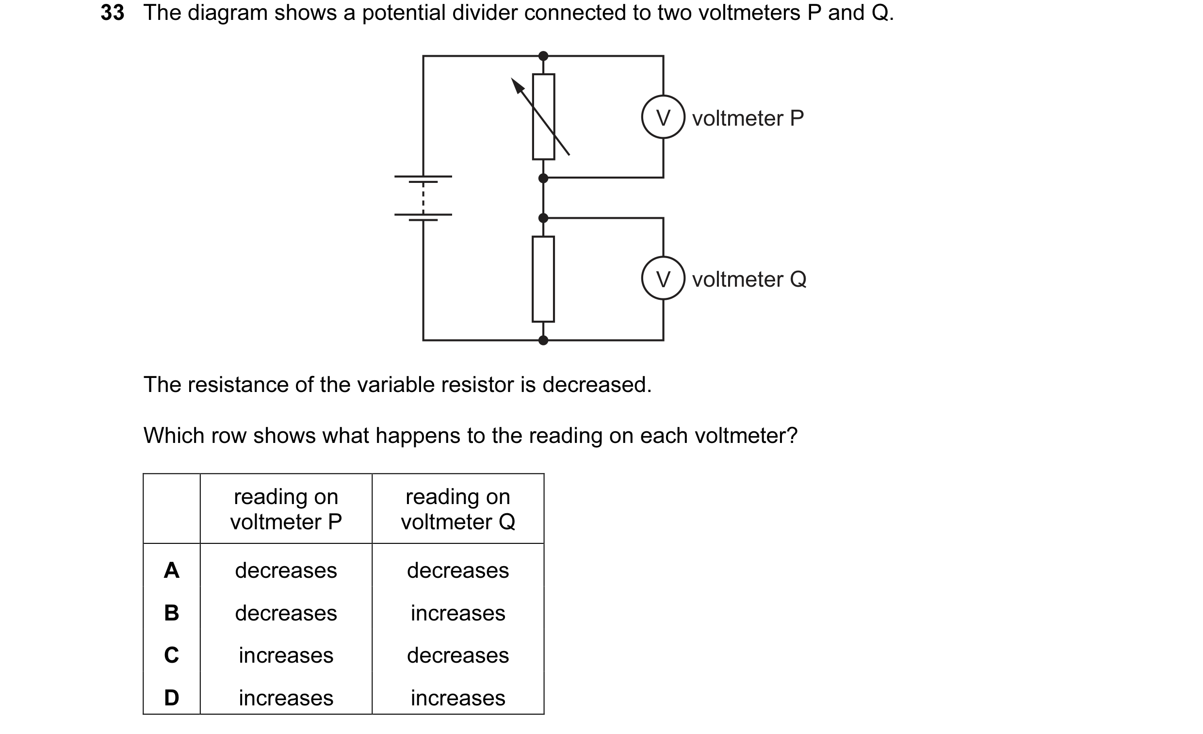
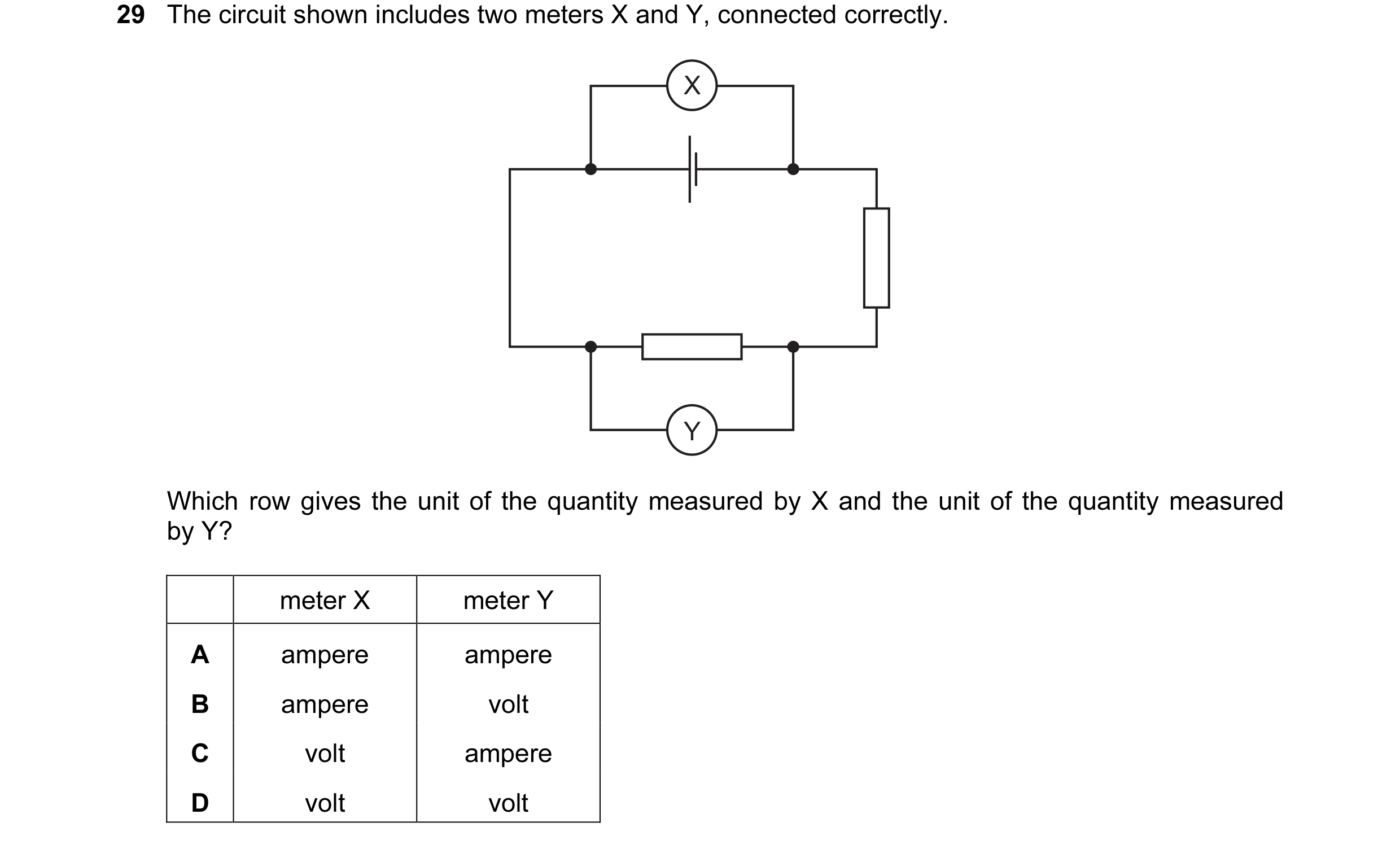 77 / 176
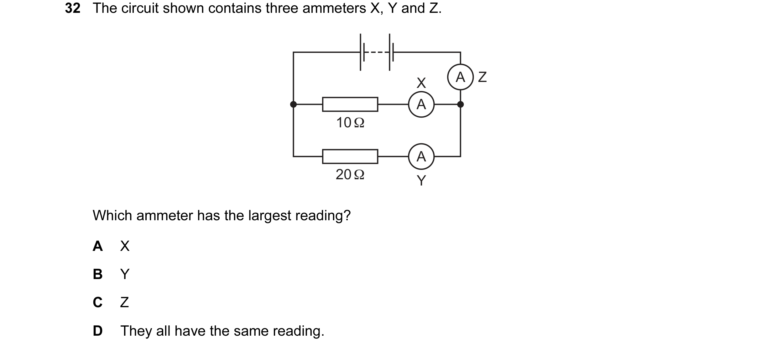
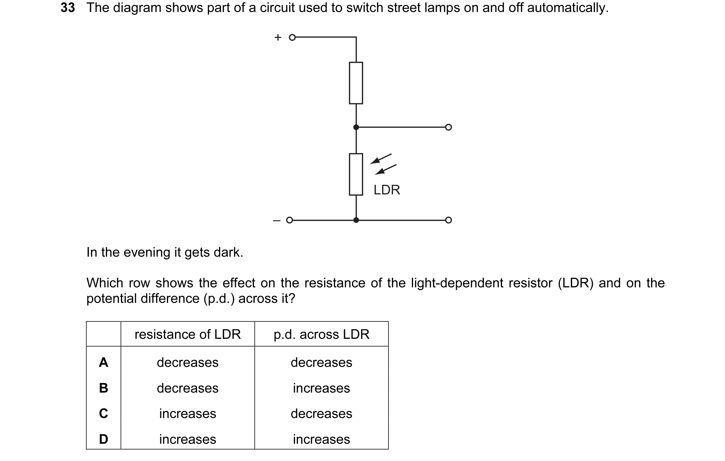 78 / 176
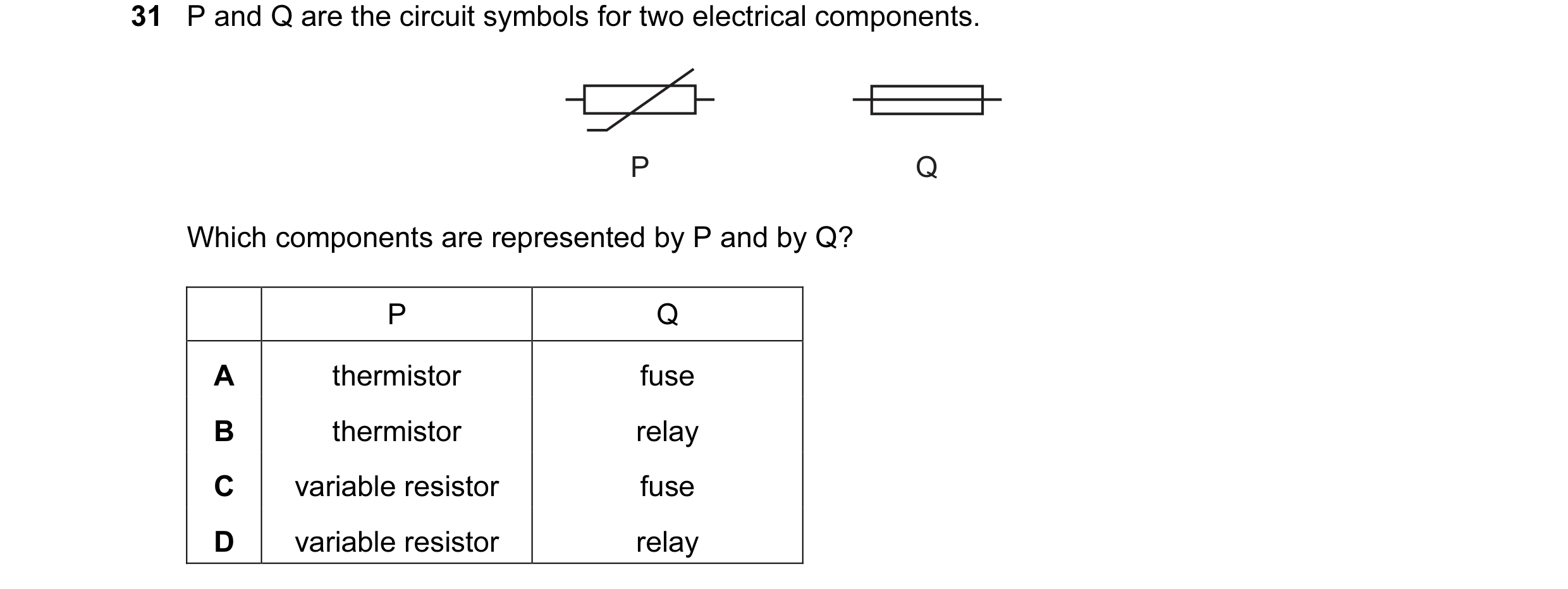
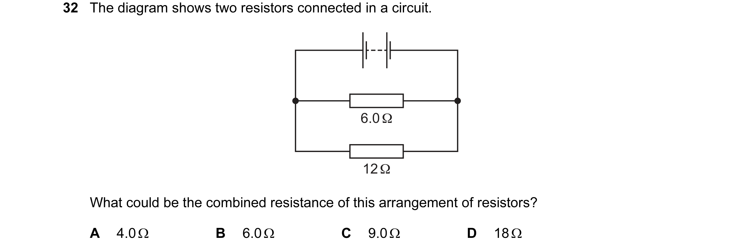 79 / 176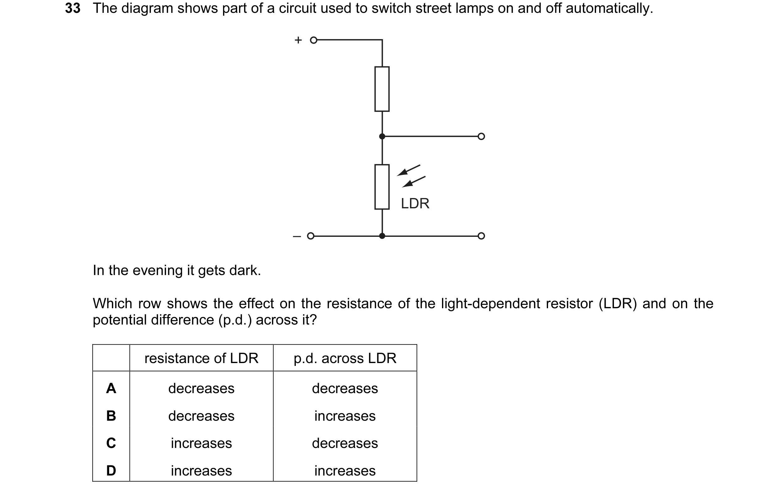
 80 / 176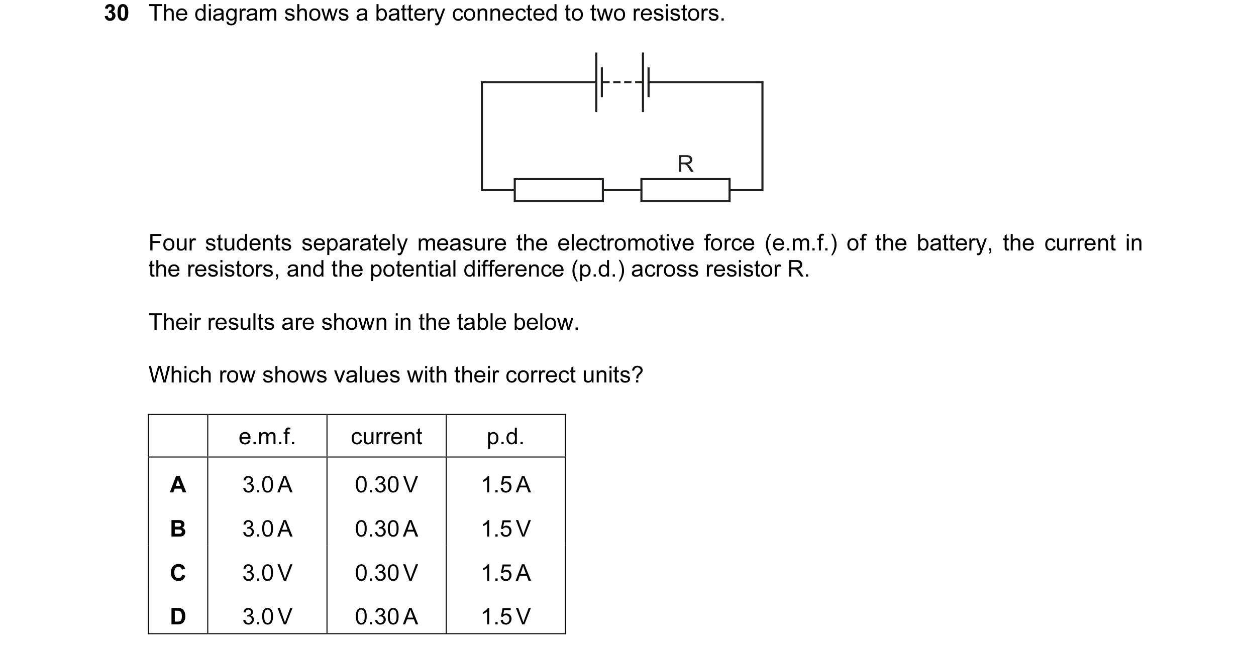

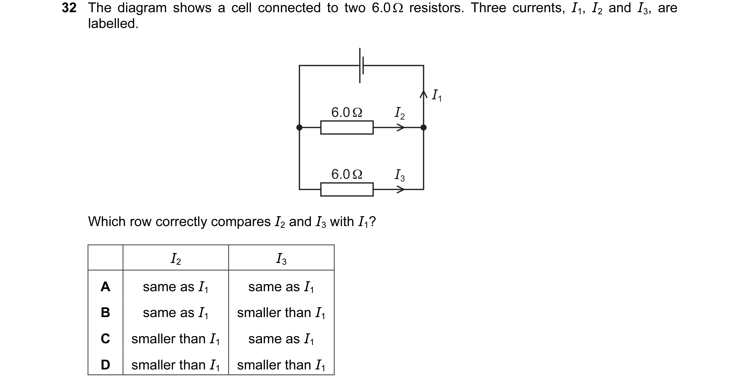 81 / 176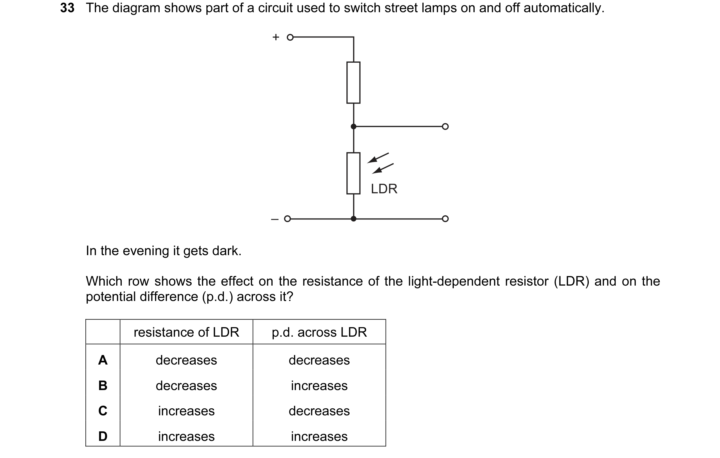
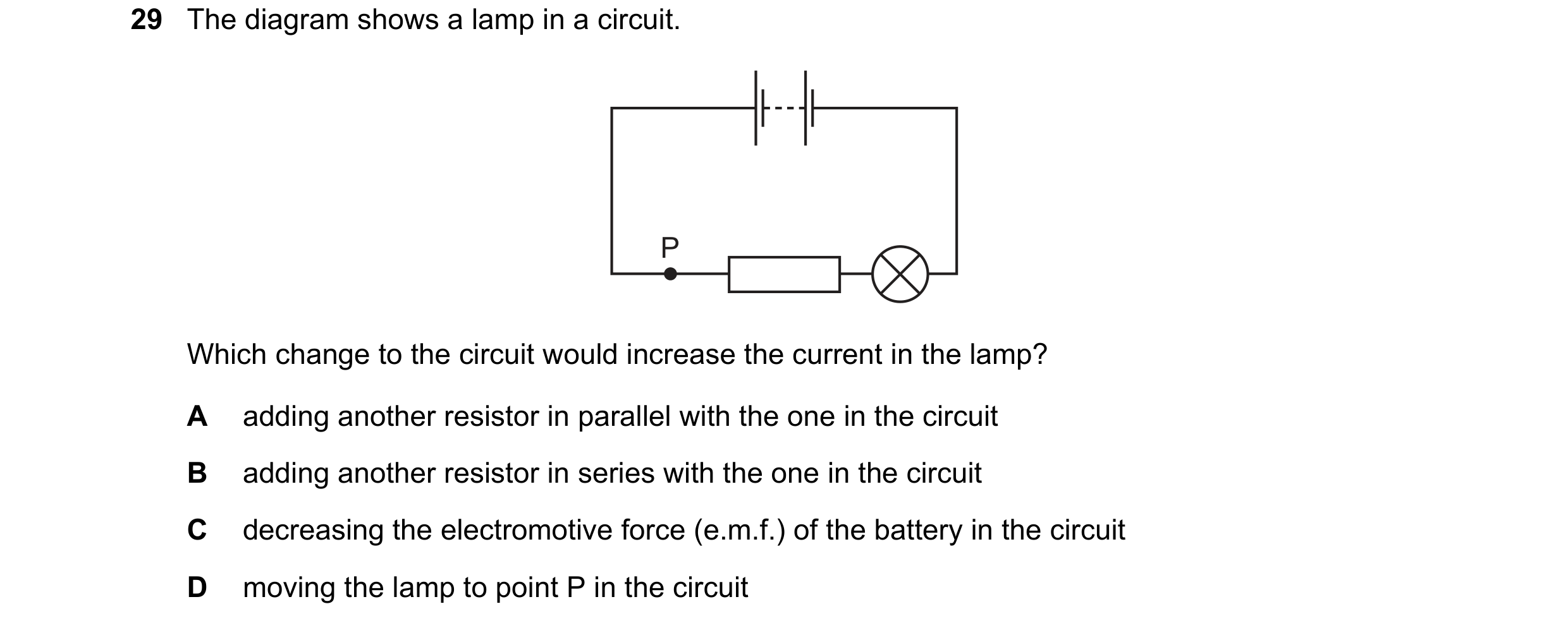
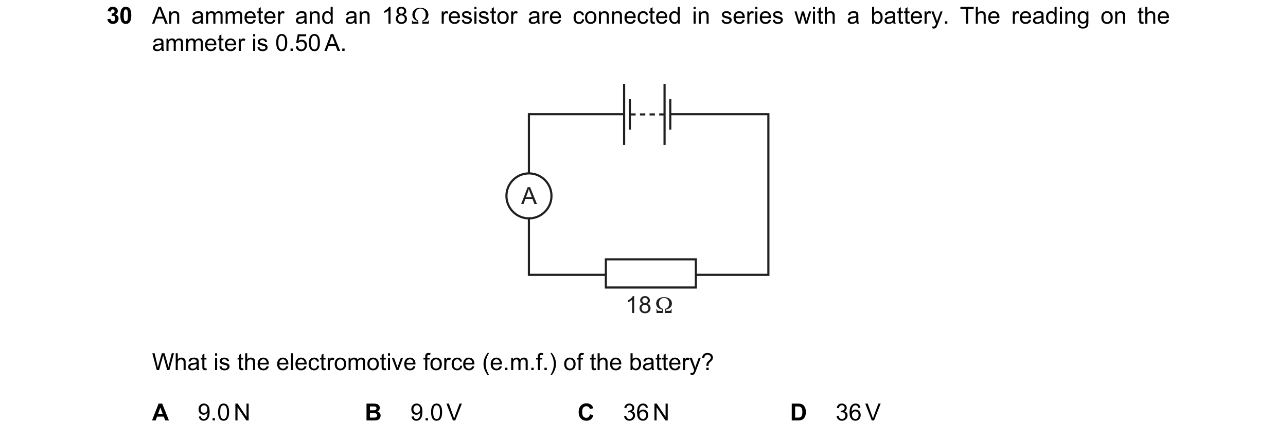 82 / 176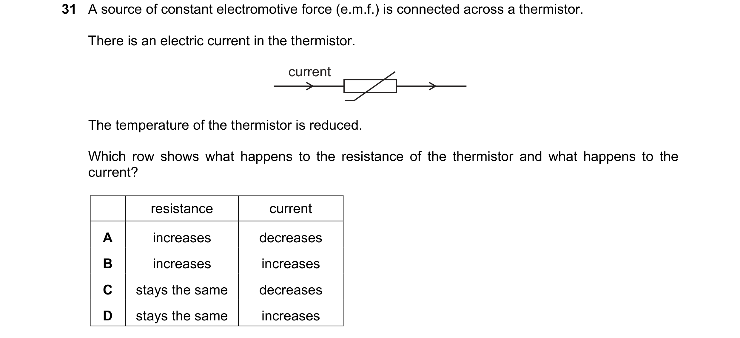
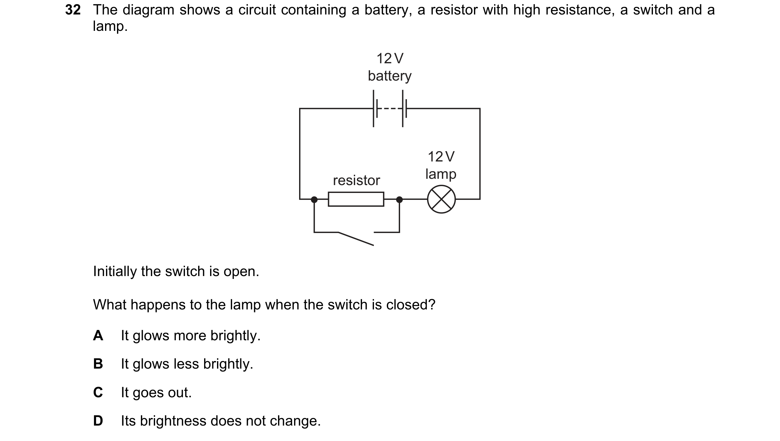 83 / 176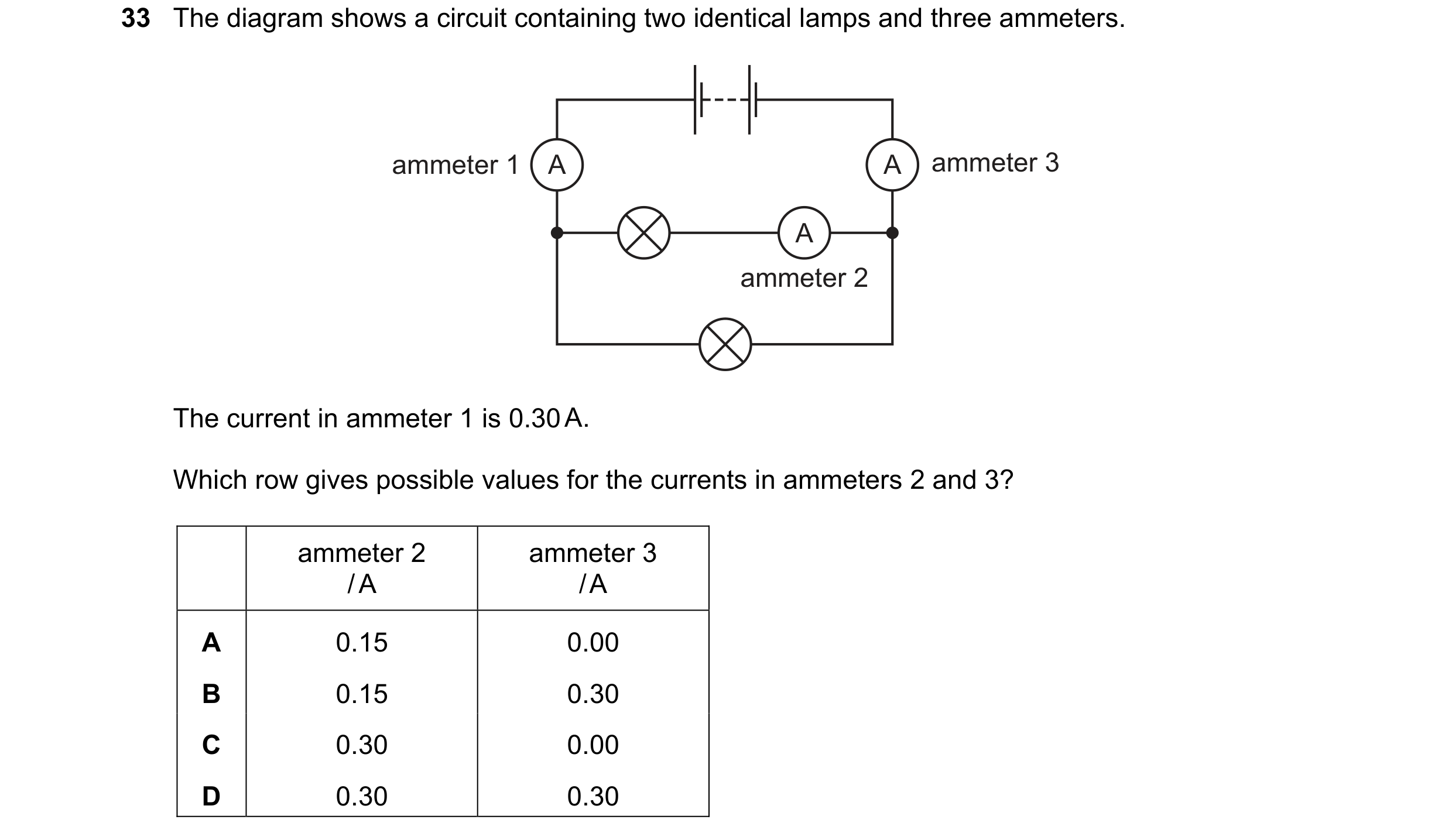
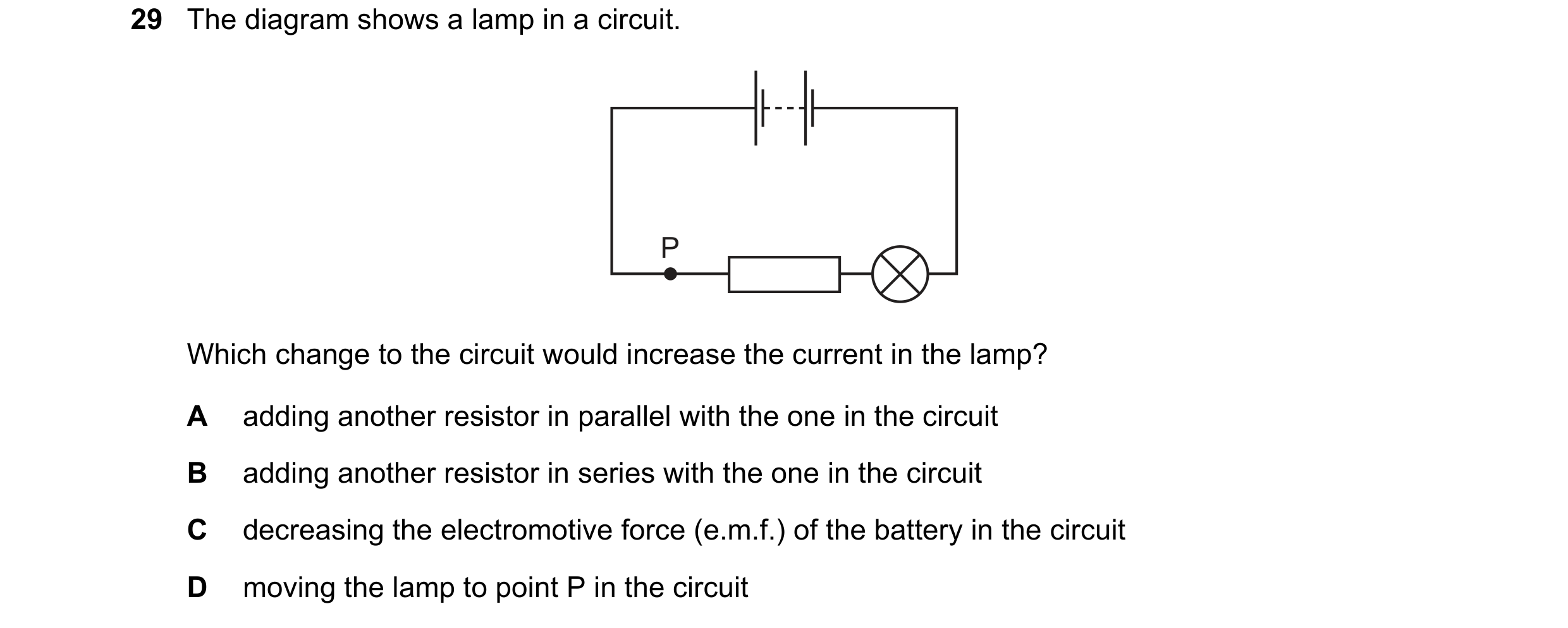
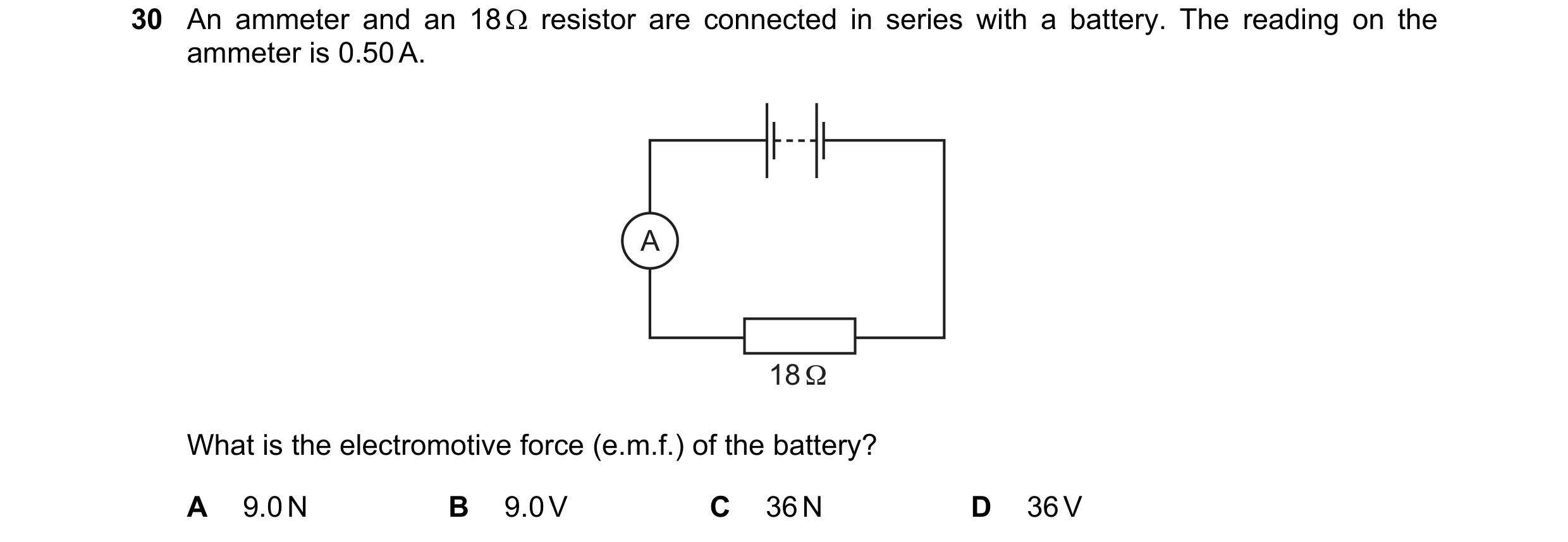 84 / 176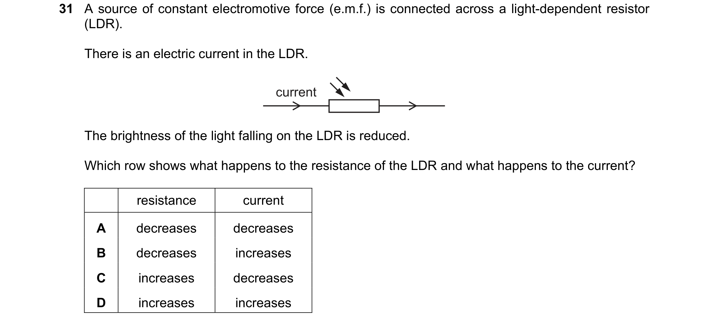
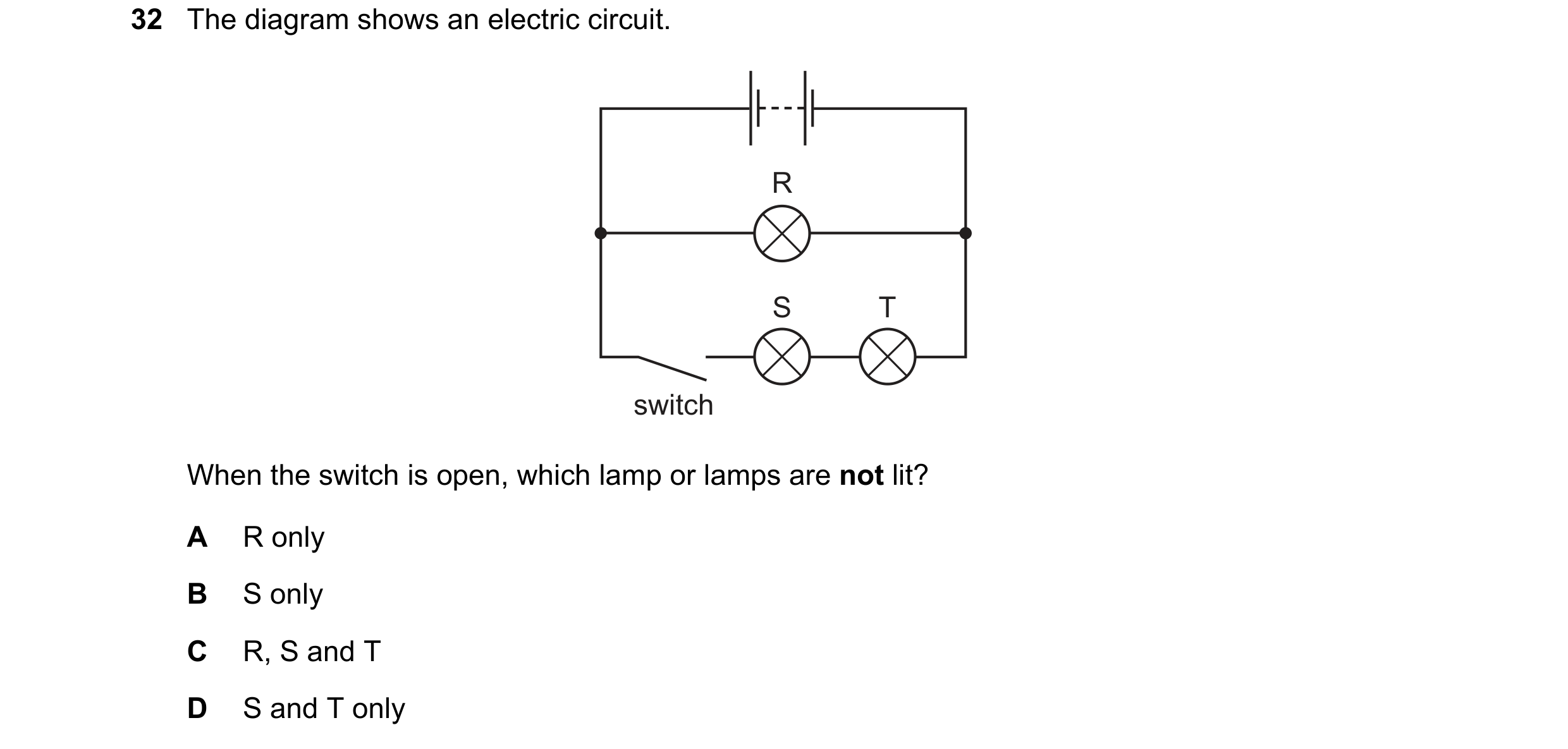 85 / 176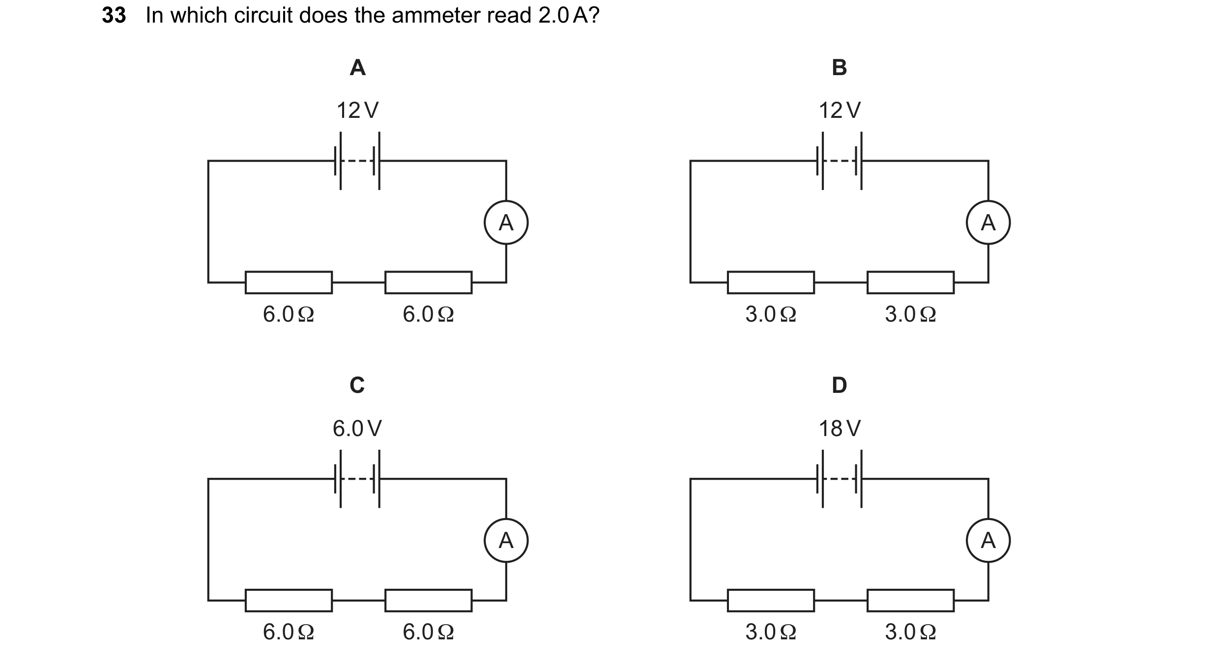
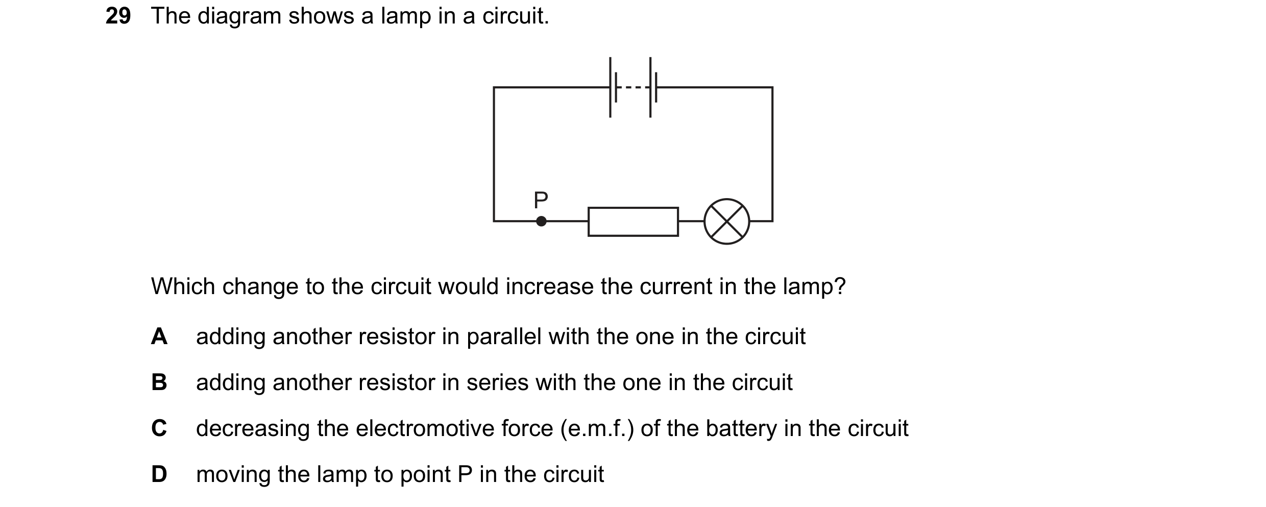
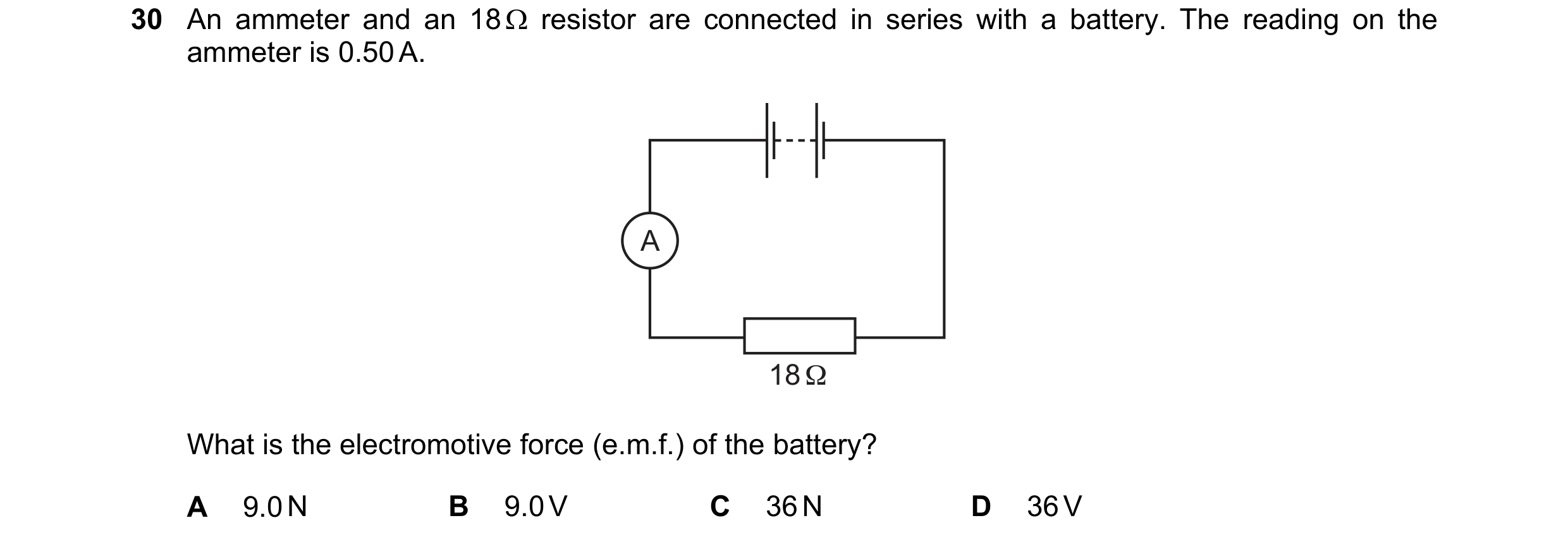 86 / 176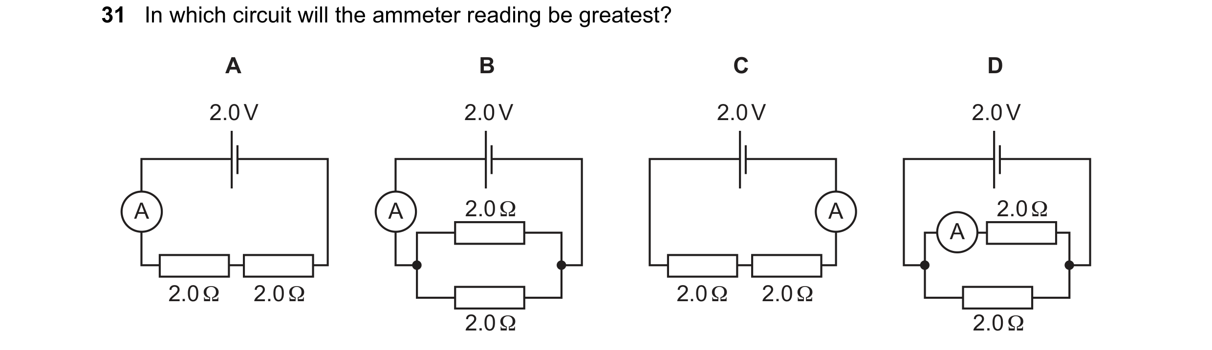
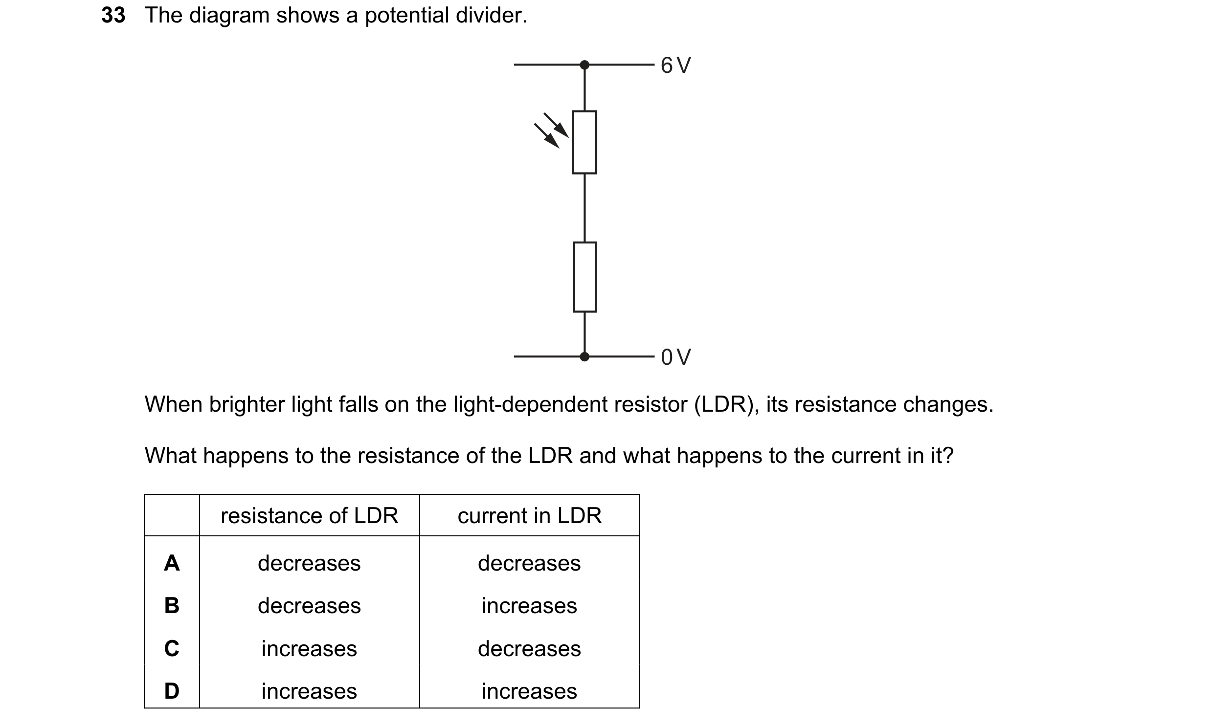 87 / 176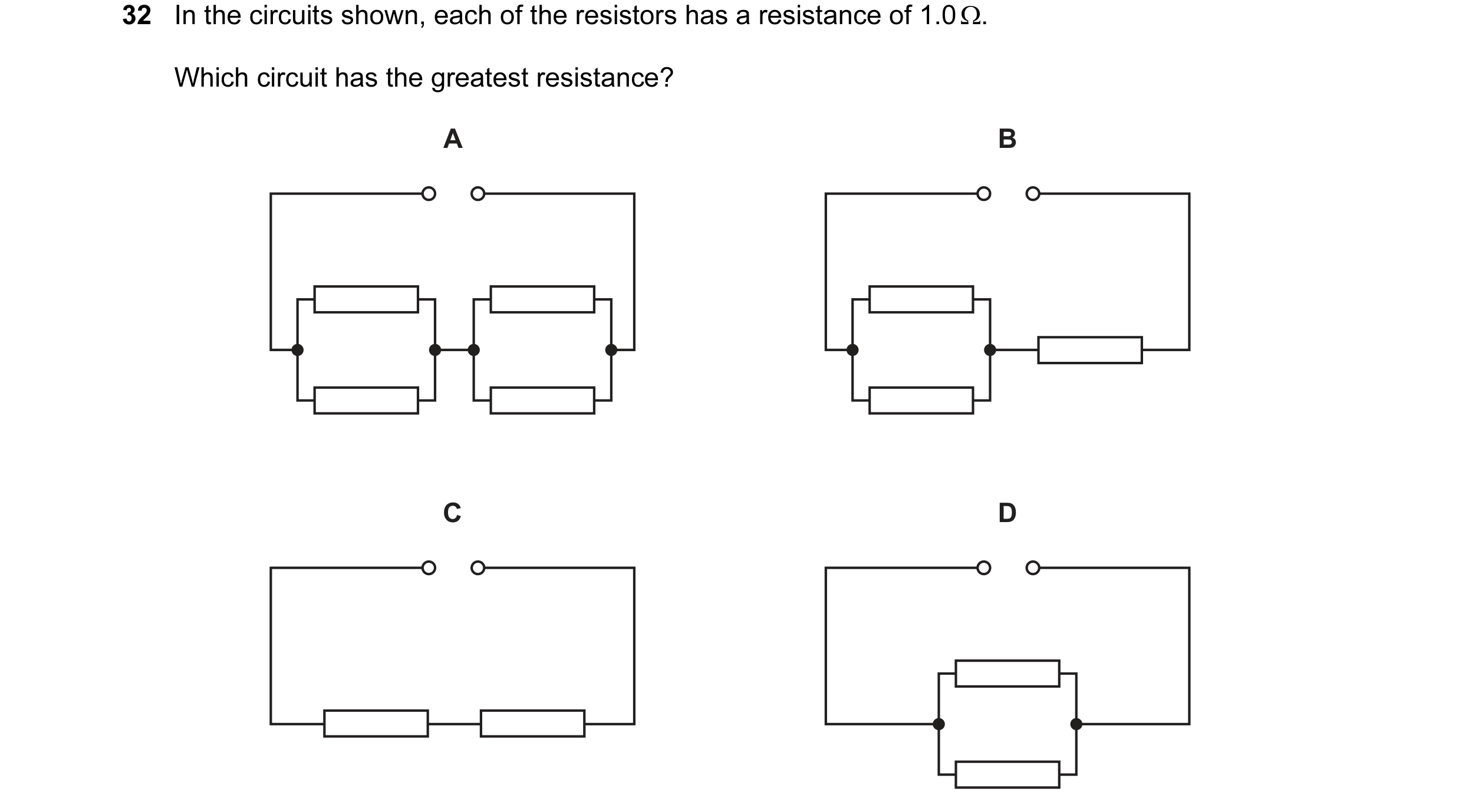
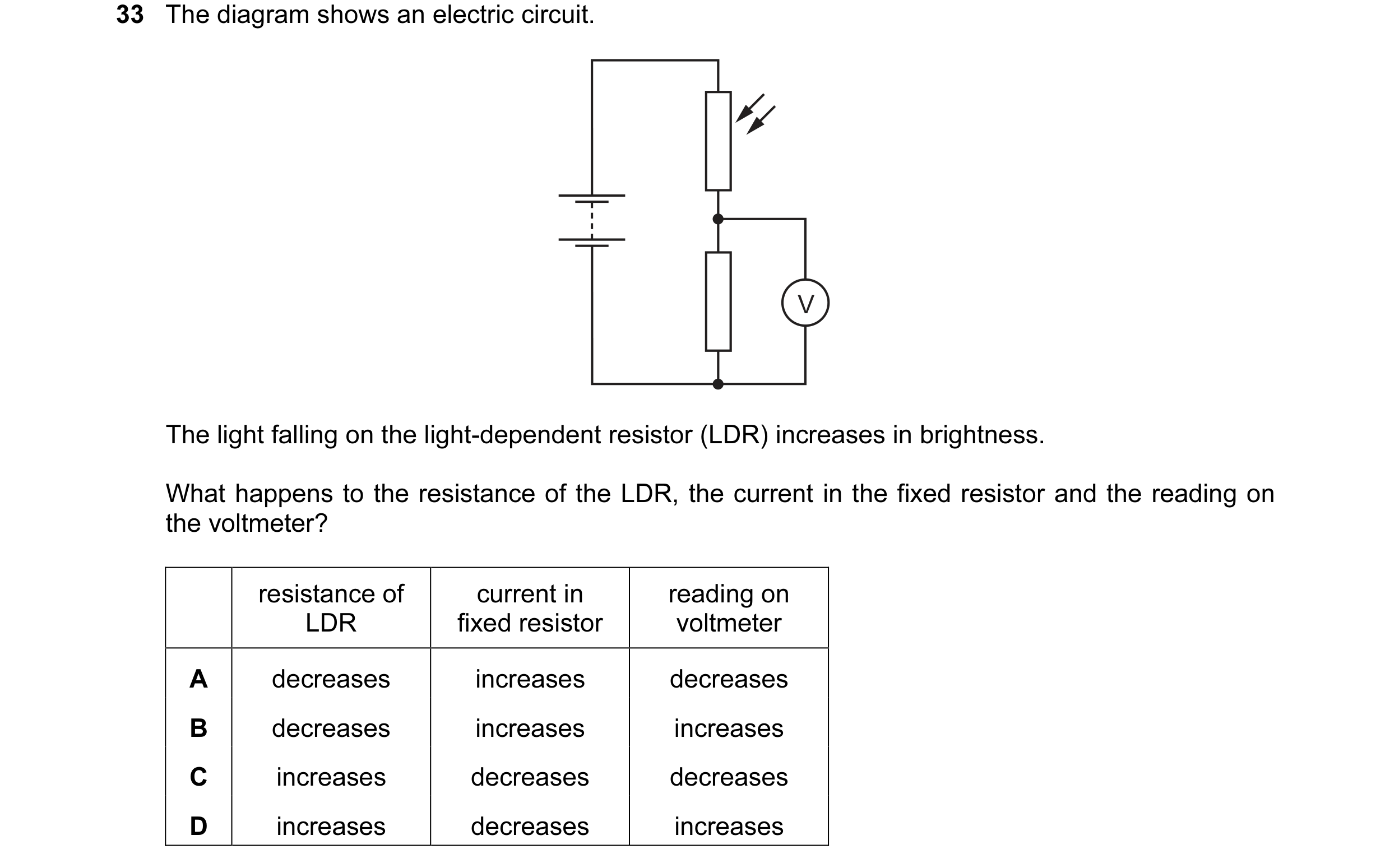 88 / 176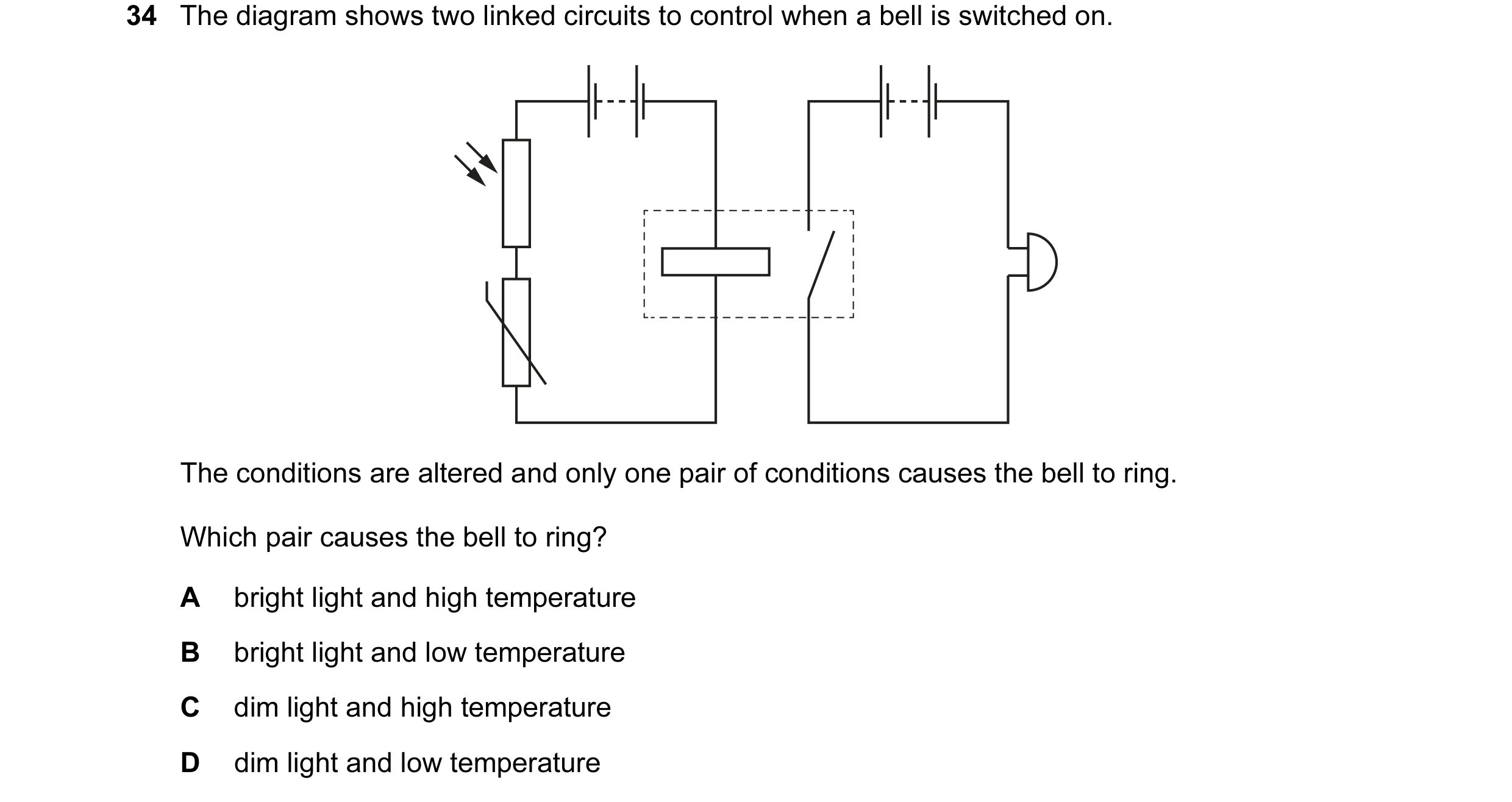
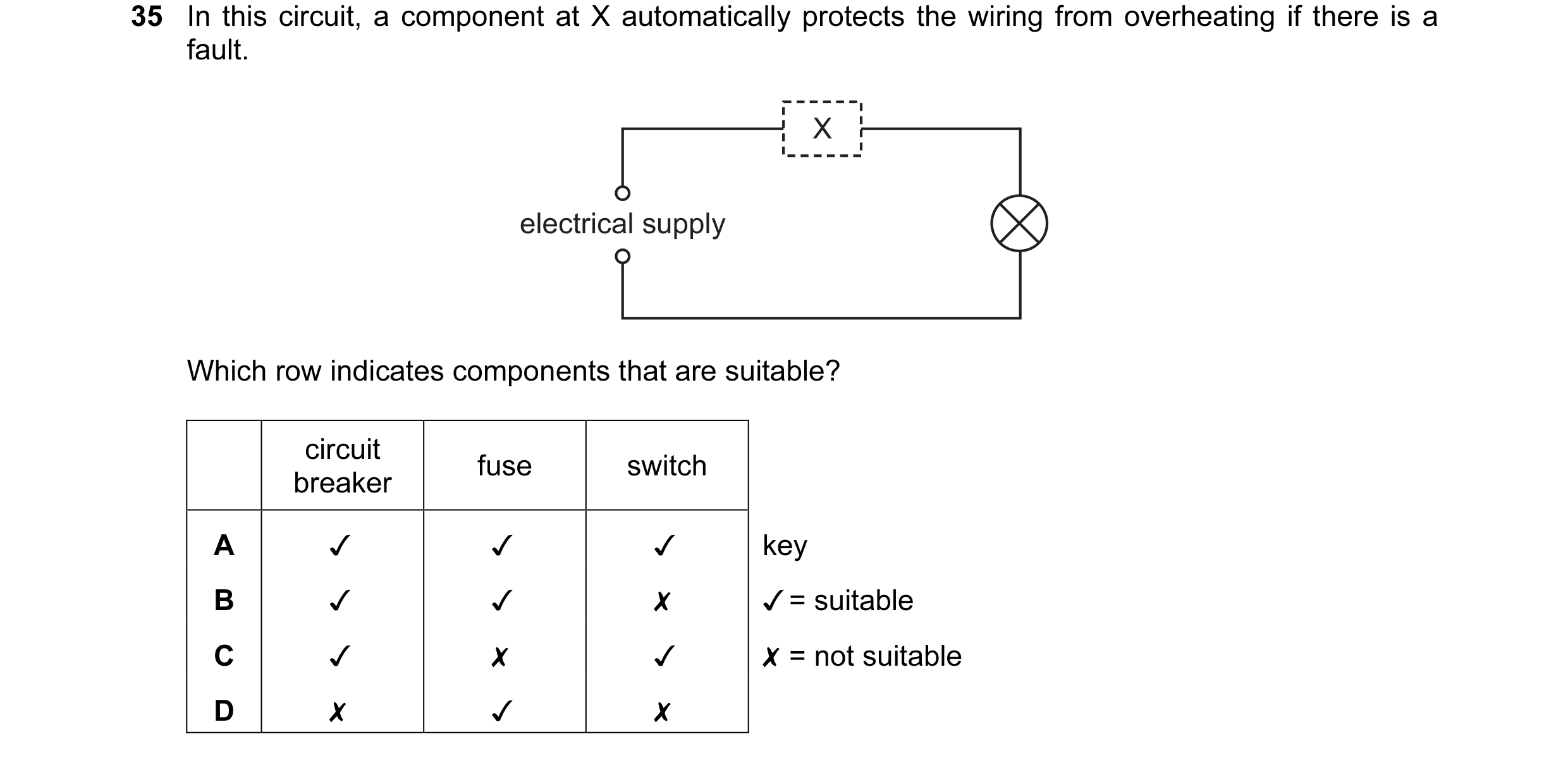
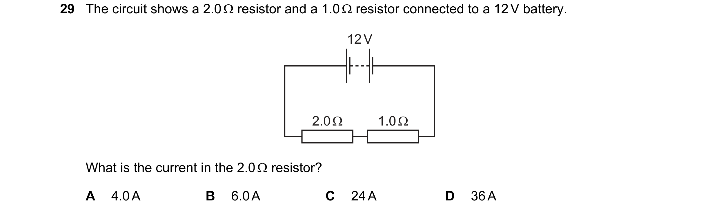 89 / 176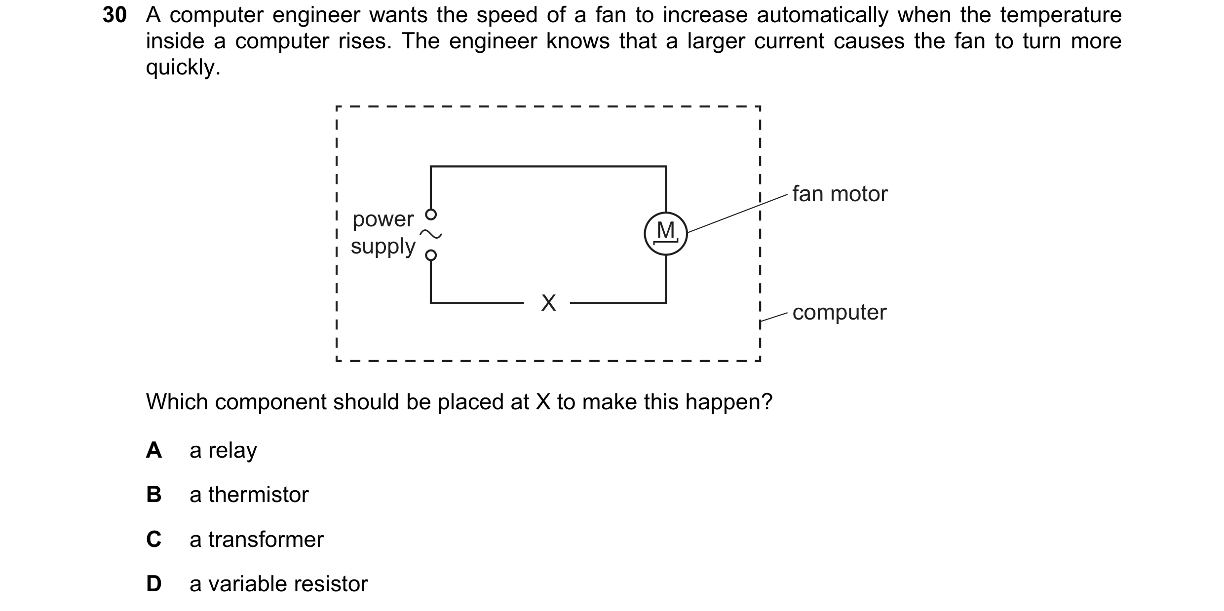
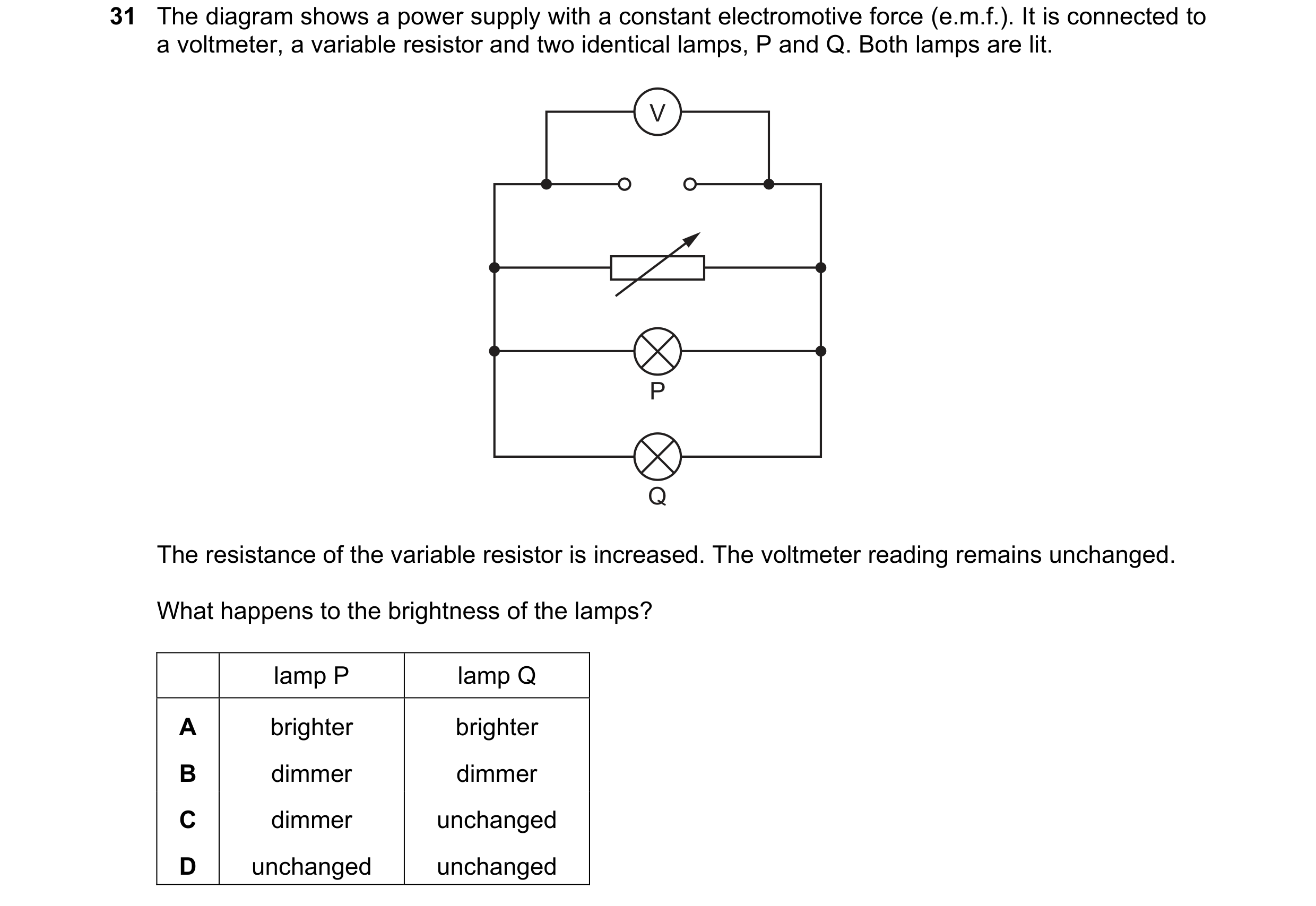 90 / 176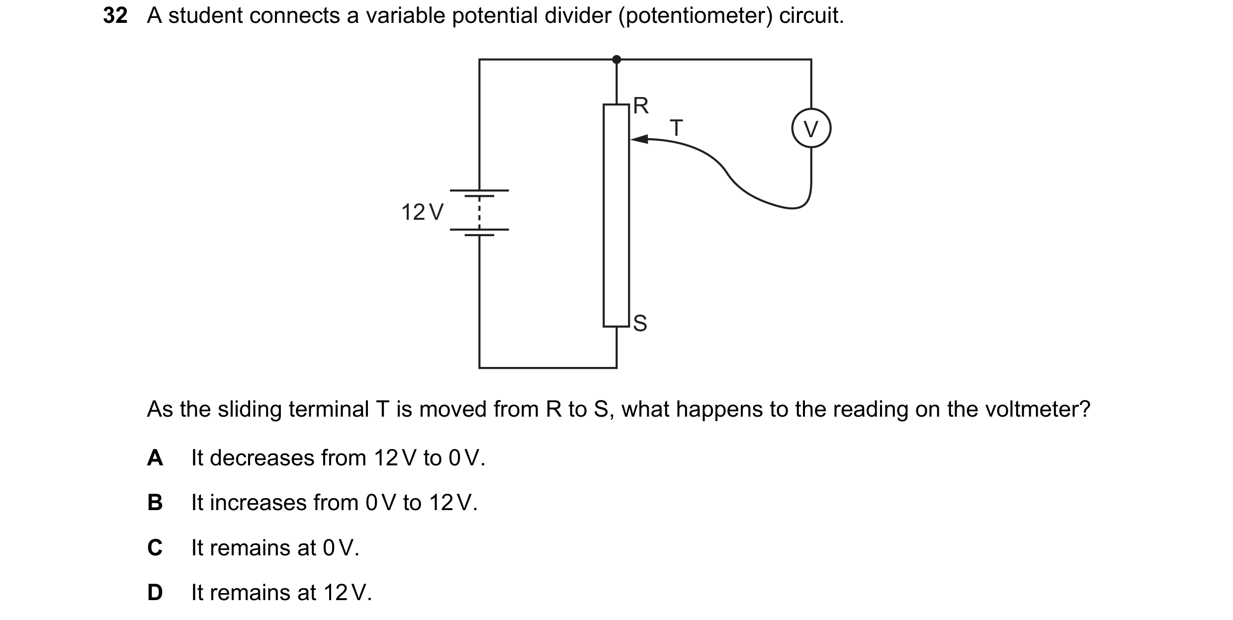
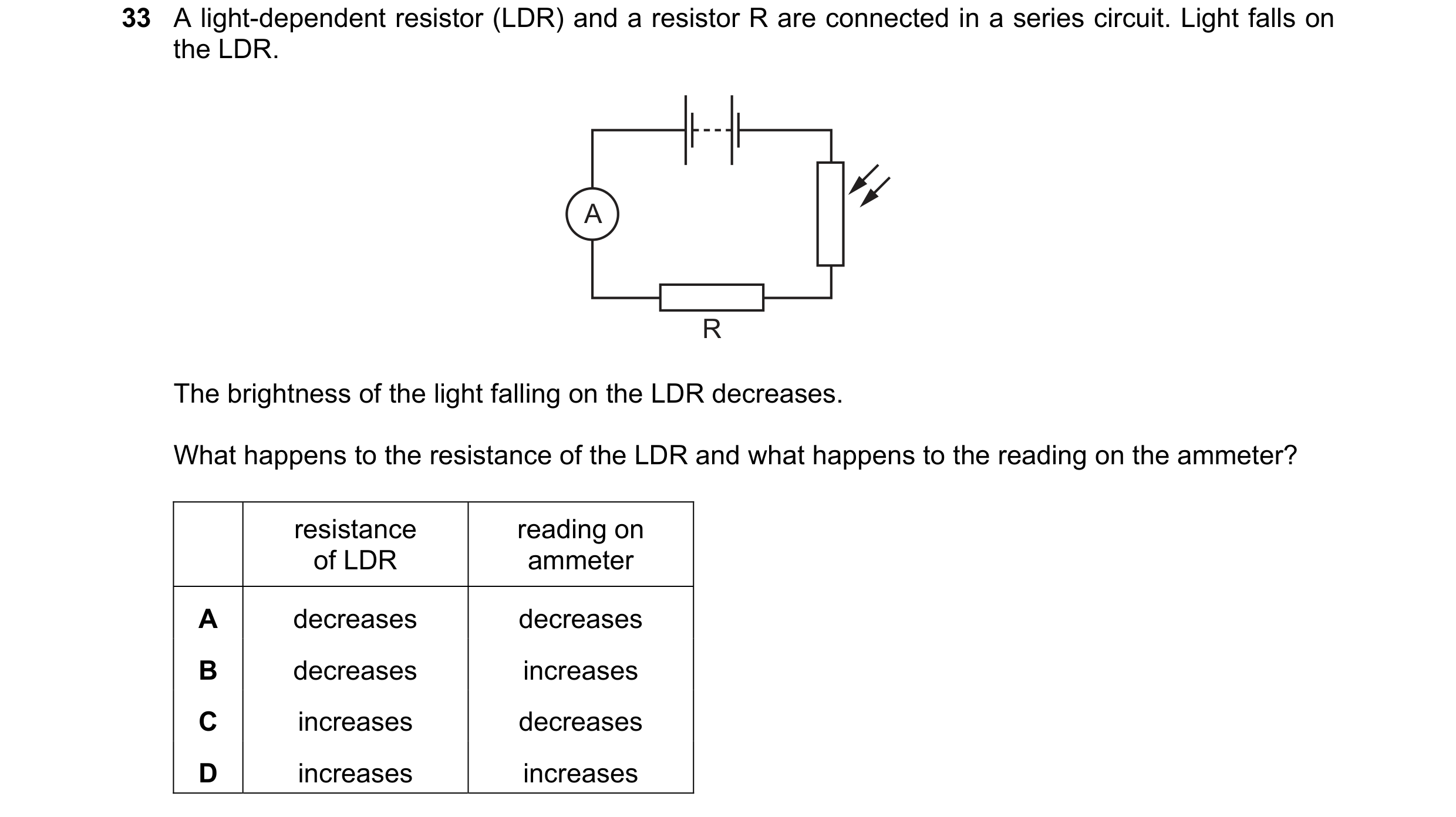 91 / 176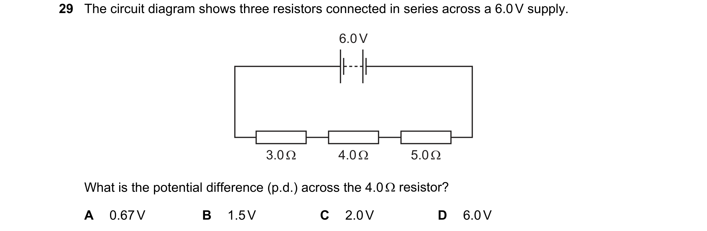
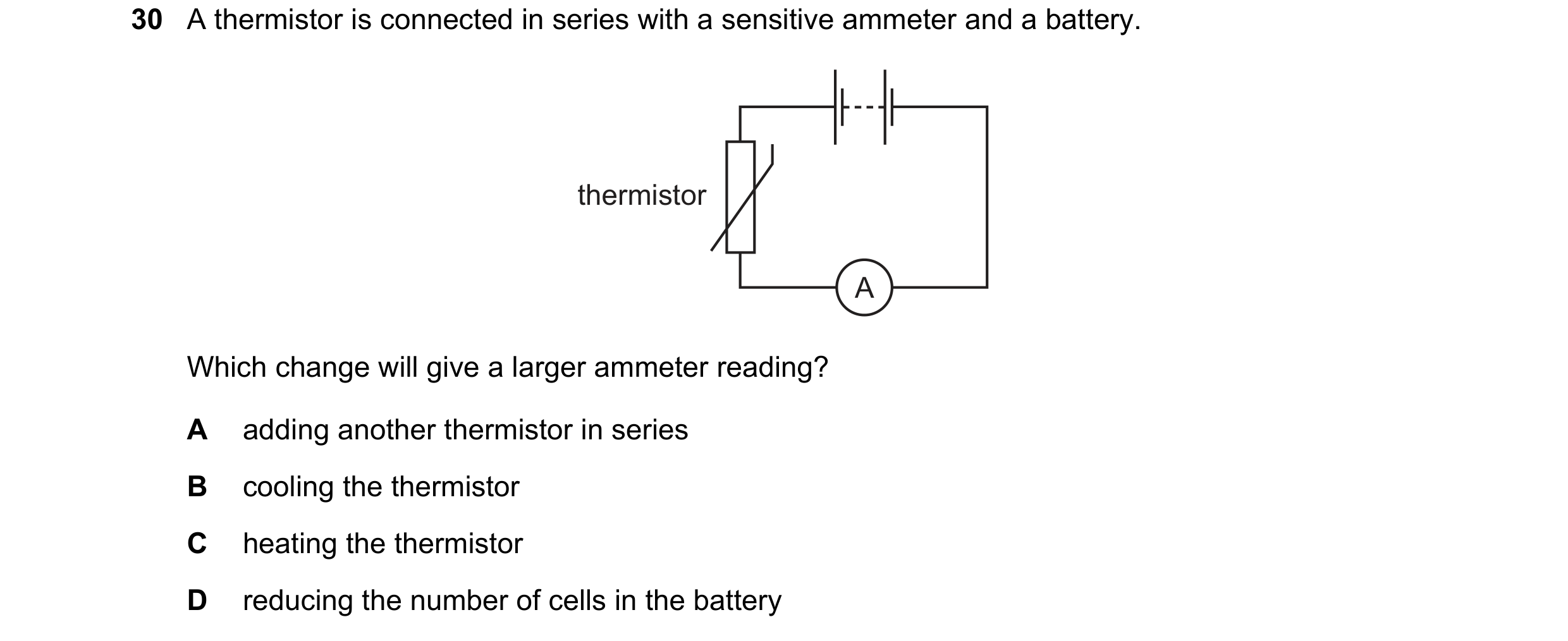
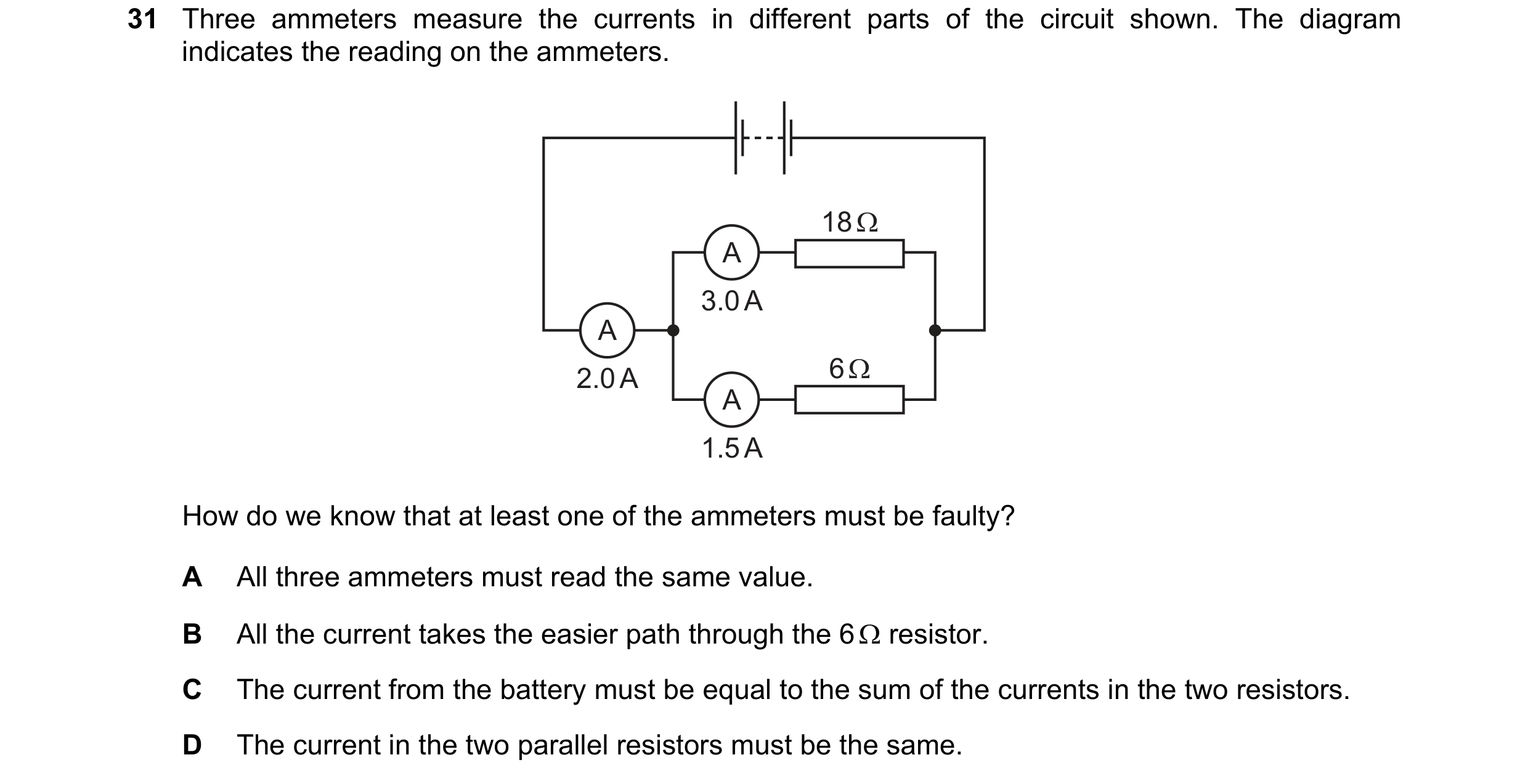 92 / 176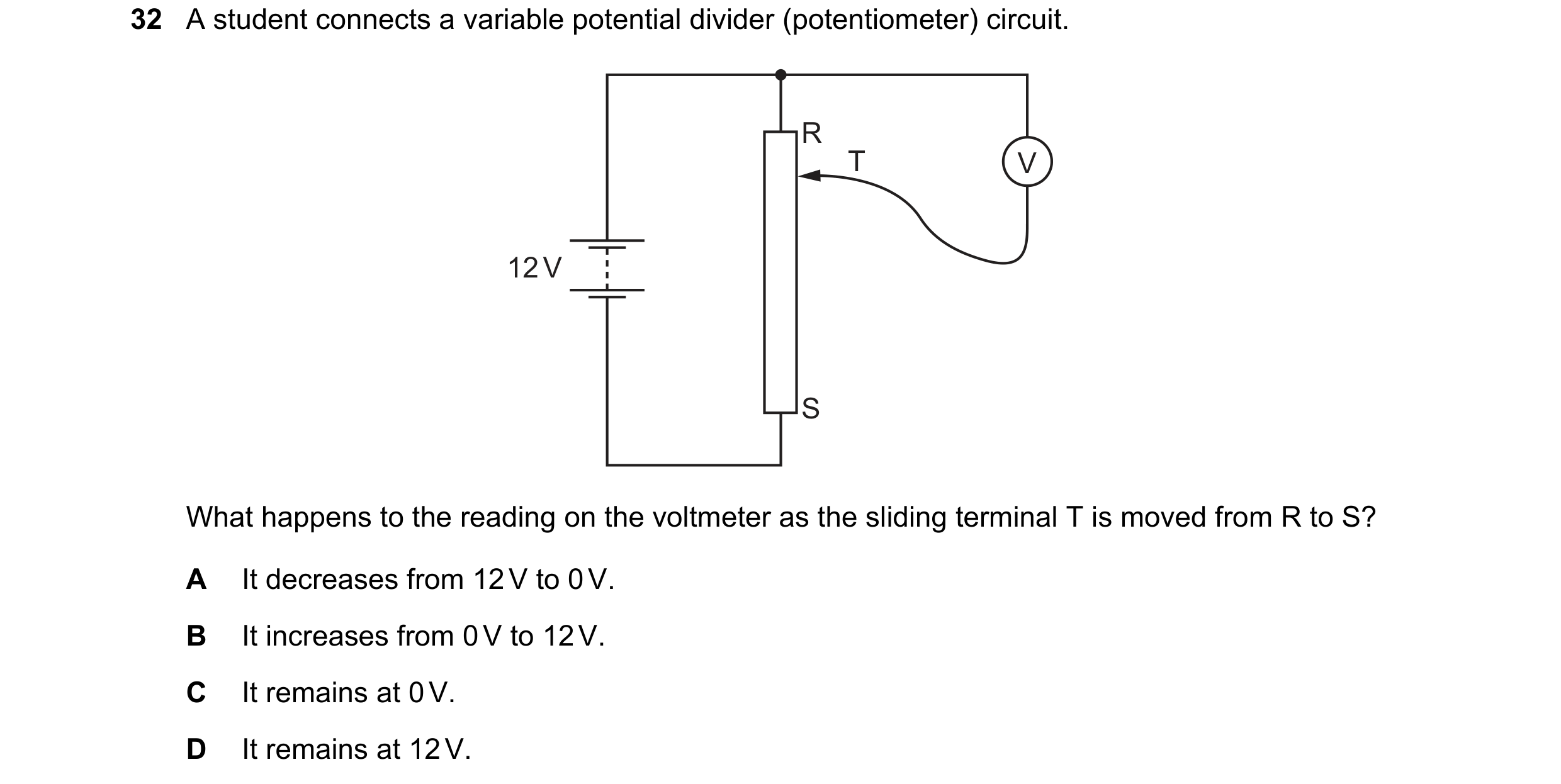
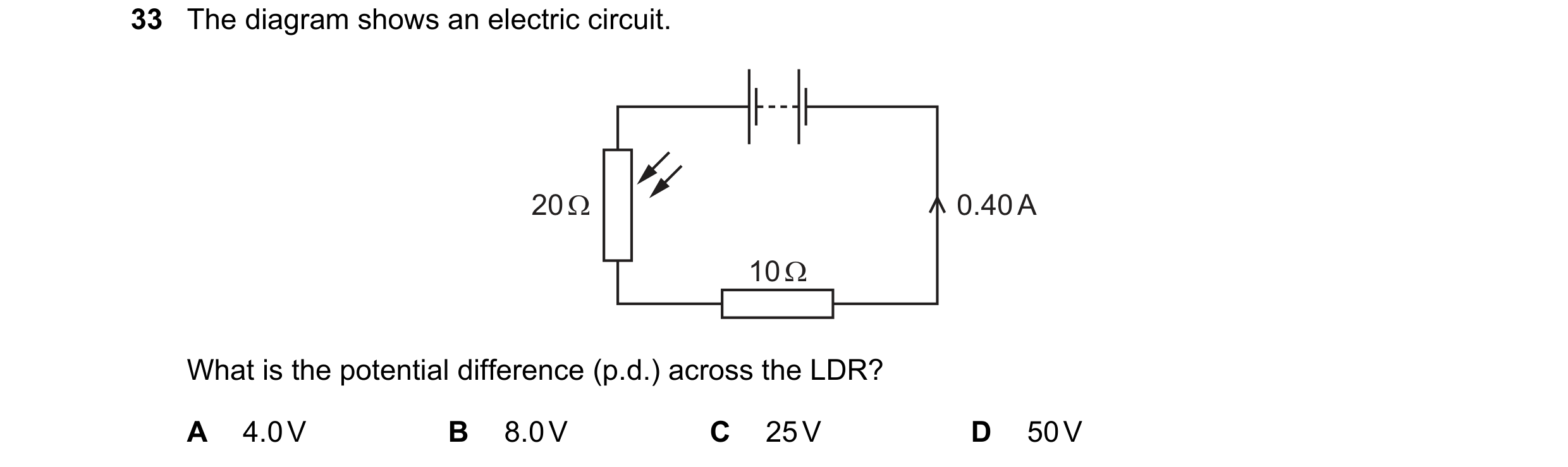
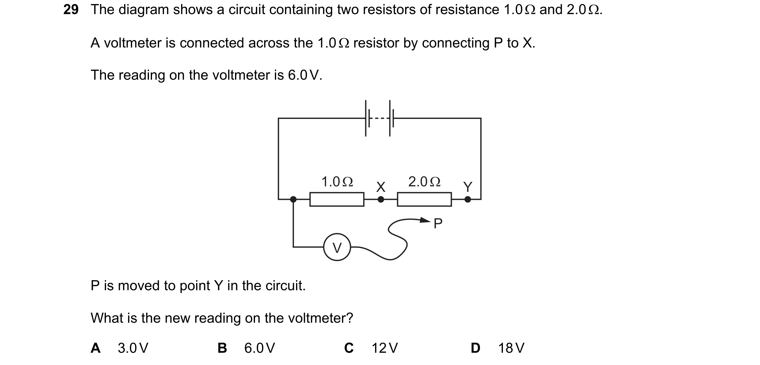 93 / 176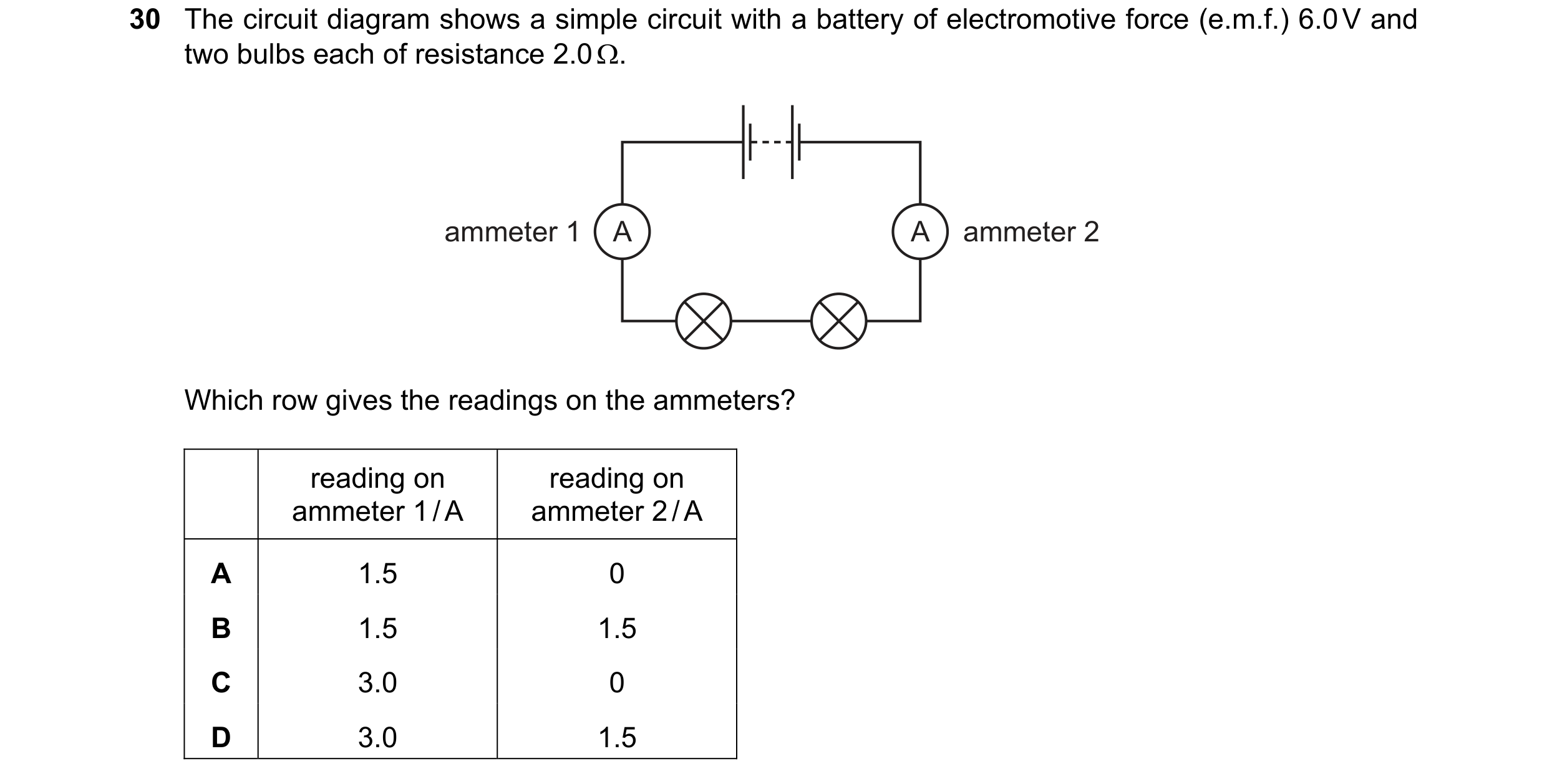
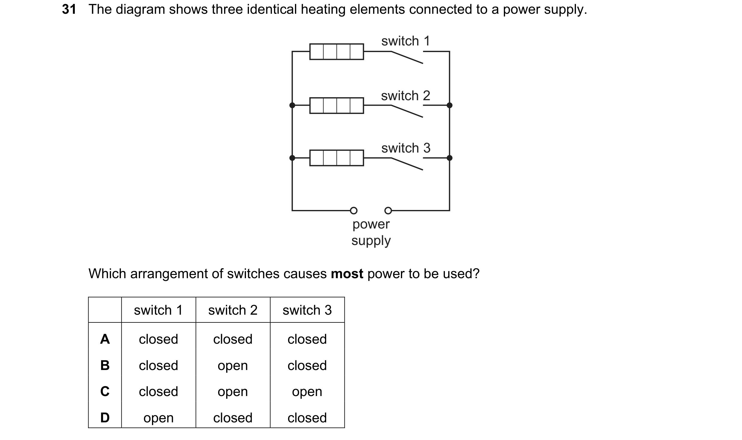 94 / 176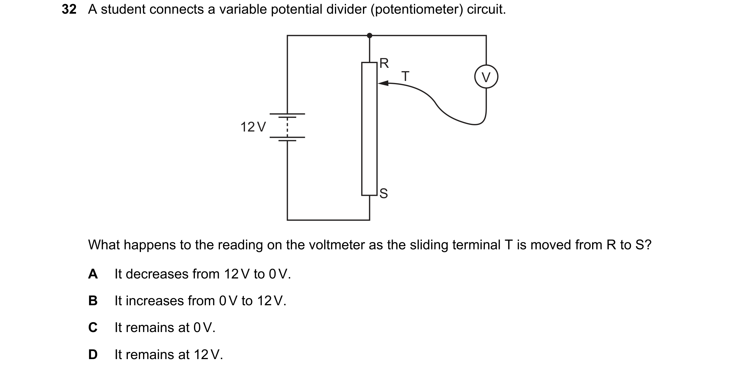
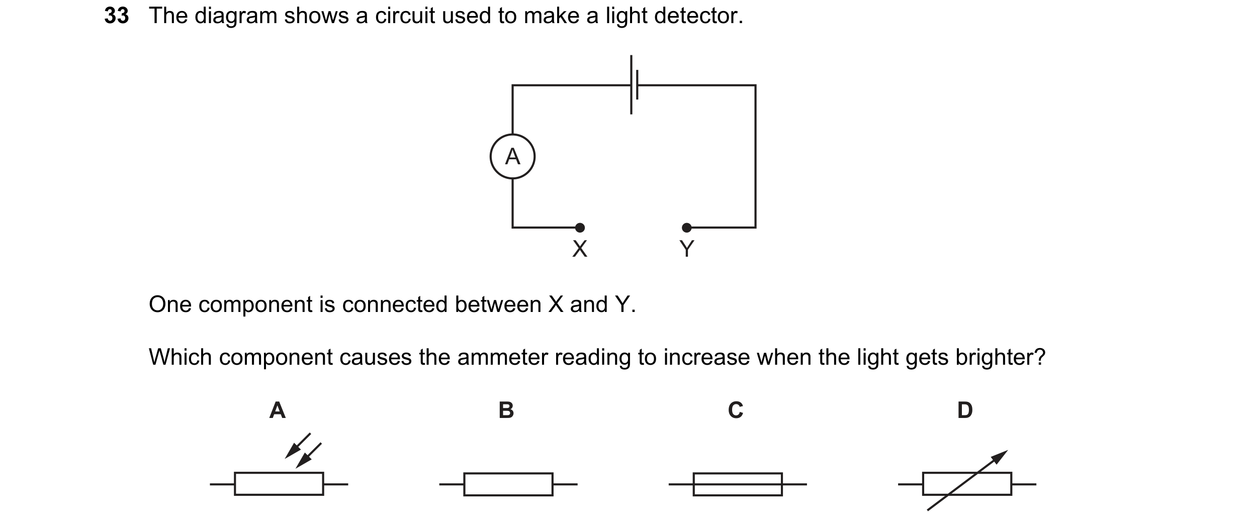

 95 / 176
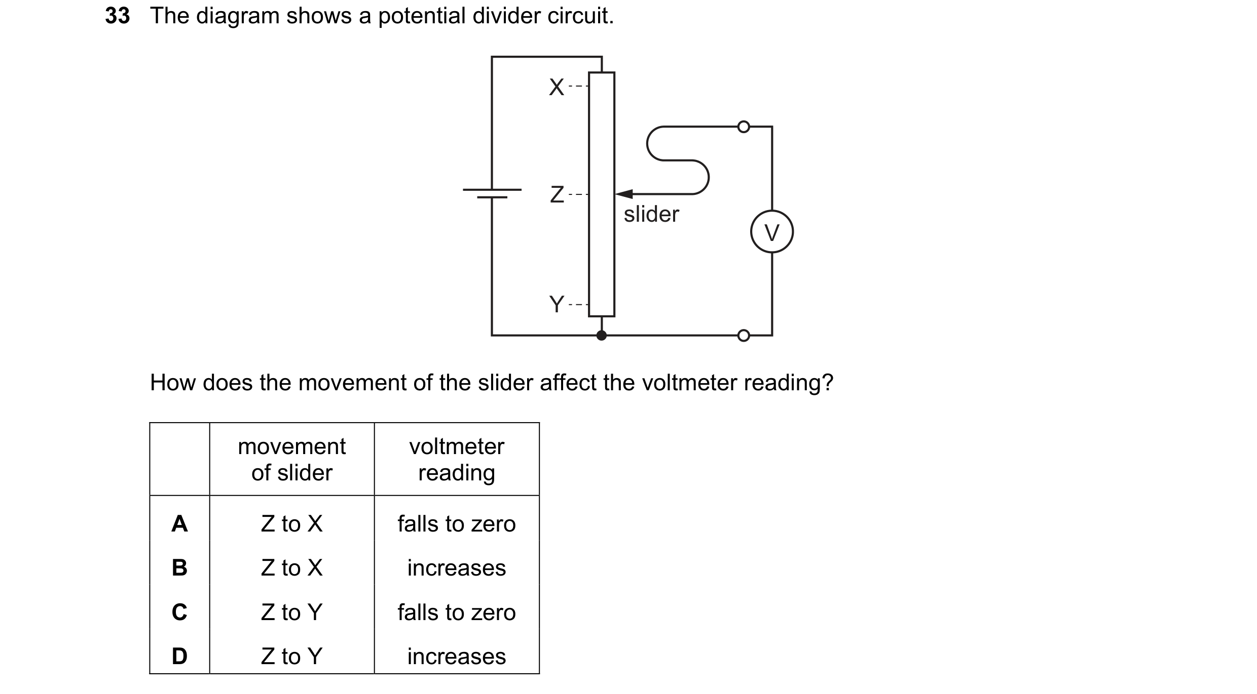
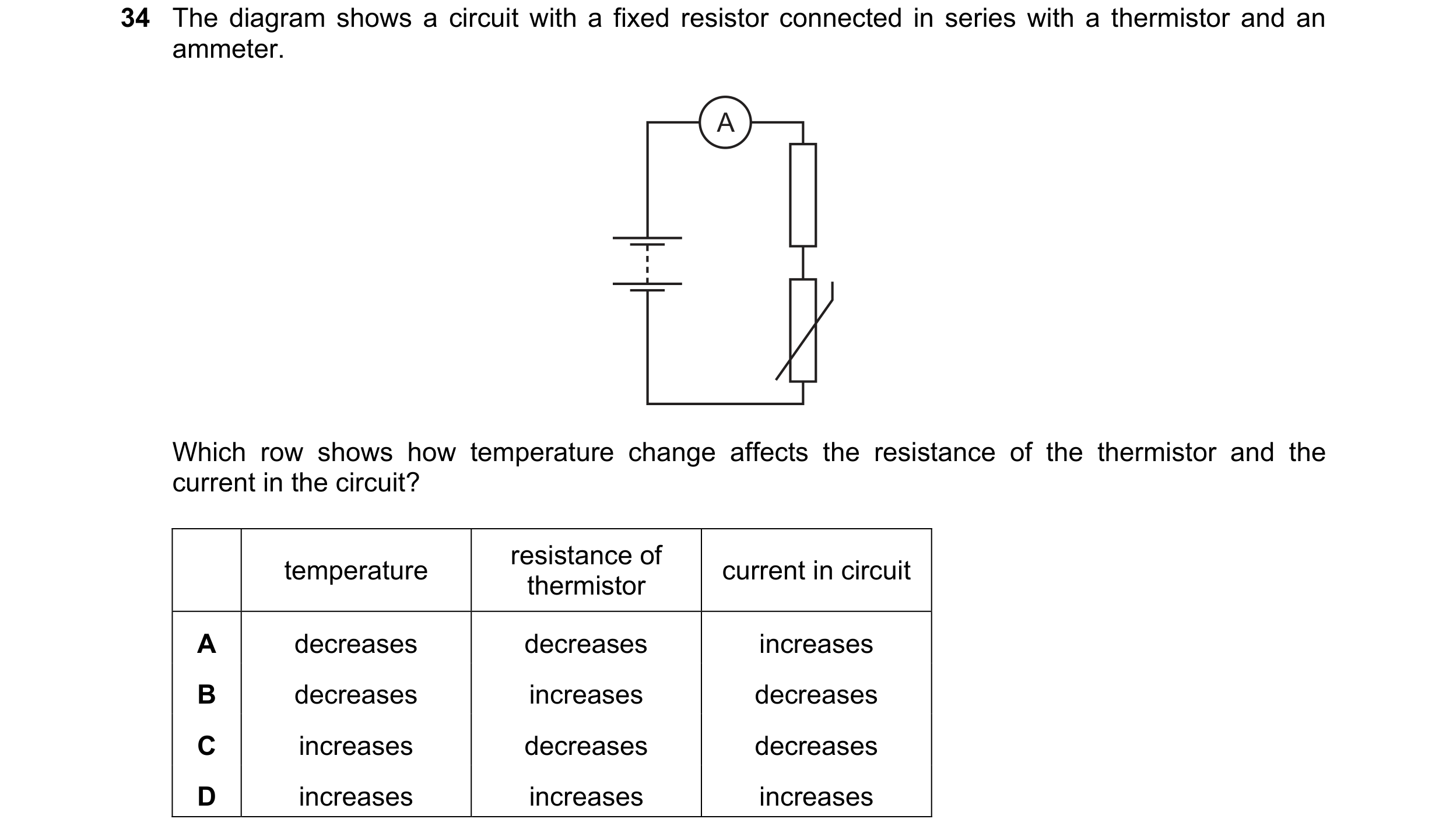 96 / 176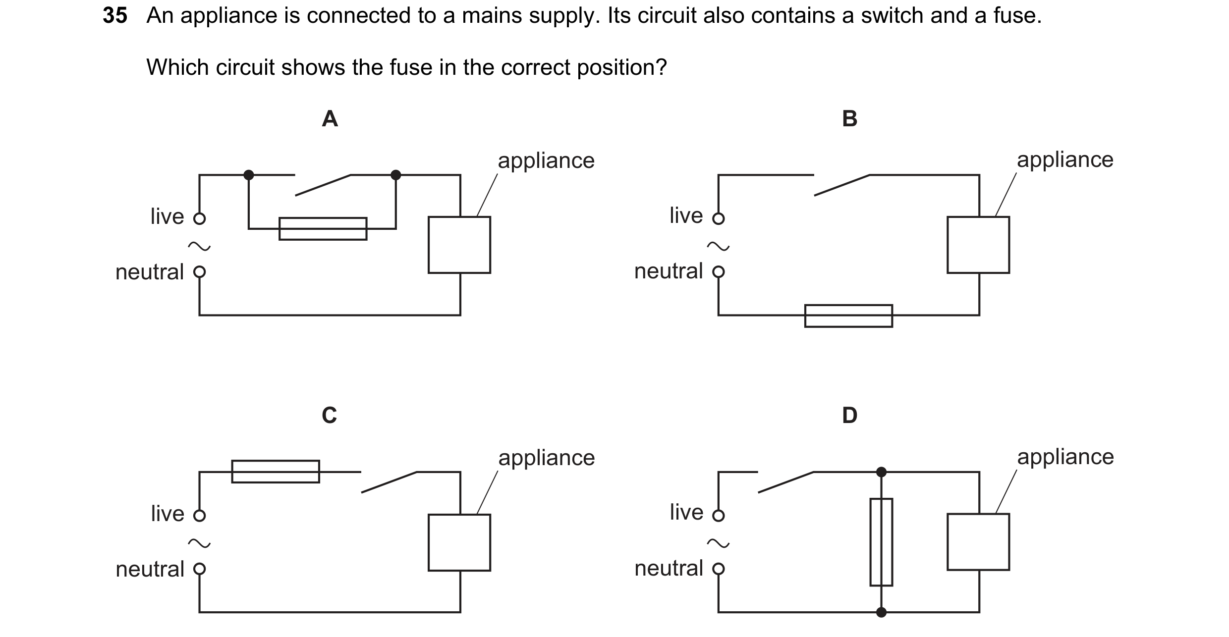
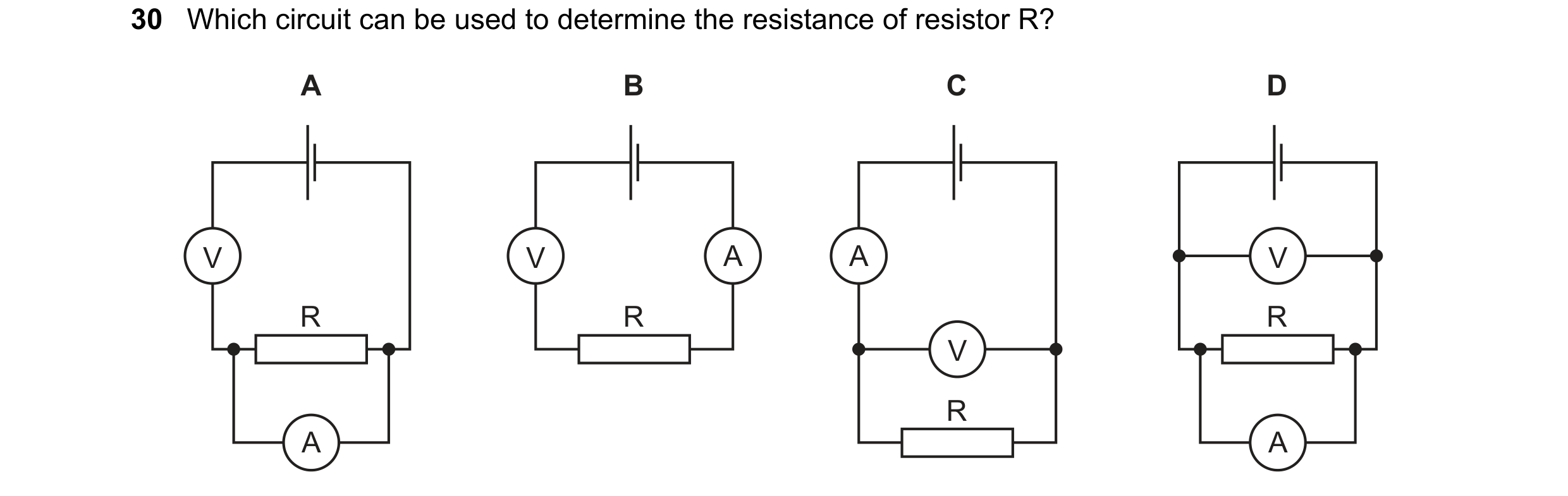
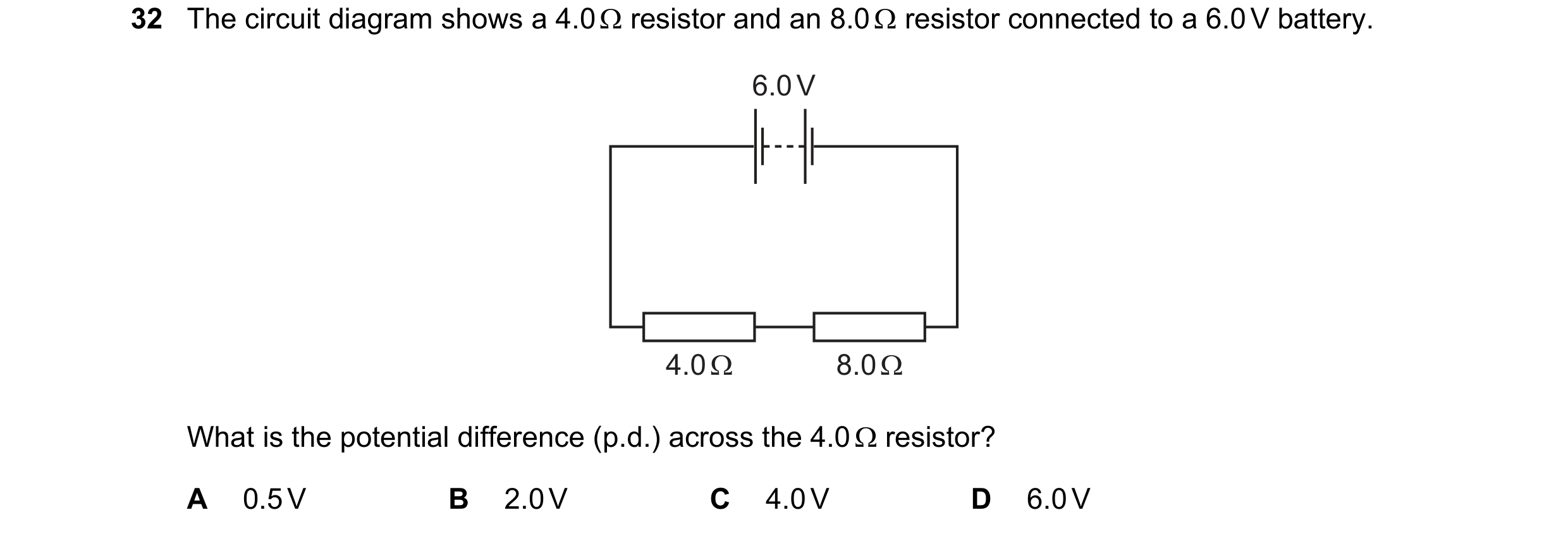 97 / 176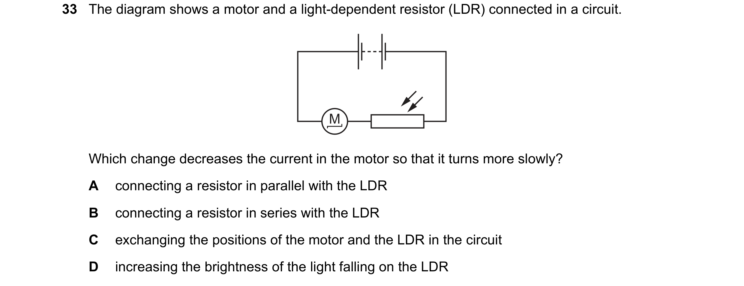
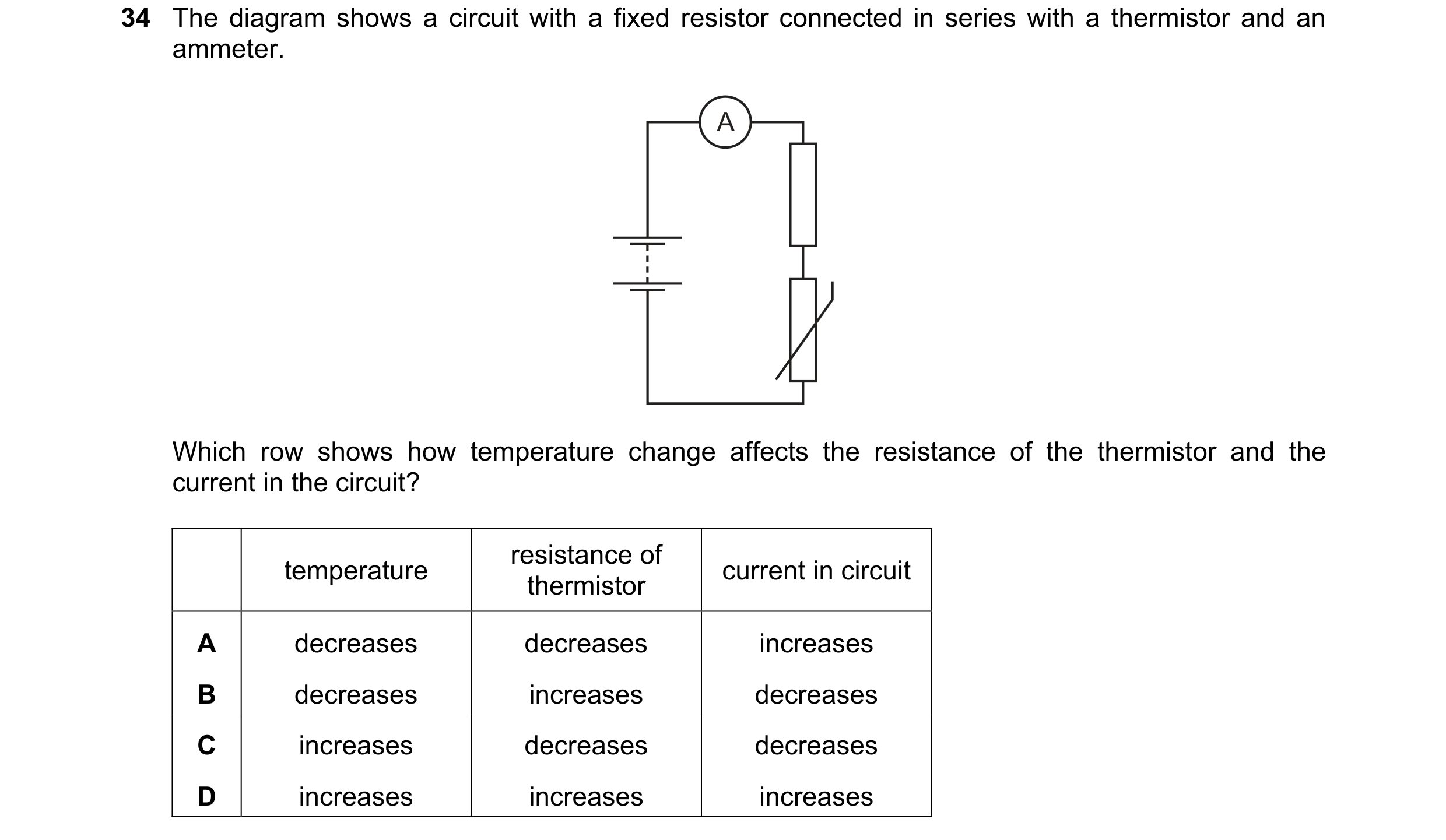 98 / 176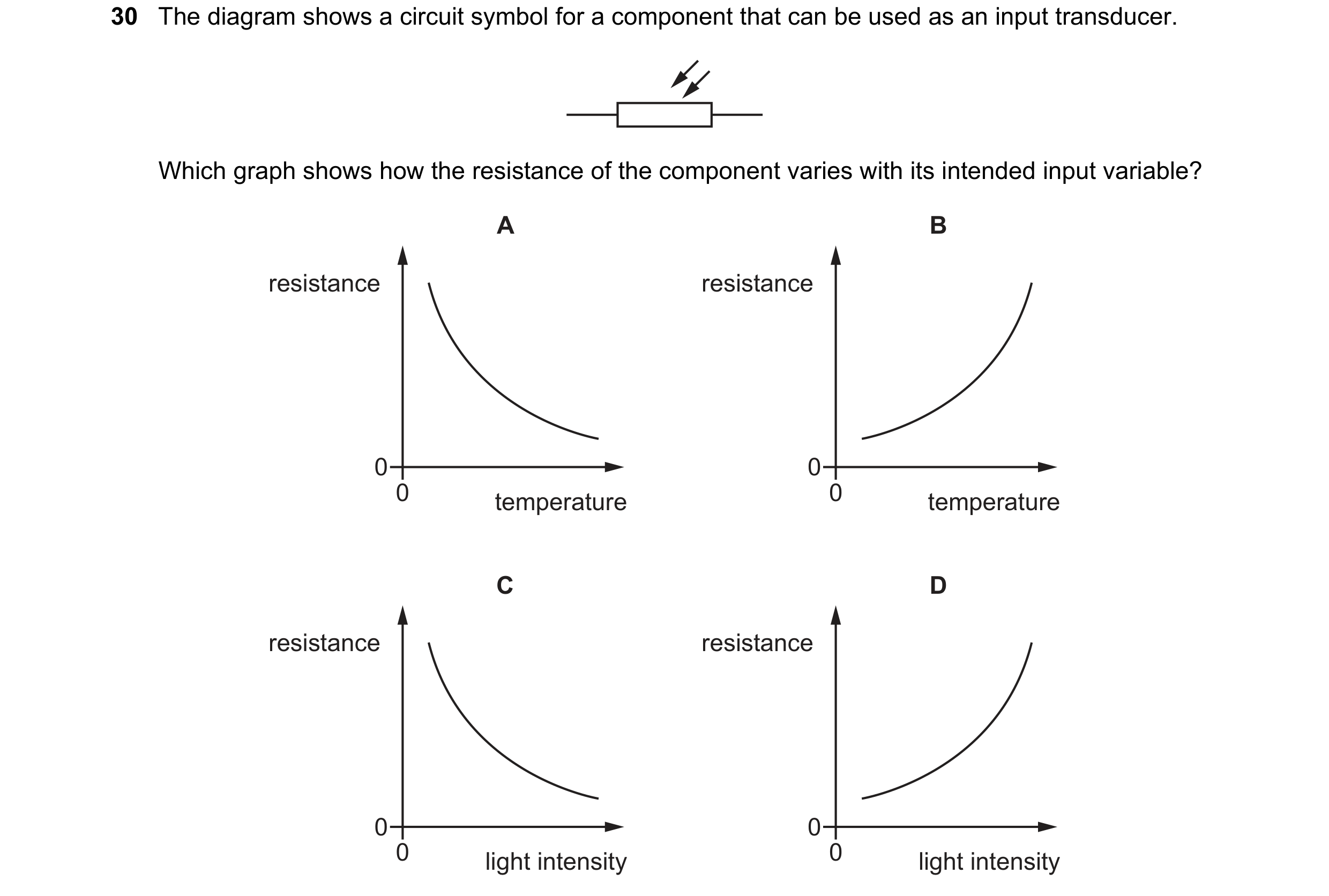

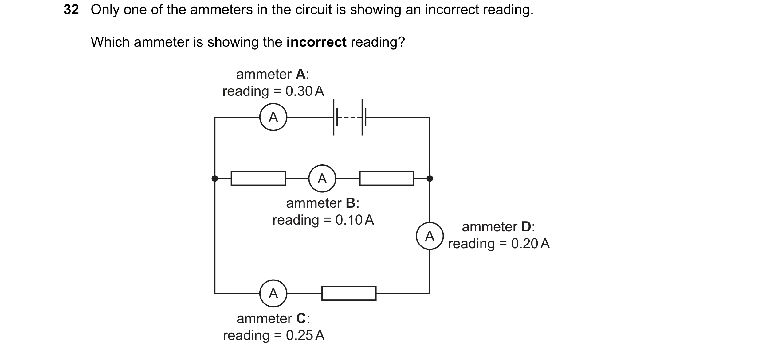 99 / 176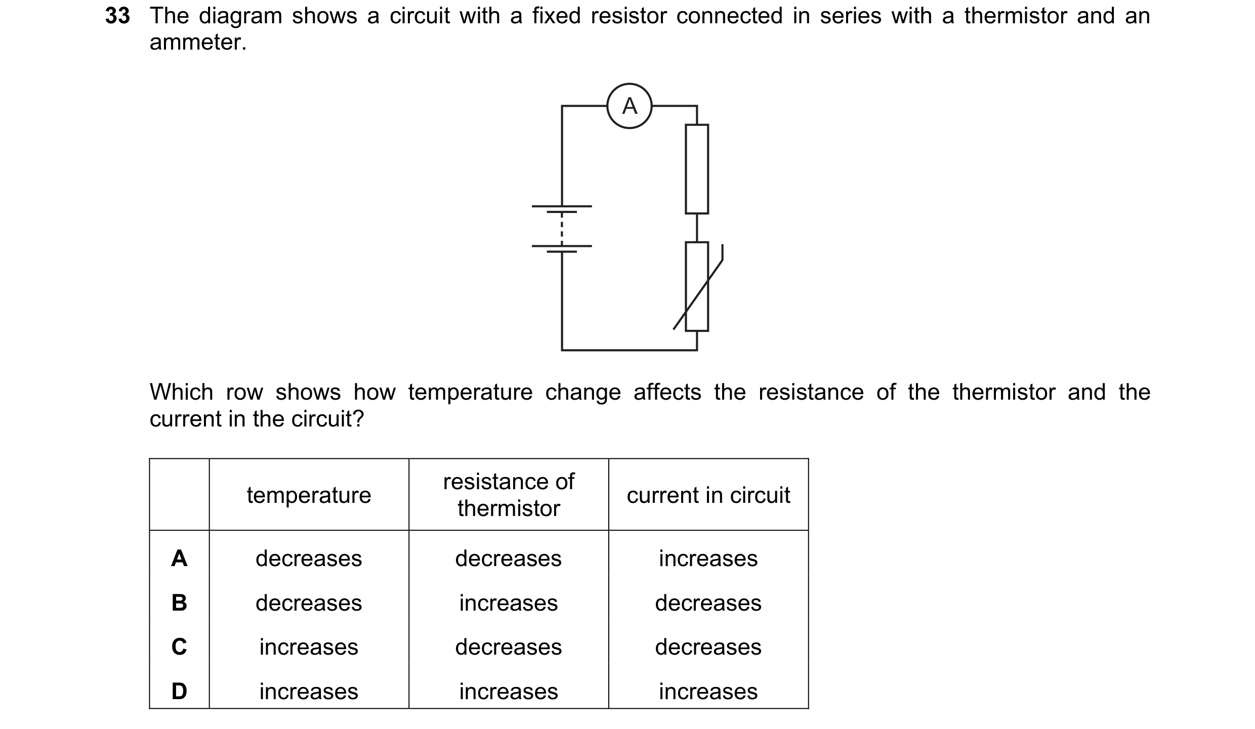
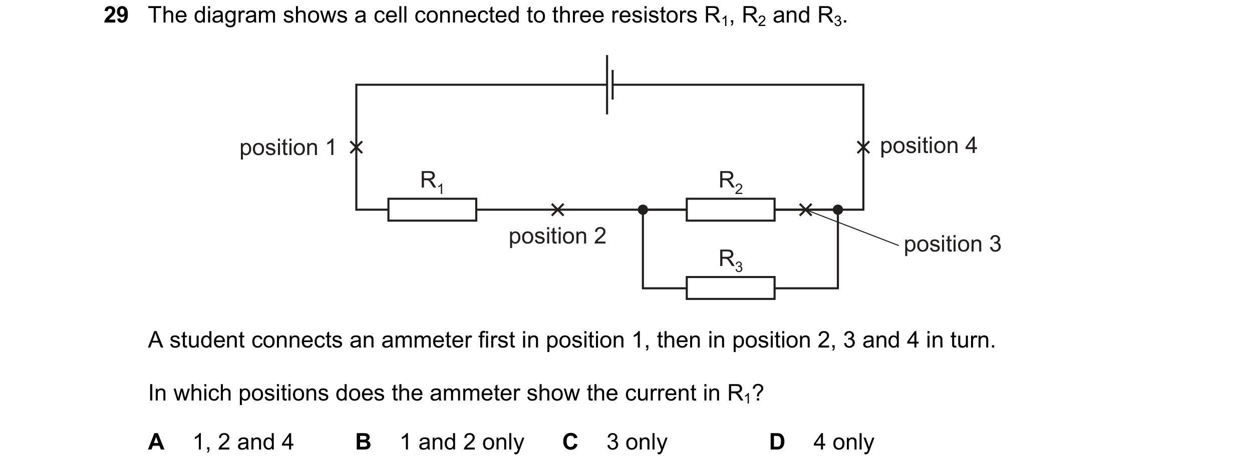 100 / 176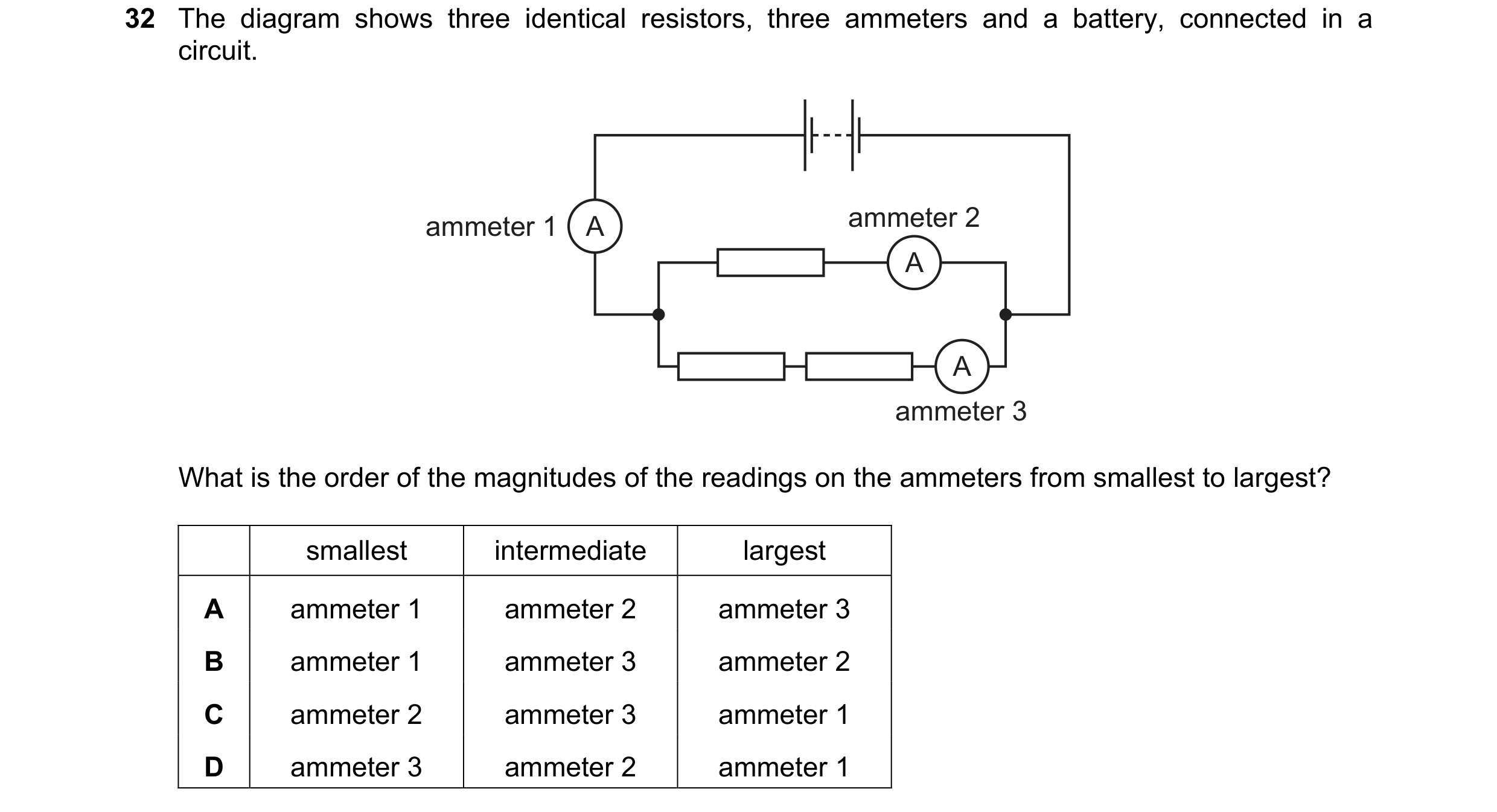
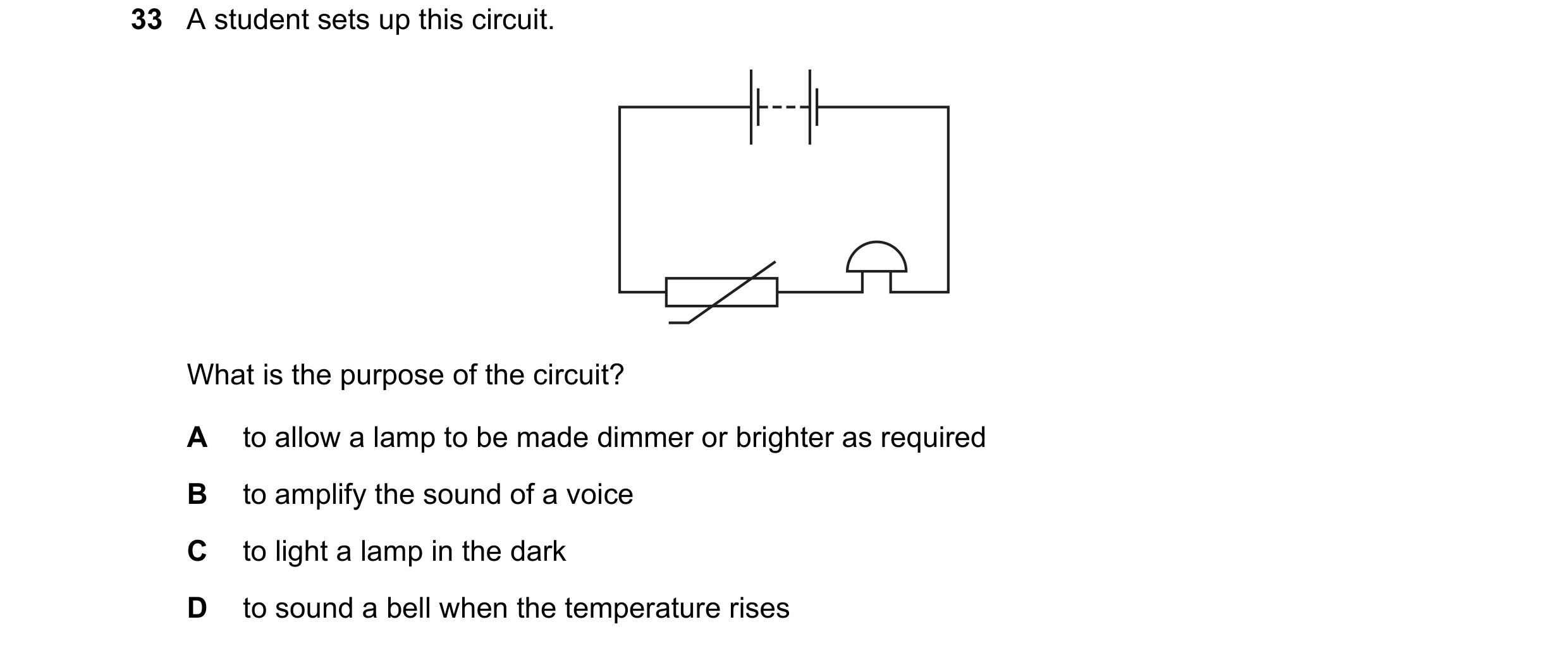 101 / 176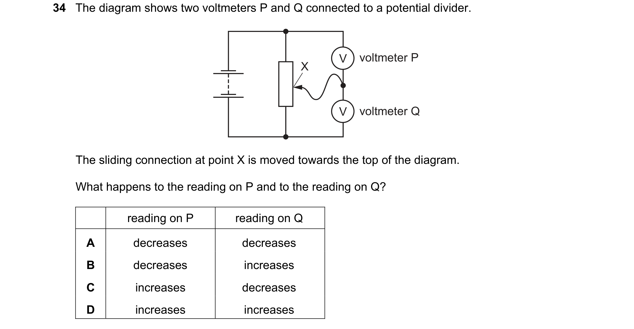
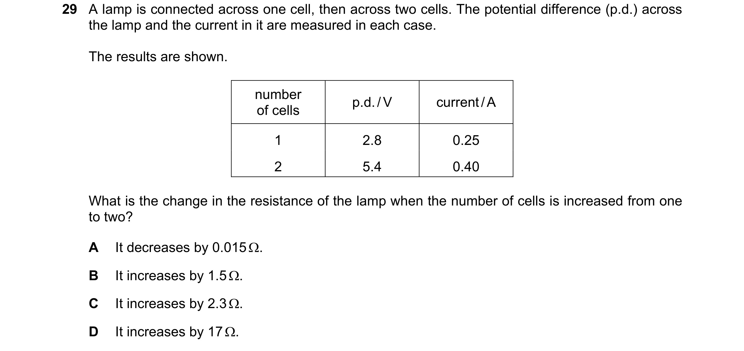
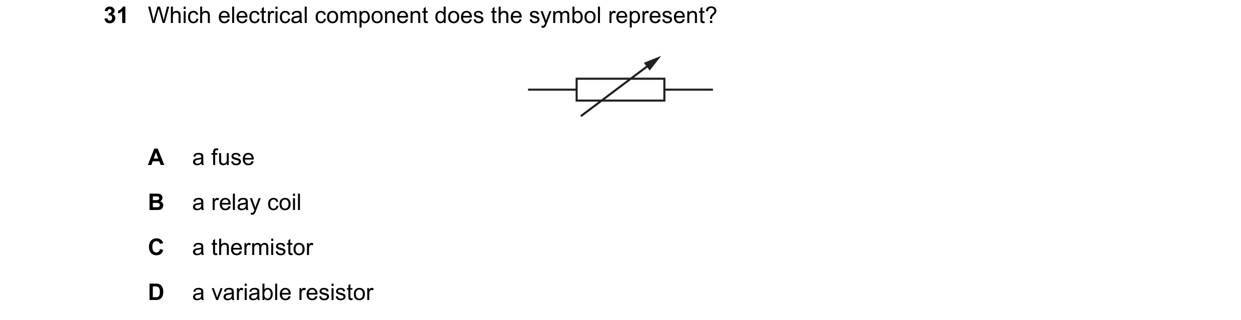 102 / 176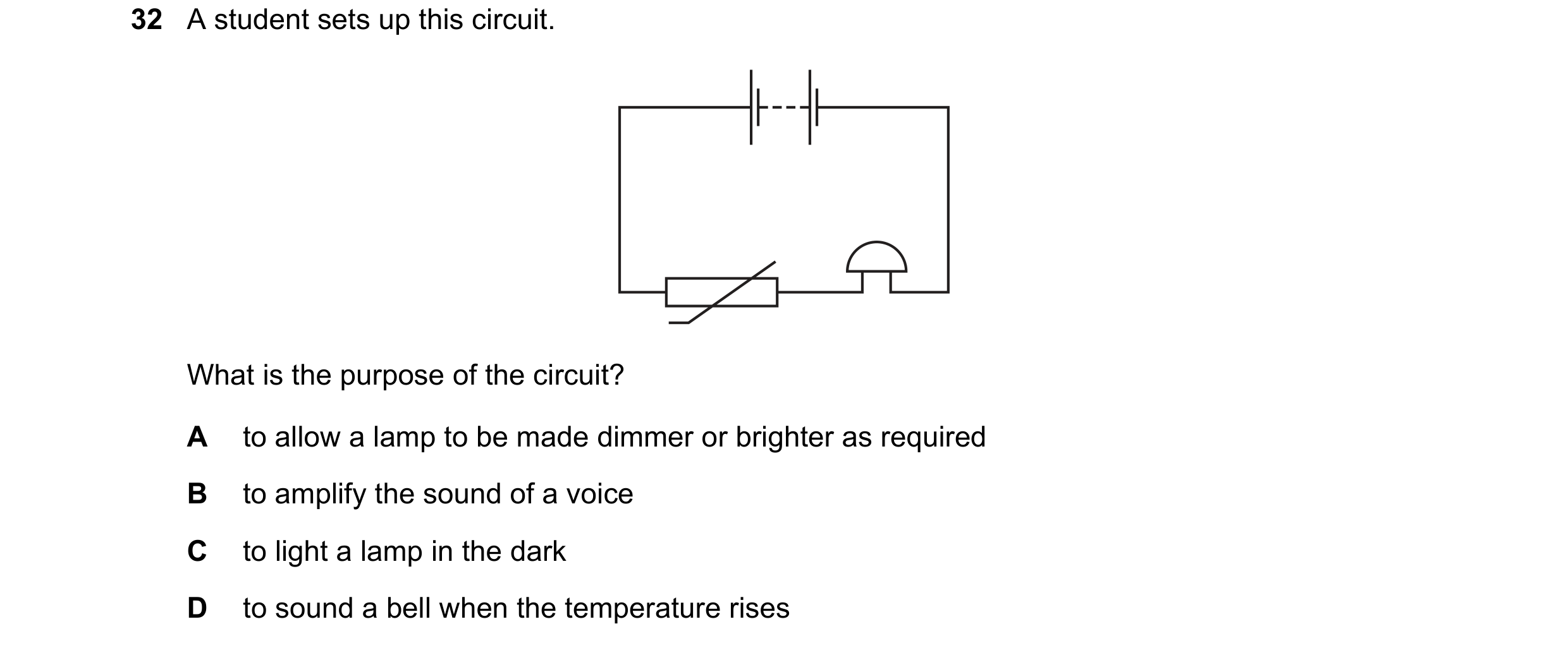
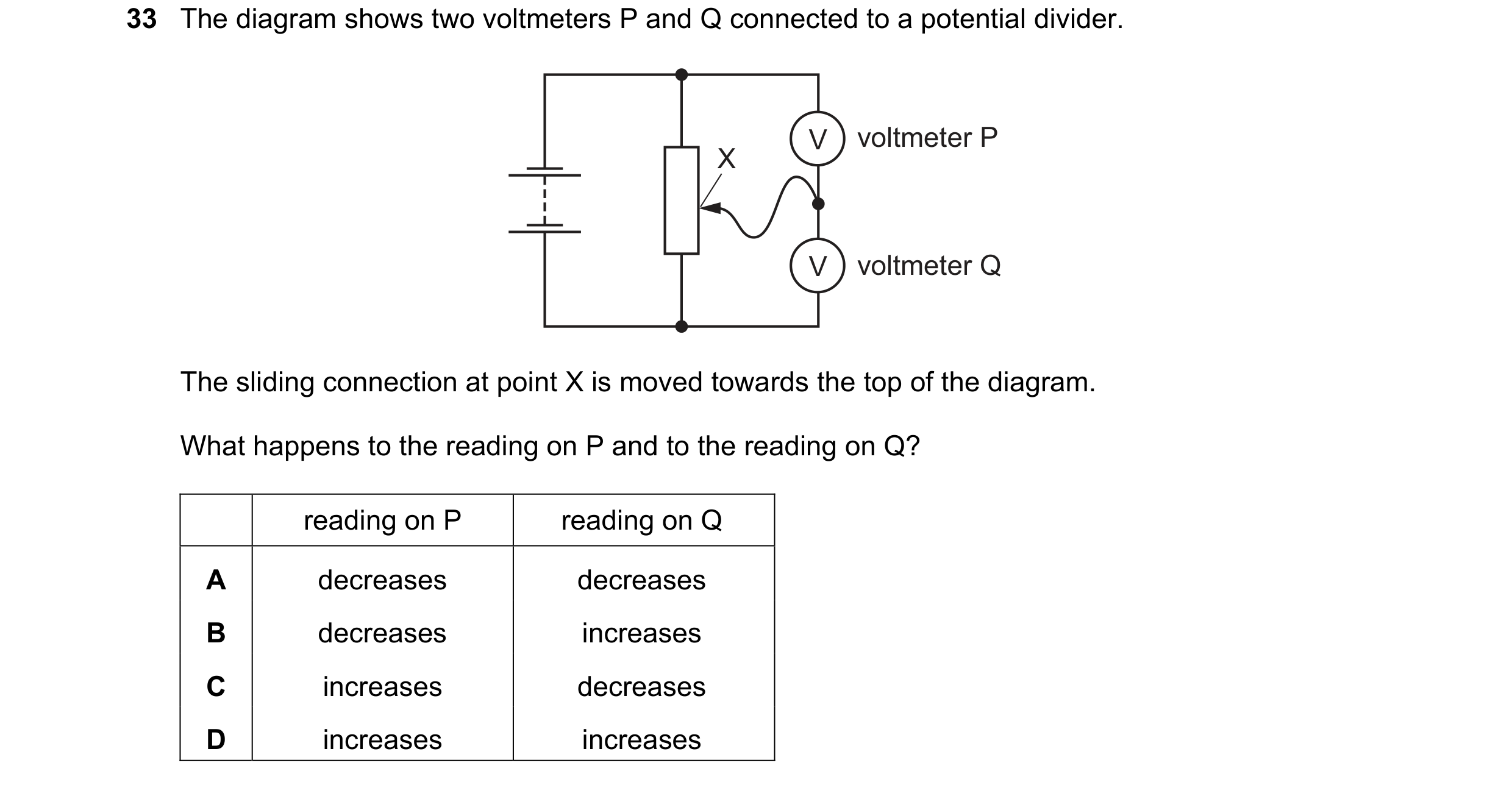
 103 / 176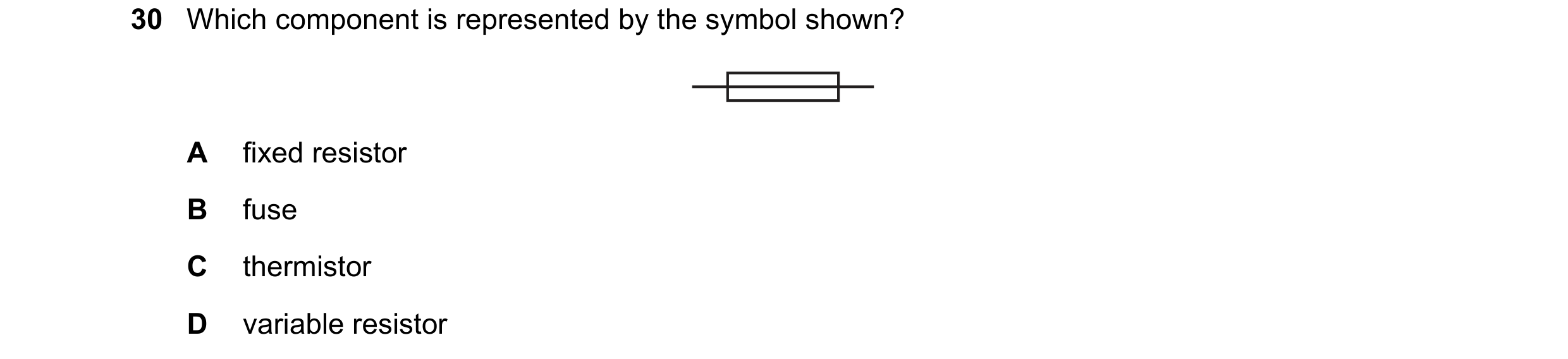
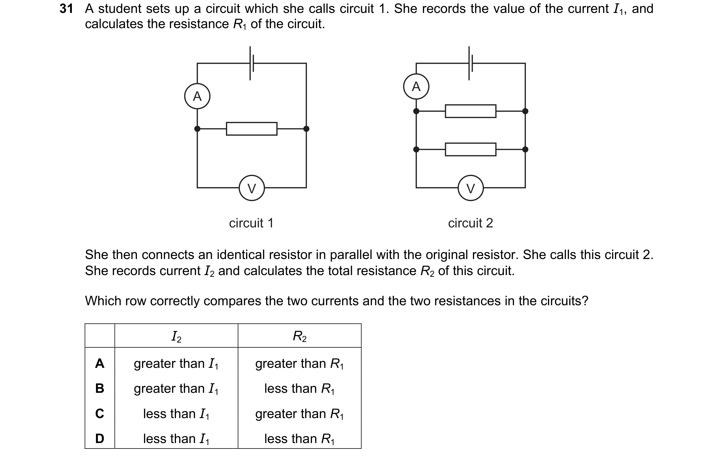
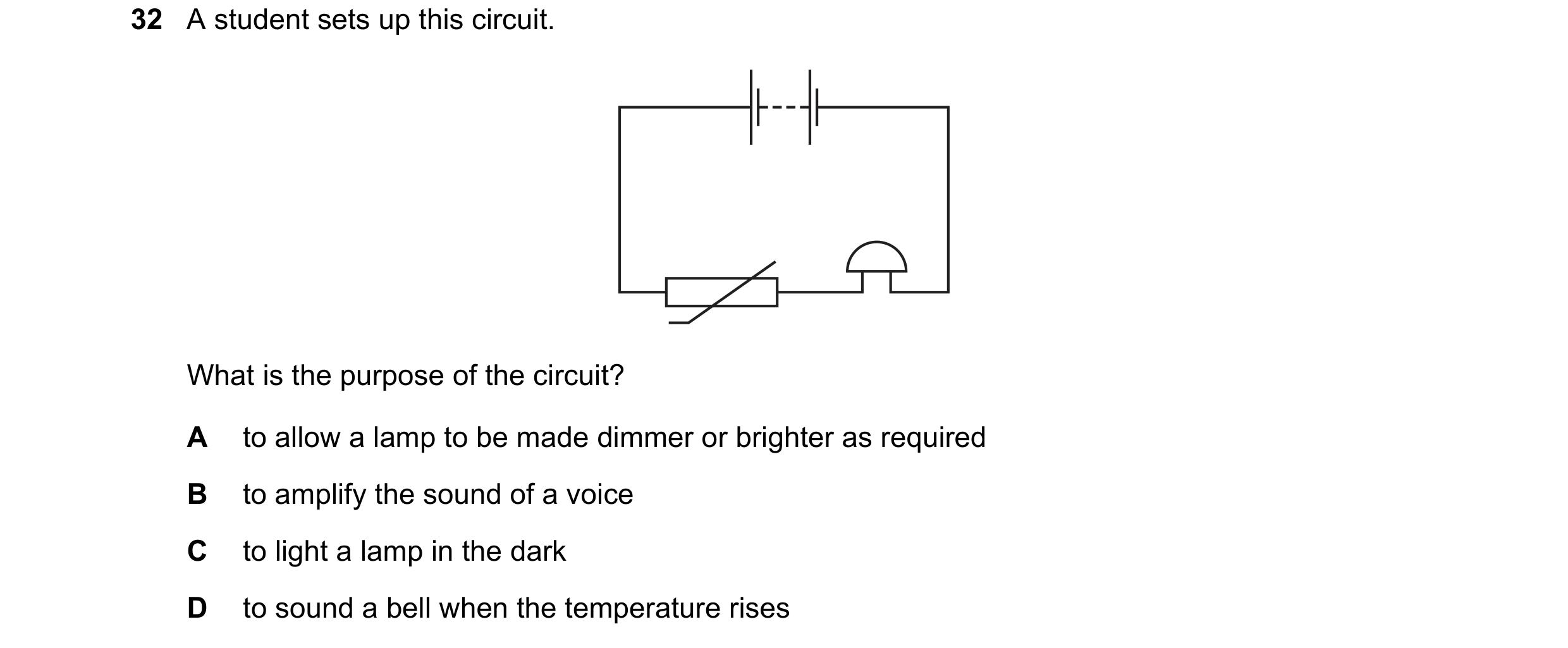 104 / 176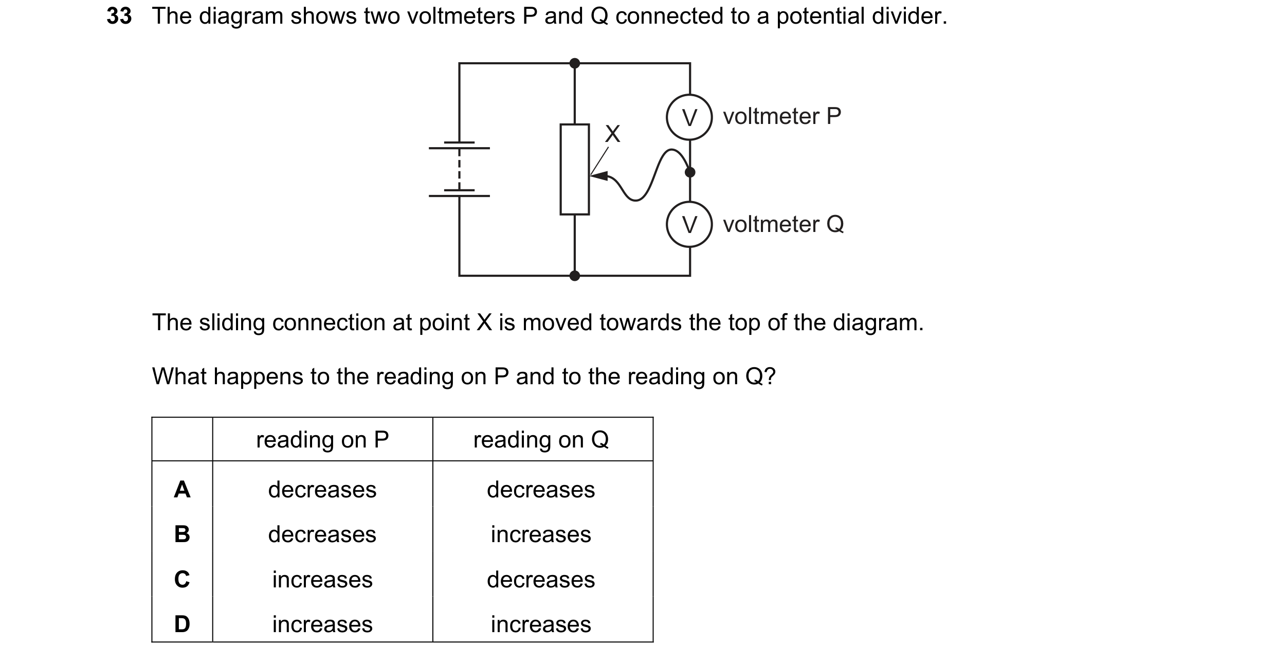
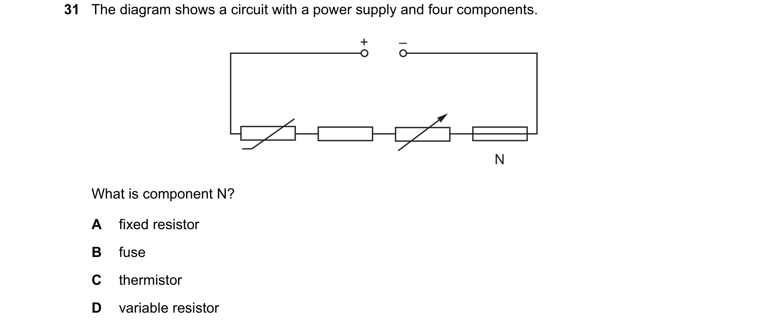 105 / 176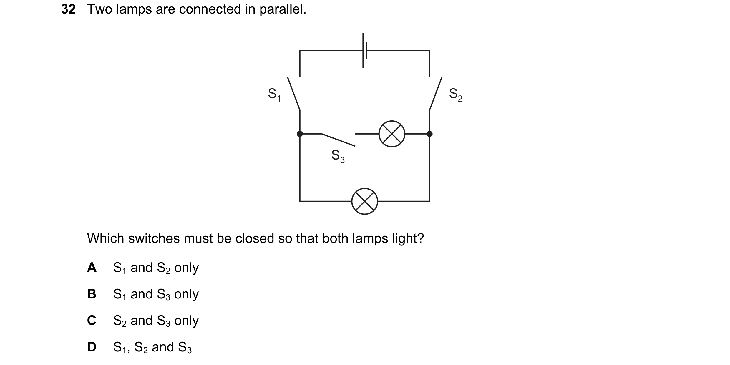
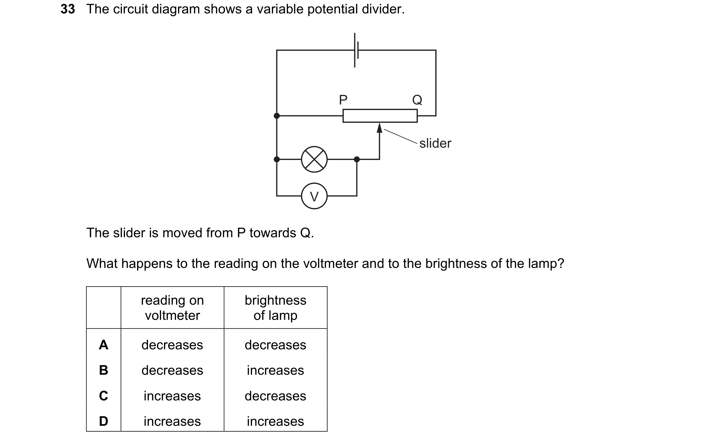 106 / 176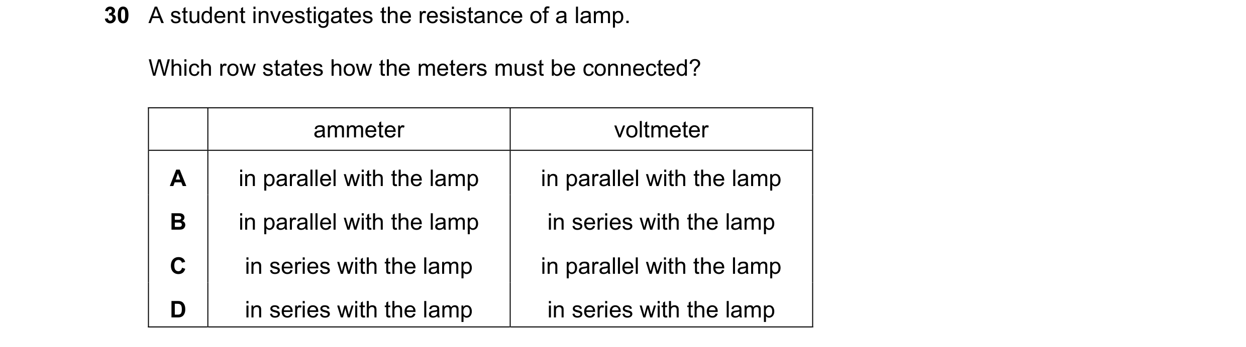
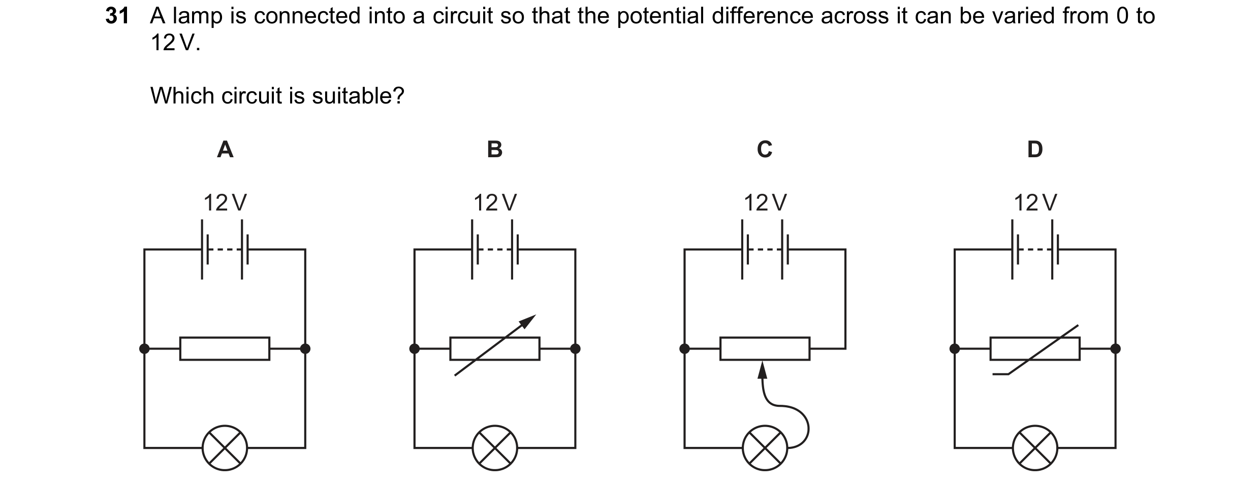
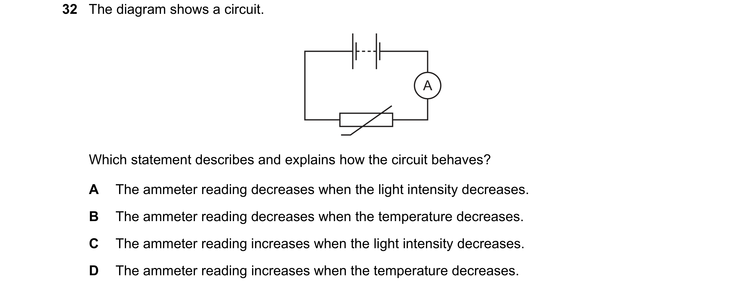
 107 / 176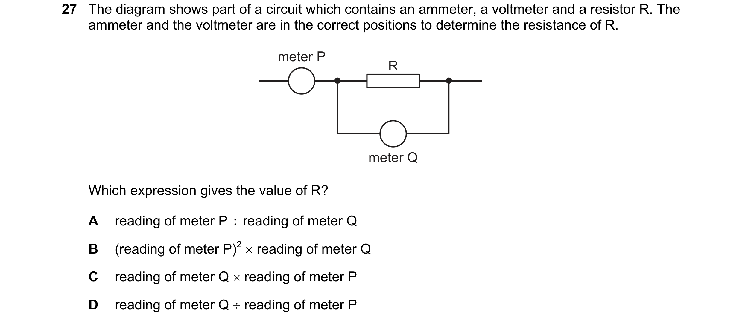
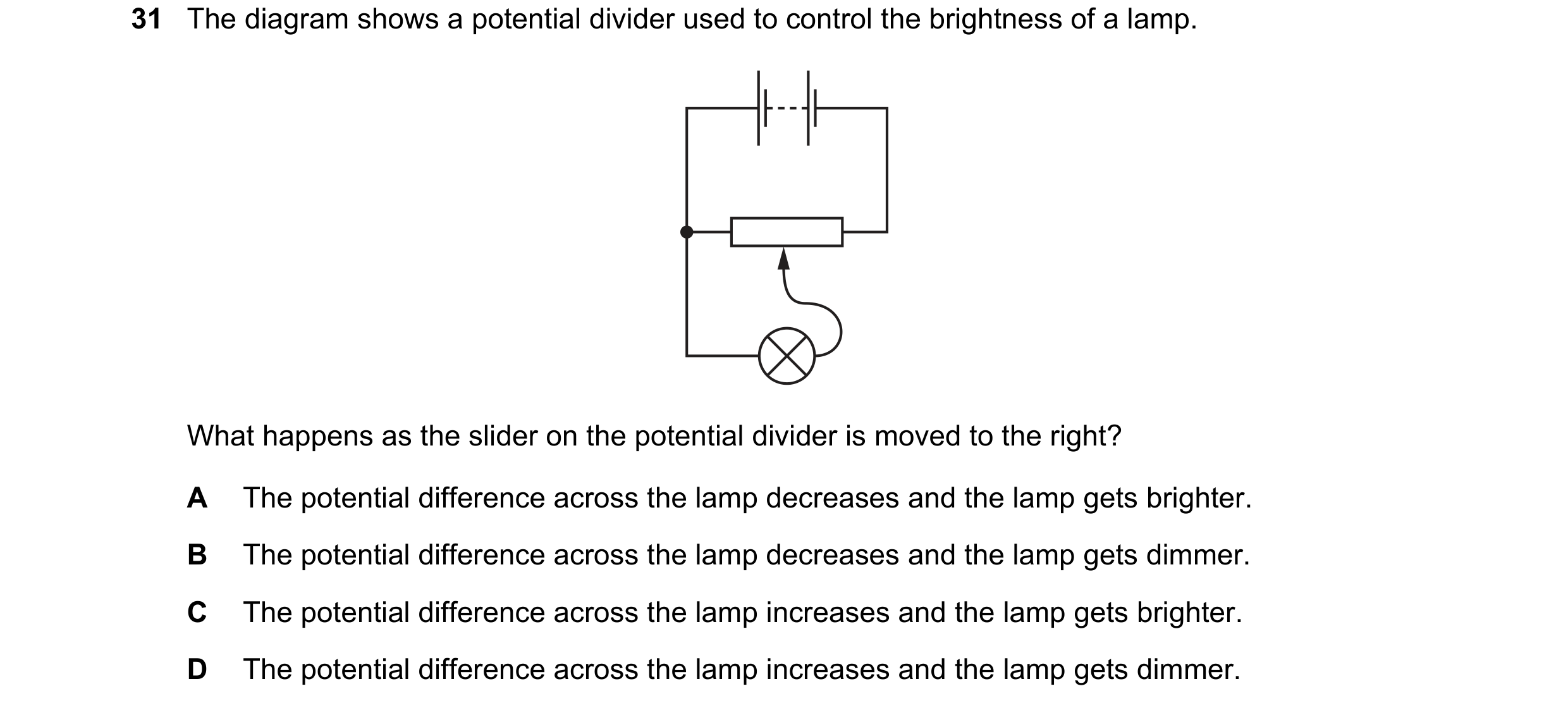 108 / 176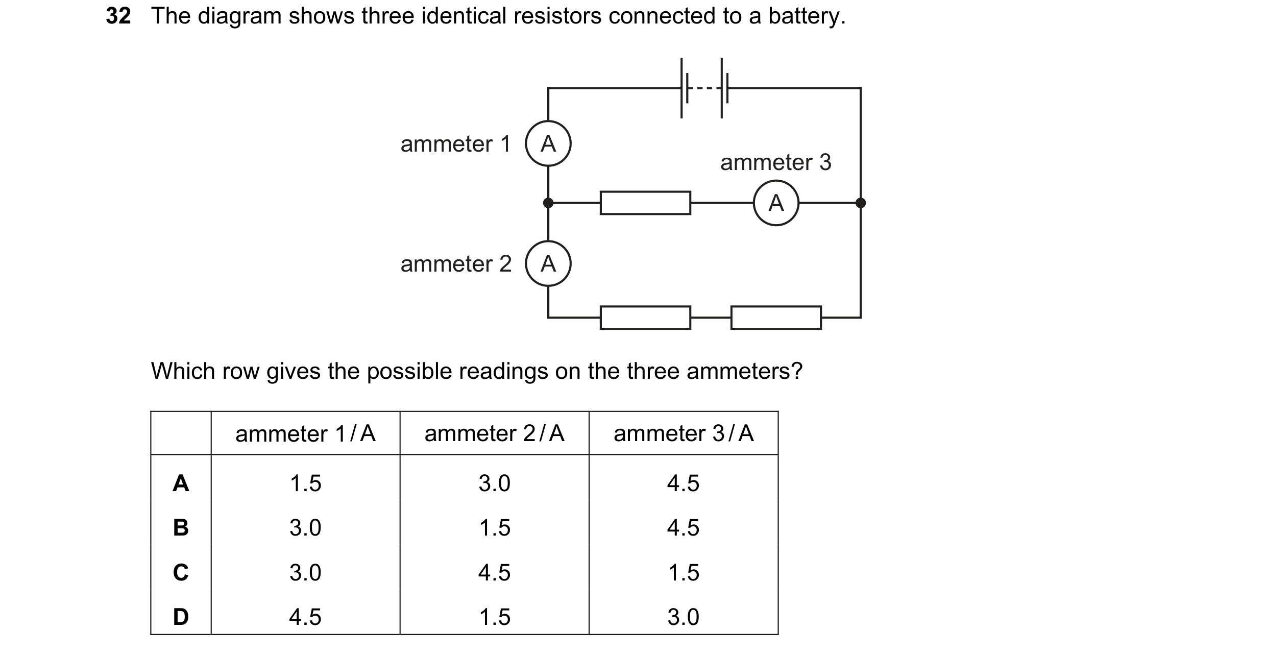
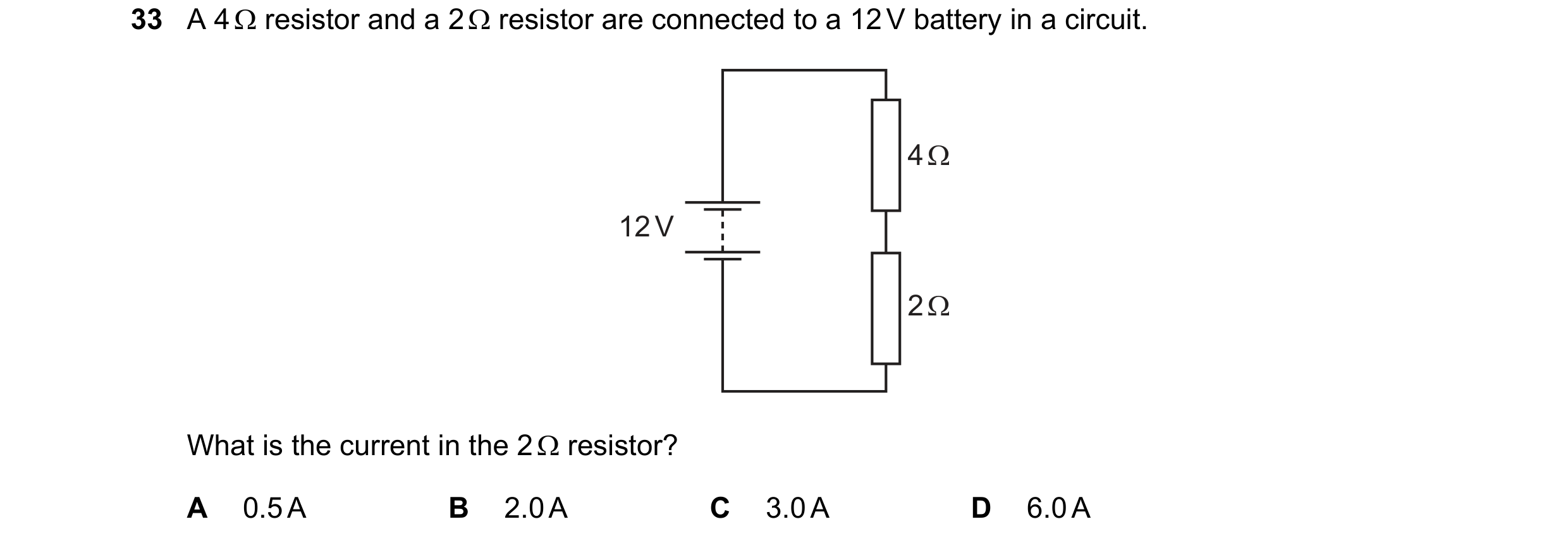
 109 / 176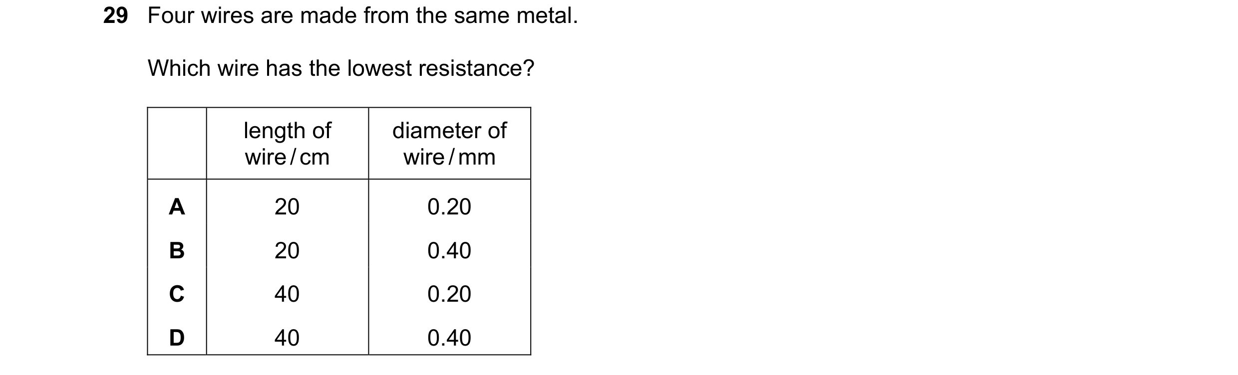
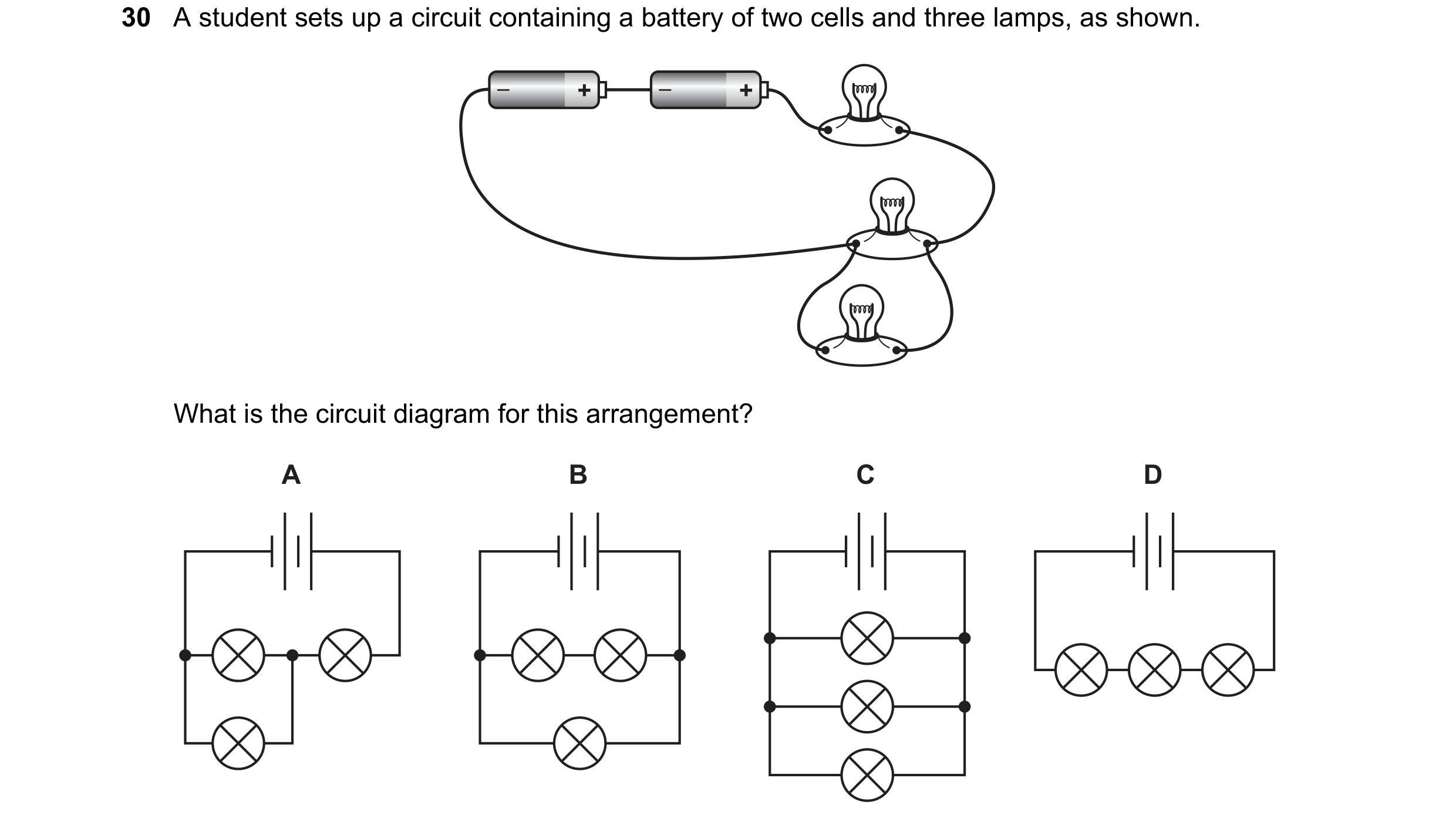
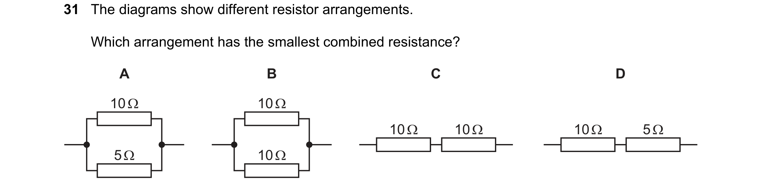 110 / 176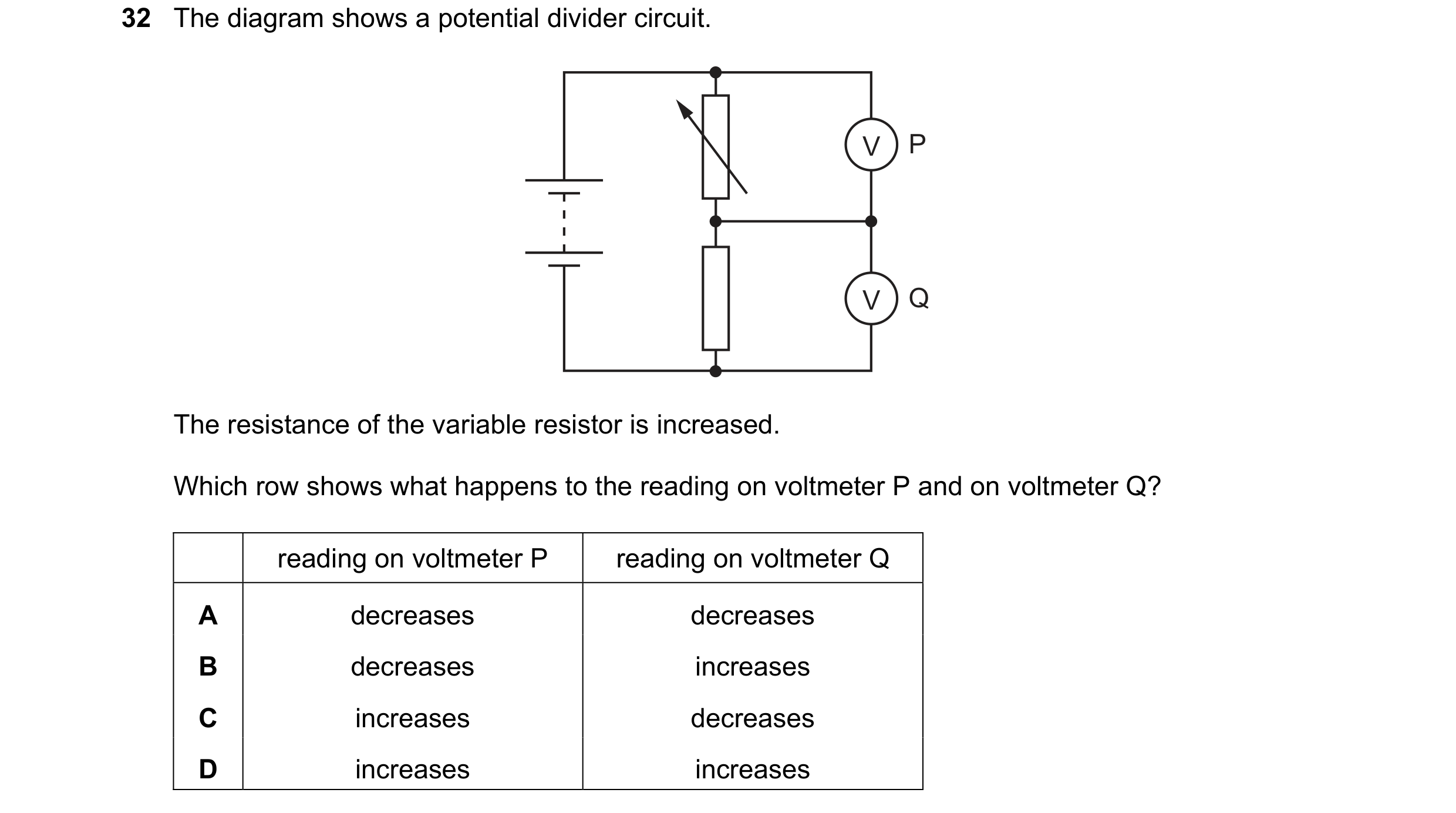
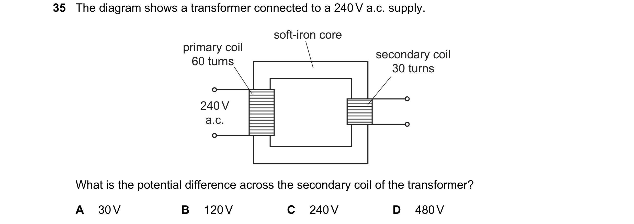
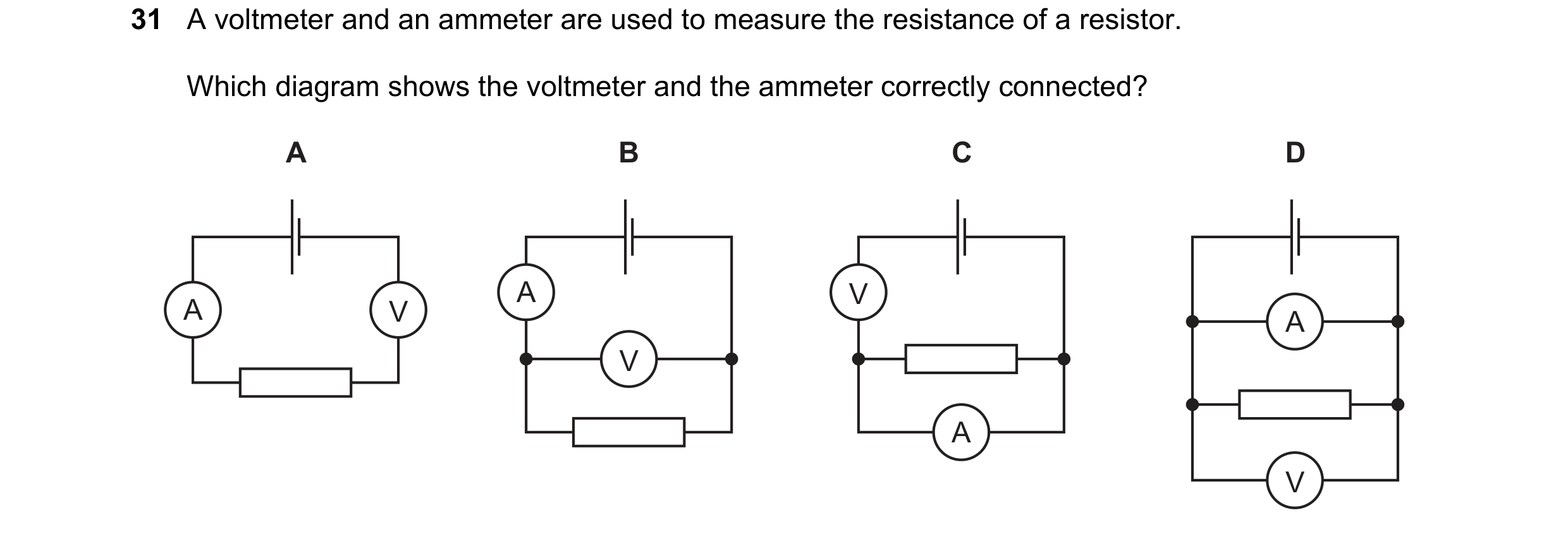 111 / 176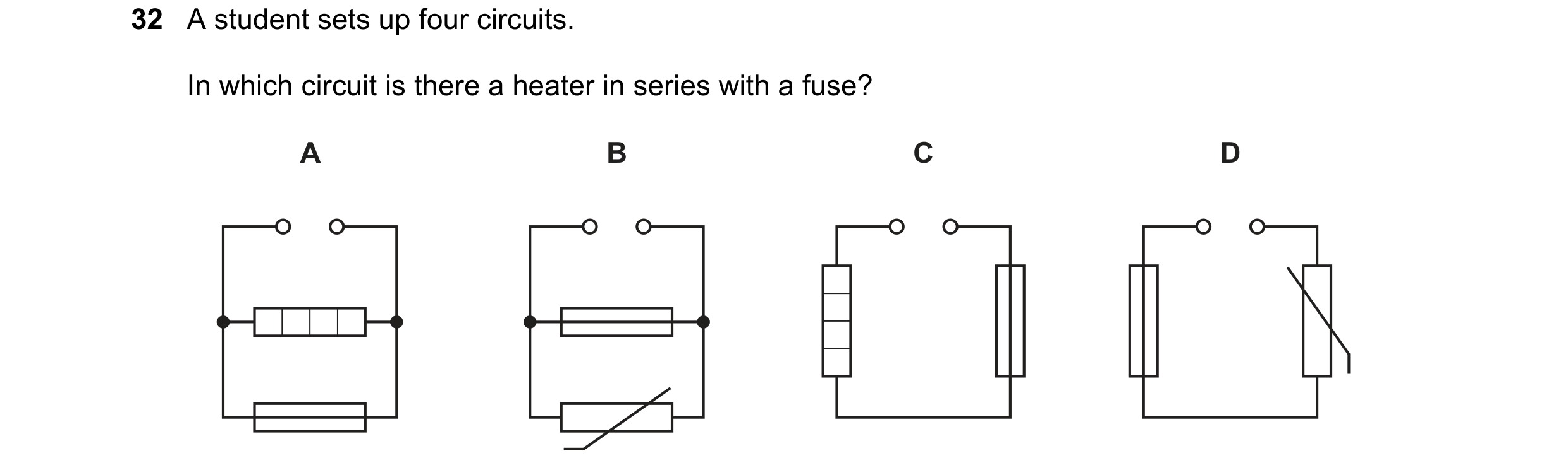
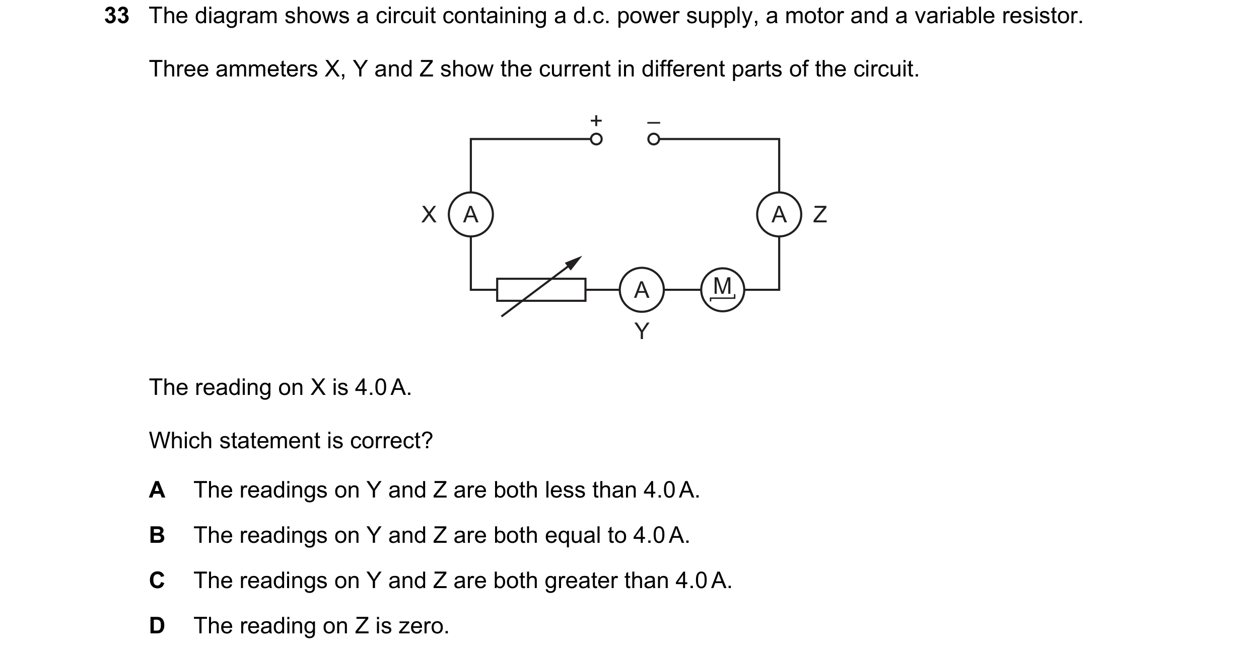 112 / 176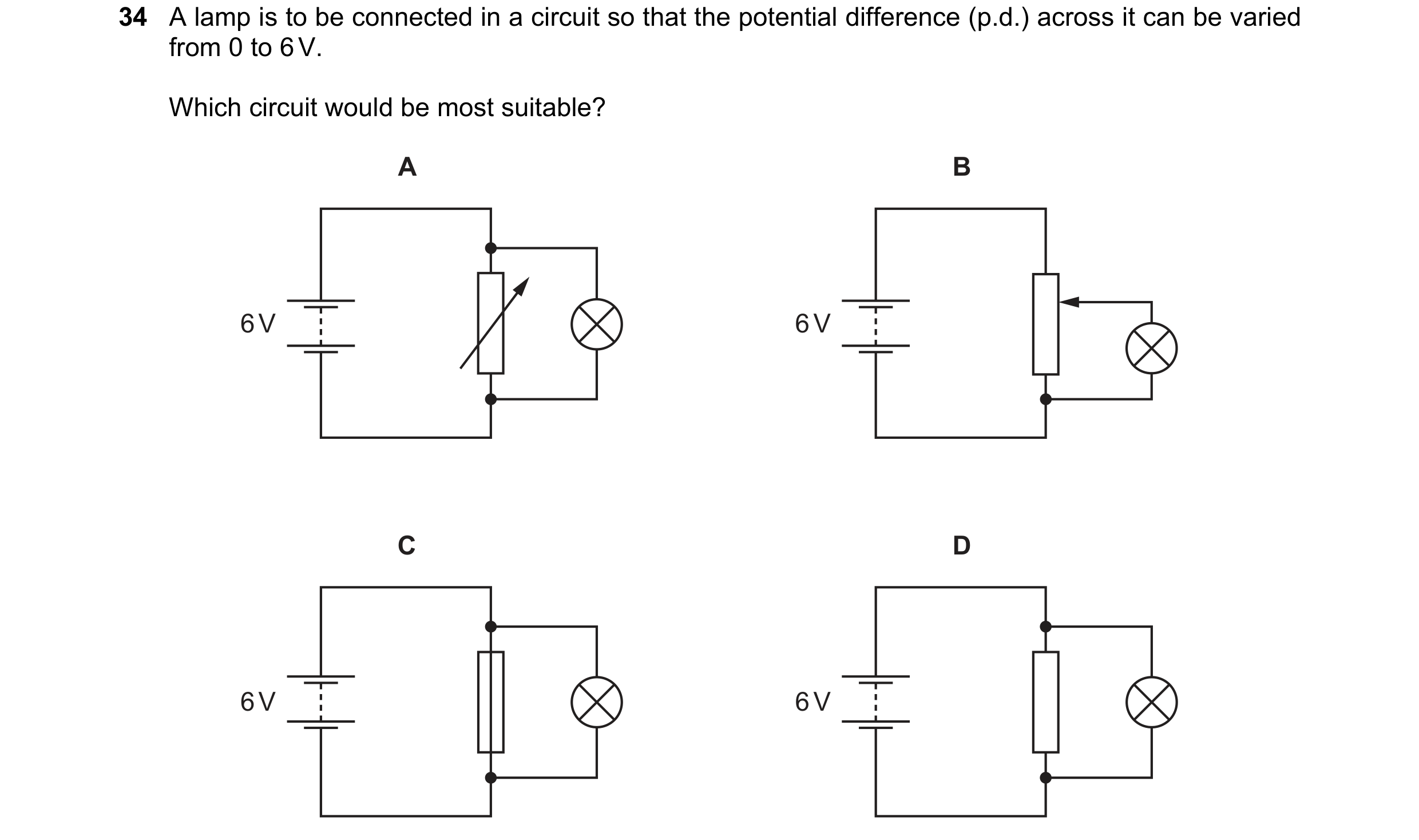
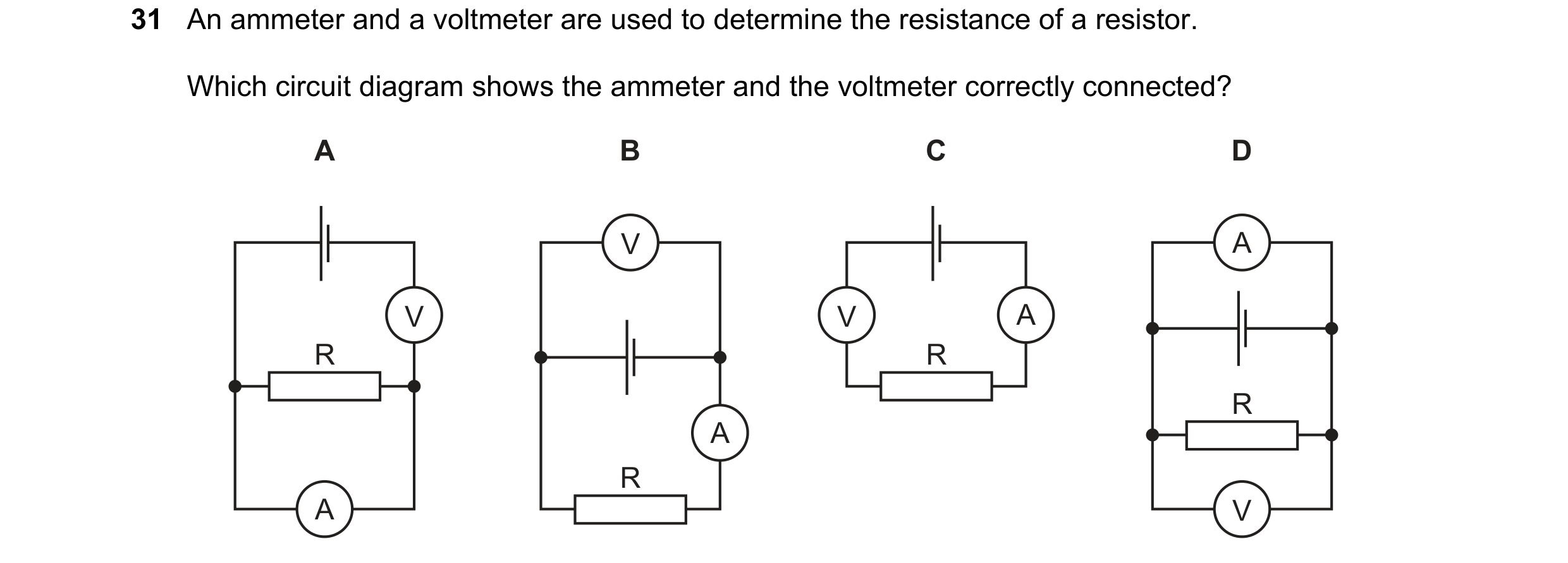 113 / 176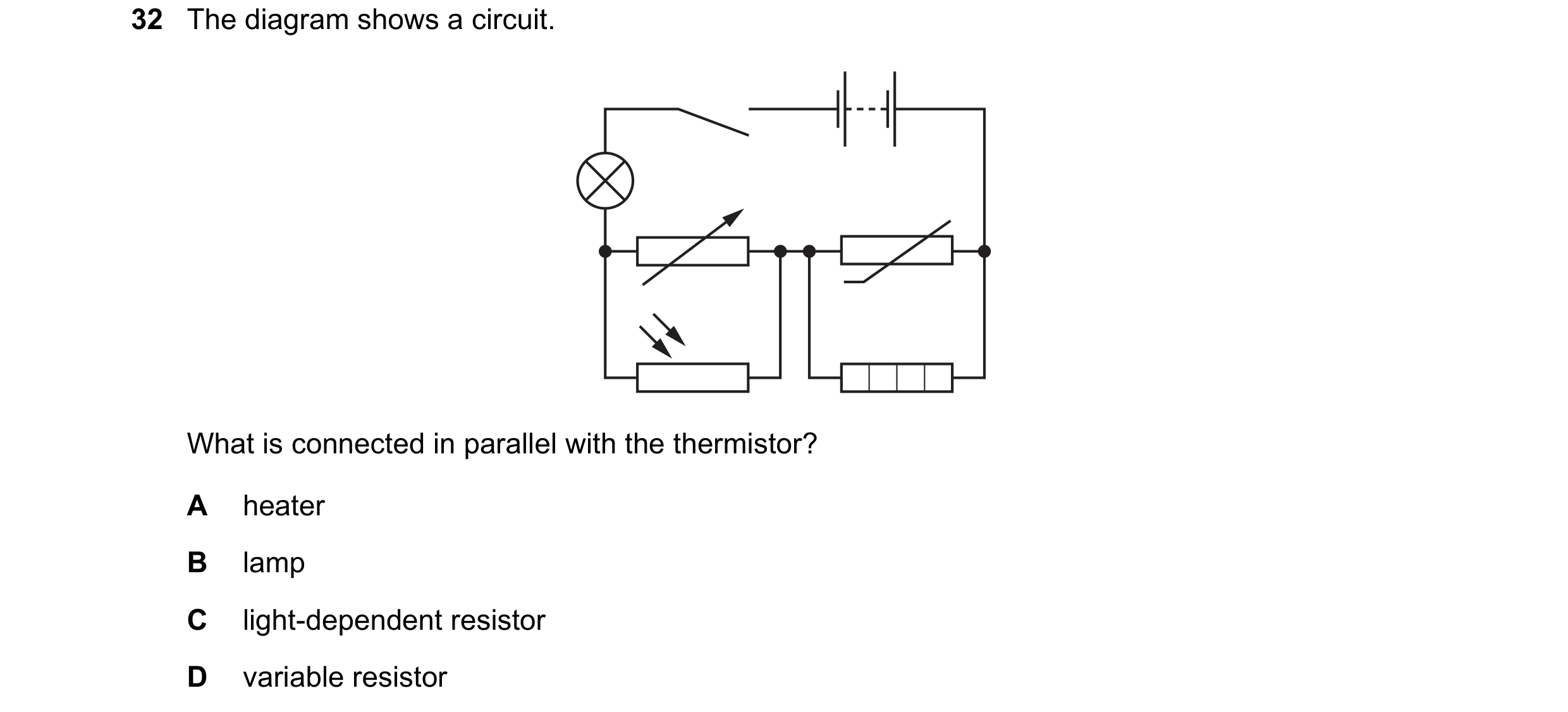
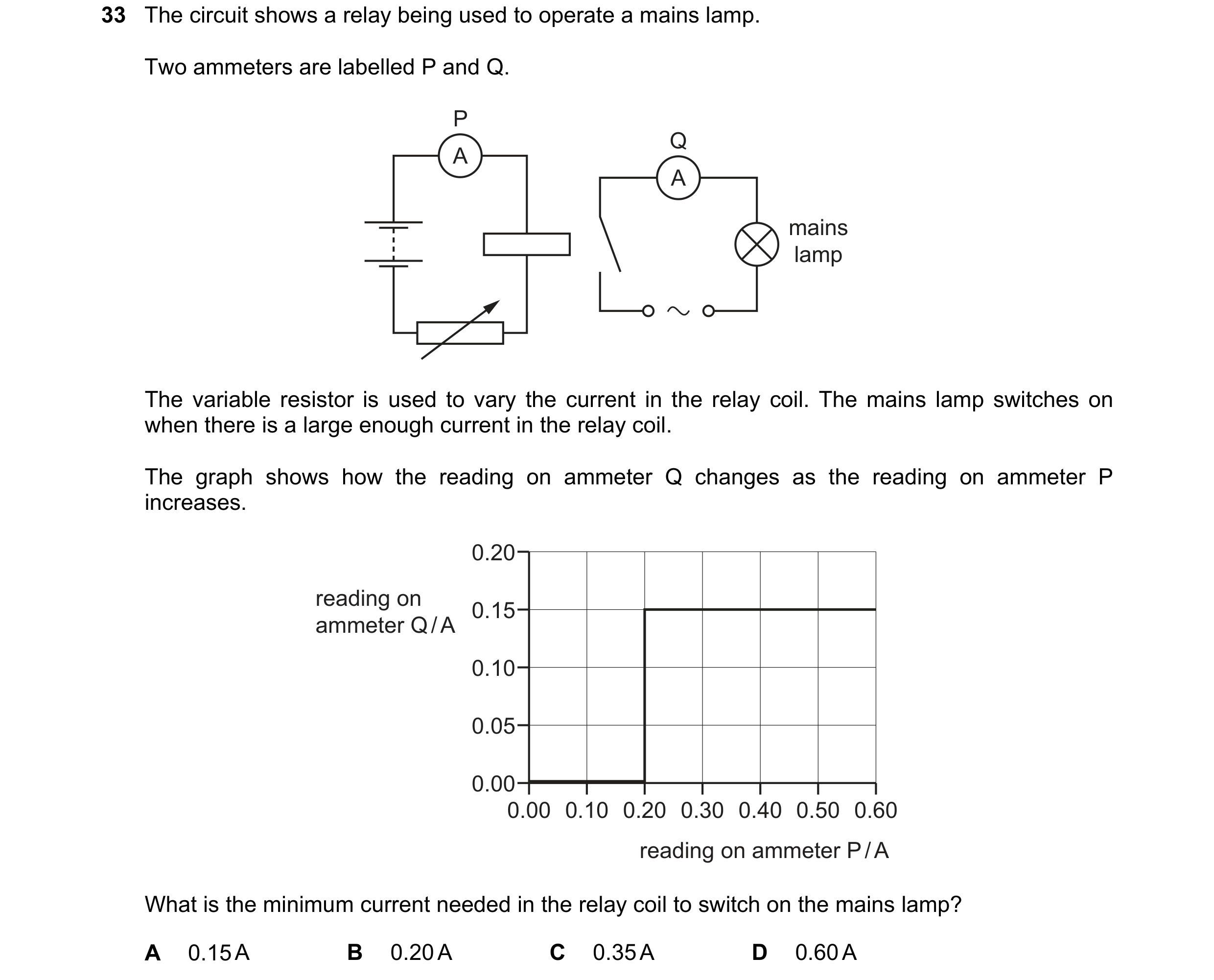 114 / 176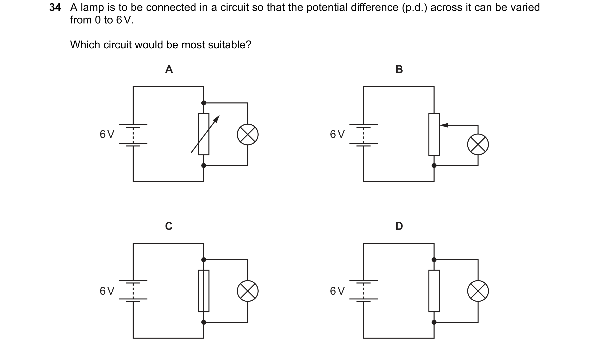
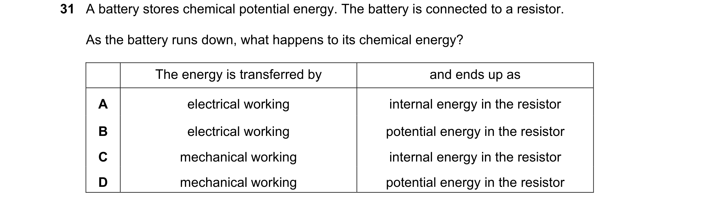 115 / 176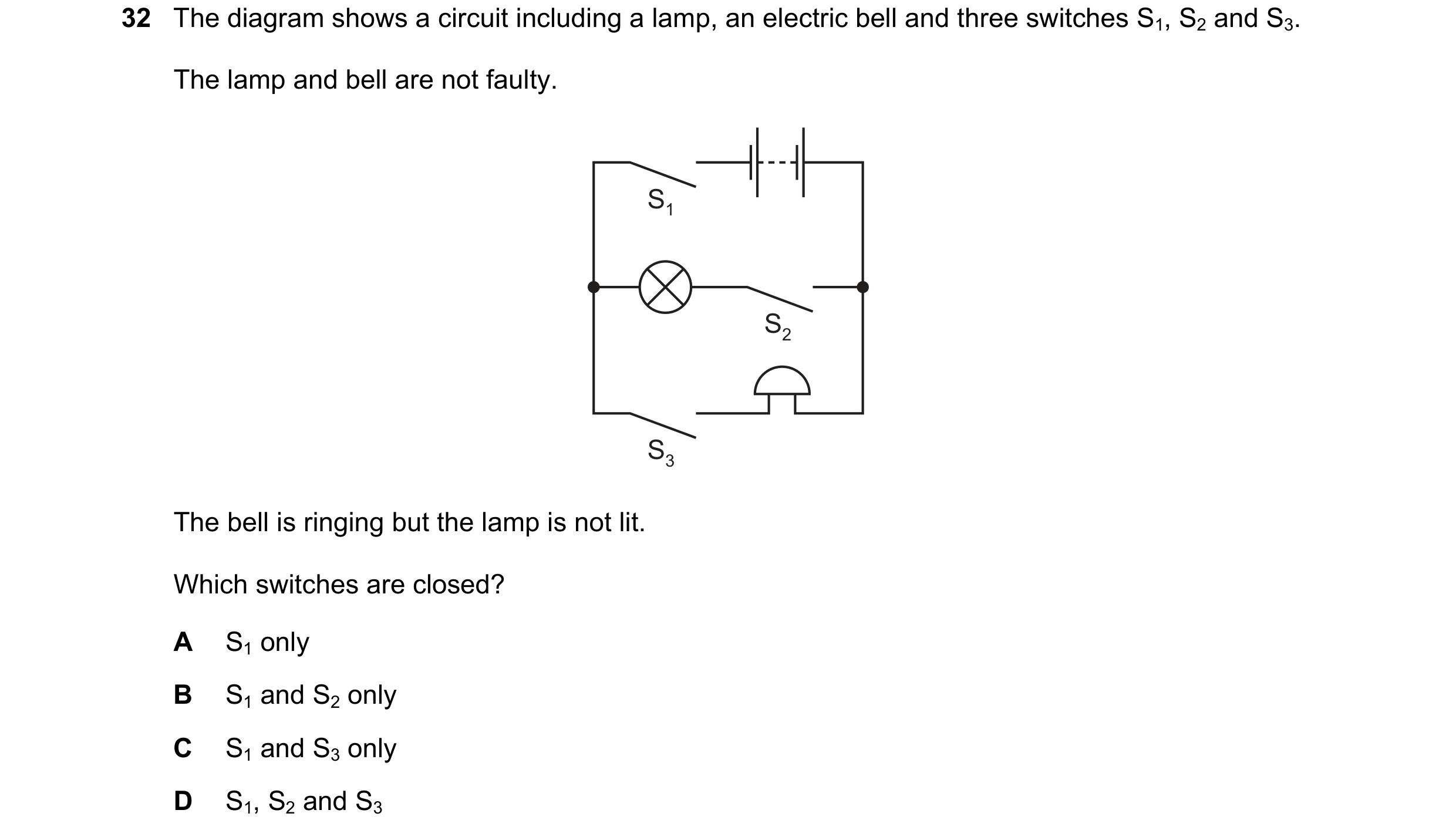
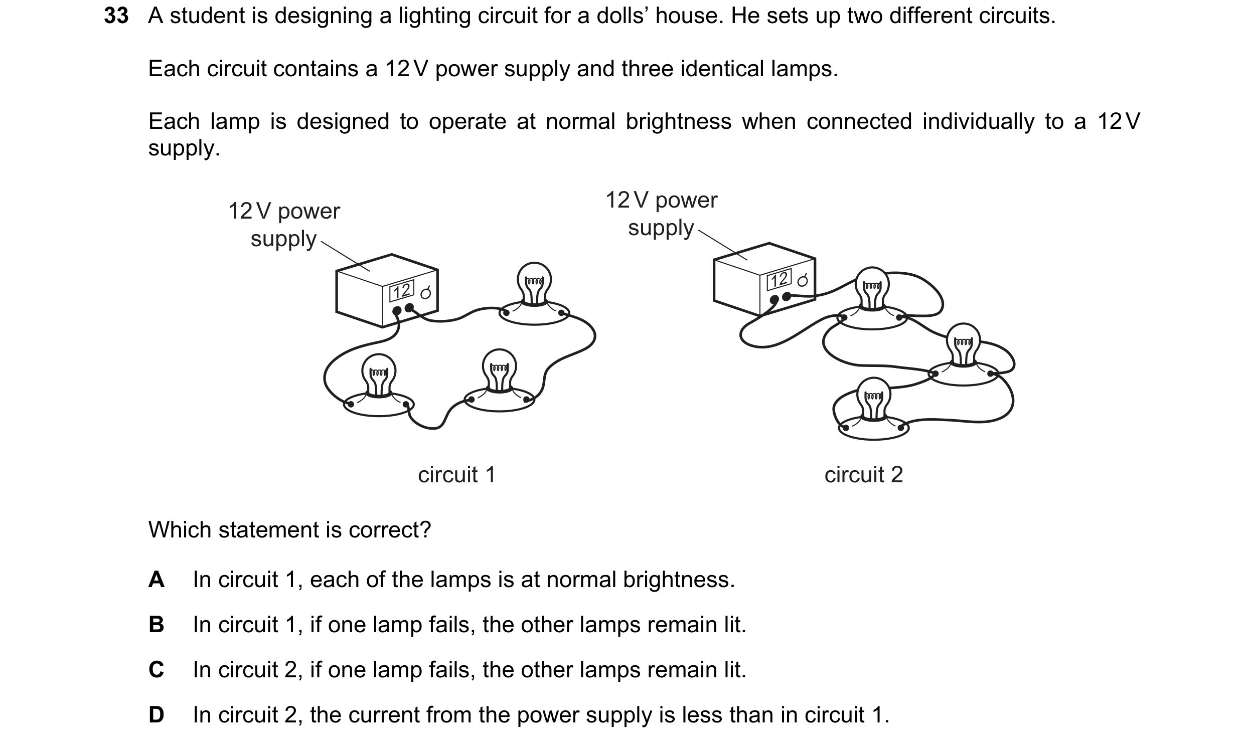 116 / 176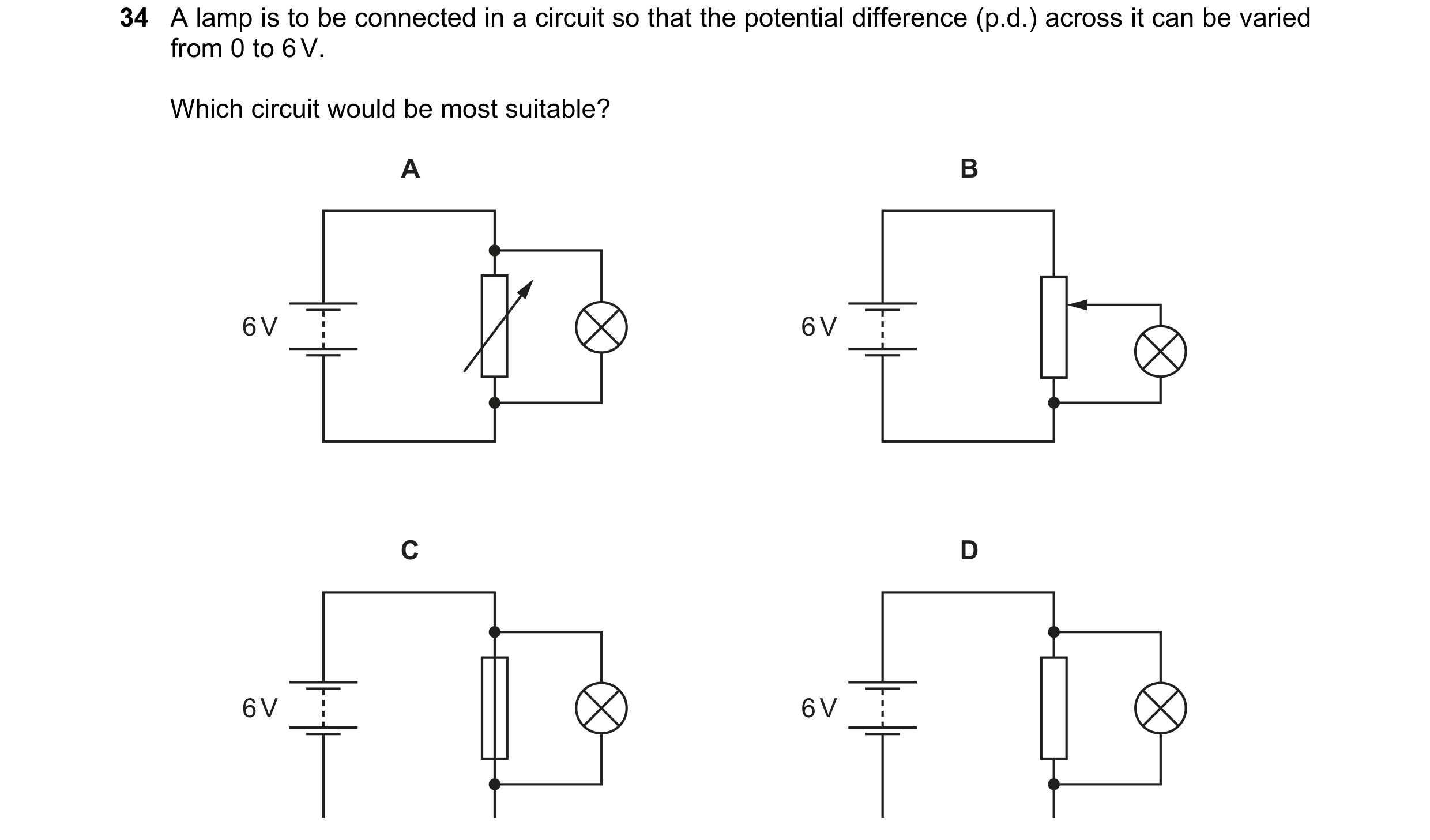
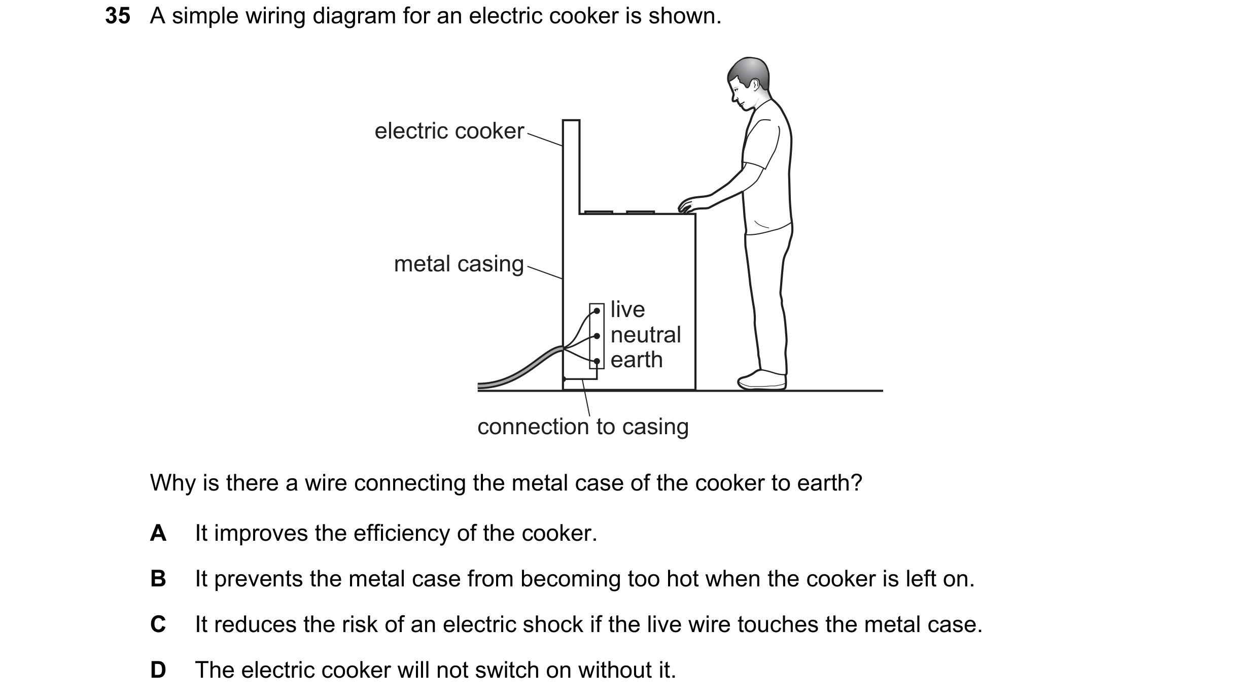
 117 / 176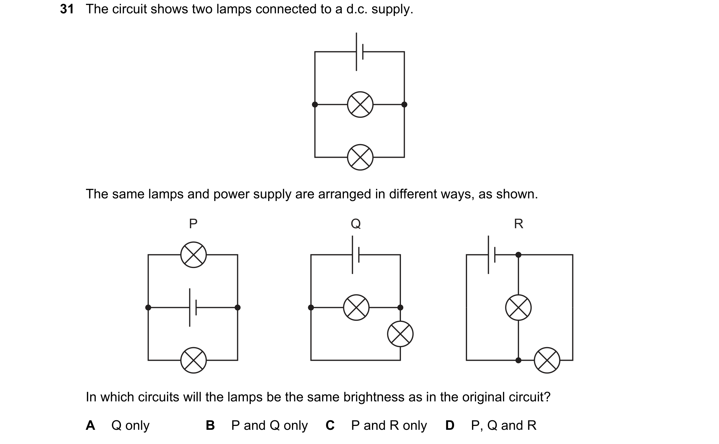
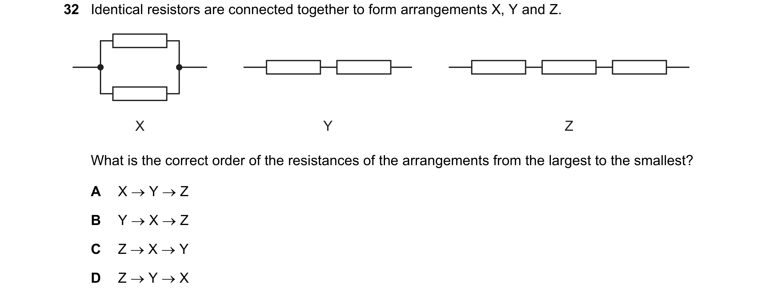 118 / 176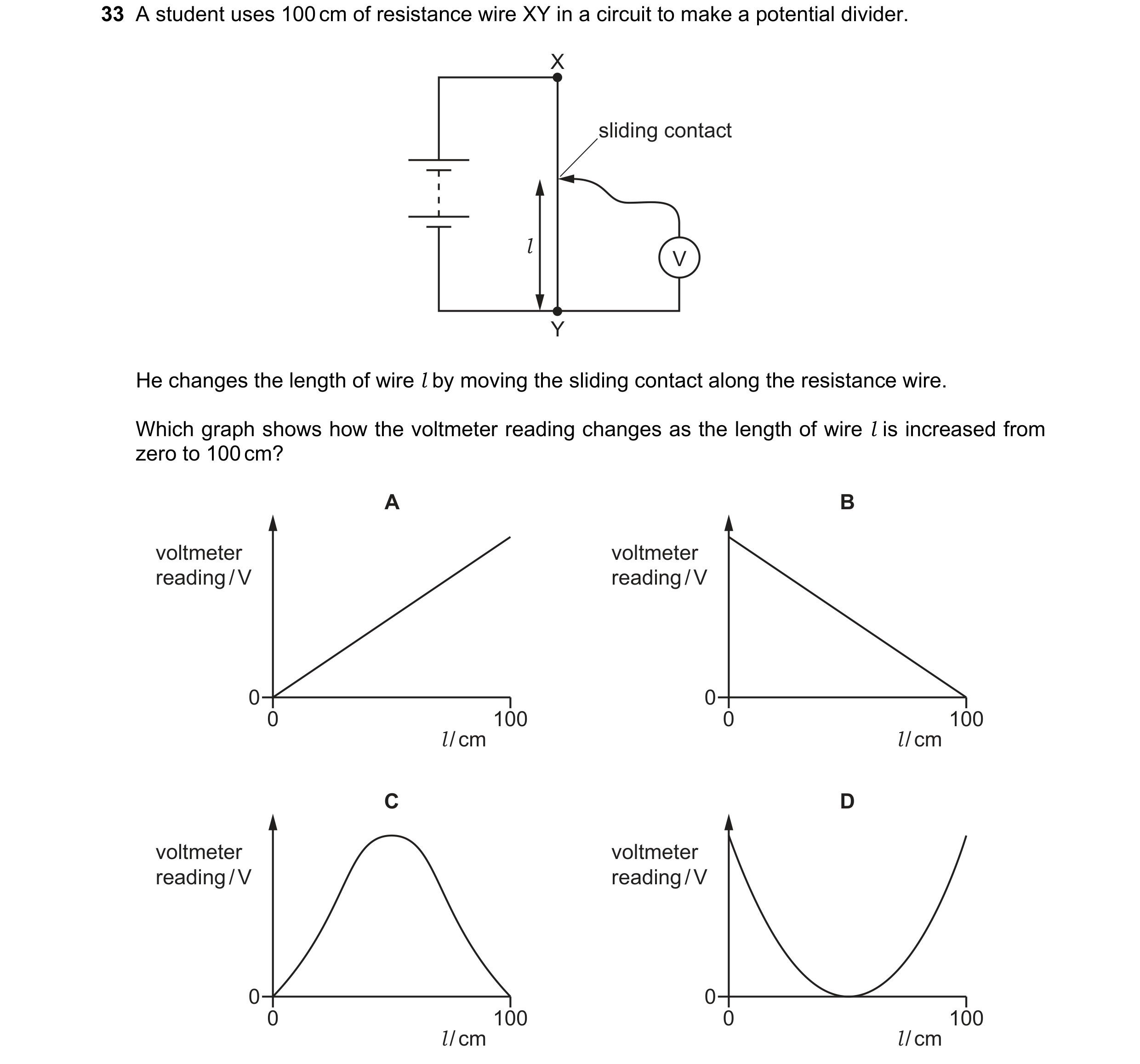
 119 / 176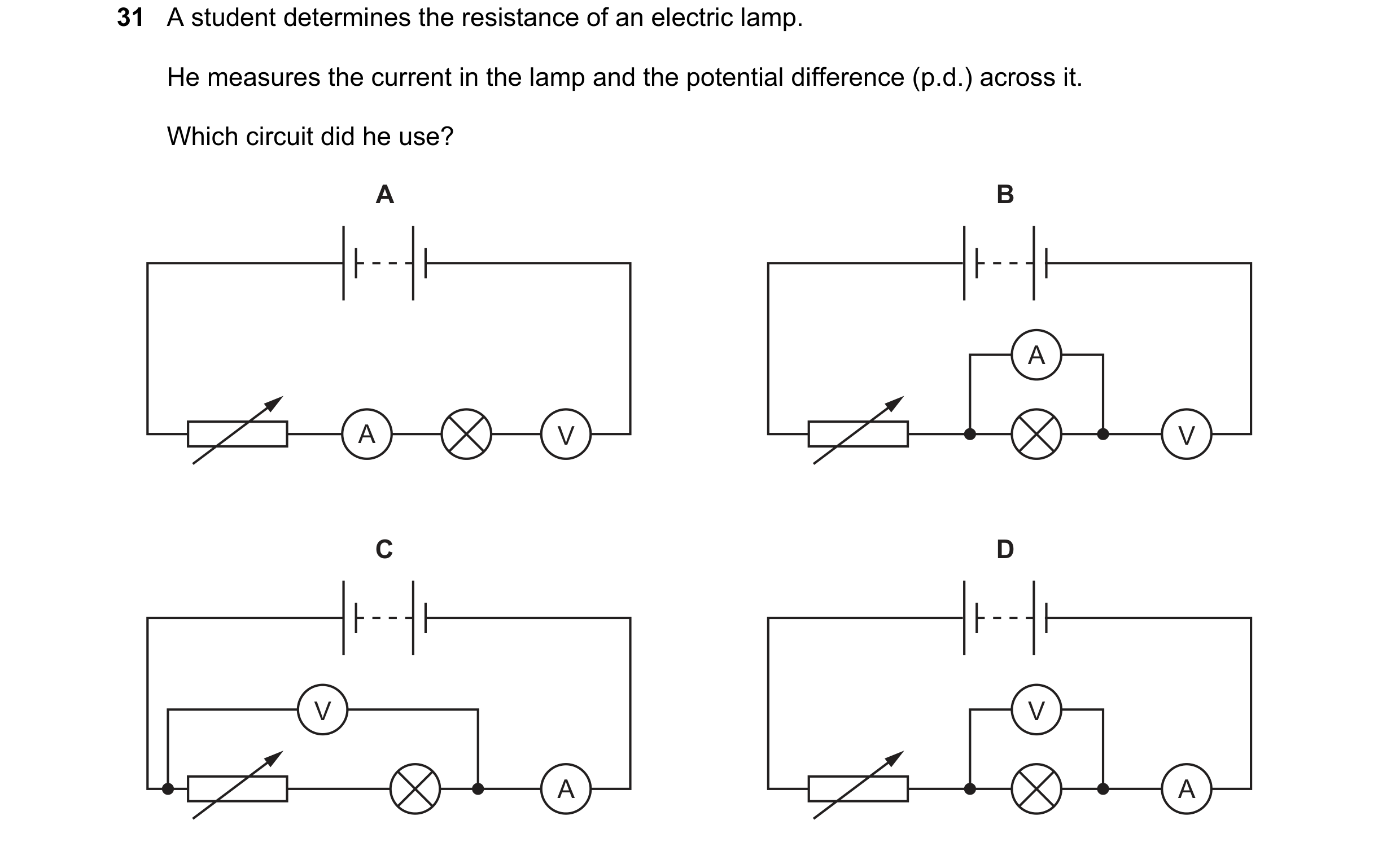
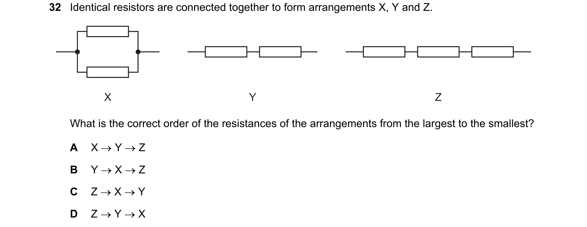
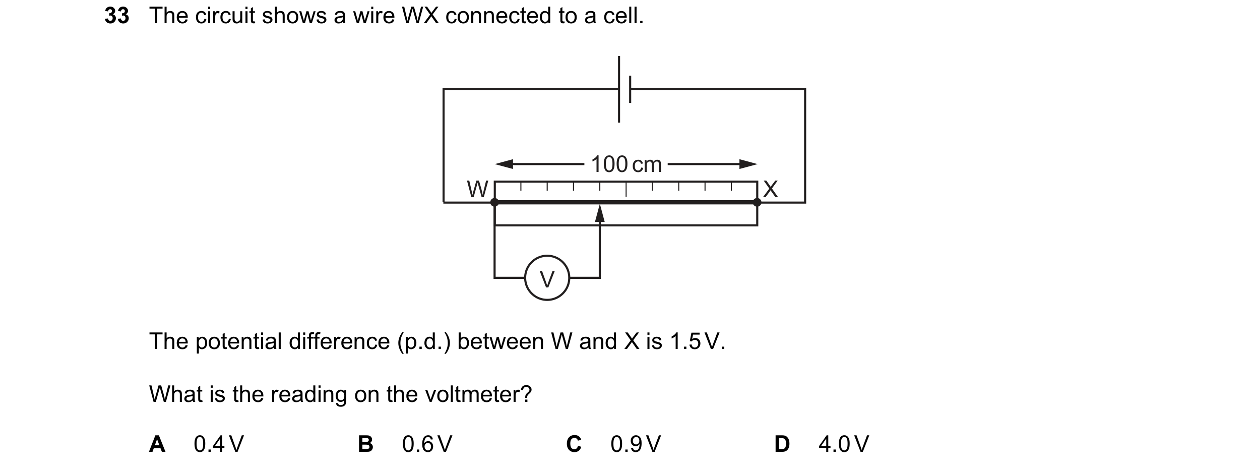 120 / 176
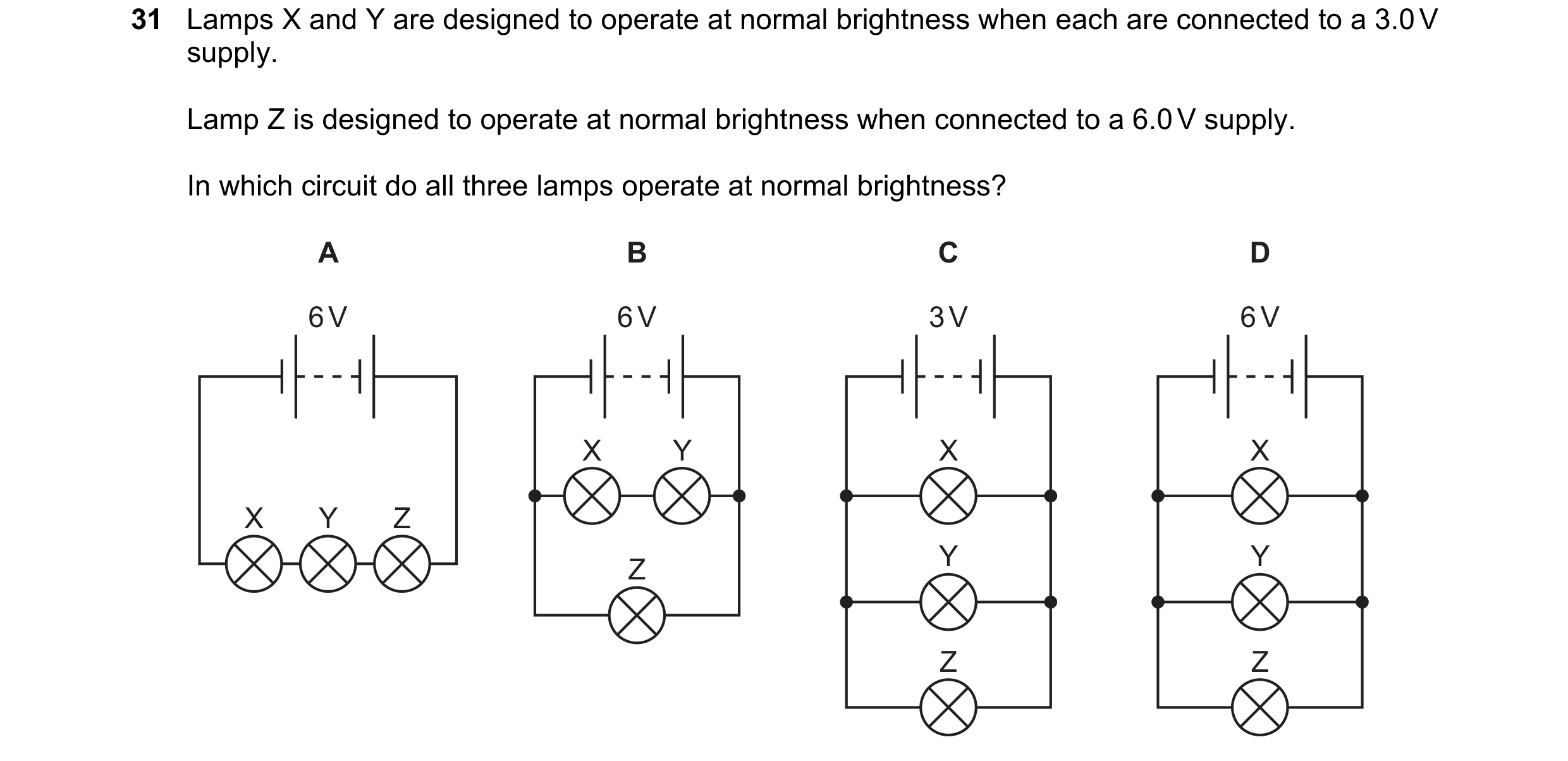
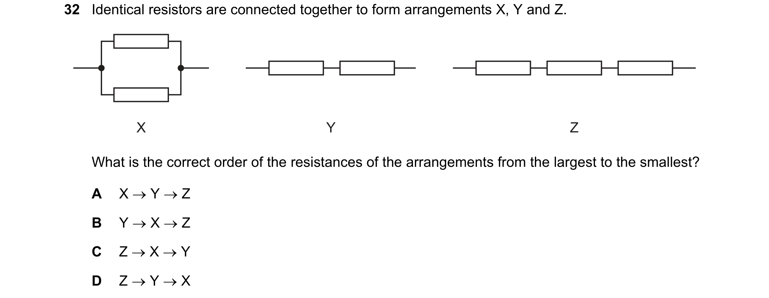 121 / 176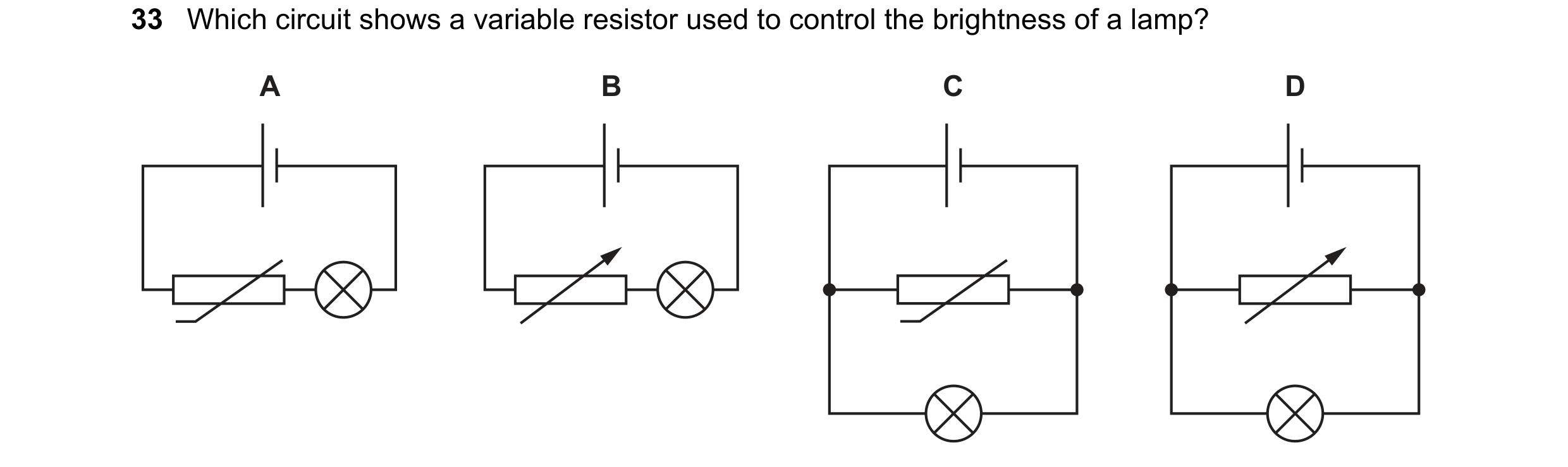


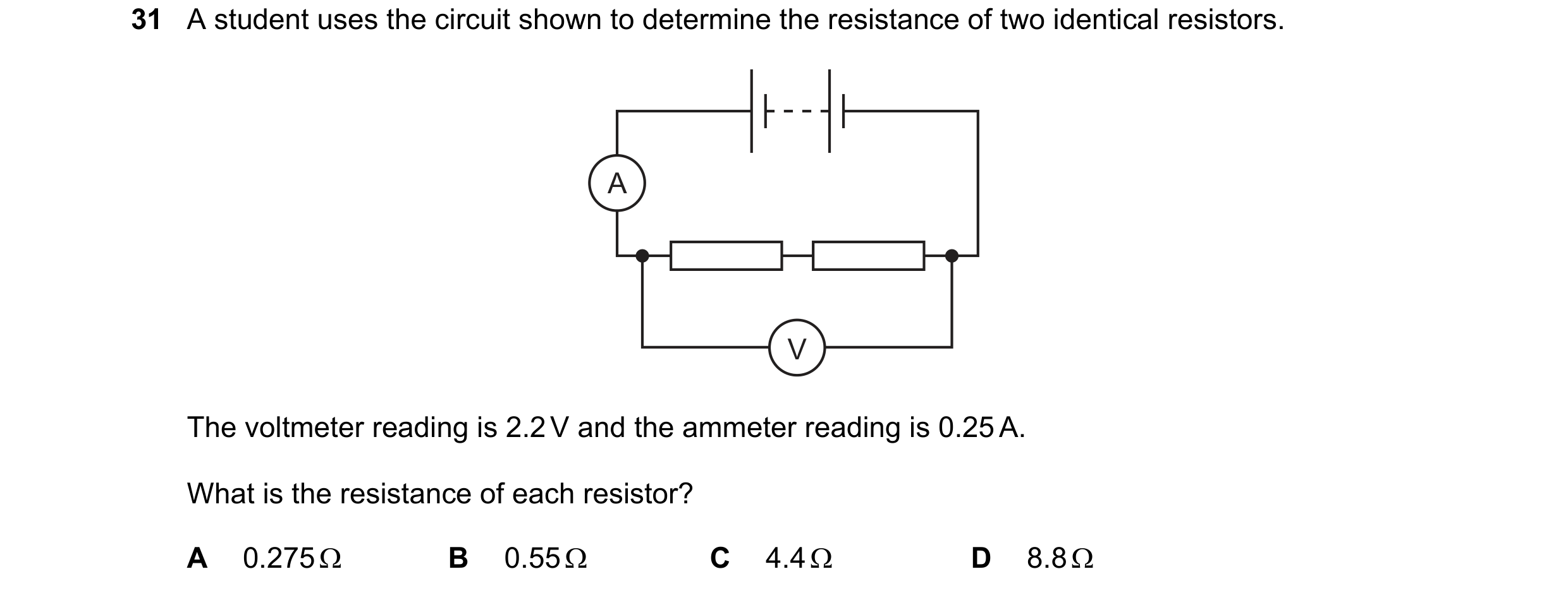 122 / 176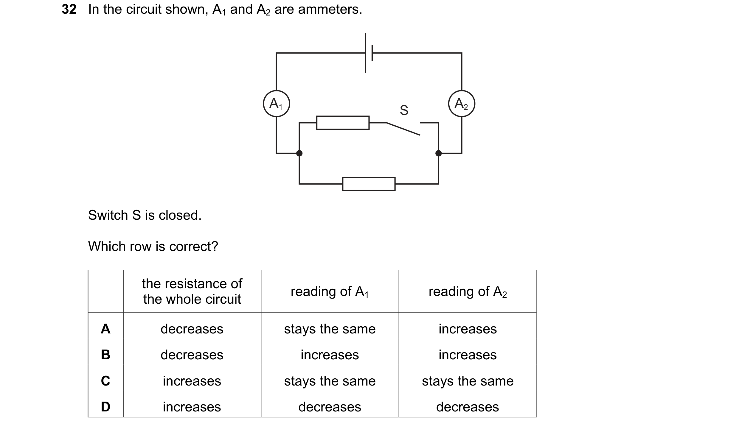

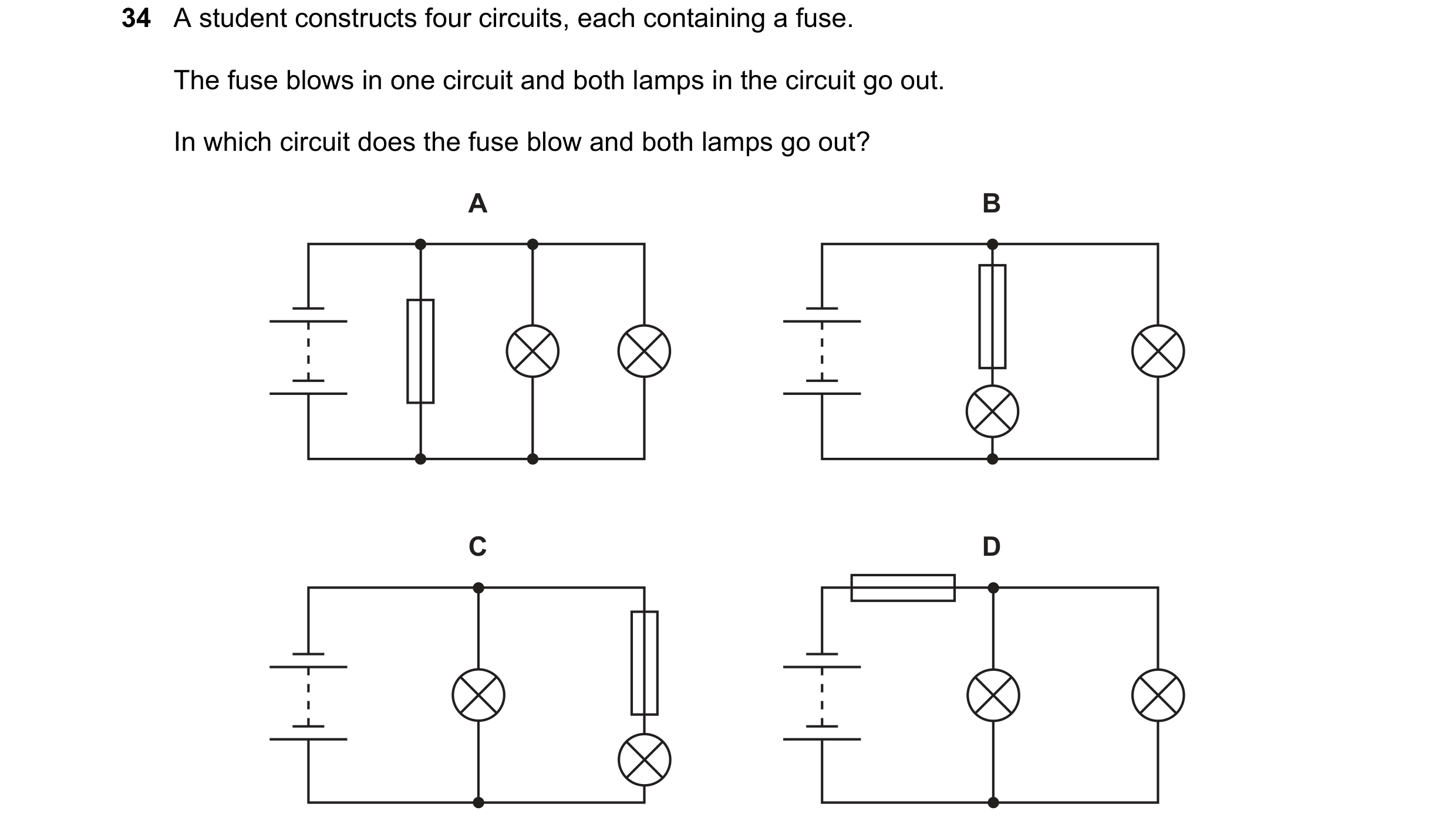 123 / 176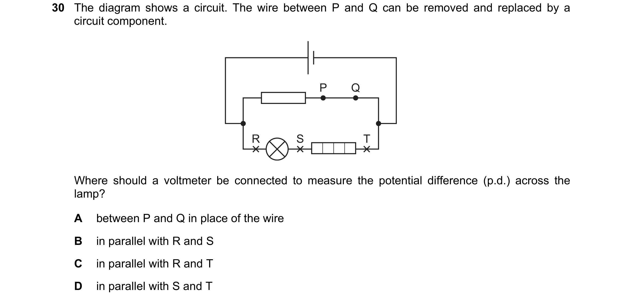
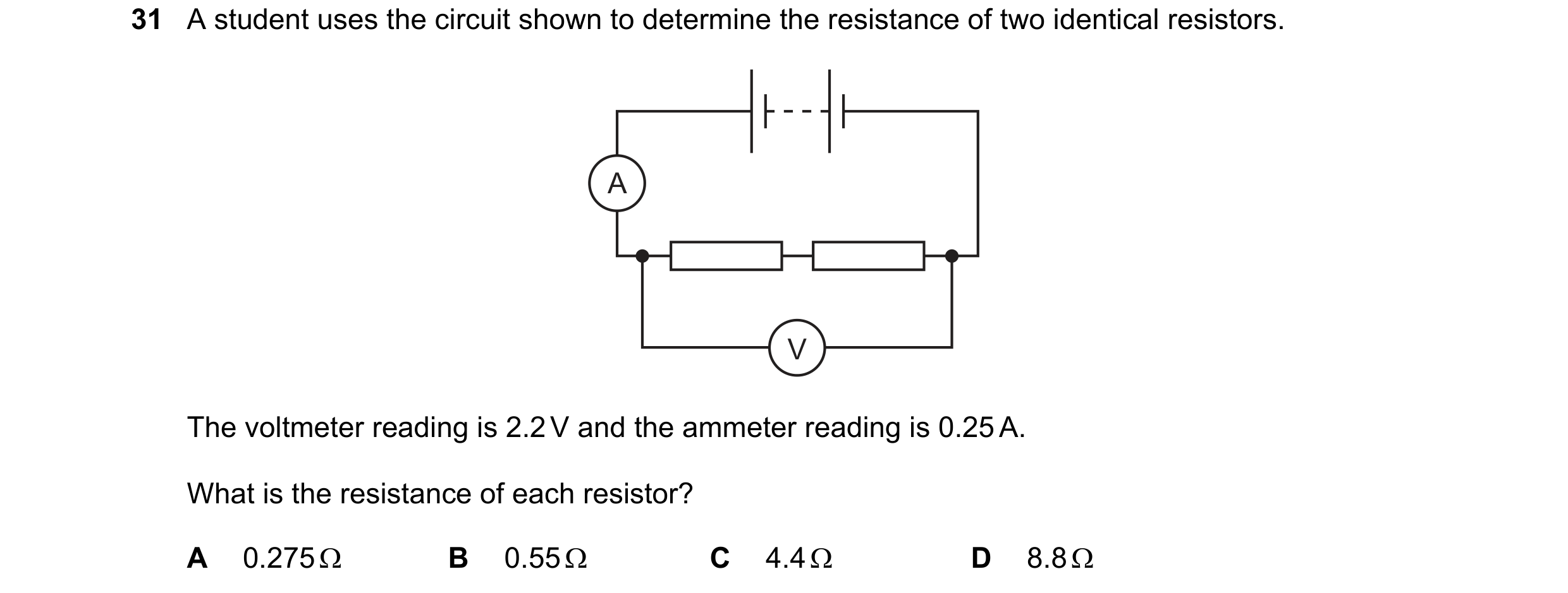 124 / 176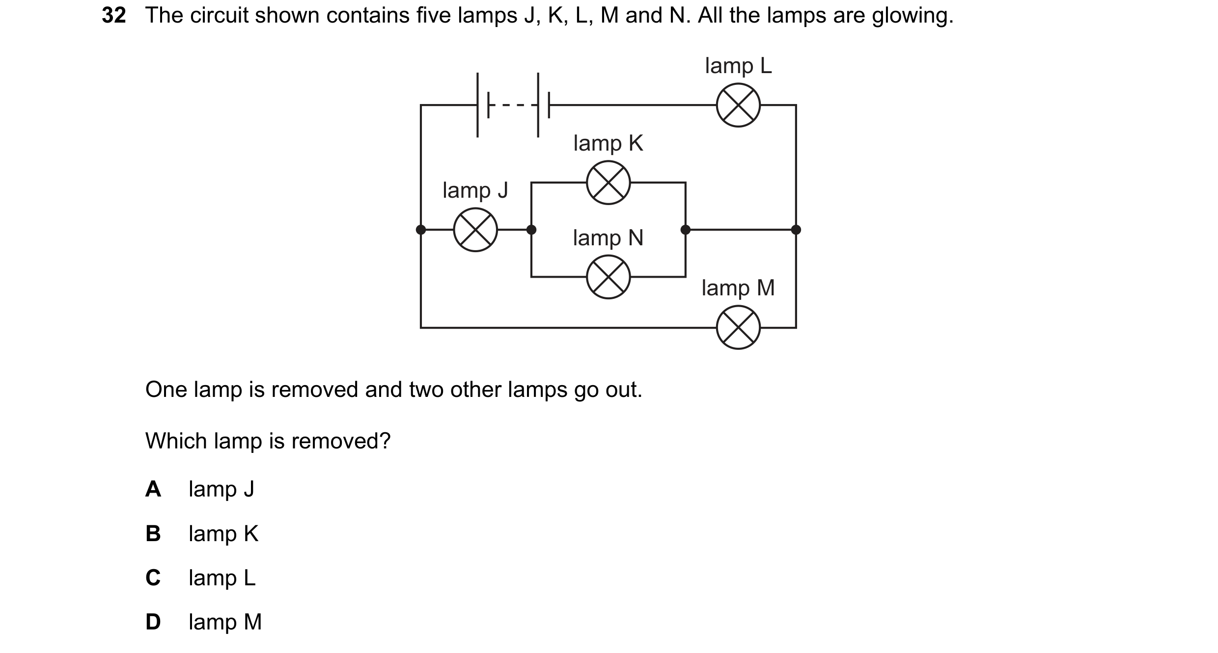
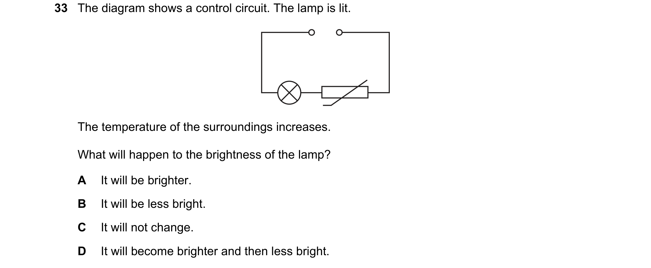 125 / 176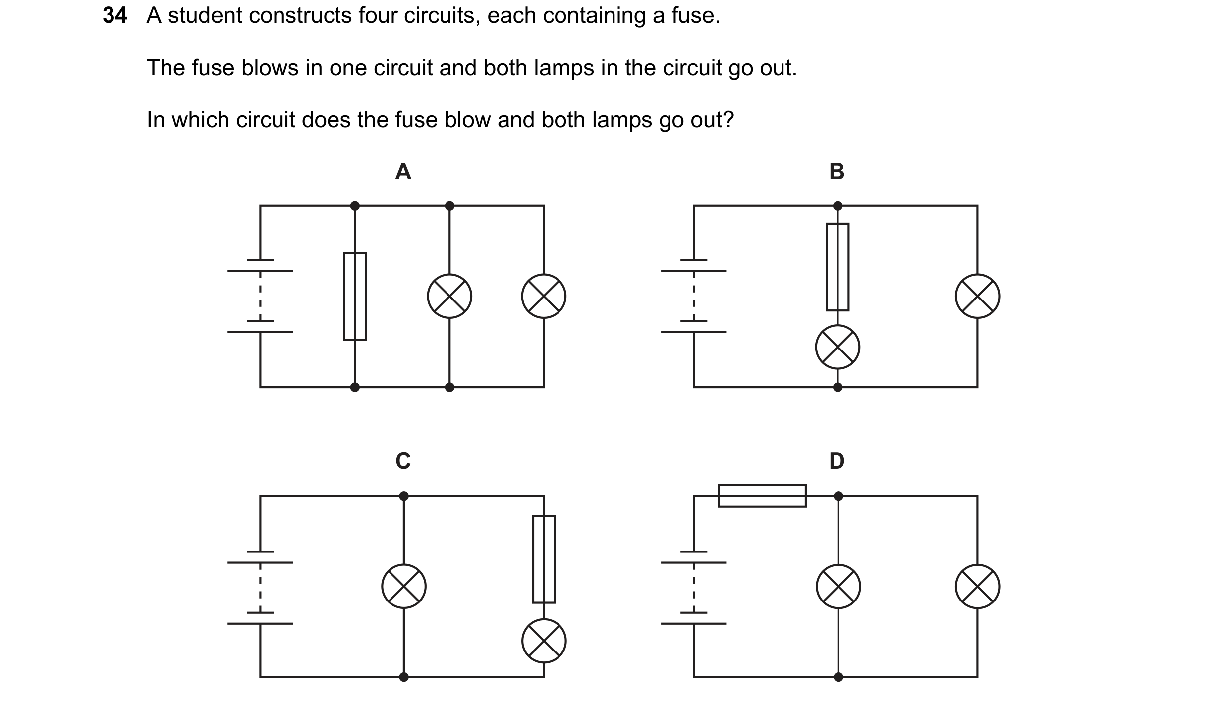
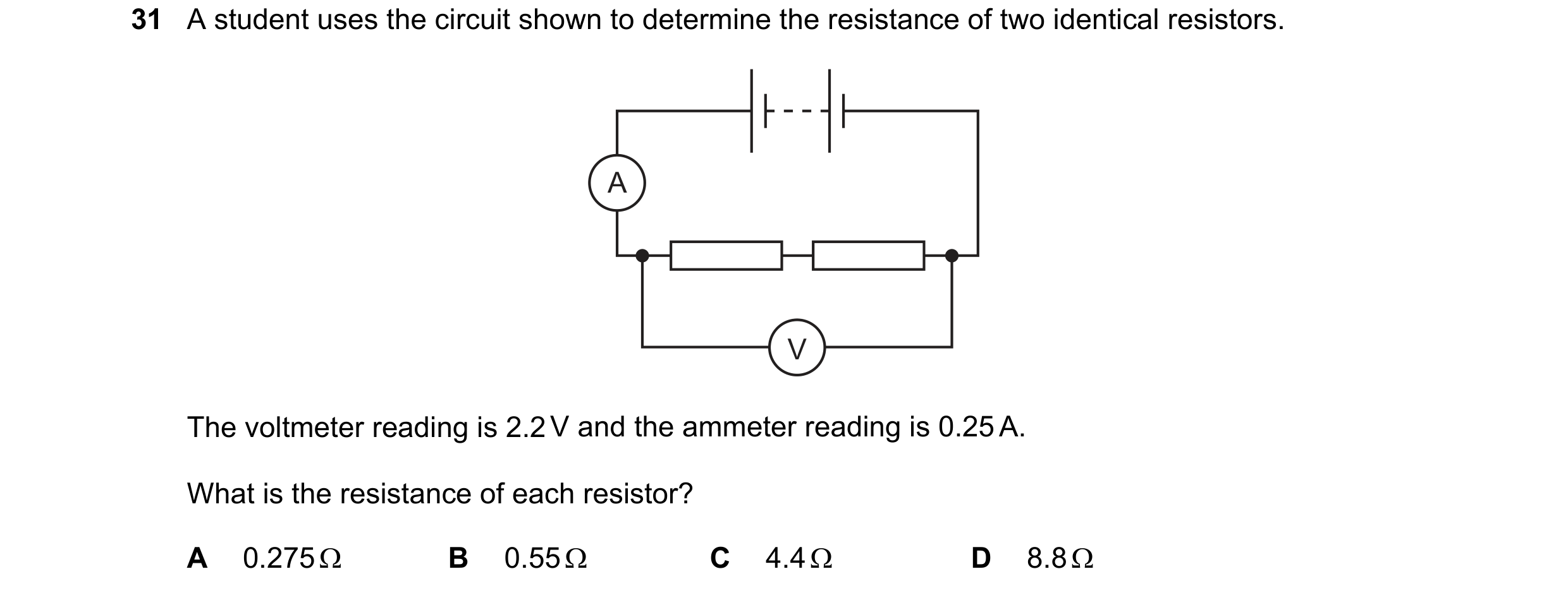
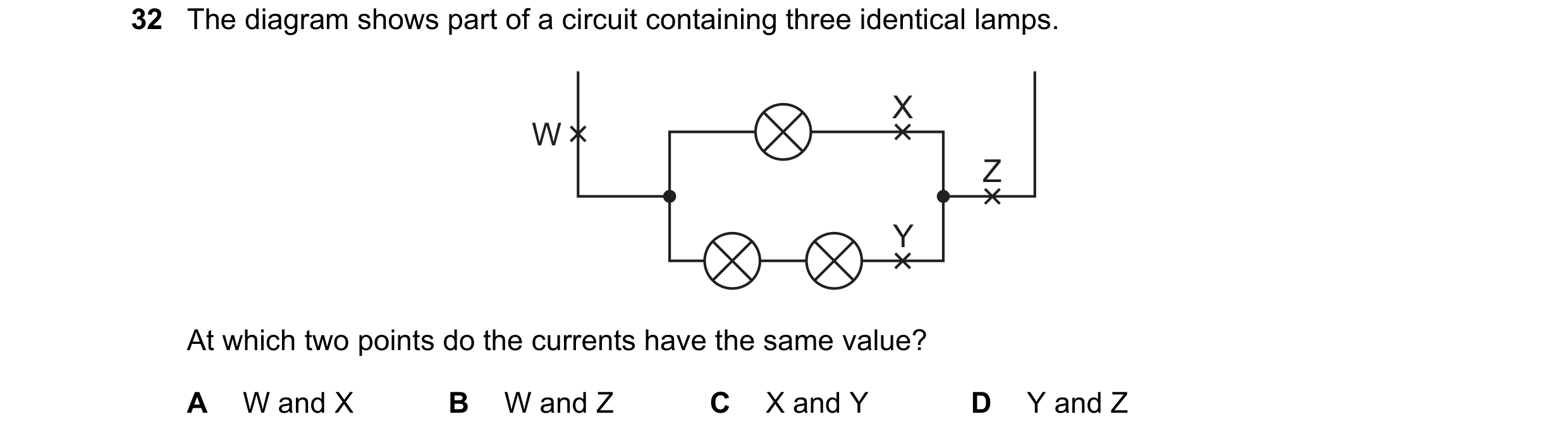 126 / 176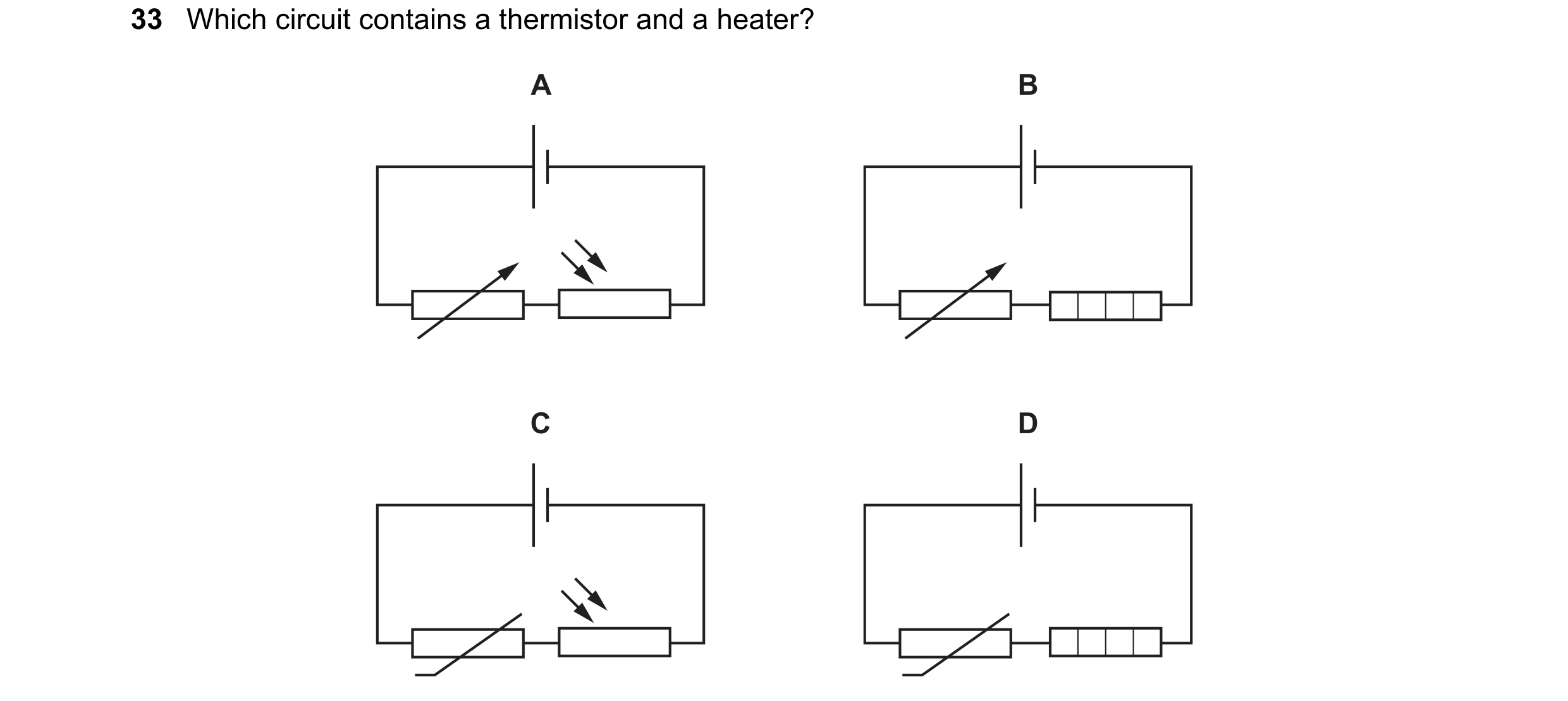
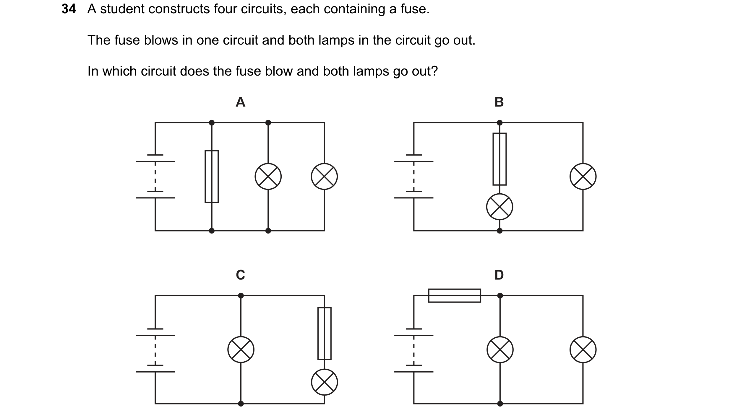 127 / 176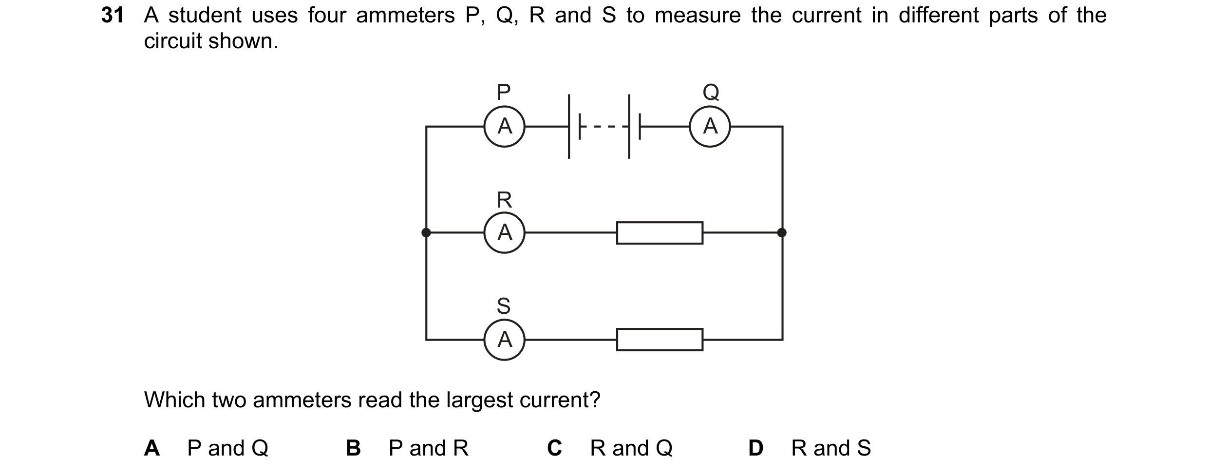
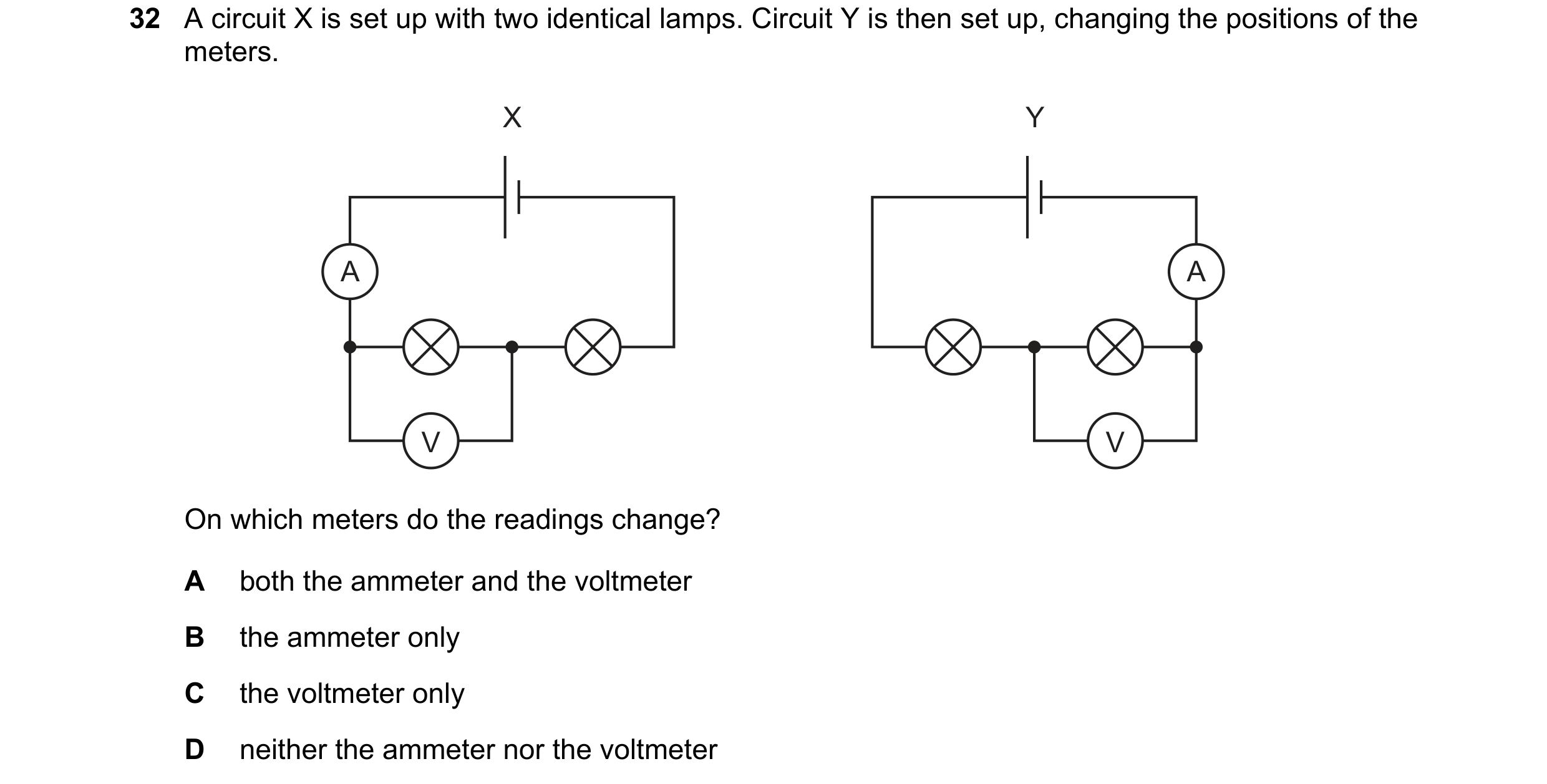
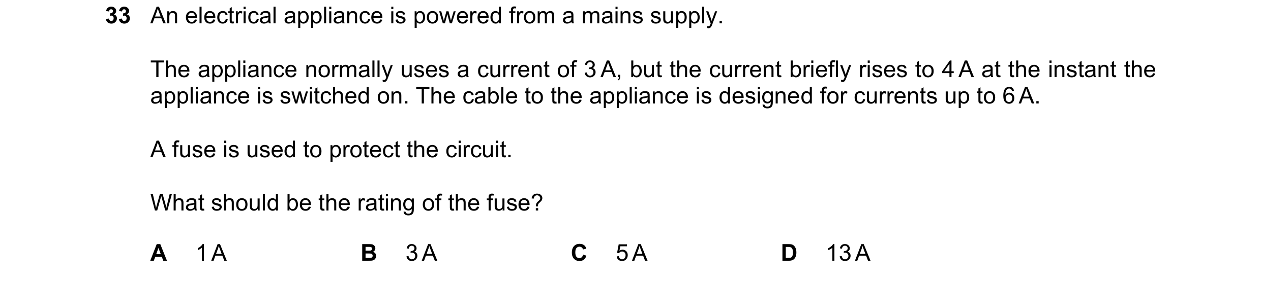 128 / 176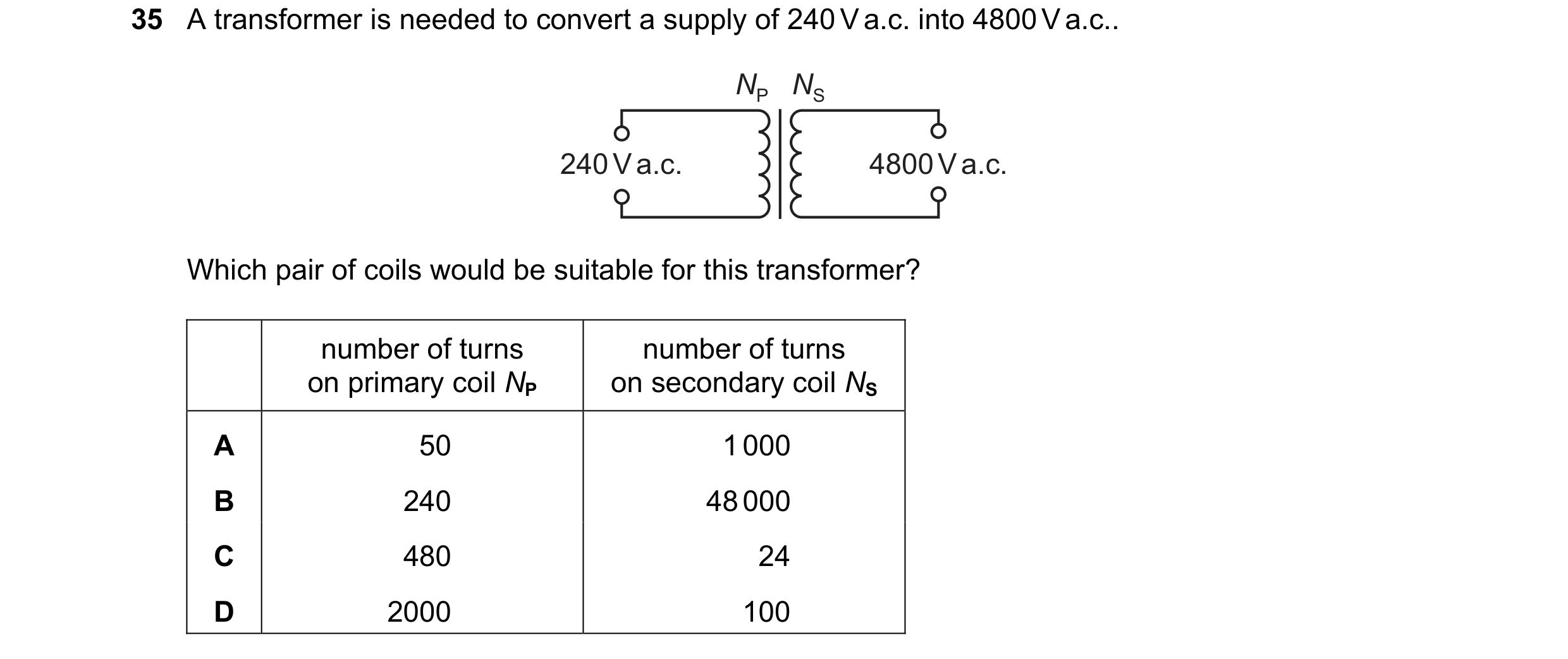
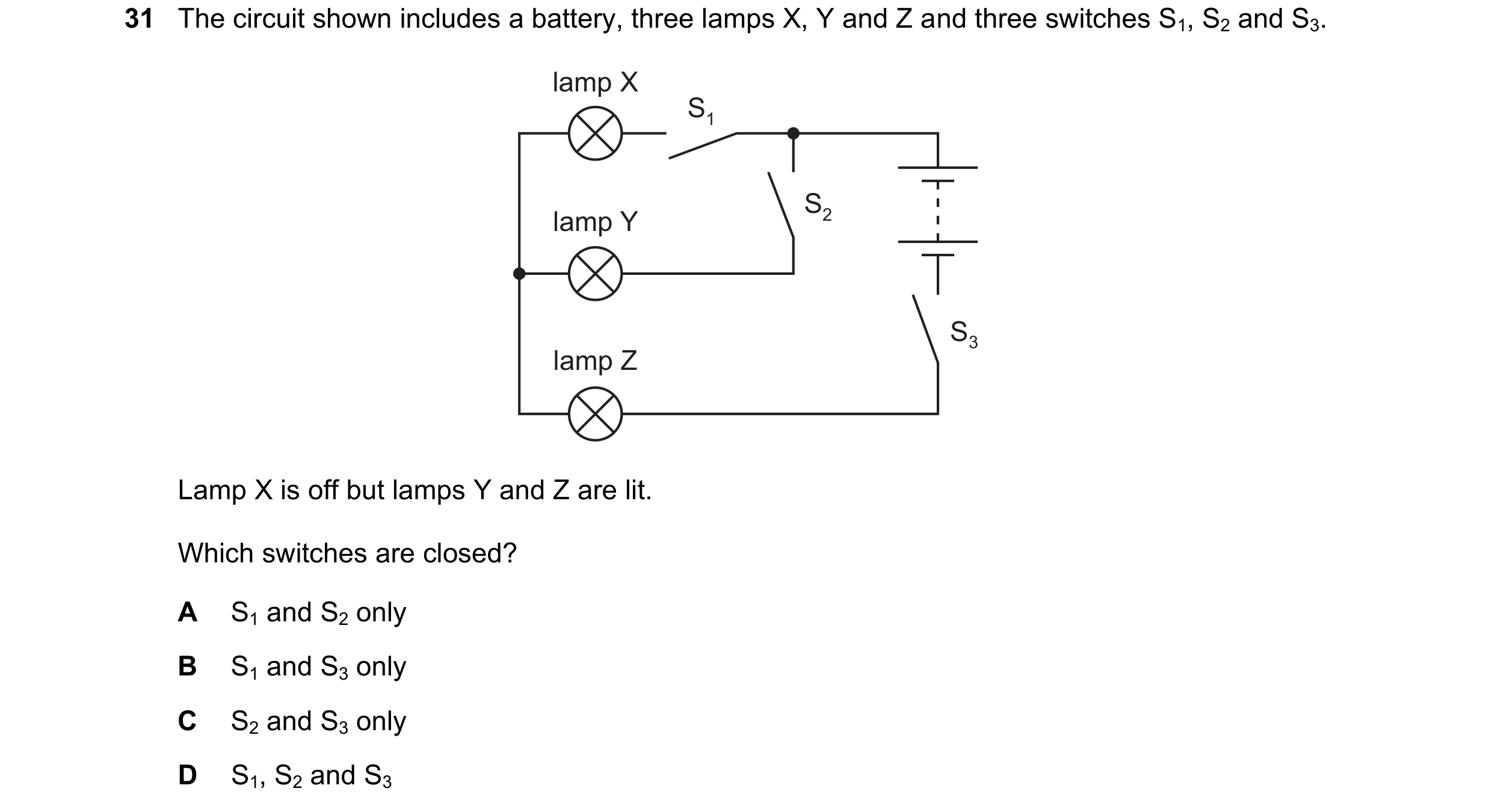 129 / 176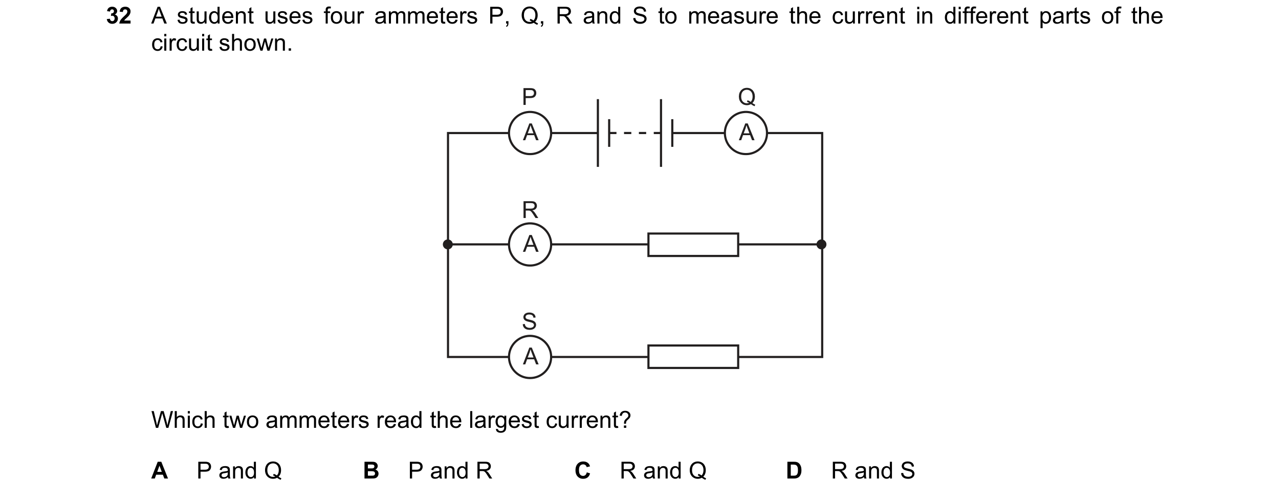
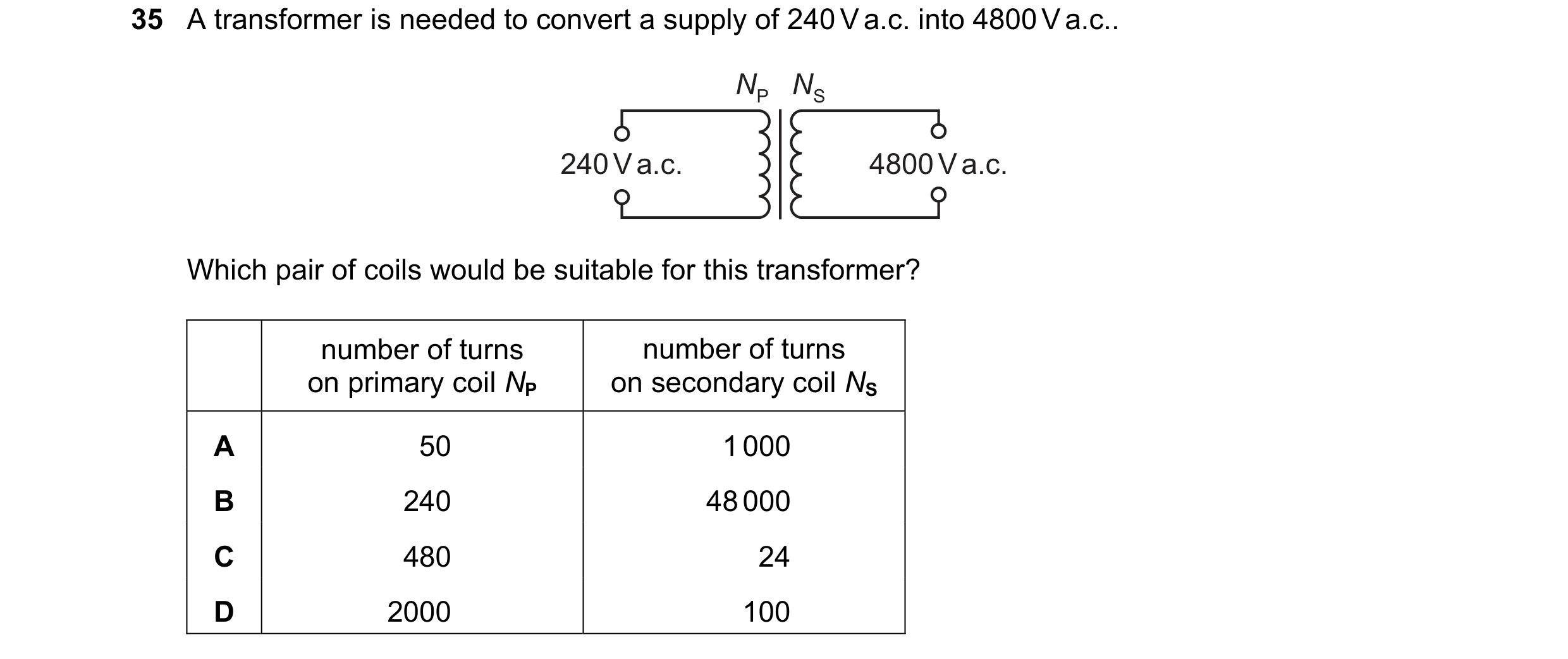 130 / 176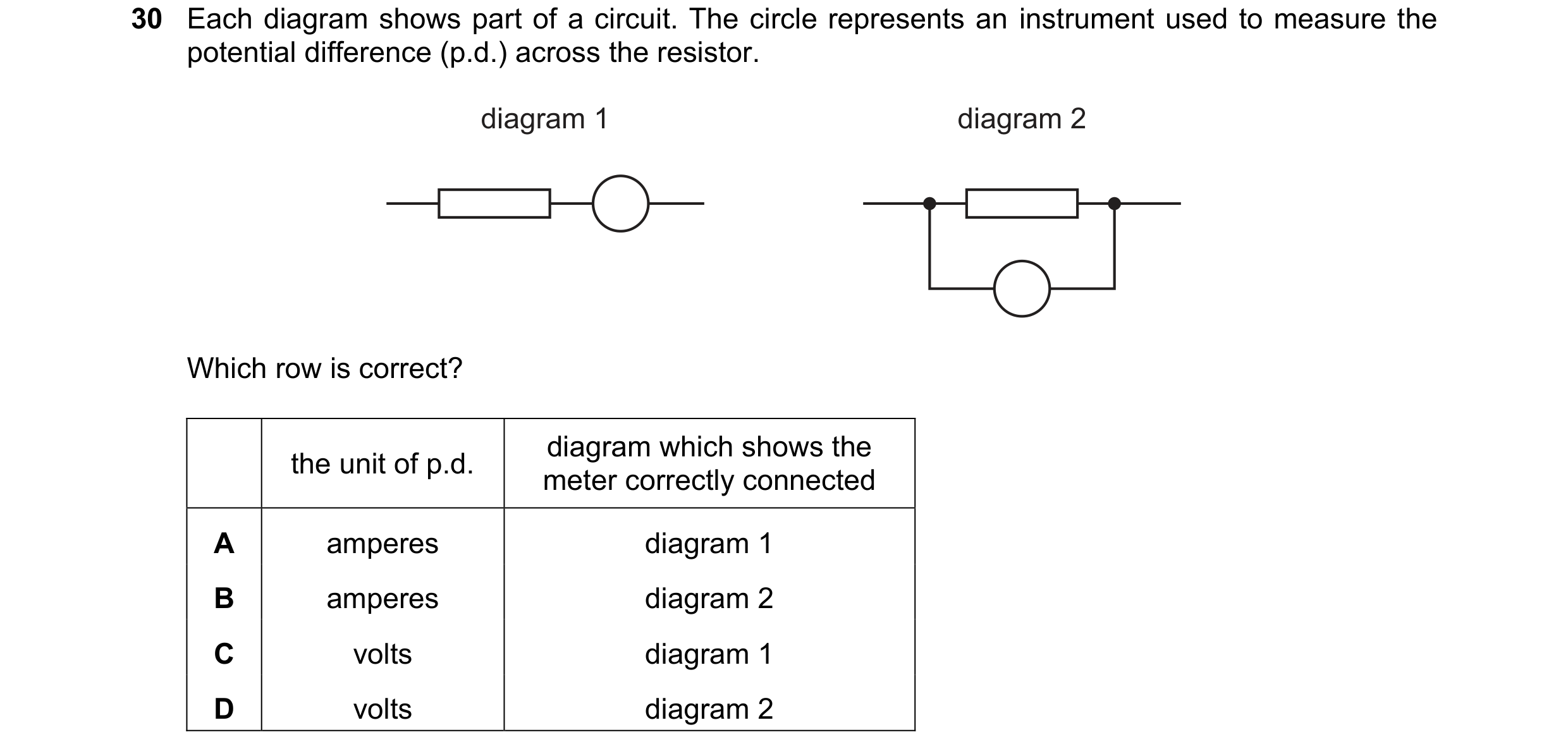
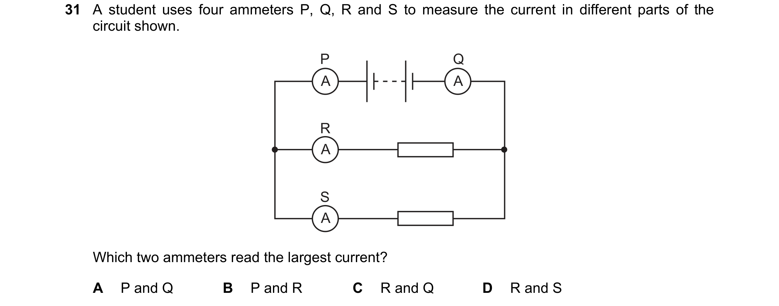
 131 / 176
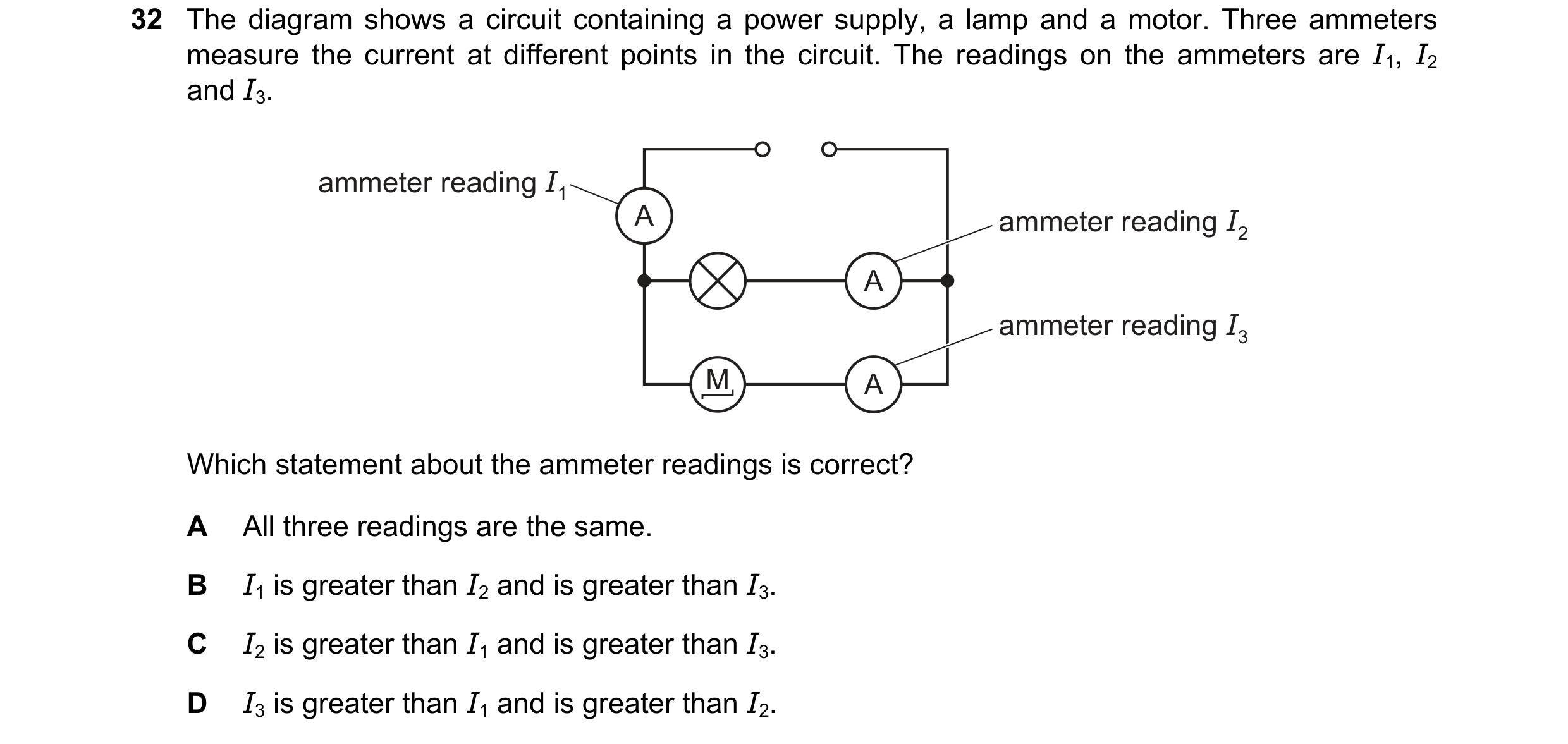
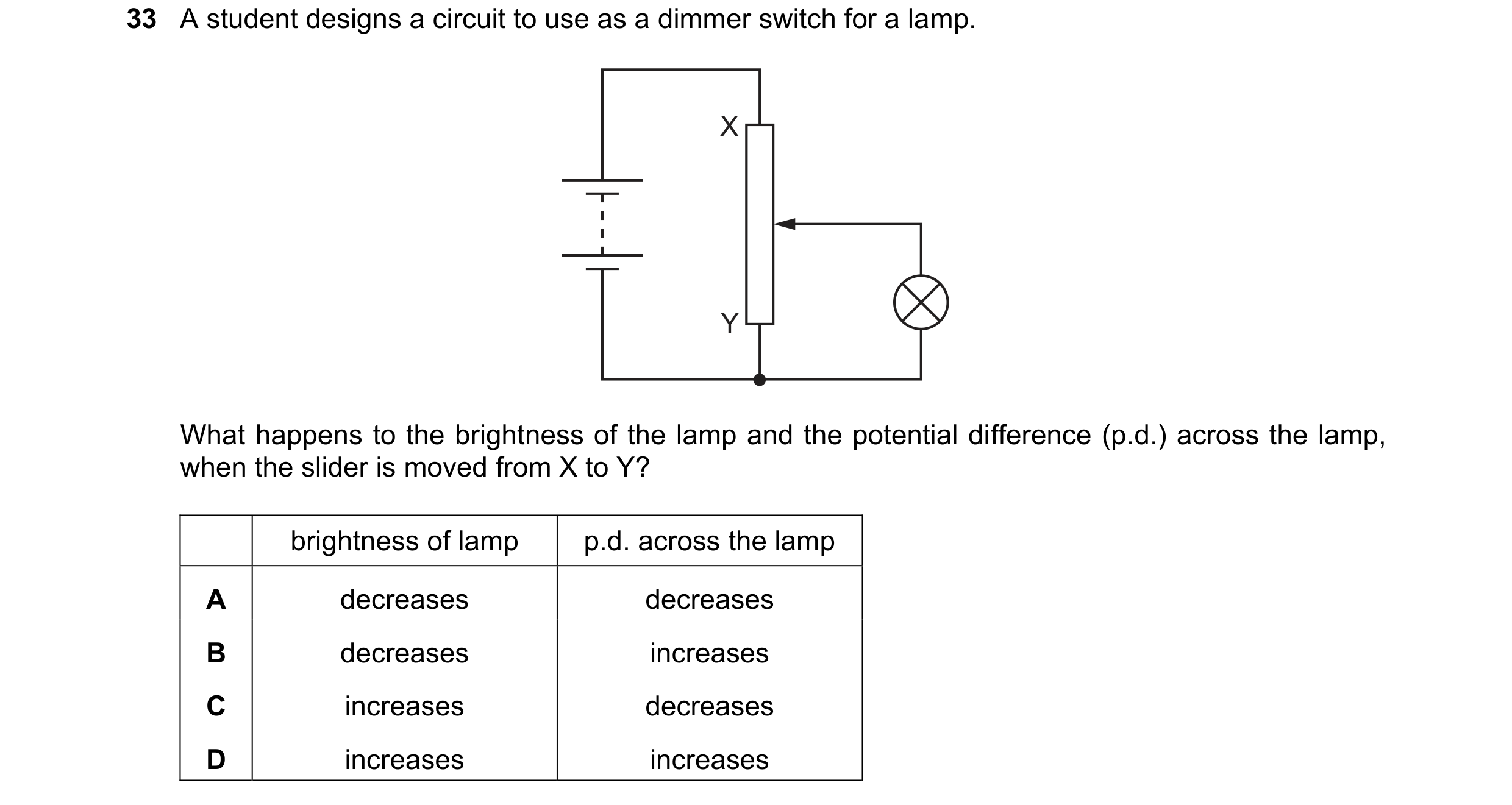 132 / 176
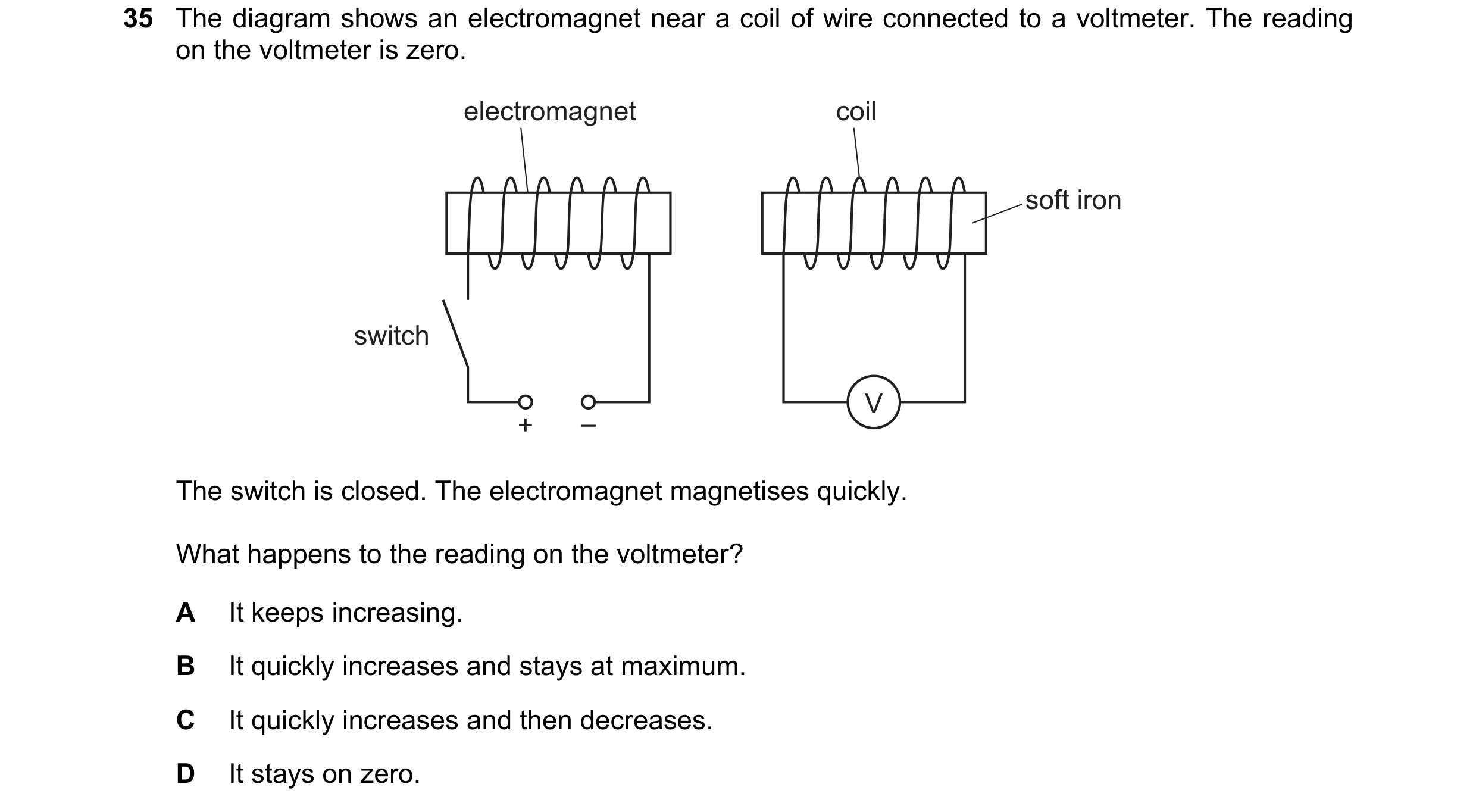
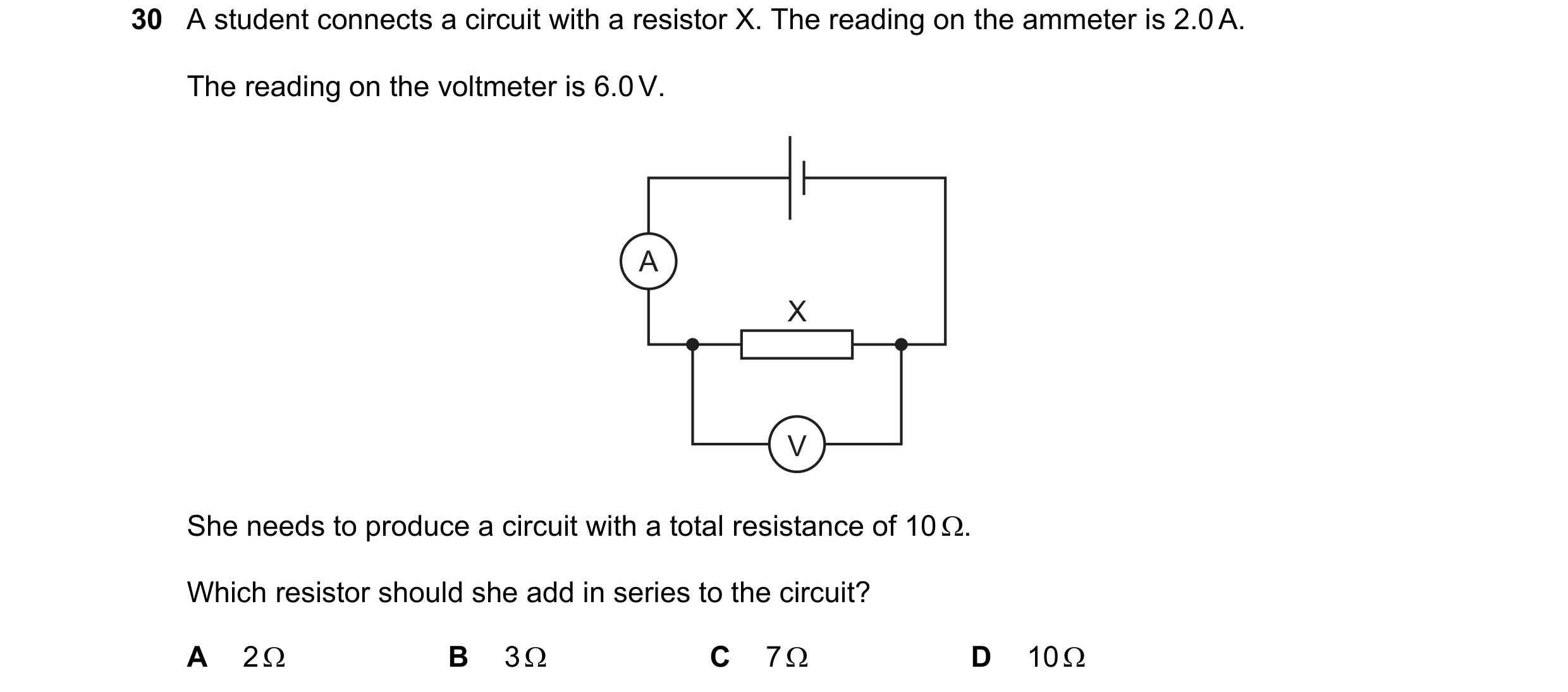 133 / 176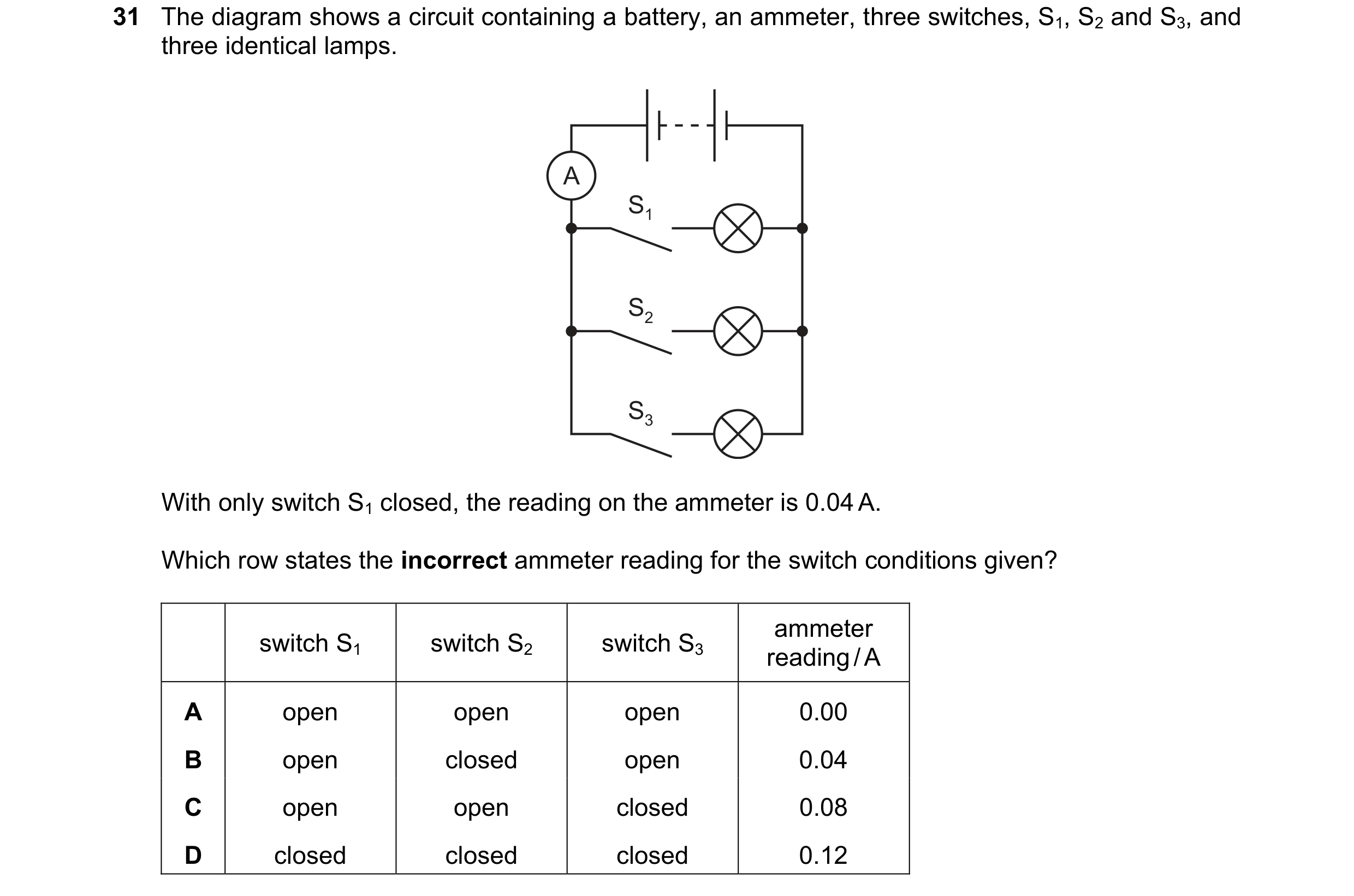
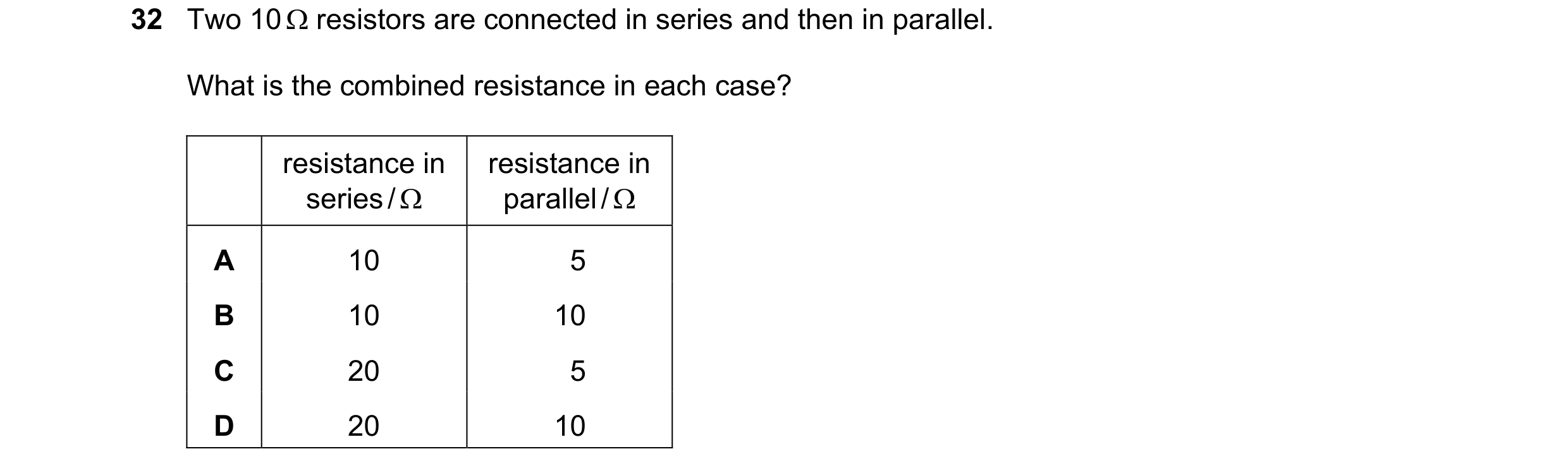 134 / 176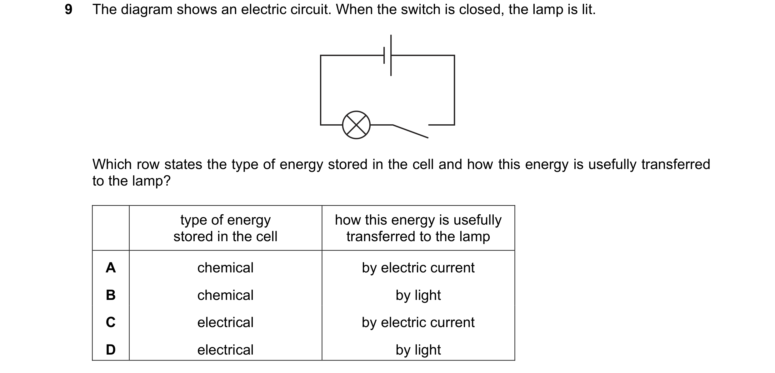
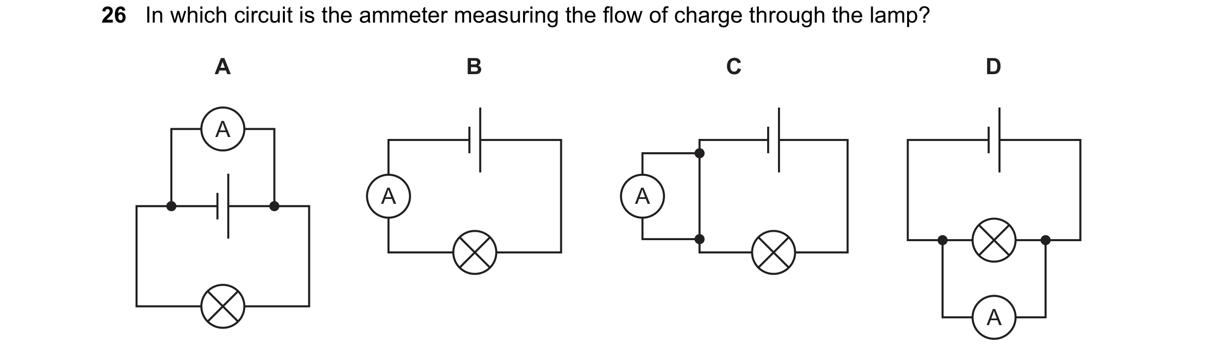
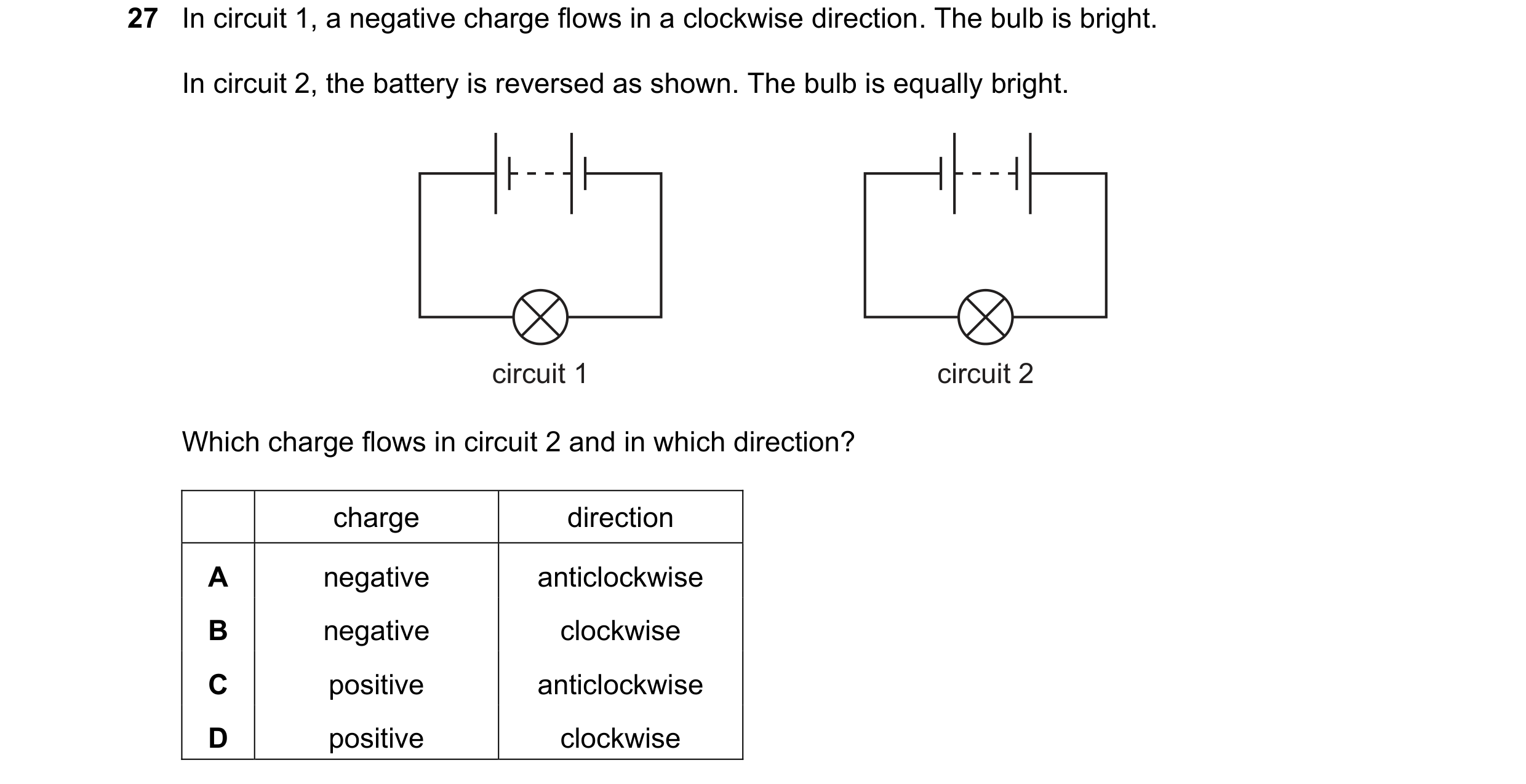 135 / 176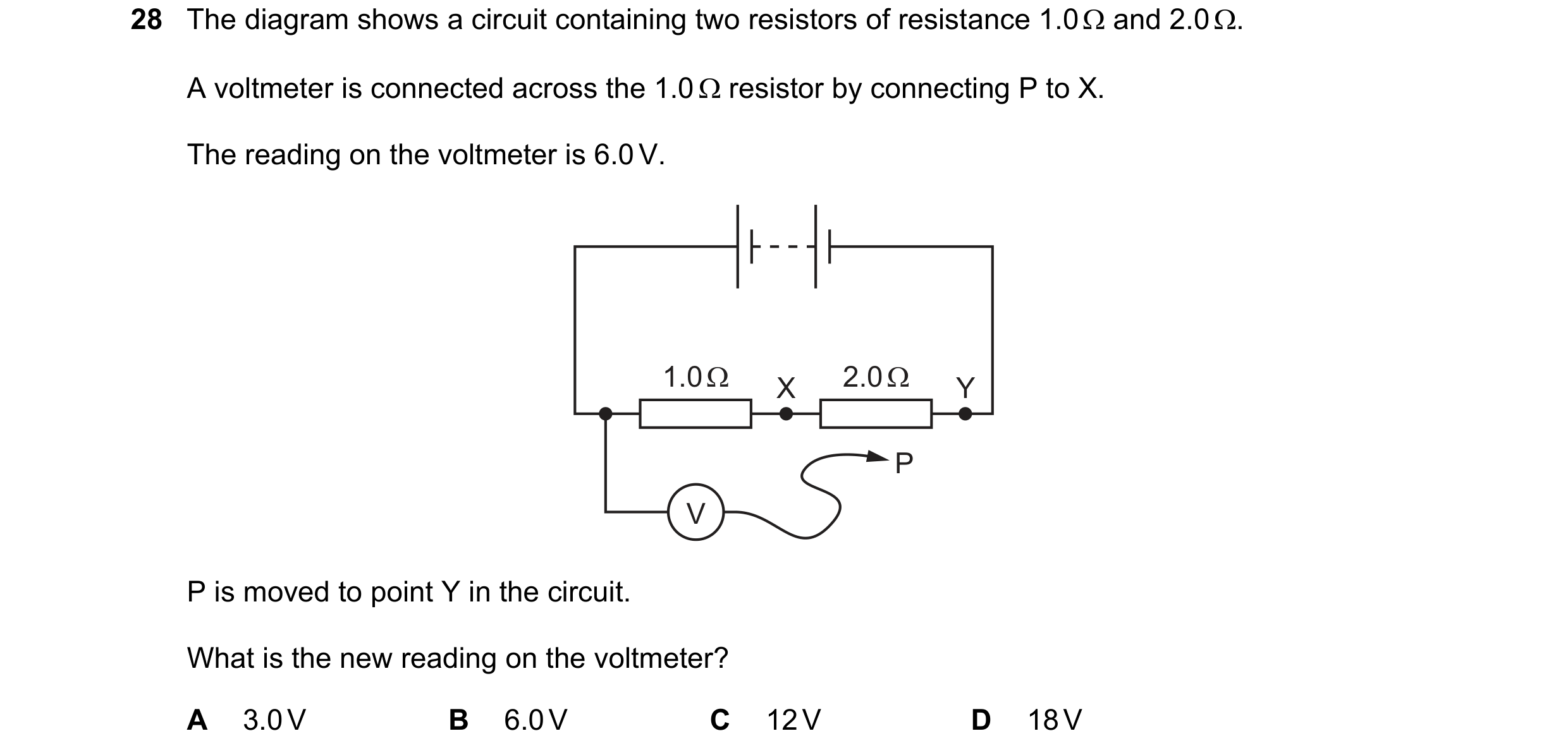
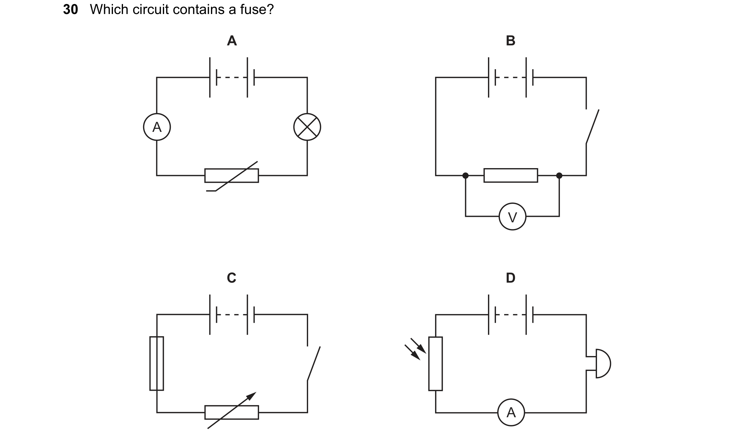 136 / 176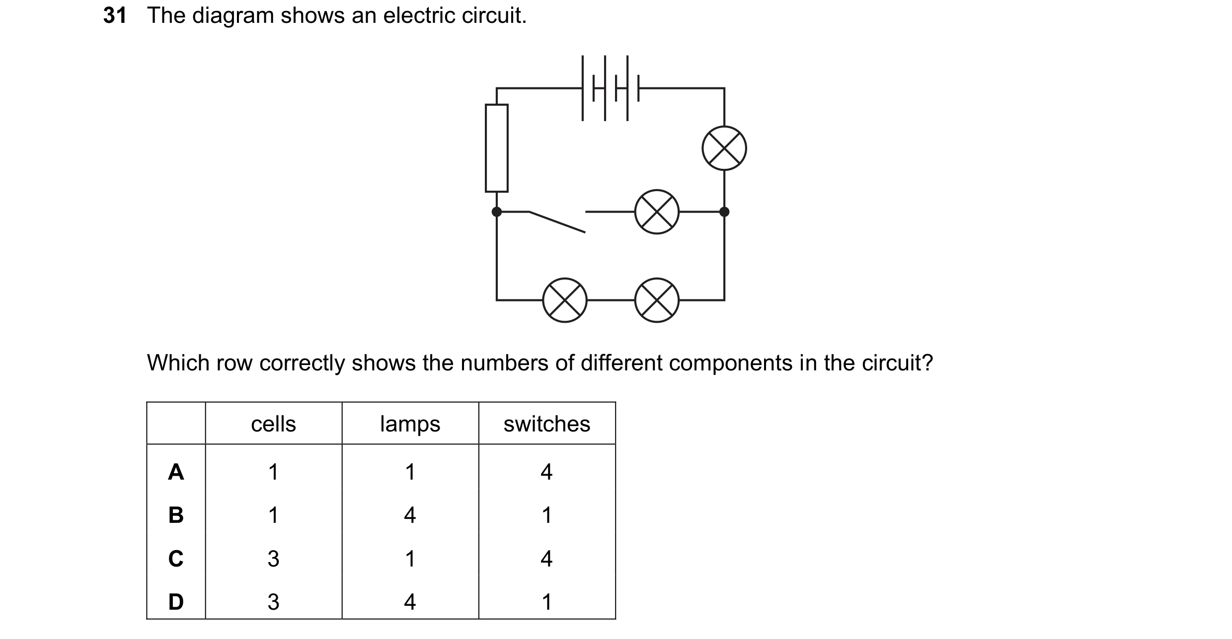
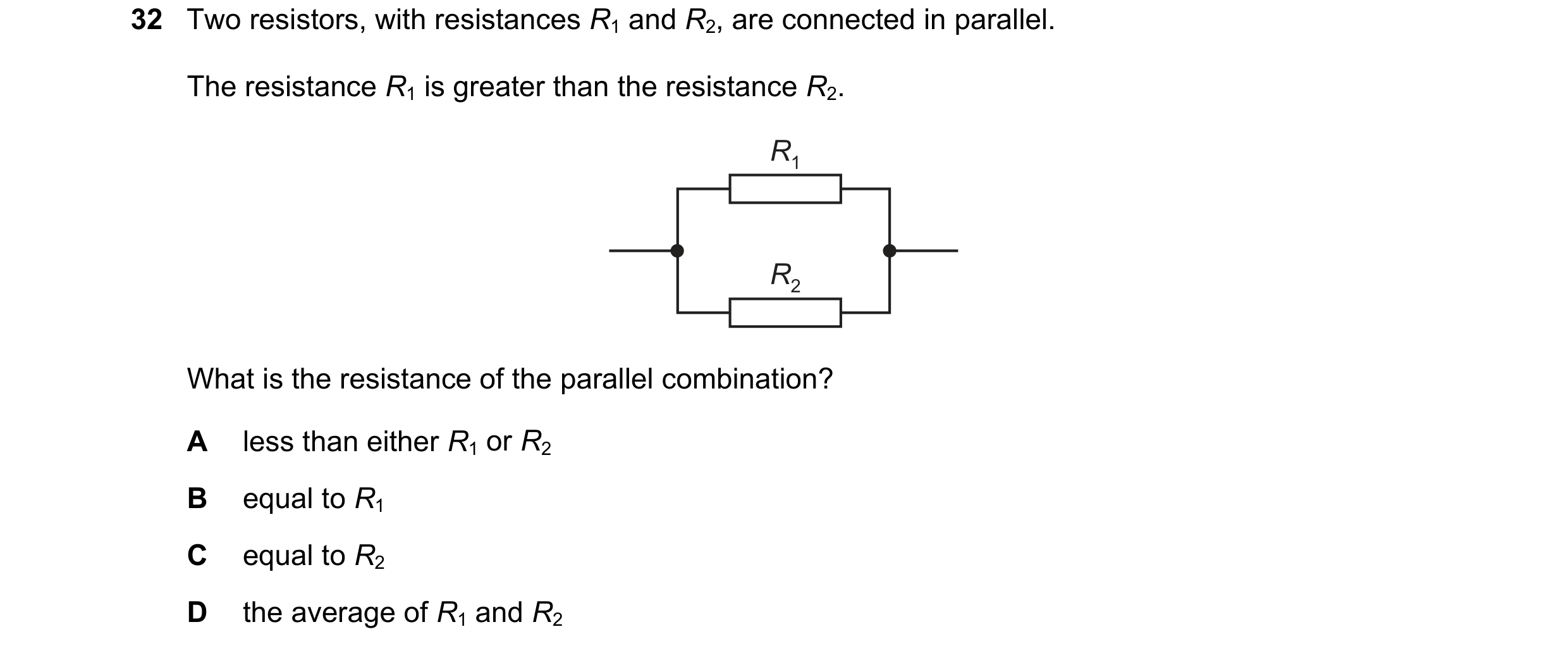
 137 / 176
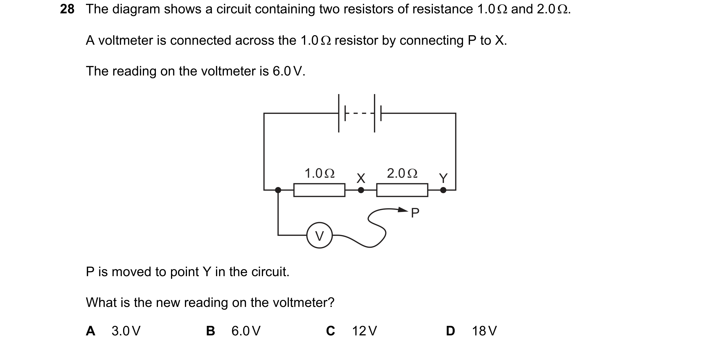
 138 / 176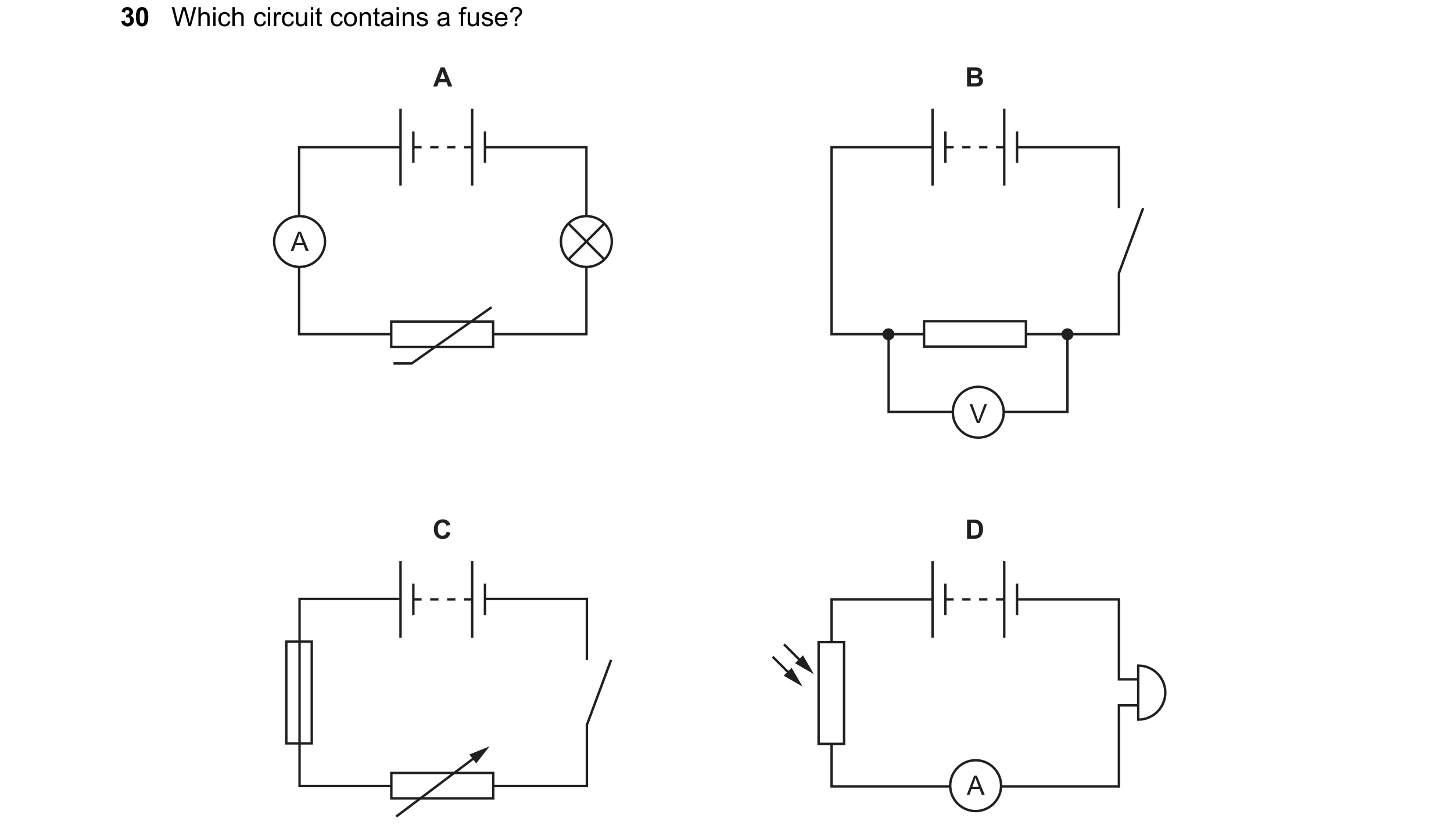

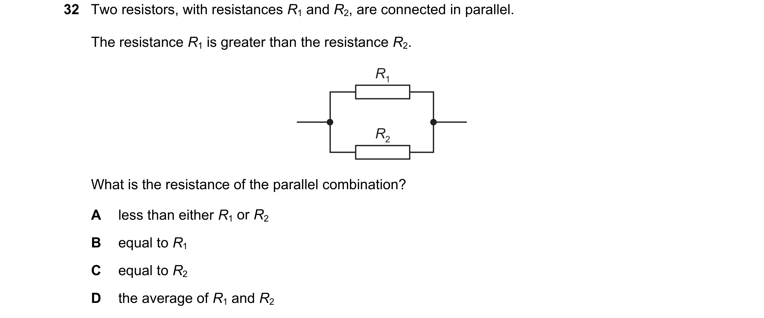 139 / 176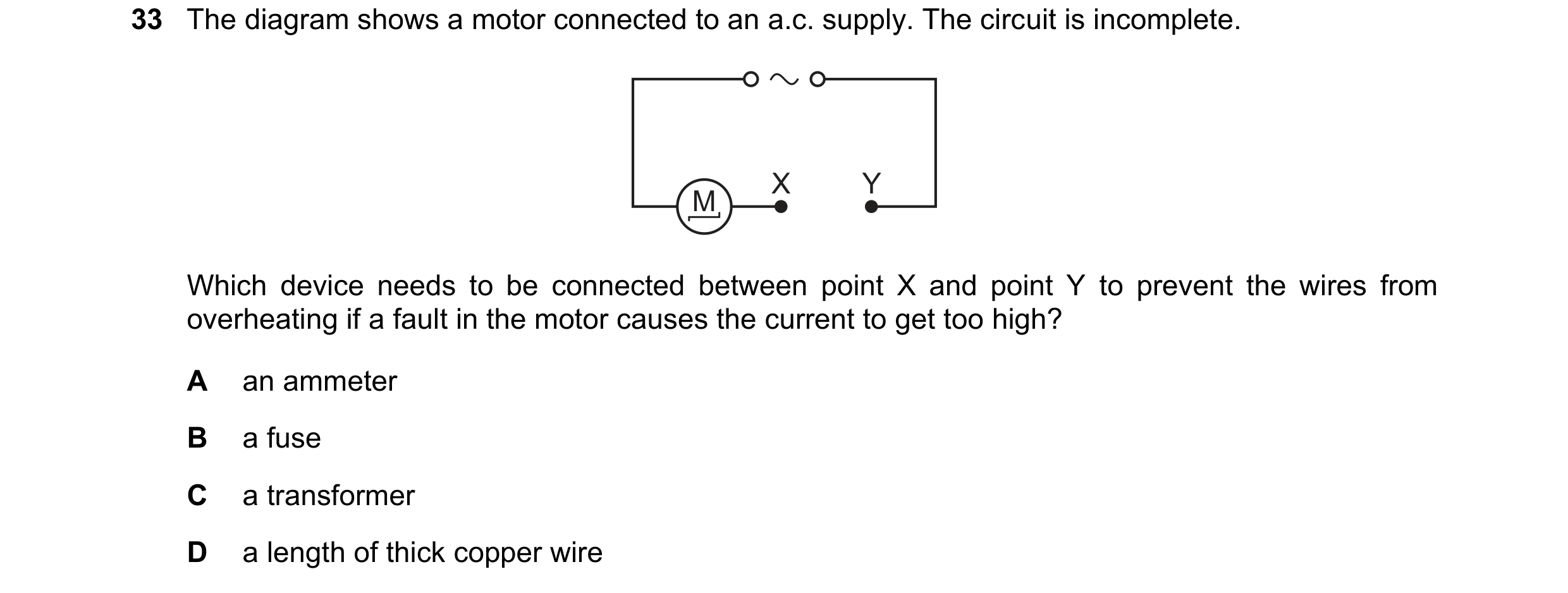

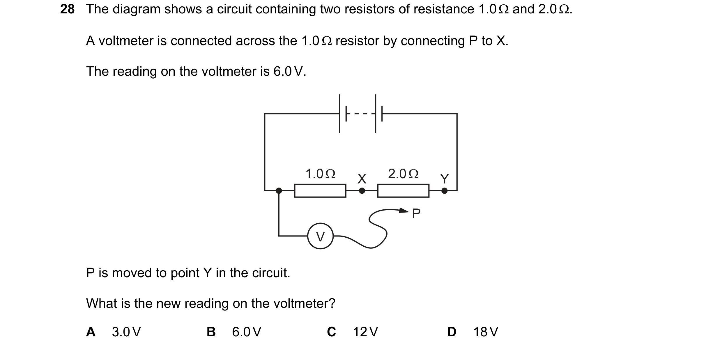 140 / 176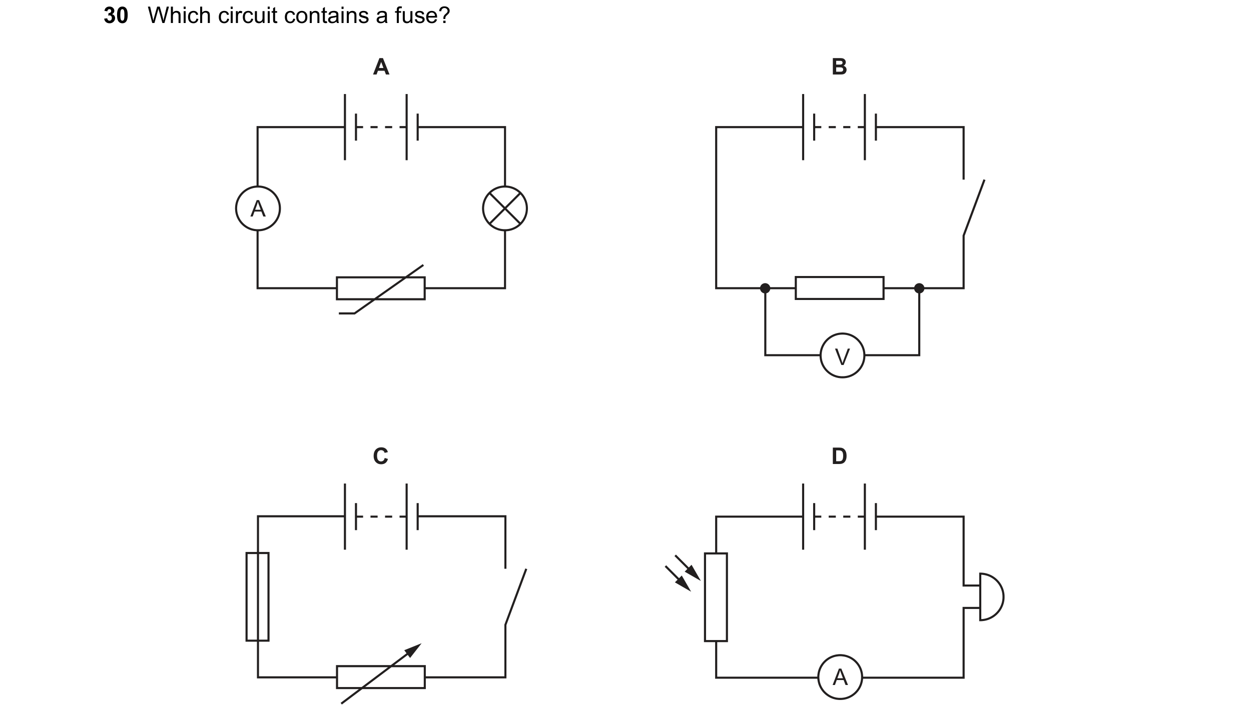
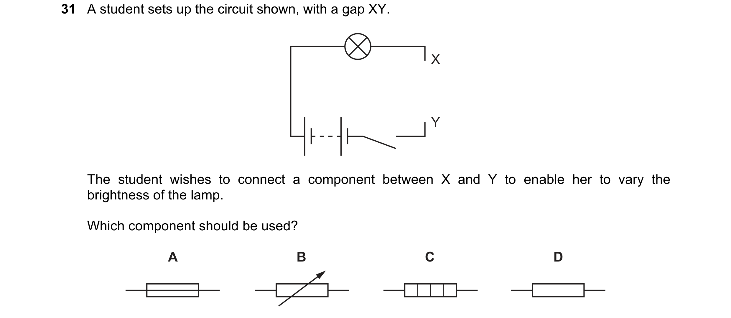 141 / 176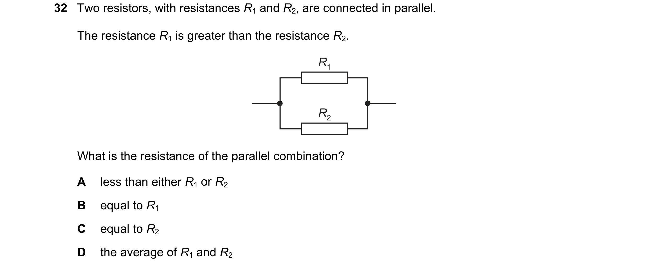
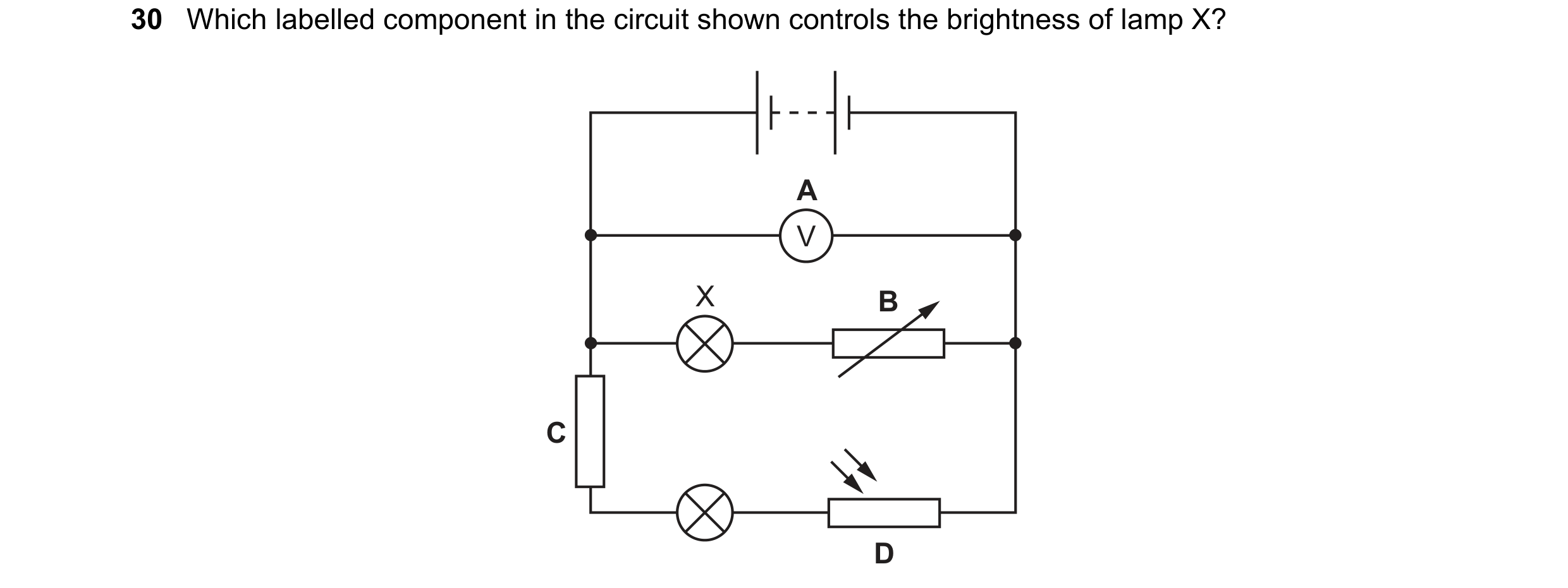 142 / 176
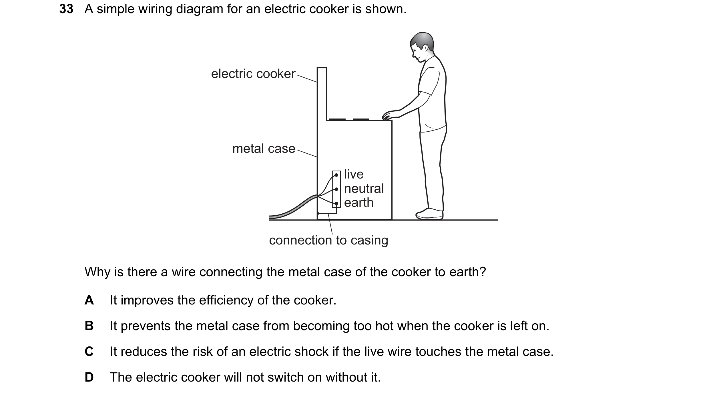 143 / 176
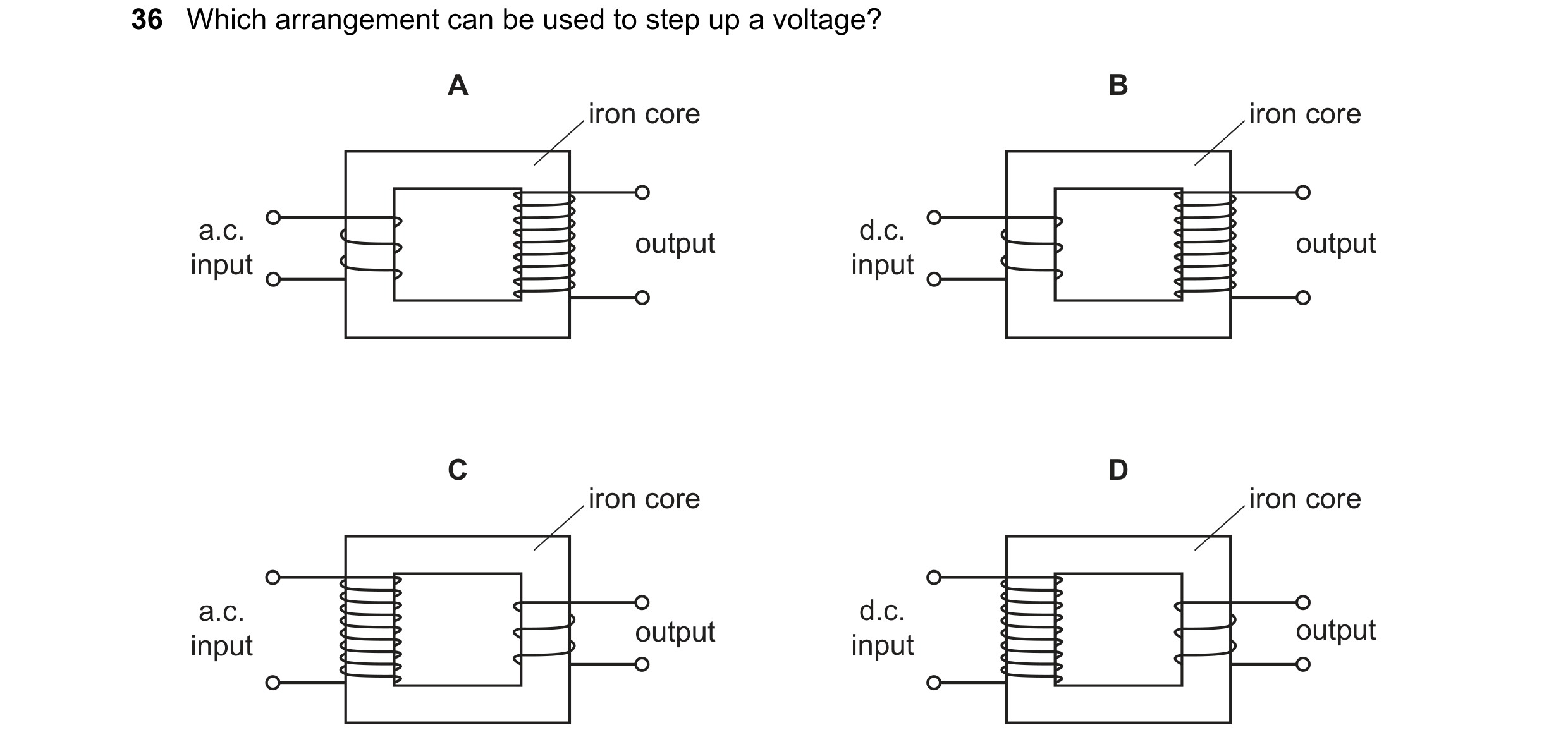
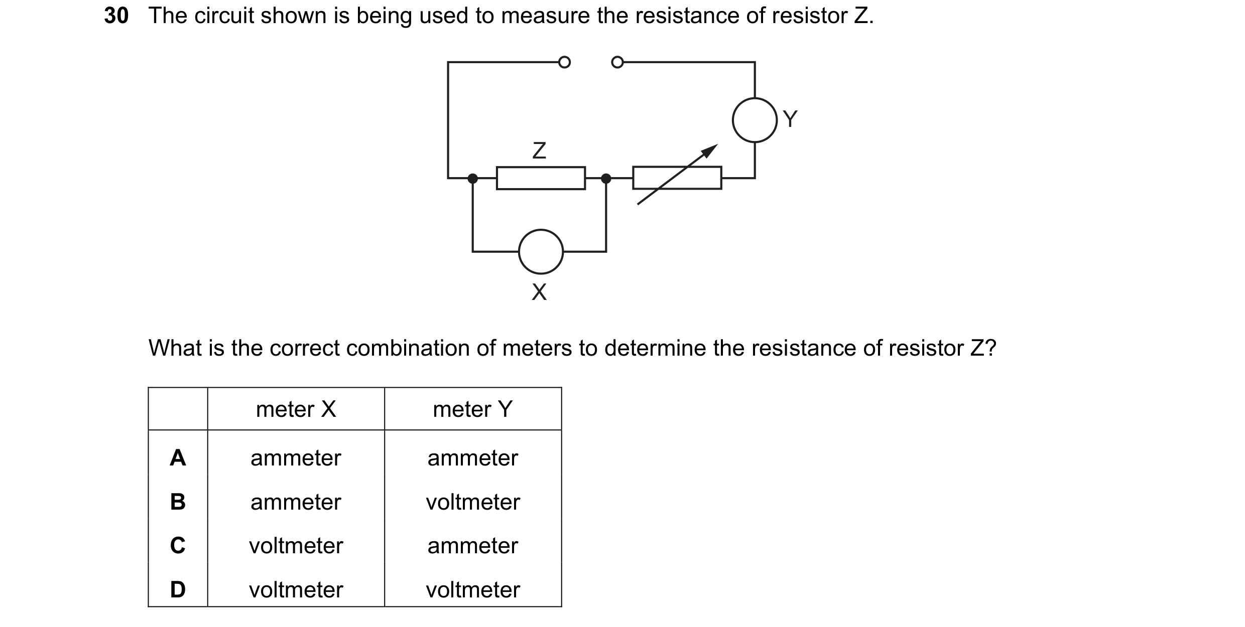 144 / 176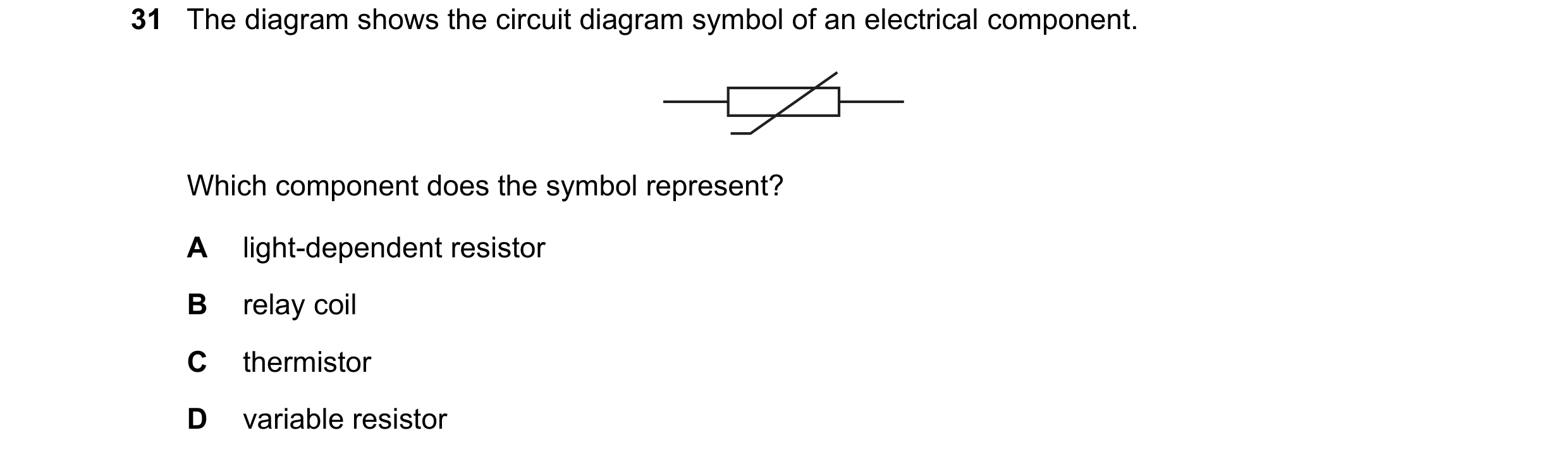

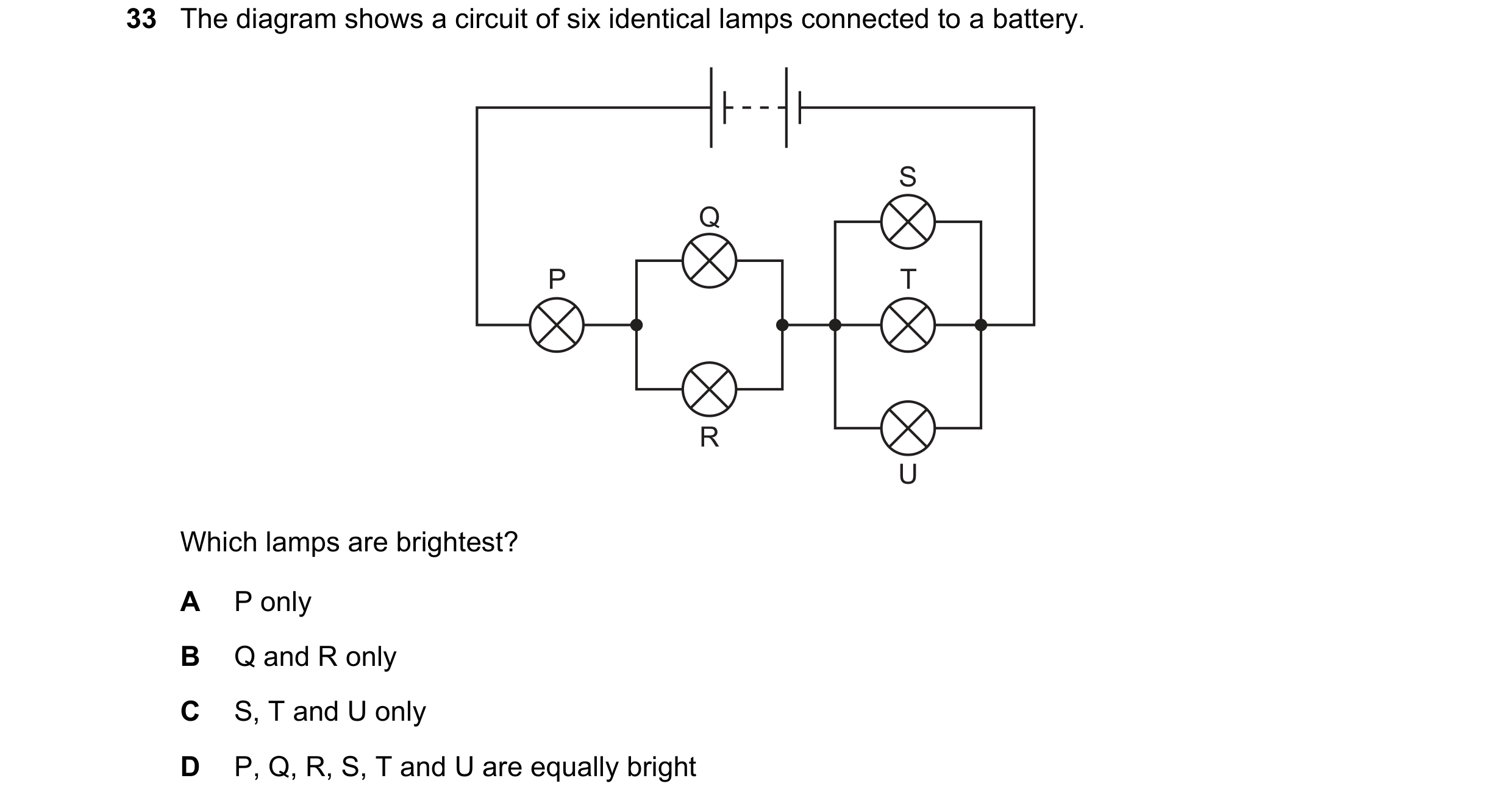
 145 / 176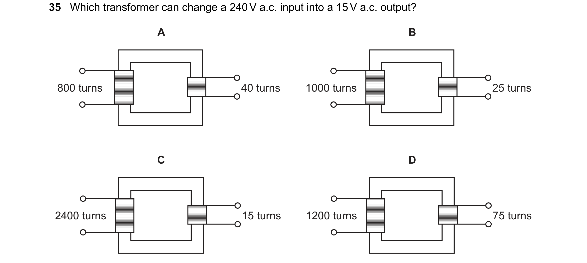
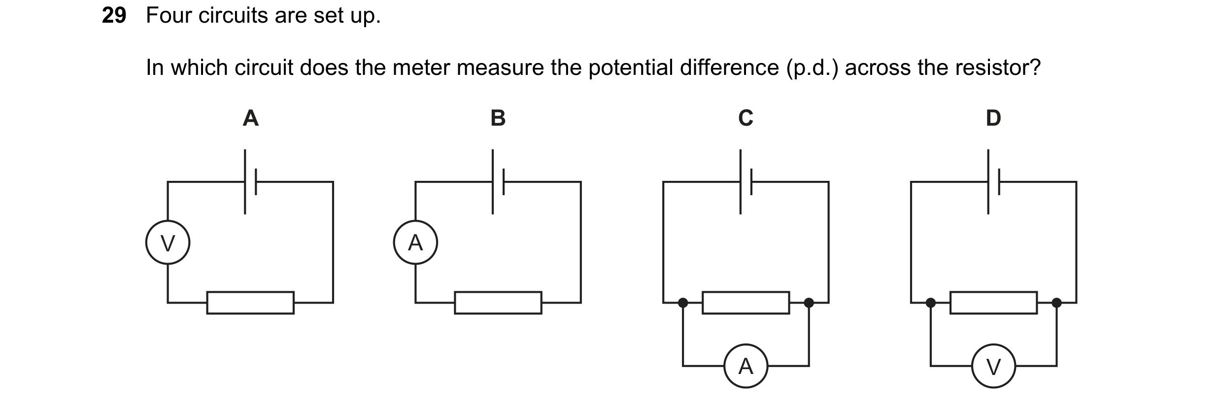 146 / 176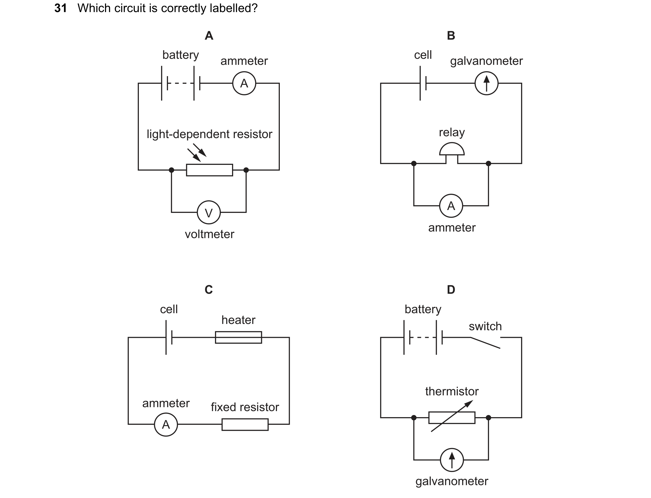
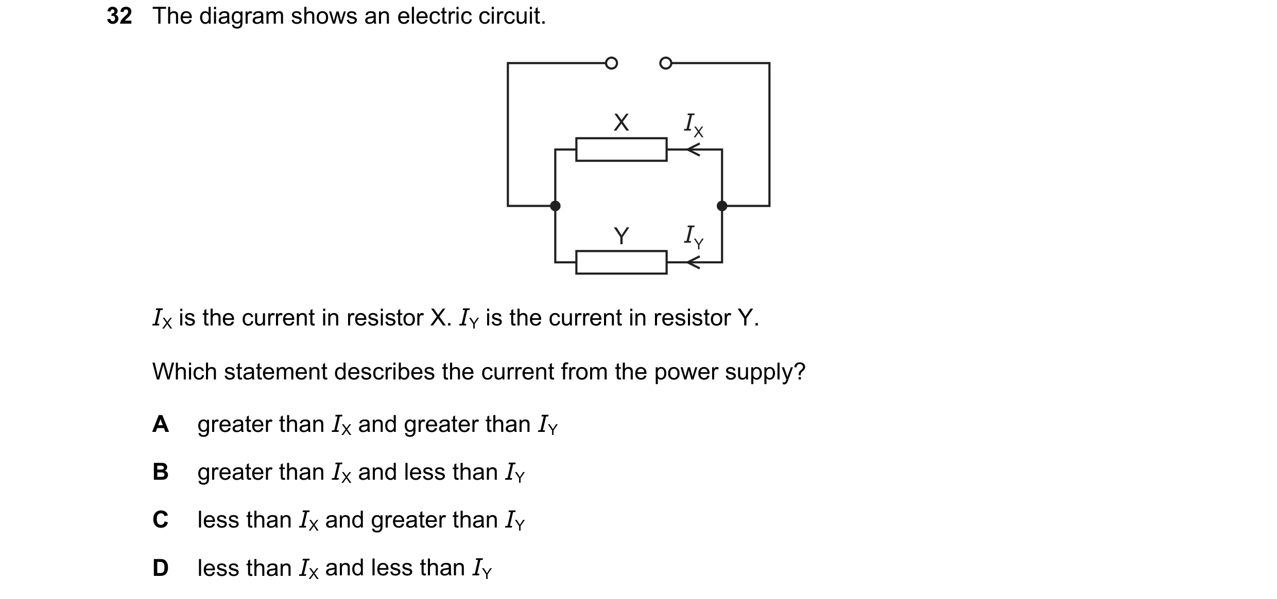 147 / 176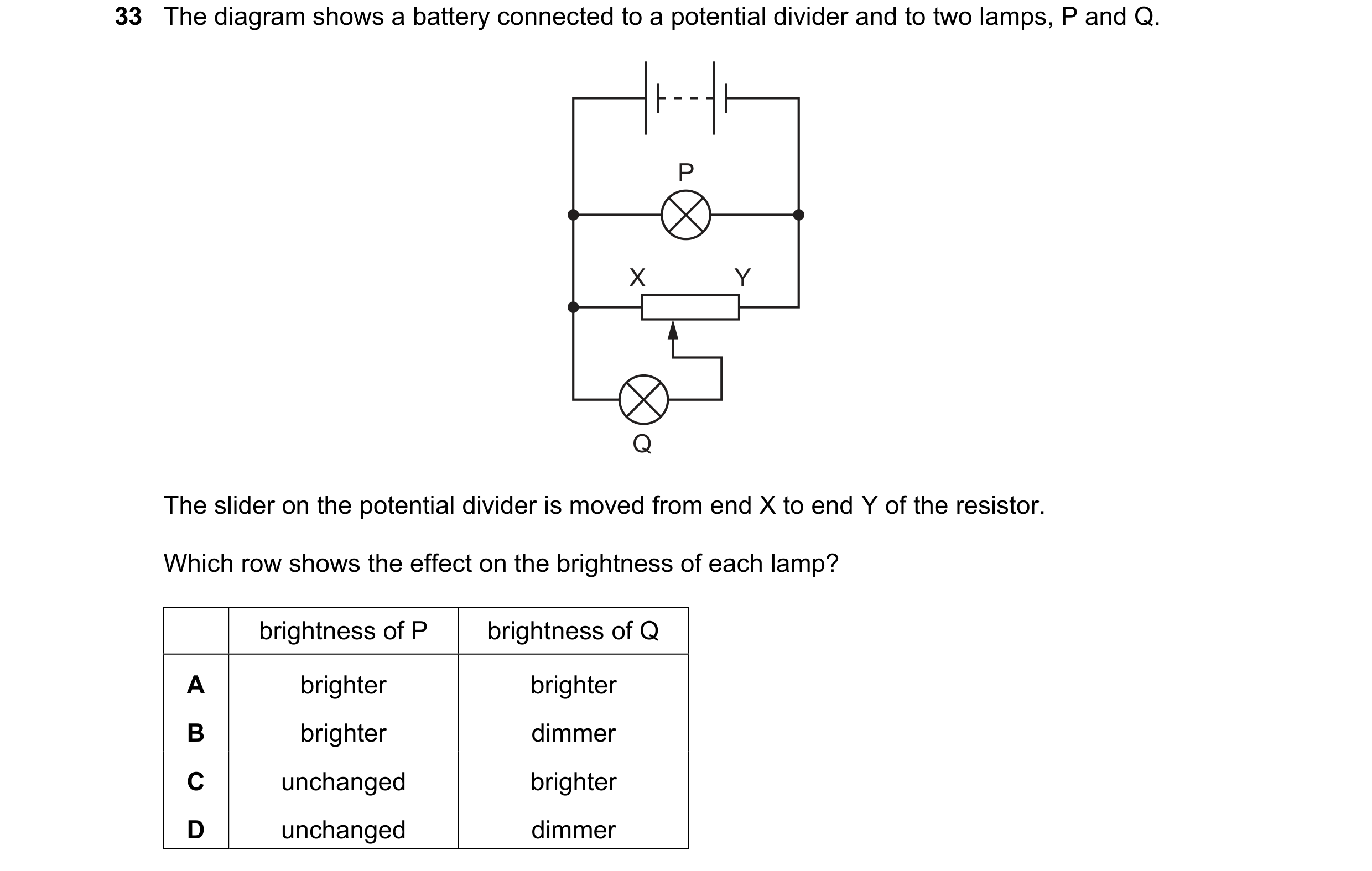
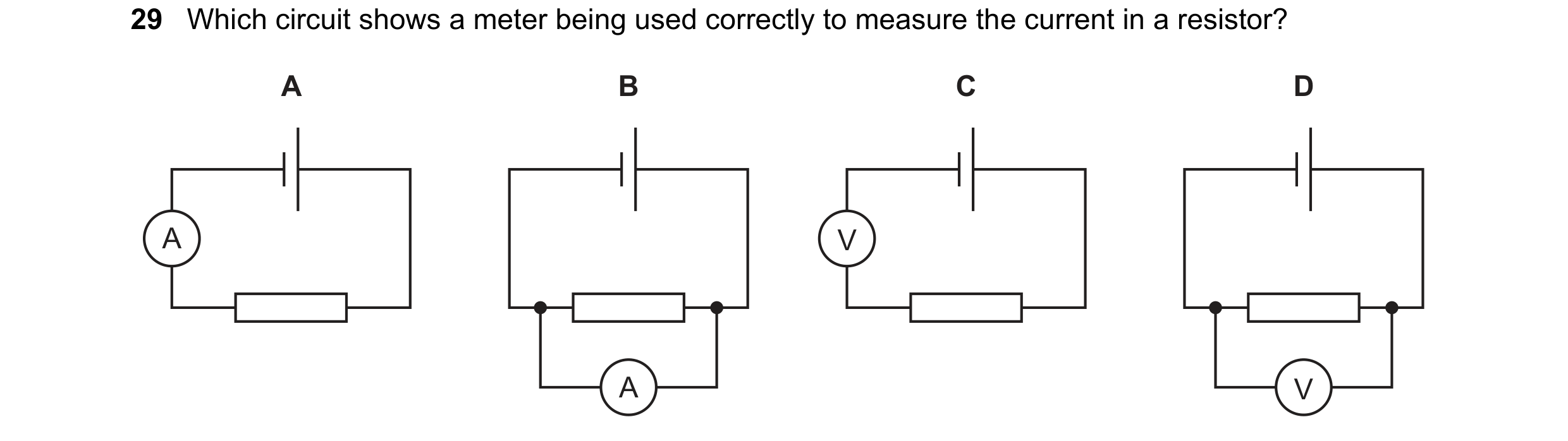
 148 / 176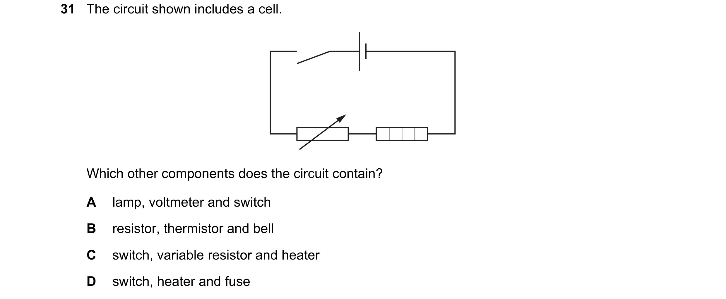
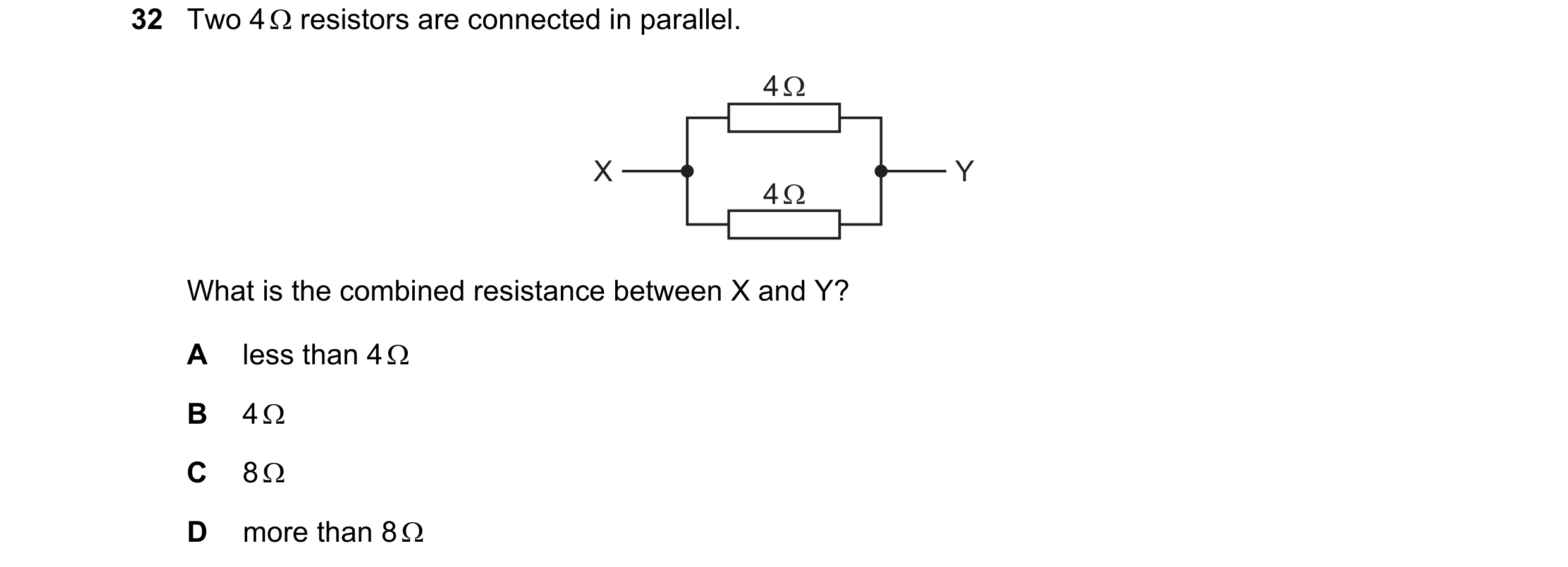

 149 / 176

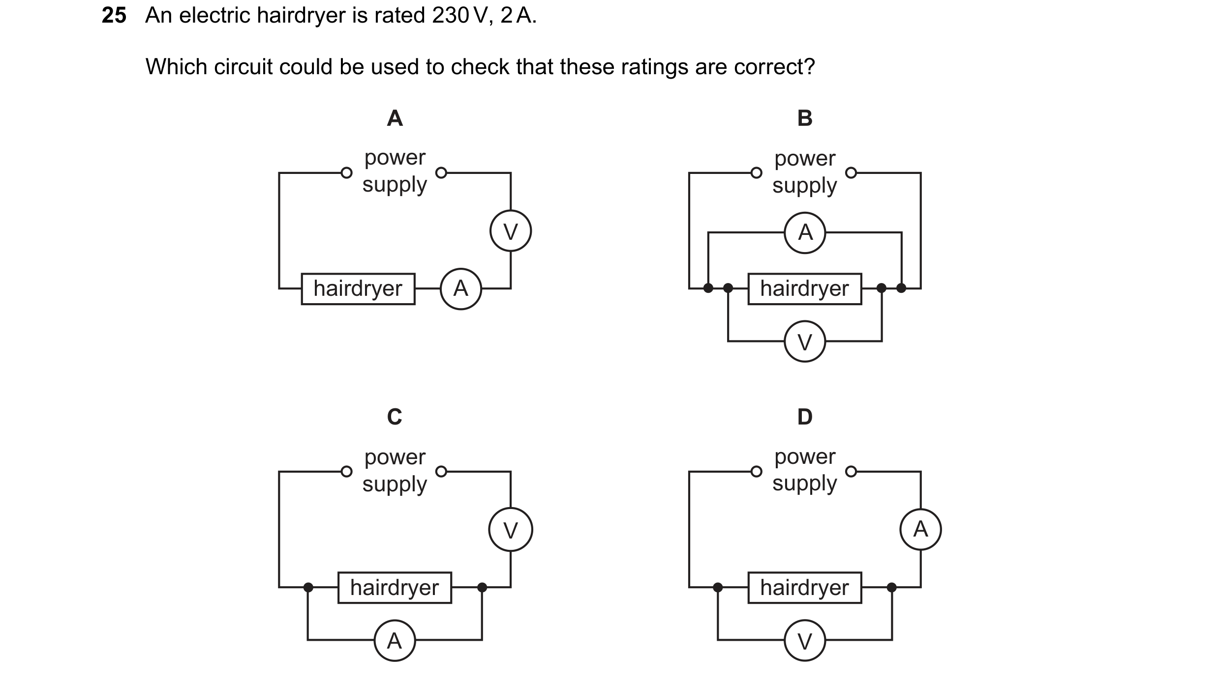 150 / 176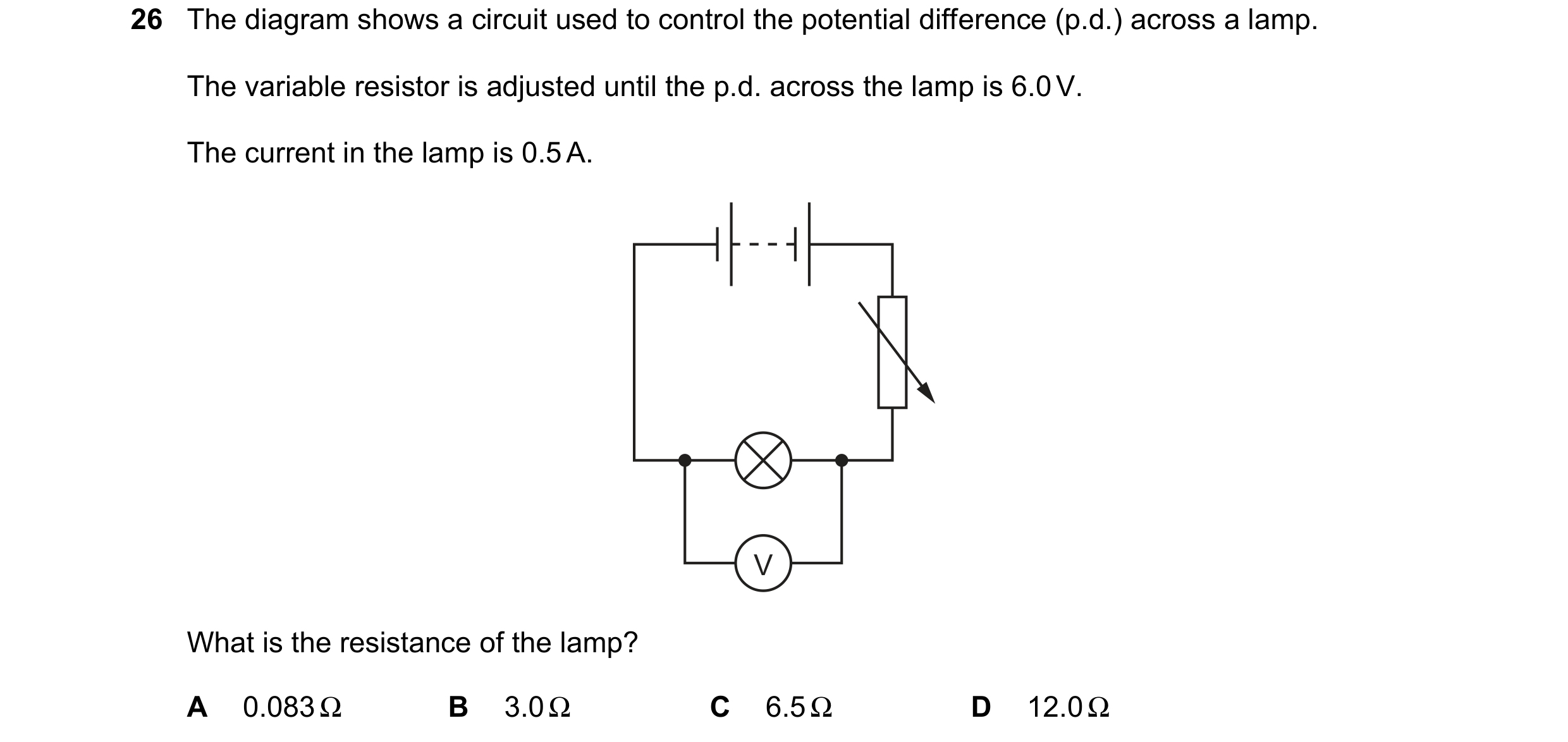
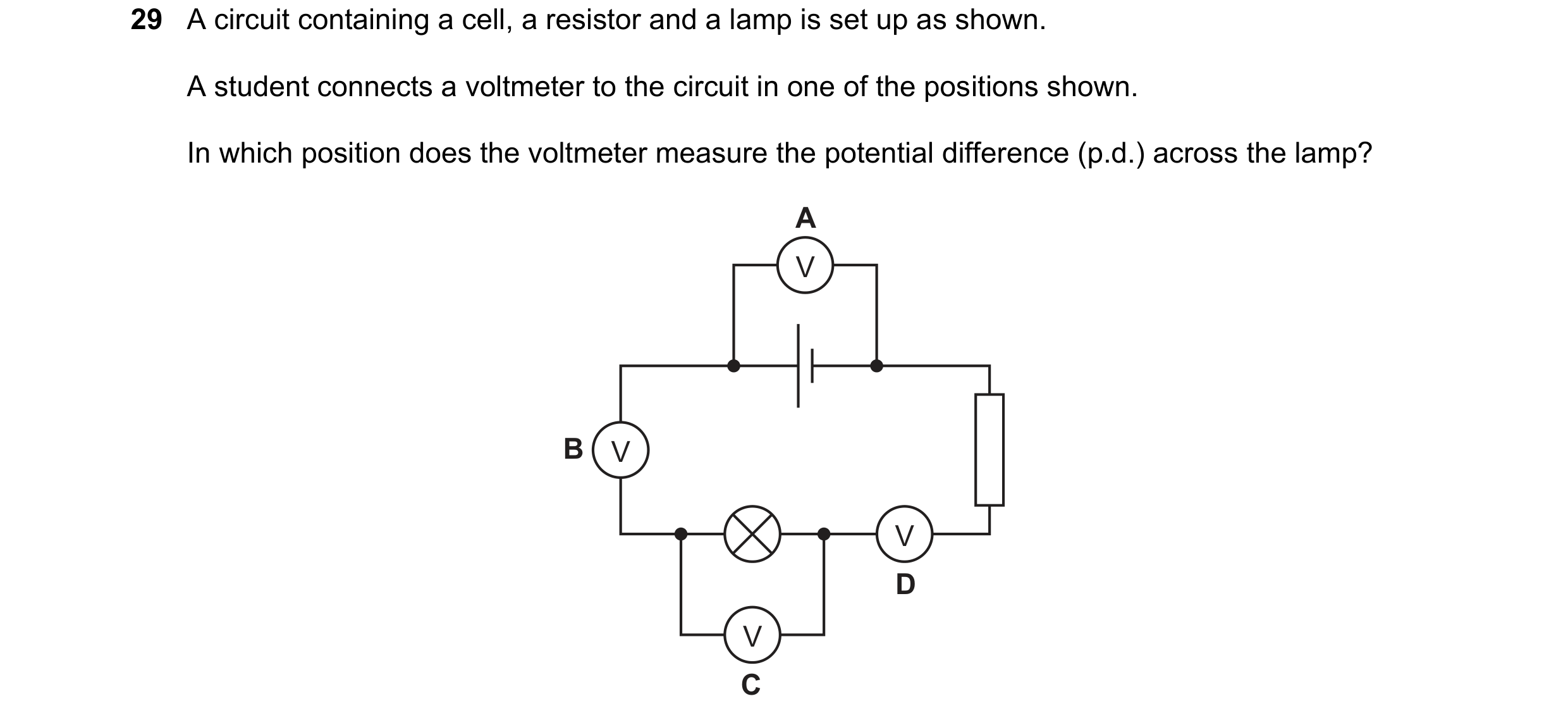 151 / 176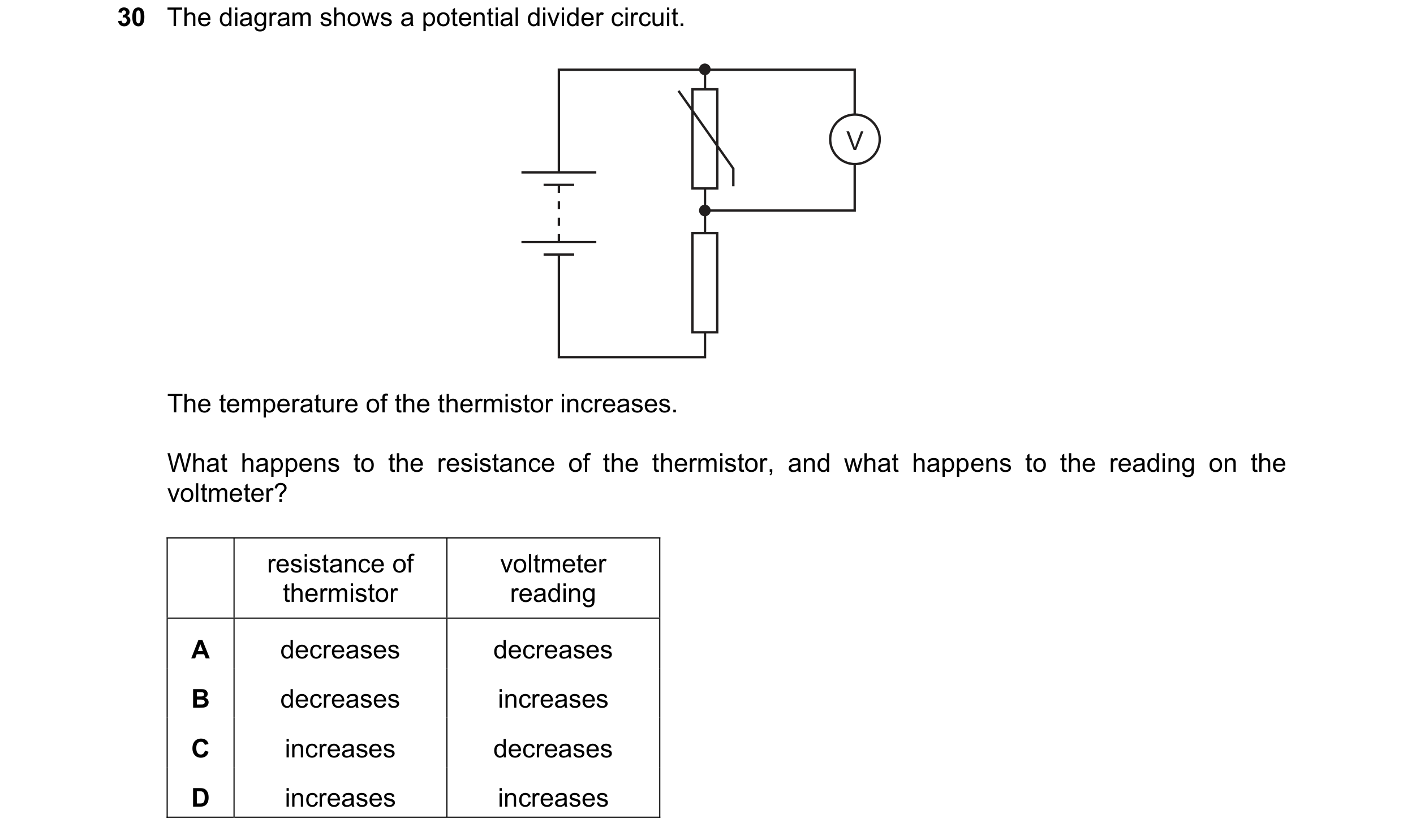
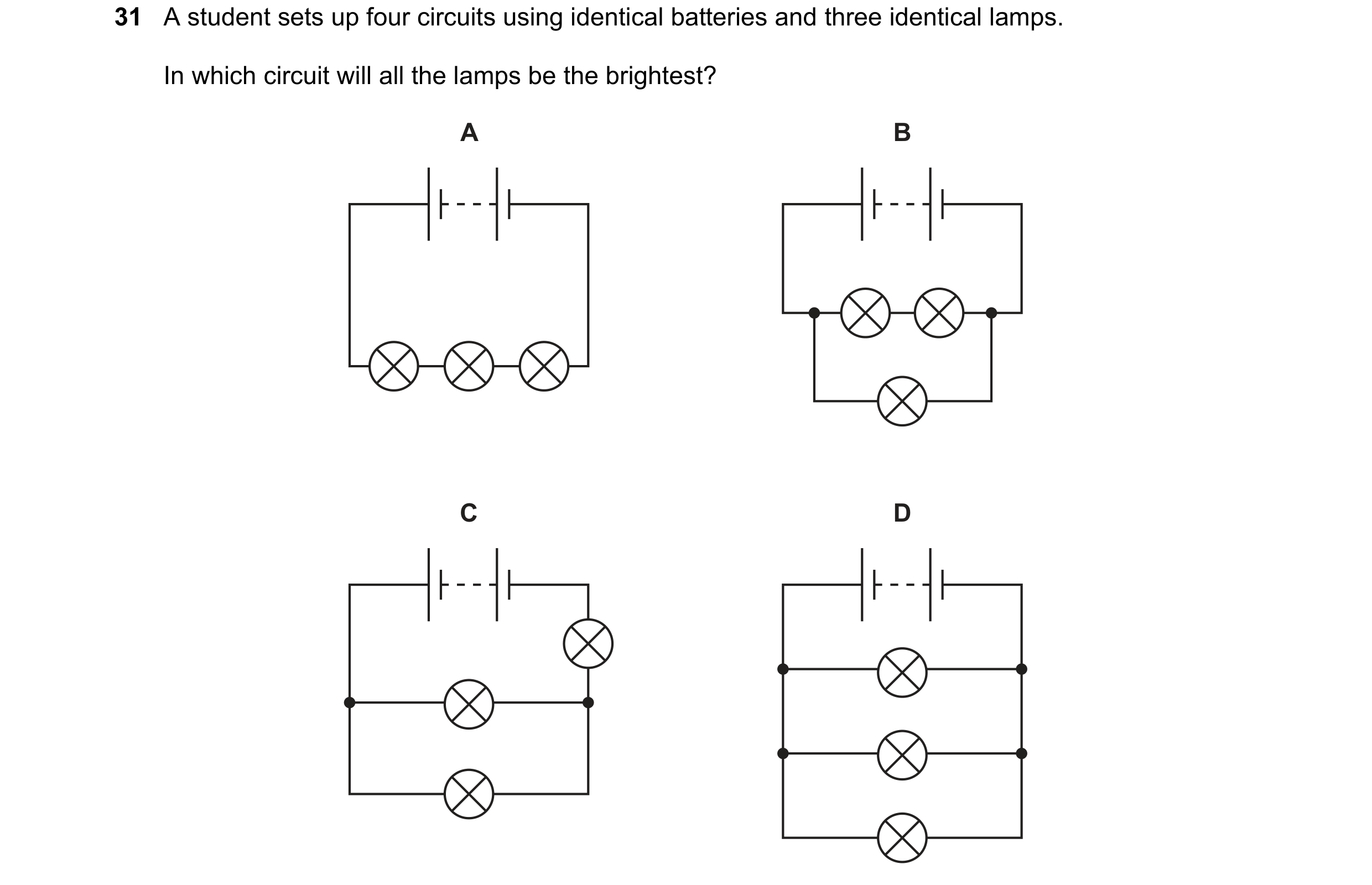
 152 / 176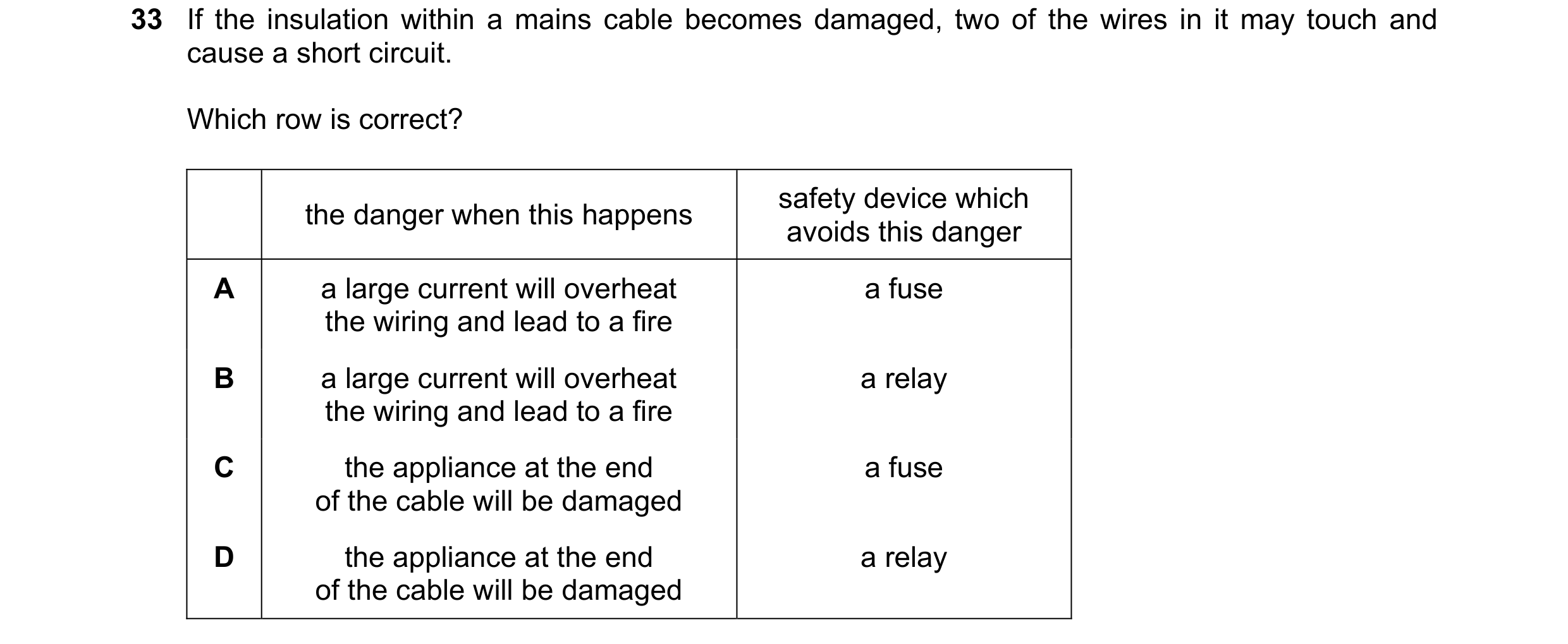
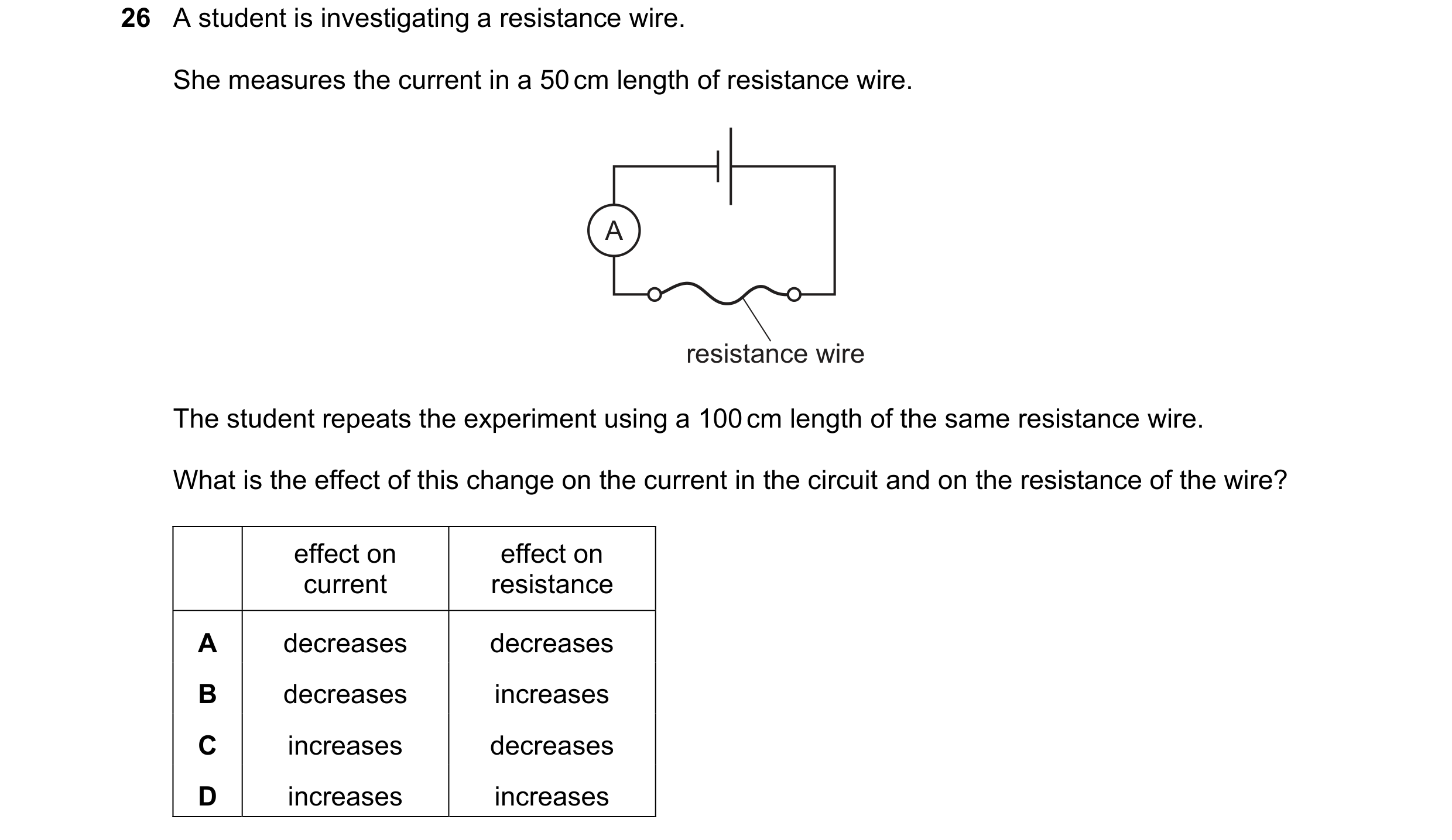 153 / 176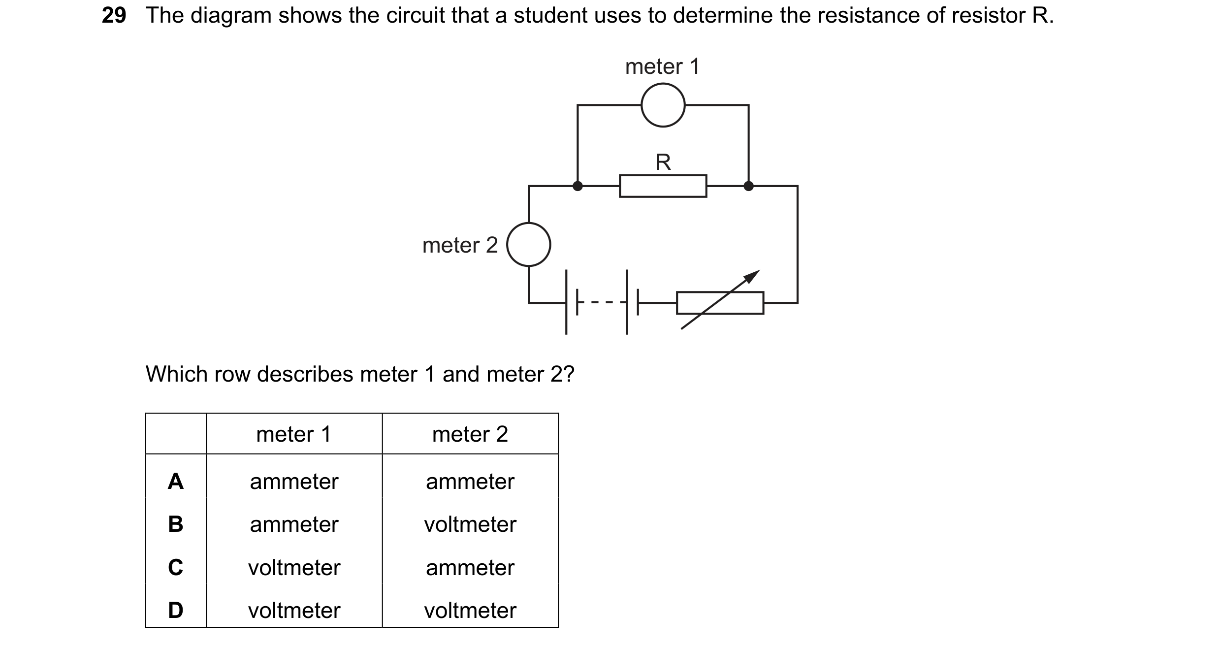
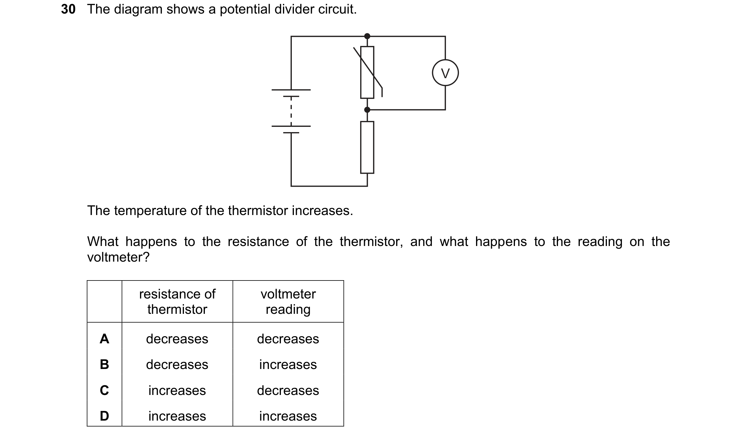 154 / 176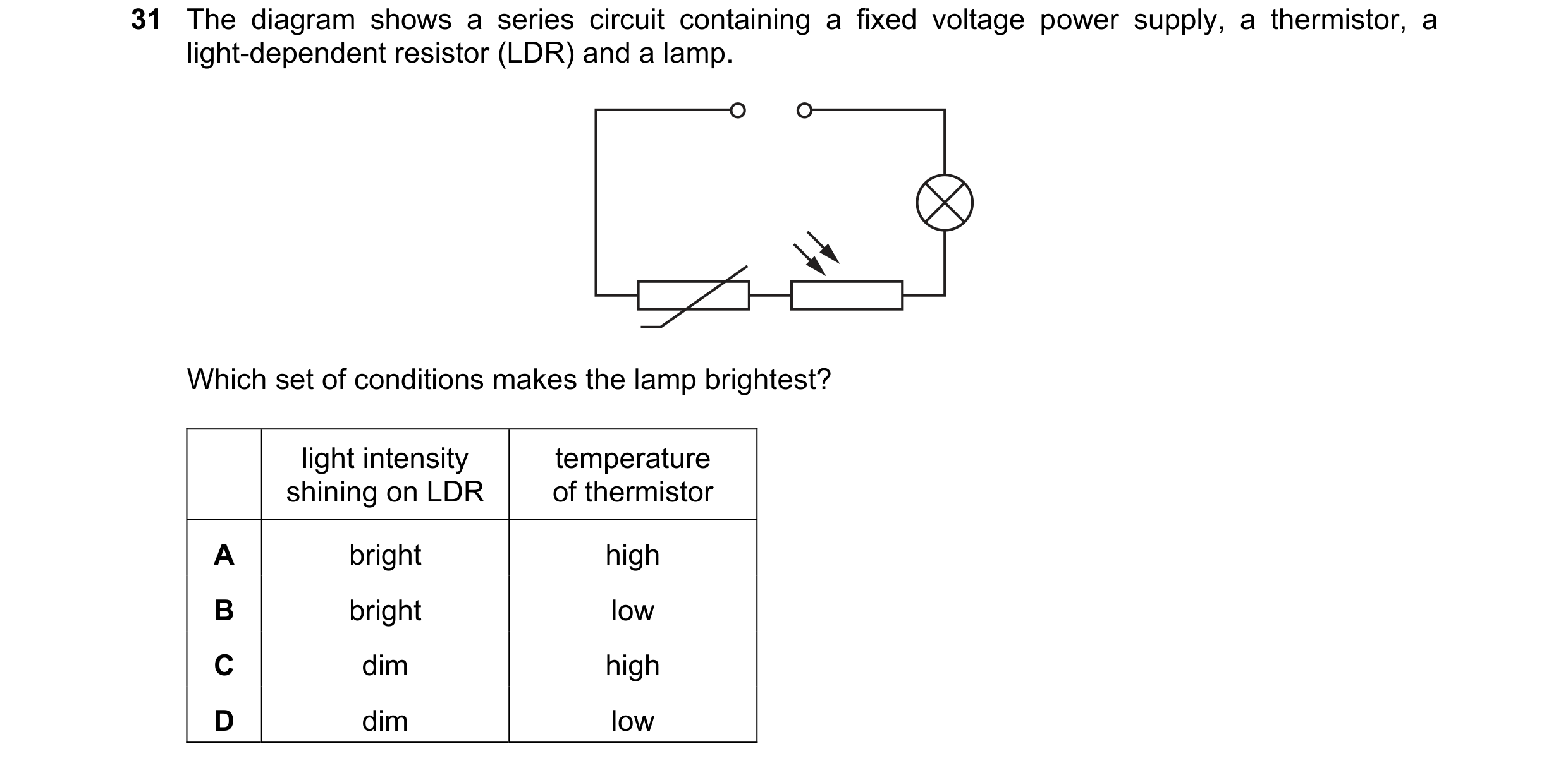
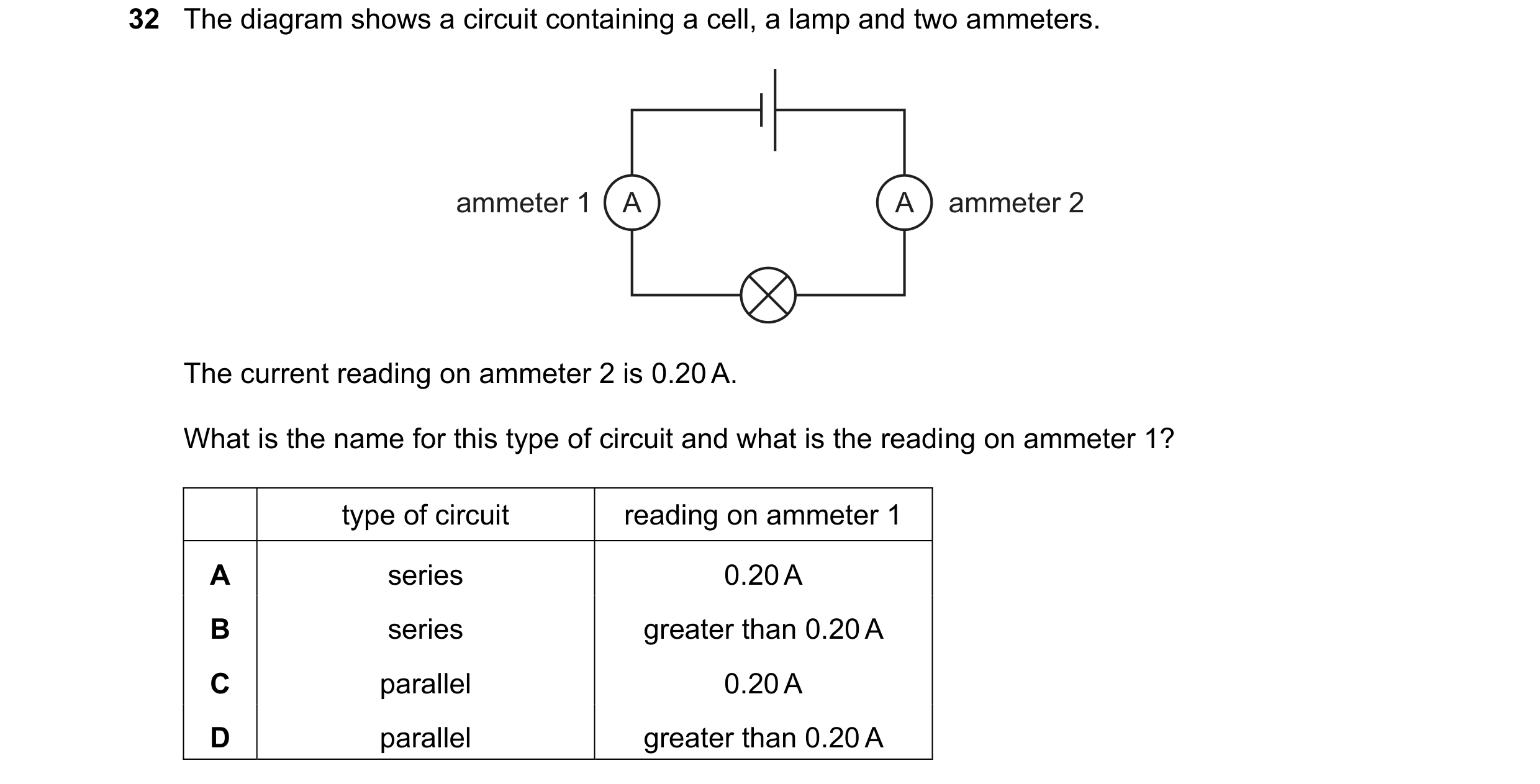
 155 / 176
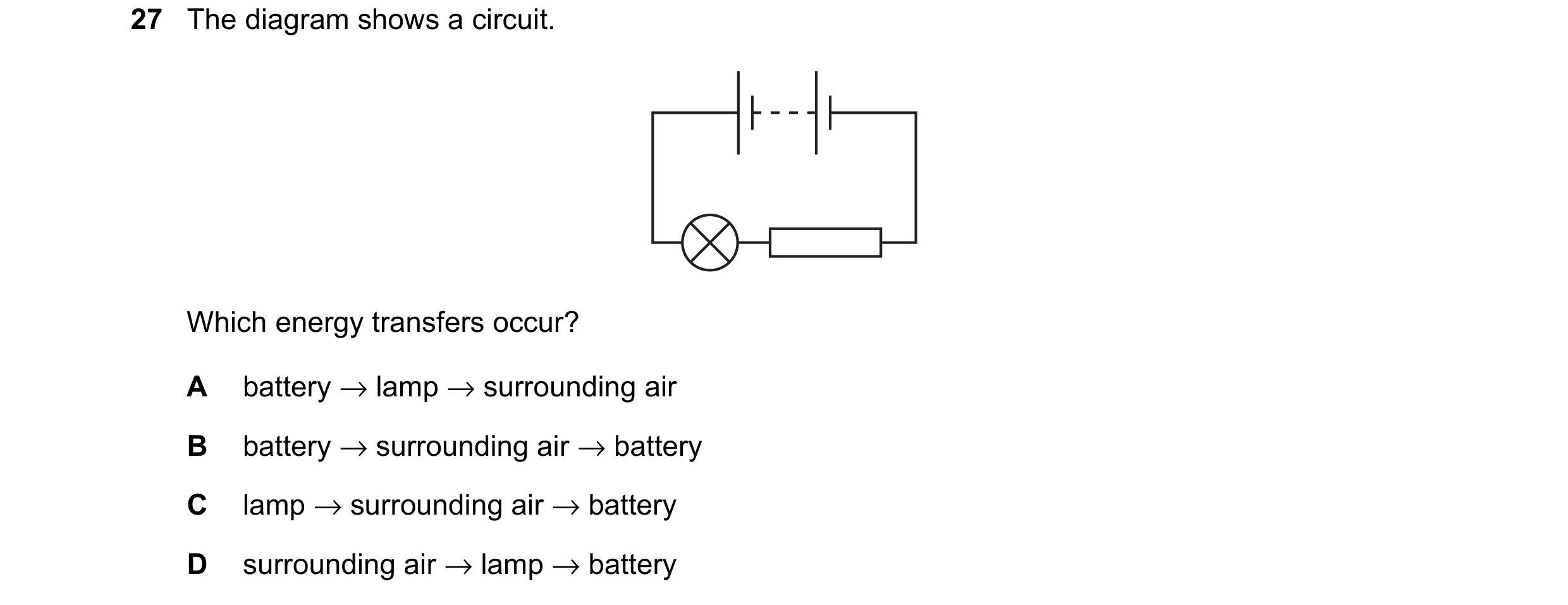
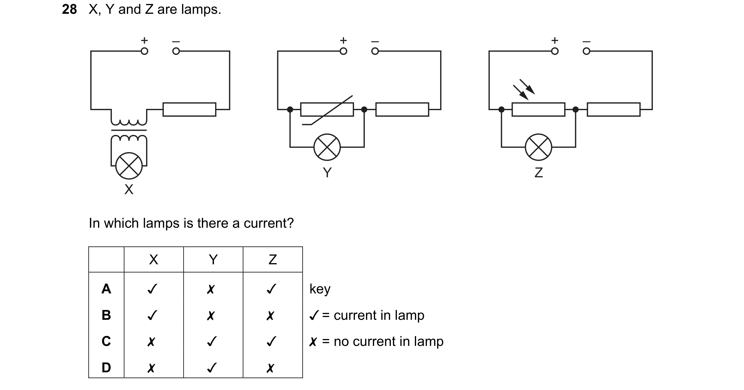 156 / 176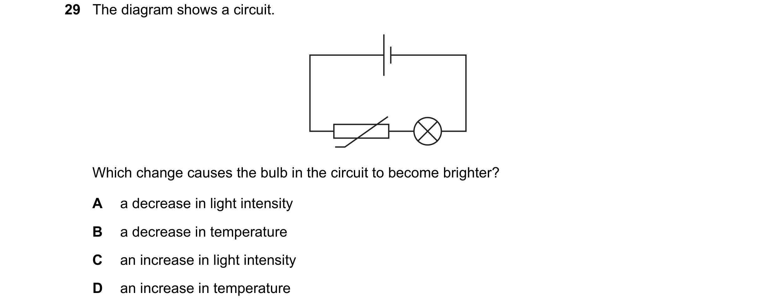
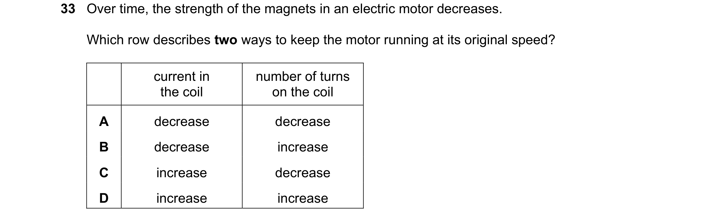
 157 / 176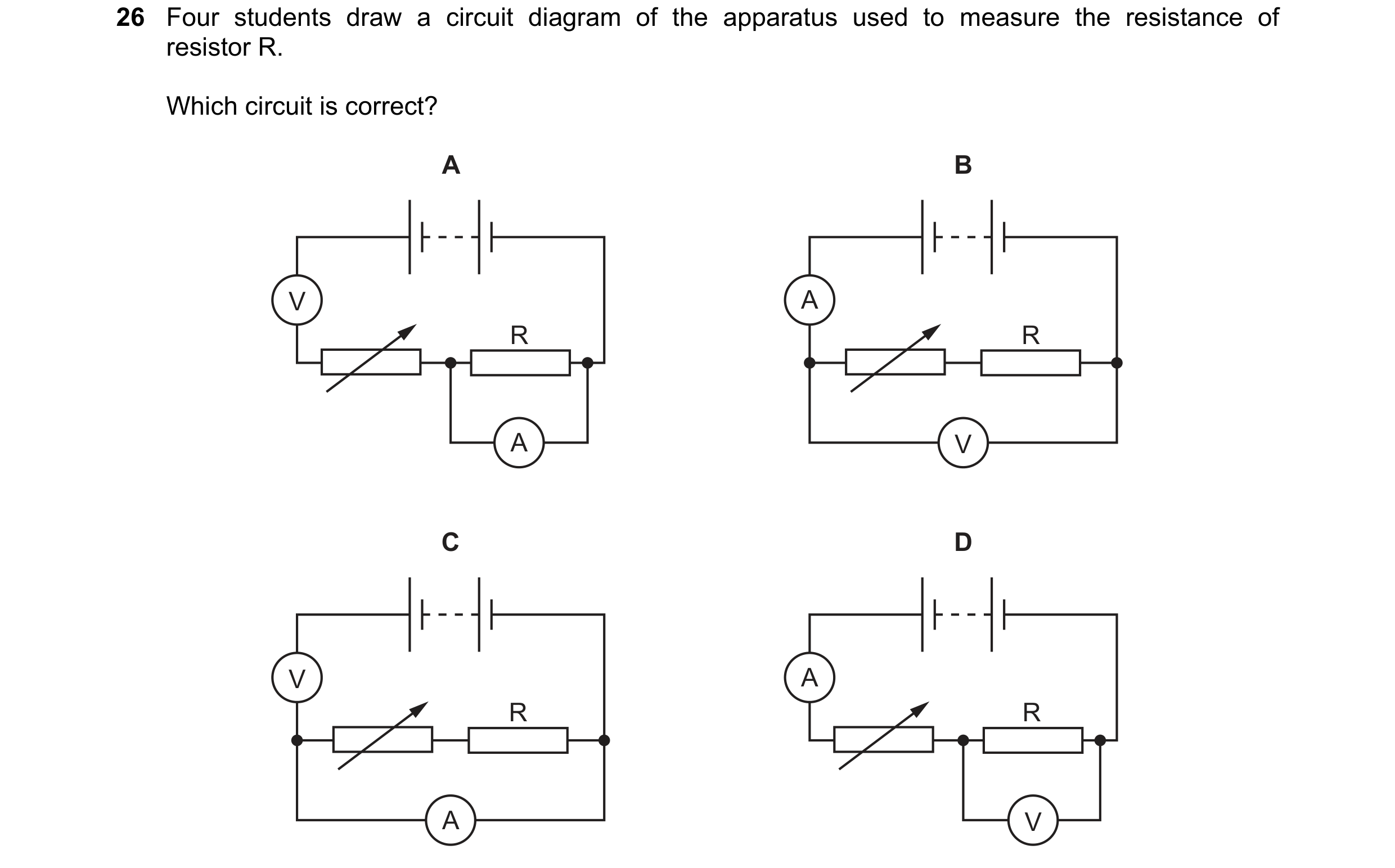
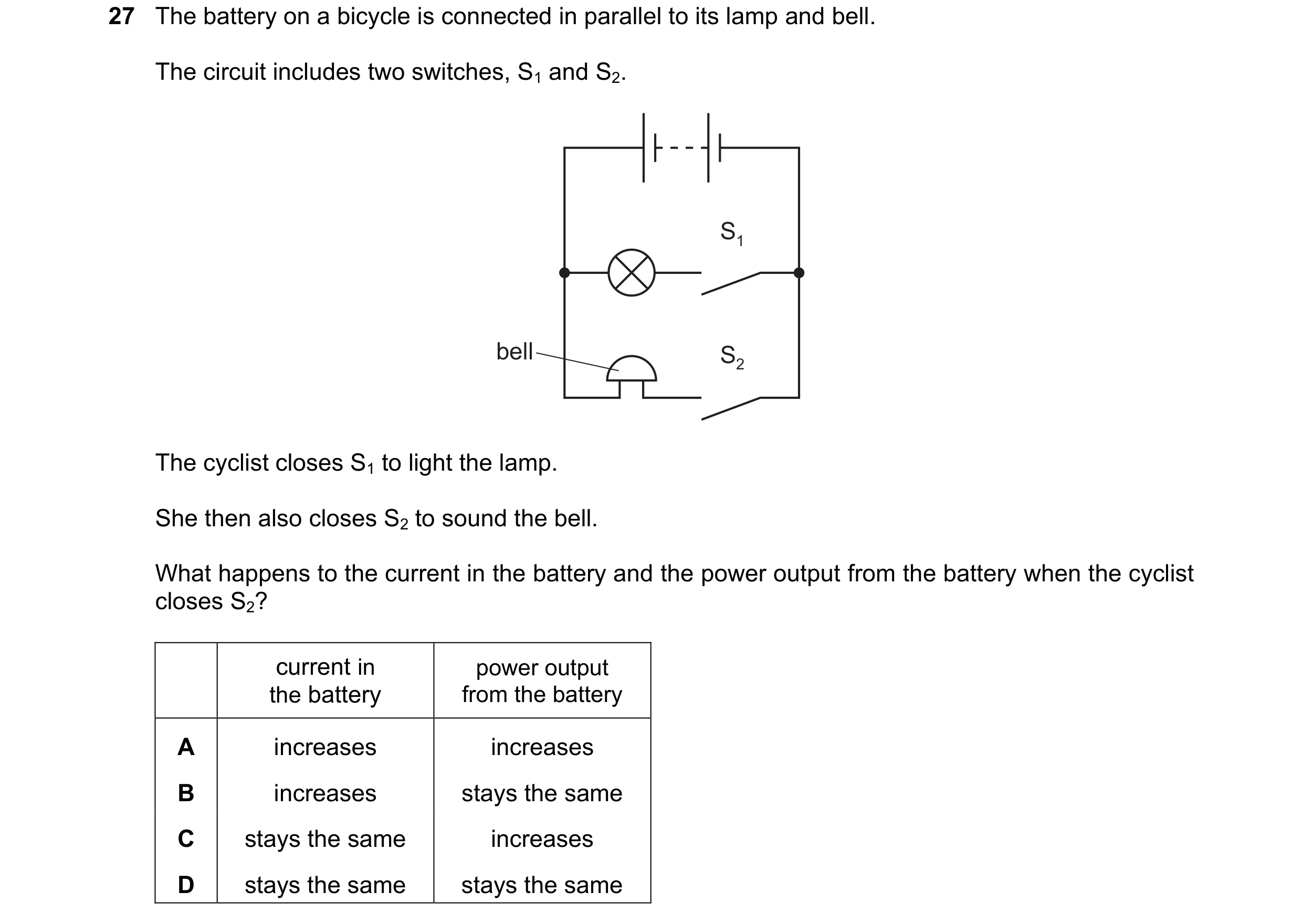 158 / 176
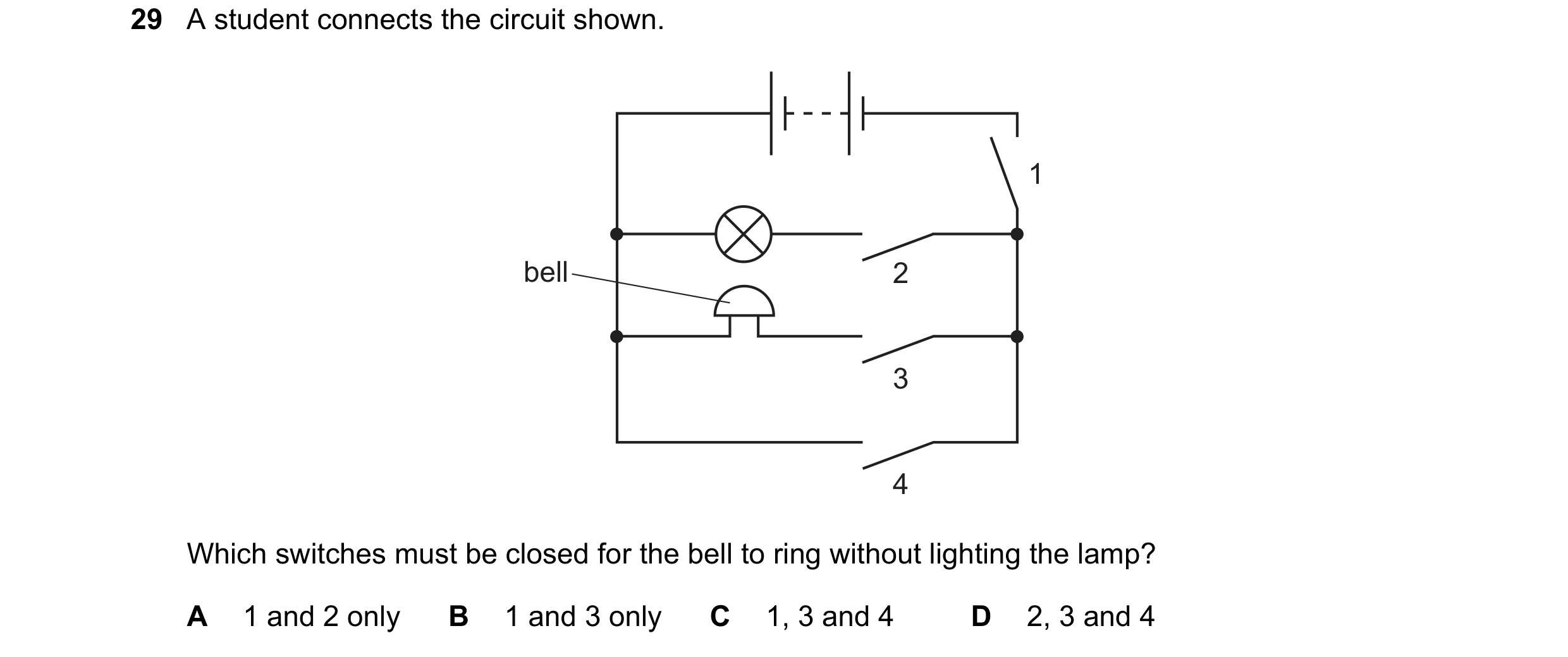

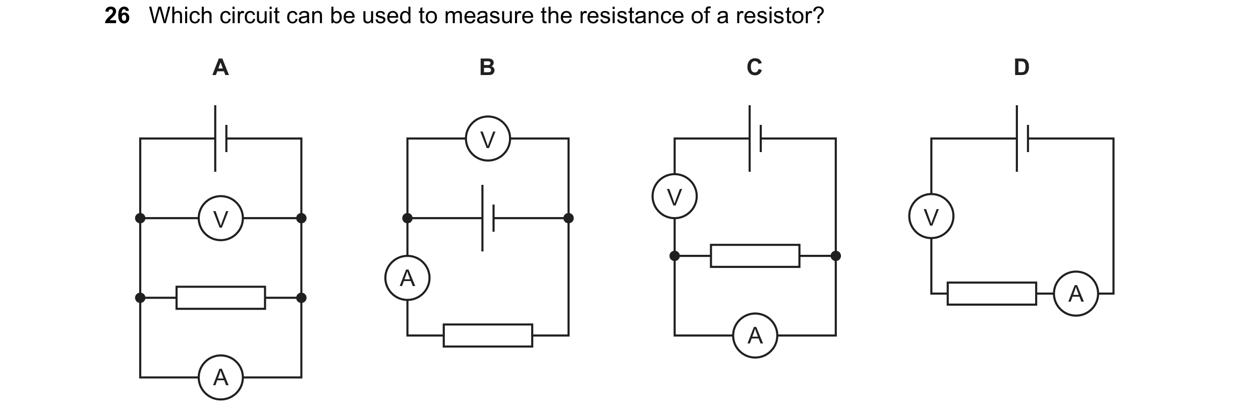 159 / 176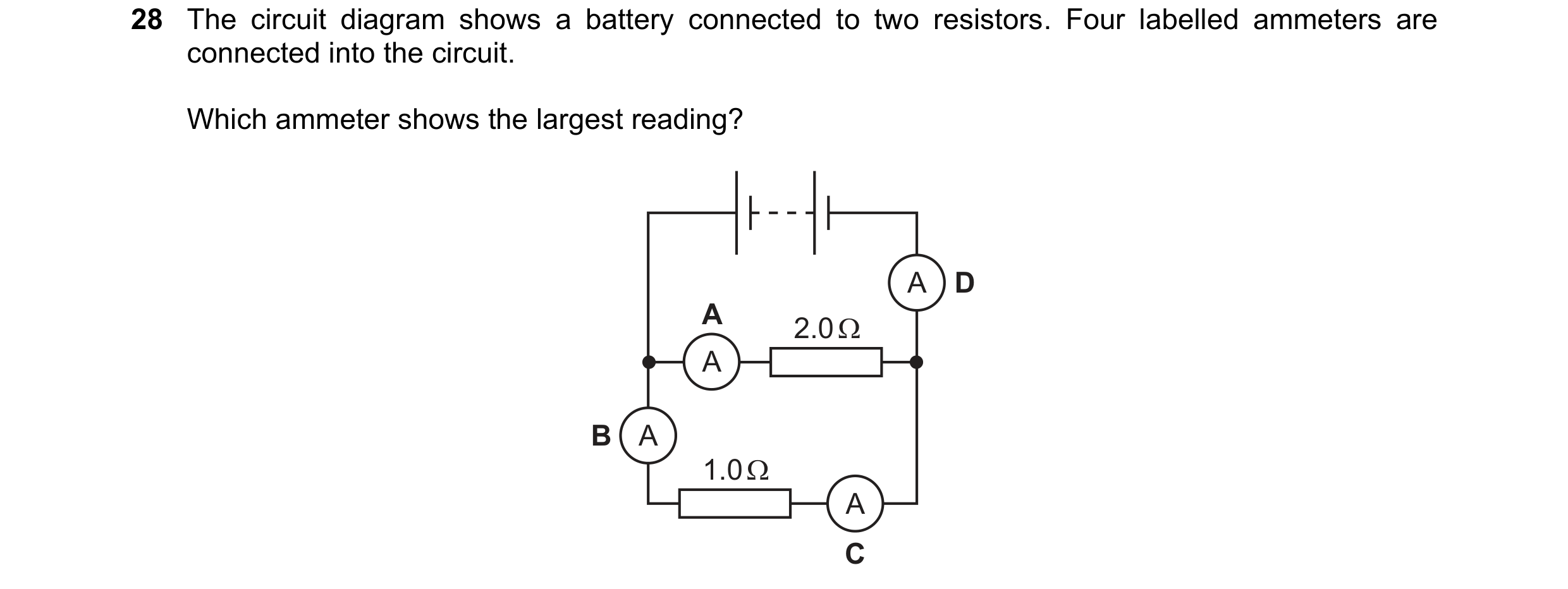
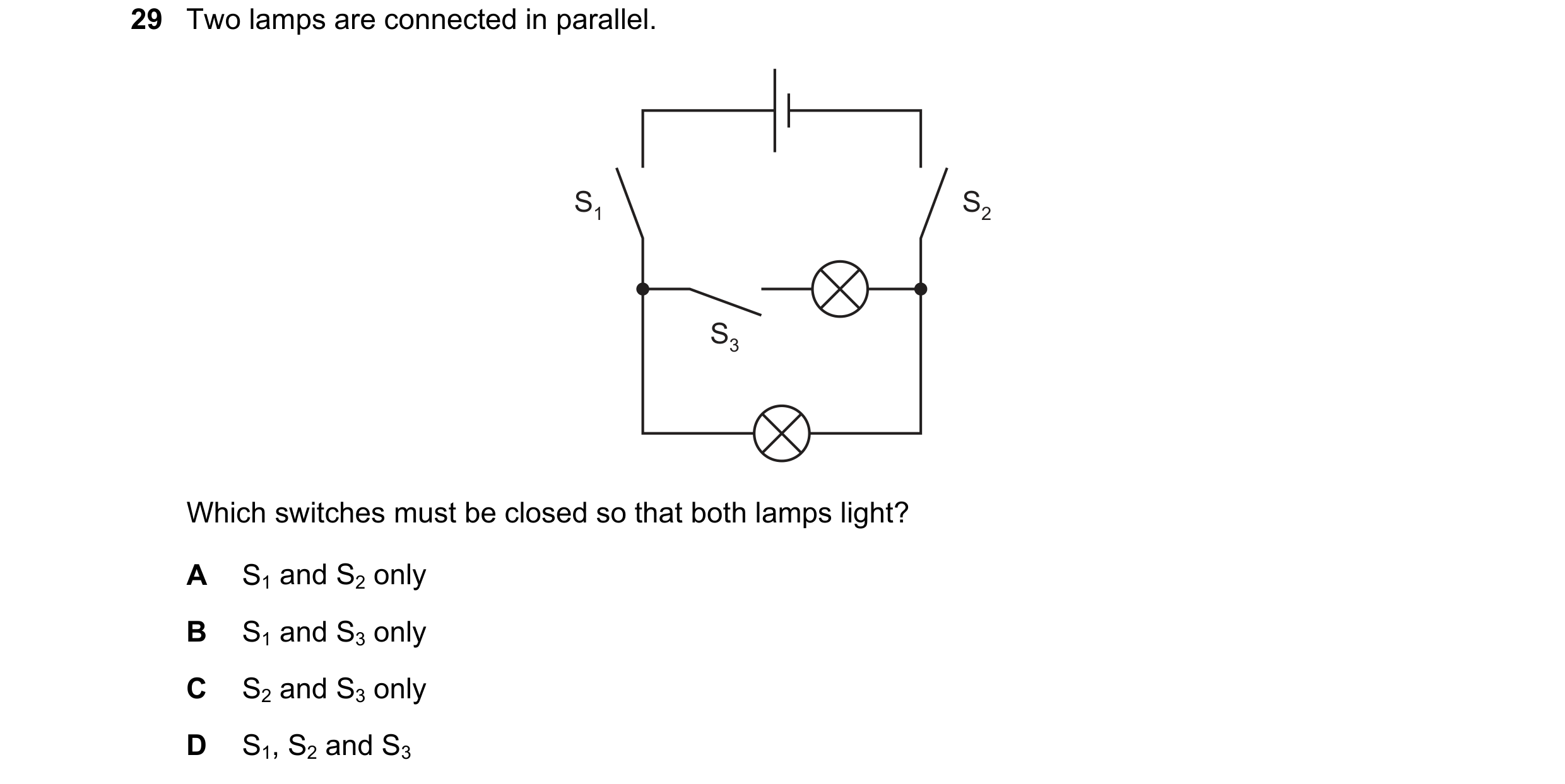 160 / 176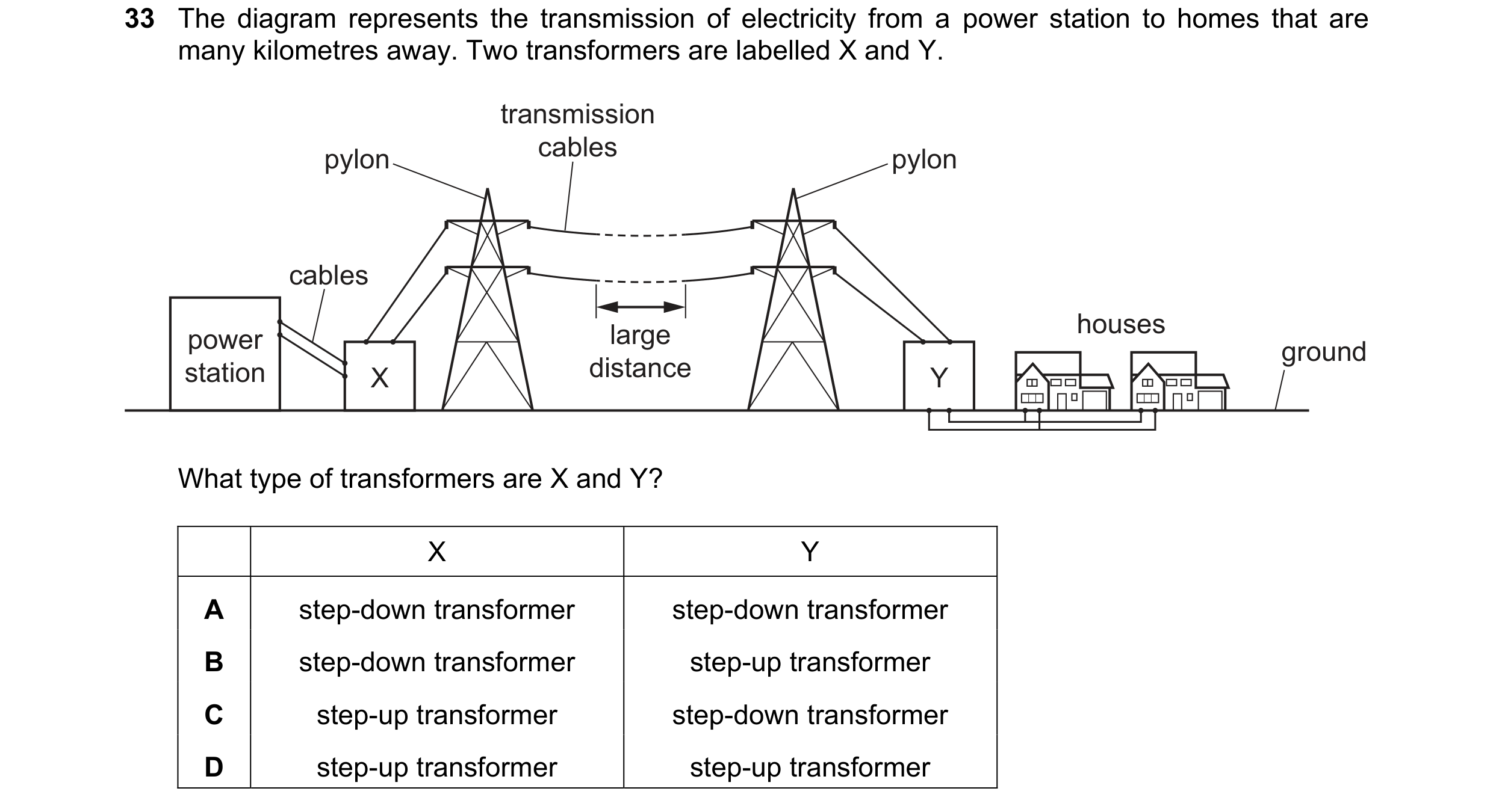


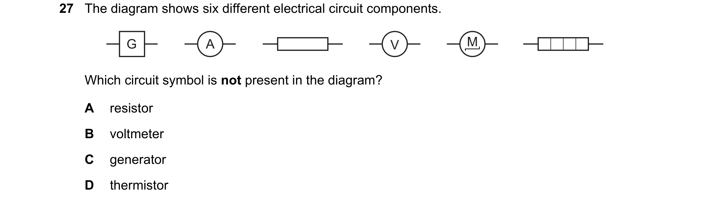 161 / 176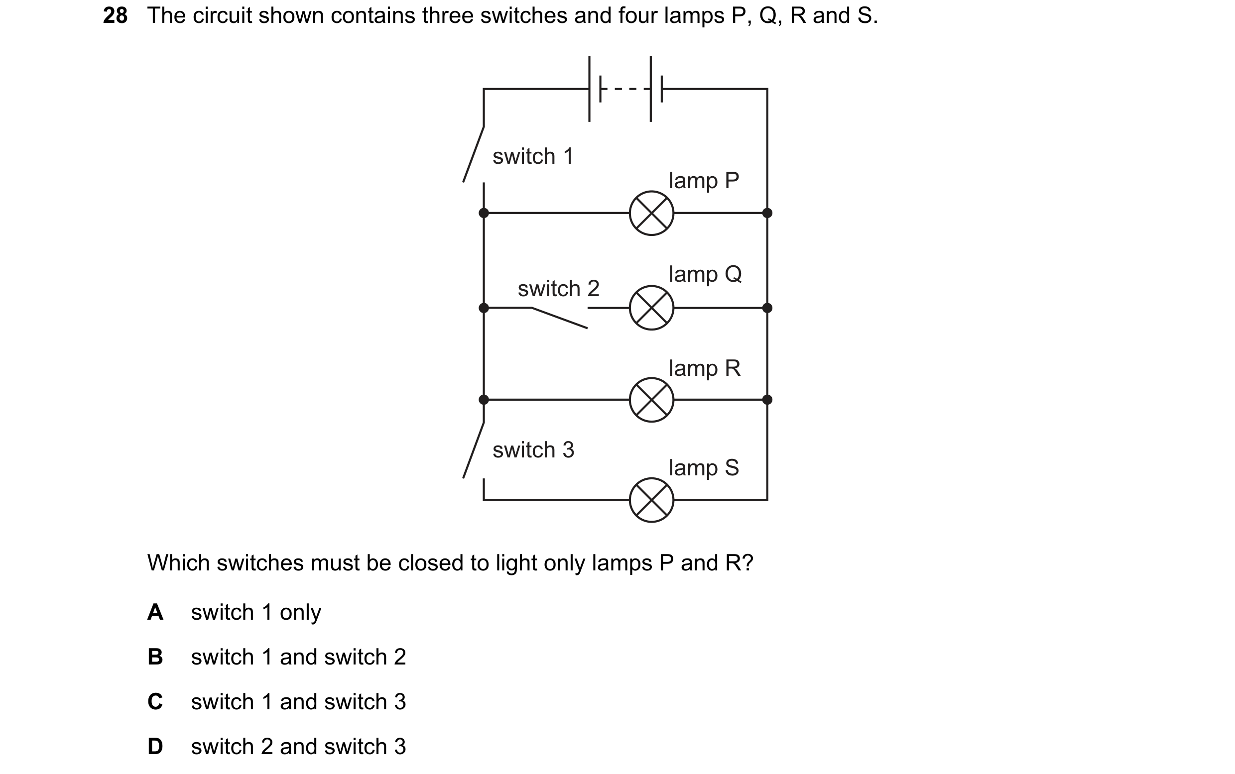
 162 / 176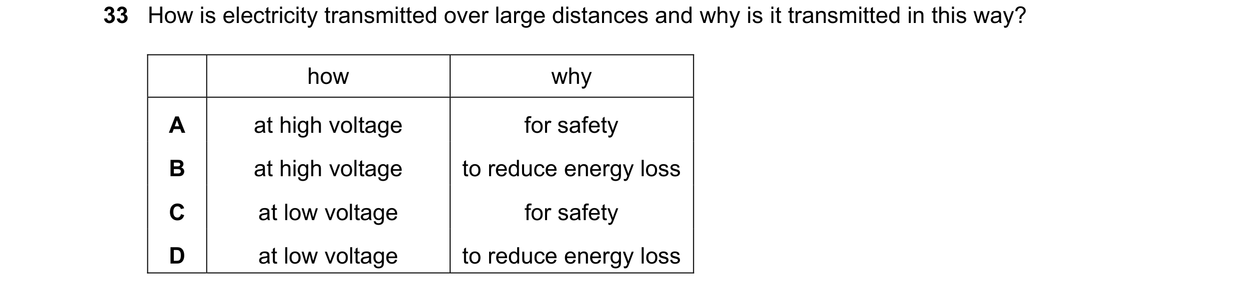

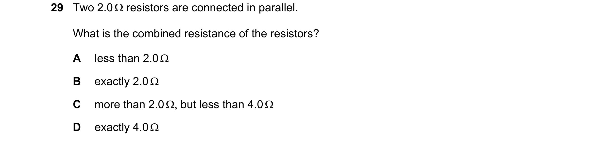
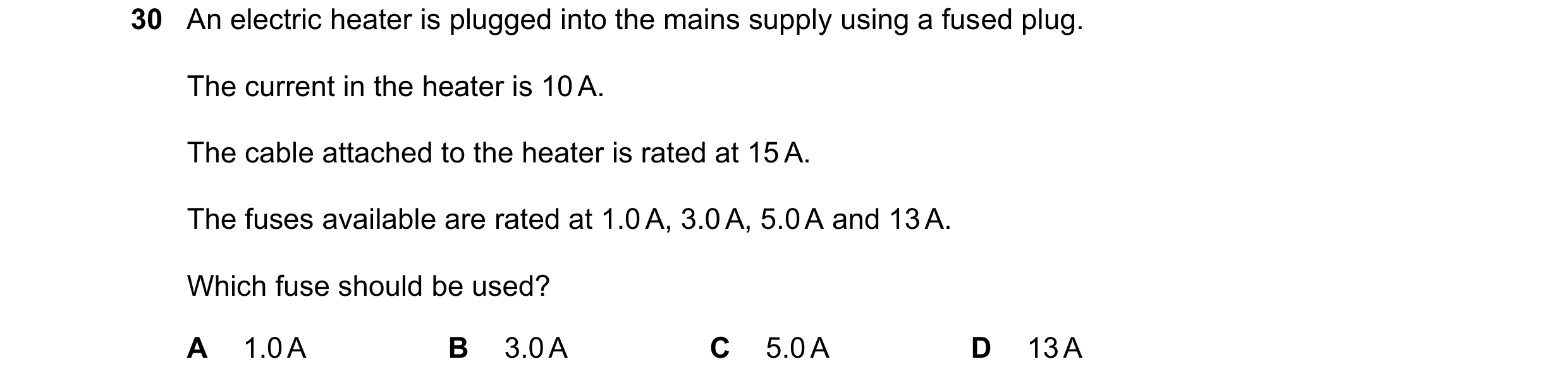 163 / 176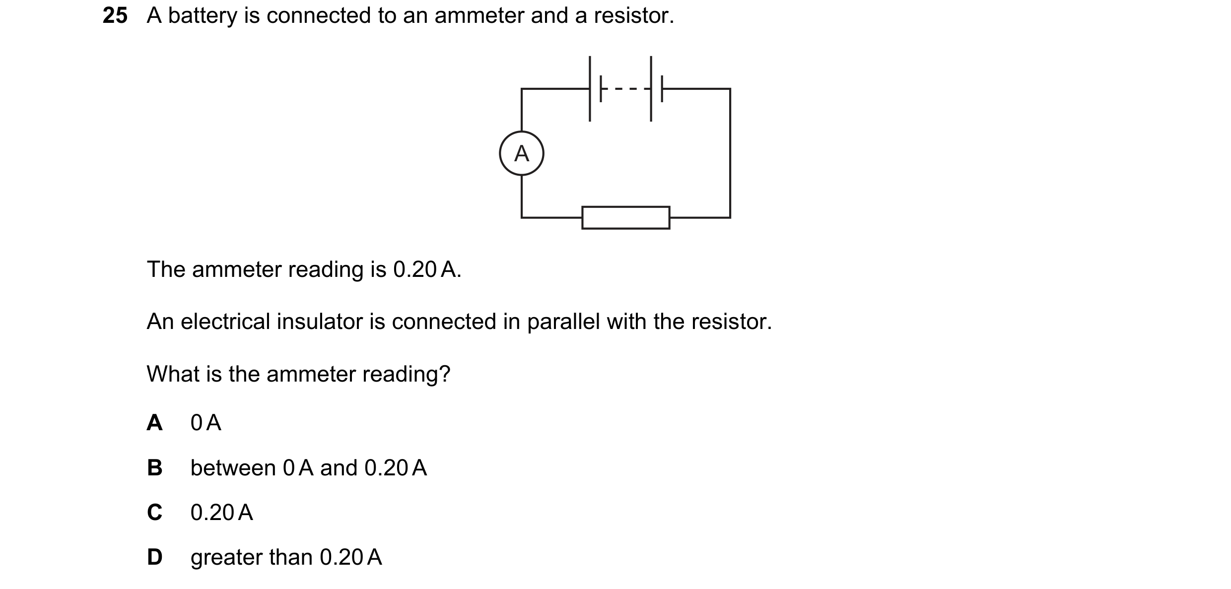


 164 / 176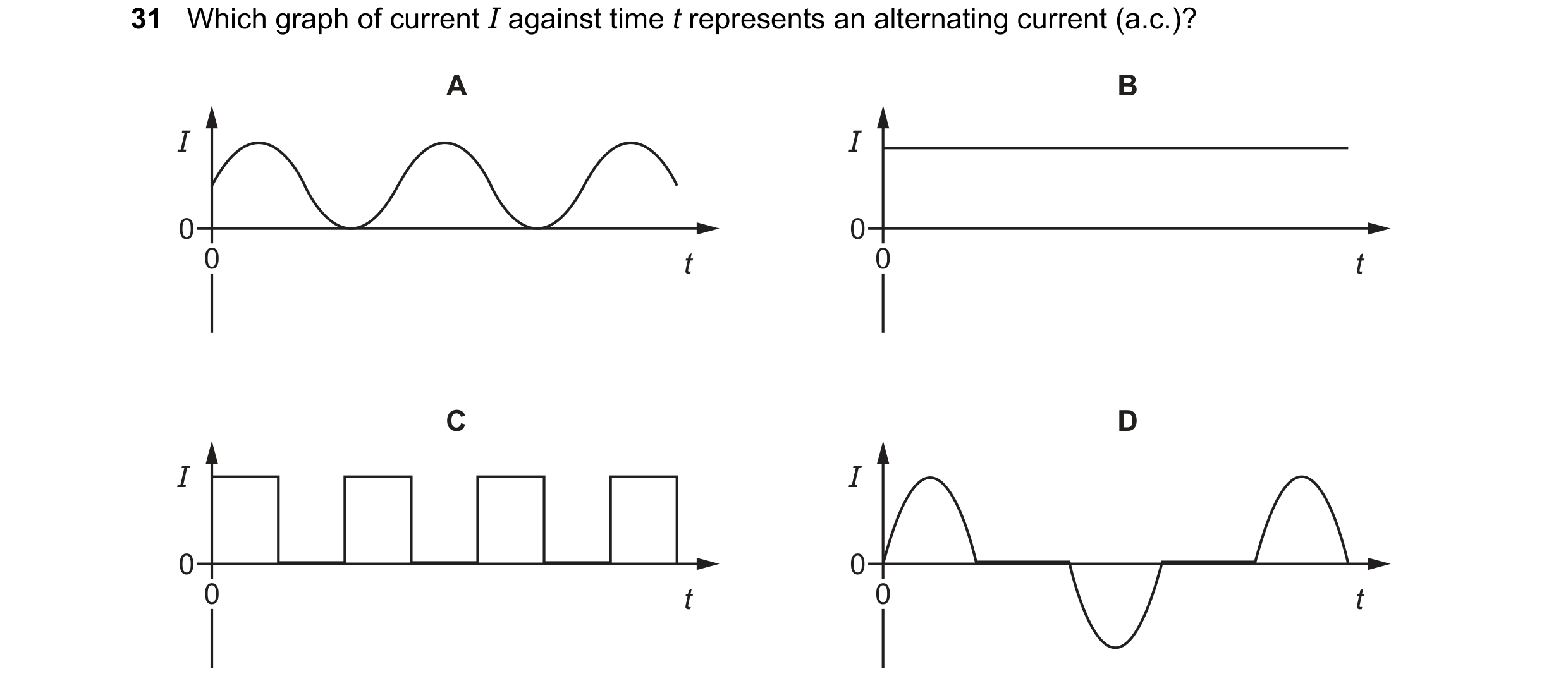
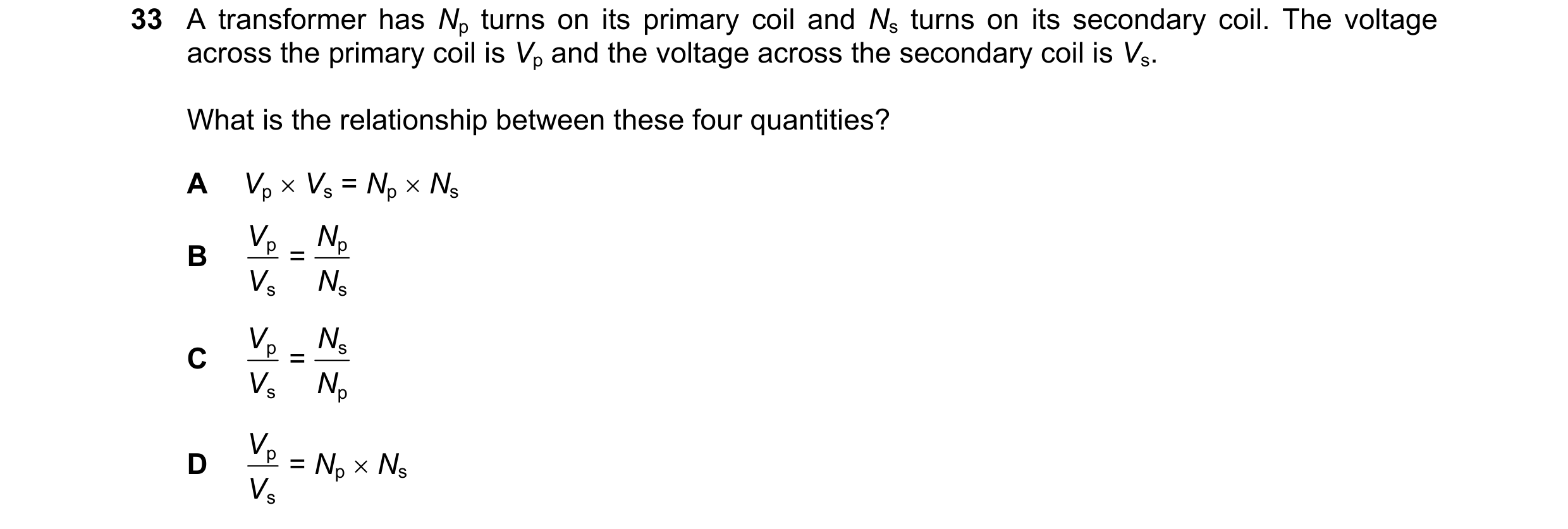
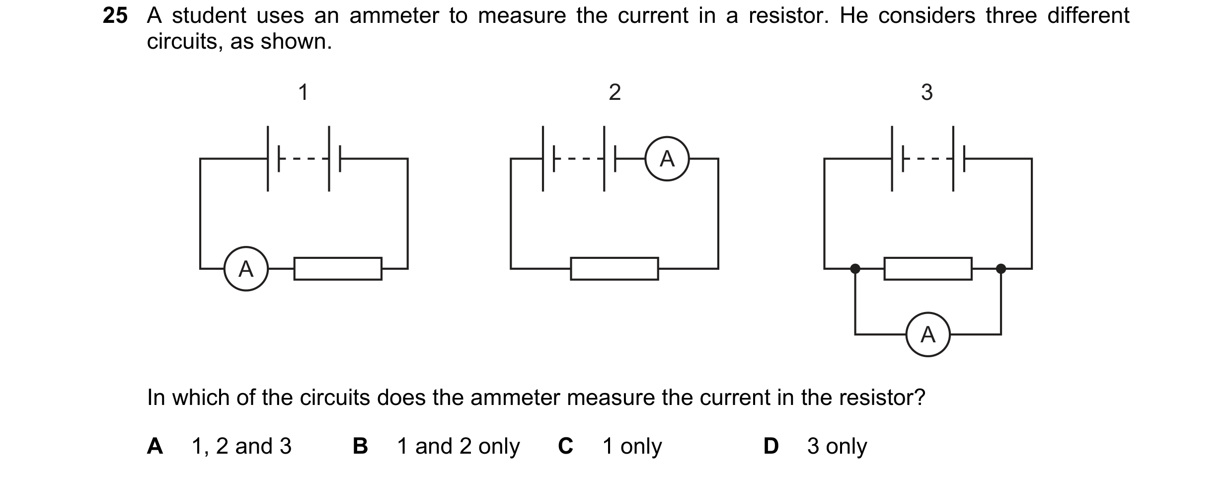 165 / 176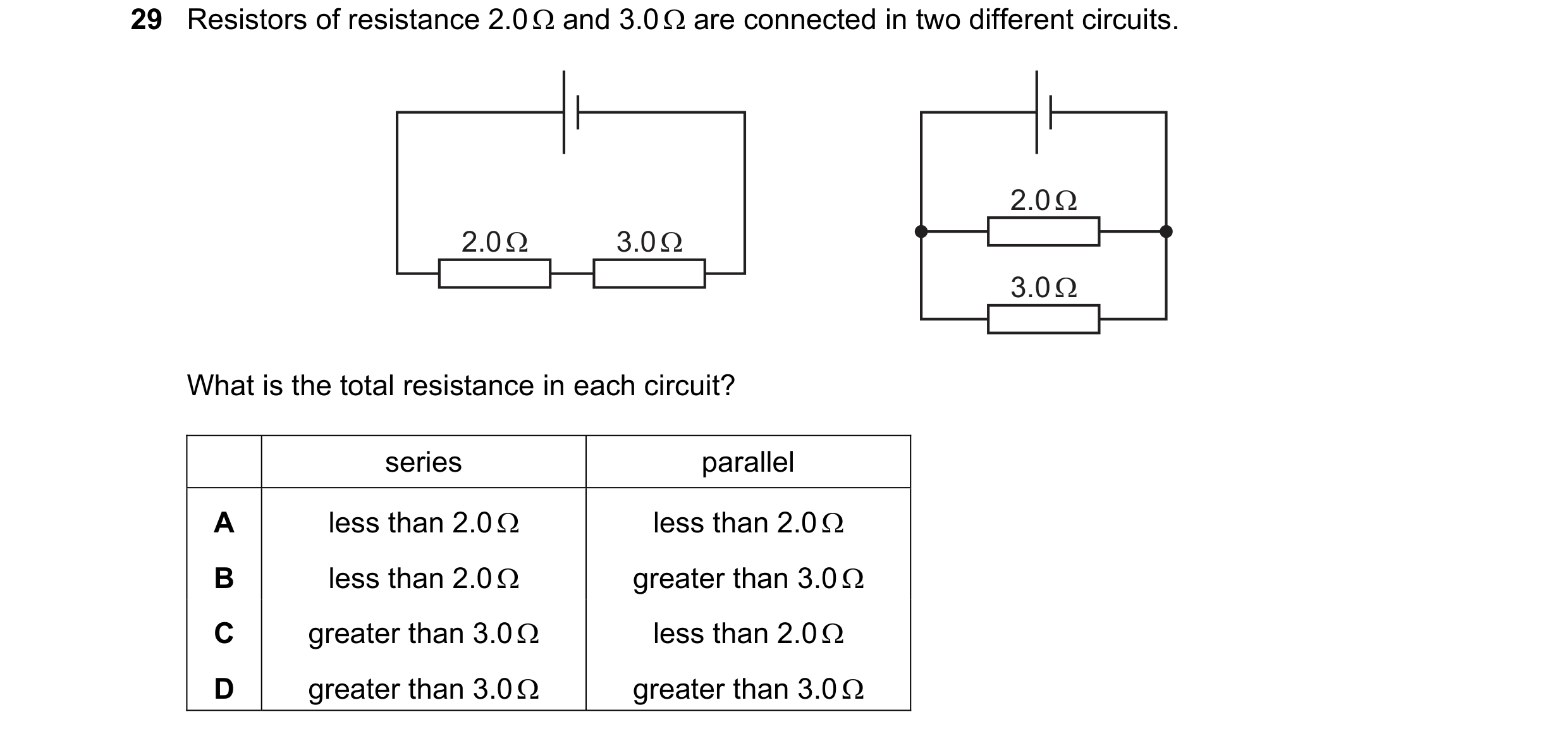
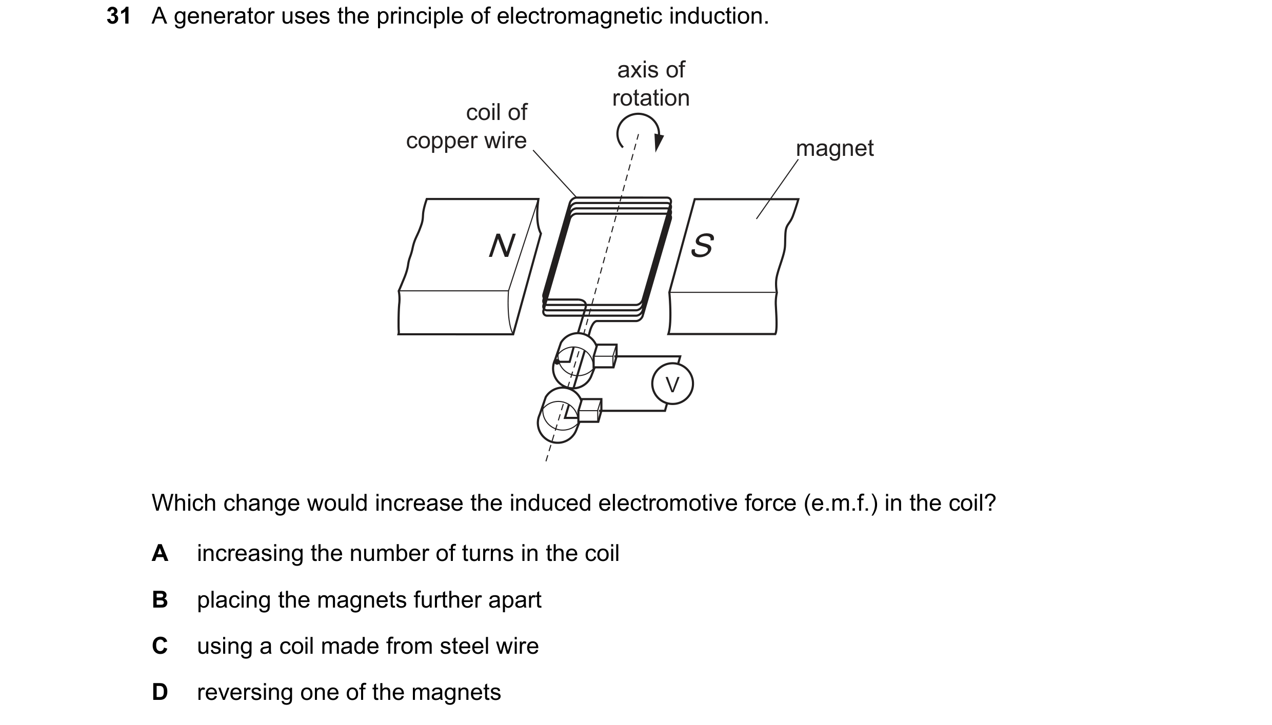
 166 / 176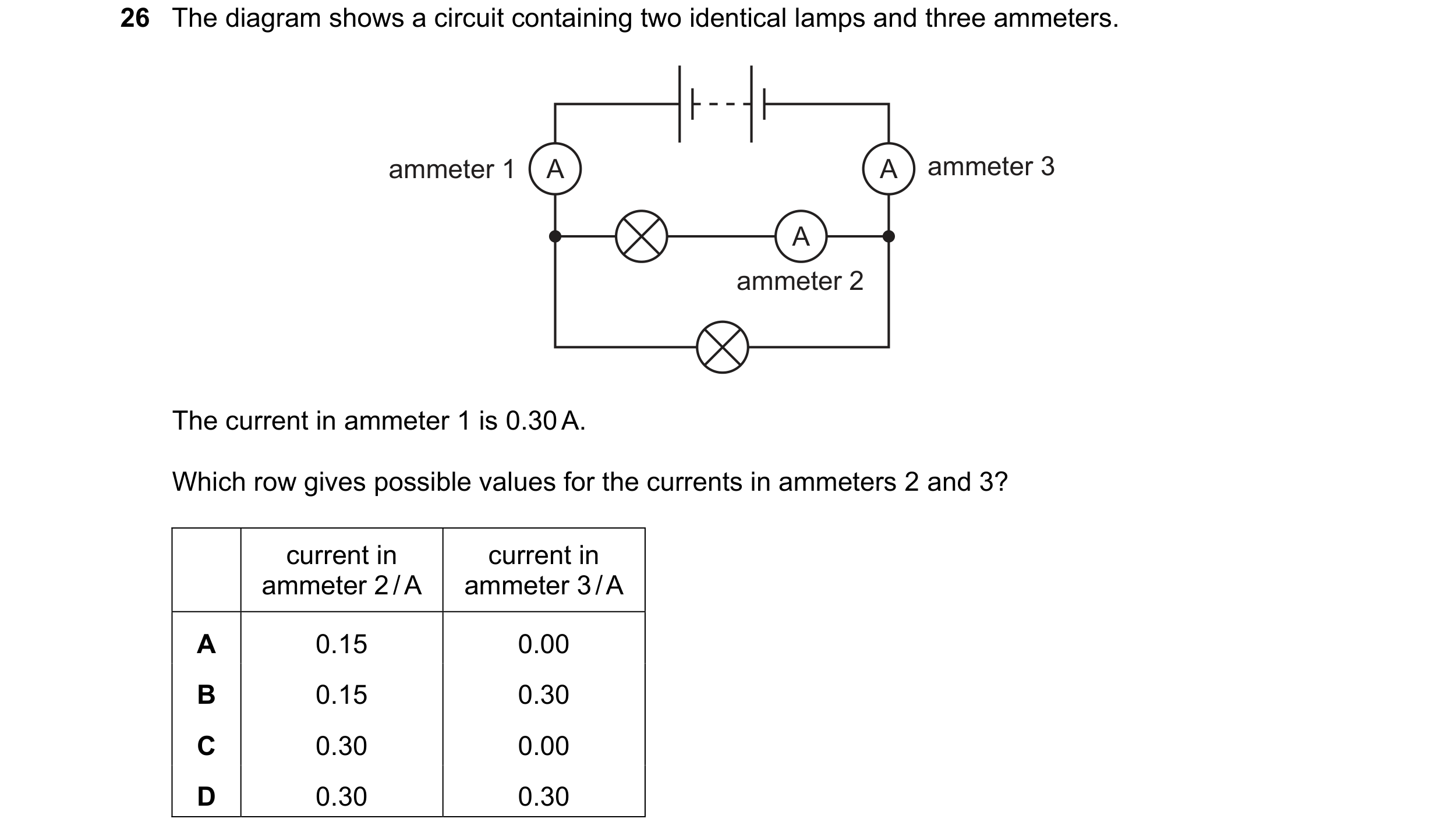

 167 / 176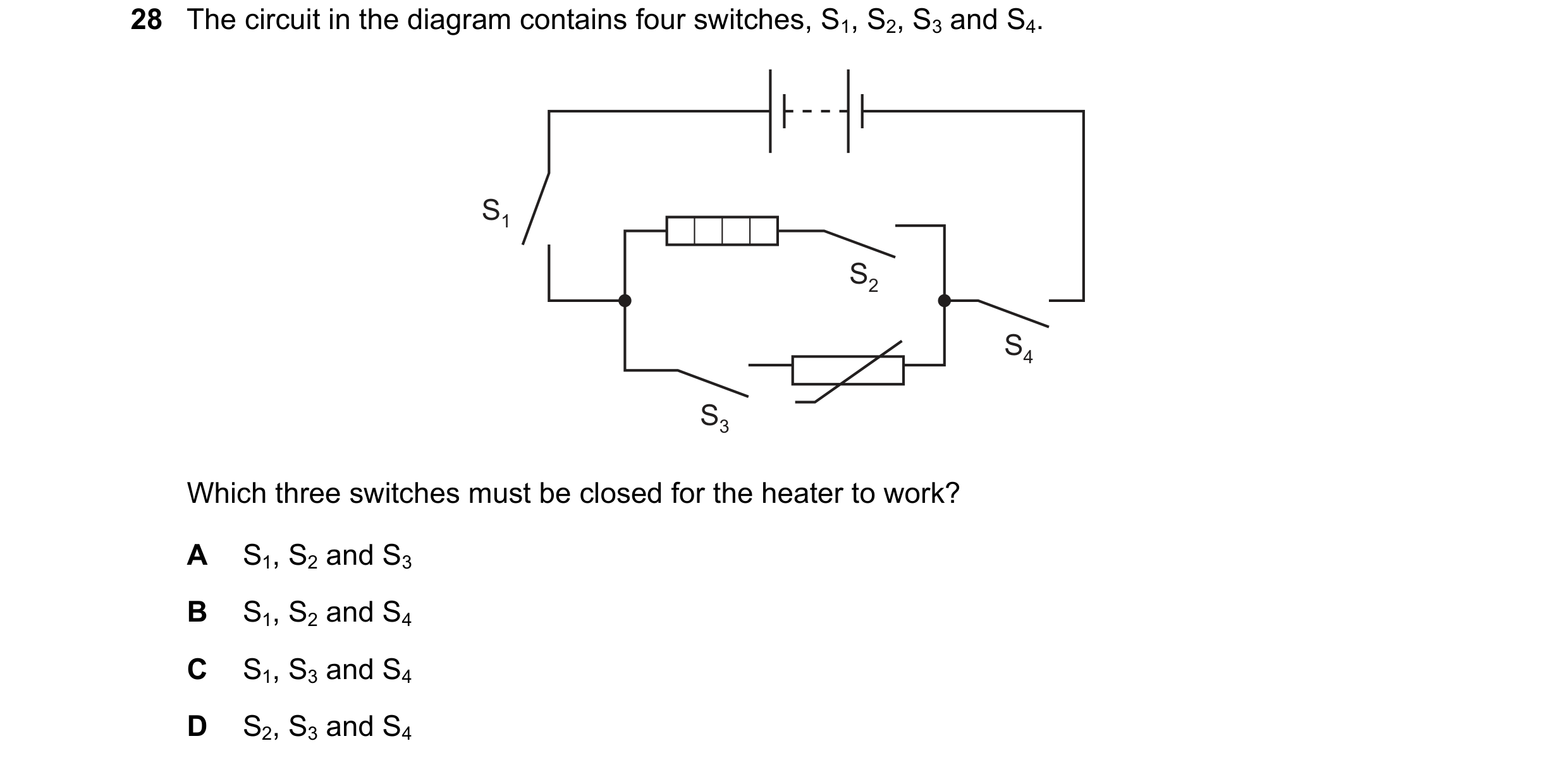
 168 / 176

 169 / 176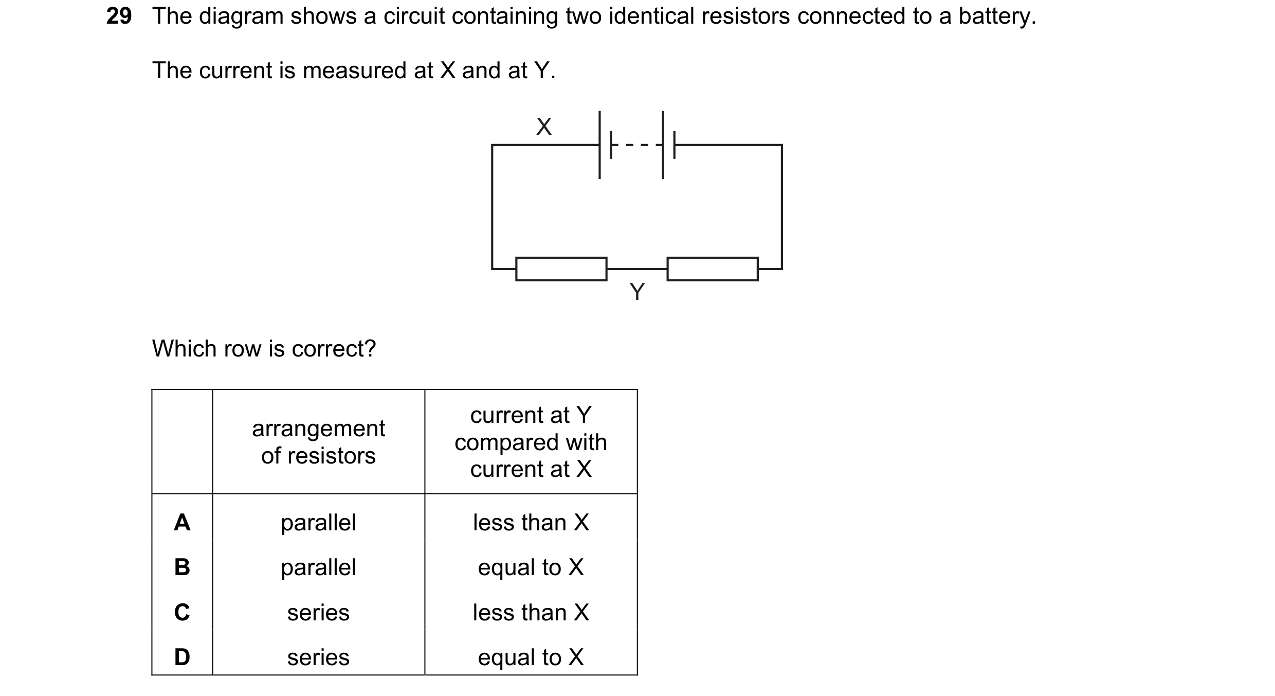
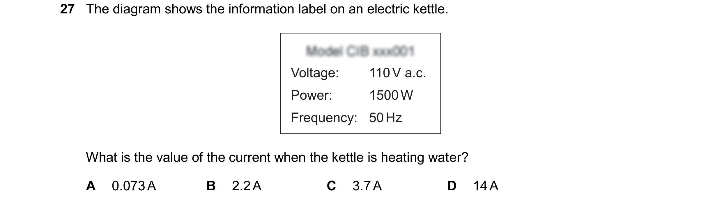 170 / 176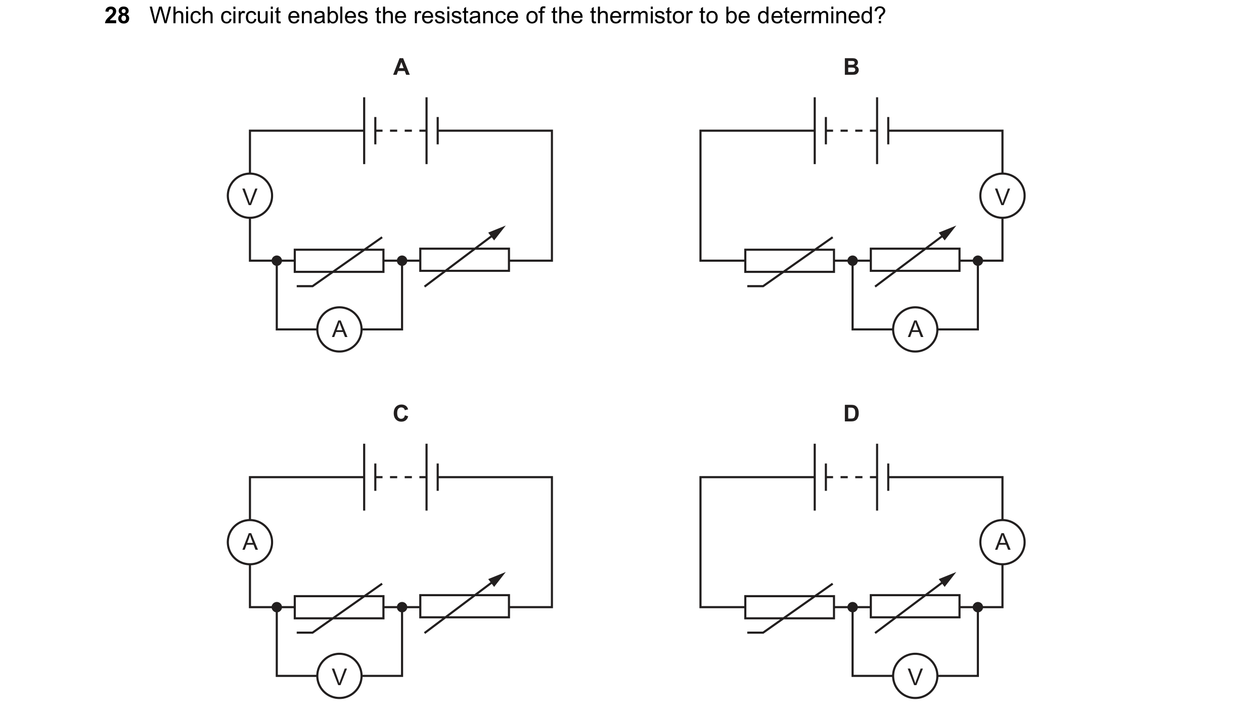
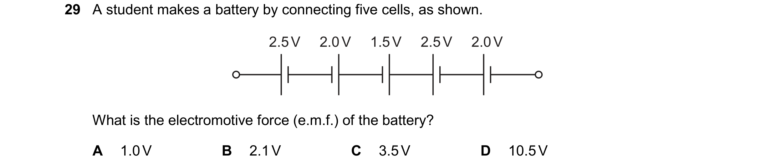
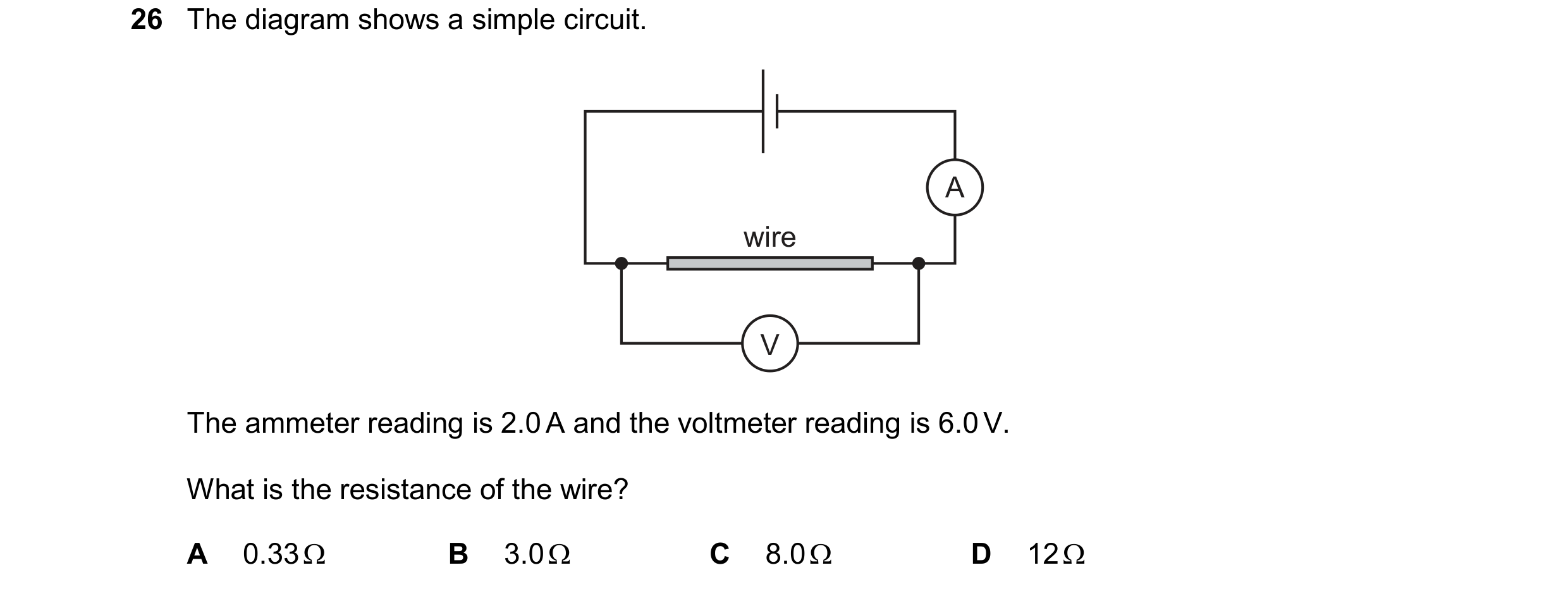 171 / 176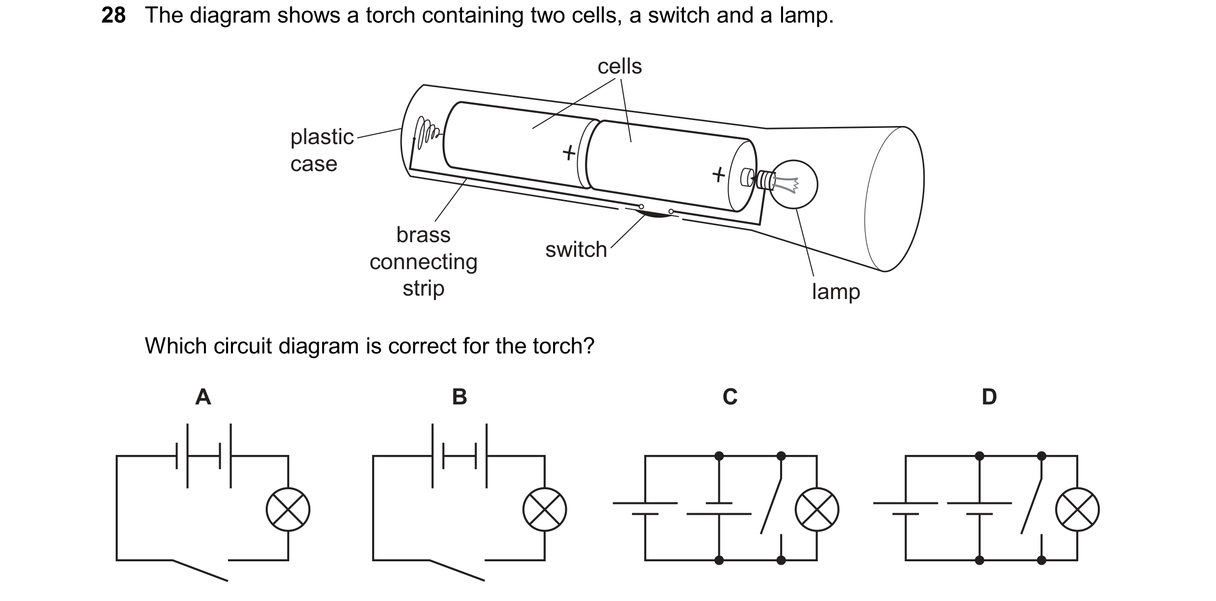
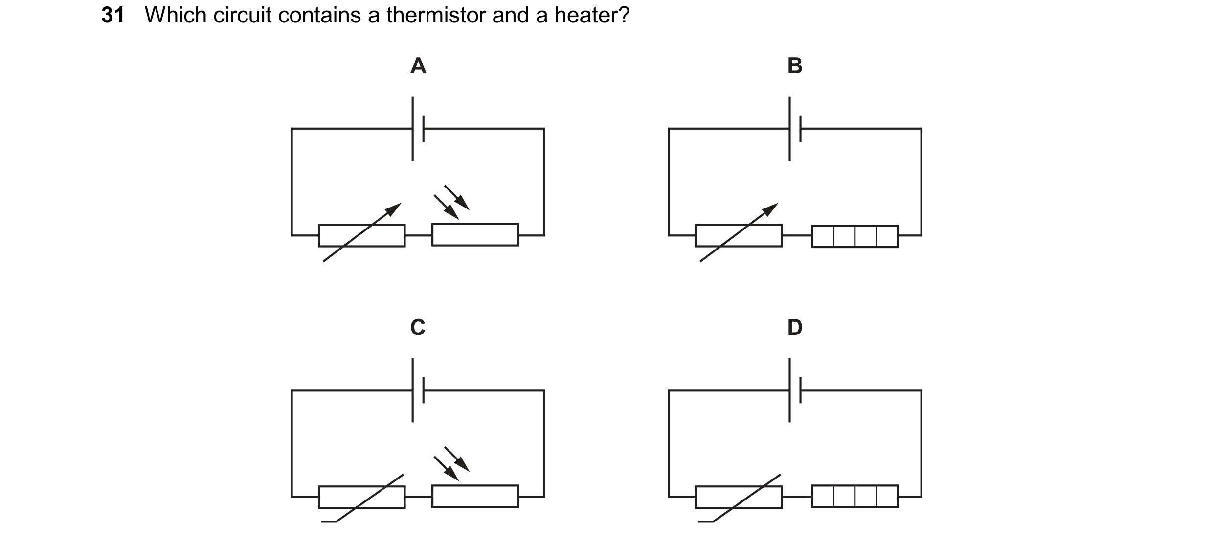
 172 / 176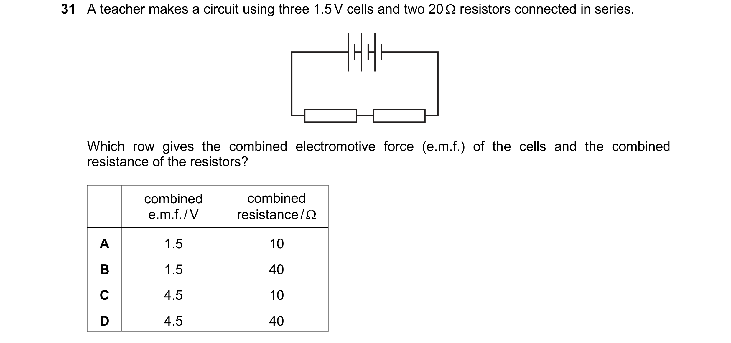

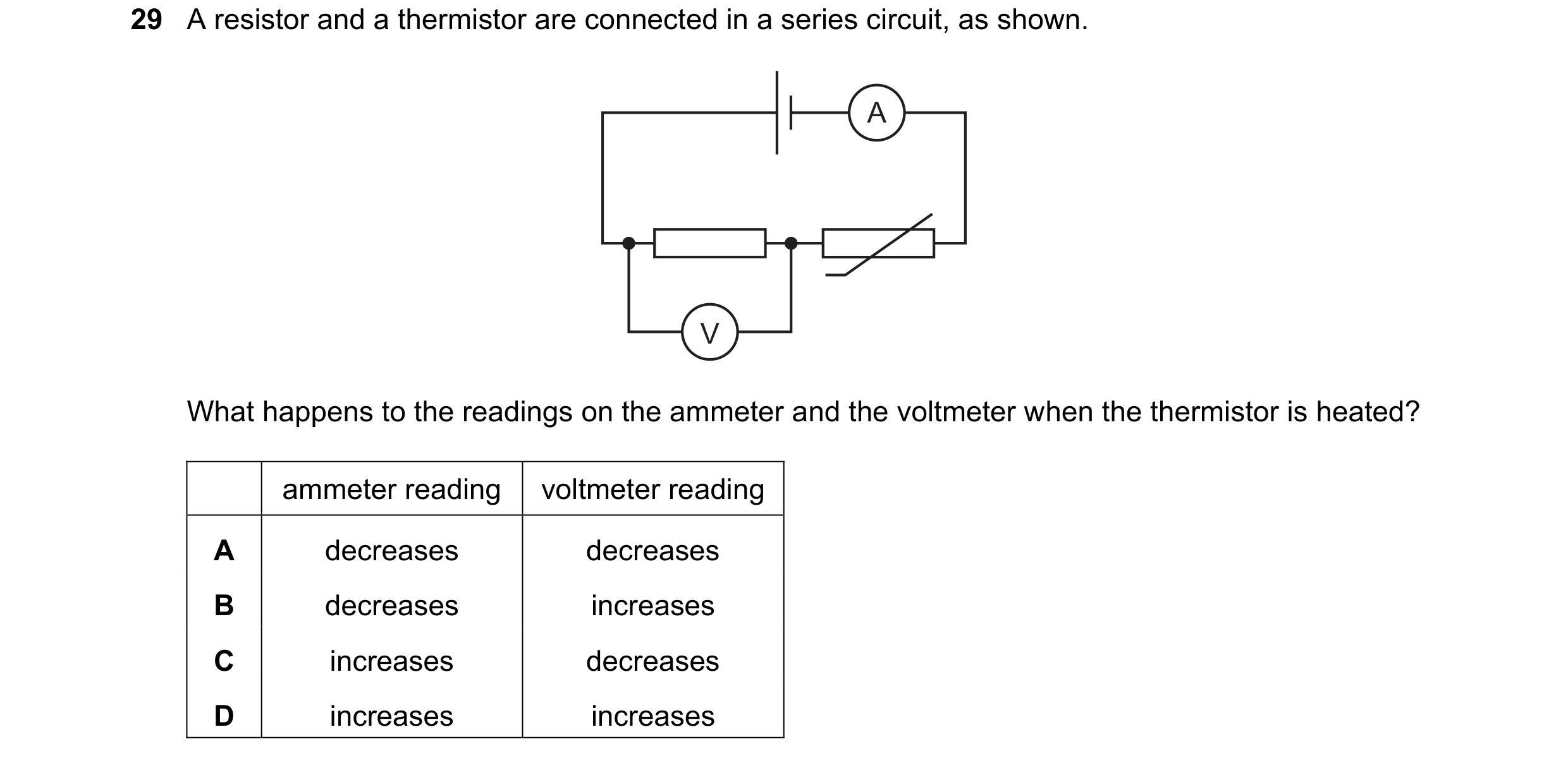 173 / 176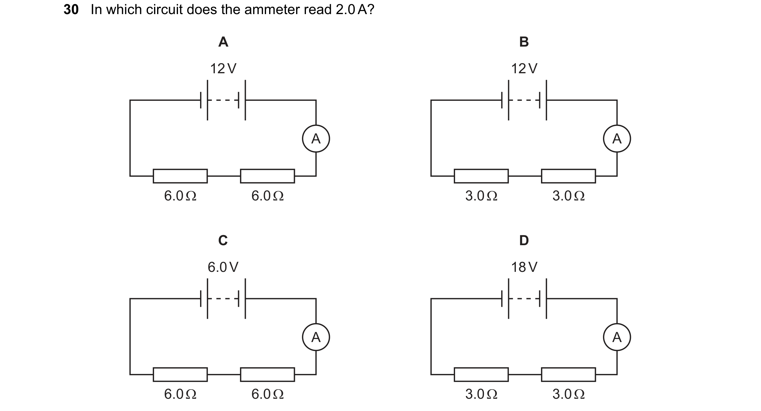

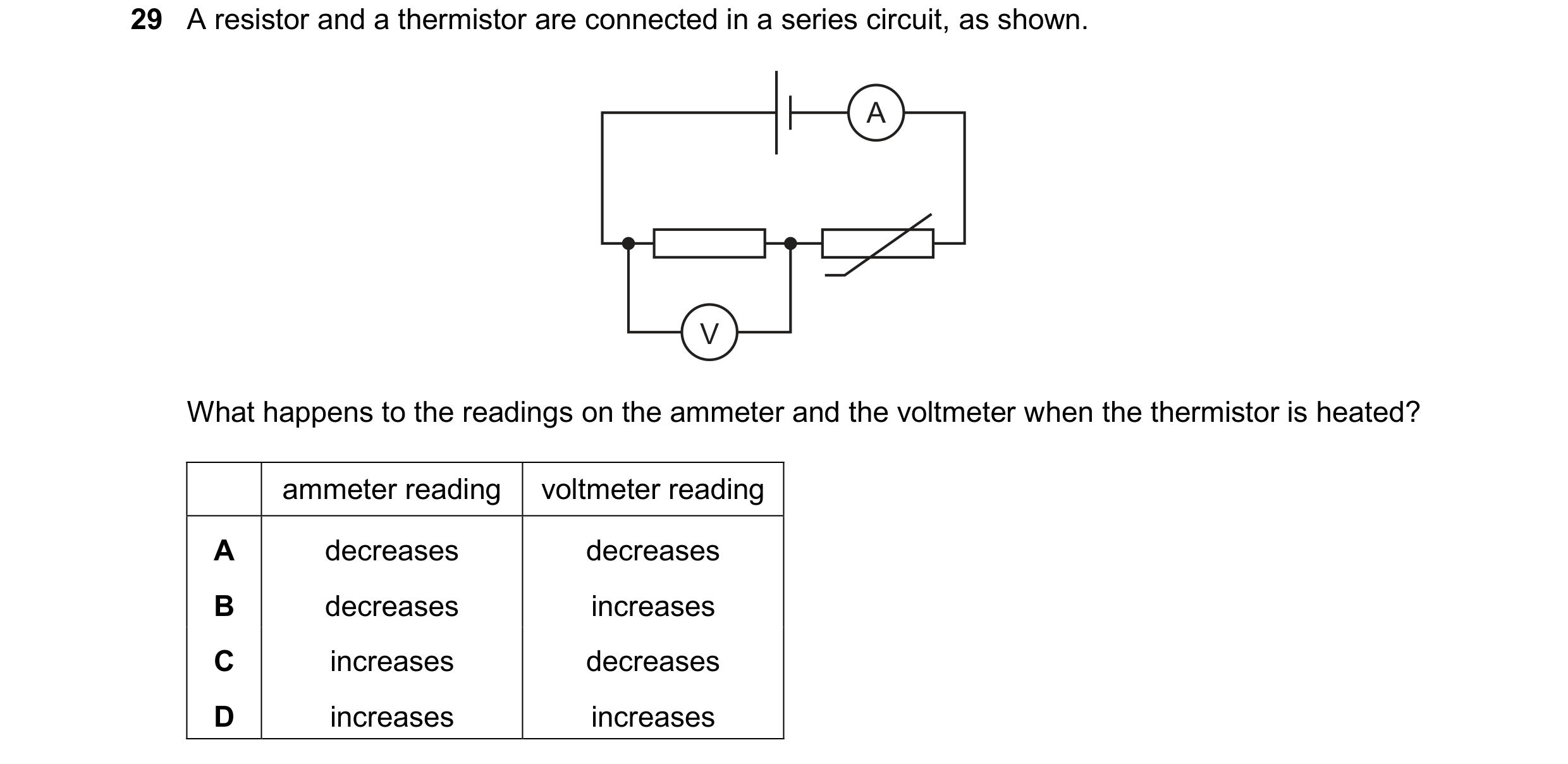 174 / 176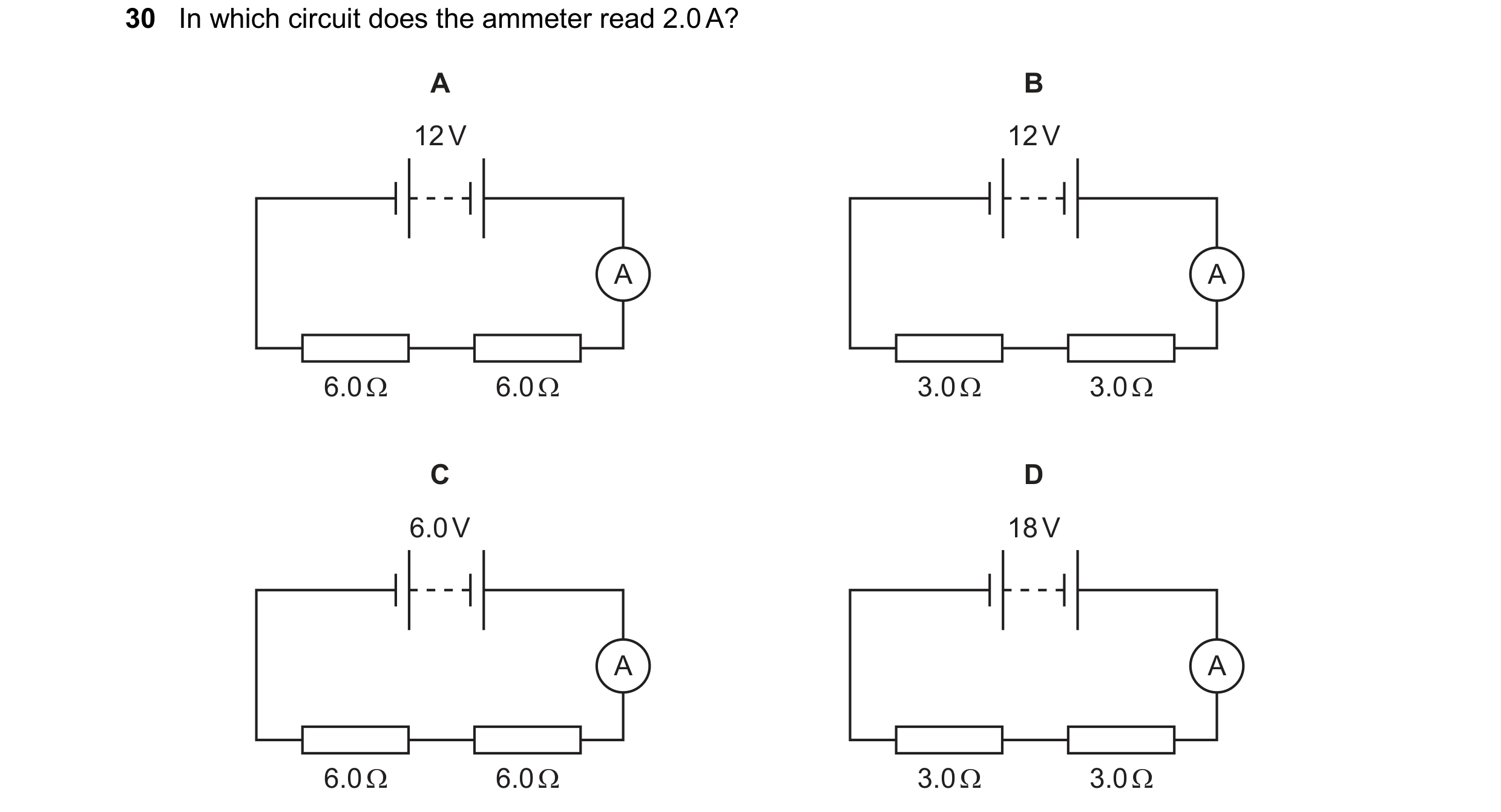
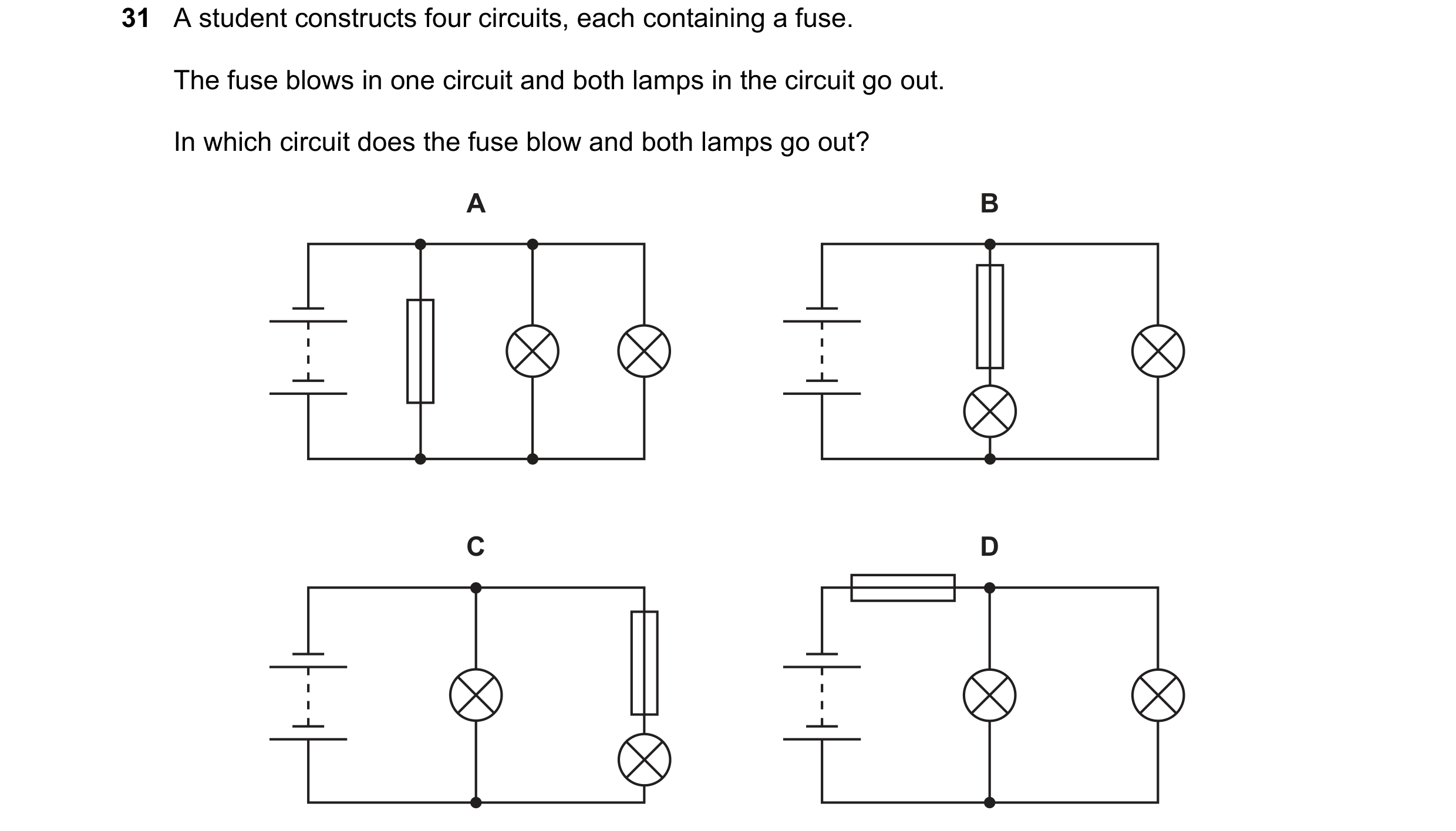
 175 / 176
 176 / 176