Questions as text
Q1 · Which circuit shows the directions of the conventional current I and the flow of… 0625/22 Feb/March 2016
30 Which circuit shows the directions of the conventional current I and the flow of electrons? A B I electrons I electrons C D I electrons I electrons
1 marks
Answer: B
This question in 0625/22 Feb/March 2016
Q2 · Four lamps are each labelled 240 V 0625/22 Feb/March 2016
31 Four lamps are each labelled 240 V. In which circuit do all four lamps have normal brightness? A B 240 V 240 V C D 240 V 240 V
1 marks
Answer: C
This question in 0625/22 Feb/March 2016
Q3 · A battery charger plugs into a 230 V a.c 0625/22 Feb/March 2016
32 A battery charger plugs into a 230 V a.c. supply. The charger is used to charge a 6.0 V d.c. battery. The charger contains diodes and a transformer. What is the purpose of these components? diodes transformer A rectify the a.c. steps down the voltage B rectify the a.c. steps up the voltage C step down the voltage rectifies the a.c. D step up the voltage rectifies the a.c.
1 marks
Answer: A
This question in 0625/22 Feb/March 2016
Q4 · The diagram shows a potential divider connected to two voltmeters P and Q 0625/22 Feb/March 2016
33 The diagram shows a potential divider connected to two voltmeters P and Q. V voltmeter P V voltmeter Q The resistance of the variable resistor is decreased. Which row shows what happens to the reading on each voltmeter? reading on reading on voltmeter P voltmeter Q A decreases decreases B decreases increases C increases decreases D increases increases
1 marks
Answer: B
This question in 0625/22 Feb/March 2016
Q5 · A cell is connected to a lamp, as shown 0625/21 May/June 2016
28 A cell is connected to a lamp, as shown. – + A charge of 4.0 C flows through the lamp in 2.0 s. What is the direction of the electron flow in the lamp and what is the current in the lamp? direction of electron current / A flow in lamp A from left to right 2.0 B from left to right 8.0 C from right to left 2.0 D from right to left 8.0
1 marks
Answer: A
This question in 0625/21 May/June 2016
Q6 · The diagrams show four current-voltage graphs 0625/21 May/June 2016
29 The diagrams show four current-voltage graphs. Which two graphs show the characteristics of an ohmic resistor and of a filament lamp? W X Y Z current current current current 0 0 0 0 0 voltage 0 voltage 0 voltage 0 voltage ohmic filament resistor lamp A W Y B X Y C W Z D X Z
1 marks
Answer: B
This question in 0625/21 May/June 2016
Q7 · The four circuits shown all include an a.c 0625/21 May/June 2016
30 The four circuits shown all include an a.c. power supply, two diodes and a lamp. In which circuit is there a rectified current in the lamp? A B C D
1 marks
Answer: A
This question in 0625/21 May/June 2016
Q8 · The diagram shows a combination of logic gates 0625/21 May/June 2016
31 The diagram shows a combination of logic gates. input P (= 0) output X input Q output Y (= 1) Input P is at a logic state 0 (low) and input Q is at a logic state 1 (high). What are the logic states at output X and at output Y? output X output Y A 0 0 B 0 1 C 1 0 D 1 1
1 marks
Answer: A
This question in 0625/21 May/June 2016
Q9 · The diagram shows part of a circuit used to switch street lamps on and off automatically 0625/21 May/June 2016
32 The diagram shows part of a circuit used to switch street lamps on and off automatically. + LDR – In the evening it gets dark. Which row shows the effect on the resistance of the light-dependent resistor (LDR) and on the potential difference (p.d.) across it? resistance of LDR p.d. across LDR A decreases decreases B decreases increases C increases decreases D increases increases
1 marks
Answer: D
This question in 0625/21 May/June 2016
Q10 · A domestic circuit includes a 30 A fuse 0625/21 May/June 2016
33 A domestic circuit includes a 30 A fuse. This protects the wiring if there is too much current in the circuit. In which wire is the 30 A fuse positioned, and what does it do when it operates? position operation A live wire disconnects the circuit B live wire reduces the current to 30 A C neutral wire disconnects the circuit D neutral wire reduces the current to 30 A
1 marks
Answer: A
This question in 0625/21 May/June 2016
Q11 · The four circuits shown all include an a.c 0625/22 May/June 2016
29 The four circuits shown all include an a.c. power supply, two diodes and a lamp. In which circuit is there a rectified current in the lamp? A B C D
1 marks
Answer: A
This question in 0625/22 May/June 2016
Q12 · P and Q are the circuit symbols for two electrical components 0625/22 May/June 2016
30 P and Q are the circuit symbols for two electrical components. P Q Which components are represented by P and by Q? P Q A thermistor fuse B thermistor relay C variable resistor fuse D variable resistor relay
1 marks
Answer: A
This question in 0625/22 May/June 2016
Q13 · The diagram shows a combination of logic gates 0625/22 May/June 2016
31 The diagram shows a combination of logic gates. input P (= 0) output X input Q output Y (= 1) Input P is at a logic state 0 (low) and input Q is at a logic state 1 (high). What are the logic states at output X and at output Y? output X output Y A 0 0 B 0 1 C 1 0 D 1 1
1 marks
Answer: A
This question in 0625/22 May/June 2016
Q14 · The diagram shows part of a circuit used to switch street lamps on and off automatically 0625/22 May/June 2016
32 The diagram shows part of a circuit used to switch street lamps on and off automatically. + LDR – In the evening it gets dark. Which row shows the effect on the resistance of the light-dependent resistor (LDR) and on the potential difference (p.d.) across it? resistance of LDR p.d. across LDR A decreases decreases B decreases increases C increases decreases D increases increases
1 marks
Answer: D
This question in 0625/22 May/June 2016
Q15 · The four circuits shown all include an a.c 0625/23 May/June 2016
28 The four circuits shown all include an a.c. power supply, two diodes and a lamp. In which circuit is there a rectified current in the lamp? A B C D
1 marks
Answer: A
This question in 0625/23 May/June 2016
Q16 · The diagram shows a battery connected to two resistors 0625/23 May/June 2016
29 The diagram shows a battery connected to two resistors. R Four students separately measure the electromotive force (e.m.f.) of the battery, the current in the resistors, and the potential difference (p.d.) across resistor R. Their results are shown in the table below. Which row shows values with their correct units? e.m.f. current p.d. A 3.0 A 0.30 V 1.5 A B 3.0 A 0.30 A 1.5 V C 3.0 V 0.30 V 1.5 A D 3.0 V 0.30 A 1.5 V
1 marks
Answer: D
This question in 0625/23 May/June 2016
Q17 · A 3.0 Ω resistor and a 6.0 Ω resistor are connected in parallel 0625/23 May/June 2016
30 A 3.0 Ω resistor and a 6.0 Ω resistor are connected in parallel. 3.0 Ω 6.0 Ω What is their combined resistance? A 0.50 Ω B 2.0 Ω C 4.5 Ω D 9.0 Ω
1 marks
Answer: B
This question in 0625/23 May/June 2016
Q18 · The diagram shows a combination of logic gates 0625/23 May/June 2016
31 The diagram shows a combination of logic gates. input P (= 0) output X input Q output Y (= 1) Input P is at a logic state 0 (low) and input Q is at a logic state 1 (high). What are the logic states at output X and at output Y? output X output Y A 0 0 B 0 1 C 1 0 D 1 1
1 marks
Answer: A
This question in 0625/23 May/June 2016
Q19 · The diagram shows part of a circuit used to switch street lamps on and off automatically 0625/23 May/June 2016
32 The diagram shows part of a circuit used to switch street lamps on and off automatically. + LDR – In the evening it gets dark. Which row shows the effect on the resistance of the light-dependent resistor (LDR) and on the potential difference (p.d.) across it? resistance of LDR p.d. across LDR A decreases decreases B decreases increases C increases decreases D increases increases
1 marks
Answer: D
This question in 0625/23 May/June 2016
Q20 · The diagram shows a lamp in a circuit 0625/21 Oct/Nov 2016
30 The diagram shows a lamp in a circuit. P Which change to the circuit would increase the current in the lamp? A adding another resistor in parallel with the one in the circuit B adding another resistor in series with the one in the circuit C decreasing the electromotive force (e.m.f.) of the battery in the circuit D moving the lamp to point P in the circuit
1 marks
Answer: A
This question in 0625/21 Oct/Nov 2016
Q21 · A 12.0 Ω resistor and a 6.0 Ω resistor are connected in parallel 0625/21 Oct/Nov 2016
31 A 12.0 Ω resistor and a 6.0 Ω resistor are connected in parallel. Another 6.0 Ω resistor is then connected in series with the parallel combination. 12.0 Ω 6.0 Ω 6.0 Ω What is the combined resistance of all three resistors? A 8.0 Ω B 10 Ω C 15 Ω D 24 Ω
1 marks
Answer: B
This question in 0625/21 Oct/Nov 2016
Q22 · The circuit shows a 12 V battery connected to a lamp of resistance 3.0 Ω 0625/21 Oct/Nov 2016
32 The circuit shows a 12 V battery connected to a lamp of resistance 3.0 Ω. 12 V How much energy is transferred to the surroundings by the lamp in 2.0 minutes? A 48 J B 96 J C 2880 J D 5760 J
1 marks
Answer: D
This question in 0625/21 Oct/Nov 2016
Q23 · The diagram shows a circuit containing a battery, a resistor with high resistance, a… 0625/21 Oct/Nov 2016
33 The diagram shows a circuit containing a battery, a resistor with high resistance, a switch and a lamp. 12 V battery 12 V resistor lamp Initially the switch is open. What happens to the lamp when the switch is closed? A It glows more brightly. B It glows less brightly. C It goes out. D Its brightness does not change.
1 marks
Answer: A
This question in 0625/21 Oct/Nov 2016
Q24 · This is the truth table for a logic gate 0625/21 Oct/Nov 2016
34 This is the truth table for a logic gate. input 1 input 2 output 0 0 1 0 1 1 1 0 1 1 1 0 Which symbol represents the logic gate? A B C D
1 marks
Answer: C
This question in 0625/21 Oct/Nov 2016
Q25 · The diagram shows a lamp in a circuit 0625/22 Oct/Nov 2016
29 The diagram shows a lamp in a circuit. P Which change to the circuit would increase the current in the lamp? A adding another resistor in parallel with the one in the circuit B adding another resistor in series with the one in the circuit C decreasing the electromotive force (e.m.f.) of the battery in the circuit D moving the lamp to point P in the circuit
1 marks
Answer: A
This question in 0625/22 Oct/Nov 2016
Q26 · Which combination of resistors in parallel has an effective resistance of 0.50 Ω? 0625/22 Oct/Nov 2016
32 Which combination of resistors in parallel has an effective resistance of 0.50 Ω? A B 1.0 Ω 2.0 Ω 1.0 Ω 2.0 Ω C D 1.0 Ω 4.0 Ω 3.0 Ω 4.0 Ω
1 marks
Answer: A
This question in 0625/22 Oct/Nov 2016
Q27 · In the circuit shown, the voltmeter reads 2.0 V 0625/22 Oct/Nov 2016
33 In the circuit shown, the voltmeter reads 2.0 V. A charge of 5.0 C passes through the resistor in a certain time. V How much energy is supplied to the resistor in this time? A 0.40 J B 2.5 J C 10 J D 20 J
1 marks
Answer: C
This question in 0625/22 Oct/Nov 2016
Q28 · Two NAND gates are connected together as shown 0625/22 Oct/Nov 2016
34 Two NAND gates are connected together as shown. input 1 output input 2 The arrangement acts like a single logic gate. What is the name of this single logic gate? A AND B NOR C NOT D OR
1 marks
Answer: A
This question in 0625/22 Oct/Nov 2016
Q29 · The diagram shows a lamp in a circuit 0625/23 Oct/Nov 2016
29 The diagram shows a lamp in a circuit. P Which change to the circuit would increase the current in the lamp? A adding another resistor in parallel with the one in the circuit B adding another resistor in series with the one in the circuit C decreasing the electromotive force (e.m.f.) of the battery in the circuit D moving the lamp to point P in the circuit
1 marks
Answer: A
This question in 0625/23 Oct/Nov 2016
Q30 · The four circuits shown each contain four diodes 0625/23 Oct/Nov 2016
32 The four circuits shown each contain four diodes. In which circuit is the direction of the current in the resistor always from the red terminal to the black terminal? A B 12 V 12 V red black red black terminal terminal terminal terminal C D 12 V 12 V red black red black terminal terminal terminal terminal
1 marks
Answer: A
This question in 0625/23 Oct/Nov 2016
Q31 · The diagram shows a potential divider 0625/23 Oct/Nov 2016
33 The diagram shows a potential divider. 6 V 0 V When brighter light falls on the light-dependent resistor (LDR), its resistance changes. What happens to the resistance of the LDR and what happens to the current in it? resistance of LDR current in LDR A decreases decreases B decreases increases C increases decreases D increases increases
1 marks
Answer: B
This question in 0625/23 Oct/Nov 2016
Q32 · The diagram shows two logic gates connected together 0625/23 Oct/Nov 2016
34 The diagram shows two logic gates connected together. low (0) P Q low (0) The two inputs are both low (0). What are the logic states at P and at Q? P Q A high (1) high (1) B high (1) low (0) C low (0) high (1) D low (0) low (0)
1 marks
Answer: B
This question in 0625/23 Oct/Nov 2016
Q33 · An electric current can produce a heating effect and a magnetic effect 0625/23 Oct/Nov 2016
36 An electric current can produce a heating effect and a magnetic effect. Which row shows the effect that a relay uses and one application of a relay? effect used by a relay one application of a relay A heating effect allowing a small current to switch on a large current B heating effect changing the voltage of an a.c. supply C magnetic effect allowing a small current to switch on a large current D magnetic effect changing the voltage of an a.c. supply
1 marks
Answer: C
This question in 0625/23 Oct/Nov 2016
Q34 · An air-conditioning unit, a lamp and an electric fire all receive electrical energy from… 0625/22 Feb/March 2017
29 An air-conditioning unit, a lamp and an electric fire all receive electrical energy from the mains
supply.
From which of these devices is all this energy eventually transferred to the surroundings?
air-
va electric
conditioning lamp
fire
unit
A v v v
B v x v
Cc x v v
D x x v
key
¥ = all energy transferred to surroundings
X = not all energy transferred to surroundings
1 marks
Answer: A
This question in 0625/22 Feb/March 2017
Q35 · Four circuits are set up 0625/22 Feb/March 2017
30 Four circuits are set up. In which circuit does the ammeter show the greatest reading? A B C D 12 V 12 V 12 V 12 V A A A A 2.0 Ω 2.0 Ω 2.0 Ω 2.0 Ω 3.0 Ω 3.0 Ω 3.0 Ω 3.0 Ω
1 marks
Answer: A
This question in 0625/22 Feb/March 2017
Q36 · The diagram shows an electric circuit 0625/22 Feb/March 2017
31 The diagram shows an electric circuit. V The light falling on the light-dependent resistor (LDR) increases in brightness. What happens to the resistance of the LDR, the current in the fixed resistor and the reading on the voltmeter? resistance of current in reading on LDR fixed resistor voltmeter A decreases increases decreases B decreases increases increases C increases decreases decreases D increases decreases increases
1 marks
Answer: B
This question in 0625/22 Feb/March 2017
Q37 · The diagram shows two linked circuits to control when a bell is switched on 0625/22 Feb/March 2017
32 The diagram shows two linked circuits to control when a bell is switched on. The conditions are altered and only one pair of conditions causes the bell to ring. Which pair causes the bell to ring? A bright light and high temperature B bright light and low temperature C dim light and high temperature D dim light and low temperature
1 marks
Answer: A
This question in 0625/22 Feb/March 2017
Q38 · The truth table for a logic gate is shown 0625/22 Feb/March 2017
33 The truth table for a logic gate is shown. input 1 input 2 output 0 0 1 0 1 0 1 0 0 1 1 0 Which type of logic gate is it? A AND B NOR C NOT D OR
1 marks
Answer: B
This question in 0625/22 Feb/March 2017
Q39 · In this circuit, a component at X automatically protects the wiring from overheating if… 0625/22 Feb/March 2017
34 In this circuit, a component at X automatically protects the wiring from overheating if there is a
fault.
electrical supply
Which row indicates components that are suitable?
cron fuse switch
A v Jv Jv key
B v v x ¥ = suitable
Cc v x v X = not suitable
D x v x
1 marks
Answer: B
This question in 0625/22 Feb/March 2017
Q40 · The diagram shows a simple transformer with an input of 240 V and an output of 40 V 0625/22 Feb/March 2017
35 The diagram shows a simple transformer with an input of 240 V and an output of 40 V. There are 600 turns on the primary coil. primary coil secondary coil 600 input 240 V 40 V output turns How many turns are there on the secondary coil? A 100 B 320 C 400 D 3600
1 marks
Answer: A
This question in 0625/22 Feb/March 2017
Q41 · A student connects a variable potential divider (potentiometer) circuit 0625/21 May/June 2017
31 A student connects a variable potential divider (potentiometer) circuit. R T V 12 V S What happens to the reading on the voltmeter as the sliding terminal T is moved from R to S? A It decreases from 12 V to 0 V. B It increases from 0 V to 12 V. C It remains at 0 V. D It remains at 12 V.
1 marks
Answer: B
This question in 0625/21 May/June 2017
Q42 · The circuit diagram shows a circuit with an a.c 0625/21 May/June 2017
32 The circuit diagram shows a circuit with an a.c. supply, a diode and a resistor. Which diagram shows how the current I in the resistor varies with time t ? A B I I 0 0 0 t 0 t C D I I 0 0 0 t 0 t
1 marks
Answer: B
This question in 0625/21 May/June 2017
Q43 · A light-dependent resistor (LDR) and a resistor R are connected in a series circuit 0625/21 May/June 2017
33 A light-dependent resistor (LDR) and a resistor R are connected in a series circuit. Light falls on the LDR. A R The brightness of the light falling on the LDR decreases. What happens to the resistance of the LDR and what happens to the reading on the ammeter? resistance reading on of LDR ammeter A decreases decreases B decreases increases C increases decreases D increases increases
1 marks
Answer: C
This question in 0625/21 May/June 2017
Q44 · The diagram shows a logic gate 0625/21 May/June 2017
34 The diagram shows a logic gate. P R Q Which input combinations at P and Q gives an output of 0 at R? P Q A 0 0 B 0 1 C 1 0 D 1 1
1 marks
Answer: D
This question in 0625/21 May/June 2017
Q45 · What is the purpose of a relay? 0625/21 May/June 2017
36 What is the purpose of a relay? A to change a large voltage into a small voltage B to change a small voltage into a large voltage C to use a large current to switch on a small current D to use a small current to switch on a large current
1 marks
Answer: D
This question in 0625/21 May/June 2017
Q46 · Four circuits each contain a 6 V battery, a diode, an ammeter and a lamp 0625/22 May/June 2017
31 Four circuits each contain a 6 V battery, a diode, an ammeter and a lamp. None of the components is faulty. Which circuit shows a possible ammeter reading? A B A A reading = 1.0 A reading = 0 A C D A A reading = 1.0 A reading = –1.0 A
1 marks
Answer: A
This question in 0625/22 May/June 2017
Q47 · A student connects a variable potential divider (potentiometer) circuit 0625/22 May/June 2017
32 A student connects a variable potential divider (potentiometer) circuit. R T V 12 V S What happens to the reading on the voltmeter as the sliding terminal T is moved from R to S? A It decreases from 12 V to 0 V. B It increases from 0 V to 12 V. C It remains at 0 V. D It remains at 12 V.
1 marks
Answer: B
This question in 0625/22 May/June 2017
Q48 · The diagram shows an electric circuit 0625/22 May/June 2017
33 The diagram shows an electric circuit. 20 Ω 0.40 A 10 Ω What is the potential difference (p.d.) across the LDR? A 4.0 V B 8.0 V C 25 V D 50 V
1 marks
Answer: B
This question in 0625/22 May/June 2017
Q49 · What does the symbol shown represent? 0625/22 May/June 2017
34 What does the symbol shown represent? A an AND gate B a NOR gate C a NOT gate D an OR gate
1 marks
Answer: B
This question in 0625/22 May/June 2017
Q50 · What is the purpose of a relay? 0625/22 May/June 2017
35 What is the purpose of a relay? A to change a large voltage into a small voltage B to change a small voltage into a large voltage C to use a large current to switch on a small current D to use a small current to switch on a large current
1 marks
Answer: D
This question in 0625/22 May/June 2017
Q51 · A circuit contains a fixed resistor 0625/23 May/June 2017
30 A circuit contains a fixed resistor. The potential difference across the resistor is 24.0 V and the current in the resistor is 2.30 A. How much energy is transferred in the resistor in a time of 17.0 minutes? A 938 J B 5630 J C 56.3 kJ D 9.38 kJ
1 marks
Answer: C
This question in 0625/23 May/June 2017
Q52 · A battery, an ammeter, a switch, a lamp and a resistor are connected together in a circuit 0625/23 May/June 2017
31 A battery, an ammeter, a switch, a lamp and a resistor are connected together in a circuit. A With the switch open, the ammeter reads 2.4 A. When the switch is closed, this reading increases to 4.0 A. What is the current through the resistor with the switch closed? A 0 A B 1.6 A C 3.2 A D 6.4 A
1 marks
Answer: B
This question in 0625/23 May/June 2017
Q53 · A student connects a variable potential divider (potentiometer) circuit 0625/23 May/June 2017
32 A student connects a variable potential divider (potentiometer) circuit. R T V 12 V S What happens to the reading on the voltmeter as the sliding terminal T is moved from R to S? A It decreases from 12 V to 0 V. B It increases from 0 V to 12 V. C It remains at 0 V. D It remains at 12 V.
1 marks
Answer: B
This question in 0625/23 May/June 2017
Q54 · The diagram shows a circuit used to make a light detector 0625/23 May/June 2017
33 The diagram shows a circuit used to make a light detector. A X Y One component is connected between X and Y. Which component causes the ammeter reading to increase when the light gets brighter? A B C D
1 marks
Answer: A
This question in 0625/23 May/June 2017
Q55 · A truth table for a type of logic gate is shown 0625/23 May/June 2017
34 A truth table for a type of logic gate is shown. input 1 input 2 output 0 0 0 0 1 1 1 0 1 1 1 1 Which type of logic gate is it? A AND B NOR C NOT D OR
1 marks
Answer: D
This question in 0625/23 May/June 2017
Q56 · What is the purpose of a relay? 0625/23 May/June 2017
36 What is the purpose of a relay? A to change a large voltage into a small voltage B to change a small voltage into a large voltage C to use a large current to switch on a small current D to use a small current to switch on a large current
1 marks
Answer: D
This question in 0625/23 May/June 2017
Q57 · A student connects the circuit shown 0625/21 Oct/Nov 2017
33 A student connects the circuit shown. Which graph shows the variation with time of the current in the resistor? A B current current 0 0 0 time 0 time C D current current 0 0 time 0 0 time
1 marks
Answer: B
This question in 0625/21 Oct/Nov 2017
Q58 · The diagram shows a circuit with a fixed resistor connected in series with a thermistor… 0625/21 Oct/Nov 2017
34 The diagram shows a circuit with a fixed resistor connected in series with a thermistor and an ammeter. A Which row shows how temperature change affects the resistance of the thermistor and the current in the circuit? resistance of temperature current in circuit thermistor A decreases decreases increases B decreases increases decreases C increases decreases decreases D increases increases increases
1 marks
Answer: B
This question in 0625/21 Oct/Nov 2017
Q59 · What does the symbol shown represent? 0625/21 Oct/Nov 2017
35 What does the symbol shown represent? A an AND gate B a NOR gate C a NOT gate D an OR gate
1 marks
Answer: A
This question in 0625/21 Oct/Nov 2017
Q60 · The diagram shows a circuit with a gap between points P and Q 0625/22 Oct/Nov 2017
31 The diagram shows a circuit with a gap between points P and Q. Four pieces of metal wire of the same material are connected, in turn, between points P and Q in the circuit. A P Q The table gives the diameters and lengths of the wires. In which wire is the current the largest? diameter / mm length / m A 0.10 1.0 B 0.10 2.0 C 0.20 1.0 D 0.20 2.0
1 marks
Answer: C
This question in 0625/22 Oct/Nov 2017
Q61 · The potential difference across a car headlamp is 12 V 0625/22 Oct/Nov 2017
33 The potential difference across a car headlamp is 12 V. The current in the lamp is 2.5 A. How much energy is transferred by the lamp in 1.0 hour? A 1800 J B 1800 W C 108 000 J D 108 000 W
1 marks
Answer: C
This question in 0625/22 Oct/Nov 2017
Q62 · The diagram shows a circuit with a fixed resistor connected in series with a thermistor… 0625/22 Oct/Nov 2017
34 The diagram shows a circuit with a fixed resistor connected in series with a thermistor and an ammeter. A Which row shows how temperature change affects the resistance of the thermistor and the current in the circuit? resistance of temperature current in circuit thermistor A decreases decreases increases B decreases increases decreases C increases decreases decreases D increases increases increases
1 marks
Answer: B
This question in 0625/22 Oct/Nov 2017
Q63 · An incomplete truth table for a NAND gate is shown 0625/22 Oct/Nov 2017
35 An incomplete truth table for a NAND gate is shown. input P input Q output 0 0 W 0 1 X 1 0 Y 1 1 Z What are the values of W, X, Y and Z? W X Y Z A 0 0 0 1 B 0 1 1 1 C 1 0 0 0 D 1 1 1 0
1 marks
Answer: D
This question in 0625/22 Oct/Nov 2017
Q64 · Identical cells and identical resistors are used to make the circuits shown 0625/23 Oct/Nov 2017
33 Identical cells and identical resistors are used to make the circuits shown. A A circuit 1 circuit 2 In circuit 1, the ammeter reads 2.0 A. What is the ammeter reading in circuit 2? A 1.0 A B 2.0 A C 4.0 A D 8.0 A
1 marks
Answer: D
This question in 0625/23 Oct/Nov 2017
Q65 · The diagram shows a circuit with a fixed resistor connected in series with a thermistor… 0625/23 Oct/Nov 2017
34 The diagram shows a circuit with a fixed resistor connected in series with a thermistor and an ammeter. A Which row shows how temperature change affects the resistance of the thermistor and the current in the circuit? resistance of temperature current in circuit thermistor A decreases decreases increases B decreases increases decreases C increases decreases decreases D increases increases increases
1 marks
Answer: B
This question in 0625/23 Oct/Nov 2017
Q66 · The diagram shows an AND gate and an OR gate connected together 0625/23 Oct/Nov 2017
35 The diagram shows an AND gate and an OR gate connected together. X Y output Z Which combination of inputs X, Y and Z gives an output of 0? X Y Z A 0 0 1 B 0 1 1 C 1 0 0 D 1 1 0
1 marks
Answer: C
This question in 0625/23 Oct/Nov 2017
Q67 · Which electrical symbol represents a diode? 0625/21 May/June 2018
30 Which electrical symbol represents a diode? A B C D
1 marks
Answer: B
This question in 0625/21 May/June 2018
Q68 · A student sets up this circuit 0625/21 May/June 2018
31 A student sets up this circuit. What is the purpose of the circuit? A to allow a lamp to be made dimmer or brighter as required B to amplify the sound of a voice C to light a lamp in the dark D to sound a bell when the temperature rises
1 marks
Answer: D
This question in 0625/21 May/June 2018
Q69 · The diagram shows two voltmeters P and Q connected to a potential divider 0625/21 May/June 2018
32 The diagram shows two voltmeters P and Q connected to a potential divider. V voltmeter P X V voltmeter Q The sliding connection at point X is moved towards the top of the diagram. What happens to the reading on P and to the reading on Q? reading on P reading on Q A decreases decreases B decreases increases C increases decreases D increases increases
1 marks
Answer: B
This question in 0625/21 May/June 2018
Q70 · The diagram represents a digital circuit using a NOR gate and an AND gate 0625/21 May/June 2018
33 The diagram represents a digital circuit using a NOR gate and an AND gate. X NOR AND Y output Z What is the truth table for this circuit? A B C D X Y Z output X Y Z output X Y Z output X Y Z output 0 0 0 0 0 0 0 0 0 0 0 1 0 0 0 1 0 0 1 0 0 0 1 1 0 0 1 1 0 0 1 0 0 1 0 0 0 1 0 0 0 1 0 1 0 1 0 1 0 1 1 1 0 1 1 0 0 1 1 0 0 1 1 1 1 0 0 0 1 0 0 0 1 0 0 1 1 0 0 1 1 0 1 1 1 0 1 0 1 0 1 0 1 0 1 1 1 1 0 0 1 1 0 0 1 1 0 1 1 1 0 1 1 1 1 1 1 1 1 0 1 1 1 0 1 1 1 1
1 marks
Answer: B
This question in 0625/21 May/June 2018
Q71 · A diode is used as a rectifier 0625/22 May/June 2018
30 A diode is used as a rectifier. What is the purpose of a rectifier? A to allow current to pass in either direction B to change alternating current into direct current C to switch off the circuit in case of a large current D to provide an efficient source of light
1 marks
Answer: B
This question in 0625/22 May/June 2018
Q72 · A student sets up this circuit 0625/22 May/June 2018
31 A student sets up this circuit. What is the purpose of the circuit? A to allow a lamp to be made dimmer or brighter as required B to amplify the sound of a voice C to light a lamp in the dark D to sound a bell when the temperature rises
1 marks
Answer: D
This question in 0625/22 May/June 2018
Q73 · The diagram shows two voltmeters P and Q connected to a potential divider 0625/22 May/June 2018
32 The diagram shows two voltmeters P and Q connected to a potential divider. V voltmeter P X V voltmeter Q The sliding connection at point X is moved towards the top of the diagram. What happens to the reading on P and to the reading on Q? reading on P reading on Q A decreases decreases B decreases increases C increases decreases D increases increases
1 marks
Answer: B
This question in 0625/22 May/June 2018
Q74 · The circuit shown contains two gates 0625/22 May/June 2018
33 The circuit shown contains two gates. P R Q Which truth table describes the operation of the circuit? A B C D P Q R P Q R P Q R P Q R 0 0 0 0 0 0 0 0 1 0 0 1 0 1 1 0 1 0 0 1 0 0 1 0 1 0 1 1 0 1 1 0 0 1 0 1 1 1 1 1 1 1 1 1 0 1 1 1
1 marks
Answer: D
This question in 0625/22 May/June 2018
Q75 · A 3.0 Ω resistor is connected in parallel with a 4.0 Ω resistor 0625/23 May/June 2018
30 A 3.0 Ω resistor is connected in parallel with a 4.0 Ω resistor. 3.0 Ω 4.0 Ω What is the resistance of this combination? A 0.14 Ω B 0.58 Ω C 1.7 Ω D 7.0 Ω
1 marks
Answer: C
This question in 0625/23 May/June 2018
Q76 · A student sets up this circuit 0625/23 May/June 2018
31 A student sets up this circuit. What is the purpose of the circuit? A to allow a lamp to be made dimmer or brighter as required B to amplify the sound of a voice C to light a lamp in the dark D to sound a bell when the temperature rises
1 marks
Answer: D
This question in 0625/23 May/June 2018
Q77 · The diagram shows two voltmeters P and Q connected to a potential divider 0625/23 May/June 2018
32 The diagram shows two voltmeters P and Q connected to a potential divider. V voltmeter P X V voltmeter Q The sliding connection at point X is moved towards the top of the diagram. What happens to the reading on P and to the reading on Q? reading on P reading on Q A decreases decreases B decreases increases C increases decreases D increases increases
1 marks
Answer: B
This question in 0625/23 May/June 2018
Q78 · The diagram shows a logic circuit with inputs X and Y 0625/23 May/June 2018
33 The diagram shows a logic circuit with inputs X and Y. X Y Q The output is Q. Which truth table is correct? A B X Y Q X Y Q 0 0 0 0 0 1 0 1 1 0 1 0 1 0 1 1 0 0 1 1 0 1 1 1 C D X Y Q X Y Q 0 0 1 0 0 0 0 1 1 0 1 0 1 0 1 1 0 0 1 1 1 1 1 0
1 marks
Answer: A
This question in 0625/23 May/June 2018
Q79 · The resistance of a component in a circuit is found using an ammeter and a voltmeter 0625/21 Oct/Nov 2018
29 The resistance of a component in a circuit is found using an ammeter and a voltmeter. How are the ammeter and the voltmeter connected? A the voltmeter and ammeter in parallel with the component B the voltmeter and ammeter in series with the component C the voltmeter in parallel with the component and the ammeter in series with the component D the voltmeter in series with the component and the ammeter in parallel with the component
1 marks
Answer: C
This question in 0625/21 Oct/Nov 2018
Q80 · The circuit diagram shows a fixed resistor R and a thermistor T used in a potential… 0625/21 Oct/Nov 2018
31 The circuit diagram shows a fixed resistor R and a thermistor T used in a potential divider circuit. T R VR and VT are the potential differences across R and T respectively. What happens to VR and to VT as the temperature of the thermistor decreases? VR VT A decreases increases B increases decreases C stays the same decreases D stays the same increases
1 marks
Answer: A
This question in 0625/21 Oct/Nov 2018
Q81 · The circuit diagram shows a power supply connected to some circuit components 0625/21 Oct/Nov 2018
32 The circuit diagram shows a power supply connected to some circuit components. In the diagram, P and Q are the terminals of the d.c. power supply. P Q R1 A R2 Under which circumstances does the ammeter show a reading other than zero? A when P is positive or negative B the ammeter always shows a zero reading C only when P is negative D only when P is positive
1 marks
Answer: D
This question in 0625/21 Oct/Nov 2018
Q82 · The diagram shows a digital circuit with two inputs and one output 0625/21 Oct/Nov 2018
33 The diagram shows a digital circuit with two inputs and one output. input 1 output input 2 What describes the action of the circuit? A AND B NAND C NOR D OR
1 marks
Answer: C
This question in 0625/21 Oct/Nov 2018
Q83 · A student investigates the resistance of a lamp 0625/22 Oct/Nov 2018
30 A student investigates the resistance of a lamp. Which row states how the meters must be connected? ammeter voltmeter A in parallel with the lamp in parallel with the lamp B in parallel with the lamp in series with the lamp C in series with the lamp in parallel with the lamp D in series with the lamp in series with the lamp
1 marks
Answer: C
This question in 0625/22 Oct/Nov 2018
Q84 · The circuit shown is used to change the voltage Vout as the temperature of device X… 0625/22 Oct/Nov 2018
31 The circuit shown is used to change the voltage Vout as the temperature of device X changes. +6.0 V device Vout X 0 V Which row is correct? name of this name of type of circuit device X A potential divider fuse B potential divider thermistor C variable resistor fuse D variable resistor thermistor
1 marks
Answer: B
This question in 0625/22 Oct/Nov 2018
Q85 · The circuit diagram shows a d.c 0625/22 Oct/Nov 2018
32 The circuit diagram shows a d.c. power supply connected to two resistors R1 and R2 and four diodes. R1 R2 + – Which statement is correct? A There is a current in R1 and a current in R2. B There is a current in R1 but no current in R2. C There is no current in R1 but a current in R2. D There is no current in R1 and no current in R2.
1 marks
Answer: A
This question in 0625/22 Oct/Nov 2018
Q86 · A logic gate has inputs 0,0 and an output 1 0625/22 Oct/Nov 2018
33 A logic gate has inputs 0,0 and an output 1. Which two types of logic gate behave in this way? A OR, AND B OR, NAND C NOR, AND D NOR, NAND
1 marks
Answer: D
This question in 0625/22 Oct/Nov 2018
Q87 · Which diagram shows the current-voltage (I - V) characteristic for a filament lamp? 0625/23 Oct/Nov 2018
29 Which diagram shows the current-voltage (I - V) characteristic for a filament lamp? A B C D I I I I 0 0 0 0 0 V 0 V 0 V 0 V
1 marks
Answer: C
This question in 0625/23 Oct/Nov 2018
Q88 · The diagram shows a light-dependent resistor (LDR) connected in a potential divider… 0625/23 Oct/Nov 2018
30 The diagram shows a light-dependent resistor (LDR) connected in a potential divider circuit. V The brightness of the light falling on the LDR is increased. Which row shows what happens to the resistance of the LDR, and what happens to the reading on the voltmeter? resistance of LDR reading on voltmeter A decreases decreases B decreases increases C increases decreases D increases increases
1 marks
Answer: A
This question in 0625/23 Oct/Nov 2018
Q89 · The diagram shows part of an electric circuit 0625/23 Oct/Nov 2018
31 The diagram shows part of an electric circuit. The reading on the voltmeter is 16 V. The current in the resistor is 8.0 A. V 8.0 A P Q One coulomb of charge flows from P to Q through the resistor. How much energy is transferred in the resistor? A 2.0 J B 8.0 J C 16 J D 128 J
1 marks
Answer: C
This question in 0625/23 Oct/Nov 2018
Q90 · Which symbol represents an AND gate? 0625/23 Oct/Nov 2018
32 Which symbol represents an AND gate? A B C D
1 marks
Answer: D
This question in 0625/23 Oct/Nov 2018
Q91 · Either a fuse or a circuit-breaker can be used to protect electrical cables from large… 0625/23 Oct/Nov 2018
33 Either a fuse or a circuit-breaker can be used to protect electrical cables from large currents that could cause overheating. X cable live electrical Y appliance supply neutral cable When a fuse is used, where should it be connected, and when a circuit-breaker is used, where should it be connected? position position of of fuse circuit-breaker A X X B X Y C Y X D Y Y
1 marks
Answer: A
This question in 0625/23 Oct/Nov 2018
Q92 · The circuit diagram shows an a.c 0625/23 Oct/Nov 2018
34 The circuit diagram shows an a.c. power supply connected to two diodes and a resistor. a.c. X power supply Y The graph shows the current from the supply. current 0 0 time Which graph shows the current in diode X? A B current current 0 0 0 time 0 time C D current current 0 0 0 time 0 time
1 marks
Answer: C
This question in 0625/23 Oct/Nov 2018
Q93 · A 100% efficient step-down transformer has primary voltage Vp and primary current Ip 0625/23 Oct/Nov 2018
35 A 100% efficient step-down transformer has primary voltage Vp and primary current Ip. Which row compares the secondary voltage with Vp and the secondary current with Ip? secondary voltage secondary current A greater than Vp greater than Ip B greater than Vp less than Ip C less than Vp greater than Ip D less than Vp less than Ip
1 marks
Answer: C
This question in 0625/23 Oct/Nov 2018
Q94 · A student sets up a circuit containing a battery of two cells and three lamps, as shown 0625/22 Feb/March 2019
31 A student sets up a circuit containing a battery of two cells and three lamps, as shown. – + – + What is the circuit diagram for this arrangement? A B C D
1 marks
Answer: A
This question in 0625/22 Feb/March 2019
Q95 · In which circuit does the lamp light? 0625/22 Feb/March 2019
32 In which circuit does the lamp light? A B C D
1 marks
Answer: C
This question in 0625/22 Feb/March 2019
Q96 · Each potential divider is placed in a circuit with a power supply 0625/22 Feb/March 2019
33 Each potential divider is placed in a circuit with a power supply. Which potential divider makes the potential difference across component Y increase when the light intensity increases? A B C D X X X X Y Y Y Y
1 marks
Answer: A
This question in 0625/22 Feb/March 2019
Q97 · There are two inputs to the combination of logic gates shown, and one output 0625/22 Feb/March 2019
34 There are two inputs to the combination of logic gates shown, and one output. input 1 output input 2 Which truth table represents the action of this combination of gates? A B input 1 input 2 output input 1 input 2 output 0 0 0 0 0 0 0 1 0 0 1 1 1 0 0 1 0 1 1 1 1 1 1 1 C D input 1 input 2 output input 1 input 2 output 0 0 1 0 0 1 0 1 1 0 1 0 1 0 1 1 0 0 1 1 0 1 1 0
1 marks
Answer: A
This question in 0625/22 Feb/March 2019
Q98 · The current in a kettle is 10 A and the kettle is protected by a 13 A fuse 0625/22 Feb/March 2019
35 The current in a kettle is 10 A and the kettle is protected by a 13 A fuse. The owner of the kettle replaces the 13 A fuse with a 3 A fuse. What happens when the kettle is switched on? A The fuse melts and the kettle might be damaged. B The fuse melts and the kettle is undamaged. C The fuse does not melt and the kettle works correctly. D The fuse does not melt but the kettle fails to work.
1 marks
Answer: B
This question in 0625/22 Feb/March 2019
Q99 · The diagram shows a circuit containing a d.c 0625/21 May/June 2019
30 The diagram shows a circuit containing a d.c. power supply, a motor and a variable resistor. Three ammeters X, Y and Z show the current in different parts of the circuit. + – X A A Z A M Y The reading on X is 4.0 A. Which statement is correct? A The readings on Y and Z are both less than 4.0 A. B The readings on Y and Z are both equal to 4.0 A. C The readings on Y and Z are both greater than 4.0 A. D The reading on Z is zero.
1 marks
Answer: B
This question in 0625/21 May/June 2019
Q100 · A lamp is to be connected in a circuit so that the potential difference (p.d.) across it… 0625/21 May/June 2019
31 A lamp is to be connected in a circuit so that the potential difference (p.d.) across it can be varied from 0 to 6 V. Which circuit would be most suitable? A B 6 V 6 V C D 6 V 6 V
1 marks
Answer: B
This question in 0625/21 May/June 2019
Q101 · Which logic gate is represented by the symbol shown? 0625/21 May/June 2019
32 Which logic gate is represented by the symbol shown? A AND B NAND C NOR D OR
1 marks
Answer: A
This question in 0625/21 May/June 2019
Q102 · The diagram shows a combination of logic gates 0625/21 May/June 2019
33 The diagram shows a combination of logic gates. Which single logic gate is equivalent to this combination? A AND B NOR C NOT D OR
1 marks
Answer: B
This question in 0625/21 May/June 2019
Q103 · An alternating current (a.c.) power supply is connected in series with a resistor R and a… 0625/21 May/June 2019
34 An alternating current (a.c.) power supply is connected in series with a resistor R and a diode. R V Which graph shows how the voltage V across the resistor R varies with time? A B voltage V voltage V 0 0 0 time 0 time C D voltage V voltage V 0 0 0 time 0 time
1 marks
Answer: C
This question in 0625/21 May/June 2019
Q104 · What is the purpose of the commutator in a d.c 0625/21 May/June 2019
36 What is the purpose of the commutator in a d.c. electric motor? A to control the speed at which the motor rotates B to reverse the direction of the voltage across the power supply every half-turn C to reverse the direction of the current in the motor coil every half-turn D to reverse the direction of spin of the motor coil every half-turn
1 marks
Answer: C
This question in 0625/21 May/June 2019
Q105 · The diagram shows a circuit 0625/22 May/June 2019
30 The diagram shows a circuit. What is connected in parallel with the thermistor? A heater B lamp C light-dependent resistor D variable resistor
1 marks
Answer: A
This question in 0625/22 May/June 2019
Q106 · A lamp is to be connected in a circuit so that the potential difference (p.d.) across it… 0625/22 May/June 2019
31 A lamp is to be connected in a circuit so that the potential difference (p.d.) across it can be varied from 0 to 6 V. Which circuit would be most suitable? A B 6 V 6 V C D 6 V 6 V
1 marks
Answer: B
This question in 0625/22 May/June 2019
Q107 · Components X and Y can be inserted to complete the circuit below 0625/22 May/June 2019
32 Components X and Y can be inserted to complete the circuit below. The completed circuit is a potential divider in which the potential difference across component Y increases when the temperature increases. X Y V Which row shows the components X and Y? X Y A light-dependent resistor resistor B resistor light-dependent resistor C resistor thermistor D thermistor resistor
1 marks
Answer: D
This question in 0625/22 May/June 2019
Q108 · Which two logic gates each have a high output (1) when both of their inputs are low (0)? 0625/22 May/June 2019
33 Which two logic gates each have a high output (1) when both of their inputs are low (0)? A AND and OR B AND and NOR C NAND and NOR D NAND and OR
1 marks
Answer: C
This question in 0625/22 May/June 2019
Q109 · Two NAND gates are joined together as shown 0625/22 May/June 2019
34 Two NAND gates are joined together as shown. input 1 output input 2 Which single logic gate is equivalent to this combination? A AND B NAND C NOR D OR
1 marks
Answer: A
This question in 0625/22 May/June 2019
Q110 · Which components are designed to improve the safe working of a mains electrical supply? 0625/22 May/June 2019
35 Which components are designed to improve the safe working of a mains electrical supply?
circuit earth
; fuse
breaker wire
Jv Jv
0 OO WwW PY
<< x
<4 x
v
x
v
1 marks
Answer: D
This question in 0625/22 May/June 2019
Q111 · Two wires X and Y are made from the same metal and have the same resistance 0625/23 May/June 2019
29 Two wires X and Y are made from the same metal and have the same resistance. Which row identifies a possible pair of values for X and for Y? length of X diameter of X length of Y diameter of Y / cm / mm / cm / mm A 50 0.40 200 0.10 B 50 0.40 200 0.20 C 50 0.40 200 0.80 D 50 0.40 200 1.60
1 marks
Answer: C
This question in 0625/23 May/June 2019
Q112 · The diagram shows a circuit including a lamp, an electric bell and three switches S1, S2… 0625/23 May/June 2019
30 The diagram shows a circuit including a lamp, an electric bell and three switches S1, S2 and S3. The lamp and bell are not faulty. S1 S2 S3 The bell is ringing but the lamp is not lit. Which switches are closed? A S1 only B S1 and S2 only C S1 and S3 only D S1, S2 and S3
1 marks
Answer: C
This question in 0625/23 May/June 2019
Q113 · A lamp is to be connected in a circuit so that the potential difference (p.d.) across it… 0625/23 May/June 2019
31 A lamp is to be connected in a circuit so that the potential difference (p.d.) across it can be varied from 0 to 6 V. Which circuit would be most suitable? A B 6 V 6 V C D 6 V 6 V
1 marks
Answer: B
This question in 0625/23 May/June 2019
Q114 · A 12 V battery is connected to a combination of 2.0 Ω resistors as shown 0625/23 May/June 2019
32 A 12 V battery is connected to a combination of 2.0 Ω resistors as shown. 12 V 2.0 Ω 2.0 Ω 2.0 Ω What is the current in the battery? A 1.5 A B 2.0 A C 4.0 A D 6.0 A
1 marks
Answer: C
This question in 0625/23 May/June 2019
Q115 · A student is designing a lighting circuit for a dolls’ house 0625/23 May/June 2019
33 A student is designing a lighting circuit for a dolls’ house. He sets up two different circuits. Each circuit contains a 12 V power supply and three identical lamps. Each lamp is designed to operate at normal brightness when connected individually to a 12 V supply. 12 V power 12 V power supply supply 12 12 circuit 1 circuit 2 Which statement is correct? A In circuit 1, each of the lamps is at normal brightness. B In circuit 1, if one lamp fails, the other lamps remain lit. C In circuit 2, if one lamp fails, the other lamps remain lit. D In circuit 2, the current from the power supply is less than in circuit 1.
1 marks
Answer: C
This question in 0625/23 May/June 2019
Q116 · The combination of logic gates shown has two inputs and one output 0625/23 May/June 2019
34 The combination of logic gates shown has two inputs and one output. input 1 output input 2 Which single logic gate is equivalent to this combination? A AND B NOR C NOT D OR
1 marks
Answer: B
This question in 0625/23 May/June 2019
Q117 · A simple wiring diagram for an electric cooker is shown 0625/23 May/June 2019
35 A simple wiring diagram for an electric cooker is shown. electric cooker metal casing live neutral earth connection to casing Why is there a wire connecting the metal case of the cooker to earth? A It improves the efficiency of the cooker. B It prevents the metal case from becoming too hot when the cooker is left on. C It reduces the risk of an electric shock if the live wire touches the metal case. D The electric cooker will not switch on without it.
1 marks
Answer: C
This question in 0625/23 May/June 2019
Q118 · A circuit contains a cell of electromotive force (e.m.f.) of 2.0 V 0625/21 Oct/Nov 2019
28 A circuit contains a cell of electromotive force (e.m.f.) of 2.0 V. The current in the circuit is 2.0 A. How much energy is converted by the cell in 2.0 minutes? A 2.0 J B 4.0 J C 8.0 J D 480 J
1 marks
Answer: D
This question in 0625/21 Oct/Nov 2019
Q119 · The circuit diagram shows a cell connected in series to a resistor and a component X 0625/21 Oct/Nov 2019
29 The circuit diagram shows a cell connected in series to a resistor and a component X. X What is component X? A bell B diode C heater D thermistor
1 marks
Answer: B
This question in 0625/21 Oct/Nov 2019
Q120 · Identical resistors are connected together to form arrangements X, Y and Z 0625/21 Oct/Nov 2019
30 Identical resistors are connected together to form arrangements X, Y and Z. X Y Z What is the correct order of the resistances of the arrangements from the largest to the smallest? A X → Y → Z B Y → X → Z C Z → X → Y D Z → Y → X
1 marks
Answer: D
This question in 0625/21 Oct/Nov 2019
Q121 · A circuit contains a cell of electromotive force (e.m.f.) 2.0 V, three resistors, three… 0625/21 Oct/Nov 2019
31 A circuit contains a cell of electromotive force (e.m.f.) 2.0 V, three resistors, three ammeters and two voltmeters. One ammeter is labelled P and one voltmeter is labelled Q. The readings on the other two ammeters and on the other voltmeter are shown. 2.0 V 2.0 A A 0.50 A A A V P 0.50 V V Q What is the reading on ammeter P and what is the reading on voltmeter Q? reading on P / A reading on Q / V A 1.5 1.5 B 1.5 2.5 C 2.5 1.5 D 2.5 2.5
1 marks
Answer: A
This question in 0625/21 Oct/Nov 2019
Q122 · There are two inputs and one output for the combination of logic gates shown 0625/21 Oct/Nov 2019
32 There are two inputs and one output for the combination of logic gates shown. input 1 output input 2 Which truth table represents the operation of this combination of logic gates? A B input 1 input 2 output input 1 input 2 output 0 0 0 0 0 0 0 1 0 0 1 0 1 0 1 1 0 1 1 1 1 1 1 0 C D input 1 input 2 output input 1 input 2 output 0 0 1 0 0 1 0 1 1 0 1 0 1 0 0 1 0 1 1 1 0 1 1 1
1 marks
Answer: B
This question in 0625/21 Oct/Nov 2019
Q123 · Where must a fuse be connected in a mains electric circuit? 0625/21 Oct/Nov 2019
33 Where must a fuse be connected in a mains electric circuit? A the earth wire only B the live wire only C the neutral wire only D the live wire and the earth wire
1 marks
Answer: B
This question in 0625/21 Oct/Nov 2019
Q124 · There is a current of 2.0 A in a resistor for 30 s 0625/22 Oct/Nov 2019
29 There is a current of 2.0 A in a resistor for 30 s. The potential difference (p.d.) across the resistor is 12 V. How much energy is transferred in the resistor? A 1.25 J B 5.0 J C 180 J D 720 J
1 marks
Answer: D
This question in 0625/22 Oct/Nov 2019
Q125 · Identical resistors are connected together to form arrangements X, Y and Z 0625/22 Oct/Nov 2019
30 Identical resistors are connected together to form arrangements X, Y and Z. X Y Z What is the correct order of the resistances of the arrangements from the largest to the smallest? A X → Y → Z B Y → X → Z C Z → X → Y D Z → Y → X
1 marks
Answer: D
This question in 0625/22 Oct/Nov 2019
Q126 · Resistors of 1.0 Ω, 2.0 Ω and 3.0 Ω are connected in parallel with a cell 0625/22 Oct/Nov 2019
31 Resistors of 1.0 Ω, 2.0 Ω and 3.0 Ω are connected in parallel with a cell. Which statement is correct? A The current in each resistor is different but the potential difference (p.d.) across each resistor is the same. B The current in each resistor is the same but the potential difference across each resistor is different. C The potential difference across the 3.0 Ω is greater than the potential difference across the 1.0 Ω resistor. D The sum of the potential differences across each resistor is equal to the electromotive force (e.m.f.) of the cell.
1 marks
Answer: A
This question in 0625/22 Oct/Nov 2019
Q127 · The diagram shows a circuit component 0625/22 Oct/Nov 2019
32 The diagram shows a circuit component. What is it used for? A to allow current in one direction only B to change the direction of the current C to emit light when there is a current D to increase the size of the current
1 marks
Answer: A
This question in 0625/22 Oct/Nov 2019
Q128 · Which single logic gate behaves the same as the combination of logic gates shown? 0625/22 Oct/Nov 2019
33 Which single logic gate behaves the same as the combination of logic gates shown? A AND B NOR C NOT D OR
1 marks
Answer: A
This question in 0625/22 Oct/Nov 2019
Q129 · Where must a fuse be connected in a mains electric circuit? 0625/22 Oct/Nov 2019
34 Where must a fuse be connected in a mains electric circuit? A the earth wire only B the live wire only C the neutral wire only D the live wire and the earth wire
1 marks
Answer: B
This question in 0625/22 Oct/Nov 2019
Q130 · A step-down transformer is 100% efficient 0625/22 Oct/Nov 2019
36 A step-down transformer is 100% efficient. It has an input voltage of 240 V a.c. and an output voltage of 60 V a.c. The current in the primary coil is 0.50 A. What is the current in the secondary coil? A 0.13 A B 0.50 A C 2.0 A D 8.0 A
1 marks
Answer: C
This question in 0625/22 Oct/Nov 2019
Q131 · Identical resistors are connected together to form arrangements X, Y and Z 0625/23 Oct/Nov 2019
29 Identical resistors are connected together to form arrangements X, Y and Z. X Y Z What is the correct order of the resistances of the arrangements from the largest to the smallest? A X → Y → Z B Y → X → Z C Z → X → Y D Z → Y → X
1 marks
Answer: D
This question in 0625/23 Oct/Nov 2019
Q132 · Resistors of resistance 1.0 Ω, 2.0 Ω and 3.0 Ω are connected in parallel across the… 0625/23 Oct/Nov 2019
30 Resistors of resistance 1.0 Ω, 2.0 Ω and 3.0 Ω are connected in parallel across the terminals of a cell. Which statement is correct? A The currents in the resistors are equal. B The sum of the currents in the three resistors is equal to the current in the cell. C The sum of the potential differences (p.d.’s) across the resistors is equal to the electromotive force (e.m.f.) of the cell. D The potential difference across the 3.0 Ω resistor is greater than the potential difference across the other two resistors.
1 marks
Answer: B
This question in 0625/23 Oct/Nov 2019
Q133 · A circuit containing an a.c 0625/23 Oct/Nov 2019
31 Diagram 1 shows a circuit containing an a.c. power supply, an unknown component X and a fixed resistor. The graph in diagram 2 shows how the potential difference (p.d.) across the resistor varies with time. X p.d. 0 0 time diagram 1 diagram 2 What is component X? A thermistor B relay coil C diode D light-dependent resistor
1 marks
Answer: C
This question in 0625/23 Oct/Nov 2019
Q134 · An AND gate has two inputs and one output 0625/23 Oct/Nov 2019
32 An AND gate has two inputs and one output. Which truth table represents the action of the AND gate? A B input 1 input 2 output input 1 input 2 output 0 0 0 0 0 0 0 1 1 0 1 0 1 0 1 1 0 0 1 1 1 1 1 1 C D input 1 input 2 output input 1 input 2 output 0 0 1 0 0 1 0 1 1 0 1 0 1 0 1 1 0 0 1 1 0 1 1 0
1 marks
Answer: B
This question in 0625/23 Oct/Nov 2019
Q135 · Where must a fuse be connected in a mains electric circuit? 0625/23 Oct/Nov 2019
33 Where must a fuse be connected in a mains electric circuit? A the earth wire only B the live wire only C the neutral wire only D the live wire and the earth wire
1 marks
Answer: B
This question in 0625/23 Oct/Nov 2019
Q136 · A step-up transformer produces a 60 V a.c 0625/23 Oct/Nov 2019
35 A step-up transformer produces a 60 V a.c. output from a 12 V a.c. input. There are 50 turns on the secondary coil. How many turns are there on the primary coil? A 5 B 10 C 50 D 250
1 marks
Answer: B
This question in 0625/23 Oct/Nov 2019
Q137 · Which row describes conventional current and electron flow in a circuit containing a cell? 0625/22 Feb/March 2020
30 Which row describes conventional current and electron flow in a circuit containing a cell? conventional current electron flow A from the negative terminal of the cell from the negative terminal of the cell to the positive terminal of the cell to the positive terminal of the cell B from the negative terminal of the cell from the positive terminal of the cell to to the positive terminal of the cell the negative terminal of the cell C from the positive terminal of the cell to from the negative terminal of the cell the negative terminal of the cell to the positive terminal of the cell D from the positive terminal of the cell to from the positive terminal of the cell to the negative terminal of the cell the negative terminal of the cell
1 marks
Answer: C
This question in 0625/22 Feb/March 2020
Q138 · A student makes four resistors using different pieces of wire 0625/22 Feb/March 2020
31 A student makes four resistors using different pieces of wire. The wires have different diameters and lengths. All the pieces of wire are made of the same material. Which piece of wire will make the resistor with the largest resistance? diameter / mm length / cm A 0.8 10 B 0.8 17 C 2.0 10 D 2.0 17
1 marks
Answer: B
This question in 0625/22 Feb/March 2020
Q139 · A student is to determine the resistance of resistor R 0625/22 Feb/March 2020
32 A student is to determine the resistance of resistor R. She uses a circuit including a voltmeter and an ammeter. Which circuit should be used? A B C D V A V V A R R R R A A V
1 marks
Answer: D
This question in 0625/22 Feb/March 2020
Q140 · The diagram shows a battery connected to two resistors 0625/22 Feb/March 2020
33 The diagram shows a battery connected to two resistors. Three ammeters M1, M2 and M3 are connected in the circuit. M1 A A M3 A M2 Ammeter M1 reads 1.0 A. What are the readings on M2 and on M3? reading on reading on M2 / A M3 / A A 0.0 0.0 B 0.5 0.5 C 0.5 1.0 D 1.0 1.0
1 marks
Answer: D
This question in 0625/22 Feb/March 2020
Q141 · A cell is connected to a parallel combination of a 2.0 Ω resistor and a 4.0 Ω resistor 0625/22 Feb/March 2020
34 A cell is connected to a parallel combination of a 2.0 Ω resistor and a 4.0 Ω resistor. The current in the 4.0 Ω resistor is 1.0 A. 2.0 Ω 4.0 Ω 1.0 A What is the current in the cell? A 1.0 A B 1.5 A C 2.0 A D 3.0 A
1 marks
Answer: D
This question in 0625/22 Feb/March 2020
Q142 · The two inputs of a NAND gate are joined together 0625/22 Feb/March 2020
35 The two inputs of a NAND gate are joined together. input output Which truth table represents the action of this gate? A B C D input output input output input output input output 0 0 0 1 0 0 0 1 1 0 1 0 1 1 1 1
1 marks
Answer: B
This question in 0625/22 Feb/March 2020
Q143 · The diagram shows a transformer that has an output voltage of 12 V 0625/22 Feb/March 2020
36 The diagram shows a transformer that has an output voltage of 12 V. primary coil with soft iron core 1000 turns 240 V a.c. 12 V a.c. input output secondary coil How many turns of wire are in the secondary coil? A 12 B 20 C 50 D 20 000
1 marks
Answer: C
This question in 0625/22 Feb/March 2020
Q144 · A student uses the circuit shown to determine the resistance of two identical resistors 0625/21 May/June 2020
28 A student uses the circuit shown to determine the resistance of two identical resistors. A V The voltmeter reading is 2.2 V and the ammeter reading is 0.25 A. What is the resistance of each resistor? A 0.275 Ω B 0.55 Ω C 4.4 Ω D 8.8 Ω
1 marks
Answer: C
This question in 0625/21 May/June 2020
Q145 · An electric fire is connected to a 240 V supply and transfers energy at a rate of 1.0 kW 0625/21 May/June 2020
29 An electric fire is connected to a 240 V supply and transfers energy at a rate of 1.0 kW. How much charge passes through the fire in 1.0 h? A 42 C B 250 C C 1.5 × 10⁴ C D 2.4 × 10⁵ C
1 marks
Answer: C
This question in 0625/21 May/June 2020
Q146 · The diagram shows an incomplete circuit 0625/21 May/June 2020
30 The diagram shows an incomplete circuit. The temperature and light levels around the circuit remain unchanged. P Q A Four electrical components are connected in turn across PQ. The cell is reversed and the four electrical components are connected again in turn across PQ. For which component is there a significant change in the magnitude of the current? A diode B light-dependent resistor C resistor D thermistor
1 marks
Answer: A
This question in 0625/21 May/June 2020
Q147 · In the circuit shown, A1 and A2 are ammeters 0625/21 May/June 2020
31 In the circuit shown, A1 and A2 are ammeters. A1 A2 S Switch S is closed. Which row is correct? the resistance of reading of A1 reading of A2 the whole circuit A decreases stays the same increases B decreases increases increases C increases stays the same stays the same D increases decreases decreases
1 marks
Answer: B
This question in 0625/21 May/June 2020
Q148 · Which symbol represents an OR gate? 0625/21 May/June 2020
32 Which symbol represents an OR gate? A B C D
1 marks
Answer: A
This question in 0625/21 May/June 2020
Q149 · A digital circuit consists of two logic gates 0625/21 May/June 2020
33 A digital circuit consists of two logic gates. When the input to the circuit is 1 and 1, the output is 0. 1 digital input 0 output circuit 1 Which combination of logic gates gives this result? A B C D
1 marks
Answer: C
This question in 0625/21 May/June 2020
Q150 · A 100% efficient transformer converts a 240 V input voltage to a 12 V output voltage 0625/21 May/June 2020
35 A 100% efficient transformer converts a 240 V input voltage to a 12 V output voltage. The output power of the transformer can be a maximum of 20 W. The output is connected to two 0.30 A bulbs in parallel. One of the bulbs fails. How does the current in the primary coil change? A It decreases by 0.30 A. B It decreases by 0.015 A. C It increases by 0.15 A. D It remains unchanged.
1 marks
Answer: B
This question in 0625/21 May/June 2020
Q151 · A student uses the circuit shown to determine the resistance of two identical resistors 0625/22 May/June 2020
29 A student uses the circuit shown to determine the resistance of two identical resistors. A V The voltmeter reading is 2.2 V and the ammeter reading is 0.25 A. What is the resistance of each resistor? A 0.275 Ω B 0.55 Ω C 4.4 Ω D 8.8 Ω
1 marks
Answer: C
This question in 0625/22 May/June 2020
Q152 · The circuit shown contains five lamps J, K, L, M and N 0625/22 May/June 2020
31 The circuit shown contains five lamps J, K, L, M and N. All the lamps are glowing. lamp L lamp K lamp J lamp N lamp M One lamp is removed and two other lamps go out. Which lamp is removed? A lamp J B lamp K C lamp L D lamp M
1 marks
Answer: A
This question in 0625/22 May/June 2020
Q153 · What is the effective resistance of the following combination of resistors? 0625/22 May/June 2020
32 What is the effective resistance of the following combination of resistors? 6.0 Ω 4.0 Ω 8.0 Ω A 1.8 Ω B 7.4 Ω C 11 Ω D 18 Ω
1 marks
Answer: B
This question in 0625/22 May/June 2020
Q154 · Which symbol represents a NAND gate? 0625/22 May/June 2020
33 Which symbol represents a NAND gate? A B C D
1 marks
Answer: B
This question in 0625/22 May/June 2020
Q155 · The diagram shows a circuit used to switch on a heater when the temperature drops below a… 0625/22 May/June 2020
34 The diagram shows a circuit used to switch on a heater when the temperature drops below a certain value. X Y Which row shows the components that should be connected at X and at Y? X Y A B C D
1 marks
Answer: B
This question in 0625/22 May/June 2020
Q156 · A student uses the circuit shown to determine the resistance of two identical resistors 0625/23 May/June 2020
29 A student uses the circuit shown to determine the resistance of two identical resistors. A V The voltmeter reading is 2.2 V and the ammeter reading is 0.25 A. What is the resistance of each resistor? A 0.275 Ω B 0.55 Ω C 4.4 Ω D 8.8 Ω
1 marks
Answer: C
This question in 0625/23 May/June 2020
Q157 · There is a current of 2.0 A in a resistor of resistance 8.0 Ω 0625/23 May/June 2020
30 There is a current of 2.0 A in a resistor of resistance 8.0 Ω. How much power is dissipated in the resistor? A 0.25 W B 4.0 W C 16 W D 32 W
1 marks
Answer: D
This question in 0625/23 May/June 2020
Q158 · The lamps, the diodes and the batteries in the circuits are identical 0625/23 May/June 2020
31 The lamps, the diodes and the batteries in the circuits are identical. In which circuit does the ammeter give the greatest reading? A B C D A A A A
1 marks
Answer: A
This question in 0625/23 May/June 2020
Q159 · Two resistors are connected in series with a power supply 0625/23 May/June 2020
32 Two resistors are connected in series with a power supply. Which statement about the circuit is correct? A The current from the supply is greater than the current in each resistor. B The current from the supply is equal to the current in each resistor. C The current from the supply is less than the current in each resistor. D The current from the supply is the sum of the currents in each resistor.
1 marks
Answer: B
This question in 0625/23 May/June 2020
Q160 · Which two logic gates each have a high output when both of their inputs are high? 0625/23 May/June 2020
33 Which two logic gates each have a high output when both of their inputs are high? A AND and OR B AND and NOR C NAND and NOR D NAND and OR
1 marks
Answer: A
This question in 0625/23 May/June 2020
Q161 · The diagram shows a series of logic gates and part of its corresponding truth table 0625/23 May/June 2020
34 The diagram shows a series of logic gates and part of its corresponding truth table. P R Q T S P Q R S T 0 0 0 0 1 0 1 1 0 0 1 1 1 1 1 1 0 What are the missing values in row 2 of the truth table? A 0 1 0 B 0 1 1 C 1 0 0 D 1 1 1
1 marks
Answer: B
This question in 0625/23 May/June 2020
Q162 · Four wires are made of the same metal 0625/21 Oct/Nov 2020
31 Four wires are made of the same metal. Which wire has the greatest resistance? A a 100 cm long wire with a diameter of 3.0 mm B a 100 cm long wire with a diameter of 6.0 mm C a 10 cm long wire with a diameter of 3.0 mm D a 10 cm long wire with a diameter of 6.0 mm
1 marks
Answer: A
This question in 0625/21 Oct/Nov 2020
Q163 · In which circuit is there just a single lamp lit? 0625/21 Oct/Nov 2020
32 In which circuit is there just a single lamp lit? A B C D
1 marks
Answer: C
This question in 0625/21 Oct/Nov 2020
Q164 · A student uses four ammeters P, Q, R and S to measure the current in different parts of… 0625/21 Oct/Nov 2020
33 A student uses four ammeters P, Q, R and S to measure the current in different parts of the circuit shown. P Q A A R A S A Which two ammeters read the largest current? A P and Q B P and R C R and Q D R and S
1 marks
Answer: A
This question in 0625/21 Oct/Nov 2020
Q165 · Which combination of logic gates gives the truth table shown? 0625/21 Oct/Nov 2020
34 Which combination of logic gates gives the truth table shown? inputs output X Y Z 0 0 1 0 1 1 1 0 1 1 1 0 A B X X Z Z Y Y C D X X Z Z Y Y
1 marks
Answer: B
This question in 0625/21 Oct/Nov 2020
Q166 · A transformer is needed to convert a supply of 240 V a.c 0625/21 Oct/Nov 2020
35 A transformer is needed to convert a supply of 240 V a.c. into 4800 V a.c.. NP NS 240 V a.c. 4800 V a.c. Which pair of coils would be suitable for this transformer? number of turns number of turns on primary coil NP on secondary coil NS A 50 1 000 B 240 48 000 C 480 24 D 2000 100
1 marks
Answer: A
This question in 0625/21 Oct/Nov 2020
Q167 · There is a current in a variable resistor when a potential difference (p.d.) is applied… 0625/22 Oct/Nov 2020
31 There is a current in a variable resistor when a potential difference (p.d.) is applied across it. In which situation is the current increased? A Decrease the p.d. and keep the resistance the same. B Decrease the p.d. and increase the resistance. C Keep the p.d. the same and decrease the resistance. D Keep the p.d. the same and increase the resistance.
1 marks
Answer: C
This question in 0625/22 Oct/Nov 2020
Q168 · A student uses four ammeters P, Q, R and S to measure the current in different parts of… 0625/22 Oct/Nov 2020
32 A student uses four ammeters P, Q, R and S to measure the current in different parts of the circuit shown. P Q A A R A S A Which two ammeters read the largest current? A P and Q B P and R C R and Q D R and S
1 marks
Answer: A
This question in 0625/22 Oct/Nov 2020
Q169 · Which combination of logic gates gives the truth table shown? 0625/22 Oct/Nov 2020
33 Which combination of logic gates gives the truth table shown? inputs output X Y Z 0 0 1 0 1 1 1 0 1 1 1 0 A B X X Z Z Y Y C D X X Z Z Y Y
1 marks
Answer: B
This question in 0625/22 Oct/Nov 2020
Q170 · The diagram shows an a.c 0625/22 Oct/Nov 2020
34 The diagram shows an a.c. generator used to power a lamp. The coil rotates in a clockwise direction. rotation of coil coil I X Y Which magnetic poles are X and Y? X Y A N pole N pole B N pole S pole C S pole N pole D S pole S pole
1 marks
Answer: B
This question in 0625/22 Oct/Nov 2020
Q171 · A transformer is needed to convert a supply of 240 V a.c 0625/22 Oct/Nov 2020
35 A transformer is needed to convert a supply of 240 V a.c. into 4800 V a.c.. NP NS 240 V a.c. 4800 V a.c. Which pair of coils would be suitable for this transformer? number of turns number of turns on primary coil NP on secondary coil NS A 50 1 000 B 240 48 000 C 480 24 D 2000 100
1 marks
Answer: A
This question in 0625/22 Oct/Nov 2020
Q172 · A student uses four ammeters P, Q, R and S to measure the current in different parts of… 0625/23 Oct/Nov 2020
31 A student uses four ammeters P, Q, R and S to measure the current in different parts of the circuit shown. P Q A A R A S A Which two ammeters read the largest current? A P and Q B P and R C R and Q D R and S
1 marks
Answer: A
This question in 0625/23 Oct/Nov 2020
Q173 · Three statements about a relay are given 0625/23 Oct/Nov 2020
32 Three statements about a relay are given. 1 A relay has a coil that becomes a temporary magnet when in operation. 2 A large current in a relay coil is used to switch off a smaller current. 3 A small current in a relay coil is used to switch on a larger current. Which statements are correct? A 1 and 2 only B 2 and 3 only C 1 and 3 only D 1, 2 and 3
1 marks
Answer: C
This question in 0625/23 Oct/Nov 2020
Q174 · Which combination of logic gates gives the truth table shown? 0625/23 Oct/Nov 2020
33 Which combination of logic gates gives the truth table shown? inputs output X Y Z 0 0 1 0 1 1 1 0 1 1 1 0 A B X X Z Z Y Y C D X X Z Z Y Y
1 marks
Answer: B
This question in 0625/23 Oct/Nov 2020
Q175 · Three cores of different metals P, Q and R are placed inside identical coils of wire 0625/22 Feb/March 2021
29 Three cores of different metals P, Q and R are placed inside identical coils of wire. At least one of the metals is non-magnetic. The cores are held above some iron nails. The three diagrams show what happens when there is a current in the coils. coil + + + – – – core P Q R iron nails The three diagrams below show what happens when the current is then switched off. + + + – – – P Q R Which core metals are magnetic? A P only B R only C P and Q D Q and R
1 marks
Answer: D
This question in 0625/22 Feb/March 2021
Q176 · There is a current I in a resistor of resistance R for a time t 0625/22 Feb/March 2021
32 There is a current I in a resistor of resistance R for a time t. The potential difference across the resistor is V. Which equation gives the energy E transferred by the resistor? A E = IR B E = IV C E = IRt D E = IVt
1 marks
Answer: D
This question in 0625/22 Feb/March 2021
Q177 · A resistor R is connected in parallel with an 8.0 resistor 0625/22 Feb/March 2021
33 A resistor R is connected in parallel with an 8.0 resistor. The resistance of this combination is 4.0 . R 8.0 Ω What is the resistance of resistor R? A 0.50 B 2.0 C 4.0 D 8.0
1 marks
Answer: D
This question in 0625/22 Feb/March 2021
Q178 · A student designs a circuit to use as a dimmer switch for a lamp 0625/22 Feb/March 2021
34 A student designs a circuit to use as a dimmer switch for a lamp. X Y What happens to the brightness of the lamp and the potential difference (p.d.) across the lamp, when the slider is moved from X to Y? brightness of lamp p.d. across the lamp A decreases decreases B decreases increases C increases decreases D increases increases
1 marks
Answer: A
This question in 0625/22 Feb/March 2021
Q179 · The circuit shown contains two gates 0625/22 Feb/March 2021
35 The circuit shown contains two gates. P R Q Which truth table describes the operation of the circuit? A B C D P Q R P Q R P Q R P Q R 0 0 0 0 0 0 0 0 1 0 0 1 0 1 1 0 1 0 0 1 0 0 1 0 1 0 1 1 0 1 1 0 0 1 0 1 1 1 1 1 1 1 1 1 0 1 1 1
1 marks
Answer: D
This question in 0625/22 Feb/March 2021
Q180 · Which circuit has a zero reading on the ammeter? 0625/22 May/June 2021
32 Which circuit has a zero reading on the ammeter? A B A A C D A A
1 marks
Answer: D
This question in 0625/22 May/June 2021
Q181 · Two 10 resistors are connected in series and then in parallel 0625/22 May/June 2021
33 Two 10 resistors are connected in series and then in parallel. What is the combined resistance in each case? resistance in resistance in series / parallel / A 10 5 B 10 10 C 20 5 D 20 10
1 marks
Answer: C
This question in 0625/22 May/June 2021
Q182 · The diagram shows a combination of four logic gates that produce an output signal at R… 0625/22 May/June 2021
34 The diagram shows a combination of four logic gates that produce an output signal at R that depends on the states of the inputs P and Q. P R Q Which single logic gate produces the same effect as the combination? A AND B NAND C NOR D OR
1 marks
Answer: D
This question in 0625/22 May/June 2021
Q183 · In which circuit is the ammeter measuring the flow of charge through the lamp? 0625/21 Oct/Nov 2021
26 In which circuit is the ammeter measuring the flow of charge through the lamp? A B C D A A A A
1 marks
Answer: B
This question in 0625/21 Oct/Nov 2021
Q184 · A lamp is connected to a cell 0625/21 Oct/Nov 2021
27 A lamp is connected to a cell. Which circuit diagram shows the direction of conventional current I and also the direction of flow of electrons e? A B C D I e I e I e I e
1 marks
Answer: C
This question in 0625/21 Oct/Nov 2021
Q185 · The diagram shows a circuit containing two resistors of resistance 1.0 and 2.0 0625/21 Oct/Nov 2021
28 The diagram shows a circuit containing two resistors of resistance 1.0 and 2.0 . A voltmeter is connected across the 1.0 resistor by connecting P to X. The reading on the voltmeter is 6.0 V. 1.0 Ω X 2.0 Ω Y P V P is moved to point Y in the circuit. What is the new reading on the voltmeter? A 3.0 V B 6.0 V C 12 V D 18 V
1 marks
Answer: D
This question in 0625/21 Oct/Nov 2021
Q186 · The graph shows the current–voltage relationship for a circuit component X 0625/21 Oct/Nov 2021
29 The graph shows the current–voltage relationship for a circuit component X. current 0 0 voltage What happens to the resistance of X and what happens to the temperature of X as the voltage increases? resistance temperature of X of X A decreases decreases B decreases increases C increases decreases D increases increases
1 marks
Answer: B
This question in 0625/21 Oct/Nov 2021
Q187 · The diagrams show pairs of circuits containing logic gates 0625/21 Oct/Nov 2021
30 The diagrams show pairs of circuits containing logic gates. In which diagram does the lower circuit of the pair behave differently from the upper circuit? A B C D
1 marks
Answer: D
This question in 0625/21 Oct/Nov 2021
Q188 · In which circuit do both lamps light? 0625/21 Oct/Nov 2021
31 In which circuit do both lamps light? A B C D
1 marks
Answer: C
This question in 0625/21 Oct/Nov 2021
Q189 · Two resistors, with resistances R1 and R2, are connected in parallel 0625/21 Oct/Nov 2021
32 Two resistors, with resistances R1 and R2, are connected in parallel. The resistance R1 is greater than the resistance R2. R1 R2 What is the resistance of the parallel combination? A less than either R1 or R2 B equal to R1 C equal to R2 D the average of R1 and R2
1 marks
Answer: A
This question in 0625/21 Oct/Nov 2021
Q190 · The metal cases of electrical appliances are connected to an earth wire 0625/21 Oct/Nov 2021
33 The metal cases of electrical appliances are connected to an earth wire. Which statement is not correct? A The live wire may become loose and touch the metal case. B If the metal case becomes live, the earth wire conducts current to the ground. C The earth wire needs to have a high resistance. D Earthing metal cases helps prevent a person from receiving an electric shock.
1 marks
Answer: C
This question in 0625/21 Oct/Nov 2021
Q191 · What is the function of the split-ring commutator in an electric motor with a single… 0625/21 Oct/Nov 2021
34 What is the function of the split-ring commutator in an electric motor with a single rotating coil? A to enable the motor to function with an a.c. source B to reverse the current in the coil once every revolution C to reverse the current in the coil whenever its plane becomes perpendicular to the magnetic field D to reverse the current in the coil whenever its plane is parallel with the magnetic field
1 marks
Answer: C
This question in 0625/21 Oct/Nov 2021
Q192 · Which circuit symbol represents a component used to measure electric current? 0625/22 Oct/Nov 2021
26 Which circuit symbol represents a component used to measure electric current? A B C D A G V
1 marks
Answer: A
This question in 0625/22 Oct/Nov 2021
Q193 · The graph shows the current–voltage characteristic for a conductor 0625/22 Oct/Nov 2021
27 The graph shows the current–voltage characteristic for a conductor. current R Q P 0 0 voltage Where on the graph can Ohm’s law be applied to the conductor? A at Q only B between P and Q C between P and R D between Q and R
1 marks
Answer: B
This question in 0625/22 Oct/Nov 2021
Q194 · The diagram shows a circuit containing two resistors of resistance 1.0 and 2.0 0625/22 Oct/Nov 2021
28 The diagram shows a circuit containing two resistors of resistance 1.0 and 2.0 . A voltmeter is connected across the 1.0 resistor by connecting P to X. The reading on the voltmeter is 6.0 V. 1.0 Ω X 2.0 Ω Y P V P is moved to point Y in the circuit. What is the new reading on the voltmeter? A 3.0 V B 6.0 V C 12 V D 18 V
1 marks
Answer: D
This question in 0625/22 Oct/Nov 2021
Q195 · There is a current I in a resistor 0625/22 Oct/Nov 2021
29 There is a current I in a resistor. The potential difference (p.d.) across the resistor is V. Which other physical quantity is needed to be able to determine the energy transferred W by the resistor? A the electromotive force (e.m.f.) E of the source B the power P dissipated C the resistance R of the resistor D the time t for which there is a current in the resistor
1 marks
Answer: D
This question in 0625/22 Oct/Nov 2021
Q196 · The diagrams show pairs of circuits containing logic gates 0625/22 Oct/Nov 2021
30 The diagrams show pairs of circuits containing logic gates. In which diagram does the lower circuit of the pair behave differently from the upper circuit? A B C D
1 marks
Answer: D
This question in 0625/22 Oct/Nov 2021
Q197 · Several cells are connected in series, as shown 0625/22 Oct/Nov 2021
31 Several cells are connected in series, as shown. What is the combined electromotive force (e.m.f.) of the cells? A the average of the e.m.f.s of the separate cells B the e.m.f. of one of the cells C the product of the e.m.f.s of the cells D the sum of the e.m.f.s of the cells
1 marks
Answer: D
This question in 0625/22 Oct/Nov 2021
Q198 · Two resistors, with resistances R1 and R2, are connected in parallel 0625/22 Oct/Nov 2021
32 Two resistors, with resistances R1 and R2, are connected in parallel. The resistance R1 is greater than the resistance R2. R1 R2 What is the resistance of the parallel combination? A less than either R1 or R2 B equal to R1 C equal to R2 D the average of R1 and R2
1 marks
Answer: A
This question in 0625/22 Oct/Nov 2021
Q199 · The diagram shows a motor connected to an a.c 0625/22 Oct/Nov 2021
33 The diagram shows a motor connected to an a.c. supply. The circuit is incomplete. X Y M Which device needs to be connected between point X and point Y to prevent the wires from overheating if a fault in the motor causes the current to get too high? A an ammeter B a fuse C a transformer D a length of thick copper wire
1 marks
Answer: B
This question in 0625/22 Oct/Nov 2021
Q200 · The diagram shows a circuit containing two resistors of resistance 1.0 and 2.0 0625/23 Oct/Nov 2021
28 The diagram shows a circuit containing two resistors of resistance 1.0 and 2.0 . A voltmeter is connected across the 1.0 resistor by connecting P to X. The reading on the voltmeter is 6.0 V. 1.0 Ω X 2.0 Ω Y P V P is moved to point Y in the circuit. What is the new reading on the voltmeter? A 3.0 V B 6.0 V C 12 V D 18 V
1 marks
Answer: D
This question in 0625/23 Oct/Nov 2021
Q201 · Which graph shows the current–voltage characteristic for a filament lamp? 0625/23 Oct/Nov 2021
29 Which graph shows the current–voltage characteristic for a filament lamp? A B C D I I I I 0 0 0 0 0 V 0 V 0 V 0 V
1 marks
Answer: D
This question in 0625/23 Oct/Nov 2021
Q202 · The diagrams show pairs of circuits containing logic gates 0625/23 Oct/Nov 2021
30 The diagrams show pairs of circuits containing logic gates. In which diagram does the lower circuit of the pair behave differently from the upper circuit? A B C D
1 marks
Answer: D
This question in 0625/23 Oct/Nov 2021
Q203 · Two 3.0 resistors and one 6.0 resistor are connected in series with a cell 0625/23 Oct/Nov 2021
31 Two 3.0 resistors and one 6.0 resistor are connected in series with a cell. Which statement is correct? A The current in the cell is equal to the current in the resistors. B The current in the cell is greater than the current in the resistors. C The potential difference (p.d.) across each resistor is equal to the p.d. across the cell. D The potential differences across each resistor are equal.
1 marks
Answer: A
This question in 0625/23 Oct/Nov 2021
Q204 · Two resistors, with resistances R1 and R2, are connected in parallel 0625/23 Oct/Nov 2021
32 Two resistors, with resistances R1 and R2, are connected in parallel. The resistance R1 is greater than the resistance R2. R1 R2 What is the resistance of the parallel combination? A less than either R1 or R2 B equal to R1 C equal to R2 D the average of R1 and R2
1 marks
Answer: A
This question in 0625/23 Oct/Nov 2021
Q205 · Circuit breakers and fuses are devices used to protect a circuit from overloading 0625/23 Oct/Nov 2021
33 Circuit breakers and fuses are devices used to protect a circuit from overloading. Which statement correctly describes the difference between a circuit breaker and a fuse? A Circuit breakers can be reset if they operate but fuses need to be replaced. B Circuit breakers need to be replaced if they operate but fuses can be reset. C Circuit breakers can be used in an a.c. circuit but fuses cannot. D Circuit breakers cannot be used in an a.c. circuit but fuses can.
1 marks
Answer: A
This question in 0625/23 Oct/Nov 2021
Q206 · Electrical energy is transferred by transmission lines at high voltage 0625/23 Oct/Nov 2021
34 Electrical energy is transferred by transmission lines at high voltage. Which statement explains why a high voltage is used? A The voltage is alternating. B The transmission lines have a larger resistance. C The transmission lines carry greater power. D There is a smaller current in the transmission lines for the same power.
1 marks
Answer: D
This question in 0625/23 Oct/Nov 2021
Q207 · The coil in a d.c 0625/23 Oct/Nov 2021
36 The coil in a d.c. motor is connected to a split-ring commutator. What is the purpose of the split-ring commutator? A to ensure that the coil continues to rotate in the same direction B to ensure that the size of the current in the coil remains constant C to ensure that the size of the turning effect on the coil remains constant D to ensure that the turning effect on the coil changes direction
1 marks
Answer: A
This question in 0625/23 Oct/Nov 2021
Q208 · The diagram shows a piece of metal resistance wire 0625/22 Feb/March 2022
29 The diagram shows a piece of metal resistance wire. Which wire, made of the same metal, has a smaller resistance? A a wire of the same length with a larger diameter B a wire of the same length with a smaller diameter C a wire of greater length with the same diameter D a wire of greater length with a smaller diameter
1 marks
Answer: A
This question in 0625/22 Feb/March 2022
Q209 · Which labelled component in the circuit shown controls the brightness of lamp X? 0625/22 Feb/March 2022
30 Which labelled component in the circuit shown controls the brightness of lamp X? A V X B C D
1 marks
Answer: B
This question in 0625/22 Feb/March 2022
Q210 · A circuit includes a battery, two identical resistors and five ammeters, P, Q, R, S and T 0625/22 Feb/March 2022
31 A circuit includes a battery, two identical resistors and five ammeters, P, Q, R, S and T. P Q A A R A S T A A Which statement about the readings on the ammeters is not correct? A P has a greater reading than Q. B P has a greater reading than R. C P has a greater reading than S. D P has a greater reading than T.
1 marks
Answer: A
This question in 0625/22 Feb/March 2022
Q211 · An electrician sets up a potential divider circuit in a fridge so that when the fridge… 0625/22 Feb/March 2022
32 An electrician sets up a potential divider circuit in a fridge so that when the fridge door is open and light from the room enters the fridge, a warning light turns on. Which component does the electrician need to use in addition to a variable resistor? A light-dependent resistor B relay C thermistor D variable resistor
1 marks
Answer: A
This question in 0625/22 Feb/March 2022
Q212 · Two NAND gates are joined together as shown 0625/22 Feb/March 2022
33 Two NAND gates are joined together as shown. input 1 output input 2 Which single logic gate is equivalent to this combination? A AND B NAND C NOR D OR
1 marks
Answer: A
This question in 0625/22 Feb/March 2022
Q213 · The diagram shows an electric drill and safety guard 0625/22 Feb/March 2022
34 The diagram shows an electric drill and safety guard. safety guard in electric motor closed position drill The drill requires the logic circuit shown. starting switch on 1 A off 0 motor on 1 motor motor off 0 safety guard open 0 B closed 1 alarm on 1 ? alarm alarm off 0 The circuit must only allow the motor to start when the safety guard is closed. If the safety guard is not closed when the starting switch is on, the alarm must sound. Which logic gate is missing from the circuit? A NOT B NAND C AND D NOR
1 marks
Answer: C
This question in 0625/22 Feb/March 2022
Q214 · Two circuits are set up as shown 0625/22 Feb/March 2022
36 Two circuits are set up as shown. The iron rods are placed close together and are able to move. S iron rod iron rod X What happens to the size of the gap at X when switch S is closed? A It decreases. B It decreases then increases. C It increases. D It does not change.
1 marks
Answer: C
This question in 0625/22 Feb/March 2022
Q215 · The four circuits shown each contain four diodes 0625/21 May/June 2022
32 The four circuits shown each contain four diodes. In which circuit is the direction of the current in the resistor always from the red terminal to the black terminal? A B 12 V 12 V red black red black terminal terminal terminal terminal C D 12 V 12 V red black red black terminal terminal terminal terminal
1 marks
Answer: A
This question in 0625/21 May/June 2022
Q216 · The diagram shows a circuit of six identical lamps connected to a battery 0625/21 May/June 2022
33 The diagram shows a circuit of six identical lamps connected to a battery. S Q P T R U Which lamps are brightest? A P only B Q and R only C S, T and U only D P, Q, R, S, T and U are equally bright
1 marks
Answer: A
This question in 0625/21 May/June 2022
Q217 · A digital circuit is made of two logic gates 0625/21 May/June 2022
34 A digital circuit is made of two logic gates. W Y Z X Which row is correct for this digital circuit? W X Y Z A 0 0 1 0 B 0 1 0 1 C 1 0 1 0 D 1 1 0 1
1 marks
Answer: C
This question in 0625/21 May/June 2022
Q218 · There is a current I in a resistor of resistance R for a time t 0625/22 May/June 2022
31 There is a current I in a resistor of resistance R for a time t. The potential difference (p.d.) across the resistor is V. Which equation gives the power P dissipated in the resistor? I V A P = IR B P = It C P = IV D P = t
1 marks
Answer: C
This question in 0625/22 May/June 2022
Q219 · The four circuits shown each contain four diodes 0625/22 May/June 2022
32 The four circuits shown each contain four diodes. In which circuit is the direction of the current in the resistor always from the red terminal to the black terminal? A B 12 V 12 V red black red black terminal terminal terminal terminal C D 12 V 12 V red black red black terminal terminal terminal terminal
1 marks
Answer: A
This question in 0625/22 May/June 2022
Q220 · The diagram shows a battery connected to a potential divider and to two lamps, P and Q 0625/22 May/June 2022
33 The diagram shows a battery connected to a potential divider and to two lamps, P and Q. P X Y Q The slider on the potential divider is moved from end X to end Y of the resistor. Which row shows the effect on the brightness of each lamp? brightness of P brightness of Q A brighter brighter B brighter dimmer C unchanged brighter D unchanged dimmer
1 marks
Answer: C
This question in 0625/22 May/June 2022
Q221 · What is the truth table for the logic gate shown by the symbol? 0625/22 May/June 2022
34 What is the truth table for the logic gate shown by the symbol? X OUT Y A B C D X Y OUT X Y OUT X Y OUT X Y OUT 0 0 0 0 0 0 0 0 1 0 0 1 0 1 0 0 1 1 0 1 0 0 1 1 1 0 0 1 0 1 1 0 0 1 0 1 1 1 1 1 1 1 1 1 0 1 1 0
1 marks
Answer: D
This question in 0625/22 May/June 2022
Q222 · A resistor and a battery are connected in series 0625/23 May/June 2022
26 A resistor and a battery are connected in series. The value of the resistor is 20 Ω. The potential difference (p.d.) of the battery is 4.0 V. What is the current in the resistor? A 0.20 A B 4.0 A C 5.0 A D 80 A
1 marks
Answer: A
This question in 0625/23 May/June 2022
Q223 · Which statement about identical lamps in a parallel circuit is not correct? 0625/23 May/June 2022
32 Which statement about identical lamps in a parallel circuit is not correct? A If one lamp blows, the others remain switched on. B The current in each lamp is different. C The lamps can be switched on and off separately. D The lamps have the same voltage across each of them.
1 marks
Answer: B
This question in 0625/23 May/June 2022
Q224 · The four circuits shown each contain four diodes 0625/23 May/June 2022
33 The four circuits shown each contain four diodes. In which circuit is the direction of the current in the resistor always from the red terminal to the black terminal? A B 12 V 12 V red black red black terminal terminal terminal terminal C D 12 V 12 V red black red black terminal terminal terminal terminal
1 marks
Answer: A
This question in 0625/23 May/June 2022
Q225 · The truth table for a logic gate is shown 0625/23 May/June 2022
34 The truth table for a logic gate is shown. inputs output 0 0 1 0 1 1 1 0 1 1 1 0 Which type of logic gate is it? A AND B NAND C OR D NOR
1 marks
Answer: B
This question in 0625/23 May/June 2022
Q226 · The diagram shows a circuit containing a variable resistor connected to a variable power… 0625/21 Oct/Nov 2022
26 The diagram shows a circuit containing a variable resistor connected to a variable power supply. power supply The table shows the currents for different values of the potential difference (p.d.) and the resistance. p.d. / V resistance / current 3.6 12 I1 1.2 12 I2 3.6 6 I3 What is the order of the currents from smallest to largest? A I1 I2 I3 B I1 I3 I2 C I2 I1 I3 D I3 I1 I2
1 marks
Answer: C
This question in 0625/21 Oct/Nov 2022
Q227 · An alternating current (a.c.) power supply is connected in series with a resistor R and a… 0625/21 Oct/Nov 2022
30 An alternating current (a.c.) power supply is connected in series with a resistor R and a diode. R V Which graph shows how the voltage V across the resistor R varies with time? A B voltage V voltage V 0 0 0 time 0 time C D voltage V voltage V 0 0 0 time 0 time
1 marks
Answer: C
This question in 0625/21 Oct/Nov 2022
Q228 · A student makes four resistors using different pieces of wire 0625/21 Oct/Nov 2022
31 A student makes four resistors using different pieces of wire. The wires have different diameters and lengths. All the pieces of wire are made of the same material. Which piece of wire will make the resistor with the largest resistance? diameter / mm length / cm A 0.8 10 B 0.8 17 C 2.0 10 D 2.0 17
1 marks
Answer: B
This question in 0625/21 Oct/Nov 2022
Q229 · Which diagram shows a circuit containing a battery, a fuse and a buzzer? 0625/21 Oct/Nov 2022
32 Which diagram shows a circuit containing a battery, a fuse and a buzzer? A B C D
1 marks
Answer: D
This question in 0625/21 Oct/Nov 2022
Q230 · The diagram shows a network of logic gates 0625/21 Oct/Nov 2022
33 The diagram shows a network of logic gates. X OUT Y Which single logic gate, placed between X, Y and OUT, would have the same effect as the network? A B C D
1 marks
Answer: D
This question in 0625/21 Oct/Nov 2022
Q231 · Which piece of equipment is designed to produce a type of electromagnetic wave? 0625/22 Oct/Nov 2022
16 Which piece of equipment is designed to produce a type of electromagnetic wave? A electric fire B electric generator C electric motor D electromagnet
1 marks
Answer: A
This question in 0625/22 Oct/Nov 2022
Q232 · The diagram shows a circuit used to control the potential difference (p.d.) across a lamp 0625/22 Oct/Nov 2022
26 The diagram shows a circuit used to control the potential difference (p.d.) across a lamp. The variable resistor is adjusted until the p.d. across the lamp is 6.0 V. The current in the lamp is 0.5 A. V What is the resistance of the lamp? A 0.083 Ω B 3.0 Ω C 6.5 Ω D 12.0 Ω
1 marks
Answer: D
This question in 0625/22 Oct/Nov 2022
Q233 · Which diagram shows a graph of current against voltage for a filament lamp? 0625/22 Oct/Nov 2022
29 Which diagram shows a graph of current against voltage for a filament lamp? A B C D current current current current 0 0 0 0 0 voltage 0 voltage 0 voltage 0 voltage
1 marks
Answer: D
This question in 0625/22 Oct/Nov 2022
Q234 · Each potential divider is placed in a circuit with a power supply 0625/22 Oct/Nov 2022
30 Each potential divider is placed in a circuit with a power supply. Which potential divider makes the potential difference (p.d.) across component Y increase when the light intensity increases? A B C D X X X X Y Y Y Y
1 marks
Answer: A
This question in 0625/22 Oct/Nov 2022
Q235 · A circuit diagram showing an a.c 0625/22 Oct/Nov 2022
31 Diagram 1 is a circuit diagram showing an a.c. power supply connected to four diodes and a resistor. Diagram 2 shows the output voltage from the power supply. diagram 1 diagram 2 voltage 0 R 0 time Which graph correctly shows the voltage–time curve across resistor R? A B voltage voltage 0 0 0 time 0 time C D voltage voltage 0 0 0 time 0 time
1 marks
Answer: B
This question in 0625/22 Oct/Nov 2022
Q236 · Which diagram shows the circuit symbol for a fuse? 0625/22 Oct/Nov 2022
32 Which diagram shows the circuit symbol for a fuse? A B C D
1 marks
Answer: D
This question in 0625/22 Oct/Nov 2022
Q237 · The diagram represents an alarm system using a logic gate 0625/22 Oct/Nov 2022
33 The diagram represents an alarm system using a logic gate. temperature sensor logic siren gate smoke detector The data for the system is shown. state 0 1 temperature sensor cold hot smoke detector no smoke smoke siren no sound sound The siren sounds when there is any indication of a fire. Which logic gate is used? A B C D
1 marks
Answer: B
This question in 0625/22 Oct/Nov 2022
Q238 · Transformers are used in the transmission of electrical power to houses 0625/22 Oct/Nov 2022
35 Transformers are used in the transmission of electrical power to houses. Which type of transformer is used at the power station prior to connection to the power lines and which type is used prior to delivery to the houses? power station before houses A step-down step-down B step-down step-up C step-up step-down D step-up step-up
1 marks
Answer: C
This question in 0625/22 Oct/Nov 2022
Q239 · The diagram shows an a.c 0625/22 Oct/Nov 2022
36 The diagram shows an a.c. generator rotating in a clockwise direction. magnets N S I 2 1 What are the names of parts 1 and 2? 1 2 A brush slip-ring B brush split-ring commutator C slip-ring brush D slip-ring split-ring commutator
1 marks
Answer: A
This question in 0625/22 Oct/Nov 2022
Q240 · A resistor is connected to a cell so that there is a current from the positive terminal… 0625/23 Oct/Nov 2022
27 A resistor is connected to a cell so that there is a current from the positive terminal of the cell to the negative terminal. What causes the current in the resistor? A electrons moving from the negative terminal of the cell to the positive terminal B electrons moving from the positive terminal of the cell to the negative terminal C protons moving from the negative terminal of the cell to the positive terminal D protons moving from the positive terminal of the cell to the negative terminal
1 marks
Answer: A
This question in 0625/23 Oct/Nov 2022
Q241 · Each potential divider is placed in a circuit with a power supply 0625/23 Oct/Nov 2022
30 Each potential divider is placed in a circuit with a power supply. Which potential divider makes the potential difference (p.d.) across component Y increase when the light intensity increases? A B C D X X X X Y Y Y Y
1 marks
Answer: A
This question in 0625/23 Oct/Nov 2022
Q242 · Two resistors, R1 and R2, are connected in series in a circuit, as shown 0625/23 Oct/Nov 2022
31 Two resistors, R1 and R2, are connected in series in a circuit, as shown. I0 R1 R2 The current in the resistors is I0. Another resistor, R3, is then connected in parallel with R2, as shown. R3 I1 R1 I2 R2 How do the currents I1 and I2 in the resistors R1 and R2 compare to current I0? current in R1 current in R2 A I1 = I0 I2 < I0 B I1 = I0 I2 = I0 C I1 > I0 I2 = I0 D I1 > I0 I2 < I0
1 marks
Answer: D
This question in 0625/23 Oct/Nov 2022
Q243 · The diagram shows a circuit containing a cell, a lamp and two ammeters 0625/23 Oct/Nov 2022
32 The diagram shows a circuit containing a cell, a lamp and two ammeters. ammeter 1 A A ammeter 2 The current reading on ammeter 2 is 0.20 A. What is the name for this type of circuit and what is the reading on ammeter 1? type of circuit reading on ammeter 1 A series 0.20 A B series greater than 0.20 A C parallel 0.20 A D parallel greater than 0.20 A
1 marks
Answer: A
This question in 0625/23 Oct/Nov 2022
Q244 · The diagram shows how logic gates can be used to monitor the temperature in a refrigerator 0625/23 Oct/Nov 2022
33 The diagram shows how logic gates can be used to monitor the temperature in a refrigerator. magnetic closed = 1 R switch NOT open = 0 W on door OR temperature cold = 1 S X NOT sensor hot = 0 Y Z warning main on = 1 AND T light system off = 0 switch The warning light will come on if the output at Z is 1. The door R is open, the temperature sensor S is cold and the main system switch T is on. What is the logic state at Y and what is the state of the warning light? logic state at Y warning light A 0 off B 0 on C 1 off D 1 on
1 marks
Answer: D
This question in 0625/23 Oct/Nov 2022
Q245 · A laboratory has a standard wire of known resistance 0625/22 Feb/March 2023
26 A laboratory has a standard wire of known resistance. It also has other wires, made from the same material as the standard wire, but of different lengths and diameters. Which wire would definitely have a resistance of less than the standard wire? wire length wire diameter A longer larger B longer smaller C shorter larger D shorter smaller
1 marks
Answer: C
This question in 0625/22 Feb/March 2023
Q246 · The graph shows the relationship between the current in a circuit component and the… 0625/22 Feb/March 2023
27 The graph shows the relationship between the current in a circuit component and the potential difference (p.d.) across it. The graph has a straight section and a curved section. current 0 0 p.d. What happens to the resistance of the component in these two sections as the current increases? straight section curved section A resistance increases resistance decreases B resistance increases resistance increases C no change in resistance resistance decreases D no change in resistance resistance increases
1 marks
Answer: D
This question in 0625/22 Feb/March 2023
Q247 · The diagram shows part of a circuit 0625/22 Feb/March 2023
28 The diagram shows part of a circuit.
2.02 1.00
ae .
|
What is the combined resistance of the resistors?
A 0.142 B 0.57 C 1.70 D 7.02
1 marks
Answer: C
This question in 0625/22 Feb/March 2023
Q248 · The diagram shows a circuit which includes two resistors and a battery 0625/22 Feb/March 2023
29 The diagram shows a circuit which includes two resistors and a battery.
10Q 30Q
6.0V
The voltmeter reads 6.0V.
What is the potential difference across the 30Q resistor?
A 2.0V B 6.0V C 18V D 24V
1 marks
Answer: C
This question in 0625/22 Feb/March 2023
Q249 · The circuit diagram shows two identical lamps connected in parallel to a cell 0625/21 May/June 2023
28 The circuit diagram shows two identical lamps connected in parallel to a cell. Three ammeters, X, Y and Z, are also connected in the circuit, as shown. X A Y A Z A Which statement about the current in X is correct? A It is equal to the current in Y and to the current in Z. B It is less than either the current in Y or the current in Z. C It is equal to the sum of the current in Y and the current in Z. D It is equal to the difference between the current in Y and the current in Z.
1 marks
Answer: C
This question in 0625/21 May/June 2023
Q250 · A student connects the circuit shown 0625/21 May/June 2023
29 A student connects the circuit shown. 1 bell 2 3 4 Which switches must be closed for the bell to ring without lighting the lamp? A 1 and 2 only B 1 and 3 only C 1, 3 and 4 D 2, 3 and 4
1 marks
Answer: B
This question in 0625/21 May/June 2023
Q251 · Which statement about electric current in a conductor is correct? 0625/22 May/June 2023
25 Which statement about electric current in a conductor is correct? A In a d.c. circuit, the electric current gradually decreases along the conductor. B In a d.c. circuit, the free electrons flow back and forth. C In an a.c. circuit, the electric current remains exactly the same all the time. D In an a.c. circuit, the flow of charge changes direction continually.
1 marks
Answer: D
This question in 0625/22 May/June 2023
Q252 · An electric fire is connected to a 240 V supply and transfers energy at a rate of 1.0 kW 0625/22 May/June 2023
27 An electric fire is connected to a 240 V supply and transfers energy at a rate of 1.0 kW. How much charge passes through the fire in 1.0 h? A 42 C B 250 C C 1.5 × 10⁴ C D 2.4 × 10⁵ C
1 marks
Answer: C
This question in 0625/22 May/June 2023
Q253 · Two lamps are connected in parallel 0625/22 May/June 2023
28 Two lamps are connected in parallel. S1 S2 S3 Which switches must be closed so that both lamps light? A S1 and S2 only B S1 and S3 only C S2 and S3 only D S1, S2 and S3
1 marks
Answer: D
This question in 0625/22 May/June 2023
Q254 · The diagram shows a circuit that switches on a lamp when there is a change in the… 0625/22 May/June 2023
29 The diagram shows a circuit that switches on a lamp when there is a change in the environment. Which change in the environment causes the lamp to be switched on? A a decrease in light intensity B a decrease in temperature C an increase in light intensity D an increase in temperature
1 marks
Answer: D
This question in 0625/22 May/June 2023
Q255 · In which device is the magnetic effect of a current not used? 0625/22 May/June 2023
32 In which device is the magnetic effect of a current not used? A electromagnet B loudspeaker C potential divider D relay
1 marks
Answer: C
This question in 0625/22 May/June 2023
Q256 · The circuit shown contains three switches and four lamps P, Q, R and S 0625/23 May/June 2023
28 The circuit shown contains three switches and four lamps P, Q, R and S. switch 1 lamp P lamp Q switch 2 lamp R switch 3 lamp S Which switches must be closed to light only lamps P and R? A switch 1 only B switch 1 and switch 2 C switch 1 and switch 3 D switch 2 and switch 3
1 marks
Answer: A
This question in 0625/23 May/June 2023
Q257 · Which statement about a voltmeter is correct? 0625/21 Oct/Nov 2023
26 Which statement about a voltmeter is correct? A It has a scale which is marked in amperes (A). B It must be connected in series in a circuit. C It measures potential difference (p.d.). D It must have three terminals.
1 marks
Answer: C
This question in 0625/21 Oct/Nov 2023
Q258 · An alternating (a.c.) supply is connected to a diode and a resistor in series 0625/21 Oct/Nov 2023
29 An alternating (a.c.) supply is connected to a diode and a resistor in series. a.c. supply a.c. supply V 0 0 t V Which graph shows how the potential difference V across the resistor varies with time t ? A B V V 0 0 0 t 0 t C D V V 0 0 0 t 0 t
1 marks
Answer: C
This question in 0625/21 Oct/Nov 2023
Q259 · The diagram shows a circuit used to switch on a heater when the temperature drops below a… 0625/21 Oct/Nov 2023
30 The diagram shows a circuit used to switch on a heater when the temperature drops below a certain value. X Y Which row shows the components that should be connected at X and at Y? X Y A B C D
1 marks
Answer: B
This question in 0625/21 Oct/Nov 2023
Q260 · A transformer in a computer is used to transform the mains voltage of 240 V to 12 V 0625/21 Oct/Nov 2023
33 A transformer in a computer is used to transform the mains voltage of 240 V to 12 V. The number of turns on the secondary coil is 2000. Which statement about the transformer is correct? A It is a step-down transformer and has 100 turns on its primary coil. B It is a step-down transformer and has 40 000 turns on its primary coil. C It is a step-up transformer and has 100 turns on its primary coil. D It is a step-up transformer and has 40 000 turns on its primary coil.
1 marks
Answer: B
This question in 0625/21 Oct/Nov 2023
Q261 · The graph shows the current–voltage characteristic for a filament lamp 0625/22 Oct/Nov 2023
27 The graph shows the current–voltage characteristic for a filament lamp. current 0 0 voltage Which statement describes how the resistance of the lamp changes as the voltage increases? A The resistance decreases to zero. B The resistance decreases, but not to zero. C The resistance increases. D The resistance remains constant.
1 marks
Answer: C
This question in 0625/22 Oct/Nov 2023
Q262 · The circuit diagram shows a circuit used to run a d.c 0625/22 Oct/Nov 2023
29 The circuit diagram shows a circuit used to run a d.c. motor from an a.c. supply. M Which graph shows the current in the motor? A B current current 0 0 0 time 0 time C D current current 0 0 0 time 0 time
1 marks
Answer: D
This question in 0625/22 Oct/Nov 2023
Q263 · The circuit shown can be completed by inserting components at X and at Y 0625/22 Oct/Nov 2023
30 The circuit shown can be completed by inserting components at X and at Y. The completed circuit is a potential divider in which the potential difference across component Y increases when the temperature increases. X Y V Which row shows the components X and Y? X Y A light-dependent resistor resistor B resistor light-dependent resistor C resistor thermistor D thermistor resistor
1 marks
Answer: D
This question in 0625/22 Oct/Nov 2023
Q264 · A transformer has Np turns on its primary coil and Ns turns on its secondary coil 0625/22 Oct/Nov 2023
33 A transformer has Np turns on its primary coil and Ns turns on its secondary coil. The voltage across the primary coil is Vp and the voltage across the secondary coil is Vs. What is the relationship between these four quantities? A Vp Vs = Np Ns V N B p = p V N s s V N C p = s V N s p V D p = Np Ns V s
1 marks
Answer: B
This question in 0625/22 Oct/Nov 2023
Q265 · The diagram shows an electric circuit 0625/23 Oct/Nov 2023
25 The diagram shows an electric circuit. A In which direction do free electrons flow around this circuit and what quantity does the ammeter measure? quantity measured direction of electron flow by the ammeter A anticlockwise charge passing each point in the circuit per unit time B anticlockwise total charge passing through the ammeter C clockwise charge passing each point in the circuit per unit time D clockwise total charge passing through the ammeter
1 marks
Answer: A
This question in 0625/23 Oct/Nov 2023
Q266 · Two resistors, with resistances R1 and R2, are used as a potential divider 0625/23 Oct/Nov 2023
29 Two resistors, with resistances R1 and R2, are used as a potential divider. R1 V1 R2 V2 What is the relationship between R1, R2 and potential differences V1 and V2? A R1 × R2 = V1 × V2 B R1 × V1 = R2 × V2 R = V1 × V2 C 1 R 2 R V D 1 = 1 R V 2 2
1 marks
Answer: D
This question in 0625/23 Oct/Nov 2023
Q267 · The diagram shows a light-dependent resistor (LDR) connected in a potential divider… 0625/23 Oct/Nov 2023
30 The diagram shows a light-dependent resistor (LDR) connected in a potential divider circuit. V The brightness of the light falling on the LDR is increased. Which row shows what happens to the resistance of the LDR and what happens to the reading on the voltmeter? resistance of LDR reading on voltmeter A decreases decreases B decreases increases C increases decreases D increases increases
1 marks
Answer: A
This question in 0625/23 Oct/Nov 2023
Question 268 0625/23 Oct/Nov 2023
31 A simple a.c. generator has a coil rotating in a magnetic field. What happens to the peak electromotive force (e.m.f.) and to the frequency of the a.c. output when the coil is rotated faster? peak e.m.f. frequency A greater greater B greater no change C no change greater D no change no change
1 marks
Answer: A
This question in 0625/23 Oct/Nov 2023
Q269 · What is a transformer used for? 0625/23 Oct/Nov 2023
33 What is a transformer used for? A changing a direct current into an alternating current B changing the magnitude of an alternating voltage C reducing the frequency of an alternating current D switching off the current in a circuit when there is a fault
1 marks
Answer: B
This question in 0625/23 Oct/Nov 2023
Q270 · A student has two resistors 0625/22 Feb/March 2024
28 A student has two resistors. One resistor has a resistance of 2.0 and the other has a resistance of 40 k. Which statement is correct? A When connected in parallel, the combined resistance is 1.9 . B When connected in parallel, the combined resistance is 2.0 . C When connected in series, the combined resistance is 1.9 . D When connected in series, the combined resistance is 42 .
1 marks
Answer: B
This question in 0625/22 Feb/March 2024
Q271 · In which circuit do both lamps light? 0625/22 Feb/March 2024
29 In which circuit do both lamps light? A B C D
1 marks
Answer: C
This question in 0625/22 Feb/March 2024
Q272 · A student determines the resistance of resistor R 0625/21 May/June 2024
26 A student determines the resistance of resistor R. She uses a circuit including a voltmeter and an ammeter. Which circuit does she use? A B C D V A V V A R R R R A A V
1 marks
Answer: D
This question in 0625/21 May/June 2024
Q273 · A diode and a resistor are connected across a variable d.c 0625/21 May/June 2024
27 A diode and a resistor are connected across a variable d.c. supply. Terminal X is initially positive and at a maximum value. The potential difference (p.d.) across XY is adjusted so that it changes, as shown by the graph. X p.d. across XY 0 0 time Y Which graph shows how the current in the circuit (from X to Y) varies during the same time interval? A B current current 0 0 0 time 0 time C D current current 0 0 0 time 0 time
1 marks
Answer: D
This question in 0625/21 May/June 2024
Q274 · Which types of electric current are in the primary coil and the secondary coil of a… 0625/21 May/June 2024
31 Which types of electric current are in the primary coil and the secondary coil of a step-up transformer? primary secondary coil coil A a.c. a.c. B a.c. d.c. C d.c. a.c. D d.c. d.c.
1 marks
Answer: A
This question in 0625/21 May/June 2024
Q275 · The diagram shows two resistors used as a potential divider 0625/22 May/June 2024
29 The diagram shows two resistors used as a potential divider.
The reading on the voltmeter is 1.8 V.
What is the resistance of the resistor R?
A 3.0kQ B 3.3kQ C 7.5kQ D 13kQ
1 marks
Answer: C
This question in 0625/22 May/June 2024
Q276 · Two electrical appliances are connected to the mains supply 0625/22 May/June 2024
30 Two electrical appliances are connected to the mains supply. The cable connected to one appliance includes an earth wire. The cable connected to the second appliance does not need an earth wire. What is a reason for this difference? A One appliance has a metal case, but the other appliance does not. B One appliance is fitted with a fuse, but the other appliance is not. C One appliance is fitted with a switch, but the other appliance is not. D One appliance needs more current than the other appliance.
1 marks
Answer: A
This question in 0625/22 May/June 2024
Q277 · The diagram shows two circuits 0625/23 May/June 2024
31 The diagram shows two circuits. Each relay is normally open when there is no current in the coil. circuit 1 circuit 2 6 V 6 V 0 V 0 V Which environmental conditions will cause the light-emitting diodes in circuit 1 and circuit 2 both to emit light? temperature light intensity A high high B high low C low high D low low
1 marks
Answer: B
This question in 0625/23 May/June 2024
Q278 · Which circuit contains a diode connected in series with a fixed resistor? 0625/21 Oct/Nov 2024
28 Which circuit contains a diode connected in series with a fixed resistor? A B C D
1 marks
Answer: C
This question in 0625/21 Oct/Nov 2024
Q279 · In the circuit shown, resistor X has twice the resistance of resistor Y 0625/21 Oct/Nov 2024
29 In the circuit shown, resistor X has twice the resistance of resistor Y. X Y Which statement about the circuit is correct? A The current in the cell is greater than the current in X. B The current in X is greater than the current in Y. C The potential difference (p.d.) across the cell is greater than the p.d. across X. D The p.d. across X is greater than the p.d. across Y.
1 marks
Answer: A
This question in 0625/21 Oct/Nov 2024
Q280 · A 4 resistor and an 8 resistor are connected in series with a power supply 0625/21 Oct/Nov 2024
30 A 4 resistor and an 8 resistor are connected in series with a power supply. A voltmeter connected across the 8 resistor reads 36 V. What is the voltmeter reading when it is connected across the 4 resistor? A 12 V B 18 V C 72 V D 108 V
1 marks
Answer: B
This question in 0625/21 Oct/Nov 2024
Q281 · Which diagram shows the current–voltage (I–V) graph for a filament lamp? 0625/22 Oct/Nov 2024
27 Which diagram shows the current–voltage (I–V) graph for a filament lamp? A B C D I I I I 0 0 0 0 0 V 0 V 0 V 0 V
1 marks
Answer: A
This question in 0625/22 Oct/Nov 2024
Q282 · The diagram shows an electrical circuit 0625/22 Oct/Nov 2024
28 The diagram shows an electrical circuit. A1 4 Ω A A2 3 Ω A A3 2 Ω A Which statement is correct? A The current reading on ammeter A1 is the highest. B The current reading on ammeter A2 is the highest. C The current reading on ammeter A3 is the highest. D The current readings on all three ammeters A1, A2 and A3 are the same.
1 marks
Answer: A
This question in 0625/22 Oct/Nov 2024
Q283 · The diagram shows an arrangement of resistors in series and parallel 0625/22 Oct/Nov 2024
29 The diagram shows an arrangement of resistors in series and parallel. R1 R2 R3 Which equation is used to calculate the combined resistance of the resistors? R R A R1 + 2 3 R R 2 3 R R B R1 + 2 3 R R 2 3 1 C R1 + R R 2 3 R R D R1 2 3 R R 2 3
1 marks
Answer: B
This question in 0625/22 Oct/Nov 2024
Q284 · An electrical engineer has made a pair of components P and Q 0625/22 Oct/Nov 2024
30 An electrical engineer has made a pair of components P and Q. The resistance of P decreases as the temperature rises. The resistance of Q increases as the temperature rises. The total resistance of P and Q in series remains constant when the temperature changes. The two components are connected in series with a power source supplying a constant current. Which statement is correct? A If a temperature change causes the potential difference (p.d.) across P to double, the p.d. across Q will always halve. B The difference between the p.d. across P and the p.d. across Q does not change with temperature. C The p.d. across component P increases as the temperature rises. D The sum of the p.d. across P and the p.d. across Q does not change with temperature.
1 marks
Answer: D
This question in 0625/22 Oct/Nov 2024
Q285 · Which statement describes how a diode operates in an electrical circuit? 0625/23 Oct/Nov 2024
28 Which statement describes how a diode operates in an electrical circuit? A When the temperature increases, its resistance increases. B When the current becomes too high, it melts and cuts off the current. C It only allows current in one direction. D It uses a low-current circuit to switch on a circuit carrying a much larger current.
1 marks
Answer: C
This question in 0625/23 Oct/Nov 2024
Q286 · A number of identical resistors of resistance 10 are arranged in circuits 0625/23 Oct/Nov 2024
29 A number of identical resistors of resistance 10 are arranged in circuits. Which arrangement of resistors will give an overall resistance of 25 ? A B C D
1 marks
Answer: D
This question in 0625/23 Oct/Nov 2024
Q287 · The circuit diagram shows a thermistor in a potential divider 0625/23 Oct/Nov 2024
30 The circuit diagram shows a thermistor in a potential divider. Two voltmeters X and Y are connected in the circuit. V X V Y When the temperature of the thermistor increases, its resistance decreases. As the thermistor becomes warmer, what happens to the reading on each voltmeter? reading on reading on voltmeter X voltmeter Y A decreases decreases B decreases increases C increases decreases D increases increases
1 marks
Answer: C
This question in 0625/23 Oct/Nov 2024
Q288 · A resistor of resistance R is connected to a battery of electromotive force (e.m.f.) V 0625/22 Feb/March 2025
26 A resistor of resistance R is connected to a battery of electromotive force (e.m.f.) V. There is a current I in the resistor. Power P is dissipated by the resistor. In time t, the energy transferred is E. Which expression is correct? E = IVt E = PIt P = VIR V A B C D P = R
1 marks
Answer: A
This question in 0625/22 Feb/March 2025
Q289 · A copper wire of length 80 cm and cross-sectional area 0.20 mm2 has resistance R 0625/22 Feb/March 2025
27 A copper wire of length 80 cm and cross-sectional area 0.20 mm2 has resistance R. Which length of copper wire of cross-sectional area 0.40 mm2 has resistance R ? A 10 cm B 20 cm C 40 cm D 160 cm
1 marks
Answer: D
This question in 0625/22 Feb/March 2025
Q290 · Four identical resistors are connected to a battery as shown 0625/22 Feb/March 2025
28 Four identical resistors are connected to a battery as shown. Each resistor has a value of 120 . R1 R2 R3 R4 Resistor R4 is removed. Which effect does removing this resistor have on the effective resistance of the circuit? A The effective resistance does not change. B The effective resistance decreases by 20 . C The effective resistance increases by 20 . D The effective resistance decreases by 120 .
1 marks
Answer: C
This question in 0625/22 Feb/March 2025
Q291 · The resistors in the circuit shown are identical 0625/22 Feb/March 2025
29 The resistors in the circuit shown are identical. The reading on voltmeter V2 is 1.5 V. The reading on ammeter A2 is 0.50 A. The reading on ammeter A3 is 0.25 A. A1 A V A2 V1 A A A3 V V2 What are the readings on ammeter A1 and voltmeter V1? ammeter A1 / A voltmeter V1 / V A 0.25 1.5 B 0.25 3.0 C 0.75 1.5 D 0.75 3.0
1 marks
Answer: D
This question in 0625/22 Feb/March 2025
Q292 · A fixed resistor is connected to the secondary coil of a step-down transformer 0625/22 Feb/March 2025
31 A fixed resistor is connected to the secondary coil of a step-down transformer. The transformer is 100% efficient. 240 V a.c. A The variable resistor is adjusted so that the current in the fixed resistor decreases by 0.25 A. What is the change to the current in the primary circuit? A It decreases by 0.25 A. B It decreases by less than 0.25 A. C It decreases by more than 0.25 A. D There is no change.
1 marks
Answer: B
This question in 0625/22 Feb/March 2025
Q293 · The diagram shows three 20 resistors, R1, R2 and R3, and a switch S connected to a d.c 0625/21 May/June 2025
27 The diagram shows three 20 resistors, R1, R2 and R3, and a switch S connected to a d.c. power supply. R1 S R3 R2 Switch S is open. The potential difference (p.d.) across R3 is 9.0 V. What is the p.d. across R3 when switch S is closed? A 3.0 V B 6.0 V C 12 V D 27 V
1 marks
Answer: C
This question in 0625/21 May/June 2025
Q294 · The circuits shown all include a d.c 0625/21 May/June 2025
28 The circuits shown all include a d.c. power supply, one diode and two light-emitting diodes (LEDs). In which circuit will both LEDs be turned on? A B + – + – C D + – + –
1 marks
Answer: C
This question in 0625/21 May/June 2025
Q295 · A student is trying to determine the resistance of a lamp 0625/22 May/June 2025
27 A student is trying to determine the resistance of a lamp. He sets up the incorrect circuit shown. V A Which change would allow him to take the measurements needed to calculate the resistance of the lamp? A Disconnect the ammeter and move it to the left of the lamp. B Swap the positions of the ammeter and the voltmeter in the circuit. C Disconnect the ammeter and connect it in parallel with the lamp. D Disconnect the voltmeter and connect it in parallel with the lamp.
1 marks
Answer: D
This question in 0625/22 May/June 2025
Q296 · The diagram shows the circuit for a potential divider 0625/22 May/June 2025
29 The diagram shows the circuit for a potential divider. R1 V1 R2 V2 Which equation is used to calculate V1? R A V1 = 1 V ( R + R ) 2 1 2 V R B V1 = 2 1 R 2 V R C V1 = 2 1 R + R 1 2 R D V1 = 1 V R 2 2
1 marks
Answer: B
This question in 0625/22 May/June 2025
Q297 · Which electrical device is used to convert a.c 0625/22 May/June 2025
30 Which electrical device is used to convert a.c. to d.c.? A diode B relay C thermistor D transformer
1 marks
Answer: A
This question in 0625/22 May/June 2025
Q298 · Acell is connected to a parallel combination of a 2.0Q resistor and a 4.0Q resistor 0625/22 May/June 2025
31 Acell is connected to a parallel combination of a 2.0Q resistor and a 4.0Q resistor. The current in
the 4.0Q resistor is 1.0A.
What is the current in the cell?
A 1.0A B 1.5A C 2.0A D 3.0A
1 marks
Answer: D
This question in 0625/22 May/June 2025
Q299 · Four lamps and four switches are connected to a power supply, as shown 0625/23 May/June 2025
28 Four lamps and four switches are connected to a power supply, as shown. When all the switches are closed, all the lamps are lit. When one of the switches is then opened, only one lamp goes out. Which switch is opened? A B C D power supply
1 marks
Answer: C
This question in 0625/23 May/June 2025
Q300 · The diagram shows two resistors in series connected to a power supply 0625/21 Oct/Nov 2025
28 The diagram shows two resistors in series connected to a power supply.
12.0V
S) t+ =
—
6.09 R
The reading on the voltmeter is 3.0V when the switch is closed.
What is the resistance of resistor R?
A 0.679 Bo 1.2Q C 1.509 D 2.0Q
1 marks
Answer: D
This question in 0625/21 Oct/Nov 2025
Q301 · Lamps can be connected in series or in parallel to a power supply 0625/21 Oct/Nov 2025
29 Lamps can be connected in series or in parallel to a power supply. What is an advantage of connecting the lamps in parallel rather than in series? A All of the lamps can be switched on and off using the same switch. B Fewer connecting leads are needed to make the circuit. C When one lamp stops working, the others may continue to work. D Less power is transferred from the supply.
1 marks
Answer: C
This question in 0625/21 Oct/Nov 2025
Q302 · In a circuit, two identical lamps are in parallel 0625/22 Oct/Nov 2025
25 In a circuit, two identical lamps are in parallel. The parallel pair of lamps is in series with a resistor and a battery. The battery does 120 J of work moving 50 C of charge around the circuit in time t. In each lamp, 40 J of work is done by the charge that passes through it in time t. The electromotive force (e.m.f.) of the battery is E and the potential difference (p.d.) across one lamp is V. Which statement about E and V is correct? A E is 2.4 V and V is 0.80 V. B E is 2.4 V and V is 1.6 V. C E is 4.8 V and V is 2.4 V. D E is 4.8 V and V is 4.8 V.
1 marks
Answer: B
This question in 0625/22 Oct/Nov 2025
Q303 · Which circuit contains a light-dependent resistor (LDR)? 0625/22 Oct/Nov 2025
27 Which circuit contains a light-dependent resistor (LDR)? A B C D
1 marks
Answer: D
This question in 0625/22 Oct/Nov 2025
Q304 · A teacher asks three students to write down an equation to determine the combined… 0625/22 Oct/Nov 2025
28 A teacher asks three students to write down an equation to determine the combined resistance RC of resistors with resistances RY and RZ. RZ RY Which students are correct? 1 1 1 student 1 = + R R R C Y Z 1 1 student 2 = R R Y + R C Z 1 1 student 3 RC = + R R Y Z A 1 and 2 B 1 only C 2 and 3 D 3 only
1 marks
Answer: B
This question in 0625/22 Oct/Nov 2025
Q305 · In which circuit does the lamp light? 0625/23 Oct/Nov 2025
29 In which circuit does the lamp light? A B C D
1 marks
Answer: D
This question in 0625/23 Oct/Nov 2025
Q306 · Which circuit shows possible correct values for the currents? 0625/23 Oct/Nov 2025
30 Which circuit shows possible correct values for the currents? A B 4.0 A 8.0 A 1.0 A 4.0 A 4.0 A 2.0 A 4.0 A 3.0 A C D 2.0 A 2.0 A 4.0 A 4.0 A 1.0 A 3.0 A 3.0 A 1.0 A
1 marks
Answer: D
This question in 0625/23 Oct/Nov 2025
Q307 · The circuit diagrams show circuits that can control the potential difference (p.d.)… 0625/23 Oct/Nov 2025
31 The circuit diagrams show circuits that can control the potential difference (p.d.) across a lamp. Which circuit allows the p.d. across the lamp to be varied from 0 V to 6.0 V? A B 6.0 V 6.0 V C D 6.0 V 6.0 V
1 marks
Answer: C
This question in 0625/23 Oct/Nov 2025
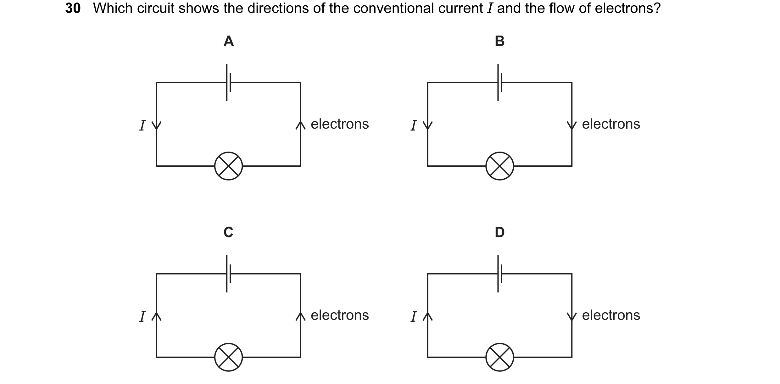
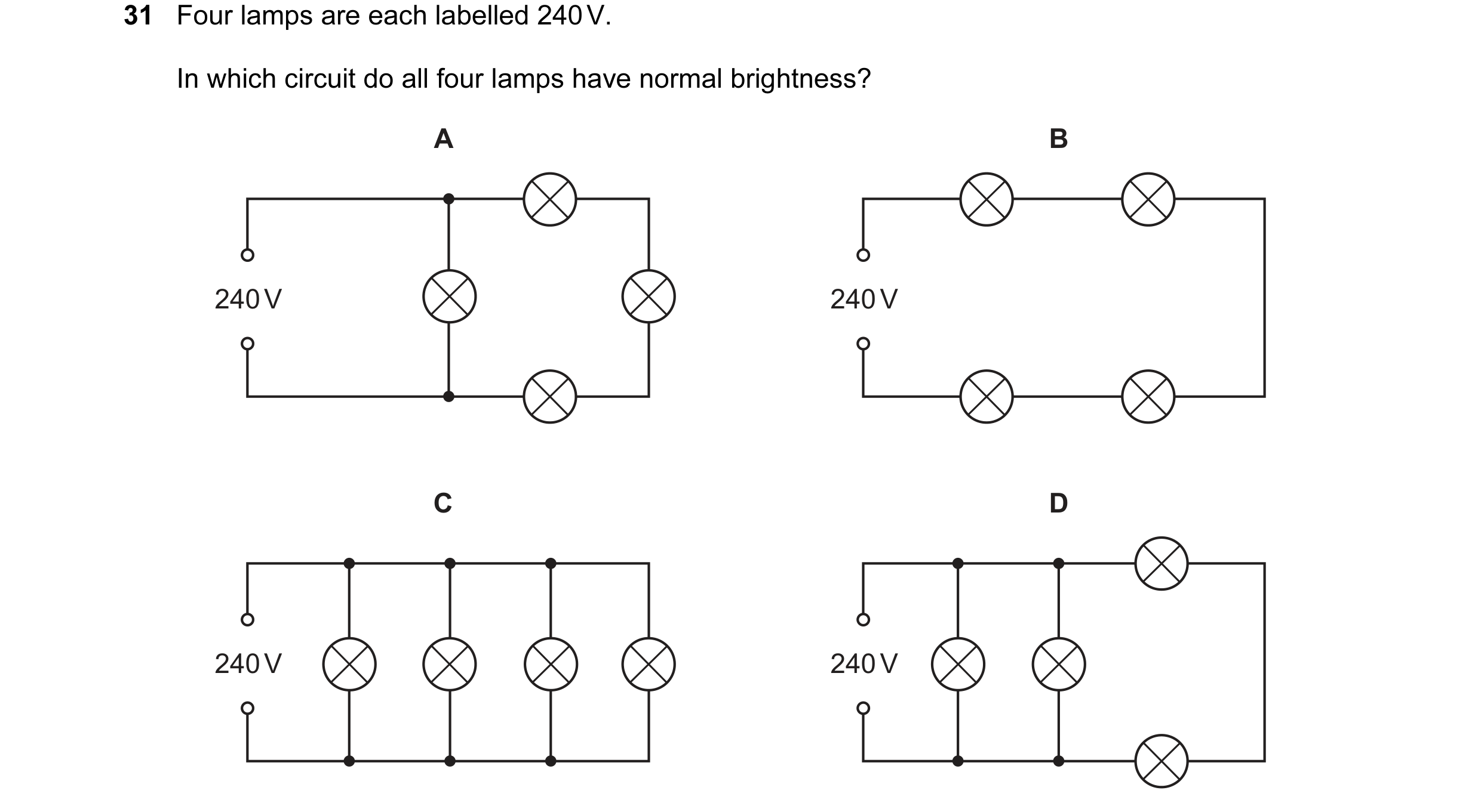
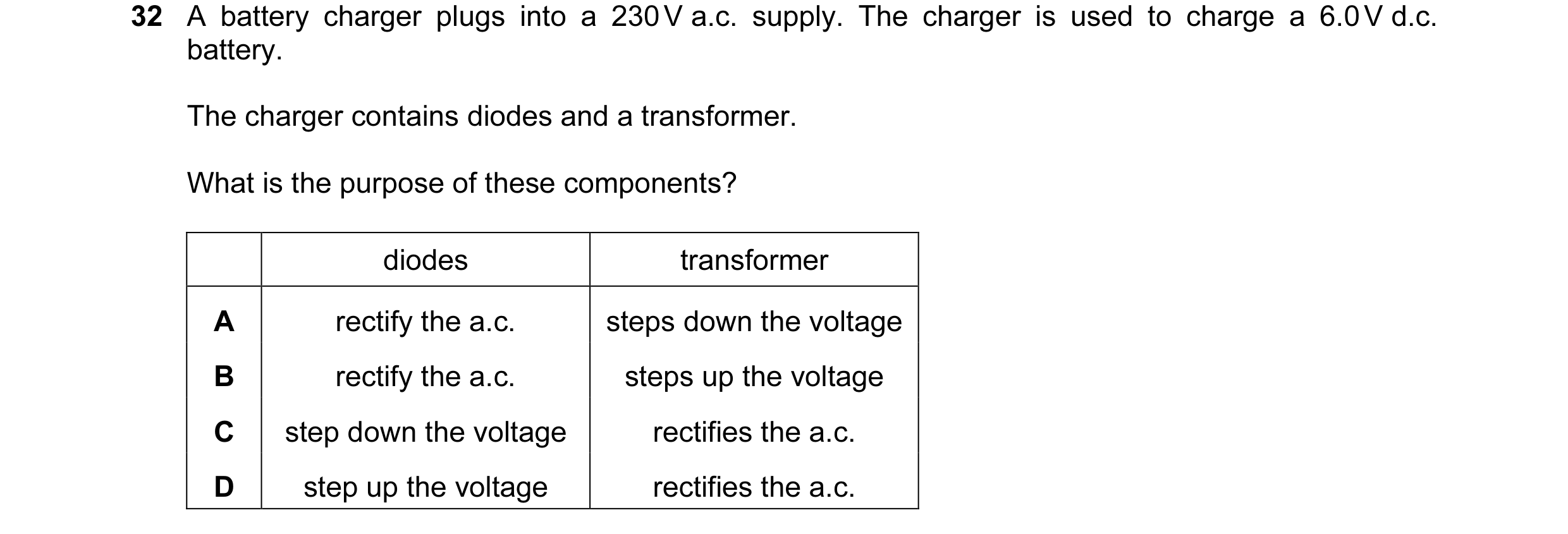 1 / 114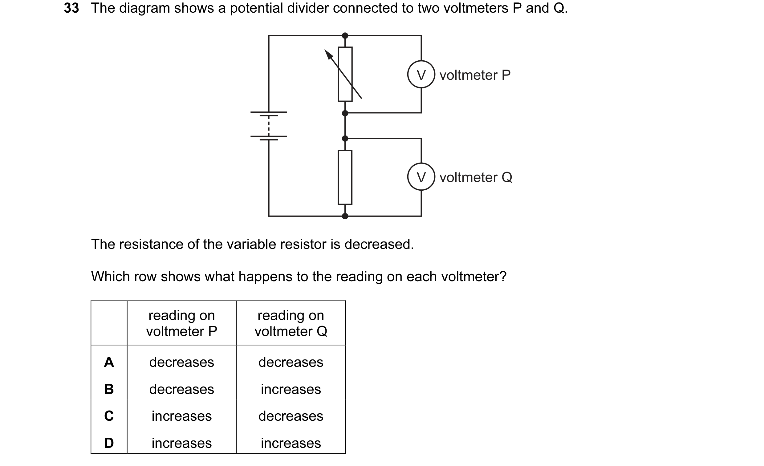
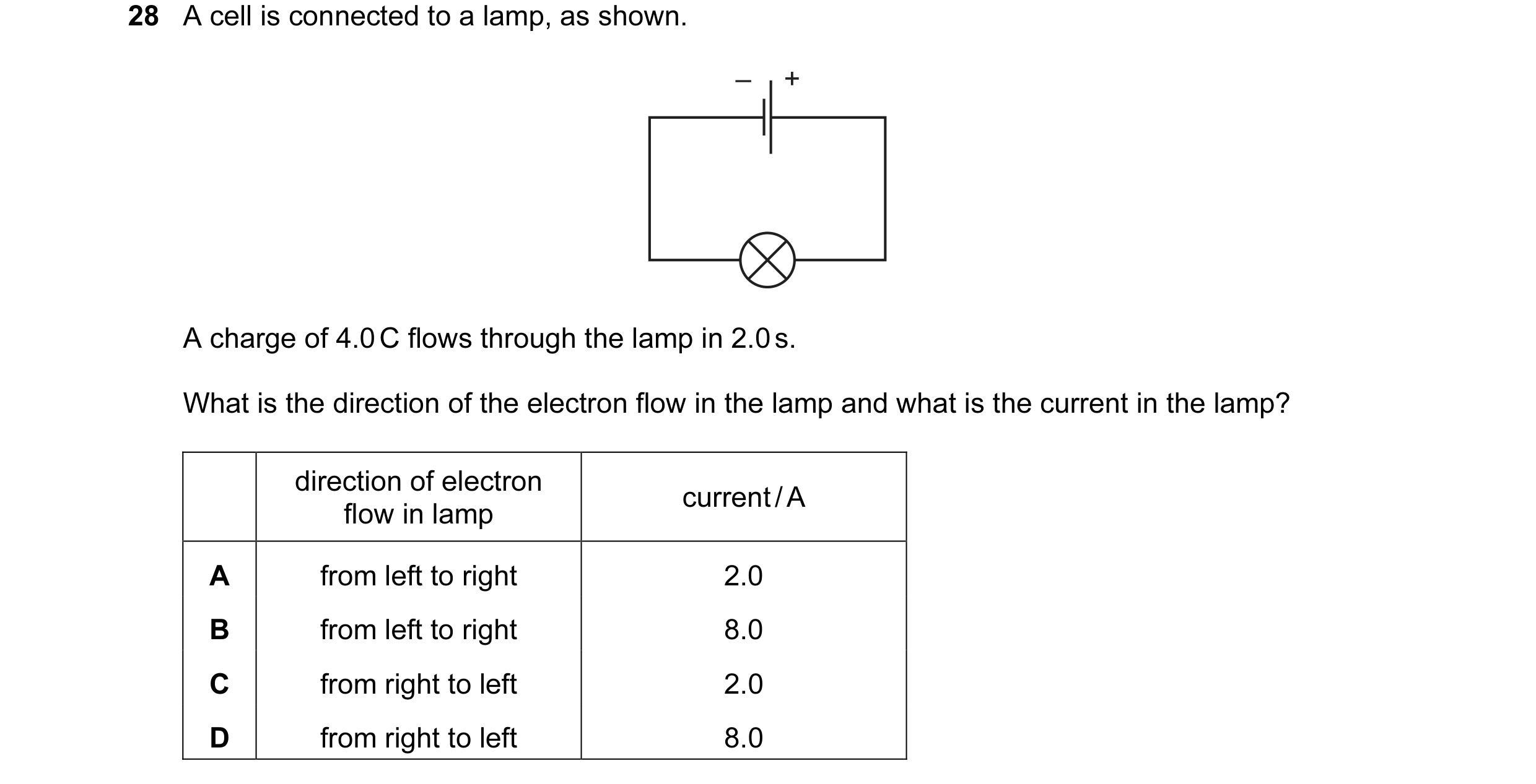 2 / 114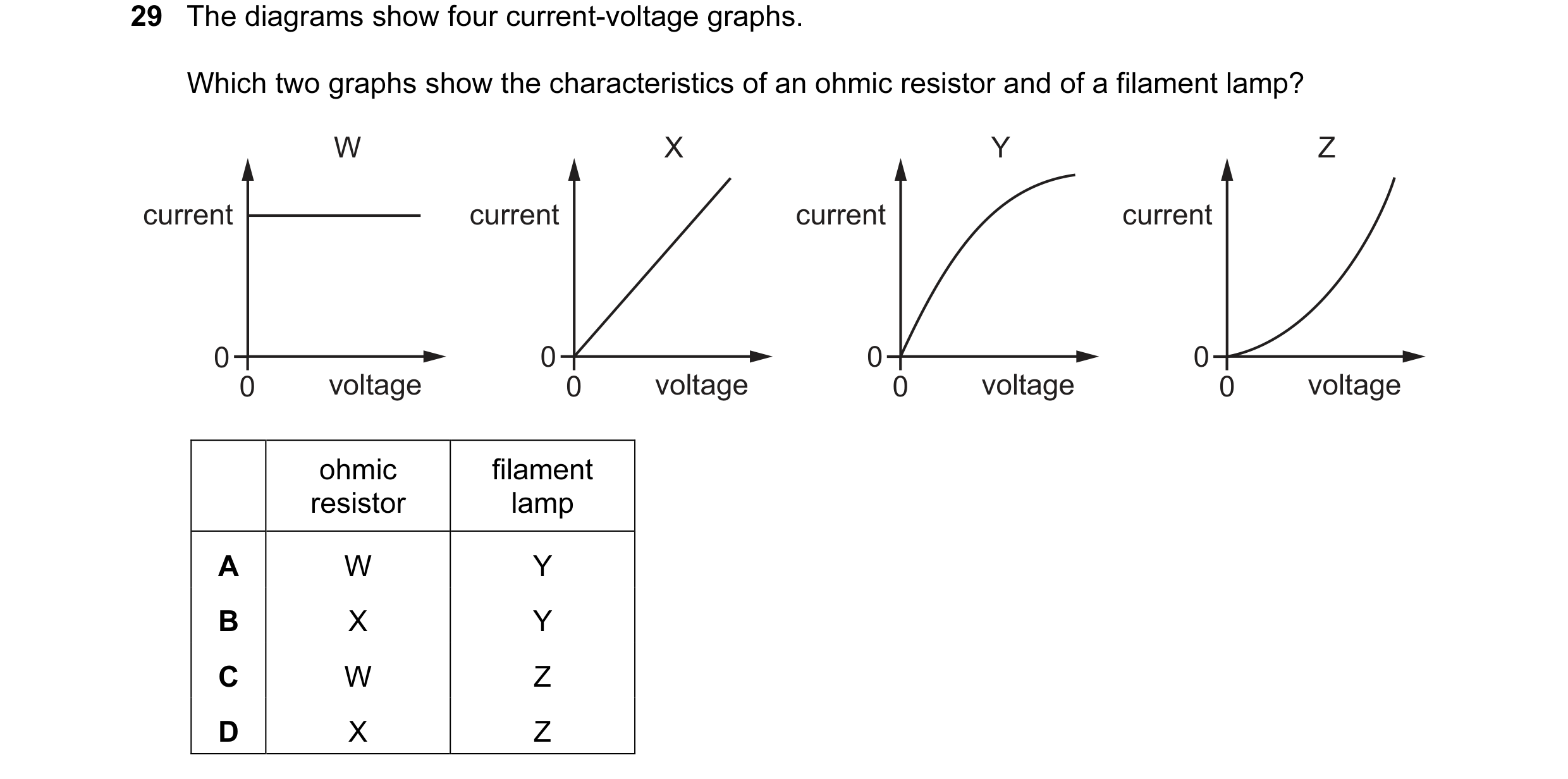
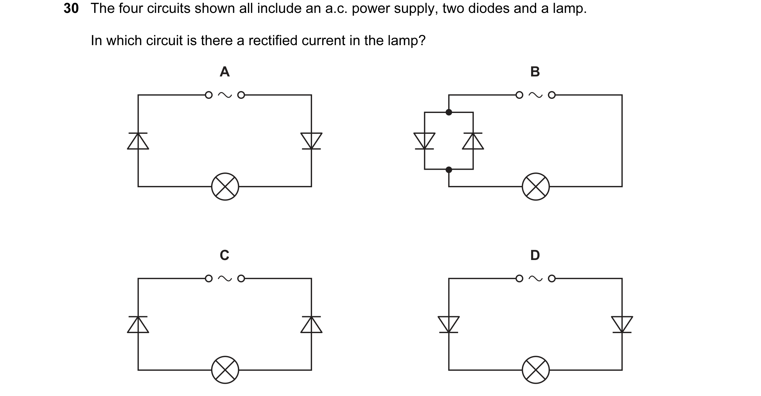 3 / 114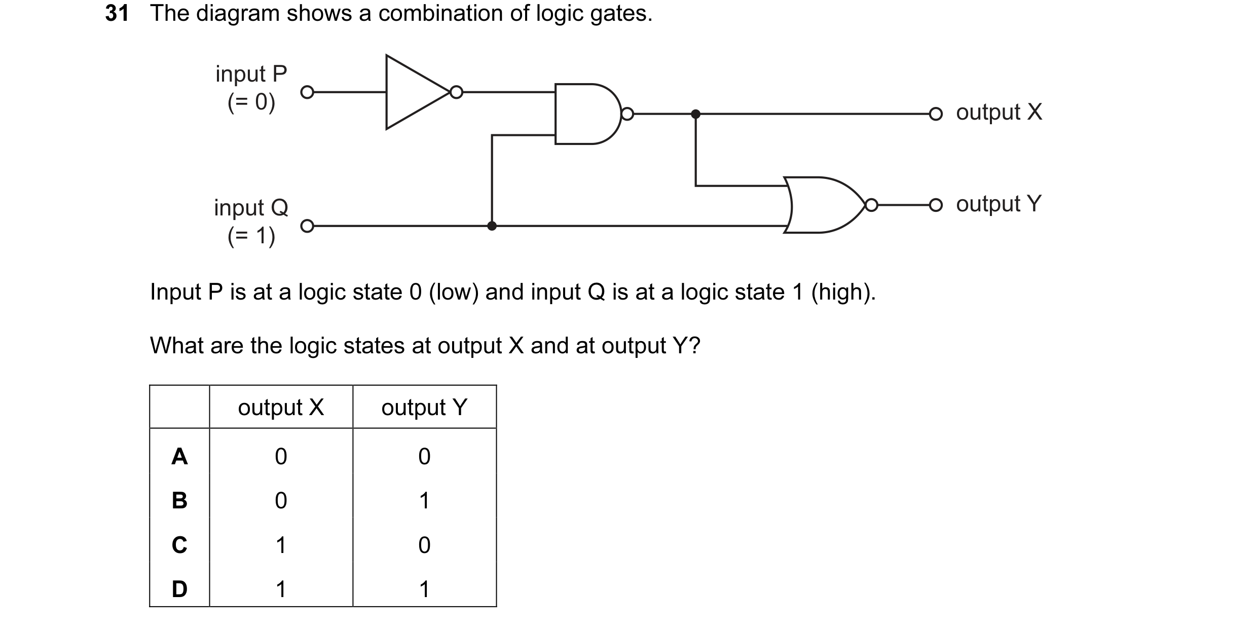
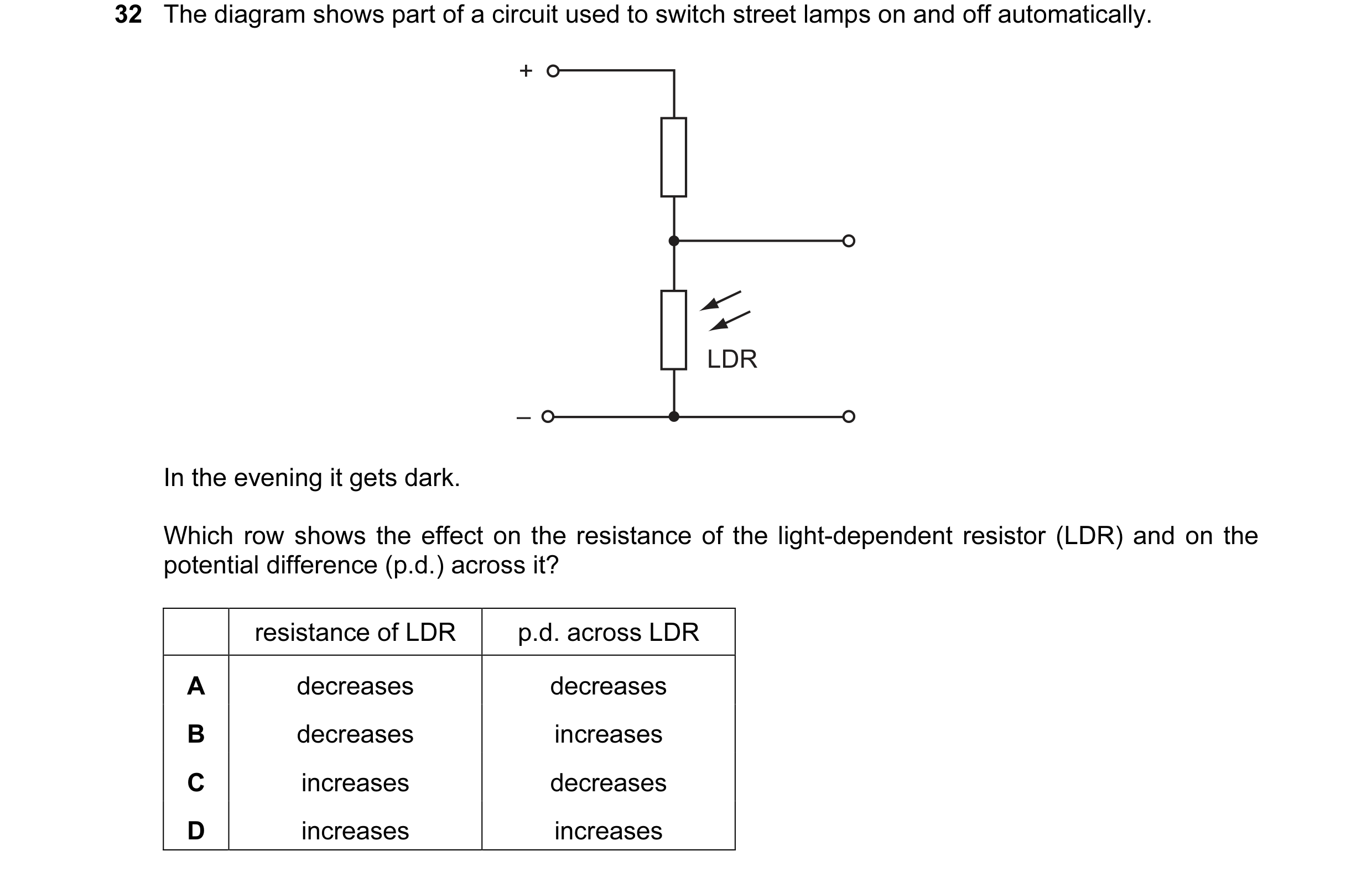 4 / 114
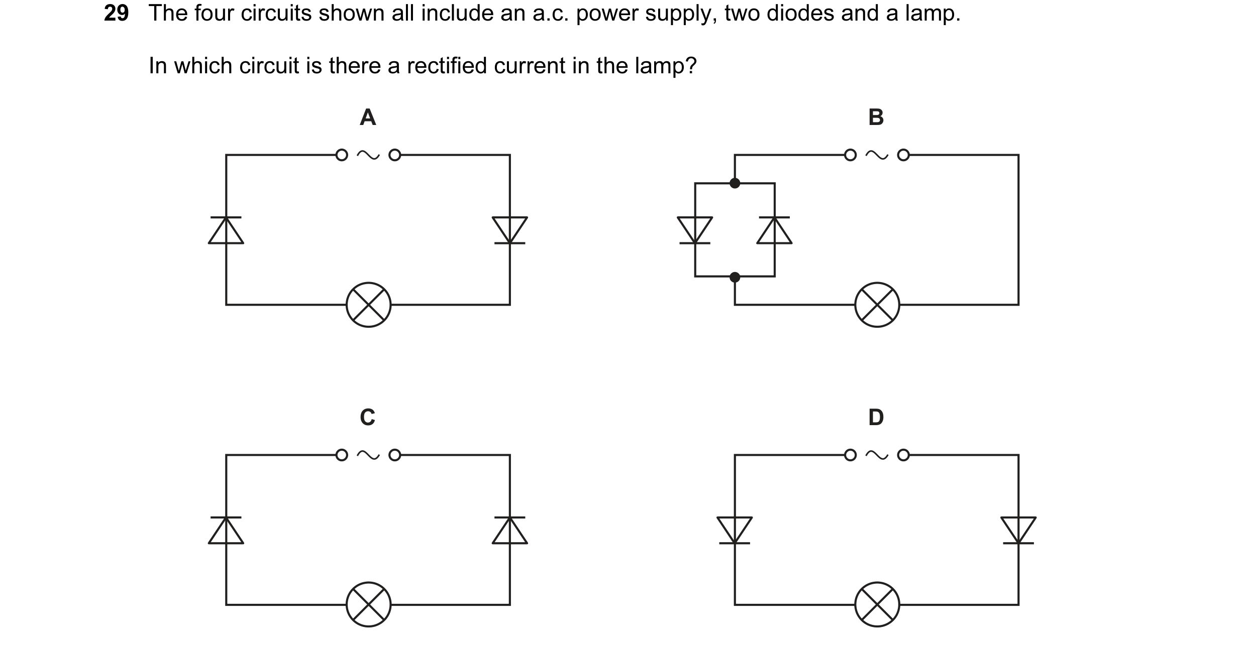
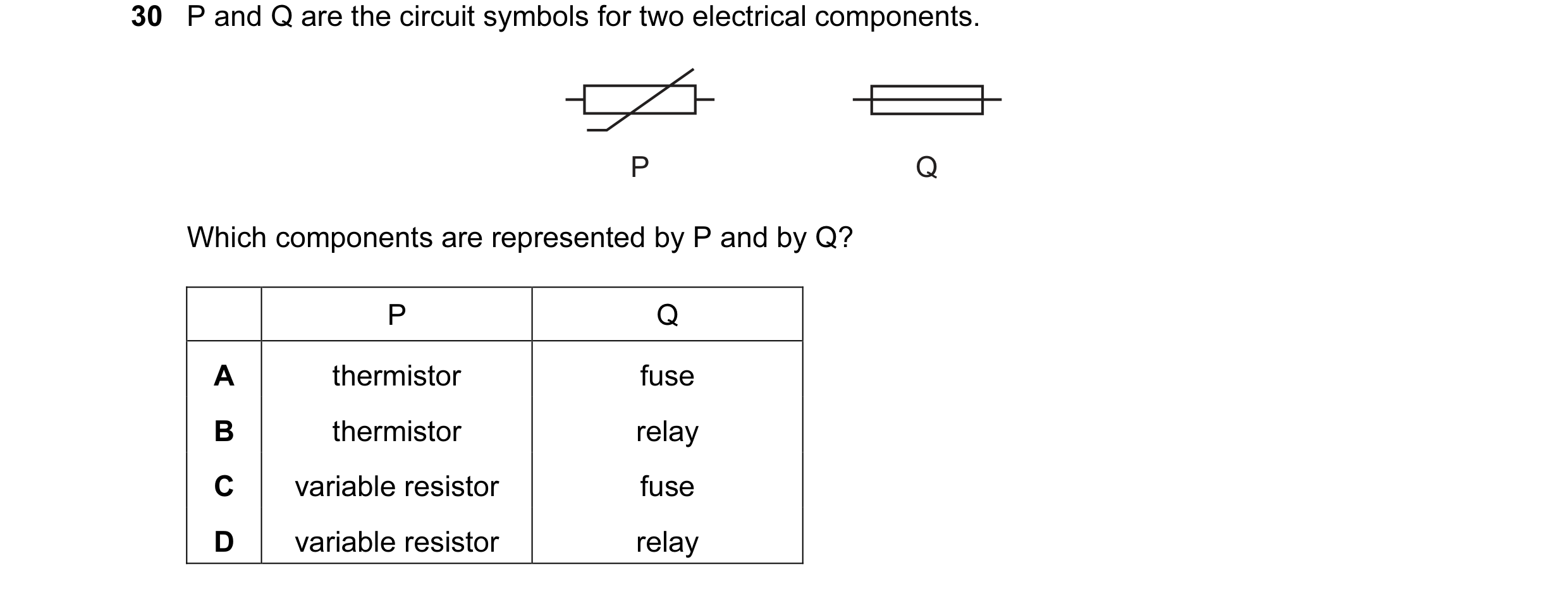 5 / 114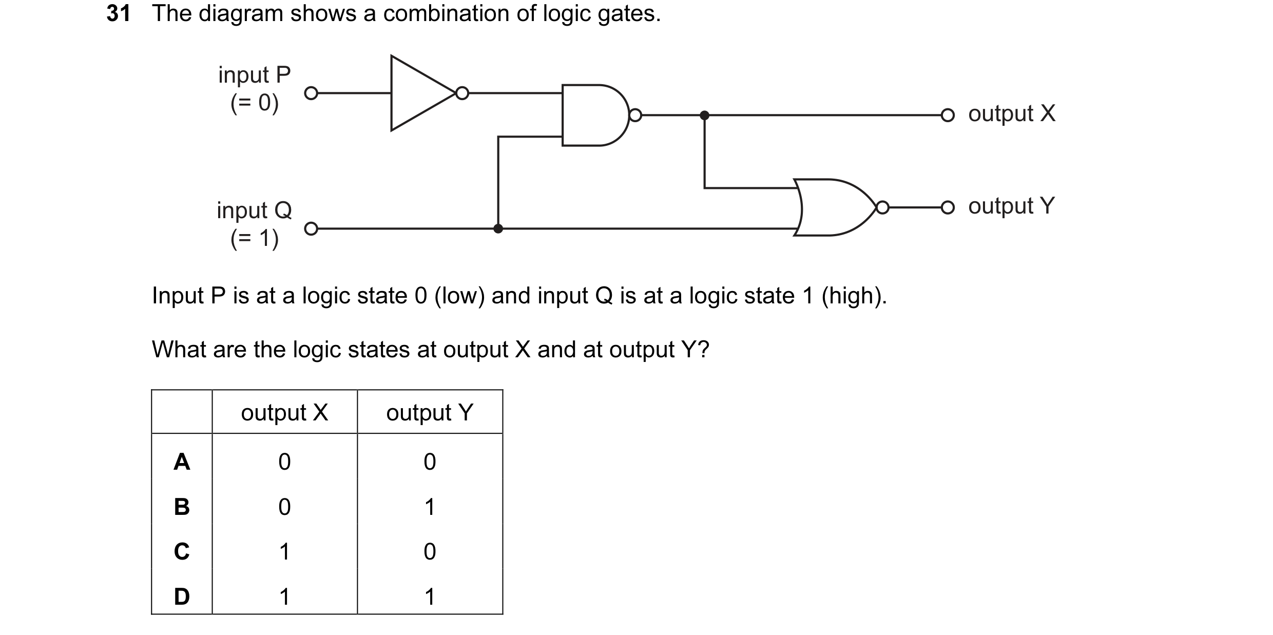
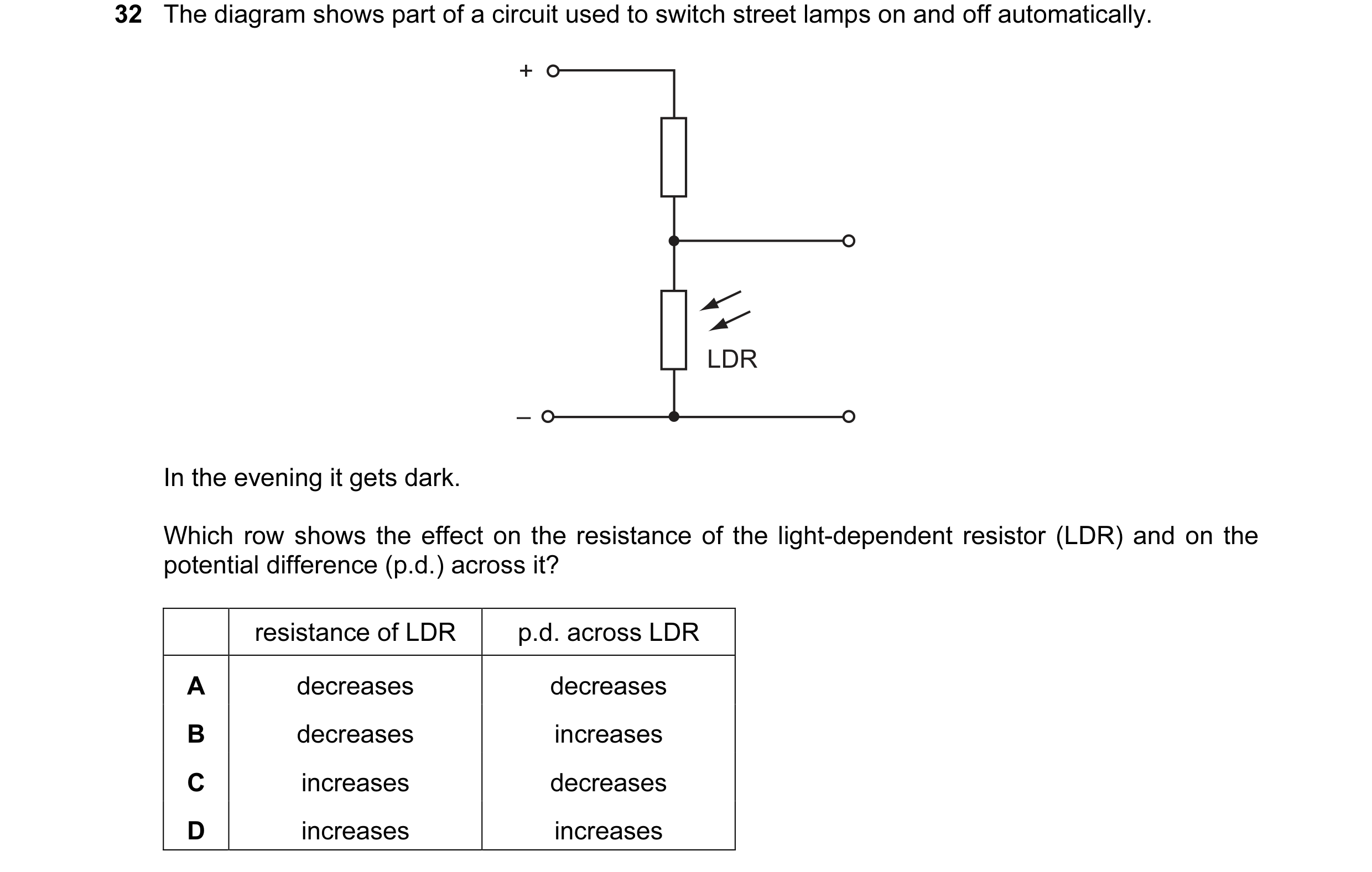 6 / 114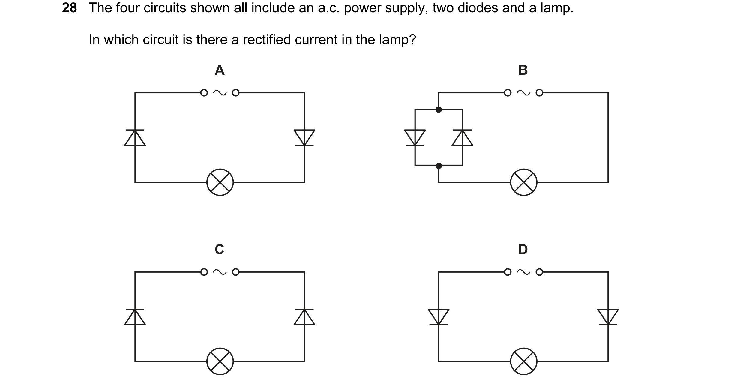
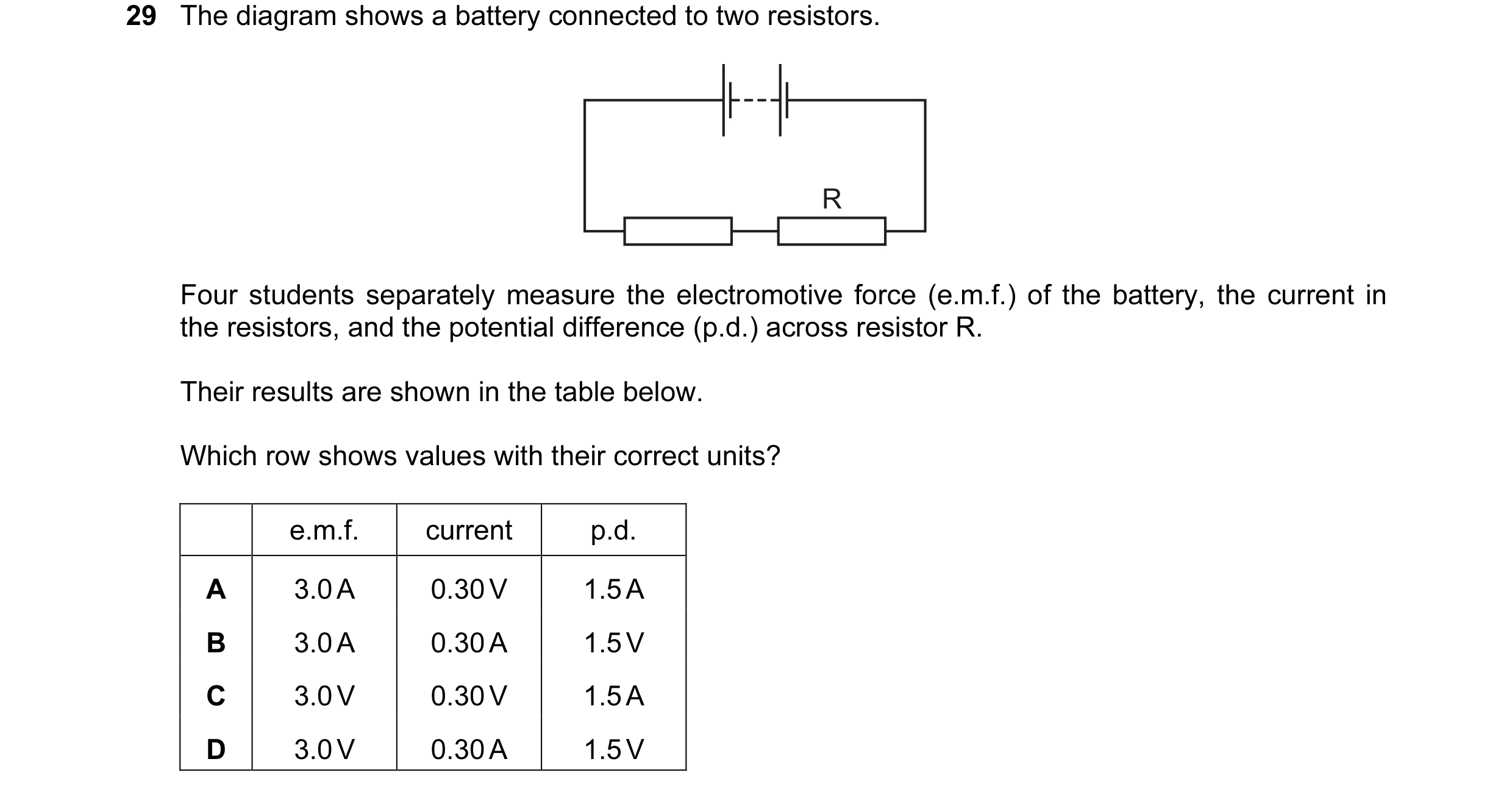
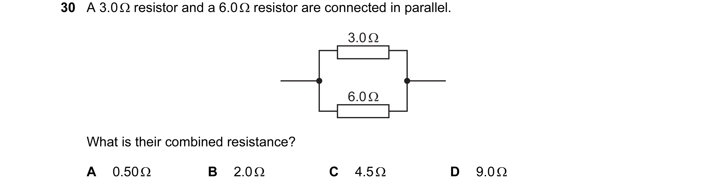 7 / 114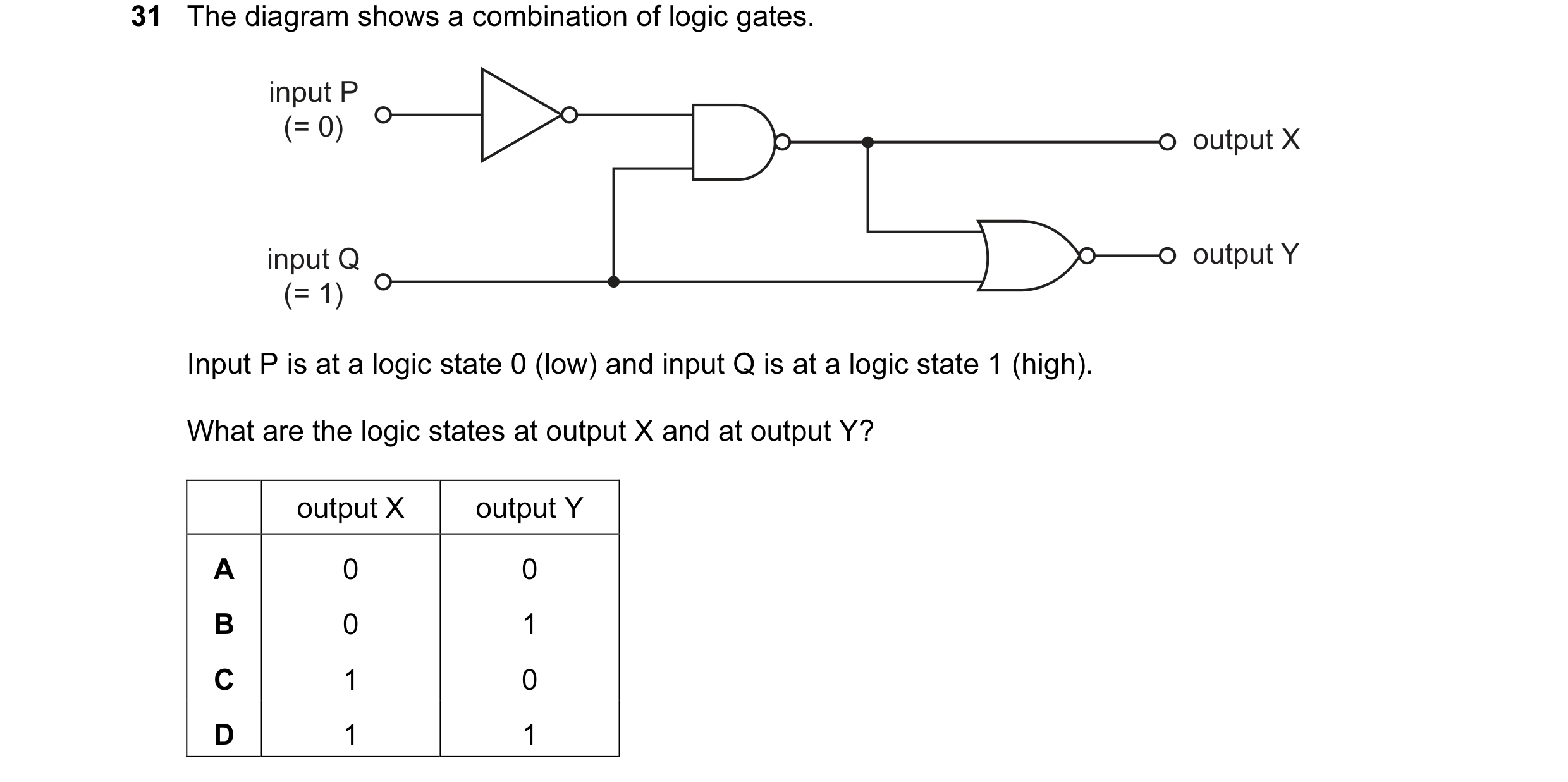
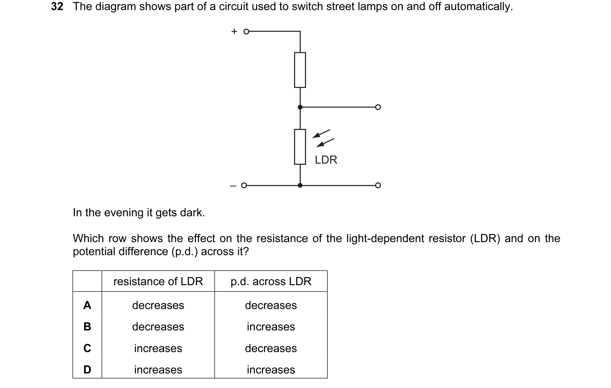 8 / 114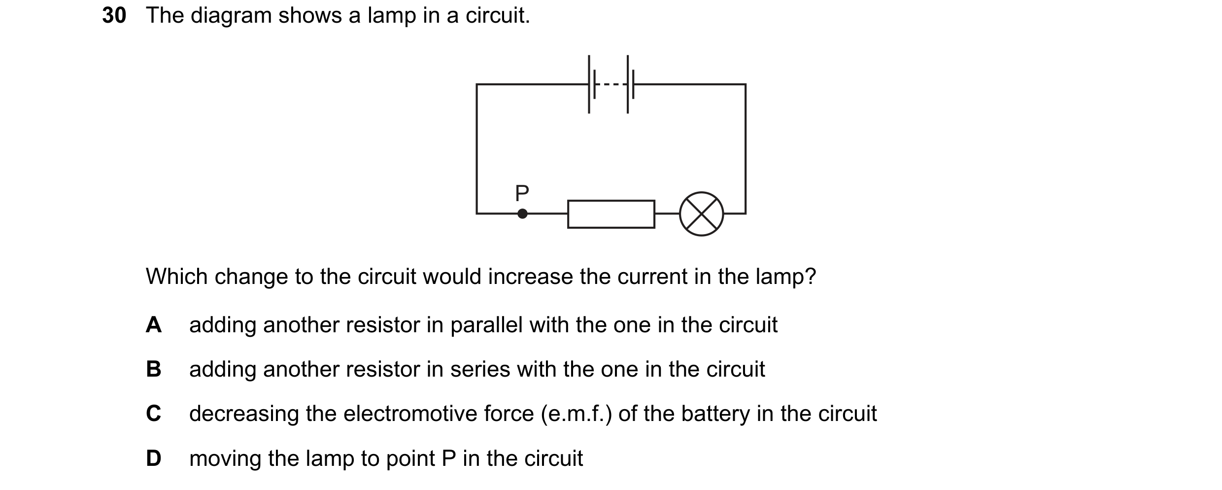
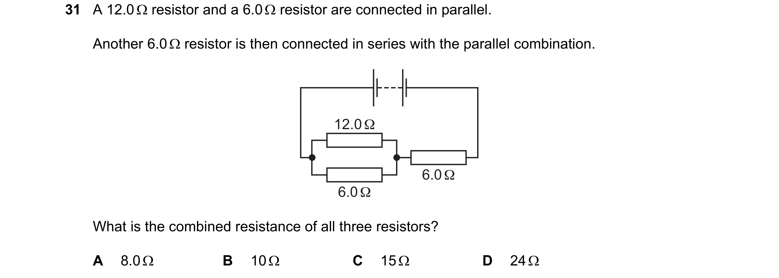
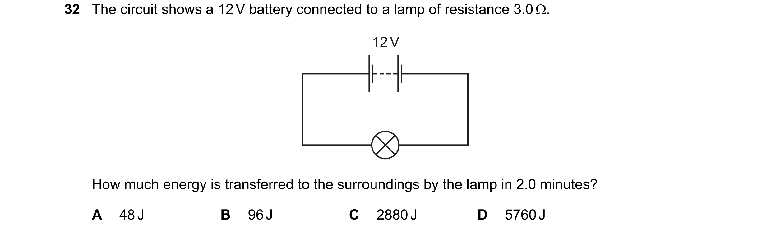 9 / 114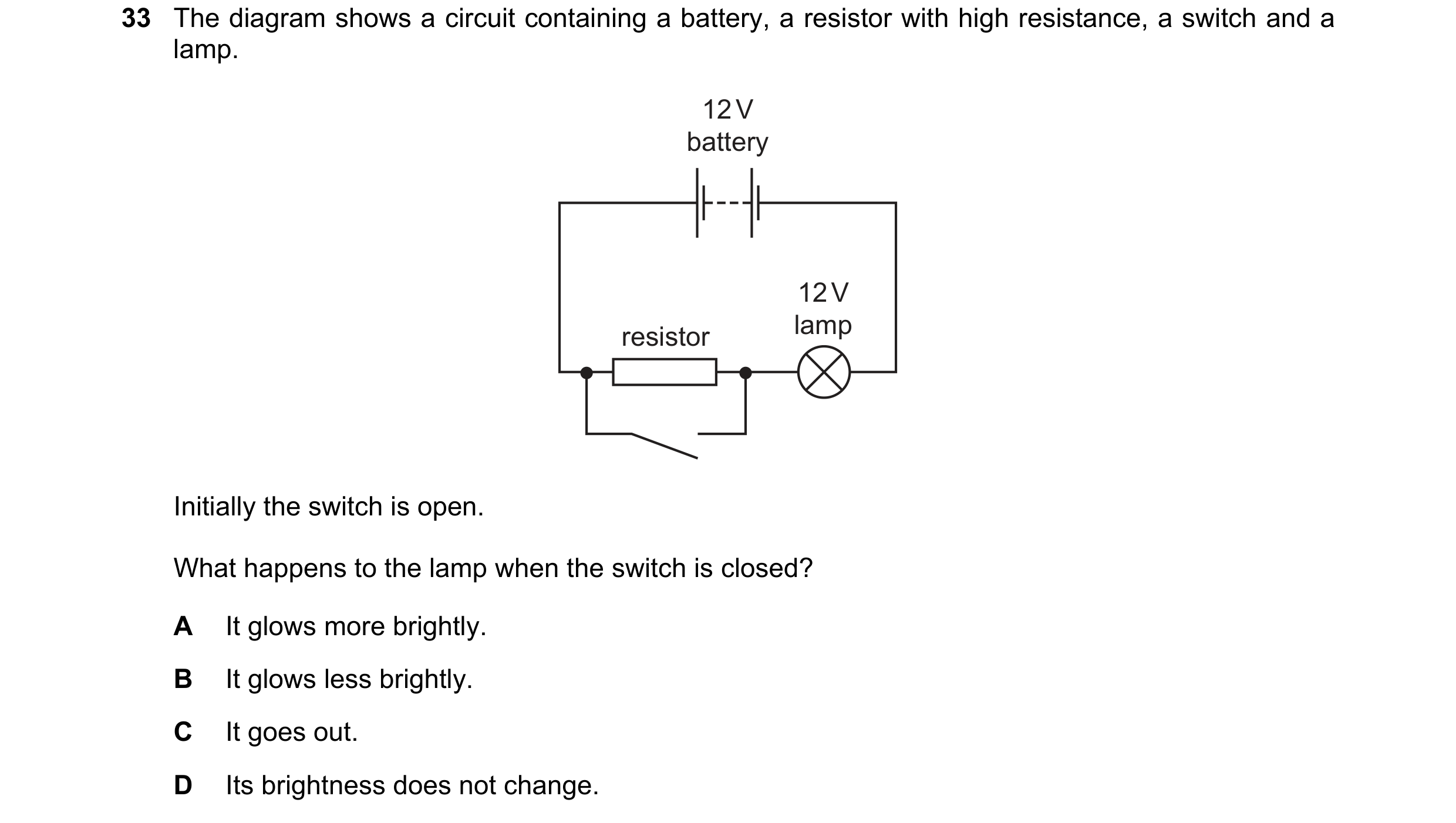
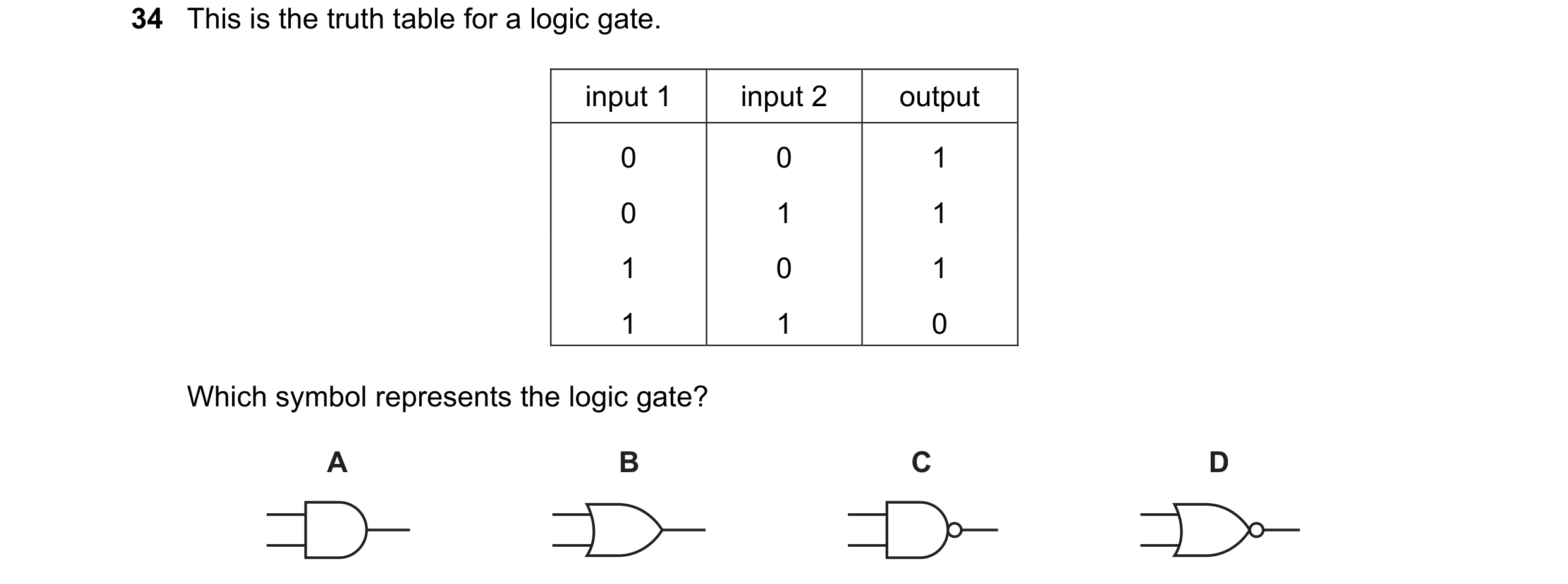
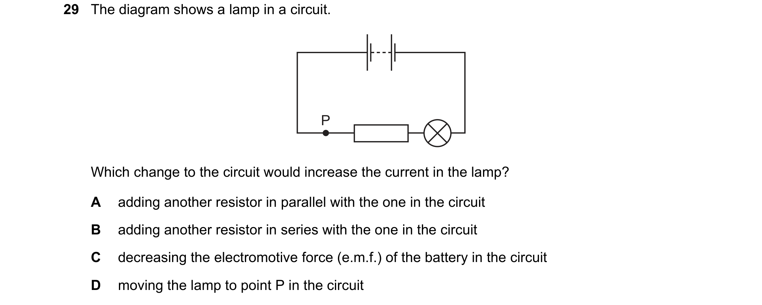 10 / 114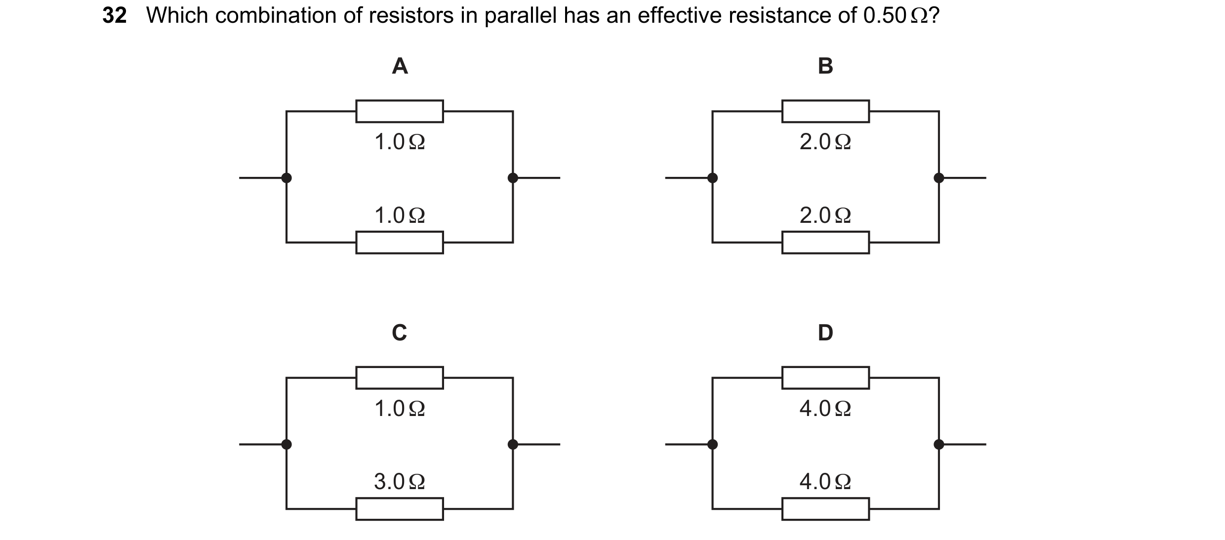
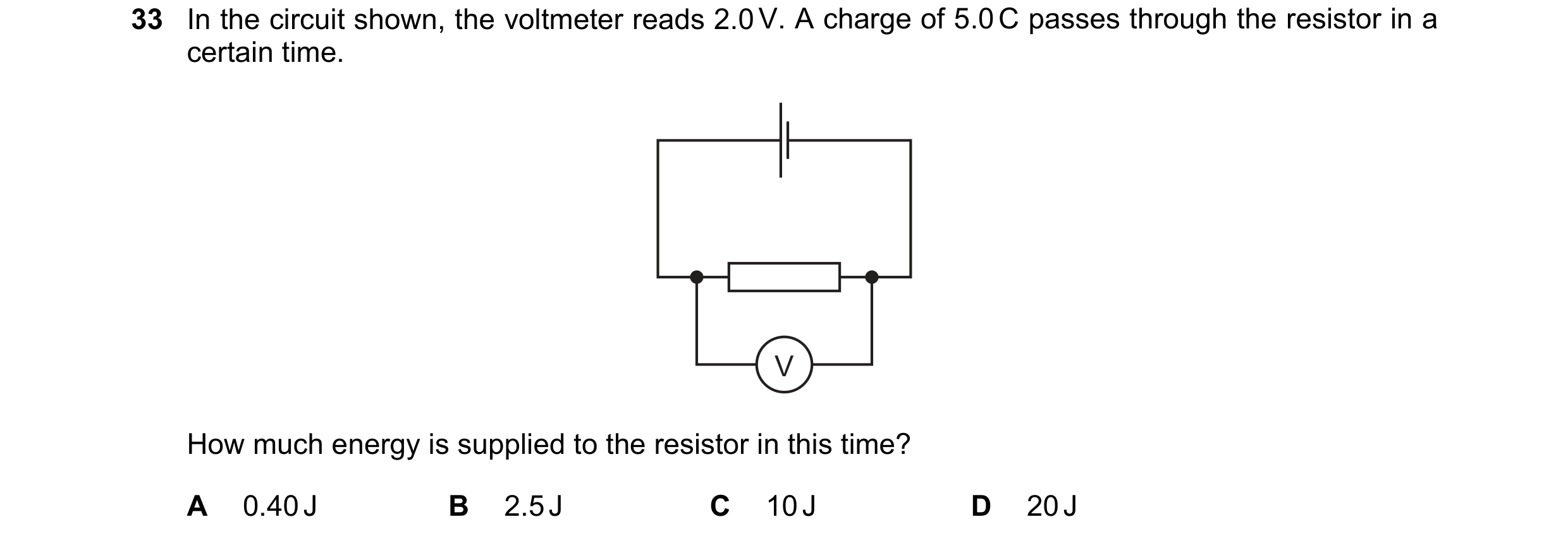
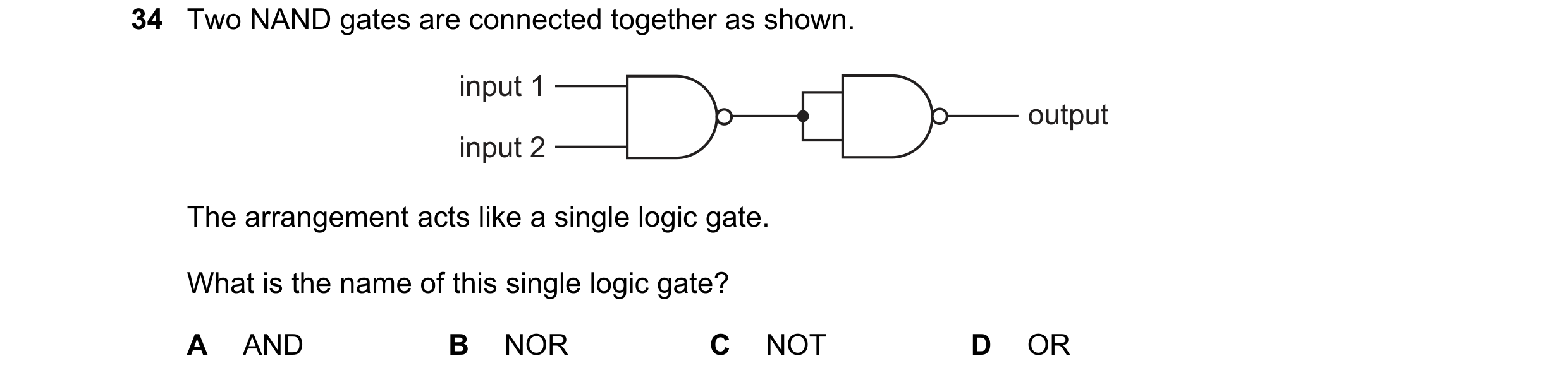 11 / 114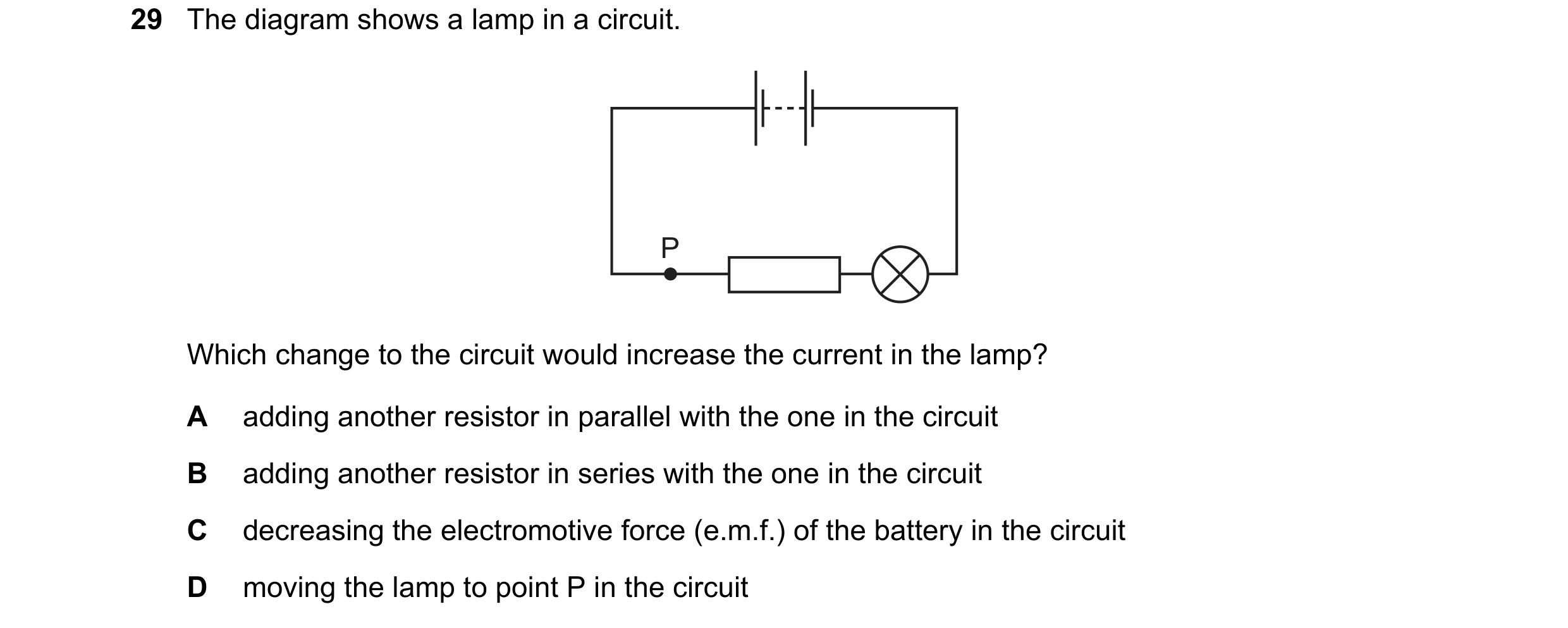
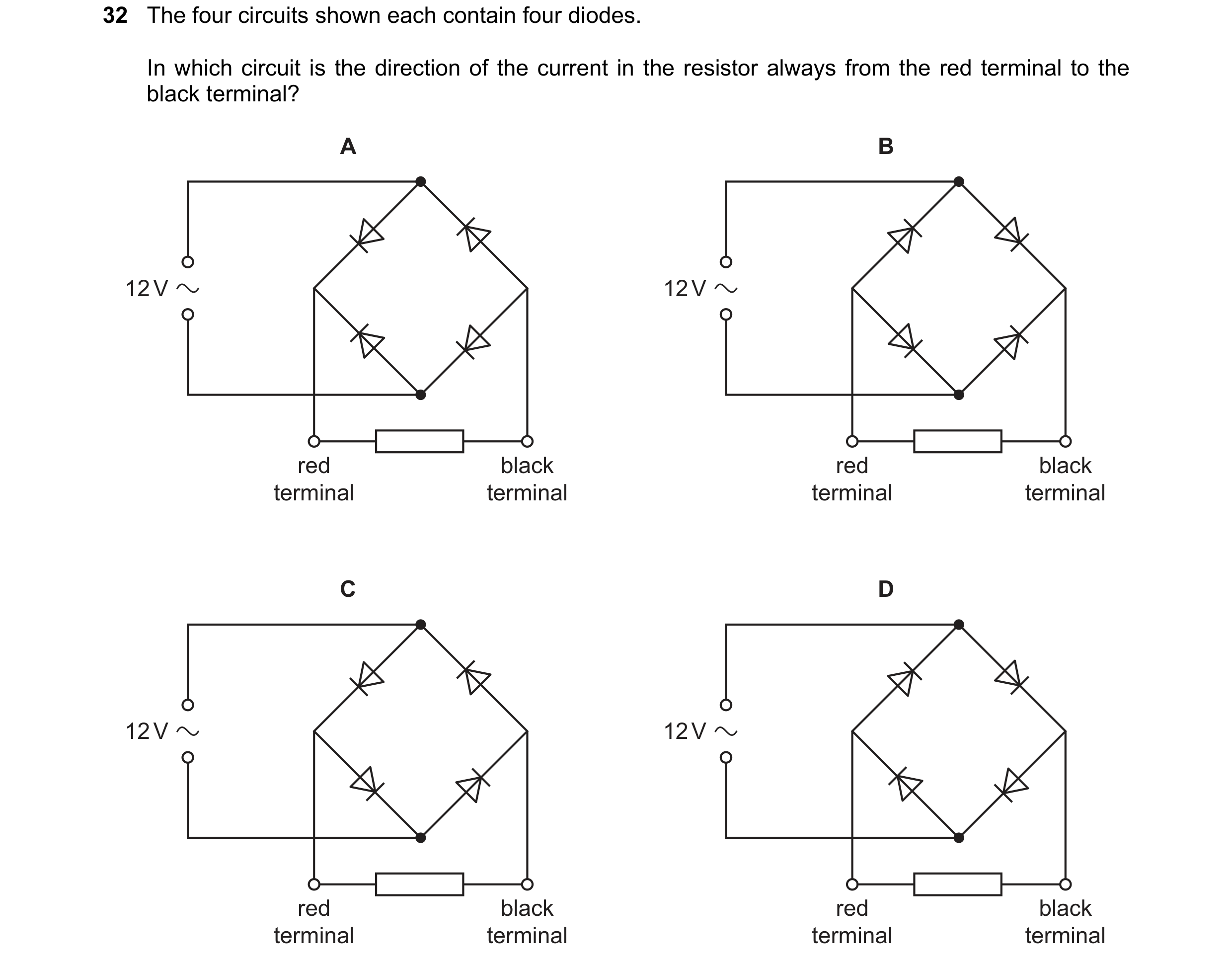 12 / 114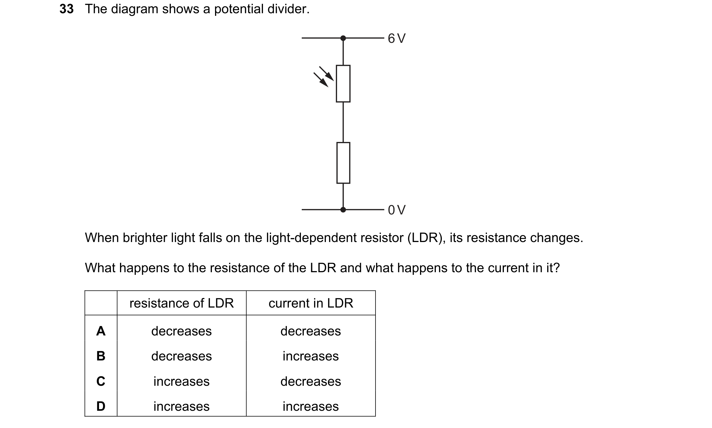
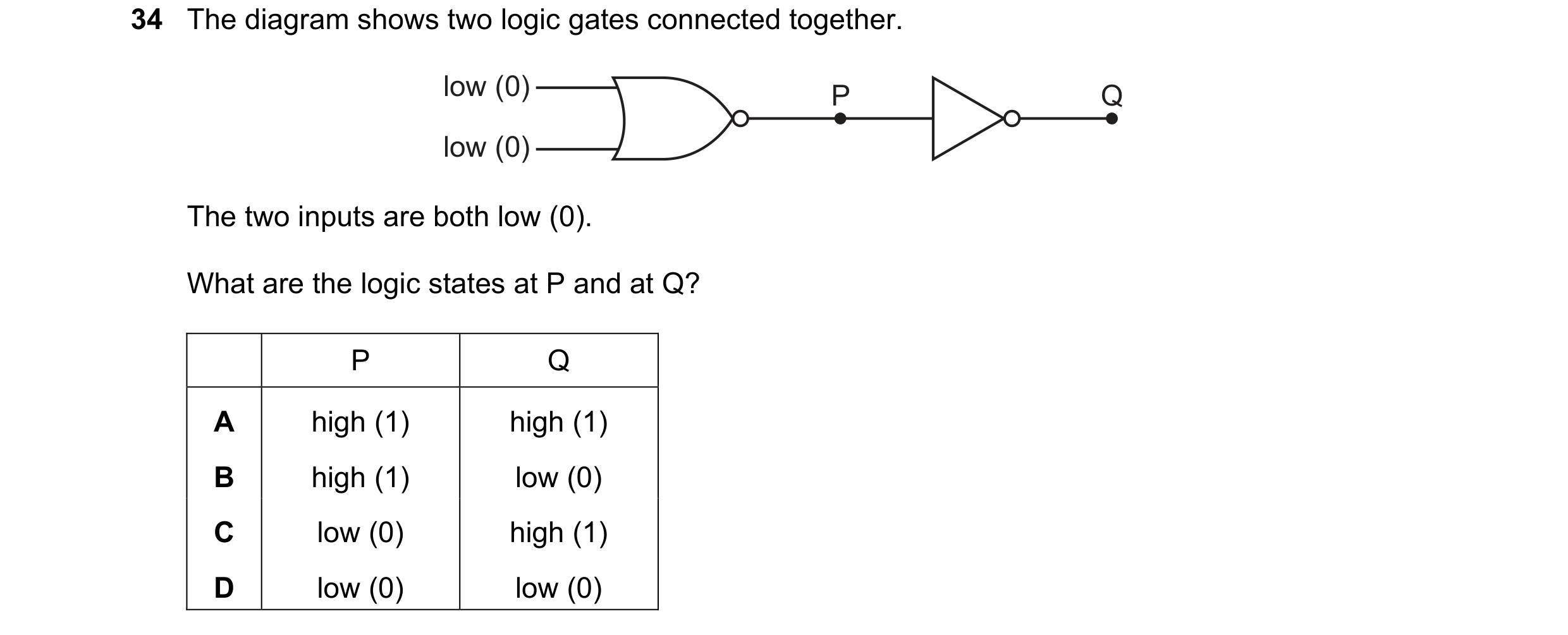
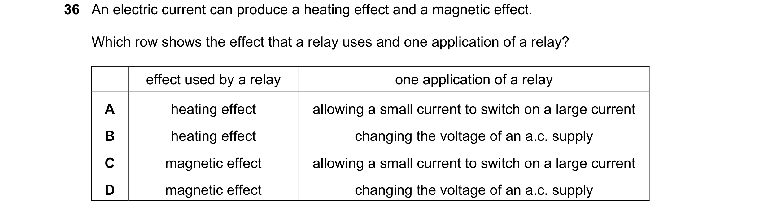 13 / 114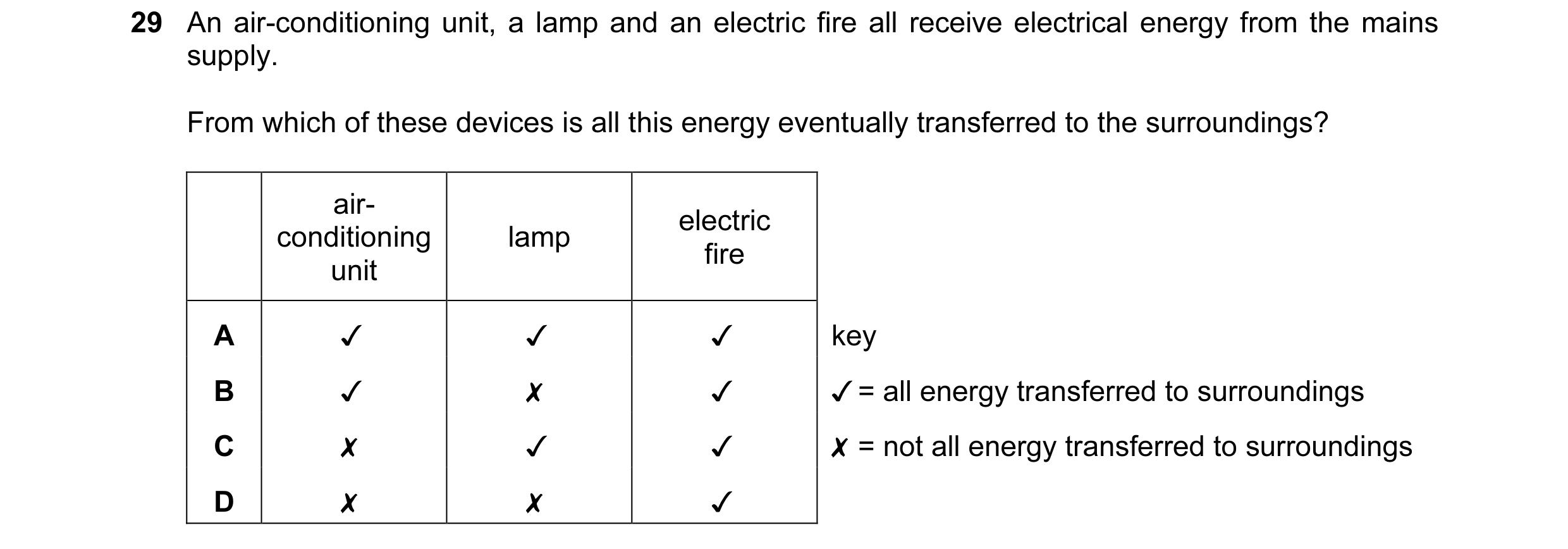
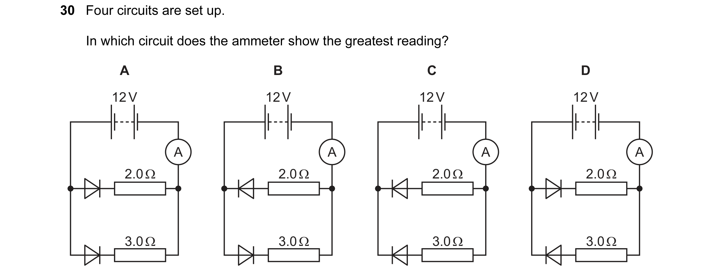
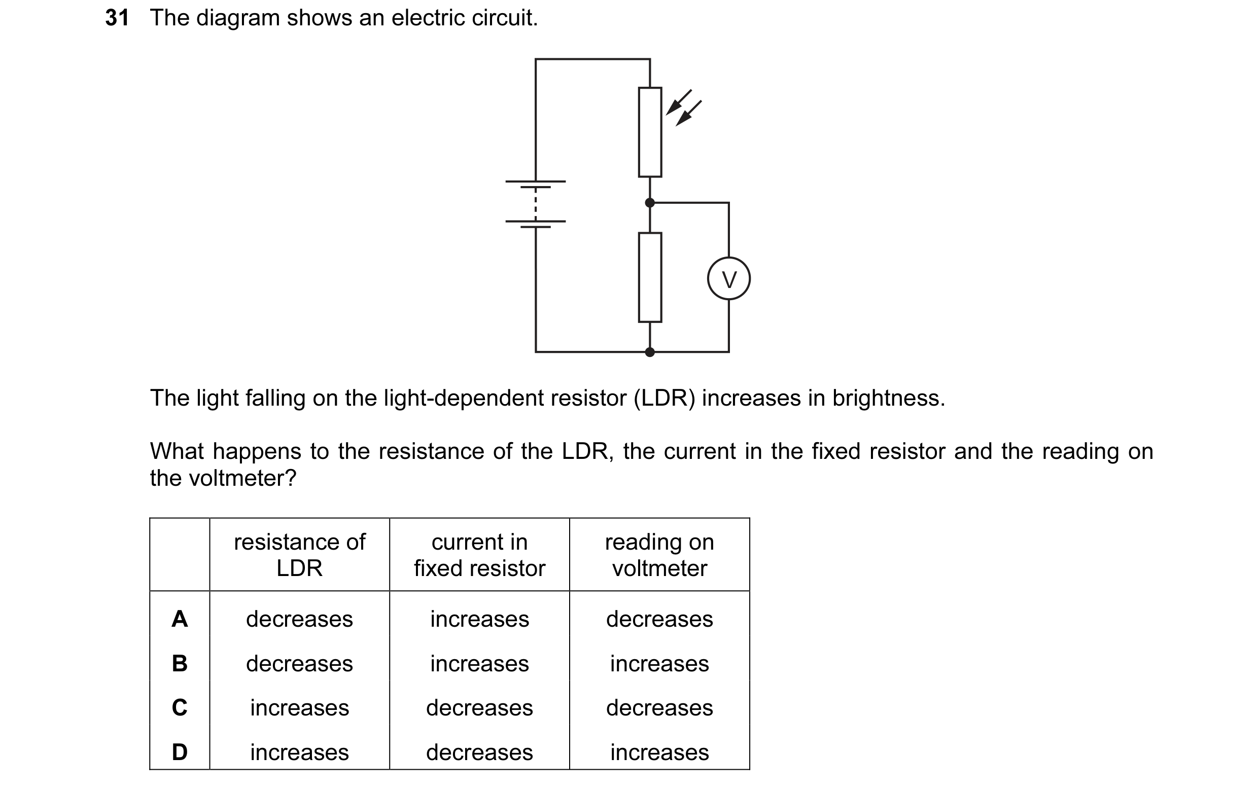 14 / 114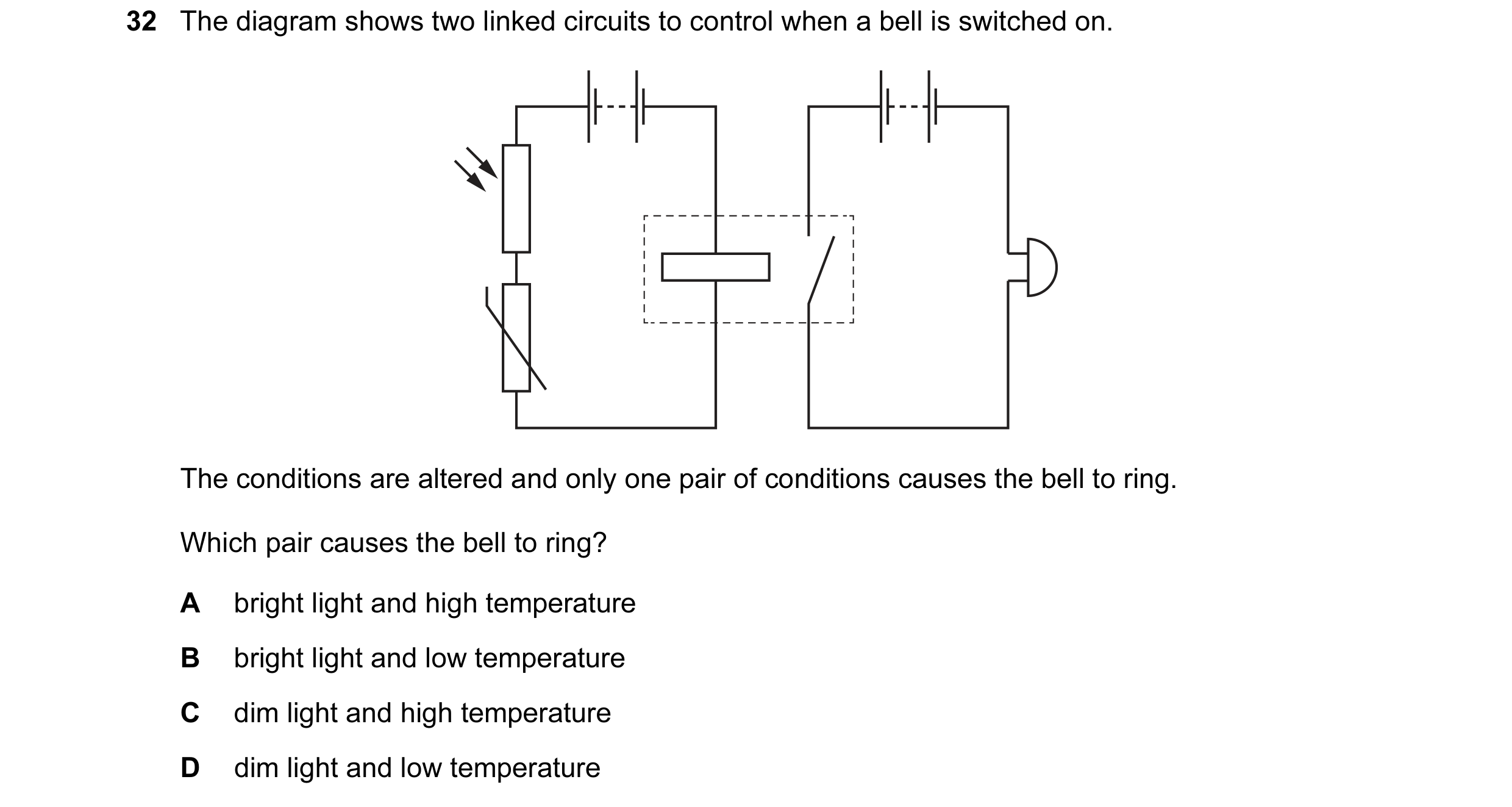
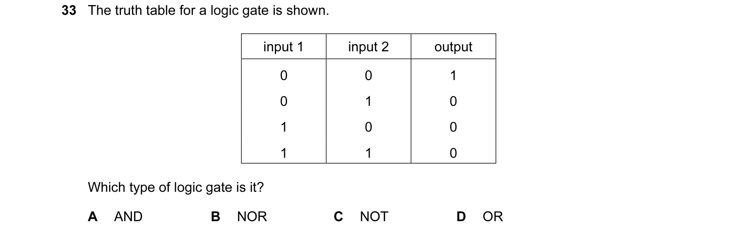
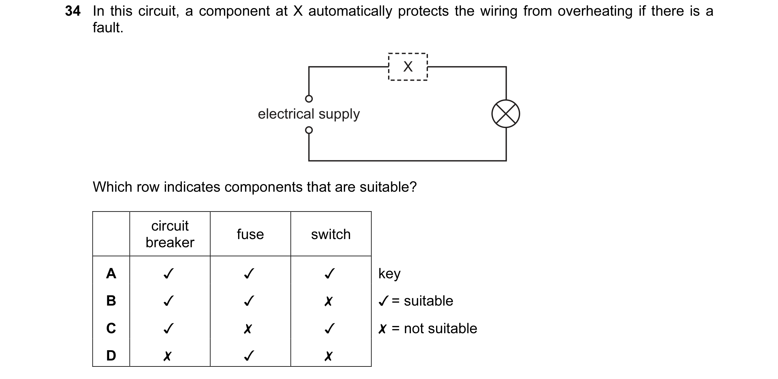 15 / 114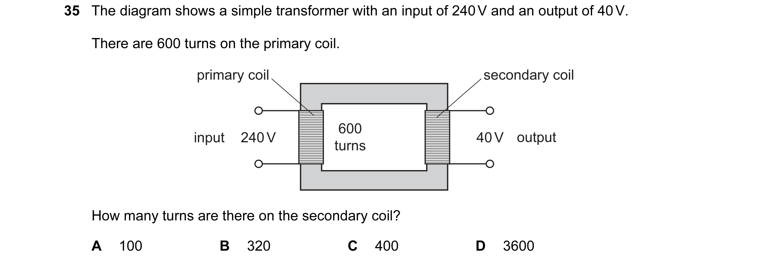
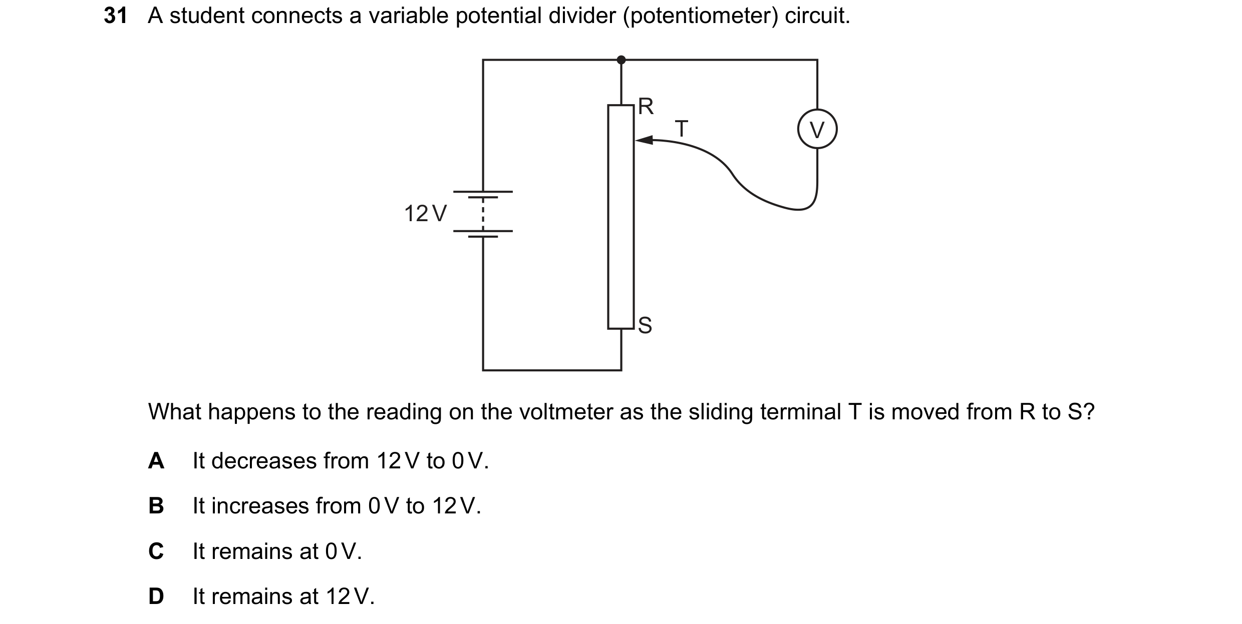 16 / 114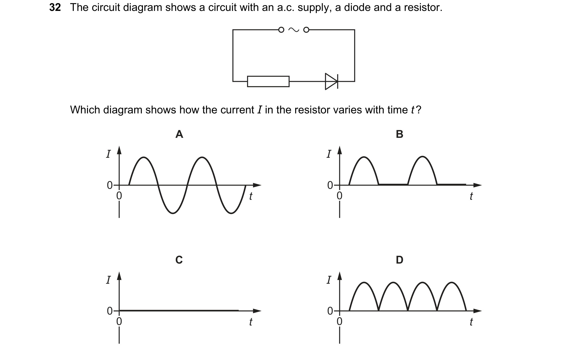
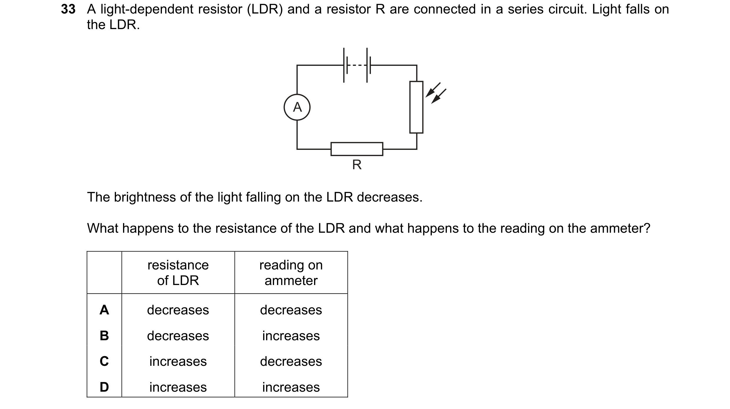 17 / 114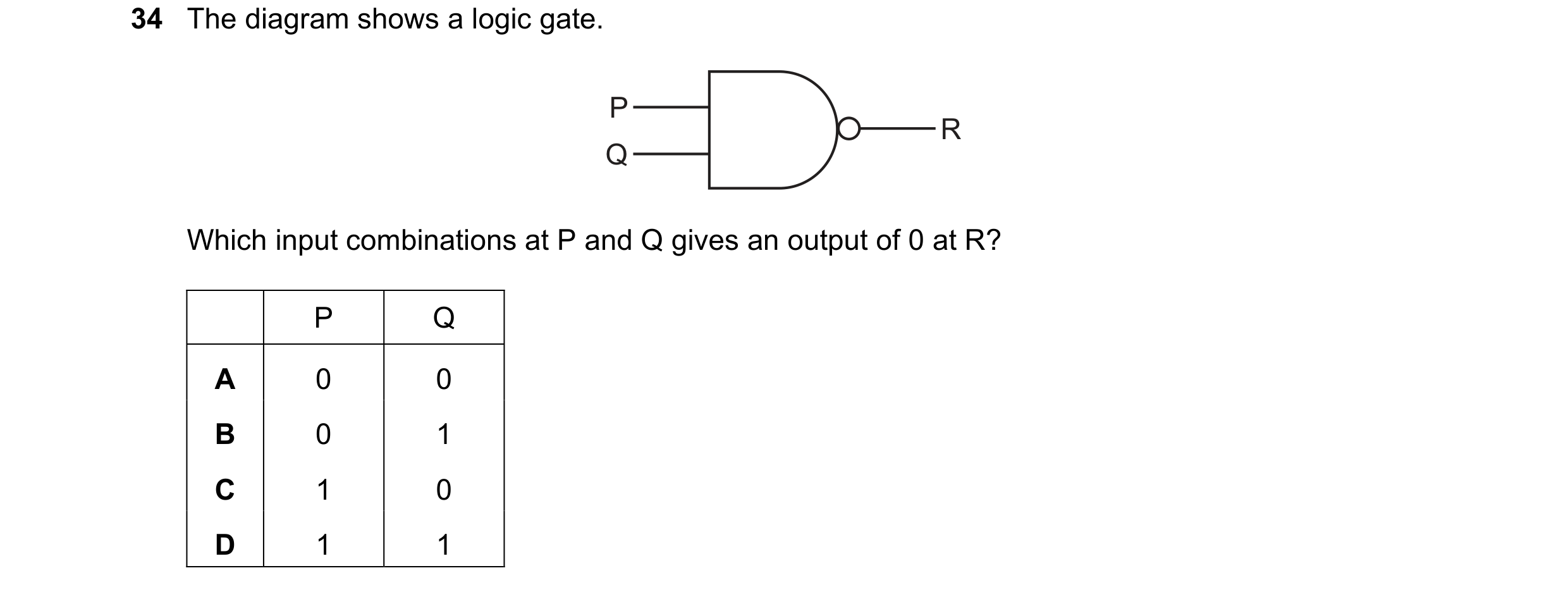

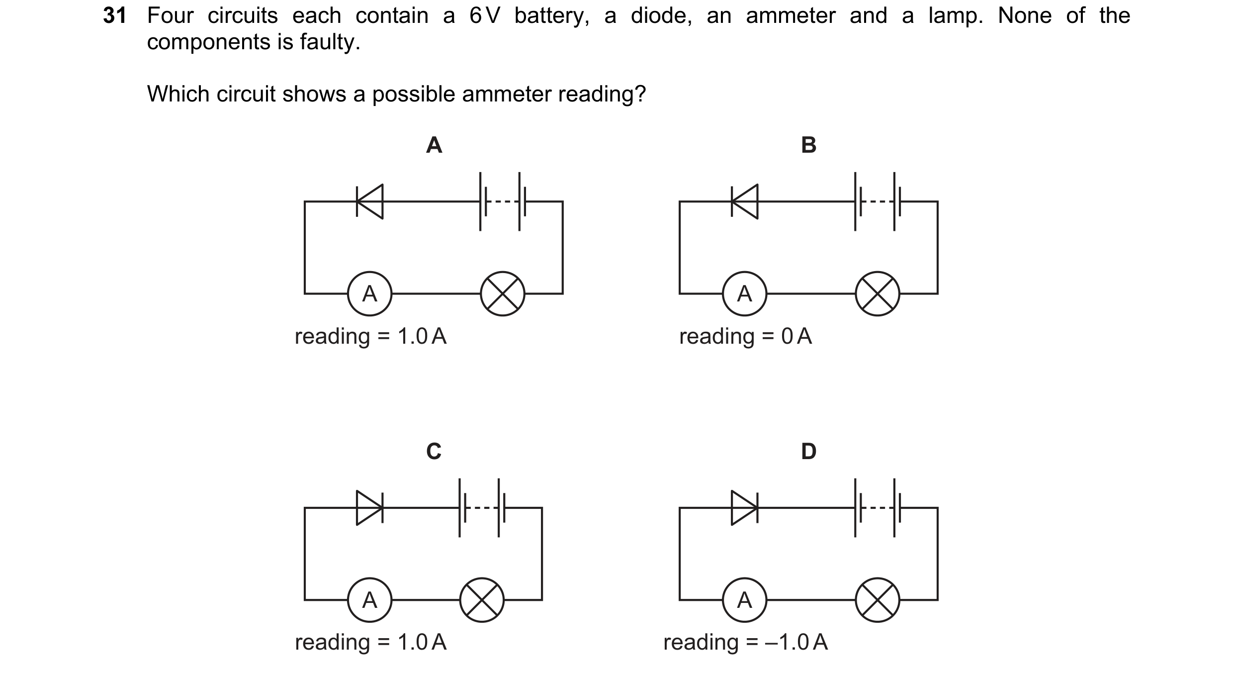 18 / 114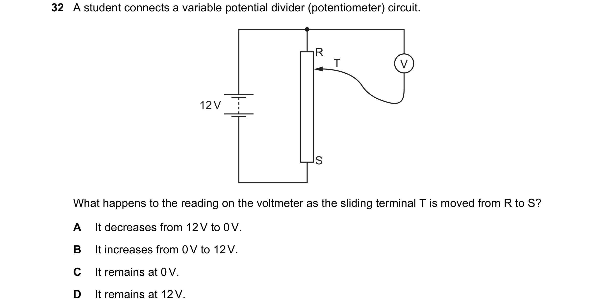
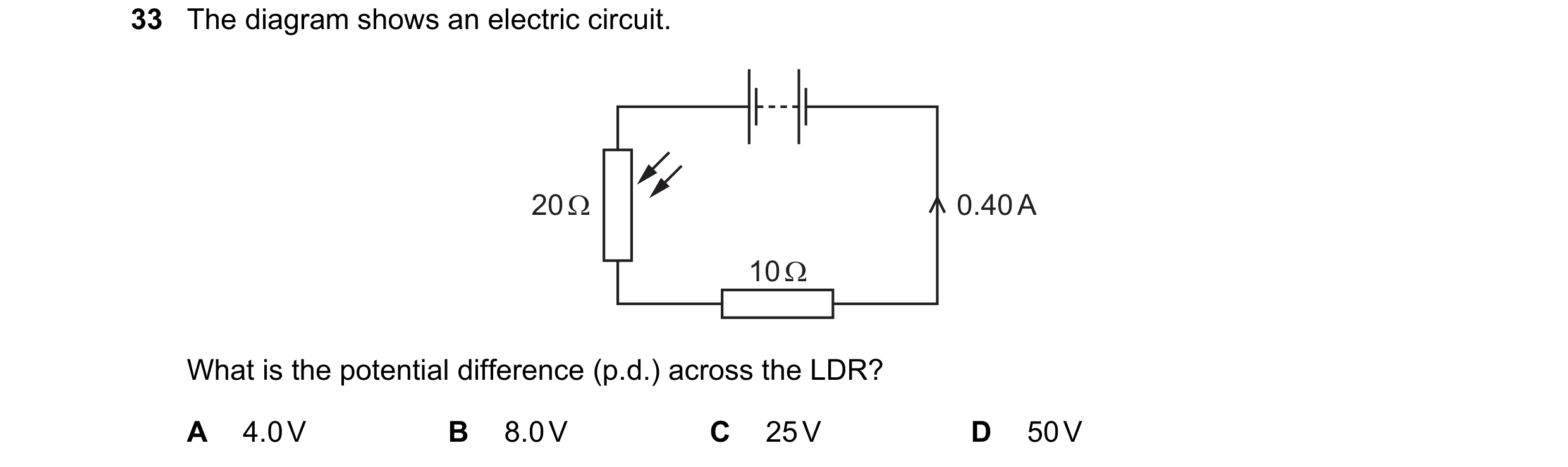
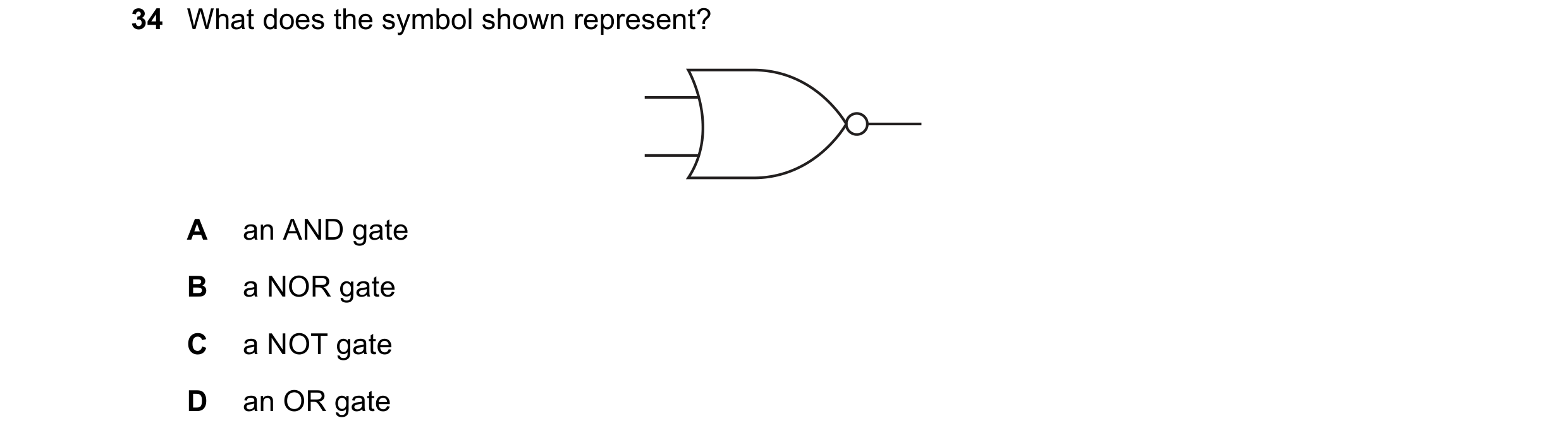
 19 / 114
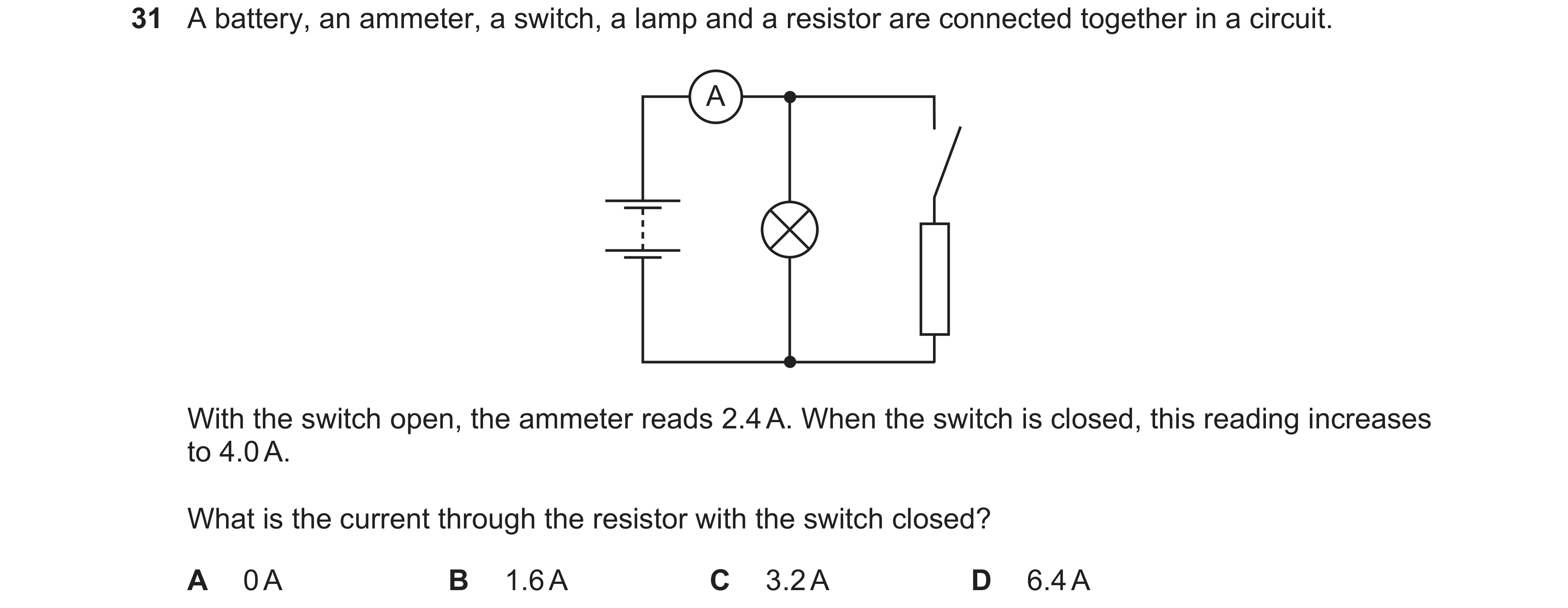
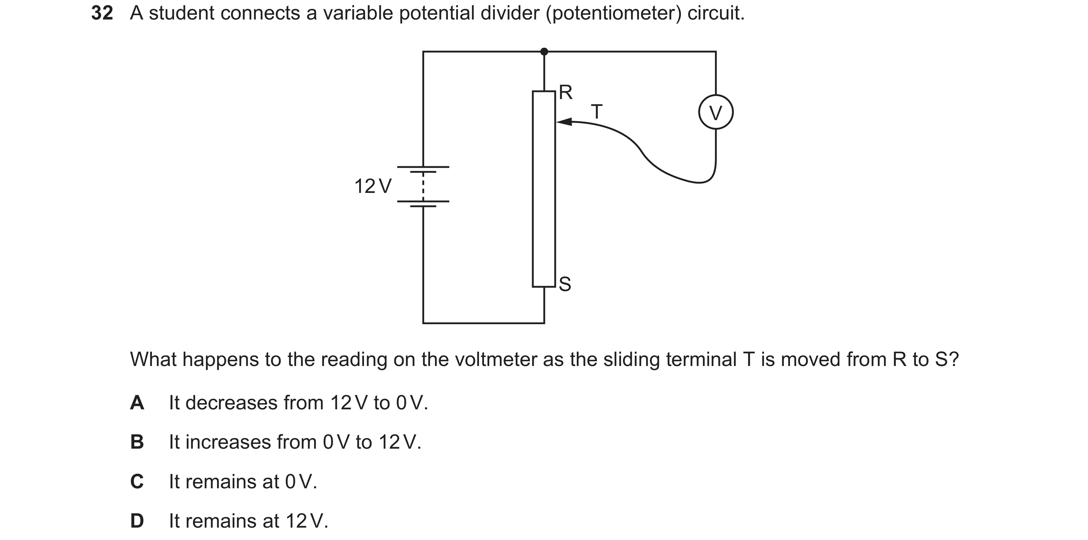 20 / 114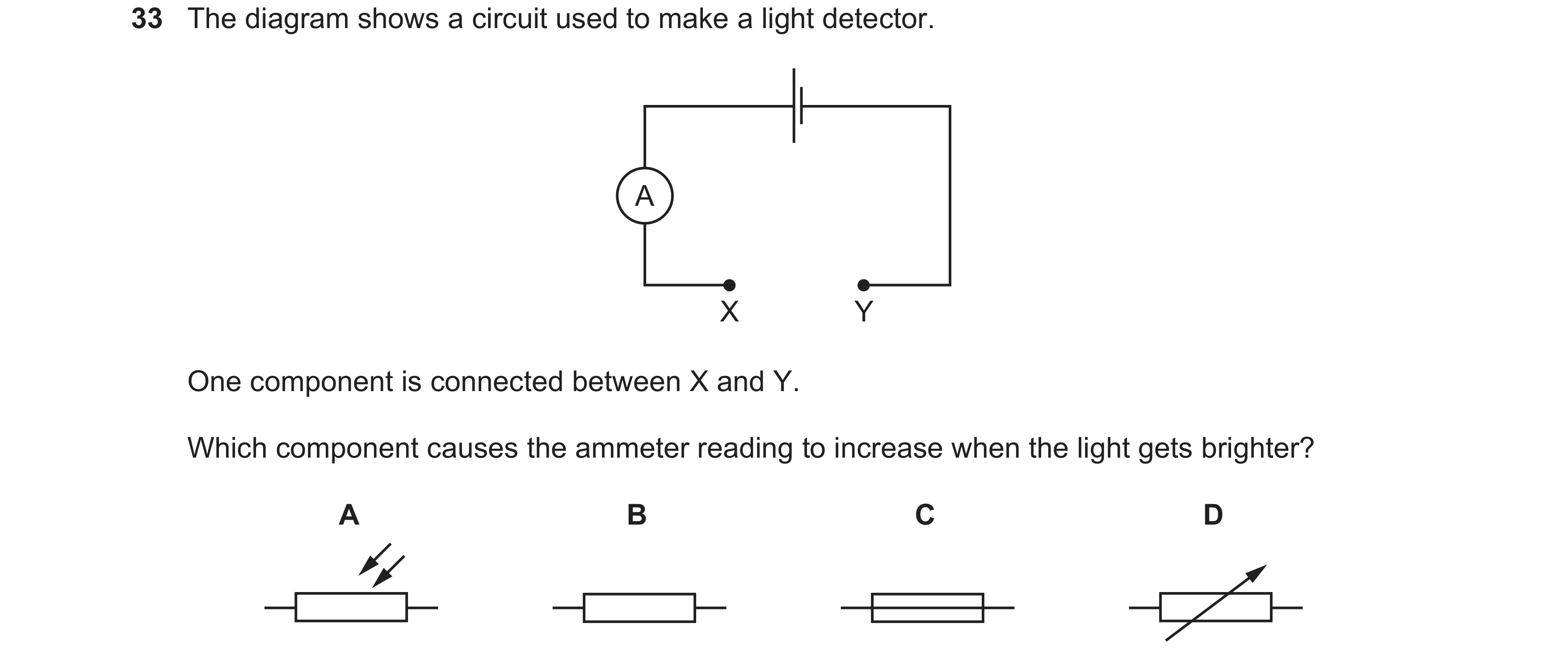
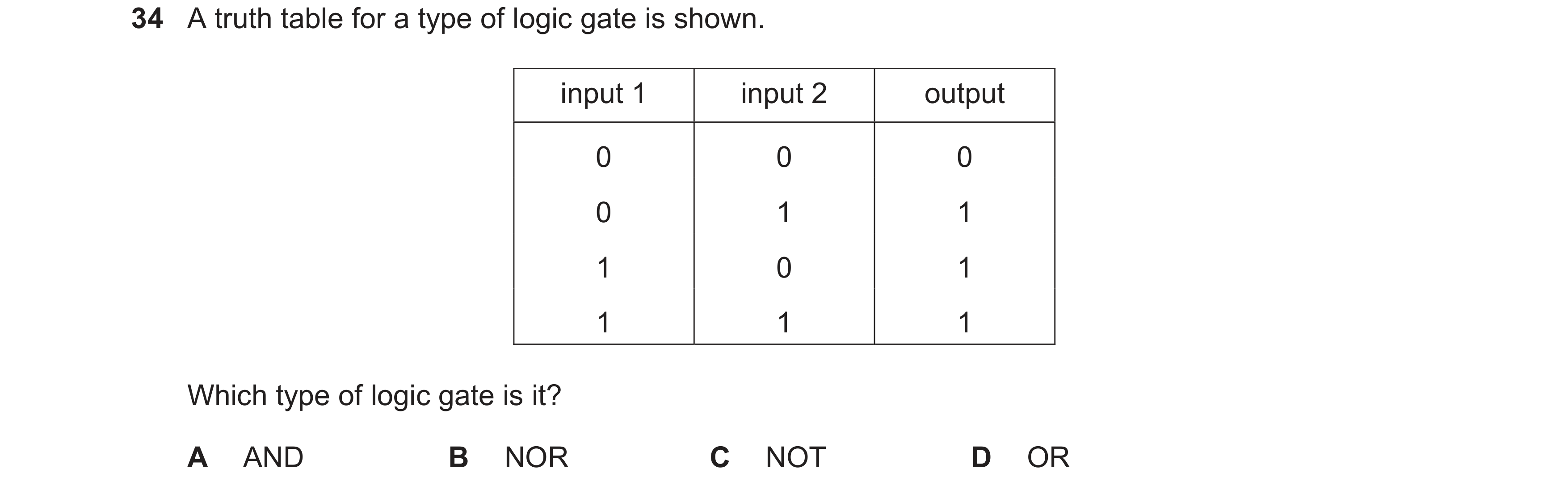
 21 / 114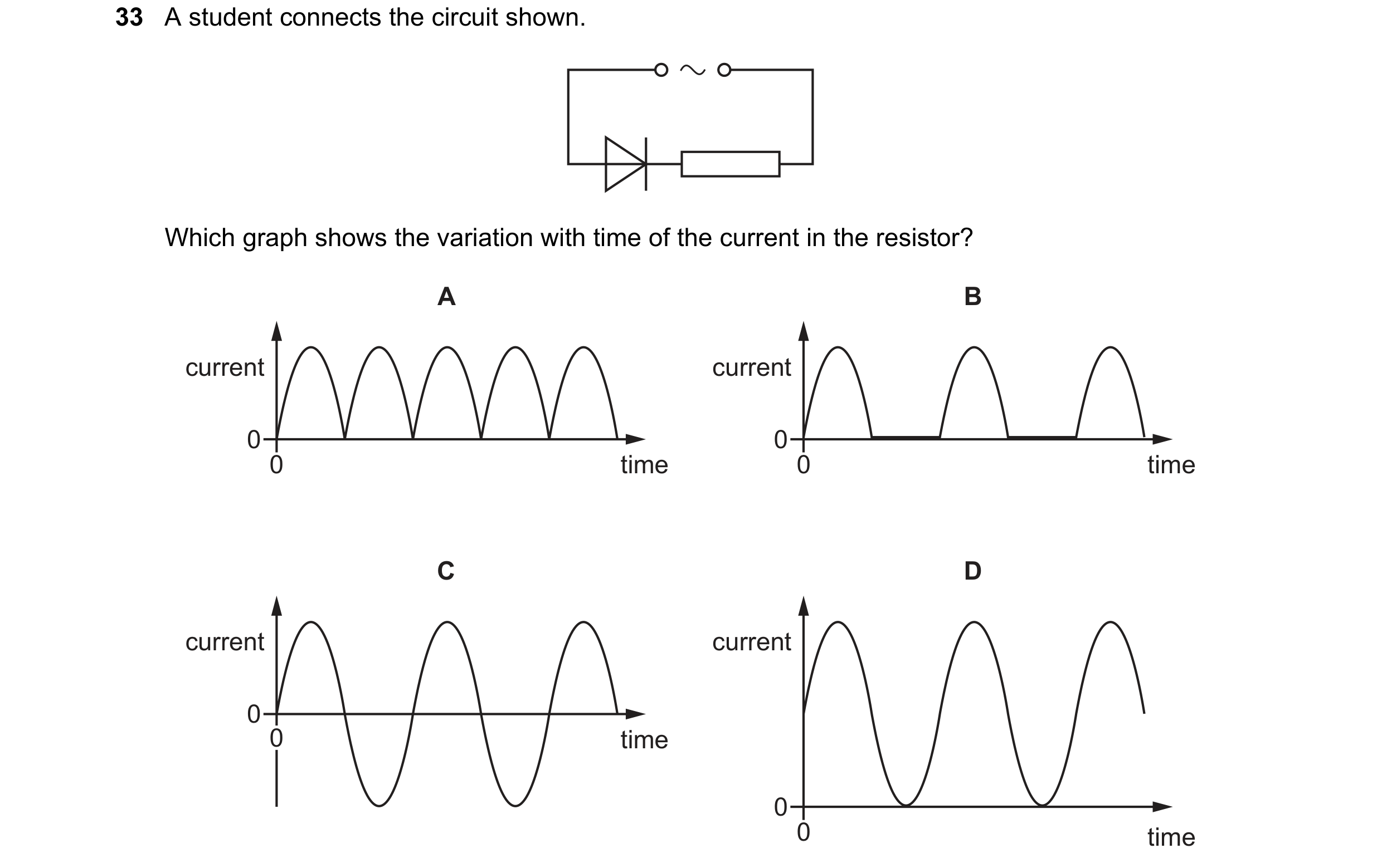
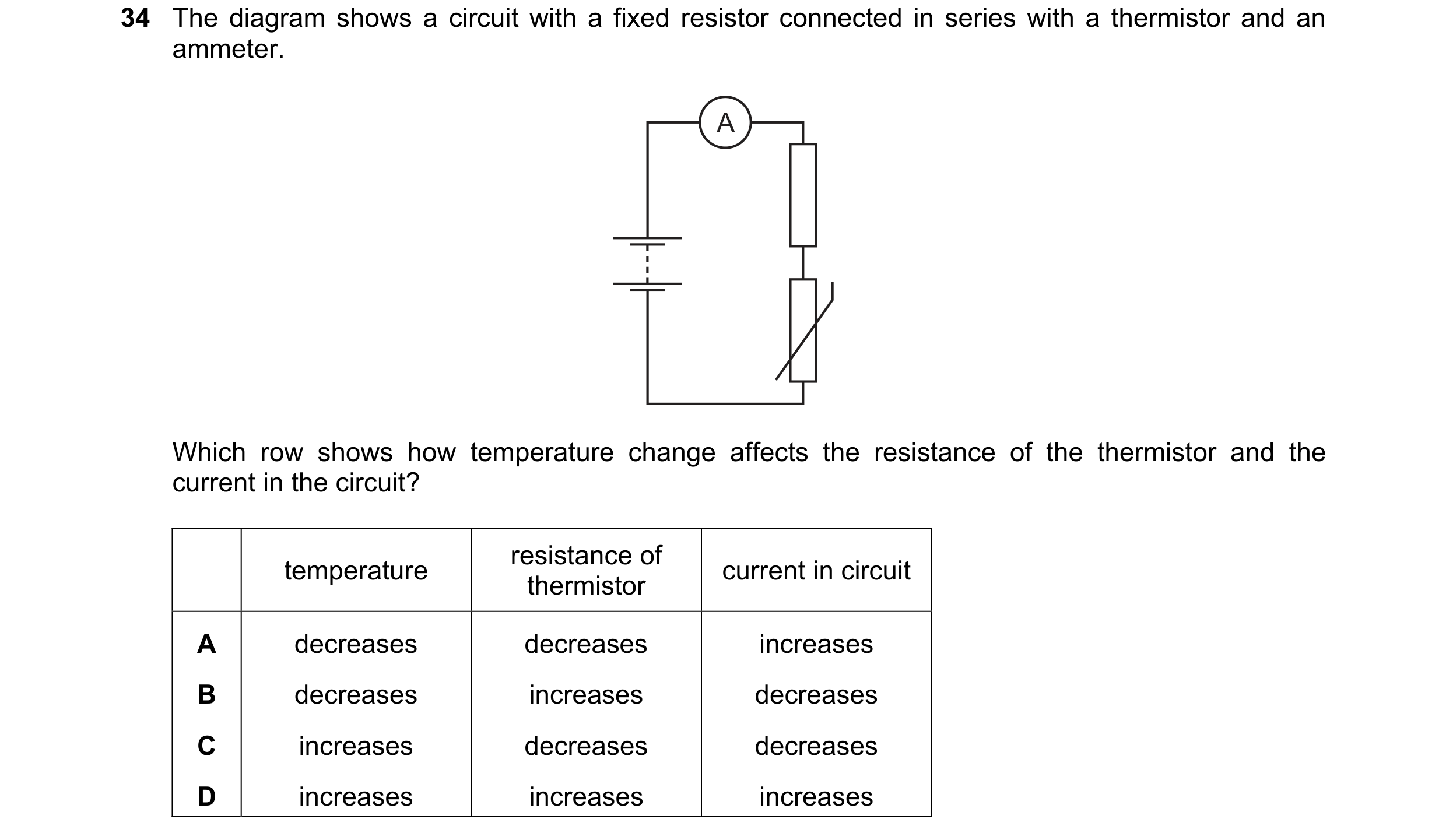 22 / 114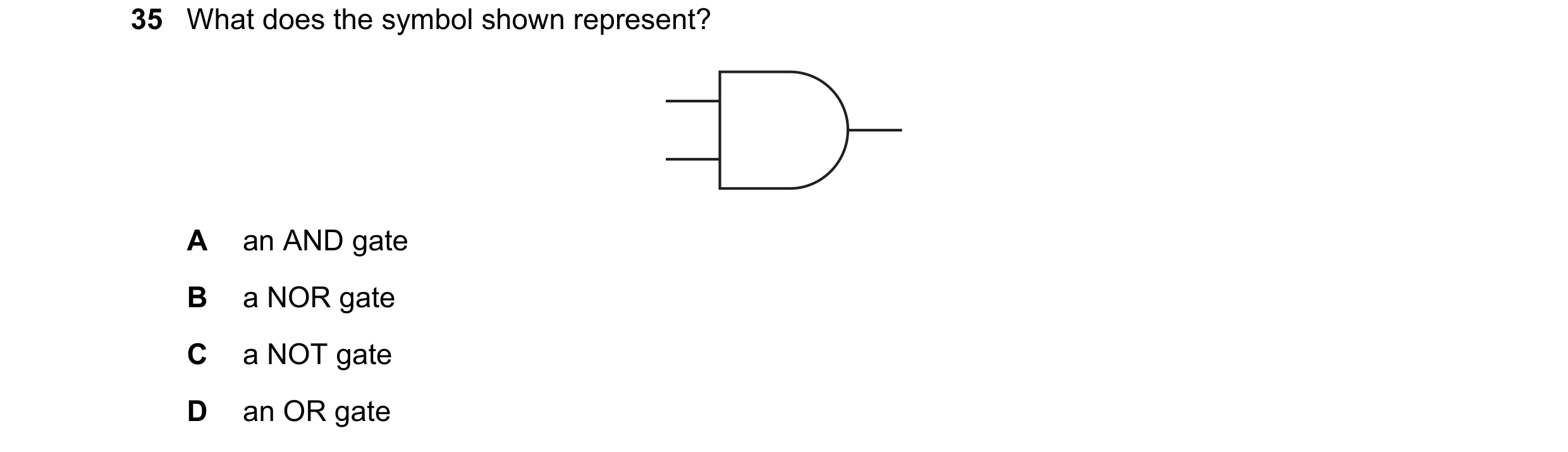
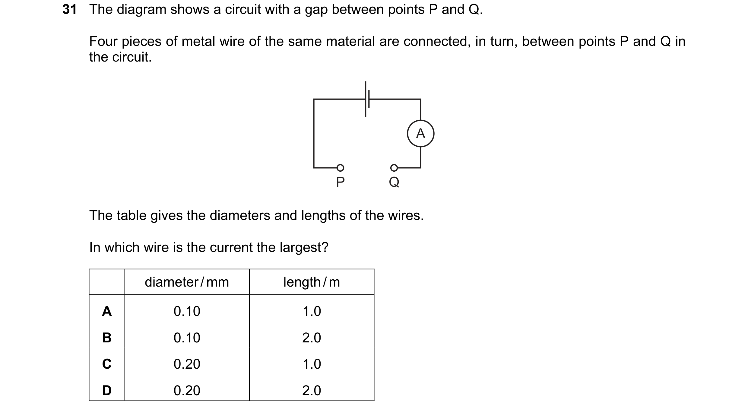
 23 / 114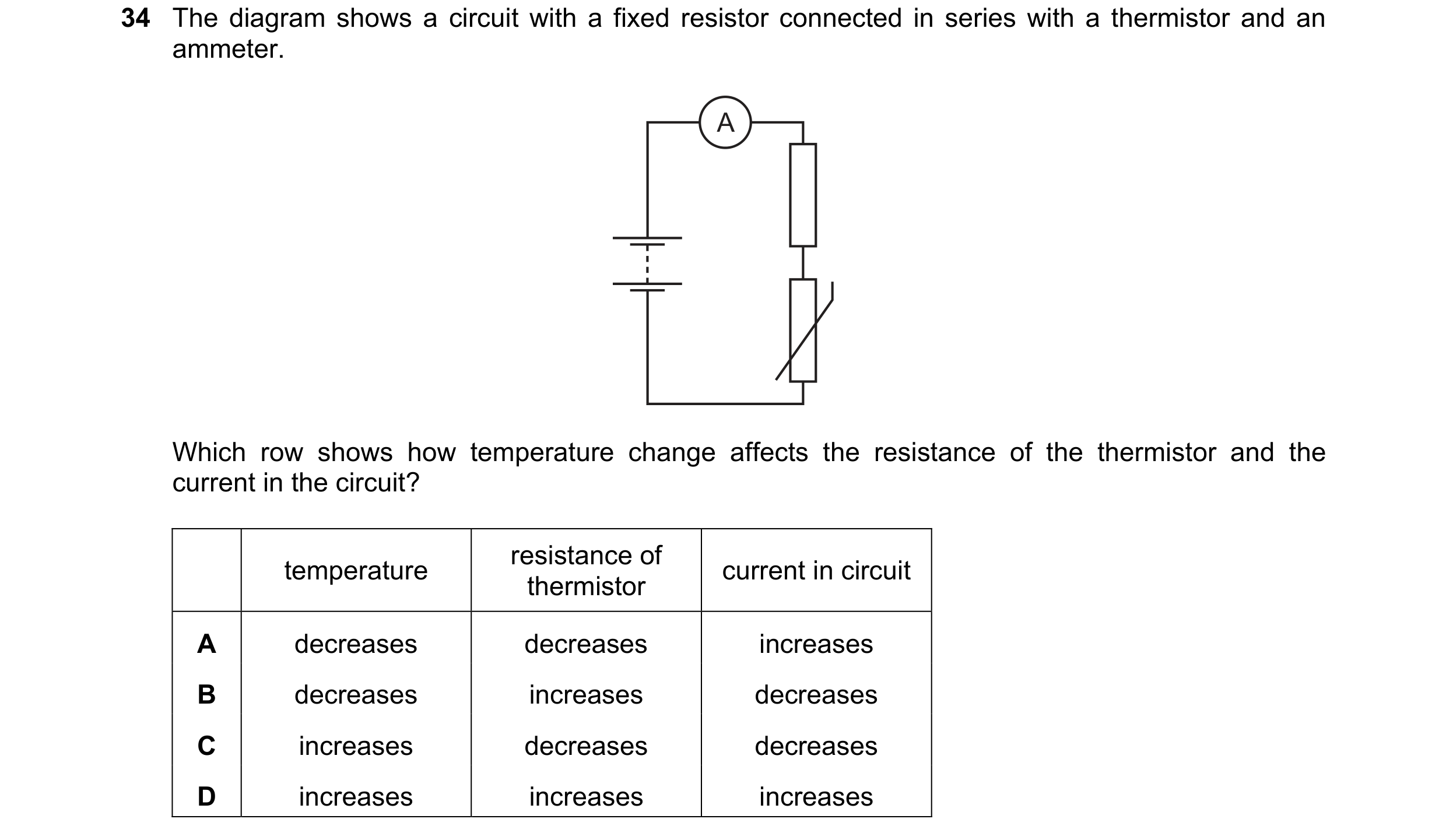
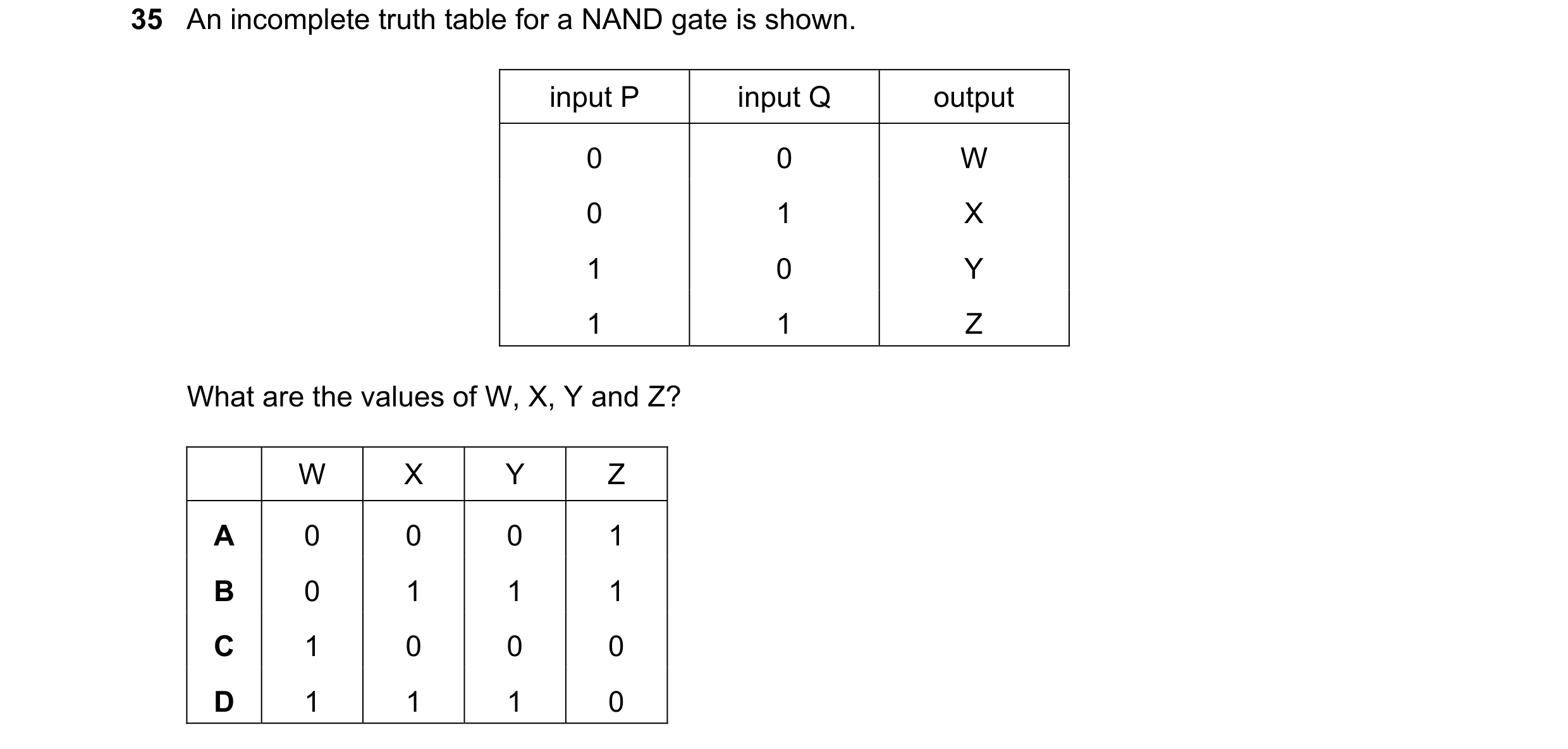 24 / 114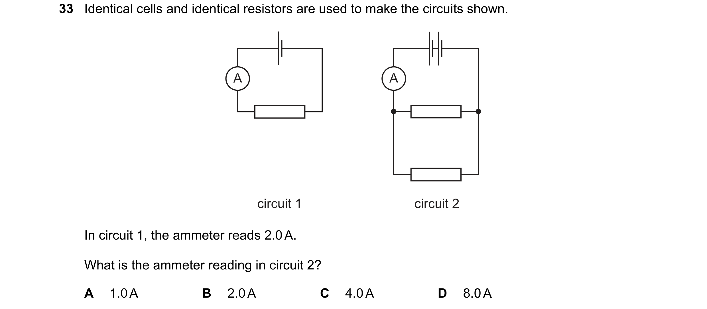
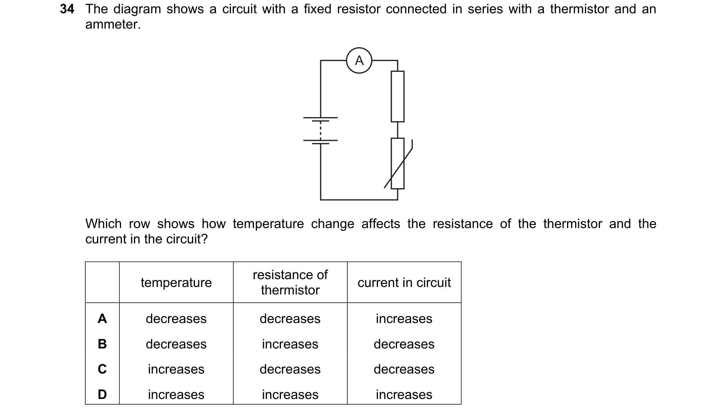 25 / 114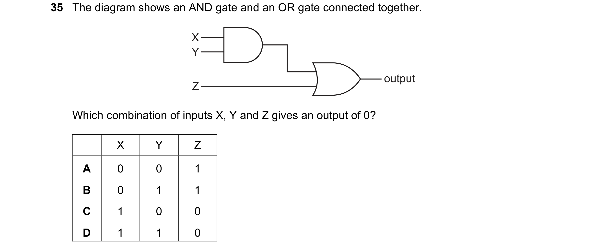

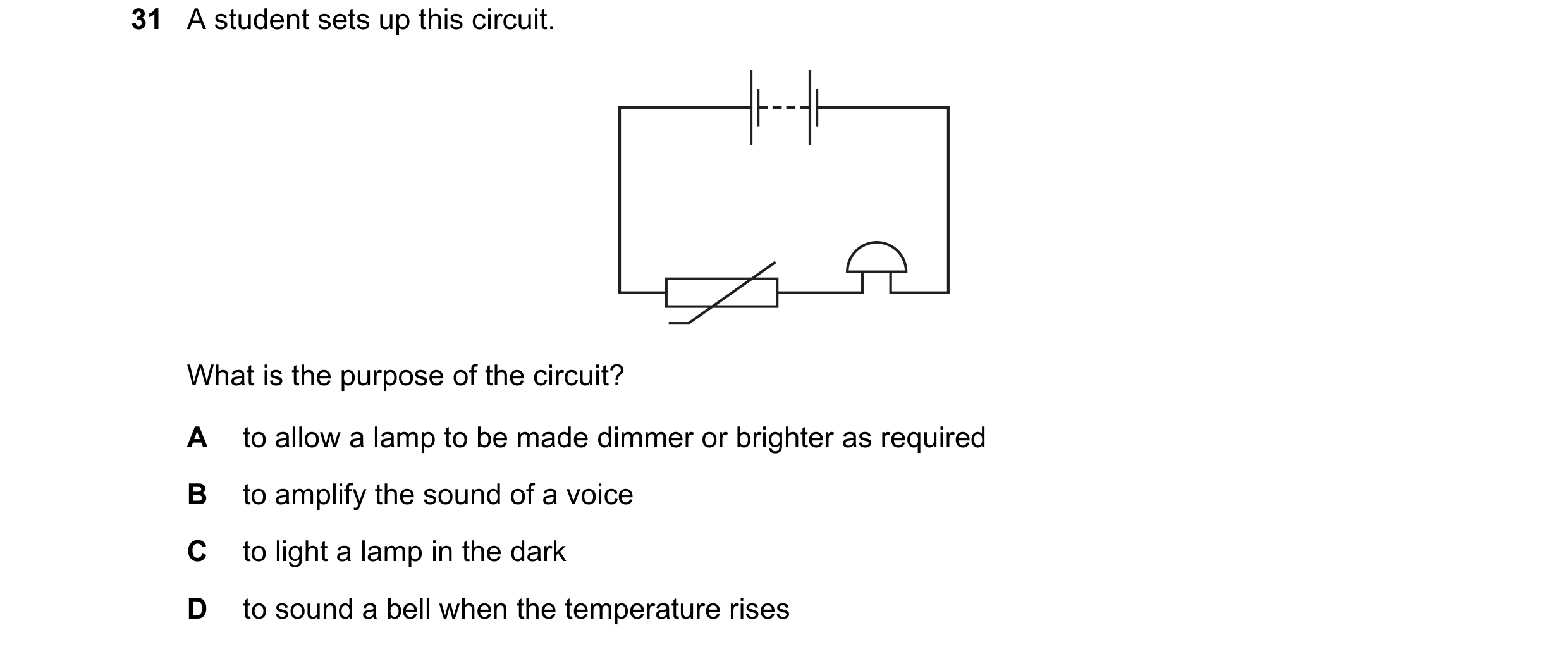 26 / 114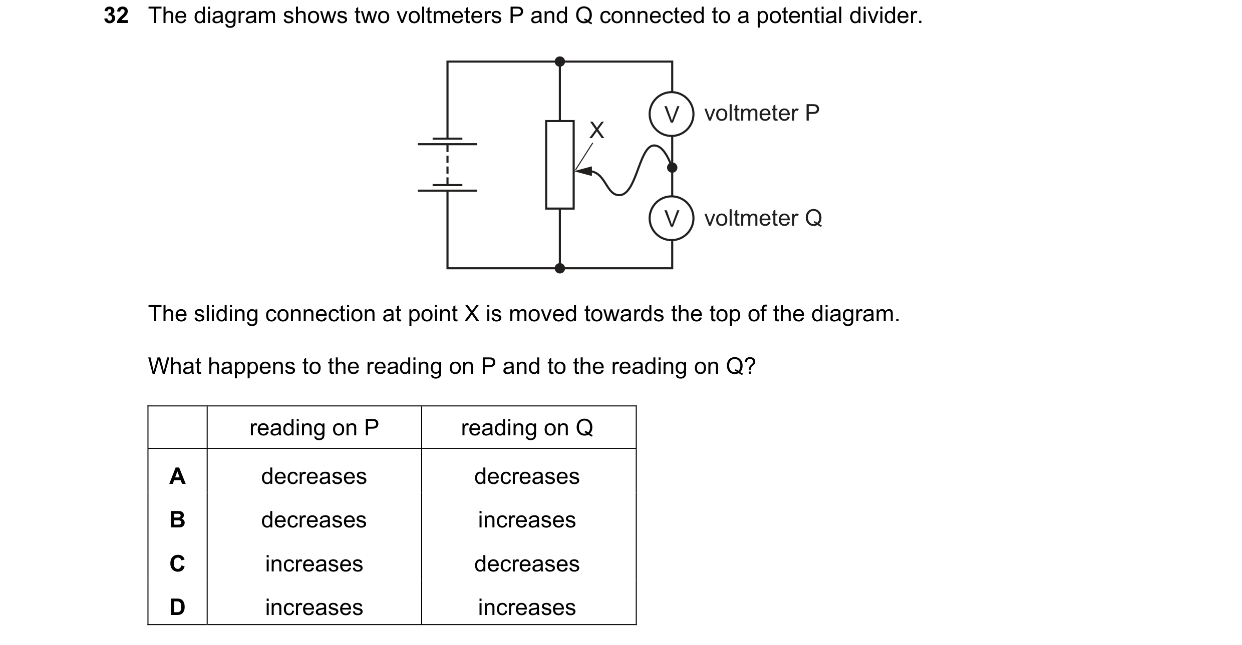
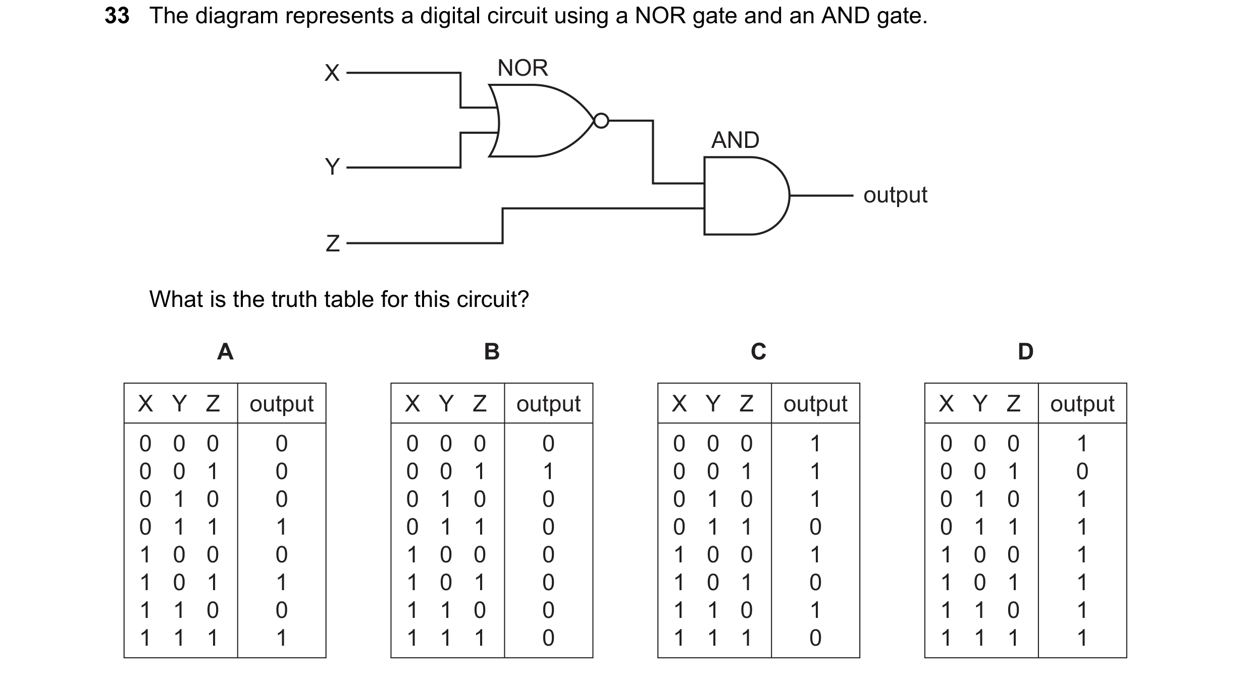
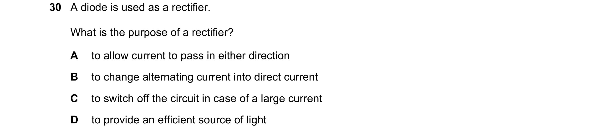 27 / 114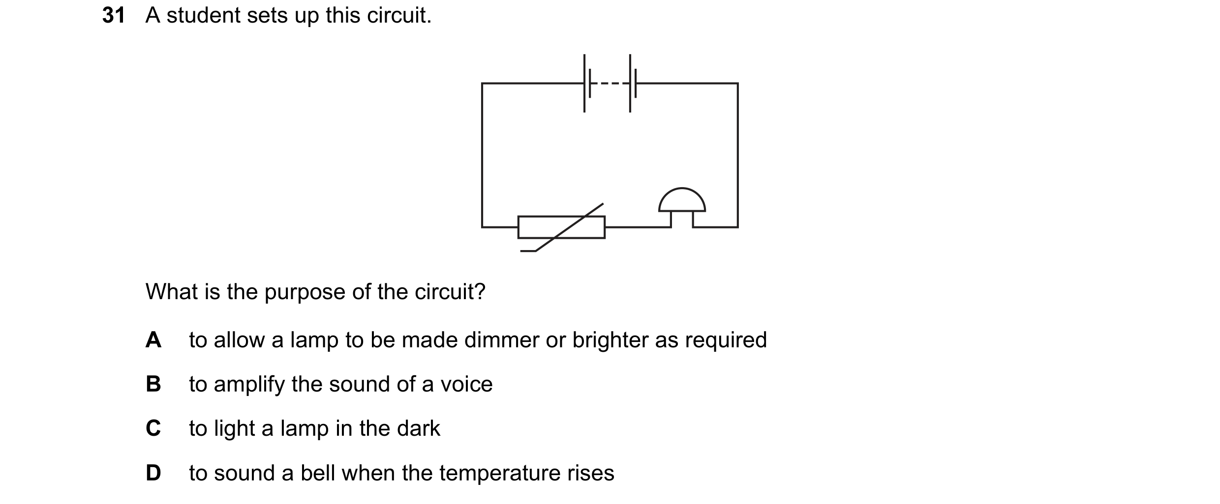
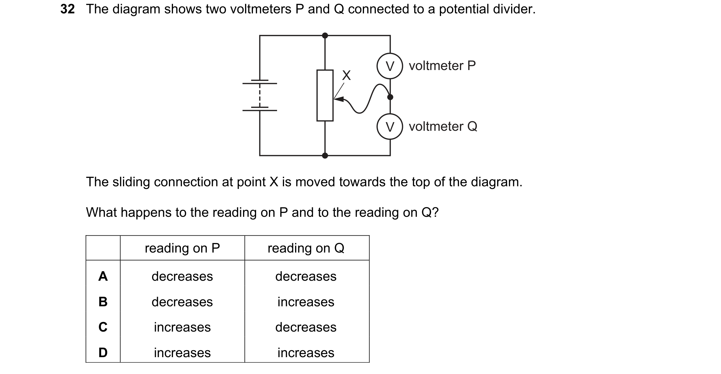 28 / 114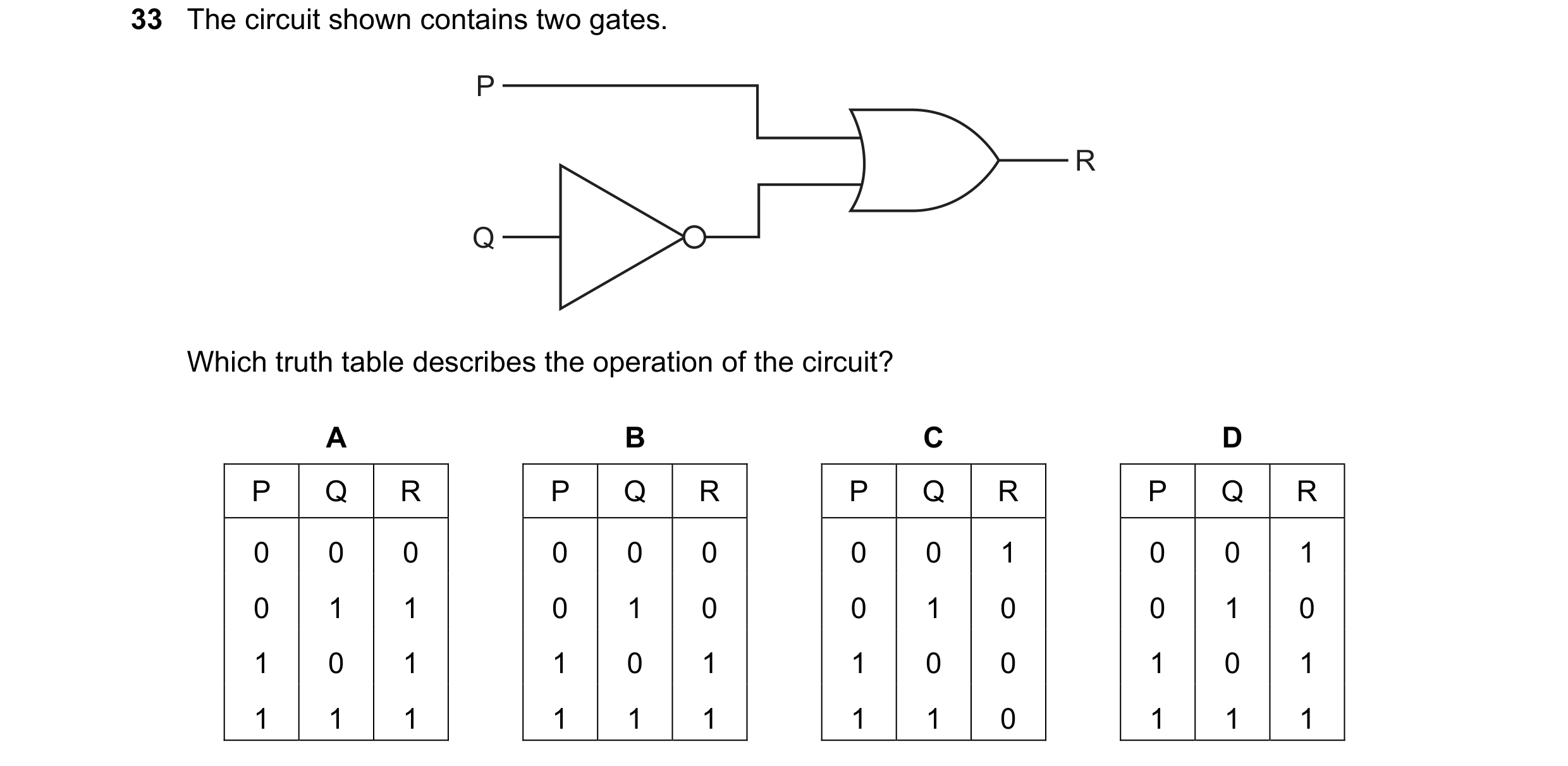

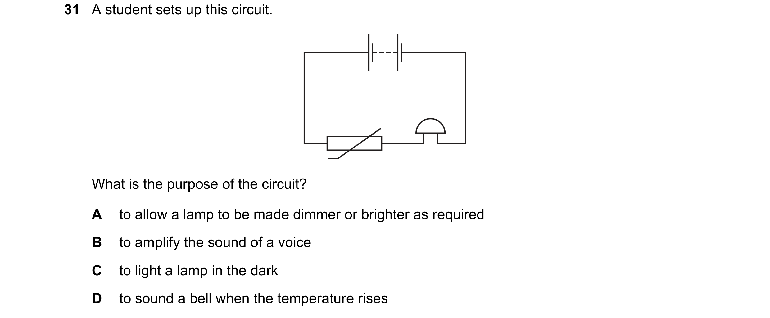 29 / 114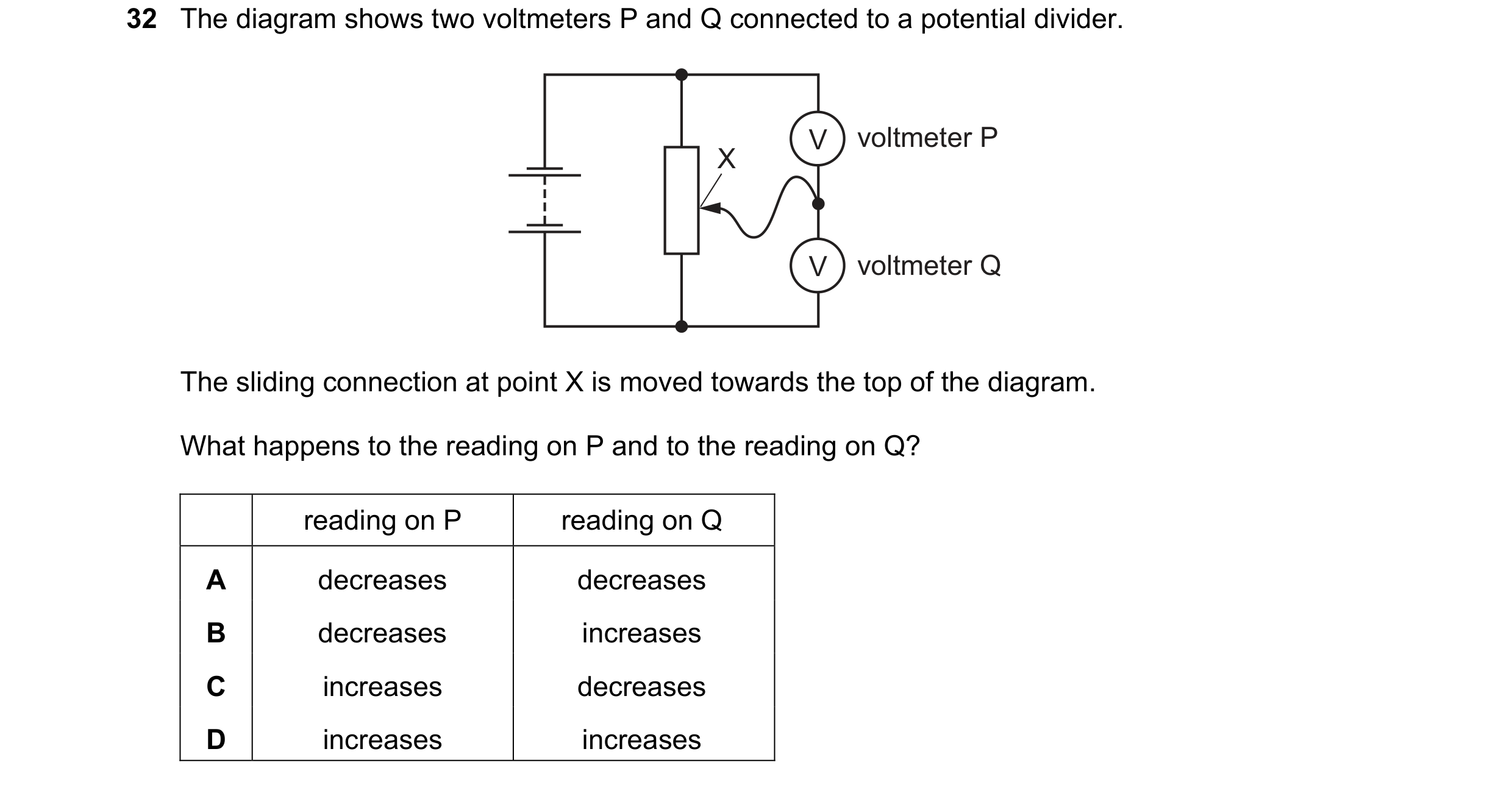
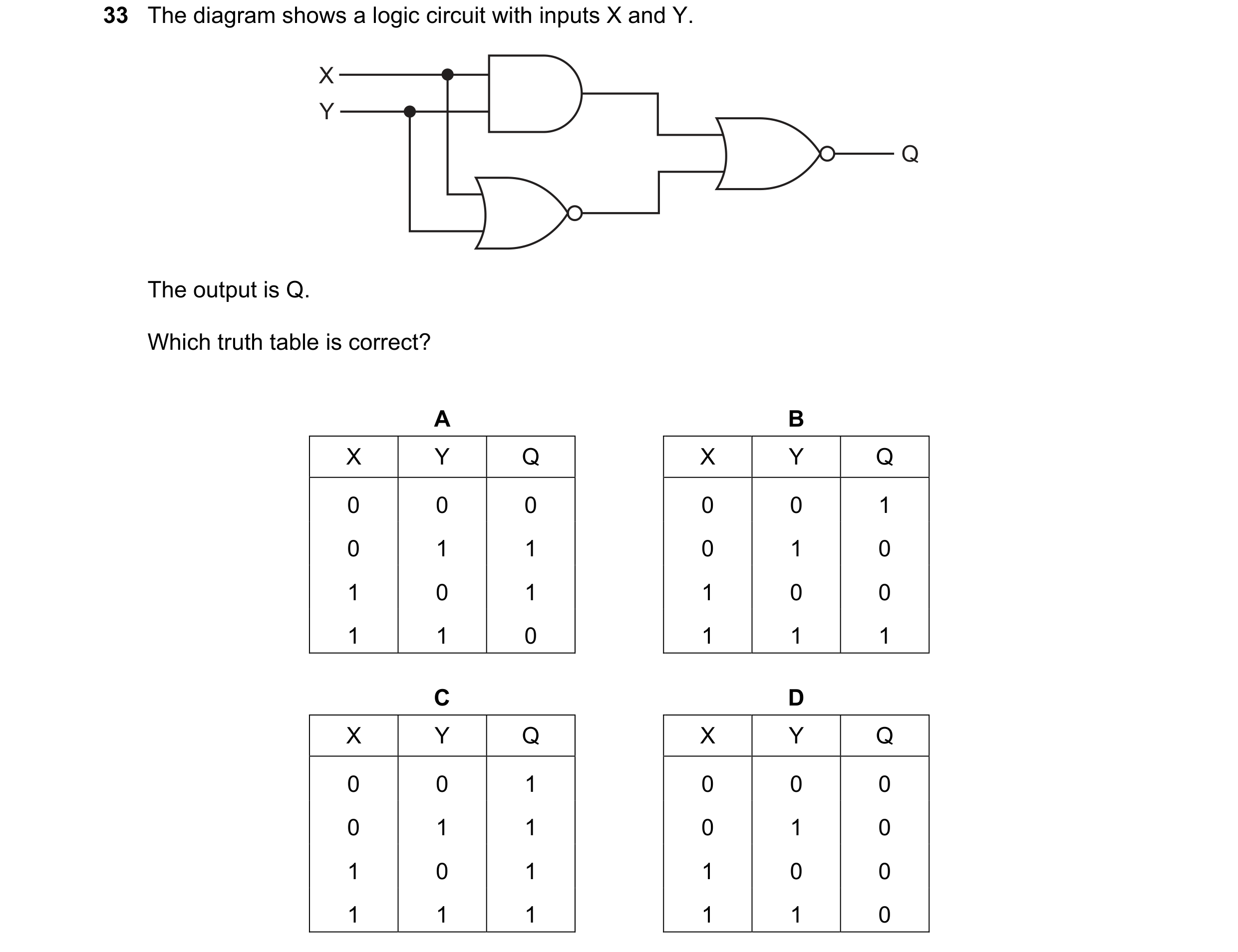 30 / 114
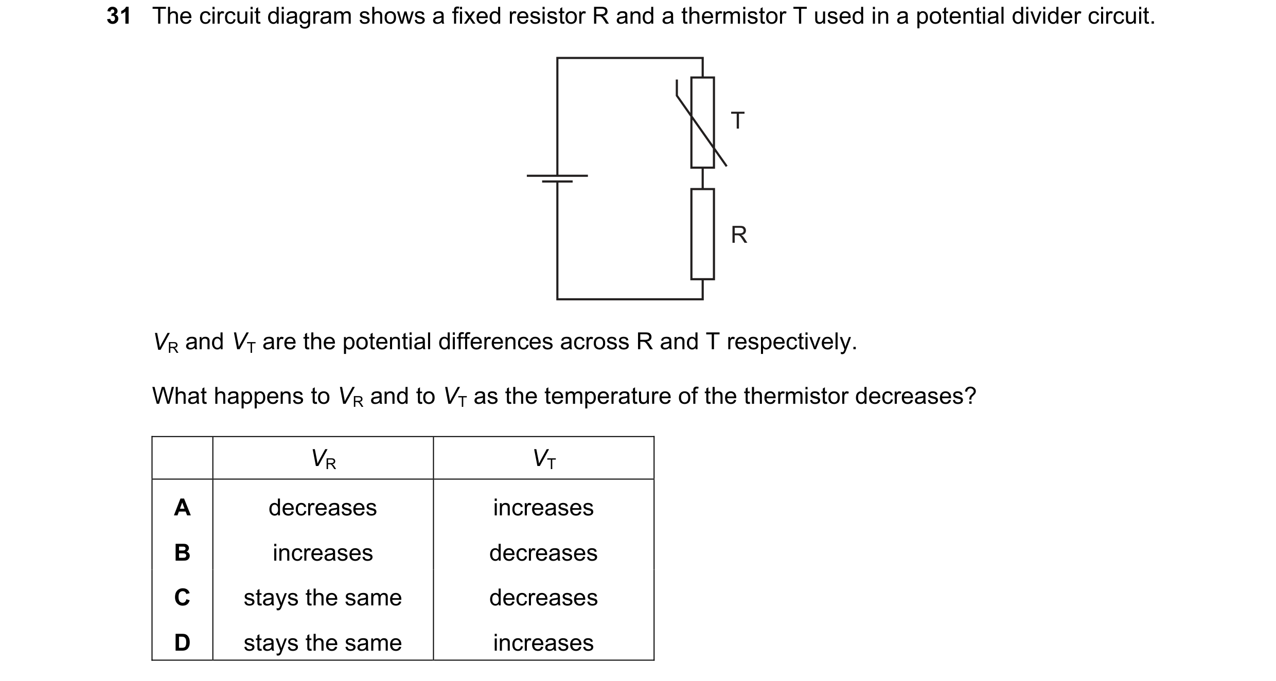
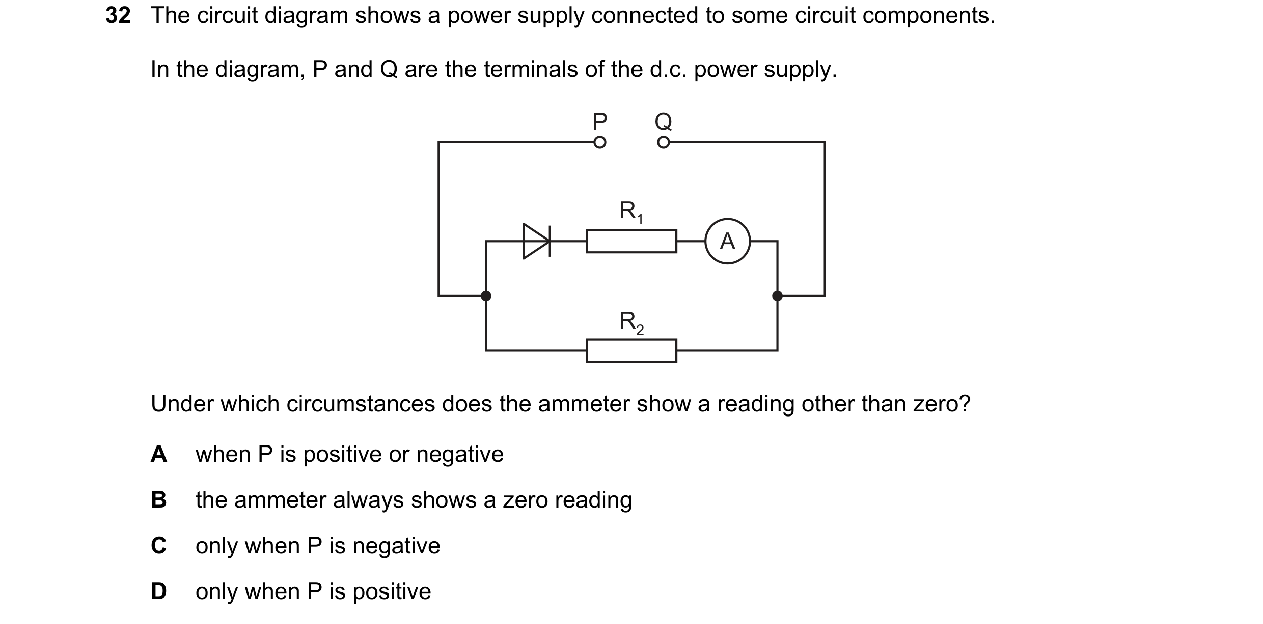 31 / 114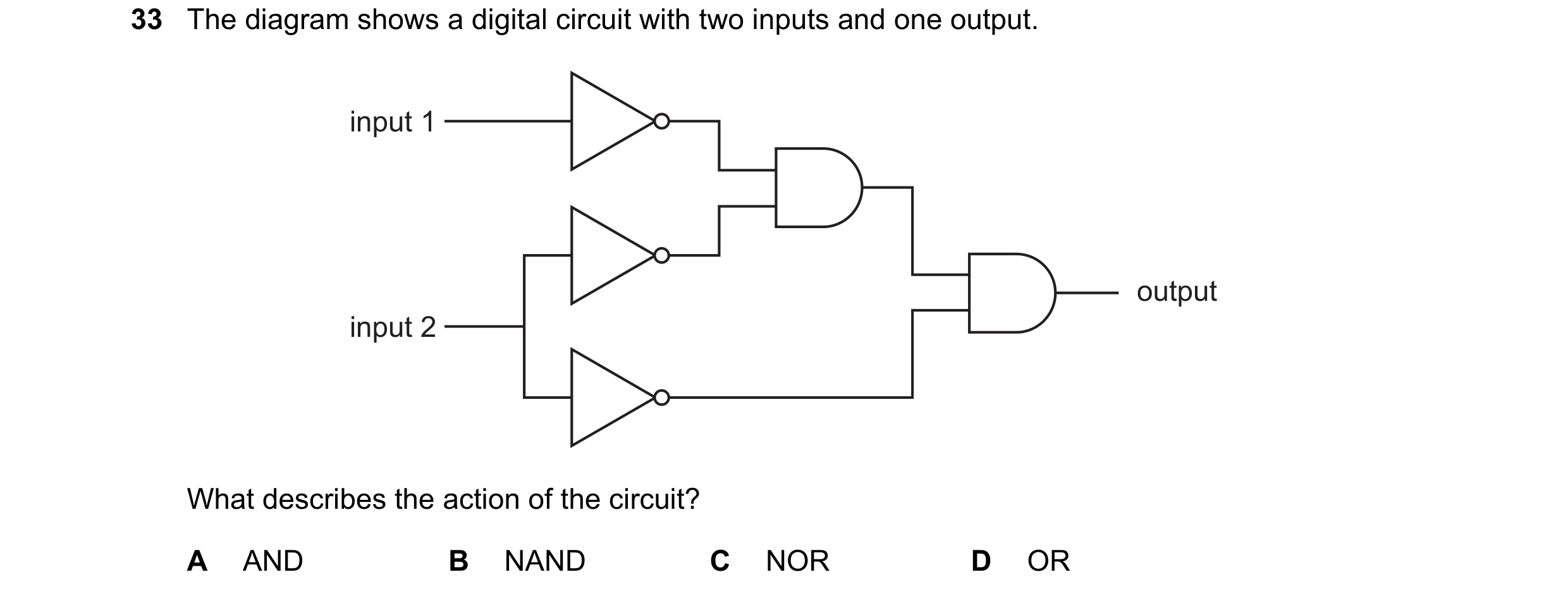
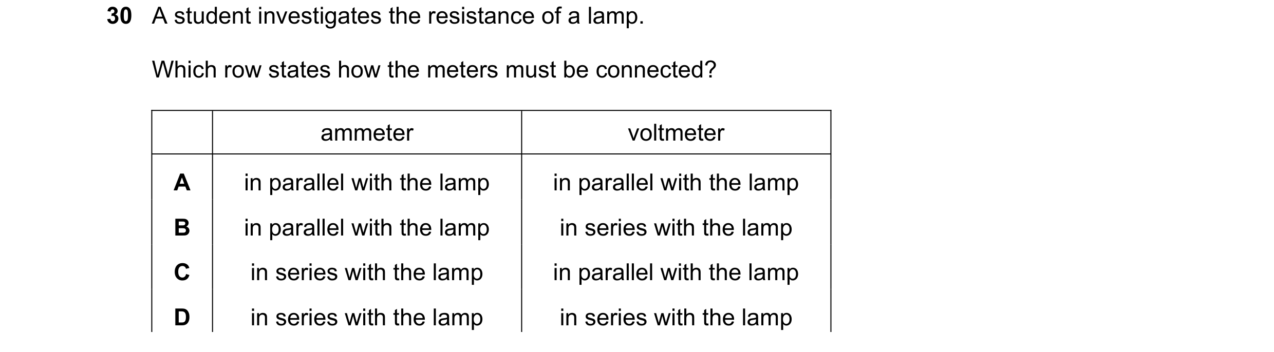
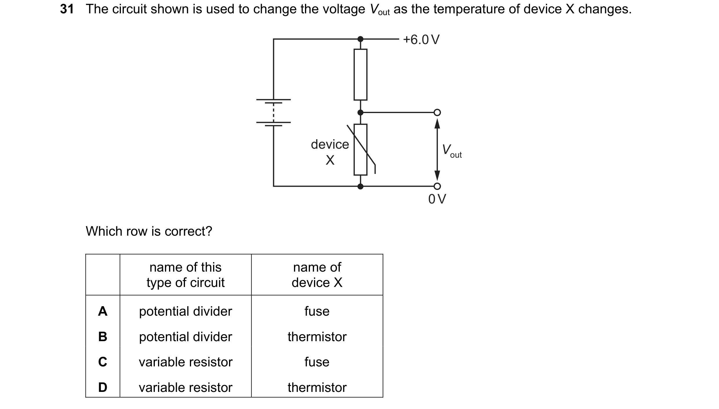 32 / 114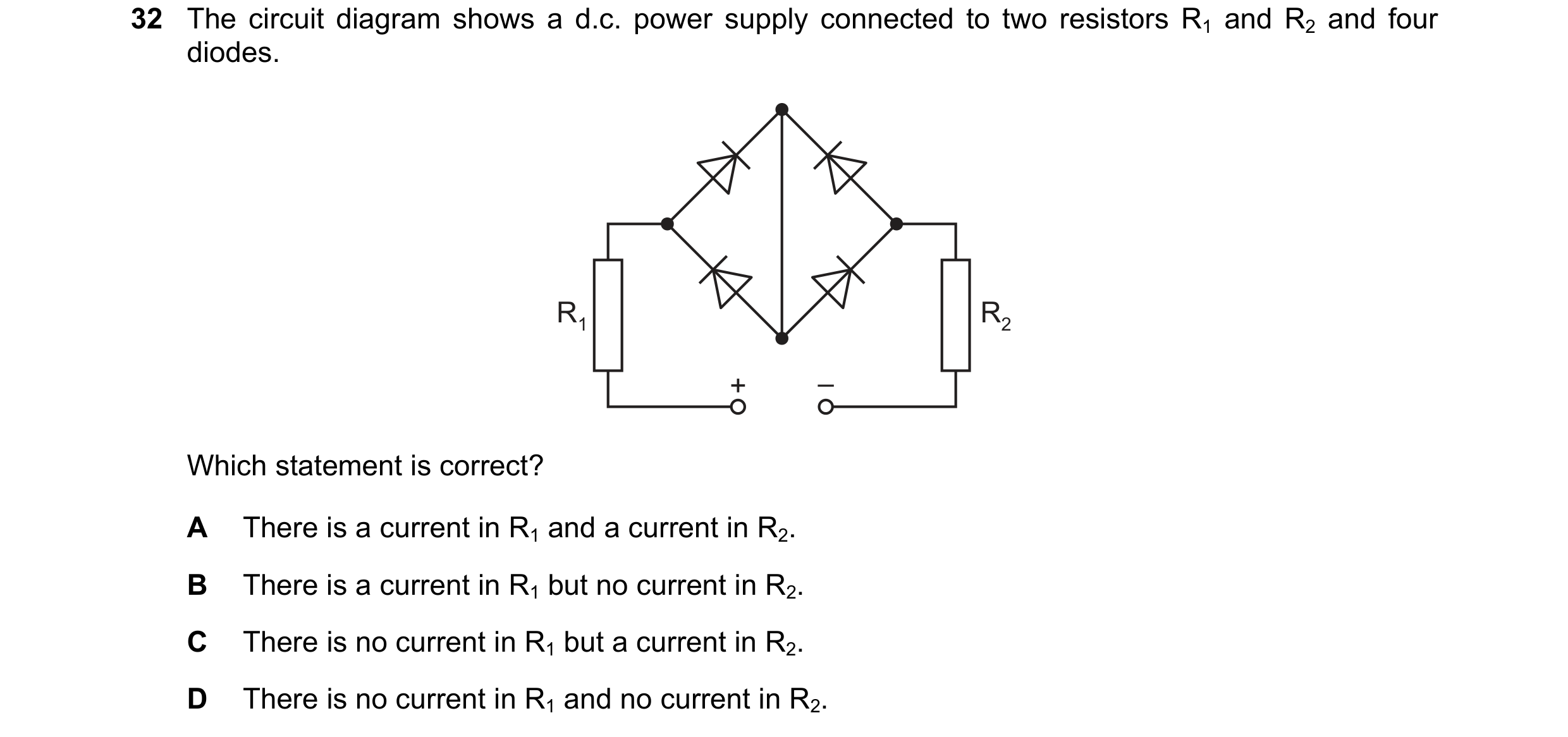
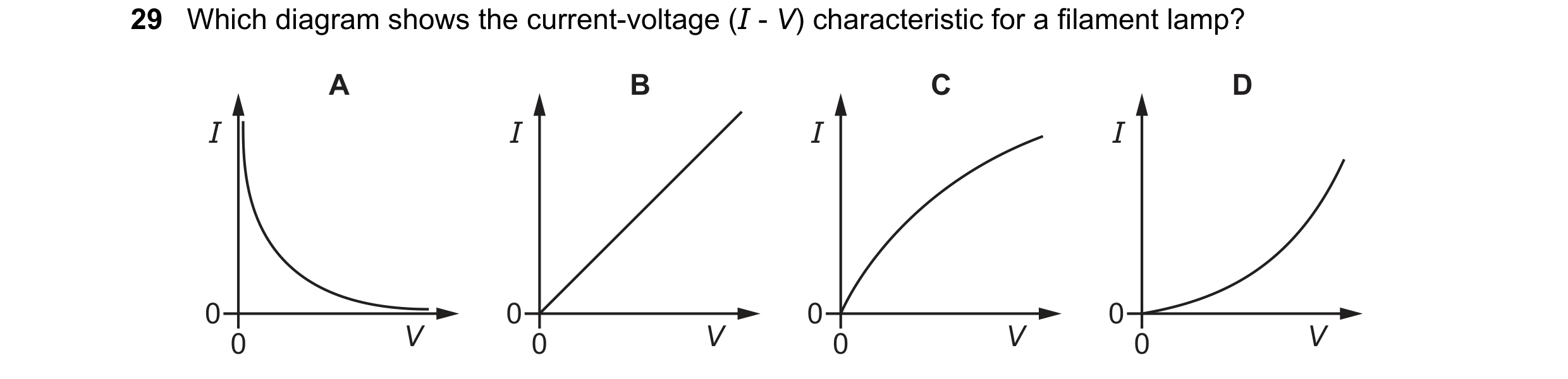 33 / 114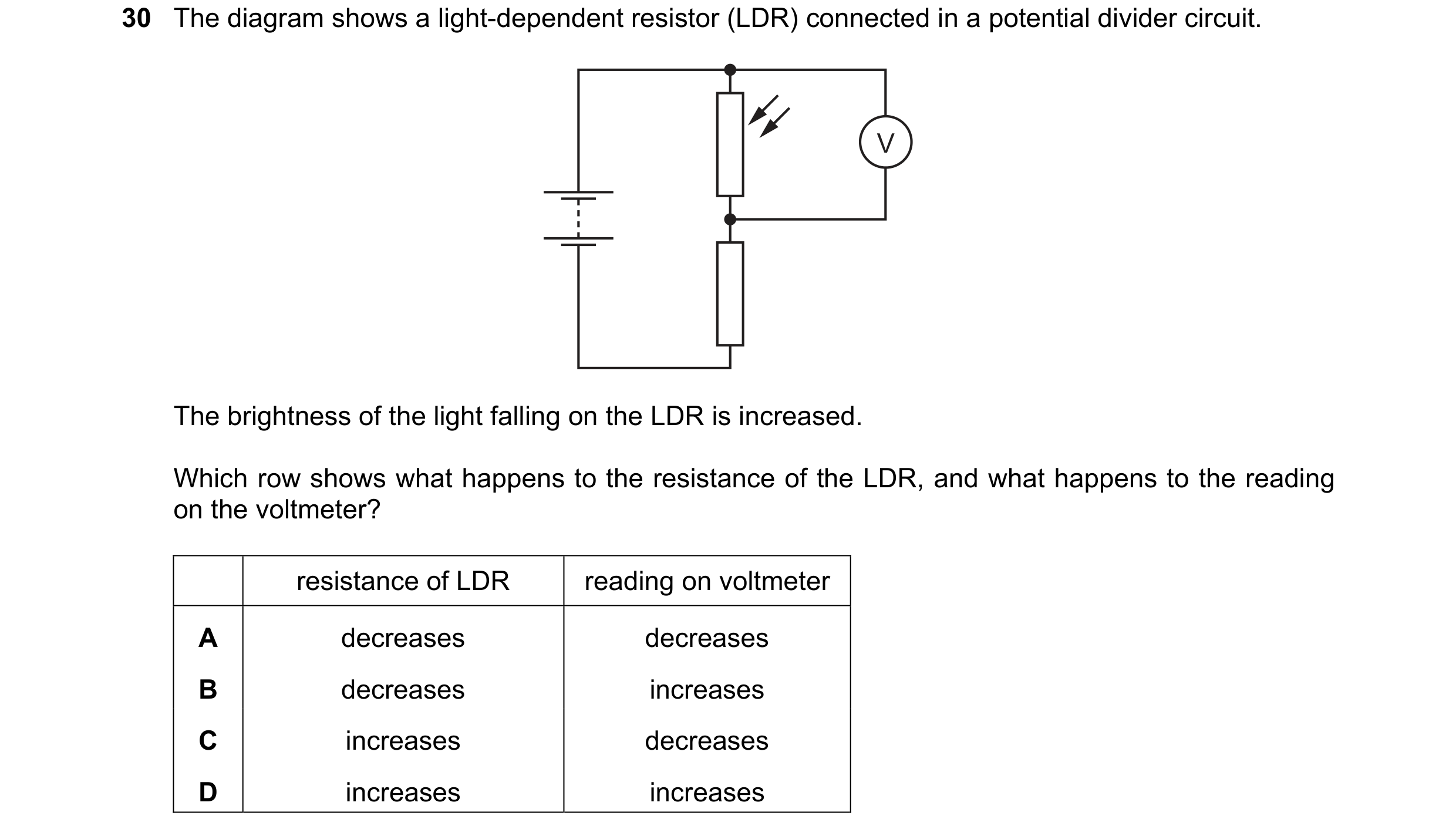
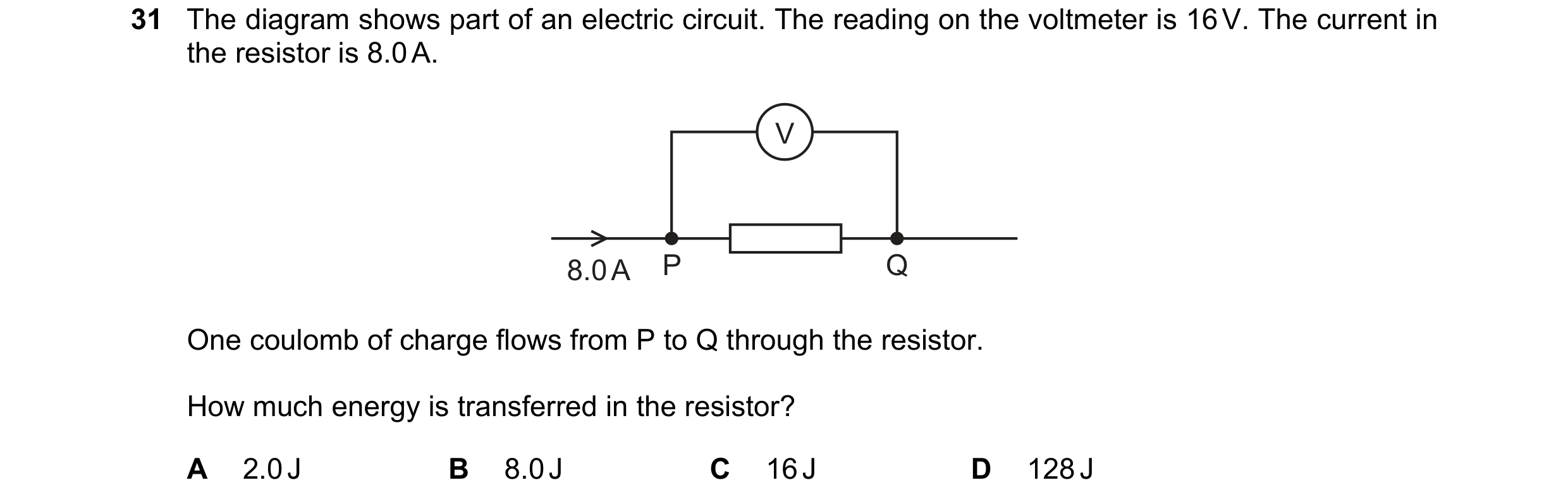
 34 / 114
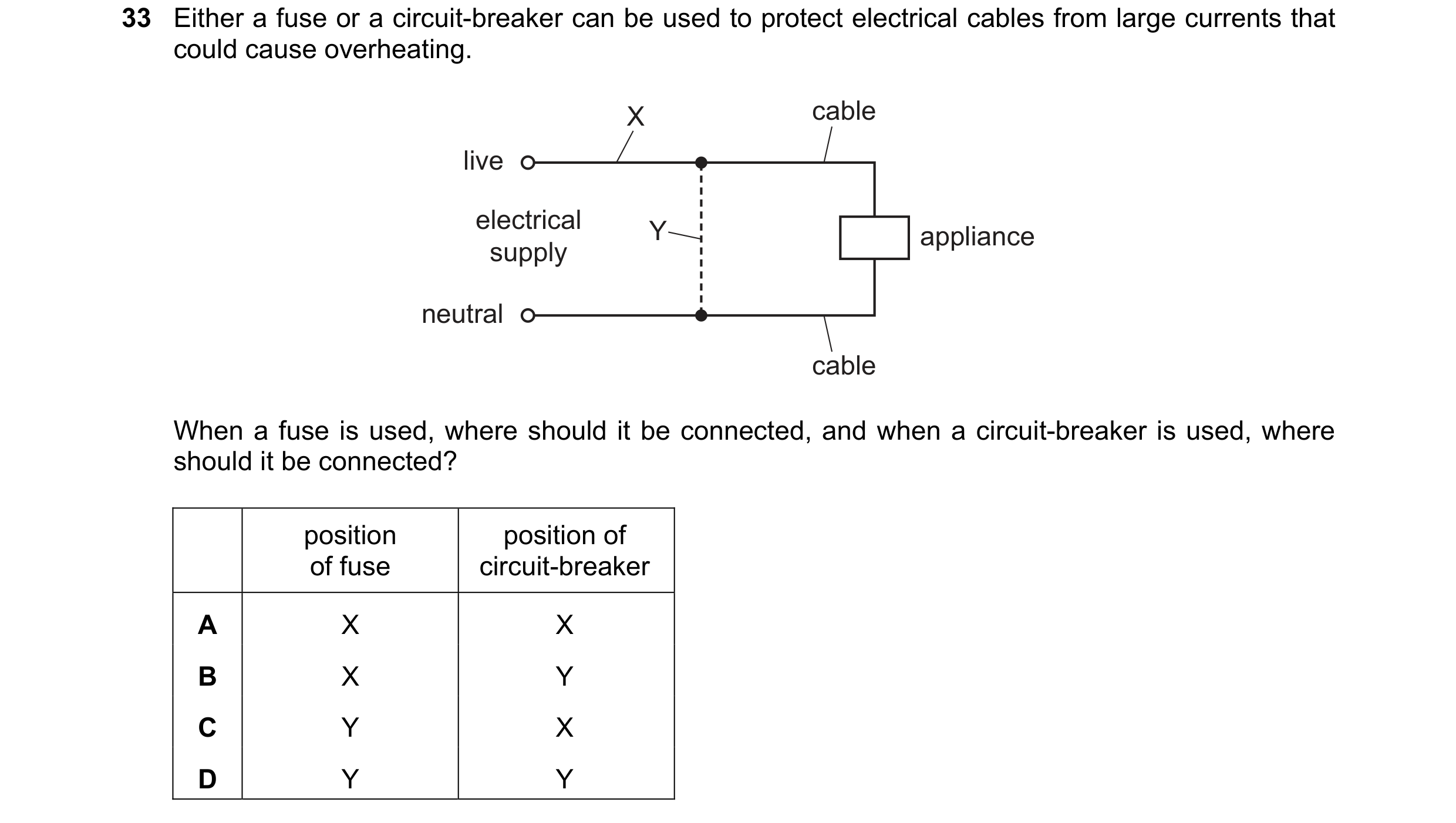 35 / 114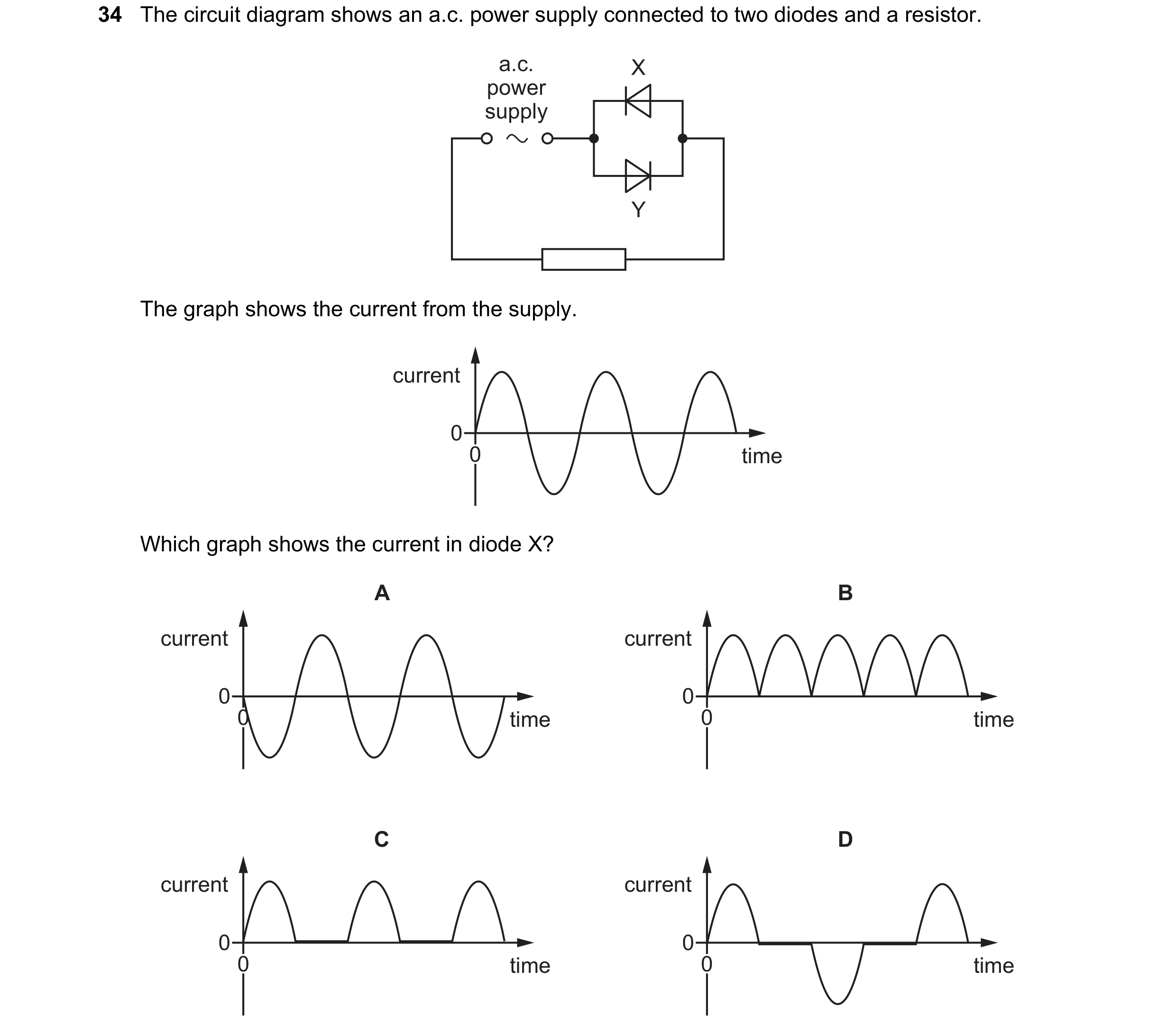
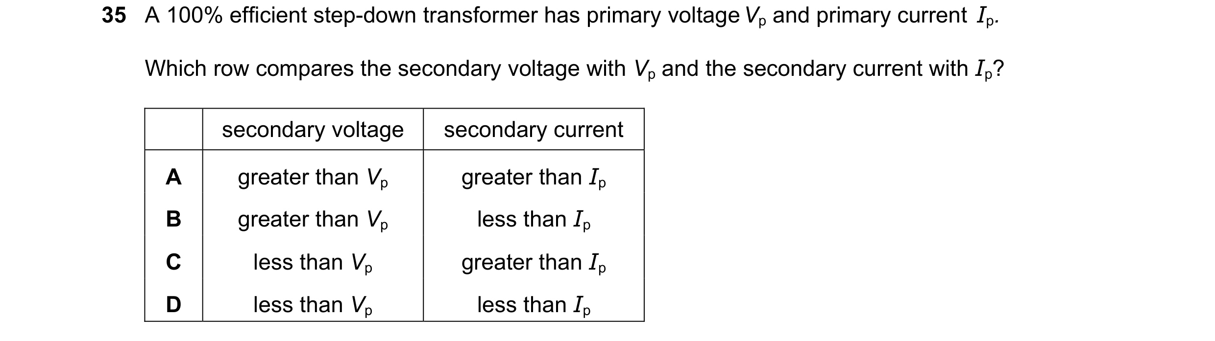 36 / 114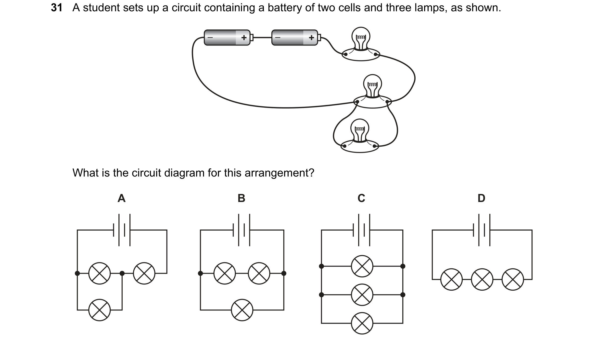
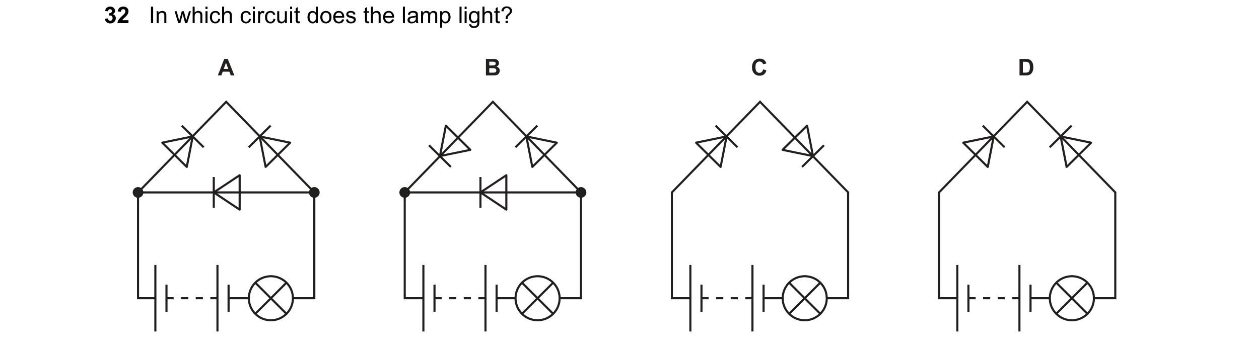
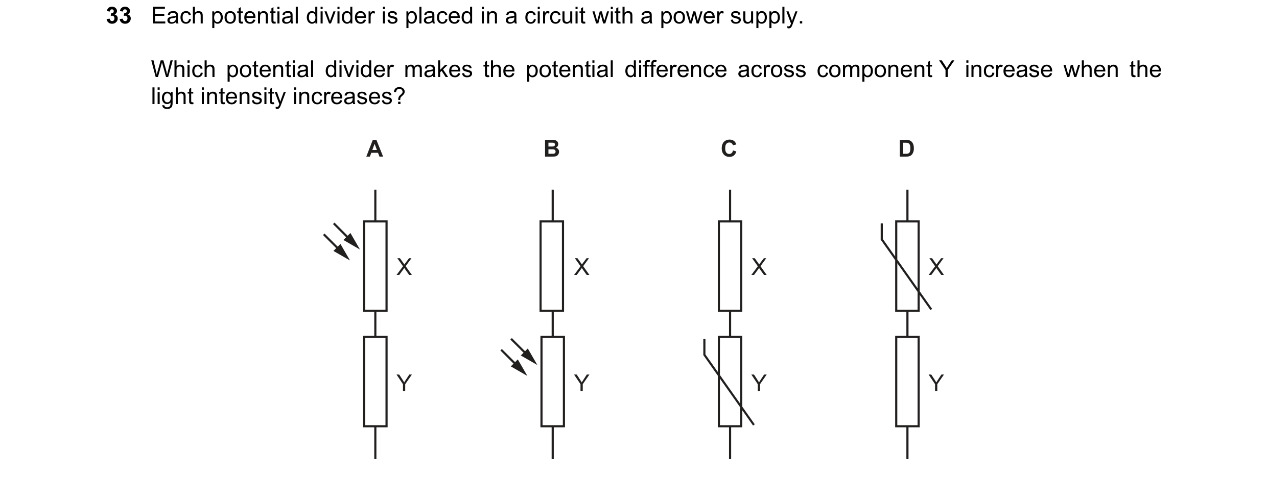 37 / 114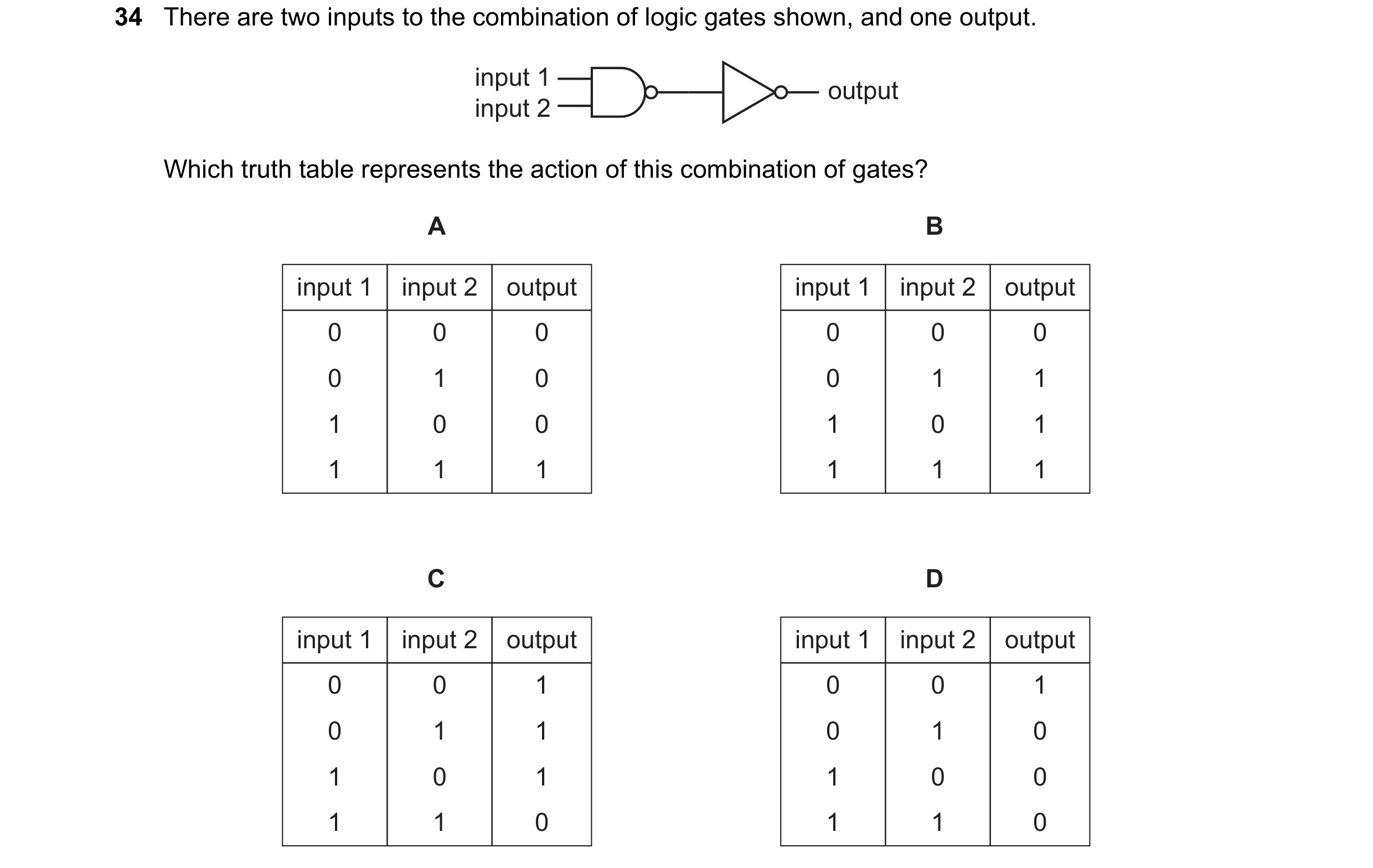
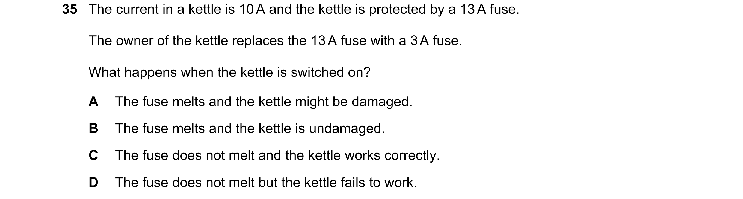 38 / 114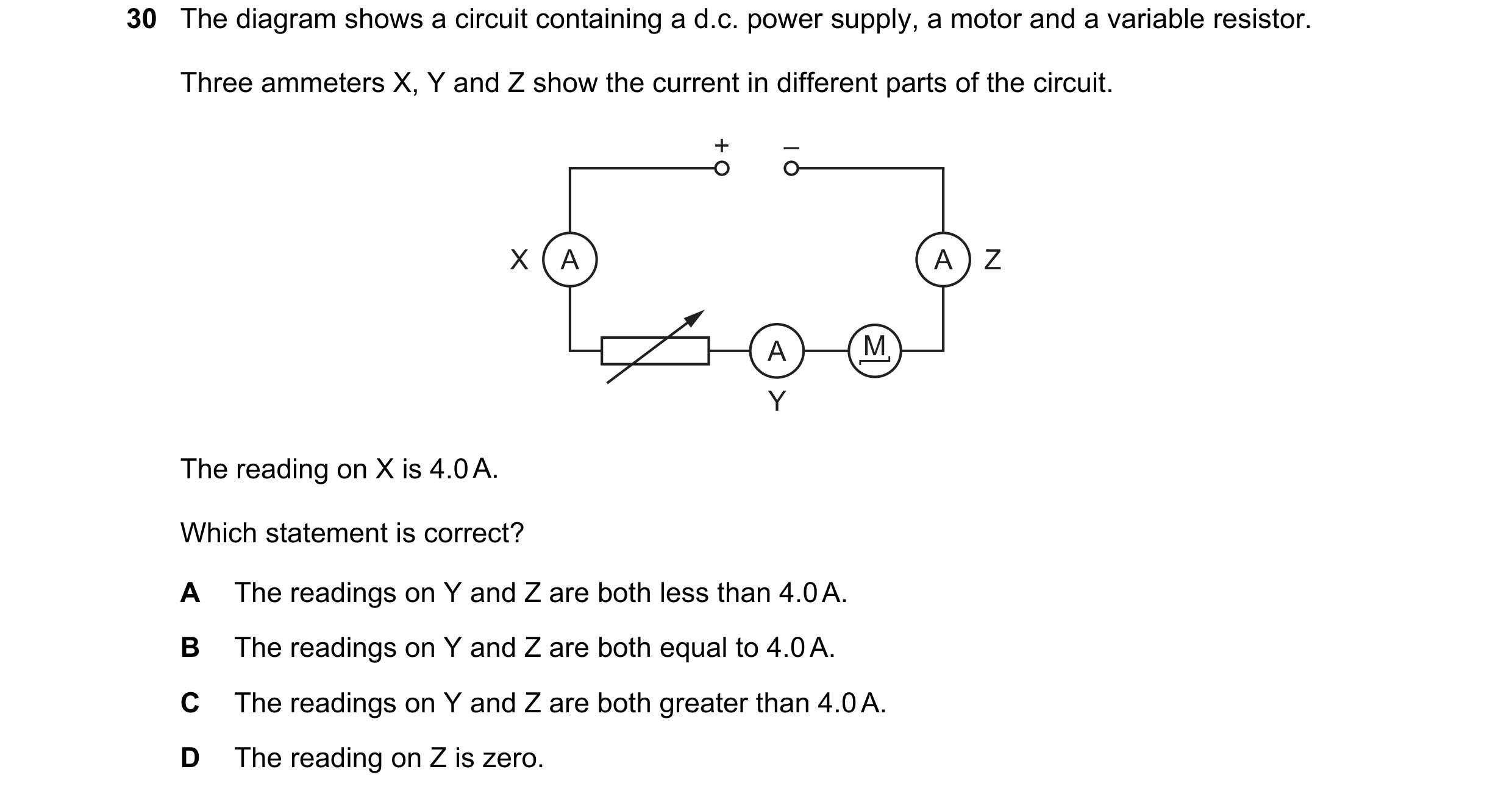
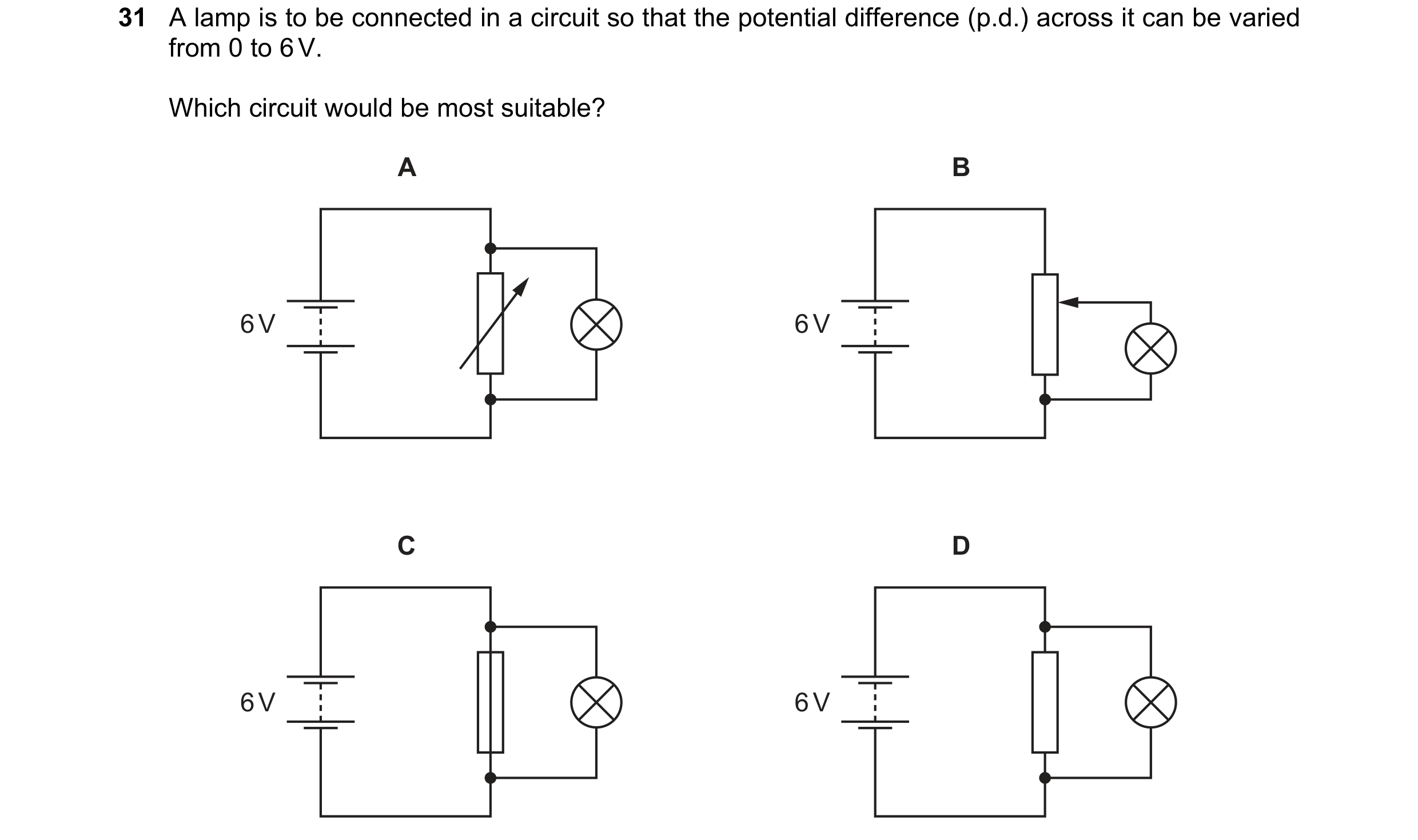
 39 / 114
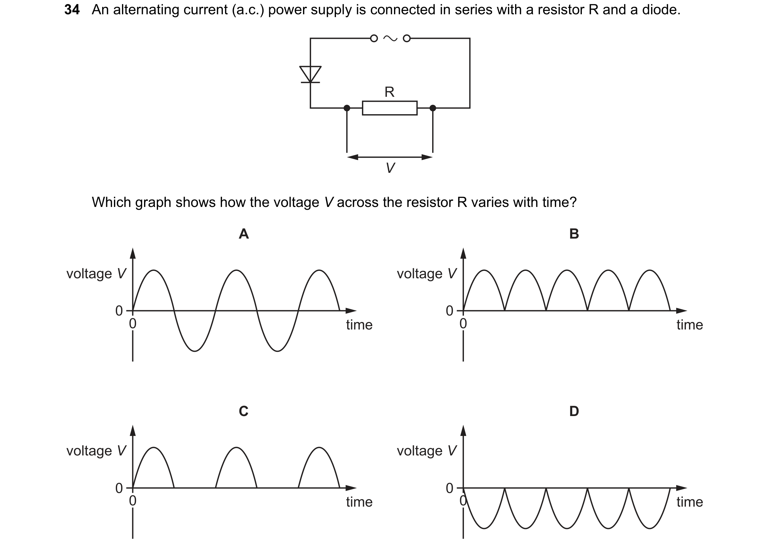
 40 / 114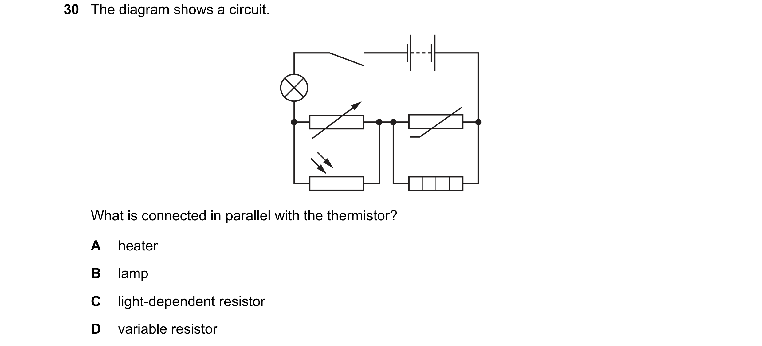
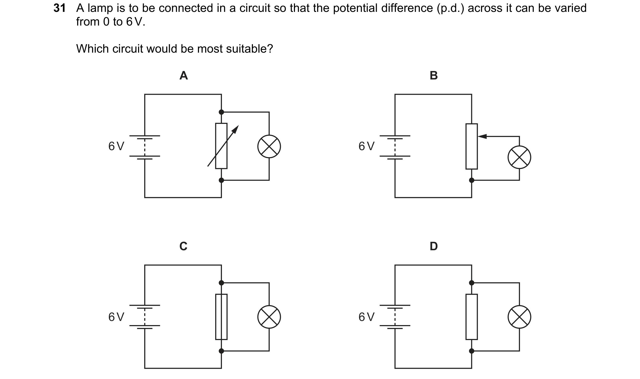 41 / 114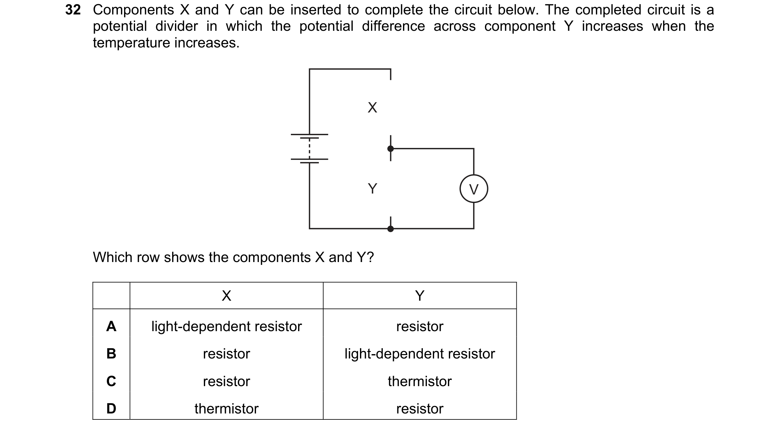

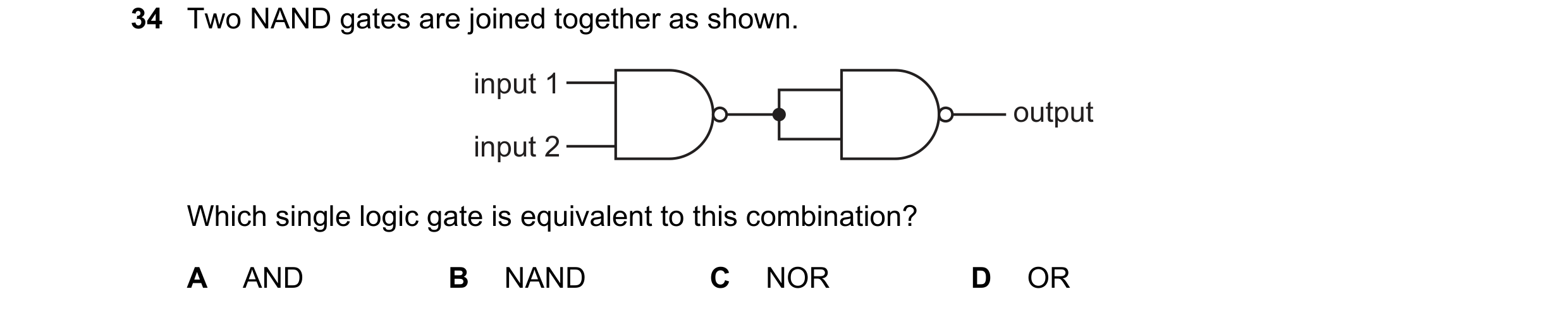
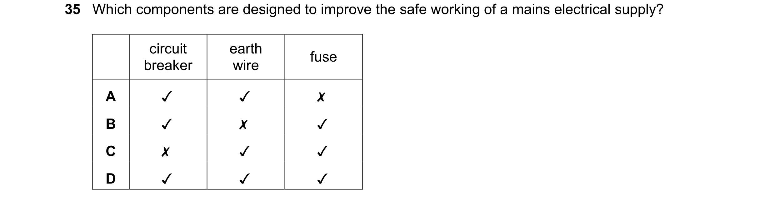 42 / 114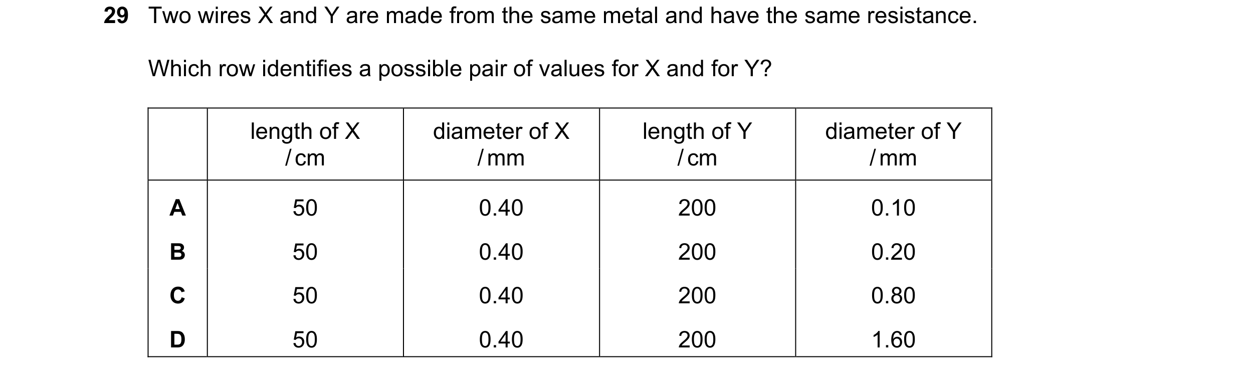
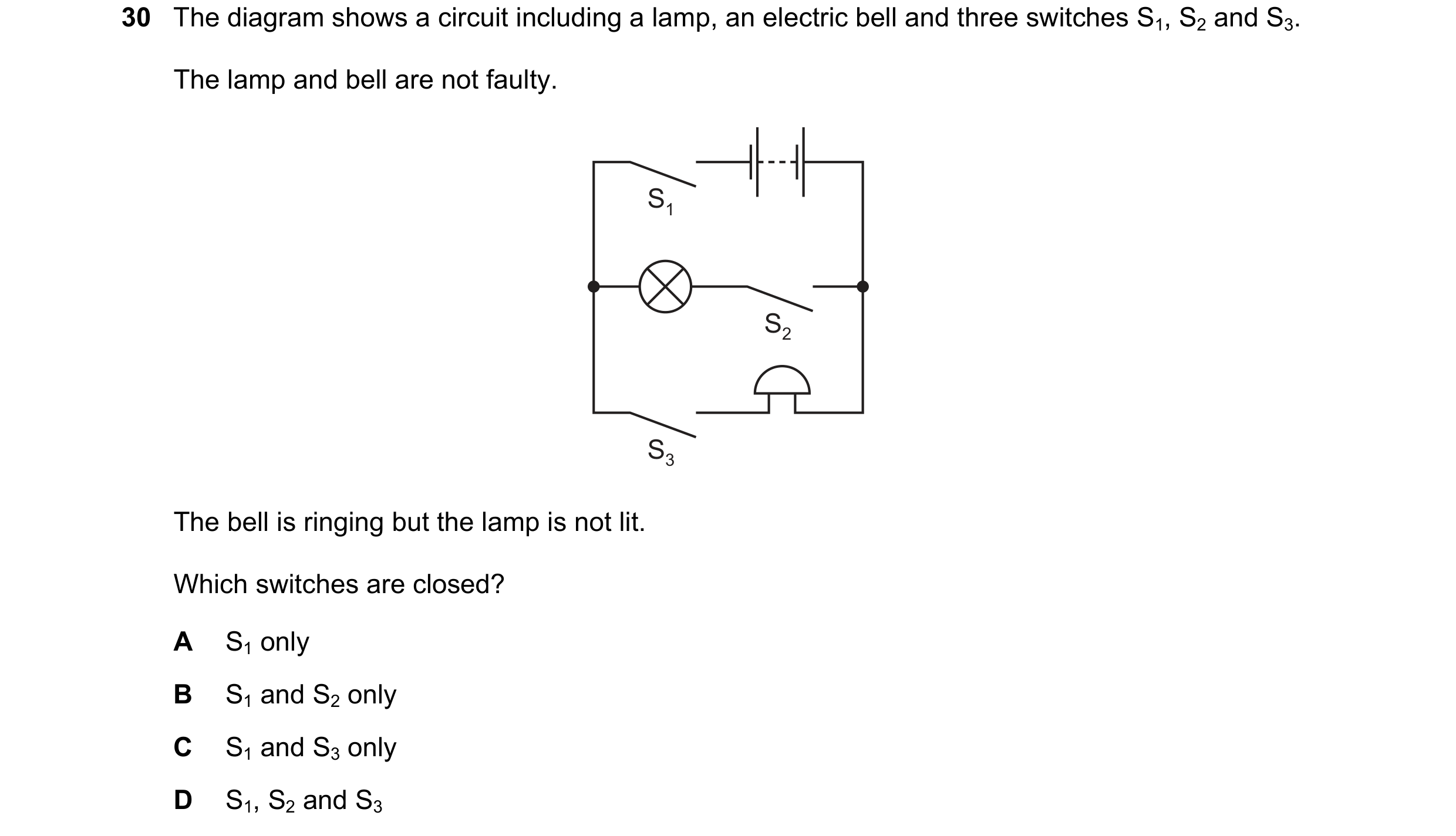 43 / 114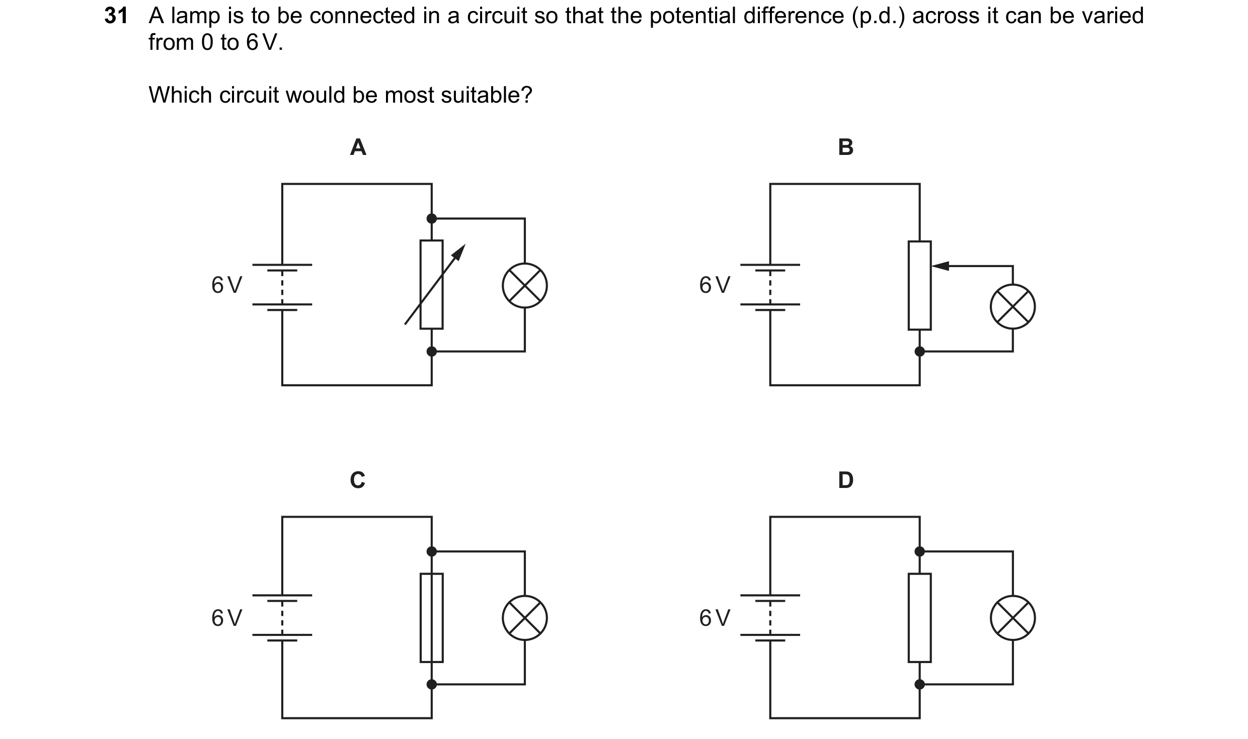
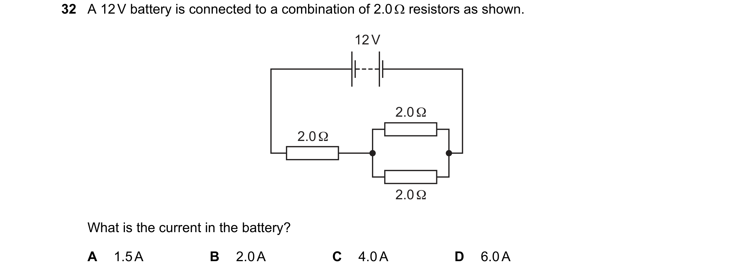 44 / 114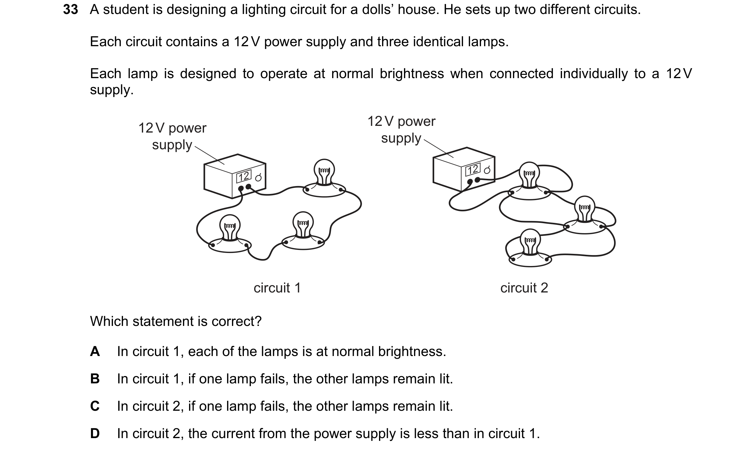
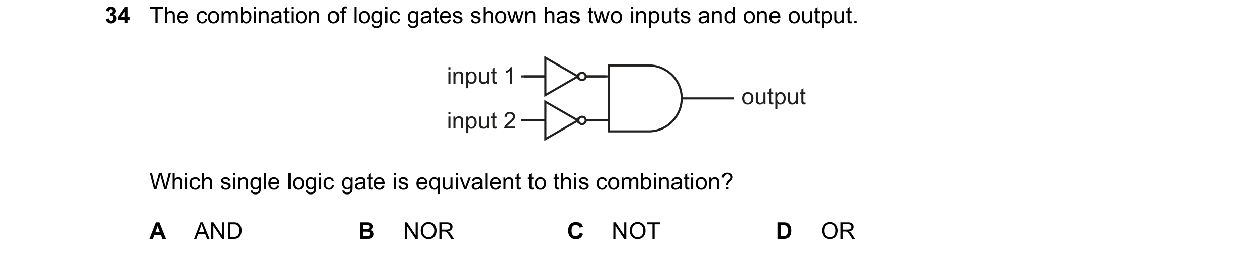
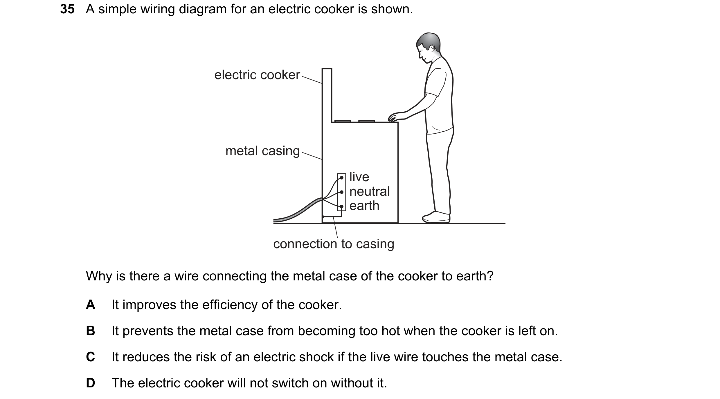 45 / 114
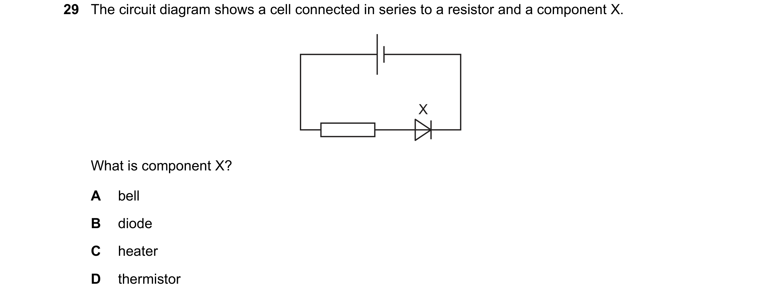
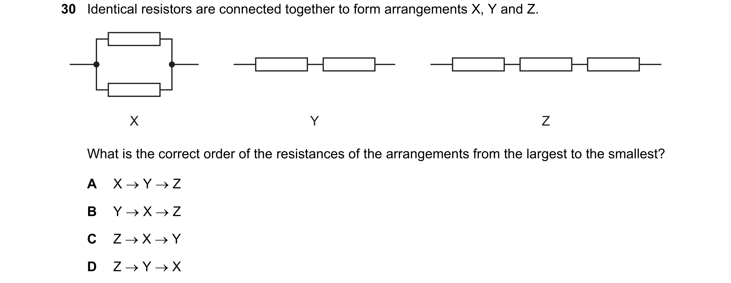 46 / 114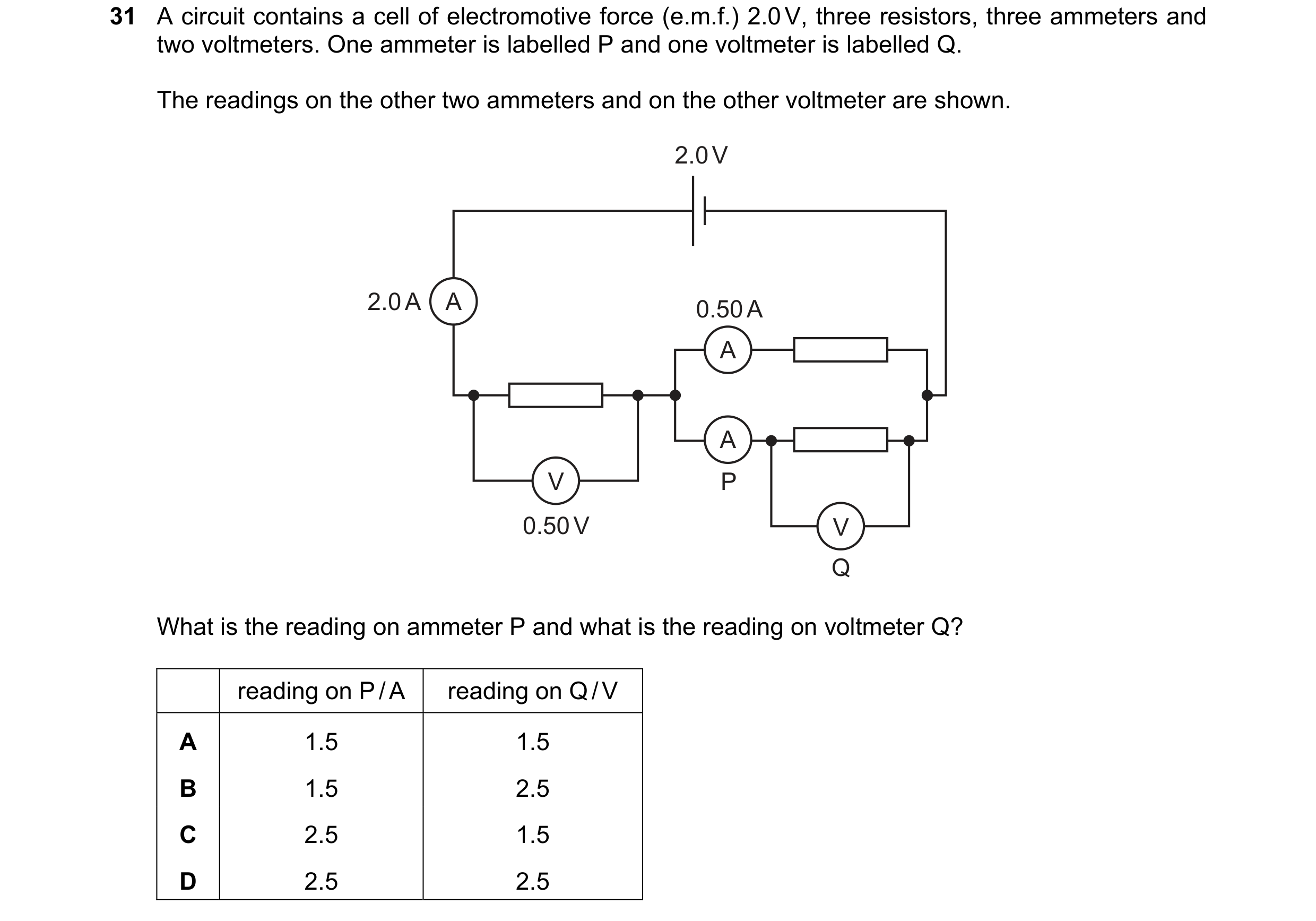
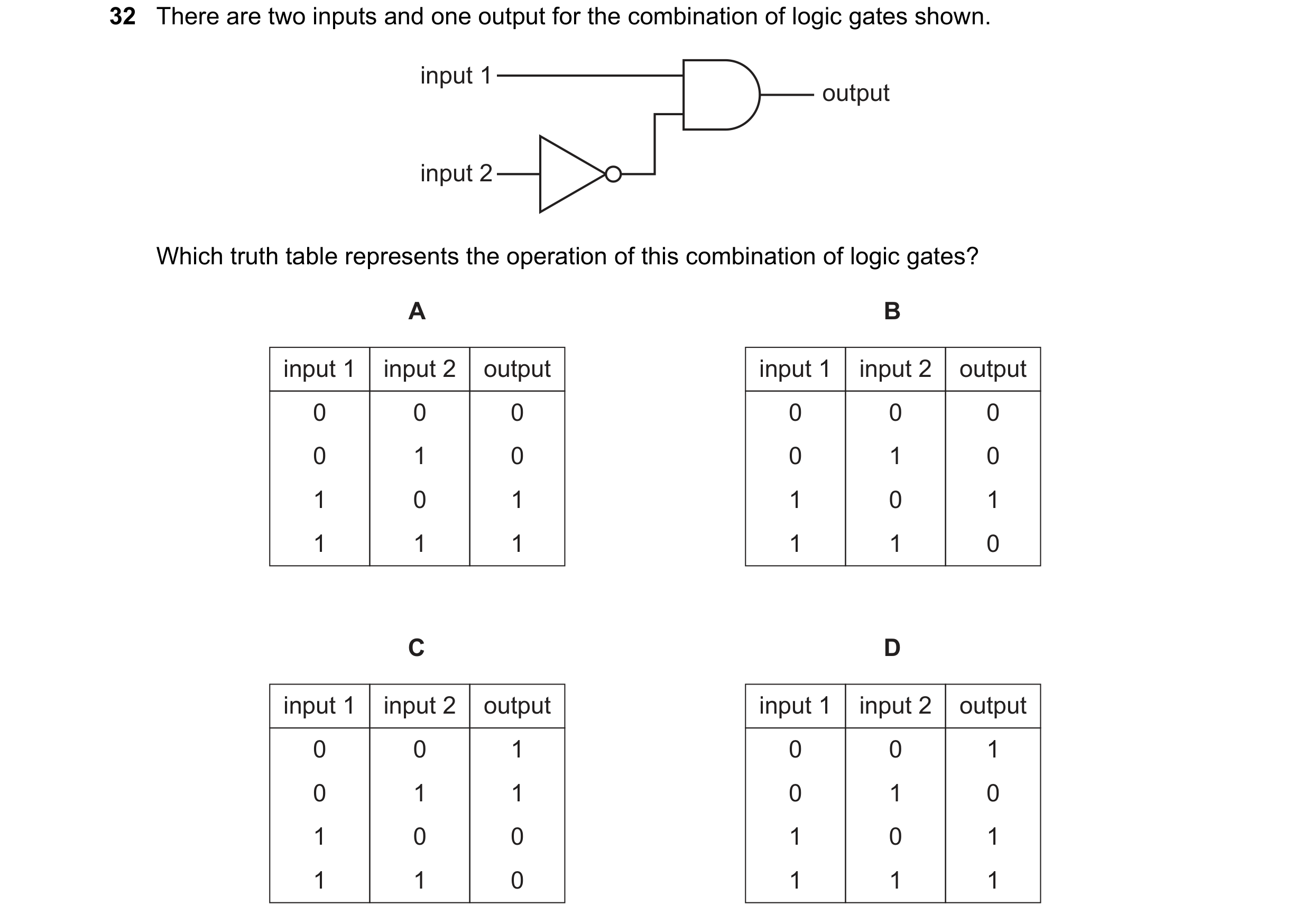 47 / 114

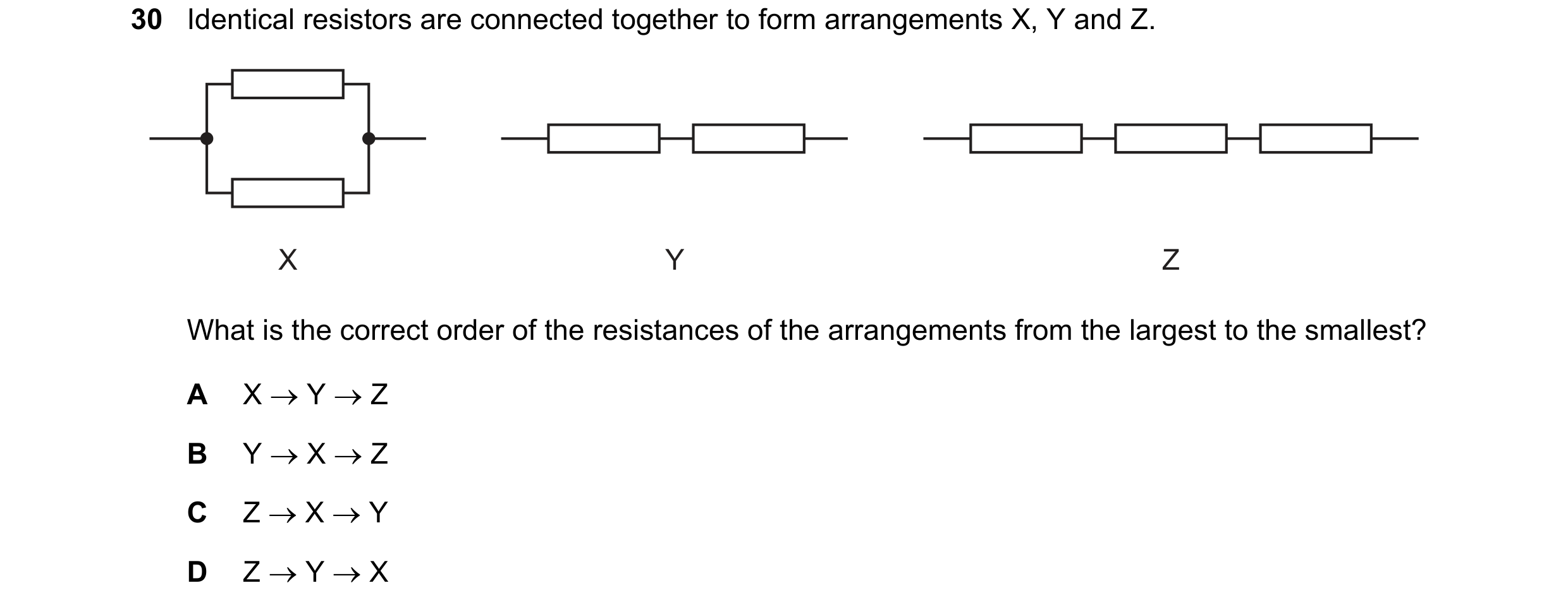
 48 / 114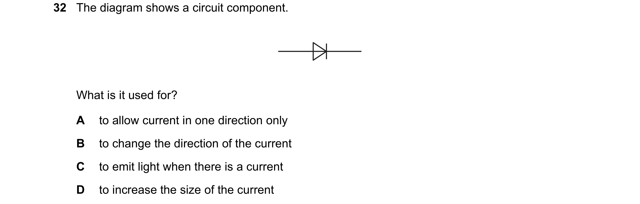



 49 / 114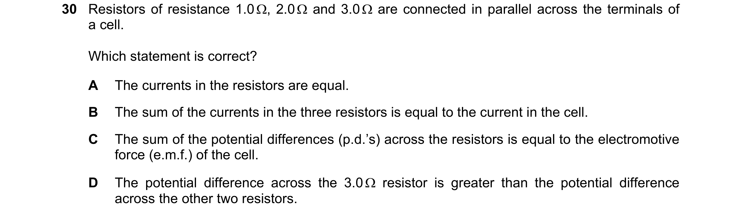
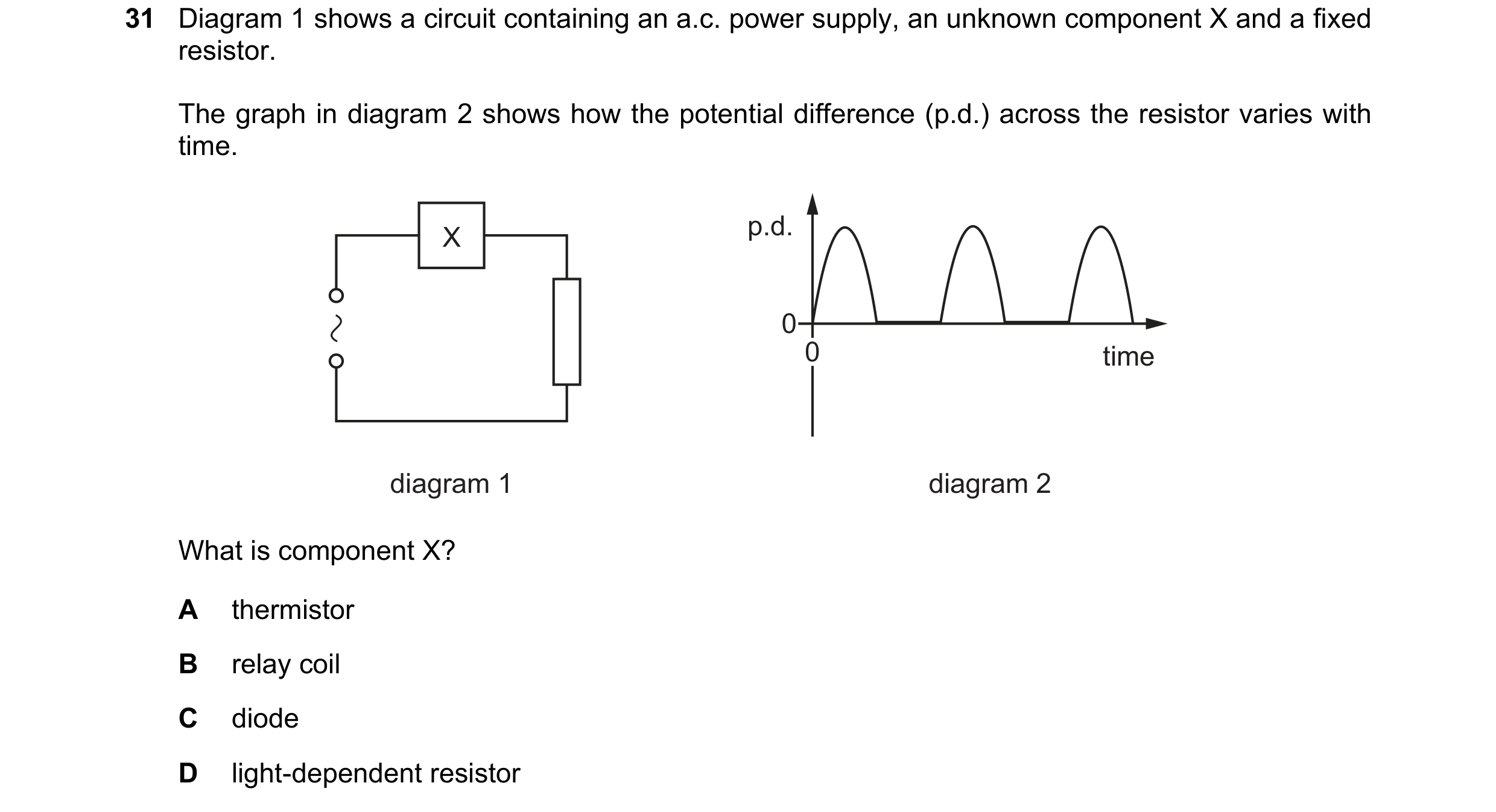
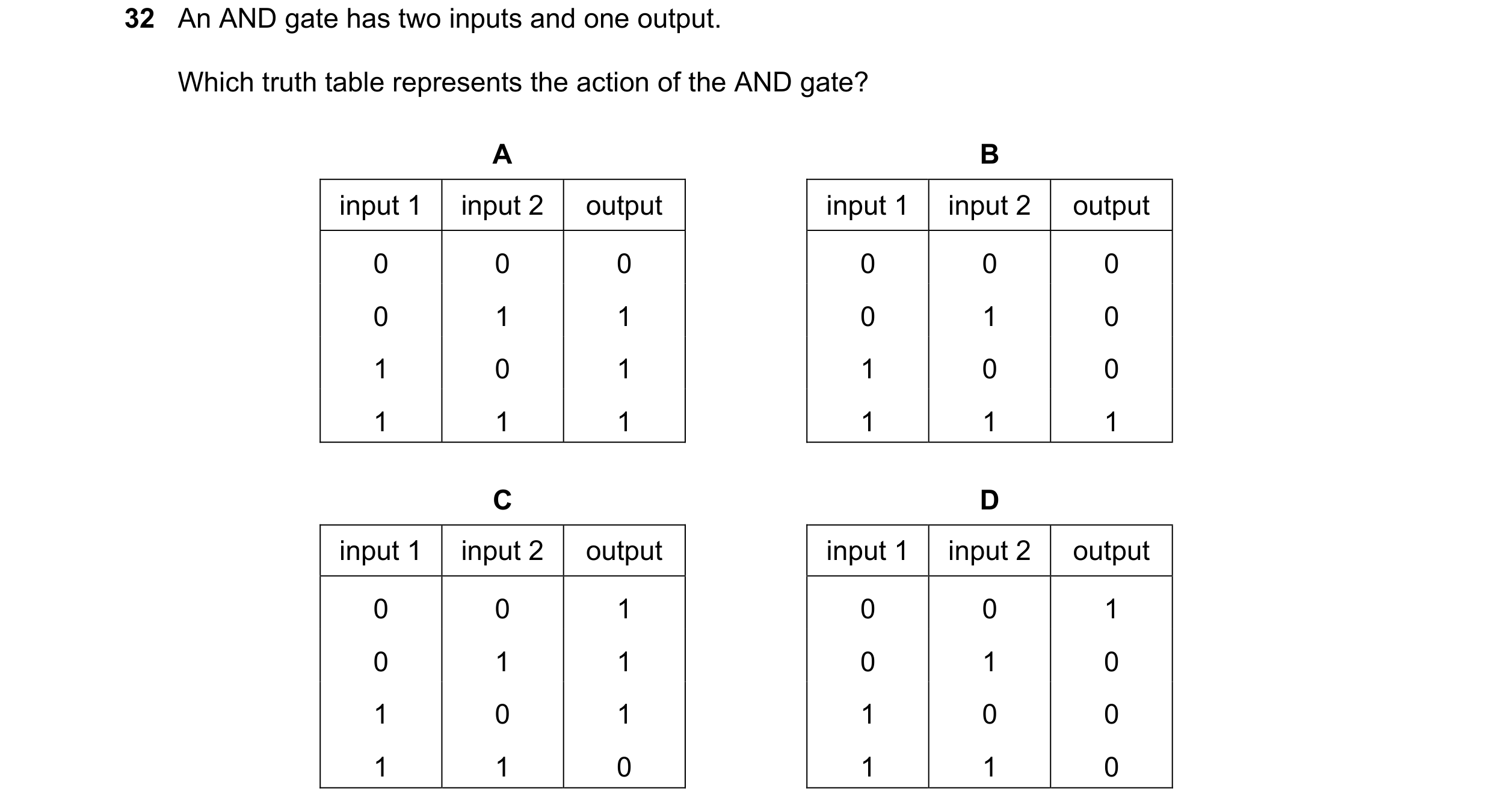 50 / 114

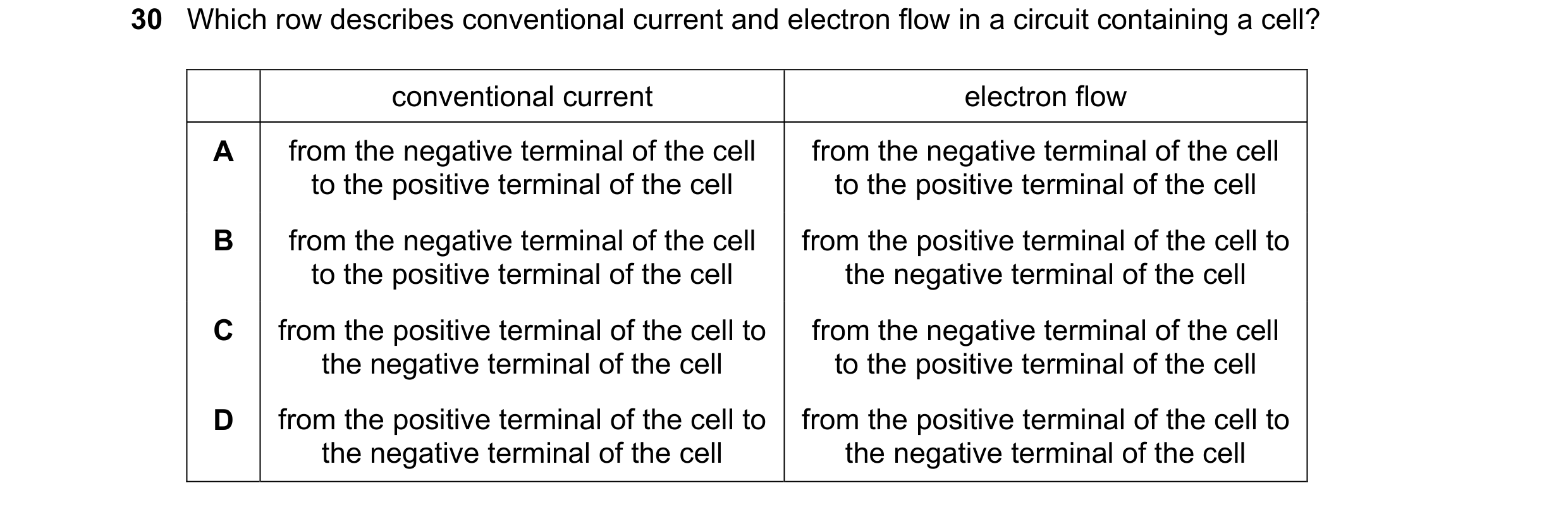
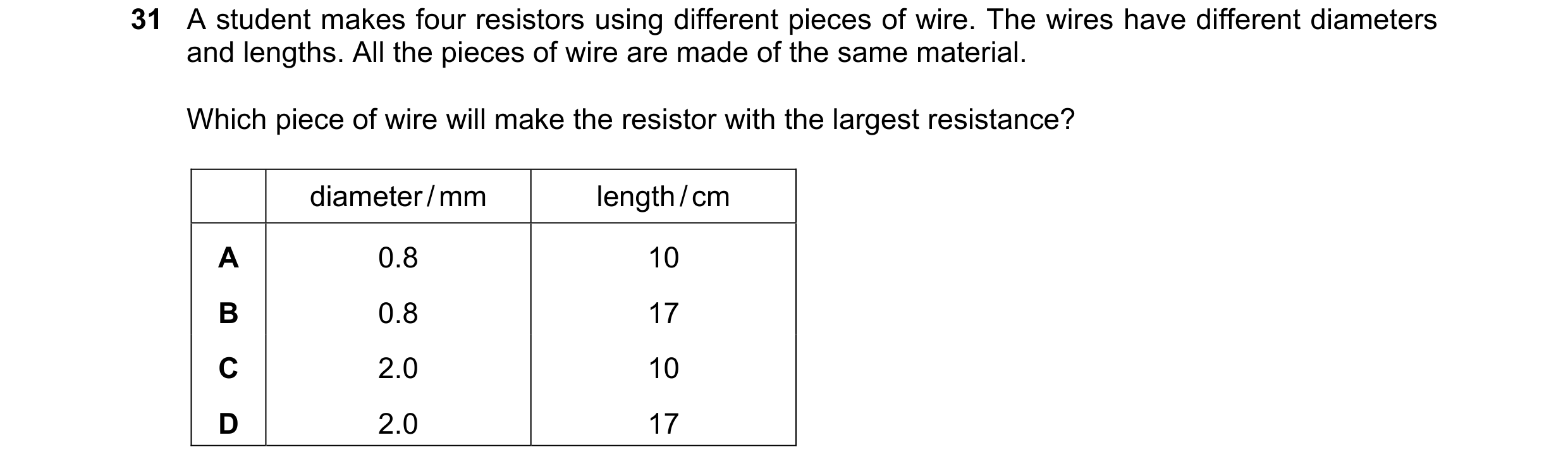 51 / 114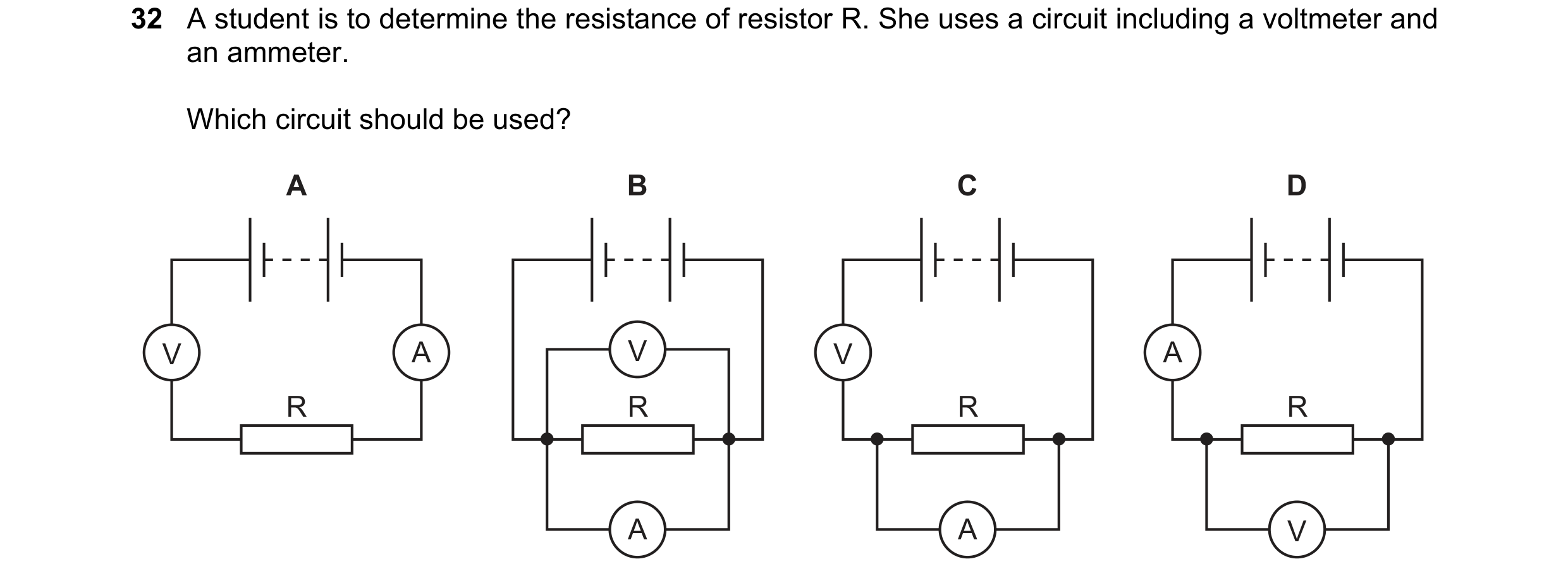
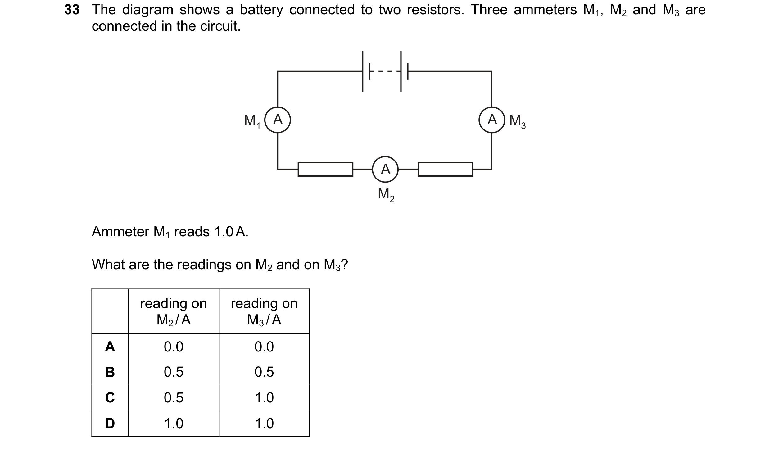
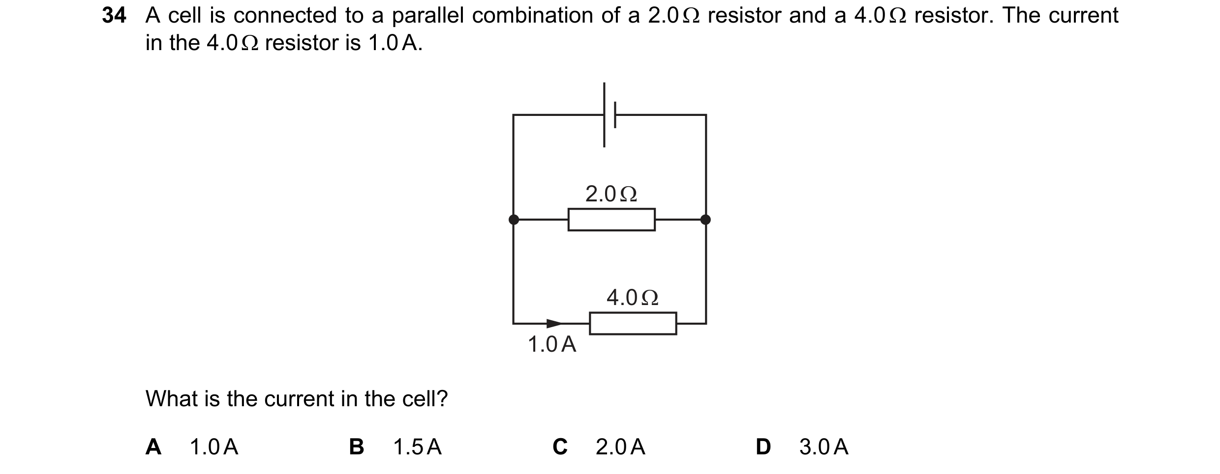 52 / 114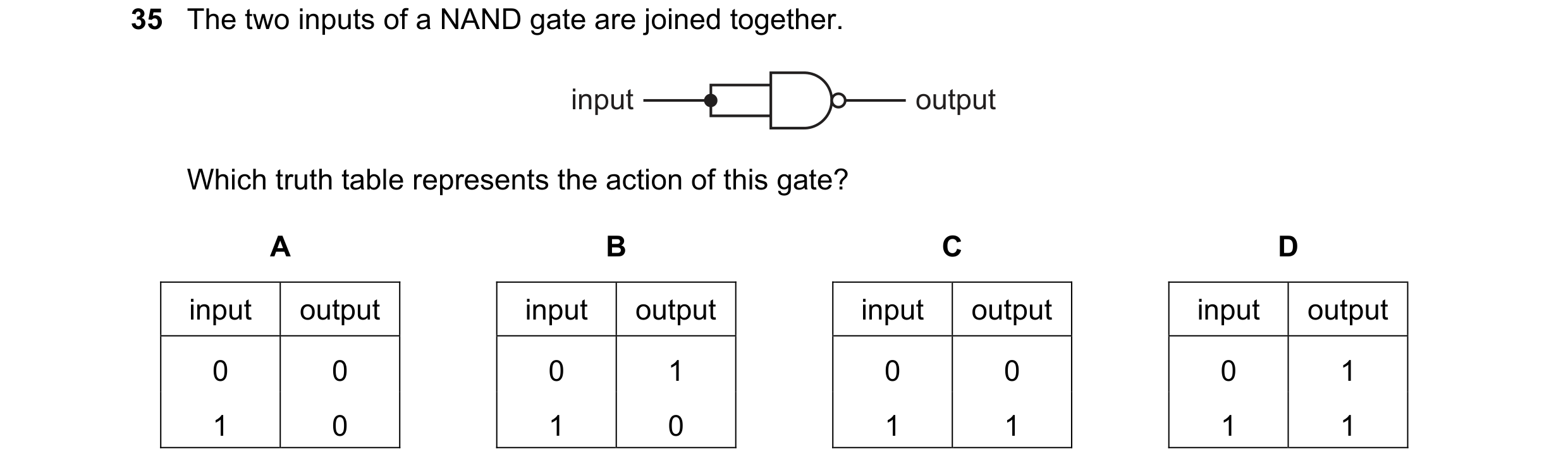
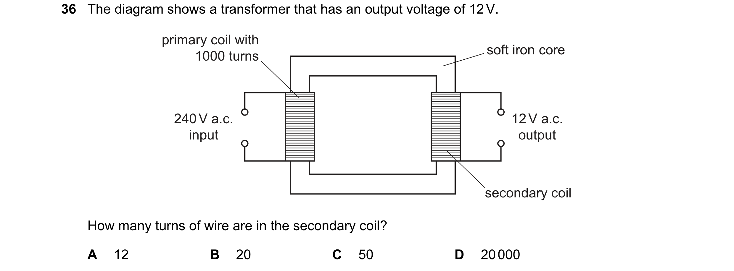
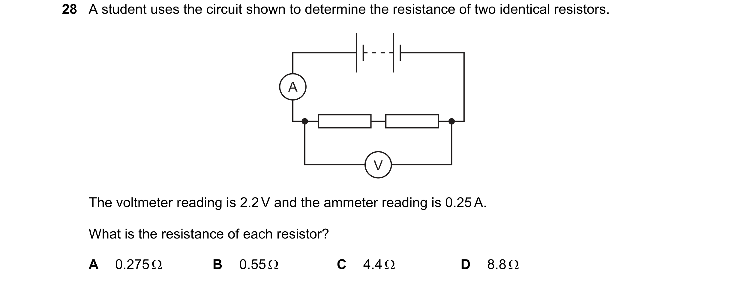
 53 / 114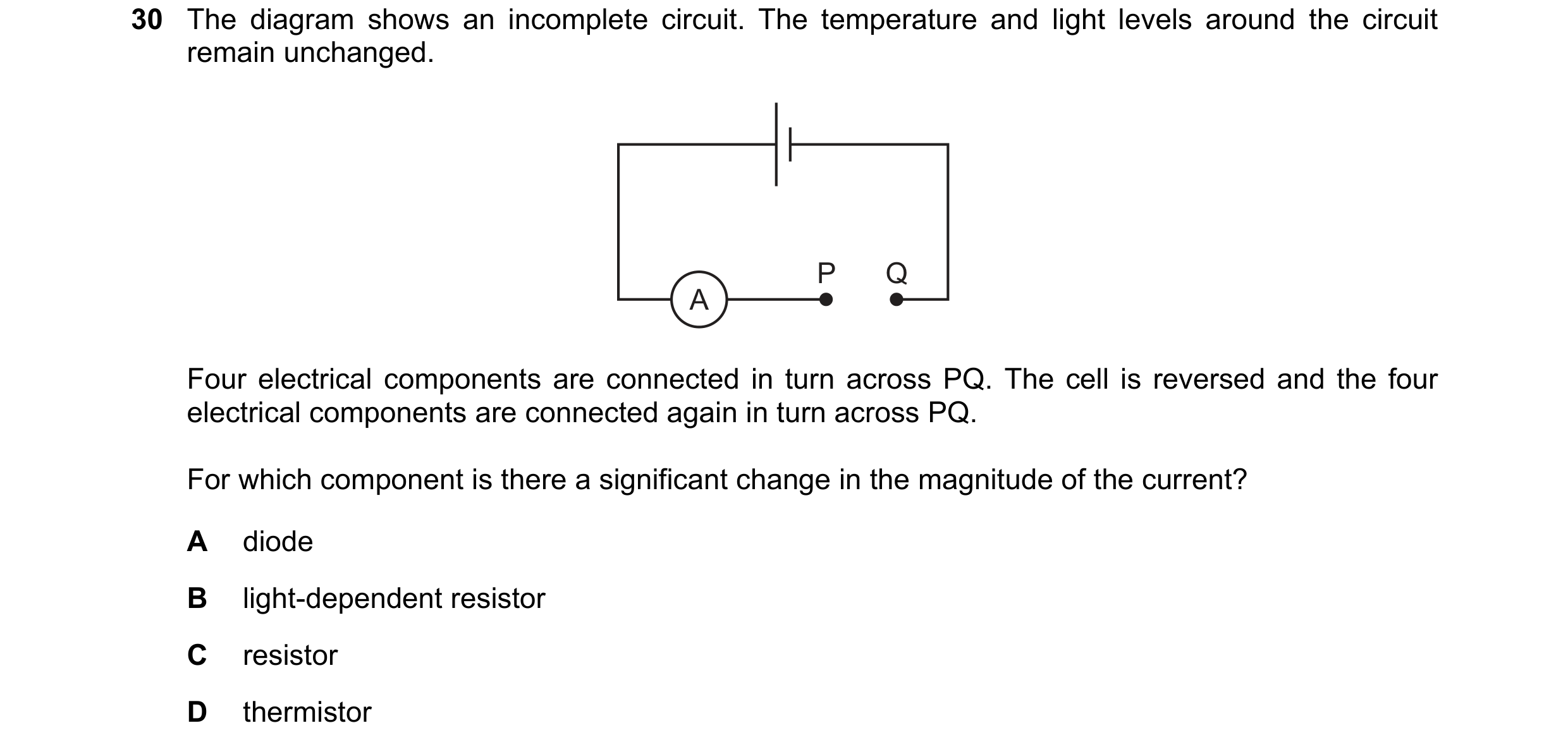
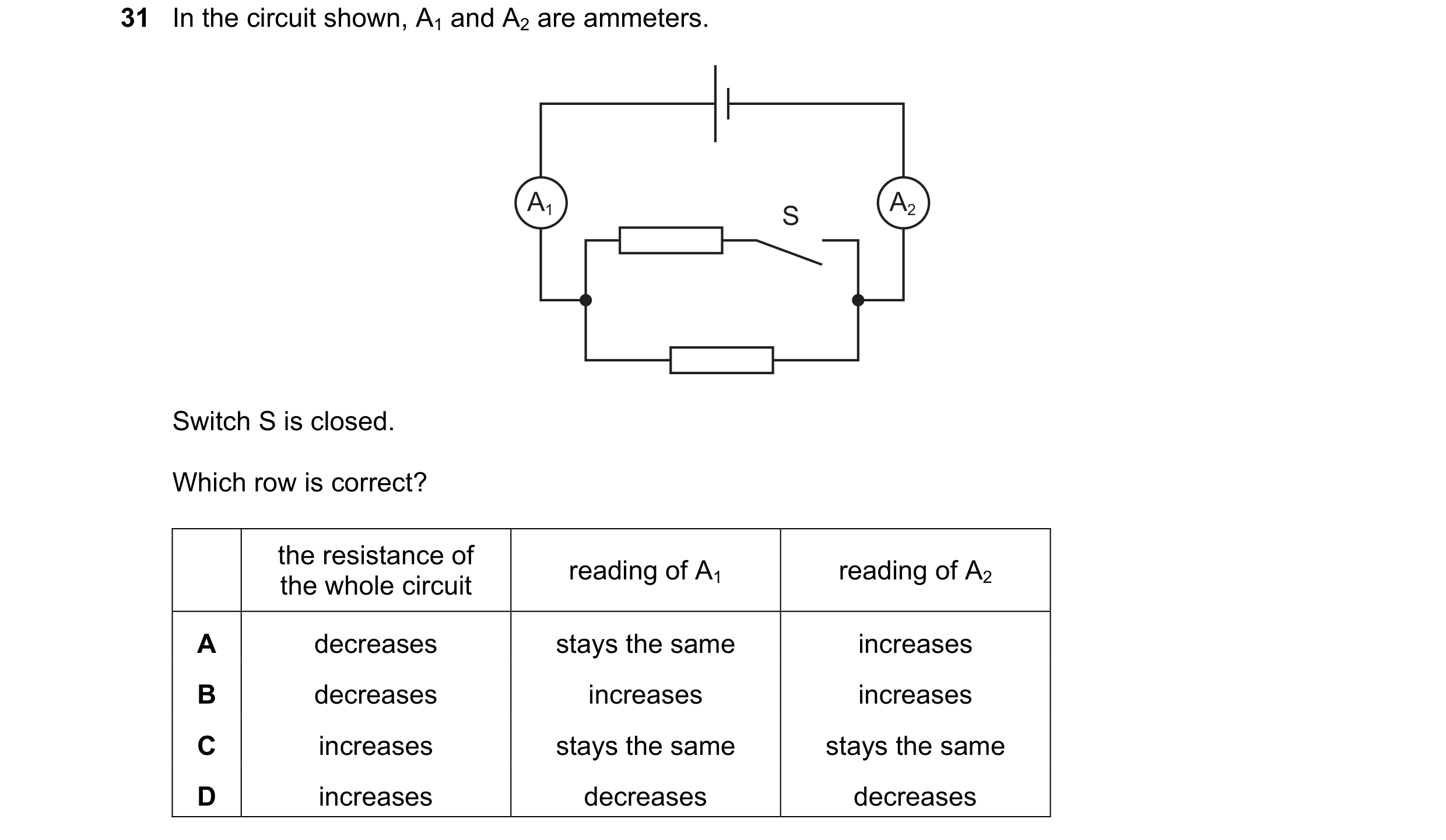
 54 / 114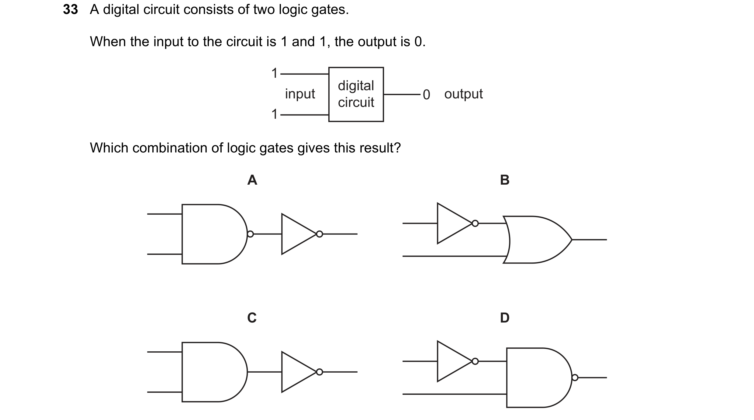
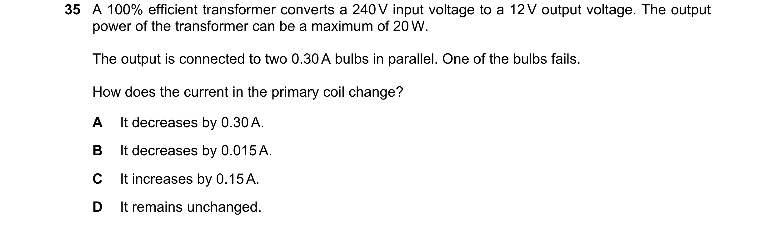
 55 / 114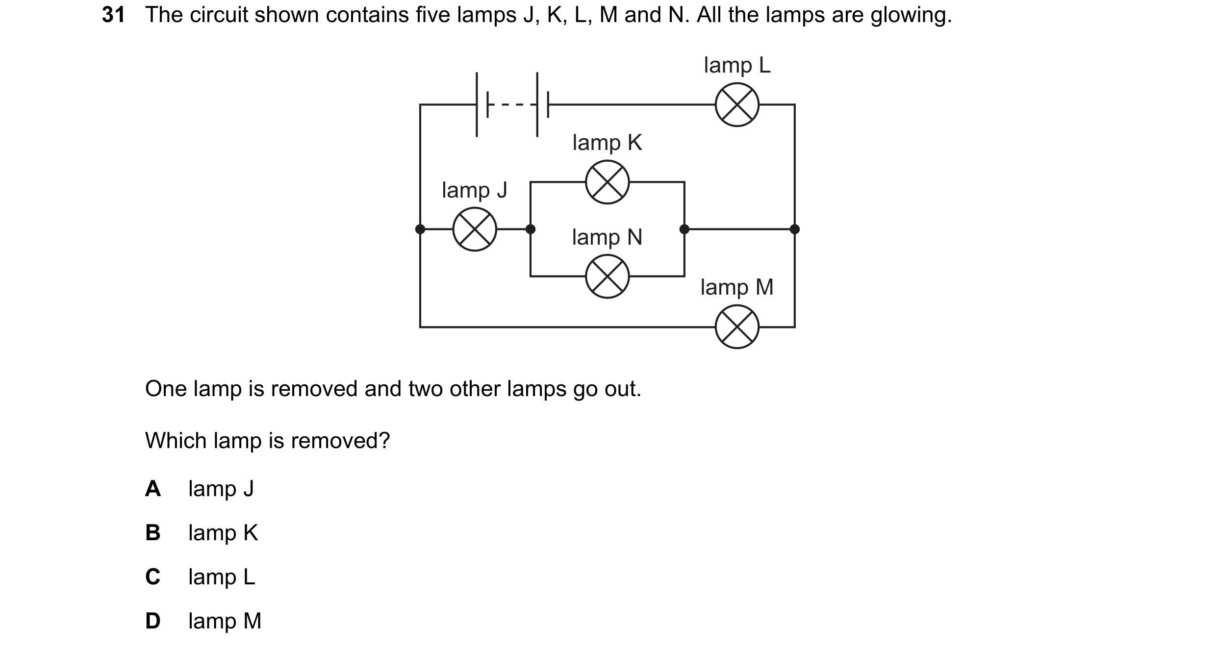
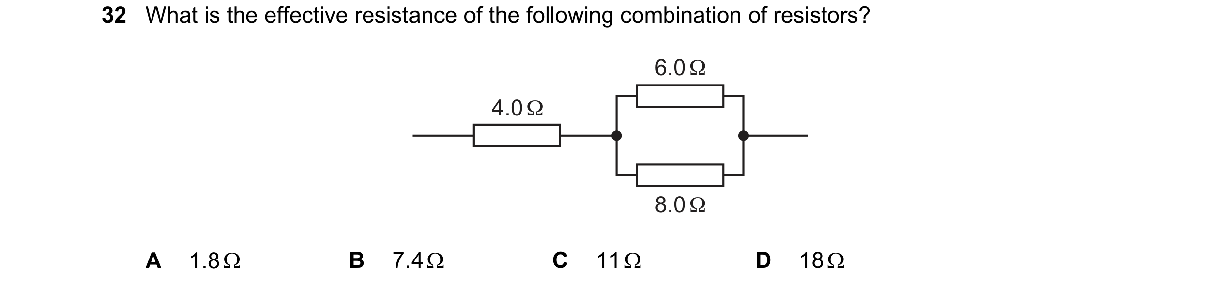
 56 / 114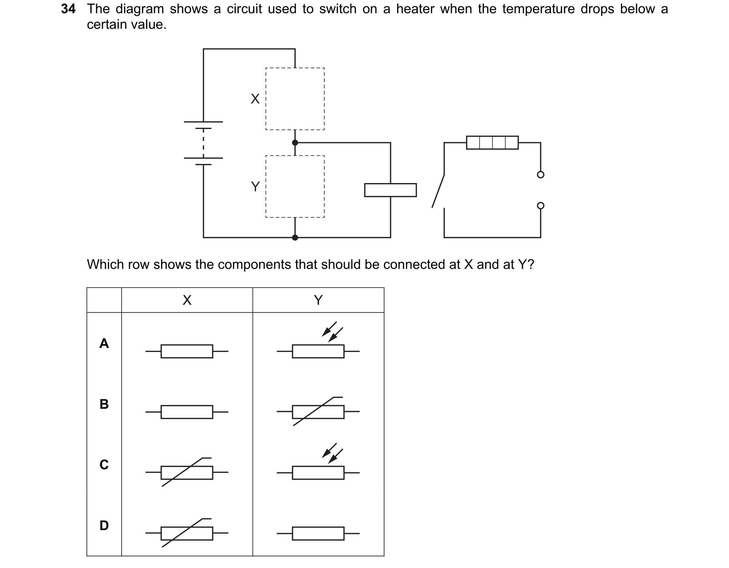
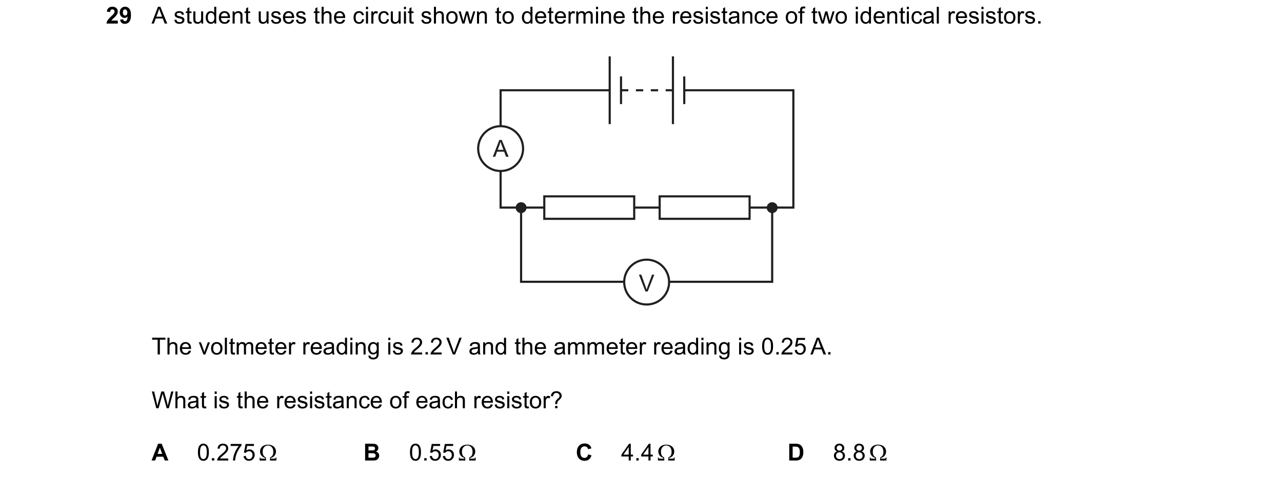
 57 / 114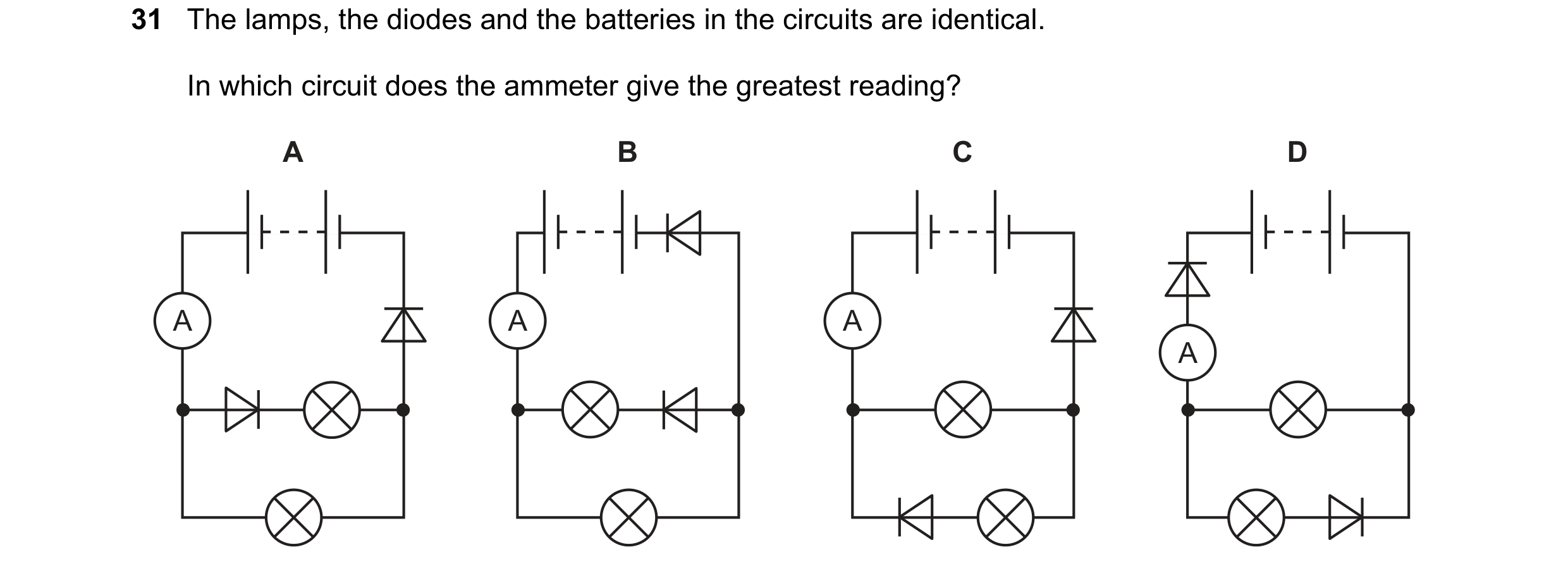

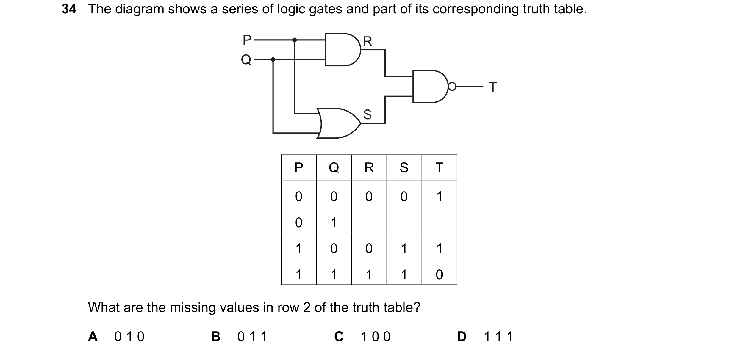 58 / 114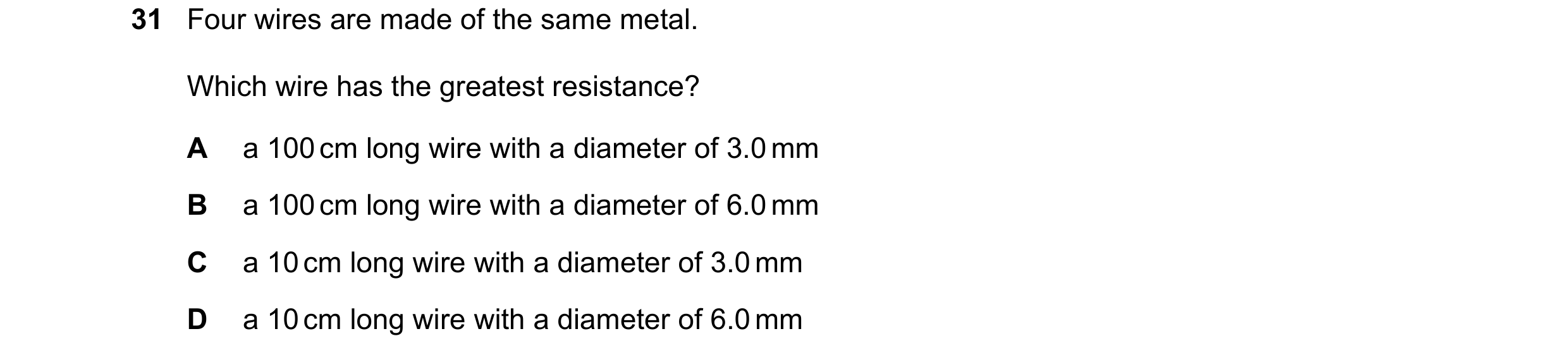
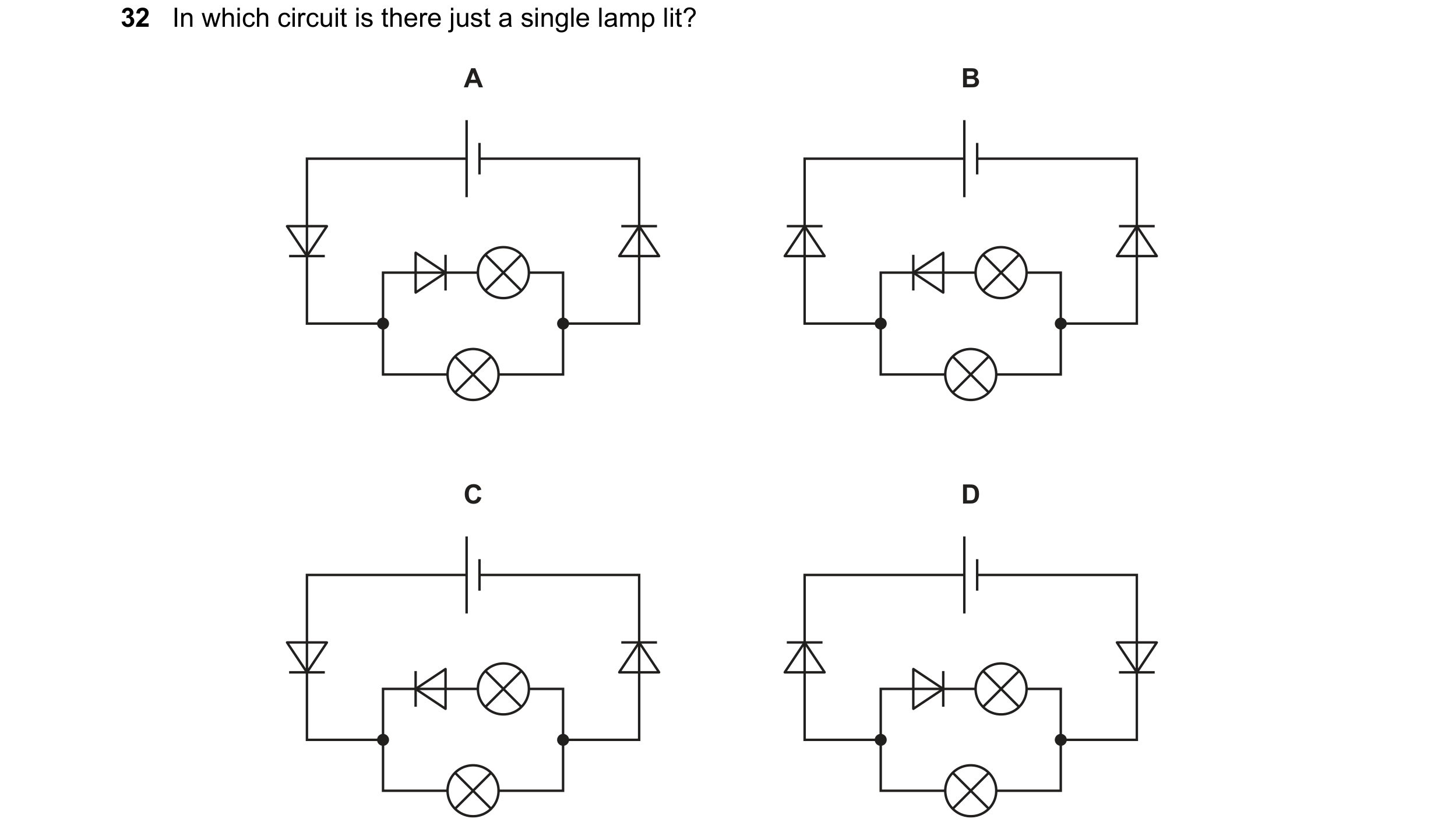
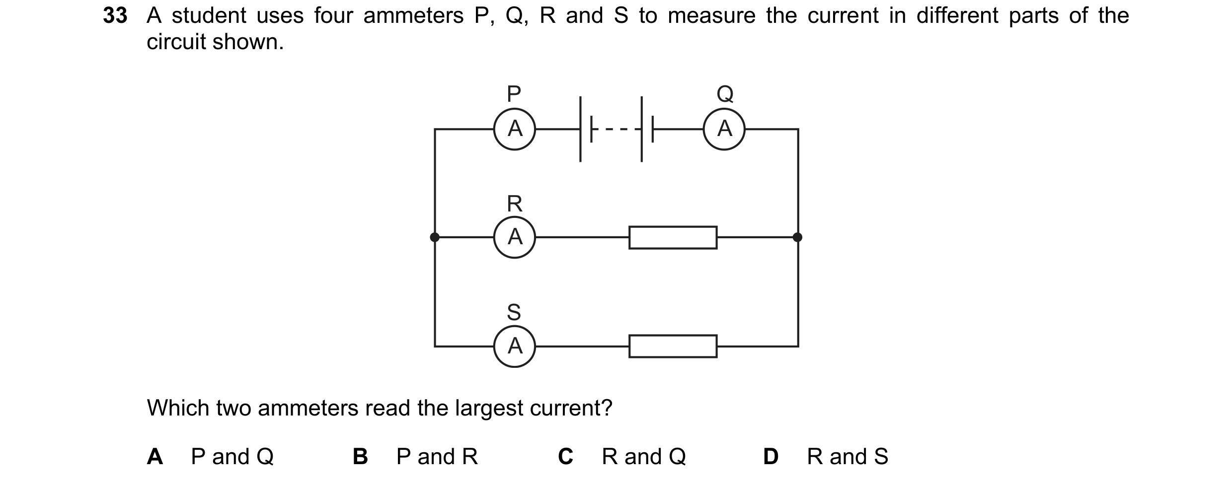 59 / 114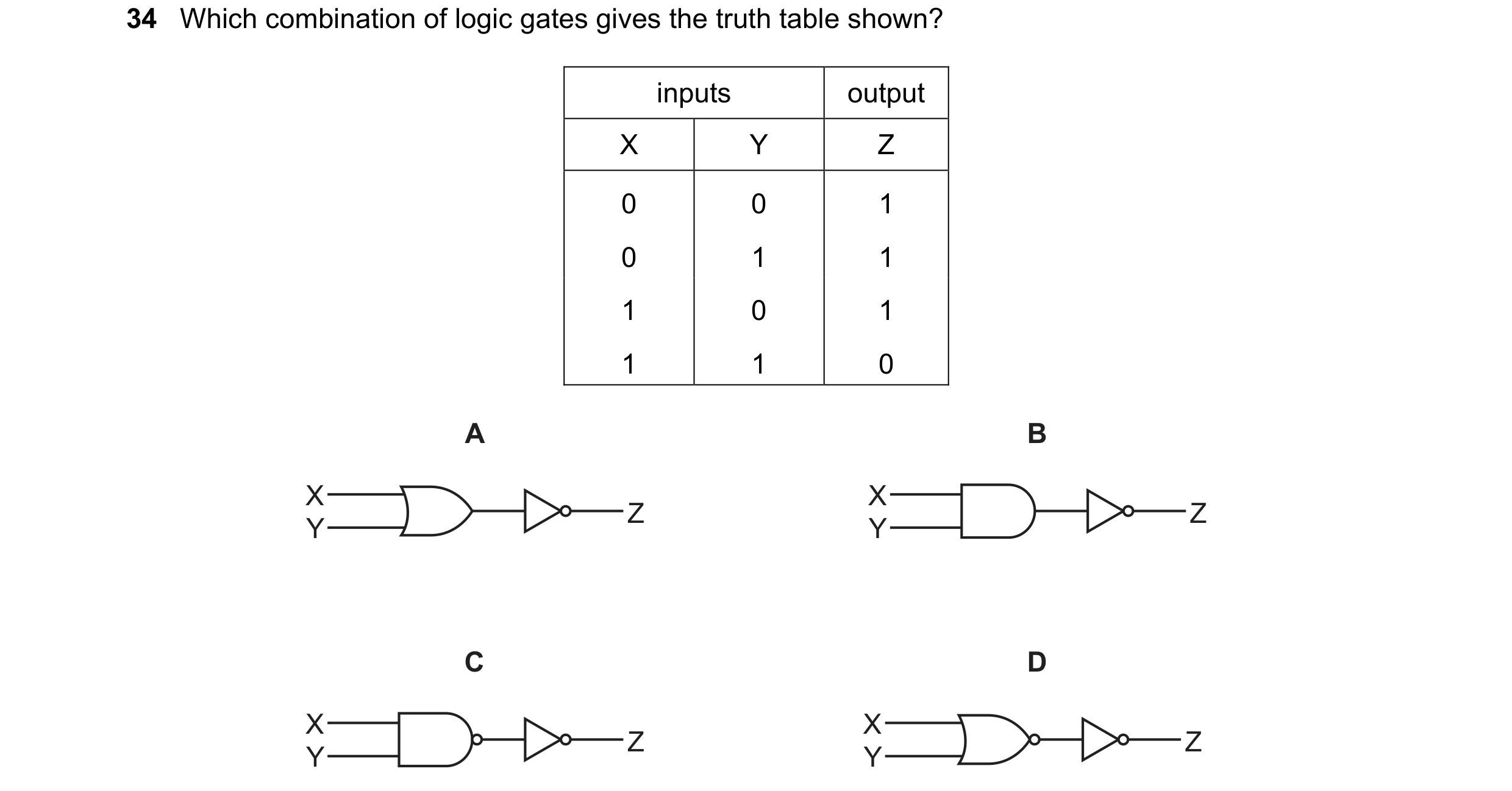
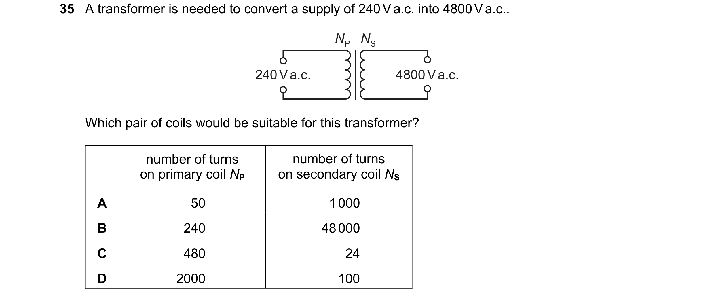
 60 / 114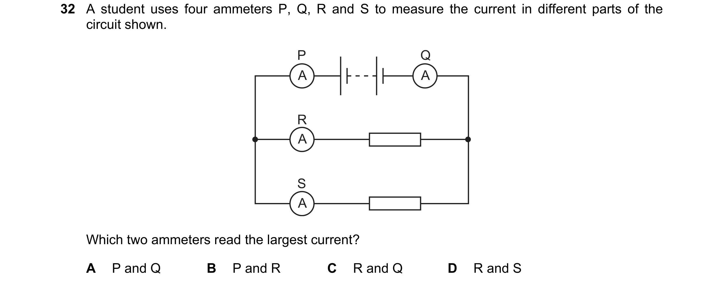
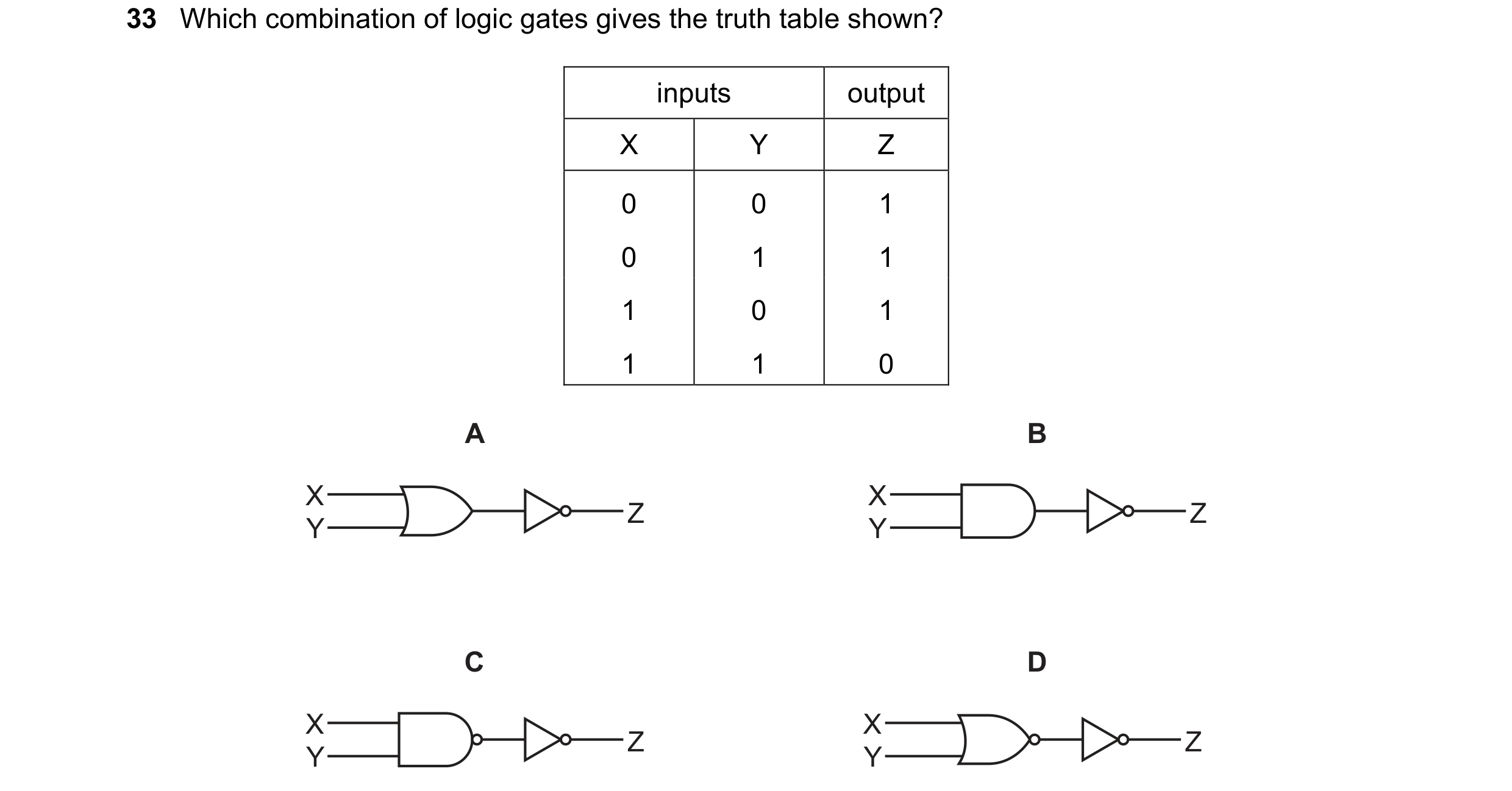 61 / 114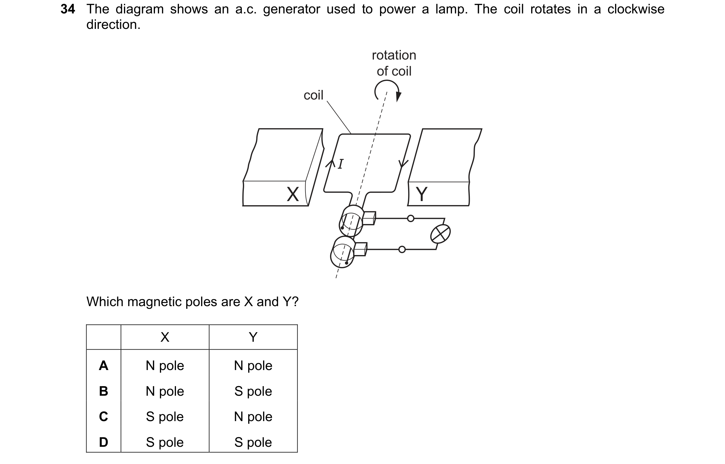
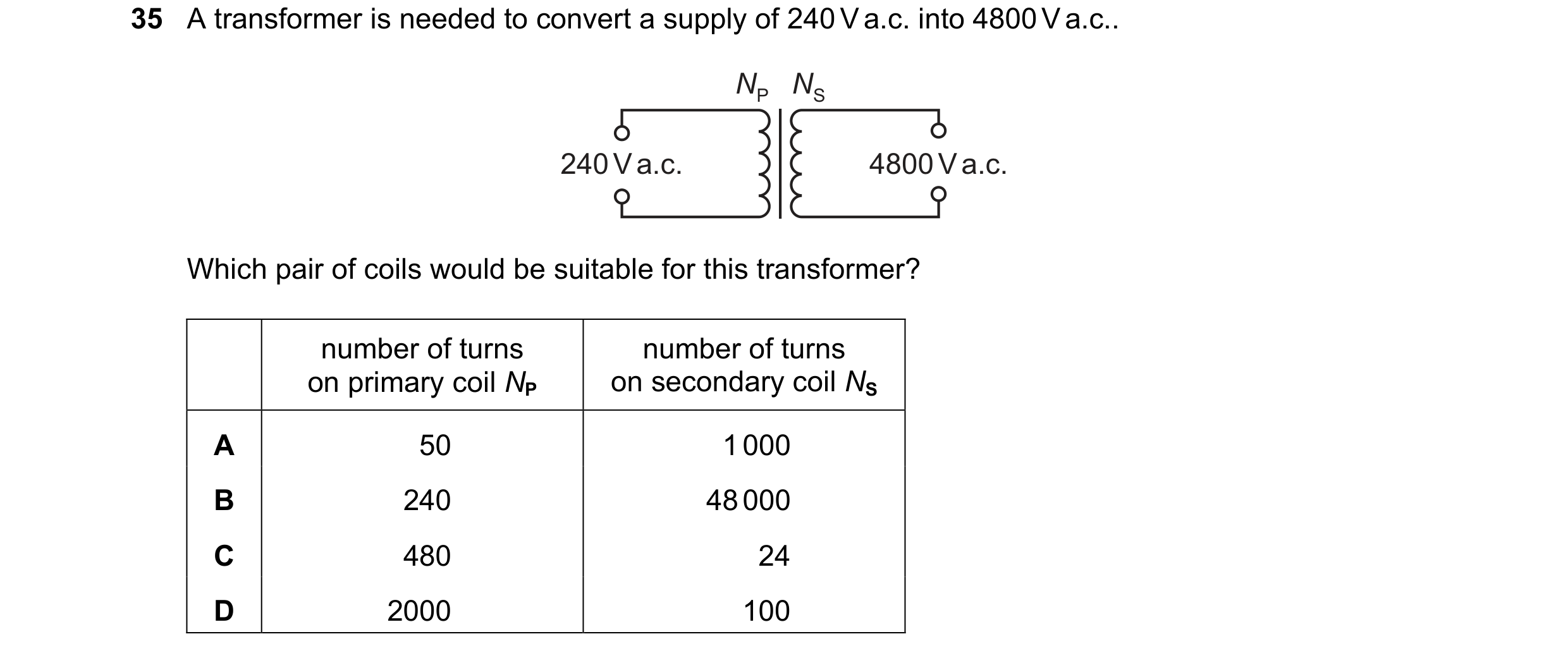 62 / 114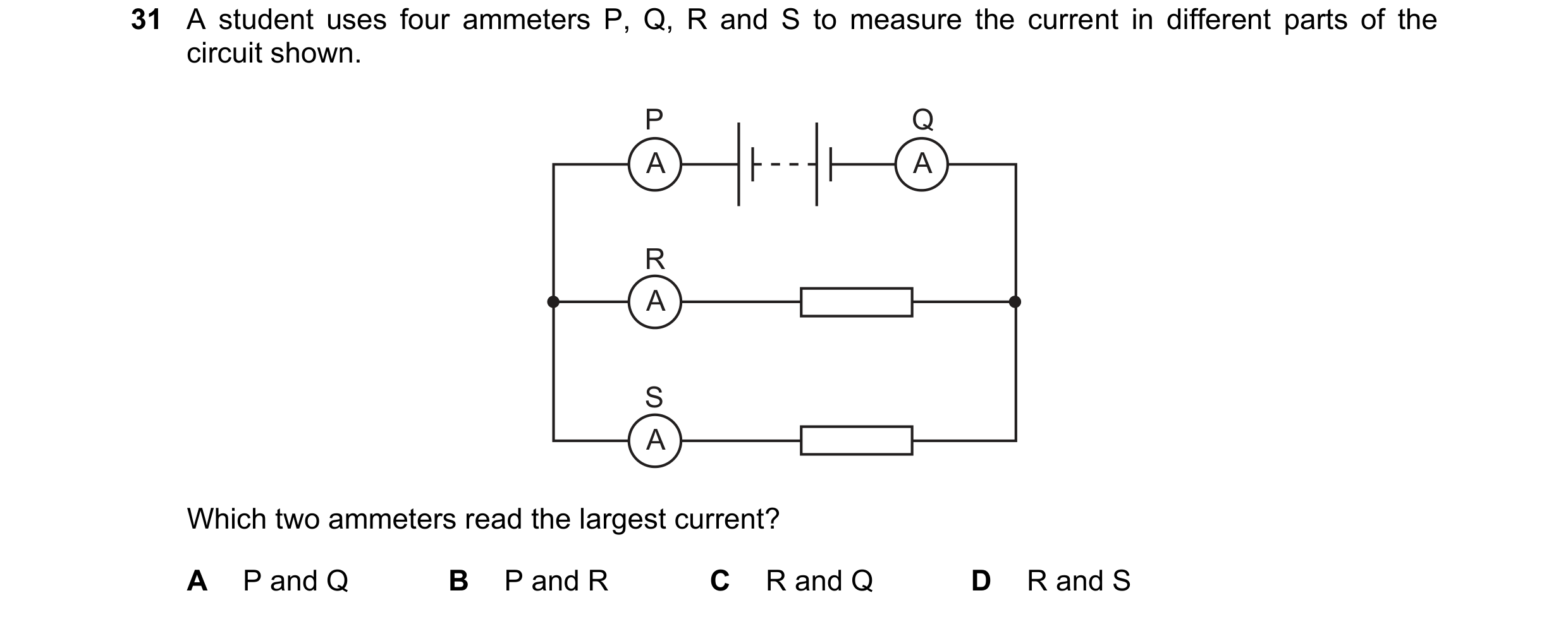
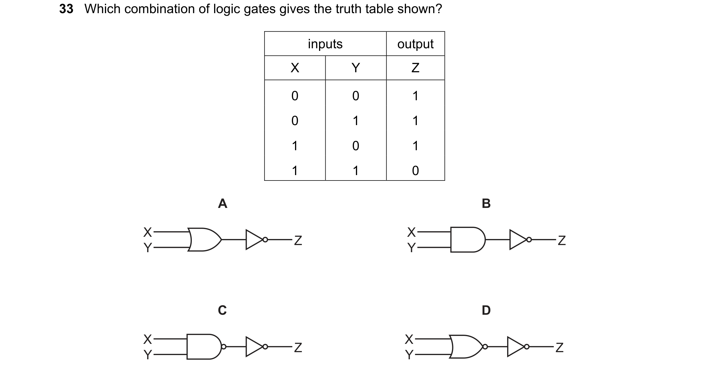 63 / 114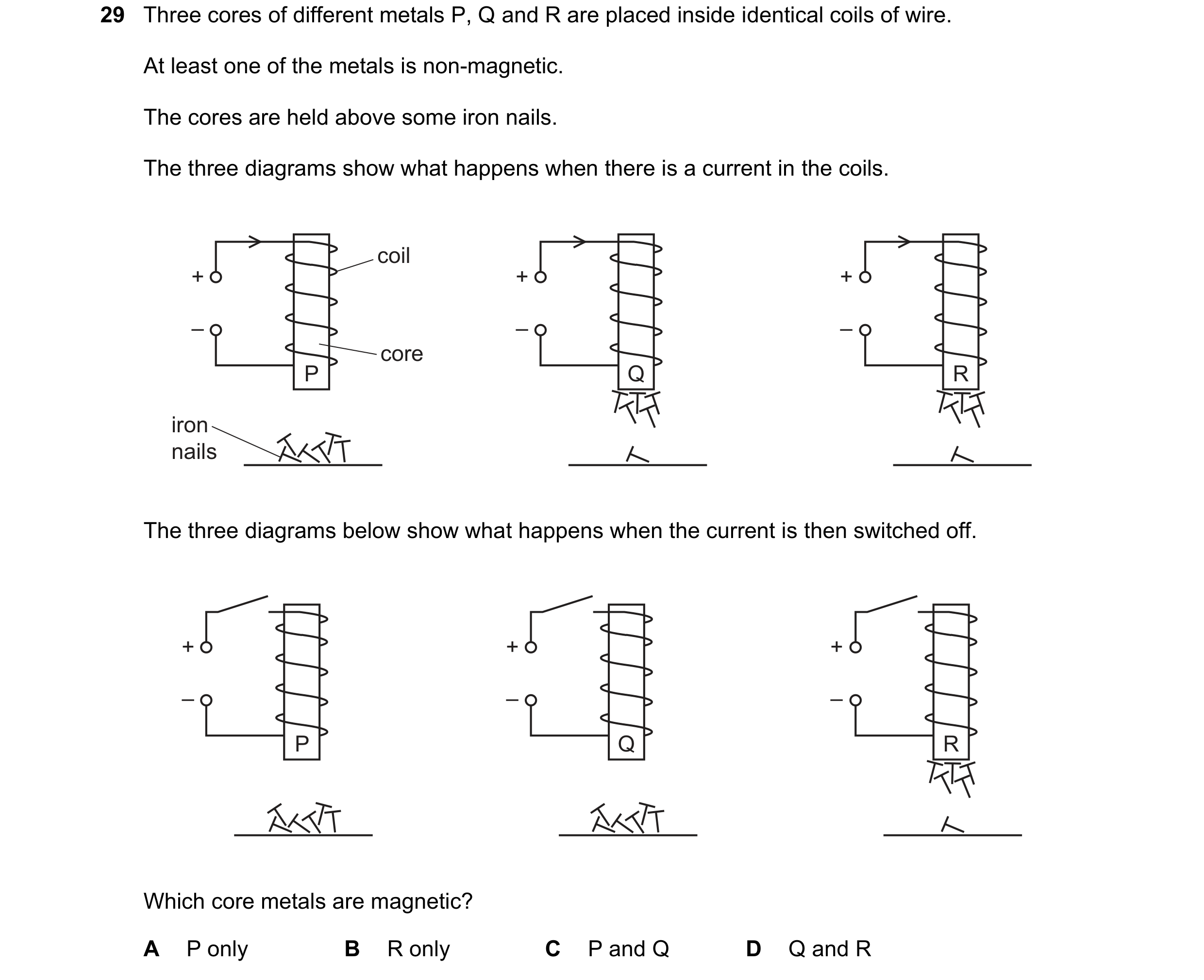

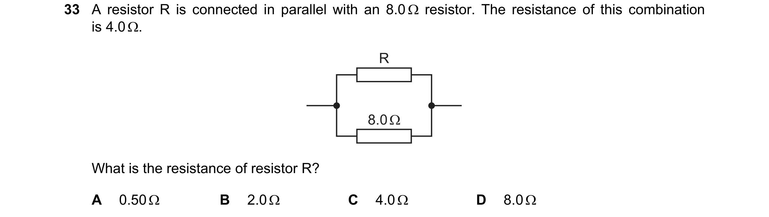 64 / 114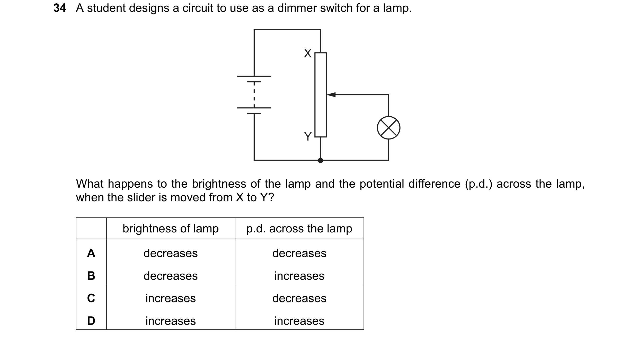
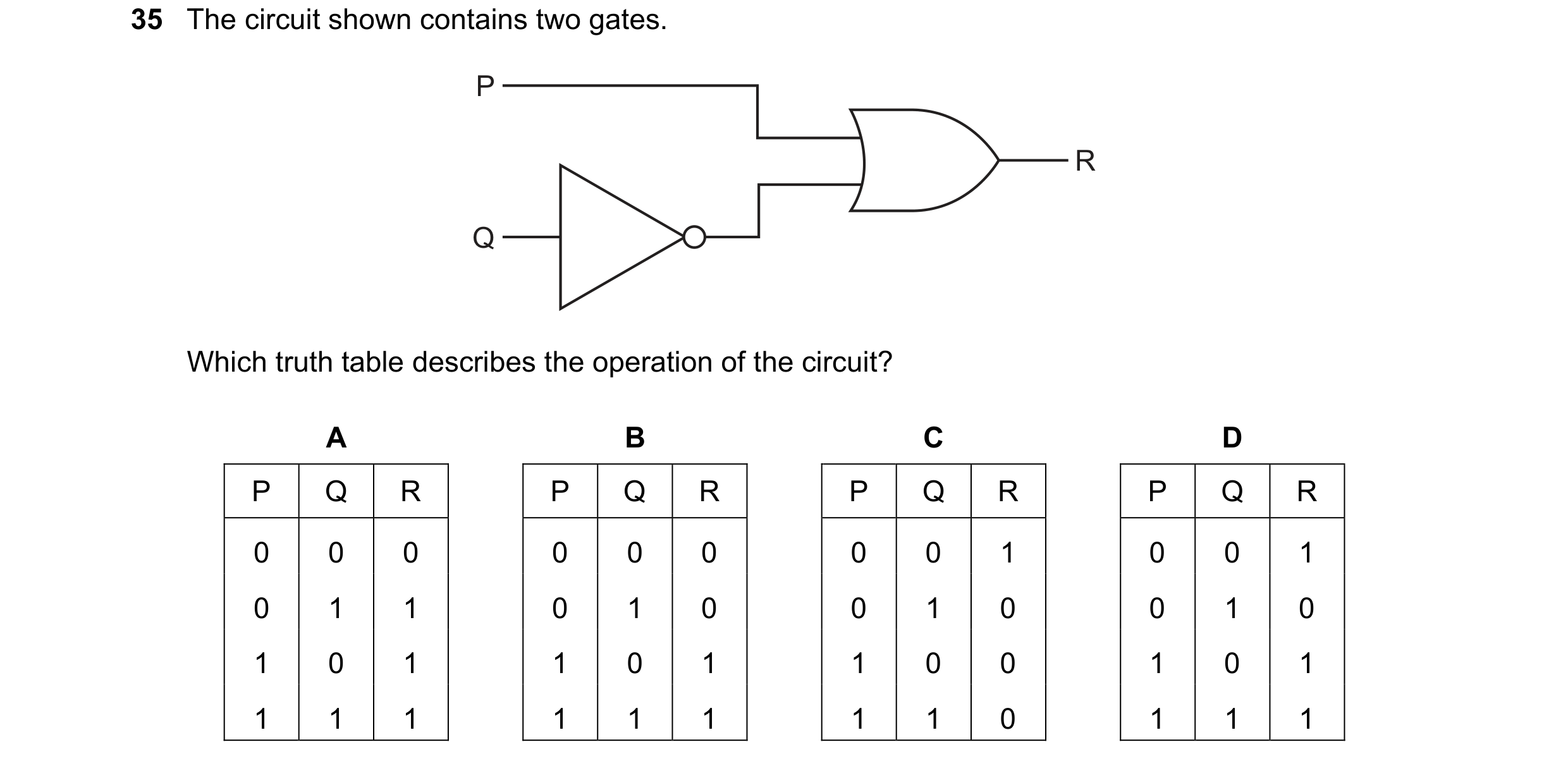 65 / 114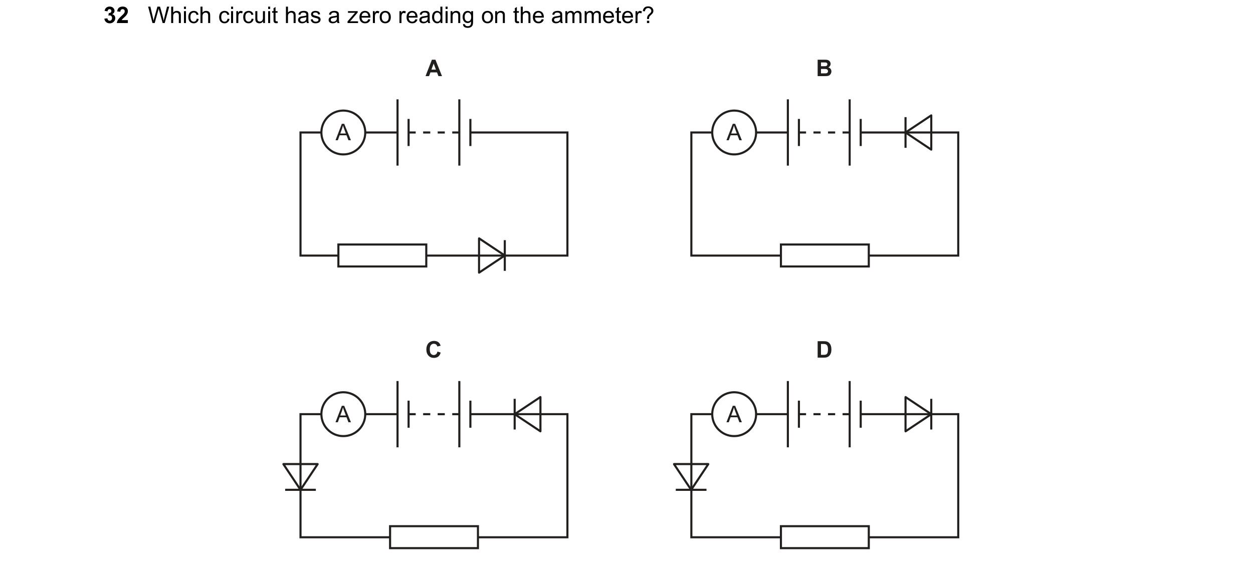
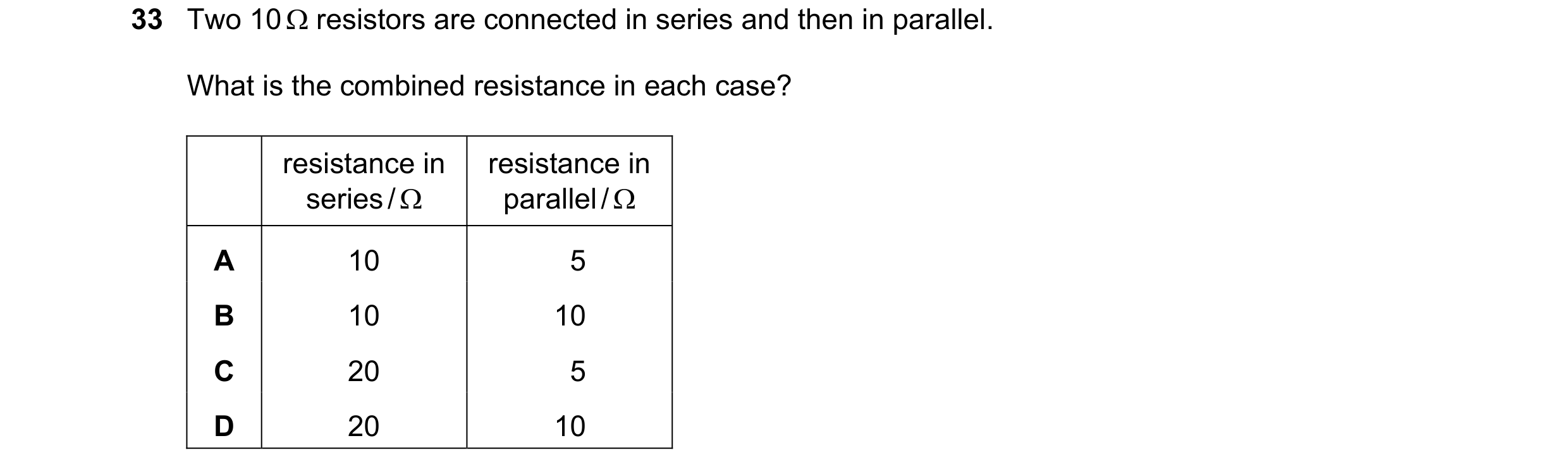
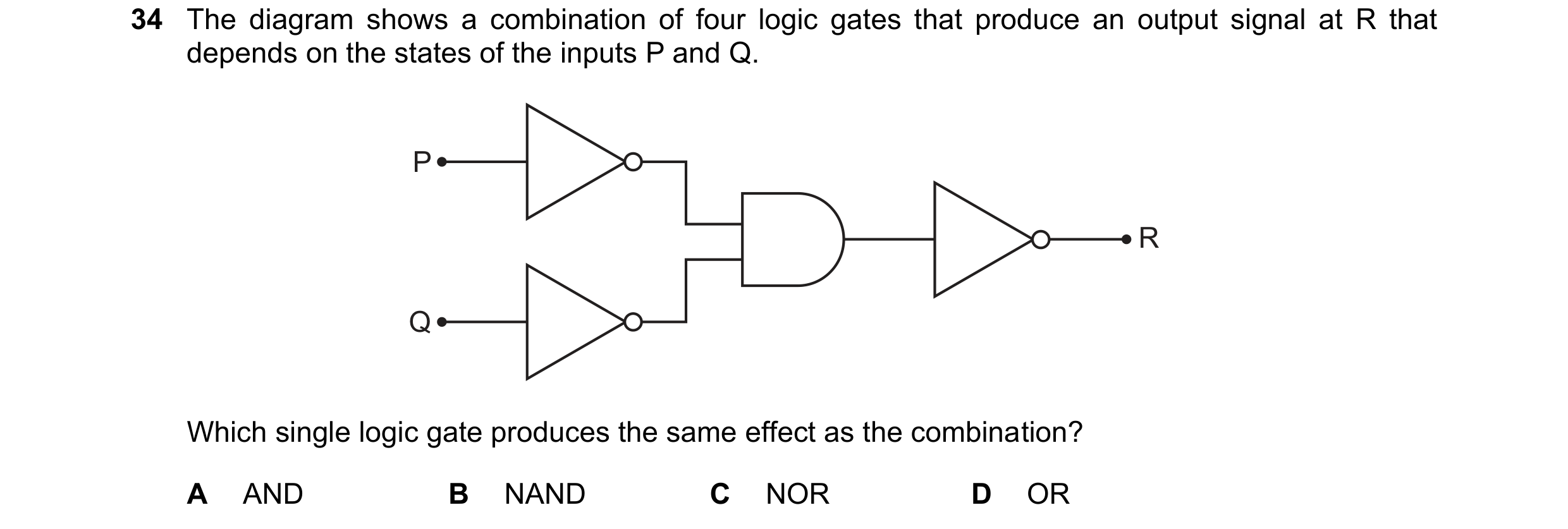 66 / 114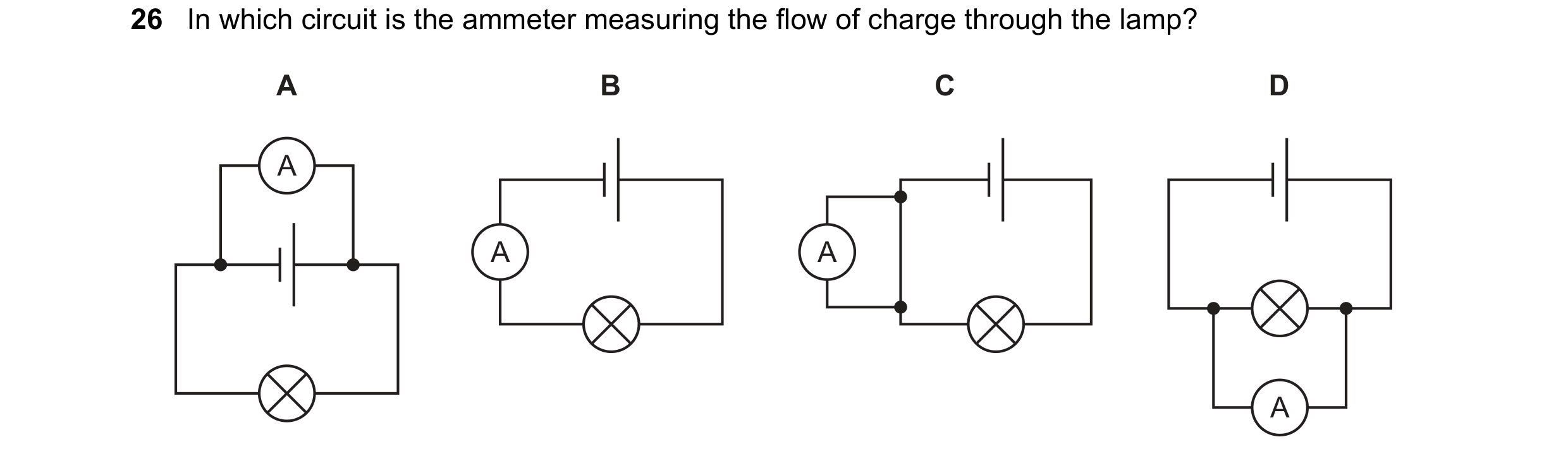
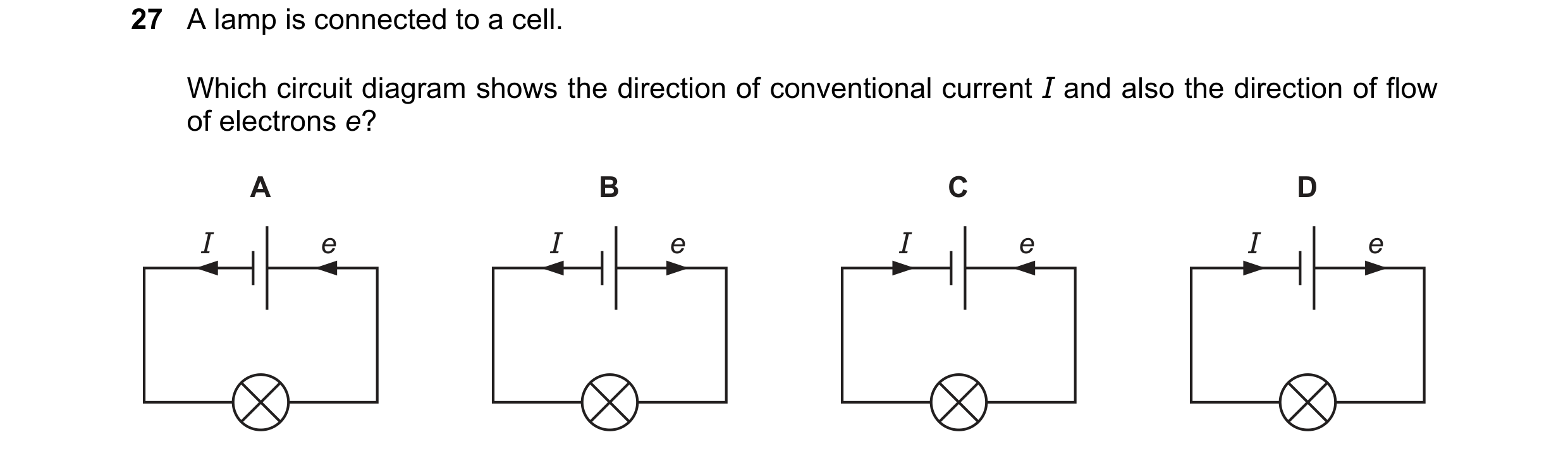
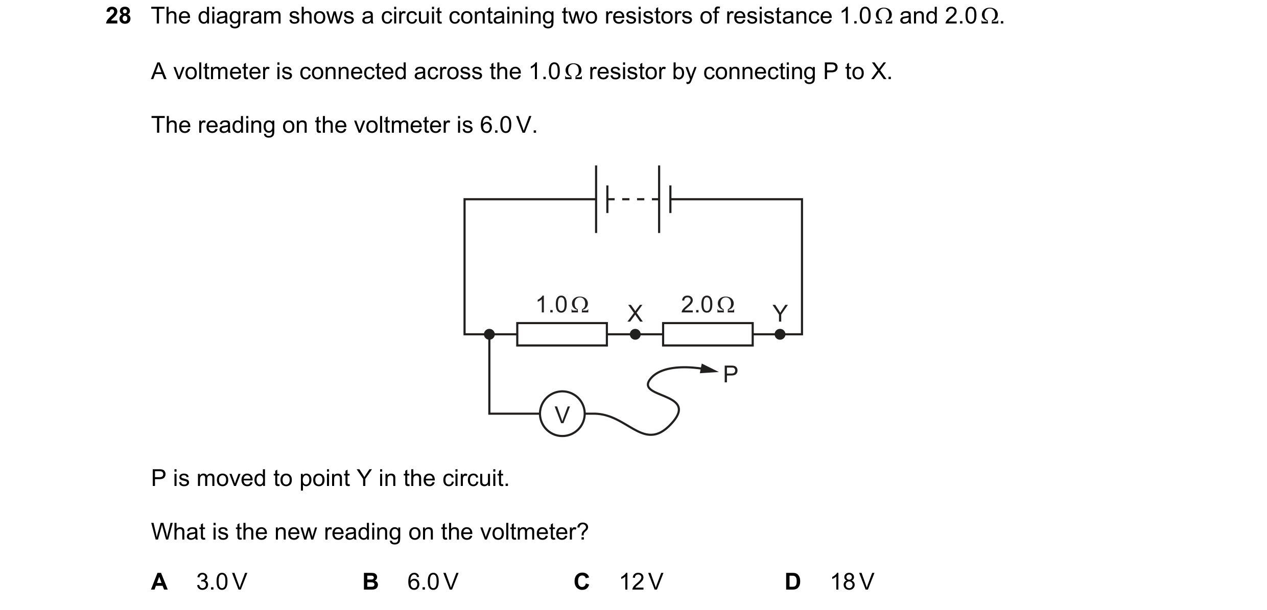 67 / 114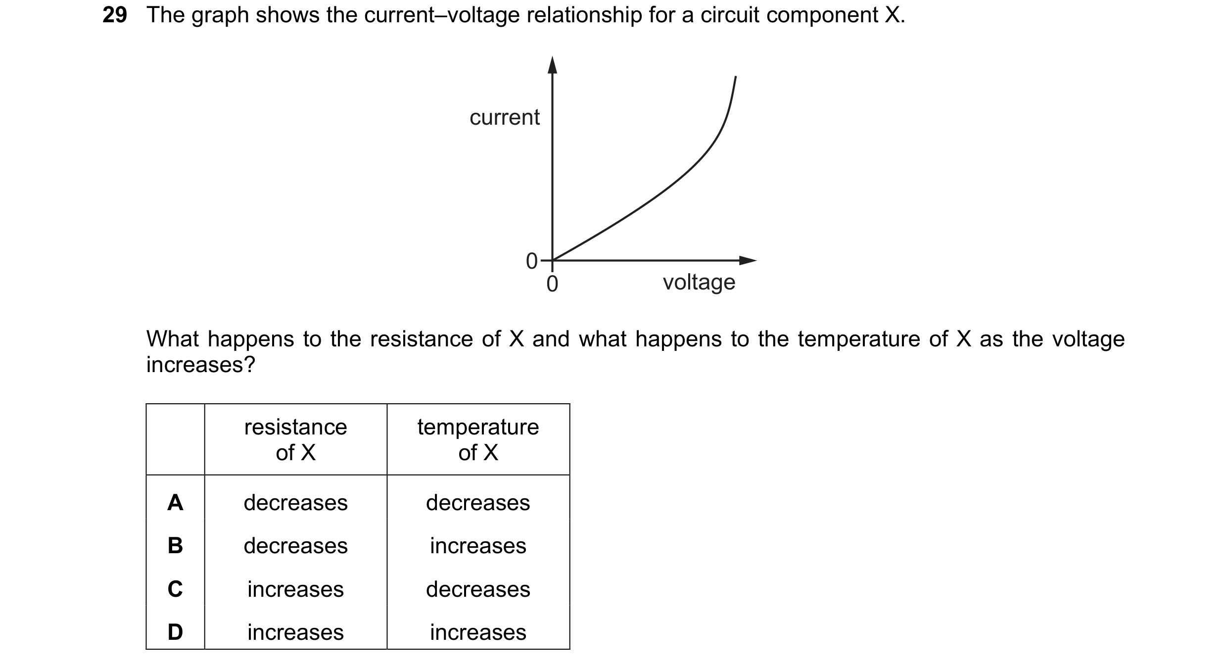
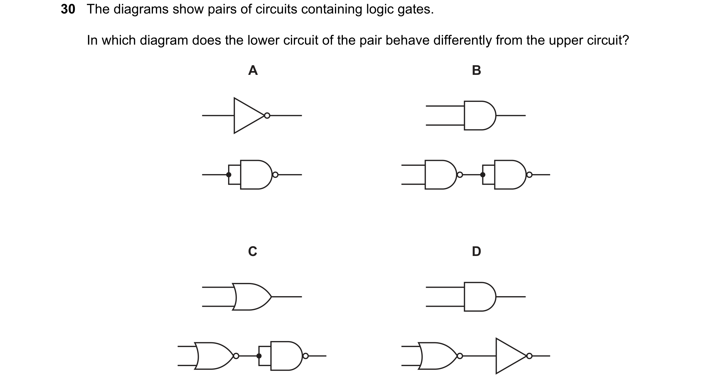 68 / 114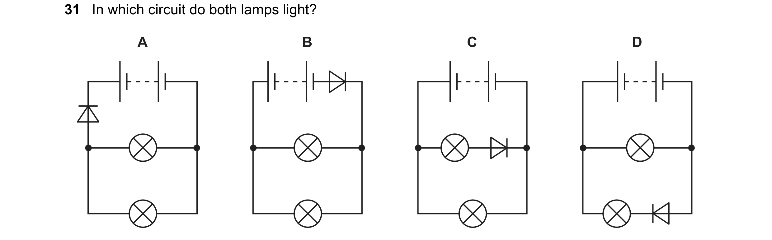
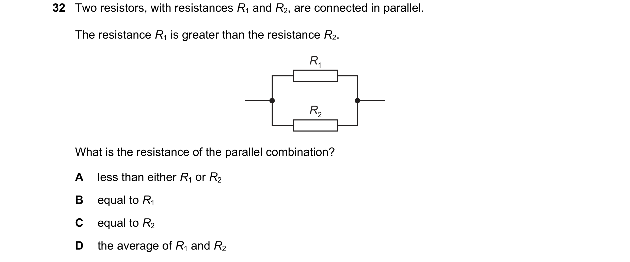
 69 / 114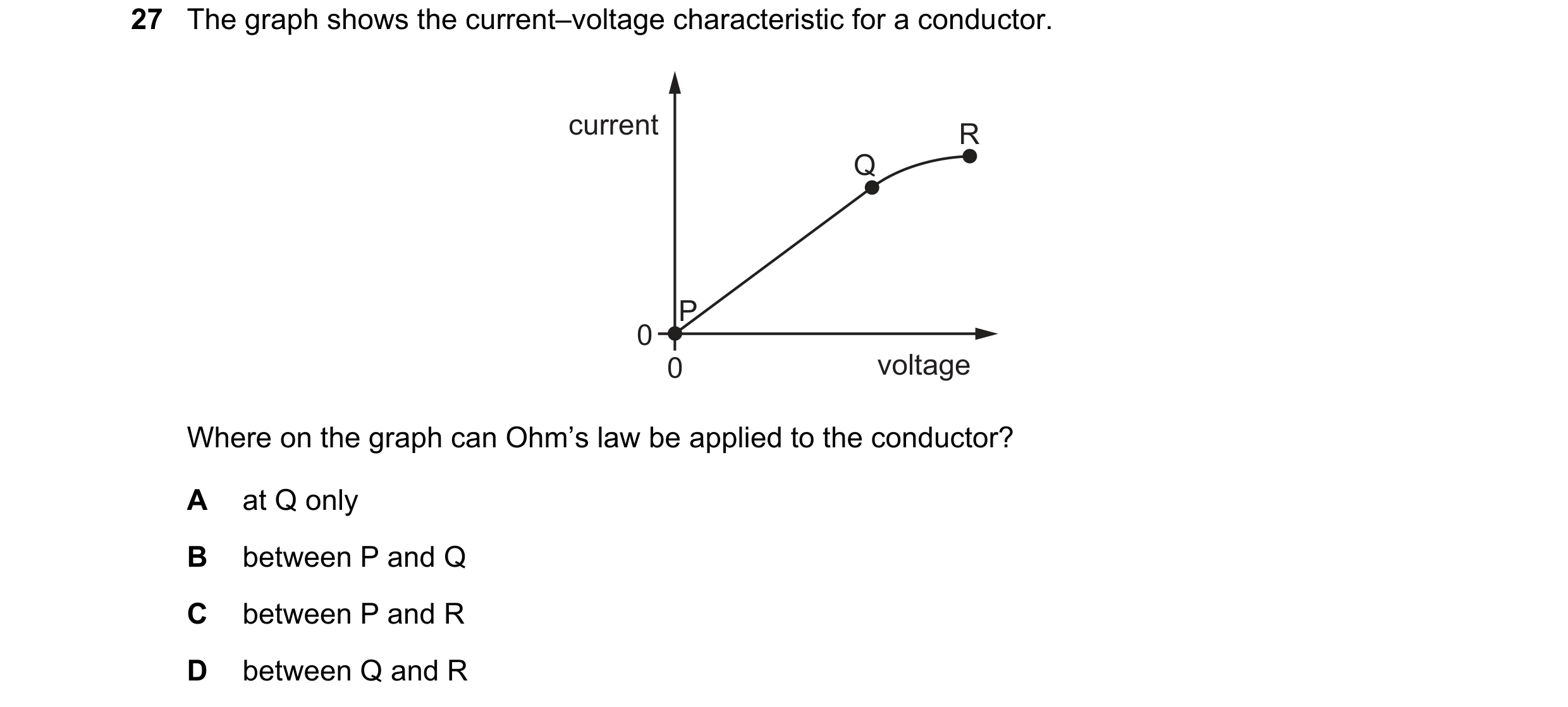
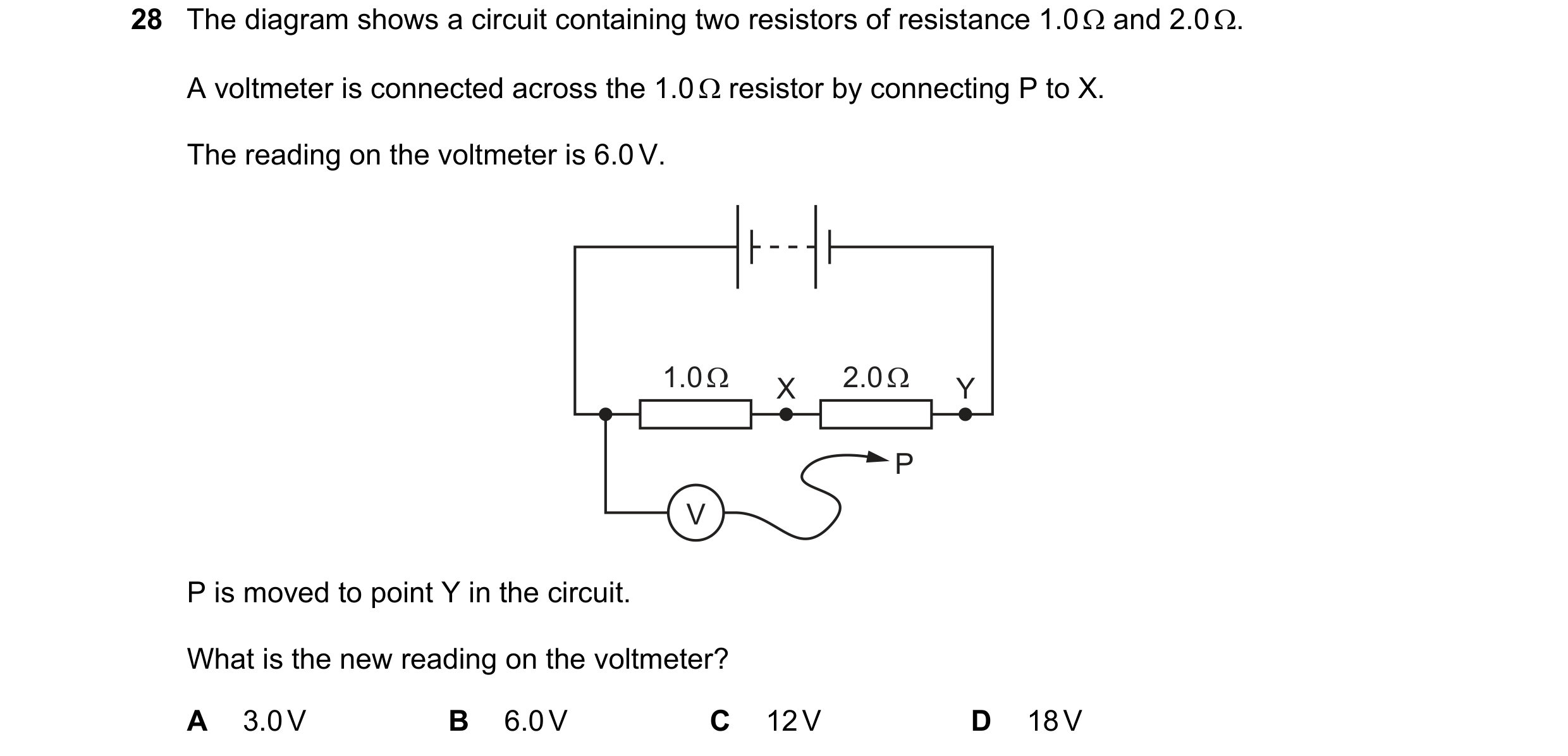
 70 / 114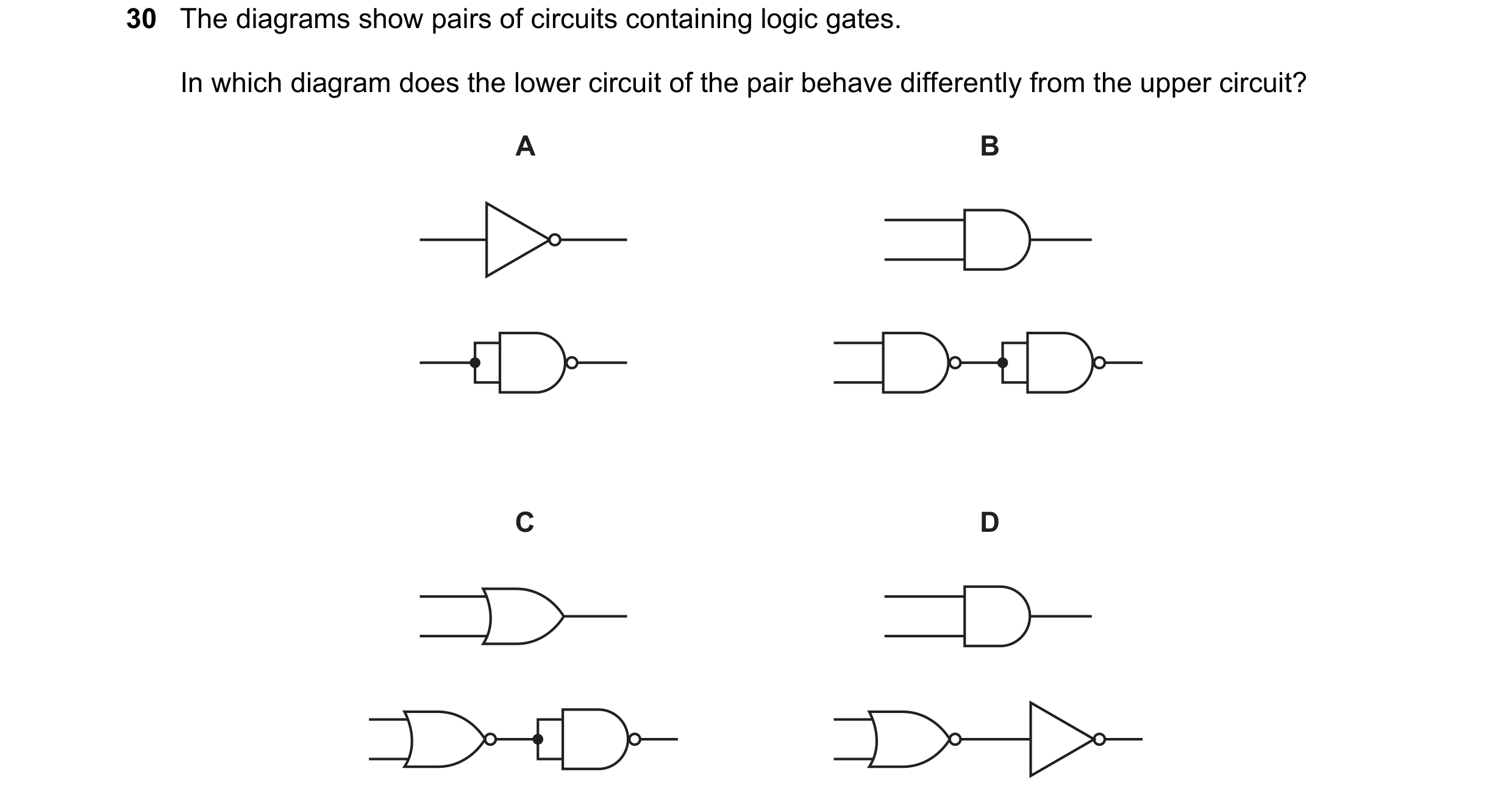
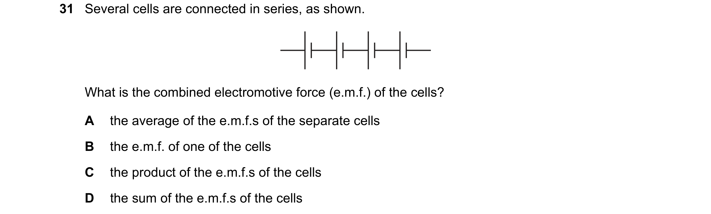
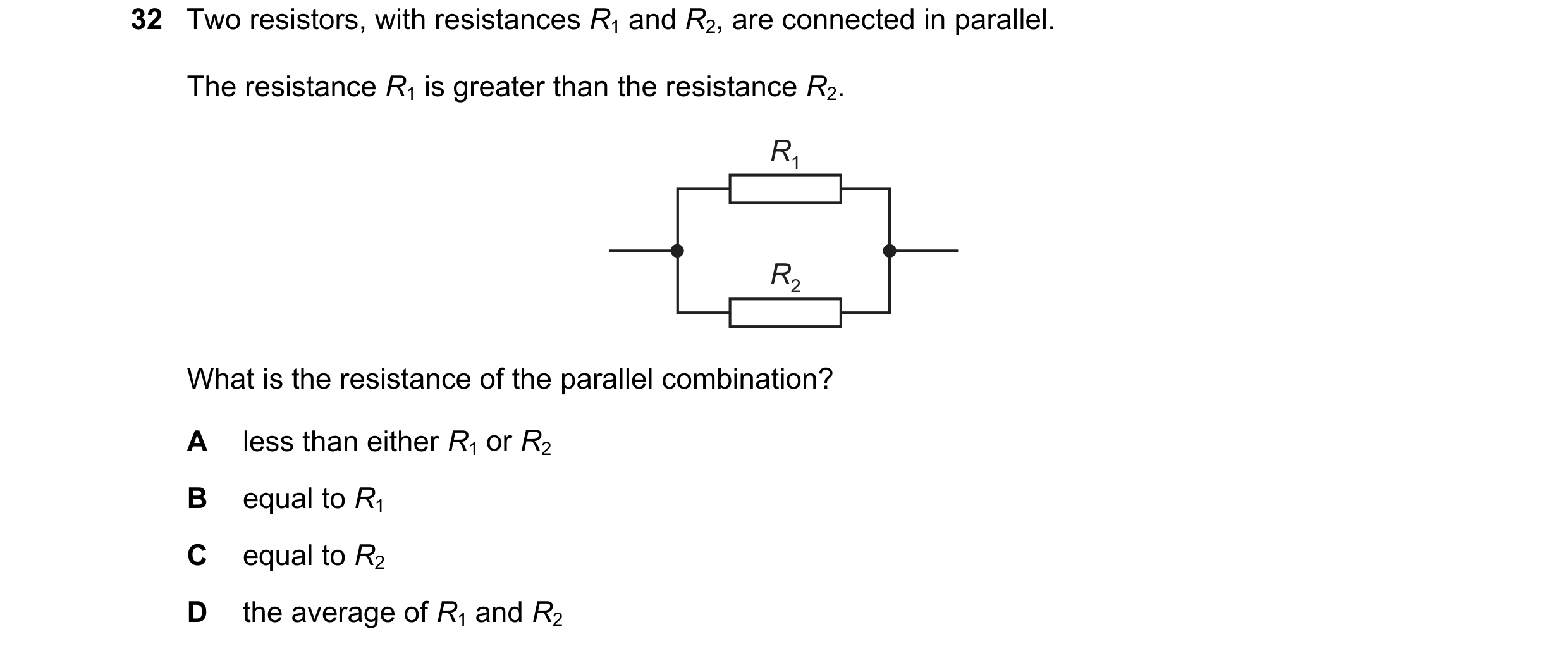 71 / 114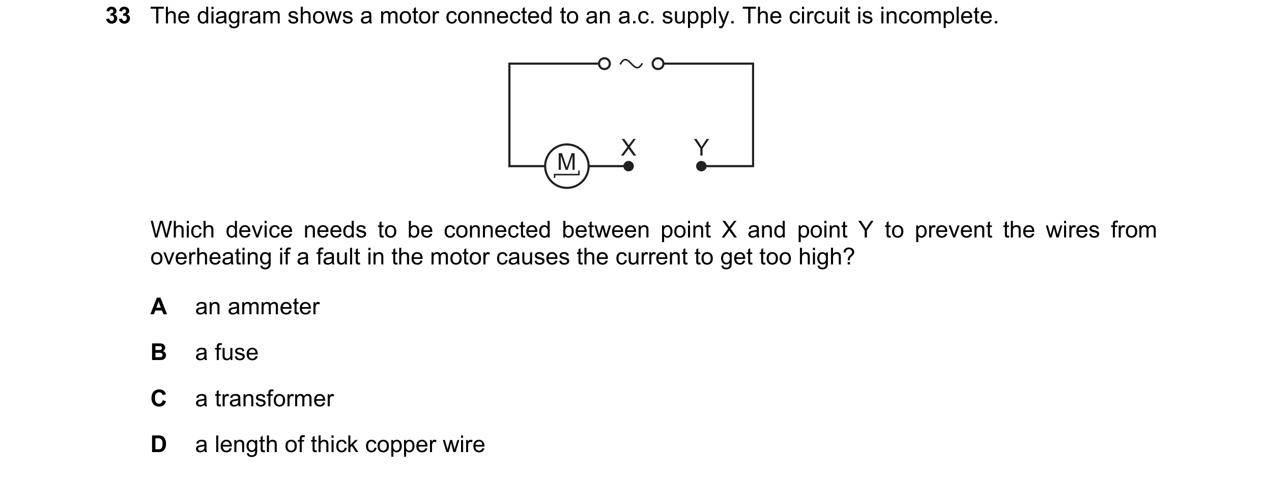
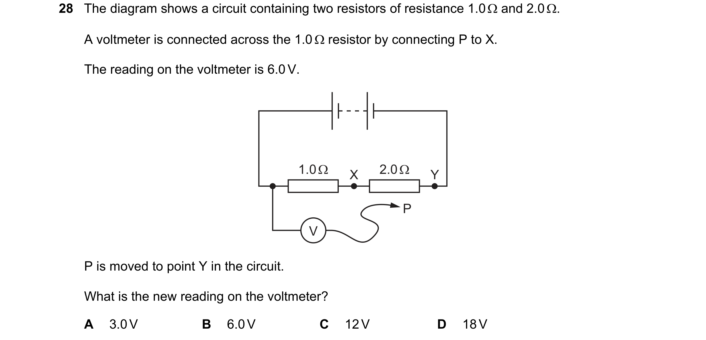
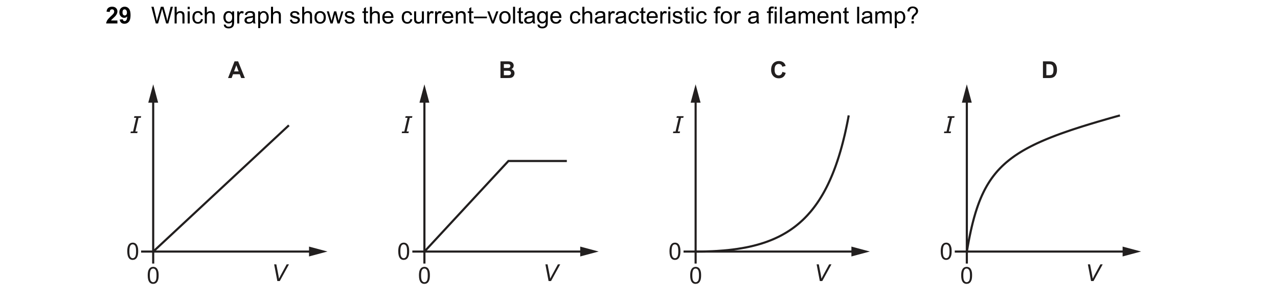 72 / 114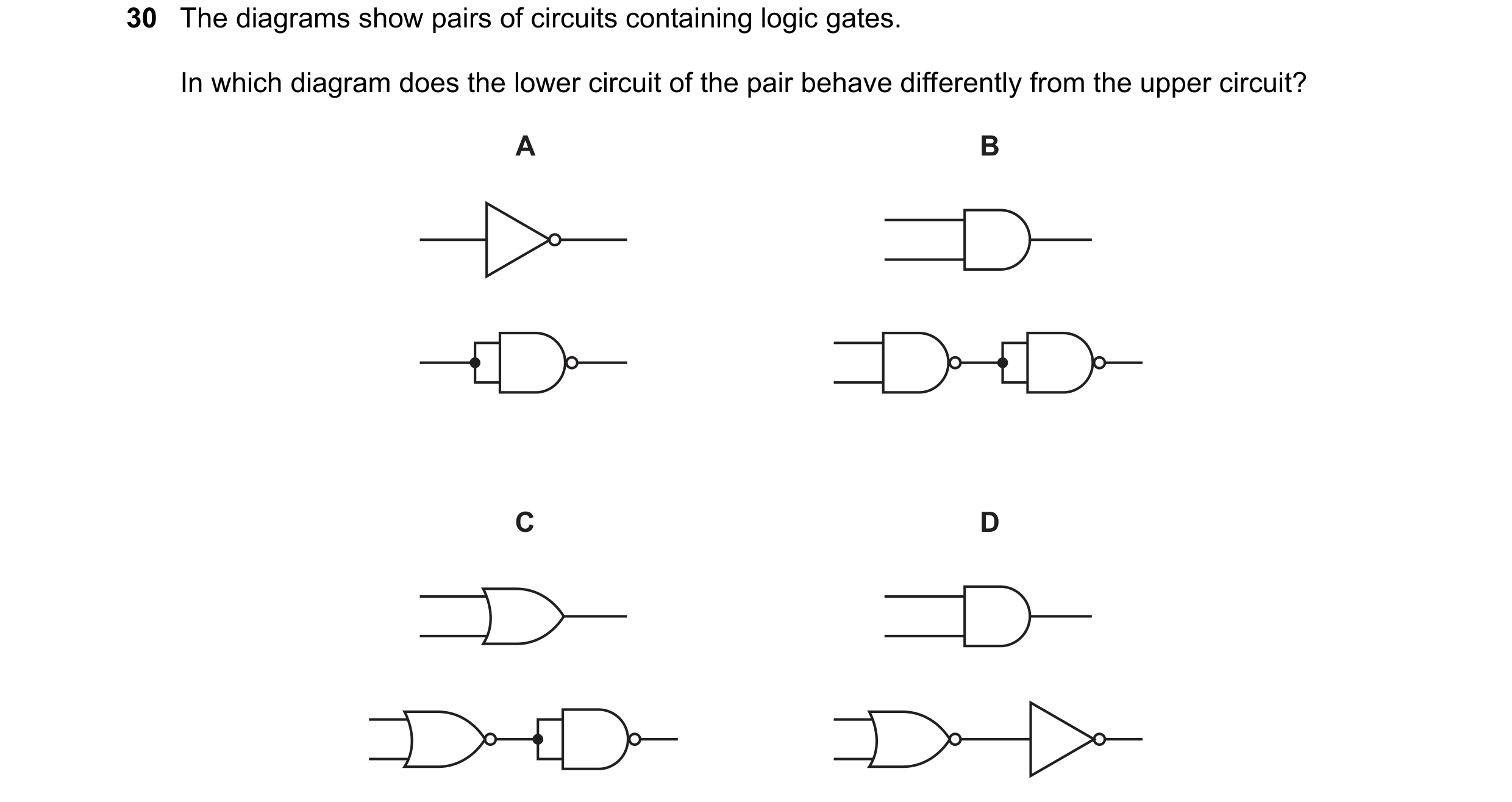
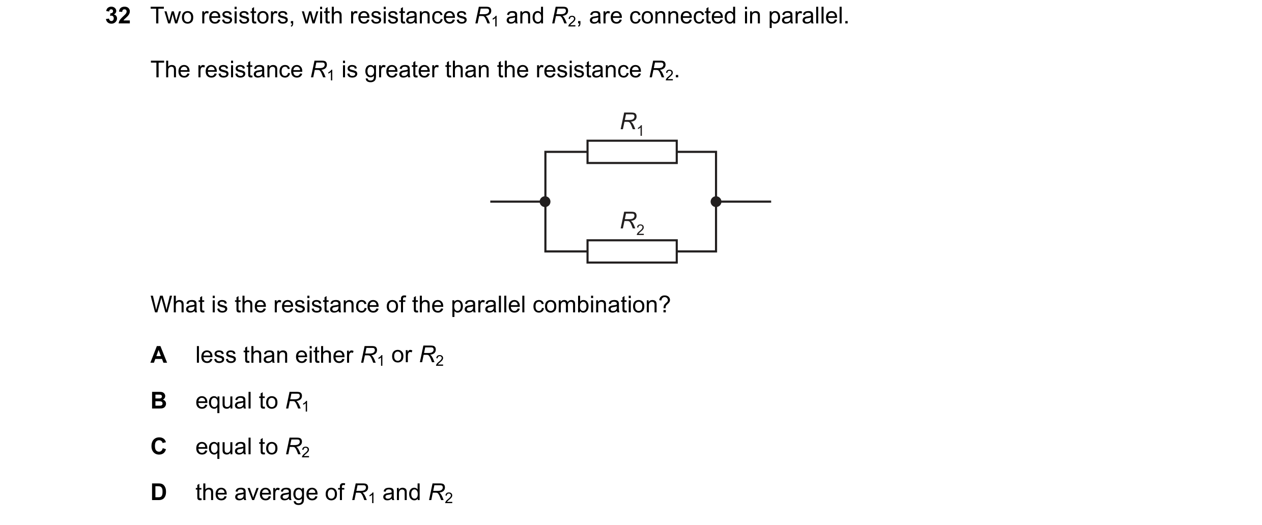 73 / 114
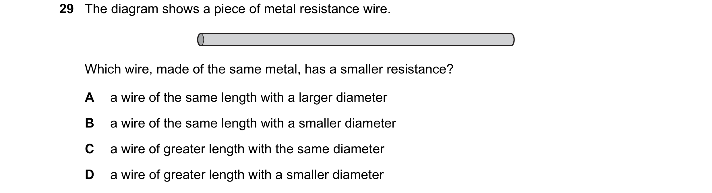 74 / 114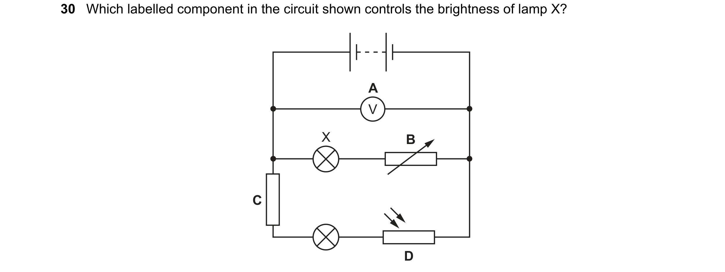
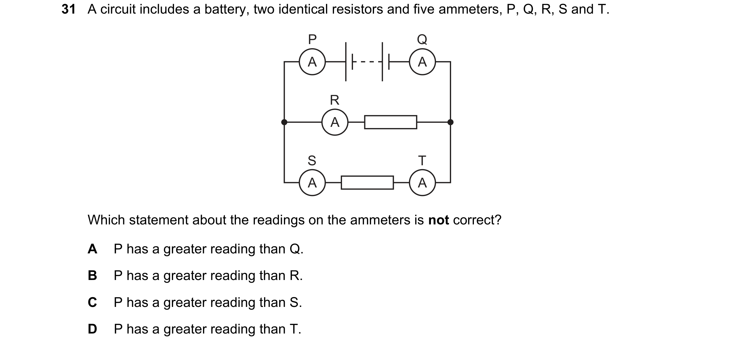
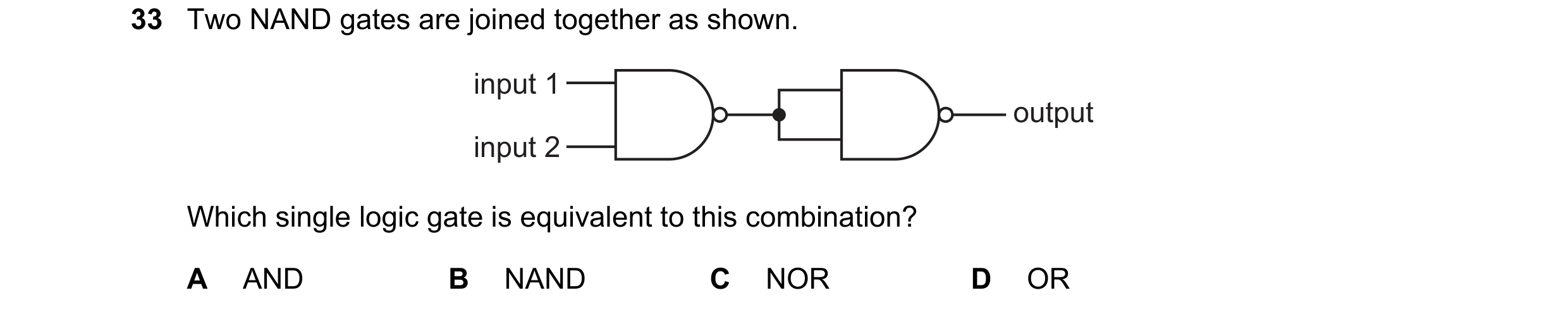 75 / 114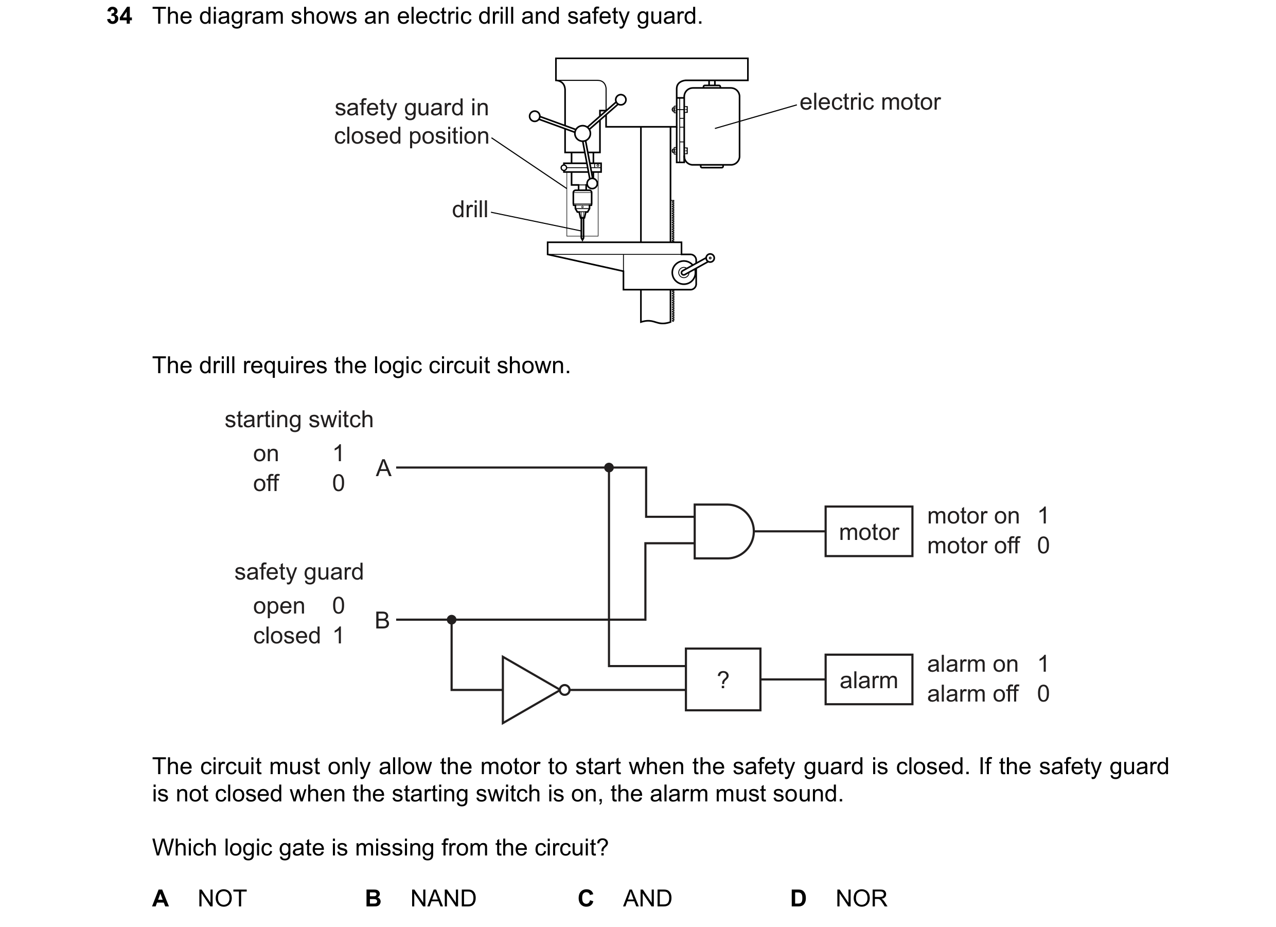
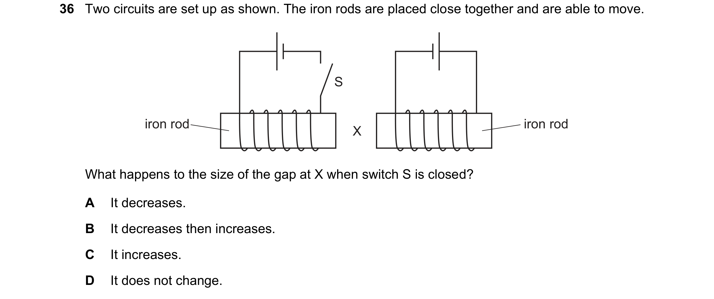 76 / 114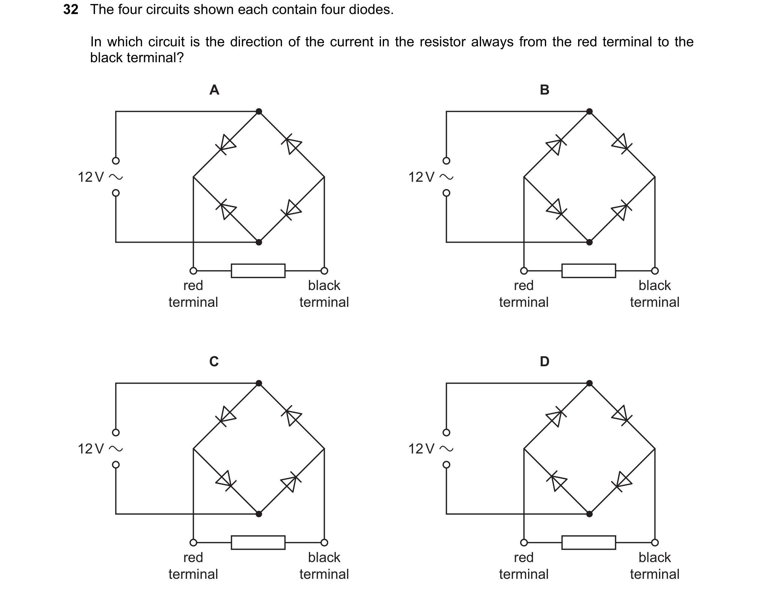
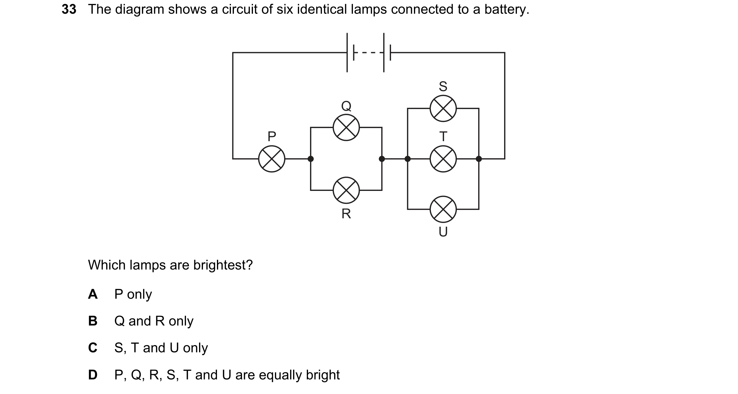 77 / 114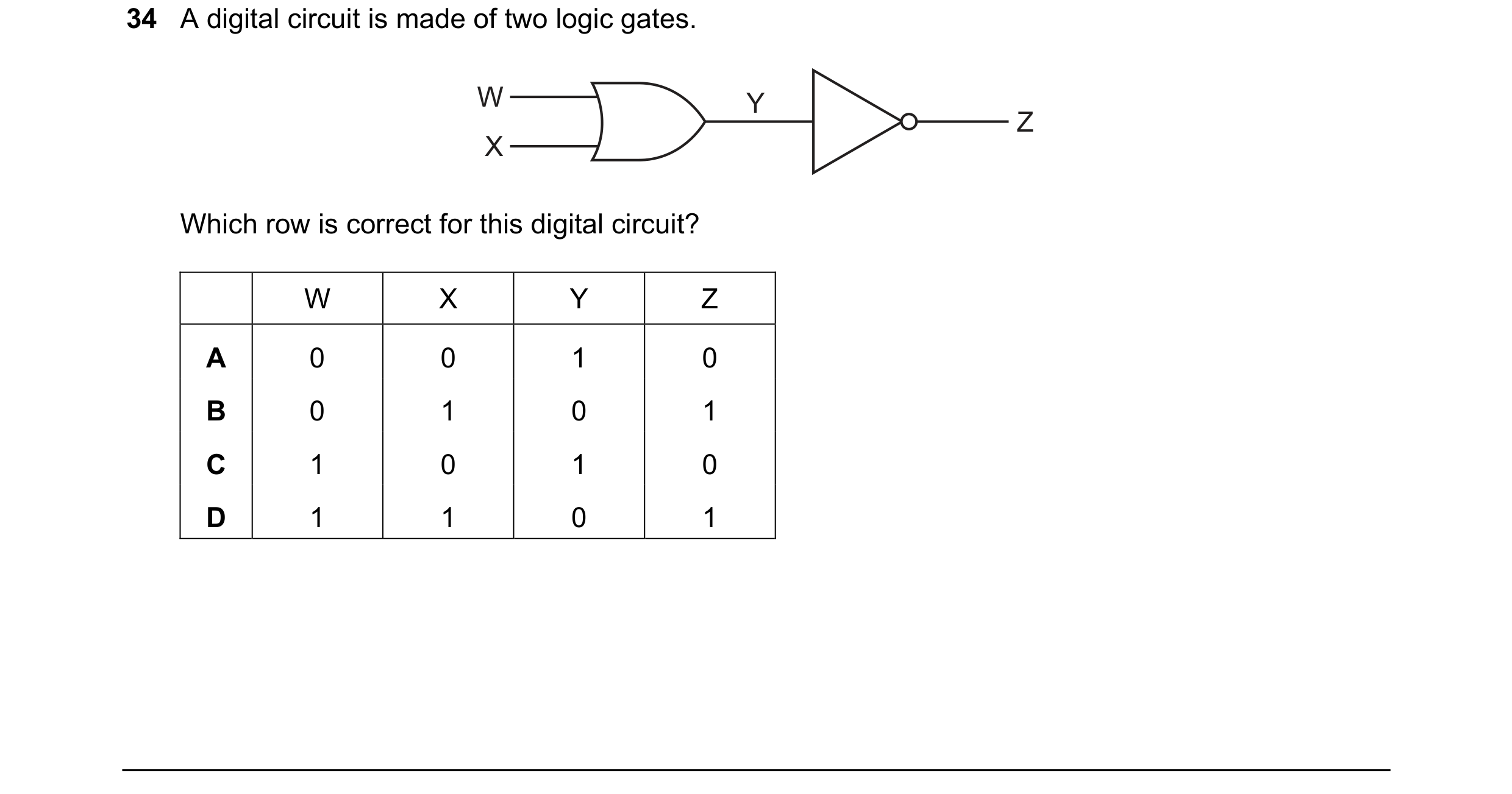
 78 / 114
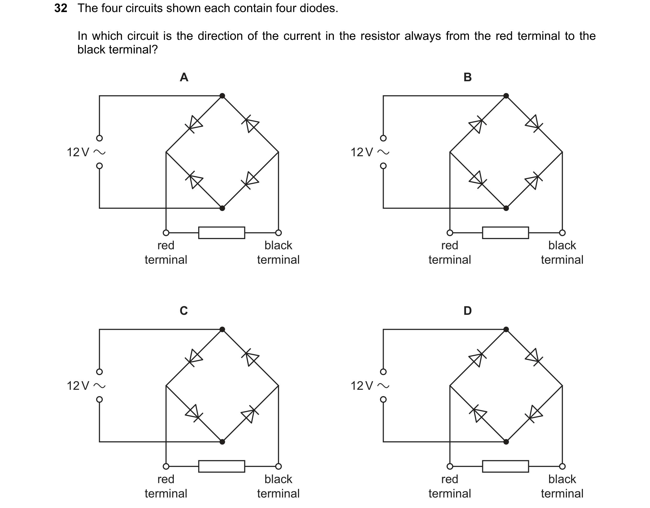 79 / 114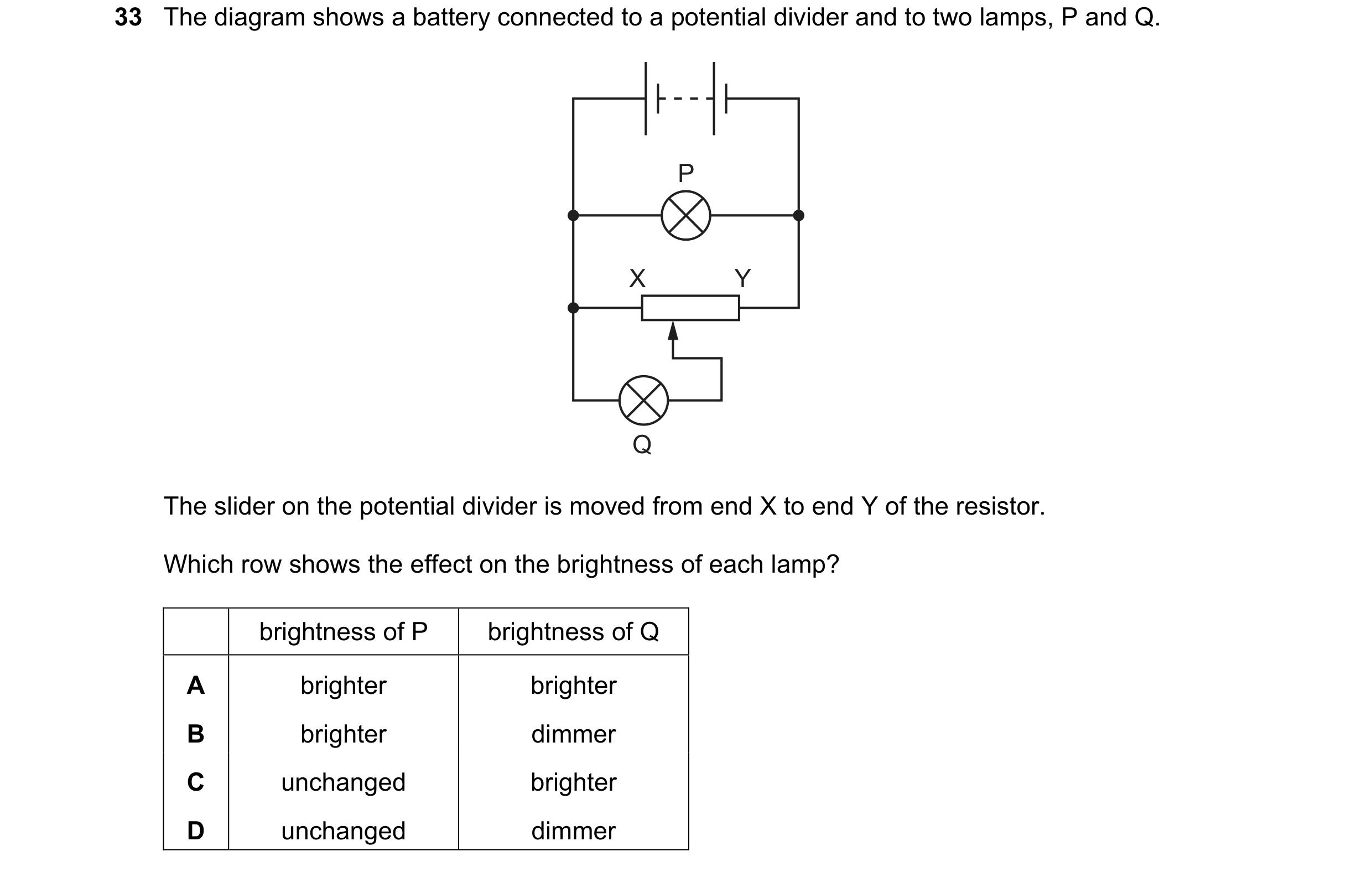
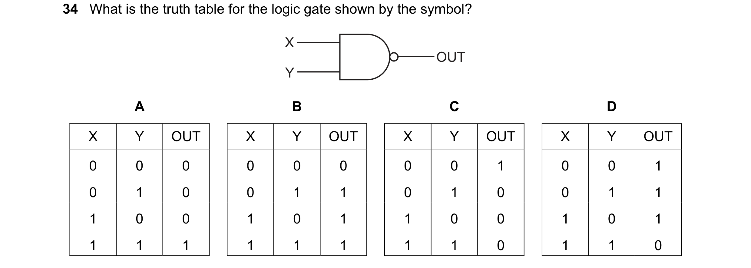
 80 / 114
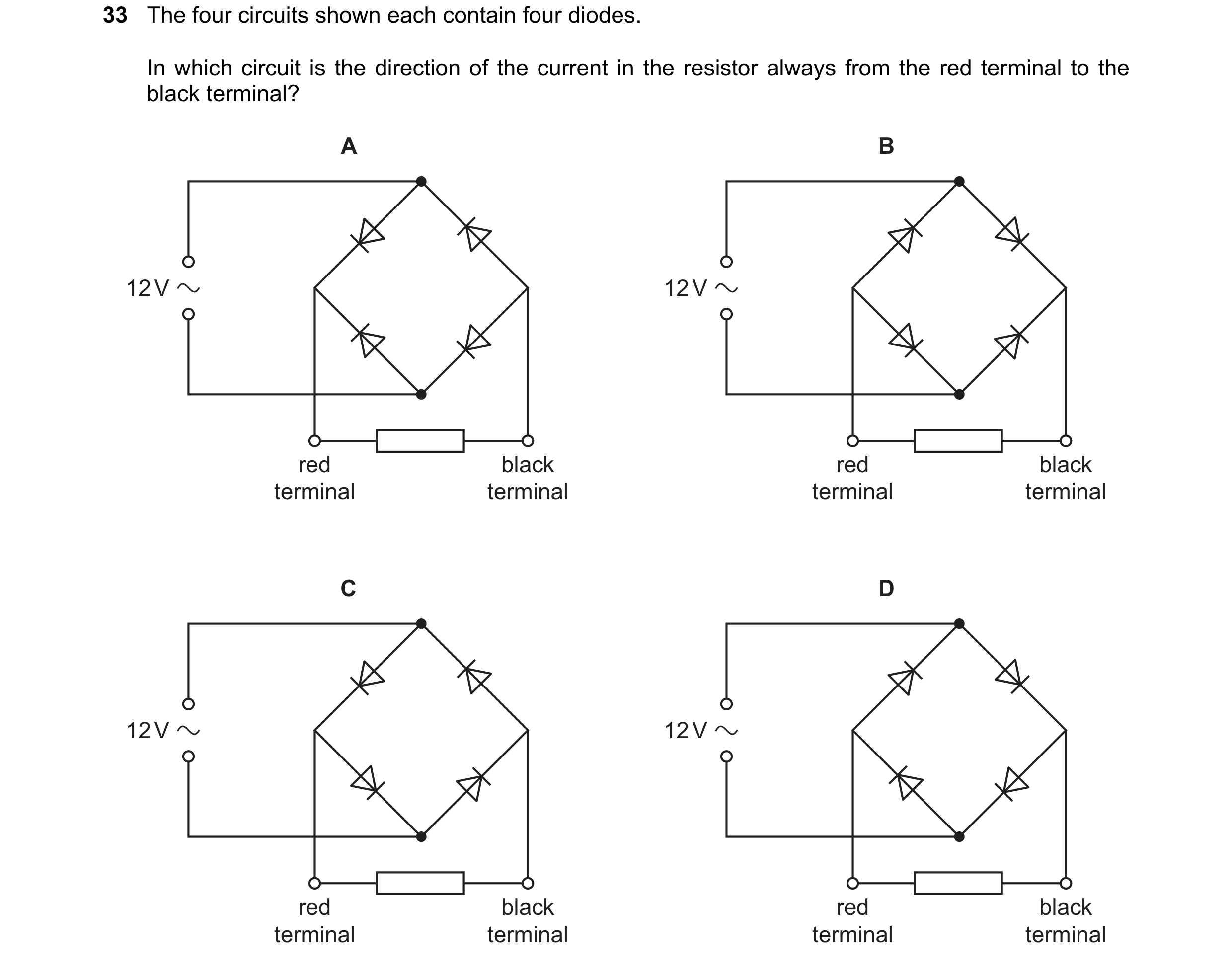
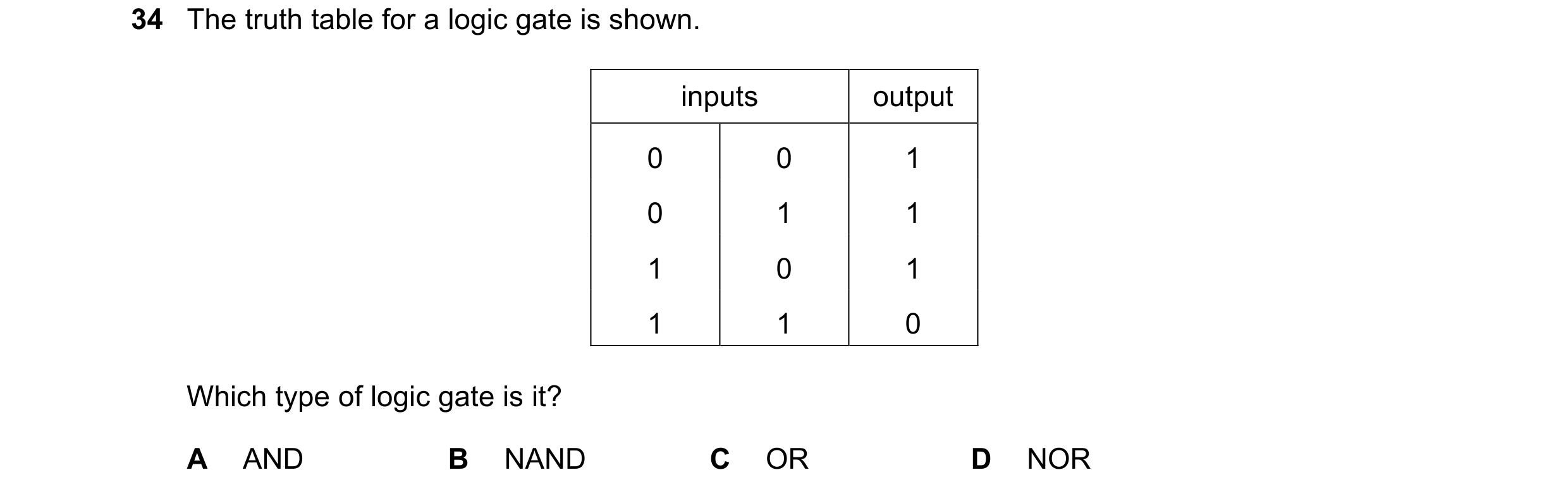 81 / 114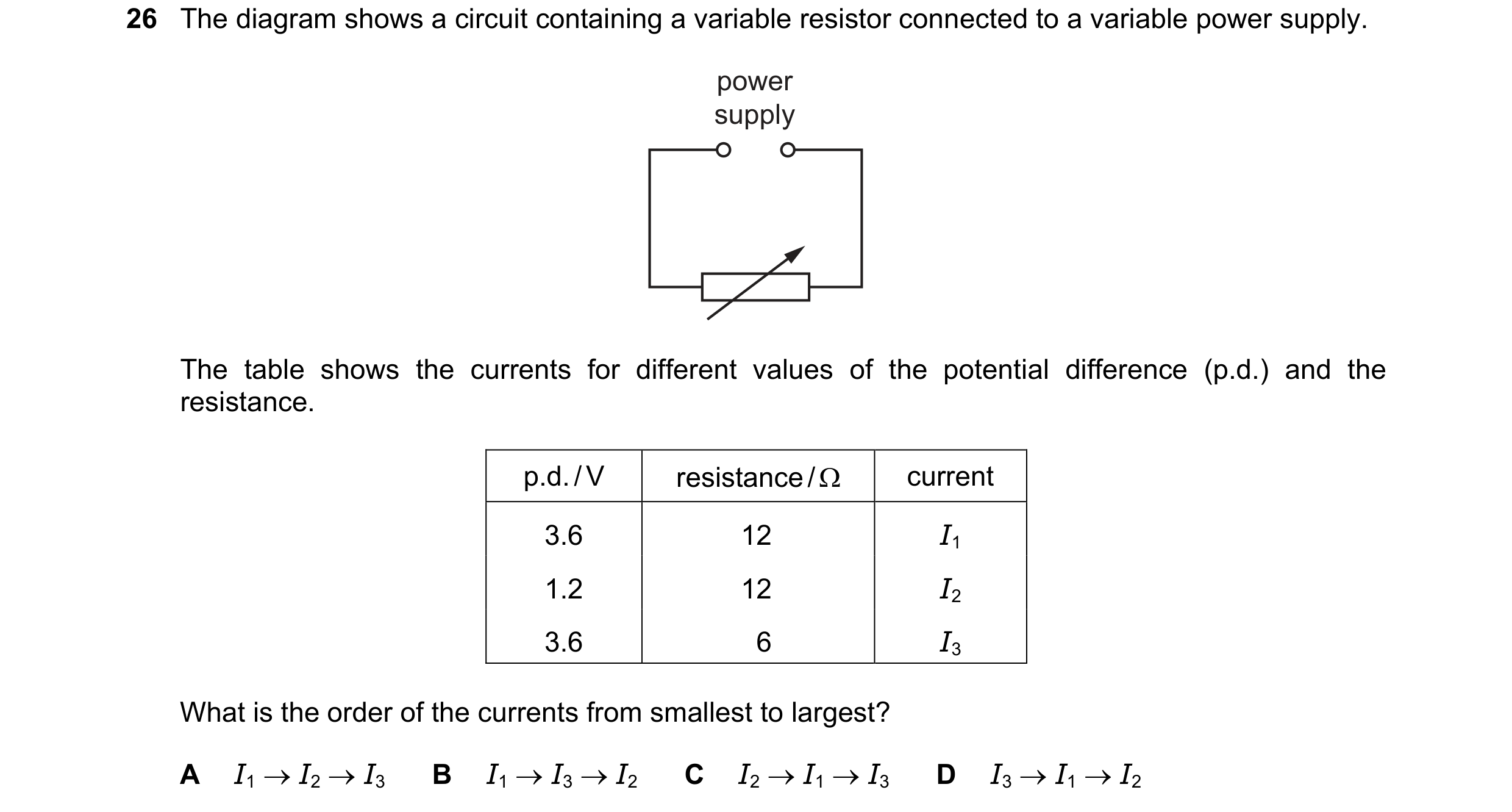
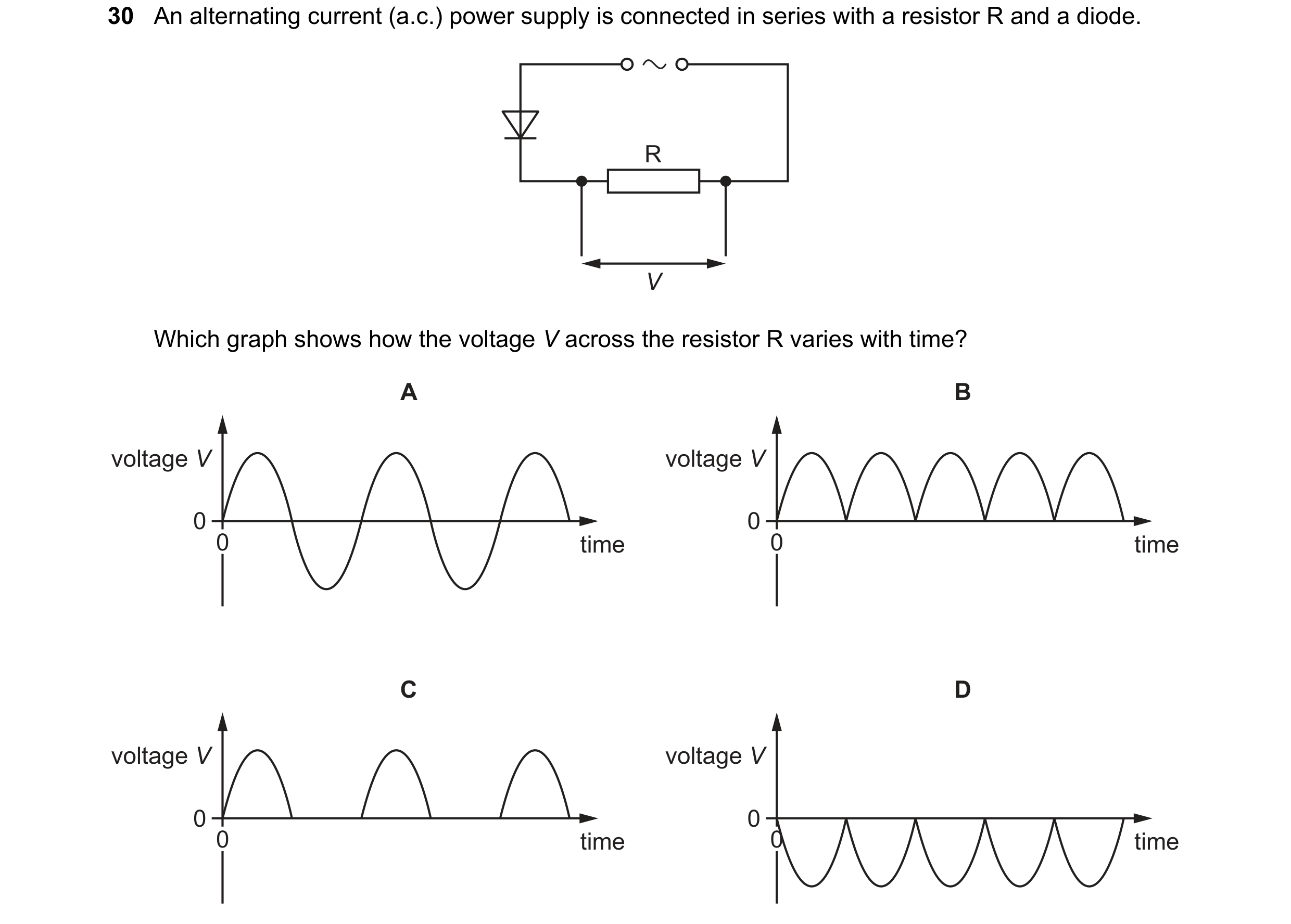 82 / 114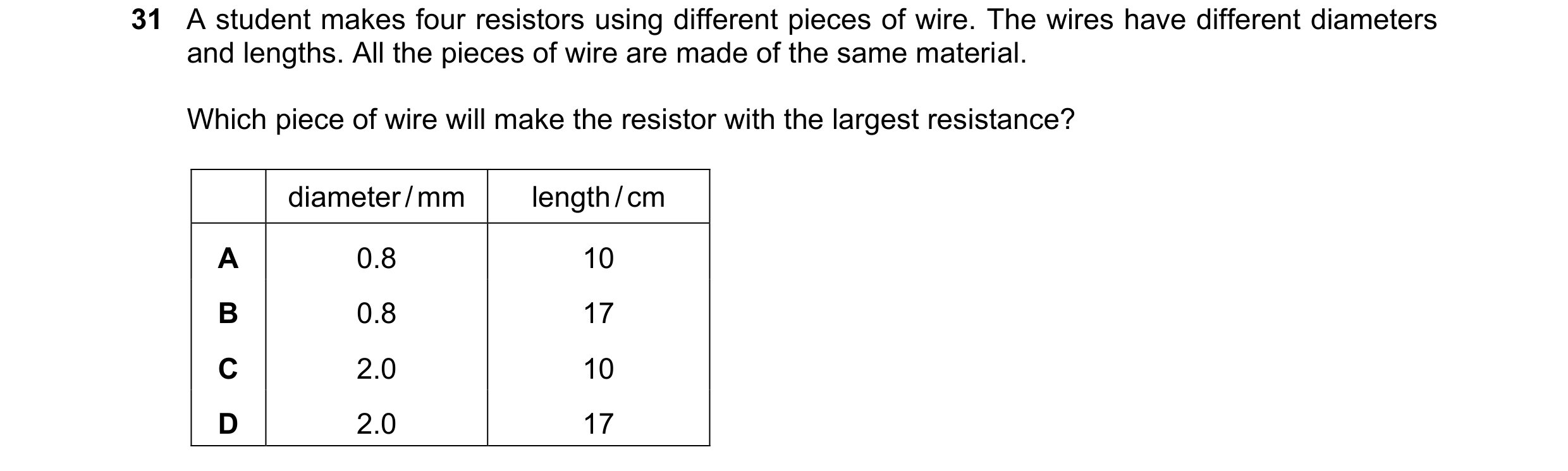
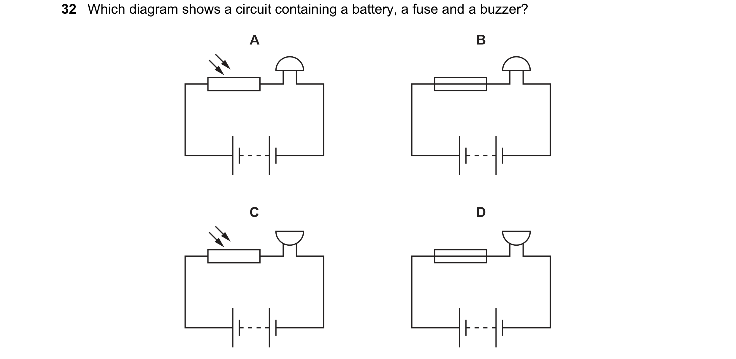
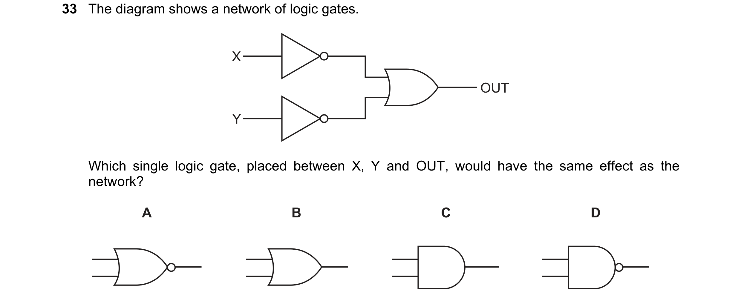 83 / 114
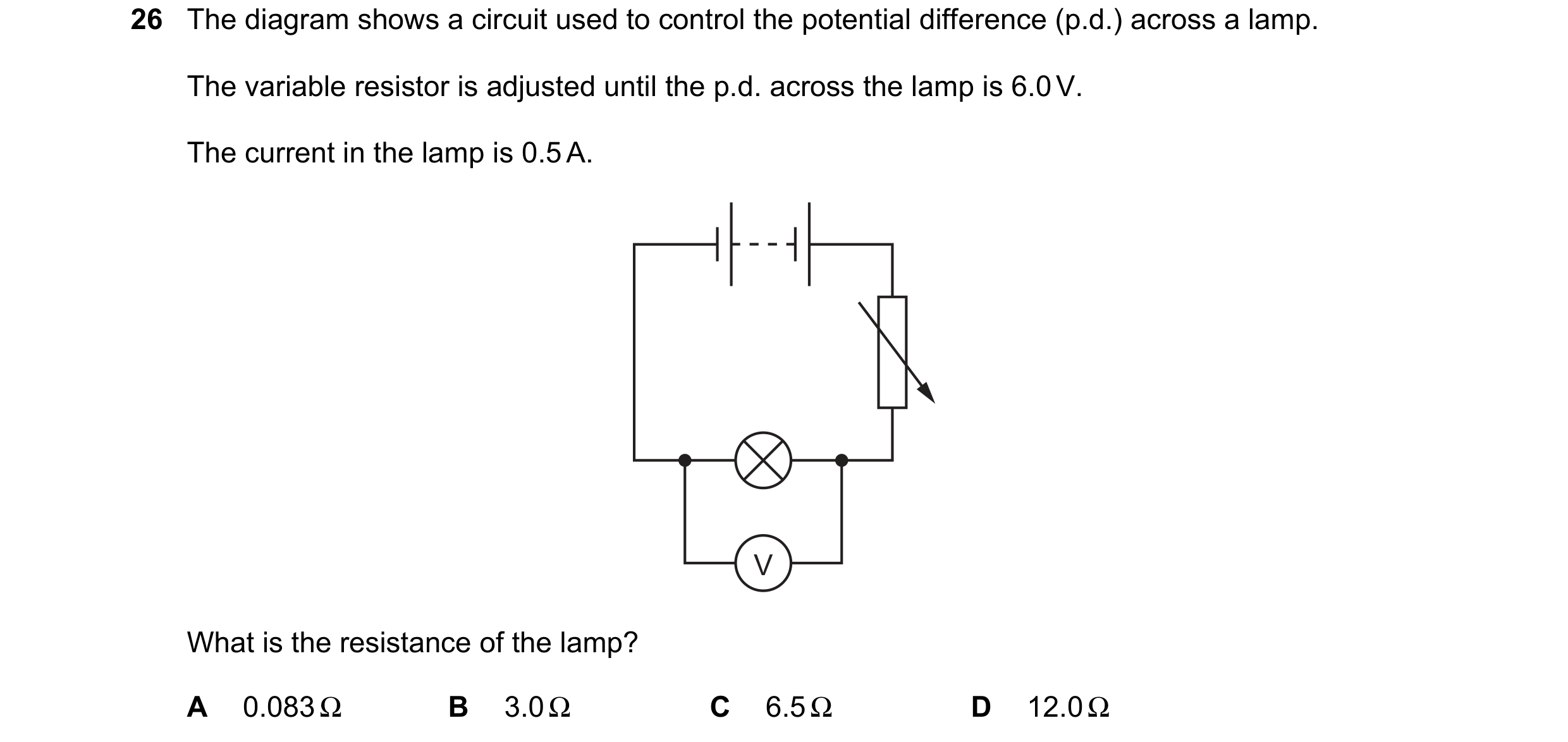
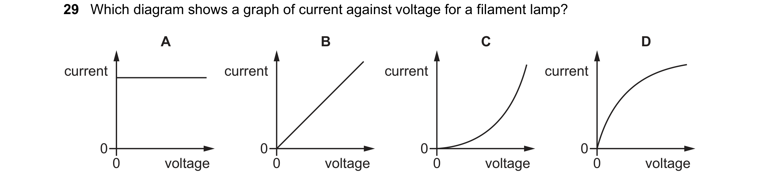
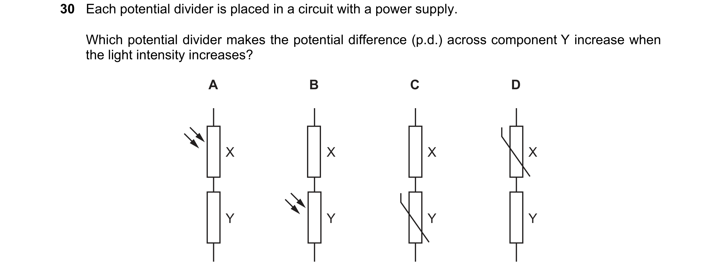 84 / 114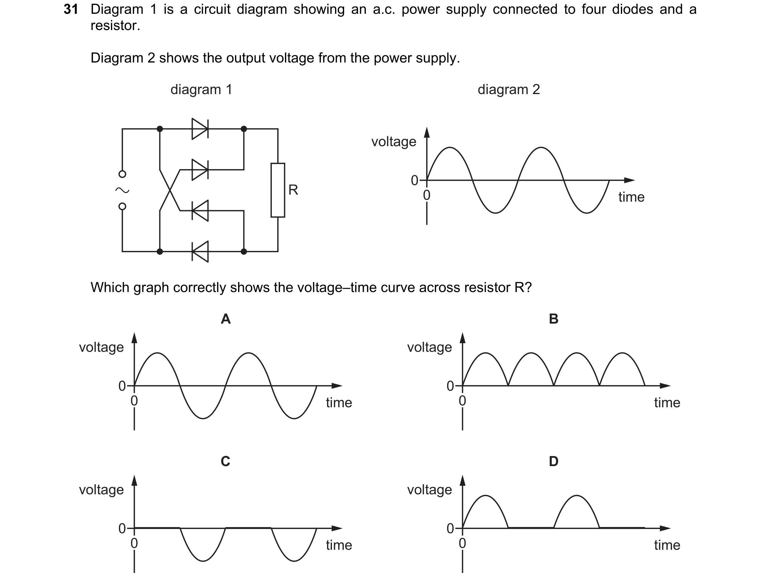
 85 / 114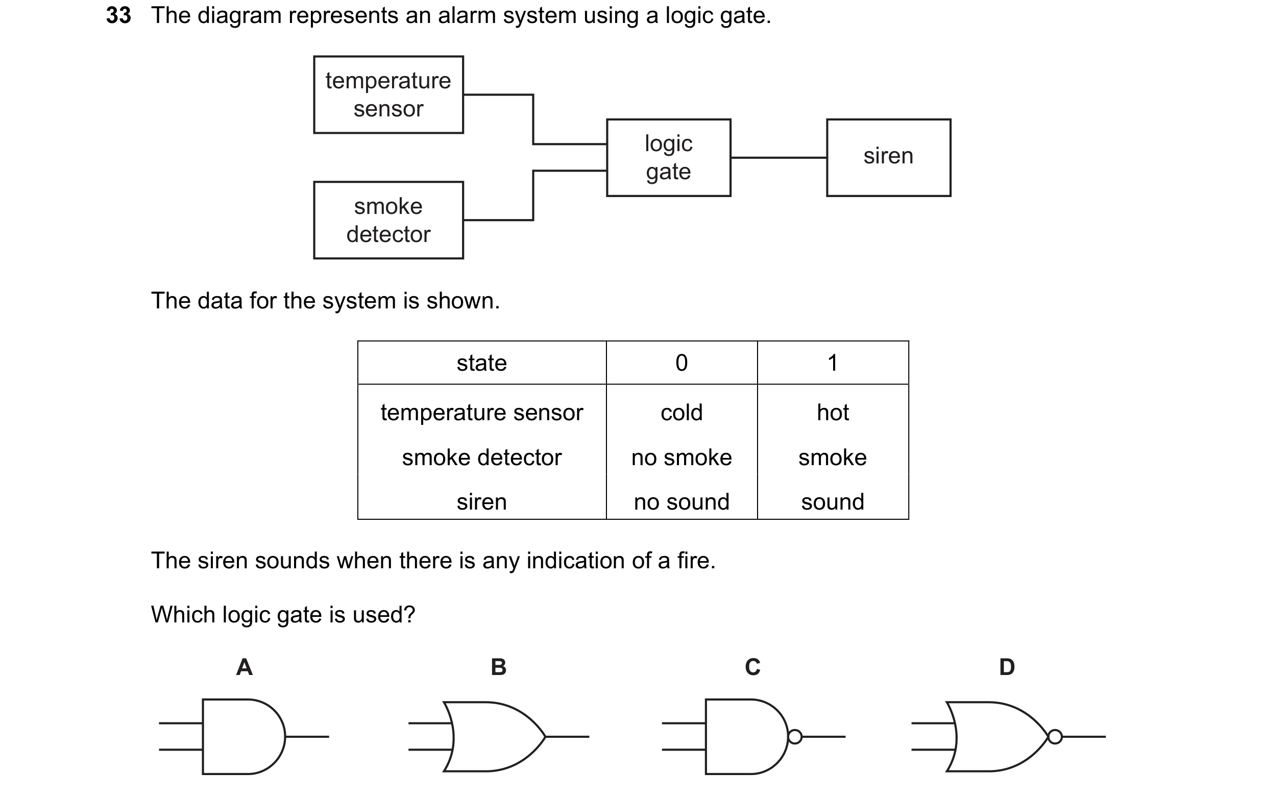
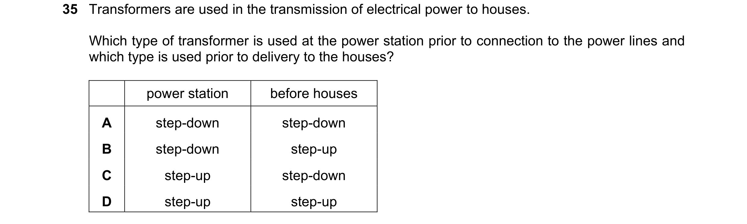 86 / 114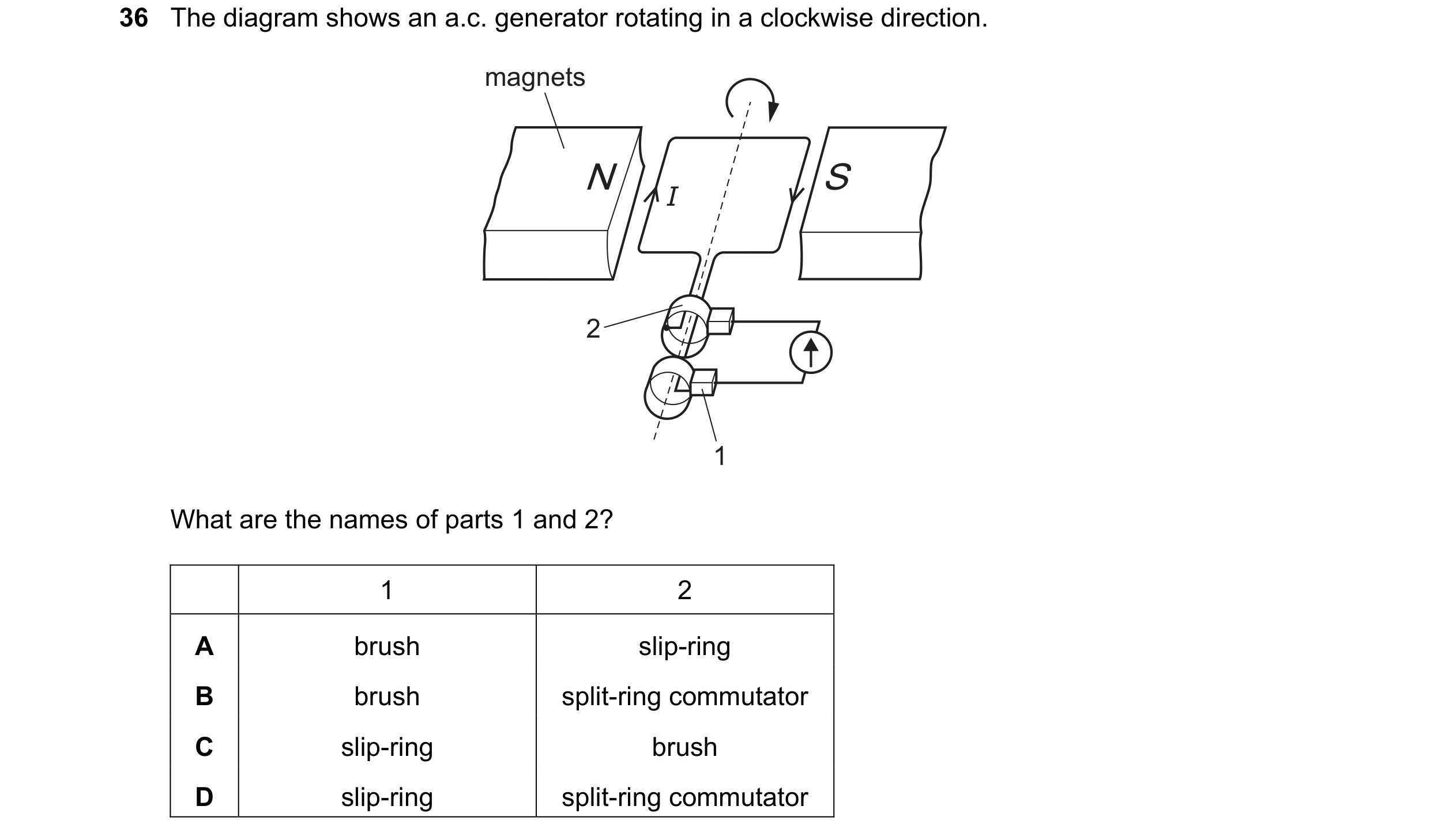
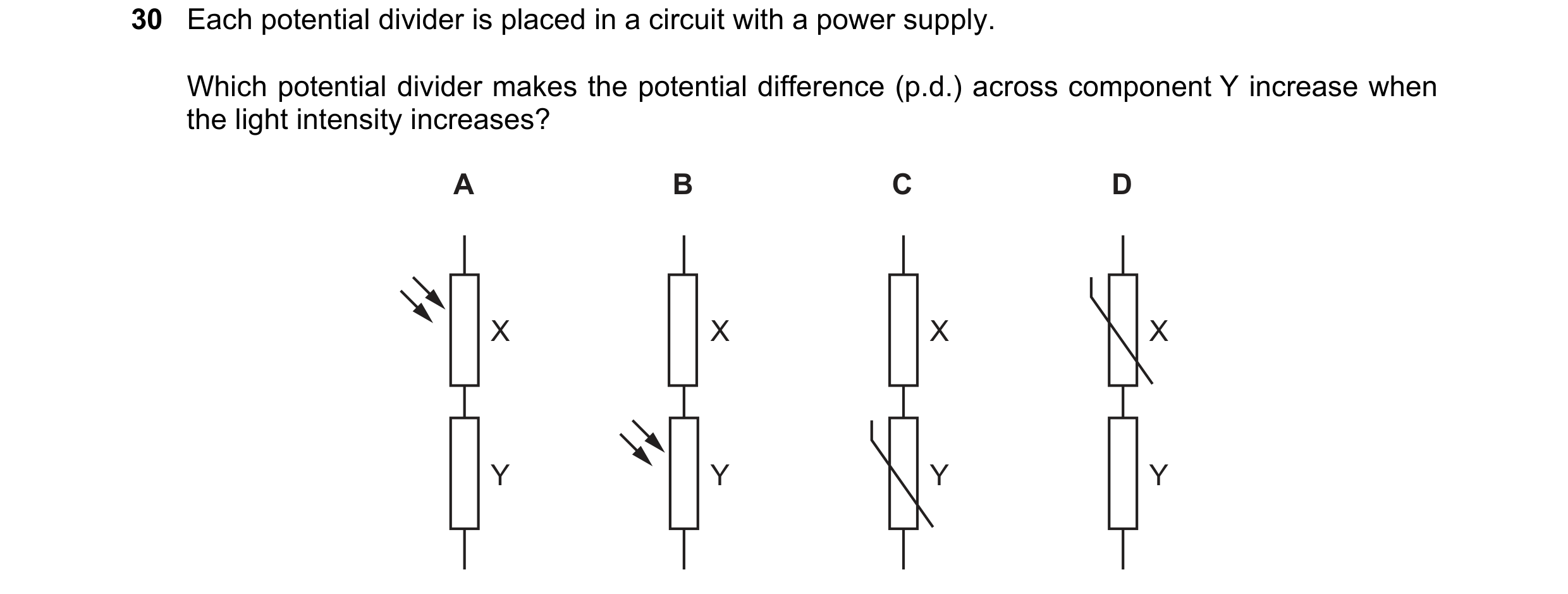 87 / 114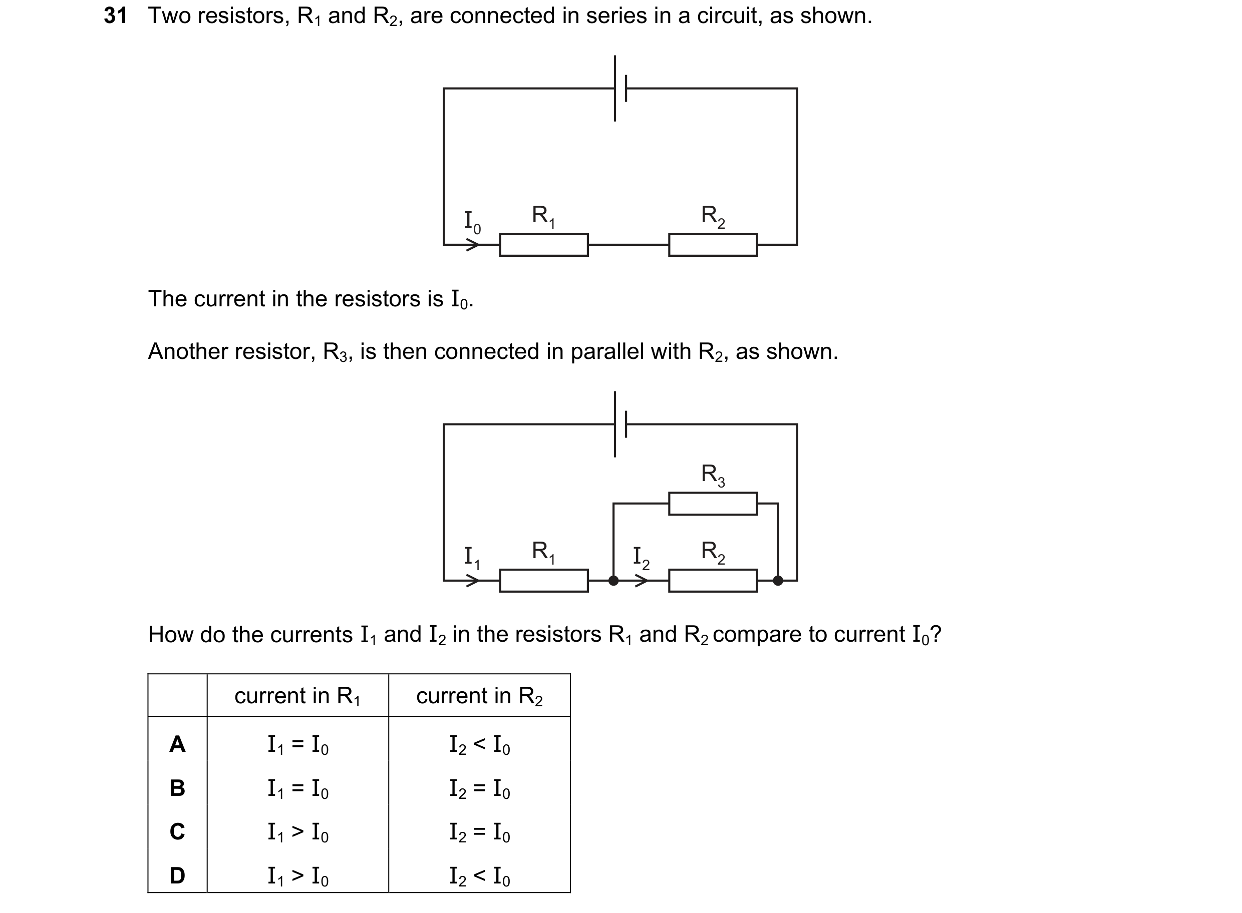
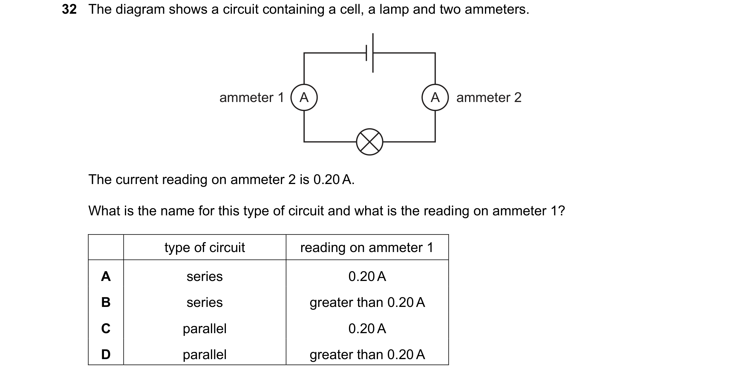 88 / 114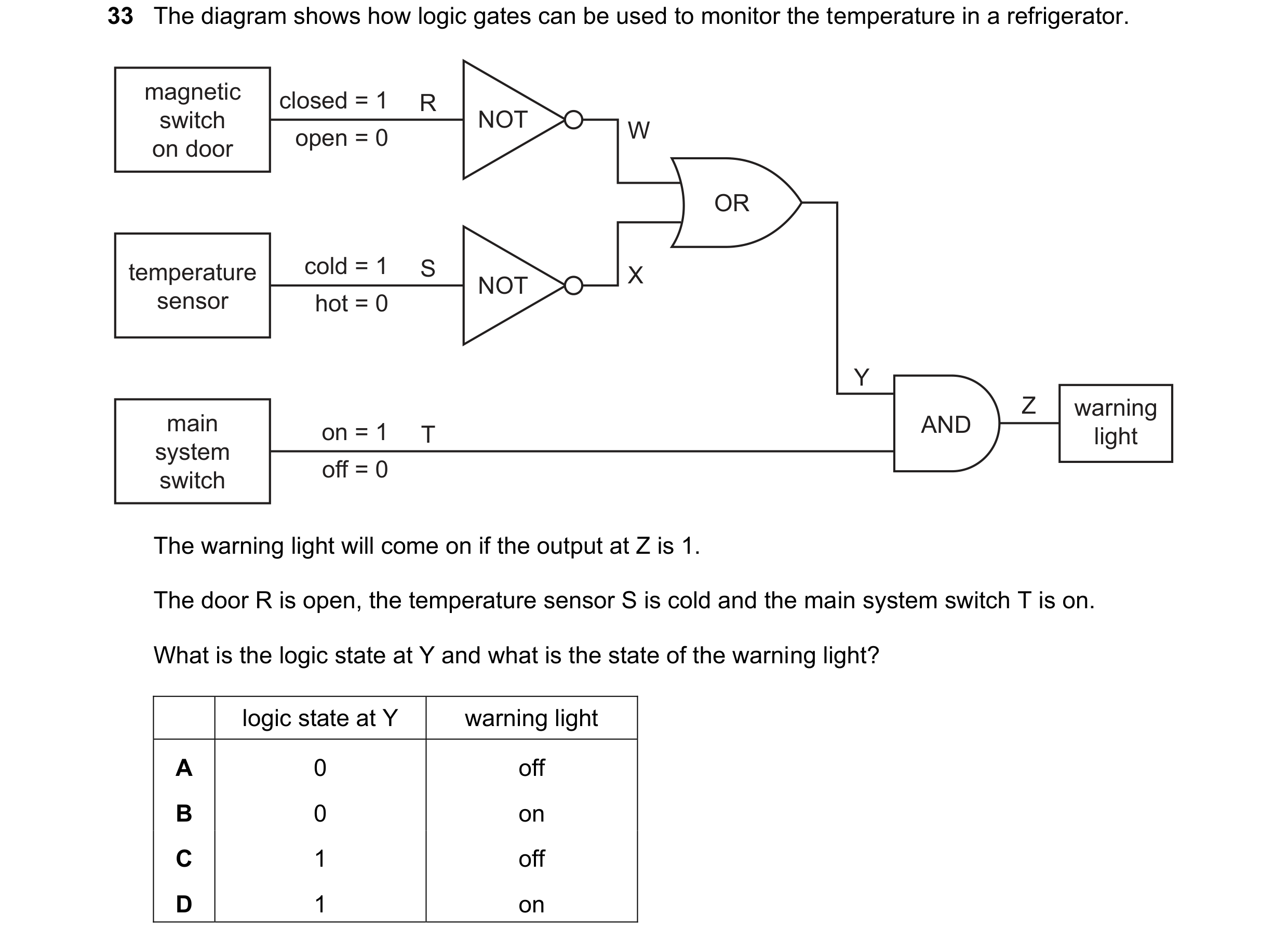
 89 / 114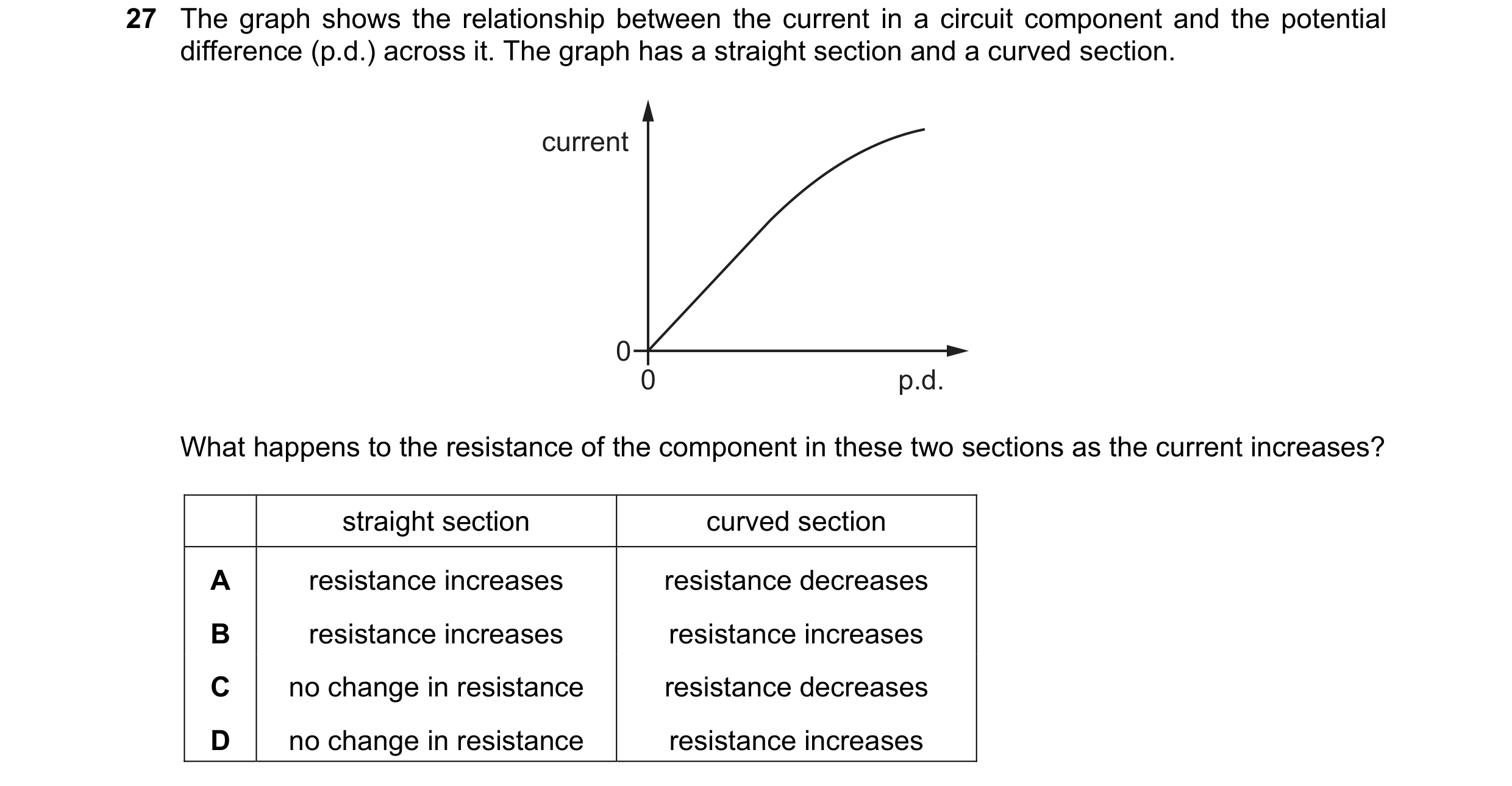
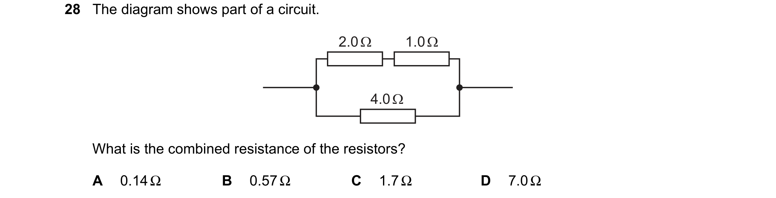
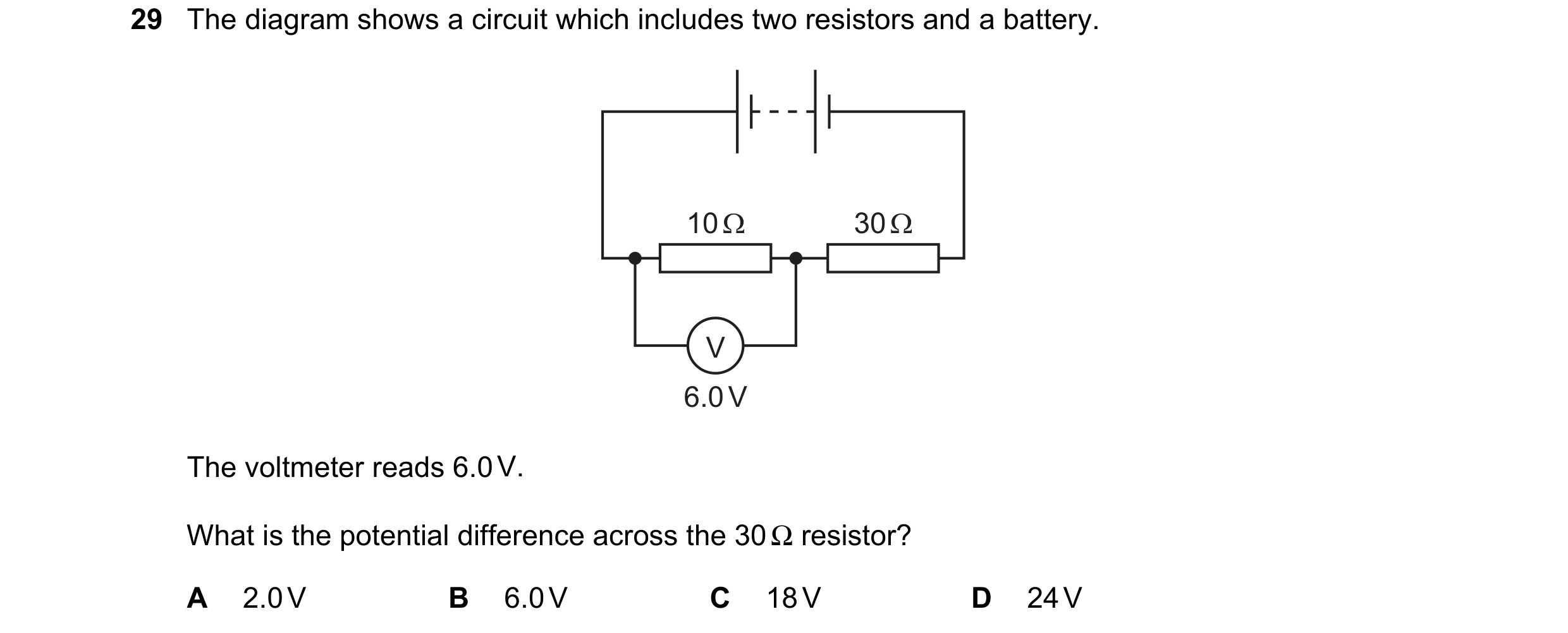 90 / 114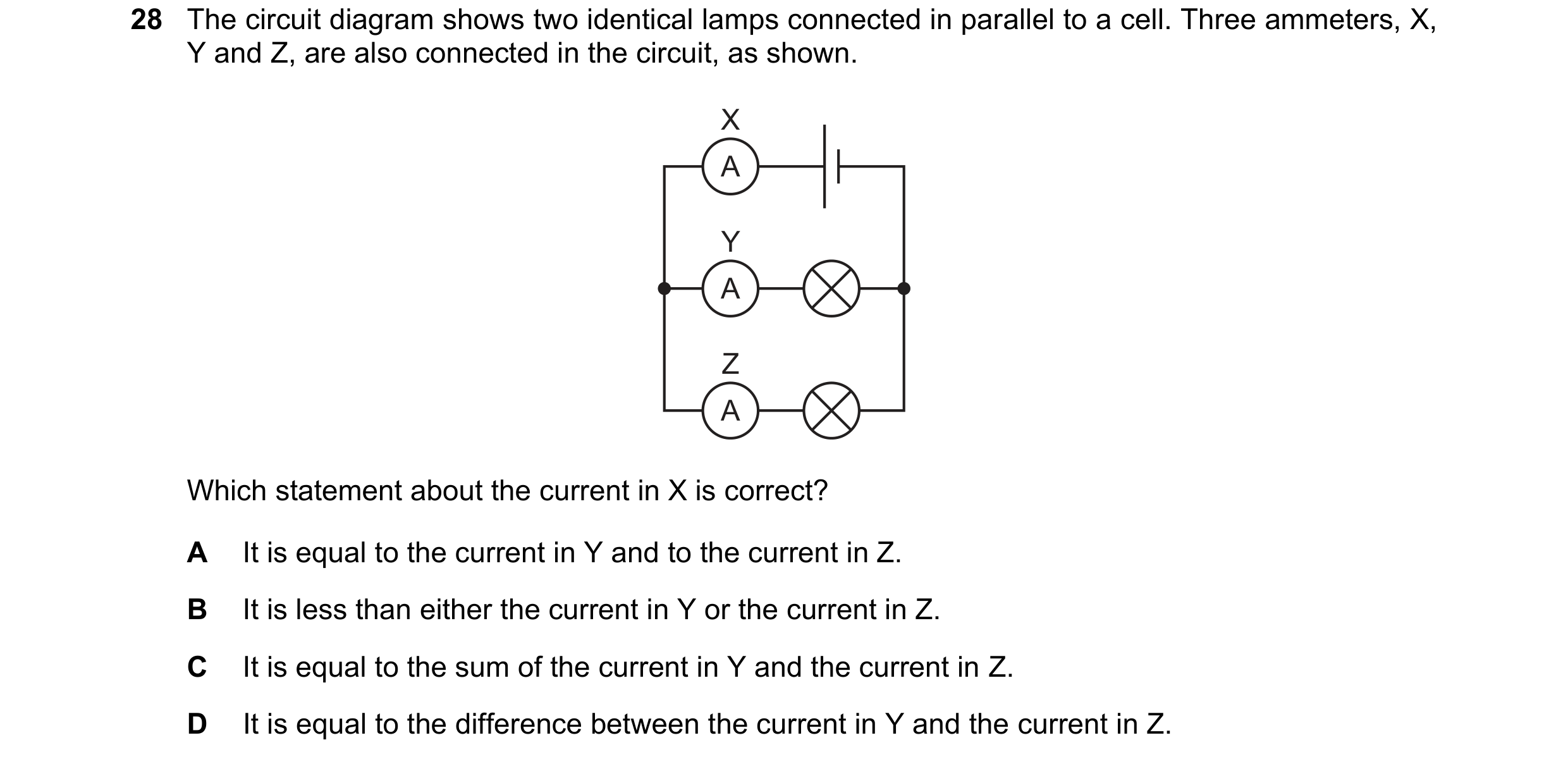
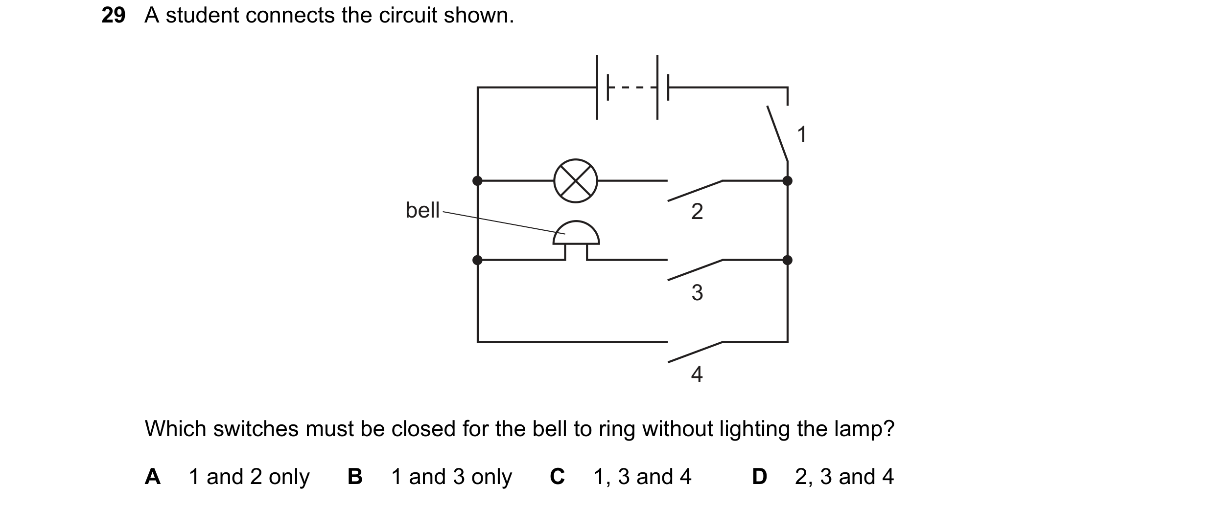

 91 / 114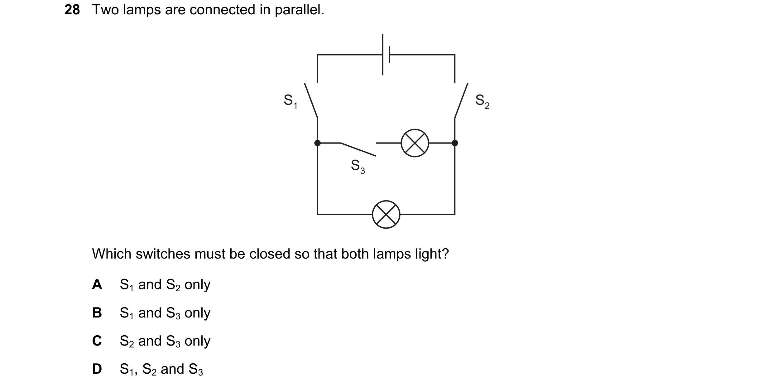
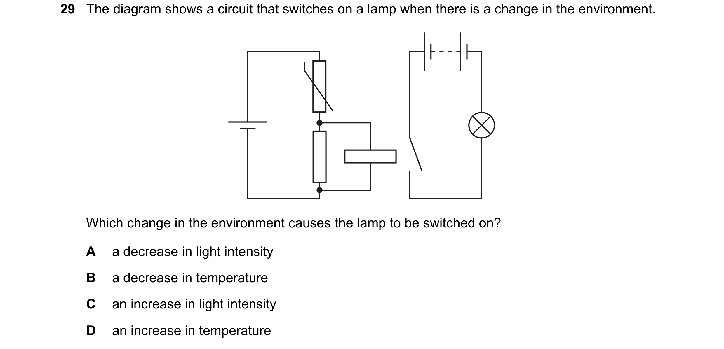
 92 / 114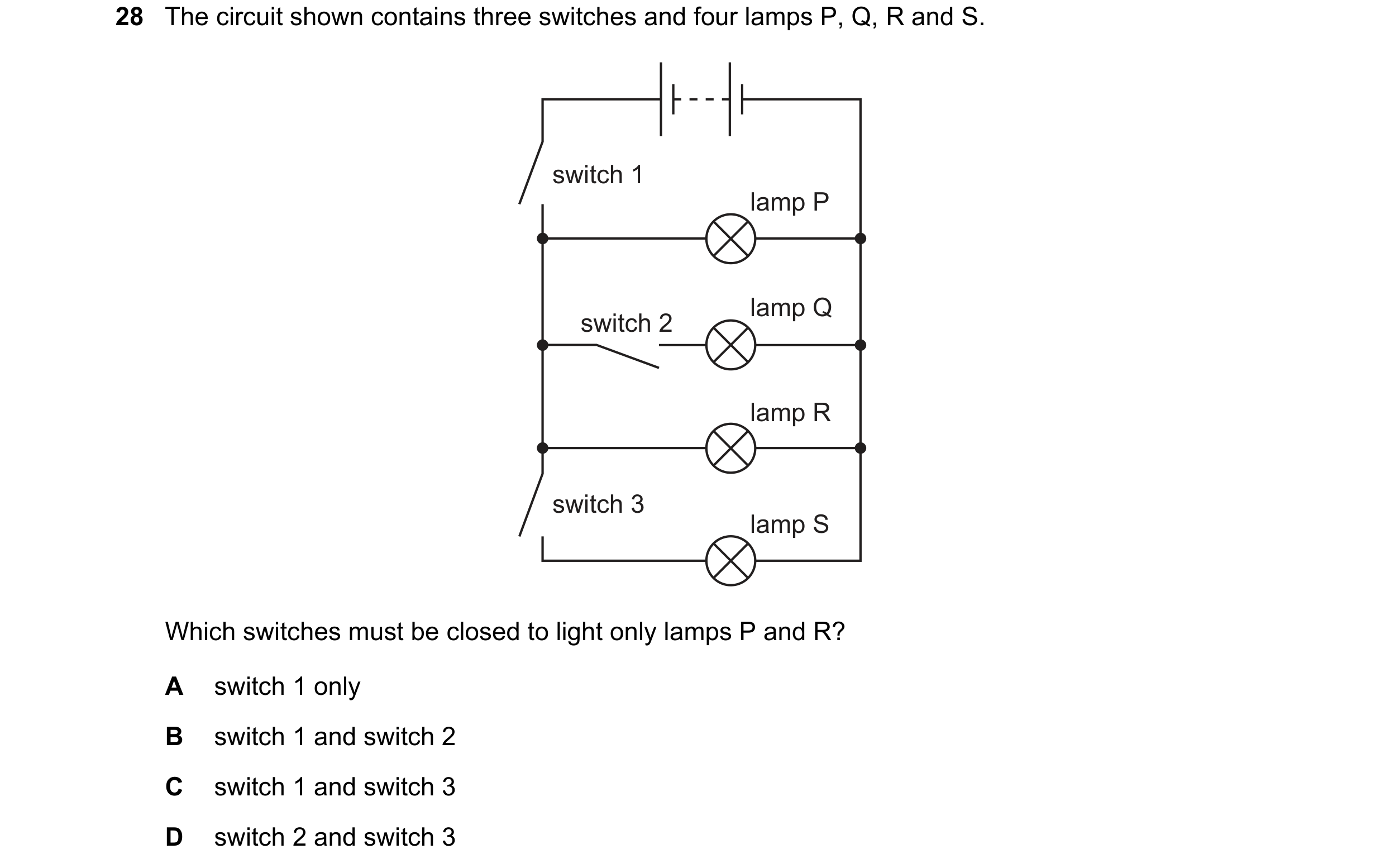
 93 / 114
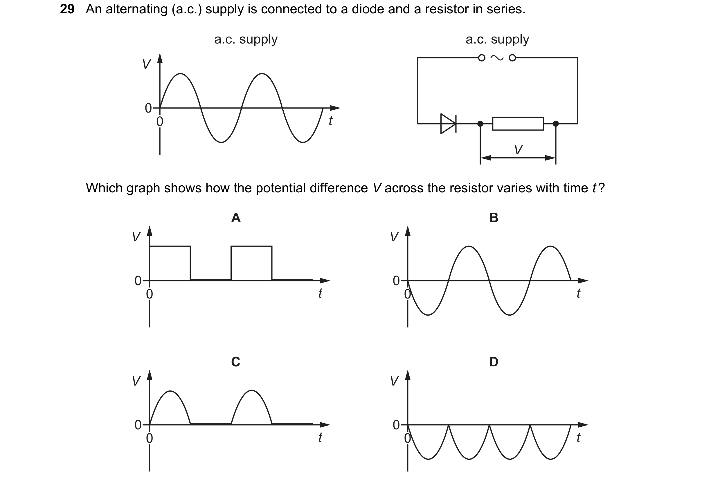 94 / 114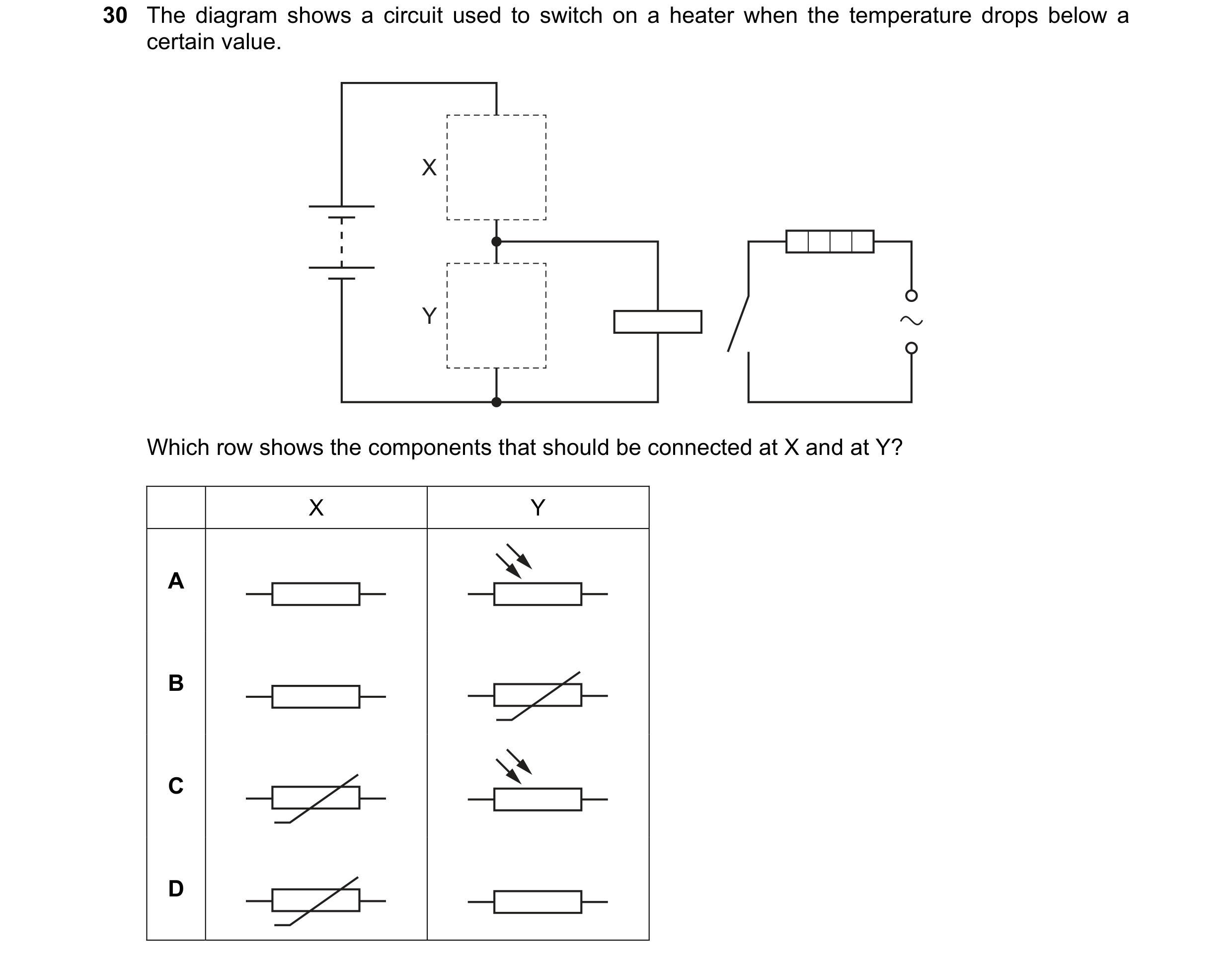
 95 / 114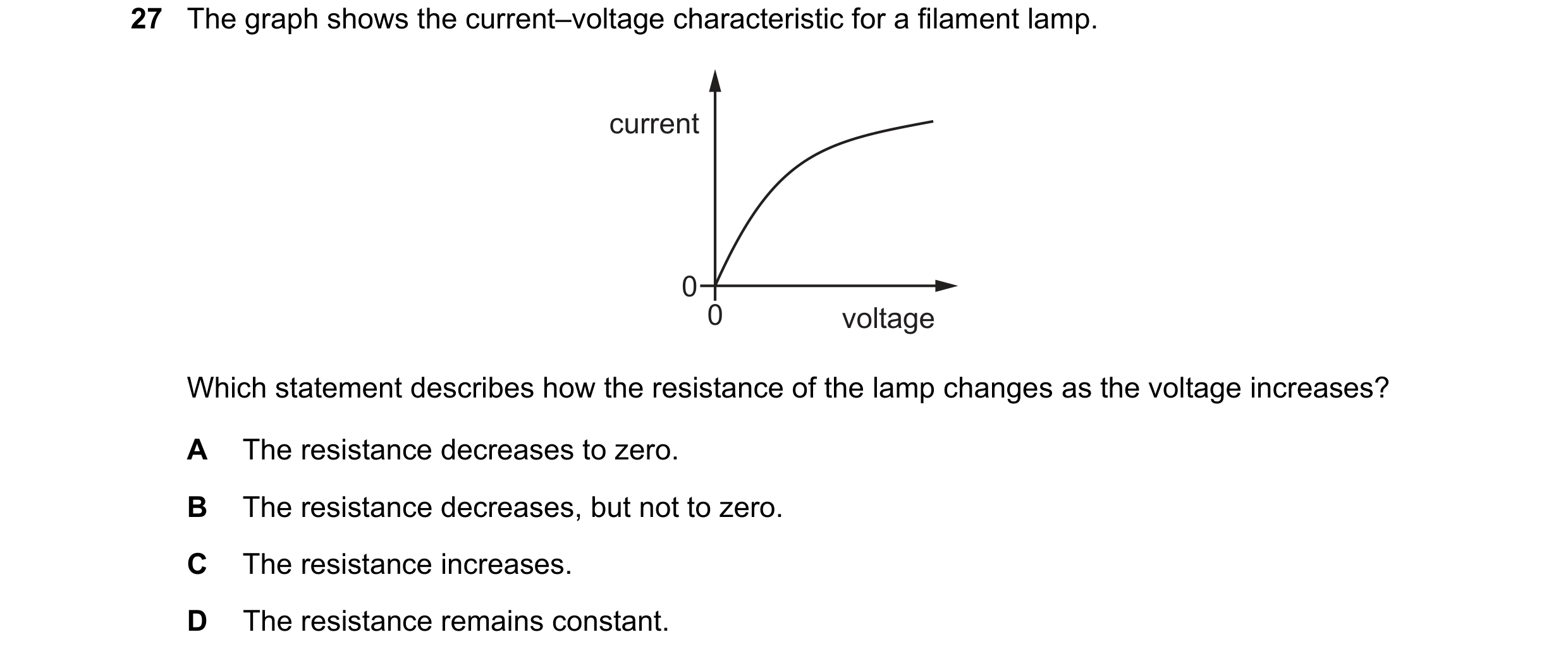
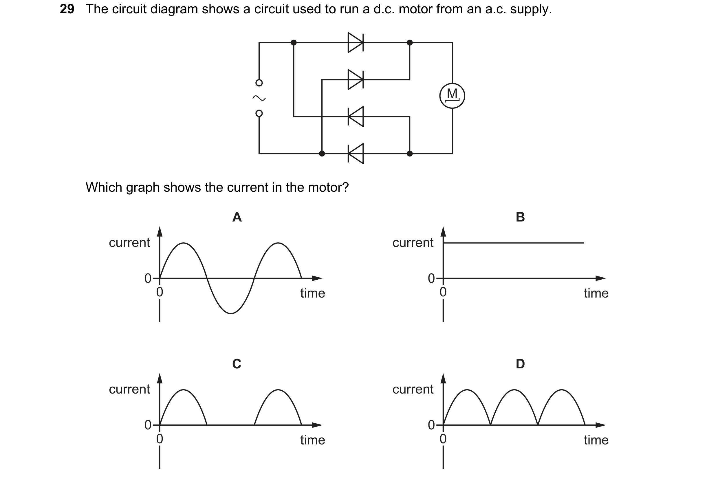 96 / 114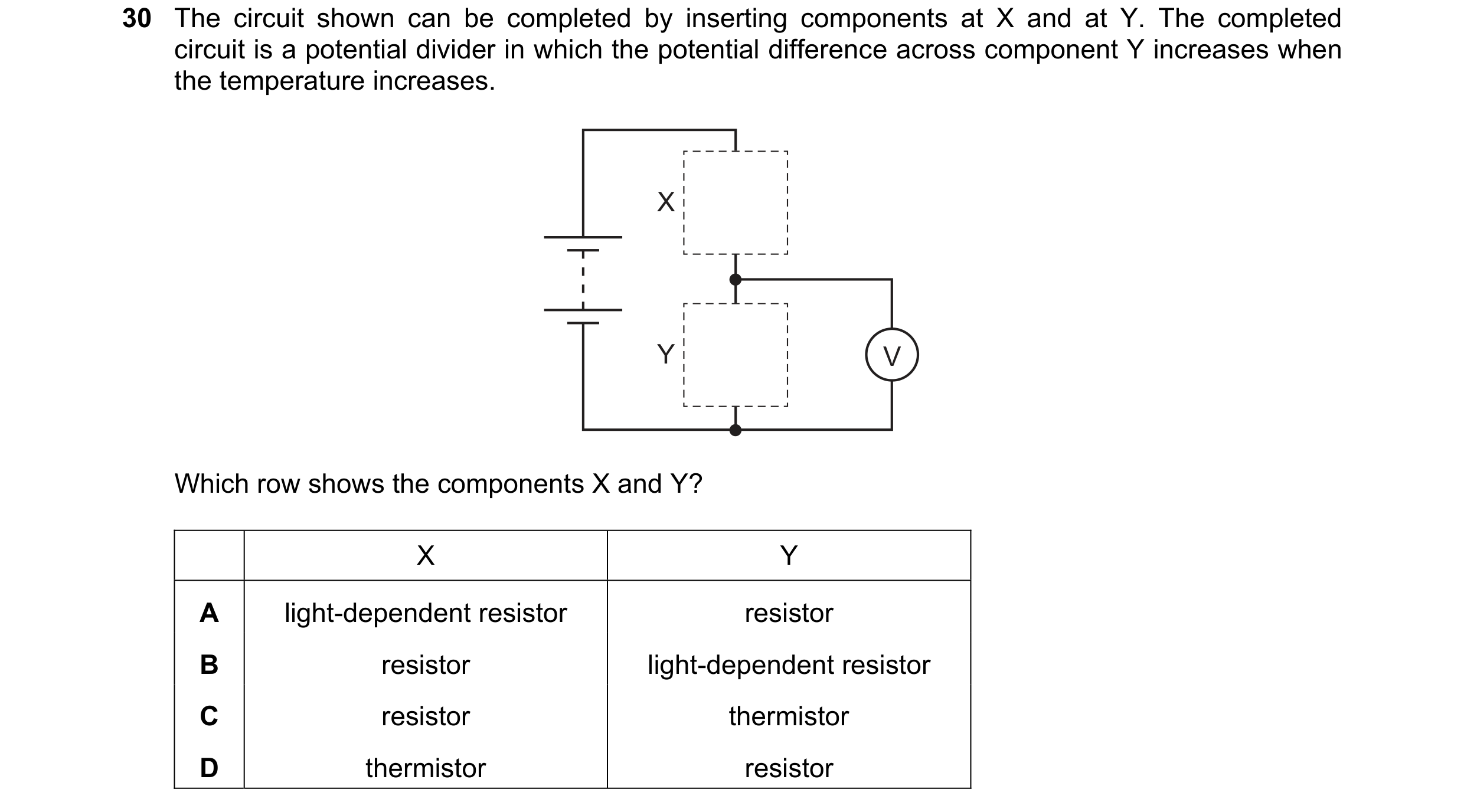
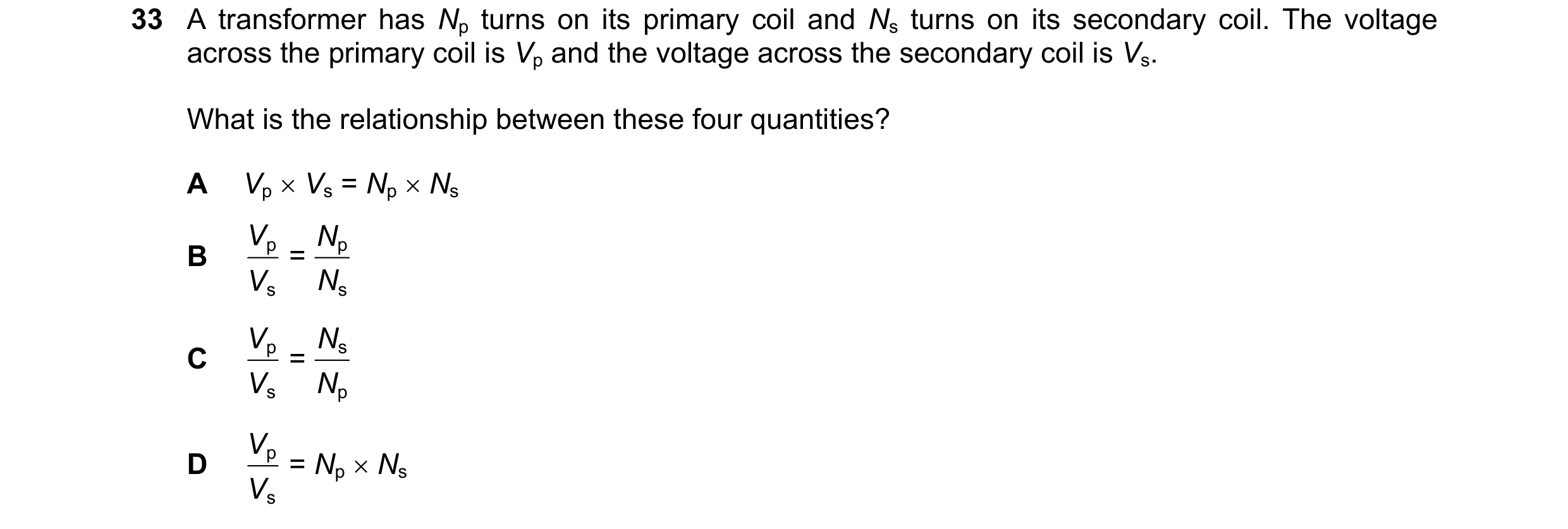 97 / 114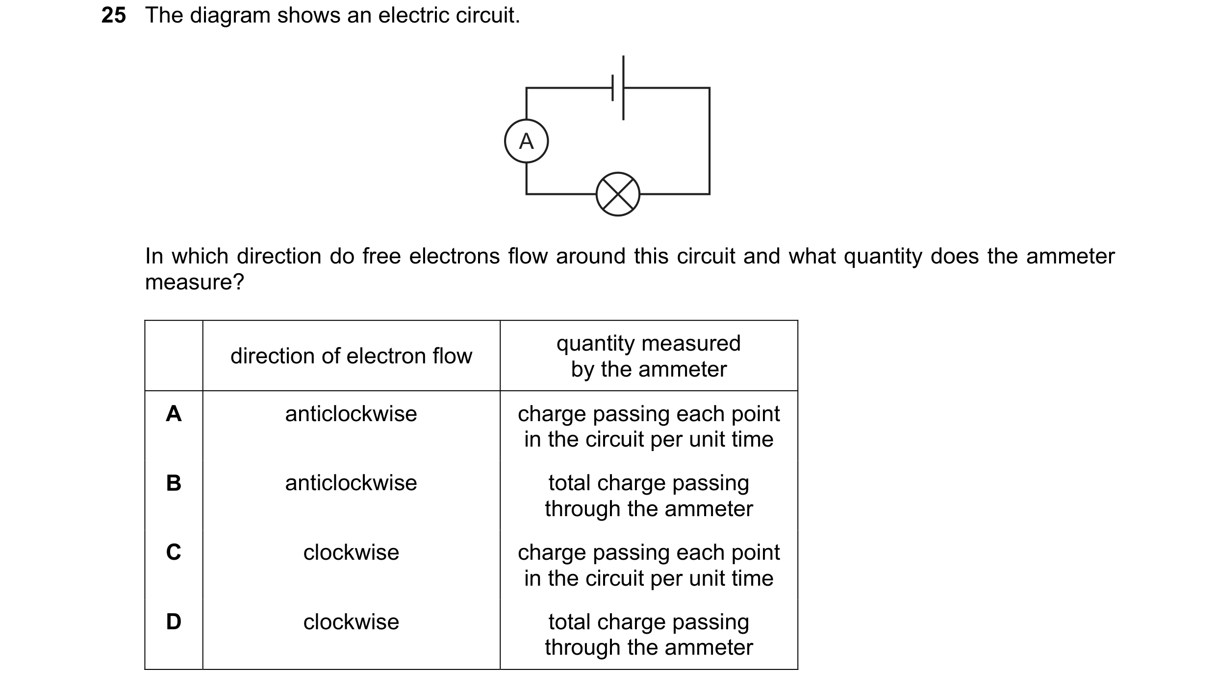
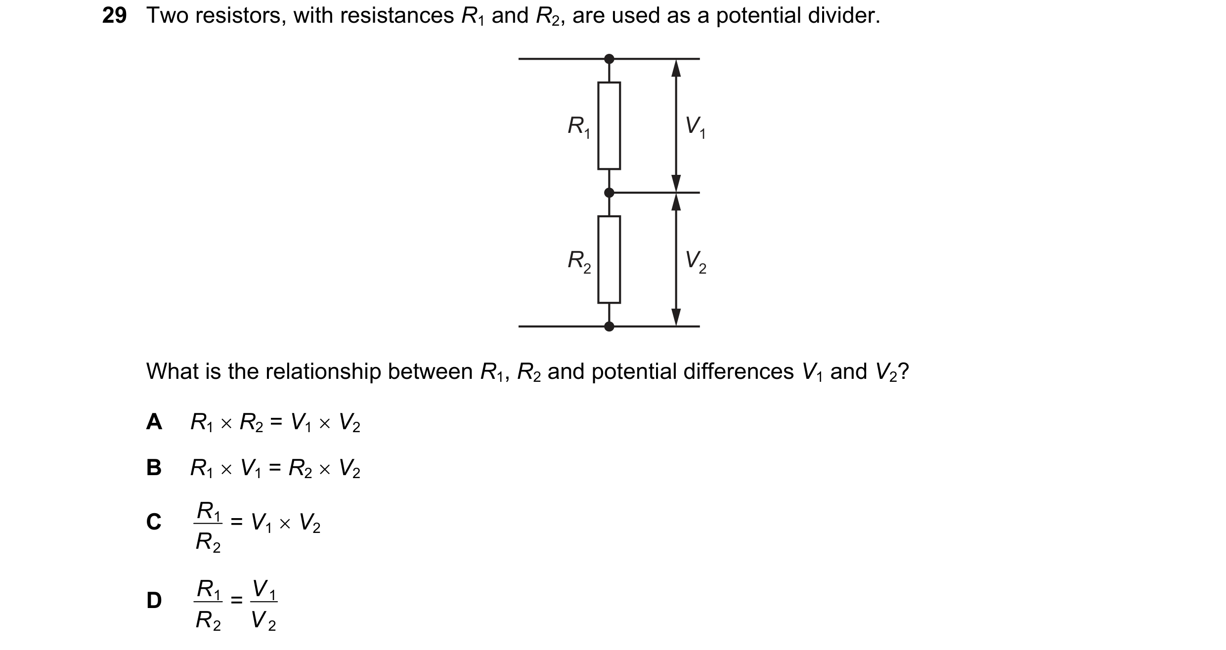 98 / 114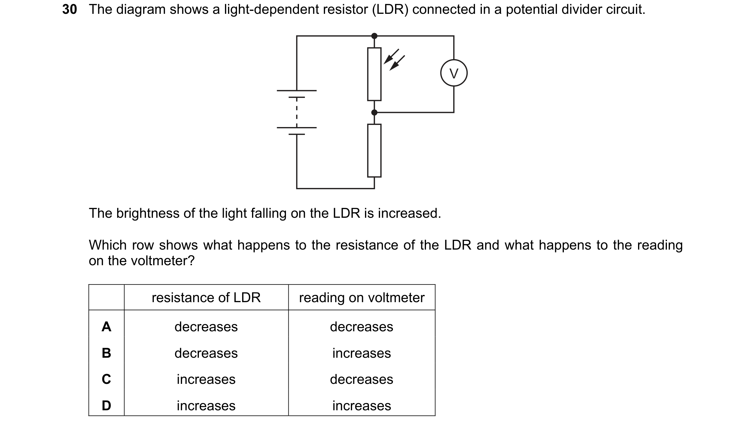
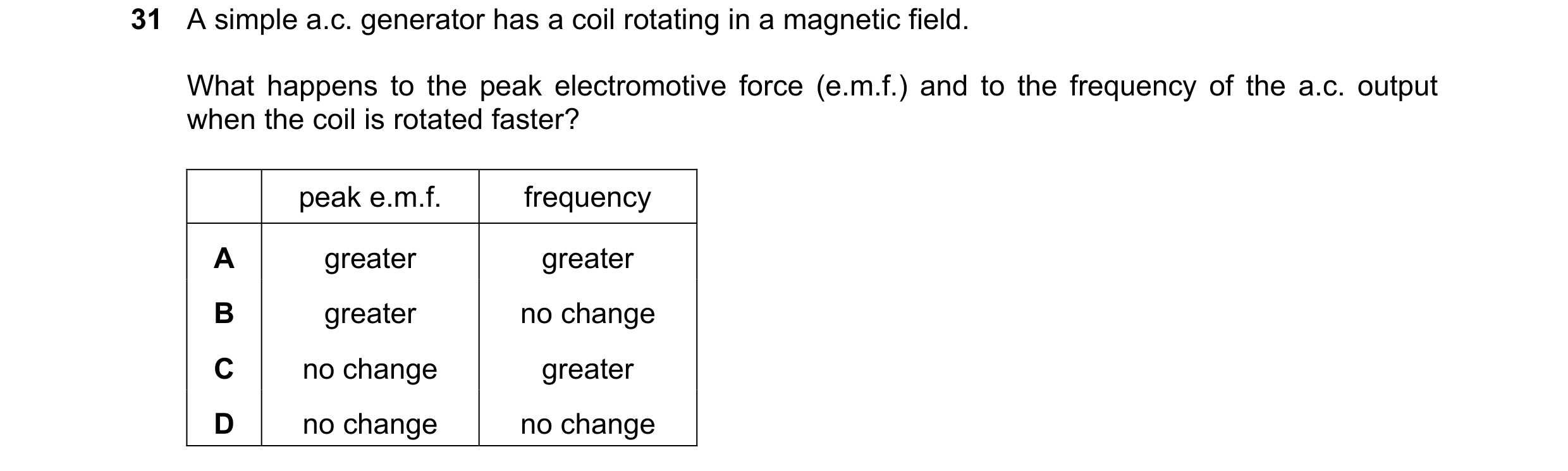

 99 / 114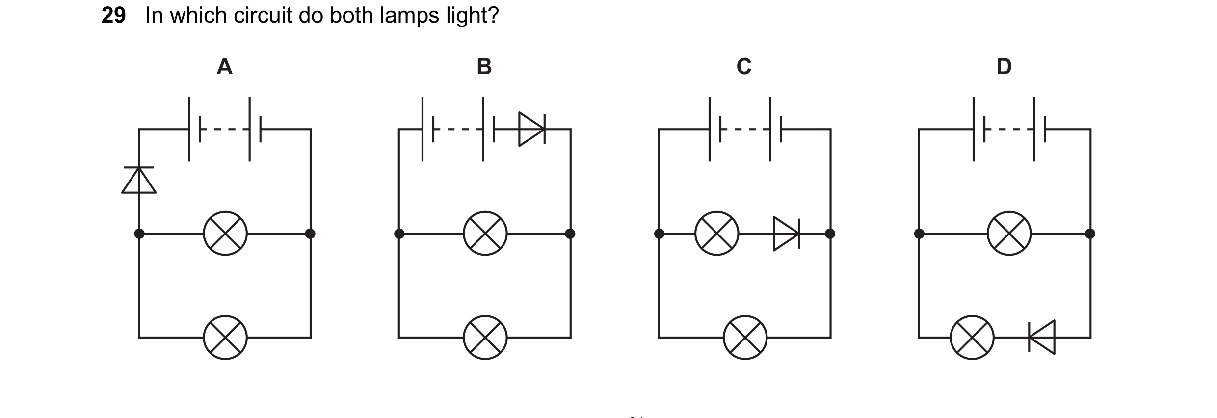
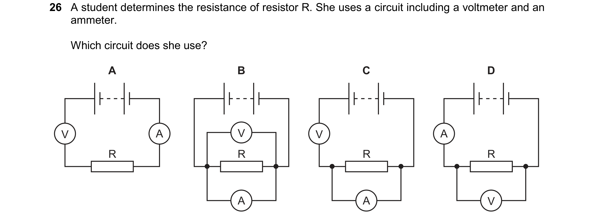 100 / 114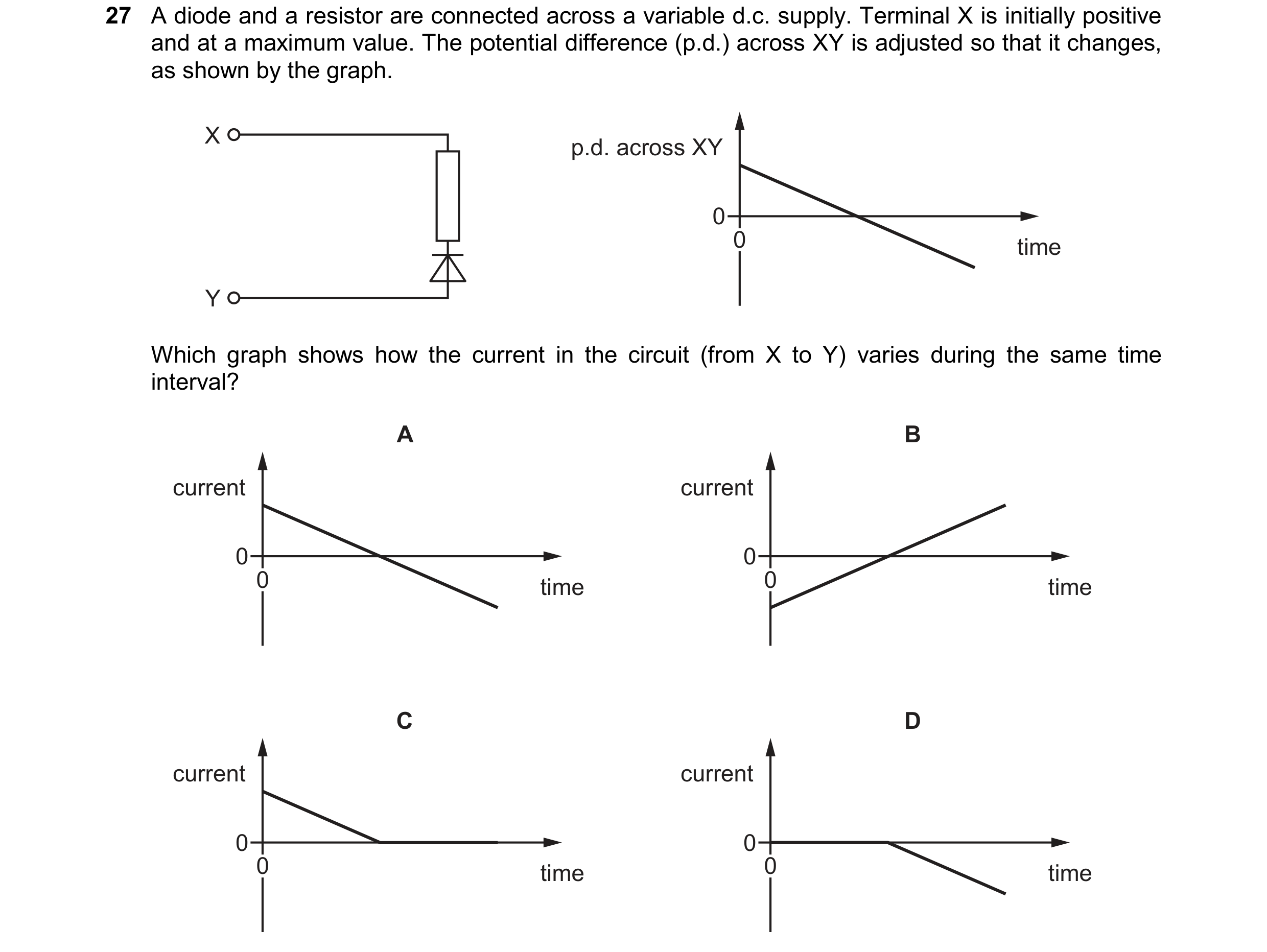
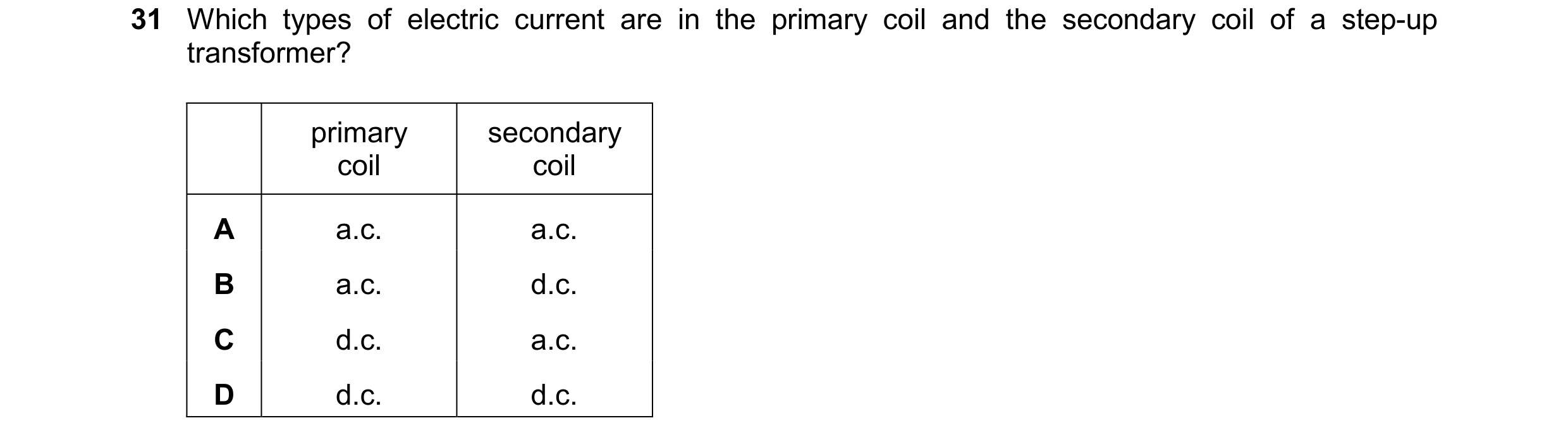 101 / 114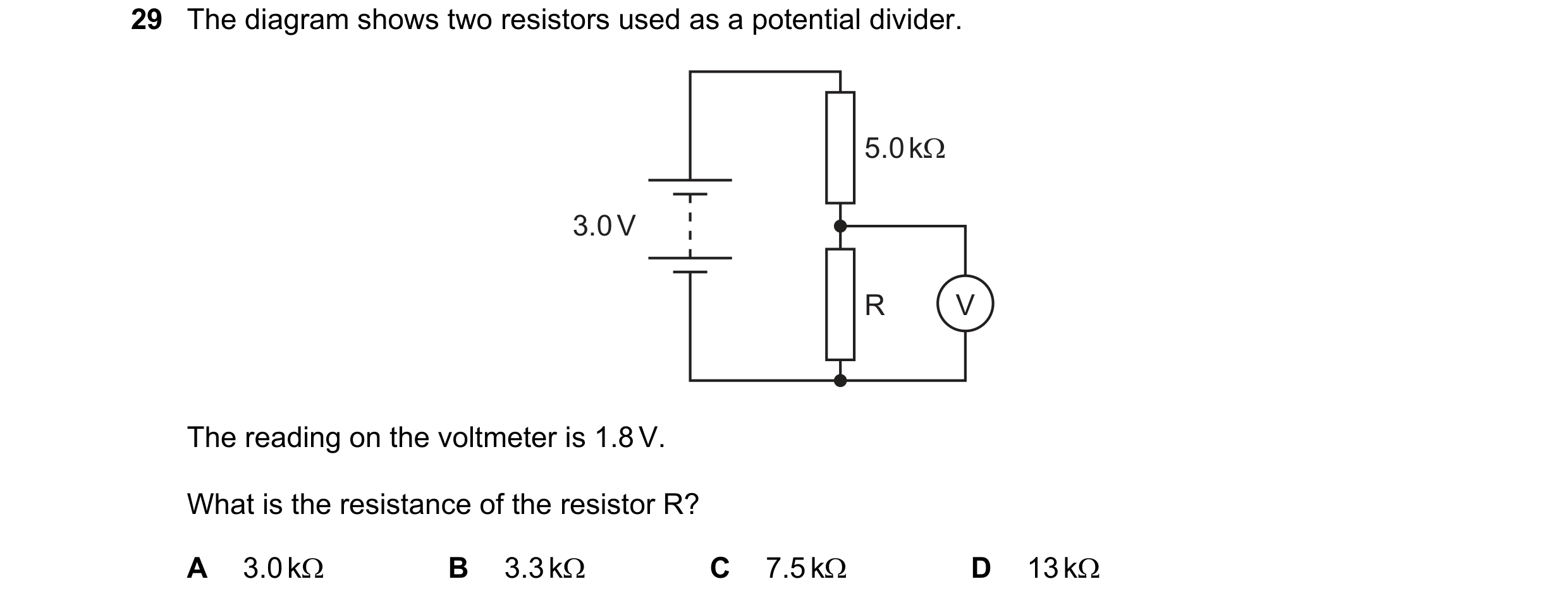
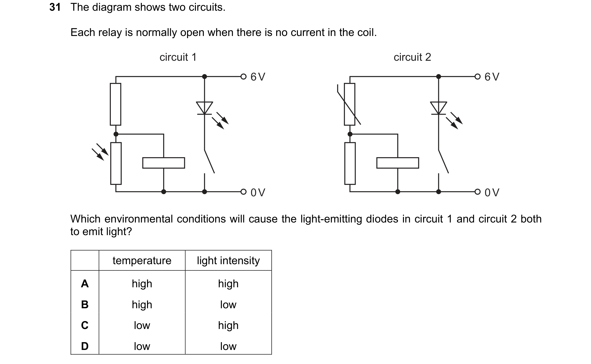 102 / 114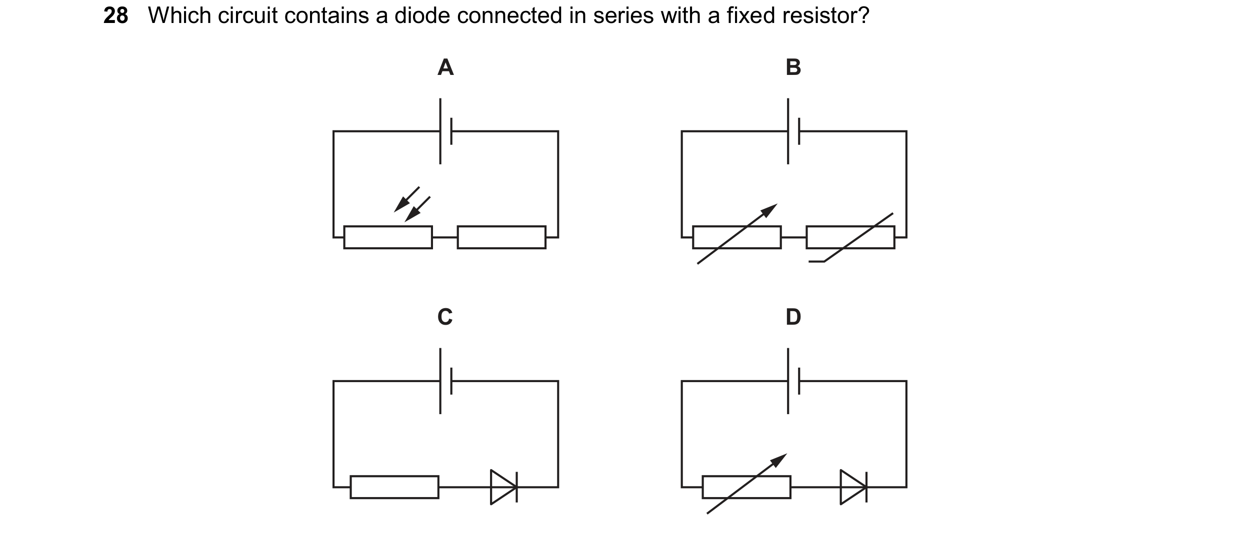
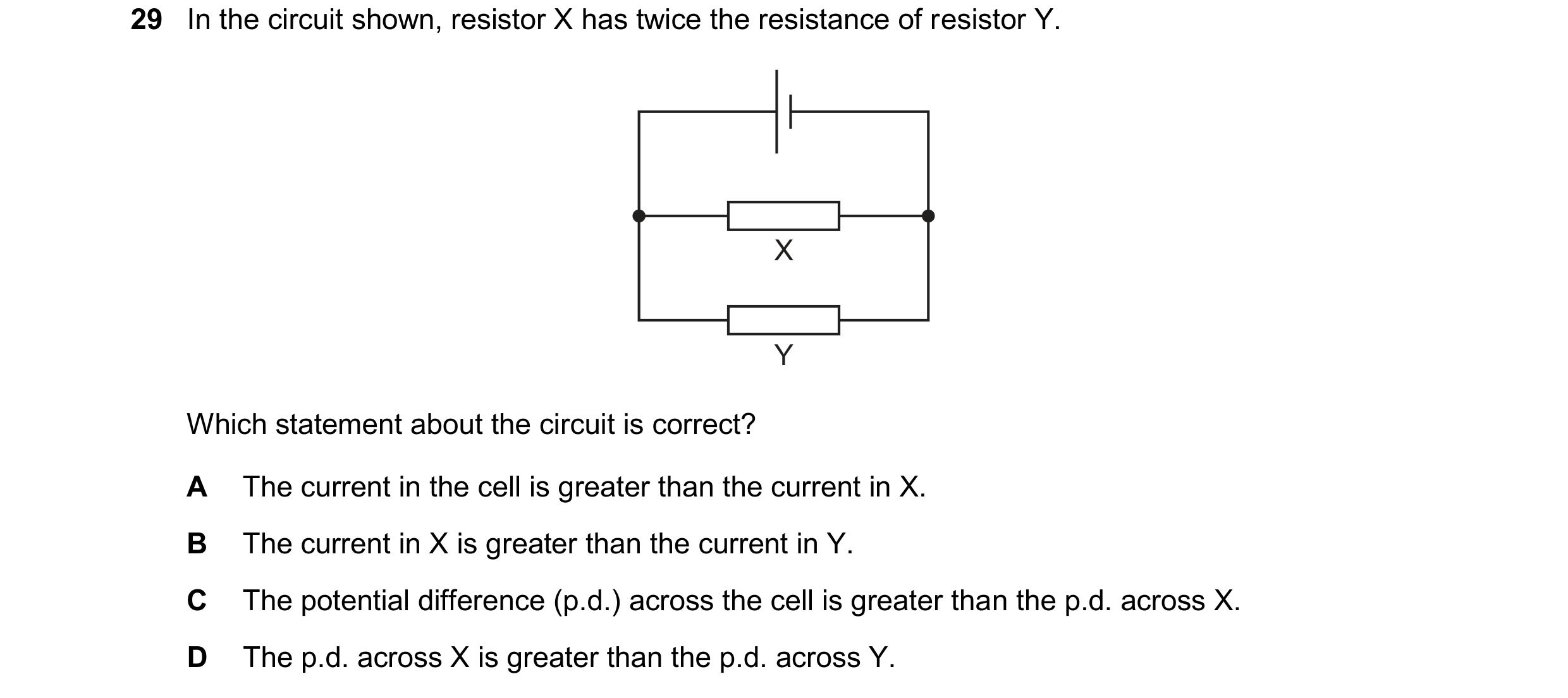

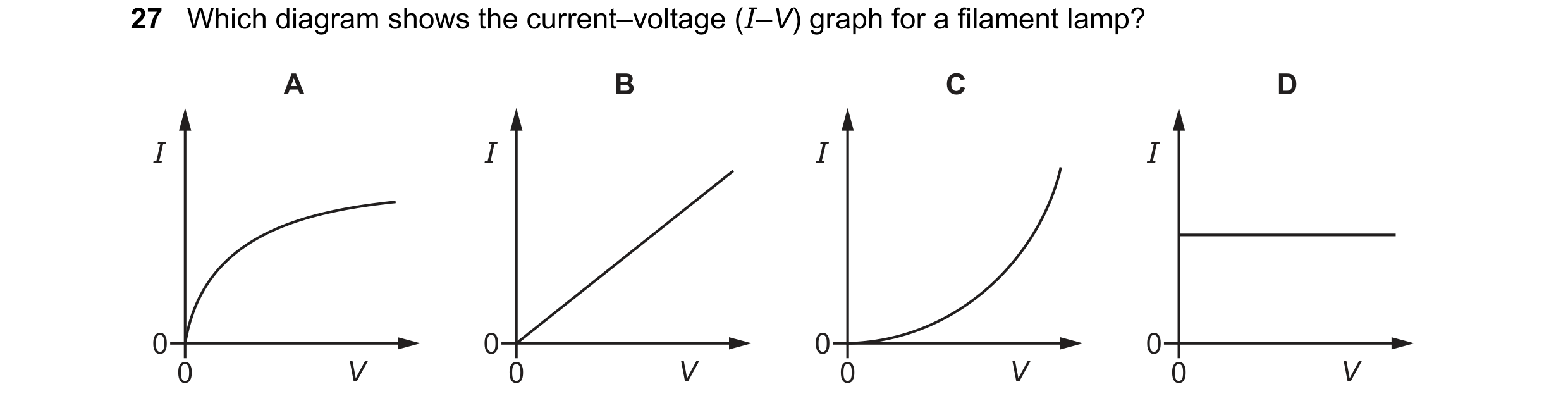 103 / 114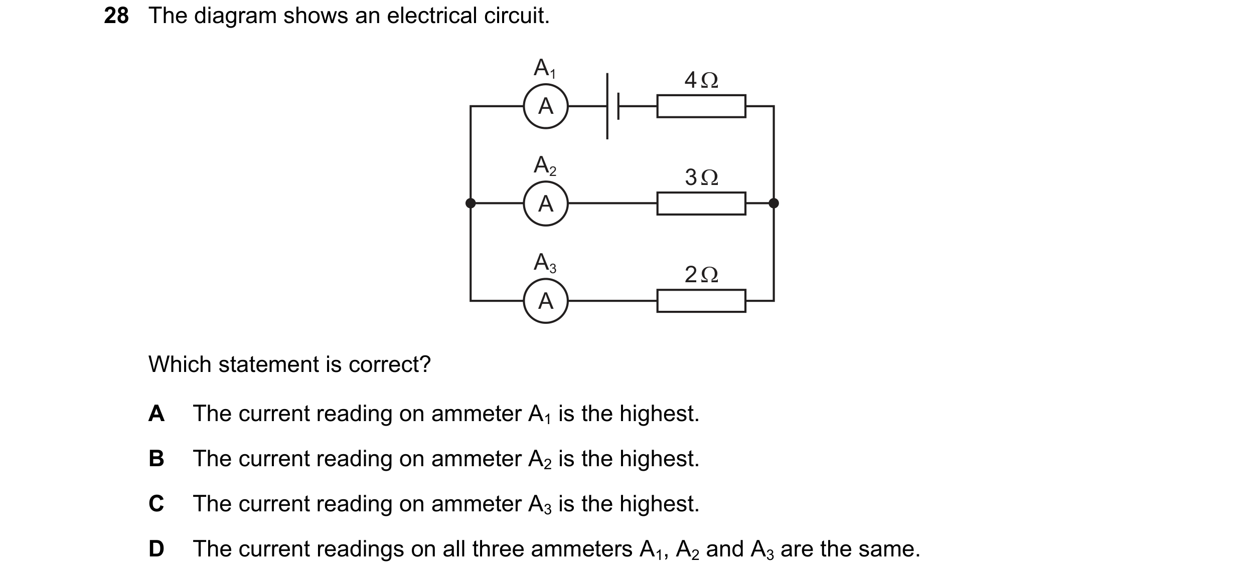
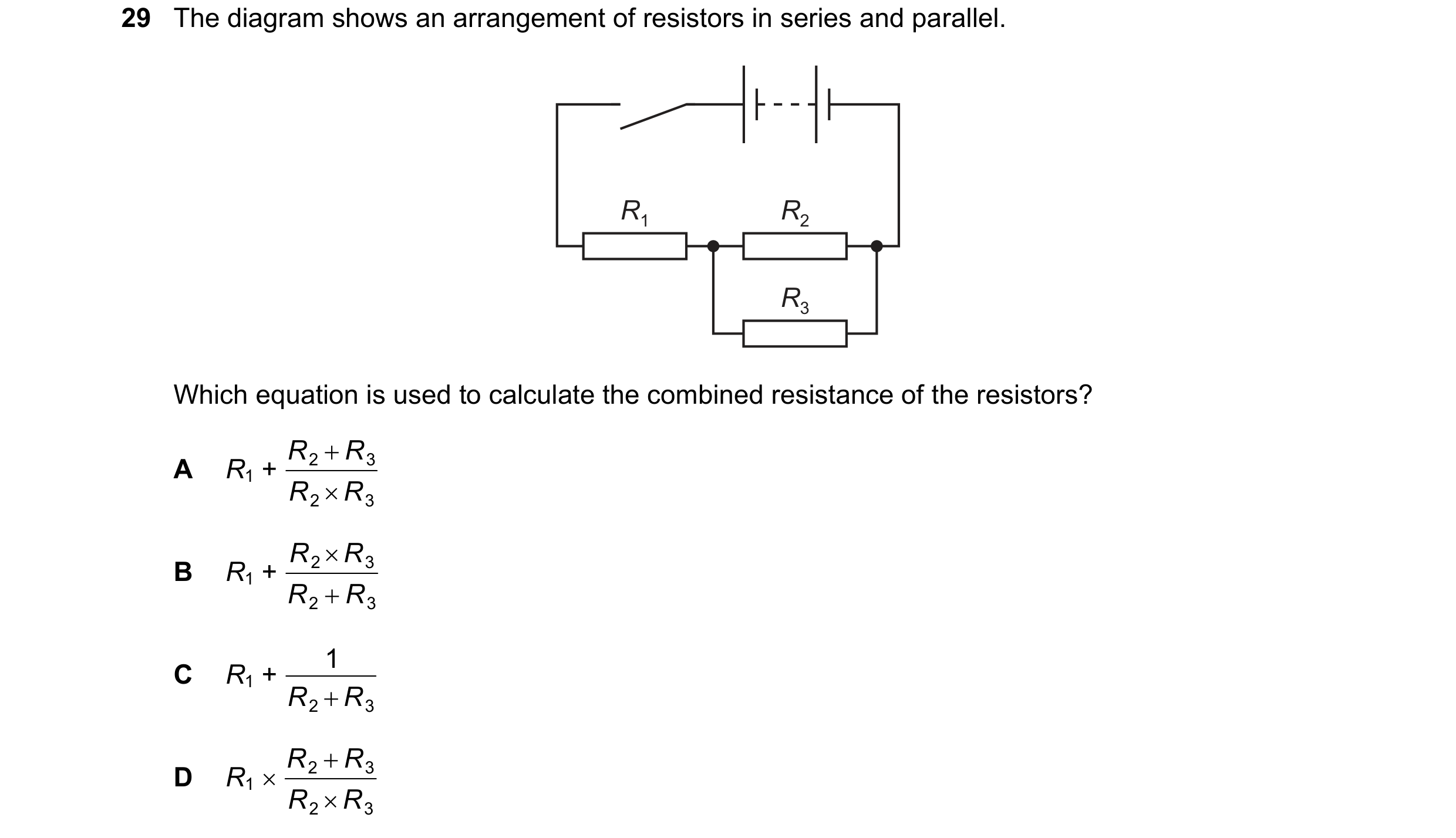 104 / 114

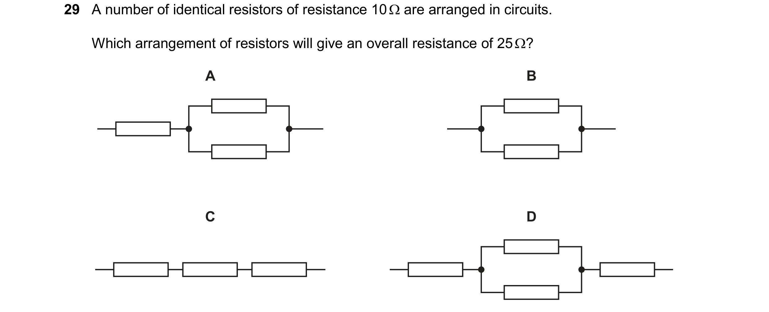 105 / 114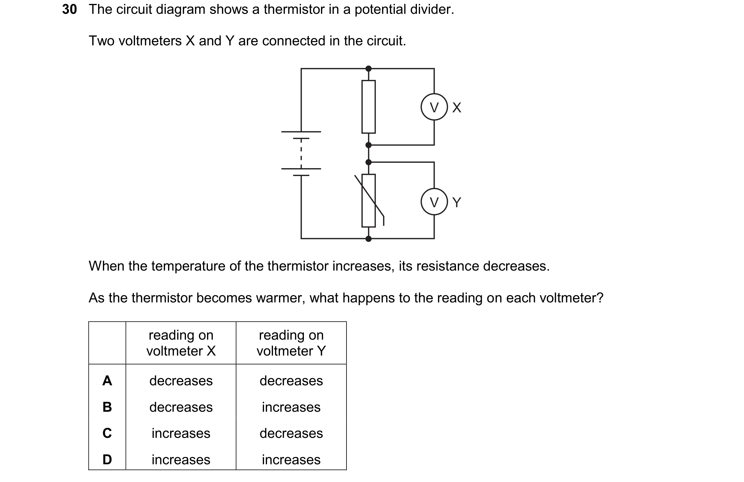
 106 / 114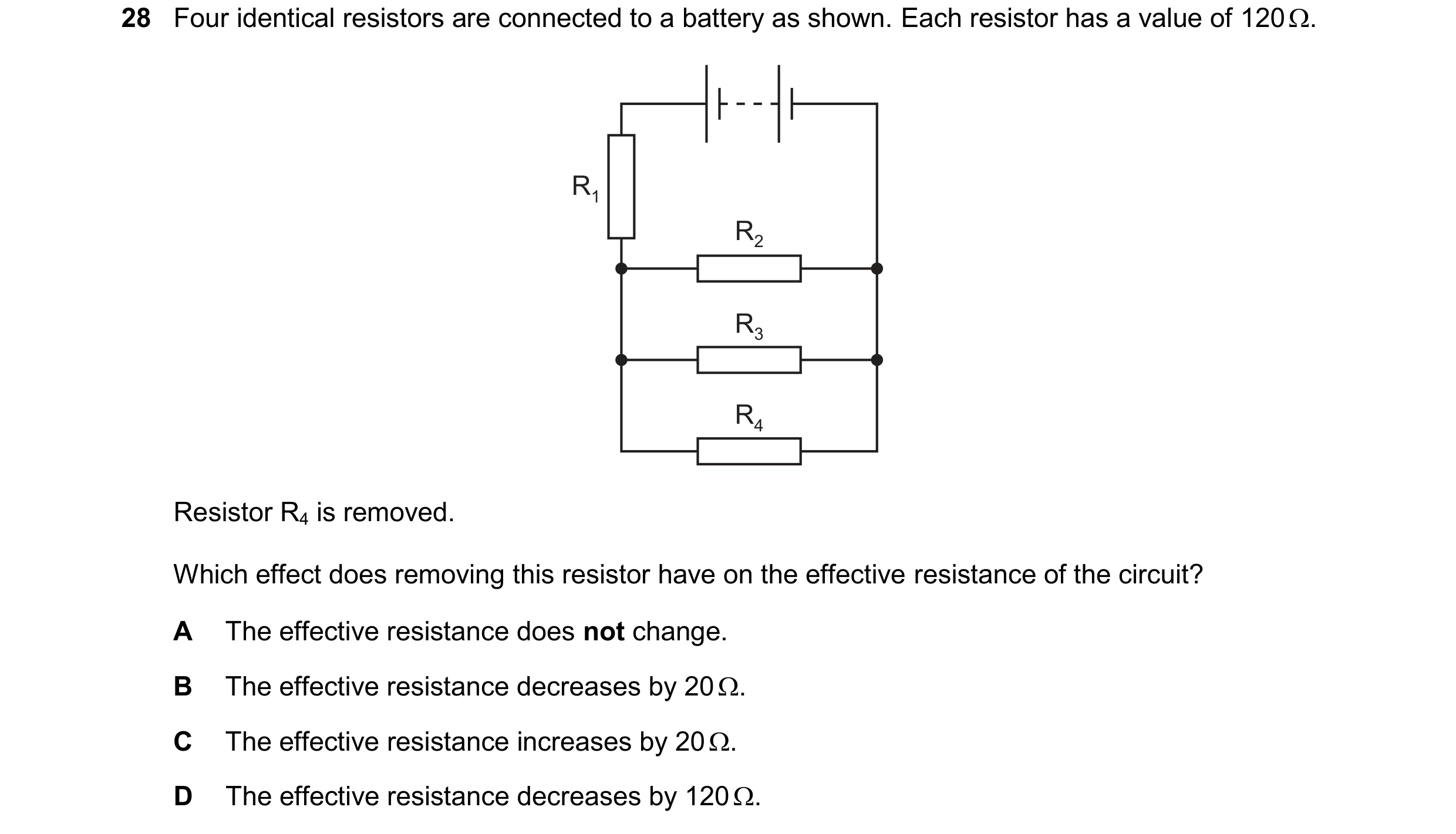
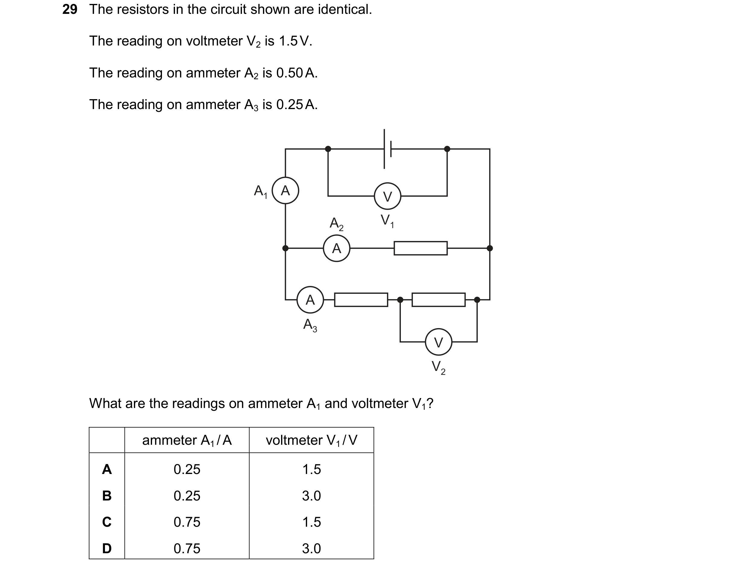 107 / 114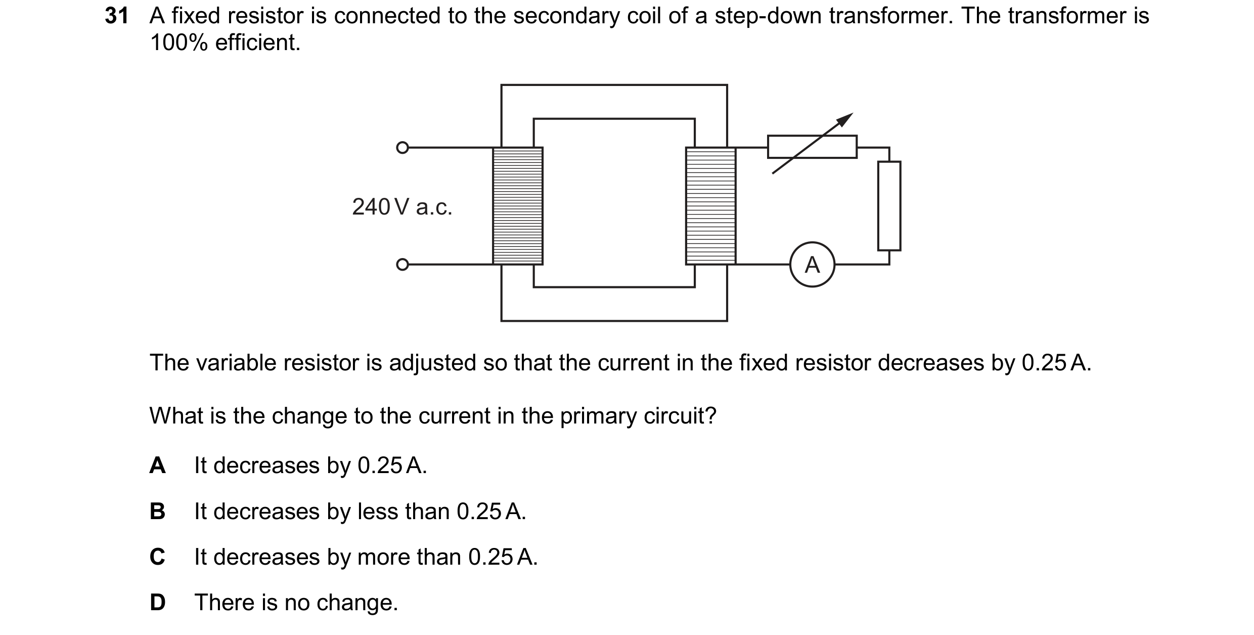
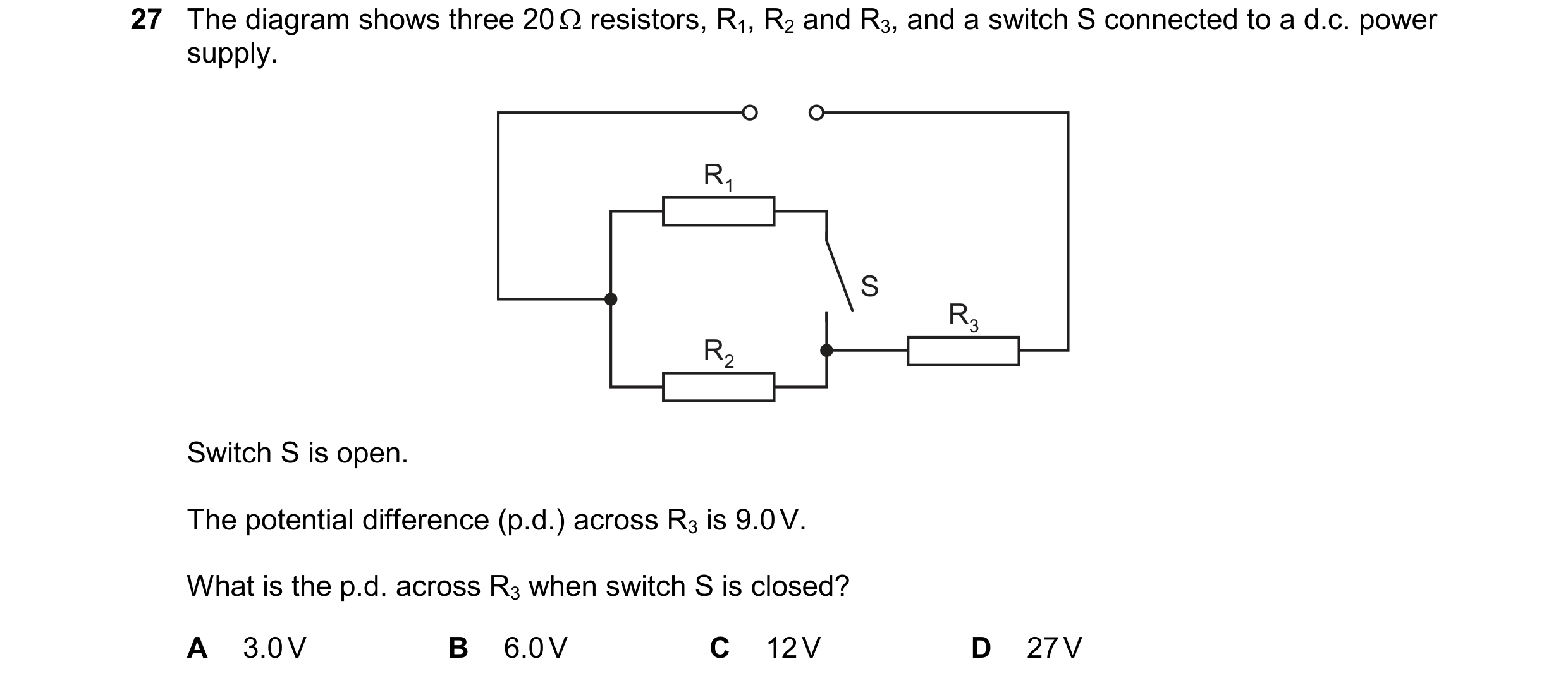 108 / 114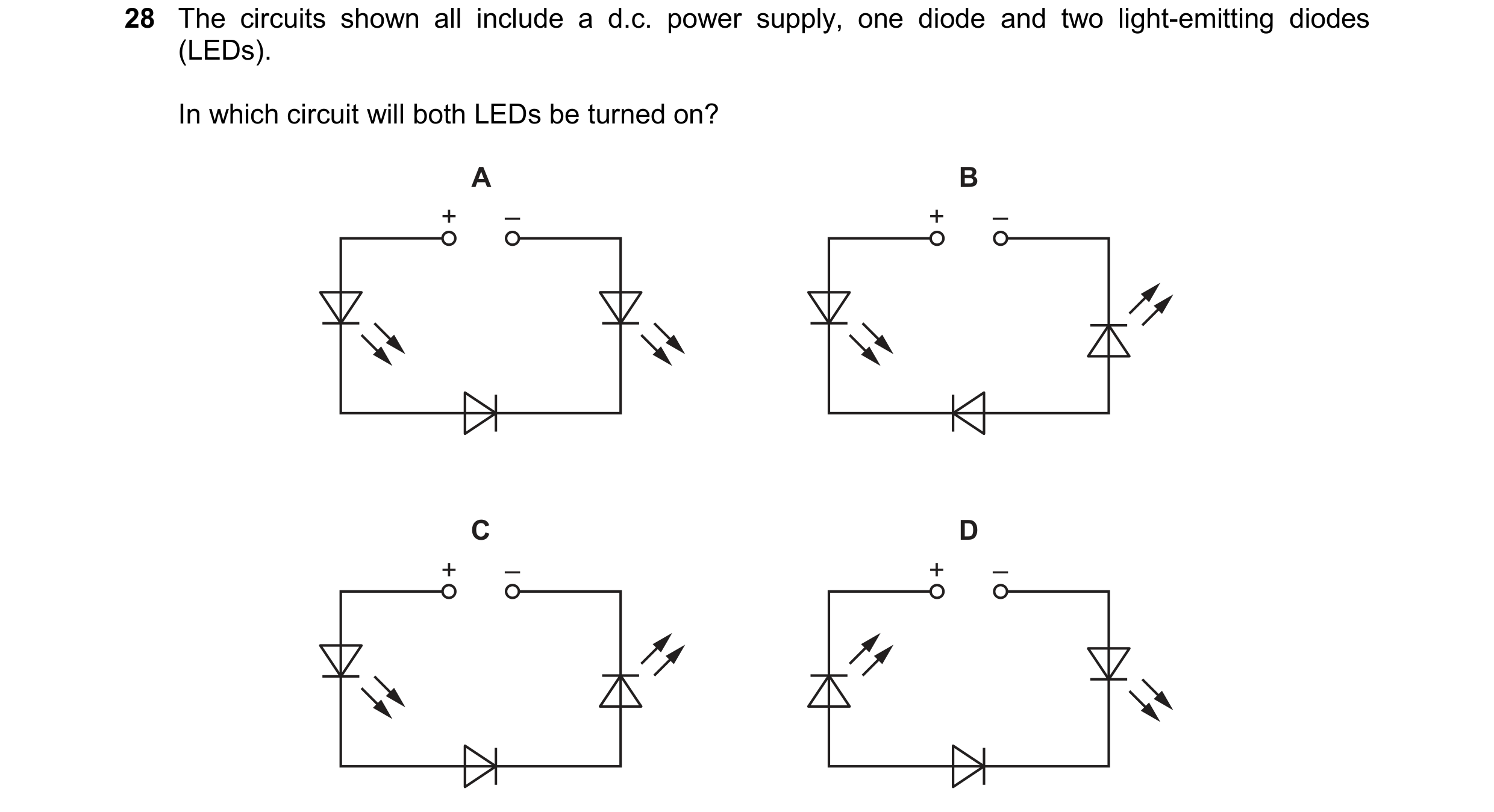
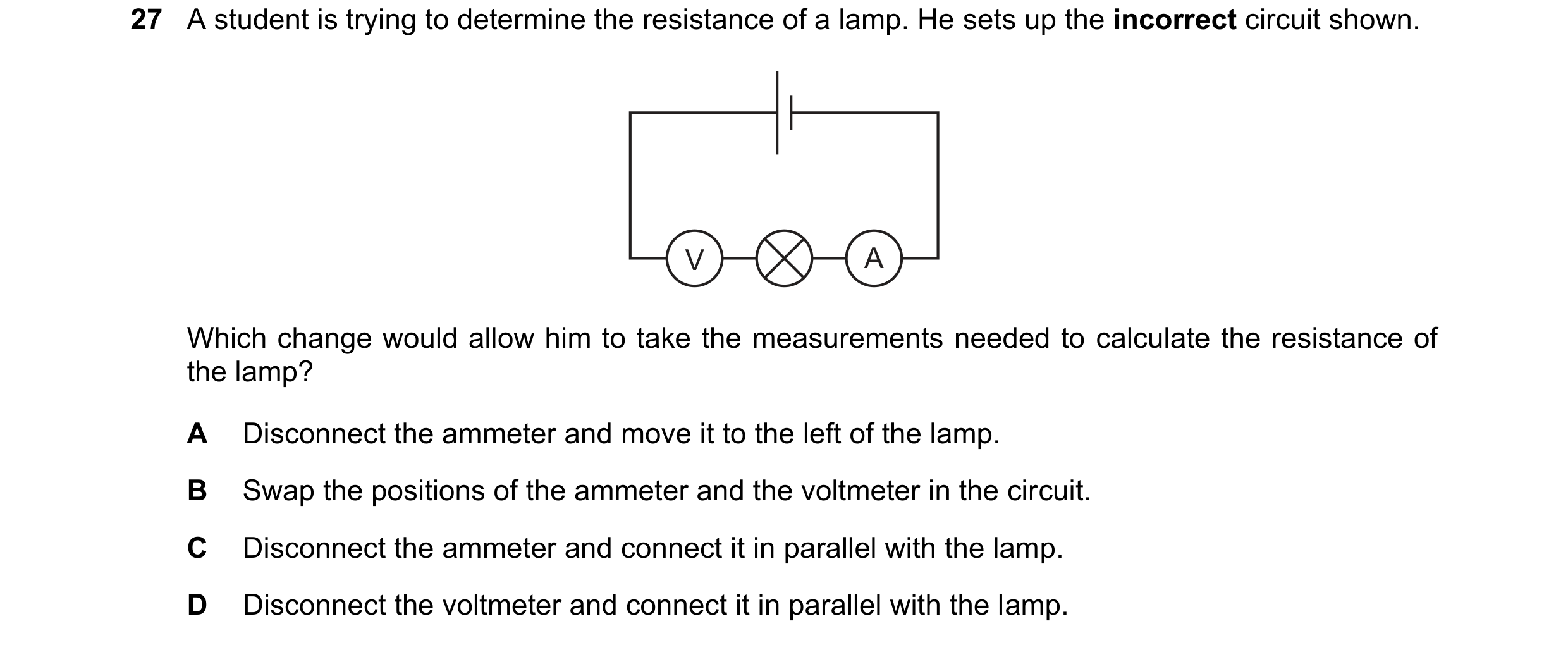 109 / 114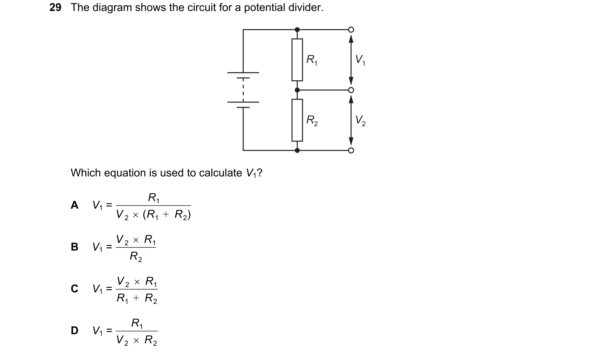

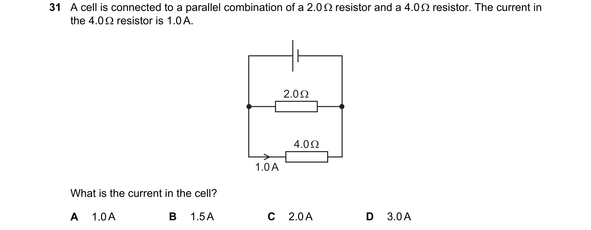 110 / 114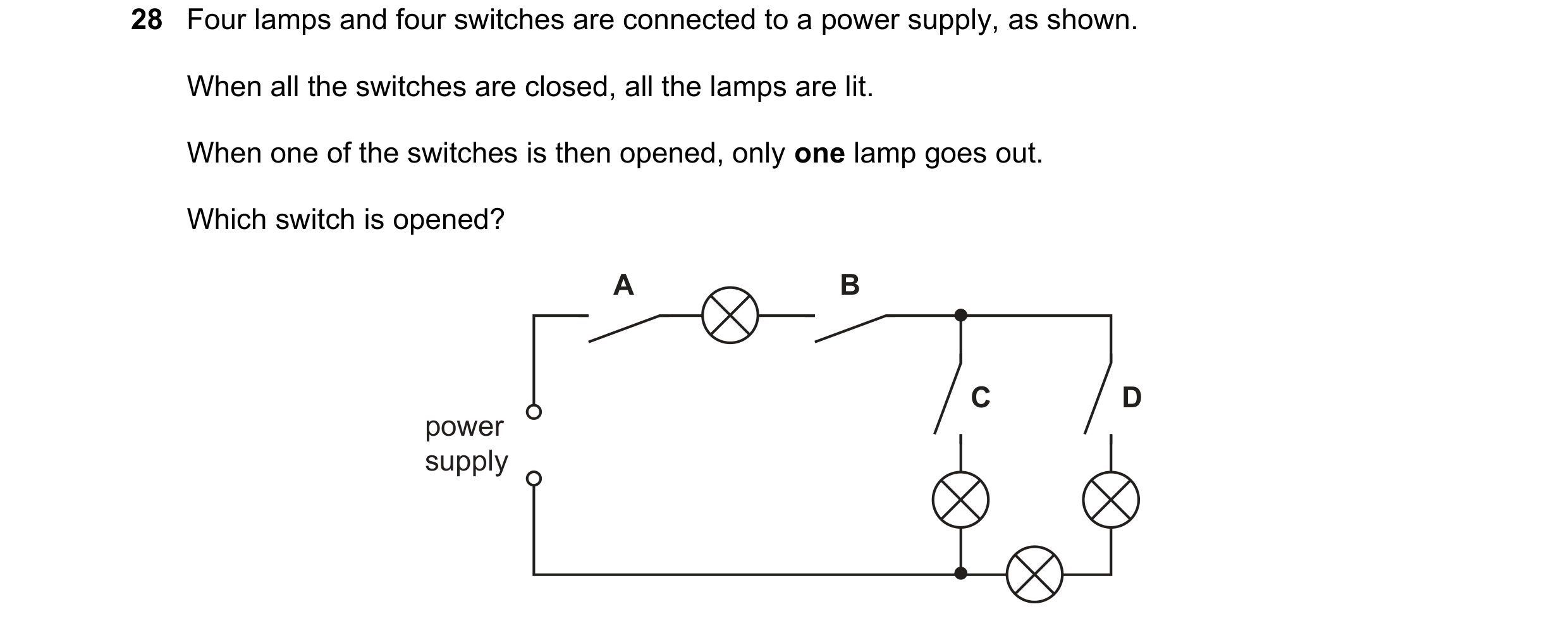
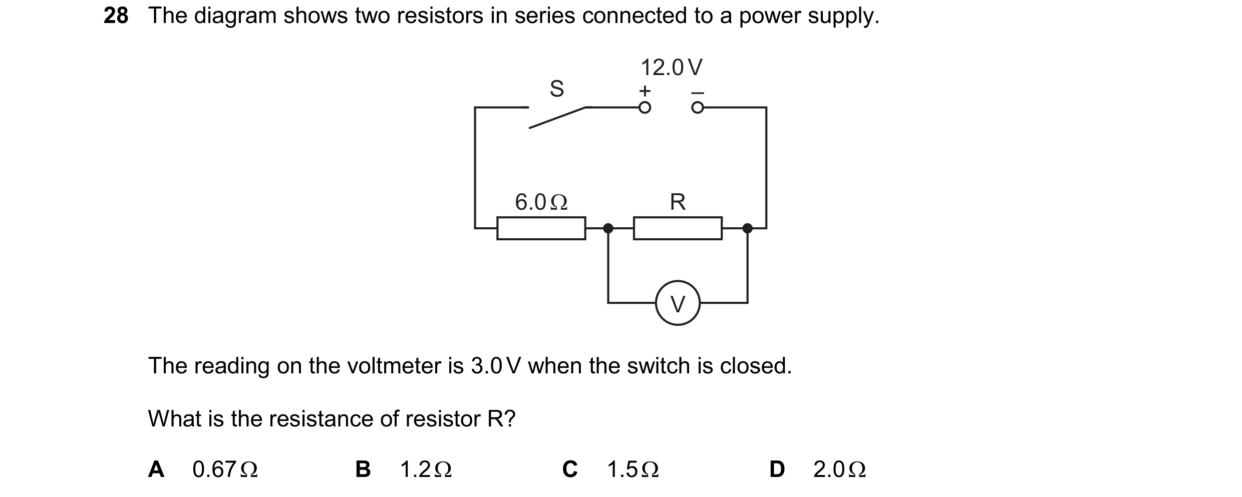
 111 / 114
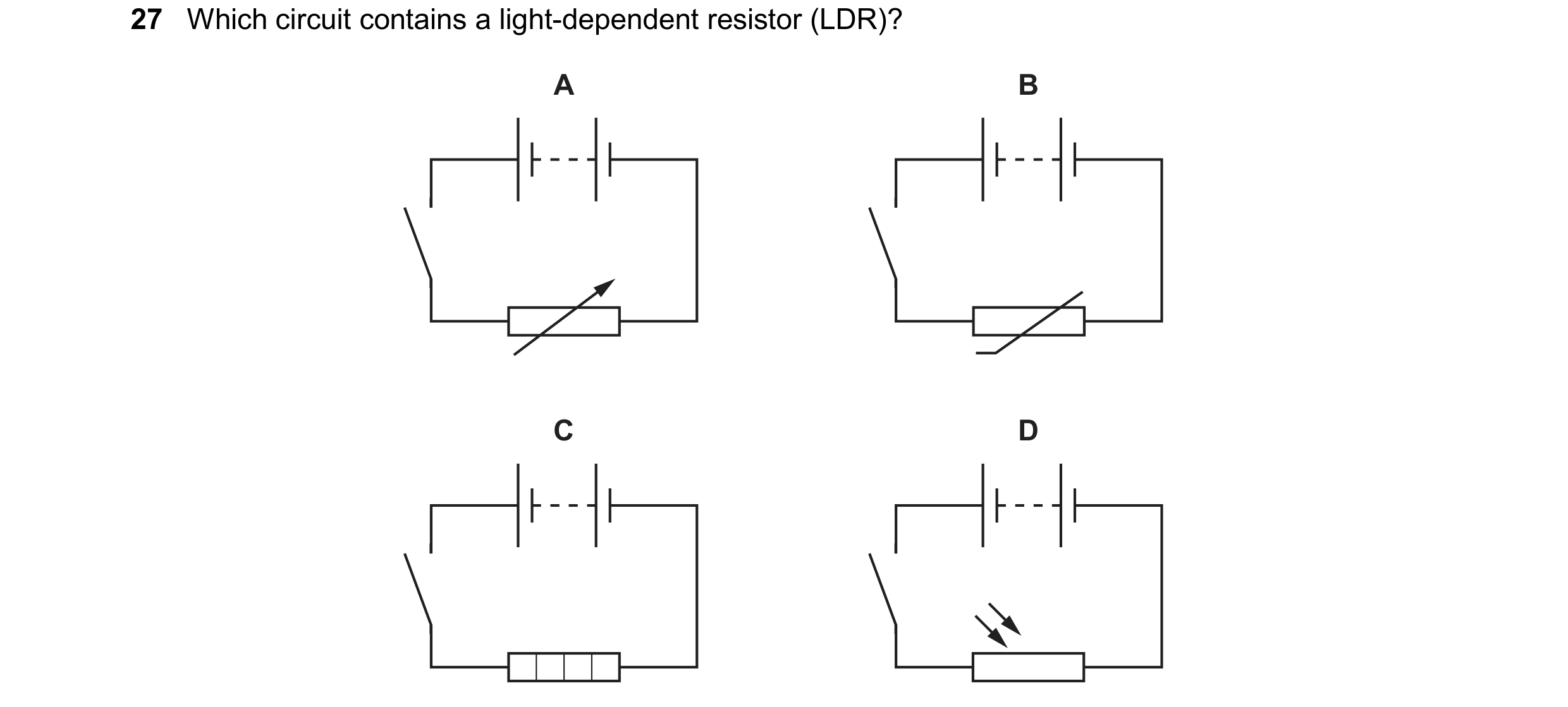
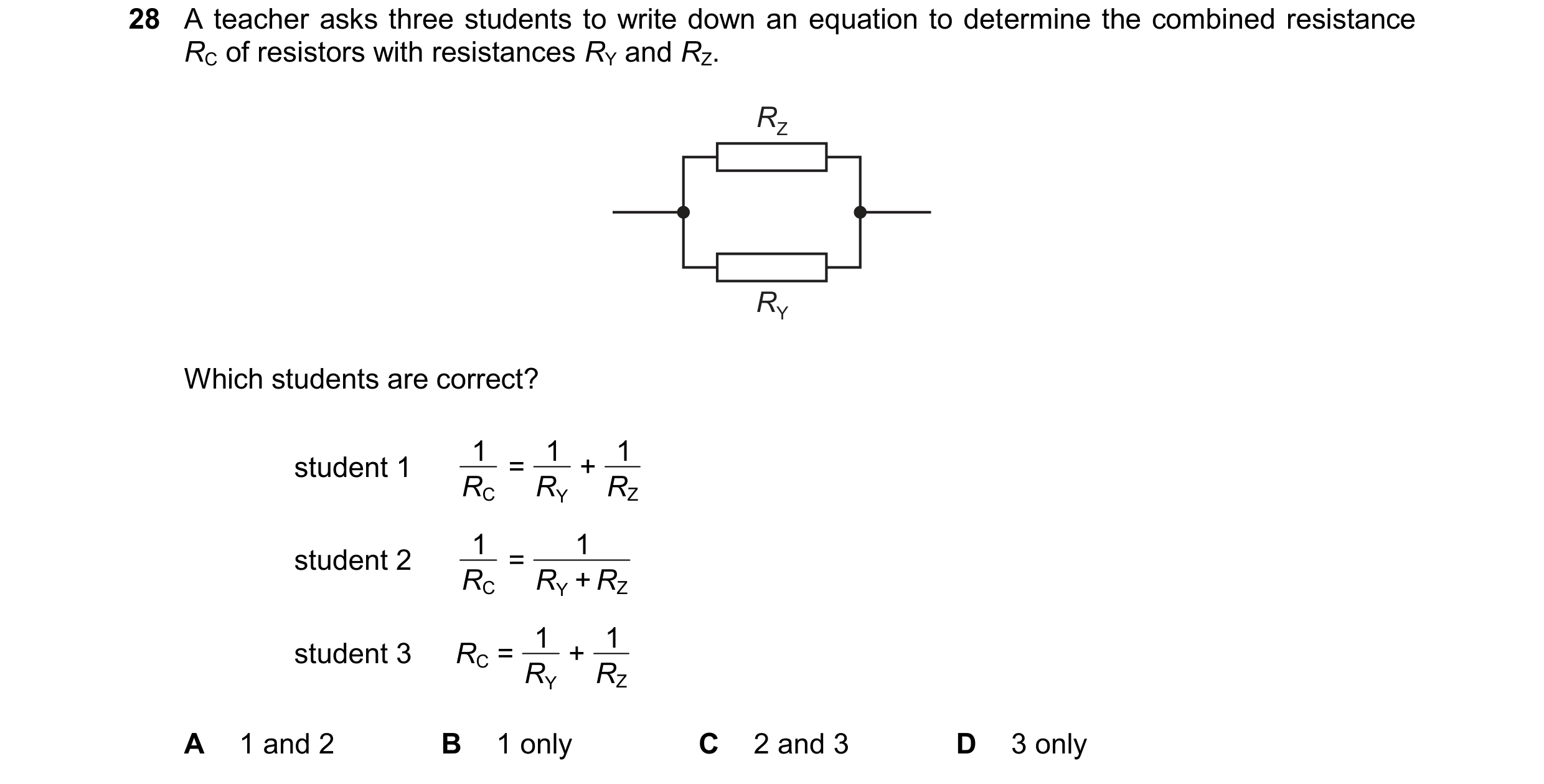 112 / 114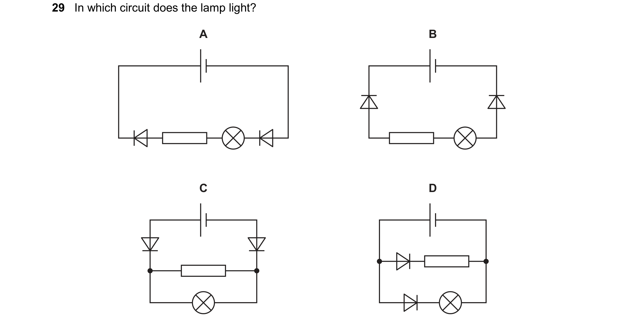
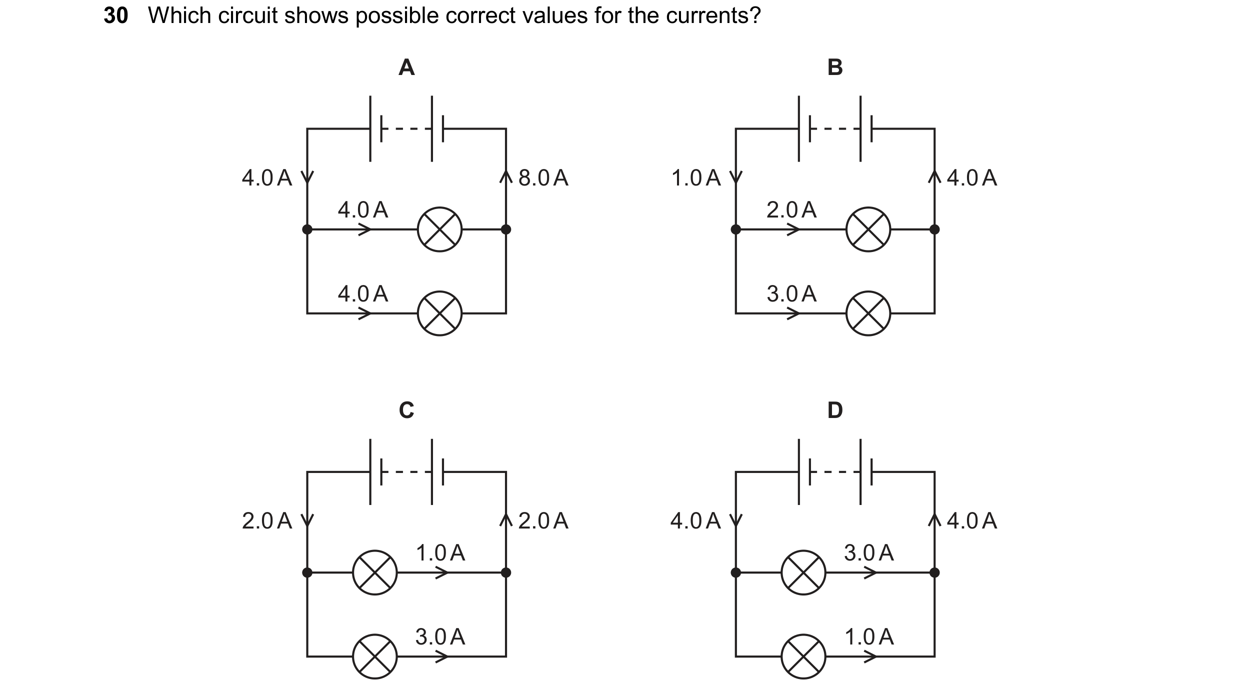 113 / 114
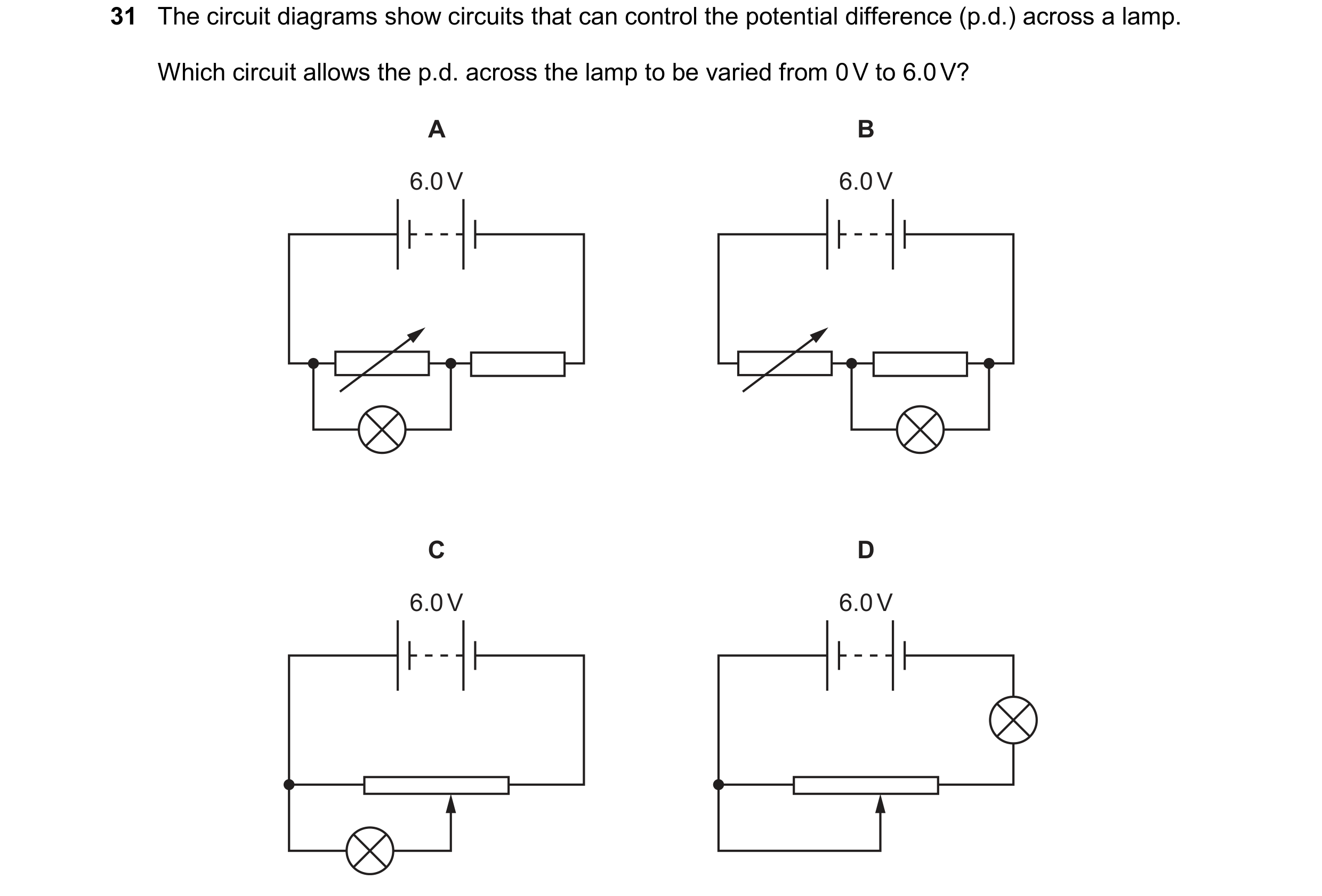 114 / 114