Questions as text
Q1 · A graph of current against potential difference (p.d.) for a filament lamp 0625/42 Feb/March 2017
9 Fig. 9.1 shows a graph of current against potential difference (p.d.) for a filament lamp. 0.80 current / A 0.60 0.40 0.20 0 0 2.0 4.0 6.0 8.0 p.d. / V Fig. 9.1 (a) State what happens to the resistance of the filament of the lamp as the p.d. changes (i) from 0 V to 1.0 V, … [1] (ii) from 1.0 V to 8.0 V. … [1] (b) At normal brightness, the p.d. across the lamp is 8.0 V. Calculate, for normal brightness, (i) the resistance of the lamp, resistance = … [3] (ii) the power of the lamp. power = … [2] (c) Five of these lamps, operating at normal brightness, are connected in parallel to a power supply. power supply Fig. 9.2 Determine (i) the electromotive force (e.m.f.) of the power supply, e.m.f. = … [1] (ii) the current from the power supply. current = … [1] [Total: 9]
9 marks
Mark scheme: 9(a)(i) Resistance constant B1 9(a)(ii) Resistance increases B1 9(b)(i) I = V/R in any form OR (R=) V/I C1 8.0/0.72 C1 11 Ω A1 9(b)(ii) (P = ) IV OR 0.72 × 8.0 C1 5.8 W A1 OR I2R OR 0.722 × candidate’s (b)(i) OR V2/R OR 82 / candidate’s (b)(i) (C1) 5.7 W or 5.8 W (dependent on exact data used) (A1) 9(c)(i) 8.0 V B1 9(c)(ii) (5 × 0.72 =) 3.6 A B1 Total: 9
This question in 0625/42 Feb/March 2017
Q2 · The resistance of a circuit component varies with the brightness of the light falling on… 0625/41 May/June 2017
9 (a) The resistance of a circuit component varies with the brightness of the light falling on its surface. (i) State the name of the component. … [1] (ii) Draw the circuit symbol for this component. [1] (b) Fig. 9.1 shows a 6.0 V battery connected in series with a 1.2 kΩ resistor and a thermistor. 1.2 kΩ 6.0 V V Fig. 9.1 (i) At a certain temperature, the resistance of the thermistor is 2.4 kΩ. Calculate the reading on the voltmeter. voltmeter reading = … [4] (ii) The battery connected to the circuit in Fig. 9.1 is not changed. Suggest a change that would cause the reading of the voltmeter to decrease. … [1] [Total: 7]
7 marks
Mark scheme: 9(a)(i) LDR OR light-dependent resistor B1 9(a)(ii) B1 9(b)(i) I = V / R C1 (total resistance =) 1.2 + 2.4 OR 3.6 seen C1 I = 6.0 / (1.2 + 2.4) OR 1.67 or 1.7 (mA) C1 (V =) 4.0 V A1 OR (V1 )= [R1 / (R1 + R2)] V (C1) (total resistance =) 1.2 + 2.4 OR 3.6 seen (C1) (V1 ) = (2.4 / 3.6) 6.0 (C1) = 4.0 V (A1) 9(b)(ii) Replace the 1.2 kΩ resistor with one of higher value OR Increase the temperature (of the thermistor or the room) B1 Total: 7
This question in 0625/41 May/June 2017
Q3 · A 12 V battery is connected in series to a 24 W lamp and to a parallel pair of identical… 0625/43 May/June 2017
9 A 12 V battery is connected in series to a 24 W lamp and to a parallel pair of identical resistors X and Y. Fig. 9.1 is the circuit diagram. 12 V X A B Y Fig. 9.1 The 24 W lamp lights at normal brightness when the potential difference (p.d.) across it is 6.0 V. The lamp is at normal brightness. (a) Calculate the resistance of the lamp. resistance = … [3] (b) Determine (i) the p.d. between A and B, p.d. = … [1] (ii) the combined resistance of the parallel pair of identical resistors X and Y, resistance = … [1] (iii) the resistance of X. resistance = … [2] (c) Resistor X is removed from the circuit in Fig 9.1. Explain why the lamp becomes dimmer. … … … … [2] [Total: 9]
9 marks
Mark scheme: 9(a) (I =) P I C1 6.0 ÷ 4.0 C1 1.5 Ω A1 9(b)(i) 6.0 V B1 9(b)(ii) 1.5 Ω B1 9(b)(iii) 1 2 1 1 1 R R R = + OR 1 ÷ 1.5 = 1 2 1 1 R R + OR 1 ÷ 1.5 = 2 R C1 3.0 (Ω) A1 9(c) resistance of circuit/parallel pair increases B1 current (in lamp) decreases OR less p.d. across lamp B1 Total: 9
This question in 0625/43 May/June 2017
Q4 · A circuit with three 1.5 V cells 0625/41 Oct/Nov 2017
9 Fig. 9.1 shows a circuit with three 1.5 V cells. A H 3.0 Ω C D B G E F 6.0 Ω Fig. 9.1 (a) Calculate (i) the total electromotive force (e.m.f.) of the cells, e.m.f. = … [1] (ii) the total resistance of the circuit, resistance = … [3] (iii) the current in the 3.0 Ω resistor. current = … [2] (b) State, using the letters in Fig. 9.1, how you would connect (i) an ammeter to measure the total current in the circuit, … … [1] (ii) a voltmeter to measure the potential difference (p.d.) across the 6.0 Ω resistor. … … [1]
8 marks
Mark scheme: 9(a)(i) B1 9(a)(ii) 1 / R = 1 / R1 + 1 / R2 OR R = 1 / (1 / R1 + 1 / R2) OR (R =) R1R2 / (R1 + R2) C1 Correct substitution of 3 and 6 C1 (R =) 2.0 Ω A1 9(a)(iii) V = IR in any form OR (I =) V / R OR 4.5 / 3 C1 1.5 A A1 OR I total = 4.5 / 2 = 2.25 A (C1) For 3 Ω, I = 2.25 × 6 / 9 = 1.5 A (A1) 9(b)(i) Connect ammeter (in wire) from A to B OR from H to G B1 9(b)(ii) Connect voltmeter (terminals) to A and H OR B and G OR C and D OR E and F B1
This question in 0625/41 Oct/Nov 2017
Q5 · Draw the circuit symbol for a diode 0625/41 Oct/Nov 2017
10 (a) (i) Draw the circuit symbol for a diode. [1] (ii) State the function of a diode. … [1] (b) Fig. 10.1 shows the proposed system for charging the battery of an electric toothbrush. battery + – handle of toothbrush B coil X A coil Y 230 V base of a.c. charger Fig. 10.1 The handle of the brush contains the battery and a coil X. The circuit from coil X to the battery is not shown. The base of the charger contains a coil Y, wound on an iron core, connected to the a.c. mains supply. To charge the battery, the handle is lowered so that coil Y is inside coil X. Fig. 10.1 shows the direction needed for the charging current at the battery. (i) On Fig. 10.1, complete the circuit from terminals A and B of coil X to the battery. Include a diode. [2] (ii) Explain how an alternating voltage is produced in coil X. … … … … … … [3] [Total: 7]
7 marks
Mark scheme: 10(a)(i) B1 10(a)(ii) To allow flow (of current) in one direction B1 10(b)(i) Wire from B to + or – terminal of battery and wire from A to other terminal of battery B1 Diode to allow current in at + terminal or out at – terminal B1 10(b)(ii) Alternating current in coil Y sets up alternating magnetic field OR causes change in magnetic flux B1 Alternating field / change in flux cuts coil X OR Alternating field links with coil X B1 (Alternating) voltage / current is induced in coil X OR (Alternating) voltage / current is produced in coil X by electromagnetic induction B1
This question in 0625/41 Oct/Nov 2017
Question 6 0625/42 Oct/Nov 2017
8 Fig. 8.1 is a circuit diagram. 24 V 8.0 Ω 4.0 Ω 6.0 Ω Fig. 8.1 Calculate (a) the resistance of the circuit, resistance = … [4] (b) the potential difference (p.d.) across the 8.0 Ω resistor. p.d. = … [2] [Total: 6]
6 marks
Mark scheme: 8(a) RS = RA + RB in any form OR (RS =) RA + RB OR (RS =) 4 + 8 C1 (RS =)12 (Ω) C1 (RP = )1 / (1 / RS + 1 / RC) in any form OR (RP =) RS RC / (RS + RC) OR (RP =) 1 / (1 / 12 + 1 / 6) OR (RP =) (6 × 12) / 18 C1 (RP =) 4.0 Ω A1 8(b) V8 = supply V × (8 / 12 ) OR = 24 × (8 / 12) C1 (V8 =) 16 V A1 OR alternative route I8 = supply V / 12 OR = 24 / 12 OR = 2 (A) (C1) (V8 = 2 × 8 =) 16 V (A1)
This question in 0625/42 Oct/Nov 2017
Question 7 0625/42 Oct/Nov 2017
9 (a) Fig. 9.1 is a circuit diagram. A C B Fig. 9.1 (i) State the names of circuit components A, B and C. component A … component B … component C … [2] (ii) The circuit can be used to indicate a change in temperature. State and explain what would be observed when the temperature changes from hot to cold. … … … … … … [4] (b) Fig. 9.2 shows a digital circuit. A B X C Fig. 9.2 Complete column X of the truth table for this circuit. Use the blank column for your working. A B C X 0 0 0 0 1 0 1 0 0 1 1 0 0 0 1 0 1 1 1 0 1 1 1 1 [3] [Total: 9]
9 marks
Mark scheme: 9(a)(i) A (fixed)resistor B thermistor C L.E.D. OR light emitting diode 2 correct B1 3 correct B1 9(a)(ii) any four from six: • if cold / hot resistance of thermistor high / low • if cold / hot voltage (across) thermistor high / low • if cold / hot voltage of input to LED high / low • if cold / hot there is current / no current in LED • if cold LED lights / brighter • if hot LED does not light / dimmer B1 9(b) Row A B C (output of AND) X 1 0 0 0 0 0 2 0 1 0 0 0 3 1 0 0 0 0 4 1 1 0 1 1 5 0 0 1 0 1 6 0 1 1 0 1 7 1 0 1 0 1 8 1 1 1 1 1 row 1 of X correct – answer 0 B1 rows 2 AND 3 of X correct – both answers 0 B1 rows 4–8 of X correct – all answers 1 B1
This question in 0625/42 Oct/Nov 2017
Q8 · State, in terms of their structure, why metals are good conductors of electricity 0625/41 May/June 2018
7 (a) State, in terms of their structure, why metals are good conductors of electricity. … … [1] (b) A cylindrical metal wire W1, of length l and cross-sectional area A, has a resistance of 16 Ω. l A second cylindrical wire W2 having length 2 and cross-sectional area 2 A, is made from the same metal. Determine (i) the resistance of W2, resistance of W2 = … [2] (ii) the effective resistance of W1 and W2 when connected in parallel. resistance of parallel pair = … [2] (c) The parallel pair of resistors in (b)(ii) is connected to a battery that is made from three cells in series, each of electromotive force (e.m.f.) E. There is a current in each resistor. (i) State the e.m.f. of the battery. … [1] (ii) The current in the battery is IB, the current in W1 is I1 and the current in W2 is I2. Place a tick (3) in one box to indicate how these three currents are related. I1 > I2 > IB I1 > IB > I2 I2 > I1 > IB I2 > IB > I1 IB > I1 > I2 IB > I2 > I1 I1 = I2 = IB [1] [Total: 7]
7 marks
Mark scheme: 7(a) (Metals) contain free/mobile electrons/delocalised electrons 1 7(b)(i) R α L and R α 1 ÷ A OR R α L ÷ A OR R = 16 × ½ ÷ 2 OR R = 16 ÷ 4 1 4.0 Ω 1 7(b)(ii) 1 ÷ R = (1 ÷ R1) + (1 ÷ R2) OR R = (R1 × R2) ÷ (R1 + R2) OR (1 ÷ R) = (1 ÷ 4) + (1 ÷ 16) OR (4 × 16) ÷ (4 + 16) 1 3.2 Ω 1 7(c)(i) 3E or 3 × E 1 7(c)(ii) IB > I2 > I1 (6th box ticked) 1
This question in 0625/41 May/June 2018
Q9 · A circuit that contains a battery of electromotive force (e.m.f.) 6.0 V, an ammeter, a 20… 0625/42 May/June 2018
8 Fig. 8.1 shows a circuit that contains a battery of electromotive force (e.m.f.) 6.0 V, an ammeter, a 20 Ω resistor and component X. 6.0 V A X 20 Ω Fig. 8.1 (a) (i) State the name of component X. … [1] (ii) The potential difference (p.d.) across the 20 Ω resistor is measured with a voltmeter. On Fig. 8.1, draw the symbol for this voltmeter connected to the circuit. [1] (b) The p.d. across the 20 Ω resistor is varied from zero to 6.0 V. For each value of p.d. a corresponding current is measured. On Fig. 8.2, draw a line to indicate how the current measured by the ammeter depends on the p.d. across the 20 Ω resistor. 0.40 current / A 0.30 0.20 0.10 0 0 1.0 2.0 3.0 4.0 5.0 6.0 p.d. / V Fig. 8.2 [3] (c) A second resistor is connected into the circuit in parallel with the 20 Ω resistor. (i) State how the combined resistance of the two resistors in parallel compares with the resistance of each of the resistors on its own. … … [1] (ii) The p.d. across the two parallel resistors is changed and the current in the battery for each value of the p.d. is measured. A second line could be drawn on Fig. 8.2 to indicate how the current measured by the ammeter depends on the p.d. across the two resistors in parallel. State how the second line differs from the original line. You are not expected to draw this second line. … … [1] [Total: 7]
7 marks
Mark scheme: 8(a)(i) variable resistor OR rheostat 1 8(a)(ii) voltmeter symbol correctly connected across 20 Ω resistor 1 8(b) (I = )V ÷ R OR 6.0 ÷ 20 OR (any value < 6.0) ÷ 20 1 correct calculation of I for V>0 accept point on graph with correct co-ordinates, apart from the origin 1 straight line from (0,0) to (6.0,0.30) tolerance within ½ small square 1 8(c)(i) (combined resistance) less (than the resistance of either/smaller resistor) 1 8(c)(ii) steeper OR gradient greater OR description of how the line differs (e.g. reaches 0.40 A before V reaches 6.0 V) ignore 2nd line above 1st line 1
This question in 0625/42 May/June 2018
Q10 · A circuit that includes a battery of electromotive force (e.m.f.) 12 V 0625/43 May/June 2018
9 Fig. 9.1 shows a circuit that includes a battery of electromotive force (e.m.f.) 12 V. 12 V A V 20 Ω Fig. 9.1 The reading on the ammeter is 0.15 A. (a) Calculate the resistance of the circuit. resistance = … [2] (b) The variable resistor is adjusted so that its resistance decreases. (i) State what happens to the reading on the ammeter. … [1] (ii) State and explain what happens to the reading on the voltmeter. … … … [2] (c) The battery is formed from cells of electromotive force (e.m.f.) 1.5 V. (i) Explain, in terms of electrical energy, what is meant by an electromotive force (e.m.f.) of 1.5 V. … … [2] (ii) State how many 1.5 V cells are connected in series to form the battery. … [1] [Total: 8]
8 marks
Mark scheme: 9(a) (R =) V ÷ I OR 12 ÷ 0.15 C1 80 Ω A1 9(b)(i) increases B1 9(b)(ii) (voltmeter reading) decreases OR less p.d. across variable resistor B1 more p.d. across 20Ω/fixed resistor B1 9(c)(i) 1.5 J of (electrical) energy supplied in driving charge around the circuit B1 energy per unit charge OR per coulomb B1 9(c)(ii) 8 B1
This question in 0625/43 May/June 2018
Q11 · The symbol for a 12 V battery 0625/41 Oct/Nov 2018
9 Fig. 9.1 shows the symbol for a 12 V battery. 12 V Fig. 9.1 (a) Two lamps are connected in parallel with the battery. On Fig. 9.1, using the correct symbols, complete the circuit diagram. [1] (b) One of these lamps has a resistance of 6.0 Ω. Calculate, for this lamp: (i) the current current = … [1] (ii) the power. power = … [2] (c) The power of the other lamp is 36 W. Calculate the total energy delivered to this lamp in 20 hours. energy = … [3] [Total: 7]
7 marks
Mark scheme: 9(a) 2 lamps with correct circuit symbol, in parallel, with correct connection to battery B1 9(b)(i) (12 / 6.0 =) 2.0 A B1 9(b)(ii) (P =) IV OR 2.0 × 12 C1 OR (P =) I2R OR 2.02 × 6.0 (C1) OR (P =) V2 / R OR 122 / 6.0 (C1) 24 W A1 9(c) (E =) IVt OR Pt in any form OR 36 × 20 C1 = 36 × 20 × 60 × 60 C1 = 2.6 × 10⁶ J A1
This question in 0625/41 Oct/Nov 2018
Q12 · Three identical lamps and an ammeter connected to a power supply 0625/42 Oct/Nov 2018
7 Fig. 7.1 shows three identical lamps and an ammeter connected to a power supply. power supply A Fig. 7.1 The switches are closed. Each lamp is rated at 60 W and operates at its normal working voltage of 110 V. (a) Calculate: (i) the current in each lamp current = … [2] (ii) the current in the ammeter current = … [1] (iii) the voltage of the power supply. voltage = … [1] (b) (i) Calculate the resistance of the filament of one of the lamps when working normally. resistance = … [2] (ii) Another lamp X has a filament with twice the resistance of each lamp in the circuit of Fig. 7.1. The material and the temperature of the filament in lamp X is the same as the filaments in the lamps in Fig. 7.1. In Table 7.1, tick any box in the right-hand column that shows a possible difference between the filament of lamp X and a filament of one of the lamps in the circuit. Table 7.1 X has half the length X has twice the length X has one quarter the area of cross-section X has half the area of cross-section X has two times the area of cross-section X has four times the area of cross-section [2] [Total: 8]
8 marks
Mark scheme: 7(a)(i) C1 (I = 60 / 110 = ) 0.55 A A1 7(a)(ii) (I =) 1.6 A B1 7(a)(iii) 110 V B1 7(b)(i) I = V / R in any form OR (R =) V / I OR (R =) V2 / P OR (R=) P / I2 C1 (R = 110 / 0.55 = ) 200 Ω A1 7(b)(ii) 2nd box (twice the length) B1 4th box (half the area of cross-section) B1
This question in 0625/42 Oct/Nov 2018
Q13 · Current-potential difference (p.d.) graphs for a resistor and for a thermistor 0625/42 Feb/March 2019
9 Fig. 9.1 shows current-potential difference (p.d.) graphs for a resistor and for a thermistor. 6.0 current / A 4.0 resistor 2.0 thermistor 0 0 2.0 4.0 6.0 8.0 p.d. / V Fig. 9.1 (a) Calculate the resistance of the thermistor when the p.d. across it is 7.0 V. resistance = … [2] (b) In Table 9.1, tick the boxes that indicate the effect on the resistances of the resistor and of the thermistor when the p.d. across them is increased from 0 to 7.0 V. Table 9.1 component resistance increases resistance is constant resistance decreases resistor thermistor [2] (c) The thermistor and the resistor are connected in parallel to a 7.0 V supply. Calculate: (i) the current from the supply current = … [2] (ii) the energy transferred from the supply in 5.0 minutes. energy = … [2] [Total: 8]
8 marks
Mark scheme: 9(a) C1 1.5 Ω A1 9(b) Resistor: resistance is constant B1 Thermistor: resistance decreases B1 9(c)(i) 4.6 + 4.6 C1 9.2 A A1 OR Combined resistance = (1.522 / (1.52 + 1.52) = ) 0.76 Ω (C1) (I = ) 7.0 / 0.76 = 9.2 A (A1) 9(c)(ii) (E =) IVt OR in words OR 9.2 × 7 × 5 × 60 C1 19 000 J A1
This question in 0625/42 Feb/March 2019
Q14 · A circuit diagram that includes component X 0625/41 May/June 2019
7 Fig. 7.1 shows a circuit diagram that includes component X. A X 20 Ω 30 Ω Fig. 7.1 (a) State the name of component X. … [1] (b) The electromotive force (e.m.f.) of the battery is E. The switch is closed. The potential difference (p.d.) across the 30 Ω resistor is V30. The p.d. across the 20 Ω resistor is V20. The p.d. across component X is VX. State an equation that relates VX to: (i) V30 … [1] (ii) E and V20. … [1] (c) The e.m.f. of the battery is 6.0 V and the resistance of component X is 15 Ω. Calculate: (i) the total resistance of the circuit resistance = … [3] (ii) the ammeter reading. reading = … [2] (d) The temperature of component X increases. State and explain what happens to the ammeter reading. … … … [2] [Total: 10]
10 marks
Mark scheme: 7(a) thermistor c.a.o. B1 7(b)(i) VX = V30 B1 7(b)(ii) VX = E – V20 in any form B1 7(c)(i) 1/R1 + 1/R2 = 1/Rtot OR (Rtot =) R1 R2 / (R1 + R2) OR 1/15 + 1/30 = 1/Rtot OR (15 × 30) / (15 + 30) C1 10 (Ω) OR 10 + 20 C1 30 Ω A1 7(c)(ii) I = V / R in any form OR (I =) V / R OR 6.0 / 30 C1 0.20 A A1 7(d) resistance of X decreases B1 ammeter reading / it increases and (total) resistance (of circuit) decreases / more voltage across 20 Ω resistor B1
This question in 0625/41 May/June 2019
Q15 · A conducting sphere is mounted on an insulating stand 0625/42 May/June 2019
8 (a) A conducting sphere is mounted on an insulating stand. Explain how you would use a positively charged rod of insulating material to charge the sphere by induction. … … … … … [3] (b) Fig. 8.1 shows an electronic component. Fig. 8.1 State the name of the component shown in Fig. 8.1 … [1] (c) In the space below, write down the truth table for a NAND gate. [2] (d) Fig. 8.2 shows the connections to two logic gates. A D B E C Fig. 8.2 Table 8.1 shows part of the truth table for the arrangement of logic gates in Fig. 8.2. Complete Table 8.1 for the input values shown. Table 8.1 intermediate inputs output point A B C D E 0 0 1 0 1 1 1 1 0 1 1 1 [3] [Total: 9]
9 marks
Mark scheme: 8(a) bring (charged) rod close to sphere / touching sphere B1 earth sphere or equivalent B1 remove earth (connection) AND keep rod close to sphere (until earth removed) o.w.t.t.e. B1 8(b) light emitting diode OR LED B1 8(c) correct labelling of I/P and O/P, all I/P numbers correct in any order B1 all 4 rows of numbers correct, in any order B1 8(d) column D correct B1 1st two rows of E correct B1 2nd two rows of E correct B1
This question in 0625/42 May/June 2019
Q16 · A circuit containing a filament lamp of resistance 0.30 Ω and two resistors, each of… 0625/42 May/June 2019
10 Fig. 10.1 shows a circuit containing a filament lamp of resistance 0.30 Ω and two resistors, each of resistance 0.20 Ω. 0.20 Ω 0.20 Ω 0.30Ω Fig. 10.1 (a) Calculate the combined resistance of the lamp and the two resistors. resistance = … [3] (b) The potential difference (p.d.) of the supply is increased so that the current in the lamp increases. State and explain any change in the resistance of the lamp. Statement … Explanation … … [2] [Total: 5]
5 marks
Mark scheme: 10(a) C1 (Rp = ) 0.12 (Ω) C1 (Rt = 0.12 Ω + 0.20 Ω = ) 0.32 Ω A1 10(b) Statement : resistance of lamp increases M1 Explanation : temperature of lamp increases A1
This question in 0625/42 May/June 2019
Question 17 0625/43 May/June 2019
9 (a) Fig. 9.1 shows an electrical component. Fig. 9.1 State the name of the component shown in Fig. 9.1. … [1] (b) In the space below, write down the truth table for a NOR gate. [2] (c) Fig. 9.2 shows the connections between two logic gates. A D B E C Fig. 9.2 Complete the truth table shown in Table 9.1 for this combination of logic gates. Table 9.1 inputs intermediate output point A B C D E 0 1 1 1 0 1 1 1 0 1 1 1 [3] (d) Referring to a simple electron model, state what distinguishes electrical conductors from electrical insulators. … … … … [1] [Total: 7]
7 marks
Mark scheme: 9(a) light dependent resistor OR LDR B1 9(b) Input 1 Input 2 Output 0 0 1 0 1 0 1 0 0 1 1 0 2 input columns and one output column AND 4 correct rows of input B1 All 4 rows with correct, in any order B1 9(c) D E 1 1 1 1 0 0 0 1 all D correct B1 first 2 rows of E correct B1 last 2 rows of E correct B1 9(d) conductors have free / delocalised electrons / electrons which move (freely) (electrons in insulators don’t move or are fixed) B1
This question in 0625/43 May/June 2019
Q18 · A circuit containing an LED and two resistors in parallel, each of resistance R 0625/43 Oct/Nov 2019
9 Fig. 9.1 shows a circuit containing an LED and two resistors in parallel, each of resistance R. R R 3.7 V Fig. 9.1 The normal operating voltage of the LED is 2.1 V and the normal current is 0.19 A. (a) (i) The potential difference (p.d.) across the LED is measured with a voltmeter. On Fig. 9.1, draw the symbol for this voltmeter connected to the circuit. [1] (ii) The current in the LED is measured with an ammeter. On Fig. 9.1, draw the symbol for this ammeter connected to the circuit. [1] (b) Calculate the value of R when the LED is operating normally. R = … [5] [Total: 7]
7 marks
Mark scheme: 9(a)(i) voltmeter shown connected across LED B1 9(a)(ii) ammeter shown connected in series with LED B1 9(b) p.d. across two resistors in parallel = (3.7 – 2.1 =) 1.6 V resistance of circuit = (3.7 / 0.19) = 19.5 Ω AND resistance of LED (= 2.1 / 0.19) = 11.1 Ω B1 combined resistances of two resistors in parallel = R / 2 OR 1 / R = 1 / R1 + 1 / R2 OR R = R1 R2 / R1 + R2 OR current in either R = I / 2 resistance across parallel combination of resistors = (19.5 – 11.1) = 8.4 Ω B1 R = V / I in any form R = V / I in any form C1 R / 2 = 1.6 / 0.19 R / 2 = 8.4 Ω C1 17 Ω 17 Ω A1
This question in 0625/43 Oct/Nov 2019
Question 19 0625/42 Feb/March 2020
8 Fig. 8.1 shows a circuit. 12 V A 3.0 Ω 2.0 Ω 6.0 Ω X Y 2.0 m Fig. 8.1 The lamp has a resistance of 3.0 Ω. Line XY represents a uniform resistance wire of resistance 6.0 Ω. (a) Calculate the reading on the ammeter. ammeter reading = … [2] (b) Fig. 8.2 shows the circuit with a different connection to the resistance wire and an added resistor. The length XY of the whole resistance wire is 2.0 m. The contact is made at Q where the distance XQ is 0.60 m. 12 V A 3.0 Ω 1.5 Ω 2.0 Ω 0.60 m X Q Y 2.0 m Fig. 8.2 Calculate the resistance of the circuit. resistance = … [4] [Total: 6]
6 marks
Mark scheme: 8(a) {Rs = R1 + R2 + R3 in any form OR (Rs )= R1 + R2 + R3 OR (Rs ) = 3 + 2 + 6 (Ω) OR (Rs ) = 11 (Ω)} AND {V= IR in any form OR (I=)V / R OR (I=) 12 / 11 (A)} (I=) 1.1 A A1 8(b) uses resistance of wire proportional to length OR (resistance XQ =) 6 Ω 0.6 / 2.0 (Ω) OR 1.8 (Ω) B1 1 / Rp = 1 / R1 + 1 / R2 OR (Rp=) R1R2 / (R1 + R2) C1 1 / Rp = 1 / 1.5 + 1 / (6 × 0.6 / 2) OR (Rp=) 1.5 × (6 × 0.6 / 2) / (1.5 + 6 × 0.6 / 2) OR (Rp= 1.5 × 1.8 / {1.5 + 1.8}) = 0.82 (Ω) C1 (R = 3 + 2 + 0.82 =) 5.8 Ω A1
This question in 0625/42 Feb/March 2020
Q20 · State the name of the logic gate with the symbol shown in Fig 0625/42 Feb/March 2020
9 (a) State the name of the logic gate with the symbol shown in Fig. 9.1. Fig. 9.1 … [1] (b) State the name of the logic gate with the truth table shown in Table 9.1. Table 9.1 input output 0 1 1 0 … [1] (c) Fig. 9.2 shows a digital circuit. A C E B D Fig. 9.2 Complete the truth table in Table 9.2 for this circuit for all possible combinations of input. Table 9.2 A B C D E 1 1 1 0 1 0 0 0 [4] [Total: 6]
6 marks
Mark scheme: 9(a) NAND B1 9(b) NOT B1 9(c) AB 1st row 11 AND 4th row 00 B1 AB 2nd and 3rd row 01 AND 10 in any order B1 E 1st two rows 0 1 B1 E last two rows 1 1 B1
This question in 0625/42 Feb/March 2020
Q21 · The power supply used in an electric vehicle contains 990 rechargeable cells each of… 0625/41 May/June 2020
8 The power supply used in an electric vehicle contains 990 rechargeable cells each of electromotive force (e.m.f.) 1.2 V. The cells are contained in packs in which all the cells are in series with each other. The e.m.f. of each pack is 54 V. (a) Calculate the number of packs in the power supply. number of packs = … [2] (b) When in use, each pack supplies a current of 3.5 A. (i) Calculate the rate at which each cell is transferring chemical energy to electrical energy. rate of energy transfer = … [2] (ii) The packs are connected in parallel to supply a large current to drive the electric vehicle. Explain why it is necessary to use thick wires to carry this current. … … … … [3] [Total: 7]
7 marks
Mark scheme: 8(a) 990 / (54 / 1.2) OR 990 / 45 OR (number of cells in pack =) 54 / 1.2 OR 45 C1 22 A1 8(b)(i) (P =) EI OR 1.2 × 3.5 C1 4.2 W OR 4.2 J / s A1 Question Answer Marks 8(b)(ii) thick wires have a smaller resistance B1 less thermal energy generated in wires B1 more efficient OR less risk of fire / insulation melting B1
This question in 0625/41 May/June 2020
Q22 · Describe how a digital signal differs from an analogue signal 0625/41 May/June 2020
9 (a) Describe how a digital signal differs from an analogue signal. You may draw a diagram. … … … [2] (b) (i) In the appropriate box, draw the symbol for an AND gate and the symbol for an OR gate. AND gate OR gate [1] (ii) State how the behaviour of an AND gate differs from that of an OR gate. … … [1] (c) An arrangement of logic gates A, B and C is shown in Fig. 9.1. The arrangement has two inputs, X and Y and two outputs P and Q. A X B P Y Q C Fig. 9.1 Output P of logic gate B has logic state 1 (high). (i) Determine the logic states of the two inputs of logic gate B. upper input = … lower input = … [1] (ii) Determine and explain the logic state of output Q. … … … … logic state of Q = … [3] [Total: 8]
8 marks
Mark scheme: 9(a) digital signal: consists of high and low states / voltages B1 analogue signal: continuously varying voltage B1 9(b)(i) AND gate AND OR gate B1 9(b)(ii) when the inputs differ AND ‘AND gate’ produces 0 AND ‘OR gate’ produces 1 B1 9(c)(i) both inputs to upper NOR gate are 0s B1 9(c)(ii) two (identical) inputs to NAND gate are 1s M1 lower input to lower NOR gate is 1 M1 output Q is 0 A1
This question in 0625/41 May/June 2020
Q23 · A light-emitting diode (LED) is a diode that emits light when there is a current in it 0625/42 May/June 2020
8 (a) A light-emitting diode (LED) is a diode that emits light when there is a current in it. Draw a circuit diagram showing an LED, connected so that it is lit, in series with a battery and a fixed resistor. Use standard electrical symbols. [4] (b) The p.d. across the LED when lit is 3.1 V and the current in the LED is 0.030 A. Calculate the value of the resistance of the LED when lit. resistance = … [2] (c) Fig. 8.1 shows a power supply of e.m.f. 10.5 V connected in series with a lamp and a heater. The p.d. across the lamp is 2.1 V and the current in the lamp is 1.5 A. Fig. 8.1 Calculate: (i) the resistance of the heater resistance = … [2] (ii) the power of the heater. power = … [2] [Total: 10]
10 marks
Mark scheme: 8(a) two circuit symbols correct B1 three circuit symbols correct B1 symbol for cell, battery or power supply AND two other circuit symbols in series B1 LED correct way round B1 8(b) R = V / I in any form OR (R =) V / I C1 (R = 3.1 / 0.030 =) 100 Ω A1 8(c)(i) uses 10.5 = 2.1 + V across heater C1 (R = 8.4 / 1.5 =) 5.6 Ω A1 8(c)(ii) P = VI in any form OR (P =) VI C1 (P = 8.4 × 1.5 =) 12.6 W A1
This question in 0625/42 May/June 2020
Q24 · Complete the truth table shown in Table 9.1 for a NAND gate 0625/42 May/June 2020
9 (a) Complete the truth table shown in Table 9.1 for a NAND gate. Table 9.1 input 1 input 2 output 0 0 0 1 1 0 1 1 [1] (b) The circuit shown in Fig. 9.1 contains two different types of gate, labelled X and Y. A X C B X E Y D Fig. 9.1 Table 9.2 shows a partially completed truth table for this circuit. Table 9.2 input intermediate point output A B C D E 0 0 0 0 0 1 1 0 1 0 1 0 1 1 1 1 (i) From Table 9.2, deduce the name of logic gate Y. Ring your answer from the list. AND NAND NOR NOT OR [1] (ii) Complete the truth table in Table 9.2. [2] (c) There is a current of 3.0 A in a copper wire. Calculate how many electrons pass through the copper wire every 60 s. The charge on an electron is 1.6 × 10⁻¹⁹ C. number of electrons = … [3] [Total: 7]
7 marks
Mark scheme: 9(a) output 1, 1, 1, 0 B1 9(b)(i) AND B1 9(b)(ii) first two lines of E 0,1 B1 last two lines of E 1,1 B1 9(c) Q = It in any form OR (Q =) It C1 (Q = 3 × 60) = 180 (C) C1 (n = 3 × 60 / 1.6 × 10⁻¹⁹) = 1.1 × 10²¹ C1
This question in 0625/42 May/June 2020
Q25 · Explain what is meant by electromotive force (e.m.f.) 0625/41 Oct/Nov 2020
8 (a) Explain what is meant by electromotive force (e.m.f.). … … … [2] (b) An electric heater contains two heating elements R1 and R2. An electric motor operates a fan. The fan blows cool air over the heating elements. Fig. 8.1 shows the circuit. S1 S2 S3 240 V mains M supply R1 R2 Fig. 8.1 The heater is powered by a mains supply of e.m.f. 240 V. Switches S1 and S2 are closed. Heating element R1 gets hot. The resistance of R1 is 30 Ω. (i) Calculate the current in heating element R1. current = … [1] (ii) Calculate the power produced in heating element R1. power = … [2] (iii) The resistance of heating element R2 is 60 Ω. Switches S1, S2 and S3 are closed. 1. State and explain how the current in R2 compares with the current in R1. … … … [2] 2. The current in the motor is 0.10 A. The cable from the electric heater to the plug for the mains socket is safe when the current in it is less than 20 A. Suggest and explain a suitable fuse rating for this circuit. … … … … [2] [Total: 9]
9 marks
Mark scheme: 8(a) (related to) energy supplied in driving charge in a circuit / conductor or property of source / battery / cell / power supply B1 energy supplied per / to unit charge or energy transferred to electrical energy or from other form of energy or energy in driving charge around a complete circuit B1 8(b)(i) (I = V ÷ R = 240 ÷ 30 =) 8.0 A B1 8(b)(ii) (P =) VI or 240 × 8.0 C1 1900 W A1 8(b)(iii)1 half (the size) B1 (equal voltage / p.d. / e.m.f. and) resistance is twice the size or I and R are inversely proportional B1 8(b)(iii)2 (fuse rating =) 13 A / 14 A / 15 A / 16 A / 17 A / 18 A / 19 A B1 total current is 12.1 A B1
This question in 0625/41 Oct/Nov 2020
Q26 · An incomplete electrical circuit 0625/42 Oct/Nov 2020
10 Fig. 10.1 shows an incomplete electrical circuit. 2.0 Ω C D 6.0 Ω A B E F 4.0 Ω Fig. 10.1 (a) (i) A student completes the circuit and measures the current in the 6.0 Ω resistor. On Fig. 10.1, draw an ammeter symbol in one gap and straight lines to indicate wires in the other gaps to show how the student should do this. [1] (ii) A voltmeter is connected to measure the potential difference (p.d.) across the 4.0 Ω resistor. On Fig. 10.1, draw a voltmeter symbol connected in the correct position. [2] (iii) With the circuit completed, the current in the 2.0 Ω resistor is 2.5 A. Calculate the current in the 6.0 Ω resistor. current = … [4] (b) Fig. 10.2 shows the same electrical circuit with an alternating current (a.c.) power supply and a wire in the gap AB. 2.0 Ω C D 6.0 Ω A B E F 4.0 Ω Fig. 10.2 On Fig. 10.2, draw a diode symbol in one gap and a straight line to indicate a wire in the other gap so that there is a current from right to left in the 4.0 Ω resistor and an alternating current in the 2.0 Ω resistor. [2] [Total: 9]
9 marks
Mark scheme: 10(a)(i) recognisable ammeter in gap AB AND straight lines in CD AND EF B1 10(a)(ii) recognisable voltmeter across 4 Ω B1 correct voltmeter symbol used B1 10(a)(iii) V = IR in any form or (V =) IR words, symbols or numbers C1 (V2Ω = 2 × 2.5 =) 5 V C1 (I4Ω = 5 ÷ 4 =) 1.3 A must be clear that I refers to 4 Ω OR calculates Rp = 1.33 Ω OR 4 ÷ 3 Ω C1 (I6Ω = 2.5 + 1.3 =) 3.8 A OR (I6Ω = 5 ÷ 1.33 =) 3.8 A A1 Alternative route for first 3 mps I proportional to 1 ÷ R OR I2Ω × R2Ω = I4Ω × R4Ω C1 I4Ω = I2Ω ÷ 2 C1 (I4Ω = I2Ω ÷ 2 = 2.5 ÷ 2 =) 1.3 A C1 Alternative route by potential divider V = IR in any form or (V =) IR words, symbols or numbers C1 (V2Ω = 2 × 2.5 =) 5 V C1 VT = 7.33 × 5 ÷ 1.33 (= 27.51 V) C1 (I6Ω = 27.51 ÷ 7.33 =) 3.8 A A1 Question Answer Marks 10(b) any sort of triangle symbol pointing to left in EF B1 a wire in CD B1
This question in 0625/42 Oct/Nov 2020
Question 27 0625/43 Oct/Nov 2020
8 (a) (i) Fig. 8.1 shows an electrical circuit. The resistor has a resistance of 4.0 Ω. The reading on the voltmeter is 3.0 V. A V Fig. 8.1 Calculate the current in the resistor. current = … [2] (ii) Fig. 8.2 shows the same circuit with one component reversed. A V Fig. 8.2 State the reading on the voltmeter and explain your answer. reading = … explanation … … [2] (b) Fig. 8.3 shows the symbol for a logic gate. X Z Y Fig. 8.3 The truth table for this logic gate is shown in Table 8.1. Table 8.1 input X input Y output Z 0 0 0 0 1 0 1 0 0 1 1 1 State the name of this logic gate. …………………………………………….. [1] (c) (i) A student designs the circuit shown in Fig. 8.4. A C B E D Fig. 8.4 Complete the truth table for this circuit in Table 8.2. Table 8.2 A B C D E 0 0 0 1 1 0 1 1 [3] (ii) A single logic gate can be used to produce output E in Fig. 8.4 with the inputs A and B shown in Table 8.2. State the name of this logic gate. ………………………………………. [1] [Total: 9]
9 marks
Mark scheme: 8(a)(i) C1 (I =) 0.75 A A1 8(a)(ii) 0 (V) OR nothing OR no reading M1 diode does not pass current (in reverse direction) A1 8(b) AND gate B1 8(c)(i) C and D both 1 0 0 0 B1 first line of E 0 B1 2nd, 3rd and 4th lines of E 1 B1 8(c)(ii) OR B1
This question in 0625/43 Oct/Nov 2020
Q28 · A student sets up a circuit that includes a 12 V battery, an 800 Ω resistor, a voltmeter… 0625/41 May/June 2021
8 A student sets up a circuit that includes a 12 V battery, an 800 Ω resistor, a voltmeter and a thermistor. Fig. 8.1 is an incomplete circuit diagram because the symbol for the thermistor is missing. 800 Ω 12 V P V Q Fig. 8.1 The thermistor is connected between terminals P and Q. (a) Complete Fig. 8.1 by drawing the symbol for a thermistor between terminals P and Q. [1] (b) The 12 V battery consists of eight identical cells connected in series. Calculate the electromotive force (e.m.f.) of each cell. e.m.f. = … [1] (c) The reading on the voltmeter is 8.0 V. (i) Determine the resistance of the thermistor. resistance = … [3] (ii) A few hours later, the student notices that the reading on the voltmeter is greater. Explain what can be deduced from this observation. … … … … [3] [Total: 8]
8 marks
Mark scheme: 8(a) and between P and Q B1 8(b) 1.5 V c.a.o. B1 8(c)(i) 1600 Ω A3 (V800 Ω =) 4.0 (V) C1 (I =) V / R in any form or 4.0 / 800 or 0.0050 (A) or (R =) V / I or 8.0 / 0.0050 C1 OR 1600 Ω (A3) (V800 Ω =) 4.0 (V) (C1) (RTh =) R800 Ω × VTh / V800 Ω in any form or (RTh =) 800 × 8.0 / 4.0 in any form (C1) OR 1600 Ω (A3) 12 800+RTh or 8.0 RTh or RTh 800+RTh (C1) 12 800+RTh = 8.0 RTh in any form (C1) Question Answer Marks 8(c)(ii) larger proportion of the e.m.f. (across thermistor) or smaller voltage across 800 Ω B1 temperature (of thermistor) is smaller / has decreased B1 resistance of thermistor / circuit is large(r) B1
This question in 0625/41 May/June 2021
Question 29 0625/42 May/June 2021
9 (a) Fig. 9.1 shows a circuit. M A Fig. 9.1 On Fig. 9.1, draw two clearly labelled arrows to show the direction of the electron flow and the direction of the conventional current in the circuit. [2] (b) The current in the motor is 13 A. The charge on an electron is 1.6 × 10⁻¹⁹ C. Calculate the number of electrons that pass through the motor every second. number of electrons = … [3] [Total: 5]
5 marks
Mark scheme: 9(a) anti-clockwise arrow labelled (conventional) current somewhere in circuit B1 electron (flow) arrow opposite to (conventional) current B1 9(b) Q = It in any form or (Q =) It OR 13 × 1 C1 (Q = It =) 13 × 1 (= 13 C) C1 (n = 13 / 1.6 × 10–19 =) 8.1 × 10¹⁹ A1
This question in 0625/42 May/June 2021
Q30 · The potential difference–current graph for a circuit component K 0625/42 May/June 2021
10 (a) Fig. 10.1 shows the potential difference–current graph for a circuit component K. 10.0 8.0 potential difference / V 6.0 4.0 2.0 0 0 1.0 2.0 3.0 4.0 5.0 6.0 current / mA Fig. 10.1 Calculate the resistance of component K when the current in it is 4.0 mA. resistance = … [2] (b) Fig. 10.2 shows a circuit containing component K. component K point X resistor R Fig. 10.2 At low temperature, component K has a much greater resistance than resistor R. At high temperature, component K has a much smaller resistance than resistor R. State and explain the effect on the lamp when the temperature changes from very low to very high. Refer to the voltage at point X in your explanation. statement … explanation … … … … … [4] (c) State the name of component K. … [1] [Total: 7]
7 marks
Mark scheme: 10(a) C1 (R = 9.2 / 0.004 =) 2300 Ω A1 Question Answer Marks 10(b) (much) greater current in lamp OR lamp activated / lights / glows / gets brighter owtte B1 resistance of thermistor / component / K reduced (compared to value at (very) low temperature) B1 voltage / p.d. of point X / across R increases M1 (larger) current in lamp A1 10(c) thermistor B1
This question in 0625/42 May/June 2021
Q31 · Define electromotive force (e.m.f.) 0625/43 May/June 2021
7 (a) Define electromotive force (e.m.f.). … … … [2] (b) Fig. 7.1 shows a circuit. 12 V P Q Fig. 7.1 The two lamps shown are identical. Each lamp has a potential difference (p.d.) of 3.0 V across it and a current of 2.0 A in it. PQ is a length of uniform metal wire. The resistance of PQ is R. (i) Calculate the value of R. R = … [3] (ii) Another piece of wire is made of the same metal as PQ. The length of the new piece of wire is twice the length of PQ. The diameter of the new piece of wire is twice the diameter of PQ. Calculate the resistance of the new piece of wire. resistance = … [3] [Total: 8]
8 marks
Mark scheme: 7(a) energy supplied M1 to drive a unit charge / 1 C round a complete circuit A1 7(b)(i) (R =) 2.3 Ω OR 2.2 Ω A3 R = V/I in any form C1 current in R = 4 (A) OR p.d. across R = 9 (V) C1 7(b)(ii) 1.1 Ω A3 resistance proportional to length (so twice length twice resistance) C1 resistance inversely proportional to area (so twice diameter decreases resistance by factor of 4) C1
This question in 0625/43 May/June 2021
Q32 · State the difference between an analogue signal and a digital signal 0625/43 May/June 2021
8 (a) State the difference between an analogue signal and a digital signal. You may draw a diagram to help explain your answer. … … [2] (b) Draw the symbol for a NOR gate. [1] (c) Fig. 8.1 shows a combination of logic gates X, Y and Z. The gates are not represented by the standard symbols. A logic gate D B logic logic X E F gate gate C Y Z Fig. 8.1 Table 8.1 shows a partly completed truth table for this combination of logic gates. Table 8.1 intermediate inputs output points A B C D E F 0 0 0 0 0 0 1 0 0 0 1 0 1 0 1 1 1 1 1 1 0 0 0 0 0 0 1 0 0 0 1 0 1 0 1 1 1 1 1 1 (i) From Table 8.1, deduce: 1. the name of logic gate X … [1] 2. the name of logic gate Y. … [1] (ii) Logic gate Z is a NAND gate. Complete column F of Table 8.1. [2] [Total: 7]
7 marks
Mark scheme: 8(a) digital signal only two states – low or high OR 0 or 1 B1 analogue signal any value B1 8(b) correct symbol for NOR gate B1 8(c)(i) AND B1 OR B1 8(c)(ii) rows 1, 2, 5, 6 all 1 B1 rows 3, 4, 7, 8 all 0 B1
This question in 0625/43 May/June 2021
Q33 · A circuit contains two fixed resistors and a light‑dependent resistor (LDR) 0625/41 Oct/Nov 2021
8 A circuit contains two fixed resistors and a light‑dependent resistor (LDR). Fig. 8.1 shows that the power supply is a 9.0 V battery. 9.0 V 450 Ω 800 Ω Fig. 8.1 The current in the 450 Ω resistor is 0.012 A. (a) State what is meant by electric current. … … [1] (b) The current in the LDR is I1 and the current in the 800 Ω resistor is I2. Complete the equation that relates the current in the 450 Ω resistor to I1 and I2. current in the 450 Ω resistor = … [1] (c) Calculate the power dissipated in the 800 Ω resistor. power = … [4] (d) The brightness of the light that is incident on the LDR increases. Explain what happens to the potential difference (p.d.) across the 450 Ω resistor. … … … … [3] [Total: 9]
9 marks
Mark scheme: 8(a) Q / t or (rate of) flow of (electric) charge / electrons B1 8(b) (current in the 450 Ω resistor =) … B1 8(c) (V450 Ω =) IR or 0.012 × 450 or 5.4 (V) or 9.0 – 5.4 or 3.6 (V) seen C1 (I =) 3.6 / 800 or 0.0045 (A) C1 (P =) VI or 3.6 × 0.0045 or 3.62 / 800 C1 1.6 × 10⁻² W or 16 mW A1 8(d) resistance (of LDR) decreases B1 current (in circuit) increases or resistance of parallel pair decreases C1 p.d. across 800 Ω resistor increases and p.d. across 450 Ω resistor decreases or resistance of parallel pair a smaller fraction of total resistance and p.d. across 450 Ω resistor decreases A1 I2 – I1
This question in 0625/41 Oct/Nov 2021
Q34 · A cell of electromotive force (e.m.f.) 1.5 V and a battery of e.m.f 0625/42 Oct/Nov 2021
9 (a) Fig. 9.1 shows a cell of electromotive force (e.m.f.) 1.5 V and a battery of e.m.f. 6.0 V connected in series. 1.5 V 6.0 V Fig. 9.1 Calculate the combined e.m.f. of the cell and the battery. e.m.f. = … [1] (b) The combined resistance of the three resistors shown in Fig. 9.2 is 4.4 Ω. 2.0 Ω I R 3.0 Ω Fig. 9.2 (i) Calculate the resistance of resistor R. resistance = … [3] (ii) The current I in Fig. 9.2 is 0.94 A. Calculate the potential difference (p.d.) across the combination of resistors. p.d. = … [2] [Total: 6]
6 marks
Mark scheme: 9(a) 7.5 V B1 9(b)(i) 1 / Rp = 1 / R1 + 1 / R2 OR (Rp =) R1R2 / (R1 + R2) in any form C1 (Rp =) 1.2 (Ω) C1 3.2 Ω A1 9(b)(ii) (V =) IR in any form C1 4.1 V A1
This question in 0625/42 Oct/Nov 2021
Q35 · Name the logic gate shown in Fig 0625/42 Oct/Nov 2021
10 (a) Name the logic gate shown in Fig. 10.1. … Fig. 10.1 [1] (b) Fig. 10.2 shows a combination of logic gates. input I output O Fig. 10.2 Complete the right-hand column of Table 10.1, the truth table for the combination of logic gates. You may use the blank column for your working. Table 10.1 input I output O 0 1 [2] (c) An electrical device has a metal case. Explain the benefit of earthing the metal case. … … … [2] (d) (i) Explain how a fuse protects a circuit. … … … [2] (ii) The current in an electric kettle connected to the mains through a fuse is 10 A. Fuses with the following ratings are available. 3 A 9 A 10 A 13 A 30 A Circle the correct fuse rating for this appliance and explain your answer. … … … [2] [Total: 9]
9 marks
Mark scheme: 10(a) OR (gate) B1 10(b) 0 B1 1 B1 10(c) prevents electrocution OR metal case cannot become live OR metal case always at earth potential / voltage B1 (if) live wire touches metal case B1 10(d)(i) if current too high B1 fuse melts B1 10(d)(ii) 13 A (circled) B1 fuse rating/value above but near (to) normal operating current/ 10 A OR fuse rating/value slightly higher (than) normal operating current /10A OWTTE B1
This question in 0625/42 Oct/Nov 2021
Q36 · Current–potential difference (p.d.) graphs for a resistor, a thermistor and a filament… 0625/43 Oct/Nov 2021
9 Fig. 9.1 shows current–potential difference (p.d.) graphs for a resistor, a thermistor and a filament lamp. 1.0 filamentfilament lamplamp current / A 0.8 resistorresistor 0.6 0.4 thermistorthermistor 0.2 0 0 2 4 6 8 10 12 p.d. / V Fig. 9.1 The resistor, the thermistor and the filament lamp are connected in series with a power supply. (a) (i) Draw a circuit diagram for this circuit. [2] (ii) Add a voltmeter to your circuit diagram in (a)(i) in a correct position to measure the p.d. across the resistor. [1] (iii) Using the graph in Fig. 9.1, determine the p.d. across the terminals of the power supply when the p.d. across the resistor is 6.0 V. p.d. across terminals of power supply = … [4] (b) Describe a practical use for a thermistor. … … [1] [Total: 8]
8 marks
Mark scheme: 9(a)(i) B2 four components joined in series B1 all circuit symbols correct for resistor, thermistor, a filament lamp and a power supply B1 9(a)(ii) voltmeter connected in parallel to the resistor B1 9(a)(iii) (p.d. across terminals of power supply) = 18 V A4 (current through resistor when p.d. across it is 6.0 V =) 0.4 A C1 current same through all components in series circuit OR horizontal line through 0.4 A on graph through all three curves OR p.d. across filament lamp = 3.0 V OR p.d. across thermistor = 9.0 V C1 p.d. across filament lamp = 3.0 V AND p.d, across thermistor = 9.0 V C1 9(b) any sensible use requiring temperature control or depending on temperature, e.g. fire alarms, to keep computers cool (by operating fan), in incubators, electronic thermometer, electronic thermostat in kettle / car engine B1
This question in 0625/43 Oct/Nov 2021
Q37 · Combinations of logic gates are used when digital signals are processed 0625/41 May/June 2022
9 Combinations of logic gates are used when digital signals are processed. (a) Describe the difference between a digital signal and an analogue signal. You may include a diagram if it helps your answer. … … … [2] (b) Fig. 9.1 is the truth table for a logic gate X. input A input B output 0 0 1 0 1 0 1 0 0 1 1 0 Fig. 9.1 State the name of logic gate X and draw the symbol that represents it. name … symbol [1] (c) Logic gate Y is identical to logic gate X. Draw a combination of logic gates X and Y that behaves like an OR gate. Label the inputs A and B and label the output Q. [2] [Total: 5]
5 marks
Mark scheme: 9(a) digital (signal) consists of 1(s) and 0(s) / high value and low B1 analogue (signal) is (continuously) variable (in magnitude) B1 9(b) NOR (gate) and B1 9(c) A2 (i.e. NOR gate symbol with two inputs joined seen) C1 A B Q
This question in 0625/41 May/June 2022
Q38 · How the electromotive force (e.m.f.) of a 60 Hz alternating current (a.c.) power supply… 0625/42 May/June 2022
8 Fig. 8.1 shows how the electromotive force (e.m.f.) of a 60 Hz alternating current (a.c.) power supply varies with time. e.m.f. 0 0 time time period Fig. 8.1 (a) Calculate the time period of the a.c. time period = … [1] (b) Fig. 8.2 shows this power supply connected in a circuit. A B C Fig. 8.2 (i) State the name of component A. … [1] (ii) In each time period of the a.c., 1.5 × 10¹⁷ electrons pass through component A. The charge on an electron is 1.6 × 10⁻¹⁹ C. Calculate the average current in the circuit during one time period. current = … [3] (c) On Fig. 8.3: 1. mark, with an arrow labelled E, the direction of the electron flow through component B 2. mark, with an arrow labelled I, the direction of the conventional current in component C. A B C Fig. 8.3 [2] (d) Fig. 8.4 shows a circuit with components B and C connected to a direct current (d.c.) power supply of e.m.f. 12 V. B C Fig. 8.4 The current in the circuit is 0.35 A. Calculate the power delivered by the power supply to the circuit. power = … [2] [Total: 9]
9 marks
Mark scheme: 8(a) 8(b)(i) diode B1 8(b)(ii) (I =) 1.4 A A3 (I =) Q / t in any form C1 (I =) 1.5 1017 1.6 10–19 / 0.017 OR 0.024 / 0.017 C1 Question Answer Marks 8(c) one arrow clockwise AND one arrow anticlockwise B1 arrow anticlockwise (around circuit) labelled I B1 8(d) (P = 0.35 12 =) 4.2 W A2 (P =) IV in any form C1
This question in 0625/42 May/June 2022
Q39 · A circuit with a 3-position switch 0625/42 May/June 2022
9 Fig. 9.1 shows a circuit with a 3-position switch. 12 V C B X Y A M Fig. 9.1 The moving part of the switch is always connected to point Y around which it pivots. The other end of the moving part, labelled X, can be connected to one of the points A, B or C. (a) The resistance of the motor is 2.0 Ω and the resistance of the resistor is 3.0 Ω. Determine the current in the motor when the switch is connected to: (i) point A current = … [1] (ii) point B current = … [2] (iii) point C. current = … [2] (b) Two resistors of resistance 2.0 Ω and 3.0 Ω are connected in parallel. Calculate the combined resistance of the resistors in this arrangement. resistance = … [3] [Total: 8]
8 marks
Mark scheme: 9(a)(i) 0 (A) B1 9(a)(ii) (I = 12 / 2 =) 6.0 A A2 (I =) V / R in any form C1 9(a)(iii) (I = 12 / 5 =) 2.4 A A2 (Rs = R1 + R2 = 2 + 3 =) 5 () C1 9(b) (Rp = 6 / 5 =) 1.2 A3 1 / Rp = 1 / R1 + 1 / R2 OR (Rp =) R1 R2 / (R1 + R2) C1 1 / Rp = 1 / 2 + 1 / 3 OR (Rp =) 2 3 / (2 + 3) C1
This question in 0625/42 May/June 2022
Q40 · A simplified diagram of a digital circuit 0625/42 May/June 2022
10 Fig. 10.1 is a simplified diagram of a digital circuit. The output of logic gate Y controls a buzzer. logic gate X input A input B logic gate Y Fig. 10.1 (a) Complete Table 10.1, the truth table for the circuit. Table 10.1 input A input B output of X output of Y 0 0 0 1 1 0 1 1 [3] (b) Input A is the output of a humidity sensor which gives logic 1 when the humidity is high and logic 0 when the humidity is low. Input B is the output of a light sensor which gives logic 1 in bright light and logic 0 in darkness. The buzzer sounds when the output of Y is logic 1. State the conditions of humidity and light when the buzzer is on. … [1] (c) The output of the digital circuit alone is not able to operate the buzzer. Ring the component from the list that must be connected between the output of the digital circuit and the buzzer. fuse heater relay resistor thermistor Explain your answer. … … [3] [Total: 7]
7 marks
Mark scheme: 10(a) output of X output of Y 1 0 1 0 0 1 0 0 all column X correct 1, 1, 0, 0 B1 first 2 rows of column Y correct 0, 0 B1 last 2 rows of column Y correct 1, 0 B1 10(b) high humidity AND dark(ness) B1 10(c) relay M1 low voltage output (of NOR gate/gate Y) OR small current (in relay coil) A1 large(r) current provided (by relay) OR large(r) voltage provided (by relay) A1
This question in 0625/42 May/June 2022
Question 41 0625/43 May/June 2022
8 (a) Fig. 8.1 shows a circuit. X Y Fig. 8.1 (i) State the name of component X. … [1] (ii) The potential difference (p.d.) across component Y is measured with a voltmeter. On Fig. 8.1, draw the symbol for the voltmeter and its connections to the circuit. [1] (iii) The electromotive force (e.m.f.) of the battery is 12 V. Component Y has a resistance of 400 Ω. In a brightly lit room, the resistance of component X is 350 Ω. 1. Calculate the current in the circuit. current = … [2] 2. Calculate the p.d. across component Y. p.d. = … [1] (iv) In a dark room, the resistance of component X is very large. State the effect this will have on the p.d. across component Y. … [1] (b) Suggest a practical use for component X. … [1] [Total: 7]
7 marks
Mark scheme: 8(a)(i) light-dependent resistor / LDR B1 8(a)(ii) voltmeter connected in parallel with component Y B1 8(a)(iii) 1 0.016 A A2 (I =) V/R in any form or 12/400 or 12/350 or 12/750 OR (Rtotal = R1 + R2 =) 750 () C1 2 6.4 V A1 8(a)(iv) (in a dark room the p.d. across component Y) decreases B1 8(b) one named practical application of LDR e.g. switch on street lights (at night) / turn on security light (at night) B1
This question in 0625/43 May/June 2022
Q42 · The electric starter motor in a car is switched on and off using a relay 0625/41 Oct/Nov 2022
7 The electric starter motor in a car is switched on and off using a relay. The relay consists of a plastic case and two flexible springy strips, X and Y, which are made of soft iron. These iron strips act as the switch when a circuit is connected between the terminals W and Z. Fig. 7.1 shows X, Y and the plastic case. W W S springy iron X strips X 12 V car battery Y Y magnetising coil plastic case Z Z Fig. 7.1 Fig. 7.2 Fig. 7.2 shows the equipment from Fig. 7.1 inside a magnetising coil. The magnetising coil is in series with the 12 V car battery and switch S, which is open. (a) Switch S is now closed. Explain what happens to the springy iron strips X and Y. … … … … [3] (b) The power of the starter motor is 1.8 kW and it is also operated by the car battery. (i) Calculate the current in the starter motor when it is used. current = … [2] (ii) The starter motor circuit is connected between terminals W and Z. Explain why copper wires with a large cross-sectional area are used for this circuit. … … … [2] (c) Fig. 7.3 shows the relay and the symbols for the car battery and the starter motor. W S X 12 V car battery Y Z M starter motor Fig. 7.3 The springy iron strips X and Y act as the switch for the starter motor circuit. Complete the circuit diagram for the motor circuit. [2] [Total: 9]
9 marks
Mark scheme: 7(a) B3 X and Y / they become magnetised or they / strips have poles B1 strips in the centre have opposite (magnetic) poles or X and Y attract B1 X and Y touch / close switch / activate relay / complete circuit B1 7(b)(i) 150 A A2 I = P / V in any form or 1.8 / 12 or 1800 / 12 or 1800 / 12 or 0.15 C1 7(b)(ii) B2 small(er) resistance mentioned B1 less thermal energy produced or wires do not melt or large current mentioned B1 7(c) B2 flexible strips in series with motor B1 power supply in series with motor B1 expected answer: W flexible iron S strips X 12 V car battery Y magnetising coil plastic case Z M starter motor
This question in 0625/41 Oct/Nov 2022
Q43 · The unit of the two electrical quantities electromotive force (e.m.f.) and potential… 0625/41 Oct/Nov 2022
8 The unit of the two electrical quantities electromotive force (e.m.f.) and potential difference (p.d.) is the volt (V). (a) State one other similarity between e.m.f. and p.d. … … [1] (b) State one difference between e.m.f. and p.d. … … [1] (c) A battery consists of four cells, each of e.m.f. 1.2 V, in series. (i) Calculate the e.m.f. of the battery. e.m.f. = … [1] (ii) The battery is connected in a circuit with four 12 Ω resistors. Fig. 8.1 is the circuit diagram. V Fig. 8.1 Calculate the total resistance of this arrangement of resistors. resistance = … [3] (iii) Calculate the reading on the voltmeter in Fig. 8.1. reading = … [2] [Total: 8]
8 marks
Mark scheme: 8(a) both relate to energy per unit charge B1 8(b) e.m.f. applies to the whole circuit / source or p.d. to one (or more) component or energy conversion to electrical for e.m.f. or B1 from electrical for p.d. 8(c)(i) 4.8 V B1 8(c)(ii) 20 A3 1 / RT = 1 / R1 + 1 / R2 or (RT =) R1 R2 / (R1 + R2) or 1 / RT = 1 / 24 + 1 / 12 C1 or 1 / RT = 3 / 24 or (RT =) 24 × 12 / (24 + 12) 8.0 () C1 8(c)(iii) 2.9 V A2 V = ER / RT in any form or 4.8 12 / 20 or I = E / R in any form or 0.24 seen C1
This question in 0625/41 Oct/Nov 2022
Q44 · Apparatus used to charge a metal plate by induction 0625/43 Oct/Nov 2022
8 Fig. 8.1 shows apparatus used to charge a metal plate by induction. positively charged plastic rod metal plate lead connected insulator to earth Fig. 8.1 (a) Describe and explain how the apparatus shown in Fig. 8.1 can be used to charge the metal plate. … … … … … … [4] (b) Fig. 8.2 shows an electric circuit. Fig. 8.2 On Fig. 8.2, draw an arrow to show the direction of flow of electrons and explain how you determined the direction. explanation … [1] [Total: 5]
5 marks
Mark scheme: 8(a) positively charged / plastic rod is brought close to metal plate B1 negative charges / electrons (from metal plate) move to top of metal plate / close(r) to rod B1 earth lead connected to (metal) plate AND negative charges / electrons move on to plate B1 (at the end of the process) earth lead removed (before charged rod removed) B1 OR (at the end of the process) metal plate has (net) negative charge 8(b) correct direction – pointing away from negative terminal / clockwise arrow B1 AND current flow in opposite direction to flow of electrons
This question in 0625/43 Oct/Nov 2022
Q45 · A circuit with an alternating current (a.c.) supply, a resistor and a diode 0625/43 Oct/Nov 2022
9 Fig. 9.1 shows a circuit with an alternating current (a.c.) supply, a resistor and a diode. Fig. 9.1 The frequency of the power supply is 50 Hz. (a) Calculate the time period (time for one complete cycle) of the a.c. supply. time = … [2] (b) The peak potential difference (p.d.) across the resistor is 340 V. p.d. / V 0 0 time / s Fig. 9.2 On Fig. 9.2: (i) sketch a graph to show how the p.d. across the resistor varies with time for two cycles [2] (ii) label the p.d. axis with the value of p.d. at the peak [1] (iii) label the time axis with two values of time. [2] [Total: 7]
7 marks
Mark scheme: 9(a) 0.02 s A2 t =1 / f OR (t = )1 / f OR 1 / 50 C1 9(b)(i) correct shape shown with rectification for two cycles A2 sine shape shown (without rectification for two cycles) C1 9(b)(ii) 340 marked A1 9(b)(iii) one correct time value marked on time axis B1 a second correct time value marked on time axis B1
This question in 0625/43 Oct/Nov 2022
Q46 · Define potential difference (p.d.) 0625/42 Feb/March 2023
7 (a) Define potential difference (p.d.). … … [2] (b) (i) State the equation which defines electromotive force (e.m.f.) E. [1] (ii) The e.m.f. of a battery is 9.0 V. The battery is in a circuit. Calculate the work done by the battery when it moves a charge of 30 C around a complete circuit. work done = … [2] (c) A circuit consists of a d.c. power supply, a lamp and a thermistor. (i) Draw a circuit diagram of these components connected in series. [2] (ii) Explain what happens in the circuit you have drawn in (c)(i) when the temperature of the thermistor is increased. … … … [2] [Total: 9]
9 marks
Mark scheme: 7(a) work done in passing charge through / across a component B1 work done per unit charge B1 7(b)(i) (definition of emf:) E = W / Q B1 7(b)(ii) 270 J A2 W = EQ OR 9.0 30 (C1) 7(c)(i) correct symbols for d.c. power supply, a lamp and a thermistor B1 three components in a complete series circuit B1 7(c)(ii) resistance (of thermistor) decreases (when temperature increases) B1 resistance of circuit decreases OR greater current (in lamp so brightness of lamp increases) OR greater p.d. across lamp B1 (so brightness of lamp increases)
This question in 0625/42 Feb/March 2023
Q47 · A circuit that contains a battery, a switch, a voltmeter and three 40 Ω resistors, R1, R2… 0625/41 May/June 2023
7 Fig. 7.1 shows a circuit that contains a battery, a switch, a voltmeter and three 40 Ω resistors, R1, R2 and R3. R1 V R3 R2 Fig. 7.1 The switch is open and resistors R1 and R2 form a potential divider. (a) Describe what is meant by a potential divider. … … … [2] (b) The reading on the voltmeter is 7.5 V. (i) Calculate the electromotive force (e.m.f.) of the battery. e.m.f. = … [1] (ii) The switch is closed. Calculate the resistance of the complete circuit. resistance = … [3] (c) Calculate the reading on the voltmeter when the switch is closed. reading = … [2] [Total: 8]
8 marks
Mark scheme: 7(a) any two from: (potential divider) splits / shares / divides the e.m.f. / voltage / potential difference / p.d. (of a power source / in a circuit) (e.m.f. is) split between (two) resistors / components (connected in series to power source) (potential divider shares e.m.f.) in proportion to the resistances (of the resistors / components) 7(b)(i) (e.m.f. =) 15 V B1 7(b)(ii) (resistance =) 60 A3 (Rll =) R2R3 / (R2 + R3) OR (Rll =) 40 40 / (40 + 40) OR (Rll =) 1600 / 80 OR 1 / Rll = 1 / R2 + 1 / R3 OR 1 / Rll = 1 / 40 + 1 / 40 OR (Rll =) (1 / 40 + 1 / 40)–1 OR (Rll =) 20 () C1 (resistance =) 40 + (candidate’s value for combined resistance of R2 and R3) C1 Question Answer Marks 7(c) (reading =) 10 V A2 emf shared in same proportion as resistance OR e.g. R1 / Rll = V1 / Vll OR (reading =) 15 40 / 60 OR (reading =) 0.25 40 C1
This question in 0625/41 May/June 2023
Q48 · State what is meant by a magnetic field 0625/42 May/June 2023
8 (a) (i) State what is meant by a magnetic field. … … [1] (ii) Define the direction of a magnetic field. … … [1] (b) Fig. 8.1 shows a negatively charged metal sphere. – – – – – – – – Fig. 8.1 On Fig. 8.1, draw four lines to show the electric field and its direction. [2] (c) Fig. 8.2 shows a circuit. V R3 R1 R2 Fig. 8.2 The three cells are identical and have zero resistance. The resistors R1, R2 and R3 are identical. The reading on the voltmeter is 6.0 V. When the diode is conducting, it has zero resistance and zero potential difference (p.d.) across it. (i) Determine the e.m.f. of one cell. e.m.f. = … [1] (ii) Determine the ratio of the p.d. across R2 to the p.d. across R3. … [1] (iii) All the cells are reversed. 1. State and explain the change in current in R1. … … [1] 2. Determine the new value of the ratio of the p.d. across R2 to the p.d. across R3. … [1] [Total: 8]
8 marks
Mark scheme: 8(a)(i) region in which a (magnetic) pole experiences a force B1 8(a)(ii) in the direction of the force on the N pole B1 Question Answer Marks 8(b) 4 radial lines outside sphere, touching the sphere and equally spaced all around sphere B1 direction of arrows towards the sphere B1 8(c)(i) 2.0 V A1 8(c)(ii) (ratio of p.d. across R2 : R3 =) 1 : 2 B1 8(c)(iii)1. current is zero in R1 AND diode is in wrong direction (to allow current) owtte B1 8(c)(iii)2. (ratio of p.d. across R2 : R3 =) 1 : 1 B1
This question in 0625/42 May/June 2023
Q49 · A cylinder is made of modelling clay 0625/41 Oct/Nov 2023
8 A cylinder is made of modelling clay. The modelling clay is an electrical conductor. Fig. 8.1 shows the cylinder. cross-sectional area length Fig. 8.1 The cylinder is connected into a circuit. Fig. 8.2 shows that the circuit also includes a battery of electromotive force (e.m.f.) 9.0 V and a resistor P. 9.0 V P cylinder of modelling clay Fig. 8.2 The resistance of P is 4.0 Ω. The current in P is 1.5 A. (a) Calculate: (i) the magnitude X of the charge that flows through P in 600 s X = … [2] (ii) the resistance of the cylinder of modelling clay. resistance = … [3] (b) The cylinder is removed from the circuit and replaced with a new cylinder made of the same modelling clay. The new cylinder is twice the length and has half the cross-sectional area of the first cylinder. Calculate the time that it now takes for a charge of magnitude X to flow through resistor P. time = … [4] [Total: 9]
9 marks
Mark scheme: 8(a)(i) 900 C A2 I = Q / t OR (Q =) It OR 1.5 600 C1 8(a)(ii) 2.0 A3 R = V / I OR (Rtot =) V / I OR 9.(0) / 1.5 or 6.(0) C1 (Rcyl =) total resistance – P OR (Rcyl =) 6.0 – 4.0 C1 8(b) 1200 s A4 R is directly proportional to l OR (new cylinder) twice as long means twice R C1 R is inversely proportional to A OR (new cylinder) half cross-sectional area means twice R C1 (resistance of cylinder =) 4 (a)(ii) () C1
This question in 0625/41 Oct/Nov 2023
Q50 · The circuit diagram for a flashlight (torch) 0625/42 Oct/Nov 2023
6 Fig. 6.1 shows the circuit diagram for a flashlight (torch). Fig. 6.1 The electromotive force (e.m.f.) of the battery is 4.5 V. The circuit contains a 60 Ω fixed resistor. The current in the light-emitting diode (LED) is 0.020 A. (a) Calculate the potential difference (p.d.) across the LED. p.d. = … [2] (b) Explain why the LED does not light up if the battery is reversed. … … [1] (c) The chemical energy stored in the battery is 1050 J. Show that the flashlight operates for approximately 3 h. [2] (d) Calculate the total charge that flows through the LED in 3600 s. charge = … [2] [Total: 7]
7 marks
Mark scheme: 6(a) (p.d. across LED = 4.5 – 1.2 =) 3.3 V A2 (V =) IR C1 6(b) LED (is a diode, which) only allows current in one direction / has a very high resistance (when direction of current is B1 reversed.) OR (it) is reverse-biased 6(c) E=IVt OR (t =) E / VI OR Q = E / V AND Q = I t B1 (t =) 1050 [0.02 4.5 3600] OR (t =) 3.2 h B1 6(d) (charge =) 72 C A2 I =Q / t OR (Q =) It OR (Q =) 0.02(0) 3600 C1
This question in 0625/42 Oct/Nov 2023
Q51 · Draw the circuit symbol for a potential divider 0625/42 Feb/March 2024
7 (a) Draw the circuit symbol for a potential divider. [1] (b) Fig. 7.1 shows a circuit. Vout Rout R 1.0 kΩ 6.0 V Fig. 7.1 (i) Calculate the value of Vout when the value of R is 3.0 kΩ. Vout = … [2] (ii) The value of R is adjusted until the current in the circuit is 1.7 mA. Calculate the charge that flows through the circuit in 300 s. charge = … [2] [Total: 5]
5 marks
Mark scheme: 7(a) B1 7(b)(i) 1.5 V A2 Vout / VR = Rout / R OR VR = 3 Vout (C1) 7(b)(ii) 0.51 C A2 I = Q / t OR (Q =) It OR 1.7 10–3 300 (C1)
This question in 0625/42 Feb/March 2024
Q52 · A wire carrying a large current 0625/42 Feb/March 2024
8 (a) Fig. 8.1 shows a wire carrying a large current. large current square card Fig. 8.1 (i) Fig. 8.2 shows the square card viewed from above. card Fig. 8.2 On Fig. 8.2, draw three magnetic field lines that indicate the direction of the magnetic field and how its strength varies with distance from the wire. [3] (ii) The current in the wire increases and the direction of the current is reversed. State how these changes affect the magnetic field. … … [2] (b) Electricity is transmitted at high voltage. Explain why a high voltage increases the efficiency of transmission even with thinner wires. … … … … [3] [Total: 8]
8 marks
Mark scheme: 8(a)(i) three concentric circles centred on X B1 second and third circles further apart than first and second circles B1 direction of arrows clockwise B1 8(a)(ii) strength of magnetic field increases B1 its direction reverses B1 8(b) any three from: B3 • P = I 2R OR power (loss) = I 2R • (high voltage allows) low current (so at same power output, less power / energy lost) • thin wires have high resistance (so more power / energy lost) • (low) current has a greater effect (on efficiency) than (high) resistance (of the thin wires)
This question in 0625/42 Feb/March 2024
Q53 · The electromotive force (e.m.f.) of a battery is 7.5 V 0625/41 May/June 2024
7 The electromotive force (e.m.f.) of a battery is 7.5 V. (a) Define the term electromotive force. … … … [2] (b) The battery is connected in series with a variable resistor and a 30 Ω resistor. The battery is made using 1.5 V cells. (i) Draw a circuit diagram that shows all the 1.5 V cells connected to produce an e.m.f. of 7.5 V, the variable resistor and the 30 Ω resistor. [3] (ii) The resistance of the variable resistor can be varied from 0 Ω to a maximum resistance of 150 Ω. Using the axes in Fig. 7.1, draw a graph to show how the current in the circuit varies with the resistance of the variable resistor as it increases from 0 Ω to 150 Ω. Determine and label the value of the maximum current on the y-axis. current / A 0 0 75 150 resistance of variable resistor / Ω Fig. 7.1 [4] [Total: 9]
9 marks
Mark scheme: 7(a) (electrical) work done moving a unit charge around a (complete) circuit A2 work done AND moving a charge (in a circuit) C1 7(b)(i) correct symbols for five cells in series B1 correct symbols for variable resistor AND fixed resistor B1 cells, variable resistor and fixed resistor connected in series B1 7(b)(ii) curve with negative gradient of decreasing magnitude from 0 to 150 AND does not reach the x-axis A2 curve / line with negative gradient from 0 to 150 C1 y-axis labelled 0.25 where candidate’s line meets the y-axis OR the mark on the y-axis labelled 0.25 A2 R = V / I OR (Imax =) V / R OR 7.5 / 30 C1
This question in 0625/41 May/June 2024
Question 54 0625/42 May/June 2024
8 (a) Fig. 8.1 shows a circuit. The circuit is designed to switch on a night light when the surroundings are dark. Fig. 8.1 (i) On Fig. 8.1, draw the circuit symbol for a voltmeter used to measure the potential difference (p.d.) across the light‑dependent resistor (LDR). [1] (ii) The surroundings change from light to dark. 1. State the effect of this change on the resistance of the LDR. … [1] 2. State and explain the effect of this change on the p.d. across the light‑emitting diode (LED). … … … [2] (b) Fig. 8.2 shows another circuit. Lamps A and B are identical filament lamps. 240 V A B Fig. 8.2 The current supplied by the power supply is 0.50 A. Calculate the resistance of lamp A. resistance = … [3] [Total: 7]
7 marks
Mark scheme: 8(a)(i) correct voltmeter symbol connected across LDR B1 8(a)(ii)1 (resistance) increases B1 8(a)(ii)2 (p.d.) increases because resistance of parallel combination of LDR and LED increases B1 greater proportion of (total) p.d. across LDR / LED / parallel combination of LDR and LED B1 Question Answer Marks 8(b) 960 A3 current in each bulb = 0.25 OR R = V / I OR (R =) V / I C1 resistance = 240 / 0.25 OR 1 / 480 = 1 / R + 1 / R C1
This question in 0625/42 May/June 2024
Q55 · Solar-powered traffic warning lights 0625/43 May/June 2024
2 Fig. 2.1 shows solar-powered traffic warning lights. solar cell lights Fig. 2.1 The energy from the solar cell is stored in a battery. (a) Name the energy store in the battery. … [1] (b) The two lights in Fig. 2.1 are connected in parallel. State one advantage of a parallel connection in a lighting circuit. … … [1] (c) The efficiency of the solar cell is 22%. The power supplied to the lights by the cell is 15 W. (i) State what is meant by 22% efficiency. … … [1] (ii) Calculate the solar power input to the solar cell. power = … [2] (d) Suggest two advantages of using a solar cell to power the traffic warning lights in Fig. 2.1 compared to using mains electricity. 1 … 2 … [2] [Total: 7]
7 marks
Mark scheme: 2(a) chemical (energy store) B1 2(b) if one lamp breaks, the other one will remain lit B1 2(c)(i) the useful energy / power output from the solar panel is 22% of the total energy / power input owtte B1 2(c)(ii) 68 W A2 (%) efficiency = {useful power output} / {total power input} ( 100%) OR 15 / 0.22 C1 2(d) any two from: no need for cables (to connect to mains) / good for locations remote from mains supply less power loss than mains (electricity) that must be transmitted not affected by mains power cuts B2
This question in 0625/43 May/June 2024
Q56 · A potential divider is made by connecting a light-dependent resistor (LDR) and a… 0625/41 Oct/Nov 2024
6 A potential divider is made by connecting a light-dependent resistor (LDR) and a thermistor in series. Fig. 6.1 shows the potential divider, a voltmeter and a direct current (d.c.) power supply connected into a circuit. + – V Fig. 6.1 The voltmeter measures the potential difference (p.d.) across the LDR. (a) Define potential difference (p.d.). … … … [2] (b) The electromotive force (e.m.f.) of the supply is E. Describe how the p.d. across the thermistor can be determined using the reading on the voltmeter. … … [1] (c) The resistance of the LDR decreases and the resistance of the thermistor increases. (i) State what has happened to the light intensity incident on the LDR and the temperature of the thermistor. intensity of incident light on LDR: … temperature of thermistor: … [1] (ii) Explain what happens to the reading on the voltmeter. … … … … [3] [Total: 7]
7 marks
Mark scheme: 6(a) work done by a unit charge passing through a component A2 (electrical) work done AND moving charge C1 6(b) (p.d. =) E – reading on voltmeter OR subtract reading on voltmeter from E B1 6(c)(i) (intensity of light on LDR) increased B1 AND (temperature of thermistor) decreased 6(c)(ii) reading on voltmeter / it decreases B1 Any two from: B2 1 e.m.f. is constant 2 RLDR / Rthermistor decreases OR RLDR is a smaller proportion of the total resistance 3 VLDR / Vthermistor decreases OR VLDR is a smaller proportion of e.m.f. R 1 V 1 4 = R 2 V 2
This question in 0625/41 Oct/Nov 2024
Q57 · A car windscreen is covered in condensation (small droplets of water) 0625/43 Oct/Nov 2024
6 (a) A car windscreen is covered in condensation (small droplets of water). Thermal energy is used to remove the droplets of water. The thermal energy is provided by three resistors on the windscreen. Fig. 6.1 shows two possible circuits for the three resistors. The three resistors are identical. 12 V car battery 12 V car battery Circuit A Circuit B Fig. 6.1 (i) Describe two advantages of using Circuit B. 1 … … 2 … … [2] (ii) Describe, in terms of the water particles, the process by which the water droplets are removed from the car windscreen using the heater. … … … … [2] (b) Fig. 6.2 shows a circuit containing two resistors, P and Q. The circuit is powered by a 12 V battery. 12 V 90 Ω P 70 Ω Q Fig. 6.2 (i) Calculate the current in resistor Q. current = … [2] (ii) Calculate the energy transferred electrically when the current calculated in (b)(i) is present in resistor Q for 5 minutes. energy = … [3] (iii) Energy is transferred from the battery by the electrical current. State the energy store in the battery. … [1] (iv) Calculate the total resistance of the circuit. total resistance = … [2] [Total: 12]
12 marks
Mark scheme: 6(a)(i) any two from: B2 • if one resistor fails / breaks the others will still work • each resistor gets the full voltage / 12 V or lower (total) resistance or higher current • higher power 6(a)(ii) any two from: B2 • evaporation / water evaporates • energy (from heater) transfers to particles OR particles gain energy (from the heater) • more energetic particles escape (from water / droplet) • particles leave from the surface (of the water / droplet) 6(b)(i) 0.17 A A2 R = V / I OR (I =) V / R OR (I =) 12 / 70 C1 6(b)(ii) 610 J OR 620 J A3 E = I V t OR (E =) V I t OR (E =) 12 0.17 300 C1 300 (s) OR 5 60 C1 6(b)(iii) chemical A1 6(b)(iv) 39 A2 1 / RT = 1 / R1 + 1 / R2 OR 1 / RT = 1 / 90 + 1 / 70 OR (RT =) 1 / (1 / R1 + 1 / R2) OR (RT =) 1 / (1 / 90 + 1 / 70) C1
This question in 0625/43 Oct/Nov 2024
Q58 · A mains electric heater used to heat a small room 0625/42 Feb/March 2025
3 Fig. 3.1 shows a mains electric heater used to heat a small room. shiny metal surface heating elements Fig. 3.1 (a) State the region of the electromagnetic spectrum which radiates thermal energy from the heater. … [1] (b) Explain why the shiny metal surface behind the heating elements increases the thermal energy radiated into the room. … … … [2] (c) The metal outer casing of the heater is earthed. State why this is an important safety feature. … … [1] (d) The mains voltage is 230 V. The two identical heating elements are connected in parallel. Each heating element has a resistance of 89 Ω. (i) Calculate the current in one heating element. current = … [2] (ii) Show that the electrical power of the heater is approximately 1200 W. State any equation you use in words or symbols. [2] (iii) The heater is 95% efficient at converting electrical work done to thermal energy. Calculate the thermal energy emitted by the heater in (d)(ii) in 60 s. Give your answer to two significant figures. thermal energy = … [3] [Total: 11]
11 marks
Mark scheme: 3(a) infrared B1 3(b) shiny surface / it is a good reflector of radiation A2 Any one from: C1 • it is a good reflector • it reflects radiation 3(c) Any one from: B1 • prevents (electric) shock (if live wire touches the metal casing) owtte • if live wire touches the metal casing the current goes to earth 3(d)(i) 2.6 A A2 R = V / I OR (I=) V/R OR (I=) 230 / 89 C1 3(d)(ii) P = IV B1 (I =) 5.2 (A) OR (P =) 2 power of one element OR B1 3(d)(iii) 68 000 J OR 68 kJ A3 E = Pt OR (E =) Pt OR (E =) 1200 60 C1 efficiency = useful energy out / total energy (in) OR 95 100 E C1 (power output of heater =) 95% 1200
This question in 0625/42 Feb/March 2025
Q59 · A light-dependent resistor (LDR) has a low resistance in high light intensity and a high… 0625/42 Feb/March 2025
5 A light-dependent resistor (LDR) has a low resistance in high light intensity and a high resistance in the dark. (a) Sketch a graph of resistance (y-axis) against light intensity (x-axis) for an LDR. [2] (b) Fig. 5.1 shows part of the electric circuit used to turn on a light when it is dark. fixed resistor Fig. 5.1 (i) Complete the circuit in Fig. 5.1 with the symbol for a light-dependent resistor (LDR). [1] (ii) Explain why the lamp is off in the light and the lamp is on in the dark. Use ideas about potential difference (p.d.) in your answer. … … … … [3] [Total: 6]
6 marks
Mark scheme: 5(a) y-axis labelled resistance AND x-axis labelled light intensity B1 Straight line / smooth curve with negative gradient B1 5(b)(i) B1 Correct symbol drawn to complete circuit. 5(b)(ii) in the dark, VLDR is a bigger proportion of e.m.f OR A2 when RLDR is high VLDR is a bigger proportion of e.m.f. OR when VLDR is high VLDR is a bigger proportion of e.m.f. In the dark, VLDR is high OR C1 when RLDR high, VLDR is high Any one from: B1 • emf shared (between fixed resistor and LDR) OR emf is constant • VLDR = VLAMP OR p.d. is the same across components in parallel
This question in 0625/42 Feb/March 2025
Q60 · A heater used to warm the air in a room 0625/41 May/June 2025
4 Fig. 4.1 shows a heater used to warm the air in a room. Fig. 4.1 (a) (i) State the main method of thermal energy transfer throughout the air in the room. … [1] (ii) Explain how the heater warms all the air in the room. … … … … … [3] (b) The power of the heater is 2.0 kW when it is connected to the mains supply with an e.m.f. of 230 V. (i) Show that the current in the heater is approximately 8.7 A. [2] (ii) The plug connecting the heater to the mains supply is fitted with a fuse. Fuse ratings of 3 A, 5 A, 10 A and 13 A are available. State which fuse is used. Explain your answer. fuse … explanation … … … [2] [Total: 8]
8 marks
Mark scheme: 4(a)(i) convection B1 4(a)(ii) warm air rises OR less dense air rises B1 warm air is less dense (than cool air) ORA B1 any one from: B1 • cold air replaces warm air • cold air falls and the process repeats owtte • there is a convection current owtte 4(b)(i) P = IV OR (I =) P V B1 2.0 kW = 2000 W OR 2000 230 B1 4(b)(ii) 10 (A) AND A2 any one from: • smaller fuse melts in normal use (of the heater) owtte • smaller fuse stops the heater working (at all) • larger fuse allows too much current (without melting) • larger fuse may not melt before the circuit is damaged • fuse (rating) must be higher than the (normal) current • the fuse will melt if current goes too high owtte any one from: C1 • 10 (A) • 13 (A) AND fuse (rating) must be higher than (normal) current • 13 (A) AND 3 A / 5 A fuse melts in normal use owtte
This question in 0625/41 May/June 2025
Q61 · A sketch of the current–voltage graph for an electrical component 0625/41 May/June 2025
7 (a) Fig. 7.1 shows a sketch of the current–voltage graph for an electrical component. current 0 0 voltage Fig. 7.1 (i) Name the electrical component. Explain how you identified the component from the graph in Fig. 7.1. name … explanation … … [2] (ii) Draw the circuit symbol for this component. [1] (b) Fig. 7.2 shows an electric circuit for two identical electric heaters, A and B, connected to a mains supply of 230 V. 230 V S1 A A B S2 Fig. 7.2 S1 is closed. S2 is open. The reading on the ammeter is 3.9 A. (i) Calculate the resistance of heater A. resistance = … [2] (ii) Calculate the energy transferred by heater A in 5.0 minutes. energy = … [3] (iii) S1 remains closed and S2 is closed. Determine the reading on the ammeter. Show your working. ammeter reading = … [2] [Total: 10]
10 marks
Mark scheme: 7(a)(i) diode B1 there is only a current (in diode) when the voltage is increased in one direction owtte OR only a current in one direction B1 7(a)(ii) B1 braille: symbol A identified 7(b)(i) 59 A2 V = IR OR (R =) V I OR (R =) 230 3.9 C1 7(b)(ii) 270 000 J OR 2.7 105 J A3 (E =) IVt C1 (t =) 5 60 seen C1 7(b)(iii) 7.8 A B1 any one from: B1 • identical heaters (each with p.d. of 230 V) so 3.9 A in each branch • I = I1 + I2 1 1 1 • = + in any form R R1 R 2
This question in 0625/41 May/June 2025
Q62 · A simplified diagram of an a.c 0625/42 May/June 2025
8 (a) Fig. 8.1 shows a simplified diagram of an a.c. generator. rotation of coil coil N S P X output Q Y Fig. 8.1 (i) State the names of components: P and Q … X and Y. … [2] (ii) Explain why an electromotive force (e.m.f.) is only induced when the coil is turning. … … [1] (iii) State one possible change that causes a larger e.m.f. to be induced. … [1] (b) Fig. 8.2 shows a circuit diagram. I A B C D V Fig. 8.2 Resistors A, B, C and D are identical. The current in resistor A is 2.4 A. (i) State the value of the current in resistor B. Explain your answer. current in resistor B … explanation … … [2] (ii) Calculate the value of the current I. current I = … [1] (iii) The reading on the voltmeter is 5.0 V. Calculate the resistance of resistor A. resistance = … [2] [Total: 9]
9 marks
Mark scheme: 8(a)(i) P and Q: slip rings B1 X and Y: brushes B1 8(a)(ii) coil cuts magnetic field B1 8(a)(iii) any one from: B1 • increase strength of magnetic field • increase speed of rotation of coil • increase number of turns (of coil) 8(b)(i) 1.2 A B1 (total) resistance of two (identical) resistors in series is added / doubled B1 8(b)(ii) 6(.0) A B1 8(b)(iii) 2.1 A2 V = I R OR (R =) V ÷ I OR (R =) 5(.0) ÷ 2.4 C1
This question in 0625/42 May/June 2025
Q63 · A student sets up the circuit shown in Fig 0625/43 May/June 2025
7 A student sets up the circuit shown in Fig. 7.1. I1 R 6.0 Ω 0.50 A I2 20 Ω 12 V A Fig. 7.1 (a) Determine the value of the current measured by the ammeter. current = … [1] (b) Calculate the potential difference (p.d.) across the 6.0 Ω resistor. p.d. = … [2] (c) Show that the p.d. across the 20 Ω resistor is 9.0 V. [1] (d) Calculate the resistance of resistor R. resistance = … [3] [Total: 7]
7 marks
Mark scheme: 7(a) 0.5(0) A B1 7(b) 3(.0) V A2 (V =) IR OR 0.5(0) 6(.0) C1 7(c) 12 – 3(.0) B1 7(d) 180 A3 I2 = 9.0 ÷ 20 OR I2 = 0.45 (A) OR I1 = 0.05 (A) C1 (R =) 9 ÷ 0.05 C1
This question in 0625/43 May/June 2025
Q64 · A circuit containing a 6.0 V battery of cells and three identical resistors 0625/41 Oct/Nov 2025
7 Fig. 7.1 shows a circuit containing a 6.0 V battery of cells and three identical resistors. 6.0 V S1 A R1 R2 R3 S2 Fig. 7.1 (a) S1 is closed and S2 is open. The current in the ammeter is 0.080 A. Calculate the resistance of R1. resistance = … [2] (b) S1 and S2 are both closed. (i) Determine the reading on the ammeter. Show your working. ammeter reading = … [3] (ii) Explain in terms of work done and potential difference why there is a larger heating effect in R3 than in R1. … … … [2] [Total: 7]
7 marks
Mark scheme: 7(a) 38 A2 (R =) V ÷ I OR (R =) 3 ÷ 0.08(0) C1 7(b)(i) Current in lower branch is 0.16(0) A B1 ammeter reading is sum of currents in each branch M1 (ammeter reading =) 0.24 A A1 OR resistance in top branch = twice value in 7(a) B1 formula for combined resistance of resistors in parallel B1 Correct current calculated from candidate’s R1 in 7(a) B1 7(b)(ii) potential difference (p.d.)(across R3) is larger (than p.d. across R1) B1 more work done (passing charge through R3) B1
This question in 0625/41 Oct/Nov 2025
Q65 · A circuit consists of an a.c 0625/42 Oct/Nov 2025
7 A circuit consists of an a.c. supply and two lamps. The lamps are connected in parallel. (a) Draw the circuit diagram. [2] (b) The electromotive force (e.m.f.) of the a.c. supply is 230 V. When connected to the 230 V supply, the resistance of one lamp is 1200 Ω and the resistance of the other lamp is 800 Ω. (i) Calculate the current in the 800 Ω lamp. current = … [2] (ii) Calculate the energy used by the 800 Ω lamp in 5.0 hours. Give your answer in kWh. energy = … kWh [3] (iii) Calculate the combined resistance of the two lamps in this circuit. resistance = … [2] [Total: 9]
9 marks
Mark scheme: 7(a) correct symbols for a.c supply and lamps B1 components all connected in parallel B1 7(b)(i) 0.29 A A2 (I =)V / R OR (I =)230 / 800 C1 7(b)(ii) 0.33 (kWh) A3 (E =)VIt OR (E =) {230 0.29 5(.0)} / 1000 C1 conversion from W to kW seen i.e. division by 1000 C1 7(b)(iii) 480 A2 1 / R = 1 / R1 + 1 / R2 OR 1 / R = 1 / 800 + 1 / 1200 OR (R =) R1R2 / {R1 + R2} OR C1 (R =) {800 1200} / {800 + 1200}
This question in 0625/42 Oct/Nov 2025
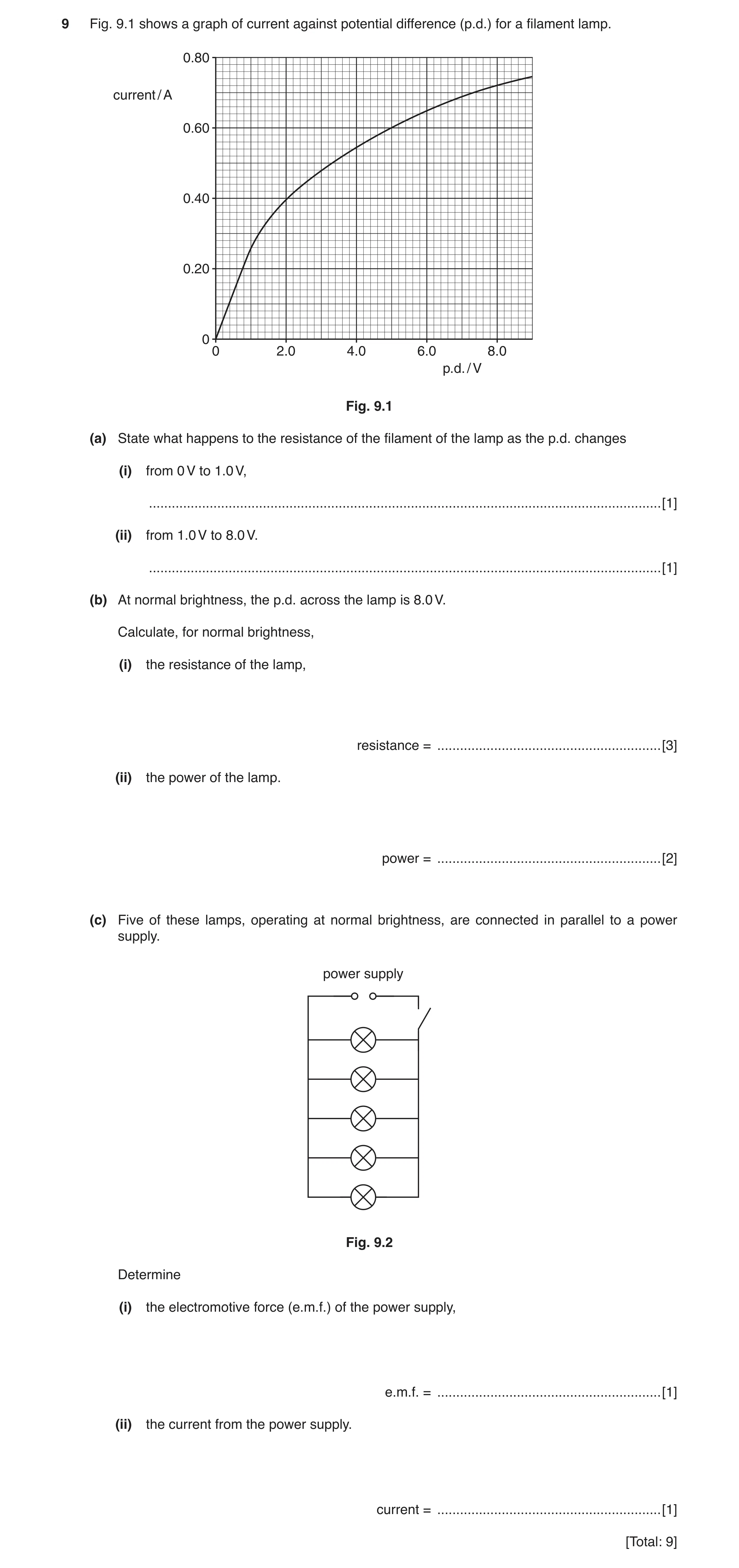
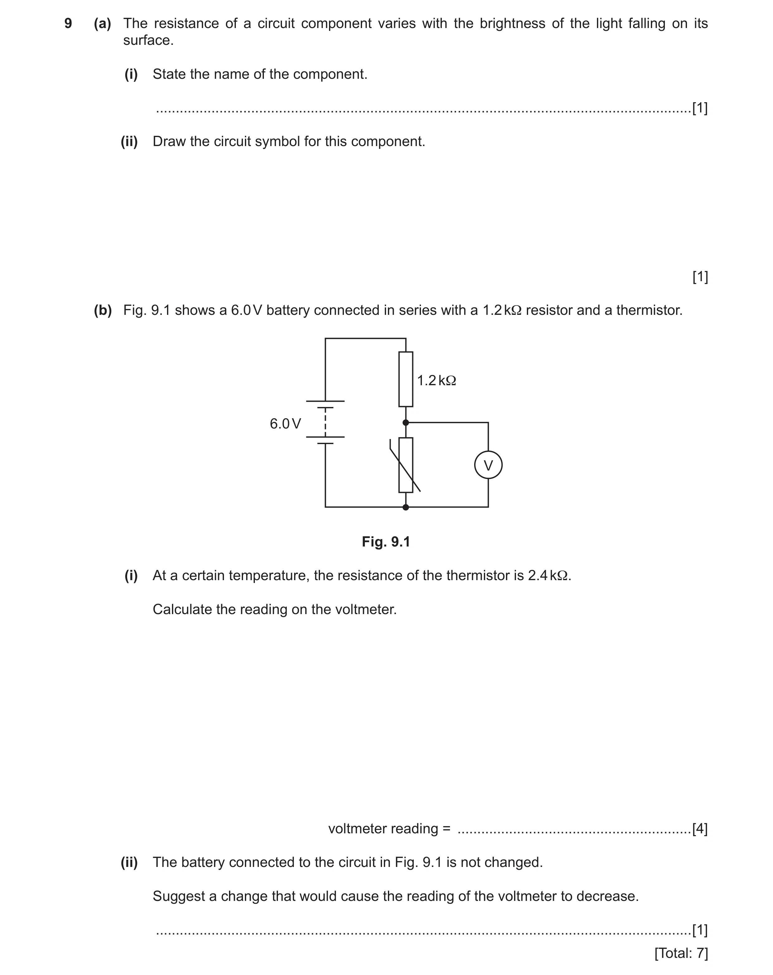 3 / 85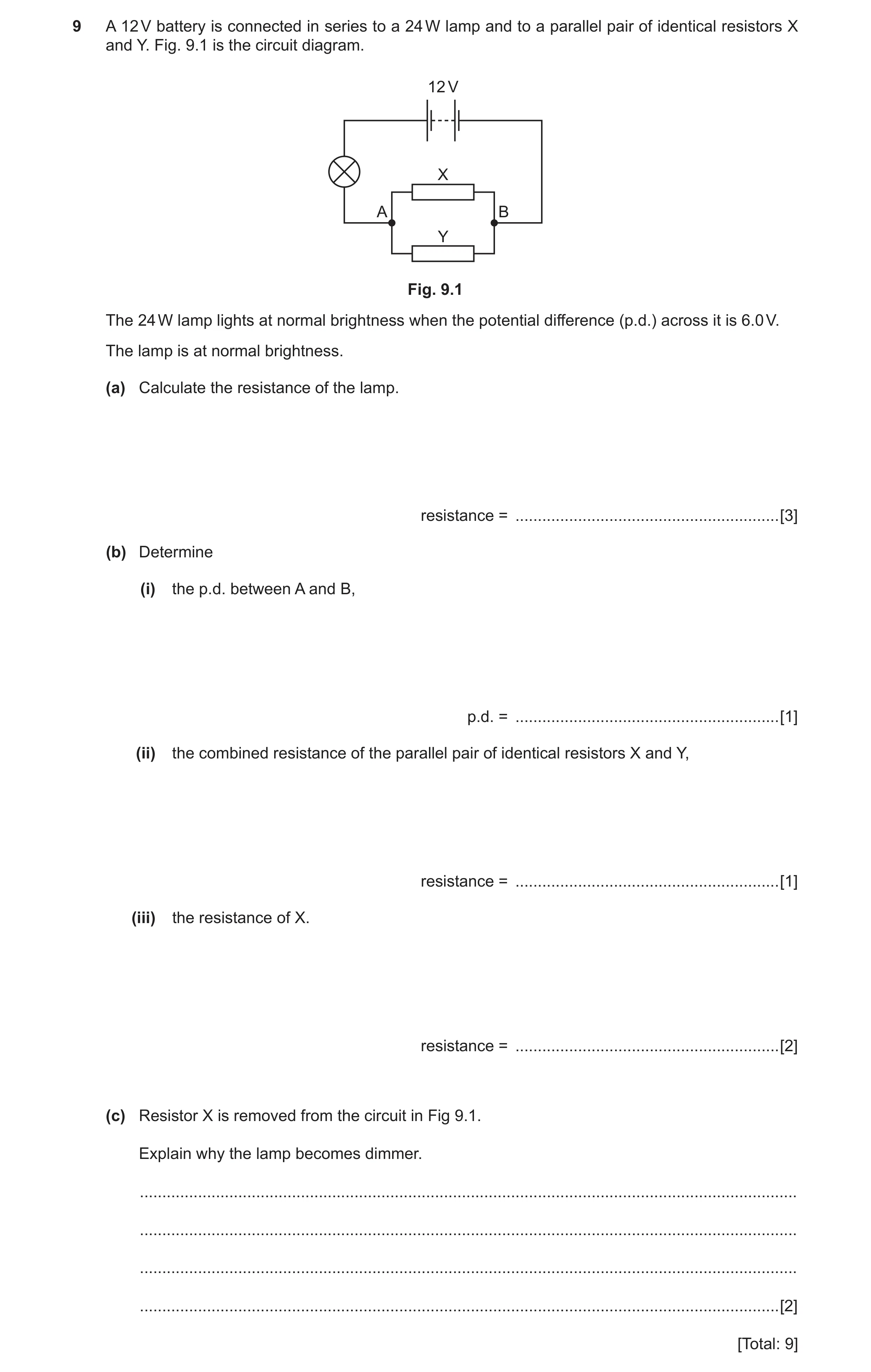
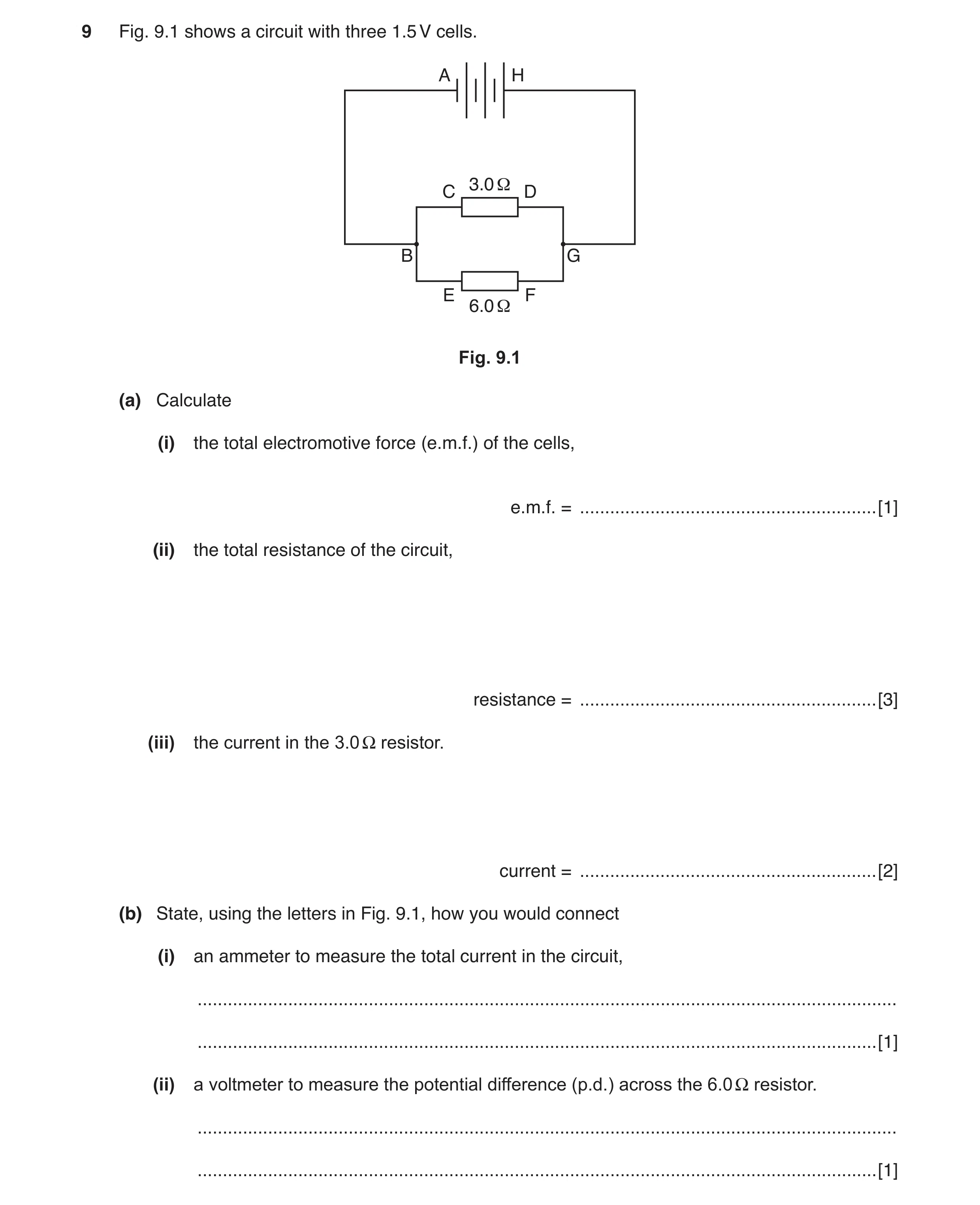 6 / 85
![Question 5: (a) (i) Draw the circuit symbol for a diode. [1] (ii) State the function of a diode. ......................................................…](https://img.pastlit.com/crops/45dc20b7-f613-4f0f-9ecf-f51c6c2bb890/q10.webp)
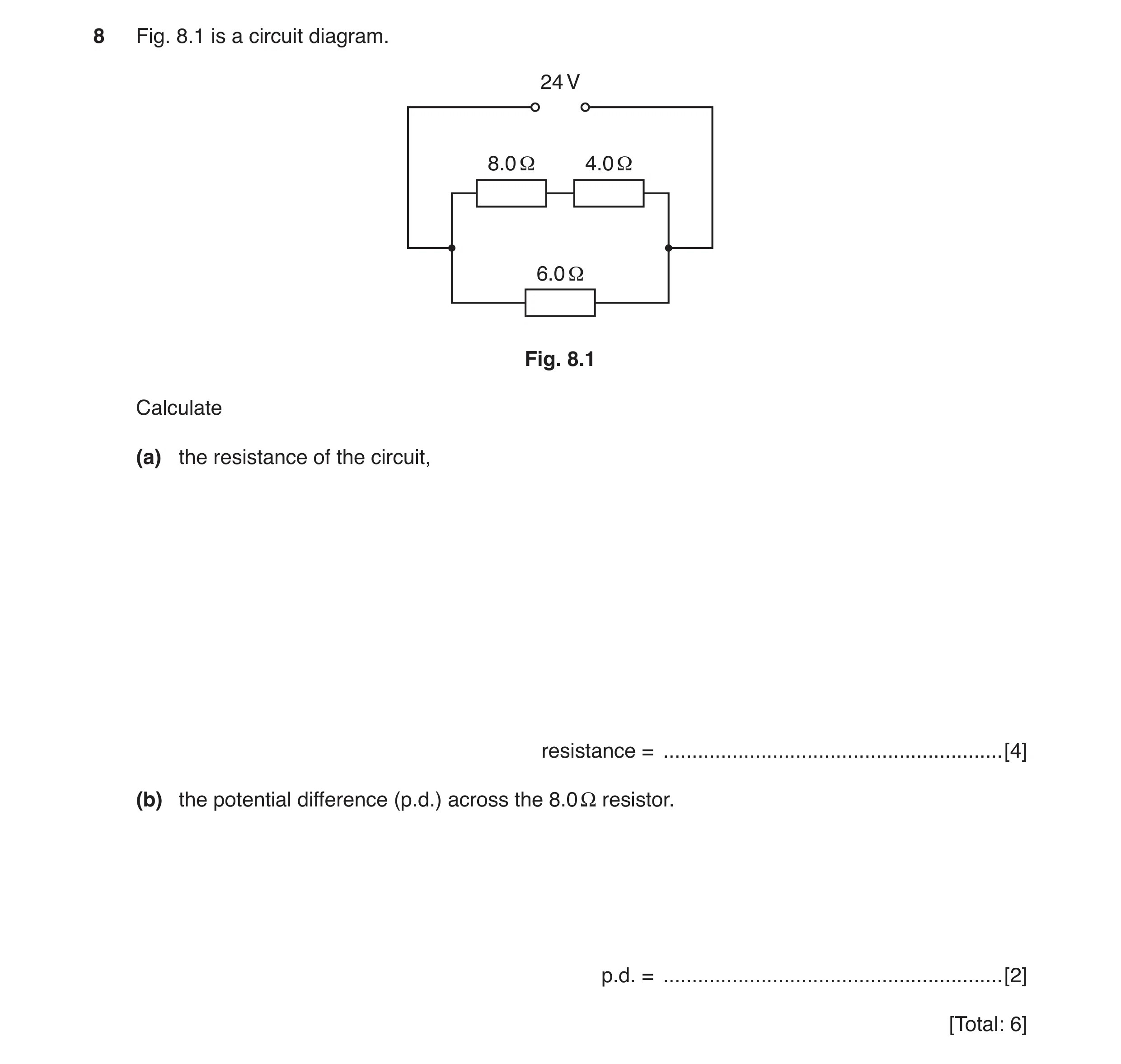 8 / 85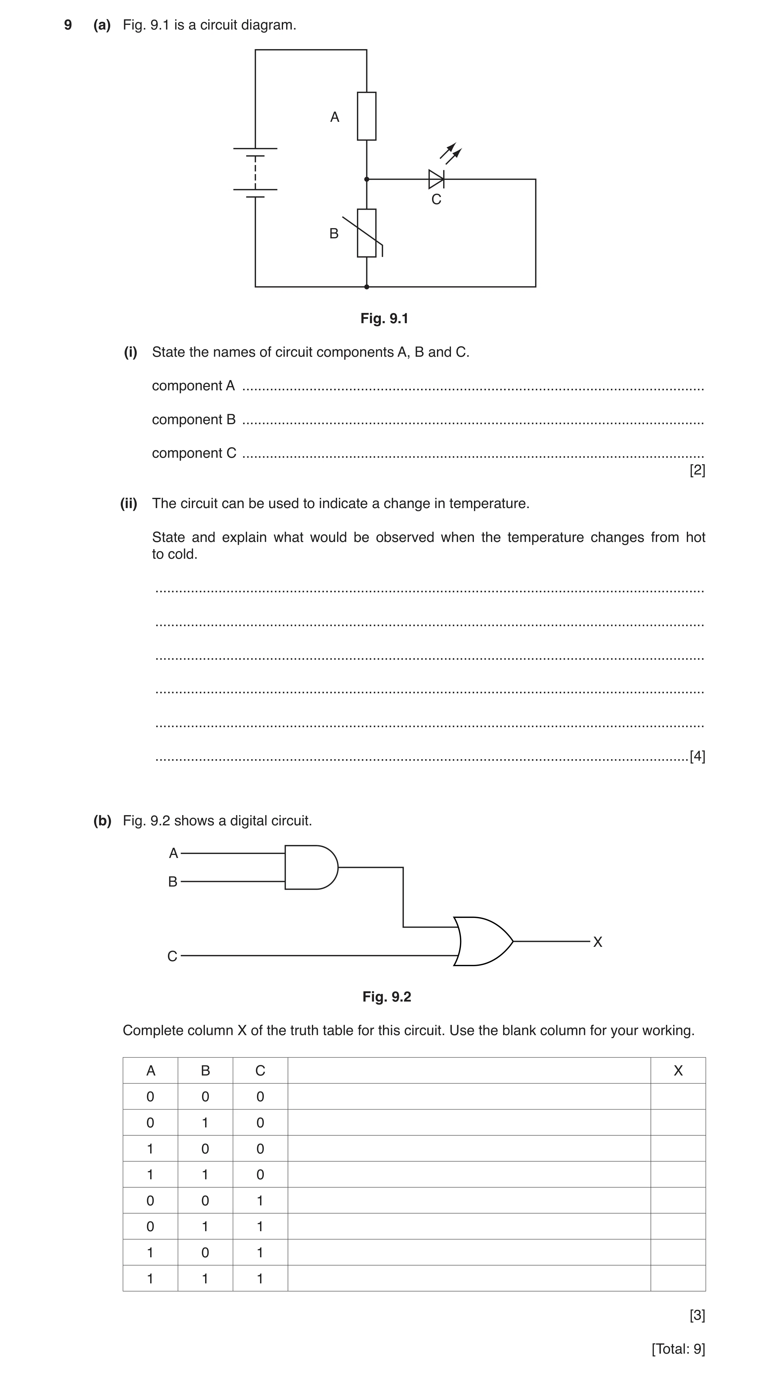
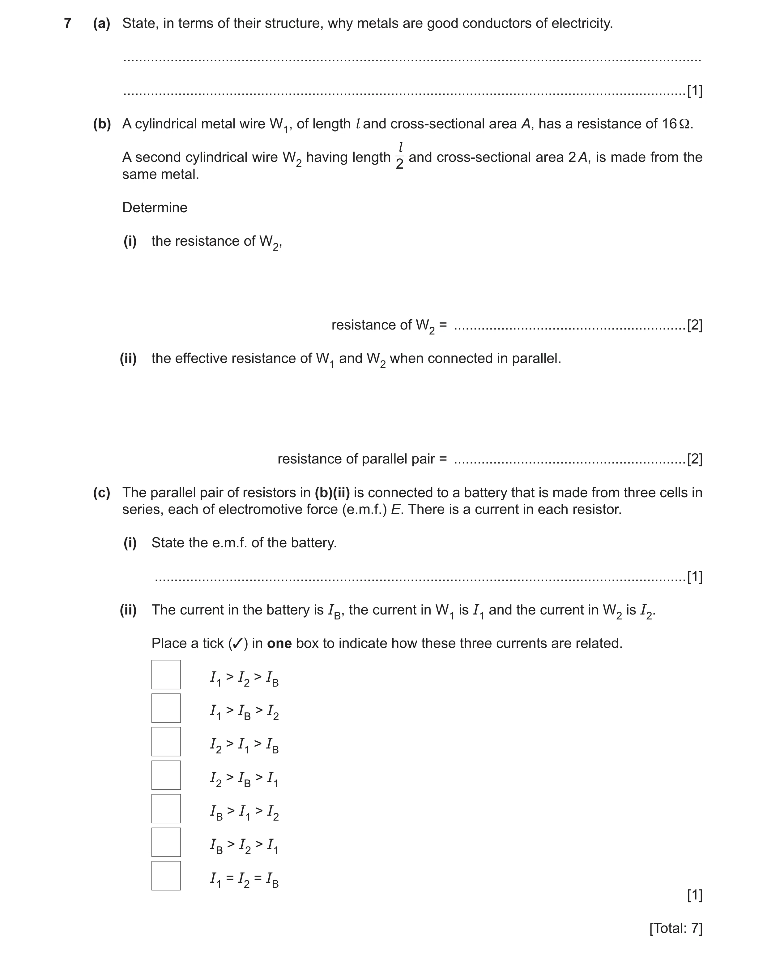 11 / 85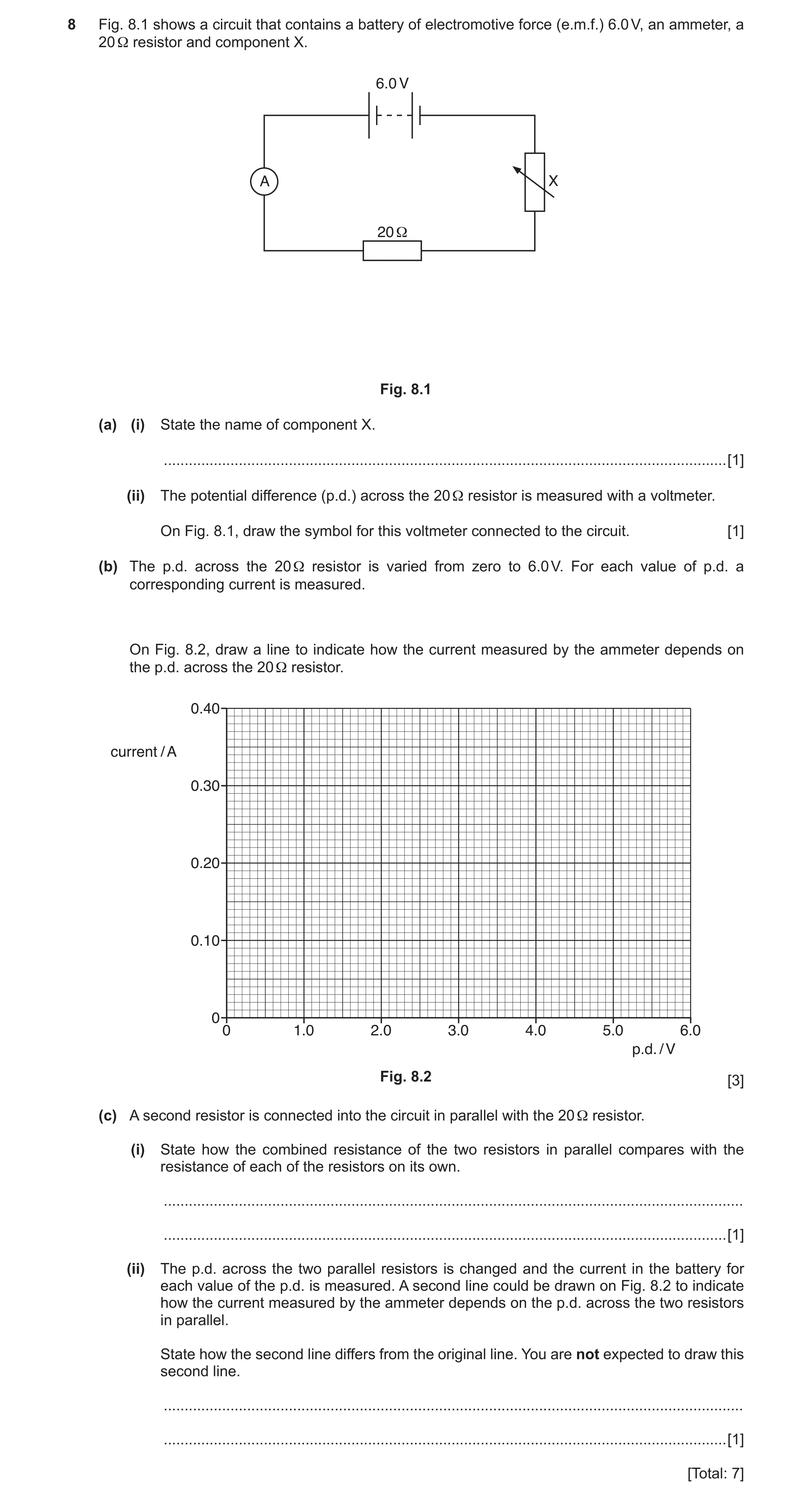
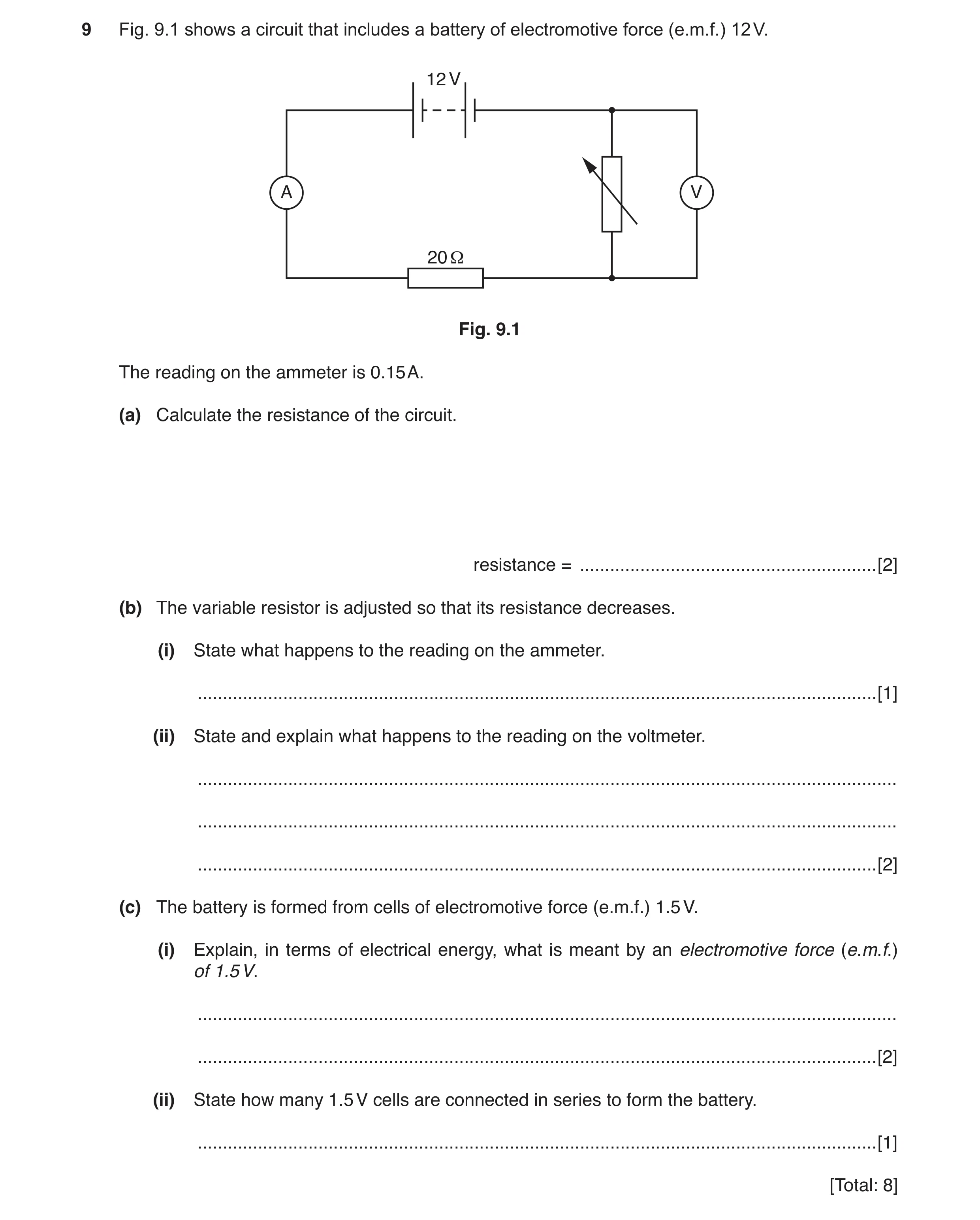 14 / 85
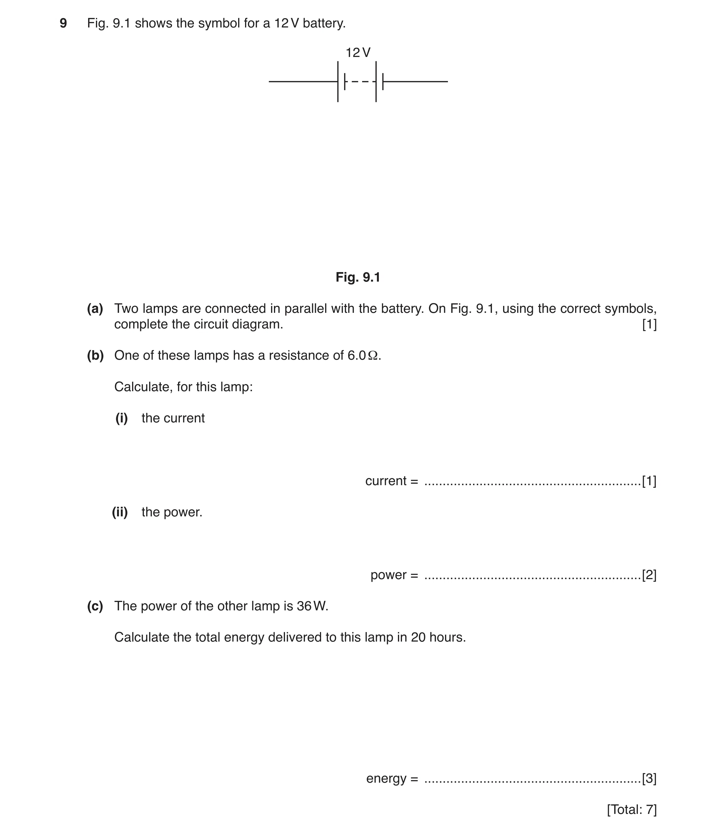 15 / 85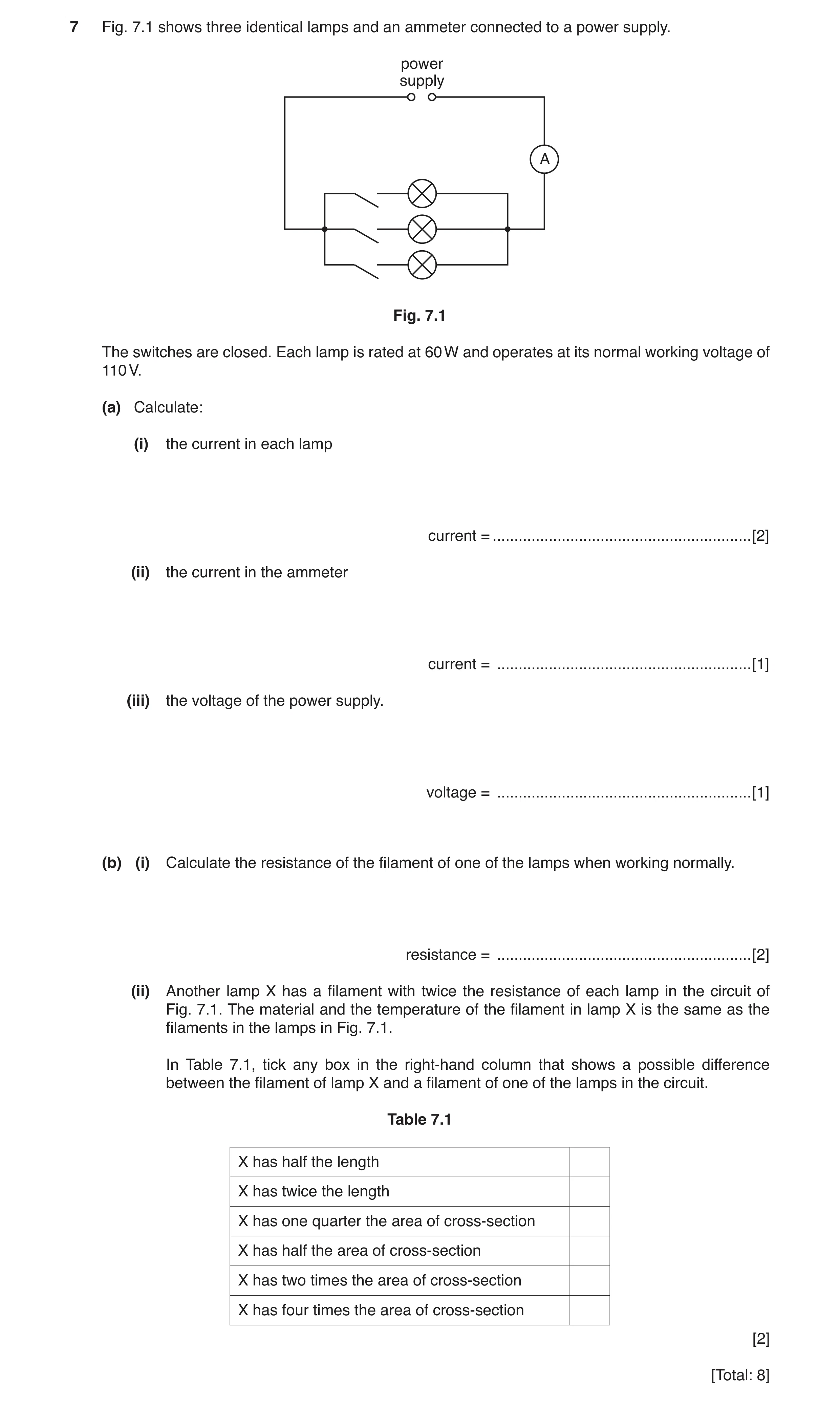
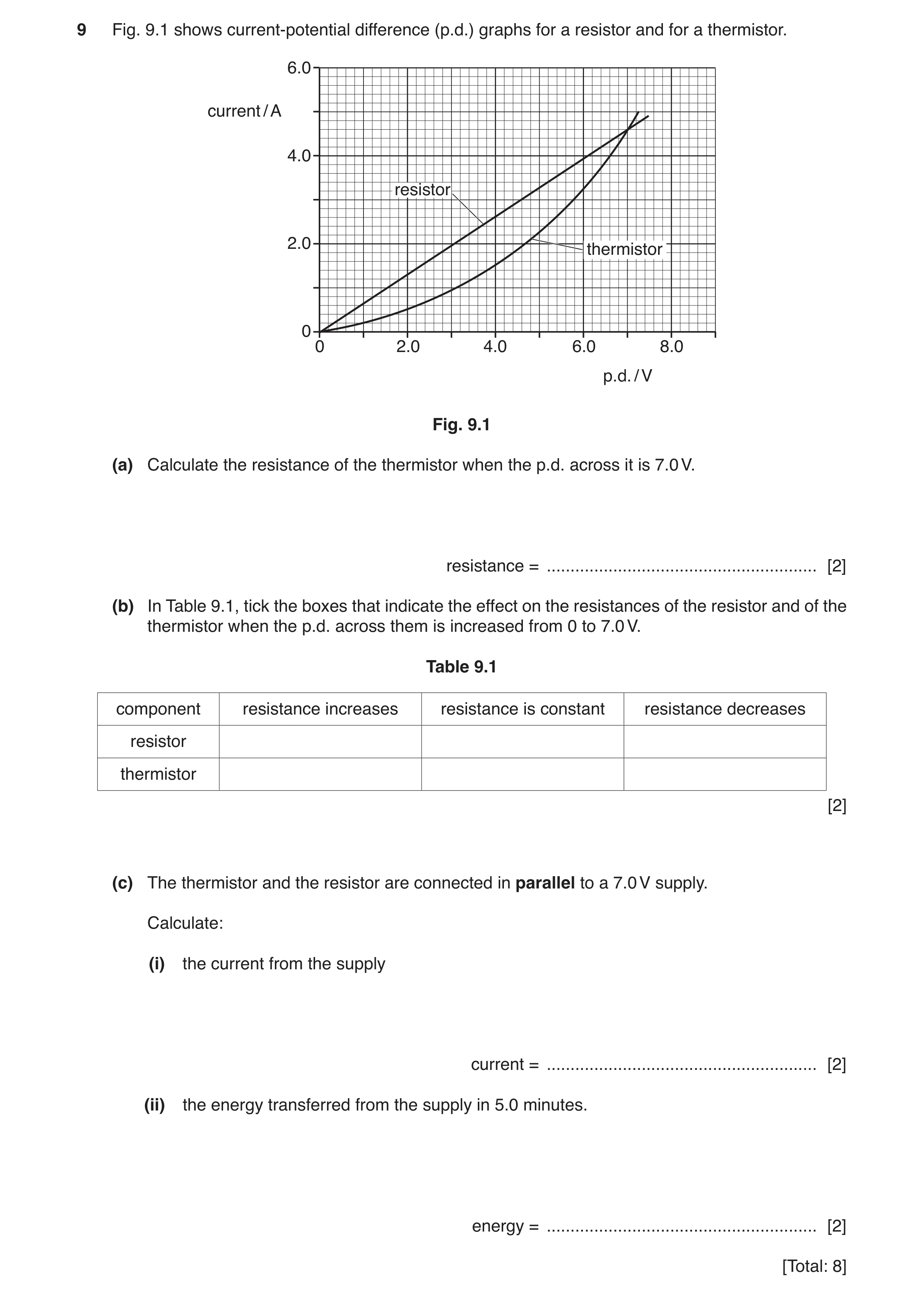 18 / 85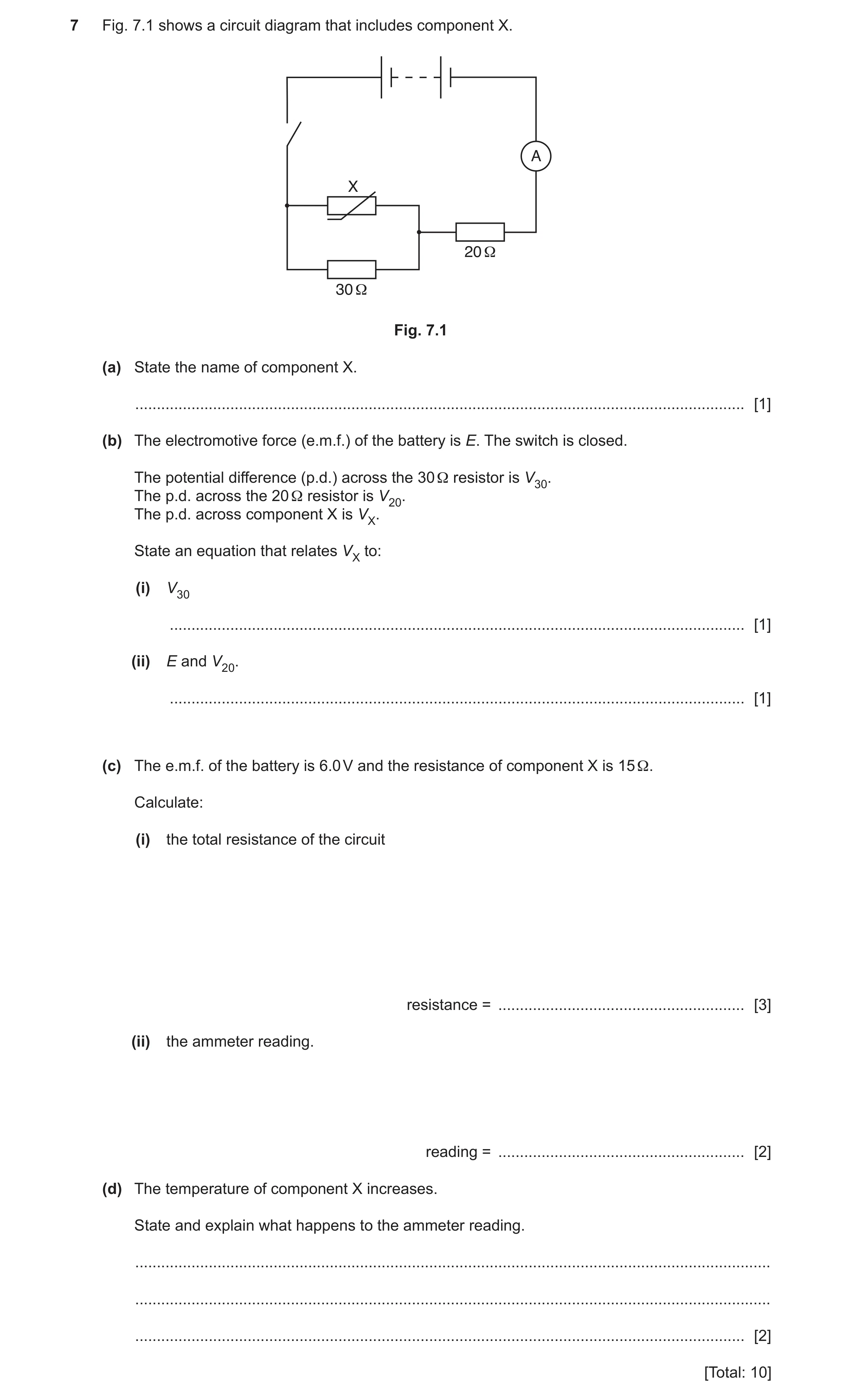
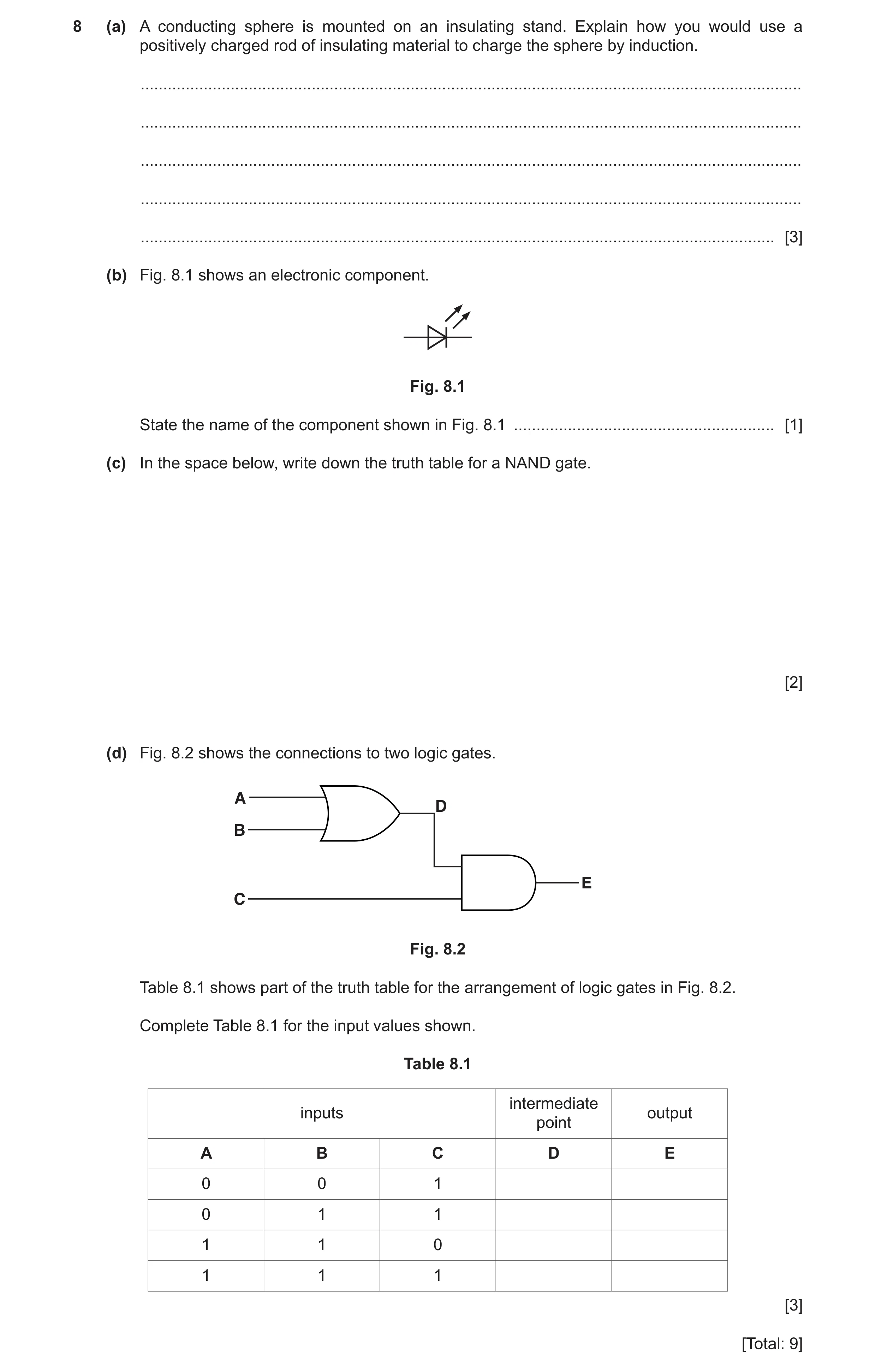
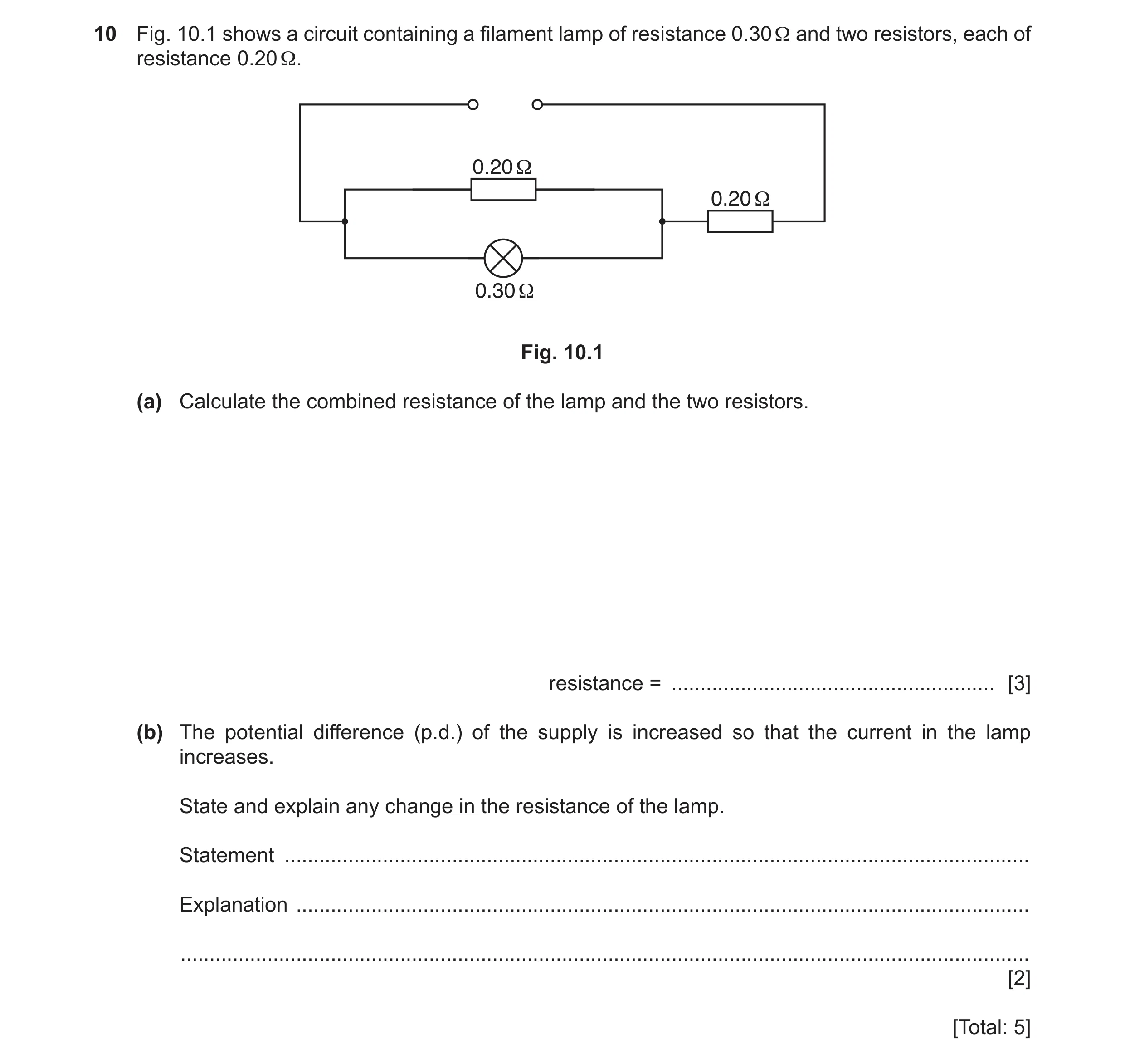 21 / 85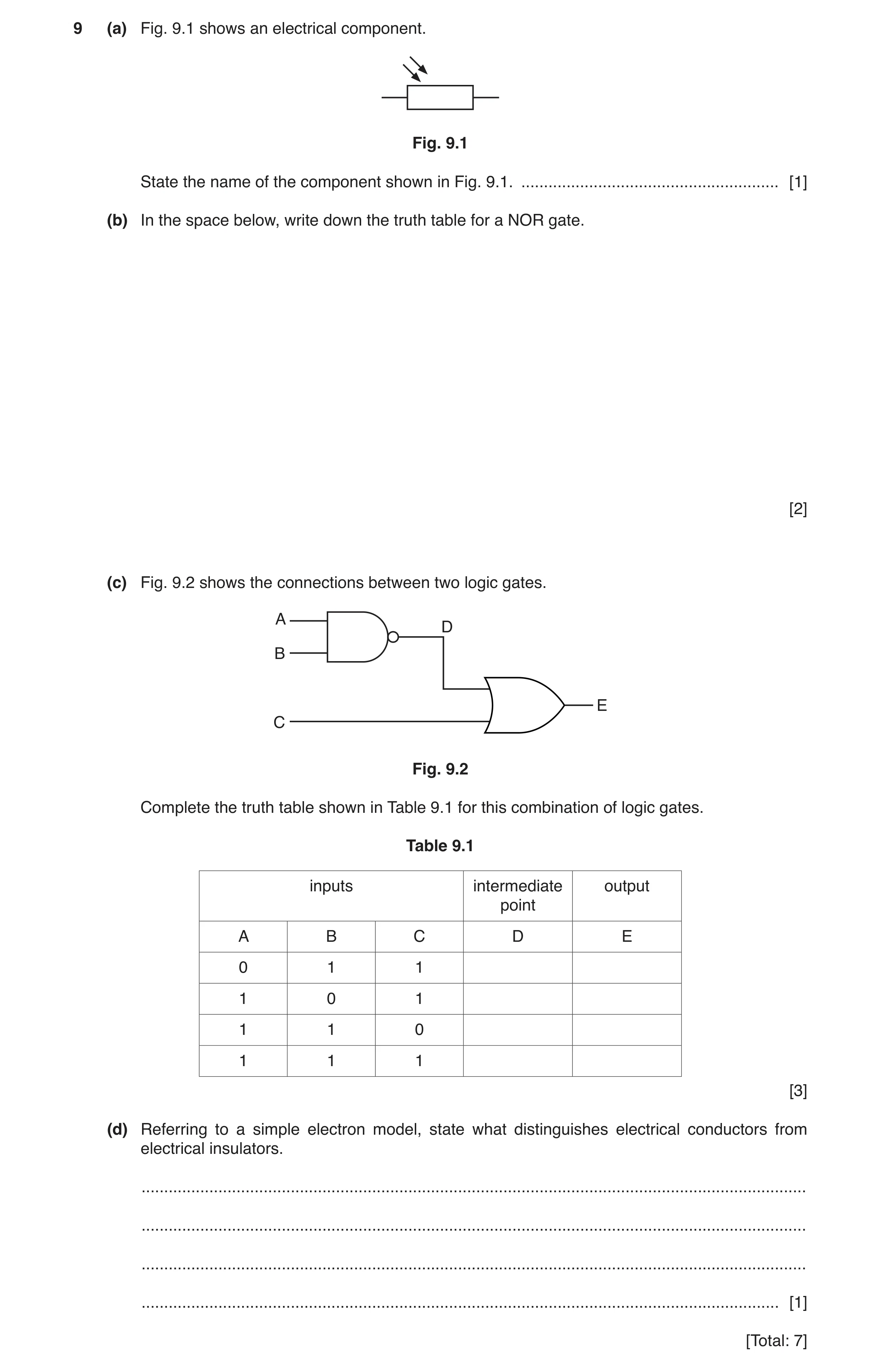
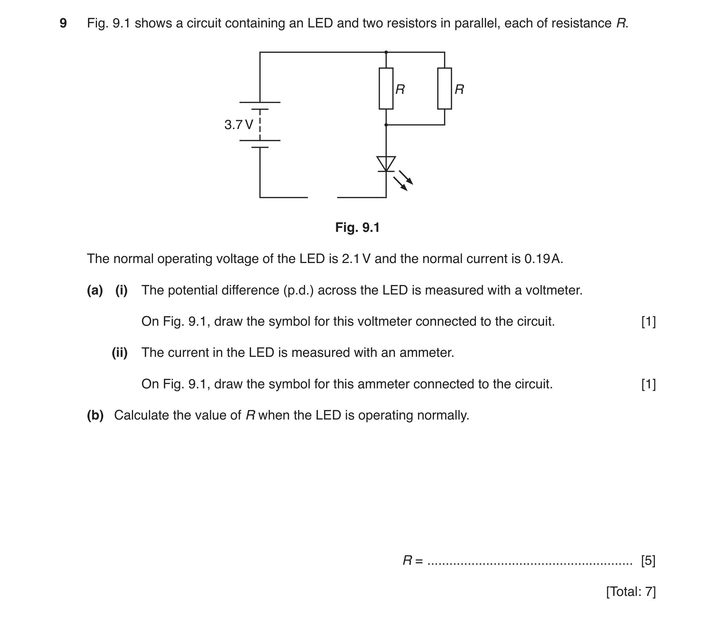 23 / 85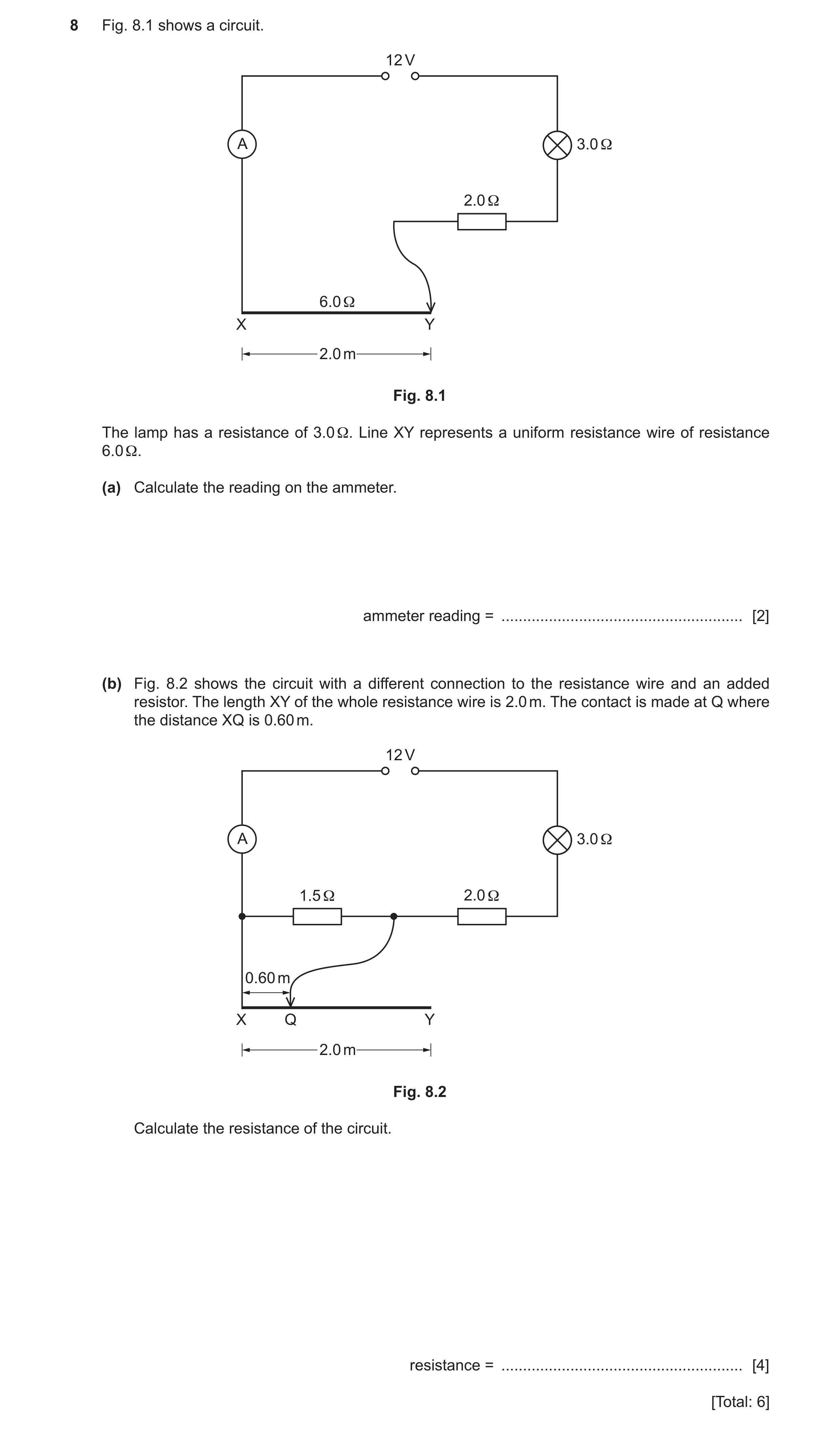
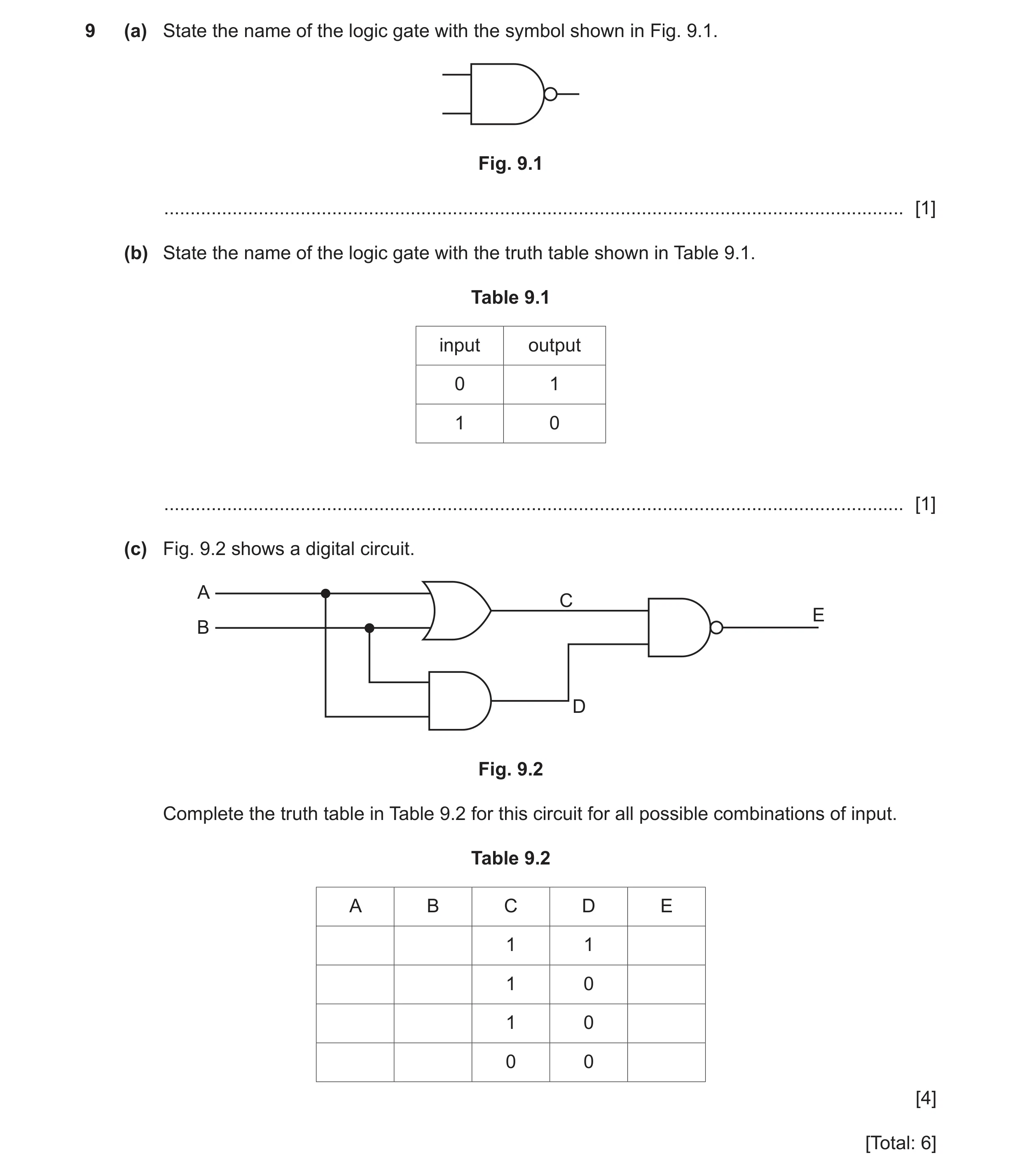 26 / 85
 27 / 85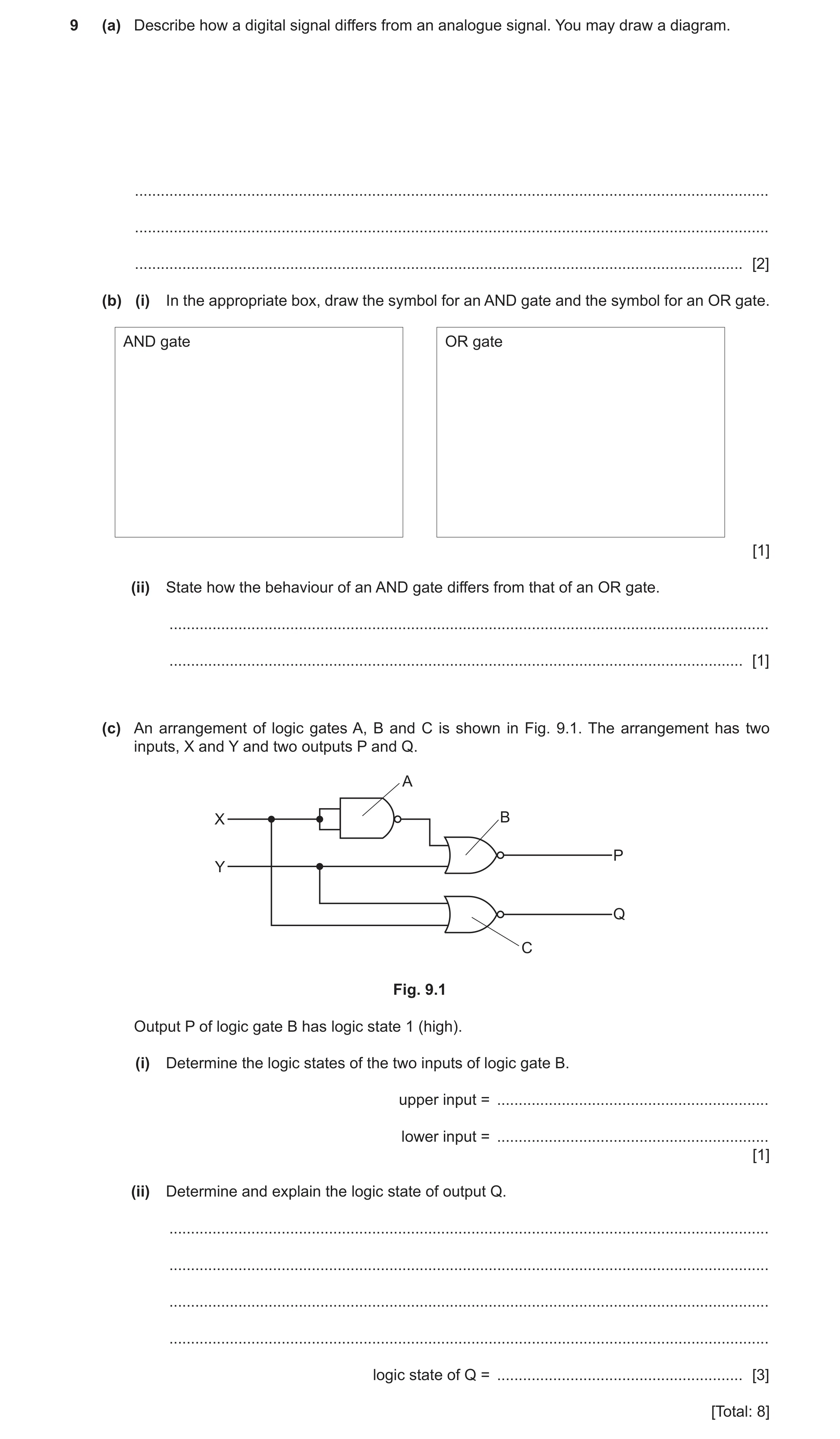
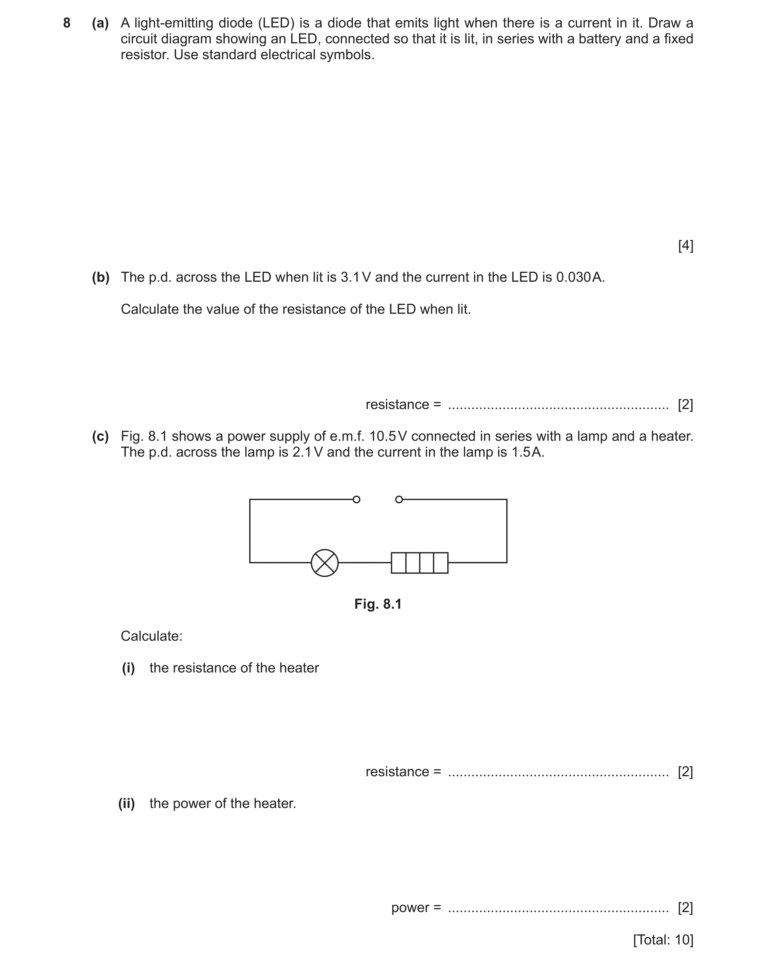 29 / 85
![Question 24: (a) Complete the truth table shown in Table 9.1 for a NAND gate. Table 9.1 input 1 input 2 output 0 0 0 1 1 0 1 1 [1] (b) The circuit shown…](https://img.pastlit.com/crops/384a8fc2-37a1-43bf-8bd2-5b45bf27aac9/q9.webp) 30 / 85
30 / 85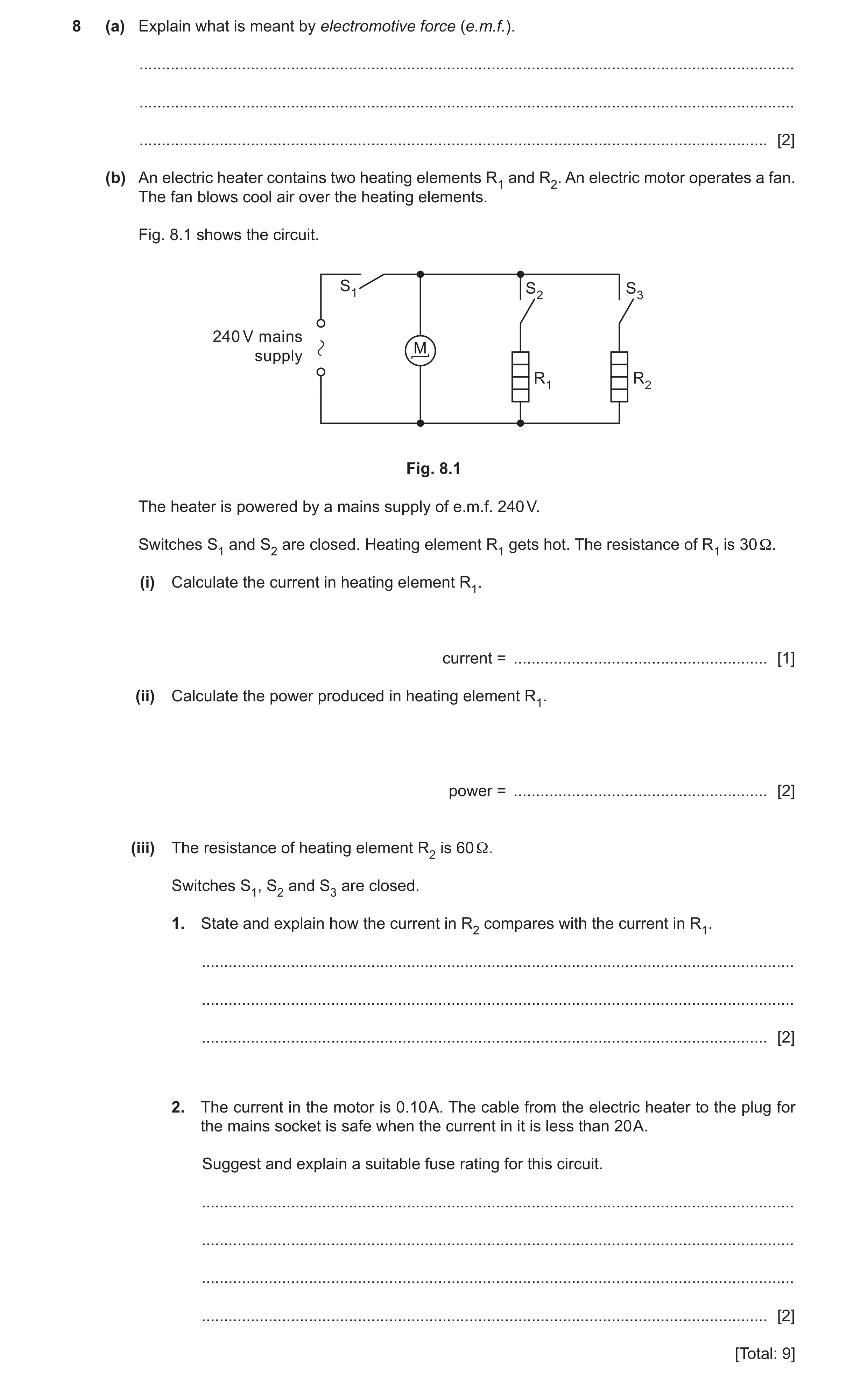
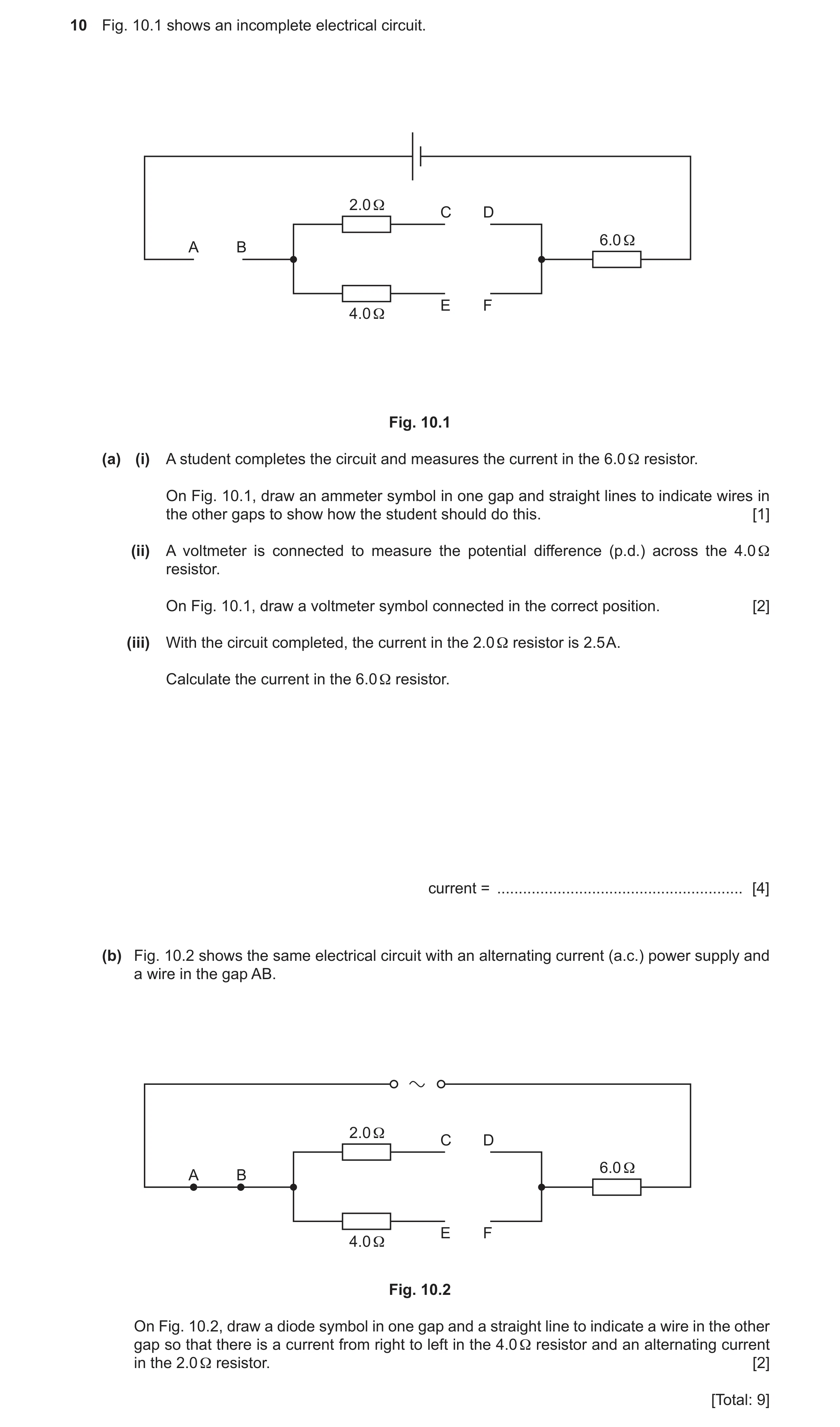
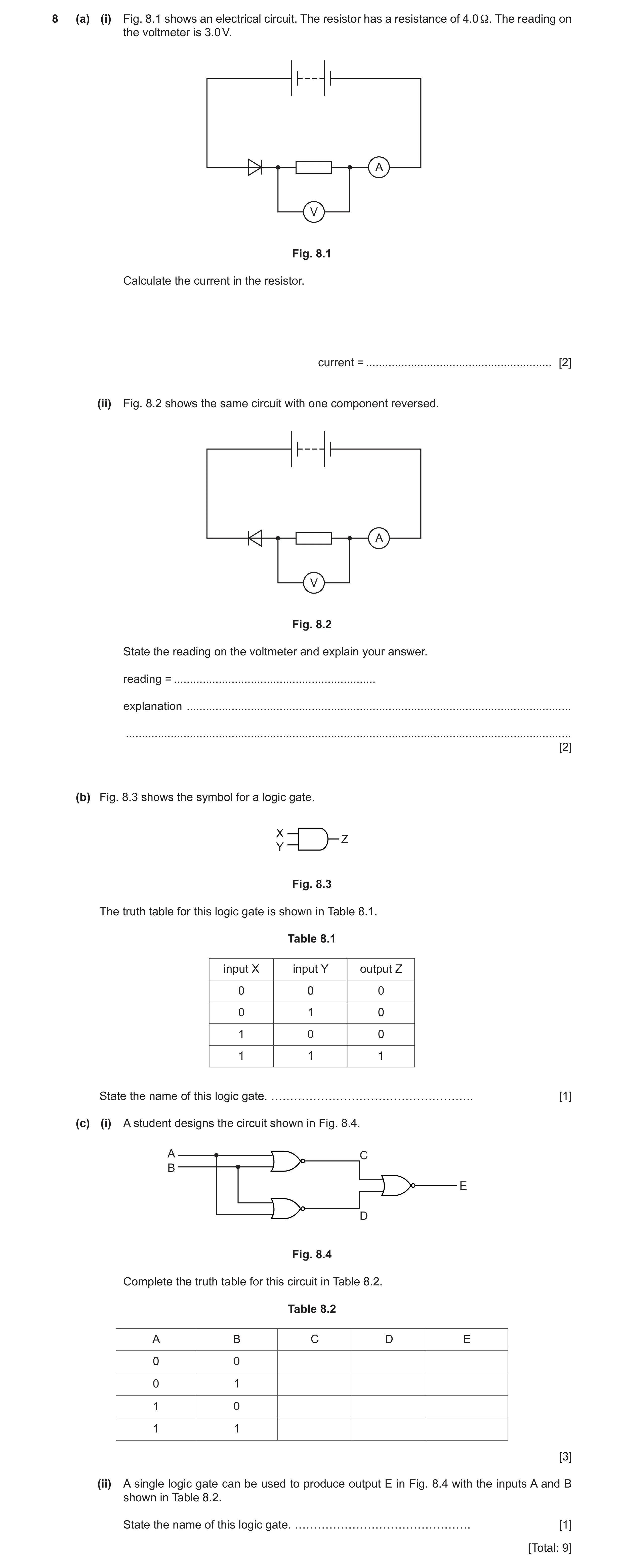
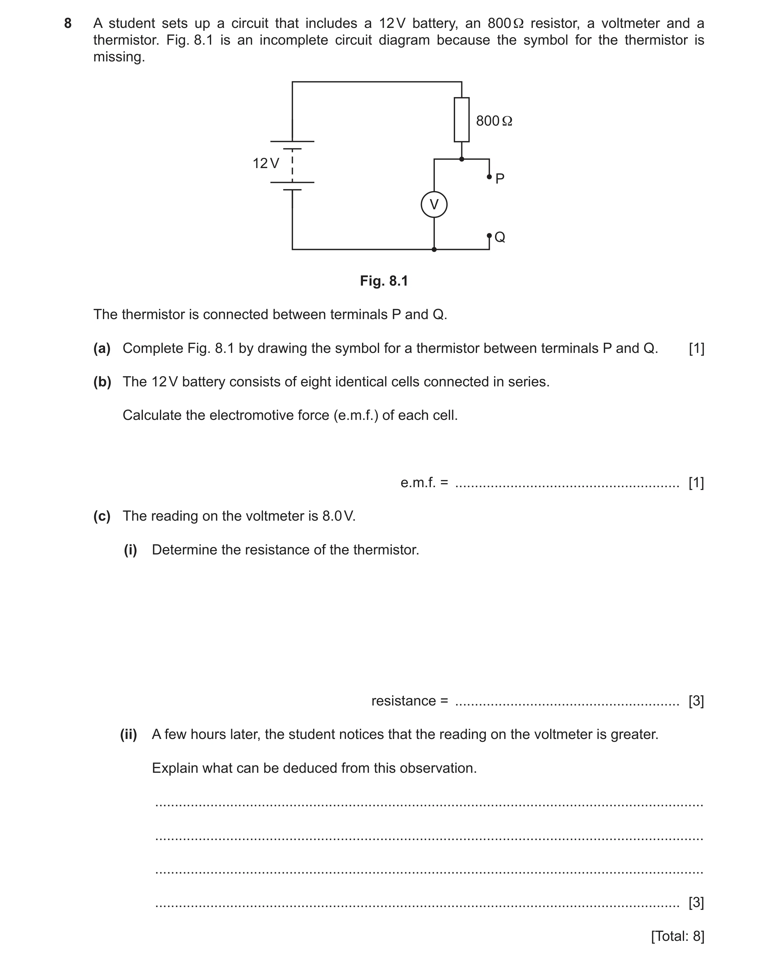 36 / 85
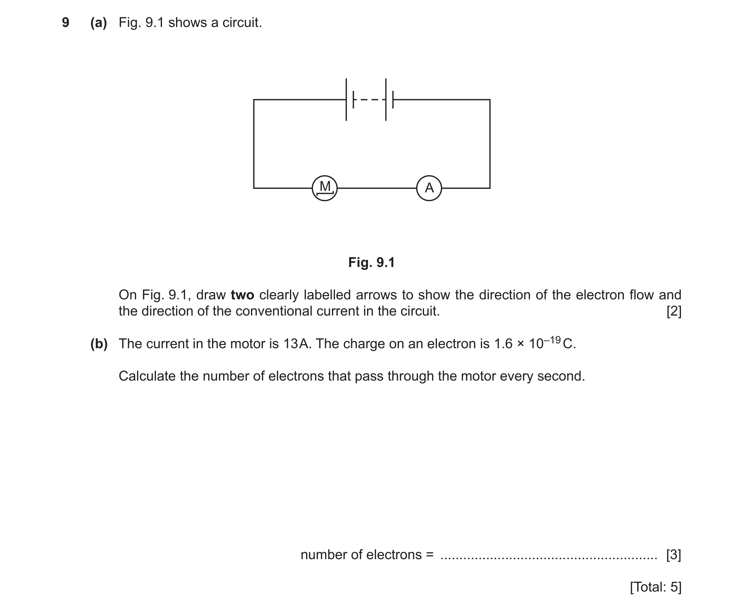 37 / 85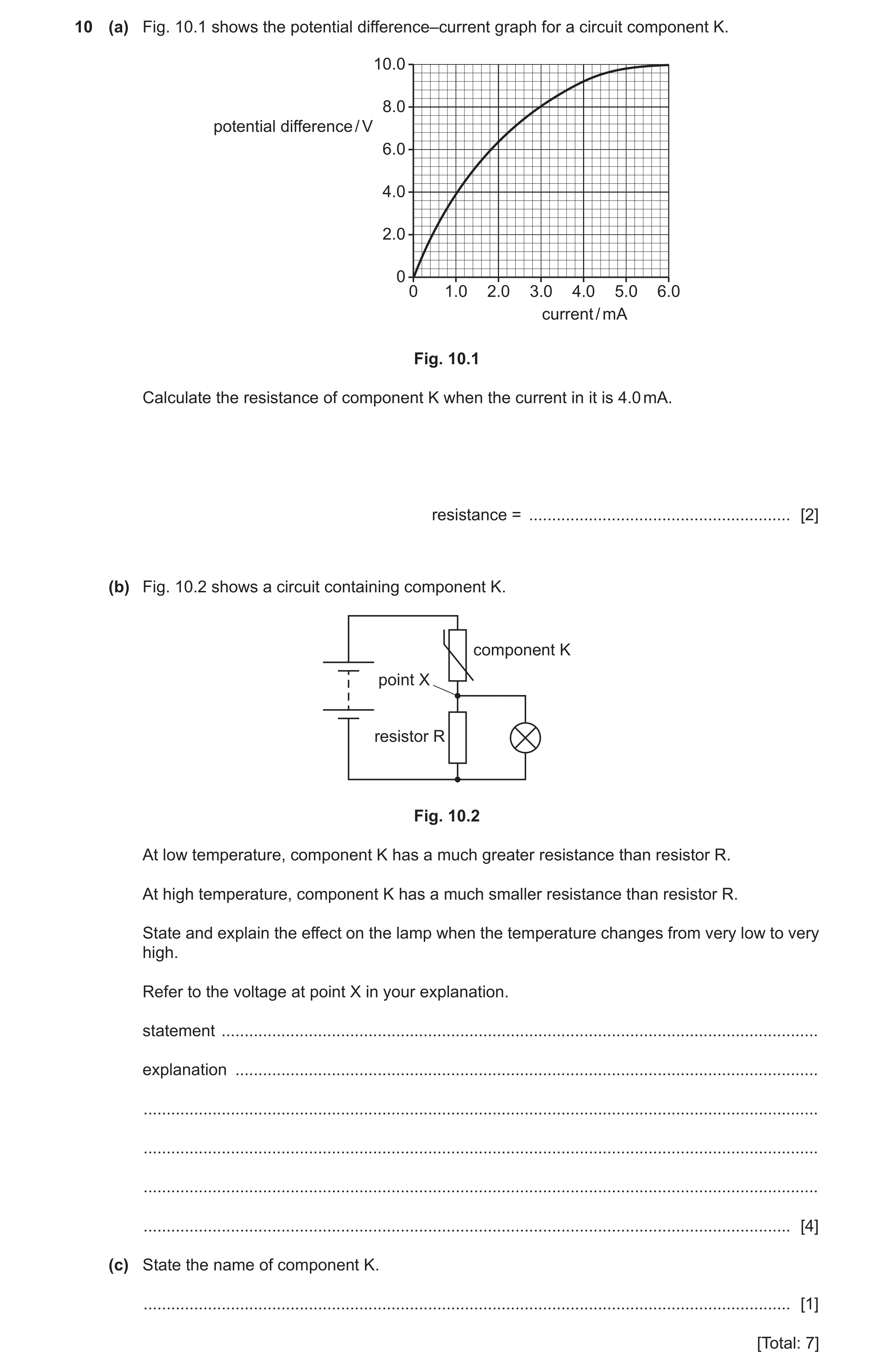
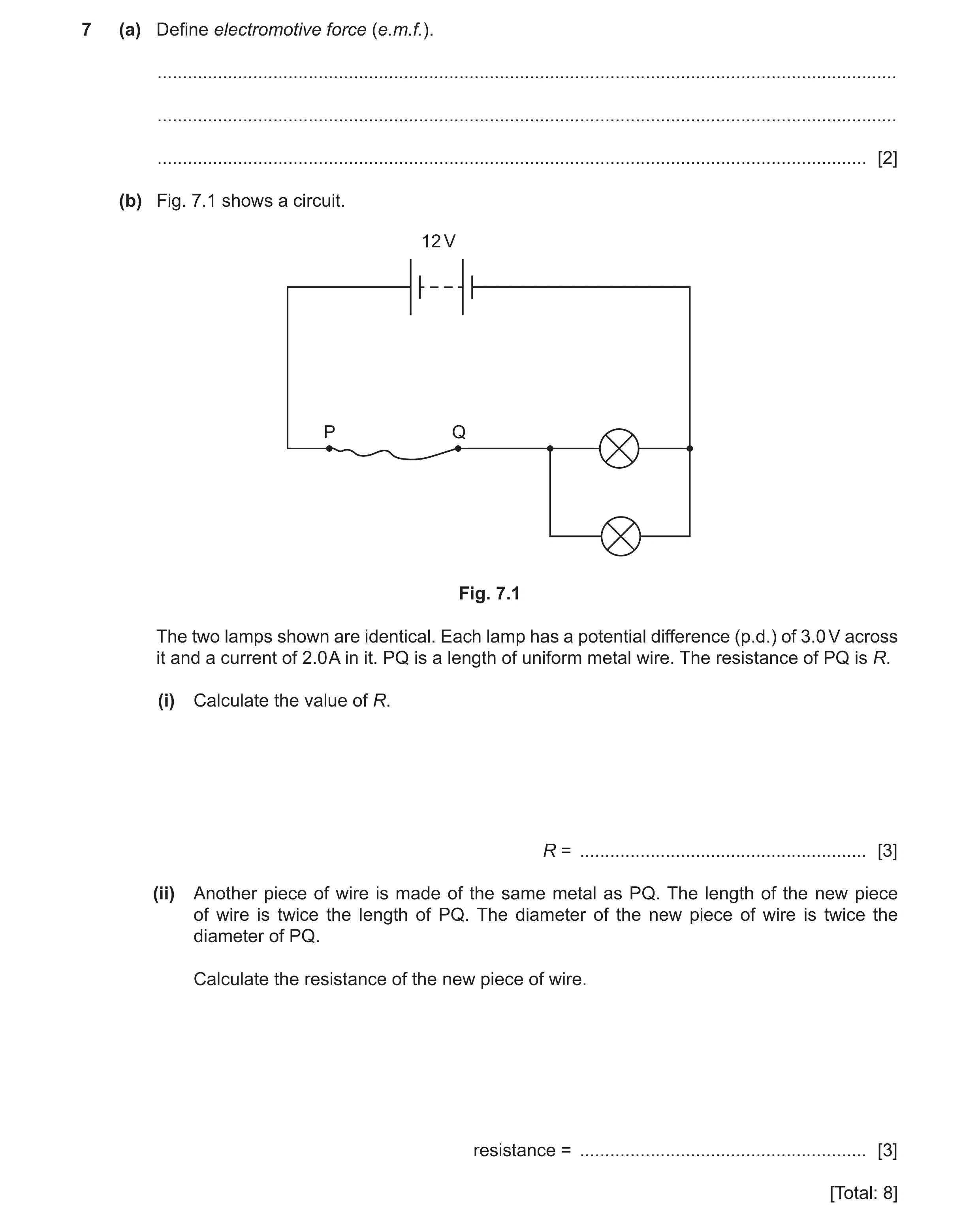 39 / 85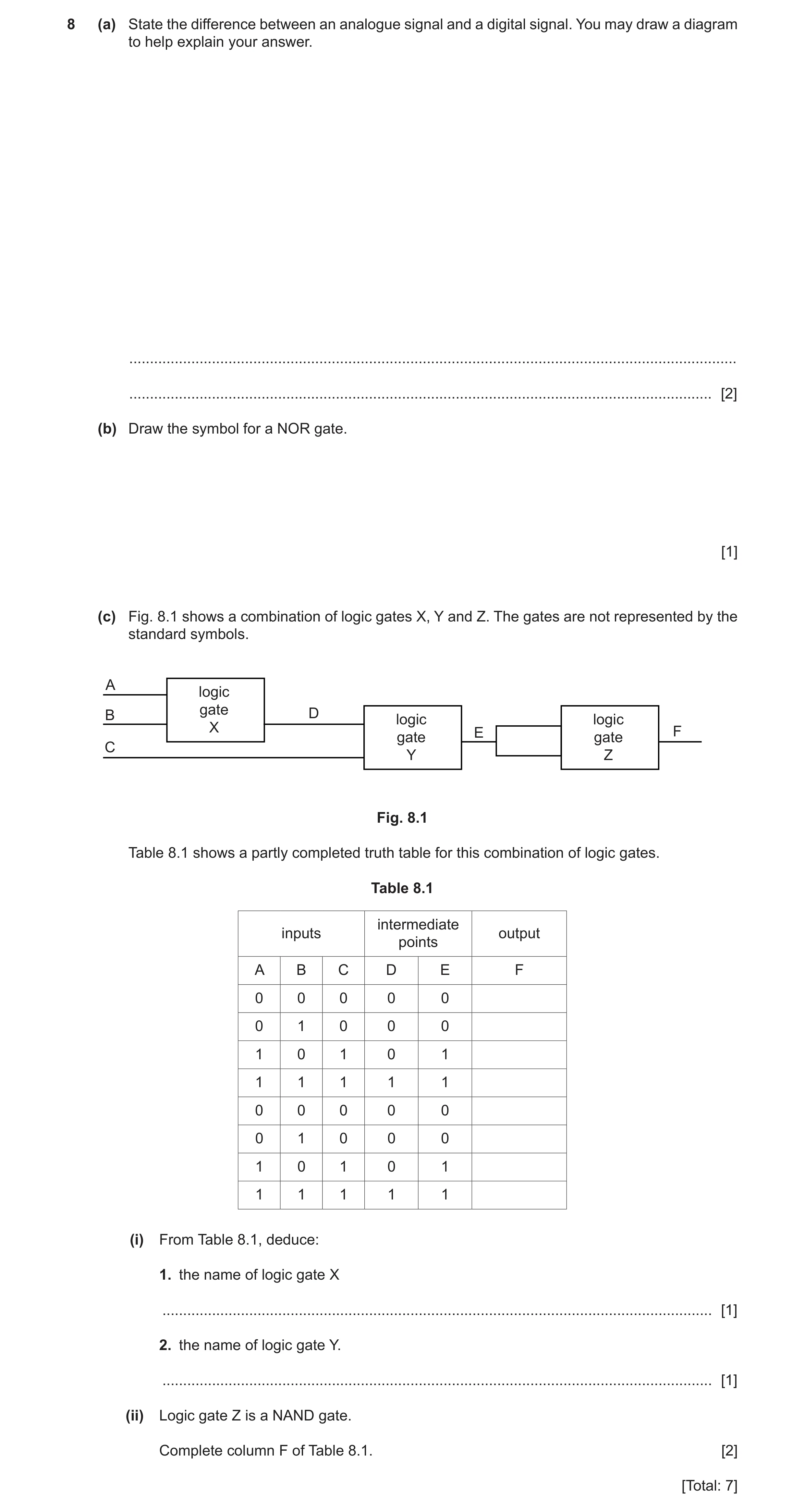
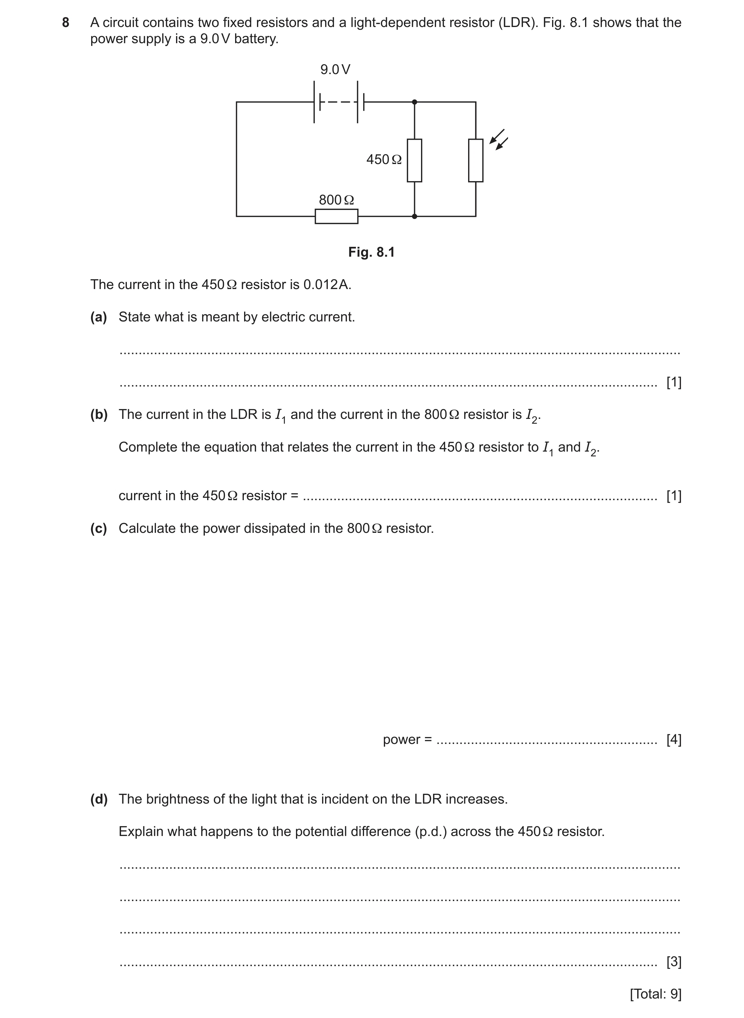 42 / 85
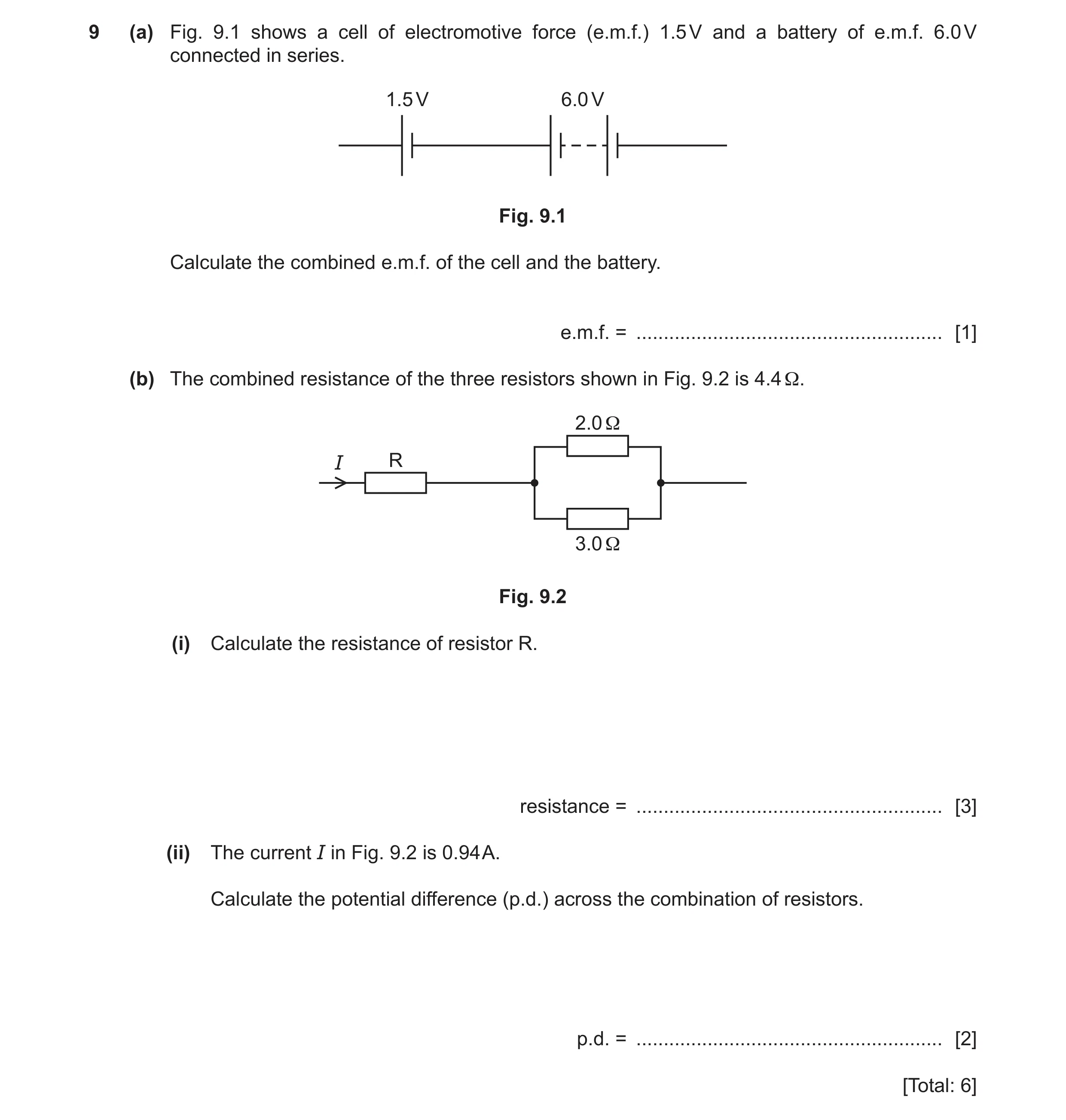 43 / 85
![Question 35: (a) Name the logic gate shown in Fig. 10.1. .............................................................. Fig. 10.1 [1] (b) Fig. 10.2 show…](https://img.pastlit.com/crops/866ff260-31d2-48cc-99e6-1e835619dd73/q10.webp)
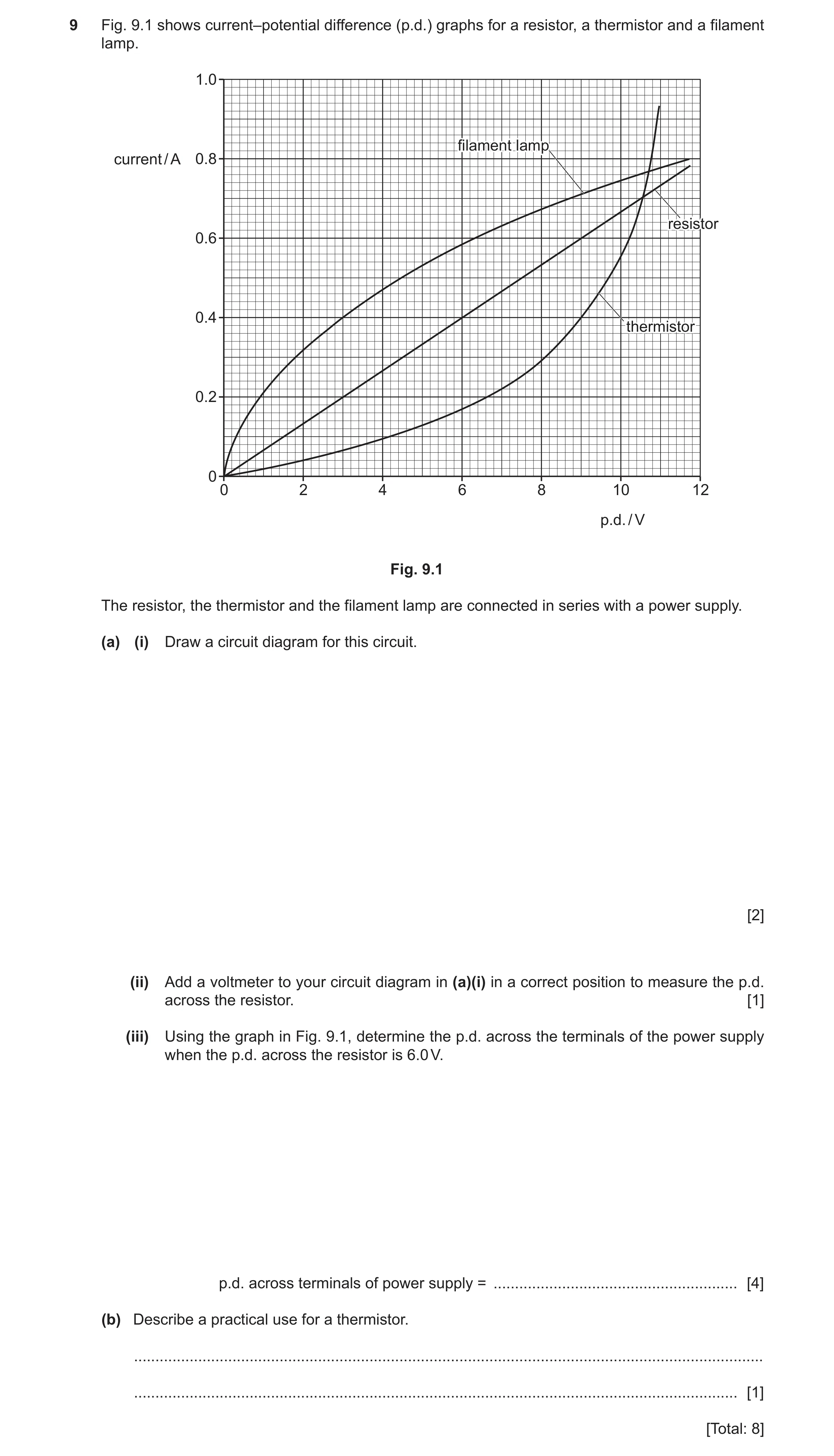
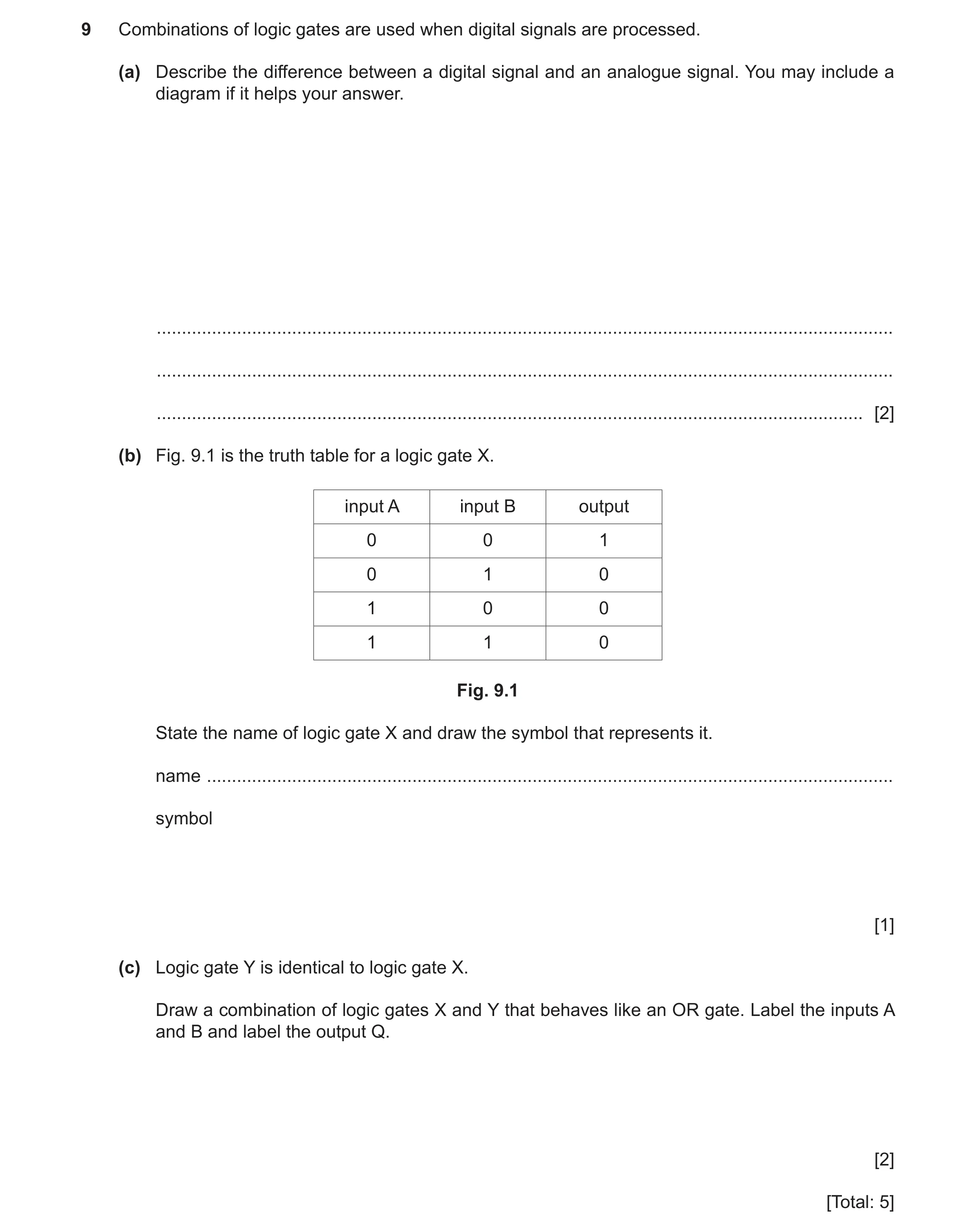 47 / 85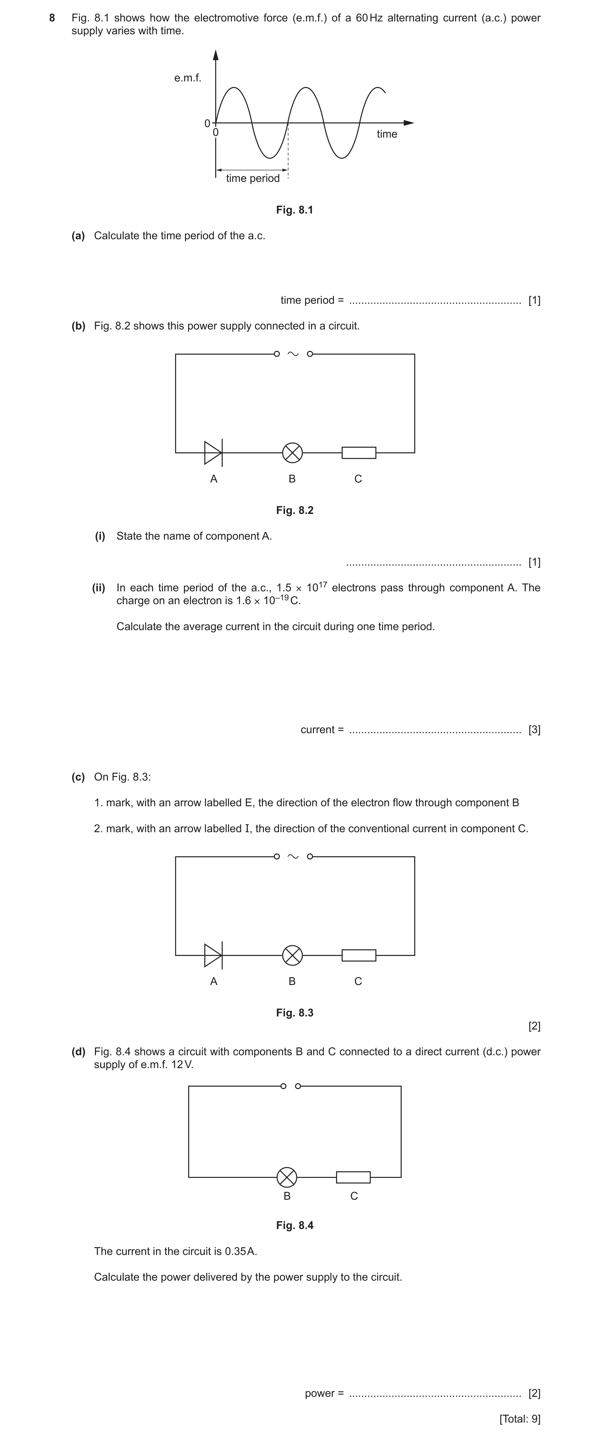
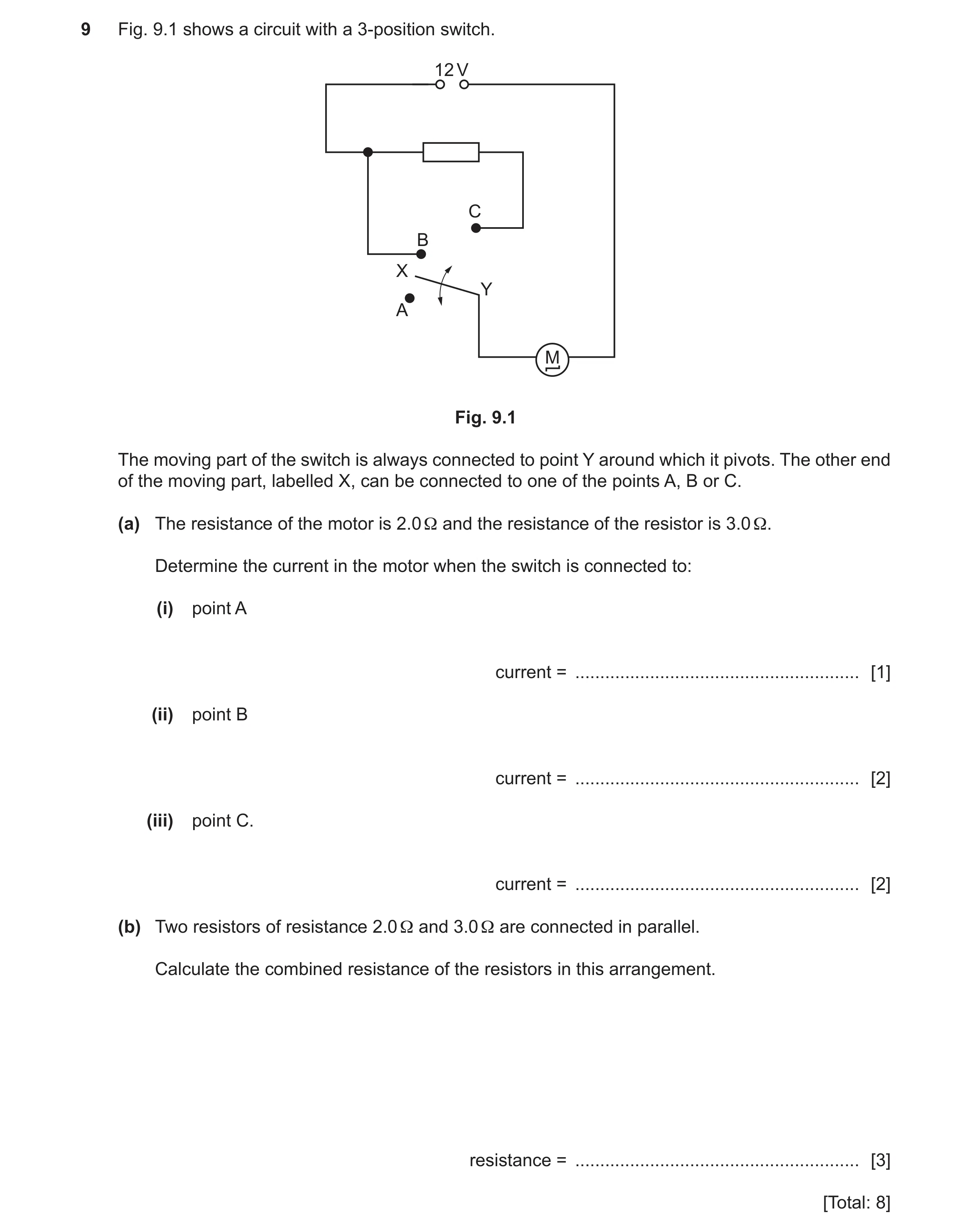 50 / 85
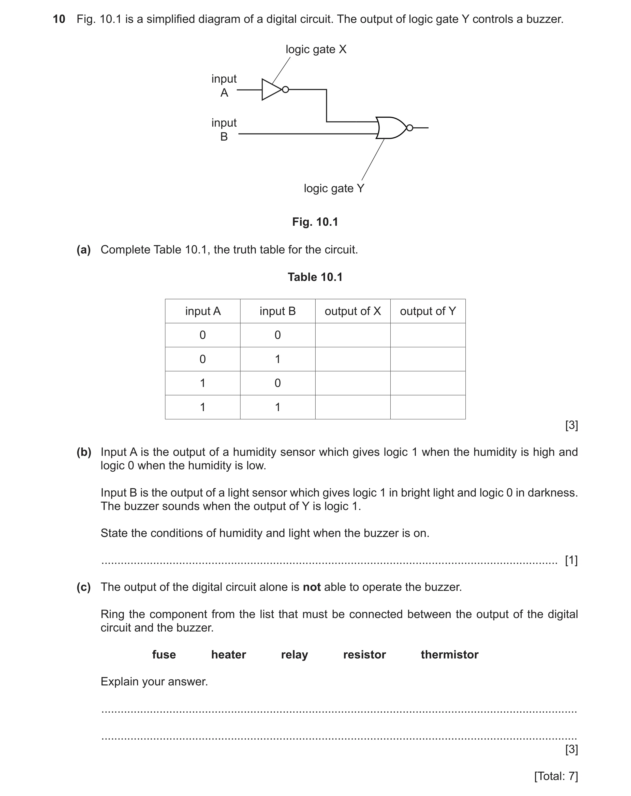 51 / 85
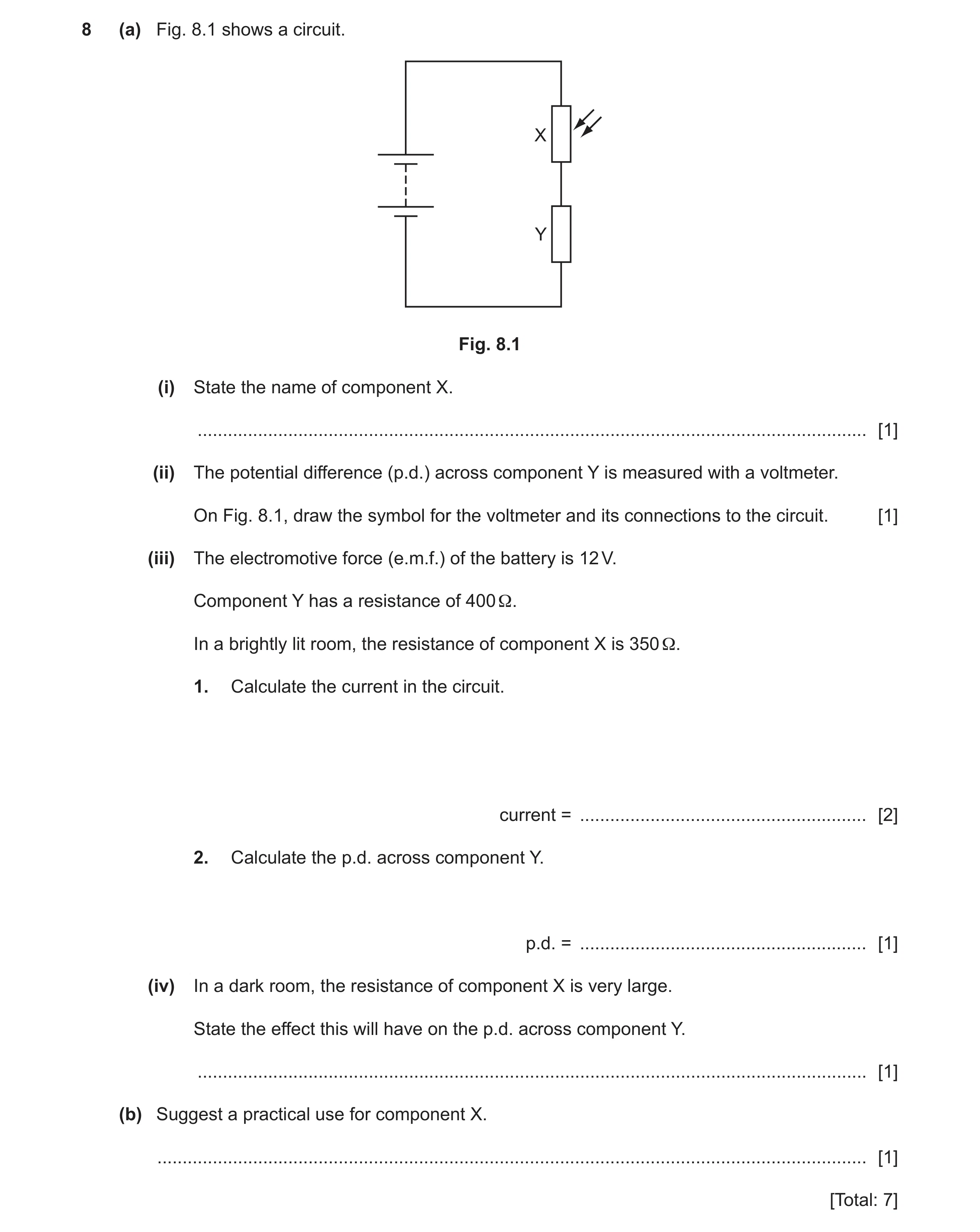 52 / 85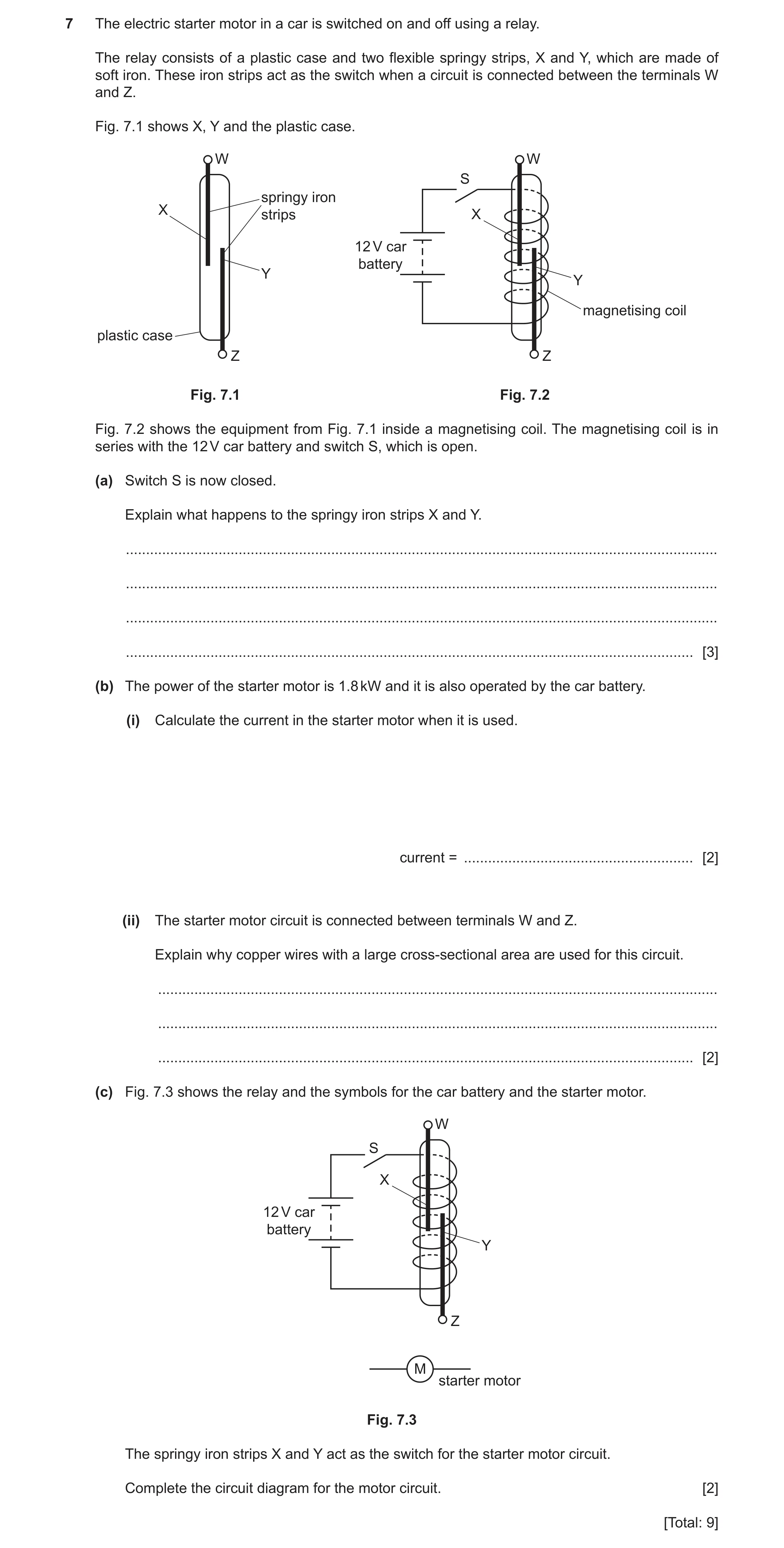
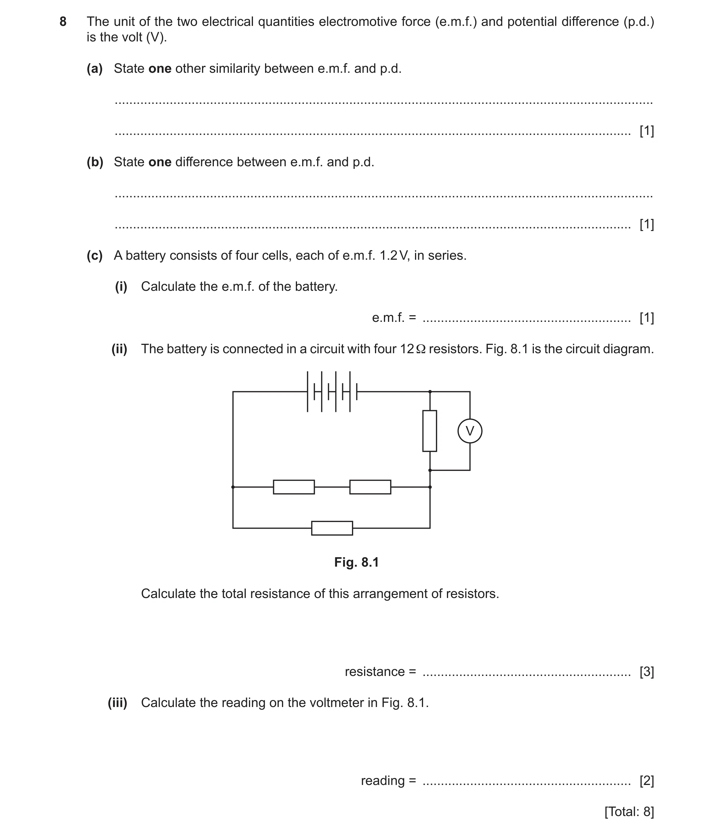 55 / 85
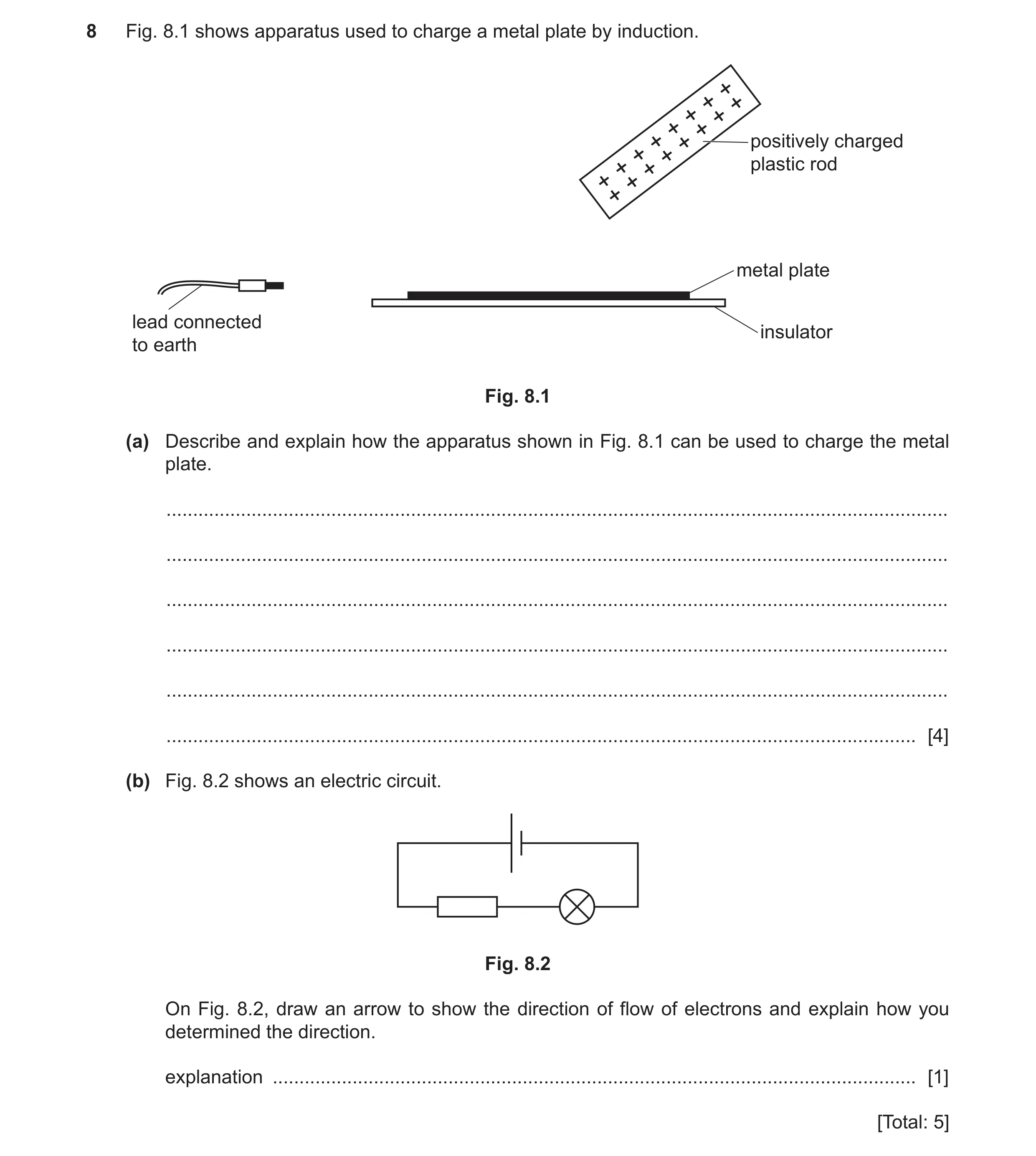 56 / 85
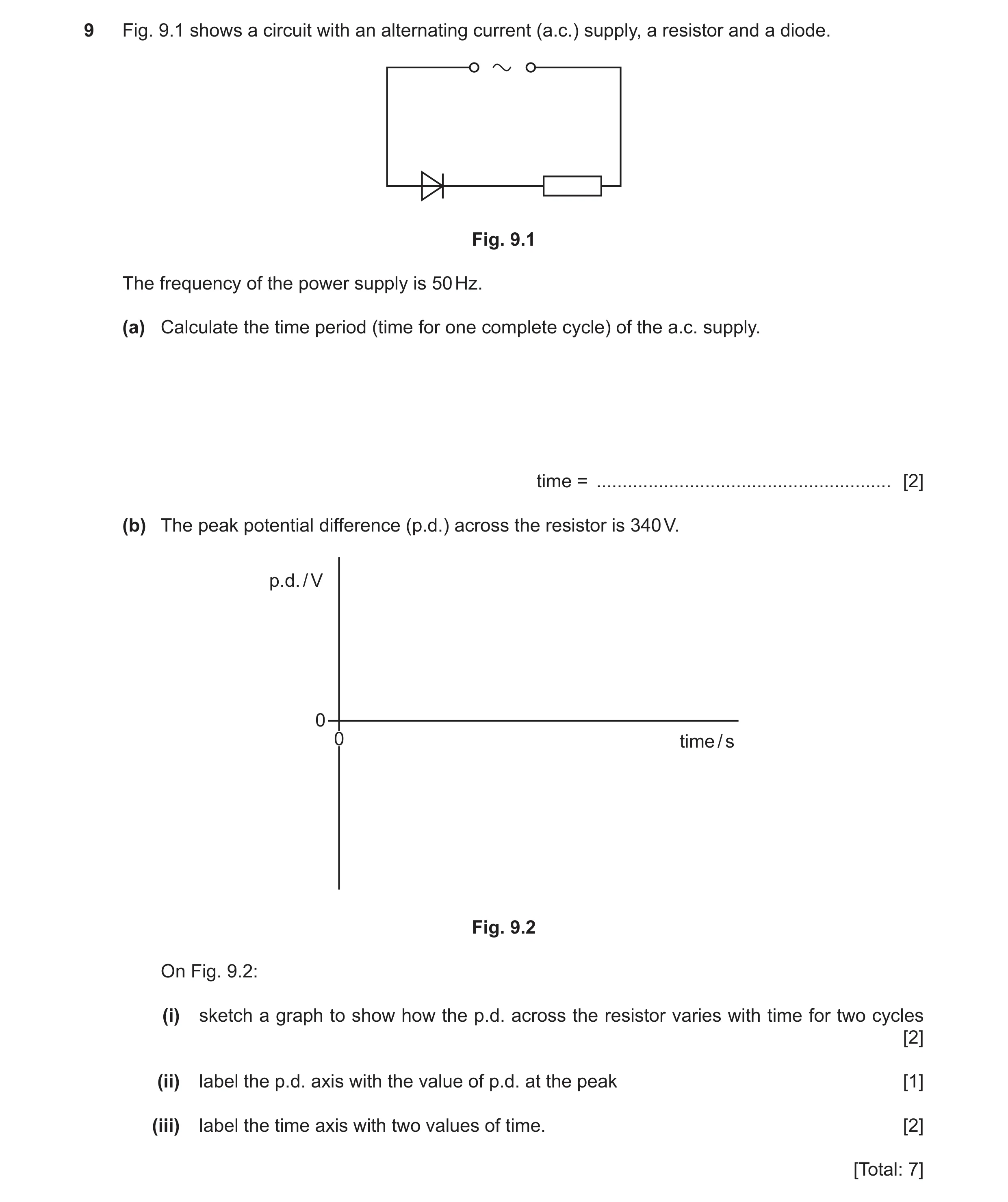 57 / 85
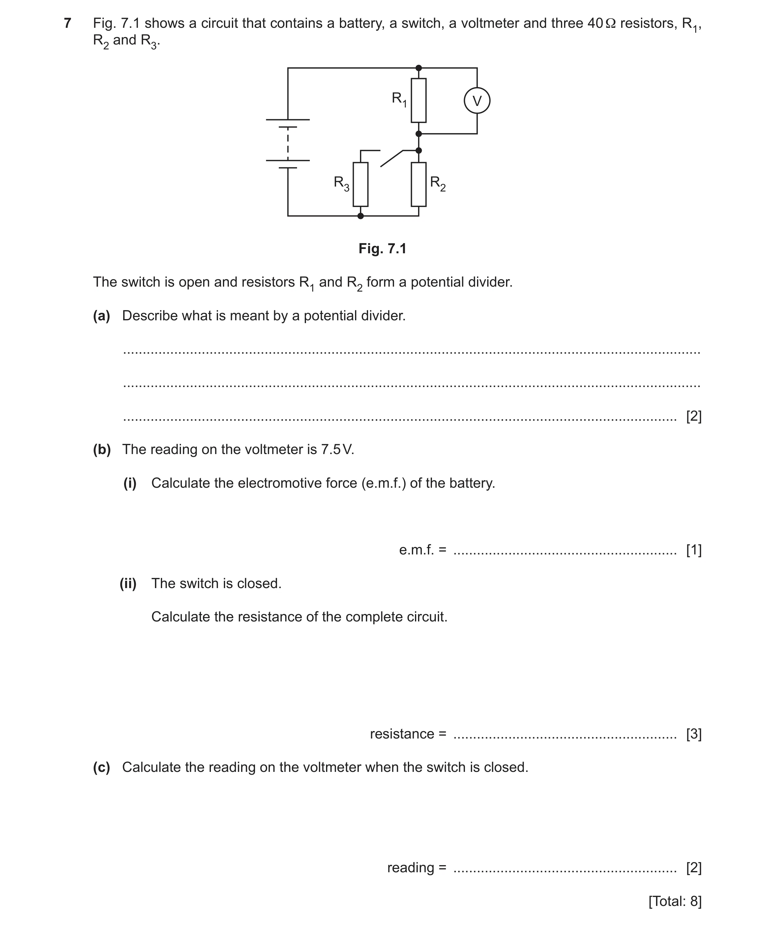 60 / 85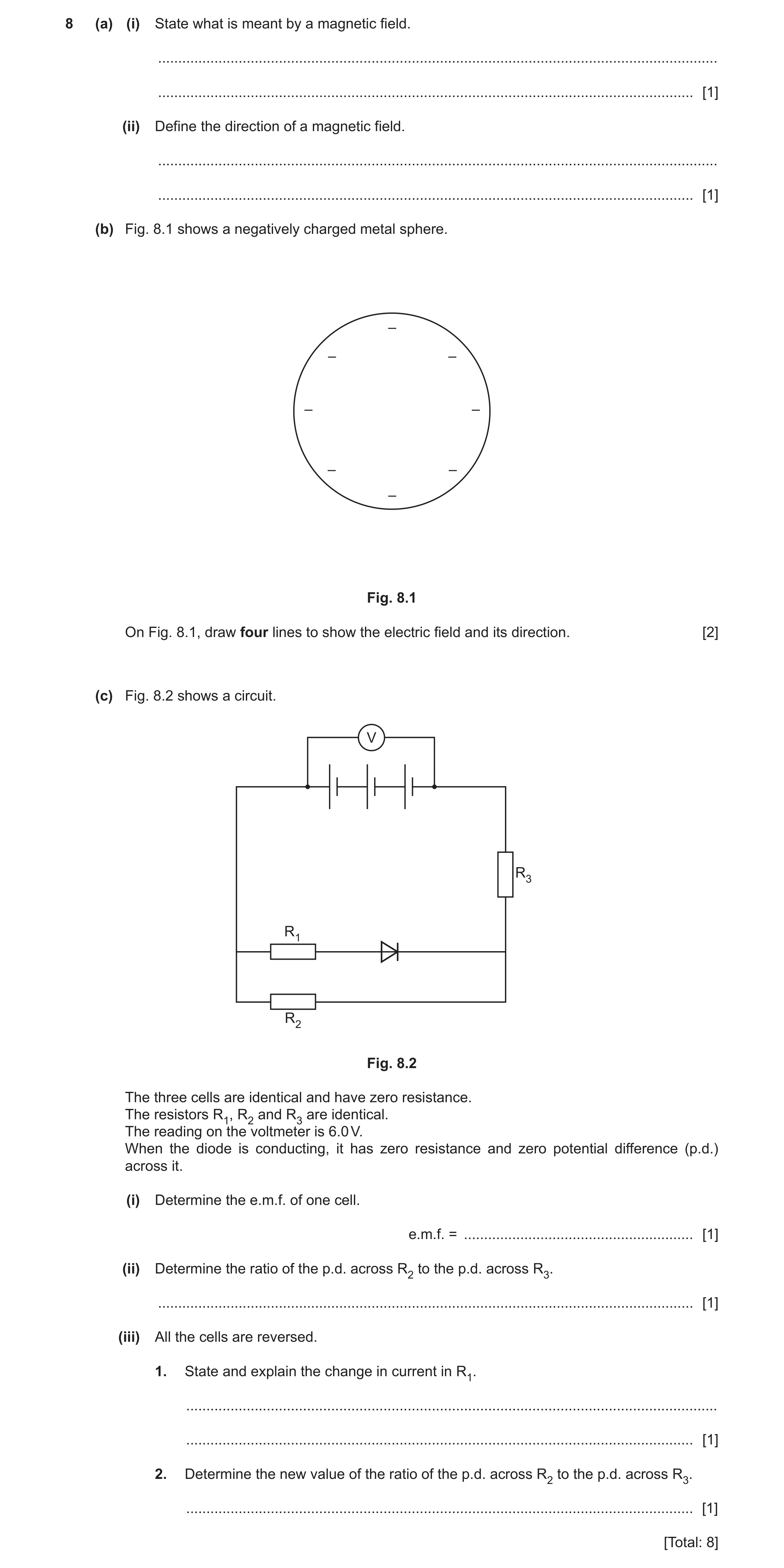
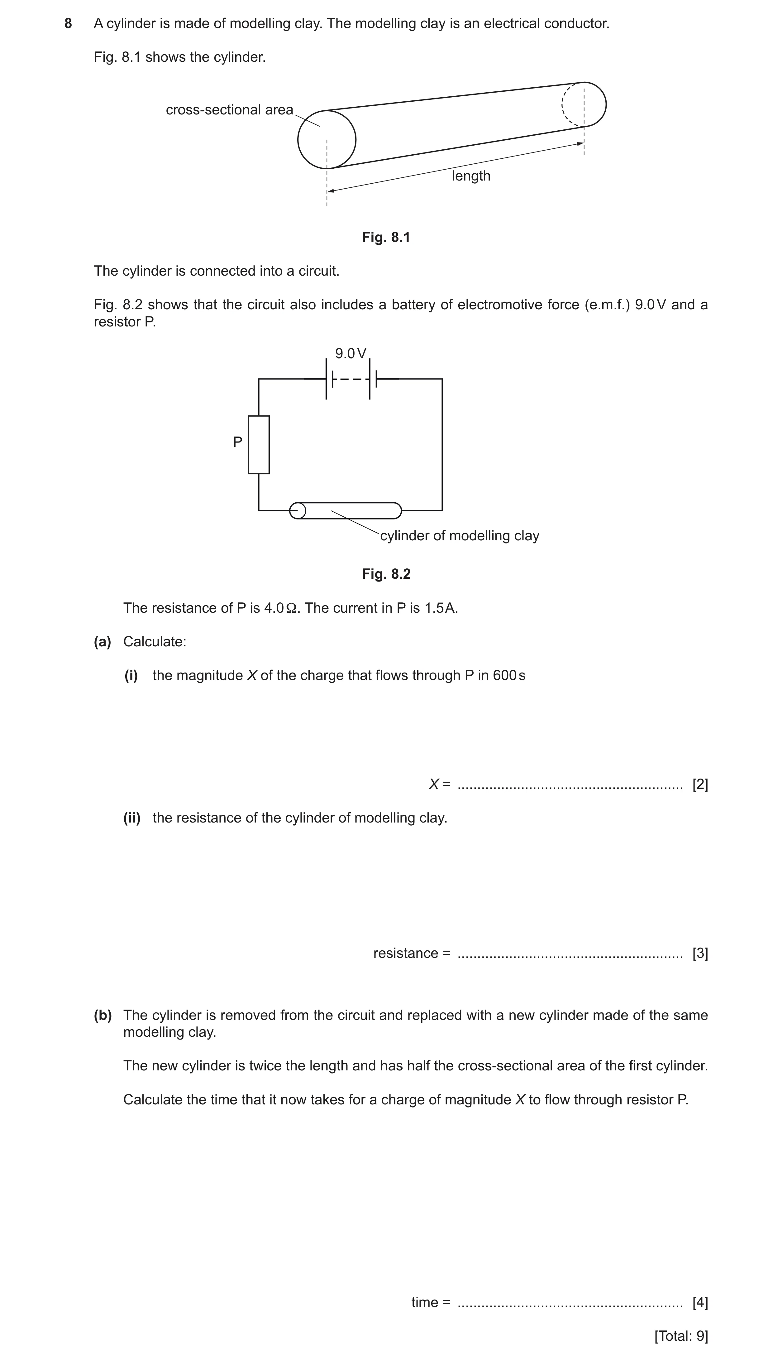
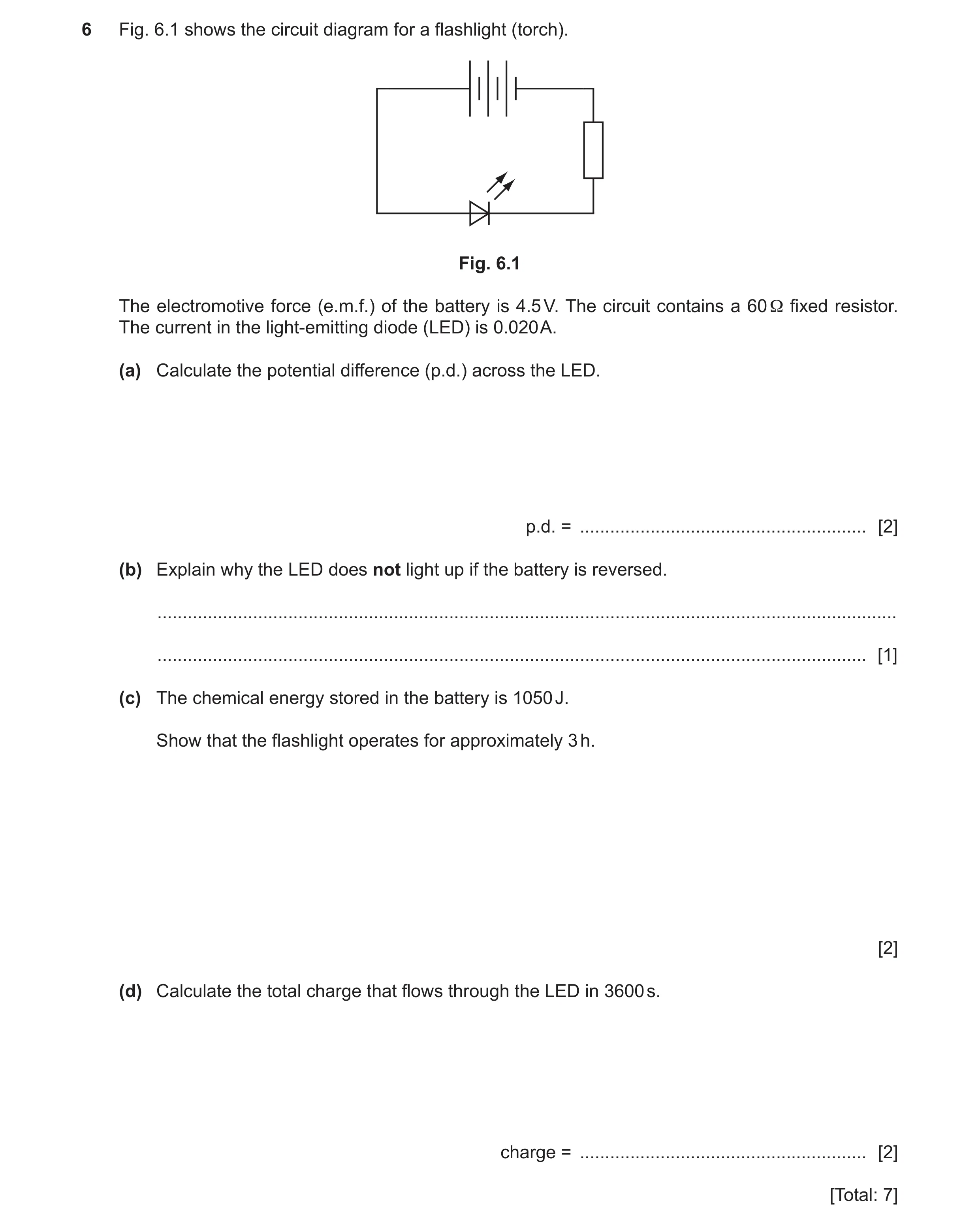 64 / 85
![Question 51: (a) Draw the circuit symbol for a potential divider. [1] (b) Fig. 7.1 shows a circuit. Vout Rout R 1.0 kΩ 6.0 V Fig. 7.1 (i) Calculate the …](https://img.pastlit.com/crops/35d6a812-b3b9-4081-84aa-ed35c77de54b/q7.webp) 65 / 85
65 / 85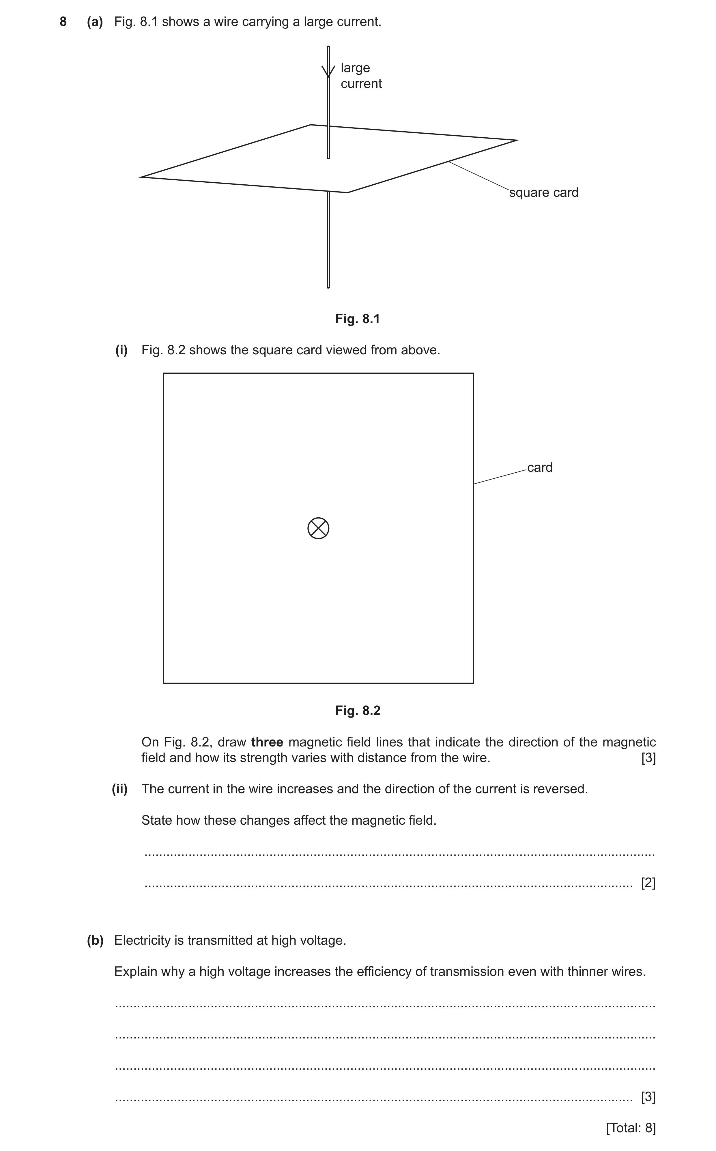
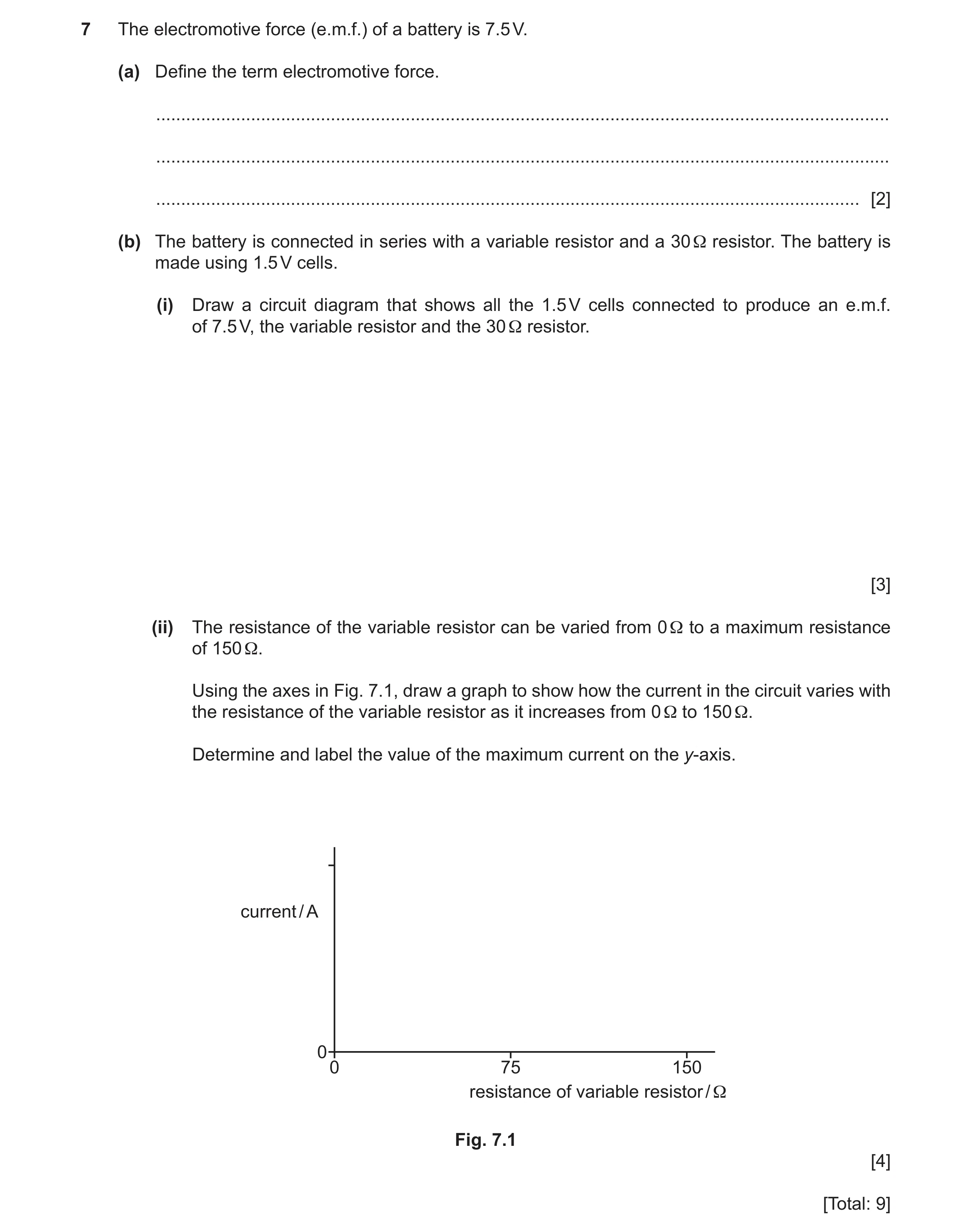 68 / 85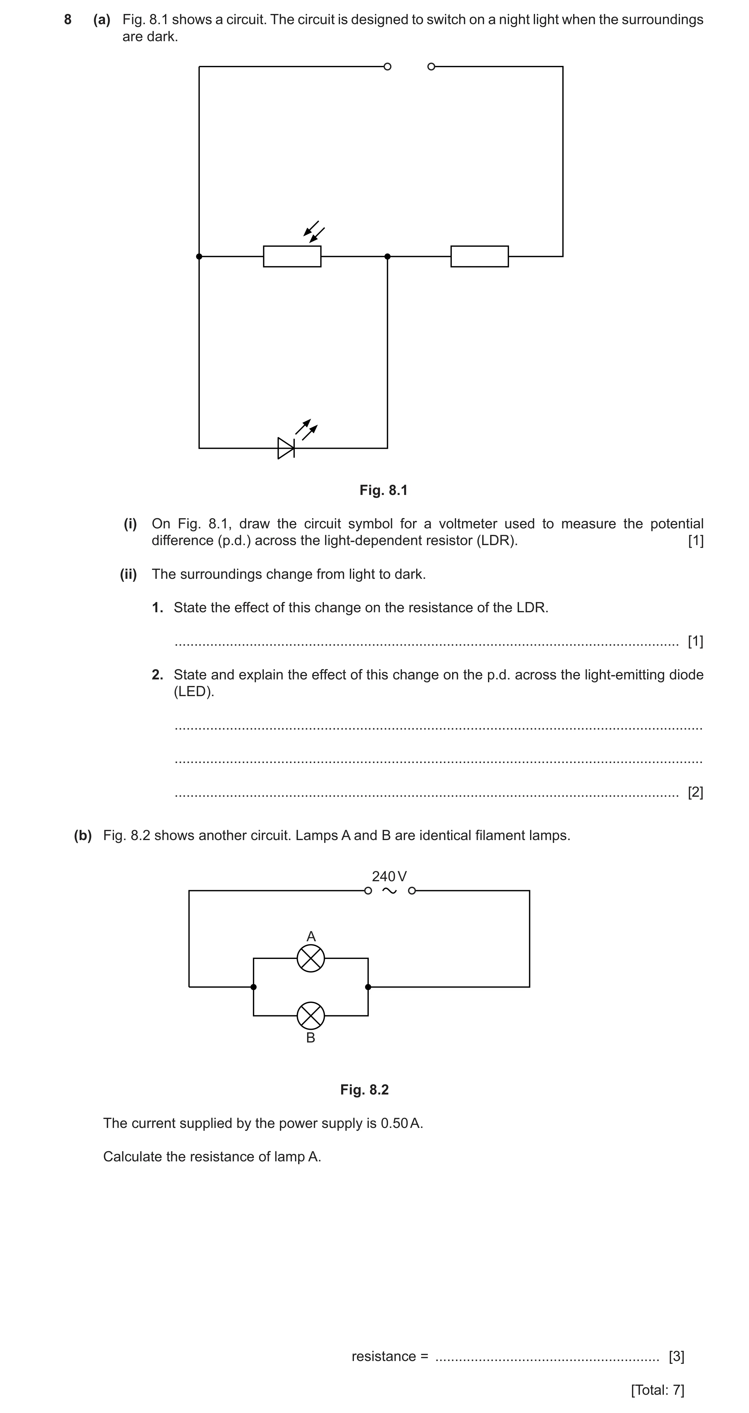
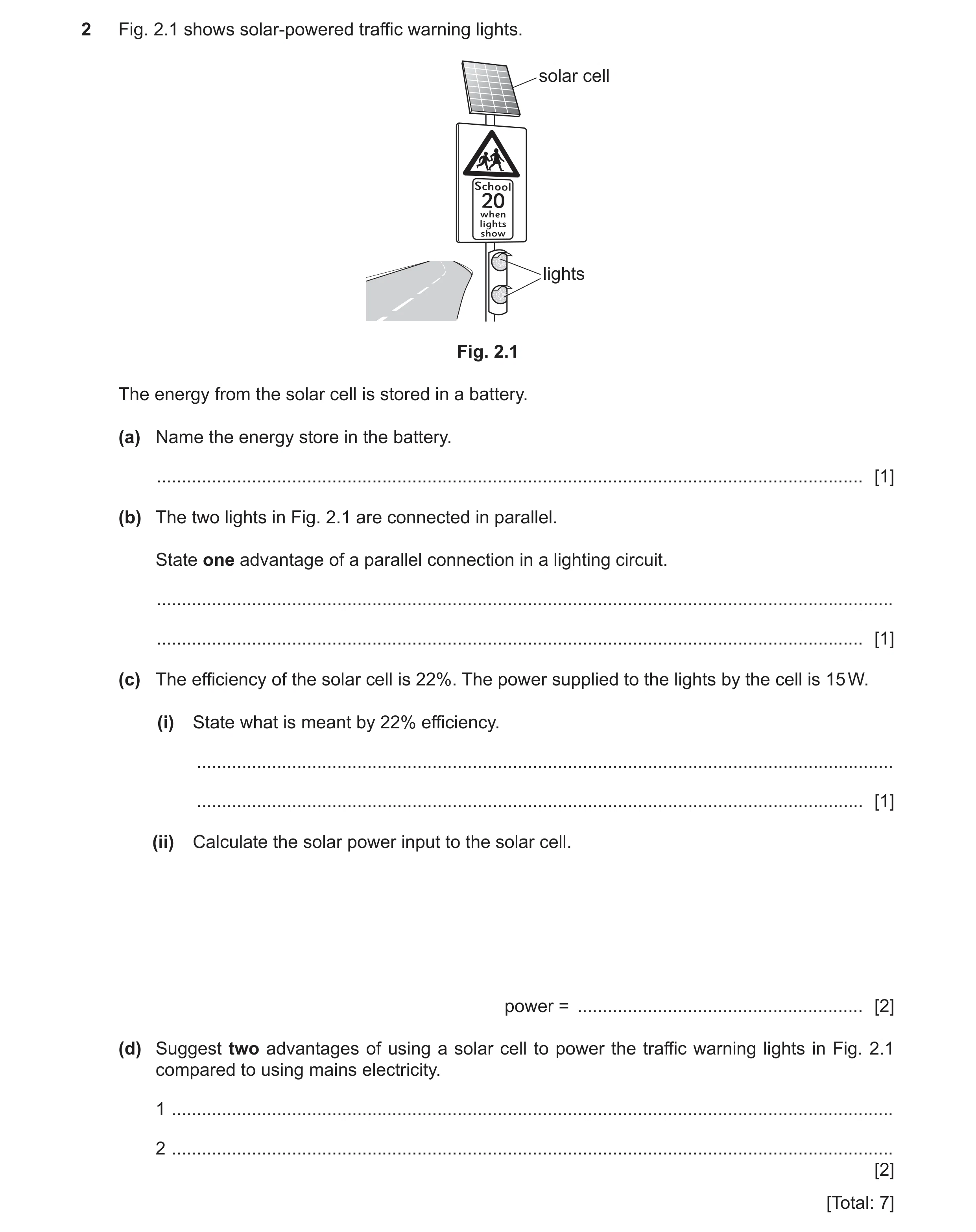 71 / 85
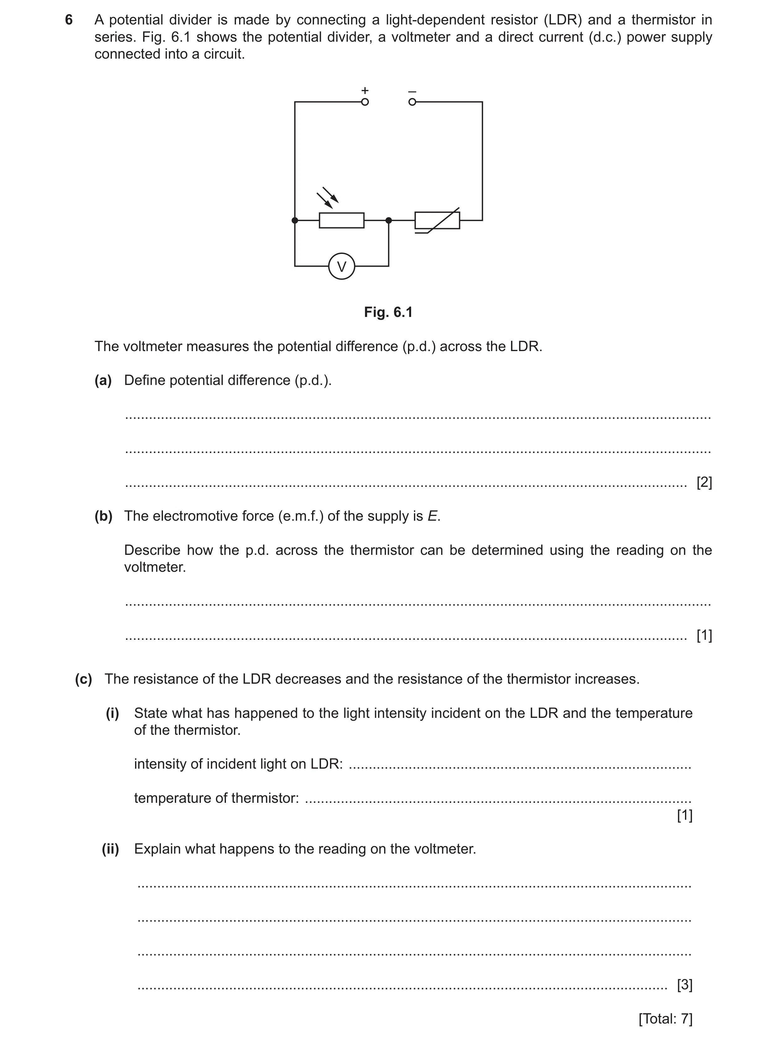 72 / 85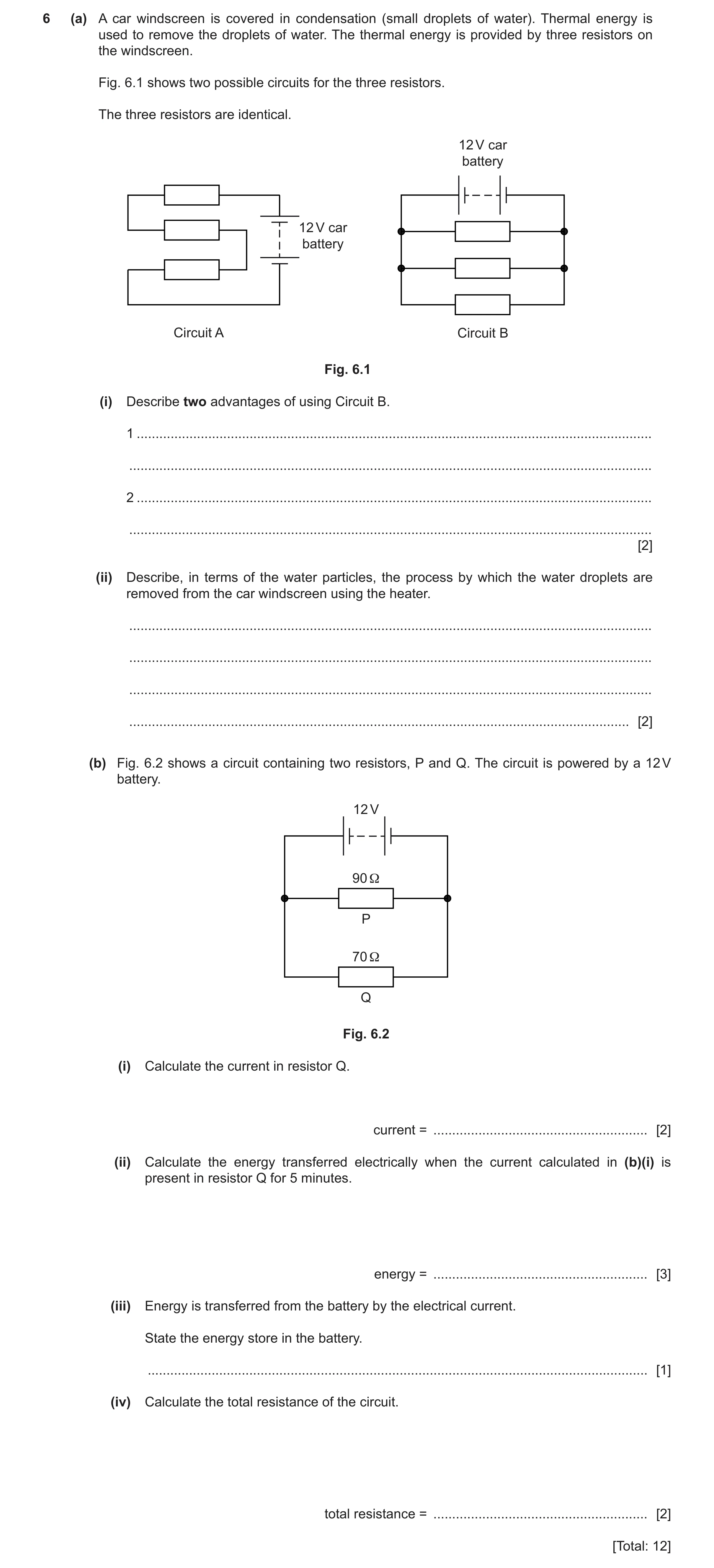
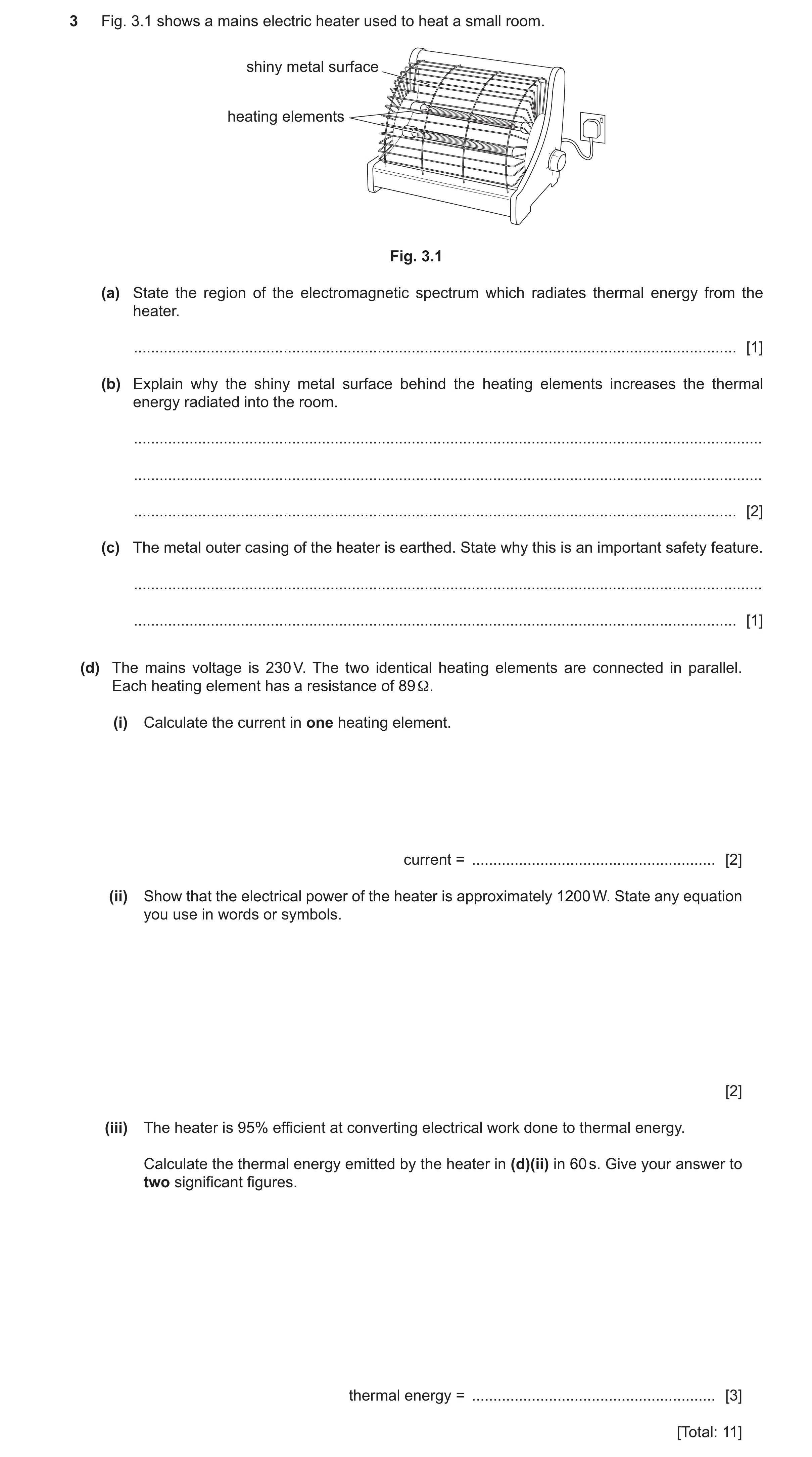
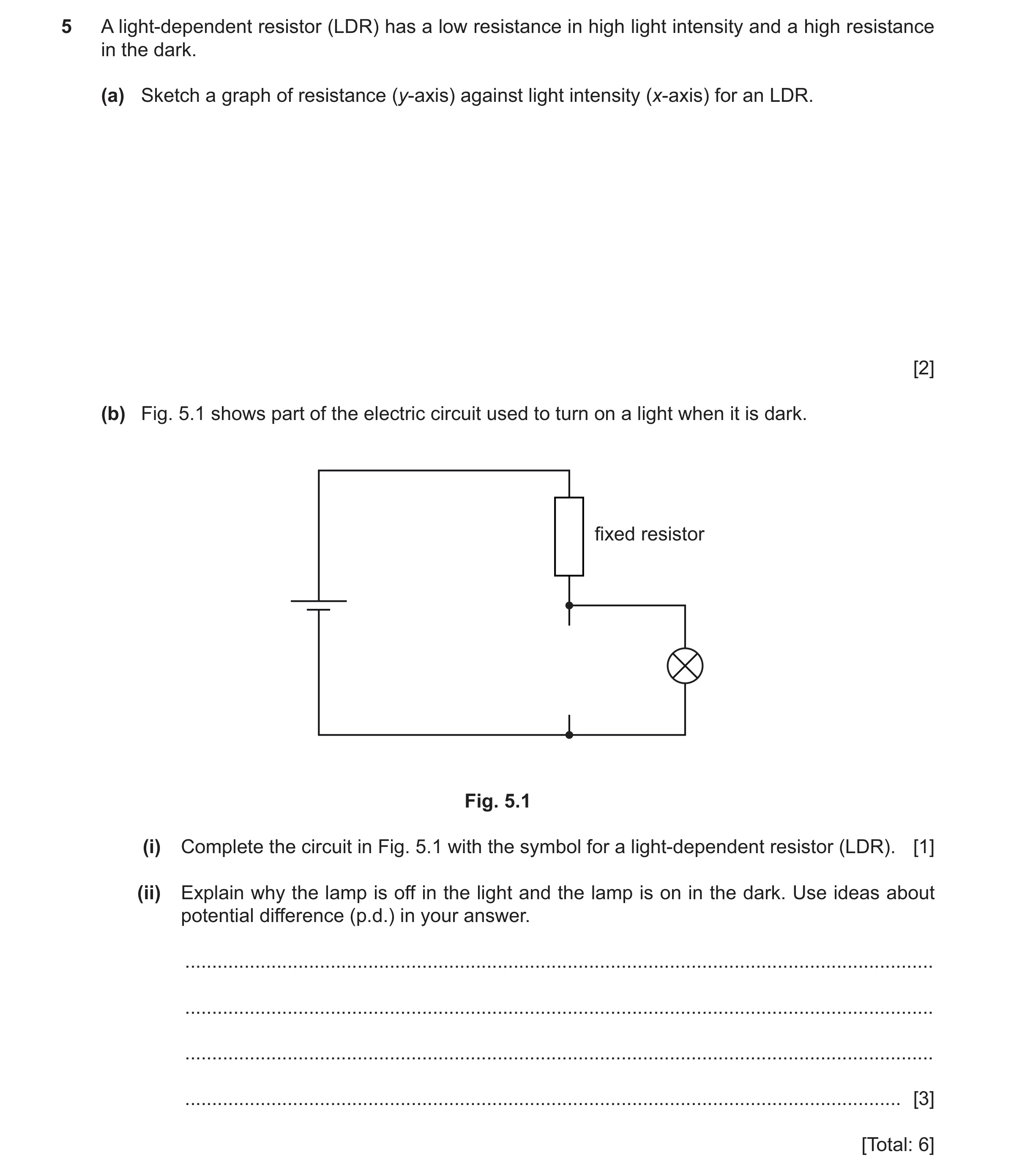 76 / 85
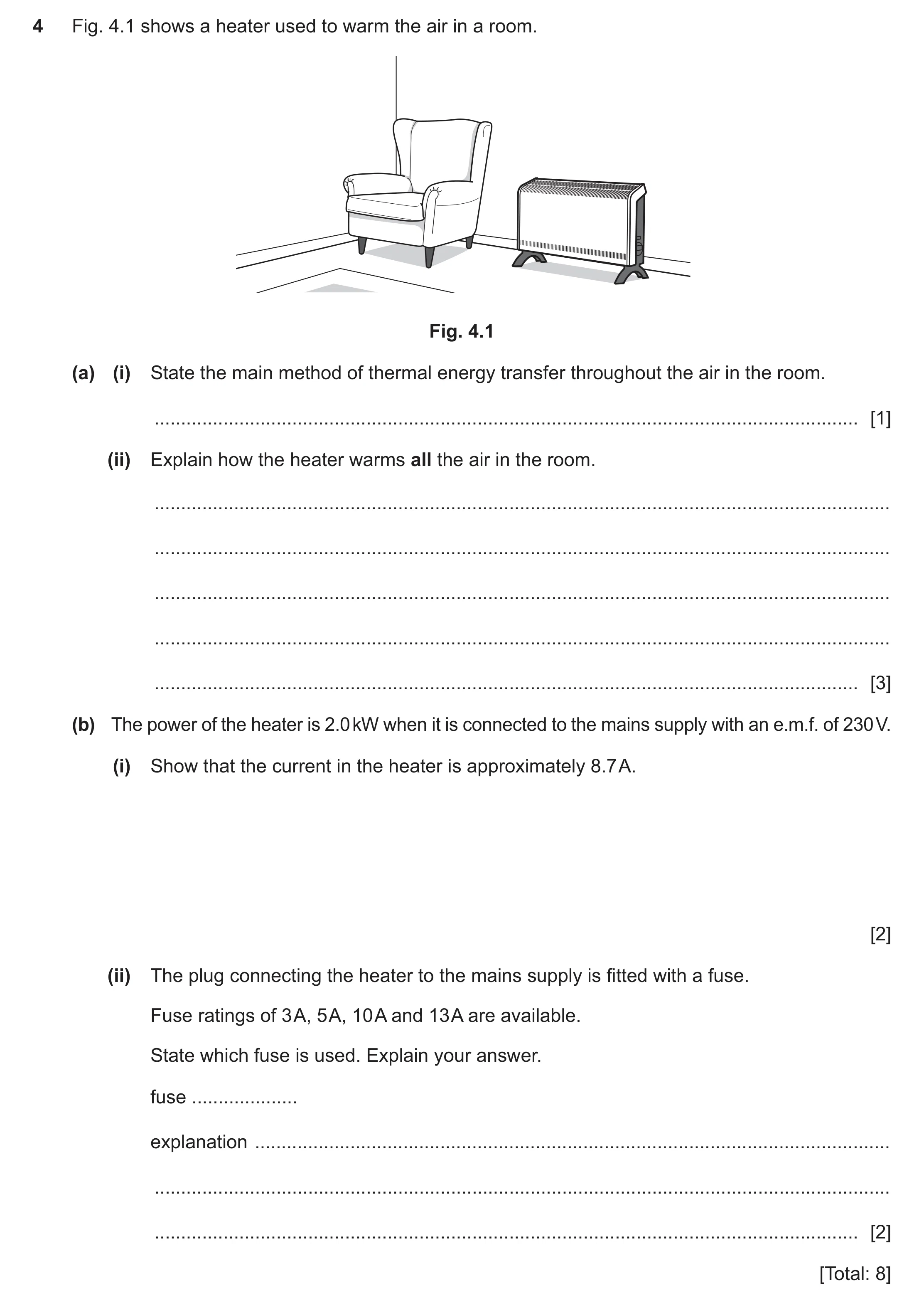 77 / 85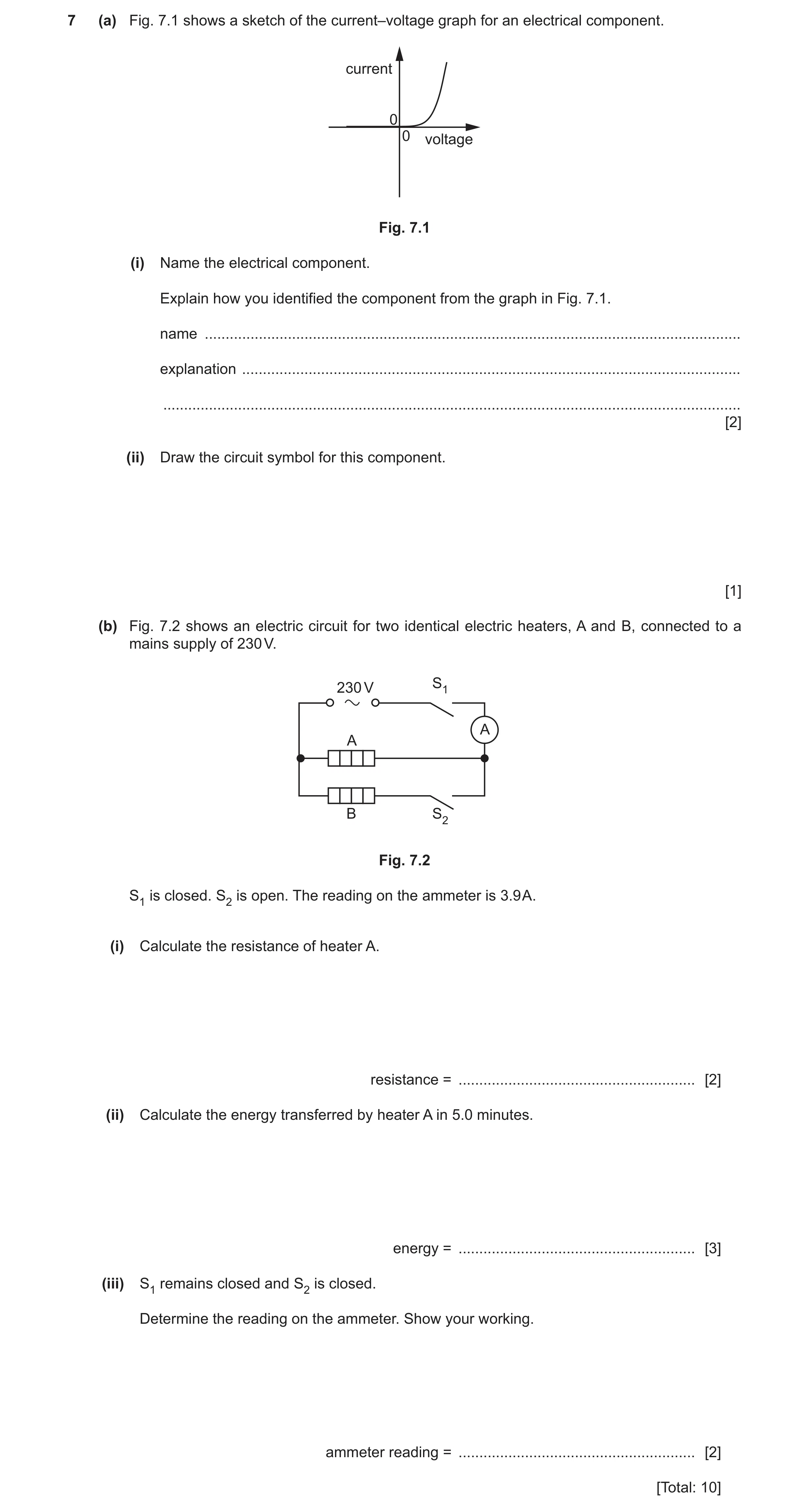

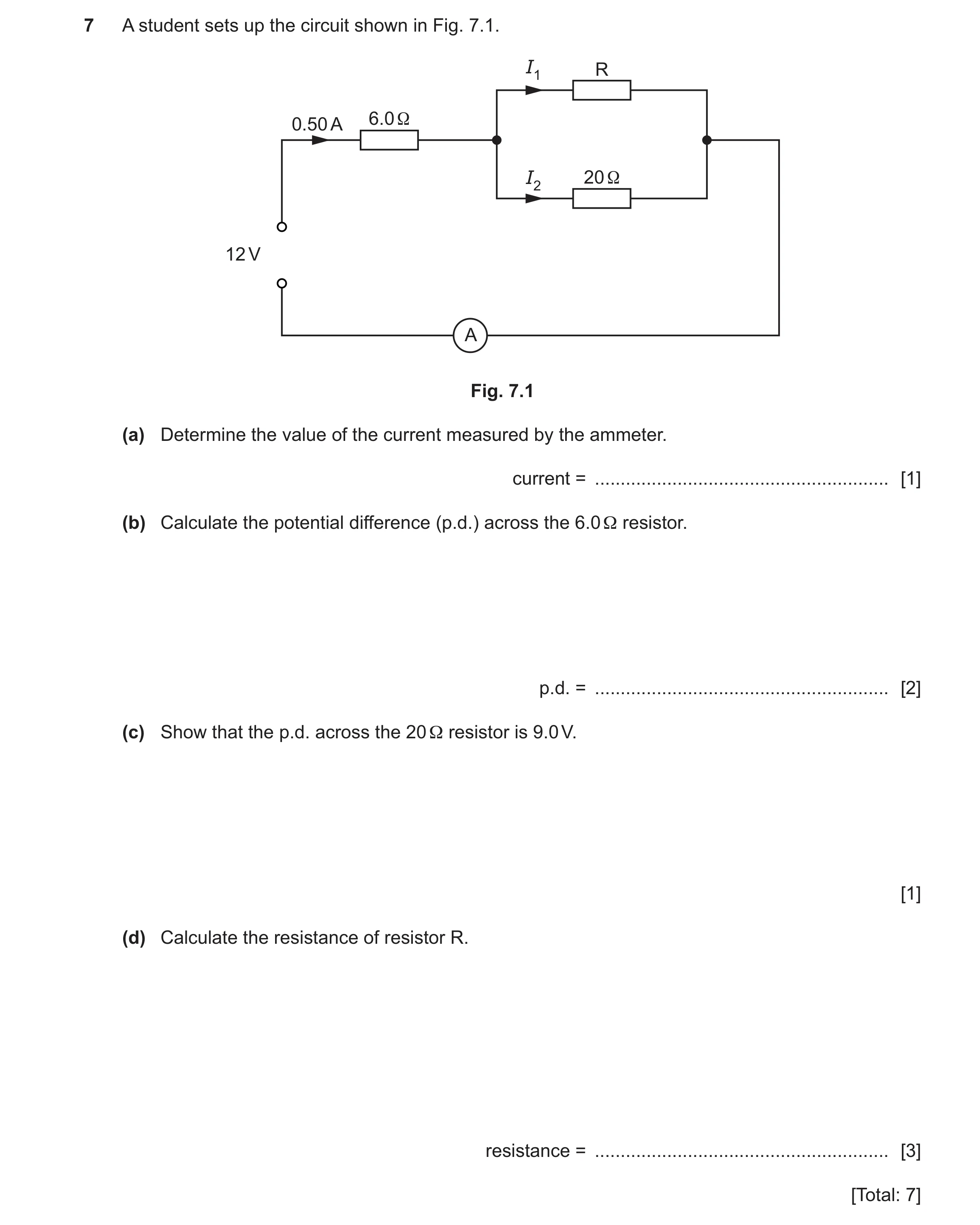 82 / 85
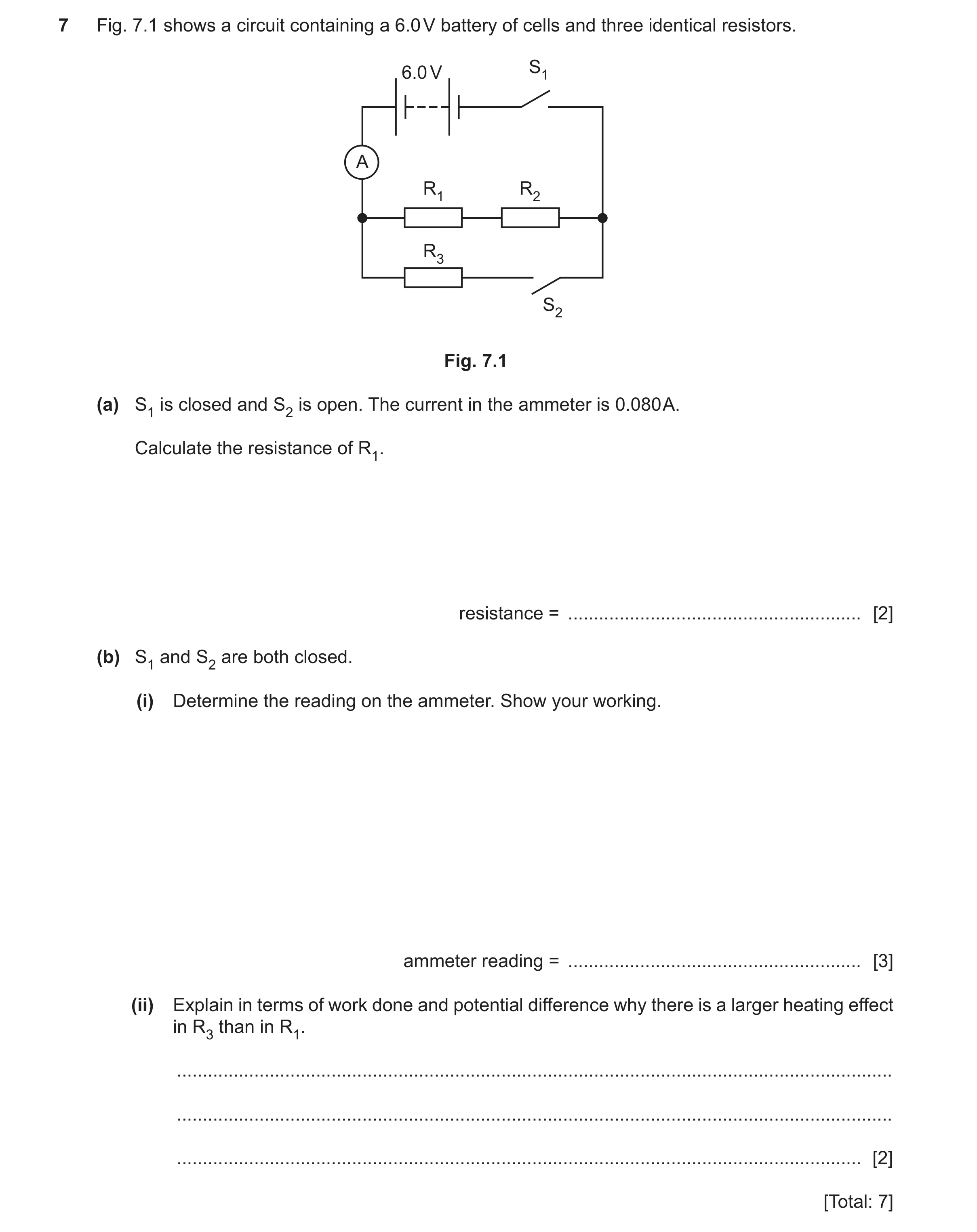 83 / 85
![Question 65: A circuit consists of an a.c. supply and two lamps. The lamps are connected in parallel. (a) Draw the circuit diagram. [2] (b) The electrom…](https://img.pastlit.com/crops/f5a1d434-d411-492a-81c8-f1c39d56daae/q7.webp)
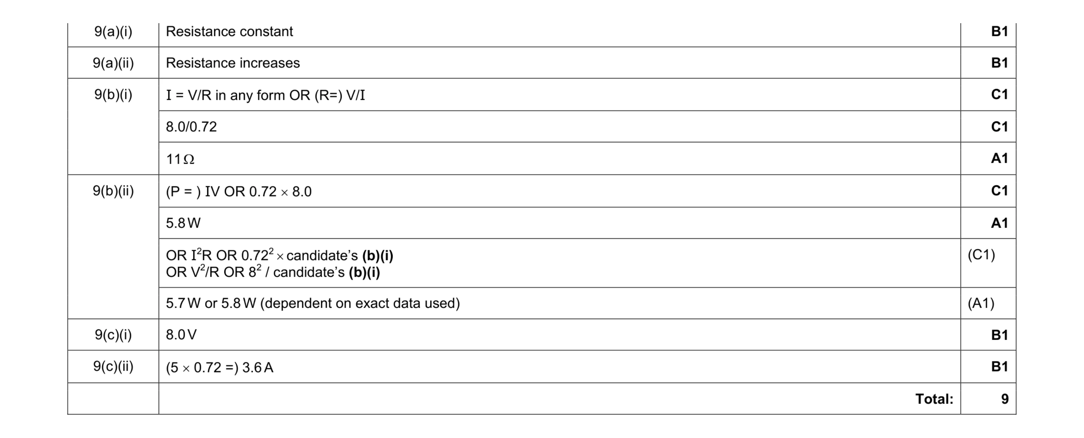 9
9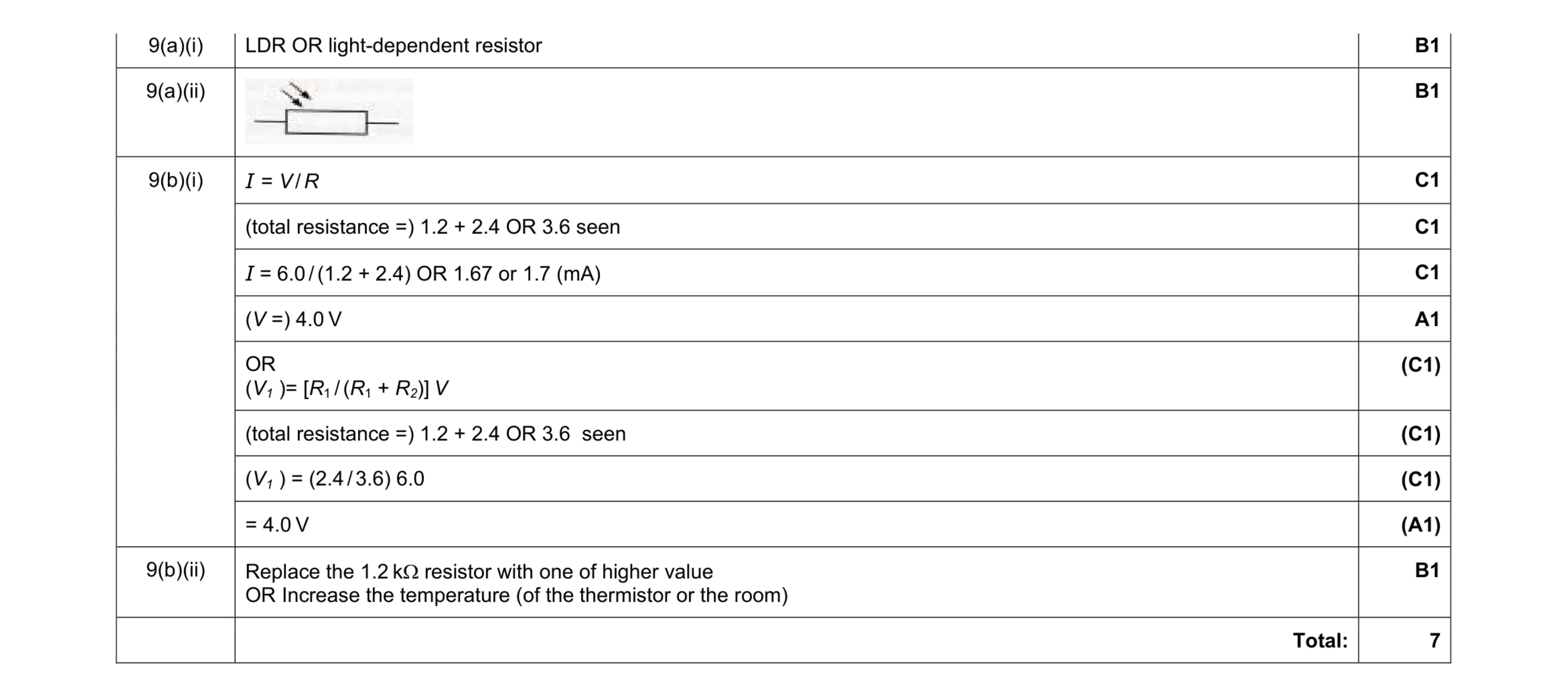 7
7 9
9 8
8 7
7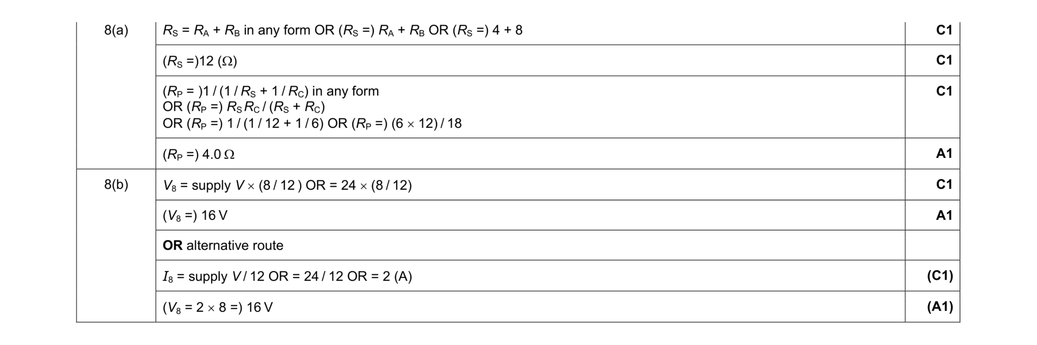 6
6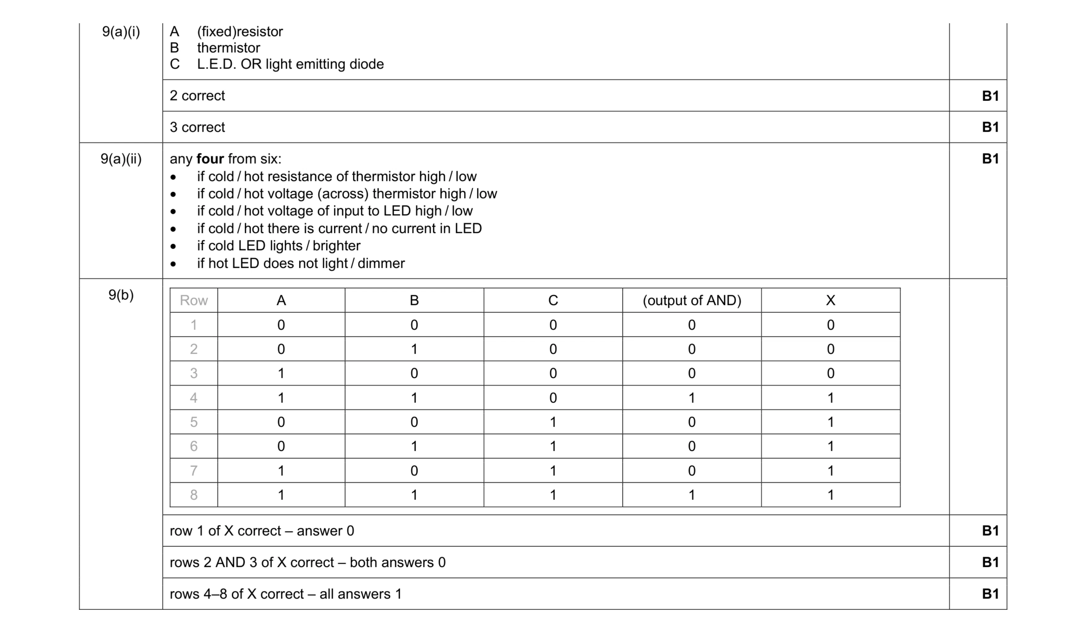 9
9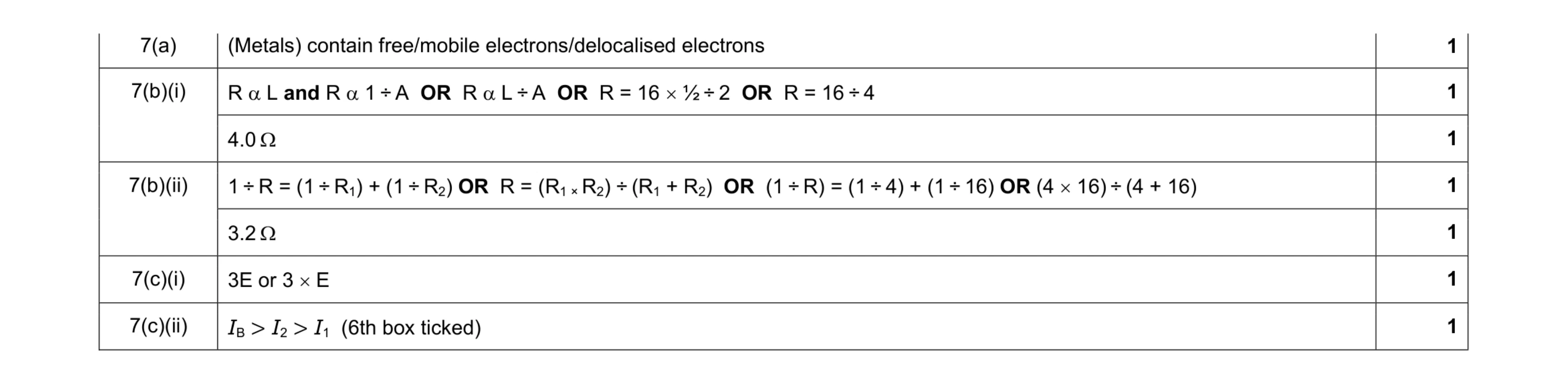 7
7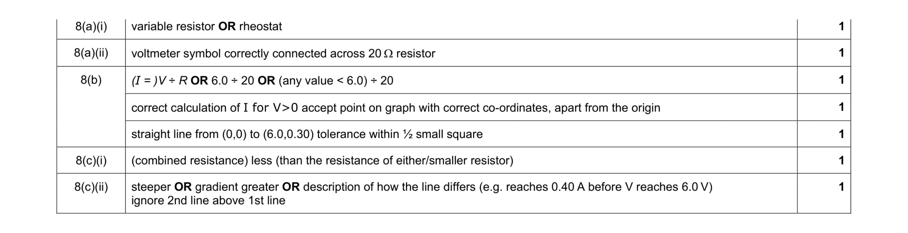 7
7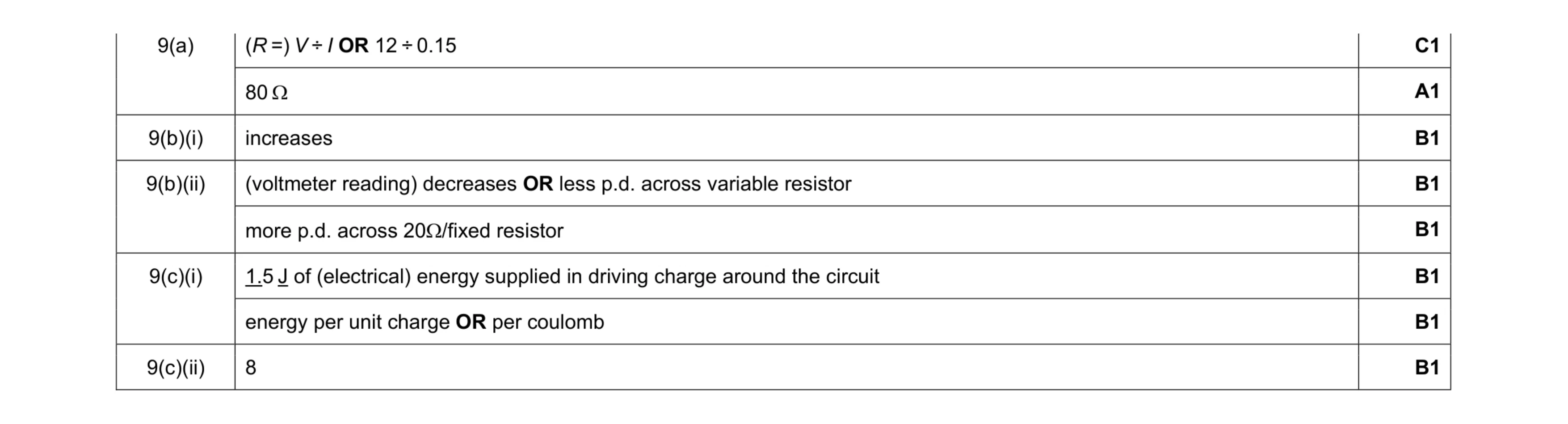 8
8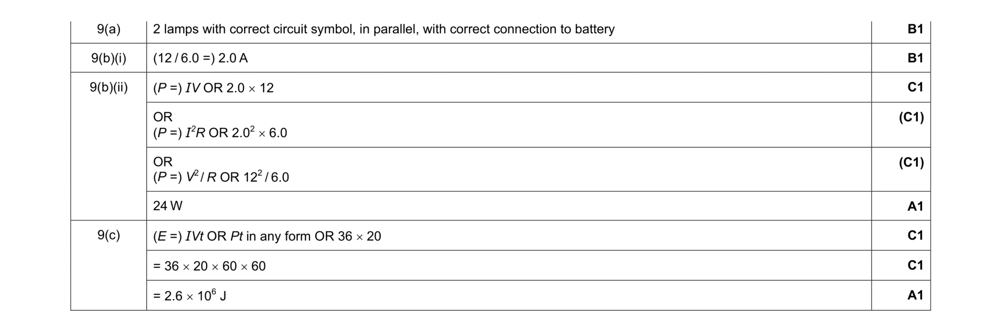 7
7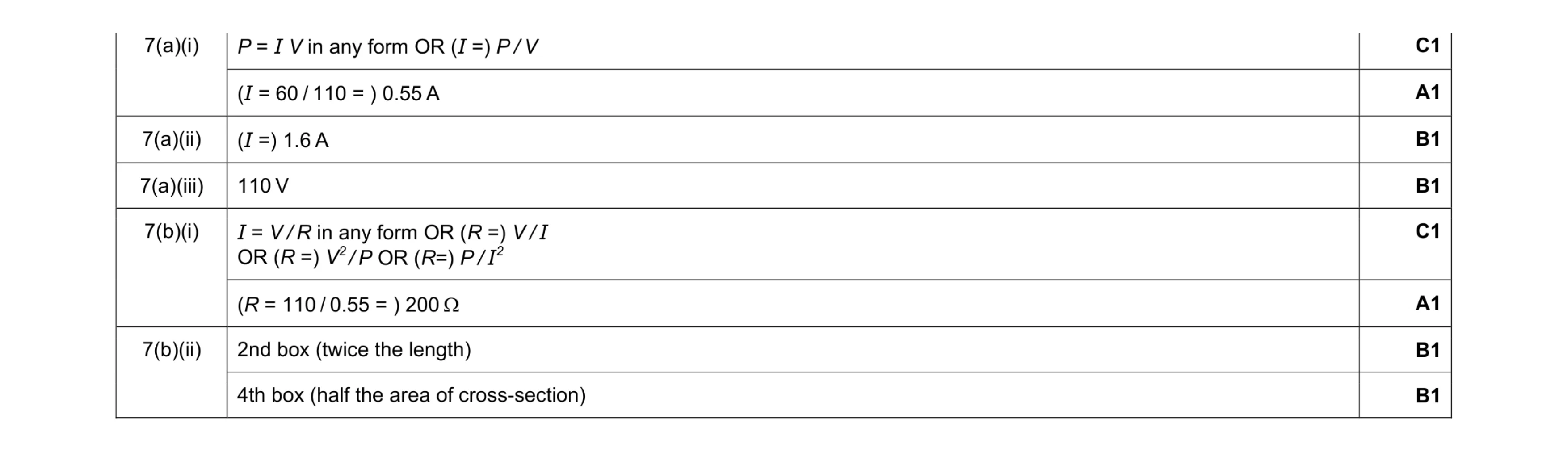 8
8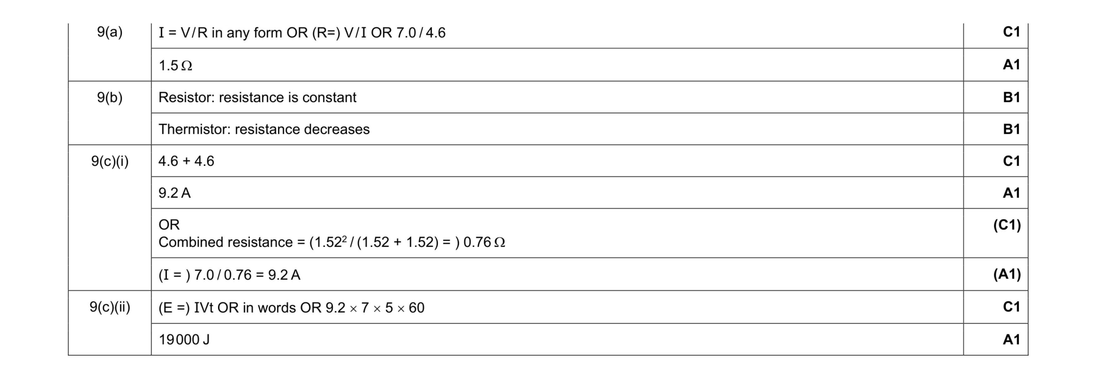 8
8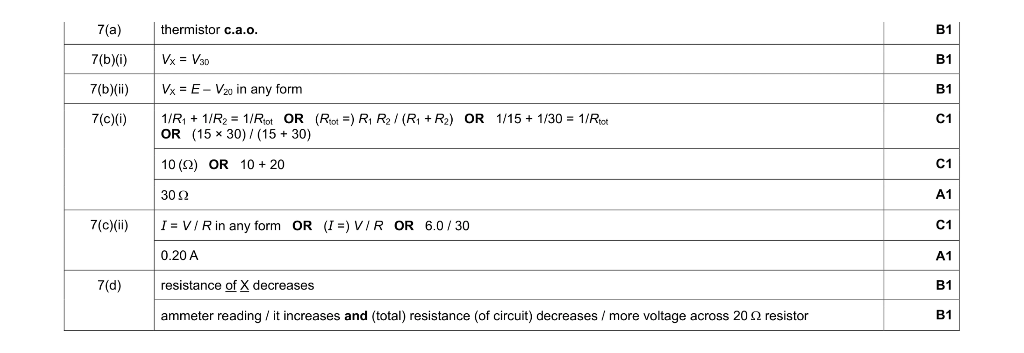 10
10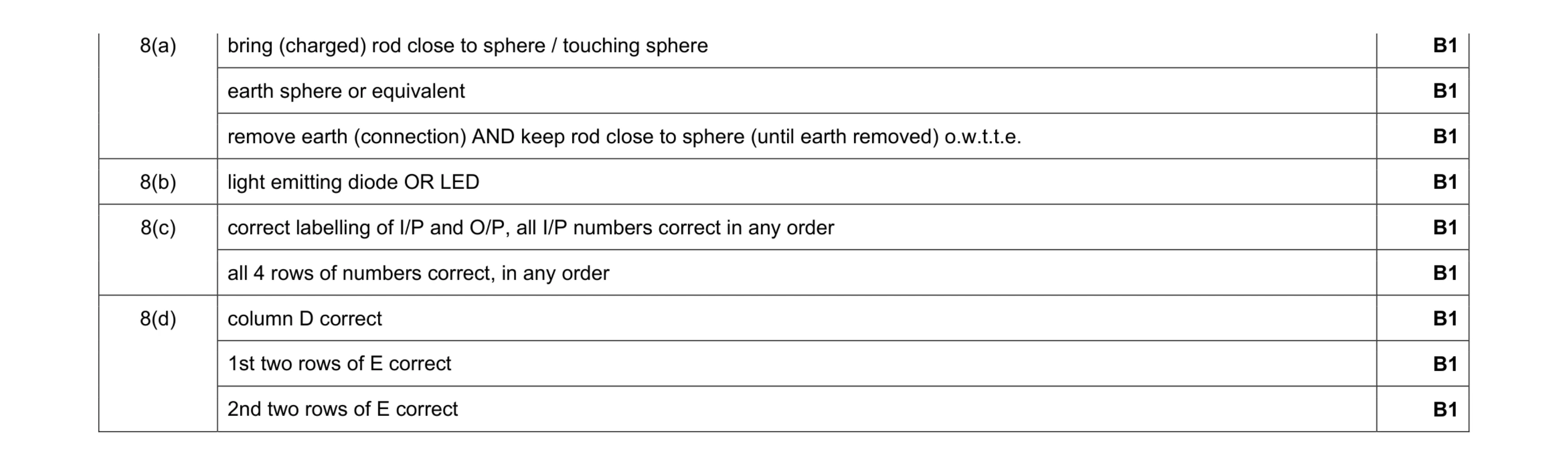 9
9 5
5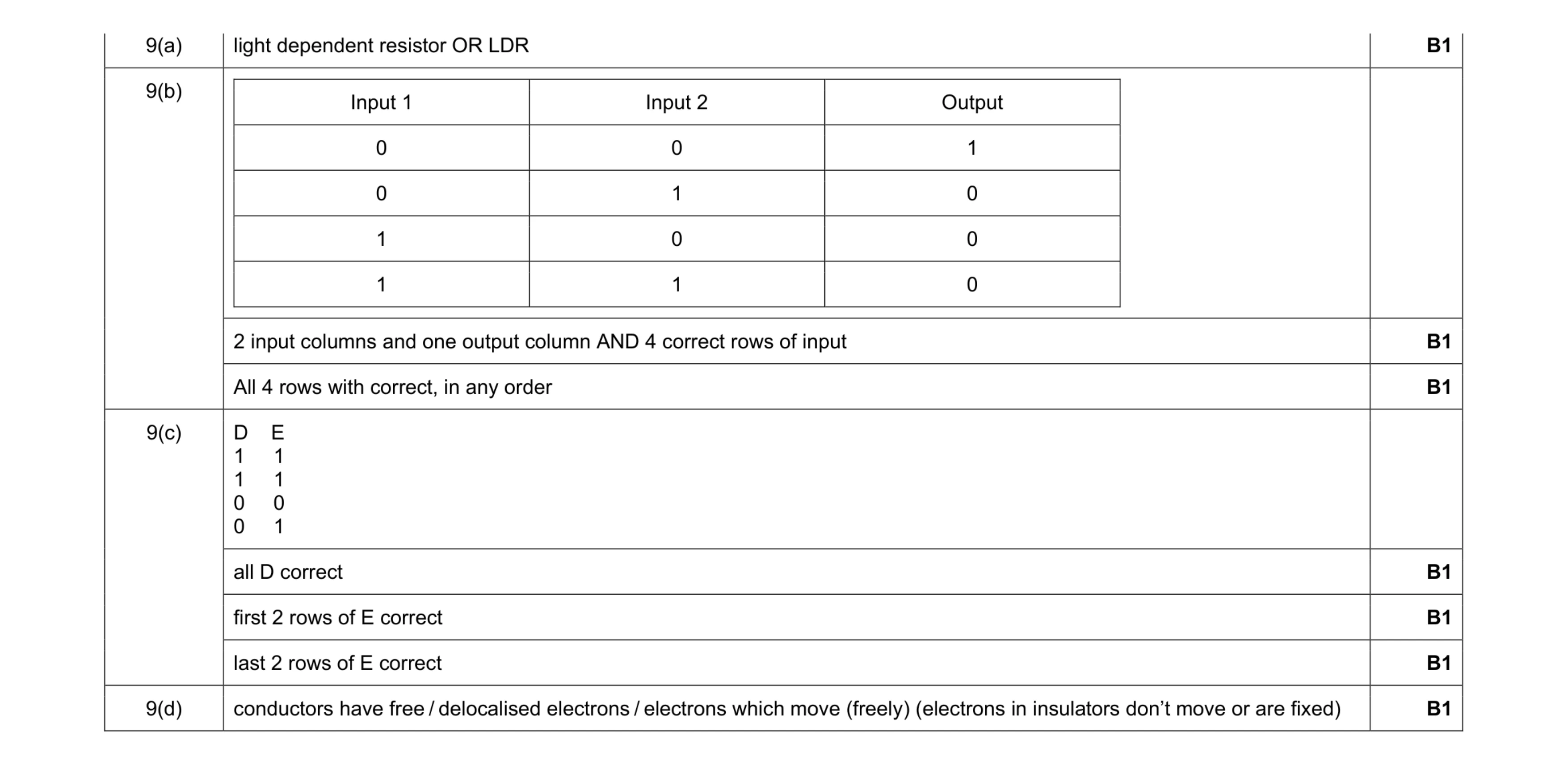 7
7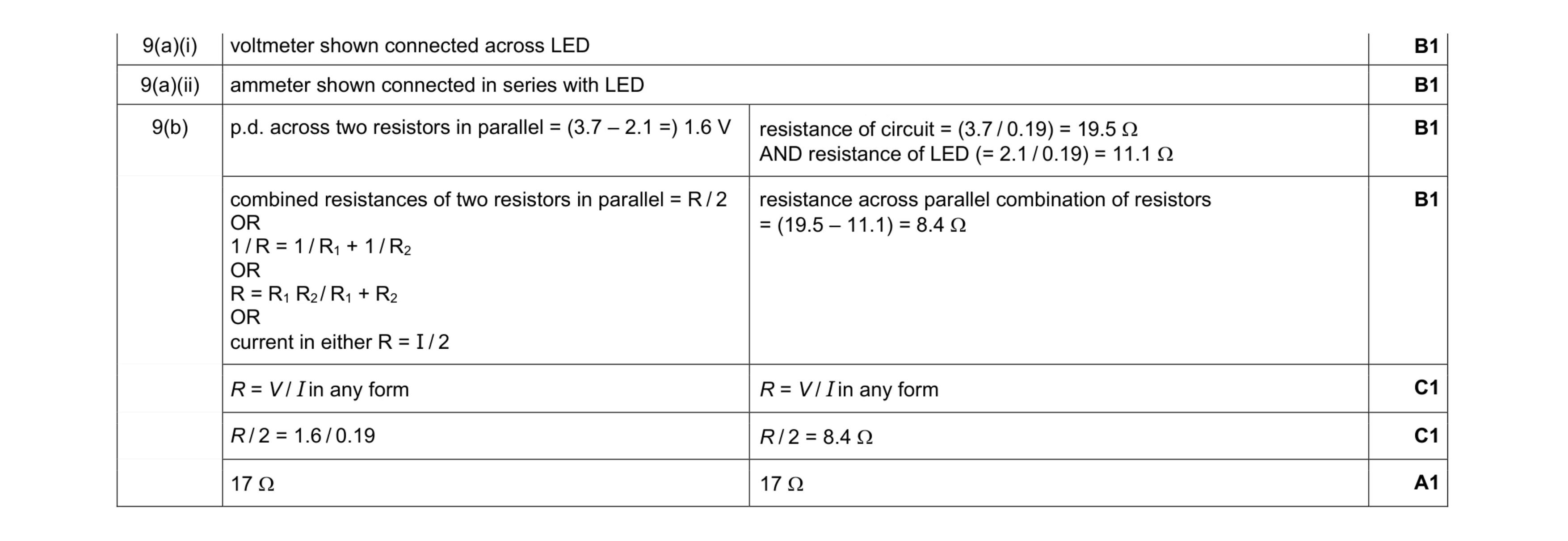 7
7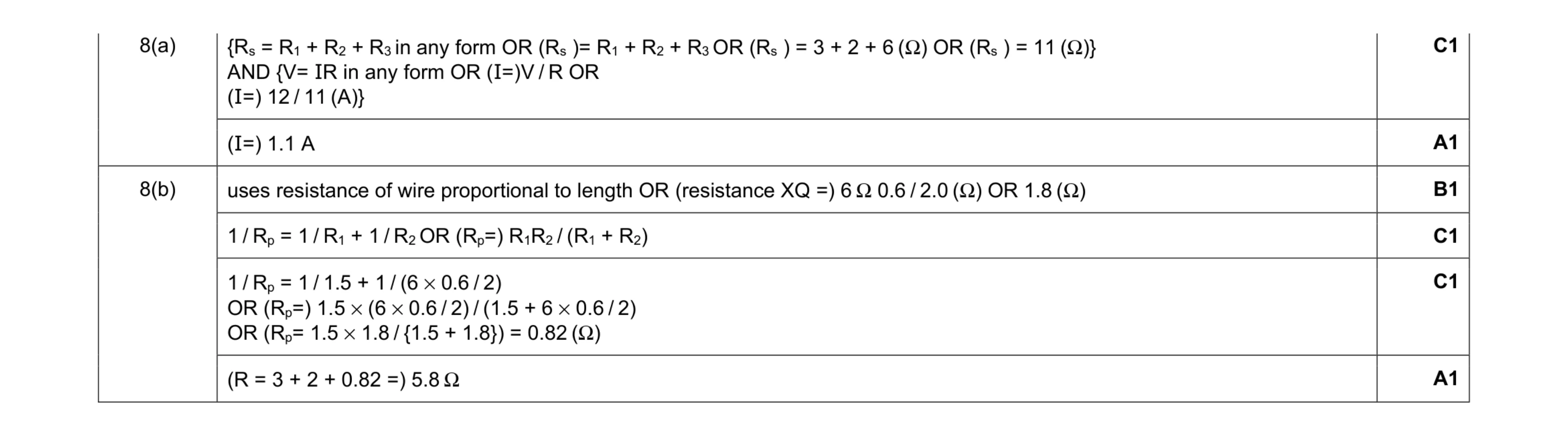 6
6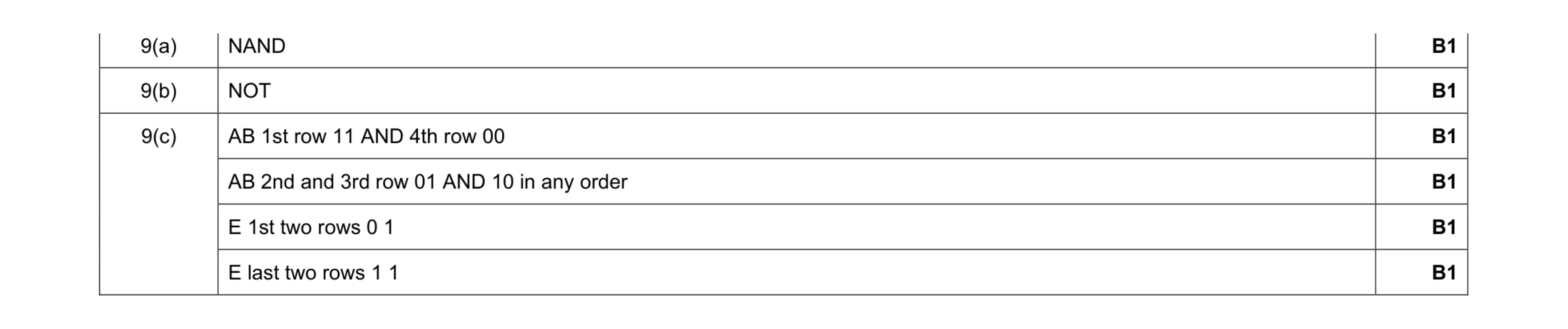 6
6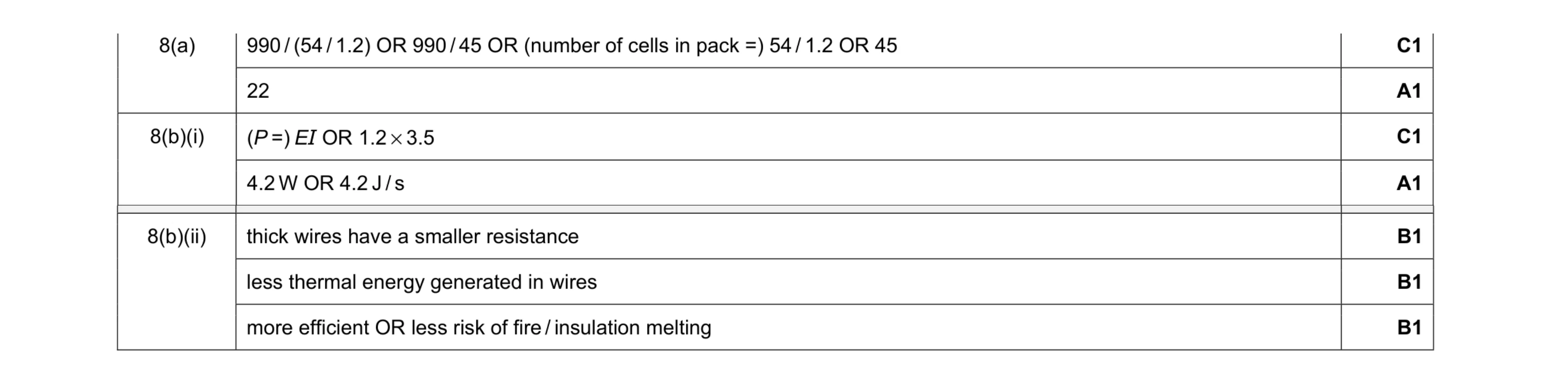 7
7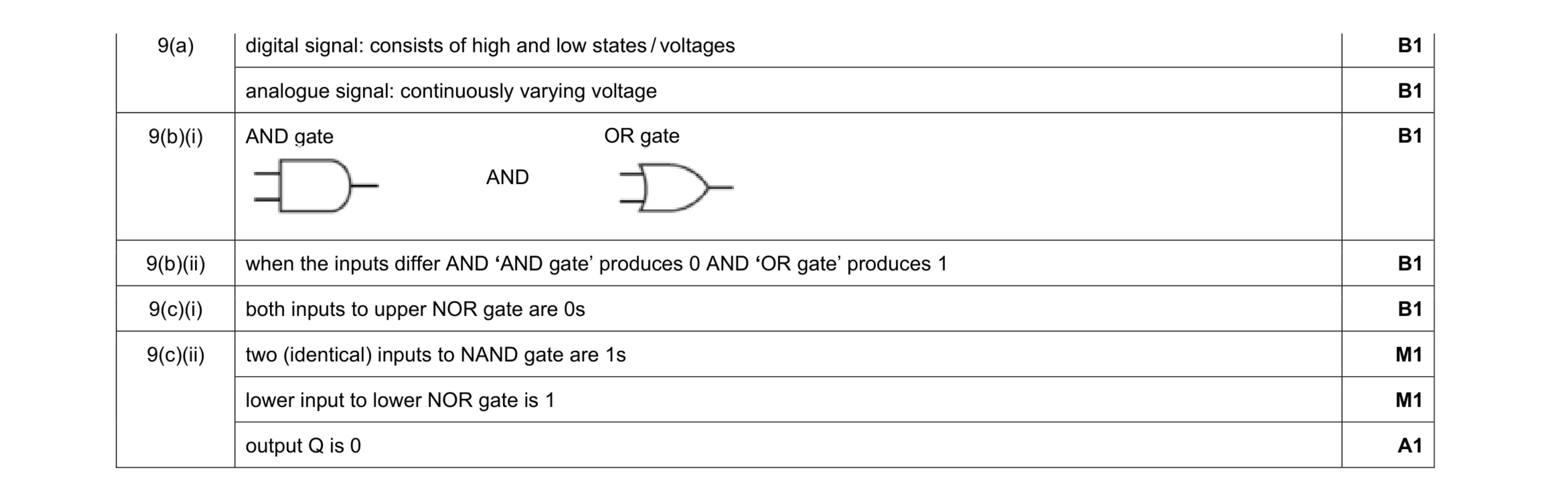 8
8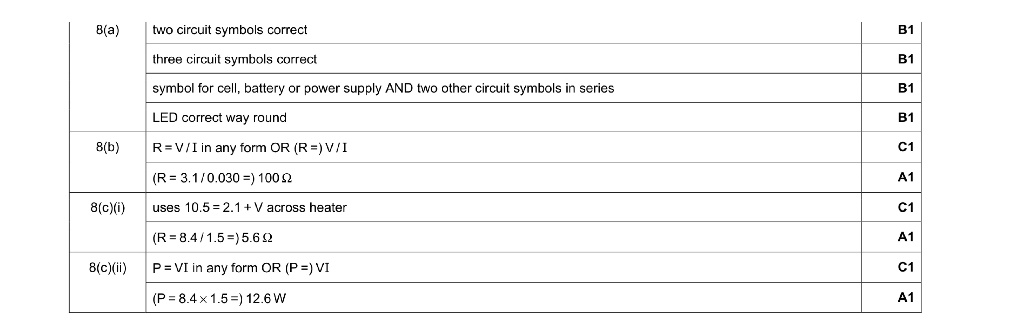 10
10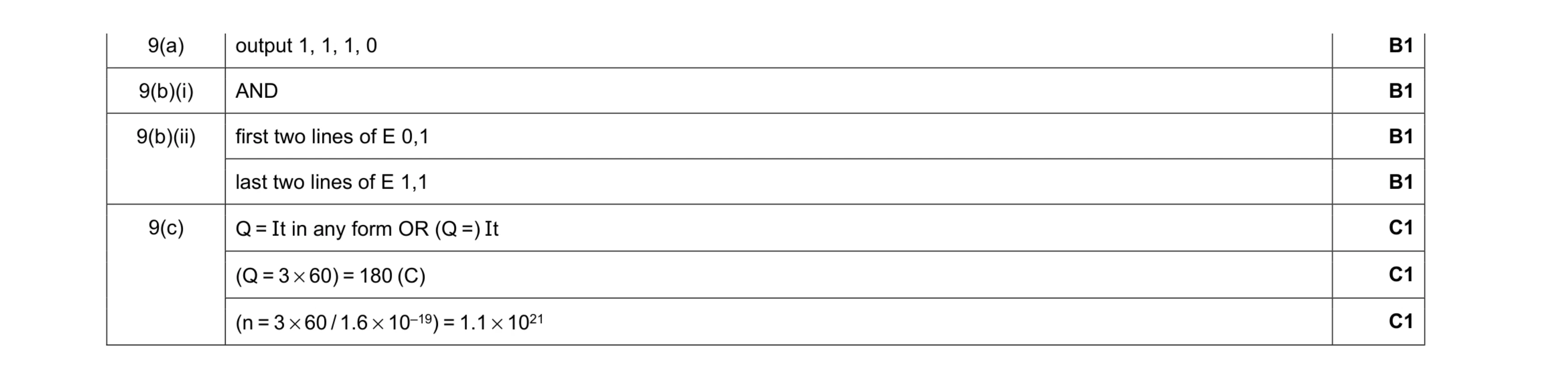 7
7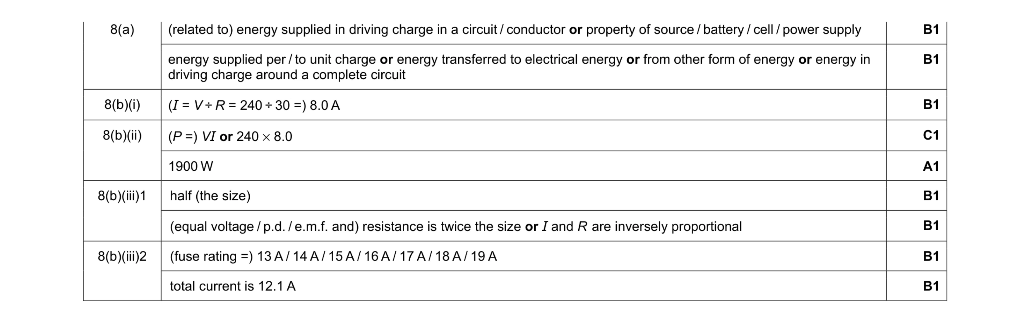 9
9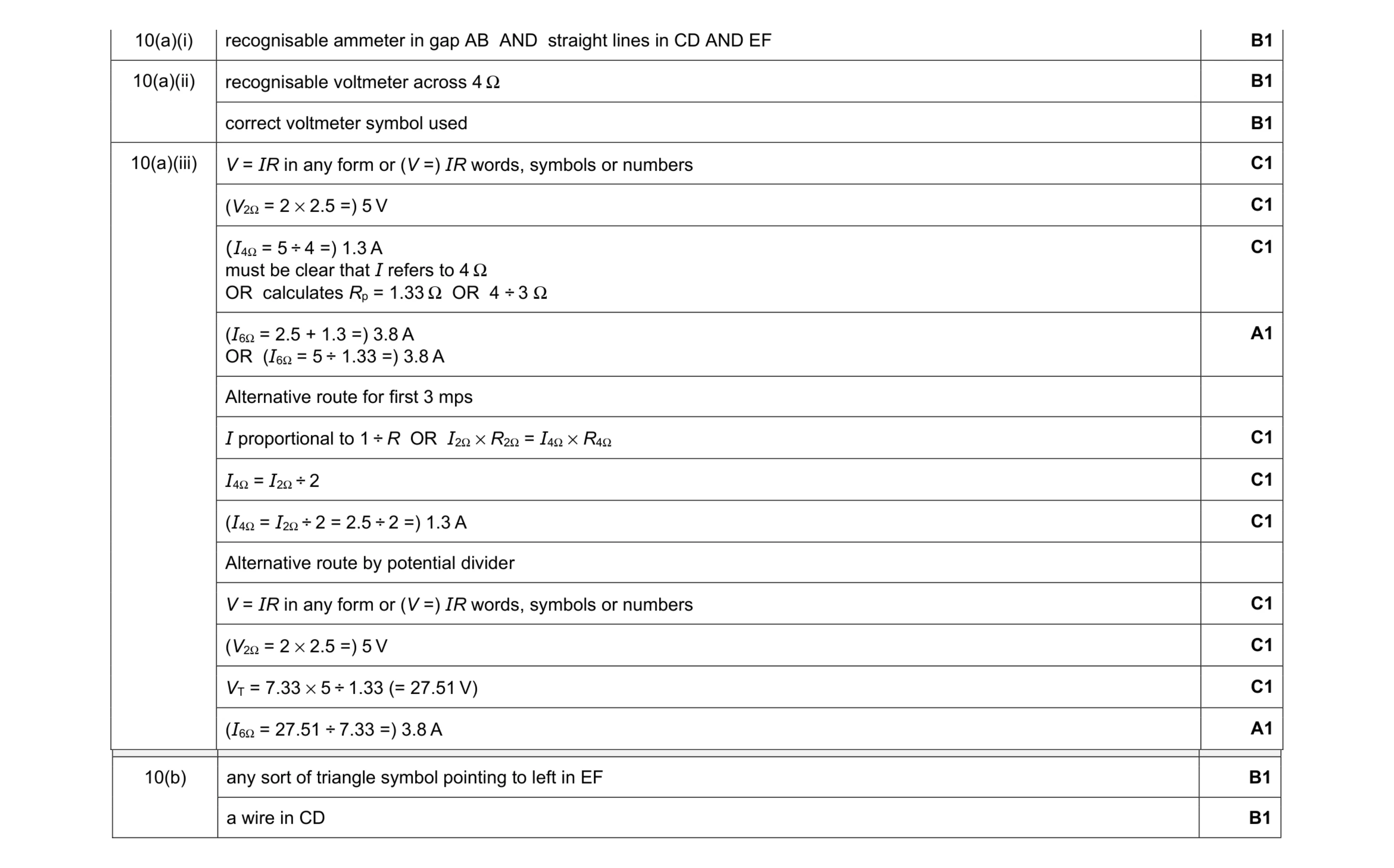 9
9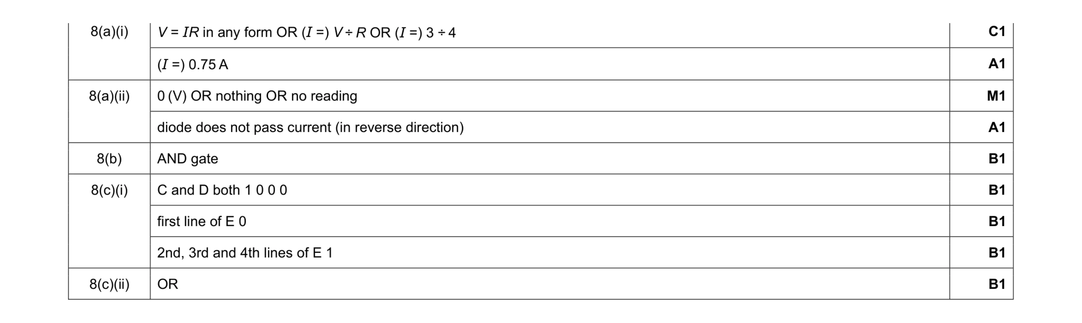 9
9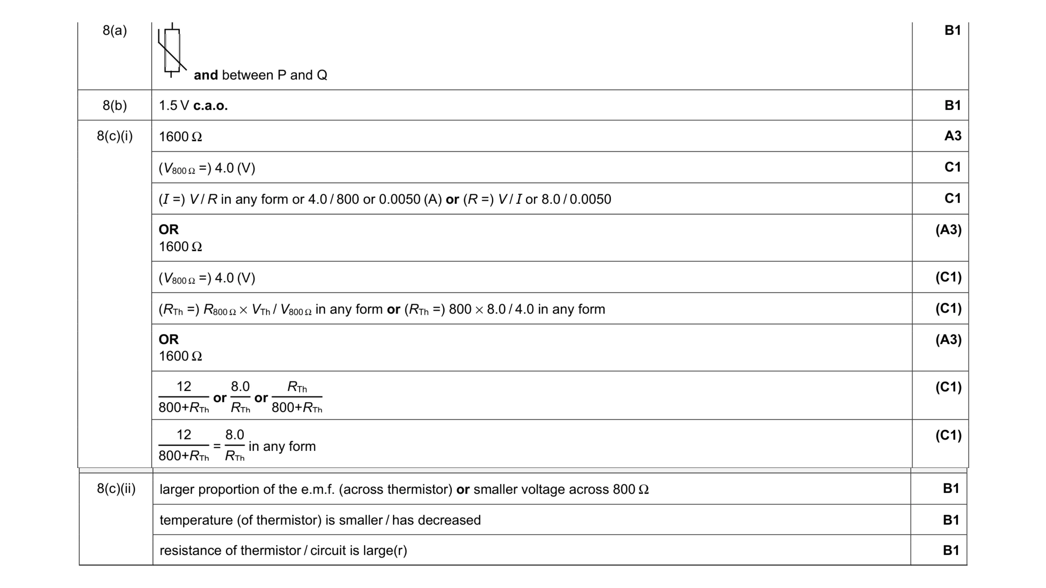 8
8 5
5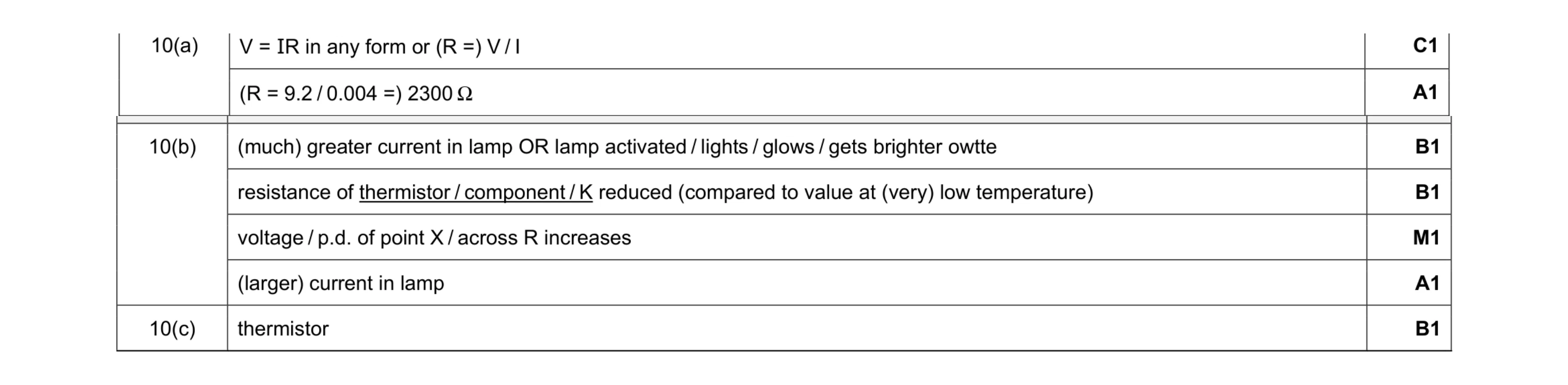 7
7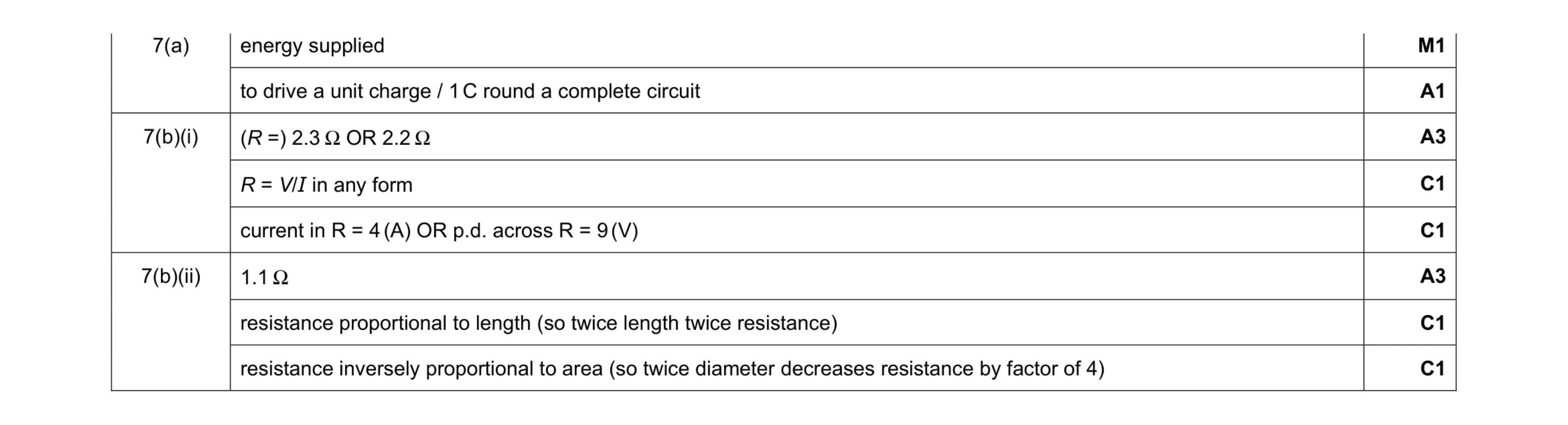 8
8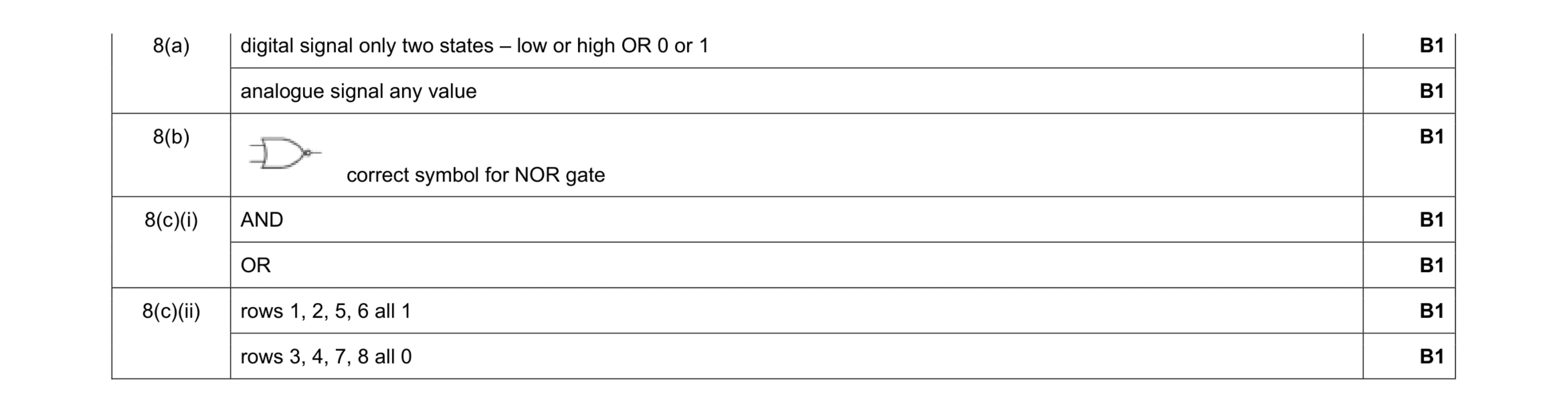 7
7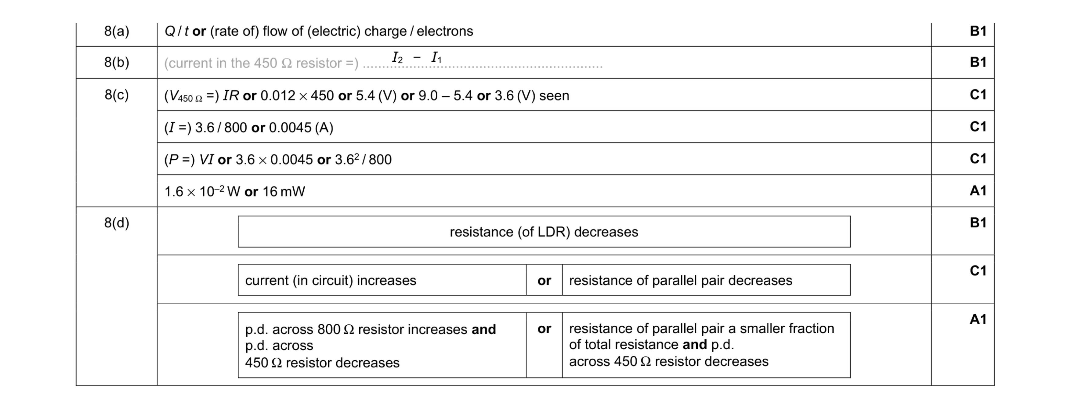 9
9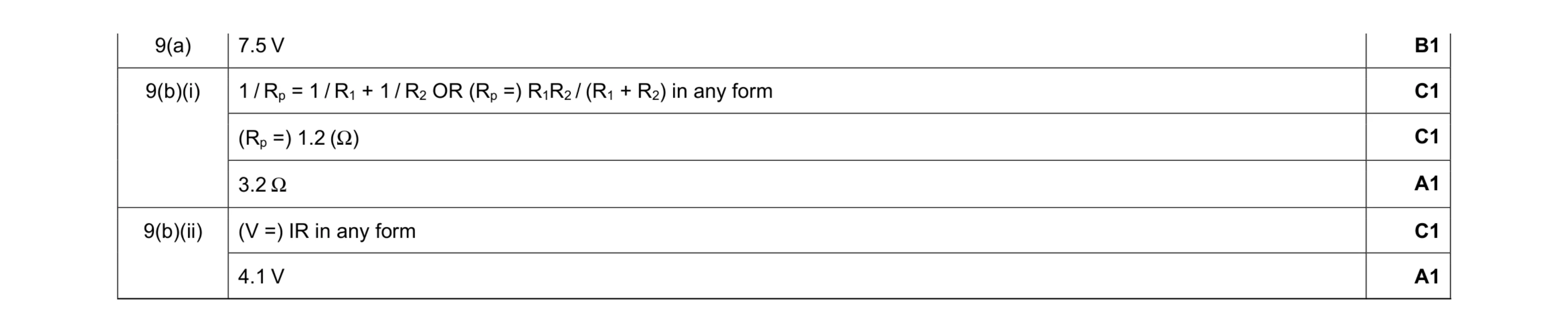 6
6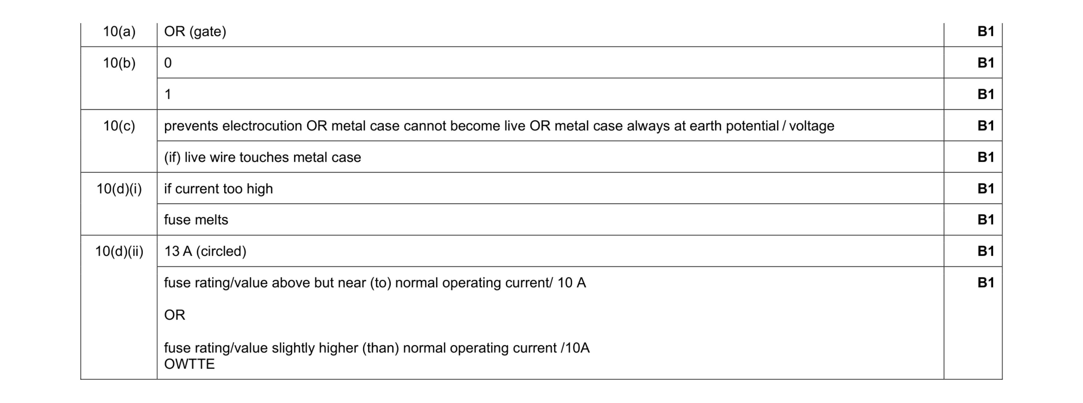 9
9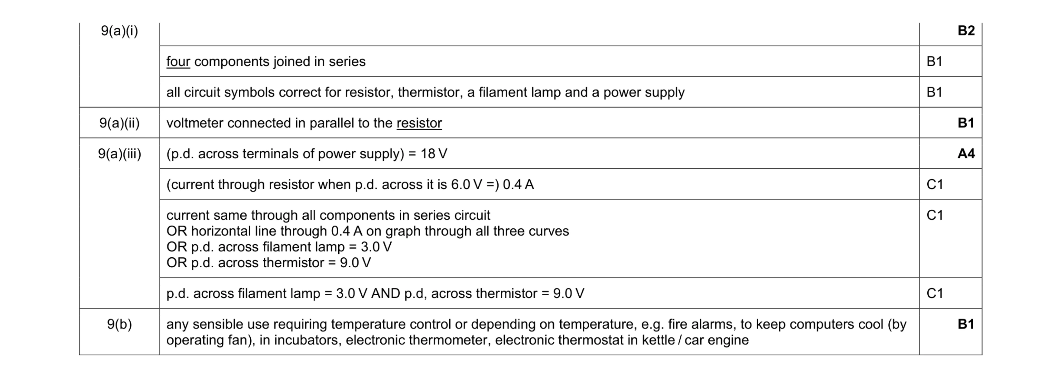 8
8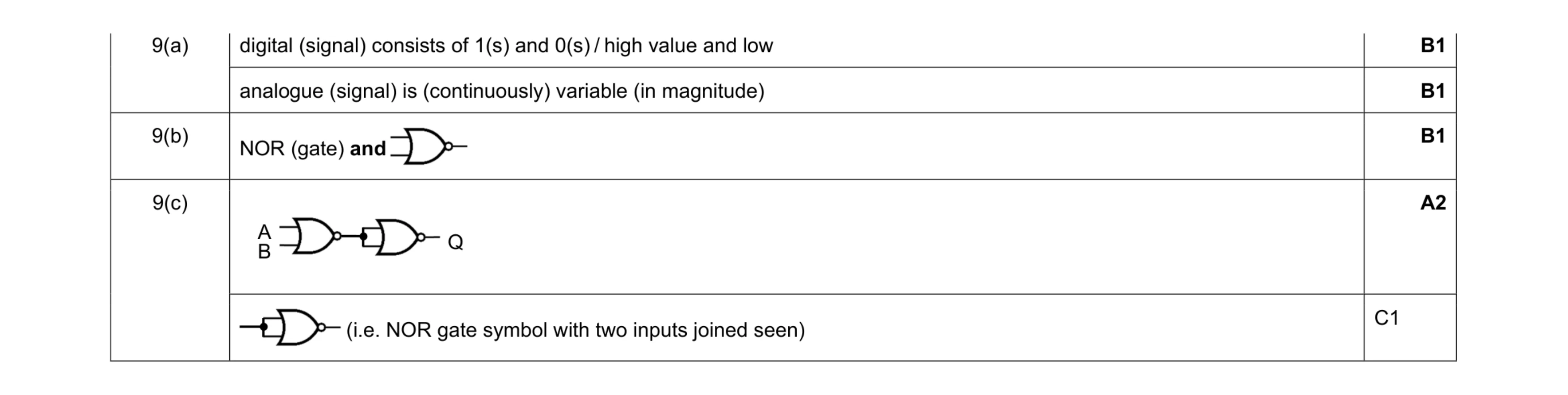 5
5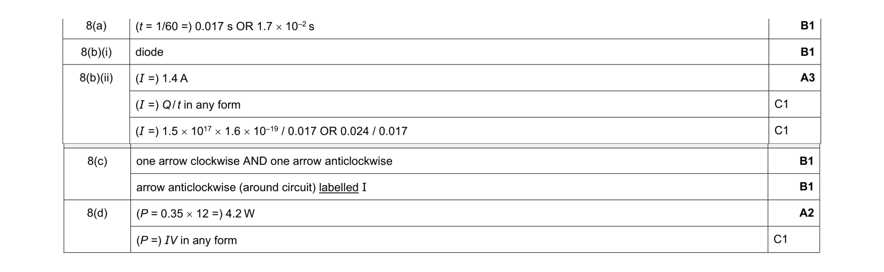 9
9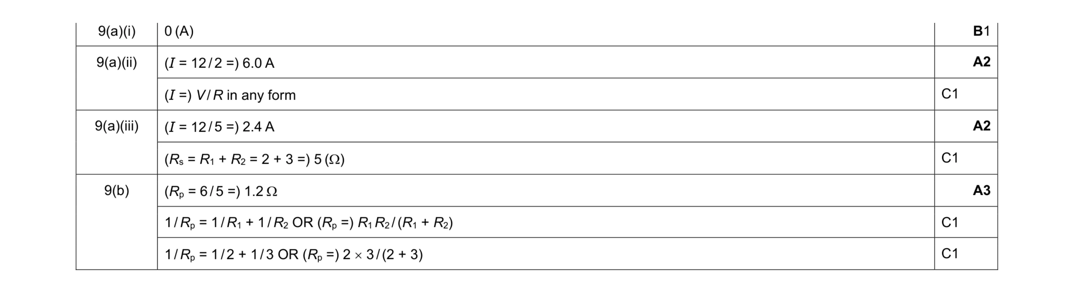 8
8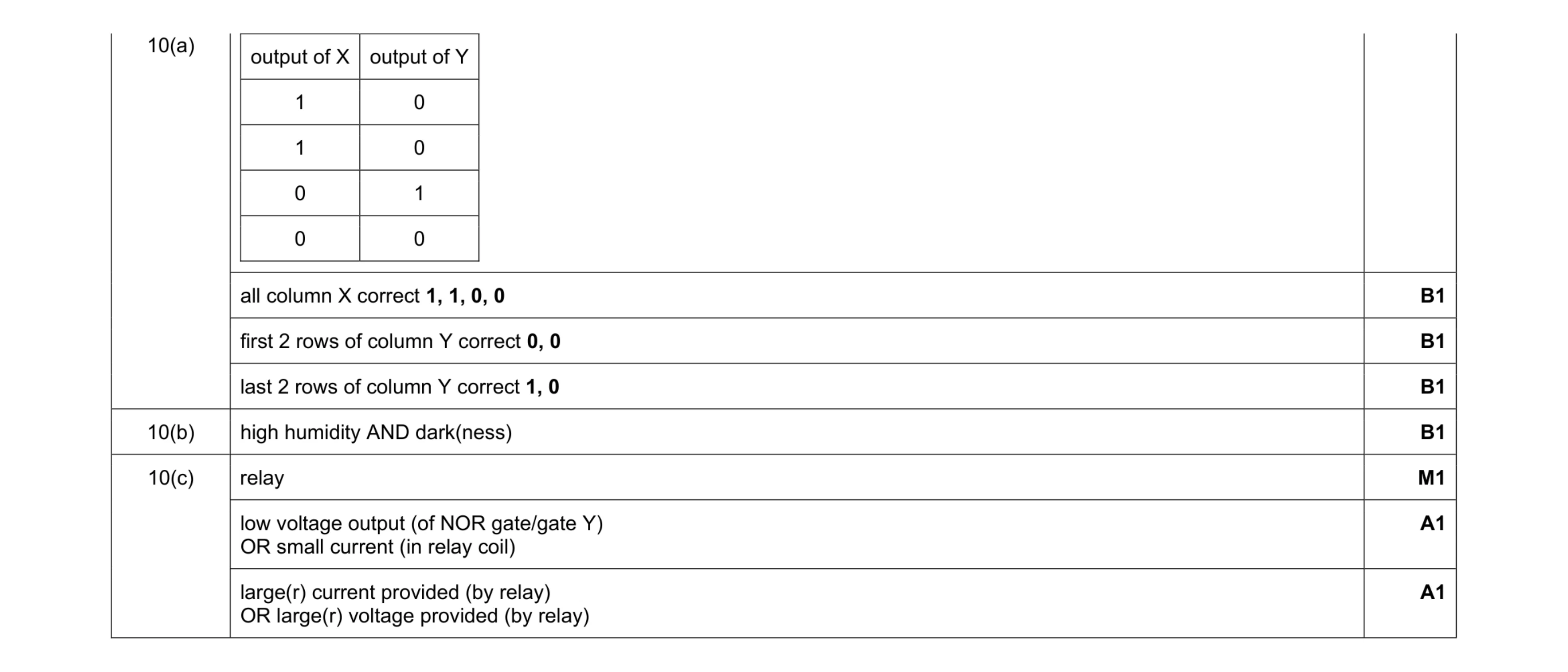 7
7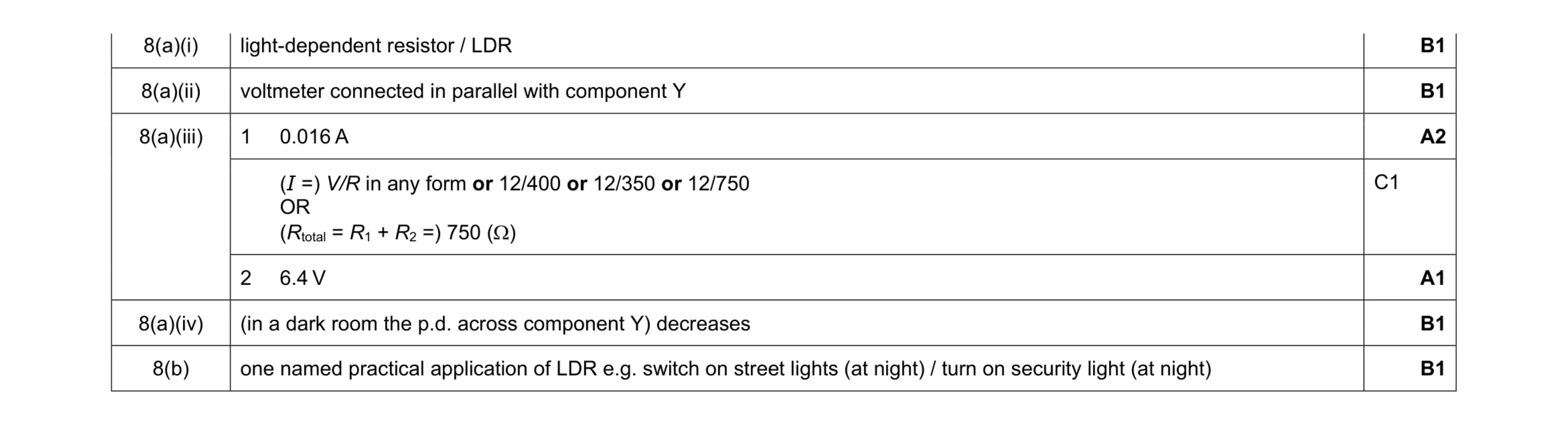 7
7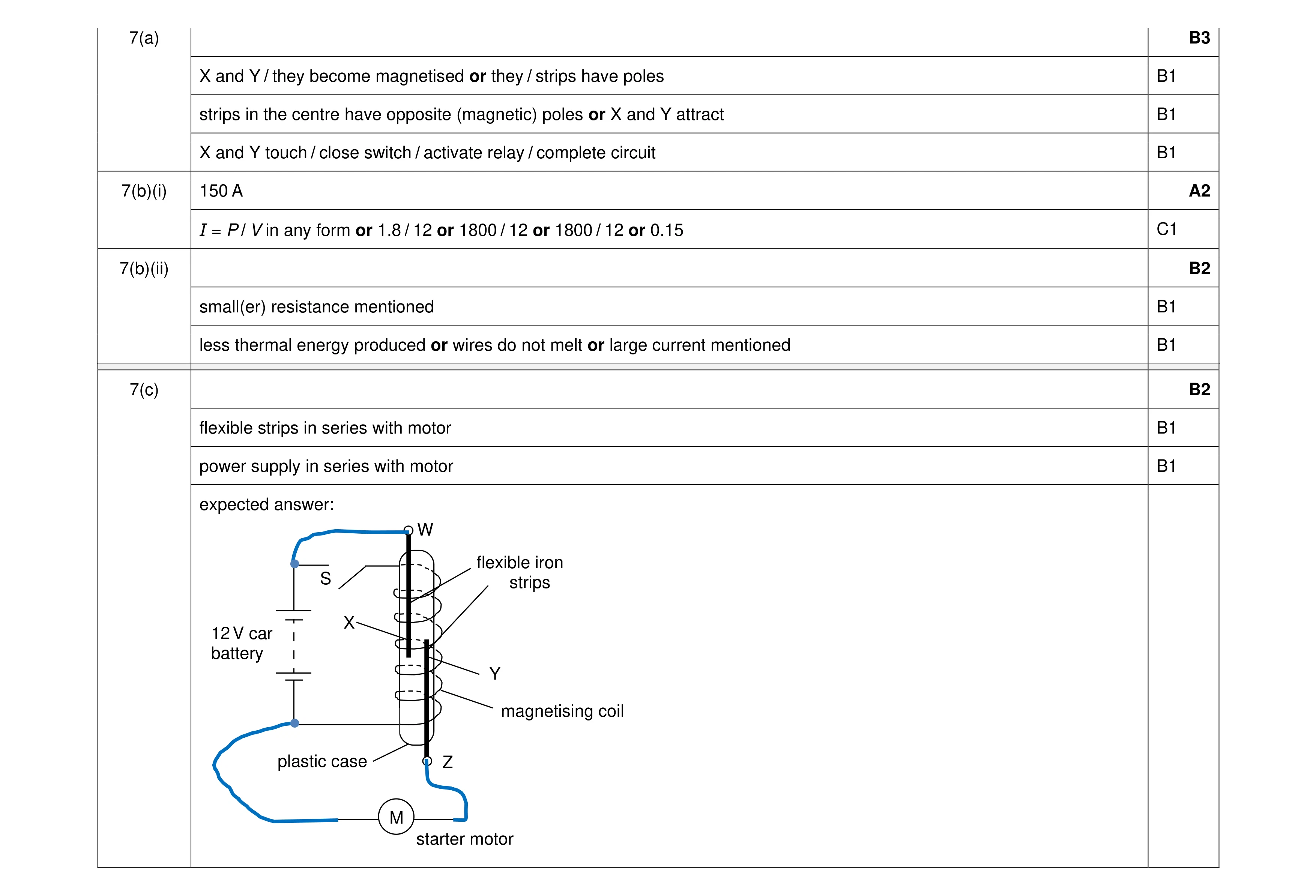 9
9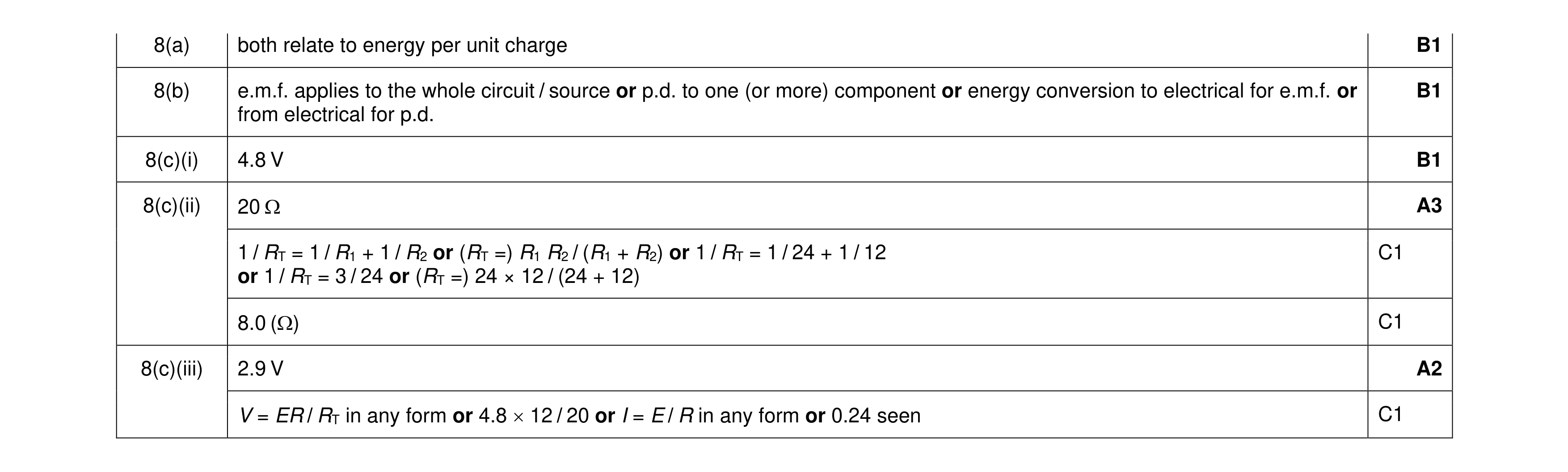 8
8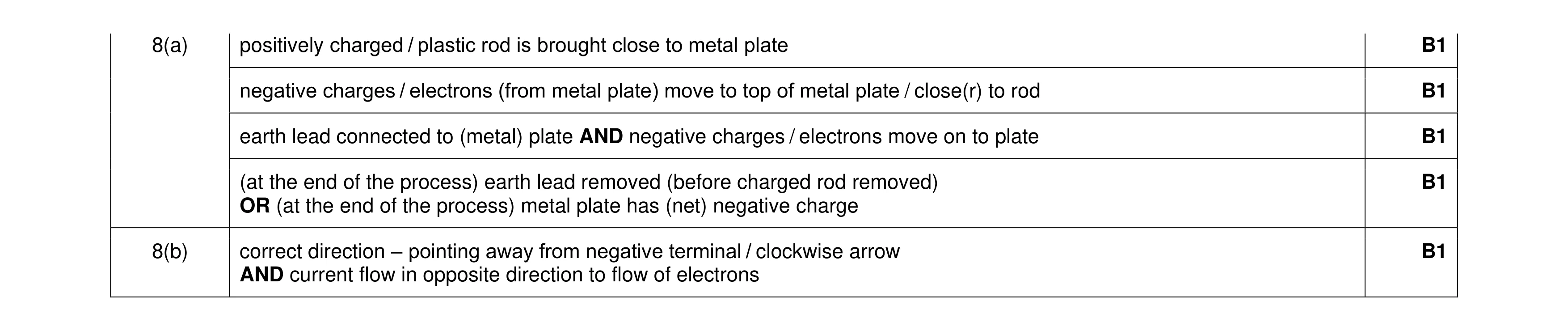 5
5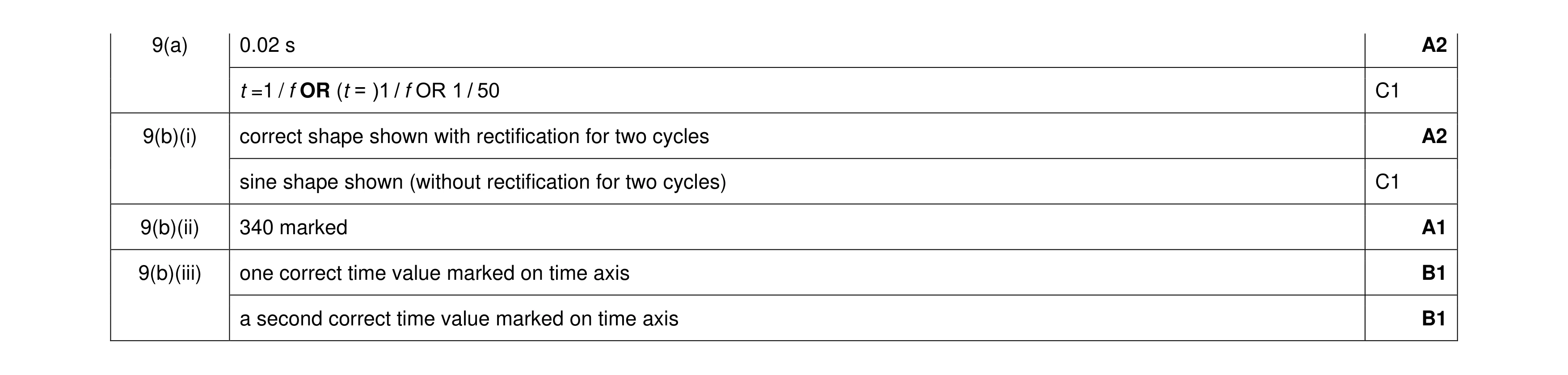 7
7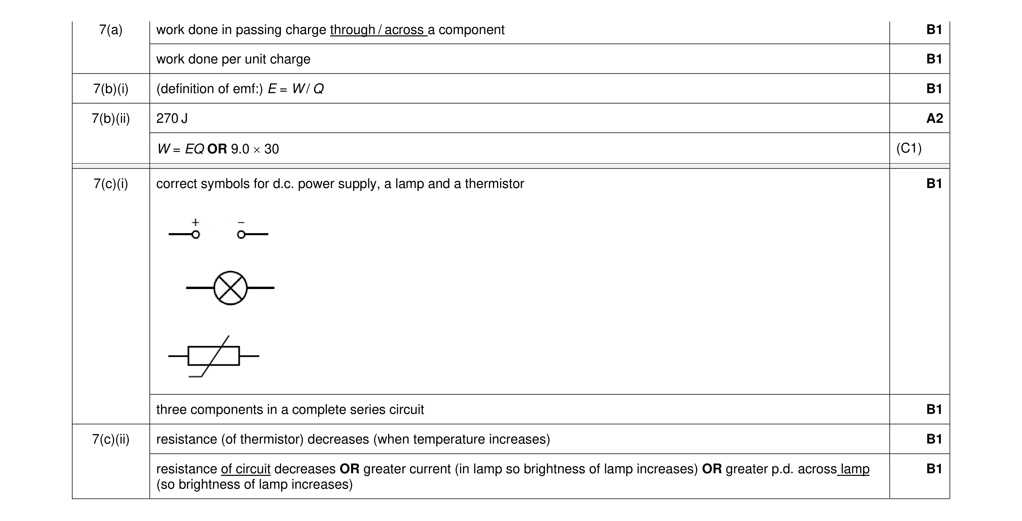 9
9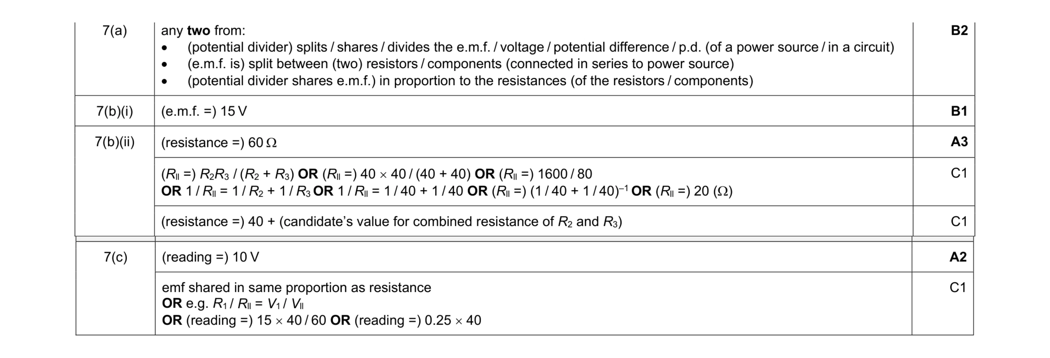 8
8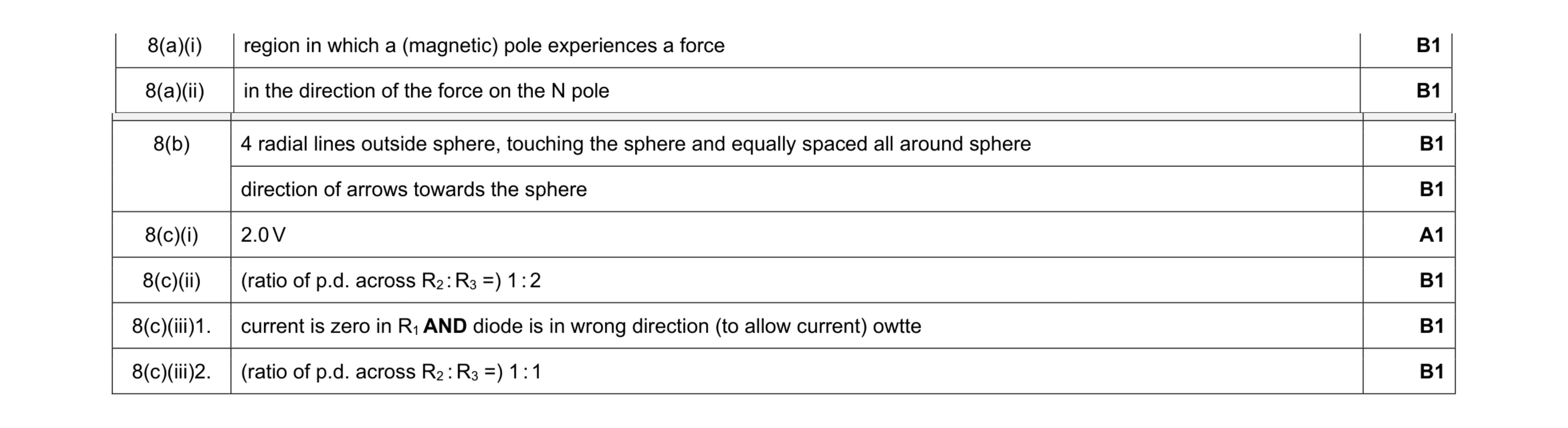 8
8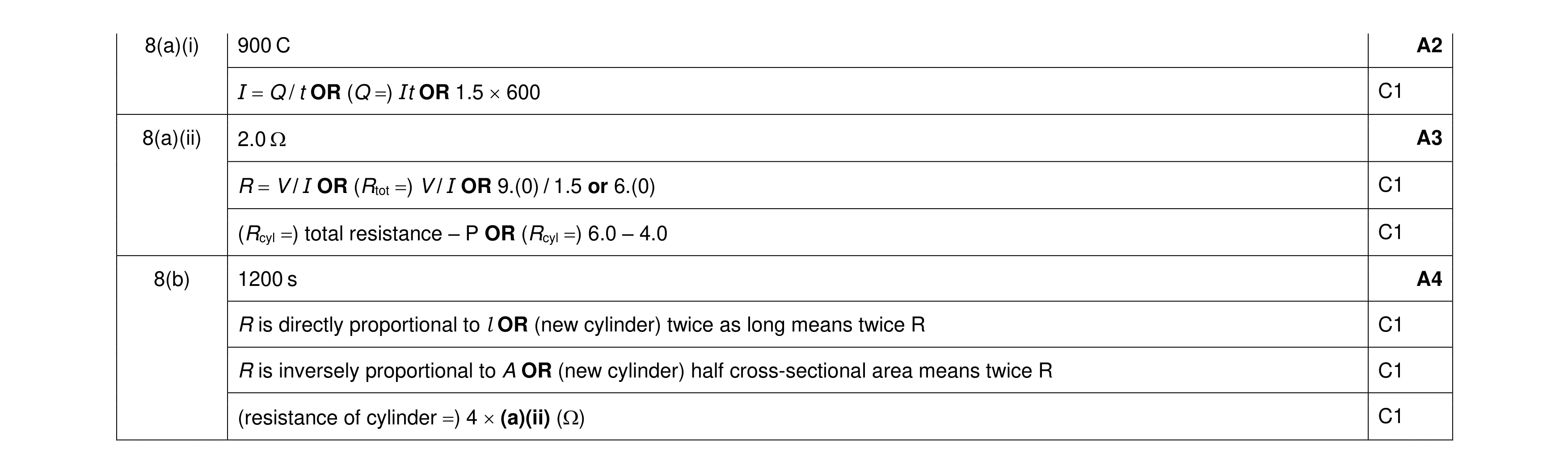 9
9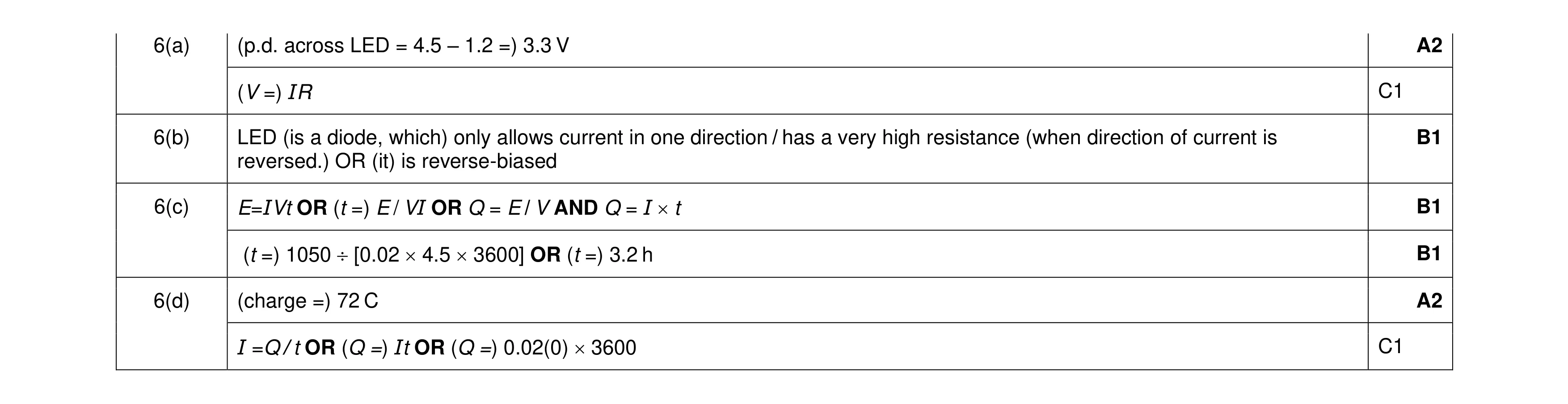 7
7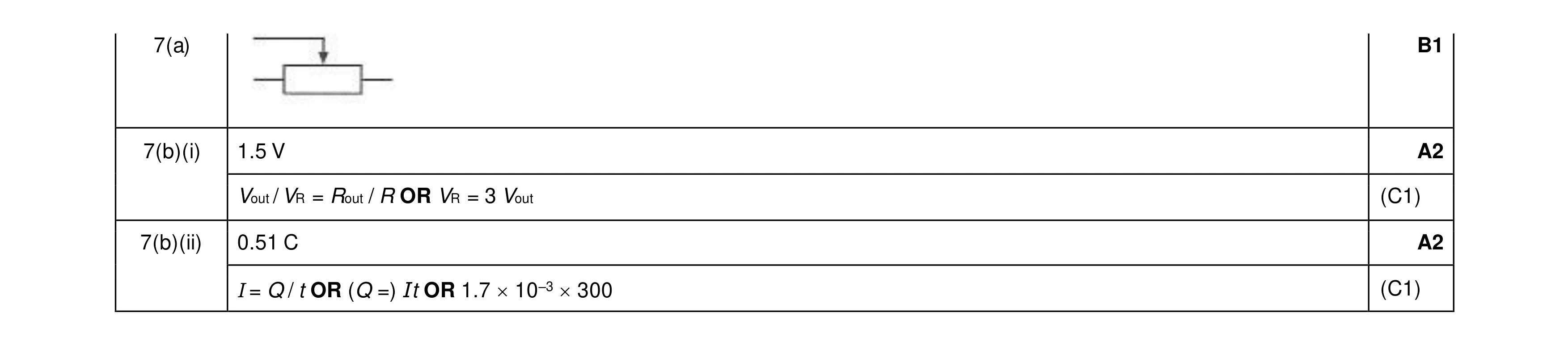 5
5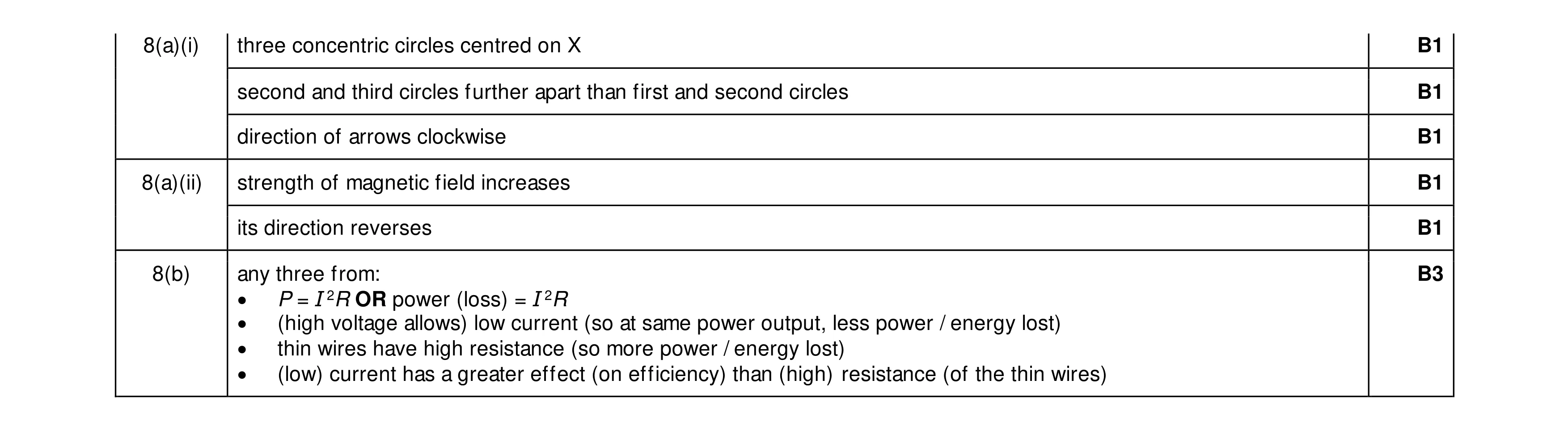 8
8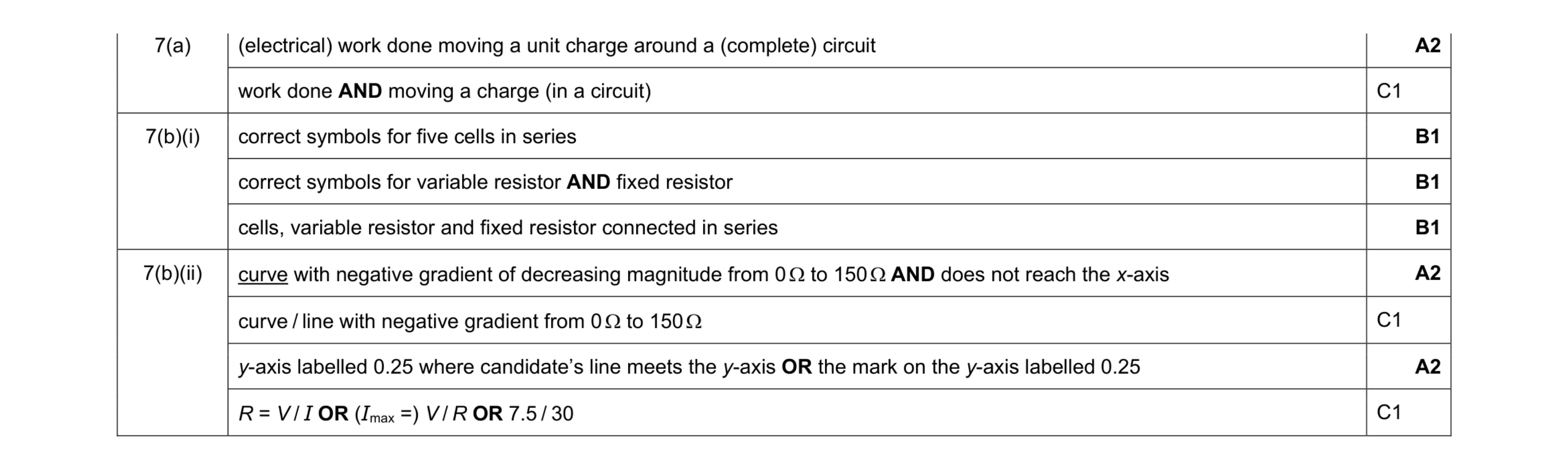 9
9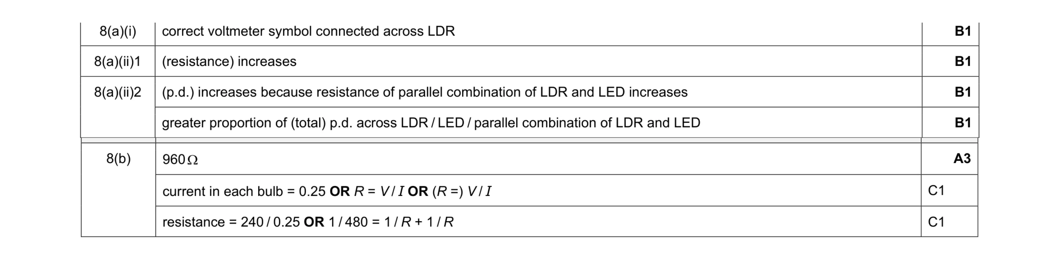 7
7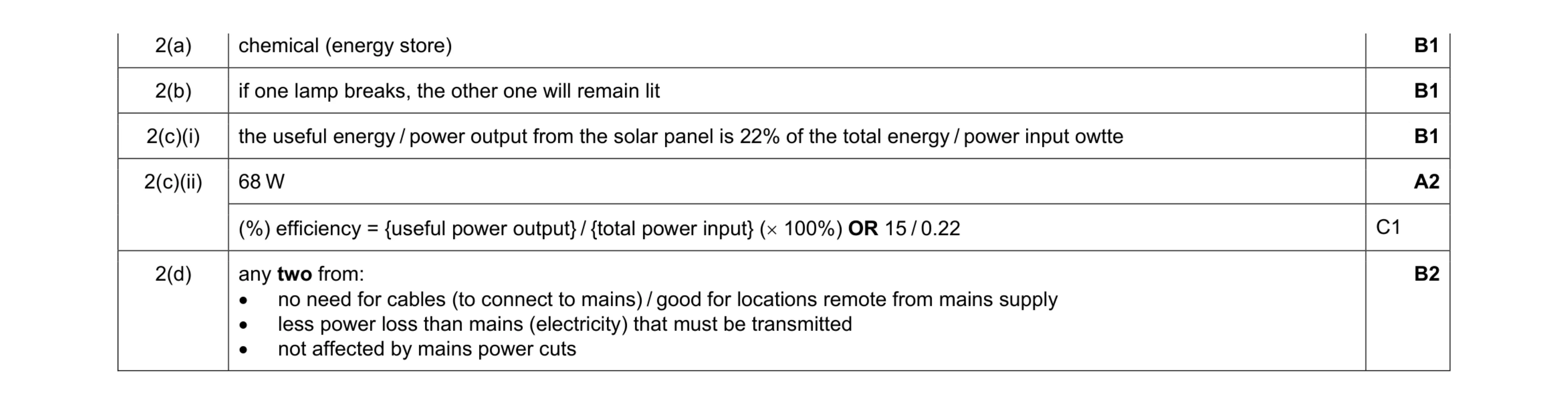 7
7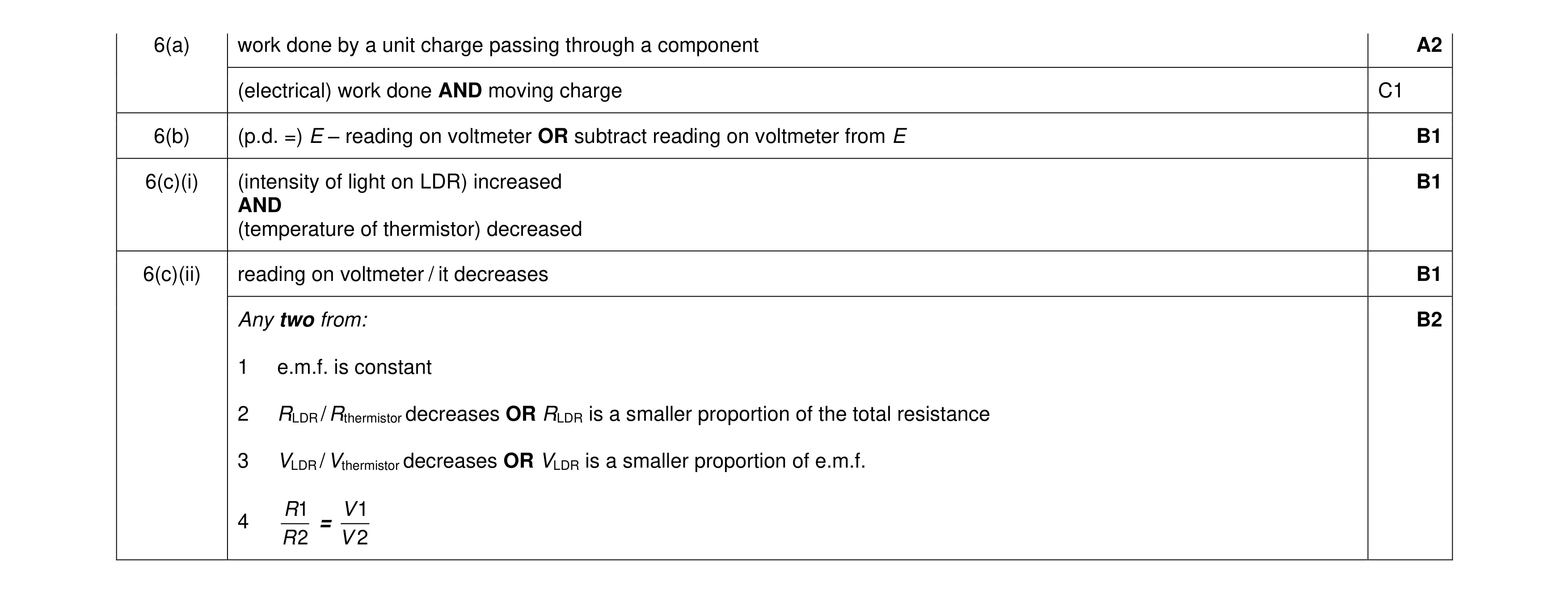 7
7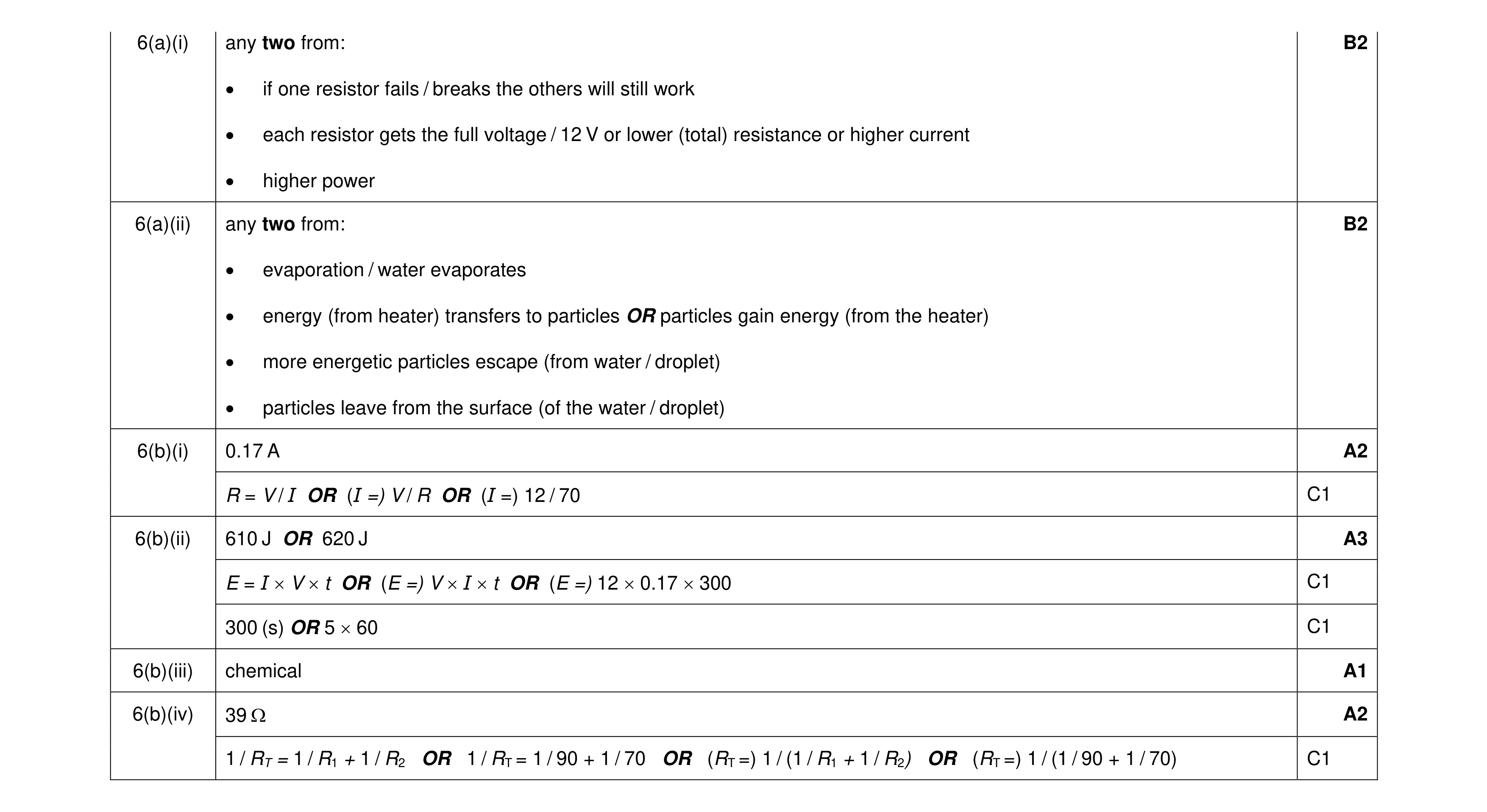 12
12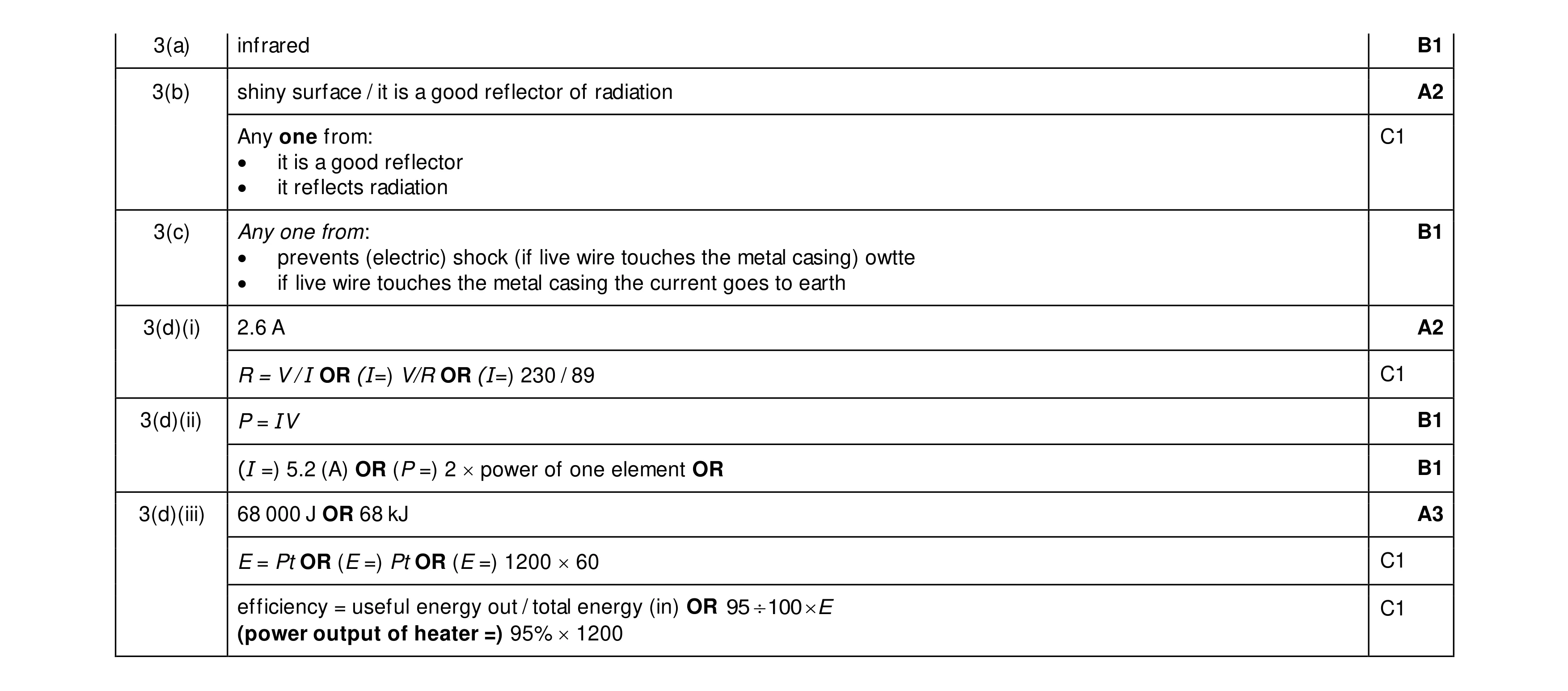 11
11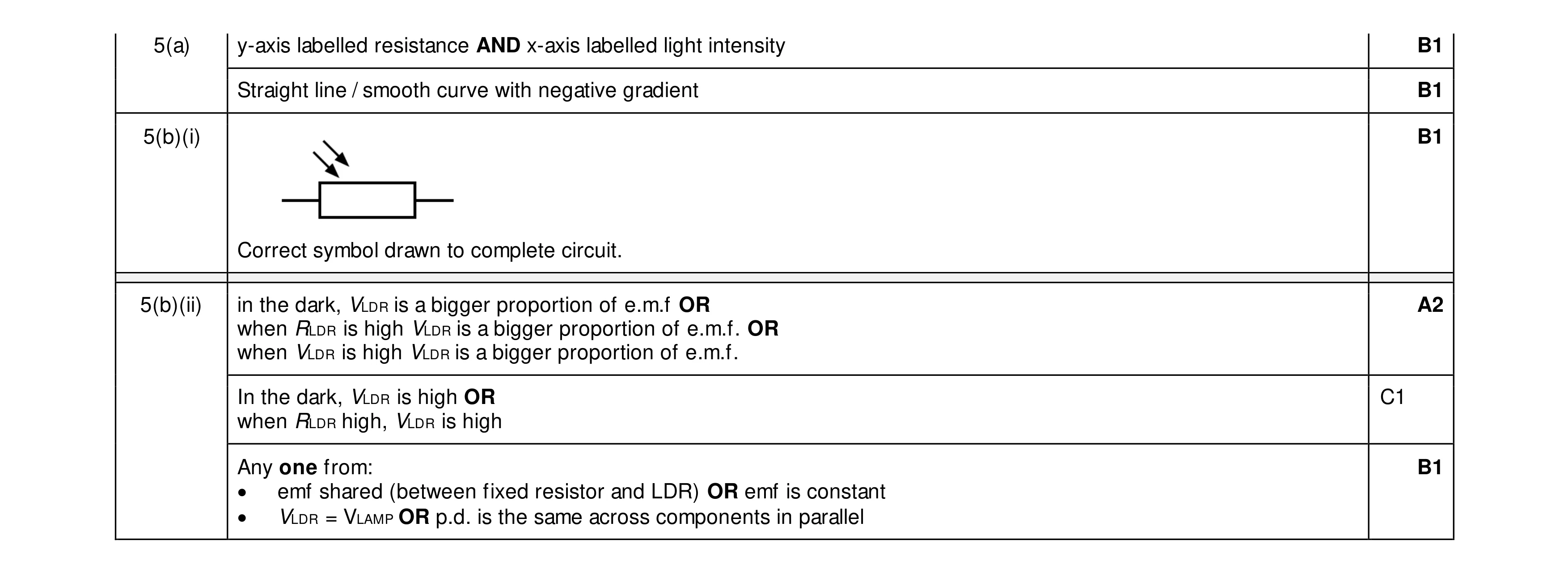 6
6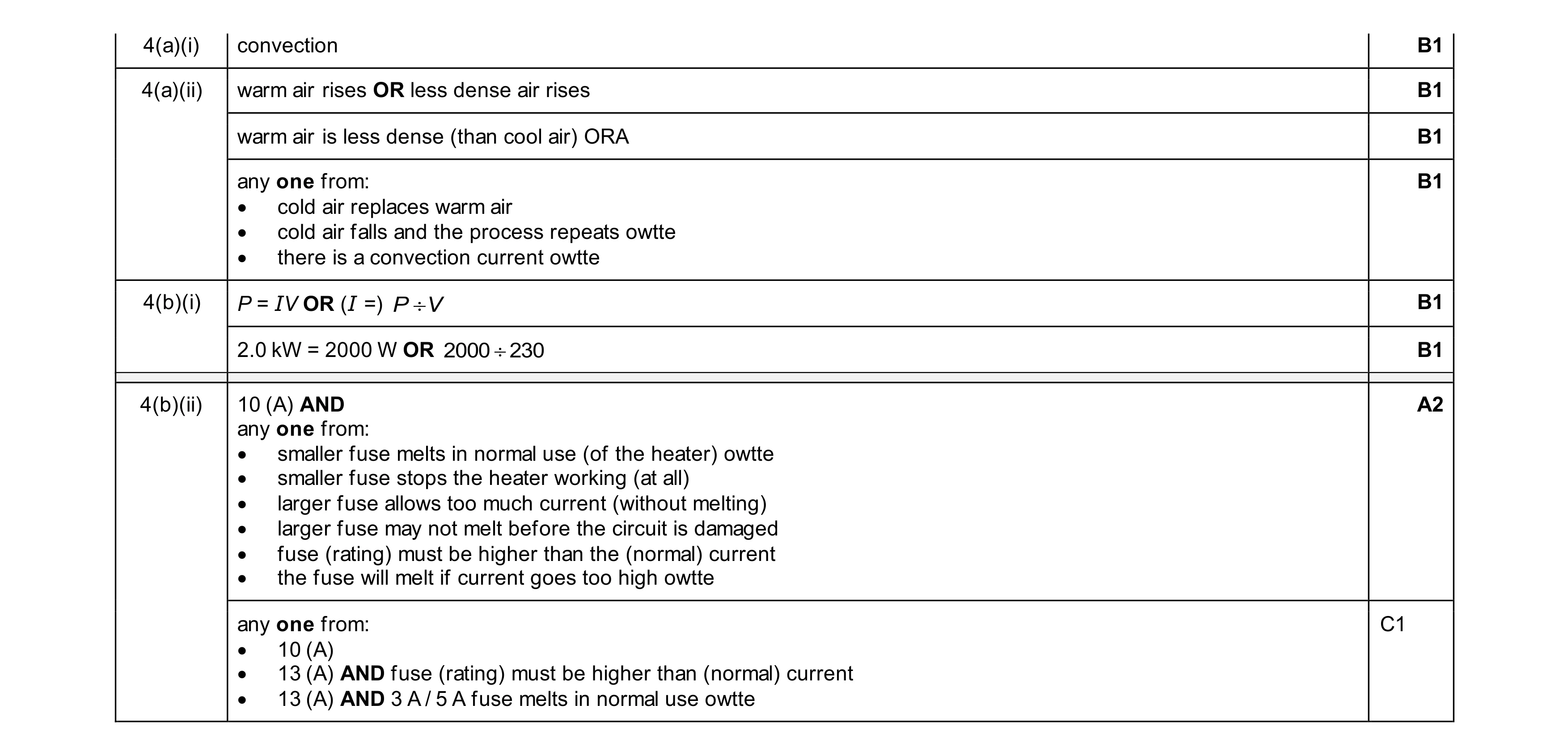 8
8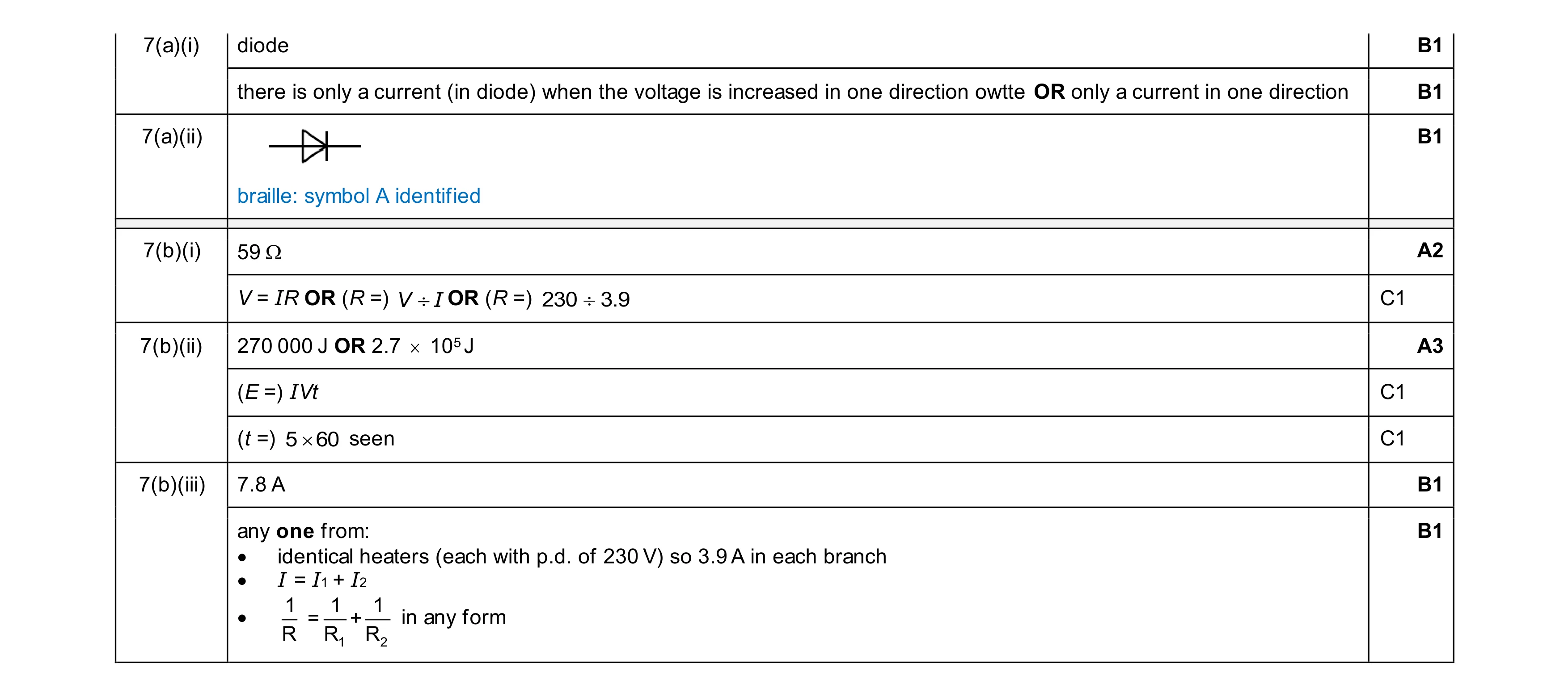 10
10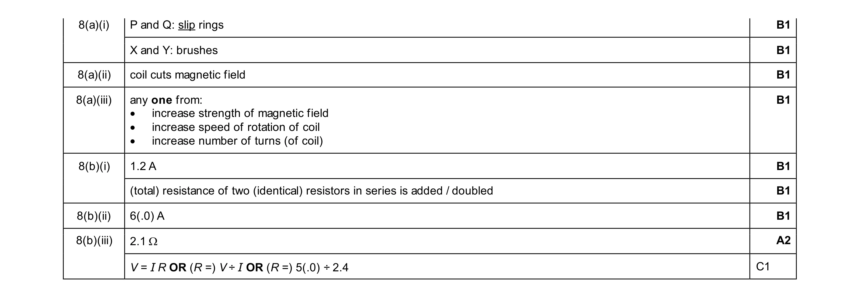 9
9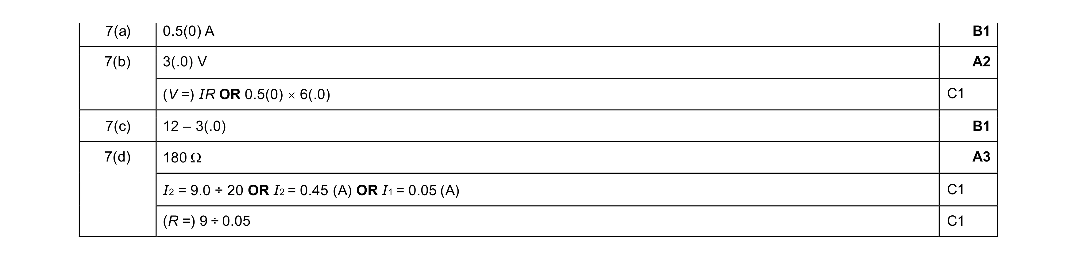 7
7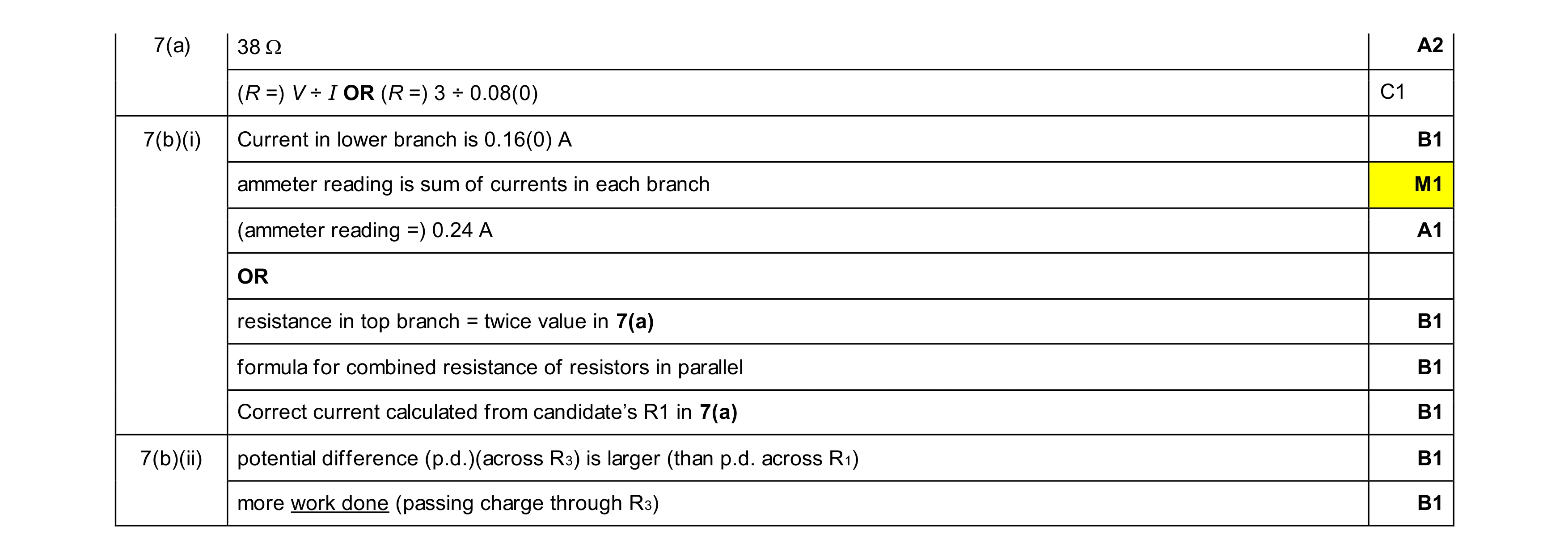 7
7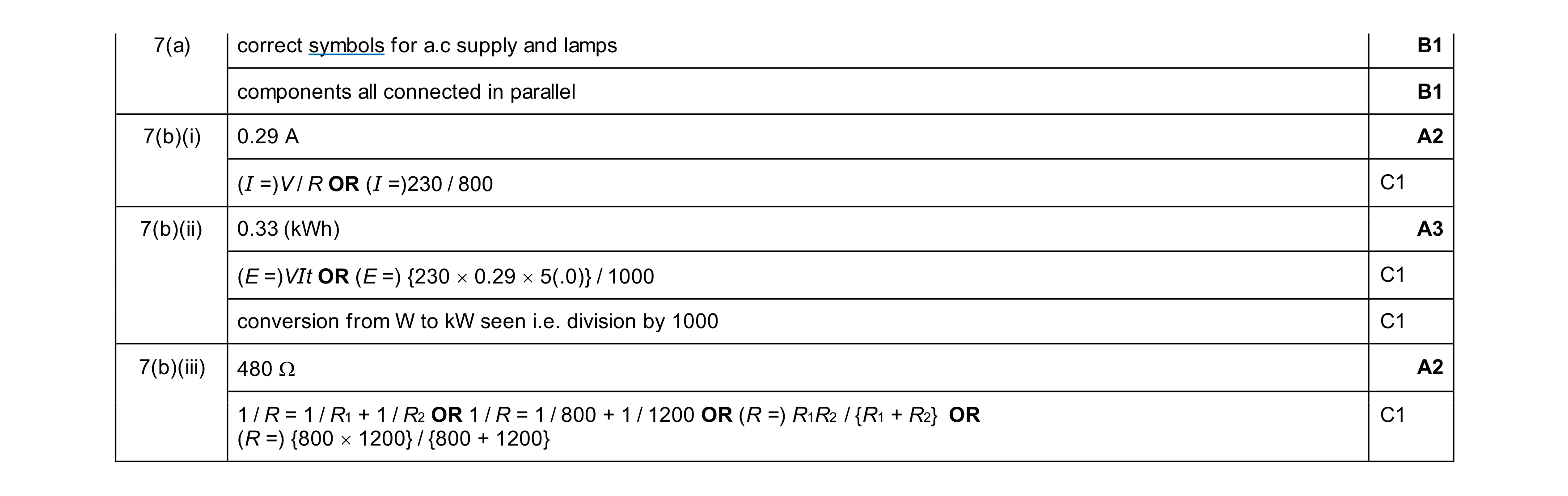 9
9