Questions as text
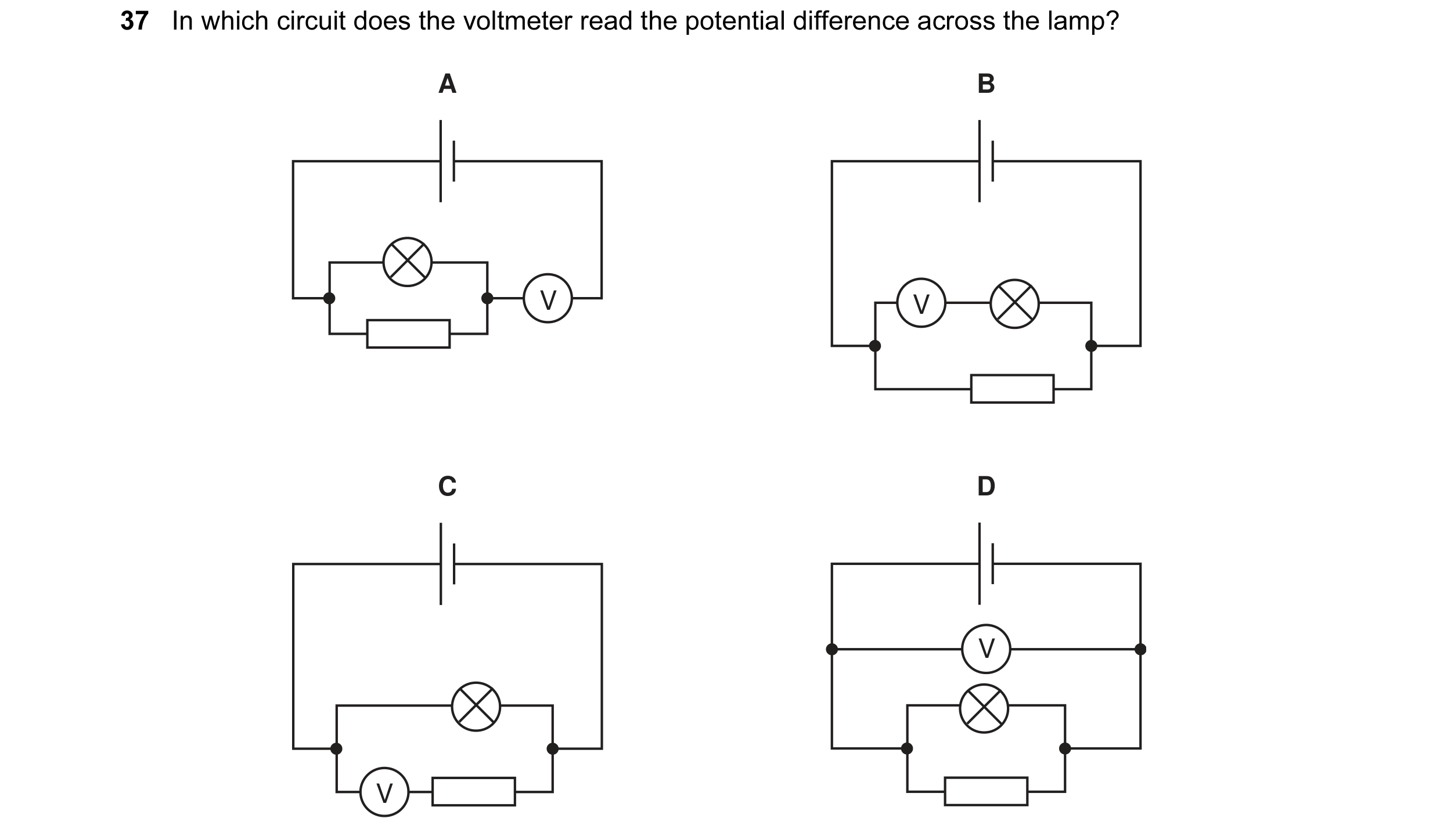
Q1 · In which circuit does the voltmeter read the potential difference across the lamp? 0654/11 May/June 2005
37 In which circuit does the voltmeter read the potential difference across the lamp? A B V V C D V V
1 marks
Answer: D
This question in 0654/11 May/June 2005
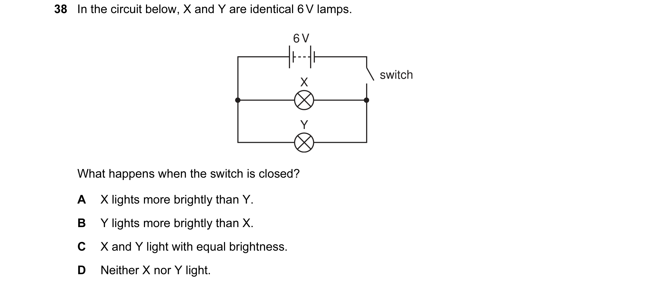
Q2 · In the circuit below, X and Y are identical 6 V lamps 0654/11 May/June 2005
38 In the circuit below, X and Y are identical 6 V lamps. 6 V switch X Y What happens when the switch is closed? A X lights more brightly than Y. B Y lights more brightly than X. C X and Y light with equal brightness. D Neither X nor Y light.
1 marks
Answer: C
This question in 0654/11 May/June 2005
Q3 · Four lamps and four switches are connected to a power supply as shown in the circuit… 0654/11 May/June 2006
37 Four lamps and four switches are connected to a power supply as shown in the circuit diagram. When all the switches are closed, all the lamps are lit. When one of the switches is then opened, only one lamp goes out. Which switch is opened? A B C D
1 marks
Answer: C
This question in 0654/11 May/June 2006
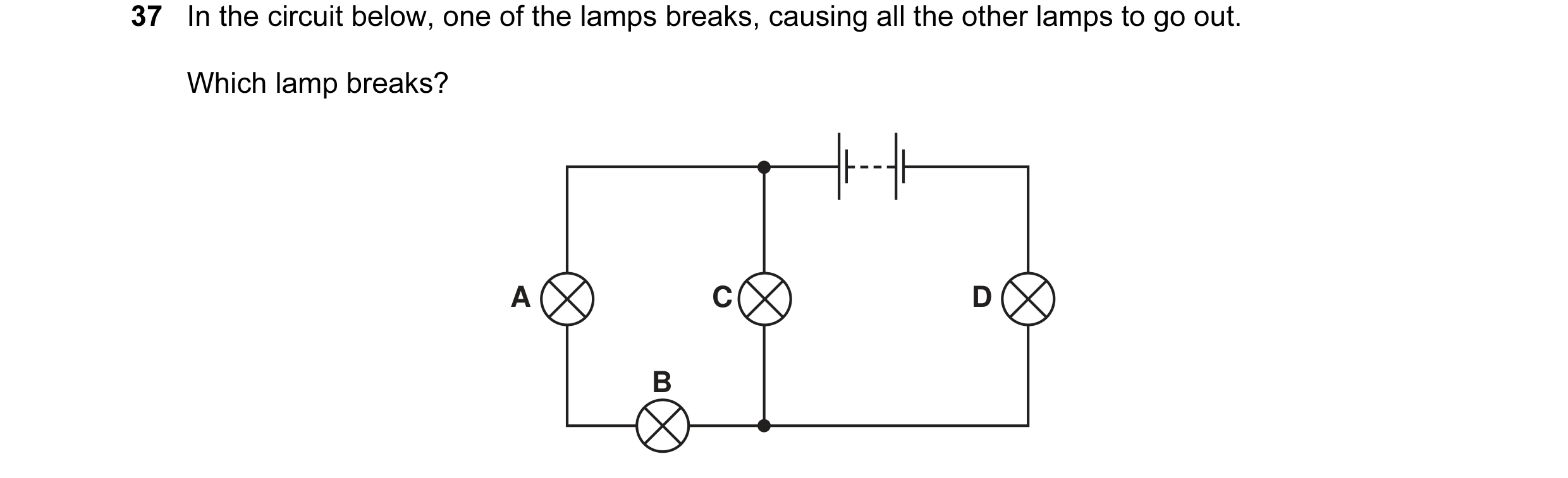
Q4 · In the circuit below, one of the lamps breaks, causing all the other lamps to go out 0654/11 Oct/Nov 2006
37 In the circuit below, one of the lamps breaks, causing all the other lamps to go out. Which lamp breaks? A C D B
1 marks
Answer: D
This question in 0654/11 Oct/Nov 2006
Q5 · An electric heater is connected to the mains, using insulated copper wires 0654/11 Oct/Nov 2006
38 An electric heater is connected to the mains, using insulated copper wires. The wires become very warm. What can be done to prevent so much heat being produced in the connecting wires? A Use thicker copper wires. B Use thinner copper wires. C Use thicker insulation. D Use thinner insulation.
1 marks
Answer: A
This question in 0654/11 Oct/Nov 2006
Q6 · Which circuit shows the correct use of a voltmeter in measuring the p.d 0654/11 May/June 2007
34 Which circuit shows the correct use of a voltmeter in measuring the p.d. across the resistor? A B V V C D V V
1 marks
Answer: B
This question in 0654/11 May/June 2007
Q7 · The circuit shows a current I in a resistor of resistance R 0654/11 Oct/Nov 2007
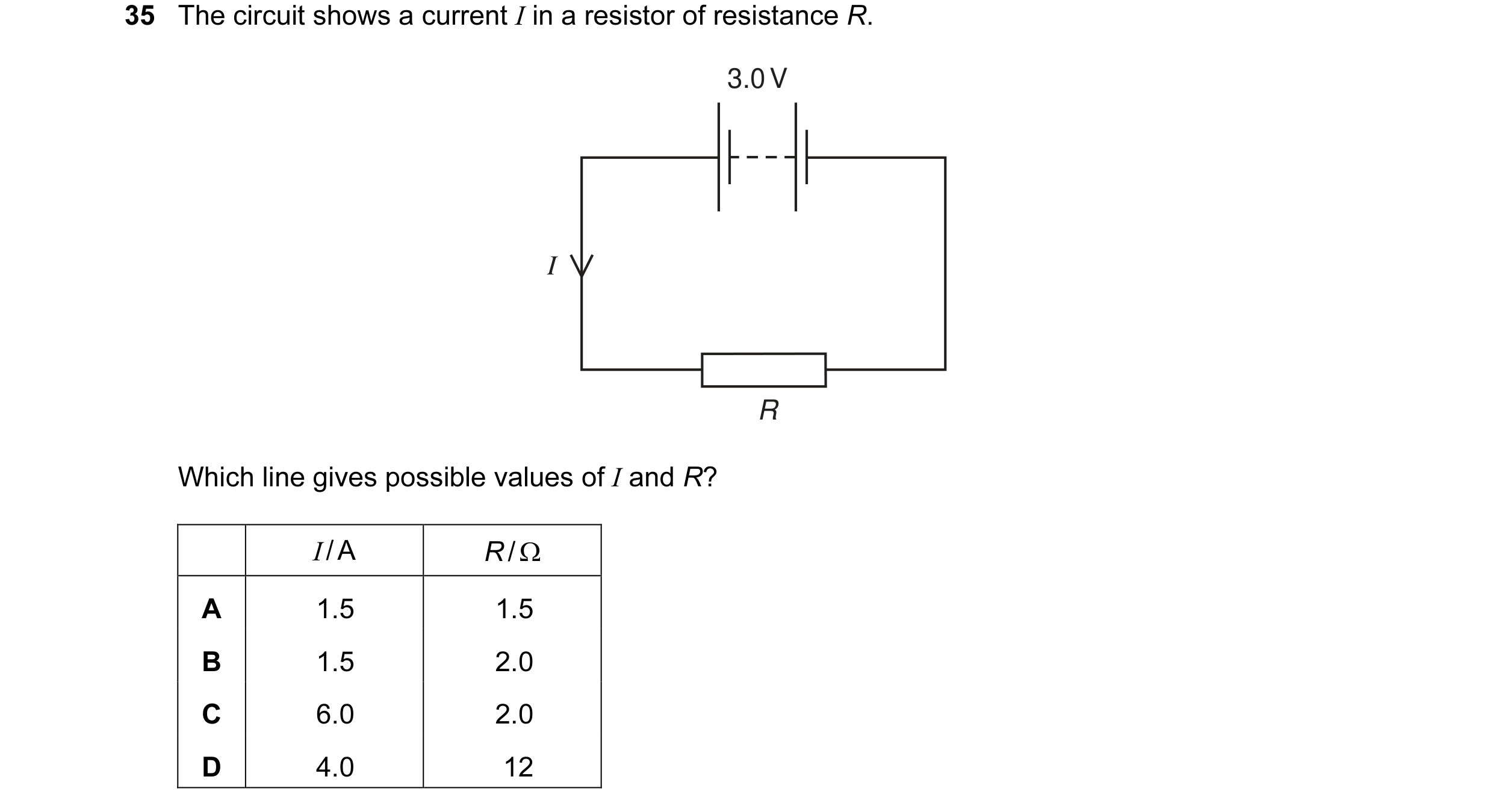
35 The circuit shows a current I in a resistor of resistance R. 3.0 V I R Which line gives possible values of I and R? I / A R / Ω A 1.5 1.5 B 1.5 2.0 C 6.0 2.0 D 4.0 12
1 marks
Answer: B
This question in 0654/11 Oct/Nov 2007
Q8 · In the circuit shown, the switches S1 and S2 may be open (off) or closed (on) 0654/11 May/June 2008
37 In the circuit shown, the switches S1 and S2 may be open (off) or closed (on). V + switches shown 12 V open (off) – S2 S1 Which line in the table shows the voltmeter reading for the switch positions given? S1 S2 voltmeter reading / V A open open 12 B closed closed 12 C open closed 0 D closed open 12
1 marks
Answer: B
This question in 0654/11 May/June 2008
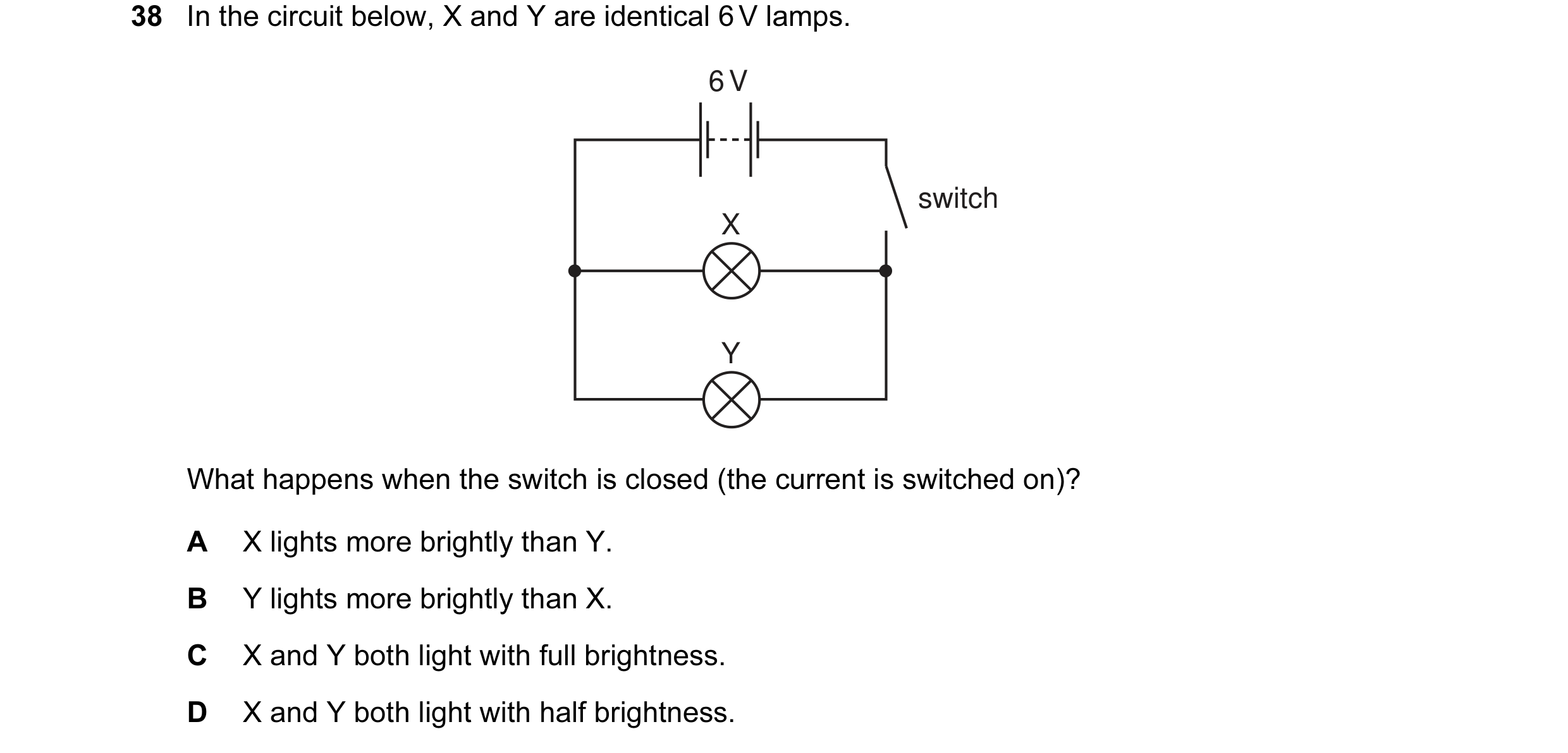
Q9 · In the circuit below, X and Y are identical 6 V lamps 0654/11 Oct/Nov 2008
38 In the circuit below, X and Y are identical 6 V lamps. 6 V switch X Y What happens when the switch is closed (the current is switched on)? A X lights more brightly than Y. B Y lights more brightly than X. C X and Y both light with full brightness. D X and Y both light with half brightness.
1 marks
Answer: C
This question in 0654/11 Oct/Nov 2008
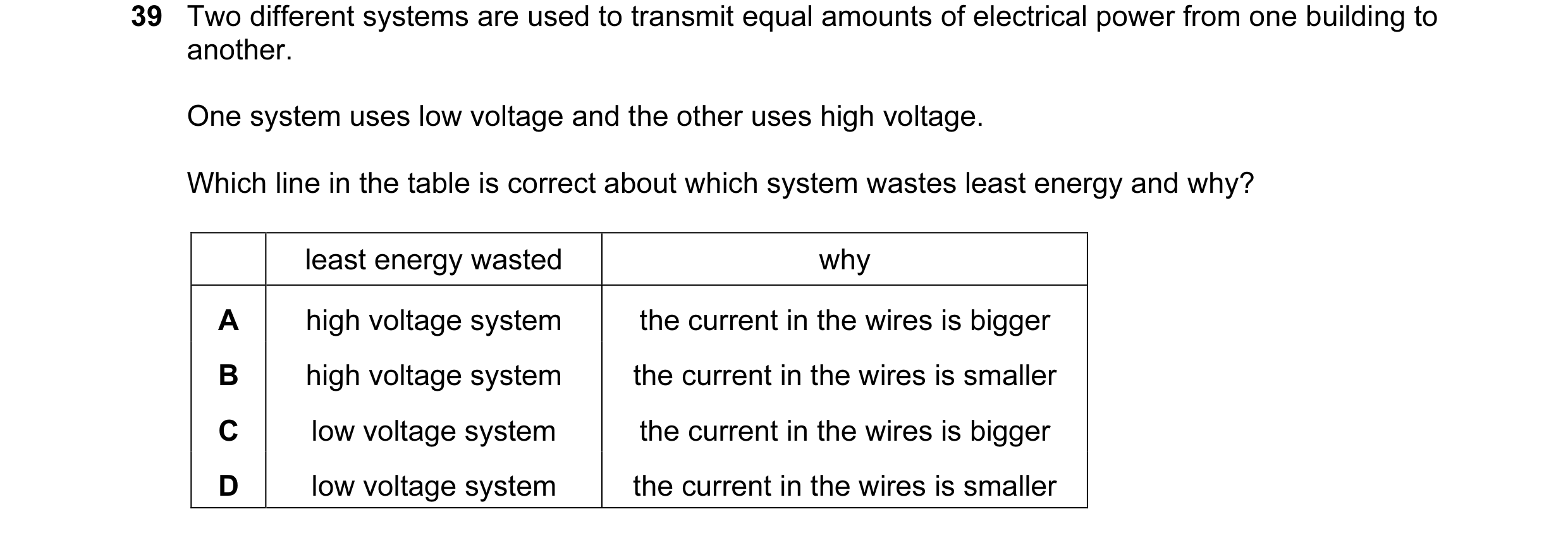
Q10 · Two different systems are used to transmit equal amounts of electrical power from one… 0654/11 Oct/Nov 2008
39 Two different systems are used to transmit equal amounts of electrical power from one building to another. One system uses low voltage and the other uses high voltage. Which line in the table is correct about which system wastes least energy and why? least energy wasted why A high voltage system the current in the wires is bigger B high voltage system the current in the wires is smaller C low voltage system the current in the wires is bigger D low voltage system the current in the wires is smaller
1 marks
Answer: B
This question in 0654/11 Oct/Nov 2008
Q11 · In the circuit shown, ammeter X reads 0.5 A 0654/11 May/June 2009
38 In the circuit shown, ammeter X reads 0.5 A. 4.0 V X A A Y 3.0 Ω 5.0 Ω What does ammeter Y read? A 0 B 0.5 A C 3.5 A D 4.0 A
1 marks
Answer: B
This question in 0654/11 May/June 2009
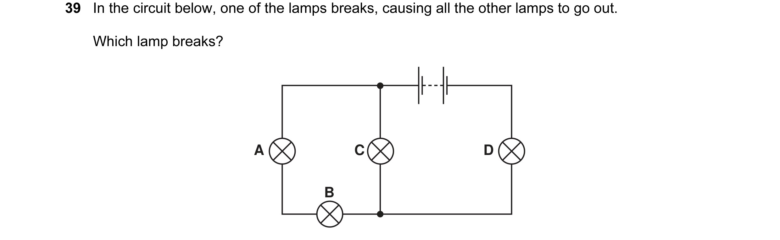
Q12 · In the circuit below, one of the lamps breaks, causing all the other lamps to go out 0654/11 May/June 2009
39 In the circuit below, one of the lamps breaks, causing all the other lamps to go out. Which lamp breaks? A C D B
1 marks
Answer: D
This question in 0654/11 May/June 2009
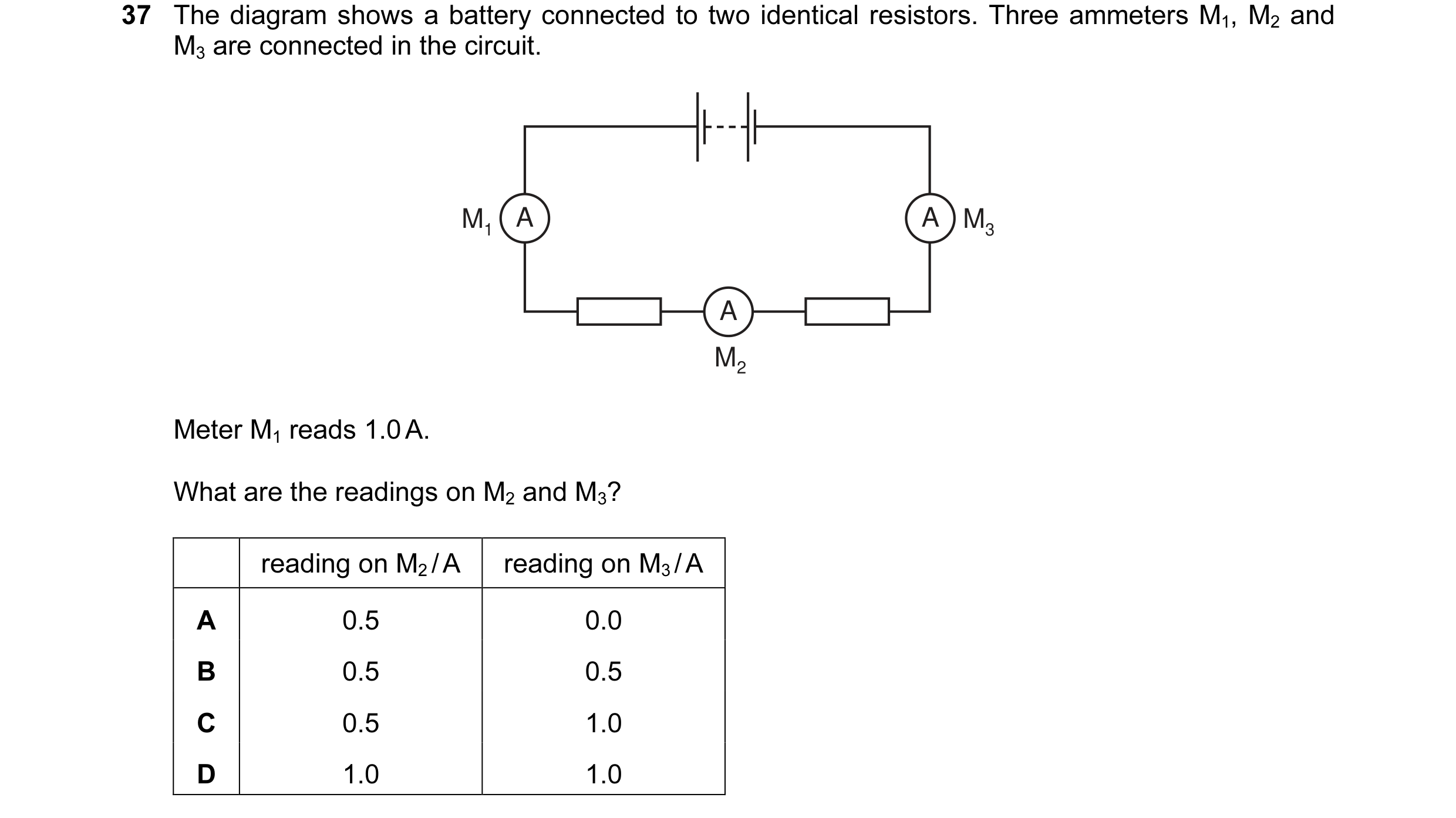
Q13 · The diagram shows a battery connected to two identical resistors 0654/11 Oct/Nov 2009
37 The diagram shows a battery connected to two identical resistors. Three ammeters M1, M2 and M3 are connected in the circuit. M1 A A M3 A M2 Meter M1 reads 1.0 A. What are the readings on M2 and M3? reading on M2 / A reading on M3 / A A 0.5 0.0 B 0.5 0.5 C 0.5 1.0 D 1.0 1.0
1 marks
Answer: D
This question in 0654/11 Oct/Nov 2009
Q14 · Which diagram shows a circuit that will allow the lamps to be switched on and off… 0654/11 Oct/Nov 2010
33 Which diagram shows a circuit that will allow the lamps to be switched on and off independently? A B C D
1 marks
Answer: D
This question in 0654/11 Oct/Nov 2010
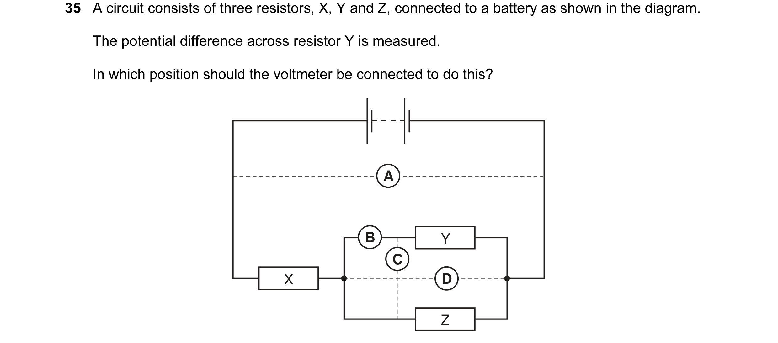
Q15 · A circuit consists of three resistors, X, Y and Z, connected to a battery as shown in the… 0654/11 Oct/Nov 2010
35 A circuit consists of three resistors, X, Y and Z, connected to a battery as shown in the diagram. The potential difference across resistor Y is measured. In which position should the voltmeter be connected to do this? A B Y C X D Z
1 marks
Answer: D
This question in 0654/11 Oct/Nov 2010
Q16 · Which diagram shows a circuit that will allow the lamps to be switched on and off… 0654/12 Oct/Nov 2010
29 Which diagram shows a circuit that will allow the lamps to be switched on and off independently? A B C D
1 marks
Answer: D
This question in 0654/12 Oct/Nov 2010
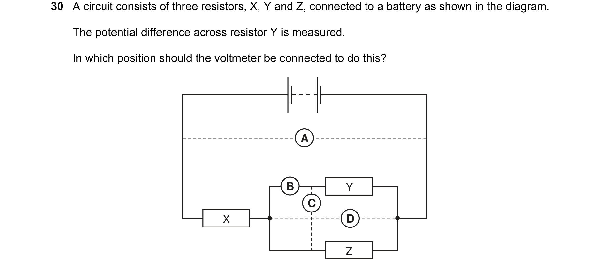
Q17 · A circuit consists of three resistors, X, Y and Z, connected to a battery as shown in the… 0654/12 Oct/Nov 2010
30 A circuit consists of three resistors, X, Y and Z, connected to a battery as shown in the diagram. The potential difference across resistor Y is measured. In which position should the voltmeter be connected to do this? A B Y C X D Z
1 marks
Answer: D
This question in 0654/12 Oct/Nov 2010
Q18 · The diagram shows a circuit 0654/13 Oct/Nov 2010
15 The diagram shows a circuit. Solid X makes the lamp light. X What is solid X? A rubber B silicon(IV) oxide C sulfur D zinc
1 marks
Answer: D
This question in 0654/13 Oct/Nov 2010
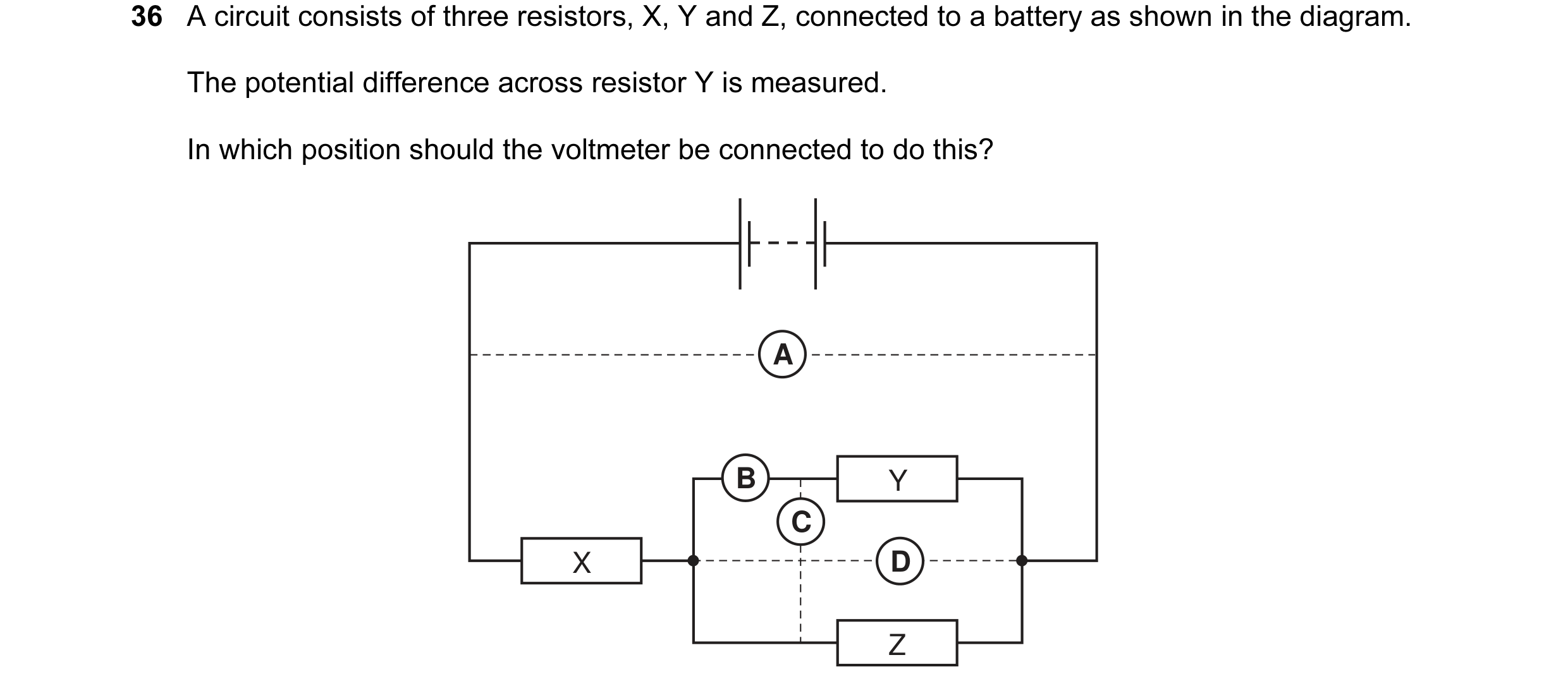
Q19 · A circuit consists of three resistors, X, Y and Z, connected to a battery as shown in the… 0654/13 Oct/Nov 2010
36 A circuit consists of three resistors, X, Y and Z, connected to a battery as shown in the diagram. The potential difference across resistor Y is measured. In which position should the voltmeter be connected to do this? A B Y C X D Z
1 marks
Answer: D
This question in 0654/13 Oct/Nov 2010
Q20 · Which diagram shows a circuit that will allow the lamps to be switched on and off… 0654/13 Oct/Nov 2010
37 Which diagram shows a circuit that will allow the lamps to be switched on and off independently? A B C D
1 marks
Answer: D
This question in 0654/13 Oct/Nov 2010
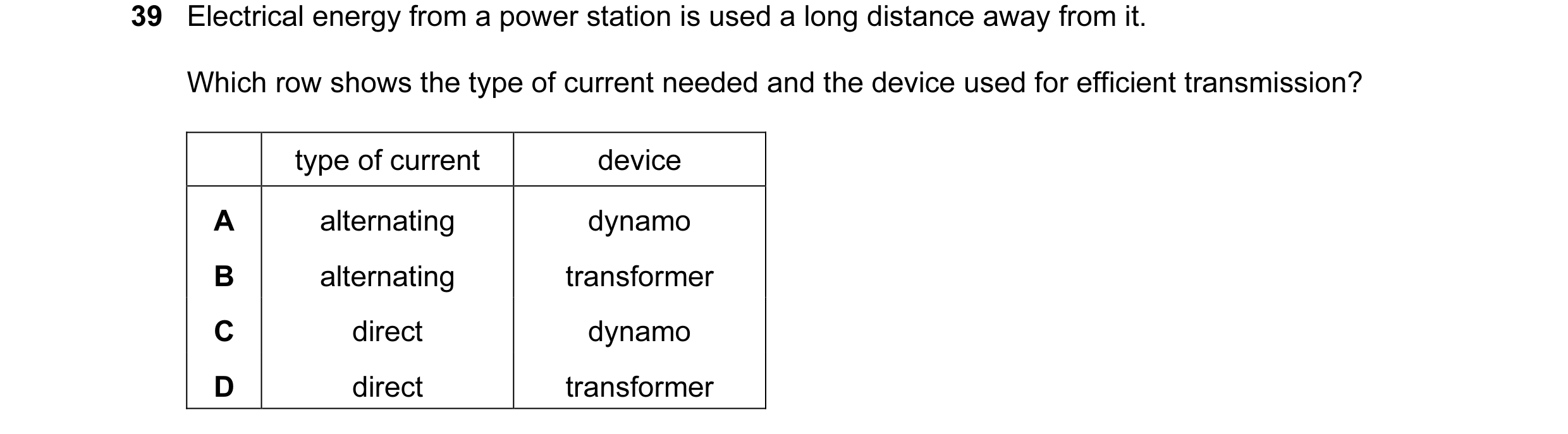
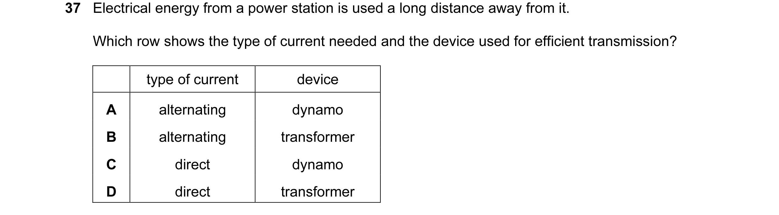
Q21 · Electrical energy from a power station is used a long distance away from it 0654/11 May/June 2011
39 Electrical energy from a power station is used a long distance away from it. Which row shows the type of current needed and the device used for efficient transmission? type of current device A alternating dynamo B alternating transformer C direct dynamo D direct transformer
1 marks
Answer: B
This question in 0654/11 May/June 2011
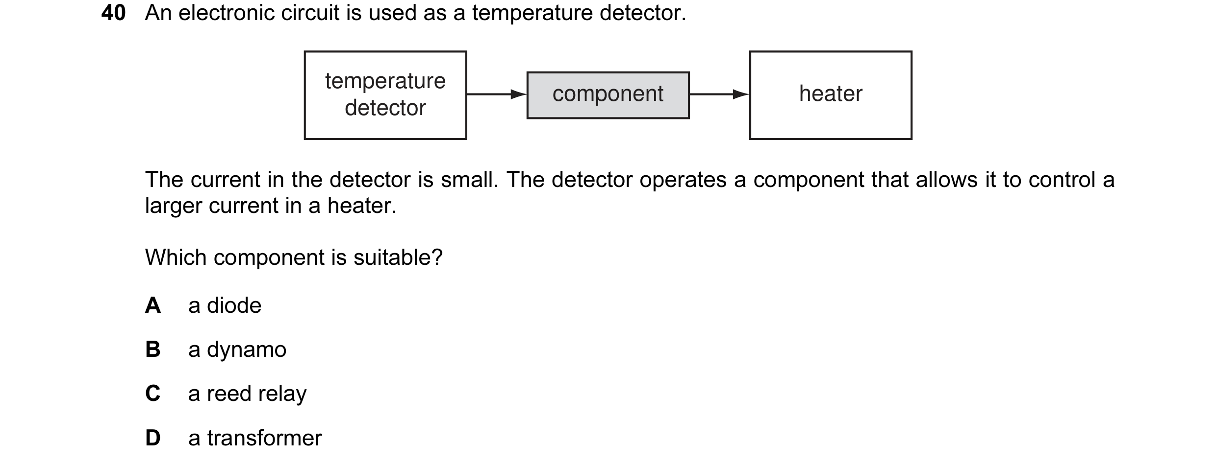
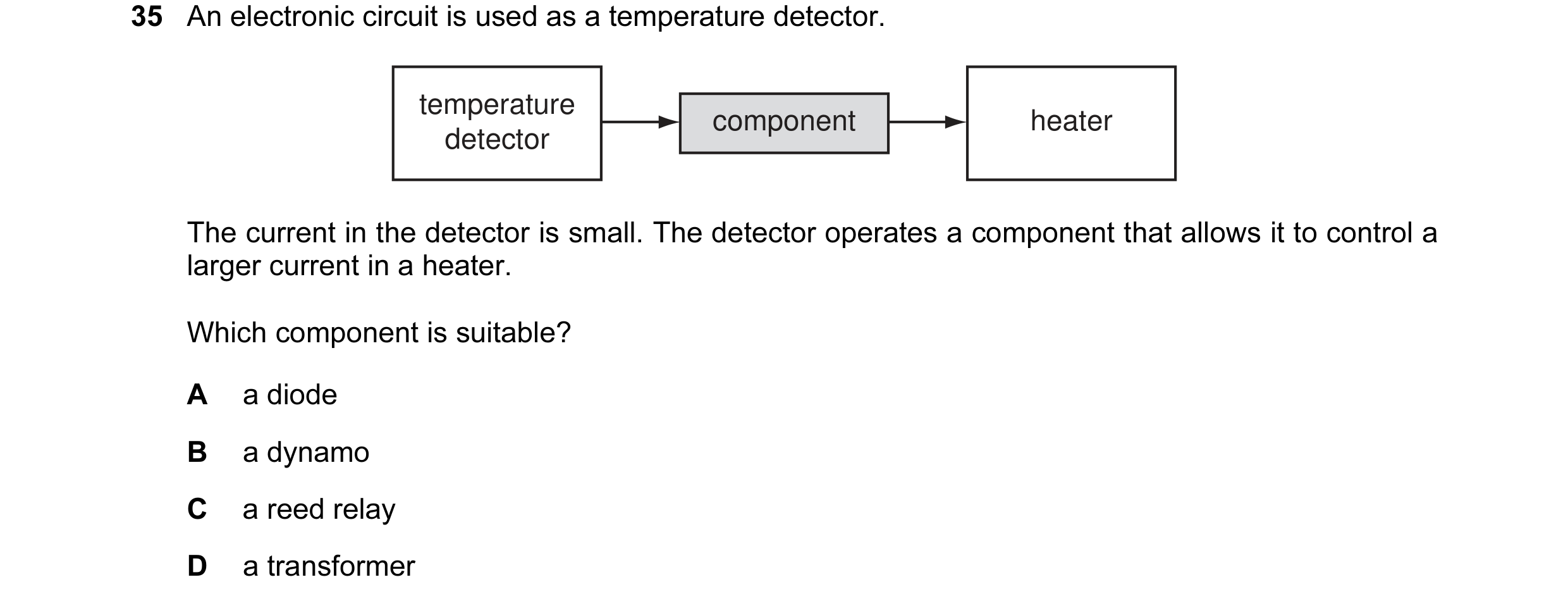
Q22 · An electronic circuit is used as a temperature detector 0654/11 May/June 2011
40 An electronic circuit is used as a temperature detector. temperature component heater detector The current in the detector is small. The detector operates a component that allows it to control a larger current in a heater. Which component is suitable? A a diode B a dynamo C a reed relay D a transformer
1 marks
Answer: C
This question in 0654/11 May/June 2011
Q23 · An electronic circuit is used as a temperature detector 0654/12 May/June 2011
35 An electronic circuit is used as a temperature detector. temperature component heater detector The current in the detector is small. The detector operates a component that allows it to control a larger current in a heater. Which component is suitable? A a diode B a dynamo C a reed relay D a transformer
1 marks
Answer: C
This question in 0654/12 May/June 2011
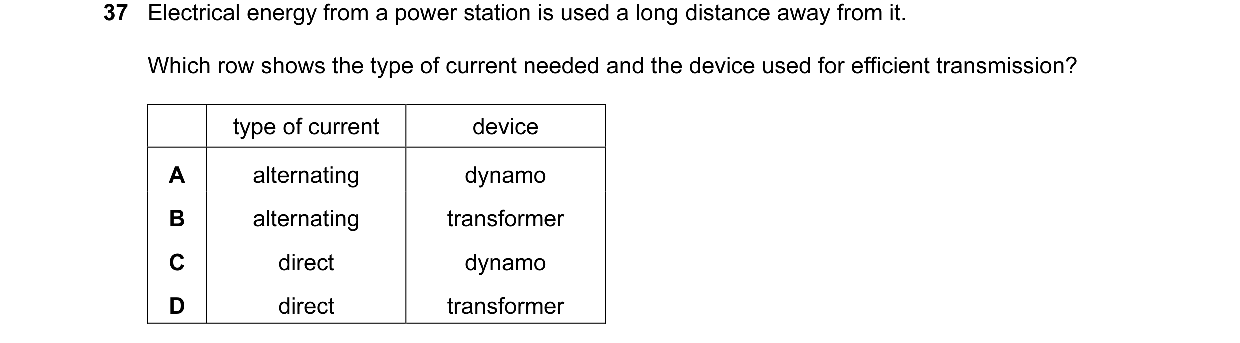
Q24 · Electrical energy from a power station is used a long distance away from it 0654/12 May/June 2011
37 Electrical energy from a power station is used a long distance away from it. Which row shows the type of current needed and the device used for efficient transmission? type of current device A alternating dynamo B alternating transformer C direct dynamo D direct transformer
1 marks
Answer: B
This question in 0654/12 May/June 2011
Q25 · An electronic circuit is used as a temperature detector 0654/13 May/June 2011
35 An electronic circuit is used as a temperature detector. temperature component heater detector The current in the detector is small. The detector operates a component that allows it to control a larger current in a heater. Which component is suitable? A a diode B a dynamo C a reed relay D a transformer
1 marks
Answer: C
This question in 0654/13 May/June 2011
Q26 · Electrical energy from a power station is used a long distance away from it 0654/13 May/June 2011
37 Electrical energy from a power station is used a long distance away from it. Which row shows the type of current needed and the device used for efficient transmission? type of current device A alternating dynamo B alternating transformer C direct dynamo D direct transformer
1 marks
Answer: B
This question in 0654/13 May/June 2011
Q27 · A student connects a length of metal resistance wire to a battery 0654/11 Oct/Nov 2011
32 A student connects a length of metal resistance wire to a battery. current metal resistance wire The student wishes to increase the current in the resistance wire. Which change would do this? A Connect a second wire in series with the first wire. B Heat the wire. C Shorten the wire. D Use a thinner wire.
1 marks
Answer: C
This question in 0654/11 Oct/Nov 2011
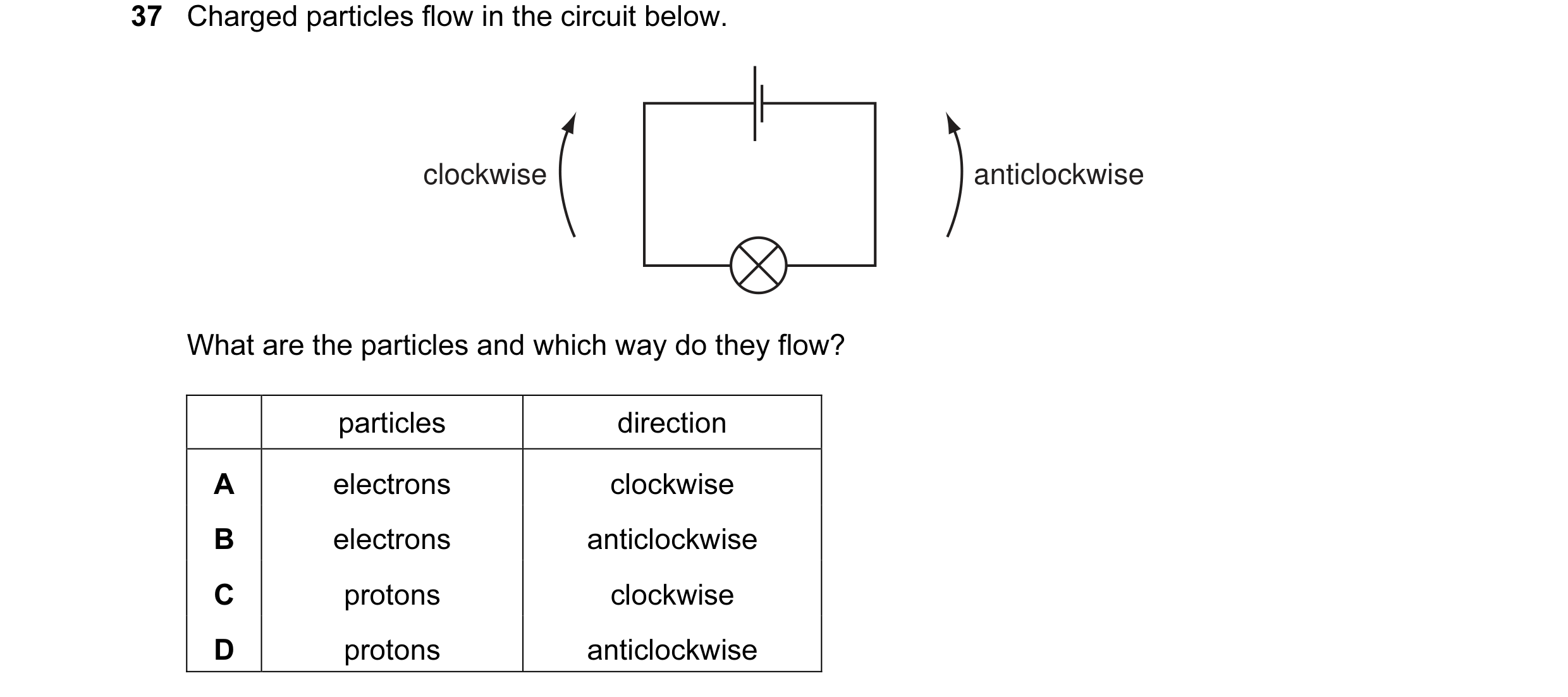
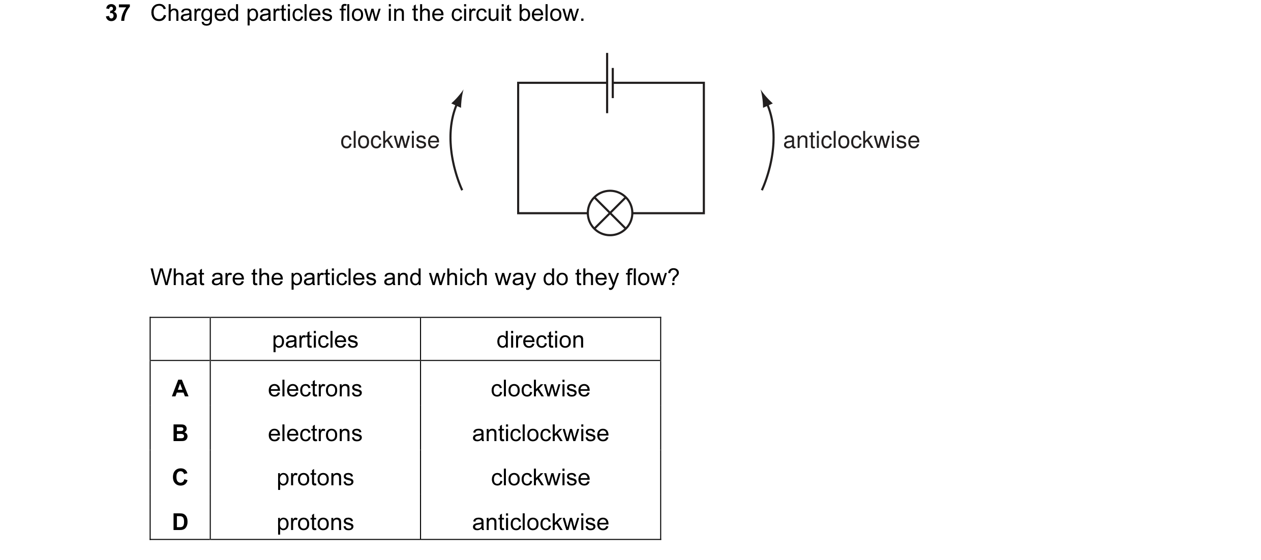
Q28 · Charged particles flow in the circuit below 0654/11 Oct/Nov 2011
37 Charged particles flow in the circuit below. clockwise anticlockwise What are the particles and which way do they flow? particles direction A electrons clockwise B electrons anticlockwise C protons clockwise D protons anticlockwise
1 marks
Answer: A
This question in 0654/11 Oct/Nov 2011
Q29 · Charged particles flow in the circuit below 0654/12 Oct/Nov 2011
37 Charged particles flow in the circuit below. clockwise anticlockwise What are the particles and which way do they flow? particles direction A electrons clockwise B electrons anticlockwise C protons clockwise D protons anticlockwise
1 marks
Answer: A
This question in 0654/12 Oct/Nov 2011
Q30 · A student connects a length of metal resistance wire to a battery 0654/13 Oct/Nov 2011
34 A student connects a length of metal resistance wire to a battery. current metal resistance wire The student wishes to increase the current in the resistance wire. Which change would do this? A Connect a second wire in series with the first wire. B Heat the wire. C Shorten the wire. D Use a thinner wire.
1 marks
Answer: C
This question in 0654/13 Oct/Nov 2011
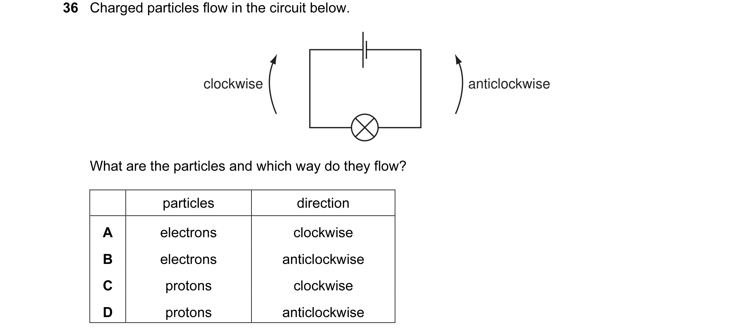
Q31 · Charged particles flow in the circuit below 0654/13 Oct/Nov 2011
36 Charged particles flow in the circuit below. clockwise anticlockwise What are the particles and which way do they flow? particles direction A electrons clockwise B electrons anticlockwise C protons clockwise D protons anticlockwise
1 marks
Answer: A
This question in 0654/13 Oct/Nov 2011
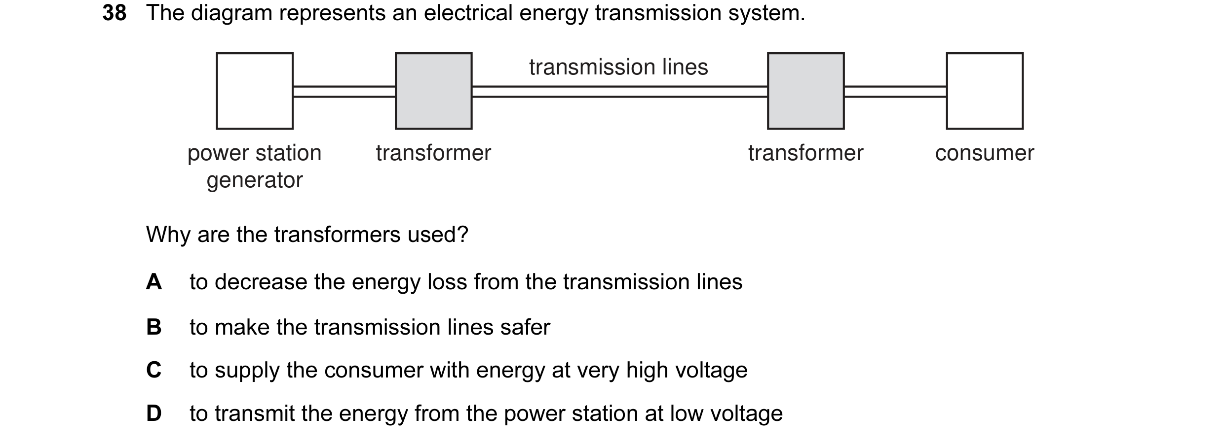
Q32 · The diagram represents an electrical energy transmission system 0654/13 Oct/Nov 2011
38 The diagram represents an electrical energy transmission system. transmission lines power station transformer transformer consumer generator Why are the transformers used? A to decrease the energy loss from the transmission lines B to make the transmission lines safer C to supply the consumer with energy at very high voltage D to transmit the energy from the power station at low voltage
1 marks
Answer: A
This question in 0654/13 Oct/Nov 2011
Q33 · A 3.0 Ω resistor and a 6.0 Ω resistor are connected to a power supply as shown 0654/11 May/June 2012
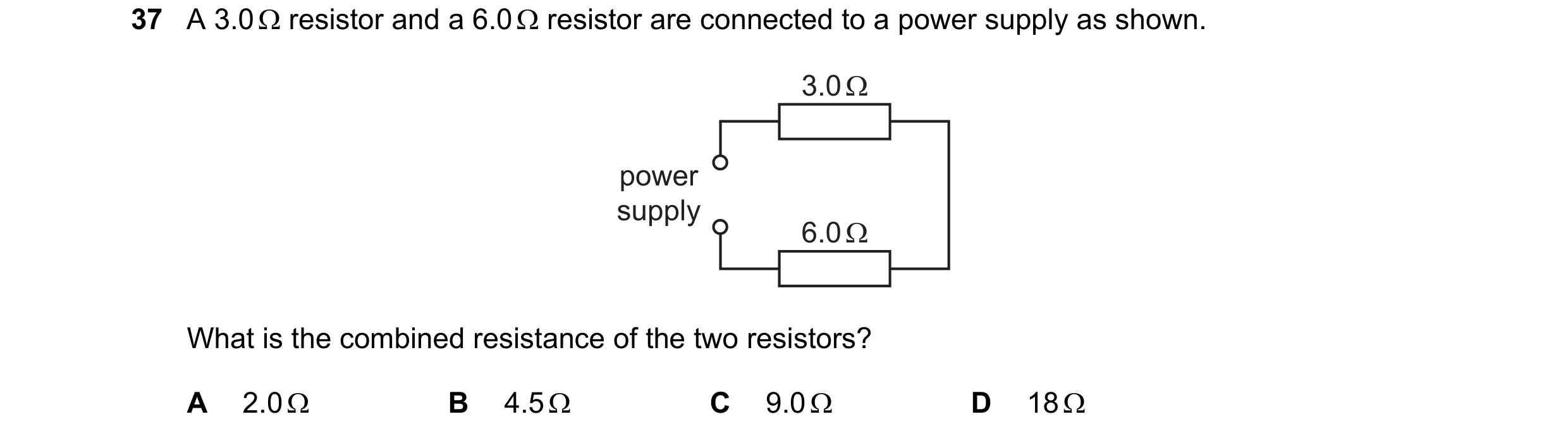
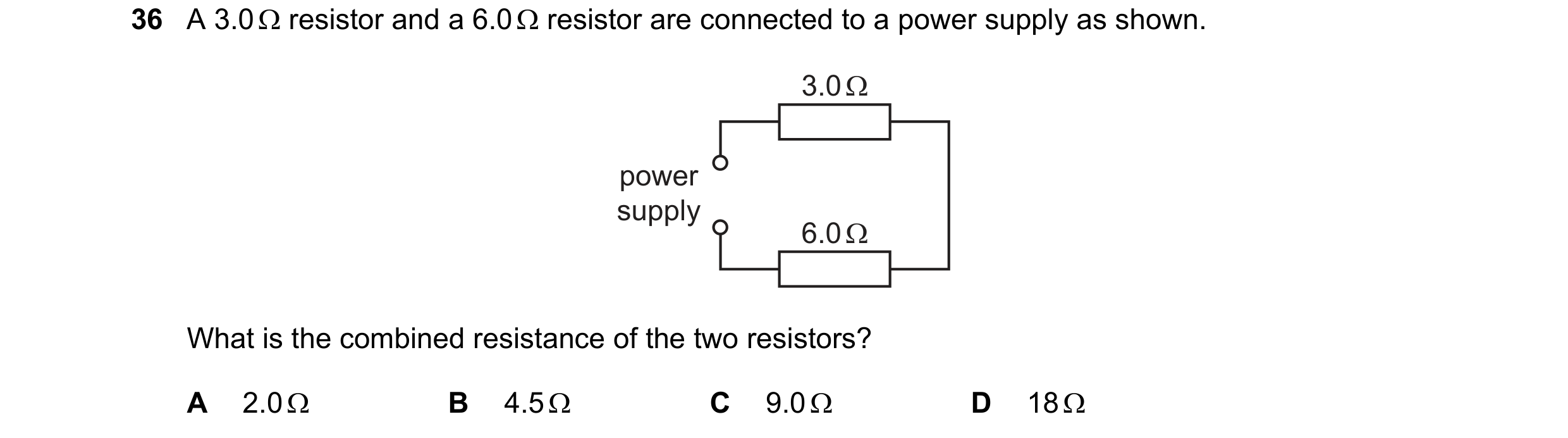
38 A 3.0 Ω resistor and a 6.0 Ω resistor are connected to a power supply as shown. 3.0 Ω power supply 6.0 Ω What is the total resistance of the circuit? A 2.0 Ω B 3.0 Ω C 9.0 Ω D 18 Ω
1 marks
Answer: C
This question in 0654/11 May/June 2012
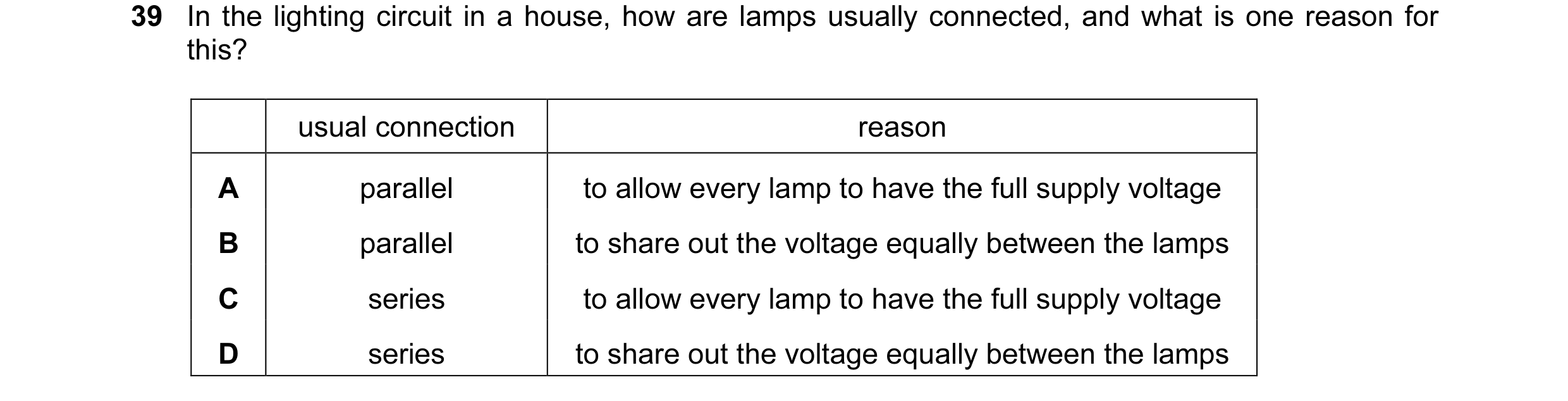
Q34 · In the lighting circuit in a house, how are lamps usually connected, and what is one… 0654/11 May/June 2012
39 In the lighting circuit in a house, how are lamps usually connected, and what is one reason for this? usual connection reason A parallel to allow every lamp to have the full supply voltage B parallel to share out the voltage equally between the lamps C series to allow every lamp to have the full supply voltage D series to share out the voltage equally between the lamps
1 marks
Answer: A
This question in 0654/11 May/June 2012
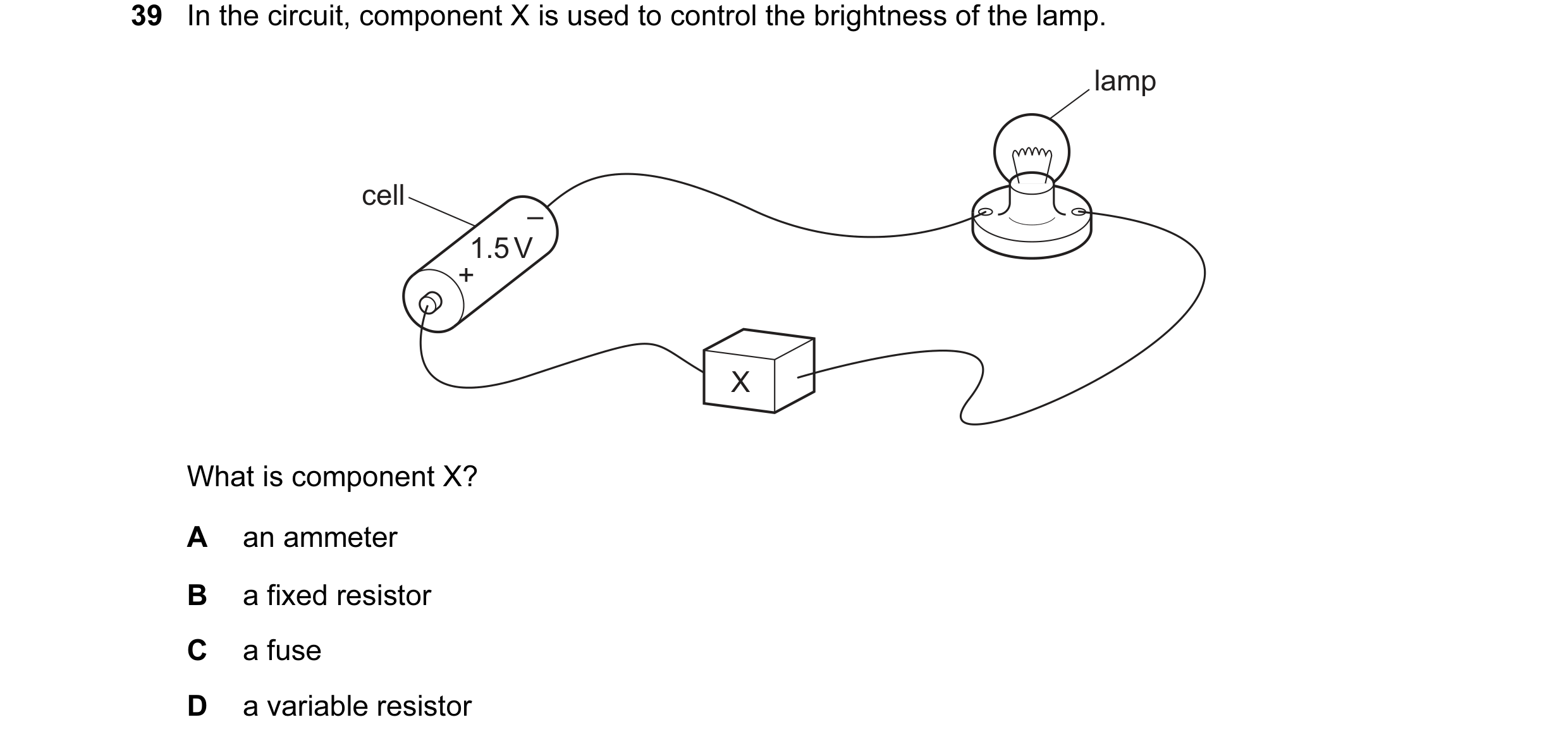
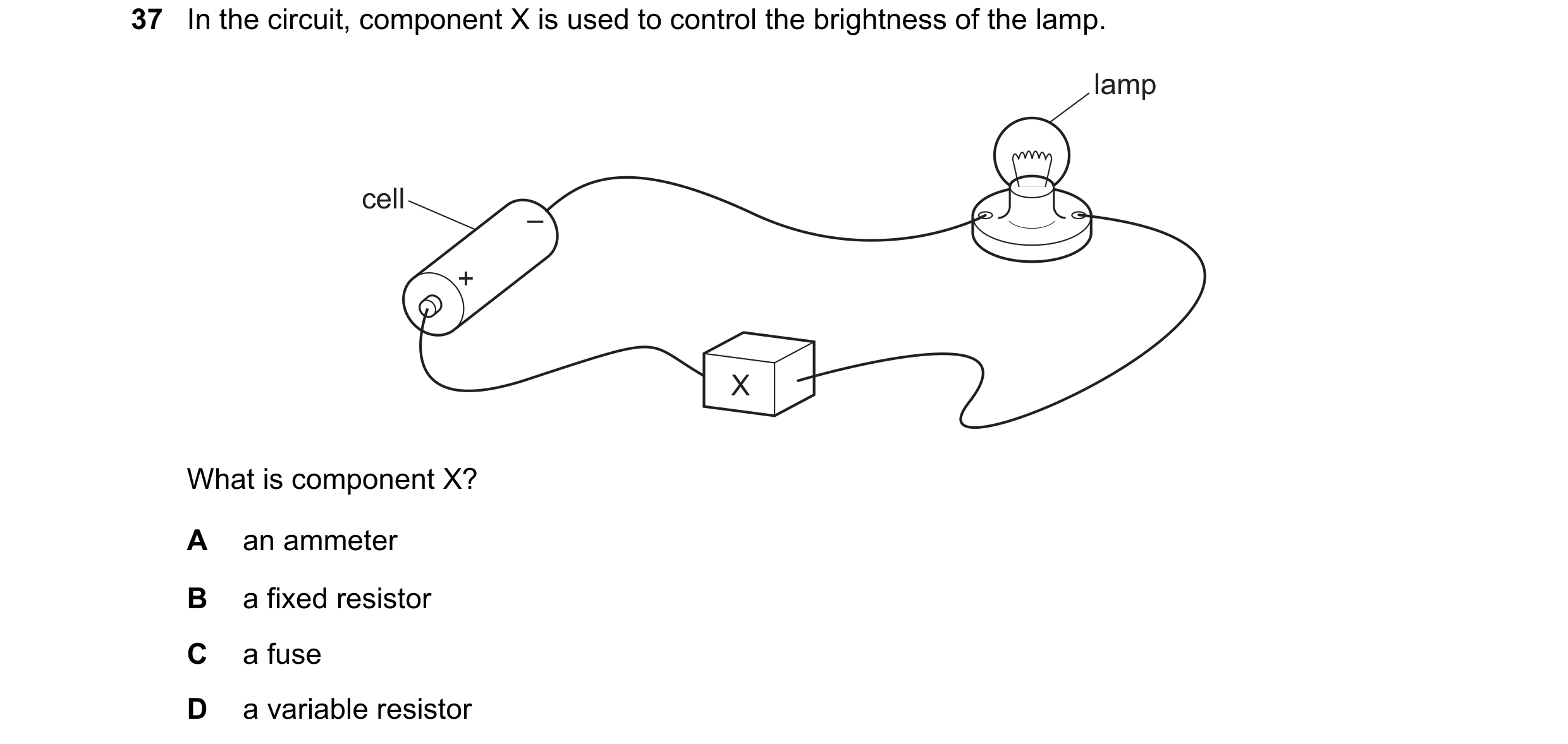
Q35 · In the circuit, component X is used to control the brightness of the lamp 0654/12 May/June 2013
39 In the circuit, component X is used to control the brightness of the lamp. lamp cell – 1.5 V + X What is component X? A an ammeter B a fixed resistor C a fuse D a variable resistor
1 marks
Answer: D
This question in 0654/12 May/June 2013
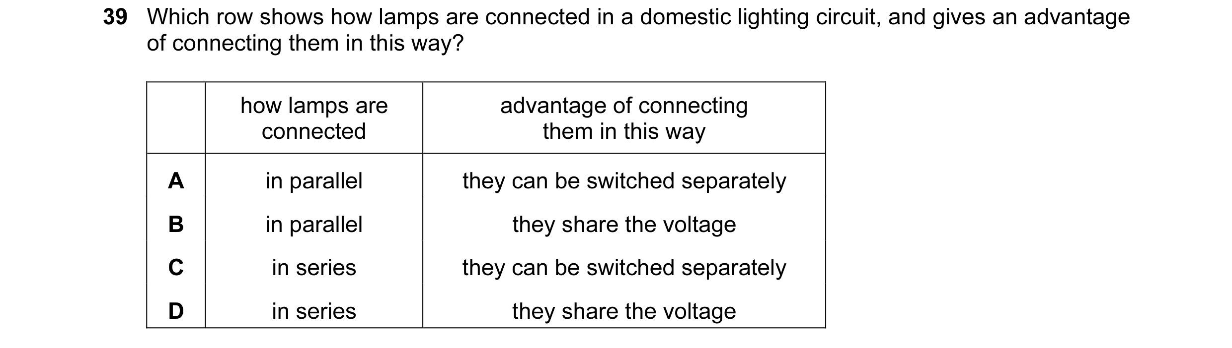
Q36 · Which row shows how lamps are connected in a domestic lighting circuit, and gives an… 0654/13 Oct/Nov 2013
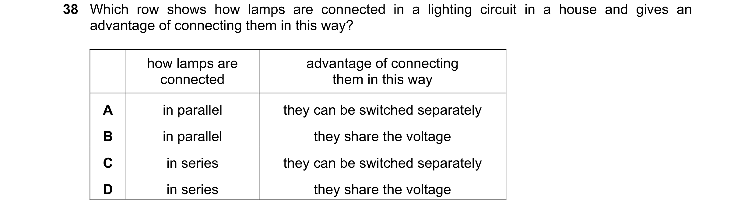
39 Which row shows how lamps are connected in a domestic lighting circuit, and gives an advantage of connecting them in this way? how lamps are advantage of connecting connected them in this way A in parallel they can be switched separately B in parallel they share the voltage C in series they can be switched separately D in series they share the voltage
1 marks
Answer: A
This question in 0654/13 Oct/Nov 2013
Q37 · A 20 V battery is connected in series with a 4.0 Ω resistor and a 6.0 Ω resistor 0654/11 May/June 2014
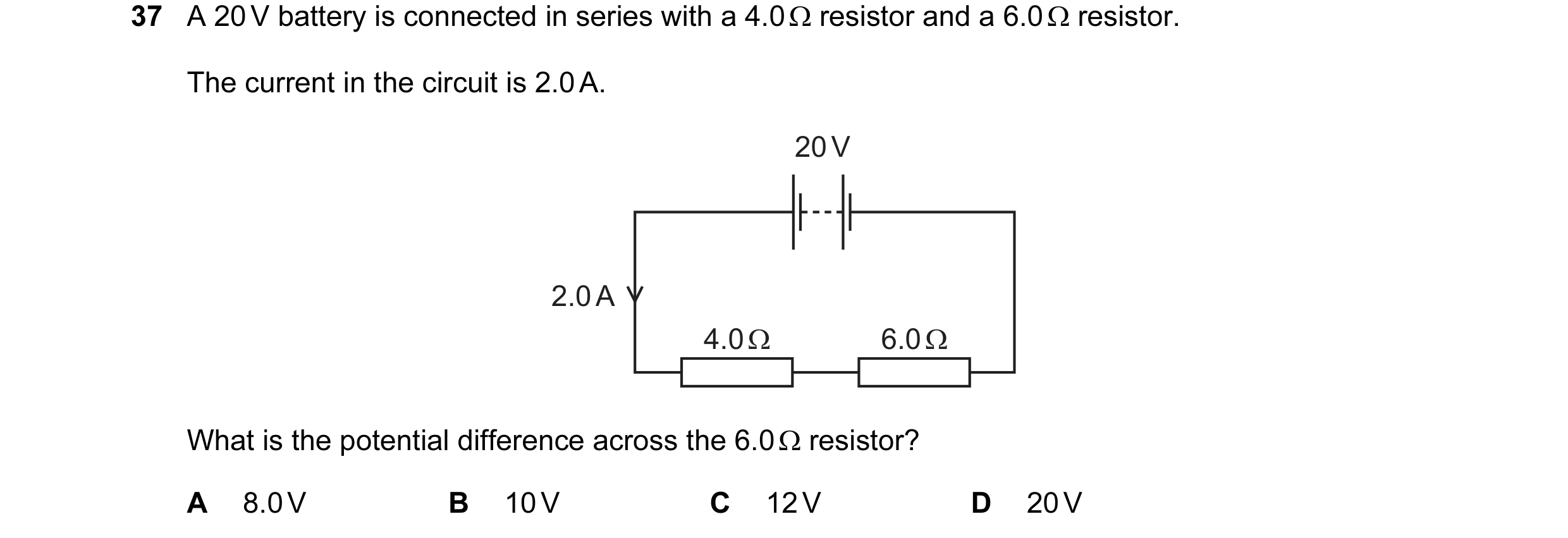
38 A 20 V battery is connected in series with a 4.0 Ω resistor and a 6.0 Ω resistor. The current in the circuit is 2.0 A. 20 V 2.0 A 4.0 Ω 6.0 Ω What is the potential difference across the 6.0 Ω resistor? A 8.0 V B 10 V C 12 V D 20 V
1 marks
Answer: C
This question in 0654/11 May/June 2014
Q38 · A series circuit contains two resistors, X and Y, and two ammeters, P and Q 0654/12 May/June 2014
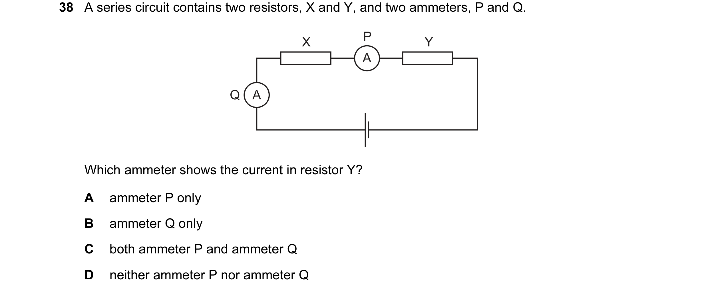
38 A series circuit contains two resistors, X and Y, and two ammeters, P and Q. X P Y A Q A Which ammeter shows the current in resistor Y? A ammeter P only B ammeter Q only C both ammeter P and ammeter Q D neither ammeter P nor ammeter Q
1 marks
Answer: C
This question in 0654/12 May/June 2014
Q39 · A 20 V battery is connected in series with a 4.0 Ω resistor and a 6.0 Ω resistor 0654/13 May/June 2014
37 A 20 V battery is connected in series with a 4.0 Ω resistor and a 6.0 Ω resistor. The current in the circuit is 2.0 A. 20 V 2.0 A 4.0 Ω 6.0 Ω What is the potential difference across the 6.0 Ω resistor? A 8.0 V B 10 V C 12 V D 20 V
1 marks
Answer: C
This question in 0654/13 May/June 2014
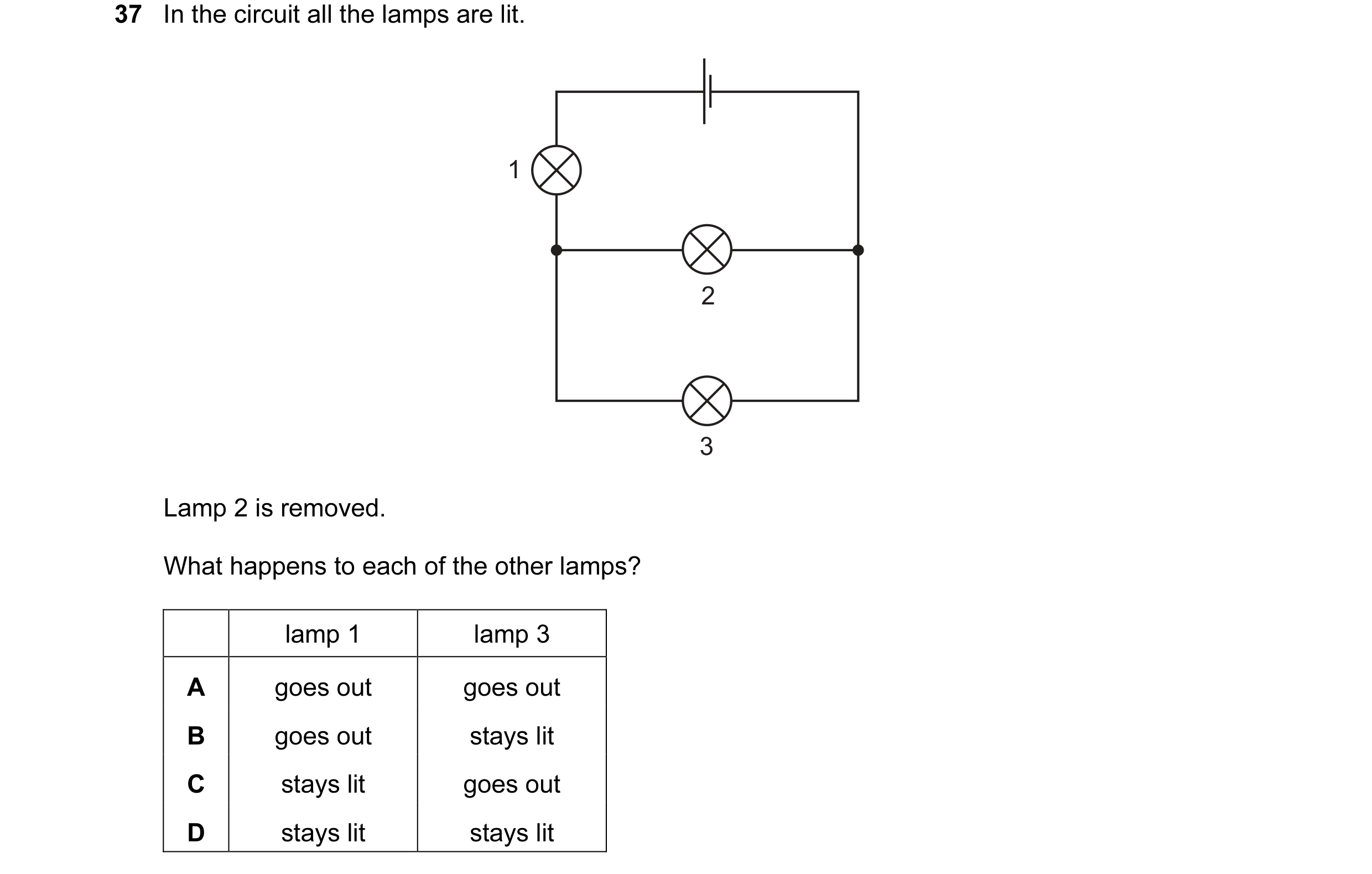
Q40 · In the circuit all the lamps are lit 0654/11 Oct/Nov 2014
38 In the circuit all the lamps are lit. 1 2 3 Lamp 2 is removed. What happens to each of the other lamps? lamp 1 lamp 3 A goes out goes out B goes out stays lit C stays lit goes out D stays lit stays lit
1 marks
Answer: D
This question in 0654/11 Oct/Nov 2014
Q41 · In the circuit all the lamps are lit 0654/12 Oct/Nov 2014
37 In the circuit all the lamps are lit. 1 2 3 Lamp 2 is removed. What happens to each of the other lamps? lamp 1 lamp 3 A goes out goes out B goes out stays lit C stays lit goes out D stays lit stays lit
1 marks
Answer: D
This question in 0654/12 Oct/Nov 2014
Q42 · The diagram shows three resistors, a battery and four ammeters connected in a circuit 0654/13 Oct/Nov 2014
37 The diagram shows three resistors, a battery and four ammeters connected in a circuit. Which ammeter shows the highest reading? A D A 3 Ω A B A 6 Ω C A 12 Ω
1 marks
Answer: D
This question in 0654/13 Oct/Nov 2014
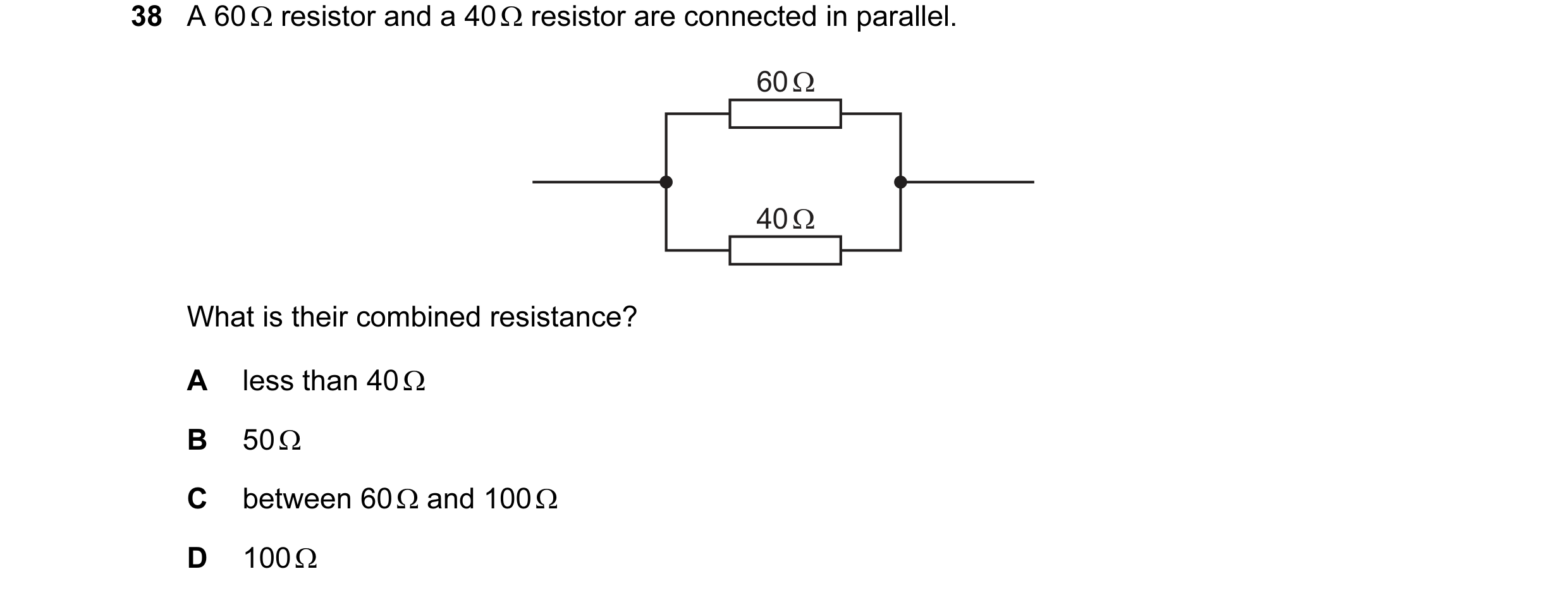
Q43 · A 60 Ω resistor and a 40 Ω resistor are connected in parallel 0654/13 Oct/Nov 2014
38 A 60 Ω resistor and a 40 Ω resistor are connected in parallel. 60 Ω 40 Ω What is their combined resistance? A less than 40 Ω B 50 Ω C between 60 Ω and 100 Ω D 100 Ω
1 marks
Answer: A
This question in 0654/13 Oct/Nov 2014
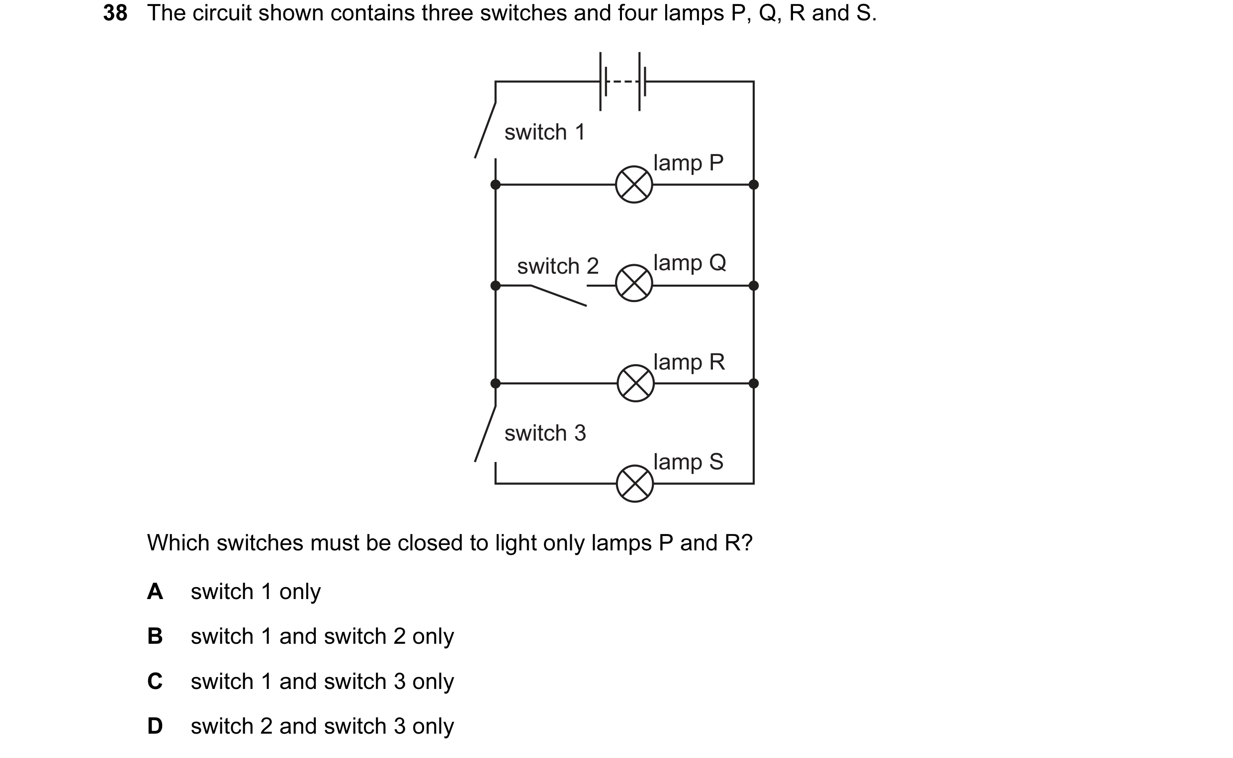
Q44 · The circuit shown contains three switches and four lamps P, Q, R and S 0654/11 May/June 2015
38 The circuit shown contains three switches and four lamps P, Q, R and S. switch 1 lamp P switch 2 lamp Q lamp R switch 3 lamp S Which switches must be closed to light only lamps P and R? A switch 1 only B switch 1 and switch 2 only C switch 1 and switch 3 only D switch 2 and switch 3 only
1 marks
Answer: A
This question in 0654/11 May/June 2015
Q45 · The diagram shows a circuit containing a 10 Ω resistor X and an ammeter 0654/11 May/June 2015
39 The diagram shows a circuit containing a 10 Ω resistor X and an ammeter. The ammeter reading is 1.0 A. A 20 Ω resistor Y is also available. 20 Ω 10 Ω Y A X 1.0 A Which change to the circuit produces a reading on the ammeter that is greater than 1.0 A? A connecting Y in parallel with X B placing X on the other side of the ammeter C replacing X with Y D reversing the connections to X
1 marks
Answer: A
This question in 0654/11 May/June 2015
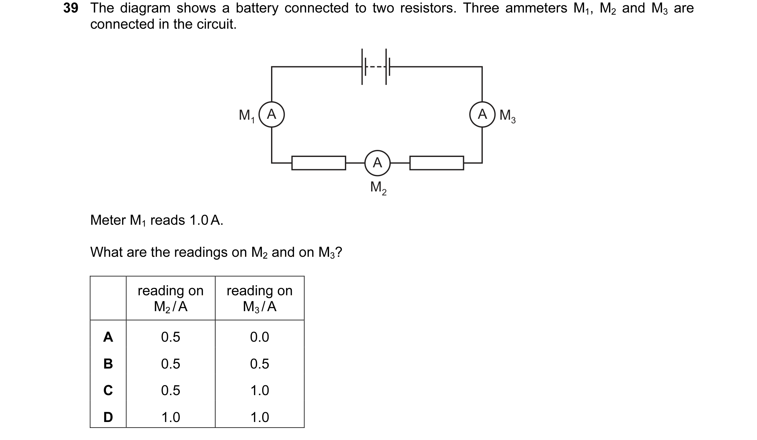
Q46 · The diagram shows a battery connected to two resistors 0654/12 May/June 2015
39 The diagram shows a battery connected to two resistors. Three ammeters M1, M2 and M3 are connected in the circuit. M1 A A M3 A M2 Meter M1 reads 1.0 A. What are the readings on M2 and on M3? reading on reading on M2 / A M3 / A A 0.5 0.0 B 0.5 0.5 C 0.5 1.0 D 1.0 1.0
1 marks
Answer: D
This question in 0654/12 May/June 2015
Q47 · A 2 Ω and a 3 Ω resistor are connected as shown 0654/13 May/June 2015
39 A 2 Ω and a 3 Ω resistor are connected as shown. 2 Ω 3 Ω What is the total resistance of the two resistors? A less than 2 Ω B between 2 Ω and 3 Ω C between 3 Ω and 5 Ω D exactly 5 Ω
1 marks
Answer: A
This question in 0654/13 May/June 2015
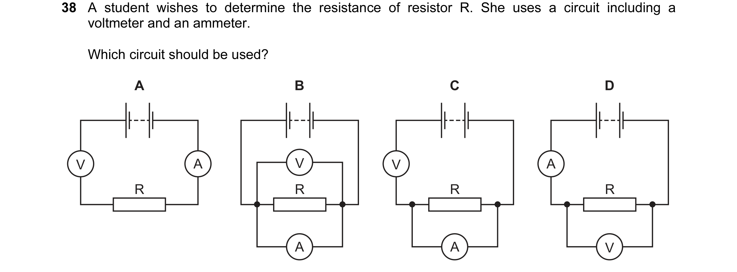
Q48 · A student wishes to determine the resistance of resistor R 0654/11 Oct/Nov 2015
38 A student wishes to determine the resistance of resistor R. She uses a circuit including a voltmeter and an ammeter. Which circuit should be used? A B C D V A V V A R R R R A A V
1 marks
Answer: D
This question in 0654/11 Oct/Nov 2015
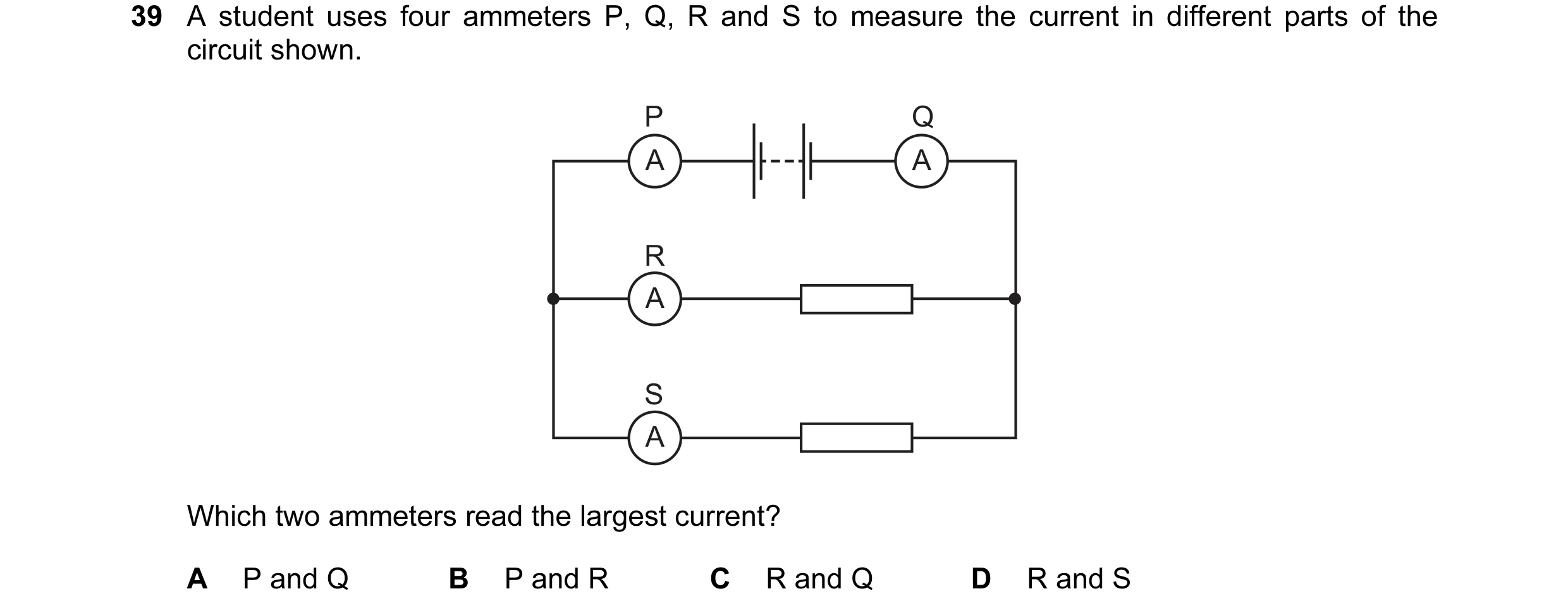
Q49 · A student uses four ammeters P, Q, R and S to measure the current in different parts of… 0654/11 Oct/Nov 2015
39 A student uses four ammeters P, Q, R and S to measure the current in different parts of the circuit shown. P Q A A R A S A Which two ammeters read the largest current? A P and Q B P and R C R and Q D R and S
1 marks
Answer: A
This question in 0654/11 Oct/Nov 2015
Q50 · A student constructs four circuits, each containing a fuse 0654/12 Oct/Nov 2015
38 A student constructs four circuits, each containing a fuse. The fuse blows in one circuit and both lamps in the circuit go out. In which circuit does the fuse blow and both lamps go out? A B C D
1 marks
Answer: D
This question in 0654/12 Oct/Nov 2015
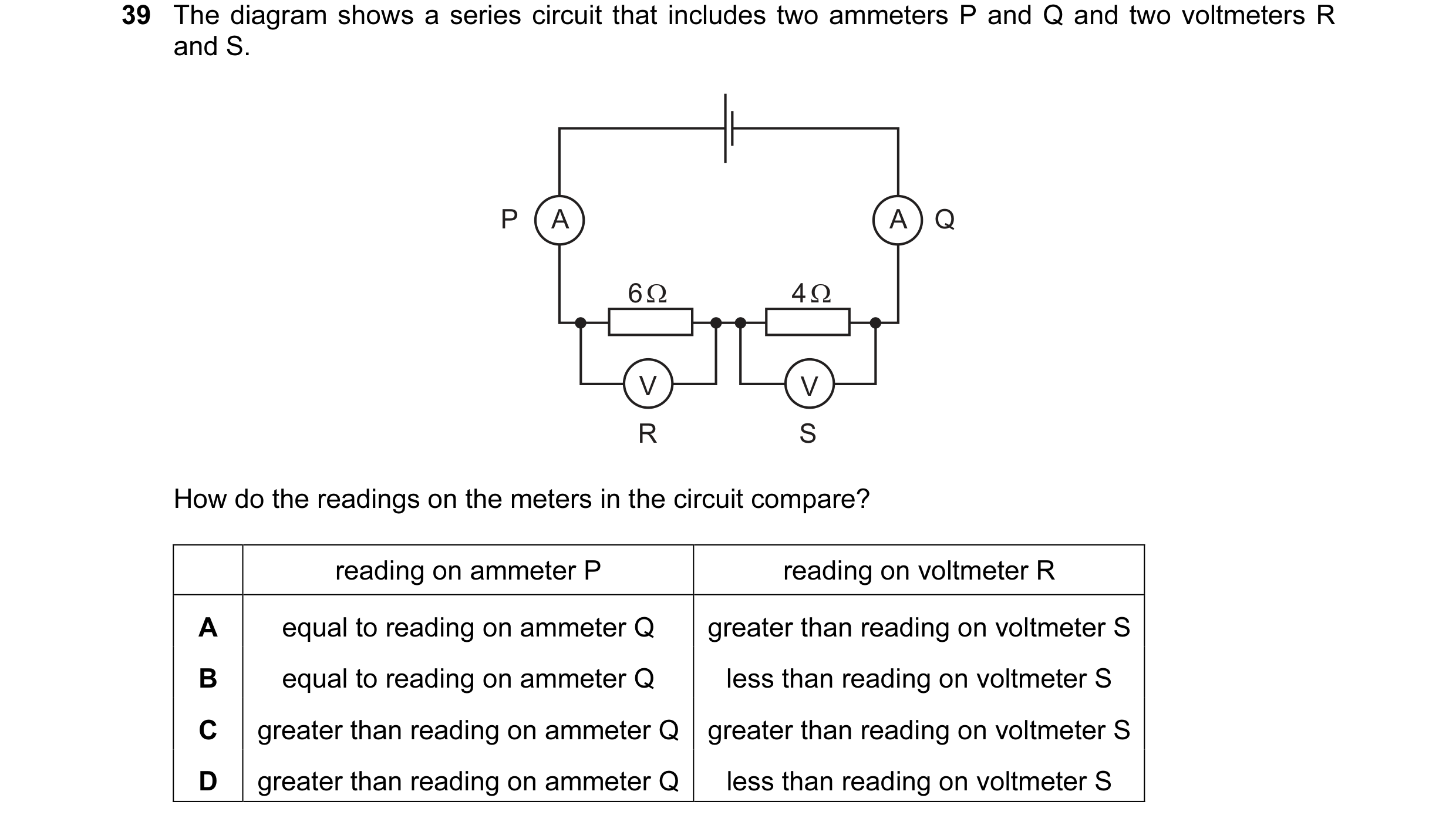
Q51 · The diagram shows a series circuit that includes two ammeters P and Q and two voltmeters… 0654/12 Oct/Nov 2015
39 The diagram shows a series circuit that includes two ammeters P and Q and two voltmeters R and S. P A A Q 6 Ω 4 Ω V V R S How do the readings on the meters in the circuit compare? reading on ammeter P reading on voltmeter R A equal to reading on ammeter Q greater than reading on voltmeter S B equal to reading on ammeter Q less than reading on voltmeter S C greater than reading on ammeter Q greater than reading on voltmeter S D greater than reading on ammeter Q less than reading on voltmeter S
1 marks
Answer: A
This question in 0654/12 Oct/Nov 2015
Q52 · A lamp is connected in four circuits in turn 0654/13 Oct/Nov 2015
39 A lamp is connected in four circuits in turn. The batteries are identical and the resistors are identical. In which circuit is the lamp brightest? A B C D
1 marks
Answer: A
This question in 0654/13 Oct/Nov 2015
Q53 · Which row shows how lamps are connected in a lighting circuit and gives an advantage of… 0654/11 May/June 2016
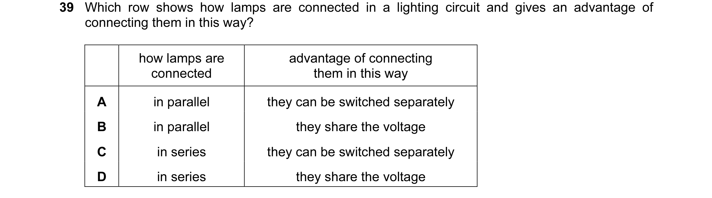
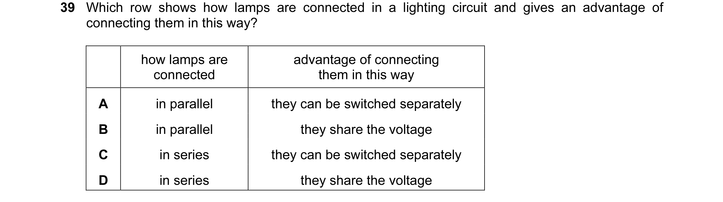
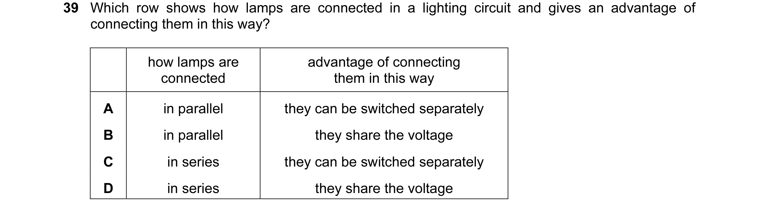
39 Which row shows how lamps are connected in a lighting circuit and gives an advantage of connecting them in this way? how lamps are advantage of connecting connected them in this way A in parallel they can be switched separately B in parallel they share the voltage C in series they can be switched separately D in series they share the voltage
1 marks
Answer: A
This question in 0654/11 May/June 2016
Q54 · Which row shows how lamps are connected in a lighting circuit and gives an advantage of… 0654/12 May/June 2016
39 Which row shows how lamps are connected in a lighting circuit and gives an advantage of connecting them in this way? how lamps are advantage of connecting connected them in this way A in parallel they can be switched separately B in parallel they share the voltage C in series they can be switched separately D in series they share the voltage
1 marks
Answer: A
This question in 0654/12 May/June 2016
Q55 · The diagram shows a 12 V battery connected to a resistor and an ammeter 0654/13 May/June 2016
37 The diagram shows a 12 V battery connected to a resistor and an ammeter. The reading on the ammeter is 3.0 A. 12 V A What is the resistance of the resistor? A 0.25 Ω B 4.0 Ω C 15 Ω D 36 Ω
1 marks
Answer: B
This question in 0654/13 May/June 2016
Q56 · Which row shows how lamps are connected in a lighting circuit and gives an advantage of… 0654/13 May/June 2016
39 Which row shows how lamps are connected in a lighting circuit and gives an advantage of connecting them in this way? how lamps are advantage of connecting connected them in this way A in parallel they can be switched separately B in parallel they share the voltage C in series they can be switched separately D in series they share the voltage
1 marks
Answer: A
This question in 0654/13 May/June 2016
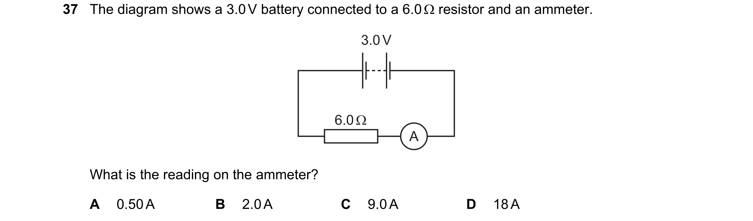
Q57 · The diagram shows a 3.0 V battery connected to a 6.0 Ω resistor and an ammeter 0654/11 Oct/Nov 2016
37 The diagram shows a 3.0 V battery connected to a 6.0 Ω resistor and an ammeter. 3.0 V 6.0 Ω A What is the reading on the ammeter? A 0.50 A B 2.0 A C 9.0 A D 18 A
1 marks
Answer: A
This question in 0654/11 Oct/Nov 2016
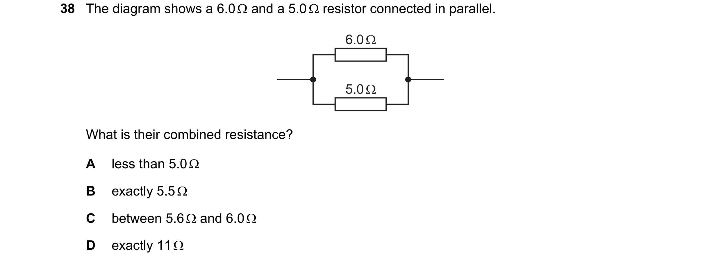
Q58 · The diagram shows a 6.0 Ω and a 5.0 Ω resistor connected in parallel 0654/11 Oct/Nov 2016
38 The diagram shows a 6.0 Ω and a 5.0 Ω resistor connected in parallel. 6.0 Ω 5.0 Ω What is their combined resistance? A less than 5.0 Ω B exactly 5.5 Ω C between 5.6 Ω and 6.0 Ω D exactly 11 Ω
1 marks
Answer: A
This question in 0654/11 Oct/Nov 2016
Q59 · The circuit shows a battery connected to two resistors in series 0654/12 Oct/Nov 2016
37 The circuit shows a battery connected to two resistors in series. A R V The reading on the ammeter is 2.0 A and the reading on the voltmeter is 8.0 V. What is the resistance of resistor R? A 0.25 Ω B 4.0 Ω C 10 Ω D 16 Ω
1 marks
Answer: B
This question in 0654/12 Oct/Nov 2016
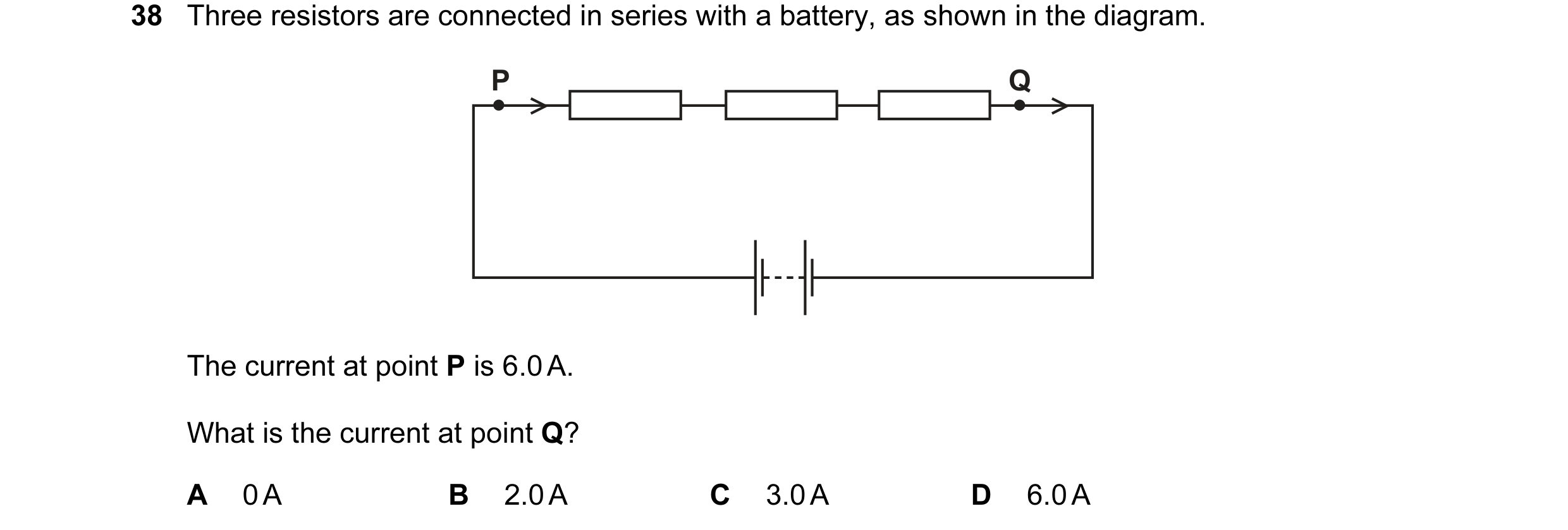
Q60 · Three resistors are connected in series with a battery, as shown in the diagram 0654/13 Oct/Nov 2016
38 Three resistors are connected in series with a battery, as shown in the diagram. P Q The current at point P is 6.0 A. What is the current at point Q? A 0 A B 2.0 A C 3.0 A D 6.0 A
1 marks
Answer: D
This question in 0654/13 Oct/Nov 2016
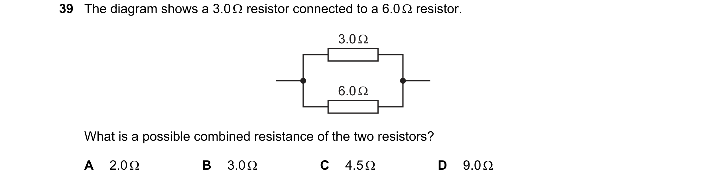
Q61 · The diagram shows a 3.0 Ω resistor connected to a 6.0 Ω resistor 0654/12 May/June 2017
39 The diagram shows a 3.0 Ω resistor connected to a 6.0 Ω resistor. 3.0 Ω 6.0 Ω What is a possible combined resistance of the two resistors? A 2.0 Ω B 3.0 Ω C 4.5 Ω D 9.0 Ω
1 marks
Answer: A
This question in 0654/12 May/June 2017
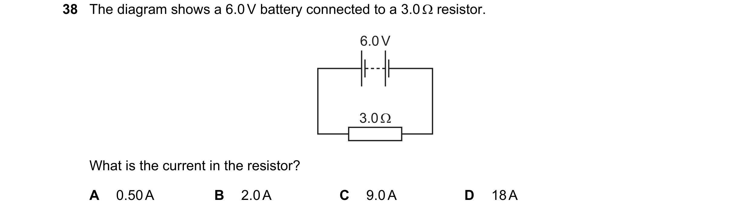
Q62 · The diagram shows a 6.0 V battery connected to a 3.0 Ω resistor 0654/13 May/June 2017
38 The diagram shows a 6.0 V battery connected to a 3.0 Ω resistor. 6.0 V 3.0 Ω What is the current in the resistor? A 0.50 A B 2.0 A C 9.0 A D 18 A
1 marks
Answer: B
This question in 0654/13 May/June 2017
Q63 · A battery is connected to a 3.0 Ω resistor, a 6.0 Ω resistor and two ammeters P and Q 0654/13 May/June 2017
39 A battery is connected to a 3.0 Ω resistor, a 6.0 Ω resistor and two ammeters P and Q. A Q P 3.0 Ω A 6.0 Ω What is the combined resistance of the two resistors and which ammeter has the greater reading? combined ammeter with resistance / Ω greater reading A less than 3.0 P B less than 3.0 Q C 9.0 P D 9.0 Q
1 marks
Answer: B
This question in 0654/13 May/June 2017
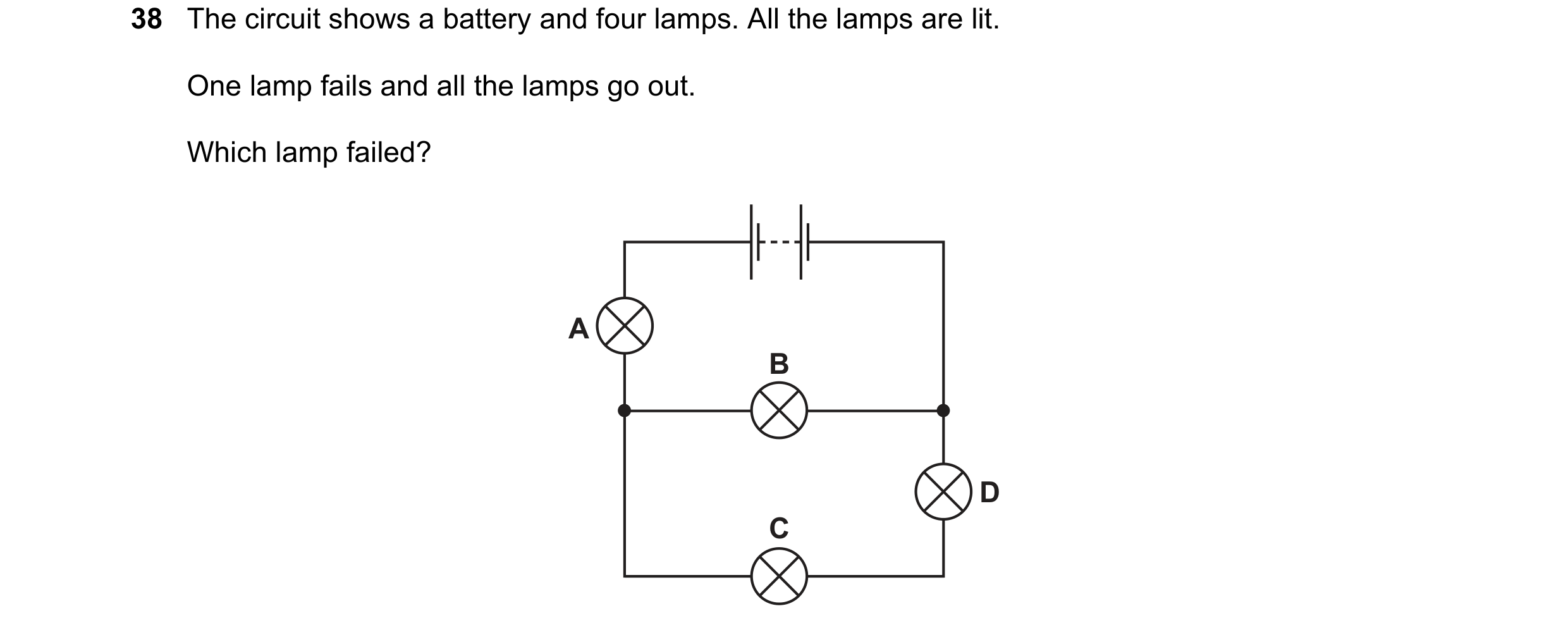
Q64 · The circuit shows a battery and four lamps 0654/12 Oct/Nov 2017
38 The circuit shows a battery and four lamps. All the lamps are lit. One lamp fails and all the lamps go out. Which lamp failed? A B D C
1 marks
Answer: A
This question in 0654/12 Oct/Nov 2017
Q65 · The diagram shows two identical resistors connected to a 24 V battery 0654/13 Oct/Nov 2017
39 The diagram shows two identical resistors connected to a 24 V battery. One resistor is labelled R. 24 V Y X R What is the potential difference (p.d.) across R, and at which labelled point, X or Y, is the current greater? p.d. across greater current R / V A 12 at X B 12 at Y C 24 at X D 24 at Y
1 marks
Answer: D
This question in 0654/13 Oct/Nov 2017
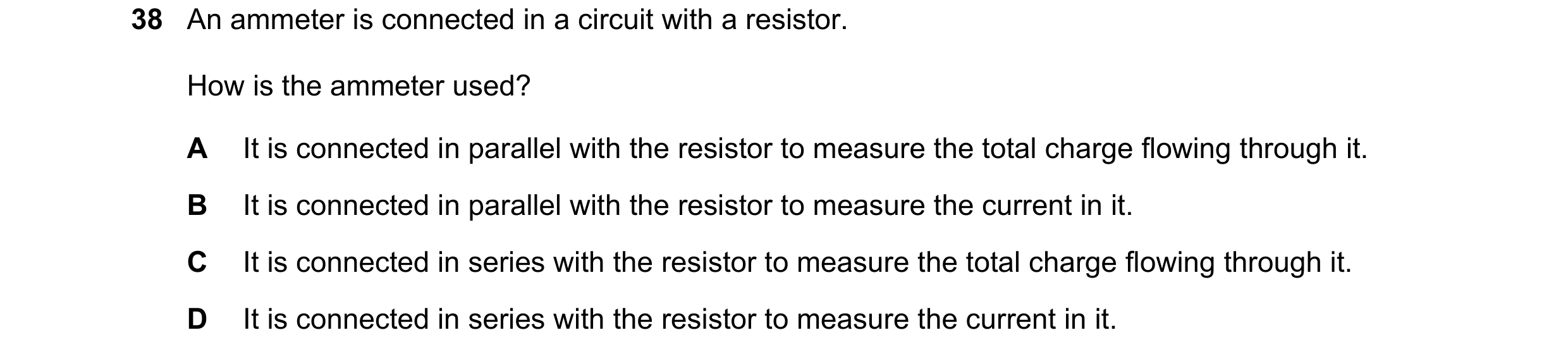
Q66 · An ammeter is connected in a circuit with a resistor 0654/11 Oct/Nov 2018
38 An ammeter is connected in a circuit with a resistor. How is the ammeter used? A It is connected in parallel with the resistor to measure the total charge flowing through it. B It is connected in parallel with the resistor to measure the current in it. C It is connected in series with the resistor to measure the total charge flowing through it. D It is connected in series with the resistor to measure the current in it.
1 marks
Answer: D
This question in 0654/11 Oct/Nov 2018
Q67 · Which diagram shows a circuit that can be used to determine the resistance of the… 0654/12 Oct/Nov 2018
38 Which diagram shows a circuit that can be used to determine the resistance of the resistor shown? A B V V A A C D A A V V
1 marks
Answer: C
This question in 0654/12 Oct/Nov 2018
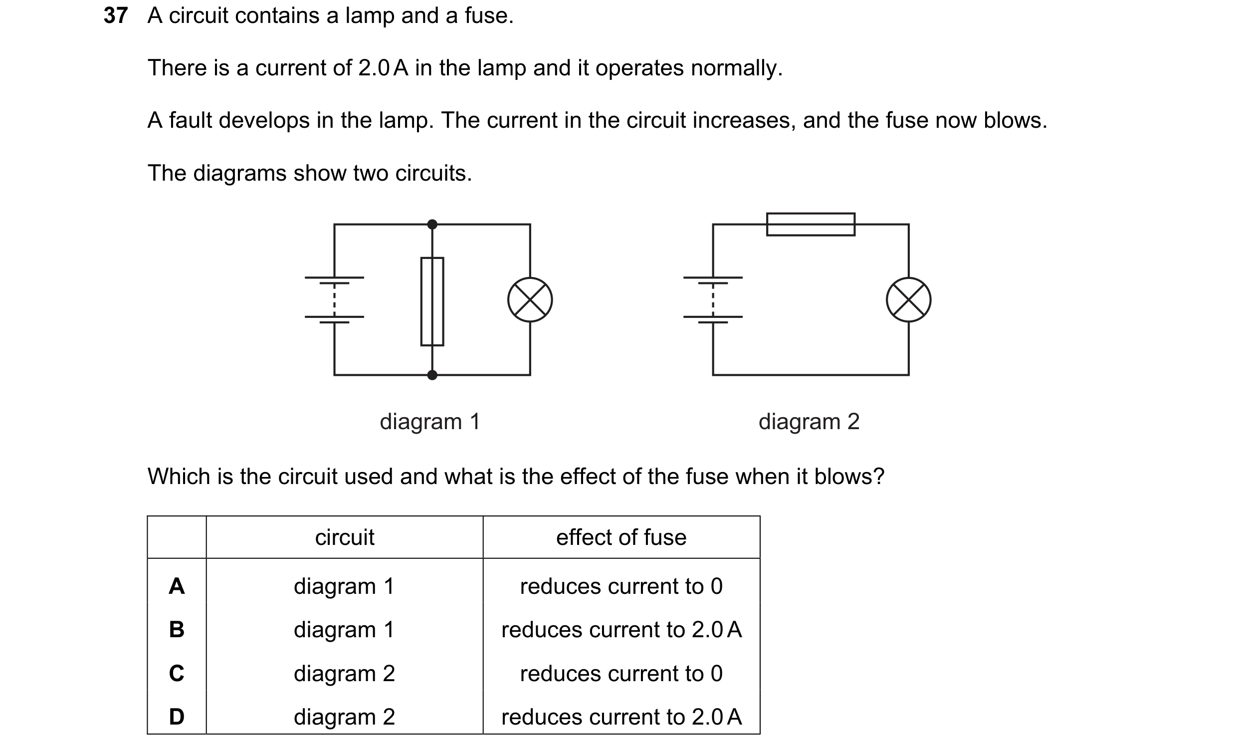
Q68 · A circuit contains a lamp and a fuse 0654/13 Oct/Nov 2018
37 A circuit contains a lamp and a fuse. There is a current of 2.0 A in the lamp and it operates normally. A fault develops in the lamp. The current in the circuit increases, and the fuse now blows. The diagrams show two circuits. diagram 1 diagram 2 Which is the circuit used and what is the effect of the fuse when it blows? circuit effect of fuse A diagram 1 reduces current to 0 B diagram 1 reduces current to 2.0 A C diagram 2 reduces current to 0 D diagram 2 reduces current to 2.0 A
1 marks
Answer: C
This question in 0654/13 Oct/Nov 2018
Q69 · Two resistors with resistances 1.0 Ω and 2.0 Ω are connected in parallel 0654/13 Oct/Nov 2018
38 Two resistors with resistances 1.0 Ω and 2.0 Ω are connected in parallel. What is their combined resistance? A less than 1.0 Ω B between 1.0 Ω and 2.0 Ω C between 2.0 Ω and 3.0 Ω D 3.0 Ω
1 marks
Answer: A
This question in 0654/13 Oct/Nov 2018
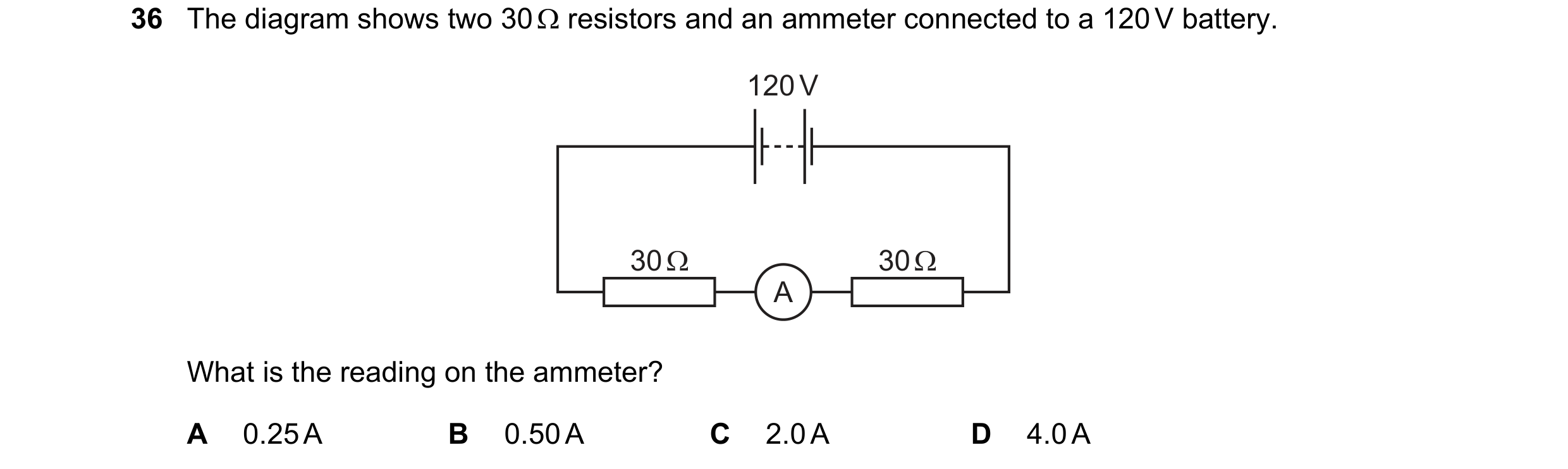
Q70 · The diagram shows two 30 Ω resistors and an ammeter connected to a 120 V battery 0654/11 May/June 2019
36 The diagram shows two 30 Ω resistors and an ammeter connected to a 120 V battery. 120 V 30 Ω 30 Ω A What is the reading on the ammeter? A 0.25 A B 0.50 A C 2.0 A D 4.0 A
1 marks
Answer: C
This question in 0654/11 May/June 2019
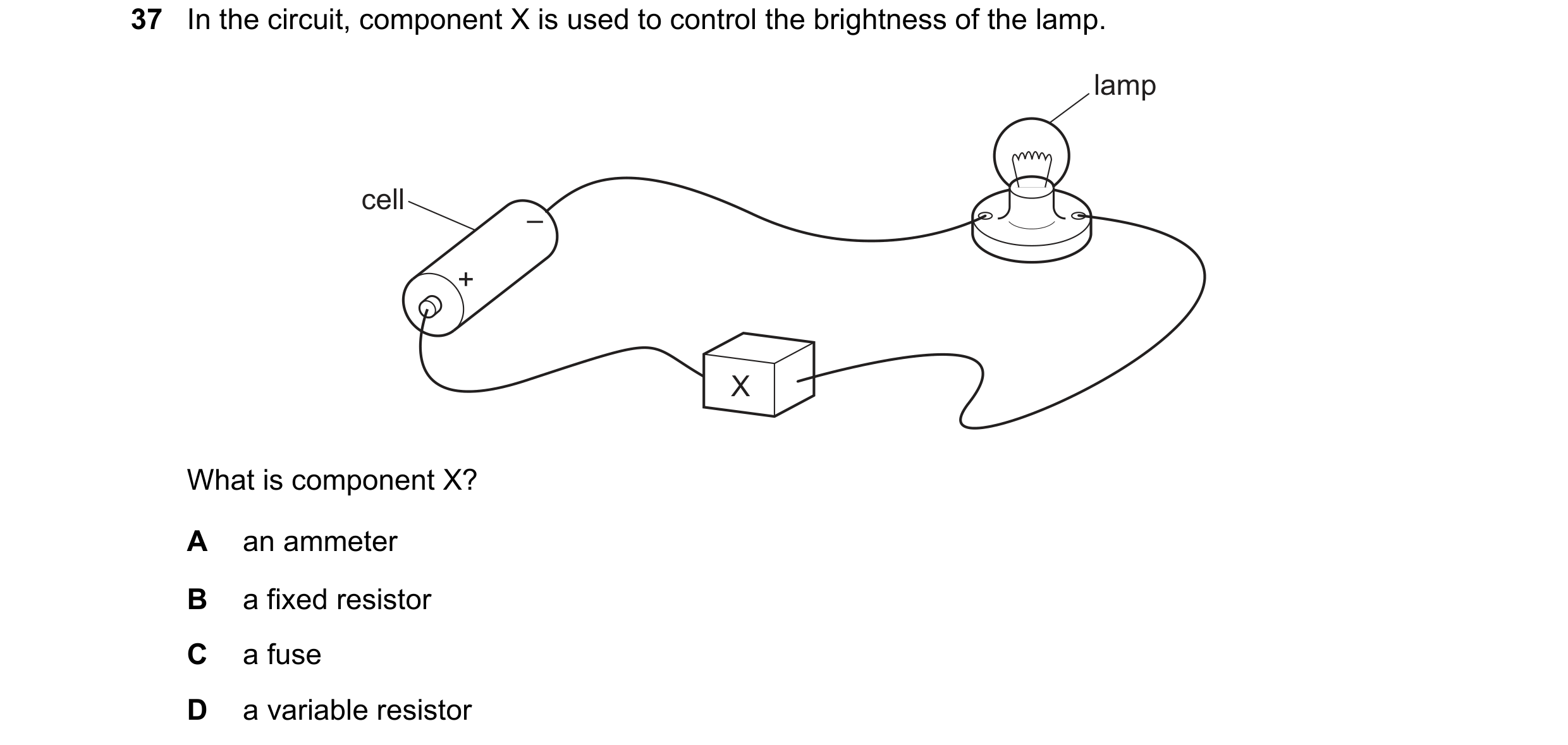
Q71 · In the circuit, component X is used to control the brightness of the lamp 0654/11 May/June 2019
37 In the circuit, component X is used to control the brightness of the lamp. lamp cell – + X What is component X? A an ammeter B a fixed resistor C a fuse D a variable resistor
1 marks
Answer: D
This question in 0654/11 May/June 2019
Q72 · In the circuit, component X is used to control the brightness of the lamp 0654/12 May/June 2019
37 In the circuit, component X is used to control the brightness of the lamp. lamp cell – + X What is component X? A an ammeter B a fixed resistor C a fuse D a variable resistor
1 marks
Answer: D
This question in 0654/12 May/June 2019
Q73 · In the circuit, component X is used to control the brightness of the lamp 0654/13 May/June 2019
37 In the circuit, component X is used to control the brightness of the lamp. lamp cell – + X What is component X? A an ammeter B a fixed resistor C a fuse D a variable resistor
1 marks
Answer: D
This question in 0654/13 May/June 2019
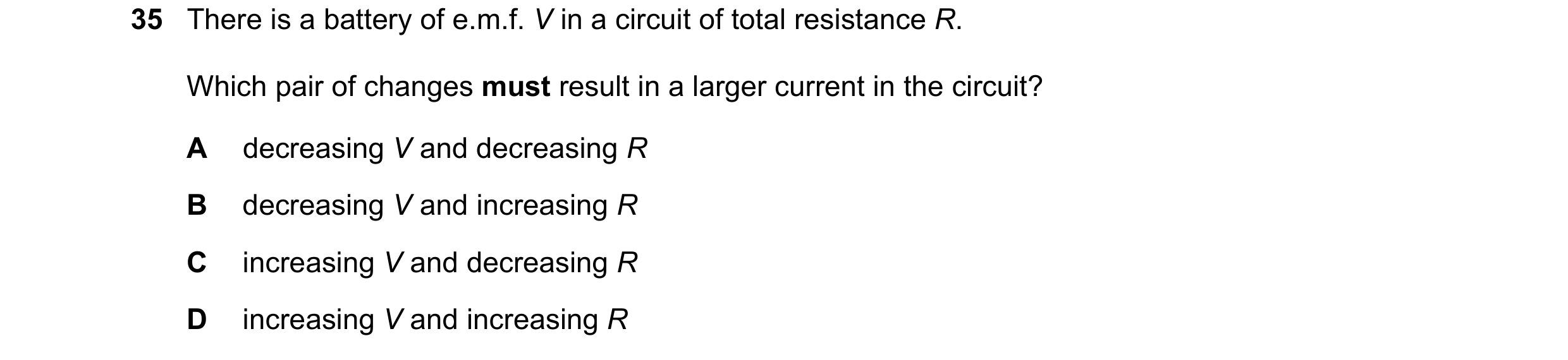
Q74 · There is a battery of e.m.f 0654/11 Oct/Nov 2019
35 There is a battery of e.m.f. V in a circuit of total resistance R. Which pair of changes must result in a larger current in the circuit? A decreasing V and decreasing R B decreasing V and increasing R C increasing V and decreasing R D increasing V and increasing R
1 marks
Answer: C
This question in 0654/11 Oct/Nov 2019
Q75 · Which circuit has the smallest resistance? 0654/11 Oct/Nov 2019
36 Which circuit has the smallest resistance? A B 8.0 Ω 1.0 Ω 6.0 Ω 2.0 Ω C D 8.0 Ω 2.0 Ω 2.0 Ω
1 marks
Answer: D
This question in 0654/11 Oct/Nov 2019
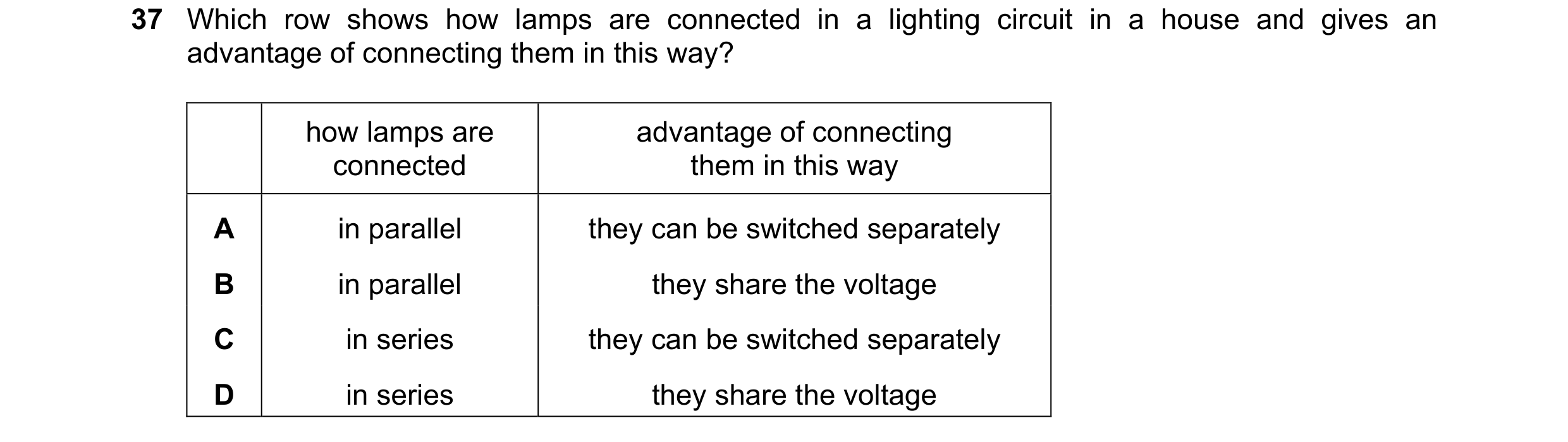
Q76 · Which row shows how lamps are connected in a lighting circuit in a house and gives an… 0654/11 Oct/Nov 2019
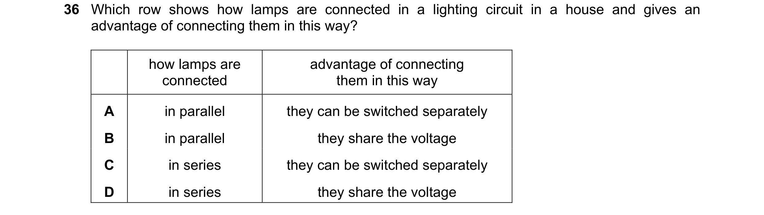
37 Which row shows how lamps are connected in a lighting circuit in a house and gives an advantage of connecting them in this way? how lamps are advantage of connecting connected them in this way A in parallel they can be switched separately B in parallel they share the voltage C in series they can be switched separately D in series they share the voltage
1 marks
Answer: A
This question in 0654/11 Oct/Nov 2019
Q77 · A 1.0 Ω resistor, a 3.0 Ω resistor, and a 6.0 Ω resistor are connected in series 0654/12 Oct/Nov 2019
37 A 1.0 Ω resistor, a 3.0 Ω resistor, and a 6.0 Ω resistor are connected in series. What is the combined resistance of this combination? A 4.0 Ω B 7.0 Ω C 10 Ω D 18 Ω
1 marks
Answer: C
This question in 0654/12 Oct/Nov 2019
Q78 · Which row shows how lamps are connected in a lighting circuit in a house and gives an… 0654/12 Oct/Nov 2019
38 Which row shows how lamps are connected in a lighting circuit in a house and gives an advantage of connecting them in this way? how lamps are advantage of connecting connected them in this way A in parallel they can be switched separately B in parallel they share the voltage C in series they can be switched separately D in series they share the voltage
1 marks
Answer: A
This question in 0654/12 Oct/Nov 2019
Q79 · The diagram shows a circuit containing two switches P and Q, and three lamps 0654/13 Oct/Nov 2019
35 The diagram shows a circuit containing two switches P and Q, and three lamps. One lamp is labelled X. Q X P Which of the switches must be closed so that only lamp X is lit? A neither switch B switch P only C switch Q only D switch P and switch Q
1 marks
Answer: D
This question in 0654/13 Oct/Nov 2019
Q80 · Which row shows how lamps are connected in a lighting circuit in a house and gives an… 0654/13 Oct/Nov 2019
36 Which row shows how lamps are connected in a lighting circuit in a house and gives an advantage of connecting them in this way? how lamps are advantage of connecting connected them in this way A in parallel they can be switched separately B in parallel they share the voltage C in series they can be switched separately D in series they share the voltage
1 marks
Answer: A
This question in 0654/13 Oct/Nov 2019
Q81 · The diagram shows a circuit containing two resistors of resistance R and 2R, and two… 0654/11 May/June 2020
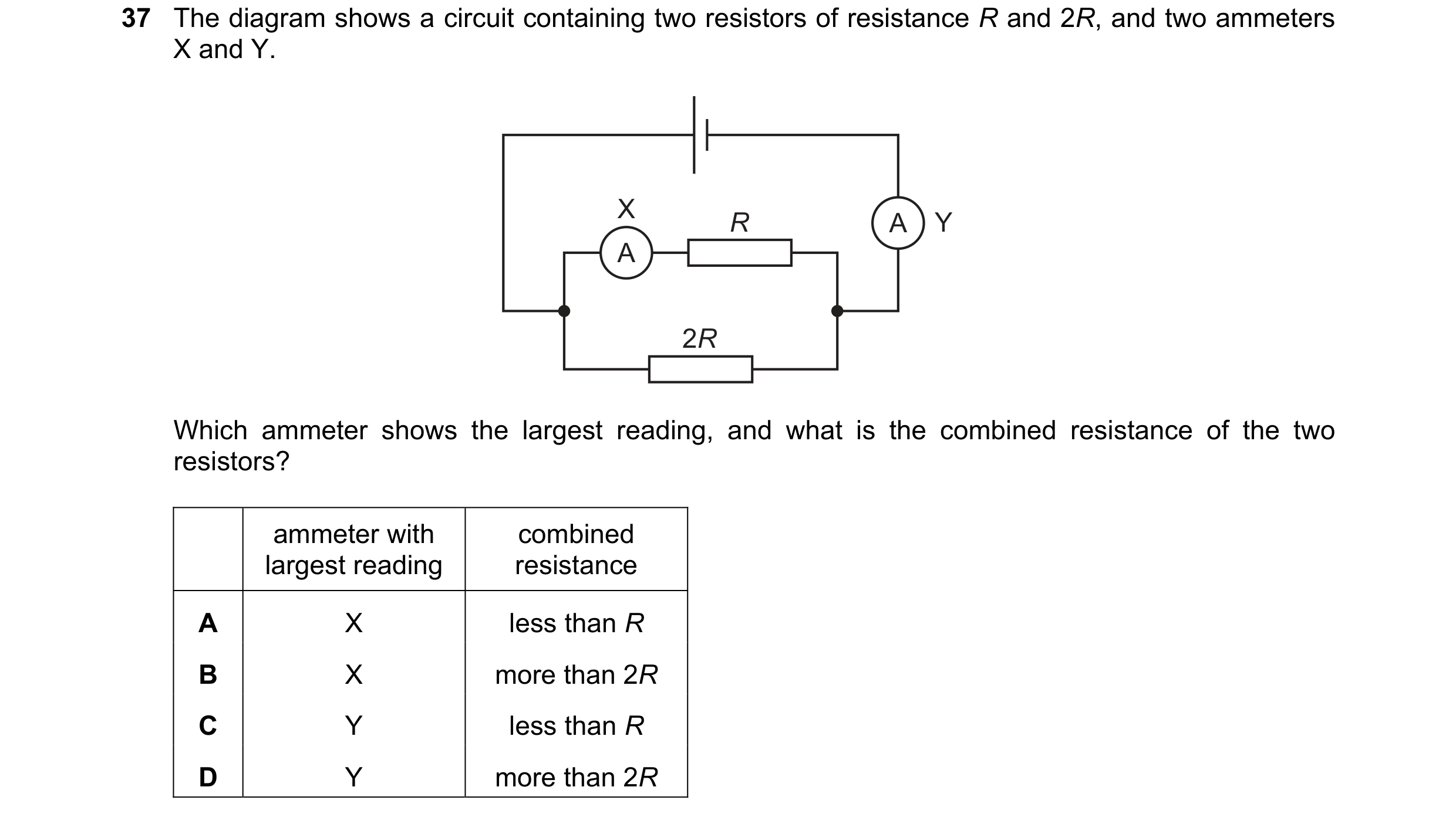
37 The diagram shows a circuit containing two resistors of resistance R and 2R, and two ammeters X and Y. X R A Y A 2R Which ammeter shows the largest reading, and what is the combined resistance of the two resistors? ammeter with combined largest reading resistance A X less than R B X more than 2R C Y less than R D Y more than 2R
1 marks
Answer: C
This question in 0654/11 May/June 2020
Q82 · Two resistors of resistance 1.0 Ω and 2.0 Ω are connected in parallel 0654/13 May/June 2020
36 Two resistors of resistance 1.0 Ω and 2.0 Ω are connected in parallel. What is the combined resistance of this arrangement of resistors? A less than 1.0 Ω B exactly 1.5 Ω C between 2.0 Ω and 3.0 Ω D exactly 3.0 Ω
1 marks
Answer: A
This question in 0654/13 May/June 2020
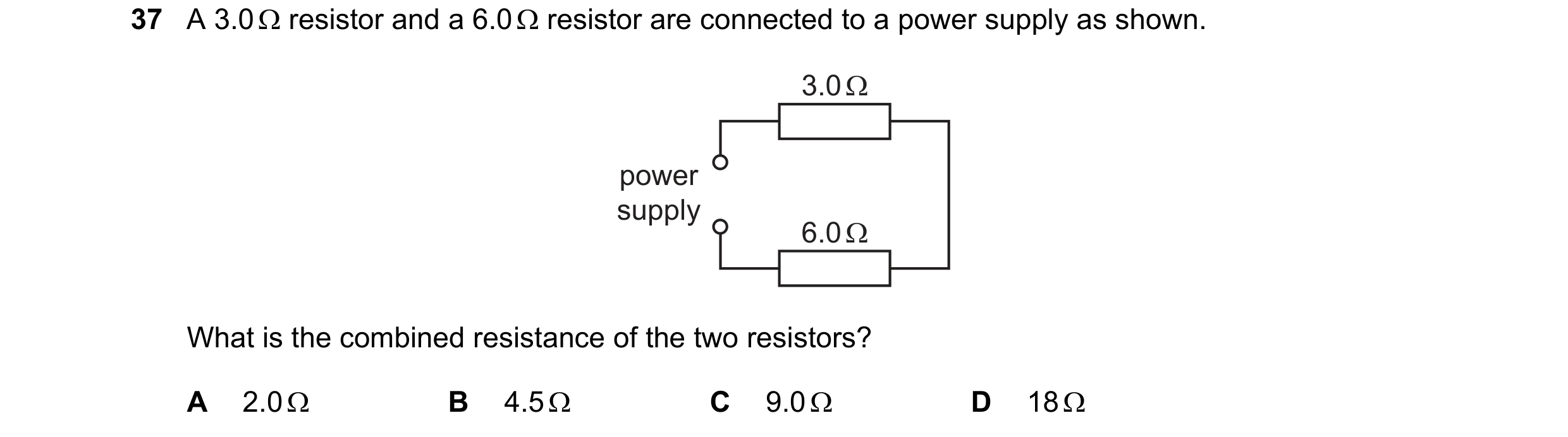
Q83 · A 3.0 resistor and a 6.0 resistor are connected to a power supply as shown 0654/11 Oct/Nov 2020
37 A 3.0 resistor and a 6.0 resistor are connected to a power supply as shown. 3.0 Ω power supply 6.0 Ω What is the combined resistance of the two resistors? A 2.0 B 4.5 C 9.0 D 18
1 marks
Answer: C
This question in 0654/11 Oct/Nov 2020
Q84 · The series circuit shown includes a single component hidden in a box 0654/11 Oct/Nov 2020
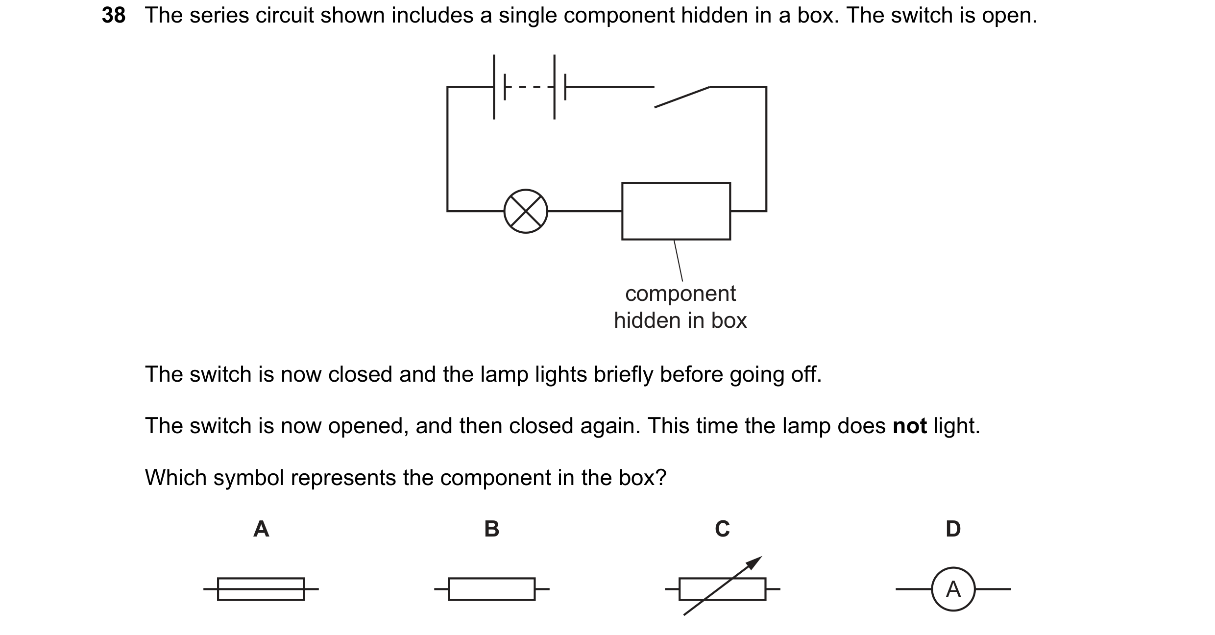
38 The series circuit shown includes a single component hidden in a box. The switch is open. component hidden in box The switch is now closed and the lamp lights briefly before going off. The switch is now opened, and then closed again. This time the lamp does not light. Which symbol represents the component in the box? A B C D A
1 marks
Answer: A
This question in 0654/11 Oct/Nov 2020
Q85 · A 3.0 resistor and a 6.0 resistor are connected to a power supply as shown 0654/12 Oct/Nov 2020
36 A 3.0 resistor and a 6.0 resistor are connected to a power supply as shown. 3.0 Ω power supply 6.0 Ω What is the combined resistance of the two resistors? A 2.0 B 4.5 C 9.0 D 18
1 marks
Answer: C
This question in 0654/12 Oct/Nov 2020
Q86 · The diagram shows a circuit containing an ammeter and a variable resistor 0654/13 Oct/Nov 2020
36 The diagram shows a circuit containing an ammeter and a variable resistor. A The resistance of the variable resistor is decreased. What happens to the reading on the ammeter and what happens to the direction of the current in the ammeter? reading on direction of current ammeter in ammeter A decreases changes B decreases stays the same C increases changes D increases stays the same
1 marks
Answer: D
This question in 0654/13 Oct/Nov 2020
Q87 · A 3.0 resistor and a 6.0 resistor are connected to a power supply as shown 0654/13 Oct/Nov 2020
37 A 3.0 resistor and a 6.0 resistor are connected to a power supply as shown. 3.0 Ω power supply 6.0 Ω What is the combined resistance of the two resistors? A 2.0 B 4.5 C 9.0 D 18
1 marks
Answer: C
This question in 0654/13 Oct/Nov 2020
Q88 · Which circuit shows an ammeter that measures the current in the lamp and a voltmeter that… 0654/11 May/June 2021
36 Which circuit shows an ammeter that measures the current in the lamp and a voltmeter that measures the potential difference (p.d.) across the lamp? A B V V A A C D A A V V
1 marks
Answer: C
This question in 0654/11 May/June 2021
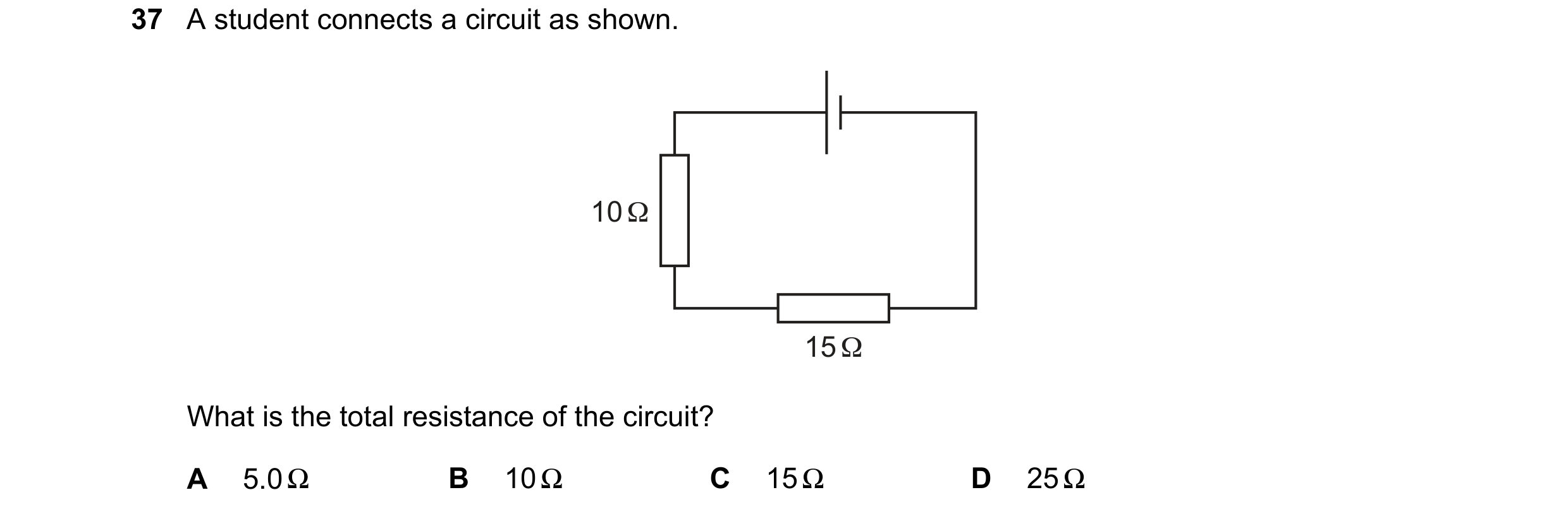
Q89 · A student connects a circuit as shown 0654/11 May/June 2021
37 A student connects a circuit as shown. 10 Ω 15 Ω What is the total resistance of the circuit? A 5.0 Ω B 10 Ω C 15 Ω D 25 Ω
1 marks
Answer: D
This question in 0654/11 May/June 2021
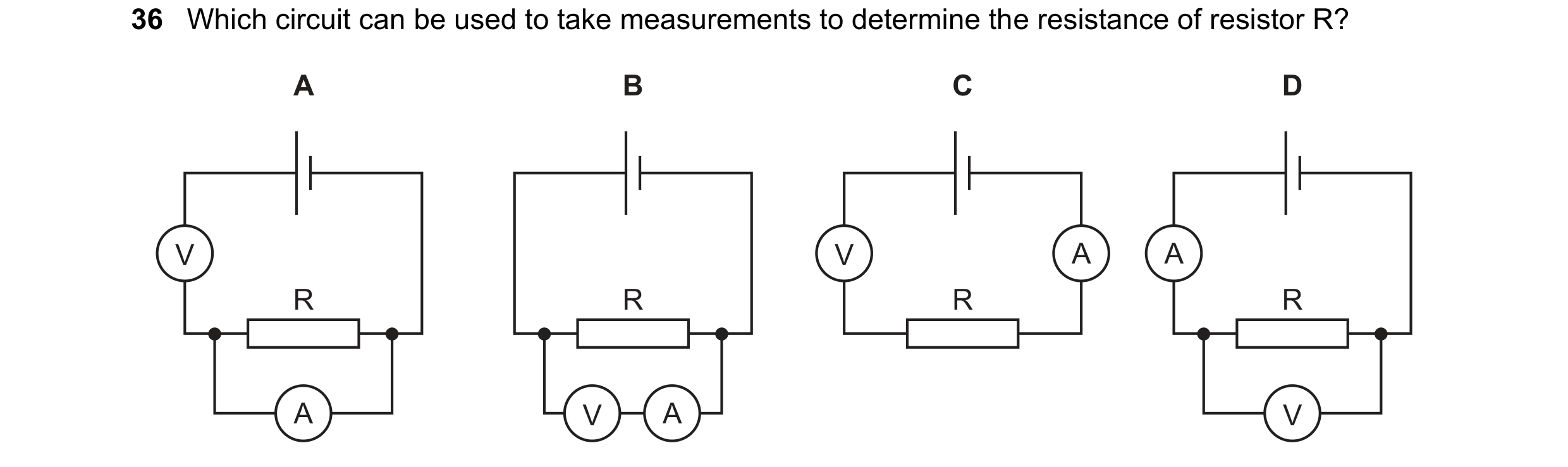
Q90 · Which circuit can be used to take measurements to determine the resistance of resistor R? 0654/12 May/June 2021
36 Which circuit can be used to take measurements to determine the resistance of resistor R? A B C D V V A A R R R R A V A V
1 marks
Answer: D
This question in 0654/12 May/June 2021
Q91 · In which circuit can the brightness of the lamp be varied continuously? 0654/12 May/June 2021
37 In which circuit can the brightness of the lamp be varied continuously? A B C D
1 marks
Answer: A
This question in 0654/12 May/June 2021
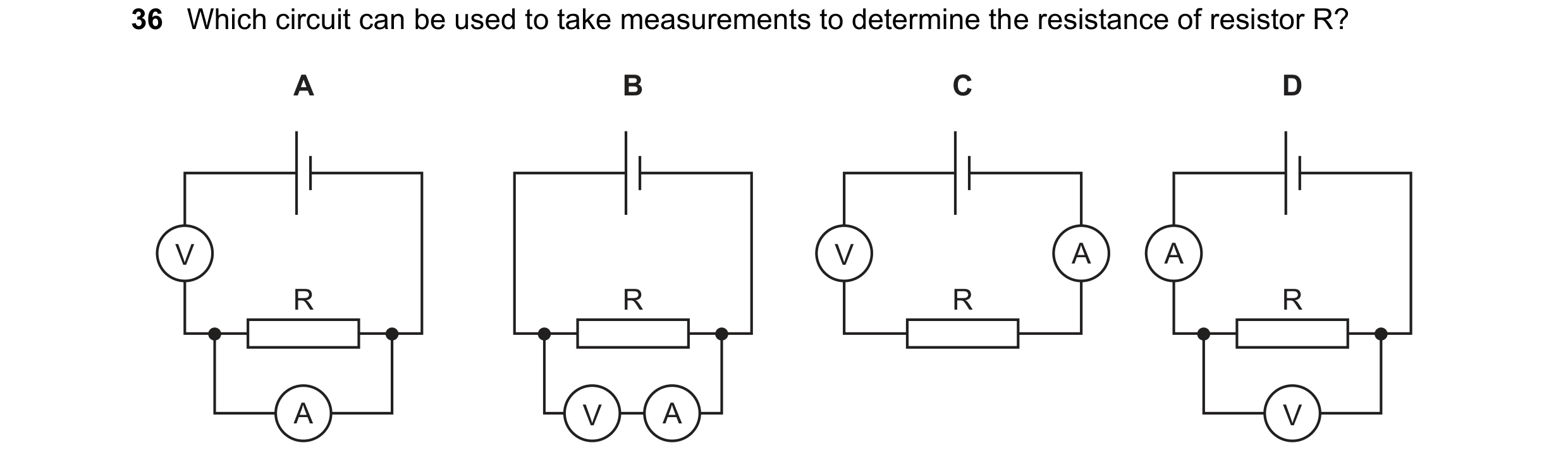
Q92 · Which circuit can be used to take measurements to determine the resistance of resistor R? 0654/13 May/June 2021
36 Which circuit can be used to take measurements to determine the resistance of resistor R? A B C D V V A A R R R R A V A V
1 marks
Answer: D
This question in 0654/13 May/June 2021
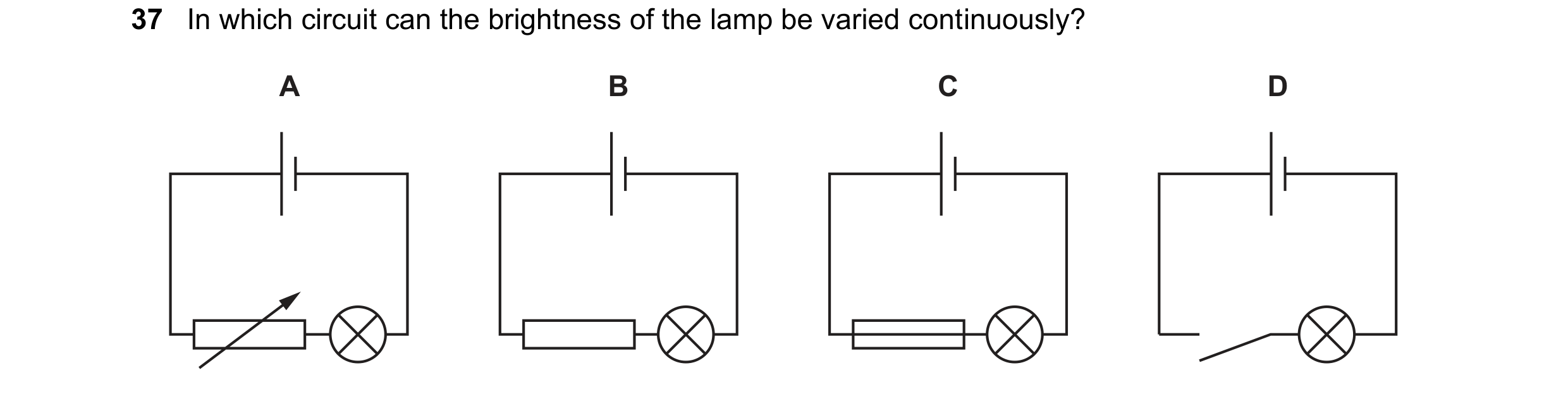
Q93 · In which circuit can the brightness of the lamp be varied continuously? 0654/13 May/June 2021
37 In which circuit can the brightness of the lamp be varied continuously? A B C D
1 marks
Answer: A
This question in 0654/13 May/June 2021
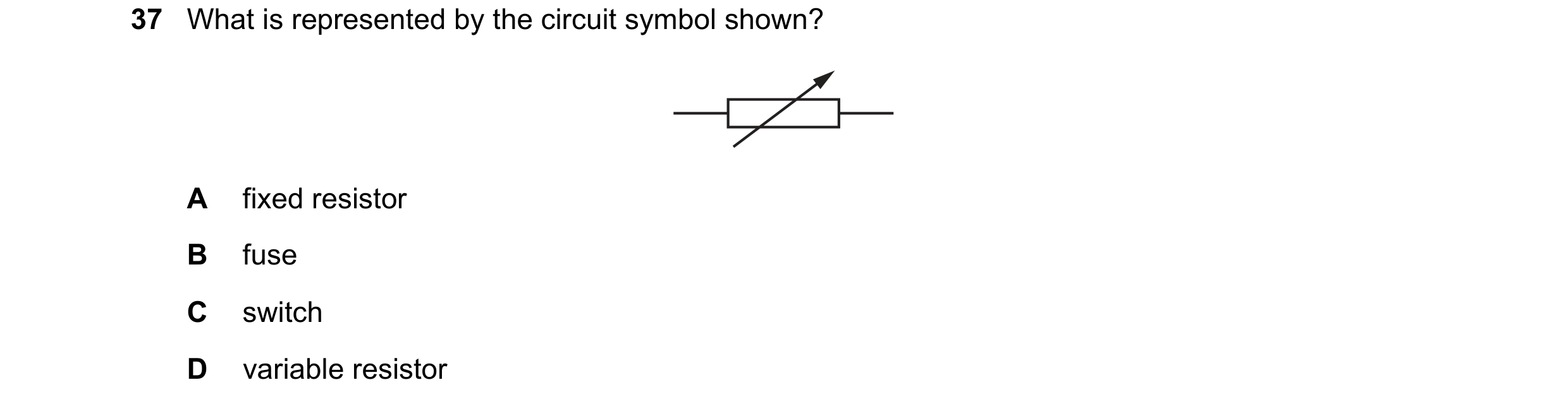
Q94 · What is represented by the circuit symbol shown? 0654/11 Oct/Nov 2021
37 What is represented by the circuit symbol shown? A fixed resistor B fuse C switch D variable resistor
1 marks
Answer: D
This question in 0654/11 Oct/Nov 2021
Q95 · Three resistors are connected in series with a battery, as shown 0654/11 Oct/Nov 2021
38 Three resistors are connected in series with a battery, as shown. P Q The current at point P is 6.0 A. What is the current at point Q? A 0 A B 2.0 A C 3.0 A D 6.0 A
1 marks
Answer: D
This question in 0654/11 Oct/Nov 2021
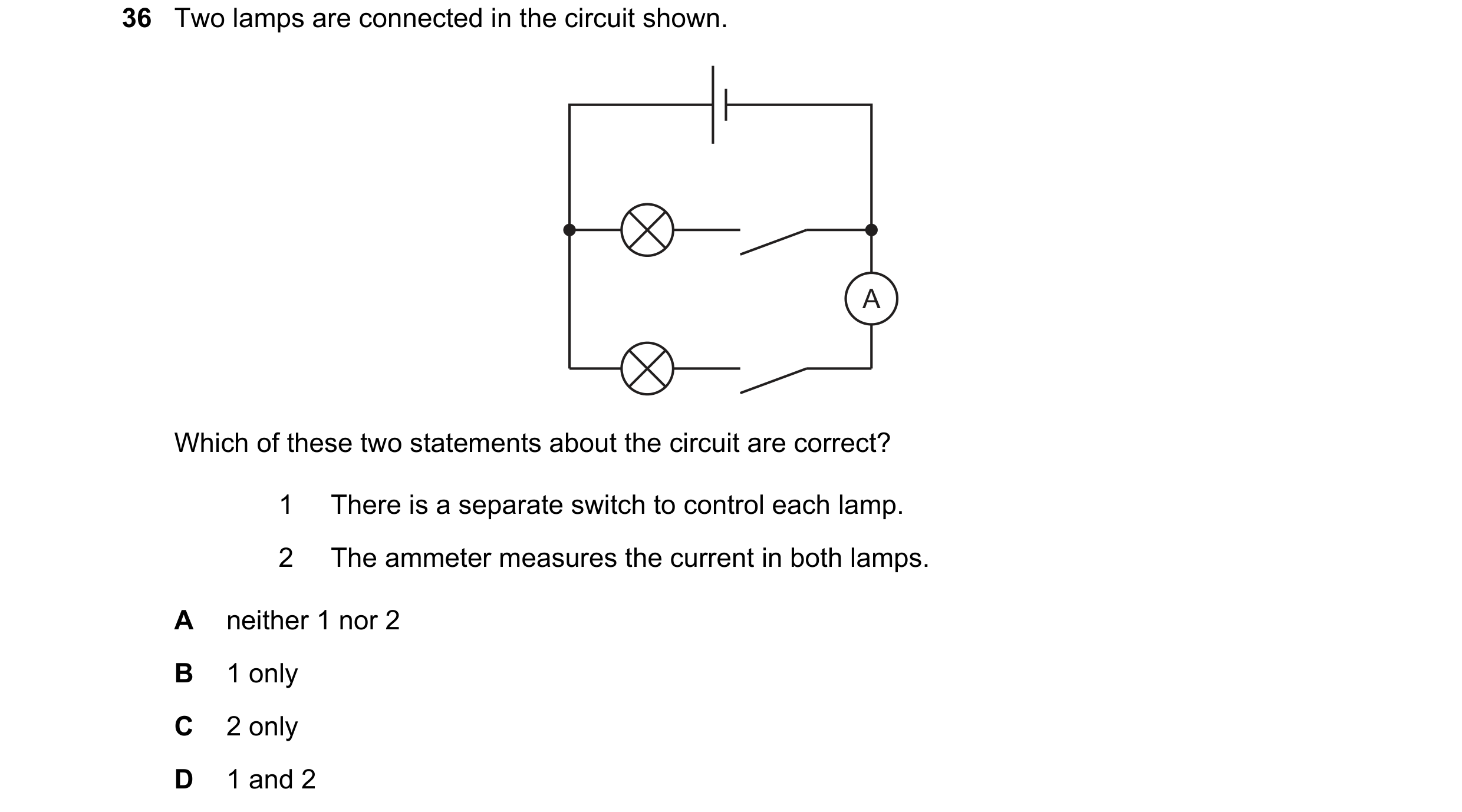
Q96 · Two lamps are connected in the circuit shown 0654/12 Oct/Nov 2021
36 Two lamps are connected in the circuit shown. A Which of these two statements about the circuit are correct? 1 There is a separate switch to control each lamp. 2 The ammeter measures the current in both lamps. A neither 1 nor 2 B 1 only C 2 only D 1 and 2
1 marks
Answer: B
This question in 0654/12 Oct/Nov 2021
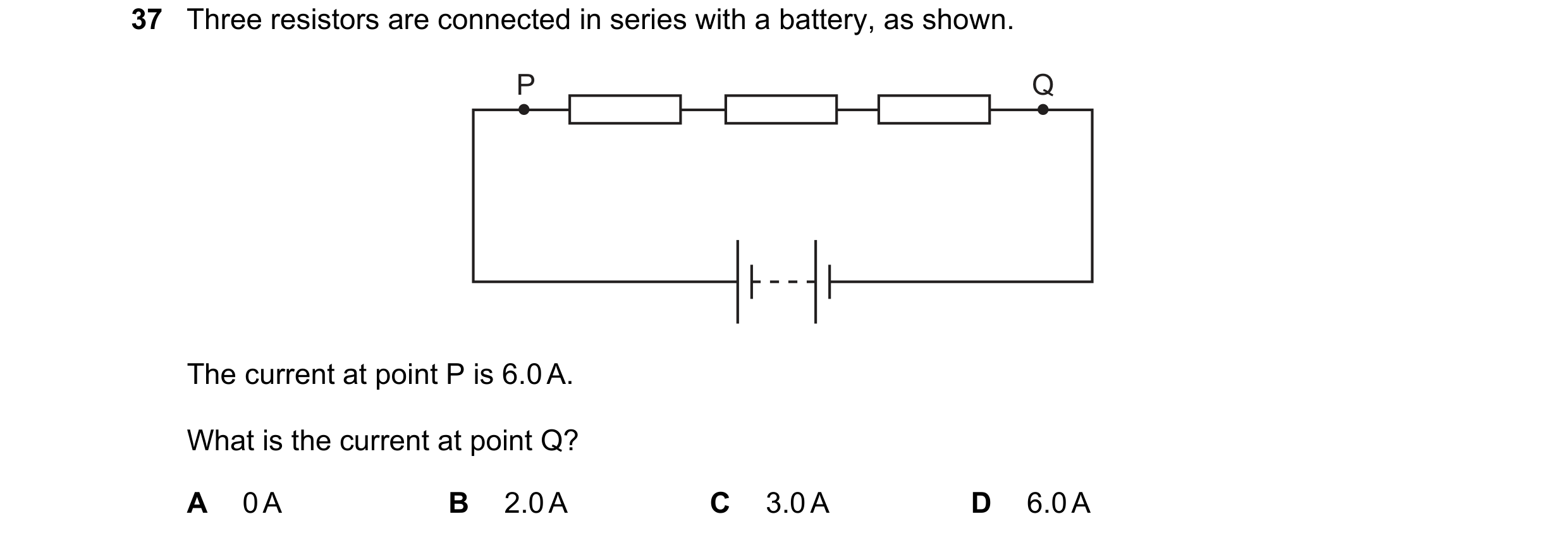
Q97 · Three resistors are connected in series with a battery, as shown 0654/12 Oct/Nov 2021
37 Three resistors are connected in series with a battery, as shown. P Q The current at point P is 6.0 A. What is the current at point Q? A 0 A B 2.0 A C 3.0 A D 6.0 A
1 marks
Answer: D
This question in 0654/12 Oct/Nov 2021
Q98 · Three resistors are connected in series with a battery, as shown 0654/13 Oct/Nov 2021
37 Three resistors are connected in series with a battery, as shown. P Q The current at point P is 6.0 A. What is the current at point Q? A 0 A B 2.0 A C 3.0 A D 6.0 A
1 marks
Answer: D
This question in 0654/13 Oct/Nov 2021
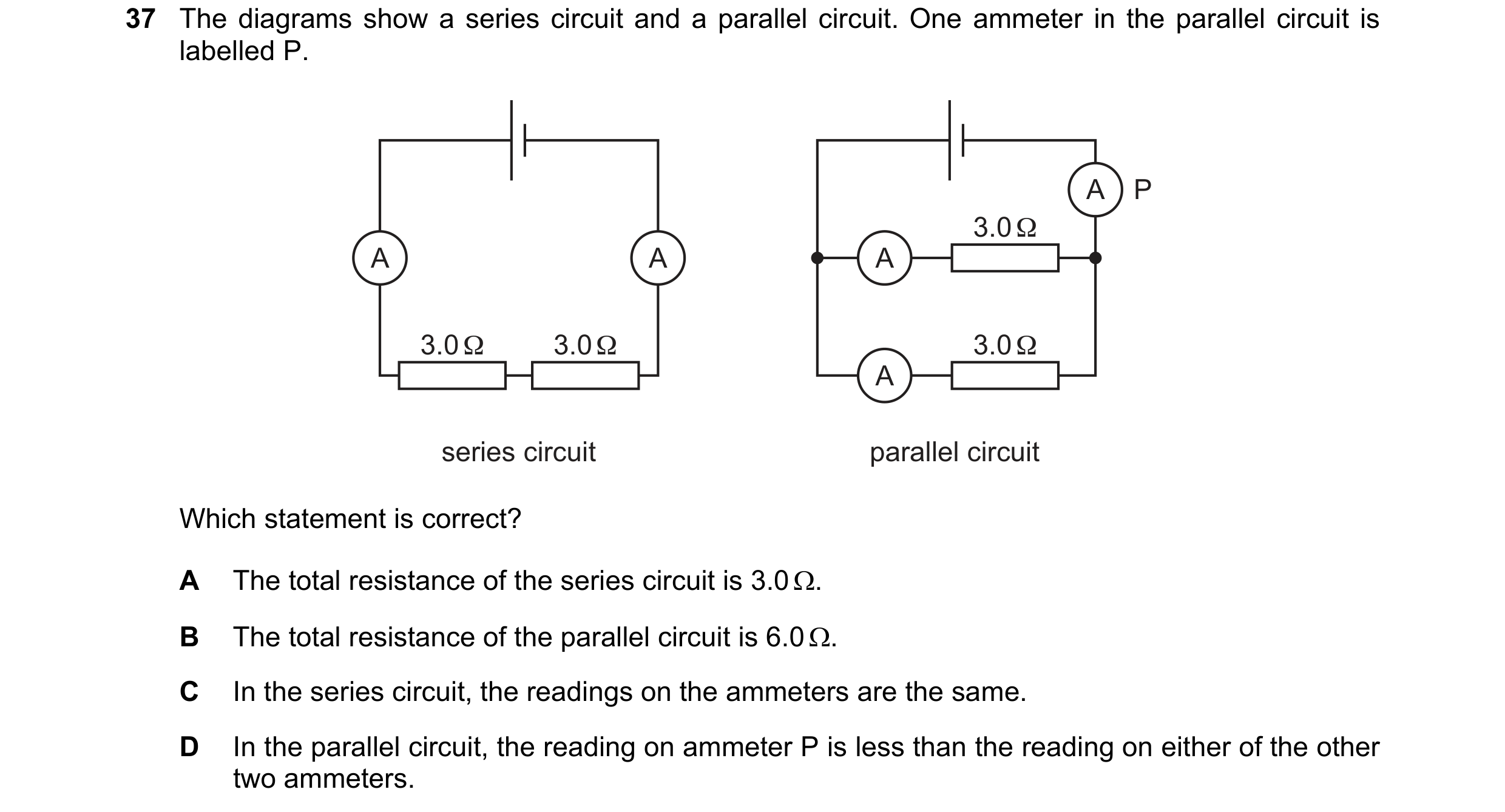
Q99 · The diagrams show a series circuit and a parallel circuit 0654/12 Feb/March 2022
37 The diagrams show a series circuit and a parallel circuit. One ammeter in the parallel circuit is labelled P. A P 3.0 Ω A A A 3.0 Ω 3.0 Ω 3.0 Ω A series circuit parallel circuit Which statement is correct? A The total resistance of the series circuit is 3.0 . B The total resistance of the parallel circuit is 6.0 . C In the series circuit, the readings on the ammeters are the same. D In the parallel circuit, the reading on ammeter P is less than the reading on either of the other two ammeters.
1 marks
Answer: C
This question in 0654/12 Feb/March 2022
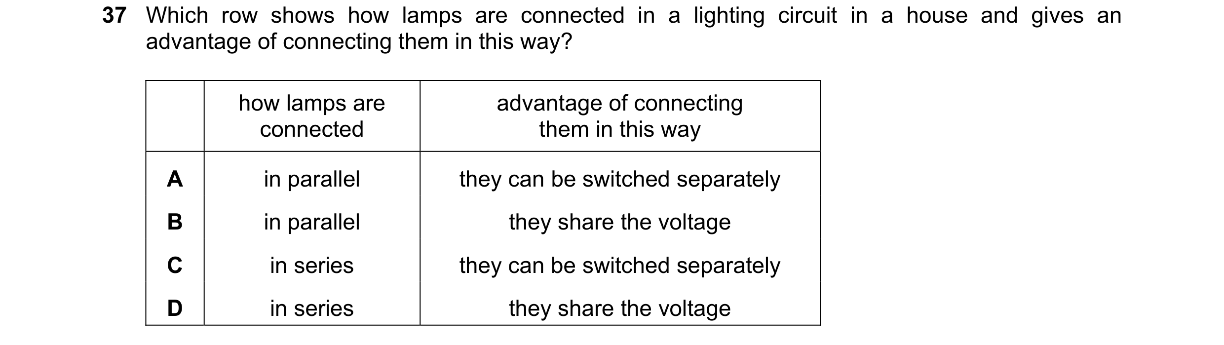
Q100 · Which row shows how lamps are connected in a lighting circuit in a house and gives an… 0654/11 May/June 2022
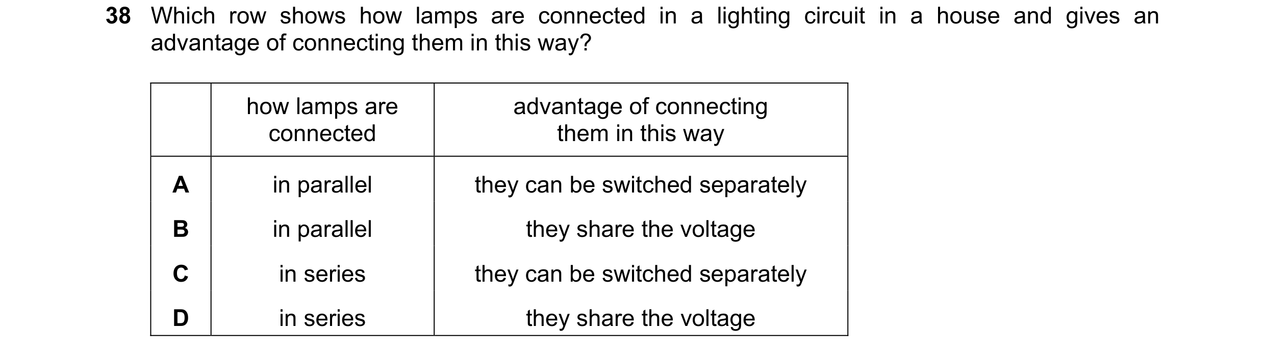
37 Which row shows how lamps are connected in a lighting circuit in a house and gives an advantage of connecting them in this way? how lamps are advantage of connecting connected them in this way A in parallel they can be switched separately B in parallel they share the voltage C in series they can be switched separately D in series they share the voltage
1 marks
Answer: A
This question in 0654/11 May/June 2022
Q101 · A student connects a circuit to determine the resistance of a resistor 0654/12 May/June 2022
37 A student connects a circuit to determine the resistance of a resistor. Which circuit enables the current in the resistor and the potential difference (p.d.) across it to be measured? A B A V A V C D V A V A
1 marks
Answer: A
This question in 0654/12 May/June 2022
Q102 · Which row shows how lamps are connected in a lighting circuit in a house and gives an… 0654/12 May/June 2022
38 Which row shows how lamps are connected in a lighting circuit in a house and gives an advantage of connecting them in this way? how lamps are advantage of connecting connected them in this way A in parallel they can be switched separately B in parallel they share the voltage C in series they can be switched separately D in series they share the voltage
1 marks
Answer: A
This question in 0654/12 May/June 2022
Q103 · A student connects a circuit to determine the resistance of a resistor 0654/13 May/June 2022
37 A student connects a circuit to determine the resistance of a resistor. Which circuit enables the current in the resistor and the potential difference (p.d.) across it to be measured? A B A V A V C D V A V A
1 marks
Answer: A
This question in 0654/13 May/June 2022
Q104 · Which row shows how lamps are connected in a lighting circuit in a house and gives an… 0654/13 May/June 2022
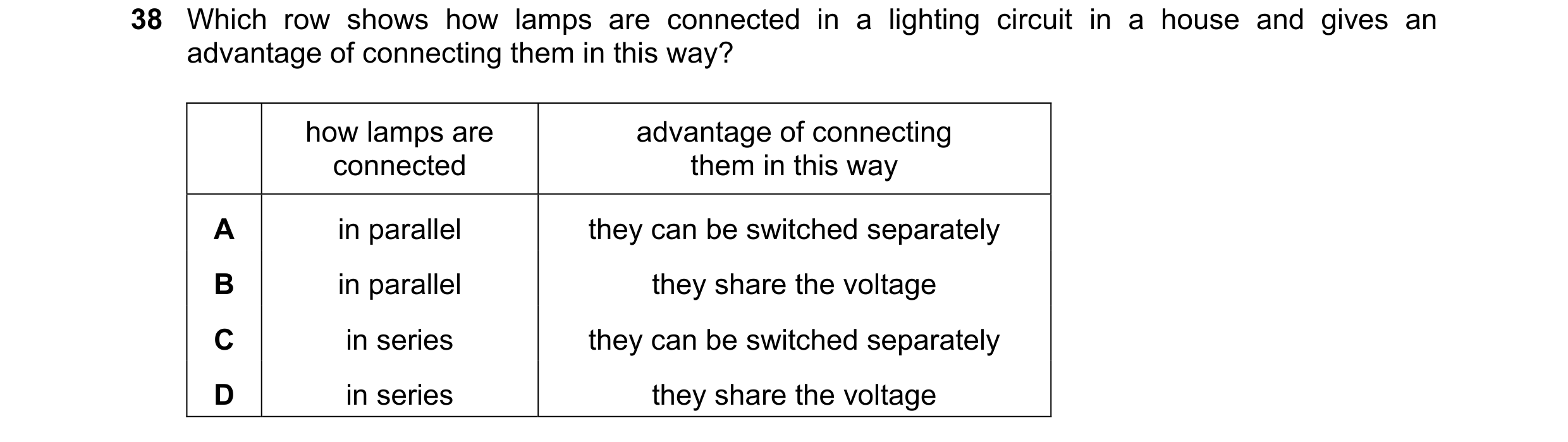
38 Which row shows how lamps are connected in a lighting circuit in a house and gives an advantage of connecting them in this way? how lamps are advantage of connecting connected them in this way A in parallel they can be switched separately B in parallel they share the voltage C in series they can be switched separately D in series they share the voltage
1 marks
Answer: A
This question in 0654/13 May/June 2022
Q105 · The diagram shows a circuit containing an electric heater, a motor and a fuse 0654/13 May/June 2022
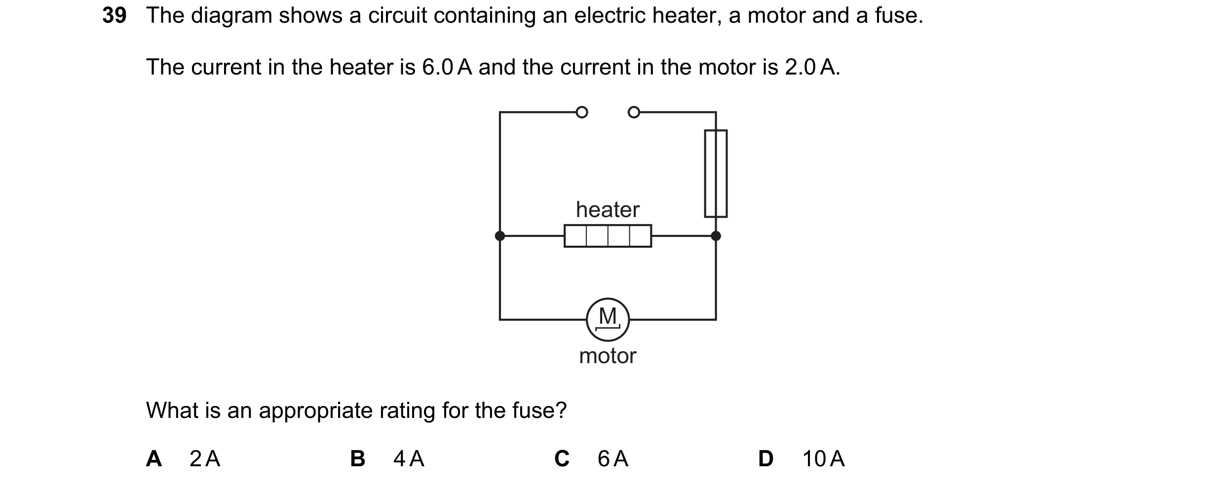
39 The diagram shows a circuit containing an electric heater, a motor and a fuse. The current in the heater is 6.0 A and the current in the motor is 2.0 A. heater M motor What is an appropriate rating for the fuse? A 2 A B 4 A C 6 A D 10 A
1 marks
Answer: D
This question in 0654/13 May/June 2022
Q106 · In which circuit is it possible to change the brightness of one lamp without changing the… 0654/11 Oct/Nov 2022
37 In which circuit is it possible to change the brightness of one lamp without changing the brightness of the other lamp? A B C D
1 marks
Answer: B
This question in 0654/11 Oct/Nov 2022
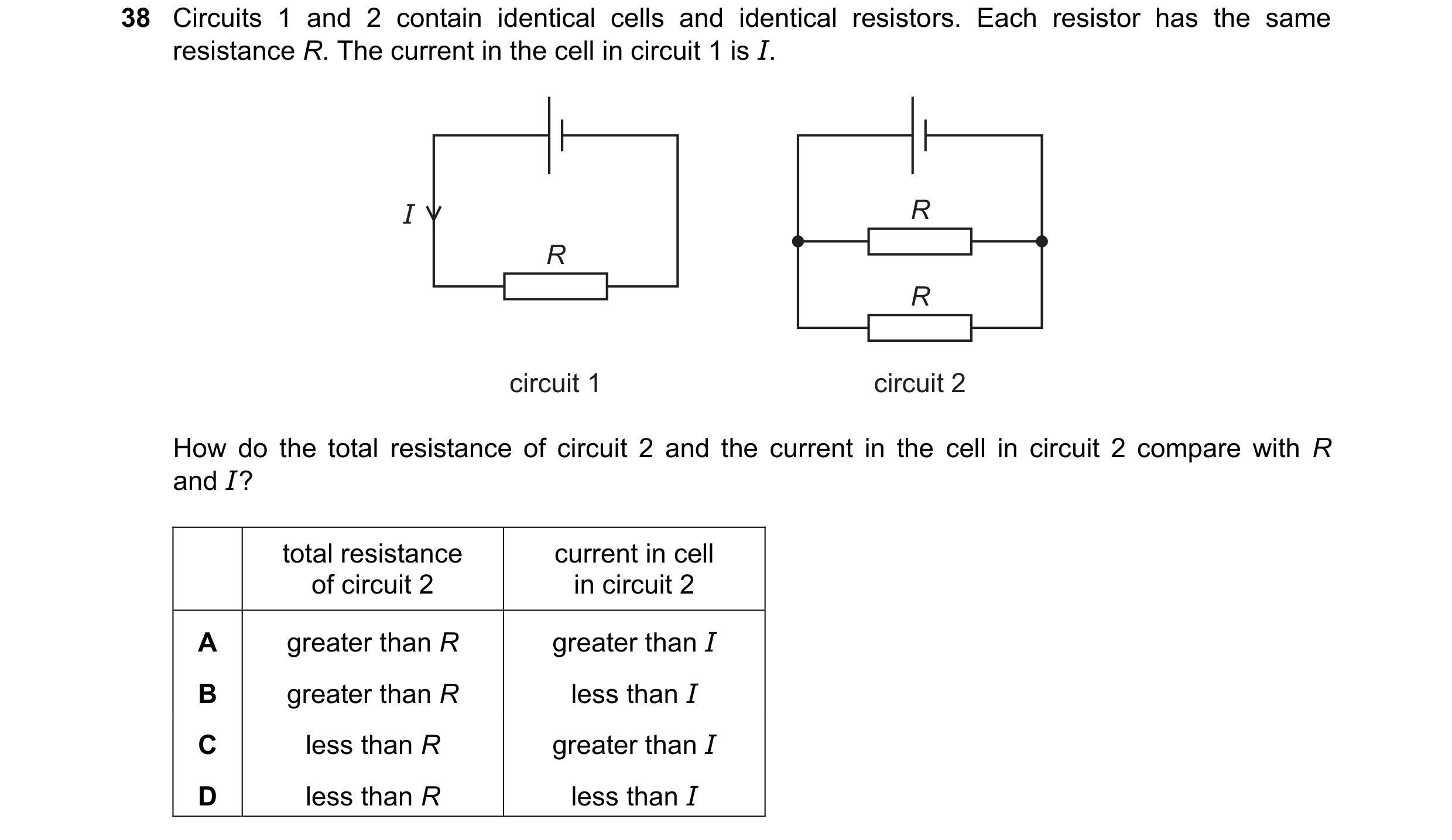
Q107 · Circuits 1 and 2 contain identical cells and identical resistors 0654/11 Oct/Nov 2022
38 Circuits 1 and 2 contain identical cells and identical resistors. Each resistor has the same resistance R. The current in the cell in circuit 1 is I. I R R R circuit 1 circuit 2 How do the total resistance of circuit 2 and the current in the cell in circuit 2 compare with R and I ? total resistance current in cell of circuit 2 in circuit 2 A greater than R greater than I B greater than R less than I C less than R greater than I D less than R less than I
1 marks
Answer: C
This question in 0654/11 Oct/Nov 2022
Q108 · X, Y and Z are combinations of identical resistors 0654/12 Oct/Nov 2022
38 X, Y and Z are combinations of identical resistors. X Y Z The combinations are put in order of decreasing resistance (largest resistance to smallest resistance). What is this order? A Y X Z B Y Z X C Z X Y D Z Y X
1 marks
Answer: B
This question in 0654/12 Oct/Nov 2022
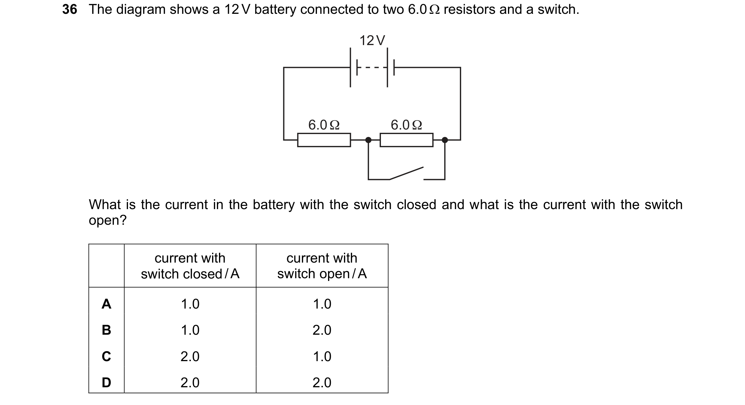
Q109 · The diagram shows a 12 V battery connected to two 6.0 resistors and a switch 0654/13 Oct/Nov 2022
36 The diagram shows a 12 V battery connected to two 6.0 resistors and a switch. 12 V 6.0 Ω 6.0 Ω What is the current in the battery with the switch closed and what is the current with the switch open? current with current with switch closed / A switch open / A A 1.0 1.0 B 1.0 2.0 C 2.0 1.0 D 2.0 2.0
1 marks
Answer: C
This question in 0654/13 Oct/Nov 2022
Q110 · The diagrams show four circuits each containing a motor and two switches 0654/13 Oct/Nov 2022
37 The diagrams show four circuits each containing a motor and two switches. The switches are all open. In one of the circuits, closing one of the switches on its own starts the motor turning, and closing the other switch on its own also starts the motor turning. Which circuit is this? A B M M motor motor C D M M motor motor
1 marks
Answer: A
This question in 0654/13 Oct/Nov 2022
Q111 · What is an advantage of connecting lamps in parallel in a circuit, rather than in series? 0654/13 Oct/Nov 2022
38 What is an advantage of connecting lamps in parallel in a circuit, rather than in series? A The lamps do not use as much energy. B The lamps last longer before failing. C The potential difference (p.d.) across each lamp is smaller. D When one lamp fails, all the others remain lit.
1 marks
Answer: D
This question in 0654/13 Oct/Nov 2022
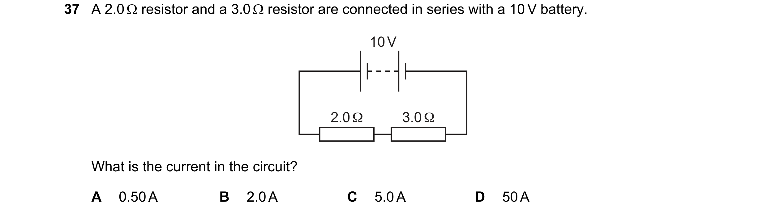
Q112 · A 2.0 resistor and a 3.0 resistor are connected in series with a 10 V battery 0654/12 Feb/March 2023
37 A 2.0 resistor and a 3.0 resistor are connected in series with a 10 V battery. 10 V 2.0 Ω 3.0 Ω What is the current in the circuit? A 0.50 A B 2.0 A C 5.0 A D 50 A
1 marks
Answer: B
This question in 0654/12 Feb/March 2023
Q113 · The diagrams show four identical resistors connected together in different arrangements 0654/12 May/June 2023
37 The diagrams show four identical resistors connected together in different arrangements. Which arrangement has the smallest combined resistance? A B C D
1 marks
Answer: D
This question in 0654/12 May/June 2023
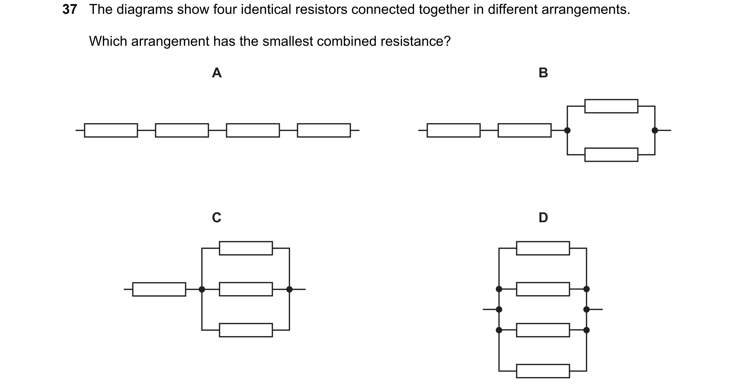
Q114 · The diagrams show four identical resistors connected together in different arrangements 0654/13 May/June 2023
37 The diagrams show four identical resistors connected together in different arrangements. Which arrangement has the smallest combined resistance? A B C D
1 marks
Answer: D
This question in 0654/13 May/June 2023
Q115 · A battery is connected in a circuit to a 3.0 resistor, a 6.0 resistor and two… 0654/11 Oct/Nov 2023
38 A battery is connected in a circuit to a 3.0 resistor, a 6.0 resistor and two ammeters P and Q. A Q P 3.0 Ω A 6.0 Ω What is the combined resistance of the two resistors and which ammeter has the greater reading? combined ammeter with resistance / greater reading A less than 3.0 P B less than 3.0 Q C 9.0 P D 9.0 Q
1 marks
Answer: B
This question in 0654/11 Oct/Nov 2023
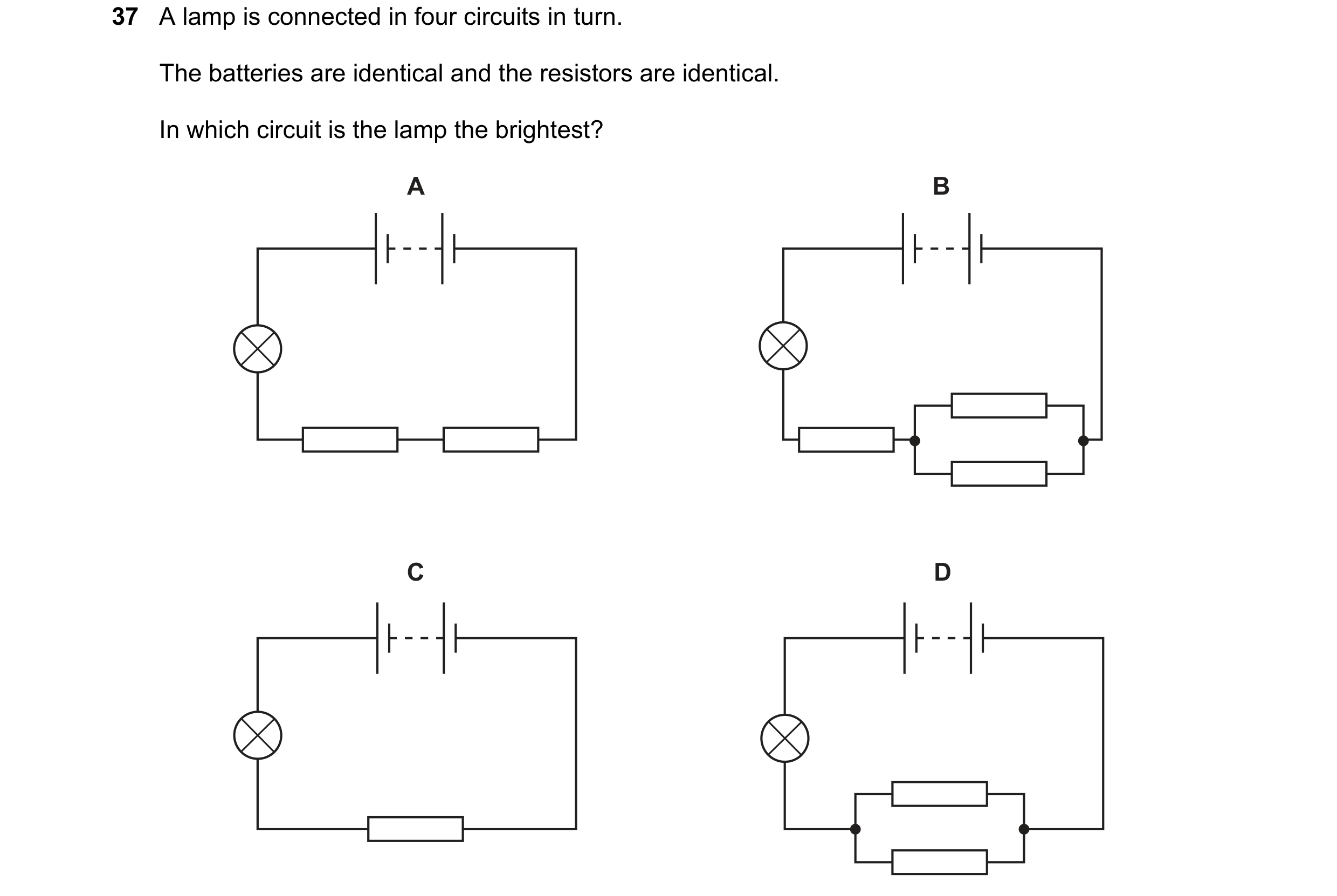
Q116 · A lamp is connected in four circuits in turn 0654/12 Oct/Nov 2023
37 A lamp is connected in four circuits in turn. The batteries are identical and the resistors are identical. In which circuit is the lamp the brightest? A B C D
1 marks
Answer: D
This question in 0654/12 Oct/Nov 2023
Q117 · Two lamps can be connected to a battery either in series or in parallel 0654/13 Oct/Nov 2023
37 Two lamps can be connected to a battery either in series or in parallel. Which statement is not a benefit of connecting two lamps in parallel rather than in series? A If one lamp breaks, the other lamp stays lit. B The lamps are brighter. C The lamps can be controlled individually using switches. D There is a smaller current in the battery.
1 marks
Answer: D
This question in 0654/13 Oct/Nov 2023
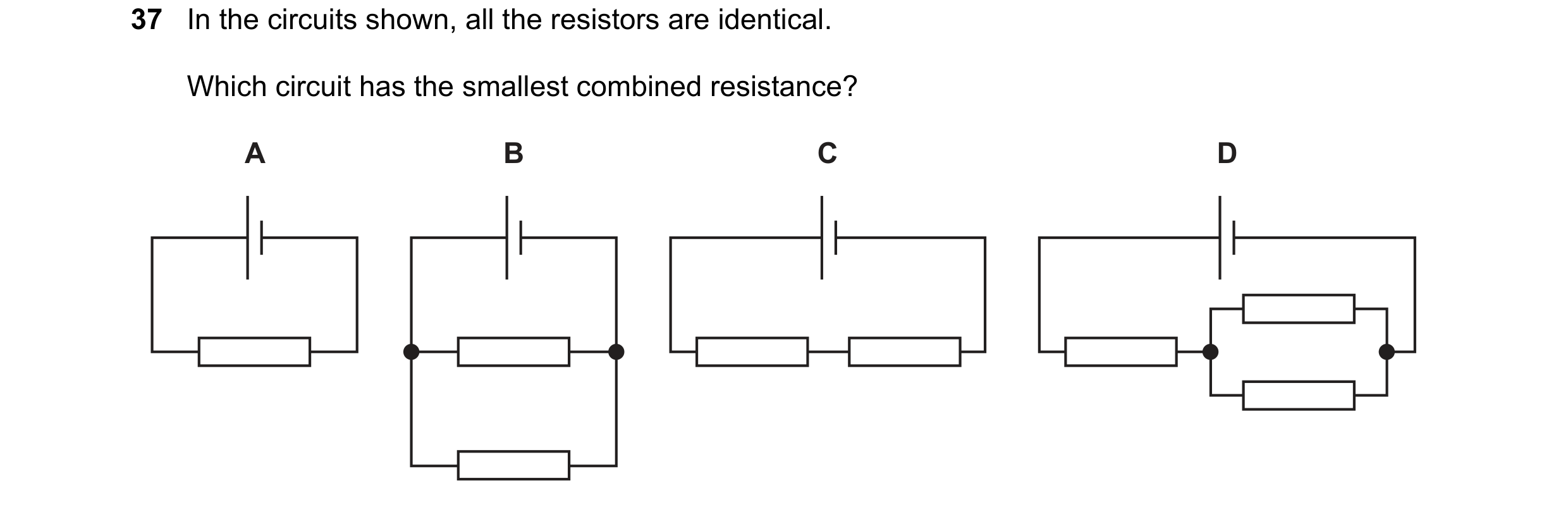
Q118 · In the circuits shown, all the resistors are identical 0654/11 May/June 2024
37 In the circuits shown, all the resistors are identical. Which circuit has the smallest combined resistance? A B C D
1 marks
Answer: B
This question in 0654/11 May/June 2024
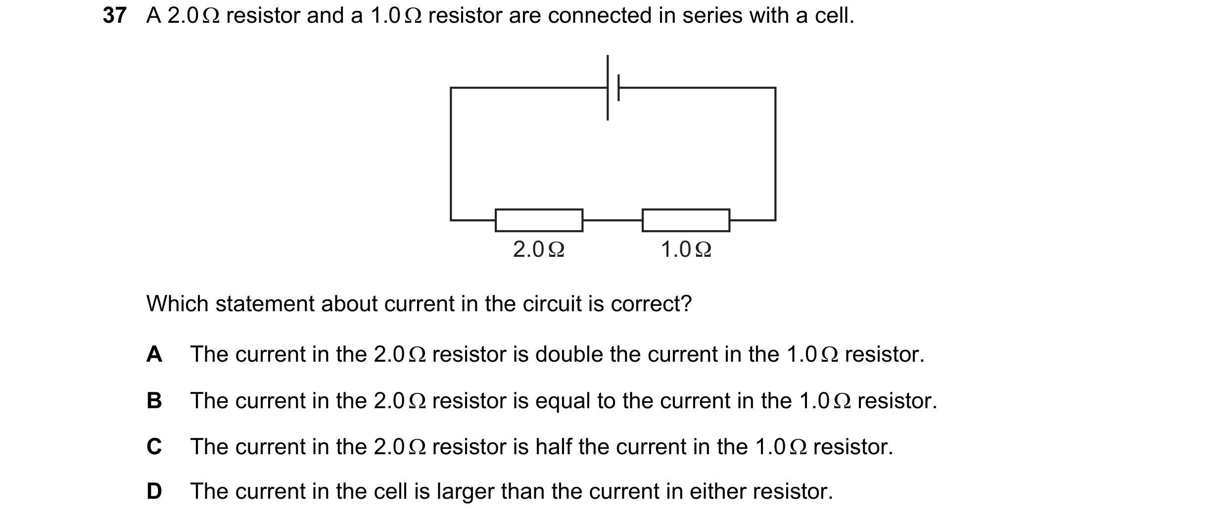
Q119 · A 2.0 resistor and a 1.0 resistor are connected in series with a cell 0654/12 May/June 2024
37 A 2.0 resistor and a 1.0 resistor are connected in series with a cell. 2.0 Ω 1.0 Ω Which statement about current in the circuit is correct? A The current in the 2.0 resistor is double the current in the 1.0 resistor. B The current in the 2.0 resistor is equal to the current in the 1.0 resistor. C The current in the 2.0 resistor is half the current in the 1.0 resistor. D The current in the cell is larger than the current in either resistor.
1 marks
Answer: B
This question in 0654/12 May/June 2024
Q120 · A 2.0 resistor and a 1.0 resistor are connected in series with a cell 0654/13 May/June 2024
37 A 2.0 resistor and a 1.0 resistor are connected in series with a cell. 2.0 Ω 1.0 Ω Which statement about current in the circuit is correct? A The current in the 2.0 resistor is double the current in the 1.0 resistor. B The current in the 2.0 resistor is equal to the current in the 1.0 resistor. C The current in the 2.0 resistor is half the current in the 1.0 resistor. D The current in the cell is larger than the current in either resistor.
1 marks
Answer: B
This question in 0654/13 May/June 2024
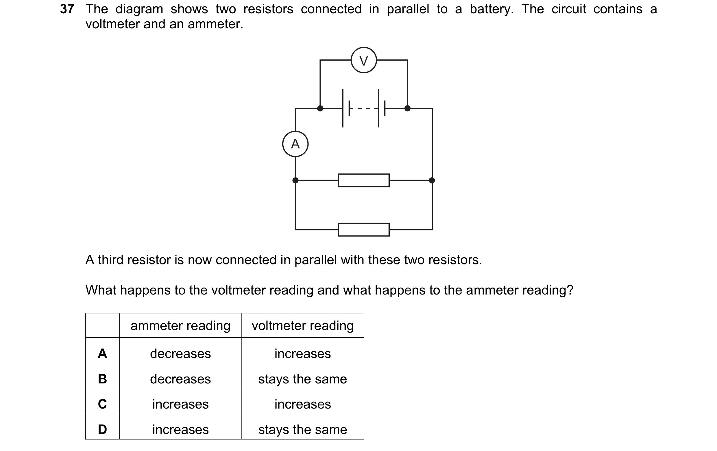
Q121 · The diagram shows two resistors connected in parallel to a battery 0654/11 Oct/Nov 2024
37 The diagram shows two resistors connected in parallel to a battery. The circuit contains a voltmeter and an ammeter. V A A third resistor is now connected in parallel with these two resistors. What happens to the voltmeter reading and what happens to the ammeter reading? ammeter reading voltmeter reading A decreases increases B decreases stays the same C increases increases D increases stays the same
1 marks
Answer: D
This question in 0654/11 Oct/Nov 2024
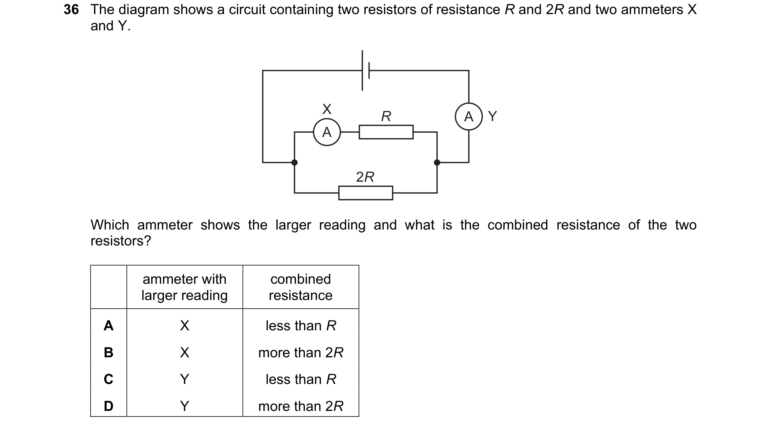
Q122 · The diagram shows a circuit containing two resistors of resistance R and 2R and two… 0654/12 Oct/Nov 2024
36 The diagram shows a circuit containing two resistors of resistance R and 2R and two ammeters X and Y. X R A Y A 2R Which ammeter shows the larger reading and what is the combined resistance of the two resistors? ammeter with combined larger reading resistance A X less than R B X more than 2R C Y less than R D Y more than 2R
1 marks
Answer: C
This question in 0654/12 Oct/Nov 2024
Q123 · The diagram shows a circuit containing two resistors of resistance R and 2R and two… 0654/13 Oct/Nov 2024
36 The diagram shows a circuit containing two resistors of resistance R and 2R and two ammeters X and Y. X R A Y A 2R Which ammeter shows the larger reading and what is the combined resistance of the two resistors? ammeter with combined larger reading resistance A X less than R B X more than 2R C Y less than R D Y more than 2R
1 marks
Answer: C
This question in 0654/13 Oct/Nov 2024
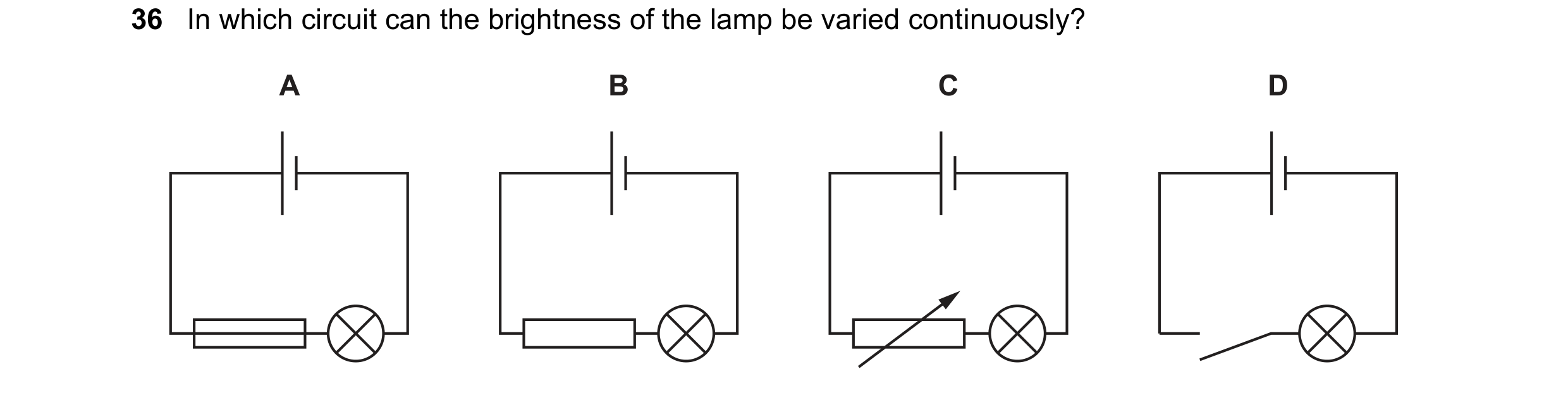
Q124 · In which circuit can the brightness of the lamp be varied continuously? 0654/11 May/June 2025
36 In which circuit can the brightness of the lamp be varied continuously? A B C D
1 marks
Answer: C
This question in 0654/11 May/June 2025
Q125 · A 12 resistor is connected in parallel with a 17 resistor 0654/11 May/June 2025
37 A 12 resistor is connected in parallel with a 17 resistor. Which statement about the combined resistance of the two resistors is correct? A It must be equal to 29 . B It must be greater than 12 but less than 17 . C It must be greater than 17 but less than 29 . D It must be less than 12 .
1 marks
Answer: D
This question in 0654/11 May/June 2025
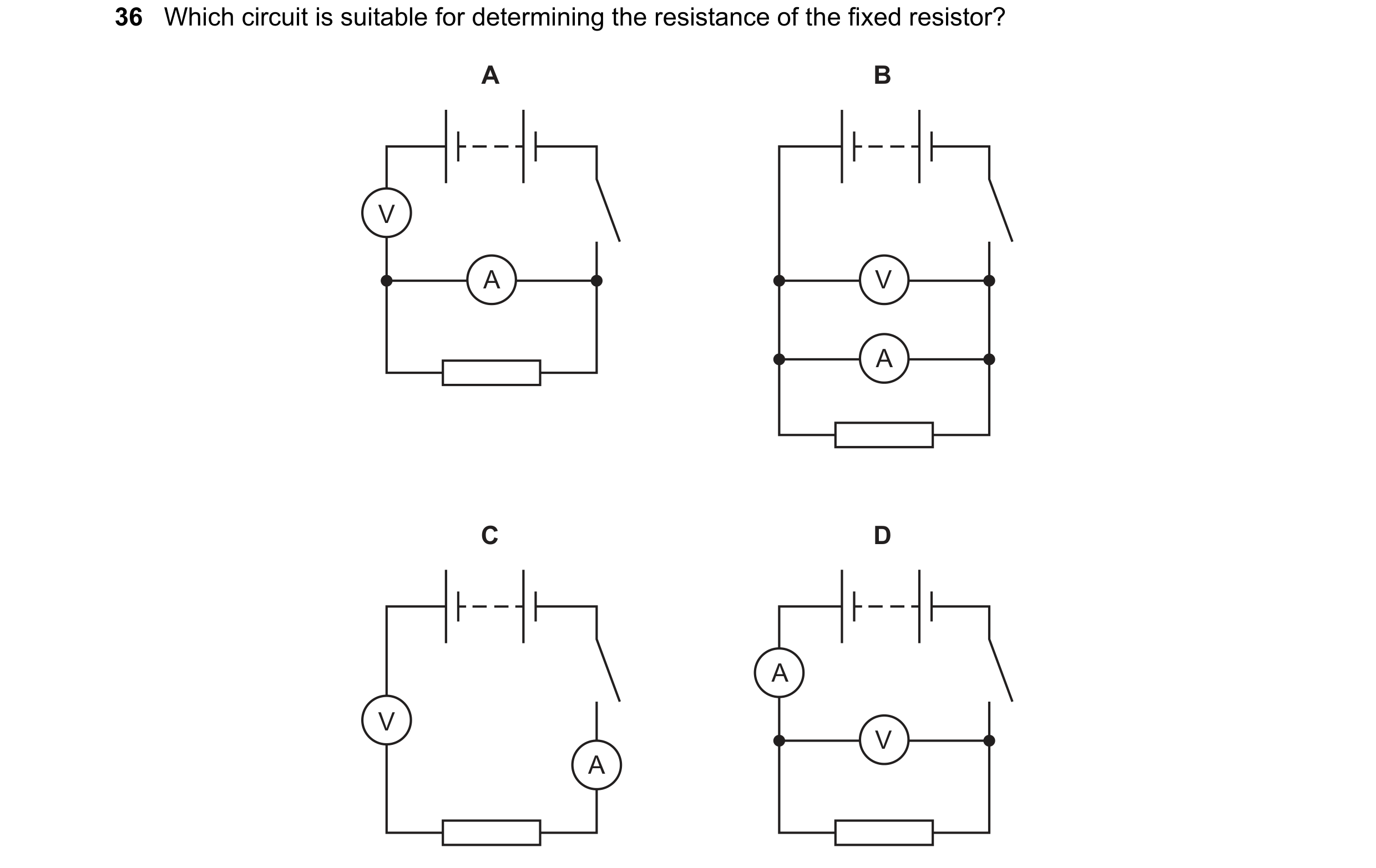
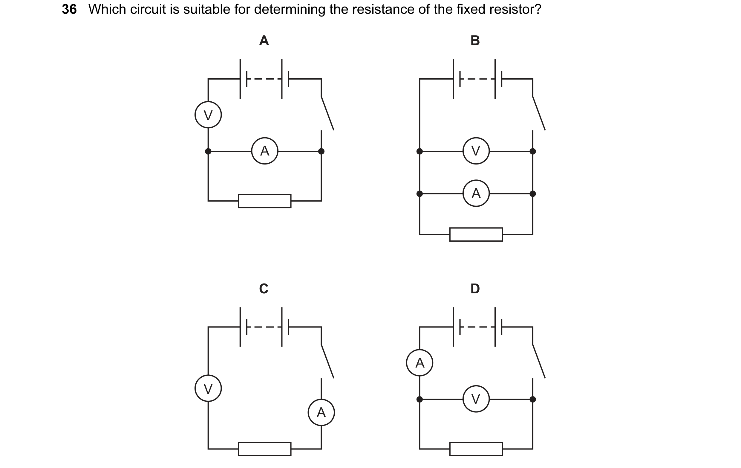
Q126 · Which circuit is suitable for determining the resistance of the fixed resistor? 0654/12 May/June 2025
36 Which circuit is suitable for determining the resistance of the fixed resistor? A B V A V A C D A V V A
1 marks
Answer: D
This question in 0654/12 May/June 2025
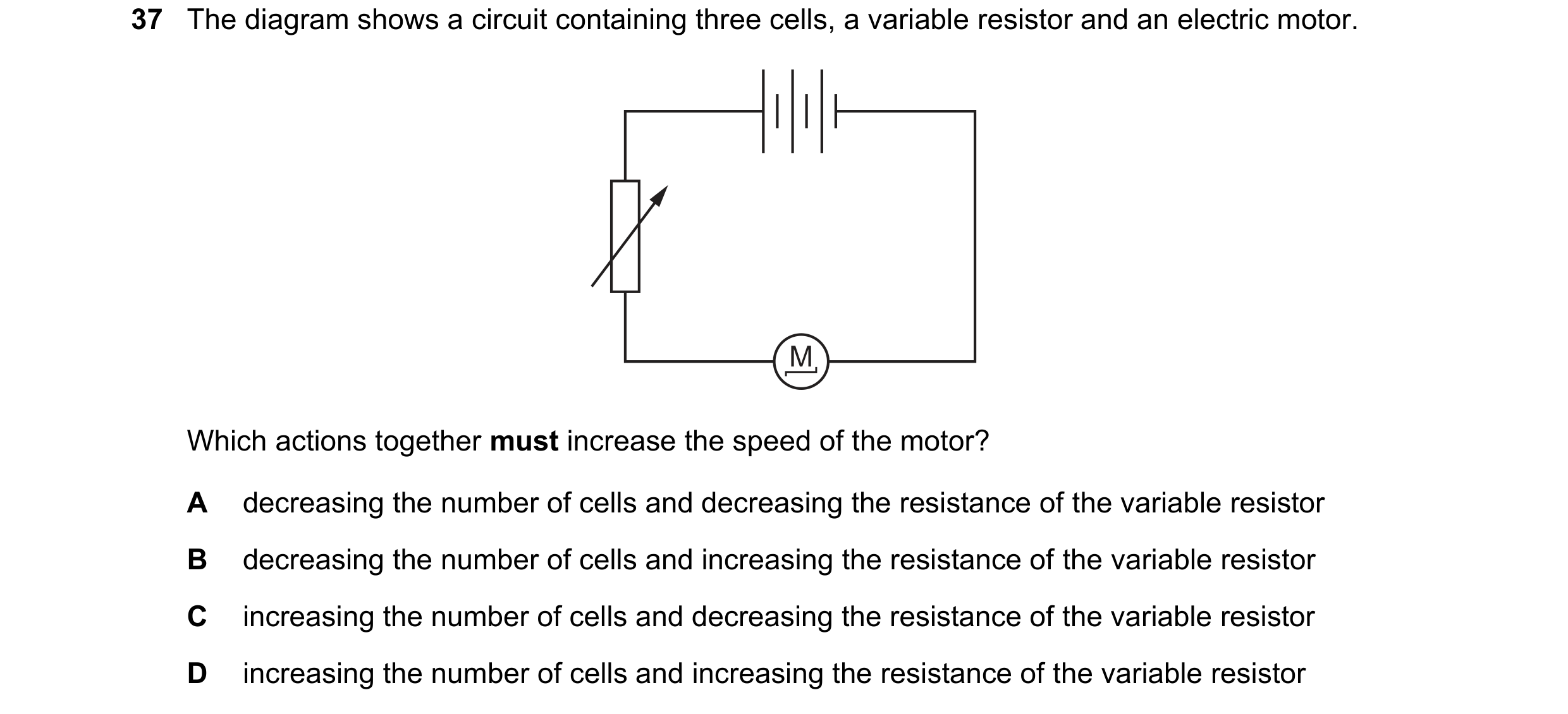
Q127 · The diagram shows a circuit containing three cells, a variable resistor and an electric… 0654/12 May/June 2025
37 The diagram shows a circuit containing three cells, a variable resistor and an electric motor. M Which actions together must increase the speed of the motor? A decreasing the number of cells and decreasing the resistance of the variable resistor B decreasing the number of cells and increasing the resistance of the variable resistor C increasing the number of cells and decreasing the resistance of the variable resistor D increasing the number of cells and increasing the resistance of the variable resistor
1 marks
Answer: C
This question in 0654/12 May/June 2025
Q128 · The diagram shows a 3.0 resistor connected to a 6.0 resistor 0654/12 May/June 2025
38 The diagram shows a 3.0 resistor connected to a 6.0 resistor. 3.0 Ω 6.0 Ω What is a possible combined resistance of the two resistors? A 2.0 B 3.0 C 4.5 D 9.0
1 marks
Answer: A
This question in 0654/12 May/June 2025
Q129 · Which circuit is suitable for determining the resistance of the fixed resistor? 0654/13 May/June 2025
36 Which circuit is suitable for determining the resistance of the fixed resistor? A B V A V A C D A V V A
1 marks
Answer: D
This question in 0654/13 May/June 2025
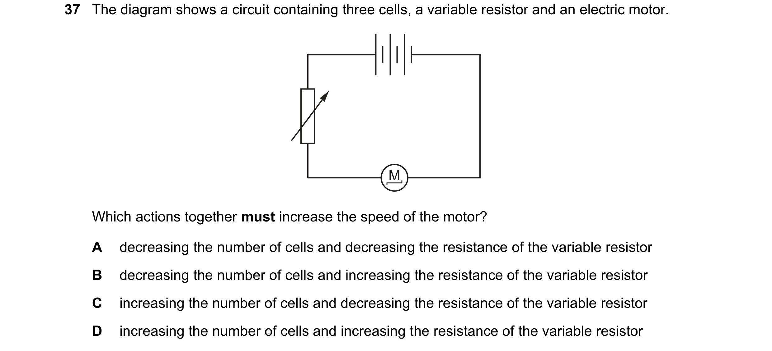
Q130 · The diagram shows a circuit containing three cells, a variable resistor and an electric… 0654/13 May/June 2025
37 The diagram shows a circuit containing three cells, a variable resistor and an electric motor. M Which actions together must increase the speed of the motor? A decreasing the number of cells and decreasing the resistance of the variable resistor B decreasing the number of cells and increasing the resistance of the variable resistor C increasing the number of cells and decreasing the resistance of the variable resistor D increasing the number of cells and increasing the resistance of the variable resistor
1 marks
Answer: C
This question in 0654/13 May/June 2025
Q131 · The diagram shows a 3.0 resistor connected to a 6.0 resistor 0654/13 May/June 2025
38 The diagram shows a 3.0 resistor connected to a 6.0 resistor. 3.0 Ω 6.0 Ω What is a possible combined resistance of the two resistors? A 2.0 B 3.0 C 4.5 D 9.0
1 marks
Answer: A
This question in 0654/13 May/June 2025
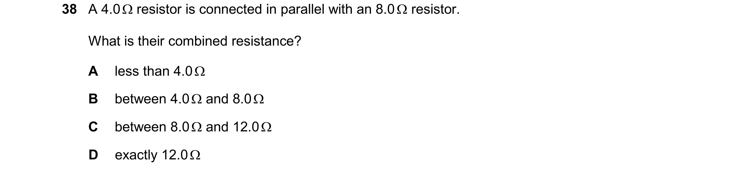
Q132 · A 4.0 resistor is connected in parallel with an 8.0 resistor 0654/12 Oct/Nov 2025
38 A 4.0 resistor is connected in parallel with an 8.0 resistor. What is their combined resistance? A less than 4.0 B between 4.0 and 8.0 C between 8.0 and 12.0 D exactly 12.0
1 marks
Answer: A
This question in 0654/12 Oct/Nov 2025
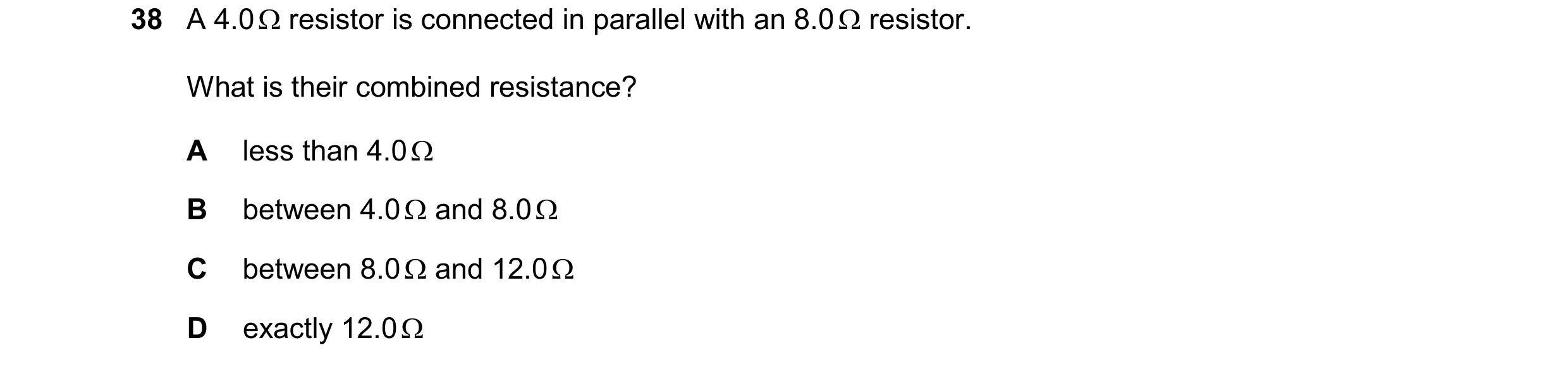
Q133 · A 4.0 resistor is connected in parallel with an 8.0 resistor 0654/13 Oct/Nov 2025
38 A 4.0 resistor is connected in parallel with an 8.0 resistor. What is their combined resistance? A less than 4.0 B between 4.0 and 8.0 C between 8.0 and 12.0 D exactly 12.0
1 marks
Answer: A
This question in 0654/13 Oct/Nov 2025
 1 / 48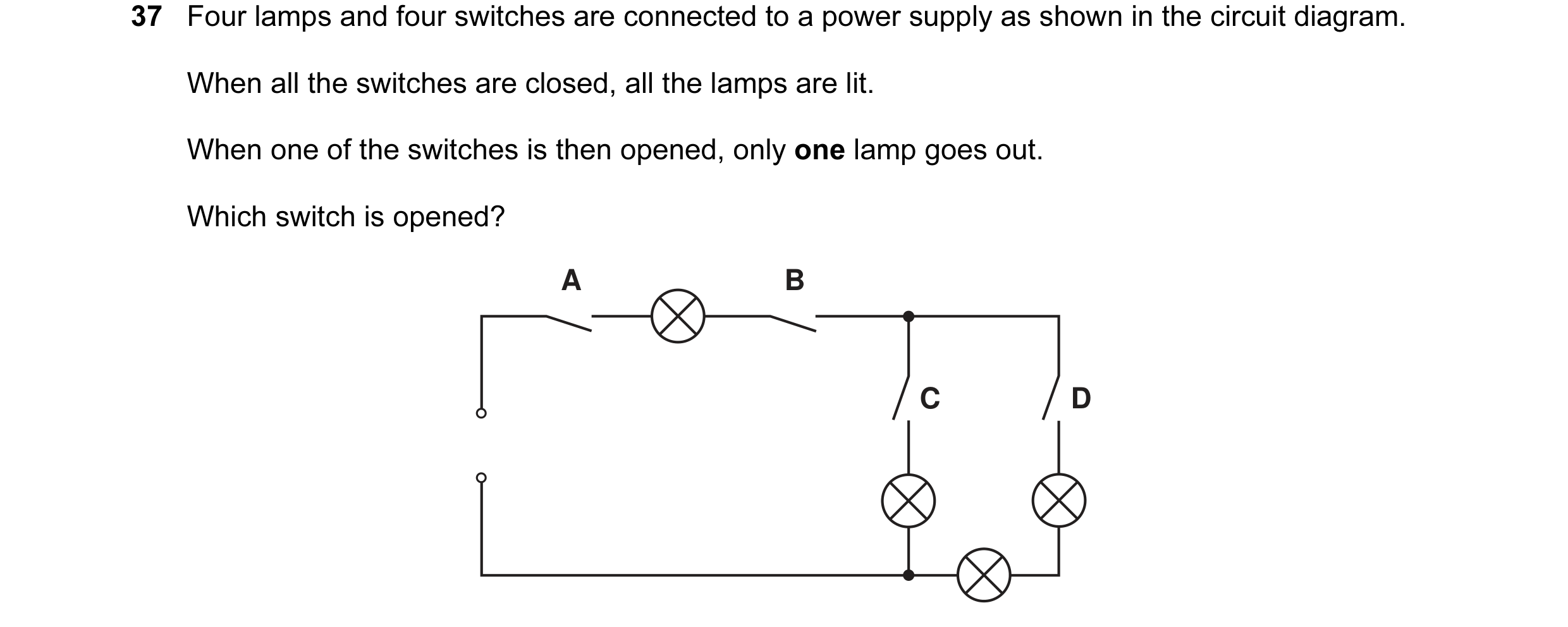
 2 / 48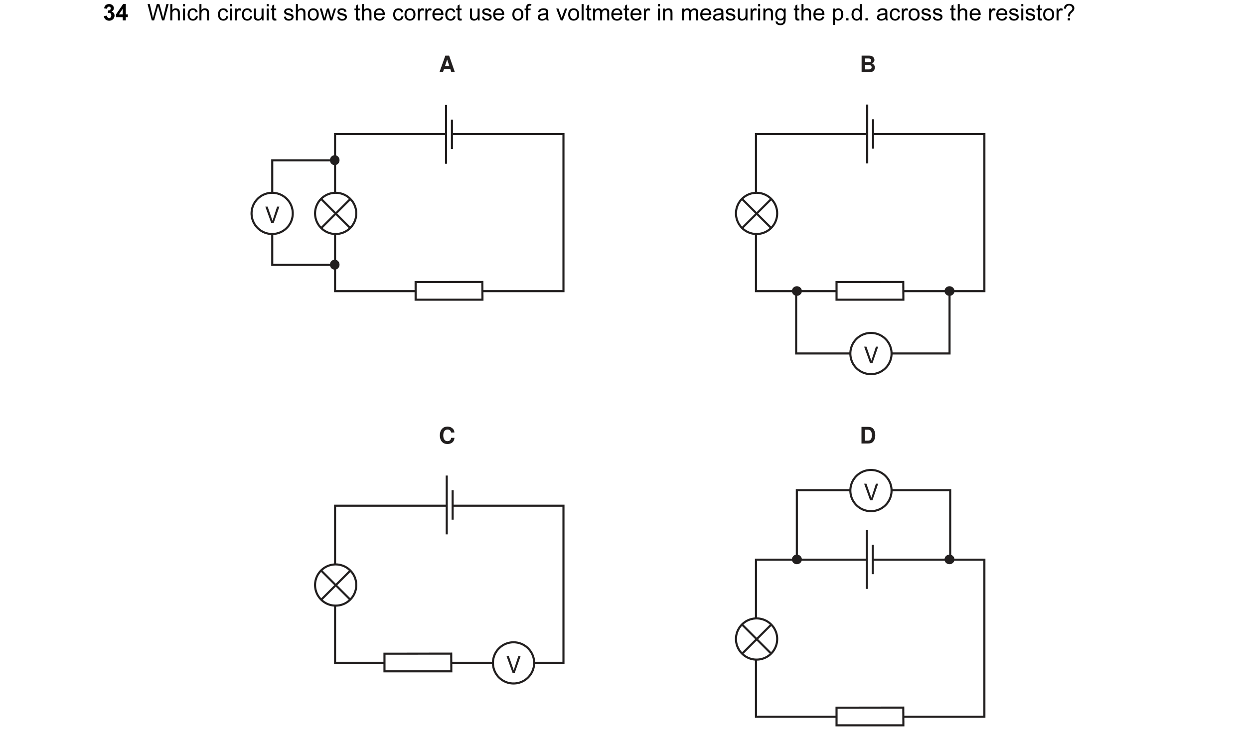
 3 / 48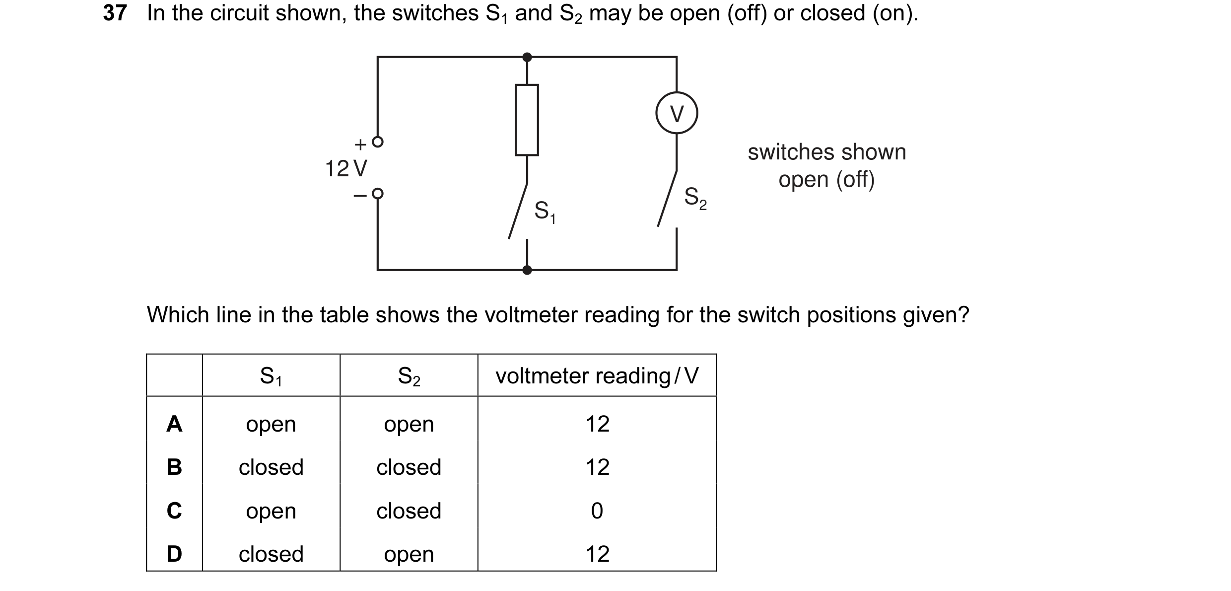
 4 / 48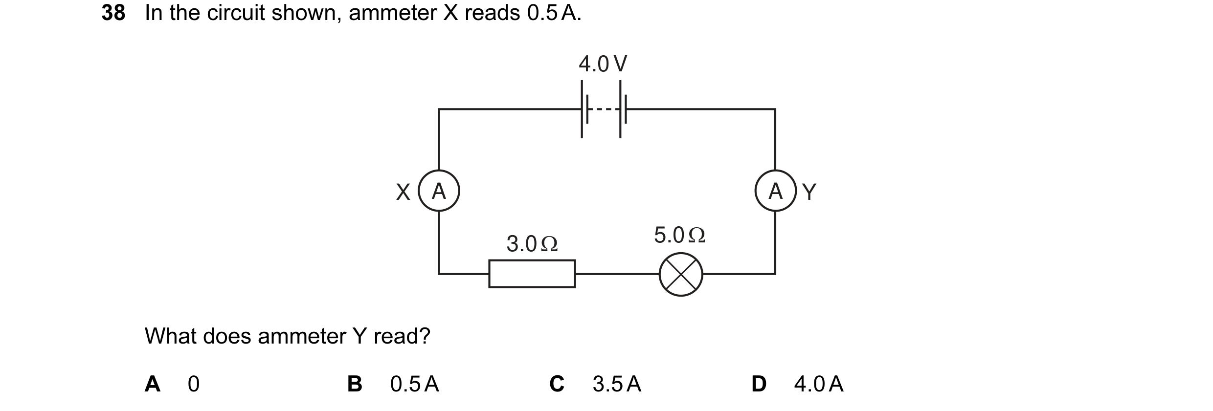
 5 / 48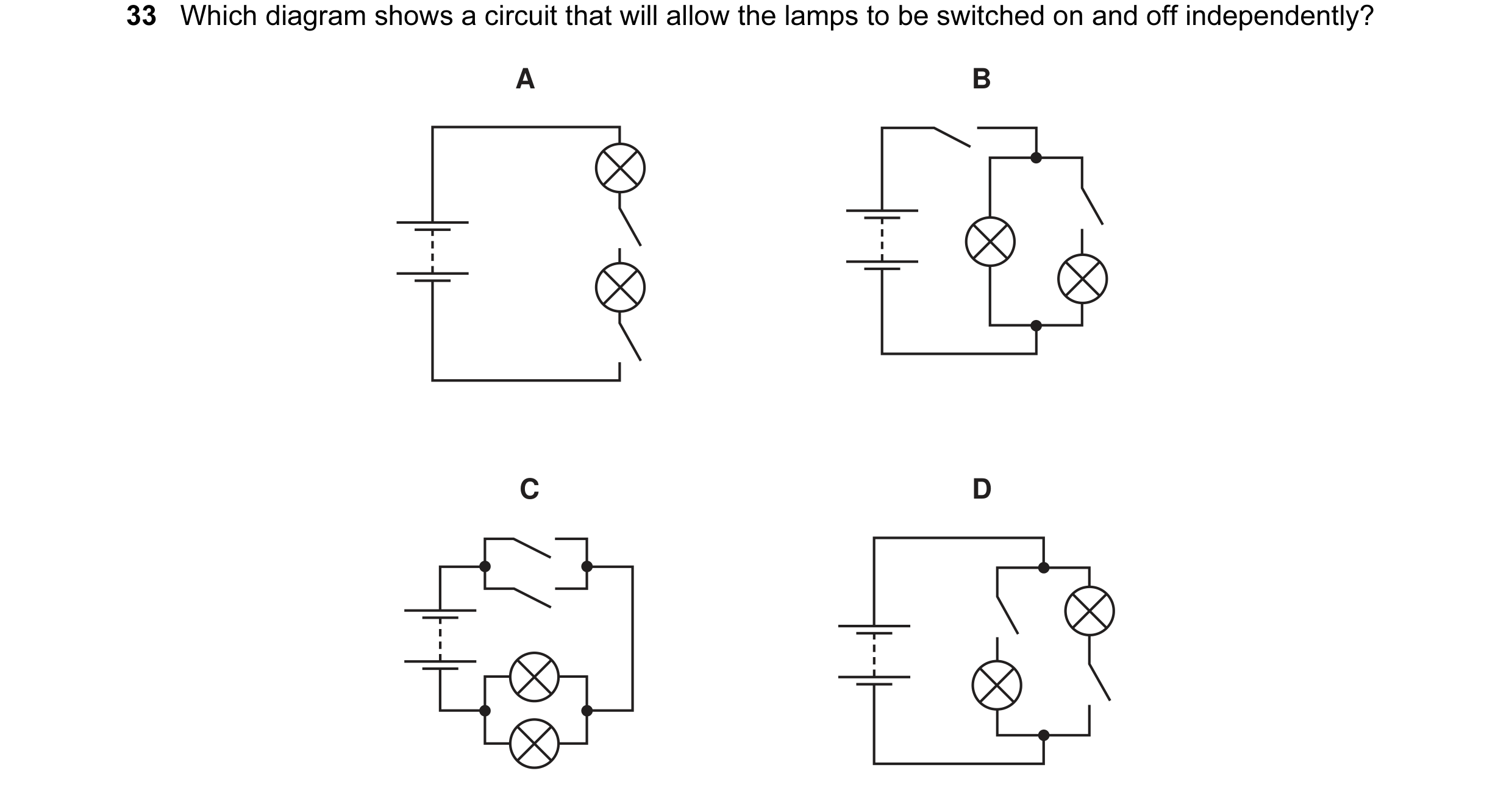
 6 / 48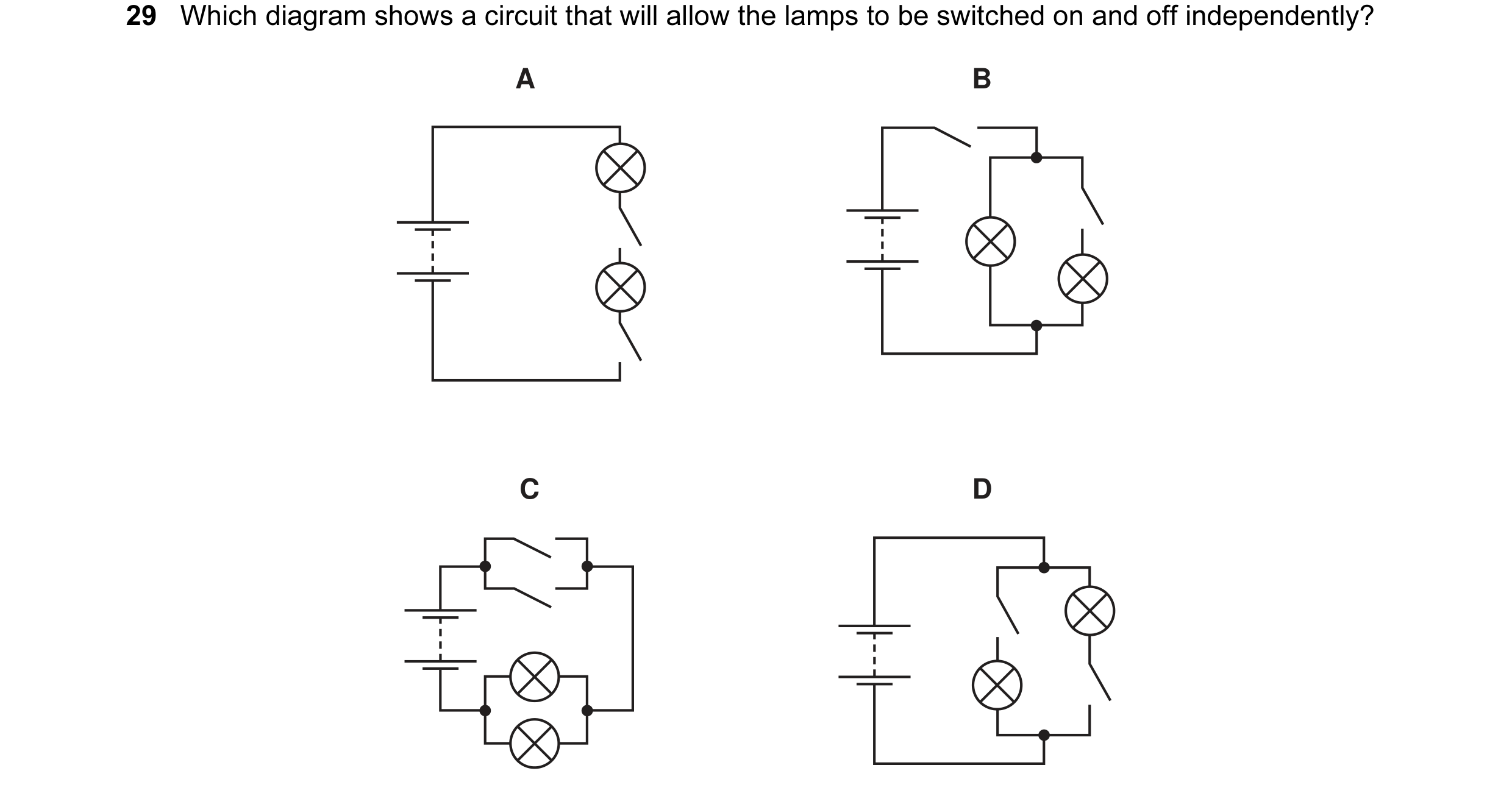
 7 / 48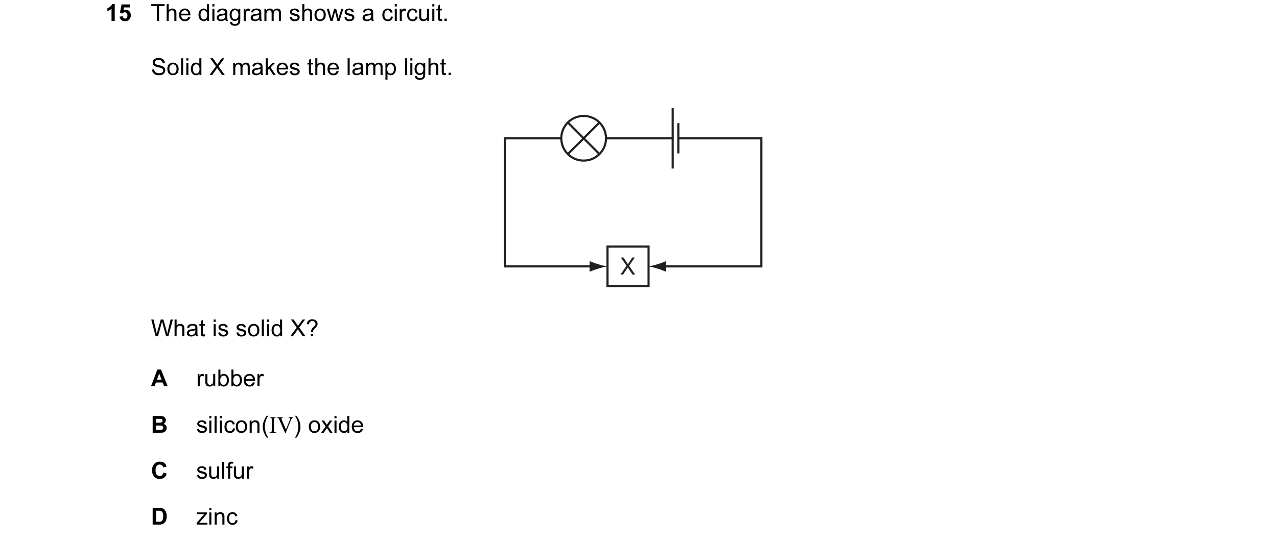
 8 / 48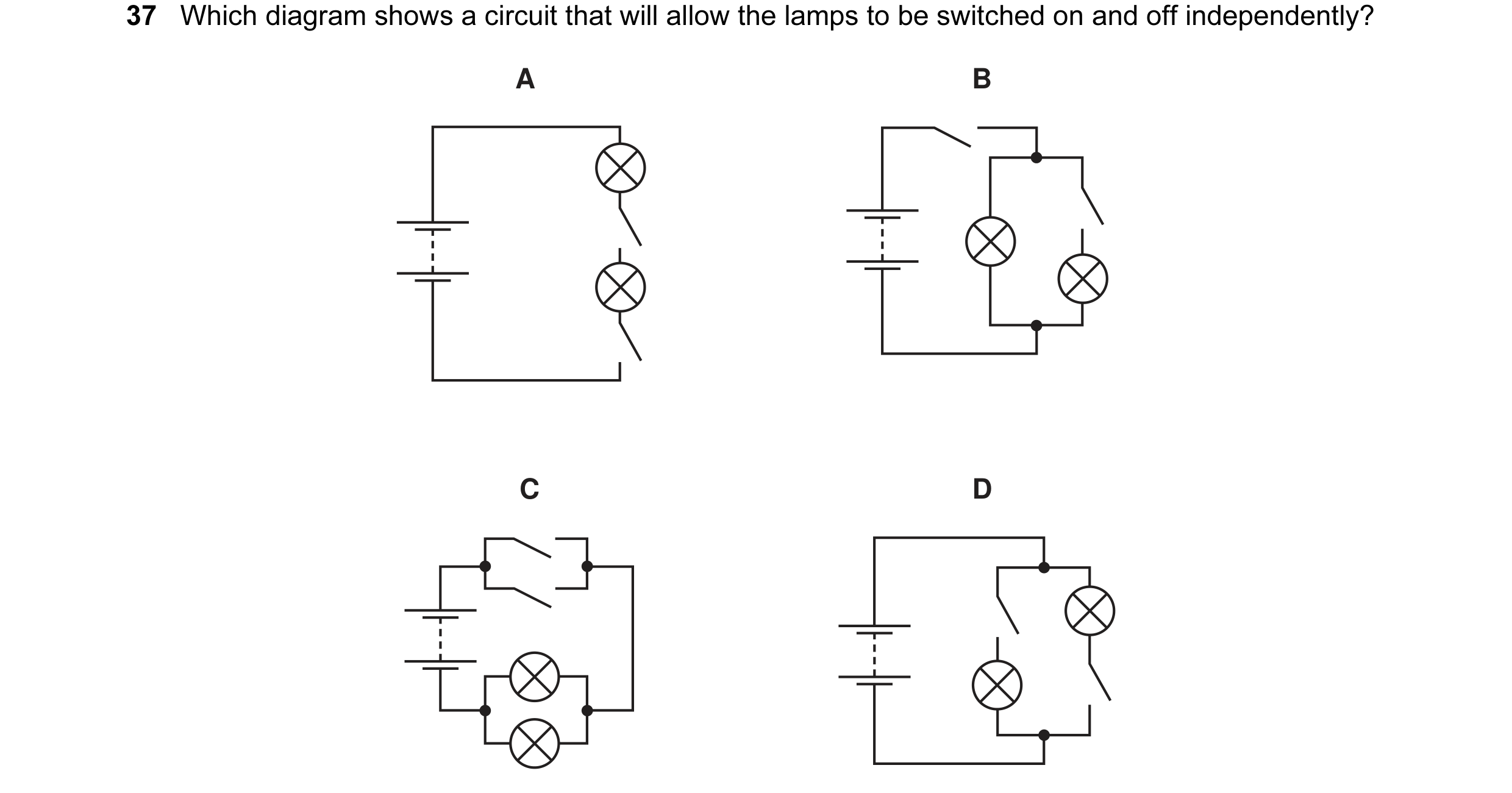
 9 / 48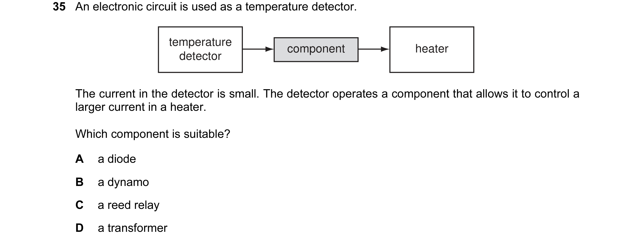
 10 / 48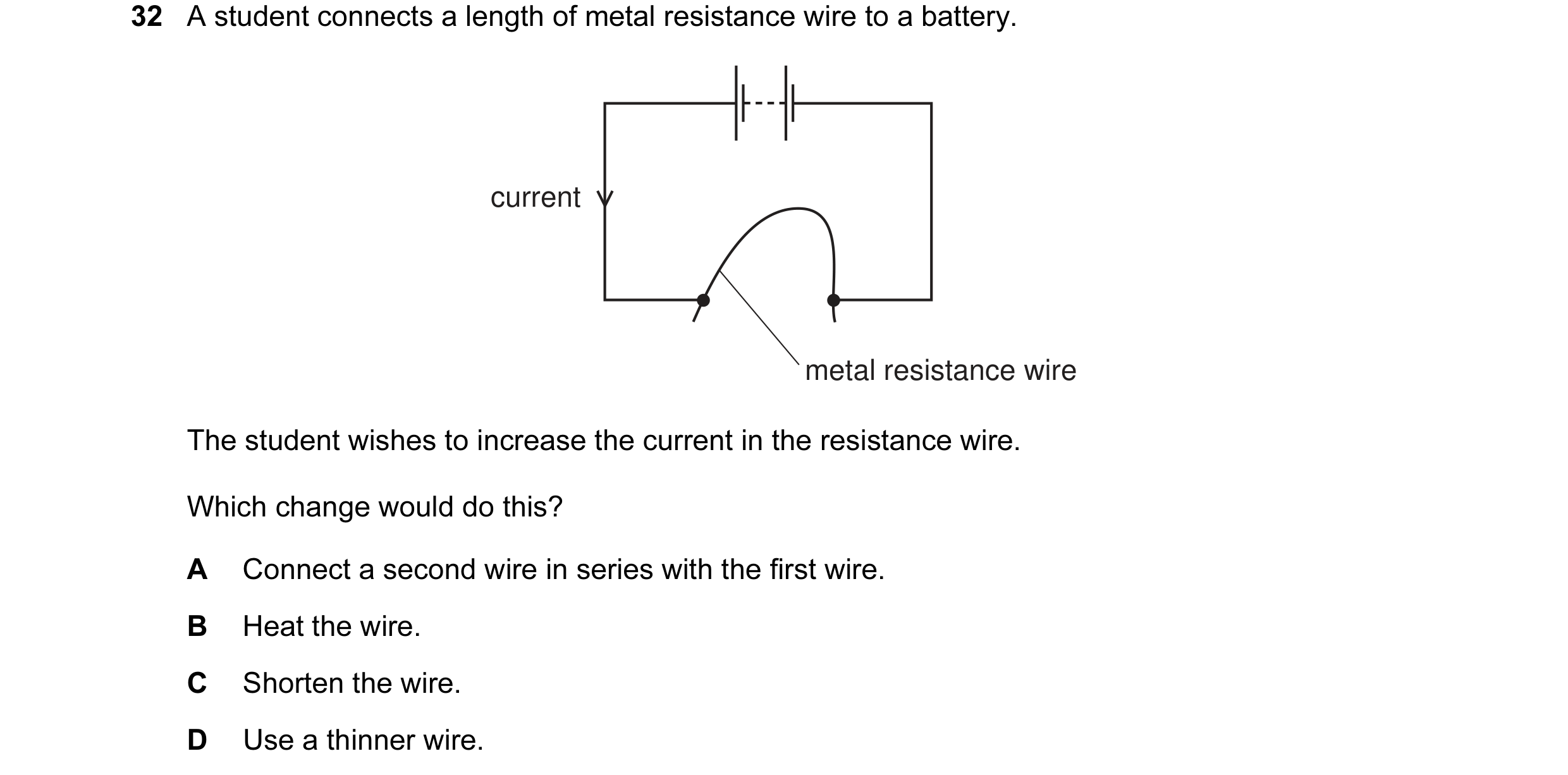
 11 / 48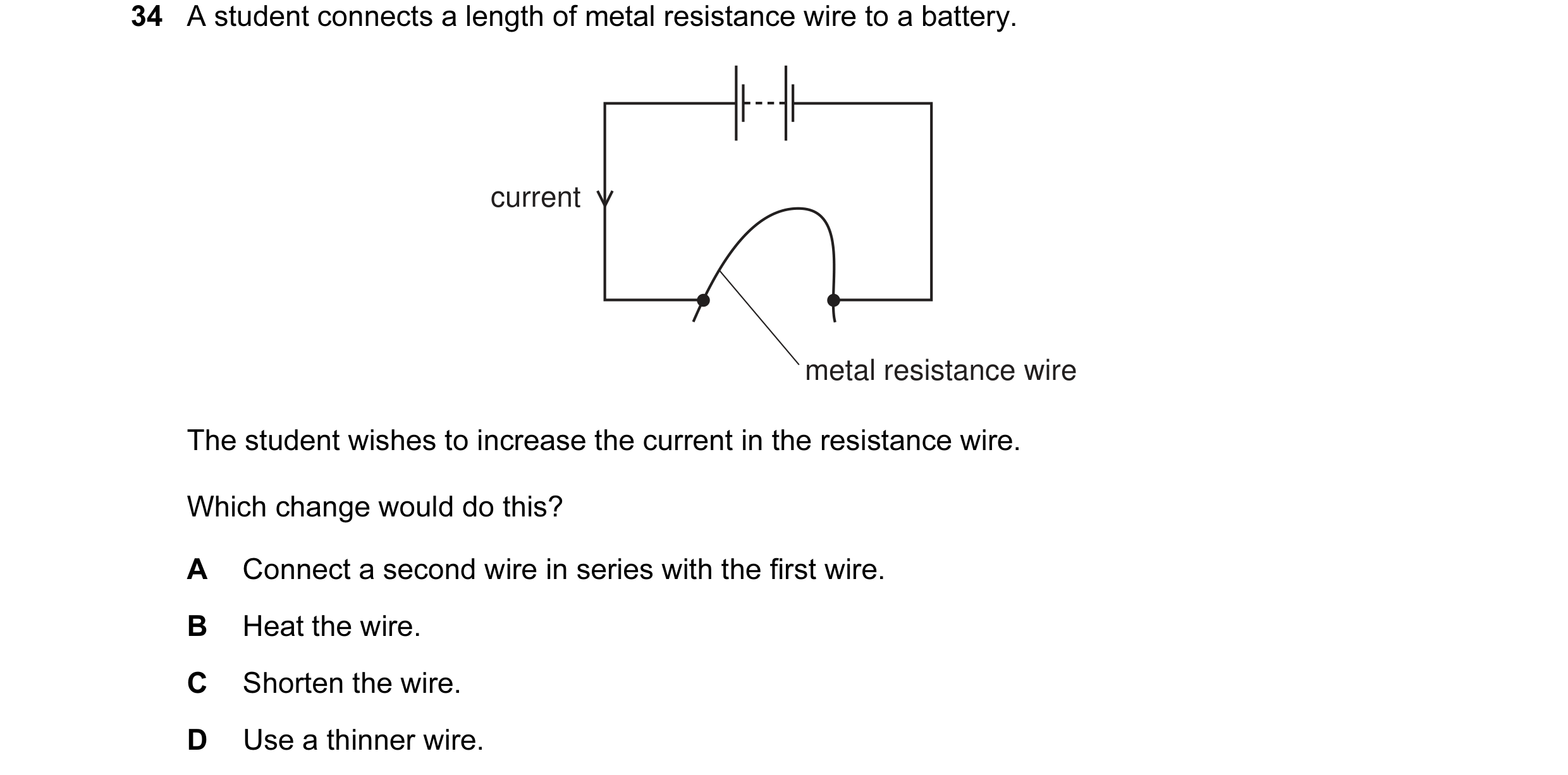
 12 / 48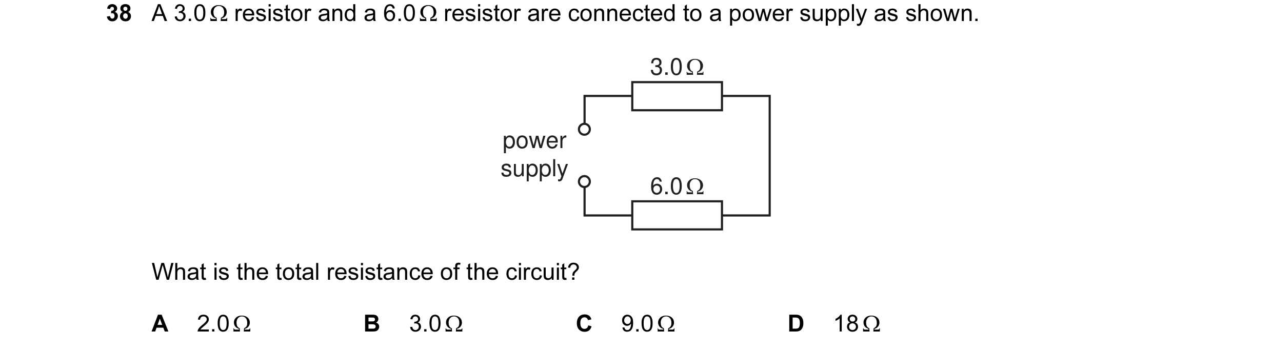
 13 / 48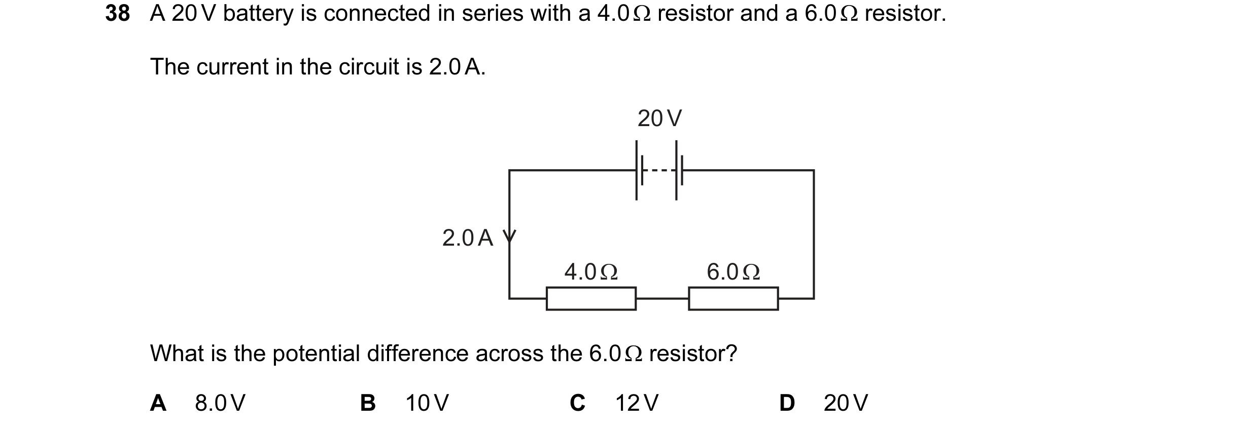
 14 / 48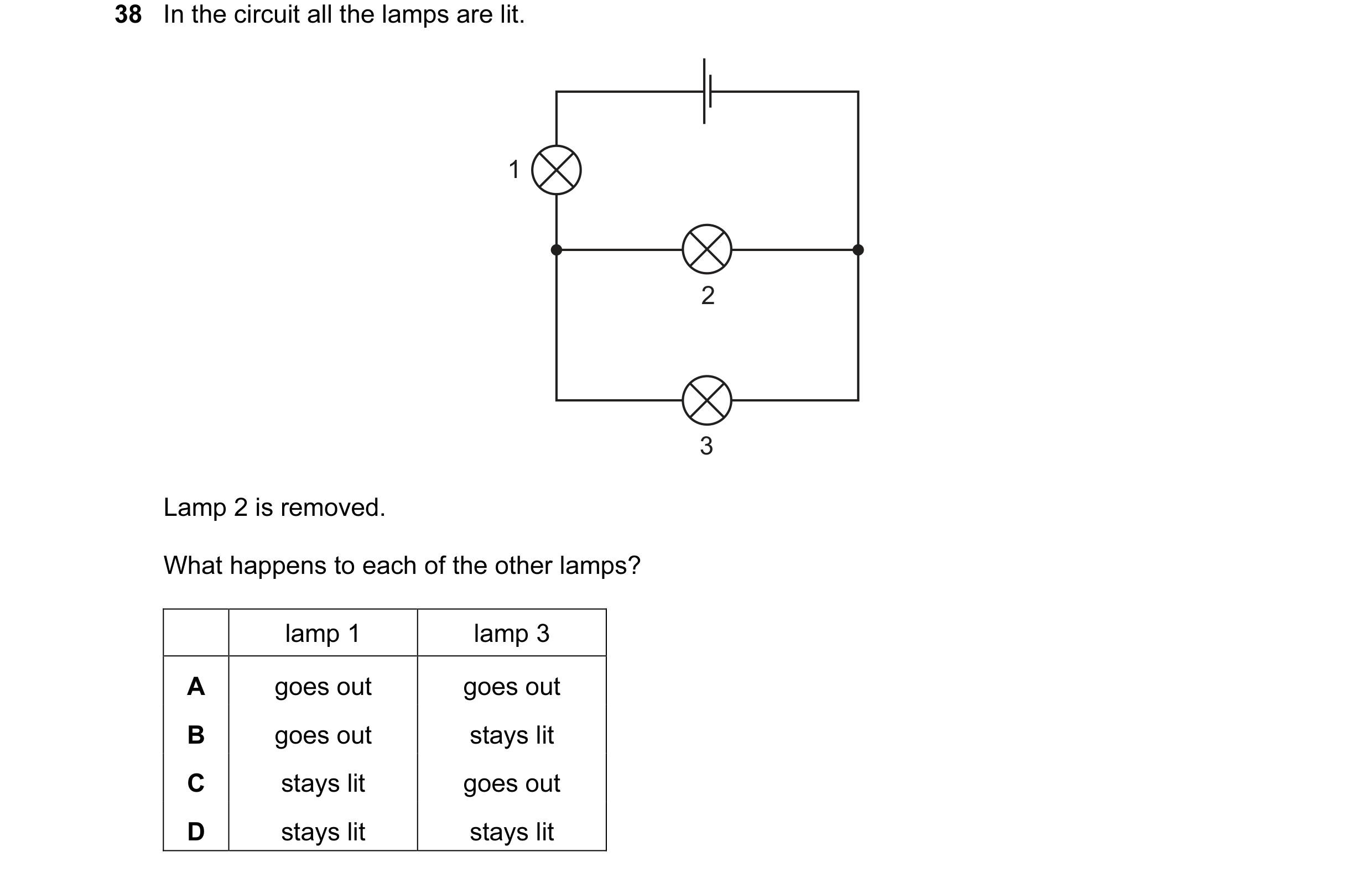
 15 / 48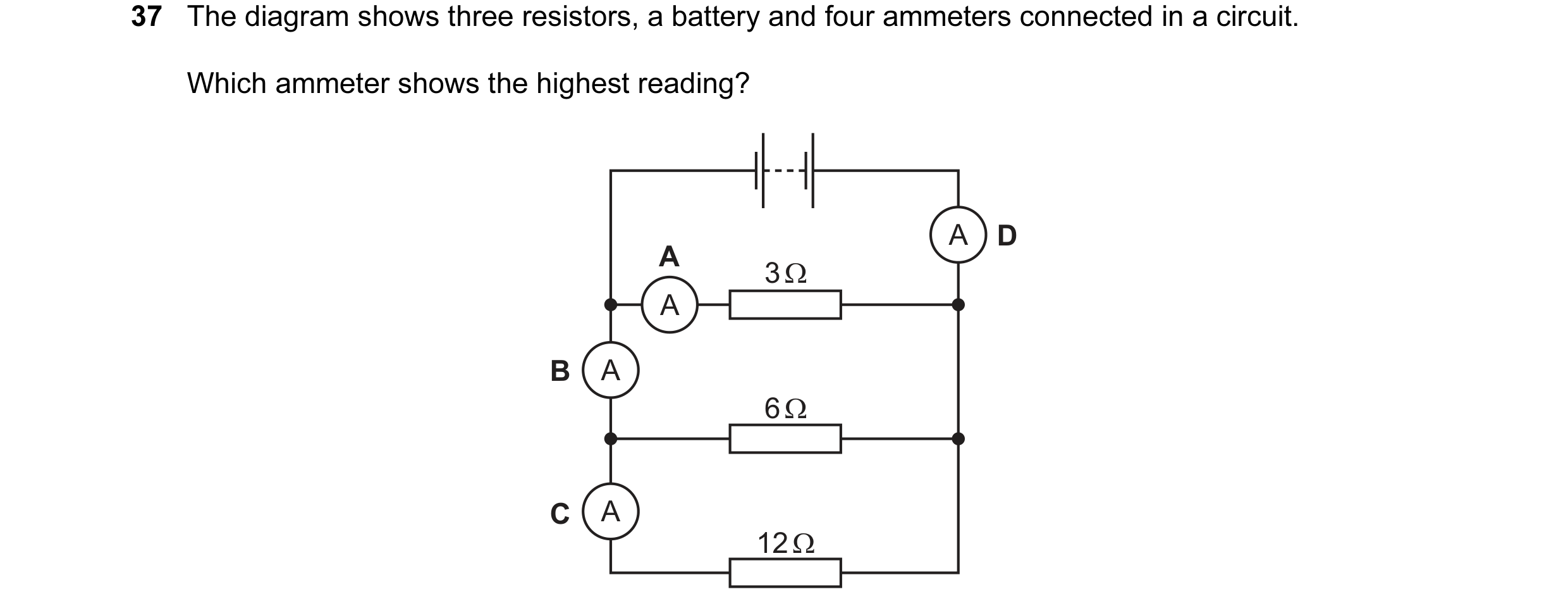
 16 / 48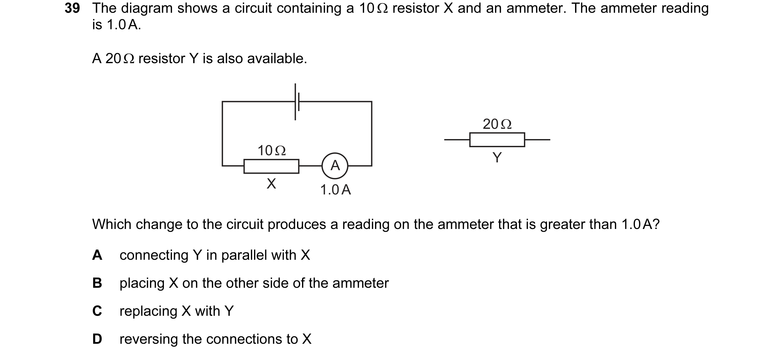
 17 / 48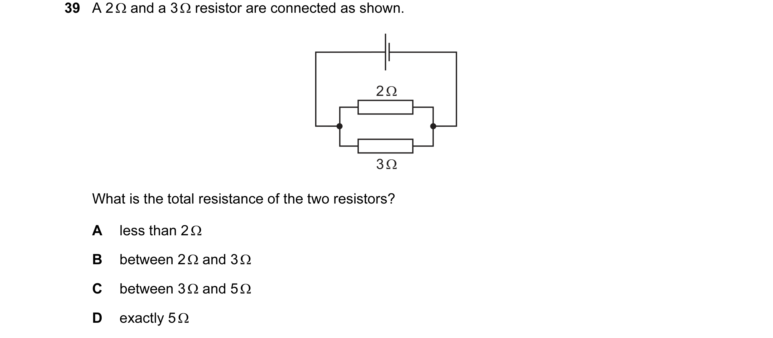
 18 / 48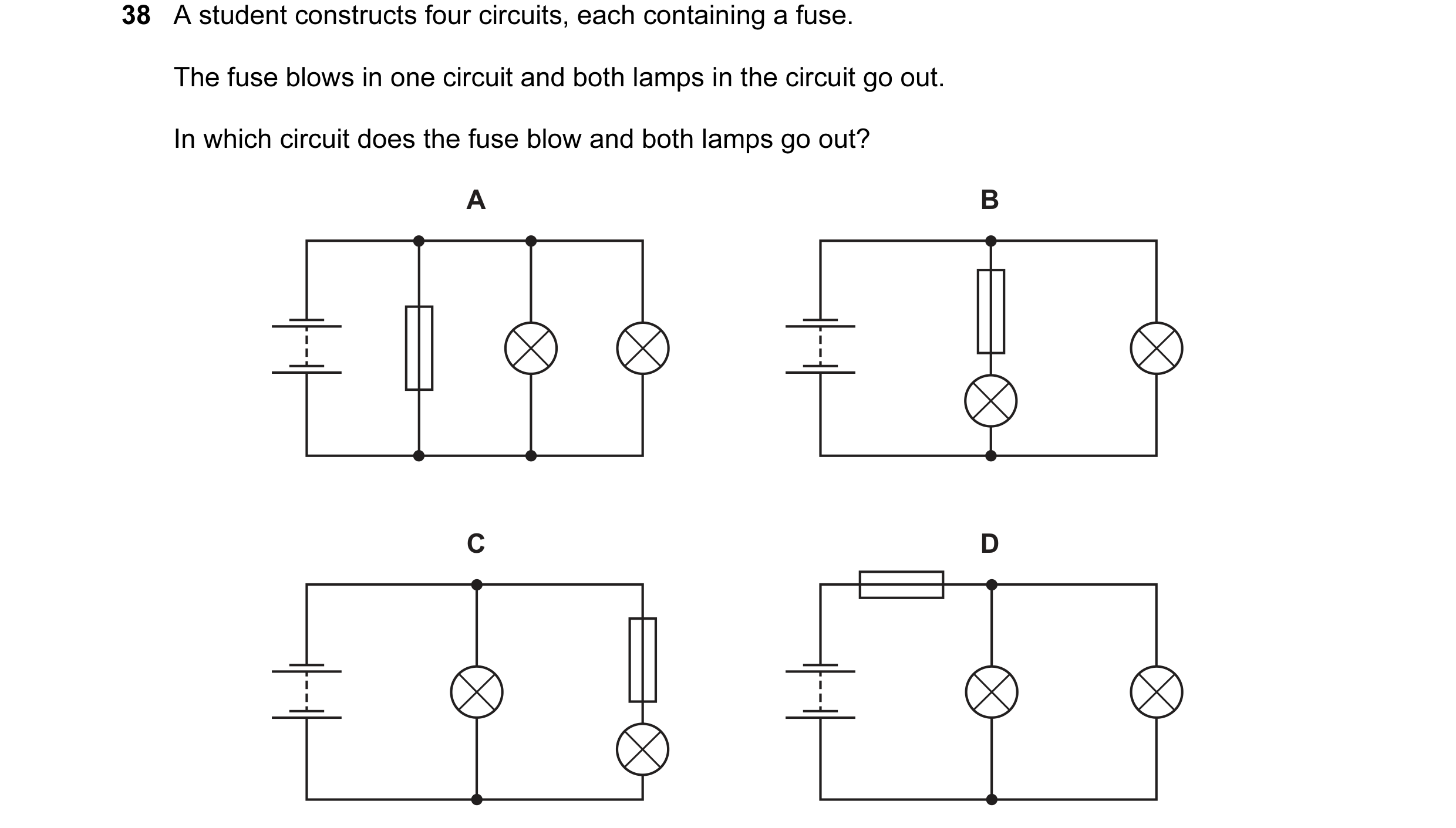
 19 / 48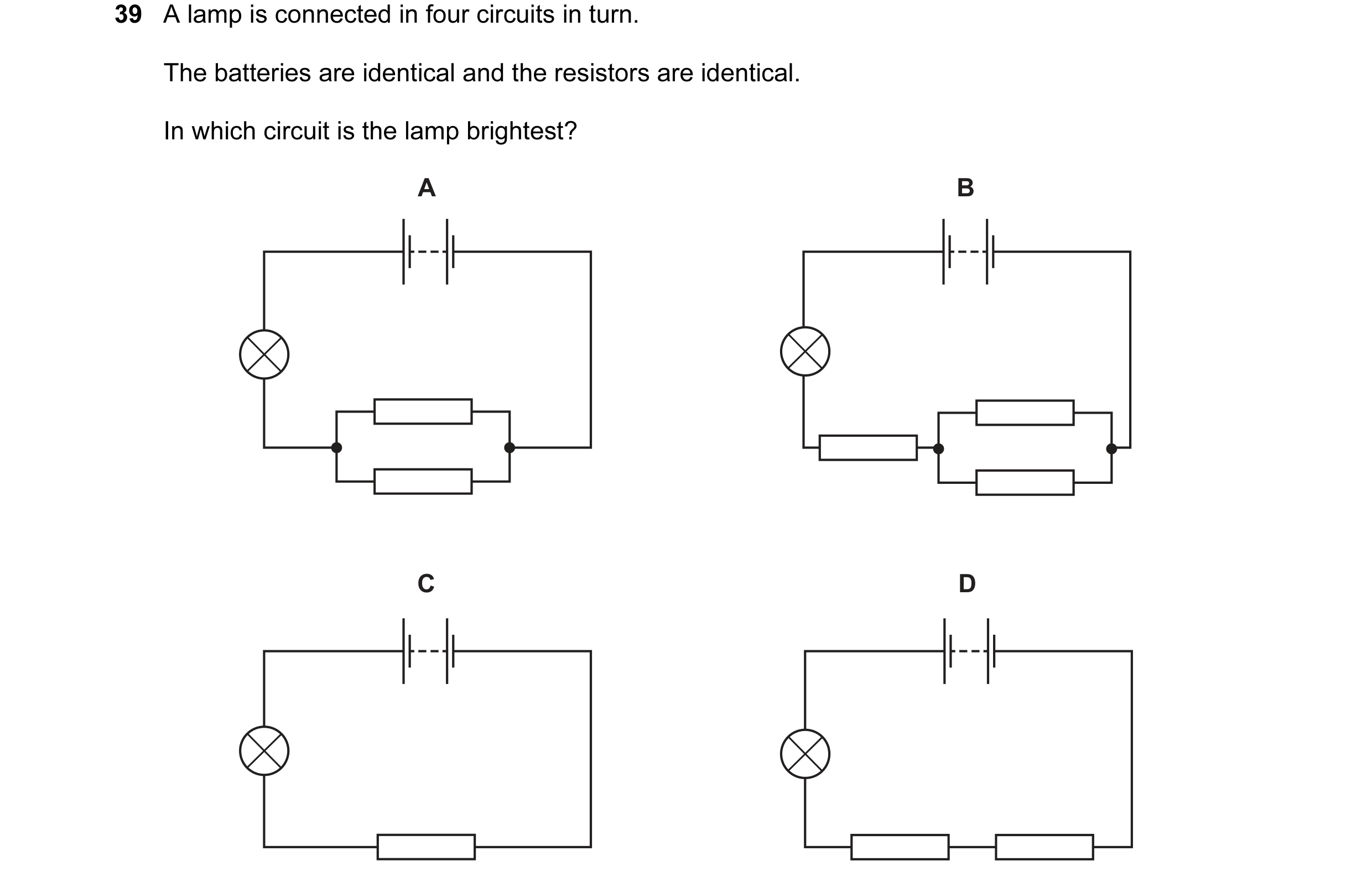
 20 / 48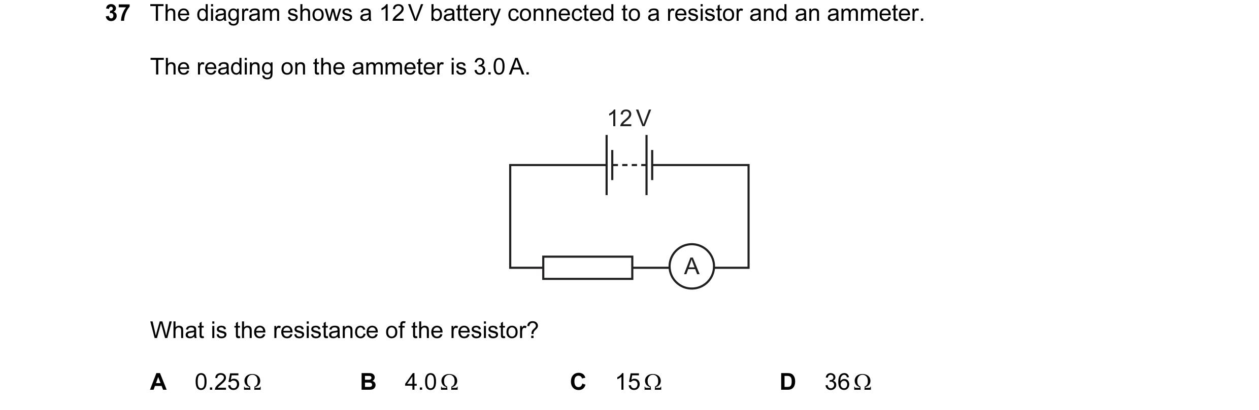
 21 / 48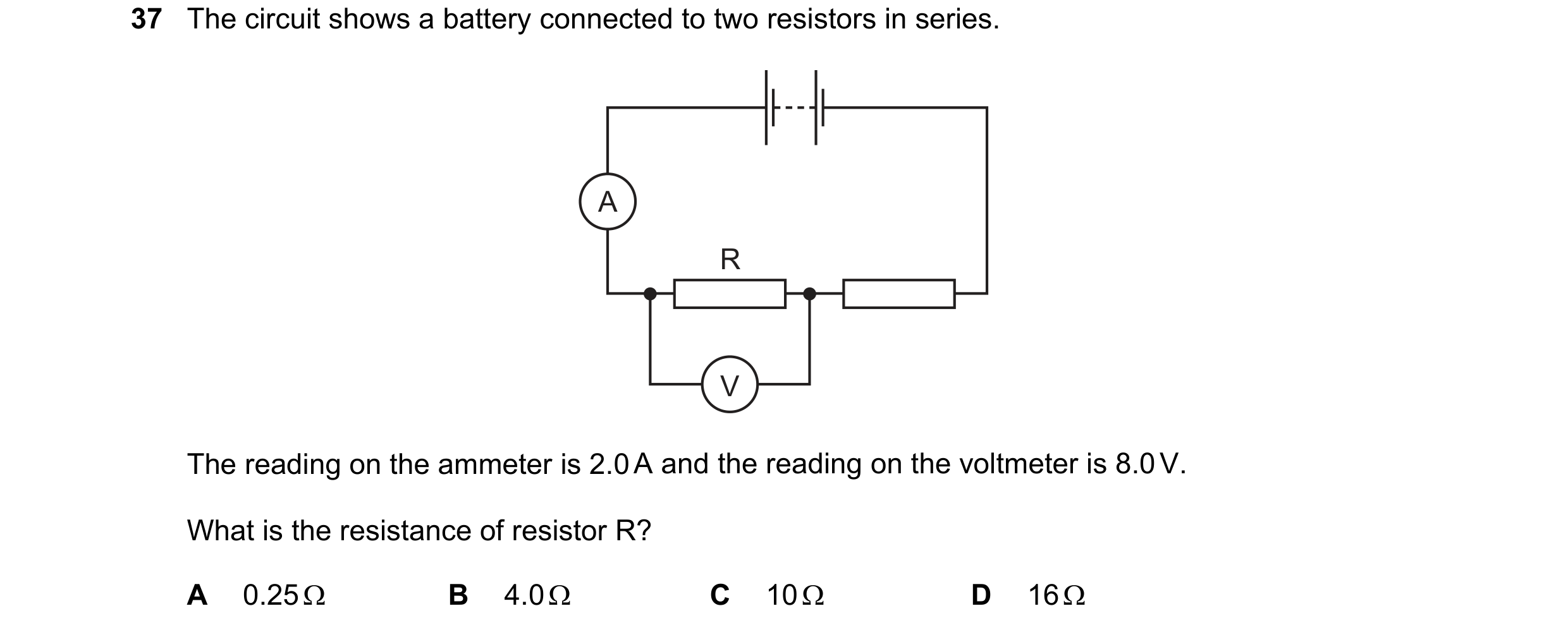
 22 / 48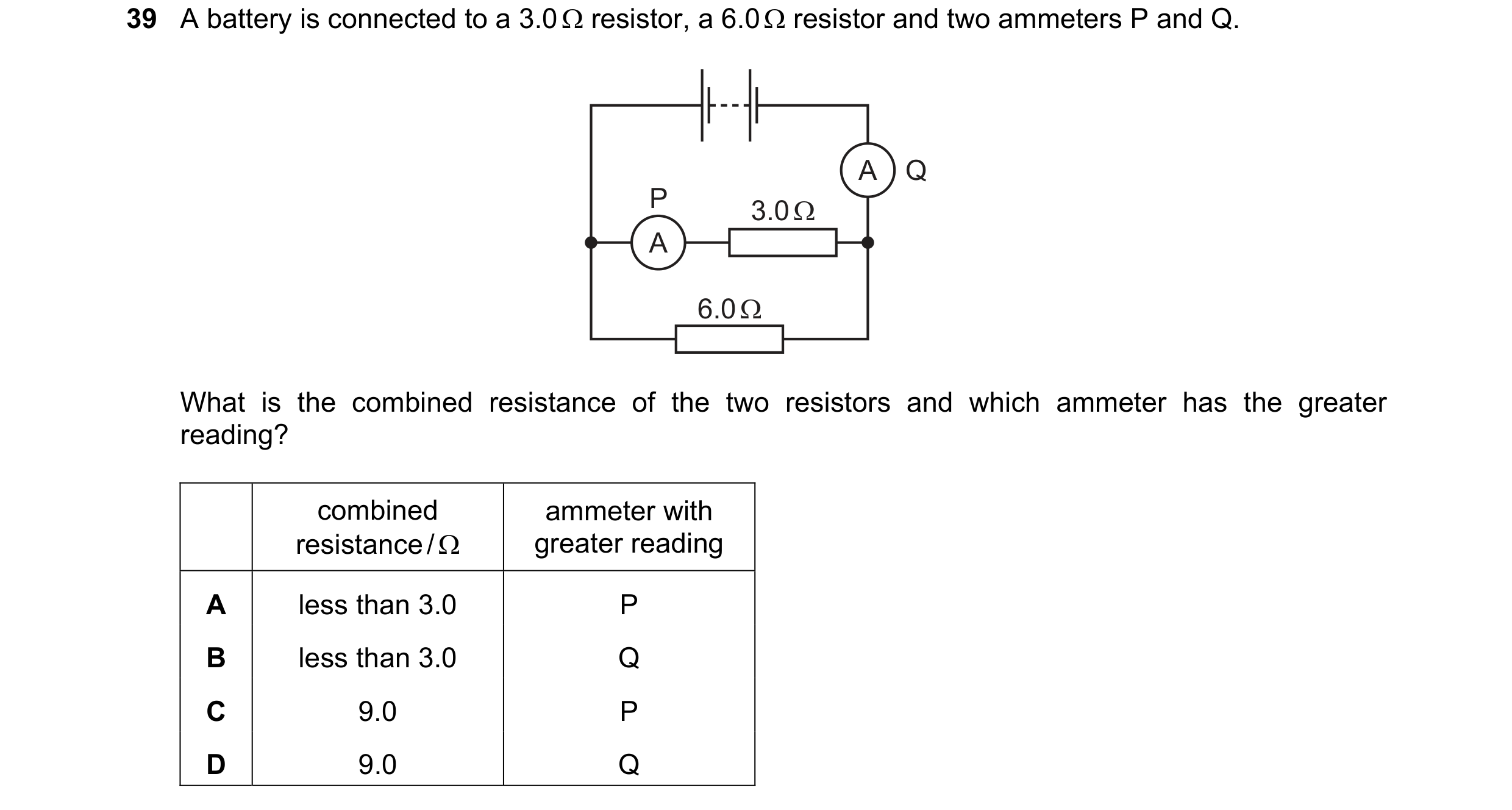
 23 / 48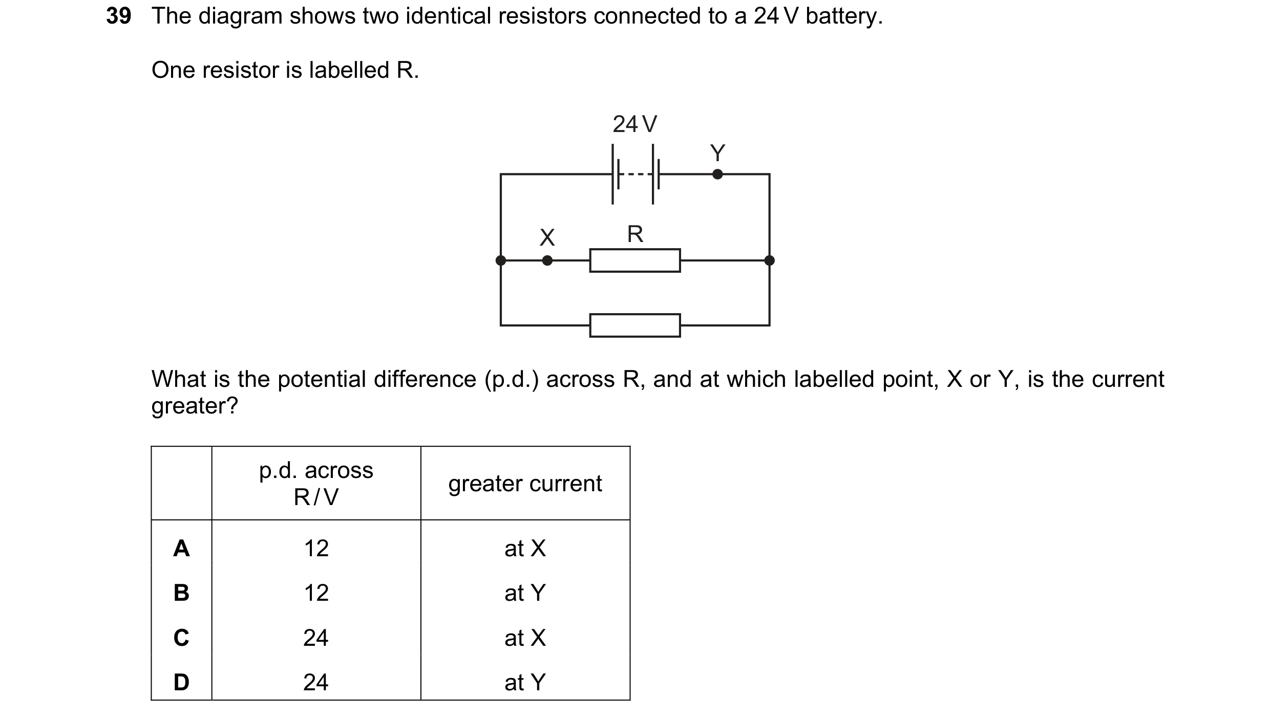
 24 / 48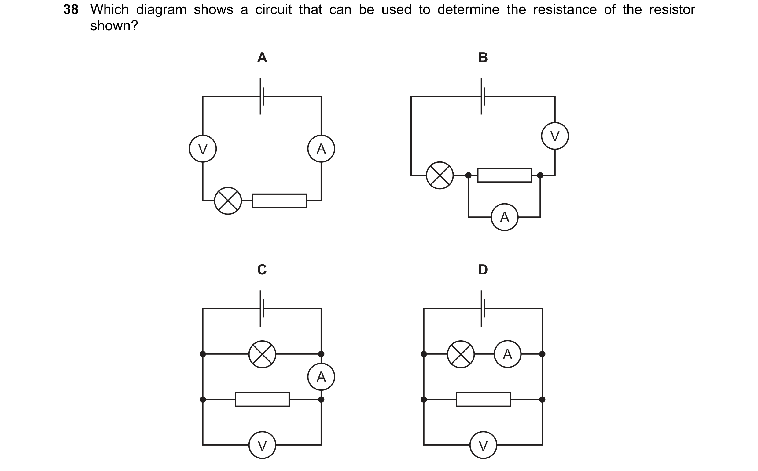
 25 / 48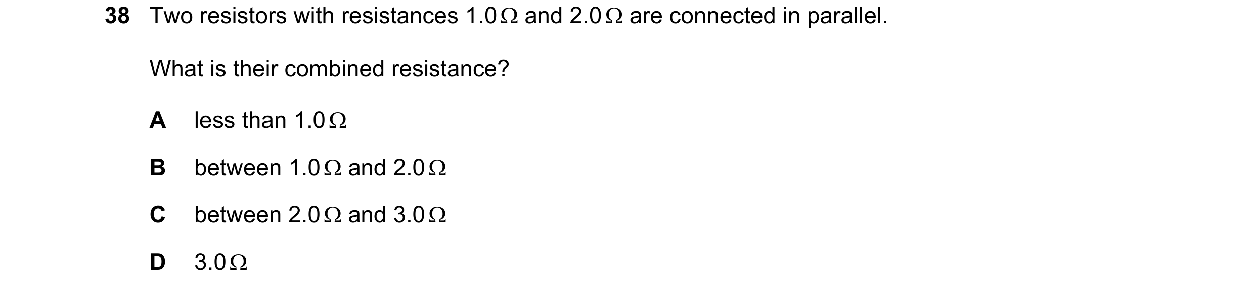
 26 / 48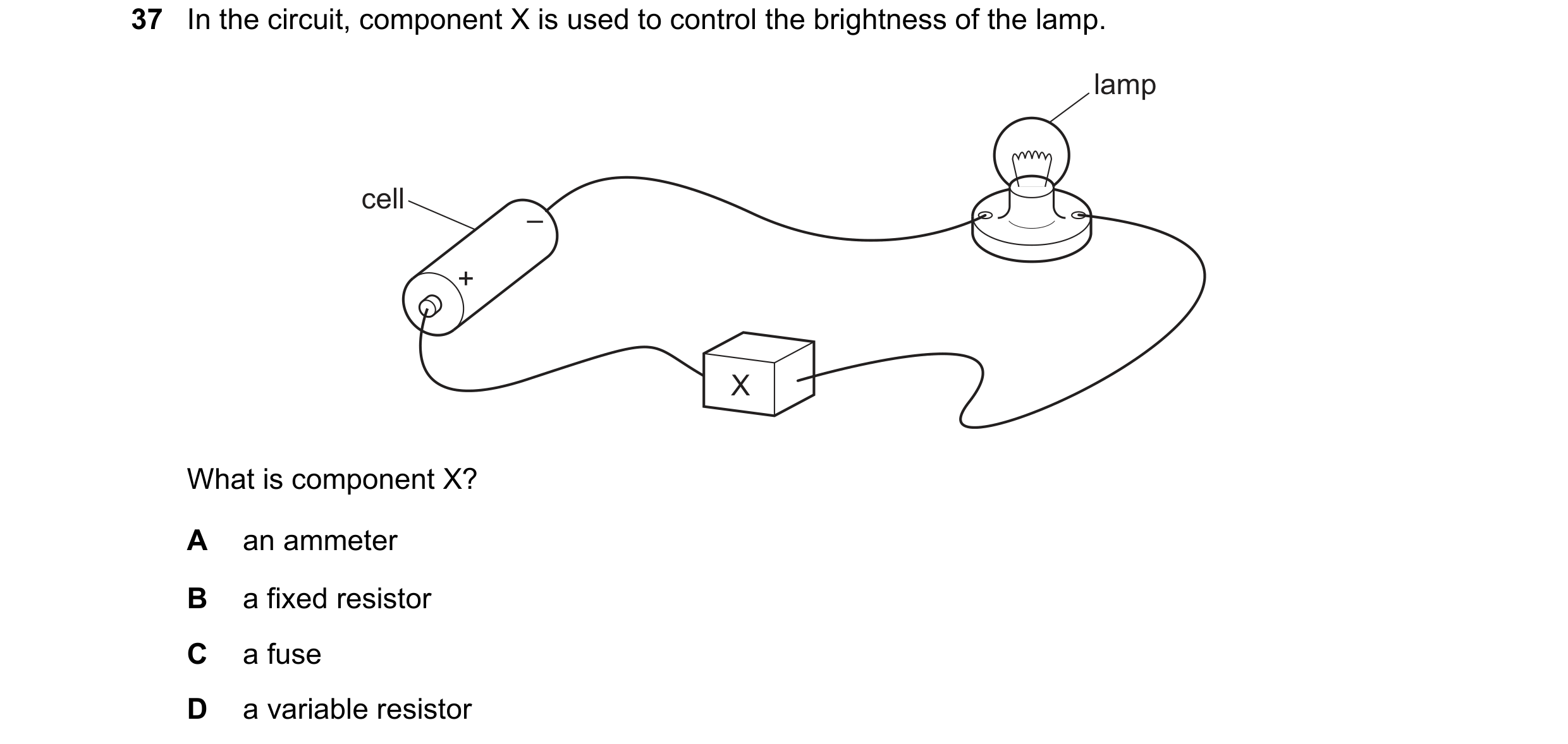
 27 / 48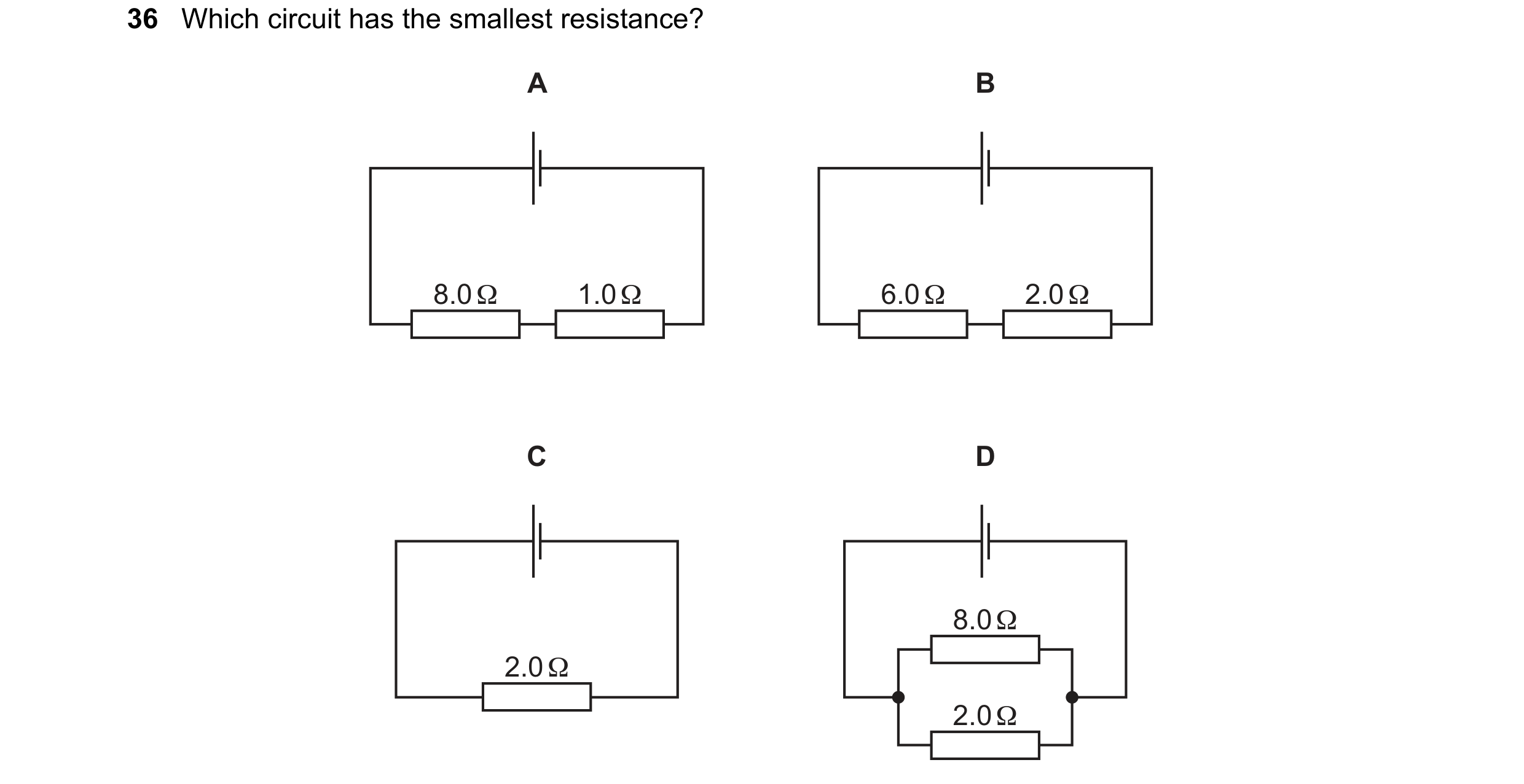

 28 / 48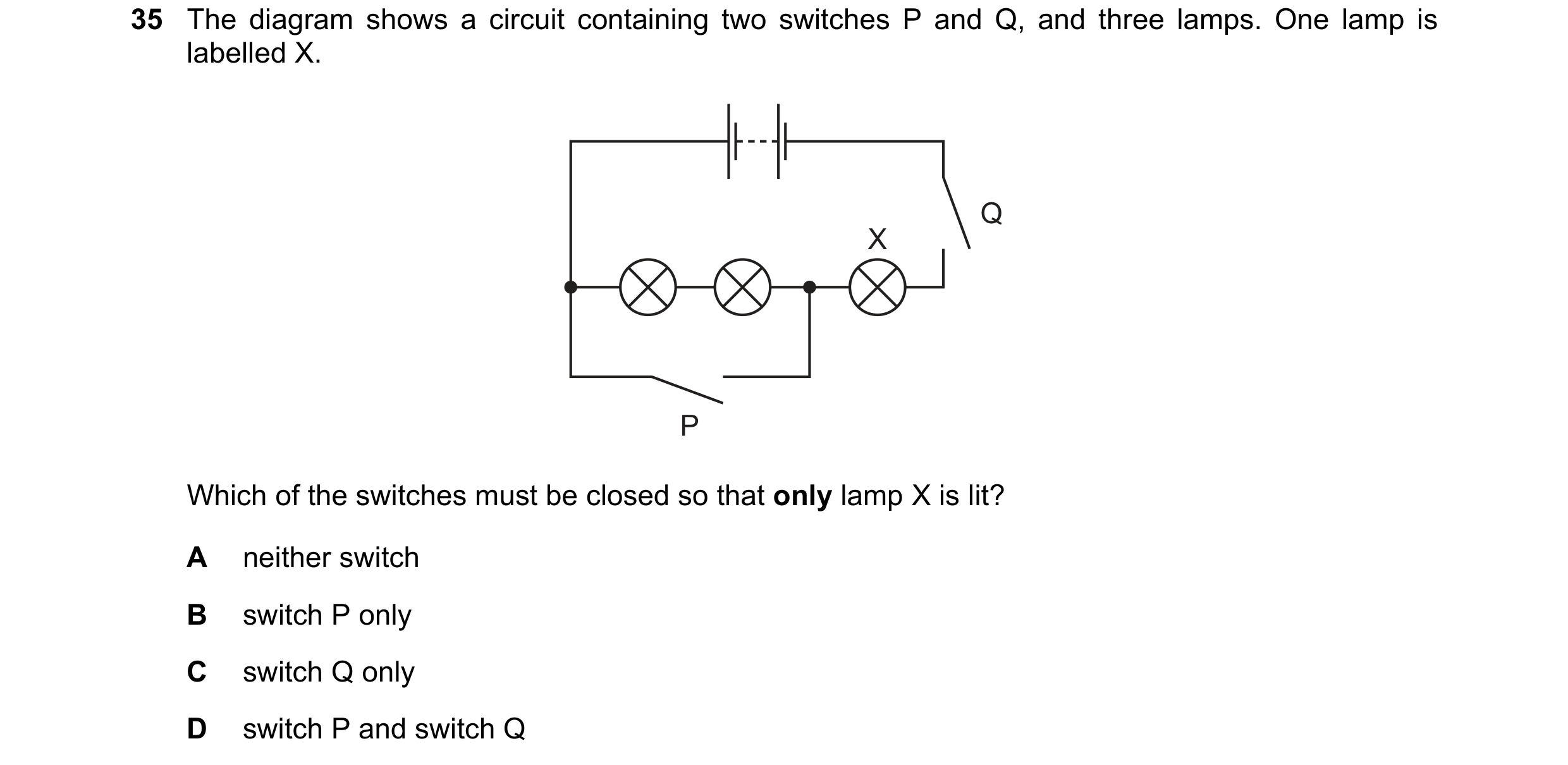
 29 / 48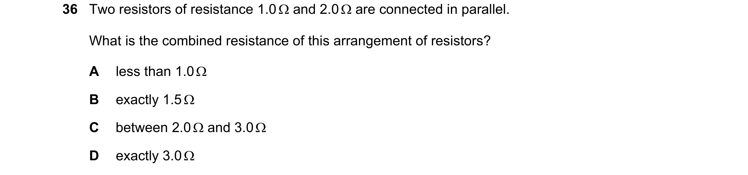
 30 / 48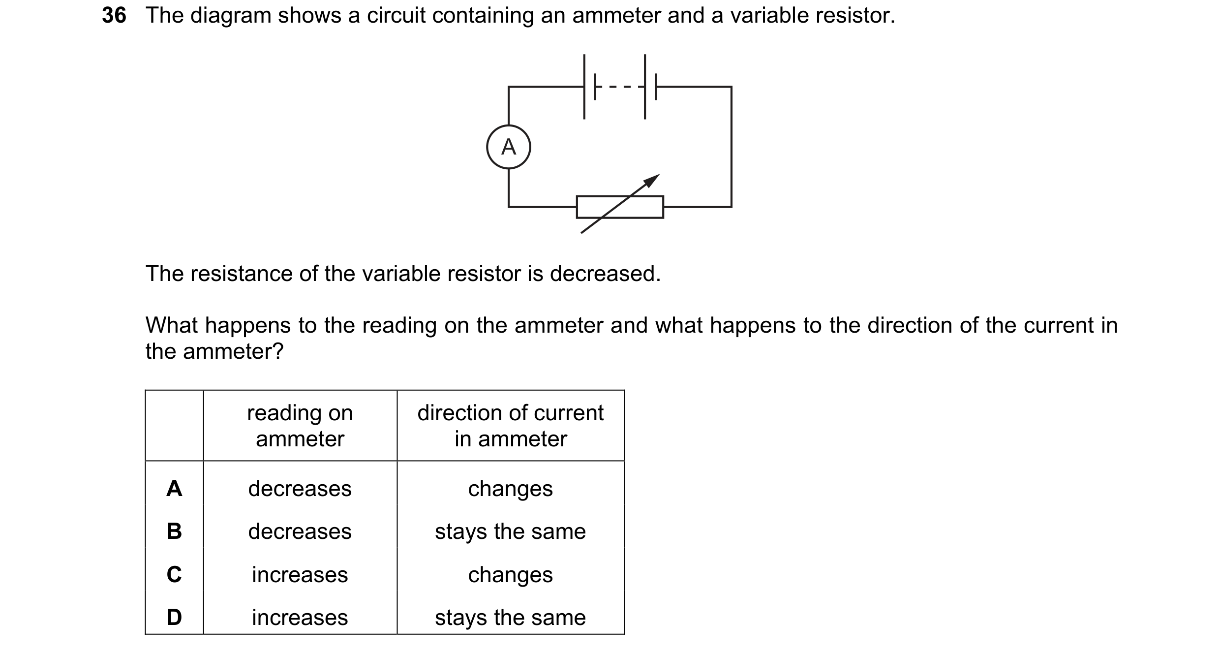
 31 / 48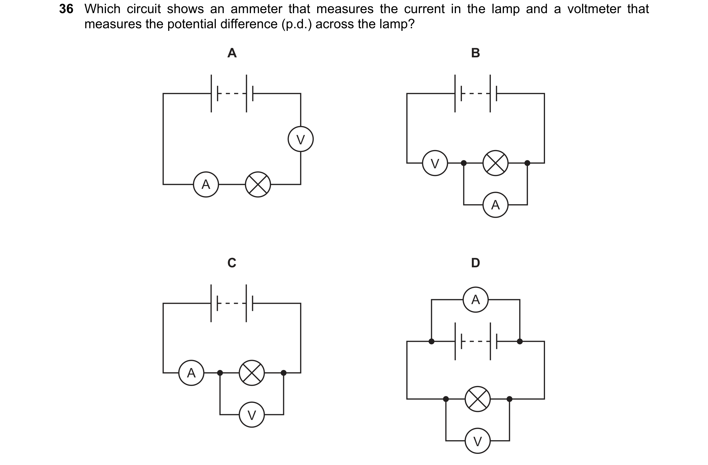
 32 / 48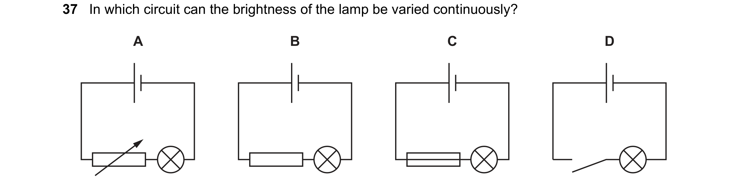
 33 / 48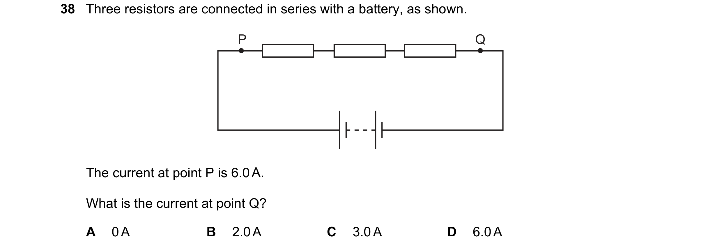
 34 / 48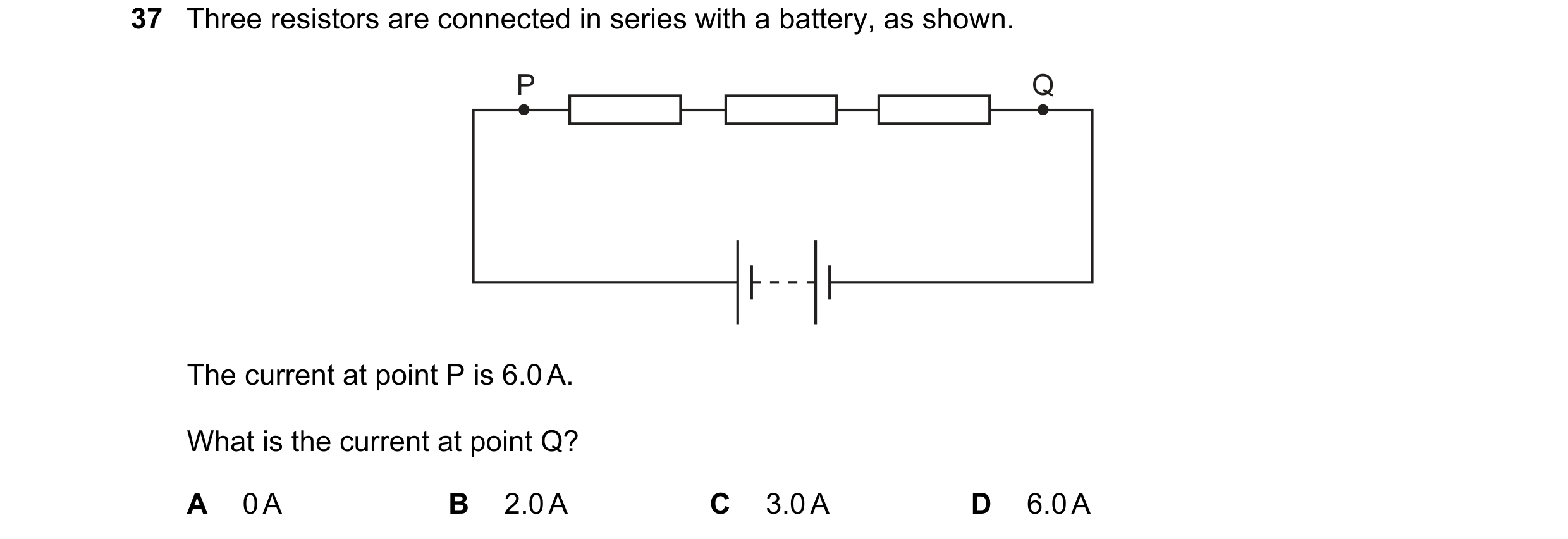
 35 / 48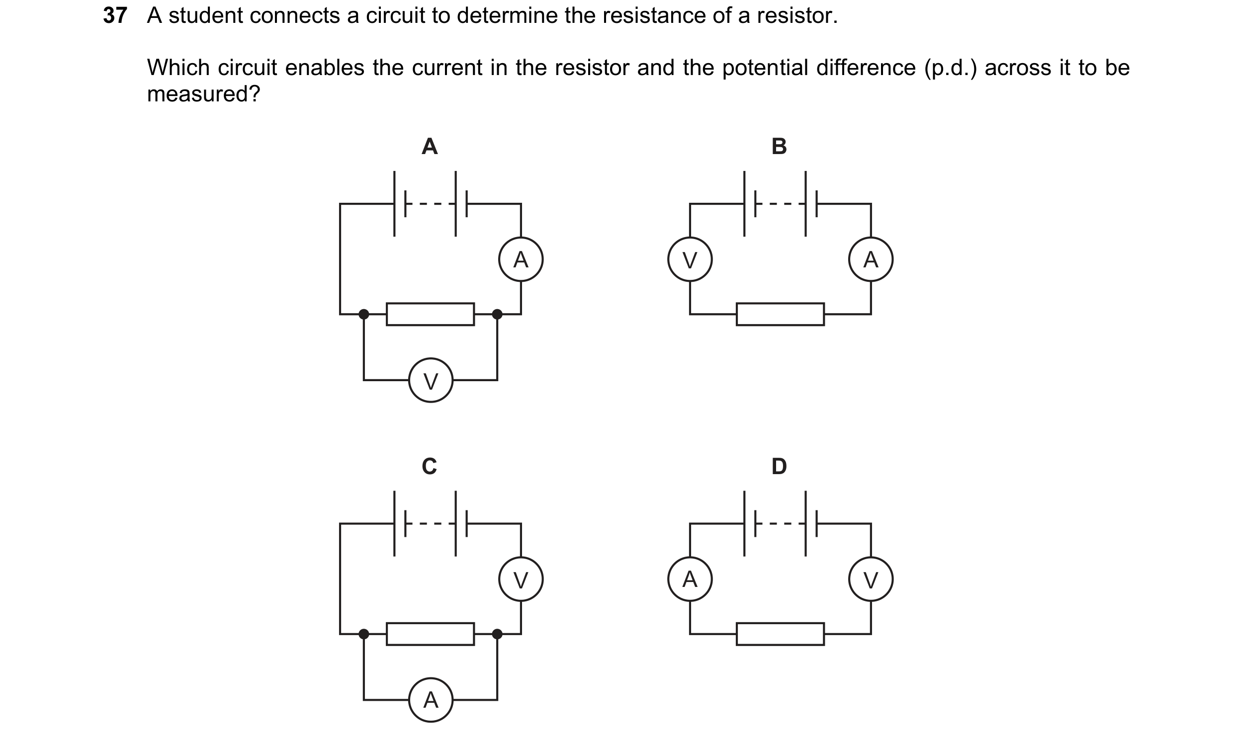
 36 / 48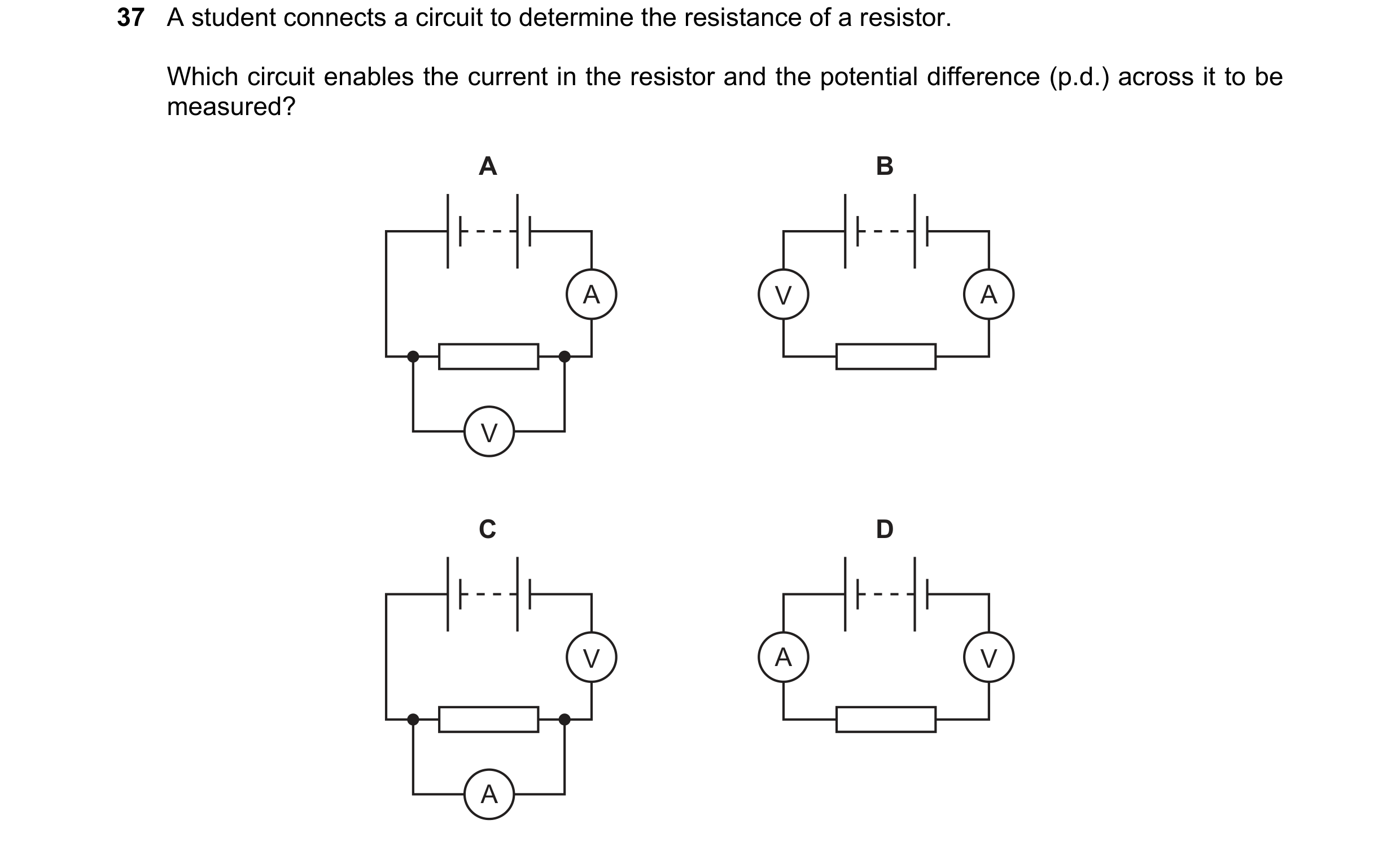
 37 / 48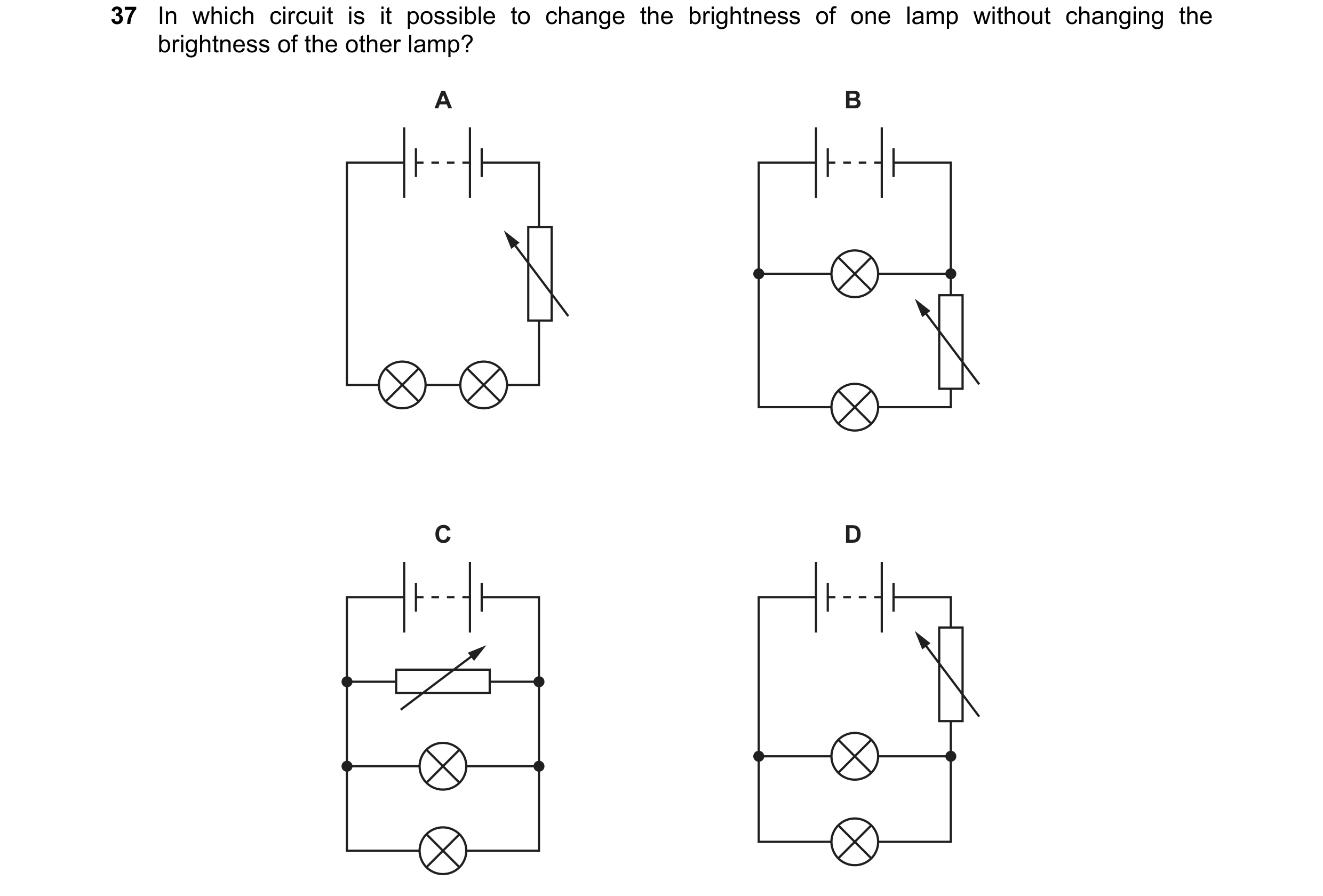
 38 / 48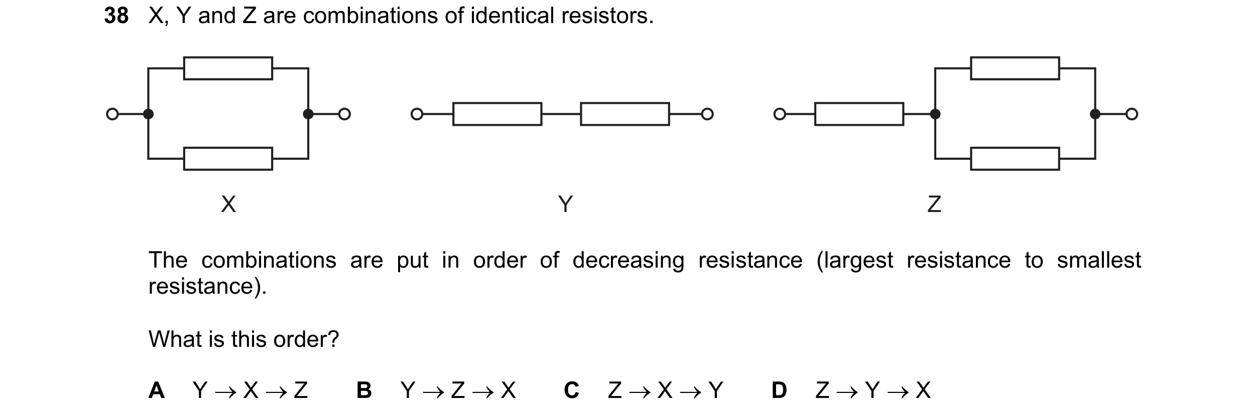
 39 / 48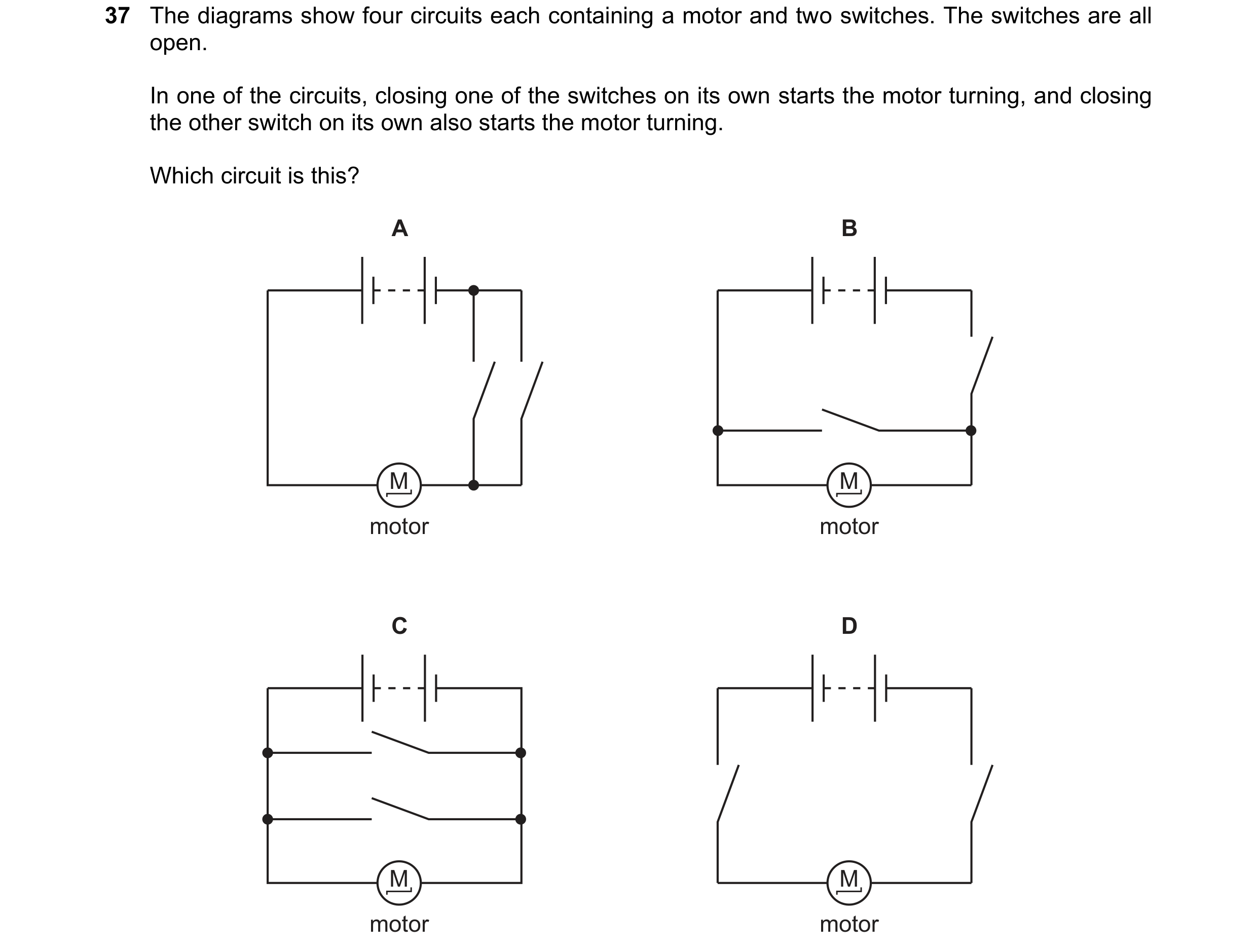

 40 / 48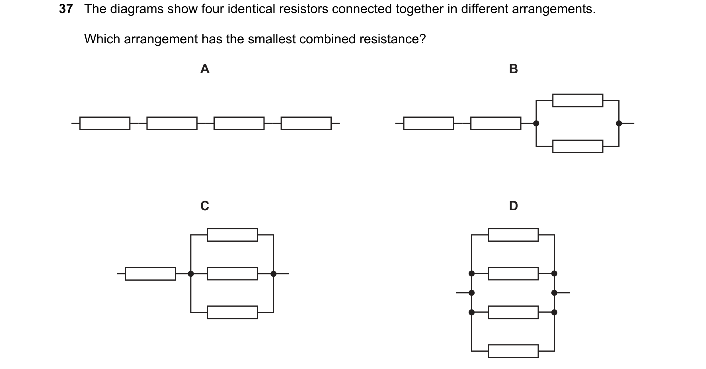
 41 / 48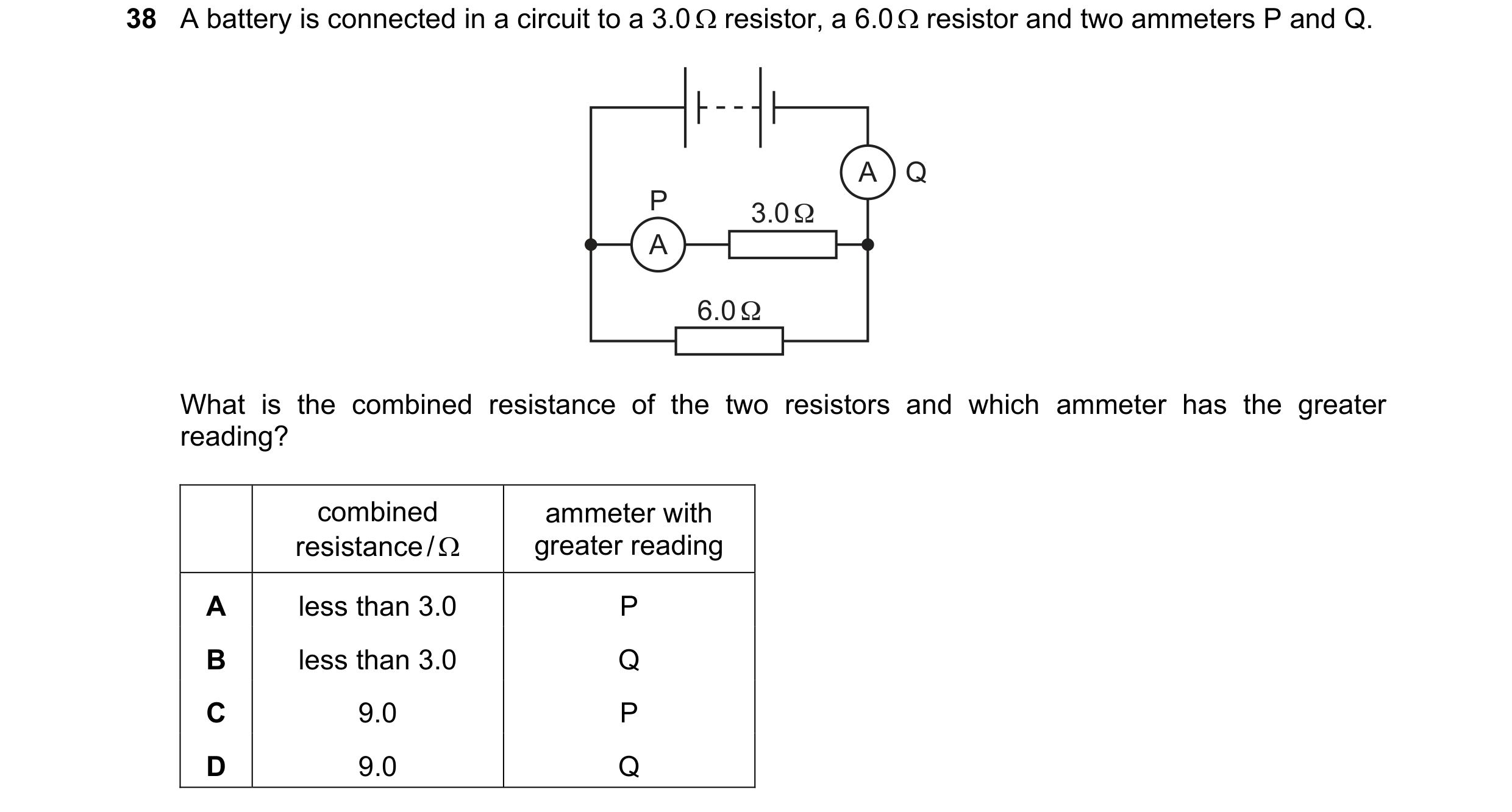
 42 / 48
 43 / 48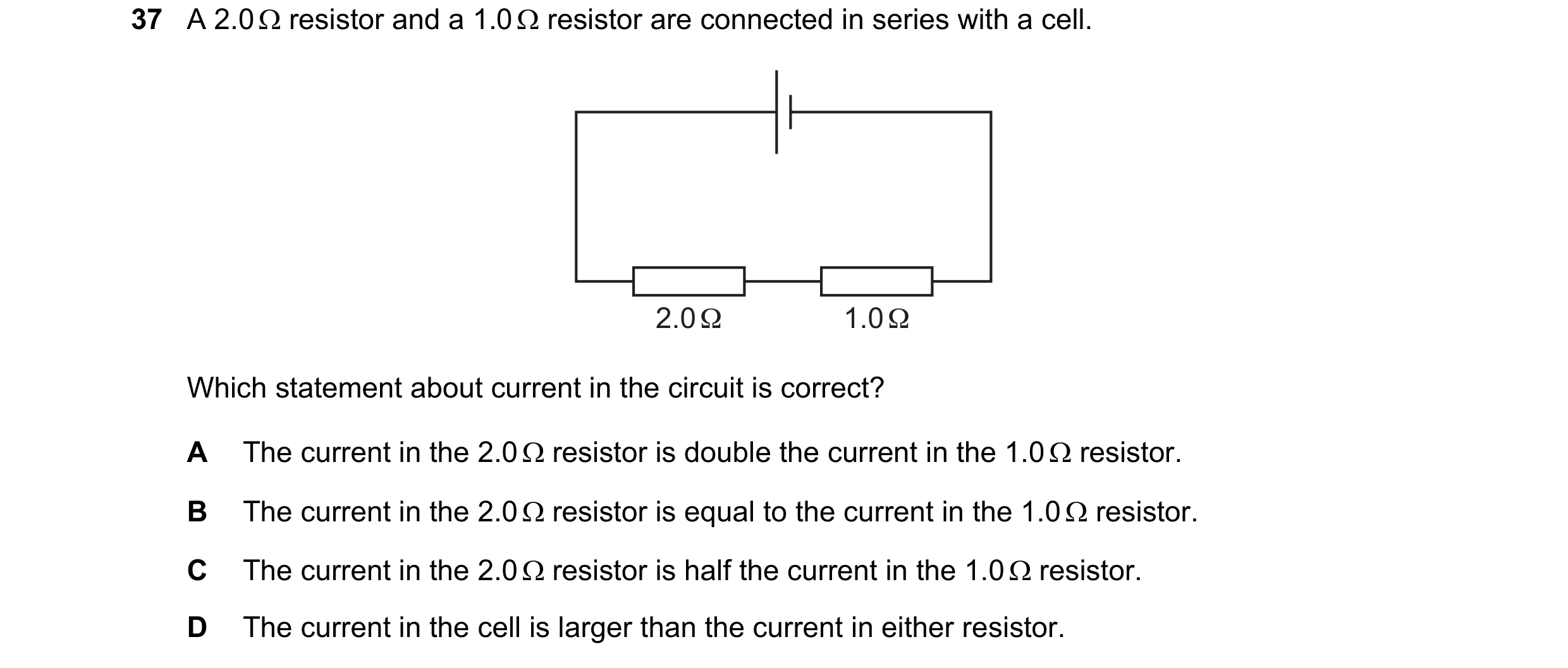
 44 / 48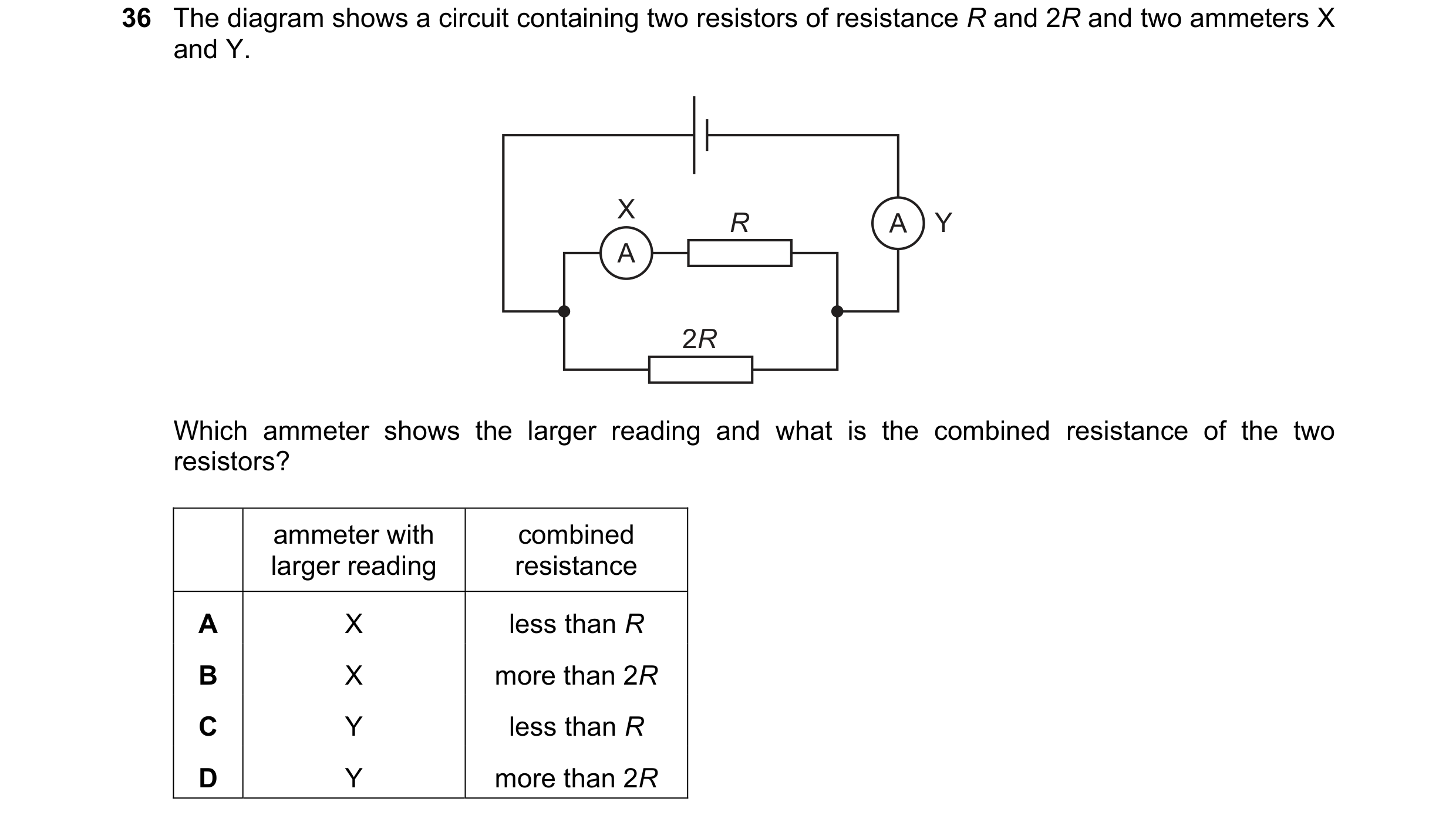
 45 / 48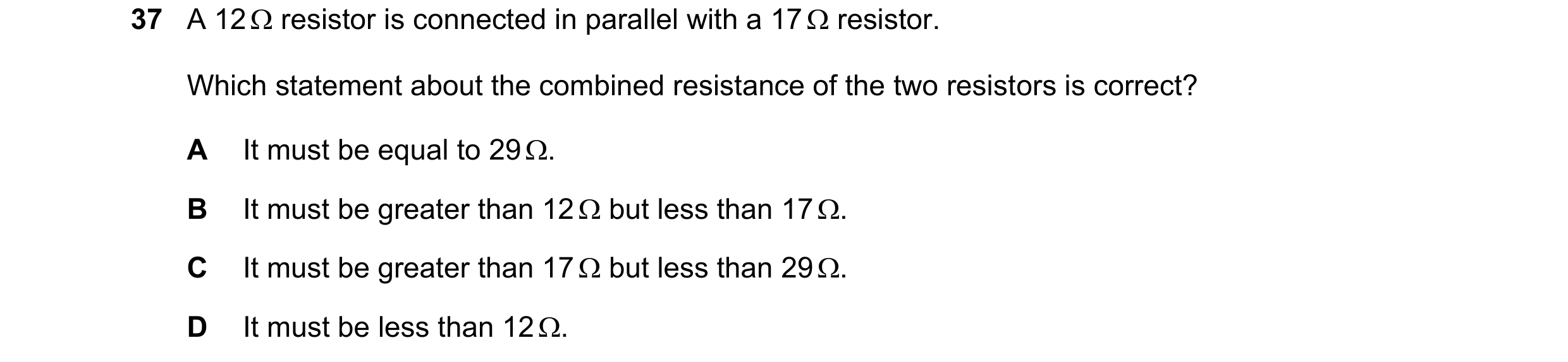
 46 / 48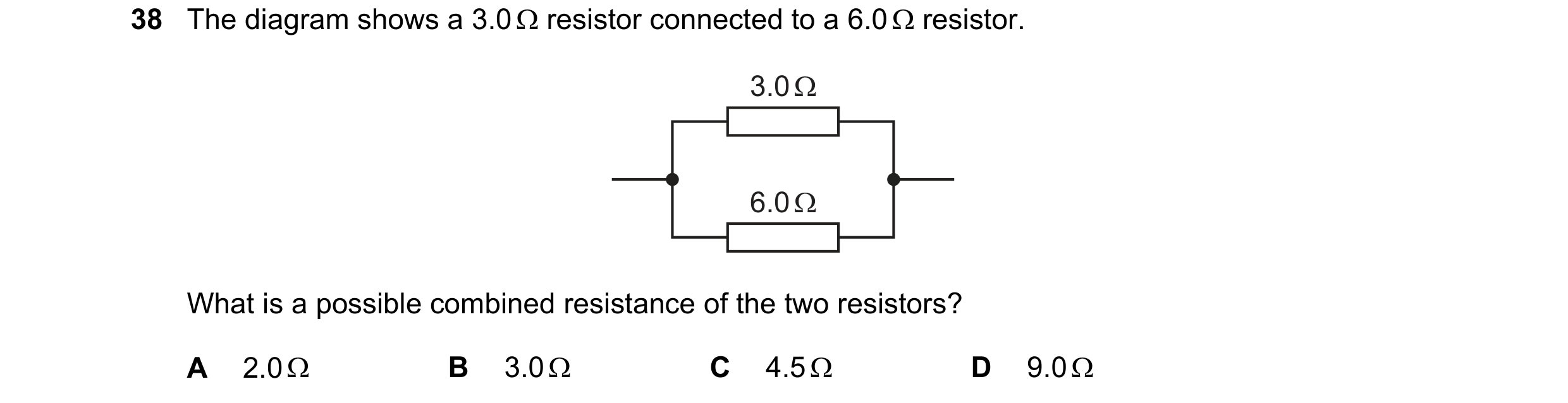
 47 / 48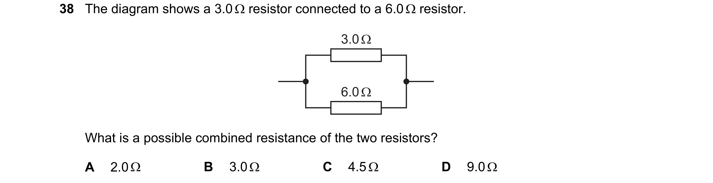
 48 / 48