Questions as text
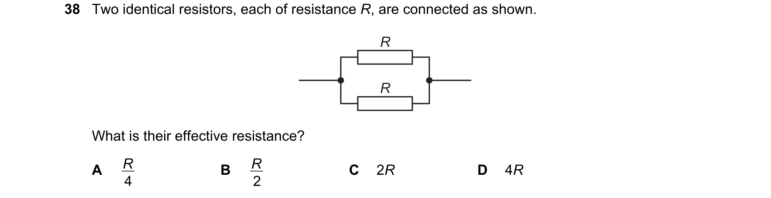
Q1 · Two identical resistors, each of resistance R, are connected as shown 0654/21 May/June 2017
38 Two identical resistors, each of resistance R, are connected as shown. R R What is their effective resistance? A R B R C 2R D 4R 4 2
1 marks
Answer: B
This question in 0654/21 May/June 2017
Q2 · Two identical resistors are connected in series 0654/22 May/June 2017
38 Two identical resistors are connected in series. Their combined resistance is 40 Ω. What is their effective resistance when connected in parallel? A 10 Ω B 20 Ω C 40 Ω D 80 Ω
1 marks
Answer: A
This question in 0654/22 May/June 2017
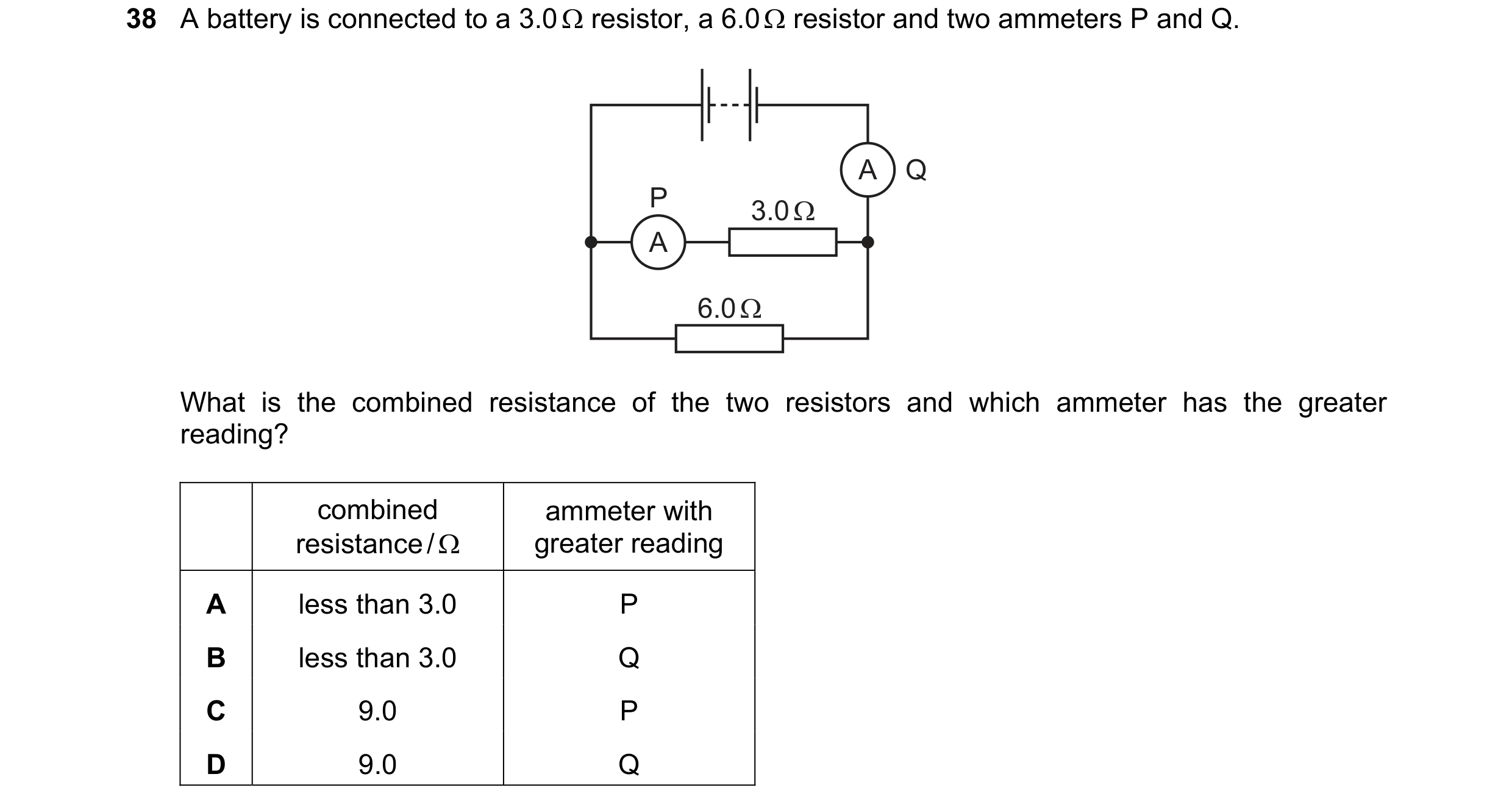
Q3 · A battery is connected to a 3.0 Ω resistor, a 6.0 Ω resistor and two ammeters P and Q 0654/23 May/June 2017
38 A battery is connected to a 3.0 Ω resistor, a 6.0 Ω resistor and two ammeters P and Q. A Q P 3.0 Ω A 6.0 Ω What is the combined resistance of the two resistors and which ammeter has the greater reading? combined ammeter with resistance / Ω greater reading A less than 3.0 P B less than 3.0 Q C 9.0 P D 9.0 Q
1 marks
Answer: B
This question in 0654/23 May/June 2017
Q4 · The circuit in the diagram contains three resistors 0654/21 Oct/Nov 2017
39 The circuit in the diagram contains three resistors. Currents P, Q and R, and potential differences S, T and U are labelled. R S P T U Q Which row shows the relationship between the currents and between the potential differences? potential currents differences A P + Q = R S = T + U B P + Q = R S = T = U C P = Q = R S = T + U D P = Q = R S = T = U
1 marks
Answer: A
This question in 0654/21 Oct/Nov 2017
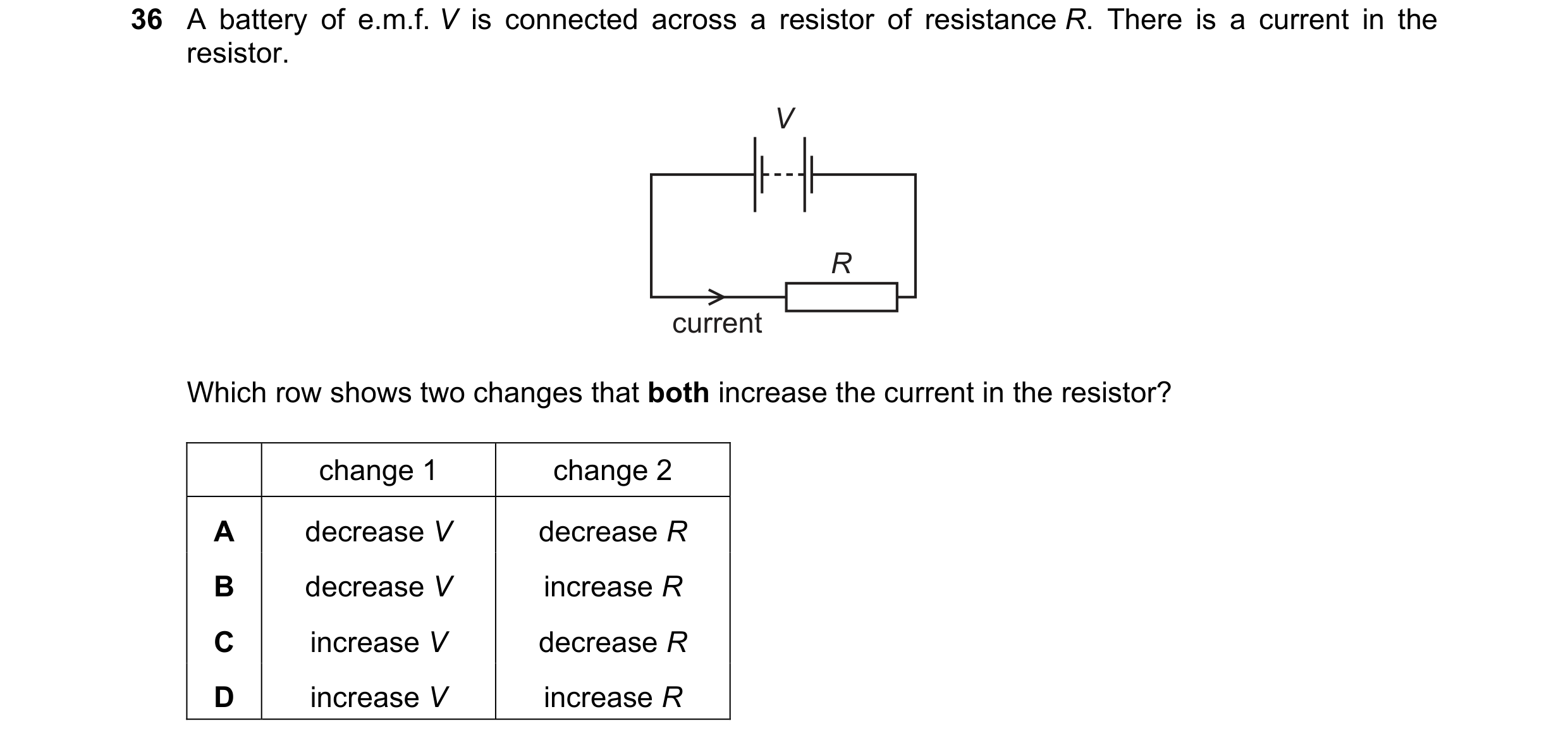
Q5 · A battery of e.m.f 0654/22 Oct/Nov 2017
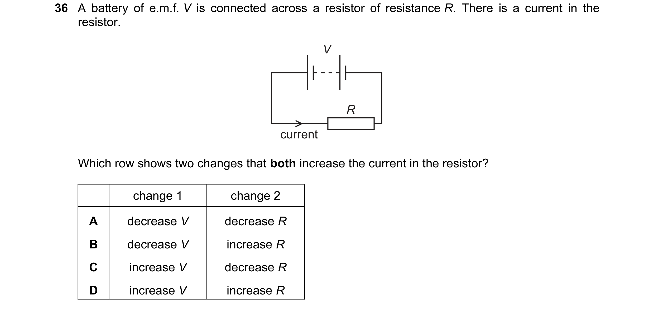
36 A battery of e.m.f. V is connected across a resistor of resistance R. There is a current in the resistor. V R current Which row shows two changes that both increase the current in the resistor? change 1 change 2 A decrease V decrease R B decrease V increase R C increase V decrease R D increase V increase R
1 marks
Answer: C
This question in 0654/22 Oct/Nov 2017
Q6 · The circuit in the diagram contains two resistors 0654/22 Oct/Nov 2017
39 The circuit in the diagram contains two resistors. Currents P, Q and R, and potential differences S, T and U are labelled. P R S T Q U Which row shows the relationship between the currents and between the potential differences? potential currents differences A P = Q = R S = T = U B P = Q = R S + T = U C P > Q > R S = T = U D P > Q > R S + T = U
1 marks
Answer: B
This question in 0654/22 Oct/Nov 2017
Q7 · An engineer wishes to make a d.c 0654/23 Oct/Nov 2017
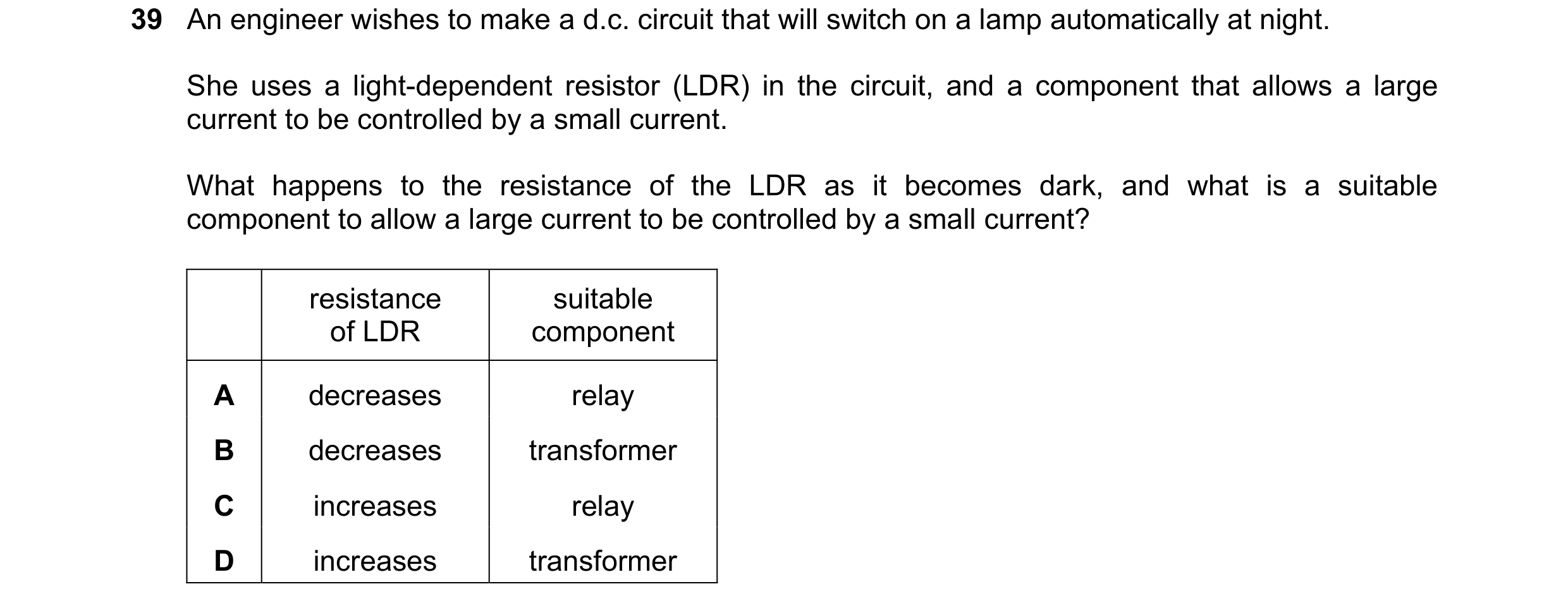
39 An engineer wishes to make a d.c. circuit that will switch on a lamp automatically at night. She uses a light-dependent resistor (LDR) in the circuit, and a component that allows a large current to be controlled by a small current. What happens to the resistance of the LDR as it becomes dark, and what is a suitable component to allow a large current to be controlled by a small current? resistance suitable of LDR component A decreases relay B decreases transformer C increases relay D increases transformer
1 marks
Answer: C
This question in 0654/23 Oct/Nov 2017
Q8 · A circuit contains a lamp and a fuse 0654/21 Oct/Nov 2018
38 A circuit contains a lamp and a fuse. There is a current of 2.0 A in the lamp and it operates normally. A fault develops in the lamp. The current in the circuit increases, and the fuse now blows. The diagrams show two circuits. diagram 1 diagram 2 Which is the circuit used and what is the effect of the fuse when it blows? circuit effect of fuse A diagram 1 reduces current to 0 B diagram 1 reduces current to 2.0 A C diagram 2 reduces current to 0 D diagram 2 reduces current to 2.0 A
1 marks
Answer: C
This question in 0654/21 Oct/Nov 2018
Q9 · A 6.0 V battery is connected to three 10 Ω resistors, as shown 0654/21 Oct/Nov 2018
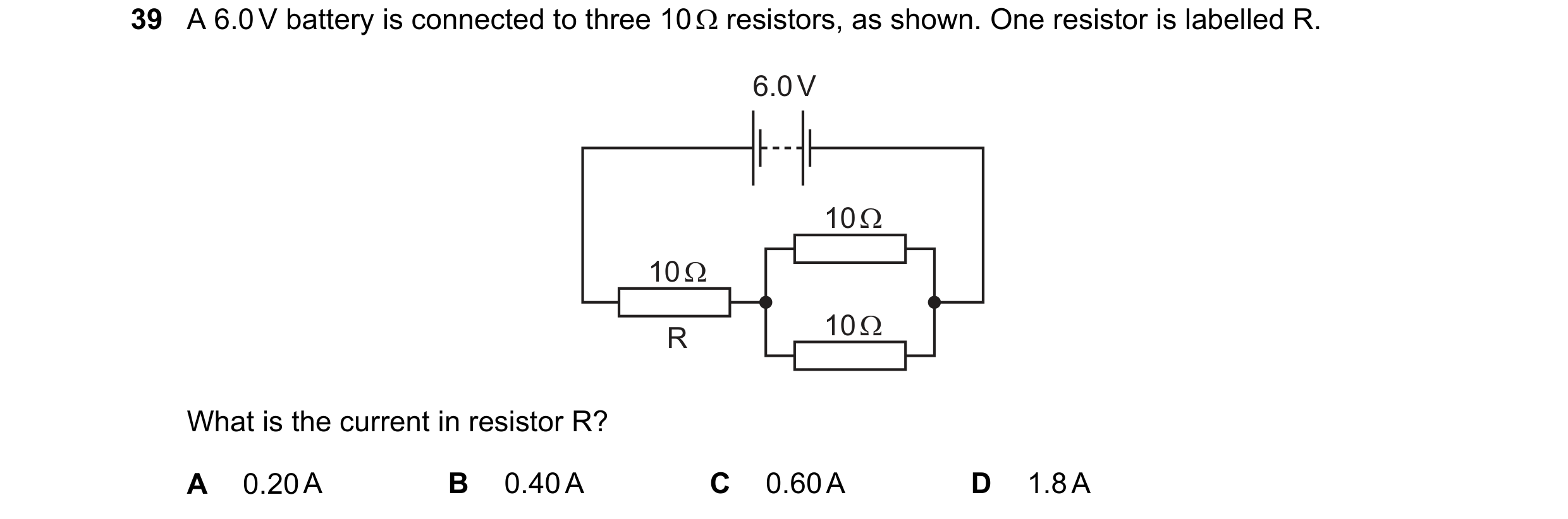
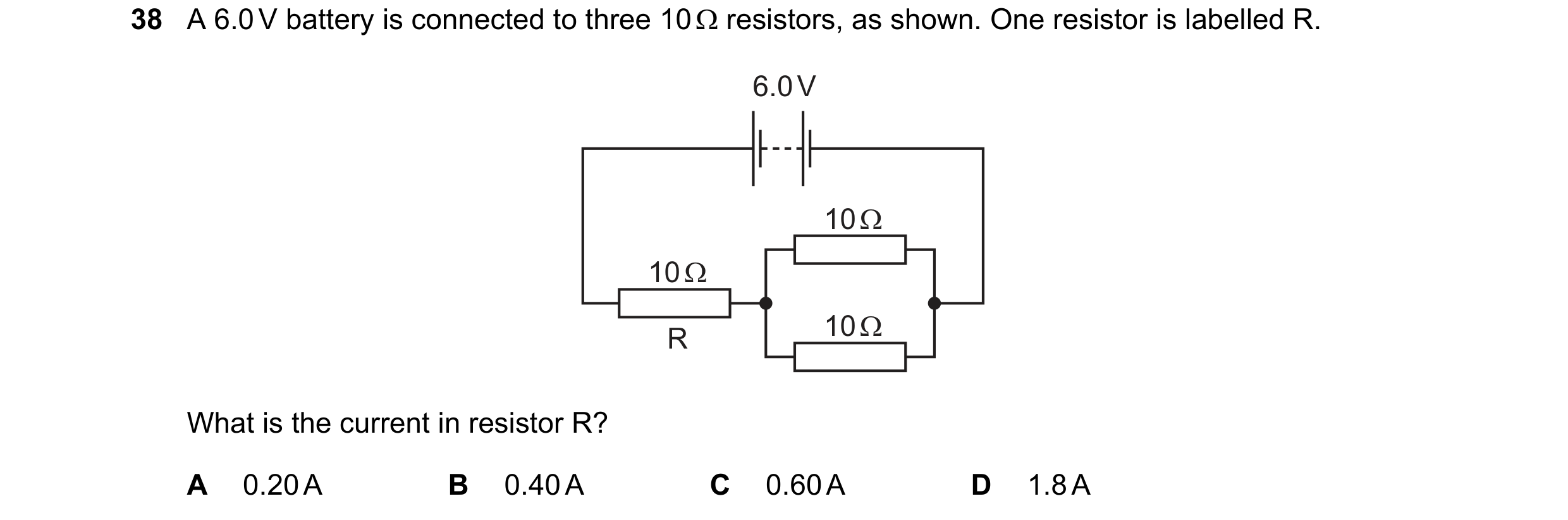
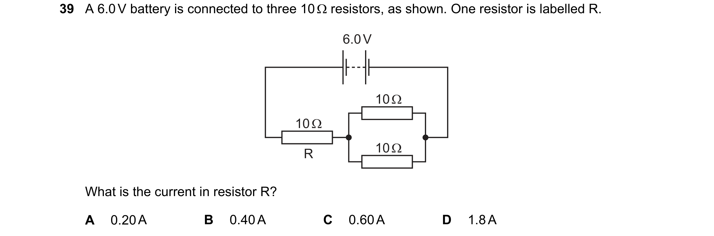
39 A 6.0 V battery is connected to three 10 Ω resistors, as shown. One resistor is labelled R. 6.0 V 10 Ω 10 Ω 10 Ω R What is the current in resistor R? A 0.20 A B 0.40 A C 0.60 A D 1.8 A
1 marks
Answer: B
This question in 0654/21 Oct/Nov 2018
Q10 · A 6.0 V battery is connected to three 10 Ω resistors, as shown 0654/22 Oct/Nov 2018
38 A 6.0 V battery is connected to three 10 Ω resistors, as shown. One resistor is labelled R. 6.0 V 10 Ω 10 Ω 10 Ω R What is the current in resistor R? A 0.20 A B 0.40 A C 0.60 A D 1.8 A
1 marks
Answer: B
This question in 0654/22 Oct/Nov 2018
Q11 · A circuit contains a lamp and a fuse 0654/23 Oct/Nov 2018
38 A circuit contains a lamp and a fuse. There is a current of 2.0 A in the lamp and it operates normally. A fault develops in the lamp. The current in the circuit increases, and the fuse now blows. The diagrams show two circuits. diagram 1 diagram 2 Which is the circuit used and what is the effect of the fuse when it blows? circuit effect of fuse A diagram 1 reduces current to 0 B diagram 1 reduces current to 2.0 A C diagram 2 reduces current to 0 D diagram 2 reduces current to 2.0 A
1 marks
Answer: C
This question in 0654/23 Oct/Nov 2018
Q12 · A 6.0 V battery is connected to three 10 Ω resistors, as shown 0654/23 Oct/Nov 2018
39 A 6.0 V battery is connected to three 10 Ω resistors, as shown. One resistor is labelled R. 6.0 V 10 Ω 10 Ω 10 Ω R What is the current in resistor R? A 0.20 A B 0.40 A C 0.60 A D 1.8 A
1 marks
Answer: B
This question in 0654/23 Oct/Nov 2018
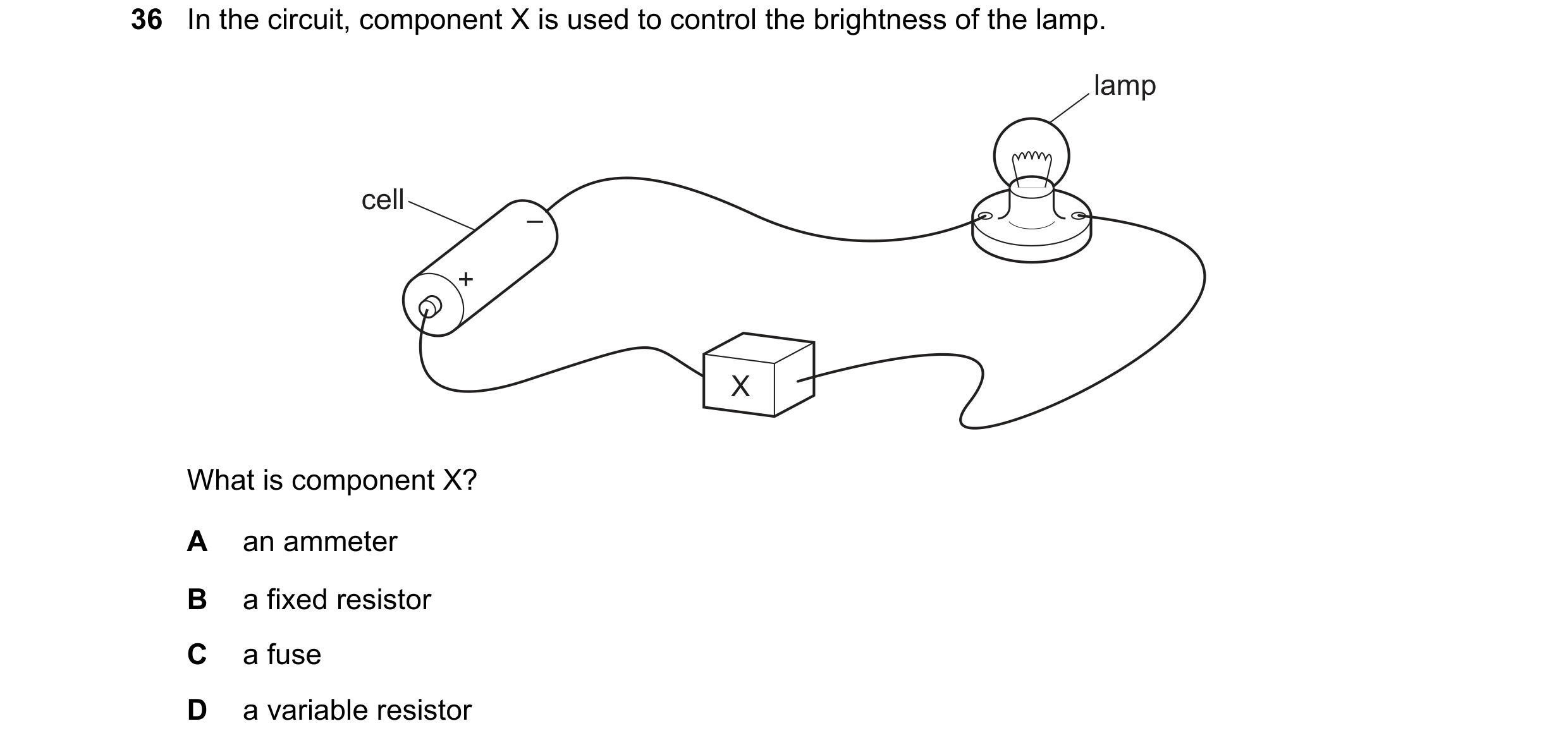
Q13 · In the circuit, component X is used to control the brightness of the lamp 0654/21 May/June 2019
36 In the circuit, component X is used to control the brightness of the lamp. lamp cell – + X What is component X? A an ammeter B a fixed resistor C a fuse D a variable resistor
1 marks
Answer: D
This question in 0654/21 May/June 2019
Q14 · In the circuit, component X is used to control the brightness of the lamp 0654/22 May/June 2019
36 In the circuit, component X is used to control the brightness of the lamp. lamp cell – + X What is component X? A an ammeter B a fixed resistor C a fuse D a variable resistor
1 marks
Answer: D
This question in 0654/22 May/June 2019
Q15 · A circuit contains a power supply, a lamp, an ammeter and a NTC thermistor, connected in… 0654/22 May/June 2019
37 A circuit contains a power supply, a lamp, an ammeter and a NTC thermistor, connected in series. A The NTC thermistor is now heated. What happens to the brightness of the lamp and what happens to the ammeter reading? brightness ammeter of lamp reading A decreases decreases B decreases increases C increases decreases D increases increases
1 marks
Answer: D
This question in 0654/22 May/June 2019
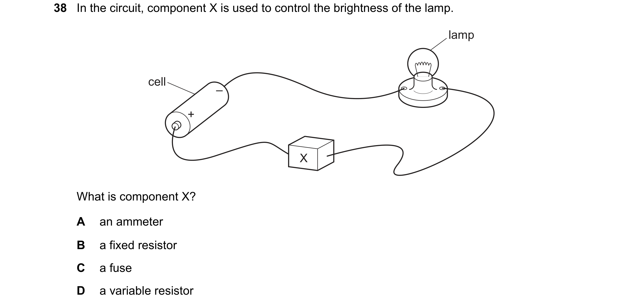
Q16 · In the circuit, component X is used to control the brightness of the lamp 0654/23 May/June 2019
38 In the circuit, component X is used to control the brightness of the lamp. lamp cell – + X What is component X? A an ammeter B a fixed resistor C a fuse D a variable resistor
1 marks
Answer: D
This question in 0654/23 May/June 2019
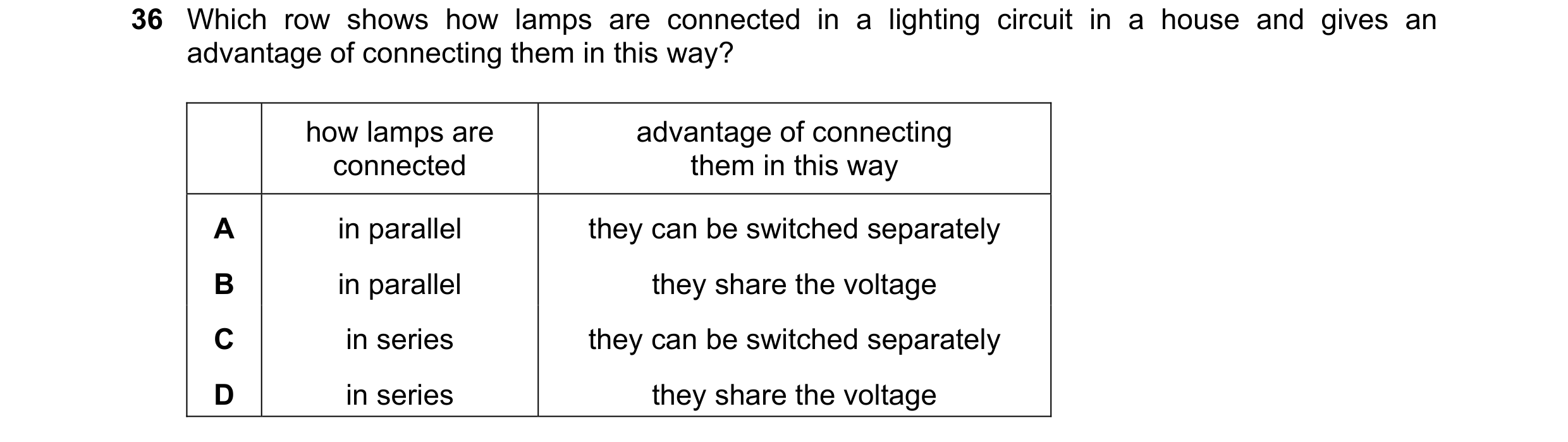
Q17 · Which row shows how lamps are connected in a lighting circuit in a house and gives an… 0654/21 Oct/Nov 2019
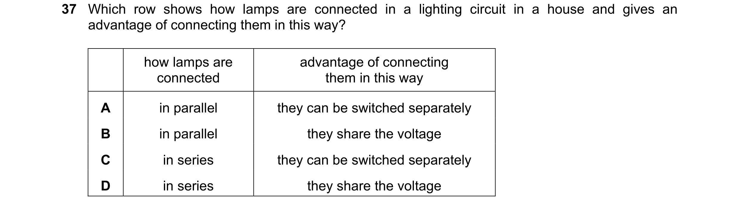
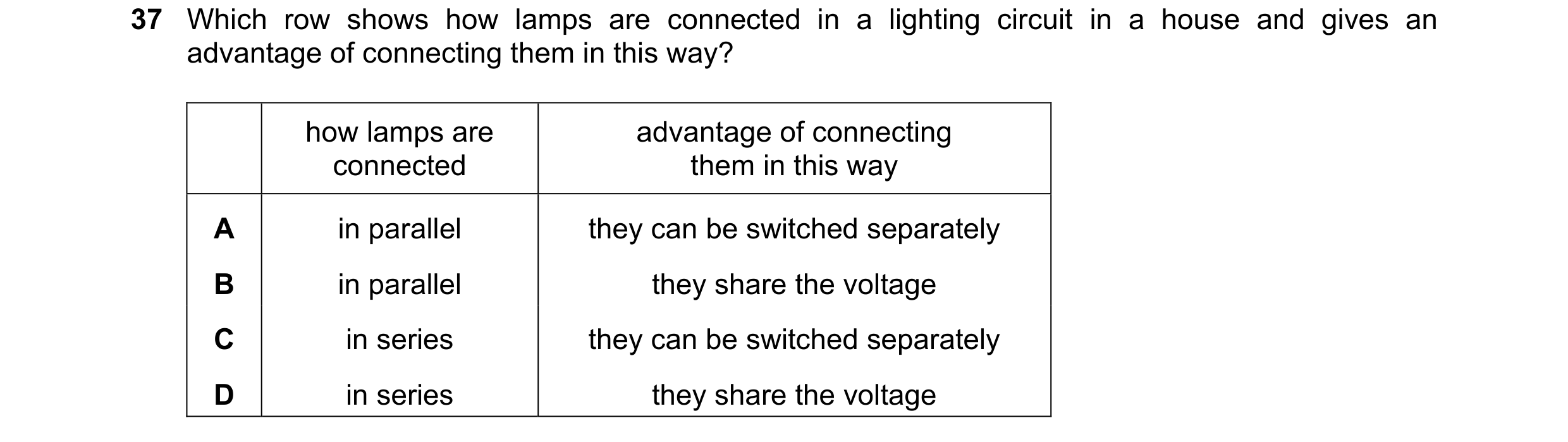
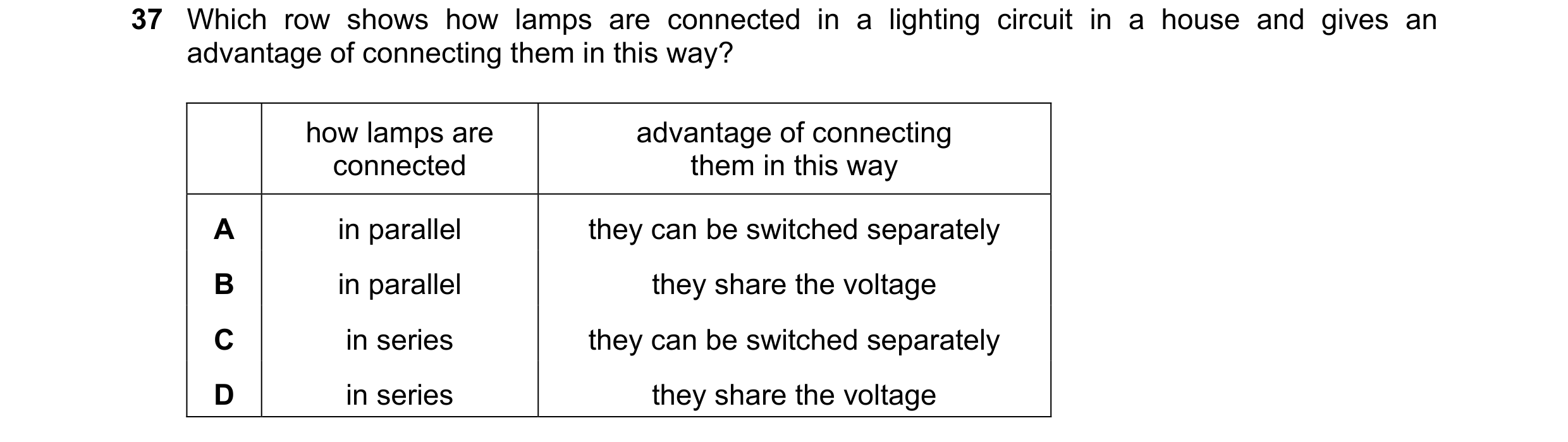
36 Which row shows how lamps are connected in a lighting circuit in a house and gives an advantage of connecting them in this way? how lamps are advantage of connecting connected them in this way A in parallel they can be switched separately B in parallel they share the voltage C in series they can be switched separately D in series they share the voltage
1 marks
Answer: A
This question in 0654/21 Oct/Nov 2019
Q18 · Which row shows how lamps are connected in a lighting circuit in a house and gives an… 0654/22 Oct/Nov 2019
37 Which row shows how lamps are connected in a lighting circuit in a house and gives an advantage of connecting them in this way? how lamps are advantage of connecting connected them in this way A in parallel they can be switched separately B in parallel they share the voltage C in series they can be switched separately D in series they share the voltage
1 marks
Answer: A
This question in 0654/22 Oct/Nov 2019
Q19 · The diagram shows a circuit containing two switches P and Q, and three lamps 0654/23 Oct/Nov 2019
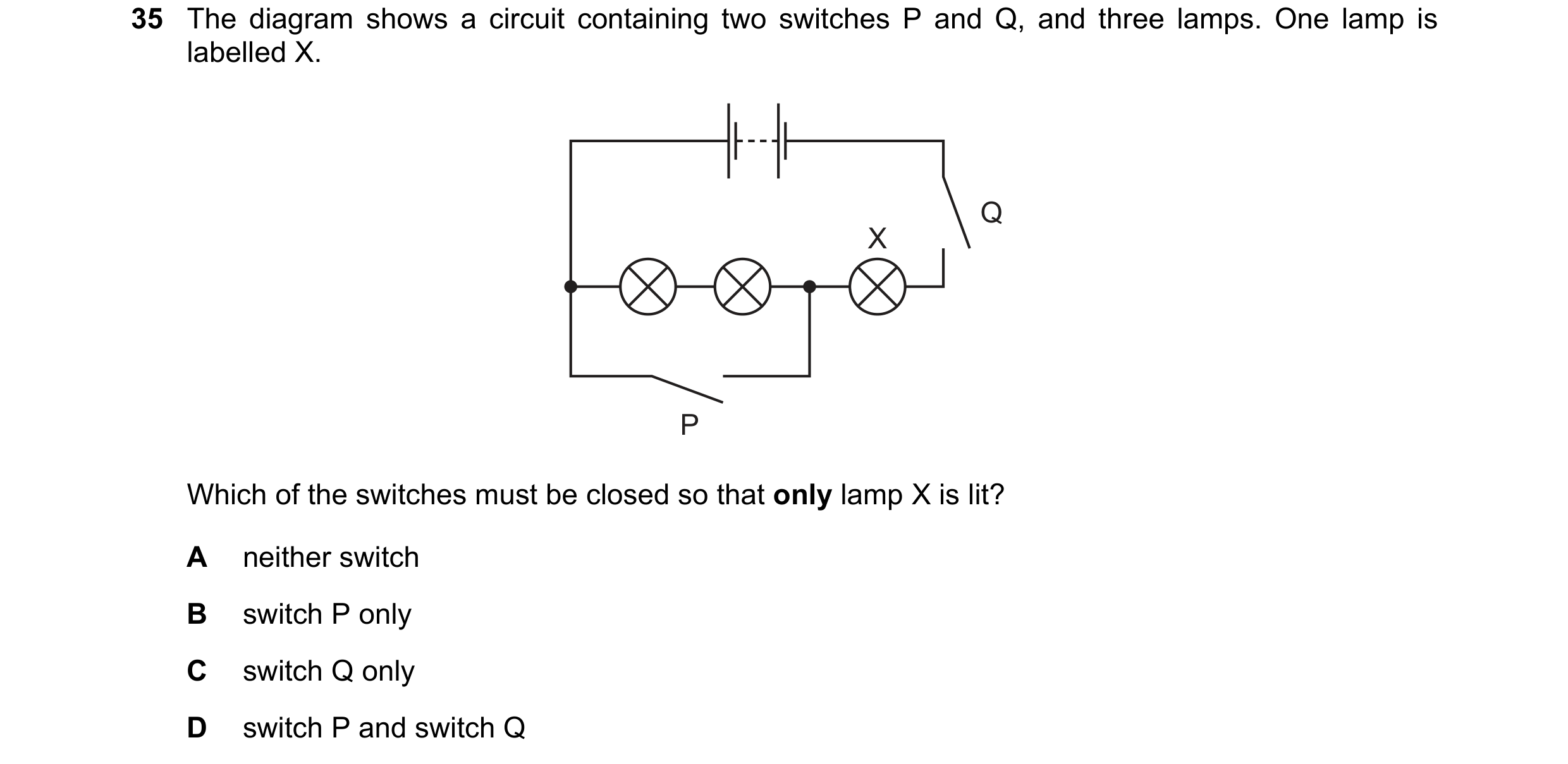
35 The diagram shows a circuit containing two switches P and Q, and three lamps. One lamp is labelled X. Q X P Which of the switches must be closed so that only lamp X is lit? A neither switch B switch P only C switch Q only D switch P and switch Q
1 marks
Answer: D
This question in 0654/23 Oct/Nov 2019
Q20 · Which row shows how lamps are connected in a lighting circuit in a house and gives an… 0654/23 Oct/Nov 2019
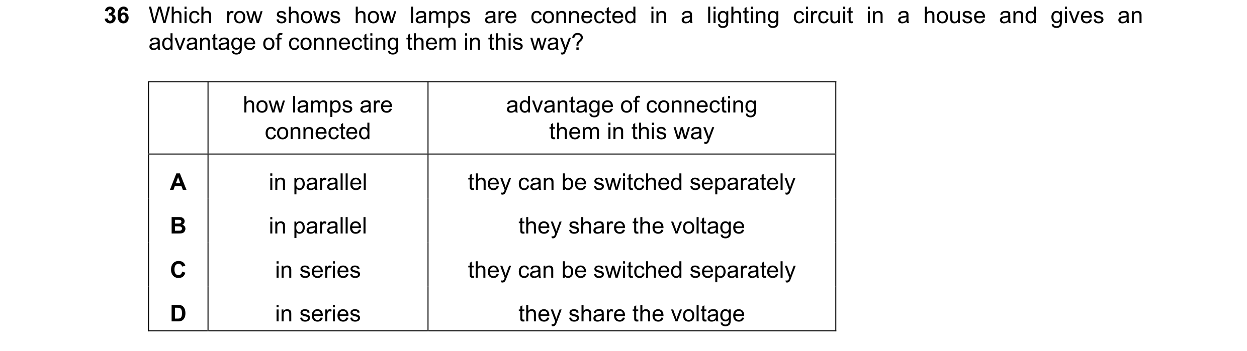
36 Which row shows how lamps are connected in a lighting circuit in a house and gives an advantage of connecting them in this way? how lamps are advantage of connecting connected them in this way A in parallel they can be switched separately B in parallel they share the voltage C in series they can be switched separately D in series they share the voltage
1 marks
Answer: A
This question in 0654/23 Oct/Nov 2019
Q21 · Which graph is the current–voltage characteristic of a filament lamp? 0654/22 May/June 2020
36 Which graph is the current–voltage characteristic of a filament lamp? A B current current 0 0 0 voltage 0 voltage C D current current 0 0 0 voltage 0 voltage
1 marks
Answer: C
This question in 0654/22 May/June 2020
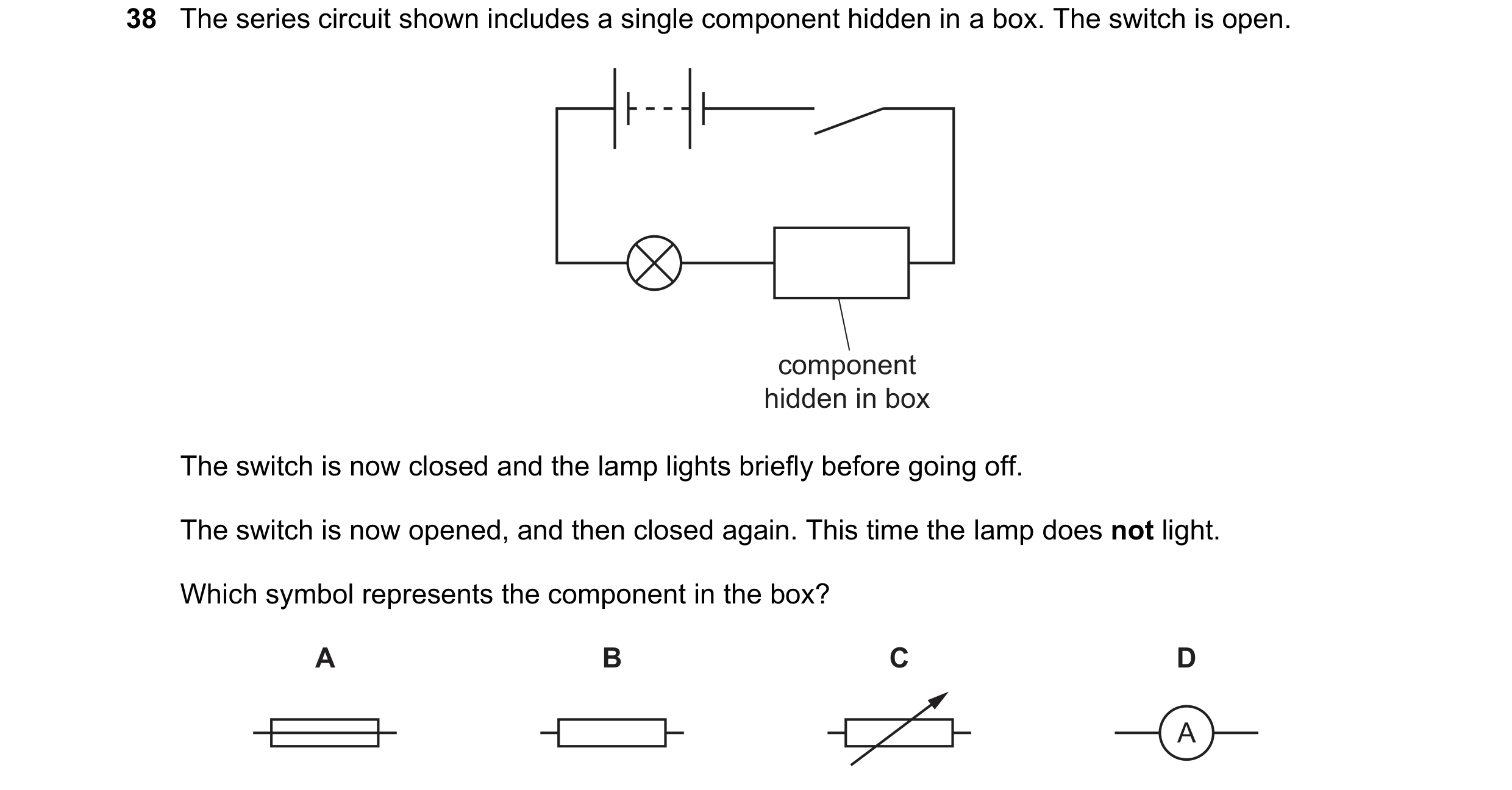
Q22 · The series circuit shown includes a single component hidden in a box 0654/21 Oct/Nov 2020
38 The series circuit shown includes a single component hidden in a box. The switch is open. component hidden in box The switch is now closed and the lamp lights briefly before going off. The switch is now opened, and then closed again. This time the lamp does not light. Which symbol represents the component in the box? A B C D A
1 marks
Answer: A
This question in 0654/21 Oct/Nov 2020
Q23 · Which statement about an NTC thermistor is correct? 0654/22 Oct/Nov 2020
35 Which statement about an NTC thermistor is correct? A As its temperature increases its resistance decreases. B As its temperature increases its resistance increases. C As the brightness of light falling on it increases its resistance decreases. D As the brightness of light falling on it increases its resistance increases.
1 marks
Answer: A
This question in 0654/22 Oct/Nov 2020
Q24 · A 12 resistor and a 4.0 resistor are connected across the terminals of a 12 V battery 0654/22 Oct/Nov 2020
36 A 12 resistor and a 4.0 resistor are connected across the terminals of a 12 V battery. 12 V 12 Ω 4.0 Ω V There is a voltmeter connected across the 12 resistor. What is the reading on the voltmeter? A 3.0 V B 8.0 V C 9.0 V D 12 V
1 marks
Answer: C
This question in 0654/22 Oct/Nov 2020
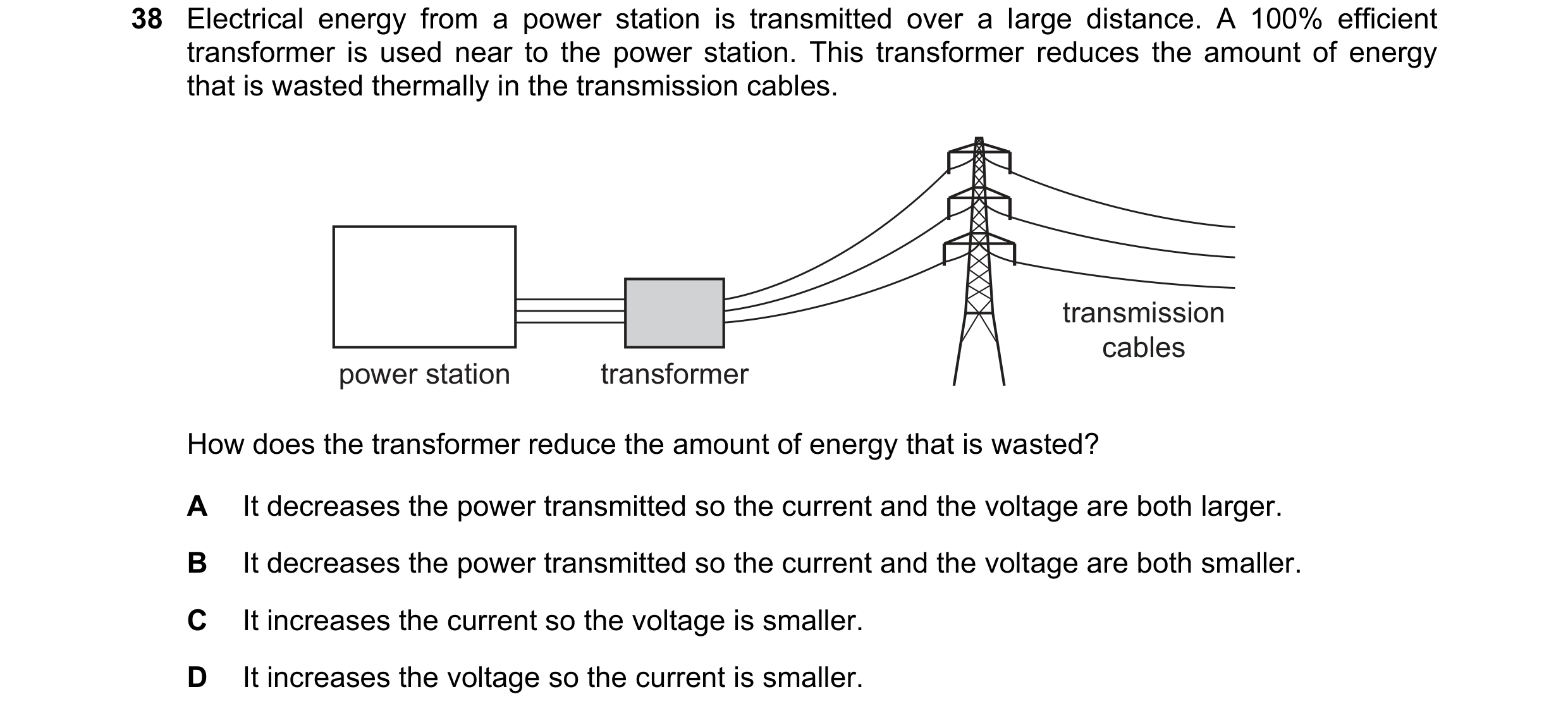
Q25 · Electrical energy from a power station is transmitted over a large distance 0654/22 Feb/March 2021
38 Electrical energy from a power station is transmitted over a large distance. A 100% efficient transformer is used near to the power station. This transformer reduces the amount of energy that is wasted thermally in the transmission cables. transmission cables power station transformer How does the transformer reduce the amount of energy that is wasted? A It decreases the power transmitted so the current and the voltage are both larger. B It decreases the power transmitted so the current and the voltage are both smaller. C It increases the current so the voltage is smaller. D It increases the voltage so the current is smaller.
1 marks
Answer: D
This question in 0654/22 Feb/March 2021
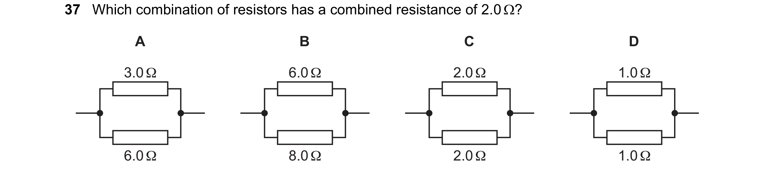
Q26 · Which combination of resistors has a combined resistance of 2.0 ? 0654/21 May/June 2021
37 Which combination of resistors has a combined resistance of 2.0 ? A B C D 3.0 Ω 6.0 Ω 2.0 Ω 1.0 Ω 6.0 Ω 8.0 Ω 2.0 Ω 1.0 Ω
1 marks
Answer: A
This question in 0654/21 May/June 2021
Q27 · Which statements about the current–voltage characteristic of a filament lamp are correct? 0654/22 May/June 2021
37 Which statements about the current–voltage characteristic of a filament lamp are correct? 1 It is a curve. 2 It passes through the origin. 3 It shows current increasing as voltage increases. A 1 and 2 only B 1 and 3 only C 2 and 3 only D 1, 2 and 3
1 marks
Answer: D
This question in 0654/22 May/June 2021
Q28 · A 4.0 resistor and an 8.0 resistor are connected in series with a power supply 0654/23 May/June 2021
37 A 4.0 resistor and an 8.0 resistor are connected in series with a power supply. The circuit diagram shows the arrangement. power supply 4.0 Ω 8.0 Ω V The reading on the voltmeter connected across the 4.0 resistor is 2.0 V. What is the potential difference (p.d.) across the power supply? A 2.0 V B 4.0 V C 6.0 V D 12 V
1 marks
Answer: C
This question in 0654/23 May/June 2021
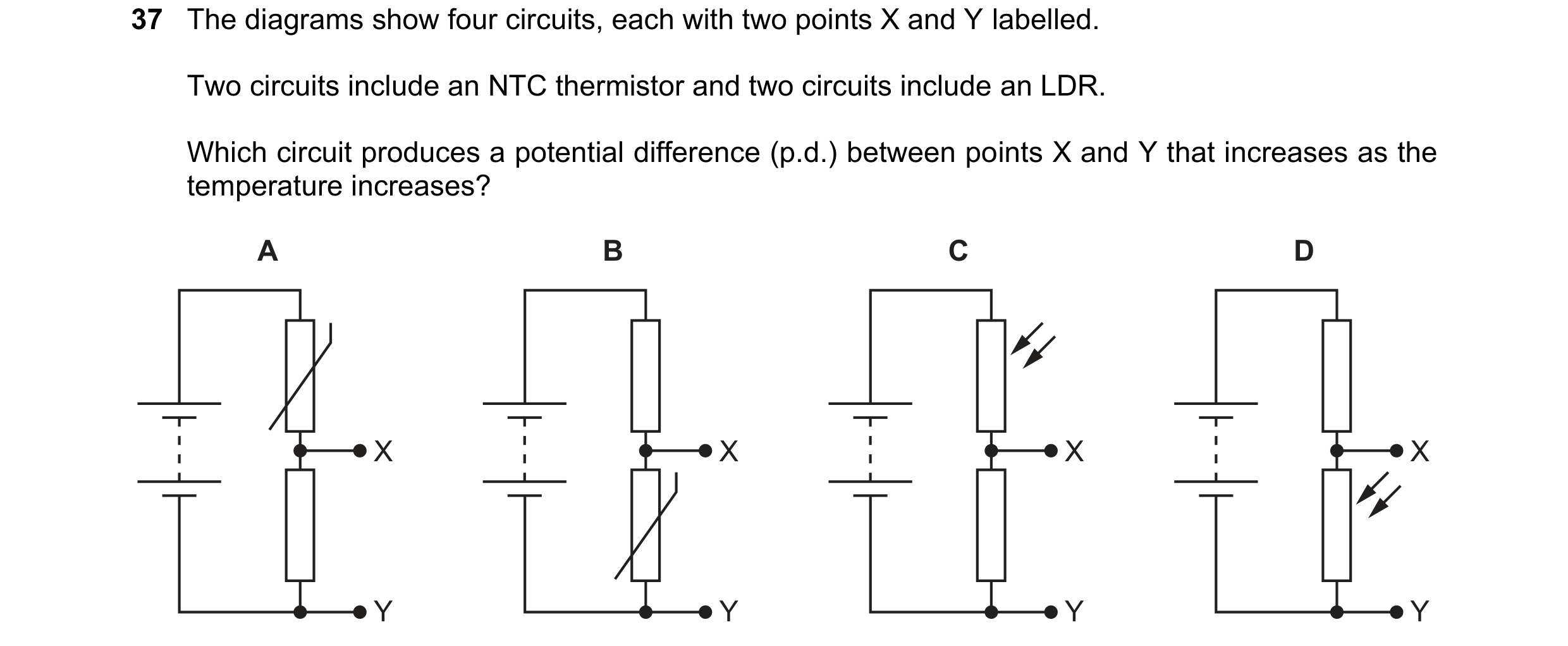
Q29 · The diagrams show four circuits, each with two points X and Y labelled 0654/23 Oct/Nov 2021
37 The diagrams show four circuits, each with two points X and Y labelled. Two circuits include an NTC thermistor and two circuits include an LDR. Which circuit produces a potential difference (p.d.) between points X and Y that increases as the temperature increases? A B C D X X X X Y Y Y Y
1 marks
Answer: A
This question in 0654/23 Oct/Nov 2021
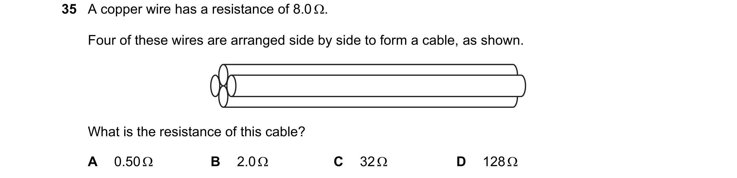
Q30 · A copper wire has a resistance of 8.0 0654/22 Feb/March 2022
35 A copper wire has a resistance of 8.0 . Four of these wires are arranged side by side to form a cable, as shown. What is the resistance of this cable? A 0.50 B 2.0 C 32 D 128
1 marks
Answer: B
This question in 0654/22 Feb/March 2022
Q31 · The diagram shows a circuit containing a resistor and an NTC thermistor 0654/22 Feb/March 2022
36 The diagram shows a circuit containing a resistor and an NTC thermistor. V The temperature of the thermistor increases. What happens to the resistance of the thermistor and what happens to the reading on the voltmeter? resistance of reading on thermistor voltmeter A decreases decreases B decreases increases C increases decreases D increases increases
1 marks
Answer: A
This question in 0654/22 Feb/March 2022
Q32 · Which row shows how lamps are connected in a lighting circuit in a house and gives an… 0654/21 May/June 2022
37 Which row shows how lamps are connected in a lighting circuit in a house and gives an advantage of connecting them in this way? how lamps are advantage of connecting connected them in this way A in parallel they can be switched separately B in parallel they share the voltage C in series they can be switched separately D in series they share the voltage
1 marks
Answer: A
This question in 0654/21 May/June 2022
Q33 · Which row shows how lamps are connected in a lighting circuit in a house and gives an… 0654/22 May/June 2022
37 Which row shows how lamps are connected in a lighting circuit in a house and gives an advantage of connecting them in this way? how lamps are advantage of connecting connected them in this way A in parallel they can be switched separately B in parallel they share the voltage C in series they can be switched separately D in series they share the voltage
1 marks
Answer: A
This question in 0654/22 May/June 2022
Q34 · A transformer increases the voltage from a power station in order to transfer electricity… 0654/22 May/June 2022
38 A transformer increases the voltage from a power station in order to transfer electricity along transmission cables. How does increasing the voltage affect the current in the cables and how does it affect the efficiency of energy transfer? current efficiency A decreases decreases B decreases increases C increases decreases D increases increases
1 marks
Answer: B
This question in 0654/22 May/June 2022
Q35 · Which row shows how lamps are connected in a lighting circuit in a house and gives an… 0654/23 May/June 2022
37 Which row shows how lamps are connected in a lighting circuit in a house and gives an advantage of connecting them in this way? how lamps are advantage of connecting connected them in this way A in parallel they can be switched separately B in parallel they share the voltage C in series they can be switched separately D in series they share the voltage
1 marks
Answer: A
This question in 0654/23 May/June 2022
Q36 · What is an advantage of connecting lamps in parallel in a circuit, rather than in series? 0654/23 Oct/Nov 2022
37 What is an advantage of connecting lamps in parallel in a circuit, rather than in series? A The lamps do not use as much energy. B The lamps last longer before failing. C The potential difference (p.d.) across each lamp is smaller. D When one lamp fails, all the others remain lit.
1 marks
Answer: D
This question in 0654/23 Oct/Nov 2022
Q37 · A battery of e.m.f 0654/21 May/June 2023
36 A battery of e.m.f. V is connected across a resistor of resistance R. There is a current in the resistor. V R current Which row shows two changes that both increase the current in the resistor? change 1 change 2 A decrease V decrease R B decrease V increase R C increase V decrease R D increase V increase R
1 marks
Answer: C
This question in 0654/21 May/June 2023
Q38 · Cables transmit electrical power 0654/22 May/June 2023
39 Cables transmit electrical power. The power input to the cables is constant, but the voltage input is increased. What happens to the power loss from the cables, and what happens to the current in the cables? power loss current in from cables cables A decreases decreases B decreases increases C increases decreases D increases increases
1 marks
Answer: A
This question in 0654/22 May/June 2023
Q39 · A student measures the current in a resistor and the potential difference (p.d.) across it 0654/23 May/June 2023
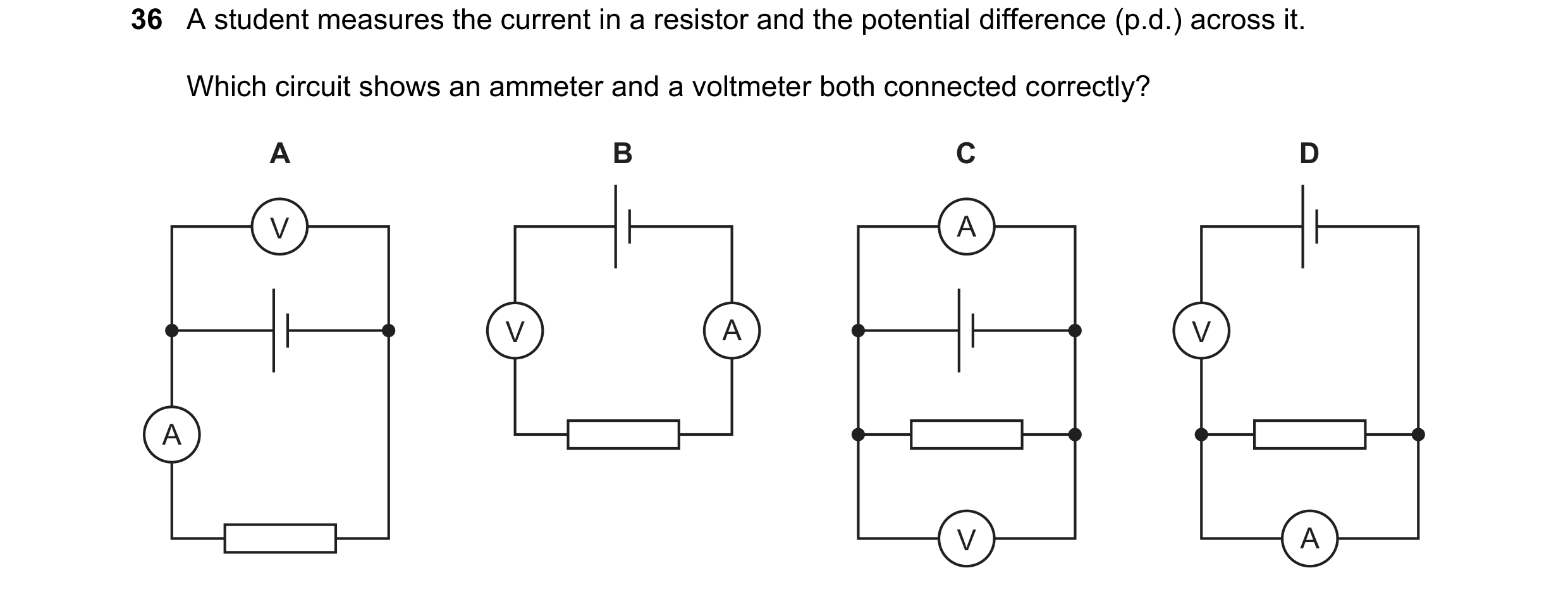
36 A student measures the current in a resistor and the potential difference (p.d.) across it. Which circuit shows an ammeter and a voltmeter both connected correctly? A B C D V A V A V A V A
1 marks
Answer: A
This question in 0654/23 May/June 2023
Q40 · Which graph shows the current–voltage characteristics of an ohmic resistor and a filament… 0654/21 Oct/Nov 2023
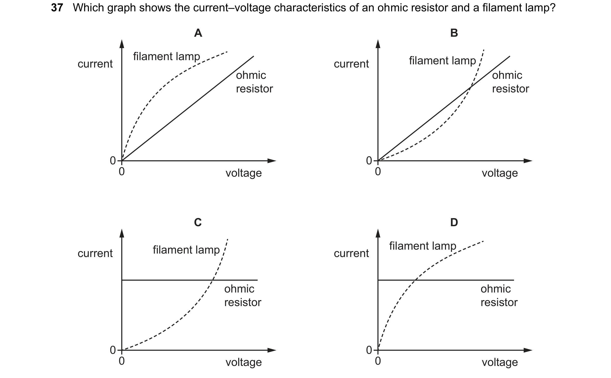
37 Which graph shows the current–voltage characteristics of an ohmic resistor and a filament lamp? A B filament lamp filament lamp current current ohmic ohmic resistor resistor 0 0 0 voltage 0 voltage C D filament lamp filament lamp current current ohmic ohmic resistor resistor 0 0 0 voltage 0 voltage
1 marks
Answer: A
This question in 0654/21 Oct/Nov 2023
Q41 · A battery is connected in a circuit to a 3.0 resistor, a 6.0 resistor and two… 0654/21 Oct/Nov 2023
38 A battery is connected in a circuit to a 3.0 resistor, a 6.0 resistor and two ammeters P and Q. A Q P 3.0 Ω A 6.0 Ω What is the combined resistance of the two resistors and which ammeter has the greater reading? combined ammeter with resistance / greater reading A less than 3.0 P B less than 3.0 Q C 9.0 P D 9.0 Q
1 marks
Answer: B
This question in 0654/21 Oct/Nov 2023
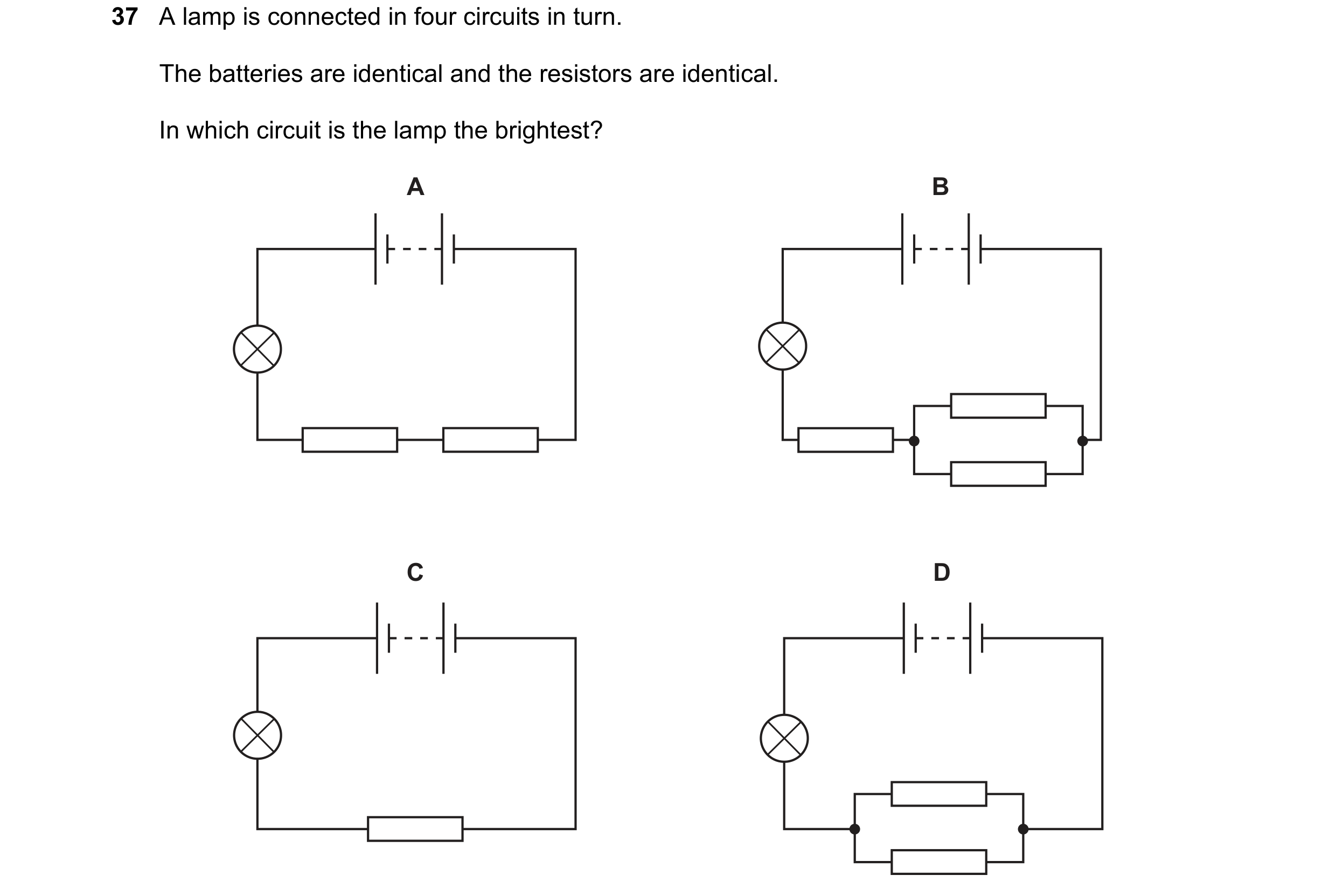
Q42 · A lamp is connected in four circuits in turn 0654/22 Oct/Nov 2023
37 A lamp is connected in four circuits in turn. The batteries are identical and the resistors are identical. In which circuit is the lamp the brightest? A B C D
1 marks
Answer: D
This question in 0654/22 Oct/Nov 2023
Q43 · The series circuit shown includes a single component hidden in a box 0654/22 Oct/Nov 2023
38 The series circuit shown includes a single component hidden in a box. The switch is open. component hidden in box The switch is now closed and the lamp lights briefly before going off. The switch is now opened, and then closed again. This time the lamp does not light. Which symbol represents the component in the box? A B C D A
1 marks
Answer: A
This question in 0654/22 Oct/Nov 2023
Q44 · Two lamps can be connected to a battery either in series or in parallel 0654/23 Oct/Nov 2023
37 Two lamps can be connected to a battery either in series or in parallel. Which statement is not a benefit of connecting two lamps in parallel rather than in series? A If one lamp breaks, the other lamp stays lit. B The lamps are brighter. C The lamps can be controlled individually using switches. D There is a smaller current in the battery.
1 marks
Answer: D
This question in 0654/23 Oct/Nov 2023
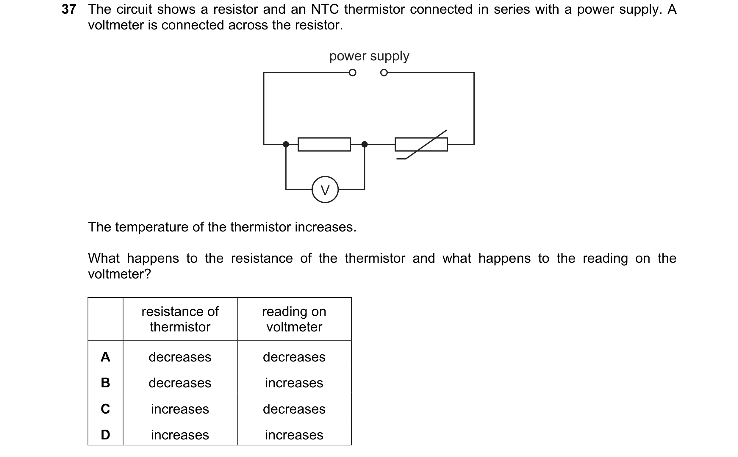
Q45 · The circuit shows a resistor and an NTC thermistor connected in series with a power supply 0654/22 Feb/March 2024
37 The circuit shows a resistor and an NTC thermistor connected in series with a power supply. A voltmeter is connected across the resistor. power supply V The temperature of the thermistor increases. What happens to the resistance of the thermistor and what happens to the reading on the voltmeter? resistance of reading on thermistor voltmeter A decreases decreases B decreases increases C increases decreases D increases increases
1 marks
Answer: B
This question in 0654/22 Feb/March 2024
Q46 · Two resistors with different resistances are connected to a power supply 0654/21 May/June 2024
37 Two resistors with different resistances are connected to a power supply. The resistors can be connected either in parallel or in series. Which statement is correct? A For resistors in parallel, the currents in the resistors are equal. B For resistors in parallel, the potential differences (p.d.s) across the resistors are different. C For resistors in series, the currents in the resistors are equal. D For resistors in series, the potential differences (p.d.s) across the resistors are equal.
1 marks
Answer: C
This question in 0654/21 May/June 2024
Q47 · There is an alternating current (a.c.) in a metal wire 0654/21 May/June 2024
38 There is an alternating current (a.c.) in a metal wire. Which statement about the current is correct? A It is a flow of both positively and negatively charged particles. B It is a flow of charged particles, first in one direction then in the opposite direction repeatedly. C It is a flow of charged particles in both directions at the same time. D It is a flow of charged particles steadily in one direction.
1 marks
Answer: B
This question in 0654/21 May/June 2024
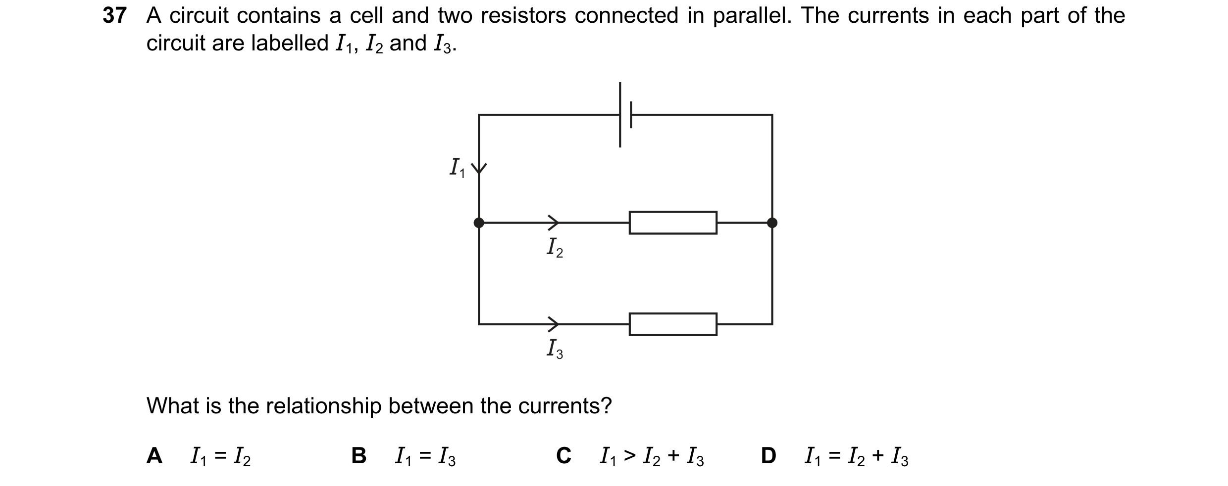
Q48 · A circuit contains a cell and two resistors connected in parallel 0654/21 Oct/Nov 2024
37 A circuit contains a cell and two resistors connected in parallel. The currents in each part of the circuit are labelled I1, I2 and I3. I1 I2 I3 What is the relationship between the currents? A I1 = I2 B I1 = I3 C I1 > I2 + I3 D I1 = I2 + I3
1 marks
Answer: D
This question in 0654/21 Oct/Nov 2024
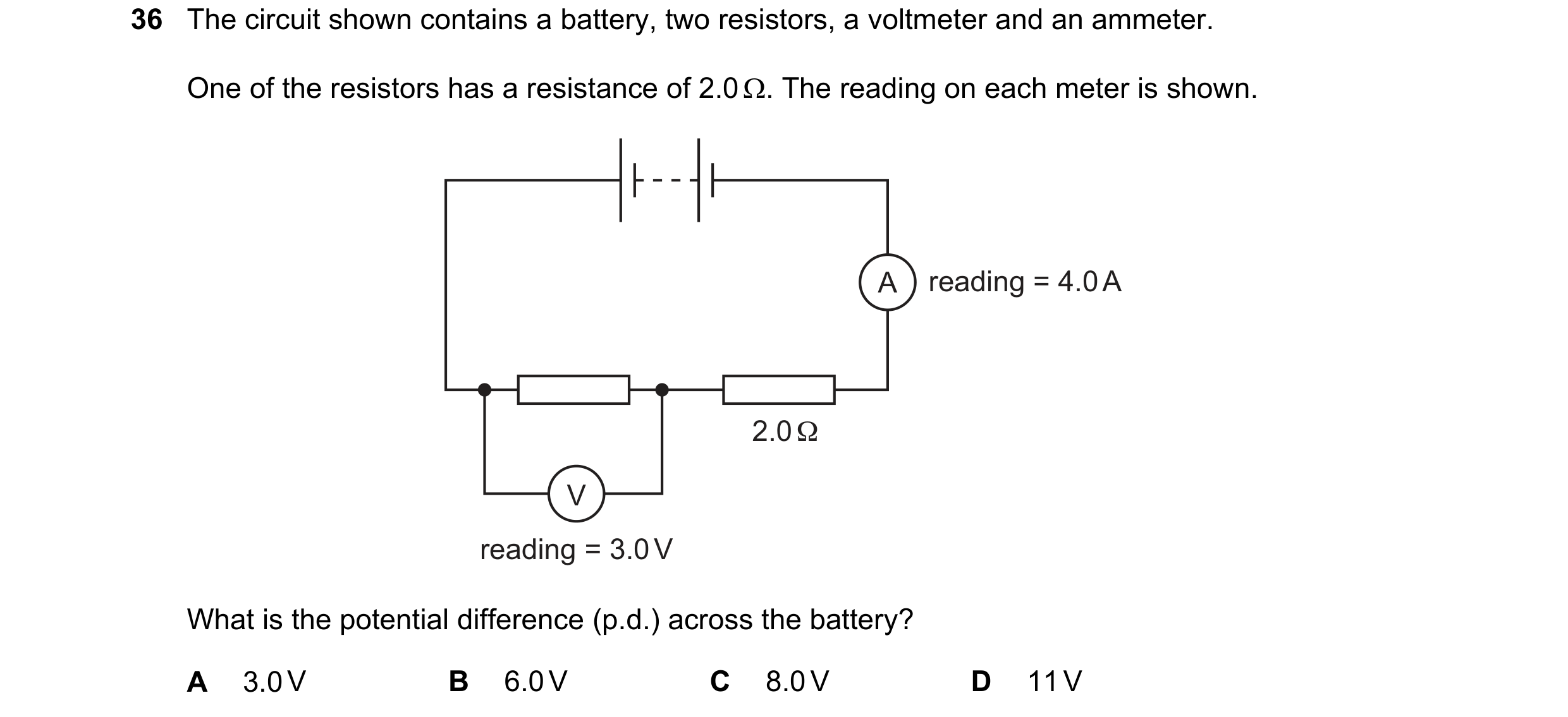
Q49 · The circuit shown contains a battery, two resistors, a voltmeter and an ammeter 0654/22 Oct/Nov 2024
36 The circuit shown contains a battery, two resistors, a voltmeter and an ammeter. One of the resistors has a resistance of 2.0 . The reading on each meter is shown. A reading = 4.0 A 2.0 Ω V reading = 3.0 V What is the potential difference (p.d.) across the battery? A 3.0 V B 6.0 V C 8.0 V D 11 V
1 marks
Answer: D
This question in 0654/22 Oct/Nov 2024
Q50 · A 12 resistor is connected in parallel with a 6.0 resistor 0654/23 Oct/Nov 2024
36 A 12 resistor is connected in parallel with a 6.0 resistor. What is the combined resistance of the two resistors? A 0.25 B 4.0 C 9.0 D 18
1 marks
Answer: B
This question in 0654/23 Oct/Nov 2024
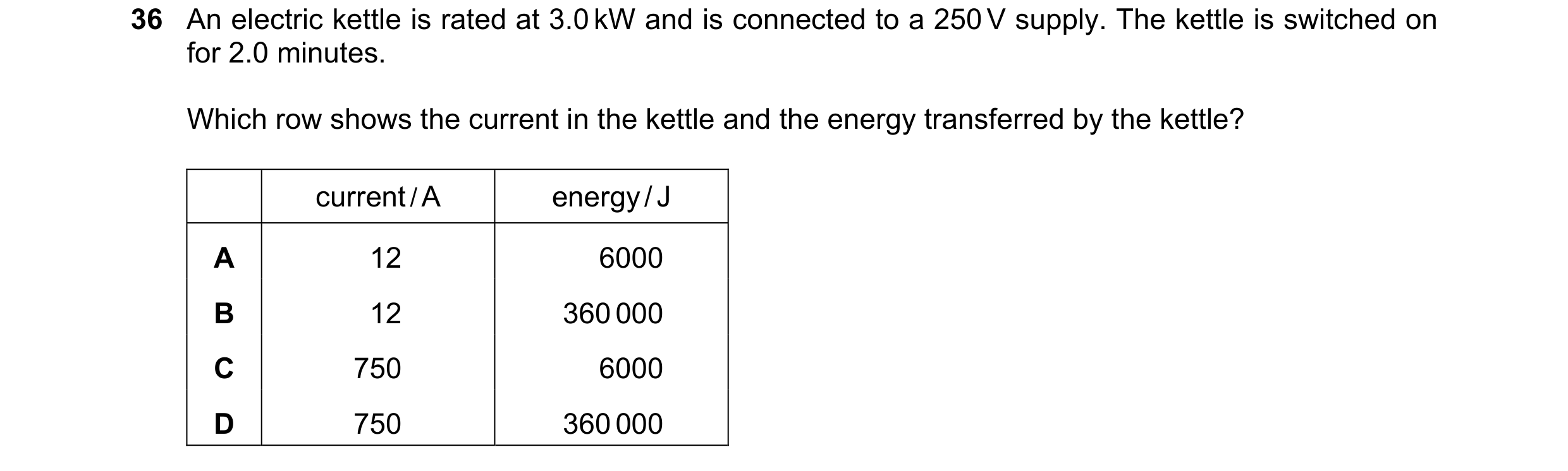
Q51 · An electric kettle is rated at 3.0 kW and is connected to a 250 V supply 0654/21 May/June 2025
36 An electric kettle is rated at 3.0 kW and is connected to a 250 V supply. The kettle is switched on for 2.0 minutes. Which row shows the current in the kettle and the energy transferred by the kettle? current / A energy / J A 12 6000 B 12 360 000 C 750 6000 D 750 360 000
1 marks
Answer: B
This question in 0654/21 May/June 2025
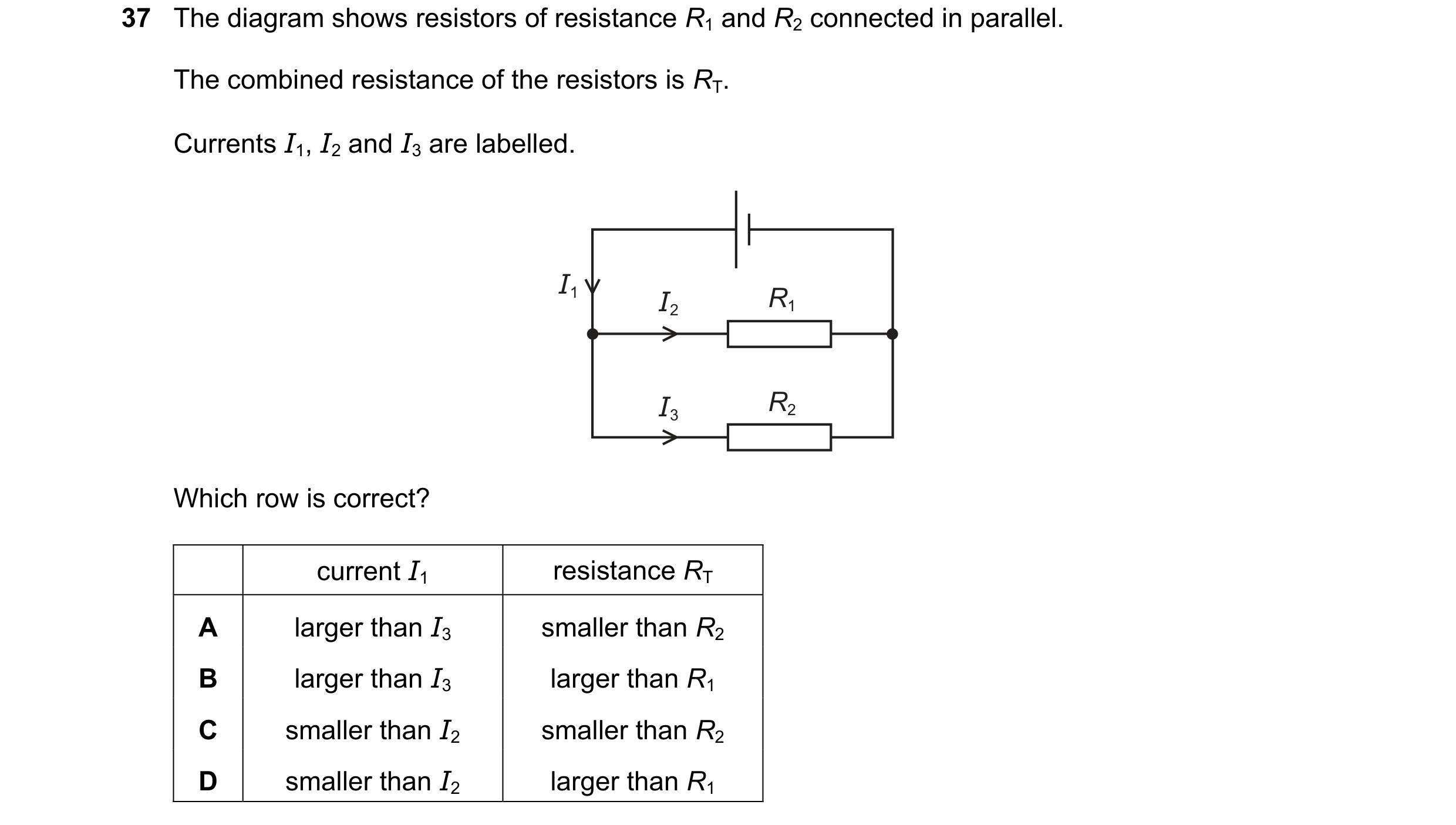
Q52 · The diagram shows resistors of resistance R1 and R2 connected in parallel 0654/21 May/June 2025
37 The diagram shows resistors of resistance R1 and R2 connected in parallel. The combined resistance of the resistors is RT. Currents I1, I2 and I3 are labelled. I1 I2 R1 I3 R2 Which row is correct? current I1 resistance RT A larger than I3 smaller than R2 B larger than I3 larger than R1 C smaller than I2 smaller than R2 D smaller than I2 larger than R1
1 marks
Answer: A
This question in 0654/21 May/June 2025
Q53 · A student connects a length of metal resistance wire to a battery 0654/22 May/June 2025
38 A student connects a length of metal resistance wire to a battery. current metal resistance wire Which change increases the current in the resistance wire? A connecting a second wire in series with the first wire B heating the wire C making the wire shorter D making the wire thinner
1 marks
Answer: C
This question in 0654/22 May/June 2025
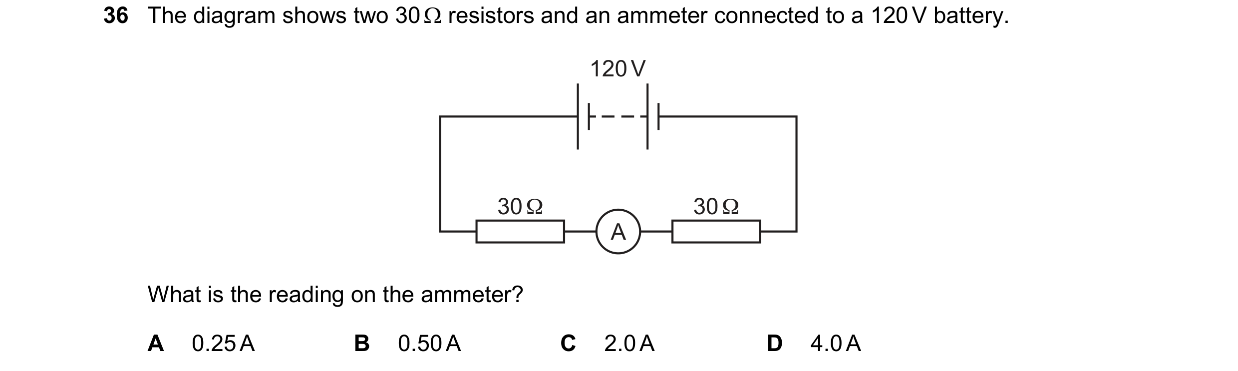
Q54 · The diagram shows two 30 resistors and an ammeter connected to a 120 V battery 0654/23 May/June 2025
36 The diagram shows two 30 resistors and an ammeter connected to a 120 V battery. 120 V 30 Ω 30 Ω A What is the reading on the ammeter? A 0.25 A B 0.50 A C 2.0 A D 4.0 A
1 marks
Answer: C
This question in 0654/23 May/June 2025
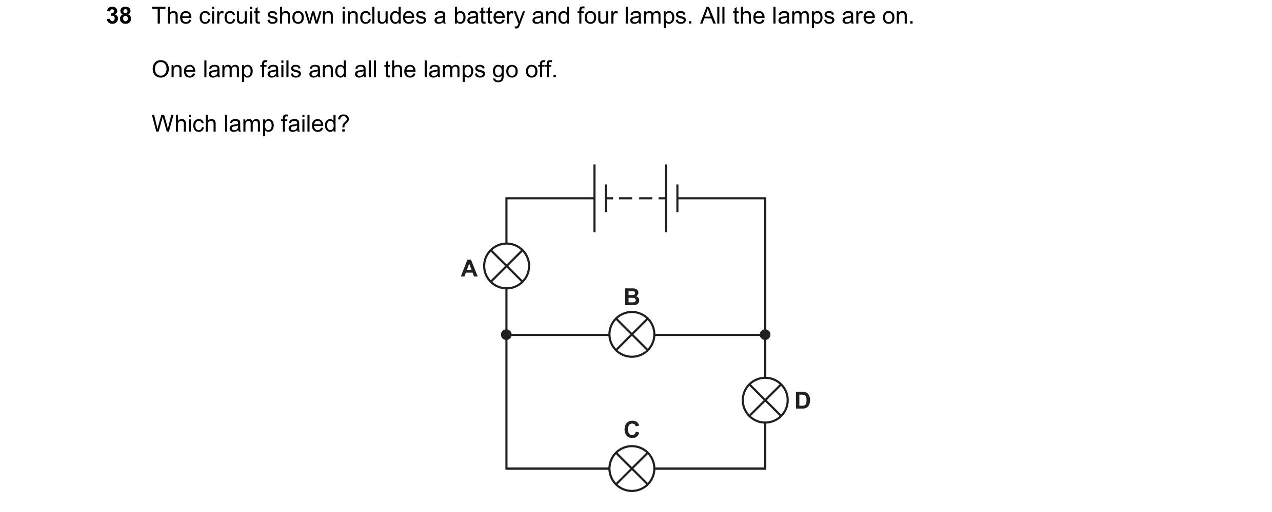
Q55 · The circuit shown includes a battery and four lamps 0654/23 May/June 2025
38 The circuit shown includes a battery and four lamps. All the lamps are on. One lamp fails and all the lamps go off. Which lamp failed? A B D C
1 marks
Answer: A
This question in 0654/23 May/June 2025
Q56 · Which circuit shows an ammeter that measures the current in the lamp and a voltmeter that… 0654/21 Oct/Nov 2025
36 Which circuit shows an ammeter that measures the current in the lamp and a voltmeter that measures the potential difference (p.d.) across the lamp? A B V V A A C D A A V V
1 marks
Answer: C
This question in 0654/21 Oct/Nov 2025
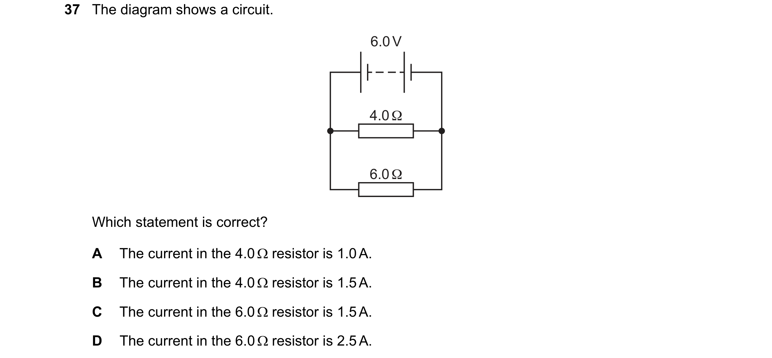
Q57 · The diagram shows a circuit 0654/23 Oct/Nov 2025
37 The diagram shows a circuit. 6.0 V 4.0 Ω 6.0 Ω Which statement is correct? A The current in the 4.0 resistor is 1.0 A. B The current in the 4.0 resistor is 1.5 A. C The current in the 6.0 resistor is 1.5 A. D The current in the 6.0 resistor is 2.5 A.
1 marks
Answer: B
This question in 0654/23 Oct/Nov 2025

 1 / 20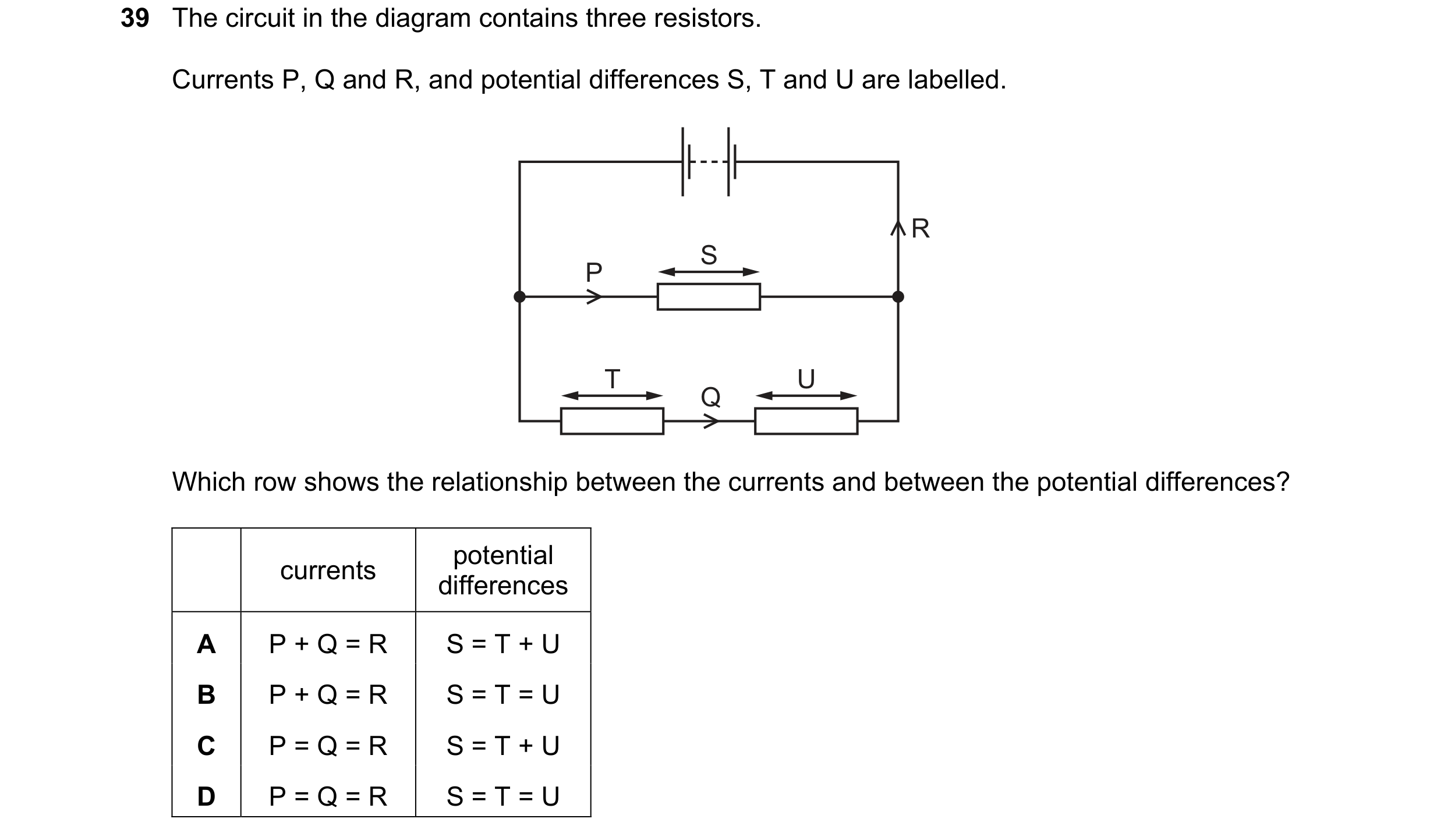
 2 / 20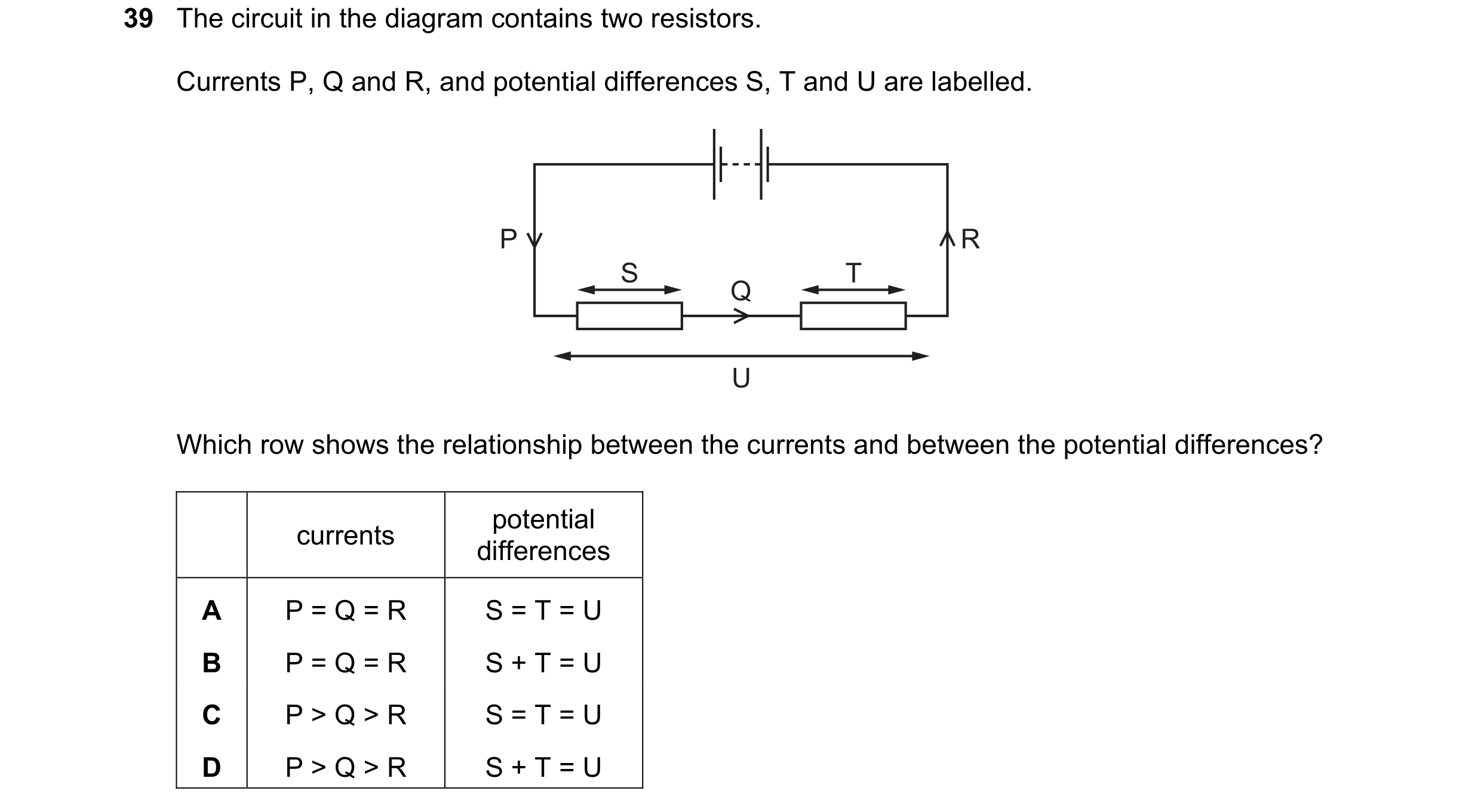
 3 / 20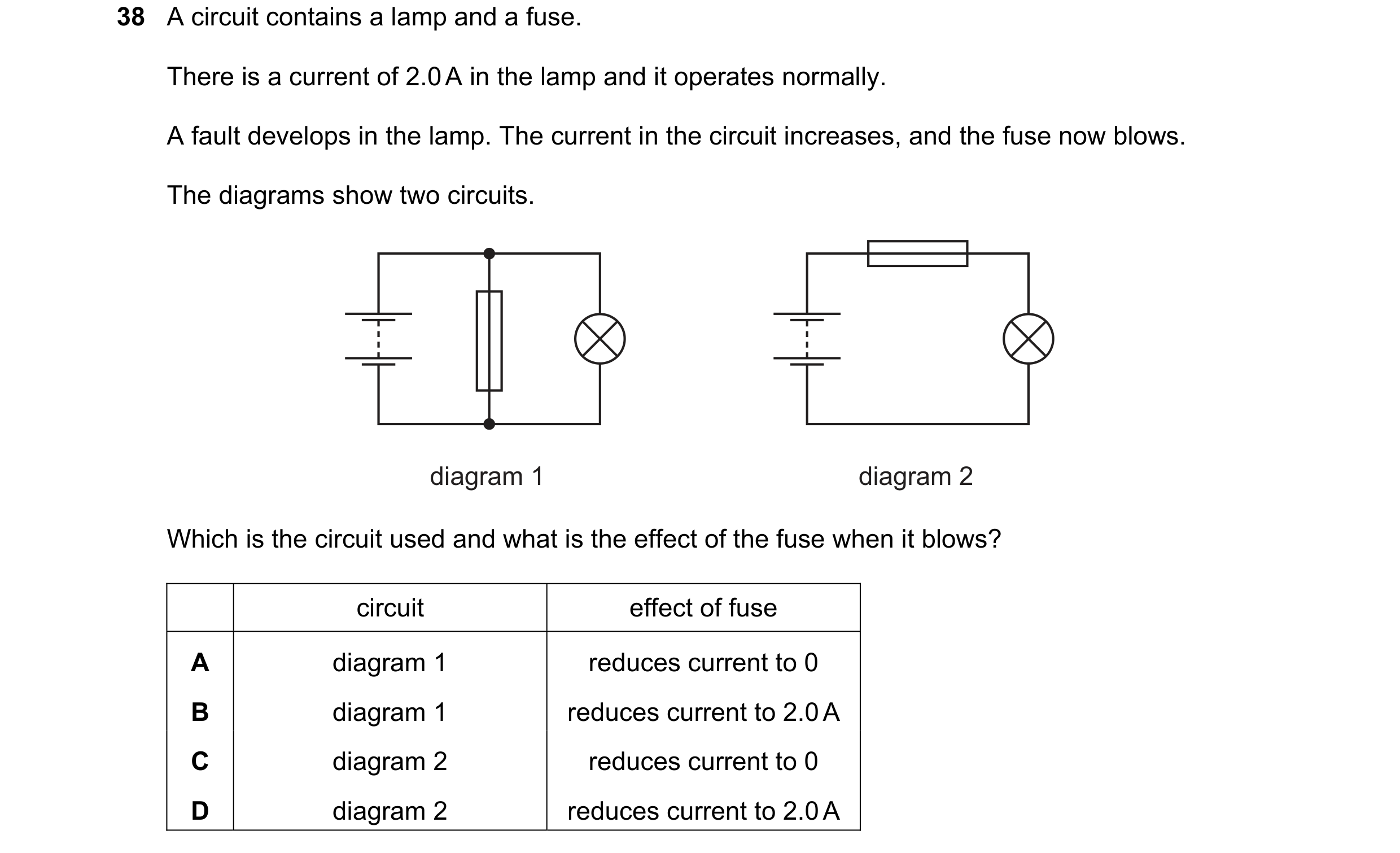
 4 / 20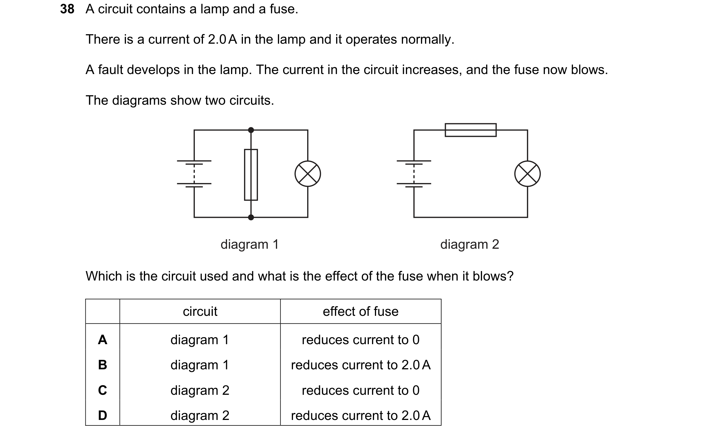
 5 / 20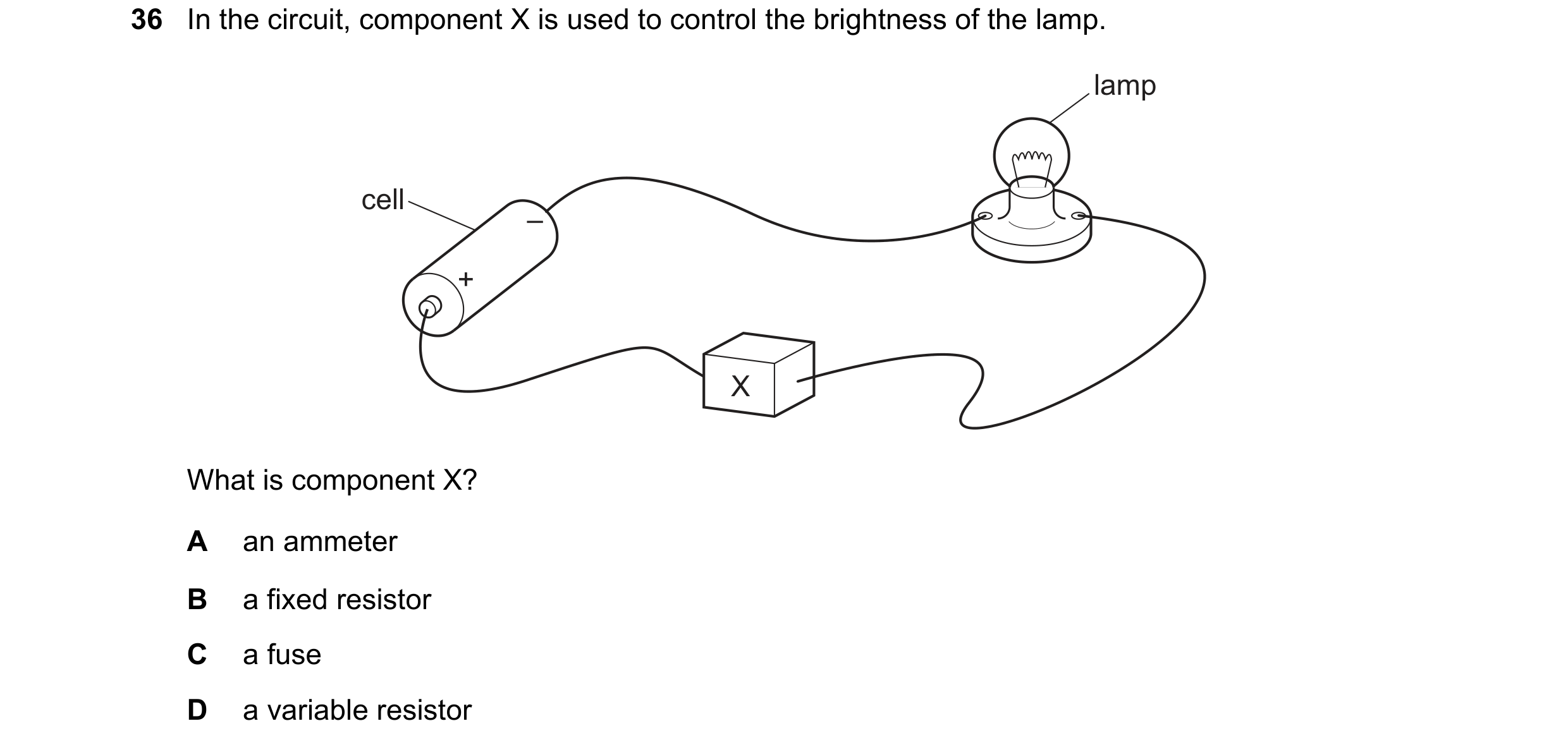
 6 / 20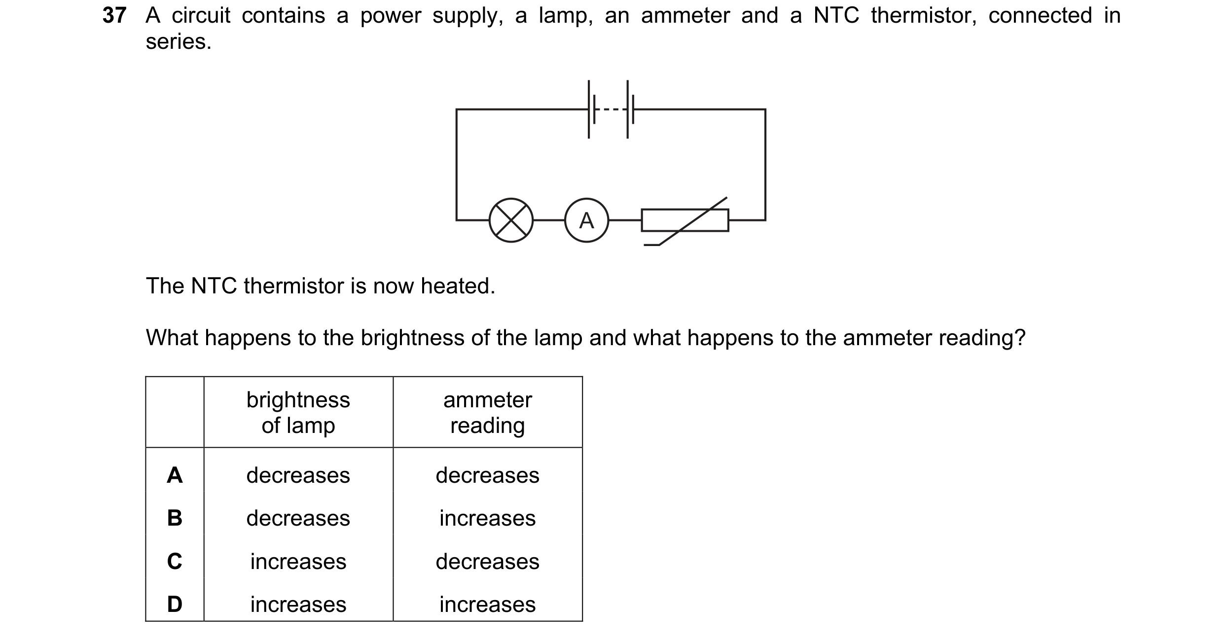
 7 / 20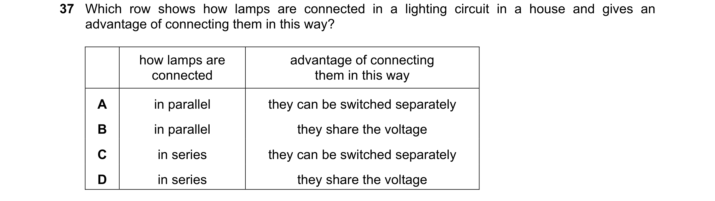
 8 / 20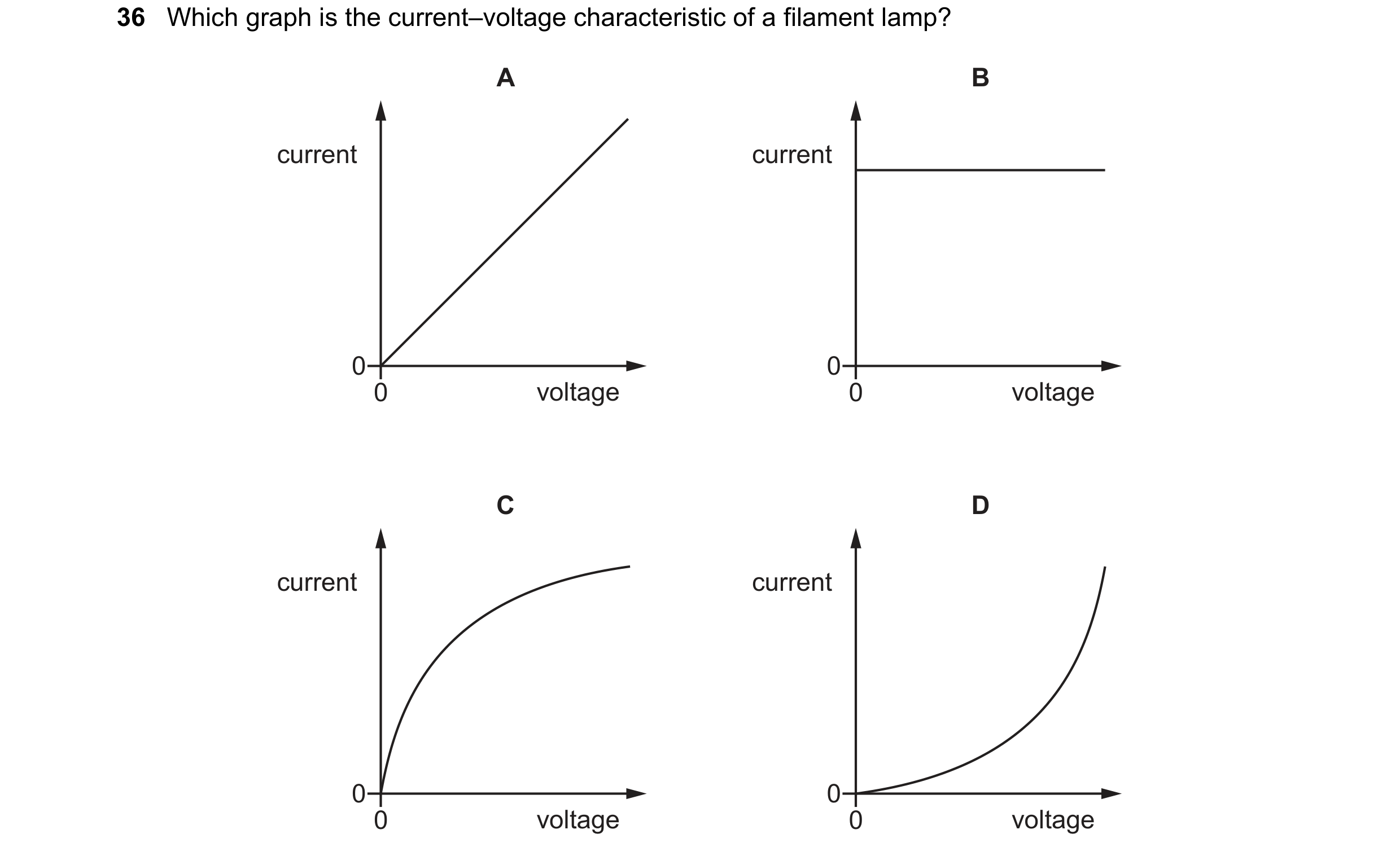
 9 / 20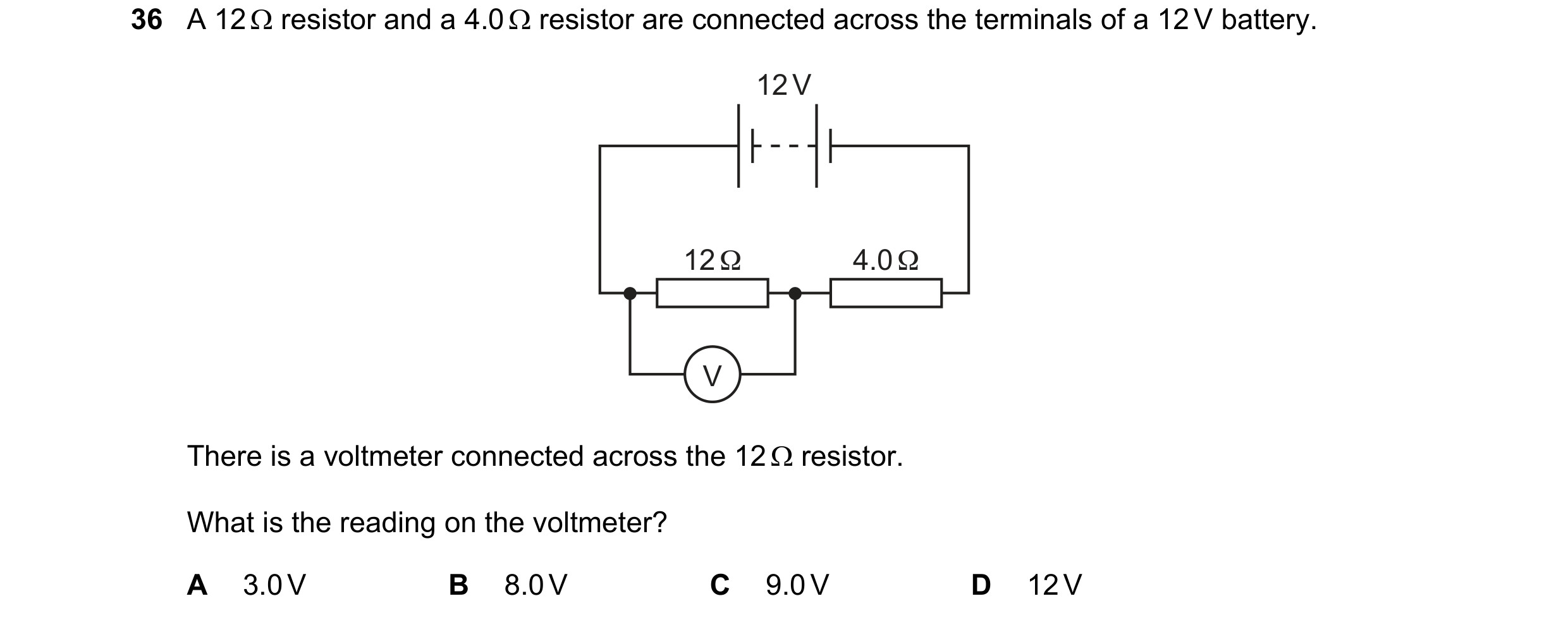
 10 / 20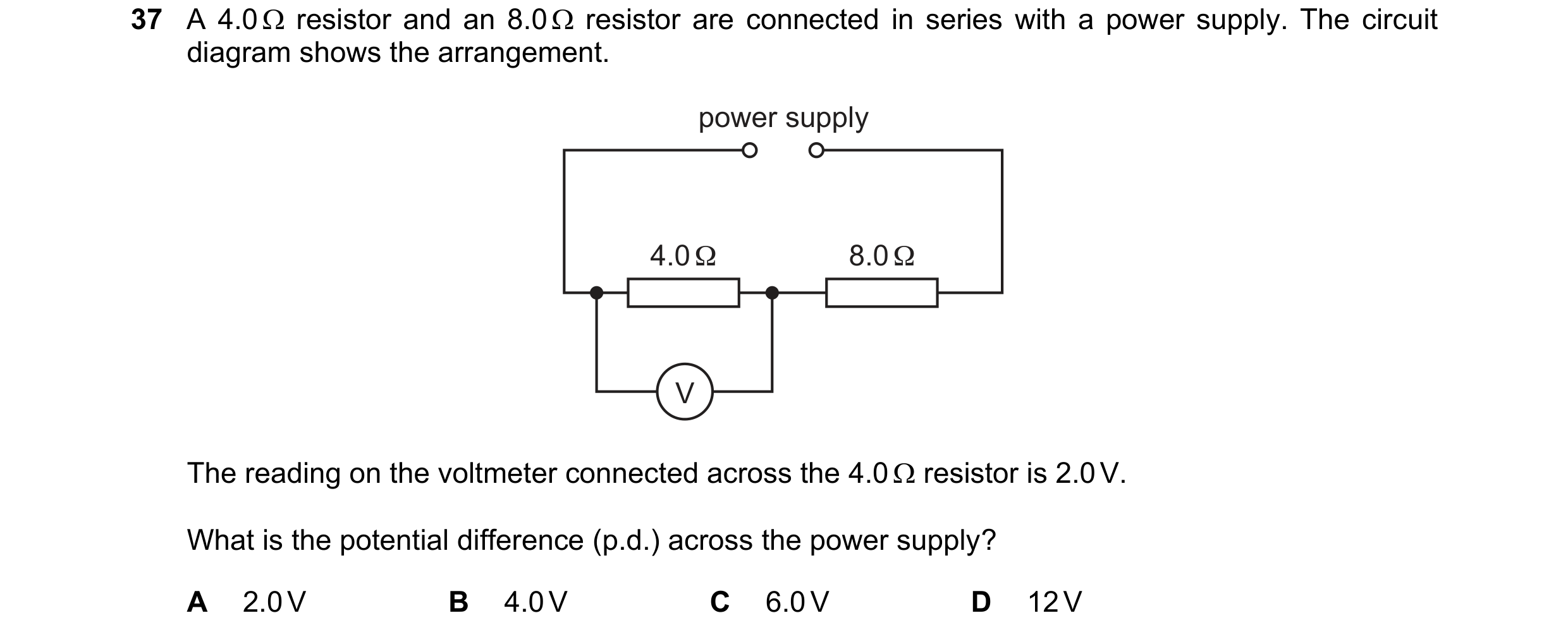
 11 / 20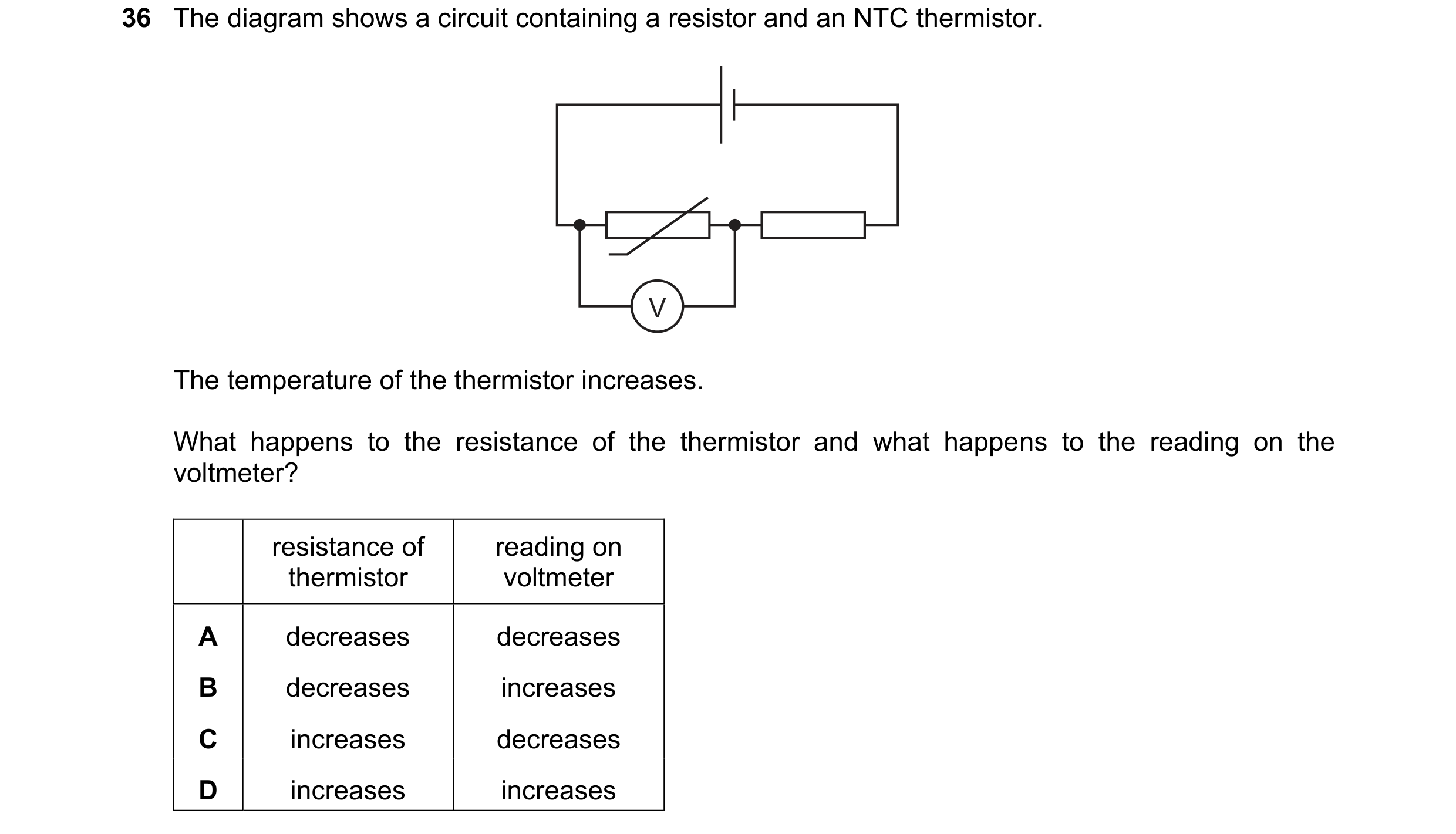
 12 / 20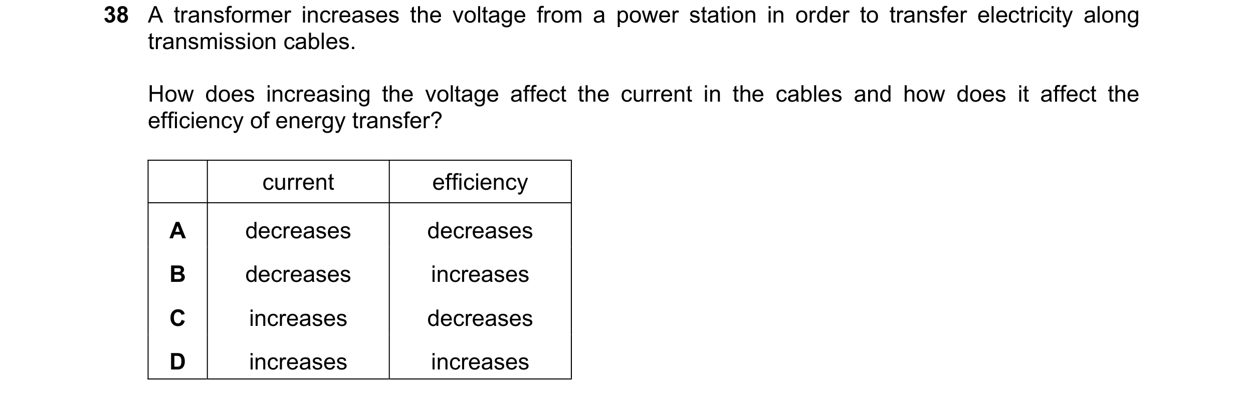

 13 / 20
 14 / 20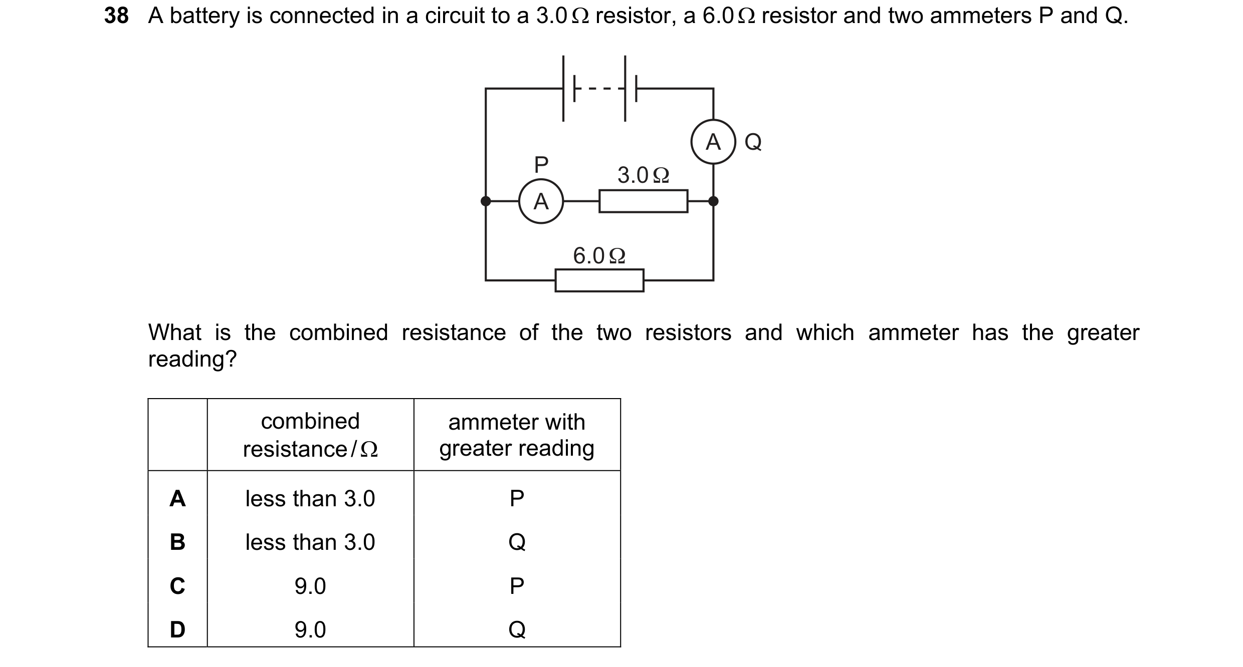
 15 / 20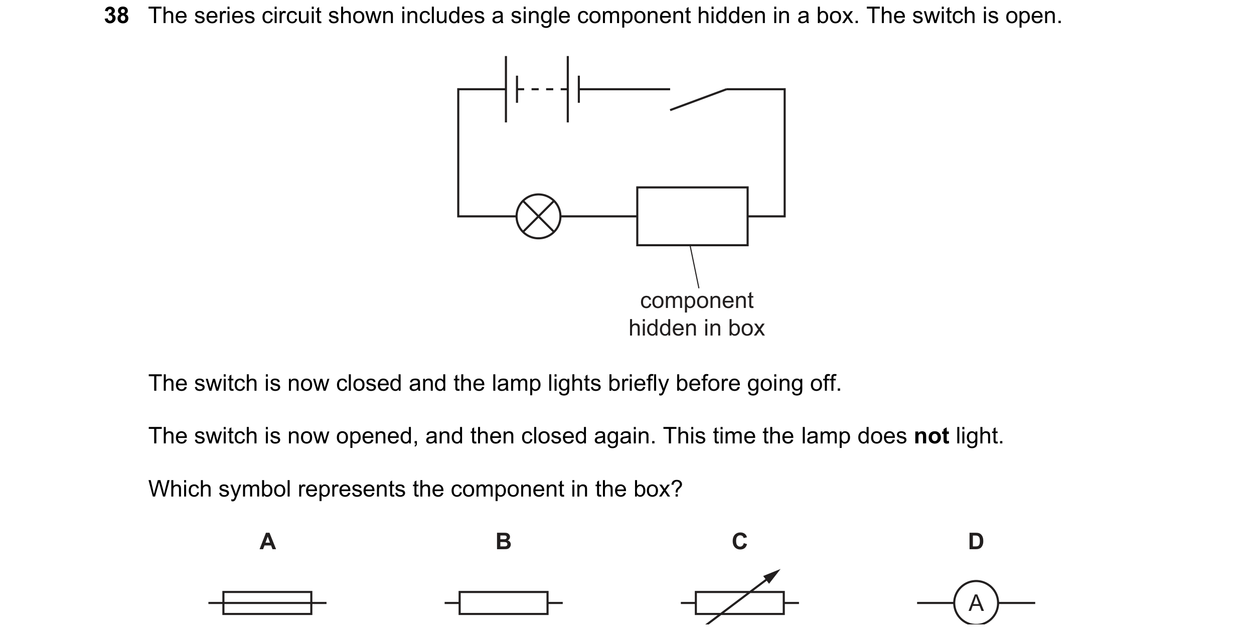
 16 / 20
 17 / 20
 18 / 20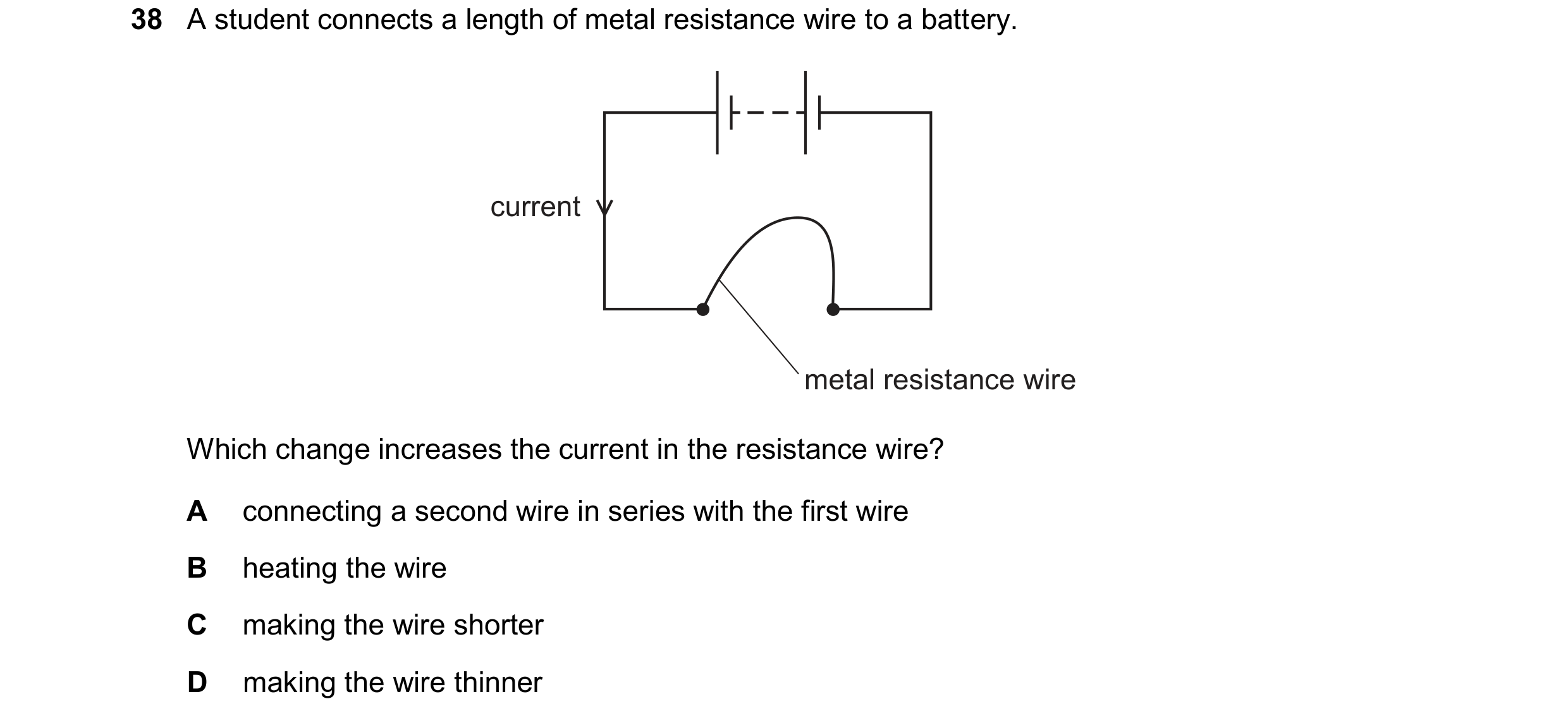
 19 / 20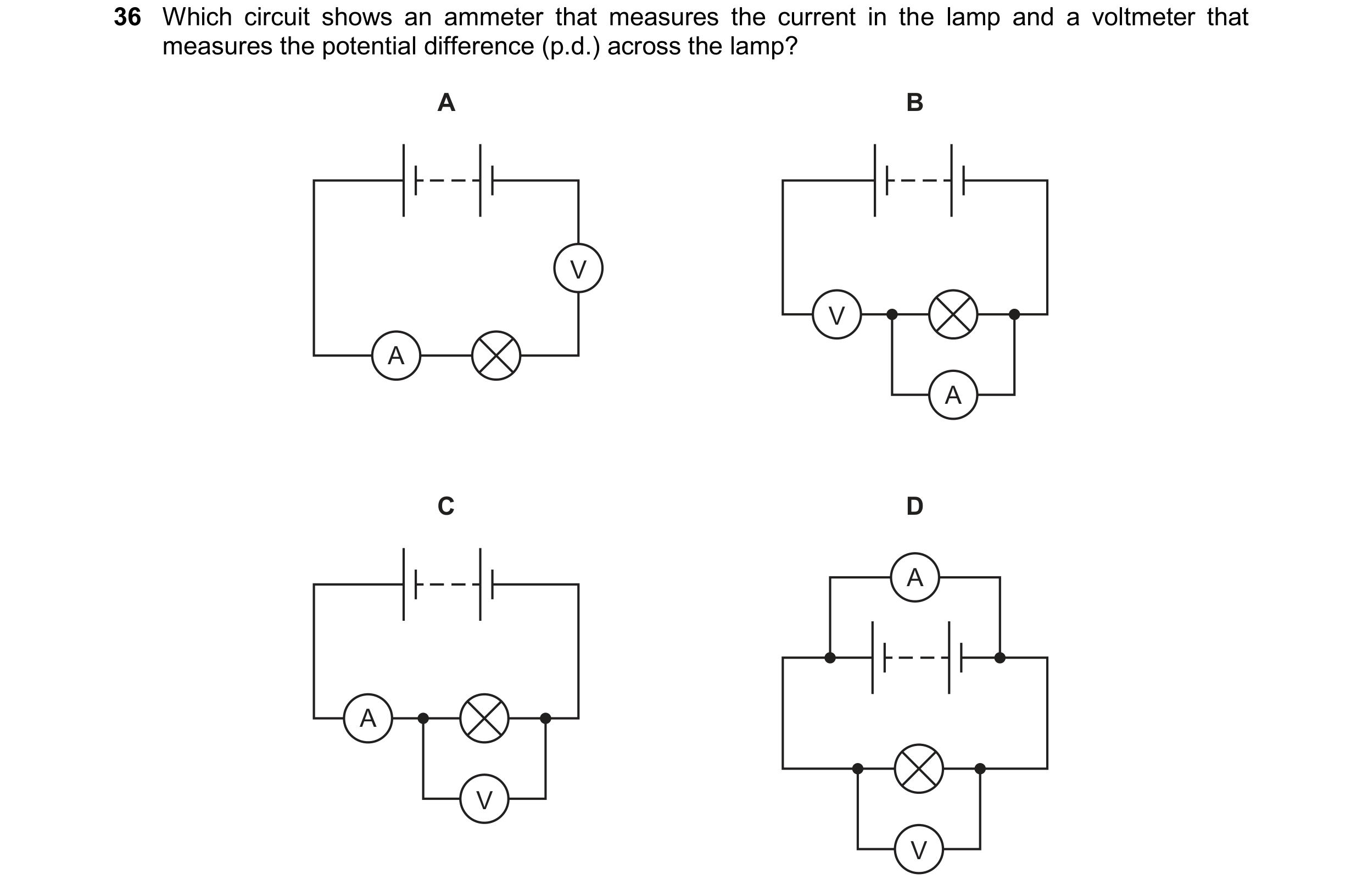
 20 / 20