Questions as text
Q1 · In the circuit shown, the ammeters have negligible resistance and the voltmeters have… 9702/11 Oct/Nov 2004
37 In the circuit shown, the ammeters have negligible resistance and the voltmeters have infinite resistance. I1 3 Ω I2 2 Ω A A 6 Ω 2 Ω V V V1 V2 The readings on the meters are I1, I2, V1 and V2, as labelled on the diagram. Which is correct? A I1 > I2 and V1 > V2 B I1 > I2 and V1 < V2 C I1 < I2 and V1 > V2 D I1 < I2 and V1 < V2
1 marks
Answer: A
This question in 9702/11 Oct/Nov 2004
Q2 · An electrical component has the following circuit symbol 9702/11 Oct/Nov 2005
35 An electrical component has the following circuit symbol. What does this symbol represent? A variable resistor (rheostat) B fuse C light-dependent resistor D thermistor
1 marks
Answer: B
This question in 9702/11 Oct/Nov 2005
Q3 · The diagram shows a low-voltage circuit for heating the water in a fish tank 9702/11 May/June 2006
34 The diagram shows a low-voltage circuit for heating the water in a fish tank. source heater The heater has a resistance of 3.0 Ω. The voltage source has an e.m.f. of 12 V and an internal resistance of 1.0 Ω. At what rate does the voltage source supply energy to the heater? A 27 W B 36 W C 48 W D 64 W
1 marks
Answer: A
This question in 9702/11 May/June 2006
Q4 · The diagram shows an arrangement of resistors 9702/11 May/June 2006
35 The diagram shows an arrangement of resistors. 10 Ω X 10 Ω 10 Ω Y 10 Ω What is the total electrical resistance between X and Y? A less than 1 Ω B between 1 Ω and 10 Ω C between 10 Ω and 30 Ω D 40 Ω
1 marks
Answer: B
This question in 9702/11 May/June 2006
Q5 · When four identical lamps P, Q, R and S are connected as shown in diagram 1, they have… 9702/11 May/June 2006
36 When four identical lamps P, Q, R and S are connected as shown in diagram 1, they have normal brightness. P Q P Q R S R S diagram 1 diagram 2 The four lamps and the battery are then connected as shown in diagram 2. Which statement is correct? A The lamps do not light. B The lamps are less bright than normal. C The lamps have normal brightness. D The lamps are brighter than normal.
1 marks
Answer: C
This question in 9702/11 May/June 2006
Q6 · The resistance of a device is designed to change with temperature 9702/11 Oct/Nov 2006
35 The resistance of a device is designed to change with temperature. What is the device? A a light-dependent resistor B a potential divider C a semiconductor diode D a thermistor
1 marks
Answer: D
This question in 9702/11 Oct/Nov 2006
Q7 · Which circuit has a resistance of 40 Ω between the terminals? 9702/11 Oct/Nov 2006
37 Which circuit has a resistance of 40 Ω between the terminals? A B 100 Ω 100 Ω 100 Ω 100 Ω 100 Ω 100 Ω 100 Ω 100 Ω 100 Ω C D 20 Ω 20 Ω 20 Ω 20 Ω 20 Ω 20 Ω 20 Ω 20 Ω
1 marks
Answer: B
This question in 9702/11 Oct/Nov 2006
Q8 · A battery has an e.m.f 9702/11 May/June 2007
36 A battery has an e.m.f. of 3.0 V and an internal resistance of 2.0 Ω. 3.0 V battery 2.0 Ω 4.0 Ω The battery is connected to a load of 4.0 Ω. What are the terminal potential difference V and output power P? V / V P / W A 1.0 0.50 B 1.0 1.5 C 2.0 1.0 D 2.0 1.5
1 marks
Answer: C
This question in 9702/11 May/June 2007
Question 9 9702/11 May/June 2008
38 The unknown e.m.f. E of a cell is to be determined using a potentiometer circuit. The balance length is to be measured when the galvanometer records a null reading. What is the correct circuit to use? A B E E C D E E
1 marks
Answer: B
This question in 9702/11 May/June 2008
Q10 · The diagram shows a circuit containing three resistors in parallel 9702/11 Oct/Nov 2008
35 The diagram shows a circuit containing three resistors in parallel. 12 V 10 Ω A 10 Ω X The battery has e.m.f. 12 V and negligible internal resistance. The ammeter reading is 3.2 A. What is the resistance of X? A 2.1 Ω B 4.6 Ω C 6.0 Ω D 15 Ω
1 marks
Answer: D
This question in 9702/11 Oct/Nov 2008
Question 11 9702/11 Oct/Nov 2008
36 The e.m.f. of the battery is 9.0 V. The reading on the high-resistance voltmeter is 7.5 V. 9.0 V I V 15 Ω What is the current I ? A 0.10 A B 0.50 A C 0.60 A D 2.0 A
1 marks
Answer: B
This question in 9702/11 Oct/Nov 2008
Q12 · What is meant by the electromotive force (e.m.f.) of a cell? 9702/11 May/June 2009
32 What is meant by the electromotive force (e.m.f.) of a cell? A The e.m.f. of a cell is the energy converted into electrical energy when unit charge passes through the cell. B The e.m.f. of a cell is the energy transferred by the cell in driving unit charge through the external resistance. C The e.m.f. of a cell is the energy transferred by the cell in driving unit charge through the internal resistance of the cell. D The e.m.f. of a cell is the amount of energy needed to bring a unit positive charge from infinity to its positive pole.
1 marks
Answer: A
This question in 9702/11 May/June 2009
Q13 · A cell is connected to a resistor 9702/11 Oct/Nov 2009
30 A cell is connected to a resistor. At any given moment, the potential difference across the cell is less than its electromotive force. Which statement explains this? A The cell is continually discharging. B The connecting wire has some resistance. C Energy is needed to drive charge through the cell. D Power is used when there is a current in the resistor. Space for working
1 marks
Answer: C
This question in 9702/11 Oct/Nov 2009
Q14 · A network of resistors consists of two 3.0 Ω resistors and three 6.0 Ω resistors 9702/11 Oct/Nov 2009
36 A network of resistors consists of two 3.0 Ω resistors and three 6.0 Ω resistors. 6.0 Ω 3.0 Ω 6.0 Ω X Y 3.0 Ω 6.0 Ω What is the combined resistance of this network between points X and Y? A 0.86 Ω B 1.2 Ω C 3.5 Ω D 24 Ω Space for working
1 marks
Answer: C
This question in 9702/11 Oct/Nov 2009
Q15 · A cell is connected to a resistor 9702/12 Oct/Nov 2009
29 A cell is connected to a resistor. At any given moment, the potential difference across the cell is less than its electromotive force. Which statement explains this? A The cell is continually discharging. B The connecting wire has some resistance. C Energy is needed to drive charge through the cell. D Power is used when there is a current in the resistor. Space for working
1 marks
Answer: C
This question in 9702/12 Oct/Nov 2009
Q16 · A network of resistors consists of two 3.0 Ω resistors and three 6.0 Ω resistors 9702/12 Oct/Nov 2009
35 A network of resistors consists of two 3.0 Ω resistors and three 6.0 Ω resistors. 6.0 Ω 3.0 Ω 6.0 Ω X Y 3.0 Ω 6.0 Ω What is the combined resistance of this network between points X and Y? A 0.86 Ω B 1.2 Ω C 3.5 Ω D 24 Ω Space for working
1 marks
Answer: C
This question in 9702/12 Oct/Nov 2009
Q17 · The resistors P, Q and R in the circuit have equal resistance 9702/11 May/June 2010
33 The resistors P, Q and R in the circuit have equal resistance. P Q R The battery, of negligible internal resistance, supplies a total power of 12 W. What is the power dissipated by heating in resistor R? A 2 W B 3 W C 4 W D 6 W Space for working
1 marks
Answer: A
This question in 9702/11 May/June 2010
Q18 · A source of e.m.f 9702/11 May/June 2010
35 A source of e.m.f. of 9.0 mV has an internal resistance of 6.0 Ω. It is connected across a galvanometer of resistance 30 Ω. What will be the current in the galvanometer? A 250 µA B 300 µA C 1.5 mA D 2.5 mA Space for working
1 marks
Answer: A
This question in 9702/11 May/June 2010
Q19 · In each arrangement of resistors, the ammeter has a resistance of 2 Ω 9702/11 May/June 2010
36 In each arrangement of resistors, the ammeter has a resistance of 2 Ω. Which arrangement gives the largest reading on the ammeter when the same potential difference is applied between points P and Q? A B 1 Ω 1 Ω 2 Ω A A P Q P Q 2 Ω C D 1 Ω 1 Ω A A P Q P Q 2 Ω 2 Ω
1 marks
Answer: D
This question in 9702/11 May/June 2010
Q20 · A source of e.m.f 9702/13 May/June 2010
31 A source of e.m.f. of 9.0 mV has an internal resistance of 6.0 Ω. It is connected across a galvanometer of resistance 30 Ω. What will be the current in the galvanometer? A 250 µA B 300 µA C 1.5 mA D 2.5 mA
1 marks
Answer: A
This question in 9702/13 May/June 2010
Q21 · In each arrangement of resistors, the ammeter has a resistance of 2 Ω 9702/13 May/June 2010
34 In each arrangement of resistors, the ammeter has a resistance of 2 Ω. Which arrangement gives the largest reading on the ammeter when the same potential difference is applied between points P and Q? A B 1 Ω 1 Ω 2 Ω A A P Q P Q 2 Ω C D 1 Ω 1 Ω A A P Q P Q 2 Ω 2 Ω
1 marks
Answer: D
This question in 9702/13 May/June 2010
Q22 · The resistors P, Q and R in the circuit have equal resistance 9702/13 May/June 2010
35 The resistors P, Q and R in the circuit have equal resistance. P Q R The battery, of negligible internal resistance, supplies a total power of 12 W. What is the power dissipated by heating in resistor R? A 2 W B 3 W C 4 W D 6 W Space for working
1 marks
Answer: A
This question in 9702/13 May/June 2010
Q23 · Which electrical component is represented by the following symbol? 9702/12 Oct/Nov 2010
30 Which electrical component is represented by the following symbol? A a diode B a potentiometer C a resistor D a thermistor Space for working
1 marks
Answer: D
This question in 9702/12 Oct/Nov 2010
Q24 · A high-resistance voltmeter connected across a battery reads 6.0 V 9702/12 Oct/Nov 2010
32 A high-resistance voltmeter connected across a battery reads 6.0 V. When the battery is connected in series with a lamp of resistance of 10 Ω, the voltmeter reading falls to 5.6 V. Which statement explains this observation? A The electromotive force (e.m.f.) of the battery decreases because more work is done across its internal resistance. B The e.m.f. of the battery decreases because work is done across the lamp. C The potential difference (p.d.) across the battery decreases because more work is done across its internal resistance. D The p.d. across the battery decreases because work is done across the lamp. Space for working
1 marks
Answer: C
This question in 9702/12 Oct/Nov 2010
Q25 · A battery of e.m.f 9702/12 Oct/Nov 2010
33 A battery of e.m.f. 12 V and internal resistance 2.0 Ω is connected in series with an ammeter of negligible resistance and an external resistor. External resistors of various different values are used. 12 V 2.0 Ω A Which combination of current and resistor value is not correct? external resistor current / A value / Ω A 1.0 10 B 1.2 8 C 1.5 6 D 1.8 4 Space for working
1 marks
Answer: D
This question in 9702/12 Oct/Nov 2010
Q26 · The diagram shows part of a circuit 9702/12 Oct/Nov 2010
35 The diagram shows part of a circuit. 6.0 Ω 4.0 Ω 4.0 Ω 3.0 Ω 6.0 Ω P Q 4.0 Ω 6.0 Ω 4.0 Ω What is the resistance between the points P and Q due to the resistance network? A 1.3 Ω B 4.0 Ω C 10 Ω D 37 Ω Space for working
1 marks
Answer: B
This question in 9702/12 Oct/Nov 2010
Q27 · Three resistors, with resistances R1, R2 and R3, are connected in series and are found to… 9702/12 Oct/Nov 2010
37 Three resistors, with resistances R1, R2 and R3, are connected in series and are found to have a combined resistance of 500 Ω. When connected in parallel, the combined resistance is found to be 50 Ω. Which values will correspond to these results? R1 / Ω R2 / Ω R3 / Ω A 160 160 80 B 200 200 100 C 225 225 50 D 230 230 40 Space for working
1 marks
Answer: B
This question in 9702/12 Oct/Nov 2010
Q28 · A relay is required to operate 800 m from its power supply 9702/13 Oct/Nov 2010
31 A relay is required to operate 800 m from its power supply. The power supply has negligible internal resistance. The relay requires 16.0 V and a current of 0.60 A to operate. A cable connects the relay to the power supply and two of the wires in the cable are used to supply power to the relay. The resistance of each of these wires is 0.0050 Ω per metre. What is the minimum output e.m.f. of the power supply? A 16.6 V B 18.4 V C 20.8 V D 29.3 V Space for working
1 marks
Answer: C
This question in 9702/13 Oct/Nov 2010
Q29 · The diagram shows part of a circuit 9702/13 Oct/Nov 2010
33 The diagram shows part of a circuit. 40 Ω 160 Ω 120 Ω What is the total resistance of the combination of the three resistors? A 320 Ω B 240 Ω C 190 Ω D 80 Ω Space for working
1 marks
Answer: C
This question in 9702/13 Oct/Nov 2010
Q30 · The diagram shows an arrangement of resistors 9702/13 Oct/Nov 2010
37 The diagram shows an arrangement of resistors. 10 Ω X 10 Ω 10 Ω Y 10 Ω What is the total electrical resistance between X and Y? A less than 1 Ω B between 1 Ω and 10 Ω C between 10 Ω and 30 Ω D 40 Ω Space for working
1 marks
Answer: B
This question in 9702/13 Oct/Nov 2010
Q31 · The graphs show possible current-voltage (I-V ) relationships for a filament lamp and for… 9702/11 May/June 2011
33 The graphs show possible current-voltage (I-V ) relationships for a filament lamp and for a semiconductor diode. P Q R S I I I I 00 00 00 00 V V V V Which row best specifies the correct I-V graphs for the lamp and the diode? semiconductor filament lamp diode A P R B P S C Q R D Q S Space for working
1 marks
Answer: A
This question in 9702/11 May/June 2011
Q32 · Four resistors of equal value are connected as shown 9702/11 May/June 2011
36 Four resistors of equal value are connected as shown. W Y X Z How will the powers to the resistors change when resistor W is removed? A The powers to X, Y and Z will all increase. B The power to X will decrease and the powers to Y and Z will increase. C The power to X will increase and the powers to Y and Z will decrease. D The power to X will increase and the powers to Y and Z will remain unaltered. Space for working
1 marks
Answer: C
This question in 9702/11 May/June 2011
Q33 · A source of electromotive force (e.m.f.) E has a constant internal resistance r and is… 9702/12 May/June 2011
34 A source of electromotive force (e.m.f.) E has a constant internal resistance r and is connected to an external variable resistor of resistance R. As R is increased from a value below r to a value above r, which statement is correct? A The terminal potential difference remains constant. B The current in the circuit increases. C The e.m.f. of the source increases. D The largest output power is obtained when R reaches r.
1 marks
Answer: D
This question in 9702/12 May/June 2011
Q34 · Safety on railways is increased by using several electrical switches 9702/12 May/June 2011
36 Safety on railways is increased by using several electrical switches. In the diagram, switches P, Q, R, S and T control the current through a green lamp. P Q S R green lamp T Which row does not allow the green lamp to light? P Q R S T A closed closed closed open closed B closed open closed closed open C closed open open closed closed D open open closed open closed Space for working
1 marks
Answer: C
This question in 9702/12 May/June 2011
Q35 · The diagram shows a d.c 9702/12 May/June 2011
38 The diagram shows a d.c. circuit. 6 Ω P Q 3 Ω 6 Ω 6 Ω What is the resistance between the points P and Q due to the resistance network? A 0.47 Ω B 2.1 Ω C 3.0 Ω D 21 Ω Space for working
1 marks
Answer: C
This question in 9702/12 May/June 2011
Q36 · Four resistors of equal value are connected as shown 9702/13 May/June 2011
33 Four resistors of equal value are connected as shown. W Y X Z How will the powers to the resistors change when resistor W is removed? A The powers to X, Y and Z will all increase. B The power to X will decrease and the powers to Y and Z will increase. C The power to X will increase and the powers to Y and Z will decrease. D The power to X will increase and the powers to Y and Z will remain unaltered. Space for working
1 marks
Answer: C
This question in 9702/13 May/June 2011
Q37 · A cell of e.m.f 9702/11 Oct/Nov 2011
36 A cell of e.m.f. E and internal resistance r is connected in series with a switch S and an external resistor of resistance R. E r P Q R S The p.d. between P and Q is V. When S is closed, A V decreases because there is a p.d. across R. B V decreases because there is a p.d. across r. C V remains the same because the decrease of p.d. across r is balanced by the increase of p.d. across R. D V remains the same because the sum of the p.d.s across r and R is still equal to E. Space for working
1 marks
Answer: B
This question in 9702/11 Oct/Nov 2011
Q38 · A cell, two resistors of equal resistance and an ammeter are used to construct four… 9702/11 Oct/Nov 2011
37 A cell, two resistors of equal resistance and an ammeter are used to construct four circuits. The resistors are the only parts of the circuits that have resistance. In which circuit will the ammeter show the greatest reading? A B A A C D A A Space for working
1 marks
Answer: D
This question in 9702/11 Oct/Nov 2011
Q39 · Three resistors of resistance R, 2R and 3R are connected in parallel 9702/11 Oct/Nov 2011
38 Three resistors of resistance R, 2R and 3R are connected in parallel. R 2R 3R Using I to represent the current through the resistor of resistance R, which row represents the relationships between the currents through the resistors? resistor resistance R 2R 3R 1 I 1 I A I 3 2 1 I 1 I B I 2 3 2 I 1 I C I 3 3 D I 2 I 3 I Space for working
1 marks
Answer: B
This question in 9702/11 Oct/Nov 2011
Q40 · A power supply of electromotive force (e.m.f.) 12 V and internal resistance 2 Ω is… 9702/12 Oct/Nov 2011
35 A power supply of electromotive force (e.m.f.) 12 V and internal resistance 2 Ω is connected in series with a load resistor. The value of the load resistor is varied from 0.5 Ω to 4 Ω. Which graph shows how the power P dissipated in the load resistor varies with the resistance of the load resistor? A B P P 0 1 2 3 4 0 1 2 3 4 resistance of load / Ω resistance of load / Ω C D P P 0 1 2 3 4 0 1 2 3 4 resistance of load / Ω resistance of load / Ω Space for working
1 marks
Answer: A
This question in 9702/12 Oct/Nov 2011
Q41 · A cell, two resistors of equal resistance and an ammeter are used to construct four… 9702/13 Oct/Nov 2011
36 A cell, two resistors of equal resistance and an ammeter are used to construct four circuits. The resistors are the only parts of the circuits that have resistance. In which circuit will the ammeter show the greatest reading? A B A A C D A A Space for working
1 marks
Answer: D
This question in 9702/13 Oct/Nov 2011
Q42 · Three resistors of resistance R, 2R and 3R are connected in parallel 9702/13 Oct/Nov 2011
37 Three resistors of resistance R, 2R and 3R are connected in parallel. R 2R 3R Using I to represent the current through the resistor of resistance R, which row represents the relationships between the currents through the resistors? resistor resistance R 2R 3R 1 I 1 I A I 3 2 1 I 1 I B I 2 3 2 I 1 I C I 3 3 D I 2 I 3 I Space for working
1 marks
Answer: B
This question in 9702/13 Oct/Nov 2011
Q43 · A cell of e.m.f 9702/13 Oct/Nov 2011
38 A cell of e.m.f. E and internal resistance r is connected in series with a switch S and an external resistor of resistance R. E r P Q R S The p.d. between P and Q is V. When S is closed, A V decreases because there is a p.d. across R. B V decreases because there is a p.d. across r. C V remains the same because the decrease of p.d. across r is balanced by the increase of p.d. across R. D V remains the same because the sum of the p.d.s across r and R is still equal to E. Space for working
1 marks
Answer: B
This question in 9702/13 Oct/Nov 2011
Q44 · The diagram shows the circuit for a signal to display a green or a red light 9702/12 May/June 2012
37 The diagram shows the circuit for a signal to display a green or a red light. It is controlled by the switch S. green g G S red R 12 V black x The signal is some way from S to which it is connected by a cable with green, red and black wires. At the signal, the green and red wires are connected to the corresponding lamp and the black wire is connected to a terminal x to provide a common return. The arrangement is shown correctly connected and with the switch set to illuminate the red lamp. During maintenance, the wires at the signal are disconnected and, when reconnected, the black wire is connected in error to the green lamp (terminal g) instead of terminal x. The red wire is connected correctly to its lamp and connections at S remain as in the diagram. black g G green S R red 12 V x When the system is tested with the switch connection to the red wire, what does the signal show? A the green lamp illuminated normally B the red lamp illuminated normally C the red and green lamps both illuminated normally D the red and green lamps both illuminated dimly Space for working
1 marks
Answer: D
This question in 9702/12 May/June 2012
Q45 · A network of electrical components is connected across a battery of negligible internal… 9702/11 Oct/Nov 2012
36 A network of electrical components is connected across a battery of negligible internal resistance, as shown. V A The resistance of the variable resistor is increased. What is the effect on the readings of the ammeter and voltmeter? ammeter voltmeter A decreases increases B increases decreases C unchanged decreases D unchanged increases Space for working
1 marks
Answer: C
This question in 9702/11 Oct/Nov 2012
Q46 · A cell of internal resistance 2.0 Ω and electromotive force (e.m.f.) 1.5 V is connected… 9702/12 Oct/Nov 2012
35 A cell of internal resistance 2.0 Ω and electromotive force (e.m.f.) 1.5 V is connected to a resistor of resistance 3.0 Ω. What is the potential difference across the 3.0 Ω resistor? A 1.5 V B 1.2 V C 0.9 V D 0.6 V
1 marks
Answer: C
This question in 9702/12 Oct/Nov 2012
Q47 · The ammeter reading in the circuit below is I 9702/12 Oct/Nov 2012
37 The ammeter reading in the circuit below is I. + – A R Another circuit containing the same voltage supply, two switches, an ammeter and two resistors each of resistance R, is shown. + – A R S1 S2 R Which row is not correct? ammeter S1 S2 reading A closed closed I B closed open I C open closed I D open open 0 Space for working
1 marks
Answer: C
This question in 9702/12 Oct/Nov 2012
Q48 · The diagram shows a four-terminal box connected to a battery and two ammeters 9702/13 Oct/Nov 2012
35 The diagram shows a four-terminal box connected to a battery and two ammeters. 1 3 A A 2 4 The currents in the two meters are identical. Which circuit, within the box, will give this result? A B C D 1 3 1 3 1 3 1 3 2 4 2 4 2 4 2 4 Space for working
1 marks
Answer: D
This question in 9702/13 Oct/Nov 2012
Q49 · The diagram shows a resistor network 9702/13 Oct/Nov 2012
37 The diagram shows a resistor network. The potential difference across the network is V. R1 R3 I R2 Is the equation shown below correct for the network? V = I (1/R1 + 1/R2 + R3) A Yes, it correctly combines two series resistors with one parallel resistor, and correctly uses Ohm’s Law. B Yes, it correctly combines two parallel resistors with one series resistor, and correctly uses Ohm’s Law. C No, because it should read V = I ÷ (1/R1 + 1/R2 + R3). D No, because the terms 1/R2 and R3 have different units and cannot be added. Space for working
1 marks
Answer: D
This question in 9702/13 Oct/Nov 2012
Q50 · A power supply of electromotive force (e.m.f.) 12 V and internal resistance 2.0 Ω is… 9702/11 May/June 2013
32 A power supply of electromotive force (e.m.f.) 12 V and internal resistance 2.0 Ω is connected in series with a 13 Ω resistor. 12 V 2.0 Ω 13 Ω What is the power dissipated in the 13 Ω resistor? A 8.3 W B 9.6 W C 10 W D 11 W Space for working
1 marks
Answer: A
This question in 9702/11 May/June 2013
Q51 · When a battery is connected to a resistor, the battery gradually becomes warm 9702/11 May/June 2013
33 When a battery is connected to a resistor, the battery gradually becomes warm. This causes the internal resistance of the battery to increase whilst its e.m.f. stays unchanged. As the internal resistance of the battery increases, how do the terminal potential difference and the output power change, if at all? terminal potential output power difference A decrease decrease B decrease unchanged C unchanged decrease D unchanged unchanged
1 marks
Answer: A
This question in 9702/11 May/June 2013
Q52 · The diagram shows an incorrectly connected circuit 9702/11 May/June 2013
36 The diagram shows an incorrectly connected circuit. The ammeter has a resistance of 0.1 Ω and the voltmeter has a resistance of 1 MΩ. 0.1 Ω A 1 MΩ 1 kΩ V 2 V Which statement is correct? A The ammeter reads 2 mA. B The ammeter reads 20 A. C The voltmeter reads zero. D The voltmeter reads 2 V. Space for working
1 marks
Answer: D
This question in 9702/11 May/June 2013
Q53 · A low-voltage supply with an e.m.f 9702/12 May/June 2013
33 A low-voltage supply with an e.m.f. of 20 V and an internal resistance of 1.5 Ω is used to supply power to a heater of resistance 6.5 Ω in a fish tank. What is the power supplied to the water in the fish tank? A 41 W B 50 W C 53 W D 62 W Space for working
1 marks
Answer: A
This question in 9702/12 May/June 2013
Q54 · Five resistors are connected as shown 9702/12 May/June 2013
37 Five resistors are connected as shown. 20 Ω 8.0 Ω 6.0 Ω 8.0 Ω P Q 7.0 Ω What is the total resistance between P and Q? A 0.25 Ω B 0.61 Ω C 4.0 Ω D 16 Ω
1 marks
Answer: C
This question in 9702/12 May/June 2013
Q55 · The diagram shows a length of track from a model railway connected to a battery, a… 9702/13 May/June 2013
35 The diagram shows a length of track from a model railway connected to a battery, a resistor and a relay coil. resistor relay coil railway track With no train present, there is a current in the relay coil which operates a switch to turn on a light. When a train occupies the section of track, most of the current flows through the wheels and axles of the train in preference to the relay coil. The switch in the relay turns off the light. Why is a resistor placed between the battery and the track? A to limit the heating of the wheels of the train B to limit the energy lost in the relay coil when a train is present C to prevent a short circuit of the battery when a train is present D to protect the relay when a train is present Space for working
1 marks
Answer: C
This question in 9702/13 May/June 2013
Q56 · In the circuit shown, the battery and ammeter each have negligible resistance 9702/13 May/June 2013
37 In the circuit shown, the battery and ammeter each have negligible resistance. 12 V A X Y The following combinations of resistors are placed in turn between the terminals X and Y of the circuit. Which combination would give an ammeter reading of 8 A? A B 2 Ω 1 Ω 1 Ω 2 Ω 3 Ω 3 Ω C D 2 Ω 1 Ω 2 Ω 1 Ω 3 Ω 3 Ω Space for working
1 marks
Answer: C
This question in 9702/13 May/June 2013
Q57 · The diagram shows an electric circuit in which the resistance of the external resistor is… 9702/11 Oct/Nov 2013
33 The diagram shows an electric circuit in which the resistance of the external resistor is 2R and the internal resistance of the source is R. R 2R power in external resistor What is the ratio ? power in internal resistance A 1 B 1 C D 2 4 4 2
1 marks
Answer: C
This question in 9702/11 Oct/Nov 2013
Q58 · Two lamps are connected in series to a 250 V power supply 9702/11 Oct/Nov 2013
34 Two lamps are connected in series to a 250 V power supply. One lamp is rated 240 V, 60 W and the other is rated 10 V, 2.5 W. Which statement most accurately describes what happens? A Both lamps light at less than their normal brightness. B Both lamps light normally. C Only the 60 W lamp lights. D The 10 V lamp blows. Space for working
1 marks
Answer: B
This question in 9702/11 Oct/Nov 2013
Q59 · Four resistors of resistance R, 2R, 3R and 4R are connected to form a network 9702/11 Oct/Nov 2013
38 Four resistors of resistance R, 2R, 3R and 4R are connected to form a network. A battery of negligible internal resistance and a voltmeter are connected to the resistor network as shown. 3R 4R V 2R R The voltmeter reading is 2 V. What is the electromotive force (e.m.f.) of the battery? A 2 V B 4 V C 6 V D 10 V
1 marks
Answer: C
This question in 9702/11 Oct/Nov 2013
Q60 · The diagram shows an electric circuit in which the resistance of the external resistor is… 9702/12 Oct/Nov 2013
33 The diagram shows an electric circuit in which the resistance of the external resistor is 2R and the internal resistance of the source is R. R 2R power in external resistor What is the ratio ? power in internal resistance A 1 B 1 C D 2 4 4 2
1 marks
Answer: C
This question in 9702/12 Oct/Nov 2013
Q61 · Two lamps are connected in series to a 250 V power supply 9702/12 Oct/Nov 2013
34 Two lamps are connected in series to a 250 V power supply. One lamp is rated 240 V, 60 W and the other is rated 10 V, 2.5 W. Which statement most accurately describes what happens? A Both lamps light at less than their normal brightness. B Both lamps light normally. C Only the 60 W lamp lights. D The 10 V lamp blows. Space for working
1 marks
Answer: B
This question in 9702/12 Oct/Nov 2013
Q62 · The diagram shows the electric motor for a garden pump connected to a 24 V power supply… 9702/13 Oct/Nov 2013
36 The diagram shows the electric motor for a garden pump connected to a 24 V power supply by an insulated two-core cable. X + cable pump M motor – Y V The motor does not work so, to find the fault, the negative terminal of a voltmeter is connected to the negative terminal of the power supply and its other end is connected in turn to terminals X and Y at the motor. Which row represents two readings and a correct conclusion? voltmeter reading voltmeter reading when connected when connected conclusion to X / V to Y / V A 24 0 break in positive wire of cable B 24 12 break in negative wire of cable C 24 24 break in connection within the motor D 24 24 break in negative wire of cable Space for working
1 marks
Answer: D
This question in 9702/13 Oct/Nov 2013
Q63 · A battery, with a constant internal resistance, is connected to a resistor of resistance… 9702/11 May/June 2014
31 A battery, with a constant internal resistance, is connected to a resistor of resistance 250 Ω, as shown. 250 Ω The current in the resistor is 40 mA for a time of 60 s. During this time 6.0 J of energy is lost in the internal resistance. What are the energy supplied to the external resistor during the 60 s and the e.m.f. of the battery? energy / J e.m.f. / V A 2.4 2.4 B 2.4 7.5 C 24 10.0 D 24 12.5 Space for working
1 marks
Answer: D
This question in 9702/11 May/June 2014
Q64 · Which symbol represents a component whose resistance is designed to change with… 9702/11 May/June 2014
32 Which symbol represents a component whose resistance is designed to change with temperature? A B C D
1 marks
Answer: B
This question in 9702/11 May/June 2014
Q65 · In the circuit below, a voltmeter of resistance RV and an ammeter of resistance RA are… 9702/11 May/June 2014
33 In the circuit below, a voltmeter of resistance RV and an ammeter of resistance RA are used to measure the resistance R of the fixed resistor. + A V R – Which condition is necessary for an accurate value to be obtained for R? A R is much smaller than RV. B R is much smaller than RA. C R is much greater than RV. D R is much greater than RA. Space for working
1 marks
Answer: A
This question in 9702/11 May/June 2014
Q66 · In the circuit shown, all the resistors are identical and all the ammeters have… 9702/11 May/June 2014
34 In the circuit shown, all the resistors are identical and all the ammeters have negligible resistance. A1 A2 A3 A4 The reading on ammeter A1 is 0.6 A. What are the readings on the other ammeters? reading on reading on reading on ammeter A2 / A ammeter A3 / A ammeter A4 / A A 1.0 0.3 0.1 B 1.4 0.6 0.2 C 1.8 0.9 0.3 D 2.2 1.2 0.4
1 marks
Answer: D
This question in 9702/11 May/June 2014
Q67 · What is the total resistance between points P and Q in this network of resistors? 9702/11 May/June 2014
36 What is the total resistance between points P and Q in this network of resistors? 8 Ω 8 Ω Q 16 Ω 16 Ω 16 Ω 8 Ω 8 Ω P A 8 Ω B 16 Ω C 24 Ω D 32 Ω
1 marks
Answer: A
This question in 9702/11 May/June 2014
Q68 · A battery of electromotive force (e.m.f.) V and negligible internal resistance is… 9702/12 May/June 2014
30 A battery of electromotive force (e.m.f.) V and negligible internal resistance is connected to a 1 kΩ resistor, as shown. 1 kΩ P V Q A student attempts to measure the potential difference (p.d.) between points P and Q using two voltmeters, one at a time. The first voltmeter has a resistance of 1 kΩ and the second voltmeter has a resistance of 1 MΩ. What are the readings of the voltmeters? reading on voltmeter reading on voltmeter with 1 kΩ resistance with 1 MΩ resistance V V A 2 2 V B V 2 V C V 2 D V V
1 marks
Answer: B
This question in 9702/12 May/June 2014
Q69 · The diagram shows an electric pump for a garden fountain connected by an 18 m cable to a… 9702/12 May/June 2014
32 The diagram shows an electric pump for a garden fountain connected by an 18 m cable to a 230 V mains electrical supply. 230 V M pump mains 18 m The performance of the pump is acceptable if the potential difference (p.d.) across it is at least 218 V. The current through it is then 0.83 A. What is the maximum resistance per metre of each of the two wires in the cable if the pump is to perform acceptably? A 0.40 Ω m–1 B 0.80 Ω m–1 C 1.3 Ω m–1 D 1.4 Ω m–1
1 marks
Answer: A
This question in 9702/12 May/June 2014
Q70 · Cell X has an e.m.f 9702/12 May/June 2014
33 Cell X has an e.m.f. of 2.0 V and an internal resistance of 2.0 Ω. Cell Y has an e.m.f. of 1.6 V and an internal resistance of 1.2 Ω. These two cells are connected to a resistor of resistance 0.8 Ω, as shown. cell X 2.0 V 2.0 Ω 0.8 Ω 1.6 V 1.2 Ω cell Y What is the current in cell X? A 0.10 A B 0.50 A C 0.90 A D 1.0 A Space for working
1 marks
Answer: A
This question in 9702/12 May/June 2014
Q71 · In the circuit shown, a light-dependent resistor (LDR) is connected to two resistors R1… 9702/12 May/June 2014
34 In the circuit shown, a light-dependent resistor (LDR) is connected to two resistors R1 and R2. The potential difference (p.d.) across R1 is V1 and the p.d. across R2 is V2. The current in the circuit is I. I R1 V1 R2 V2 Which statement about this circuit is correct? A The current I increases when the light intensity decreases. B The LDR is an ohmic conductor. C The p.d. V2 increases when the light intensity decreases. V is independent of light intensity. D The ratio 1 V 2 Space for working
1 marks
Answer: D
This question in 9702/12 May/June 2014
Q72 · A power supply and a solar cell are compared using the potentiometer circuit shown 9702/12 May/June 2014
35 A power supply and a solar cell are compared using the potentiometer circuit shown. power supply 2.000 V + – R S P Q 40.0 cm galvanometer solar cell The e.m.f. produced by the solar cell is measured on the potentiometer. The potentiometer wire PQ is 100.0 cm long and has a resistance of 5.00 Ω. The power supply has an e.m.f. of 2.000 V and the solar cell has an e.m.f. of 5.00 mV. Which resistance R must be used so that the galvanometer reads zero when PS = 40.0 cm? A 395 Ω B 795 Ω C 995 Ω D 1055 Ω Space for working
1 marks
Answer: B
This question in 9702/12 May/June 2014
Q73 · The diagram shows a light-dependent resistor (LDR) and a thermistor forming a potential… 9702/12 May/June 2014
37 The diagram shows a light-dependent resistor (LDR) and a thermistor forming a potential divider. + – Under which set of conditions will the potential difference across the thermistor have the greatest value? illumination temperature A low low B high low C low high D high high
1 marks
Answer: B
This question in 9702/12 May/June 2014
Q74 · A cell has an electromotive force (e.m.f.) of 6 V and internal resistance R 9702/13 May/June 2014
34 A cell has an electromotive force (e.m.f.) of 6 V and internal resistance R. An external resistor, also of resistance R, is connected across this cell, as shown. cell 6 V R R Power P is dissipated by the external resistor. The cell is replaced by a different cell that has an e.m.f. of 6 V and negligible internal resistance. What is the new power that is dissipated in the external resistor? A 0.5P B P C 2P D 4P Space for working
1 marks
Answer: D
This question in 9702/13 May/June 2014
Q75 · The diagram shows a low-voltage circuit for heating the water in a fish tank 9702/13 May/June 2014
35 The diagram shows a low-voltage circuit for heating the water in a fish tank. power heater supply The heater has a resistance of 3.0 Ω. The power supply has an e.m.f. of 12 V and an internal resistance of 1.0 Ω. At which rate is energy supplied to the heater? A 27 W B 36 W C 48 W D 64 W Space for working
1 marks
Answer: A
This question in 9702/13 May/June 2014
Q76 · What is the current in the 40 Ω resistor of the circuit shown? 9702/13 May/June 2014
37 What is the current in the 40 Ω resistor of the circuit shown? 20 Ω 20 Ω 40 Ω 20 Ω 20 Ω 10 V A zero B 0.13 A C 0.25 A D 0.50 A
1 marks
Answer: A
This question in 9702/13 May/June 2014
Q77 · A battery of negligible internal resistance is connected to a resistor network, an… 9702/13 May/June 2014
38 A battery of negligible internal resistance is connected to a resistor network, an ammeter and a switch S, as shown. A 4.8 Ω 7.2 Ω S 2.8 Ω When S is open, the reading on the ammeter is 250 mA. When S is closed, what is the change in the reading on the ammeter? A 1.07 A B 1.32 A C 190 mA D 440 mA Space for working
1 marks
Answer: C
This question in 9702/13 May/June 2014
Q78 · B1, B2 and B3 are three identical lamps 9702/11 Oct/Nov 2014
30 B1, B2 and B3 are three identical lamps. They are connected to a battery with zero internal resistance, as shown. B1 switch B2 B3 Initially the switch is closed. The switch is then opened and lamp B3 goes out. What happens to the brightness of lamps B1 and B2 when the switch is opened? brightness of brightness of lamp B1 lamp B2 A decreases decreases B decreases increases C increases decreases D increases increases
1 marks
Answer: B
This question in 9702/11 Oct/Nov 2014
Q79 · The combined resistance RT of two resistors of resistances R1 and R2 connected in… 9702/11 Oct/Nov 2014
35 The combined resistance RT of two resistors of resistances R1 and R2 connected in parallel is given by the formula shown. 1 1 1 = R + R R T 1 2 Which statement is used in the derivation of this formula? A The currents through the two resistors are equal. B The potential difference across each resistor is the same. C The supply current is split between the two resistors in the same ratio as the ratio of their resistances. D The total power dissipated is the sum of the powers dissipated in the two resistors separately. Space for working
1 marks
Answer: B
This question in 9702/11 Oct/Nov 2014
Q80 · Six resistors, each of resistance R, are connected as shown 9702/11 Oct/Nov 2014
37 Six resistors, each of resistance R, are connected as shown. The combined resistance is 66 kΩ. What is the value of R ? A 11 kΩ B 18 kΩ C 22 kΩ D 36 kΩ
1 marks
Answer: D
This question in 9702/11 Oct/Nov 2014
Q81 · B1, B2 and B3 are three identical lamps 9702/12 Oct/Nov 2014
30 B1, B2 and B3 are three identical lamps. They are connected to a battery with zero internal resistance, as shown. B1 switch B2 B3 Initially the switch is closed. The switch is then opened and lamp B3 goes out. What happens to the brightness of lamps B1 and B2 when the switch is opened? brightness of brightness of lamp B1 lamp B2 A decreases decreases B decreases increases C increases decreases D increases increases
1 marks
Answer: B
This question in 9702/12 Oct/Nov 2014
Q82 · The combined resistance RT of two resistors of resistances R1 and R2 connected in… 9702/12 Oct/Nov 2014
35 The combined resistance RT of two resistors of resistances R1 and R2 connected in parallel is given by the formula shown. 1 1 1 = R + R R T 1 2 Which statement is used in the derivation of this formula? A The currents through the two resistors are equal. B The potential difference across each resistor is the same. C The supply current is split between the two resistors in the same ratio as the ratio of their resistances. D The total power dissipated is the sum of the powers dissipated in the two resistors separately. Space for working
1 marks
Answer: B
This question in 9702/12 Oct/Nov 2014
Q83 · Six resistors, each of resistance R, are connected as shown 9702/12 Oct/Nov 2014
37 Six resistors, each of resistance R, are connected as shown. The combined resistance is 66 kΩ. What is the value of R ? A 11 kΩ B 18 kΩ C 22 kΩ D 36 kΩ
1 marks
Answer: D
This question in 9702/12 Oct/Nov 2014
Q84 · In the circuit shown, an analogue ammeter is to be recalibrated as a thermometer 9702/13 Oct/Nov 2014
3 In the circuit shown, an analogue ammeter is to be recalibrated as a thermometer. The graph shows how the resistance R of the thermistor changes with temperature T. R / Ω A 0 100 T / °C Which diagram could represent the temperature scale on the ammeter? A B C D 20 40 60 40 60 80 80 60 40 20 100 80 60 40 20 0 80 100 0 20 100 100 0 0 °C °C °C °C Space for working
1 marks
Answer: A
This question in 9702/13 Oct/Nov 2014
Q85 · A student found two unmarked resistors 9702/13 Oct/Nov 2014
34 A student found two unmarked resistors. To determine the resistance of the resistors, the circuit below was set up. The resistors were connected in turn between P and Q, noting the current readings. The voltage readings were noted without the resistors and with each resistor in turn. A P Q V The results were entered into a spreadsheet as shown. 1.5 1.3 28 46 1.5 1.4 14 100 The student forgot to enter the column headings. Which order of the headings would be correct? A e.m.f. / V V / V R / Ω I / mA B V / V e.m.f. / V R / Ω I / mA C V / V e.m.f. / V I / mA R / Ω D e.m.f. / V V / V I / mA R / Ω Space for working
1 marks
Answer: D
This question in 9702/13 Oct/Nov 2014
Q86 · An extension lead is used to connect a 240 V electrical supply to a heater as shown 9702/13 Oct/Nov 2014
36 An extension lead is used to connect a 240 V electrical supply to a heater as shown. A 240 V V heater extension lead A voltmeter measures the potential difference (p.d.) across the heater as 216 V and an ammeter measures the current through the heater as 7.7 A. What is the total resistance of the extension lead? A 3.1 Ω B 6.2 Ω C 28 Ω D 31 Ω Space for working
1 marks
Answer: A
This question in 9702/13 Oct/Nov 2014
Q87 · The diagrams show two different circuits 9702/11 May/June 2015
33 The diagrams show two different circuits. R R R The cells in each circuit have the same electromotive force and zero internal resistance. The three resistors each have the same resistance R. In the circuit on the left, the power dissipated in the resistor is P. What is the total power dissipated in the circuit on the right? P P A B C P D 2P 4 2
1 marks
Answer: B
This question in 9702/11 May/June 2015
Q88 · A battery with e.m.f 9702/11 May/June 2015
36 A battery with e.m.f. E and internal resistance r is connected in series with a variable external resistor. E r R The value of the external resistance R is slowly increased from zero. Which statement is correct? (Ignore any temperature effects.) A The potential difference across the external resistance decreases. B The potential difference across the internal resistance increases. C The power dissipated in r increases and then decreases. D The power dissipated in R increases and then decreases.
1 marks
Answer: D
This question in 9702/11 May/June 2015
Q89 · A wire RST is connected to another wire XY as shown 9702/11 May/June 2015
38 A wire RST is connected to another wire XY as shown. S X R T Y 50 cm Each wire is 100 cm long with a resistance per unit length of 10 Ω m–1. What is the total resistance between X and Y? A 3.3 Ω B 5.0 Ω C 8.3 Ω D 13.3 Ω
1 marks
Answer: C
This question in 9702/11 May/June 2015
Q90 · A power supply of electromotive force (e.m.f.) 50 V and negligible internal resistance is… 9702/12 May/June 2015
5 A power supply of electromotive force (e.m.f.) 50 V and negligible internal resistance is connected in series with resistors of resistance 100 Ω and 5 Ω, as shown. 100 Ω 5 Ω V 50 V A A voltmeter measures the potential difference (p.d.) across the 5 Ω resistor and an ammeter measures the current in the circuit. What are suitable ranges for the ammeter and for the voltmeter? ammeter voltmeter range / A range / V A 0 – 0.1 0 – 1 B 0 – 0.1 0 – 3 C 0 – 1.0 0 – 1 D 0 – 1.0 0 – 3
1 marks
Answer: D
This question in 9702/12 May/June 2015
Q91 · A cell of e.m.f 9702/12 May/June 2015
37 A cell of e.m.f. 2.0 V and negligible internal resistance is connected to a network of resistors as shown. 2.0 V 2.0 Ω 4.0 Ω 2.0 Ω I 4.0 Ω What is the current I ? A 0.25 A B 0.33 A C 0.50 A D 1.5 A
1 marks
Answer: A
This question in 9702/12 May/June 2015
Q92 · The diagram shows a simple circuit 9702/13 May/June 2015
33 The diagram shows a simple circuit. S R Which statement is correct? A When switch S is closed, the electromotive force (e.m.f.) of the battery falls because work is done against the internal resistance of the battery. B When switch S is closed, the e.m.f. of the battery falls because work is done against the resistance of R. C When switch S is closed, the potential difference across the battery falls because work is done against the internal resistance of the battery. D When switch S is closed, the potential difference across the battery falls because work is done against the resistance of R.
1 marks
Answer: C
This question in 9702/13 May/June 2015
Q93 · A simple circuit is formed by connecting a resistor of resistance R between the terminals… 9702/13 May/June 2015
34 A simple circuit is formed by connecting a resistor of resistance R between the terminals of a battery of electromotive force (e.m.f.) 9.0 V and constant internal resistance r. 9.0 V r R A charge of 6.0 C flows through the resistor in a time of 2.0 minutes causing it to dissipate 48 J of thermal energy. What is the internal resistance r of the battery? A 0.17 Ω B 0.33 Ω C 20 Ω D 160 Ω
1 marks
Answer: C
This question in 9702/13 May/June 2015
Q94 · A source of e.m.f 9702/13 May/June 2015
35 A source of e.m.f. 9.0 mV has an internal resistance of 6.0 Ω. It is connected across a galvanometer of resistance 30 Ω. What is the current in the galvanometer? A 250 µA B 300 µA C 1.5 mA D 2.5 mA
1 marks
Answer: A
This question in 9702/13 May/June 2015
Q95 · A 110 V d.c 9702/11 Oct/Nov 2015
35 A 110 V d.c. supply is connected to a heater, a fuse and a switch, as shown. F1 fuse F2 switch S+ 110 V heater S– Owing to a fault in the system, power is not supplied to the heater. A technician diagnoses the fault using a voltmeter. He closes the switch and connects his meter between the positive supply terminal S+ and the fuse terminal F2. The voltmeter reads 110 V. Which diagnosis is correct? A The fuse has melted. B The fuse has not melted and there is a short circuit in the heater. C The fuse has not melted and there is no path for current through the heater. D The fuse has not melted and the switch has operated correctly.
1 marks
Answer: A
This question in 9702/11 Oct/Nov 2015
Q96 · A power supply of electromotive force (e.m.f.) 12 V and internal resistance 2 Ω is… 9702/12 Oct/Nov 2015
35 A power supply of electromotive force (e.m.f.) 12 V and internal resistance 2 Ω is connected in series with a load resistor. The resistance of the load resistor is varied from 0.5 Ω to 4 Ω. Which graph shows how the power P dissipated in the load resistor varies with the resistance of the load resistor? A B P P 0 0 0 1 2 3 4 0 1 2 3 4 resistance of load / Ω resistance of load / Ω C D P P 0 0 0 1 2 3 4 0 1 2 3 4 resistance of load / Ω resistance of load / Ω
1 marks
Answer: A
This question in 9702/12 Oct/Nov 2015
Q97 · The diagram shows an arrangement of resistors 9702/12 Oct/Nov 2015
36 The diagram shows an arrangement of resistors. 10 Ω X 10 Ω 10 Ω Y 10 Ω What is the total electrical resistance between X and Y? A less than 1 Ω B between 1 Ω and 10 Ω C between 10 Ω and 30 Ω D 40 Ω
1 marks
Answer: B
This question in 9702/12 Oct/Nov 2015
Q98 · The electromotive force of a power supply is 120 V 9702/12 Oct/Nov 2015
37 The electromotive force of a power supply is 120 V. It delivers a current of 1.2 A to a resistor of resistance 80 Ω and a current of 0.40 A to another resistor, as shown. e.m.f. of supply 120 V 1.2 A 80 Ω 0.40 A What is the internal resistance of the power supply? A 15 Ω B 20 Ω C 60 Ω D 75 Ω
1 marks
Answer: A
This question in 9702/12 Oct/Nov 2015
Q99 · The diagram shows a four-terminal box connected to a battery and two ammeters 9702/12 Oct/Nov 2015
38 The diagram shows a four-terminal box connected to a battery and two ammeters. 1 3 A A 2 4 The currents in the two meters are identical. Which circuit, within the box, will give this result? A B C D 1 3 1 3 1 3 1 3 2 4 2 4 2 4 2 4
1 marks
Answer: D
This question in 9702/12 Oct/Nov 2015
Q100 · A cell of electromotive force E and internal resistance r is connected to an external… 9702/13 Oct/Nov 2015
32 A cell of electromotive force E and internal resistance r is connected to an external resistor, as shown. E r I V The current in the circuit is I and the potential difference (p.d.) across the external resistor is V. In the equation (E – V ) = Ir , what does the term (E – V ) represent? A electrical energy per unit charge lost in the cell B electrical energy per unit charge lost in the complete circuit C electrical energy per unit charge lost in the connecting wire D electrical energy per unit charge lost in the external resistor
1 marks
Answer: A
This question in 9702/13 Oct/Nov 2015
Q101 · In the circuit shown, lamp P is rated 250 V, 50 W and lamp Q is rated 250 V, 200 W 9702/13 Oct/Nov 2015
34 In the circuit shown, lamp P is rated 250 V, 50 W and lamp Q is rated 250 V, 200 W. The two lamps are connected in series to a 250 V power supply. 250 V P Q Assume that the resistance of each lamp remains constant. Which statement most accurately describes what happens when the switch is closed? A Lamp P emits four times as much power as lamp Q. B Lamp P emits twice as much power as lamp Q. C Lamp Q emits four times as much power as lamp P. D Lamp Q emits twice as much power as lamp P.
1 marks
Answer: A
This question in 9702/13 Oct/Nov 2015
Q102 · The cooling system in many houses is controlled by three electrical switches 9702/13 Oct/Nov 2015
35 The cooling system in many houses is controlled by three electrical switches. These are: • a thermostat switch that closes when the temperature rises to a given value, • a clock switch that closes at times when cooling may be required, • an override switch that closes to turn on the system when exceptional temperature rises occur. Which diagram shows the switches correctly connected between the power supply and the cooling system? thermostat clock A power supply cooling system override thermostat B power supply cooling system override clock thermostat override clock C power supply cooling system thermostat override D power supply cooling system clock
1 marks
Answer: A
This question in 9702/13 Oct/Nov 2015
Q103 · A 110 V supply of negligible internal resistance is connected to a heater through a fuse… 9702/13 Oct/Nov 2015
36 A 110 V supply of negligible internal resistance is connected to a heater through a fuse and a switch. fuse switch C1 S+ 110 V heater S– C2 Terminals S+ and S– are the positive and negative terminals of the supply. Points C1 and C2 at either side of the heater are accessible for fault-finding. A voltmeter is connected between S– and C1. With the circuit working correctly, the voltmeter reading is noted with the switch closed. A fault occurs and the voltmeter is again connected between S– and C1 with the switch closed. Which fault would result in the same two voltmeter readings? A a break in the wire of the heater B a broken switch that cannot close correctly C a melted fuse D a short circuit in the heater
1 marks
Answer: A
This question in 9702/13 Oct/Nov 2015
Q104 · PQR and XYZ are wires in a circuit 9702/12 Feb/March 2016
5 PQR and XYZ are wires in a circuit. A galvanometer connects Q and Y as a null indicator. P Q R X Y Z When the galvanometer reads zero, which statement is correct? A The potential difference between Q and Y is infinite. B The potential difference between Q and Y is zero. C The resistance between Q and Y is infinite. D The resistance between Q and Y is zero.
1 marks
Answer: B
This question in 9702/12 Feb/March 2016
Q105 · Three resistors, each of resistance R, are connected in a network, as shown 9702/12 Feb/March 2016
35 Three resistors, each of resistance R, are connected in a network, as shown. R X Y R R The total resistance between points X and Y is 8.0 Ω. What is the value of R ? A 2.7 Ω B 4.0 Ω C 5.3 Ω D 12 Ω
1 marks
Answer: D
This question in 9702/12 Feb/March 2016
Q106 · The battery of a car has an internal resistance of 0.10 Ω and an electromotive force of… 9702/12 Feb/March 2016
37 The battery of a car has an internal resistance of 0.10 Ω and an electromotive force of 12 V. When the battery is connected to the starter motor, the potential difference across the battery terminals is 7.0 V. What is the current supplied to the starter motor? A 50 A B 70 A C 120 A D 190 A
1 marks
Answer: A
This question in 9702/12 Feb/March 2016
Q107 · Two resistors of resistances R1 and R2 are connected in parallel 9702/11 May/June 2016
36 Two resistors of resistances R1 and R2 are connected in parallel. R1 X Y R2 What is the combined resistance between X and Y? R 1 R 2 R 1 + R 2 R 1 A R1 + R2 B C D R 1 R + 2 R 1 R 2 R 2
1 marks
Answer: B
This question in 9702/11 May/June 2016
Q108 · A voltmeter is used to monitor the operation of an electric motor 9702/11 May/June 2016
37 A voltmeter is used to monitor the operation of an electric motor. The motor speed is controlled by a variable resistor. A fixed resistor is used to limit the speed. The current in the motor is gradually changed. In which circuit is the voltmeter reading proportional to the current in the motor? V M + A supply – V M + B supply – V M + C supply – M + D V supply –
1 marks
Answer: B
This question in 9702/11 May/June 2016
Q109 · Two lamps are connected in series to a 250 V power supply 9702/12 May/June 2016
33 Two lamps are connected in series to a 250 V power supply. One lamp is rated 240 V, 60 W and the other is rated 10 V, 2.5 W. Which statement most accurately describes what happens? A Both lamps light at less than their normal brightness. B Both lamps light at their normal brightness. C Only the 240 V lamp lights. D The 10 V lamp blows.
1 marks
Answer: B
This question in 9702/12 May/June 2016
Q110 · The graphs show possible current-voltage (I-V ) characteristics for a filament lamp and… 9702/13 May/June 2016
34 The graphs show possible current-voltage (I-V ) characteristics for a filament lamp and for a semiconductor diode. P Q R S I I I I 00 00 00 00 V V V V Which row in the table best specifies the correct I-V graphs for the lamp and for the diode? semiconductor filament lamp diode A P R B P S C Q R D Q S
1 marks
Answer: A
This question in 9702/13 May/June 2016
Q111 · A circuit contains a cell, two resistors of resistances R1 and R2 and a variable resistor… 9702/13 May/June 2016
35 A circuit contains a cell, two resistors of resistances R1 and R2 and a variable resistor X. The cell has negligible internal resistance. V1 R1 X I2 R2 V1 is the potential difference across the resistor of resistance R1. I2 is the current through the resistor of resistance R2. The resistance of X is reduced. What is the effect on V1 and I2? V1 I2 A decreases decreases B decreases increases C increases decreases D increases increases
1 marks
Answer: C
This question in 9702/13 May/June 2016
Q112 · Two identical batteries each have e.m.f 9702/13 May/June 2016
37 Two identical batteries each have e.m.f. 6.0 V and internal resistance r. The batteries are connected to an external resistor of resistance 11 Ω, as shown. 6.0 V r 6.0 V r 11 Ω 0.50 A The current in the external resistor is 0.50 A. What is the internal resistance r of each battery? A 1.0 Ω B 2.0 Ω C 4.0 Ω D 6.5 Ω
1 marks
Answer: B
This question in 9702/13 May/June 2016
Q113 · Two cells are connected to a load resistor of resistance 3.0 Ω 9702/12 Feb/March 2017
35 Two cells are connected to a load resistor of resistance 3.0 Ω. The electromotive force (e.m.f). and the internal resistance of each of the cells is shown. 6.0 V 3.0 V 0.8 Ω 1.2 Ω 3.0 Ω What is the current in the load resistor? A 0.60 A B 1.2 A C 1.8 A D 3.0 A
1 marks
Answer: C
This question in 9702/12 Feb/March 2017
Q114 · Six resistors, each of resistance R, are connected as shown 9702/12 Feb/March 2017
36 Six resistors, each of resistance R, are connected as shown. The combined resistance is 66 kΩ. What is the value of R ? A 11 kΩ B 18 kΩ C 22 kΩ D 36 kΩ
1 marks
Answer: D
This question in 9702/12 Feb/March 2017
Q115 · The circuit shown includes a cell of constant internal resistance and an external… 9702/11 May/June 2017
35 The circuit shown includes a cell of constant internal resistance and an external resistor R. cell V R A A student records the ammeter and voltmeter readings. She then connects a second identical external resistor in parallel with the first external resistor. What happens to the ammeter reading and to the voltmeter reading? ammeter reading voltmeter reading A decreases decreases B decreases stays the same C increases decreases D increases stays the same
1 marks
Answer: C
This question in 9702/11 May/June 2017
Q116 · In the circuit shown, the battery and ammeter have negligible resistance 9702/11 May/June 2017
37 In the circuit shown, the battery and ammeter have negligible resistance. 12 V A X Y The following combinations of resistors are each separately placed between the terminals X and Y of the circuit. Which combination would give an ammeter reading of 8 A? A B 2 Ω 1 Ω 1 Ω 2 Ω 3 Ω 3 Ω C D 2 Ω 1 Ω 2 Ω 1 Ω 3 Ω 3 Ω
1 marks
Answer: C
This question in 9702/11 May/June 2017
Q117 · A cell has a constant electromotive force 9702/12 May/June 2017
35 A cell has a constant electromotive force. A variable resistor is connected between the terminals of the cell. The resistance of the variable resistor is decreased. Which statement about the change of the cell’s terminal potential difference (p.d.) is correct? A The terminal p.d. is decreased because more work is done moving unit charge through the internal resistance of the cell. B The terminal p.d. is decreased because the current in the variable resistor is decreased. C The terminal p.d. is increased because more work is done moving unit charge through the variable resistor. D The terminal p.d. is increased because the current in the variable resistor is increased.
1 marks
Answer: A
This question in 9702/12 May/June 2017
Q118 · Four resistors are connected in a square as shown 9702/12 May/June 2017
36 Four resistors are connected in a square as shown. Q 2 Ω 4 Ω P R 8 Ω 6 Ω S The resistance may be measured between any two junctions. Between which two junctions is the measured resistance greatest? A P and Q B Q and S C R and S D S and P
1 marks
Answer: B
This question in 9702/12 May/June 2017
Q119 · The diagram shows a portable generator connected by cables to floodlights 9702/13 May/June 2017
32 The diagram shows a portable generator connected by cables to floodlights. The generator produces a current of 10 A at a constant potential difference (p.d.) of 240 V. The total resistance of the cables is 2 Ω. generator 1 Ω 240 V cables floodlights 10 A 1 Ω What is the p.d. V across, and the power P delivered to, the floodlights? V / V P / W A 220 2000 B 220 2200 C 230 2000 D 230 2300
1 marks
Answer: B
This question in 9702/13 May/June 2017
Q120 · A graph of potential difference (p.d.) V across a cell against current I in the cell is… 9702/13 May/June 2017
34 A graph of potential difference (p.d.) V across a cell against current I in the cell is shown. V 0 0 I As the cell reaches the end of its useful life, its internal resistance increases and its electromotive force (e.m.f.) decreases. Which diagram shows a graph of V against I for the cell nearing the end of its useful life? A B C D V V V V line of original graph 0 0 0 0 0 I 0 I 0 I 0 I
1 marks
Answer: B
This question in 9702/13 May/June 2017
Q121 · In the circuit shown, the ammeter reading is I and the voltmeter reading is V 9702/11 Oct/Nov 2017
36 In the circuit shown, the ammeter reading is I and the voltmeter reading is V. A V When the switch is closed, which row describes what happens to I and to V ? I V A decreases decreases B increases increases C increases stays the same D stays the same increases
1 marks
Answer: B
This question in 9702/11 Oct/Nov 2017
Q122 · A typical mobile phone battery has an e.m.f 9702/12 Oct/Nov 2017
36 A typical mobile phone battery has an e.m.f. of 5.0 V and an internal resistance of 200 mΩ. What is the terminal p.d. of the battery when it supplies a current of 500 mA? A 4.8 V B 4.9 V C 5.0 V D 5.1 V
1 marks
Answer: B
This question in 9702/12 Oct/Nov 2017
Q123 · A simple circuit comprises a source of electromotive force (e.m.f.) connected to a load 9702/13 Oct/Nov 2017
34 A simple circuit comprises a source of electromotive force (e.m.f.) connected to a load. How does the output power P of the source depend on the internal resistance r of the source and the resistance R of the load? A P is independent of both r and R. B P depends on r but not on R. C P depends on R but not on r. D P depends on both r and R.
1 marks
Answer: D
This question in 9702/13 Oct/Nov 2017
Q124 · An ideal diode has zero resistance when forward biased and infinite resistance when… 9702/13 Oct/Nov 2017
35 An ideal diode has zero resistance when forward biased and infinite resistance when reverse biased. The diode is connected in series with a 2 Ω resistor across the terminals of a source having electromotive force (e.m.f.) 3 V and internal resistance 1 Ω, as shown. 3 V 2 Ω V 1 Ω diode A high-resistance voltmeter is connected across the diode and resistor. Which row gives the readings of the voltmeter for the two ways of connecting the diode? forward reverse biased biased A 1 V 3 V B 2 V 0 V C 2 V 3 V D 3 V 0 V
1 marks
Answer: C
This question in 9702/13 Oct/Nov 2017
Q125 · In each arrangement of resistors, the ammeter has a resistance of 2 Ω 9702/13 Oct/Nov 2017
38 In each arrangement of resistors, the ammeter has a resistance of 2 Ω. Which arrangement gives the largest reading on the ammeter when the same potential difference is applied between points P and Q? A B 1 Ω 1 Ω 2 Ω A A P Q P Q 2 Ω C D 1 Ω 1 Ω A P Q A P Q 2 Ω 2 Ω
1 marks
Answer: D
This question in 9702/13 Oct/Nov 2017
Q126 · The diagram shows a simple circuit 9702/12 Feb/March 2018
32 The diagram shows a simple circuit. S R Which statement is correct? A When switch S is closed, the e.m.f. of the battery falls because work is done against the internal resistance of the battery. B When switch S is closed, the e.m.f. of the battery falls because work is done against the resistance of R. C When switch S is closed, the potential difference across the battery falls because work is done against the internal resistance of the battery. D When switch S is closed, the potential difference across the battery falls because work is done against the resistance of R.
1 marks
Answer: C
This question in 9702/12 Feb/March 2018
Q127 · Five resistors are connected as shown 9702/12 Feb/March 2018
38 Five resistors are connected as shown. 20 Ω 8.0 Ω 6.0 Ω 8.0 Ω P Q 7.0 Ω What is the total resistance between points P and Q? A 0.25 Ω B 0.61 Ω C 4.0 Ω D 16 Ω
1 marks
Answer: C
This question in 9702/12 Feb/March 2018
Q128 · A motor is required to operate at a distance of 800 m from its power supply 9702/11 May/June 2018
37 A motor is required to operate at a distance of 800 m from its power supply. The motor requires a potential difference (p.d.) of 16.0 V and a current of 0.60 A to operate. Two wires are used to supply power to the motor as shown. wires power motor supply 800 m The resistance of each of these wires is 0.0050 Ω per metre. What is the minimum output p.d. of the power supply? A 11.2 V B 16.0 V C 18.4 V D 20.8 V
1 marks
Answer: D
This question in 9702/11 May/June 2018
Q129 · Which graph shows the variation of voltage V with current I for a semiconductor diode? 9702/12 May/June 2018
33 Which graph shows the variation of voltage V with current I for a semiconductor diode? A B V V 0 0 0 I 0 I C D V V 0 0 0 I 0 I
1 marks
Answer: B
This question in 9702/12 May/June 2018
Q130 · A cell of constant electromotive force drives a current I through an external resistor of… 9702/12 May/June 2018
35 A cell of constant electromotive force drives a current I through an external resistor of resistance R. The terminal potential difference (p.d.) across the cell is V. V r cell I R When the internal resistance r of the cell increases, what is the effect on V and on I? V I A decreases decreases B decreases increases C increases decreases D increases increases
1 marks
Answer: A
This question in 9702/12 May/June 2018
Q131 · In the circuits shown, the batteries are identical and all have negligible internal… 9702/12 May/June 2018
36 In the circuits shown, the batteries are identical and all have negligible internal resistance. All of the resistors have the same resistance. The diodes have zero resistance when conducting and infinite resistance when not conducting. In which circuit is the current in the battery greatest? A B C D
1 marks
Answer: A
This question in 9702/12 May/June 2018
Q132 · A cell of electromotive force (e.m.f.) E and internal resistance r is connected to an… 9702/13 May/June 2018
31 A cell of electromotive force (e.m.f.) E and internal resistance r is connected to an external resistor of resistance R, as shown. E r R What is the power dissipated in the external resistor? E 2 ( R + r ) E 2 R E 2 ( R + r ) E 2 r A B C D R 2 ( R + r ) 2 r 2 ( R + r ) 2
1 marks
Answer: B
This question in 9702/13 May/June 2018
Q133 · A battery of electromotive force (e.m.f.) 6.0 V and negligible internal resistance is… 9702/13 May/June 2018
34 A battery of electromotive force (e.m.f.) 6.0 V and negligible internal resistance is connected to three resistors each of resistance 6.0 Ω. Which circuit will produce a current through the battery of 0.67 A? A B 6.0 V 6.0 V 6.0 Ω 6.0 Ω 6.0 Ω 6.0 Ω 6.0 Ω 6.0 Ω C D 6.0 V 6.0 V 6.0 Ω 6.0 Ω 6.0 Ω 6.0 Ω 6.0 Ω 6.0 Ω
1 marks
Answer: A
This question in 9702/13 May/June 2018
Q134 · The diagram shows a network of three resistors 9702/13 May/June 2018
35 The diagram shows a network of three resistors. Two of these, marked R, are identical. The other resistor has a resistance of 5.0 Ω. Y R X 5.0 Ω R Z The resistance between Y and Z is found to be 2.5 Ω. What is the resistance between X and Y? A 0.30 Ω B 0.53 Ω C 1.9 Ω D 3.3 Ω
1 marks
Answer: C
This question in 9702/13 May/June 2018
Q135 · The diagram shows a battery, a fixed resistor, an ammeter and a variable resistor… 9702/13 May/June 2018
36 The diagram shows a battery, a fixed resistor, an ammeter and a variable resistor connected in series. A voltmeter is connected across the fixed resistor. V A The resistance of the variable resistor is reduced. Which row describes the changes in the readings of the ammeter and of the voltmeter? ammeter voltmeter A decrease decrease B decrease increase C increase decrease D increase increase
1 marks
Answer: D
This question in 9702/13 May/June 2018
Q136 · A battery, with internal resistance, is connected to a parallel arrangement of two… 9702/11 Oct/Nov 2018
36 A battery, with internal resistance, is connected to a parallel arrangement of two resistors and a switch S, as shown. A V switch S Initially switch S is open. What happens to the voltmeter and ammeter readings when switch S is closed? voltmeter reading ammeter reading A decreases increases B decreases decreases C increases increases D increases decreases
1 marks
Answer: A
This question in 9702/11 Oct/Nov 2018
Q137 · An electrical device of fixed resistance 20 Ω is connected in series with a variable… 9702/12 Oct/Nov 2018
34 An electrical device of fixed resistance 20 Ω is connected in series with a variable resistor and a battery of electromotive force (e.m.f.) 16 V and negligible internal resistance. 16 V 20 Ω device What is the resistance of the variable resistor when the power dissipated in the electrical device is 4.0 W? A 16 Ω B 36 Ω C 44 Ω D 60 Ω
1 marks
Answer: A
This question in 9702/12 Oct/Nov 2018
Q138 · A battery of negligible internal resistance may be connected between any two points P, Q… 9702/12 Oct/Nov 2018
36 A battery of negligible internal resistance may be connected between any two points P, Q, R and S of the network of resistors shown. P 3.0 Ω Q 6.0 Ω 5.0 Ω S 4.0 Ω R Which connections will give the largest current and the smallest current in the battery? largest current smallest current A PQ PR B PQ QS C RS PR D RS QS
1 marks
Answer: B
This question in 9702/12 Oct/Nov 2018
Q139 · Three resistors are to be connected into a circuit with the arrangement shown 9702/13 Oct/Nov 2018
33 Three resistors are to be connected into a circuit with the arrangement shown. X 100 Ω 100 Ω Y 100 Ω The power in any resistor must not be greater than 4.0 W. What is the maximum voltage across XY? A 24 V B 30 V C 40 V D 60 V
1 marks
Answer: B
This question in 9702/13 Oct/Nov 2018
Q140 · A resistor X of resistance 40 Ω and a variable resistor are connected to a battery of… 9702/13 Oct/Nov 2018
35 A resistor X of resistance 40 Ω and a variable resistor are connected to a battery of electromotive force (e.m.f.) 12 V and internal resistance 2.0 Ω, as shown. 12 V 2.0 Ω 0 – 40 Ω 40 Ω X The resistance of the variable resistor is changed from 0 to 40 Ω. What is the change in power dissipated in resistor X? A 2.4 W B 2.7 W C 3.6 W D 5.6 W
1 marks
Answer: A
This question in 9702/13 Oct/Nov 2018
Q141 · All the resistors shown in the resistor networks W, X, Y and Z have the same resistance 9702/13 Oct/Nov 2018
36 All the resistors shown in the resistor networks W, X, Y and Z have the same resistance. W X Y Z Which list gives the networks in order of increasing total resistance? A W → Z → Y → X B X → W → Y → Z C X → Y → W → Z D X → Y → Z → W
1 marks
Answer: D
This question in 9702/13 Oct/Nov 2018
Q142 · Three resistors are connected in parallel across a power supply, as shown 9702/12 Feb/March 2019
33 Three resistors are connected in parallel across a power supply, as shown. + – 2 Ω 3 Ω 4 Ω The power dissipated in each of the resistors of resistance 2 Ω, 3 Ω and 4 Ω is P2, P3 and P4 respectively. What is the ratio P2 : P3 : P4? A 2 : 3 : 4 B 4 : 3 : 2 C 6 : 4 : 3 D 36 : 16 : 9
1 marks
Answer: C
This question in 9702/12 Feb/March 2019
Q143 · A cell of internal resistance r and electromotive force (e.m.f.) E is connected in series… 9702/12 Feb/March 2019
36 A cell of internal resistance r and electromotive force (e.m.f.) E is connected in series with a resistor of resistance R. E r I R The resistance R and the e.m.f. E remain fixed. The internal resistance r of the cell changes over time. Which graph best shows the variation of the current I in the circuit with the internal resistance r ? A B I I 0 0 0 r 0 r C D I I 0 0 0 r 0 r
1 marks
Answer: B
This question in 9702/12 Feb/March 2019
Q144 · Identical resistors are connected in four combinations P, Q, R and S between terminals X… 9702/12 Feb/March 2019
37 Identical resistors are connected in four combinations P, Q, R and S between terminals X and Y. P Q X Y X Y R S X Y X Y What is the order of decreasing combined resistance between X and Y (largest first)? A P → S → Q → R B P → S → R → Q C Q → R → S → P D S → P → Q → R
1 marks
Answer: A
This question in 9702/12 Feb/March 2019
Q145 · When a battery is connected to a resistor, the battery gradually becomes warm 9702/11 May/June 2019
35 When a battery is connected to a resistor, the battery gradually becomes warm. This causes the internal resistance of the battery to increase whilst its electromotive force (e.m.f.) stays unchanged. As the internal resistance of the battery increases, how do the terminal potential difference and the output power change, if at all? terminal potential output power difference A decreases decreases B decreases unchanged C unchanged decreases D unchanged unchanged
1 marks
Answer: A
This question in 9702/11 May/June 2019
Q146 · A cell is connected to a resistor of resistance 3.00 Ω 9702/11 May/June 2019
36 A cell is connected to a resistor of resistance 3.00 Ω. The current in the resistor is 1.00 A. A second identical resistor is added in parallel. The current becomes 1.93 A. What are the e.m.f. E and internal resistance r of the cell? E / V r / Ω A 0.113 3.11 B 3.04 0.0358 C 3.11 0.113 D 9.34 6.34
1 marks
Answer: C
This question in 9702/11 May/June 2019
Q147 · A cell with internal resistance is connected to a variable resistor R as shown 9702/12 May/June 2019
35 A cell with internal resistance is connected to a variable resistor R as shown. cell I R The resistance of R is gradually decreased. How do the current I and the terminal potential difference across the cell change? terminal potential current I difference across cell A decreases decreases B decreases increases C increases decreases D increases increases
1 marks
Answer: C
This question in 9702/12 May/June 2019
Q148 · A lamp connected to a supply through two switches 9702/13 May/June 2019
34 Diagram 1 shows a lamp connected to a supply through two switches. During repairs, an electrician mistakenly reverses the connections X1 and Z1, so that Z1 is connected to the supply and X1 to the other switch at Z2, as shown in diagram 2. Y1 Y2 X1 X2 Z1 Z2 diagram 1 supply Y1 Y2 X2 X1 Z1 Z2 diagram 2 supply Which switch positions will now light the lamp? A X1 to Y1 X2 to Y2 B X1 to Y1 X2 to Z2 C X1 to Z1 X2 to Y2 D X1 to Z1 X2 to Z2
1 marks
Answer: D
This question in 9702/13 May/June 2019
Q149 · A student has a set of identical cells and identical lamps 9702/13 May/June 2019
36 A student has a set of identical cells and identical lamps. The cells have negligible internal resistance. A lamp connected to a cell lights with normal brightness. What happens when the student connects the lamps and the cells as shown? 2 1 3 A All three lamps light with normal brightness. B Only lamp 2 lights with normal brightness. C Only lamps 1 and 3 light with normal brightness. D None of the lamps light with normal brightness.
1 marks
Answer: C
This question in 9702/13 May/June 2019
Q150 · The diagram shows a circuit 9702/11 Oct/Nov 2019
35 The diagram shows a circuit. V Which statement about the circuit is not correct? A Electromotive force is the energy transferred per unit charge. B Energy is transferred from chemical potential energy in the cell to other forms when the switch is closed. C The electromotive force of the cell is greater than the terminal potential difference when the switch is closed. D When the switch is open, the voltmeter measures the electromotive force of the cell.
1 marks
Answer: D
This question in 9702/11 Oct/Nov 2019
Q151 · In the circuit shown, all the resistors are identical and all the ammeters have… 9702/11 Oct/Nov 2019
38 In the circuit shown, all the resistors are identical and all the ammeters have negligible resistance. A1 A A2 A A3 A A4 A The reading A1 is 0.6 A. What are the readings on the other ammeters? A2 / A A3 / A A4 / A A 1.0 0.3 0.1 B 1.4 0.6 0.2 C 1.8 0.9 0.3 D 2.2 1.2 0.4
1 marks
Answer: D
This question in 9702/11 Oct/Nov 2019
Q152 · Two cells with electromotive forces E1 and E2 and internal resistances r1 and r2 are… 9702/12 Oct/Nov 2019
34 Two cells with electromotive forces E1 and E2 and internal resistances r1 and r2 are connected to a resistor R as shown. cell 1 cell 2 E1 E2 r1 r2 current R The terminal potential difference across cell 1 is zero. Which expression gives the resistance of resistor R? E r − E r E r − E r E r 1 2 − E r E r 1 2 − E r A 2 1 1 2 B 2 1 1 2 C 2 1 D 2 1 E E E E 1 2 1 2
1 marks
Answer: A
This question in 9702/12 Oct/Nov 2019
Q153 · A battery has an electromotive force (e.m.f.) E and internal resistance r 9702/12 Oct/Nov 2019
35 A battery has an electromotive force (e.m.f.) E and internal resistance r. The battery delivers a current I to a variable resistor and the potential difference (p.d.) across its terminals is V. E r I V The variable resistor is adjusted so that I increases. Why does V decrease? A The e.m.f. E decreases. B The internal resistance r increases. C The p.d. across r increases. D The resistance of the variable resistor increases.
1 marks
Answer: C
This question in 9702/12 Oct/Nov 2019
Q154 · Three identical resistors are connected between terminals P and Q in different networks… 9702/12 Oct/Nov 2019
36 Three identical resistors are connected between terminals P and Q in different networks X, Y and Z as shown. X Y Z P Q P Q P Q What is the order of increasing combined resistance between P and Q (lowest first)? A X → Y → Z B X → Z → Y C Y → X → Z D Y → Z → X
1 marks
Answer: C
This question in 9702/12 Oct/Nov 2019
Q155 · A battery of electromotive force (e.m.f.) 12 V and negligible internal resistance is… 9702/13 Oct/Nov 2019
34 A battery of electromotive force (e.m.f.) 12 V and negligible internal resistance is connected to three resistors, each of resistance 6.0 Ω, as shown. 6.0 Ω 6.0 Ω 6.0 Ω R 12 V What is the power dissipated in resistor R? A 2.7 W B 6.0 W C 11 W D 24 W
1 marks
Answer: C
This question in 9702/13 Oct/Nov 2019
Q156 · A cell of internal resistance 0.5 Ω is connected to a fixed resistor of resistance 10 Ω 9702/13 Oct/Nov 2019
36 A cell of internal resistance 0.5 Ω is connected to a fixed resistor of resistance 10 Ω. The resistance of the resistor is changed to 20 Ω. Which statement is not correct? A The current in the circuit will halve. B The e.m.f. of the cell will remain constant. C The power dissipated by the fixed resistor will decrease. D The terminal p.d. of the cell will increase.
1 marks
Answer: A
This question in 9702/13 Oct/Nov 2019
Q157 · A battery is connected to three resistors of resistances 12 Ω, 6 Ω and 2 Ω, as shown 9702/12 Feb/March 2020
33 A battery is connected to three resistors of resistances 12 Ω, 6 Ω and 2 Ω, as shown. 3 A 12 Ω 2 Ω 6 Ω The current from the battery is 3 A. power dissipated in the resistor of resistance 6 Ω What is the value of the ratio Ω? power dissipated in the resistor of resistance 2 1 4 2 3 A B C D 3 3 1 1
1 marks
Answer: B
This question in 9702/12 Feb/March 2020
Q158 · The diagram shows a circuit 9702/12 Feb/March 2020
36 The diagram shows a circuit. 6.0 V 0.1 Ω 2.0 Ω V What is the reading on the voltmeter? A 0.3 V B 5.7 V C 6.0 V D 6.3 V
1 marks
Answer: B
This question in 9702/12 Feb/March 2020
Q159 · A cell of electromotive force (e.m.f.) E and internal resistance r is connected to a… 9702/11 May/June 2020
36 A cell of electromotive force (e.m.f.) E and internal resistance r is connected to a resistor of resistance R. A maximum power P can be dissipated by the resistor without overheating. E r R What is the maximum value of E if the resistor does not overheat? P P ) P ) P A R B R C ( R − r D ( R + r ( R − r ) ( R + r ) R R
1 marks
Answer: D
This question in 9702/11 May/June 2020
Q160 · Three identical resistors can be connected together in four different ways 9702/11 May/June 2020
37 Three identical resistors can be connected together in four different ways. The resistances of two of these combinations are 4.0 Ω and 9.0 Ω. What is the resistance of each individual resistor? A 3.0 Ω B 6.0 Ω C 12 Ω D 18 Ω
1 marks
Answer: B
This question in 9702/11 May/June 2020
Q161 · A galvanometer of resistance 5 Ω is to be used in a null method 9702/12 May/June 2020
3 A galvanometer of resistance 5 Ω is to be used in a null method. In order to protect the galvanometer from damage due to an excessive initial current, resistors of resistance 0.5 Ω and 1 kΩ are available. Which arrangement would provide this protection? A the 0.5 Ω resistor in series with the galvanometer B the 0.5 Ω resistor in parallel with the galvanometer and this combination placed in series with the 1 kΩ resistor C the 1 kΩ resistor in parallel with the galvanometer D the 1 kΩ resistor in parallel with the galvanometer and this combination placed in series with the 0.5 Ω resistor
1 marks
Answer: B
This question in 9702/12 May/June 2020
Q162 · A cell of electromotive force (e.m.f.) E and internal resistance 0.50 Ω is connected to a… 9702/12 May/June 2020
36 A cell of electromotive force (e.m.f.) E and internal resistance 0.50 Ω is connected to a resistor of resistance 4.7 Ω. E 0.50 Ω 4.7 Ω The maximum power that can be dissipated by the resistor without overheating is 0.50 W. What is the maximum value of E for the resistor not to overheat? A 1.4 V B 1.5 V C 1.7 V D 2.9 V
1 marks
Answer: C
This question in 9702/12 May/June 2020
Q163 · A circuit is set up in order to determine the resistance of a 12 V, 1.2 W lamp when… 9702/13 May/June 2020
4 A circuit is set up in order to determine the resistance of a 12 V, 1.2 W lamp when operating normally. An analogue ammeter and an analogue voltmeter are used. Which ranges for the meters would be most suitable? ammeter range voltmeter range / A / V A 0–0.5 0–20 B 0–0.5 0–100 C 0–10 0–20 D 0–10 0–100
1 marks
Answer: A
This question in 9702/13 May/June 2020
Q164 · A power supply of electromotive force (e.m.f.) V and negligible internal resistance is… 9702/13 May/June 2020
35 A power supply of electromotive force (e.m.f.) V and negligible internal resistance is connected in the circuit shown. There is a current of 3.0 A in the 4.0 Ω resistor. V + – 3.0 Ω 4.0 Ω 3.0 A 2.0 Ω What is the value of V ? A 15 V B 29 V C 39 V D 51 V
1 marks
Answer: C
This question in 9702/13 May/June 2020
Q165 · A fixed resistor and a variable resistor are connected in series with a cell that has an… 9702/13 May/June 2020
37 A fixed resistor and a variable resistor are connected in series with a cell that has an internal resistance, as shown. R The graph shows the variation of a quantity X with the resistance R of the variable resistor as R is increased from zero to its maximum value. X 0 0 R What could X represent? A the current in the circuit B the electromotive force of the cell C the potential difference across the internal resistance D the terminal potential difference across the cell
1 marks
Answer: D
This question in 9702/13 May/June 2020
Q166 · Three identical lamps L1, L2 and L3 are connected to a battery with negligible internal… 9702/11 Oct/Nov 2020
36 Three identical lamps L1, L2 and L3 are connected to a battery with negligible internal resistance, as shown. L1 S L2 L3 What happens to the brightness of lamps L1 and L2 when the switch S is closed? lamp L1 lamp L2 A brighter brighter B brighter dimmer C dimmer brighter D dimmer dimmer
1 marks
Answer: B
This question in 9702/11 Oct/Nov 2020
Q167 · A resistor and a filament lamp are connected in series with a power supply 9702/12 Oct/Nov 2020
35 A resistor and a filament lamp are connected in series with a power supply. The I–V characteristics of the resistor and of the lamp are shown below. resistor filament lamp 0.4 0.4 I / A I / A 0.3 0.3 0.2 0.2 0.1 0.1 0 0 0 1 2 3 4 5 0 1 2 3 4 5 V / V V / V The potential difference (p.d.) across the resistor is 3.3 V. What is the resistance of the lamp? A 0.071 B 4.2 C 11 D 14
1 marks
Answer: D
This question in 9702/12 Oct/Nov 2020
Q168 · A car battery has an electromotive force (e.m.f.) of 12 V and an internal resistance of… 9702/12 Oct/Nov 2020
36 A car battery has an electromotive force (e.m.f.) of 12 V and an internal resistance of 0.05 . The battery is connected to the starter motor of a car. The current in the motor is 160 A. 12 V 0.05 Ω 160 A M What is the terminal p.d. across the battery? A 0 V B 4 V C 8 V D 12 V
1 marks
Answer: B
This question in 9702/12 Oct/Nov 2020
Q169 · A cell is connected to a fixed resistor 9702/13 Oct/Nov 2020
36 A cell is connected to a fixed resistor. Over a long period of time, the internal resistance of the cell increases. What is the effect of the increase in internal resistance on the electromotive force (e.m.f.) of the cell and on the power dissipated by the fixed resistor? e.m.f. power dissipated A decreases decreases B decreases no change C no change decreases D no change no change
1 marks
Answer: C
This question in 9702/13 Oct/Nov 2020
Q170 · A fixed resistor and a diode are connected in series to a battery of electromotive force… 9702/12 Feb/March 2021
34 A fixed resistor and a diode are connected in series to a battery of electromotive force (e.m.f.) 6.0 V and negligible internal resistance. The graph shows the variation with potential difference (p.d.) V of the current I for the diode. 50 6.0 V I / mA 40 30 40 mA 20 10 0 0 0.5 1.0 1.5 V / V The current in the diode is 40 mA. What is the resistance of the fixed resistor? A 30 Ω B 120 Ω C 150 Ω D 180 Ω
1 marks
Answer: B
This question in 9702/12 Feb/March 2021
Q171 · A cell that has internal resistance is connected to a switch S and a variable resistor 9702/12 Feb/March 2021
36 A cell that has internal resistance is connected to a switch S and a variable resistor. A voltmeter is connected between the terminals of the cell, as shown. V S When switch S is open, the voltmeter reads 1.5 V. The switch is then closed and the variable resistor is adjusted to have a resistance of 4.0 Ω. The voltmeter now reads 0.75 V. What is the internal resistance of the cell? A 1.0 Ω B 2.0 Ω C 4.0 Ω D 8.0 Ω
1 marks
Answer: C
This question in 9702/12 Feb/March 2021
Q172 · The diagram shows a network of resistors 9702/11 May/June 2021
36 The diagram shows a network of resistors. Each resistor has resistance R. R R X R R Y R R What is the total resistance of the network between points X and Y? A R B 6 R C 11 R D 6R 6 11 6
1 marks
Answer: C
This question in 9702/11 May/June 2021
Q173 · A potentiometer circuit is used to determine the unknown electromotive force (e.m.f.) of… 9702/11 May/June 2021
38 A potentiometer circuit is used to determine the unknown electromotive force (e.m.f.) of a cell X. In the circuit shown, E is a cell with an e.m.f. that is known accurately. QR is the potentiometer wire, which has a movable contact S. Contact S is connected to a galvanometer and to cell X. E S Q R X What is not a necessary requirement to determine the e.m.f. of X from the circuit? A The e.m.f. of cell X must be lower than the e.m.f. of cell E. B The internal resistance of cell X must be known. C The lengths QS and QR must be determined accurately. D The resistance of the wire QR must be proportional to its length.
1 marks
Answer: B
This question in 9702/11 May/June 2021
Q174 · The circuit shown includes a cell of constant internal resistance and an external… 9702/13 May/June 2021
36 The circuit shown includes a cell of constant internal resistance and an external resistor R. cell V R A A student records the ammeter and voltmeter readings. She then connects a second identical external resistor in parallel with the first external resistor. What happens to the ammeter reading and to the voltmeter reading? ammeter reading voltmeter reading A decreases decreases B decreases stays the same C increases decreases D increases stays the same
1 marks
Answer: C
This question in 9702/13 May/June 2021
Q175 · What is the circuit symbol for an oscilloscope? 9702/11 Oct/Nov 2021
36 What is the circuit symbol for an oscilloscope? A B C D
1 marks
Answer: C
This question in 9702/11 Oct/Nov 2021
Q176 · A cell has an electromotive force (e.m.f.) of 6 V and internal resistance R 9702/13 Oct/Nov 2021
34 A cell has an electromotive force (e.m.f.) of 6 V and internal resistance R. An external resistor, also of resistance R, is connected across this cell, as shown. cell 6 V R R Power P is dissipated by the external resistor. The cell is replaced by a different cell that has an e.m.f. of 6 V and negligible internal resistance. What is the new power that is dissipated in the external resistor? A 0.5P B P C 2P D 4P
1 marks
Answer: D
This question in 9702/13 Oct/Nov 2021
Q177 · The diagram shows two resistor networks 9702/13 Oct/Nov 2021
36 The diagram shows two resistor networks. network 1 network 2 2R R R 2R 2R R What is the ratio total resistance of network 1 total resistance of network 2 ? A 5 4 B 5 4 C 2 1 D 2 1
1 marks
Answer: A
This question in 9702/13 Oct/Nov 2021
Q178 · Ten cells, each of electromotive force (e.m.f.) 1.5 V, are connected together, as shown 9702/12 Feb/March 2022
33 Ten cells, each of electromotive force (e.m.f.) 1.5 V, are connected together, as shown. X Y What is the combined e.m.f. between terminals X and Y? A 8 V B 9 V C 12 V D 15 V
1 marks
Answer: C
This question in 9702/12 Feb/March 2022
Q179 · A cell has internal resistance r and electromotive force (e.m.f.) E 9702/11 May/June 2022
35 A cell has internal resistance r and electromotive force (e.m.f.) E. The cell is connected in series with an ammeter and a variable resistor of resistance R. E r A R When R is 10 the ammeter reads 0.3 A. When R is 5 the ammeter reads 0.4 A. What is the value of E ? A 0.5 V B 2 V C 3 V D 6 V
1 marks
Answer: D
This question in 9702/11 May/June 2022
Q180 · A cell with constant electromotive force (e.m.f.) is connected across a fixed resistor 9702/12 May/June 2022
35 A cell with constant electromotive force (e.m.f.) is connected across a fixed resistor. Over time, the internal resistance of the cell increases. Which change occurs as the internal resistance of the cell increases? A a decrease in the charge of each charge carrier B a decrease in the potential difference measured across the cell C an increase in the energy dissipated per unit time in the fixed resistor D an increase in the number of charge carriers leaving the cell per unit time
1 marks
Answer: B
This question in 9702/12 May/June 2022
Q181 · Three identical filament lamps, P, Q and R, are connected to a battery of negligible… 9702/11 Oct/Nov 2022
34 Three identical filament lamps, P, Q and R, are connected to a battery of negligible internal resistance, as shown. Q R P The filament wire in lamp Q breaks so that it no longer conducts. What are the changes in the brightness of lamps P and R? lamp P lamp R A brighter brighter B brighter dimmer C dimmer brighter D dimmer dimmer
1 marks
Answer: B
This question in 9702/11 Oct/Nov 2022
Q182 · The diagrams show two different circuits 9702/12 Oct/Nov 2022
32 The diagrams show two different circuits. R R R The cells in each circuit have the same electromotive force (e.m.f.) and negligible internal resistance. The three resistors each have the same resistance R. In the circuit on the left, the power dissipated in the resistor is P. What is the total power dissipated in the circuit on the right? P P A B C P D 2P 4 2
1 marks
Answer: B
This question in 9702/12 Oct/Nov 2022
Q183 · The diagram shows a cell of electromotive force (e.m.f.) 3.0V and internal resistance… 9702/12 Oct/Nov 2022
35 The diagram shows a cell of electromotive force (e.m.f.) 3.0V and internal resistance 4.7Q
connected across a lamp. The lamp has a resistance of 9.3Q.
9.30
What is the power dissipated by the internal resistance of the cell?
A 0.22W B 0.43W C 0.64W D 1.0W
1 marks
Answer: A
This question in 9702/12 Oct/Nov 2022
Q184 · A battery with a constant internal resistance is connected to a resistor of resistance… 9702/13 Oct/Nov 2022
31 A battery with a constant internal resistance is connected to a resistor of resistance 250Q, as
shown.
The current in the resistor is 40 mA for a time of 60s. During this time 6.0 J of energy is dissipated
by the internal resistance.
What is the energy supplied to the external resistor during the 60s and the electromotive force
(e.m.f.) of the battery?
energy/J e.m.f./V
1 marks
Answer: D
This question in 9702/13 Oct/Nov 2022
Q185 · A voltmeter reads 9.000V when it is connected across the terminals of a battery 9702/13 Oct/Nov 2022
34 A voltmeter reads 9.000V when it is connected across the terminals of a battery.
9.000 V
When a resistor of resistance 11.0Q is connected in parallel with the battery, the voltmeter
reading changes to 8.800 V.
8.800 V
11.00
What is the internal resistance of the battery?
A 0.244Q B 0.2509 C 10.80 D 11.30
1 marks
Answer: B
This question in 9702/13 Oct/Nov 2022
Q186 · A cell has a constant electromotive force 9702/12 Feb/March 2023
34 A cell has a constant electromotive force. A variable resistor is connected between the terminals of the cell. The resistance of the variable resistor is decreased. Which statement about the change of the cell’s terminal potential difference (p.d.) is correct? A The terminal p.d. is decreased because more work is done moving unit charge through the internal resistance of the cell. B The terminal p.d. is decreased because the current in the variable resistor is decreased. C The terminal p.d. is increased because more work is done moving unit charge through the variable resistor. D The terminal p.d. is increased because the current in the variable resistor is increased.
1 marks
Answer: A
This question in 9702/12 Feb/March 2023
Q187 · A battery of electromotive force (e.m.f.) 10V and internal resistance r is connected to… 9702/12 Feb/March 2023
36 A battery of electromotive force (e.m.f.) 10V and internal resistance r is connected to three
resistors of resistances R, 2.02 and 15Q, as shown. A current of 0.45A is in the resistor of
resistance 2.0Q and a current of 0.48A is in the resistor of resistance 15Q.
150
What are the values of rand R?
r/Q. R/Q.
A 3.0 14
B 3.0 20
Cc 5.8 14
D 5.8 20
1 marks
Answer: A
This question in 9702/12 Feb/March 2023
Q188 · Which circuit symbol represents a microphone? 9702/11 May/June 2023
34 Which circuit symbol represents a microphone? A B C D
1 marks
Answer: C
This question in 9702/11 May/June 2023
Q189 · A battery with internal resistance is connected to a fixed resistor, an ammeter and a… 9702/11 May/June 2023
35 A battery with internal resistance is connected to a fixed resistor, an ammeter and a voltmeter, as shown. V A The battery is replaced by a different battery that has the same electromotive force (e.m.f.) but a greater internal resistance. What happens to the readings on the ammeter and voltmeter? ammeter reading voltmeter reading A decreases decreases B decreases stays the same C stays the same decreases D stays the same stays the same
1 marks
Answer: A
This question in 9702/11 May/June 2023
Q190 · A student assembles the circuit shown 9702/12 May/June 2023
34 A student assembles the circuit shown. lamp 1 lamp 2 Which row describes the state of the two lamps? lamp 1 lamp 2 A off off B on off C off on D on on
1 marks
Answer: D
This question in 9702/12 May/June 2023
Q191 · Two resistors of resistances R and 2R are connected in parallel with a battery of… 9702/13 May/June 2023
31 Two resistors of resistances R and 2R are connected in parallel with a battery of electromotive force (e.m.f.) 12 V and negligible internal resistance. 12 V R 2R The total power dissipated by the two resistors is 36 W. What is the value of R? A 0.50 B 2.7 C 4.0 D 6.0
1 marks
Answer: D
This question in 9702/13 May/June 2023
Q192 · A cell of negligible internal resistance is connected in series with a thermistor, a… 9702/13 May/June 2023
33 A cell of negligible internal resistance is connected in series with a thermistor, a fixed resistor and an ammeter. The thermistor is placed in a beaker of water and the temperature of the water is slowly increased. A graph of current I against the temperature T of the thermistor is plotted. Which graph could show the variation of I with T ? A B C D I I I I T T T T
1 marks
Answer: B
This question in 9702/13 May/June 2023
Q193 · A battery with internal resistance is connected to a parallel arrangement of two… 9702/13 May/June 2023
34 A battery with internal resistance is connected to a parallel arrangement of two resistors and a switch S, as shown. A V switch S Initially, switch S is open. What happens to the voltmeter and ammeter readings when switch S is closed? voltmeter ammeter reading reading A decreases increases B decreases decreases C increases increases D increases decreases
1 marks
Answer: A
This question in 9702/13 May/June 2023
Q194 · Two resistors have a combined resistance of 34 when connected in series 9702/13 May/June 2023
36 Two resistors have a combined resistance of 34 when connected in series. The same resistors have a combined resistance of 7.4 when connected in parallel. What is the resistance of one of the resistors? A 15 B 17 C 23 D 27
1 marks
Answer: C
This question in 9702/13 May/June 2023
Q195 · A student sets up a circuit 9702/12 Oct/Nov 2023
33 A student sets up a circuit. The circuit diagram shows how the positive and negative terminals of a voltmeter are connected to the circuit. The voltmeter has an initial reading that is positive. + – V Which changes, if any, in temperature and light intensity would cause the voltmeter reading to decrease? temperature light intensity A increase increase B no change decrease C decrease no change D decrease decrease
1 marks
Answer: A
This question in 9702/12 Oct/Nov 2023
Q196 · The diagram shows a network of resistors 9702/12 Oct/Nov 2023
36 The diagram shows a network of resistors. Each resistor has a resistance of 6.0 Ω. X Y What is the total resistance of the network between points X and Y? A 3.0 Ω B 5.0 Ω C 7.2 Ω D 18 Ω
1 marks
Answer: B
This question in 9702/12 Oct/Nov 2023
Q197 · A cell of electromotive force (e.m.f.) 3.0V and internal resistance 0.509 is connected to… 9702/13 Oct/Nov 2023
34 A cell of electromotive force (e.m.f.) 3.0V and internal resistance 0.509 is connected to a
variable resistor, a voltmeter and an ammeter, as shown. The resistance of the variable resistor is
varied.
The reading on the ammeter J and the reading on the voltmeter V are recorded.
Which graph shows how V varies with I?
A
0.50
V/IV
0
0 6.0
I/A
Cc
3.0
V/IV
0
0 6.0
I/A
B
3.0
V/IV
0
0 0.5
I/A
D
6.0
V/IV
0
0 3.0
I/A
1 marks
Answer: C
This question in 9702/13 Oct/Nov 2023
Q198 · Three resistors, each of resistance R, are connected in a network, as shown 9702/13 Oct/Nov 2023
36 Three resistors, each of resistance R, are connected in a network, as shown. R X Y R R The total resistance between points X and Y is 8.0 . What is the value of R ? A 2.7 B 4.0 C 5.3 D 12
1 marks
Answer: D
This question in 9702/13 Oct/Nov 2023
Q199 · The diagram shows a network consisting of three resistors 9702/12 Feb/March 2024
33 The diagram shows a network consisting of three resistors.
1.2kQ
What is the combined resistance of the network between terminal X and terminal Y?
A 0.67kQ B 1.6kQ C 3.2kQ D 8.1kQ
1 marks
Answer: C
This question in 9702/12 Feb/March 2024
Q200 · The diagram shows a cell with internal resistance connected in parallel with a fixed… 9702/12 Feb/March 2024
35 The diagram shows a cell with internal resistance connected in parallel with a fixed resistor and a variable resistor. I V The resistance of the variable resistor is decreased. What happens to the potential difference V across the variable resistor and the current I in the variable resistor? V I A decreases decreases B decreases increases C increases decreases D increases increases
1 marks
Answer: B
This question in 9702/12 Feb/March 2024
Q201 · Four resistors, each of resistance R, are connected as shown 9702/11 May/June 2024
34 Four resistors, each of resistance R, are connected as shown. R X R R R Y The total resistance between point X and point Y is 120 . What is the magnitude of the resistance R ? A 30 B 90 C 160 D 480
1 marks
Answer: C
This question in 9702/11 May/June 2024
Q202 · A cell with internal resistance is connected to a variable resistor R as shown 9702/11 May/June 2024
35 A cell with internal resistance is connected to a variable resistor R as shown. cell I R The resistance of R is gradually decreased. How do the current I and the terminal potential difference (p.d.) across the cell change? terminal p.d. current I across cell A decreases decreases B decreases increases C increases decreases D increases increases
1 marks
Answer: C
This question in 9702/11 May/June 2024
Q203 · The diagram shows a circuit with a cell and three resistors with resistances R1, R2 and R3 9702/11 May/June 2024
36 The diagram shows a circuit with a cell and three resistors with resistances R1, R2 and R3. The cell has negligible internal resistance. R1 R2 R3 The total resistance of the circuit is RT. Which equation for RT is correct? A RT = R1 + R2 + R3 1 1 B RT = + R1 + R2 R3 1 1 C = RT R1 + R2 + R3 1 1 1 D = + RT R1 + R2 R3
1 marks
Answer: D
This question in 9702/11 May/June 2024
Q204 · The diagram shows a cell of negligible internal resistance connected to a switch and two… 9702/12 May/June 2024
30 The diagram shows a cell of negligible internal resistance connected to a switch and two resistors of resistances R and 2R. X A R 2R Y A The circuit also contains two ammeters X and Y. The reading on X is 4.0 A when the switch is open. What are the readings on X and Y after the switch is closed? reading reading on X / A on Y / A A 4.0 1.3 B 4.0 2.7 C 6.0 2.0 D 6.0 4.0
1 marks
Answer: C
This question in 9702/12 May/June 2024
Q205 · Two resistors of resistances r and R are connected in parallel 9702/12 May/June 2024
35 Two resistors of resistances r and R are connected in parallel. The value of r is less than that of R. r R Which statement about the combined resistance of the two resistors is correct? A It is between r and R. B It is equal to (r + R). C It is greater than (r + R). D It is less than r.
1 marks
Answer: D
This question in 9702/12 May/June 2024
Q206 · The diagram shows four identical resistors connected in a circuit 9702/12 May/June 2024
36 The diagram shows four identical resistors connected in a circuit. Which resistor dissipates the most power? A B C D
1 marks
Answer: A
This question in 9702/12 May/June 2024
Q207 · A student builds the circuit shown 9702/13 May/June 2024
32 A student builds the circuit shown. All the lamps are identical. Which lamp dissipates the most power? B A C D
1 marks
Answer: D
This question in 9702/13 May/June 2024
Q208 · A circuit needs to be completed by connecting two resistors between points X and Y, as… 9702/13 May/June 2024
34 A circuit needs to be completed by connecting two resistors between points X and Y, as shown. The resistors can be connected in series or in parallel with each other. X Y Which combination of resistors produces the least resistance between X and Y? resistances type of of resistors / combination A 20 and 40 parallel B 40 and 100 parallel C 20 and 40 series D 40 and 100 series
1 marks
Answer: A
This question in 9702/13 May/June 2024
Q209 · The diagram shows a circuit that includes a cell with internal resistance 9702/13 May/June 2024
35 The diagram shows a circuit that includes a cell with internal resistance. I1 I2 The switch is initially open. Which row describes the effects on currents I1 and I2 of closing the switch? I1 I2 A decreases decreases B decreases stays the same C increases decreases D increases stays the same
1 marks
Answer: C
This question in 9702/13 May/June 2024
Q210 · A cell with internal resistance is connected to a light-dependent resistor (LDR), a fixed… 9702/11 Oct/Nov 2024
34 A cell with internal resistance is connected to a light-dependent resistor (LDR), a fixed resistor and a voltmeter, as shown. V The voltmeter reading increases. Which quantity decreases as the voltmeter reading increases? A the charge moving through the cell per unit time B the energy transferred to the fixed resistor per unit charge C the intensity of the light incident on the LDR D the terminal potential difference across the cell
1 marks
Answer: D
This question in 9702/11 Oct/Nov 2024
Q211 · The circuit shown contains a cell with negligible internal resistance 9702/11 Oct/Nov 2024
35 The circuit shown contains a cell with negligible internal resistance. X The energy transferred per unit charge in driving charge around the complete circuit is E. The potential difference (p.d.) across X is V. The cell is then replaced with a different cell of the same electromotive force (e.m.f.) that has significant internal resistance. What is the effect on E and V of replacing the cell? effect on E effect on V A decreases decreases B decreases increases C no change decreases D no change increases
1 marks
Answer: C
This question in 9702/11 Oct/Nov 2024
Q212 · In the circuits shown, the batteries are identical and all have negligible internal… 9702/11 Oct/Nov 2024
36 In the circuits shown, the batteries are identical and all have negligible internal resistance. All of the resistors have the same resistance. The diodes have zero resistance when conducting and infinite resistance when not conducting. In which circuit is the current in the battery greatest? A B C D
1 marks
Answer: A
This question in 9702/11 Oct/Nov 2024
Q213 · What could describe the time-base of a cathode-ray oscilloscope (CRO)? 9702/12 Oct/Nov 2024
27 What could describe the time-base of a cathode-ray oscilloscope (CRO)? A the frequency per division on the screen B the number of divisions on the screen per unit frequency C the number of divisions on the screen per unit time D the time per division on the screen
1 marks
Answer: D
This question in 9702/12 Oct/Nov 2024
Q214 · Three resistors are connected to a cell of negligible internal resistance 9702/12 Oct/Nov 2024
35 Three resistors are connected to a cell of negligible internal resistance.
Which circuit has a combined resistance of 100 Q?
A
B
1002 1002 50Q 1002
| |
Cc D
1002
|
oun 1002 1009 50Q
|
50Q
|
1 marks
Answer: B
This question in 9702/12 Oct/Nov 2024
Q215 · A cell with electromotive force (e.m.f.) 1.50 V delivers a current of 0.26 A to a… 9702/12 Oct/Nov 2024
37 A cell with electromotive force (e.m.f.) 1.50 V delivers a current of 0.26 A to a resistor of resistance 5.0 connected between its terminals. What is the internal resistance of the cell? A 0.04 B 0.20 C 0.39 D 0.77
1 marks
Answer: D
This question in 9702/12 Oct/Nov 2024
Q216 · A fixed resistor and a diode are combined by connecting them in series 9702/13 Oct/Nov 2024
33 A fixed resistor and a diode are combined by connecting them in series. The total potential difference V across the combination is varied and the corresponding current I is measured. Which graph could represent the variation of I with V ? A B I I 0 0 0 V 0 V C D I I 0 0 0 V 0 V
1 marks
Answer: A
This question in 9702/13 Oct/Nov 2024
Q217 · The diagram shows a circuit 9702/13 Oct/Nov 2024
36 The diagram shows a circuit. V Which statement about the circuit is not correct? A Electromotive force is the energy transferred per unit charge. B Energy is transferred from chemical potential energy in the cell to other forms when the switch is closed. C The electromotive force of the cell is greater than the terminal potential difference when the switch is closed. D When the switch is open, the voltmeter measures the electromotive force of the cell.
1 marks
Answer: D
This question in 9702/13 Oct/Nov 2024
Q218 · Which circuit symbol does not represent an electric component that is designed to emit… 9702/12 Feb/March 2025
34 Which circuit symbol does not represent an electric component that is designed to emit sound waves? A B C D
1 marks
Answer: B
This question in 9702/12 Feb/March 2025
Q219 · A cell of electromotive force (e.m.f.) E and internal resistance r is connected in series… 9702/12 Feb/March 2025
36 A cell of electromotive force (e.m.f.) E and internal resistance r is connected in series with a switch S and an external resistor of resistance R. E r P Q R S The potential difference (p.d.) between P and Q is V. Which statement is correct when S is changed from open to closed? A V increases because there is a p.d. across R. B V decreases because there is a p.d. across r. C V remains the same because the decrease of p.d. across r is balanced by the increase of p.d. across R. D V remains the same because the sum of the p.d.s across r and R is still equal to E.
1 marks
Answer: B
This question in 9702/12 Feb/March 2025
Q220 · The diagram shows six identical resistors connected in a circuit 9702/11 May/June 2025
34 The diagram shows six identical resistors connected in a circuit. Q P R S In which branch of the circuit is the most power dissipated? A PQ B QR C RS D SP
1 marks
Answer: D
This question in 9702/11 May/June 2025
Q221 · Two resistors of resistances R1 and R2 are connected in parallel 9702/11 May/June 2025
36 Two resistors of resistances R1 and R2 are connected in parallel. R1 X Y R2 What is the combined resistance between X and Y? R R R + R R A R1 + R2 B 1 2 C 1 2 D 1 R + R R R R 1 2 1 2 2
1 marks
Answer: B
This question in 9702/11 May/June 2025
Q222 · A cell is connected in series with an ammeter and a variable resistor 9702/11 May/June 2025
37 A cell is connected in series with an ammeter and a variable resistor. A voltmeter is used to measure the p.d. across the variable resistor. The resistance of the variable resistor is varied, and the p.d. and the current are recorded. The graph shows the variation with current of the p.d. across the variable resistor. 1.8 1.6 1.4 p.d. / V 1.2 1.0 0.8 0.6 0.4 0.2 0 0 10 20 30 40 50 60 70 80 current / mA What is the internal resistance of the cell? A 0.050 B 1.6 C 20 D 23
1 marks
Answer: C
This question in 9702/11 May/June 2025
Q223 · The diagram shows a cell of internal resistance 1.0R connected to a variable resistor 9702/12 May/June 2025
35 The diagram shows a cell of internal resistance 1.0R connected to a variable resistor. 1.0R When the variable resistor has an initial resistance of 2.0R, the current in the cell is I1 and the terminal potential difference (p.d.) across the cell is V1. The variable resistor is now adjusted to a new resistance of 4.0R. What is the new current in the cell and the new terminal p.d. across the cell? current terminal p.d. A 0.50I1 1.0V1 B 0.50I1 1.2V1 C 0.60I1 1.0V1 D 0.60I1 1.2V1
1 marks
Answer: D
This question in 9702/12 May/June 2025
Q224 · A battery has an e.m.f 9702/13 May/June 2025
36 A battery has an e.m.f. E and internal resistance r. The battery delivers a current I to a variable resistor and the p.d. across its terminals is V. E r I V The variable resistor is adjusted so that I increases. Why does V decrease? A The e.m.f. E decreases. B The internal resistance r increases. C The p.d. across r increases. D The resistance of the variable resistor increases.
1 marks
Answer: C
This question in 9702/13 May/June 2025
Q225 · An electrical device of fixed resistance 20Q is connected in series with a variable… 9702/13 May/June 2025
37 An electrical device of fixed resistance 20Q is connected in series with a variable resistor and a
battery of e.m.f. 16 V and negligible internal resistance.
16V
} - -
200
device
The power dissipated in the electrical device is 4.0 W.
What is the resistance of the variable resistor?
A 16 B 360 C 440 D 64Q
1 marks
Answer: A
This question in 9702/13 May/June 2025
Q226 · A cell of constant electromotive force (e.m.f.) and negligible internal resistance is… 9702/14 May/June 2025
33 A cell of constant electromotive force (e.m.f.) and negligible internal resistance is separately connected into four different circuits. In which circuit does the power dissipated by the lamp stay the same as the variable resistor is adjusted? A B C D
1 marks
Answer: A
This question in 9702/14 May/June 2025
Q227 · The diagram shows a circuit with a battery connected to a resistor R 9702/11 Oct/Nov 2025
35 The diagram shows a circuit with a battery connected to a resistor R. The battery has an internal resistance represented by resistor r. r A R A second resistor, identical to R, is connected in parallel with R. Which row describes the changes to the potential difference (p.d.) across r and the current shown on the ammeter when the second resistor is connected? current shown p.d. across r on ammeter A decreases decreases B decreases increases C increases decreases D increases increases
1 marks
Answer: D
This question in 9702/11 Oct/Nov 2025
Q228 · Two identical wires X and Y, each of length L and radius r, are connected in parallel as… 9702/11 Oct/Nov 2025
36 Two identical wires X and Y, each of length L and radius r, are connected in parallel as shown. X Y The total resistance of this combination is R1. Wire X is replaced with a wire of the same material with length L and radius 2r. The total resistance of the new combination is R2. R ? What is the ratio 1 R 2 2 2 3 5 A B C D 5 3 2 2
1 marks
Answer: D
This question in 9702/11 Oct/Nov 2025
Q229 · A potentiometer circuit is used to determine the electromotive force (e.m.f.) EX of a cell 9702/12 Oct/Nov 2025
36 A potentiometer circuit is used to determine the electromotive force (e.m.f.) EX of a cell. The circuit includes a second cell of known e.m.f. E0 and negligible internal resistance, and a uniform resistance wire PQ of known length. EX is less than E0. The movable connection J can be positioned anywhere along the length of the resistance wire. Which circuit is suitable for determining EX? A B E0 EX P Q P Q J J EX E0 C D E0 EX J P Q P Q J EX E0
1 marks
Answer: D
This question in 9702/12 Oct/Nov 2025
Q230 · The diagram shows a circuit with a battery connected to a resistor R 9702/13 Oct/Nov 2025
35 The diagram shows a circuit with a battery connected to a resistor R. The battery has an internal resistance represented by resistor r. r A R A second resistor, identical to R, is connected in parallel with R. Which row describes the changes to the potential difference (p.d.) across r and the current shown on the ammeter when the second resistor is connected? current shown p.d. across r on ammeter A decreases decreases B decreases increases C increases decreases D increases increases
1 marks
Answer: D
This question in 9702/13 Oct/Nov 2025
Q231 · The diagram shows an electrical circuit containing a light-dependent resistor (LDR) 9702/14 Oct/Nov 2025
33 The diagram shows an electrical circuit containing a light-dependent resistor (LDR). power supply potentiometer ammeter 4 8 12 16 0 20 A LDR What is the circuit diagram for this circuit? A B A A C D A A
1 marks
Answer: A
This question in 9702/14 Oct/Nov 2025
Q232 · Four resistors of resistance R, 2R, 3R and 4R are connected to form a network 9702/14 Oct/Nov 2025
36 Four resistors of resistance R, 2R, 3R and 4R are connected to form a network. A battery of negligible internal resistance and a voltmeter are connected to the resistor network as shown. 3R 4R V 2R R The voltmeter reading is 2 V. What is the electromotive force (e.m.f.) of the battery? A 2 V B 4 V C 6 V D 10 V
1 marks
Answer: C
This question in 9702/14 Oct/Nov 2025
Q233 · The circuit diagram shows a battery with internal resistance r, two resistors, a switch… 9702/14 Oct/Nov 2025
37 The circuit diagram shows a battery with internal resistance r, two resistors, a switch and a voltmeter. The switch is open. r V The switch is now closed. What happens to the current in the battery, and what happens to the reading on the voltmeter, when the switch is closed? current in battery reading on voltmeter A increases decreases B increases remains the same C remains the same decreases D remains the same remains the same
1 marks
Answer: A
This question in 9702/14 Oct/Nov 2025
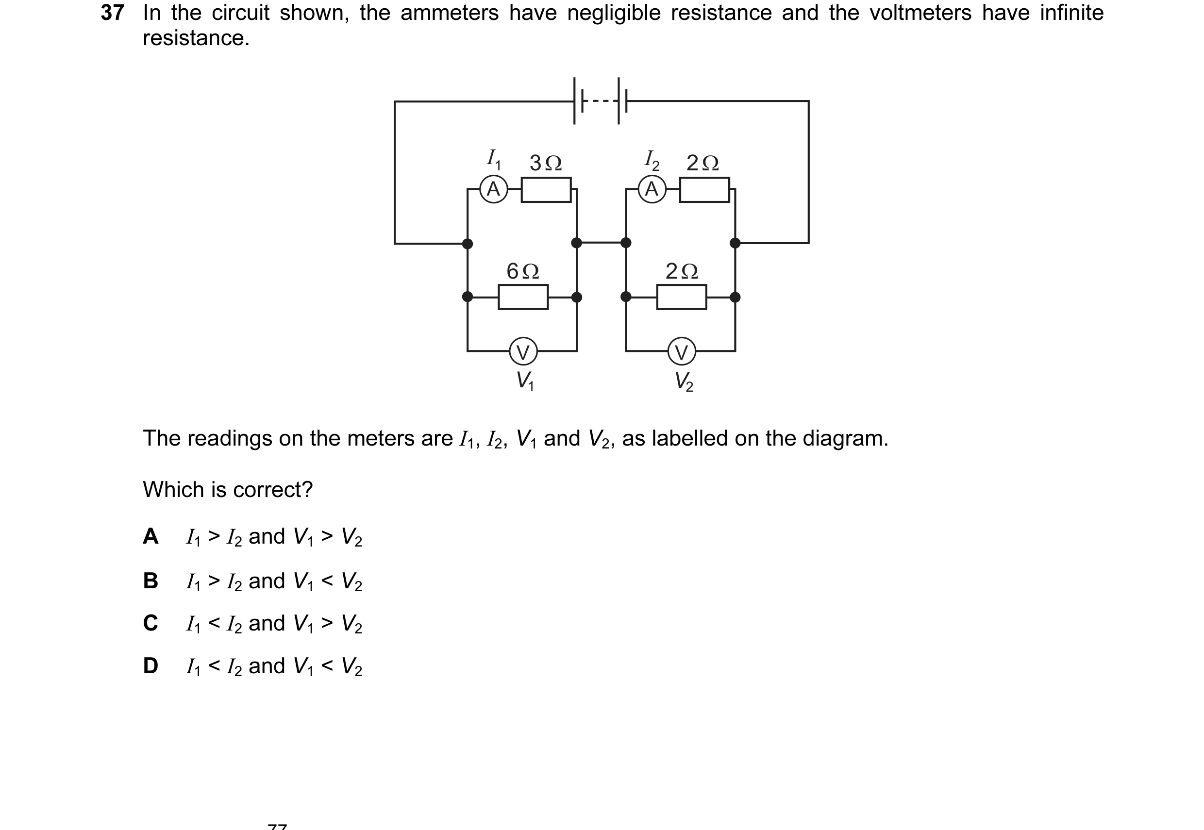
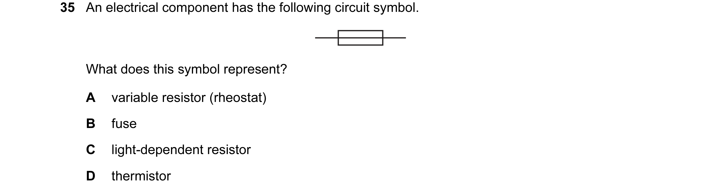
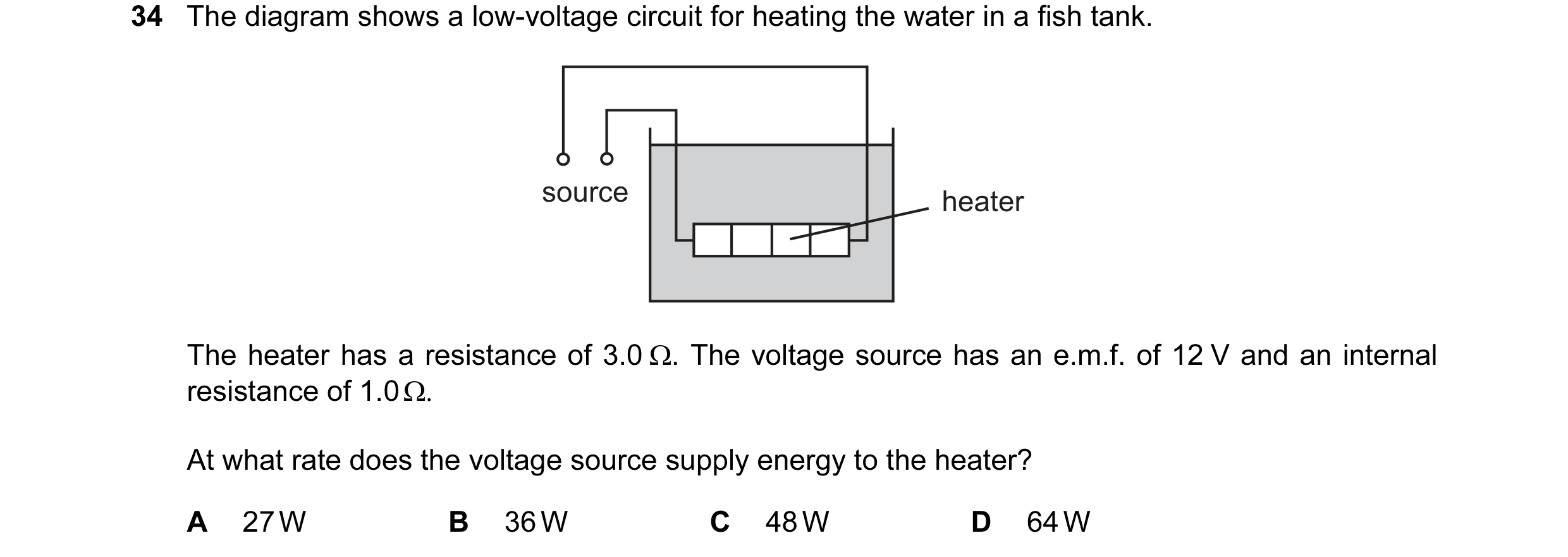 1 / 100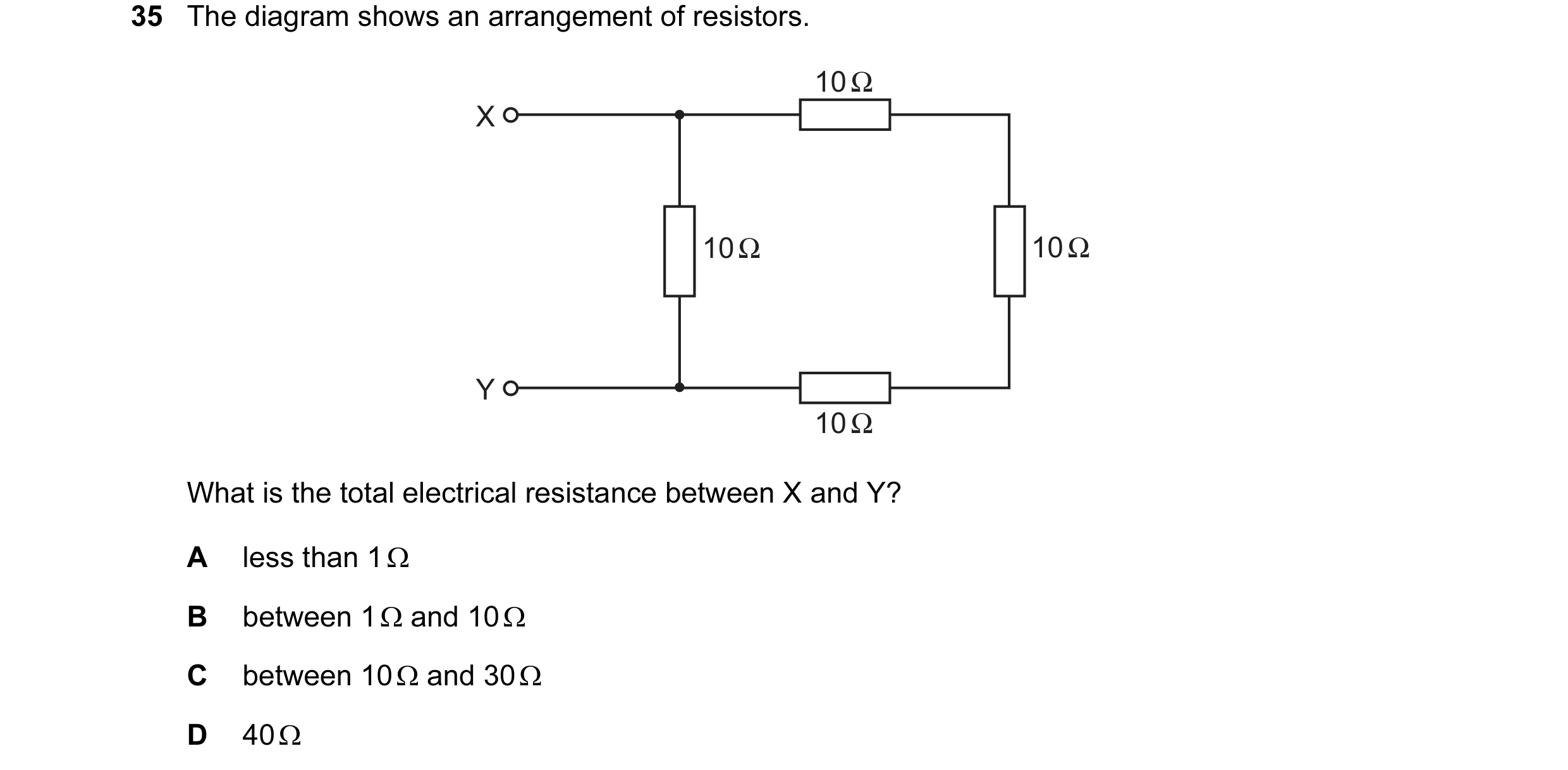
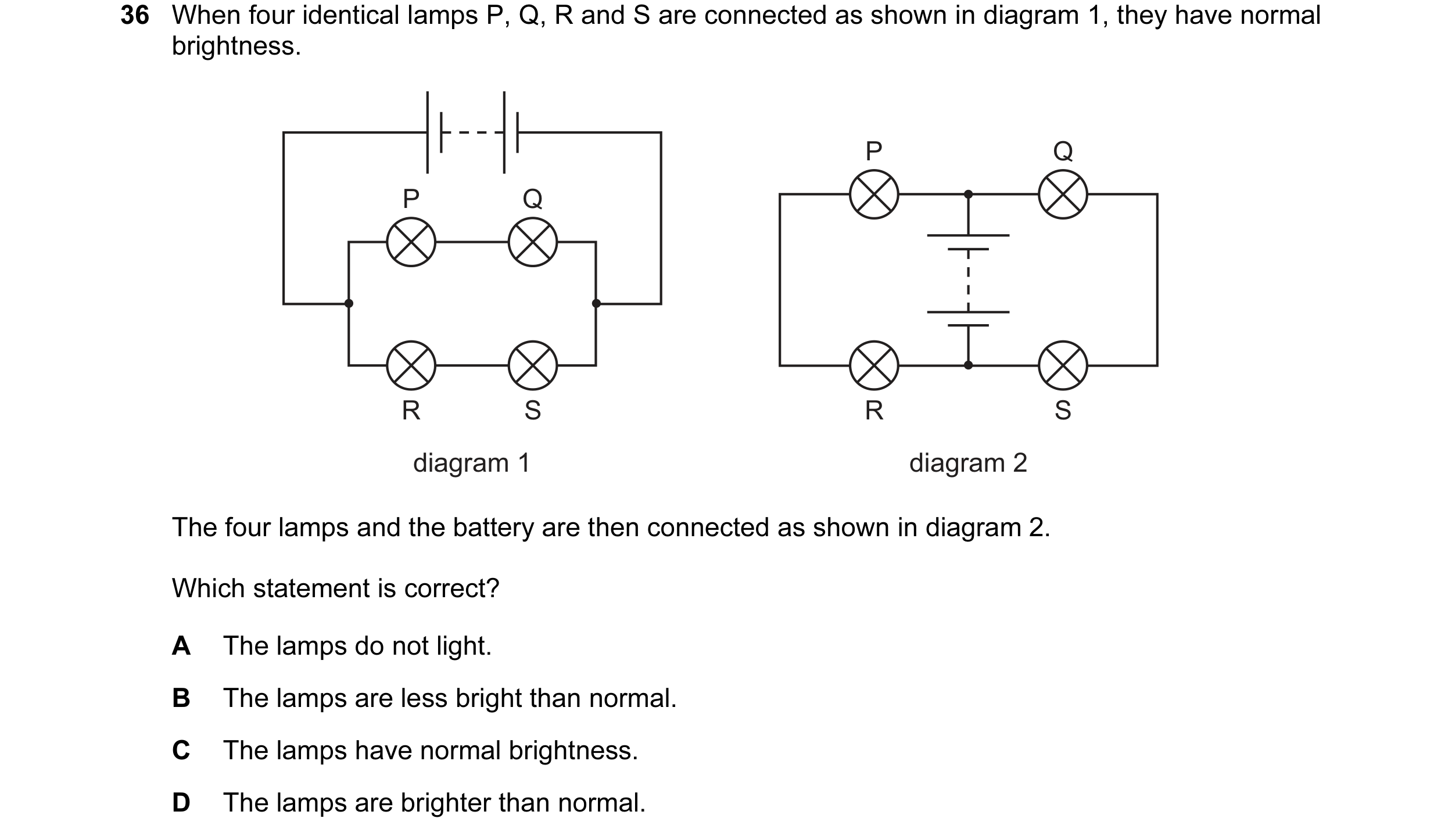
 2 / 100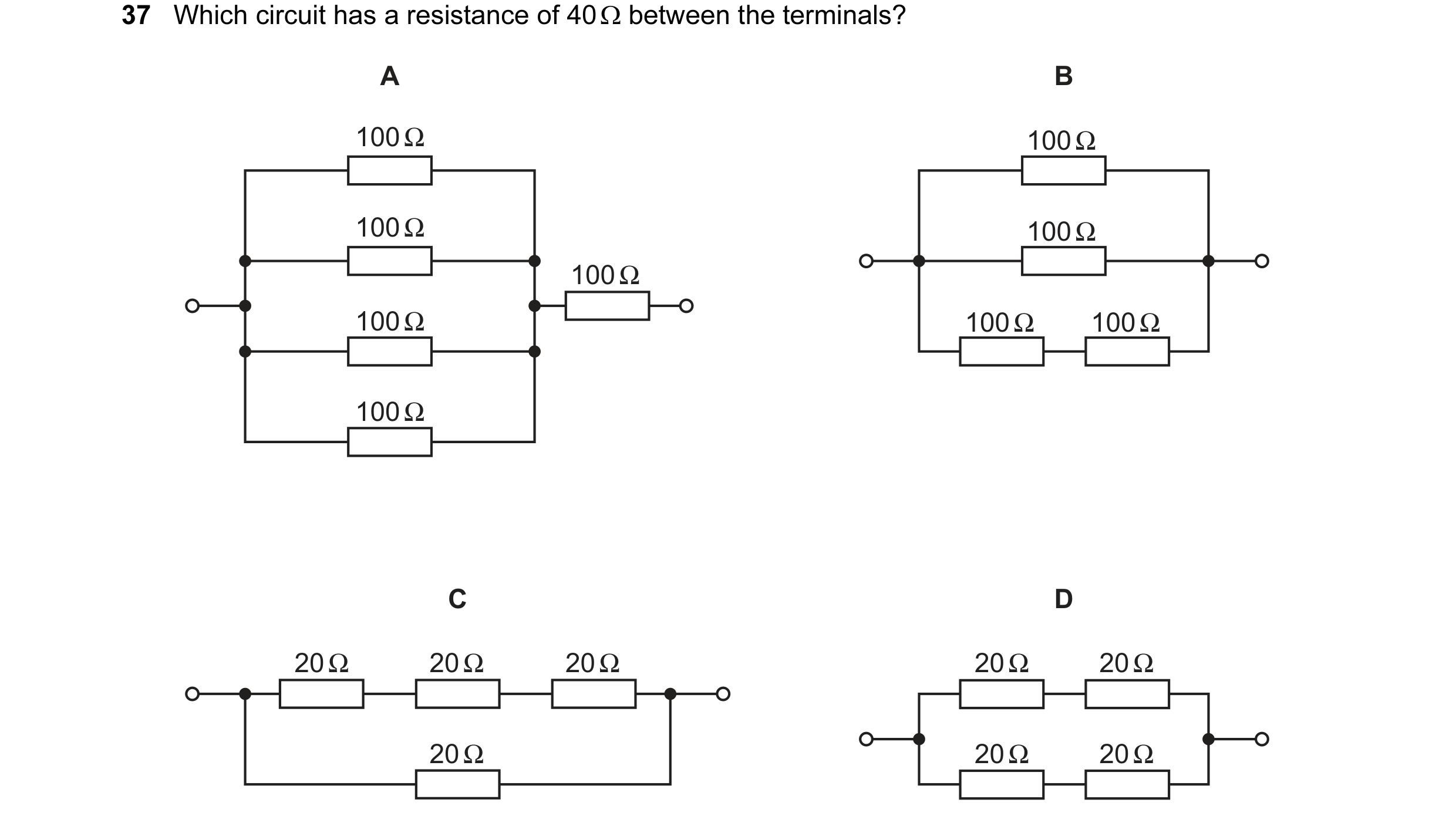
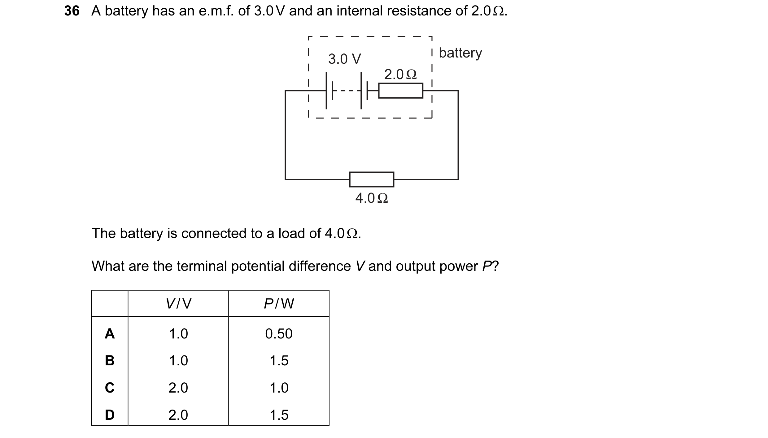 3 / 100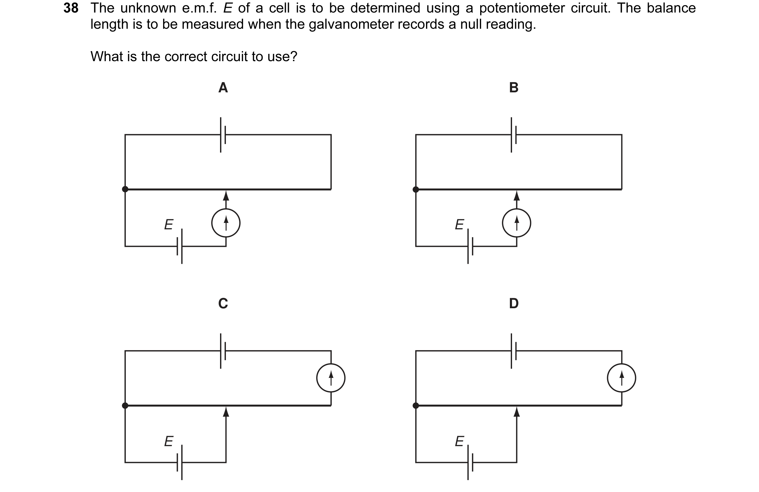
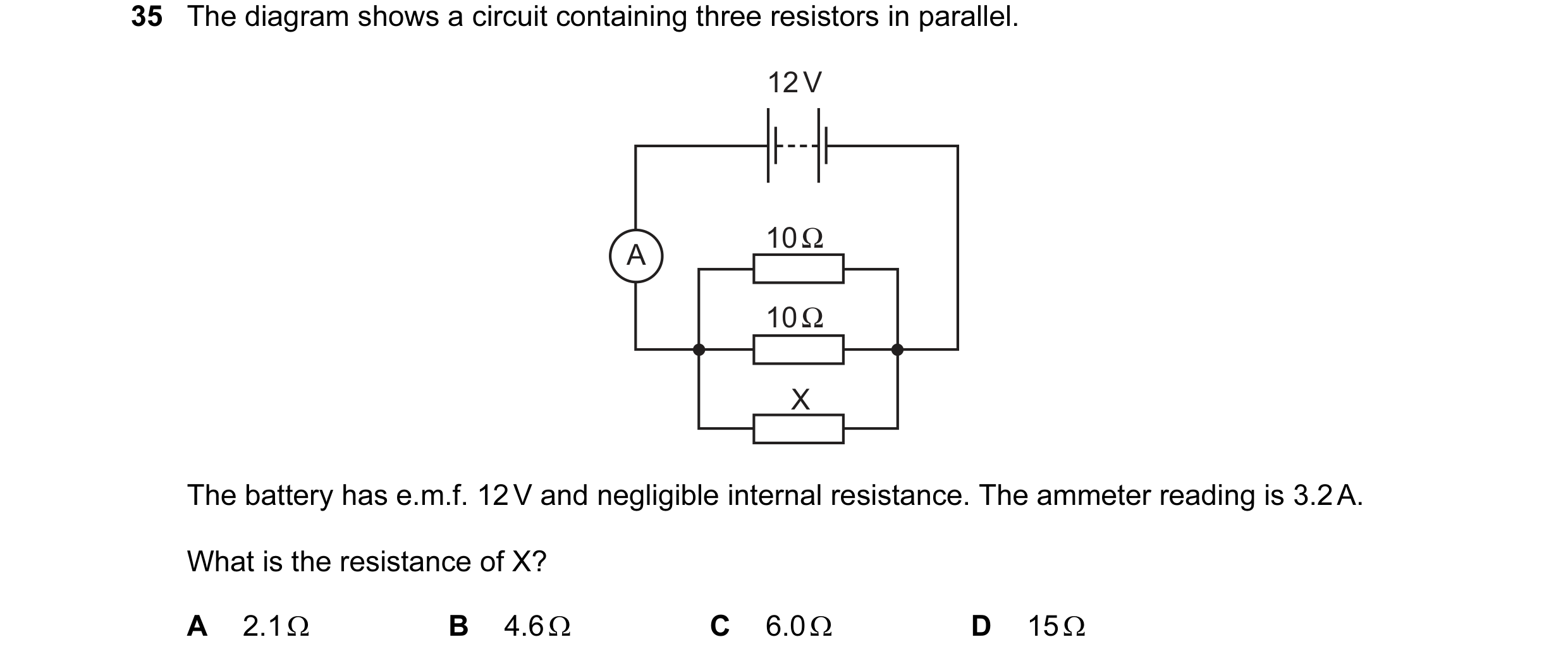 4 / 100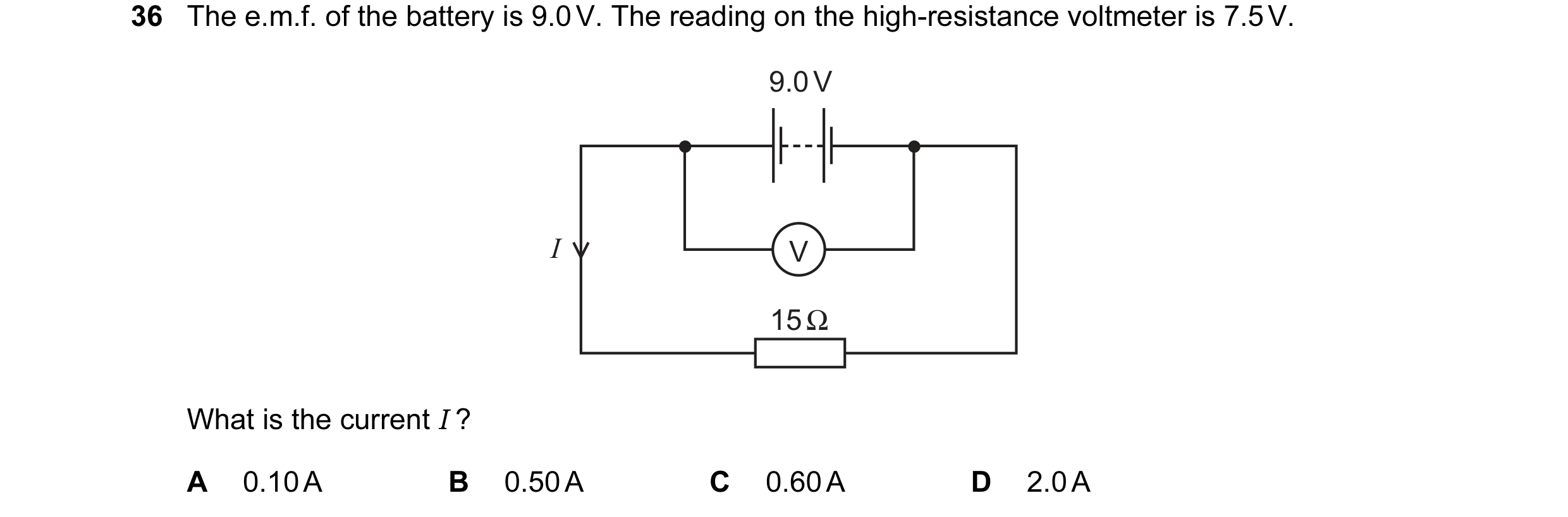
 5 / 100
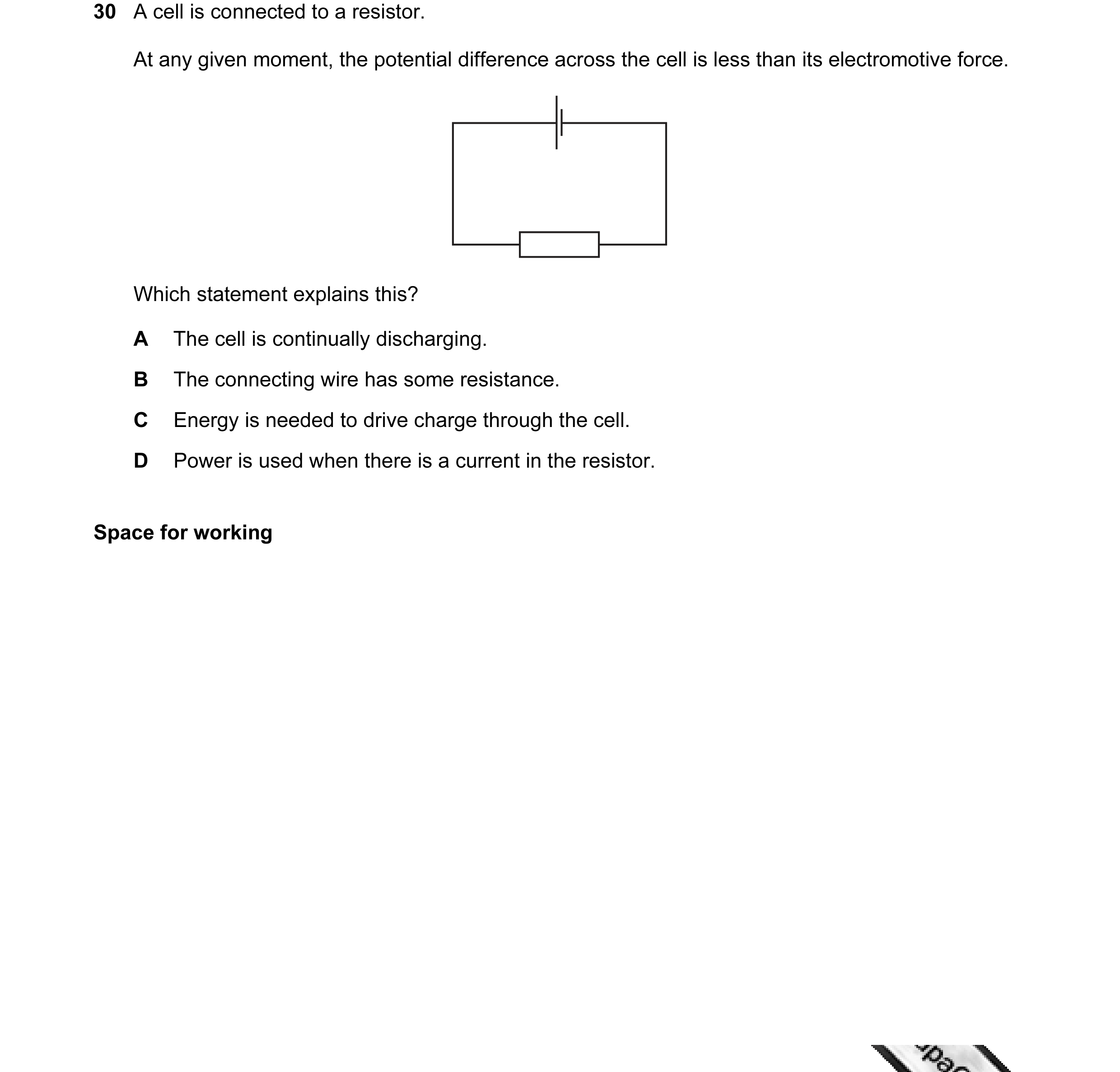 6 / 100
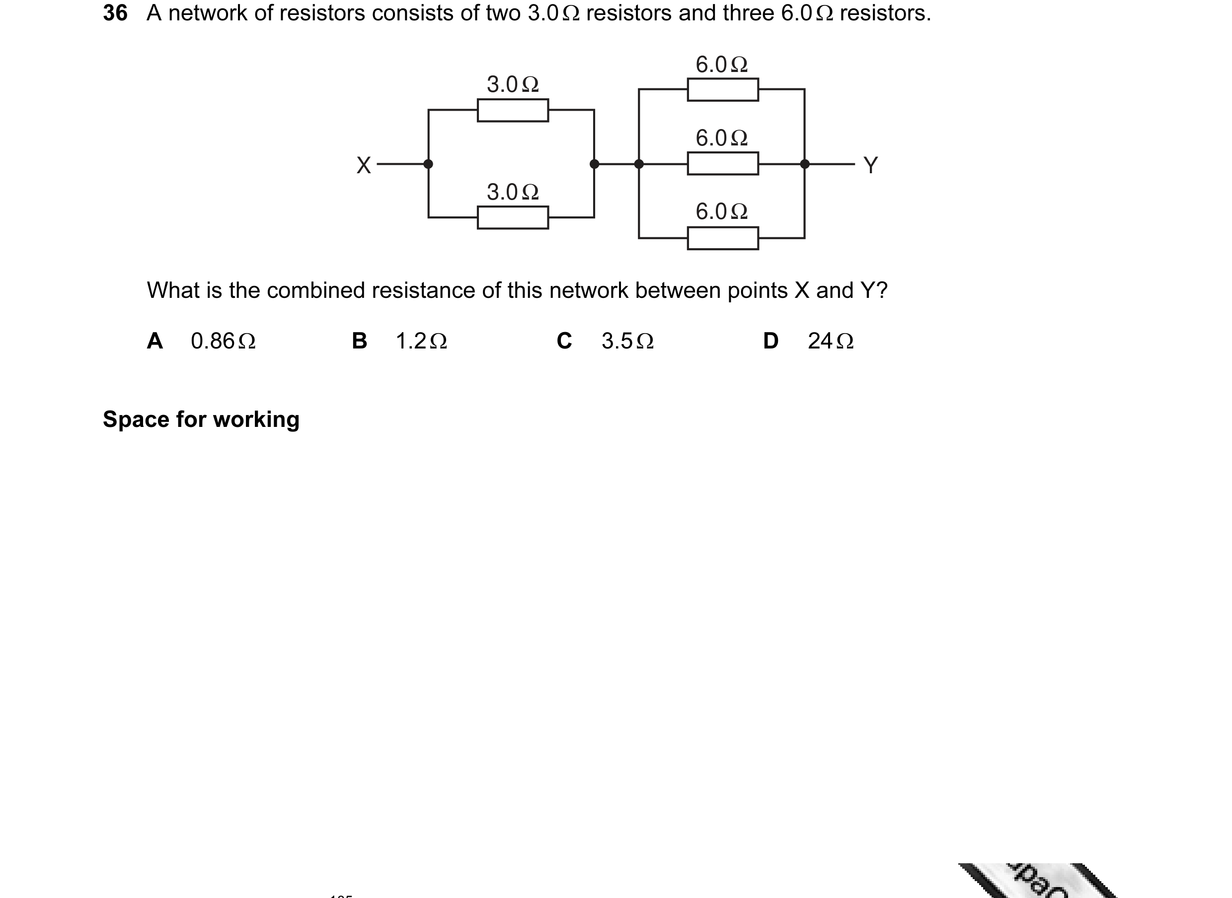 7 / 100
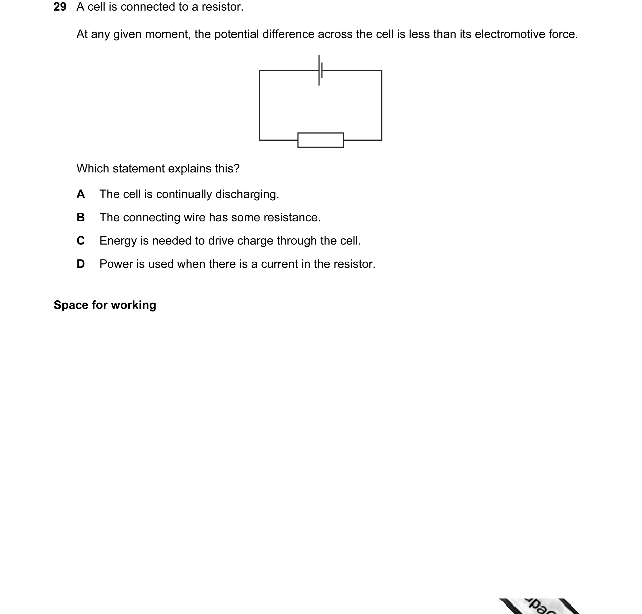 8 / 100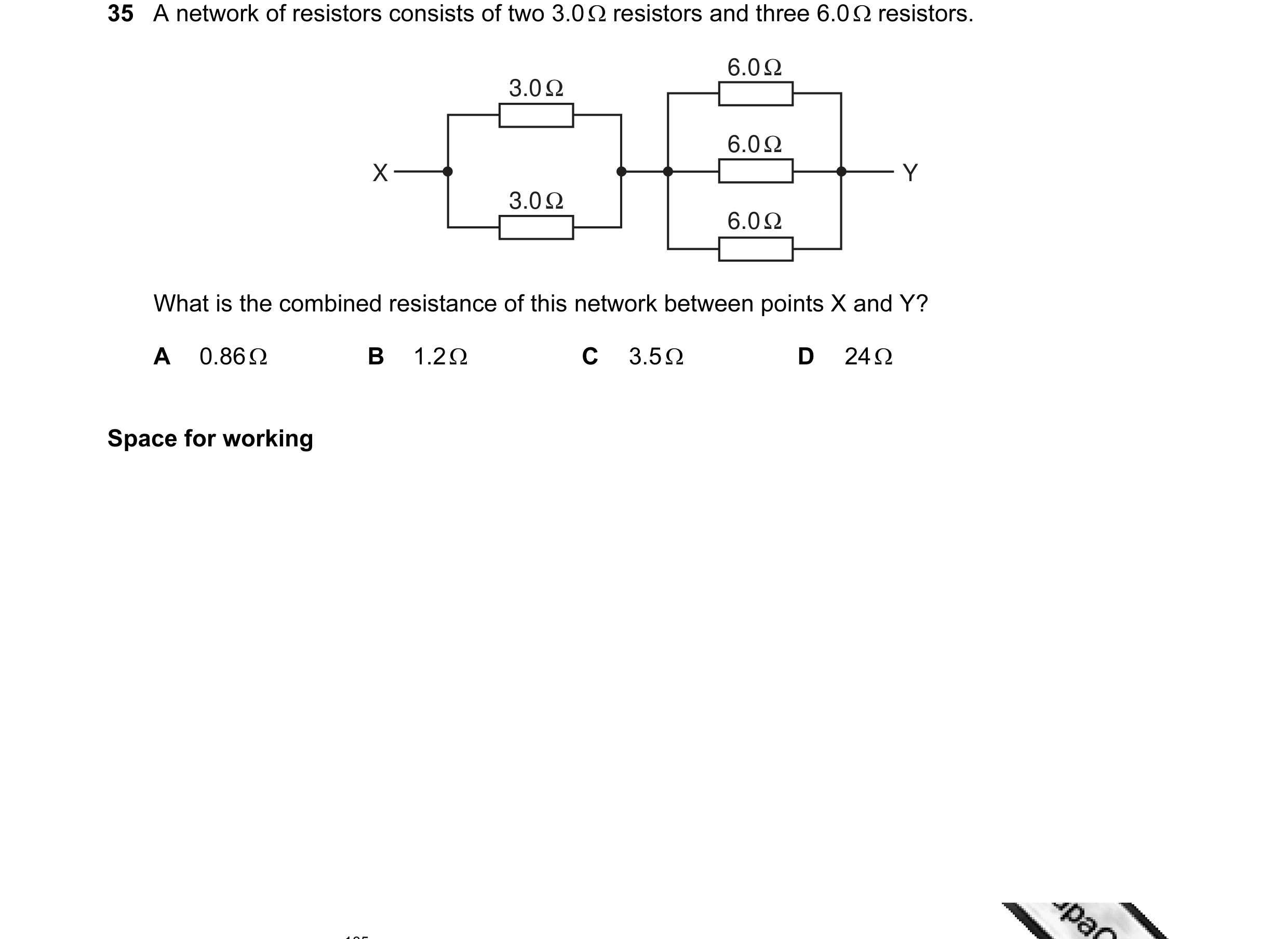
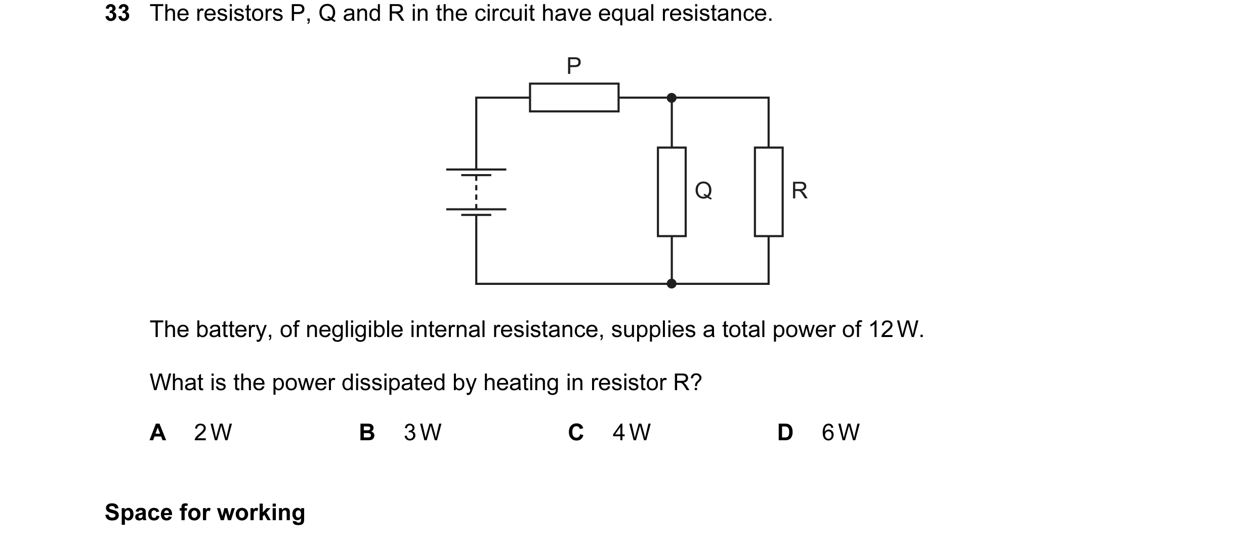 9 / 100
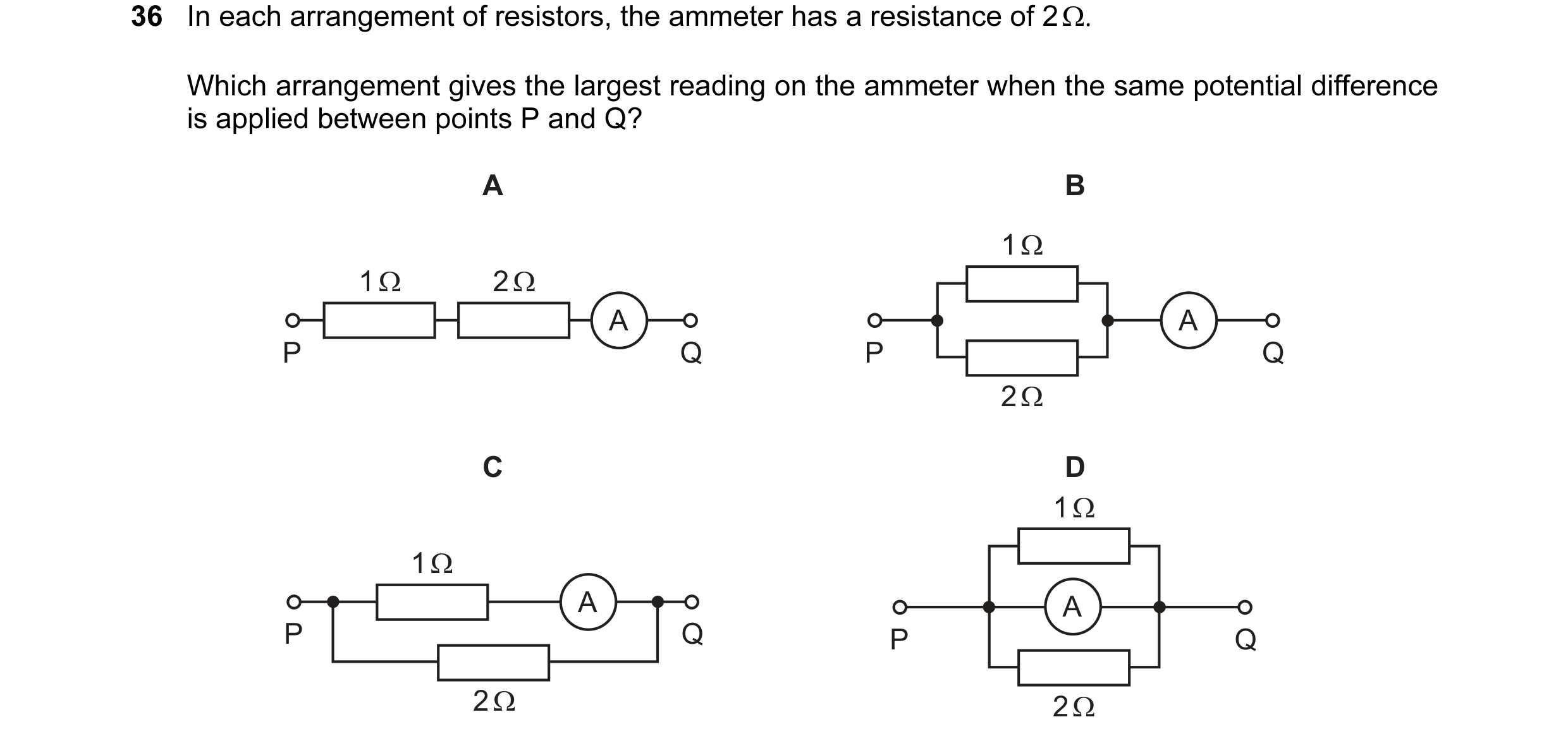

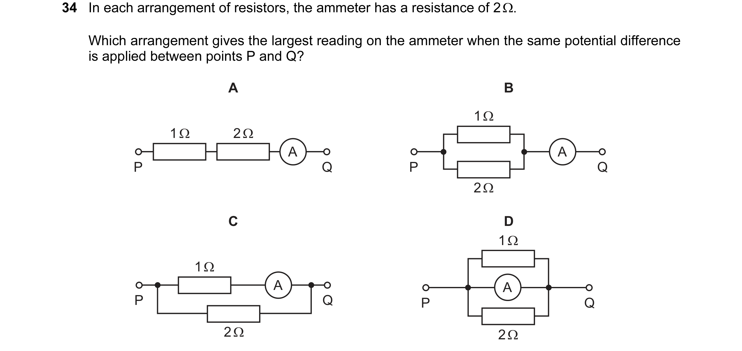 10 / 100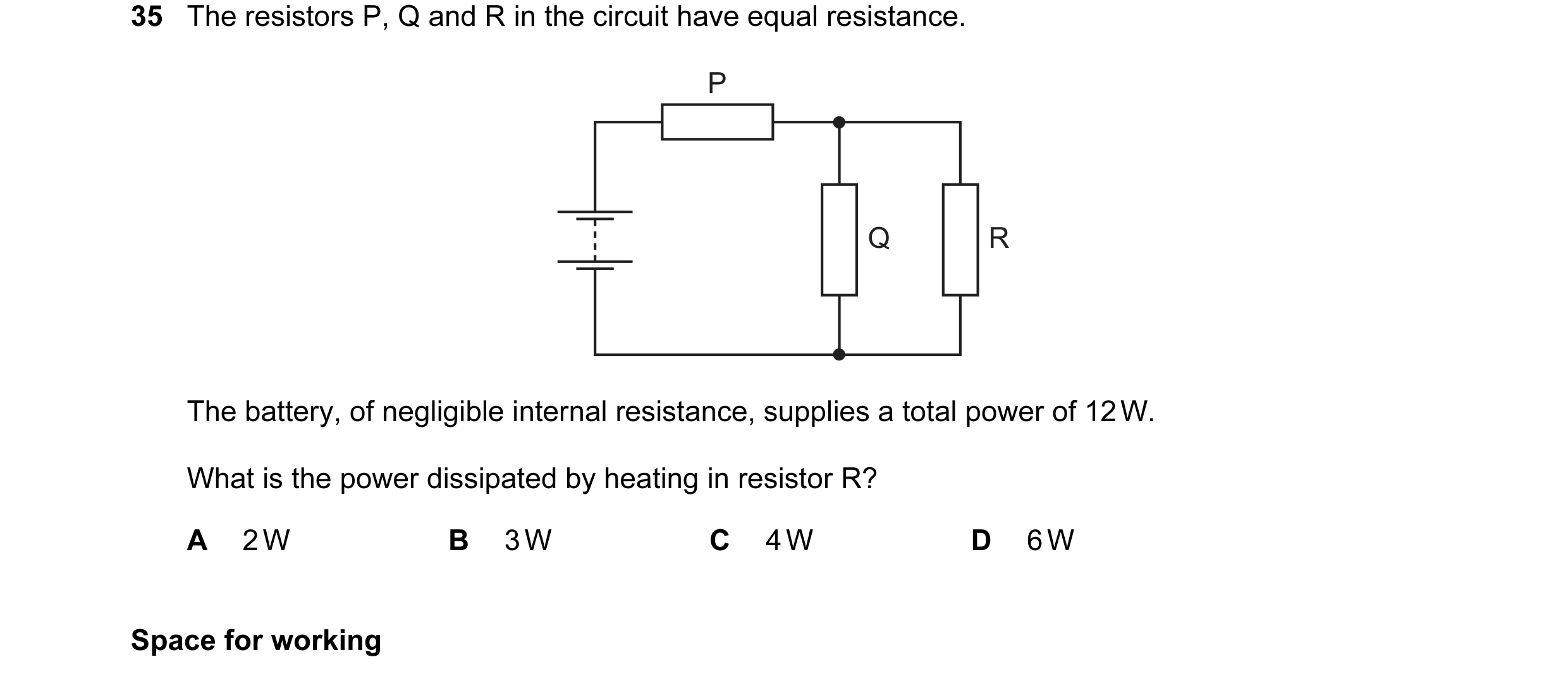
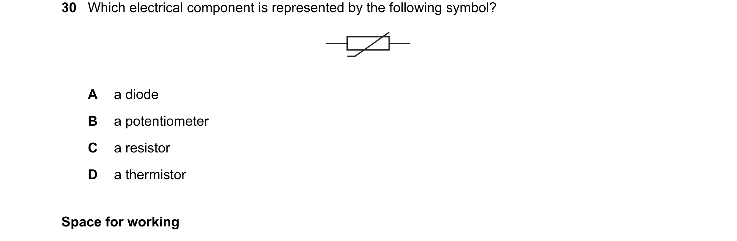
 11 / 100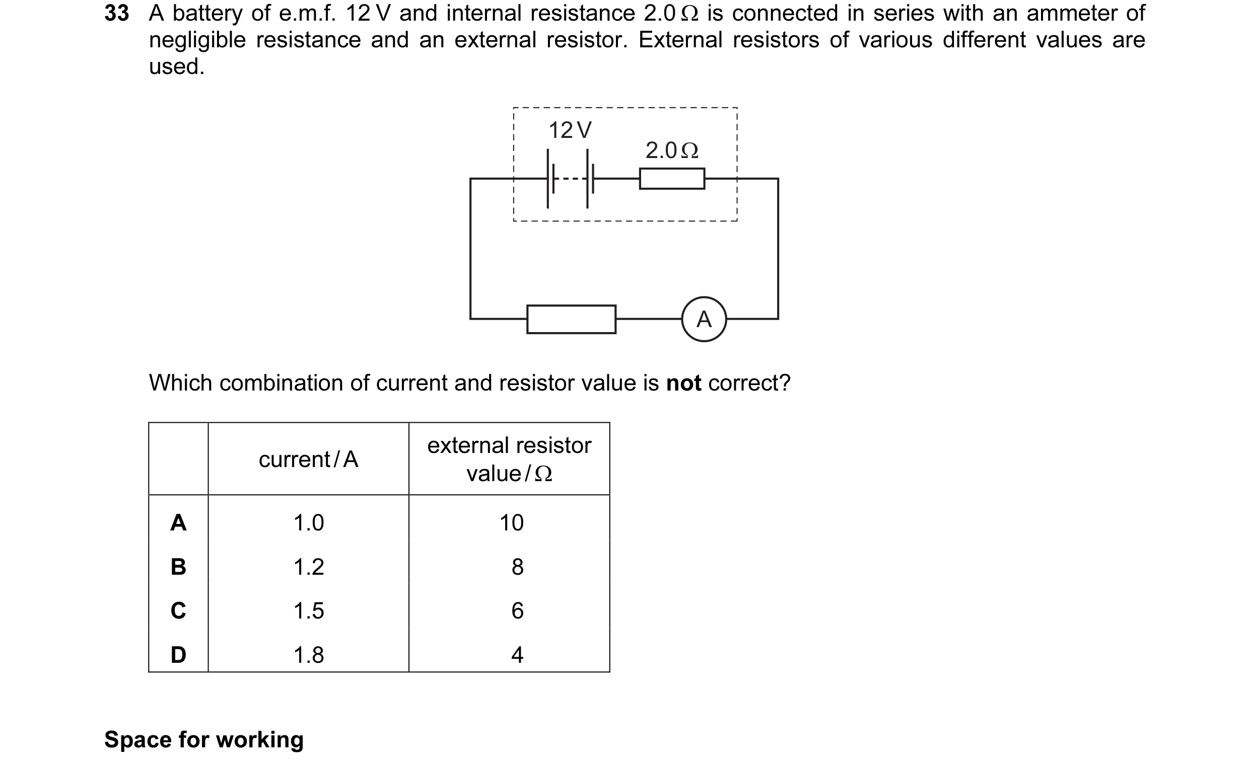
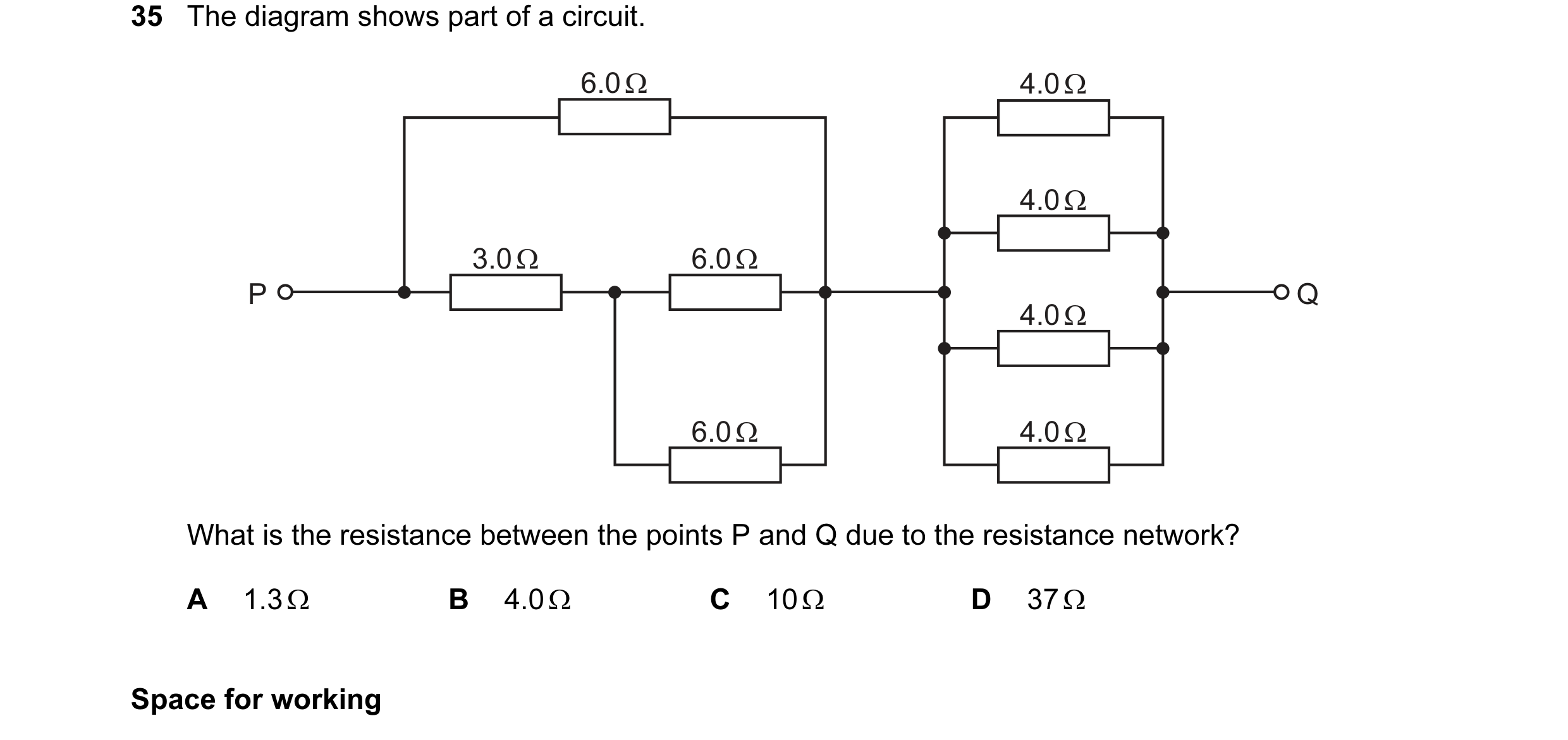 12 / 100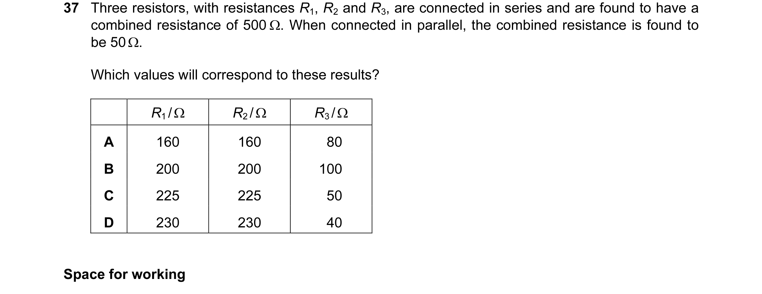
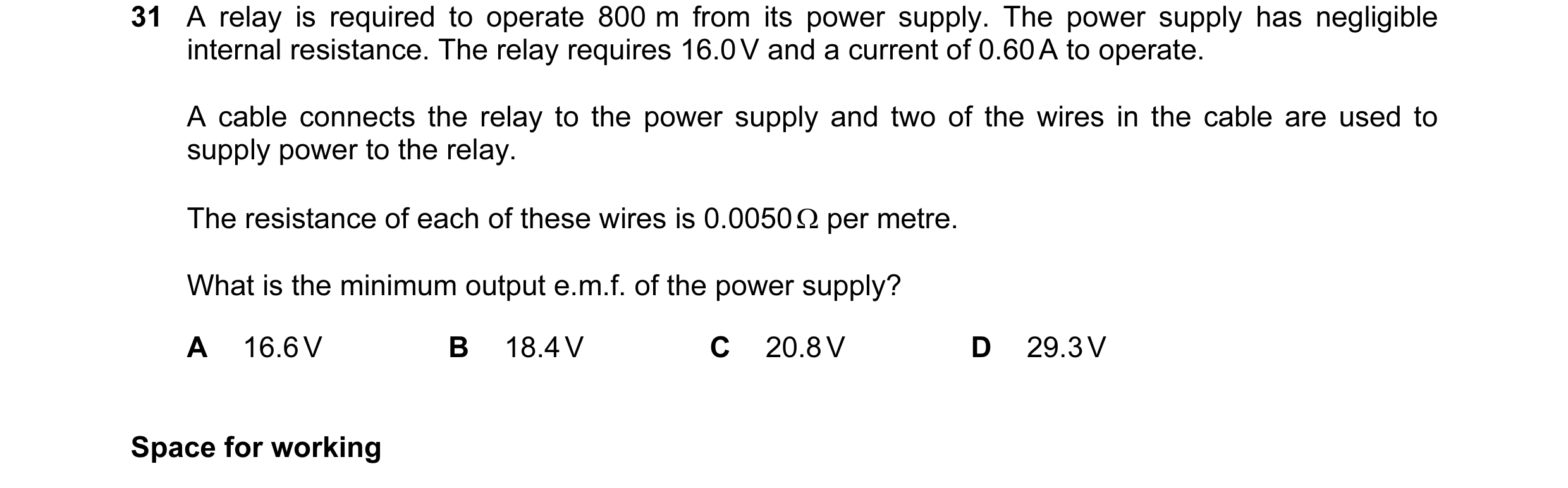
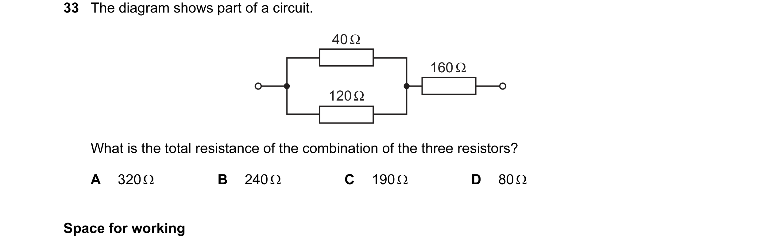 13 / 100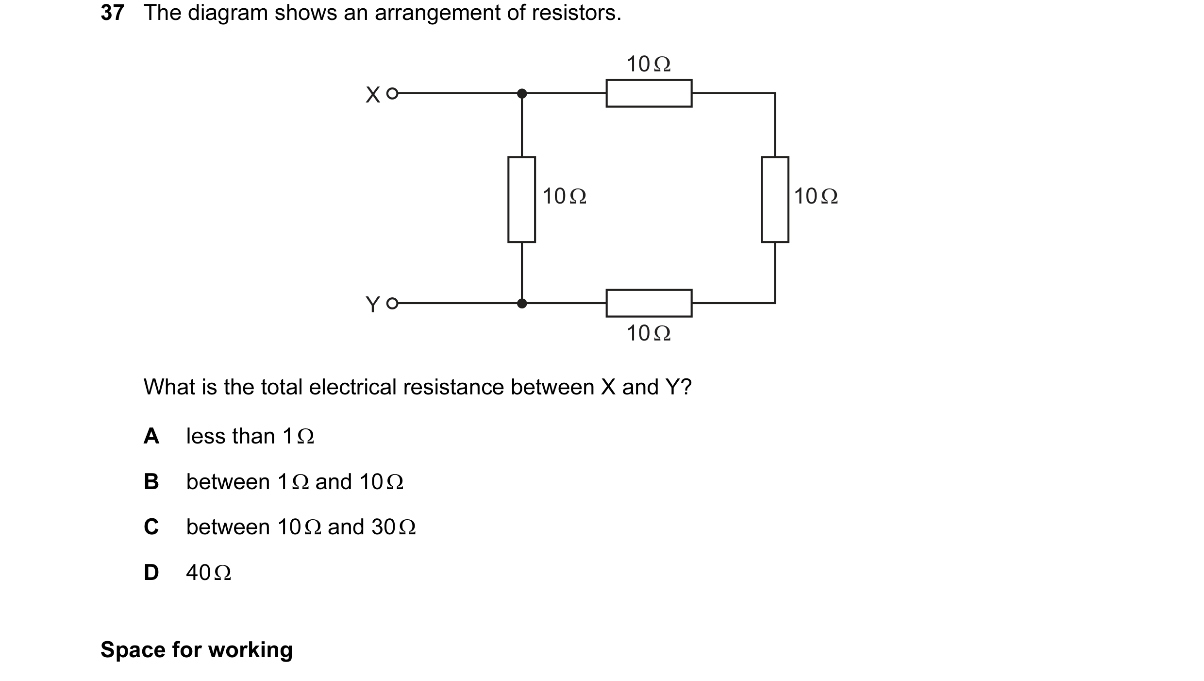
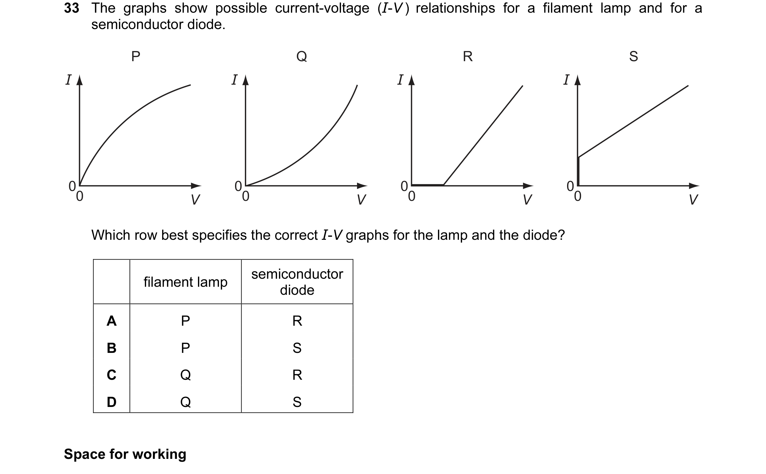 14 / 100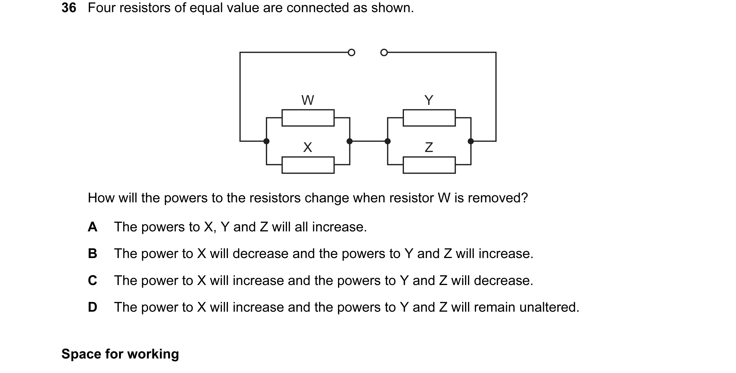
 15 / 100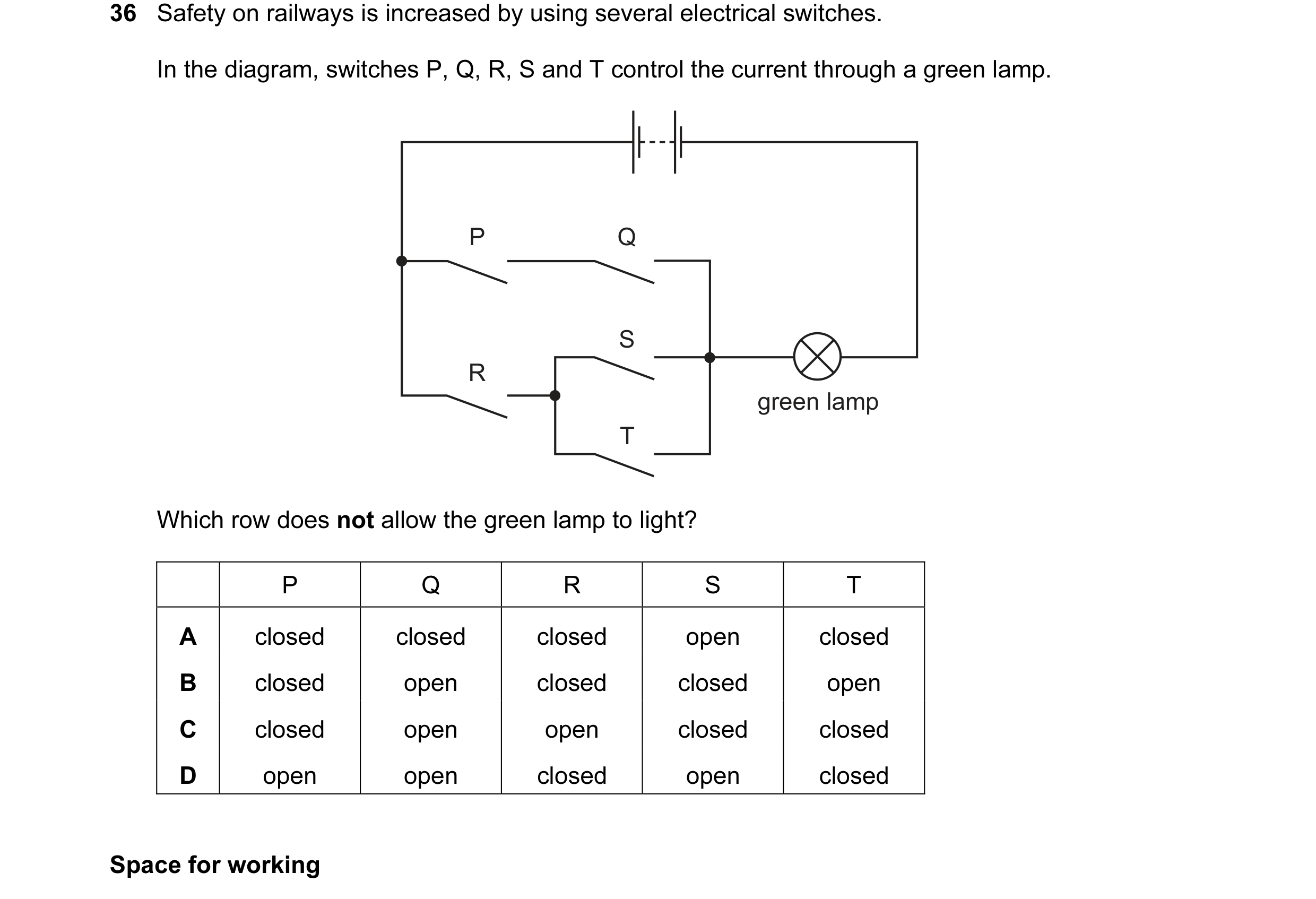
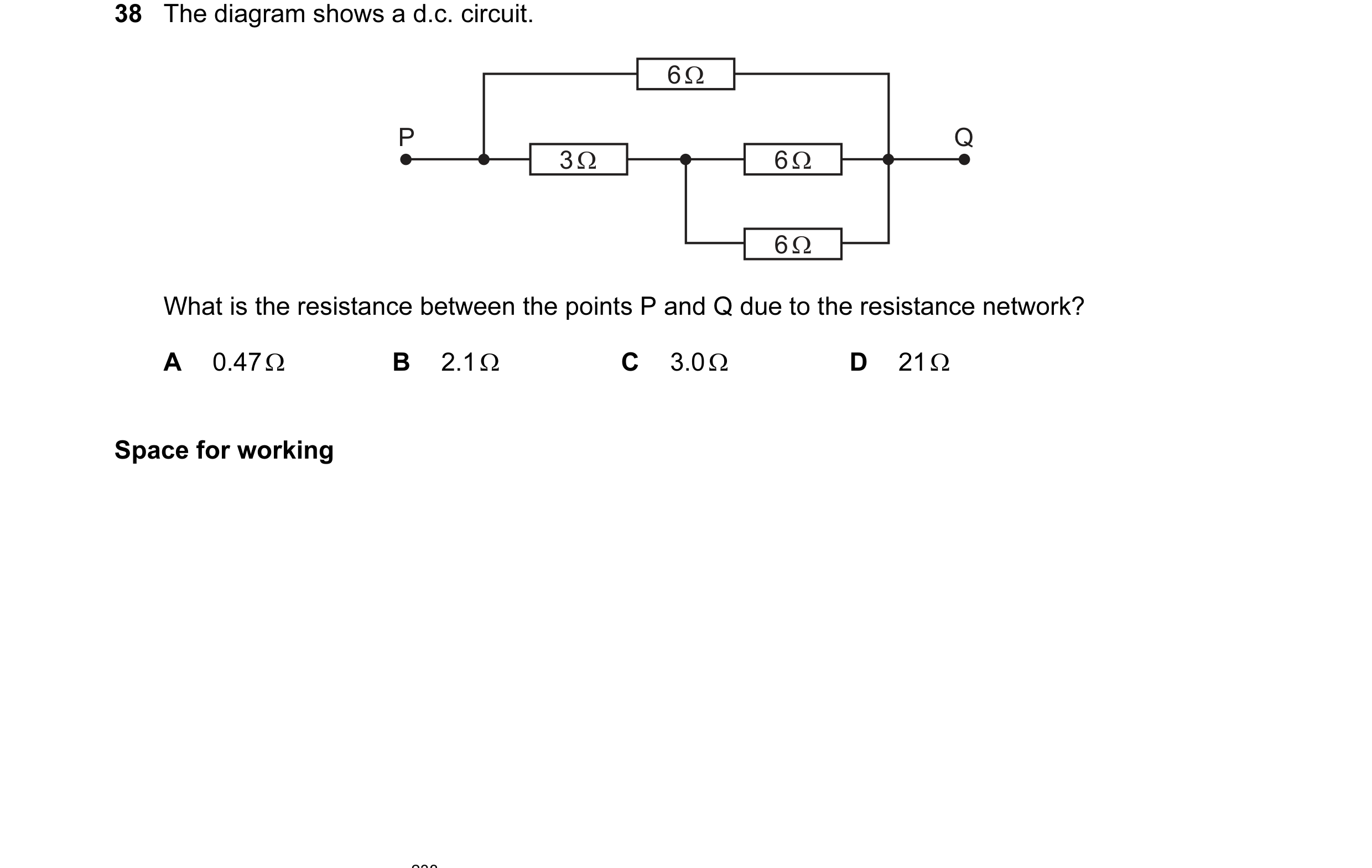 16 / 100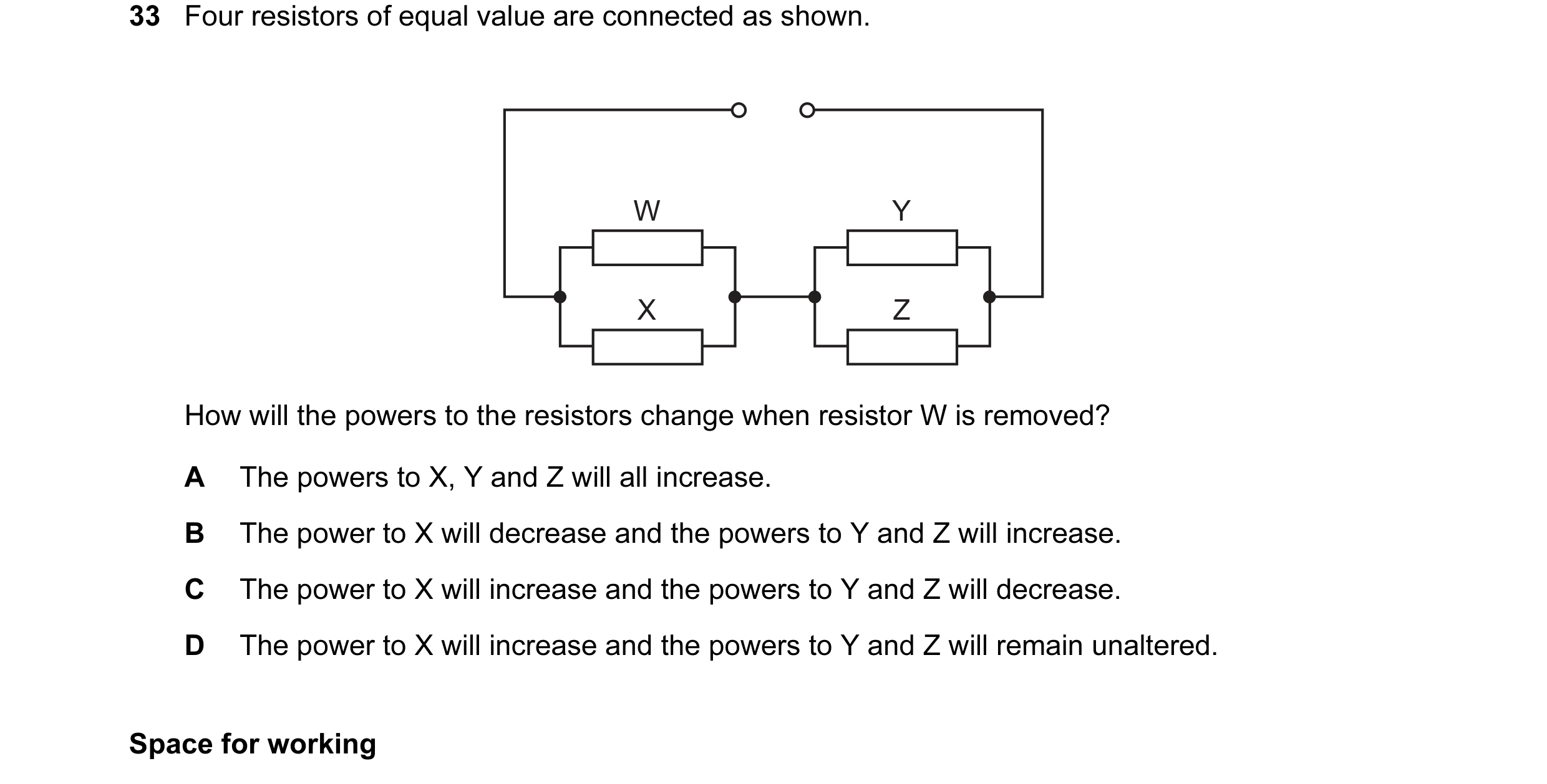
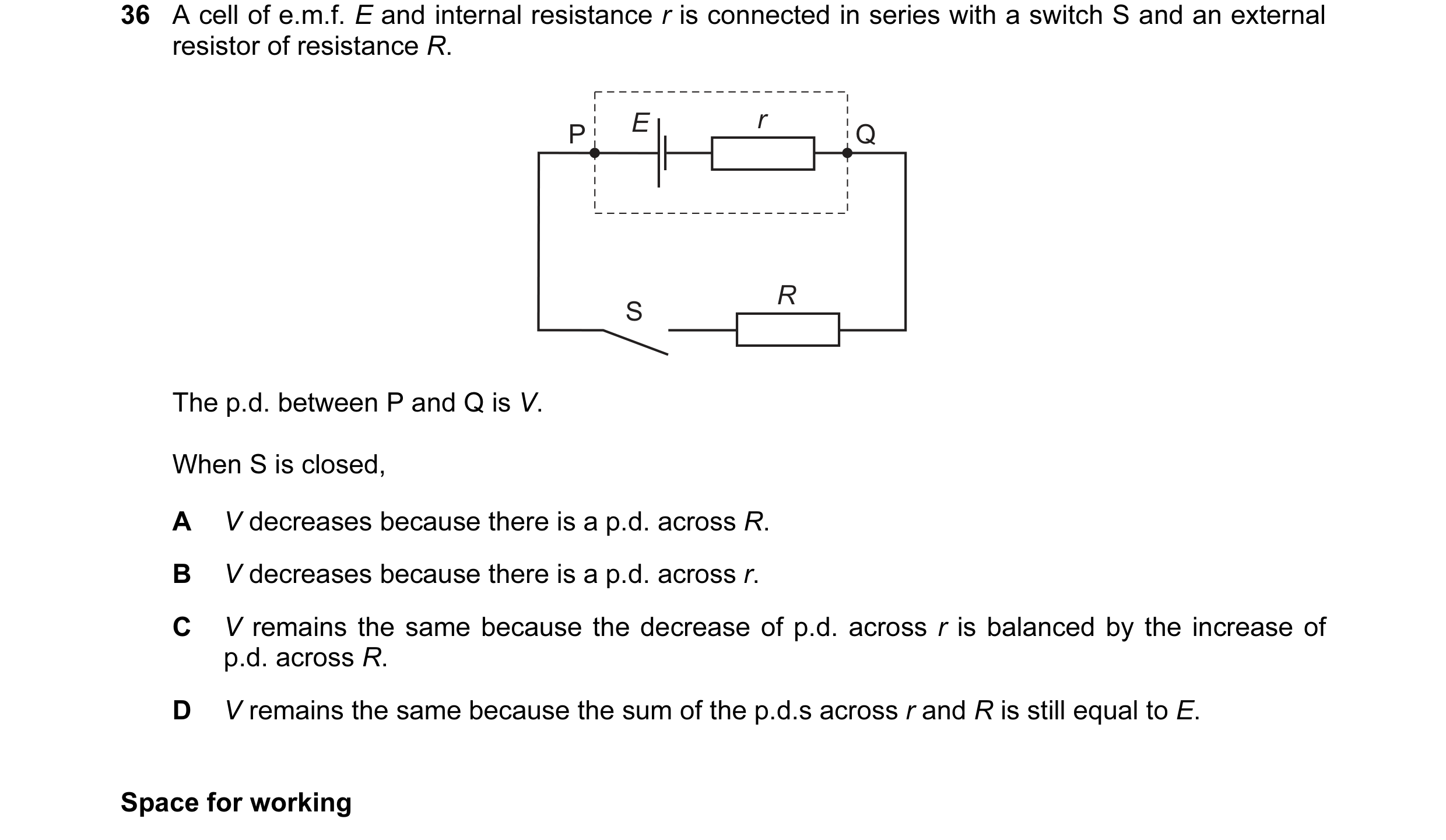 17 / 100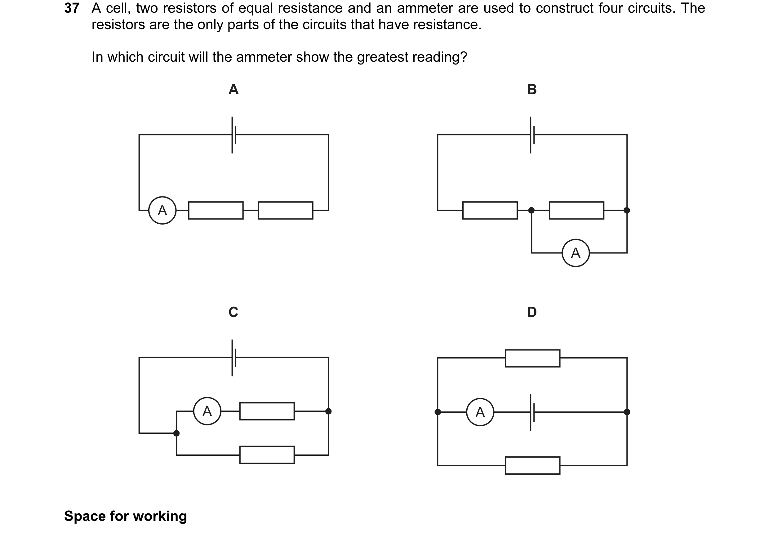
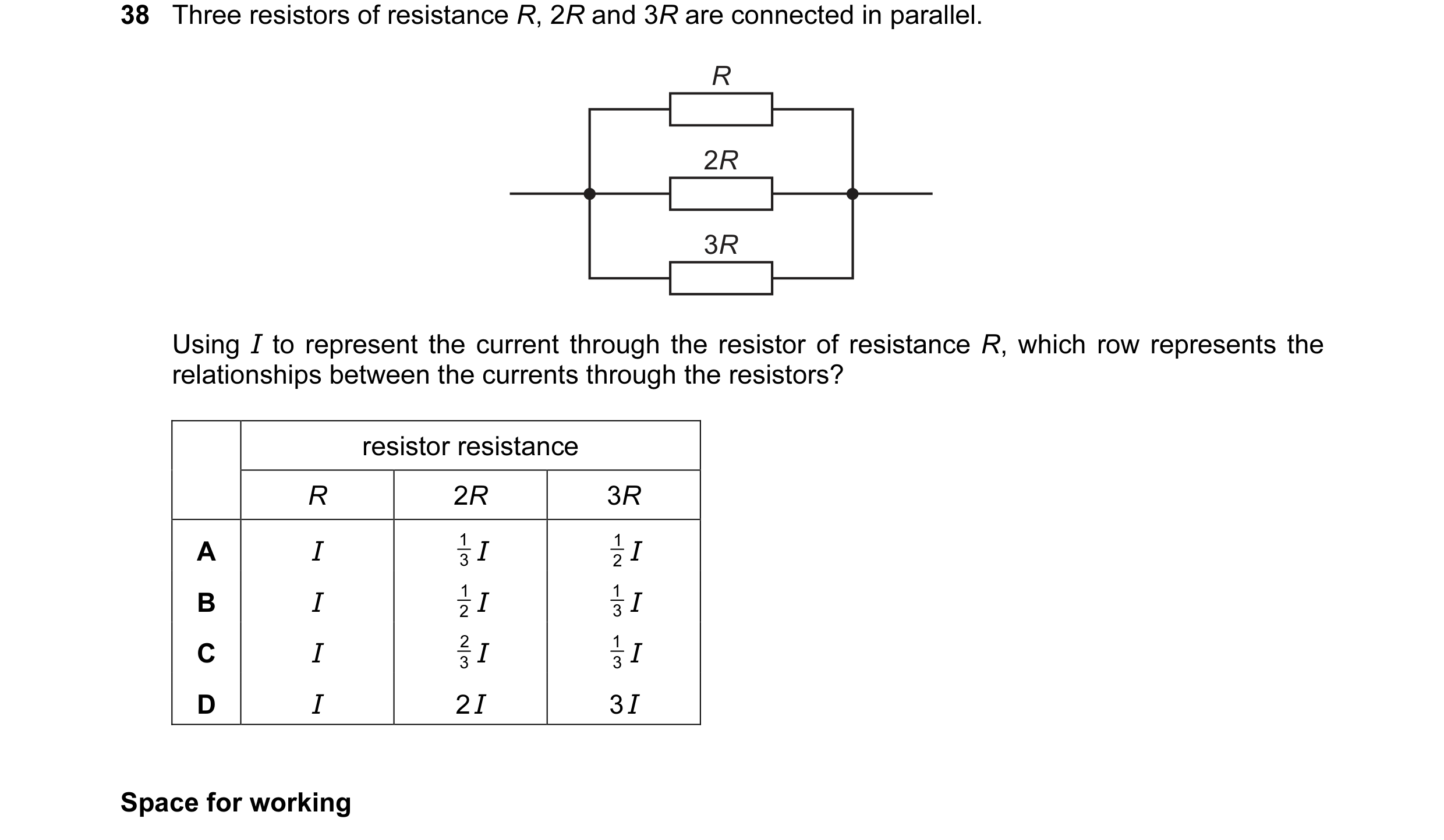 18 / 100
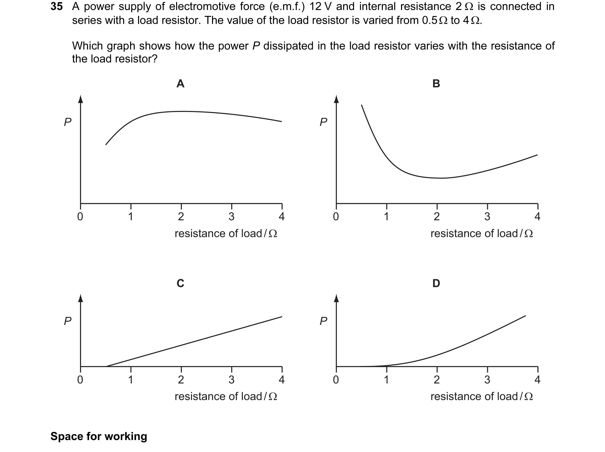 19 / 100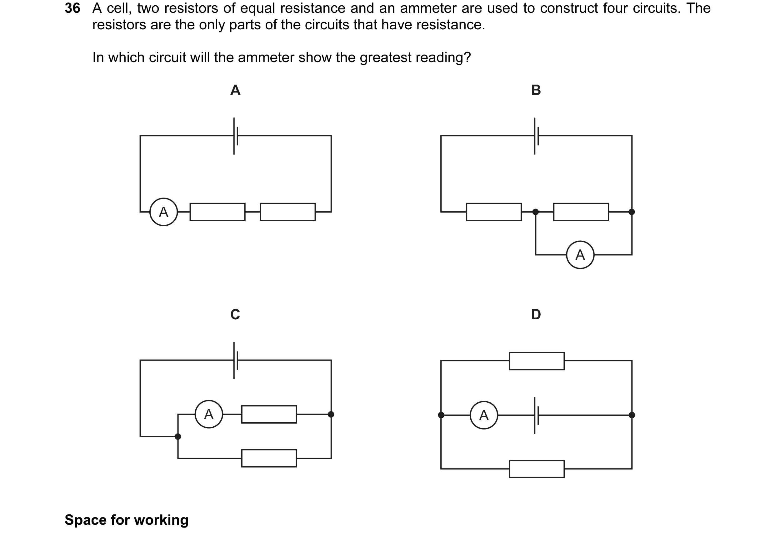
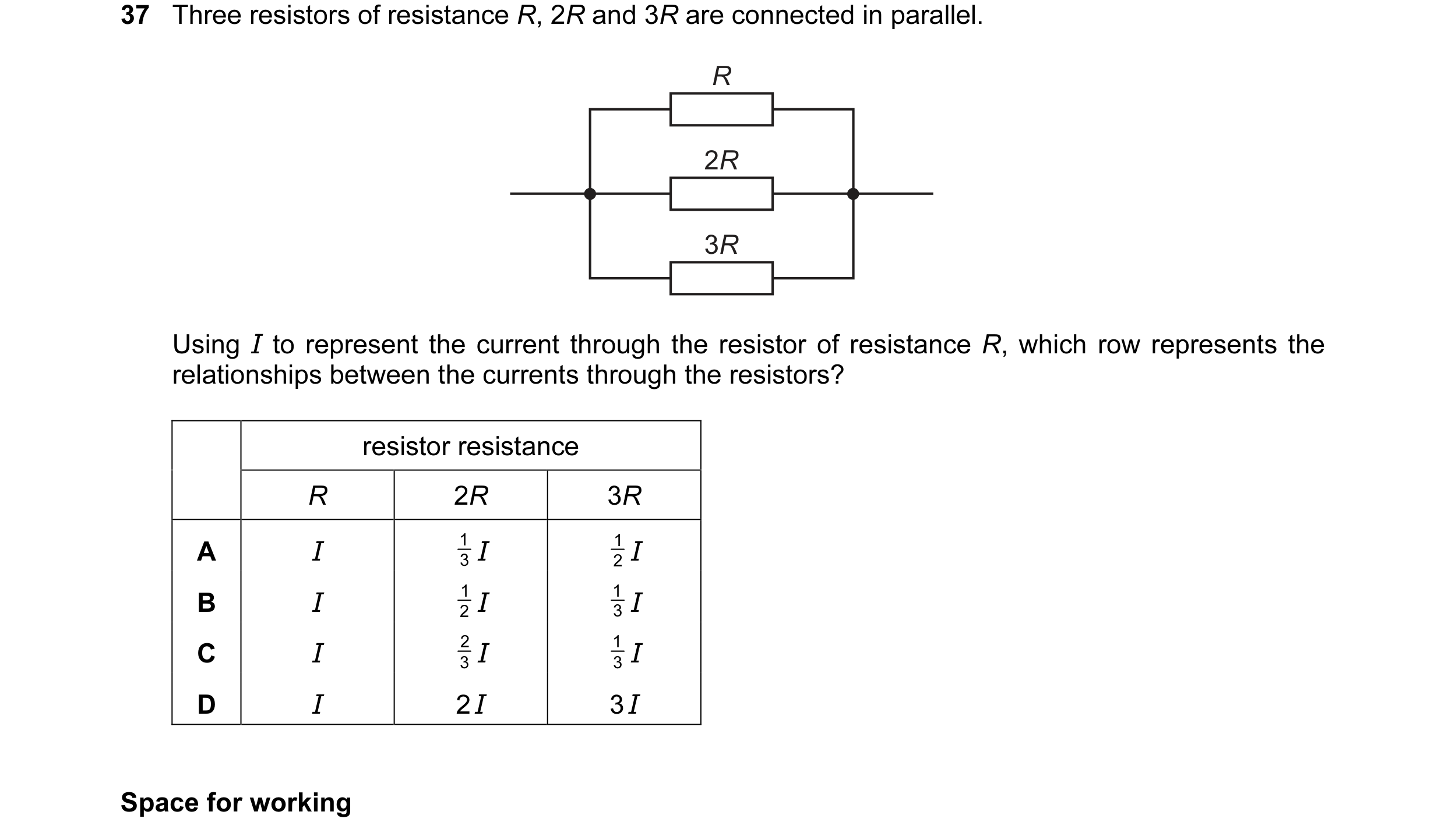 20 / 100
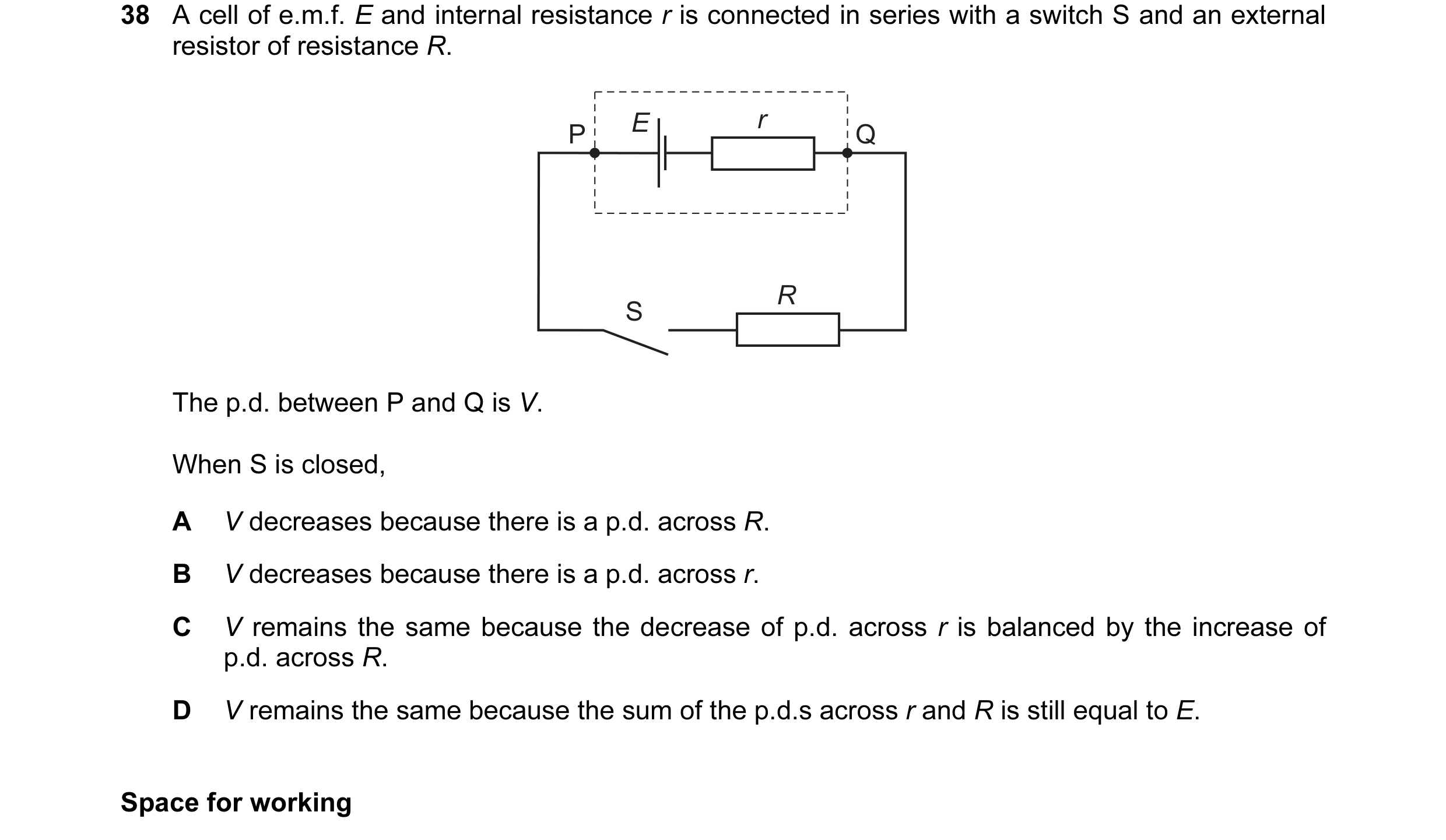 21 / 100
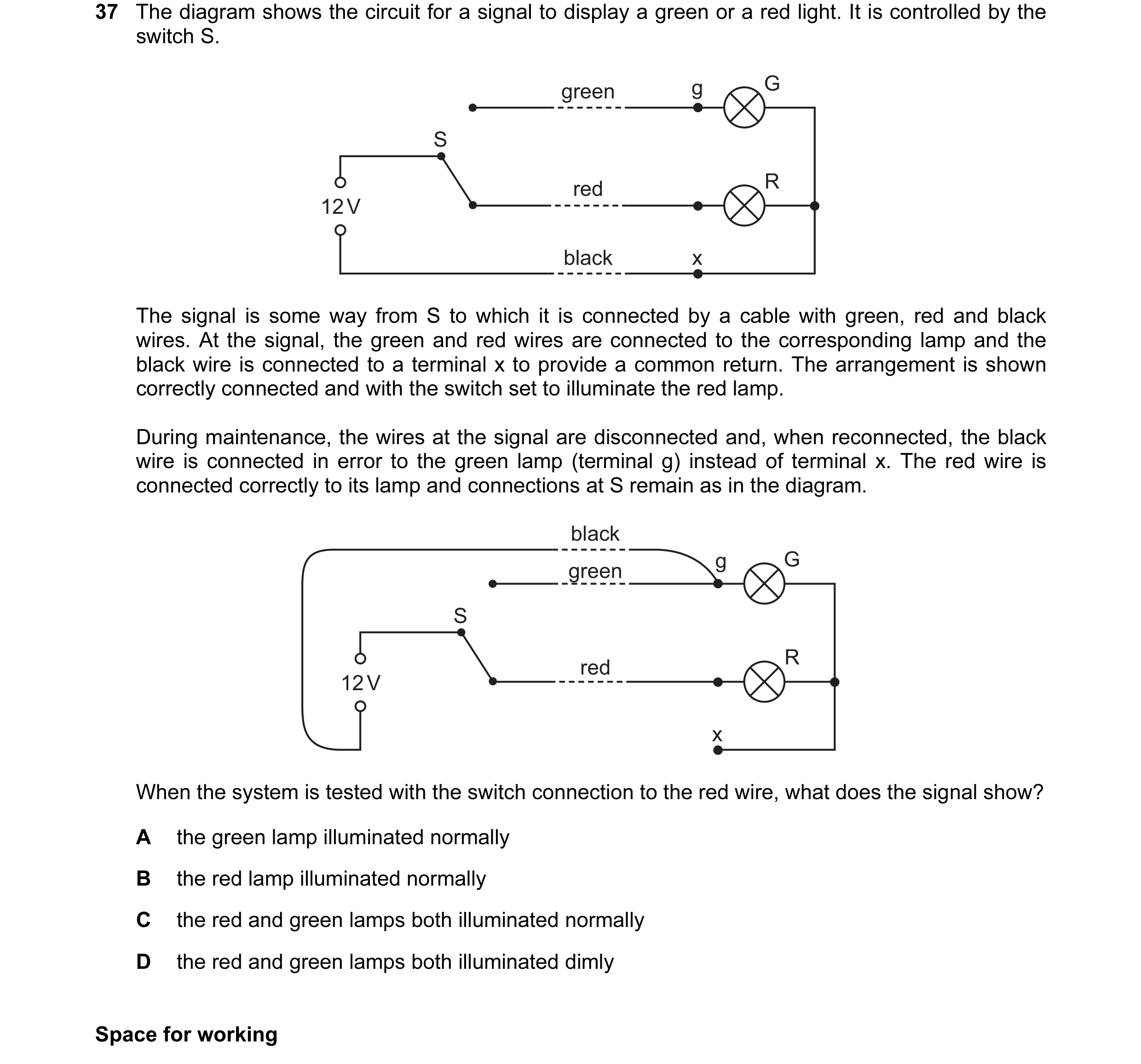 22 / 100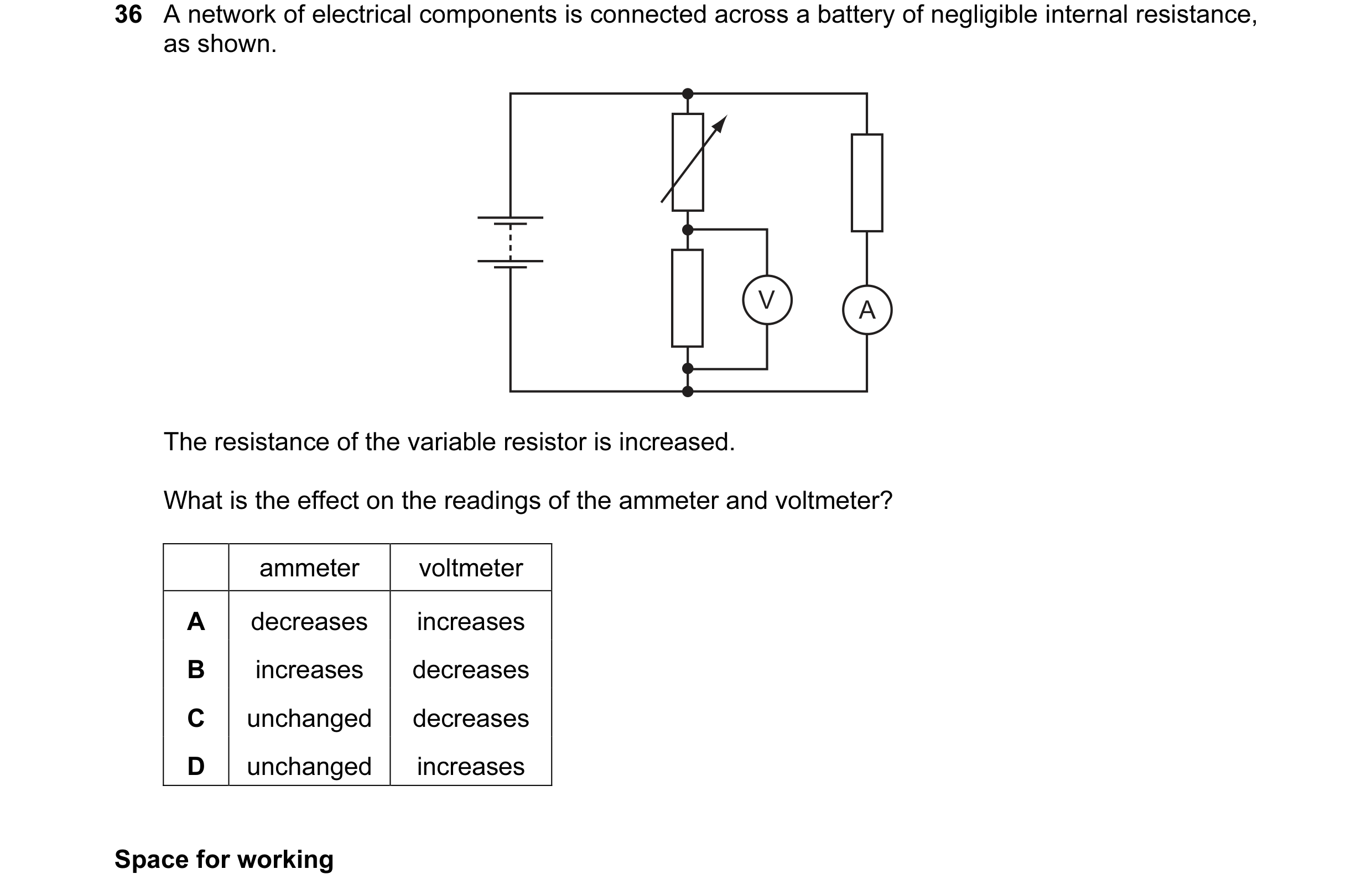
 23 / 100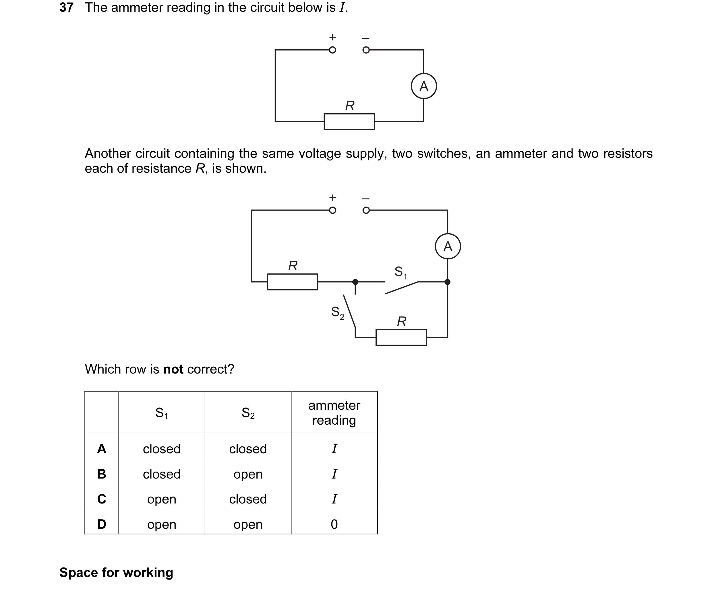
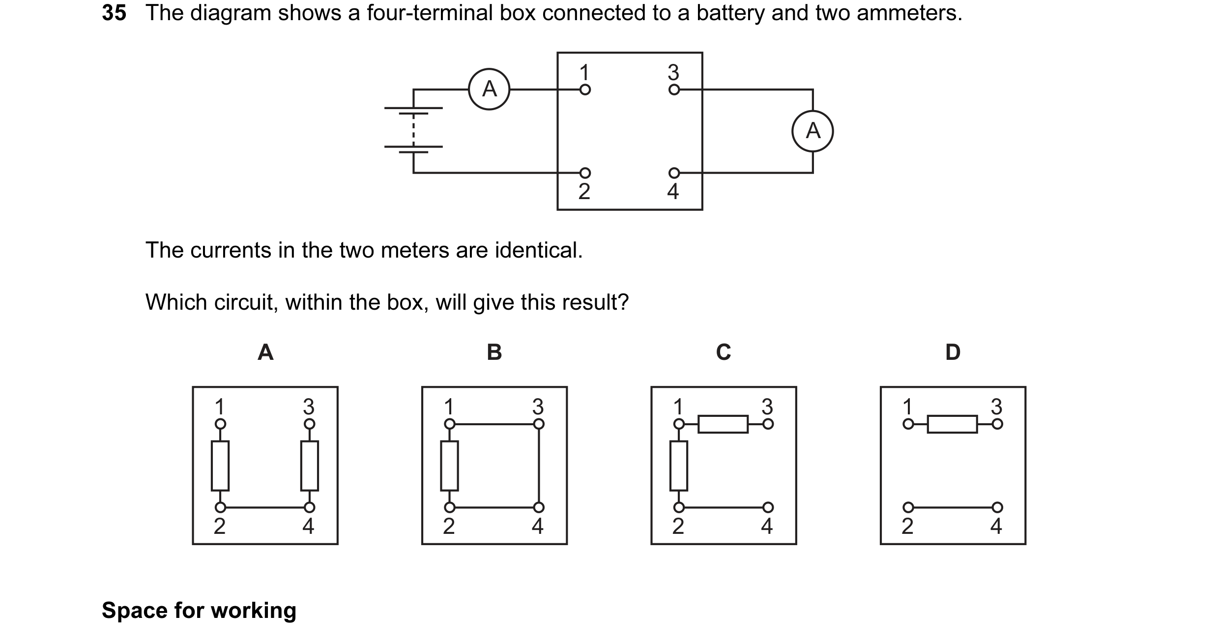 24 / 100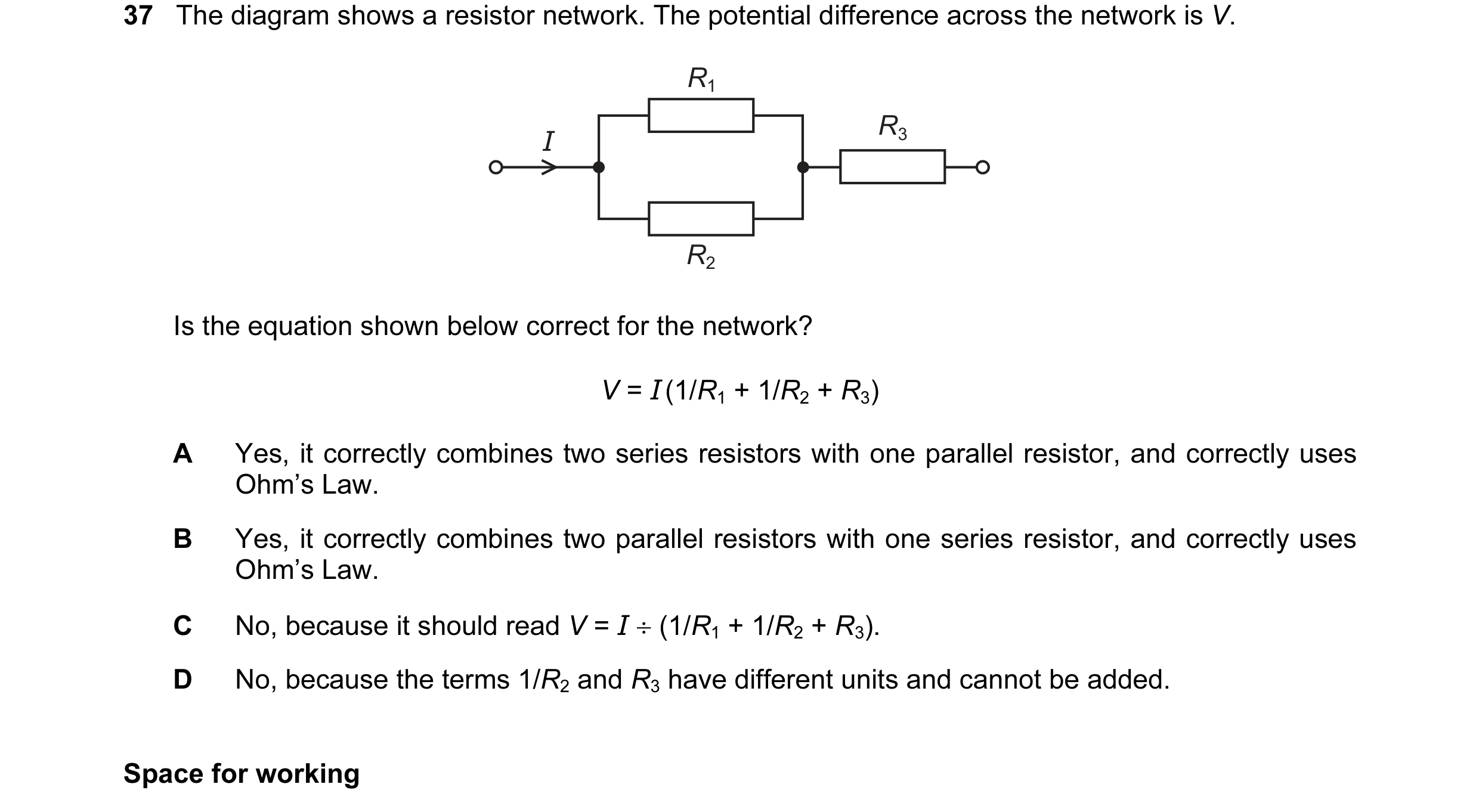
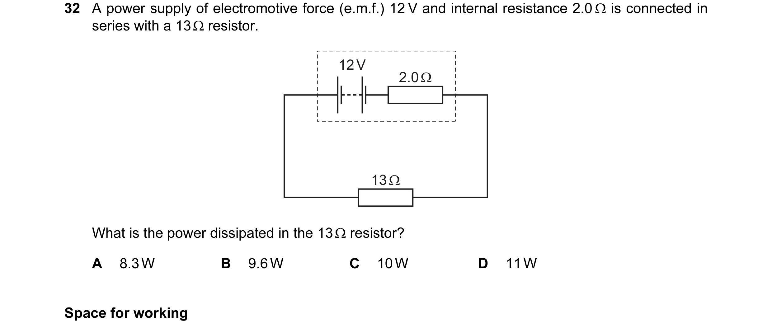
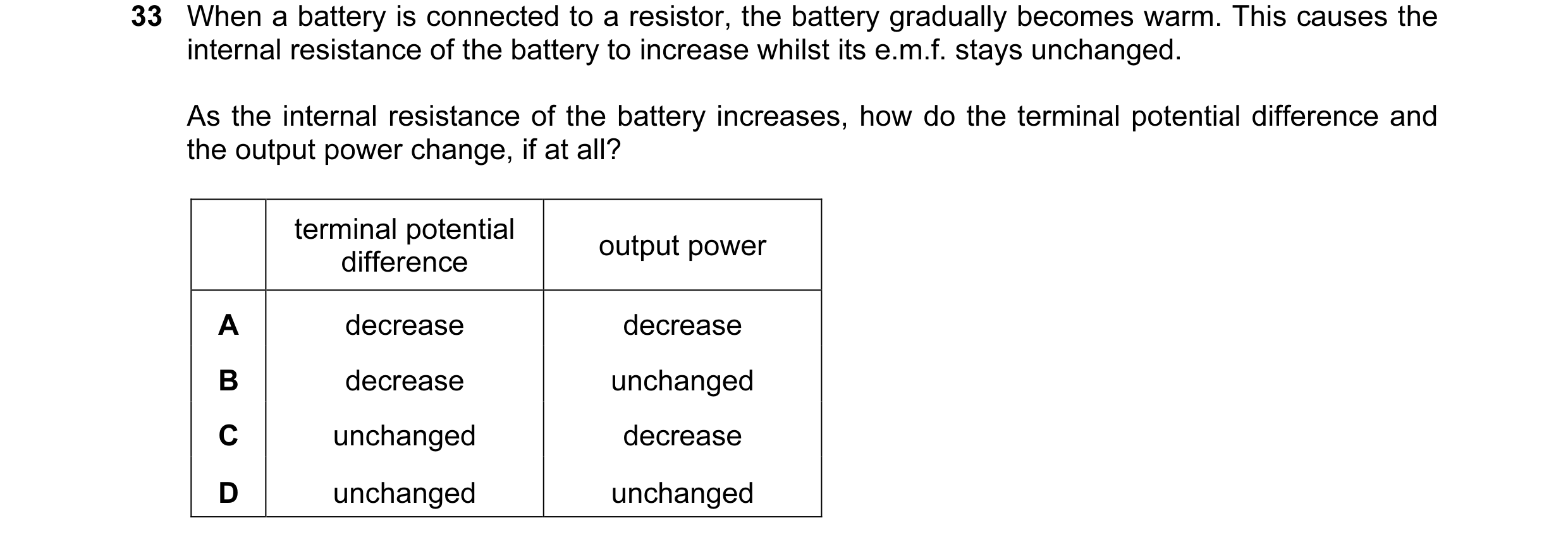 25 / 100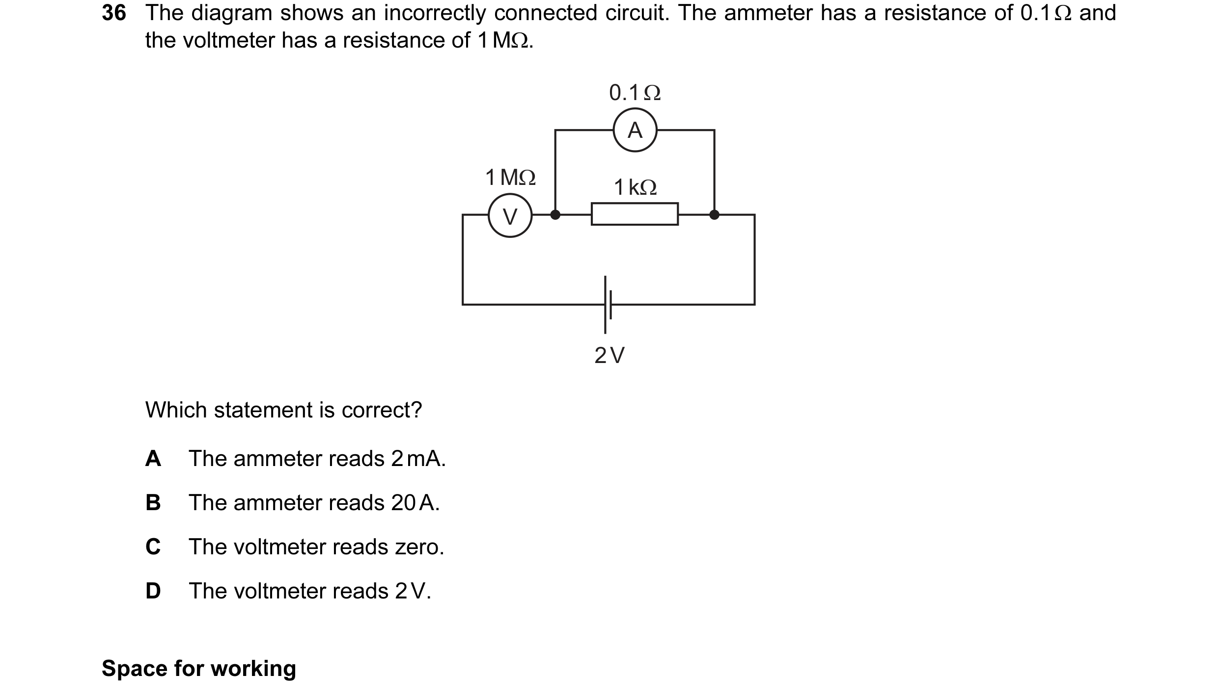
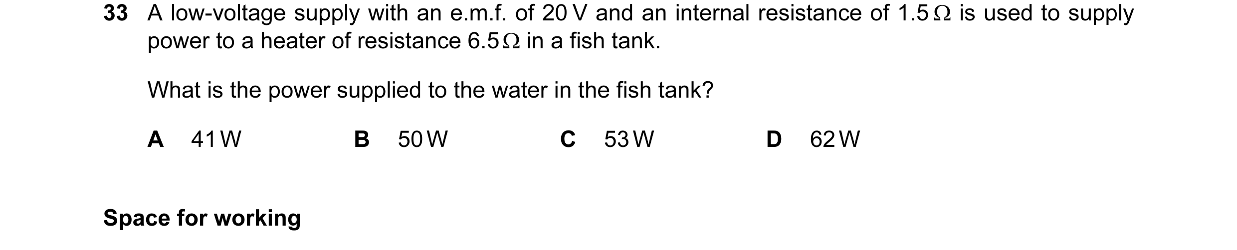
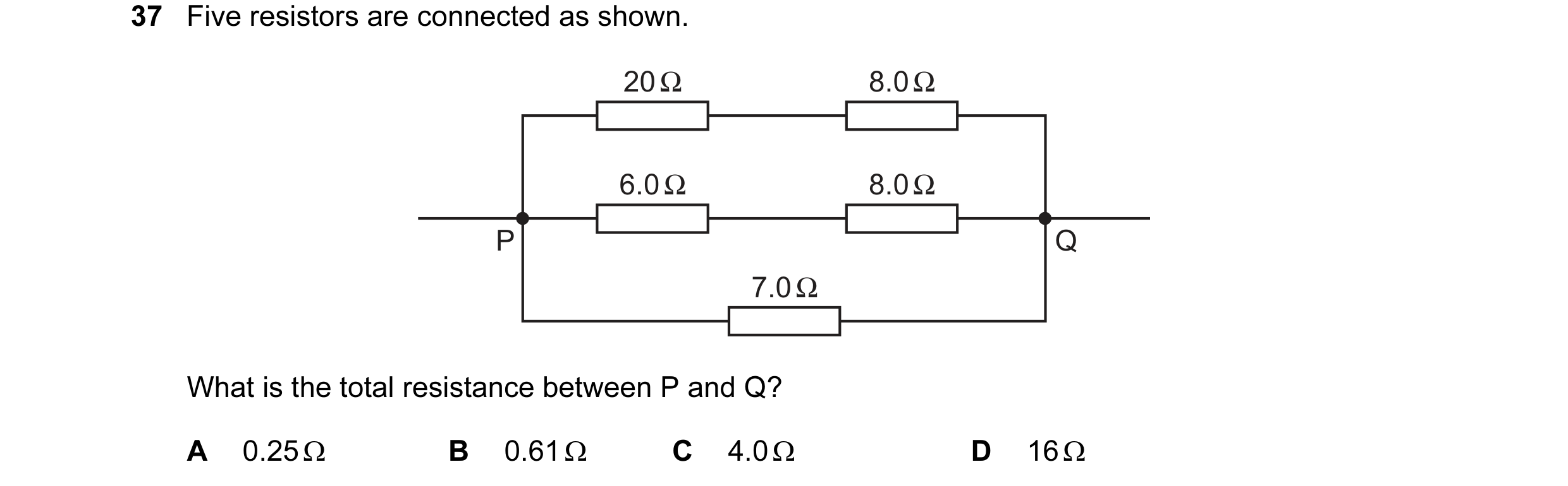 26 / 100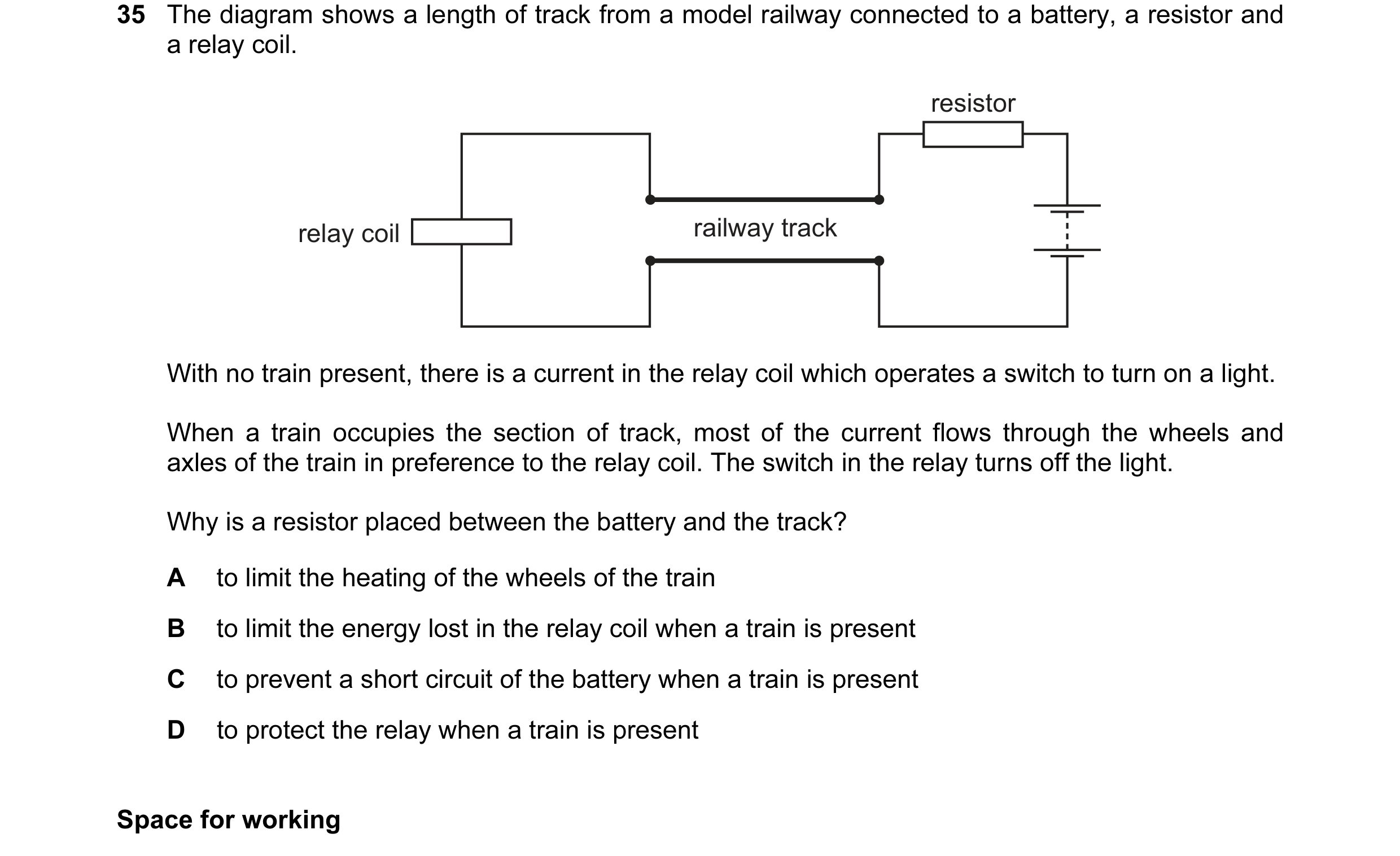
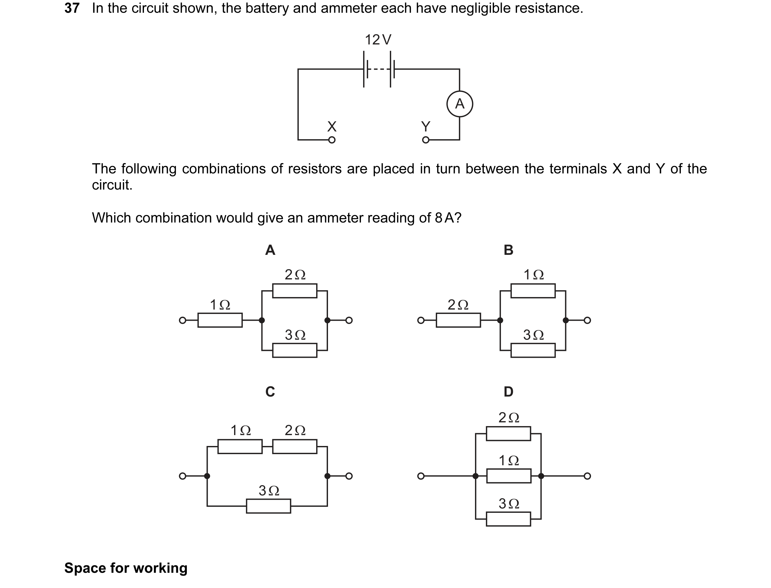 27 / 100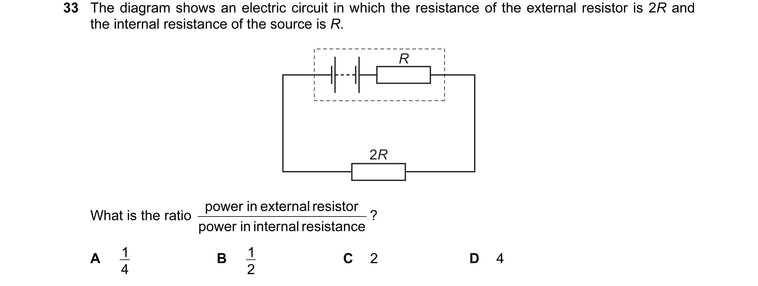
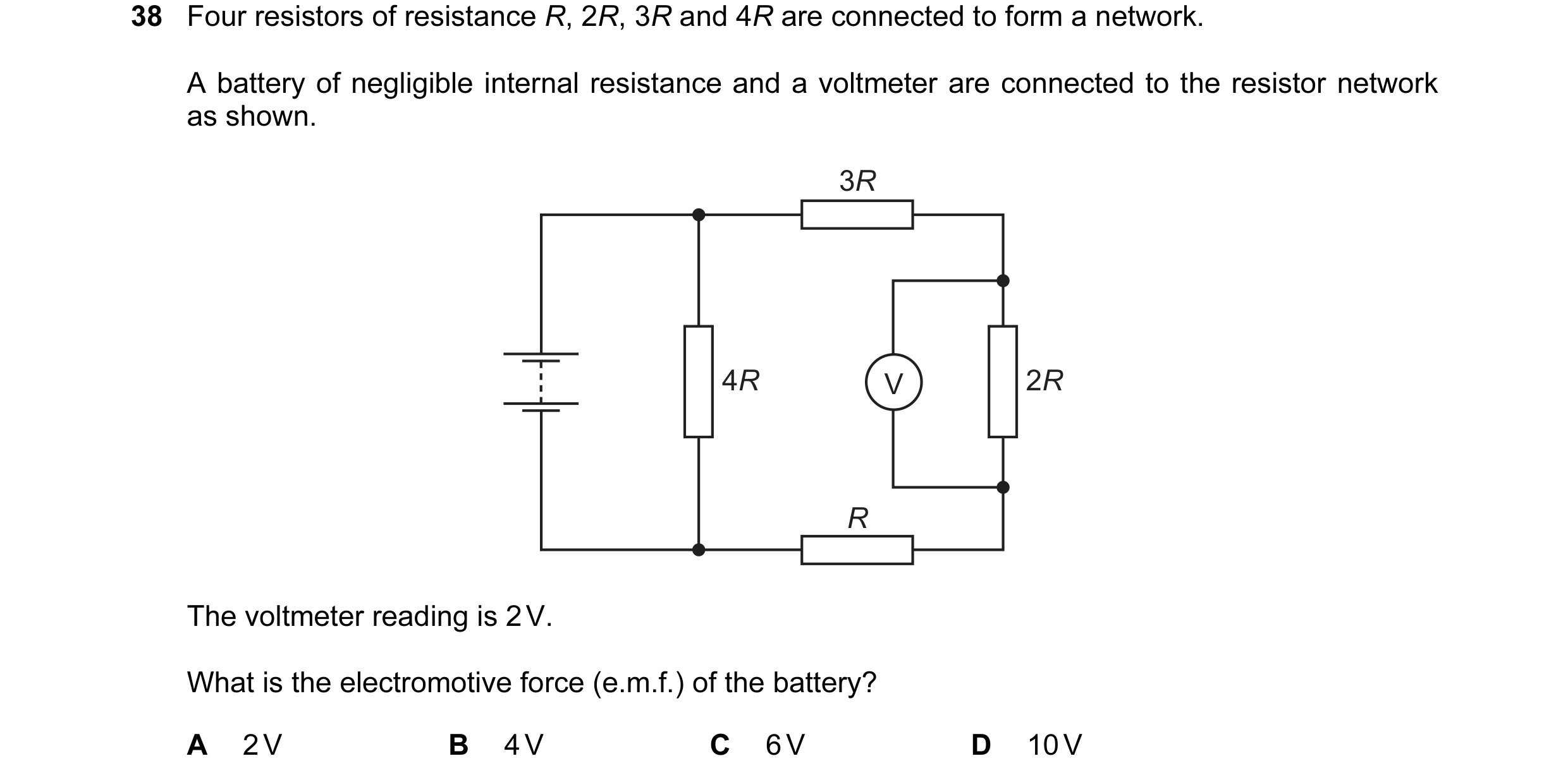 28 / 100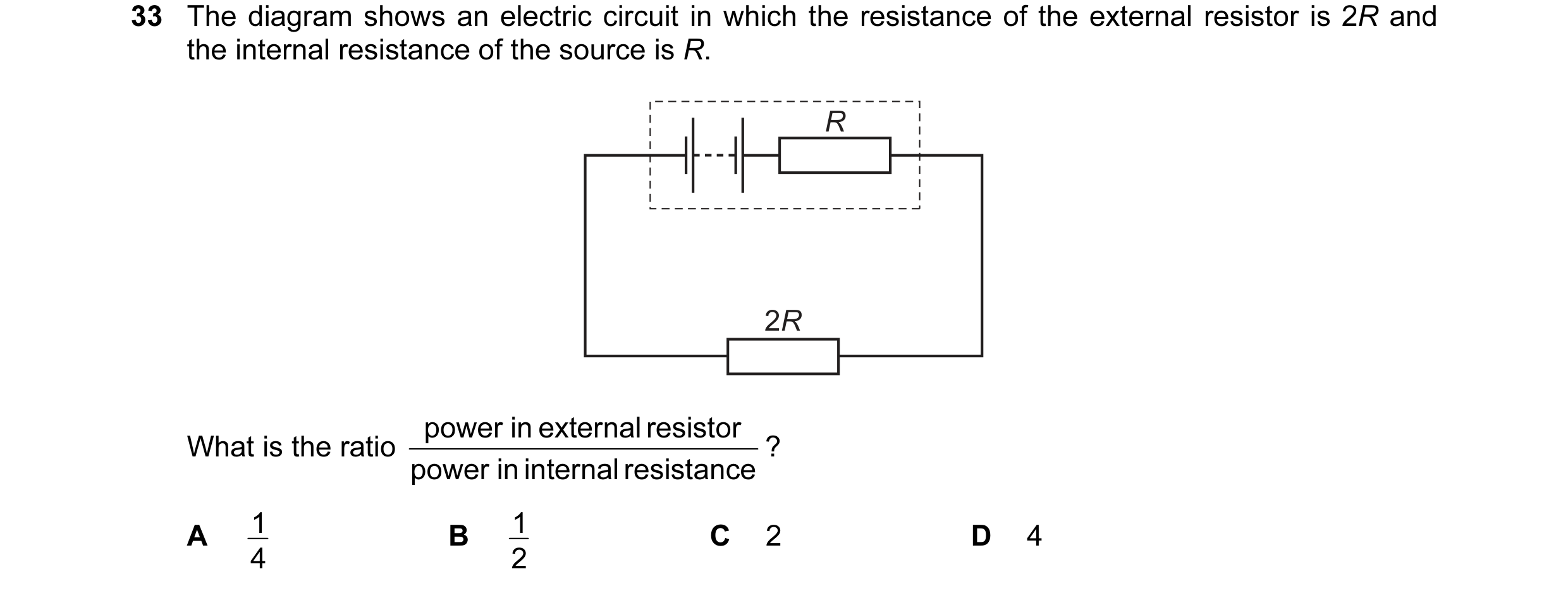
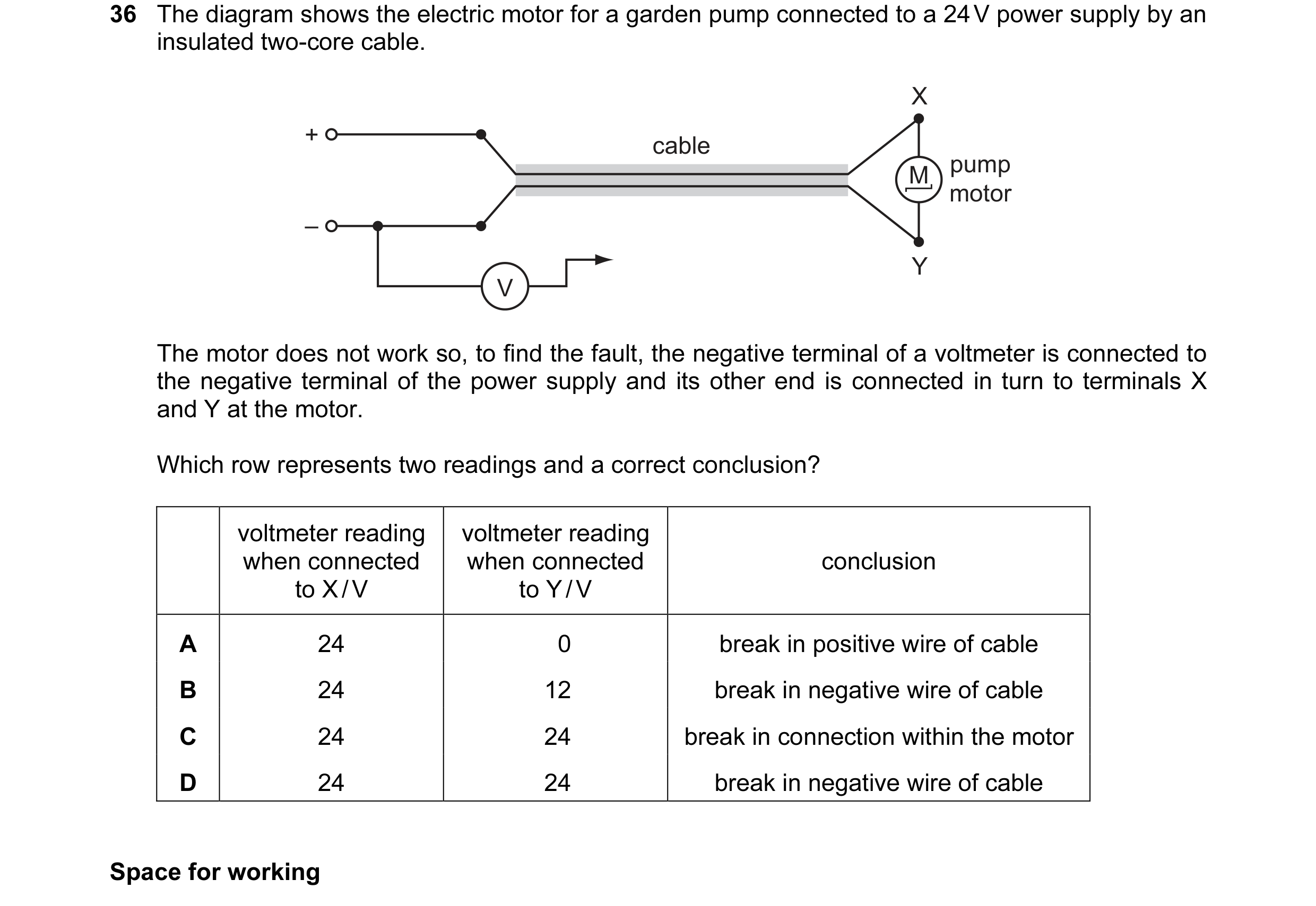 29 / 100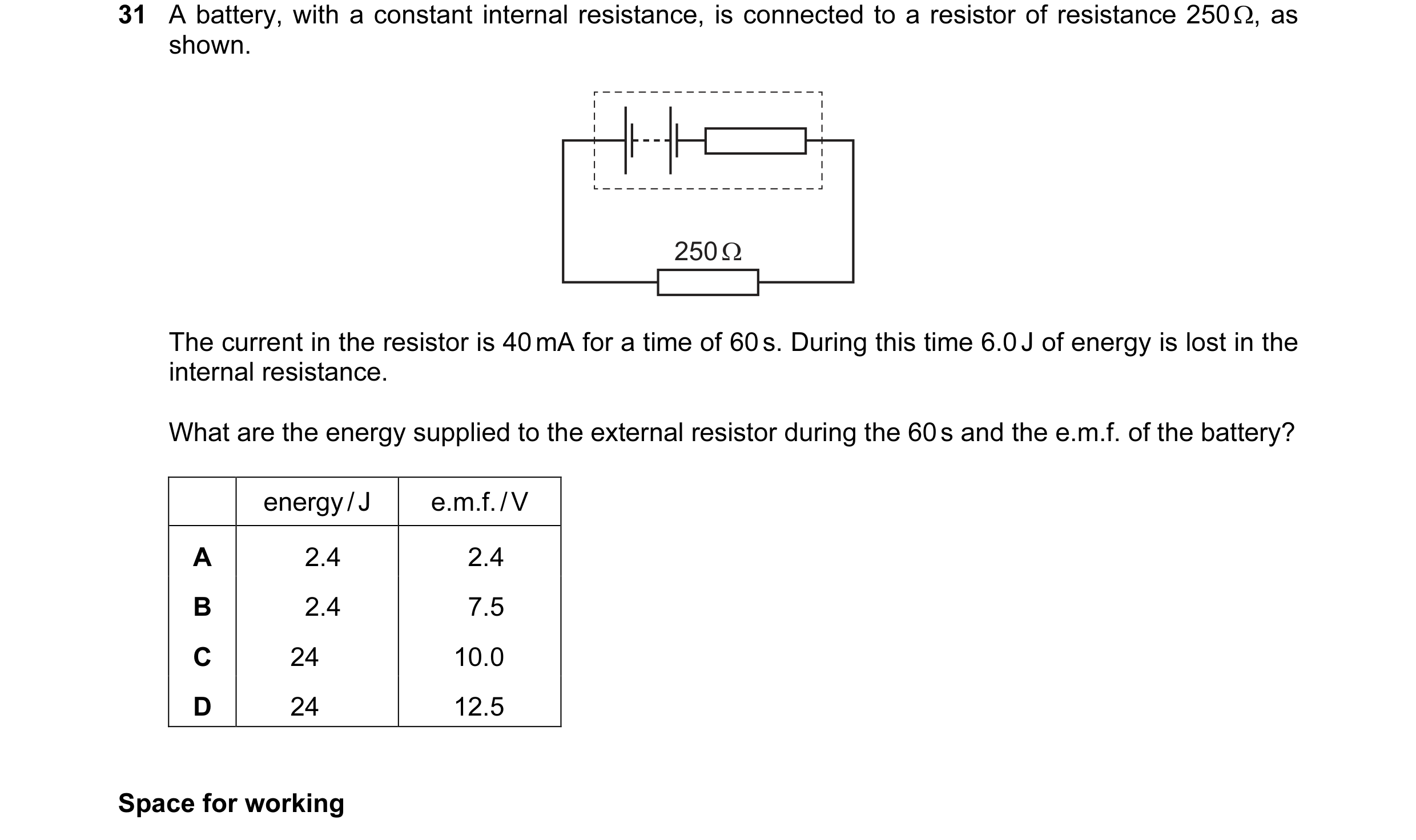

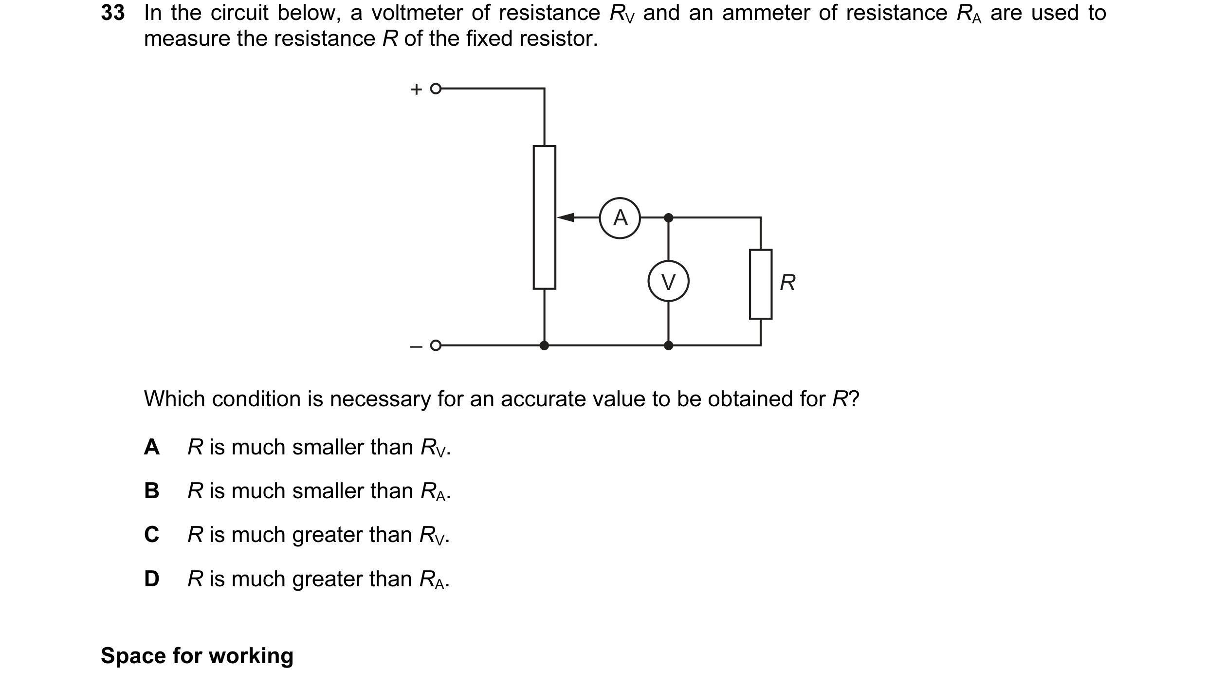 30 / 100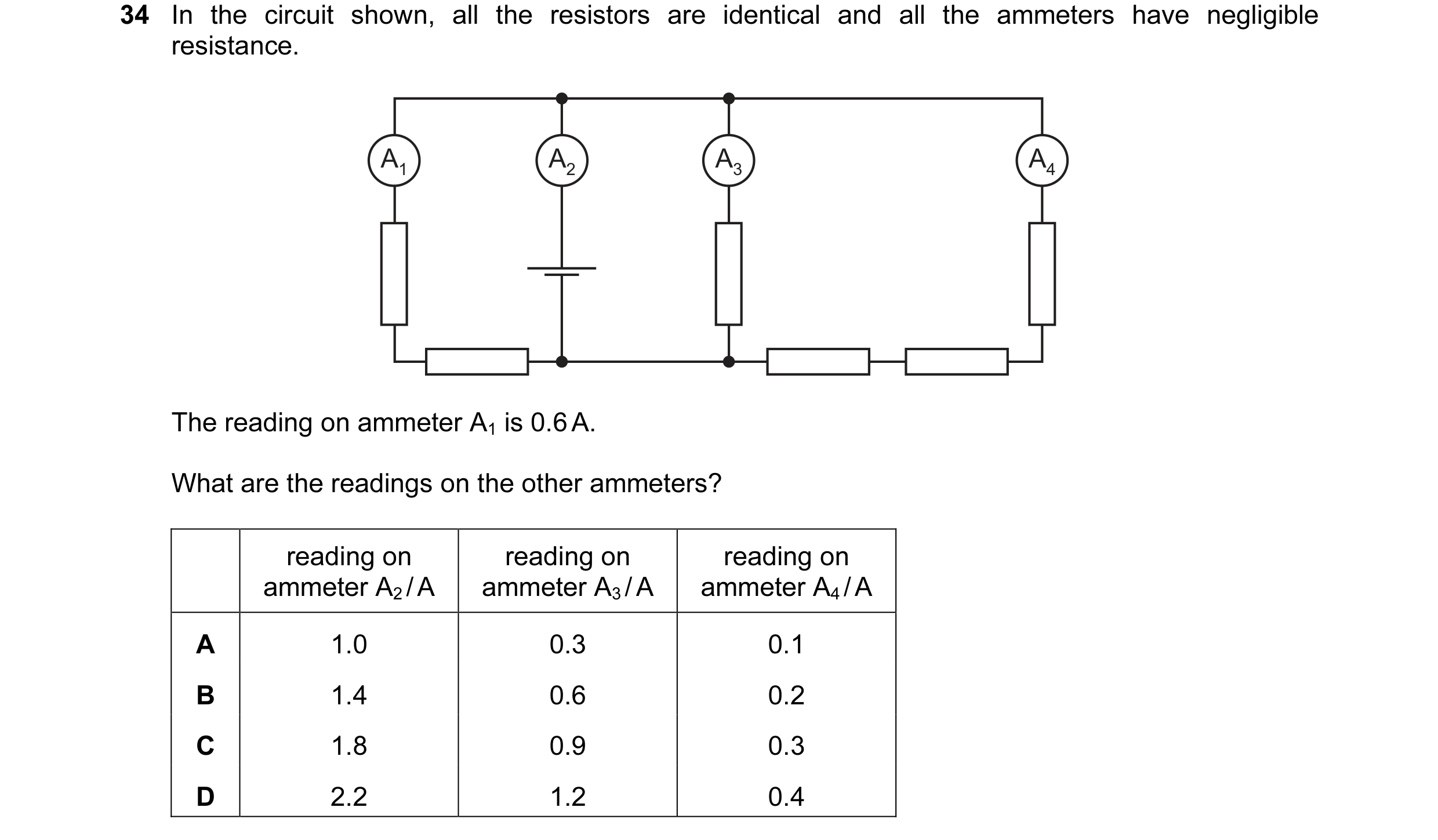
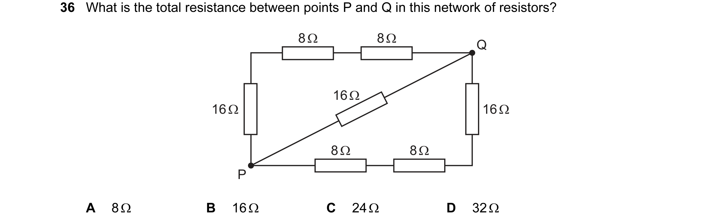 31 / 100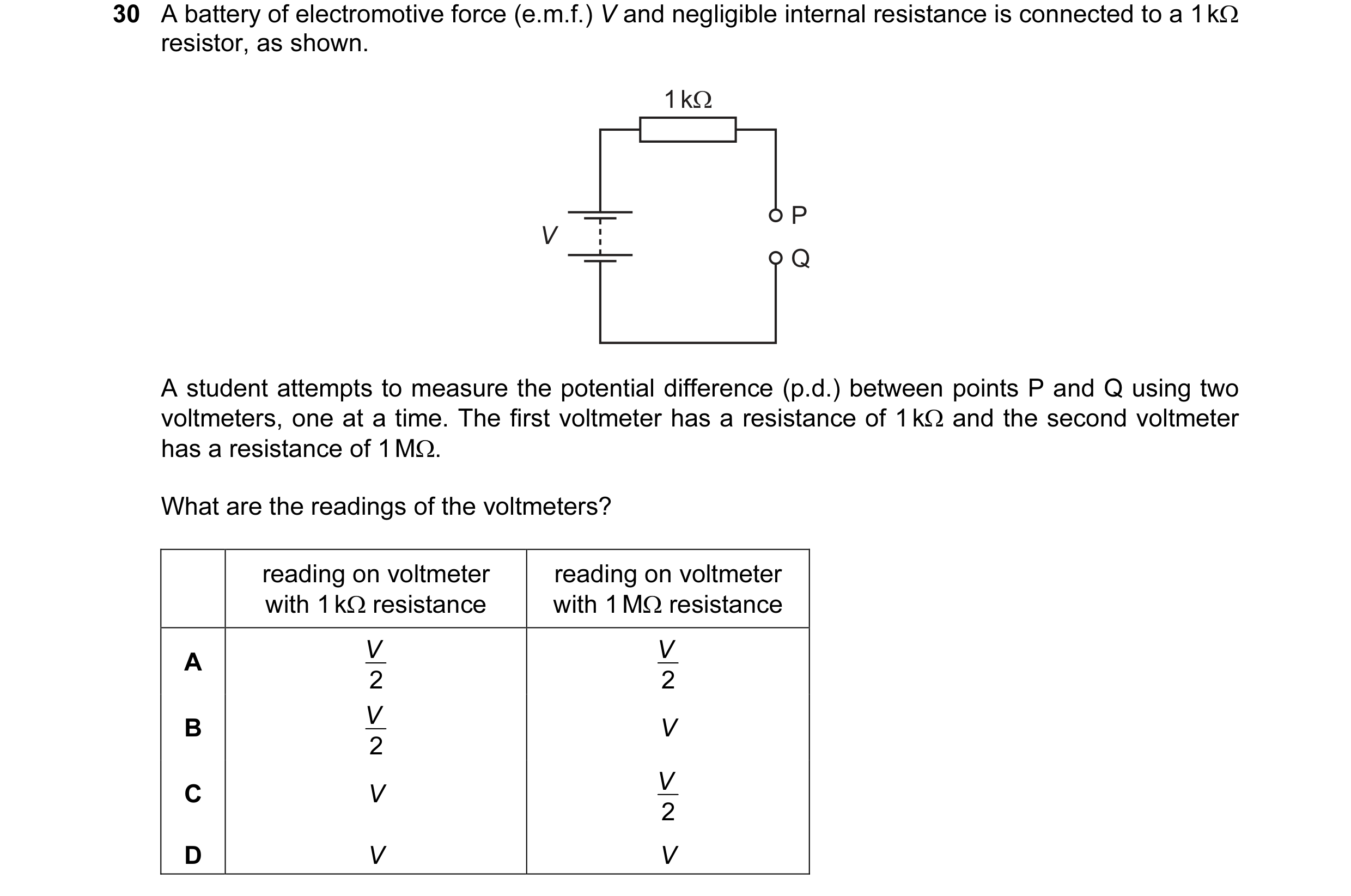
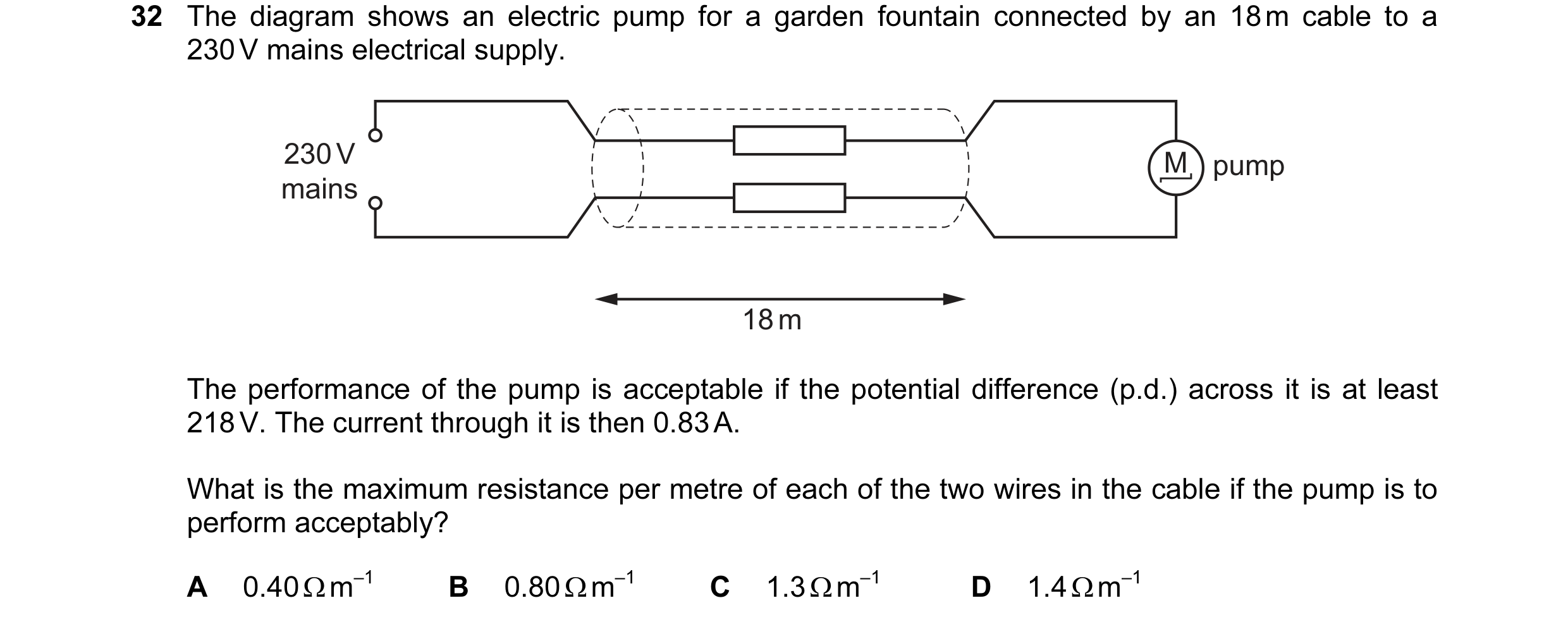 32 / 100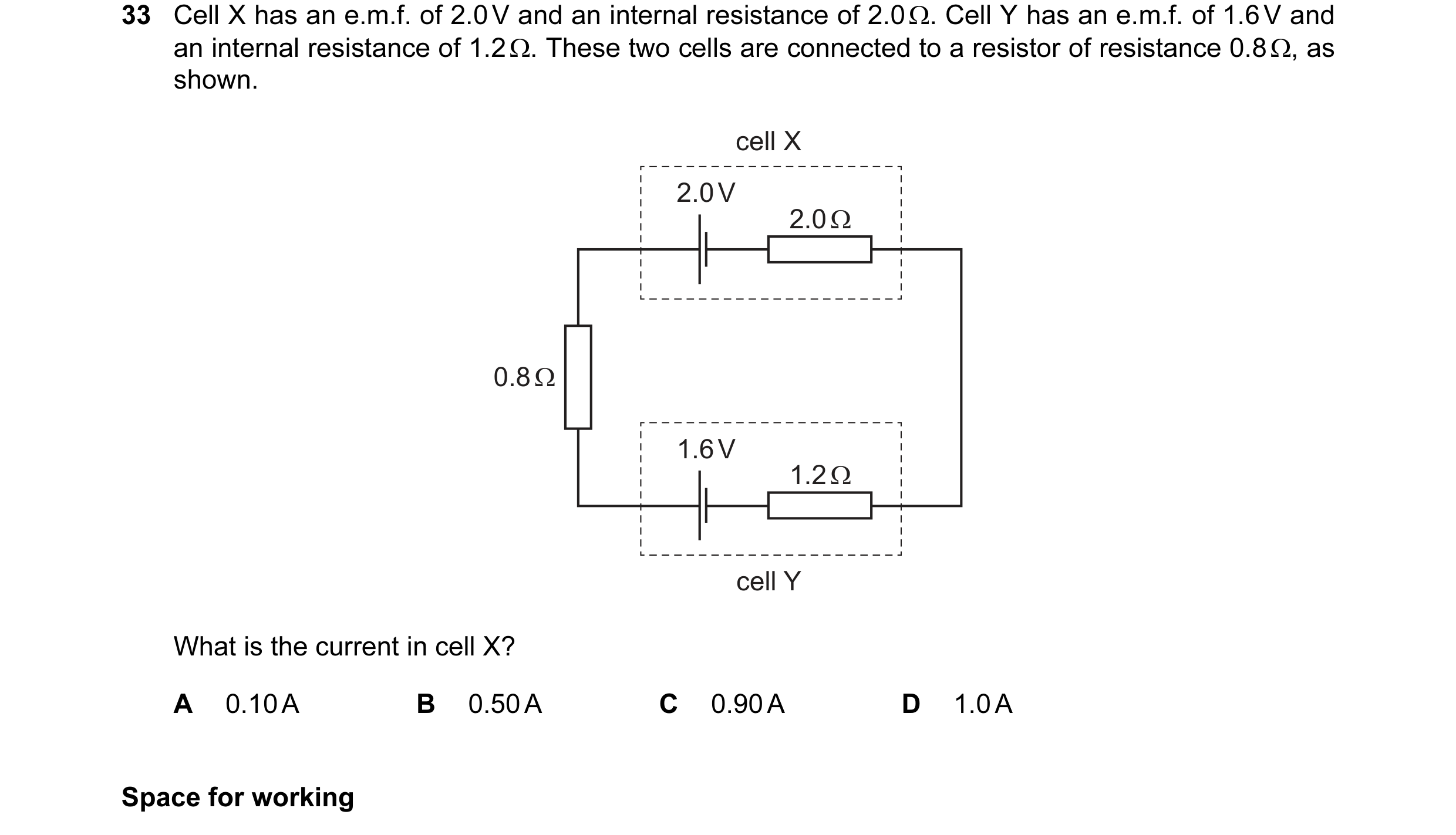
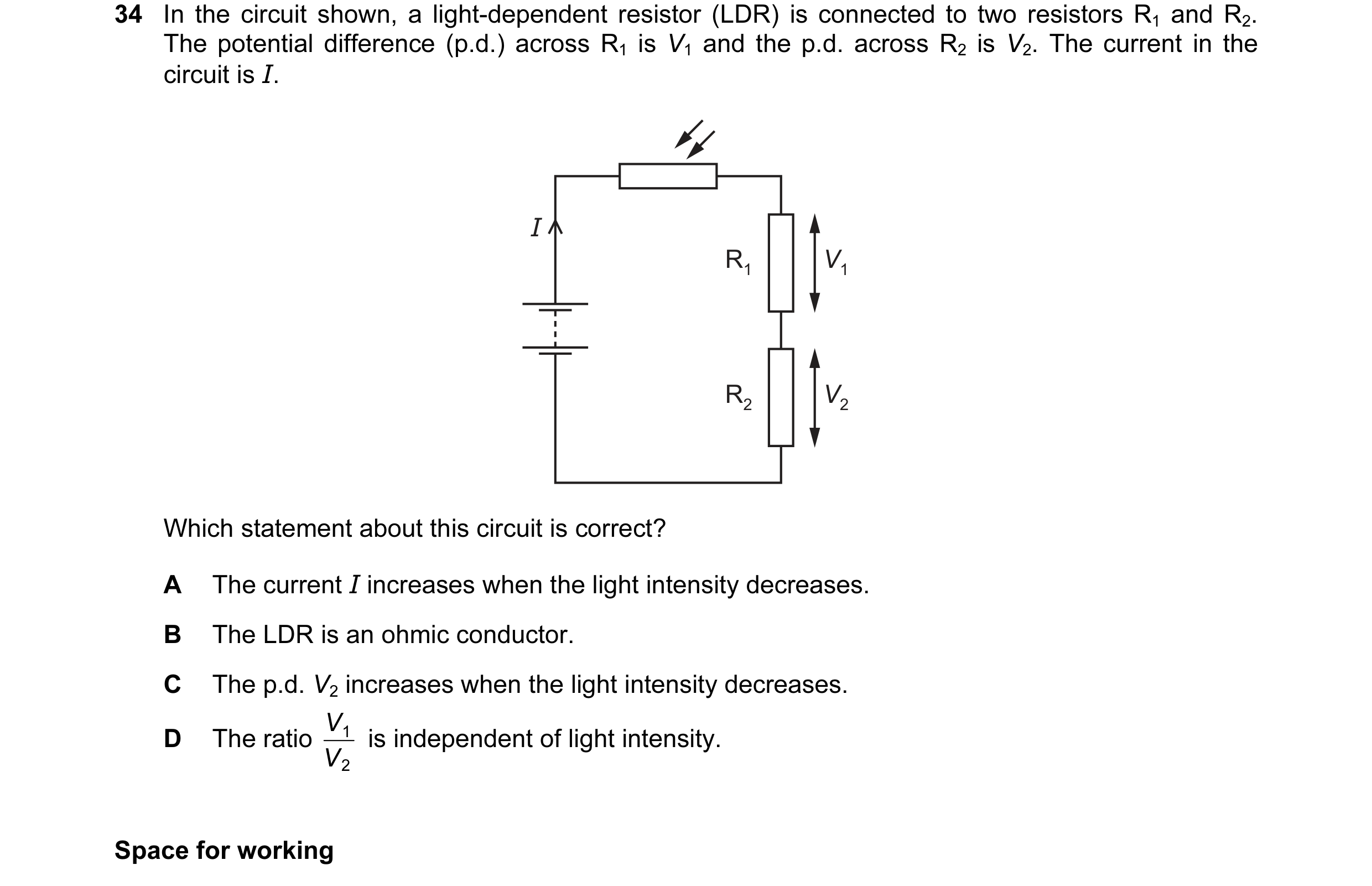 33 / 100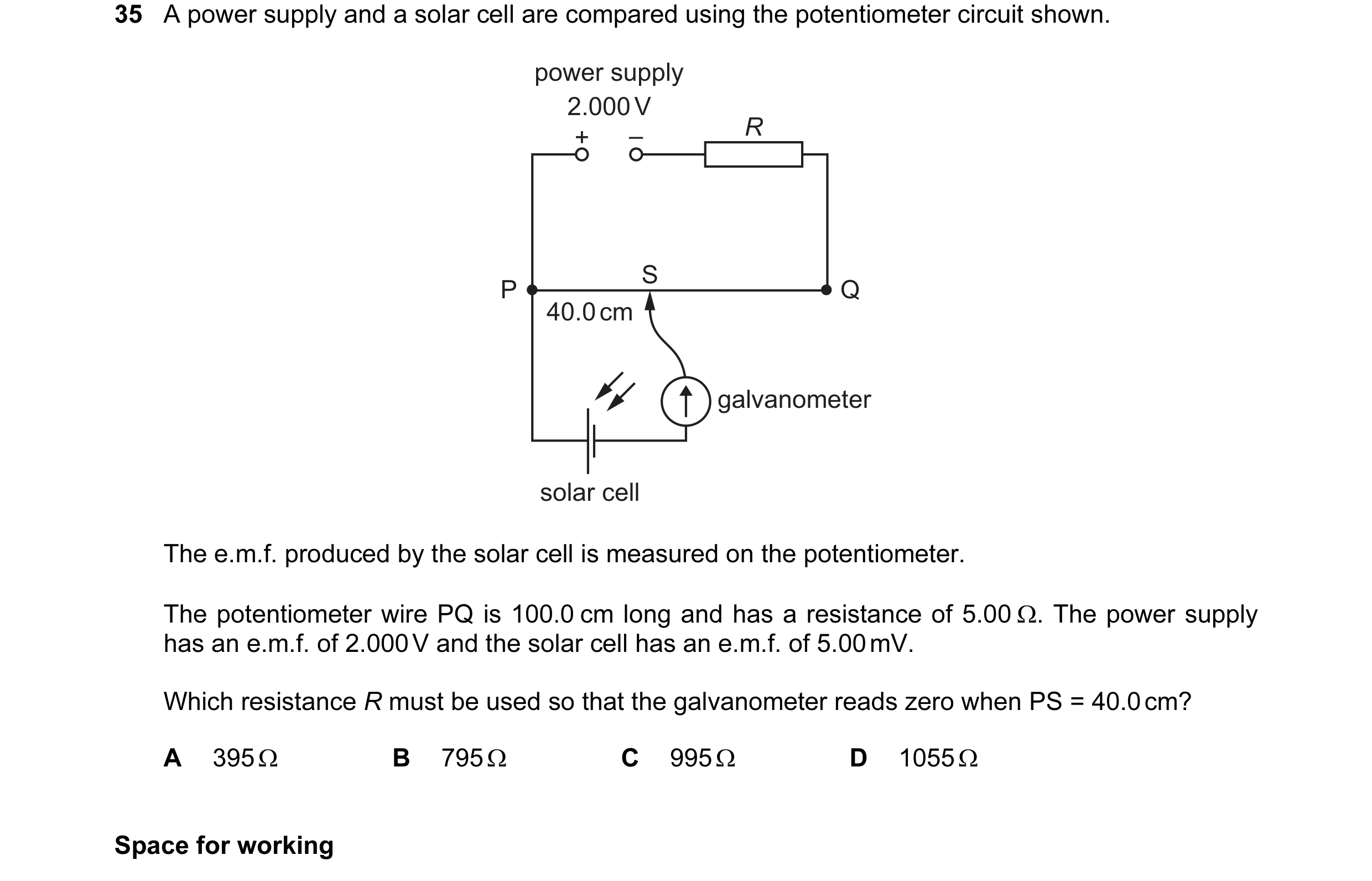
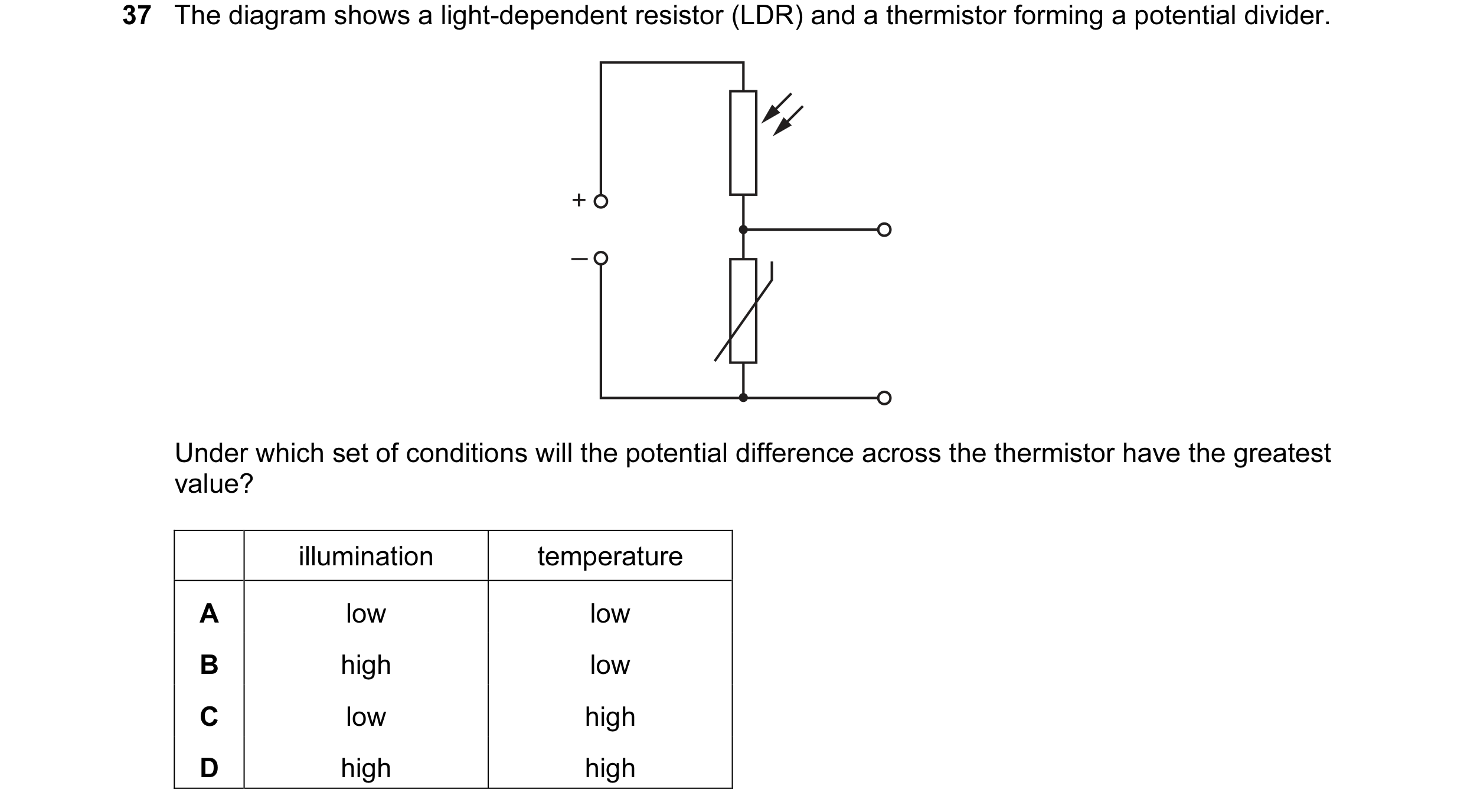 34 / 100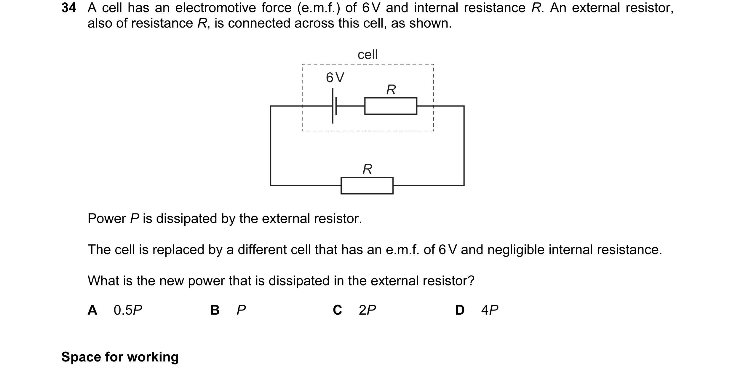
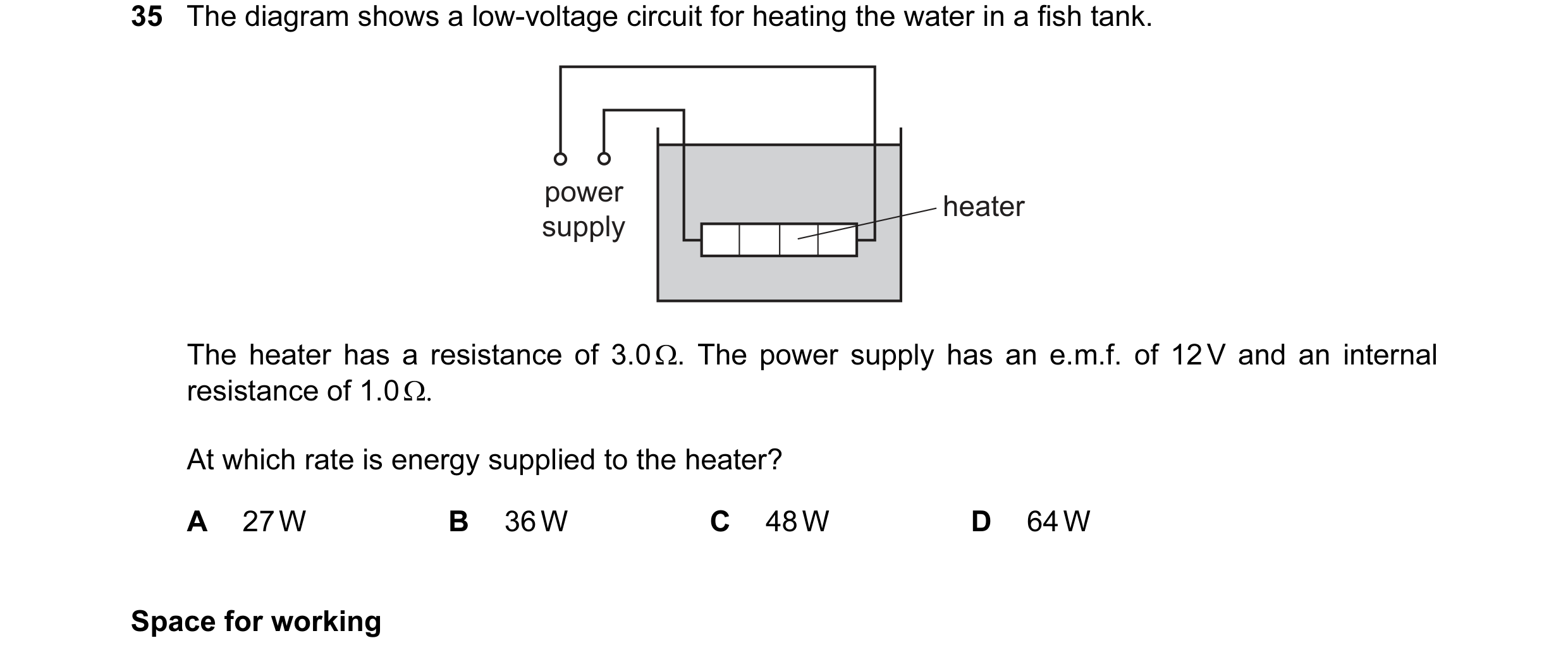
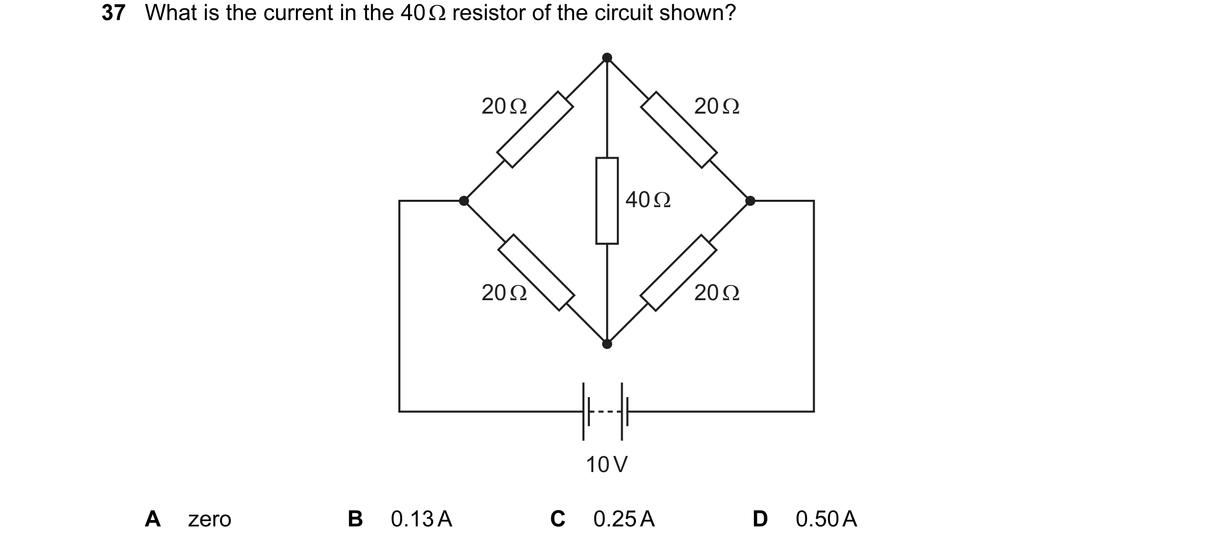 35 / 100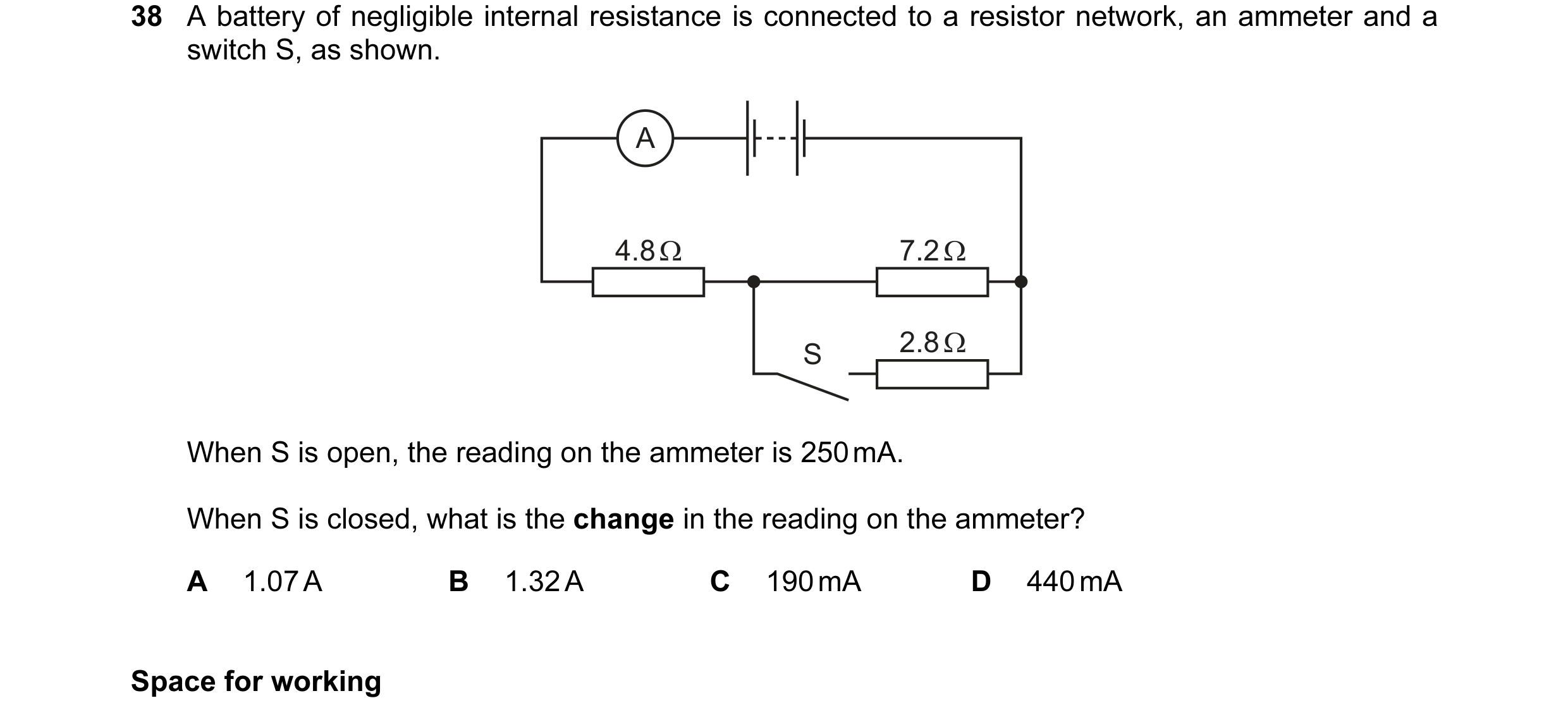
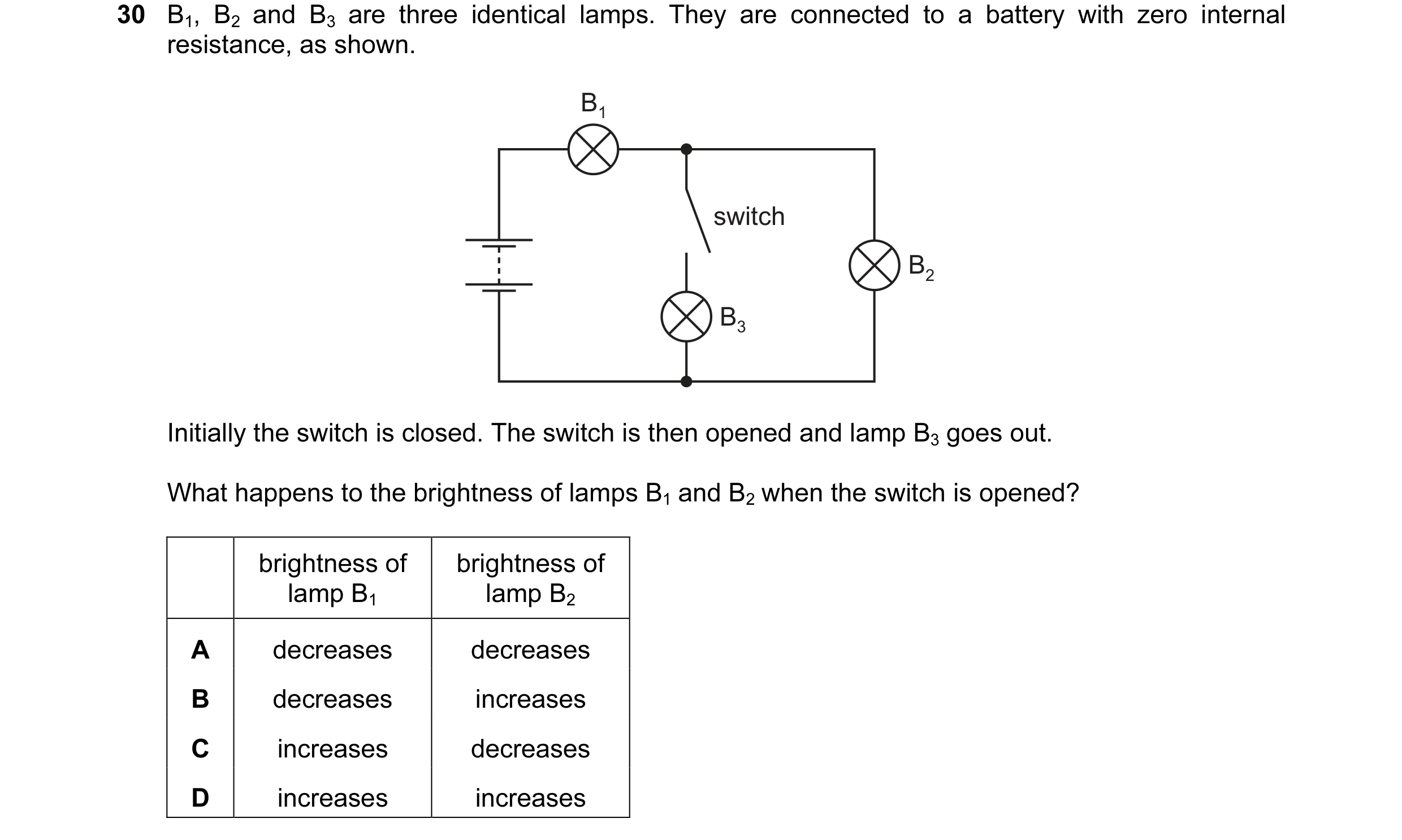 36 / 100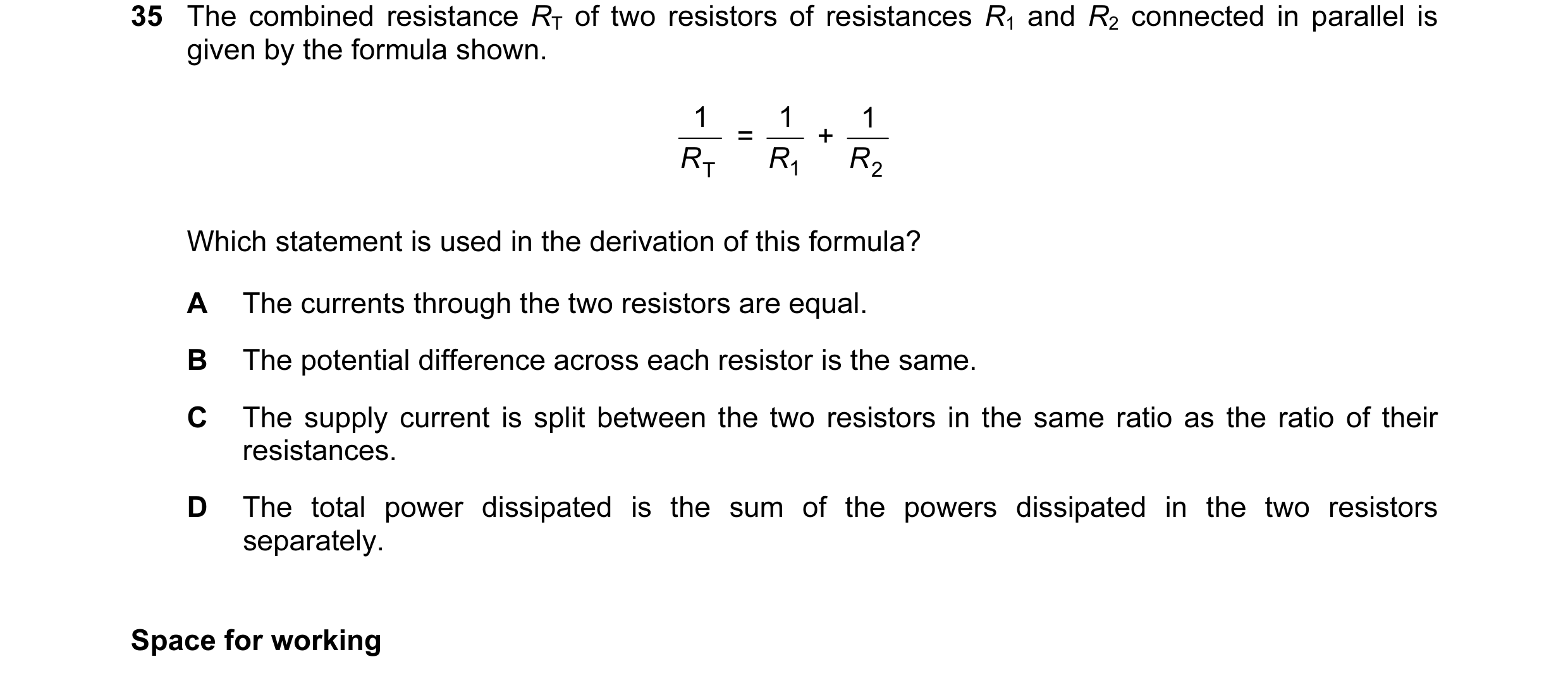
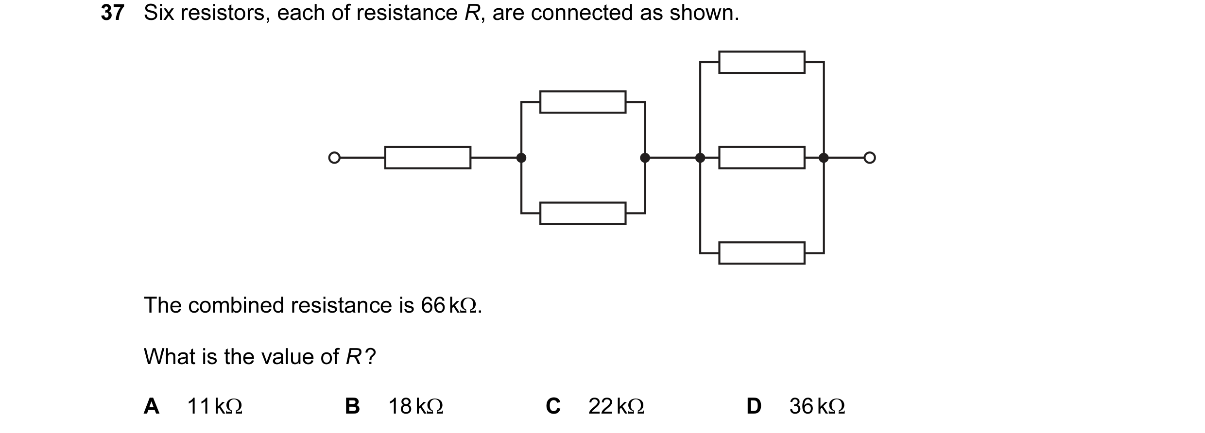 37 / 100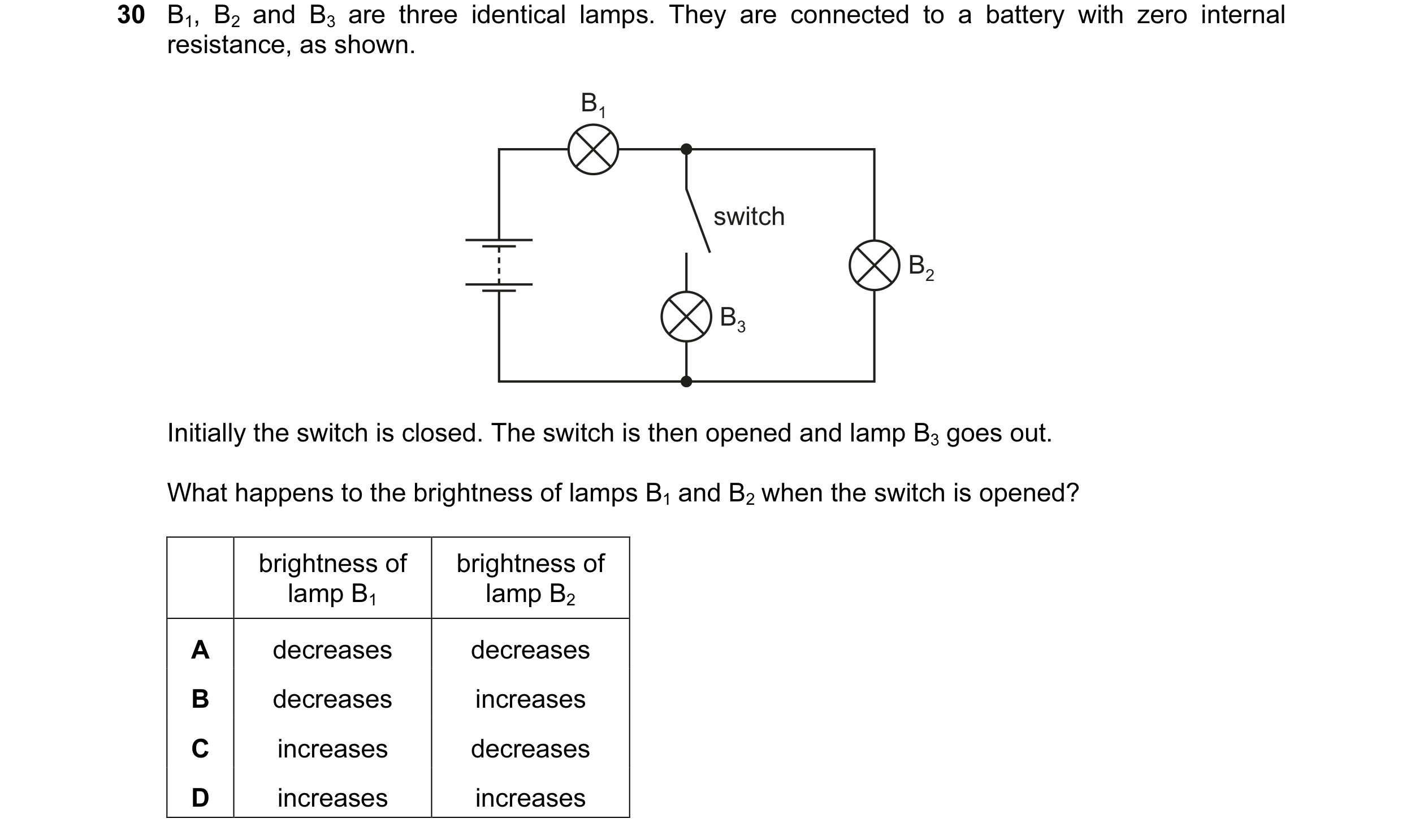
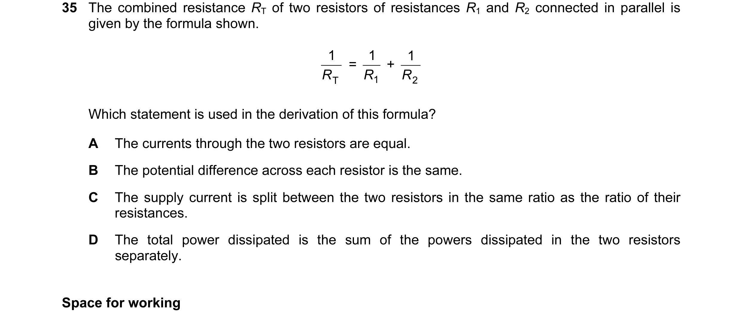 38 / 100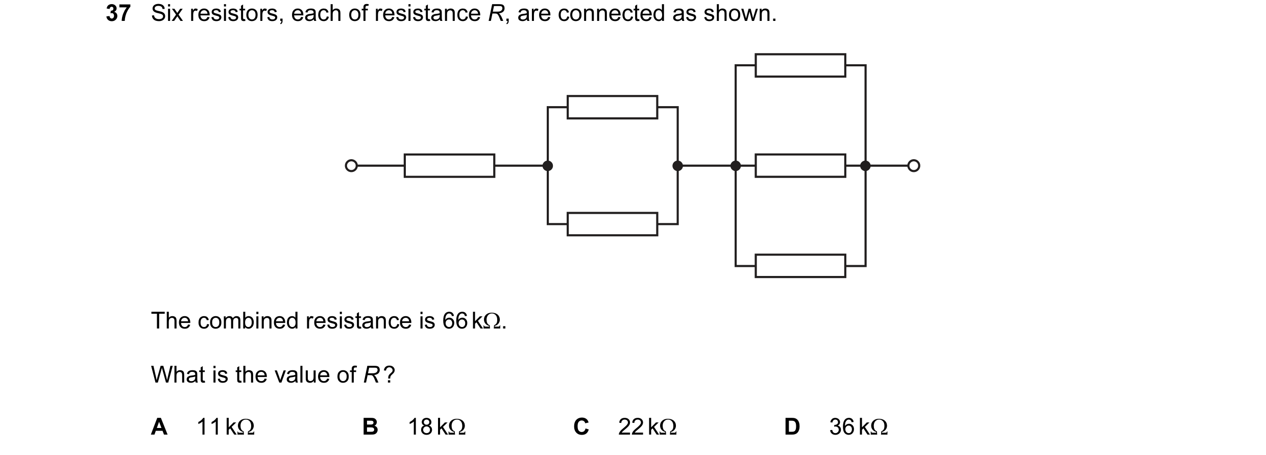
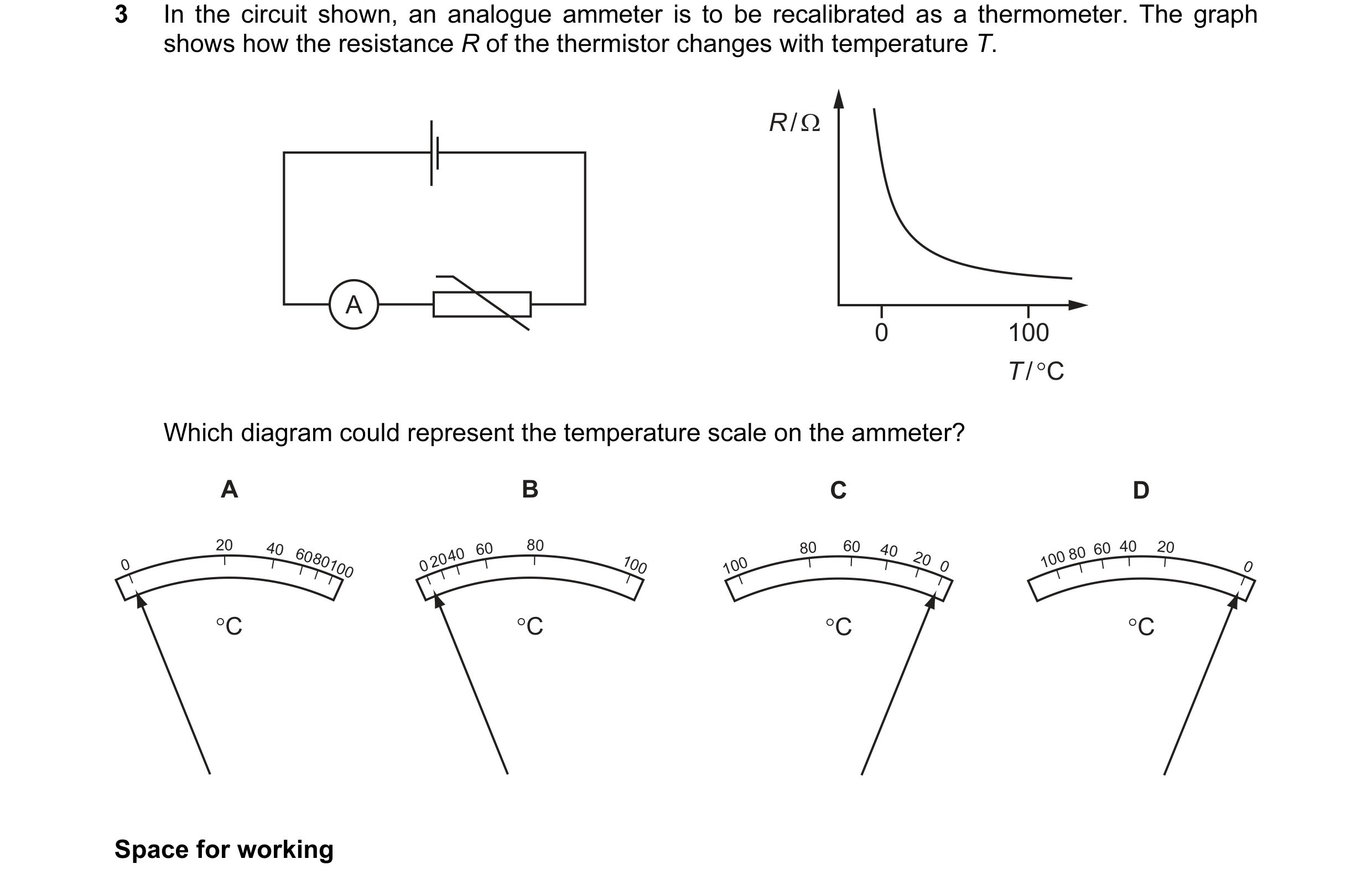 39 / 100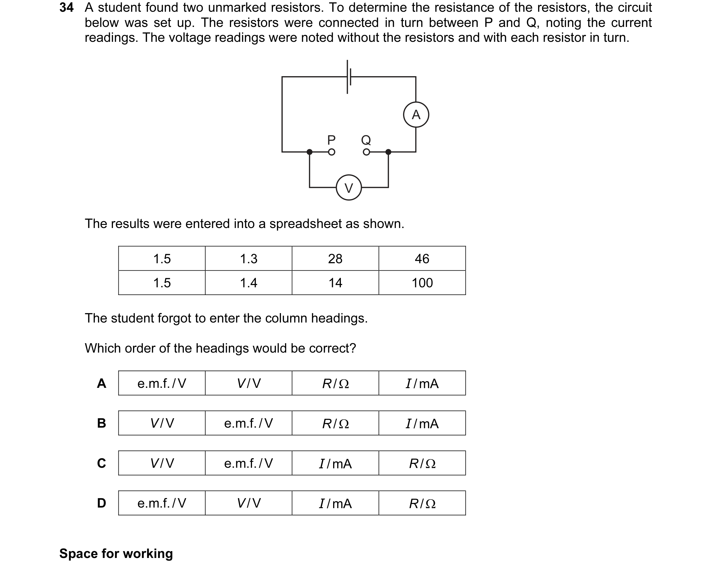
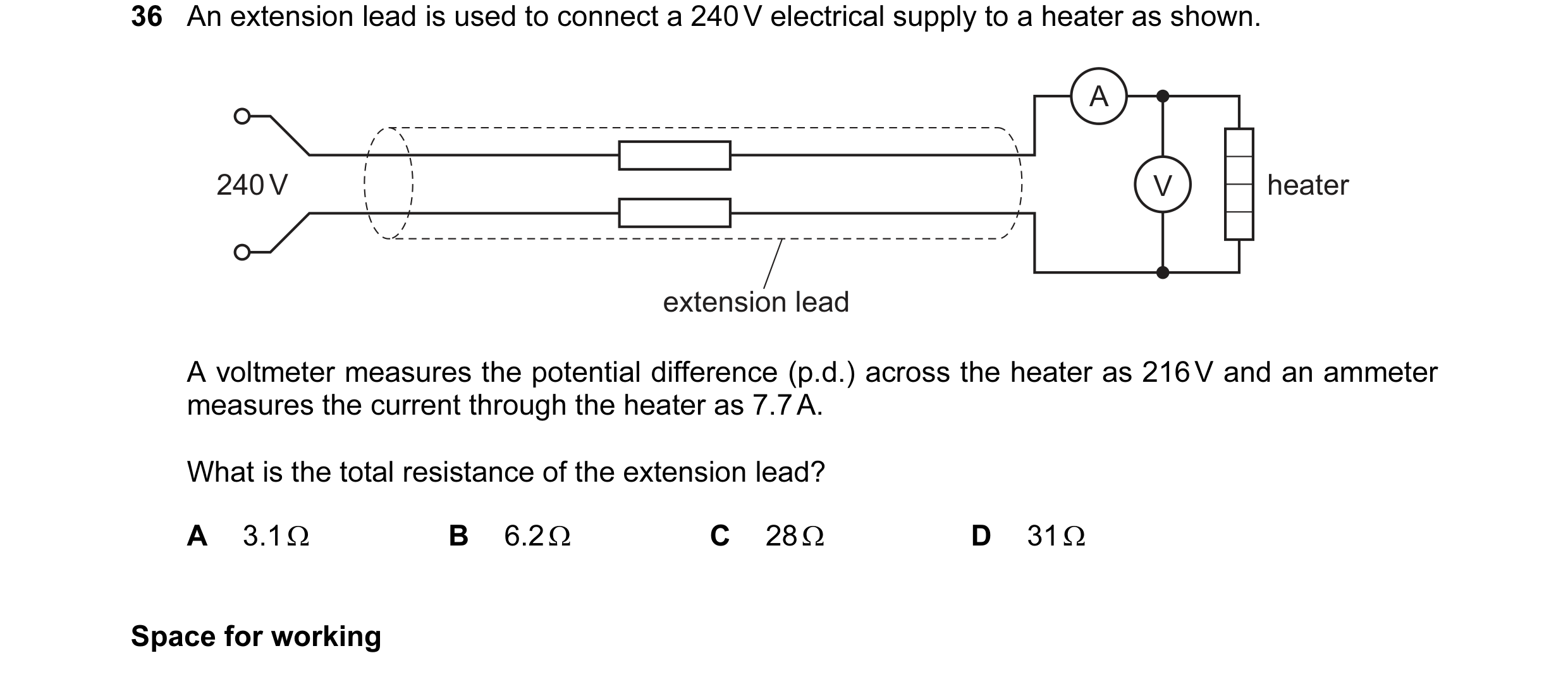 40 / 100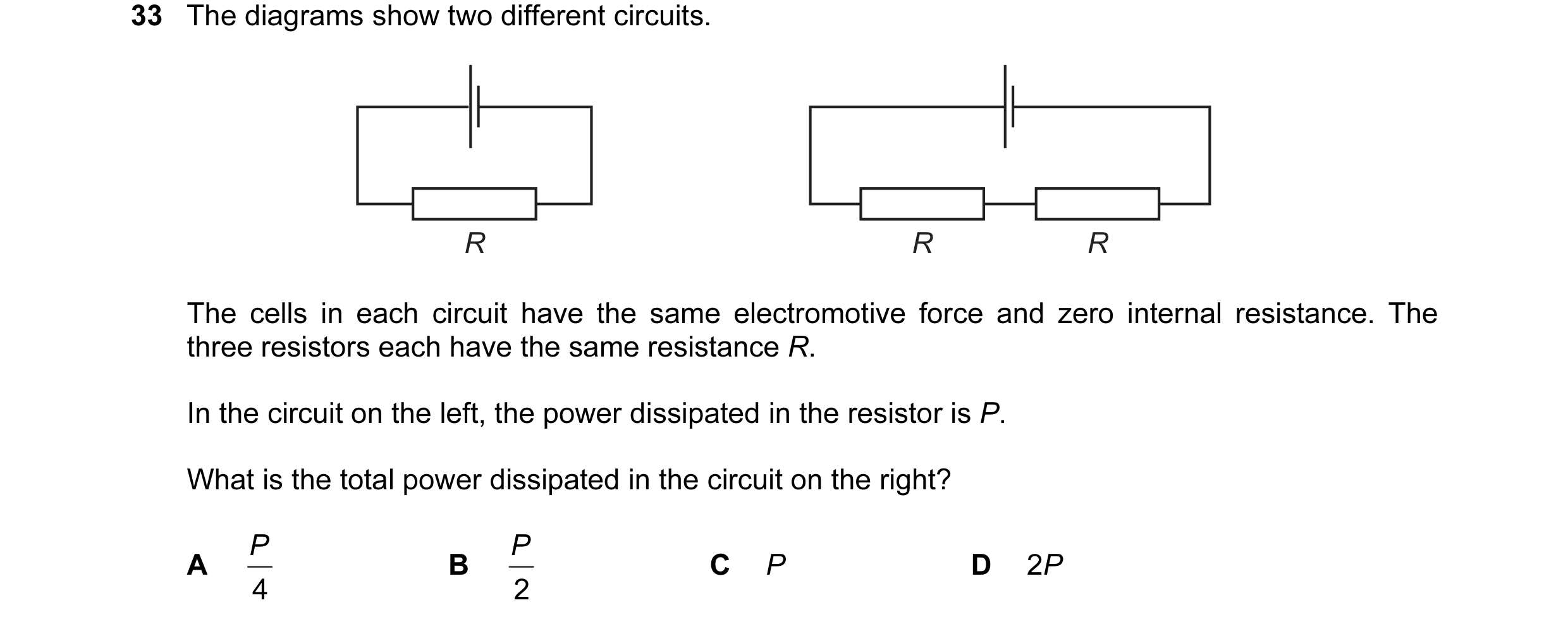
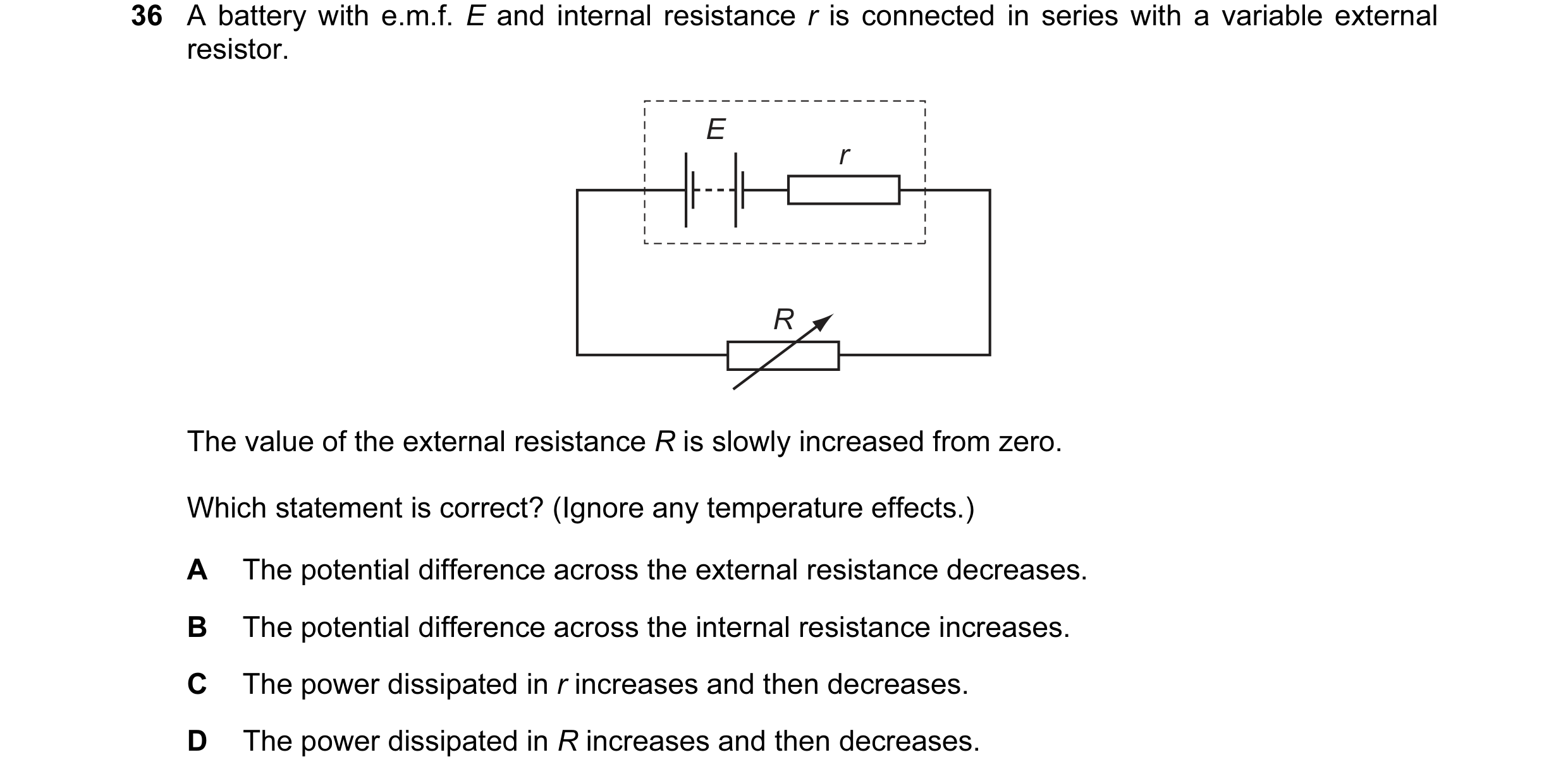
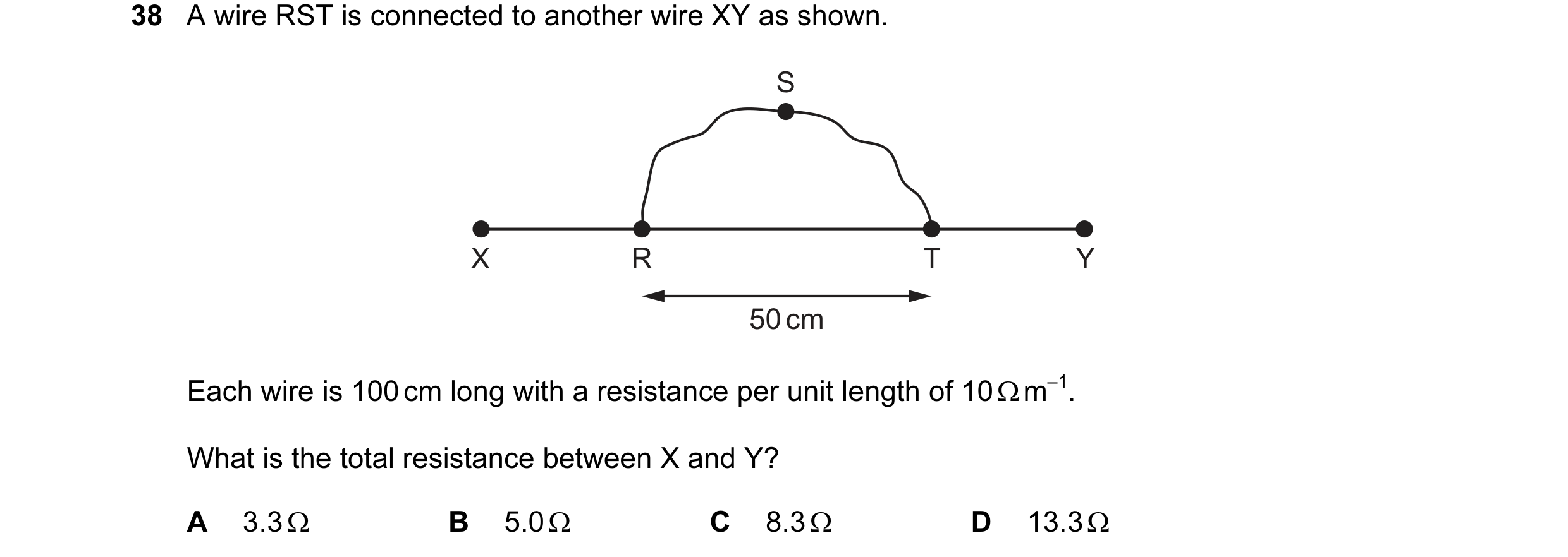 41 / 100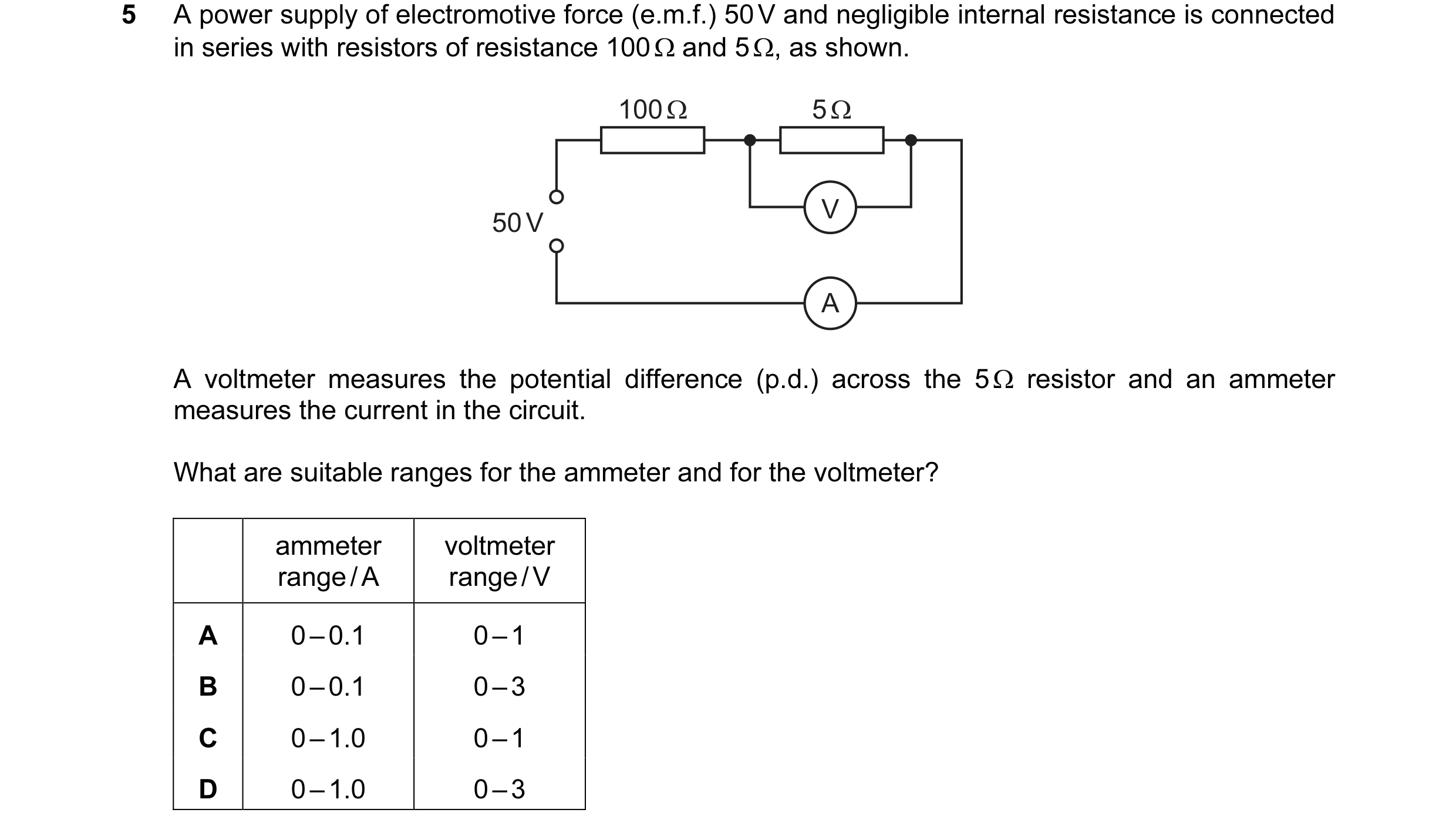
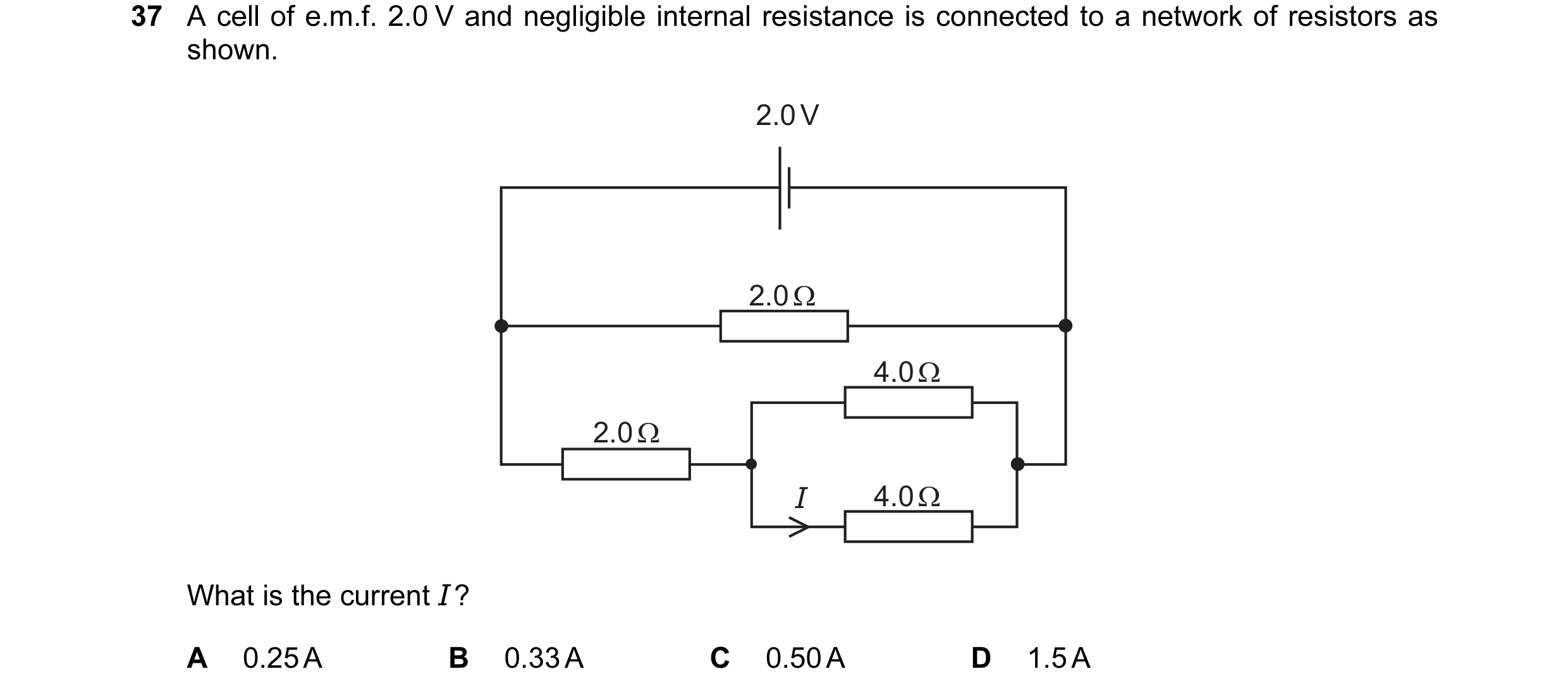 42 / 100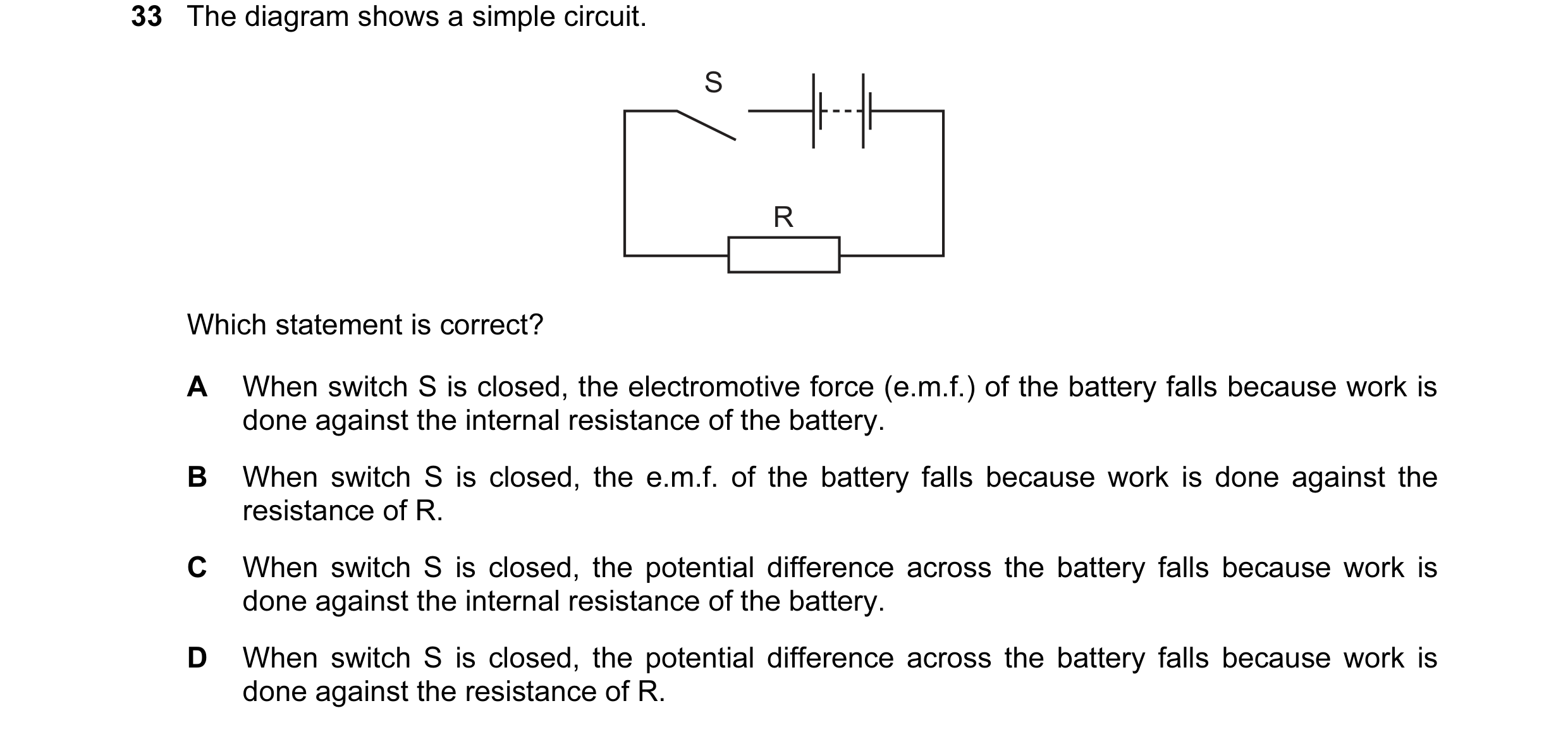
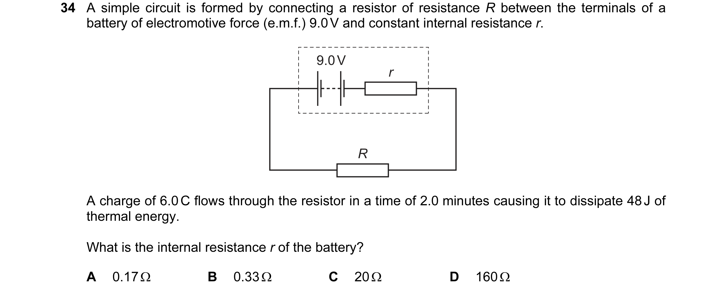
 43 / 100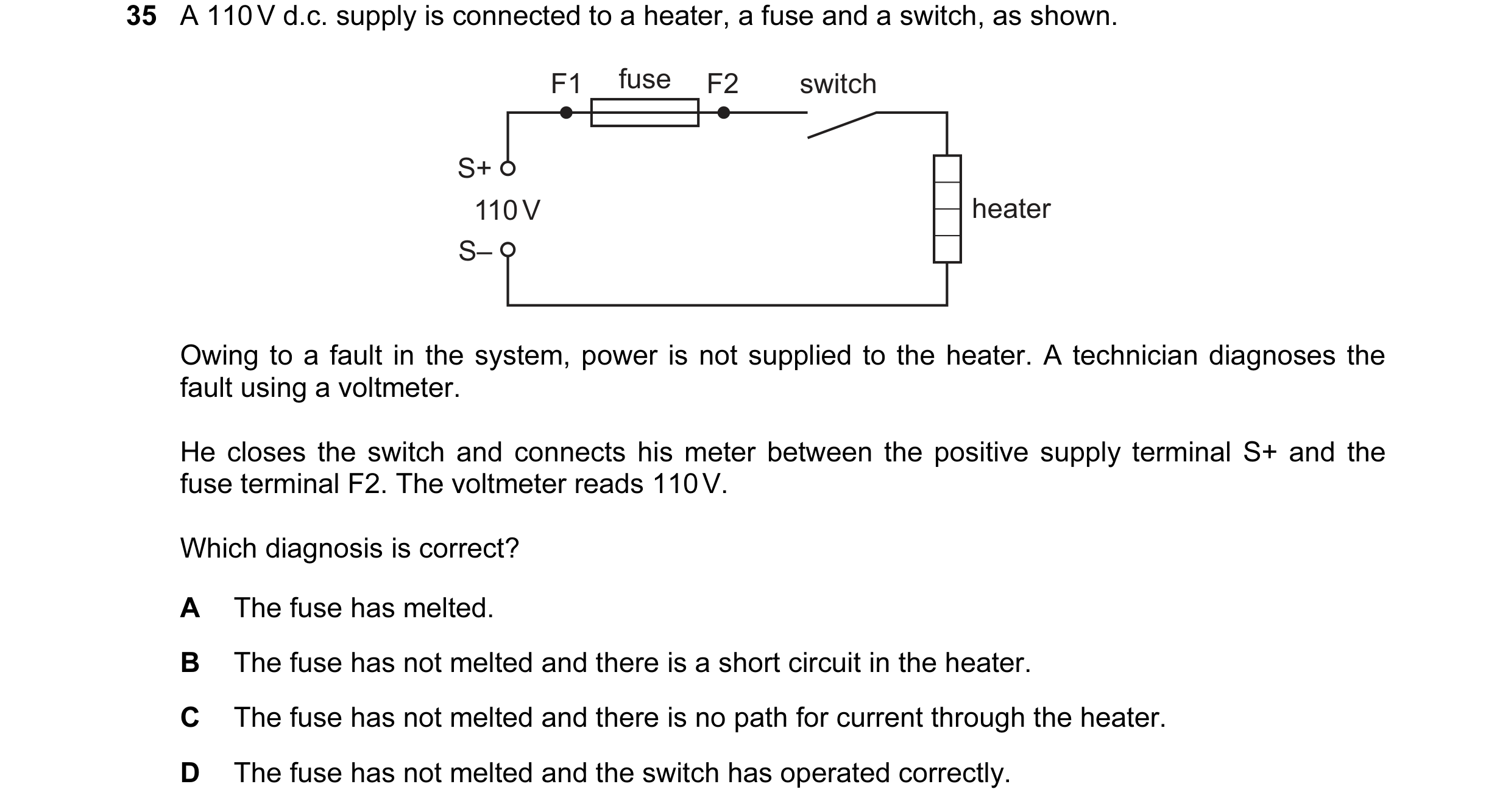
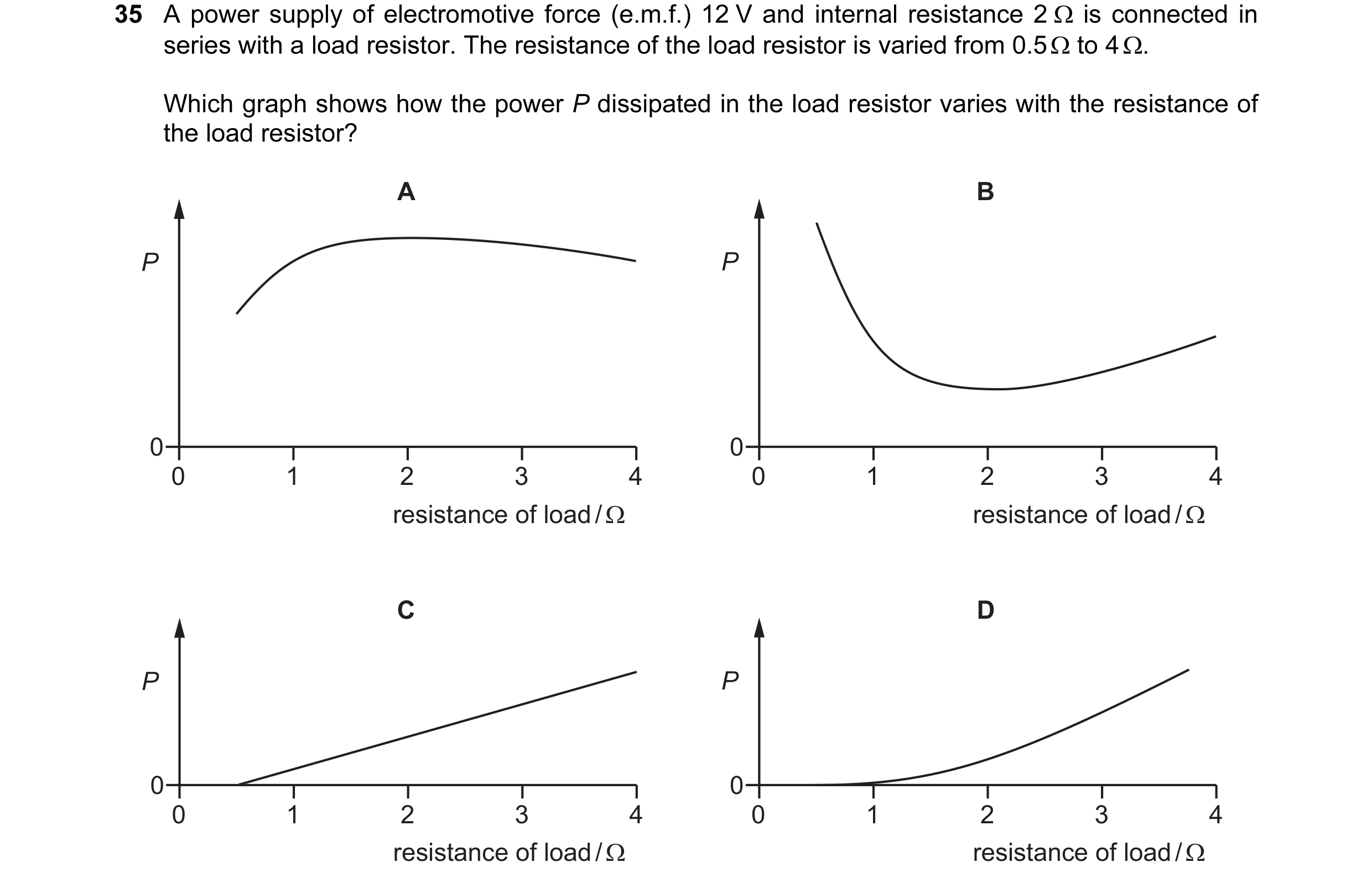 44 / 100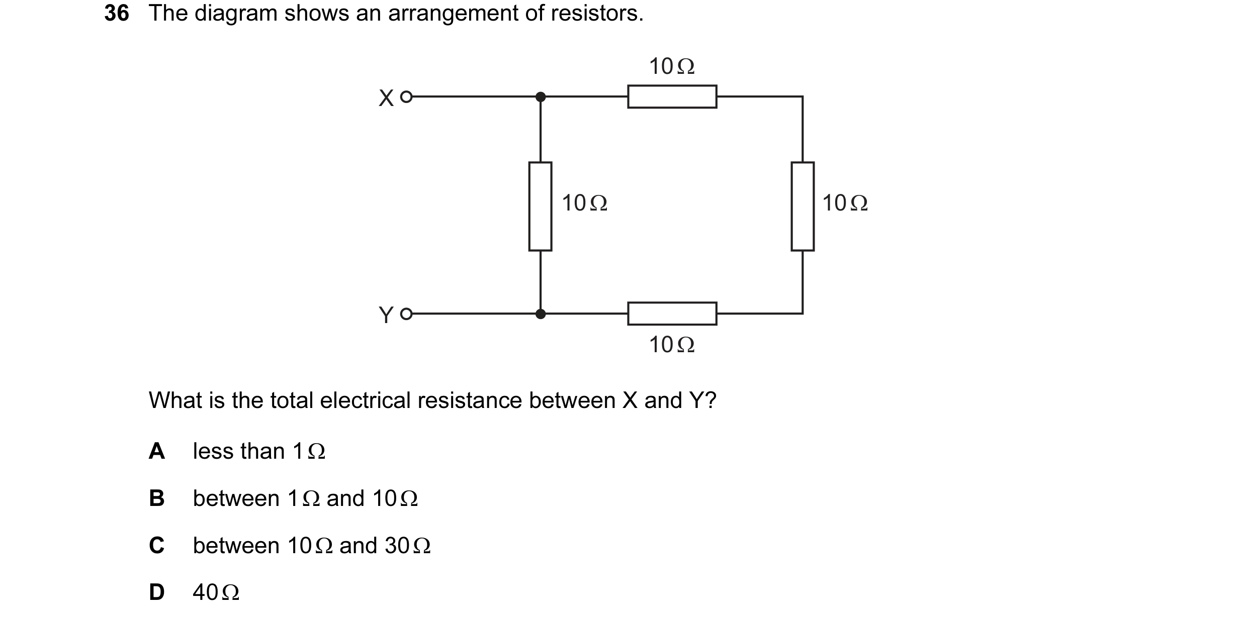
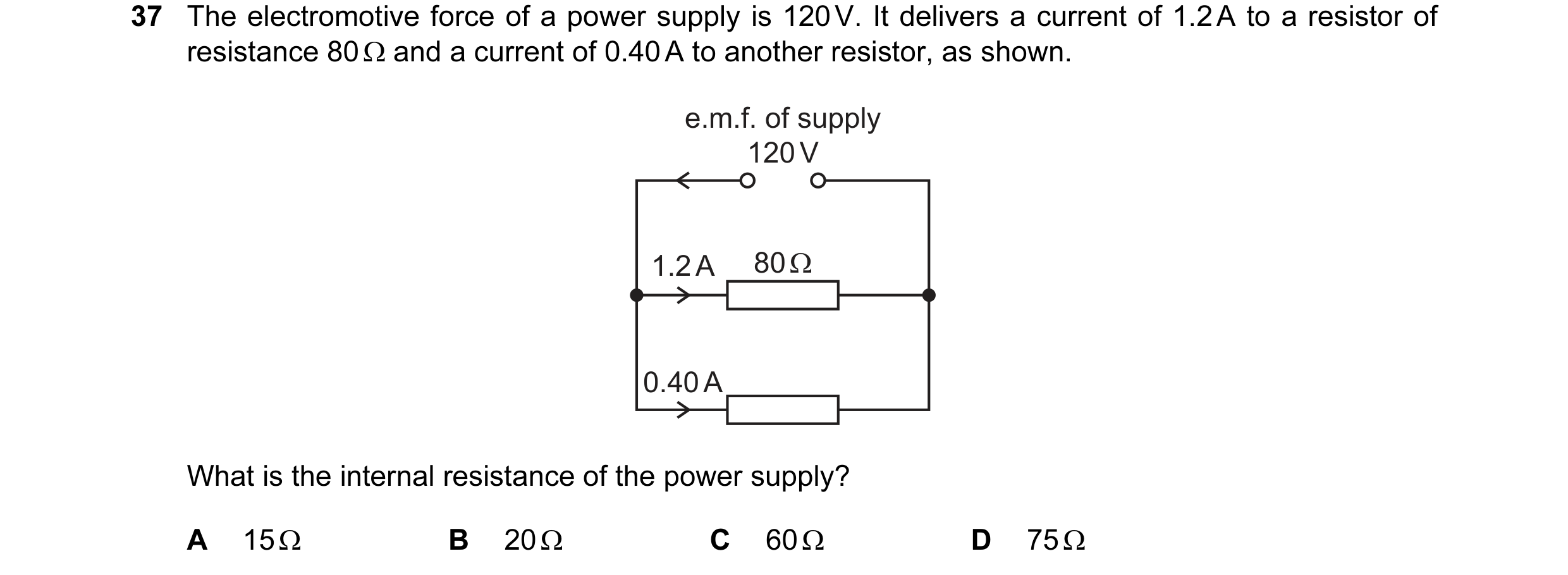
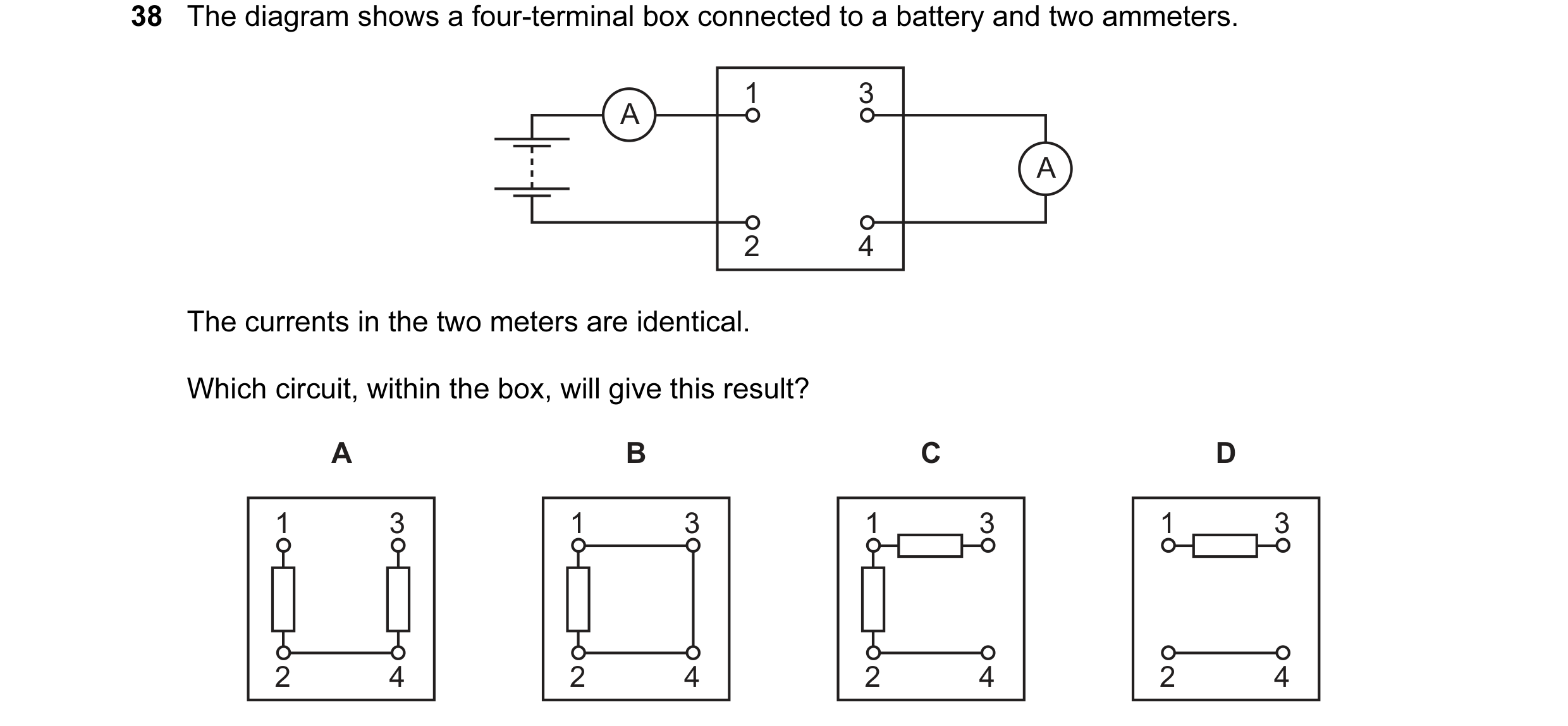 45 / 100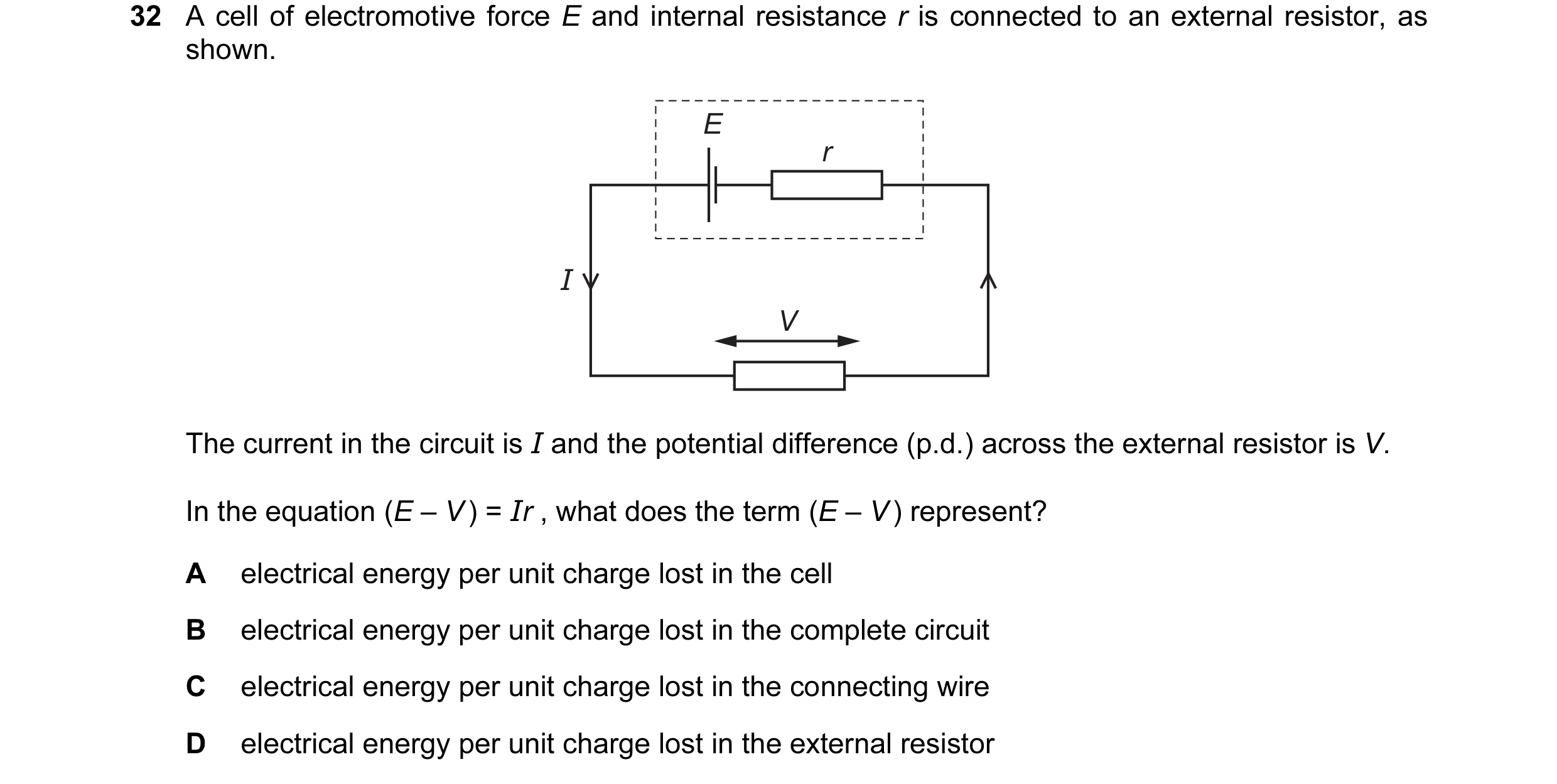
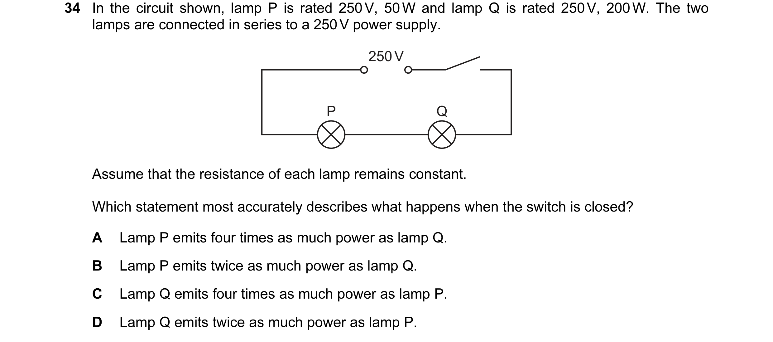 46 / 100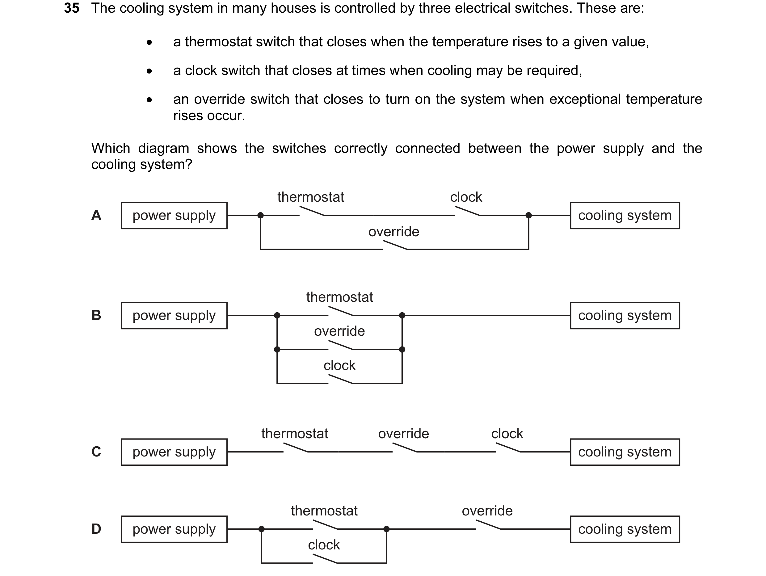
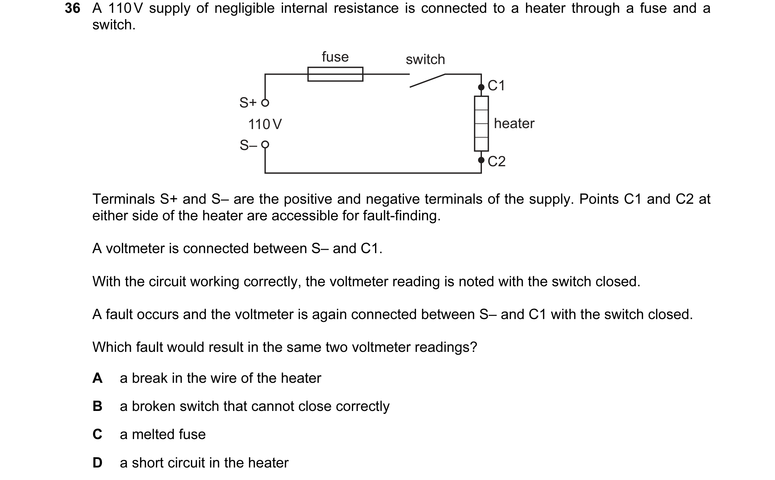 47 / 100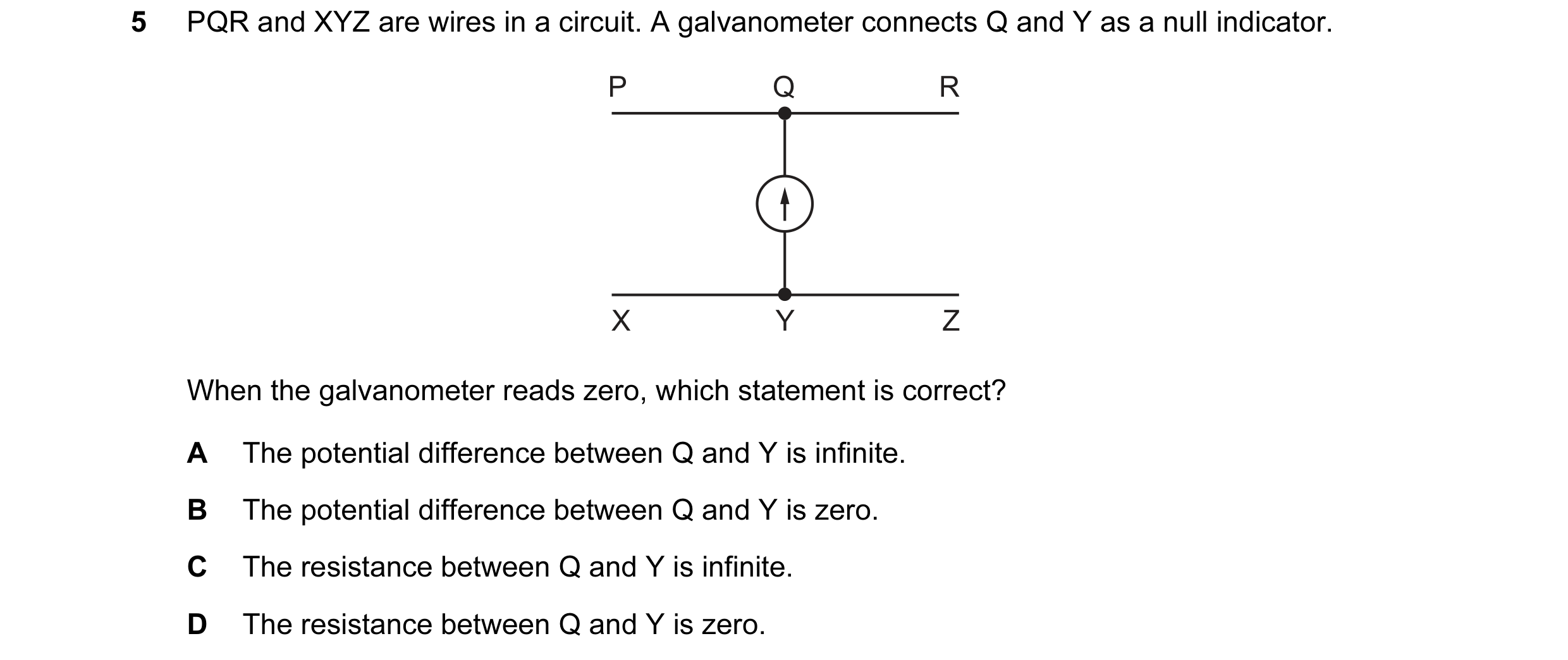
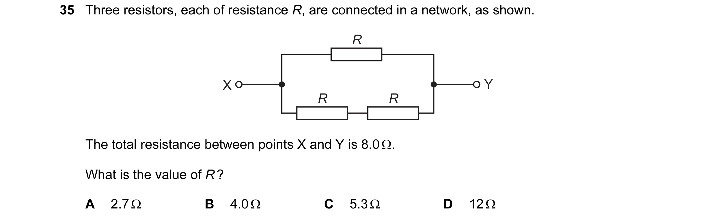

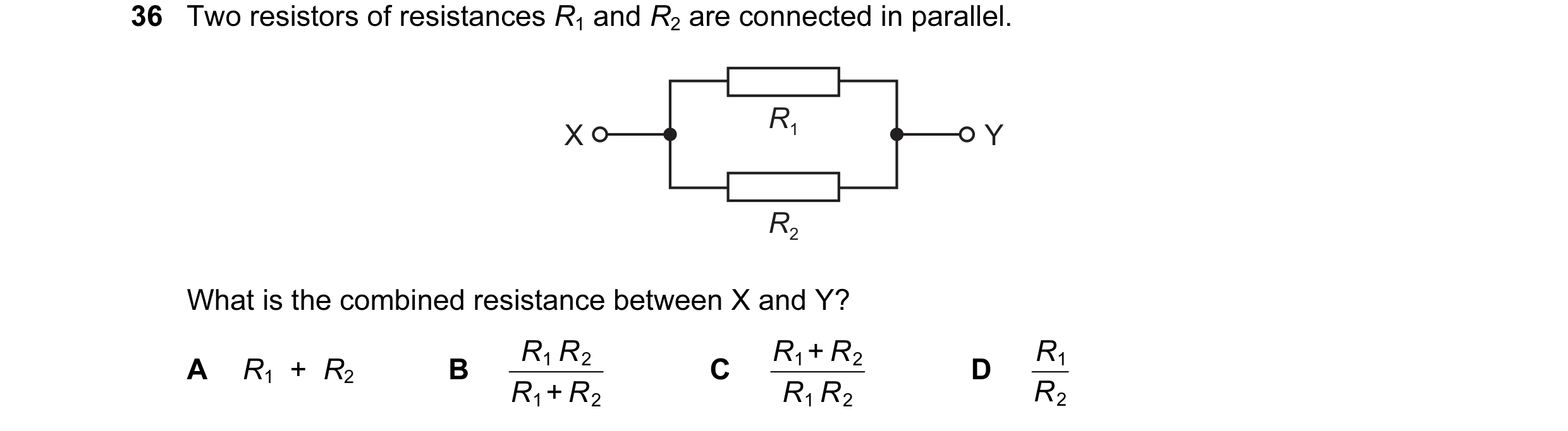 48 / 100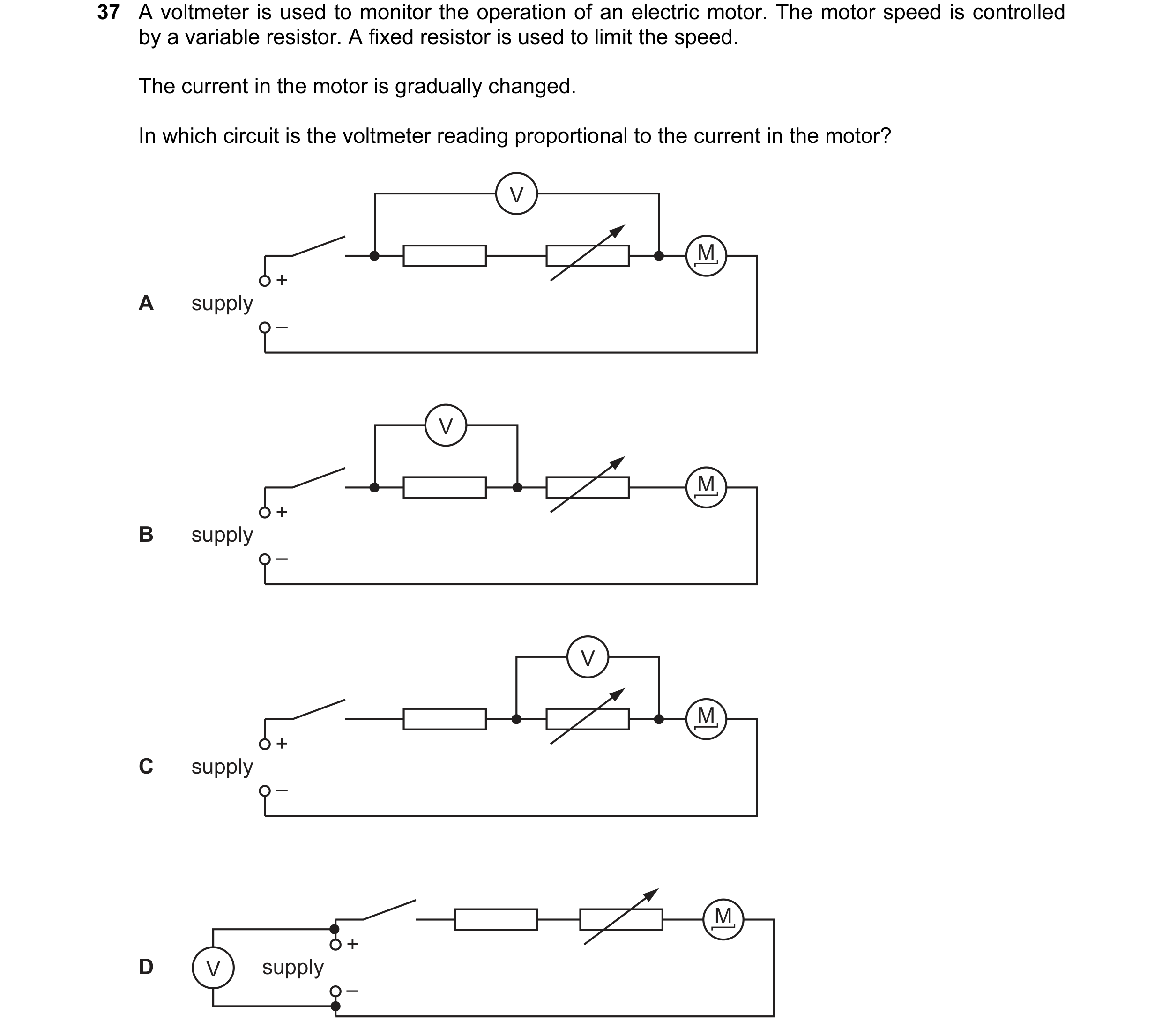
 49 / 100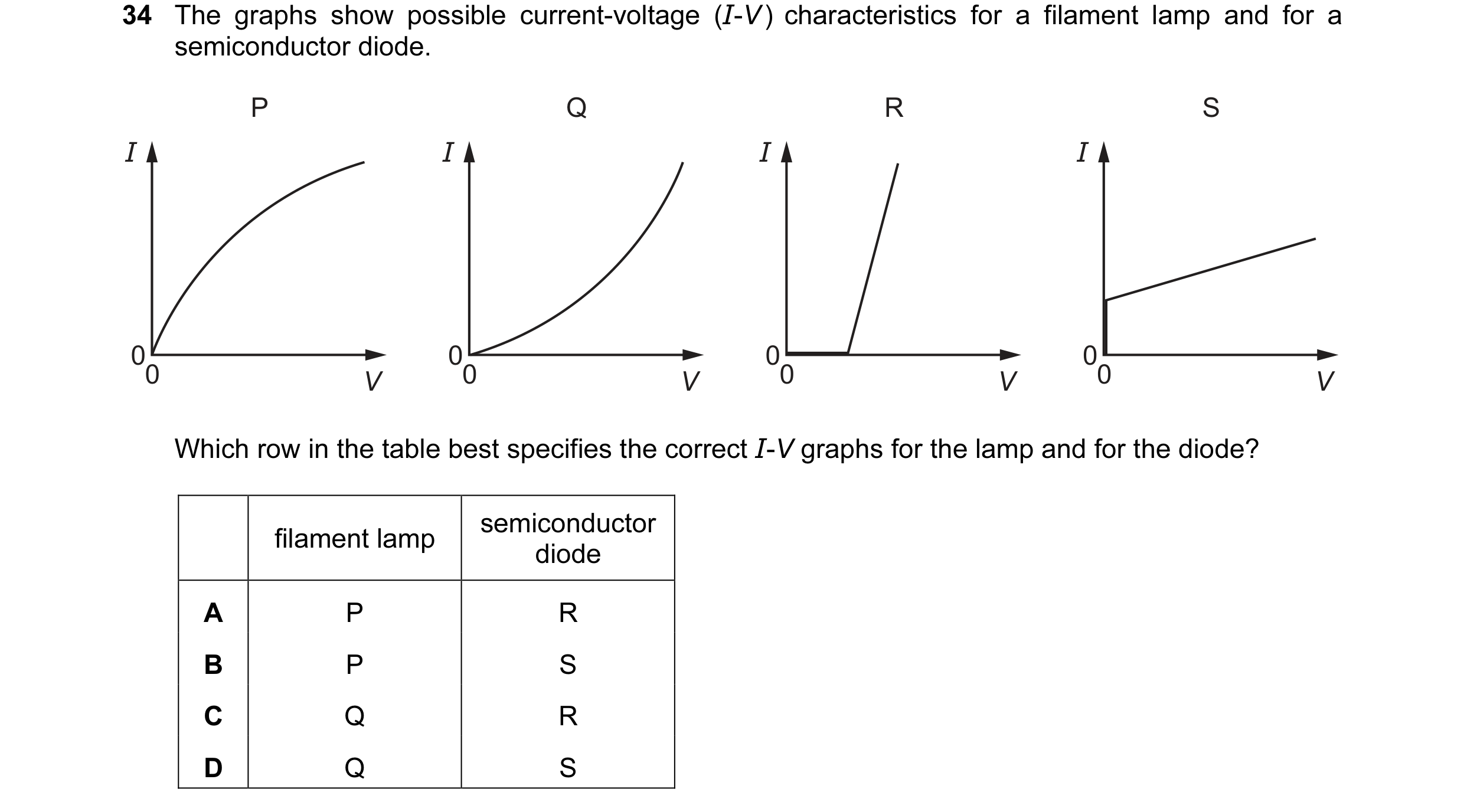
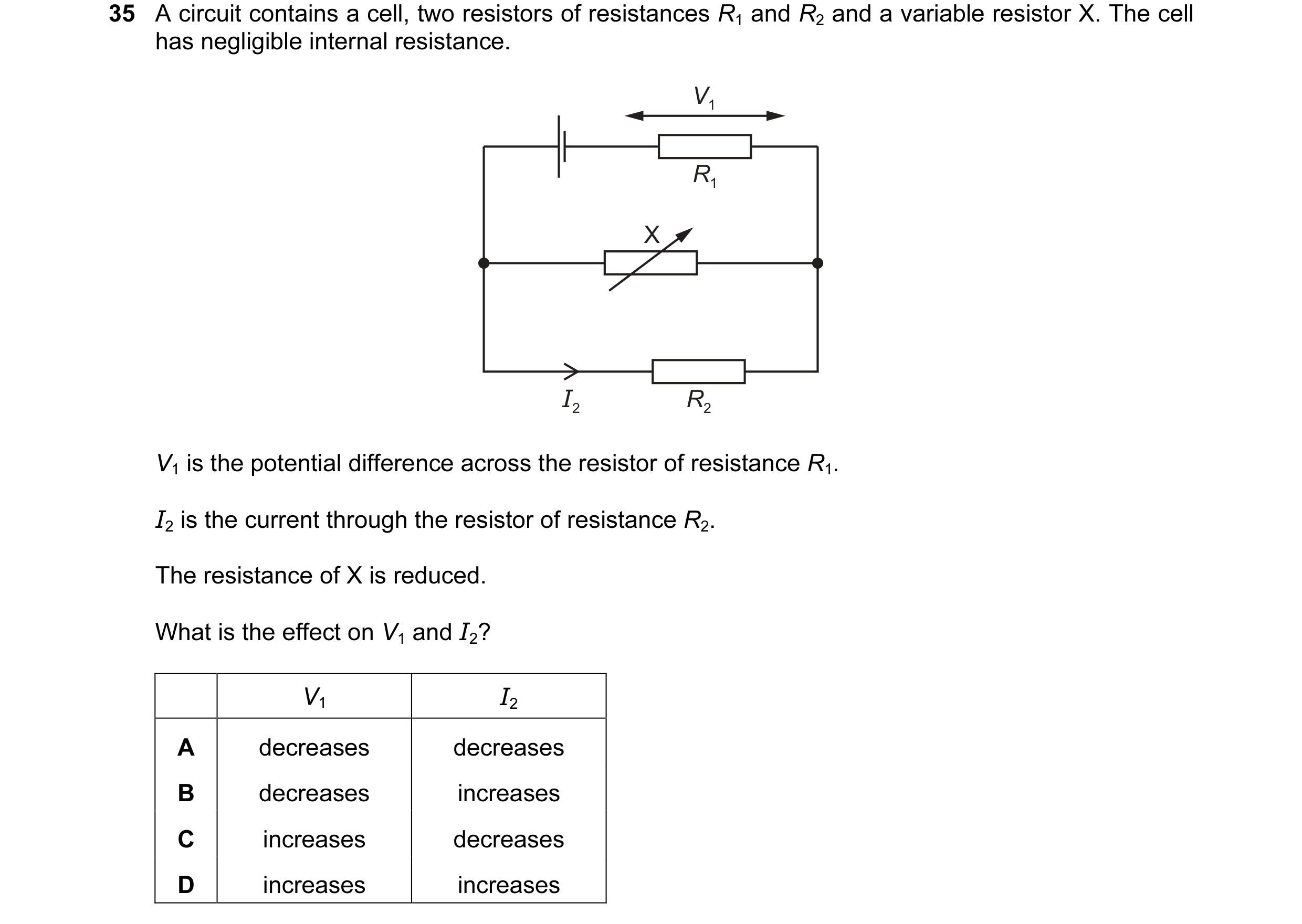 50 / 100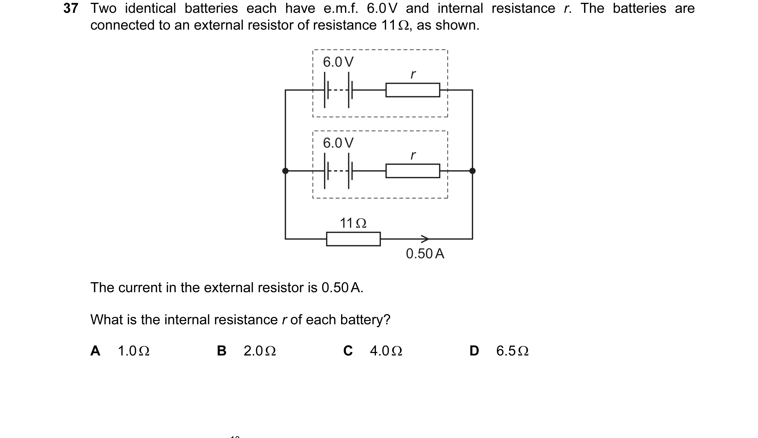
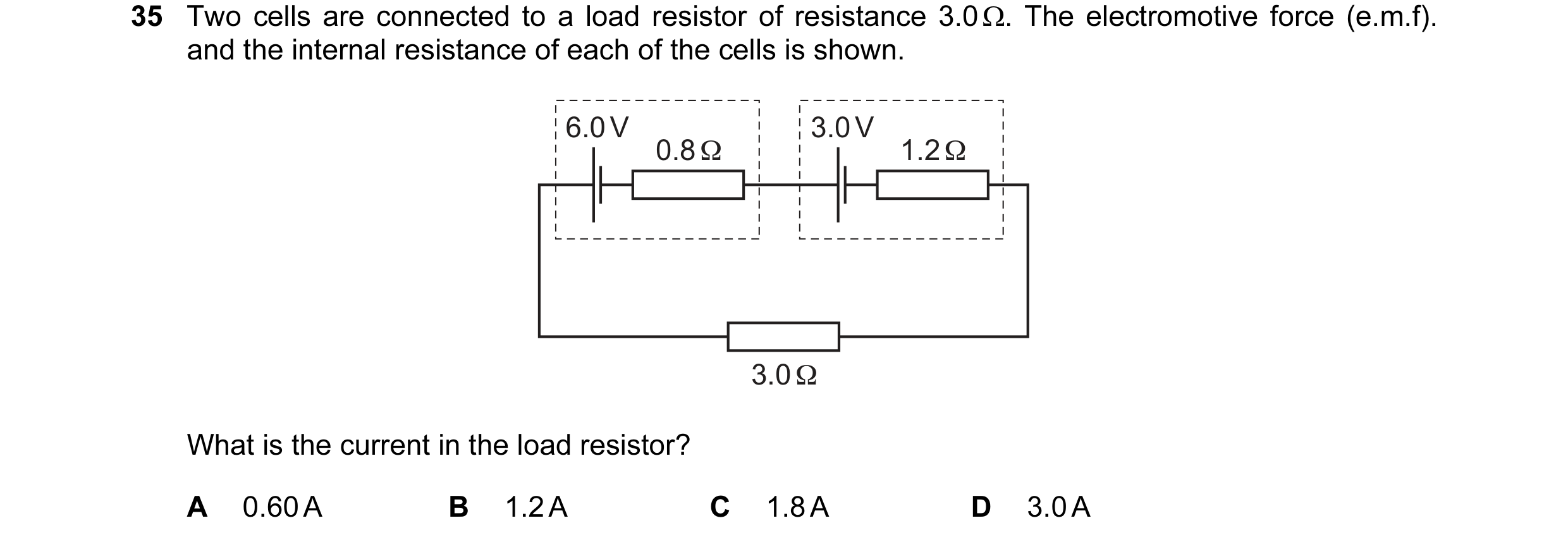
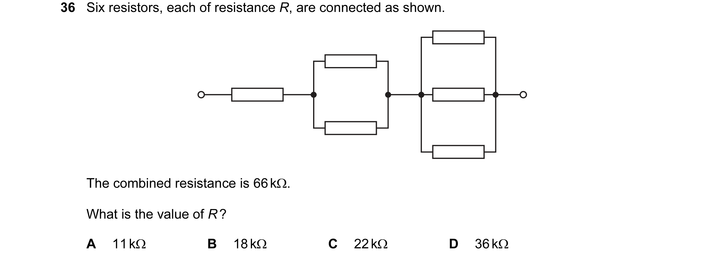 51 / 100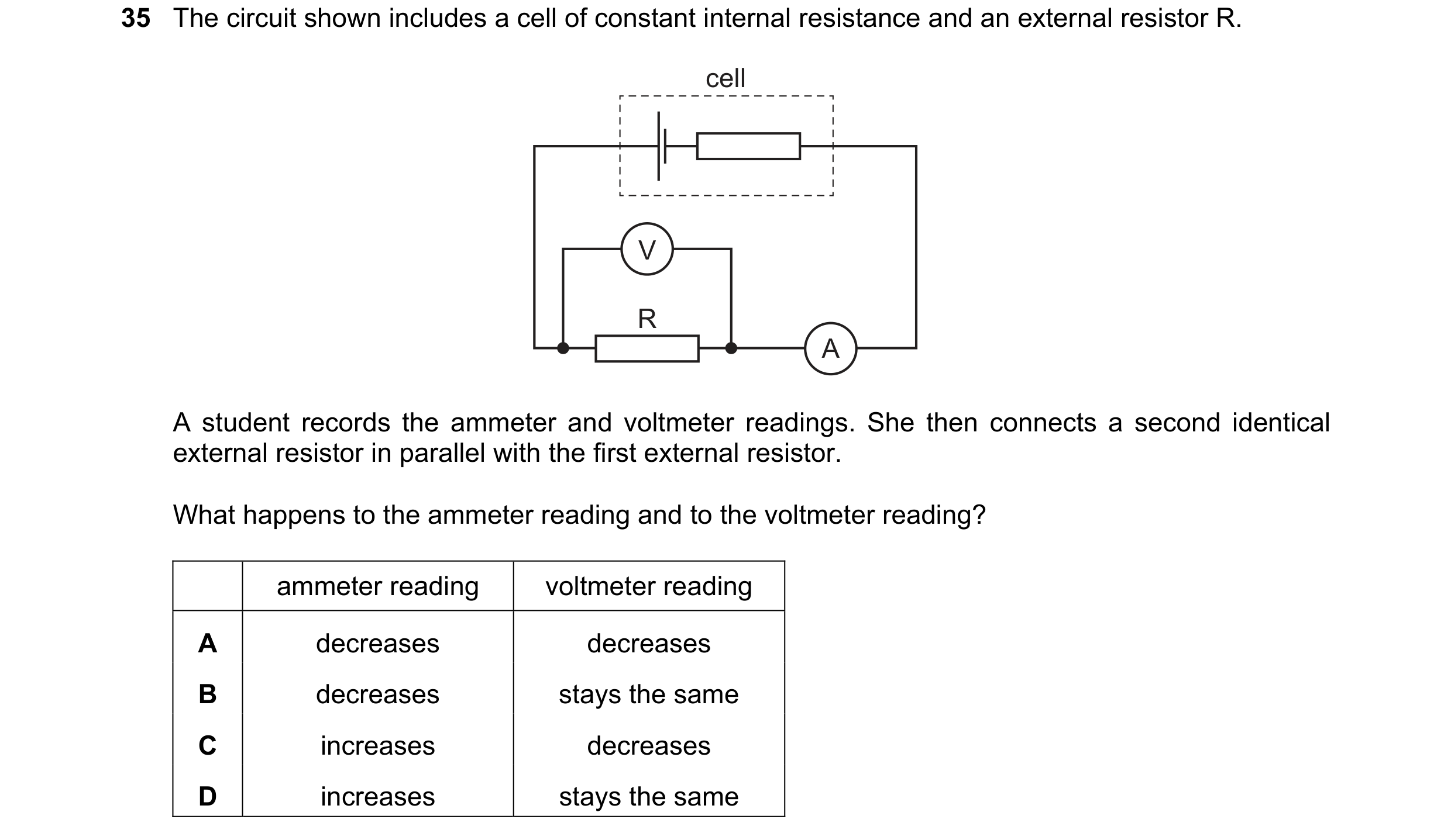
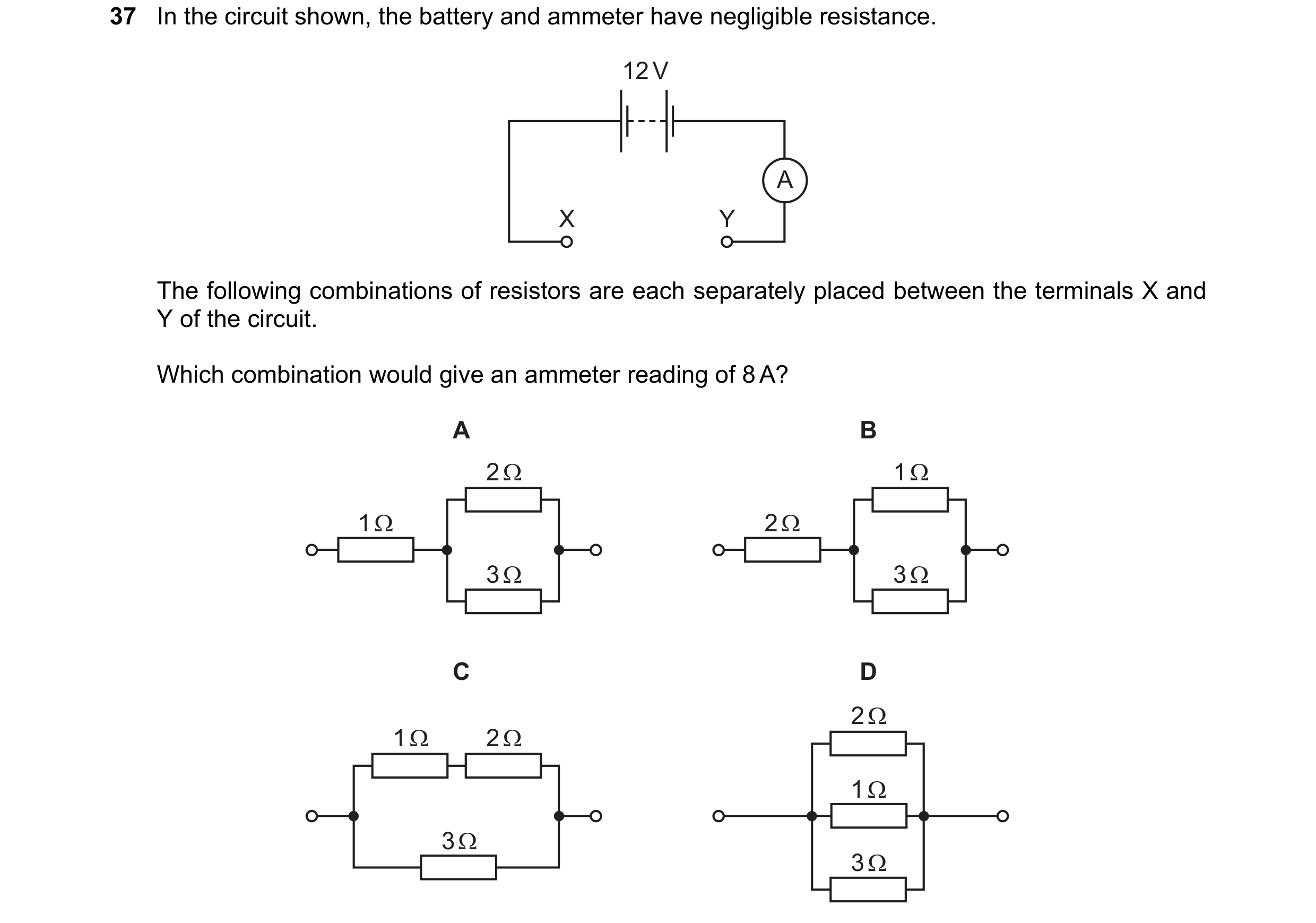 52 / 100
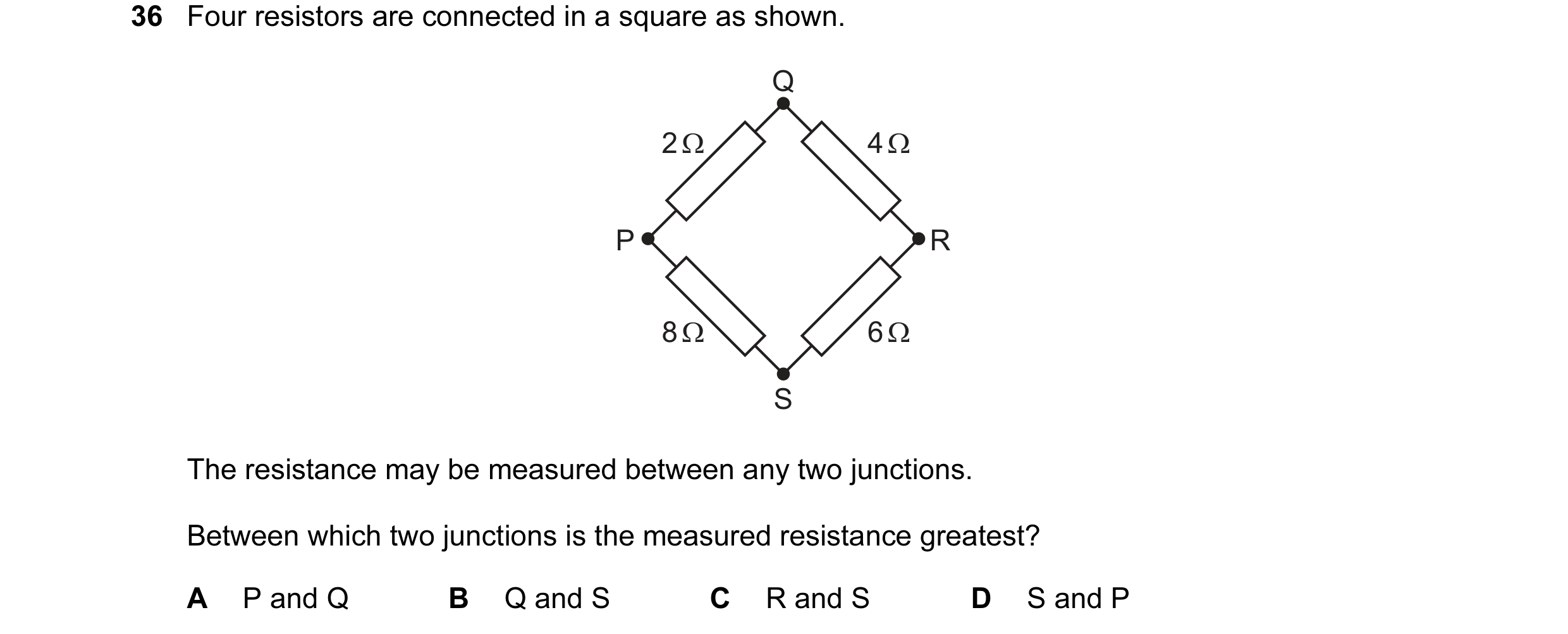
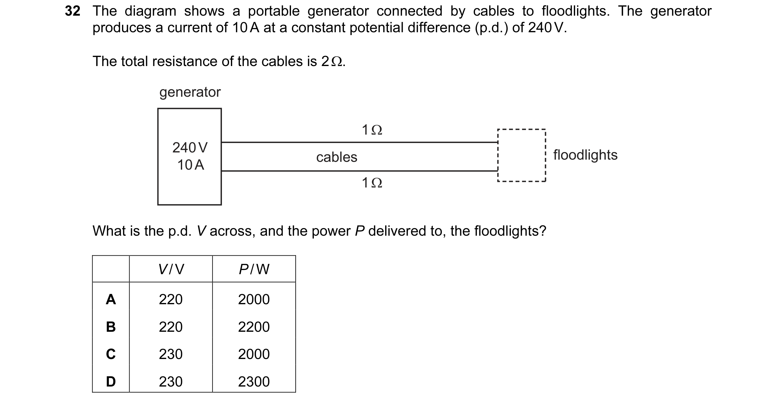 53 / 100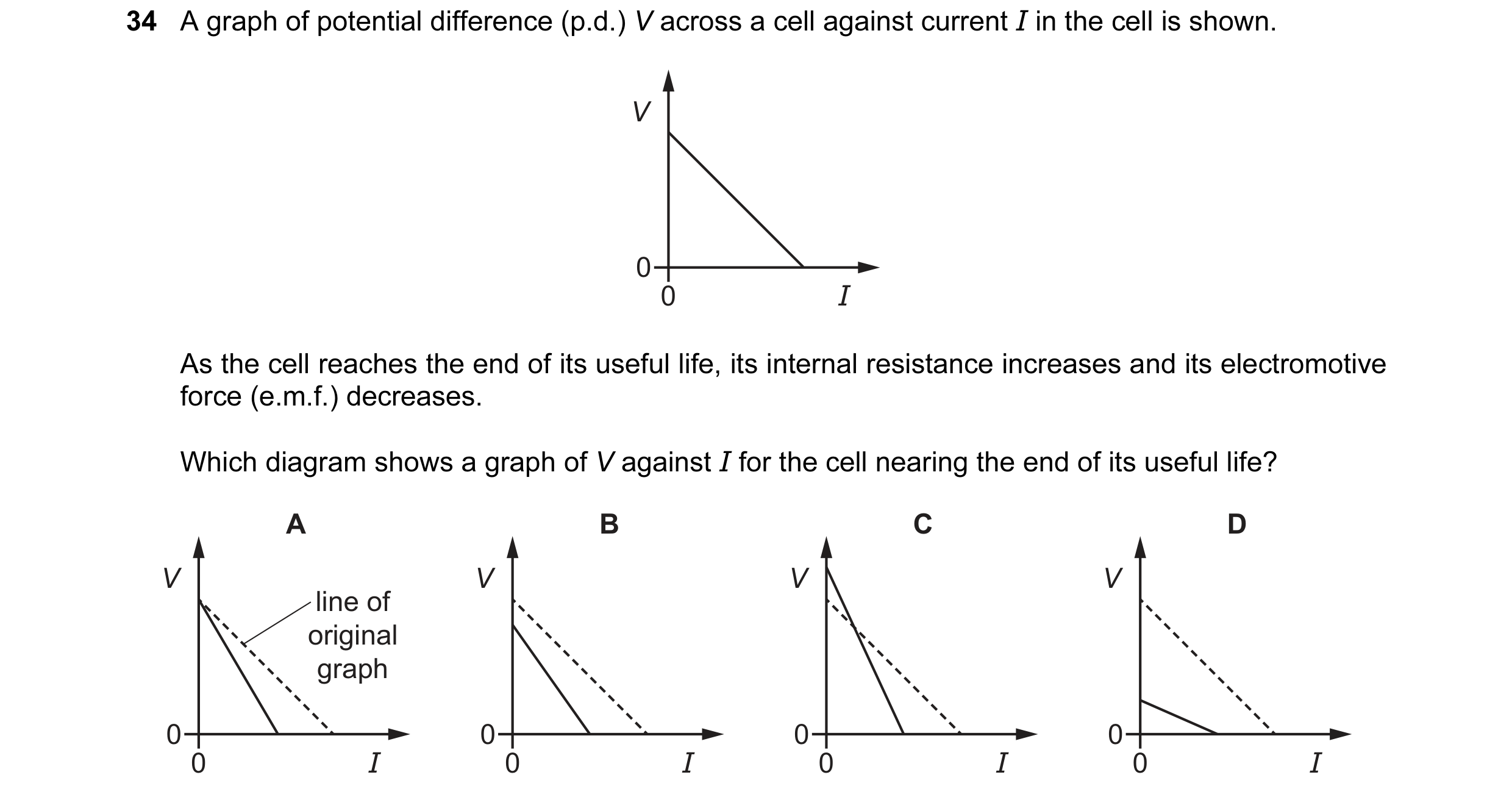
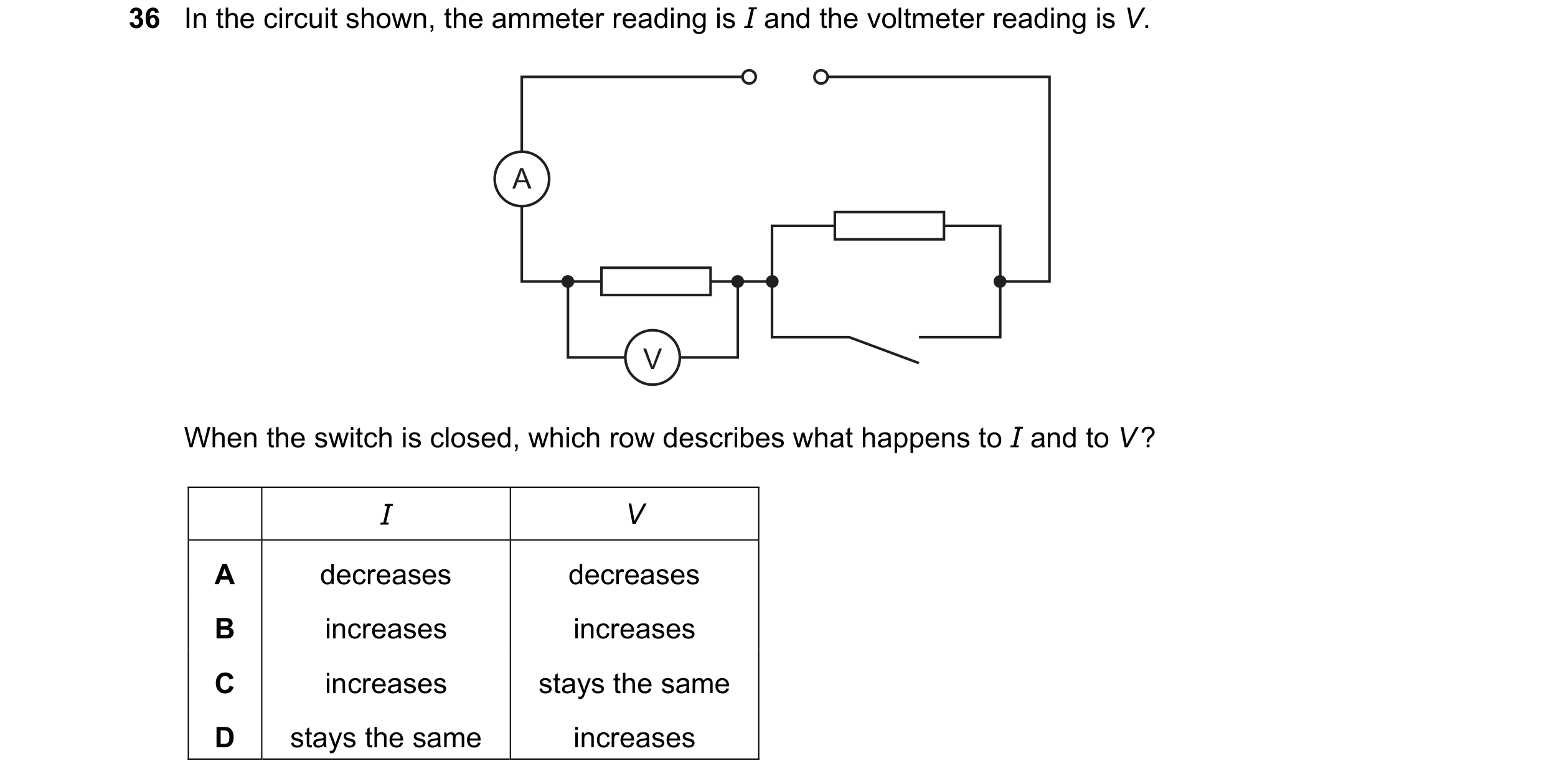
 54 / 100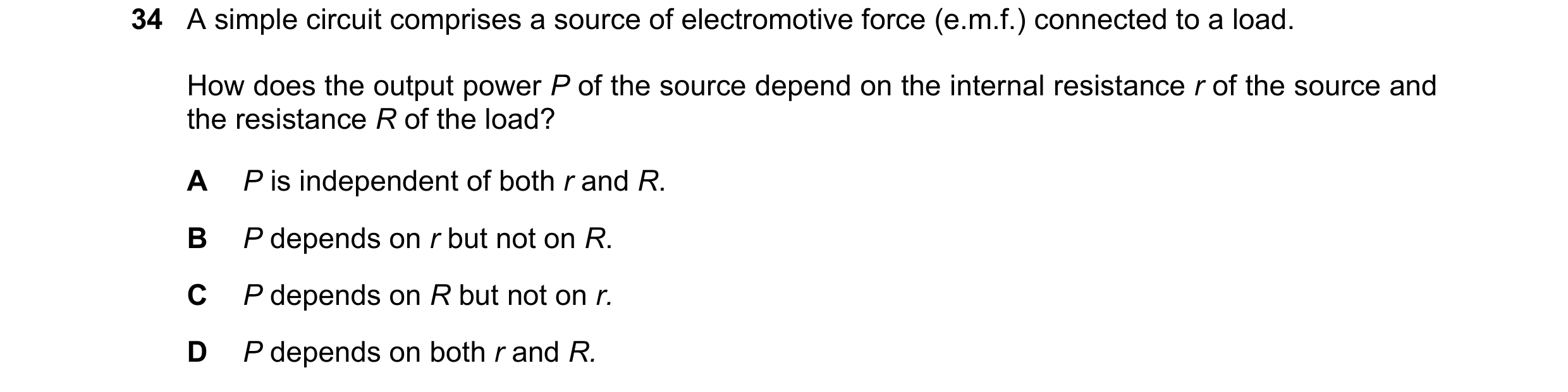
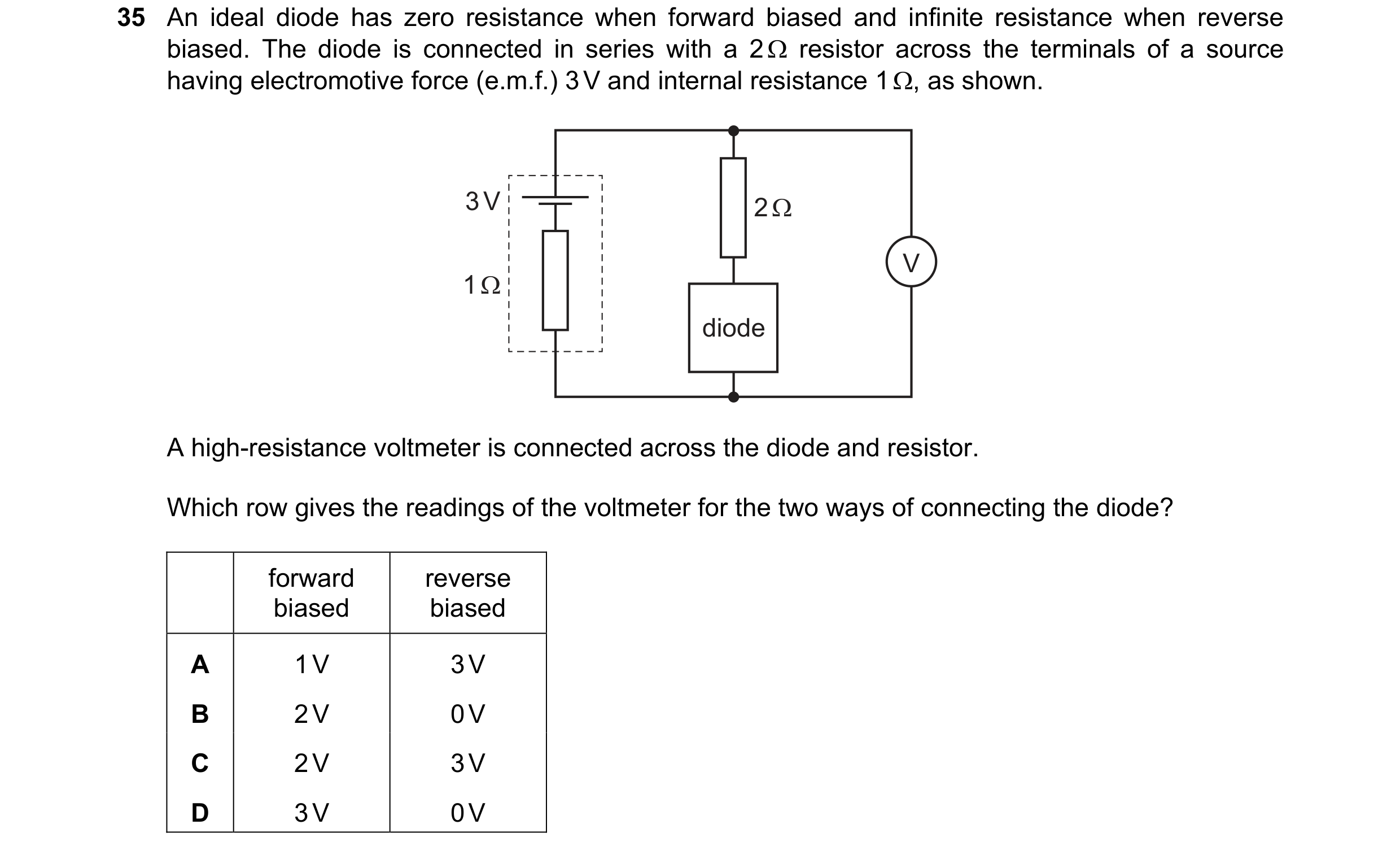
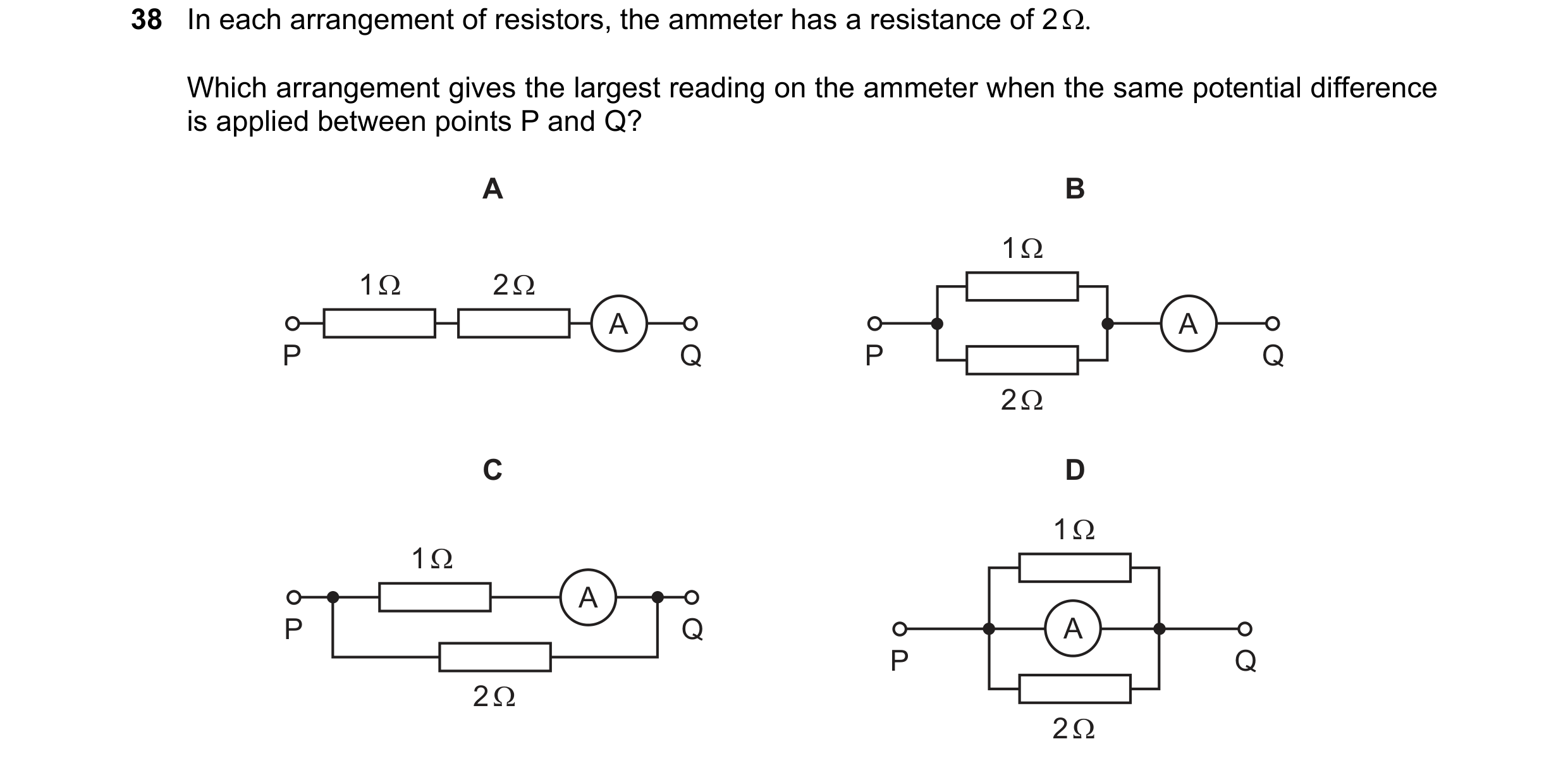 55 / 100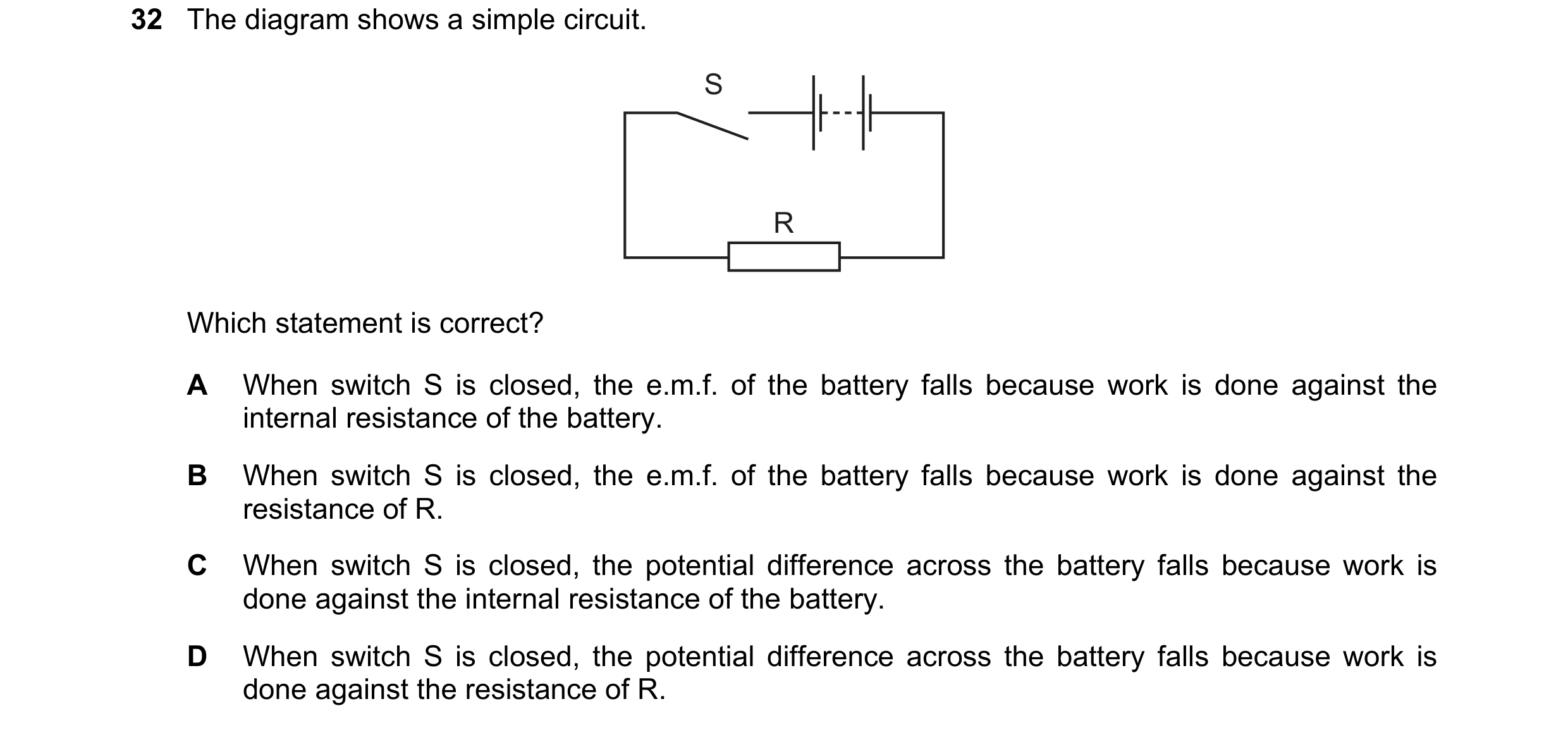
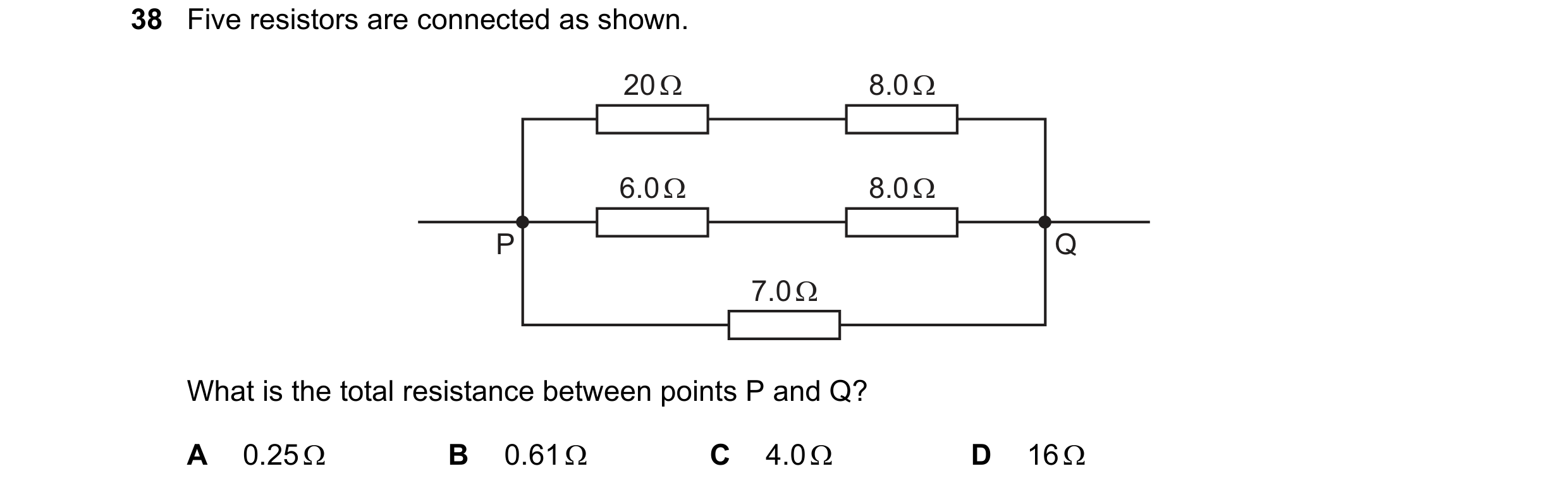
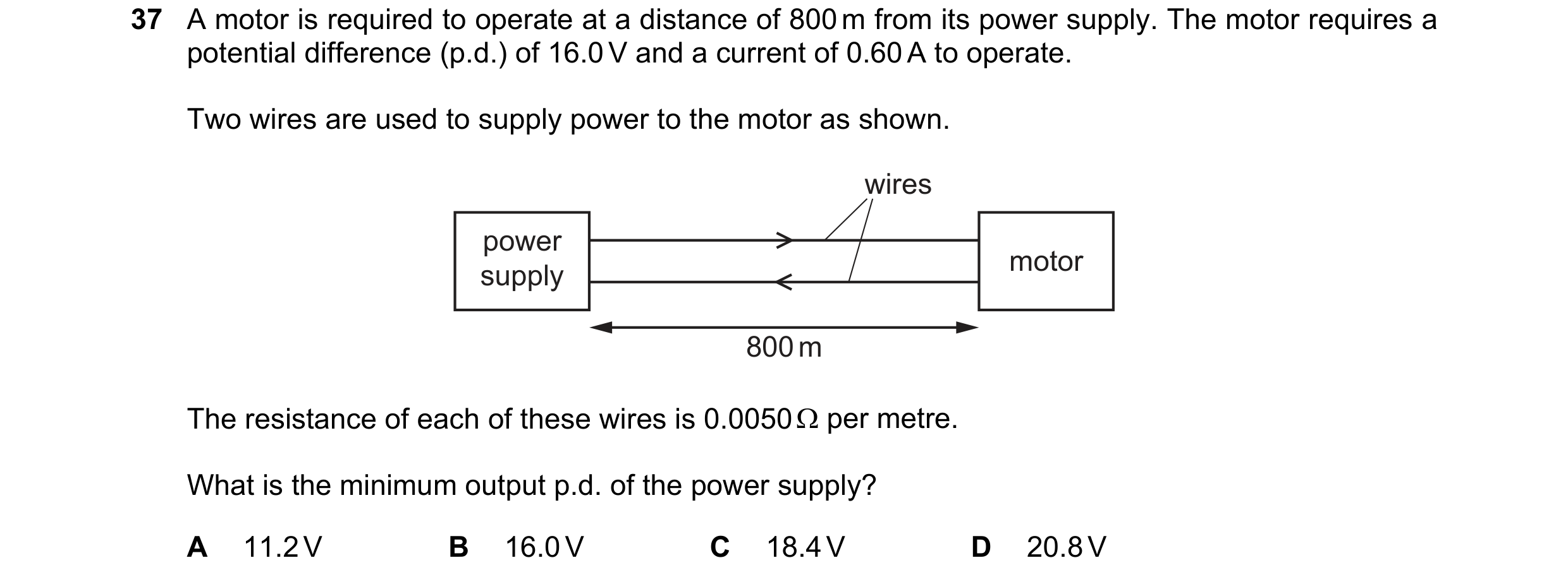 56 / 100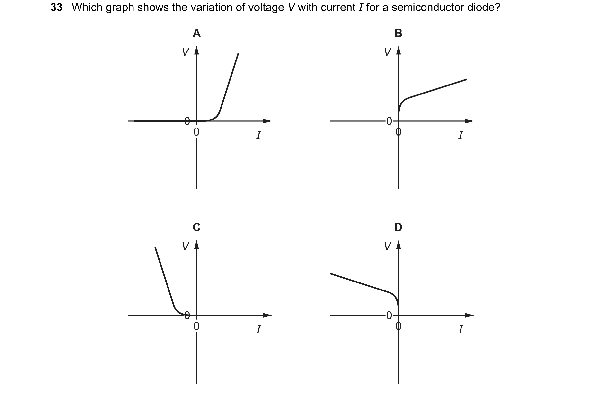
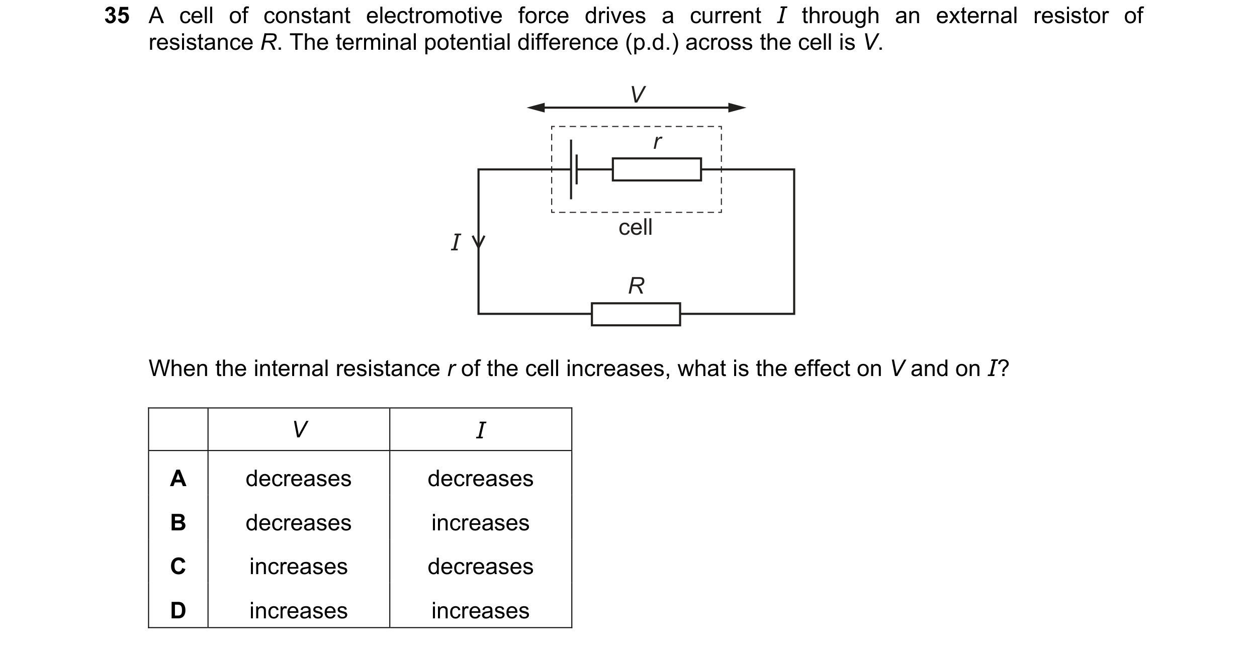 57 / 100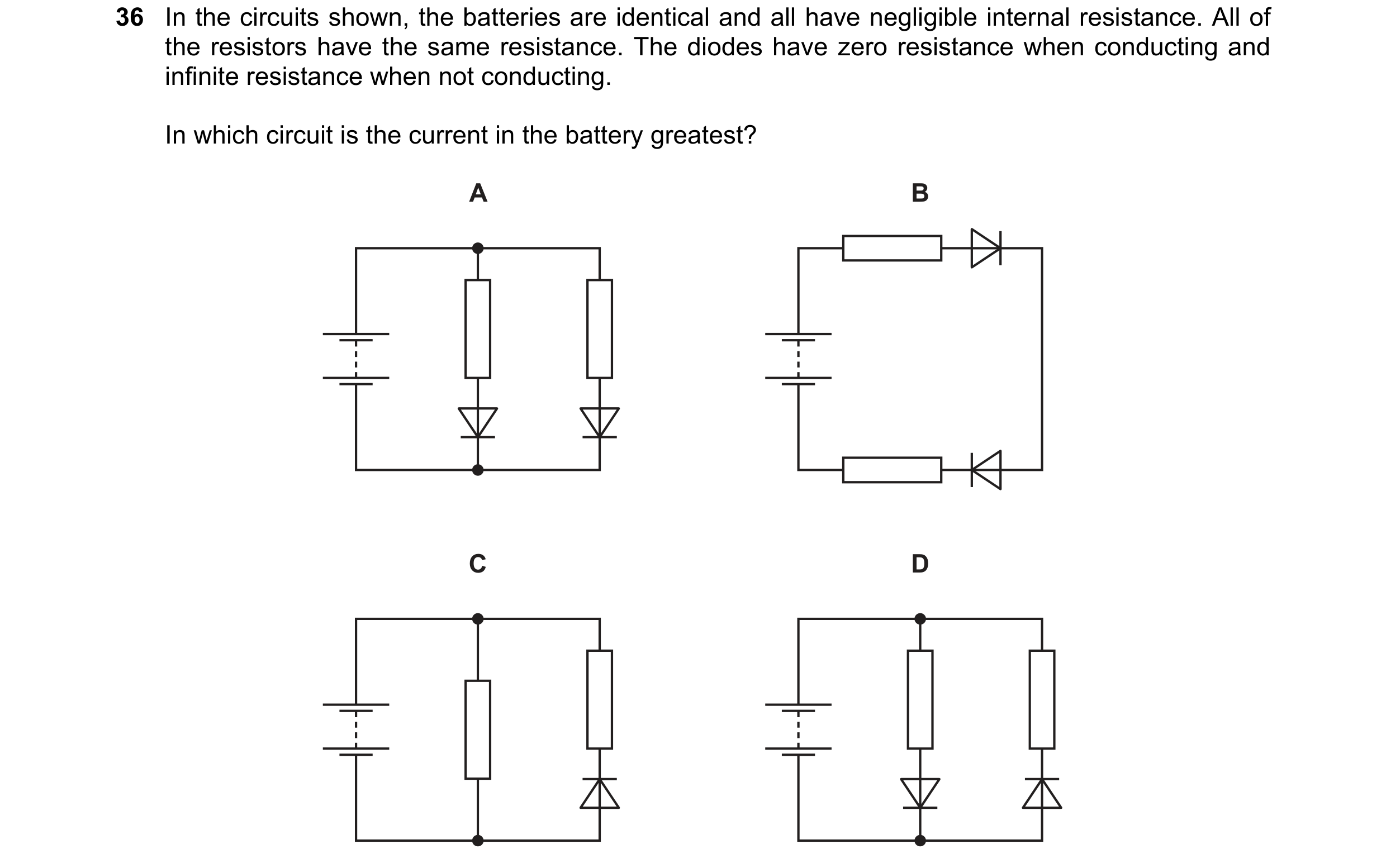
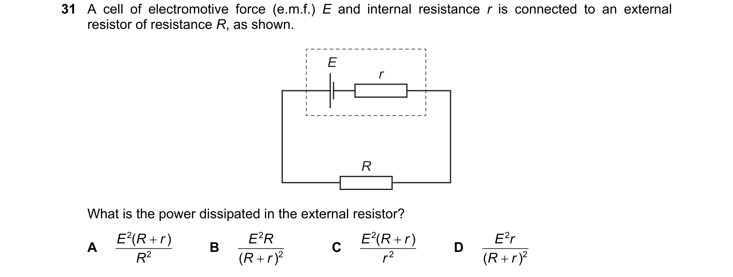 58 / 100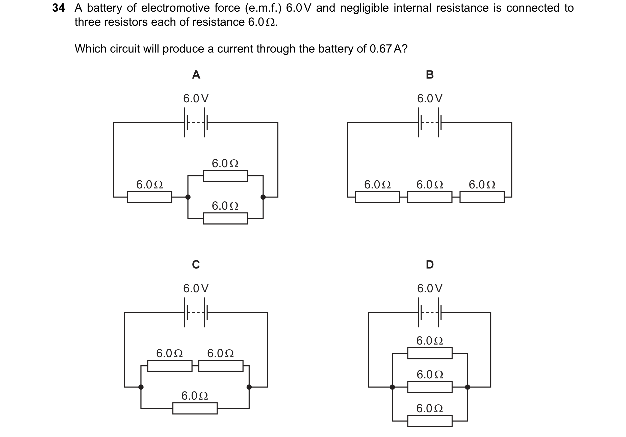
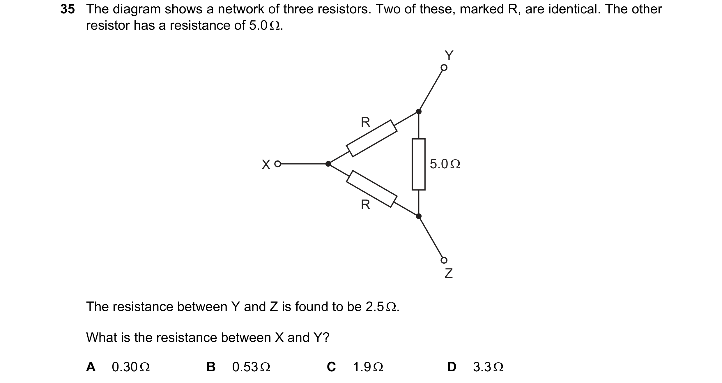 59 / 100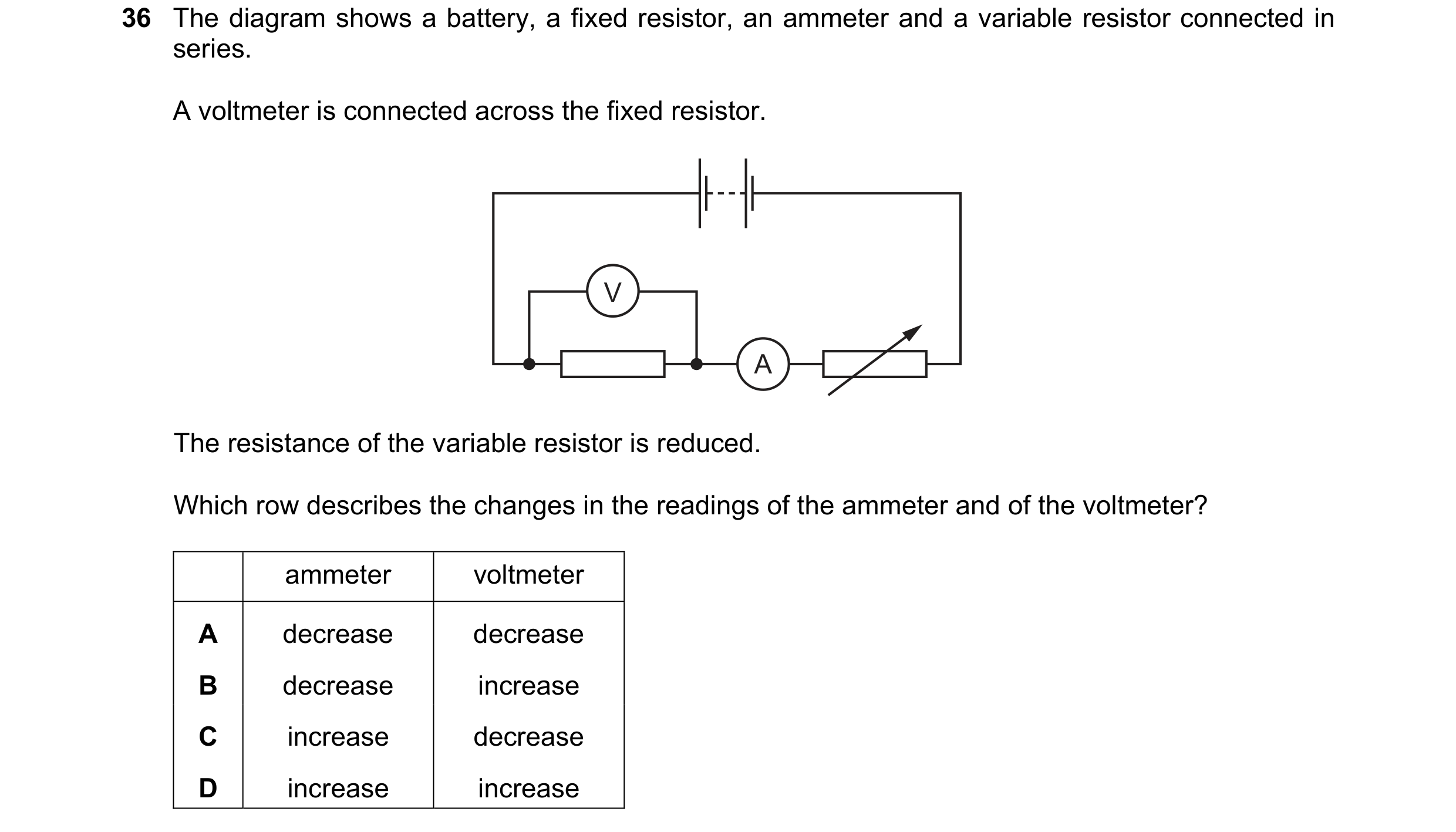
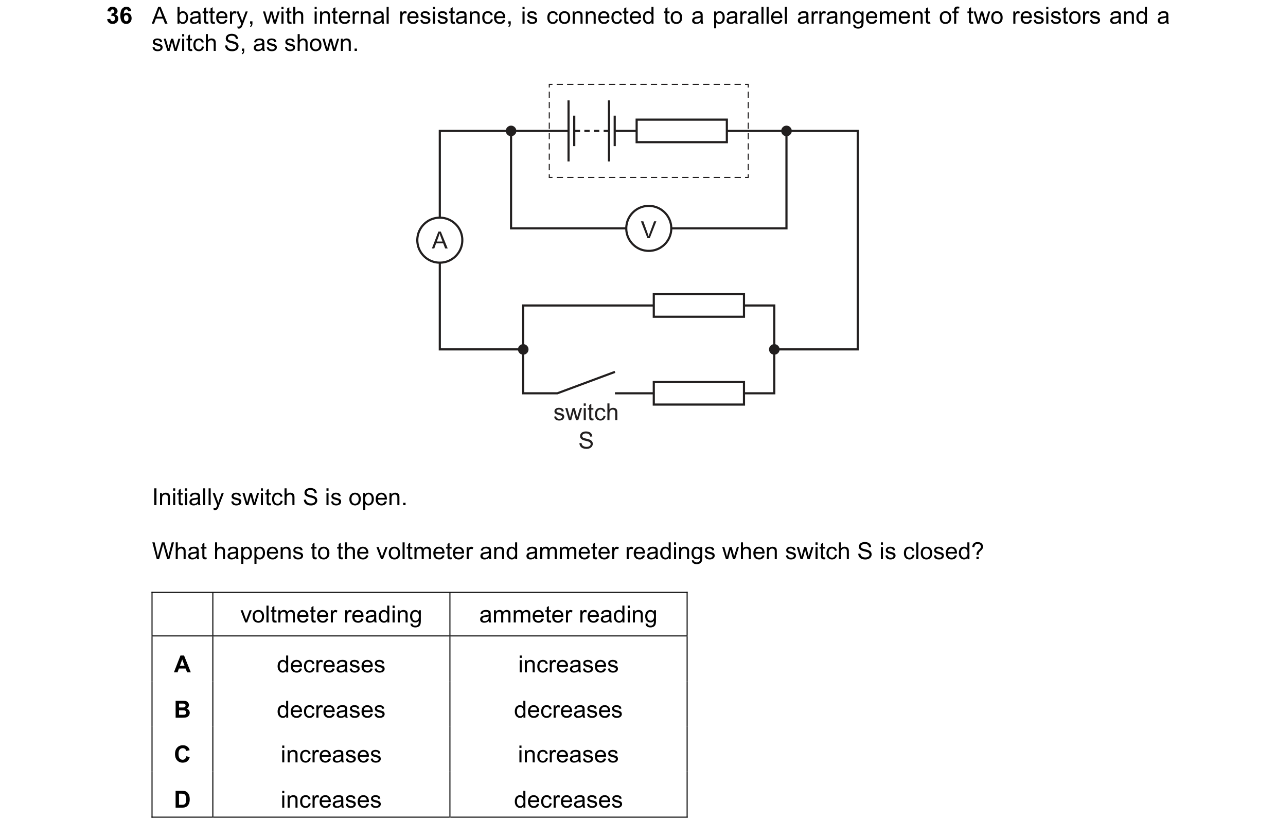 60 / 100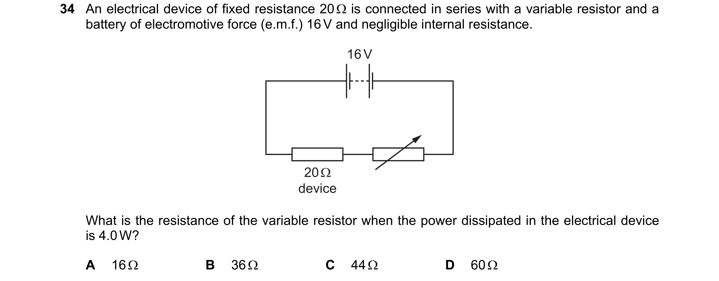
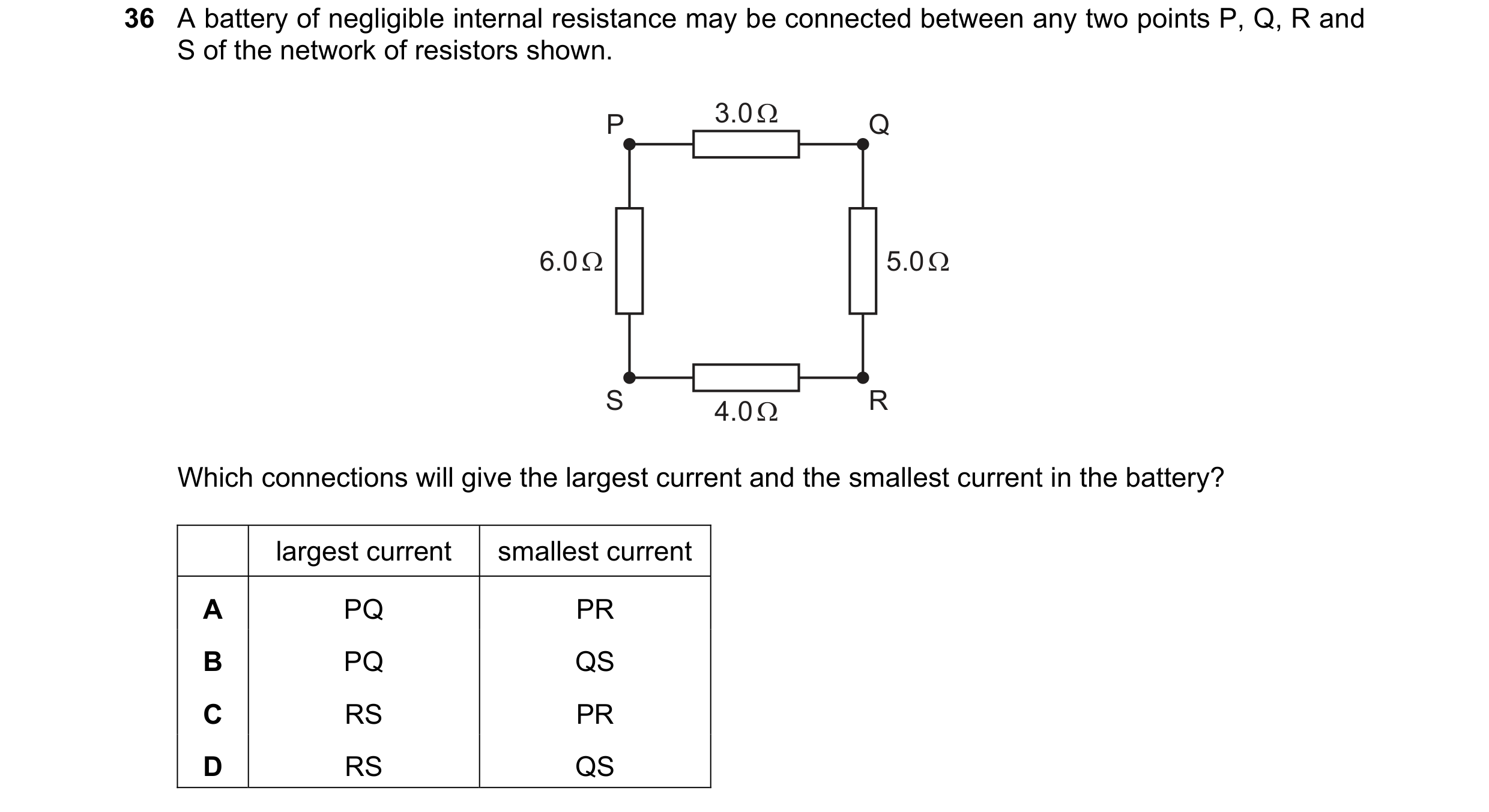
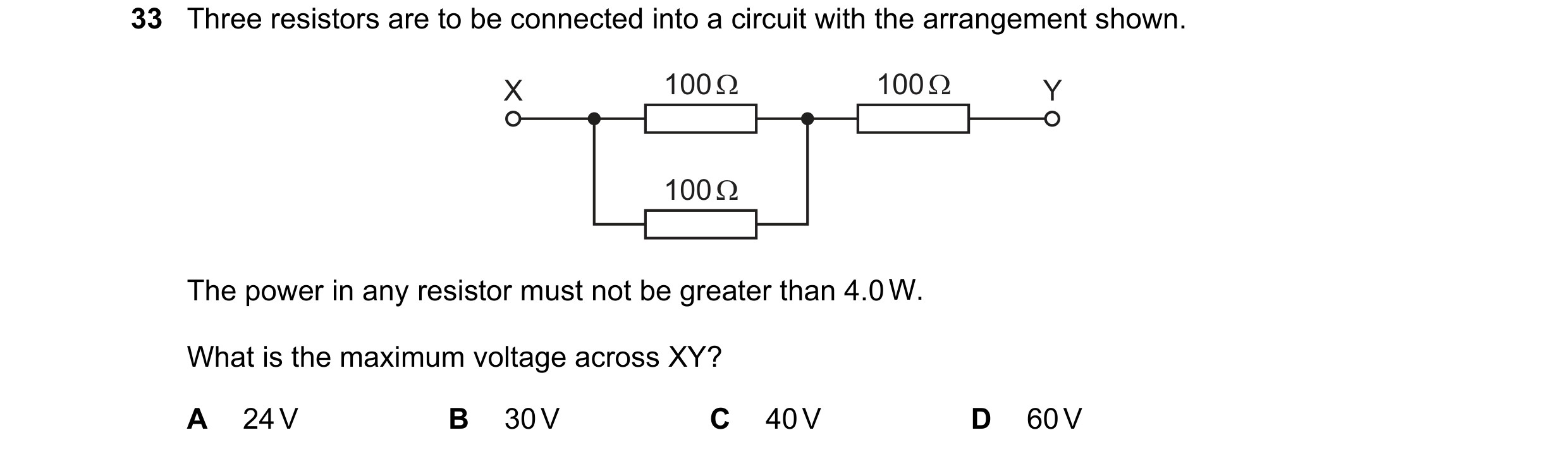 61 / 100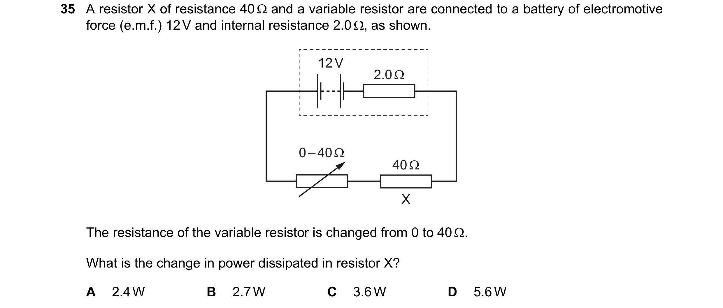
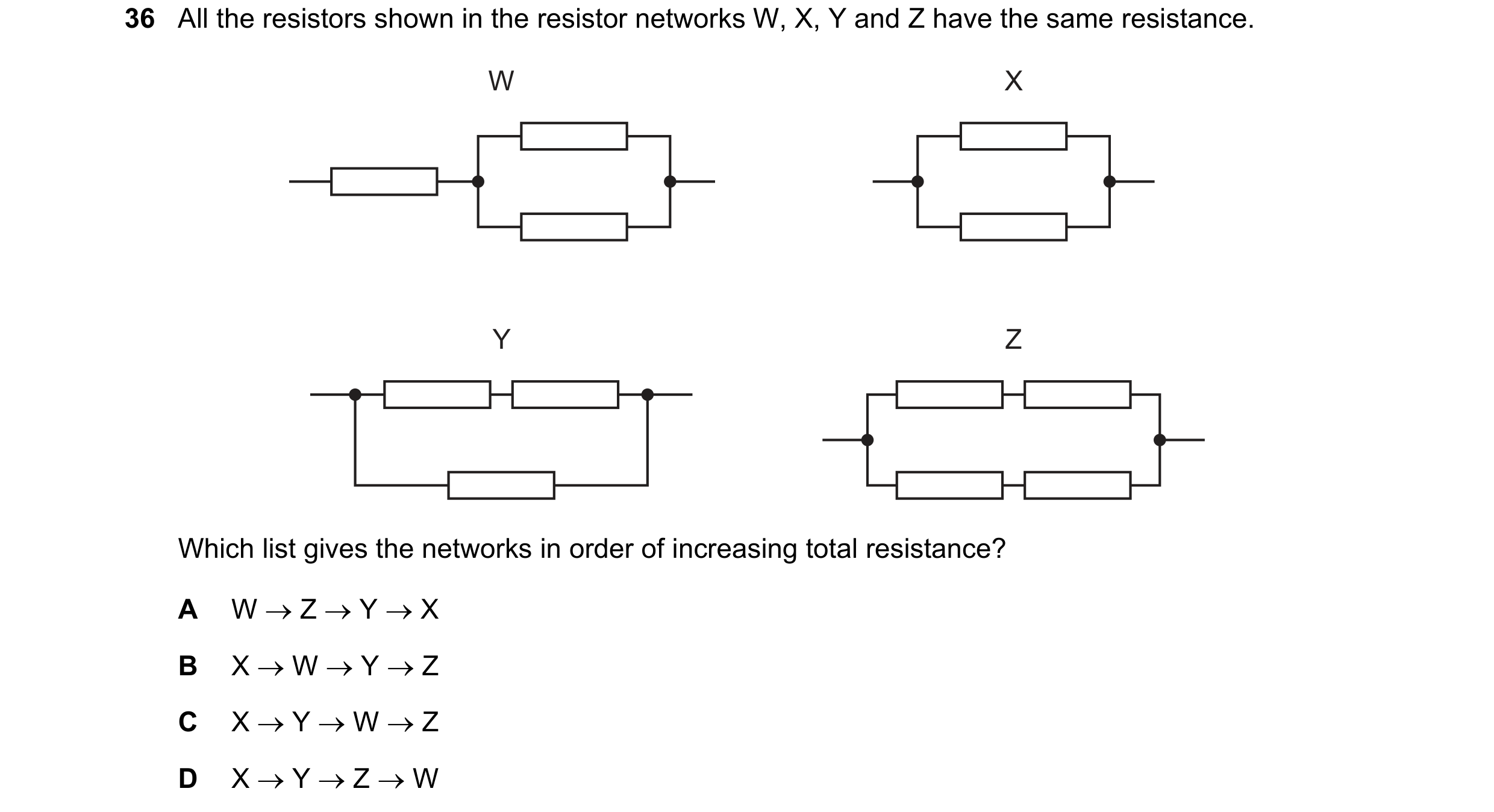 62 / 100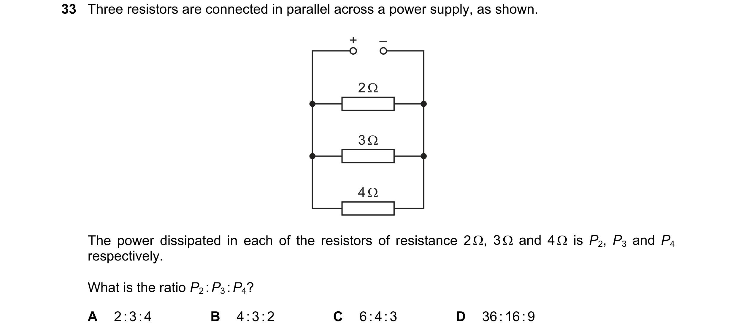
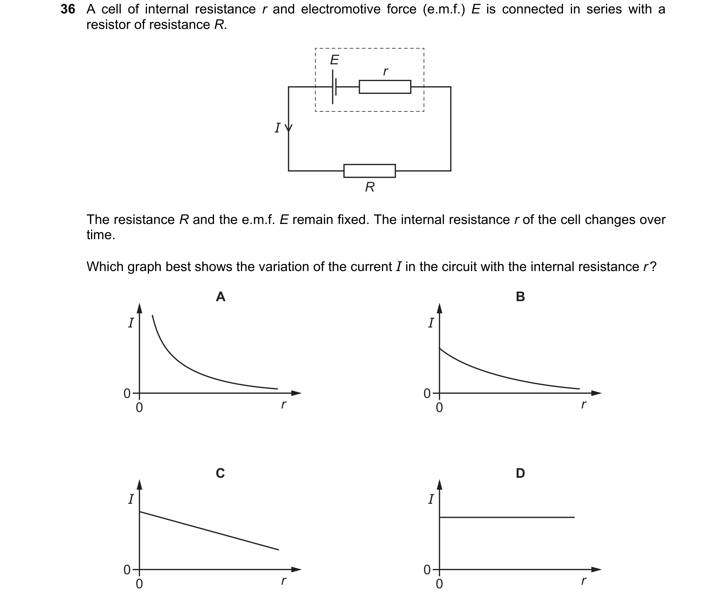 63 / 100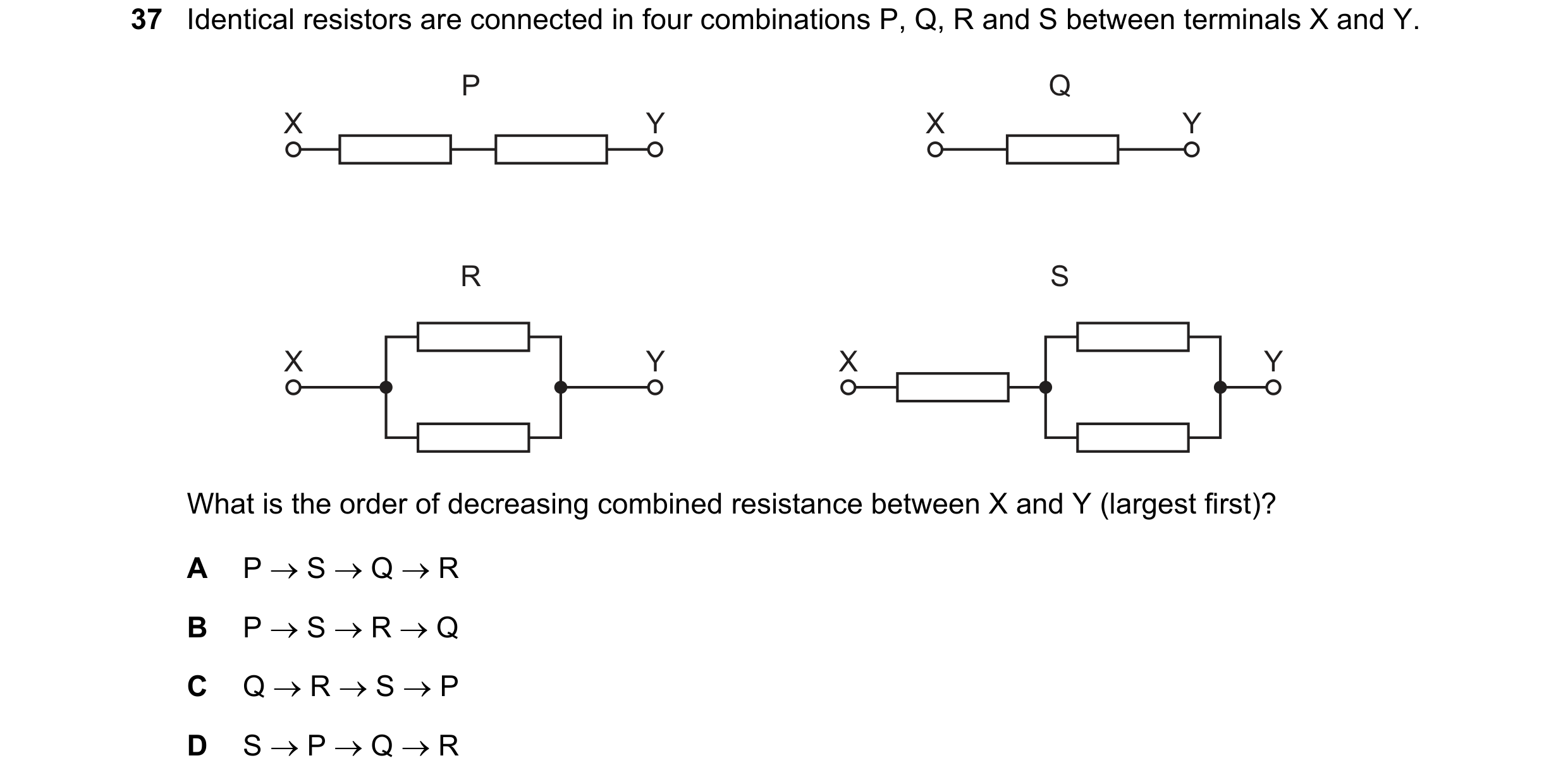
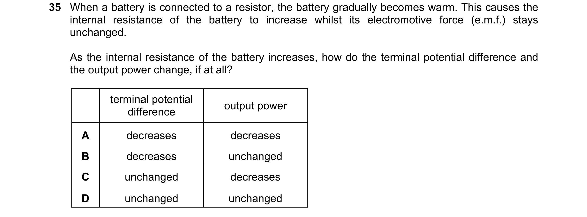
 64 / 100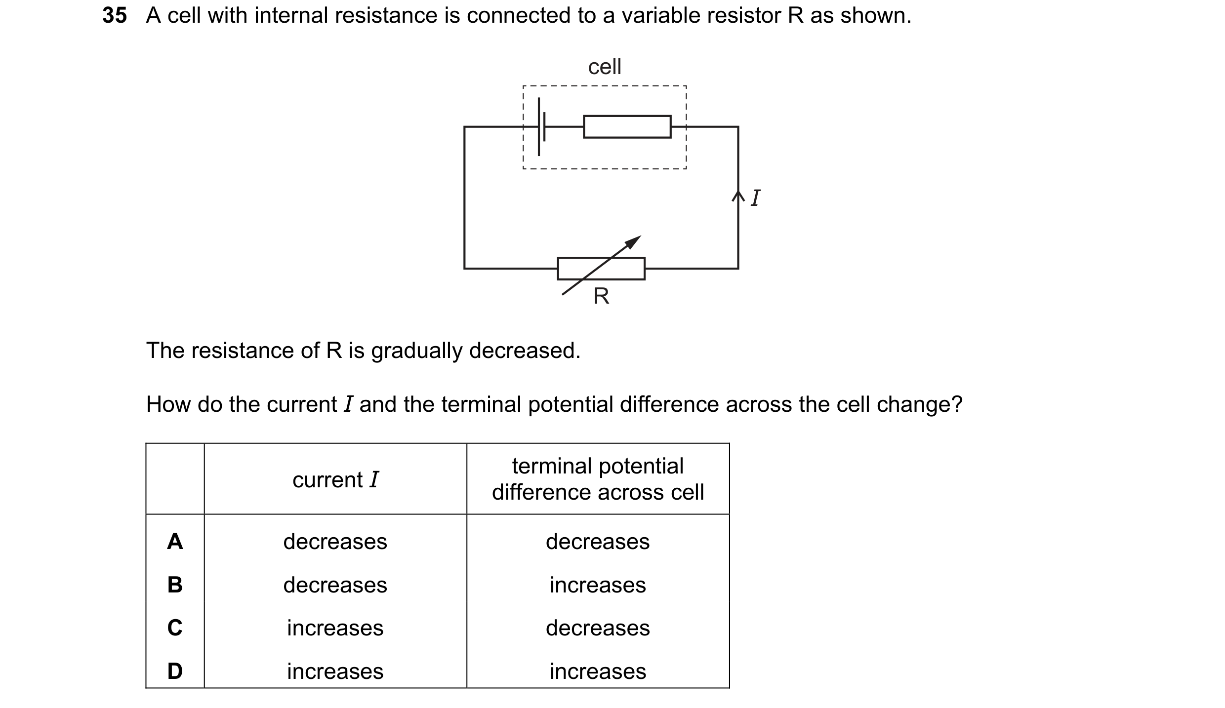
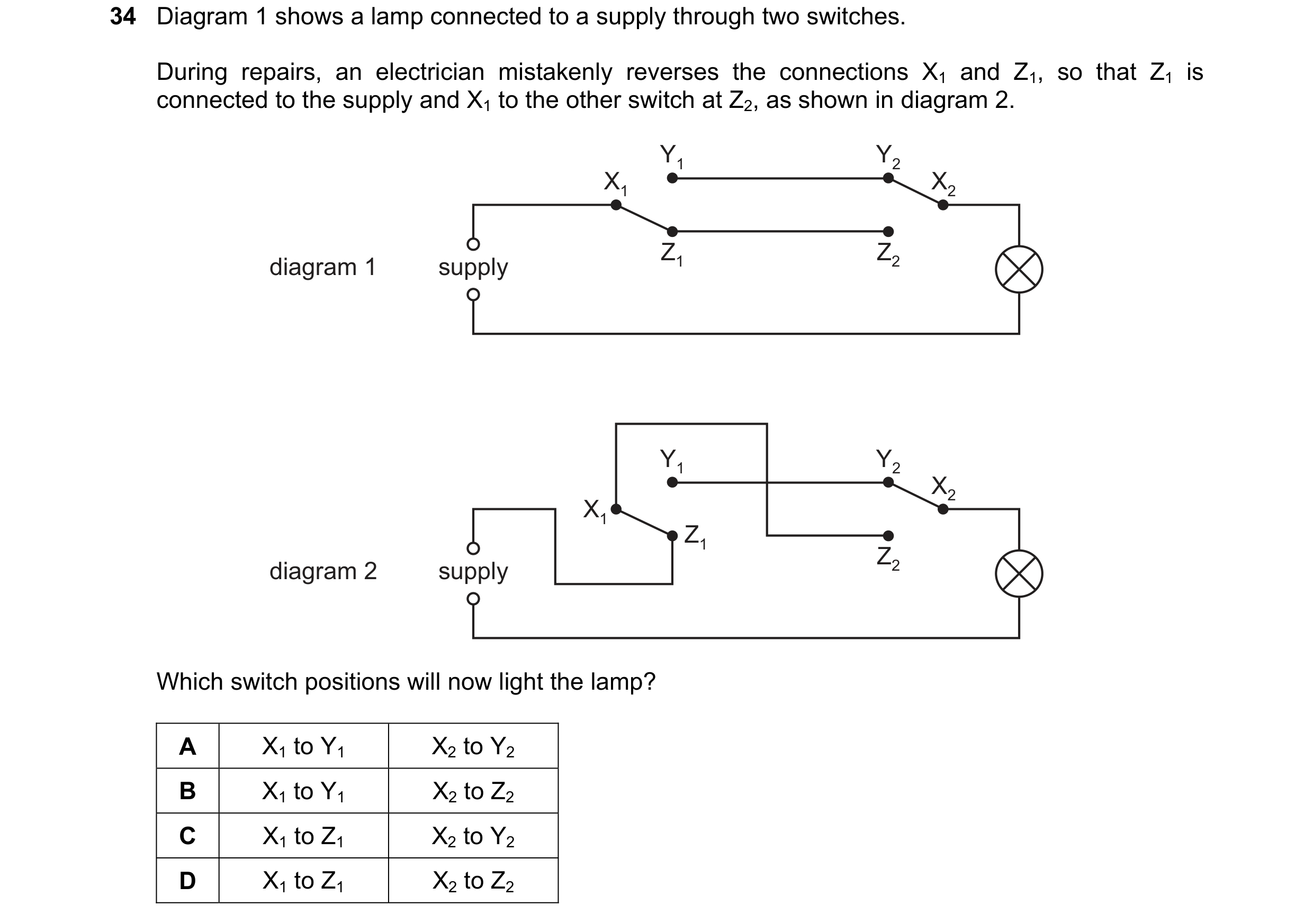 65 / 100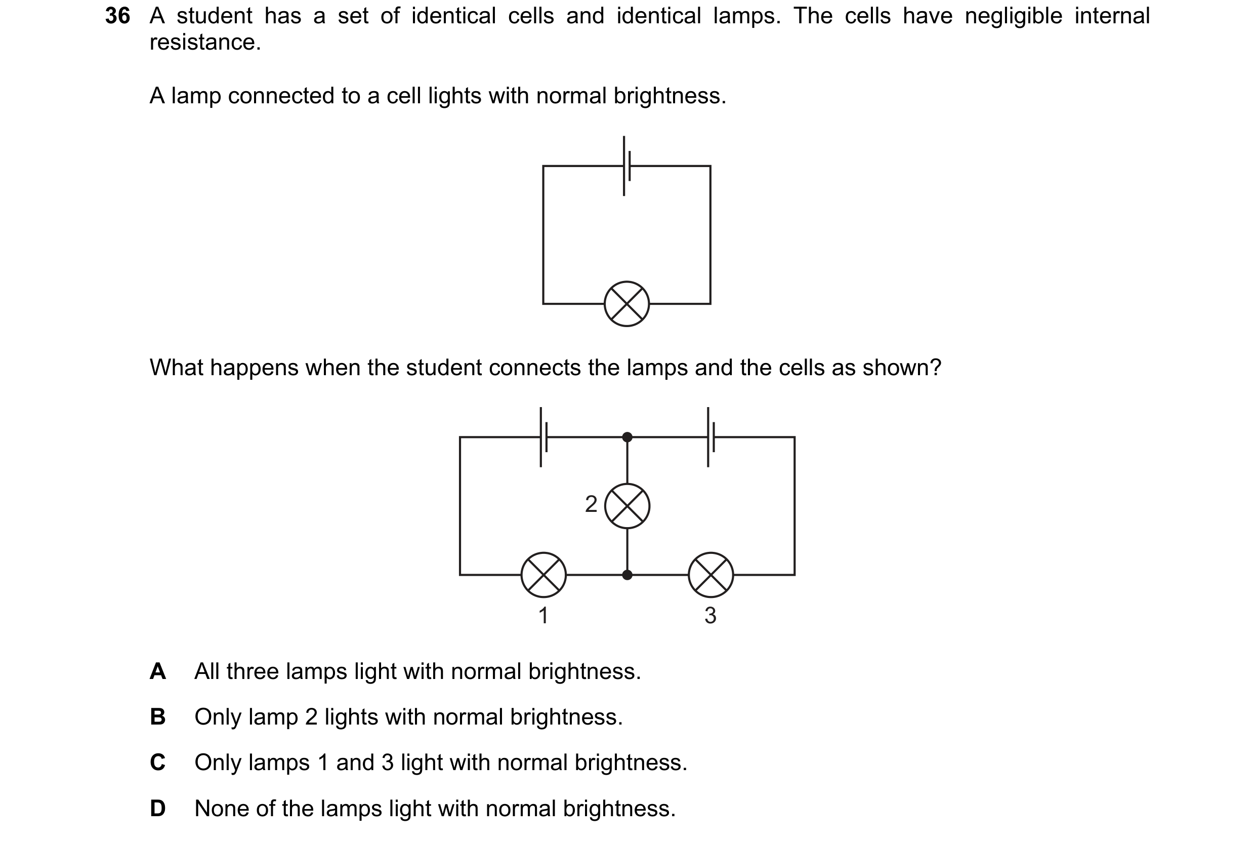
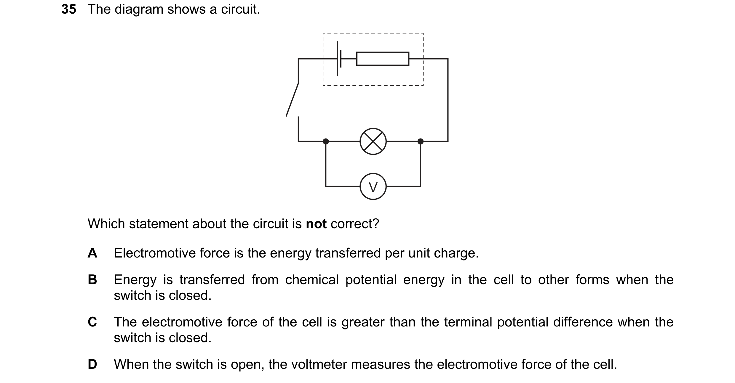 66 / 100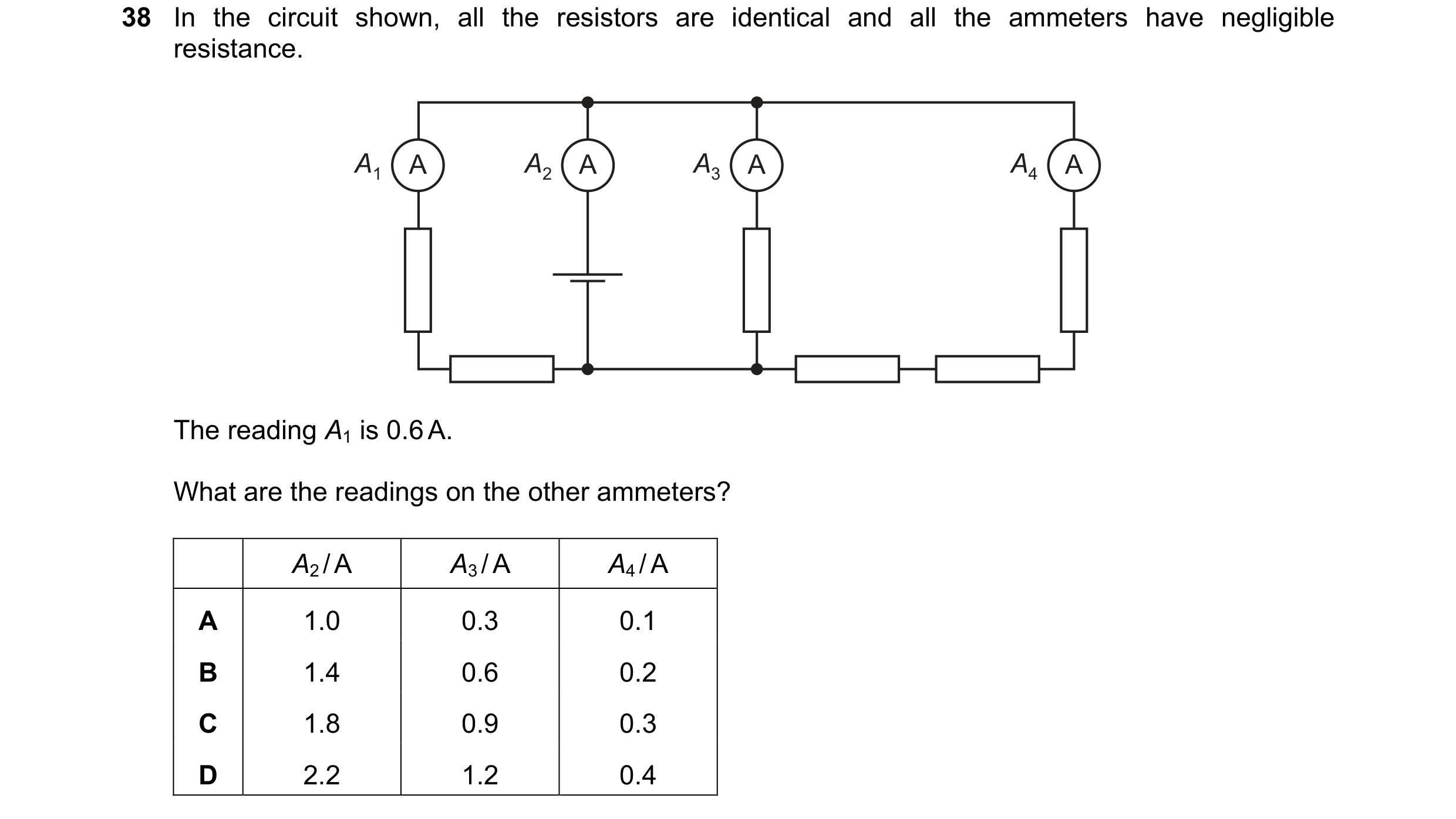
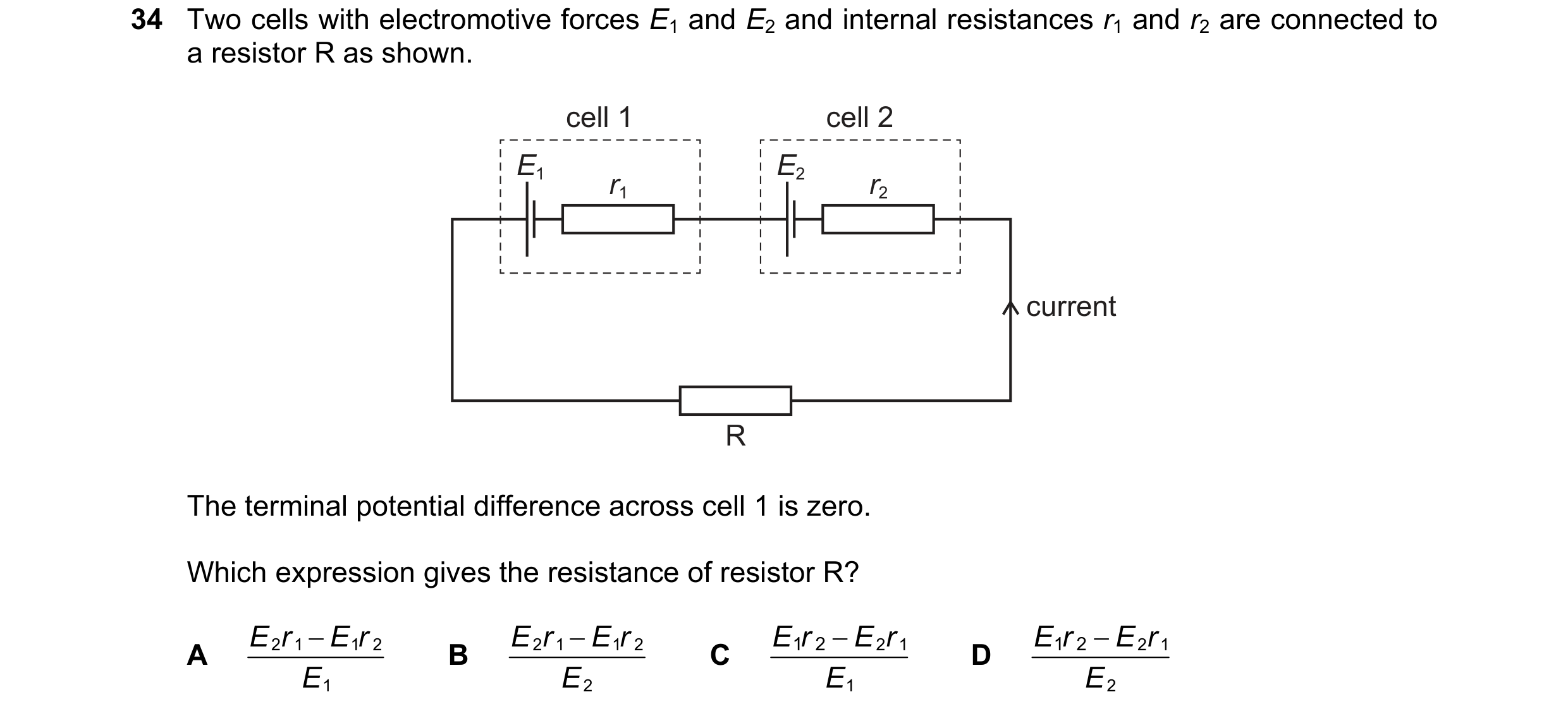 67 / 100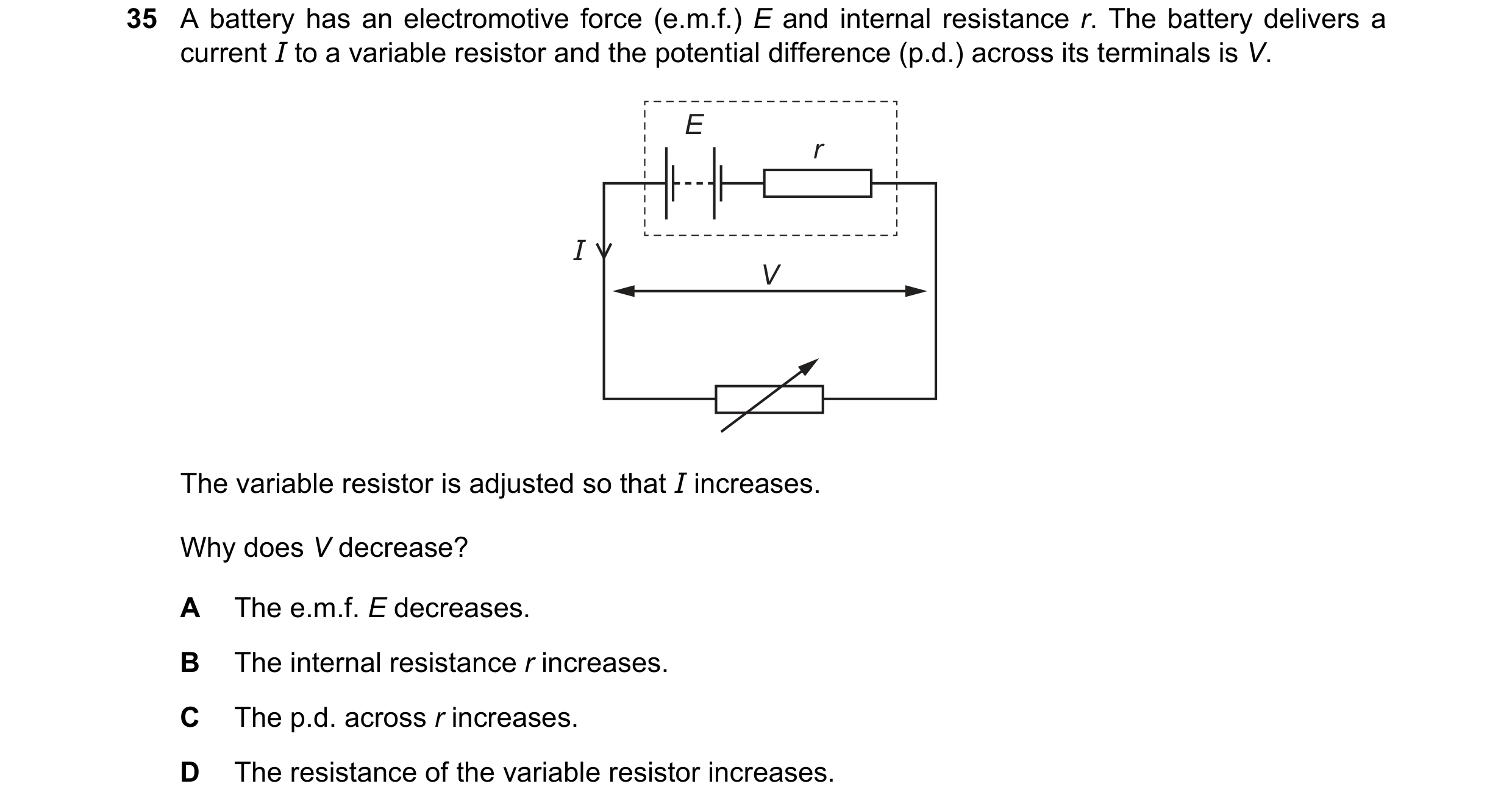
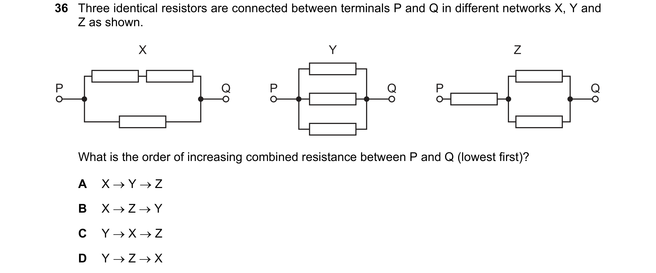
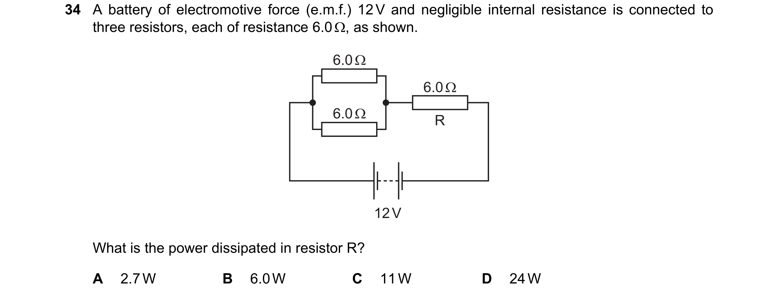 68 / 100
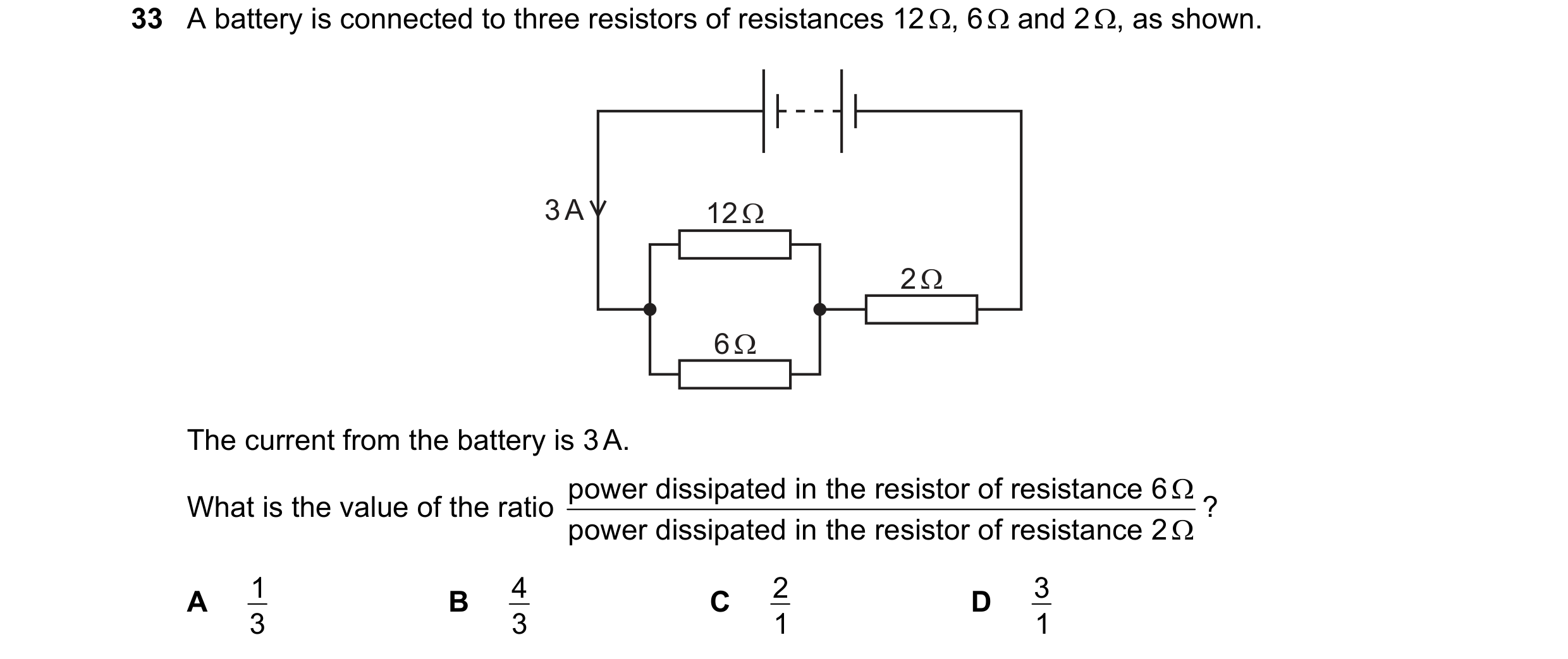
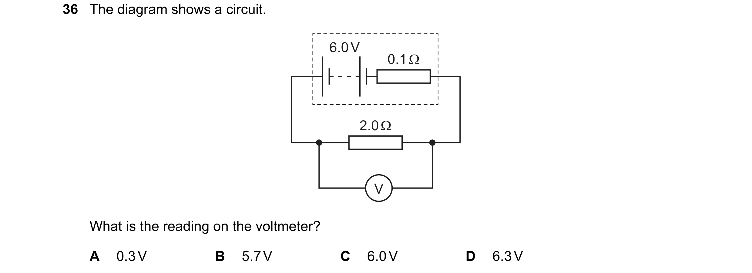 69 / 100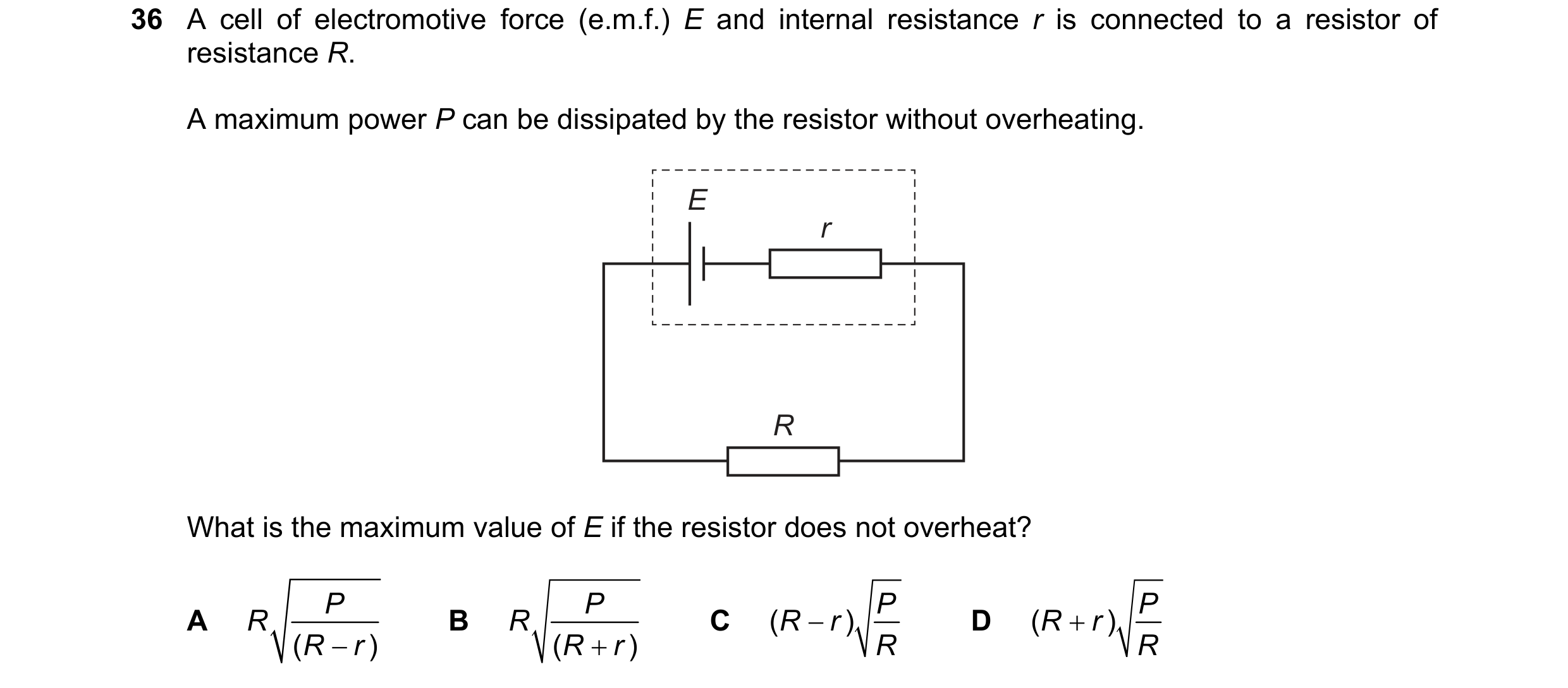

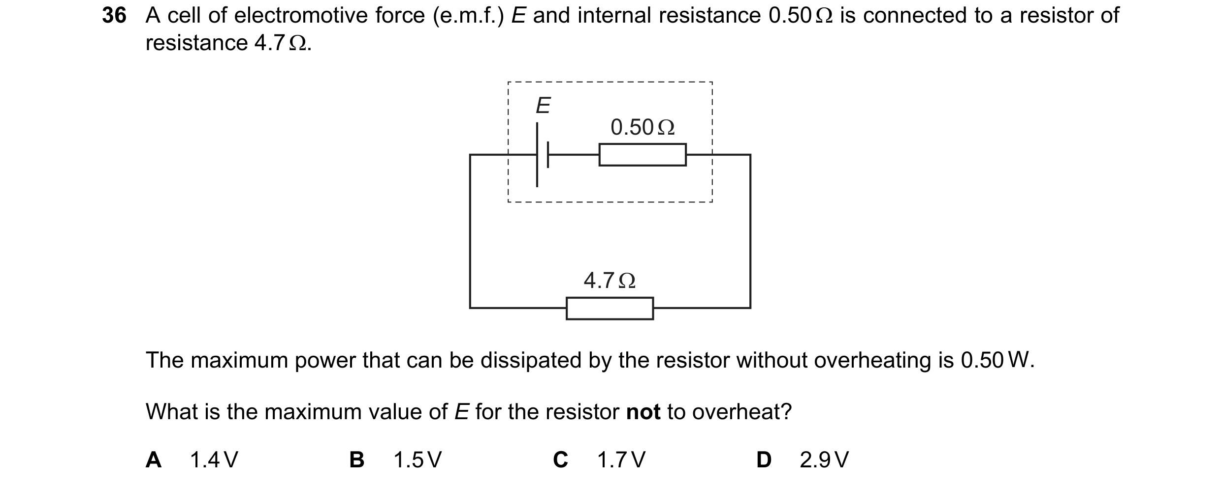 70 / 100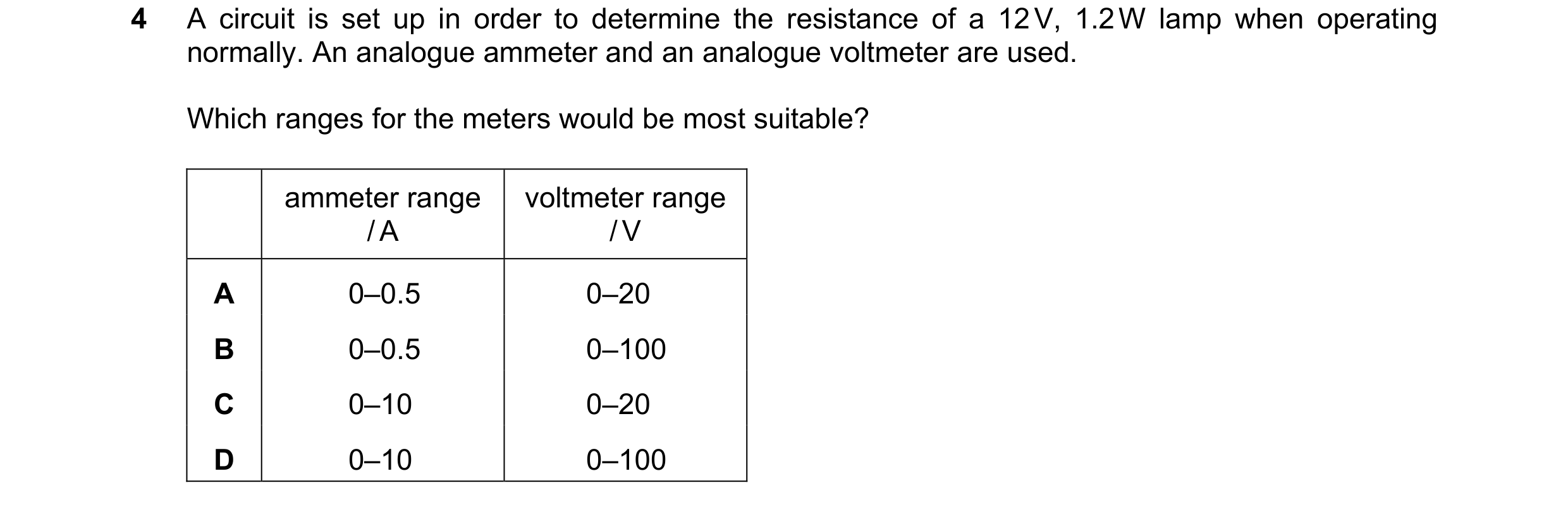
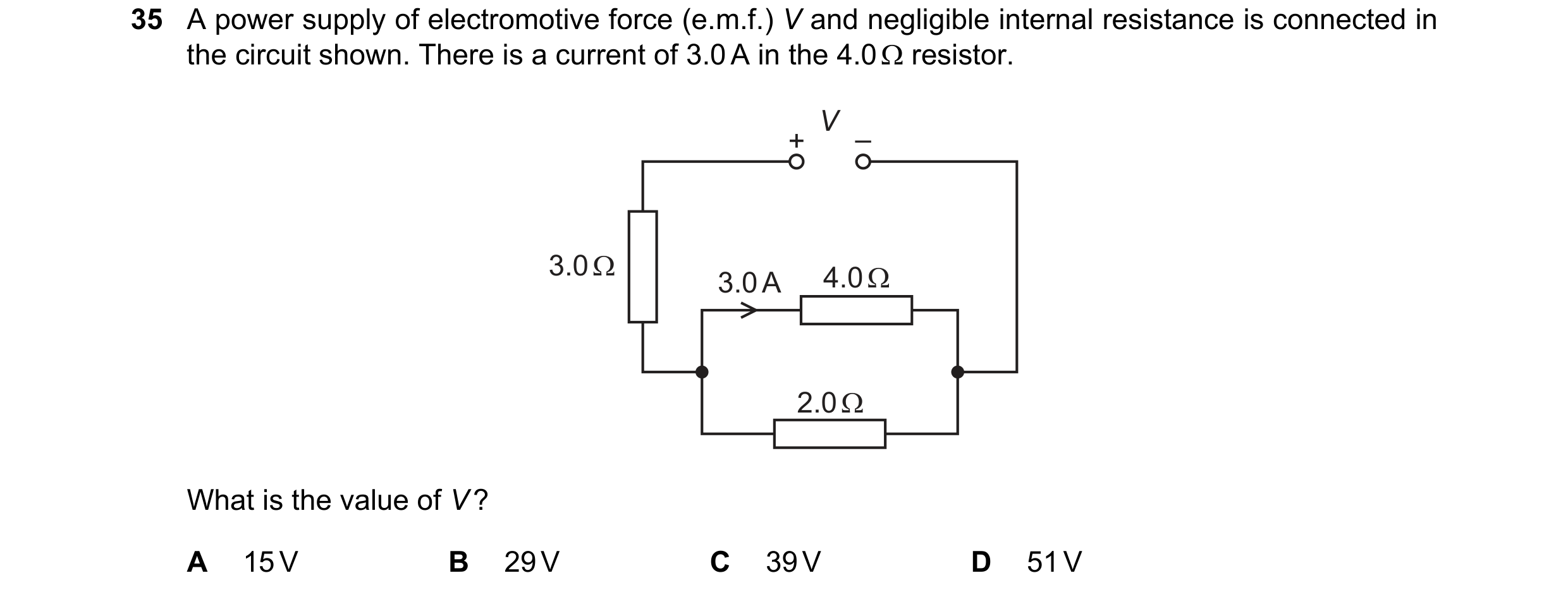 71 / 100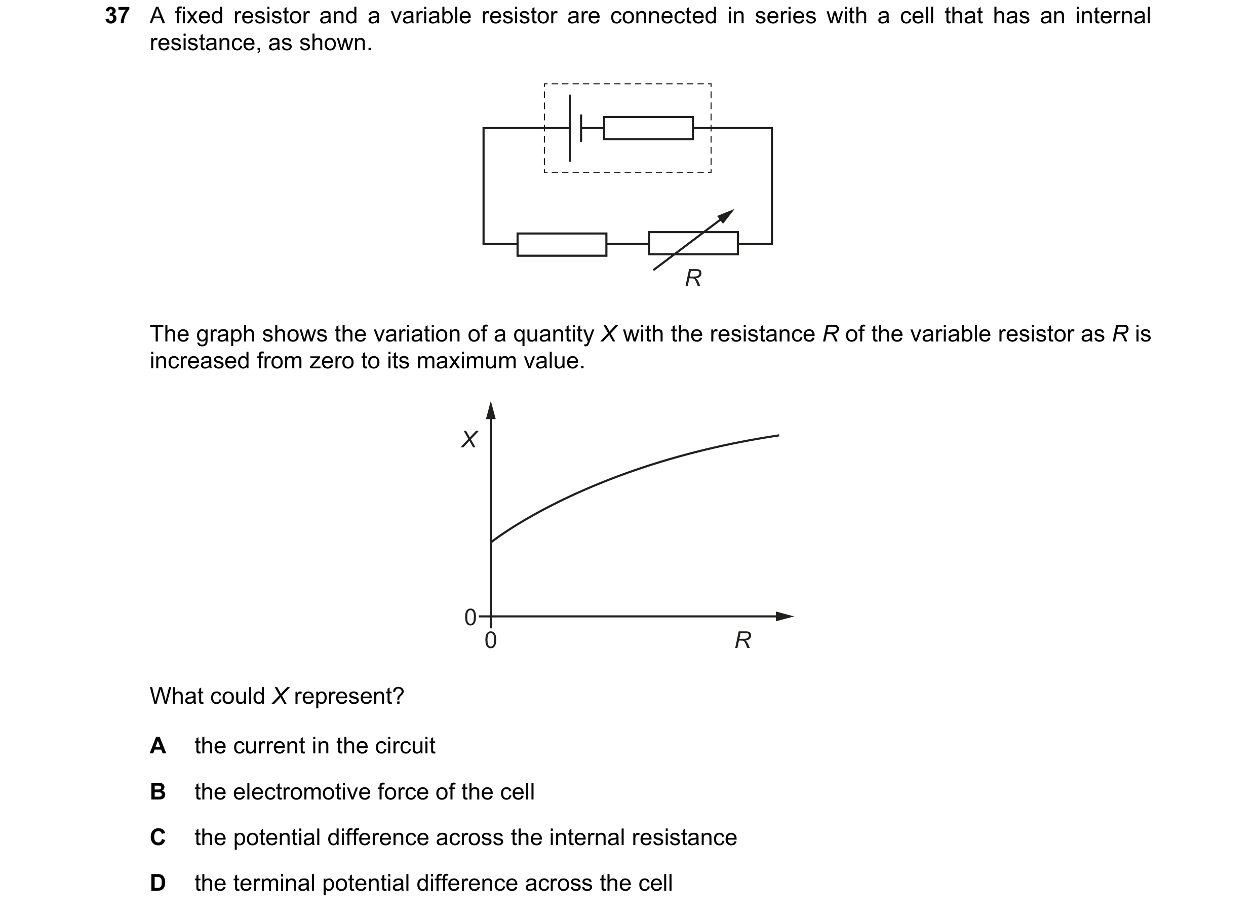
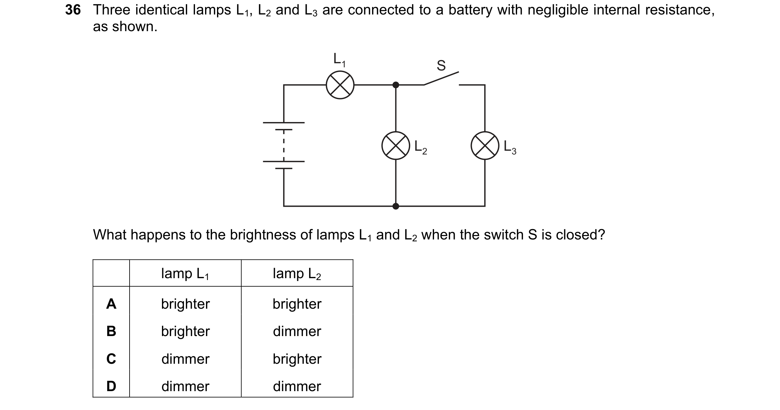 72 / 100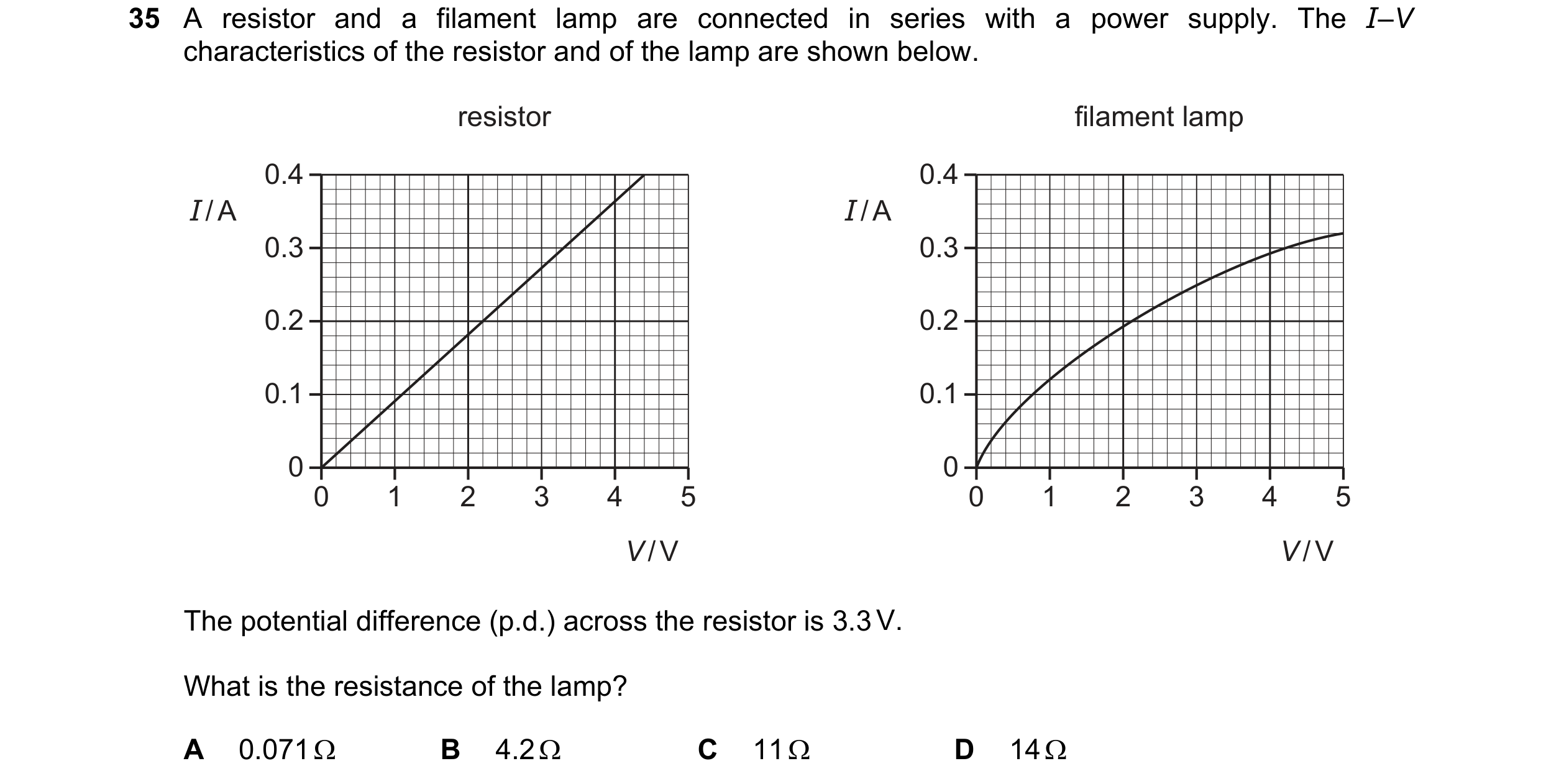
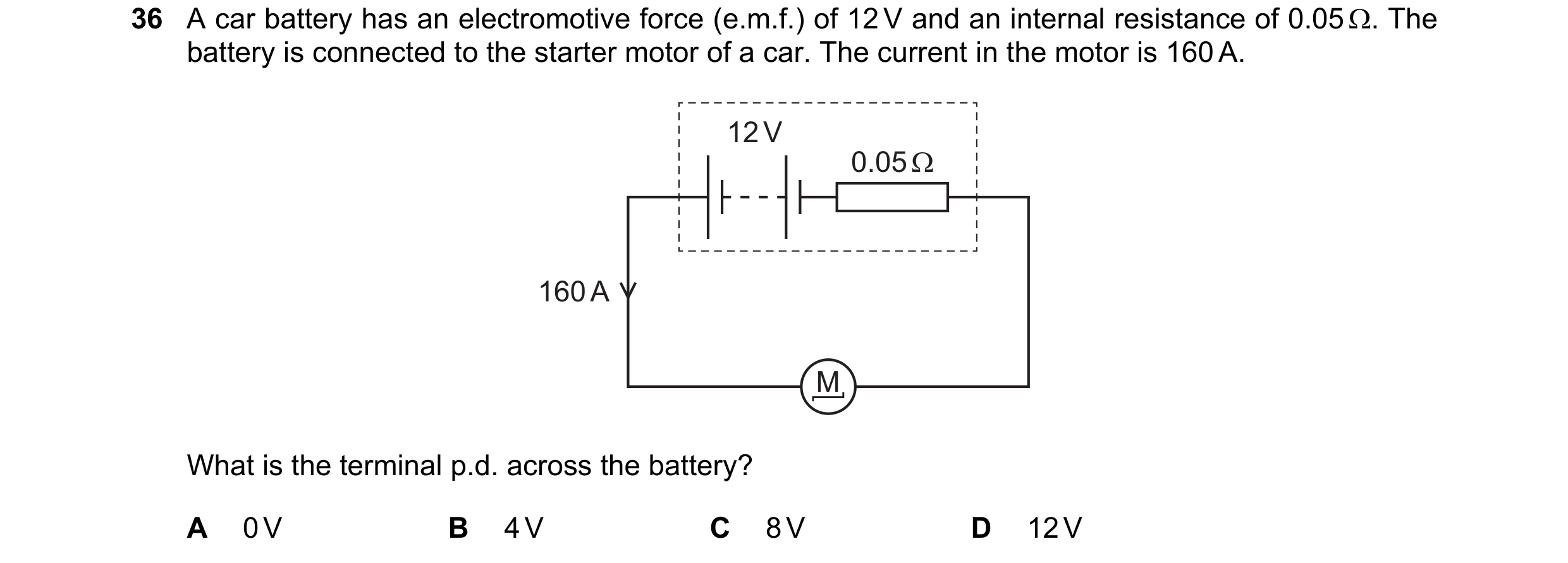
 73 / 100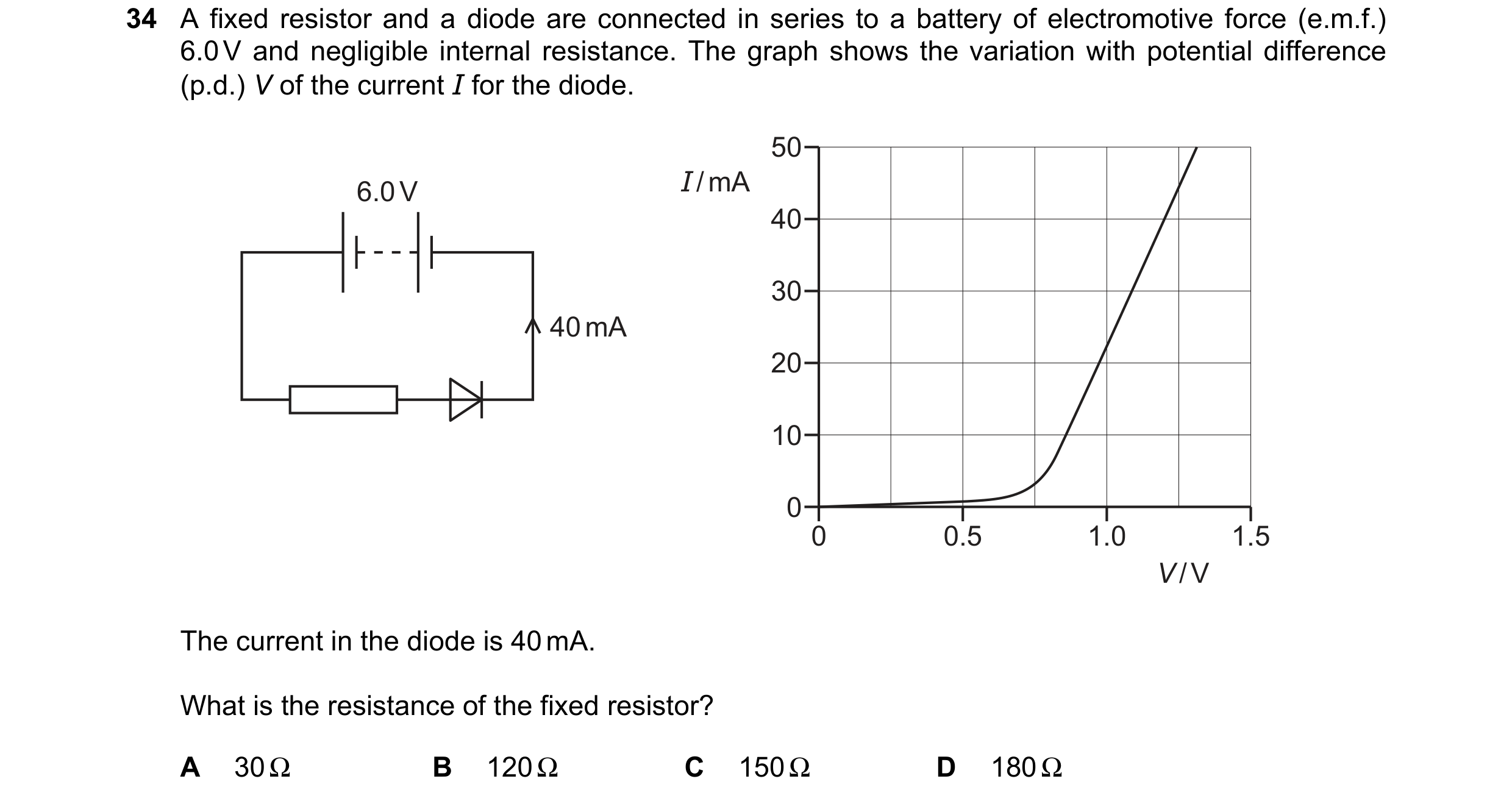
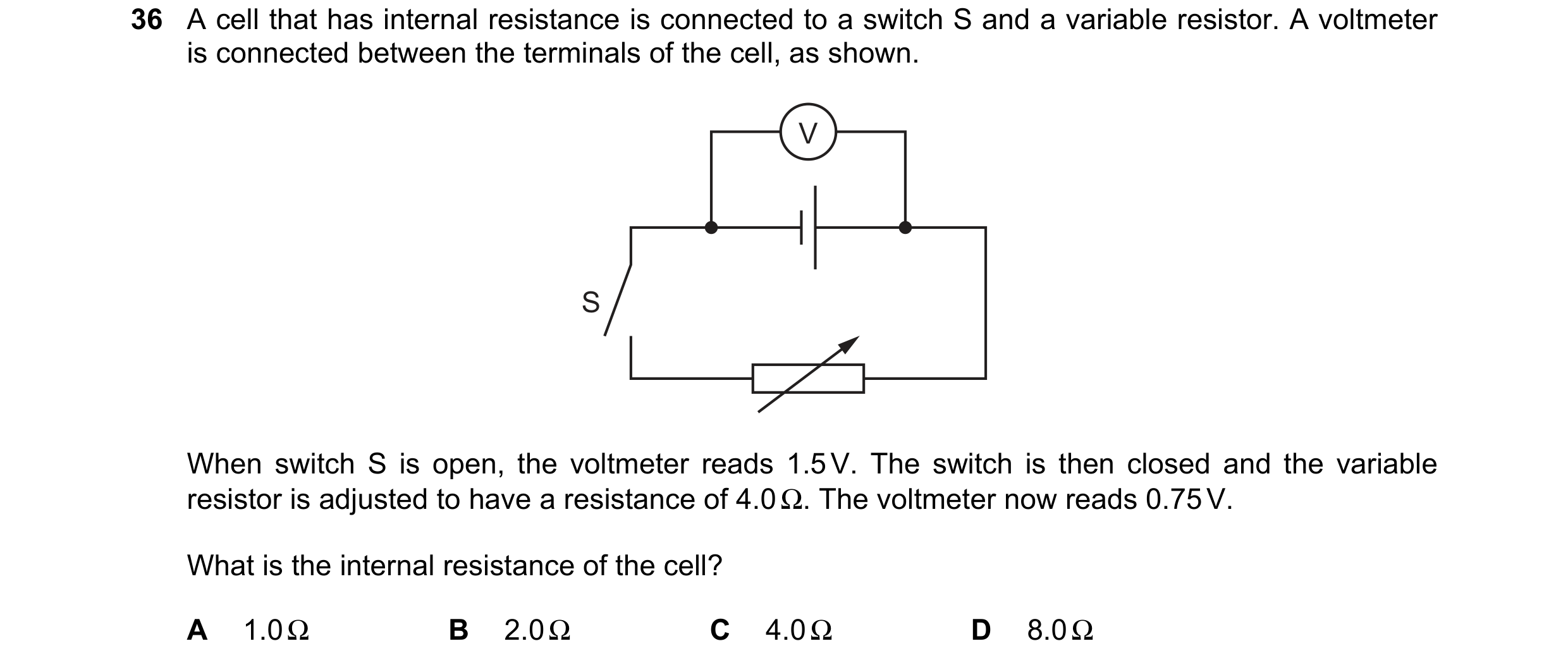
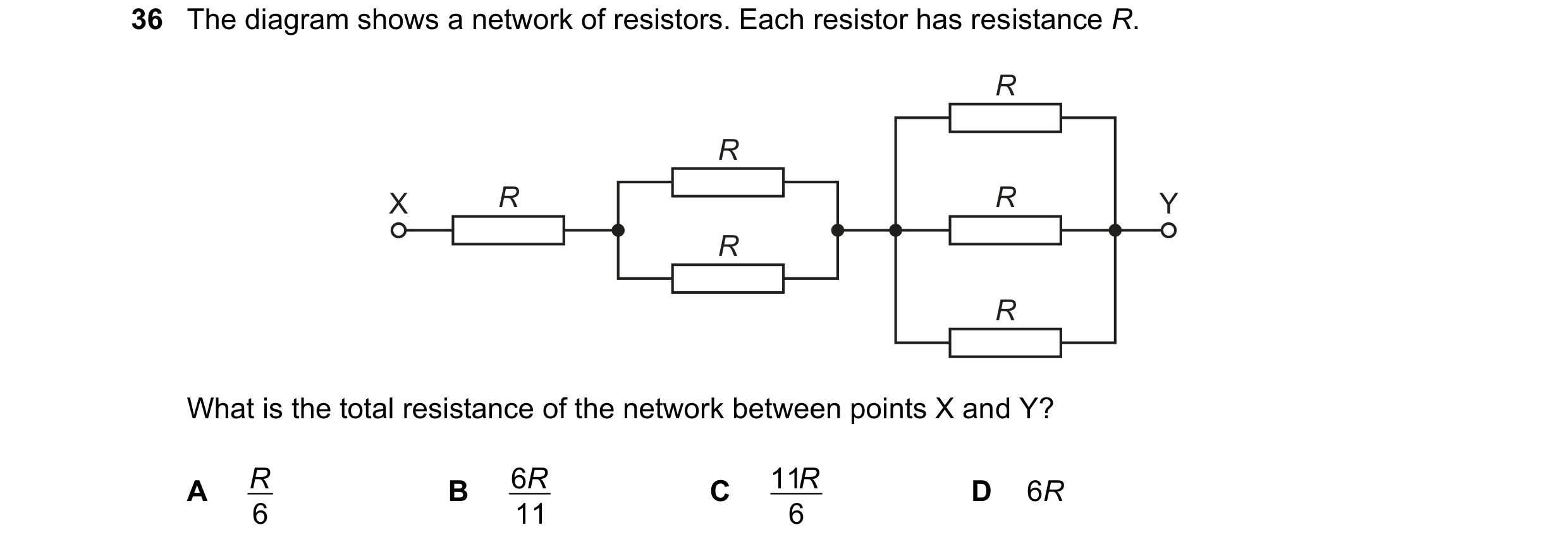 74 / 100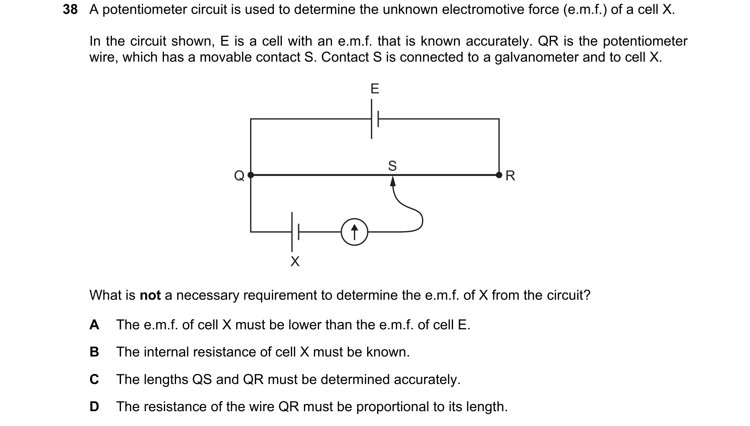
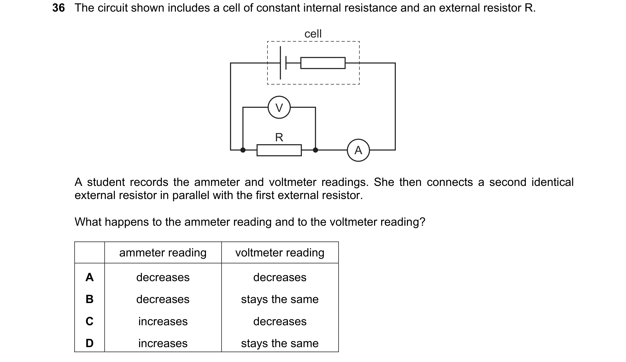
 75 / 100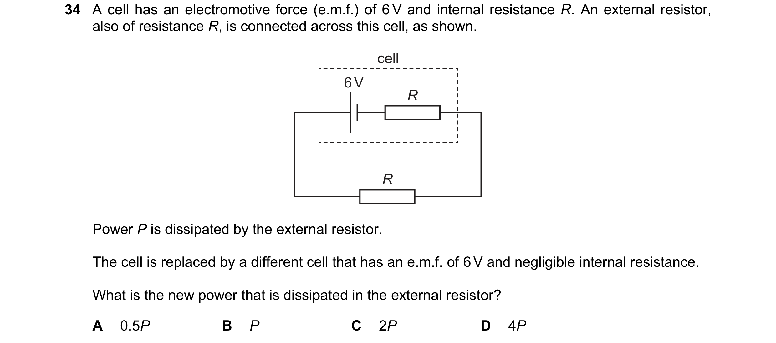
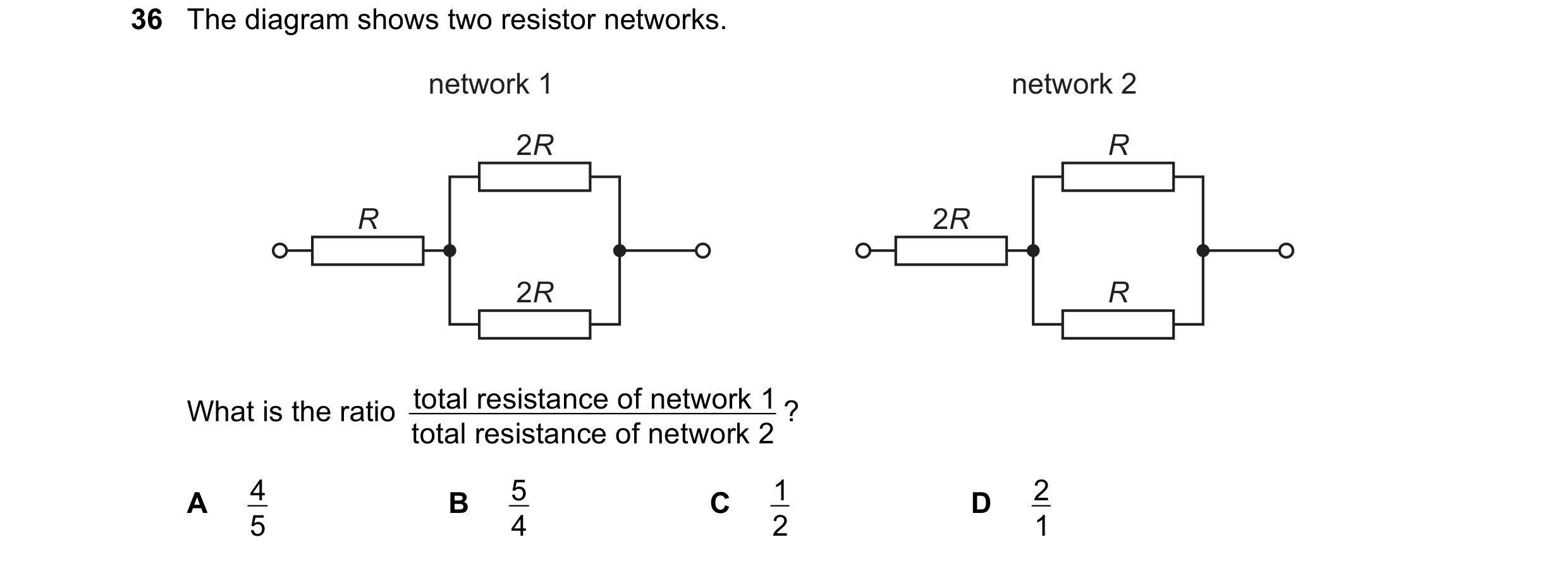
 76 / 100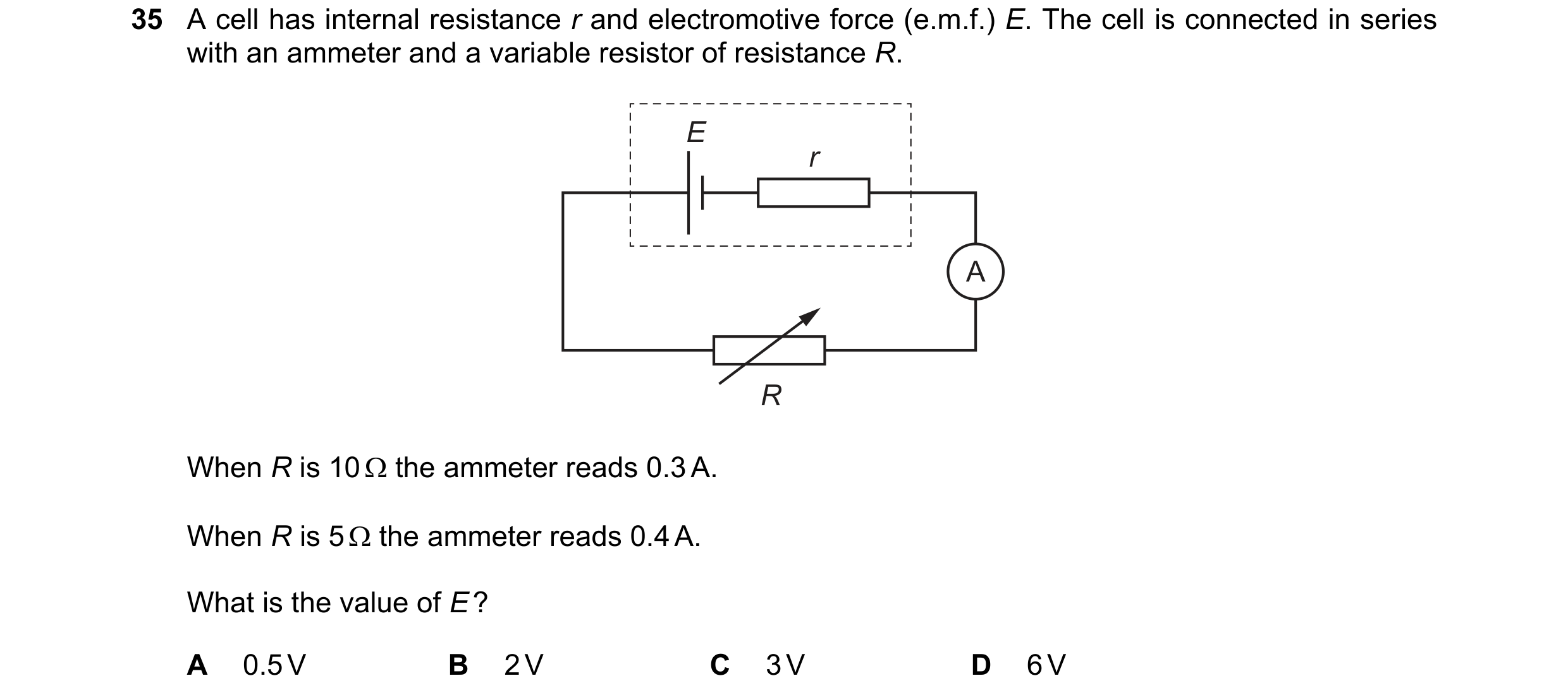
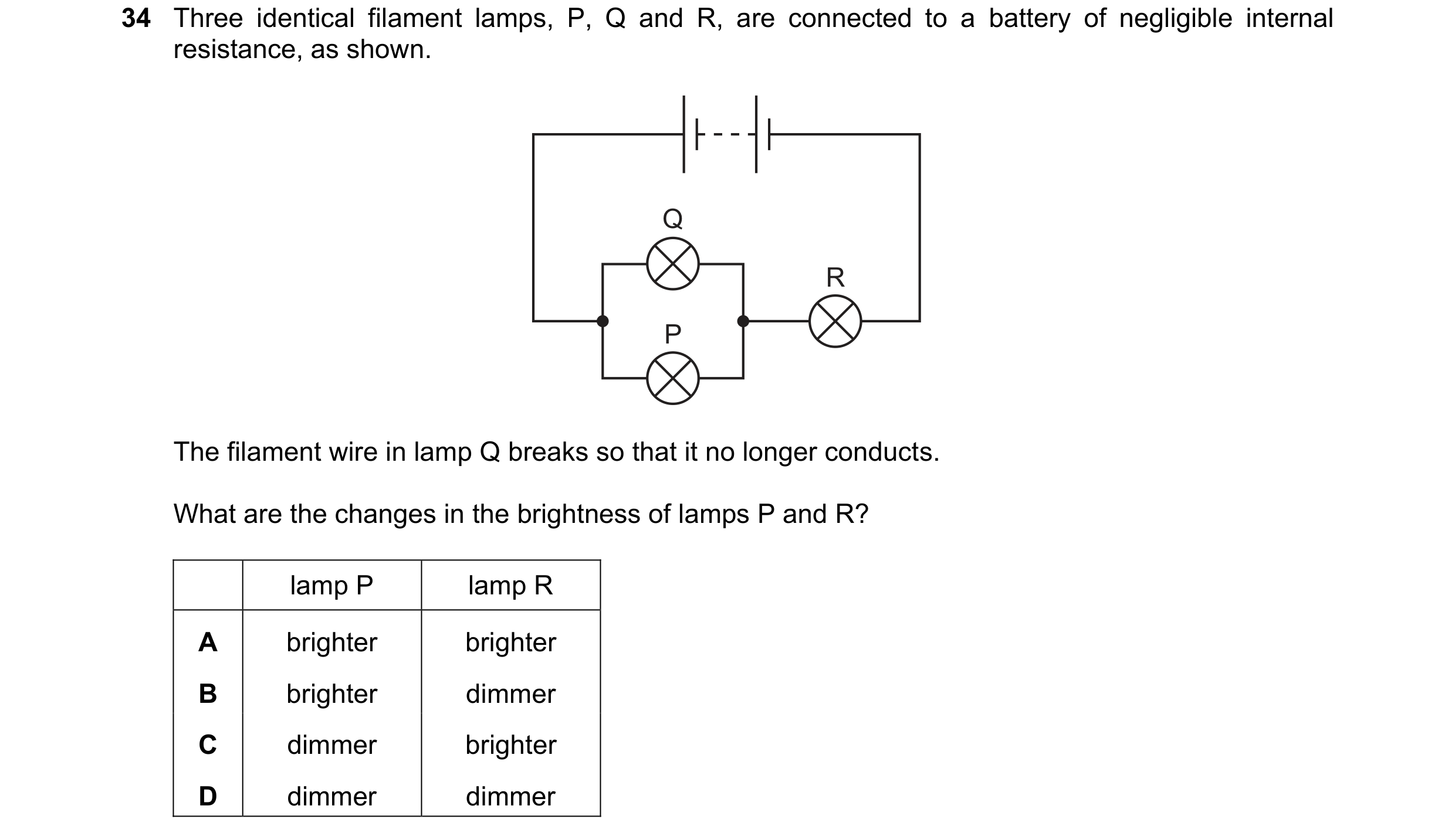 77 / 100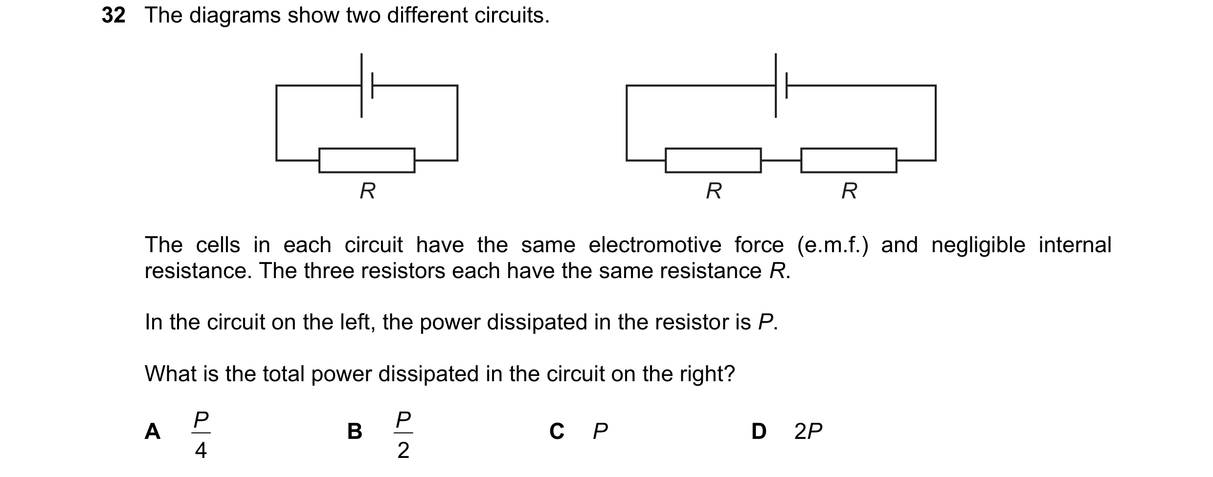
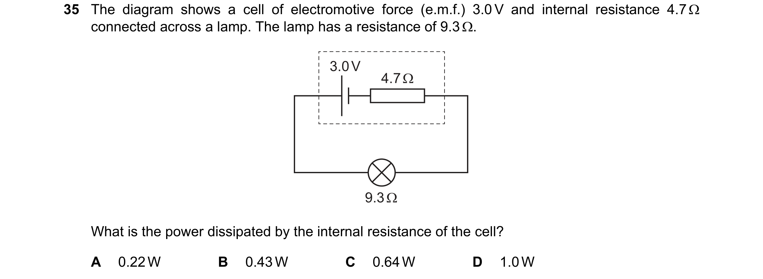
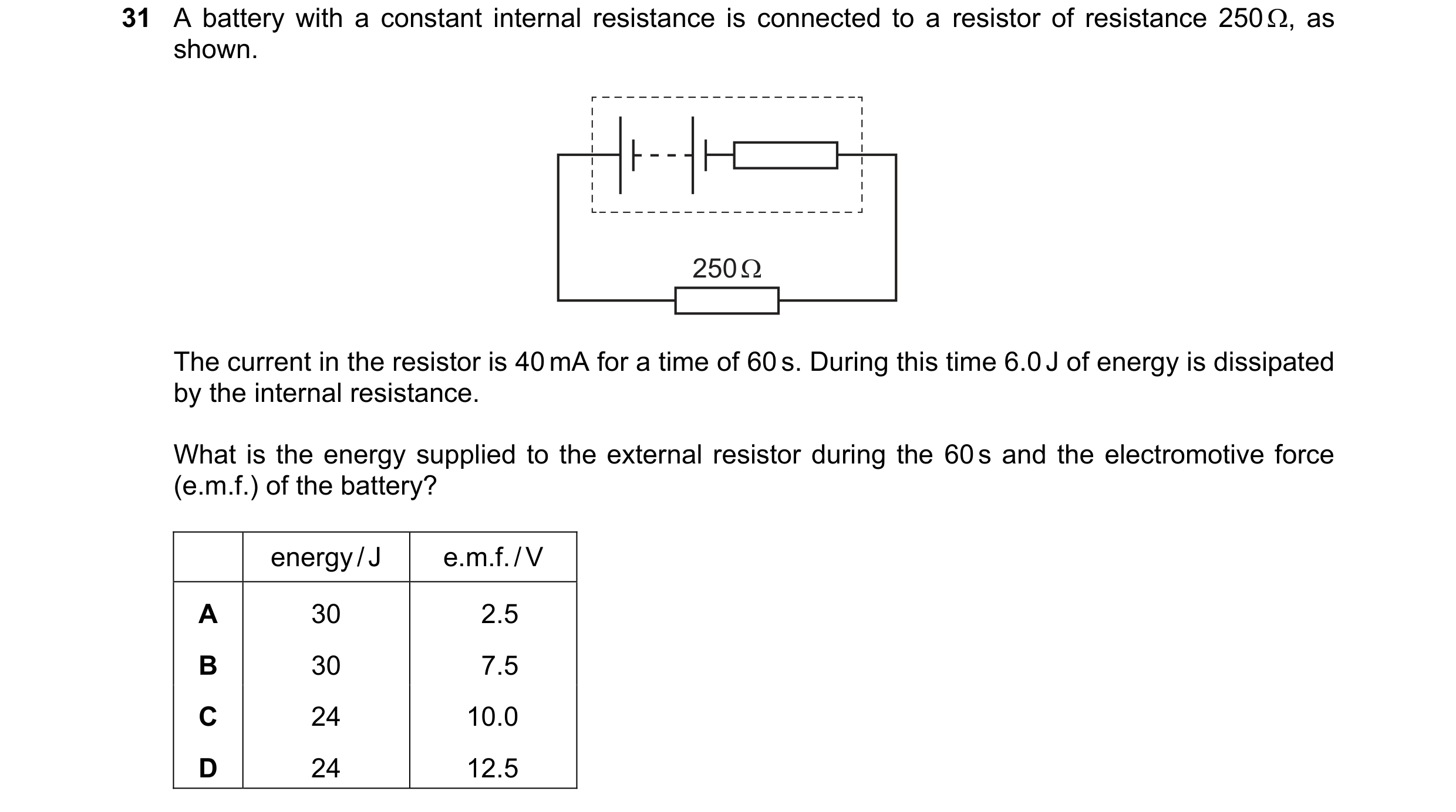 78 / 100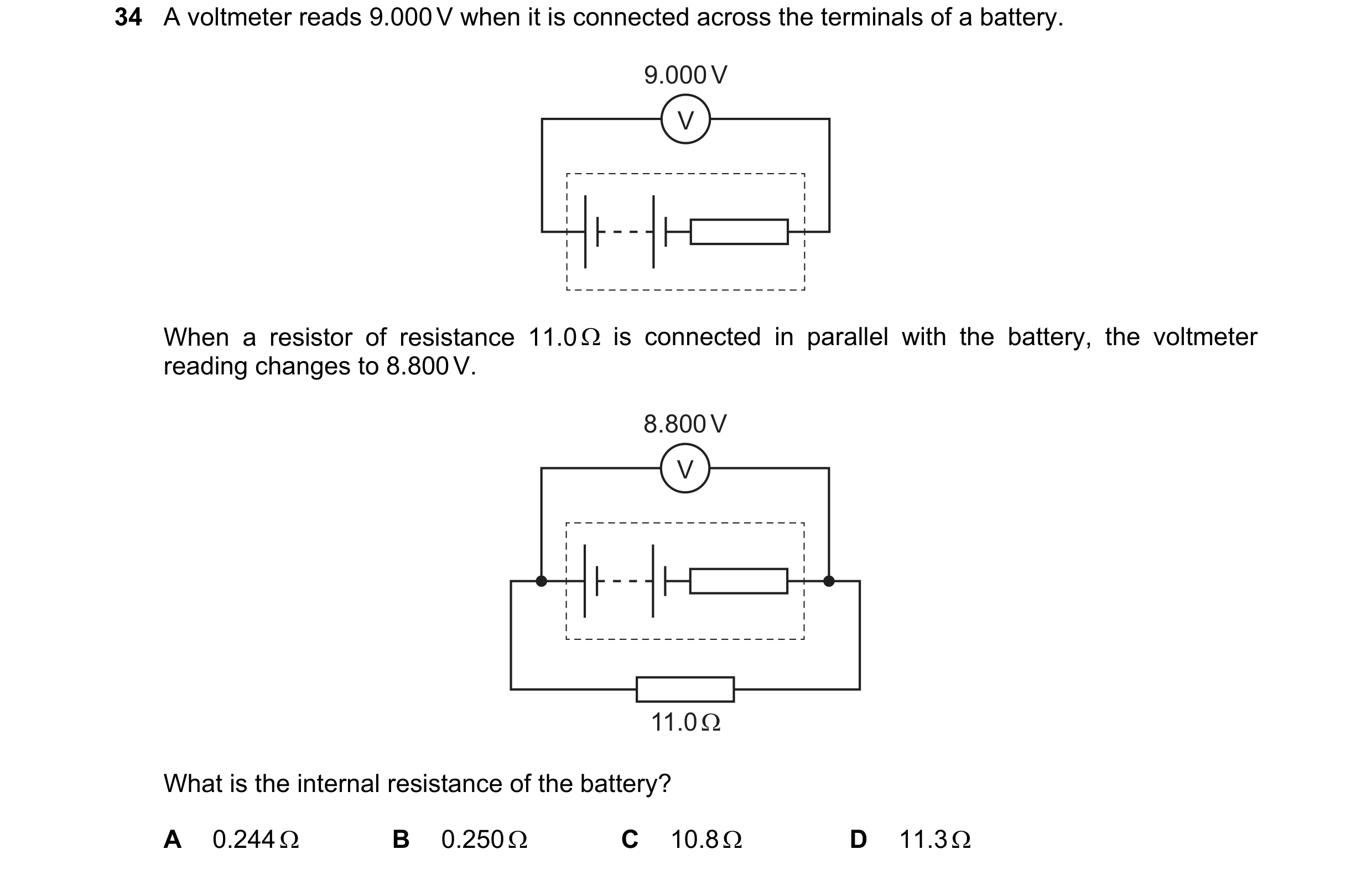
 79 / 100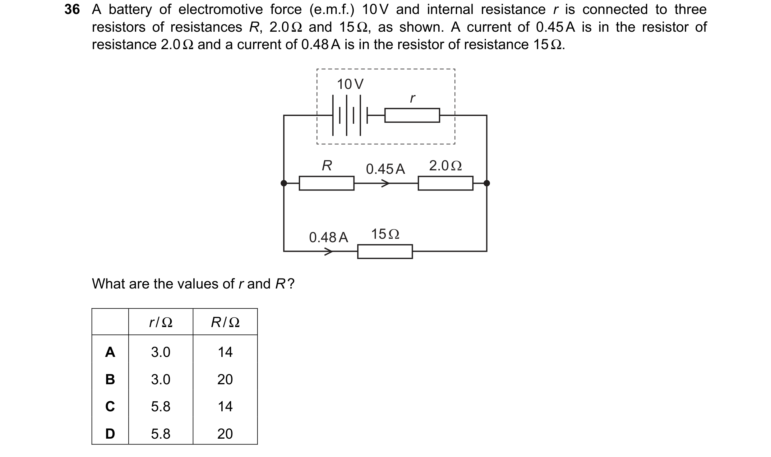

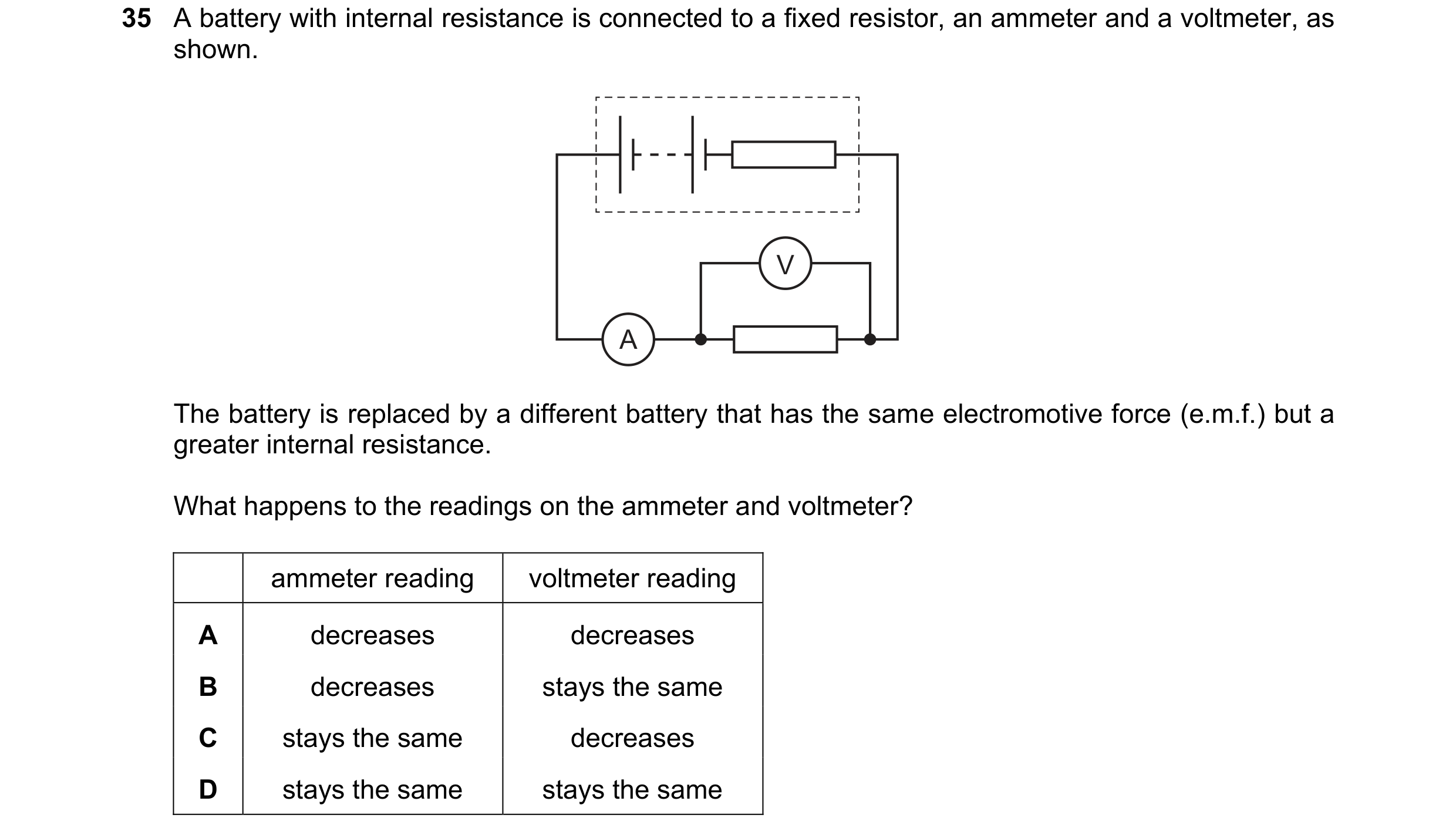 80 / 100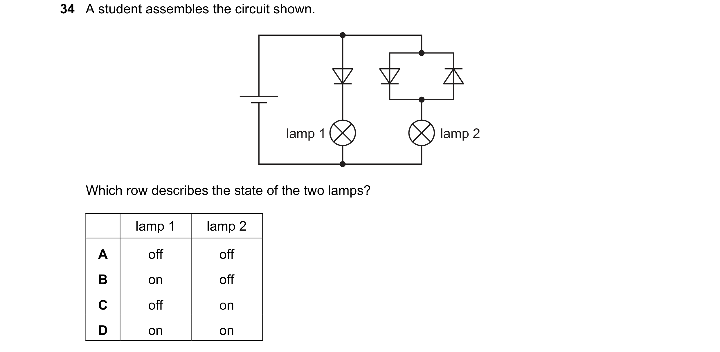
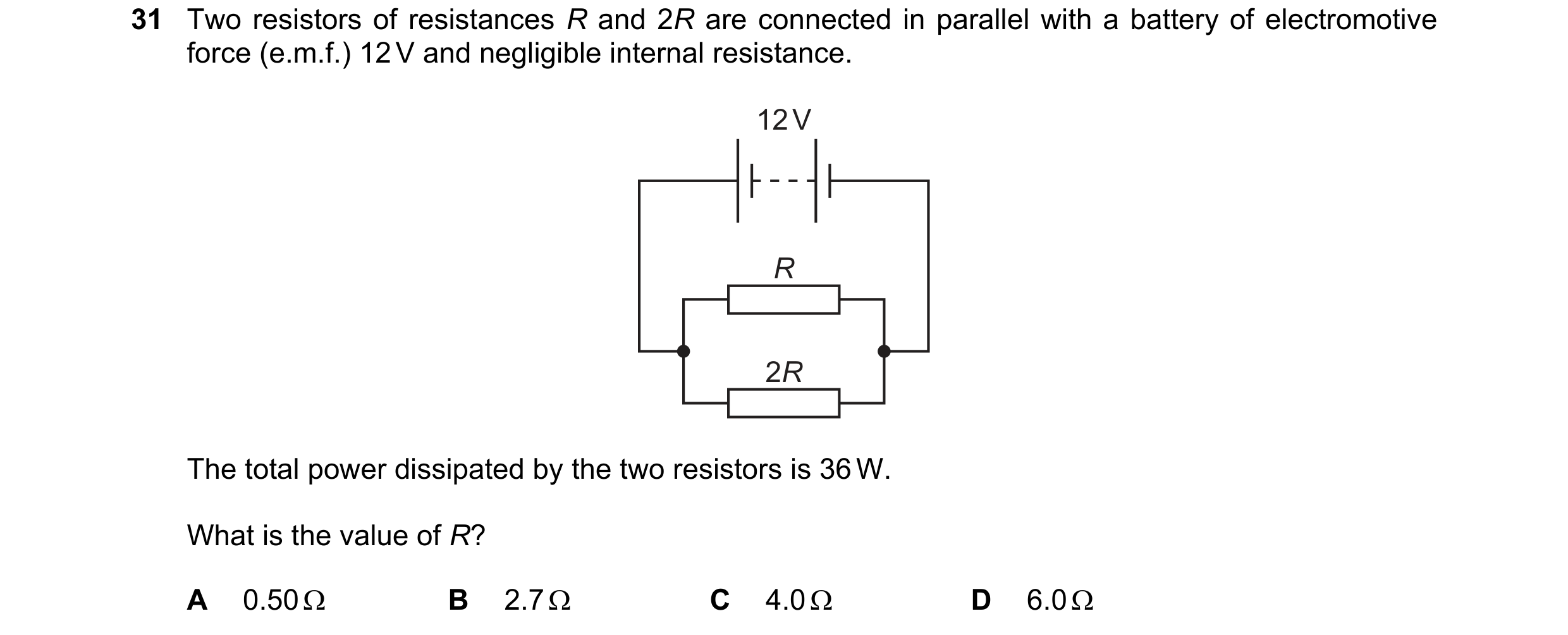
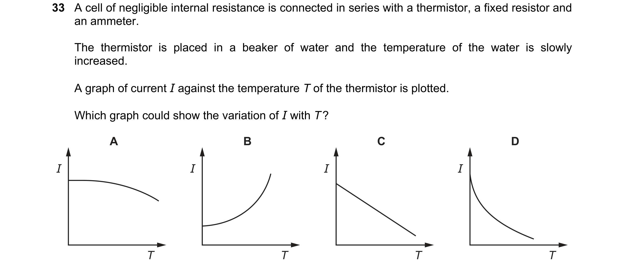 81 / 100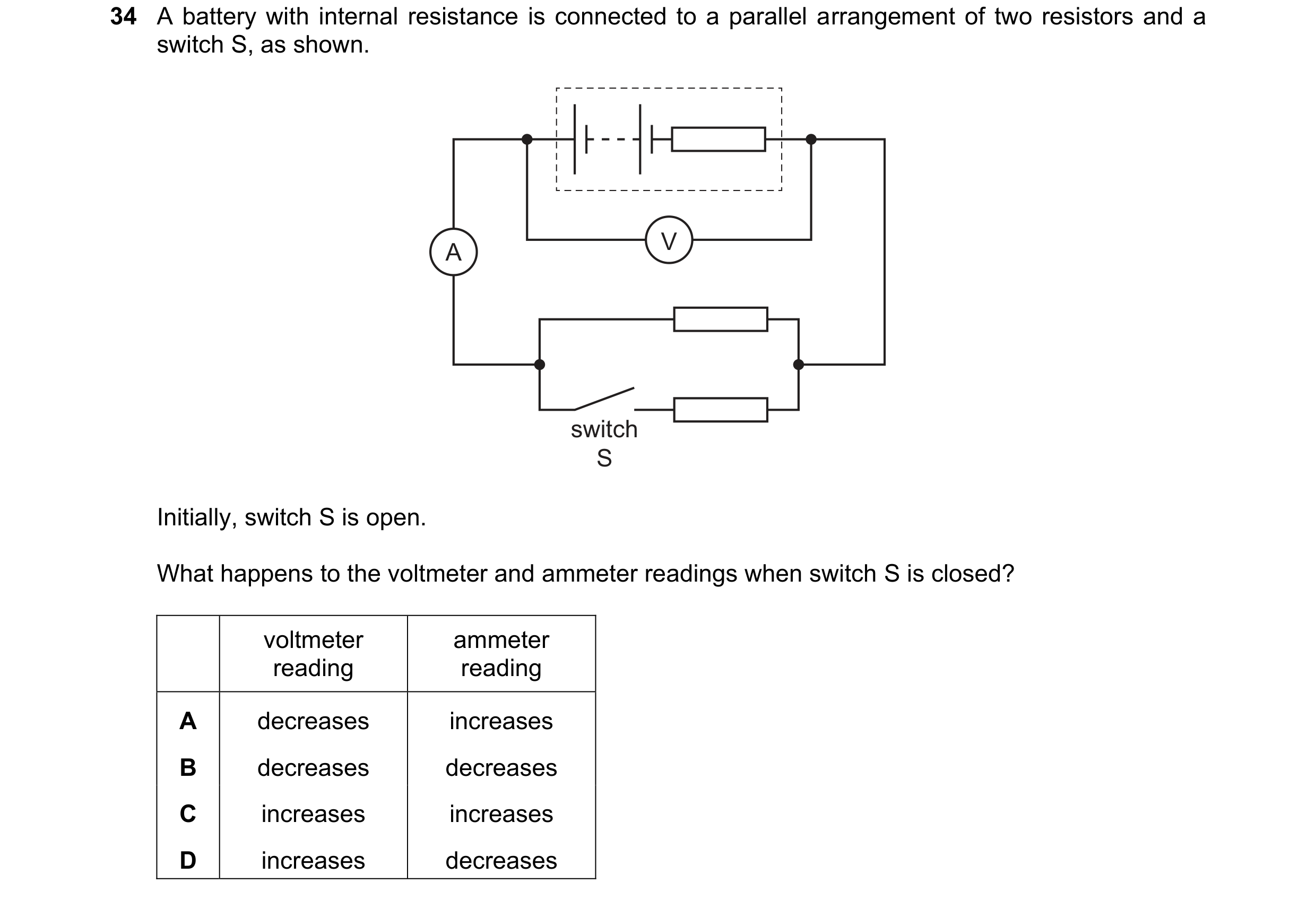

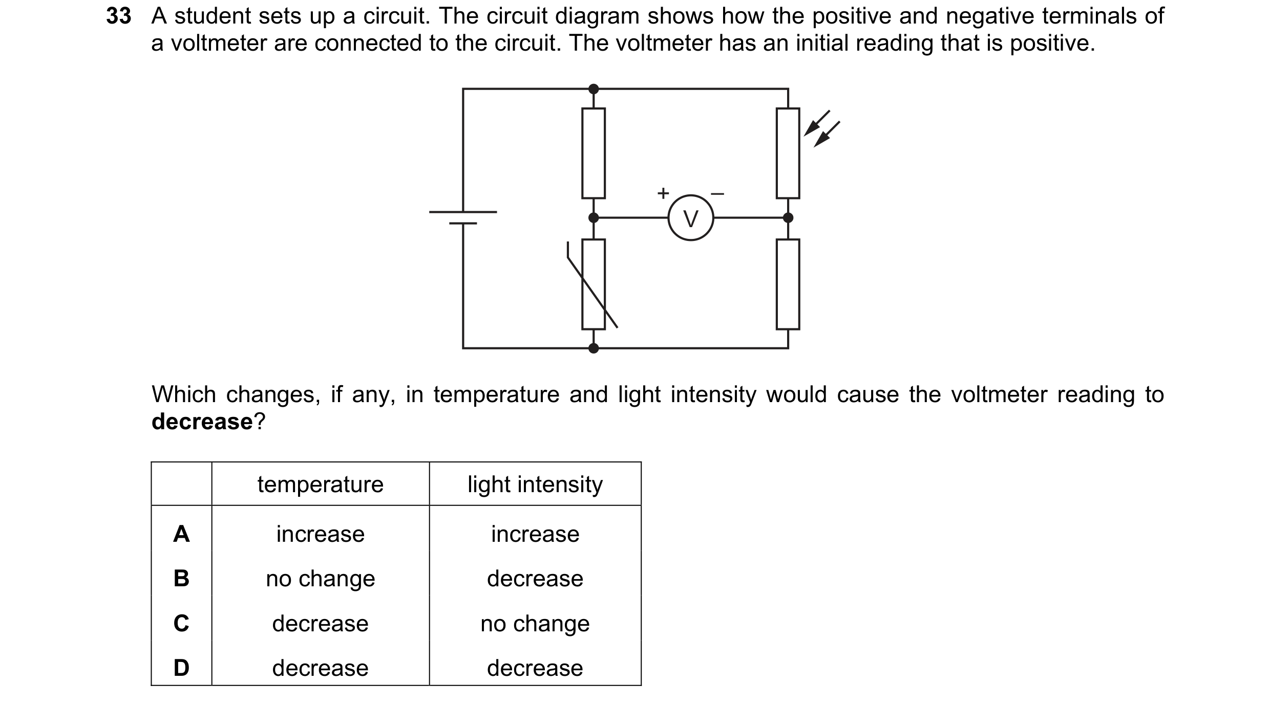 82 / 100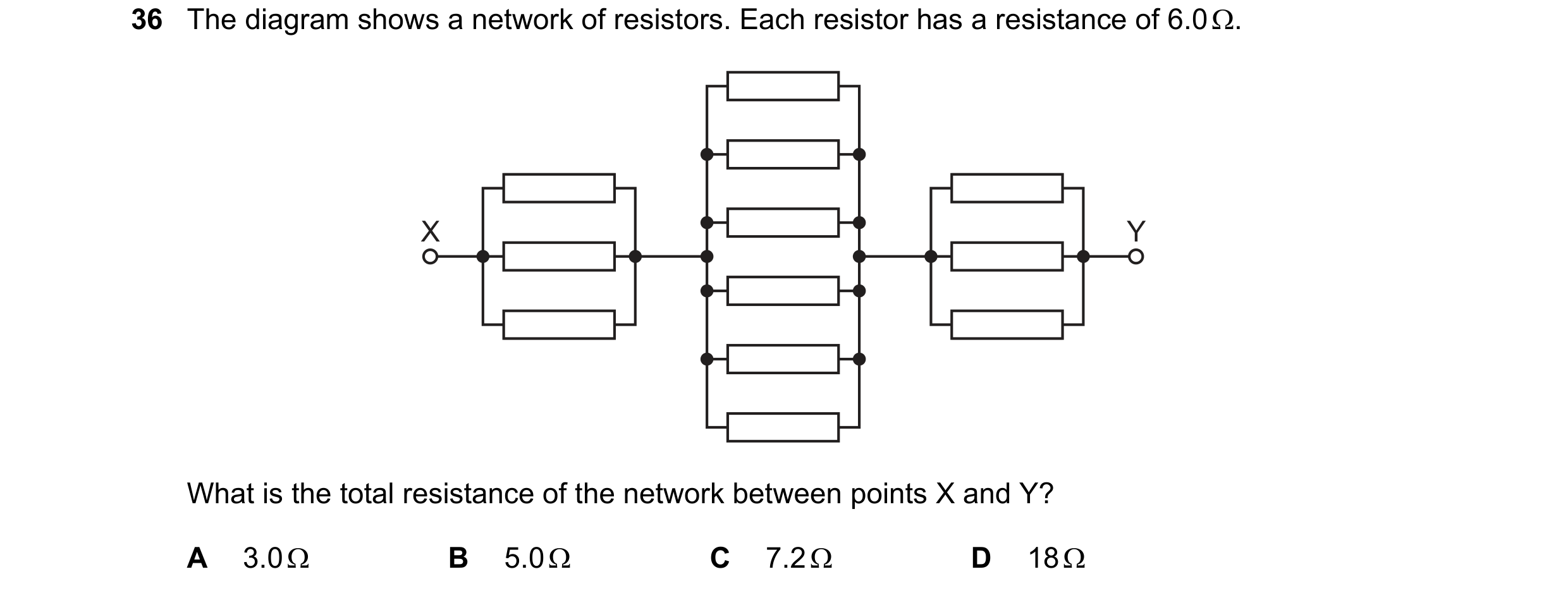
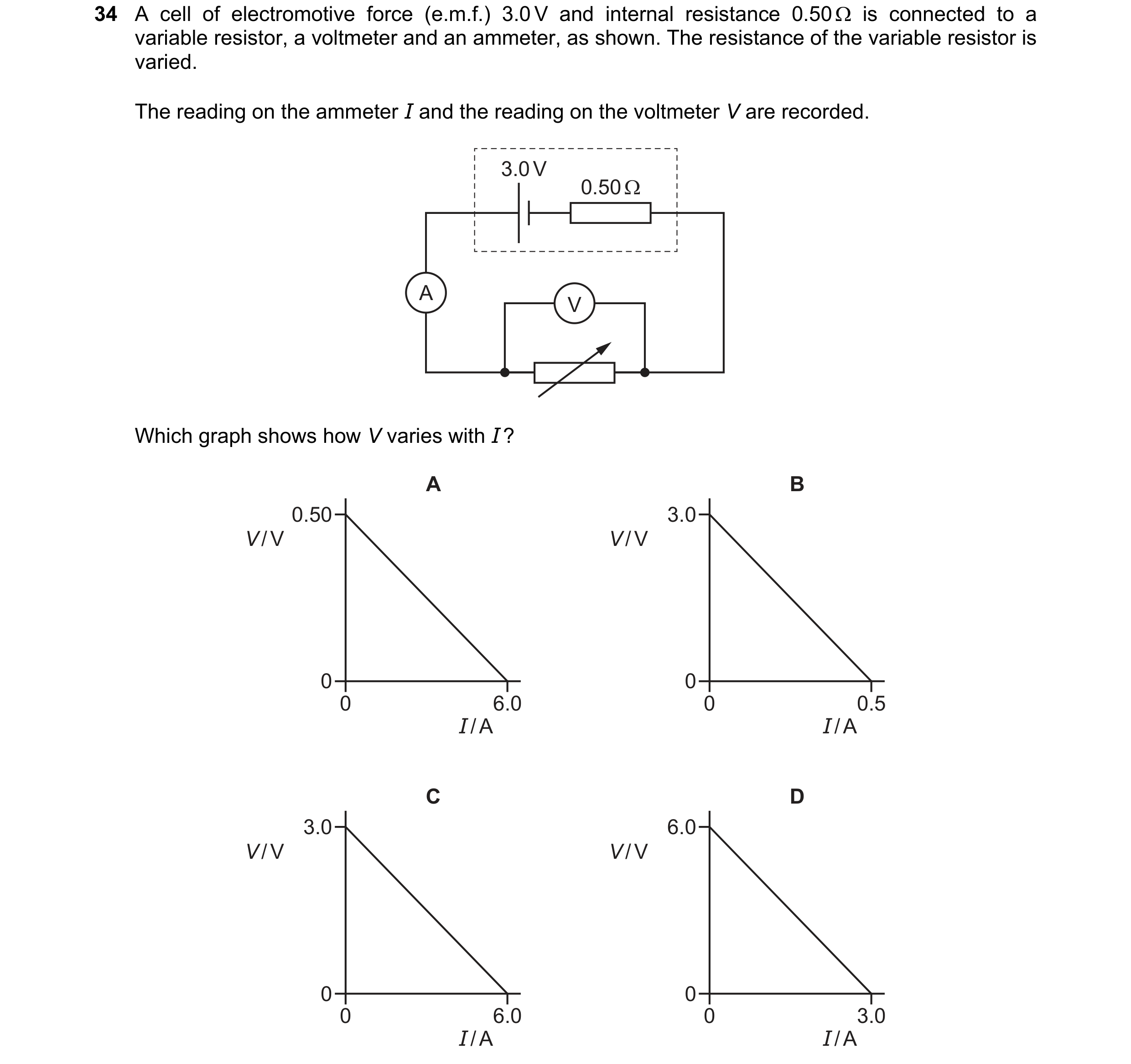 83 / 100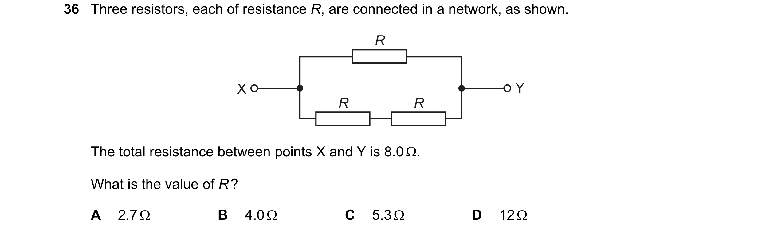
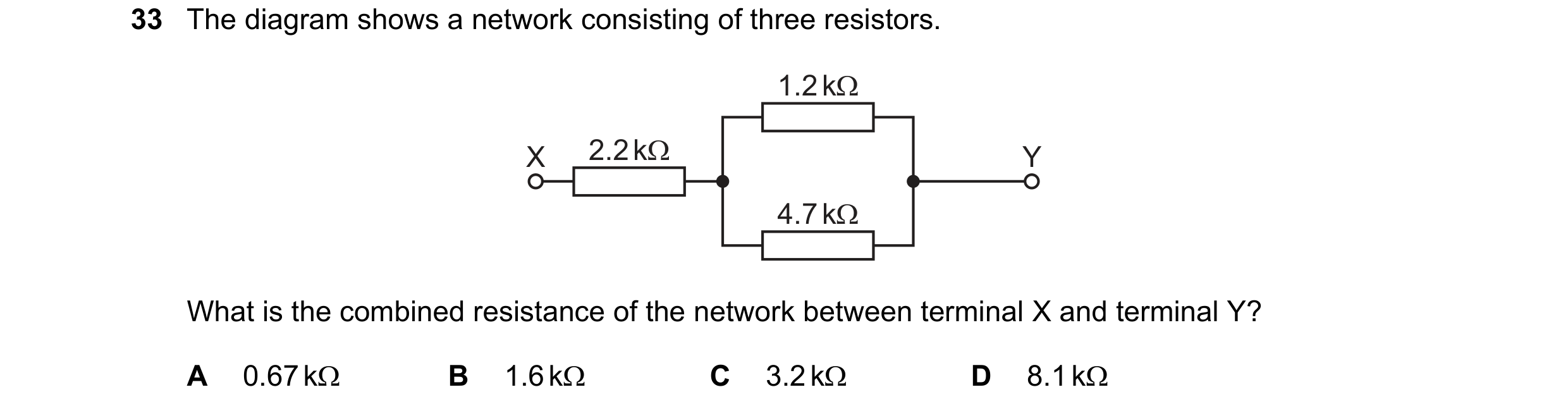
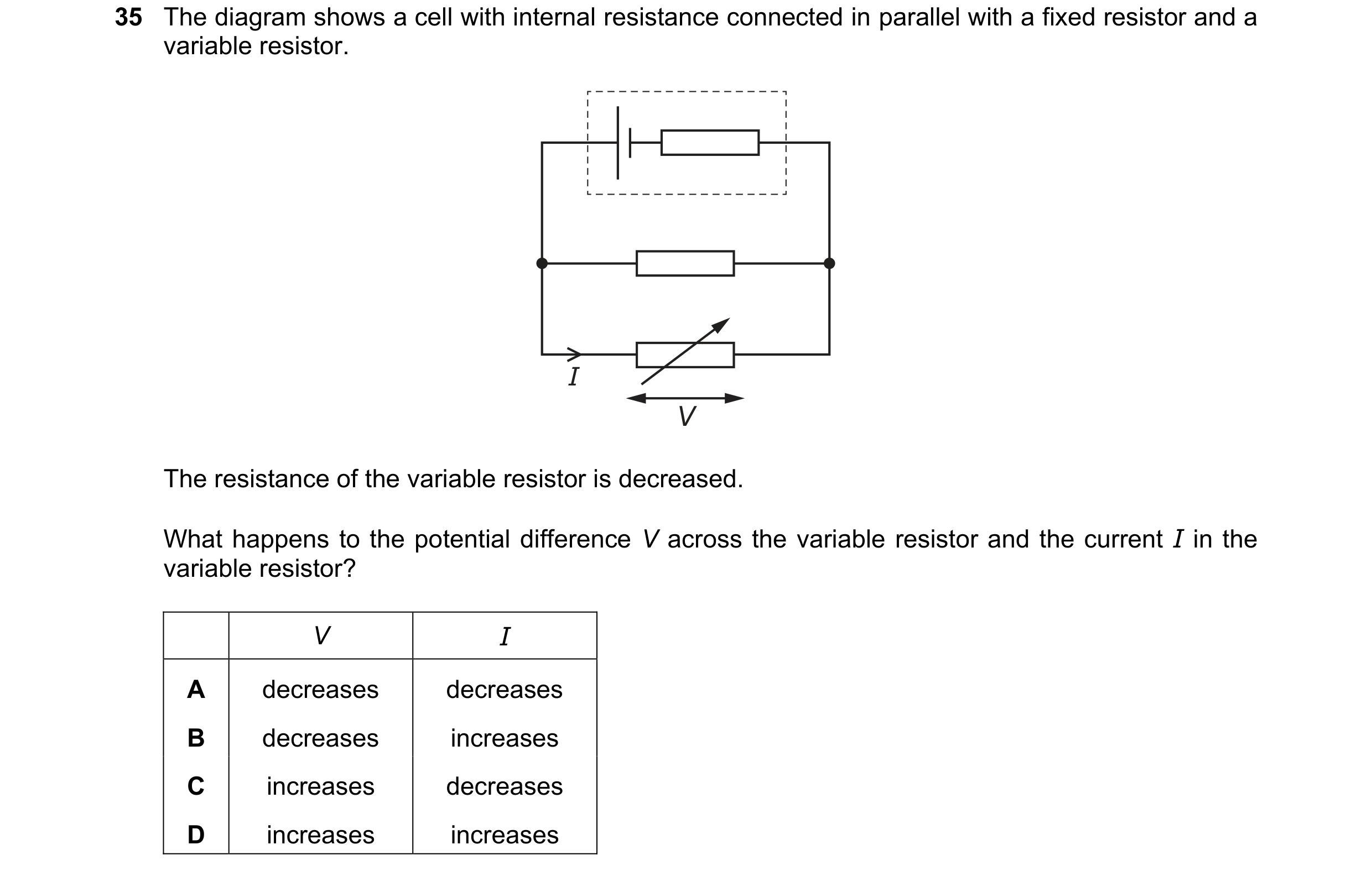 84 / 100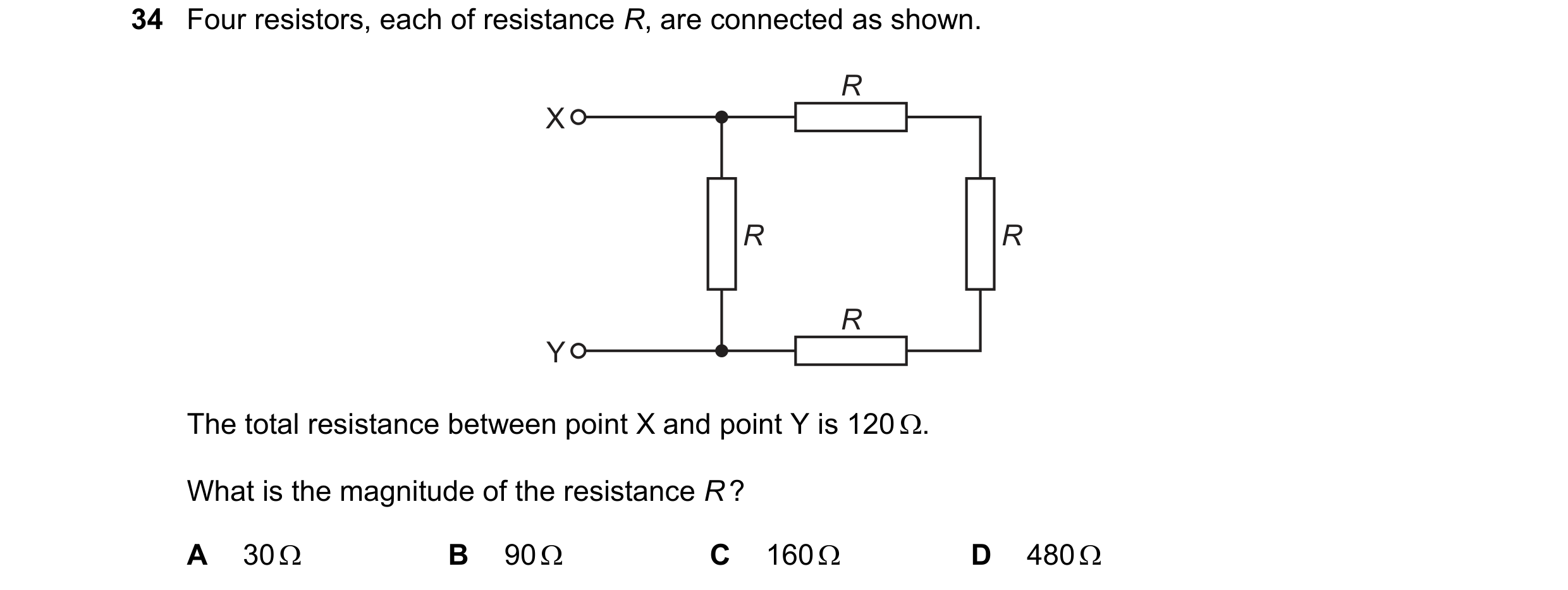
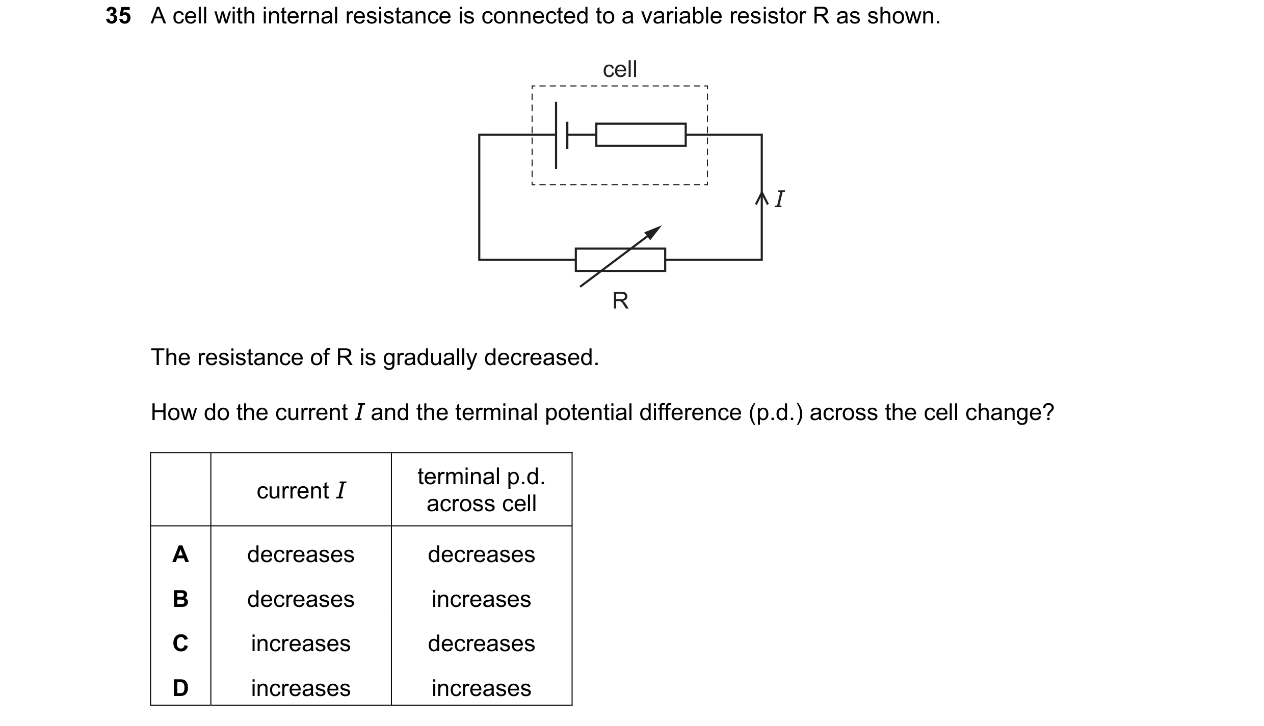 85 / 100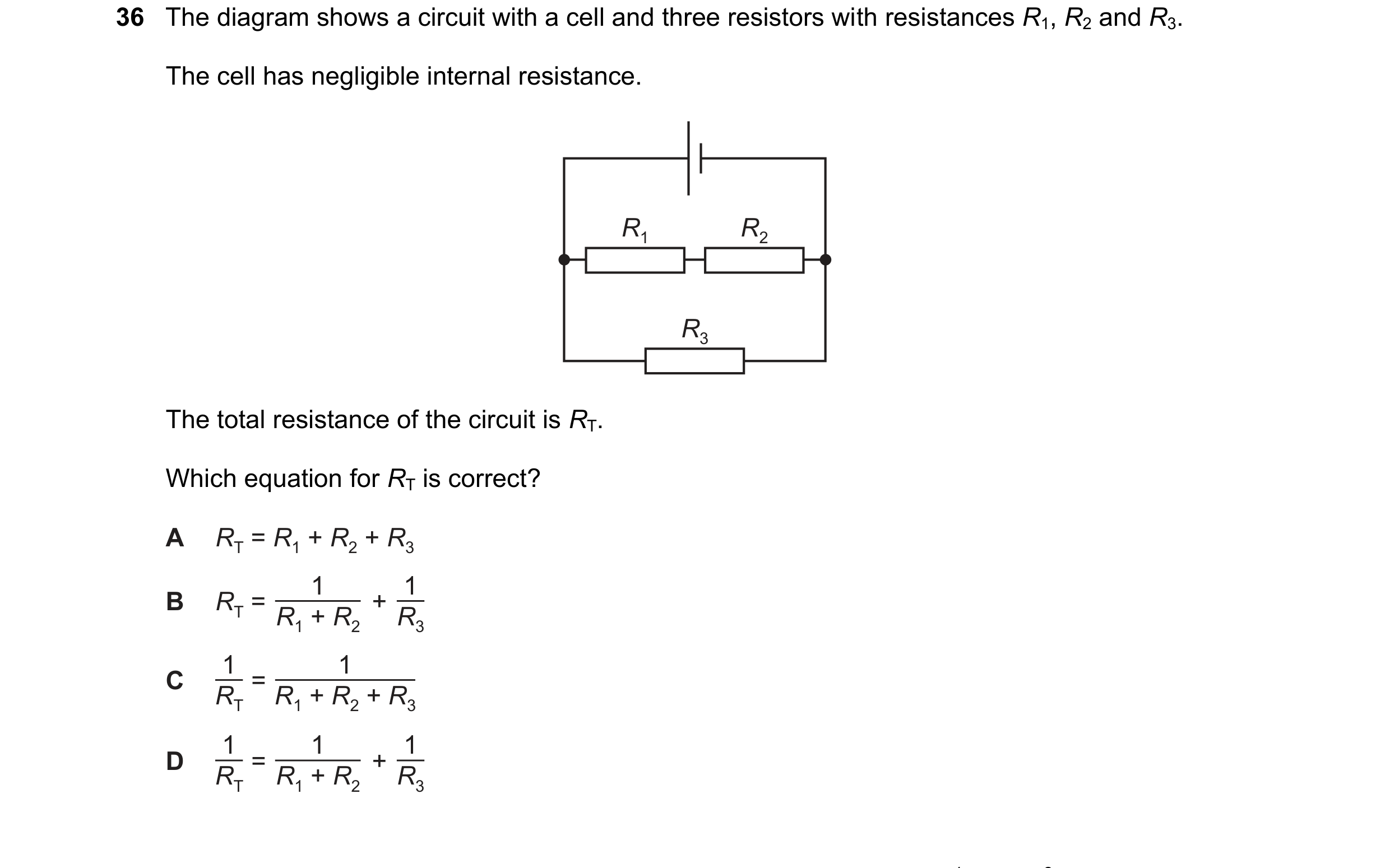
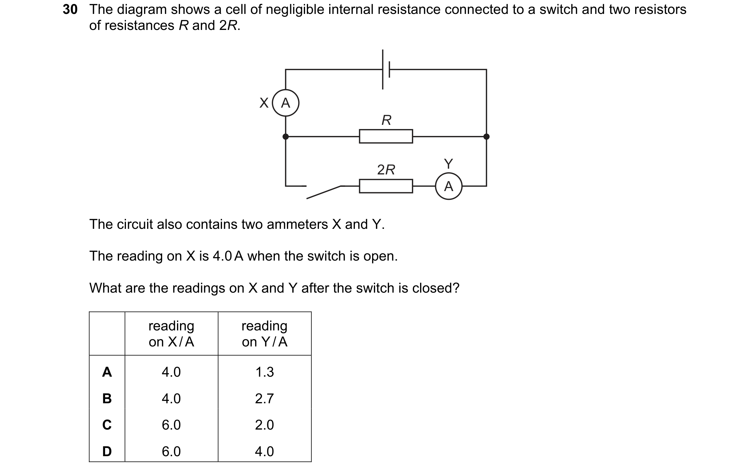 86 / 100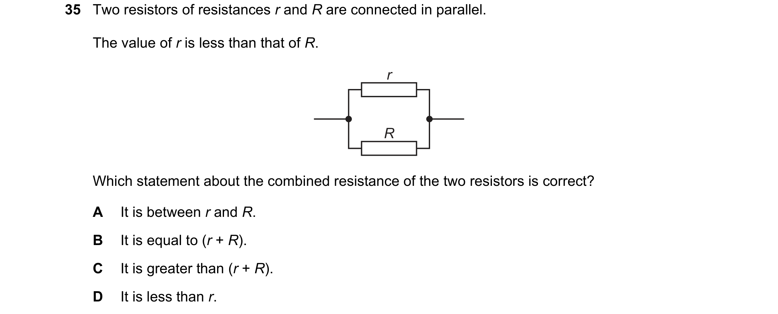
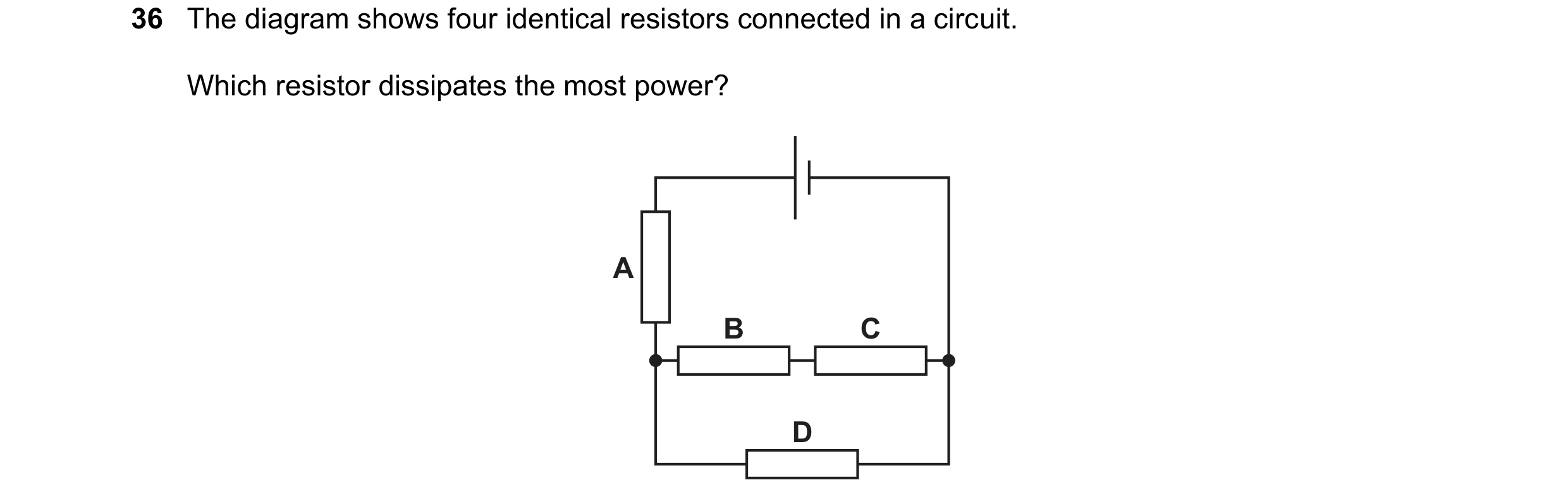
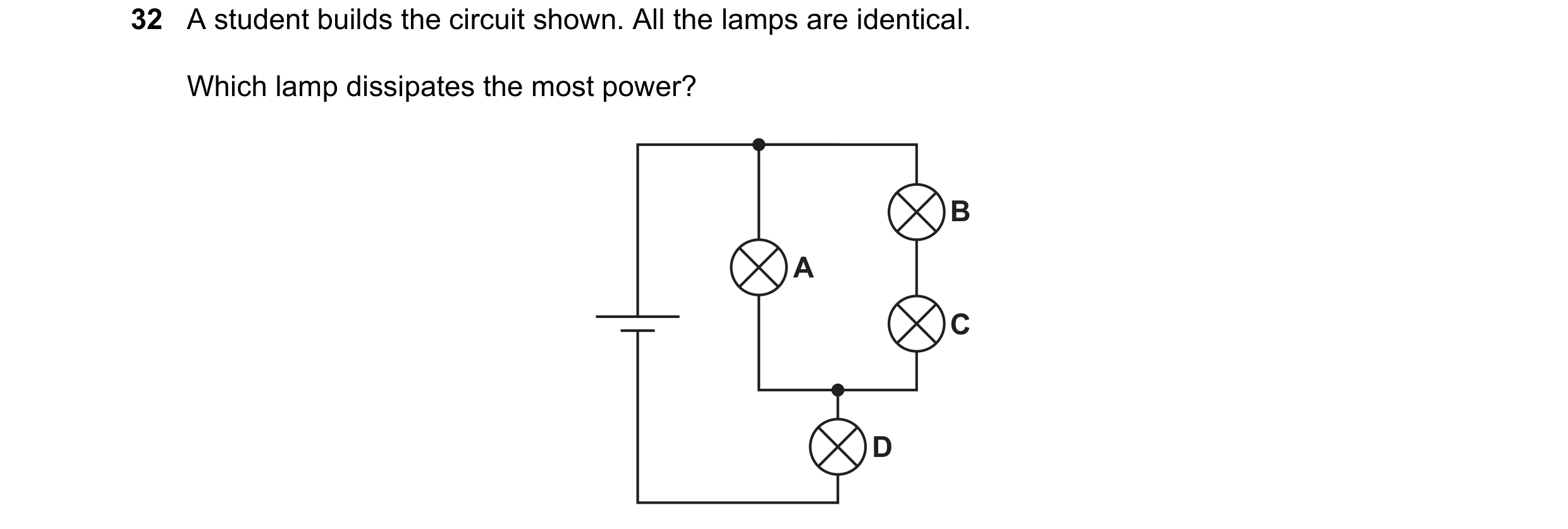 87 / 100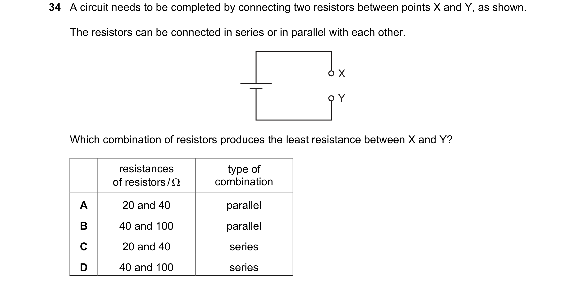
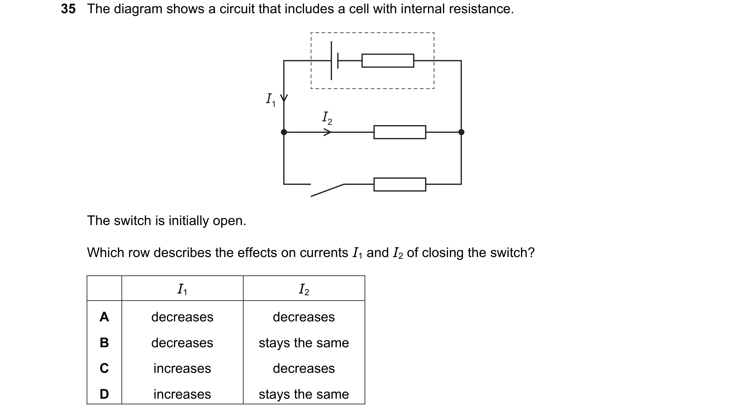 88 / 100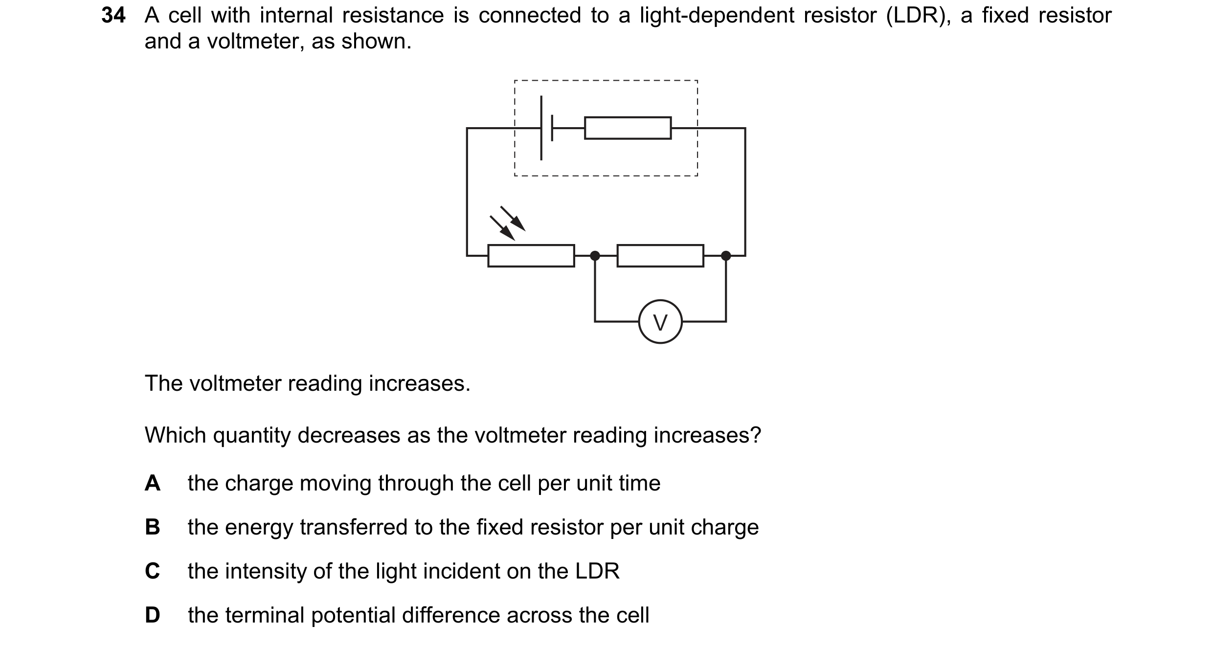
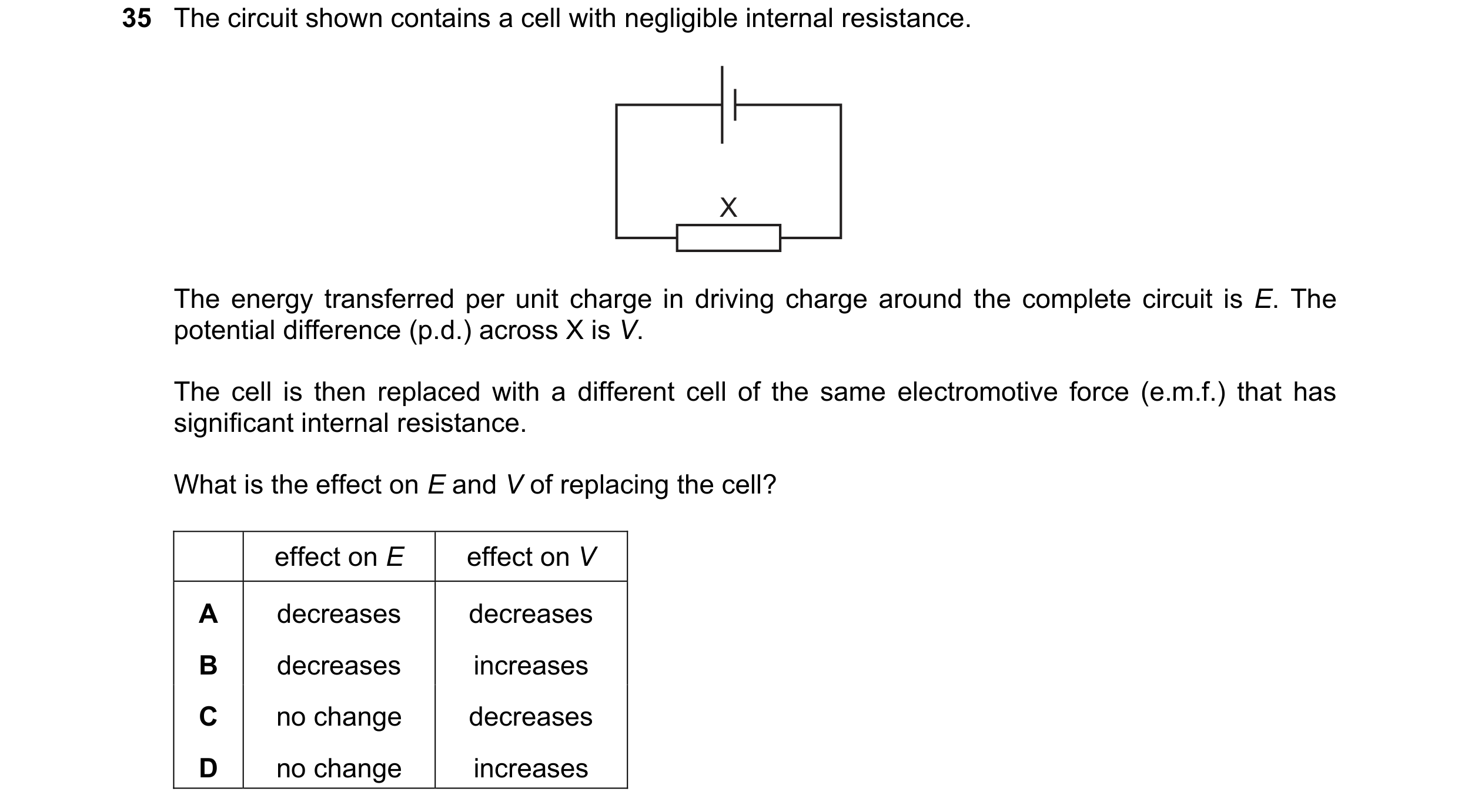 89 / 100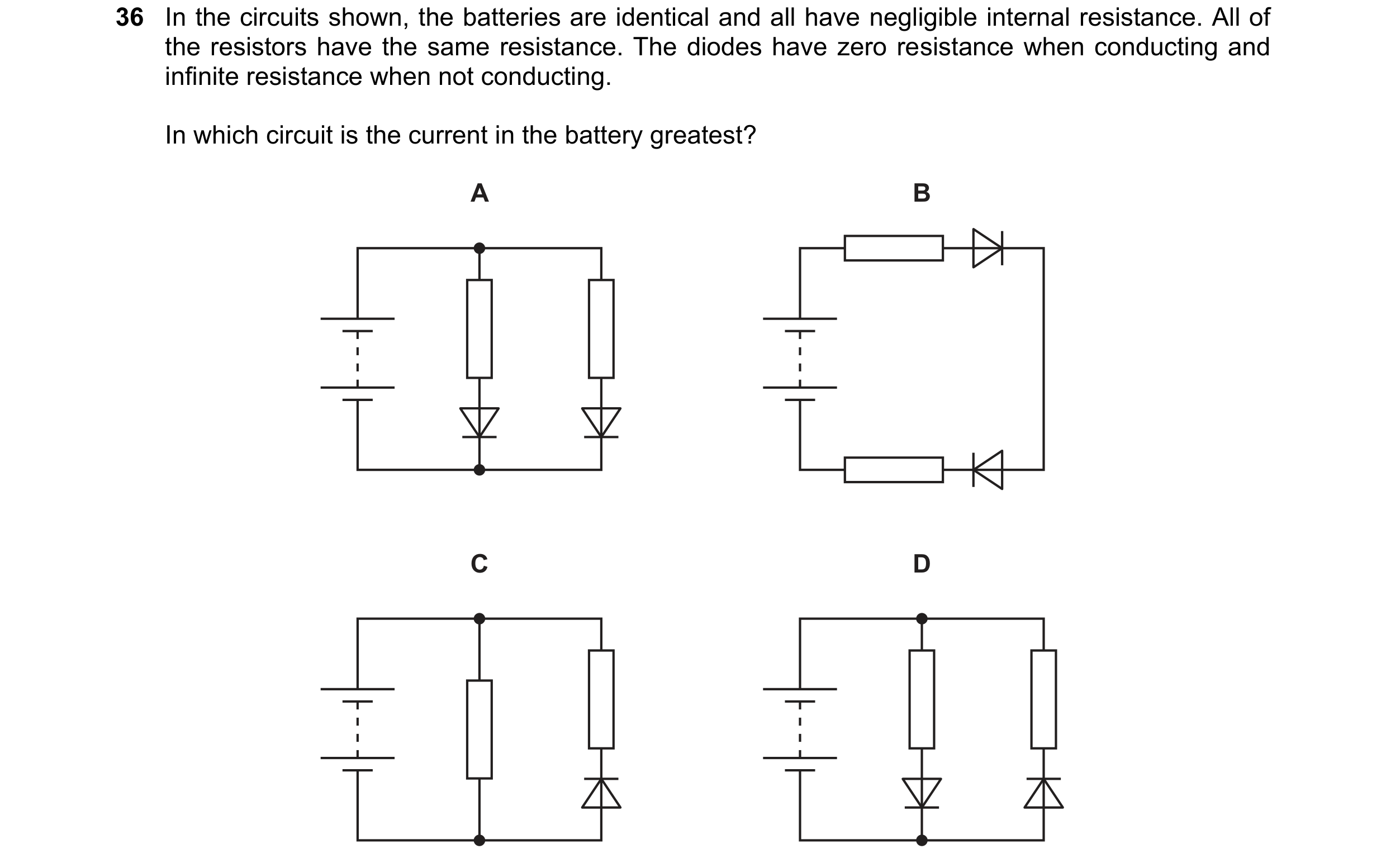
 90 / 100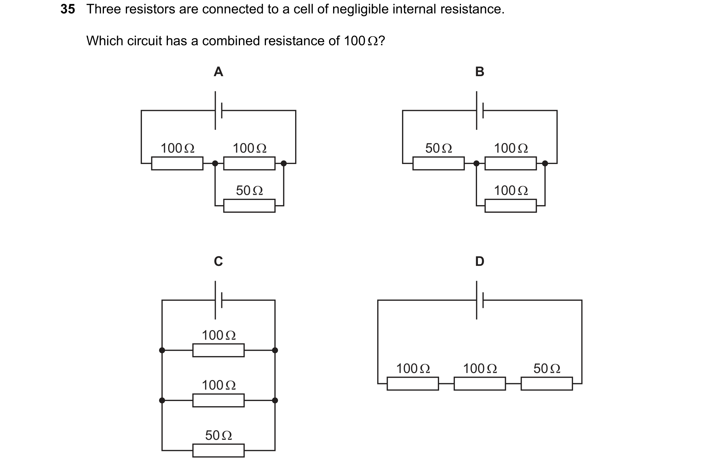

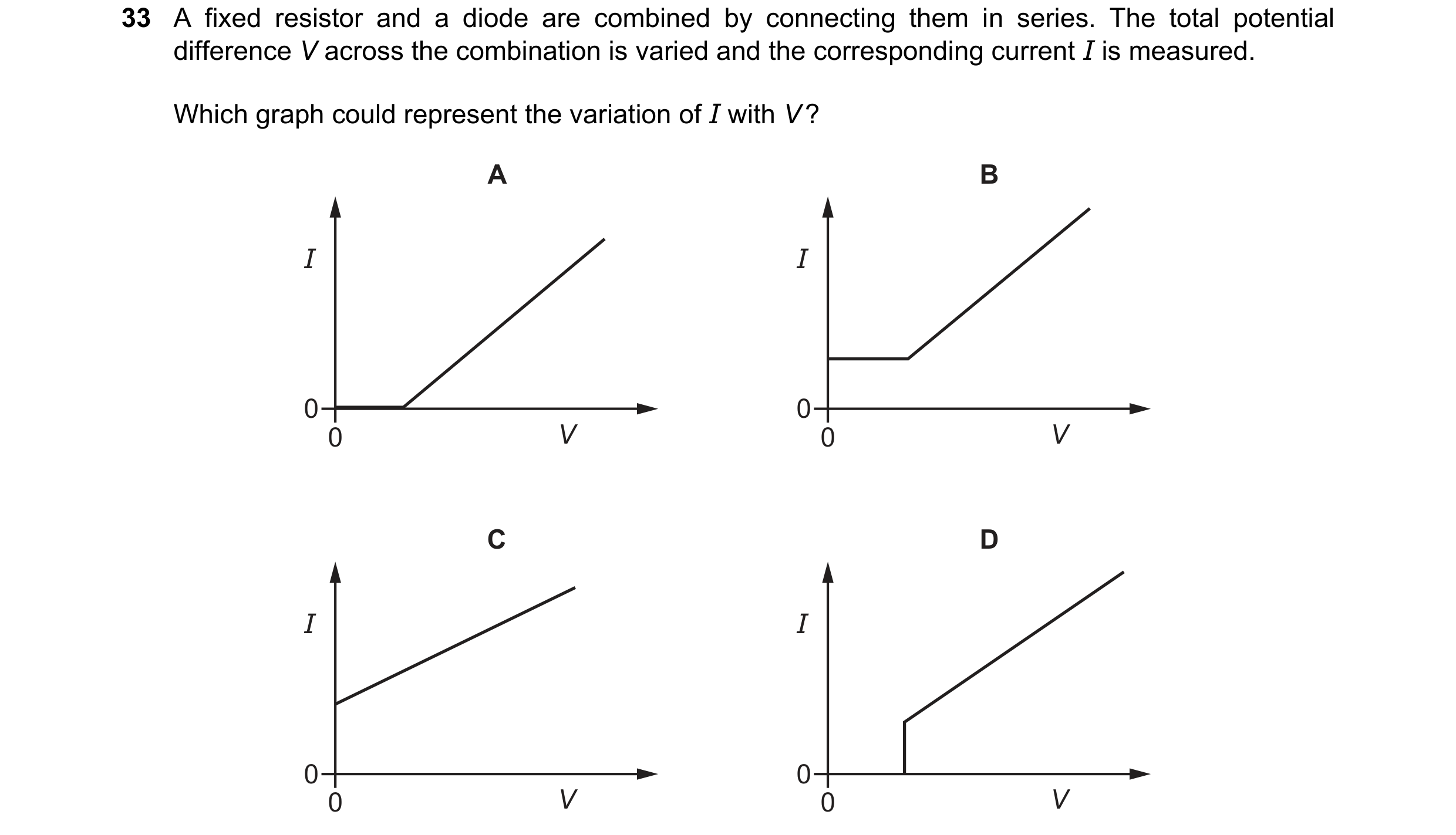 91 / 100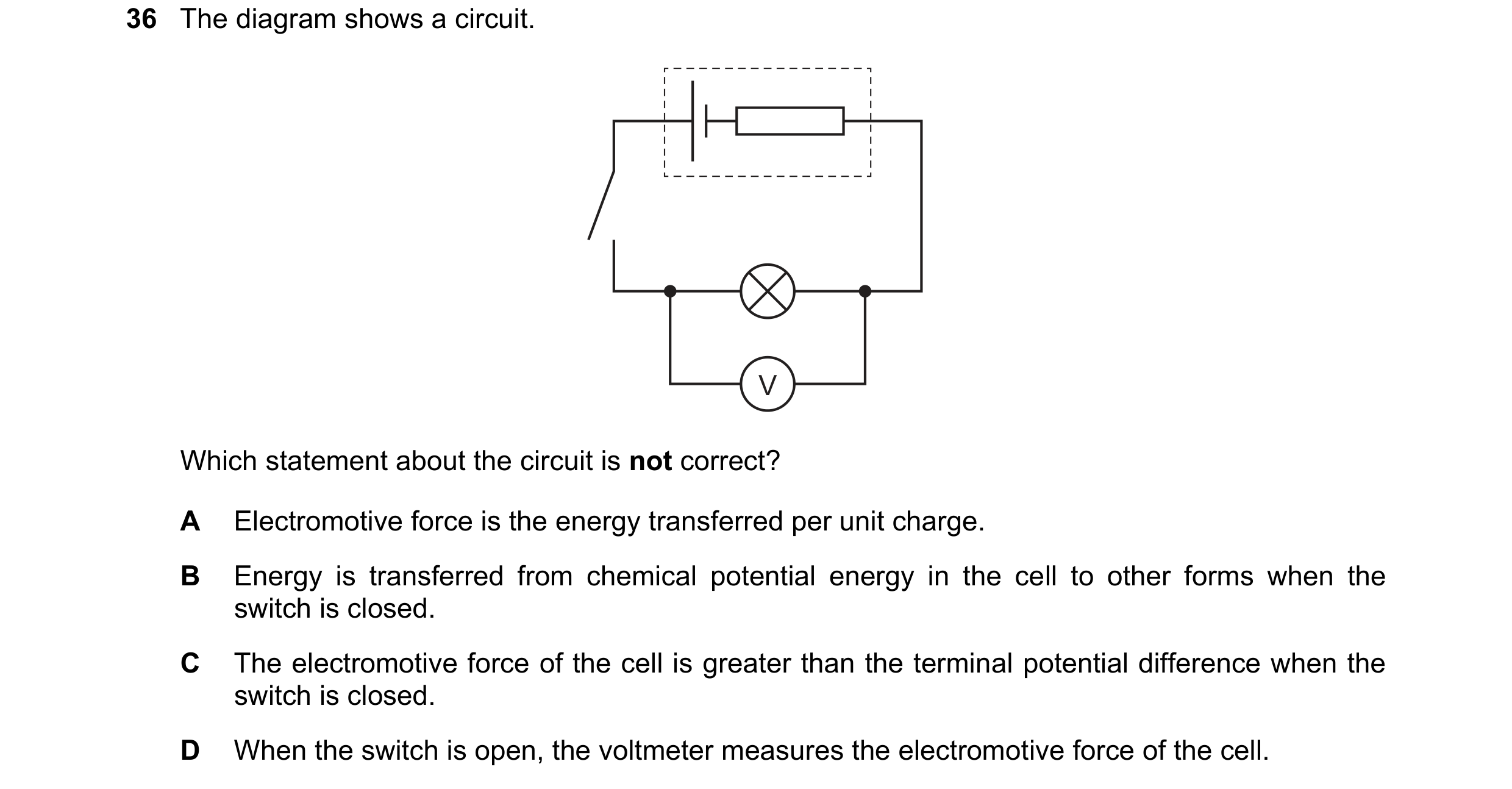

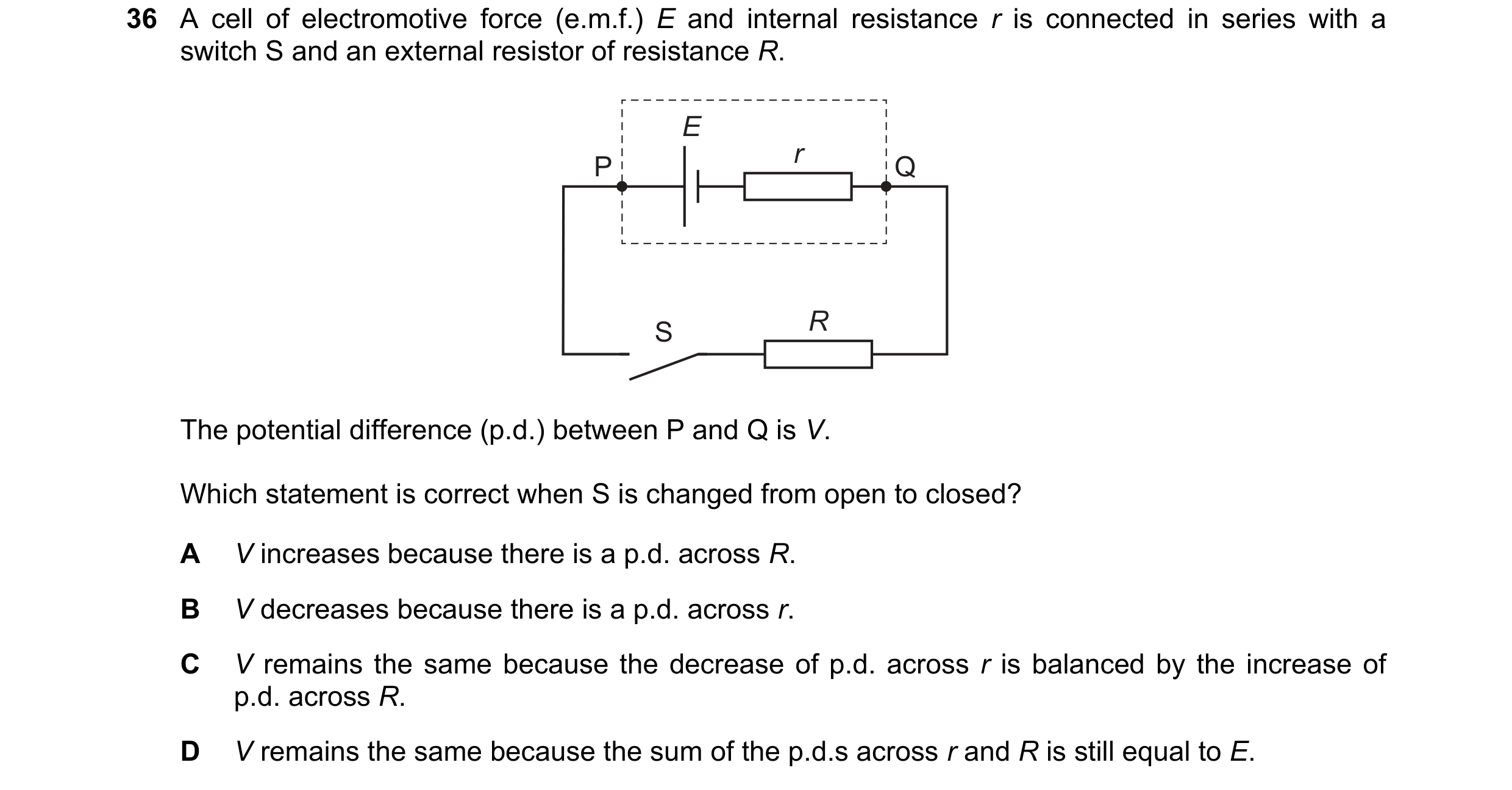 92 / 100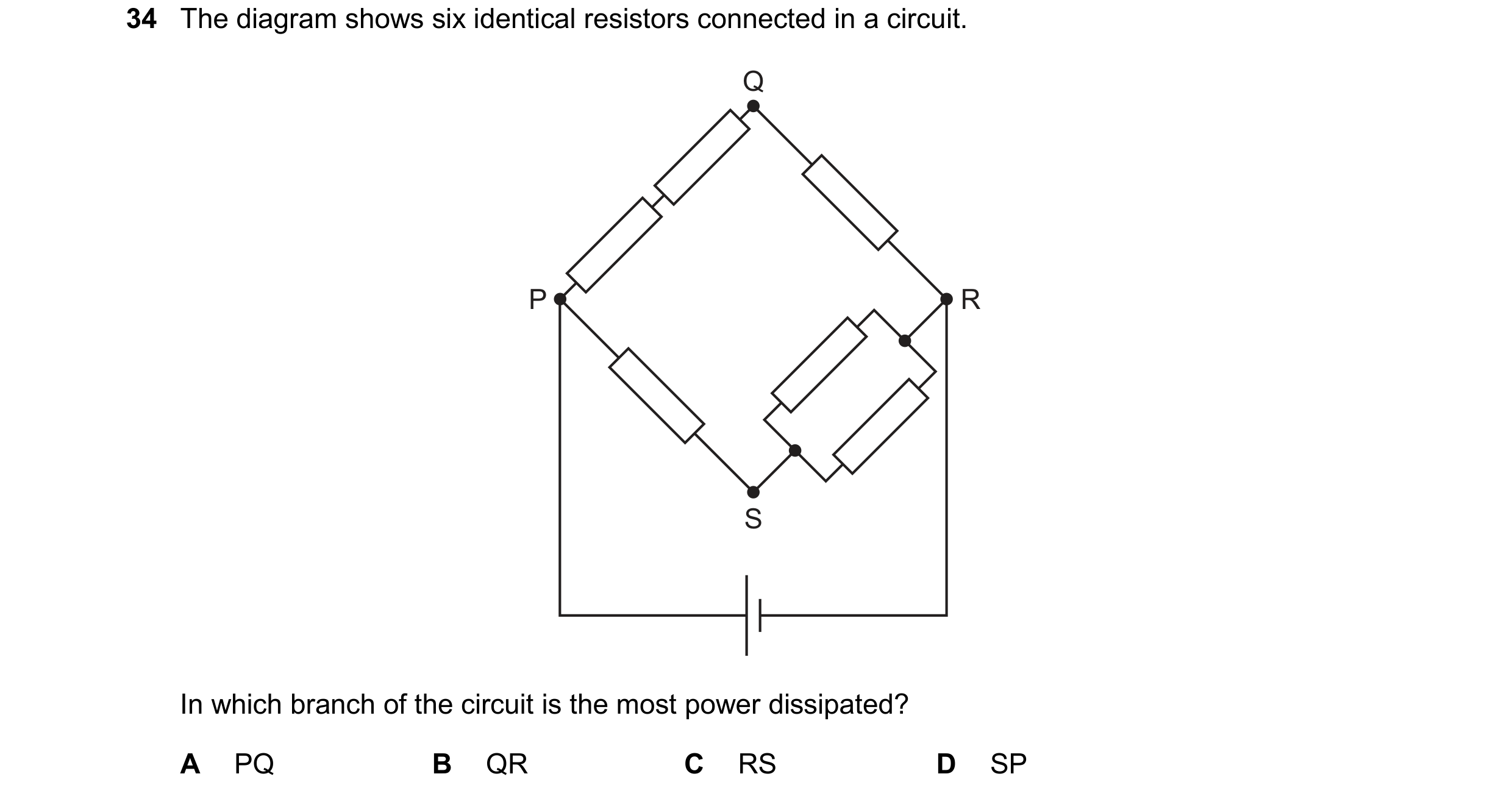
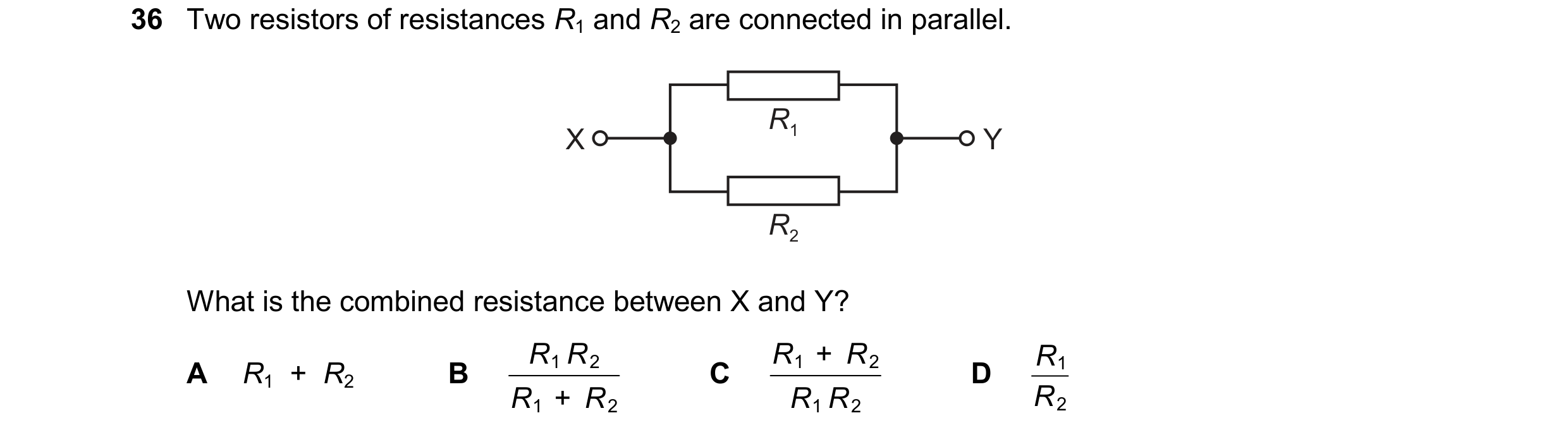 93 / 100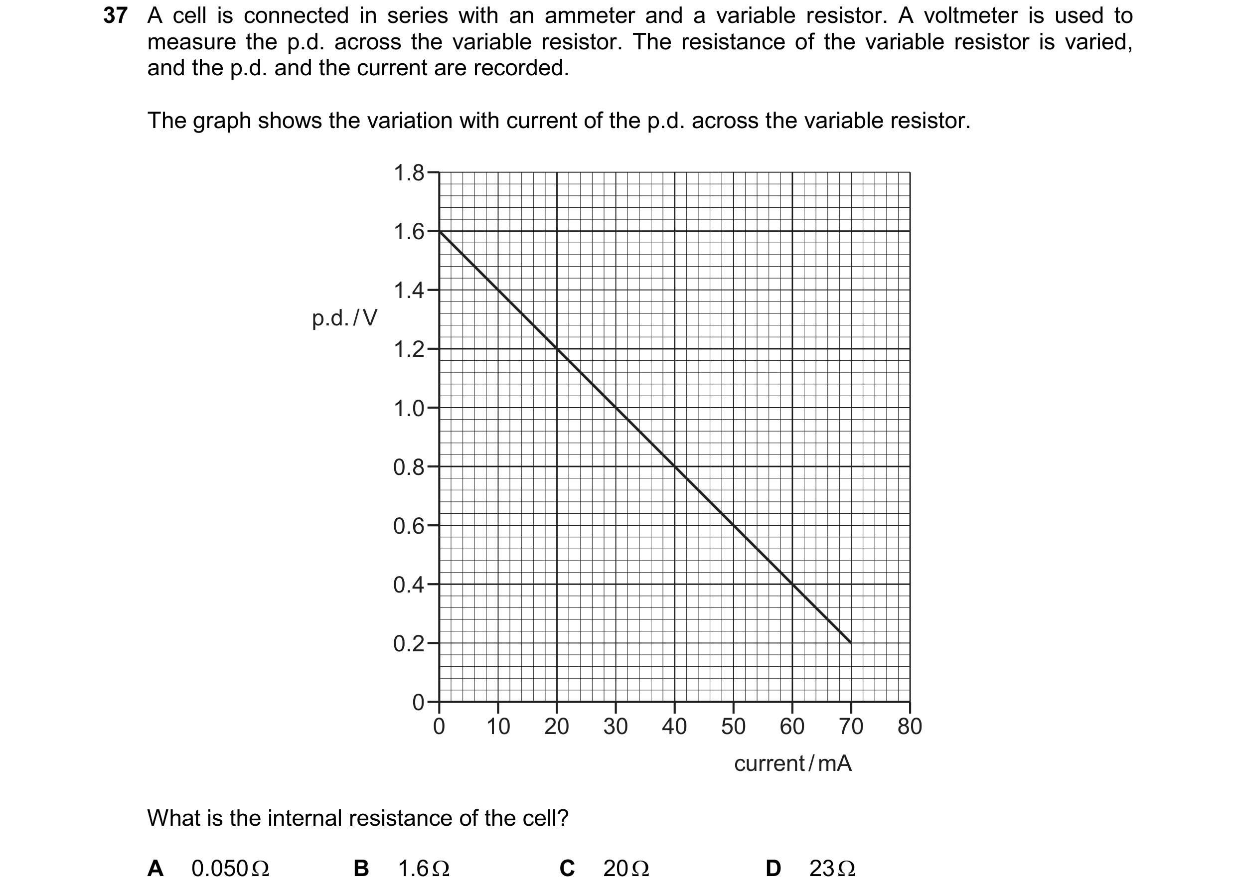
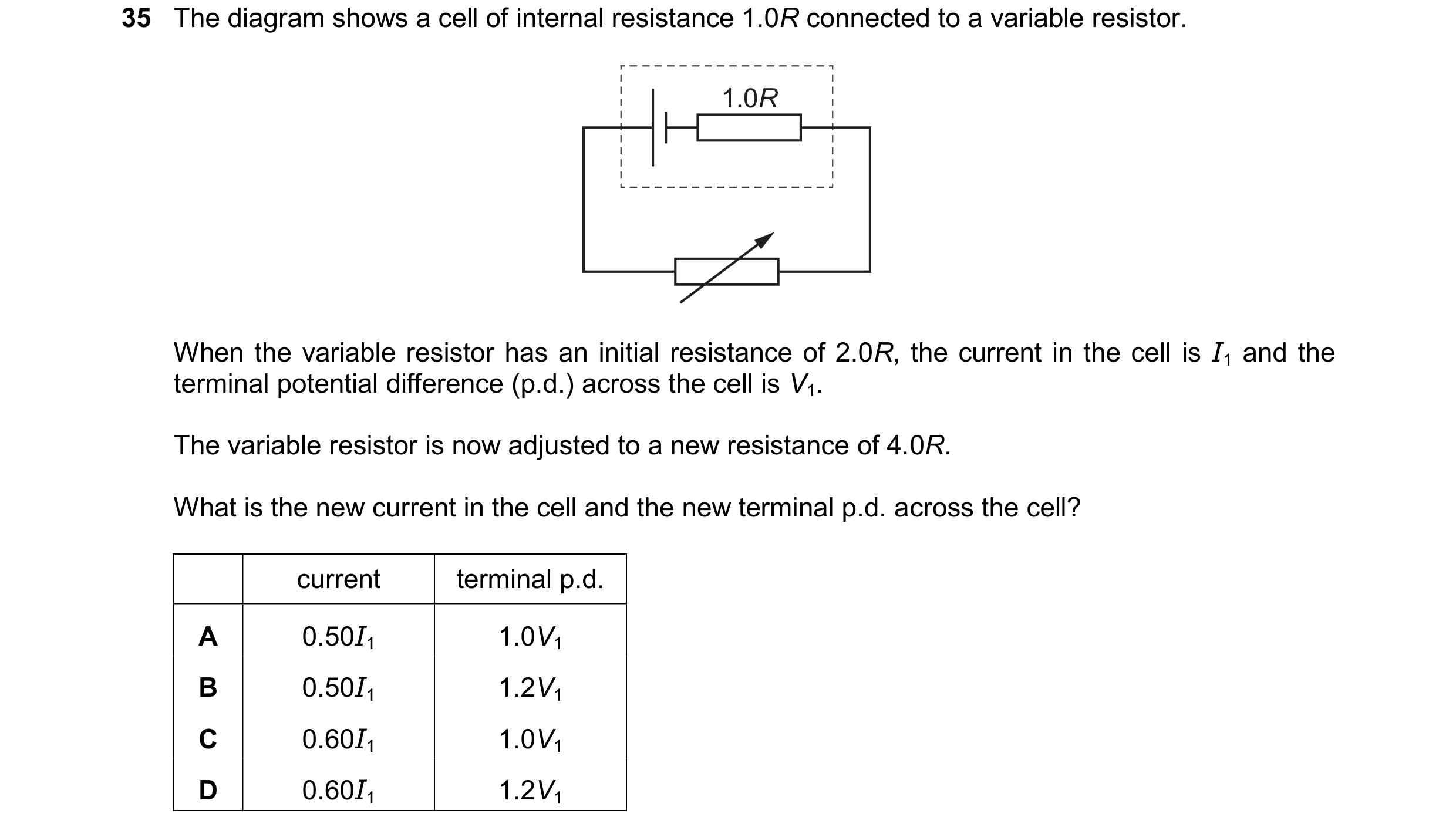 94 / 100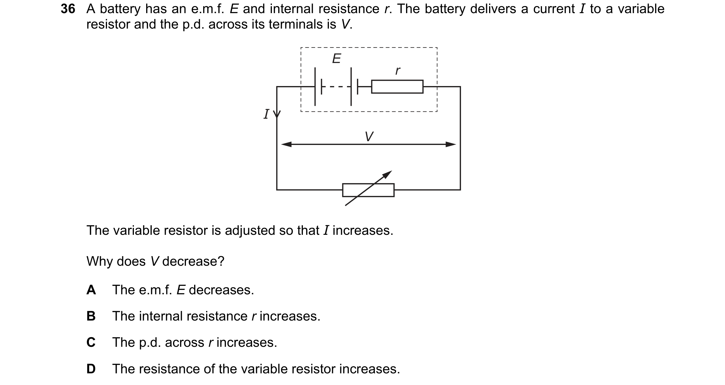
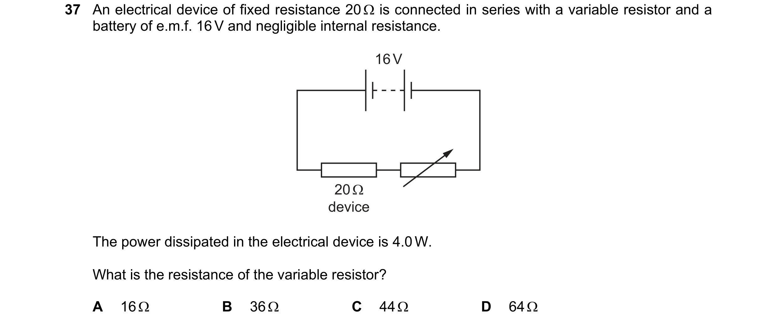 95 / 100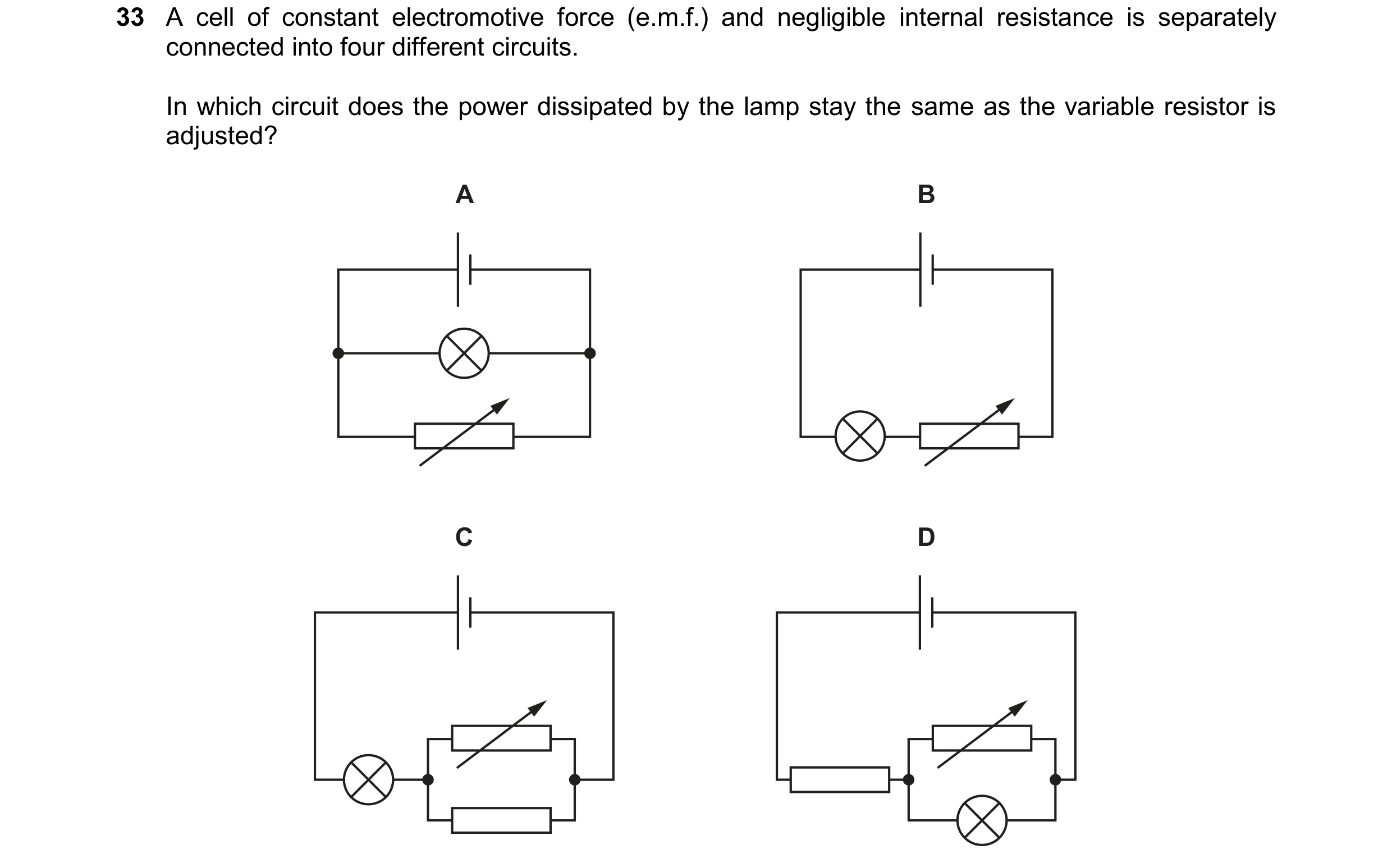
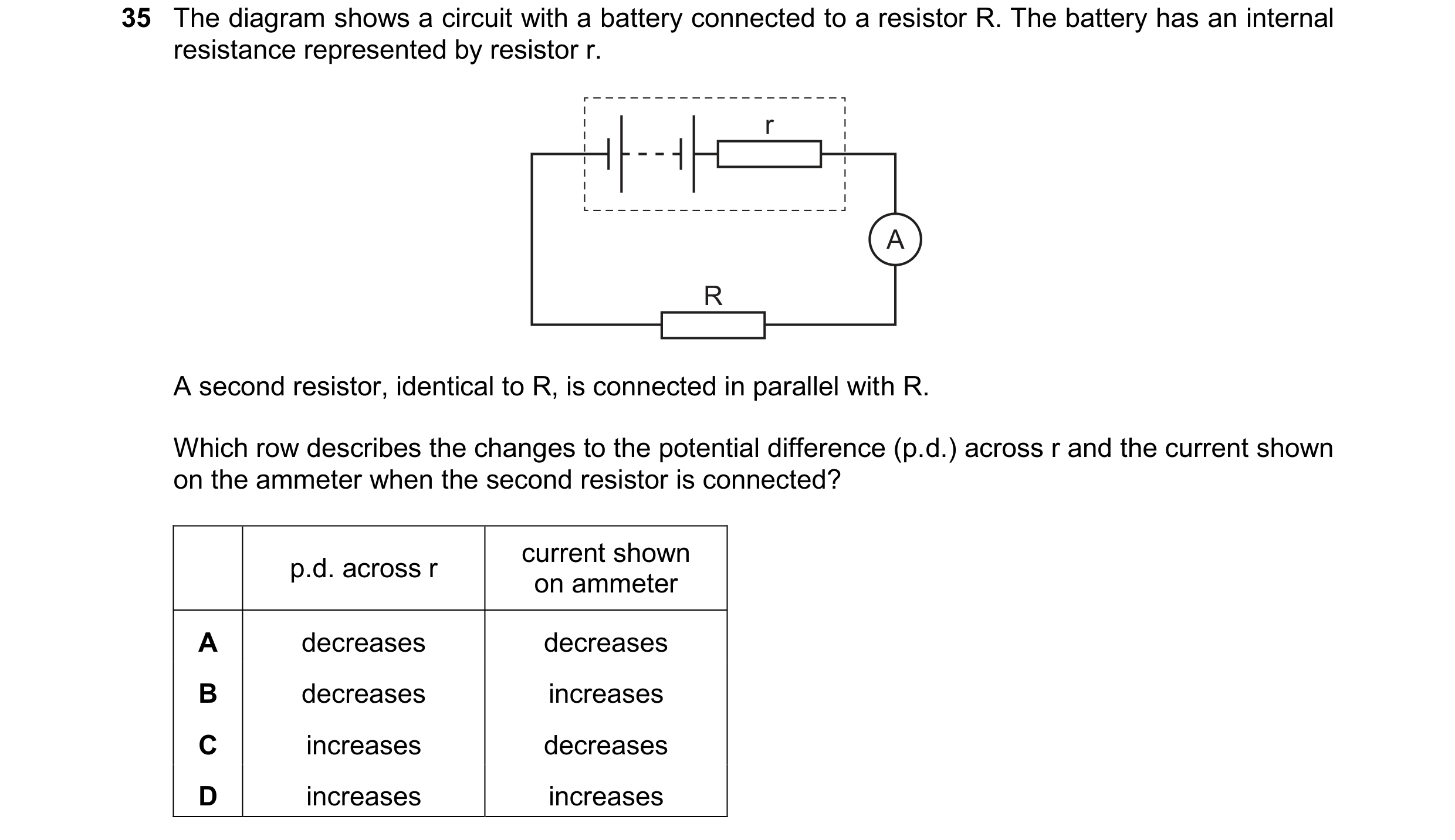 96 / 100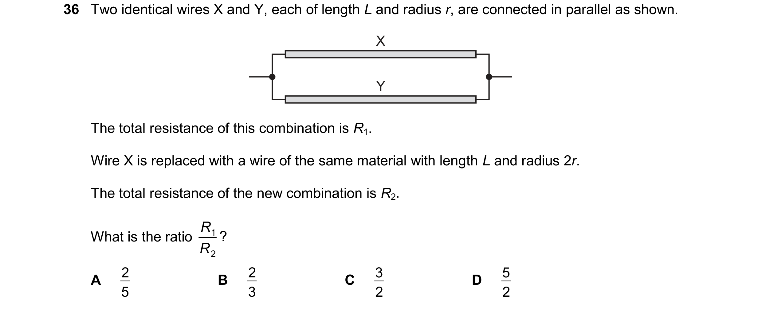
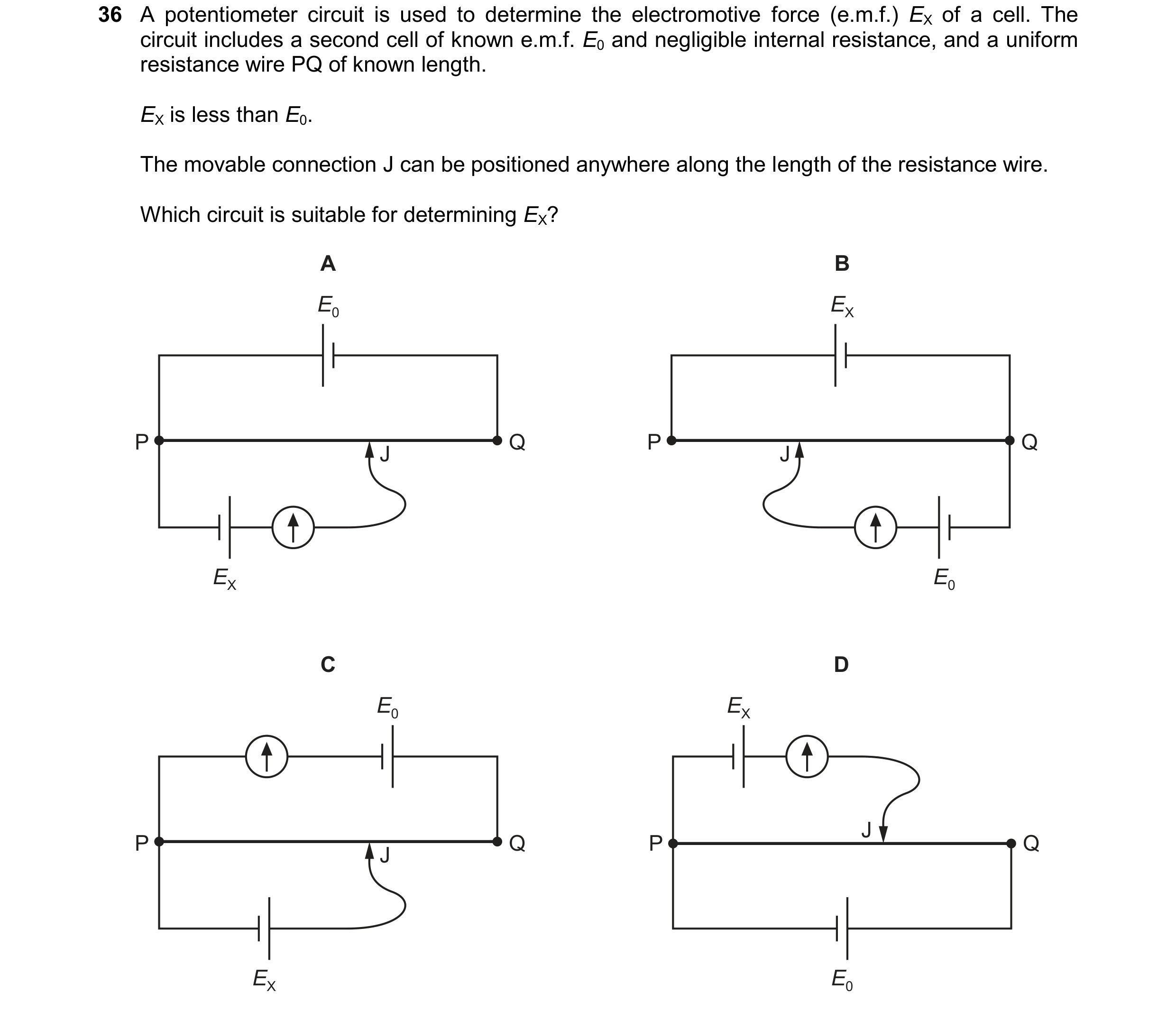 97 / 100
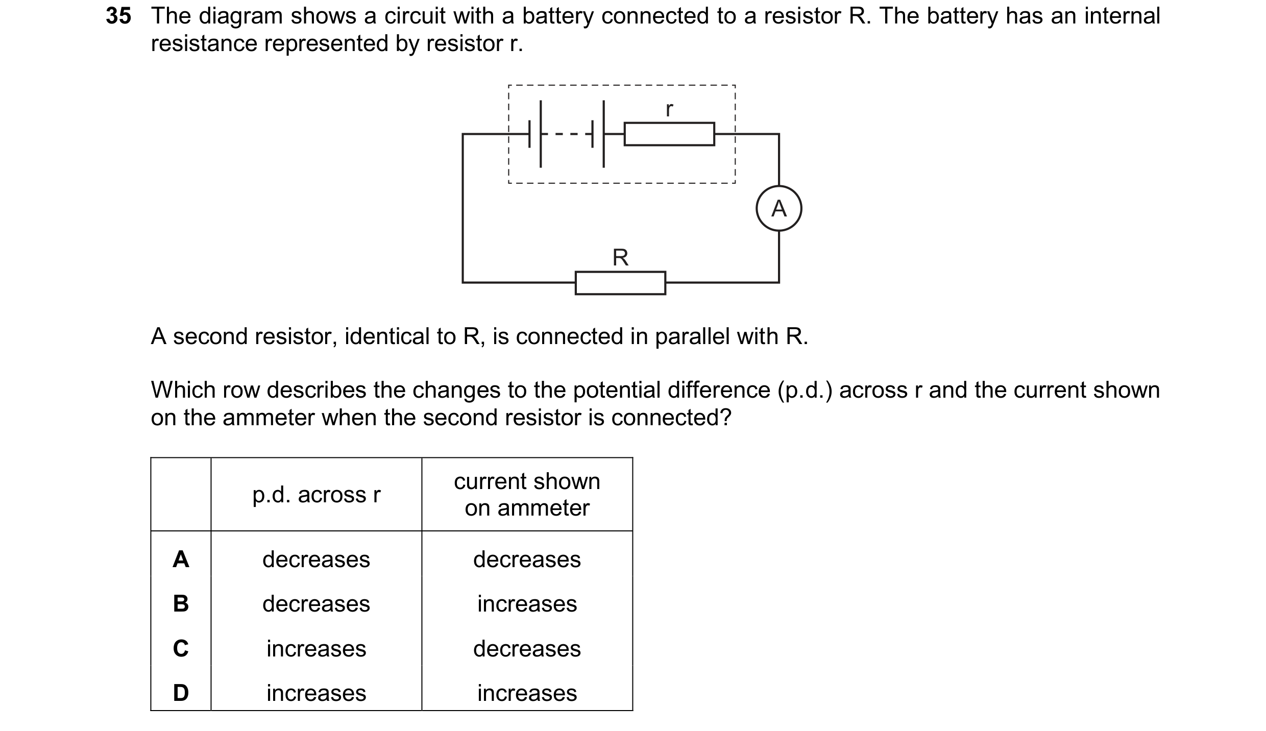 98 / 100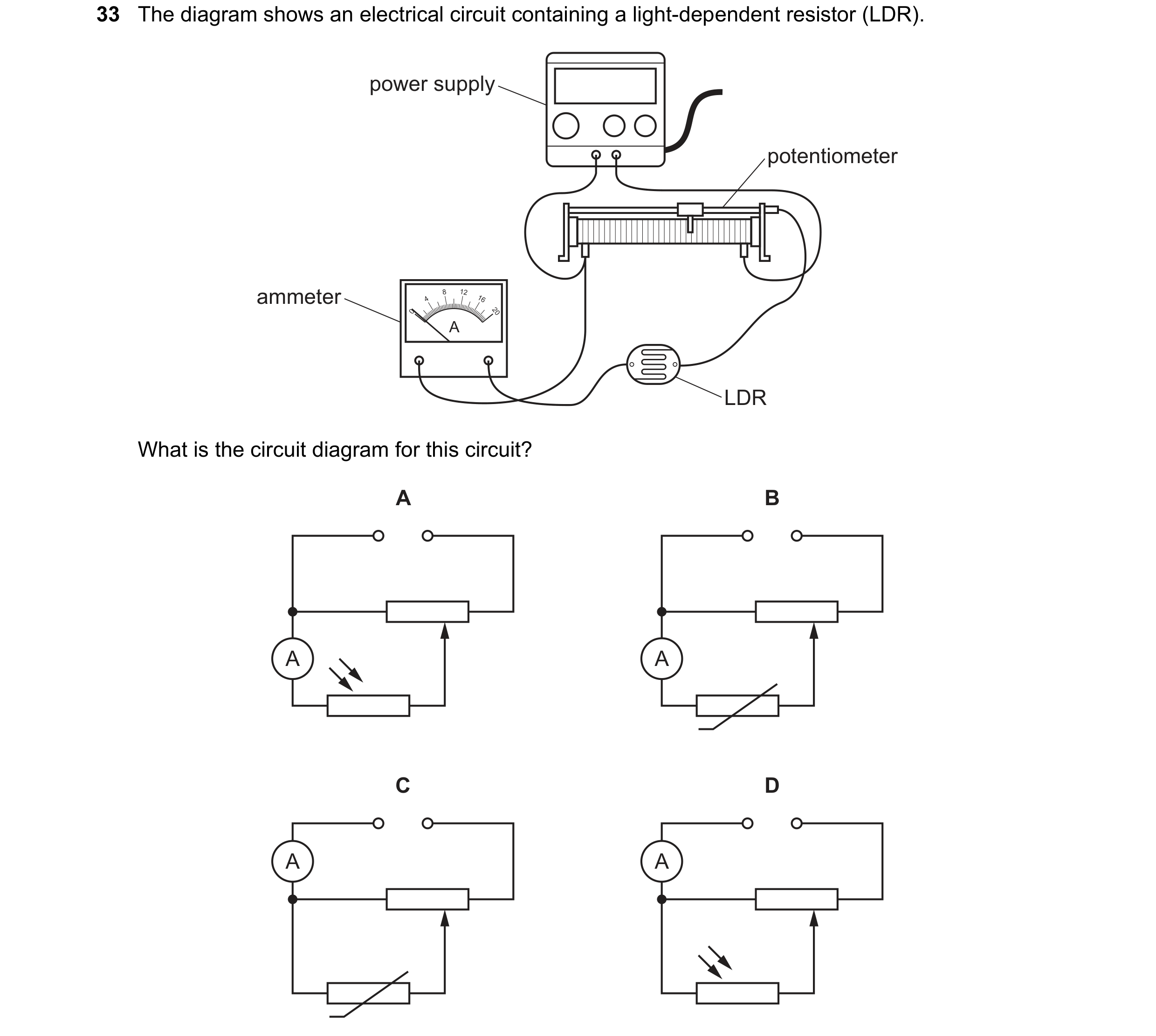
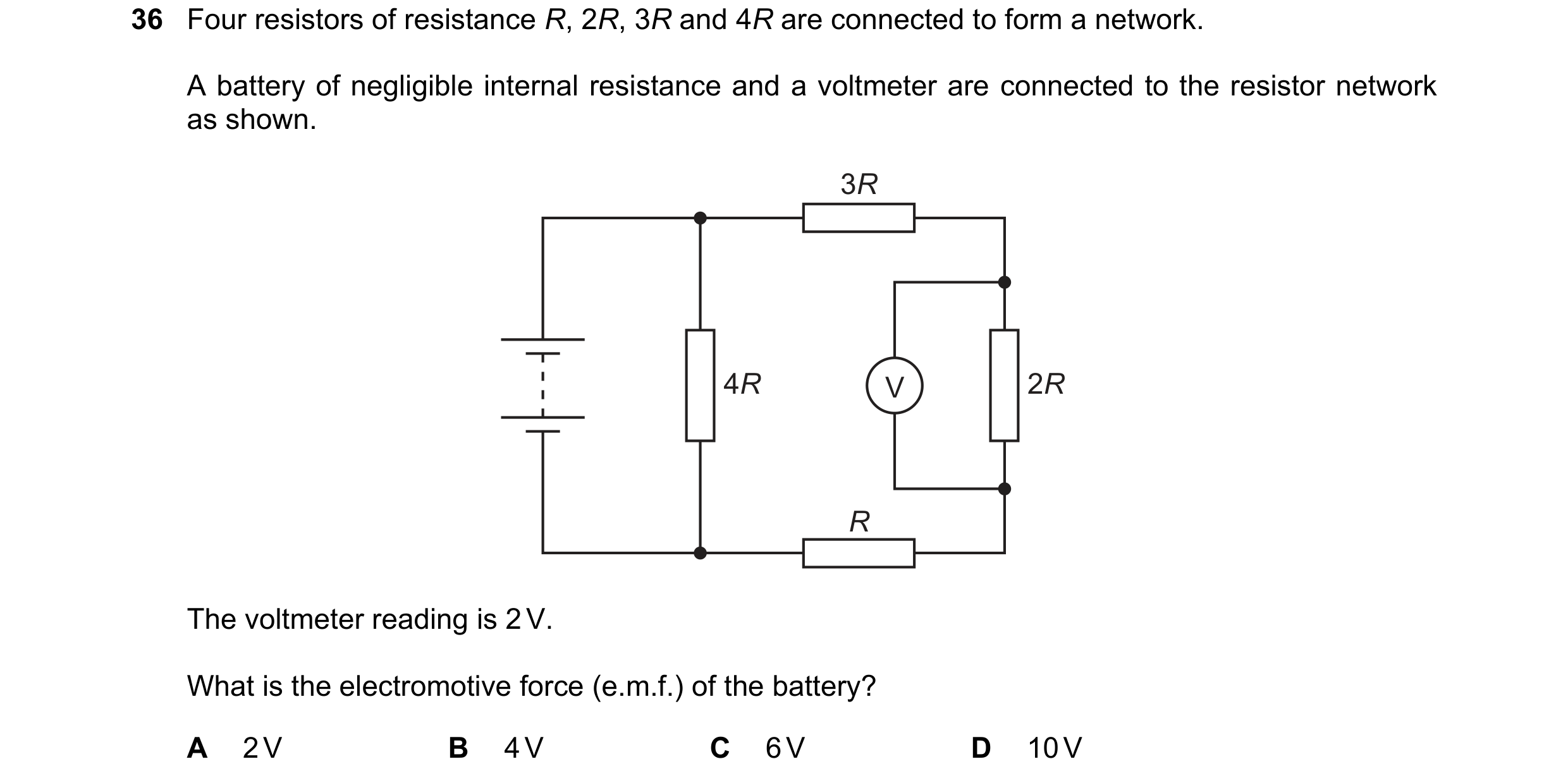 99 / 100
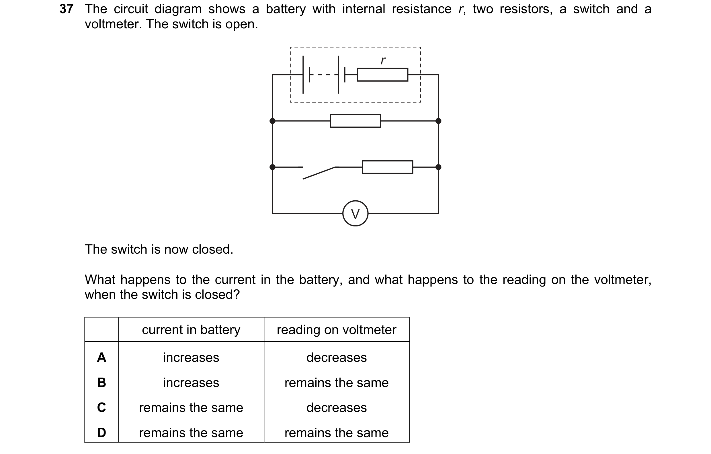 100 / 100