Questions as text
Q1 · Three resistors of resistances R1, R2 and R3 are connected as shown in Fig 9702/22 Feb/March 2017
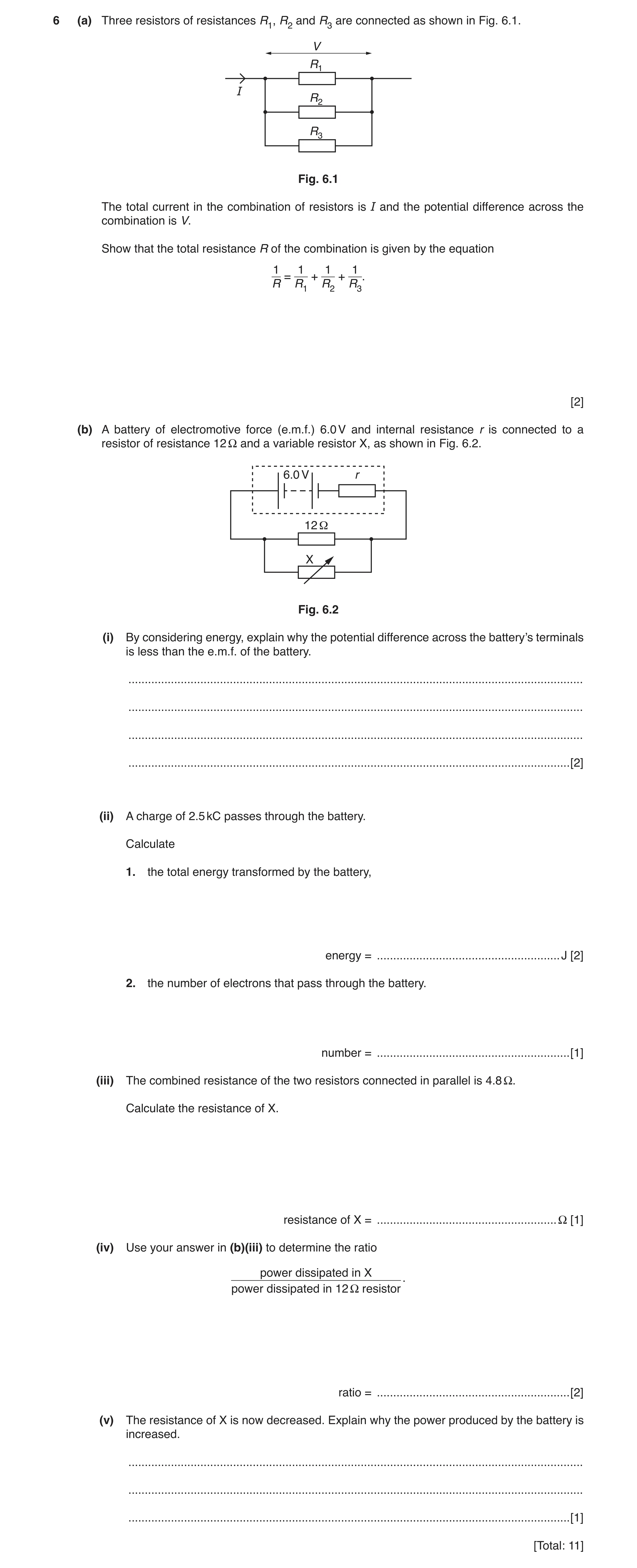
6 (a) Three resistors of resistances R1, R2 and R3 are connected as shown in Fig. 6.1. V R1 I R2 R3 Fig. 6.1 The total current in the combination of resistors is I and the potential difference across the combination is V. Show that the total resistance R of the combination is given by the equation 1 1 1 1 = + + . R R1 R2 R3 [2] (b) A battery of electromotive force (e.m.f.) 6.0 V and internal resistance r is connected to a resistor of resistance 12 Ω and a variable resistor X, as shown in Fig. 6.2. 6.0 V r 12 Ω X Fig. 6.2 (i) By considering energy, explain why the potential difference across the battery’s terminals is less than the e.m.f. of the battery. … … … … [2] (ii) A charge of 2.5 kC passes through the battery. Calculate 1. the total energy transformed by the battery, energy = … J [2] 2. the number of electrons that pass through the battery. number = … [1] (iii) The combined resistance of the two resistors connected in parallel is 4.8 Ω. Calculate the resistance of X. resistance of X = … Ω [1] (iv) Use your answer in (b)(iii) to determine the ratio power dissipated in X . power dissipated in 12 Ω resistor ratio = … [2] (v) The resistance of X is now decreased. Explain why the power produced by the battery is increased. … … … [1] [Total: 11]
11 marks
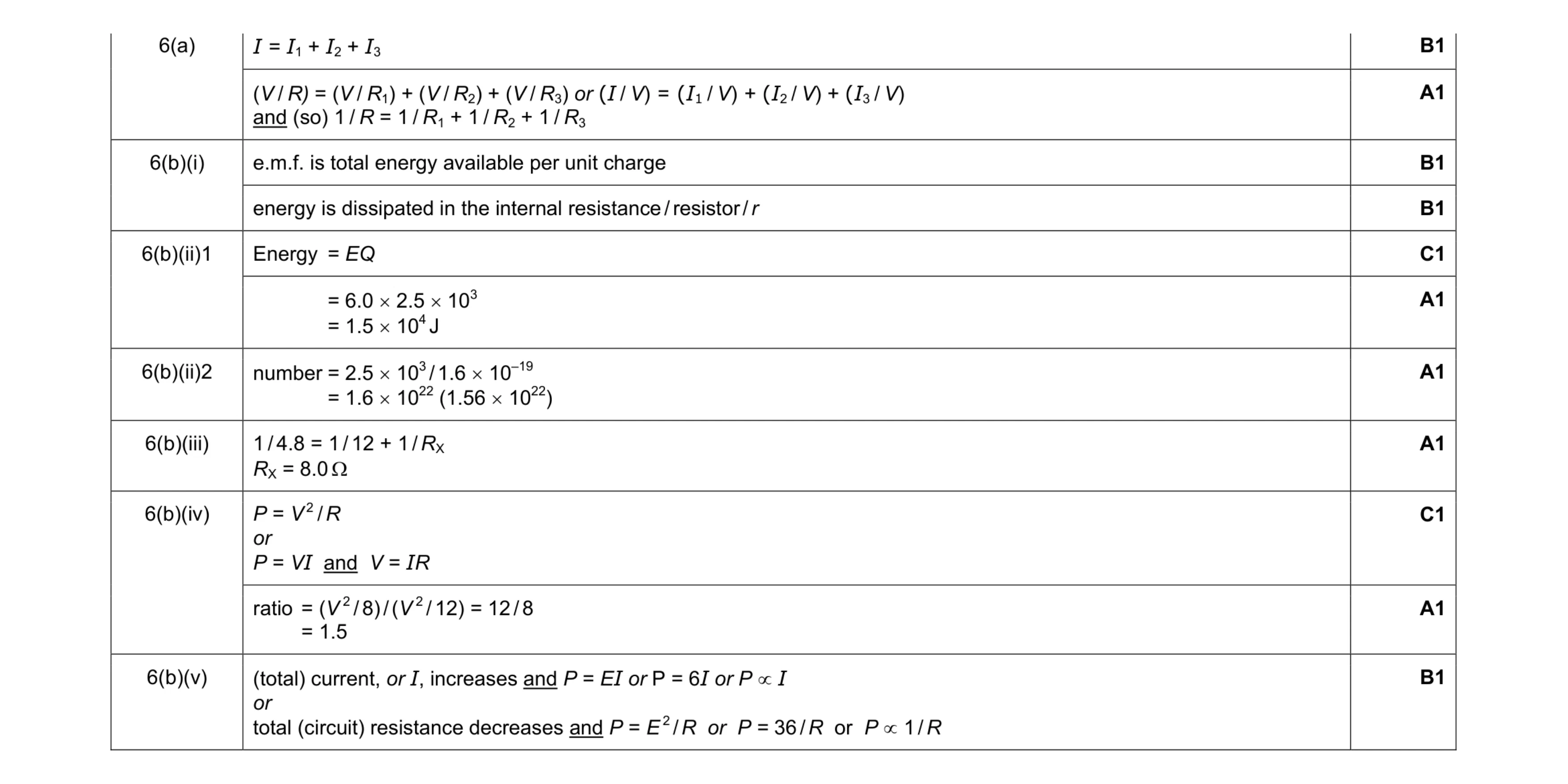
Mark scheme: 6(a) B1 (V / R) = (V / R1) + (V / R2) + (V / R3) or (I / V) = (I1 / V) + (I2 / V) + (I3 / V) and (so) 1 / R = 1 / R1 + 1 / R2 + 1 / R3 A1 6(b)(i) e.m.f. is total energy available per unit charge B1 energy is dissipated in the internal resistance / resistor / r B1 6(b)(ii)1 Energy = EQ C1 = 6.0 × 2.5 × 103 = 1.5 × 10⁴ J A1 6(b)(ii)2 number = 2.5 × 10³ / 1.6 × 10–19 = 1.6 × 10²² (1.56 × 10²²) A1 6(b)(iii) 1 / 4.8 = 1 / 12 + 1 / RX RX = 8.0 Ω A1 6(b)(iv) P = V 2 / R or P = VI and V = IR C1 ratio = (V 2 / 8) / (V 2 / 12) = 12 / 8 = 1.5 A1 6(b)(v) (total) current, or I, increases and P = EI or P = 6I or P ∝ I or total (circuit) resistance decreases and P = E 2 / R or P = 36 / R or P ∝ 1 / R B1
This question in 9702/22 Feb/March 2017
Q2 · State Kirchhoff’s second law 9702/21 Oct/Nov 2018
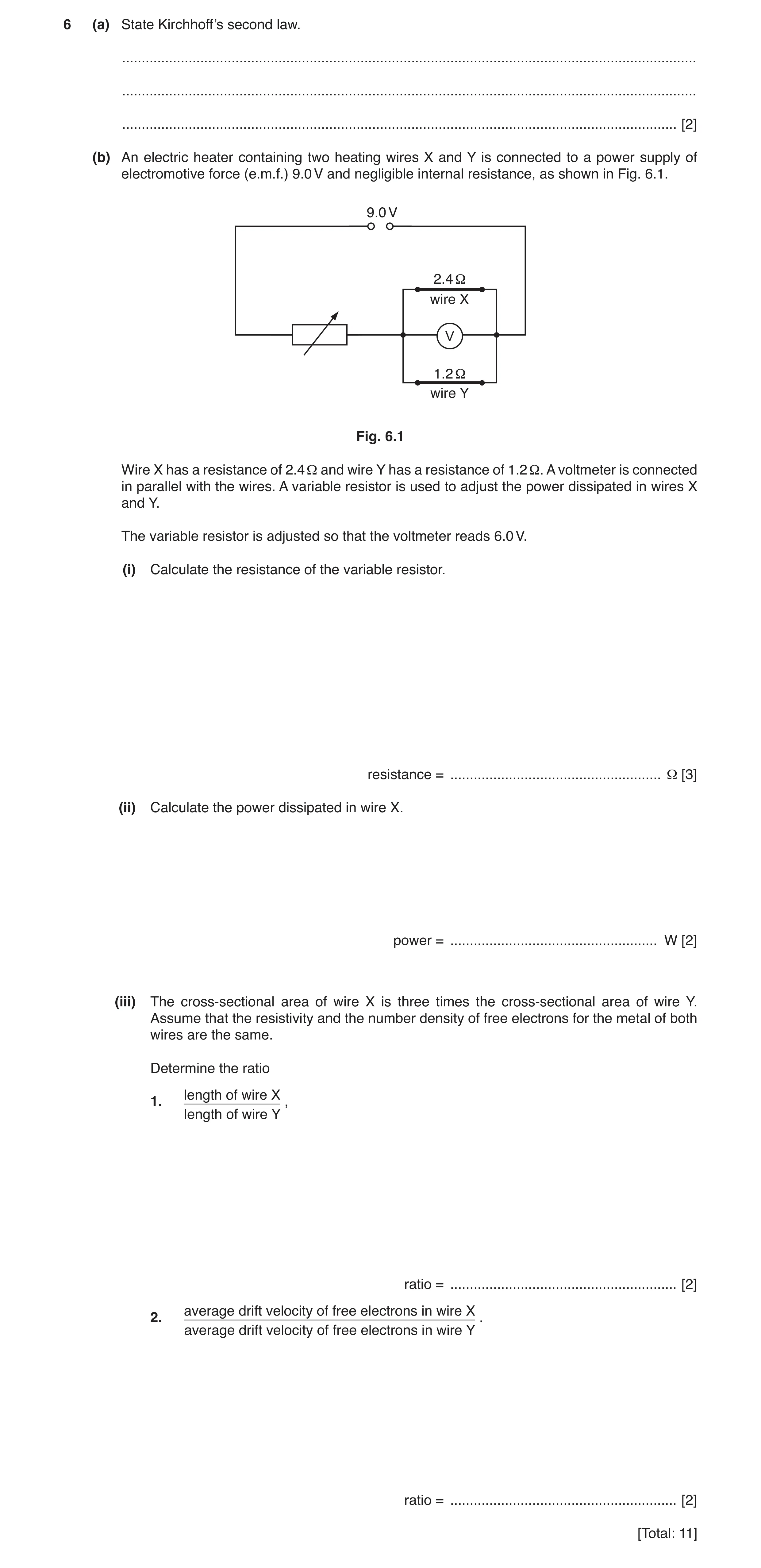
6 (a) State Kirchhoff’s second law. … … … [2] (b) An electric heater containing two heating wires X and Y is connected to a power supply of electromotive force (e.m.f.) 9.0 V and negligible internal resistance, as shown in Fig. 6.1. 9.0 V 2.4 Ω wire X V 1.2Ω wire Y Fig. 6.1 Wire X has a resistance of 2.4 Ω and wire Y has a resistance of 1.2 Ω. A voltmeter is connected in parallel with the wires. A variable resistor is used to adjust the power dissipated in wires X and Y. The variable resistor is adjusted so that the voltmeter reads 6.0 V. (i) Calculate the resistance of the variable resistor. resistance = … Ω [3] (ii) Calculate the power dissipated in wire X. power = … W [2] (iii) The cross-sectional area of wire X is three times the cross-sectional area of wire Y. Assume that the resistivity and the number density of free electrons for the metal of both wires are the same. Determine the ratio length of wire X 1. , length of wire Y ratio = … [2] average drift velocity of free electrons in wire X 2. . average drift velocity of free electrons in wire Y ratio = … [2] [Total: 11]
11 marks
Mark scheme: 6(a) sum of e.m.f.(s) equal to sum of p.d.(s) M1 around a loop/around a closed circuit A1 6(b)(i) current in variable resistor = (6.0 / 2.4) + (6.0 / 1.2) (= 7.5 A) C1 p.d. across variable resistor = 9.0 – 6.0 (= 3.0 V) C1 R = 3.0 / 7.5 = 0.40 Ω A1 or 1 1 1 2.4 1.2 T R = + RT = 0.80 (Ω) (C1) ( ) 3 9 0.80 R R = + or 3 6 0.8 R = (C1) R = 0.40 Ω (A1) 6(b)(ii) P = V2 / R or P = I2R or P = IV C1 P = 6.02 / 24 or 2.52 × 2.4 or 6.0 × 2.5 = 15 W A1 Question Answer Marks 6(b)(iii) 1. L R A ρ = C1 ratio = (2.4 / 1.2) × (3 / 1) = 6.0 A1 2. (I = nAvq) IX / IY = 2.5 / 5.0 or 1.2 / 2.4 or 0.5 C1 ratio = (2.5 / 5.0) × (1 / 3) or (1.2 / 2.4) × (1 / 3) = 0.17 A1
This question in 9702/21 Oct/Nov 2018
Q3 · State Kirchhoff’s second law 9702/22 May/June 2019
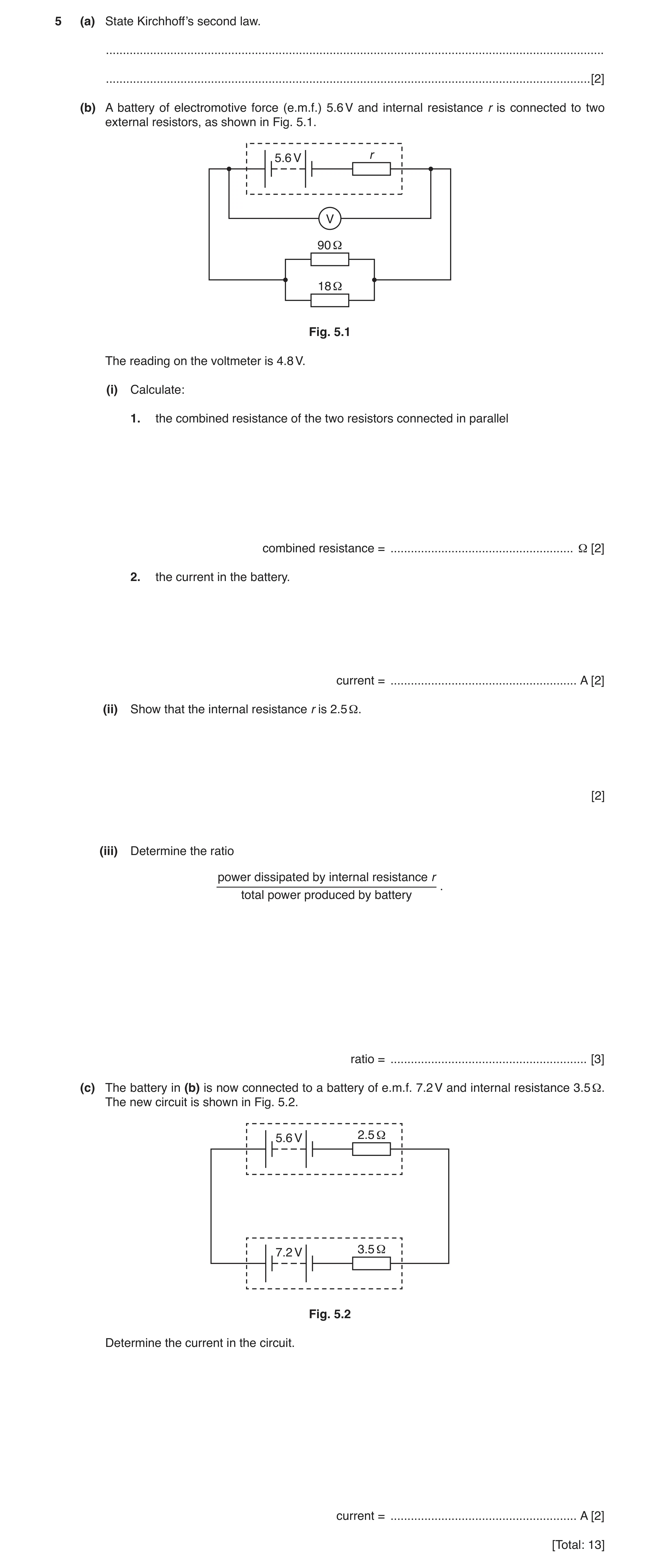
5 (a) State Kirchhoff’s second law. … … [2] (b) A battery of electromotive force (e.m.f.) 5.6 V and internal resistance r is connected to two external resistors, as shown in Fig. 5.1. 5.6 V r V 90 18 Fig. 5.1 The reading on the voltmeter is 4.8 V. (i) Calculate: 1. the combined resistance of the two resistors connected in parallel combined resistance = … Ω [2] 2. the current in the battery. current = … A [2] (ii) Show that the internal resistance r is 2.5 Ω. [2] (iii) Determine the ratio power dissipated by internal resistance r . total power produced by battery ratio = … [3] (c) The battery in (b) is now connected to a battery of e.m.f. 7.2 V and internal resistance 3.5 Ω. The new circuit is shown in Fig. 5.2. 5.6 V 2.5 3.5 7.2 V Fig. 5.2 Determine the current in the circuit. current = … A [2] [Total: 13]
13 marks
Mark scheme: 5(a) sum of e.m.f.(s) = sum of p.d.(s) M1 around a loop/around a closed circuit A1 5(b)(i) 1. 1 / R = 1 / R1 + 1 / R2 1 / R = 1 / 90 + 1 / 18 C1 R = 15 Ω A1 2. I = V / R C1 I = 4.8 / 15 or I = 4.8 / 90 + 4.8 / 18 I = 0.32 A A1 5(b)(ii) E = V + Ir or E = I(R + r) C1 5.6 = 4.8 + 0.32 r so r = 2.5 (Ω) or 5.6 = 0.32 × (15 + r) so r = 2.5 (Ω) A1 5(b)(iii) P = EI or P = VI or P = I2R or P = V2 / R C1 ratio = (0.322 × 2.5) / (5.6 × 0.32) or 0.256 / 1.792 C1 = 0.14 A1 Question Answer Marks 5(c) 7.2 – 5.6 – 2.5I – 3.5I = 0 C1 I = 0.27 A A1
This question in 9702/22 May/June 2019
Question 4 9702/22 Feb/March 2020
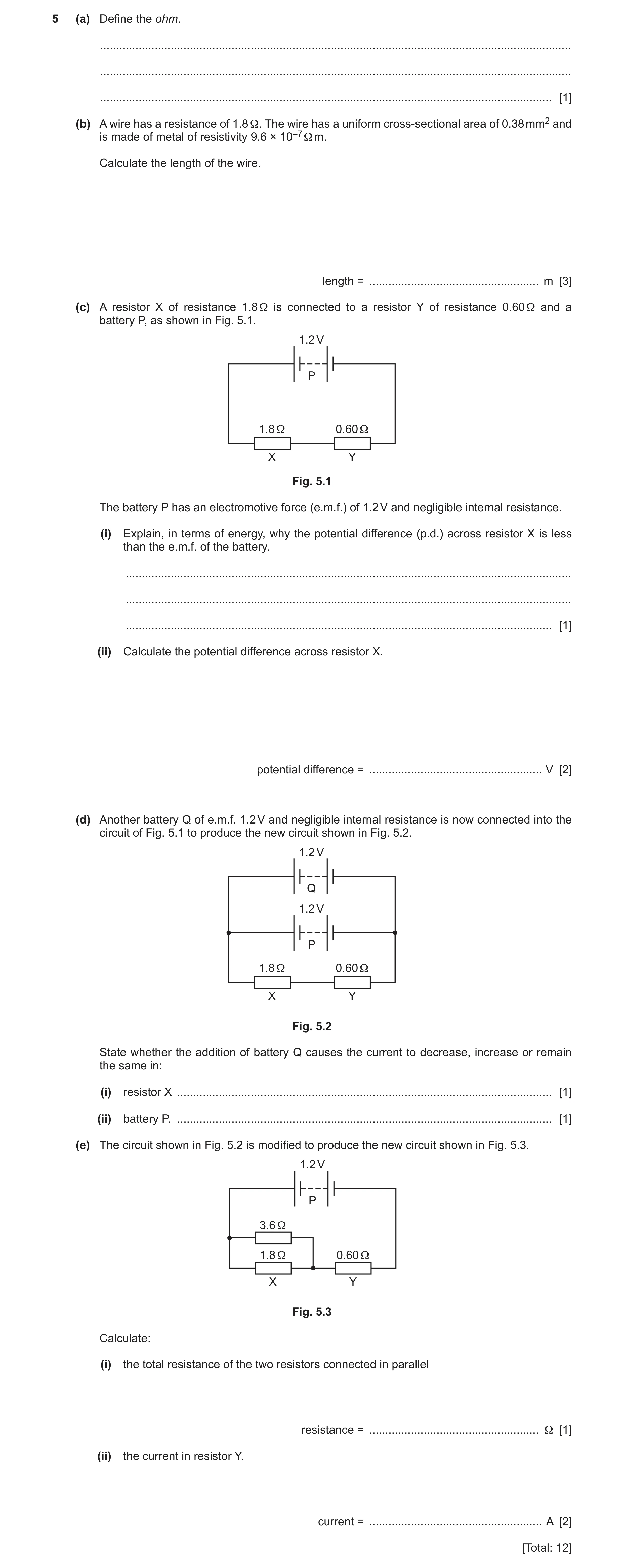
5 (a) Define the ohm. … … … [1] (b) A wire has a resistance of 1.8 Ω. The wire has a uniform cross-sectional area of 0.38 mm2 and is made of metal of resistivity 9.6 × 10⁻⁷ Ω m. Calculate the length of the wire. length = … m [3] (c) A resistor X of resistance 1.8 Ω is connected to a resistor Y of resistance 0.60 Ω and a battery P, as shown in Fig. 5.1. 1.2 V P 1.8 Ω 0.60 Ω X Y Fig. 5.1 The battery P has an electromotive force (e.m.f.) of 1.2 V and negligible internal resistance. (i) Explain, in terms of energy, why the potential difference (p.d.) across resistor X is less than the e.m.f. of the battery. … … … [1] (ii) Calculate the potential difference across resistor X. potential difference = … V [2] (d) Another battery Q of e.m.f. 1.2 V and negligible internal resistance is now connected into the circuit of Fig. 5.1 to produce the new circuit shown in Fig. 5.2. 1.2 V Q 1.2 V P 1.8 Ω 0.60 Ω X Y Fig. 5.2 State whether the addition of battery Q causes the current to decrease, increase or remain the same in: (i) resistor X … [1] (ii) battery P. … [1] (e) The circuit shown in Fig. 5.2 is modified to produce the new circuit shown in Fig. 5.3. 1.2 V P 3.6 Ω 1.8 Ω 0.60 Ω X Y Fig. 5.3 Calculate: (i) the total resistance of the two resistors connected in parallel resistance = … Ω [1] (ii) the current in resistor Y. current = … A [2] [Total: 12]
12 marks
Mark scheme: 5(a) volt / ampere B1 5(b) R = ρ L / A C1 L = (1.8 × 0.38 × 10–6) / 9.6 × 10⁻⁷ C1 = 0.71 m A1 5(c)(i) thermal energy is dissipated in resistor Y B1 5(c)(ii) V / 1.2 = 1.8 / (1.8 + 0.6) C1 V = 0.90 V A1 or I = 1.2 / (1.8 + 0.6) (= 0.50) (C1) V = 0.50 × 1.8 = 0.90 V (A1) 5(d)(i) remain the same B1 5(d)(ii) decrease B1 5(e)(i) 1 / R = 1 / 1.8 + 1 / 3.6 R = 1.2 Ω A1 Question Answer Marks 5(e)(ii) I = 1.2 / (1.2 + 0.60) C1 = 0.67 A A1 or VY = 1.2 × 0.60 / (1.2 + 0.60) (= 0.40) (C1) I = 0.40 / 0.60 = 0.67 A (A1)
This question in 9702/22 Feb/March 2020
Question 5 9702/23 May/June 2020
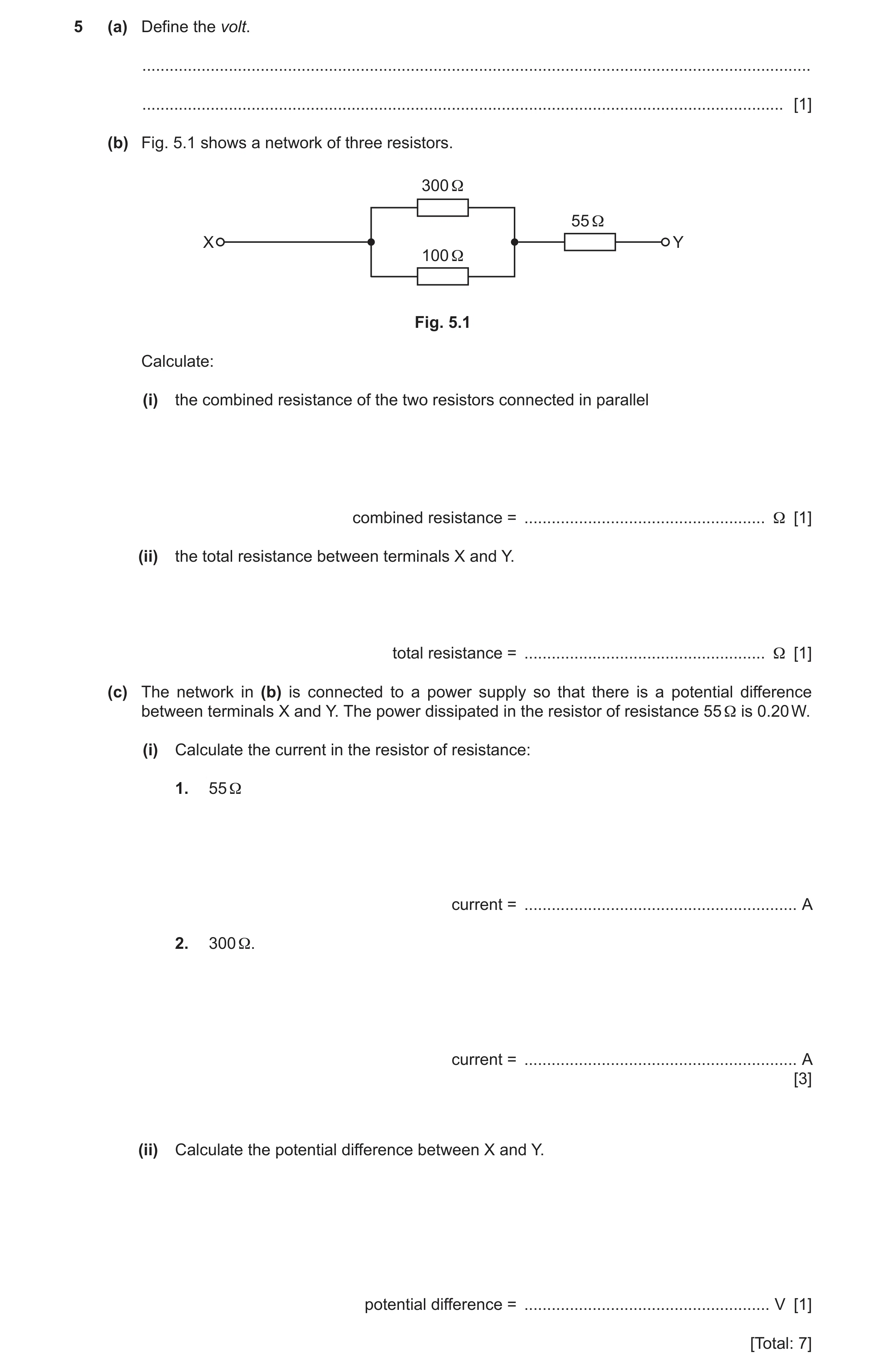
5 (a) Define the volt. … … [1] (b) Fig. 5.1 shows a network of three resistors. 300 Ω 55 Ω X Y 100 Ω Fig. 5.1 Calculate: (i) the combined resistance of the two resistors connected in parallel combined resistance = … Ω [1] (ii) the total resistance between terminals X and Y. total resistance = … Ω [1] (c) The network in (b) is connected to a power supply so that there is a potential difference between terminals X and Y. The power dissipated in the resistor of resistance 55 Ω is 0.20 W. (i) Calculate the current in the resistor of resistance: 1. 55 Ω current = … A 2. 300 Ω. current = … A [3] (ii) Calculate the potential difference between X and Y. potential difference = … V [1] [Total: 7]
7 marks
Mark scheme: 5(a) joule per coulomb B1 5(b)(i) 1 / R = 1 / R1 + 1 / R2 = 1 / 300 + 1 / 200 R = 75 Ω A1 5(b)(ii) R = 75 + 55 = 130 Ω A1 5(c)(i) 1. P = I2R or P = VI and V = IR C1 I = (0.20 / 55)0.5 = 0.060 A A1 2. I = 0.060 / 4 = 0.015 A A1 5(c)(ii) potential difference = 130 × 0.060 = 7.8 V A1 or potential difference = (300 × 0.015) + (55 × 0.060) = 7.8 V (other valid methods are also possible) (A1)
This question in 9702/23 May/June 2020
Q6 · State Kirchhoff’s first law 9702/22 Feb/March 2021
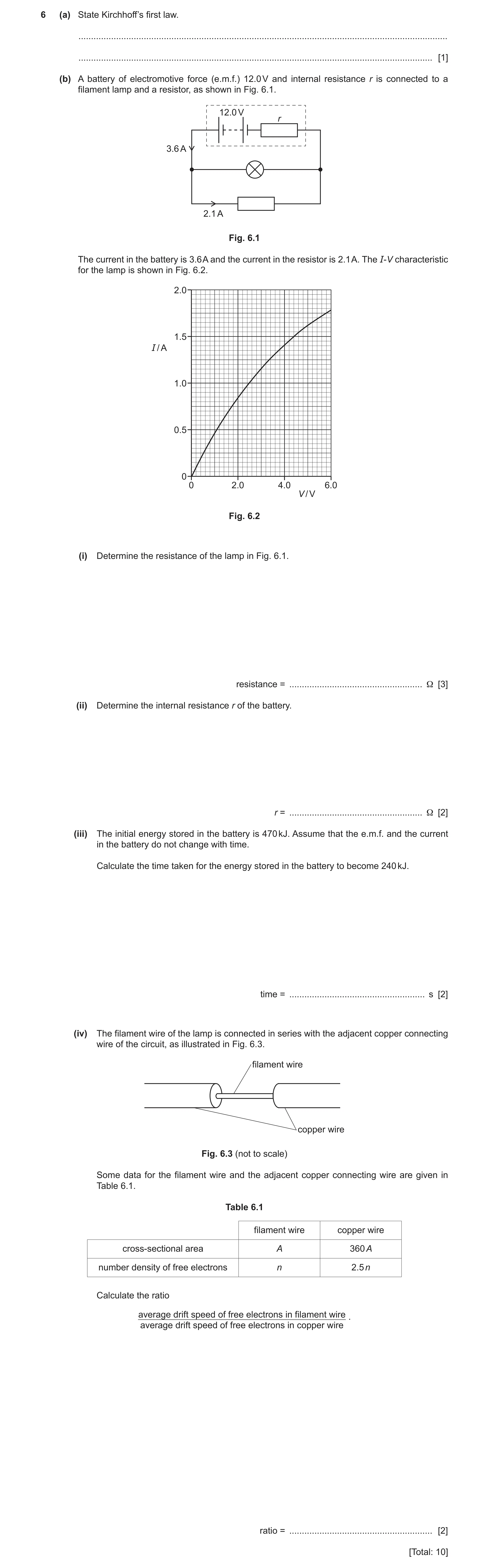
6 (a) State Kirchhoff’s first law. … … [1] (b) A battery of electromotive force (e.m.f.) 12.0 V and internal resistance r is connected to a filament lamp and a resistor, as shown in Fig. 6.1. 12.0 V r 3.6 A 2.1 A Fig. 6.1 The current in the battery is 3.6 A and the current in the resistor is 2.1 A. The I-V characteristic for the lamp is shown in Fig. 6.2. 2.0 1.5 I / A 1.0 0.5 0 0 2.0 4.0 6.0 V / V Fig. 6.2 (i) Determine the resistance of the lamp in Fig. 6.1. resistance = … Ω [3] (ii) Determine the internal resistance r of the battery. r = … Ω [2] (iii) The initial energy stored in the battery is 470 kJ. Assume that the e.m.f. and the current in the battery do not change with time. Calculate the time taken for the energy stored in the battery to become 240 kJ. time = … s [2] (iv) The filament wire of the lamp is connected in series with the adjacent copper connecting wire of the circuit, as illustrated in Fig. 6.3. filament wire copper wire Fig. 6.3 (not to scale) Some data for the filament wire and the adjacent copper connecting wire are given in Table 6.1. Table 6.1 filament wire copper wire cross-sectional area A 360 A number density of free electrons n 2.5 n Calculate the ratio average drift speed of free electrons in filament wire . average drift speed of free electrons in copper wire ratio = … [2] [Total: 10]
10 marks
Mark scheme: 6(a) sum of current(s) into junction = sum of current(s) out of junction or (algebraic) sum of current(s) at a junction is zero B1 6(b)(i) I = 3.6 – 2.1 = 1.5 C1 V = 4.4 C1 R = 4.4 / 1.5 = 2.9 Ω A1 6(b)(ii) 12.0 = 4.4 + 3.6r or 12.0 = 3.6 (1.2 + r ) C1 r = 2.1 Ω A1 6(b)(iii) t = (470 × 103 – 240 × 103 ) / (12 × 3.6) C1 = 5300 s A1 6(b)(iv) I = Anvq ratio = (360A / A) × (2.5n / n) or 360 × 2.5 C1 = 900 A1
This question in 9702/22 Feb/March 2021
Question 7 9702/22 May/June 2021
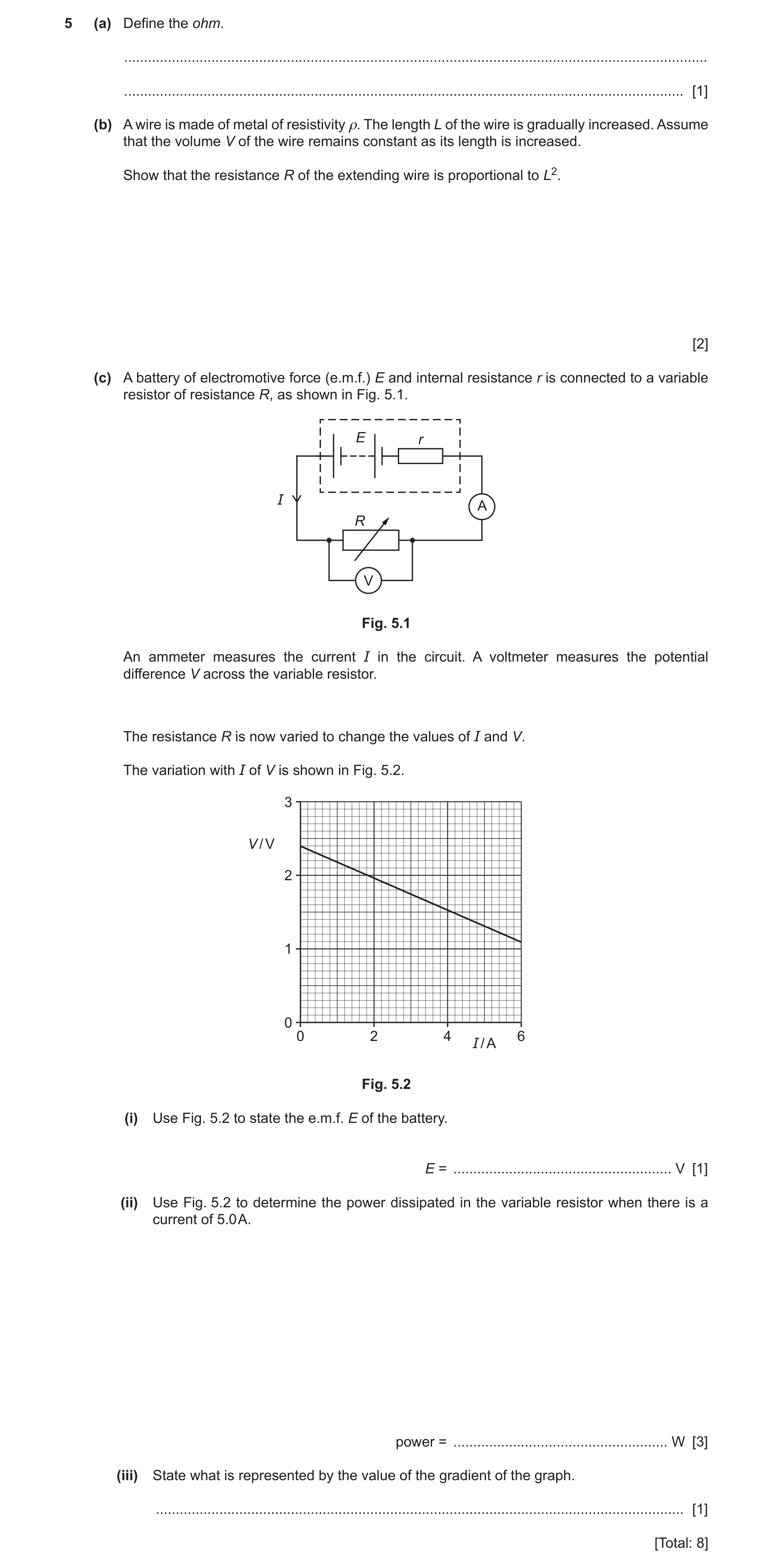
5 (a) Define the ohm. … … [1] (b) A wire is made of metal of resistivity ρ. The length L of the wire is gradually increased. Assume that the volume V of the wire remains constant as its length is increased. Show that the resistance R of the extending wire is proportional to L2. [2] (c) A battery of electromotive force (e.m.f.) E and internal resistance r is connected to a variable resistor of resistance R, as shown in Fig. 5.1. E r I A R VV Fig. 5.1 An ammeter measures the current I in the circuit. A voltmeter measures the potential difference V across the variable resistor. The resistance R is now varied to change the values of I and V. The variation with I of V is shown in Fig. 5.2. 3 V / V 2 1 0 0 2 4 6 I / A Fig. 5.2 (i) Use Fig. 5.2 to state the e.m.f. E of the battery. E = … V [1] (ii) Use Fig. 5.2 to determine the power dissipated in the variable resistor when there is a current of 5.0 A. power = … W [3] (iii) State what is represented by the value of the gradient of the graph. … [1] [Total: 8]
8 marks
Mark scheme: 5(a) volt / ampere B1 5(b) R = ρL / A B1 (A = V / L) (so) R = ρL2 / V (with ρ and V constant so R ∝ L2) B1 5(c)(i) E = 2.4 V A1 5(c)(ii) P = VI or I2R or V2 / R C1 = 1.3 × 5.0 or 5.02 × 0.26 or 1.32 / 0.26 C1 = 6.5 W A1 5(c)(iii) (–) internal resistance or (–) r B1
This question in 9702/22 May/June 2021
Q8 · Define the electromotive force (e.m.f.) of a source 9702/23 May/June 2021
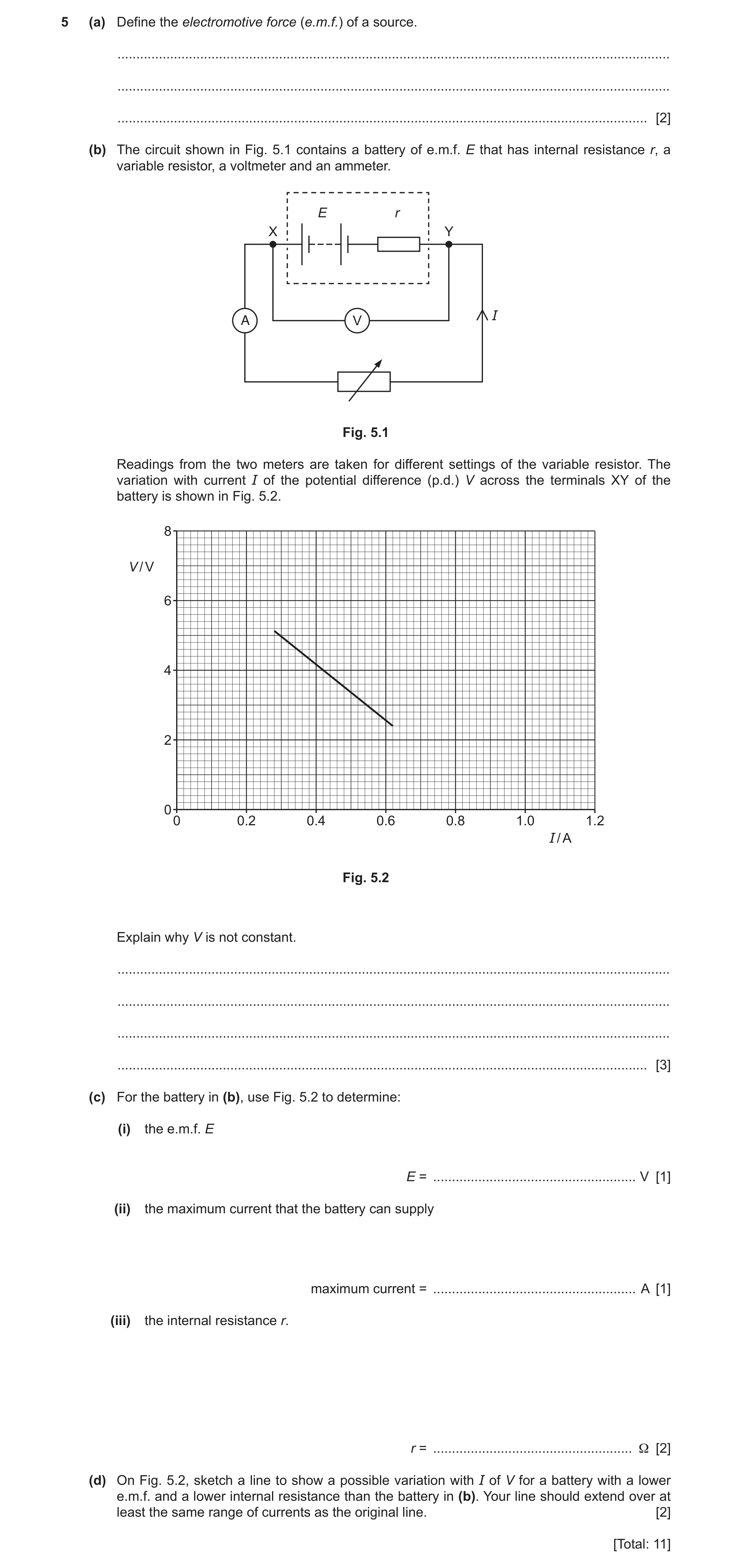
5 (a) Define the electromotive force (e.m.f.) of a source. … … … [2] (b) The circuit shown in Fig. 5.1 contains a battery of e.m.f. E that has internal resistance r, a variable resistor, a voltmeter and an ammeter. E r X Y A V I Fig. 5.1 Readings from the two meters are taken for different settings of the variable resistor. The variation with current I of the potential difference (p.d.) V across the terminals XY of the battery is shown in Fig. 5.2. 8 V / V 6 4 2 0 0 0.2 0.4 0.6 0.8 1.0 1.2 I / A Fig. 5.2 Explain why V is not constant. … … … … [3] (c) For the battery in (b), use Fig. 5.2 to determine: (i) the e.m.f. E E = … V [1] (ii) the maximum current that the battery can supply maximum current = … A [1] (iii) the internal resistance r. r = … Ω [2] (d) On Fig. 5.2, sketch a line to show a possible variation with I of V for a battery with a lower e.m.f. and a lower internal resistance than the battery in (b). Your line should extend over at least the same range of currents as the original line. [2] [Total: 11]
11 marks
Mark scheme: 5(a) energy per unit charge B1 energy transferred by source driving charge around the complete circuit or energy transferred from other forms to electrical energy B1 5(b) there is a p.d. across the internal resistance/r B1 change in current/I results in a change in p.d. across the internal resistance B1 V = E – p.d. across internal resistance or change in p.d. across r causes a change in V (as e.m.f. is constant) B1 5(c)(i) E = 7.4 V A1 5(c)(ii) maximum current = 0.92 A A1 5(c)(iii) r = E / IMAX or (–)gradient C1 e.g. r = 7.4 / 0.92 = 8.0 Ω A1 5(d) straight line with negative gradient that is smaller in magnitude than the original line B1 line which would have intercept on V-axis below the original line B1 Question Answer Marks
This question in 9702/23 May/June 2021
Q9 · State Kirchhoff’s first law 9702/21 Oct/Nov 2021
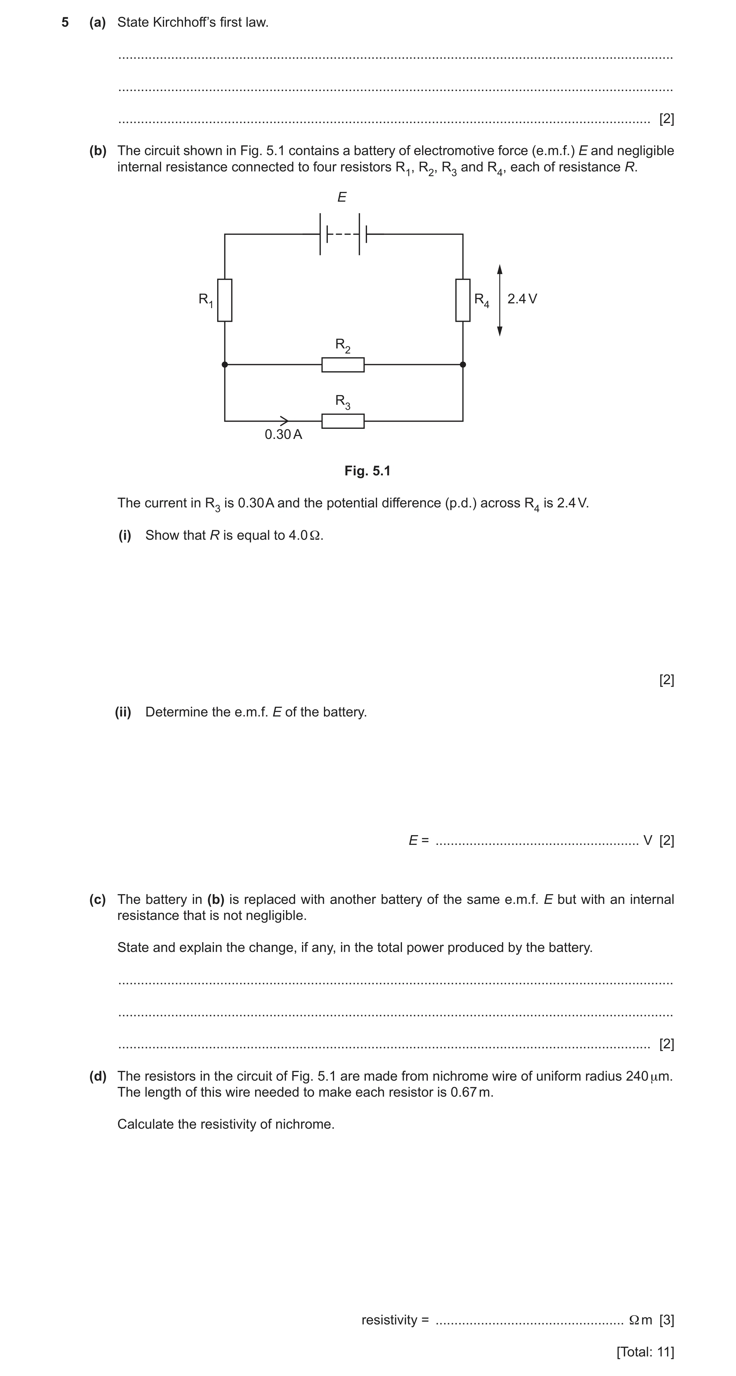
5 (a) State Kirchhoff’s first law. … … … [2] (b) The circuit shown in Fig. 5.1 contains a battery of electromotive force (e.m.f.) E and negligible internal resistance connected to four resistors R1, R2, R3 and R4, each of resistance R. E R1 R4 2.4 V R2 R3 0.30 A Fig. 5.1 The current in R3 is 0.30 A and the potential difference (p.d.) across R4 is 2.4 V. (i) Show that R is equal to 4.0 Ω. [2] (ii) Determine the e.m.f. E of the battery. E = … V [2] (c) The battery in (b) is replaced with another battery of the same e.m.f. E but with an internal resistance that is not negligible. State and explain the change, if any, in the total power produced by the battery. … … … [2] (d) The resistors in the circuit of Fig. 5.1 are made from nichrome wire of uniform radius 240 μm. The length of this wire needed to make each resistor is 0.67 m. Calculate the resistivity of nichrome. resistivity = … Ω m [3] [Total: 11]
11 marks
Mark scheme: 5(a) sum of current(s) in = sum of current(s) out or (algebraic) sum of current(s) is zero M1 at a junction (in a circuit) A1 5(b)(i) (current in R4 or R1 =) 0.30 + 0.30 (= 0.60 A) B1 (R =) 2.4 / 0.60 = 4.0 (Ω) A1 or (p.d. across R3 or R2 =) 2.4 / 2 (= 1.2 V) (B1) (R =) 1.2 / 0.30 = 4.0 (Ω) (A1) 5(b)(ii) E = 2.4 + 2.4 + 1.2 C1 = 6.0 V A1 or total resistance = 10 (Ω) (C1) E = 10 × 0.60 = 6.0 V (A1) 5(c) total resistance increases B1 current decreases (in battery) so total power decreases B1 Question Answer Marks 5(d) resistivity = RA / L C1 = 4.0 × π × (240 × 10–6)2 / 0.67 C1 = 1.1 × 10⁻⁶ Ω m A1
This question in 9702/21 Oct/Nov 2021
Q10 · State Kirchhoff’s second law 9702/23 Oct/Nov 2022
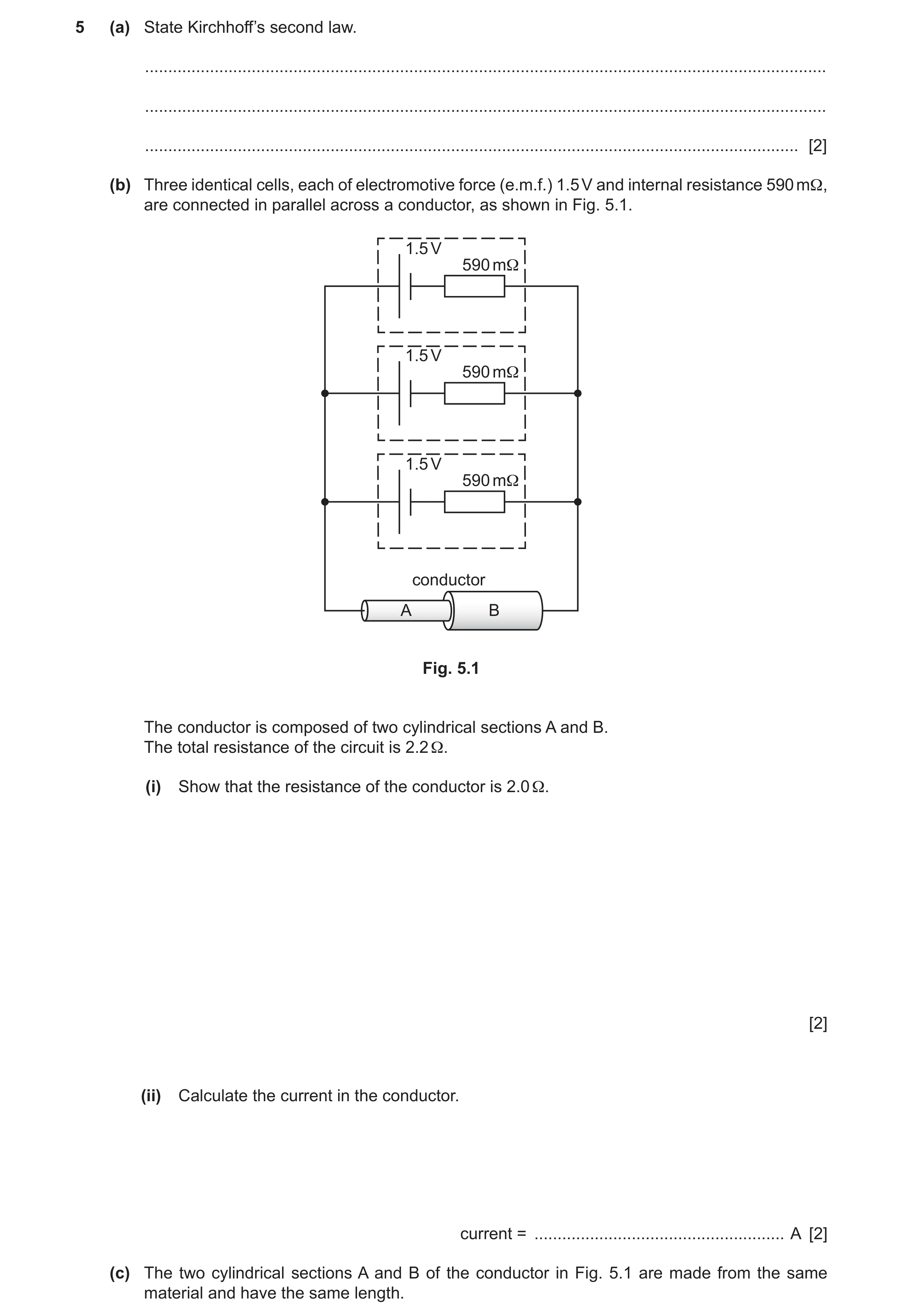
5 (a) State Kirchhoff’s second law. … … … [2] (b) Three identical cells, each of electromotive force (e.m.f.) 1.5 V and internal resistance 590 mΩ, are connected in parallel across a conductor, as shown in Fig. 5.1. 1.5 V 590 mΩ 1.5 V 590 mΩ 1.5 V 590 mΩ conductor A B Fig. 5.1 The conductor is composed of two cylindrical sections A and B. The total resistance of the circuit is 2.2 Ω. (i) Show that the resistance of the conductor is 2.0 Ω. [2] (ii) Calculate the current in the conductor. current = … A [2] (c) The two cylindrical sections A and B of the conductor in Fig. 5.1 are made from the same material and have the same length.
6 marks
Mark scheme: 5(a) sum of e.m.f.(s) = sum of p.d.(s) M1 or (algebraic) sum of e.m.f.(s) and p.d.(s) is zero around a loop / around a closed circuit A1 5(b)(i) 1 / r(T) = 1 / 0.59 + 1 / 0.59 + 1 / 0.59 B1 (r(T) =) 0.197 () A1 (R =) 2.2 – 0.197 = 2.0 or I = 1.5 / 2.2 (= 0.68 A) and i = 0.68 / 3 (where I is the circuit current and i is the current from each cell) (B1) (E = IR + ir =) 1.5 = 0.68R + (0.68 / 3) 0.59 and R = 2.0 (A1) 5(b)(ii) current = 1.5 / 2.2 C1 = 0.68 A A1 or p.d. across cell = p.d. across conductor (C1) 1.5 – 0.59I = 3I 2.0 so I = 0.228 A (where I is current in cell) current = 3 0.228 = 0.68 A (A1) or current in conductor = 3 current in cell (C1) V / 2.0 = 3 (1.5 – V) / 0.59 (where V is p.d. across conductor) V = 1.37 V current = 1.37 / 2.0 = 0.68 A (A1) 5(c)(i) R = L / A C1 R = 4L / d 2 C1 (and L are the same so) RA / RB = 7.62 / 4.32 = 3.1 A1 5(c)(ii) I = Anvq and I, n, q are same / equal / constant B1 v A A B dB 2 A1 = = v B A A dA 2 ratio = 7.62 / 4.32 = 3.1 5(d) combined internal resistance (of the cells) will be greater B1 or total / circuit resistance (of circuit) greater (because a parallel resistance removed) more ‘lost volts’ (inside each cell) or internal resistances take a greater share of total p.d. or conductor gets a smaller share M1 of the total p.d. or current in conductor/total current decreases (so) potential difference (across conductor) decreases A1
This question in 9702/23 Oct/Nov 2022
Q11 · A student sets up a circuit with a battery, an ammeter, a heater and a light-dependent… 9702/23 May/June 2023
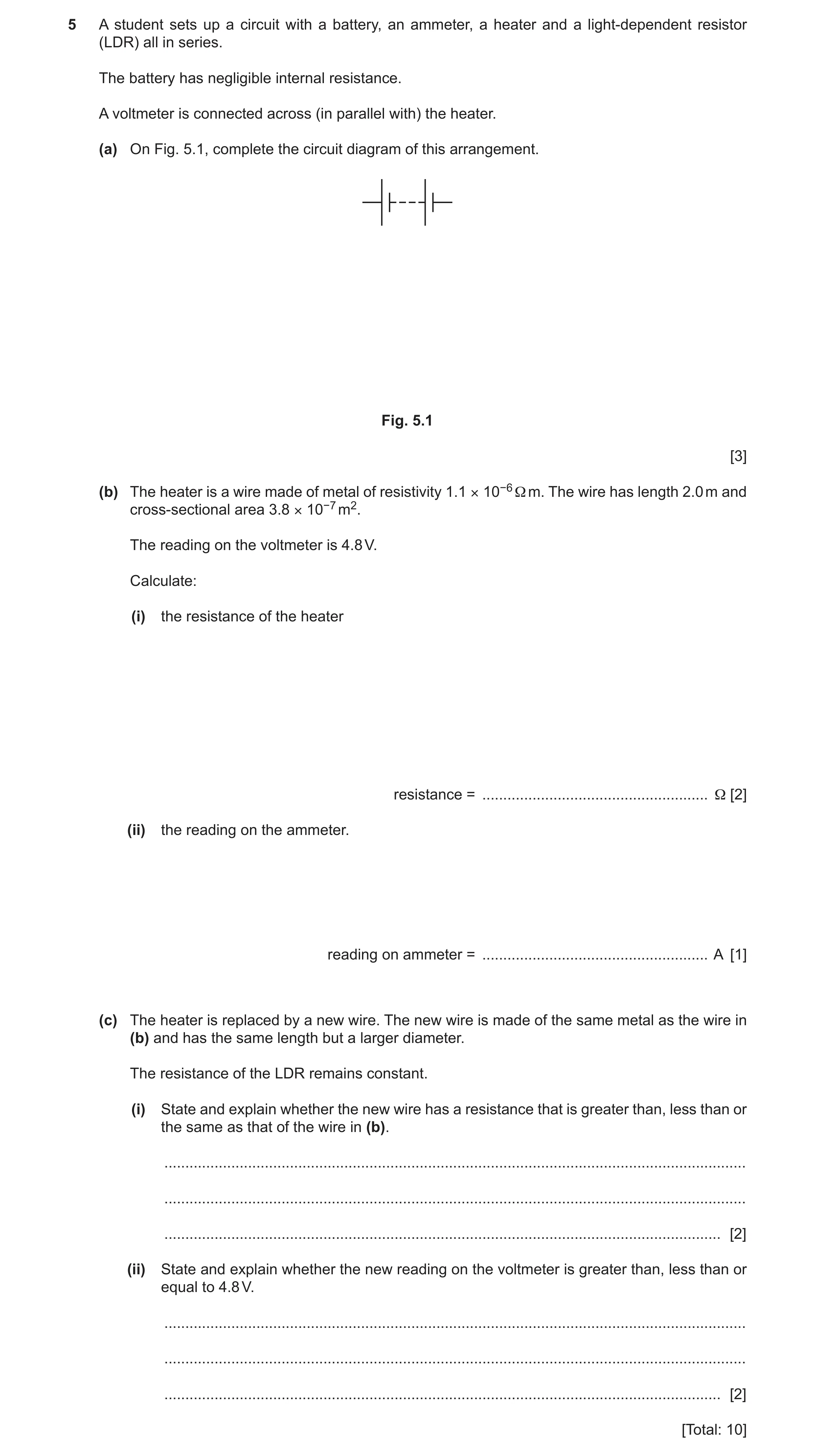
5 A student sets up a circuit with a battery, an ammeter, a heater and a light-dependent resistor (LDR) all in series. The battery has negligible internal resistance. A voltmeter is connected across (in parallel with) the heater. (a) On Fig. 5.1, complete the circuit diagram of this arrangement. Fig. 5.1 [3] (b) The heater is a wire made of metal of resistivity 1.1 × 10⁻⁶ Ω m. The wire has length 2.0 m and cross-sectional area 3.8 × 10⁻⁷ m2. The reading on the voltmeter is 4.8 V. Calculate: (i) the resistance of the heater resistance = … Ω [2] (ii) the reading on the ammeter. reading on ammeter = … A [1] (c) The heater is replaced by a new wire. The new wire is made of the same metal as the wire in (b) and has the same length but a larger diameter. The resistance of the LDR remains constant. (i) State and explain whether the new wire has a resistance that is greater than, less than or the same as that of the wire in (b). … … … [2] (ii) State and explain whether the new reading on the voltmeter is greater than, less than or equal to 4.8 V. … … … [2] [Total: 10]
10 marks
Mark scheme: 5(a) correct symbol for the heater or for the LDR M1 all correct symbols in series (ignore voltmeter) and no extra symbols A1 correct symbol for voltmeter and in parallel with the heater B1 5(b)(i) R = L / A C1 = (1.1 10−6 2.0) / 3.8 10−7 = 5.8 A1 5(b)(ii) I = 4.8 / 5.8 = 0.83 A A1 5(c)(i) A larger (for new wire) or A d 2 (and d larger for new wire) or R 1 / d 2 (and d larger for new wire) M1 so R is less (than that of first wire) A1 5(c)(ii) (heater / total resistance decreases so) current (in circuit) increases (so p.d. across LDR increases) or heater resistance decreases so it has a smaller share/proportion/fraction of the (total) voltage / e.m.f. M1 (so voltmeter) reading is less (than 4.8 V) A1
This question in 9702/23 May/June 2023
Q12 · A battery is connected in a circuit with a light-dependent resistor (LDR), two fixed… 9702/21 Oct/Nov 2023
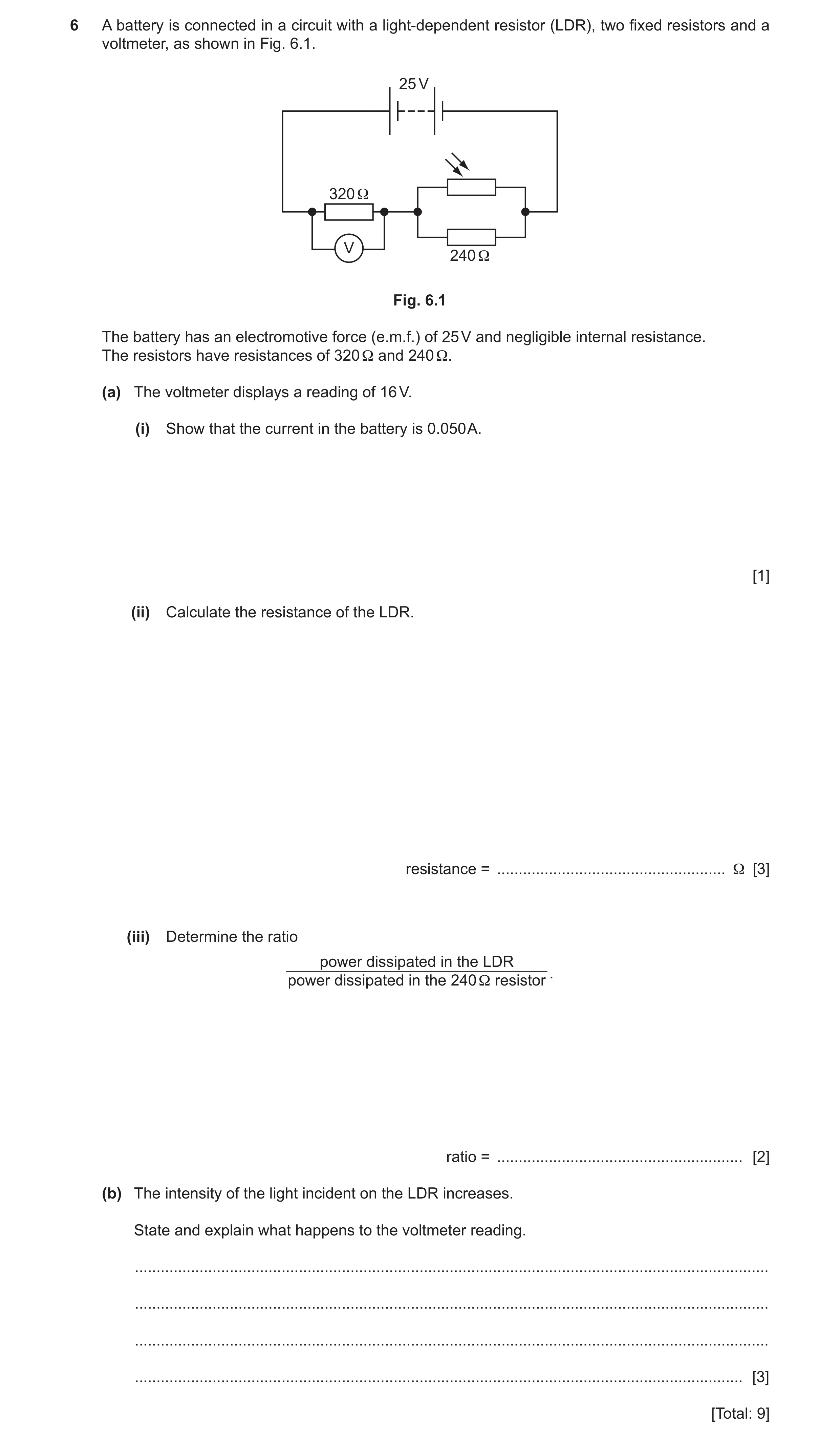
6 A battery is connected in a circuit with a light-dependent resistor (LDR), two fixed resistors and a voltmeter, as shown in Fig. 6.1. 25 V 320 Ω V 240 Ω Fig. 6.1 The battery has an electromotive force (e.m.f.) of 25 V and negligible internal resistance. The resistors have resistances of 320 Ω and 240 Ω. (a) The voltmeter displays a reading of 16 V. (i) Show that the current in the battery is 0.050 A. [1] (ii) Calculate the resistance of the LDR. resistance = … Ω [3] (iii) Determine the ratio power dissipated in the LDR . power dissipated in the 240 Ω resistor ratio = … [2] (b) The intensity of the light incident on the LDR increases. State and explain what happens to the voltmeter reading. … … … … [3] [Total: 9]
9 marks
Mark scheme: 6(a)(i) (I =) 16 / 320 = 0.050 (A) A1 6(a)(ii) R = (25 – 16) / 0.050 C1 or R = (9 / 16) 320 or R = (25 / 0.050) – 320 R = 180 () C1 R(LDR) = [(1 / 180) – (1 / 240)]–1 A1 = 720 or I = (25 – 16) / 240 (C1) ( = 0.0375 A) I (LDR) = 0.050 – 0.0375 (C1) ( = 0.0125 A) R(LDR) = 9.0 / 0.0125 (A1) = 720 6(a)(iii) P = V 2 / R or P = VI or P = I2R C1 ratio = (92 / 720) / (92 / 240) A1 or ratio = (9 0.0125) / (9 0.0375) or ratio = (0.01252 720) / (0.03752 240) ratio = 0.1125 / 0.3375 = 0.33 6(b) resistance of LDR decreases B1 resistance of parallel combination decreases M1 or total resistance (of circuit) decreases or current in resistor of resistance 320 increases or potential difference across parallel combination / LDR / 240 resistor decreases voltmeter reading increases A1
This question in 9702/21 Oct/Nov 2023
Q13 · Define electric potential difference 9702/22 Feb/March 2024
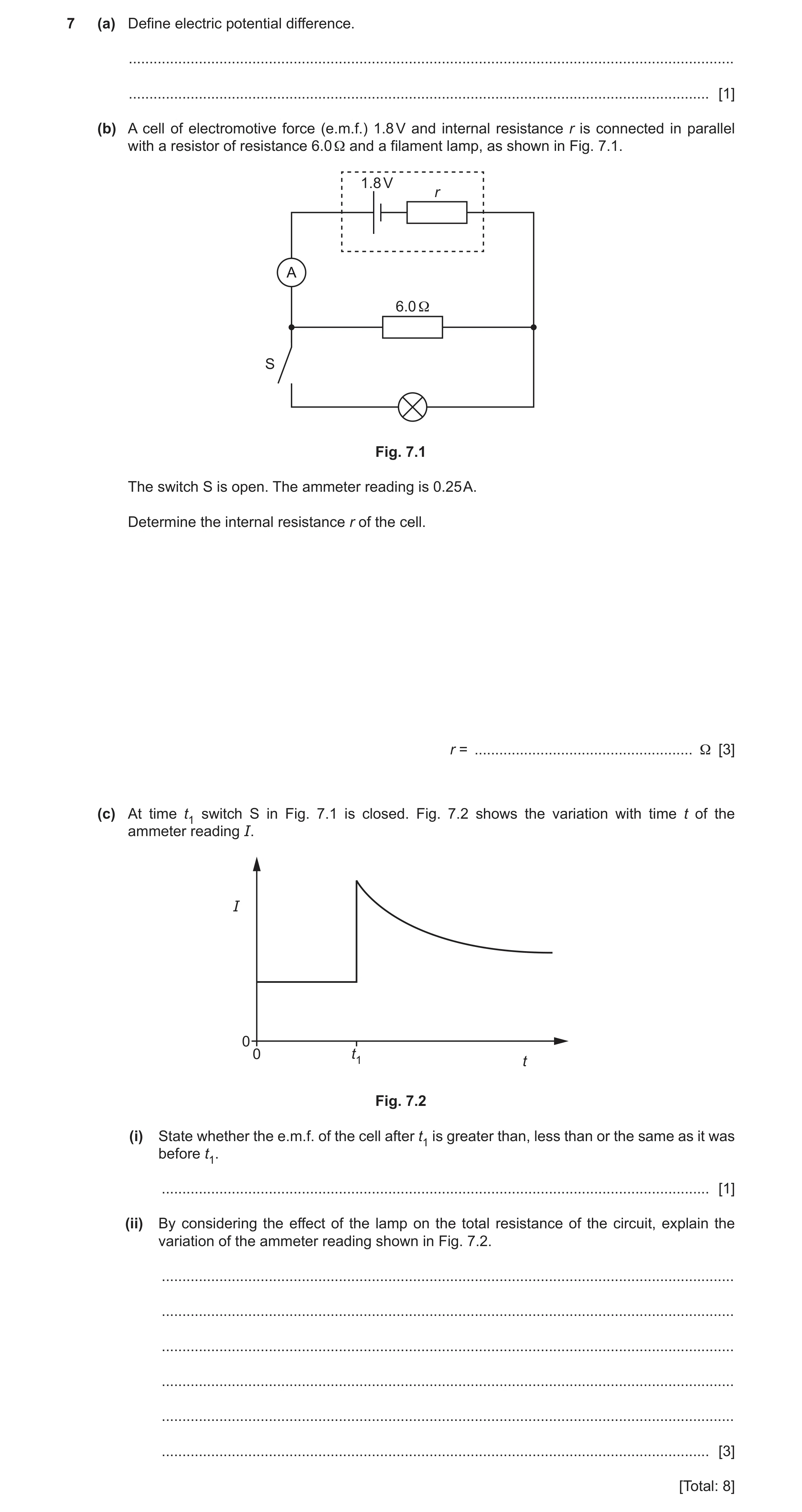
7 (a) Define electric potential difference. … … [1] (b) A cell of electromotive force (e.m.f.) 1.8 V and internal resistance r is connected in parallel with a resistor of resistance 6.0 Ω and a filament lamp, as shown in Fig. 7.1. 1.8 V r A 6.0 Ω S Fig. 7.1 The switch S is open. The ammeter reading is 0.25 A. Determine the internal resistance r of the cell. r = … Ω [3] (c) At time t1 switch S in Fig. 7.1 is closed. Fig. 7.2 shows the variation with time t of the ammeter reading I. I 0 0 t1 t Fig. 7.2 (i) State whether the e.m.f. of the cell after t1 is greater than, less than or the same as it was before t1. … [1] (ii) By considering the effect of the lamp on the total resistance of the circuit, explain the variation of the ammeter reading shown in Fig. 7.2. … … … … … … [3] [Total: 8]
8 marks
Mark scheme: 7(a) energy (transferred) per (unit) charge B1 7(b) V = 0.25 6 C1 =1.5 Ir = E – IR C1 Ir = 1.8 – 1.5 = 0.3 r = 0.3 / 0.25 A1 = 1.2 or (C1) (Total) R = 1.8 / 0.25 = 7.2 E / I = (R + r) 1.8/0.25 = 6 + r (C1) r = 7.2 – 6 (A1) = 1.2 7(c)(i) The same B1 7(c)(ii) Any 3 from: B3 • before t1 / when current constant, the (total) resistance is constant • at t1 / when current increases, the (total) resistance decreases (due to decrease of external resistance) • (after t1) temperature (of lamp) increases (so the resistance of the lamp increases) • (after t1) resistance of lamp increases (so total resistance increases so the current in the ammeter decreases)
This question in 9702/22 Feb/March 2024
Q14 · State Kirchhoff’s first law 9702/21 May/June 2024
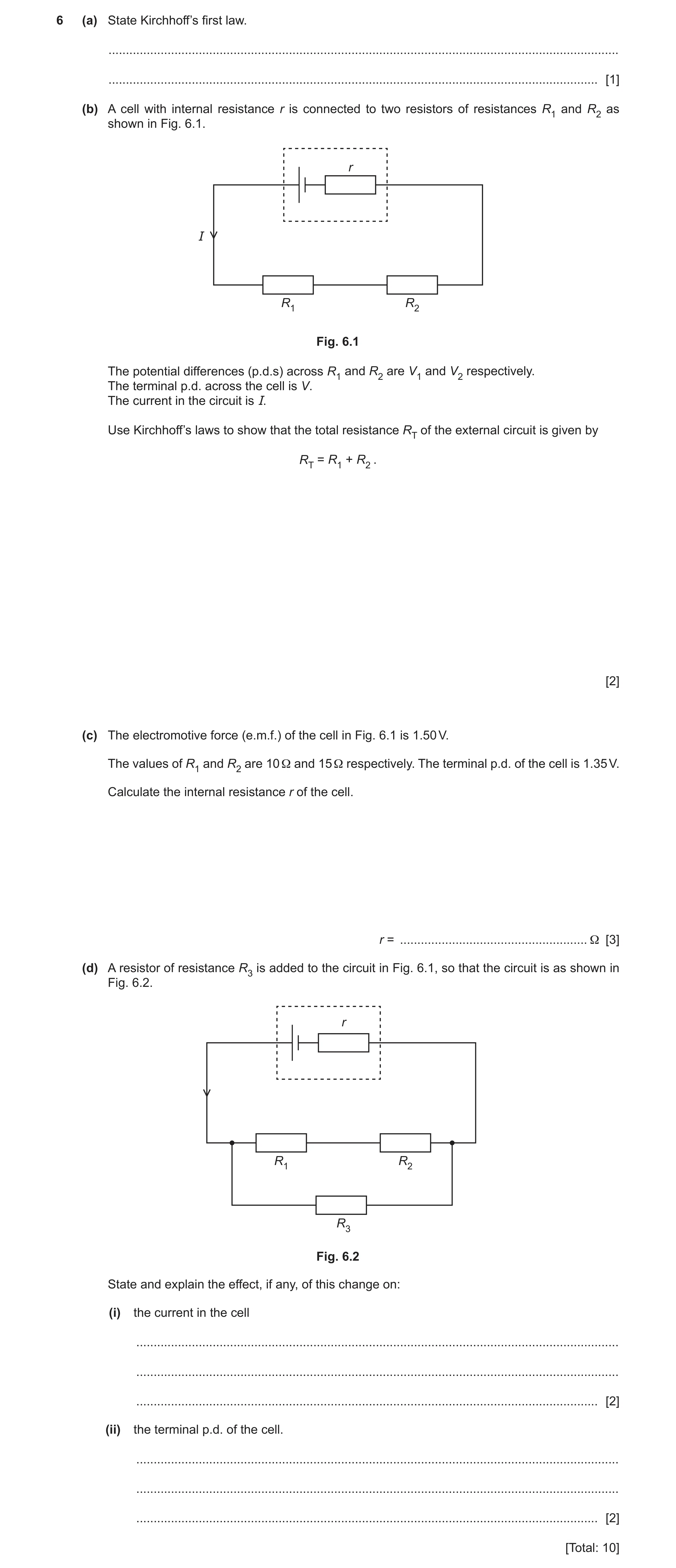
6 (a) State Kirchhoff’s first law. … … [1] (b) A cell with internal resistance r is connected to two resistors of resistances R1 and R2 as shown in Fig. 6.1. r I R1 R2 Fig. 6.1 The potential differences (p.d.s) across R1 and R2 are V1 and V2 respectively. The terminal p.d. across the cell is V. The current in the circuit is I. Use Kirchhoff’s laws to show that the total resistance RT of the external circuit is given by RT = R1 + R2 . [2] (c) The electromotive force (e.m.f.) of the cell in Fig. 6.1 is 1.50 V. The values of R1 and R2 are 10 Ω and 15 Ω respectively. The terminal p.d. of the cell is 1.35 V. Calculate the internal resistance r of the cell. r = … Ω [3] (d) A resistor of resistance R3 is added to the circuit in Fig. 6.1, so that the circuit is as shown in Fig. 6.2. r R1 R2 R3 Fig. 6.2 State and explain the effect, if any, of this change on: (i) the current in the cell … … … [2] (ii) the terminal p.d. of the cell. … … … [2] [Total: 10]
10 marks
Mark scheme: 6(a) sum of current(s) entering a junction = sum of current(s) leaving (the same junction) or (algebraic) sum of current (s) at a junction is zero B1 6(b) (by Kirchhoff’s second law) V = V1 + V2 B1 so IRT = IR1 + IR2 (and cancelling I gives) RT = R1 + R2 or V / I = V1/ I + V2 / I (and substituting R gives) RT = R1 + R2 B1 6(c) current in circuit = 1.35 / (10 + 15) (= 0.054 A) C1 r = (E – V) / I C1 = (1.5 – 1.35) / 0.054 = 2.8 A1 or by potential divider principle 0.15 1.35 25 r (C2) r = 2.8 (A1) or I = 1.35 / (10 + 15) (= 0.054 A) (C1) total resistance = 1.50 / 0.054 (= 27.8 ) r = 27.8 – 25 (C1) r = 2.8 (A1) Question Answer Marks 6(d)(i) the (total) resistance (of the circuit) has decreased (and e.m.f. is unchanged) M1 (the current (in the cell) will) increase A1 6(d)(ii) (as the current is greater and so there is a) larger p.d. across the internal resistance M1 (terminal p.d. will) decrease A1
This question in 9702/21 May/June 2024
Q15 · State Kirchhoff’s second law 9702/22 May/June 2024
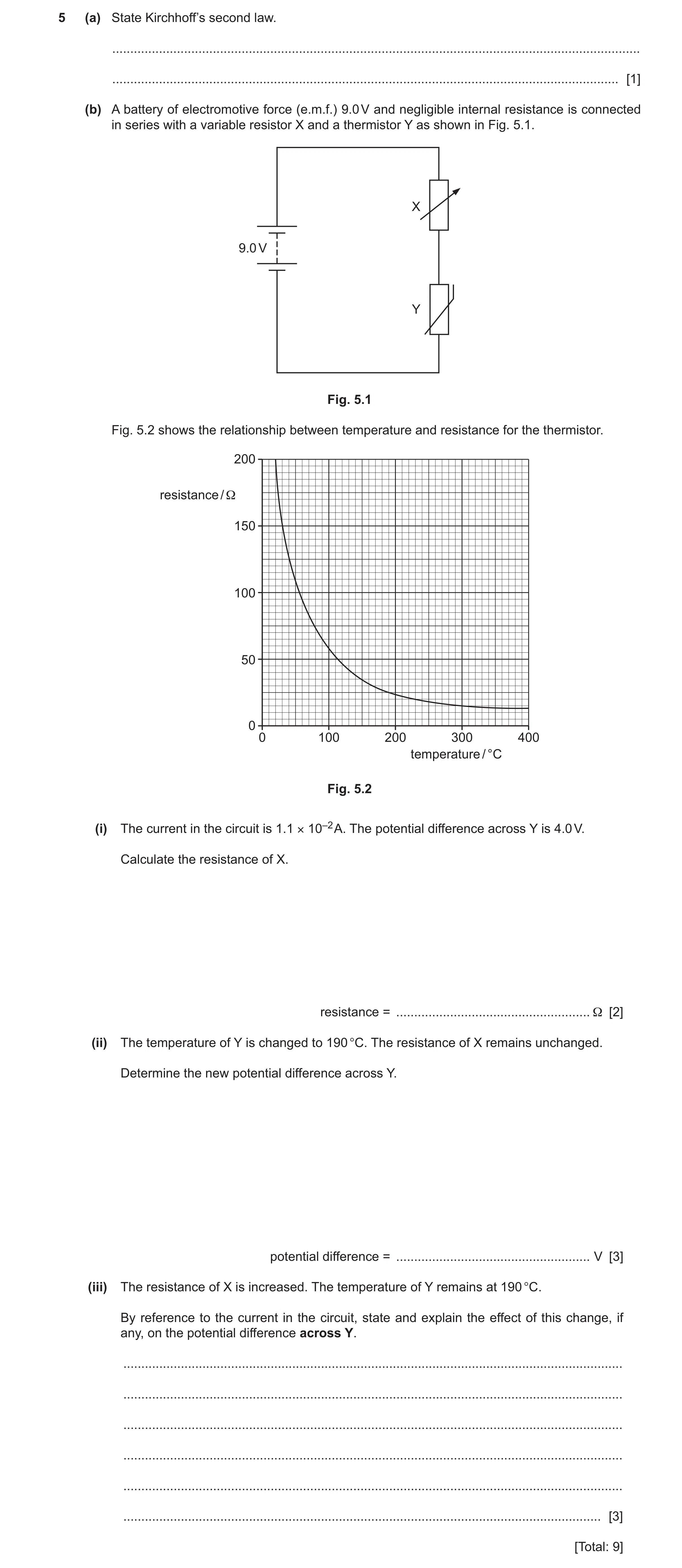
5 (a) State Kirchhoff’s second law. … … [1] (b) A battery of electromotive force (e.m.f.) 9.0 V and negligible internal resistance is connected in series with a variable resistor X and a thermistor Y as shown in Fig. 5.1. X 9.0 V Y Fig. 5.1 Fig. 5.2 shows the relationship between temperature and resistance for the thermistor. 200 resistance / Ω 150 100 50 0 0 100 200 300 400 temperature / °C Fig. 5.2 (i) The current in the circuit is 1.1 × 10⁻² A. The potential difference across Y is 4.0 V. Calculate the resistance of X. resistance = … Ω [2] (ii) The temperature of Y is changed to 190 °C. The resistance of X remains unchanged. Determine the new potential difference across Y. potential difference = … V [3] (iii) The resistance of X is increased. The temperature of Y remains at 190 °C. By reference to the current in the circuit, state and explain the effect of this change, if any, on the potential difference across Y. … … … … … … [3] [Total: 9]
9 marks
Mark scheme: 5(a) sum of electromotive force(s) = sum of potential difference(s) around a (closed) loop. B1 5(b)(i) R = V / I C1 = (9.0 – 4.0) / 1.1 10–2 = 450 A1 5(b)(ii) resistance (of thermistor) = 25 () (from graph) C1 V = E RY / (RY + RX) = 9 25 / (25 + 450) or I = E / RTotal = 9 / (25 + 450) = 1.89 10–2 A V = IR = 1.89 10–2 25 or V(X) = 9 450 / (25 + 450) = 8.53 V V = 9 – 8.53 C1 V = 0.47 V A1 5(b)(iii) (resistance of X increases so) the total resistance increases B1 current decreases B1 potential difference (across thermistor / Y) decreases B1
This question in 9702/22 May/June 2024
Q16 · State Kirchhoff’s second law 9702/23 May/June 2024
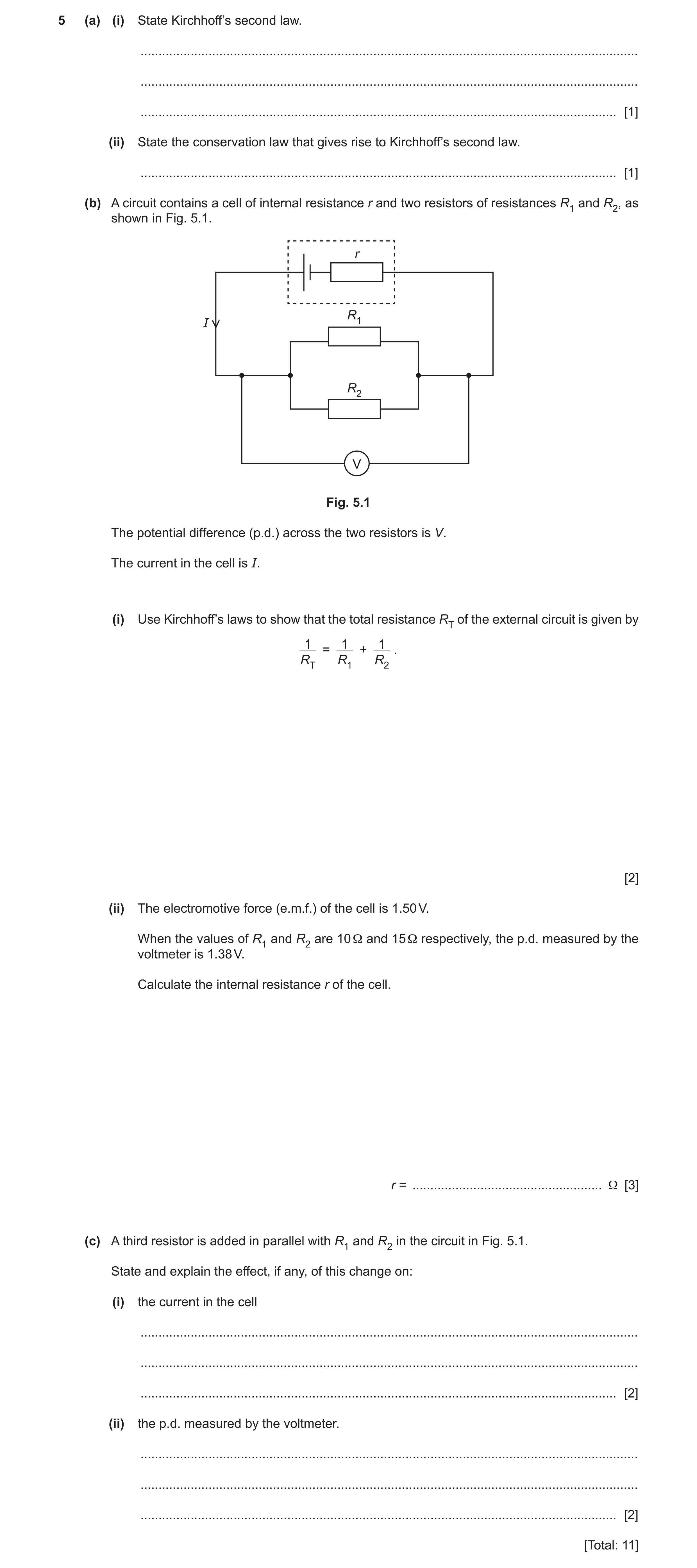
5 (a) (i) State Kirchhoff’s second law. … … … [1] (ii) State the conservation law that gives rise to Kirchhoff’s second law. … [1] (b) A circuit contains a cell of internal resistance r and two resistors of resistances R1 and R2, as shown in Fig. 5.1. r R1 I R2 V Fig. 5.1 The potential difference (p.d.) across the two resistors is V. The current in the cell is I. (i) Use Kirchhoff’s laws to show that the total resistance RT of the external circuit is given by 1 1 1 = + . RT R1 R2 [2] (ii) The electromotive force (e.m.f.) of the cell is 1.50 V. When the values of R1 and R2 are 10 Ω and 15 Ω respectively, the p.d. measured by the voltmeter is 1.38 V. Calculate the internal resistance r of the cell. r = … Ω [3] (c) A third resistor is added in parallel with R1 and R2 in the circuit in Fig. 5.1. State and explain the effect, if any, of this change on: (i) the current in the cell … … … [2] (ii) the p.d. measured by the voltmeter. … … … [2] [Total: 11]
11 marks
Mark scheme: 5(a)(i) sum of electromotive force(s) = sum of potential difference(s) around a (closed) loop or the (algebraic) sum of the p.d.(s) and e.m.f.(s) is zero around a (closed) loop B1 5(a)(ii) (law of conservation of) energy B1 5(b)(i) (by Kirchhoff’s first law) I = I1 + I2 B1 V / RT = V / R1 + V / R2 therefore 1 / RT = 1 / R1 + 1 / R2 B1 5(b)(ii) resistance of parallel combination = (15 10) / (15 + 10) (= 6.0 ) C1 r = (E – V) / I C1 I= 1.38 / 6.0 = 0.23 A r = (1.50 – 1.38) / 0.23 = 0.52 A1 or (by potential divider principle) r / RT = Ir / V (C1) r / 6.0 = 0.12 / 1.38 r = 0.52 (A1) or (by potential divider equation) V = E RT / (RT + r) (C1) 1.38 = 1.5 6.0 / (6.0 + r) r = 0.52 (A1) Question Answer Marks 5(c)(i) as the (total) resistance has decreased (and e.m.f. is unchanged) M1 current will (in the cell) increase A1 5(c)(ii) (as greater current means a) bigger drop in p.d. across the internal resistance M1 p.d. (on voltmeter) will decrease A1
This question in 9702/23 May/June 2024
Question 17 9702/23 Oct/Nov 2024
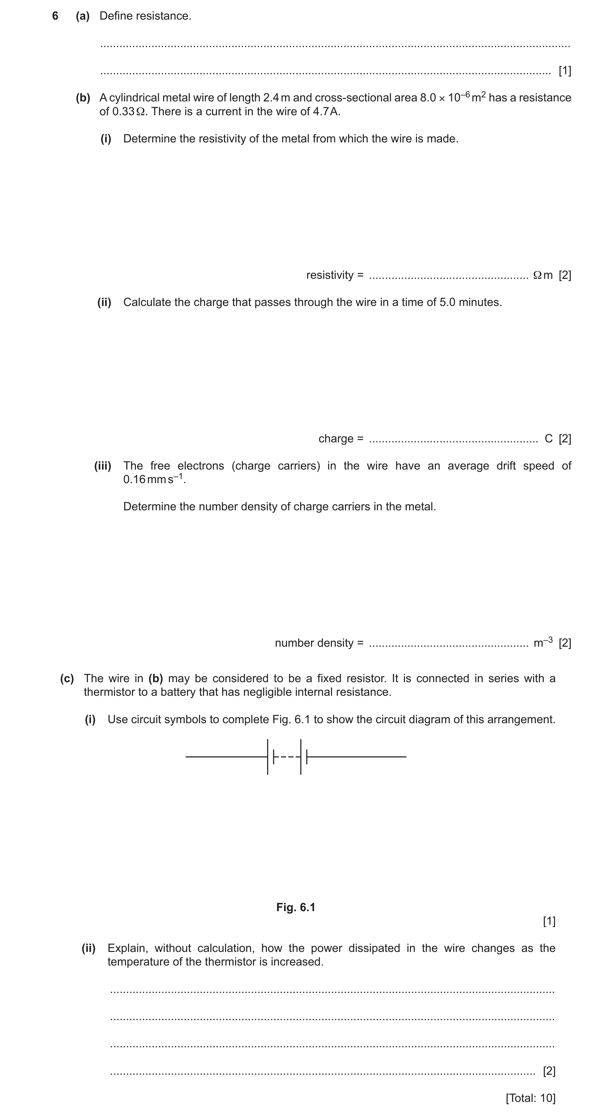
6 (a) Define resistance. … … [1] (b) A cylindrical metal wire of length 2.4 m and cross-sectional area 8.0 × 10⁻⁶ m2 has a resistance of 0.33 Ω. There is a current in the wire of 4.7 A. (i) Determine the resistivity of the metal from which the wire is made. resistivity = … Ω m [2] (ii) Calculate the charge that passes through the wire in a time of 5.0 minutes. charge = … C [2] (iii) The free electrons (charge carriers) in the wire have an average drift speed of 0.16 mm s–1. Determine the number density of charge carriers in the metal. number density = … m–3 [2] (c) The wire in (b) may be considered to be a fixed resistor. It is connected in series with a thermistor to a battery that has negligible internal resistance. (i) Use circuit symbols to complete Fig. 6.1 to show the circuit diagram of this arrangement. Fig. 6.1 [1] (ii) Explain, without calculation, how the power dissipated in the wire changes as the temperature of the thermistor is increased. … … … … [2] [Total: 10]
10 marks
Mark scheme: 6(a) potential difference per unit current B1 6(b)(i) = RA / L C1 = (0.33 8.0 10–6) / 2.4 A1 = 1.1 10–6 m 6(b)(ii) Q = It C1 = 4.7 5.0 60 A1 = 1400 C 6(b)(iii) I = nAvq C1 n = 4.7 / (8.0 10–6 0.16 10–3 1.60 10–19) = 2.3 1028 m–3 A1 6(c)(i) correct symbols for resistor and thermistor, shown correctly connected in series with the battery B1 6(c)(ii) (as temperature increases) resistance of thermistor decreases M1 (total resistance decreases so) greater current (in circuit/wire) so power (dissipated in the wire) increases A1 or (total resistance decreases so) greater (share of) p.d. across wire so power (dissipated in the wire) increases
This question in 9702/23 Oct/Nov 2024
Q18 · Define electric potential difference across a component 9702/22 May/June 2025
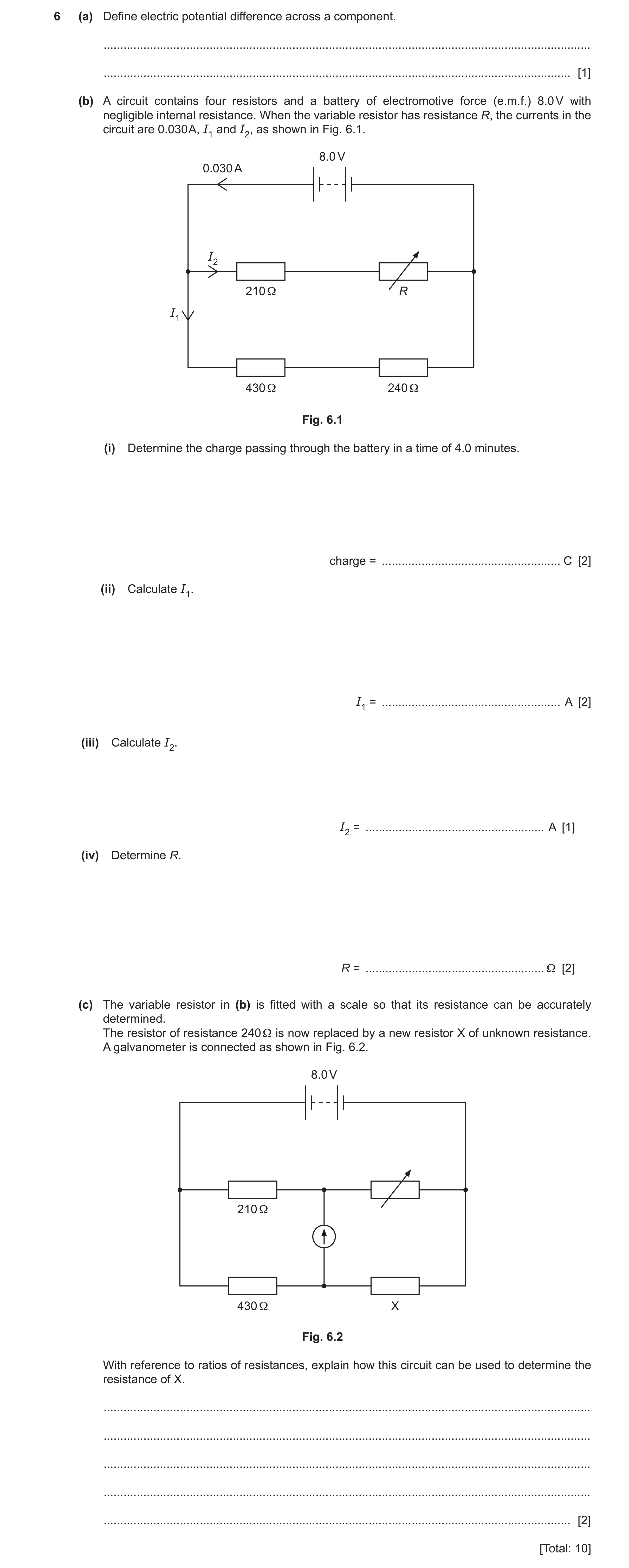
6 (a) Define electric potential difference across a component. … … [1] (b) A circuit contains four resistors and a battery of electromotive force (e.m.f.) 8.0 V with negligible internal resistance. When the variable resistor has resistance R, the currents in the circuit are 0.030 A, I1 and I2, as shown in Fig. 6.1. 8.0 V 0.030 A I2 210 Ω R I1 430 Ω 240 Ω Fig. 6.1 (i) Determine the charge passing through the battery in a time of 4.0 minutes. charge = … C [2] (ii) Calculate I1. I1 = … A [2] (iii) Calculate I2. I2 = … A [1] (iv) Determine R. R = … Ω [2] (c) The variable resistor in (b) is fitted with a scale so that its resistance can be accurately determined. The resistor of resistance 240 Ω is now replaced by a new resistor X of unknown resistance. A galvanometer is connected as shown in Fig. 6.2. 8.0 V 210 Ω 430 Ω X Fig. 6.2 With reference to ratios of resistances, explain how this circuit can be used to determine the resistance of X. … … … … … [2] [Total: 10]
10 marks
Mark scheme: 6(a) energy transferred (to the component) per (unit) charge B1 6(b)(i) Q = It C1 = 0.030 4.0 60 = 7.2 C A1 6(b)(ii) I = V / R C1 I1 = 8.0 / (430+240) = 0.012 A A1 6(b)(iii) I2 = 0.030 – I1 A1 = 0.030 – 0.012 = 0.018 A 6(b)(iv) R = V / I2 C1 = (8.0 – (0.018 210)) / 0.018 = 230 A1 OR (C1) resistance of top branch = 8.0 / 0.018 R = 8.0 / 0.018 – 210 = 230 (A1) OR (C1) total circuit resistance = 8.0 / 0.030 = 267 1 / 267 = 1 / (210 + R) + 1 / (430 + 240) 1 / 267 – 1 / 670 = 1 / (210 +R) 210 + R = 443 R = 230 (A1) 6(c) (When) the galvanometer reads 0 (A) M1 The ratio of the resistances in the top branch will equal the ratio of the resistances in the bottom branch (so the resistance A1 of X can be determined) OR (A1) The ratio of the left pair of resistances will equal the ratio of the right pair of resistances
This question in 9702/22 May/June 2025
Q19 · A nichrome resistance wire has length 150 cm, cross-sectional area 2.45 × 10⁻⁷ m2 and… 9702/23 May/June 2025
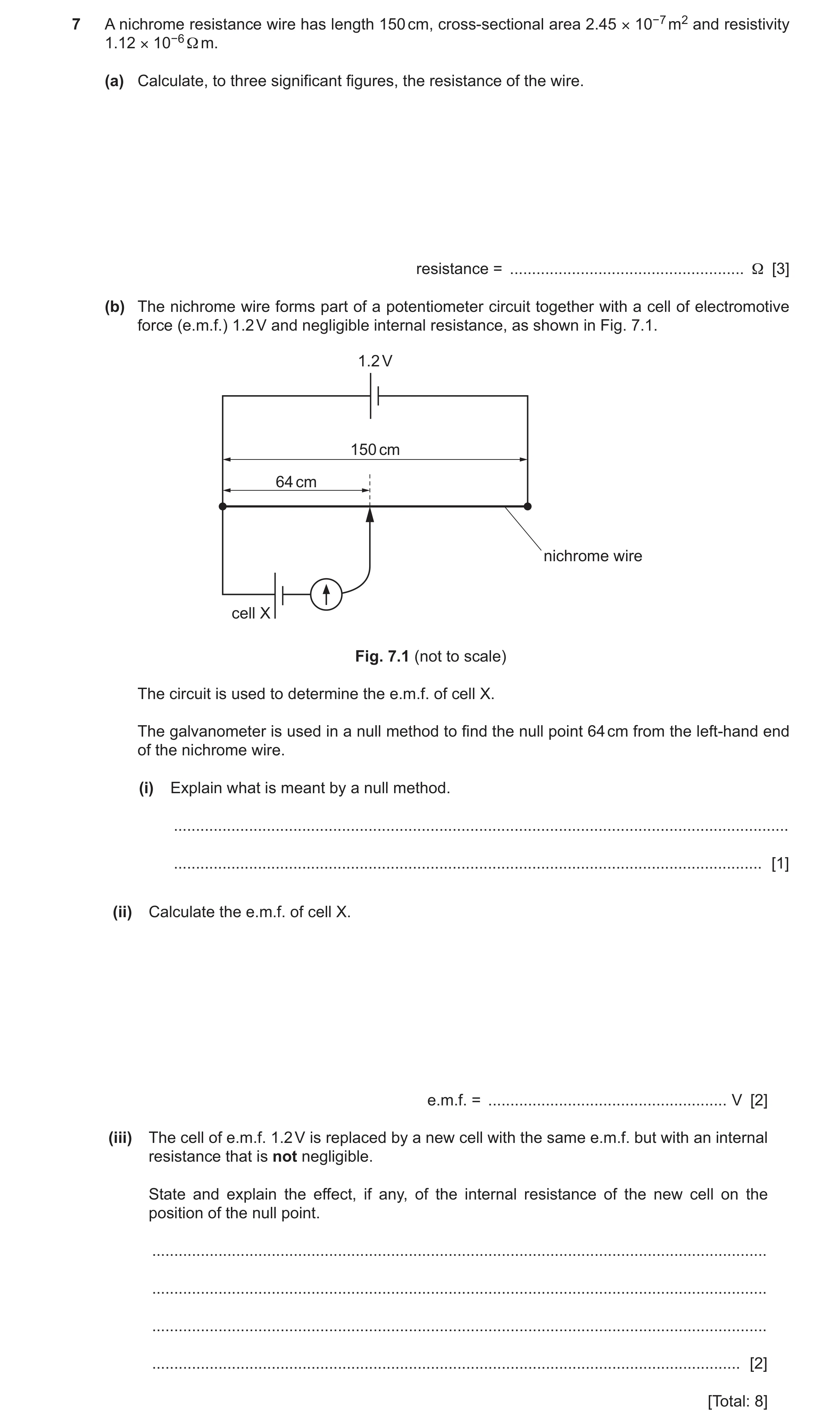
7 A nichrome resistance wire has length 150 cm, cross-sectional area 2.45 × 10⁻⁷ m2 and resistivity 1.12 × 10⁻⁶ Ω m. (a) Calculate, to three significant figures, the resistance of the wire. resistance = … Ω [3] (b) The nichrome wire forms part of a potentiometer circuit together with a cell of electromotive force (e.m.f.) 1.2 V and negligible internal resistance, as shown in Fig. 7.1. 1.2 V 150 cm 64 cm nichrome wire cell X Fig. 7.1 (not to scale) The circuit is used to determine the e.m.f. of cell X. The galvanometer is used in a null method to find the null point 64 cm from the left-hand end of the nichrome wire. (i) Explain what is meant by a null method. … … [1] (ii) Calculate the e.m.f. of cell X. e.m.f. = … V [2] (iii) The cell of e.m.f. 1.2 V is replaced by a new cell with the same e.m.f. but with an internal resistance that is not negligible. State and explain the effect, if any, of the internal resistance of the new cell on the position of the null point. … … … … [2] [Total: 8]
8 marks
Mark scheme: 7(a) R = L / A C1 = (1.12 10−6 1.5) / 2.45 10−7 C1 = 6.86 A1 7(b)(i) (A method where the) reading (on the galvanometer) is zero. B1 7(b)(ii) e.m.f. / 1.2 = 64 / 150 C1 e.m.f. = (64 / 150) 1.2 A1 = 0.51 V 7(b)(iii) (the internal resistance will cause a) drop in p.d. across the wire / the terminal p.d. is lower B1 So the null point will move to the right B1
This question in 9702/23 May/June 2025
Q20 · A circuit containing a battery, two fixed resistors X and Y, and a light-dependent… 9702/22 Oct/Nov 2025
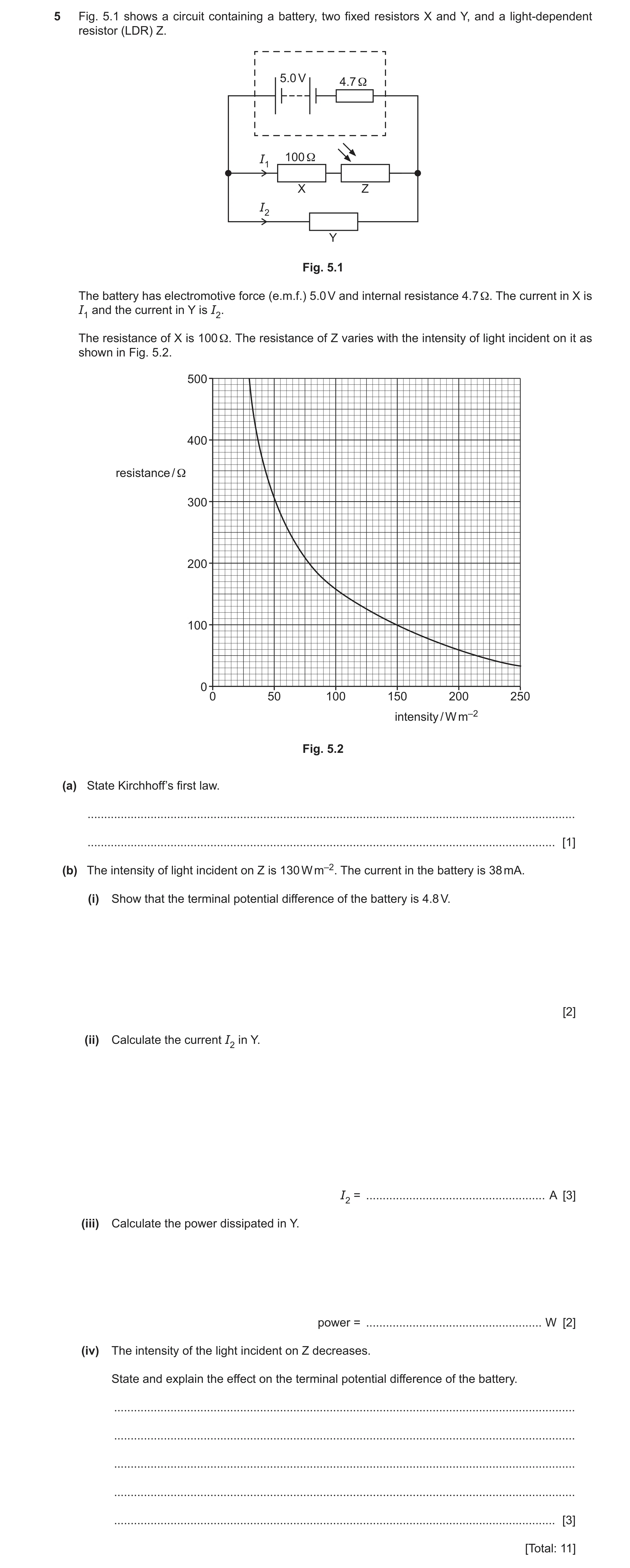
5 Fig. 5.1 shows a circuit containing a battery, two fixed resistors X and Y, and a light-dependent resistor (LDR) Z. 5.0 V 4.7 Ω I1 100 Ω X Z I2 Y Fig. 5.1 The battery has electromotive force (e.m.f.) 5.0 V and internal resistance 4.7 Ω. The current in X is I1 and the current in Y is I2. The resistance of X is 100 Ω. The resistance of Z varies with the intensity of light incident on it as shown in Fig. 5.2. 500 400 resistance / Ω 300 200 100 0 0 50 100 150 200 250 intensity / W m–2 Fig. 5.2 (a) State Kirchhoff’s first law. … … [1] (b) The intensity of light incident on Z is 130 W m–2. The current in the battery is 38 mA. (i) Show that the terminal potential difference of the battery is 4.8 V. [2] (ii) Calculate the current I2 in Y. I2 = … A [3] (iii) Calculate the power dissipated in Y. power = … W [2] (iv) The intensity of the light incident on Z decreases. State and explain the effect on the terminal potential difference of the battery. … … … … … [3] [Total: 11]
11 marks
Mark scheme: 5(a) sum of current(s) into junction = sum of current(s) out junction or (algebraic) sum of current(s) at a junction is zero B1 5(b)(i) (V =) E – Ir C1 (V =) 5.0 – (38 10–3 4.7) = 4.8 (V) A1 5(b)(ii) R(Z) = 120 C1 I2 = 38 × 10–3 – (4.8 / (100 + 120)) C1 I2 = 0.016 A A1 or R(Z) = 120 (C1) R(EXT) = 4.8 / 38 × 10–3 (C1) (= 126 ) 1 / R(Y) = 1 / 126 – 1 / (120 + 100) (R(Y) = 297 ) I2 = 4.8 / 297 I2 = 0.016 A (A1) 5(b)(iii) P = IV or P = I2R or P = V2 / R C1 P = 0.016 4.8 A1 or P = 0.0162 (4.8 / 0.016) or P = 4.82 / (4.8 / 0.016) P = 0.077 W 5(b)(iv) resistance of the LDR / Z increases (as light intensity decreases) B1 total resistance (of the circuit) increases M1 or current in the battery decreases (potential difference across the internal resistor decreases so) the terminal potential difference increases A1
This question in 9702/22 Oct/Nov 2025
Q21 · State Kirchhoff’s first law 9702/23 Oct/Nov 2025
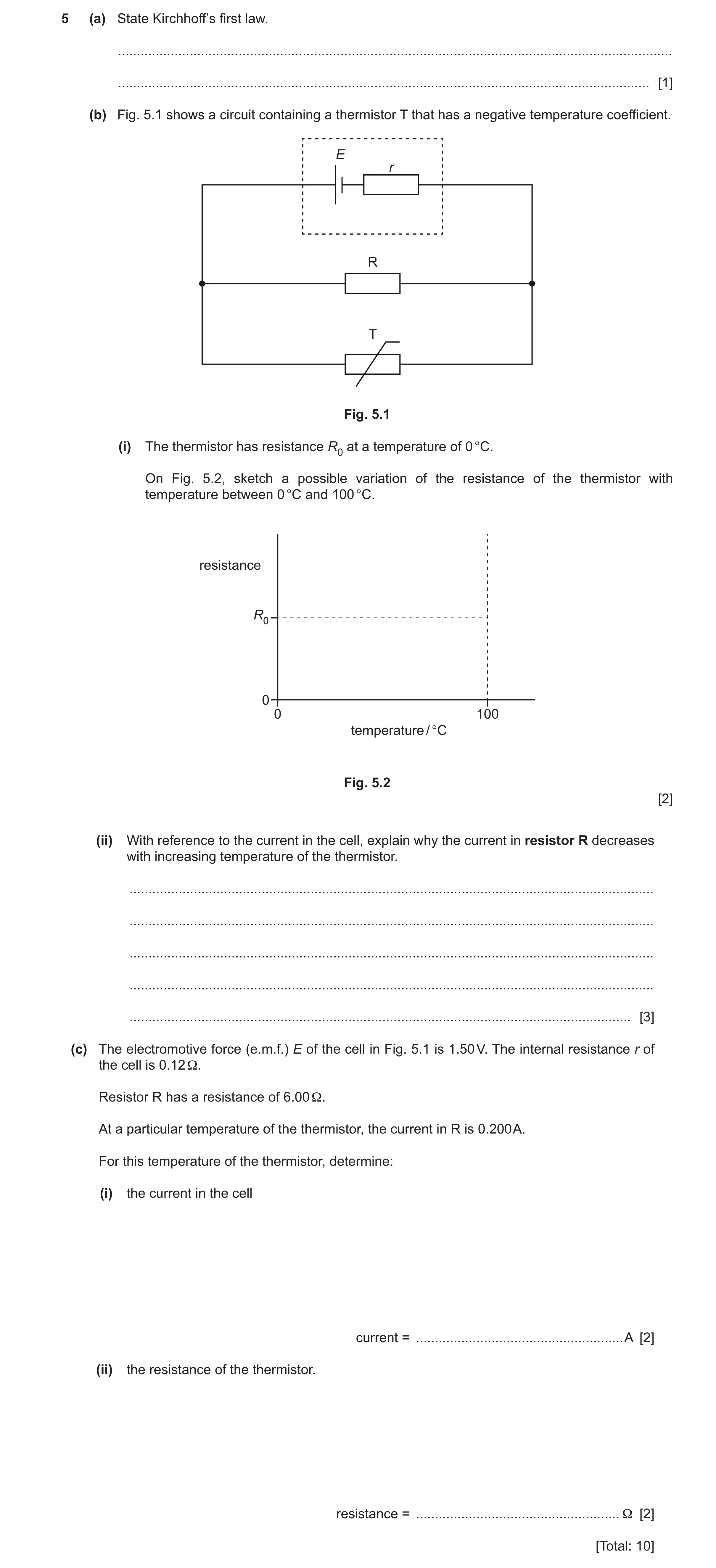
5 (a) State Kirchhoff’s first law. … … [1] (b) Fig. 5.1 shows a circuit containing a thermistor T that has a negative temperature coefficient. E r R T Fig. 5.1 (i) The thermistor has resistance R0 at a temperature of 0 °C. On Fig. 5.2, sketch a possible variation of the resistance of the thermistor with temperature between 0 °C and 100 °C. resistance R0 0 0 100 temperature / °C Fig. 5.2 [2] (ii) With reference to the current in the cell, explain why the current in resistor R decreases with increasing temperature of the thermistor. … … … … … [3] (c) The electromotive force (e.m.f.) E of the cell in Fig. 5.1 is 1.50 V. The internal resistance r of the cell is 0.12 Ω. Resistor R has a resistance of 6.00 Ω. At a particular temperature of the thermistor, the current in R is 0.200 A. For this temperature of the thermistor, determine: (i) the current in the cell current = … A [2] (ii) the resistance of the thermistor. resistance = … Ω [2] [Total: 10]
10 marks
Mark scheme: 5(a) sum of current(s) into junction = sum of current(s) out junction B1 or (algebraic) sum of current(s) at a junction is zero 5(b)(i) line with negative gradient C1 line from 0 °C to 100 °C, starting at (0, R0) with negative gradient throughout and never reaching R = 0 A1 5(b)(ii) (resistance of T decreases so) total resistance (of circuit) decreases B1 current in cell increases (so p.d. across internal resistance increases) B1 terminal p.d. decreases (and resistance of R is constant) so current in R decreases B1 5(c)(i) p.d. across r = 1.50 – (6.00 0.200) C1 (= 0.30 V) current in cell = 0.30 / 0.12 A1 = 2.5 A 5(c)(ii) current in thermistor = 2.5 – 0.200 C1 (= 2.3 A) resistance of T = (6.00 0.200) / 2.3 A1 = 0.52
This question in 9702/23 Oct/Nov 2025
Q22 · A student uses a circuit containing an ammeter, a voltmeter and a cell to take… 9702/24 Oct/Nov 2025
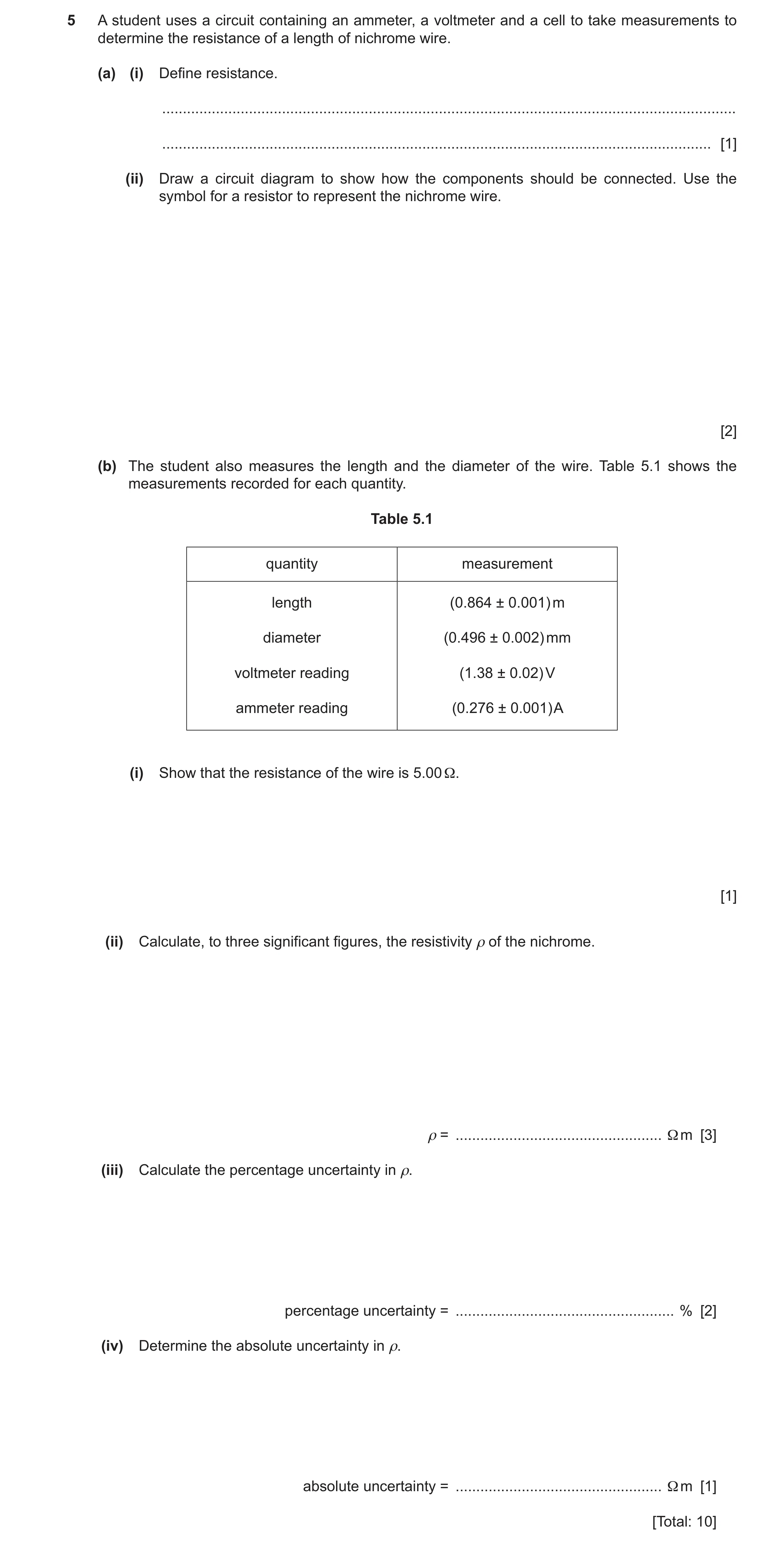
5 A student uses a circuit containing an ammeter, a voltmeter and a cell to take measurements to determine the resistance of a length of nichrome wire. (a) (i) Define resistance. … … [1] (ii) Draw a circuit diagram to show how the components should be connected. Use the symbol for a resistor to represent the nichrome wire. [2] (b) The student also measures the length and the diameter of the wire. Table 5.1 shows the measurements recorded for each quantity. Table 5.1 quantity measurement length (0.864 ± 0.001) m diameter (0.496 ± 0.002) mm voltmeter reading (1.38 ± 0.02) V ammeter reading (0.276 ± 0.001) A (i) Show that the resistance of the wire is 5.00 Ω. [1] (ii) Calculate, to three significant figures, the resistivity ρ of the nichrome. ρ = … Ω m [3] (iii) Calculate the percentage uncertainty in ρ. percentage uncertainty = … % [2] (iv) Determine the absolute uncertainty in ρ. absolute uncertainty = … Ω m [1] [Total: 10]
10 marks
Mark scheme: 5(a)(i) potential difference per unit current B1 5(a)(ii) resistor connected to cell in a closed loop and correct circuit symbols used for all components B1 ammeter connected in series with resistor and voltmeter connected in parallel with resistor B1 5(b)(i) (resistance) = 1.38 / 0.276 = 5.00 () A1 5(b)(ii) = RA / L C1 = 5.00 (0.496 10–3)2 / (4 0.864) C1 = 1.12 10–6 m A1 5(b)(iii) calculation of a fractional or percentage uncertainty in one quantity C1 0.001 / 0.864 or 0.002 / 0.496 or 0.02 / 1.38 or 0.001 / 0.276 percentage uncertainty = [(0.001 / 0.864) + (2 0.002 / 0.496) + (0.02 / 1.38) + (0.001 / 0.276)] 100 A1 = 2.7% 5(b)(iv) = 0.03 1.12 10–6 A1 = 3 10–8 m
This question in 9702/24 Oct/Nov 2025
 11
11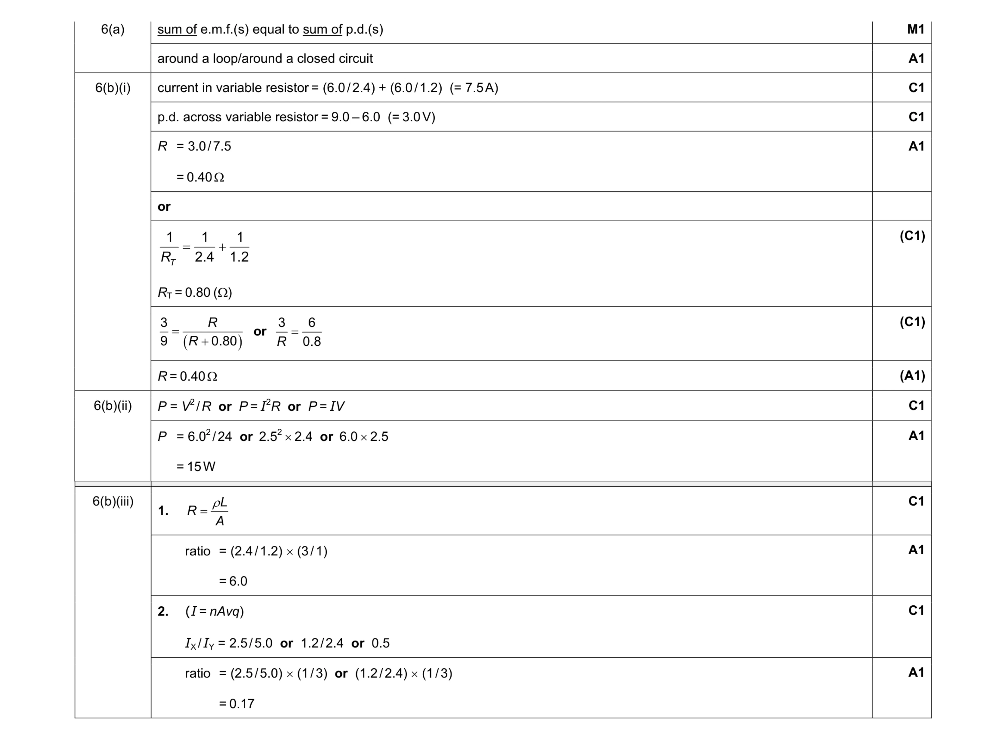 11
11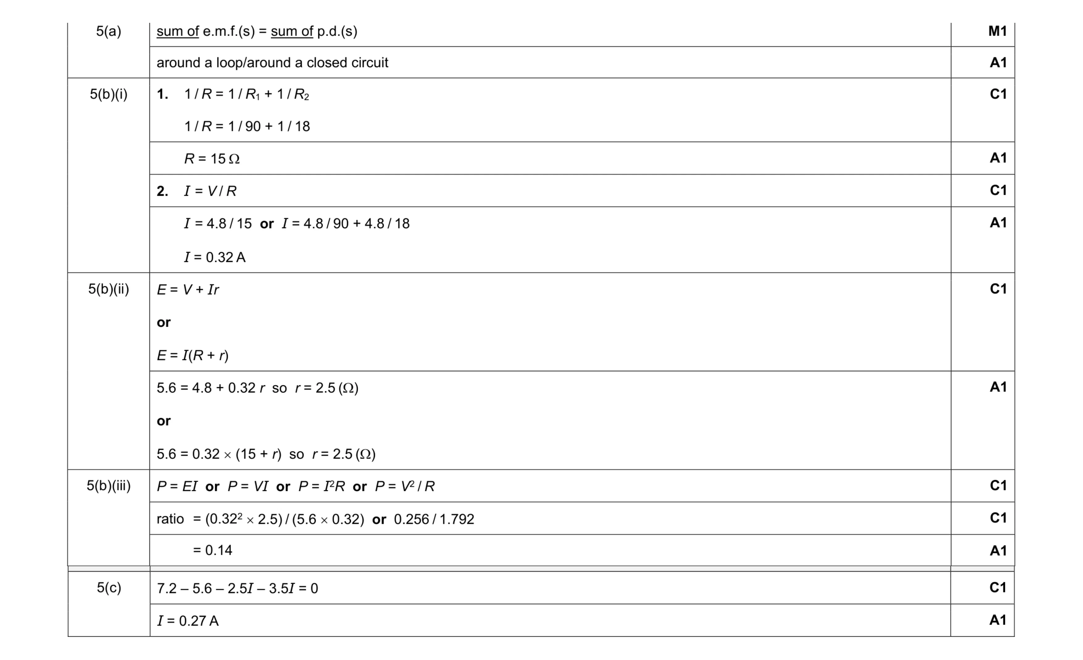 13
13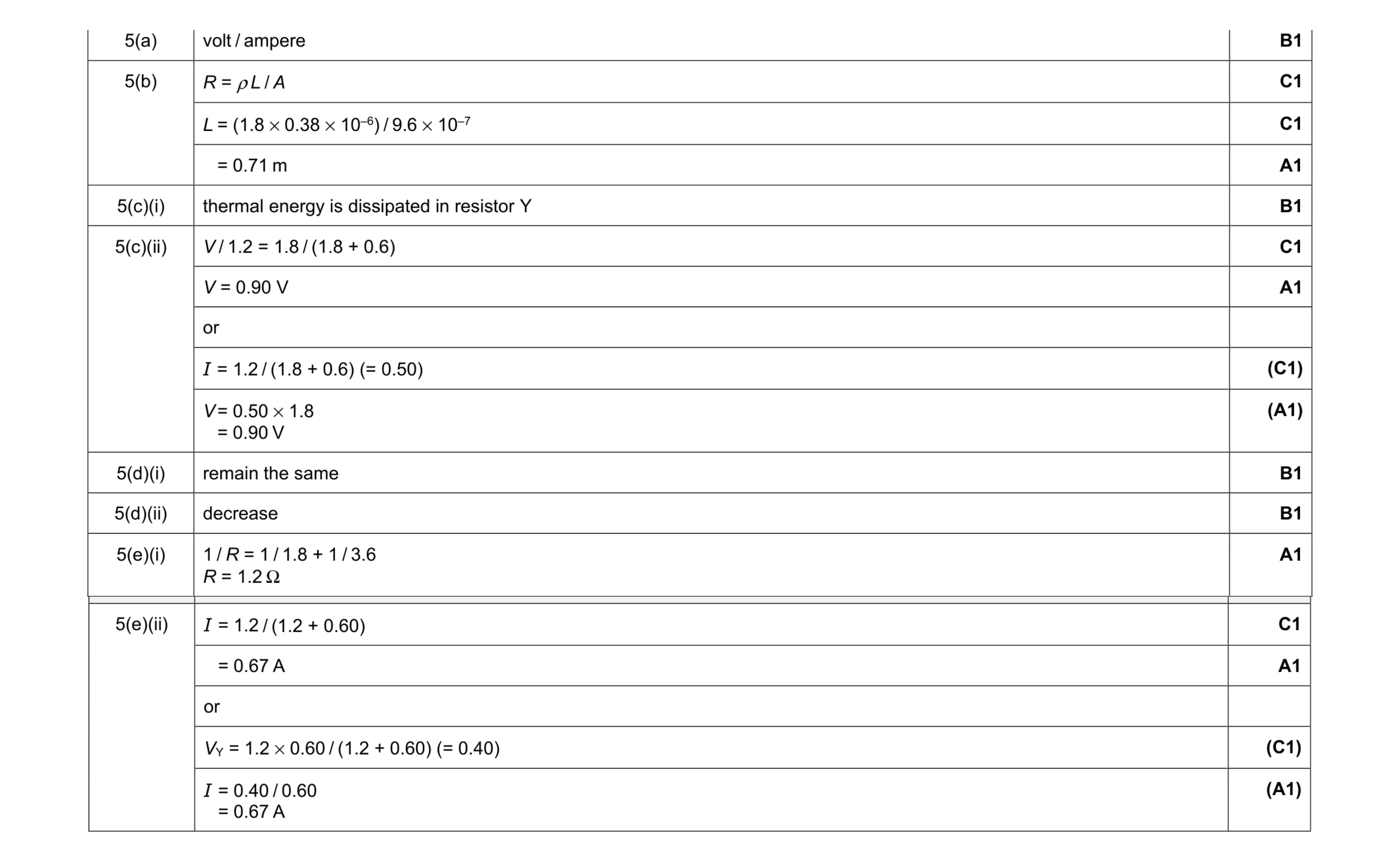 12
12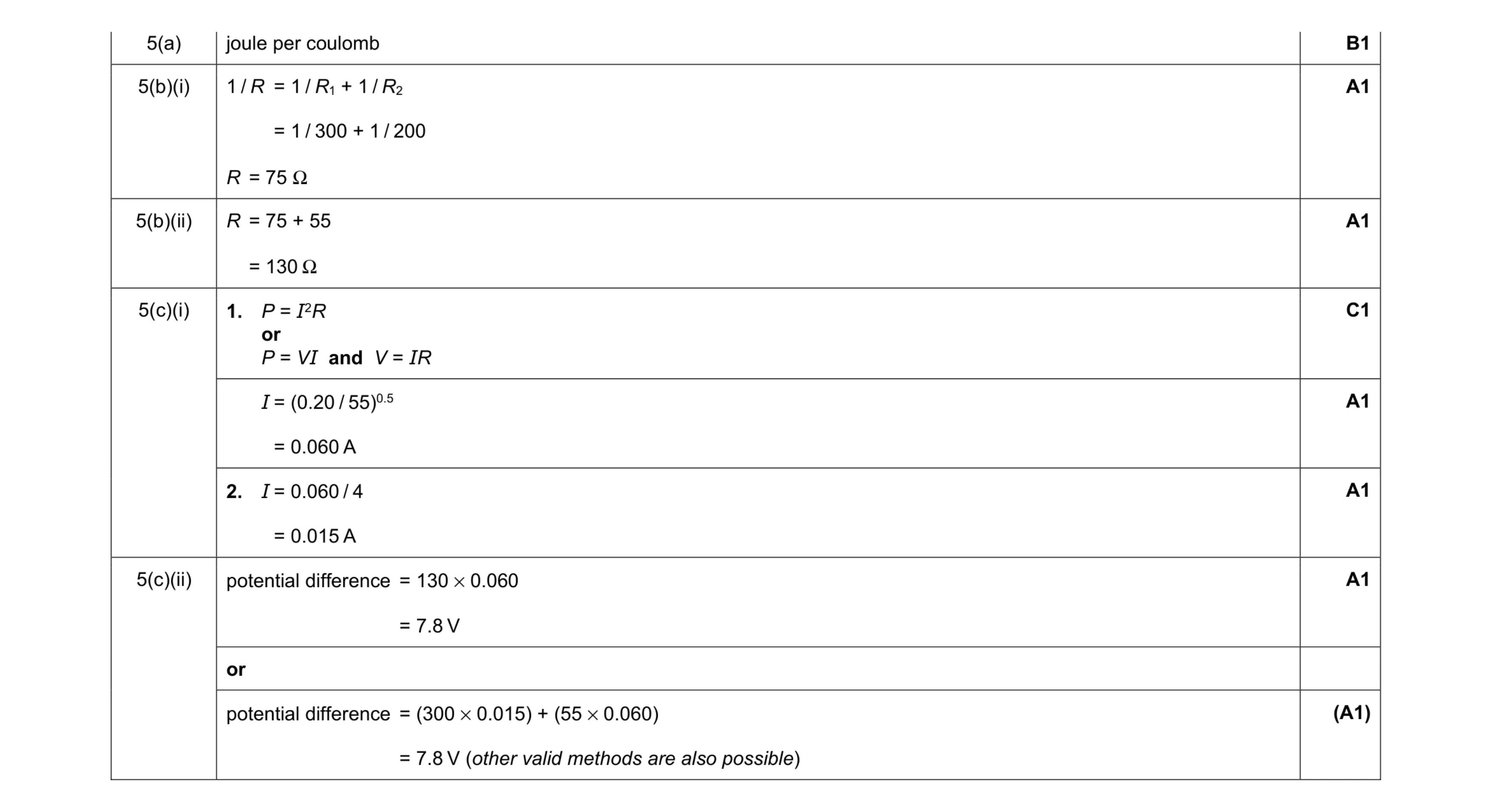 7
7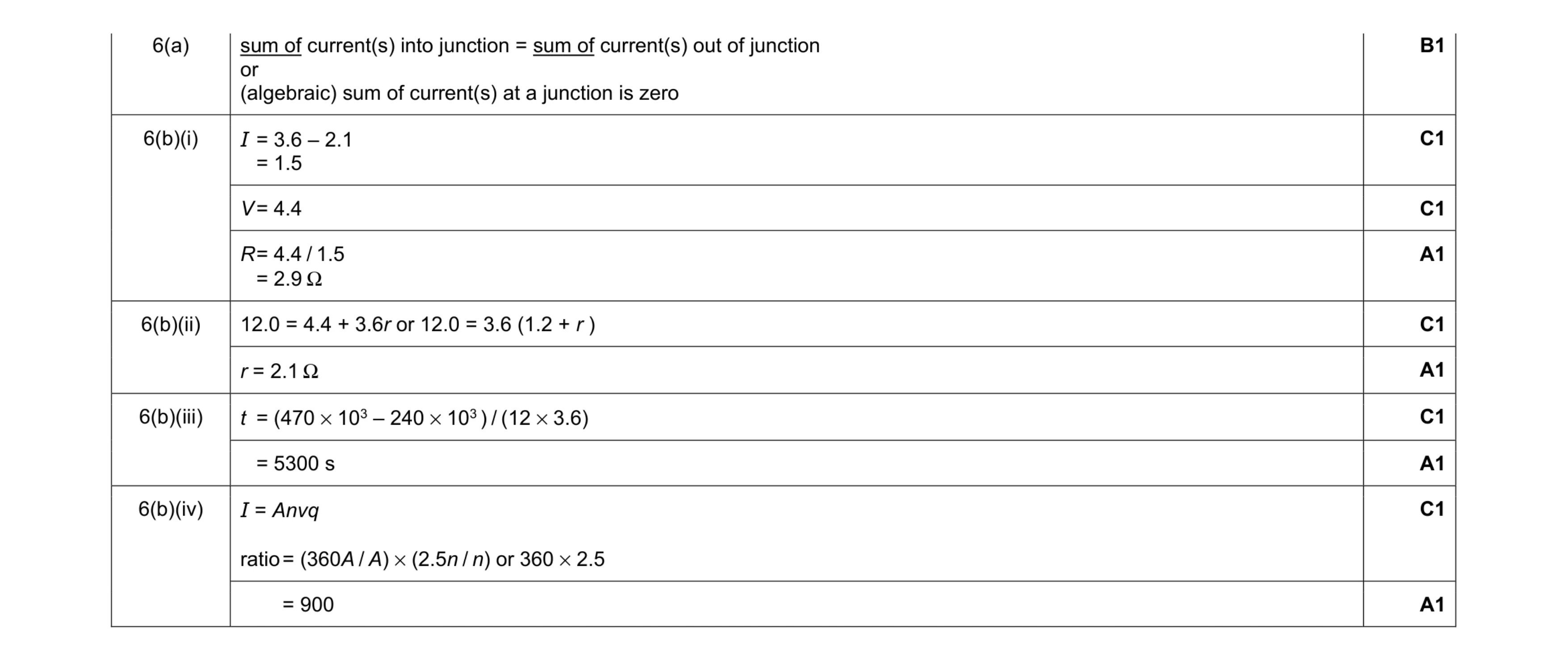 10
10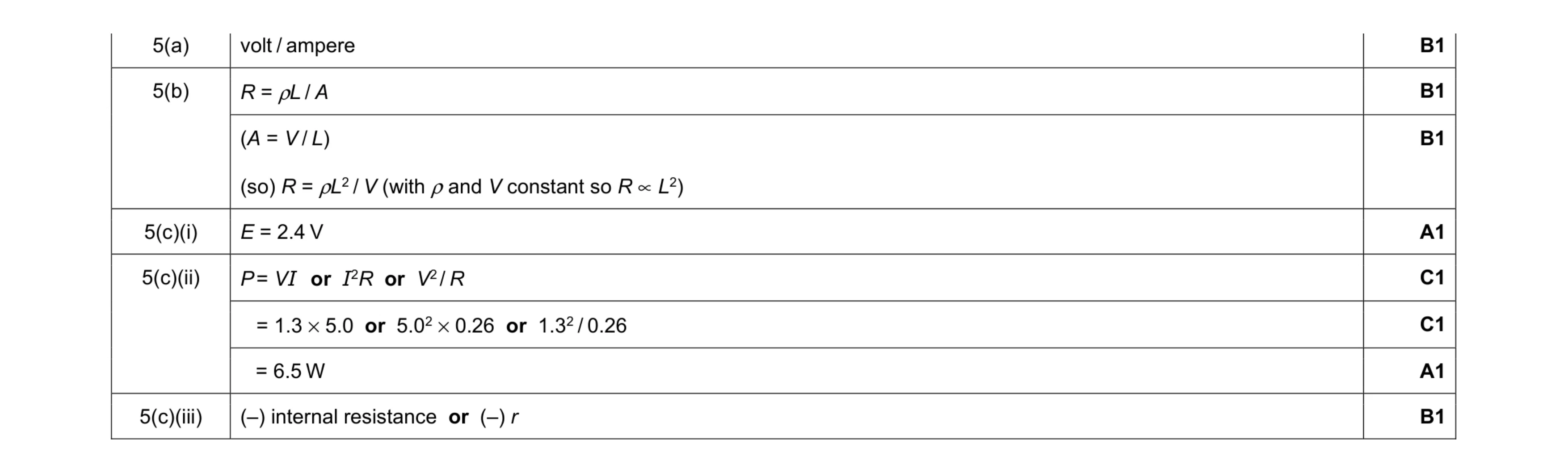 8
8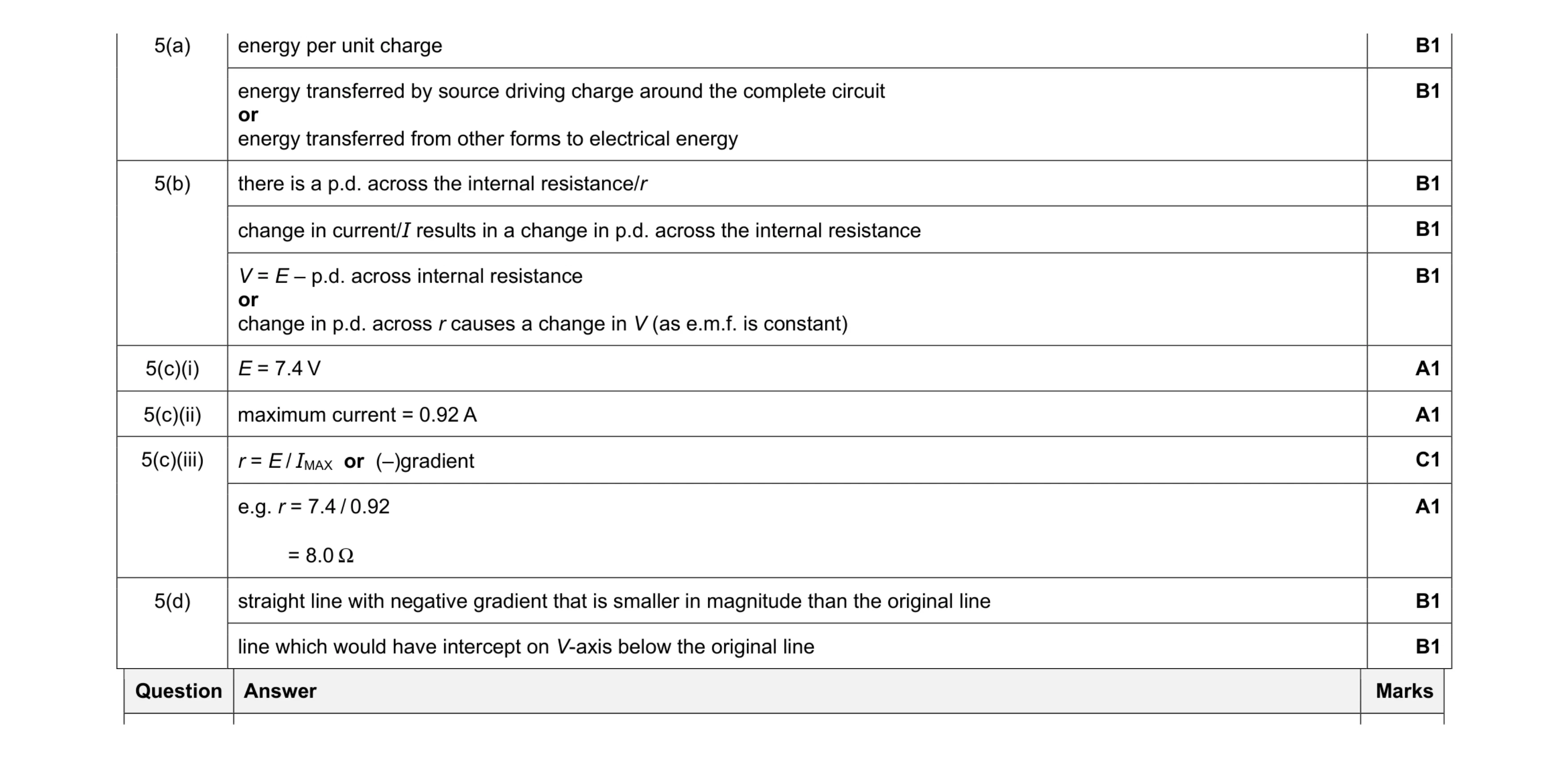 11
11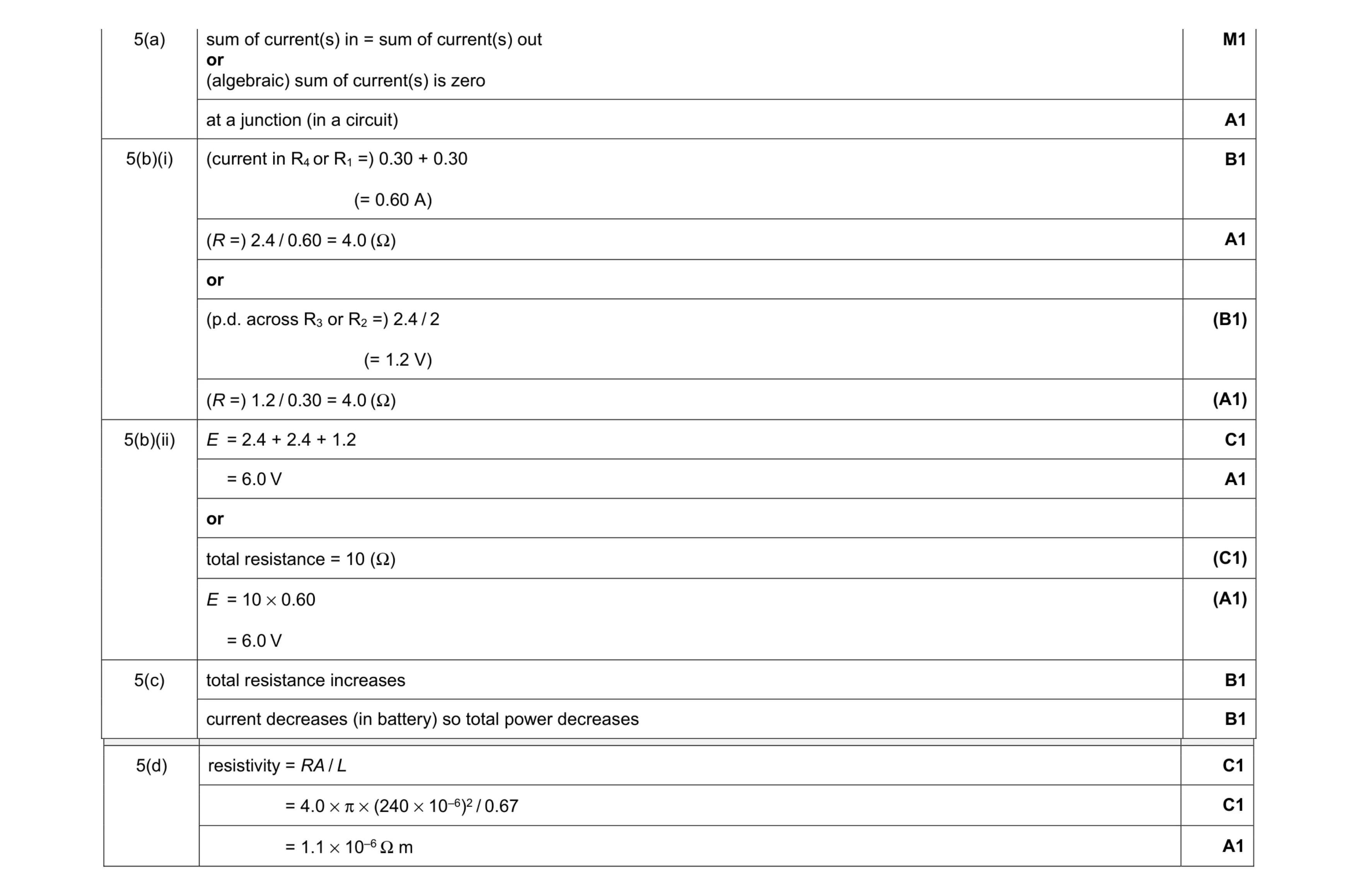 11
11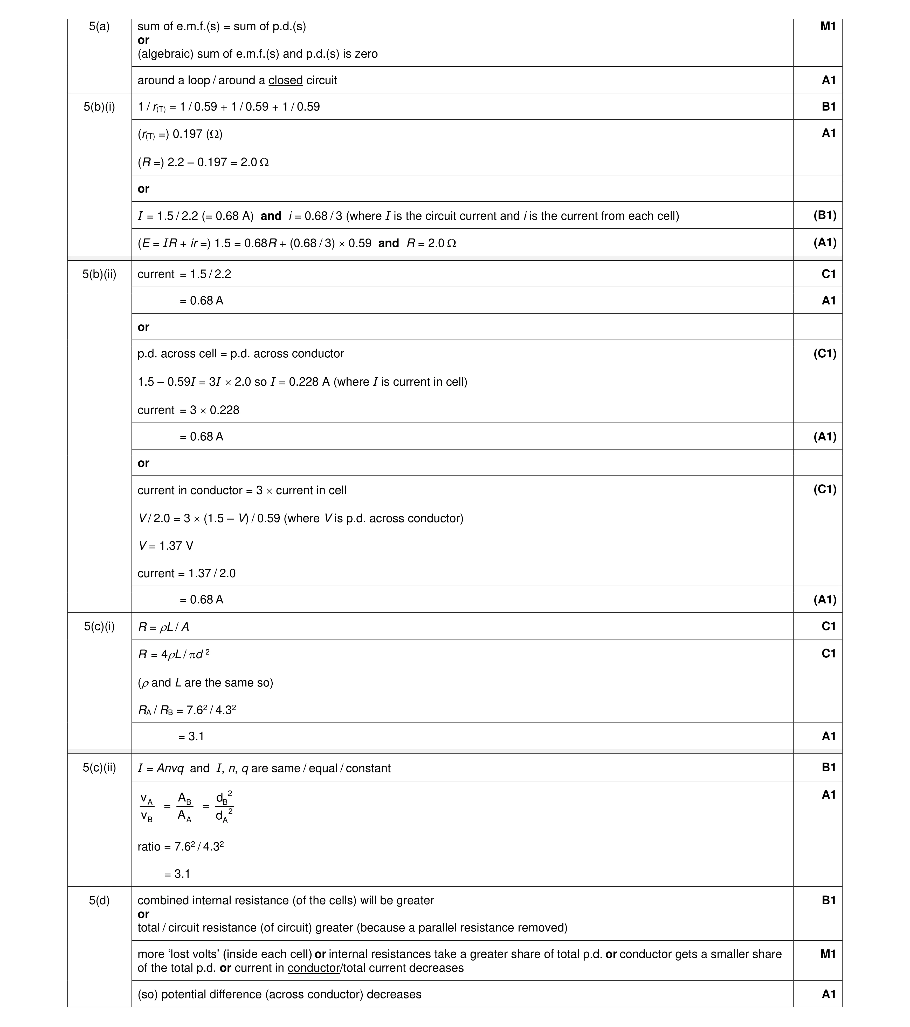 6
6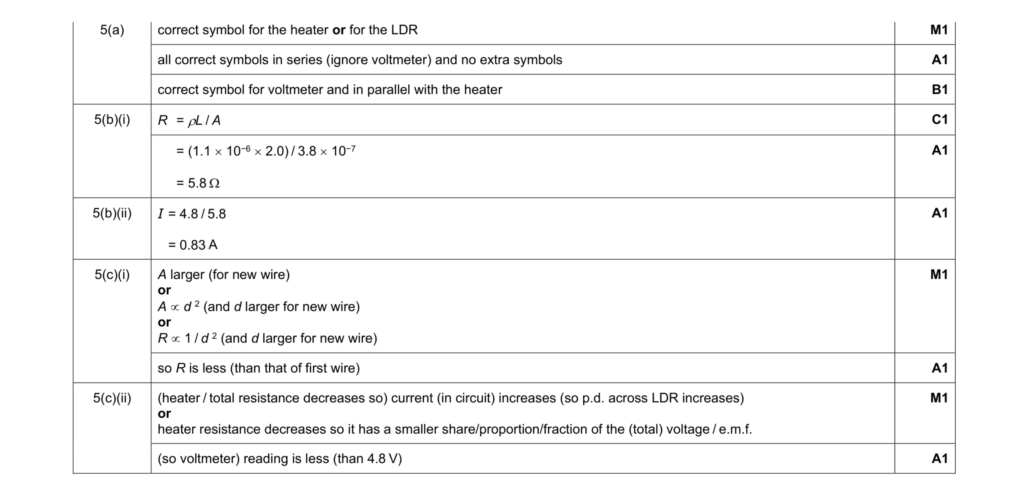 10
10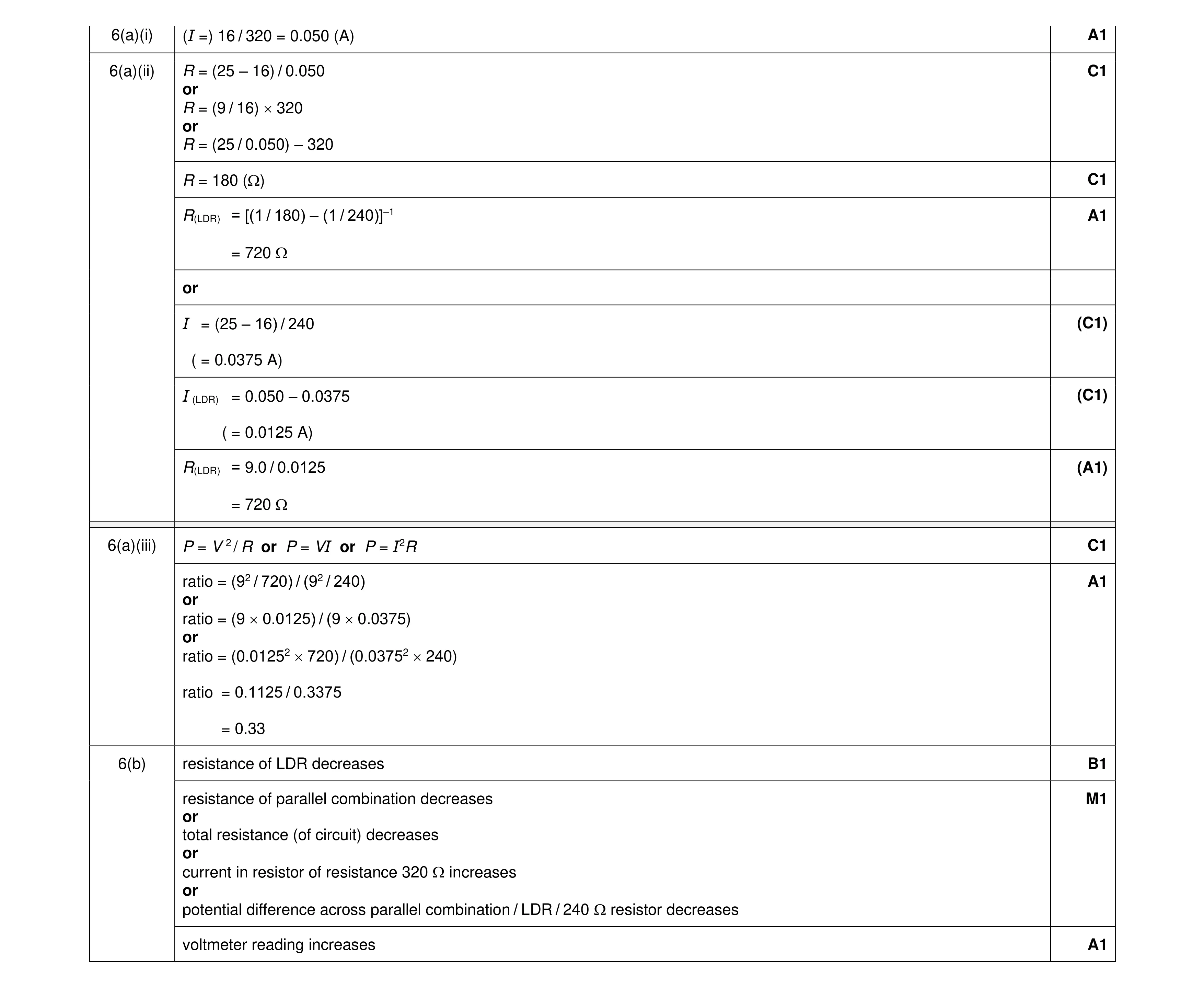 9
9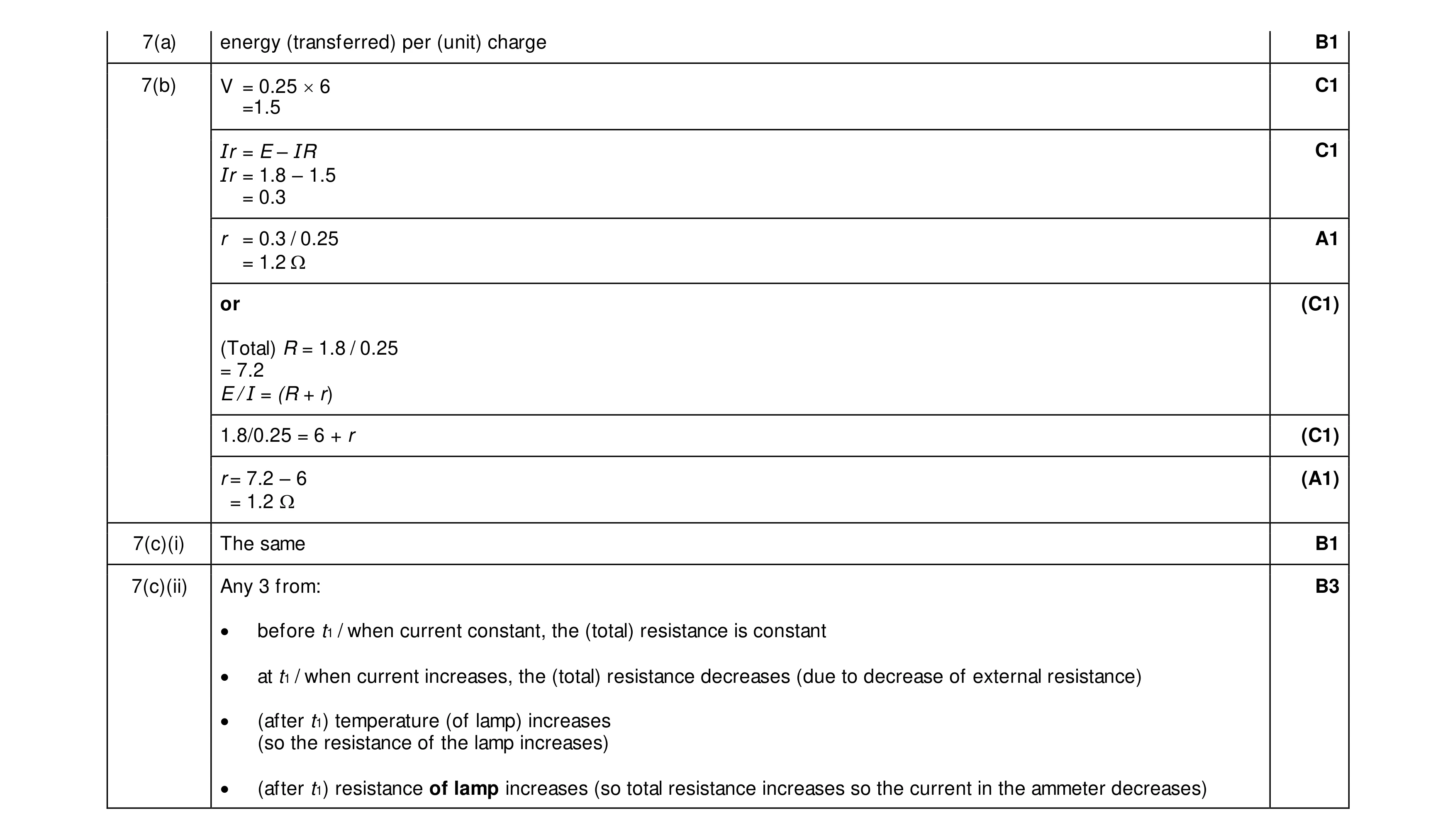 8
8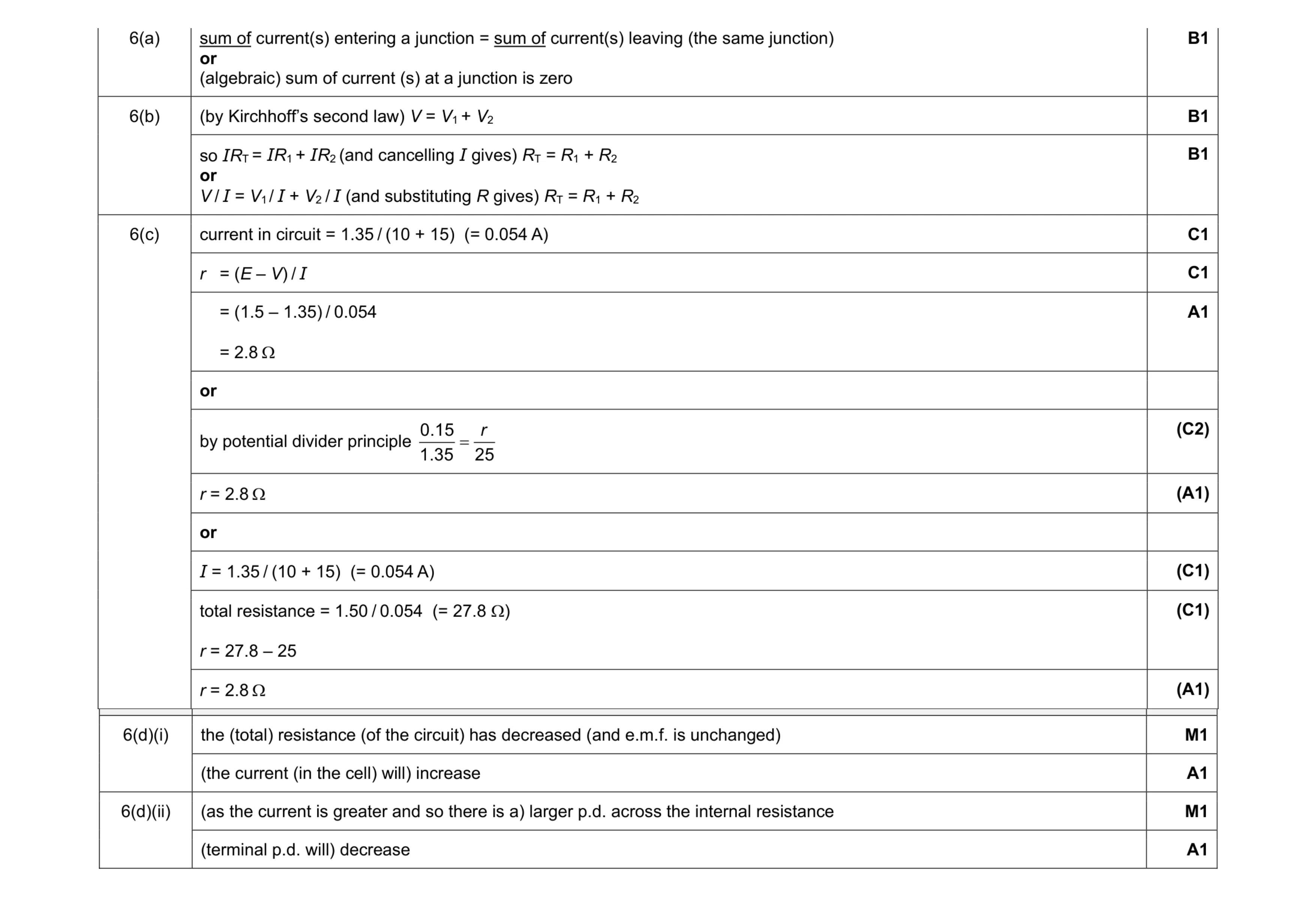 10
10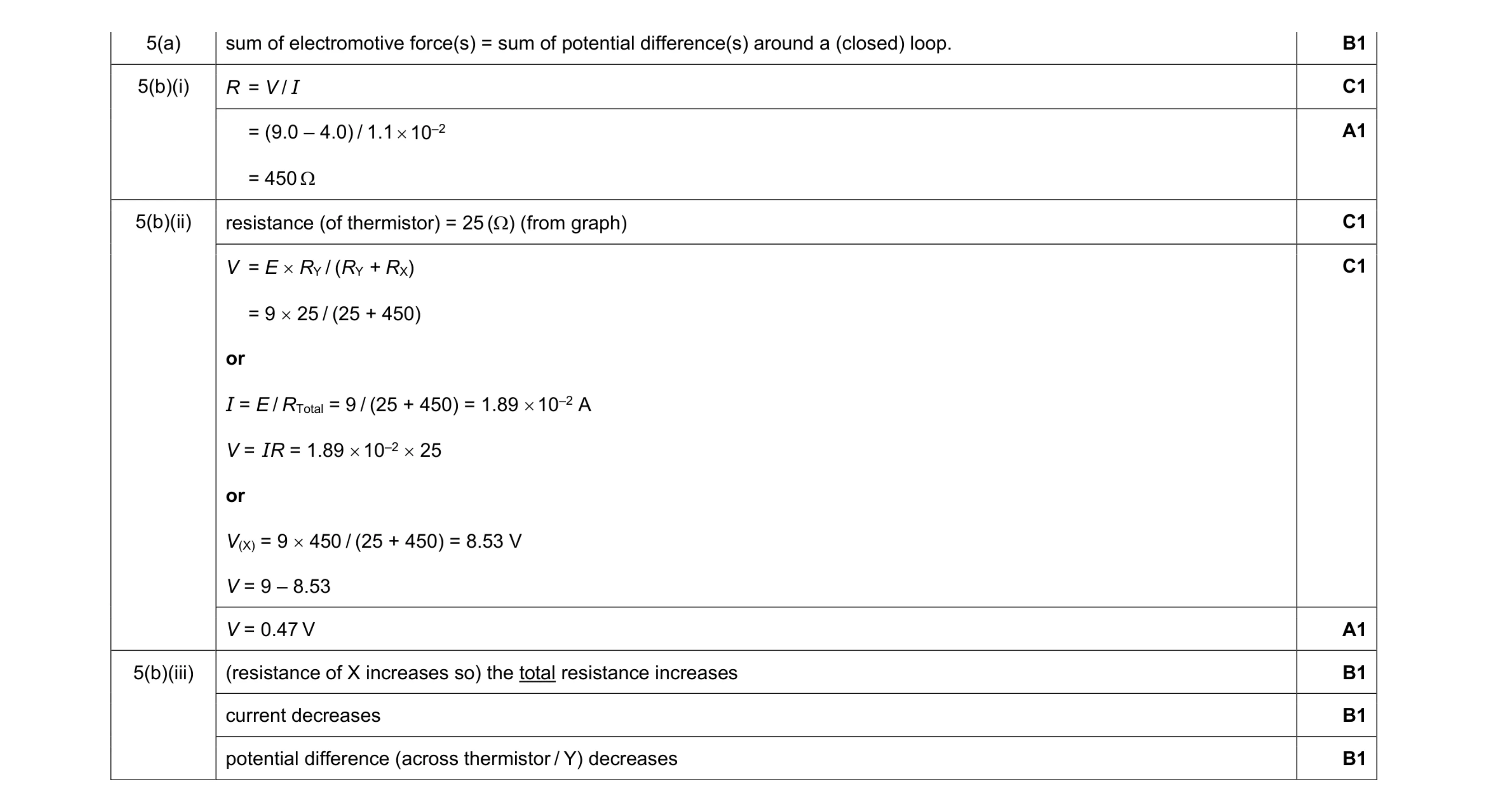 9
9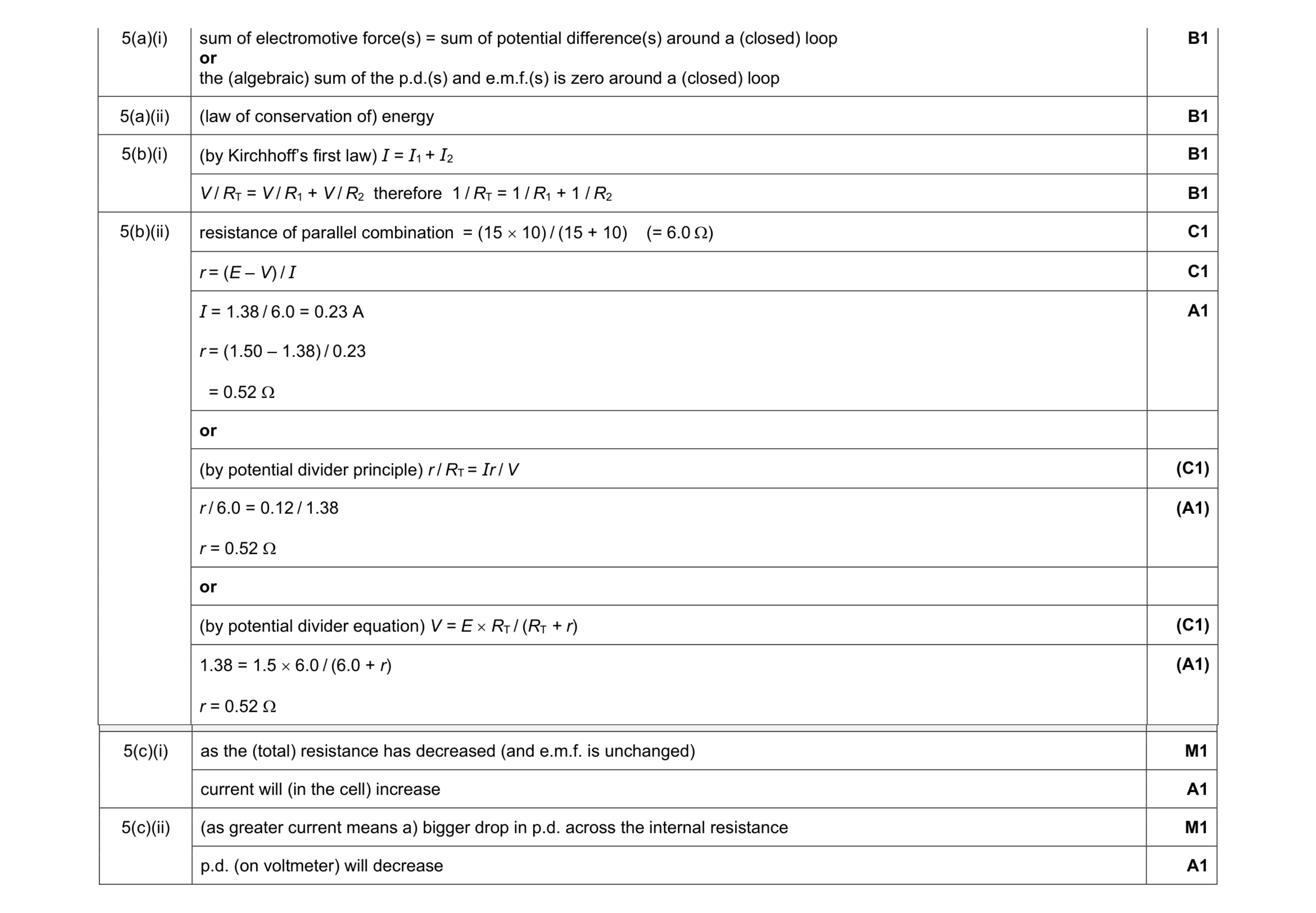 11
11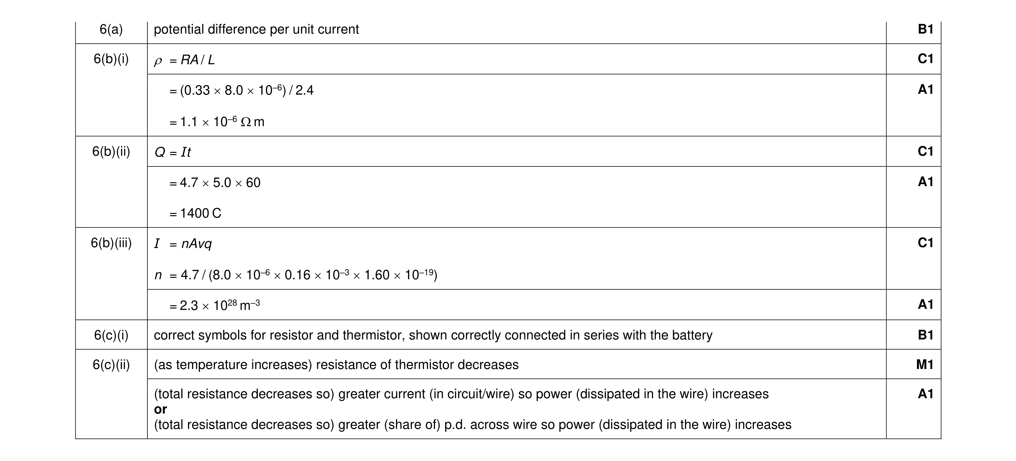 10
10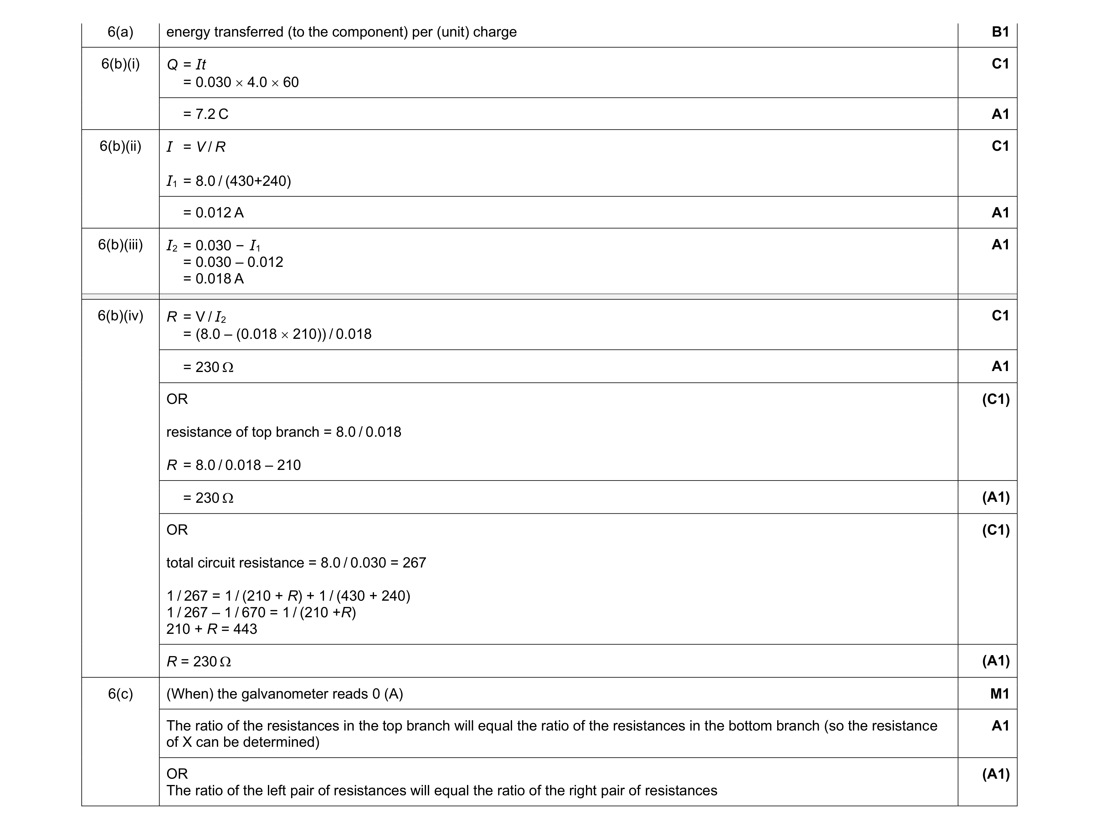 10
10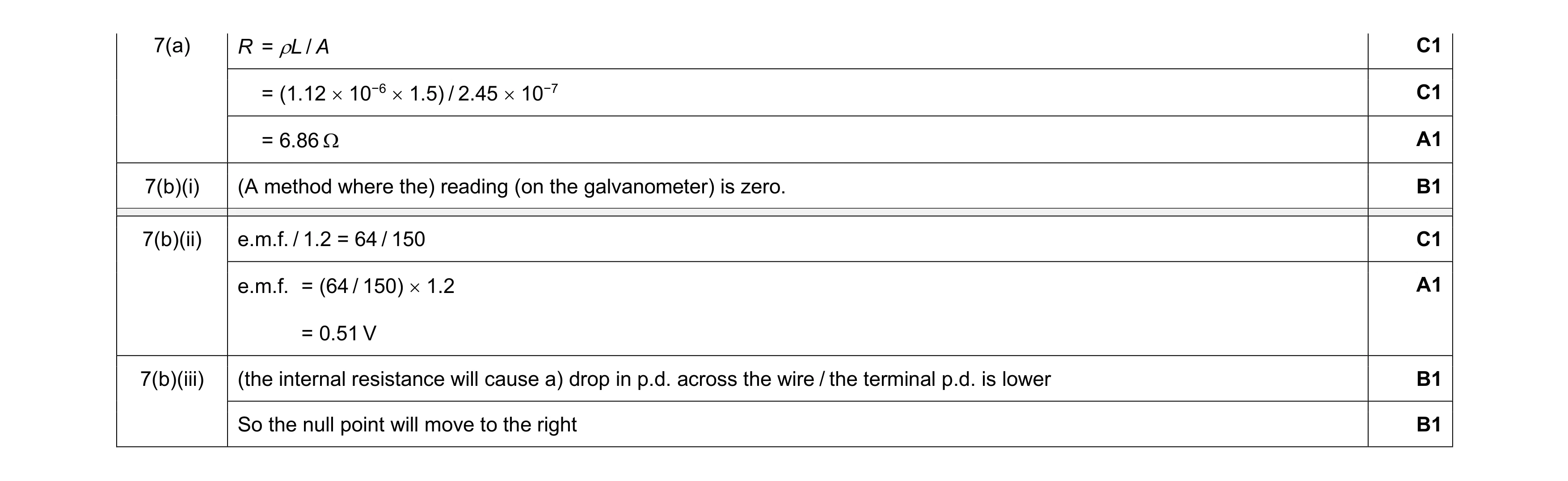 8
8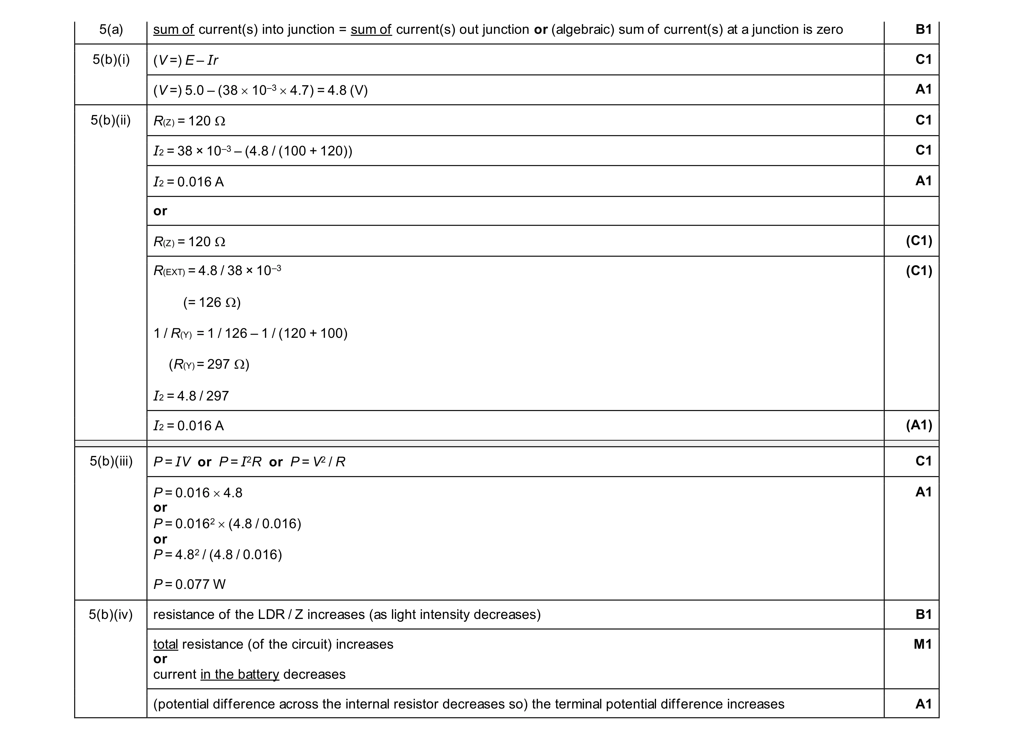 11
11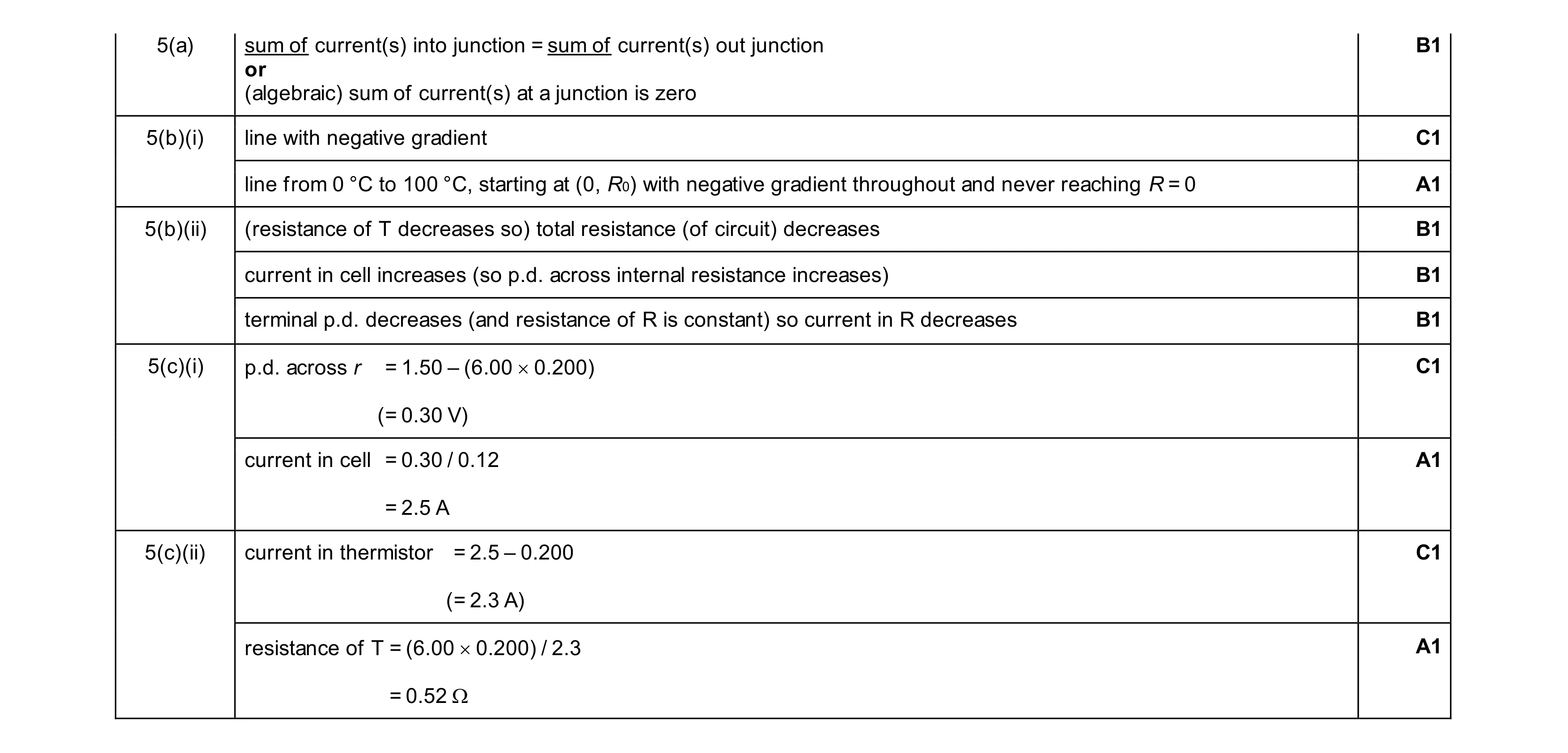 10
10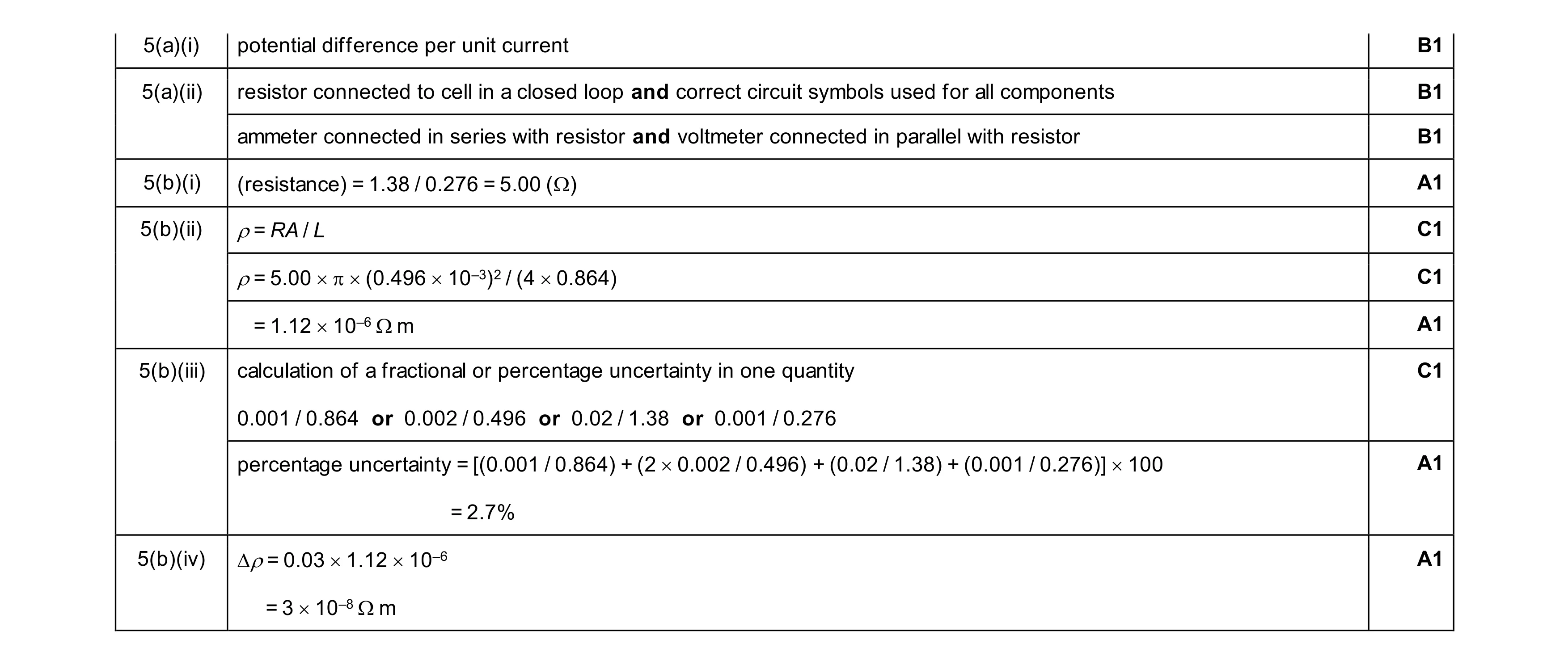 10
10