Questions as text
Q1 · A beam on a pivot 0625/32 Feb/March 2017
3 Fig. 3.1 shows a beam on a pivot. The beam is balanced at its centre of mass. beam pivot bench Fig. 3.1 (a) Explain the meaning of centre of mass. … … [1] (b) Fig. 3.2 shows a load of 2.5 N on one side of the beam. The beam is balanced by a load of 1.5 N suspended by a thin string. load of 18 cm x 2.5 N string load of 1.5 N Fig. 3.2 (not to scale) (i) Calculate the distance x from the pivot to the string. distance from pivot = … cm [3] (ii) Calculate the mass of the 2.5 N load. mass = … kg [3] [Total: 7]
7 marks
Mark scheme: 3(a) point where all the weight seems to act owtte B1 3(b)(i) moments clockwise = moments anticlockwise C1 2.5 X 18 = 1.5 x ? OR 45 ÷ 1.5 C1 30 (cm) A1 3(b)(ii) w = m × g in any recognised form C1 2.5 ÷ 10 C1 0.25 (kg) A1 Total: 7
This question in 0625/32 Feb/March 2017
Q2 · A tyre hanging from the branch of a tree 0625/31 May/June 2017
3 Fig. 3.1 shows a tyre hanging from the branch of a tree. branch 2.5 m P rope tyre Fig. 3.1 (a) The mass of the tyre is 15 kg. Calculate its weight. weight of tyre = … N [2] (b) The weight of the tyre exerts a moment on the branch, about point P where the branch joins the tree. (i) Explain what is meant by the term moment. … [1] (ii) A child sits on the tyre. The weight of the child and tyre together is 425 N. Calculate the moment of this force about point P. Use information given in Fig. 3.1. Include the unit. moment = … [4] (iii) A heavier child wants to sit on the tyre. Describe how the tyre position should be adjusted so that the moment is the same as in (b)(ii). … [1] [Total: 8]
8 marks
Mark scheme: 3(a) C1 150 (N) A1 3(b)(i) turning effect (of a force) B1 3(b)(ii) moment = force × distance C1 425 × 2.5 C1 1062.5 OR 1063 A1 N m B1 3(b)(iii) (move rope/tyre) closer to trunk owtte B1 Total: 8
This question in 0625/31 May/June 2017
Q3 · A laboratory floor has a surface that prevents people from slipping when the floor is wet 0625/31 May/June 2017
5 A laboratory floor has a surface that prevents people from slipping when the floor is wet. (a) Name the force that prevents a person from slipping. … [1] (b) A stool has a round non-slip pad fitted to the bottom of each leg. (i) The stool has four legs. The area of each pad is 3 cm2. The weight of the stool is 75 N. A student sits on the stool. The weight of the student is 525 N. Calculate the pressure acting on the floor due to the student and the stool. pressure = … N / cm2 [5] (ii) The legs of the stool are made of hollow metal tubes. Fig. 5.1 shows the bottom of a stool leg with and without a pad. metal tube with pad without a pad Fig. 5.1 Explain why a stool leg without a pad does more damage to the floor. … … [2] [Total: 8]
8 marks
Mark scheme: 5(a) friction B1 5(b)(i) total area = 3 × 4 = 12 (cm2) C1 total weight = 525 + 75 N = 600(N) C1 P = F ÷ A in any form C1 600 ÷ 12 C1 50 (N / cm2) A1 5(b)(ii) less (surface) area (in contact with the ground) owtte B1 more pressure (results in more damage to the surface) B1 Total: 8
This question in 0625/31 May/June 2017
Question 4 0625/32 May/June 2017
3 Fig. 3.1 shows a large sunshade. arm sunshade pivot support base Fig. 3.1 The arm holding the sunshade pivots about the end of a support. (a) The sunshade has a mass of 20.0 kg. Calculate the weight of the sunshade. weight = … N [3] (b) (i) Another sunshade is shown in Fig. 3.2. This sunshade weighs 180 N. The arm holding the sunshade extends 2.5 m from the pivot. 2.5 m pivot support 180 N base Fig. 3.2 Calculate the moment of the sunshade about the pivot. moment = … N m [3] (ii) How can the moment produced by the sunshade be reduced? Tick one box. by decreasing the height of the support by decreasing the length of the arm holding the sunshade by increasing the weight of the base by increasing the weight of the sunshade [1] [Total: 7]
7 marks
Mark scheme: 3(a) C1 20.0 × 10.0 C1 200 (N) A1 3(b)(i) moment = force × (perpendicular) distance (from pivot) in any form C1 180.0 × 2.5 C1 450 (N m) A1 3(b)(ii) 2nd box down ticked decrease the length of the arm holding the sun-shade B1 Total: 7
This question in 0625/32 May/June 2017
Q5 · A student has a laptop computer 0625/33 May/June 2017
2 A student has a laptop computer. The computer is powered by a battery. (a) State the word used to describe the energy stored in the battery. … [1] (b) The student opens the laptop using a force of 3.0 N, as shown in Fig. 2.1. 3.0 N 25.0 cm pivot Fig. 2.1 (i) Calculate the moment of the 3.0 N force about the pivot. moment = … N cm [3] (ii) The student does work as he opens the laptop. Explain how the principle of conservation of energy applies to this example. … … [2] (c) The student is in a country with many hours of sunshine each day. He charges his laptop using a solar panel. Give two advantages of using a solar panel, compared with using a mains electrical supply. 1. … 2. … [2] (d) A mains battery charger has a power output of 80 W. The solar panel has a power output of 16 W. Describe one disadvantage of using the solar panel, compared with using the mains battery charger. … [1] [Total: 9]
9 marks
Mark scheme: 2(a) chemical B1 2(b)(i) Moment = force × (perpendicular) distance (from pivot) in any form C1 3.0 × 25.0 C1 75 (N cm) A1 2(b)(ii) any two from: idea that work done = energy gained total energy does not change the student loses chemical energy laptop gains (gravitational) PE (of lid) energy dissipated as thermal energy in the environment B2 2(c) any two from: laptop can be charged anywhere owtte cost of charging is zero (Sun is a) renewable energy (source)/not using fossil fuels B2 2(d) (Takes 5 times) longer to (re-)charge (battery) B1 Total: 9
This question in 0625/33 May/June 2017
Q6 · A river flowing through a village 0625/31 Oct/Nov 2017
2 Fig. 2.1 shows a river flowing through a village. There are two bridges across the river. bridge X direction of flow bridge Y Fig. 2.1 Two students plan to measure the speed of a stick as it floats on the river between bridge X and bridge Y. (a) The students plan to drop a stick into the middle of the river from bridge X. The stick moves with the water between bridge X and bridge Y. Describe how the students can determine the average speed of the stick. … … … … … … … … [4] (b) The stick moves with constant speed. One statement correctly describes the horizontal forces acting on the stick. Put a tick (✓) in the box next to the correct statement. Only a forward force acts. The forward force and the backward force are equal. The forward force is greater than the backward force. The backward force is greater than the forward force. [1] [Total: 5]
5 marks
Mark scheme: 2(a) Any four from: Measure the distance between the two bridges Start stopwatch when stick hits water / starts moving (with river) stop stopwatch when stick reaches bridge Y Use speed = distance ÷ time repeat procedure and find average B4 2(b) 2nd box ticked The forward force and the backward force are equal B1
This question in 0625/31 Oct/Nov 2017
Q7 · A warning marker floating on the surface of a lake 0625/31 Oct/Nov 2017
3 Fig 3.1 shows a warning marker floating on the surface of a lake. warning marker surface of lake metal chain heavy object bottom of lake Fig. 3.1 The marker is attached by a metal chain to a heavy object on the bottom of the lake. (a) Fig. 3.2 shows the forces acting on the marker at one moment in time. 280 N 250 N Fig. 3.2 Calculate the resultant force on the marker. resultant force = … N direction = … [2] (b) Fig. 3.3 shows part of the metal chain. It is made from small metal loops. Fig. 3.3 A damaged loop is removed from the chain. Describe a method to determine the density of the metal from which the loops are made. … … … … … … … [5] [Total: 7]
7 marks
Mark scheme: 3(a) subtraction of forces to obtain resultant or 30 (N) B1 up(wards) B1 3(b) any five from: measure mass (on top pan balance) part fill measuring cylinder with water (and note volume) submerge link in measuring cylinder determine increase in volume increase in volume = volume of link use density = mass ÷ volume Only award full marks for a viable method B5
This question in 0625/31 Oct/Nov 2017
Question 8 0625/32 Oct/Nov 2017
4 Fig. 4.1 shows a fairground ride. pylon pylon starting position path of cabin cabin Fig. 4.1 People sit inside a cabin suspended between two pylons. The cabin is lifted to the starting position shown in Fig. 4.1. (a) State the name of the type of energy gained by the cabin as it rises. … [1] (b) The cabin is released and swings down between the two pylons. The path of the cabin is shown on Fig. 4.1. The cabin has maximum kinetic energy at one point on its path. Draw this point on Fig. 4.1 and label this point X. [1] (c) A force opposes the motion of the cabin as it falls. State the name of this force. … [1] (d) After a few swings, a brake system stops the cabin (not shown on the diagram). Use ideas about energy transfer to suggest how the brake system stops the cabin. … … … … [3] [Total: 6]
6 marks
Mark scheme: 4(a) (gravitational) potential (energy) B1 4(b) arrow at the lowest point of swing B1 4(c) friction / air resistance / drag B1 4(d) any three from: cabin has kinetic energy two surfaces rub together / friction thermal energy generated / KE transferred to thermal dissipated to surroundings / air B3
This question in 0625/32 Oct/Nov 2017
Q9 · A large box with a heavy lid 0625/33 Oct/Nov 2017
3 Fig. 3.1 shows a large box with a heavy lid. Fig. 3.1 (a) The weight of the box is 2250 N. Calculate the mass of the box. mass = … kg [3] (b) A man wants to lift the lid of the box. He puts a strong metal bar between the box and the lid. He applies a force to the bar as shown in Fig. 3.2. metal bar 40 cm 400 N pivot Fig. 3.2 (i) Calculate the moment of his force about the pivot. State the unit. moment = … [4] (ii) The moment in (b)(i) is not sufficient to lift the lid. Describe how the man can increase the moment, using the same force. … … [1] [Total: 8]
8 marks
Mark scheme: 3(a) C1 2250 / 10 C1 225 (kg) A1 3(b)(i) moment = force × distance from pivot in any recognised form C1 400 × 0.4 OR 400 × 40 C1 160 OR 16 000 A1 Nm OR Ncm B1 3(b)(ii) apply force further from pivot owtte B1
This question in 0625/33 Oct/Nov 2017
Q10 · The vertical forces on a rocket 0625/31 May/June 2018
3 (a) Fig. 3.1 shows the vertical forces on a rocket. thrust 74.2 N air resistance 2.4 N weight 43.0 N Fig. 3.1 Calculate the resultant force on the rocket. resultant force = … N direction = … [3] (b) Fig. 3.2 shows the speed and direction of motion of an object at a point in time. 150.0 m / s object Fig. 3.2 The resultant force on the object is zero for 10 seconds. Deduce the speed and direction of motion after 5 seconds. Indicate the speed and direction of the object by drawing a labelled arrow next to the object in Fig. 3.3. Fig. 3.3 [1] [Total: 4]
4 marks
Mark scheme: 3(a) 43.0 + 2.4 = 45.4 (N) 1 (74.2 – 45.4 =) 28.8 (N) 1 upwards 1 3(b) 1
This question in 0625/31 May/June 2018
Q11 · A man uses a metal bar to remove an iron nail from a piece of wood, as shown in Fig 0625/32 May/June 2018
3 A man uses a metal bar to remove an iron nail from a piece of wood, as shown in Fig. 3.1. 150 N nail 0.50 m wood pivot Fig. 3.1 (a) (i) The man applies a force of 150 N at a distance of 0.50 m from the pivot. Calculate the moment of this force about the pivot. Include a unit. moment = … [4] (ii) The force applied by the man produces a turning effect (moment) about the pivot. Describe another example of using the turning effect of a force. … … [1] (b) The man tries to use the metal bar to remove another nail from the piece of wood. He applies the same force of 150 N at a distance of 0.50 m from the pivot. The turning effect produced is not enough to remove this nail from the piece of wood. Describe how the man can increase the turning effect without increasing the force. … … [1] [Total: 6]
6 marks
Mark scheme: 3(a)(i) 1 150 × 0.5 1 75 1 N m 1 3(a)(ii) accept any example involving turning forces 1 3(b) increase distance (of force from pivot point ) 1
This question in 0625/32 May/June 2018
Q12 · A student is using some 50 g masses 0625/33 May/June 2018
2 A student is using some 50 g masses. (a) Calculate the weight of one 50 g mass. weight of 50 g mass = … N [3] (b) The student uses the 50 g masses as loads to stretch a spring. Fig. 2.1 shows the apparatus the student uses to obtain readings for a load-extension graph. spring pin stand 50 g masses 50 g mass rule hanger Fig. 2.1 (NOT to scale) Describe how the student could use the apparatus and ensure that the readings are accurate. … … … … … … … … … … [4] [Total: 7]
7 marks
Mark scheme: 2(a) W = m × g 1 50 ÷ 1000 OR 0.05 seen 1 0.5 (N) 1 2(b) any 4 from: fix ruler vertically add weight/hanger to spring fix pin (horizontally) to (top/bottom) of weight hanger pin arranged so near ruler scale ensure load stationary eye level with pin to take reading (of length) determine extension for given load repeat for different loads 4
This question in 0625/33 May/June 2018
Q13 · The mass of a small steel ball is 120 g 0625/33 May/June 2018
3 (a) The mass of a small steel ball is 120 g. The volume of the ball is 16.0 cm3. (i) Calculate the density of the steel ball. density = … g / cm3 [3] (ii) The ball falls to the ground from rest. At a time of 0.2 s after it started to fall, its acceleration is 10 m / s2. State the acceleration of the ball at a time of 0.1 s after it started to fall. … [1] (b) Fig. 3.1 shows the vertical forces that act on a large plastic ball as it is falling. 0.3 N large plastic ball 1.2 N Fig. 3.1 (not to scale) (i) State the name given to each of the forces shown in Fig. 3.1. 1. … 2. … [1] (ii) Calculate the size of the resultant force on the ball. resultant force = … N [1] [Total: 6]
6 marks
Mark scheme: 3(a)(i) (D =) m ÷ v in any form 1 120 ÷ 16.0 1 7.50 (g / cm3) 1 3(a)(ii) 10 (m / s2) 1 3(b)(i) (downward force) weight AND (upward force) air resistance/friction/drag 1 3(b)(ii) (1.2 – 0.3 =) 0.9 (N) 1
This question in 0625/33 May/June 2018
Q14 · A lamp is attached to a wall, as shown in Fig 0625/33 May/June 2018
4 A lamp is attached to a wall, as shown in Fig. 4.1. 90.0 cm lamp pivot wall 25.0 N Fig. 4.1 Calculate the moment of the lamp about the pivot. Give the unit. moment = … [4] [Total: 4]
4 marks
Mark scheme: 4 1 25 × 90 or 25 × 0.9 1 2250 or 22.5 1 N cm or N m 1
This question in 0625/33 May/June 2018
Q15 · A raft floating on water 0625/31 Oct/Nov 2018
2 Fig. 2.1 shows a raft floating on water. raft water Fig. 2.1 (a) A force of 20 000 N acts on the raft in the direction of the arrow shown in Fig. 2.1. (i) State the name given to the force shown in Fig. 2.1. … [1] (ii) Calculate the mass of the raft. mass = … kg [3] (b) A sail is added to the raft, as shown in Fig. 2.2. sail 800 N 1200 N Fig. 2.2 Fig. 2.2 shows the horizontal forces acting on the raft at one moment. Calculate the resultant horizontal force acting on the raft and state the direction of this force. force = … N direction = … [2] [Total: 6]
6 marks
Mark scheme: 2(a)(i) weight B1 2(a)(ii) W = m × g C1 m = 20 000 ÷ 10 C1 2000 (kg) A1 2(b) 400 (N) B1 forwards / to the right B1
This question in 0625/31 Oct/Nov 2018
Q16 · A tower crane has a load W, as shown in Fig 0625/31 Oct/Nov 2018
3 A tower crane has a load W, as shown in Fig. 3.1. 8.0 m 5.0 m counterweight pivot 80 000 N tower load W Fig. 3.1 (a) The counterweight has a weight of 80 000 N. This acts at a distance of 5.0 m from the pivot, as shown in Fig. 3.1. Calculate the moment of the counterweight about the pivot. Give the unit. moment = … [3] (b) The tower crane in Fig. 3.1 balances horizontally when holding the load W. Calculate the weight of load W. weight = … N [3] [Total: 6]
6 marks
Mark scheme: 3(a) C1 400 000 A1 Nm B1 3(b) c.w. moment = a.c.w moment OR moment of load = moment of counterweight OR 5.0 × 80 000 = load × 8.0 C1 400 000 ÷ 8.0 = load C1 50 000 (N) A1
This question in 0625/31 Oct/Nov 2018
Q17 · A load is attached to a spring, as shown in Fig 0625/32 Feb/March 2019
3 A load is attached to a spring, as shown in Fig. 3.1. Two arrows indicate the vertical forces acting on the load. The spring and the load are stationary. support spring 4.0 N load Fig. 3.1 (a) (i) State the name of the force acting vertically downwards. … [1] (ii) The vertical force that acts upwards is 4.0 N. State the value of the force acting vertically downwards. force = … N [1] (b) The load is pulled downwards and then released. The load moves up and down. Fig. 3.2 represents the vertical forces acting on the load at some time after it is released. 7.6 N 2.8 N Fig. 3.2 Calculate the resultant force on the load and state its direction. resultant force = … N direction = … [2] (c) (i) State the principle of conservation of energy. … … [1] (ii) Eventually the load stops moving up and down. Describe and explain why the load stops moving. Use your ideas about conservation of energy. … … … … [2] [Total: 7]
7 marks
Mark scheme: 3(a)(i) gravity OR weight B1 3(a)(ii) 4.0 (N) B1 Question Answer Marks 3(b) 4.8 (N) B1 Up(wards) B1 3(c)(i) energy cannot be created or destroyed (but can be transformed) B1 3(c)(ii) PE / KE / elastic energy of load / spring decreases / is transformed B1 Any one from: to thermal energy (which is) dissipated (to surroundings) B1
This question in 0625/32 Feb/March 2019
Q18 · A truck lifting a heavy load 0625/32 Feb/March 2019
4 Fig. 4.1 shows a truck lifting a heavy load. load truck pivot Fig. 4.1 (a) (i) The truck is stationary. Identify the quantities that determine the work done as it lifts the load. Tick the box next to each correct quantity. distance force time [1] (ii) Draw a ring around the unit for work done from the list. joule newton pascal watt [1] (b) Identify the quantities that determine the power of the truck. Tick the box next to each correct quantity. energy transferred temperature time [1] (c) The truck has a pivot near the front wheel. Fig. 4.2 represents the pivot and the vertical forces acting on the truck. 1.5 m 1.0 m 30 000 N pivot load Fig. 4.2 The truck is in equilibrium. Calculate the load. load = … N [3] (d) Fig. 4.3 shows another truck lifting a pile of identical bricks. pile of bricks Fig. 4.3 (i) On Fig. 4.3, draw a cross to indicate the centre of mass of the pile of bricks. [1] (ii) The truck can tilt the pile of bricks backwards, as shown in Fig. 4.4. Fig. 4.4 Explain how tilting the pile of bricks backwards makes the truck more stable. … … … … [1] [Total: 8]
8 marks
Mark scheme: 4(a)(i) tick in top two boxes: distance AND force B1 4(a)(ii) first word circled: joule B1 4(b) tick in top AND bottom boxes: energy transferred AND time B1 4(c) clockwise moment = anticlockwise moment C1 1.5 × 30 000 = 1 × (load) C1 (load =) 45 000 (N) A1 4(d)(i) centre of mass in centre of load B1 4(d)(ii) centre of mass (moves) closer to pivot (point) B1
This question in 0625/32 Feb/March 2019
Q19 · A student has a metal object 0625/31 May/June 2019
1 (a) A student has a metal object. (i) The student measures the mass of the object. State the name of the equipment used to measure the mass. … [1] (ii) The mass of the metal object is 1260 g. The volume of the metal is 150 cm3. Calculate the density of the metal. Include the unit. density = … [4] (iii) The mass of the metal object is given in grams. State the mass in kg. mass = … kg [1] (b) A vase is placed on a table. Forces X and Y act on the vase, as shown in Fig. 1.1. X vase Y Fig. 1.1 The mass of the vase is 0.25 kg. The vase is not moving. Calculate the value of force X and the value of force Y. X … Y … [4] [Total: 10]
10 marks
Mark scheme: 1(a)(i) balance B1 1(a)(ii) density = mass ÷ volume in any form C1 1260 ÷ 150 C1 8.4 A1 g / cm3 B1 1(a)(iii) 1.26 (kg) B1 1(b) W = mg in any form C1 0.25 × 10 C1 2.5 (N) A1 Both lines have 2.5 (N) B1
This question in 0625/31 May/June 2019
Q20 · A man pushing down on a lever to lift one end of a heavy log 0625/31 May/June 2019
2 Fig. 2.1 shows a man pushing down on a lever to lift one end of a heavy log. lever heavy log Fig. 2.1 (a) State the term used to describe the turning force exerted by the man. … [1] (b) (i) Fig. 2.2 shows the forces acting as the man starts to lift the heavy log. 1.2 m 0.3 m lever F 400 N pivot Fig. 2.2 Calculate the force F, exerted by the lever on the heavy log. force F = … N [3] (ii) Describe how the man can use a smaller force to lift the heavy log. … … [1] [Total: 5]
5 marks
Mark scheme: 2(a) moment B1 2(b)(i) (sum of) clockwise moment(s) = (sum of) anticlockwise moment(s) C1 1.2 × 400 = 0.3 × F C1 1600 (N) A1 2(b)(ii) use a longer lever OR pivot closer to log / force F B1
This question in 0625/31 May/June 2019
Q21 · A wheelbarrow and Fig 0625/33 May/June 2019
3 Fig. 3.1 shows a wheelbarrow and Fig. 3.2 shows the dimensions of its wheel. load 35 cm = diameter of wheel 1.50 m pivot 25 mm = diameter of axle Fig. 3.1 Fig. 3.2 (a) Complete the table to show the diameter of the wheel and axle in metres. measurement measurement in metres diameter of wheel 35 cm diameter of axle 25 mm [2] (b) The mass of the wheelbarrow is 20 kg. The mass of the load in the wheelbarrow is 30 kg. Calculate the total weight of the wheelbarrow and its load. weight of wheelbarrow and load = … N [3] (c) A man lifts the handle of the wheelbarrow. He applies a force of 140 N, as shown in Fig. 3.3. wheelbarrow 140 N handle 1.30 m pivot Fig. 3.3 Calculate the moment of the force about the pivot. Include the unit. moment = … [4] [Total: 9]
9 marks
Mark scheme: 3(a) 0.35 (m) B1 0.025 (m) B1 3(b) (weight =) mass × gravity in any form C1 50 × 10 OR (20 × 10) + (30 × 10) C1 500 (N) A1 3(c) moment = force × distance from pivot C1 140 × 1.3 C1 180 A1 Nm B1
This question in 0625/33 May/June 2019
Q22 · A spring with no load attached 0625/31 Oct/Nov 2019
3 Fig. 3.1 shows a spring with no load attached. Fig. 3.2 shows the same spring with a load attached. stand spring load Fig. 3.1 Fig. 3.2 (a) Describe how a student can determine the extension of the spring. You may draw on Fig. 3.1 and Fig. 3.2 as part of your answer. … … … … … [3] (b) The student plots a graph of load against extension, as shown in Fig. 3.3. 10.0 load / N 9.0 8.0 7.0 6.0 5.0 4.0 3.0 2.0 1.0 0.0 0 4 8 12 16 20 24 28 32 36 40 extension / cm Fig. 3.3 (i) Determine the extension produced by a load of 7.5 N. extension = … cm [1] (ii) Determine the load that would produce an extension of 10.0 cm. load = … N [1] (c) Calculate the mass that has a weight of 6.0 N. mass = … kg [3] [Total: 8]
8 marks
Mark scheme: 3(a) measure without any load / weights AND measure with load / weights B1 measure length OR ruler stated or seen B1 (extension =) difference in two values B1 3(b)(i) 30 (cm) B1 3(b)(ii) 2.5 (N) B1 3(c) W = m × g OR W = m × 10 OR (m =) W ÷ g in any form C1 6.0 ÷ 10 C1 0.6(0) (kg) A1
This question in 0625/31 Oct/Nov 2019
Q23 · A tractor fitted with a device for breaking up soil in a field 0625/31 Oct/Nov 2019
4 Fig. 4.1 shows a tractor fitted with a device for breaking up soil in a field. tractor device heavy weight pivot point soil Fig. 4.1 (a) (i) The tractor has a heavy weight at the front. Explain why the heavy weight is needed. … … [1] (ii) Fig. 4.2 represents the weight of the device and its distance from the pivot. pivot 2.1 m 6000 N Fig. 4.2 Calculate the moment of the weight of the device about the pivot. State the unit. moment = … [4] (b) Fig. 4.3 shows a tractor fitted with narrow tyres and the same tractor fitted with wide tyres. narrow tyre wide tyre tractor fitted with same tractor fitted with narrow tyres wide tyres Fig. 4.3 (view from the front) Explain why wide tyres are more suitable for the tractor on soft soil. … … … … [3] [Total: 8]
8 marks
Mark scheme: 4(a)(i) stop the tractor tipping up/keep tractor level owtte B1 4(a)(ii) moment = force × (perp.) distance from pivot in any form C1 6000 × 2.1 C1 12 600 A1 Nm B1 4(b) Any three from: (wide tyres have) greater area (in contact with ground) pressure = force ÷ area in any form the bigger the area the smaller the pressure so tractor less likely to sink/become stuck (in soft ground) B3
This question in 0625/31 Oct/Nov 2019
Q24 · The horizontal forces acting on a swimmer 0625/32 Oct/Nov 2019
3 (a) Fig. 3.1 shows the horizontal forces acting on a swimmer. 120 N 110 N Fig. 3.1 (i) Calculate the size and direction of the resultant horizontal force on the swimmer. size of resultant horizontal force = … N direction of resultant horizontal force = … [1] (ii) State the name of the 110 N force on the swimmer. … [1] (iii) Fig. 3.2 shows the horizontal forces acting on the swimmer as he moves forwards a short time later. 120 N 120 N Fig. 3.2 Describe and explain the motion of the swimmer. … … [2] (b) Another swimmer weighs 700 N. He stands on a diving board, as shown in Fig. 3.3. P 3.5 m diving board 700 N Fig. 3.3 Calculate the moment of the swimmer’s weight about point P. moment = … N m [3] [Total: 7]
7 marks
Mark scheme: 3(a)(i) 10 (N) AND forwards/to the right B1 3(a)(ii) friction (between swimmer and water) B1 3(a)(iii) (now) moving at steady/constant speed B1 forces (now)balanced / in equilibrium OR forward force = backward force OR no resultant force B1 3(b) moment = force × (perp.) distance (from pivot) C1 700 × 3.5 C1 2450 (N m) A1
This question in 0625/32 Oct/Nov 2019
Q25 · A metal triangle suspended from a thread 0625/32 Oct/Nov 2019
4 (a) Fig. 4.1 shows a metal triangle suspended from a thread. thread metal triangle Fig. 4.1 Complete the sentence. Choose the correct word or phrase from the box. above below to the left of to the right of The metal triangle will come to rest with its centre of mass directly … the point of suspension. [1] (b) A student finds the centre of mass of a shape made of thin card. Fig. 4.2 shows the equipment. clamp stand and clamp plumbline nail or pin shape made of thin card Fig. 4.2 (NOT to scale) Describe how the student finds the centre of mass of the card. Choose from these sentences. A A line is drawn on the card showing the position of the string. B A pin held in a clamp is put through the hole in the card. C The centre of mass is where the lines cross on the card. D The process is repeated using holes near the other two edges. Complete the flow chart. Write the letter for the correct sentence in each box. A small hole is made near one edge of the card The plumbline is attached to the pin [3] [Total: 4]
4 marks
Mark scheme: 4(a) below B1 4(b) B A D C B3
This question in 0625/32 Oct/Nov 2019
Q26 · A model aircraft is flying through air 0625/33 Oct/Nov 2019
3 A model aircraft is flying through air. Fig. 3.1 shows the forces acting on the model aircraft. The weight of the model aircraft is 15.0 N. 15.0 N direction of motion 11.0 N 19.0 N 15.0 N Fig. 3.1 (a) (i) Determine the size and direction of the resultant horizontal force acting on the model aircraft. size of resultant horizontal force = … N direction of resultant horizontal force = … [1] (ii) Describe the change in the motion of the model aircraft. … … [2] (b) The horizontal forces acting on the model aircraft become balanced. Suggest how the horizontal forces acting on the model aircraft have changed. … … [1] [Total: 4]
4 marks
Mark scheme: 3(a)(i) 8.0 (N) AND forwards / to the left B1 3(a)(ii) accelerating forwards / to the left B1 B1 3(b) greater drag force / air resistance OR lower thrust owtte B1
This question in 0625/33 Oct/Nov 2019
Q27 · A 50 cm rule is balanced at its mid-point 0625/32 Feb/March 2020
2 A 50 cm rule is balanced at its mid-point. A force of 8.0 N acts at a distance of 10 cm from one end of the rule. Fig. 2.1 shows the arrangement. 10 cm 25 cm 50 cm rule 8.0 N pivot Fig. 2.1 (a) Calculate the moment of the 8.0 N force about the pivot. Give the unit. moment = … unit = … [5] (b) Another force acts at a point 10 cm from the pivot. It makes the rule balance. On Fig. 2.1, draw an arrow to show the position and direction of this force. [2] [Total: 7]
7 marks
Mark scheme: 2(a) moment = force × distance from pivot in any form C1 (distance of force from pivot = (25 – 10) =) 15 (cm) C1 8 × 15 C1 120 A1 N cm B1 2(b) arrow giving clockwise moment B1 arrow drawn 10 cm from pivot by eye B1
This question in 0625/32 Feb/March 2020
Q28 · A student stretches a spring by adding different loads to it 0625/31 May/June 2020
2 (a) A student stretches a spring by adding different loads to it. She measures the length of the spring for each load. She plots a graph of the results. Fig. 2.1 shows the graph of her results. 16.0 length / cm 12.0 8.0 4.0 0 0 1.0 2.0 3.0 4.0 5.0 6.0 load / N Fig. 2.1 Use the graph to determine: (i) the length of the spring without a load length = … cm [1] (ii) the length of the spring with a load of 4.0 N length = … cm [1] (iii) the extension due to a 4.0 N load. extension = … cm [1] (b) Complete the sentence about effects of forces. Choose words from the box. colour friction pressure shape size speed Stretching a spring with a load is an example of how a force can change the … and the … of an object. [2] [Total: 5]
5 marks
Mark scheme: 2(a)(i) 6.0 (cm) B1 2(a)(ii) 13.0 (cm) B1 2(a)(iii) (ii) – (i) B1 2(b) shape B1 size B1
This question in 0625/31 May/June 2020
Q29 · A metre rule is balanced on a pivot by three vertical forces, as shown in Fig 0625/31 May/June 2020
5 A metre rule is balanced on a pivot by three vertical forces, as shown in Fig. 5.1. 100 cm 40 cm 10 cm 5.0 N pivot weight F = 2.0 N of rule Fig. 5.1 (not to scale) (a) Show that the moment of the 5.0 N force about the pivot is 200 N cm. [2] (b) Calculate the size of force F. F = … N [4] [Total: 6]
6 marks
Mark scheme: 5(a) (moment =) force × distance (from pivot) B1 (moment =) 5.0 × 40 B1 5(b) (sum of) clockwise moments = (sum of) anticlockwise moments C1 200 = (2.0 × 10) + (F × 60) C1 F = (200 – 20) ÷ 60 OR 180 ÷ 60 C1 (F =) 3.0 (N) A1
This question in 0625/31 May/June 2020
Q30 · Three horizontal forces acting on a car as it moves along a straight road 0625/31 Oct/Nov 2020
3 Fig. 3.1 shows three horizontal forces acting on a car as it moves along a straight road. The horizontal forces act along the same straight line. 250 N 900 N 300 N Fig. 3.1 (a) (i) Calculate the size of the resultant horizontal force on the car and state its direction. size of resultant force = … N direction of resultant force … [3] (ii) The driver presses the brake pedal and the car slows down. As the car slows down, the kinetic energy of the car decreases by 100 kJ. Describe and explain what happens to this 100 kJ of energy. … … [2] (b) Fig. 3.2 shows the force applied to the brake pedal by the driver’s foot. pivot 20 cm 35 N brake pedal Fig. 3.2 Calculate the moment of the force about the pivot. Include the unit. moment = … unit … [4] [Total: 9]
9 marks
Mark scheme: 3(a)(i) 900 – (300 + 250) C1 350 (N) A1 (direction of resultant force =) forwards B1 3(a)(ii) any two from: • friction (in the brakes) • (transfers 100 kJ OR kinetic energy) into thermal energy (store) OR internal energy (store) • of brakes / car / surroundings OR is dissipated OR (transferred) into surroundings / environment B2 3(b) (moment =) force × (perpendicular) distance (from pivot) C1 (moment =) 35 × 20 C1 (moment =) 700 A1 Ncm B1
This question in 0625/31 Oct/Nov 2020
Q31 · A box attached to a parachute 0625/32 Oct/Nov 2020
1 Fig. 1.1 shows a box attached to a parachute. The box and the parachute are falling through the air. 16.0 N parachute 2.5 N box 20.0 N Fig. 1.1 (a) Fig. 1.1 shows three vertical forces acting on the box and the parachute. (i) Calculate the resultant vertical force and state its direction. resultant vertical force = … N direction … [3] (ii) Suggest and explain what happens to the size of the upward vertical force on the parachute if the area of the parachute used is increased. suggestion … explanation … … [2] (b) Fig. 1.2 shows the speed–time graph for the box before the parachute is opened. 45 40 35 speed m / s 30 25 20 15 10 5 0 0 10 20 30 40 time / s Fig. 1.2 (i) Determine the time when the speed of the box is 30 m / s. time = … s [1] (ii) Deduce the size of the resultant vertical force on the box when the time is 35 s. Explain your answer. size of resultant vertical force … explanation … … [2] (iii) Calculate the distance the box moves between time = 30 s and time = 40 s. distance = … m [3] [Total: 11]
11 marks
Mark scheme: 1(a)(i) 20.0 – (2.5 + 16.0) C1 1.5 (N) A1 (vertically) down B1 1(a)(ii) (upwards force) increases B1 increases air resistance B1 1(b)(i) 6.5 (s) B1 (b)(ii) (resultant force is) zero B1 (because the) speed (of parachute) is constant / steady / uniform B1 1(b)(iii) (dist. travelled =) area under line (of speed-time graph) C1 45 x 10 C1 450 (m) A1
This question in 0625/32 Oct/Nov 2020
Q32 · A car driver needs to remove one of the wheels on his car 0625/32 Oct/Nov 2020
2 A car driver needs to remove one of the wheels on his car. He puts a spanner on a wheel nut. wheel 50 cm 200 N wheel nut spanner tyre Fig. 2.1 (a) The driver applies a force of 200 N, as shown in Fig. 2.1. Calculate the moment of the 200 N force about the centre of the wheel nut. moment of force = … N cm [3] (b) The moment in (a) does not release the wheel nut. The driver cannot increase the force but can increase its moment. State and explain how the driver can increase the moment of the force. statement … explanation … … [2] (c) The driver releases a second wheel nut in a shorter time than the first wheel nut. The driver uses the same amount of energy in releasing both wheel nuts. less than the same as greater than Complete the sentences using the phrases in the box. Each phrase may be used once, more than once or not at all. The work done in releasing the second wheel nut is … the work done in releasing the first wheel nut. The power produced in releasing the second wheel nut is … the power produced in releasing the first wheel nut. [2] [Total: 7]
7 marks
Mark scheme: 2(a) (Moment) = F × d C1 200 × 50 C1 10 000 (Ncm) A1 2(b) use a longer spanner / move force to end of spanner owtte B1 (to) increase the distance (from force to wheel nut or pivot) OR distance (from force to wheel nut or pivot) is greater than 50 cm B1 2(c) (work done is the) same (as) B1 (power produced is) greater (than) B1
This question in 0625/32 Oct/Nov 2020
Q33 · A lorry moving on a straight road 0625/33 Oct/Nov 2020
1 (a) Fig. 1.1 shows a lorry moving on a straight road. The arrows represent the horizontal forces acting on the lorry. These forces act along the same straight line. 500 N 1000 N 1500 N Fig. 1.1 (i) Calculate the size of the resultant horizontal force on the lorry. size of resultant force = … N [2] (ii) Describe the effect of a horizontal resultant force of zero on the speed of the lorry. Put a tick (3) in one box. speed increases to a higher constant speed speed stays the same speed decreases to a lower constant speed speed decreases to zero [1] (b) The speed of the motorcycle in Fig. 1.2 is 20 m / s. Fig. 1.2 The rider reacts to a sudden change in the traffic ahead. He stops as quickly as possible by applying the brakes. The total stopping distance is made up of the distance travelled while the rider is reacting and the distance travelled when the brakes are applied. Fig. 1.3 shows information about stopping when the speed of the motorcycle is 20 m / s. 15 m 38 m distance travelled distance travelled while braking while reacting Fig. 1.3 (i) Calculate the total stopping distance when the speed of the motorcycle is 20 m / s. total stopping distance = … m [1] (ii) Suggest one factor that could increase the total stopping distance. … [1] [Total: 5]
5 marks
Mark scheme: 1(a)(i) 1000 + 500 OR 1500 OR 1500 – 1500 OR 1500 – their ‘1500’ OR 1500 – 1000 OR 1500 – 500 C1 0 / zero A1 1(a)(ii) 2nd box (speed stays the same) B1 1(b)(i) (15 + 38) = 53 (m) B1 1(b)(ii) reduced friction / wet / icy (conditions) / worn tyres tiredness / drugs / alcohol / higher speed / going down hill B1
This question in 0625/33 Oct/Nov 2020
Q34 · Two children sitting on a see-saw 0625/33 Oct/Nov 2020
2 (a) Fig. 2.1 shows two children sitting on a see-saw. child A child B X 0.5 m beam 125 N pivot 250 N Fig. 2.1 (not to scale) (i) The weight of child A is 125 N. Calculate the mass of child A. Include the unit in your answer. mass of child A = … unit … [3] (ii) Fig. 2.1 shows child A and child B sitting in positions which balance the see-saw horizontally. Using the information in Fig. 2.1, determine the distance X. distance X = … m [3] (b) The person in Fig. 2.2 is pushing a child on a swing. Fig. 2.2 State the name of the force that acts against the motion of the swing. … [1] [Total: 7]
7 marks
Mark scheme: 2(a)(i) W = mg OR W = 10 × m C1 12.5 A1 kg B1 2(a)(ii) 250 × 0.5 OR X × 125 C1 clockwise moment = anticlockwise moment C1 (X=) 1.0 (m) A1 2(b) air resistance / drag B1
This question in 0625/33 Oct/Nov 2020
Q35 · A box dropped from an aeroplane 0625/32 Feb/March 2021
1 Fig. 1.1 shows a box dropped from an aeroplane. The box contains supplies. A parachute is attached to the box. The parachute is opened when the time is 6.0 s. parachute box containing supplies Fig. 1.1 The graph in Fig. 1.2 shows the vertical speed of the box as it falls. 50 40 30 speed m / s 20 10 0 0 2.0 4.0 6.0 8.0 10.0 12.0 14.0 16.0 18.0 time / s Fig. 1.2 (a) State and explain what happens to the kinetic energy of the box during the first 6.0 s of its descent. … … … [2] (b) State and explain what happens to the gravitational potential energy of the box during the first 6.0 s. … … … [2] (c) (i) Use the graph in Fig. 1.2 to determine the speed of the object when the object is moving with a constant speed. speed of the object at constant speed = … m / s [2] (ii) State the size of the resultant vertical force on the box when it is falling at a constant speed. … [1] (d) Use the graph in Fig. 1.2 to determine the distance travelled by the box during the first 6.0 s. distance travelled in first 6.0 s = … m [3] (e) Without calculation, describe how Fig. 1.2 shows that the deceleration of the box is greater than the acceleration of the box. … … [1] [Total: 11]
11 marks
Mark scheme: 1(a) (kinetic energy / it) increases B1 (because) speed / velocity (of box) increases OR faster B1 1(b) (gravitational potential energy) decreases M1 (because) height (of box) decreases A1 1(c)(i) any indication on graph / in text that horizontal section represents steady speed C1 10 (m / s) A1 1(c)(ii) (resultant vertical force =) zero OR 0 (N) B1 1(d) distance = area under graph OR ½ × b × h C1 (distance =) ½ × 6.0 × 45 C1 135 (m) A1 1(e) deceleration (line) is steeper OR higher gradient than acceleration (line) B1
This question in 0625/32 Feb/March 2021
Q36 · The forces acting on a uniform balanced beam 0625/32 Feb/March 2021
3 Fig. 3.1 shows the forces acting on a uniform balanced beam. The beam is pivoted at its centre. P 2.0 cm pivot 6.0 cm 2.0 cm 5.2 N 8.1 N Fig. 3.1 (a) Calculate the moment of the 5.2 N force about the pivot and show that its value is close to 30 Ncm. [3] (b) The beam is balanced. Calculate force P. force P = … N [4] [Total: 7]
7 marks
Mark scheme: 3(a) (moment of force =) force × (perpendicular) distance of force from pivot B1 5.2 × 6.0 B1 31.2 B1 3(b) (sum of) clockwise moment(s) = (sum of) anticlockwise moment(s) C1 P × 2.0 + 8.1 × 2.0 = 5.2 × 6.0 OR 31.2 OR answer from (a) C1 P = (31.2 – 16.2) ÷ 2.0 OR 15 ÷ 2.0 C1 7.5 (N) A1
This question in 0625/32 Feb/March 2021
Q37 · A plank balances horizontally on a log of wood, which acts as a pivot 0625/31 May/June 2021
3 A plank balances horizontally on a log of wood, which acts as a pivot. (a) A girl sits on one end of the plank, and her brother pushes down on the other end to make the plank balance horizontally. Fig. 3.1 shows the arrangement. pivot 1.2 m 1.6 m weight = 404 N F Fig. 3.1 (not to scale) Calculate the moment of the girl’s weight about the pivot and show that it is close to 480 N m. [3] (b) The plank balances horizontally when the boy pushes down with a force F at a distance of 1.6 m from the pivot. Calculate the size of force F. force F = … N [3] [Total: 6]
6 marks
Mark scheme: 3(a) moment = force × distance (of direction of force from pivot) C1 404 × 1.2 C1 484.8 (N m) (which is about 480 N m) A1 3(b) c.w. moment = a.c.w moment OR moment of weight = moment of force/F C1 404 × 1.2 = F × 1.6 OR (F =) 484.8 ÷ 1.6 C1 (F = ) 300 (N) A1
This question in 0625/31 May/June 2021
Q38 · A man starts pulling his suitcase across the floor 0625/31 May/June 2021
5 (a) A man starts pulling his suitcase across the floor. suitcase 12 N 20 N Fig. 5.1 (not to scale) (i) Fig. 5.1 shows the horizontal forces acting on the suitcase. Calculate the resultant horizontal force on the suitcase. size of force = … N direction … [2] (ii) After a short time, the suitcase is moving at a constant speed. Suggest values for the sizes of the two horizontal forces on the suitcase when it is moving at a constant speed. pulling force = … (N) friction force = … (N) [1] (b) The total downward force of the suitcase on the ground is 150 N. The suitcase has two wheels. Each wheel has an area of 0.60 cm2 touching the ground. Calculate the pressure of the suitcase on the ground. pressure on the ground = … N / cm2 [4] [Total: 7]
7 marks
Mark scheme: 5(a)(i) 8 (N) B1 forwards B1 5(a)(ii) same non-zero values for pulling and friction force B1 5(b) (area = 2 × 0.60) = 1.2 (cm2) B1 (P =) F ÷ A C1 150 ÷ 1.2 OR 150 ÷ 0.60 C1 125 (N / cm2) A1
This question in 0625/31 May/June 2021
Q39 · A barrier used at a car park 0625/32 May/June 2021
3 Fig. 3.1 shows a barrier used at a car park. The beam can be raised and lowered by a man rotating it about its pivot. heavy weight pivot beam 1.8 m 150 N W Fig. 3.1 (not to scale) (a) The weight of the beam is 150 N. This acts at a distance of 1.8 m from the pivot as shown in Fig. 3.1. Calculate the moment of the weight of the beam about the pivot. Include the correct unit in your answer. moment of weight of beam = … unit … [4] (b) When the weight W of the heavy weight acts at a distance of 0.6 m from the pivot, the barrier is horizontal and balanced as shown in Fig. 3.1. The man raises the barrier and the heavy weight slips to a distance of 0.8 m from the pivot. This causes a problem for the man trying to lower the barrier. Describe and explain the problem this causes for the man lowering the barrier. … … … … … [3] [Total: 7]
7 marks
Mark scheme: 3(a) (moment of weight =) weight × (perpendicular) distance (of weight from pivot) (moment of weight =) 150 × 1.8 C1 270 A1 N m B1 3(b) barrier no longer balanced OR cannot be lowered (easily) B1 (more) force needed to lower barrier B1 (because) moment of heavy weight (has) increased B1
This question in 0625/32 May/June 2021
Q40 · A girl and her brother sit on opposite sides of a see-saw as shown in Fig 0625/33 May/June 2021
3 (a) A girl and her brother sit on opposite sides of a see-saw as shown in Fig. 3.1. girl brother 1.9 m 1.2 m 240 N pivot W Fig. 3.1 (i) Calculate the girl’s moment about the pivot and show that it is close to 460 N m. [3] (ii) The see-saw is balanced horizontally. Calculate the weight W of the brother. W = … N [3] (b) The weight of the girl in Fig. 3.1 is 240 N. Calculate the mass of the girl. Include the unit in your answer. mass of girl = … unit … [4] [Total: 10]
10 marks
Mark scheme: 3(a)(i) force × (perp) distance C1 240 × 1.9 C1 456 (Nm) (which is close to 460 Nm) A1 3(a)(ii) c.w. moment = a.c.w moment OR girl’s moment = brother’s moment C1 240 × 1.9 = W × 1.2 OR 456 ÷ 1.2 OR 460 ÷ 1.2 C1 380 (N) A1 3(b) W = mg in any form OR (m =) W ÷ g C1 240 ÷ 10 C1 24 A1 kg B1
This question in 0625/33 May/June 2021
Q41 · A student determines the centre of mass of a piece of card 0625/31 Oct/Nov 2021
3 (a) A student determines the centre of mass of a piece of card. Fig. 3.1 shows the equipment the student uses. pin cork A stand card ruler B C cotton thread weight Fig. 3.1 Describe how the student determines the centre of mass of the card using the equipment in Fig. 3.1. … … … … … … [3] (b) Another card is pivoted at point P. The weight of the card is 1.4 N and acts through a point 20 cm from P. Fig. 3.2 shows the arrangement. card P 20 cm pivot 1.4 N Fig. 3.2 Calculate the moment of the weight of the card about point P. moment of weight = … N cm [3] [Total: 6]
6 marks
Mark scheme: 3(a) any three from: line drawn alongside cotton thread / string hang triangle from a different corner (B or C) repeat marking of string (position on the card) centre of mass is where lines intersect B3 3(b) (moment of weight =) weight × distance (of direction of force from pivot) C1 (moment =) 1.4 × 20 C1 28 (N cm) A1
This question in 0625/31 Oct/Nov 2021
Q42 · The vertical forces acting on a toy rocket as it leaves the ground 0625/32 Oct/Nov 2021
3 Fig. 3.1 shows the vertical forces acting on a toy rocket as it leaves the ground. upward force = 70 N smooth surface weight of rocket = 15 N Fig. 3.1 (a) Calculate the size of the resultant vertical force on the rocket. resultant force = … N [2] (b) Explain why the top of the rocket is pointed and has a smooth surface. … … [2] [Total: 4]
4 marks
Mark scheme: 3(a) 70 – 15 C1 55 (N) A1 3(b) streamline / friction / drag / air resistance M1 reduce (owtte) friction / drag / air resistance A1
This question in 0625/32 Oct/Nov 2021
Q43 · The horizontal forces acting on a skateboarder 0625/33 Oct/Nov 2021
3 Fig. 3.1 shows the horizontal forces acting on a skateboarder. backward force = 60 N forward force = 100 N skateboarder skateboard Fig. 3.1 (a) Calculate the resultant force acting on the skateboarder. resultant force = … N direction = … [2] (b) Describe the effect of the resultant force in (a) on the motion of the skateboarder. … [1] (c) The skateboarder is moving along a horizontal path. The backward force is 100 N. The forward force is 100 N. Describe the motion of the skateboarder. … [1] [Total: 4]
4 marks
Mark scheme: 3(a) 40 (N) B1 forward / to the right B1 3(b) accelerates / speed increases B1 3(c) constant / uniform speed / zero acceleration B1
This question in 0625/33 Oct/Nov 2021
Q44 · A student is doing some physical exercise 0625/32 Feb/March 2022
2 (a) A student is doing some physical exercise. Fig. 2.1 shows the student holding a 50 N weight. 0.90 m pivot 50 N Fig. 2.1 The pivot in the shoulder is 0.90 m from the centre of mass of the weight. Calculate the moment of the weight about this pivot. moment of the weight = … N m [3] (b) The student does some running exercises. Fig. 2.2 shows the speed–time graph for one exercise. B CC 8.0 speed m / s 6.0 4.0 2.0 AA D E 0 D 0 5.0 10.0 15.0 20.0 time / s Fig. 2.2 (i) Describe the motion of the athlete in sections AB and DE. section AB … section DE … [2] (ii) Calculate the distance moved by the athlete from time = 0 to time = 5.0 s. distance = … m [3] [Total: 8]
8 marks
Mark scheme: 2(a) 45 (Nm) A3 (moment of force =) force × (perpendicular) distance (of force from pivot) (C1) 50 × 0.9 (C2) 2(b)(i) (section AB) increasing speed OR acceleration B1 (section DE) stationary OR stopped OR at rest B1 2(b)(ii) 20 (m) A3 (distance =) ½ × 8(.0) × 5(.0) (C2) distance travelled = area under graph OR (d = ) speed × time (C1)
This question in 0625/32 Feb/March 2022
Q45 · A woman starts to push a trolley across the floor 0625/32 Feb/March 2022
5 A woman starts to push a trolley across the floor. Fig. 5.1 shows the horizontal forces acting on the trolley. trolley 120 N 90 N Fig. 5.1 (a) Determine the resultant horizontal force on the trolley. resultant force = … N direction of resultant force = … [3] (b) The total weight of the trolley and boxes is 900 N. The area of each wheel in contact with the ground is 8.0 cm2. The trolley has four wheels. Calculate the pressure on the ground due to the total weight of the trolley and boxes. Include the correct unit in your answer. pressure on the ground = … unit … [5] [Total: 8]
8 marks
Mark scheme: 5(a) (resultant force =) 30 (N) A2 (resultant force =) 120 – 90 (A1) to the left OR forwards B1 5(b) (pressure =) 28 A4 (pressure =) 900 ÷ 32 (C3) (total area =) (4 × 8 =) 32 (cm2) (B1) (pressure =) force ÷ area (C1) N / cm2 B1
This question in 0625/32 Feb/March 2022
Q46 · An electric motor and pulley wheel being used to raise a load M 0625/31 May/June 2022
4 Fig. 4.1 shows an electric motor and pulley wheel being used to raise a load M. The electric motor uses a belt to turn the pulley wheel. pulley pivot wheel belt electric motor load M Fig. 4.1 (a) When the electric motor lifts the load, it transfers energy. Fig. 4.2 shows the energy transfers. Write on Fig. 4.2 to complete the label in each box. The first label is done for you. useful energy electrical transfers … … …………… + … …………… energy energy energy wasted energy … …………… energy Fig. 4.2 [3] (b) Fig. 4.3 shows the force on the pulley from the load M. pulley pivot wheel 20 cm 2.5 N Fig. 4.3 The weight of load M is 2.5 N and the weight acts at a distance of 20 cm from the pivot of the pulley wheel. Calculate the moment of the weight of load M about the pivot. moment = … N cm [3] [Total: 6]
6 marks
Mark scheme: 4(a) (useful energy transfers:) kinetic (energy) B1 in either order gravitational potential (energy) B1 (wasted energy transfer:) thermal (energy) B1 4(b) 50 (N cm) A3 2.5 20 (C2) (moment of force =) force (perpendicular) distance (of force from pivot) (C1)
This question in 0625/31 May/June 2022
Question 47 0625/32 May/June 2022
3 (a) Fig. 3.1 shows an aeroplane flying. There are horizontal forces acting on the aeroplane, as shown in Fig. 3.1. 12 000 N 8000 N Fig. 3.1 (not to scale) (i) Calculate the resultant horizontal force on the aeroplane. resultant force = … N direction of resultant force … [3] (ii) State the name of the effect producing the 8000 N force on the aeroplane. … [1] (iii) At a later time in the flight, the resultant horizontal force on the aeroplane is zero. Describe the horizontal motion of the aeroplane. … [1] (b) Fig. 3.2 shows the handle used to open and close a cupboard door on the aeroplane. 60 N pivot 20 cm Fig. 3.2 (not to scale) A force of 60 N acts at a distance of 20 cm from the pivot of the handle. Calculate the moment of the 60 N force about the pivot. moment = … N cm [3] [Total: 8]
8 marks
Mark scheme: 3(a)(i) 4000 (N) A2 (resultant force =) force to R – force to L OR 12 000 – 8000 (C1) (to the) left or forwards B1 3(a)(ii) air resistance B1 3(a)(iii) constant/steady speed B1 3(b) 1200 (N cm) A3 (moment of force =) 60 20 (C2) (moment of force =) force (perpendicular) distance of force from pivot (C1)
This question in 0625/32 May/June 2022
Q48 · The horizontal forces acting on a car 0625/31 Oct/Nov 2022
2 Fig. 2.1 shows the horizontal forces acting on a car. 900 N 1200 N Fig. 2.1 (not to scale) (a) Calculate the resultant horizontal force on the car. size of force = … N direction … [3] (b) A student uses a digital stop-watch to measure the time for the car to travel 100 m. Fig. 2.2 shows the time reading on the stop-watch. 1 s min s 100 0 : 07 20 Fig. 2.2 (i) Using the information in Fig. 2.2, state the time taken to travel 100 m. time to travel 100 m = … s [1] (ii) The car takes 12.8 s to travel the next 200 m. Calculate the average speed of the car for this 200 m. average speed = … m / s [3] (c) Fig. 2.3 shows the speed–time graph for another car. 20.0 speed 18.0 m / s 16.0 14.0 12.0 10.0 8.0 6.0 4.0 2.0 0.0 0.0 2.0 4.0 6.0 time / s Fig. 2.3 Calculate the distance travelled by this car between time = 2.0 s and time = 6.0 s. distance travelled = … m [3] [Total: 10]
10 marks
Mark scheme: 2(a) 300 (N) A2 (resultant force =) force to right – force to left OR 1200 – 900 C1 to the right OR in forward direction B1 2(b)(i) 7.20 (s) B1 2(b)(ii) 16 (m / s) A3 200 / 12.8 C2 (average speed =) (total) distance / (total) time in any form C1 2(c) 48 (m) A3 1 1 C2 (6 + 18) 4.0 OR 6 4 + 12 4 2 2 distance = area under graph C1 1 OR area = (sum of parallel sides) base 2
This question in 0625/31 Oct/Nov 2022
Q49 · A sailor uses a winch to raise a sail on a boat 0625/31 Oct/Nov 2022
3 A sailor uses a winch to raise a sail on a boat. Fig. 3.1 shows the sailor turning the winch. sail winchwinch Fig. 3.1 (a) The sailor applies a force of 200 N at a distance of 30 cm from the pivot in the winch, as shown in Fig. 3.2. 200 N winch pivot 30 cm Fig. 3.2 Calculate the moment of this force about the pivot. moment of force = … N cm [3] (b) (i) Describe two useful energy transfers when the sailor uses the winch to raise the sail. 1 … 2 … [2] (ii) Describe one non-useful energy transfer when the sailor uses the winch to raise the sail. … [1] [Total: 6]
6 marks
Mark scheme: 3(a) 6000 (N cm) A3 (moment of force =) 200 30 C2 (moment of force =) force (perpendicular) distance (of force from pivot) C1 3(b)(i) any two from: B2 • chemical energy to (gravitational) potential energy (of sail) • chemical energy to kinetic energy • kinetic energy (of winch) to kinetic energy (of rope / sail) • kinetic energy (of rope / sail) to (gravitational) potential energy (of sail). 3(b)(ii) chemical energy OR kinetic energy to thermal OR sound (energy) B1
This question in 0625/31 Oct/Nov 2022
Q50 · A skydiver jumps from an aeroplane 0625/32 Oct/Nov 2022
1 A skydiver jumps from an aeroplane. She falls freely with her parachute closed; then she opens her parachute. Fig. 1.1 shows the skydiver falling freely with her parachute closed. Fig. 1.2 shows the skydiver falling with the parachute open. Fig. 1.1 Fig. 1.2 Fig. 1.3 shows the speed–time graph for the skydiver’s vertical motion, from leaving the aeroplane to landing on the ground. 60 vertical speed m / s BB CC 50 40 30 20 10 DD EE A 0 0 10 20 30 40 50 60 70 80 time / s Fig. 1.3 (a) Using the information from Fig. 1.3: (i) Describe the vertical motion of the skydiver between time = 0 and time = 20 s. … [1] (ii) Determine the maximum vertical speed of the skydiver. maximum speed = … m / s [1] (iii) Determine the point, A, B, C, D or E, at which the skydiver opens her parachute. … [1] (iv) Determine the distance the skydiver falls between time = 50 s and time = 80 s. distance = … m [3] (b) The weight of the skydiver is 750 N. The weight of the skydiver acts downwards, as shown in Fig. 1.4. While the skydiver is falling, another force acts upwards. The upward force varies as the skydiver falls. … weight = 750 N Fig. 1.4 (not to scale) (i) On Fig. 1.4, write the name of the upward force on the dotted line above the upward force. [1] (ii) Suggest a value for the upward force on the skydiver at time = 10 s. … N [1] (iii) Determine the value of the upward force on the skydiver at time = 30 s. … N [1] (c) The weight of the skydiver is 750 N. Calculate the mass of the skydiver. mass = … kg [3] [Total: 12]
12 marks
Mark scheme: Question Answer Marks 1(a)(i) accelerating / increasing speed B1 1(a)(ii) 50 (m / s) B1 1(a)(iii) C B1 1(a)(iv) 150 (m) A3 5 30 (C2) (distance =) area under graph (C1) 1(b)(i) friction / air resistance / drag B1 1(b)(ii) number greater than 0 AND smaller than 750 (N) B1 1(b)(iii) 750 (N) B1 1(c) 75 (kg) A3 750 ÷ 10 (C2) W = mg OR (m =) W ÷ g OR W ÷ 10 in any form (C1)
This question in 0625/32 Oct/Nov 2022
Q51 · A student has a spring of length 14.0 cm 0625/32 Feb/March 2023
2 (a) A student has a spring of length 14.0 cm. She stretches the spring by adding different loads to the spring. She measures the length of the spring for each load. She plots a graph of the results. Fig. 2.1 shows the graph of her results. 24.0 22.0 20.0 18.0 16.0 14.0 length of spring / cm 12.0 10.0 8.0 6.0 4.0 2.0 0 0 2.0 4.0 6.0 8.0 10.0 12.0 load / N Fig. 2.1 (i) Use the graph to determine the length of the spring when the student adds a load of 8.0 N to the spring. length of spring = … cm [1] (ii) Use the graph to determine the load added to the spring when the extension of the spring is 7.0 cm. load for an extension of 7.0 cm = … N [2] (b) Complete the sentence about effects of forces. Choose a word from the box. charge mass power shape velocity A load stretching a spring is an example of a force changing the size and the … of an object. [1] (c) A clamp stand used in the experiment has a weight of 8.6 N. Calculate the mass of the clamp stand. mass of clamp stand = … kg [3] [Total: 7]
7 marks
Mark scheme: 2(a)(i) (length of spring with 8.0 N load =) 20 (cm) B1 2(a)(ii) (load for length of 21 cm =) 9.3 (N) A2 (extension of 7 cm = length of) 21 cm (C1) 2(b) shape B1 2(c) (m = ) 0.88 (kg) A3 (m = ) 8.6 ÷ 9.8 (C2) W = mg OR (m =) W ÷ g (C1)
This question in 0625/32 Feb/March 2023
Q52 · A concrete beam resting on the ground 0625/31 May/June 2023
2 Fig. 2.1 shows a concrete beam resting on the ground. concrete beam 12 cm 160 cm ground Fig. 2.1 (not to scale) (a) The weight of the concrete beam is 1540 N. Calculate the pressure on the ground due to the concrete beam. pressure = … N / cm2 [4] (b) A builder starts to raise one end of the beam. He uses a force of 1030 N at a perpendicular distance of 120 cm from the pivot. Fig. 2.2 shows the arrangement. 1030 N one end of pivot the beam 120 cm ground Fig. 2.2 (not to scale) Calculate the moment of the 1030 N force about the pivot. moment = … N cm [3] (c) Describe how the builder can use a smaller force to lift the beam. … [1] (d) The builder positions the beam as shown in Fig. 2.3. 160 cm ground Fig. 2.3 (not to scale) State why the beam shown in Fig. 2.3 is less stable than the beam shown in Fig. 2.1. … [1] [Total: 9]
9 marks
Mark scheme: 2(a) (pressure =) 0.8(0) (N / cm2) A4 (pressure =) 1540 1920 OR 1540 (160 12) (C3) (pressure =) force area (C1) (area in contact with ground =) 12 160 = 1920 (cm2) (C1) 2(b) (moment =) 120 000 (N cm) OR 1.2 105 (N cm) A3 (moment =) 1030 120 (C2) (moment =) force (perpendicular) distance from pivot (C1) 2(c) move (lifting) force further from pivot owtte B1 2(d) centre of gravity / mass is high(er) OR idea that area of base is small(er) B1
This question in 0625/31 May/June 2023
Q53 · The speed–time graph for a cyclist 0625/32 May/June 2023
2 Fig. 2.1 shows the speed–time graph for a cyclist. 14 W X 12 speed 10 m / s S T 8 6 4 2 Y Z 0 0 10 20 30 40 50 time / s Fig. 2.1 (a) In Fig. 2.1, the sections ST, TW, WX, XY and YZ indicate stages of the cyclist’s journey. State one section which shows the cyclist moving with: (i) constant speed … [1] (ii) constant deceleration … [1] (iii) constant non-zero acceleration. … [1] (b) Calculate the distance travelled by the cyclist in section ST. distance travelled = … m [3] (c) Fig. 2.2 shows the horizontal forces on a cyclist. 160 N 220 N Fig. 2.2 (i) Calculate the size of the resultant force on the cyclist. resultant force = … N [1] (ii) State the effect, if any, of the resultant force on the motion of the cyclist. … [1] [Total: 8]
8 marks
Mark scheme: 2(a)(i) ST OR WX B1 2(a)(ii) XY B1 2(a)(iii) TW OR XY B1 2(b) (distance travelled =) 100 (m) A3 (distance travelled =) 8 13 (C2) (distance travelled =) area under graph OR b h (C1) 2(c)(i) 60 (N) B1 2(c)(ii) accelerates OR increases speed B1
This question in 0625/32 May/June 2023
Q54 · A student balances a beam on a pivot 0625/33 May/June 2023
3 A student balances a beam on a pivot. They then balance block A and block B on the beam, as shown in Fig. 3.1. 5.5 cm d block B block A beam pivot 0.14 N 0.19 N Fig. 3.1 (not to scale) (a) (i) The weight of block A is 0.14 N. Show that the moment of block A about the pivot is approximately 0.8 N cm. [3] (ii) The weight of block B is 0.19 N. Calculate the distance d between the pivot and the centre of block B. distance d = … cm [3] (b) The weight of block B is 0.19 N. Calculate the mass of block B. mass of block B = … kg [3] [Total: 9]
9 marks
Mark scheme: 3(a)(i) C1 0.14 5.5 C1 0.77 (N cm) A1 3(a)(ii) (sum of) ACM = (sum of) CM C1 0.19 X = 0.77 OR 0.19 X = 0.8 OR 0.19 X = 0.14 5.5 C1 4.1 (cm) OR 4.2 (cm) A1 3(b) (m =) W ÷ g OR W ÷ 9.8 in any form C1 0.19 ÷ 9.8 C1 0.019 (kg) A1
This question in 0625/33 May/June 2023
Q55 · The mass of a solid metal cylinder is 400 g and its volume is 52 cm3 0625/31 Oct/Nov 2023
2 The mass of a solid metal cylinder is 400 g and its volume is 52 cm3. (a) Calculate the density of the metal. Include the unit. density = … [4] (b) The cylinder is falling at constant speed through the air. Fig. 2.1 shows the vertical forces acting on the cylinder. … … N cylinder 3.9 N weight Fig. 2.1 (not to scale) On Fig. 2.1, write the name and the size of the upward force on the cylinder. [2] (c) The student balances a beam on a pivot. On the beam, he positions the cylinder and a block so that the beam remains balanced. The arrangement is shown in Fig. 2.2. cylinder block pivot 42 cm 25 cm weight of block 3.9 N Fig. 2.2 (not to scale) Calculate the weight of the block. weight of block = … N [4] [Total: 10]
10 marks
Mark scheme: 2(a) 7.7 A3 400 ÷ 52 (C2) (density =) mass ÷ volume OR m / V (C1) g / cm3 B1 2(b) friction OR drag OR (air) resistance B1 3.9 (N) B1 2(c) (weight = 97.5 ÷ 42) = 2.3 (N) A4 W 42 = 3.9 25 {OR 97.5} OR (W =) 3.9 25 / 42 (C3) (moment of cylinder =) 3.9 25 OR 97.5 (C1) clockwise moment = anticlockwise moment OR moment of cylinder = moment of block (C1)
This question in 0625/31 Oct/Nov 2023
Q56 · A platform rests on a pivot as shown in Fig 0625/32 Oct/Nov 2023
3 A platform rests on a pivot as shown in Fig. 3.1. A diver sits at a distance of 1.8 m from the pivot. The weight of the diver is 1100 N. 1.8 m diver pivot spring platform 1100 N water Fig. 3.1 (not to scale) (a) Using the information in Fig. 3.1, calculate the moment of the diver about the pivot. moment of diver = … N m [3] (b) (i) Fig. 3.2 represents the platform without the diver. 1.2 m 0.40 m platform 62 N spring pivot W Fig. 3.2 (not to scale) The moment of the weight W of the platform is balanced by the moment of the spring. The spring exerts a downward force of 62 N. Using the information in Fig. 3.2, calculate the weight W of the platform. W = … N [3] (ii) The graph of load against extension for a spring is shown in Fig. 3.3. 500 load / N 400 300 200 100 0 0 1 2 extension / cm Fig. 3.3 The unstretched length of the spring is 16 cm. Determine the length of the spring when the load on the spring is 240 N. length of spring = … cm [2] [Total: 8]
8 marks
Mark scheme: 3(a) 2000 (N m) A3 1100 1.8 (C2) (moment =) force (perpendicular) distance (C1) 3(b)(i) 190 (N) A3 (W =) {62 1.2} ÷ 0.4 OR 74.4 ÷ 0.4 (C2) (moment of spring =) 62 1.2 OR 74.4 (C1) 3(b)(ii) (length of spring =) 17 (cm) A2 (extension =) 1.0 (cm) (C1)
This question in 0625/32 Oct/Nov 2023
Q57 · A student determines the volume of a piece of metal 0625/32 Feb/March 2024
2 (a) A student determines the volume of a piece of metal. The student pours 30 cm3 of water into a measuring cylinder. The piece of metal is submerged in the water and the new volume reading on the measuring cylinder is 42 cm3. Calculate the volume of the piece of metal. volume = … cm3 [1] (b) The mass of another piece of metal is 320 g. The volume of the piece of metal is 40 cm3. Calculate the density of the metal. Give the correct unit. density = … unit … [4] (c) The student drops the piece of metal into a tank of water. Two vertical forces act on the piece of metal as it falls through the water in the tank. On Fig. 2.1, each arrow represents a vertical force. … piece of metal … Fig. 2.1 (i) Complete the diagram in Fig. 2.1 by labelling the two forces. [2] (ii) The upward force is the same size as the downward force. Describe the motion of the piece of metal as it falls through the water. … [1] [Total: 8]
8 marks
Mark scheme: 2(a) (42 – 30 = ) 12 (cm3) B1 2(b) (=) 8(.0) A3 (=) 320 ÷ 40 (C2) (density =) mass ÷ volume OR (=) m / V in any form (C1) g / cm3 B1 2(c)(i) friction / drag (upward arrow) B1 weight (downward arrow) B1 2(c)(ii) (falling with) {constant / steady / uniform} speed B1
This question in 0625/32 Feb/March 2024
Q58 · A computer on the surface of a desk 0625/32 Feb/March 2024
3 Fig. 3.1 shows a computer on the surface of a desk. computer surface of desk Fig. 3.1 (a) The weight of the computer is 48 N. The area of the computer in contact with the surface of the desk is 20 cm2. Calculate the pressure due to the computer on the surface of the desk. pressure = … N / cm2 [3] (b) A student uses a force of 12 N to tilt the computer as shown in Fig. 3.2. 12 N 32 cm pivot Fig. 3.2 Calculate the moment of the 12 N force about the pivot. moment = … N cm [3] [Total: 6]
6 marks
Mark scheme: 3(a) (P =) 2.4 (N / cm2) A3 (P =) 48 ÷ 20 (C2) (P =) F ÷ A (C1) 3(b) (moment = ) 380 (N cm) A3 (moment = ) 12 32 (C2) moment = force (perp.) distance from pivot (C1)
This question in 0625/32 Feb/March 2024
Q59 · The horizontal forces acting on a boat 0625/31 May/June 2024
3 Fig. 3.1 shows the horizontal forces acting on a boat. 80 N (backwards) 200 N (forwards) boat Fig. 3.1 (a) (i) Calculate the resultant horizontal force on the boat in Fig. 3.1. size of resultant force = … N direction of resultant force … [2] (ii) Suggest what causes the 80 N force on the boat in Fig. 3.1. … … [1] (iii) Another boat is travelling and the horizontal forces on this boat are balanced. Describe the horizontal motion of this boat. … [1] (b) Fig. 3.2 shows the wheel used to steer a boat. 60 N 50 cm50 cm pivot Fig. 3.2 A force of 60 N acts at a perpendicular distance of 50 cm from the wheel’s pivot. Calculate the moment of the 60 N force about the pivot. Include the unit. moment = … unit … [4] [Total: 8]
8 marks
Mark scheme: 3(a)(i) (200 – 80 =) 120 (N) B1 forwards OR to the right OR in same direction as 200 (N force) B1 3(a)(ii) friction OR air / water / wind resistance OR drag (from water) B1 3(a)(iii) constant / steady / uniform velocity B1 3(b) 3000 OR 30 A3 60 50 OR 60 0.5(0) (C2) moment = force distance from pivot (C1) N cm OR N m B1
This question in 0625/31 May/June 2024
Q60 · Two solid shapes, a cylinder and a cone, which are made from the same material 0625/32 May/June 2024
3 Fig. 3.1 shows two solid shapes, a cylinder and a cone, which are made from the same material. cylinder cone Fig. 3.1 (a) State and explain which shape is the more stable. the more stable shape is … explanation … … [1] (b) The mass of the cylinder is 0.25 kg. Calculate the weight of the cylinder. weight = … N [2] (c) A horizontal force of 3.0 N tilts the cone. The cone balances on one edge, as shown in Fig. 3.2. 3.0 N 22 cm pivot Fig. 3.2 (i) Calculate the moment of the 3.0 N force about the pivot in Fig. 3.2. moment = … N cm [3] (ii) Determine the moment of the weight of the cone about the pivot. Use ideas about the principle of moments. moment of weight about pivot = … N cm [1] [Total: 7]
7 marks
Mark scheme: 3(a) cone M0 (because it has) lower centre of mass/gravity A1 3(b) (weight =) 2.5 (N) A2 (weight =) mass g OR 0.25 9.8 (C1) 3(c)(i) (moment =) 66 (N cm) A3 (moment =) 3(.0) 22 (C2) moment = force (perpendicular) distance (from pivot) (C1) 3(c)(ii) (moment of weight =) answer to (c)(i) OR 66 (N cm) B1
This question in 0625/32 May/June 2024
Q61 · A girl is cycling along a straight horizontal road 0625/33 May/June 2024
1 A girl is cycling along a straight horizontal road. Fig. 1.1 shows the directions of the forces acting on the cyclist as she cycles in the direction of force C. force B force A force C force D Fig. 1.1 (a) State which force shows the direction of: (i) the force due to gravity … [1] (ii) the force due to air resistance. … [1] (iii) Force A changes and becomes larger than force C. State any effect this change has on the motion of the cyclist. … [1] (b) Another cyclist travels a distance of 250 m in a time of 21 s. (i) Calculate the average speed of the cyclist. average speed = … m/s [3] (ii) The cyclist exerts a force of 36 N to move the cycle forwards. Calculate the work done by this force when the cyclist travels 250 m. Include the unit. work done = … unit … [4] [Total: 10]
10 marks
Mark scheme: 1(a)(i) D B1 1(a)(ii) A B1 1(a)(iii) decelerating / slowing down / less speed owtte B1 1(b)(i) 12 (m / s) A3 250 21 (C2) (average speed =) (total) distance (travelled) (total) time(taken) in any form (C1) 1(b)(ii) 9000 A3 36 250 (C2) (work =) force distance in any form (C1) J B1
This question in 0625/33 May/June 2024
Q62 · A road sign on the ground 0625/33 May/June 2024
2 Fig. 2.1 shows a road sign on the ground. STOP base ground front view side view Fig. 2.1 (a) A strong wind blows and the sign begins to fall over. A man catches the sign before it falls completely. Fig. 2.2 shows the force applied to the sign by the man. 5.6 N 82 cm pivot Fig. 2.2 Calculate the moment of the 5.6 N force about the pivot. Use the information in Fig. 2.2. moment = … N cm [3] (b) The sign needs to be easy to move and stable. The base cannot be fixed to the ground. Suggest how to change the base so that the sign is more stable. Explain your answer. suggestion … explanation … [2] [Total: 5]
5 marks
Mark scheme: 2(a) 460 (N cm) A3 5.6 82 (C2) (moment =) force (perpendicular) distance in any form (C1) 2(b) heavier base OR increases area of base B1 lowers centre of mass / gravity B1
This question in 0625/33 May/June 2024
Q63 · A person pushes a pushchair 0625/31 Oct/Nov 2024
2 A person pushes a pushchair. A young child rides in the pushchair. Fig. 2.1 shows horizontal forces acting on the front wheel of the pushchair. 30 N 10 N Fig. 2.1 (not to scale) (a) Calculate the resultant of the horizontal forces shown in Fig. 2.1. resultant force = … N direction = … [2] (b) (i) Another person pushes a shopping trolley with a force of 40 N. The shopping trolley moves at a constant speed along a horizontal path. Calculate the work done by the 40 N force to move the shopping trolley a distance of 50 m. work done = … J [3] (ii) The work done on the shopping trolley as it starts moving is transferred into other energy stores. State two such energy stores. 1 … 2 … [2] (c) In (a), the weight of the pushchair and child is 240 N. The total area of contact with the ground is 38 cm2. Calculate the pressure on the ground due to the pushchair and child. pressure on ground = … N / cm2 [3] [Total: 10]
10 marks
Mark scheme: 2(a) (30 – 10 =) 20 (N) B1 forwards OR in direction of 30 N force B1 2(b)(i) (work done =) 2000 (J) A3 (work done =) 40 50 (C2) (work done =) force distance (moved in direction of force) OR (W) = F × d (C1) 2(b)(ii) internal OR thermal energy (of surroundings / tyres) B1 kinetic energy B1 2(c) (pressure =) 6.3 (N / cm2) A3 (pressure =) 240 38 (C2) (pressure =) force area OR (p) = F A (C1)
This question in 0625/31 Oct/Nov 2024
Q64 · A car has a fault 0625/32 Oct/Nov 2024
3 A car has a fault. A mechanic uses a machine to pull the car onto a recovery vehicle as shown in Fig. 3.1. handle mechanic machine rope recovery vehicle ramp Fig. 3.1 (a) Fig. 3.2 shows how the mechanic applies a force to the handle of the machine. handle 26 N machine 0.94 m pivot Fig. 3.2 (i) Calculate the moment of the 26 N force about the pivot. Use the information in Fig. 3.2. moment = … N m [3] (ii) Describe one way the mechanic can increase the moment of the 26 N force about the pivot. … [1] (b) The car is lifted vertically 0.78 m onto the recovery vehicle, as shown in Fig. 3.3. 0.78 m ground Fig. 3.3 The weight of the car is 14 000 N. Calculate the minimum work done on the car in lifting it onto the recovery vehicle from the ground. Include the unit. work done = … unit … [4] [Total: 8]
8 marks
Mark scheme: 3(a)(i) 24 (N m) A3 26 0.94 (C2) (moment =) force (perpendicular) distance (from pivot) (C1) 3(a)(ii) increase distance between pivot and force owtte B1 3(b) 11 000 A3 14 000 0.78 (C2) (work =) force distance OR (W =) F d (C1) J B1
This question in 0625/32 Oct/Nov 2024
Q65 · The speed–time graph for a cyclist at the beginning of a race 0625/33 Oct/Nov 2024
1 (a) Fig. 1.1 shows the speed–time graph for a cyclist at the beginning of a race. 5.0 speed m / s 4.0 3.0 2.0 1.0 0 0 2.0 4.0 6.0 8.0 10.0 time / s Fig. 1.1 (i) Describe the motion of the cyclist from time = 6.0 s to time = 10.0 s. … [1] (ii) Determine the distance moved by the cyclist from time = 6.0 s to time = 10.0 s. distance = … m [3] (b) Another cyclist travels 1000 m in 1 minute and 29 seconds. (i) Determine how many seconds there are in 1 minute and 29 seconds. number of seconds = … s [1] (ii) Calculate the average speed of this cyclist. average speed = … m / s [3] (c) The horizontal forces acting on a cyclist vary. Fig. 1.2 shows the horizontal forces at one moment during a race. backward force = 50 N forward force = 90 N Fig. 1.2 (not to scale) (i) Calculate the resultant horizontal force acting on the cyclist. resultant horizontal force = … N direction = … [2] (ii) Describe the effect of the resultant horizontal force in (c)(i) on the motion of the cyclist. … [1] [Total: 11]
11 marks
Mark scheme: Question Answer Marks 1(a)(i) constant speed or moving with zero acceleration B1 1(a)(ii) 18 (m) A3 4.5 4(.0) (C2) (distance =) area under graph OR (distance=) speed time OR (d =) s × t (C1) 1(b)(i) 89 (s) B1 1(b)(ii) 11 (m / s) A3 1000 89 (C2) (speed =) distance time OR (s =) d t (C1) 1(c)(i) 40 (N) B1 forwards / to the right B1 1(c)(ii) accelerate / speed increase owtte B1
This question in 0625/33 Oct/Nov 2024
Q66 · A teacher uses a spring in a demonstration 0625/33 Oct/Nov 2024
2 A teacher uses a spring in a demonstration. The spring is shown in Fig. 2.1. spring wire Fig. 2.1 (a) The spring is made from wire. Describe how to determine the diameter of the wire accurately. You may include a diagram as part of your answer. … … … … [3] (b) A student adds loads to the spring. She measures the extension for each load. Fig. 2.2 shows the graph of extension against load for the spring. extension / cm 2.0 1.0 0 0 1.0 2.0 3.0 4.0 5.0 load / N Fig. 2.2 (i) Using Fig. 2.2, determine the extension of the spring with a load of 4.0 N. extension = … cm [2] (ii) The length of the spring without a load is 8.0 cm. Calculate the length of the spring with a load of 4.0 N. length = … cm [1] [Total: 6]
6 marks
Mark scheme: 2(a) measure the diameter of n loops / turns with rule(r) B1 n = 5 or more loops / loops B1 (diameter of wire =) their measurement n if n 1 B1 2(b)(i) 1.6 (cm) A2 any indication of correct attempt on graph (C1) 2(b)(ii) 9.6 (cm) B1
This question in 0625/33 Oct/Nov 2024
Q67 · The Moon orbiting the Earth 0625/33 Oct/Nov 2024
11 (a) Fig. 11.1 shows the Moon orbiting the Earth. the Moon the Earth Fig. 11.1 (i) State the name of the force that keeps the Moon in orbit around the Earth. … [1] (ii) State the time taken by the Moon to complete one orbit of the Earth. Include the unit. time for one orbit = … unit … [1] (iii) A device on the Moon sends a radio signal to the Earth. The distance from the Moon to the Earth is 3.8 × 10⁸ m. The speed of a radio wave is 3.0 × 10⁸ m / s. Calculate the time the radio signal takes to travel from the Moon to the Earth. time = … s [3] (b) An astronomer observes light from a distant galaxy. She writes this conclusion: ‘The observed wavelength of light from the distant galaxy is longer than the wavelength of the light emitted by the galaxy.’ Explain how this conclusion supports the Big Bang Theory of the Universe. … … … … … … [3] [Total: 8]
8 marks
Mark scheme: 11(a)(i) gravity B1 11(a)(ii) 1 month OR 4 weeks OR 27 to 31 days B1 11(a)(iii) 1.3 (s) A3 3.8 108 3(.0) 108 (C2) (time =) distance speed OR (t =) d s (C1) 11(b) any three from: B3 • redshift (of light) • (galaxy is) moving away / receding • Universe is expanding • Big Bang theory predicts expanding Universe
This question in 0625/33 Oct/Nov 2024
Q68 · The speed-time graph for a ball falling through the air 0625/32 Feb/March 2025
1 Fig. 1.1 shows the speed-time graph for a ball falling through the air. 4.0 speed 3.0 m / s 2.0 1.0 0.0 0.0 1.0 2.0 3.0 4.0 5.0 time / s Fig. 1.1 (a) Determine the speed of the ball at time = 1.0 s. speed = … m / s [1] (b) Describe the speed of the ball between time = 2.0 s and time = 5.0 s. … [1] (c) Calculate the distance moved by the ball between time = 2.0 s and time = 5.0 s. distance = … m [3] (d) Fig. 1.2 shows the two vertical forces acting on the ball at time = 3.0 s. X ball Y Fig. 1.2 Give the term used to describe each force. upward force X is ………………………………… downward force Y is ………………………………… [2] [Total: 7]
7 marks
Mark scheme: Question Answer Marks 1(a) 3.55 (m/s) B1 1(b) constant/steady (speed) OR B1 zero acceleration 1(c) (distance travelled =) 12 (m) A3 (distance travelled =) 4(.0) 3(.0) (C2) (distance travelled =) area under graph OR b h (C1) 1(d) (upward force is) air resistance OR friction OR drag B1 (downward force Y is) weight OR (force of) gravity B1
This question in 0625/32 Feb/March 2025
Q69 · A cross-section through the centre of a solid cone and a cross-section through the centre… 0625/32 Feb/March 2025
3 Fig. 3.1 shows a cross-section through the centre of a solid cone and a cross-section through the centre of a solid cuboid. The cone and the cuboid are placed on the ground as shown in Fig. 3.1. The solid cone is more stable than the solid cuboid. The symbol × indicates the position of the centre of gravity of each object. cone cuboid ground Fig. 3.1 (a) Explain why the solid cone in Fig. 3.1 is more stable than the solid cuboid. … … [1] (b) The weight of the solid cuboid is 48 N. The area of the solid cuboid in contact with the ground is 32 cm2. Calculate the pressure exerted by the solid cuboid on the ground. pressure on ground = … N / cm2 [3] (c) A horizontal force of 15 N tilts the solid cone, as shown in Fig. 3.2. 15 N 18 cm pivot Fig. 3.2 Calculate the moment of the 15 N force about the pivot. moment = … N cm [3] [Total: 7]
7 marks
Mark scheme: 3(a) (has) lower centre of gravity owtte B1 3(b) (P =) 1.5 (N / cm2) A3 (P =) 48 ÷ 32 (C2) (P =) F ÷ A (C1) 3(c) (moment =) 270 (Ncm) A3 (moment =) 15 18 (C2) moment = force (perp.) distance (from pivot) (C1)
This question in 0625/32 Feb/March 2025
Q70 · The Earth’s orbit of the Sun 0625/32 Feb/March 2025
12 Fig. 12.1 represents the Earth’s orbit of the Sun. Sun Earth Fig. 12.1 (Not to scale) (a) State the term used to describe the force that keeps the Earth in orbit around the Sun. … [1] (b) Explain why the Earth has an annual cycle of seasons. … … … [1] (c) The distance of the Earth from the Sun is 1.48 × 10¹¹ m. The speed of light is 3.0 × 10⁸ m / s. Calculate the time it takes light from the Sun to reach the Earth. time taken to reach Earth = … s [3] [Total: 5]
5 marks
Mark scheme: 12(a) gravitational (attraction) B1 12(b) Earth’s axis is tilted (relative to its orbital plane) B1 OR idea that in part of orbit, N or S pole points towards/away from Sun 12(c) 490 (s) A3 1.48 1011 ÷ 3(.0) 108 (C2) speed = distance ÷ time OR (t =) d ÷ s (C1)
This question in 0625/32 Feb/March 2025
Q71 · A wooden beam is used in a see-saw 0625/31 May/June 2025
3 A wooden beam is used in a see-saw. (a) The mass of the wooden beam is 40 kg. Calculate the weight of the wooden beam. weight of beam = … N [2] (b) Two children balance the wooden beam horizontally on a log. The wooden beam pivots on the log to make the see-saw. Fig. 3.1 shows the children on the see-saw. child B child A 1.6 m 1.2 m wooden beam W 360 N log pivot Fig. 3.1 (not to scale) The see-saw balances horizontally, as shown in Fig. 3.1. The weight of child B is 360 N. Calculate the weight W of child A. State and use the principle of moments in your answer. weight W of child A = … N [4] [Total: 6]
6 marks
Mark scheme: 3(a) 390 (N) A2 (weight =) mass g OR (weight =) 40 9.8 C1 3(b) 270 (N) A4 W 1.6 = 360 1.2 OR (W =) 432 ÷ 1.6 OR (W =) {360 1.2} ÷ 1.6 C3 (clockwise moment OR moment of child B =) 360 1.2 OR 430 OR 432 seen C1 (total) clockwise moment = (total) anticlockwise moment C1
This question in 0625/31 May/June 2025
Q72 · The speed–time graphs for two racing cars, X and Y, at the beginning of a race 0625/32 May/June 2025
1 (a) Fig. 1.1 shows the speed–time graphs for two racing cars, X and Y, at the beginning of a race. 25 speed m / s 20 racingracing carcar XX 15 racingracing carcar YY 10 5 0 0 2 4 6 8 10 12 time / s Fig. 1.1 (i) Using the information on Fig. 1.1, state and explain which racing car, X or Y, has the greater acceleration between time = 2 s and time = 4 s. racing car … explanation … … [1] (ii) Determine the speed of racing car Y at time = 10 s. speed = … m / s [1] (iii) Determine the distance moved by racing car X from time = 0 to time = 4.0 s. distance = … m [3] (b) Fig. 1.2 shows the directions of four forces, A, B, C and D, acting on a racing car. A D B C Fig. 1.2 (i) Force B is described as ‘the driving force’. Describe: force C … force D … [2] (ii) The racing car is decelerating along a straight horizontal track. The value of force D is 2800 N. Suggest a value for force B. force B = … N [1] [Total: 8]
8 marks
Mark scheme: Question Answer Marks 1(a)(i) racing car X M0 steeper slope owtte A1 1(a)(ii) 24 (m / s) B1 1(a)(iii) 44 (m) A3 ½ 22 4 C2 (distance =) area under graph OR ½ b h OR speed time C1 1(b)(i) force C – weight OR (force of) gravity OR gravitational pull B1 force D – (air) resistance/drag/friction B1 1(b)(ii) a value less than 2800 (N) B1
This question in 0625/32 May/June 2025
Q73 · A student determines the weight W of a metal block by using a 1.5 N load and a uniform… 0625/32 May/June 2025
3 (a) A student determines the weight W of a metal block by using a 1.5 N load and a uniform metre ruler. She places the centre of the uniform metre ruler on a pivot. metal 0.44 m 0.21 m block load 1.5 N pivot W uniform metre ruler Fig. 3.1 (not to scale) She moves the metal block and the 1.5 N load until the uniform metre ruler balances horizontally as shown in Fig. 3.1. Calculate the weight W of the metal block. Use the principle of moments in your answer. weight W = … N [4] (b) A different metal block is lying on the ground, as shown in Fig. 3.2. 0.54 m 0.18 m ground Fig. 3.2 (not to scale) The weight of the metal block is 890 N. Calculate the pressure on the ground caused by the block in the position shown in Fig. 3.2. pressure = … N / m2 [3] [Total: 7]
7 marks
Mark scheme: 3(a) 3.1 (N) A4 1.5 0.44 = W 0.21 OR (W =) (1.5 0.44) ÷ 0.21 C3 OR (W =) 0.66 ÷ 0.21 (anticlockwise moment =) 1.5 0.44 OR 0.66 seen C1 (sum of) anticlockwise moment = (sum of) clockwise moment C1 3(b) 9200 (N / m2) A3 890 ÷ (0.54 0.18) OR 890 ÷ 0.0972 C2 (pressure =) force ÷ area C1
This question in 0625/32 May/June 2025
Q74 · The speed–time graphs for two racing cars, X and Y, at the beginning of a race 0625/33 May/June 2025
1 (a) Fig. 1.1 shows the speed–time graphs for two racing cars, X and Y, at the beginning of a race. 25 speed m / s 20 racingracing carcar XX 15 racingracing carcar YY 10 5 0 0 2 4 6 8 10 12 time / s Fig. 1.1 (i) Using the information on Fig. 1.1, state and explain which racing car, X or Y, has the greater acceleration between time = 2 s and time = 4 s. racing car … explanation … … [1] (ii) Determine the speed of racing car Y at time = 10 s. speed = … m / s [1] (iii) Determine the distance moved by racing car X from time = 0 to time = 4.0 s. distance = … m [3] (b) Fig. 1.2 shows the directions of four forces, A, B, C and D, acting on a racing car. A D B C Fig. 1.2 (i) Force B is described as ‘the driving force’. Describe: force C … force D … [2] (ii) The racing car is decelerating along a straight horizontal track. The value of force D is 2800 N. Suggest a value for force B. force B = … N [1] [Total: 8]
8 marks
Mark scheme: Question Answer Marks 1(a)(i) racing car X M0 steeper slope owtte A1 1(a)(ii) 24 (m / s) B1 1(a)(iii) 44 (m) A3 ½ 22 4 C2 (distance =) area under graph OR ½ b h OR speed time C1 1(b)(i) force C – weight OR (force of) gravity OR gravitational pull B1 force D – (air) resistance/drag/friction B1 1(b)(ii) a value less than 2800 (N) B1
This question in 0625/33 May/June 2025
Q75 · A student determines the weight W of a metal block by using a 1.5 N load and a uniform… 0625/33 May/June 2025
3 (a) A student determines the weight W of a metal block by using a 1.5 N load and a uniform metre ruler. She places the centre of the uniform metre ruler on a pivot. metal 0.44 m 0.21 m block load 1.5 N pivot W uniform metre ruler Fig. 3.1 (not to scale) She moves the metal block and the 1.5 N load until the uniform metre ruler balances horizontally as shown in Fig. 3.1. Calculate the weight W of the metal block. Use the principle of moments in your answer. weight W = … N [4] (b) A different metal block is lying on the ground, as shown in Fig. 3.2. 0.54 m 0.18 m ground Fig. 3.2 (not to scale) The weight of the metal block is 890 N. Calculate the pressure on the ground caused by the block in the position shown in Fig. 3.2. pressure = … N / m2 [3] [Total: 7]
7 marks
Mark scheme: 3(a) 3.1 (N) A4 1.5 0.44 = W 0.21 OR (W =) (1.5 0.44) ÷ 0.21 C3 OR (W =) 0.66 ÷ 0.21 (anticlockwise moment =) 1.5 0.44 OR 0.66 seen C1 (sum of) anticlockwise moment = (sum of) clockwise moment C1 3(b) 9200 (N / m2) A3 890 ÷ (0.54 0.18) OR 890 ÷ 0.0972 C2 (pressure =) force ÷ area C1
This question in 0625/33 May/June 2025
Q76 · A student stretches a spring by suspending it and attaching metal discs to it, as shown… 0625/31 Oct/Nov 2025
3 A student stretches a spring by suspending it and attaching metal discs to it, as shown in Fig. 3.1. clampstand ruler spring metal discs Fig. 3.1 (a) The mass of a metal disc is 0.25 kg. Calculate the weight of the metal disc. weight of metal disc = … N [2] (b) Fig. 3.2 shows the results from the student’s experiment. 60 50 length of 40 spring / cm 30 20 0 2.0 4.0 6.0 8.0 10 load on spring / N Fig. 3.2 (i) Determine the length of the spring when the load attached to the spring is 7.0 N. Show your working on Fig. 3.2. length of spring = … cm [2] (ii) Determine the length of the spring when the load attached to the spring is zero. Show your working on Fig. 3.2. length of spring when load is zero = … cm [2] [Total: 6]
6 marks
Mark scheme: 3(a) 2.5 (N) A2 (weight =) mass (in kg) g OR (weight =) 0.25 9.8 (C1) 3(b)(i) (length of spring =) 48.5 (cm) A2 line from 7.0 on x-axis to line on graph OR line from graph to about 48.5 on y-axis (C1) (b)(ii) (length of spring =) 33.5 (cm) A2 graph line extended in straight line to meet y-axis (C1)
This question in 0625/31 Oct/Nov 2025
Q77 · The horizontal forces acting on an ice skater 0625/32 Oct/Nov 2025
2 Fig. 2.1 shows the horizontal forces acting on an ice skater. The ice skater is moving forwards. ice skater backward force = 45 N forward force = 80 N skate edge of skate in contact with the ice Fig. 2.1 (a) Calculate the resultant horizontal force acting on the ice skater. Determine the direction of the resultant force. resultant horizontal force = … N direction = … [2] (b) The weight of the ice skater is 700 N. The area of the skate in contact with the ice is 6.2 cm2. Calculate the pressure on the surface of the ice exerted by the skate. Give your answer to two significant figures. pressure = … N / cm2 [3] (c) The weight of the ice skater is 700 N. Calculate the mass of the ice skater. Give your answer to two significant figures. mass of skater = … kg [3] [Total: 8]
8 marks
Mark scheme: 2(a) 35 (N) B1 forwards / to the right B1 2(b) 110 (N / cm2) A3 700 ÷ 6.2 C2 (pressure =) force / area C1 2(c) 71 (kg) A3 700 ÷ 9.8 C2 (mass =) weight / gravitational field strength or W / g or W / 9.8 C1
This question in 0625/32 Oct/Nov 2025
Q78 · A builder uses a metal bar to raise one end of the rock 0625/33 Oct/Nov 2025
2 (a) A builder uses a metal bar to raise one end of the rock. builder rock metal bar 320 N pivot 1.2 m Fig. 2.1 (not to scale) Calculate the moment of the 320 N force about the pivot. moment = … Nm [3] (b) The builder lifts another rock using a truck as shown in Fig. 2.2. truck position 2 0.60 m position 1 Fig. 2.2 (not to scale) The truck lifts the rock through a vertical height of 0.60 m. The weight of the rock is 4800 N. Calculate the work done in lifting the rock. work done … J [3] (c) The work done by the truck in lifting a different rock is 5800 J. The truck lifts the rock in a time of 7.4 s. Calculate the power of the truck in lifting the rock. Include the unit. power = … unit … [4] [Total: 10]
10 marks
Mark scheme: 2(a) 380 (Nm) A3 1.2 320 C2 (clockwise moment =) force (perpendicular) distance C1 2(b) 2900 (J) A3 4800 0.6 C2 (work done =) force distance C1 2(c) 780 (W) A3 5800 / 7.4 C2 (power =) work(done) / time or energy / time C1 W or watts B1
This question in 0625/33 Oct/Nov 2025
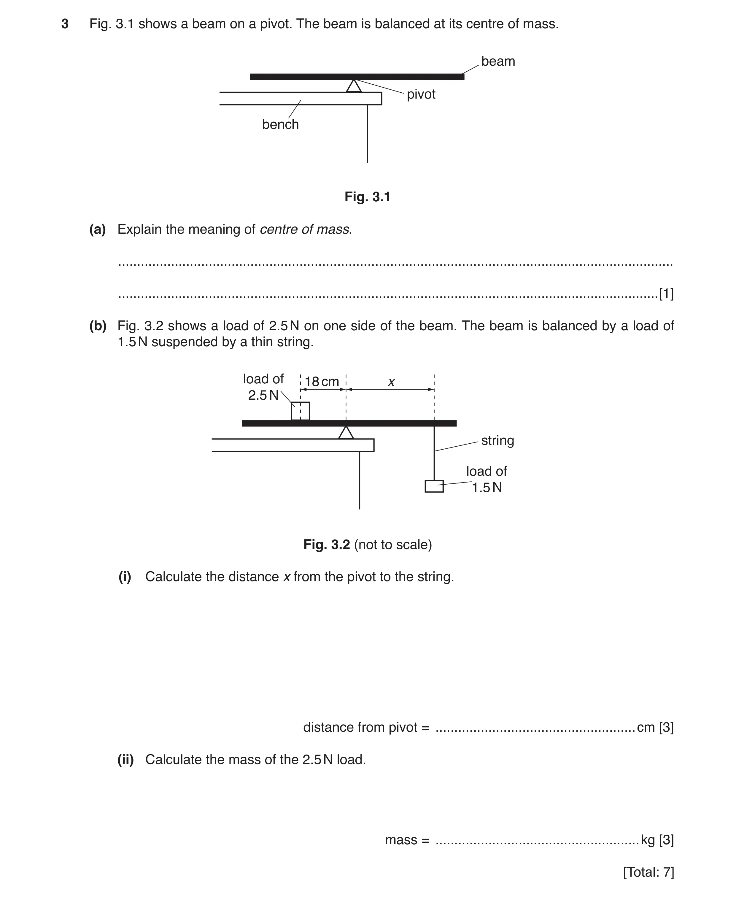 1 / 97
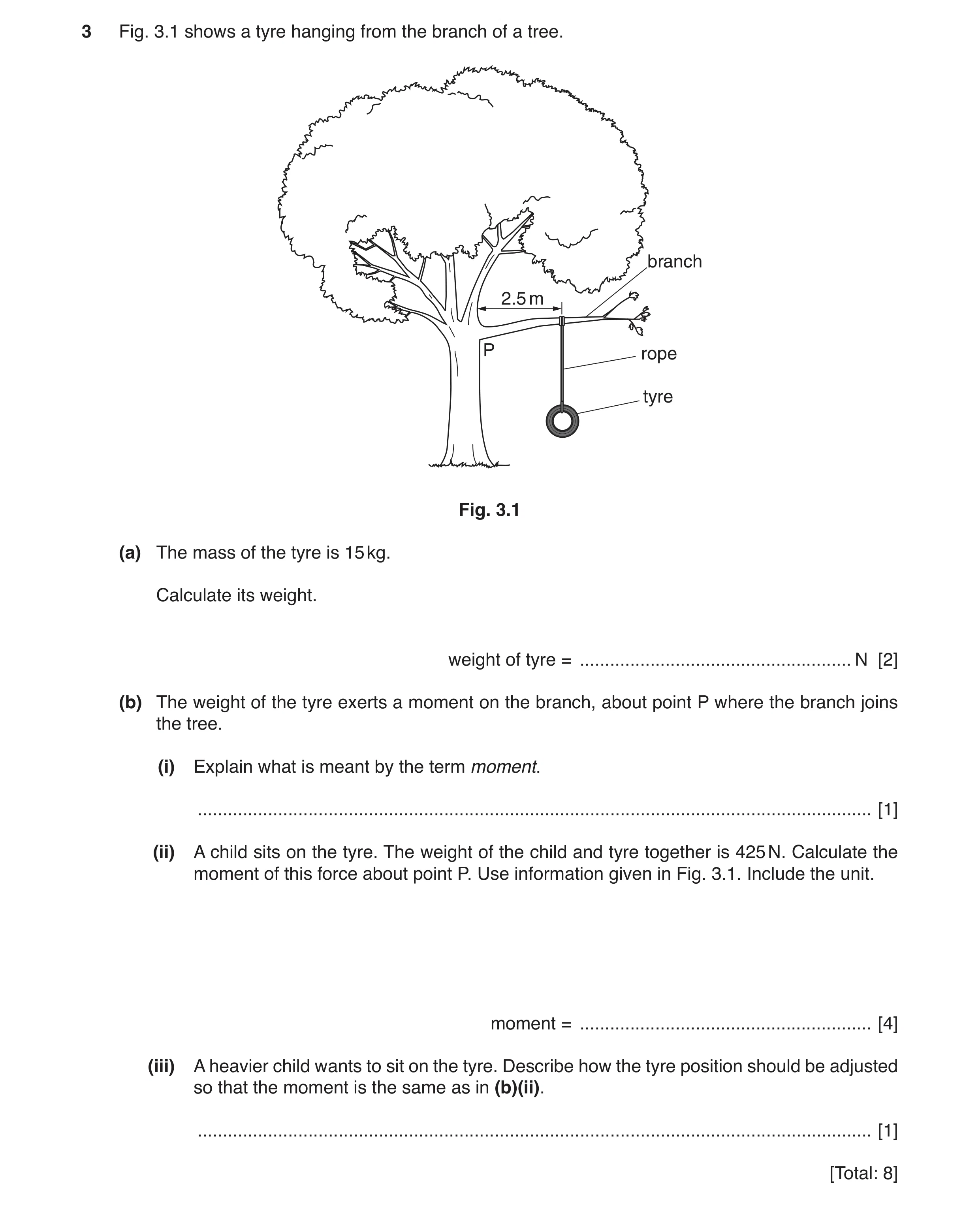 2 / 97
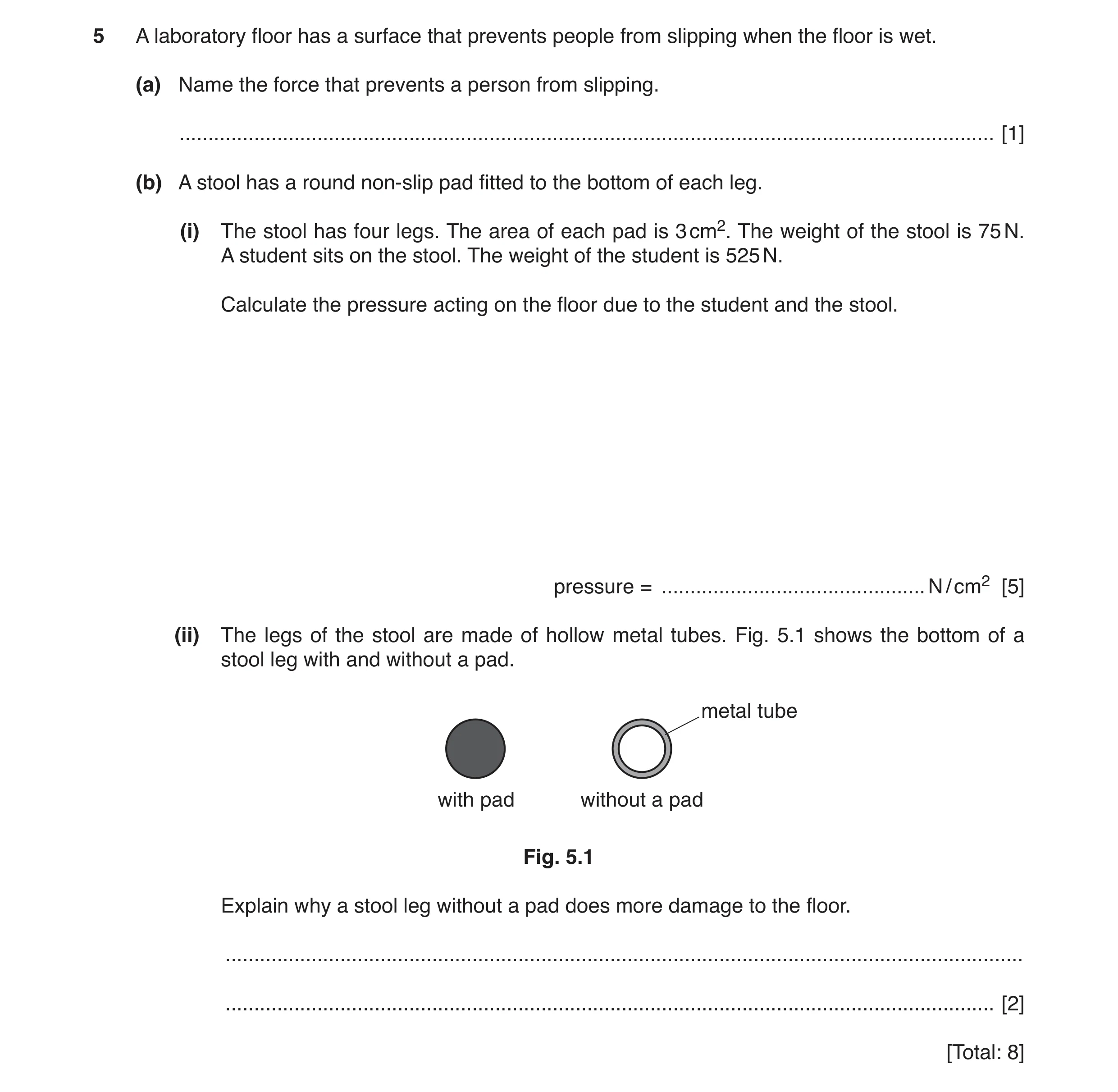 3 / 97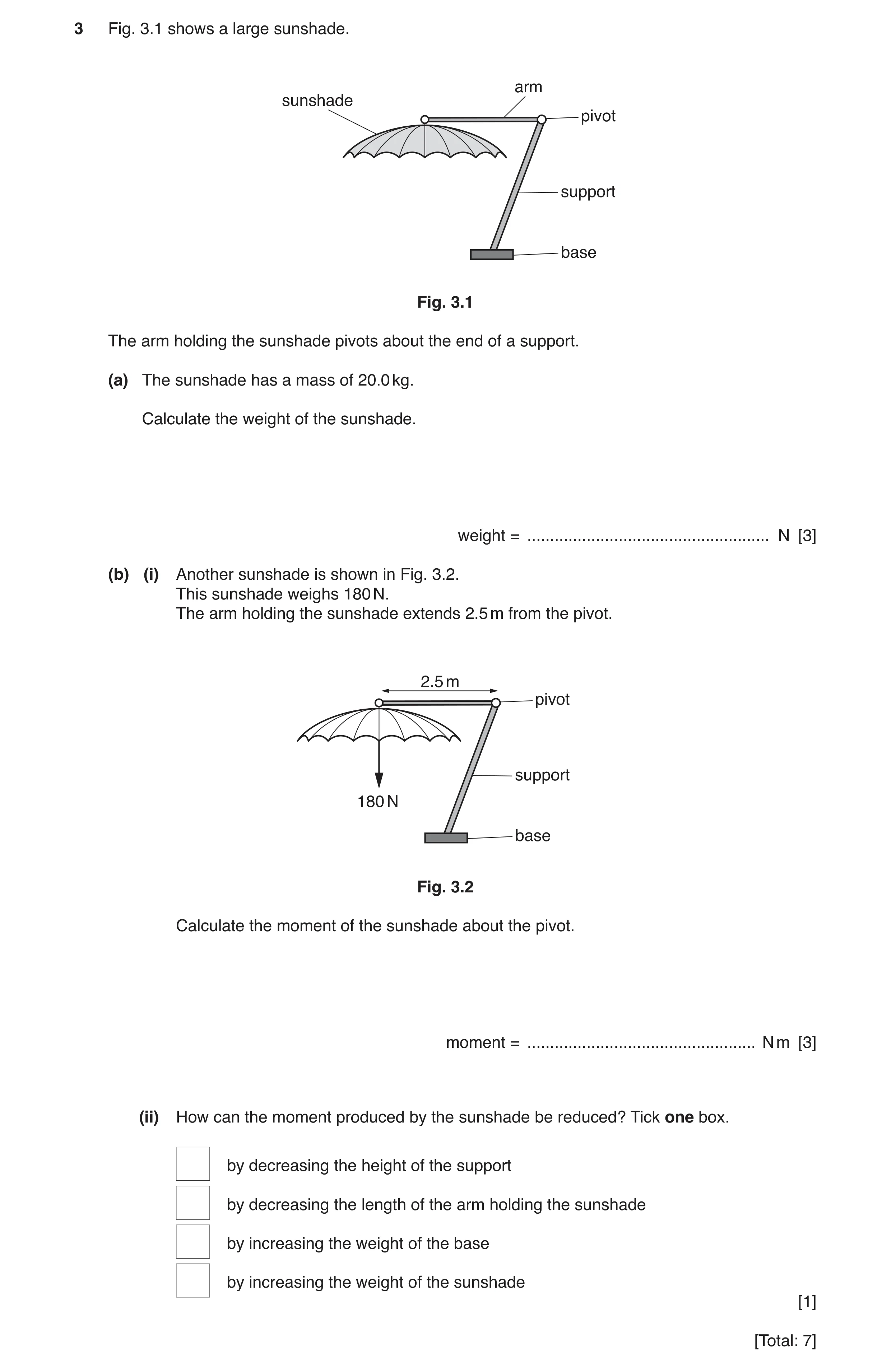
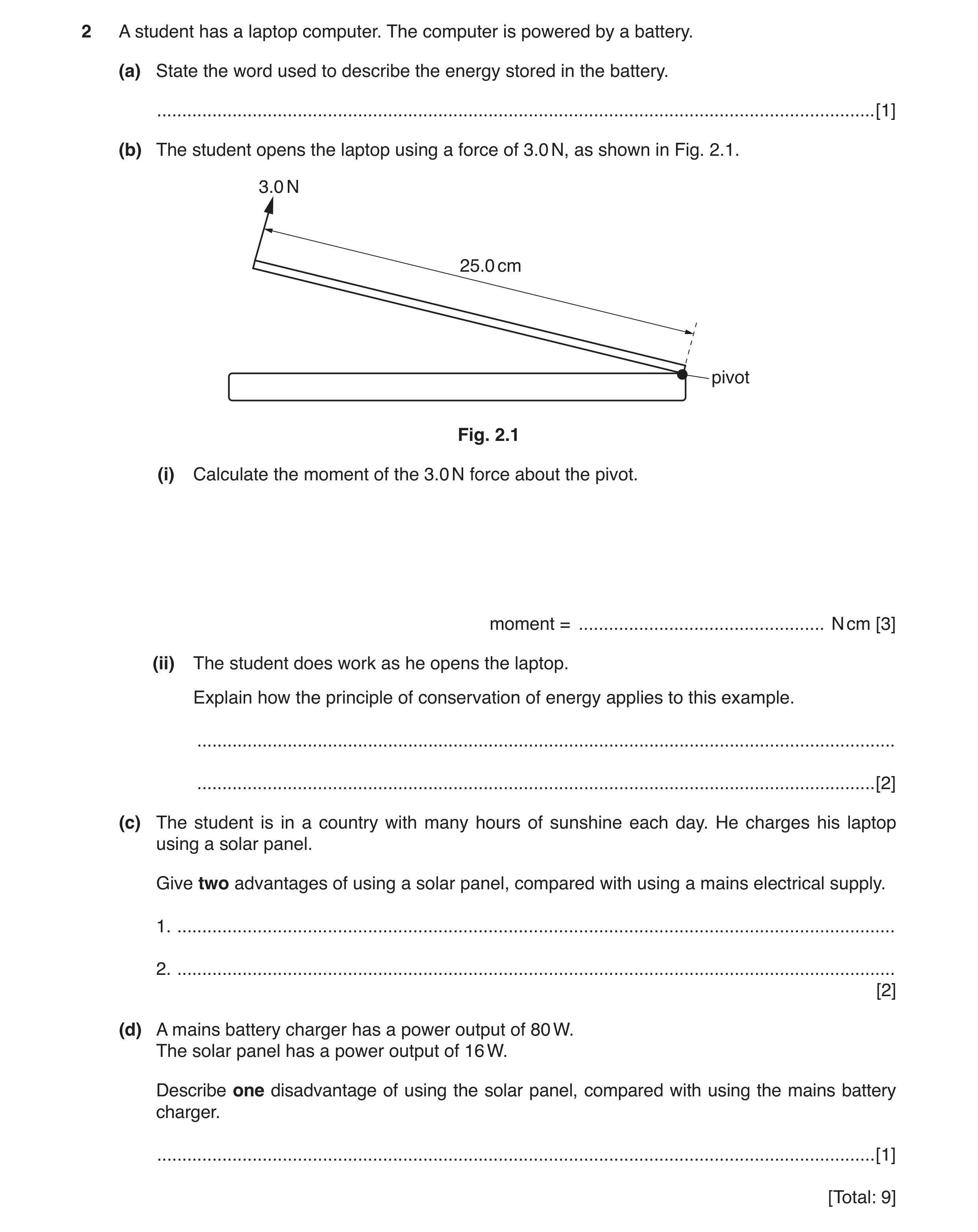 5 / 97
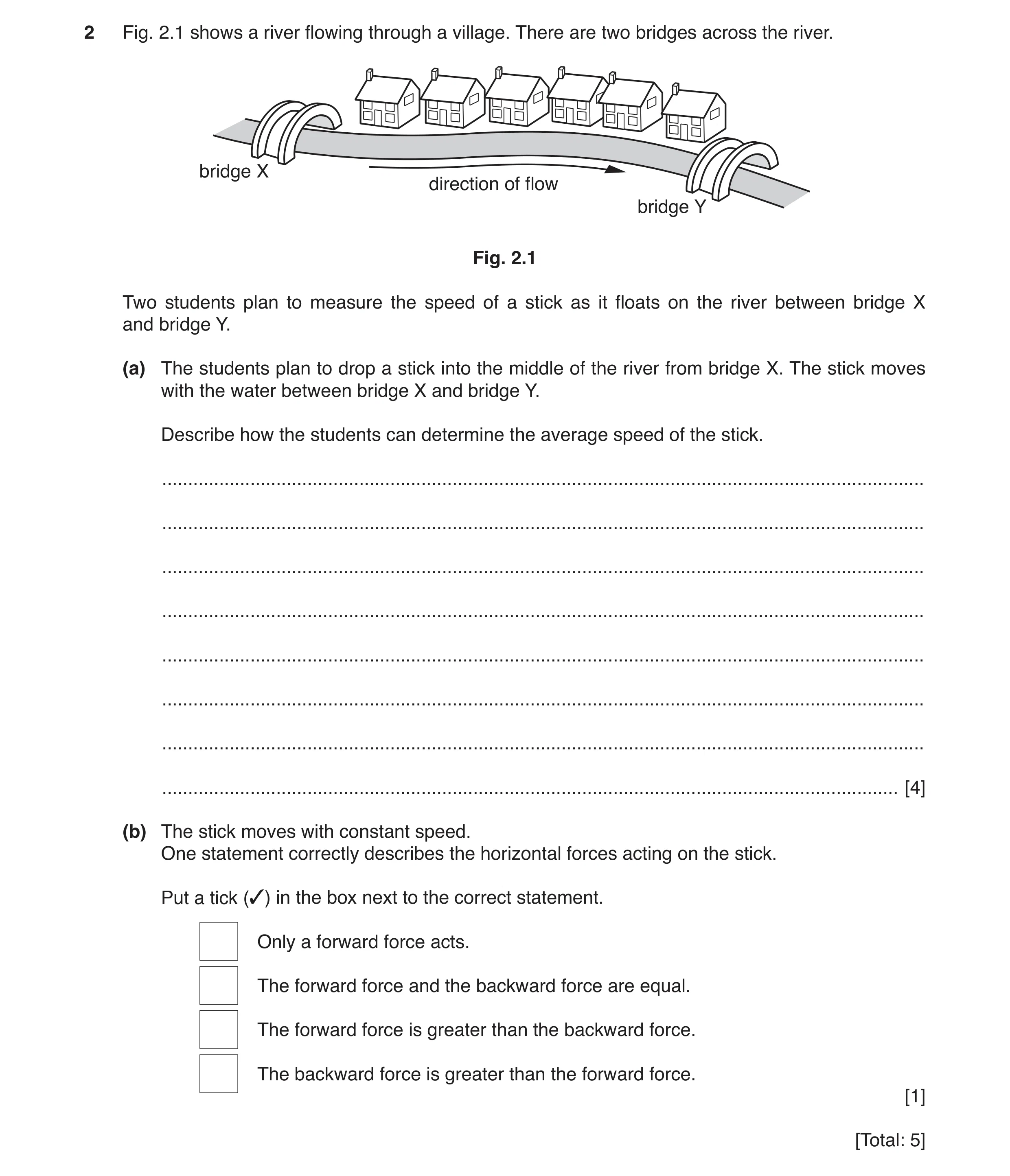 6 / 97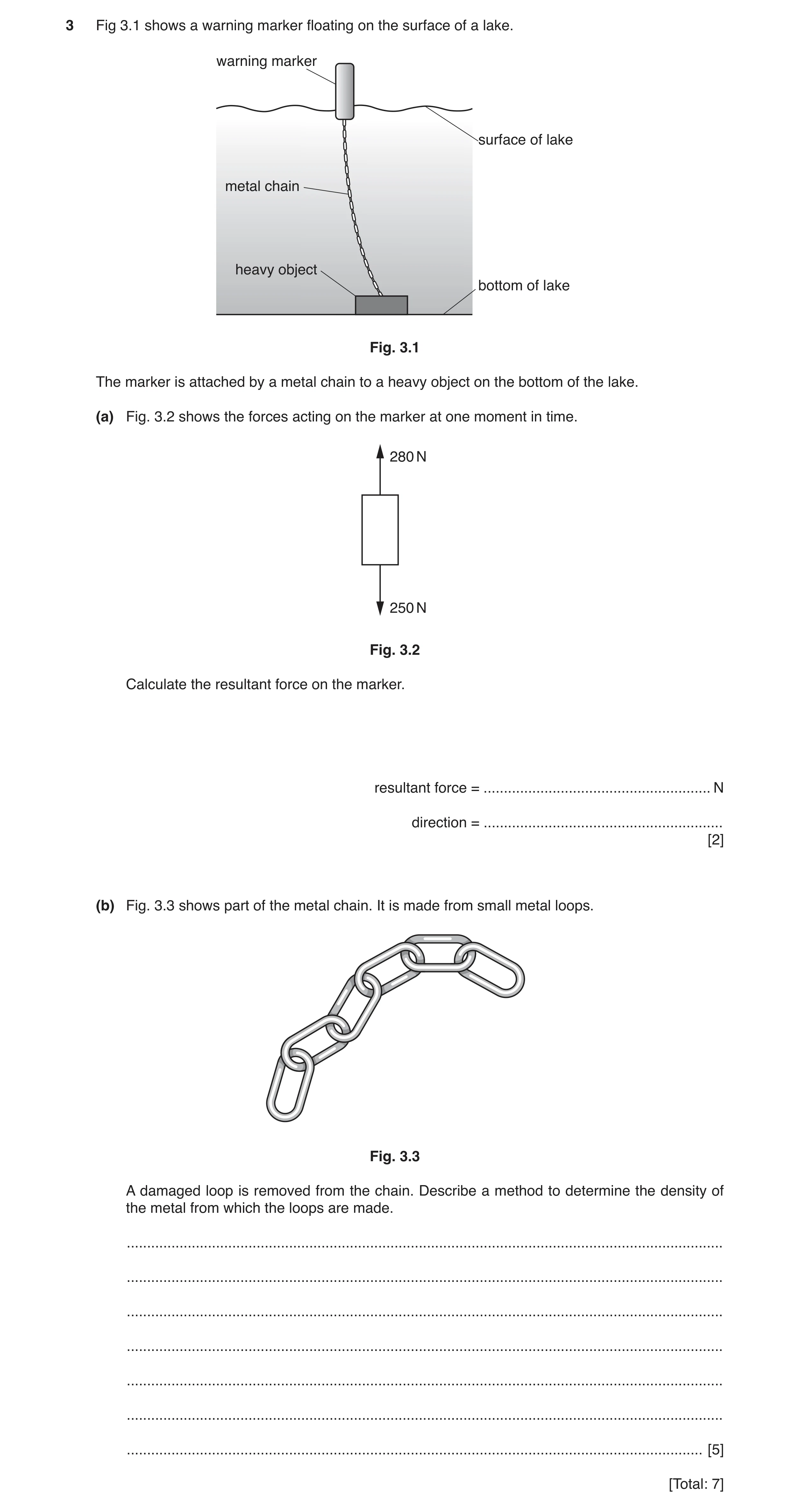
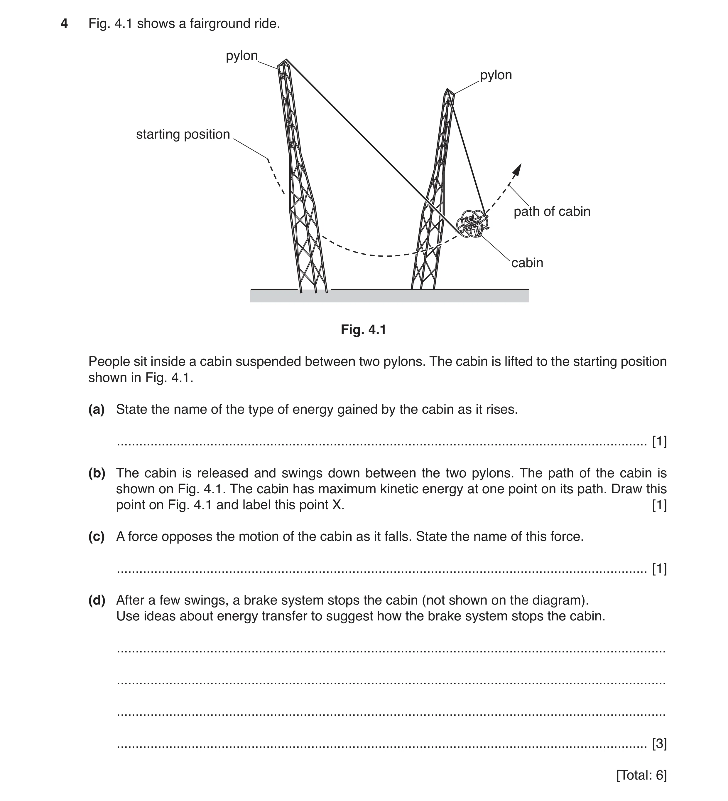 9 / 97
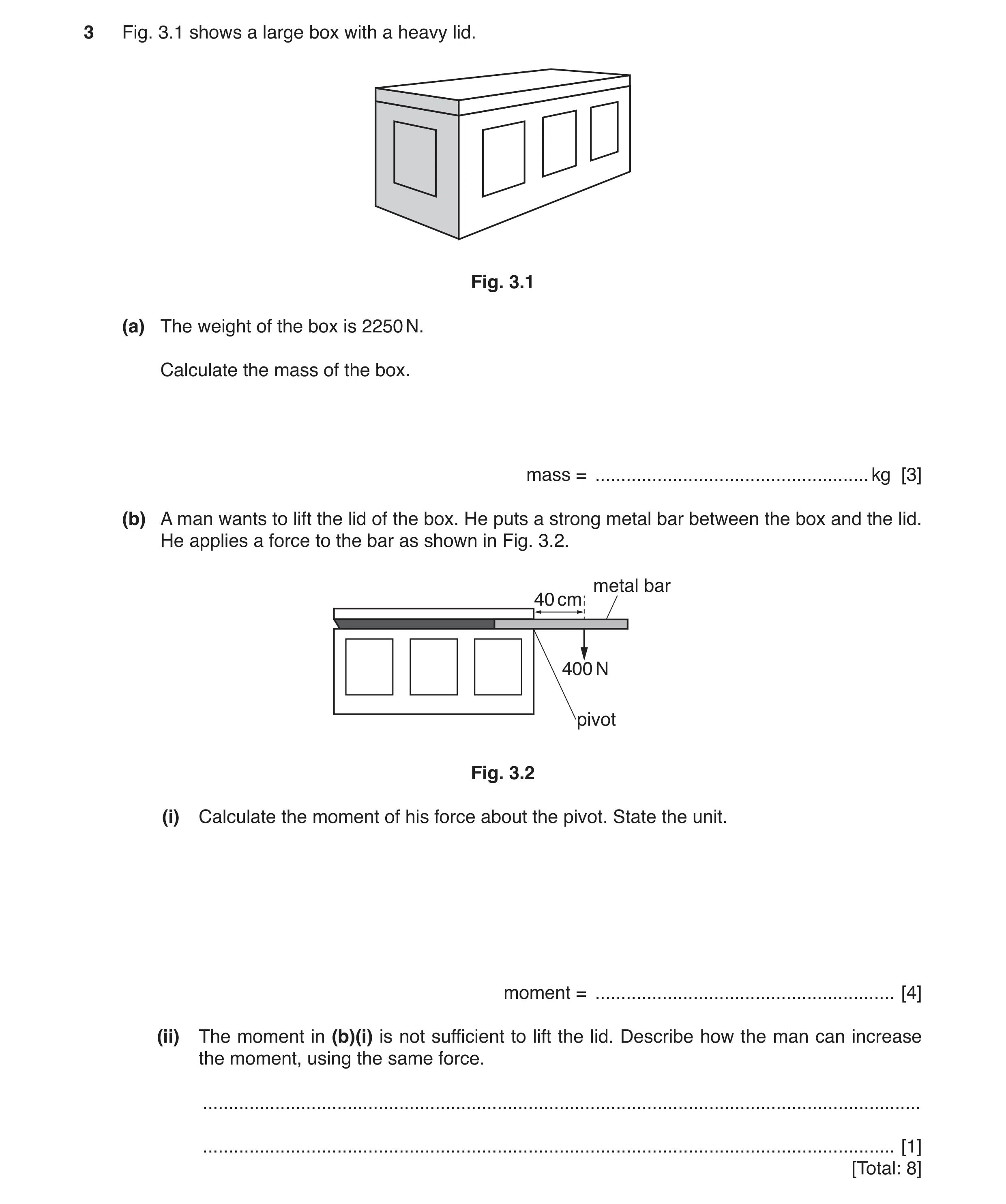 10 / 97
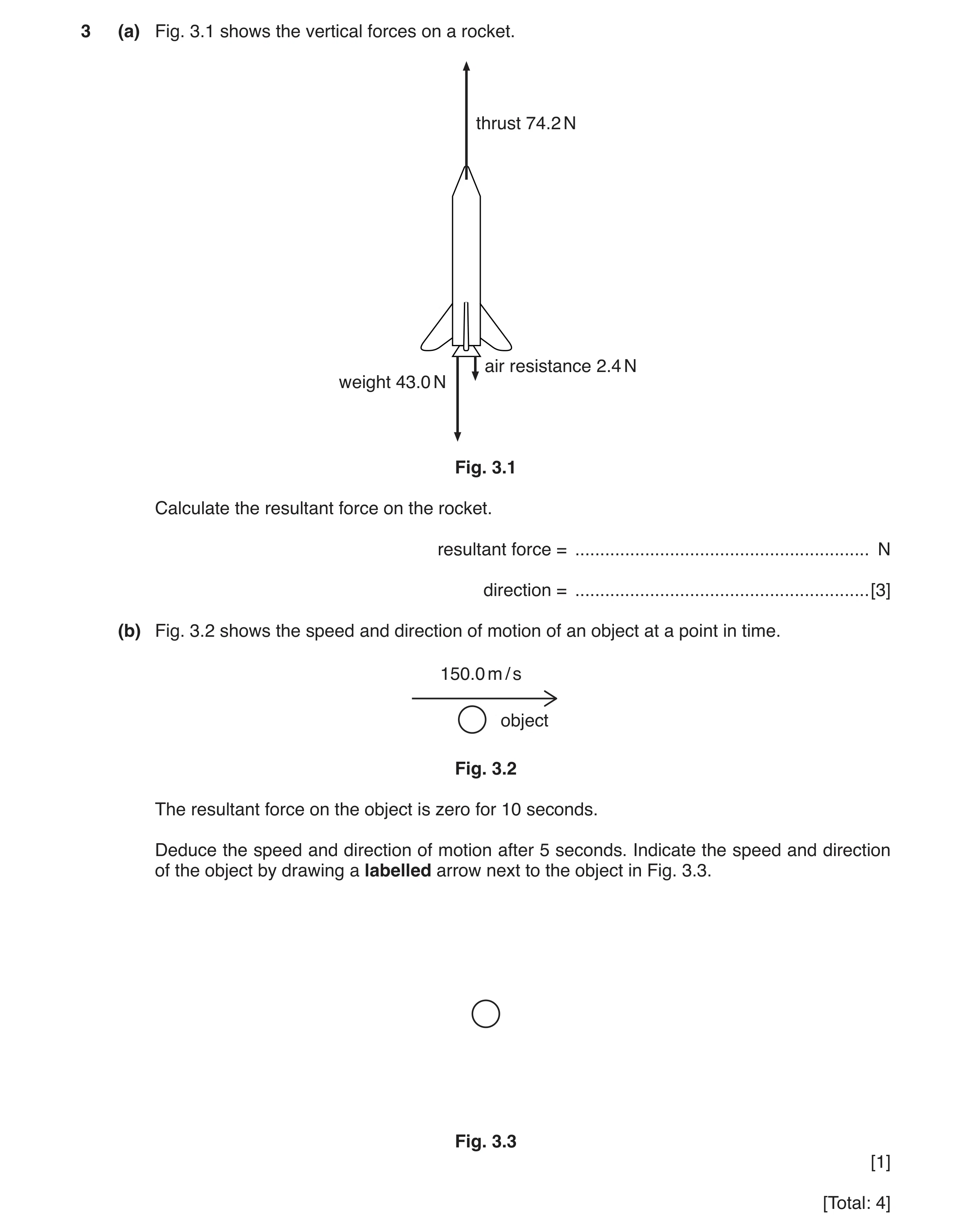 11 / 97
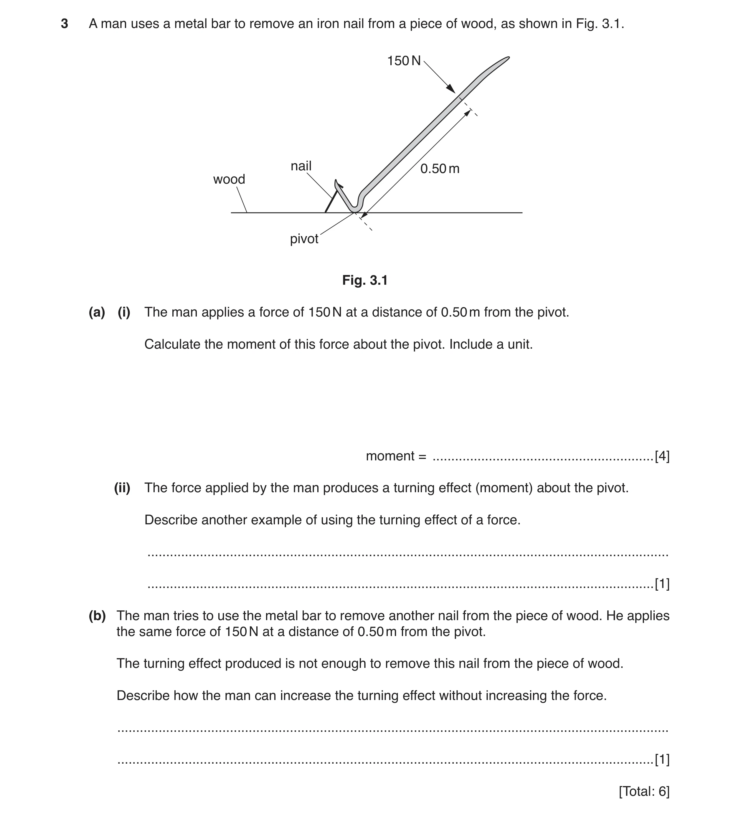 12 / 97
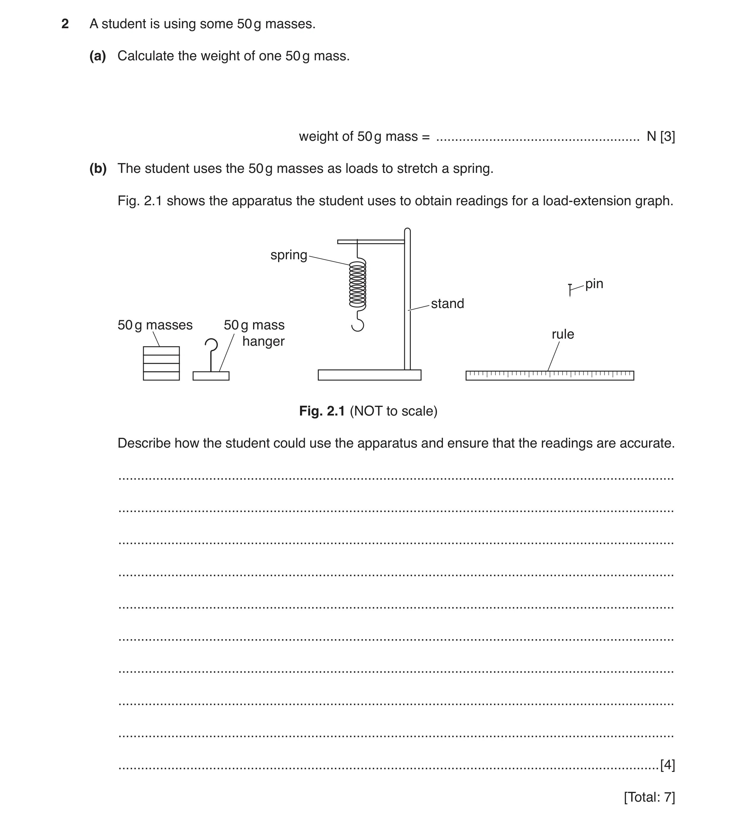 13 / 97
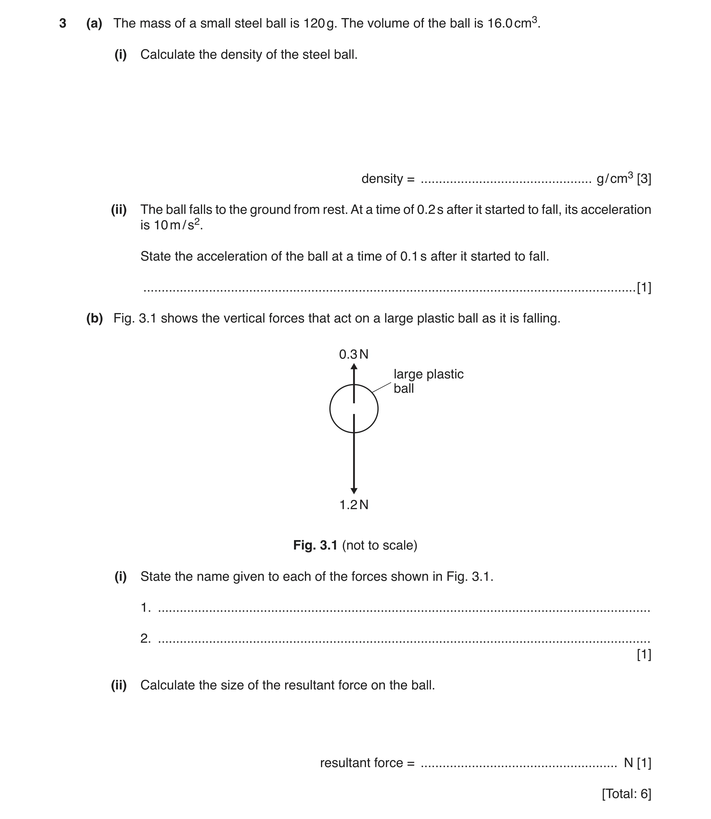 14 / 97
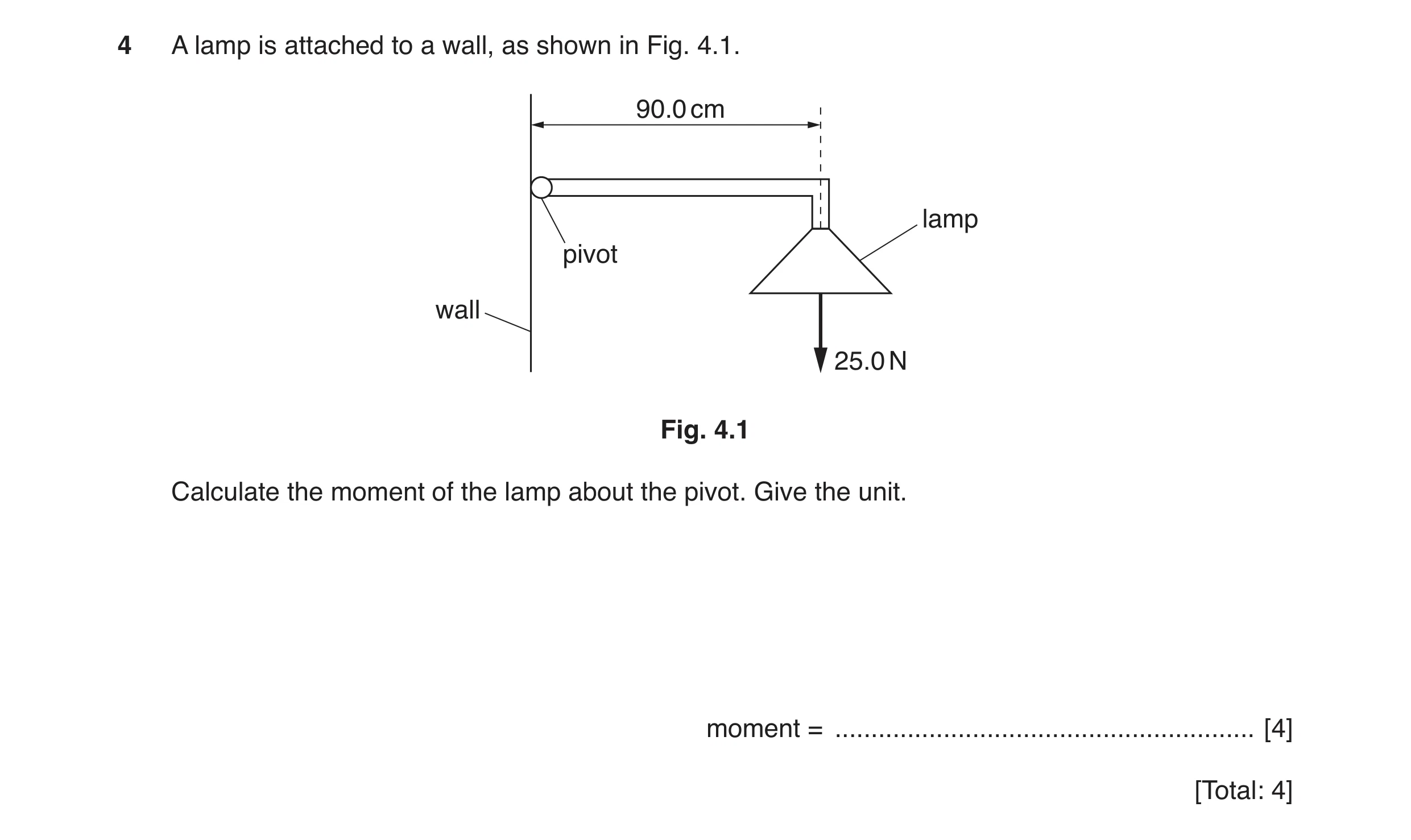 15 / 97
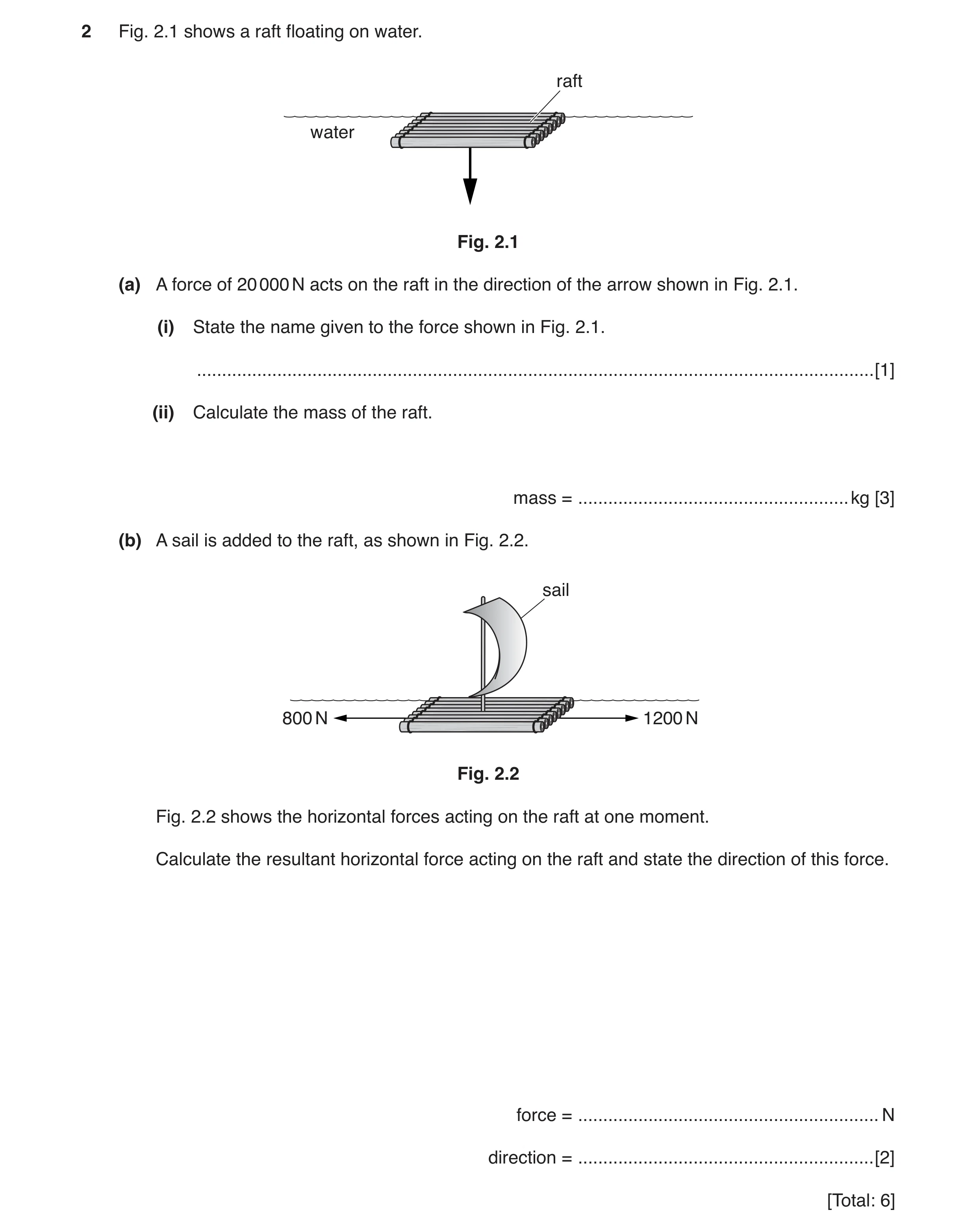 16 / 97
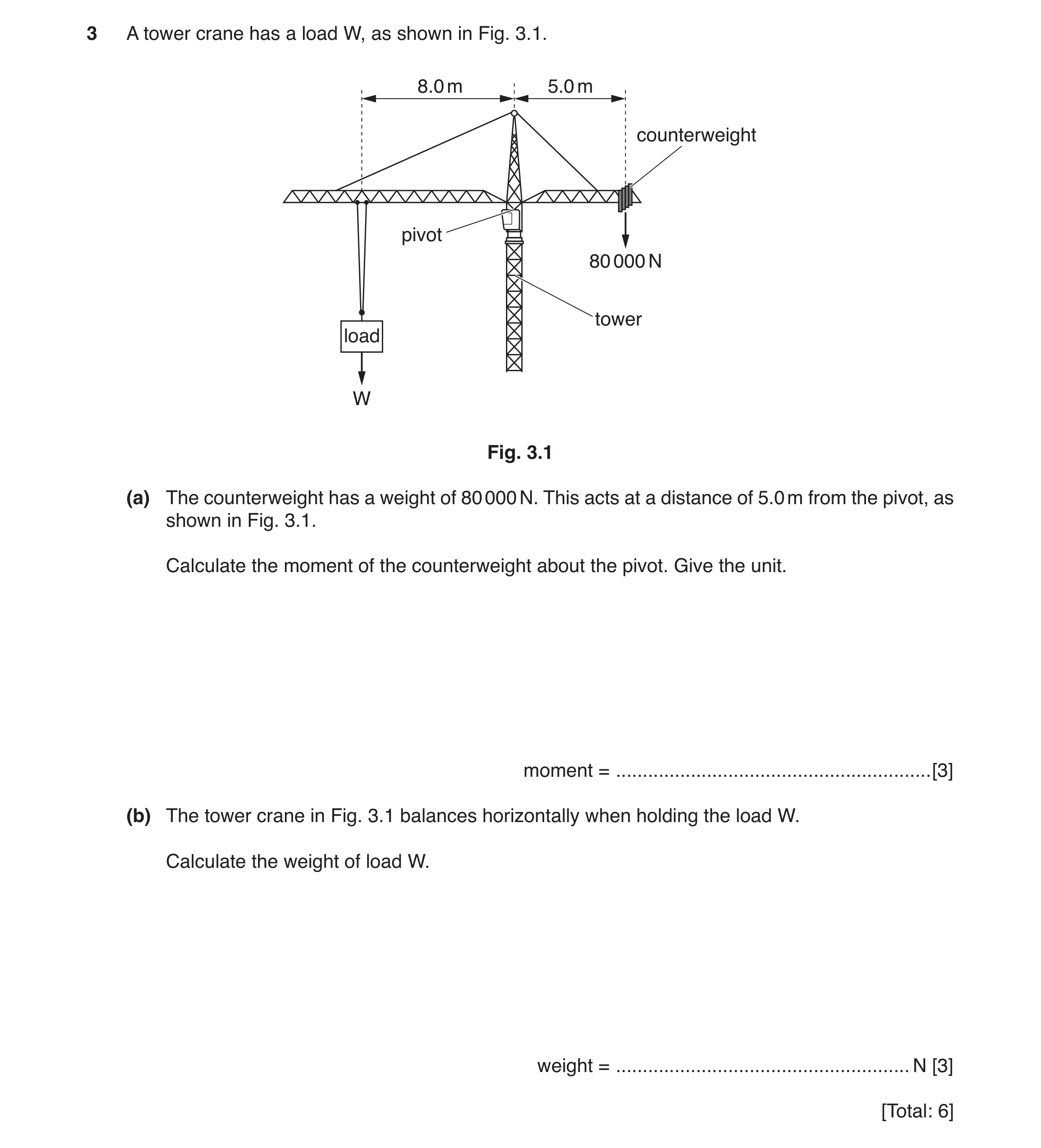 17 / 97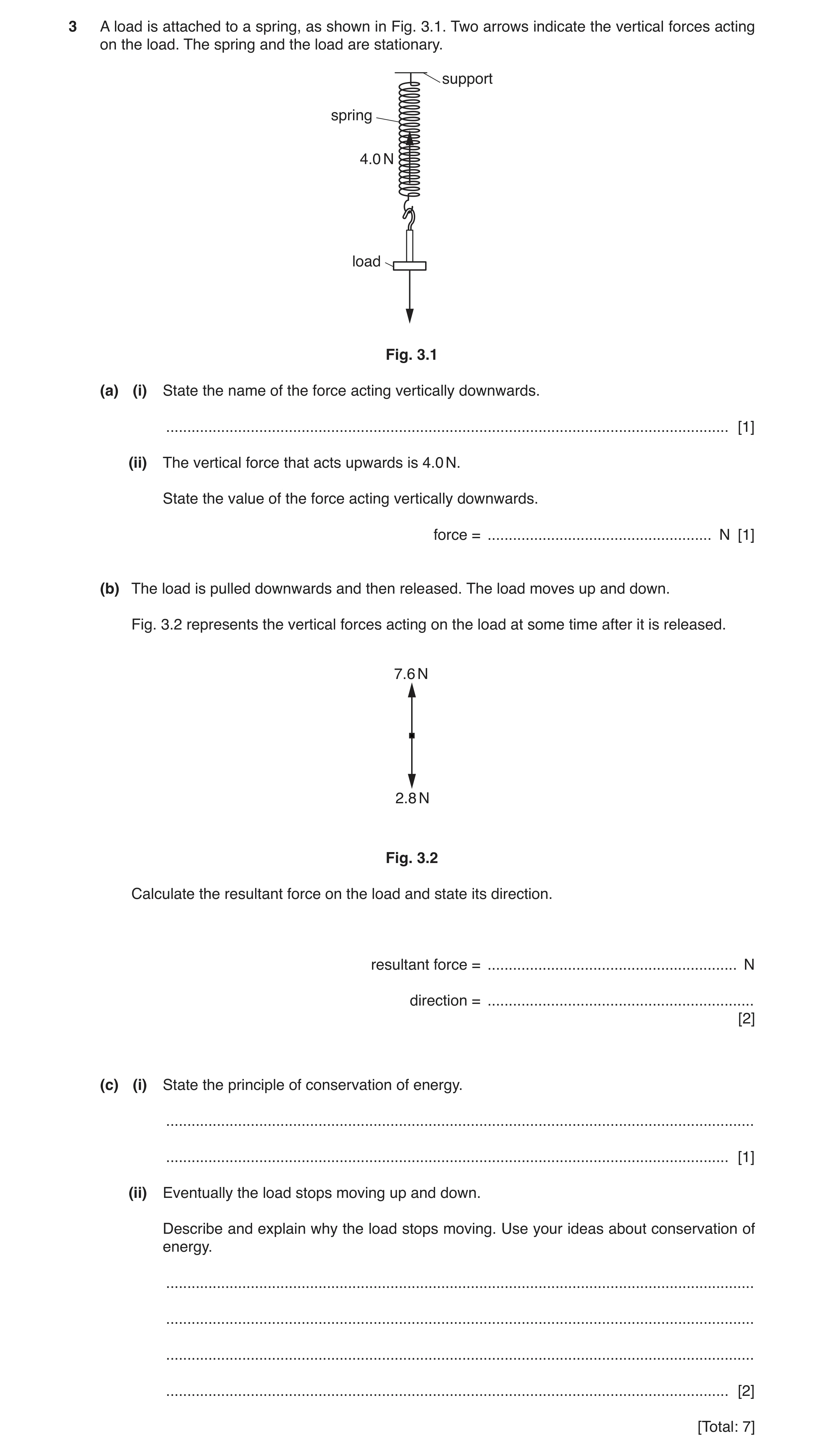
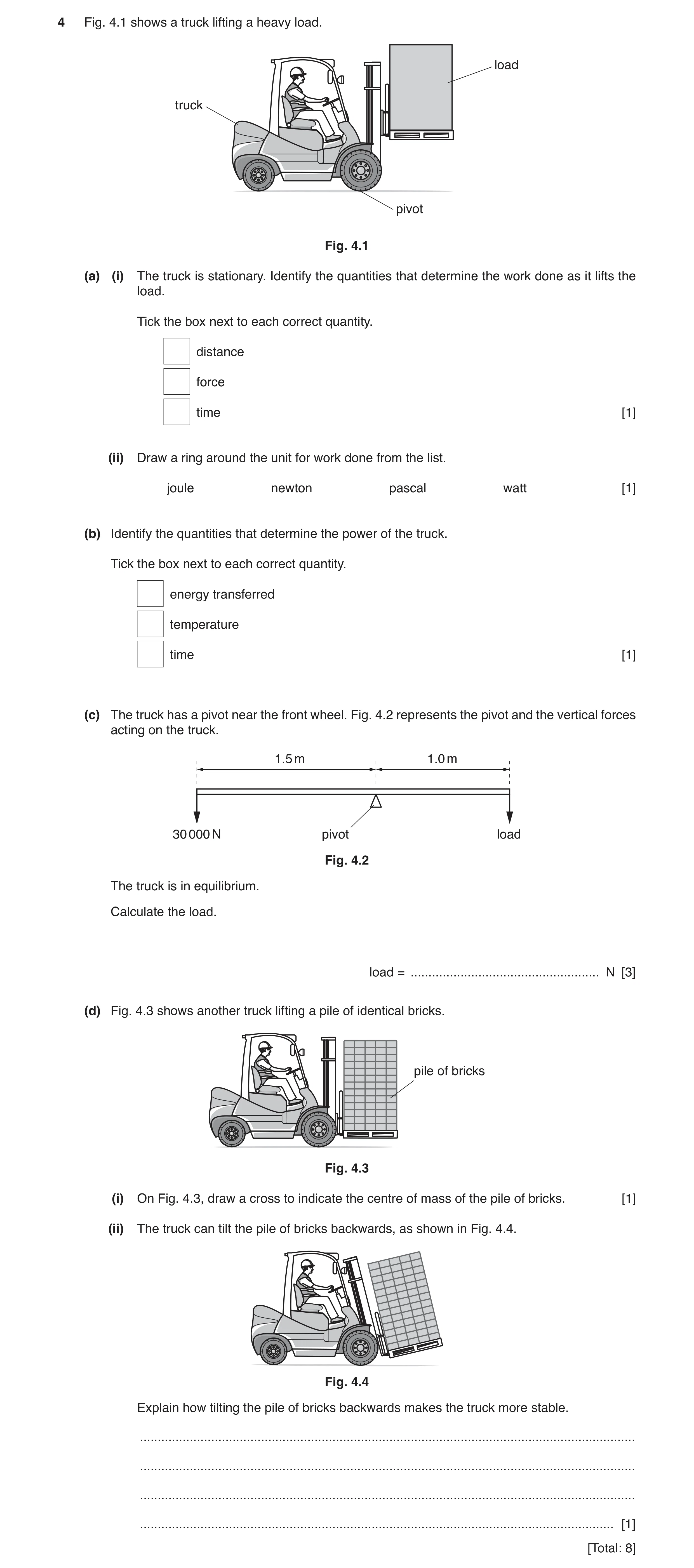
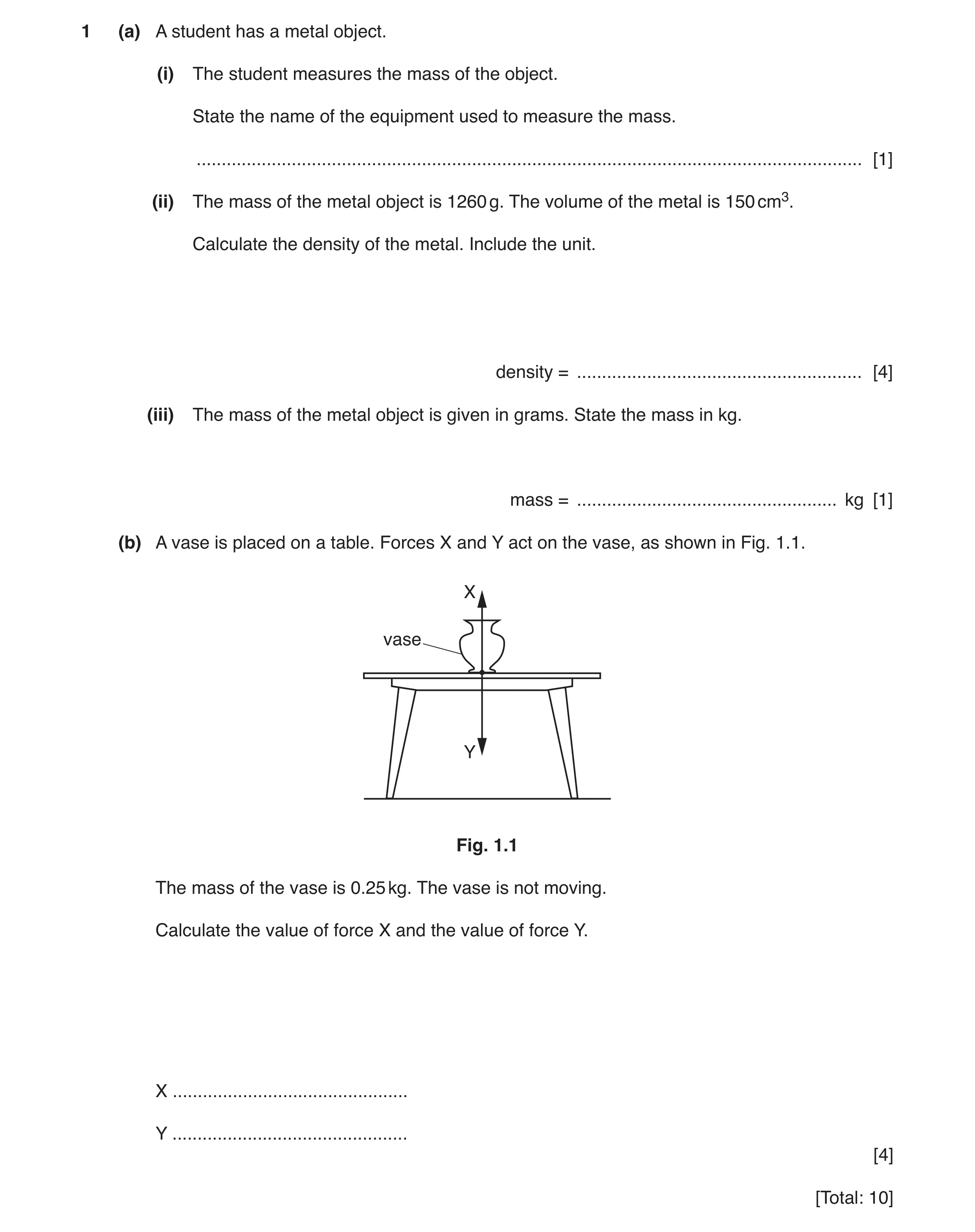 21 / 97
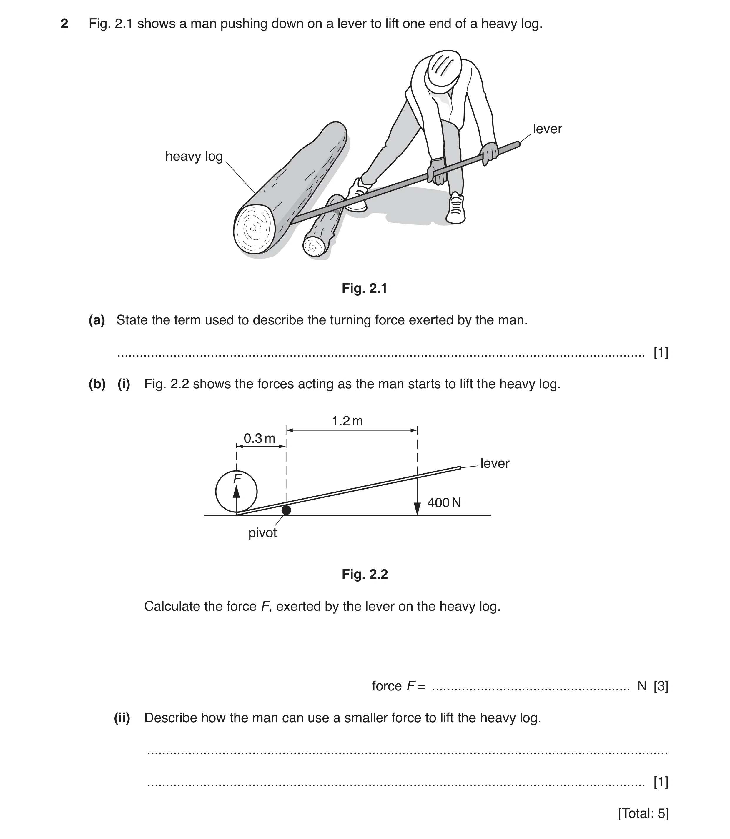 22 / 97
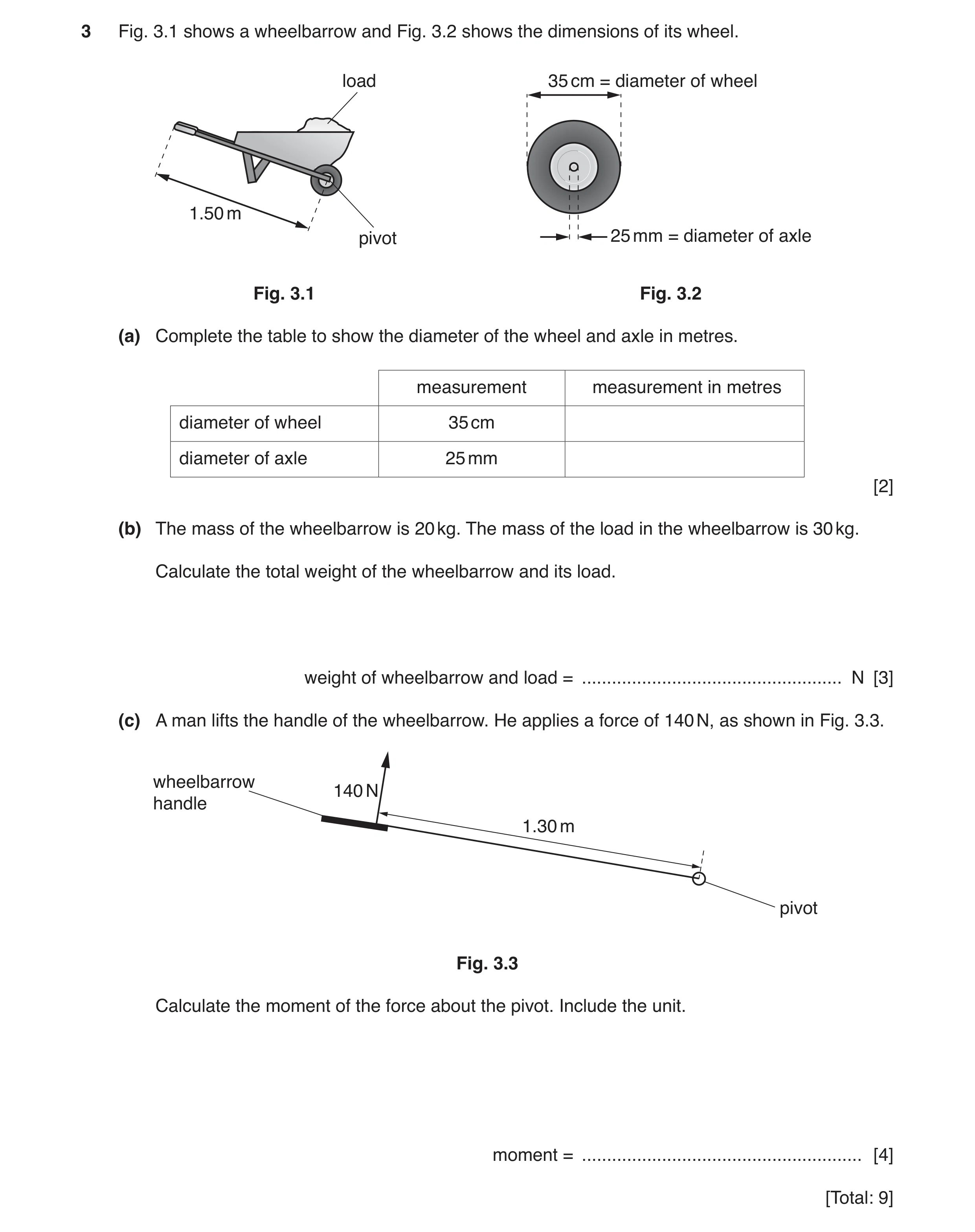 23 / 97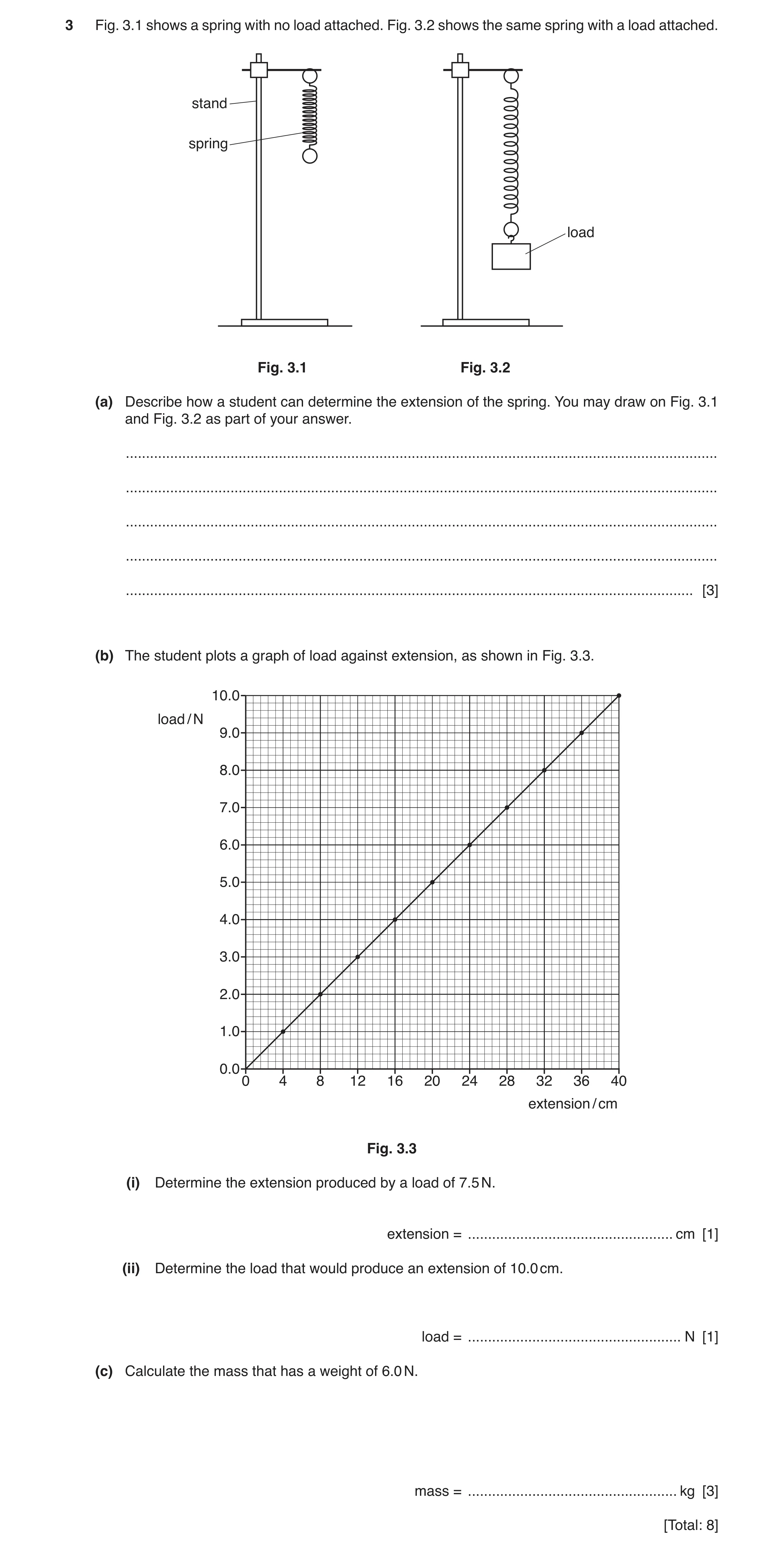
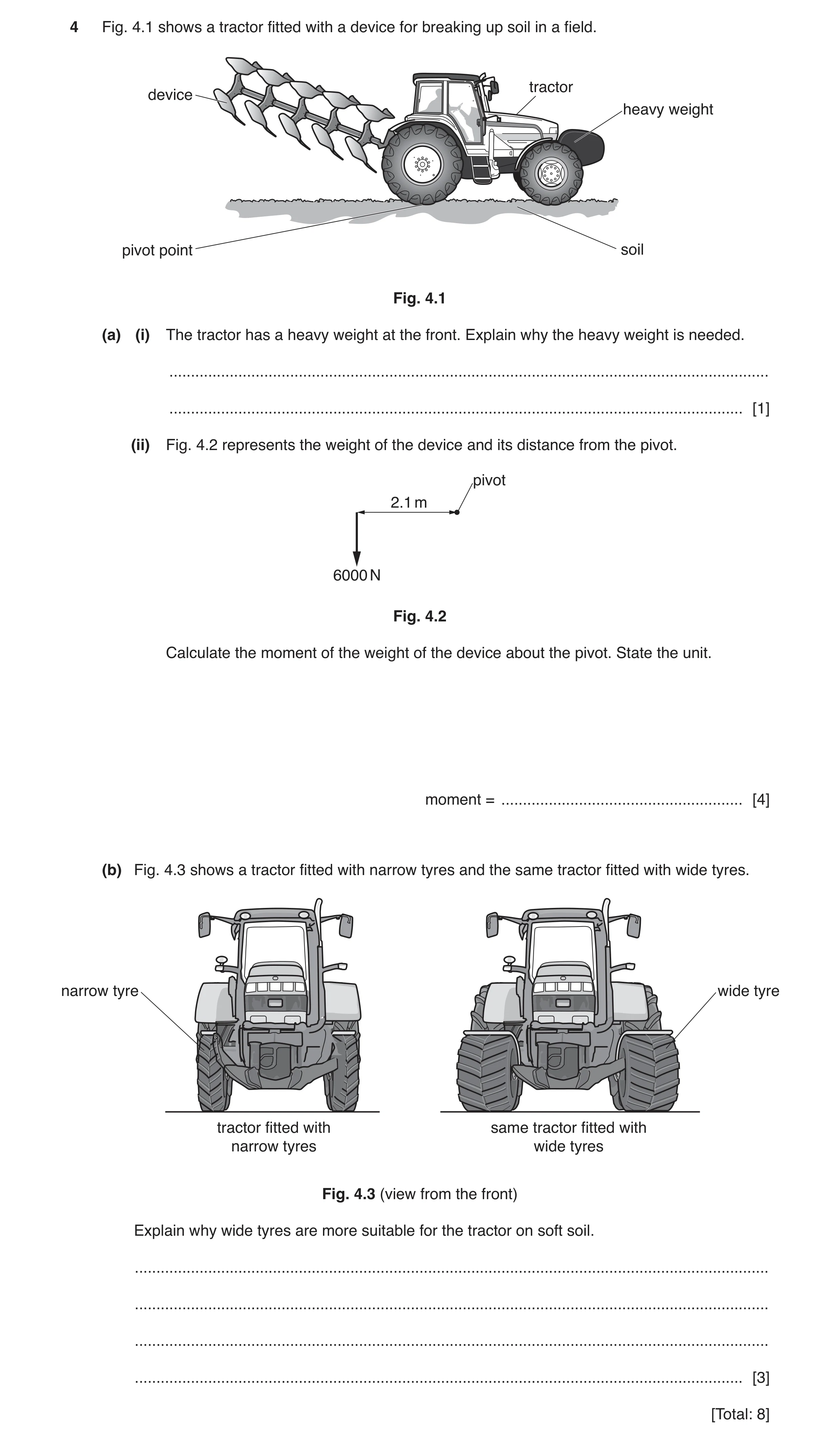
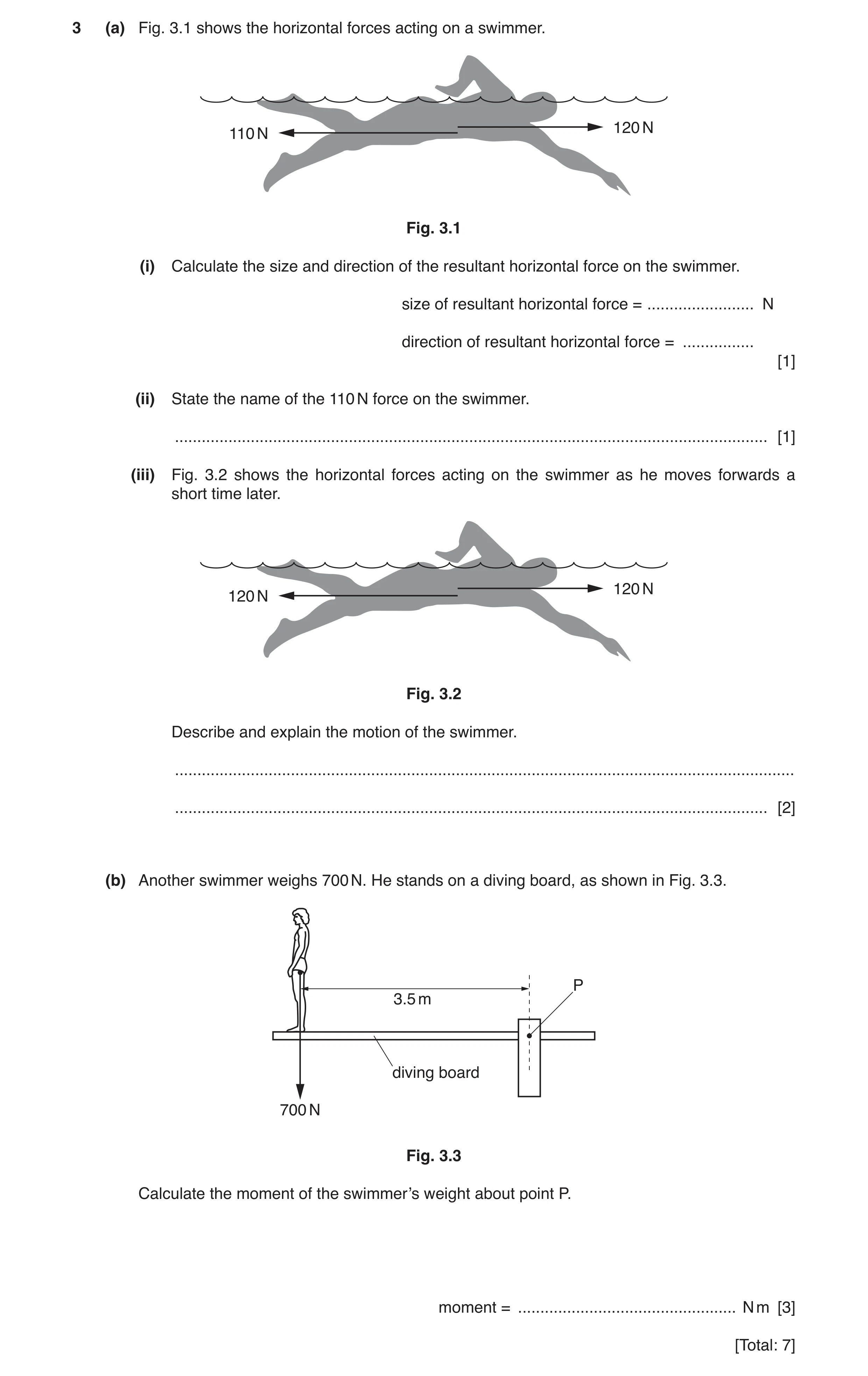
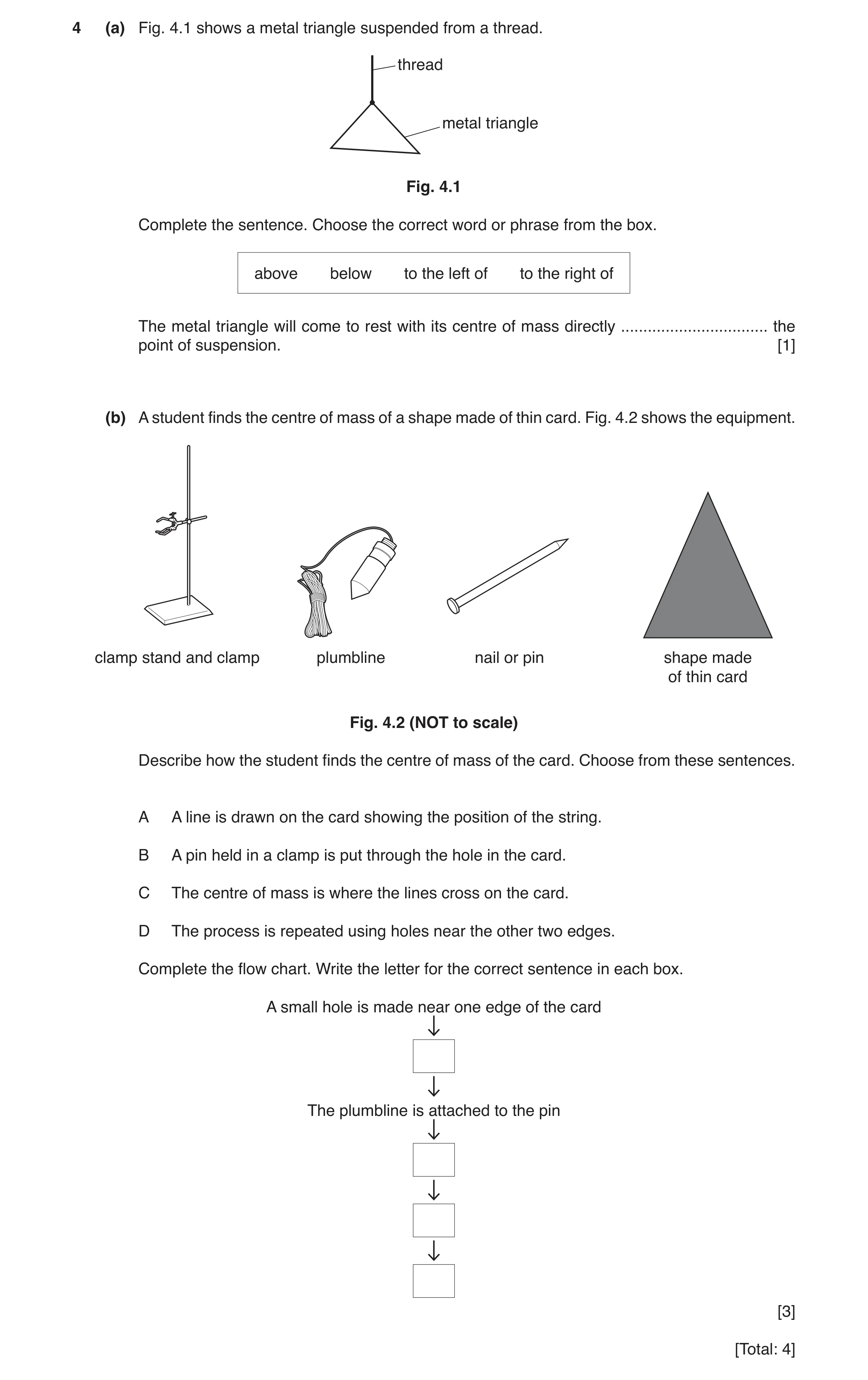
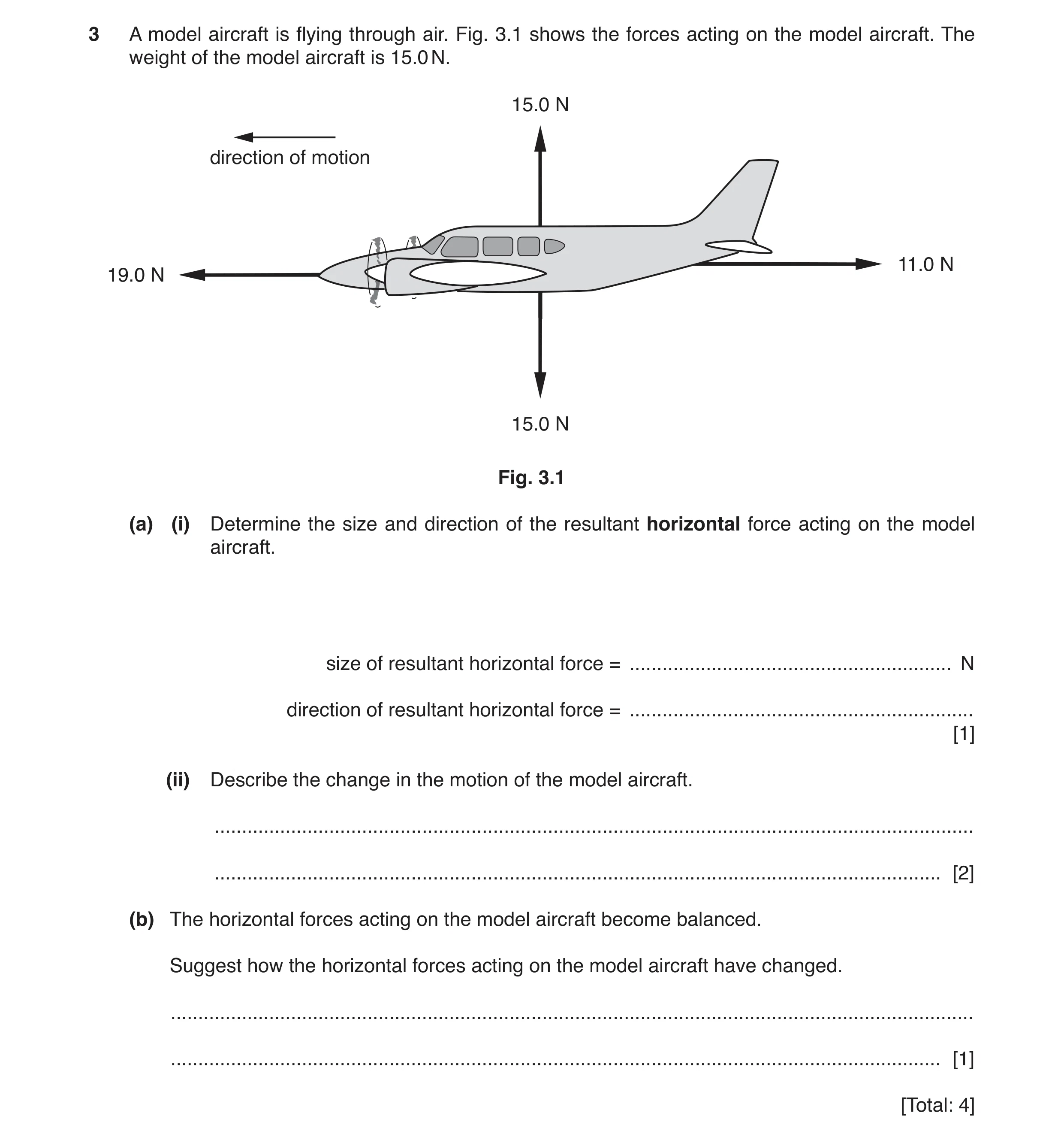 29 / 97
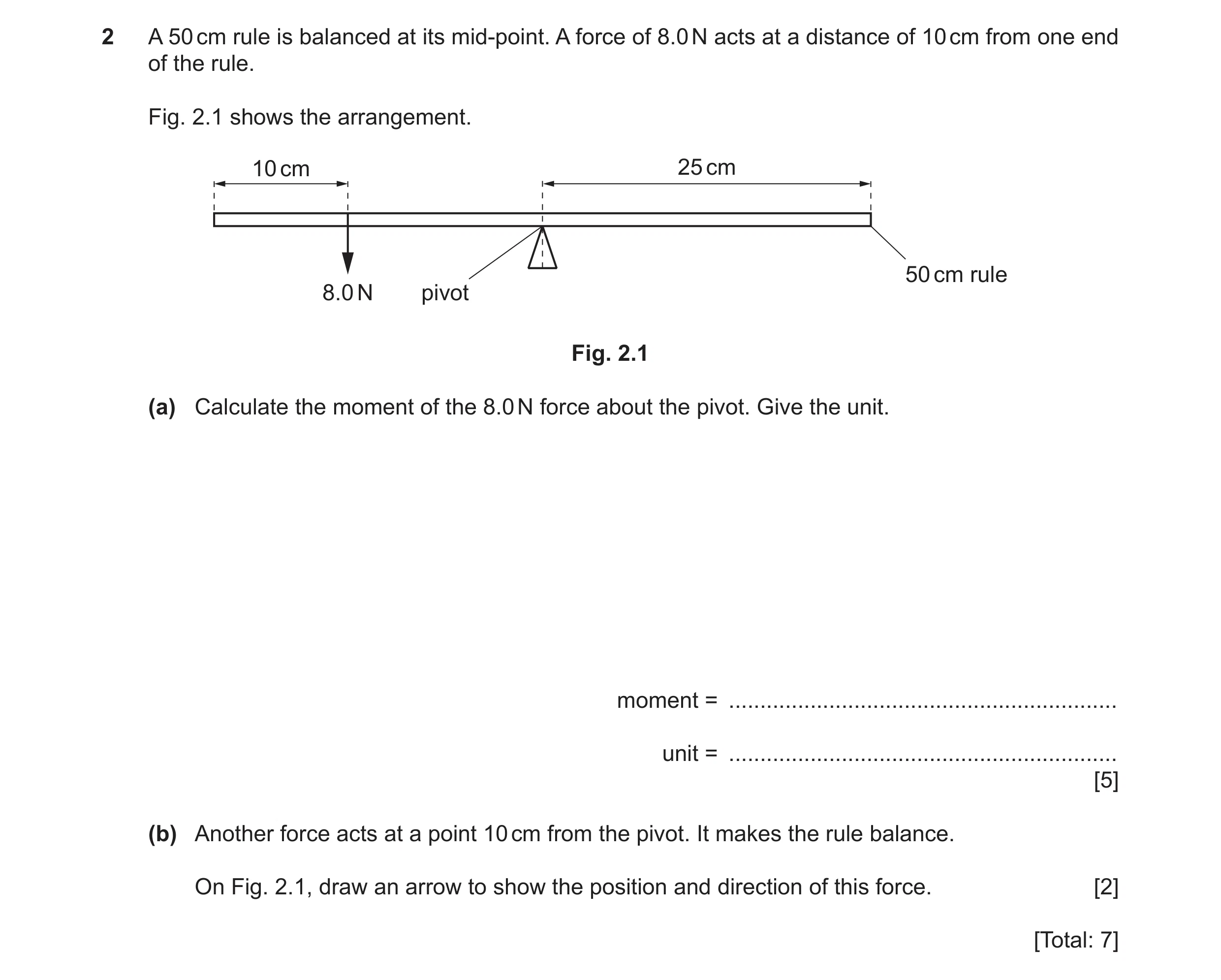 30 / 97
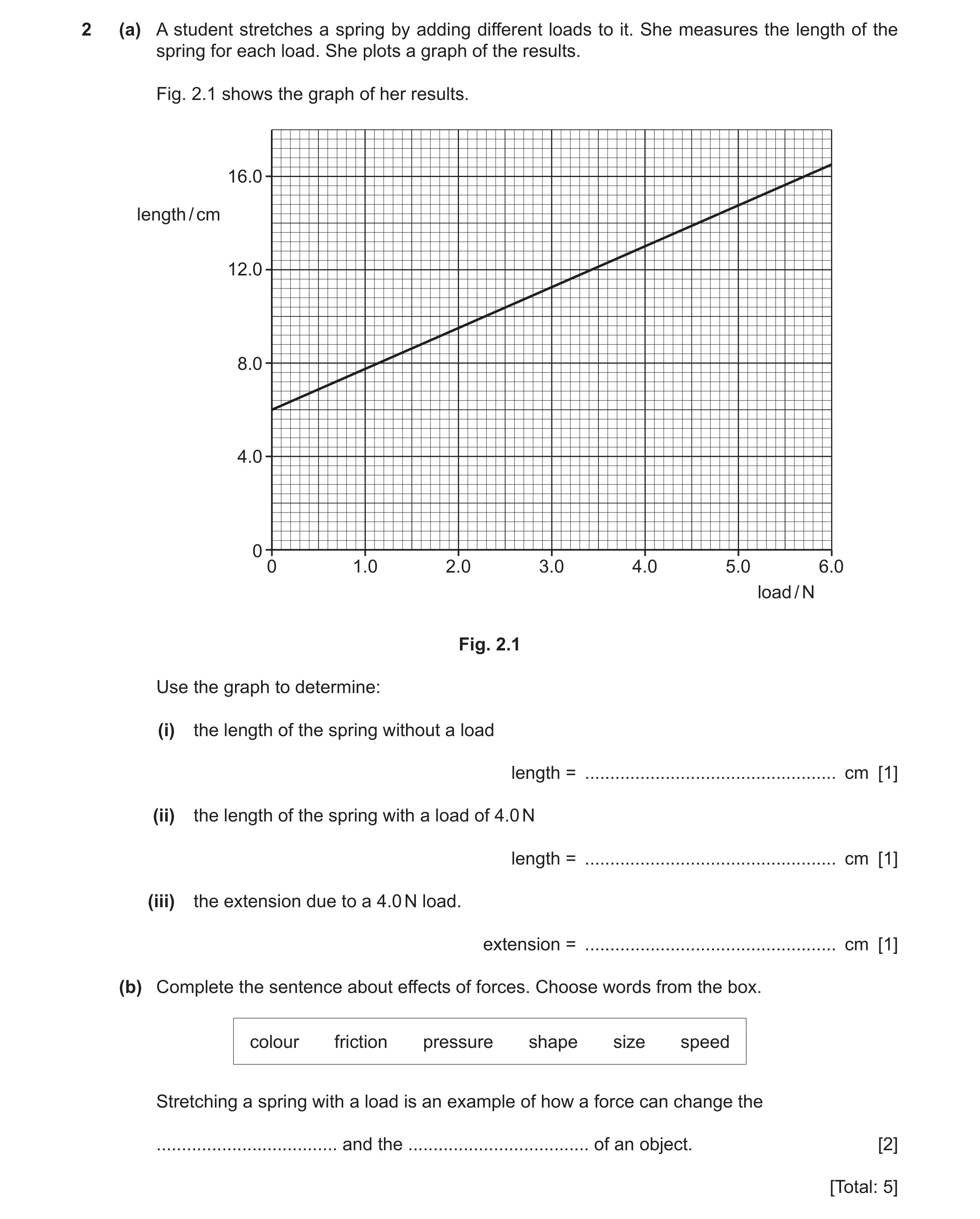 31 / 97
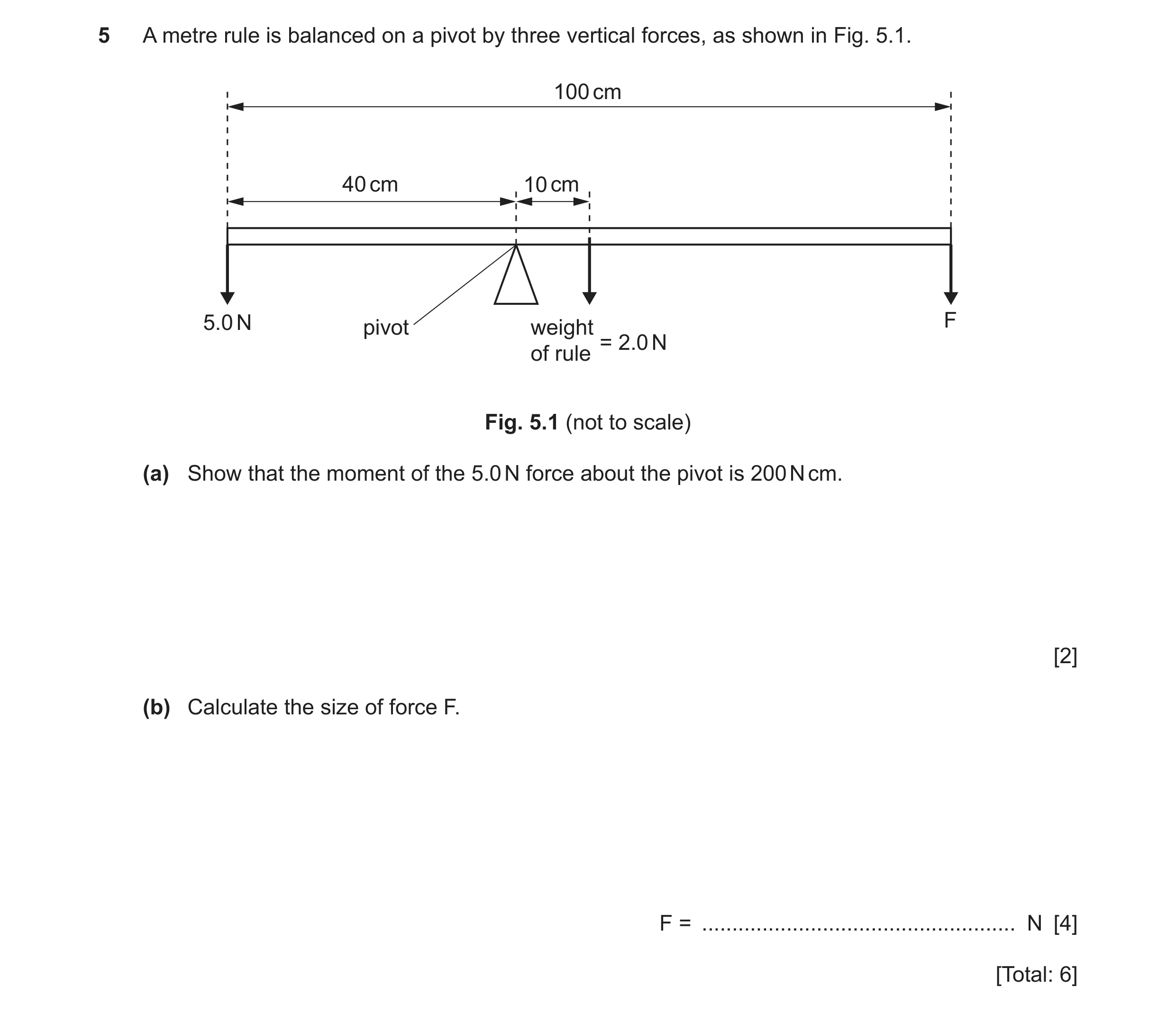 32 / 97
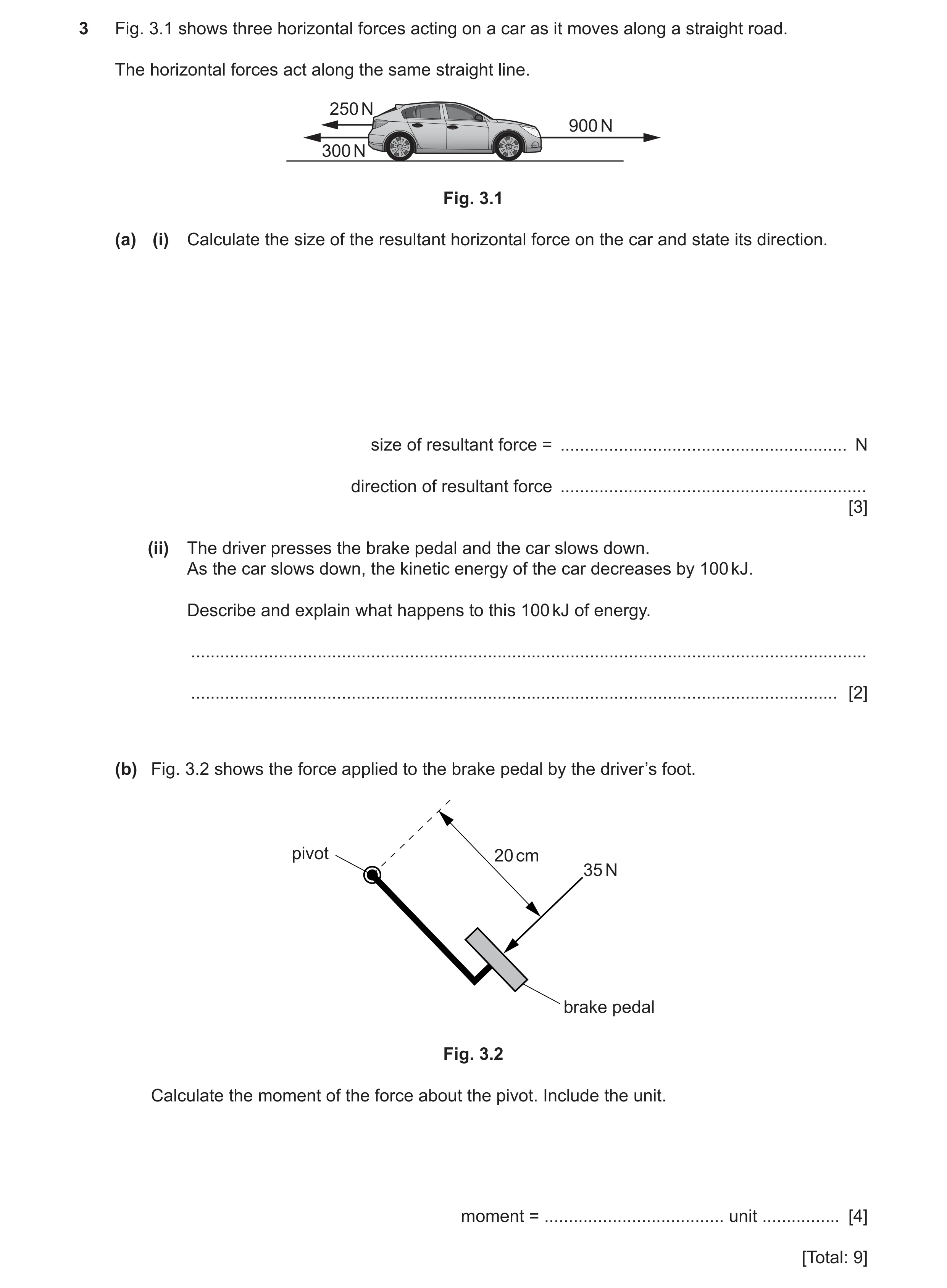 33 / 97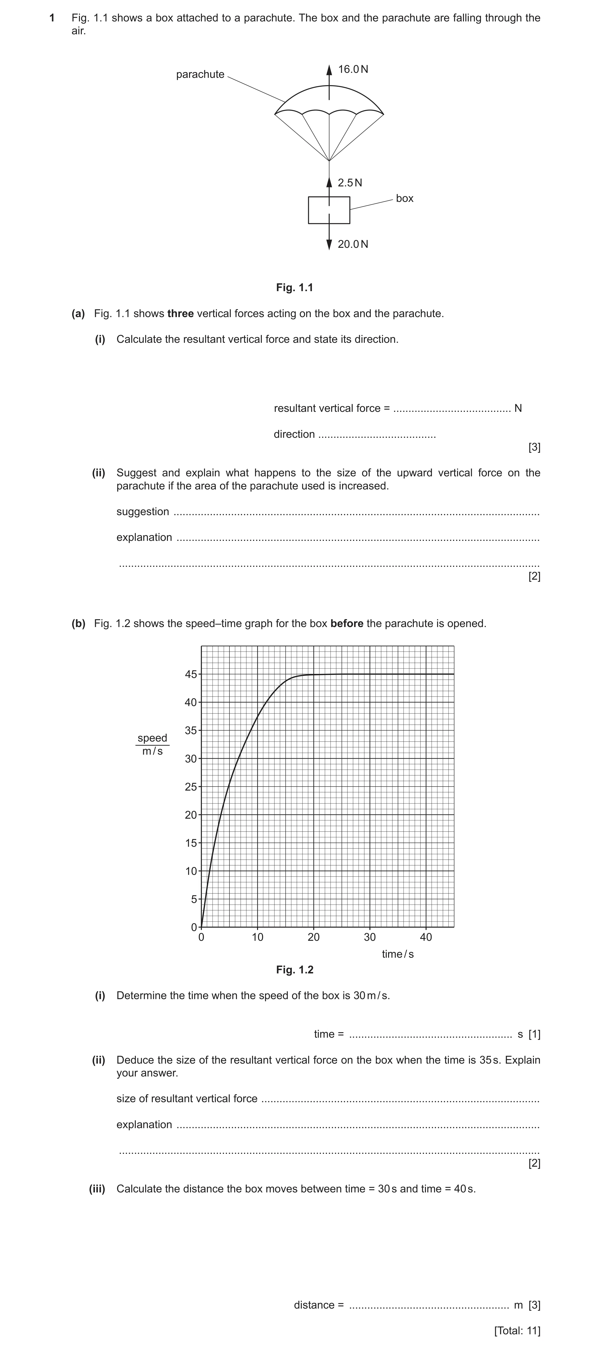
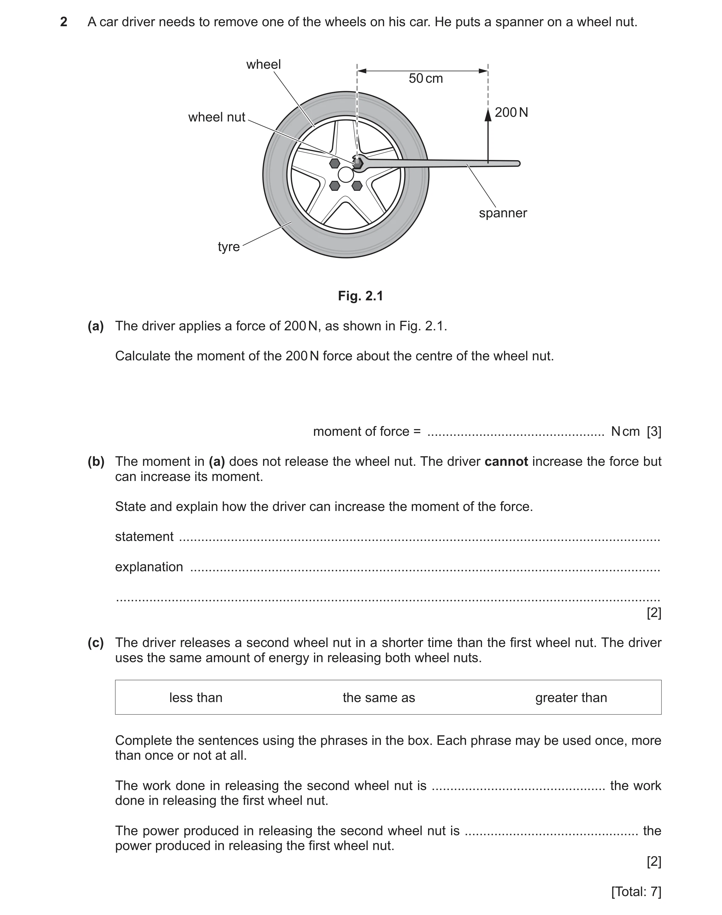 36 / 97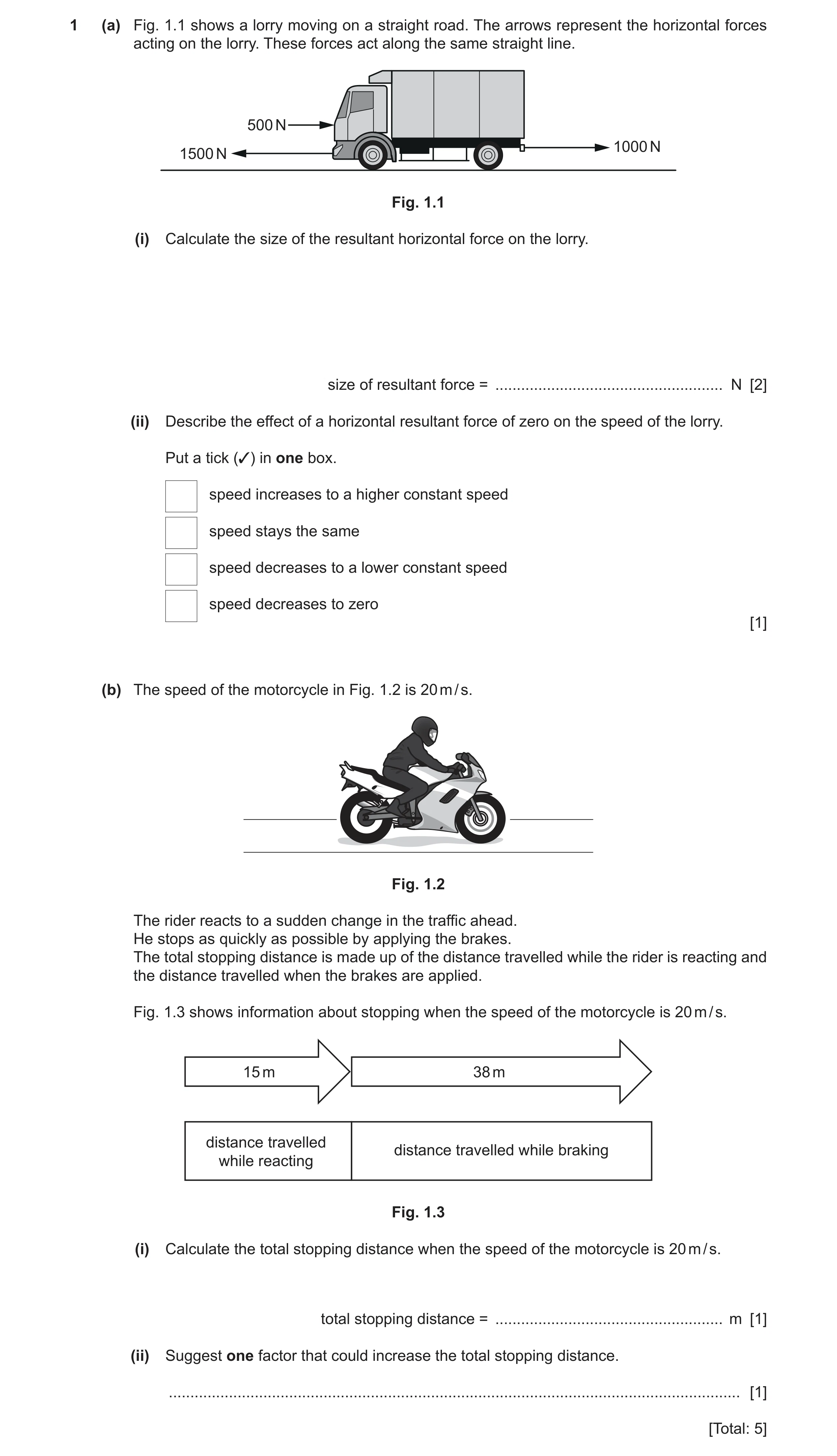
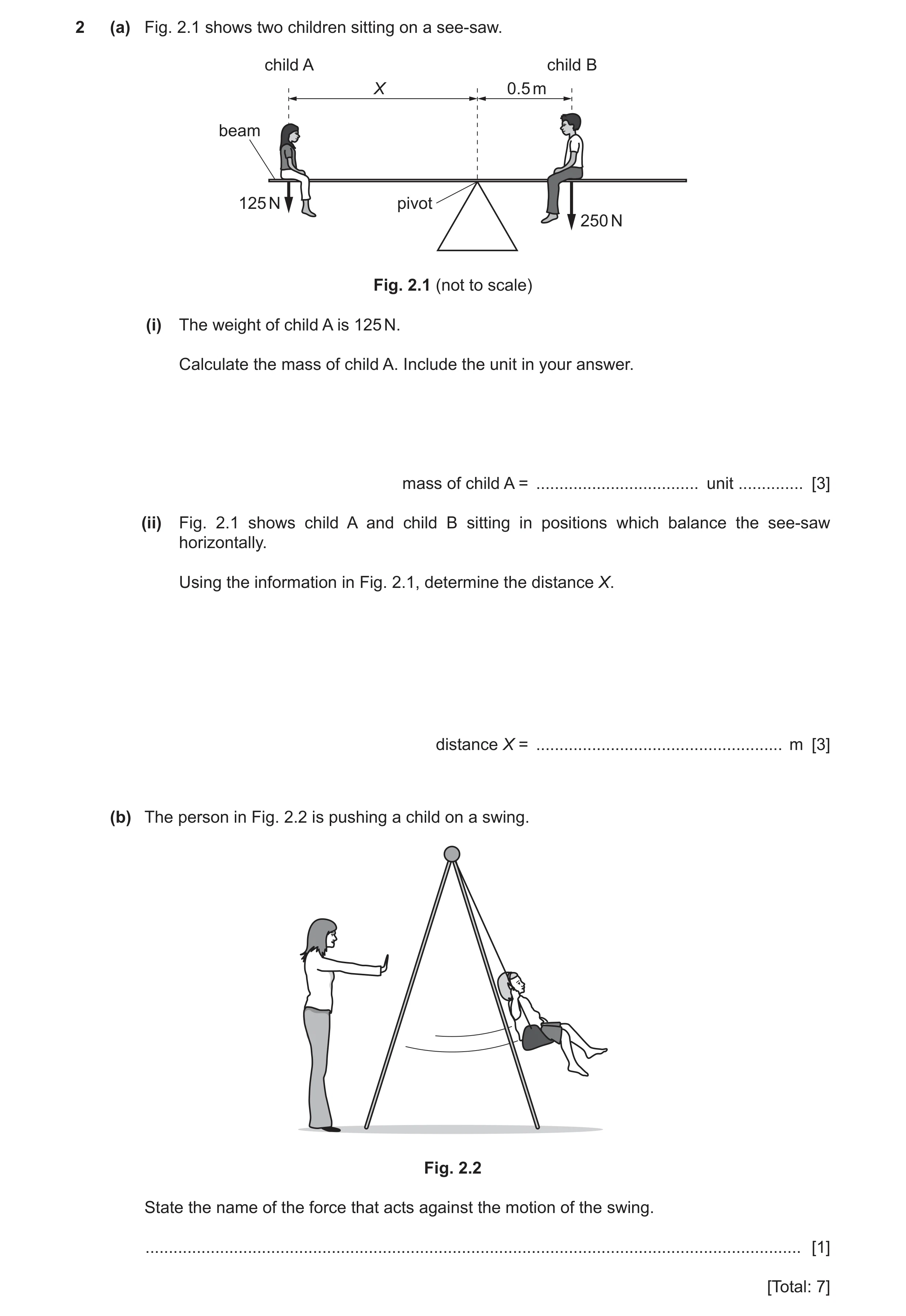
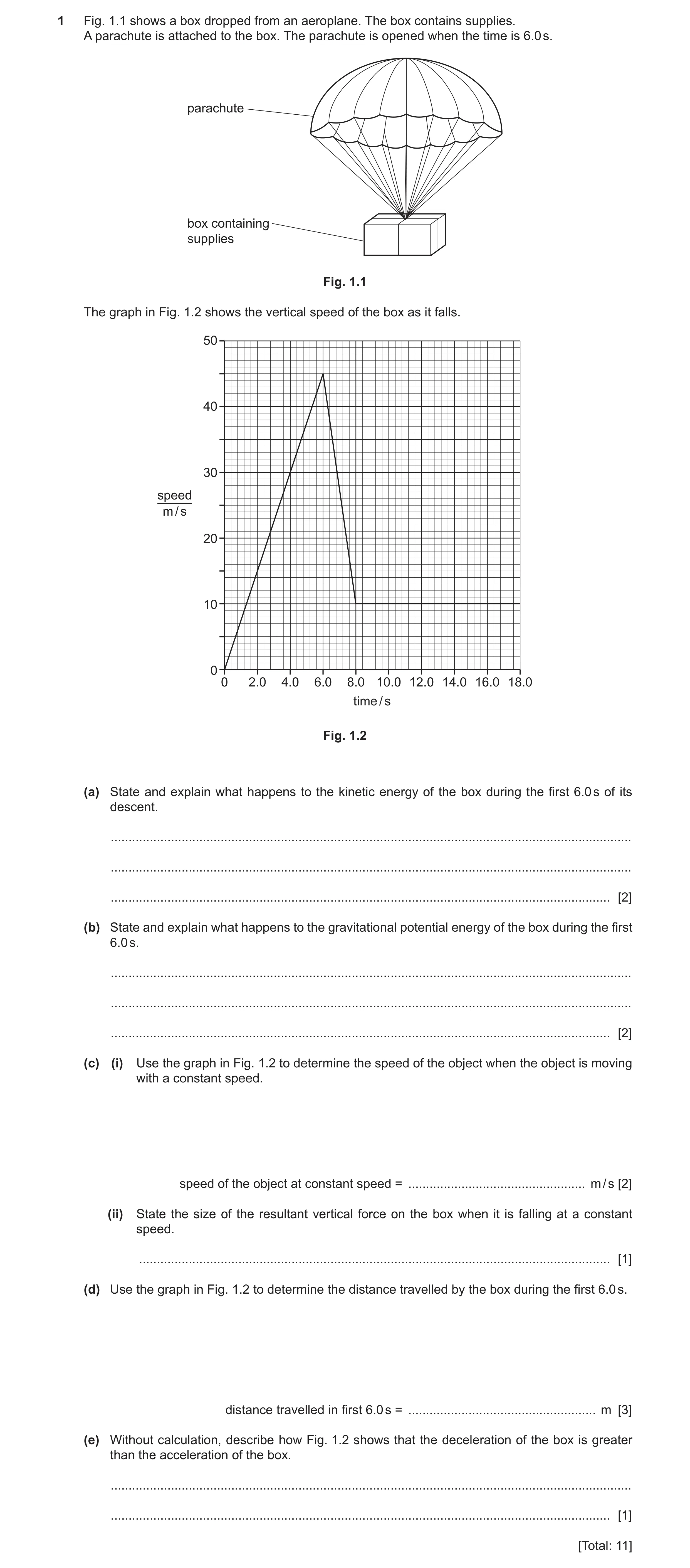
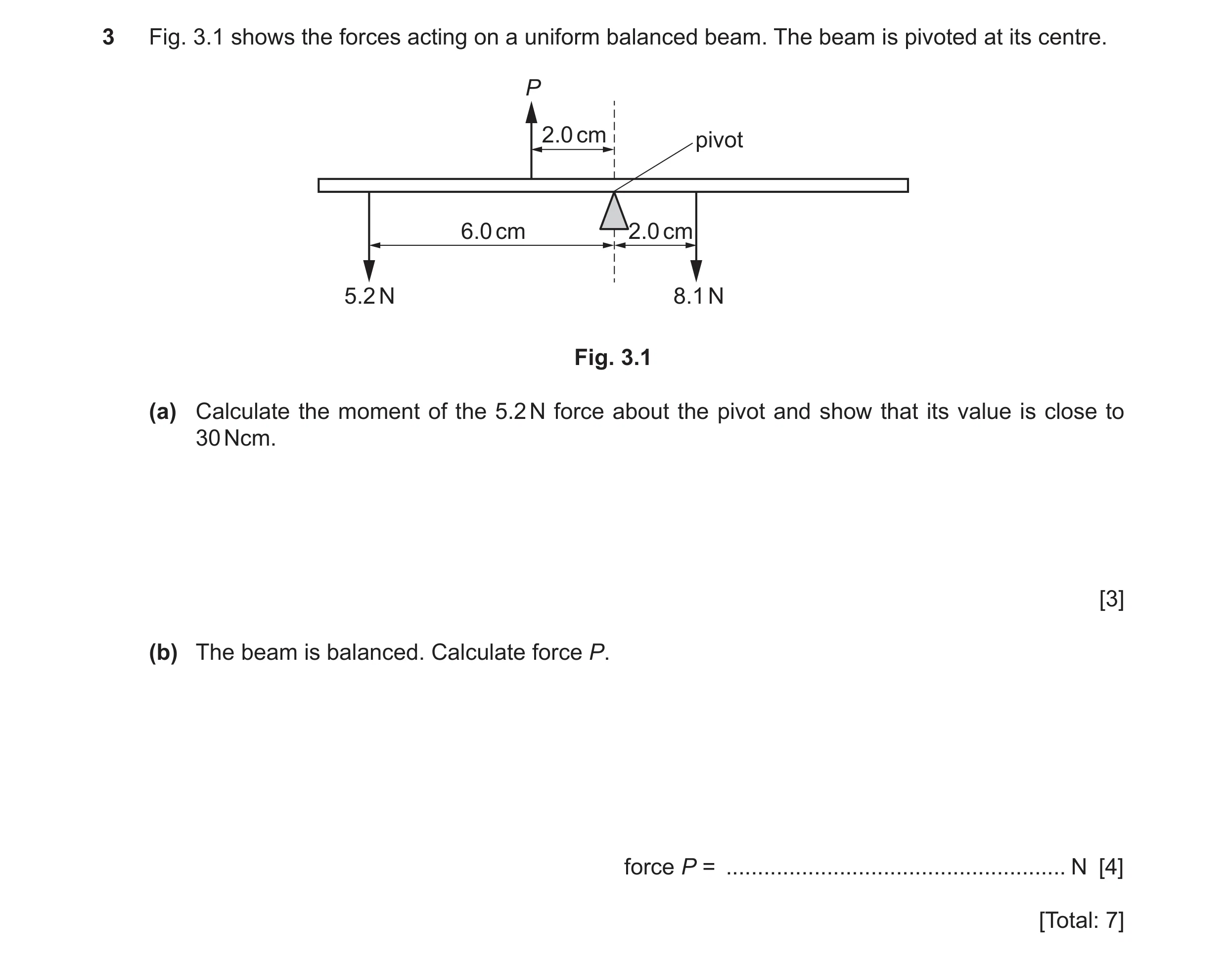 41 / 97
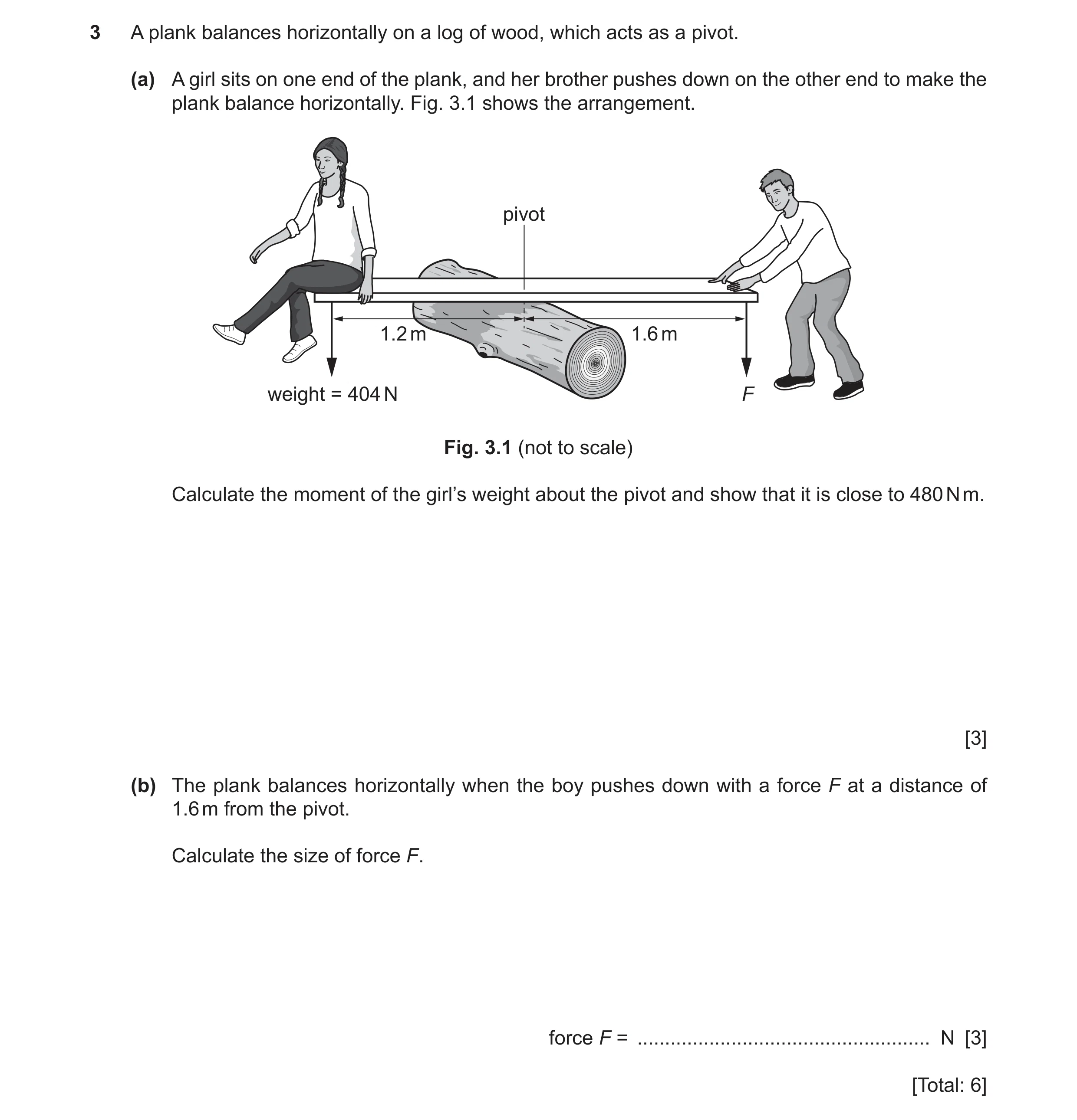 42 / 97
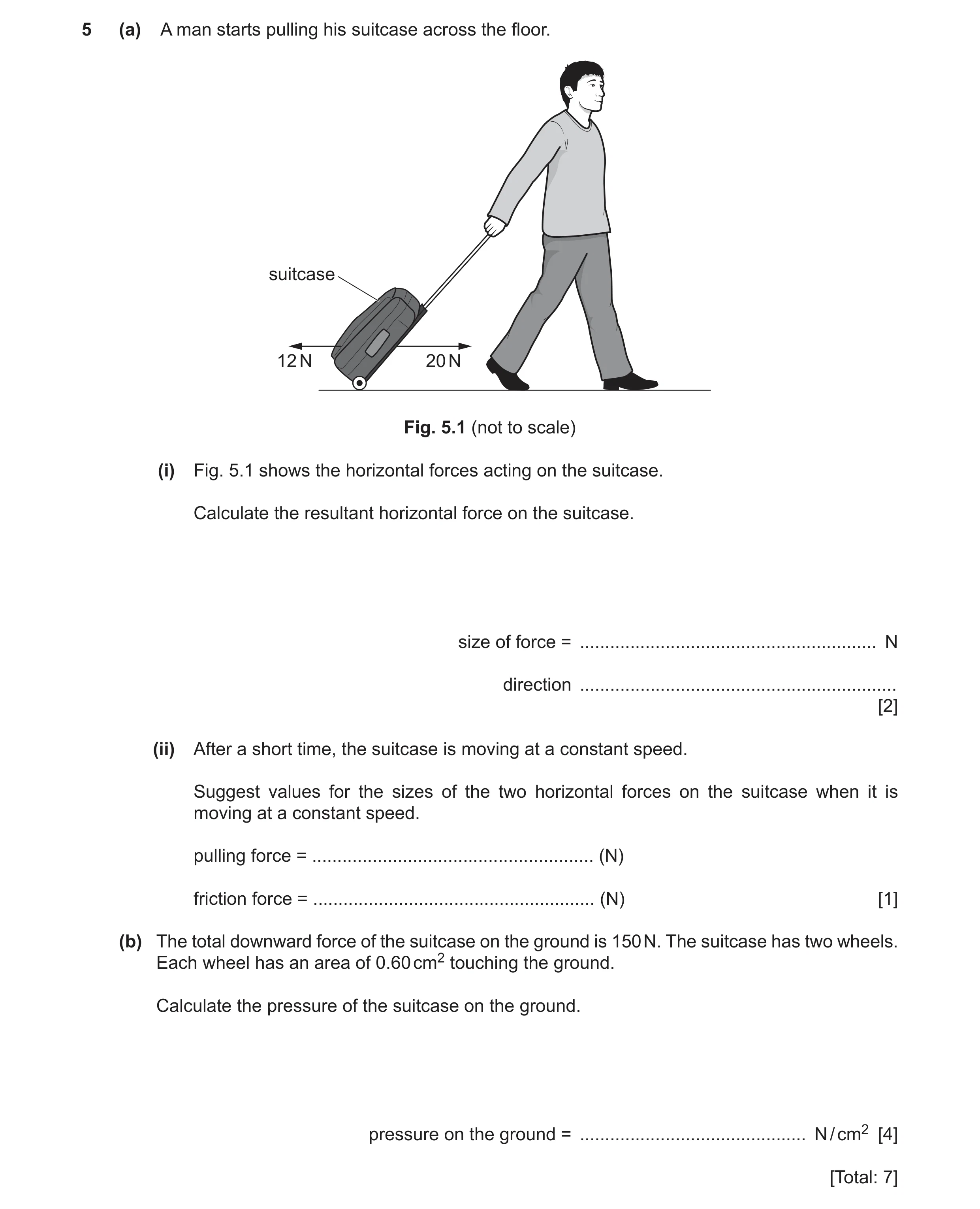 43 / 97
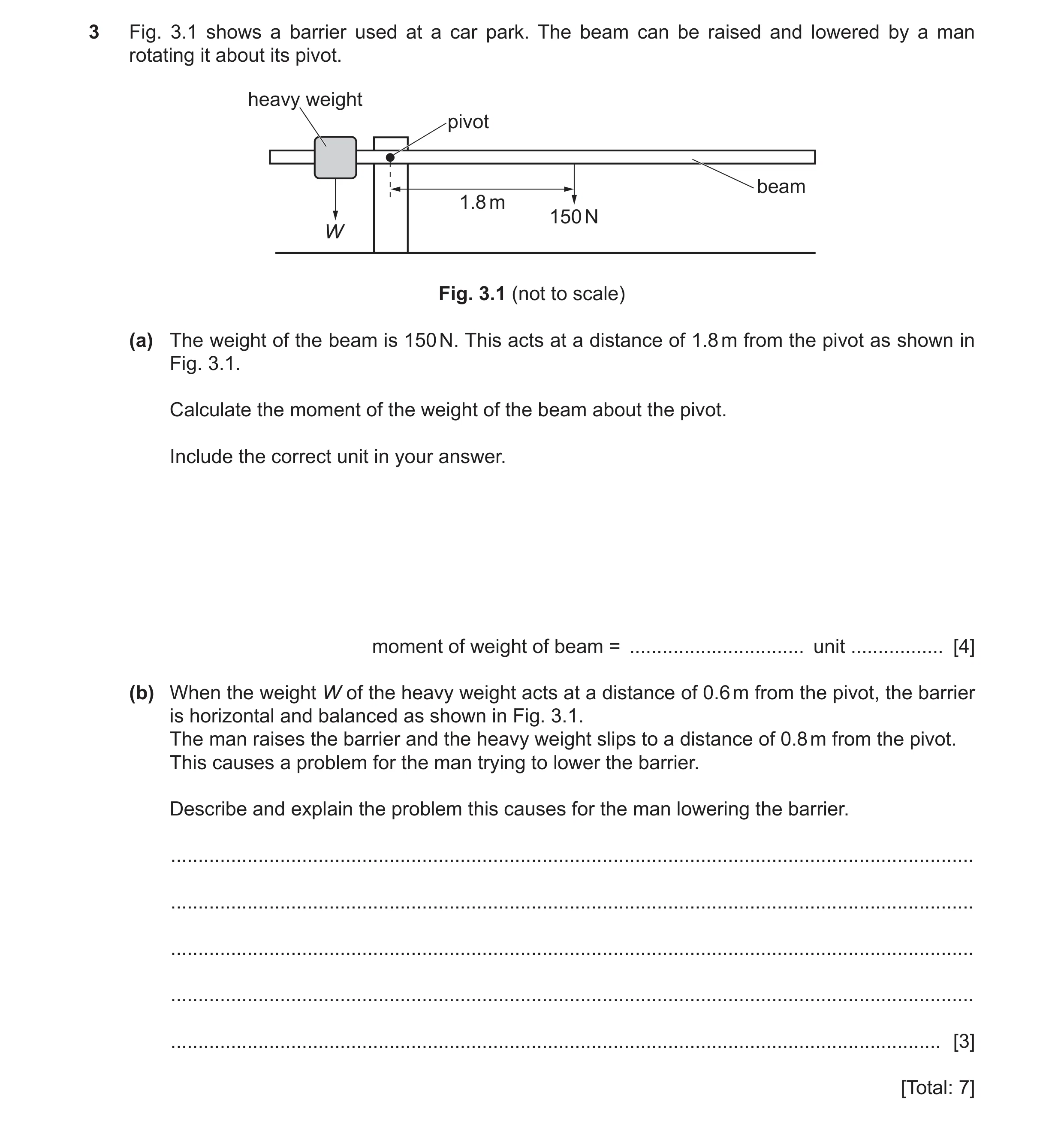 44 / 97
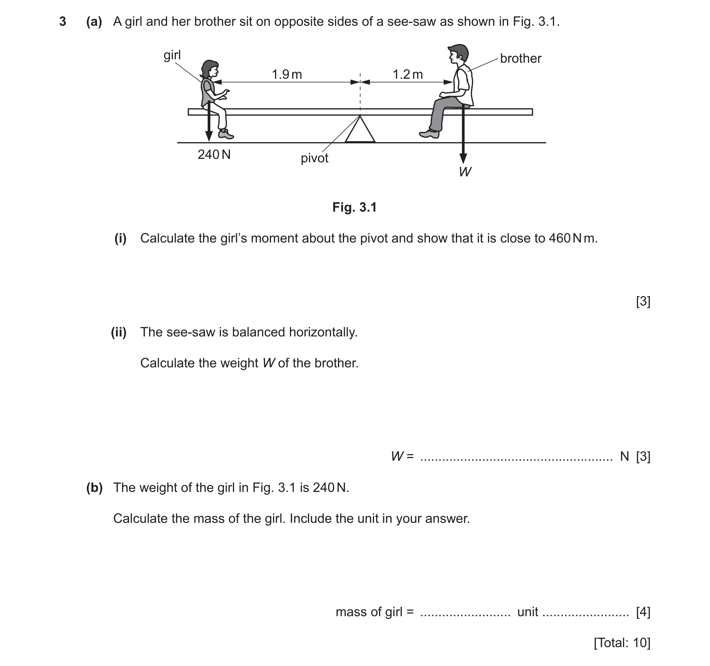 45 / 97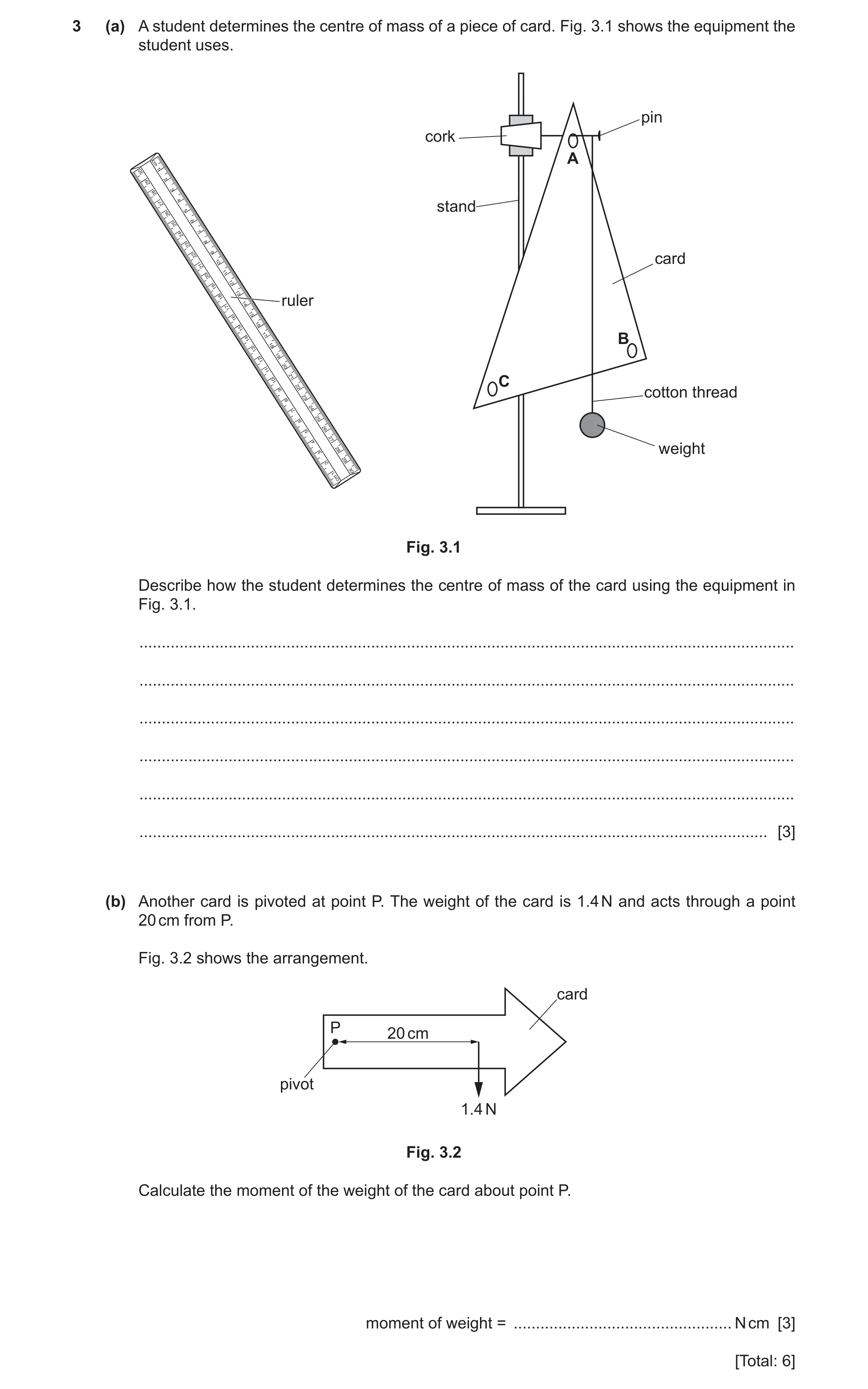
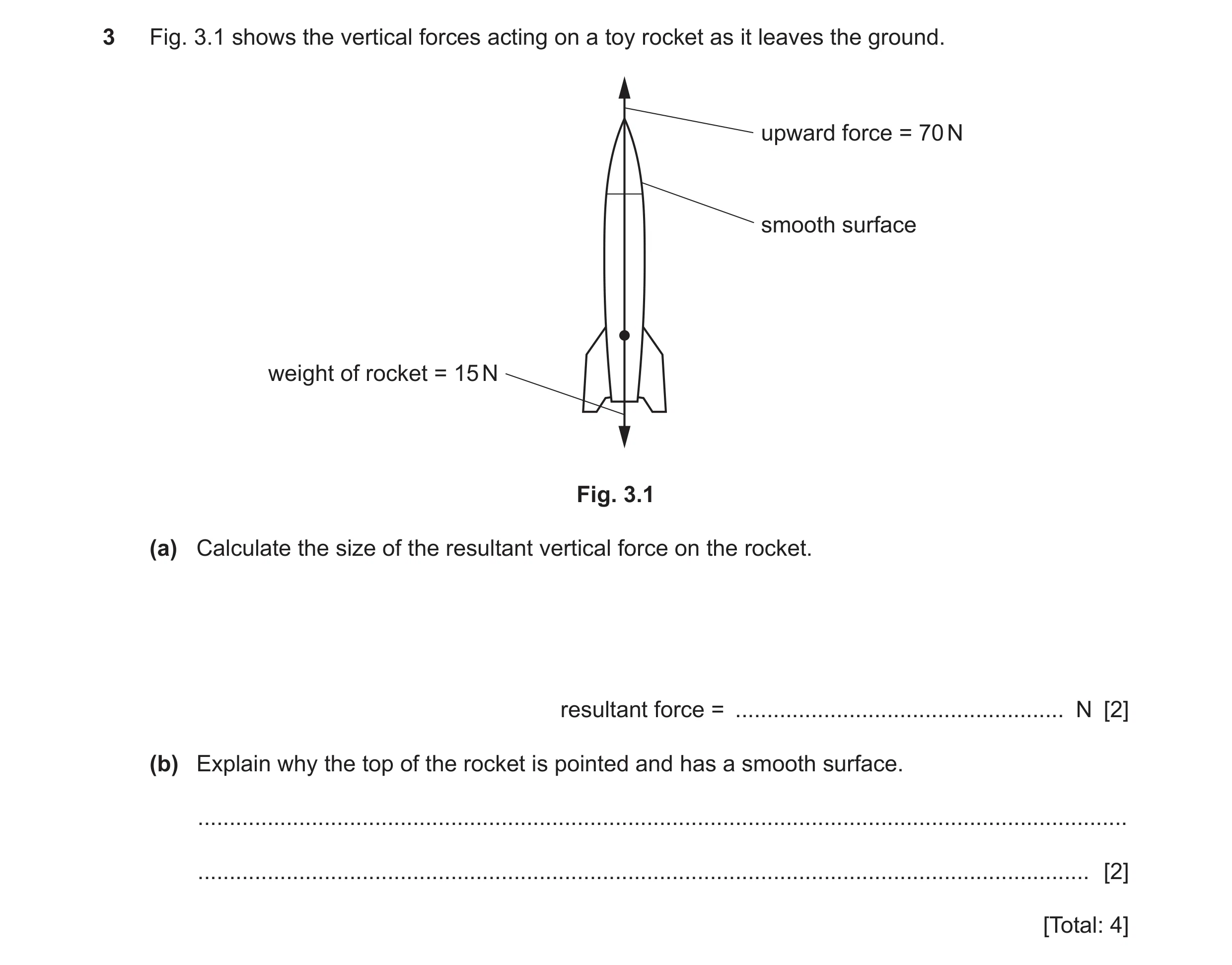 47 / 97
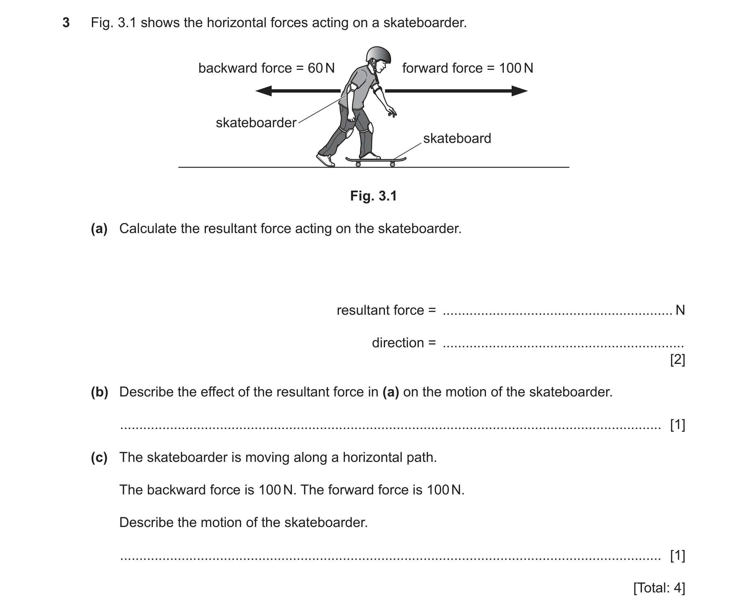 48 / 97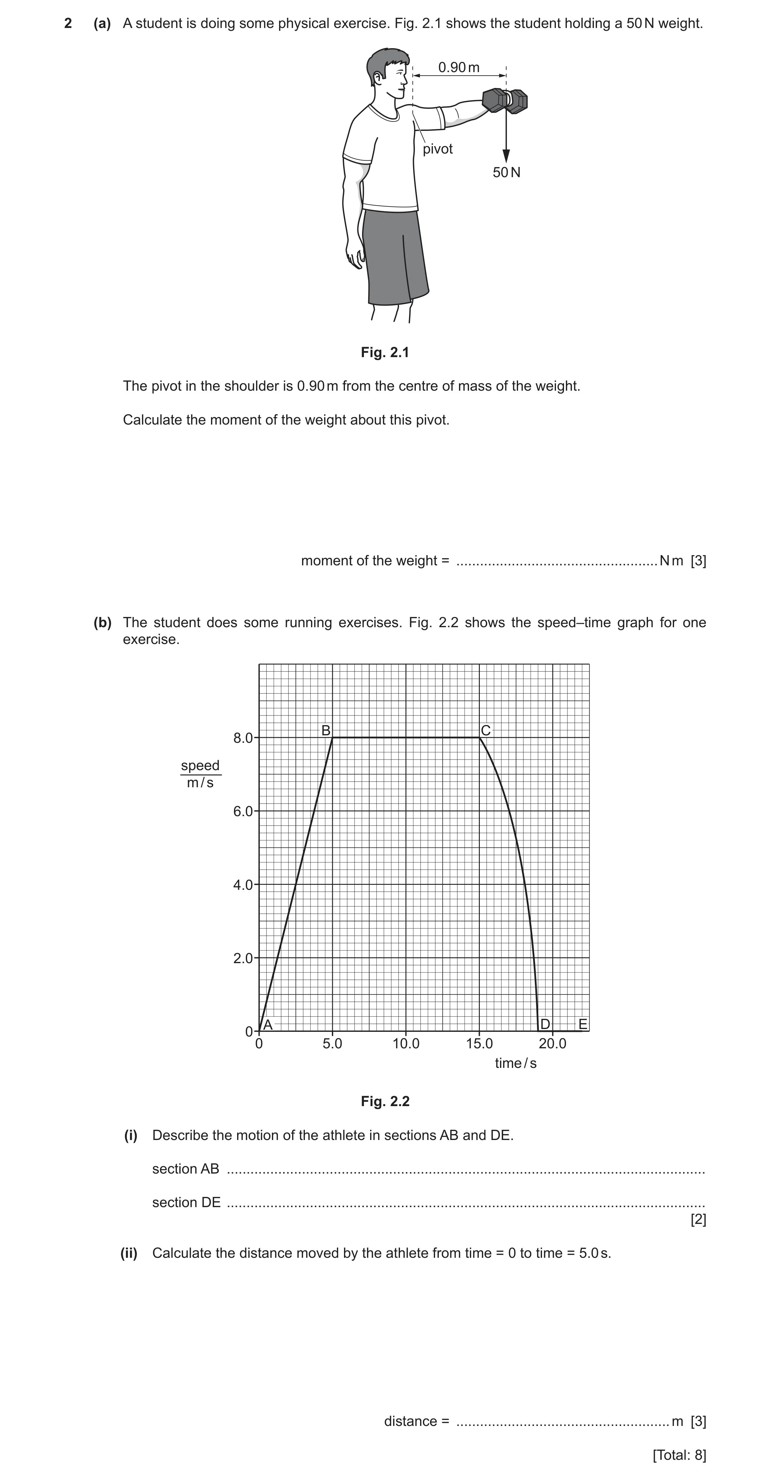
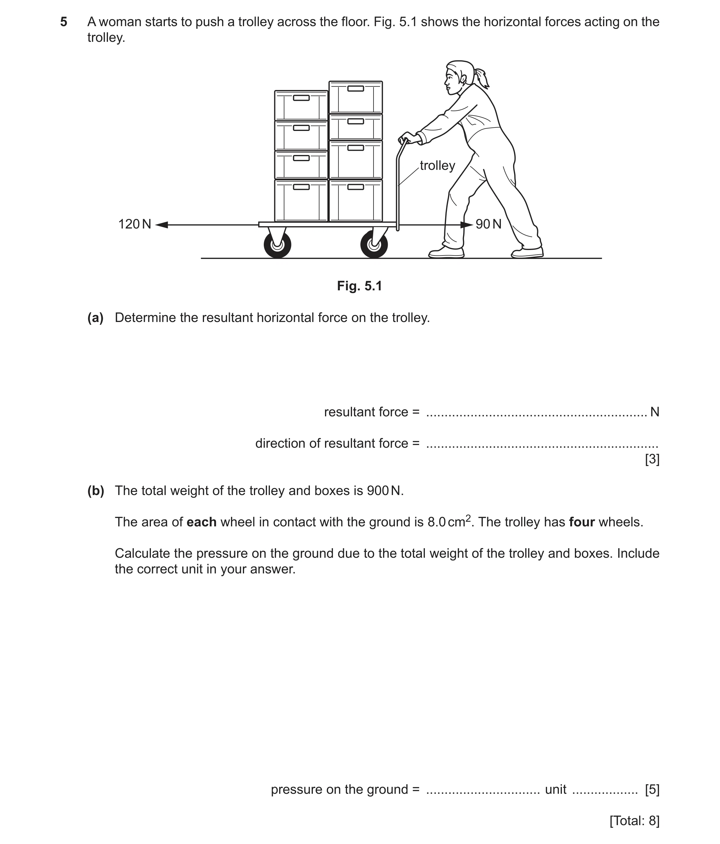 50 / 97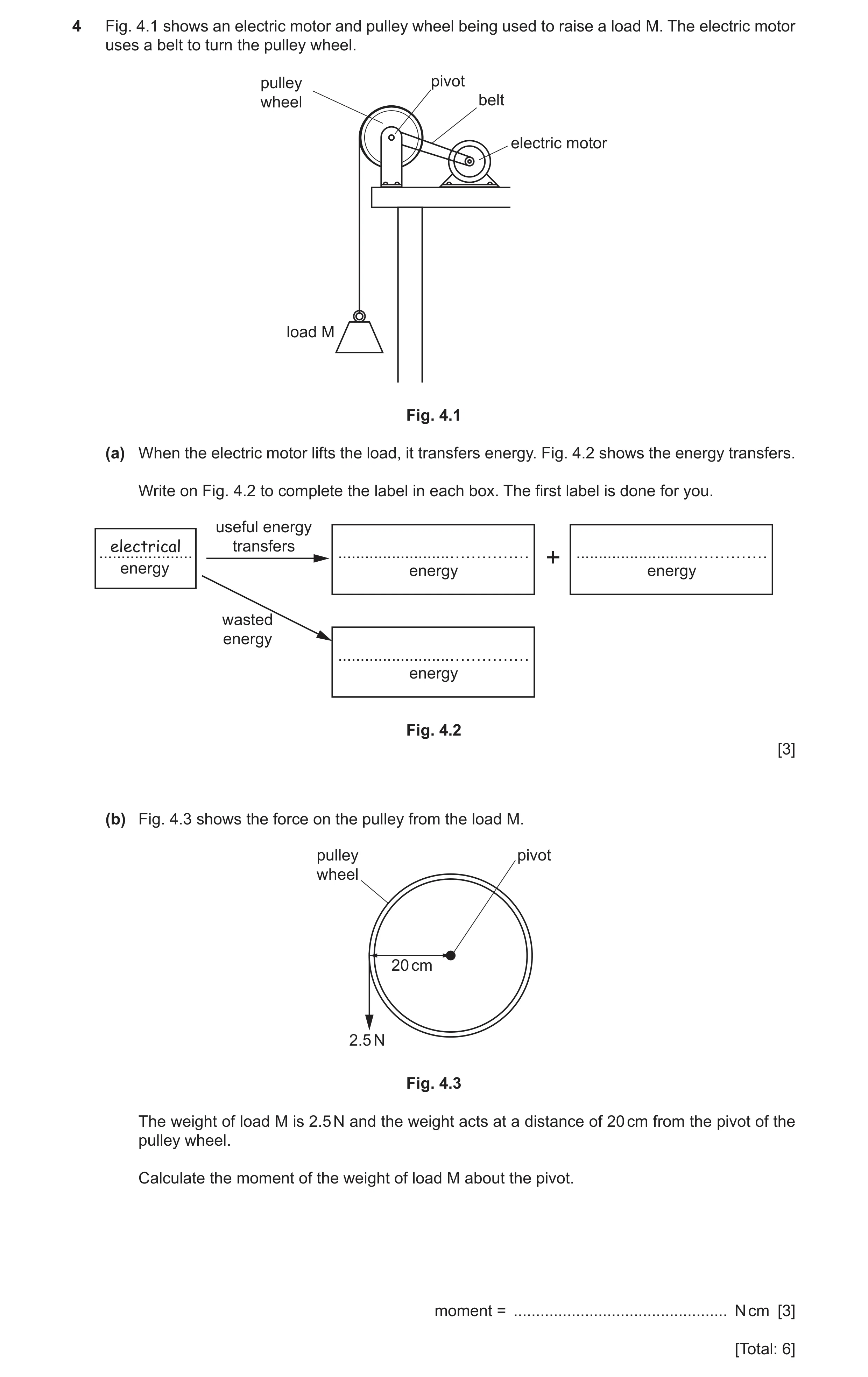
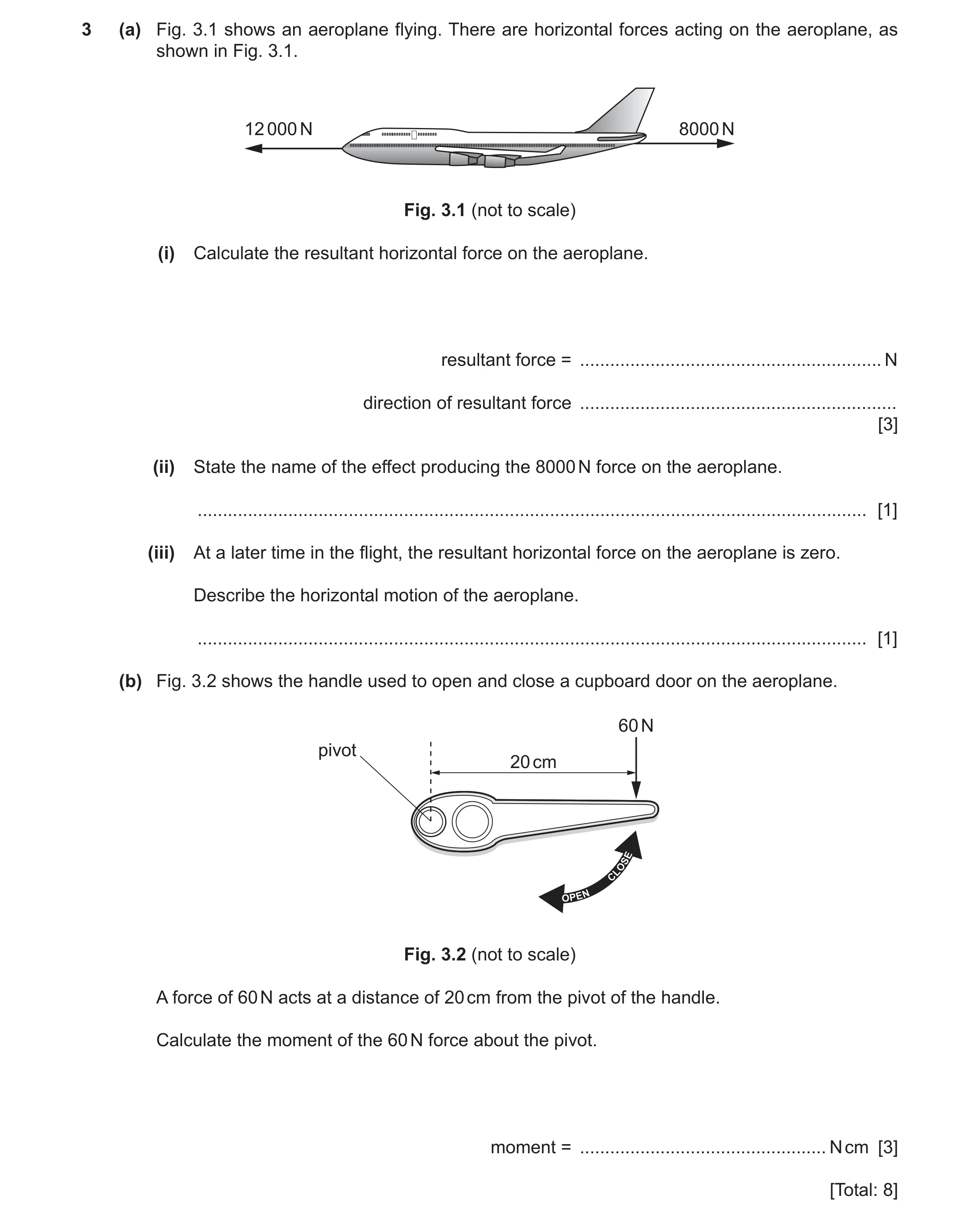 53 / 97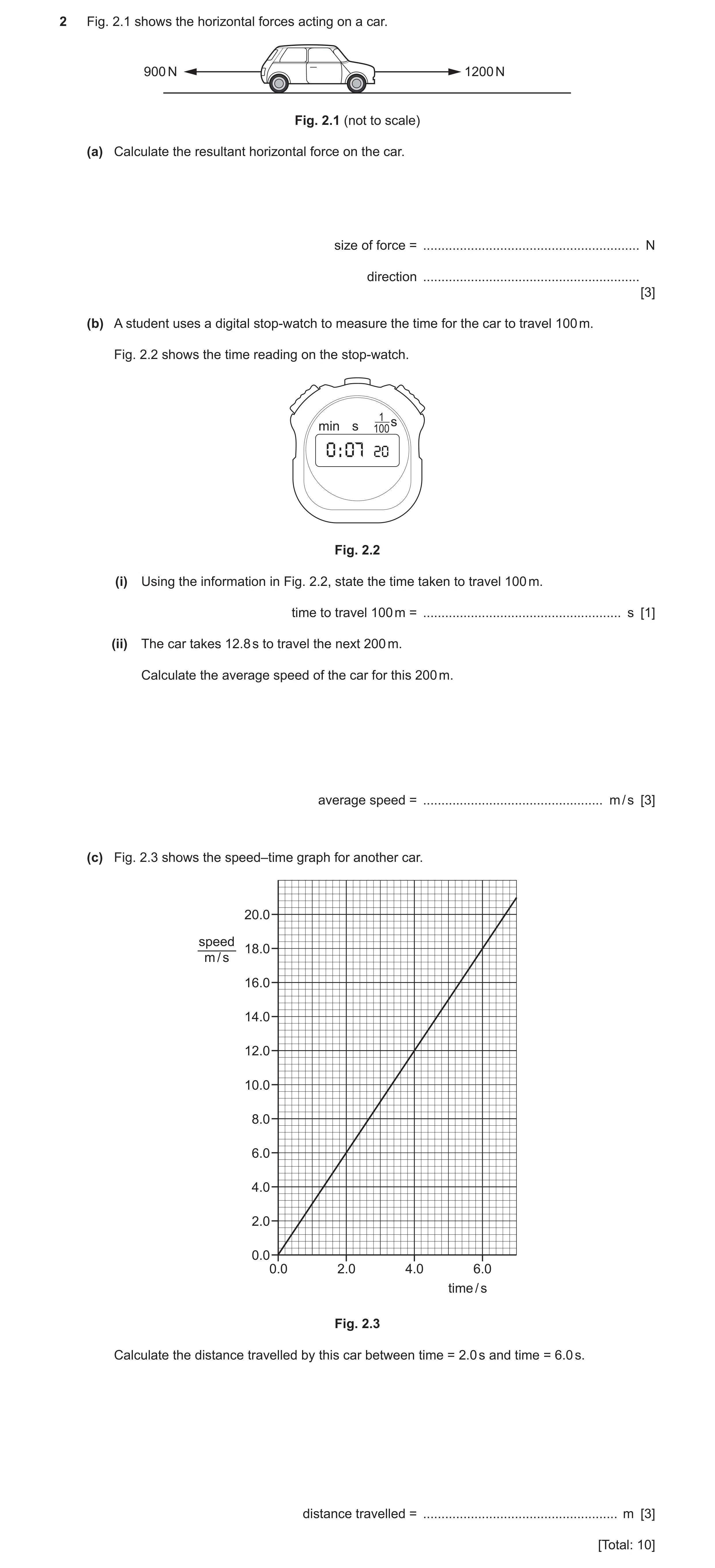
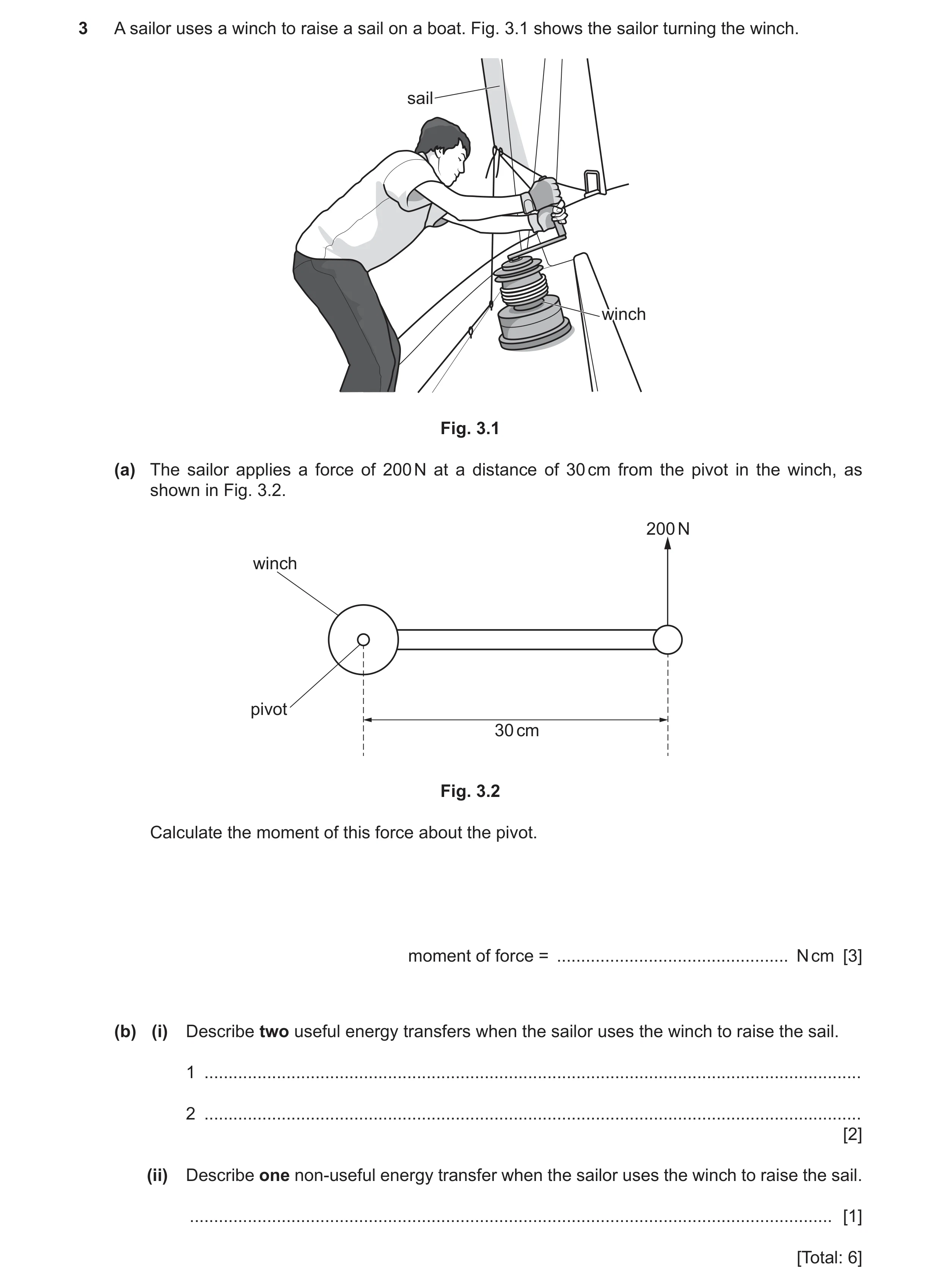 56 / 97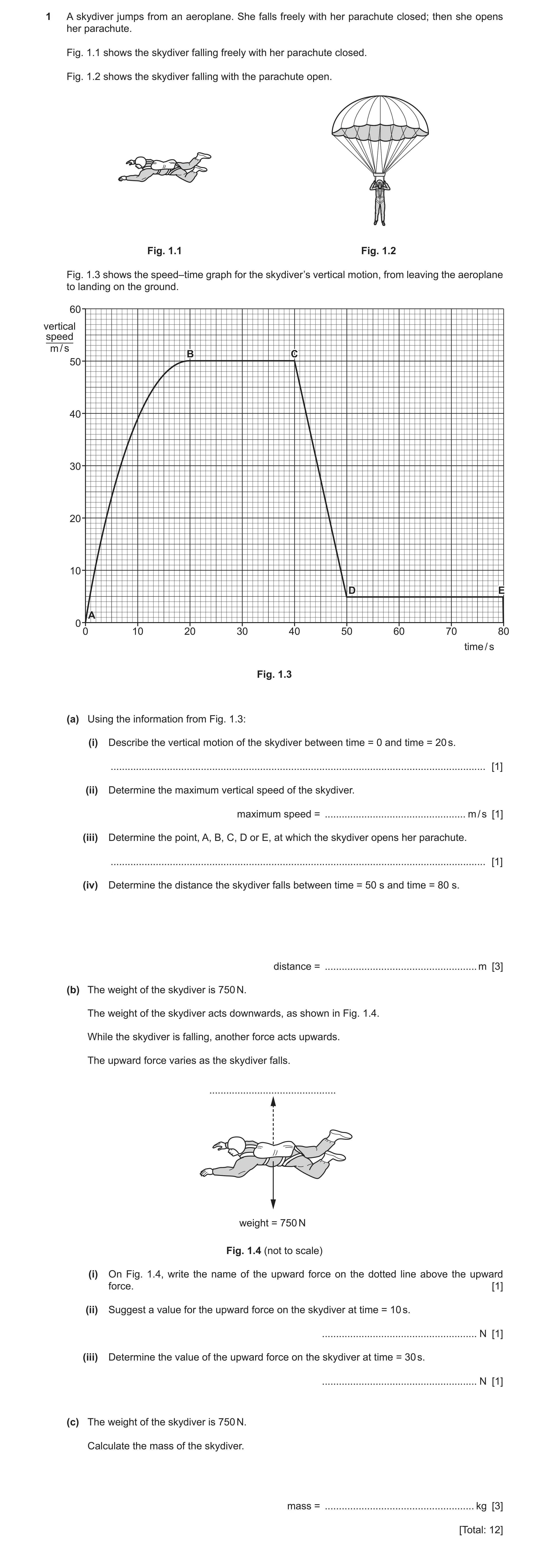
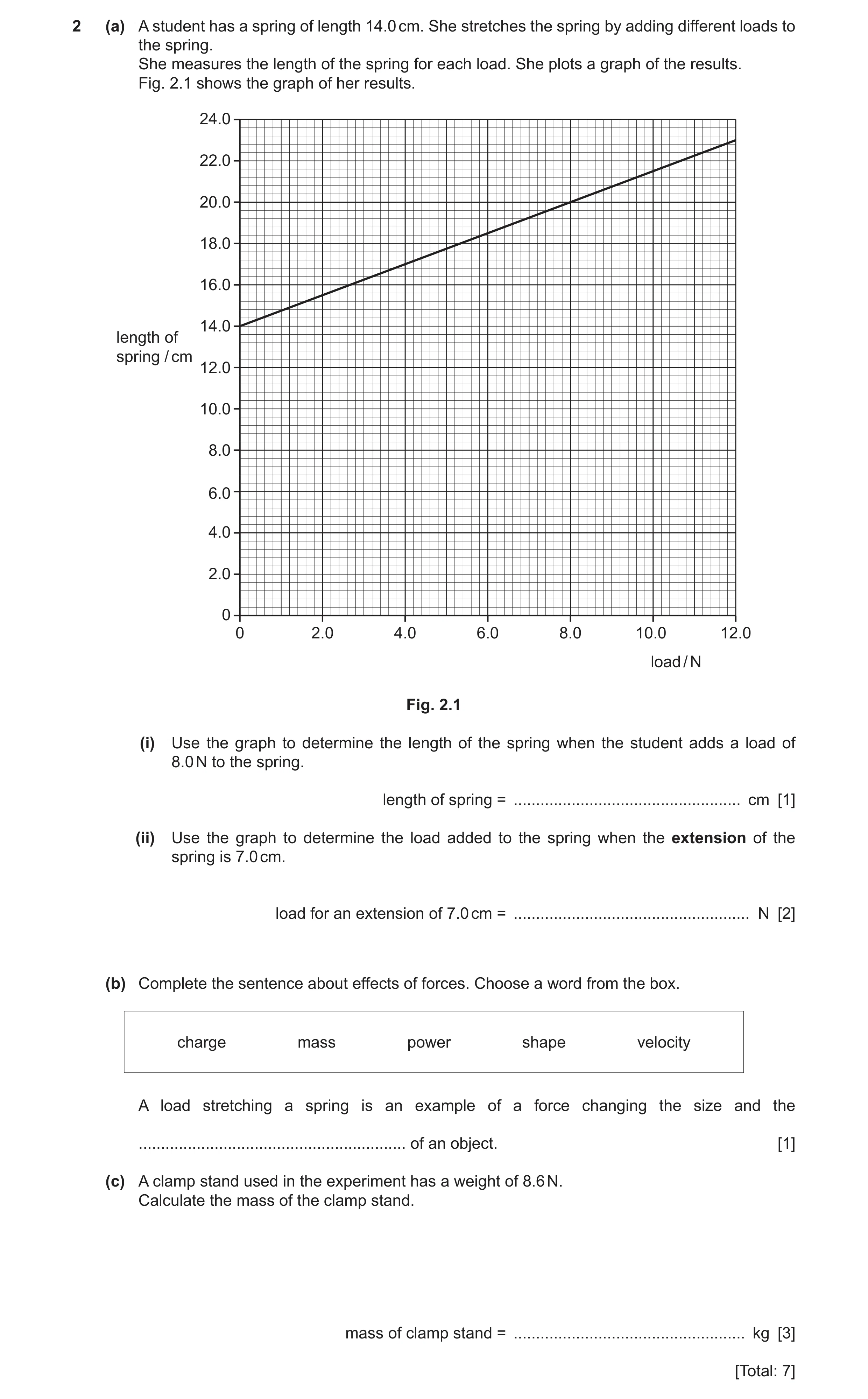
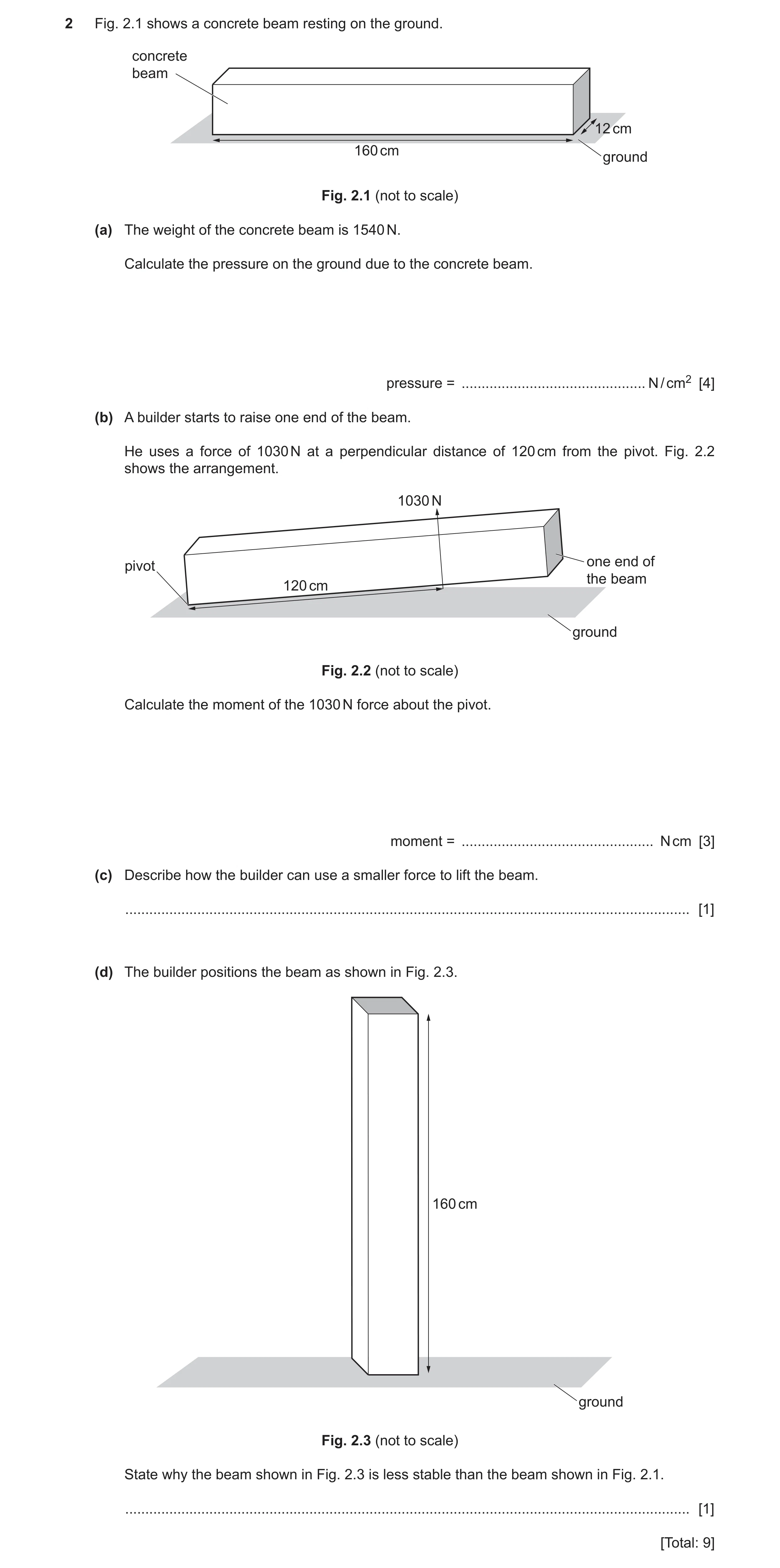
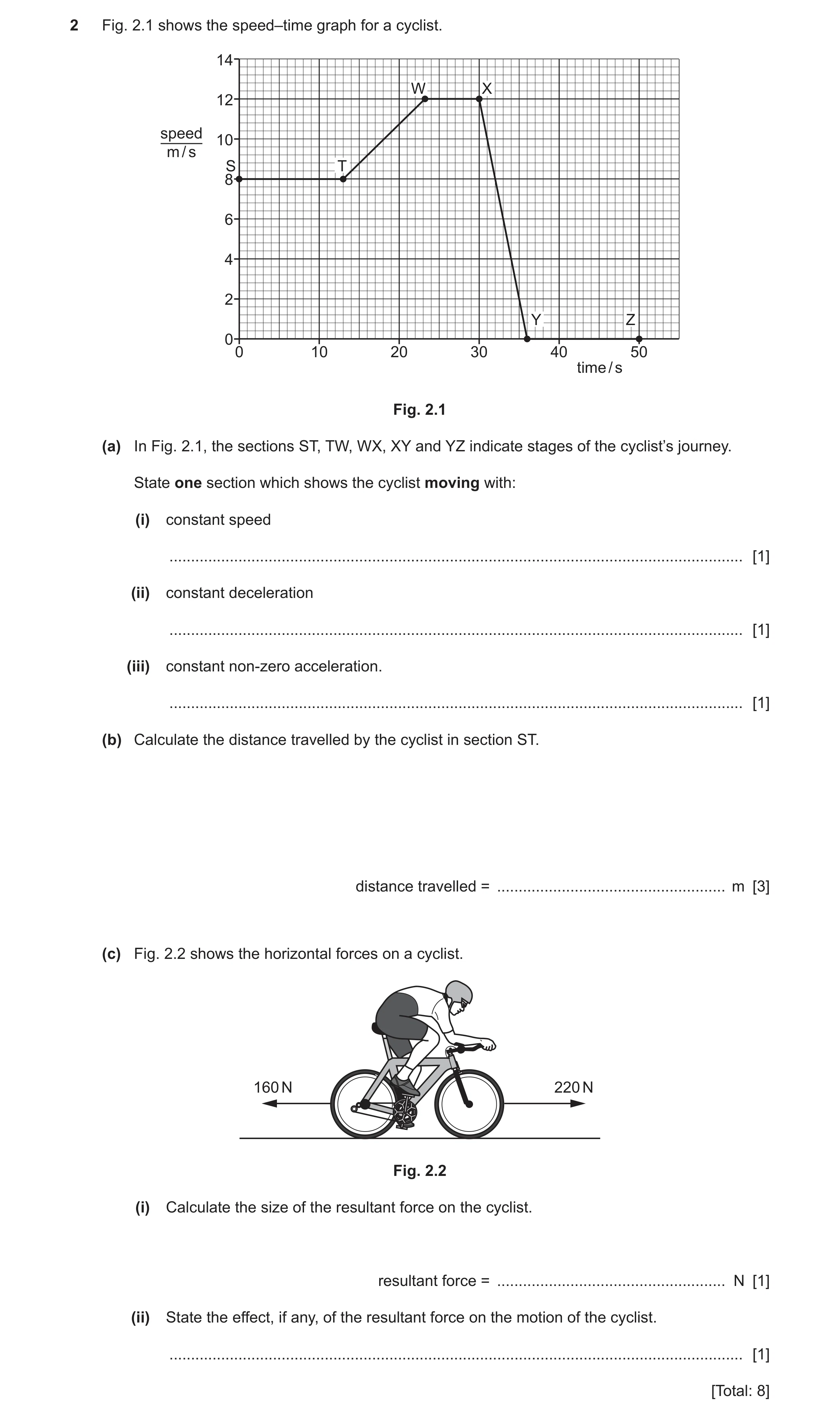
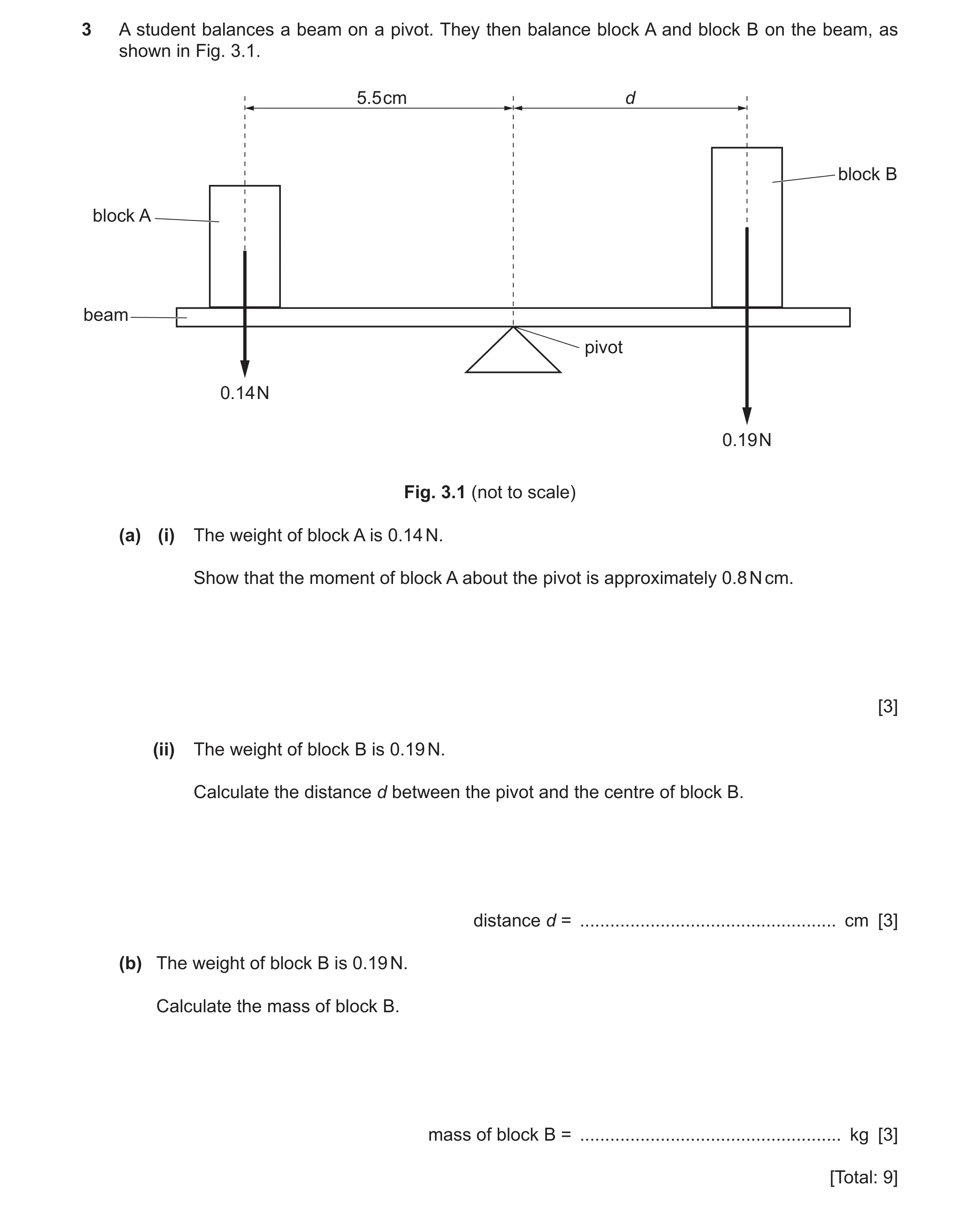 64 / 97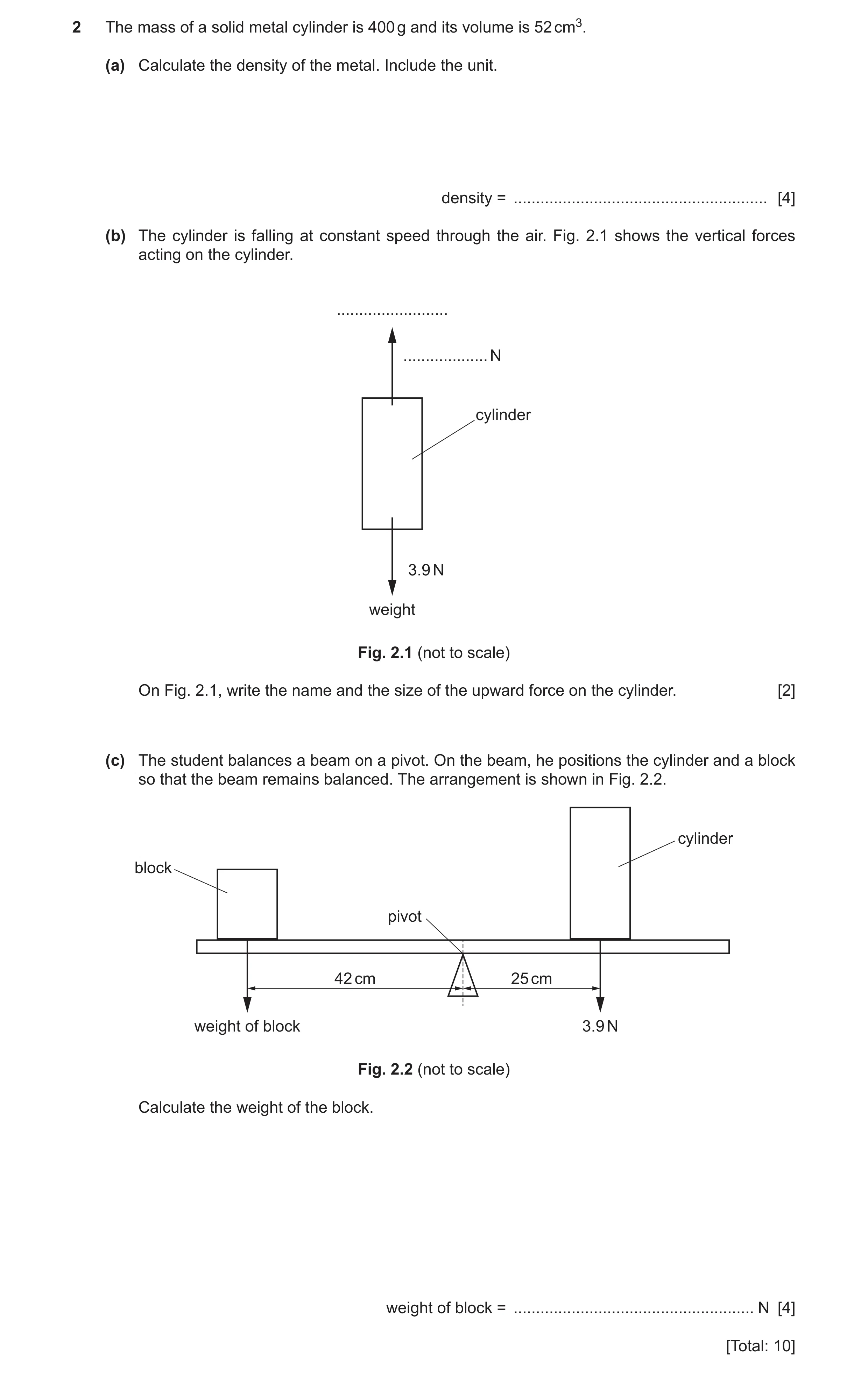
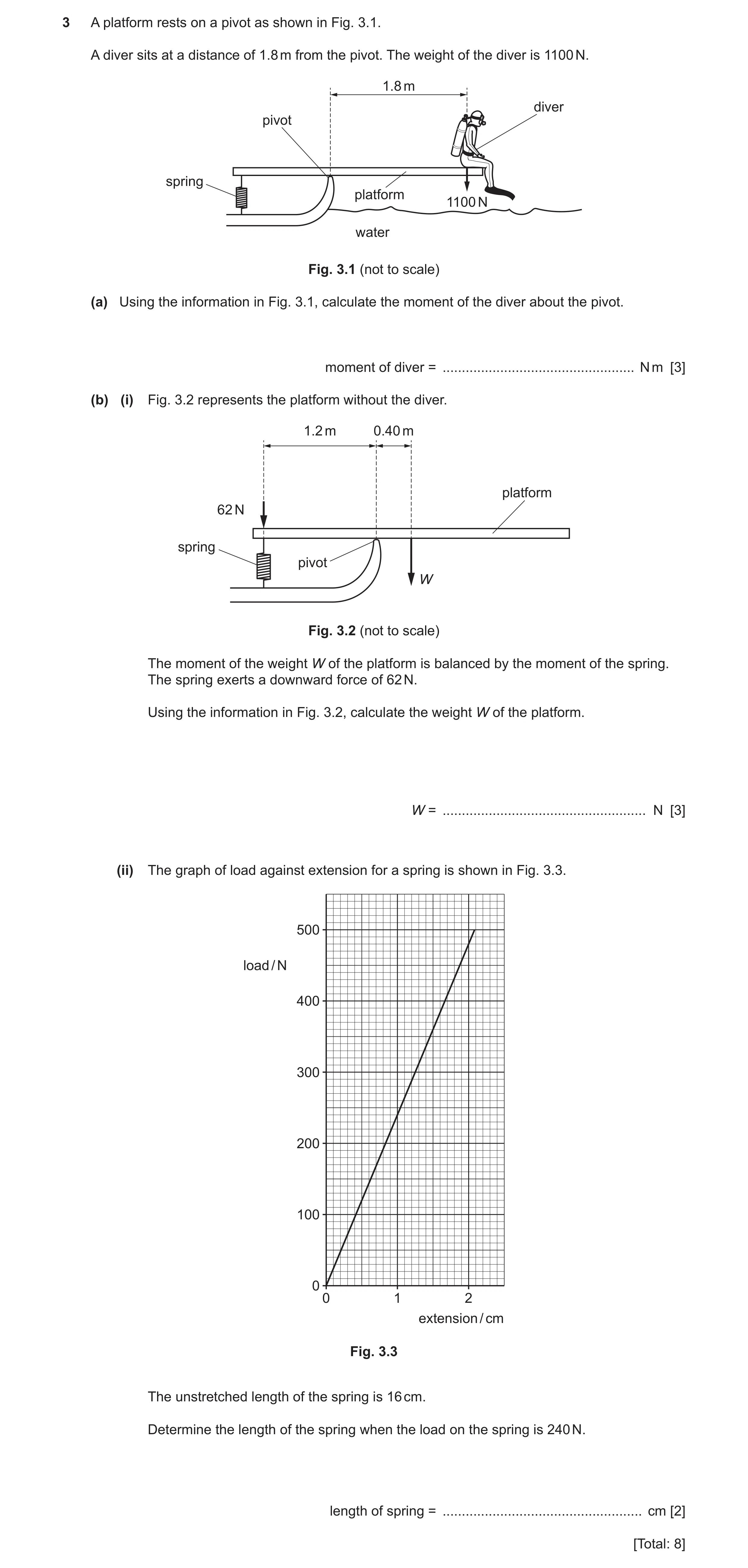
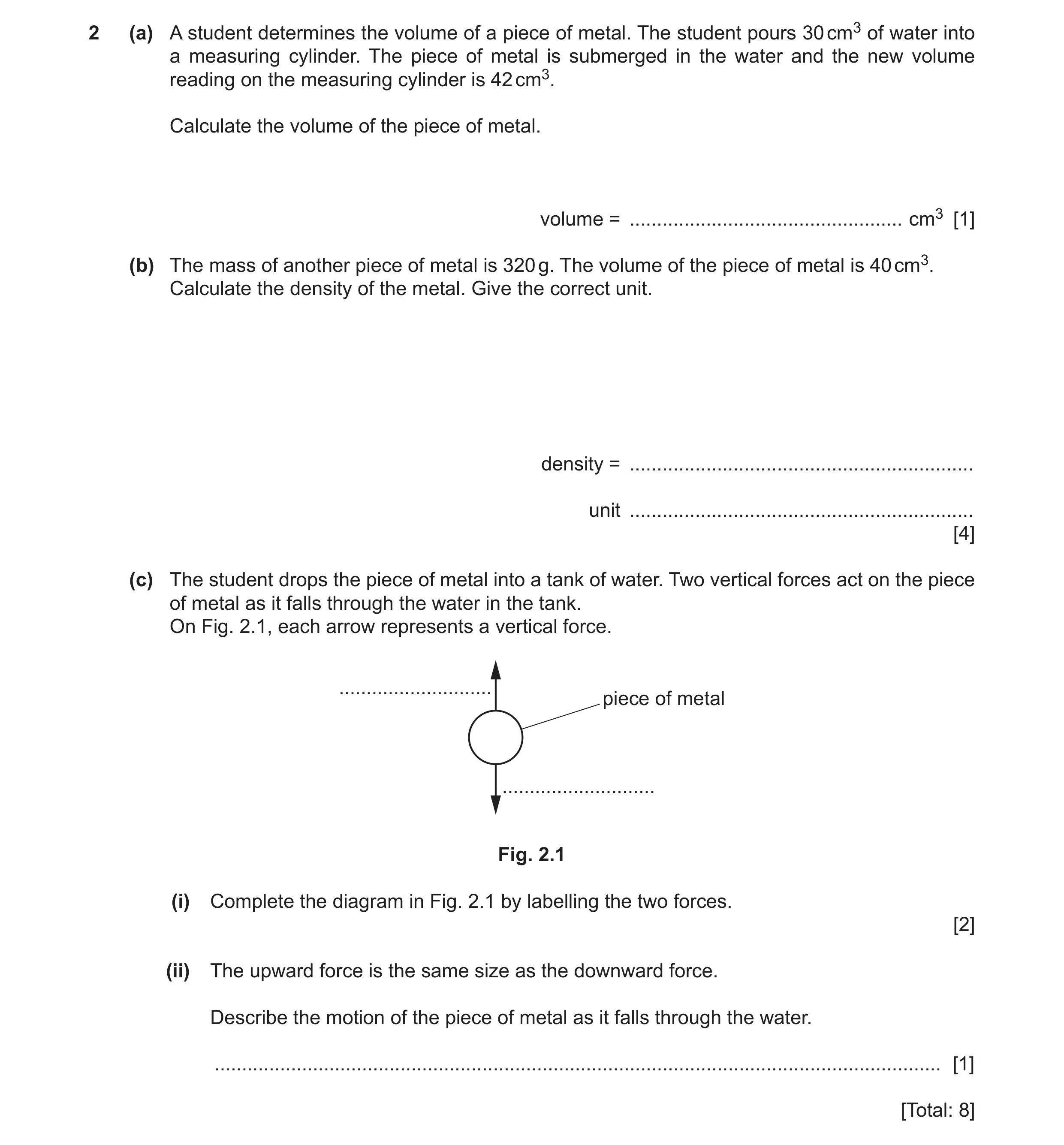 68 / 97
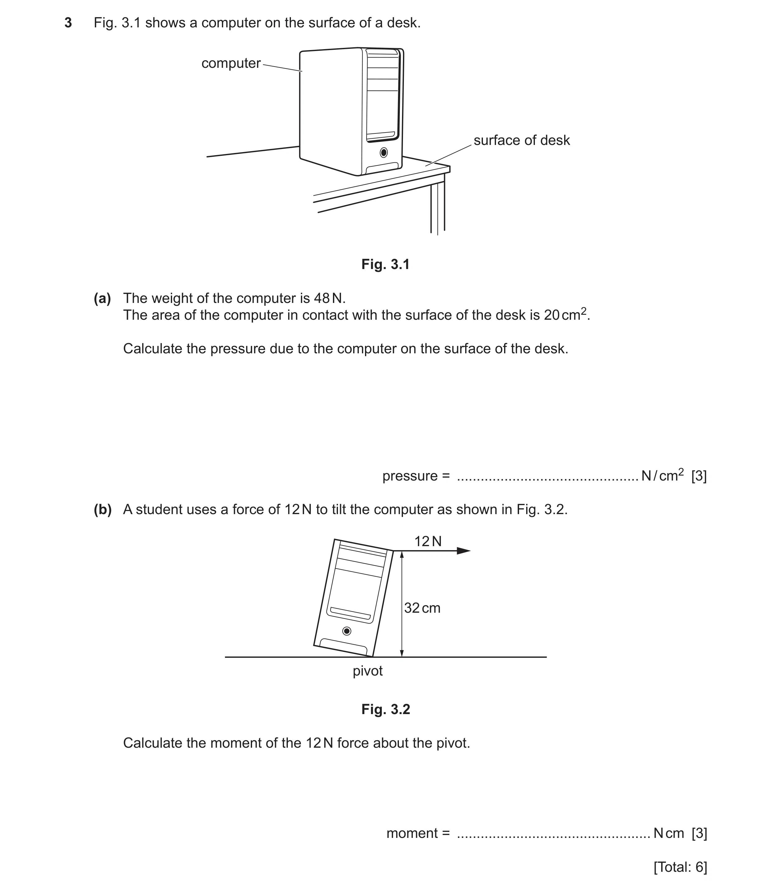 69 / 97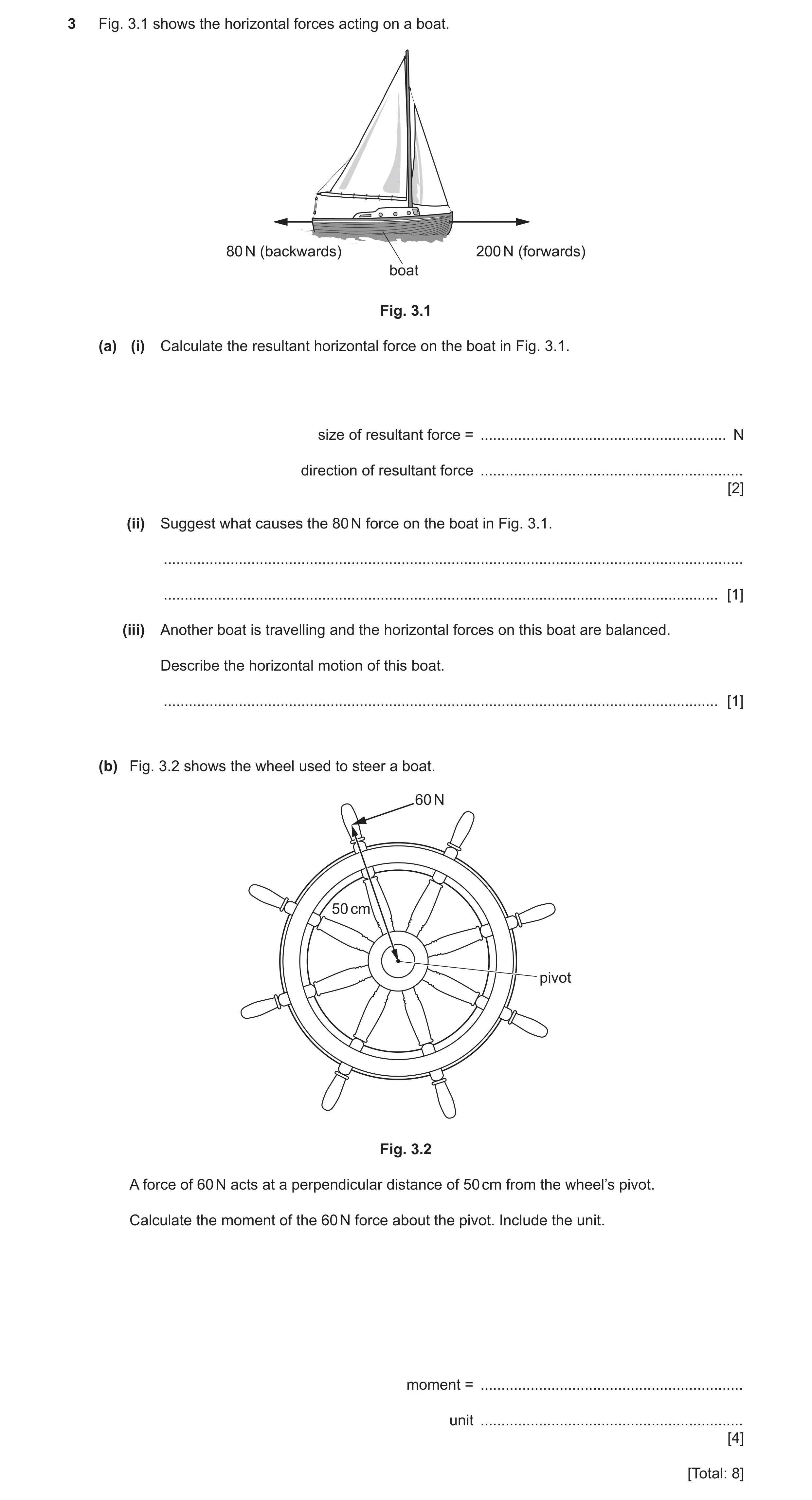
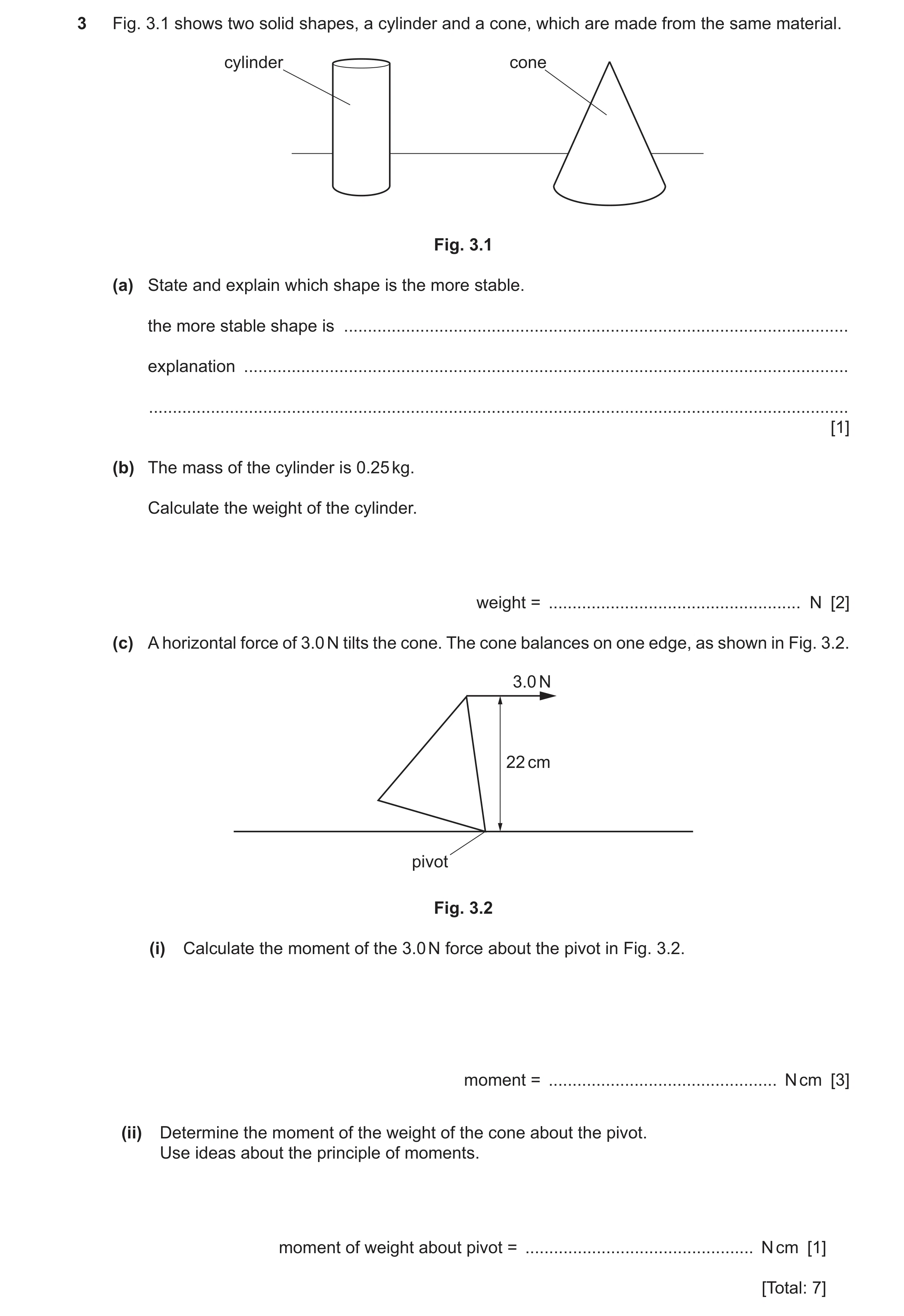
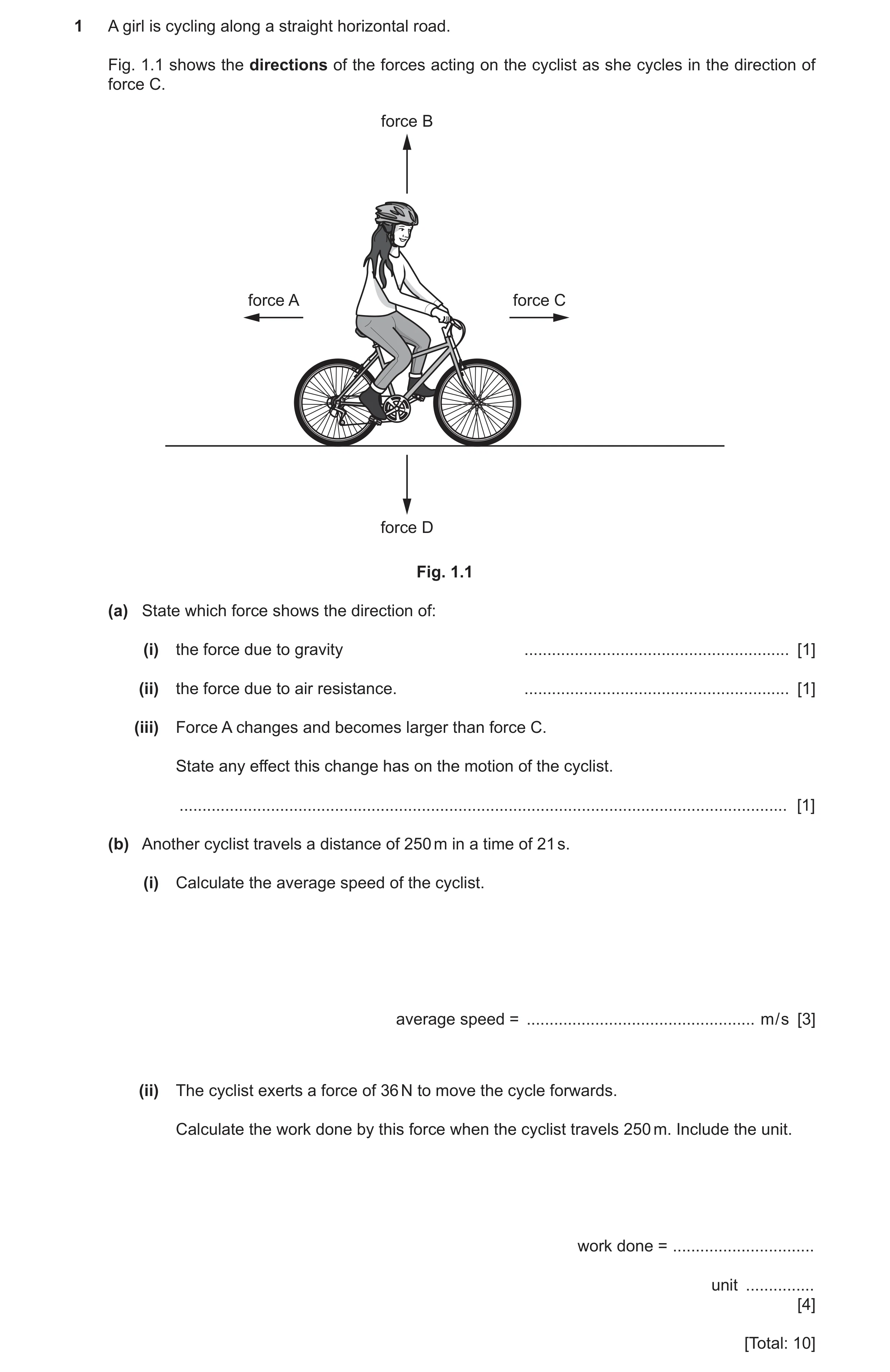
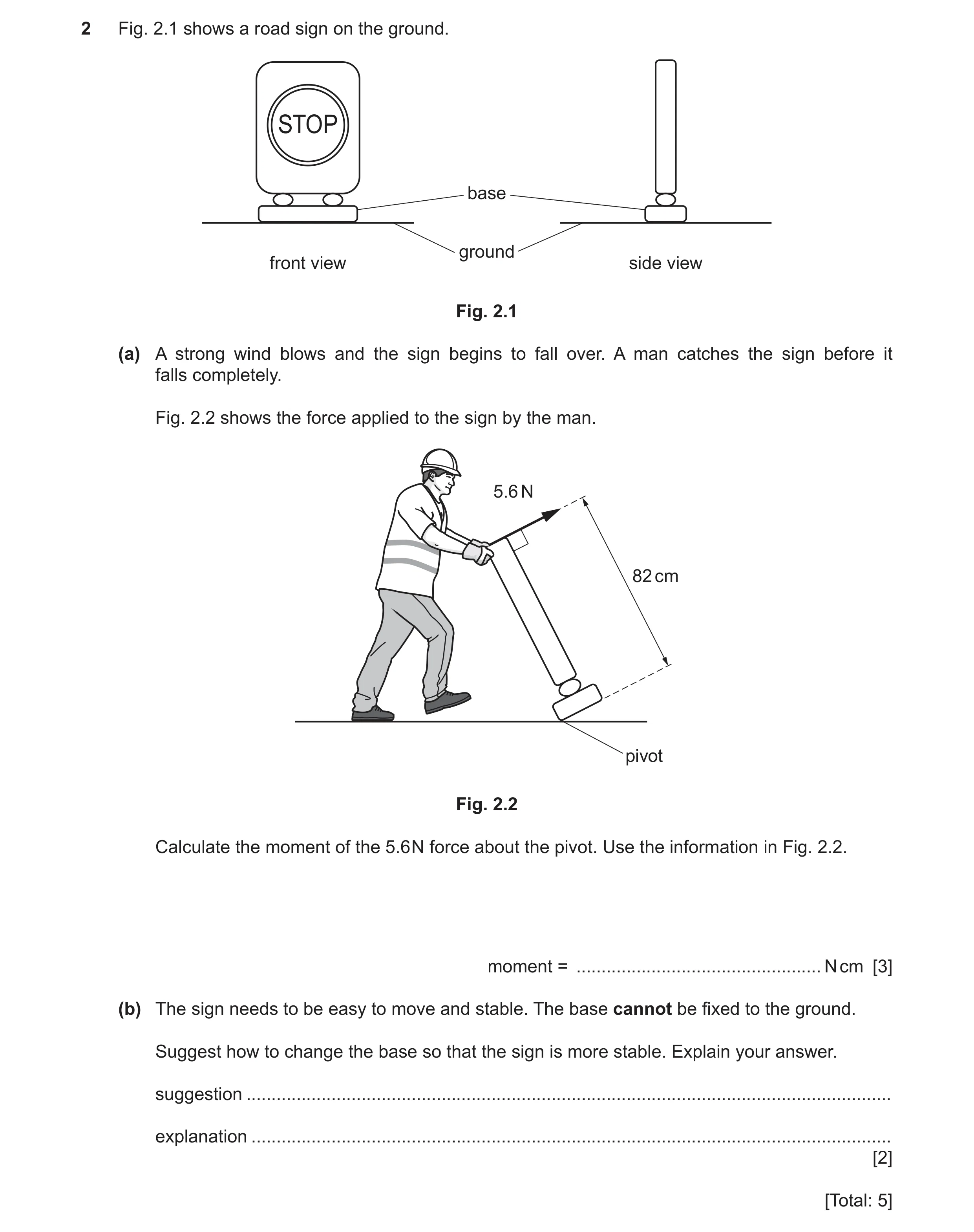 74 / 97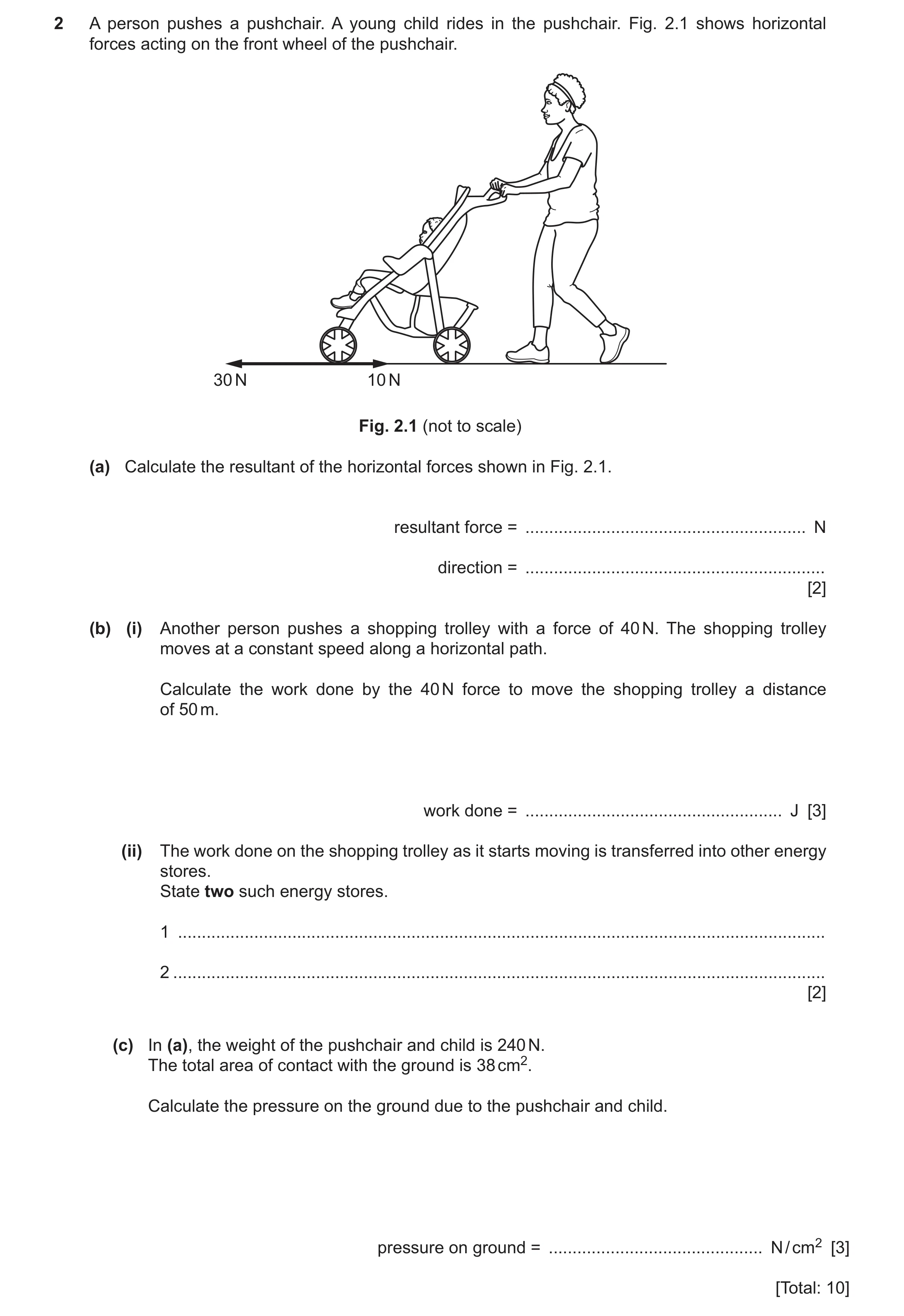
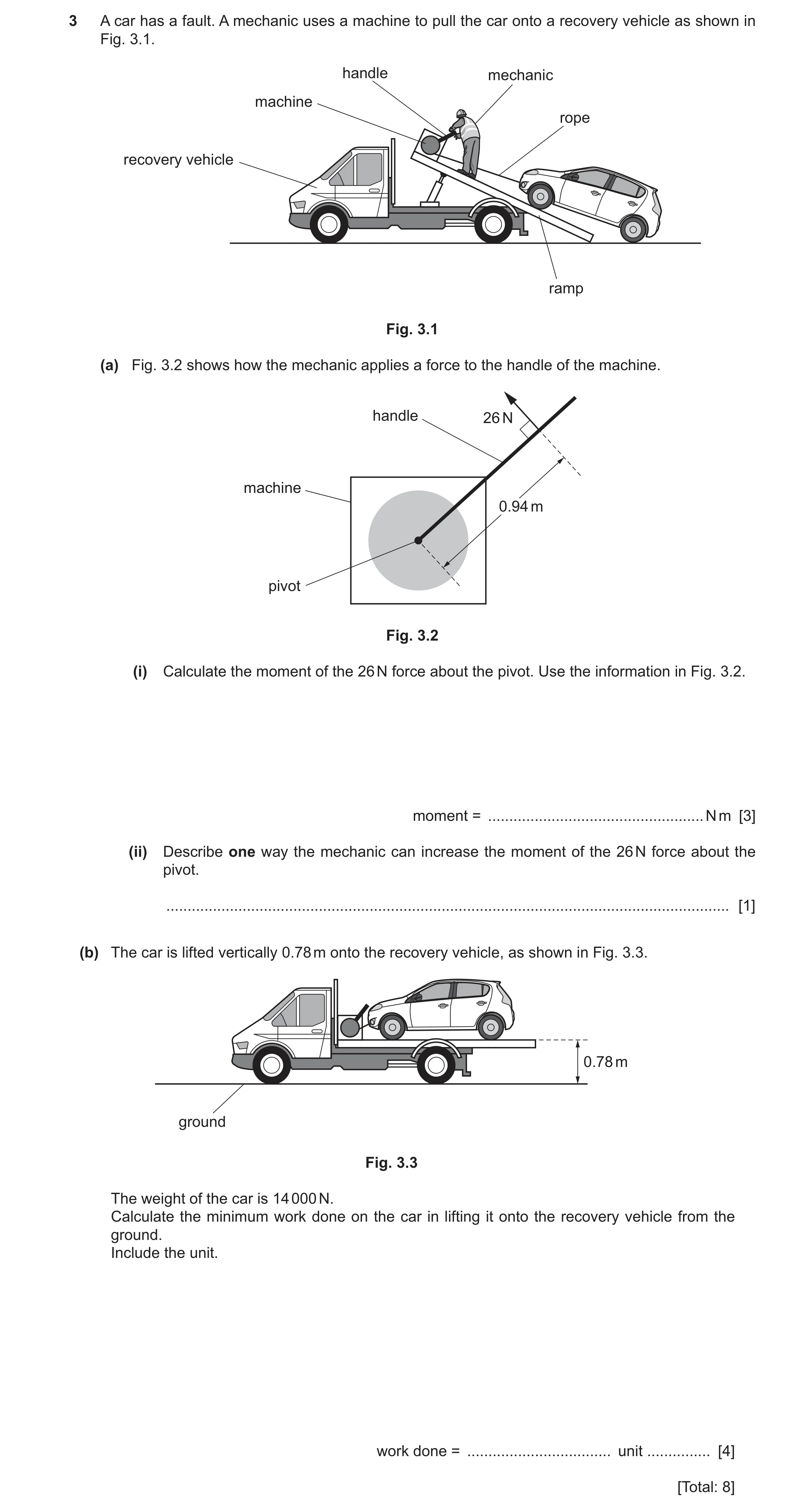
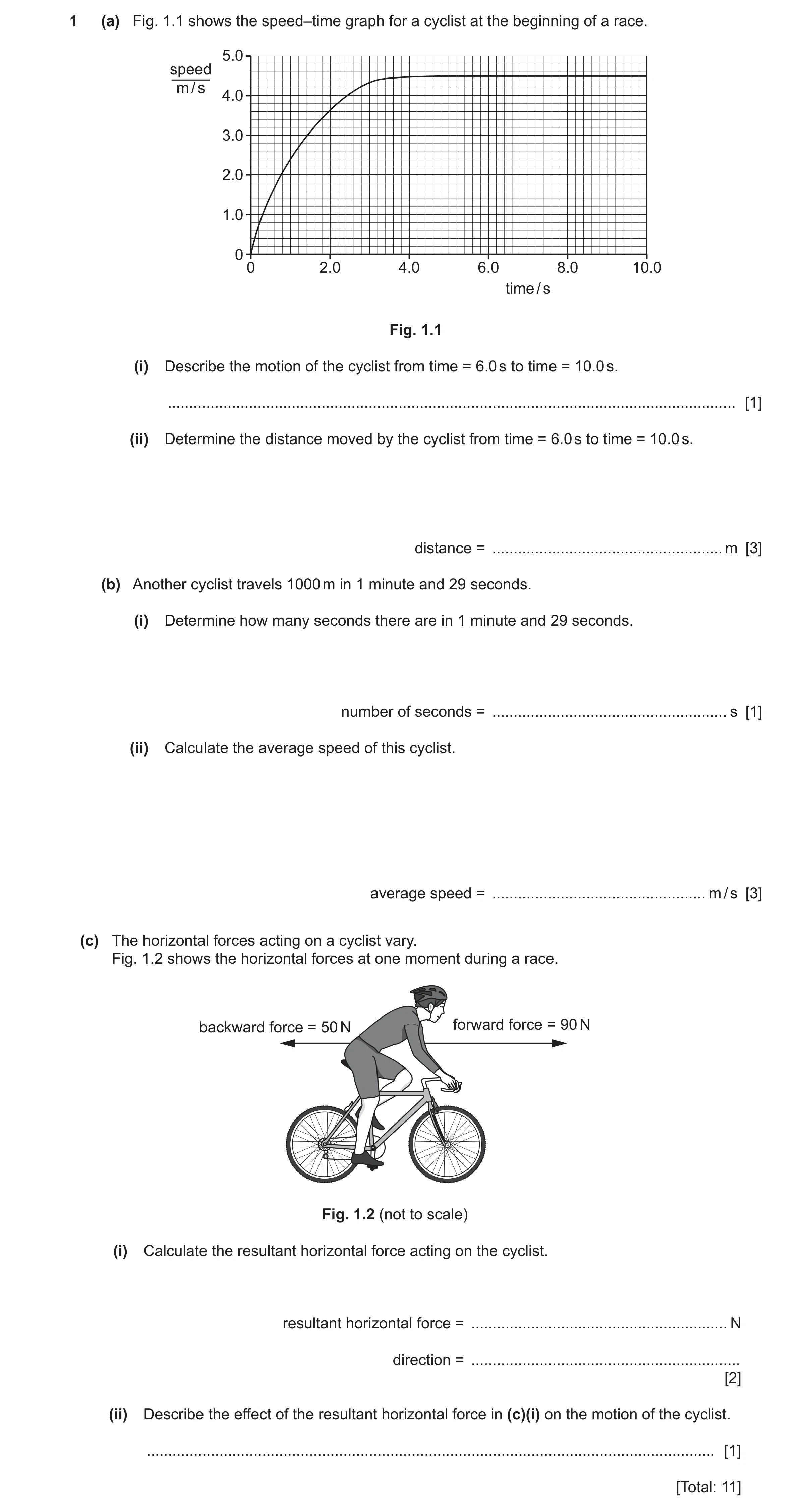
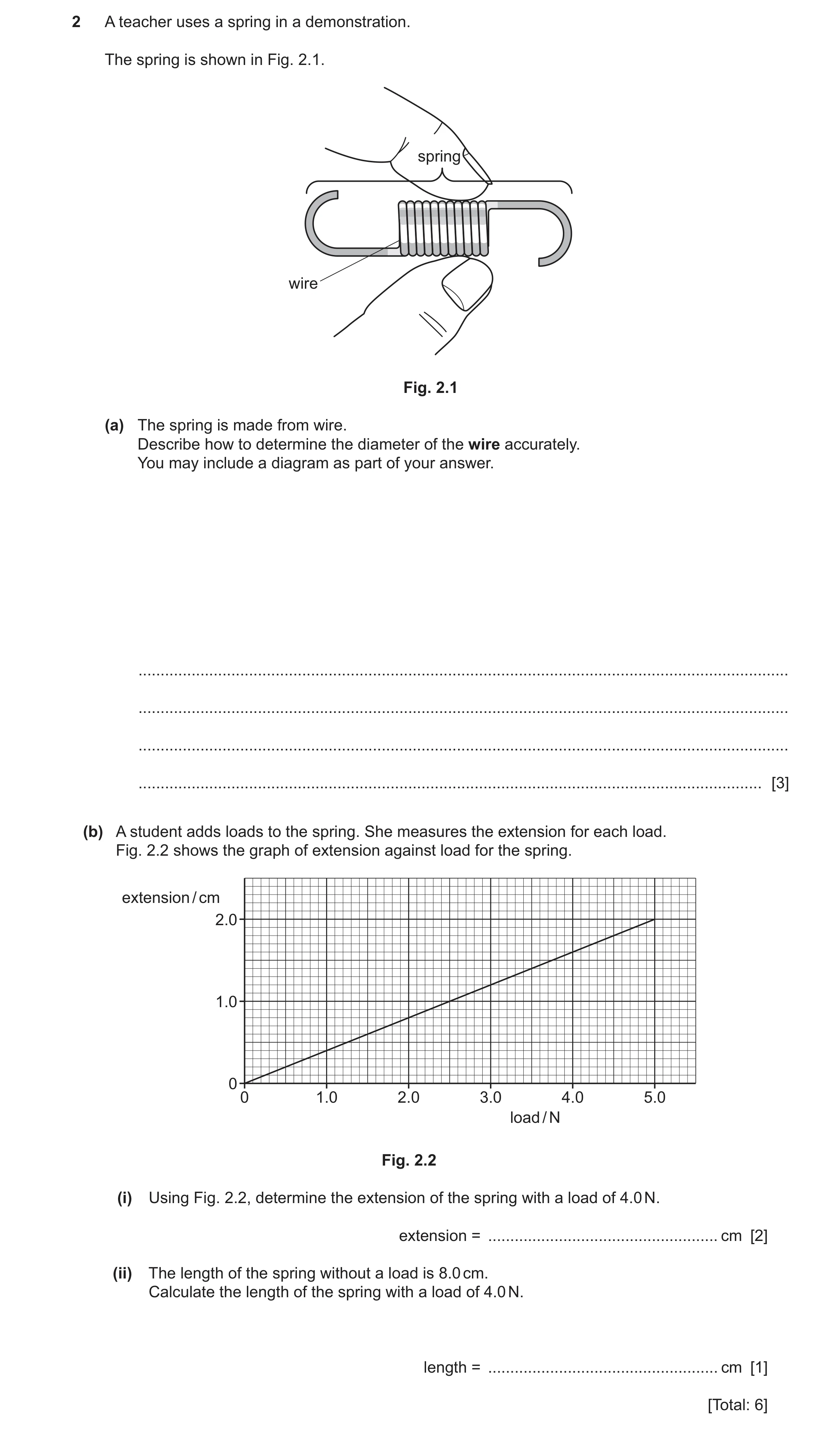
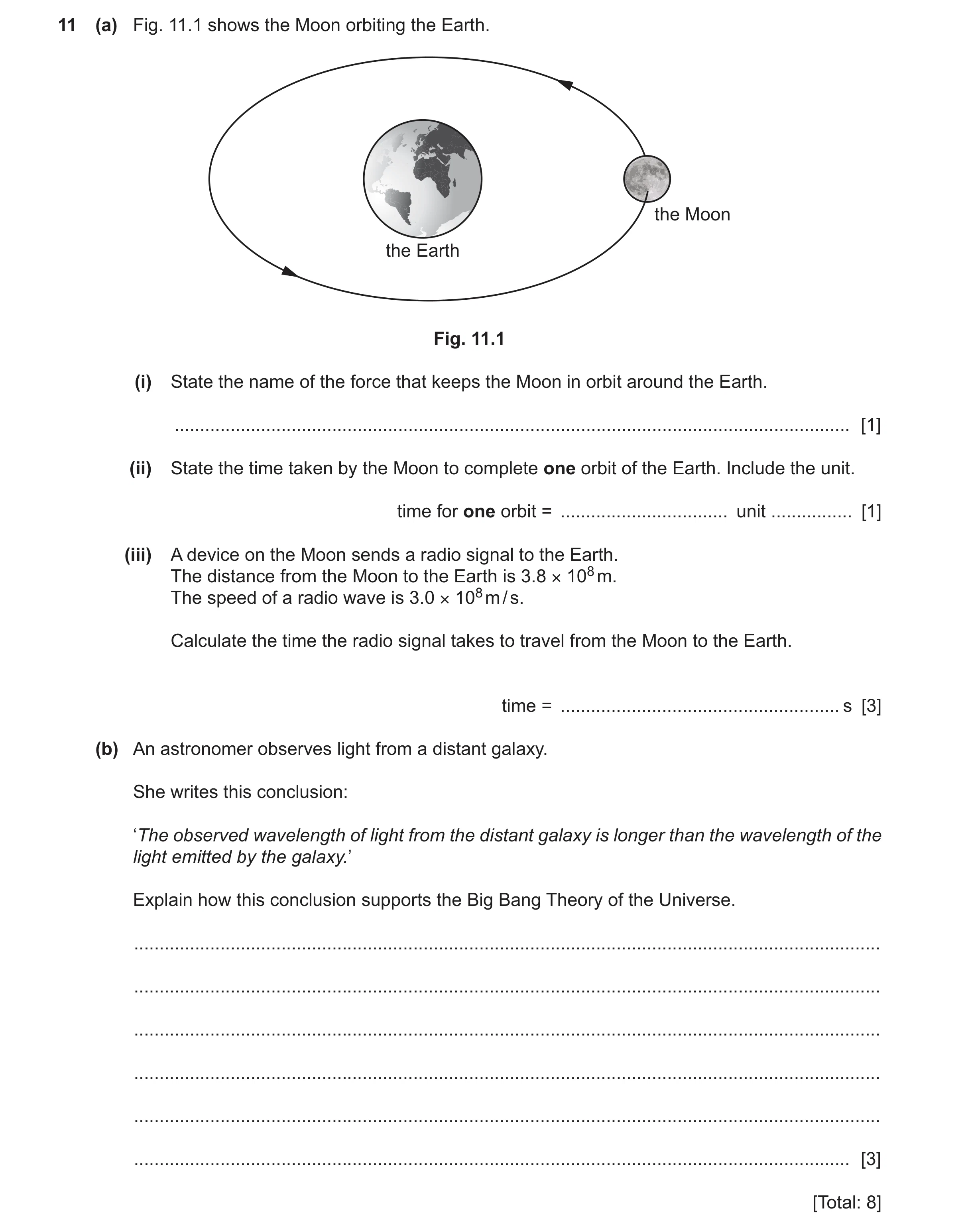 81 / 97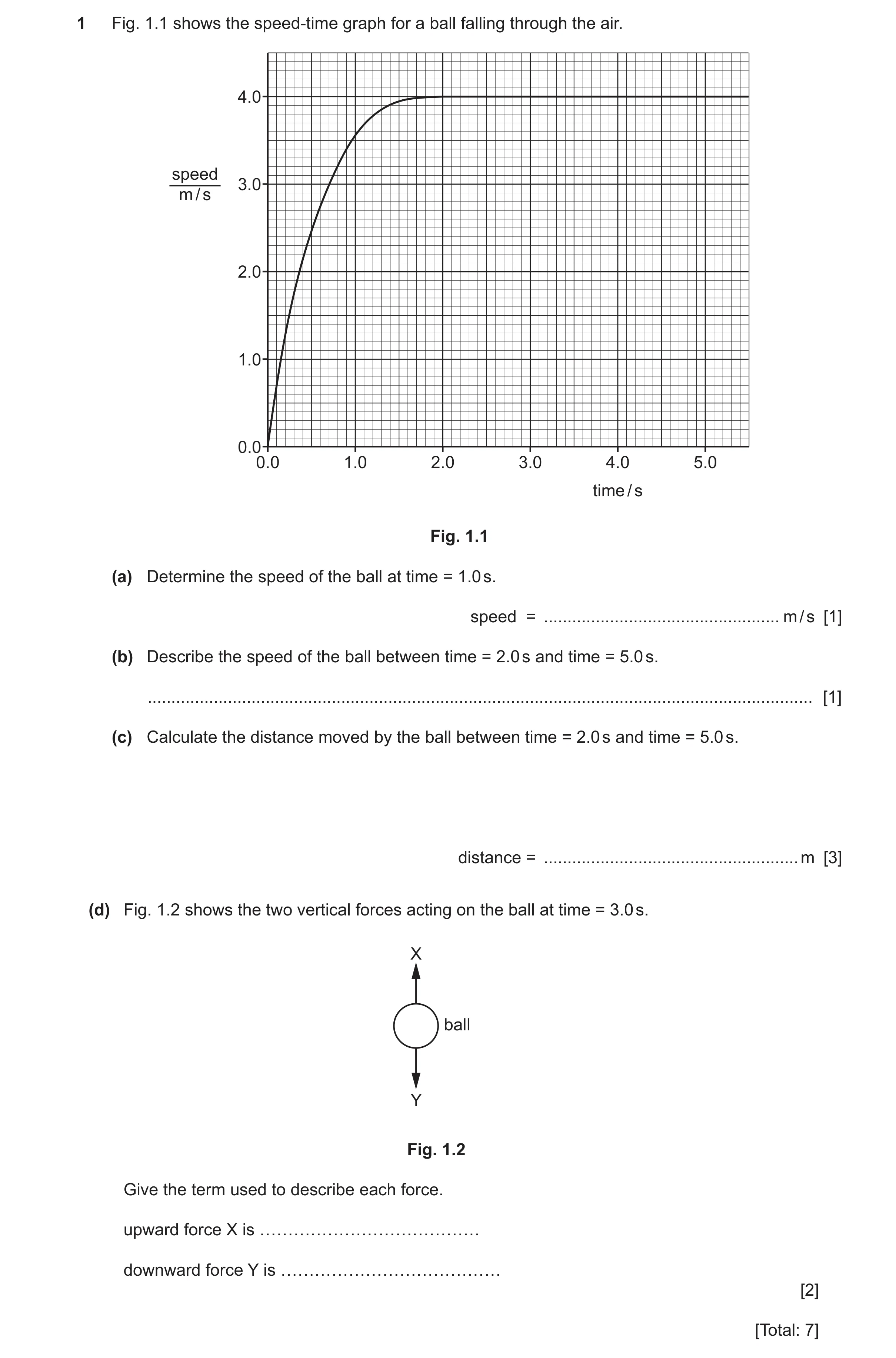
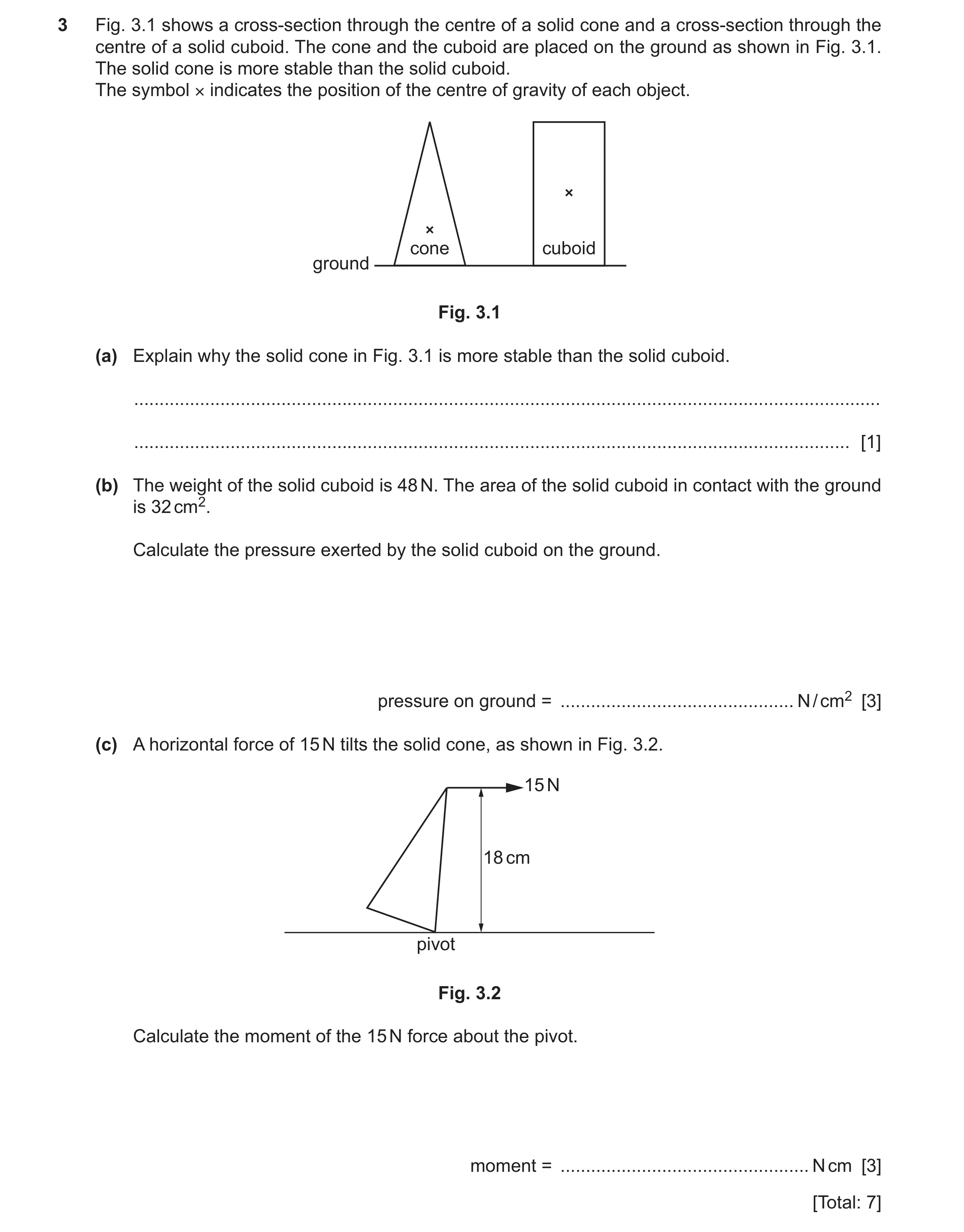 84 / 97
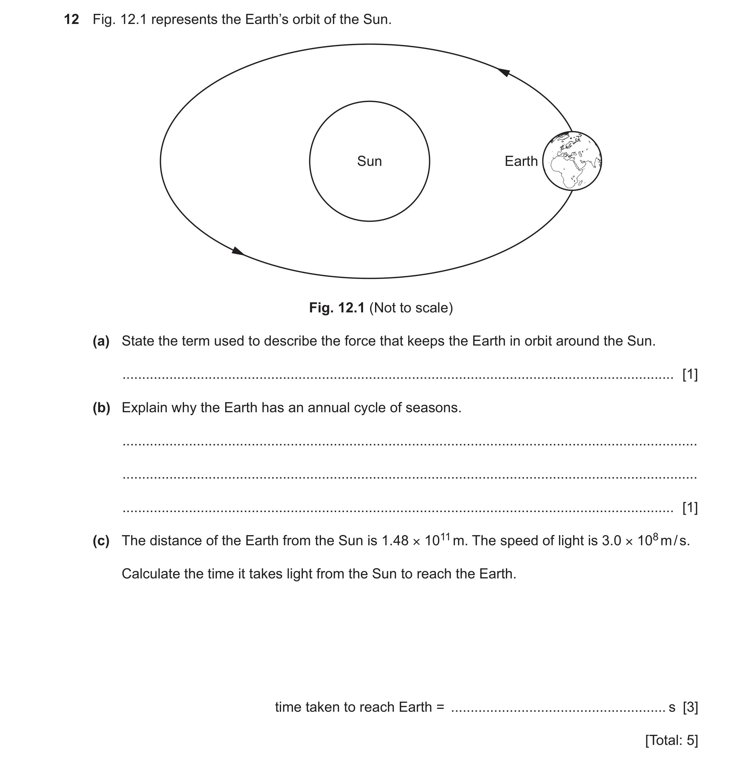 85 / 97
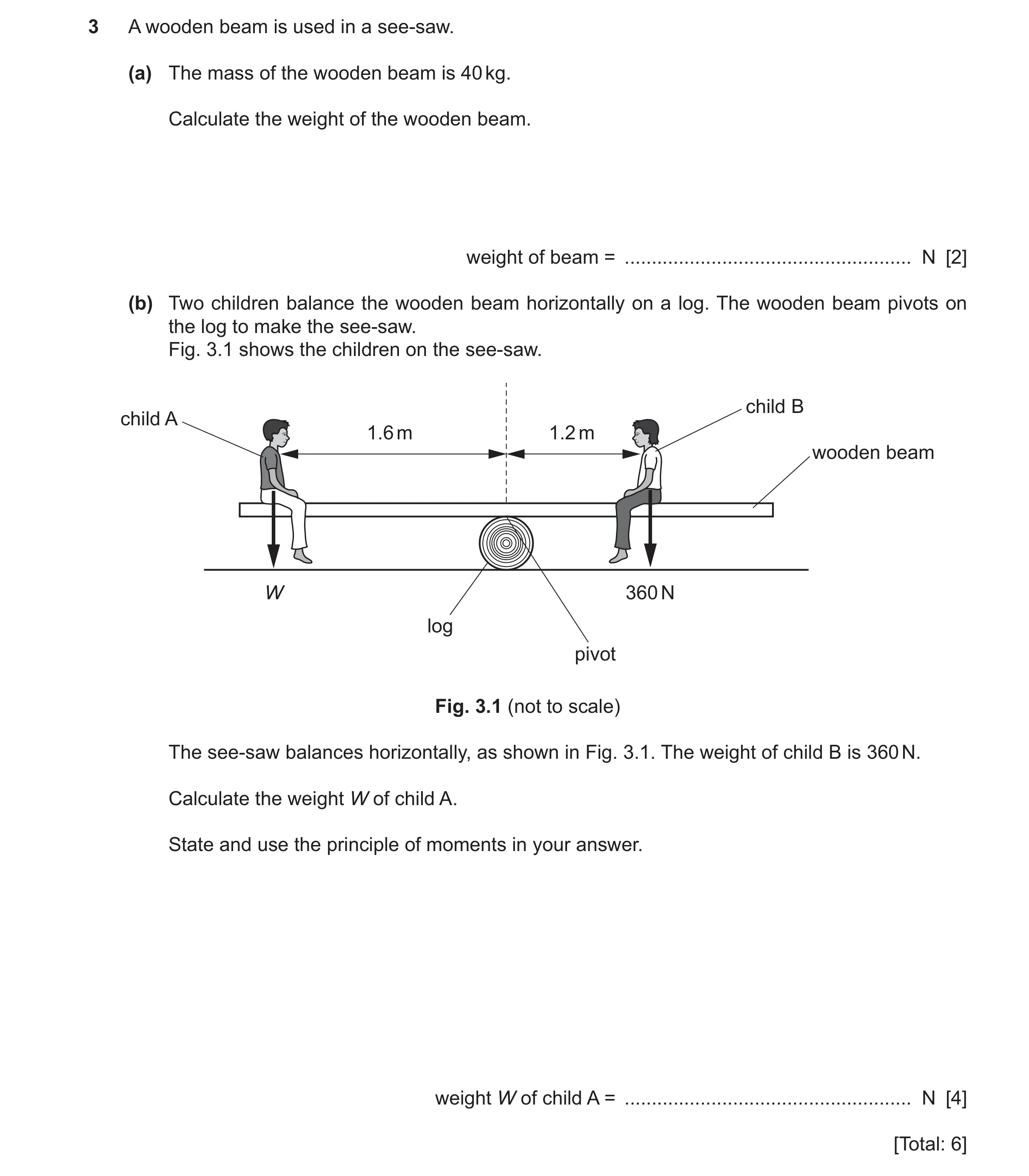 86 / 97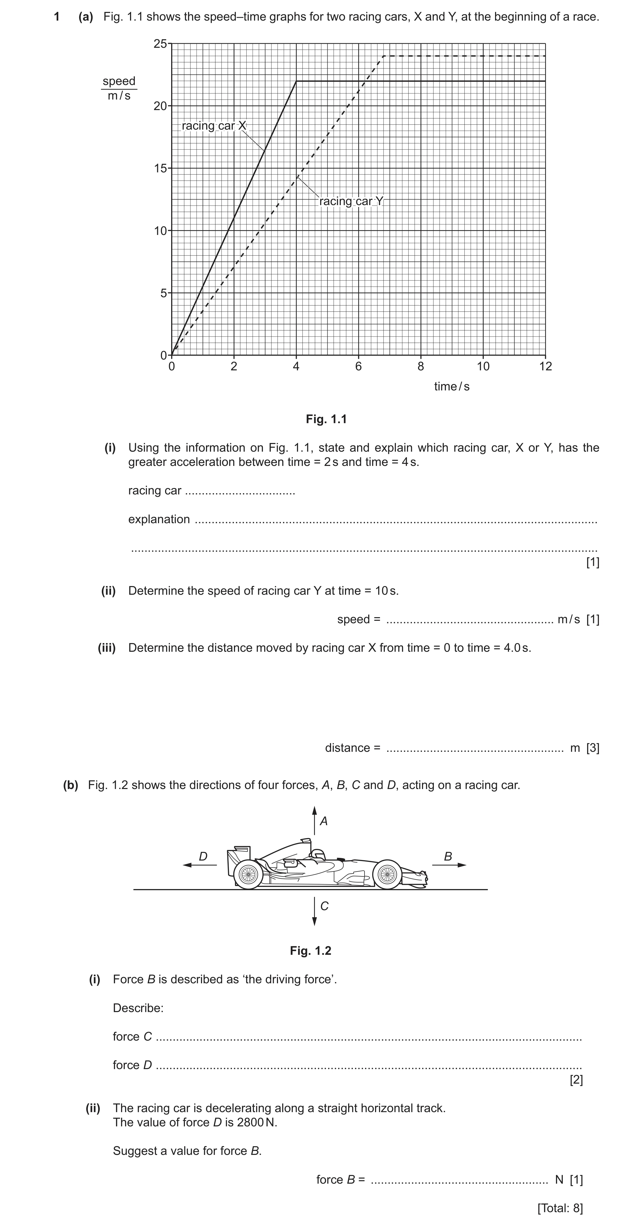
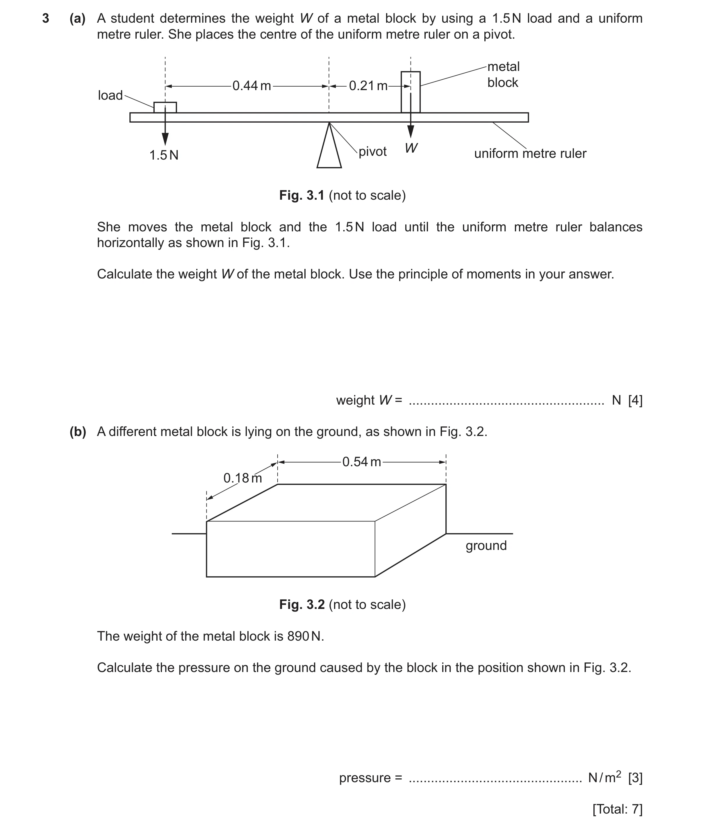 89 / 97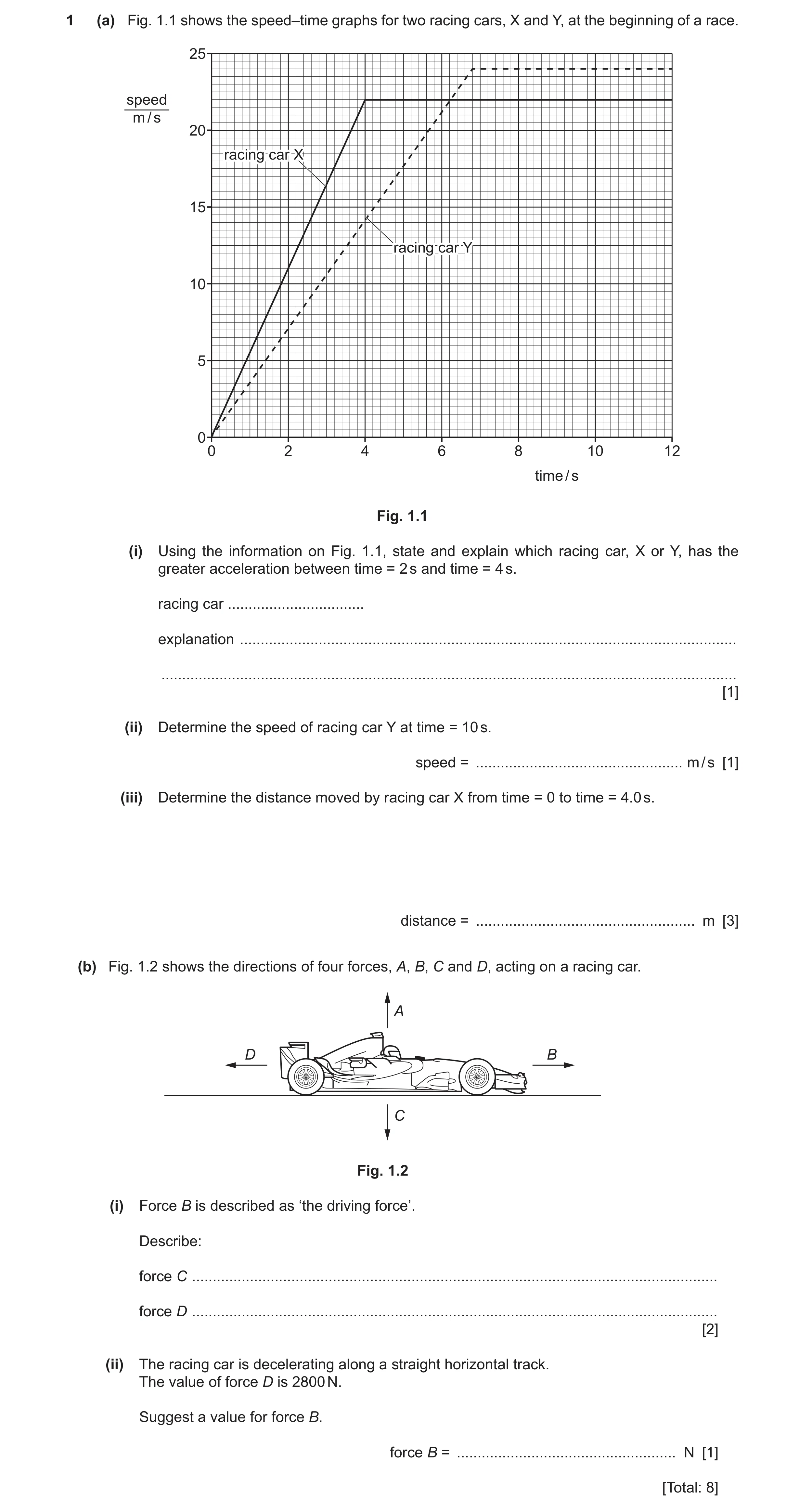
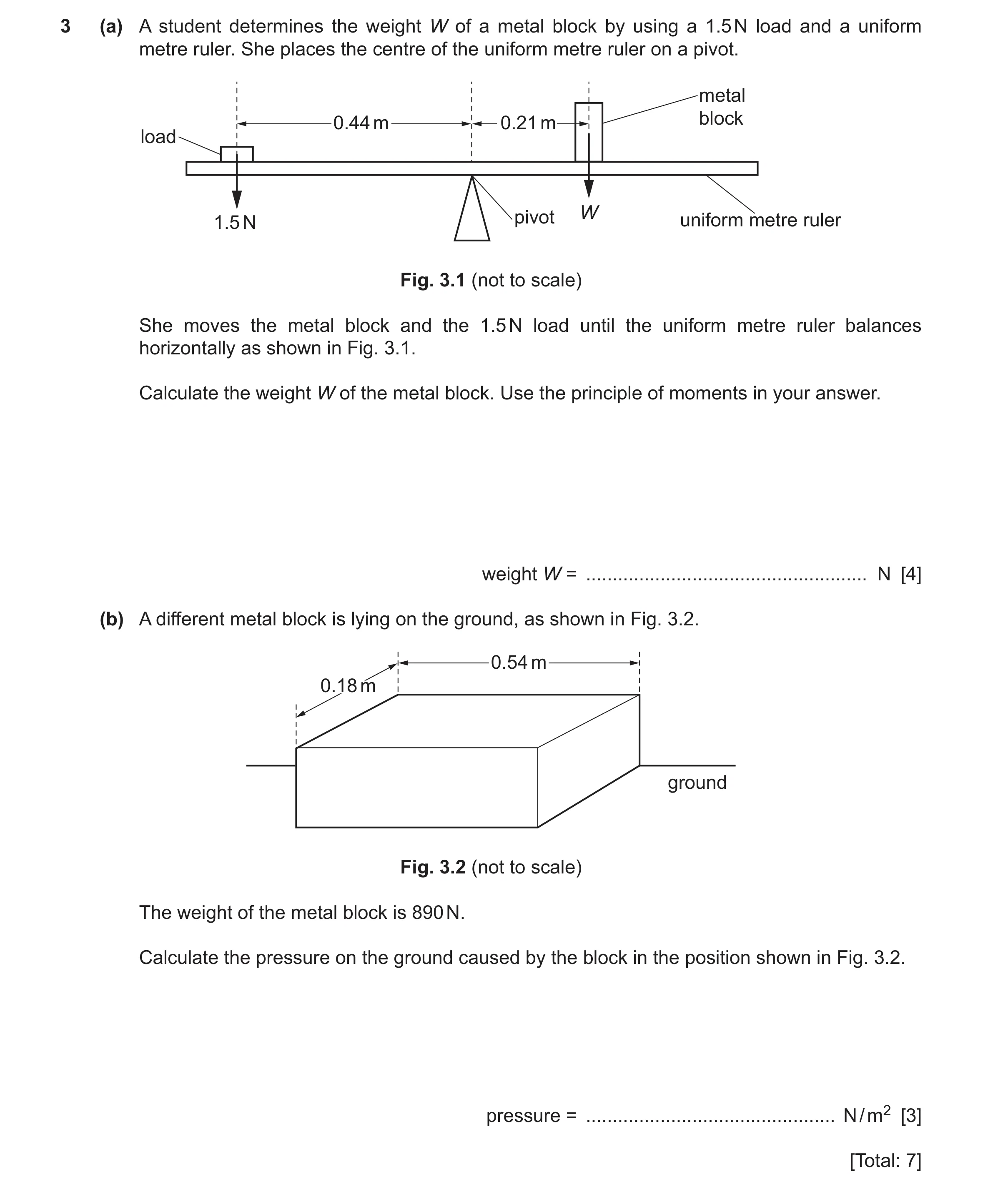 92 / 97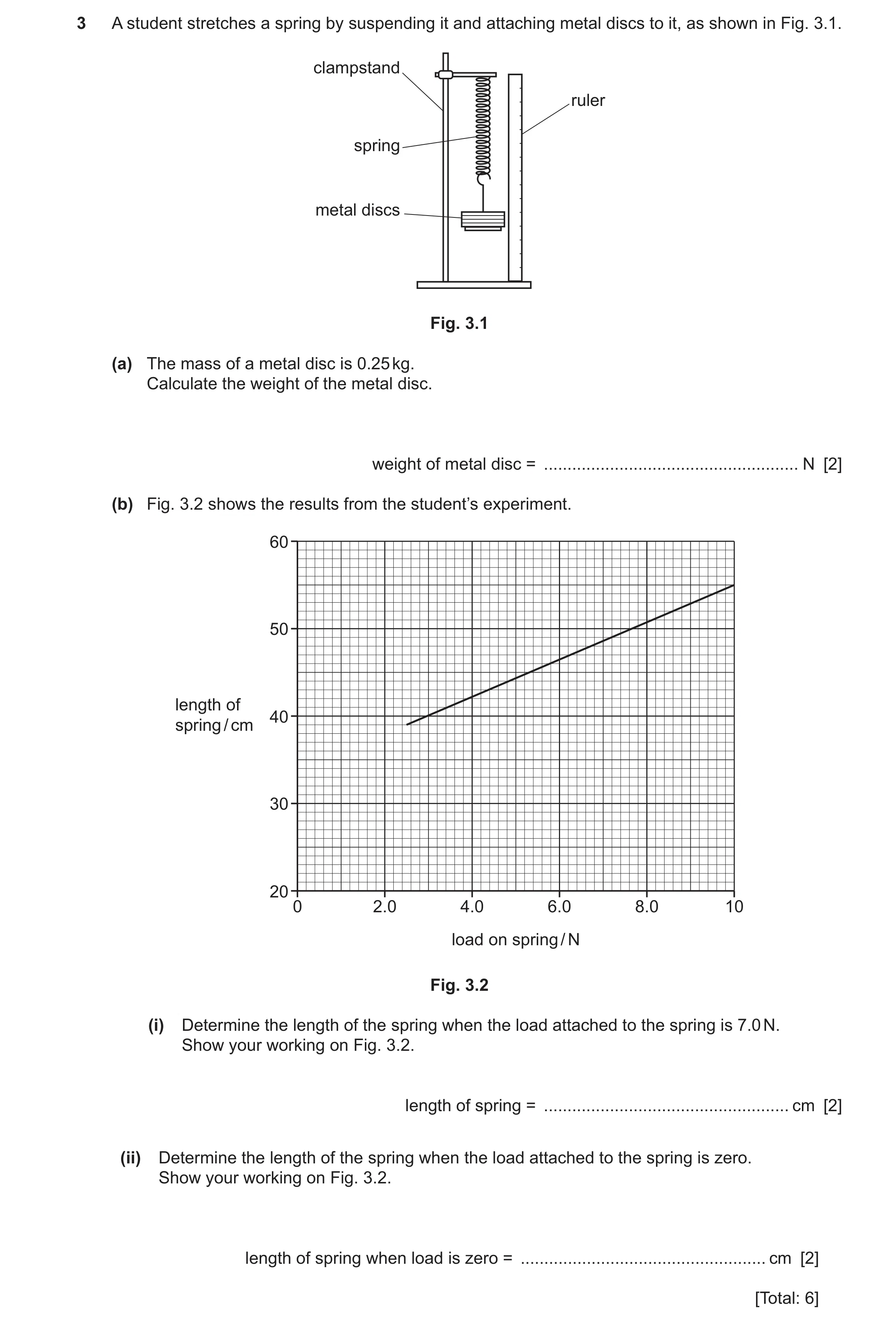
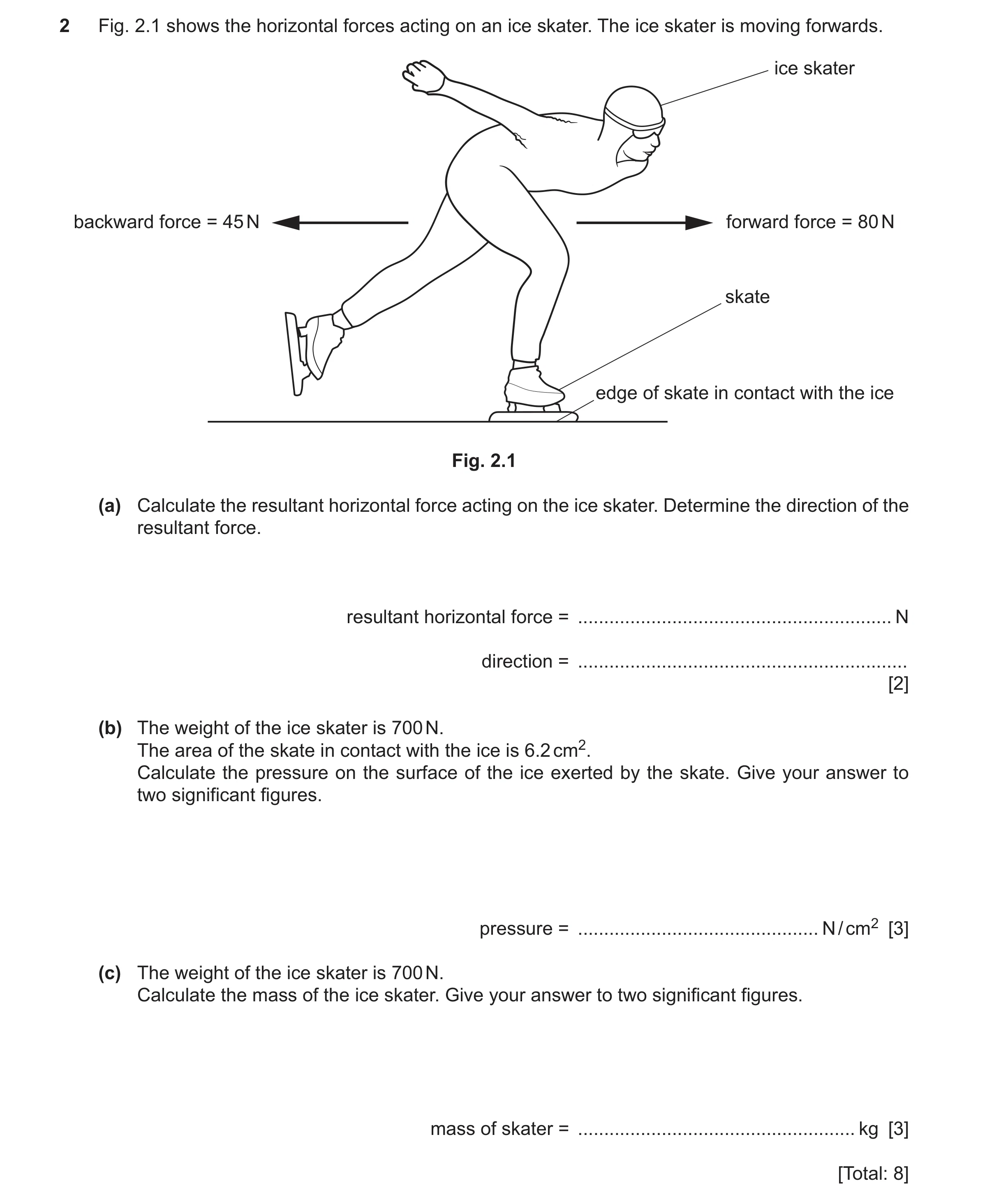 95 / 97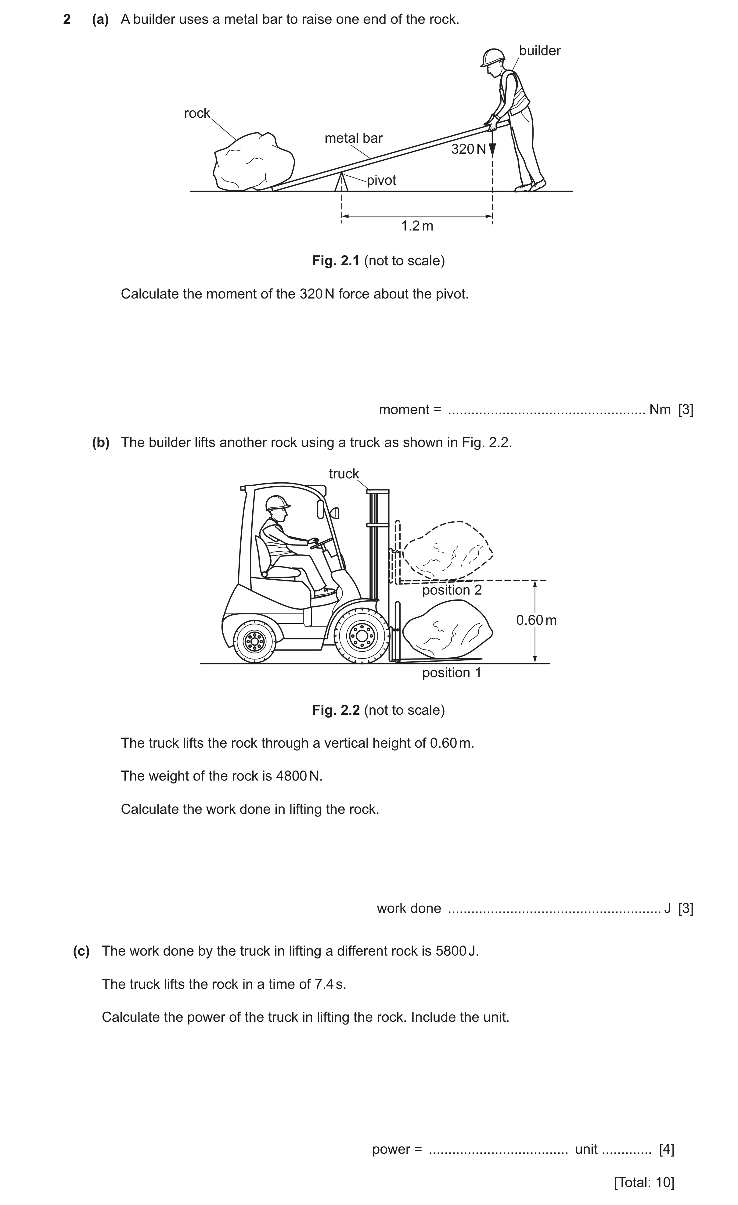
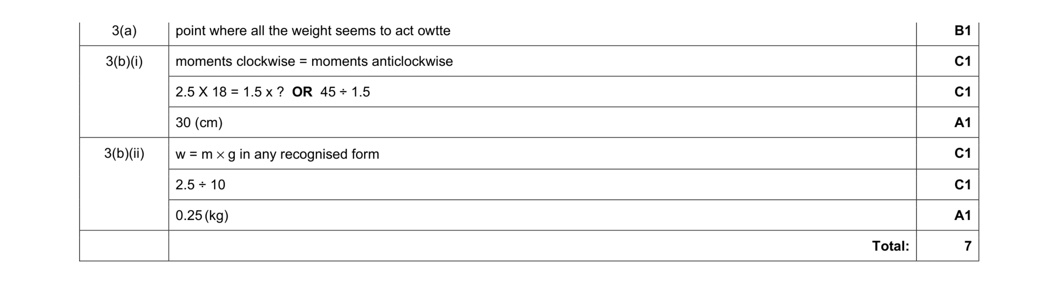 7
7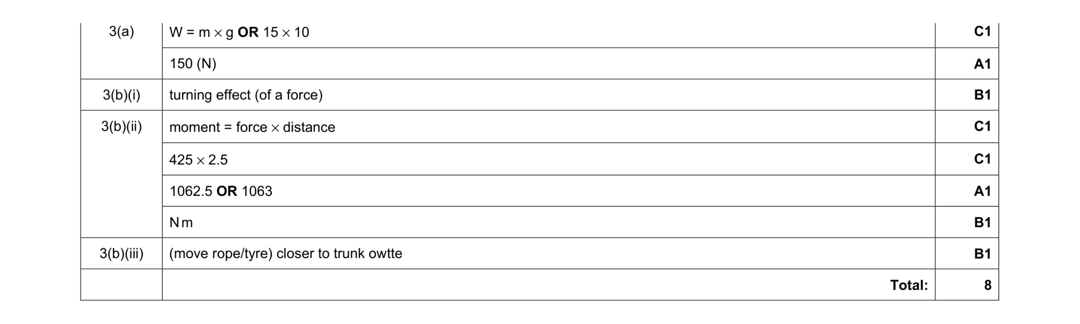 8
8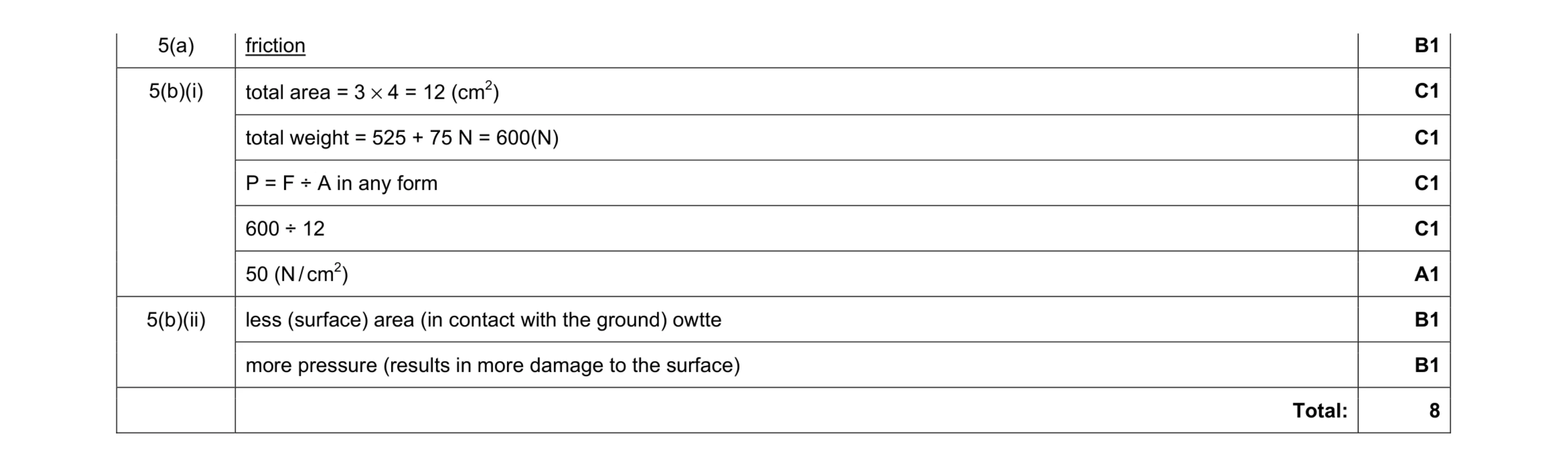 8
8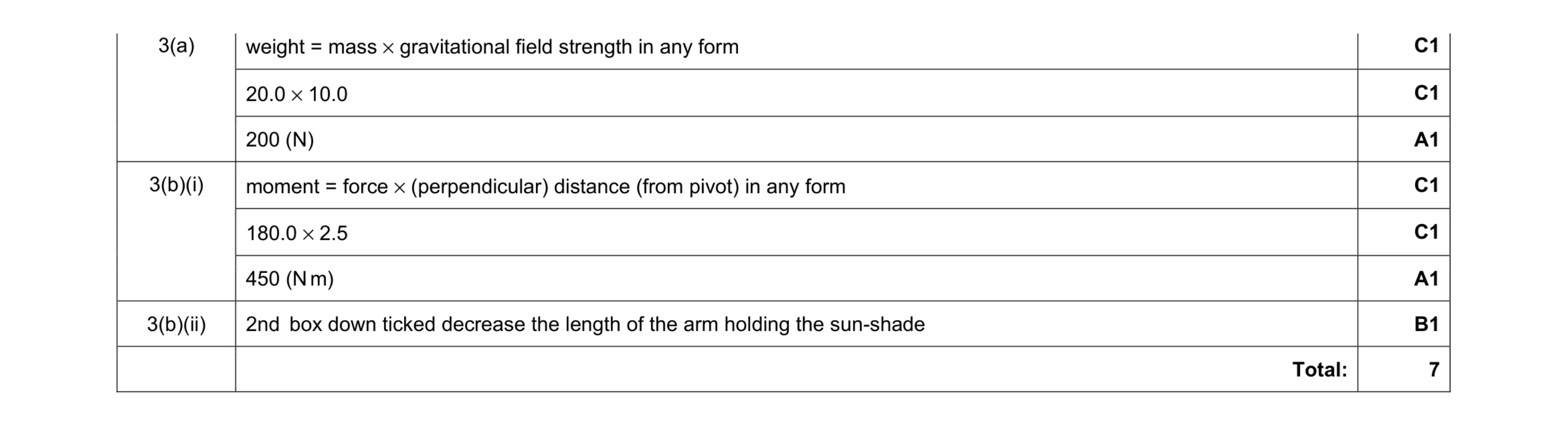 7
7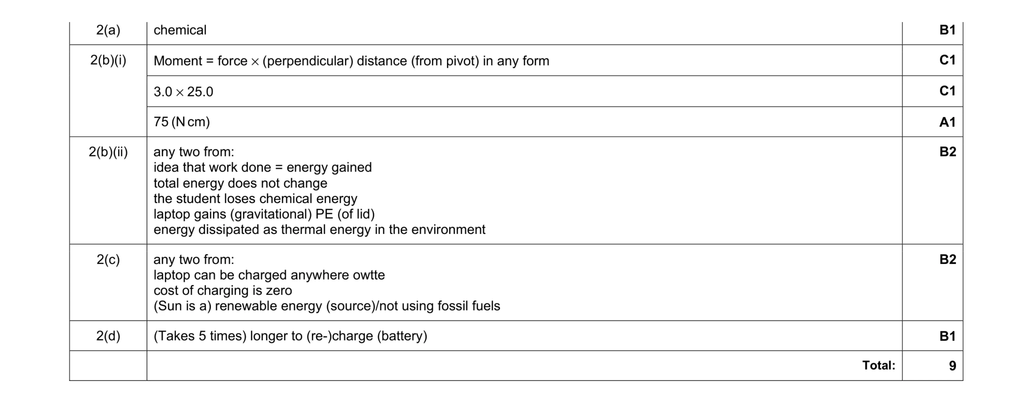 9
9 5
5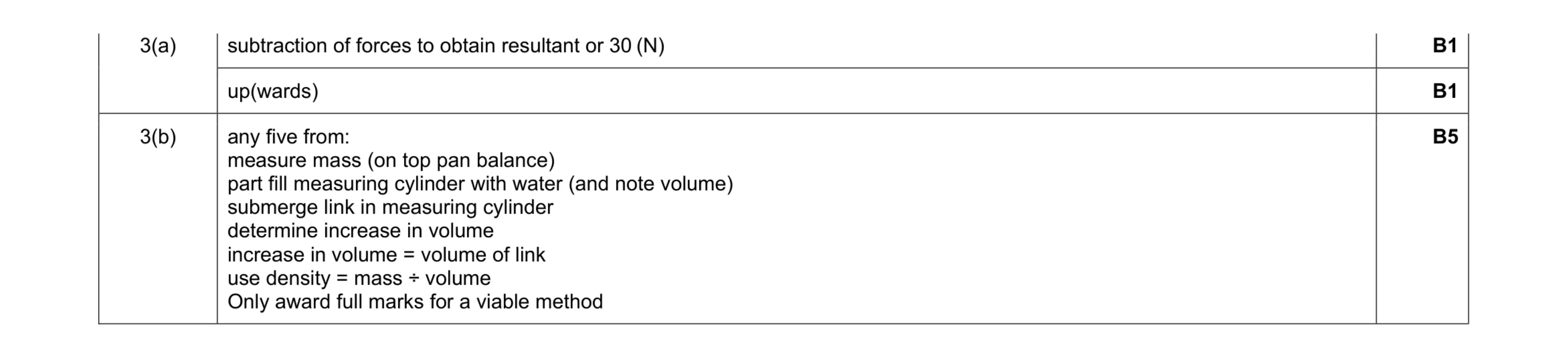 7
7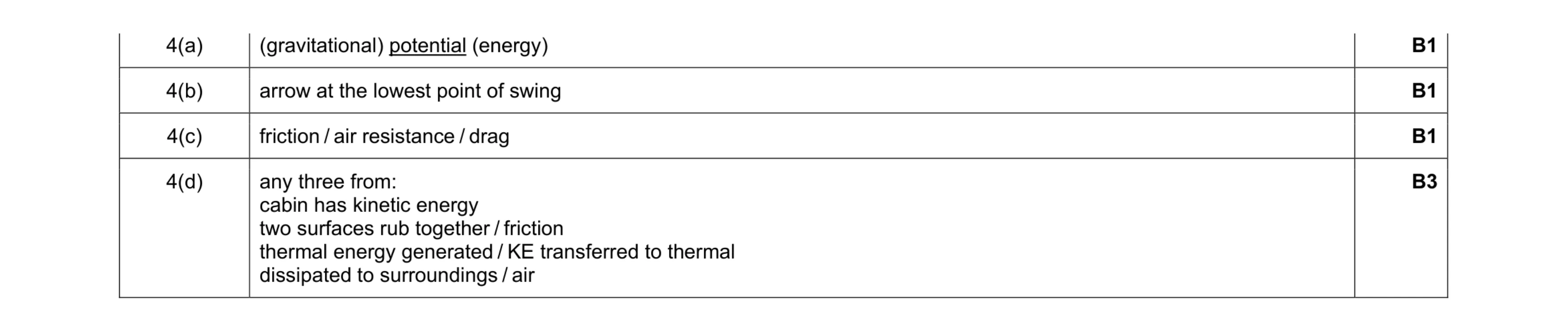 6
6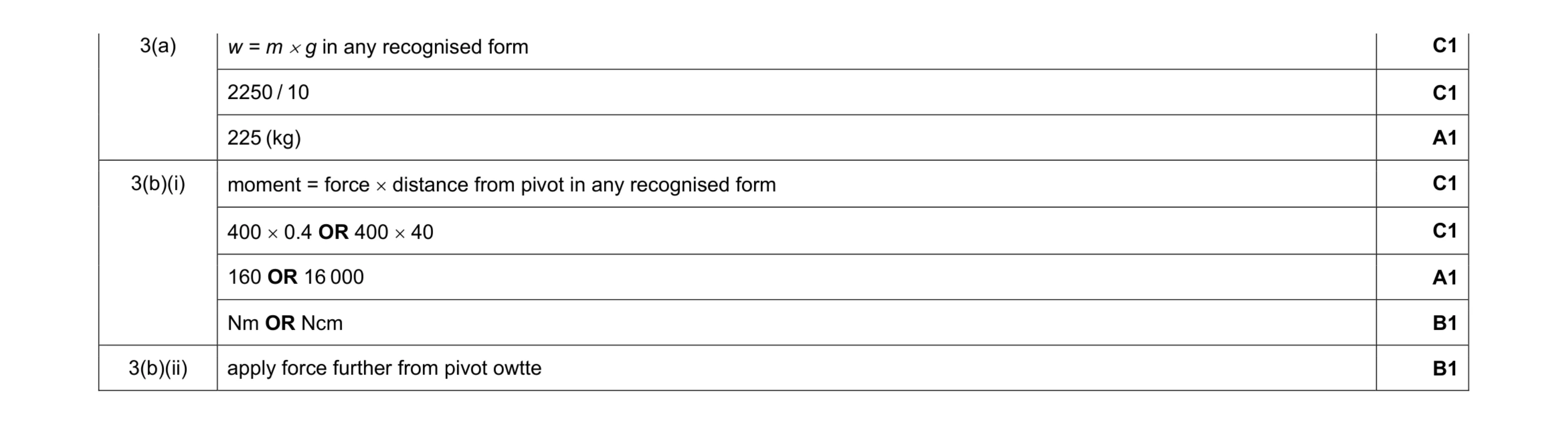 8
8 4
4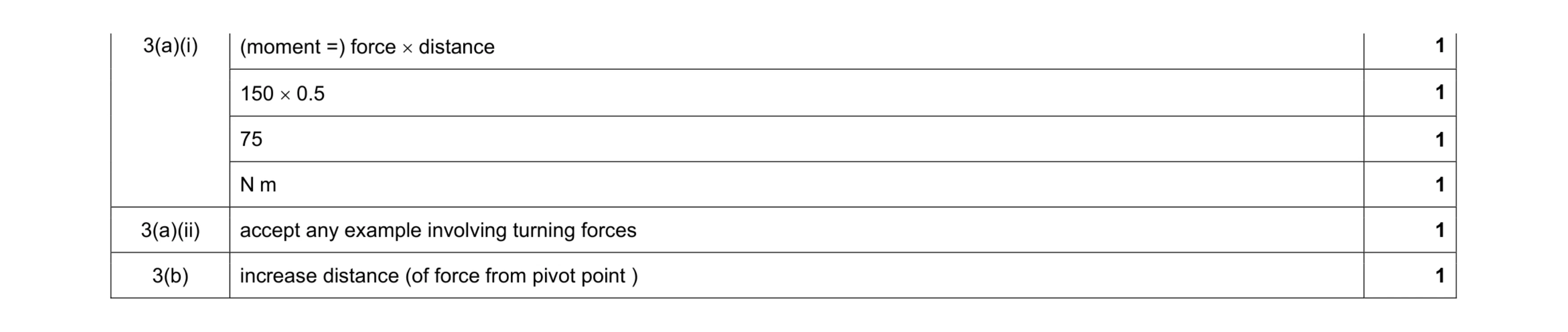 6
6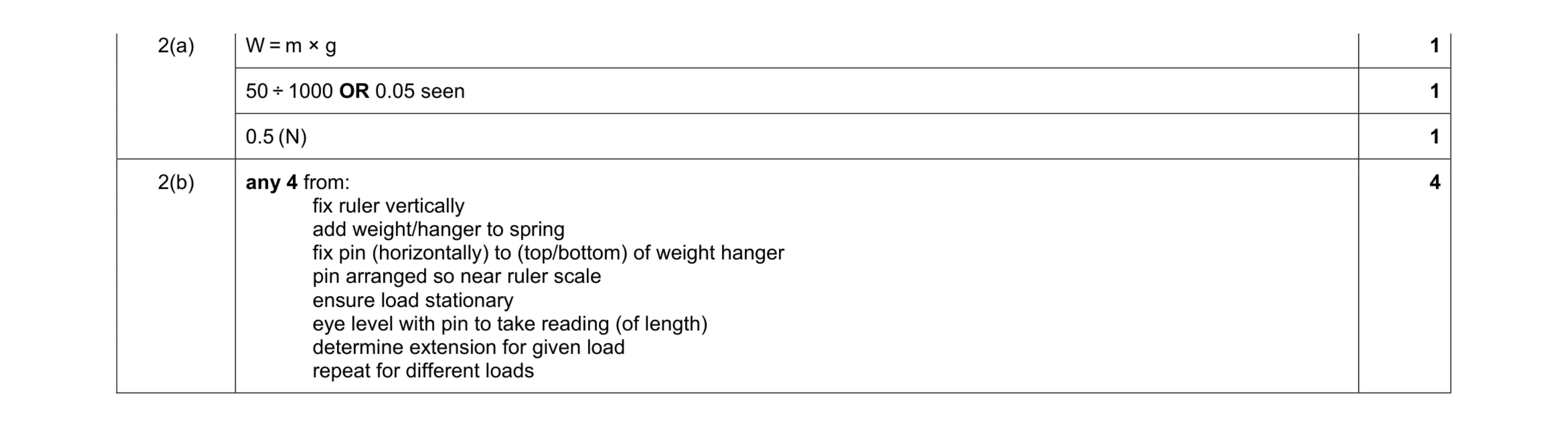 7
7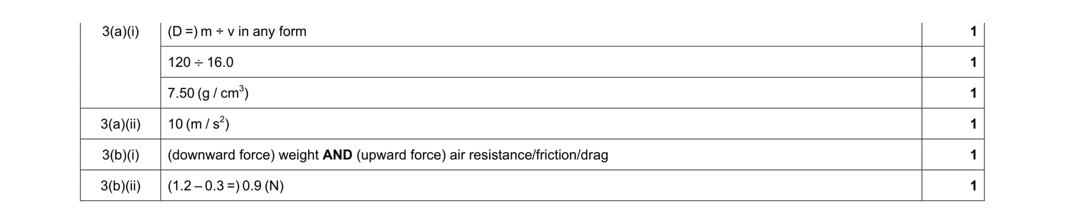 6
6 4
4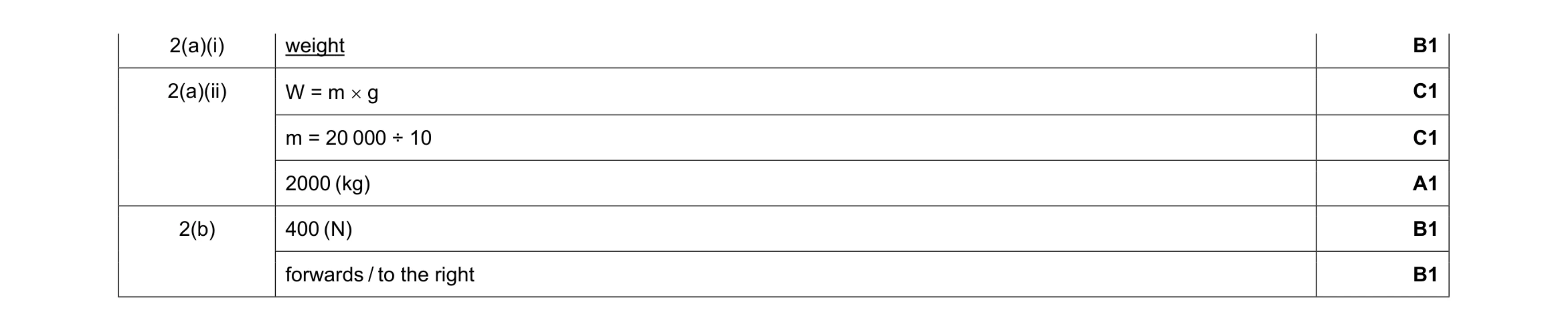 6
6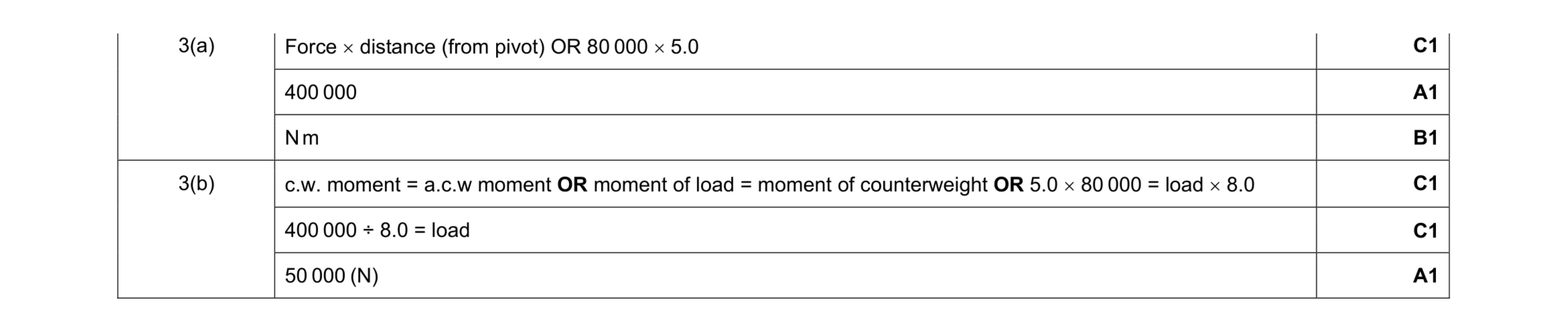 6
6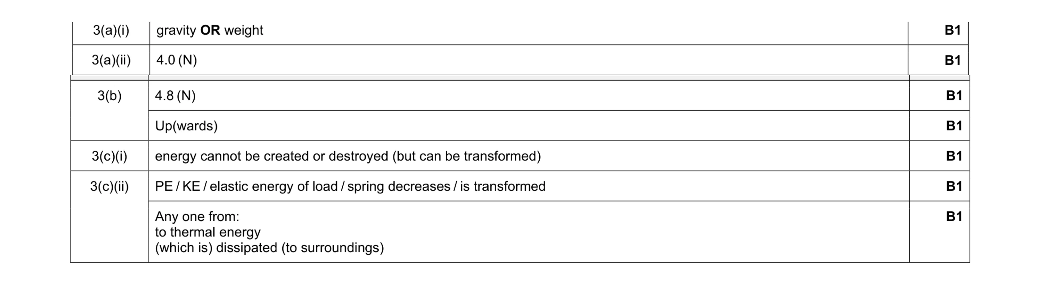 7
7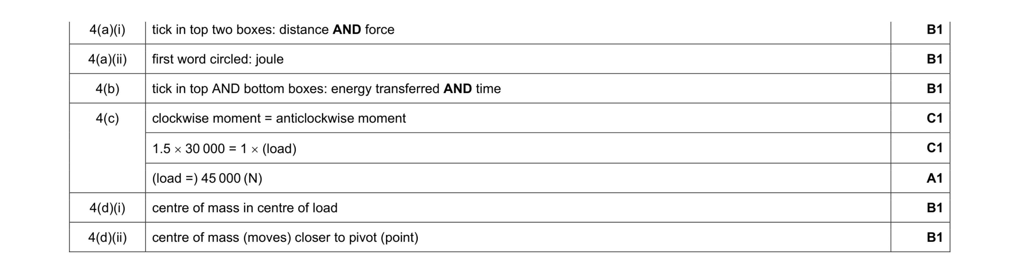 8
8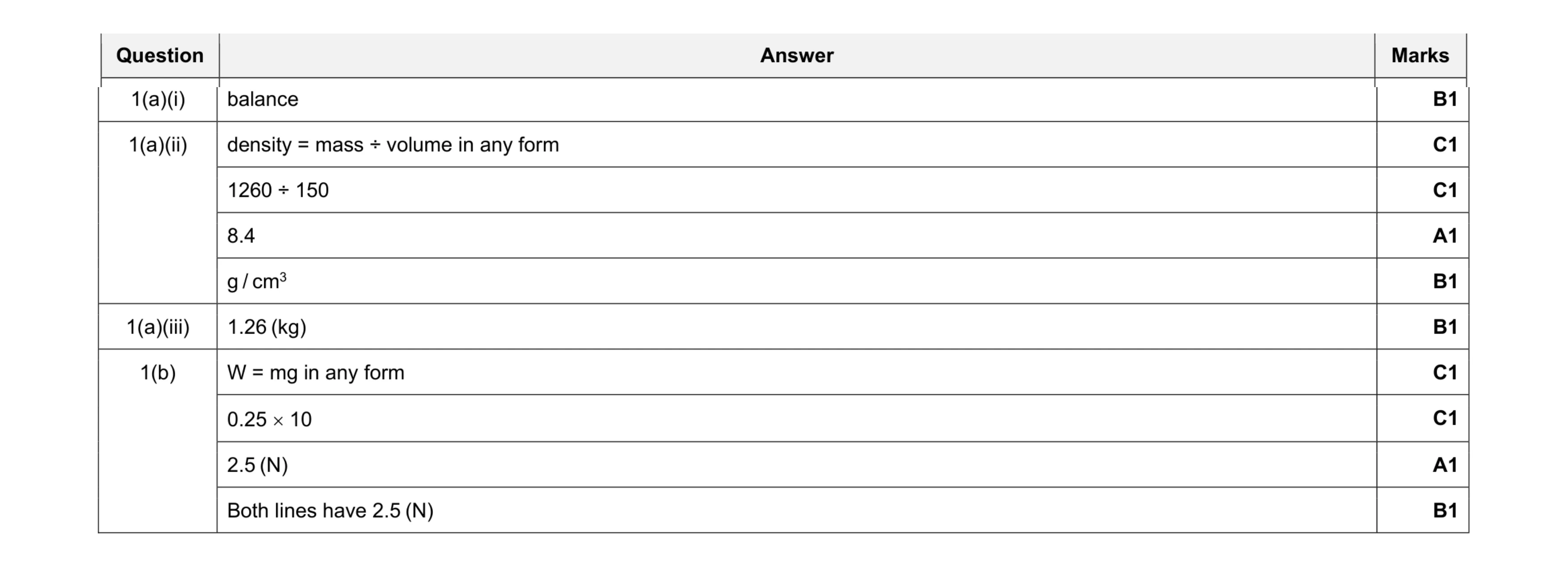 10
10 5
5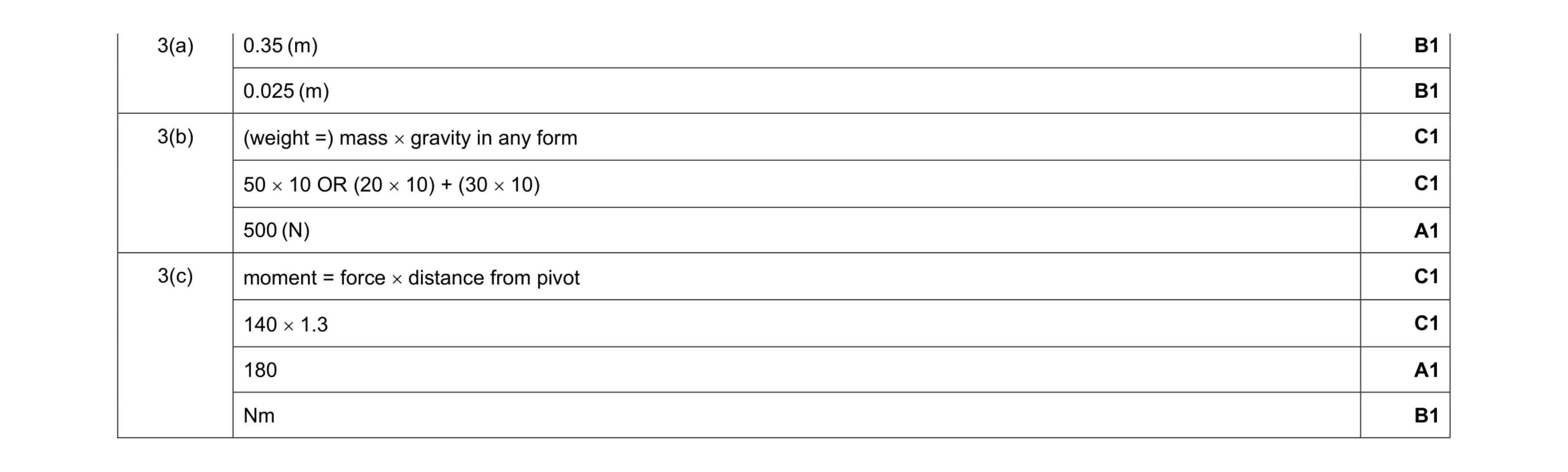 9
9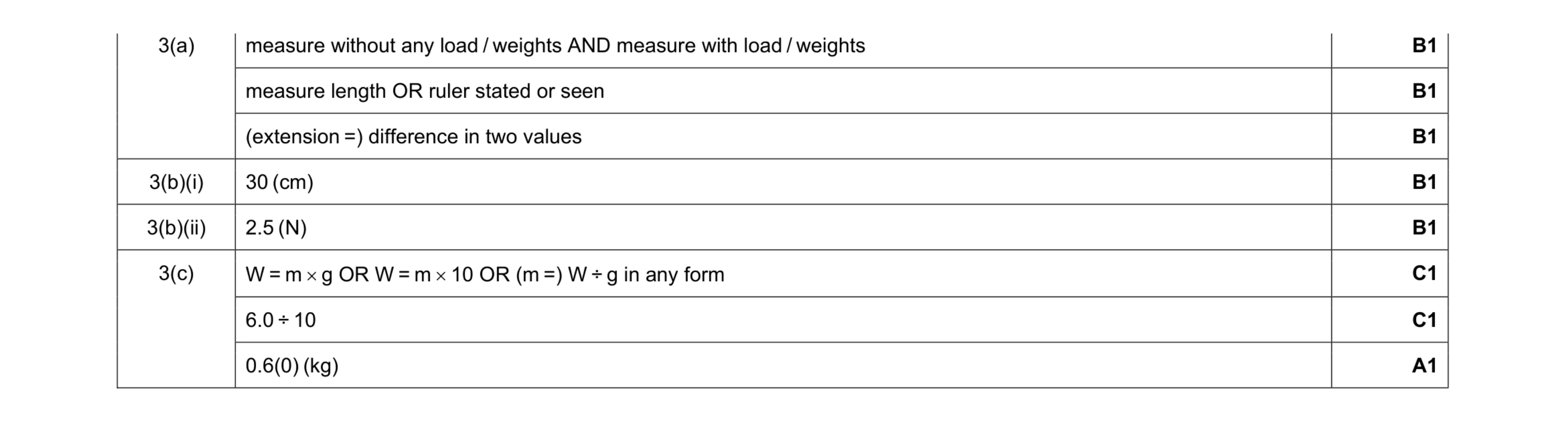 8
8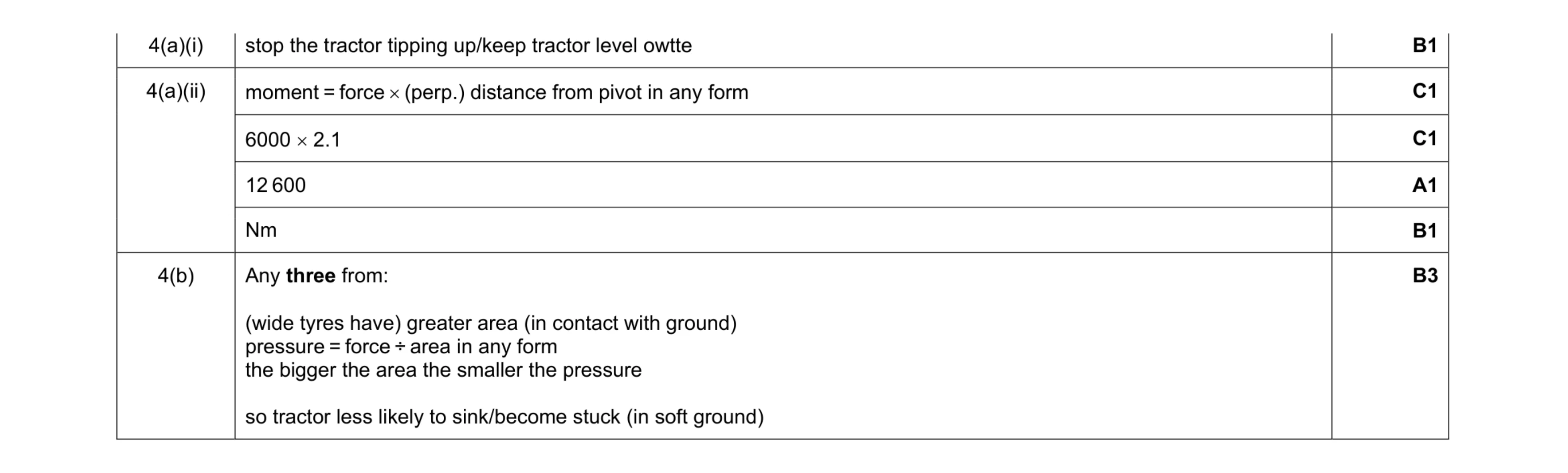 8
8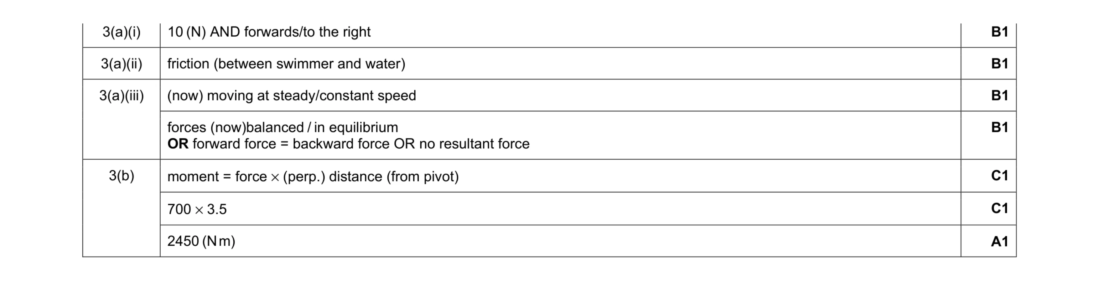 7
7 4
4 4
4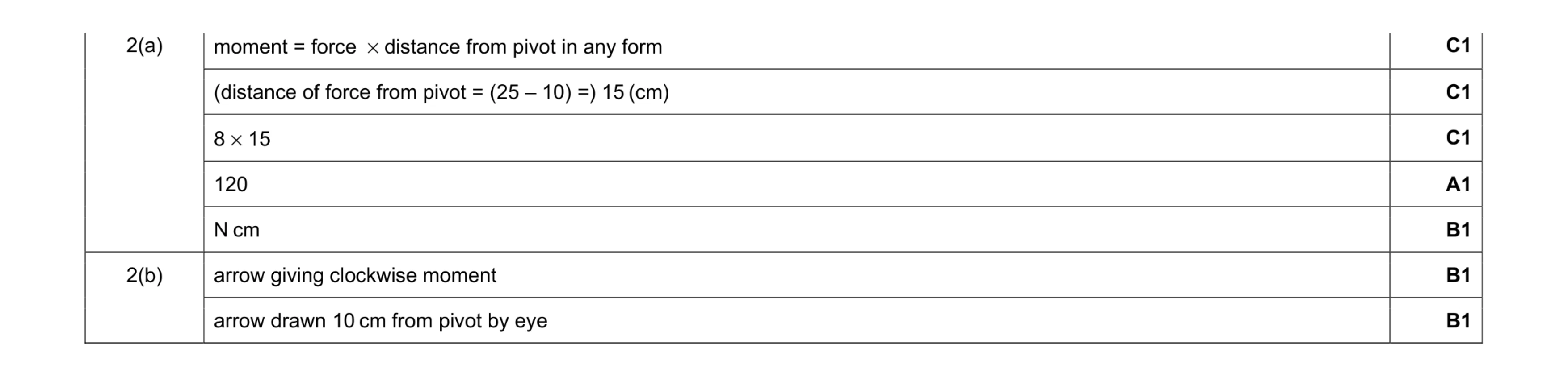 7
7 5
5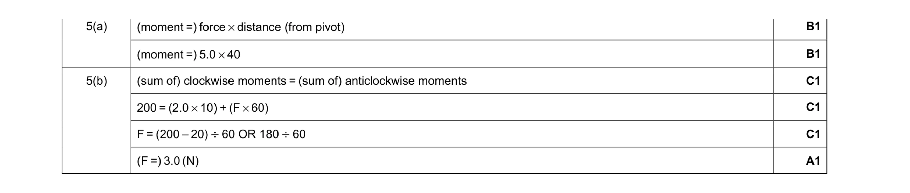 6
6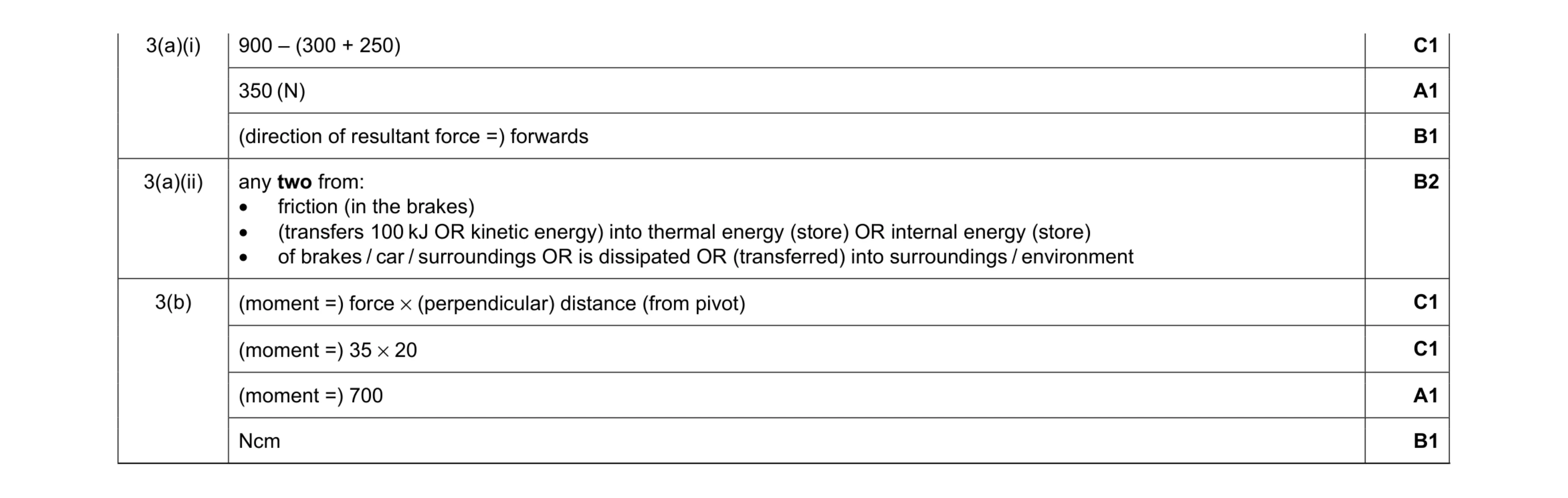 9
9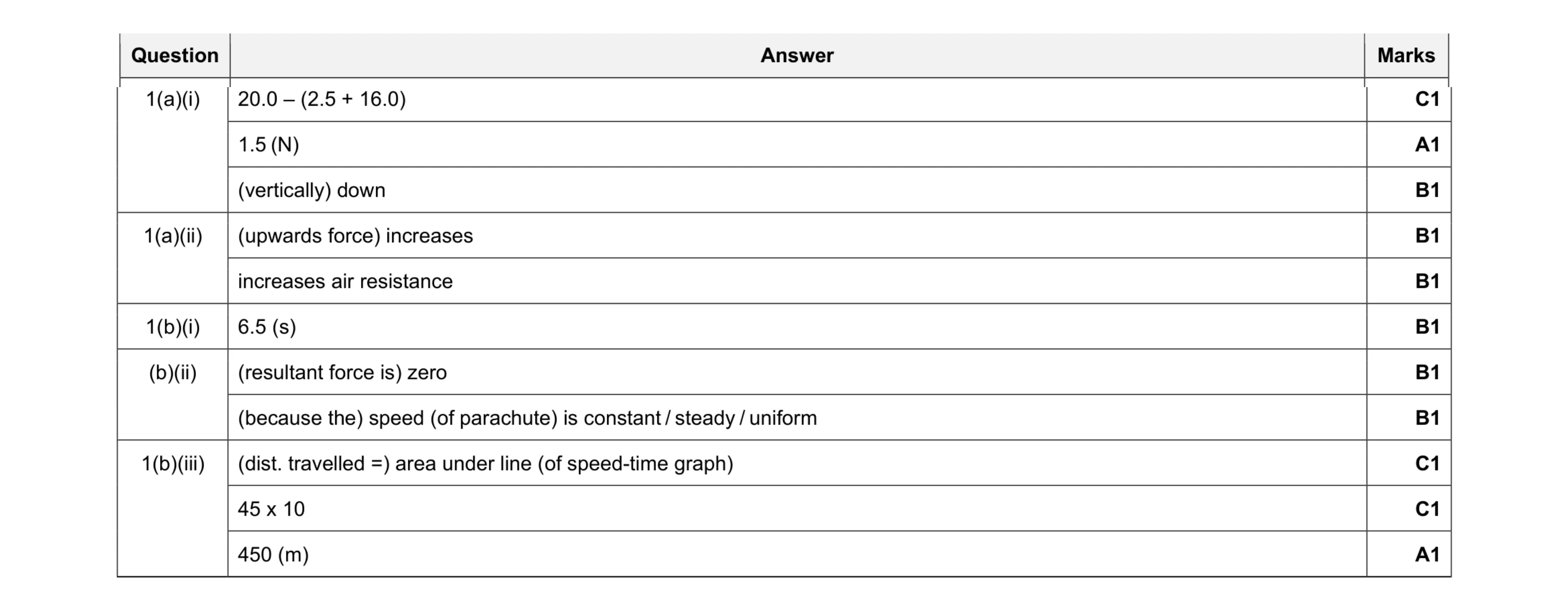 11
11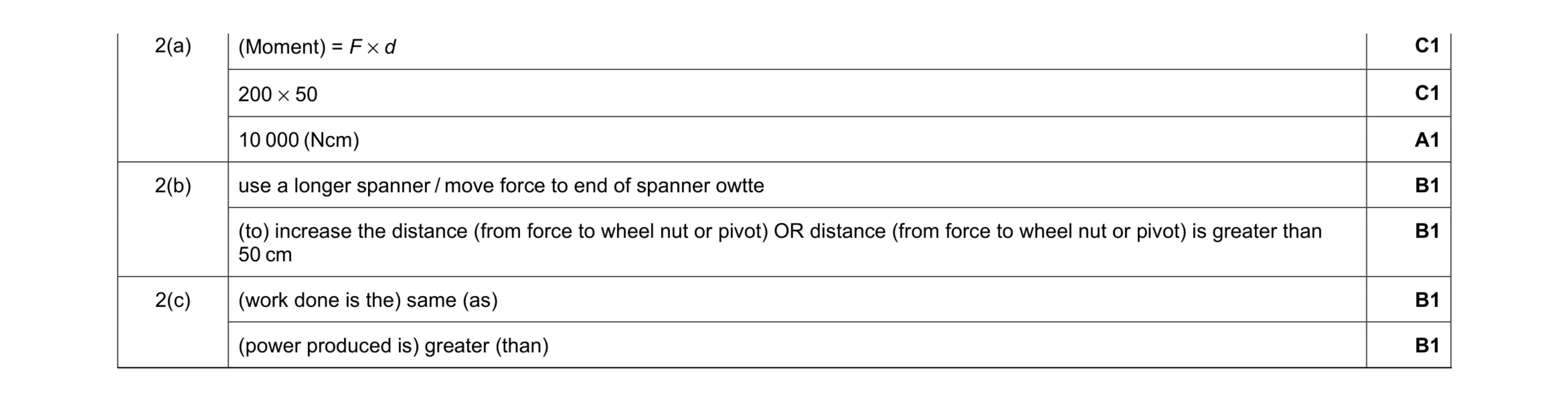 7
7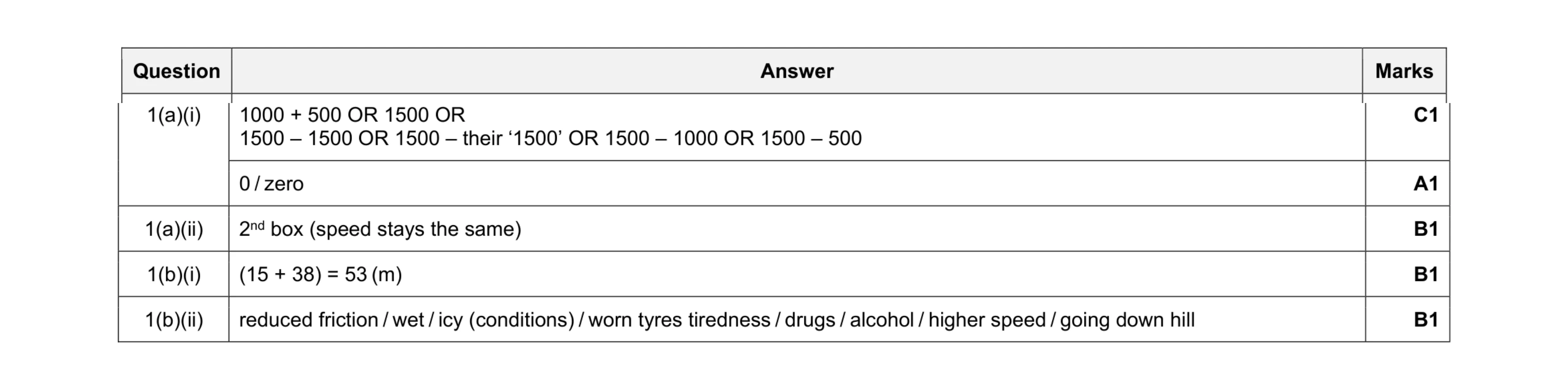 5
5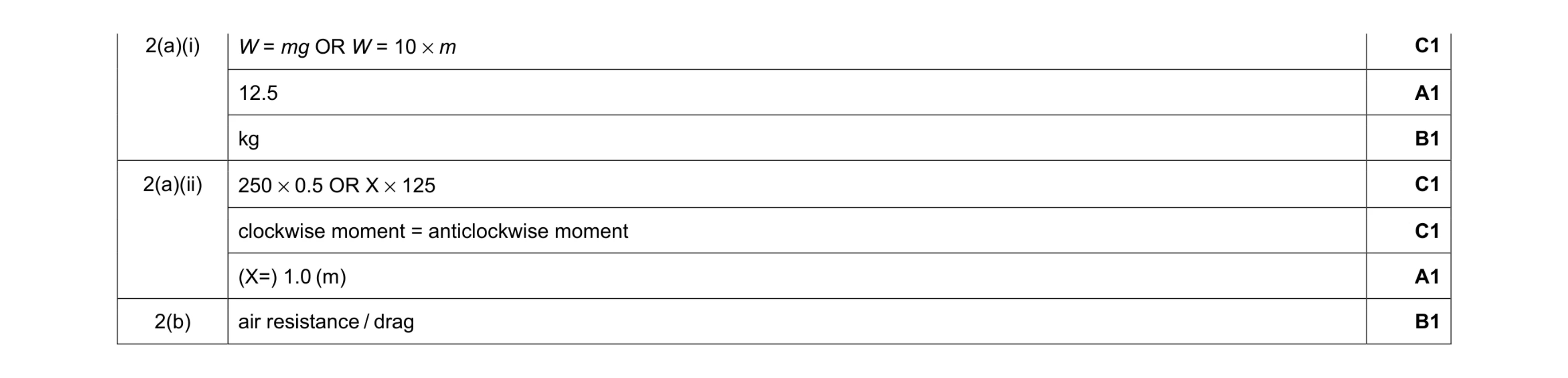 7
7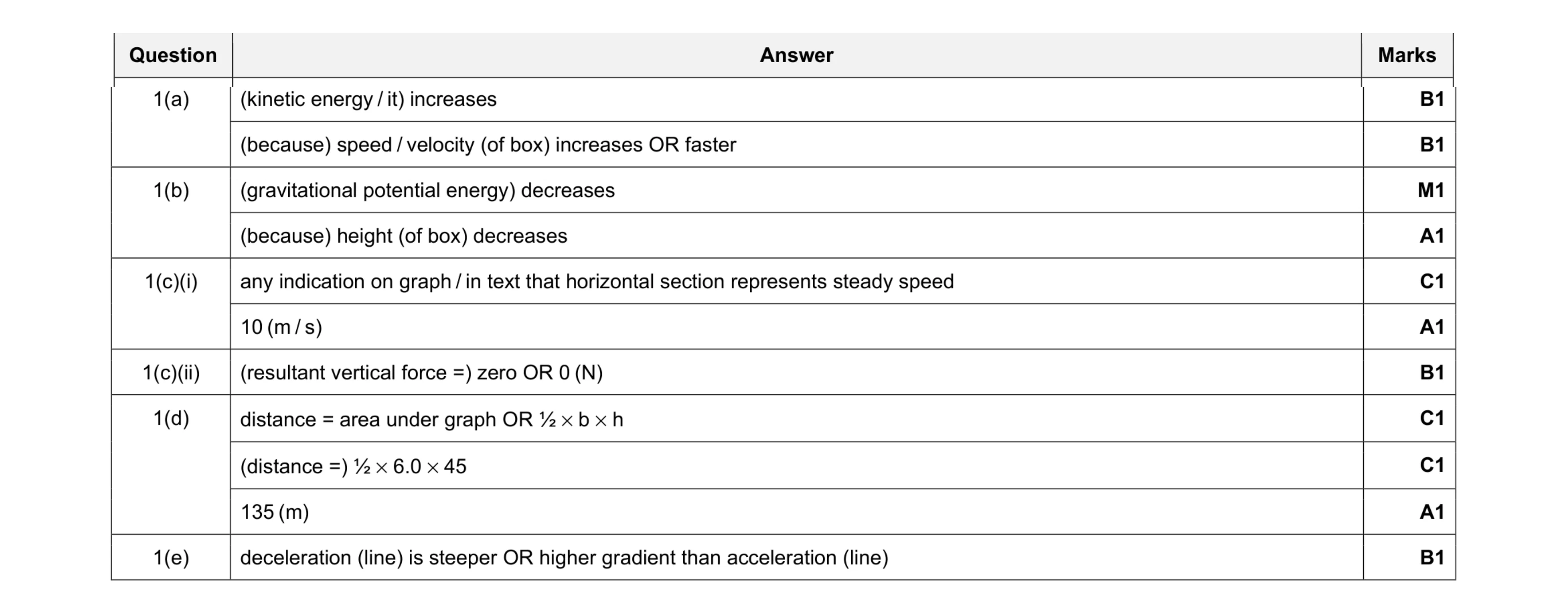 11
11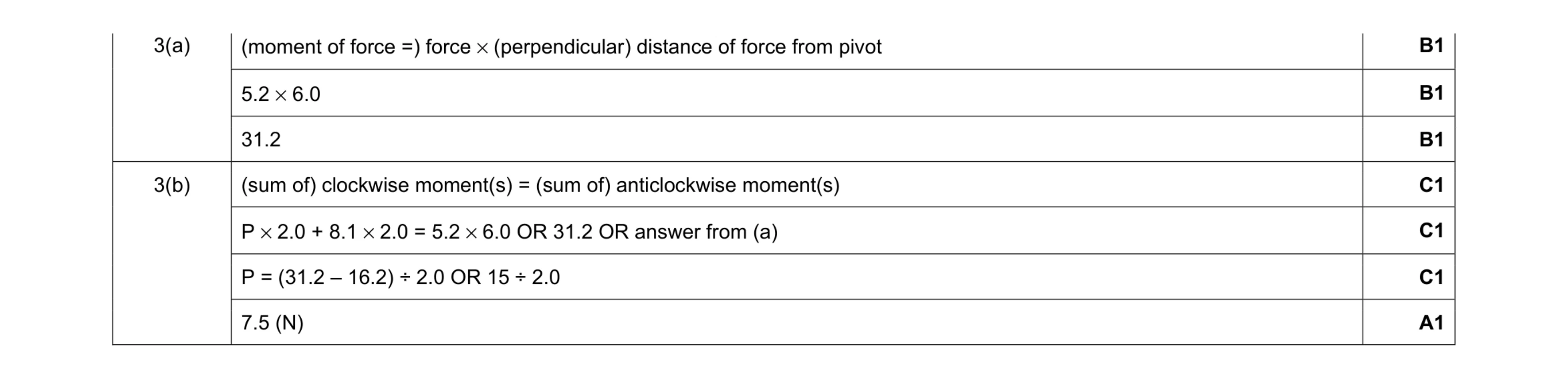 7
7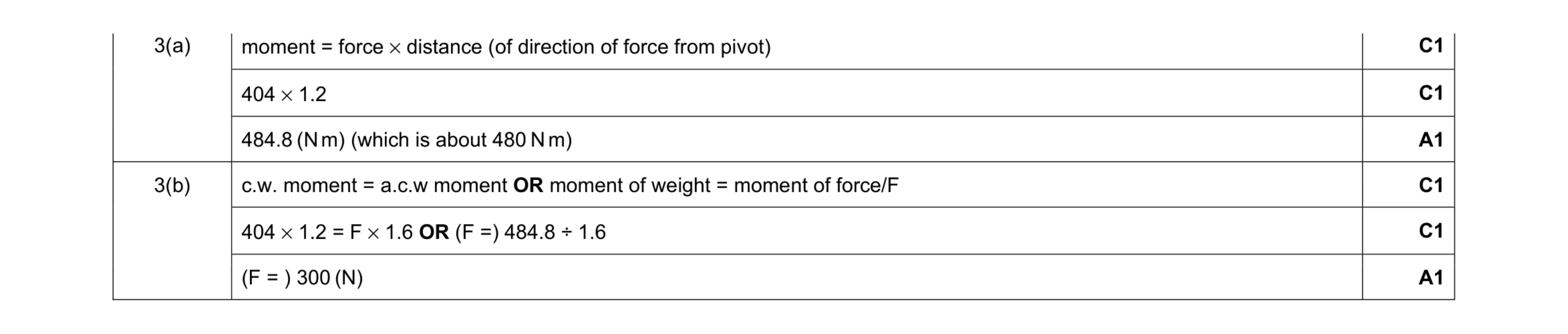 6
6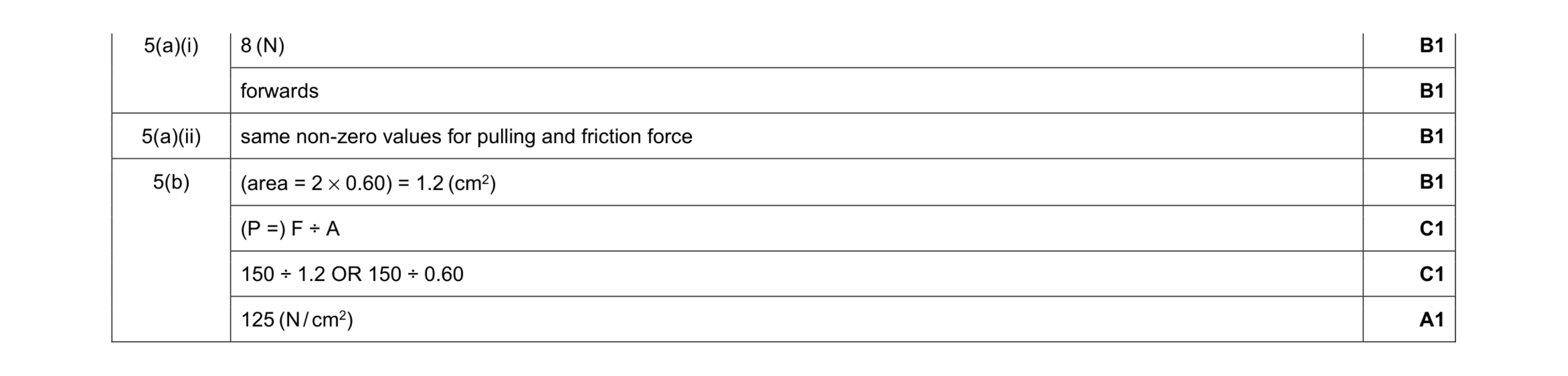 7
7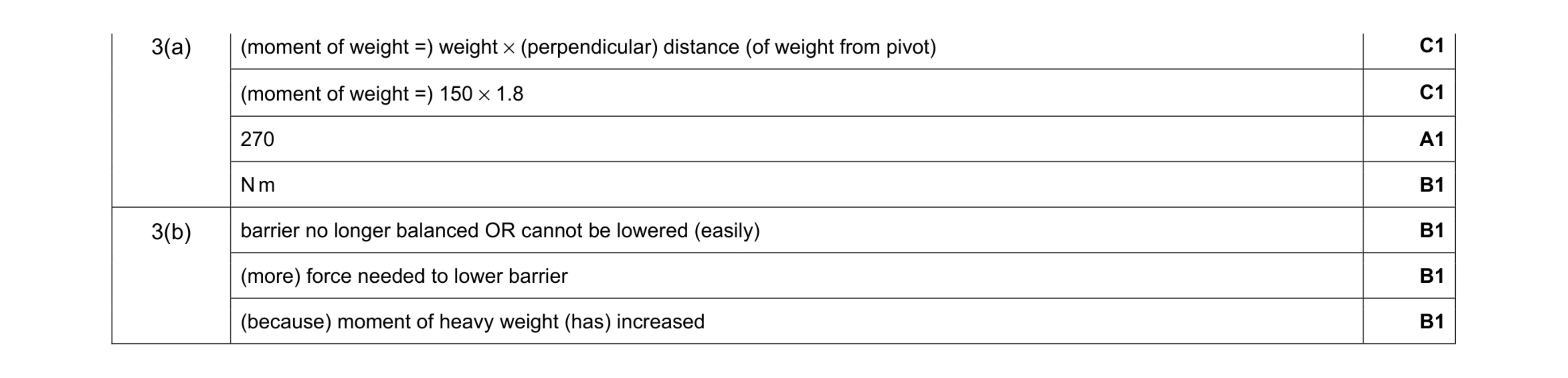 7
7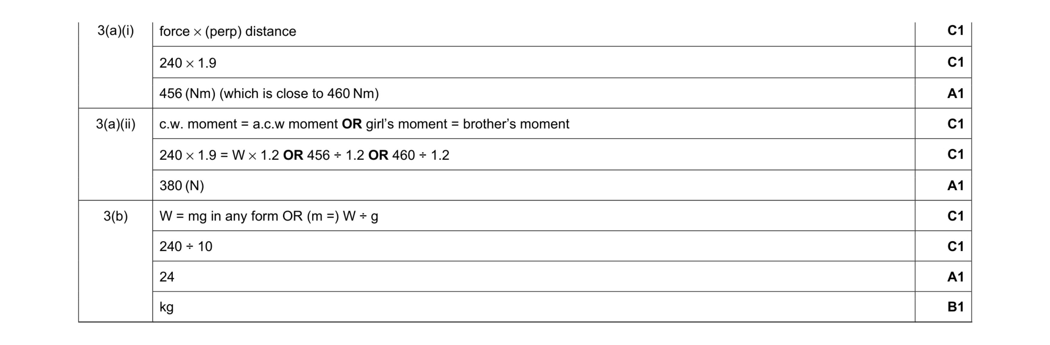 10
10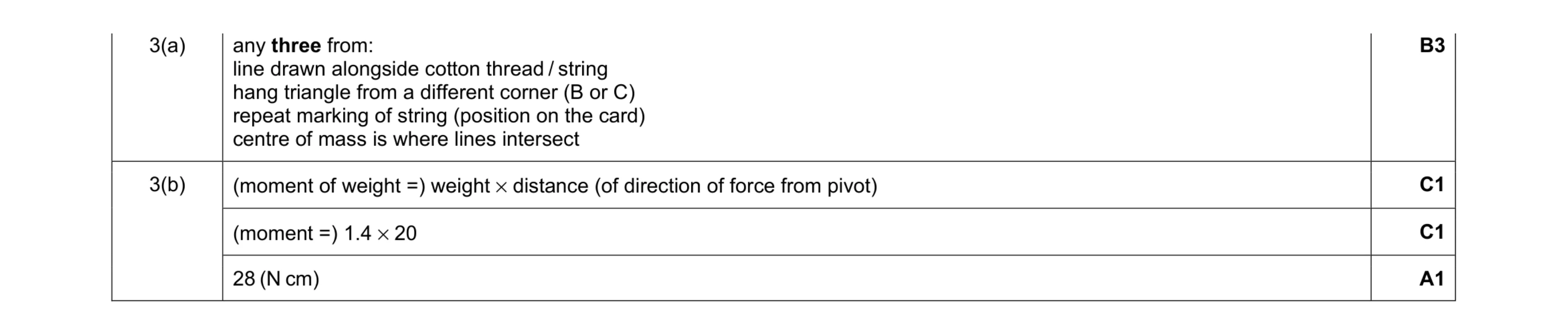 6
6 4
4 4
4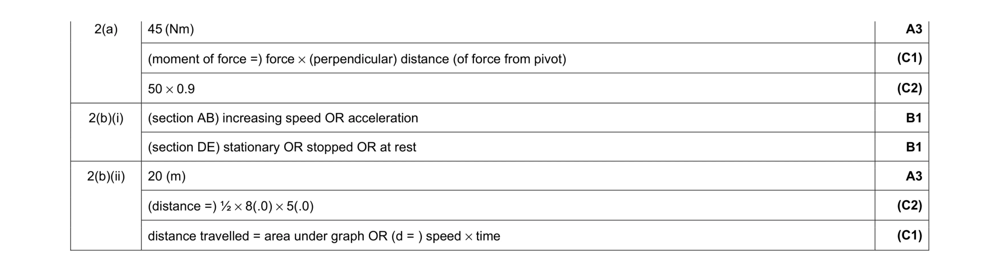 8
8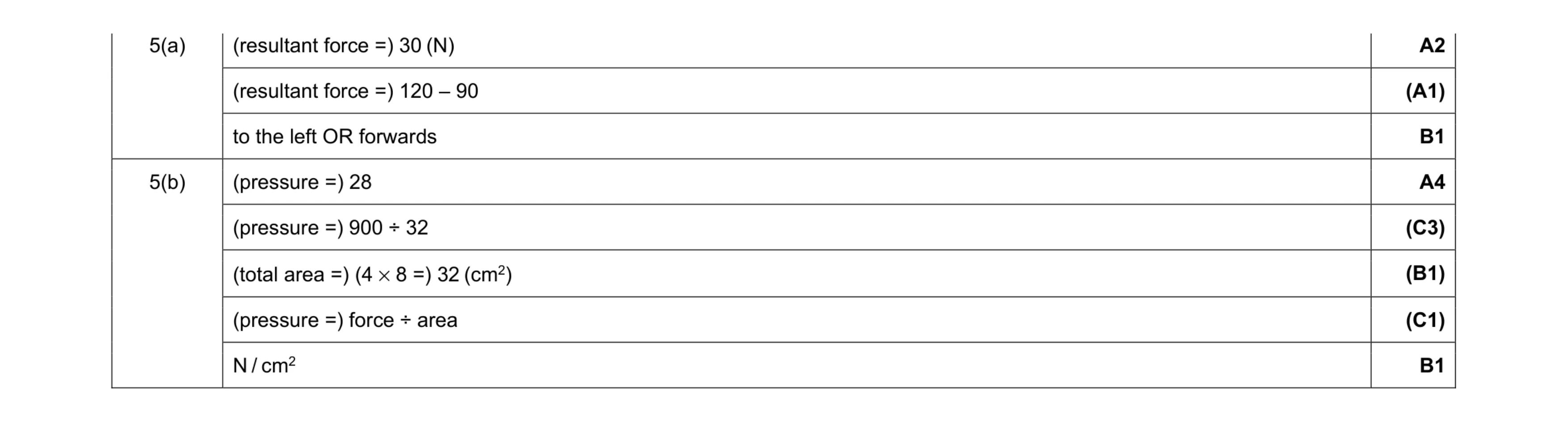 8
8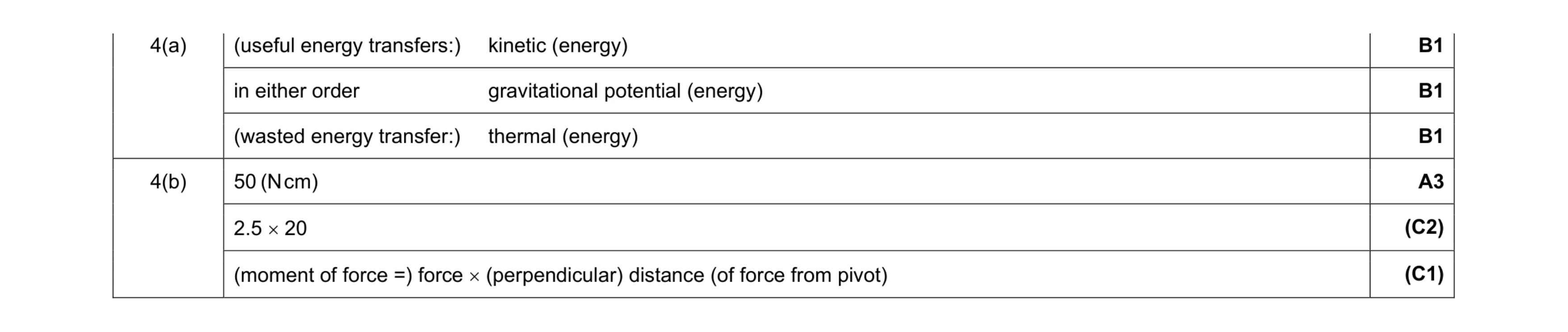 6
6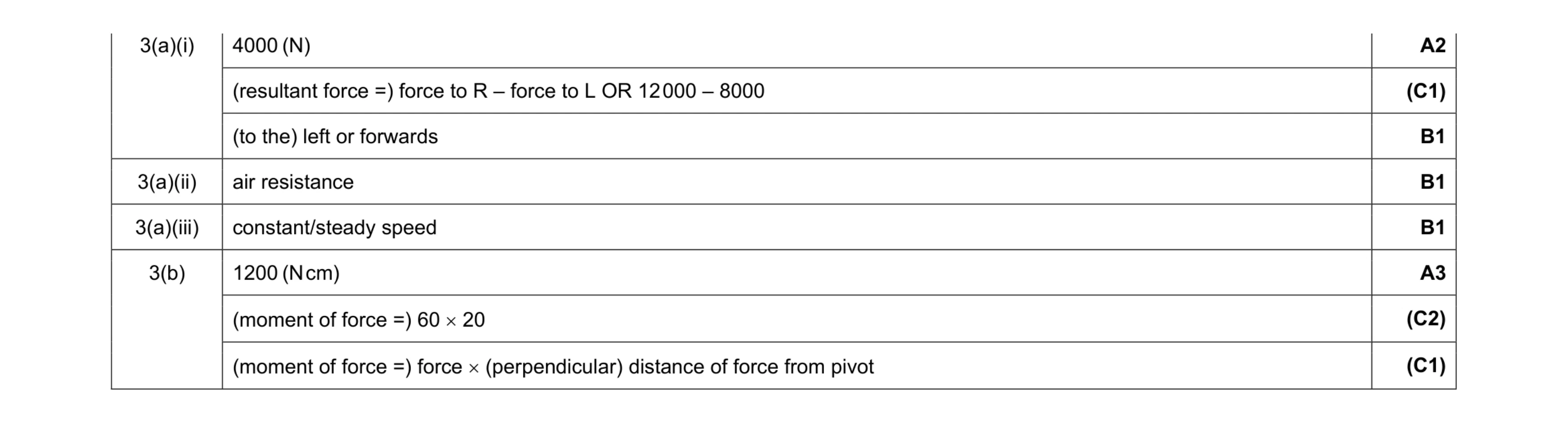 8
8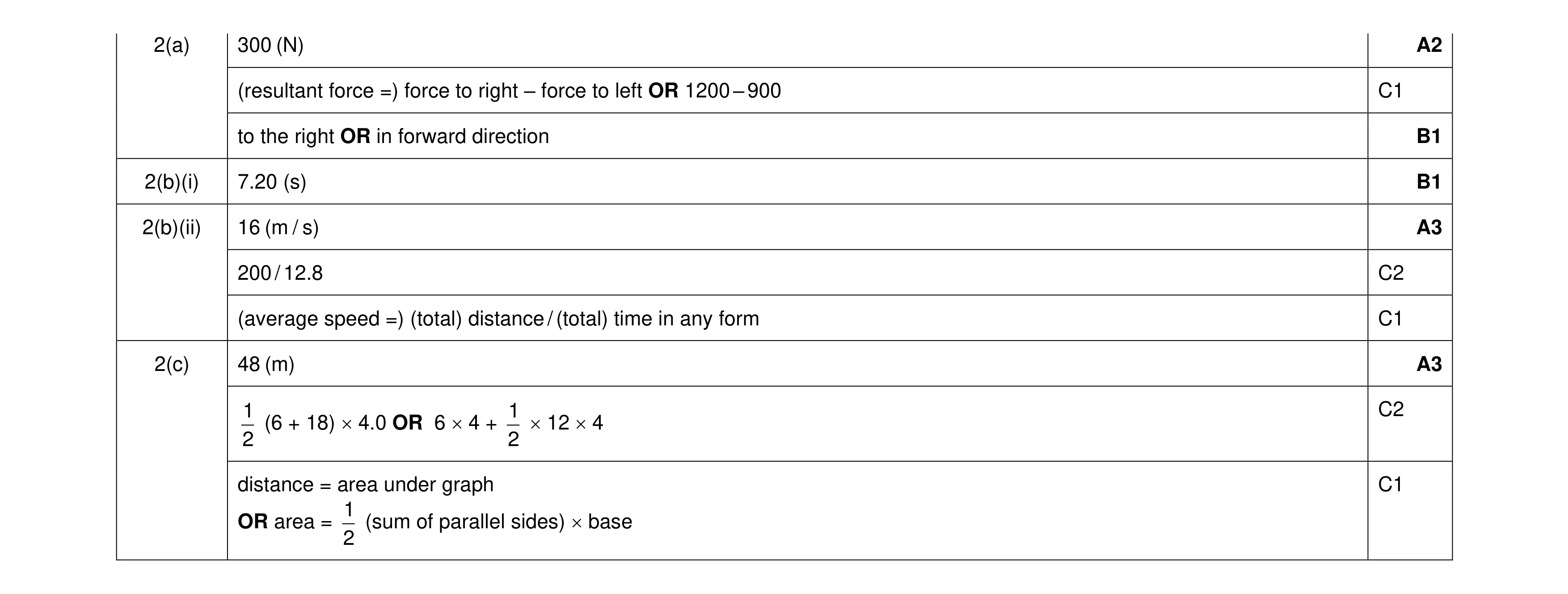 10
10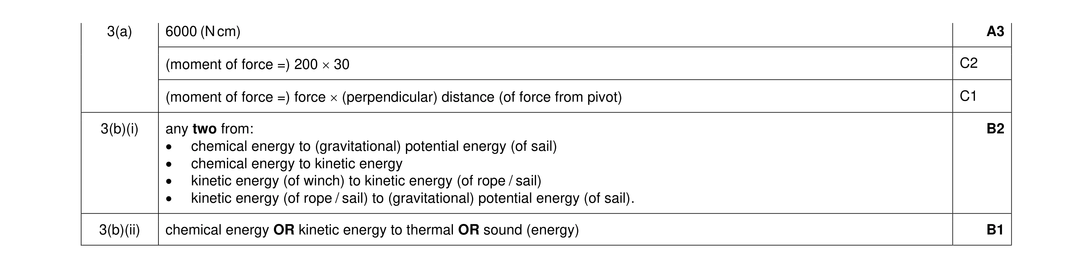 6
6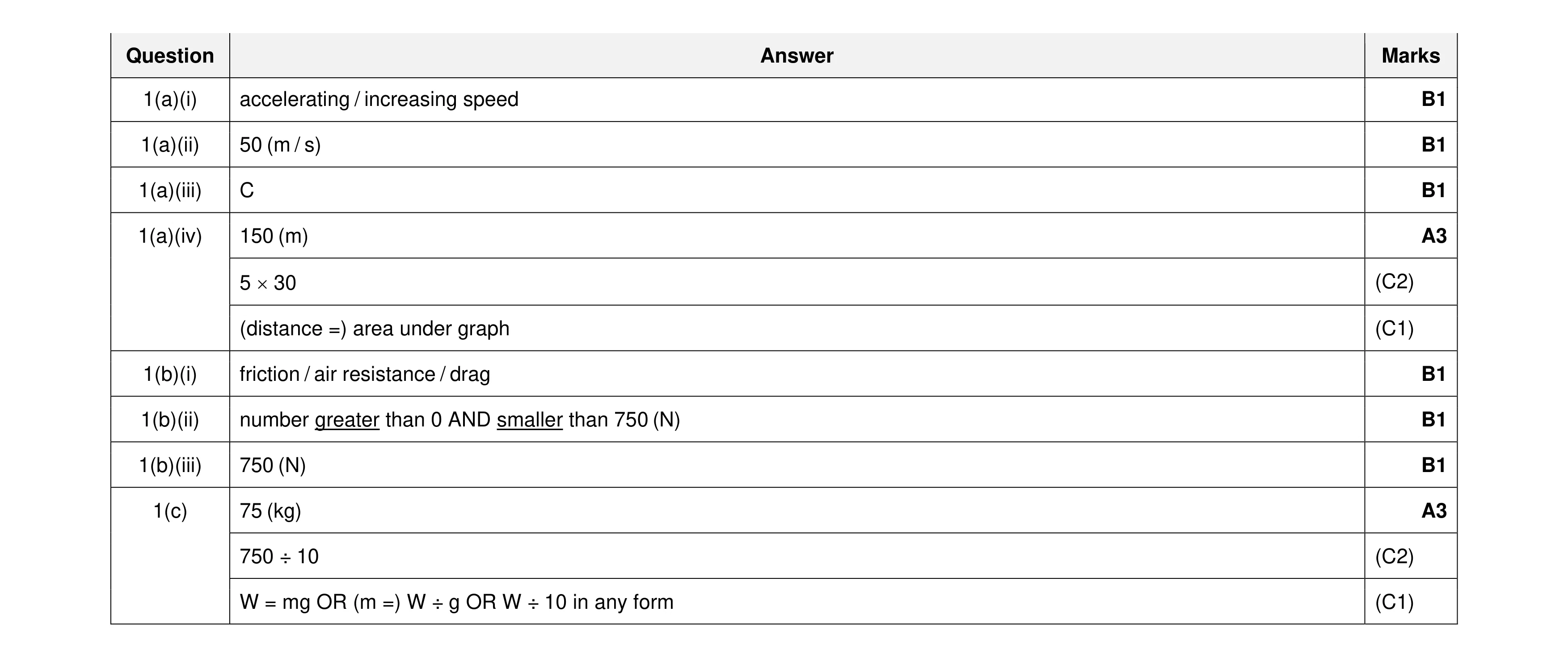 12
12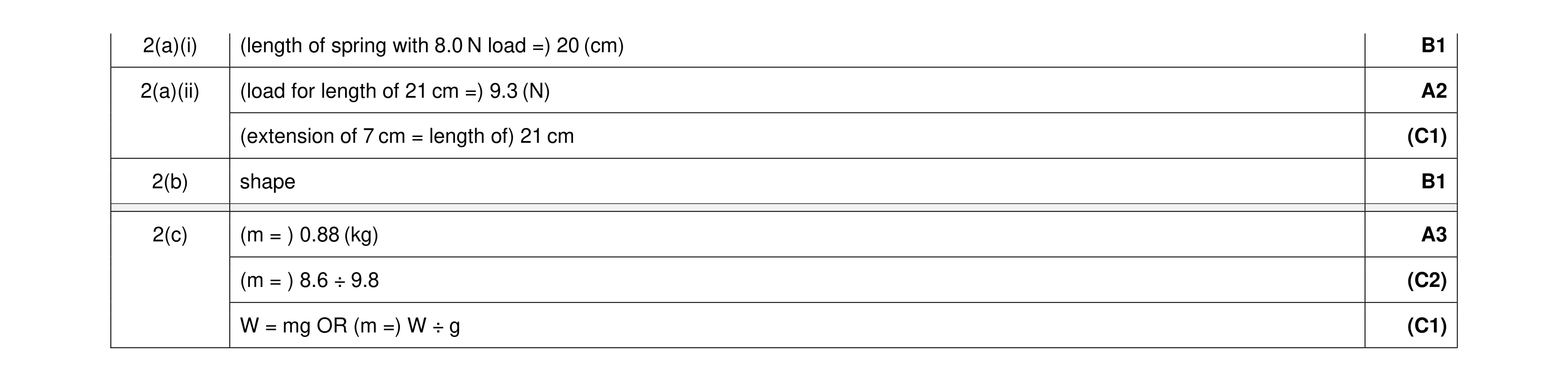 7
7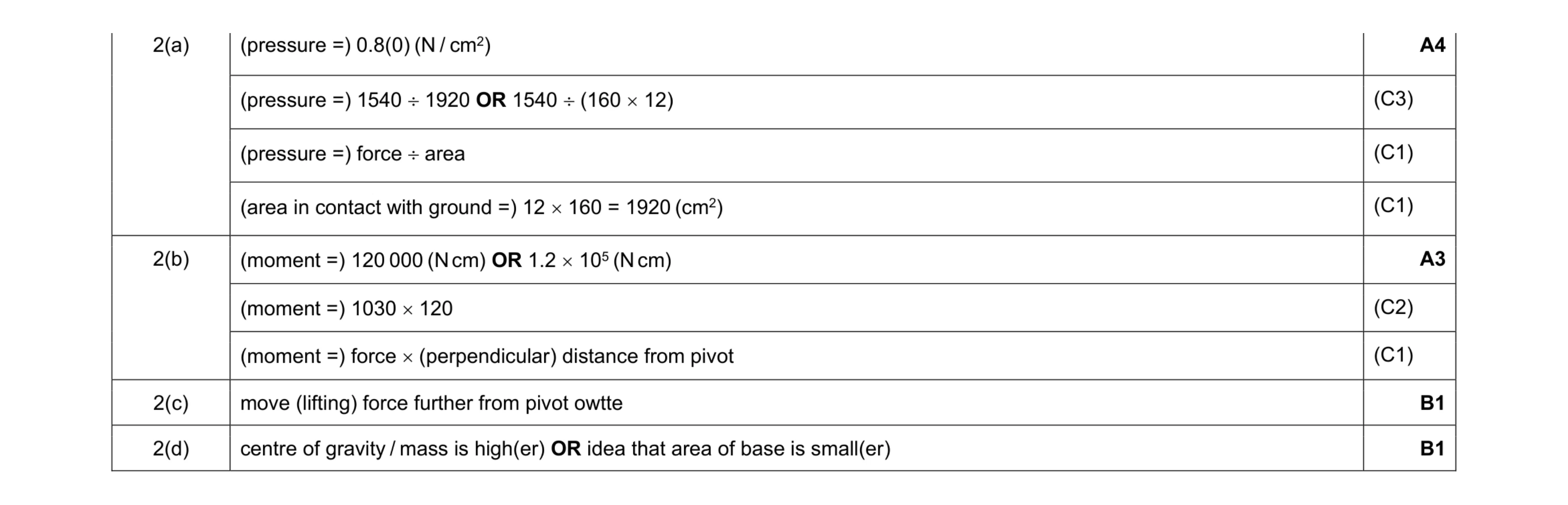 9
9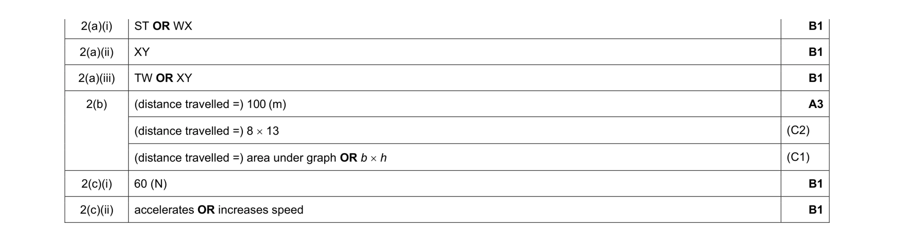 8
8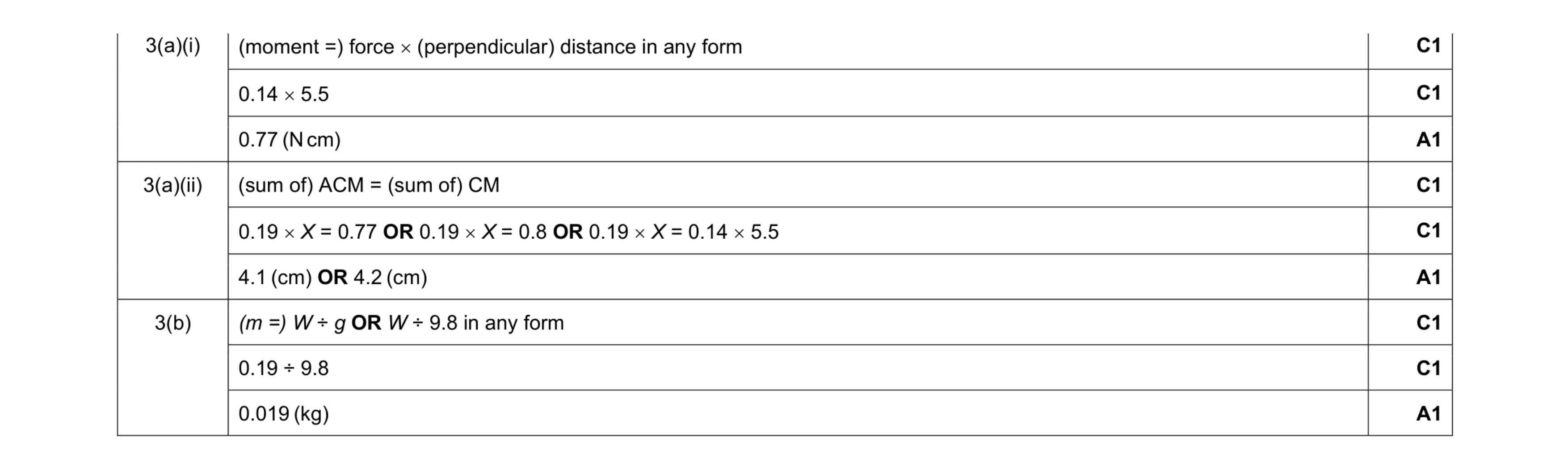 9
9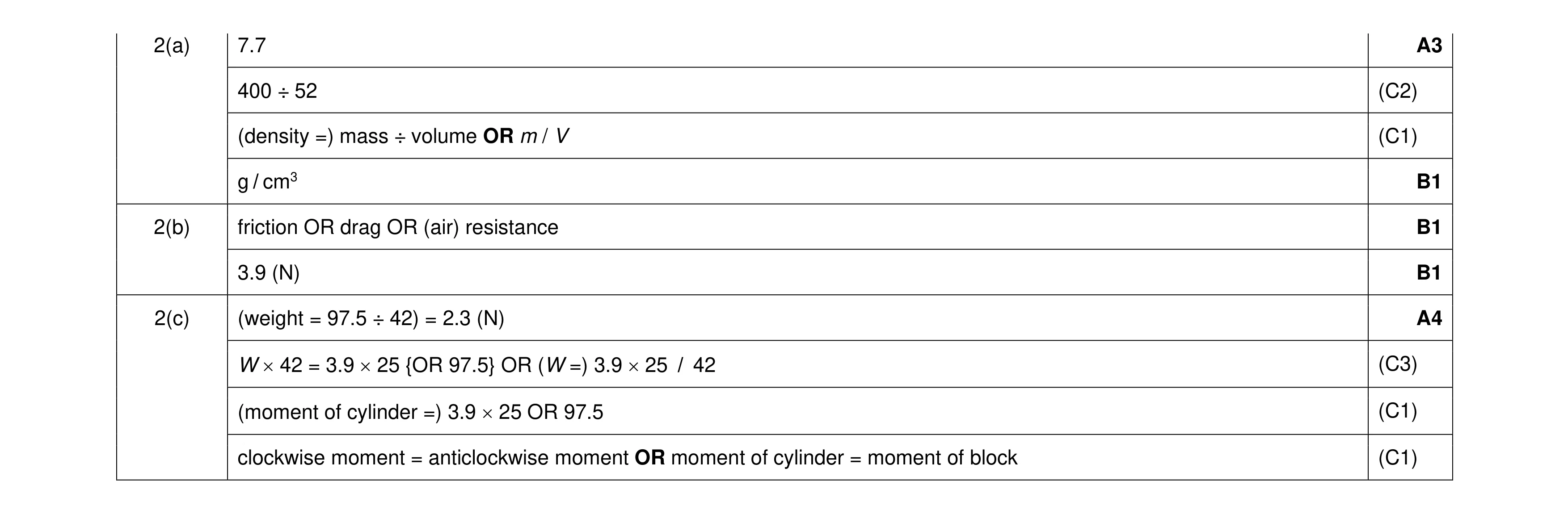 10
10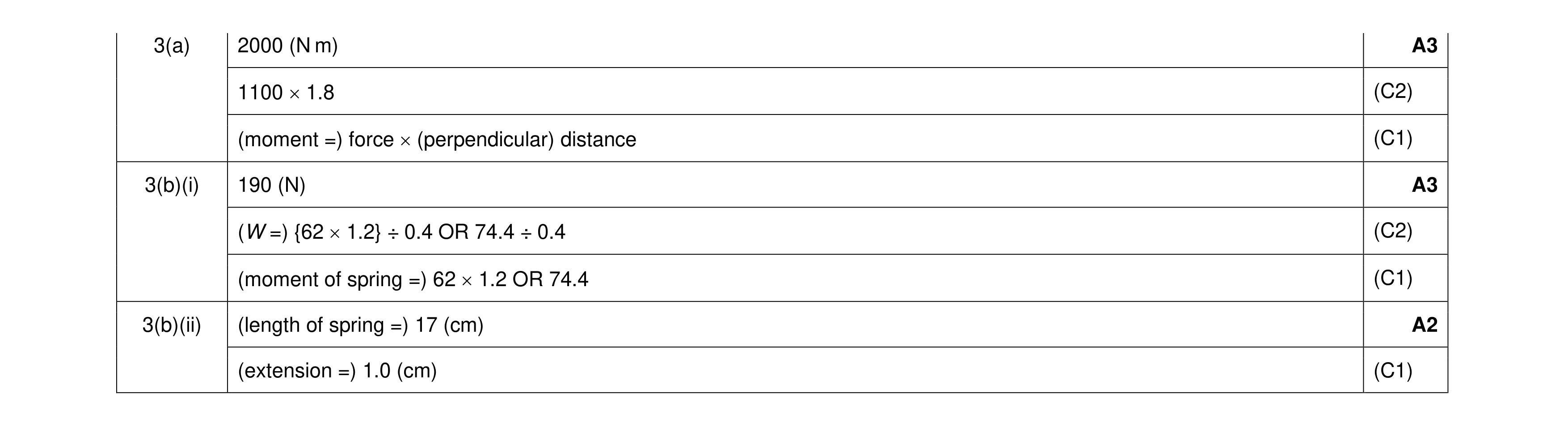 8
8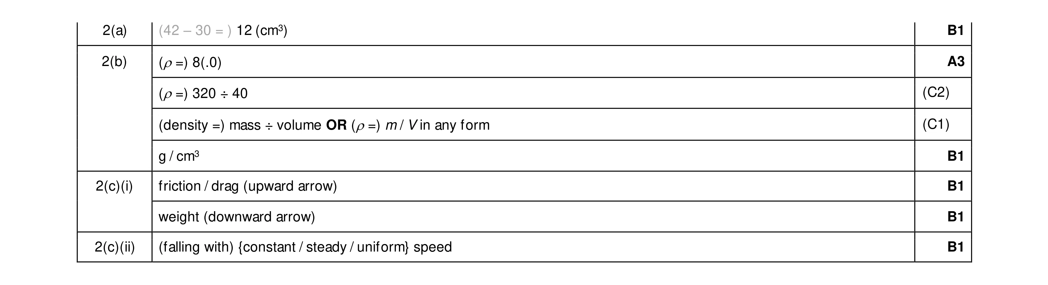 8
8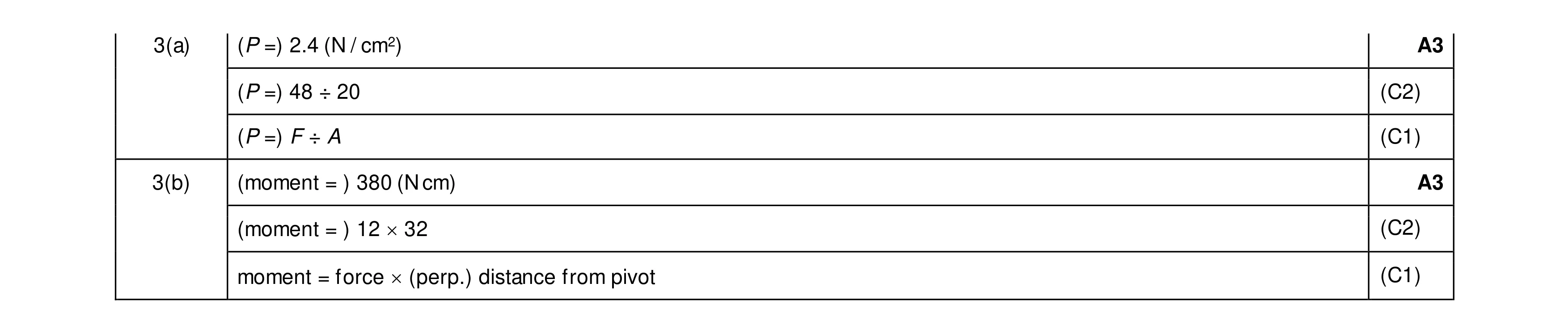 6
6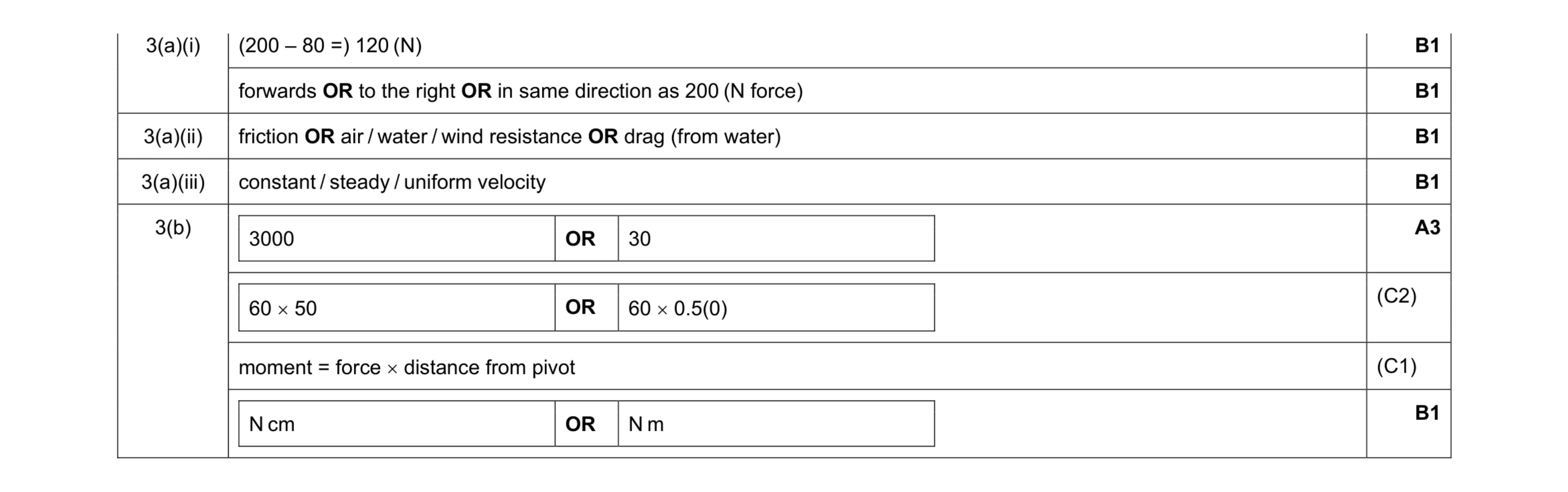 8
8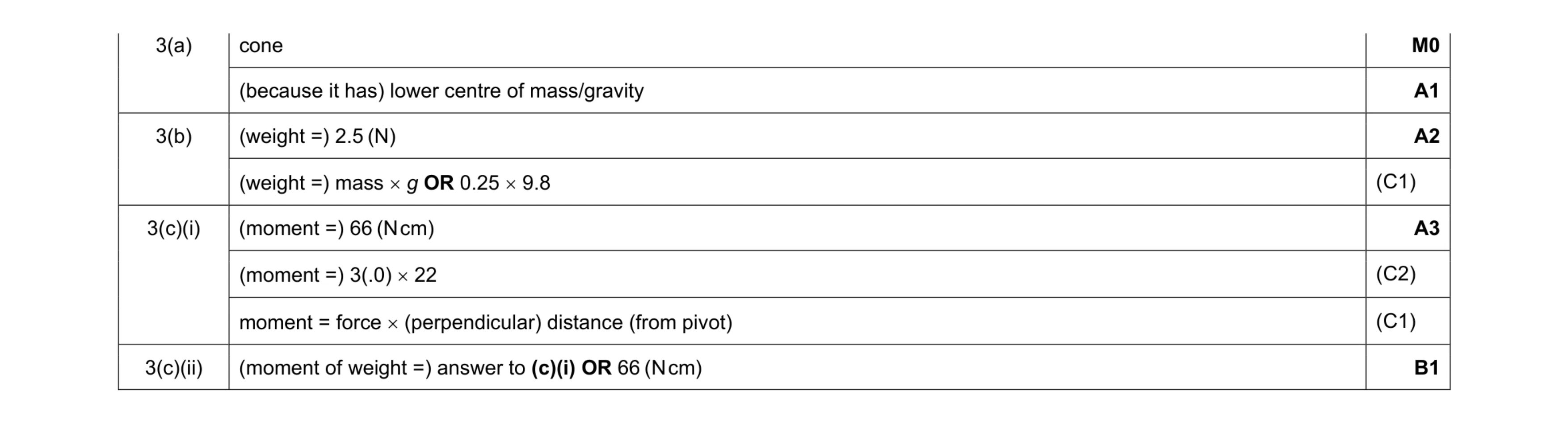 7
7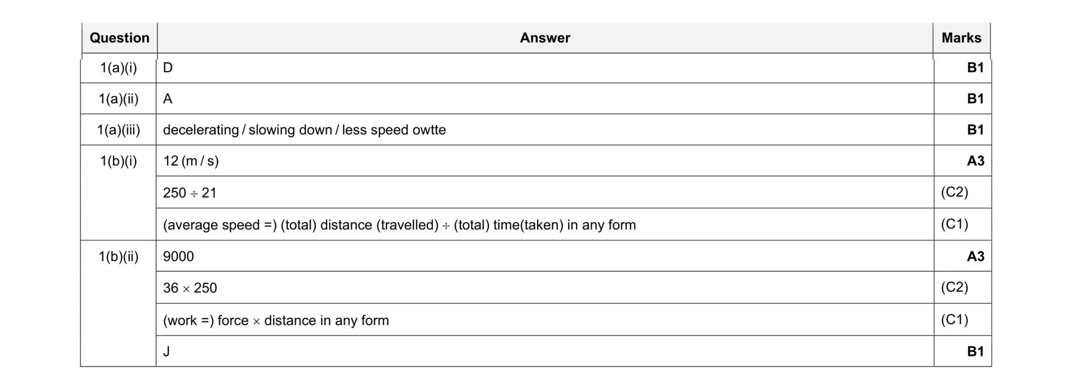 10
10 5
5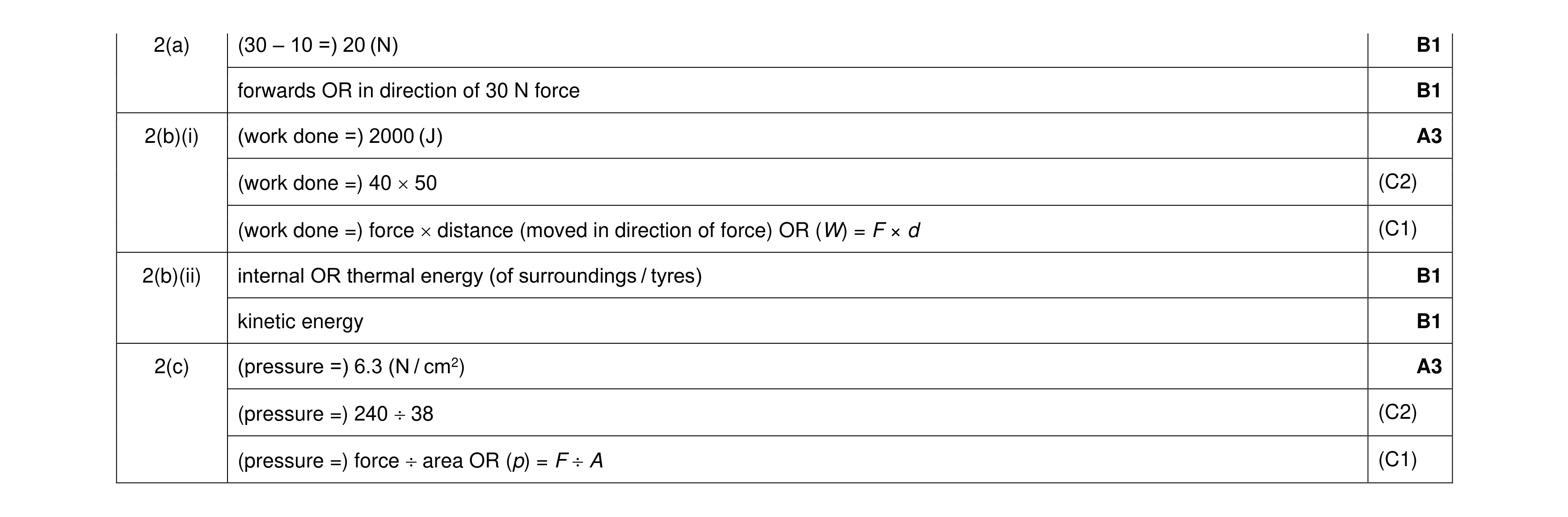 10
10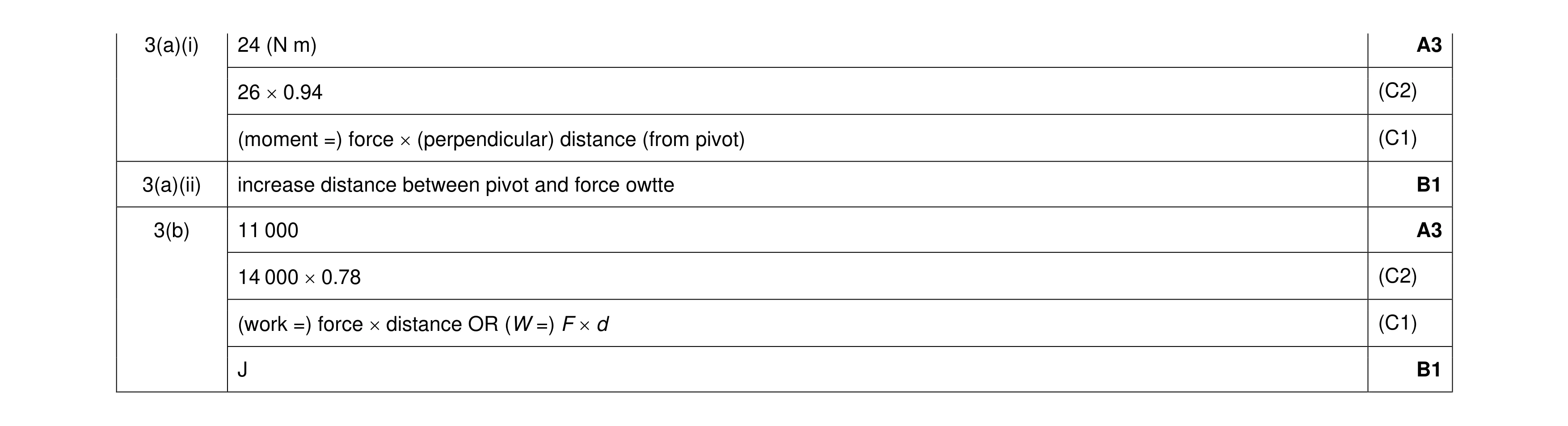 8
8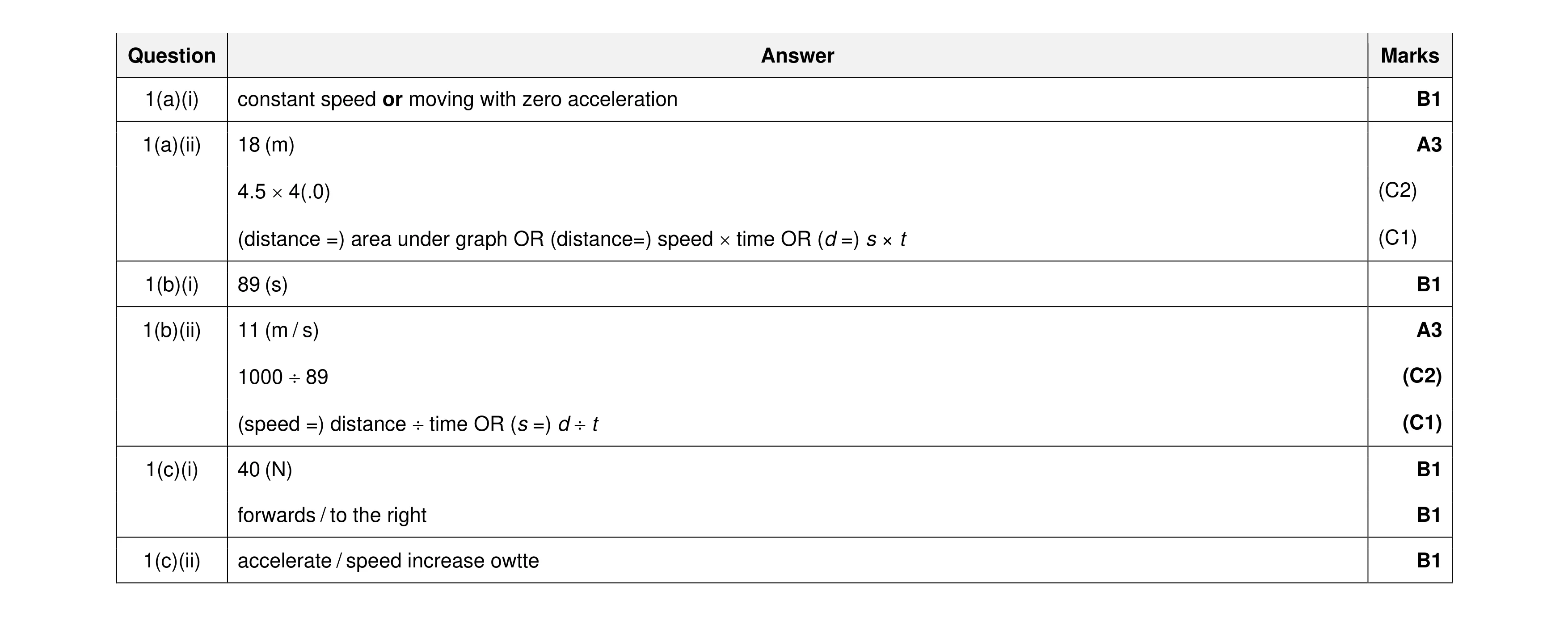 11
11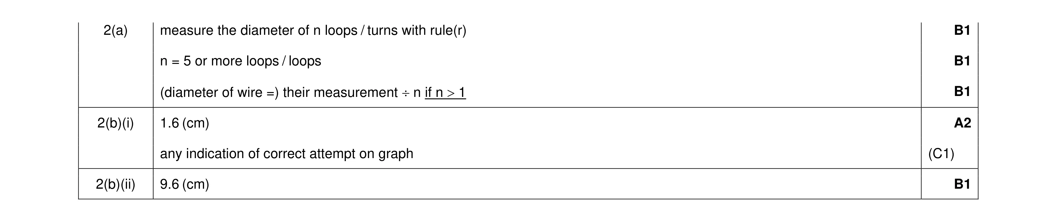 6
6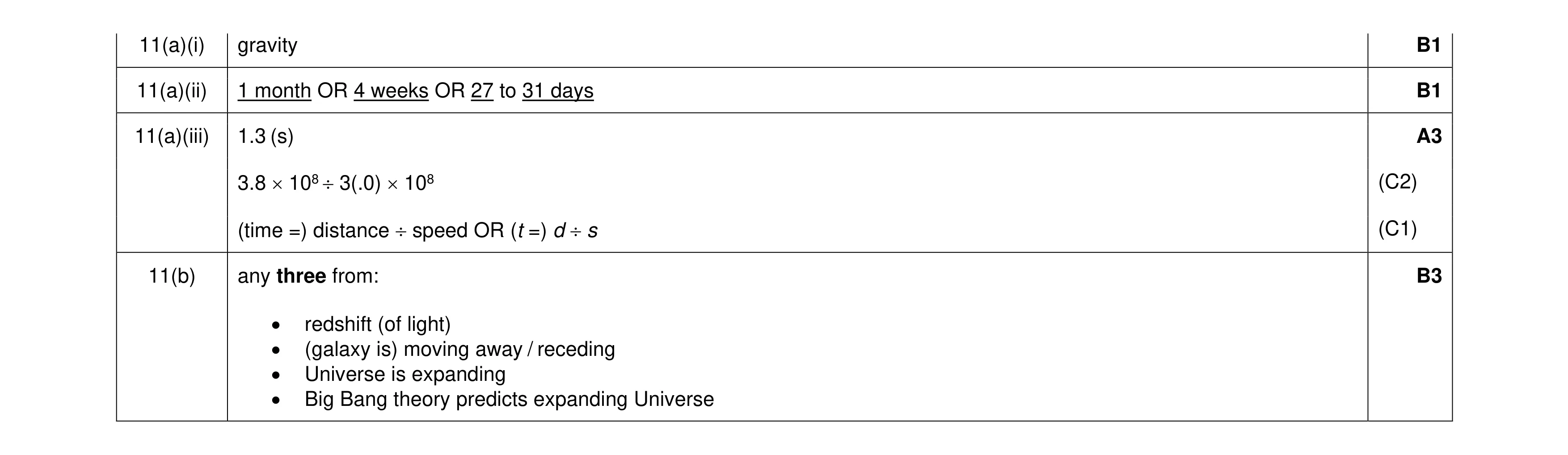 8
8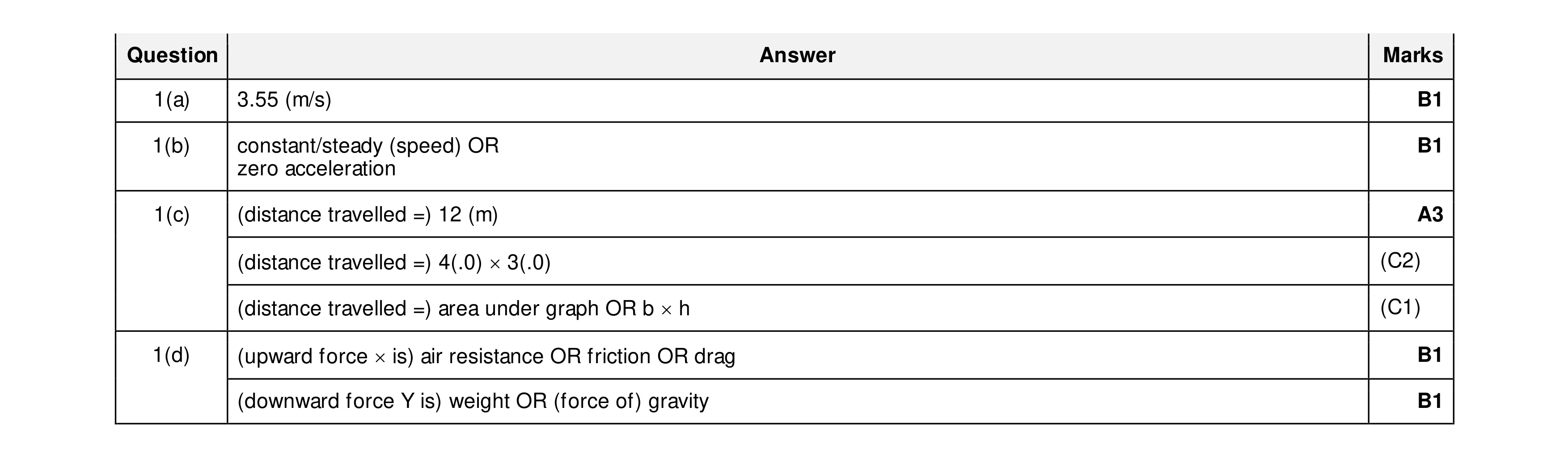 7
7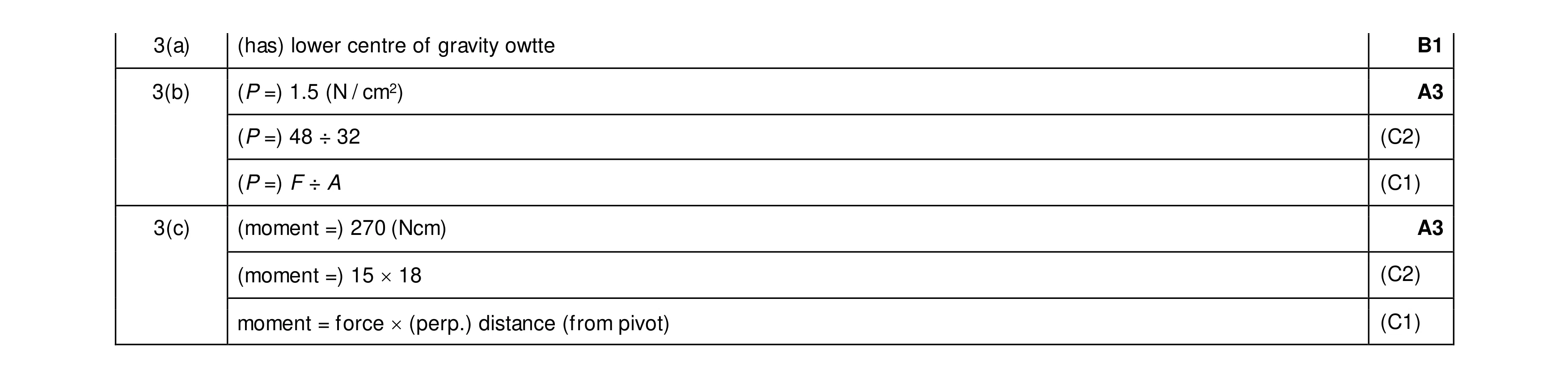 7
7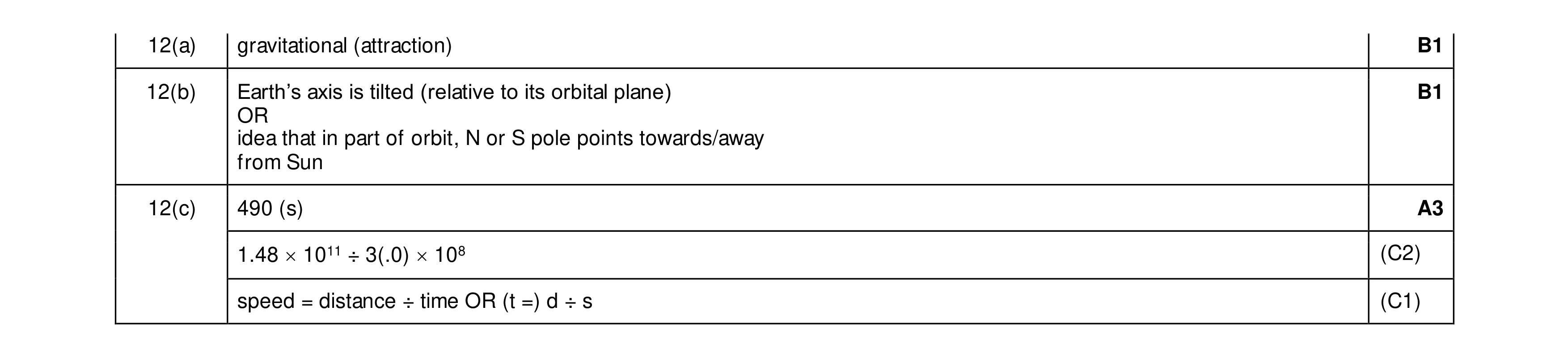 5
5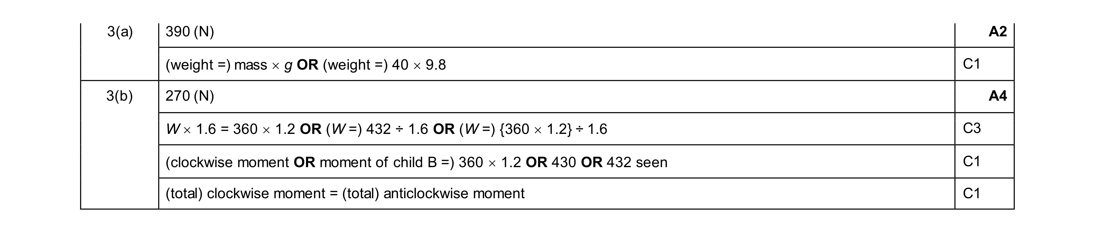 6
6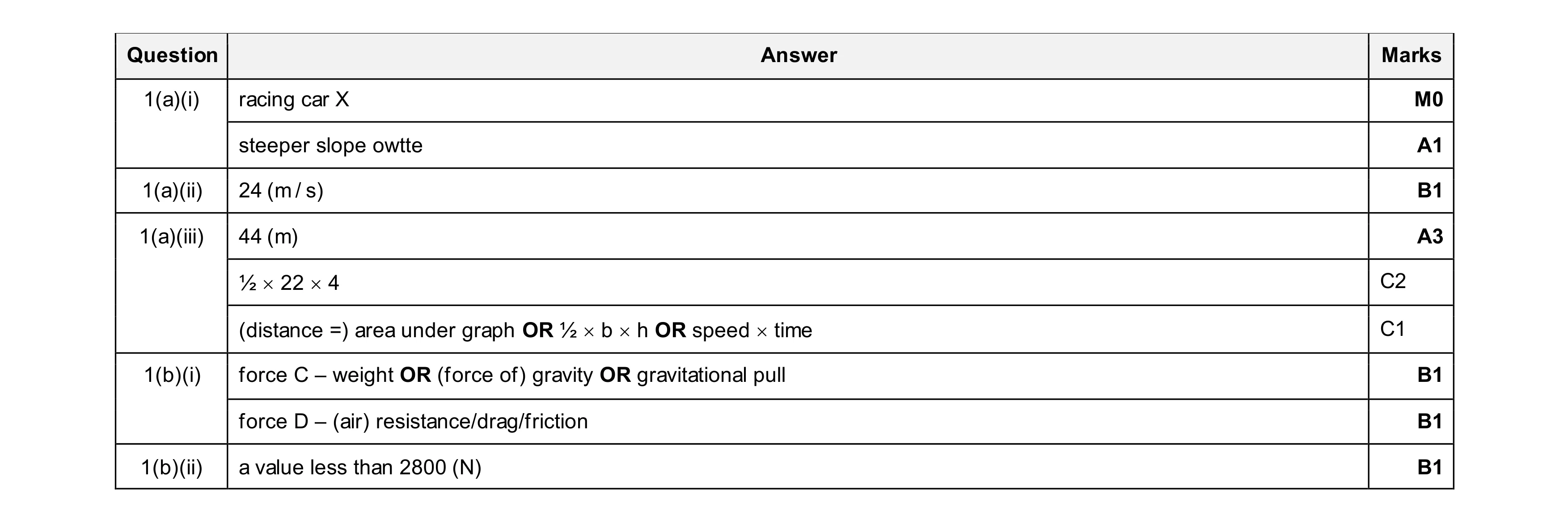 8
8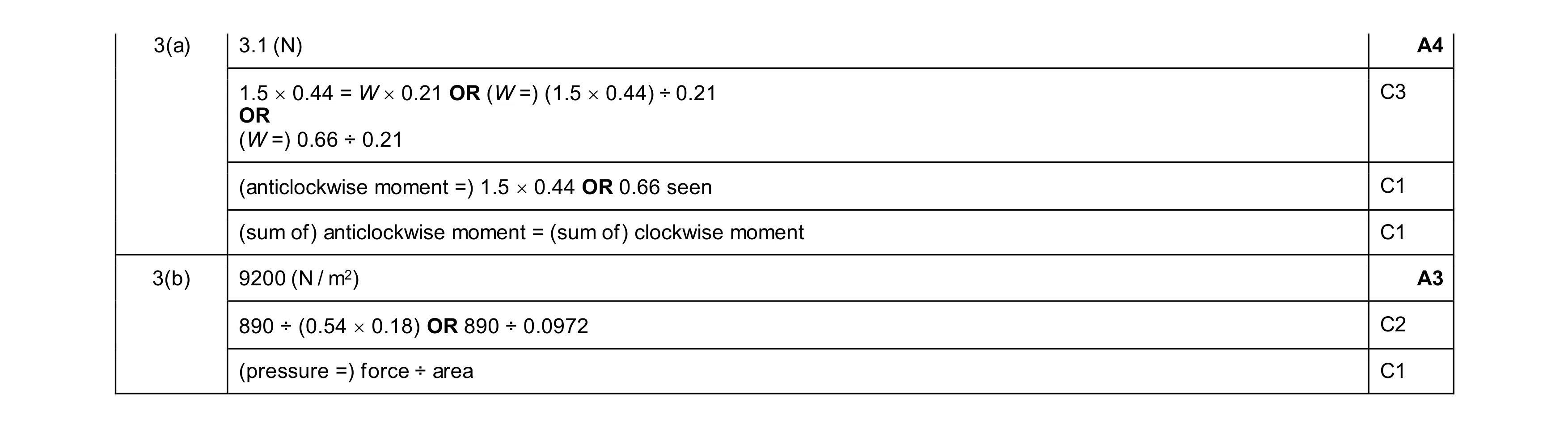 7
7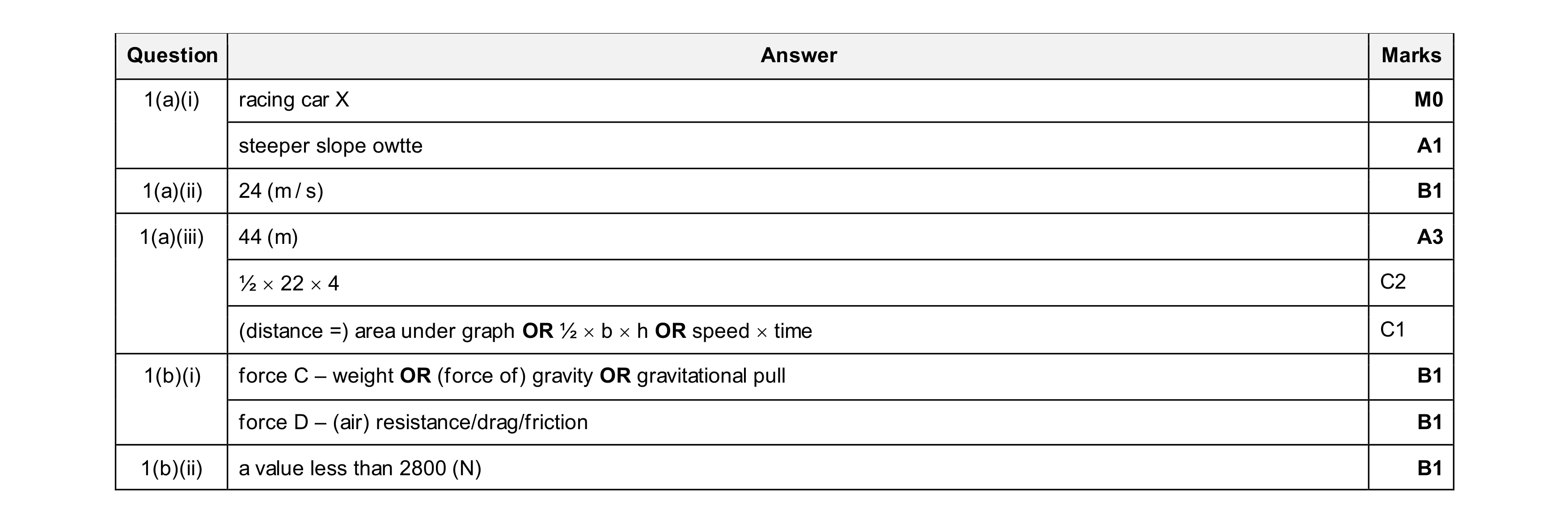 8
8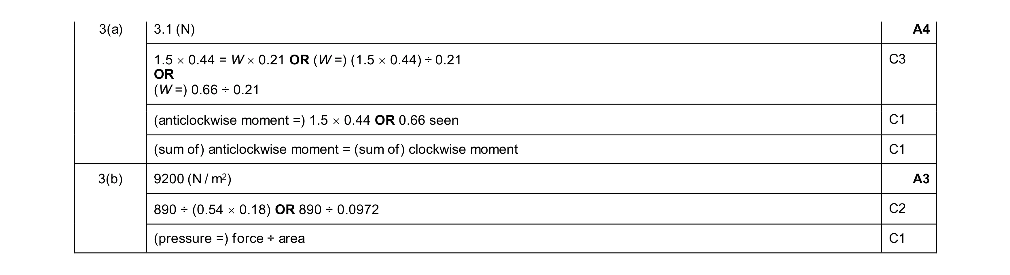 7
7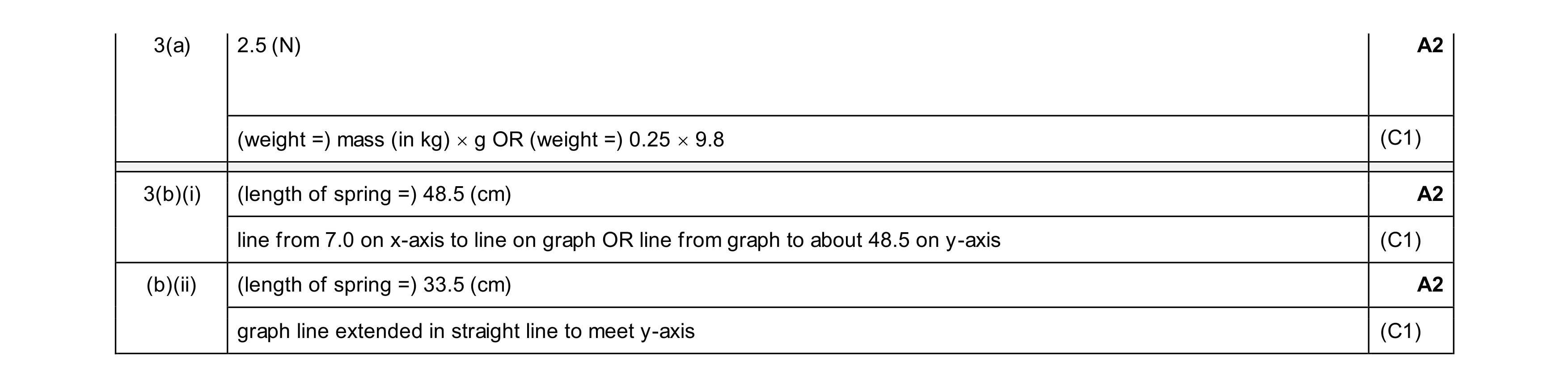 6
6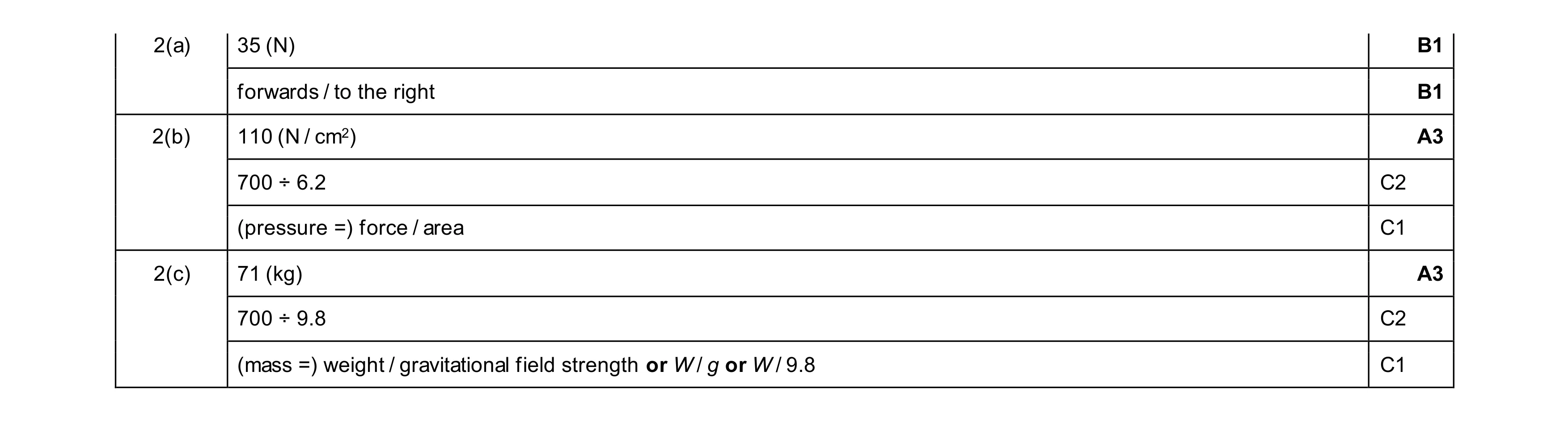 8
8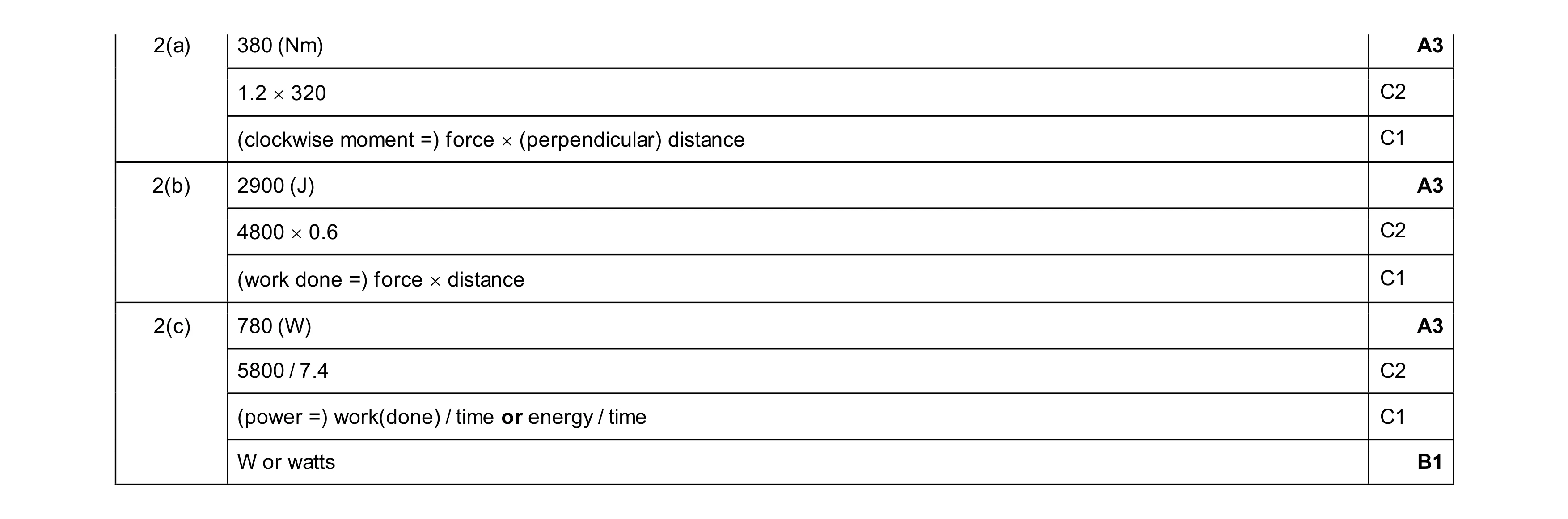 10
10