Questions as text
Q1 · The axes used to plot distance-time graphs 0625/42 Feb/March 2017
1 (a) Fig. 1.1 shows the axes used to plot distance-time graphs. distance 0 0 time Fig. 1.1 On Fig. 1.1, draw graphs for an object that is (i) moving with constant speed, labelling the graph A, (ii) moving with decreasing speed, labelling the graph B. [2] (b) Fig. 1.2 shows the axes used to plot speed-time graphs. speed 0 0 time Fig. 1.2 On Fig. 1.2, draw graphs for an object that is (i) moving with constant acceleration, labelling the graph S, (ii) moving with increasing acceleration, labelling the graph T. [2] (c) A plane is at rest on an airport runway. The brakes of the plane are released and the engine of the plane provides a constant accelerating force. Using the following data, calculate the take-off speed of the plane. Ignore any resistive forces. constant forward force = 56 000 N mass of plane = 16 000 kg time of travel along runway = 16 s speed = … [4] [Total: 8]
8 marks
Mark scheme: 1(a)(i) Constant positive or negative gradient, labelled A B1 1(a)(ii) Decreasing positive or negative gradient, labelled B B1 1(b)(i) Constant positive or negative gradient, labelled S B1 1(b)(ii) Increasing positive or negative gradient, labelled T B1 1(c) F = ma in any form OR (a =) F / m OR 56 000 / 16 000 C1 3.5 (m / s2) C1 a = (v – u) / t in any form OR v – u = at OR v = at OR at OR 3.5 × 16 C1 56 m / s A1 Total: 8
This question in 0625/42 Feb/March 2017
Q2 · A stationary object is acted upon by a number of forces 0625/42 Feb/March 2017
3 (a) A stationary object is acted upon by a number of forces. State the conditions which must be true if the object (i) does not accelerate, … [1] (ii) does not rotate. … [1] (b) Fig. 3.1 shows a boat that has been lifted out of a river. The boat is suspended by two ropes. It is stationary. T1 T2 C P 1.20 m 0.40 m 24 kN Fig. 3.1 (not to scale) The weight of the boat, acting at the centre of mass, is 24 kN. The tensions in the ropes are T1 and T2. Determine (i) the moment of the weight of the boat about the point P, moment = … [1] (ii) the tension T1, T1 = … [3] (iii) the tension T2. T2 = … [2]
8 marks
Mark scheme: 3(a)(i) No resultant force / net force OR Forces are balanced OR Forces in opposite directions are equal OR Forces cancel B1 3(a)(ii) no resultant / net moment / torque / turning effect OR (Sum of) clockwise moments = (sum of) anticlockwise moments B1 3(b)(i) 24 × 0.4 = 9.6 kN m OR 24 000 × 0.4 = 9600 N m B1 3(b)(ii) T1 × 1.6 B1 = 9.6 OR = 9600 C1 (T1 =) 6 kN OR (T1 =) 6000 N A1 3(b)(iii) T1 + T2 = 24 000 OR 6000 + T2 = 24 000 C1 (T2 =) 18 000 N A1 OR T1 + T2 = 24 OR 6.0 + T2 = 24 (C1) (T2 =) 18 kN (A1) OR T2 × 0.40 = 6000 × 1.2 (C1) (T2 =) 18 000 N (A1) OR T2 × 0.40 = 6.0 × 1.2 (C1) (T2 =) 18 kN (A1) Total: 8
This question in 0625/42 Feb/March 2017
Question 3 0625/41 Oct/Nov 2017
2 (a) State Hooke’s Law. … … [1] (b) For forces up to 120 N, a spring obeys Hooke’s Law. A force of 120 N causes an extension of 64 mm. (i) On Fig. 2.1, draw the force-extension graph for the spring for loads up to 120 N. [1] 150 force / N 100 50 0 0 20 40 60 80 extension / mm Fig. 2.1 (ii) Calculate the spring constant k of the spring. k = … [2] (c) A student makes a spring balance using the spring in (b). The maximum reading of this balance is 150 N. The student tests his balance with a known weight of 140 N. He observes that the reading of the balance is not 140 N. Suggest and explain why the reading is not 140 N. … … … [2] [Total: 6]
6 marks
Mark scheme: 2(a) Extension of a spring is (directly) proportional to load / force / weight OR F = ke where e is extension B1 2(b)(i) Straight line drawn from origin to (64 mm, 120 N) B1 2(b)(ii) F = ke in any form OR 120 / 64 OR 120 / 6.4 OR 120 / 0.064 C1 c.a.o. 1.9 N / mm OR 19 N / cm OR 1900 N / m A1 2(c) Above 120 N / at 140 N, the spring does not obey Hooke’s law OR the extension is not proportional to the load / weight / force B1 The elastic limit / limit of proportionality of the spring has been exceeded B1
This question in 0625/41 Oct/Nov 2017
Q4 · An object is moving in a straight line at constant speed 0625/42 Oct/Nov 2017
2 (a) An object is moving in a straight line at constant speed. A resultant force begins to act upon the object. State the ways in which the force may change the motion of the object. … … … … [2] (b) State one other effect a force could have on the object. … [1] (c) The mass of a car is 1400 kg. The car, initially at rest, is moved along a level road by a resultant force of 3500 N. The car reaches a speed of 30 m / s. (i) Calculate the average acceleration of the car. acceleration = … [2] (ii) Calculate the time for which the force is applied. time = … [2] (iii) State the name of a force which opposes the motion of the car. … [1] [Total: 8]
8 marks
Mark scheme: 2(a) accelerate / increase speed OR decelerate / decrease speed OR stop B1 change direction / move in a curve o.w.t.t.e. B1 2(b) change of shape OR size B1 2(c)(i) F = m a in any form OR (a =) F / m OR (a =) 3500 / 1400 C1 (a =) 2.5 m / s2 A1 2(c)(ii) a = (v – u) / t in any form OR (t =) (v – u) / a OR (t =) (30 – 0) / 2.5 OR 30 / 2.5 C1 (t =) 12 s A1 2(c)(iii) friction / air resistance / drag B1
This question in 0625/42 Oct/Nov 2017
Q5 · A truck accelerates uniformly along a straight, horizontal road 0625/43 Oct/Nov 2017
1 A truck accelerates uniformly along a straight, horizontal road. The mass of the truck is 2.0 × 10⁴ kg. (a) The speed of the truck increases from rest to 12 m / s in 30 s. Calculate (i) the distance travelled by the truck during this time, distance = … [2] (ii) the resultant force on the truck. resultant force = … [4] (b) To maintain a uniform acceleration, the forward force on the truck must change. Explain why. … … … [2] [Total: 8]
8 marks
Mark scheme: 1(a)(i) C1 180 m A1 1(a)(ii) (a = )∆v / t or 12 / 30 C1 0.40 (m / s2) or 12 / 30 C1 (F = )ma or 2.0 × 104 × 0.40 or 2.0 × 104 × 0.40 × 12 / 30 C1 8000 N A1 1(b) drag / friction / air resistance mentioned C1 drag / friction / air resistance increases (as speed increases) A1
This question in 0625/43 Oct/Nov 2017
Q6 · The speed-time graph for a vehicle accelerating from rest 0625/41 May/June 2018
1 Fig. 1.1 shows the speed-time graph for a vehicle accelerating from rest. 30 25 speed m / s 20 15 10 5 0 0 20 40 60 80 100 120 140 160 time / s Fig. 1.1 (a) Calculate the acceleration of the vehicle at time = 30 s. acceleration = … [2] (b) Without further calculation, state how the acceleration at time = 100 s compares to the acceleration at time = 10 s. Suggest, in terms of force, a reason why any change has taken place. … … … [3] (c) Determine the distance travelled by the vehicle between time = 120 s and time = 160 s. distance = … [3] [Total: 8]
8 marks
Mark scheme: 1(a) Mention of gradient of graph at t = 30 s OR tangent drawn at t = 30 s and triangle drawn 1 Acceleration in range 0.30 to 0.45 m / s2 1 1(b) Acceleration less/at a slower rate 1 Less driving force OR greater resistive force/friction/air resistance/drag 1 Resultant force less 1 1(c) Area under graph 1 Distance = (20 × 40) + (½ × 40 × 10) OR ½ × (30 + 20) × 40 1 1000 m 1
This question in 0625/41 May/June 2018
Q7 · A hollow metal cylinder containing air, floating in the sea 0625/42 May/June 2018
2 Fig. 2.1 shows a hollow metal cylinder containing air, floating in the sea. surface air of sea 1.8 m 1.2 m seawater bottom Fig. 2.1 (a) The density of the metal used to make the cylinder is greater than the density of seawater. Explain why the cylinder floats. … … [1] (b) The cylinder has a length of 1.8 m. It floats with 1.2 m submerged in the sea. The bottom of the cylinder has an area of cross-section of 0.80 m2. The density of seawater is 1020 kg / m3. Calculate the force exerted on the bottom of the cylinder due to the depth of the seawater. force = … [4] (c) Deduce the weight of the cylinder. Explain your answer. weight = … explanation … … [2] [Total: 7]
7 marks
Mark scheme: 2(a) average/overall/combined density (of the metal and air contained) less (than density of sea water) 1 2(b) (P =) h × ρ × g OR (V=) A × l in any form 1 (P= 1.2 × 1020 × 10 =) 12 000 (Pa) OR (V= 0.8 × 1.2 = ) 0.96 (m3) 1 P = F ÷ A OR (F =) P × A OR (W =) V × ρ × g 1 (F = 12240 × 0.80 =) 9800 N OR (F = W = ) 9800 N 1 2(c) same numerical answer as (b) 1 resultant/net (vertical) force = 0 OR downward force = upward force OR forces are balanced 1
This question in 0625/42 May/June 2018
Q8 · On a particular day, the atmospheric pressure is 1.0 × 10⁵ Pa 0625/43 May/June 2018
3 On a particular day, the atmospheric pressure is 1.0 × 10⁵ Pa. A bubble of gas forms at a point 5.0 m below the surface of a lake. The density of water is 1000 kg / m3. (a) Determine (i) the total pressure at a depth of 5.0 m in the water, pressure = … [3] (ii) the pressure of the gas in the bubble. pressure = … [1] (b) As the bubble rises to the surface, the mass of gas in the bubble stays constant. The temperature of the water in the lake is the same throughout. Explain why the bubble rises to the surface and why its volume increases as it rises. … … … … … … [3] [Total: 7]
7 marks
Mark scheme: 3(a)(i) C1 50 000 (Pa) C1 (total pressure = 50 000 + 1.0 × 105 =) 1.5 × 10⁵Pa A1 3(a)(ii) 1.5 × 10⁵ Pa B1 3(b) (rises because) density of gas is less than density of OR resultant upward force on bubble B1 (as bubble rises) pressure (of gas in bubble) decreases B1 (volume of bubble increases because) p × V = constant OR V∝ 1 ÷ p B1
This question in 0625/43 May/June 2018
Q9 · A train of mass 5.6 × 10⁵ kg is at rest in a station 0625/41 Oct/Nov 2018
1 A train of mass 5.6 × 10⁵ kg is at rest in a station. At time t = 0 s, a resultant force acts on the train and it starts to accelerate forwards. Fig. 1.1 is the distance-time graph for the train for the first 120 s. 5000 distance / m 4000 3000 2000 1000 0 0 20 40 60 80 100 120 time t / s Fig. 1.1 (a) (i) Use Fig. 1.1 to determine: 1. the average speed of the train during the 120 s average speed = … [1] 2. the speed of the train at time t = 100 s. speed = … [2] (ii) Describe how the acceleration of the train at time t = 100 s differs from the acceleration at time t = 20 s. … … … [2] (b) (i) The initial acceleration of the train is 0.75 m / s2. Calculate the resultant force that acts on the train at this time. resultant force = … [2] (ii) At time t = 120 s, the train begins to decelerate. State what is meant by deceleration. … … [1] [Total: 8]
8 marks
Mark scheme: 1(a)(i)1 (4800 / 120 =) 40 m / s B1 1(a)(i)2 (v =) gradient of any part of straight line C1 Value between 50 and 60 m / s A1 1(a)(ii) At t = 20 s, acceleration > zero / acceleration is taking place / greater acceleration than at 100 s B1 At t = 100 s, acceleration = zero / 0 B1 1(b)(i) (F =) ma OR 5.6 × 105 × 0.75 C1 4.2 × 10⁵ N A1 1(b)(ii) Speed / velocity decreases (with time) OR slowing down OR negative acceleration OR Rate of decrease of speed / velocity B1
This question in 0625/41 Oct/Nov 2018
Q10 · A uniform plank AB of length 2.0 m suspended from two ropes X and Y 0625/41 Oct/Nov 2018
2 Fig. 2.1 shows a uniform plank AB of length 2.0 m suspended from two ropes X and Y. P Q 1.5 m rope X rope Y A B 0.5 m W = 210 N Fig. 2.1 The weight W of the plank is 210 N. The force in rope X is P. The force in rope Y is Q. (a) State, in terms of P, the moment of force P about B. … [1] (b) Calculate: (i) the moment of W about B moment = … [1] (ii) the force P force P = … [2] (iii) the force Q. force Q = … [2] [Total: 6]
6 marks
Mark scheme: 2(a) B1 2(b)(i) (W × 1.0 OR 210 × 1.0 =) 210 N m B1 2(b)(ii) P × 1.5 = 210 OR P = 210 / 1.5 C1 140 N A1 2(b)(iii) P + Q = 210 OR 140 + Q = 210 OR Q × 1.5 = 210 × 0.5 OR Q = 210 × 0.5 / 1.5 OR P × 0.5 = Q C1 Q = 70 N A1
This question in 0625/41 Oct/Nov 2018
Q11 · A lorry is travelling along a straight, horizontal road 0625/42 Oct/Nov 2018
1 A lorry is travelling along a straight, horizontal road. Fig. 1.1 is the distance-time graph for the lorry. 3000 distance / m 2000 1000 0 0 20 40 60 80 100 120 140 time t / s Fig. 1.1 (a) Using Fig. 1.1, determine: (i) the speed of the lorry at time t = 30 s speed = … [2] (ii) the average speed of the lorry between time t = 60 s and time t = 120 s. average speed = … [2] (b) At time t = 30 s, the total resistive force acting on the lorry is 1.4 × 10⁴ N. (i) Using Fig. 1.1, determine the magnitude of the acceleration of the lorry at time t = 30 s. acceleration = … [1] (ii) Determine the forward force on the lorry due to its engine at time t = 30 s. forward force = … [1] (c) Describe the motion of the lorry between time t = 60 s and time t = 130 s. … … … [2] [Total: 8]
8 marks
Mark scheme: 1(a)(i) (v =) gradient or 1800 / 60 or 900 / 30 C1 30 m / s A1 1(a)(ii) (v = ) d / t or (average speed =) d / t OR (2700 – 1800) / (120 – 60) = 900 / 60 C1 (v =) 15 m / s A1 1(b)(i) 0 (m / s2) B1 1(b)(ii) 1.4 × 10⁴ N B1 1(c) speed / velocity decreases (with time) or negative acceleration or deceleration B1 to zero (speed) / stationary B1
This question in 0625/42 Oct/Nov 2018
Question 12 0625/43 Oct/Nov 2018
2 (a) Complete Fig. 2.1 by writing in the right-hand column the name of the quantity given by the product in the left-hand column. product quantity mass × acceleration force × time [2] Fig. 2.1 (b) Fig. 2.2 shows a man hitting a ball with a golf club. golf club ball Fig. 2.2 The ball has a mass of 0.046 kg. The golf club is in contact with the ball for 5.0 × 10⁻⁴ s and the ball leaves the golf club at a speed of 65 m / s. (i) Calculate: 1. the momentum of the ball as it leaves the golf club momentum = … [2] 2. the average resultant force acting on the ball while it is in contact with the golf club. average force = … [2] (ii) While the golf club is in contact with the ball, the ball becomes compressed and changes shape. State the type of energy stored in the ball during its contact with the golf club. … [1] [Total: 7]
7 marks
Mark scheme: 2(a) 1st box: force B1 2nd box: impulse B1 2(b)(i) 1 (p =) mv or 0.046 × 65 C1 3.0 kg m / s or 3.0 N s A1 2 (F =) m(v – u) / t or 3.0 / 0.00050 or a = (v – u) / t and F = ma or 0.046 × 65 / 0.00050 or 0.046 × 130 000 C1 6000 N or 6000 N A1 2(b)(ii) elastic (energy) or strain (energy) B1
This question in 0625/43 Oct/Nov 2018
Q13 · An object is moving in a straight line at constant speed 0625/42 Feb/March 2019
3 (a) An object is moving in a straight line at constant speed. State three ways in which a force may change the motion of the object. 1 … 2 … 3 … [2] (b) Fig. 3.1 shows an object suspended from two ropes. The weight of the object is 360 N. The magnitude of the tension in each rope is T. T T 45° 45° object 360 N Fig. 3.1 In the space below, determine the tension T by drawing a vector diagram of the forces acting on the object. State the scale you have used. scale … T = … [5] [Total: 7]
7 marks
Mark scheme: 3(a) Accelerate or increase speed OR Decelerate or decrease speed OR Change speed B1 Change direction OR causes rotation B1 3(b) Sensible scale stated B1 T vectors, labelled T or with arrow, both of same length, drawn at right angles (any orientation) B1 Triangle or parallelogram completed using candidate’s T vectors B1 Correct orientation vector diagram with 360 N vector vertical B1 T value stated: 250 or 260 N B1
This question in 0625/42 Feb/March 2019
Q14 · A sign that extends over a road 0625/41 May/June 2019
2 Fig. 2.1 shows a sign that extends over a road. support post ACCIDENT SLOW DOWN sign 1.8 m concrete block W 1.3 m P 70 cm Fig. 2.1 The mass of the sign is 3.4 × 10³ kg. (a) Calculate the weight W of the sign. W = … [2] (b) The weight of the sign acts at a horizontal distance of 1.8 m from the centre of the support post and it produces a turning effect about point P. Point P is a horizontal distance of 1.3 m from the centre of the support post. (i) Calculate the moment about P due to the weight of the sign. moment = … [3] (ii) A concrete block is positioned on the other side of the support post with its centre of mass a horizontal distance of 70 cm from the centre of the support post. 1. State what is meant by centre of mass. … … [1] 2. The weight of the concrete block produces a moment about point P that exactly cancels the moment caused by the weight W. Calculate the weight of the concrete block. weight = … [2] (c) The concrete block is removed. The sign and support post rotate about point P in a clockwise direction. State and explain what happens to the moment about point P due to the weight of the sign as it rotates. … … … [2] [Total: 10]
10 marks
Mark scheme: 2(a) C1 3.4 × 10⁴ N A1 2(b)(i) moment = Fx in any form OR (moment) = Fx OR 0.50 (seen) C1 3.4 × 104 × (1.8 – 1.3) OR 3.4 × 104 × 0.50 C1 1.7 × 10⁴ N m A1 2(b)(ii) 1. (the point) where (all) the mass can be considered to be concentrated B1 2. 1.7 × 10⁴ / (1.3 + 0.70) OR 1.7 × 10⁴ / (2.0) C1 8.5 × 10³ N A1 2(c) (moment / it) increases B1 perpendicular distance (between P and line of action of) W increases B1
This question in 0625/41 May/June 2019
Q15 · A model fire engine 0625/42 May/June 2019
2 Fig. 2.1 shows a model fire engine. Its brakes are applied. model fire engine containing water tank jet of water FIRE Fig. 2.1 0.80 kg of water is emitted in the jet every 6.0 s at a velocity of 0.72 m / s relative to the model. (a) Calculate the change in momentum of the water that is ejected in 6.0 s. momentum = … [2] (b) Calculate the magnitude of the force acting on the model because of the jet of water. force = … [2] (c) The brakes of the model are released. State and explain the direction of the acceleration of the model. Statement … Explanation … … [2] (d) In (c) the model contains a water tank, which is initially full. State and explain any change in the magnitude of the initial acceleration if the brakes are first released when the tank is nearly empty. Statement … Explanation … … … [3] [Total: 9]
9 marks
Mark scheme: 2(a) C1 (∆p= ) 0.58 kg m/s A1 2(b) Ft= ∆p in any form OR (F=) ∆p/t OR 0.58/6 B1 (F=) 0.096 N accept rounding if 0.096 seen B1 Question Answer Marks 2(c) Statement: (acceleration is) to right/backward B1 Explanation: force (from water OR on model) to right /backwards OR acceleration in same direction as force (from water OR on model) B1 2(d) (acceleration) more (when empty) B1 mass less (and force is constant) B1 meaningful reference to F=ma / Newton’s 2nd law / change in momentum B1
This question in 0625/42 May/June 2019
Q16 · The top view of a small ship of mass 1.2 × 10⁶ kg 0625/43 May/June 2019
2 Fig. 2.1 is the top view of a small ship of mass 1.2 × 10⁶ kg. The ship is moving slowly sideways at 0.040 m / s as it comes in to dock. large wooden pillars dock wall small ship 0.040 m / s Fig. 2.1 The ship hits the wooden pillars which move towards the dock wall. (a) Calculate the kinetic energy of the ship before it hits the pillars. kinetic energy = … [2] (b) The ship is in contact with the pillars for 0.30 s as it comes to rest. Calculate the average force exerted on the side of the ship. force = … [4] (c) Assume that the kinetic energy calculated in (a) is used to do work moving the pillars. Calculate the distance moved by the pillars. distance = … [2] (d) Dock walls sometimes have the pillars replaced with rubber car tyres. Explain how this reduces the possibility of damage when a boat docks. … … … [1] [Total: 9]
9 marks
Mark scheme: 2(a) C1 (KE = ) 960 J A1 Question Answer Marks 2(b) EITHER (change in momentum) = mv OR (change in momentum) = 1.2 × 106 × 0.04 C1 (=) 4.8 × 10⁴ (kg m/s) C1 change in momentum = Ft in any form C1 (Force = 4.8 × 10⁴ / 0.3 =) 1.6 × 10⁵ N A1 OR a = (v-u)/t = 0.04/0.3 (C1) = 0.13 (m/s2) (C1) F = ma (C1) (Force = 1.2 × 106 × 0.13 = ) 1.6 × 10⁵ N (A1) 2(c) Work done or KE transferred = Fd in any form C1 (distance = 960 / 1.6 × 105 =) 6 .0 × 10–3 m OR 0.006 m OR 0.60 cm A1 2(d) smaller force (on dock/ship) because increases time of collision OR increased distance of collision (on the dock/ship) B1
This question in 0625/43 May/June 2019
Q17 · A car accelerates from rest at time t = 0 to its maximum speed 0625/41 Oct/Nov 2019
1 A car accelerates from rest at time t = 0 to its maximum speed. Fig. 1.1 is the speed-time graph for the first 25 s of its motion. 40 speed m / s 30 20 10 0 0 5 10 15 20 25 t / s Fig. 1.1 (a) The mass of the car is 2300 kg. For the time between t = 0 and t = 5.0 s, determine: (i) the acceleration of the car acceleration = … [2] (ii) the resultant force acting on the car. resultant force = … [2] (b) Describe the motion of the car between t = 10 s and t = 15 s. Explain how Fig. 1.1 shows this. … … … … [3] (c) Between t = 10 s and t = 15 s, the force exerted on the car due to the engine remains constant. Suggest and explain why the car moves in the way shown by Fig. 1.1. … … … [2] [Total: 9]
9 marks
Mark scheme: 1(a)(i) gradient 3.0 m / s2 C1 A1 1(a)(ii) (F =) ma in any form words, symbols or numbers or (F =) ma or 2300 × 3.0 6900 N C1 A1 1(b) accelerating or speed / velocity increasing at a decreasing rate or acceleration decreasing gradient (of graph is positive and) decreasing B1 B1 B1 1(c) air resistance or friction mentioned or resistive force air resistance or friction or resistive force increases (with speed) B1 B1
This question in 0625/41 Oct/Nov 2019
Q18 · State two properties of an object that may be changed by the action of forces 0625/41 Oct/Nov 2019
2 (a) State two properties of an object that may be changed by the action of forces. 1. … 2. … [2] (b) A chest expander is a piece of equipment used by athletes in a gym. Fig. 2.1 shows a chest expander that consists of five identical springs connected in parallel between two handles. springs Fig. 2.1 Each spring has an unstretched length of 0.63 m. Two athletes are stretching the chest expander by pulling on the two handles in opposite directions. (i) The springs obey Hooke’s law. Explain what is meant by this statement. … … … [2] (ii) Each athlete pulls the handle towards himself with a force of 1300 N. 1. State the tension in each spring. tension = … [1] 2. The chest expander stretches and each spring is now 0.94 m long. Calculate the spring constant k of each spring. k = … [2] (iii) State the energy changes taking place as the two athletes use their muscles to stretch the chest expander. … … … [2] [Total: 9]
9 marks
Mark scheme: 2(a) any two from: shape size / volume / length / density / any linear dimension direction (of motion) / speed / velocity / momentum / kinetic energy / acceleration B2 2(b)(i) extension and tension / force / load mentioned extension is directly proportional to tension / force / load C1 A1 2(b)(ii)1. 260 N B1 2(b)(ii)2. k = F / x in any form words, symbols or numbers or (k =) F / x or 260 / (0.94 – 0.63) or 260 / 0.31 840 N / m C1 A1 2(b)(iii) from chemical (potential energy) to elastic (potential) / strain (at end) B1 B1
This question in 0625/41 Oct/Nov 2019
Q19 · State, in words, the equation that defines the moment of a force 0625/43 Oct/Nov 2019
2 (a) (i) State, in words, the equation that defines the moment of a force. … … [2] (ii) State what is meant by the moment of a force. … [1] (iii) Force is a vector quantity. Explain what is meant by the term vector. … … [1] (b) Fig. 2.1 shows a tower crane used to lift a load on a construction site. counterweight load Fig. 2.1 Explain how the counterweight prevents the crane from toppling over. … … … [2] [Total: 6]
6 marks
Mark scheme: 2(a)(i) C1 moment = force × perpendicular distance A1 2(a)(ii) turning effect owtte B1 2(a)(iii) (quantity that has) magnitude and direction B1 2(b) provides (anticlockwise) moment M1 total clockwise moment = total anticlockwise moment OR resultant turning effect = 0 A1
This question in 0625/43 Oct/Nov 2019
Q20 · An athlete crossing the finishing line in a race 0625/42 Feb/March 2020
2 Fig. 2.1 shows an athlete crossing the finishing line in a race. As she crosses the finishing line, her speed is 10.0 m / s. She slows down to a speed of 4.0 m / s. Fig. 2.1 (a) The mass of the athlete is 71 kg. Calculate the impulse applied to her as she slows down. impulse = … [3] (b) (i) Define impulse in terms of force and time. … … [1] (ii) The athlete takes 1.2 s to slow down from a speed of 10.0 m / s to a speed of 4.0 m / s. Calculate the average resultant force applied to the athlete as she slows down. force = … [2] (c) Calculate the force required to give a mass of 71 kg an acceleration of 6.4 m / s2. force = … [2] [Total: 8]
8 marks
Mark scheme: 2(a) (impulse =) change of momentum C1 (impulse =) 71(10 – 4) C1 (impulse =) 430 N s A1 2(b)(i) (impulse =) force × time B1 2(b)(ii) (av F =) impulse / time (= 430 / 1.2) C1 (av F =) 360 N A1 2(c) F= ma in any form OR (F =) ma OR 71 × 6.4 C1 (F=) 450 N A1
This question in 0625/42 Feb/March 2020
Q21 · An aeroplane of mass 2.5 × 10⁵ kg lands with a speed of 62 m / s, on a horizontal runway… 0625/41 May/June 2020
1 An aeroplane of mass 2.5 × 10⁵ kg lands with a speed of 62 m / s, on a horizontal runway at time t = 0. The aeroplane decelerates uniformly as it travels along the runway in a straight line until it reaches a speed of 6.0 m / s at t = 35 s. (a) Calculate: (i) the deceleration of the aeroplane in the 35 s after it lands deceleration = … [2] (ii) the resultant force acting on the aeroplane as it decelerates force = … [2] (iii) the momentum of the aeroplane when its speed is 6.0 m / s. momentum = … [2] (b) At t = 35 s, the aeroplane stops decelerating and moves along the runway at a constant speed of 6.0 m / s for a further 15 s. On Fig. 1.1, sketch the shape of the graph for the distance travelled by the aeroplane along the runway between t = 0 and t = 50 s. You are not required to calculate distance values. distance 0 0 35 50 time / s Fig. 1.1 [3] (c) As the aeroplane decelerates, its kinetic energy decreases. Suggest what happens to this energy. … … [1] [Total: 10]
10 marks
Mark scheme: 1(a)(i) (a =) (v – u) / t OR (62 – 6.0) / 35 OR 56 / 35 C1 1.6 m / s2 A1 1(a)(ii) (F =) ma OR Δp / Δt OR 2.5 × 105 × 1.6 OR (62 × 2.5 × 105 – 6.0 × 2.5 × 105) / 35 C1 4.0 × 10⁵ N A1 1(a)(iii) (p =) mv OR 2.5 × 105 × 6.0 C1 1.5 × 10⁶ kg m / s A1 1(b) curve of decreasing gradient from (0,0) to a point along dashed line B1 straight line of positive gradient after t = 35 s B1 gradient not zero at t = 35 s OR no change of gradient (at t = 35 s) B1 1(c) thermal energy AND in something specific (e.g. brakes / air / tyres) OR kinetic energy of air B1
This question in 0625/41 May/June 2020
Q22 · The extension–load graph for a light spring S 0625/41 May/June 2020
2 Fig. 2.1 is the extension–load graph for a light spring S. 30 extension / cm 20 10 0 0 2 4 6 8 10 load / N Fig. 2.1 (a) State the range of loads for which S obeys Hooke’s law. from … to … [1] (b) Using information from Fig. 2.1, determine the spring constant k of spring S. k = … [2] (c) A second spring, identical to spring S, is attached to spring S. The two springs are attached to a rod, as shown in Fig. 2.2. A load of 4.0 N is suspended from the bottom of spring S. The arrangement is in equilibrium. rod second spring spring S 4.0 N load Fig. 2.2 (i) State the name of the form of energy stored in the two springs when they are stretched. … [1] (ii) Determine the extension of the arrangement in Fig. 2.2. extension = … cm [1] (iii) The load is carefully increased to 6.0 N in total. Calculate the distance moved by the load to the new equilibrium position as the load increases from 4.0 N to 6.0 N. distance moved = … [1] [Total: 6]
6 marks
Mark scheme: 2(a) 0 (N) AND 8.0 N B1 2(b) (k =) F / x OR 8.0 / 0.15 C1 53 N / m OR 0.53 N / cm A1 2(c)(i) elastic potential (energy) B1 2(c)(ii) 15 cm B1 2(c)(iii) 7.5 cm OR 2(c)(ii) / 2 B1
This question in 0625/41 May/June 2020
Question 23 0625/42 May/June 2020
2 Fig. 2.1 shows a train. Fig. 2.1 The total mass of the train and its passengers is 750 000 kg. The train is travelling at a speed of 84 m / s. The driver applies the brakes and the train takes 80 s to slow down to a speed of 42 m / s. (a) Calculate the impulse applied to the train as it slows down. impulse = … [3] (b) Calculate the average resultant force applied to the train as it slows down. force = … [2] (c) Suggest how the shape of the train helps it to travel at high speeds. … … [1] (d) The train took 80 s to reduce its speed from 84 m / s to 42 m / s. Explain why, with the same braking force, the train takes more than 80 s to reduce its speed from 42 m / s to zero. … … [1] (e) On a wet day, the train travels a greater distance before it stops along the same track. The train has the same speed of 84 m / s before the brakes are applied. Suggest a reason for this. … … [1] [Total: 8]
8 marks
Mark scheme: 2(a) impulse OR Δp = m(v – u) in any form C1 (impulse =) 750 000 (84 – 42) C1 (impulse =) 3.2 × 10⁷ N s or m kg / s A1 2(b) Ft = impulse OR Δp in any form OR (F =) (impulse OR Δp) / t C1 (F = 3.2 x 10⁷ / 80 =) 3.9 ×10⁵ N A1 2(c) reduces drag / air resistance (experienced by the train) / more streamlined B1 2(d) less drag / air resistance (at slower speeds) B1 2(e) (maximum) friction (force) between rails and train reduced / train may slide B1
This question in 0625/42 May/June 2020
Q24 · In a double-decker bus there are two passenger compartments, one above the other 0625/43 May/June 2020
3 In a double-decker bus there are two passenger compartments, one above the other. (a) Fig. 3.1 shows a double-decker bus on a tilted platform. top compartment bottom compartment platform angle Fig. 3.1 The platform is used to test the stability of the bus. The angle the bus makes with the horizontal is gradually increased until the bus begins to topple to the left. Explain why the bus begins to topple. … … … [1] (b) There are 30 passengers in the upper compartment of the bus and 2 passengers in the bottom compartment of the bus. State how this affects the stability of the bus and the reason for this. … … … [2] (c) A bus is travelling along a straight road. The bus and the driver have a combined mass of 16 000 kg when there are no passengers in it. The bus has 73 passengers. The average mass of each of the passengers is 65 kg. (i) Calculate the total mass of the bus, the driver and the 73 passengers. mass = … [2] (ii) The fully loaded bus accelerates uniformly from rest to a speed of 14 m / s. The time taken to reach a speed of 14 m / s is 20 s. Calculate the resultant force on the bus during the acceleration. force = … [2] [Total: 7]
7 marks
Mark scheme: 3(a) line of action of the centre of mass falls outside the base of the bus OR anticlockwise moment is greater than clockwise moment B1 3(b) bus more likely to fall over / topple / less stable M1 (line of action of) centre of mass may fall outside (the base of) the bus A1 3(c)(i) total mass of passengers = 73 × 65 (kg) OR 4700 kg C1 (total mass of bus, driver and 73 passengers) = 21 000 kg A1 3(c)(ii) (F =) ma in any form C1 (F =) 15 000 N A1
This question in 0625/43 May/June 2020
Q25 · A vertical tube contains a liquid 0625/41 Oct/Nov 2020
2 A vertical tube contains a liquid. A metal ball is held at rest by a thread just below the surface of the liquid, as shown in Fig. 2.1. thread metal ball tube liquid Fig. 2.1 (not to scale) The diameter of the tube is much greater than the diameter of the ball. The ball is released and it accelerates downwards uniformly for a short period of time. (a) Describe what happens to the velocity of the ball in the short period of time as it accelerates downwards uniformly. … … [2] (b) The ball reaches terminal velocity. Describe and explain the motion of the ball from when it is released until it reaches terminal velocity. … … … … [3] (c) The metal ball has a mass of 2.1 g. It falls a distance of 0.80 m between being released and reaching the bottom of the tube. (i) Calculate the gravitational potential energy transferred from the ball as it falls. gravitational potential energy transferred = … [2] (ii) When the ball reaches the bottom of the tube, it has a speed of 1.2 m / s. Calculate the kinetic energy of the ball at the bottom of the tube. kinetic energy = … [3] (iii) Explain why the value calculated in (c)(i) is different from that calculated in (c)(ii). … … [1] [Total: 11]
11 marks
Mark scheme: 2(a) it / velocity / speed changes / increases (with time) C1 it / velocity / speed increases at constant rate / steadily A1 2(b) any three from: • (initial) acceleration caused by weight / force of gravity • acceleration decreases • drag / resistance force increases (with speed) • (finally / at terminal velocity) no acceleration / constant speed • (finally / at terminal velocity) no resultant force B3 2(c)(i) (GPE =) mg (Δ) h (in any form) or 0.0021 × 10 × 0.80 or 2.1 × 10 × 0.80 or 17 (J) C1 0.017 J A1 2(c)(ii) (KE =) 1 2 mv 2 (in any form) C1 1 2 × 0.0021 × 1.22 or 1 2 × 2.1 × 1.22 or 1.5 (J) C1 1.5 × 10⁻³ J A1 2(c)(iii) (work done against) friction / drag / resistance or thermal energy generated or (displaced) liquid gains gravitational potential energy B1
This question in 0625/41 Oct/Nov 2020
Q26 · A U-shaped tube of constant cross-sectional area contains water of density 1000 kg / m3 0625/41 Oct/Nov 2020
3 A U-shaped tube of constant cross-sectional area contains water of density 1000 kg / m3. Both sides of the U-tube are open to the atmosphere. Fig. 3.1 shows that the water levels in the two sides of the tube are equal. rubber tubing connected to gas supply stopper 0.200 m Fig. 3.1 Fig. 3.2 The atmospheric pressure is 1.00 × 10⁵ Pa. The left-hand side of the tube is now connected to a gas supply using a length of rubber tubing. This causes the level of the water in the left-hand side of the tube to drop by 0.200 m, as shown in Fig. 3.2. (a) Calculate the pressure of the gas supply. Give your answer to 3 significant figures. pressure = … [3] (b) Fig. 3.3 shows that the gas supply is now connected to a cylinder that contains a piston. cylinder open to the rubber tubing atmosphere connected to gas supply piston Fig. 3.3 The pressure of the gas moves the piston to the right. (i) The area of the piston in contact with the gas is 0.025 m2. Calculate the resultant force on the piston. resultant force = … [2] (ii) The pressure of the gas causes the piston to move a distance of 0.50 m to the right. Calculate the work done by the gas from the supply on the piston. work done = … [2] [Total: 7]
7 marks
Mark scheme: 3(a) (pliq =) hρg (in any form) or 0.400 × 1000 × 10 or 2000 or 4000 or 1.02 × 10⁵ (Pa) C1 (p =) patm + hρg (in any form) or 1.00 × 10⁵ + 0.400 × 1000 × 10 or 4000 or 1.02 × 10⁵ (Pa) C1 1.04 × 10⁵ Pa A1 3(b)(i) (F =) pA (in any form) or 4000 × 0.025 C1 100 N A1 3(b)(ii) (W.D. =) F × x (in any form) or 1.04 × 105 × 0.025 × 0.50 or 4000 × 0.025 × 0.50 or 50 (J) C1 1300 J A1
This question in 0625/41 Oct/Nov 2020
Q27 · A sky-diver jumps out of a hot-air balloon, which is 4000 m above the ground 0625/42 Oct/Nov 2020
1 A sky-diver jumps out of a hot-air balloon, which is 4000 m above the ground. At time = 30 s, she opens her parachute. Fig. 1.1 is the speed-time graph of her fall. 60 speed m / s 40 20 0 0 10 20 30 40 50 4.0 time / s Fig. 1.1 (a) (i) Label with the letter X the point on the graph where the sky-diver opens her parachute. [1] (ii) Label with the letters Y and Z the two parts of the graph where the sky-diver falls at terminal velocity. [1] (b) Describe, in terms of the forces acting on the sky-diver, her motion between leaving the balloon and opening her parachute. … … … … … … [4] (c) Calculate the average speed of the sky-diver in the first 4.0 s of her fall. average speed = … [2] [Total: 8]
8 marks
Mark scheme: 1(a)(i) X near (30,60) B1 1(a)(ii) Y AND Z near any horizontal section of graph B1 1(b) any two from: • weight OR force of / due to gravity acts down • (force of / due to) air resistance / drag / friction acts up / opposes motion • initially / up to 10 s: resultant force is downward OR downward force is greater than upward force • resultant force causes acceleration • air resistance increases as speed increases / she accelerates B1 any two from: • acceleration (down) initially / for first 10 s • acceleration decreases as air resistance increases / resultant force decreases • zero acceleration / constant speed / terminal velocity reached when upwards force = downwards force OR when no / zero resultant OR when forces balanced OR when downward force = air resistance • terminal velocity / constant speed reached after (about) 10 s OR at 60 m / s B2 1(c) (average speed =) {initial speed + final speed} / 2 words, symbols or numbers OR (average speed =) distance (from area) / time words, symbols or numbers C1 (average speed = 40 / 2 =) 20 m / s OR (av speed = 80 / 4 = ) 20 m / s A1
This question in 0625/42 Oct/Nov 2020
Q28 · Define the moment of a force about a point 0625/42 Oct/Nov 2020
2 (a) Define the moment of a force about a point. … … [1] (b) Fig. 2.1 shows a uniform rod of wood suspended from a pivot. 0.25 m pivot 34° centre of mass 0.75 m rod of wood W F Fig. 2.1 (not to scale) The rod is held stationary by a horizontal force F acting as shown. The mass of the rod is 0.080 kg. Calculate: (i) the weight W of the rod weight = … [1] (ii) the moment of W about the pivot moment = … [2] (iii) the moment of F about the pivot moment = … [1] (iv) the force F. force = … [2] (c) The angle between the rod and the vertical is increased. State whether the force F needed to hold the rod stationary must be increased, decreased or stay the same. Explain your answer. … … … … [2] [Total: 9]
9 marks
Mark scheme: 2(a) force × perpendicular distance (from point) B1 2(b)(i) 0.80 N B1 2(b)(ii) (moment = force × distance = ) 0.8 × 0.25 C1 (moment =) 0.20 N m A1 2(b)(iii) same value as (ii) with correct unit B1 2(b)(iv) F × 0.75 = 0.20 in any form OR (F =) 0.2 / 0.75 C1 (F = 0.2 / 0.75 = ) 0.27 N A1 2(c) (perpendicular) distance (from pivot) of F decreases / is less (than 0.75 m) OR (perpendicular) distance (from pivot) of W increases / is more (than 0.75 m) M1 (so) increased / greater (force F) (needed for greater moment) A1
This question in 0625/42 Oct/Nov 2020
Q29 · A trolley travelling down a ramp 0625/43 Oct/Nov 2020
1 (a) Fig. 1.1 shows a trolley travelling down a ramp. tape trolley P ramp x Fig. 1.1 The trolley has a piece of paper tape attached to it. The tape passes through a machine which makes a dot on the tape every 0.02 s. Fig. 1.2 shows a section of the tape. Fig. 1.2 (i) State how the dots on the tape show that the trolley was moving with constant speed. … [1] (ii) When the trolley reaches the point P, the ramp is tilted so that the angle x is greater. Describe and explain the change in motion of the trolley. description … … explanation … … [2] (b) Another trolley is released from the top of the ramp. Fig. 1.3 shows the speed–time graph for this trolley. 1.5 speed m / s 1.0 0.5 0 0 0.5 1.0 1.5 time / s Fig. 1.3 Using Fig. 1.3, calculate the distance travelled by the trolley in the first 0.5 s. distance = … [2] (c) Fig. 1.4 shows a metal ball at rest in a tube of liquid. metal ball X liquid tube Fig. 1.4 The ball is released and reaches terminal velocity at point X. Explain the motion of the ball as it falls from rest until it reaches point X. Use ideas of force and acceleration in your answer. … … … … … [3] [Total: 8]
8 marks
Mark scheme: 1(a)(i) same distance travelled in same time / 0.02 s / dots equally spaced B1 1(a)(ii) trolley accelerates OR trolley increases speed / velocity B1 a resultant force is acting on the trolley B1 1(b) distance = area under graph, in any form C1 (distance = 0.5 0.75 2 × =) 0.19 m A1 1(c) any three from • initially velocity increases or the metal ball is accelerating OR (downwards) resultant force • resistance (of liquid) has increased (as velocity increases) • downwards force (on metal ball) = upwards force (on metal ball) (at point X) • (metal ball) travels at constant velocity / speed B3
This question in 0625/43 Oct/Nov 2020
Q30 · A skydiver of mass 76 kg is falling vertically in still air 0625/41 May/June 2021
1 A skydiver of mass 76 kg is falling vertically in still air. At time t = 0, the skydiver opens his parachute. Fig. 1.1 is the speed–time graph for the skydiver from t = 0. 60 speed m / s 40 20 0 0 1 2 3 4 5 6 t / s Fig. 1.1 (a) Using Fig. 1.1, determine: (i) the deceleration of the skydiver immediately after the parachute opens deceleration = … [2] (ii) the force due to air resistance acting on the skydiver immediately after the parachute opens. force = … [3] (b) Explain, in terms of the forces acting on the skydiver, his motion between t = 0 and t = 6.0 s. … … … … [3] (c) Explain why opening the parachute cannot reduce the speed of the skydiver to zero. … … … [2] [Total: 10]
10 marks
Mark scheme: 1(a)(i) any value from 35 to 43 m / s2 A2 (a =) (v – u) / t in any form or gradient (of line) or (58 – 50) / 0.20 or equivalent values from the graph C1 1(a)(ii) 3800 N A3 (F =) ma in any form or Δp / Δt in any form or 76 × candidate’s 1(a)(i) or 760 seen C1 76 × candidate’s 1(a)(i) evaluated or 76 × (candidate’s 1(a)(i) + 10) or 76 × (candidate’s 1(a)(i))+ 760 C1 1(b) (deceleration because) upward force greater than weight or upward resultant force B1 air resistance decreases (with decreasing speed / with time) or deceleration decreases or resultant (upward) force decreases B1 (until / finally) weight equals air resistance or forces balance or at terminal / constant velocity / speed B1 1(c) at zero speed there is no air resistance B1 weight / downwards force is (still) acting or there is (now) a resultant force (downwards at zero speed) B1 OR forces balance at a speed greater than zero (B1) speed cannot decrease / no deceleration once forces balance (B1)
This question in 0625/41 May/June 2021
Q31 · Define the moment of a force 0625/42 May/June 2021
2 (a) Define the moment of a force. … [1] (b) Fig. 2.1 shows an object of negligible weight. The object is in equilibrium. rope object pulley 20 cm pivot P 50 kg mass 12 cm force F Fig. 2.1 The object is free to rotate about its pivot P. Calculate the value of force F. F = … [2] (c) Describe an experiment involving vertical forces to show that there is no net moment on an object in equilibrium. You may draw a diagram in the space provided. … … … … … … [3] [Total: 6]
6 marks
Mark scheme: 2(a) force × perpendicular distance from pivot / point B1 2(b) (F1d1 = F2d2 =) 500 × 20 = F × 12 numbers substituted in any form C1 (F = 10 000 / 12 =) 830 N A1 Question Answer Marks 2(c) clear diagram or description (of object) with pivot and vertical forces / weights / masses / cord tension causing moments in each direction B1 indicate / measure forces and perpendicular distances B1 calculates a moment or shows / describes how to AND confirms equality of total moment (in each direction) AND statement of equilibrium / balance B1
This question in 0625/42 May/June 2021
Q32 · A load suspended from a spring 0625/43 May/June 2021
1 Fig. 1.1 shows a load suspended from a spring. spring load Fig. 1.1 The value of the spring constant k of the spring is 0.20 N / cm. The spring reaches its limit of proportionality when the load is 15 N. (a) Calculate the extension of the spring when the load is 3.0 N. extension = … [2] (b) Explain what is meant by the term limit of proportionality of the spring. … … … [2] (c) On Fig. 1.2, sketch an extension–load graph for a spring. Label the limit of proportionality with the letter L on your graph. extension 0 0 load Fig. 1.2 [2] (d) The load is pulled down a small distance below its equilibrium position to position A, as shown in Fig. 1.3. The load then moves up and down between position A and position B in Fig. 1.3. position B position A Fig. 1.3 Describe the energy transfers which occur as the load moves: from position A to the equilibrium position … … from the equilibrium position to position B. … … [3] [Total: 9]
9 marks
Mark scheme: 1(a) (extension =) 15 cm A2 F = kx OR x = F/k OR 3.0/0.2 C1 1(b) extension is proportional to load B1 up to the limit of proportionality, extension proportional to load B1 1(c) graph initially straight line with positive gradient that passes through the origin B1 point labelled, increasing gradient to the right B1 1(d) • from elastic / strain energy • to gravitational potential energy EITHER: • to kinetic energy, when moving from A to equilibrium OR from kinetic energy, when moving from equilibrium to B B3
This question in 0625/43 May/June 2021
Q33 · Some physical quantities are scalars and other physical quantities are vectors 0625/41 Oct/Nov 2021
1 Some physical quantities are scalars and other physical quantities are vectors. (a) State how a vector quantity differs from a scalar quantity. … … [1] (b) Circle the vector quantities in the list. acceleration energy mass momentum temperature time speed velocity [2] (c) A microphone in a recording studio has a mass of 0.55 kg and a weight W. (i) Calculate W. W = … [1] (ii) The microphone is suspended from the ceiling by a cord attached to a small ring. Fig. 1.1 shows the microphone pulled to one side and kept stationary by a horizontal thread. ceiling cord horizontal thread ring microphone Fig. 1.1 (not to scale) The tension T in the horizontal thread is 8.1 N. Determine graphically the magnitude and the direction, relative to the vertical, of the resultant of W and T. Use a scale of 1.0 cm to 1.0 N or greater. magnitude of resultant = … direction of resultant = … relative to vertical [3] (iii) State and explain how the magnitude and direction of the resultant in (c)(ii) compares with the force on the ring due to the tension in the cord. … … … [2] [Total: 9]
9 marks
Mark scheme: 1(a) it / a vector has a direction B1 1(b) two / three vectors and no more than one other quantity underlined C1 acceleration and momentum and velocity underlined and no others A1 1(c)(i) 5.5 N B1 1(c)(ii) correct right-angled triangle / rectangle / intersecting arcs seen e.g. B1 (magnitude from) 9.6 to 10.0 N B1 (angle to vertical from) 54.0 to 57.5° B1 1(c)(iii) any two of: equal (in magnitude) opposite (in direction) the ring is in equilibrium or no resultant force on ring or forces on ring balance B2
This question in 0625/41 Oct/Nov 2021
Question 34 0625/42 Oct/Nov 2021
2 (a) State Hooke’s law. … … [1] (b) Fig. 2.1 shows the extension–load graph for a spring. 200 extension / mm 100 0 0 10 20 30 load / N Fig. 2.1 (i) On Fig. 2.1, mark and label the region where the spring obeys Hooke’s law. [1] (ii) Calculate the spring constant k. k = … [2] (iii) The original length of the spring is 120 mm. Calculate the length of the spring when a load of 8.5 N is applied to the spring. length = … [2] (c) The weight of an object is 4.0 N on a planet where the acceleration of free fall is 8.7 m / s2. Calculate the mass of the object. mass = … [2] [Total: 8]
8 marks
Mark scheme: 2(a) extension is (directly) proportional to load (if elastic limit is not exceeded) B1 2(b)(i) 0 to 20.5 + / – 0.5 N B1 2(b)(ii) (k = ) F / x OR (k =) 1 / gradient C1 140 N / m OR 0.14 N / mm A1 2(b)(iii) 60 OR 61 OR 62 OR 63 (mm) seen C1 180 mm OR 0.18 m A1 2(c) W = mg in any form OR (m =) W / g OR (m) = 4 / 8.7 C1 0.46 kg A1
This question in 0625/42 Oct/Nov 2021
Q35 · A ship sails in a straight line between two ports 0625/43 Oct/Nov 2021
1 A ship sails in a straight line between two ports. Fig. 1.1 shows the speed–time graph of the ship for the first 100 minutes of its journey between the two ports. 20 speed 15 m / s 10 5 0 0 20 40 60 80 100 time / min Fig. 1.1 (a) Calculate the maximum acceleration during the first 100 minutes of the ship’s journey. maximum acceleration = … [2] (b) Calculate the total distance travelled by the ship between time = 42 min and time = 100 min. distance travelled = … [3] (c) At a time not shown on the graph, the acceleration of the ship is 0.0087 m / s2. The total mass of the ship and its passengers is 2.3 × 10⁷ kg. (i) Calculate the resultant force on the ship. force = … [2] (ii) Explain why the force on the ship due to the ship’s engine is greater than the value you calculated in (c)(i). … … [1] [Total: 8]
8 marks
Mark scheme: 1(a) 0.0069 m / s2 A2 (acceleration =) gradient of graph or Δv / Δt in any form OR ( ) 15 7.5 60 42 60 − − C1 1(b) 48 000 m or 48 km A3 area under graph C1 ( ) ( ) ( ) 1 18 7.5 60 7.5 18 60 15 40 60 2 × × + × × + × × C1 1(c)(i) (force =) 2.0 × 10⁵ N A2 (F =) ma OR 2.3 × 107 × 0.0087 in any form C1 1(c)(ii) there is a backward / drag force OR water resistance B1
This question in 0625/43 Oct/Nov 2021
Q36 · A car of mass m is travelling along a straight, horizontal road at a constant speed v 0625/41 May/June 2022
1 A car of mass m is travelling along a straight, horizontal road at a constant speed v. At time t = 0, the driver of the car sees an obstruction in the road ahead of the car and applies the brakes. The car does not begin to decelerate at t = 0. (a) Explain what is meant by deceleration. … … … [2] (b) Suggest one reason why the car does not begin to decelerate at t = 0. … … [1] (c) Fig. 1.1 is the distance–time graph for the car from t = 0. 60 distance / m 40 20 0 0 1 2 3 4 5 time / s Fig. 1.1 (i) State the property of a distance–time graph that corresponds to speed. … [1] (ii) Using Fig. 1.1, determine the initial speed v of the car. v = … [2] (d) When the car is decelerating, there is a constant resistive force F on the car due to the brakes. F The deceleration of the car is greater than and is not constant. m Explain why: F (i) the deceleration of the car is greater than m … … [1] (ii) the deceleration is not constant. … … … [2] [Total: 9]
9 marks
Mark scheme: 1(a) negative acceleration or decrease in velocity B1 change in velocity per unit time or rate of change of velocity B1 1(b) delay in applying brakes or (human) reaction time or foot not removed from accelerator B1 1(c)(i) gradient or slope B1 1(c)(ii) 20.5 m / s ⩽ answer ⩽ 23.5 m / s A2 the coordinates at one point on curve (e.g. (0.50, 11)) and (upper) time coordinate ⩽ 1.0 s C1 1(d)(i) air resistance / air friction acts on the car B1 1(d)(ii) air resistance / resultant / resistive force decreases and as speed decreases / car decelerates A2 air resistance / resultant / resistive force decreases / changes C1
This question in 0625/41 May/June 2022
Q37 · An object of mass 2.0 kg on a bench 0625/42 May/June 2022
2 Fig. 2.1 shows an object of mass 2.0 kg on a bench. This object is connected by a cord, passing over a pulley, to an object of mass 3.0 kg. card cord pulley 2.0 cm 2.0 kg object F bench 3.0 kg object Fig. 2.1 The 2.0 kg object is released from rest and accelerates at 4.0 m / s2. (a) Calculate the resultant force acting on the 2.0 kg object. force = … [2] (b) Calculate the upward force F exerted by the cord on the 3.0 kg object. force F = … [3] (c) The objects have a constant acceleration. (i) Show that the speed of the objects 0.80 s after release is 3.2 m / s. [2] (ii) A card, of width 2.0 cm, is fixed to the 2.0 kg object. As the 2.0 kg object moves to the left, the card passes through a beam of light that is perpendicular to the card. Using the speed given in (c)(i), calculate the time taken for the card to pass through the beam of light. time = … [2] [Total: 9]
9 marks
Mark scheme: 2(a) A2 (F =) ma in any form C1 Question Answer Marks 2(b) (F = 30 – 12 =) 18 N A3 resultant force on 3 kg mass (3 4 =) 12 (N) C1 (weight of 3 kg mass = 3 10) = 30 (N) C1 2(c)(i) (v =) 4.0 0.80 (= 3.2 m / s) A2 ()v = at in any form C1 2(c)(ii) (t = 0.020 / 3.2 =) 0.0063 s OR 6.3 10–3 s A2 (t =) d / v in any form C1
This question in 0625/42 May/June 2022
Q38 · A battery provides energy to an electric car 0625/43 May/June 2022
1 A battery provides energy to an electric car. (a) The electric car has an acceleration of 2.9 m / s2 when it moves from rest. The combined mass of the car and its driver is 1600 kg. (i) Calculate the time taken to reach a speed of 28 m / s. time = … [2] (ii) Calculate the force required to produce this acceleration. force = … [2] (iii) Calculate the kinetic energy of the car when its speed is 28 m / s. kinetic energy = … [2] (b) The time taken for the car battery to be recharged from zero charge to full charge is 8.3 h. The charge is delivered to the battery by a charger with a current of 32 A. Calculate the charge supplied by the charger. charge = … [3] (c) Under ideal conditions, the car can travel a maximum distance of 390 km when the battery is fully charged. Suggest why, in normal use, the car needs to be recharged after travelling less than 390 km. … … [1] [Total: 10]
10 marks
Mark scheme: 1(a)(i) 9.7 s A2 (a =) v t in any form OR 28 (–0)/2.9 C1 1(a)(ii) 4600 N A2 (F =) ma in any form OR 1600 2.9 C1 1(a)(iii) 630 000 J / 6.3 105 J A2 (KE =) ½ mv 2 in any form OR 2 1600 28 2 C1 1(b) 960 000 C / 9.6 105 C A3 (Q =) It in any form OR 32 8.3 60 60 C1 (t s =) 8.3 60 60 C1 1(c) any one explicit example of a variation from ideal conditions such as: (repeated) acceleration / deceleration / use of brakes / varying speed motion uphill / uneven road surface cold weather / headwind B1
This question in 0625/43 May/June 2022
Q39 · A boat stored in a shed 0625/43 May/June 2022
3 (a) Fig. 3.1 shows a boat stored in a shed. The boat is suspended from the ceiling of the shed by two ropes. ceiling 60° 60° ropes T T boat Fig. 3.1 The tension T in each of the ropes is 75 N. (i) Draw a vector diagram to determine the resultant of the forces exerted by the two ropes on the boat. State the scale you used. scale = … magnitude of resultant force = … direction of resultant force = … [4] (ii) Determine the mass of the boat. mass = … [1] (b) Force is a vector. Draw a circle around two other quantities in the list which are vectors. acceleration density energy mass momentum power refractive index [2] [Total: 7]
7 marks
Mark scheme: 3(a)(i) suitable scale recorded (e.g. 2 cm : 25 N) B1 two vectors correctly drawn by eye AND correct resultant M1 130 N A1 (vertically) upwards A1 3(a)(ii) 13 kg B1 3(b) acceleration B1 momentum B1
This question in 0625/43 May/June 2022
Q40 · A force is a vector quantity 0625/41 Oct/Nov 2022
2 A force is a vector quantity. (a) (i) State two features of a vector quantity. 1. … 2. … [2] (ii) State the names of two other quantities that are vectors. 1. … 2. … [2] (b) A student suspends a spring from a clamp stand and measures the length l0 of the spring. Fig. 2.1 shows the apparatus. l0 Fig. 2.1 (not to scale) The student then suspends loads of different weights from the spring and measures the length of the spring for each load. He then plots a graph of the length of the spring against weight. Fig. 2.2 is the graph that the student plots. 0.80 length / m 0.60 0.40 0.20 0 0 2.0 4.0 6.0 8.0 10.0 12.0 weight / N Fig. 2.2 (i) Using Fig. 2.2, determine the initial length l0 of the spring. l0 = … [1] (ii) State what is meant by the limit of proportionality and, using Fig. 2.2, determine the weight of the load that causes this spring just to reach the limit of proportionality. limit of proportionality … … … weight = … [2] (iii) Using Fig. 2.2, determine the spring constant of this spring. spring constant = … [3] [Total: 10]
10 marks
Mark scheme: 2(a)(i) B2 magnitude or size B1 direction B1 2(a)(ii) B2 any two from: acceleration / deceleration, gravitational field strength, impulse, momentum, velocity, weight B2 2(b)(i) 0.12 m B1 2(b)(ii) B2 beyond where the extension is not directly proportional to the load or (point) where extension stops being directly B1 proportional to the load or point up to which extension is directly proportional to the load 10.4 N ⩽ weight ⩽ 10.9 N B1 2(b)(iii) 22 N / m ⩽ k ⩽ 25 N / m A3 clear subtraction of 0.12 from a length that is in Hooke’s law region C1 e.g. 0.54 – 0.12 k = F / x in any form or k = W / x in any form or k = 1 / gradient C1
This question in 0625/41 Oct/Nov 2022
Q41 · A rock climber, of total mass 62 kg, holds herself in horizontal equilibrium against a… 0625/41 Oct/Nov 2022
3 A rock climber, of total mass 62 kg, holds herself in horizontal equilibrium against a vertical cliff. She pulls on a rope that is fixed at the top of the cliff and presses her feet against the cliff. Fig. 3.1 shows her position. rope cliff 0.90 m 60° rock climber 1.2 m centre of mass Fig. 3.1 (not to scale) (a) Calculate the total weight of the climber. weight = … [1] (b) State the two conditions needed for equilibrium. 1. … 2. … [2] (c) The climber’s centre of mass is 0.90 m from the cliff. (i) Calculate the moment about her feet due to her weight. moment = … [2] (ii) The line of the rope meets the horizontal line through her centre of mass at a distance of 1.2 m from the cliff, as shown in Fig. 3.1. The rope is at an angle of 60° to the horizontal. Determine the tension in the rope. tension = … [3] [Total: 8]
8 marks
Mark scheme: 3(a) 620 N B1 3(b) B2 no resultant force (on object in equilibrium) B1 no resultant moment (on object in equilibrium) B1 3(c)(i) 560 N m A2 (=) Fx┴r or 620 0.90 C1 3(c)(ii) 540 N A3 use of any moment C1 T 1.2 sin 60° (= 560) or (T =) 560 / (1.2 sin 60°) C1
This question in 0625/41 Oct/Nov 2022
Q42 · A ship loaded with containers 0625/42 Feb/March 2023
2 Fig. 2.1 shows a ship loaded with containers. containers ship water Fig. 2.1 (a) The ship is made of steel. The density of steel is 7800 kg / m3 and the density of water is 1000 kg / m3. Explain why the ship floats in the water. … … … [2] (b) The containers with the greatest mass are loaded near the bottom of the ship. State and explain the effect on the stability of the ship of loading the containers in this way. … … … [2] (c) A crane lifts a container 48 m vertically upwards. The mass of the container is 30 000 kg. Calculate the energy transferred to the gravitational potential energy stored in the container. energy = … [2] [Total: 6]
6 marks
Mark scheme: 2(a) ship is not solid steel / there are air spaces in ship B1 (average) density of ship is less than the density of the water B1 2(b) the centre of gravity is lower and (so) the ship is more stable A2 the centre of gravity is lower OR ship more stable (C1) 2(c) 1.4 107 J OR 14 MJ OR 14 000 kJ A2 ∆Ep= mg(∆)h OR (∆Ep= ) mg(∆)h OR 30 000 9.8 48 (C1)
This question in 0625/42 Feb/March 2023
Q43 · A straight section of a river where the water is flowing from right to left at a speed of… 0625/41 May/June 2023
1 Fig. 1.1 shows a straight section of a river where the water is flowing from right to left at a speed of 0.54 m / s. river current 0.54 m / s P swimmer Fig. 1.1 (not to scale) A swimmer starts at point P and swims at a constant speed of 0.72 m / s relative to the water and at right angles to the current. (a) (i) Determine, relative to the river bank, both the magnitude and direction of the swimmer’s velocity. magnitude of velocity = … direction of velocity … [4] (ii) After 1.5 minutes, the swimmer reaches point Q. Calculate the distance between P and Q. distance = … [3] (b) When the swimmer is crossing the river, his actions produce a constant forward force on his body. Explain why he moves at a constant speed. … … … … [2] [Total: 9]
9 marks
Mark scheme: 1(a)(i) (magnitude of velocity =) 0.90 m / s A2 use of Pythagoras’ theorem e.g. a2 + b2 = c2 OR (speed =) 2 2 0.54 0.72 OR correct vector triangle or rectangle drawn C1 (direction of velocity =) 53° (to riverbank) A2 use of trigonometry to find angle e.g. tan = 0.72 / 0.54 OR (only) angle with horizontal identified on the diagram C1 1(a)(ii) (distance =) 81 m A3 v = s / t OR (s =) vt OR (s =) 0.9(0) 90 C1 (time =) 1.5 60 (= 90) OR (time =) 90 C1 1(b) friction (of water backwards) OR resistance (on swimmer backwards) B1 (friction / resistance) balances forward force OR (there is) no resultant force B1
This question in 0625/41 May/June 2023
Q44 · A motorcyclist accelerating along a straight horizontal section of track 0625/41 May/June 2023
2 Fig. 2.1 shows a motorcyclist accelerating along a straight horizontal section of track. Fig. 2.1 The motorcyclist and motorcycle have a combined mass of 240 kg. (a) On the straight horizontal section of the track, the motorcyclist accelerates from rest at 7.2 m / s2. (i) The motorcyclist reaches the end of the straight section of track in 5.3 s. Calculate the speed of the motorcyclist at the end of the straight section. speed = … [2] (ii) Calculate the resultant force on the motorcyclist and motorcycle on the straight section of track. resultant force = … [2] (b) At the end of the straight section, the track remains horizontal but bends to the right, as shown in Fig. 2.1. When the motorcyclist reaches the bend, she travels around the bend in a circular path at a constant speed. (i) Velocity is a vector quantity. State how a vector quantity differs from a scalar quantity. … … [1] (ii) Describe what happens to the velocity of the motorcyclist as she travels around the bend at constant speed. … … [1] (iii) Explain why there must be a resultant force on the motorcyclist as she travels around the bend. … … … [2] [Total: 8]
8 marks
Mark scheme: 2(a)(i) (speed =) 38 m / s A2 a = ∆v / ∆t OR (∆v =) a∆t OR (∆v =) 7.2 5.3 C1 2(a)(ii) (resultant force = ) 1 700 N A2 F = ma OR (F =) ma OR (F =) 240 7.2 C1 2(b)(i) (vector) has direction (as well as magnitude) OR scalar does not have direction B1 Question Answer Marks 2(b)(ii) (velocity) changes (as direction of motion changes) OR direction (of velocity) changes B1 2(b)(iii) any two from: because there is an acceleration / change in velocity / change in direction / change in momentum (which needs a resultant force) motorcyclist accelerates / changes momentum (because velocity / direction changes) (resultant) force is perpendicular to the motion (of the motorcycle) OR a ∝ F B2
This question in 0625/41 May/June 2023
Q45 · A helicopter which is stationary at a height of 1500 m above the ground 0625/42 May/June 2023
1 (a) Fig. 1.1 shows a helicopter which is stationary at a height of 1500 m above the ground. 1500 m ground Fig. 1.1 (not to scale) (i) State the two conditions necessary for the helicopter to remain in equilibrium. condition 1 … … condition 2 … … [2] (ii) The mass of the helicopter is 3200 kg. Calculate the change in the gravitational potential energy of the helicopter as it rises from the ground to 1500 m. change in gravitational potential energy = … [2] (b) Fig. 1.2 shows a vertical speed–time graph for a parachutist who jumps from a stationary hot-air balloon. A speed B 0 0 time Fig. 1.2 The parachutist jumps from the balloon at time = 0 and reaches the ground at B. The point A indicates when the parachute opens. (i) On Fig. 1.2, label a point on the graph where the acceleration is: • zero with ‘1’ • negative with ‘2’ • decreasing with ‘3’. [3] (ii) Explain, in terms of forces, the changes in motion which occur from when the parachutist leaves the hot-air balloon until point A. … … … … … … … … [4] [Total: 11]
11 marks
Mark scheme: 1(a)(i) no resultant / net force B1 no resultant/net moment B1 1(a)(ii) 4.7 107 J or 47 MJ A2 (∆)Ep = mg(∆)h OR (∆Ep =) mg(∆)h OR (∆Ep =) 3200 9.8 1500 C1 1(b)(i) point, labelled 1, on either of the horizontal sections of the graph (to the left of A or to the left of B) B1 point, labelled 2, on the graph between A and the start of the horizontal section of the graph to the left of B B1 point, labelled 3, on the graph between the start of the curved section to the right of the origin and the start of the horizontal section of the graph to the left of A B1 1(b)(ii) (initially there is acceleration due to) weight OR gravitational force OR unbalanced force / resultant force / downward force B1 (then) air resistance increases as speed or velocity increases B1 (as air resistance increases) resultant force downwards decreases OR acceleration decreases B1 constant speed when air resistance = weight / gravitational force B1
This question in 0625/42 May/June 2023
Q46 · A radio transmitter is a very tall, thin cylinder 0625/41 Oct/Nov 2023
4 A radio transmitter is a very tall, thin cylinder. It is prevented from falling over by wires which have one end fixed to the transmitter and the other end fixed in the ground. The ends of the wires in the ground are a long distance from the transmitter. Fig. 4.1 shows the transmitter and two of the wires. transmitter G wire W base ground Fig. 4.1 (a) The centre of gravity G is shown on Fig. 4.1. (i) State what is meant by centre of gravity. … … [1] (ii) Explain why the radio transmitter without the wires is a very unstable structure. … … [1] (b) Wire W is under tension and it exerts a force T on the transmitter. (i) On Fig. 4.1, mark an arrow to show the force T exerted by wire W on the transmitter. [1] (ii) The force T produces a moment on the transmitter about its base. Describe how the moment produced by T is calculated and indicate on Fig. 4.1 what is meant by any other terms in the description. … … [3] (c) The radio transmitter uses radio waves to transmit radio and television programmes. State one other use of radio waves. … … [1] [Total: 7]
7 marks
Mark scheme: 4(a)(i) (point / place / position) where (all) the weight (seems to) acts B1 4(a)(ii) a small tilt / rotation makes G no longer vertically above the base OR small tilt / rotation produces moment (that topples B1 transmitter) 4(b)(i) arrow(head) marked along wire W towards ground B1 4(b)(ii) moment = F d AND correct indication of F and d on Fig. 4.1. A3 (moment is ) force (perpendicular) distance (from base / pivot) C1 (moment is ) force perpendicular distance (from base / pivot) C1 4(c) a use of radio waves, e.g. RFID / astronomy / Bluetooth / RADAR / wifi B1
This question in 0625/41 Oct/Nov 2023
Q47 · A car accelerates uniformly in a straight line from rest at time t = 0 0625/42 Oct/Nov 2023
1 A car accelerates uniformly in a straight line from rest at time t = 0. At t = 3.2 s, the speed of the car is 13.0 m / s. (a) (i) Calculate the acceleration of the car. acceleration = … [2] (ii) Explain in words what is meant by the term acceleration. … … [1] (b) The car travels at 13.0 m / s from t = 3.2 s to t = 12.0 s. (i) Plot the speed–time graph for the car from t = 0 to t = 12.0 s. 14.0 speed 12.0 m / s 10.0 8.0 6.0 4.0 2.0 0 0 2.0 4.0 6.0 8.0 10.0 12.0 14.0 16.0 t / s [2] (ii) Determine the distance travelled by the car between t = 0 and t = 3.2 s. distance = … [2] (c) The car decelerates from 13.0 m / s to 0 m / s at a constant deceleration. The mass of the car is 1350 kg. The car travels 13 m in 2.0 s as it decelerates. Show that the work done by the car as it decelerates is approximately 1.1 × 10⁵ J. [4] (d) On another day, the car in (c) travels a longer distance while it decelerates from 13.0 m / s to 0 m / s. The deceleration is constant. Suggest and explain what causes the stopping distance to increase. suggestion … … explanation … … [2] [Total: 13]
13 marks
Mark scheme: Question Answer Marks 1(a)(i) 4.1 m / s2 A2 (a =) (∆)v / (∆)t OR 13(.0) / 3.2 C1 1(a)(ii) (acceleration is) change / increase in velocity per unit time OR rate of change of velocity B1 1(b)(i) straight line joining (0,0) and (3.2,13.0) B1 horizontal line from 3.2 s to 12.0 s B1 1(b)(ii) 21 m A2 area under speed-time graph (between 0 s and 3.2 s) C1 OR average velocity time 1(c) (W =) F d B1 F = ma OR F(∆)t = m∆v B1 F= (1350 13) ÷ 2 OR 8775 (N) OR (F=) 1350 6.5 B1 W = 8775 13.0 (= 1.1 105 J) OR 114 075 (J) B1 1(d) any sensible suggestion that increases the stopping distance B1 explanation (to match suggestion) B1
This question in 0625/42 Oct/Nov 2023
Q48 · A balloon of mass 15 g is glued to a straw 0625/42 Oct/Nov 2023
3 (a) A balloon of mass 15 g is glued to a straw. The straw is threaded onto a horizontal string, as shown in Fig. 3.1. The balloon is filled with air and then the air is released. horizontal string direction of motion of balloon hollow straw fixed to balloon balloon Fig. 3.1 As the air leaves the balloon, the balloon experiences a force. The balloon accelerates from rest until it reaches a constant speed. It then travels 0.67 m in 0.18 s at this constant speed. (i) Explain in words what is meant by the term impulse. … … [1] (ii) Calculate the resultant impulse on the balloon while it is accelerating. impulse = … [3] (iii) Explain how momentum is conserved as the balloon accelerates. … … … [2] (b) Fig. 3.2 shows the directions of two forces acting on a different balloon as it moves. 0.40 N force 0.74 N force Fig. 3.2 (not to scale) Determine the magnitude and direction of the resultant force on the balloon. magnitude … direction relative to horizontal force … [4] [Total: 10]
10 marks
Mark scheme: 3(a)(i) force time (for which force acts) B1 3(a)(ii) 0.056 Ns A3 v = s / t OR v = 0.67 / 0.18 (m / s) C1 (impulse =) ∆{mv} OR (impulse =) 0.015 0.67 / 0.18 OR C1 (impulse =) 15 0.67 / 0.18 OR (impulse =) 5.6 10N 3(a)(iii) (momentum is conserved as) air released from the balloon moves in the opposite direction to the balloon B1 momentum of balloon (and straw) is equal in size to momentum of air B1 3(b) resultant force = 0.84 N resultant force = 0.84 N A2 correct vector triangle or rectangle drawn use of Pythagoras’ theorem C1 e.g. a2 + b2 = c2 OR (force =) (0.40 2 + 0.74 2 ) direction 62° (below the horizontal) direction 62° (below the horizontal) A2 correct resultant force vector with correct arrows on all vectors use of trigonometry to find angle C1 e.g. tan = 0.74 / 0.40
This question in 0625/42 Oct/Nov 2023
Q49 · A long tube contains oil 0625/41 May/June 2024
1 A long tube contains oil. A small ball is held at rest at the surface of the oil. At time t = 0, the ball is released and begins to fall vertically through the oil. Fig. 1.1 shows the ball falling through the oil. oil ball Fig. 1.1 As the ball begins to fall through the oil, it accelerates. (a) Define acceleration. … … [1] (b) The mass of the ball is 0.0075 kg. Calculate the resultant force acting on the ball when it is accelerating downwards at 2.8 m / s2 . resultant force = … [2] (c) As the ball falls, its speed v is recorded. Fig. 1.2 is the speed–time graph for the falling ball. 0.06 v m / s 0.04 0.02 0 0 0.01 0.02 0.03 0.04 t / s Fig. 1.2 (i) Describe what happens to the acceleration between t = 0 and t = 0.040 s. Explain why this happens. … … … … [4] (ii) By drawing a tangent on Fig. 1.2, determine a value for the acceleration of the ball at t = 0.010 s. acceleration = … [3] [Total: 10]
10 marks
Mark scheme: 1(a) (acceleration is) rate of change in velocity OR change in velocity per unit time OR (a =) ∆v / ∆t B1 1(b) 0.021 N A2 F = ma OR (F =) ma OR 0.0075 2.8 C1 1(c)(i) any four from: (acceleration) decreases (acceleration decreases) to zero (at approximately 0.03 s) resistive force increases / resistance increases (as speed / velocity increases) resultant force (downwards) decreases (until) terminal velocity / constant speed (is reached) (when) resistive force = weight OR resultant force is zero OR forces are balanced B4 1(c)(ii) tangent drawn at t = 0.010 s M1 1.2 m / s2 ⩽ acceleration ⩽ 1.8 m / s2 A2 (a =) gradient of tangent OR (a =) {y / x} C1
This question in 0625/41 May/June 2024
Q50 · A load is suspended from a thread 0625/42 May/June 2024
1 A load is suspended from a thread. The vertical force on the thread due to the load is 0.75 N. (a) Calculate the mass of the load. mass = … [2] (b) Fig. 1.1 shows the load suspended from the thread. thread X load Fig. 1.1 A wire is attached to the load at point X and pulled horizontally to the right. The tension in the horizontal wire is 1.2 N. By drawing a scale diagram or by calculation, determine: • the magnitude of the resultant of the force at X due to the load and due to the tension in the wire • the direction of the resultant relative to the vertical direction. Show your working. magnitude of resultant force = … N direction of resultant relative to vertical = … ° [4] (c) Forces may produce changes in the size and the shape of an object. State two other changes that forces may produce. 1 … 2 … [2] [Total: 8]
8 marks
Mark scheme: 1(a) 0.077 kg OR 77 g A2 g = W / m OR (m =) W / g OR 0.75 / 9.8 C1 1(b) 2 vectors at right angles OR use of Pythagoras’ theorem e.g. a2 + b2 = c2 OR (force =) √(1.22 + 0.752) B1 1.4 (N) B1 58(°) A2 resultant force including correct direction of arrow OR use of trigonometry to find angle e.g. tan = 1.2 / 0.75 C1 1(c) any two from: velocity speed direction acceleration / deceleration moment B2
This question in 0625/42 May/June 2024
Q51 · A ball of mass 130 g is launched from the ground at an initial velocity of 14 m / s… 0625/43 May/June 2024
1 A ball of mass 130 g is launched from the ground at an initial velocity of 14 m / s vertically upwards. It decelerates until it is at rest momentarily at a height h above the ground. (a) Define deceleration. … … [2] (b) The acceleration of free fall is 9.8 m / s2. Show that the time taken for the ball to reach height h is 1.4 s. Ignore the effect of air resistance. [1] (c) Calculate h. Ignore the effect of air resistance. h = … [3] (d) The ball is dropped from the top of a tall building. Describe and explain the motion of the ball as it falls. Consider the effect of air resistance in your answer. … … … … [3] [Total: 9]
9 marks
Mark scheme: 1(a) (deceleration is) decrease in velocity per unit time OR rate of decrease in velocity OR negative rate of change of velocity OR –v / t A2 negative acceleration OR change in velocity per unit time OR rate of change of velocity C1 1(b) a = v / ()t AND (t =) 14 / 9.8 OR (t =) ∆v / a = 14 / 9.8 B1 1(c) 10 m A3 (initial) Ek of ball = (maximum) Ep gained OR ½ mv2 = mgh C1 (h =) Ep / mg OR (h =) ½ v2 / g OR (h =) 12.74 / (0.13 9.8) (= 10 m) OR (h =) (½ 196) / 9.8 C1 1(d) any three from: (ball) accelerates (accelerates) at 9.8 m / s2 initially OR (accelerates) due to force of gravity air resistance / resistive force increases (with speed / velocity) resultant force (downwards) decreases acceleration decreases terminal velocity is reached when acceleration is zero OR terminal velocity is reached when resultant force is zero B3
This question in 0625/43 May/June 2024
Q52 · Two children balanced on a seesaw 0625/43 May/June 2024
3 Fig. 3.1 shows two children balanced on a seesaw. A seesaw is a length of wood which rotates about a central pivot. child A child B 1.60 m 0.80 m 450 N 900 N pivot (fulcrum) Fig. 3.1 (a) Child B moves 0.050 m further away from the pivot. (i) Explain why the seesaw rotates clockwise. … … [1] (ii) Child A puts on a backpack and the seesaw now balances. Calculate the mass of the backpack. mass = … kg [3] (b) The concrete floor under the seesaw is replaced with a rubber floor. A child falls from the seesaw and experiences an impulse when they hit the floor. (i) Define impulse. … … [1] (ii) Explain how the rubber floor reduces injury to the child. Use ideas about impulse, force, momentum and time in your answer. … … … … [3] [Total: 8]
8 marks
Mark scheme: 3(a)(i) clockwise moment has increased (and no change to anti-clockwise moment) B1 3(a)(ii) (mass of backpack =) 45 / (1.6 9.8)) 2.9 (kg) A3 (at balance) sum of clockwise moments = sum of anti-clockwise moments OR (900 0.85) = 1.6 (450 + W) C1 (clockwise moment =) 765 (N m) OR (moment due to backpack =) 45 (N m) OR (W =) [{900 0.85} – {450 1.6}] / 1.6 C1 3(b)(i) (impulse is the) force × time (for which the force acts) OR I = F × t OR (impulse =) change in momentum OR ∆{mv} B1 3(b)(ii) any three from: change in momentum/impulse is the same (on both floors) (change in momentum/Impulse) is over longer time force = rate of change of momentum OR F = {mv} / t less force on child (so less injury) B3
This question in 0625/43 May/June 2024
Q53 · A spring is suspended from a clamp 0625/41 Oct/Nov 2024
1 A spring is suspended from a clamp. Fig. 1.1 shows a pointer attached to the lower end of the spring. cm metre ruler 10 20 30 spring 40 50 pointer 60 70 80 loads 90 Fig. 1.1 A student suspends loads of different weights from the spring and records the readings on the metre ruler. Fig. 1.2 is the reading–weight graph that the student obtains. 80 70 60 reading / cm 50 40 30 20 10 0 0 1.0 2.0 3.0 4.0 5.0 6.0 7.0 weight / N Fig. 1.2 (a) (i) Using Fig. 1.2, determine the reading on the metre ruler when 1. no weight is attached to the spring … 2. a weight of 5.6 N is attached to the spring … [1] (ii) Calculate the extension of the spring when the weight attached is 5.6 N. extension = … [1] (b) Using the values found in (a), calculate the spring constant of the spring. spring constant = … [2] (c) An object of mass 0.50 kg is attached to the spring. (i) Calculate the weight of the object. weight = … [1] (ii) The object is pulled downwards until the tension in the spring is 6.5 N. The object is released. Calculate the acceleration of the object immediately after it is released. acceleration = … [3] [Total: 8]
8 marks
Mark scheme: Question Answer Marks 1(a)(i) 43 cm AND 63 cm B1 1(a)(ii) 20 cm B1 1(b) 0.28 N / cm A2 k = F / x OR (k =) F / x OR 5.6 / 20 C1 1(c)(i) 4.9 N B1 1(c)(ii) 3.2(0) m / s2 A3 F = ma OR (a =) F / m OR (6.5 – 4.9) / 0.50 C1 (resultant force =) 6.5 – 4.9 OR 1.6 C1
This question in 0625/41 Oct/Nov 2024
Q54 · Define the moment of a force and describe the effect that it measures 0625/41 Oct/Nov 2024
3 (a) Define the moment of a force and describe the effect that it measures. … … … … [3] (b) A large rectangular block of stone has a square base of side 3.4 m. Fig. 3.1 shows the block at rest on a horizontal surface. 3.4 m G horizontal surface X Fig. 3.1 The block is of uniform density and the centre of gravity G is at its centre. (i) Explain what is meant by centre of gravity. … … [1] (ii) The weight of the block is 1.3 × 10⁷ N. Calculate the moment of the weight of the block about corner X. moment of weight = … [2] (c) The block shown in Fig. 3.1 is in equilibrium. State the two different conditions that apply when an object is in equilibrium. 1 … 2 … [2] [Total: 8]
8 marks
Mark scheme: 3(a) force perpendicular distance (from pivot) A2 Any one from: C1 • force distance from pivot • reference to perpendicular distance (from pivot) • reference to perpendicular force (it measures the) turning effect (of a force) B1 3(b)(i) point where (all) the weight (of an object) seems to act B1 3(b)(ii) 2.2 107 N m A2 1.7 (m) OR 3.4 / 2 seen C1 3(c) resultant force = 0 OR (all) forces cancel out owtte B1 resultant moment = 0 OR moments balance owtte B1
This question in 0625/41 Oct/Nov 2024
Q55 · Describe an experiment to determine the spring constant of a spring 0625/43 Oct/Nov 2024
2 (a) Describe an experiment to determine the spring constant of a spring. State: • the apparatus you need • details of how to take measurements • how to calculate the spring constant You may use the space below to draw a labelled diagram as part of your answer. … … … … … … … … [4] (b) Fig. 2.1 shows a baby in a baby bouncer. The baby bouncer consists of a holder suspended from a spring. The baby pushes his feet on the ground and bounces gently up and down. hook spring 140 cm 100 cm baby in holder Fig. 2.1 (i) Two springs Q and R are tested to determine their spring constants. Each spring is tested up to its limit of proportionality. Define ‘limit of proportionality’. … … [1] (ii) Table 2.1 shows the results of the tests. spring constant spring N / cm Q 7.8 R 1.1 Table 2.1 The total weight of the baby and the holder is 120 N. Calculate the extension of each spring for this weight. extension of spring Q = … extension of spring R = … [1] (iii) The unstretched length of each spring is 25 cm. State and explain which spring would be more suitable for the baby bouncer in Fig. 2.1. spring … explanation … … [1] [Total: 7]
7 marks
Mark scheme: 2(a) hang mass / weight on the bottom of the spring B1 use a ruler / metre rule AND measure / calculate extension B1 use of k = F / x to calculate the spring constant B1 OR k is the gradient of load-extension graph any one of: B1 • repeat measurements using different masses / weights and plot a load against extension graph • measure final length and initial length of spring and subtract to obtain (magnitude of) extension / change in length • use a pointer on the bottom of spring to obtain more accurate measurements on ruler 2(b)(i) maximum load that can be applied when the extension is proportional to load B1 OR the maximum force up to which the extension is proportional to the load 2(b)(ii) (extension of spring Q =) 15 cm or 0.15 m B1 AND (extension of spring R =) 110 cm or 1.1 m 2(b)(iii) Q AND extension produced by Q is the right length to allow baby to just reach the floor with feet A1 OR Q AND extension produced by R is too big (for gentle bounces in the space provided) OR R would make the baby collapse on floor (so unsafe) OR bouncer would have to be hung higher if R was used
This question in 0625/43 Oct/Nov 2024
Q56 · A barrier at the entrance to a car park 0625/43 Oct/Nov 2024
7 Fig. 7.1 shows a barrier at the entrance to a car park. The wooden barrier arm has a weight of 60 N which acts through the centre of gravity at the position shown on Fig. 7.1. centre of gravity d 1.7 m wooden barrier arm joint pivot soft iron bar A weight of wooden barrier arm = 60 N Fig. 7.1 (a) Initially the wooden barrier arm is horizontal. (i) Using Fig. 7.1, calculate the clockwise moment of the weight of the wooden arm about the pivot. clockwise moment = … Nm [1] (ii) The wooden barrier arm is in equilibrium. The mass of the soft iron bar A is 23 kg. Calculate the distance d between the pivot and the joint holding the soft iron bar A. distance d = … [3] (b) Fig. 7.2 shows a coil attached to a power supply placed below the soft iron bar A. d 1.7 m joint pivot soft iron bar A weight = 60 N power + coil supply − soft iron core Fig. 7.2 (i) State and explain what happens to the wooden barrier arm when the switch in the coil circuit is closed. statement … explanation … … … … [3] (ii) The switch is opened. An operator decreases the potential difference across the coil and the switch is closed. State and explain how the effect on the wooden barrier arm compares with the effect in (b)(i). statement … explanation … … [2] (iii) A student suggests that the soft iron bar A is replaced by a steel bar. Explain why a steel bar is less effective than a soft iron bar in the barrier. … … … [2] [Total: 11]
11 marks
Mark scheme: 7(a)(i) 100 (Nm) B1 7(a)(ii) 0.44 m OR 0.45 m A3 total clockwise moment = total anticlockwise moment C1 (d =) 100 / 225 OR (d =) 100 / (23 9.8) OR 100 / (23 g d) C1 7(b)(i) (barrier arm) rotates anticlockwise OR (RHS of barrier arm) moves upwards B1 (when the switch is closed) coil produces a magnetic field OR coil / core becomes an (electro)magnet B1 (coil/core/electromagnet) attracts (iron) bar (downwards) B1 7(b)(ii) statement: (barrier arm) moves slower / goes up (more) slowly B1 explanation: decreases strength of (magnetic) field / smaller force / smaller moment B1 7(b)(iii) steel would become permanently magnetised B1 (so when switch is opened) barrier would stay up or bar A will stay attracted (to soft iron core) B1
This question in 0625/43 Oct/Nov 2024
Q57 · A force–extension graph for a spring 0625/42 Feb/March 2025
1 Fig. 1.1 shows a force–extension graph for a spring. 5000 4000 force / N 3000 2000 1000 –0.04 –0.02 0.02 0.04 0.06 0.08 0.10 extension / m Fig. 1.1 (a) Calculate the spring constant k of the spring. k = … [2] (b) A student states that the spring has not reached the limit of proportionality when a force of 4500 N is applied to it. State how the graph shows that this statement is true. … … [1] (c) Springs can be compressed by forces. The spring described by Fig. 1.1 is compressed by a force F and has an extension of –0.025 m. Determine F. F = … [2] (d) State whether force is a scalar quantity or a vector quantity. Explain your answer. … … [1] [Total: 6]
6 marks
Mark scheme: Question Answer Marks 1(a) 50 000 N / m OR 5.0 104 N / m A2 (k =) F x OR k is (determined from) the gradient (of the line in Fig. 1.1) C1 1(b) Any one from: B1 • The graph is a straight line (through the origin) • The slope / gradient is constant • The graph / line does not curve 1(c) 1300 N B1 any negative number OR indication that force is in opposite direction B1 1(d) (Force is a) vector quantity. Forces have (both magnitude / size and) direction B1
This question in 0625/42 Feb/March 2025
Q58 · A train has a maximum speed of 200 km / h 0625/42 Feb/March 2025
4 A train has a maximum speed of 200 km / h. It accelerates from rest with constant acceleration of 0.70 m / s2. (a) (i) Define acceleration. … … [1] (ii) Show that the maximum speed of the train is approximately 56 m / s. [2] (iii) Calculate the time taken for the train to reach its maximum speed. time = … [2] (b) (i) The train has a total mass of 440 000 kg. Calculate the force which causes the acceleration of the train. force = … [2] (ii) The train travels into a headwind. The force of this headwind opposes the motion of the train. State and explain the effect of this force on the motion of the train. statement … explanation … … [1] [Total: 8]
8 marks
Mark scheme: 4(a)(i) (acceleration is) rate of change in velocity OR B1 (acceleration is) change in velocity per unit time OR (acceleration is) change in velocity per second 4(a)(ii) 200 km = 200 000 m OR 1000 seen B1 division by {60 60} seen OR division by 3600 seen B1 4(a)(iii) 80 s OR 79 s A2 (t =) ∆v / a OR 56 / 0.7(0) C1 4(b)(i) 310 000 N OR 3.11 0 5 N A2 F = ma OR 440 000 0.7 ( 0 ) C1 4(b)(ii) (statement:) reduces acceleration OR lower (maximum) velocity B1 AND (explanation:) resultant/net force decreases
This question in 0625/42 Feb/March 2025
Q59 · A resultant force is applied to an object moving with a velocity v in a straight line 0625/41 May/June 2025
2 (a) A resultant force is applied to an object moving with a velocity v in a straight line. (i) State two different changes to the motion that the resultant force may cause. 1 … 2 … [2] (ii) State one other way that forces may change a stationary object. … [1] (b) Describe how a uniform metre ruler, a pivot and a selection of masses can be used to demonstrate that there is no resultant moment on an object in equilibrium. You may include a labelled diagram in your answer. … … … … … … [4] [Total: 7]
7 marks
Mark scheme: 2(a)(i) direction (changes) B1 any one from: B1 • magnitude of the velocity (changes) • speed (changes) • (there is) acceleration 2(a)(ii) any one from: B1 • (change) size • (change) shape 2(b) 1 place (the centre of) the metre ruler on the pivot owtte B1 OR (labelled) diagram showing metre ruler on a pivot 2 add mass on one side (of pivot) and then add mass on other side to balance the ruler owtte B1 3 (moment =) force perpendicular distance (from pivot) B1 4 sum of clockwise moments = sum of anticlockwise moments (when in equilibrium) B1
This question in 0625/41 May/June 2025
Q60 · A balanced, uniform metre ruler made of wood 0625/42 May/June 2025
2 Fig. 2.1 shows a balanced, uniform metre ruler made of wood. metre ruler 0 cm 10 cm 42 cm 80 cm 100 cm 6.0 × 10⁻³ m 2.6 × 10⁻² m pivot 0.34 N 0.12 N Fig. 2.1 The width of the metre ruler is 2.6 × 10⁻² m and the thickness of the ruler is 6.0 × 10⁻³ m. (a) Define the ‘moment’ of a force in words. … … [1] (b) On Fig. 2.1, mark the position of the centre of gravity of the metre ruler with a point labelled X. Label the distance of X from the 0 cm end of the ruler. [1] (c) (i) Show that the mass of the metre ruler is 0.081 kg. [3] (ii) Calculate the density of the wood of the metre ruler. density = … [2] [Total: 7]
7 marks
Mark scheme: 2(a) (moment =) force perpendicular distance (from the pivot) B1 2(b) X AND 50 cm labelled to the right of the pivot AND left of 80 cm B1 2(c)(i) sum of clockwise moments = sum of anticlockwise moments B1 {mg 8} + {0.12 38} = {0.34 32} B1 any one from: B1 • mg = [{0.34 32} – {0.12 38}] ÷ 8 • mg = {10.88 – 4.56} ÷ 8 • mg = 6.32 ÷ 8 • mg = 0.79 • (mass =) 0.79 ÷ 9.8 2(c)(ii) 520 kg / m3 A2 (density =) mass ÷ volume OR 0.081 ÷ {1(.0) 2.6 10–2 6(.0) 10–3} C1
This question in 0625/42 May/June 2025
Q61 · A train travels with a constant velocity of 56 m / s on a horizontal track 0625/41 Oct/Nov 2025
1 A train travels with a constant velocity of 56 m / s on a horizontal track. The mass of the train is 440 000 kg. (a) State the difference between the velocity of the train and its speed. … … [1] (b) Calculate the kinetic energy stored in the moving train. kinetic energy = … [2] (c) (i) The train has a uniform deceleration of 1.2 m / s2. Calculate the constant braking force which brings the train to rest. force = … [2] (ii) Calculate the distance travelled by the train as it comes to rest. distance = … [3] [Total: 8]
8 marks
Mark scheme: Question Answer Marks 1(a) the velocity is the speed in a particular direction OR velocity has a direction OR velocity is 56 m / s in a certain direction B1 velocity is a vector OR speed is a scalar 1(b) 6.9 108 J OR 690 000 000 J OR 690 MJ A2 (KE =) ½ mv2 OR 0.5 440 000 (56)2 C1 1(c)(i) 5.3 105 N OR 530 000 N A2 (F =) ma OR 440 000 1.2 C1 1(c)(ii) 1300 m OR 1.3 km A3 1(c)(ii) (d =) W / F C1 OR (∆)t = ∆v / a OR 56 / 1.2 OR (∆) t = change of momentum / force (distance =) 6.9 108 / 530 000 C1 OR (distance =) average velocity time taken OR 1.3 10N
This question in 0625/41 Oct/Nov 2025
Q62 · A truck moves with a constant acceleration 0625/42 Oct/Nov 2025
2 (a) A truck moves with a constant acceleration. The speed of the truck increases from 13 m / s to 22 m / s. The time taken for this increase in speed is 4.5 s. The mass of the truck is 3700 kg. (i) Calculate the resultant force acting on the truck. resultant force = … [3] (ii) The engine of the truck provides the forward force on the truck. State two forces acting on the truck in the opposite direction to the forward force. … … … [2] (b) Fig. 2.1 shows a car as it travels round a circular racing track. direction of movement P car circular racing track Fig. 2.1 (i) The car travels at constant speed. On Fig. 2.1, draw an arrow to show the direction of the force acting on the car. [1] (ii) A different car travels around the same track and slides off the track at point P. State two possible reasons that cause the car to slide off the track. … … … … [2] [Total: 8]
8 marks
Mark scheme: 2(a)(i) 7400 N A3 a = ∆v / ∆t OR a = {22 – 13} / 4.5 OR 2.0 (m / s2) SEEN C1 (F =) ma OR 3700 2.0 C1 2(a)(ii) air resistance OR drag B1 friction (between tyres and road) B1 2(b)(i) arrow from car pointing towards the centre of the circle B1 2(b)(ii) any two from: B2 • car has higher speed • less friction (between car and track) OR not enough friction • larger mass
This question in 0625/42 Oct/Nov 2025
Q63 · There is a large puddle of water on a road 0625/42 Oct/Nov 2025
5 (a) There is a large puddle of water on a road. The water in the puddle evaporates. (i) Describe how evaporation from the puddle occurs. Use ideas about particles in your answer. … … … [2] (ii) State and explain one change in the weather that causes a faster rate of evaporation. Statement … Explanation … … … [2] (b) A car travels on a dry road. The driver presses the brakes. The car travels a distance before it comes to rest. This distance is called the braking distance. State and explain how the braking distance changes when the road is wet. … … … [1] [Total: 5]
5 marks
Mark scheme: 5(a)(i) particles with more (kinetic) energy escape OR fast(er) particles escape B1 (particles) escape from the surface B1 5(a)(ii) windy OR (air) temperature higher / Sun shining M1 particles that escape from surface blown away (and unable to return) A1 OR more energy given to the particles (to escape) 5(b) braking distance increases AND friction (between tyres and road) decreases B1
This question in 0625/42 Oct/Nov 2025
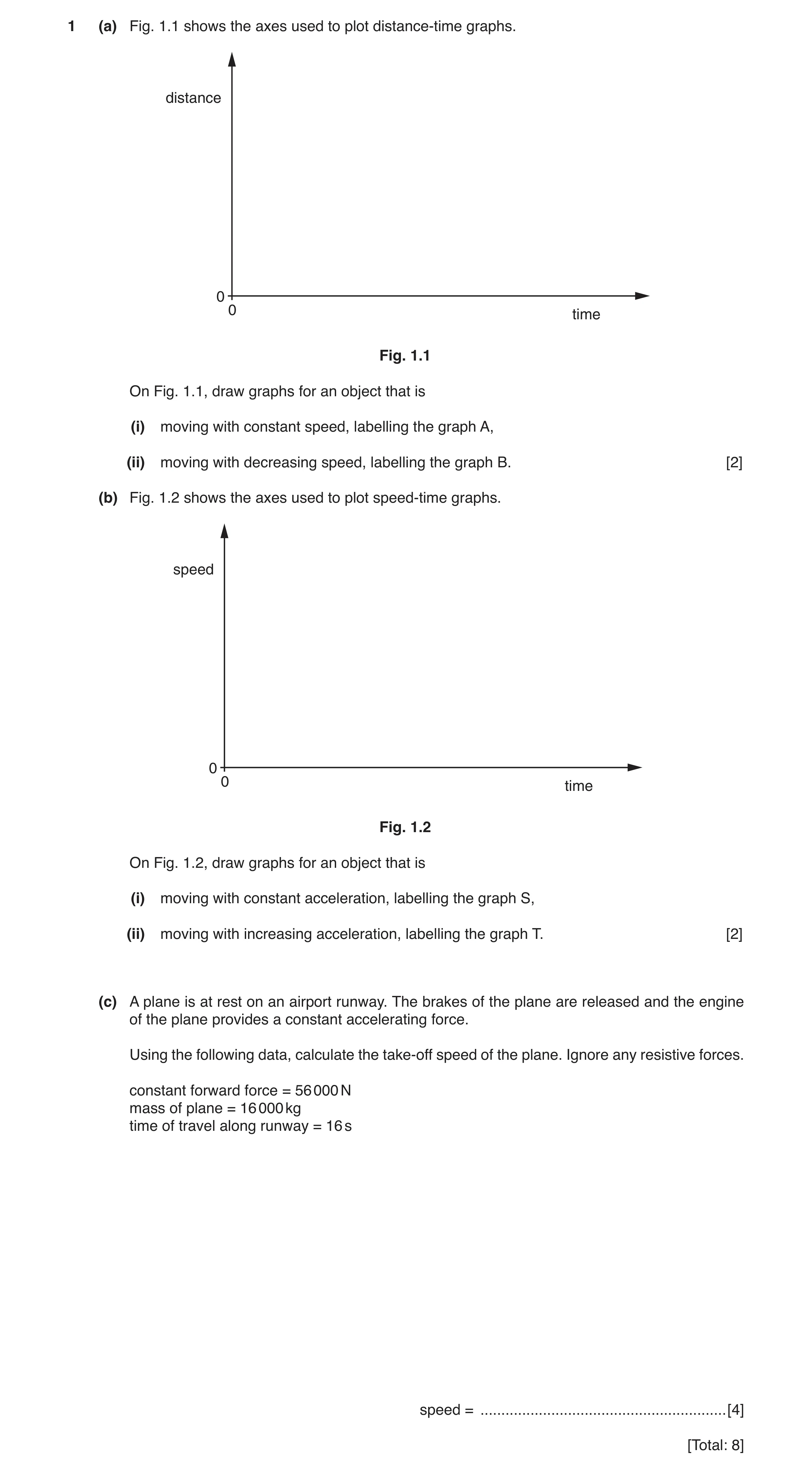
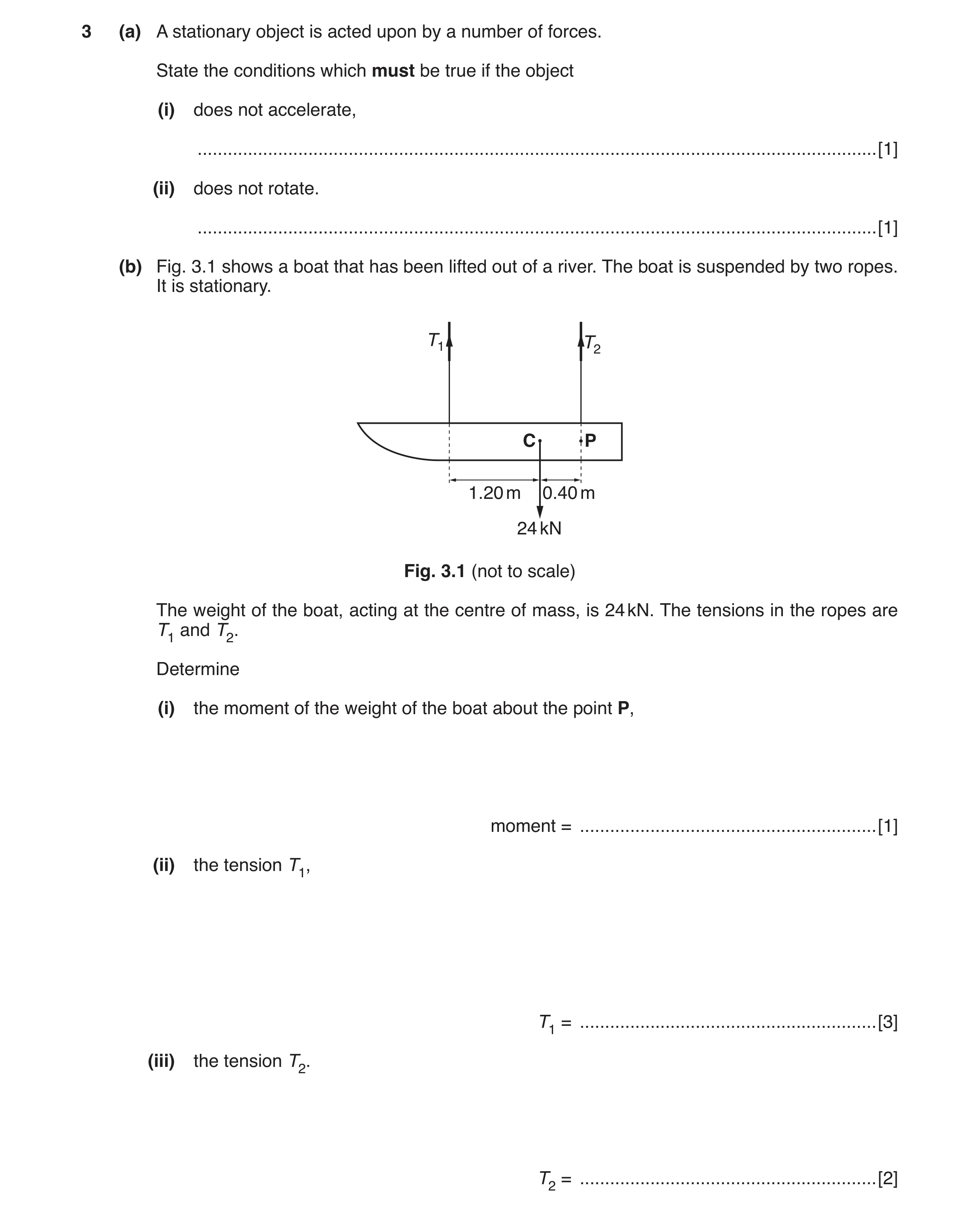 3 / 83
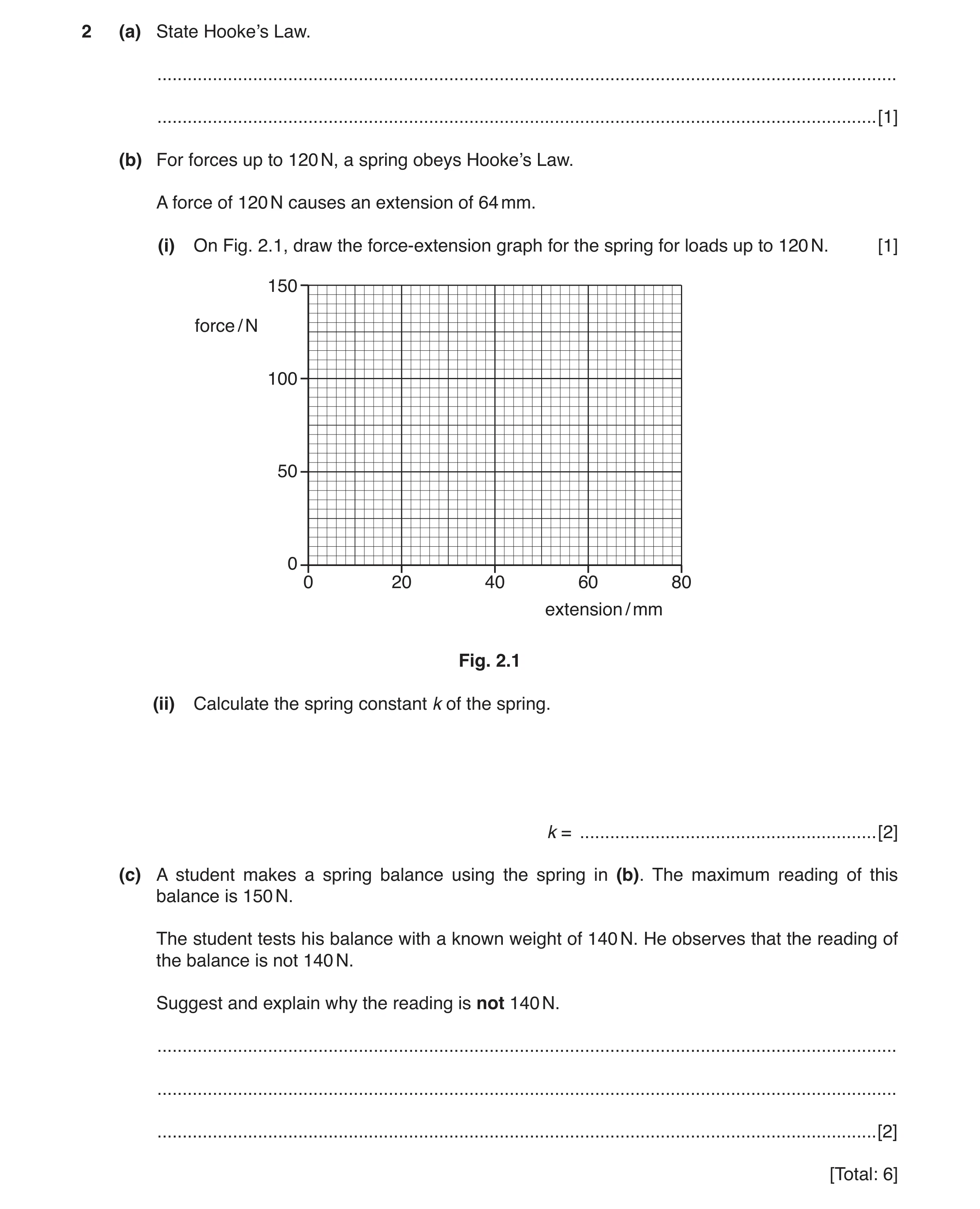 4 / 83
 5 / 83
 6 / 83
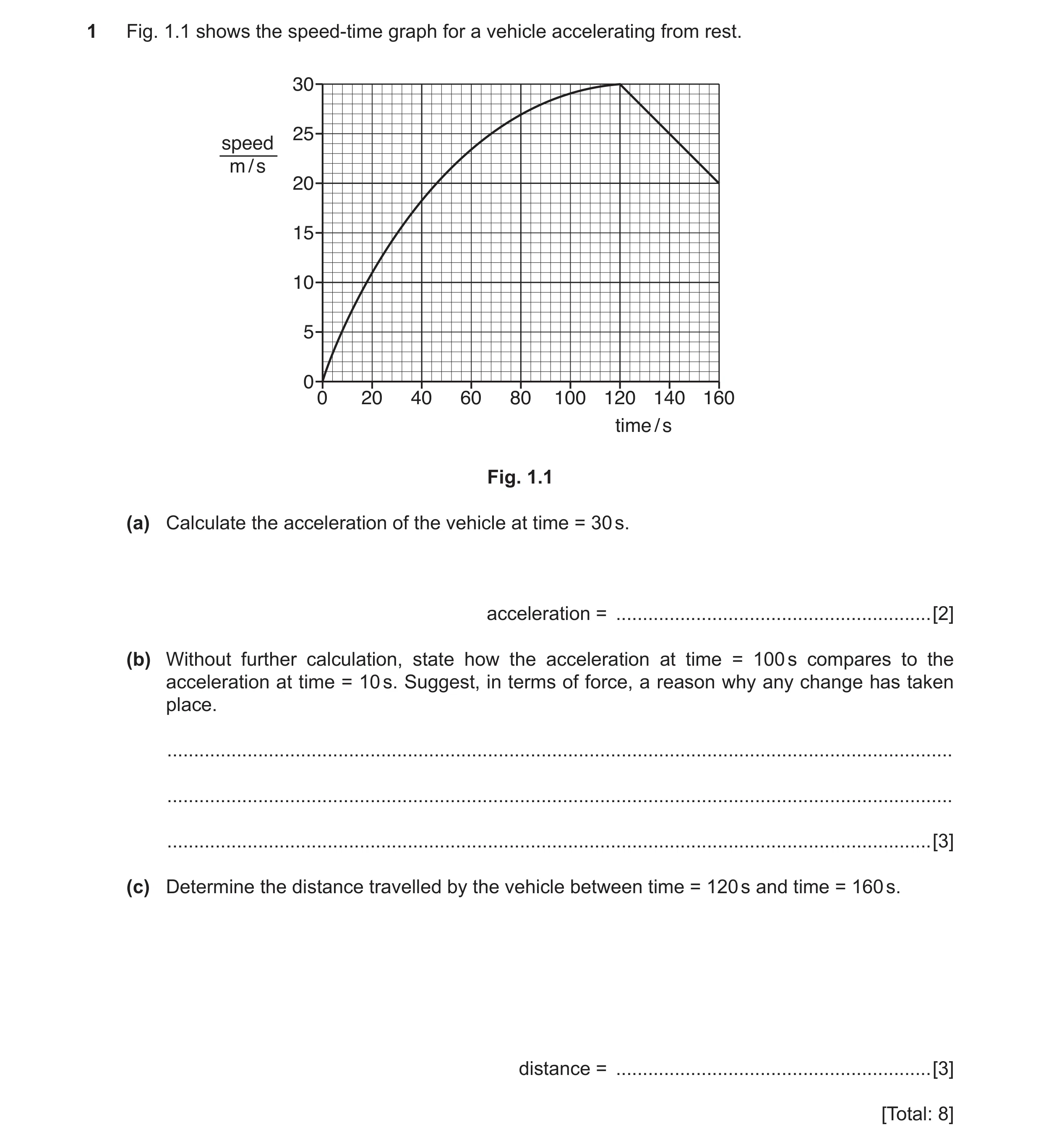 7 / 83
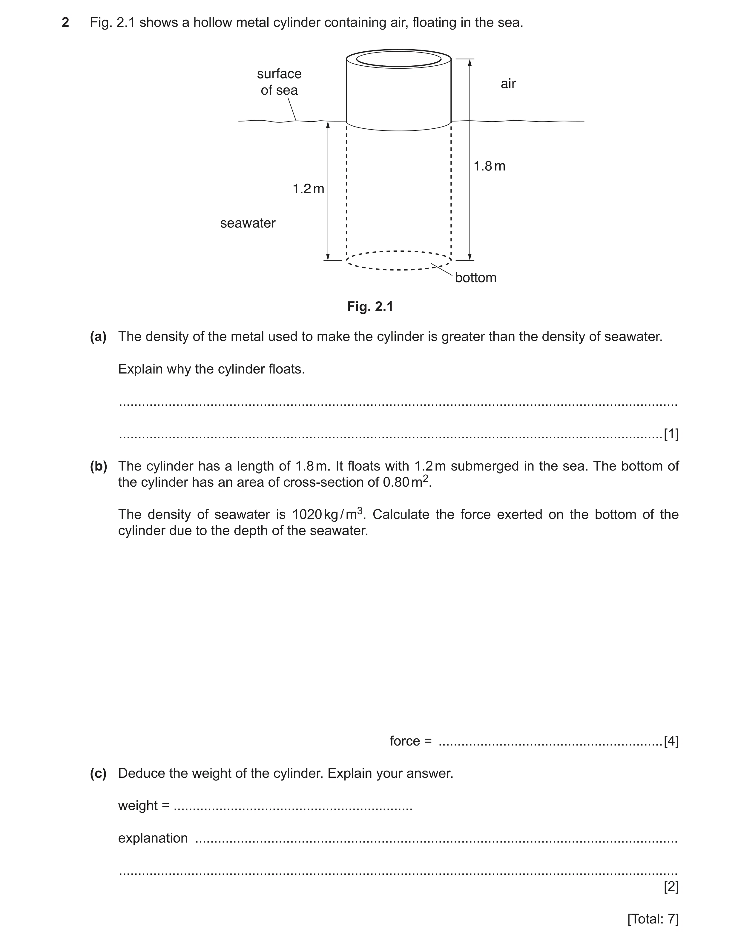 8 / 83
 9 / 83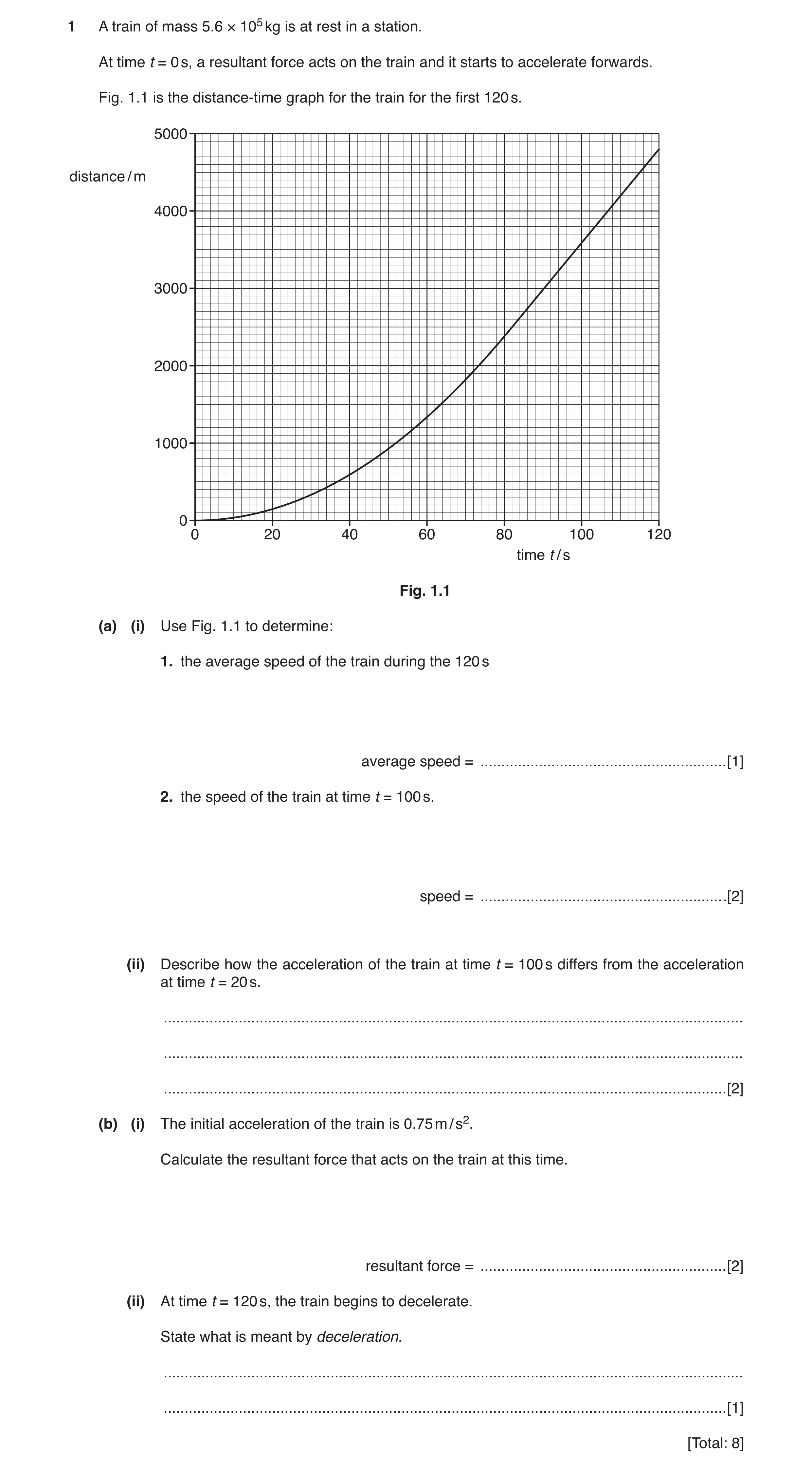
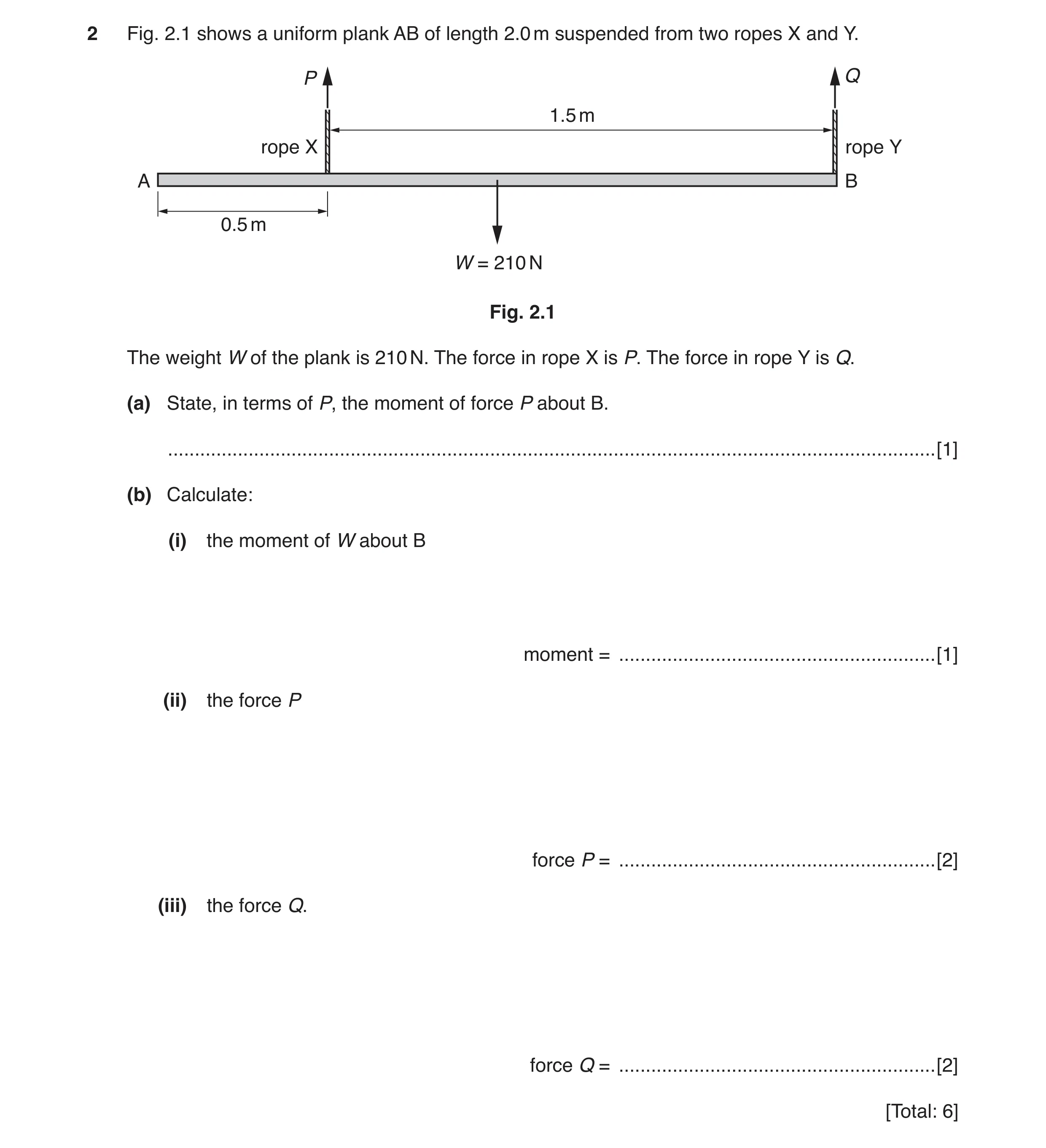 12 / 83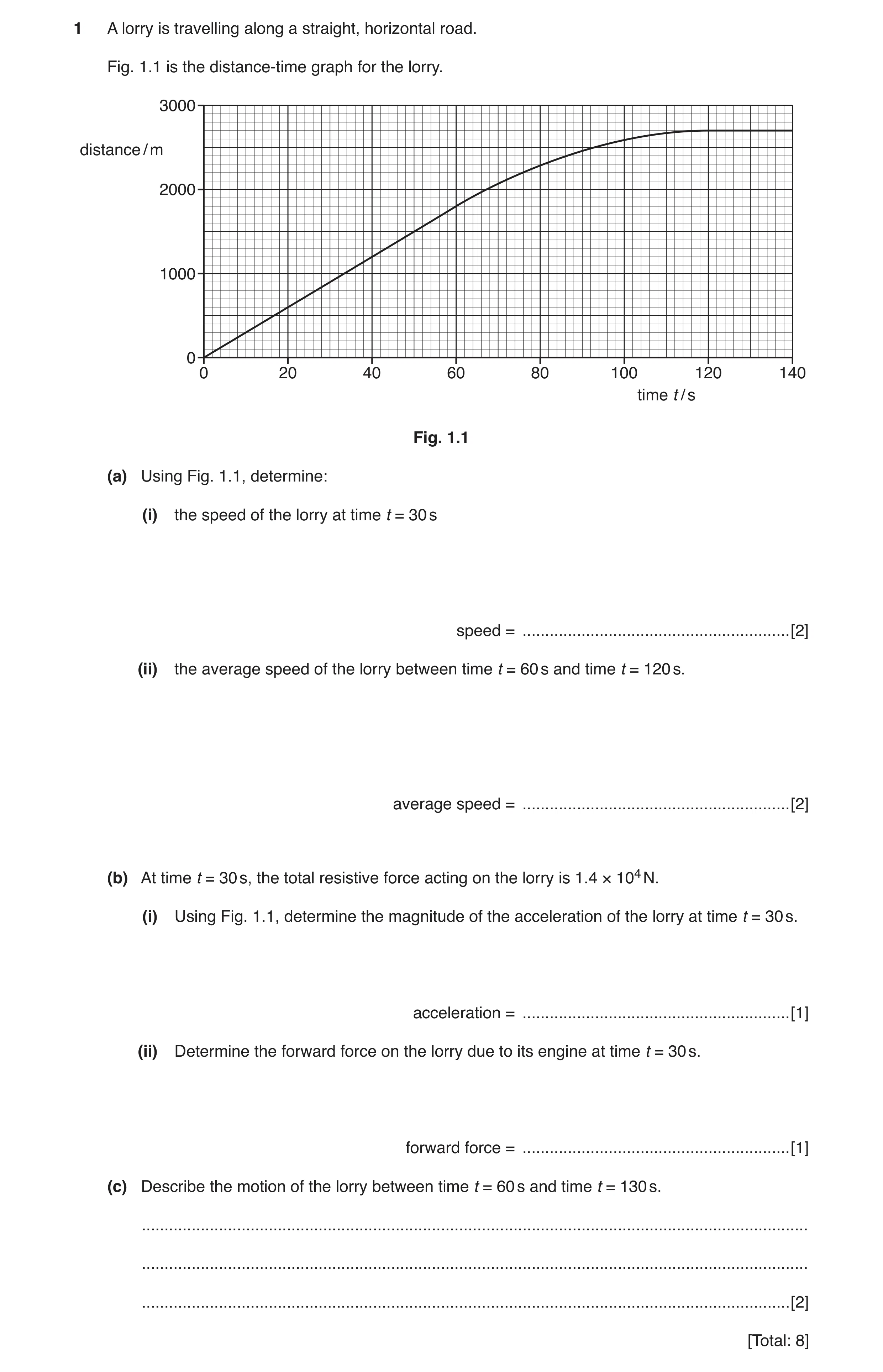
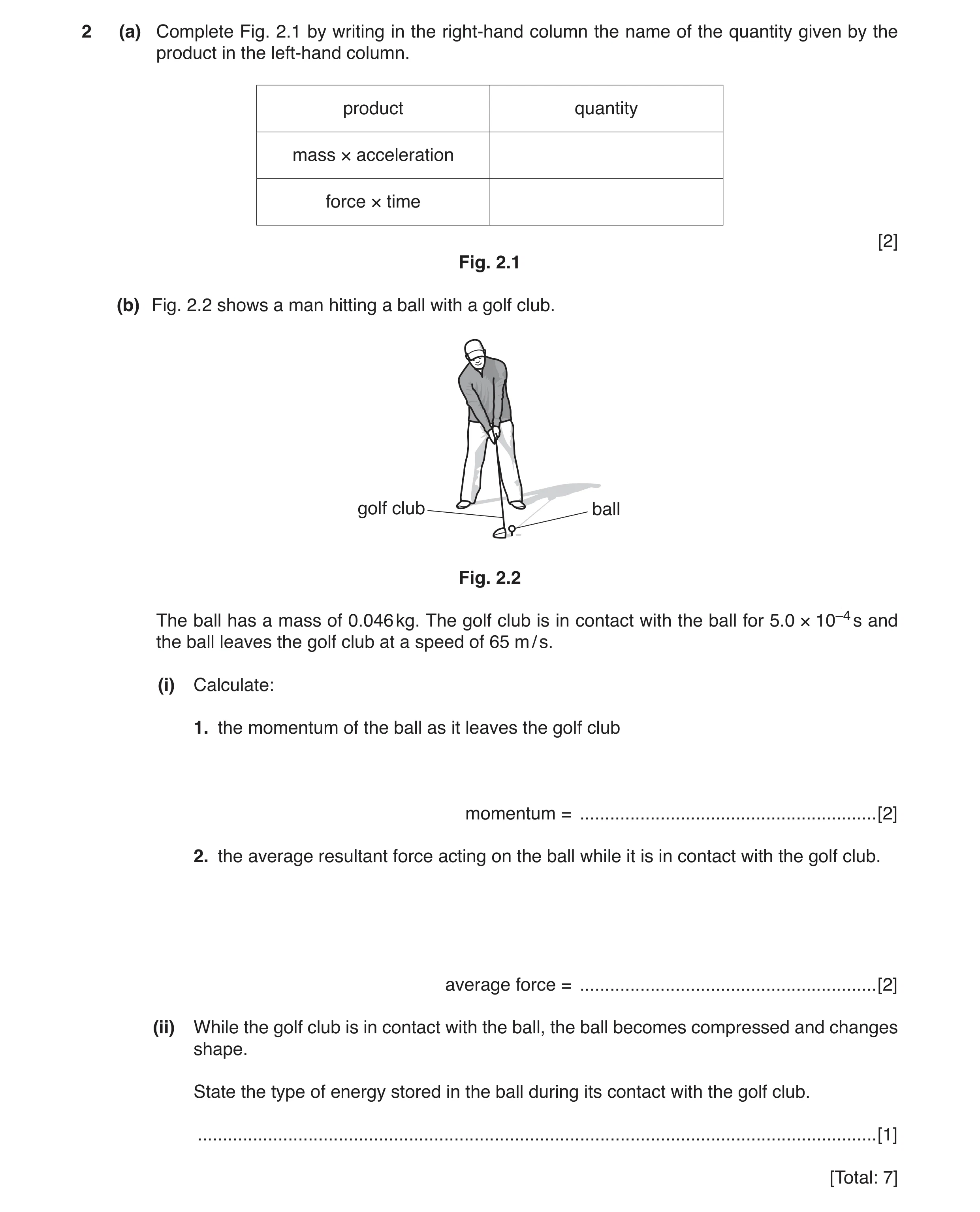 15 / 83
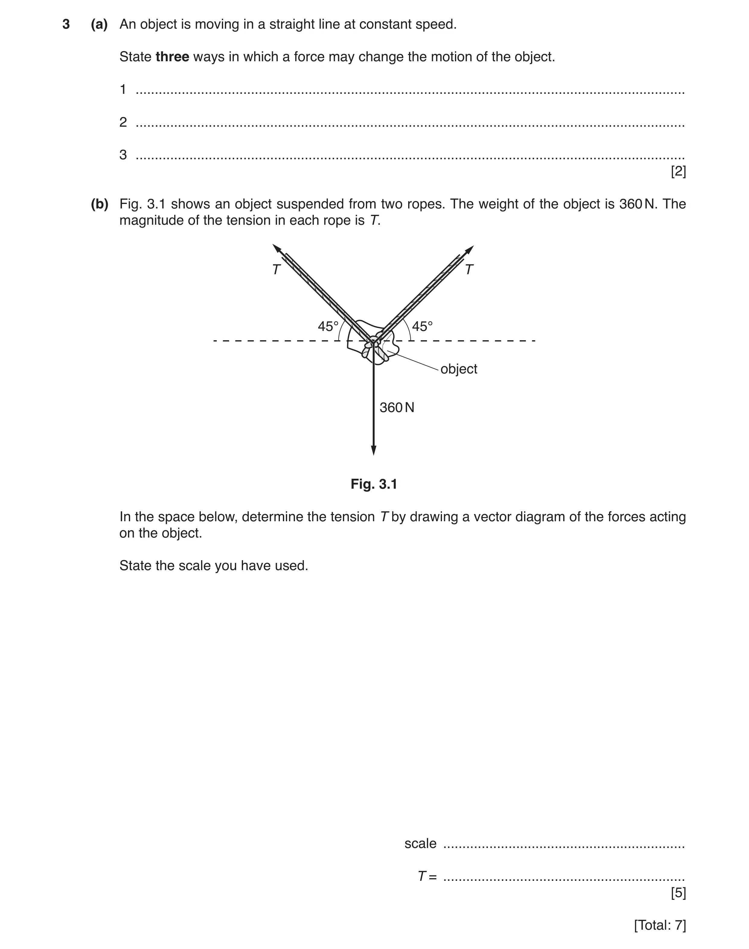 16 / 83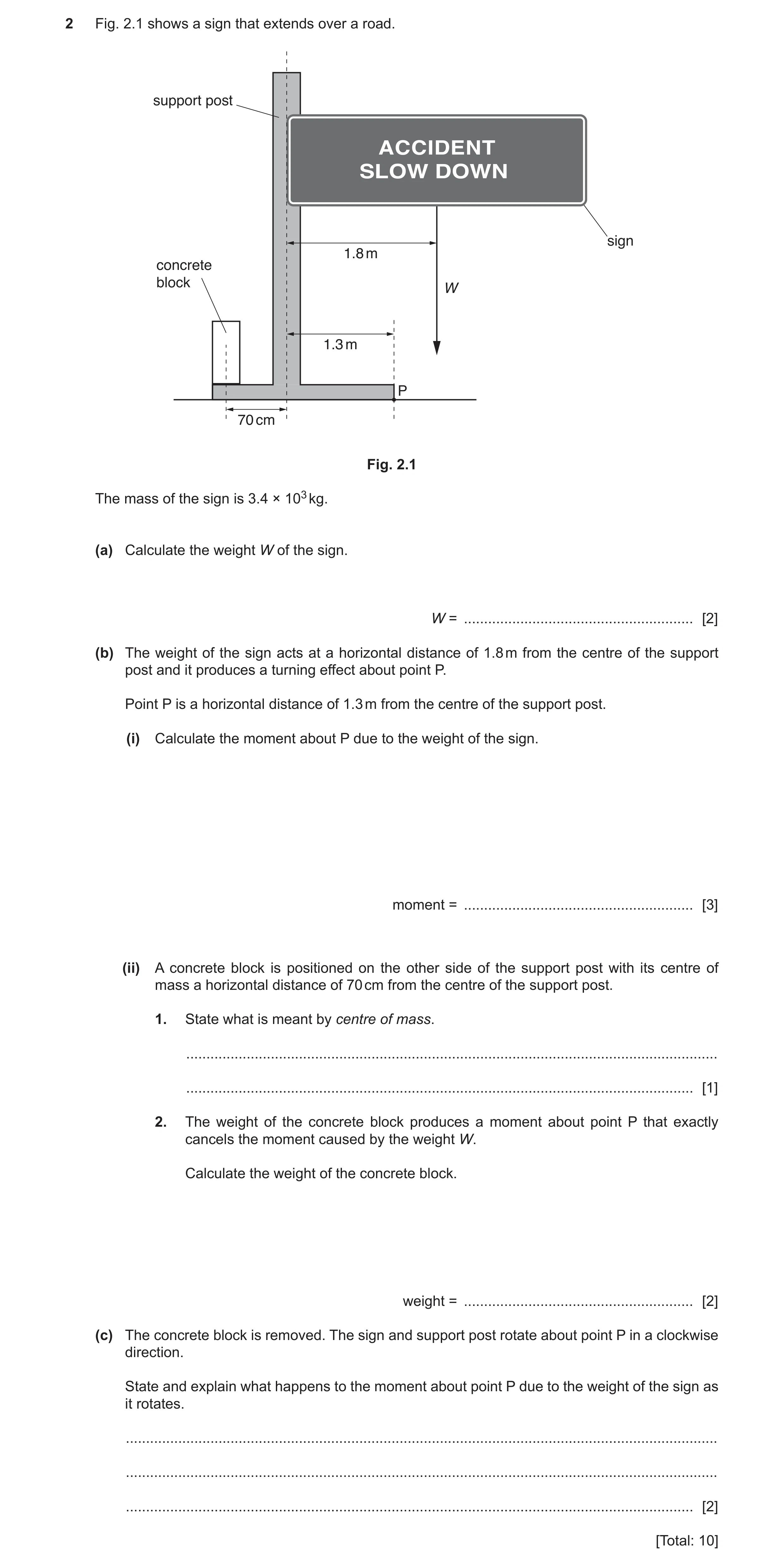
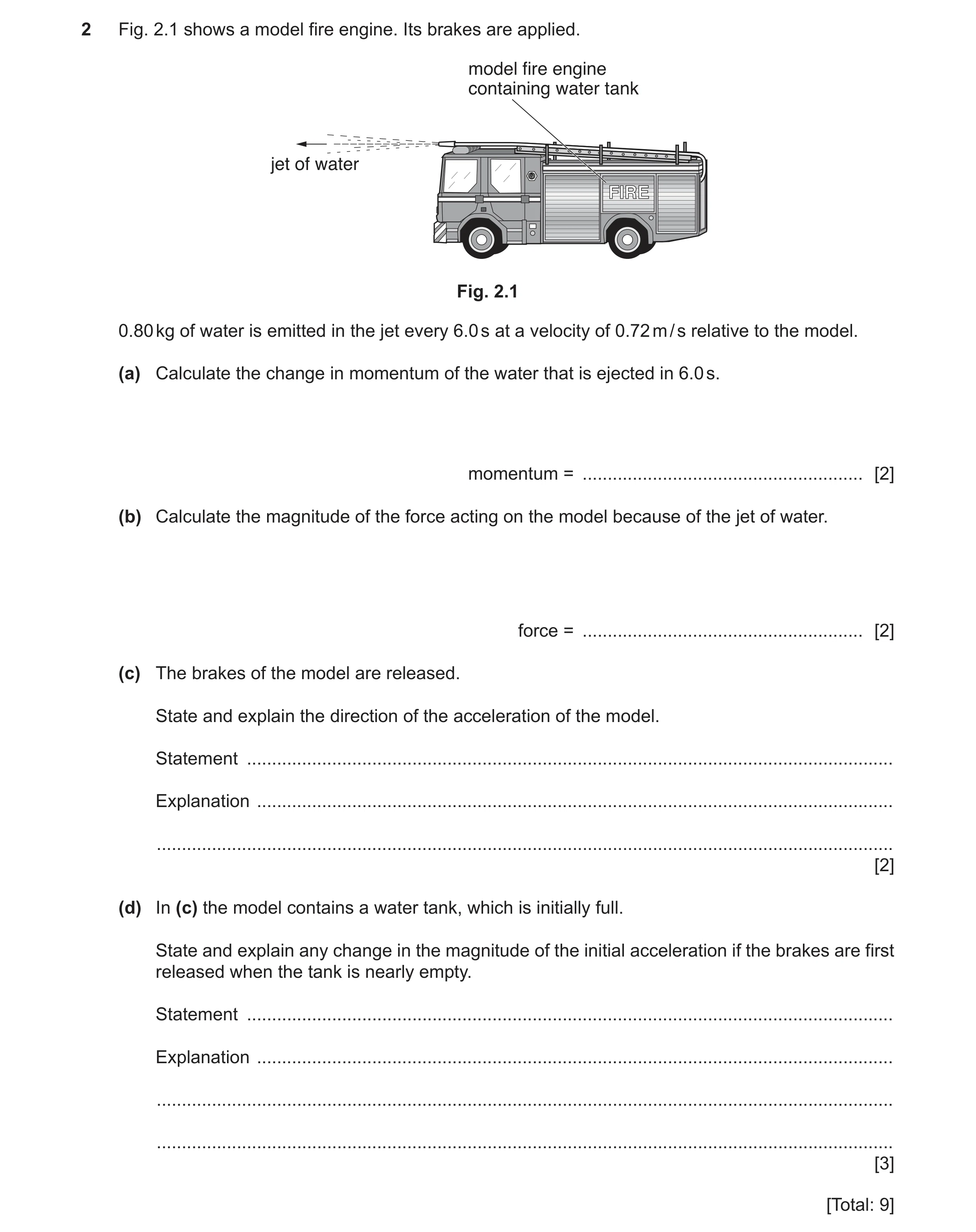 19 / 83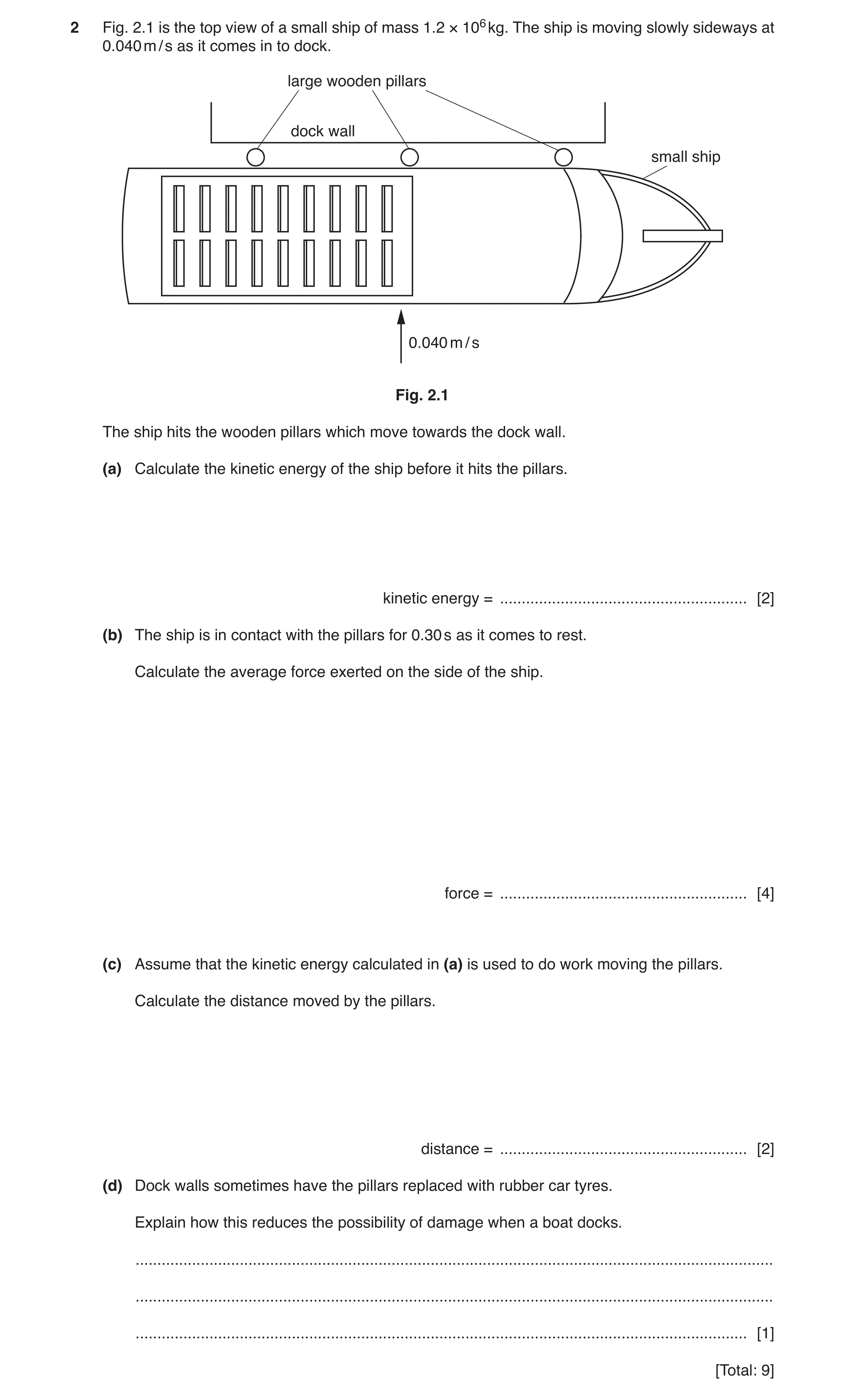
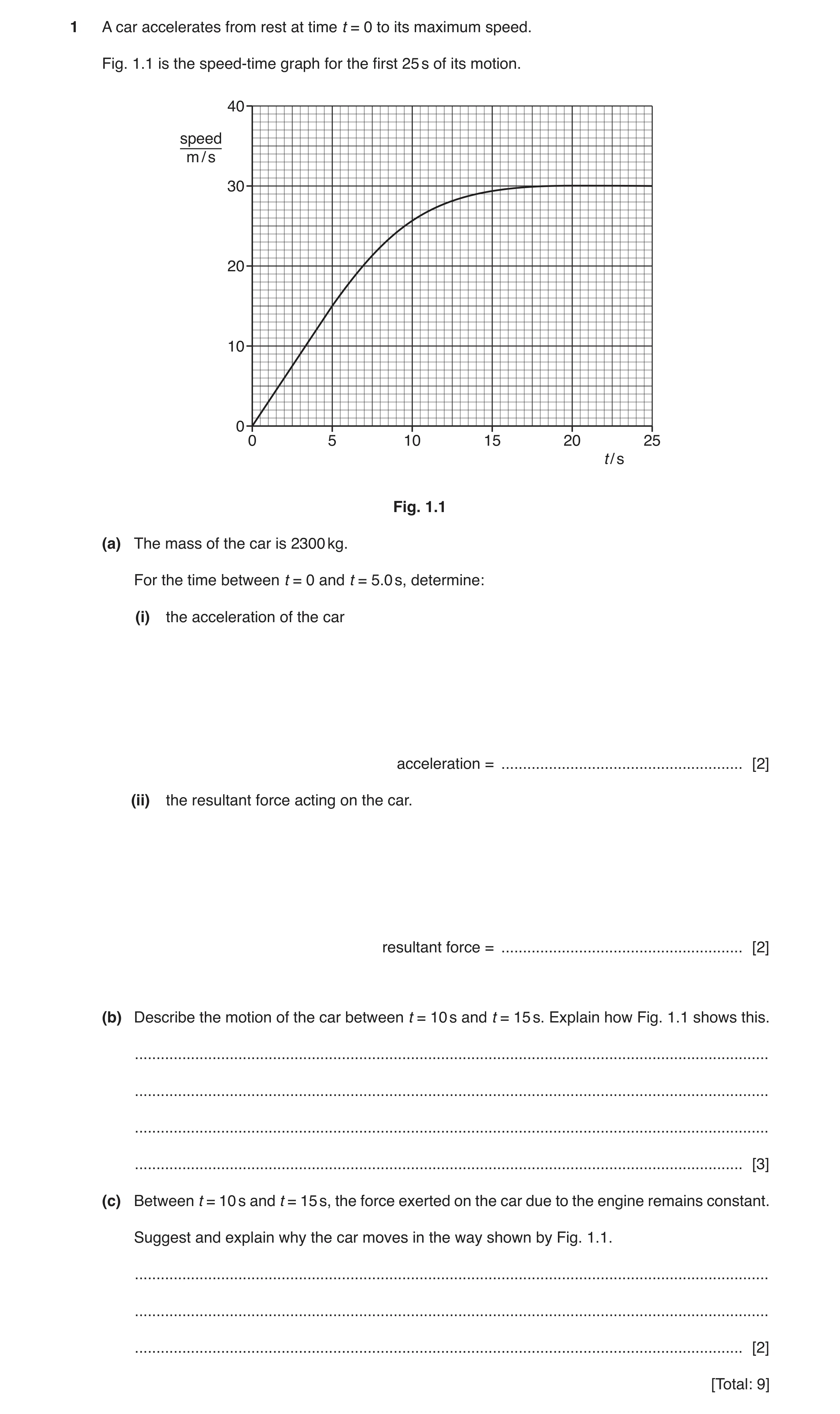
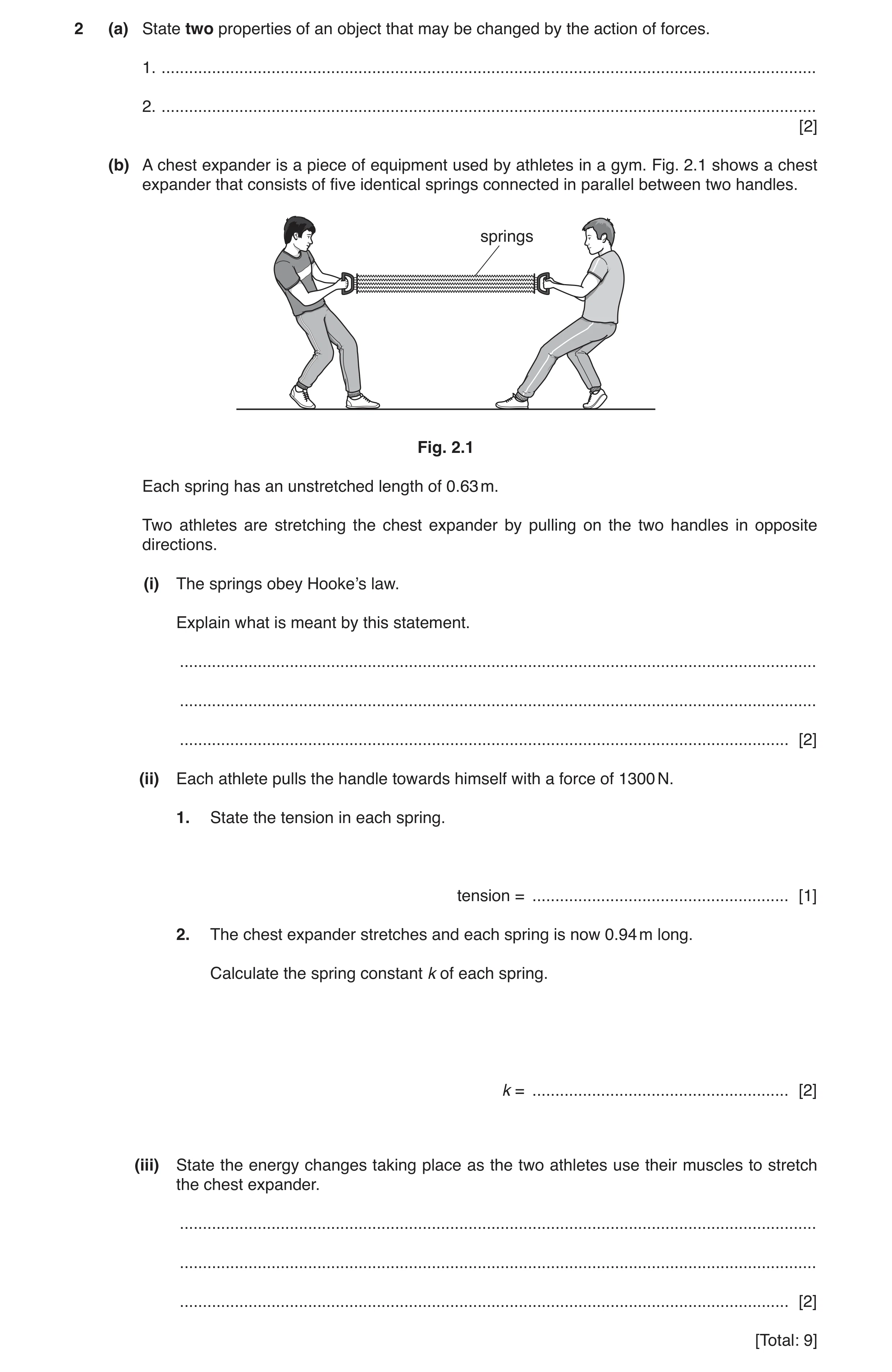
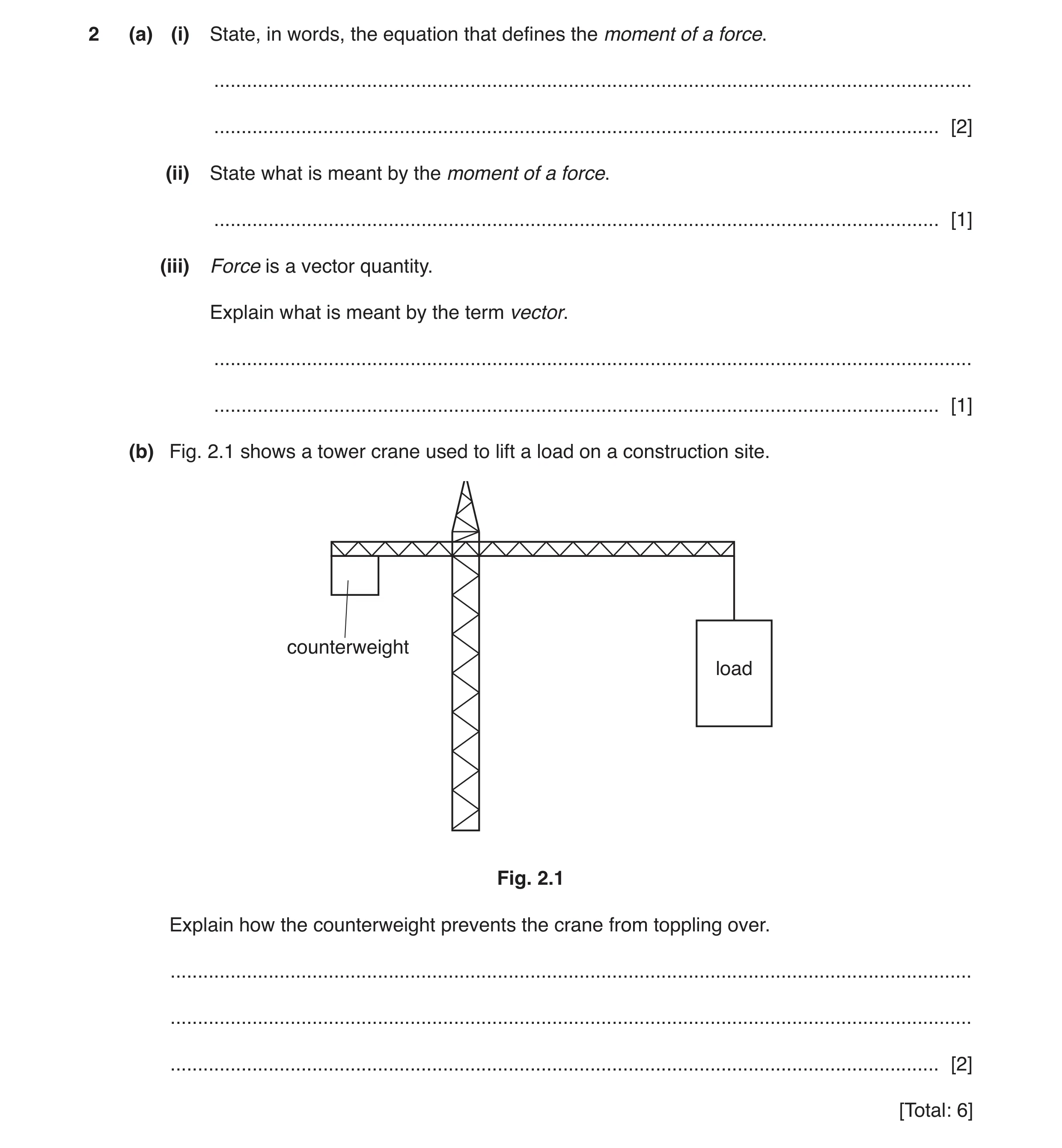 24 / 83
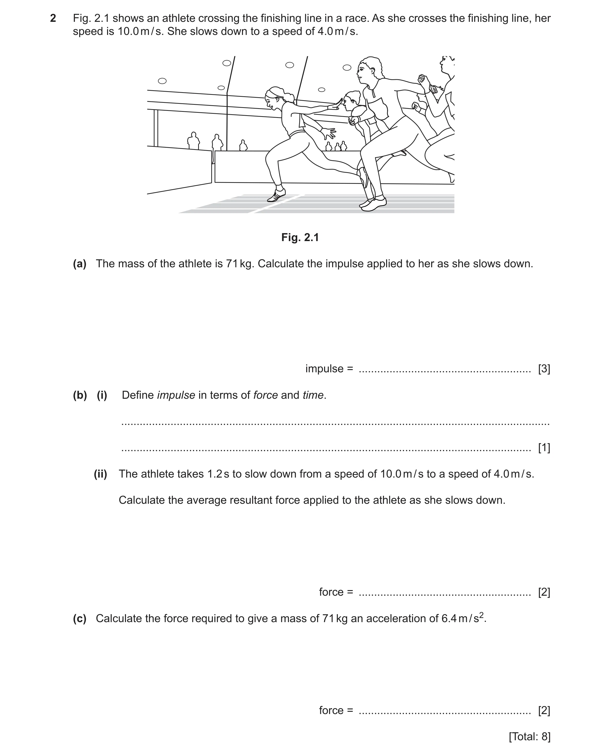 25 / 83
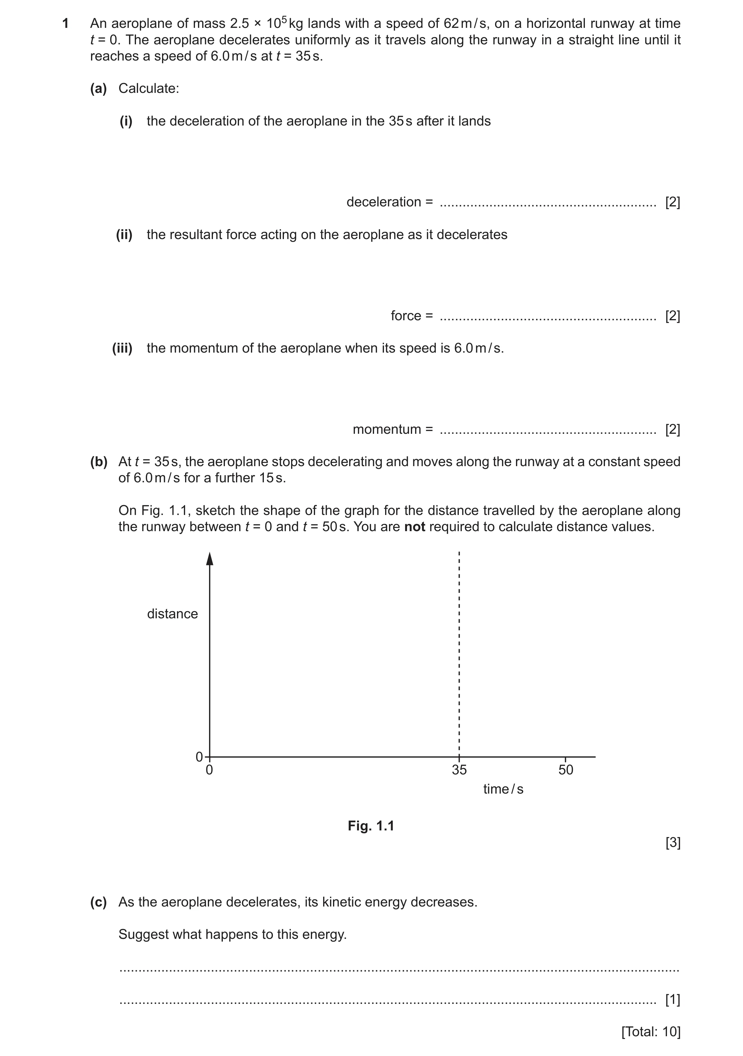 26 / 83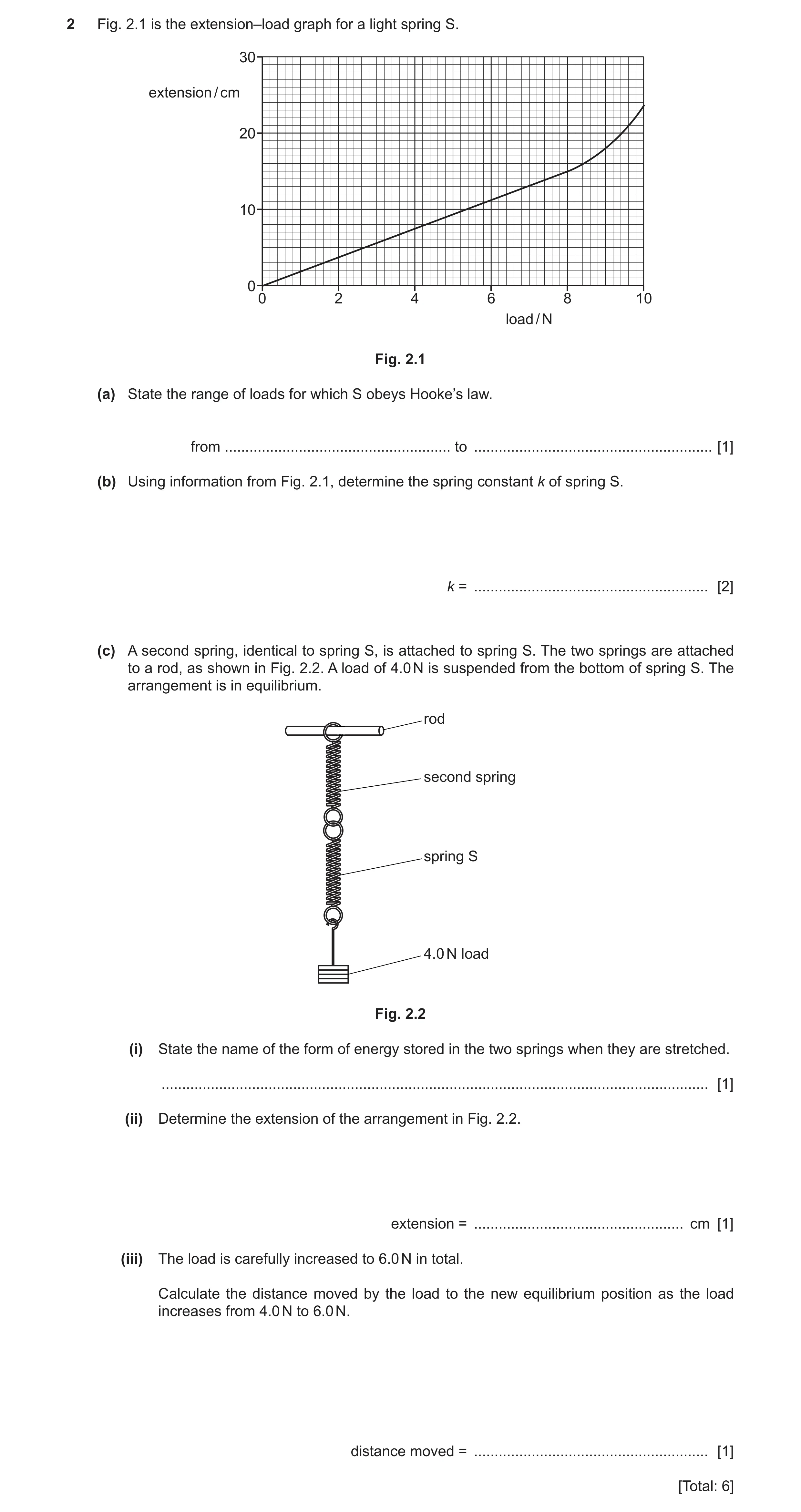
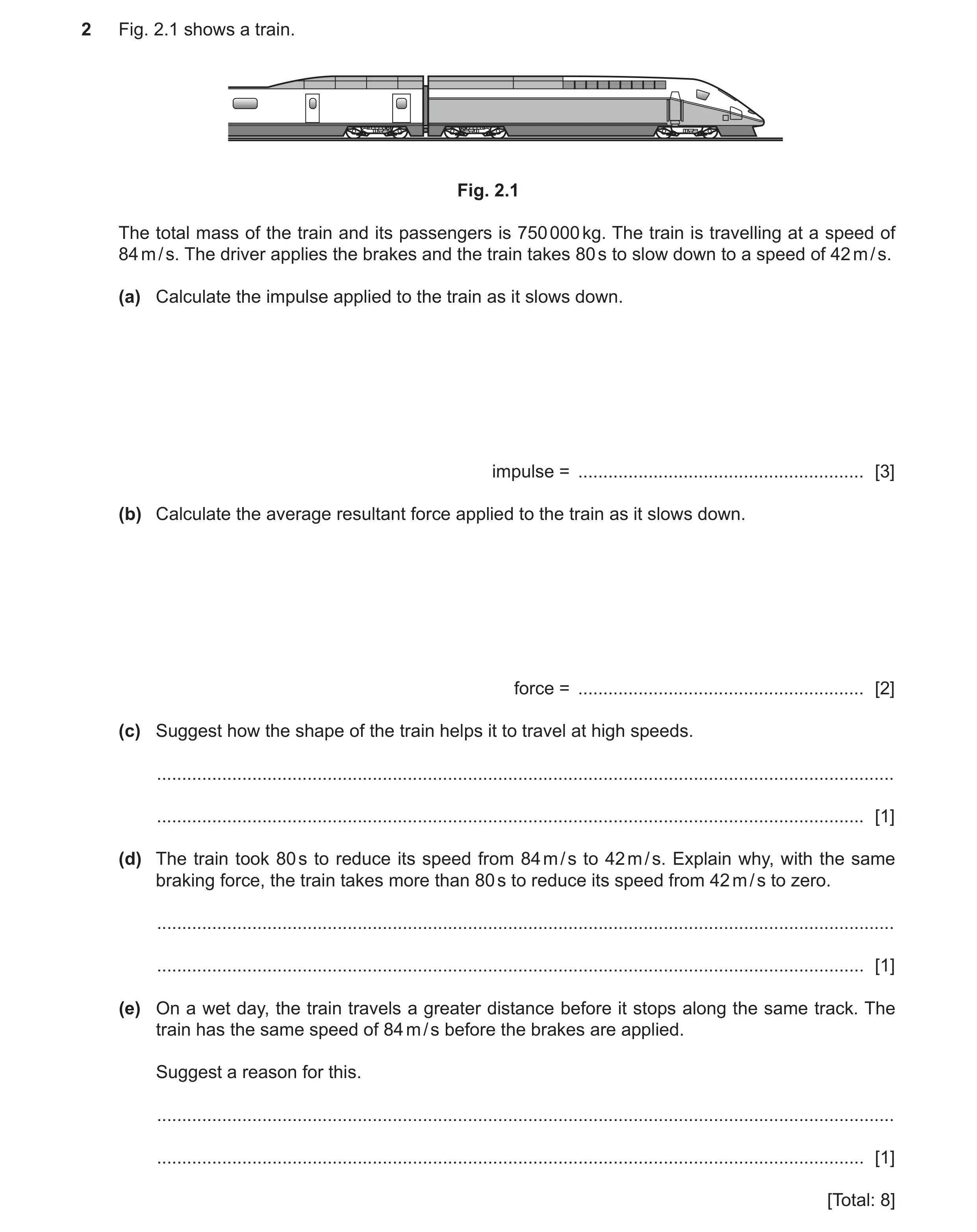 29 / 83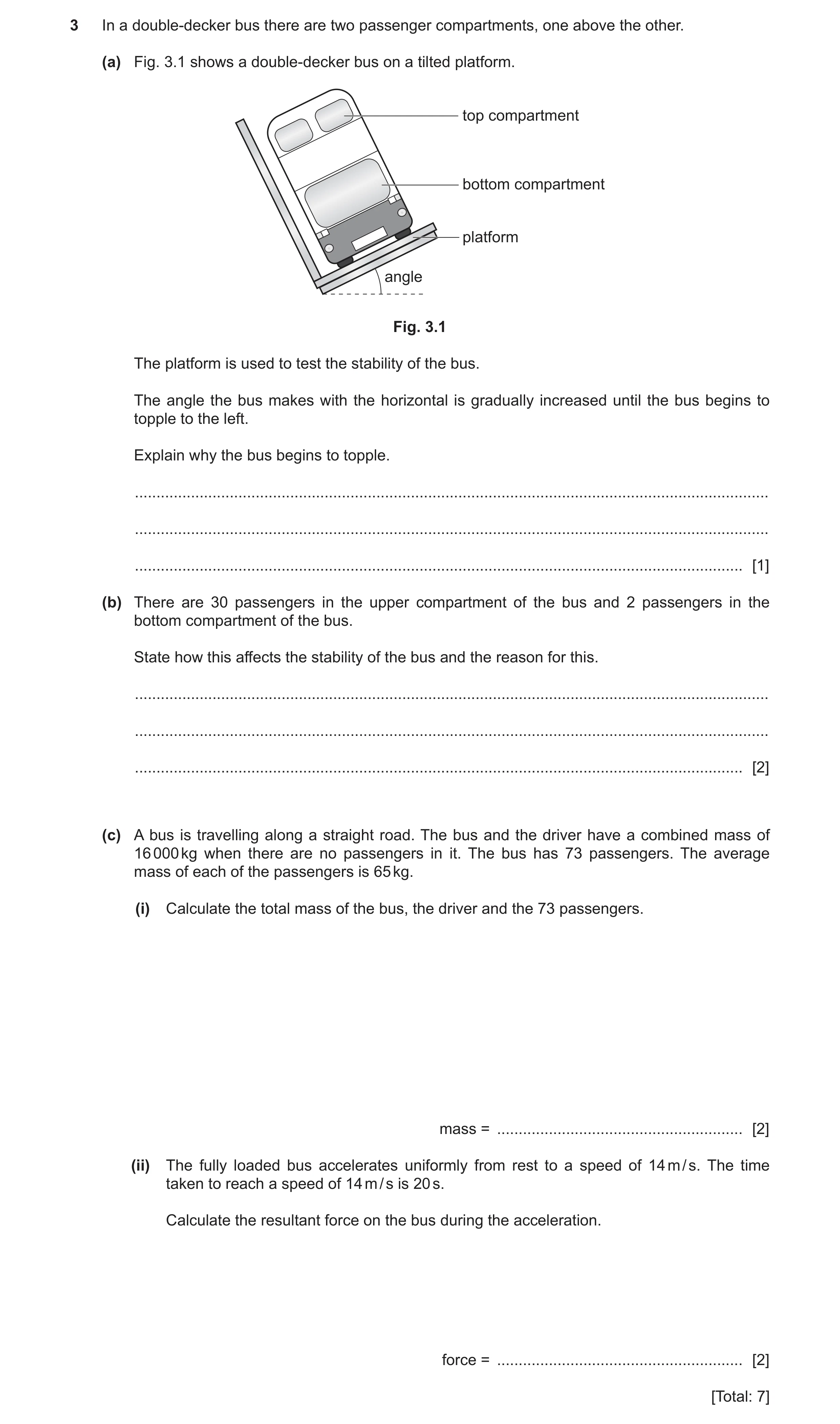
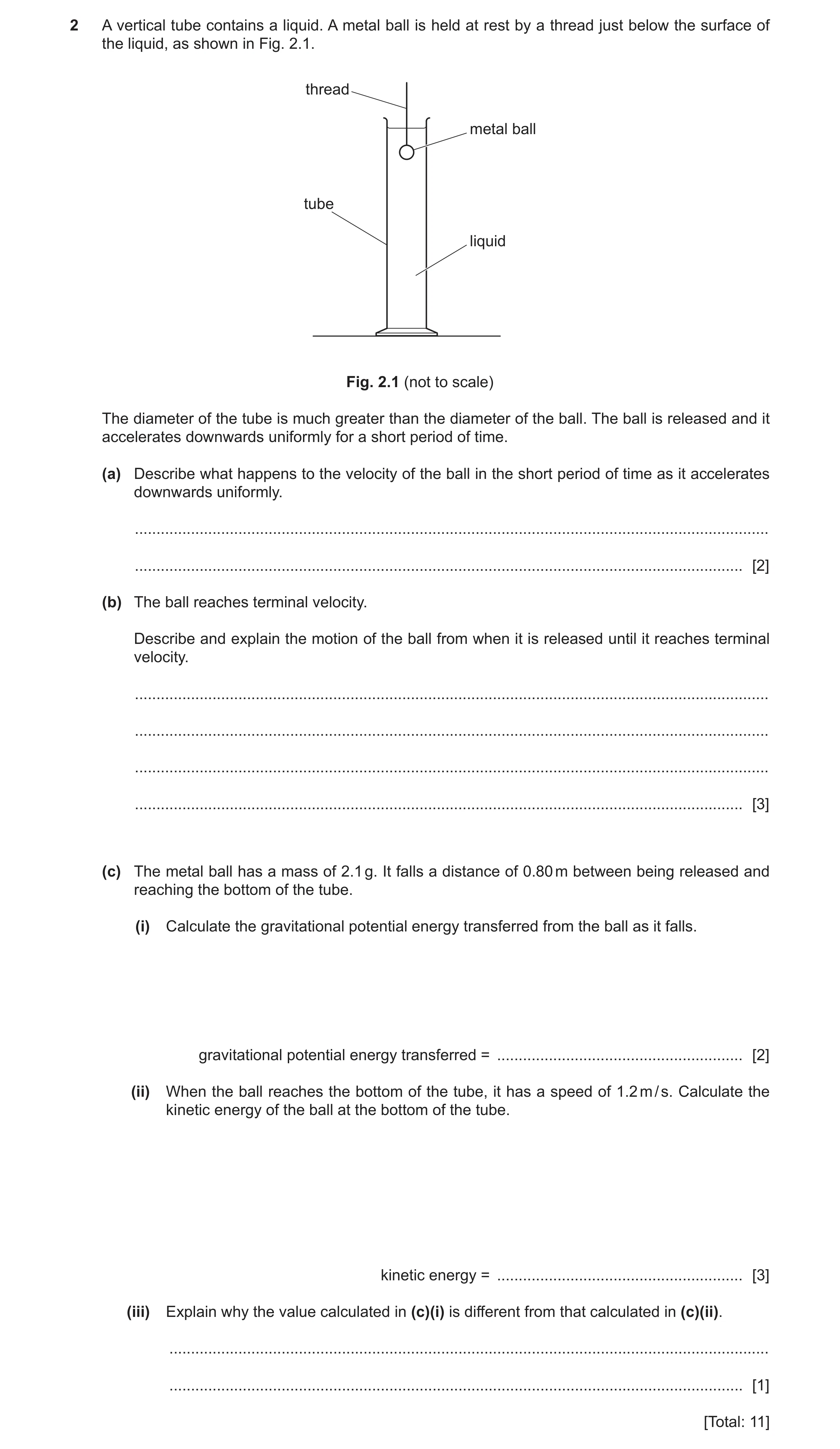
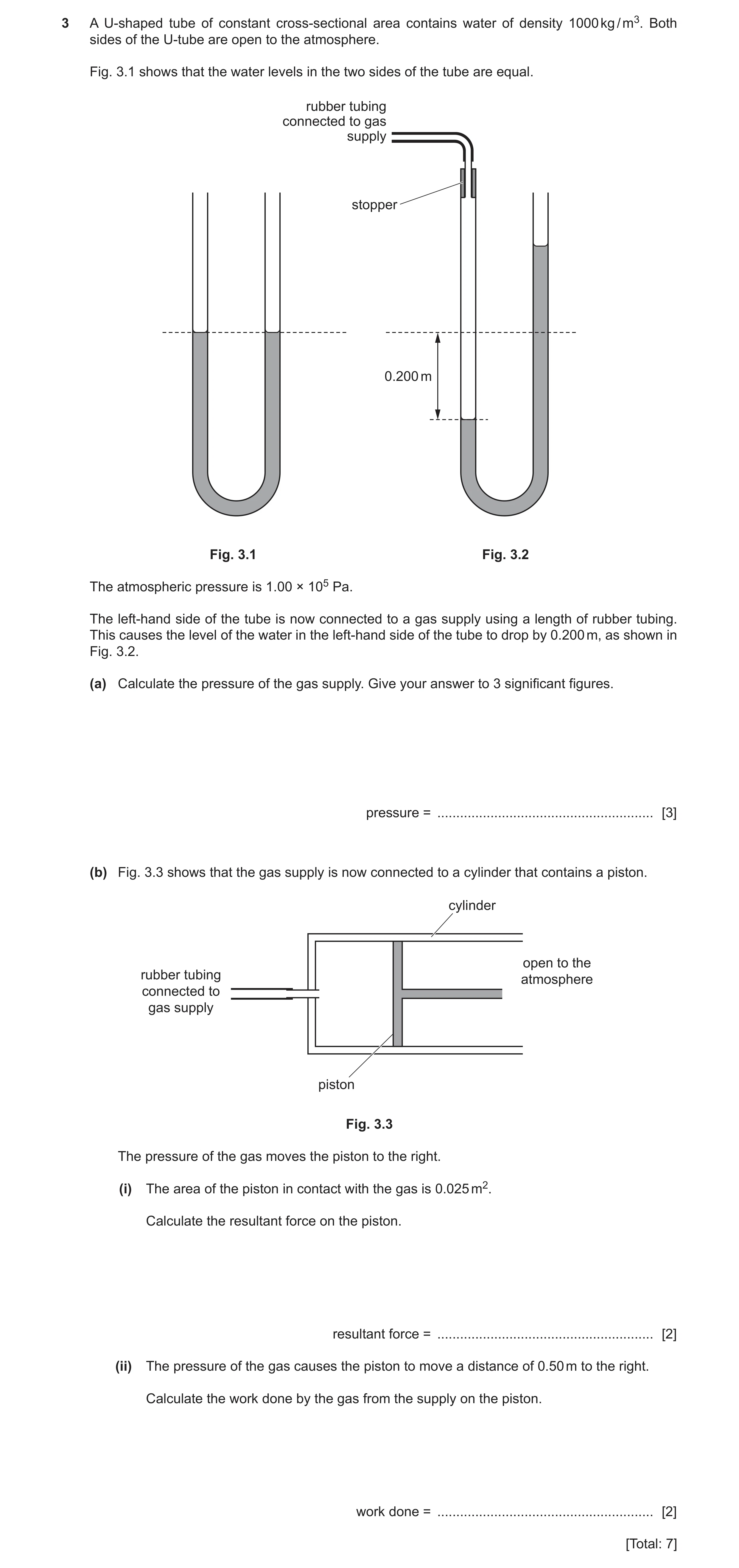
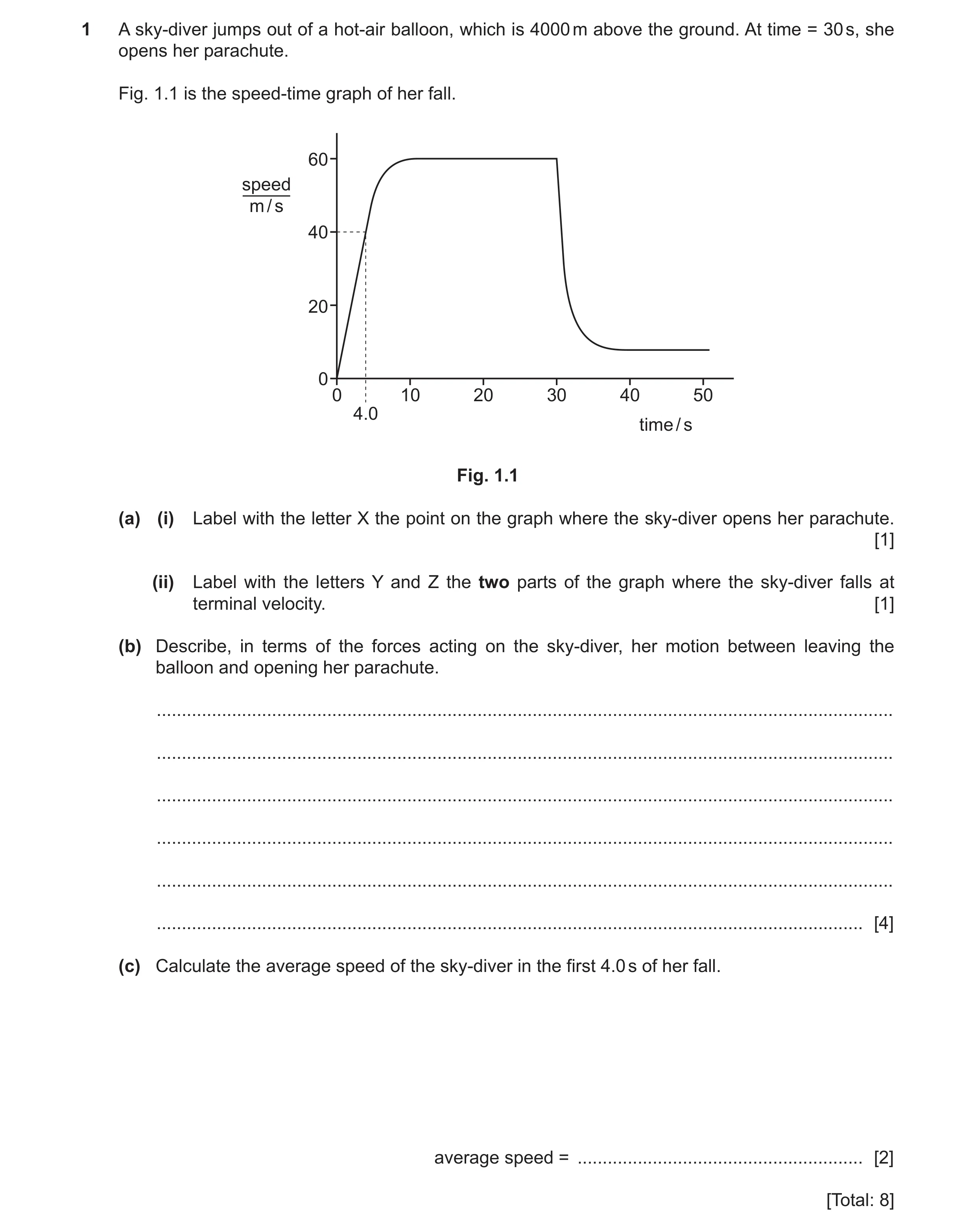 34 / 83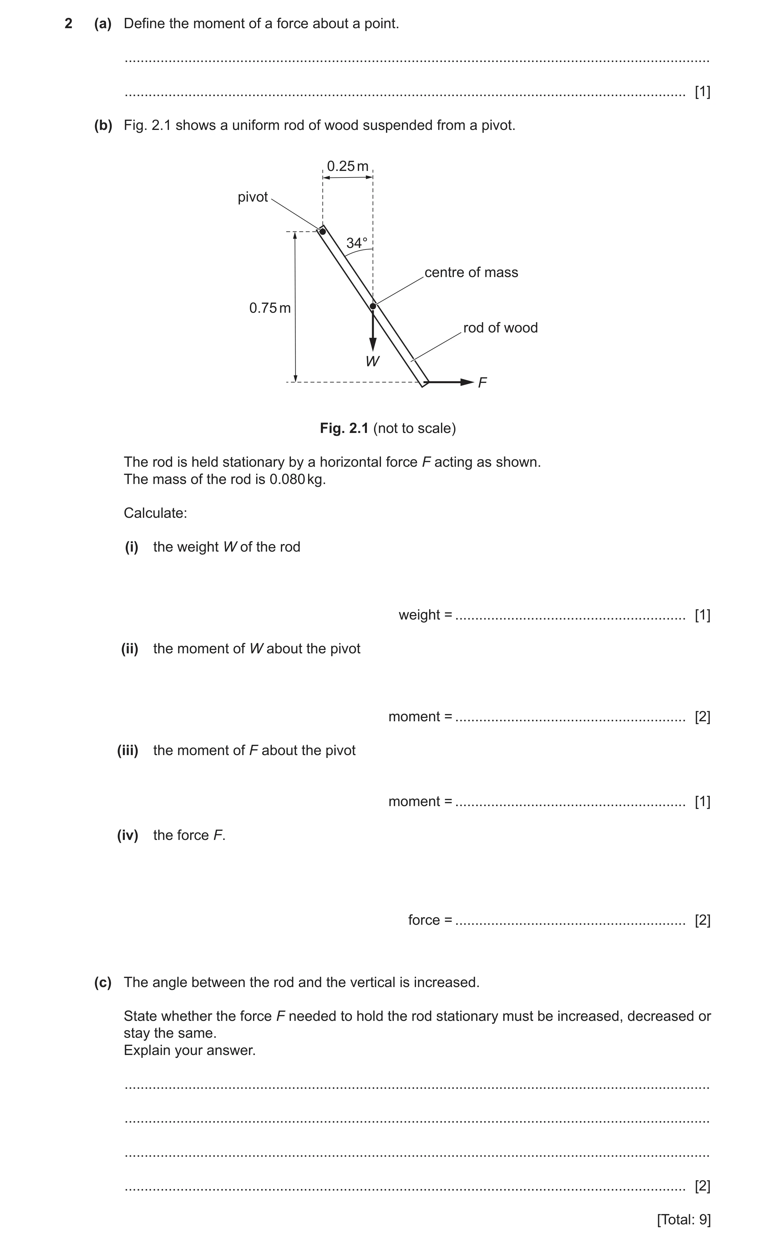
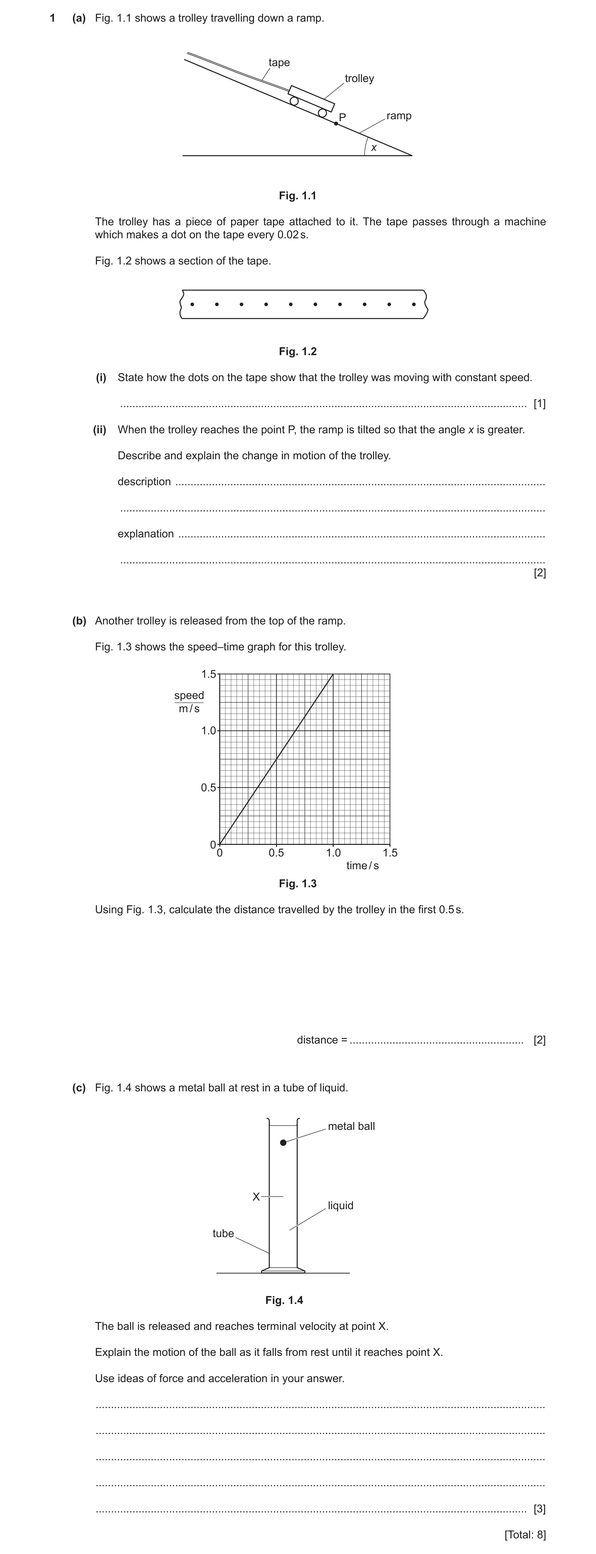
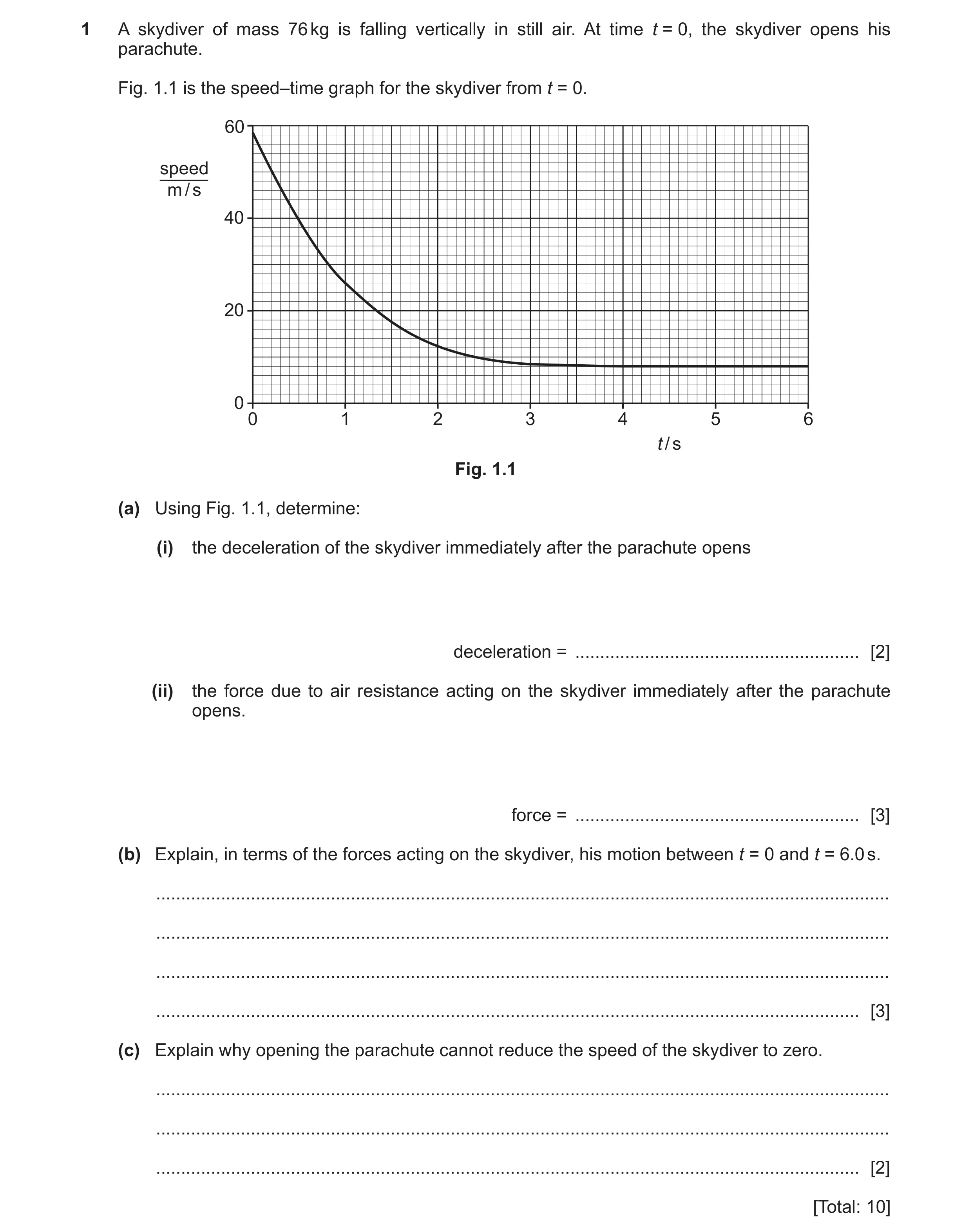 39 / 83
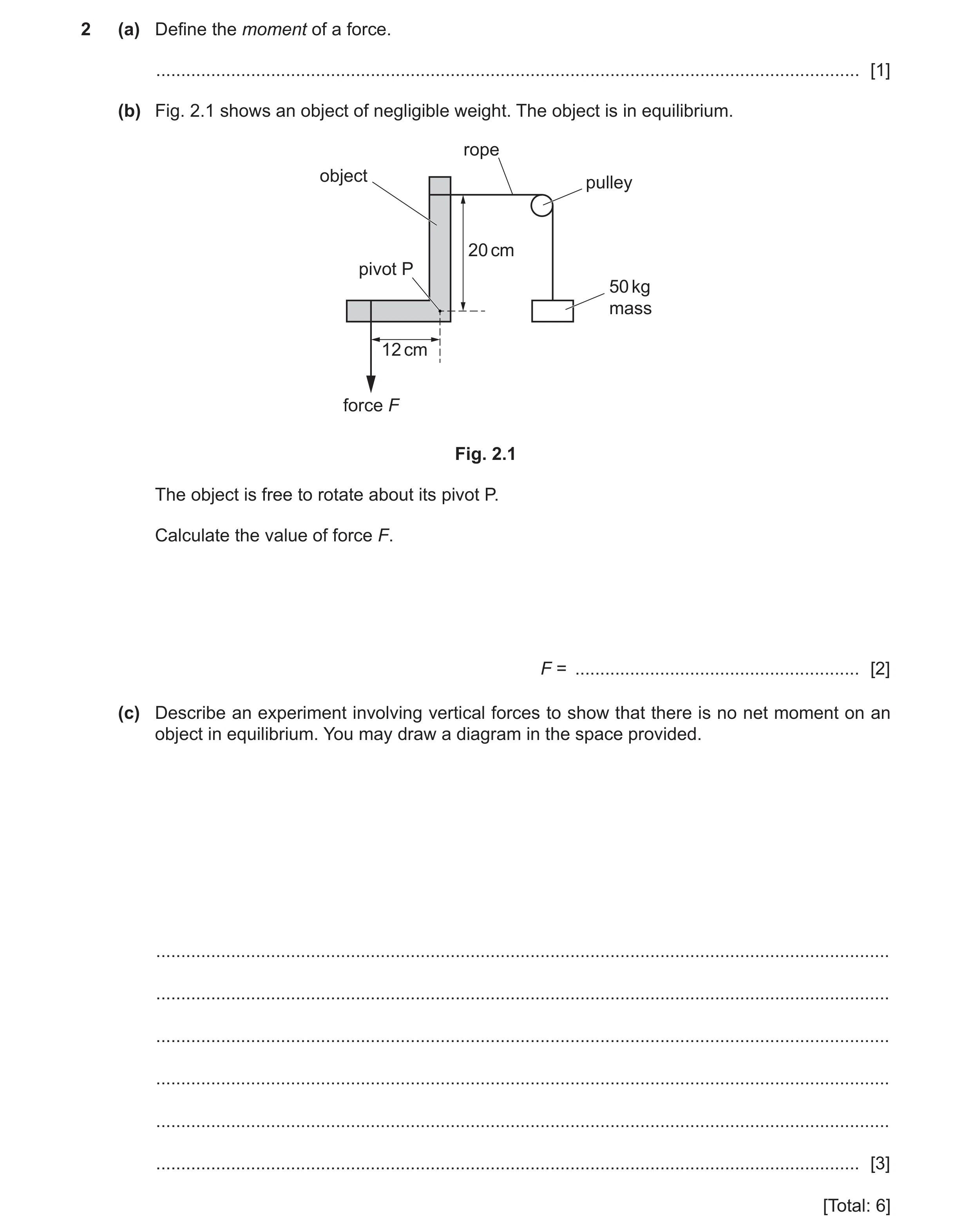 40 / 83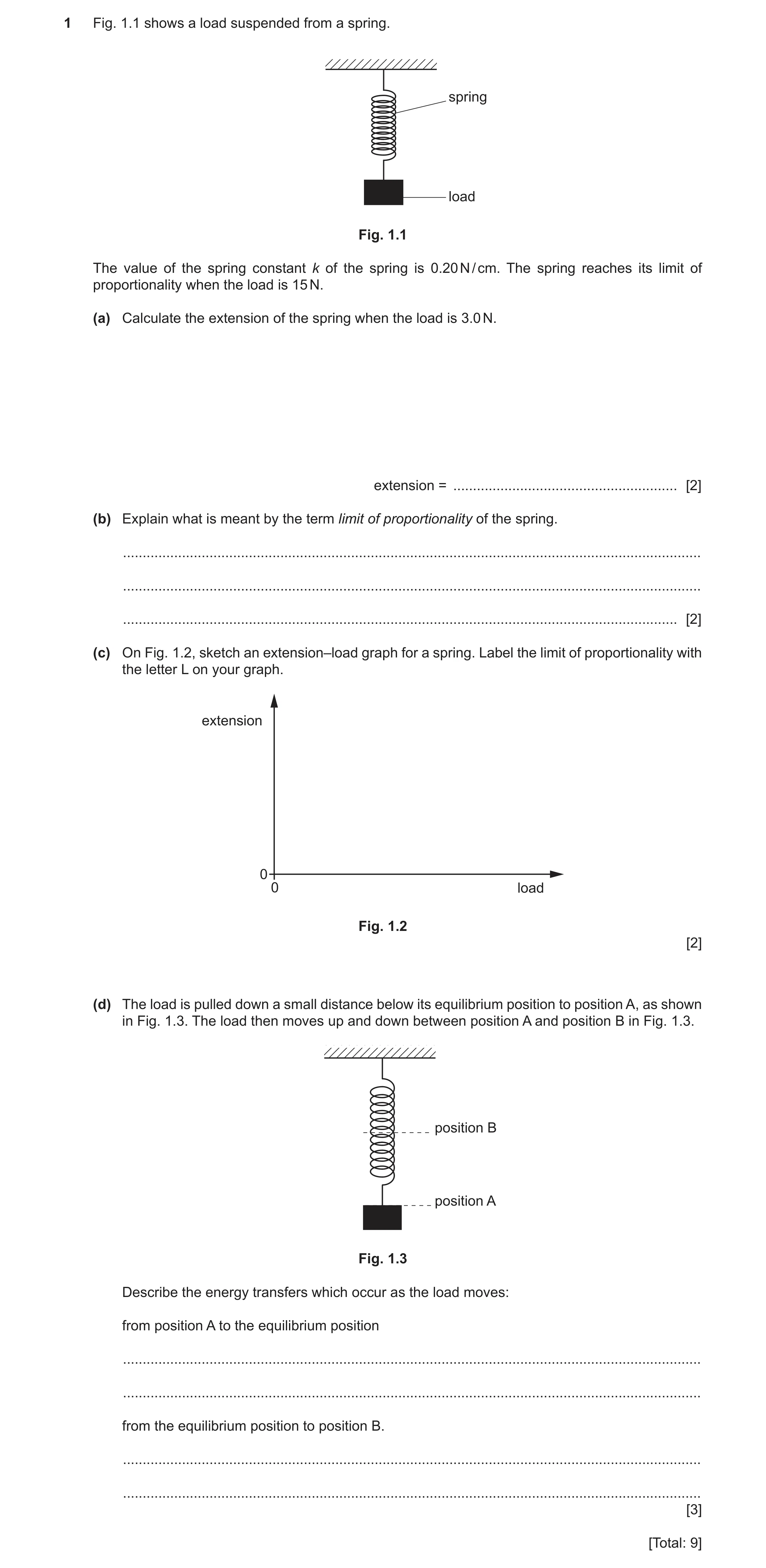
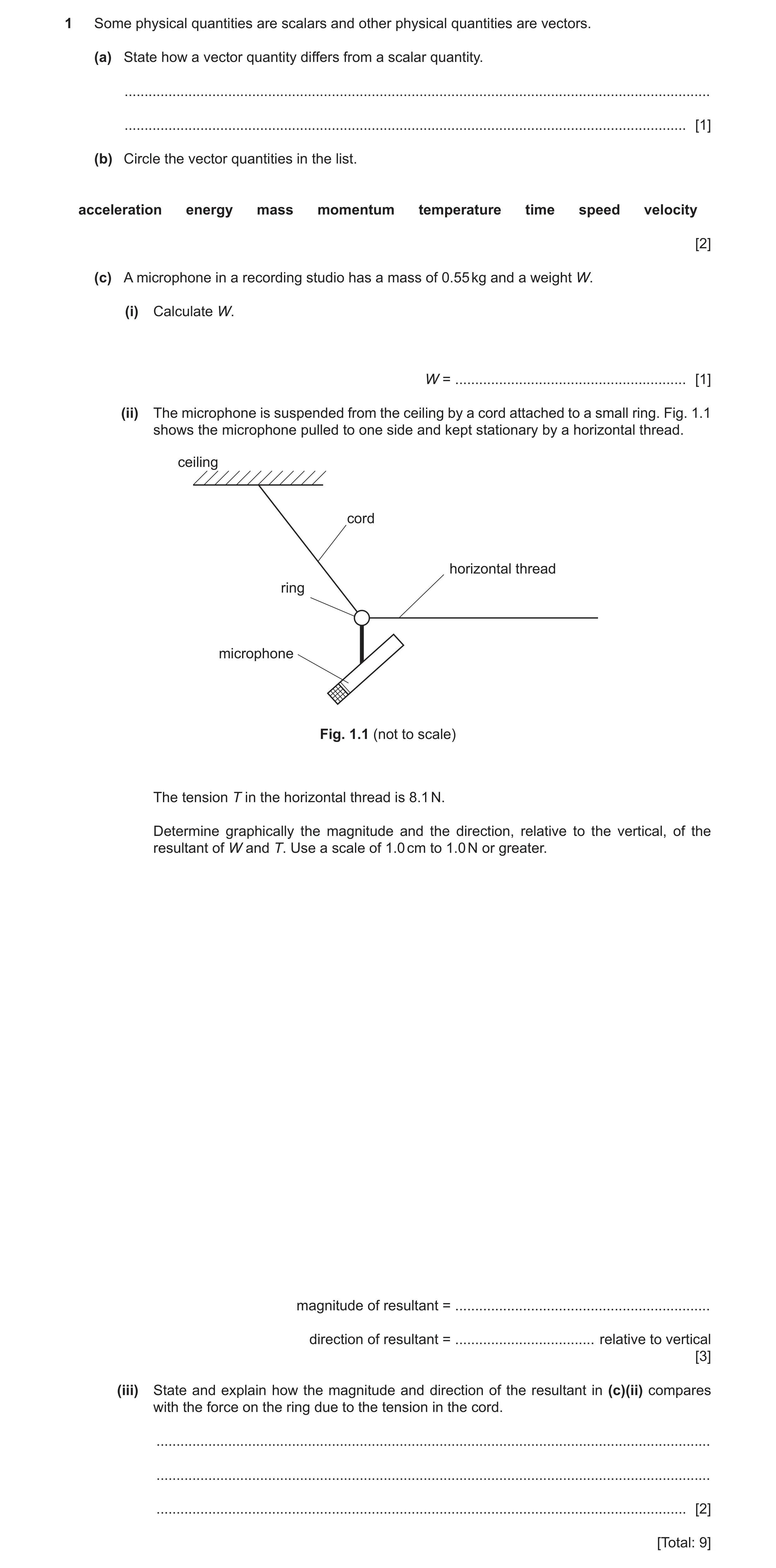
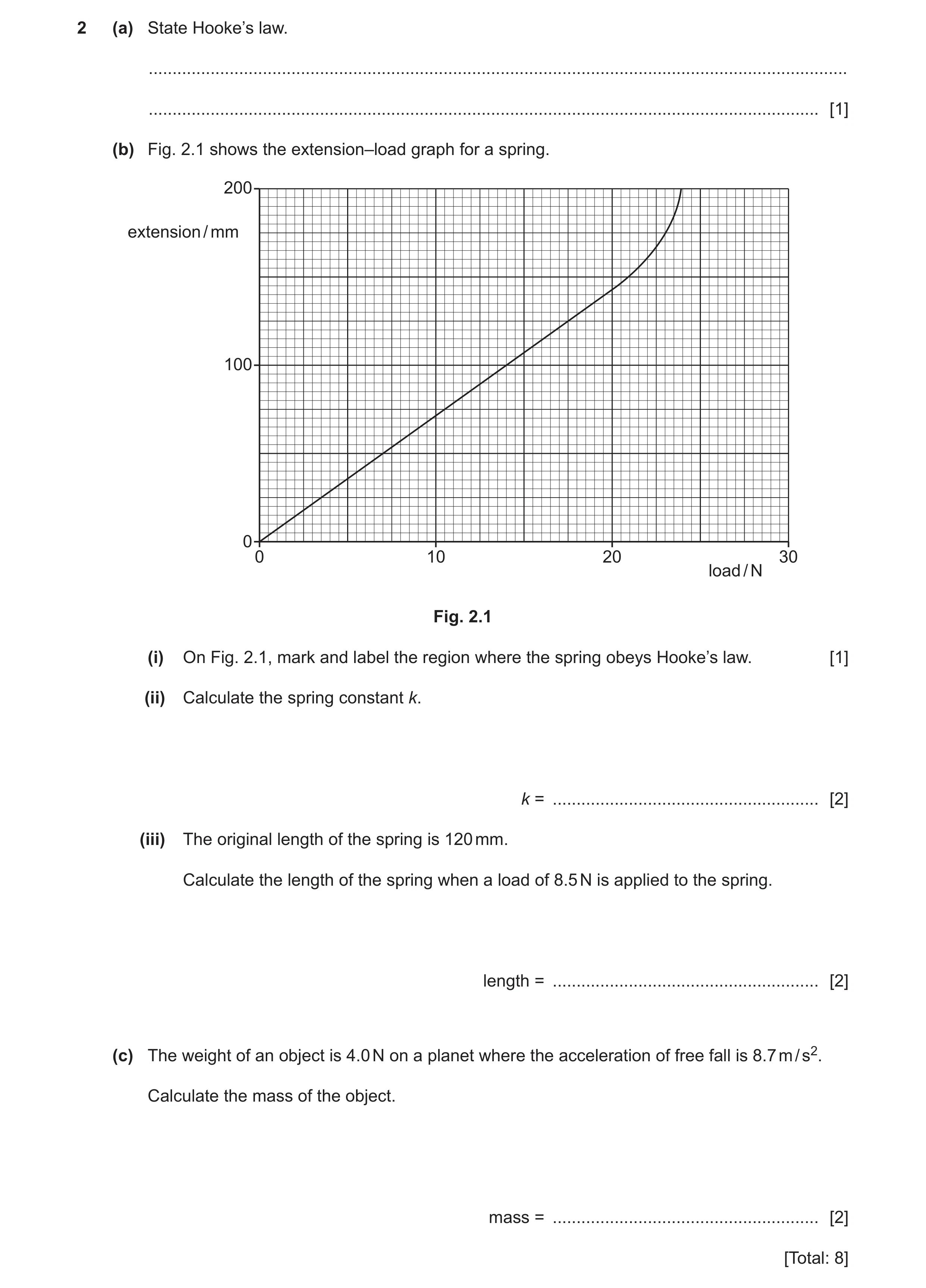 44 / 83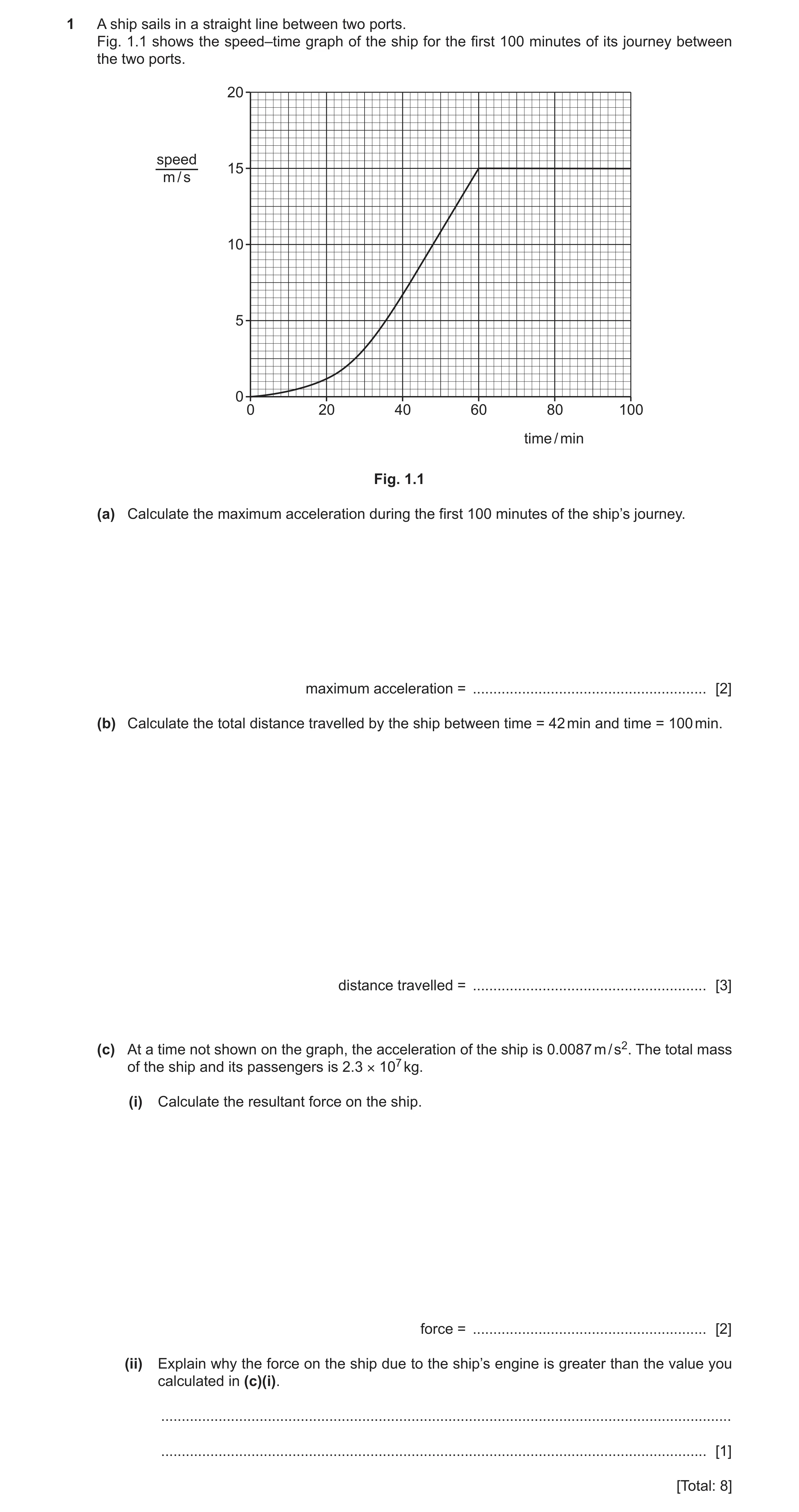
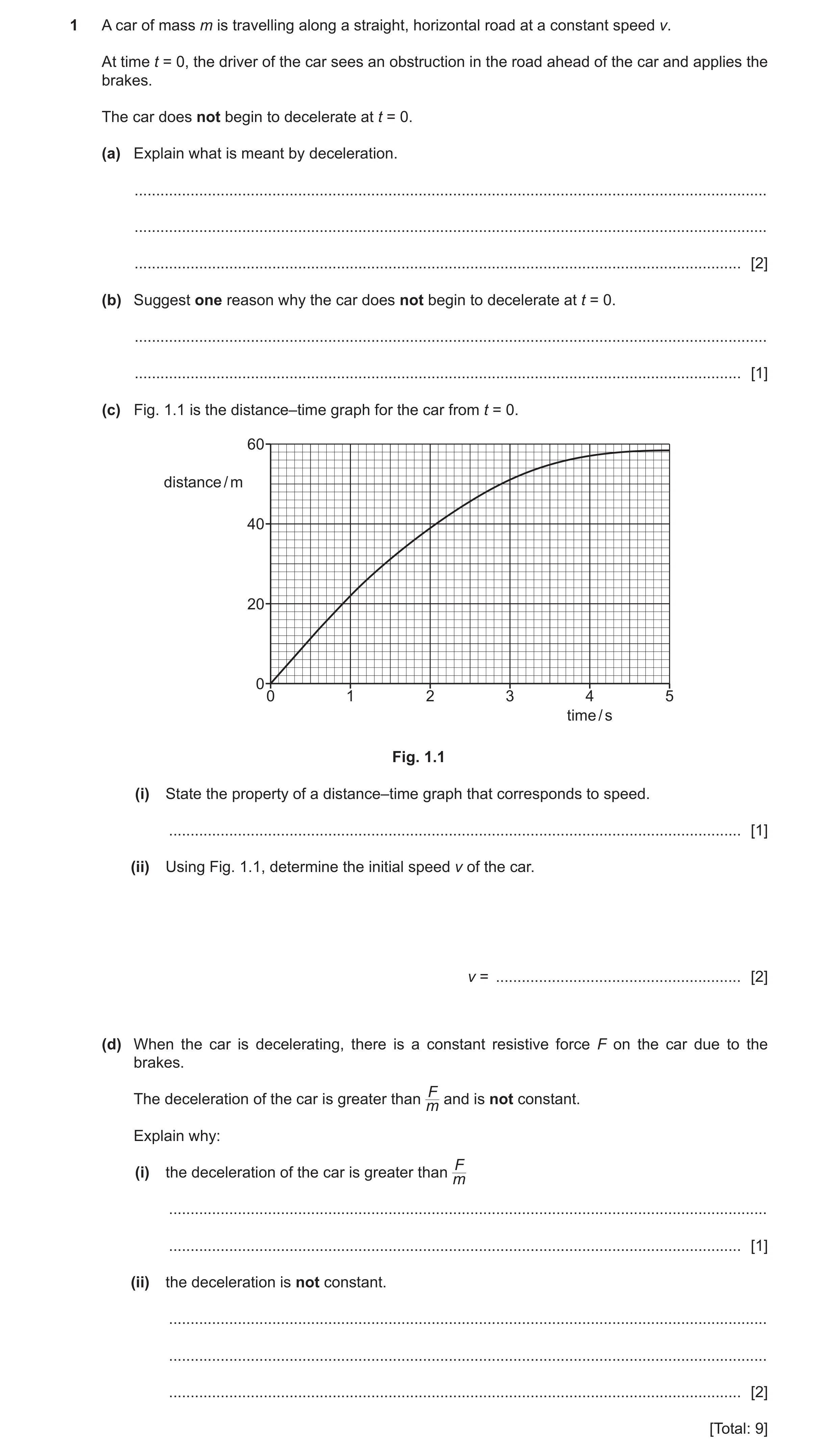
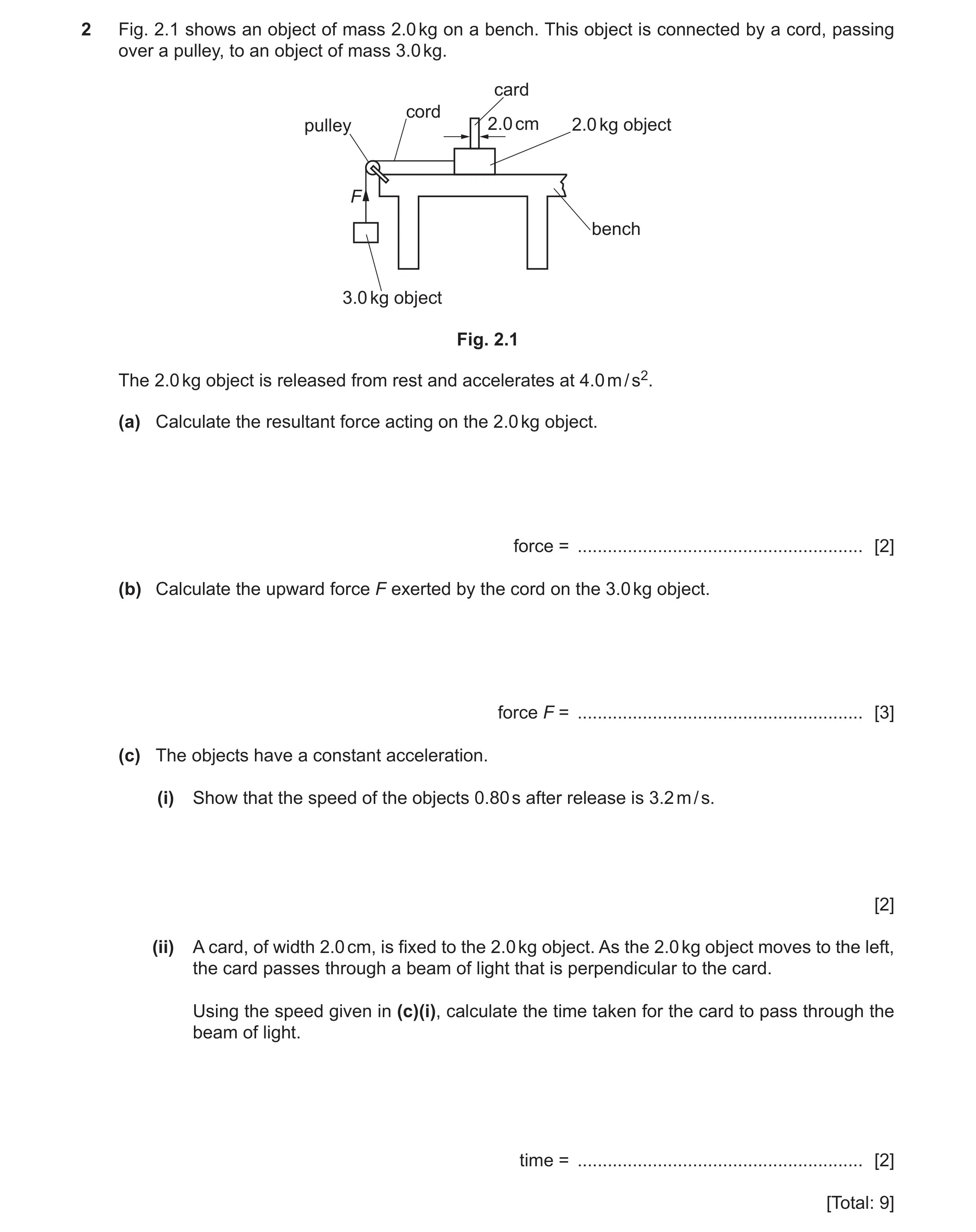 48 / 83
 49 / 83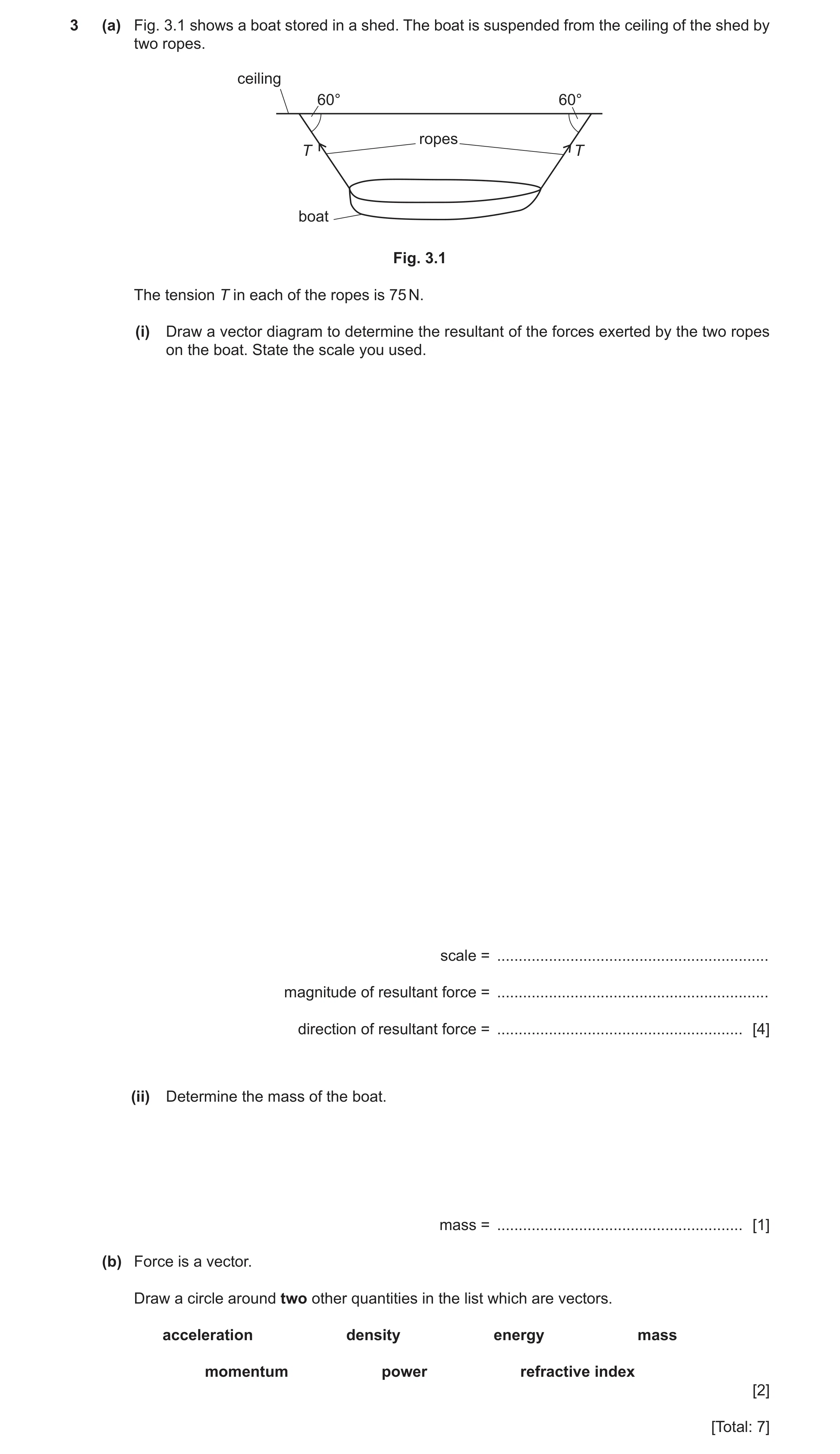
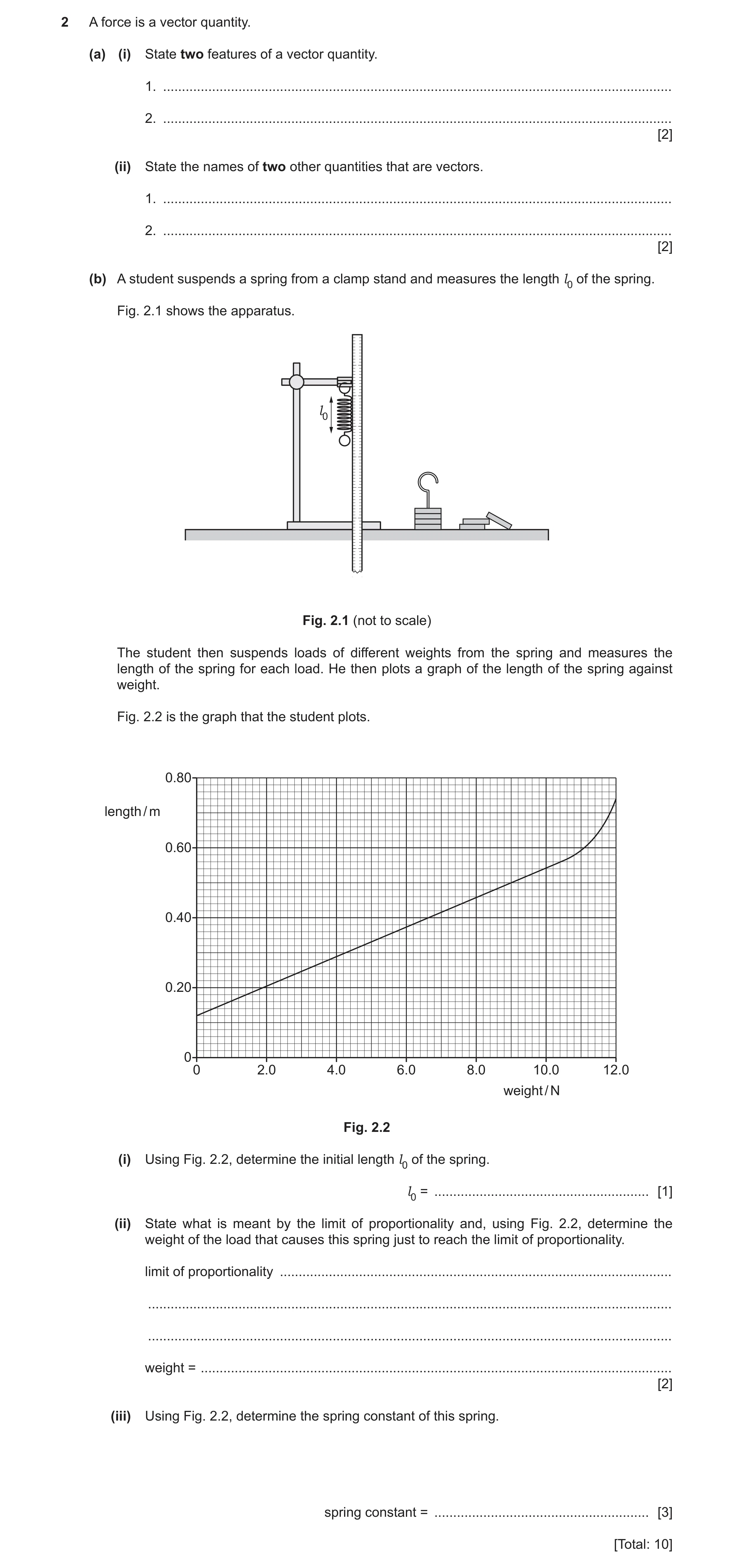
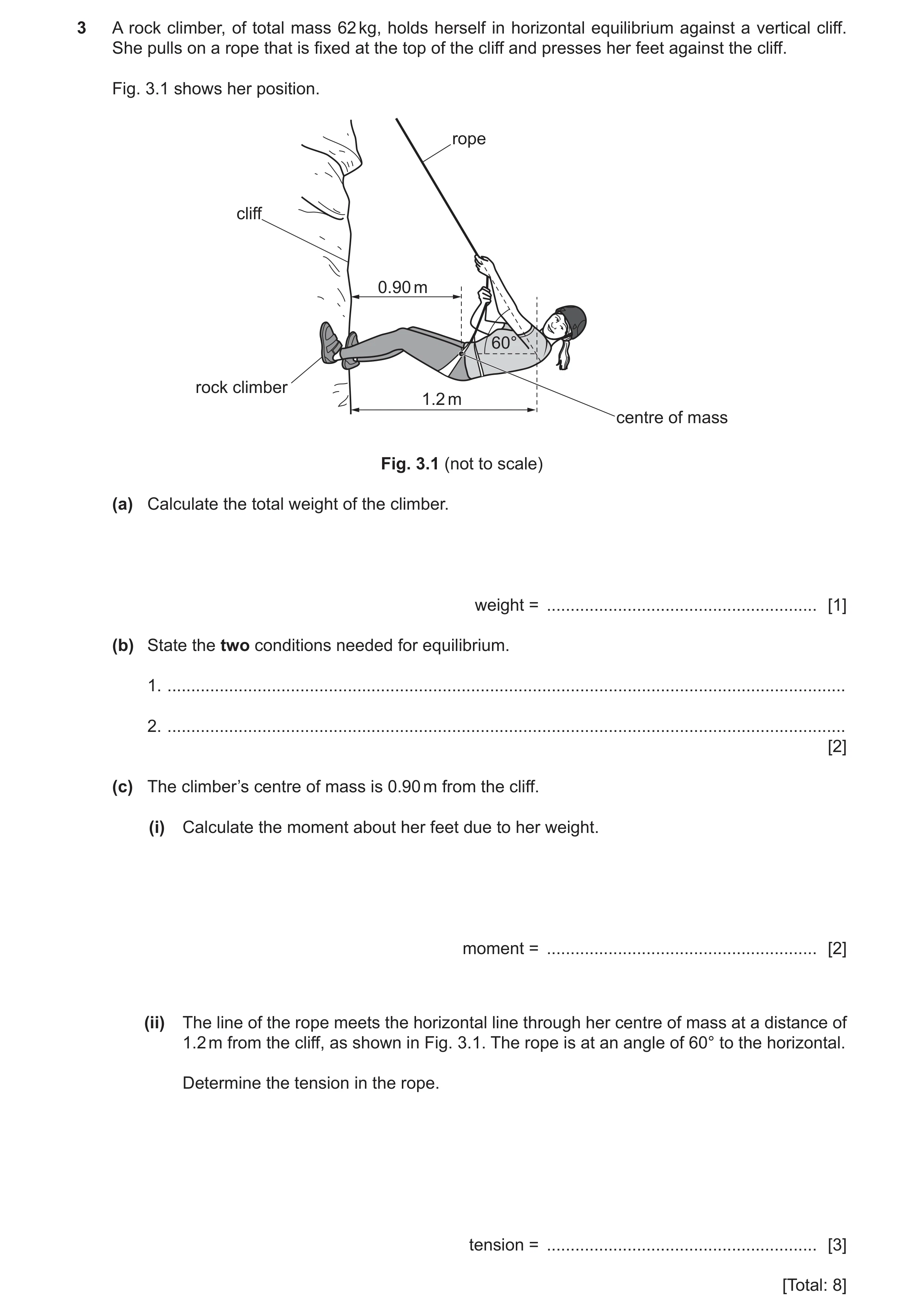 53 / 83
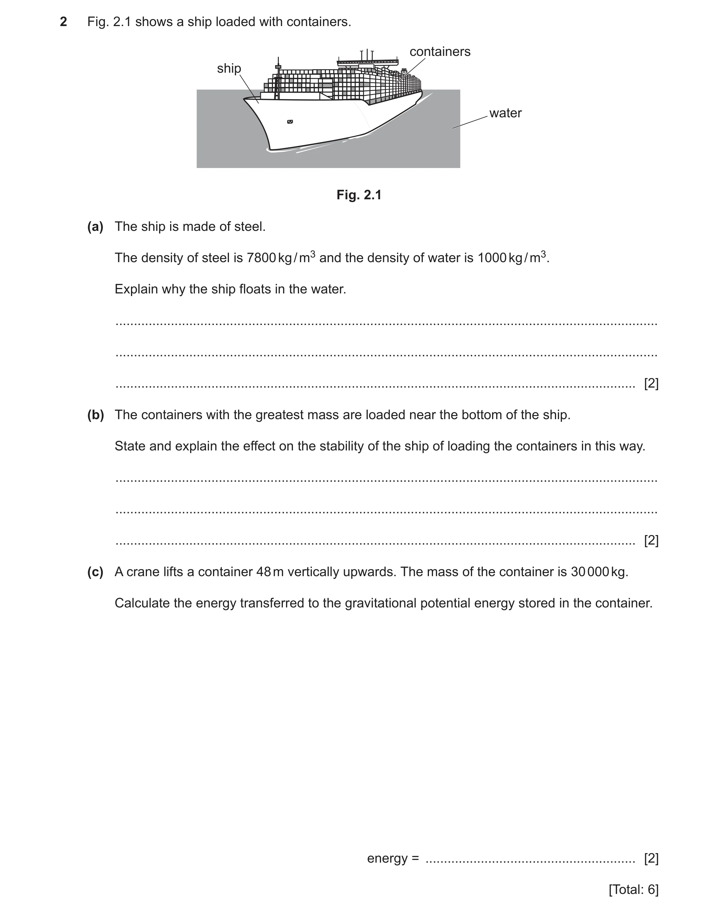 54 / 83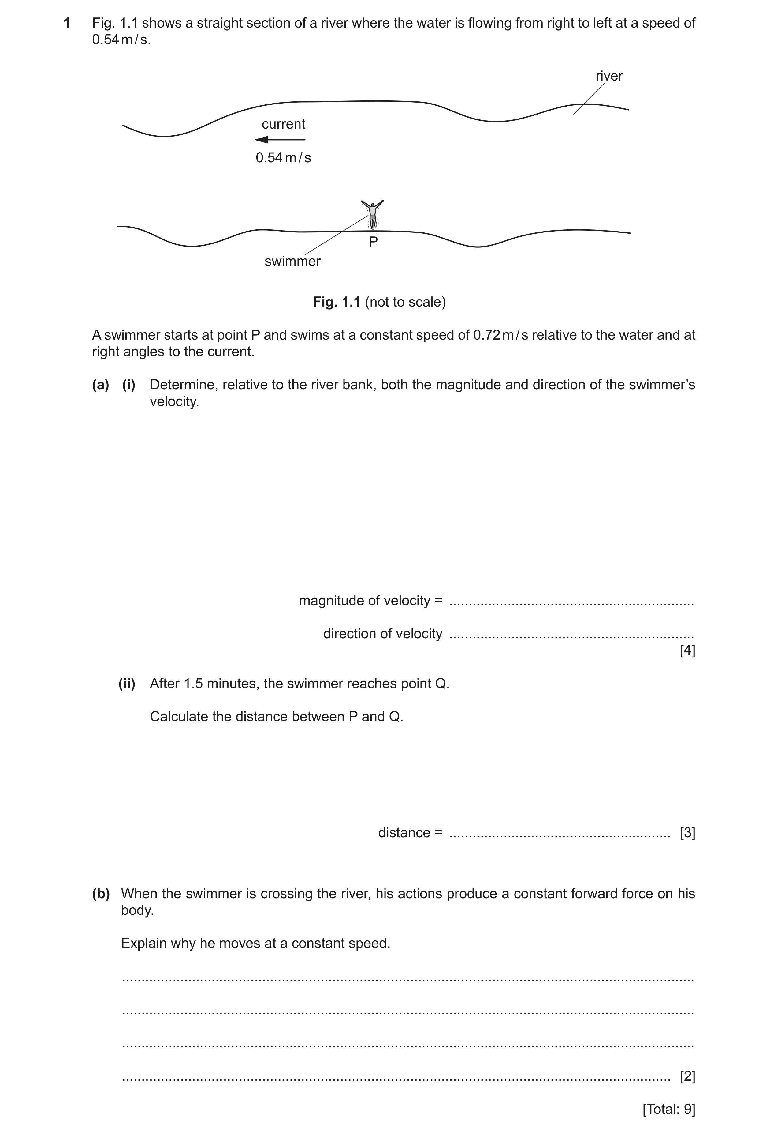
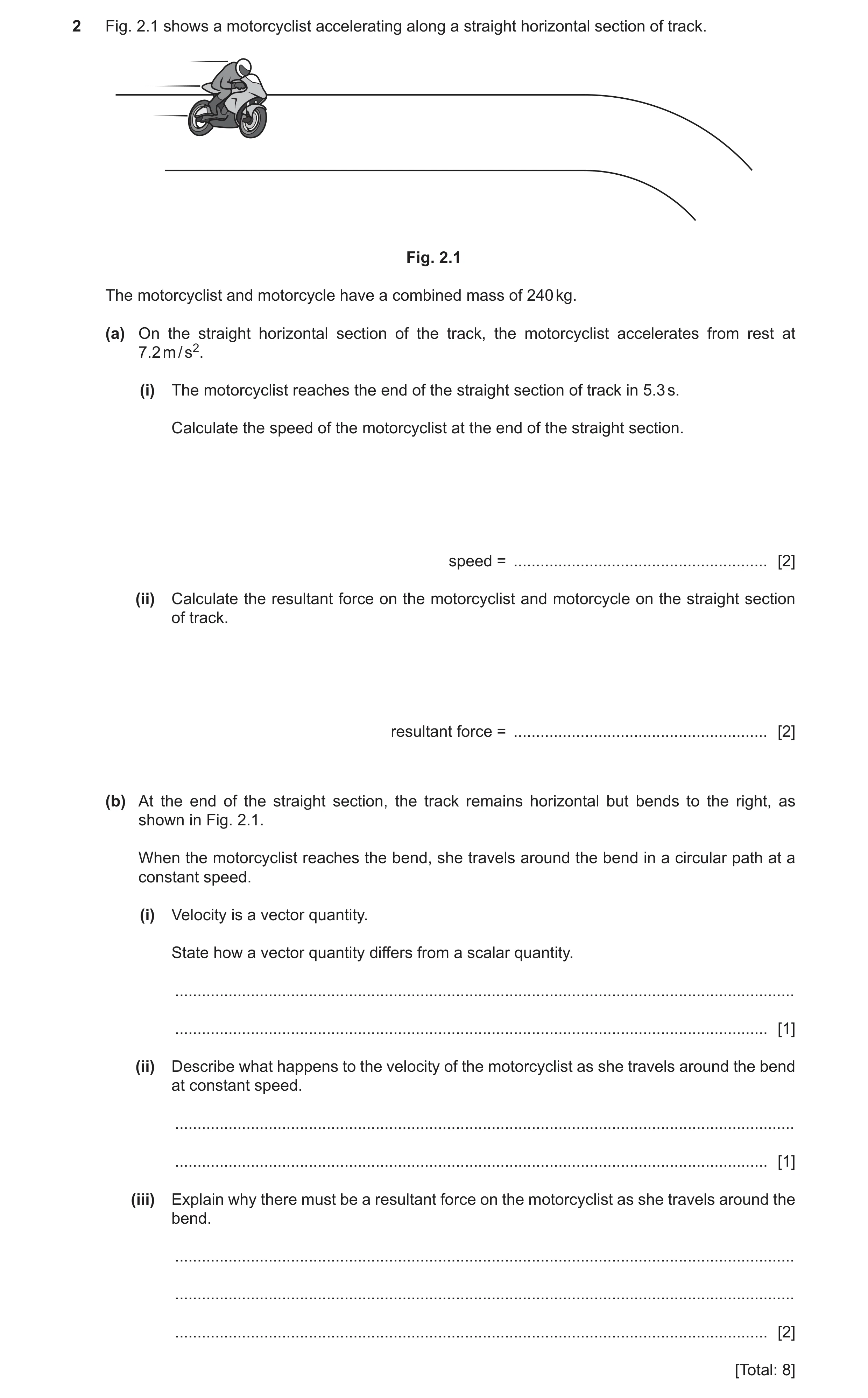
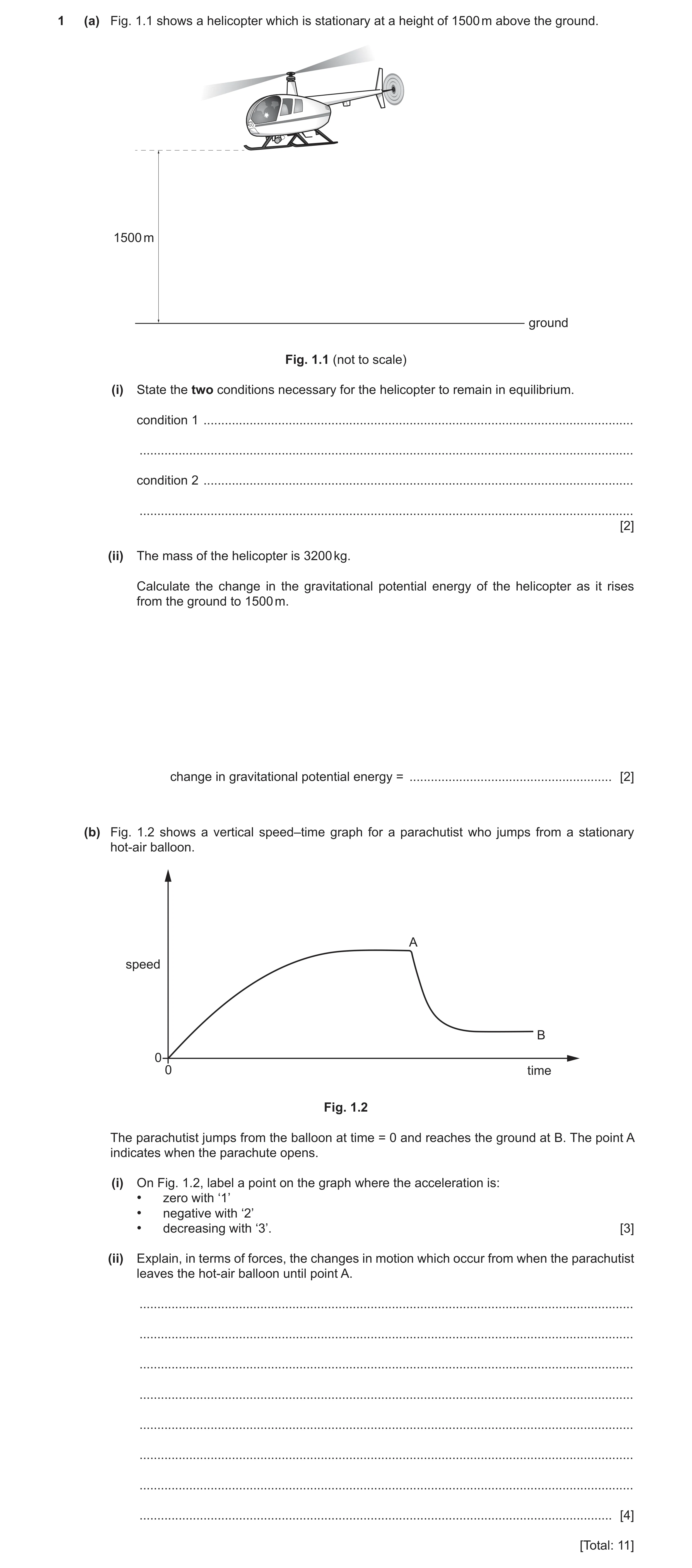
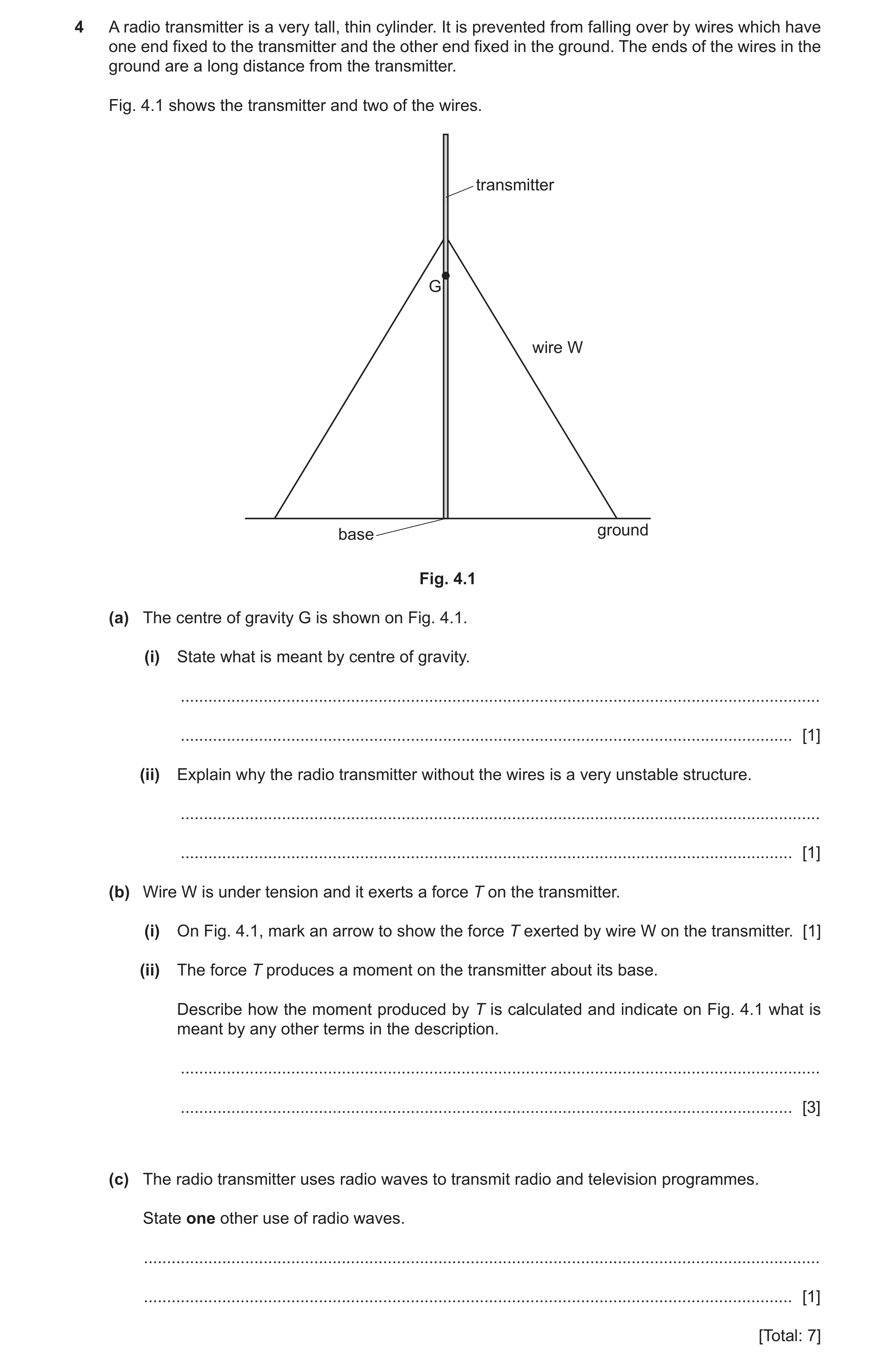
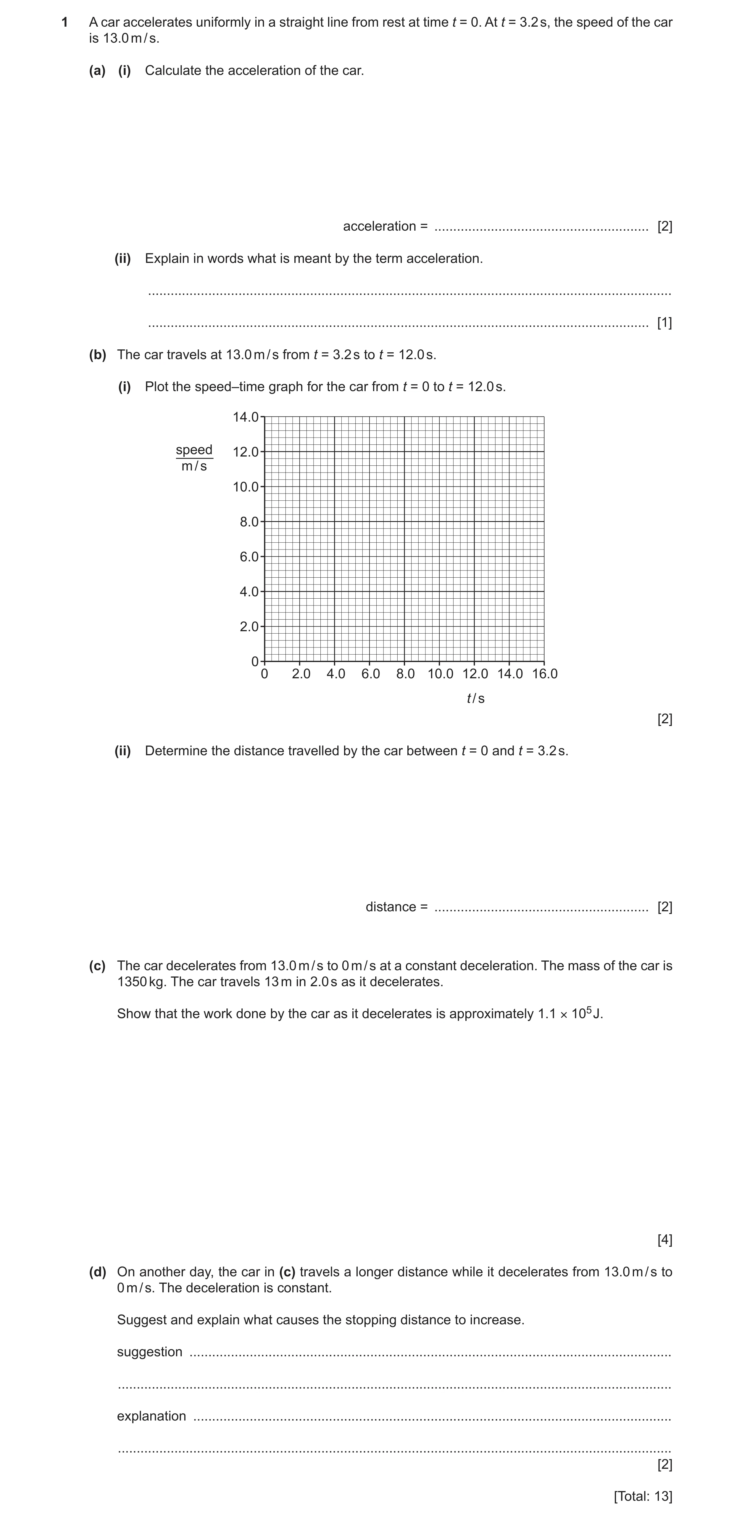
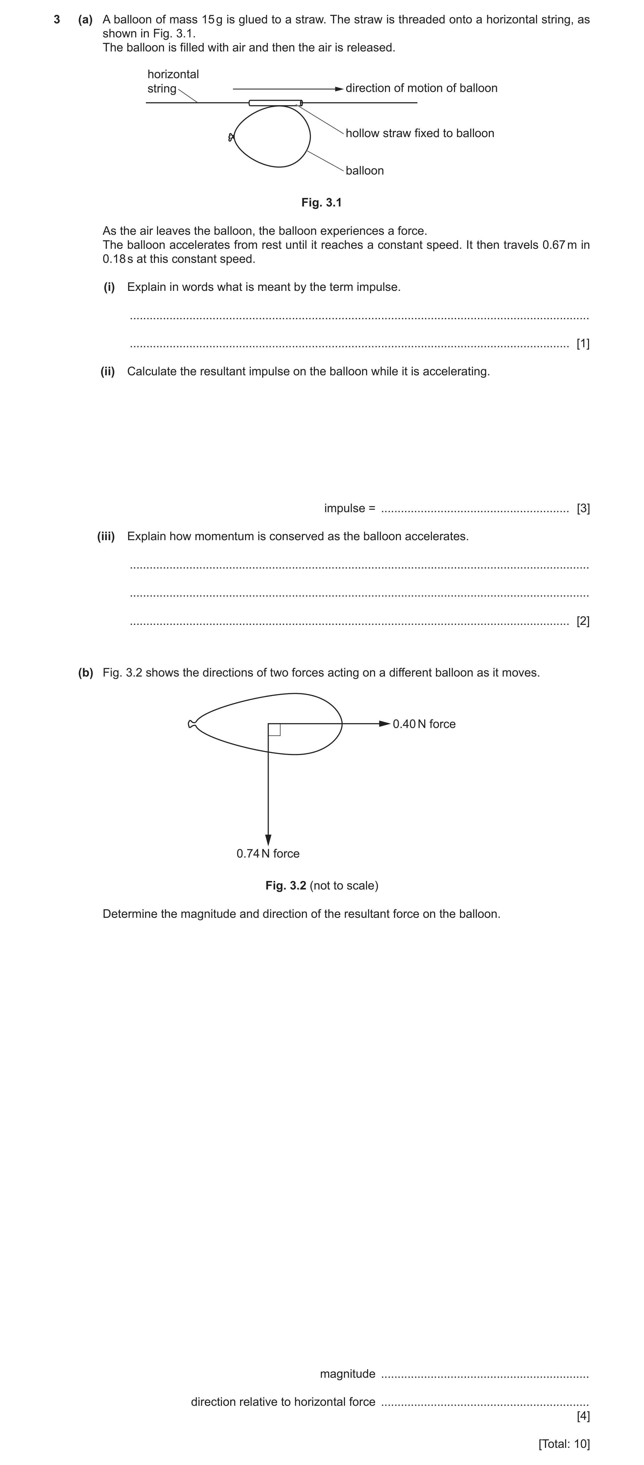
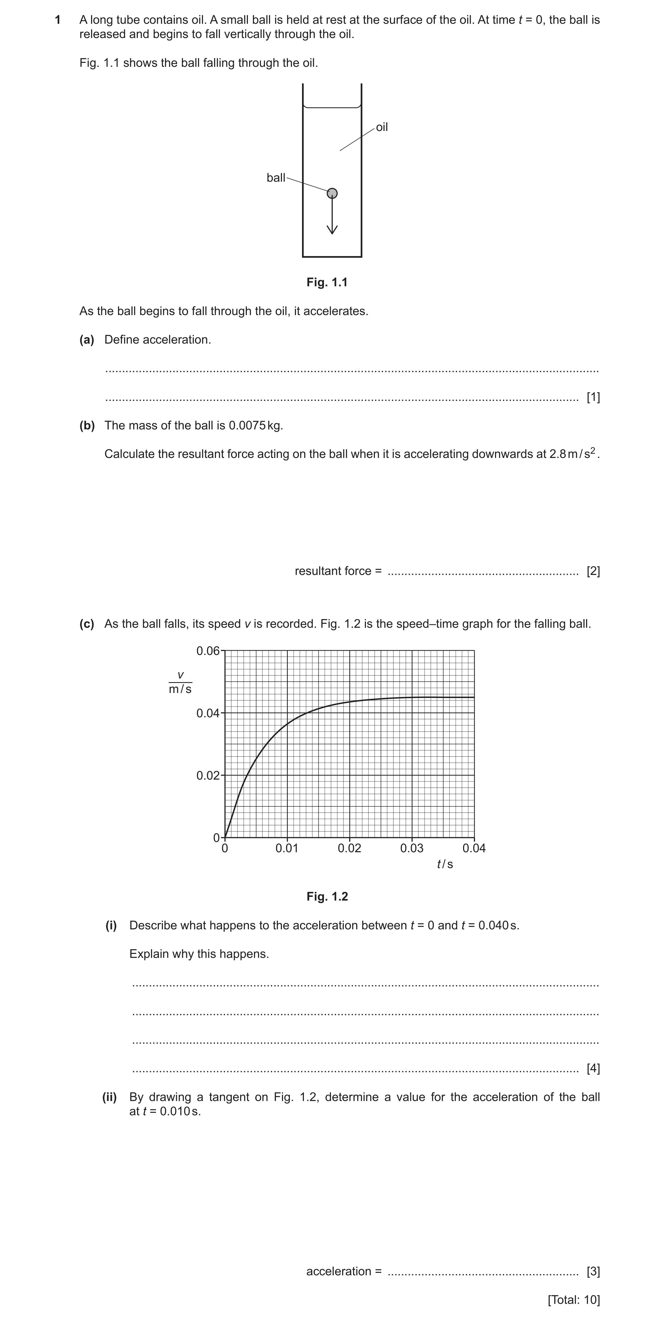
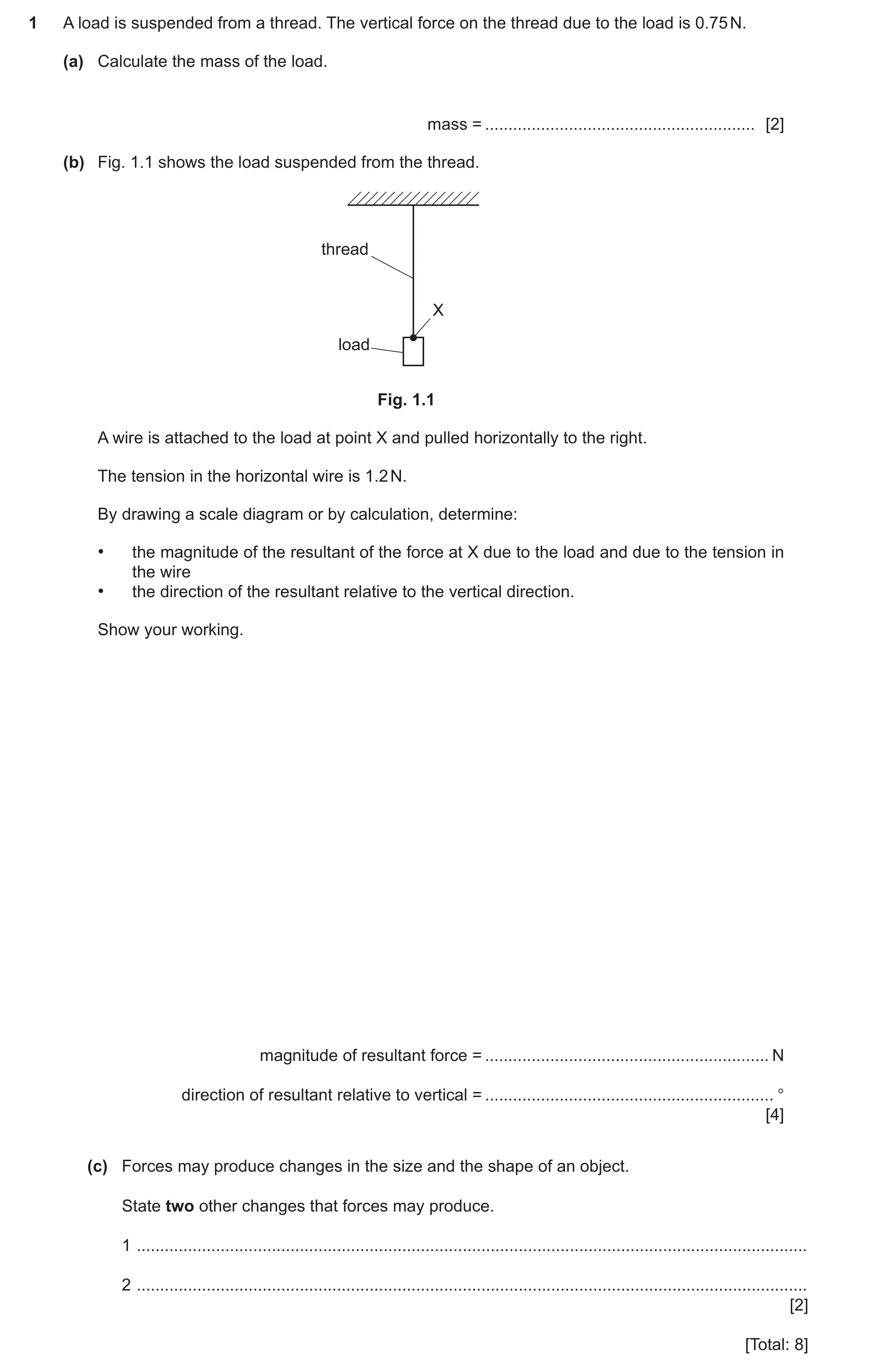
 66 / 83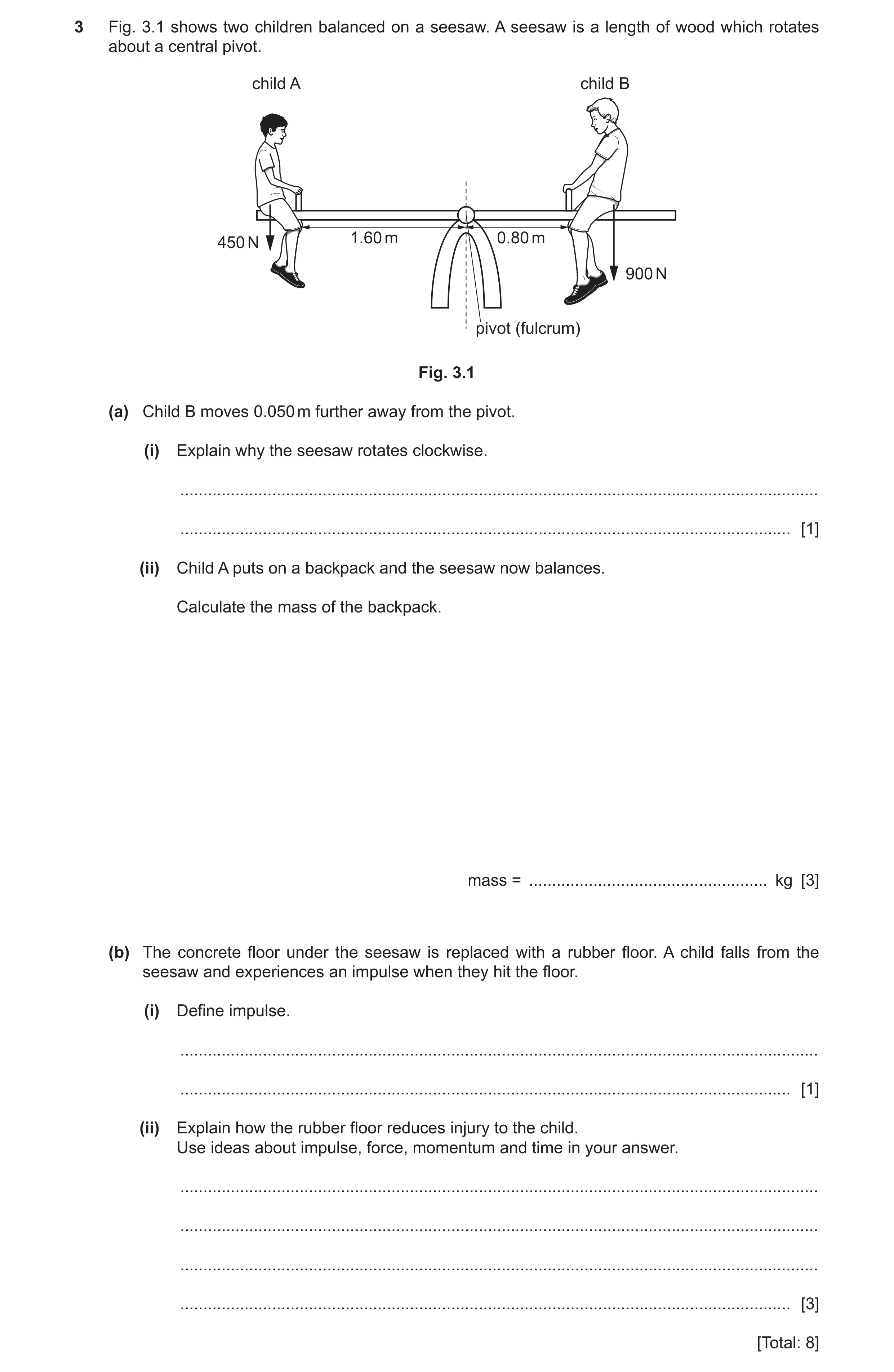
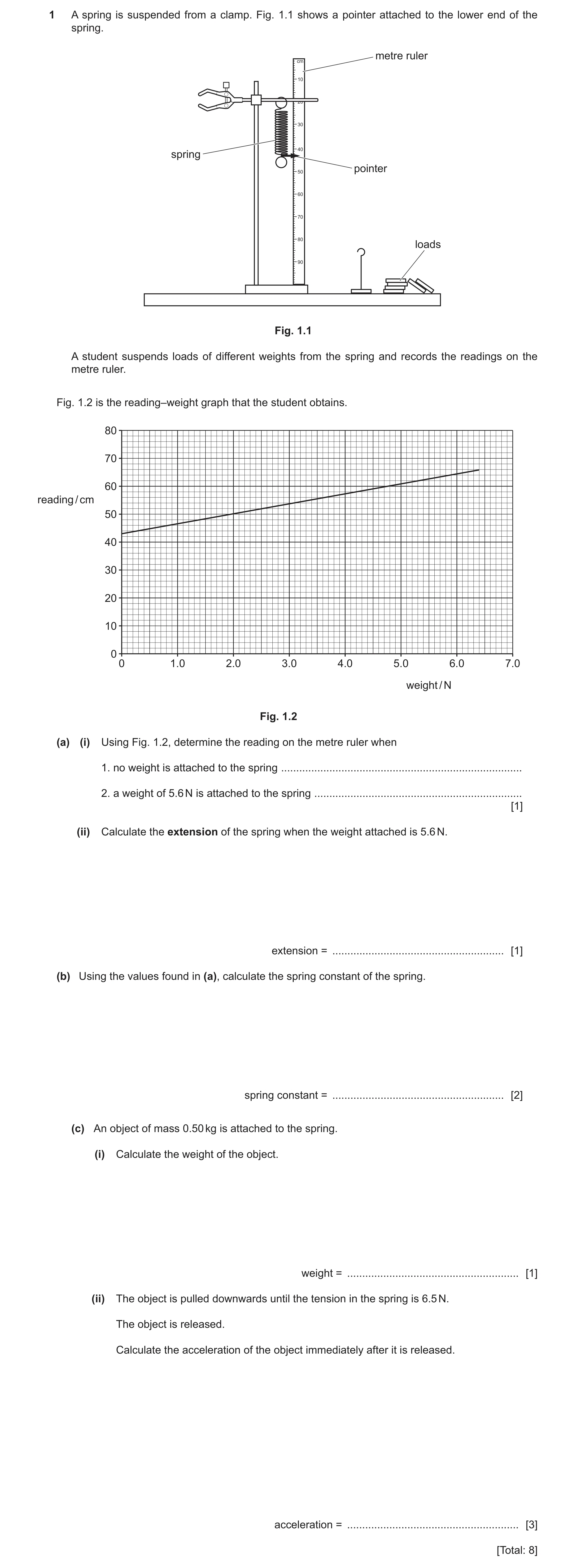
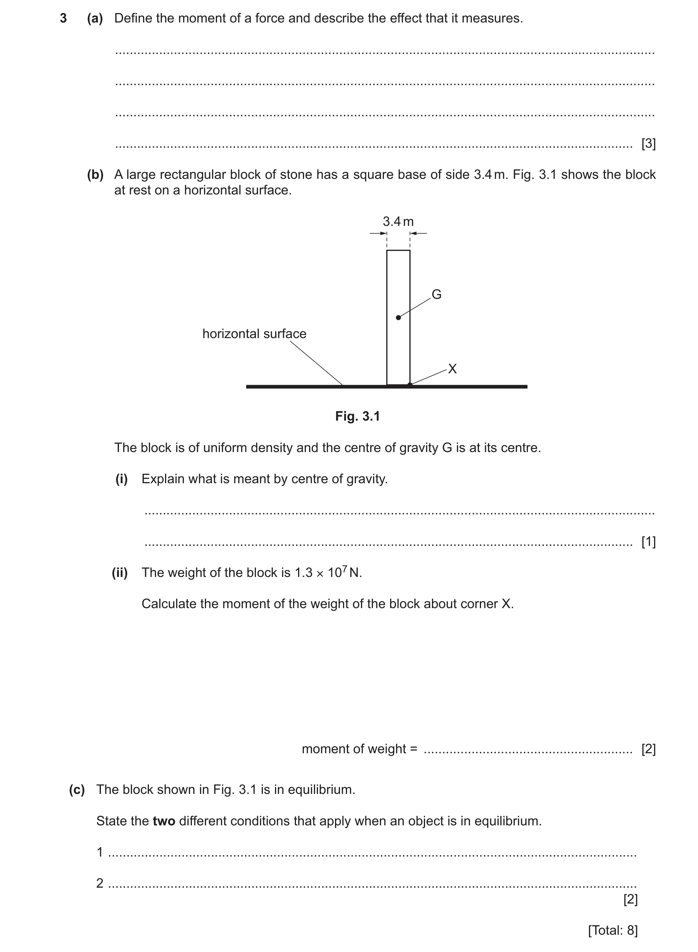 71 / 83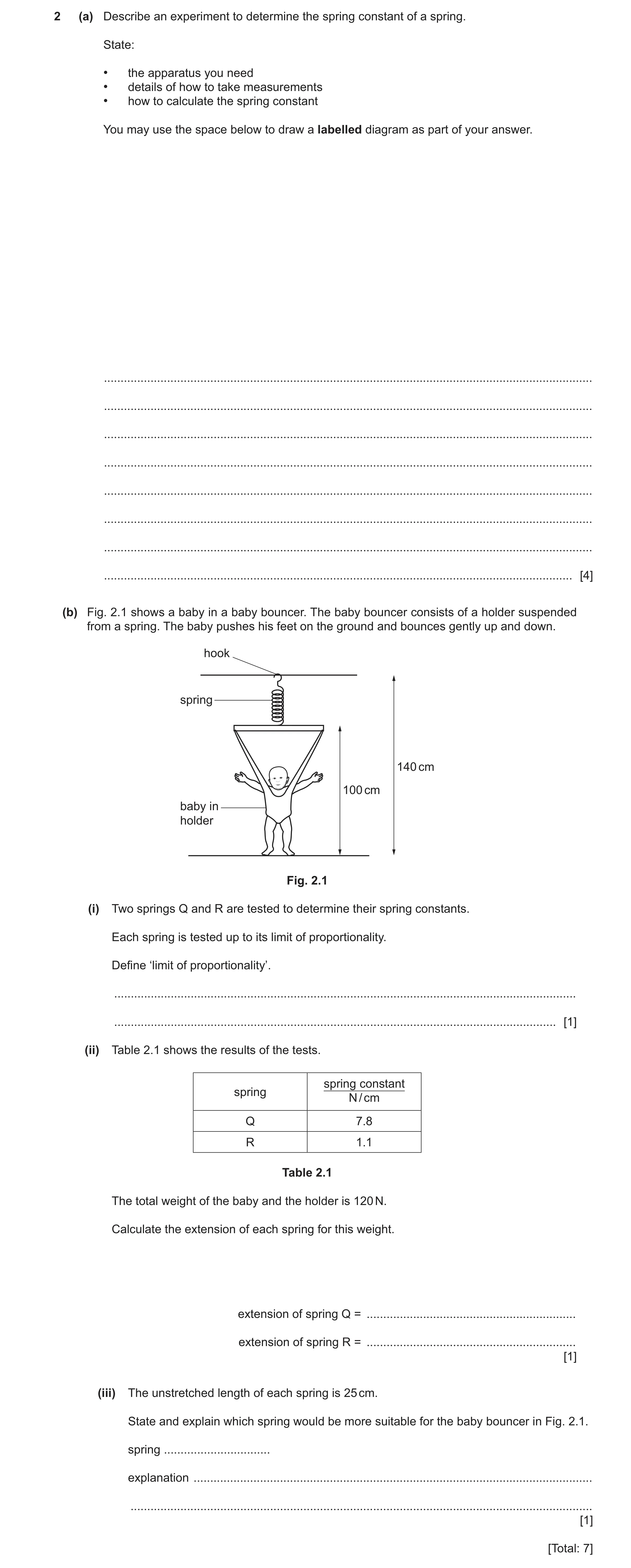
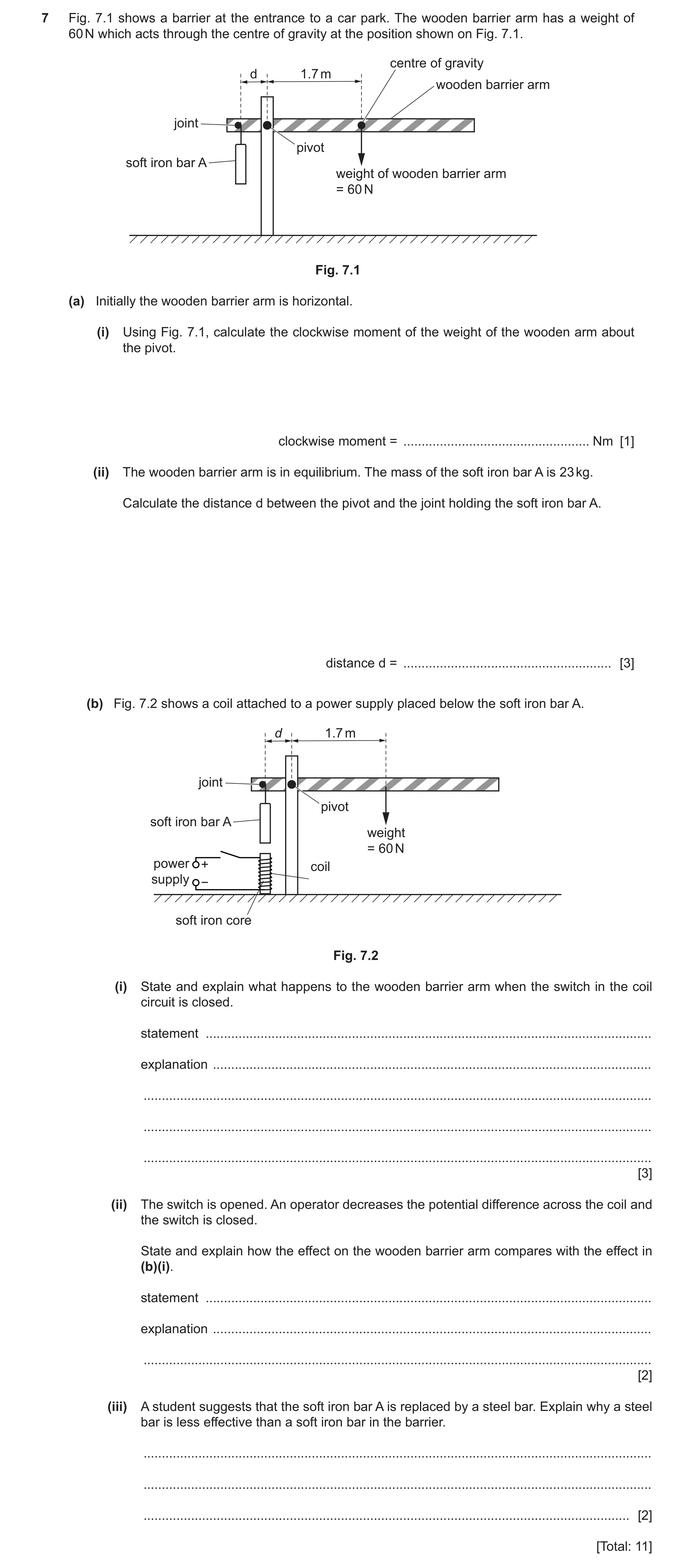
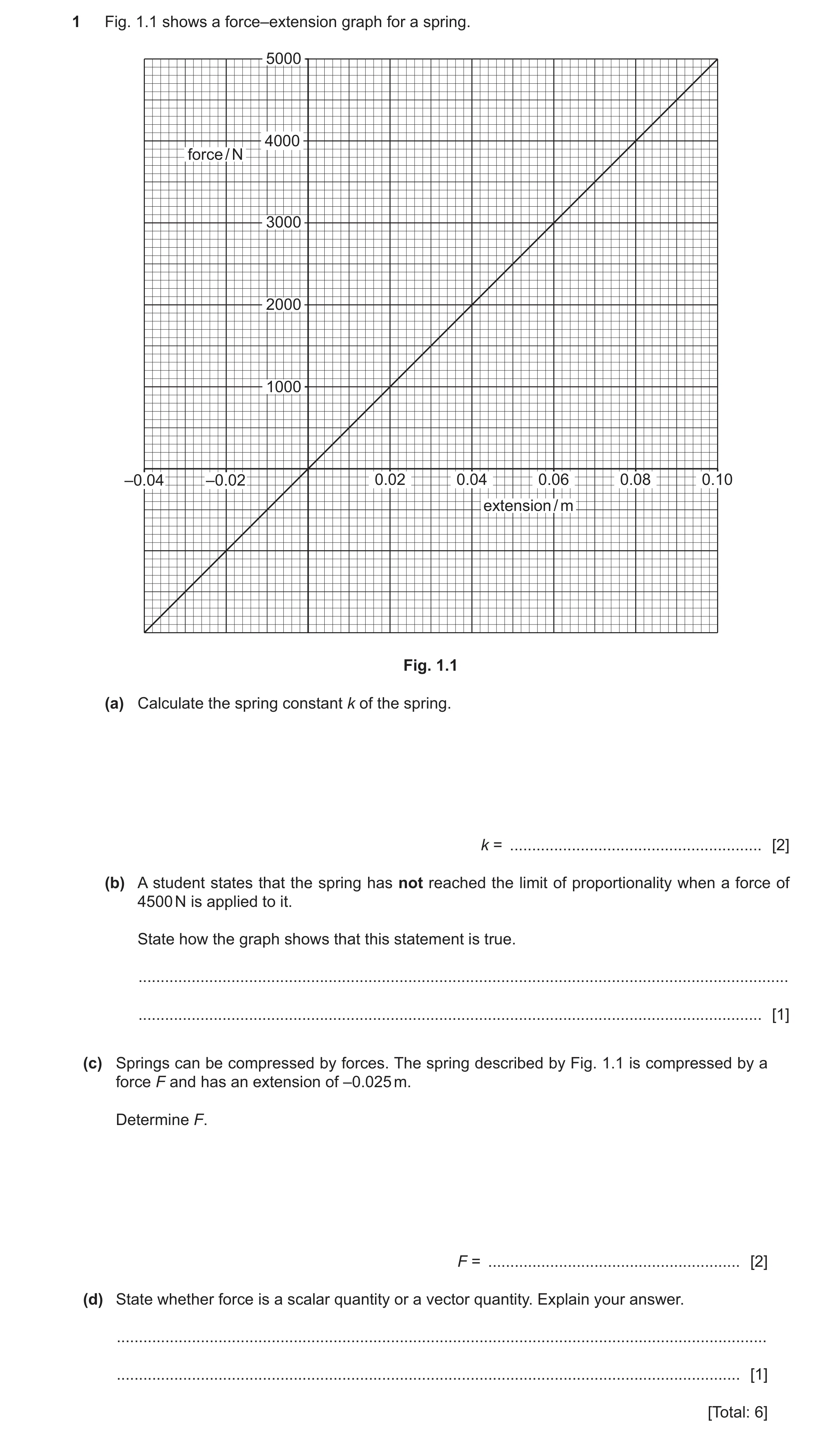
 78 / 83
 79 / 83
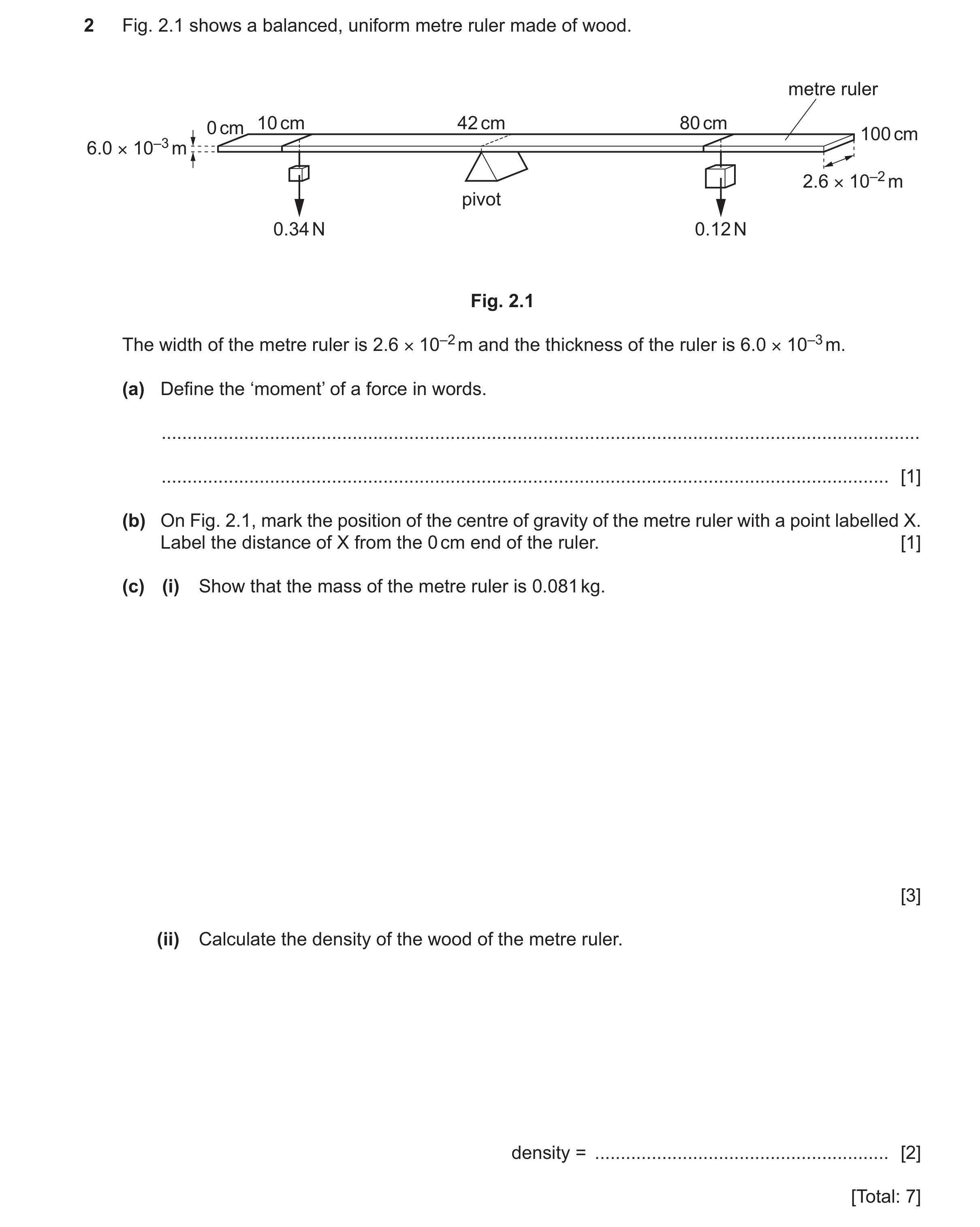 80 / 83
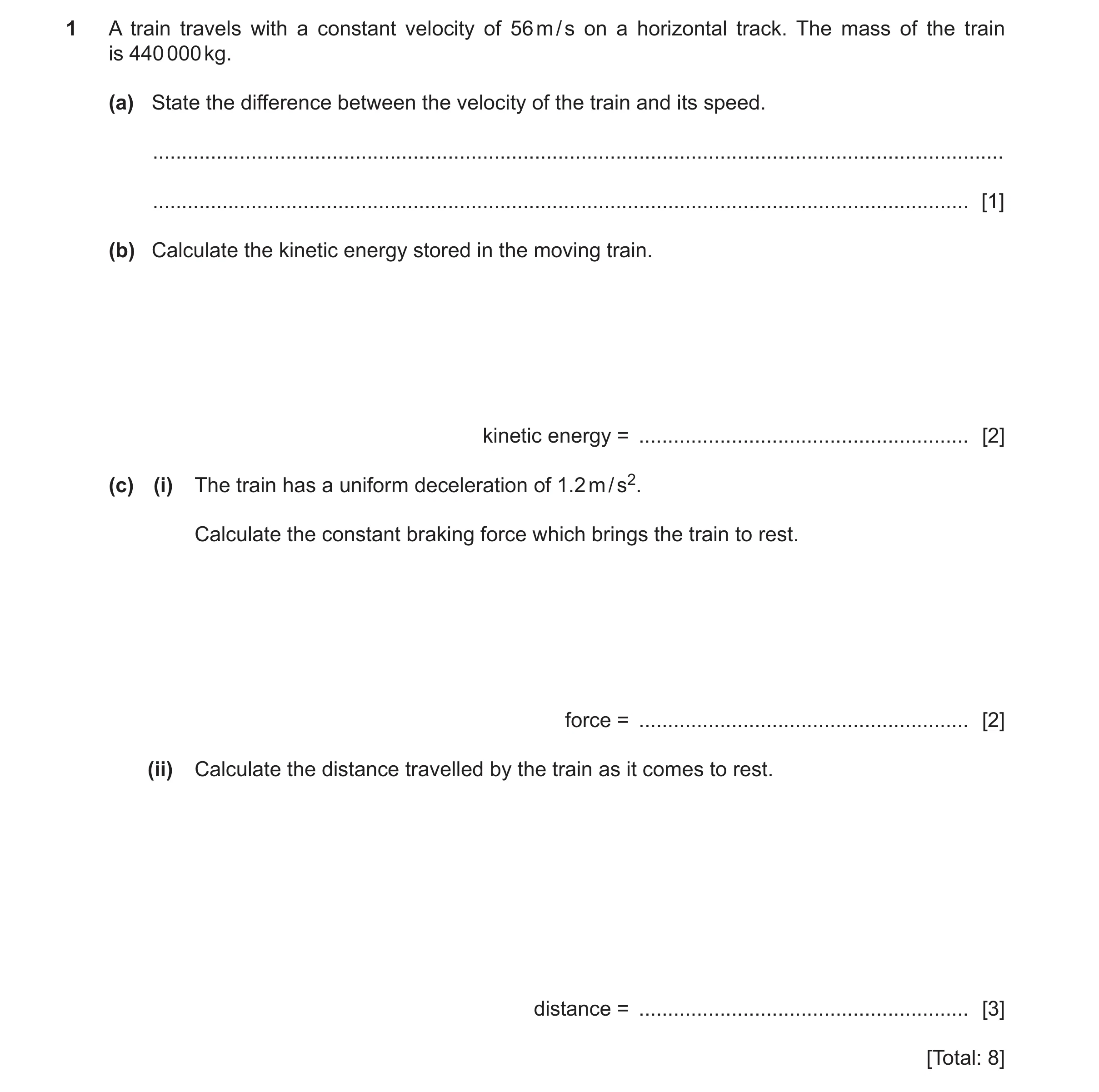 81 / 83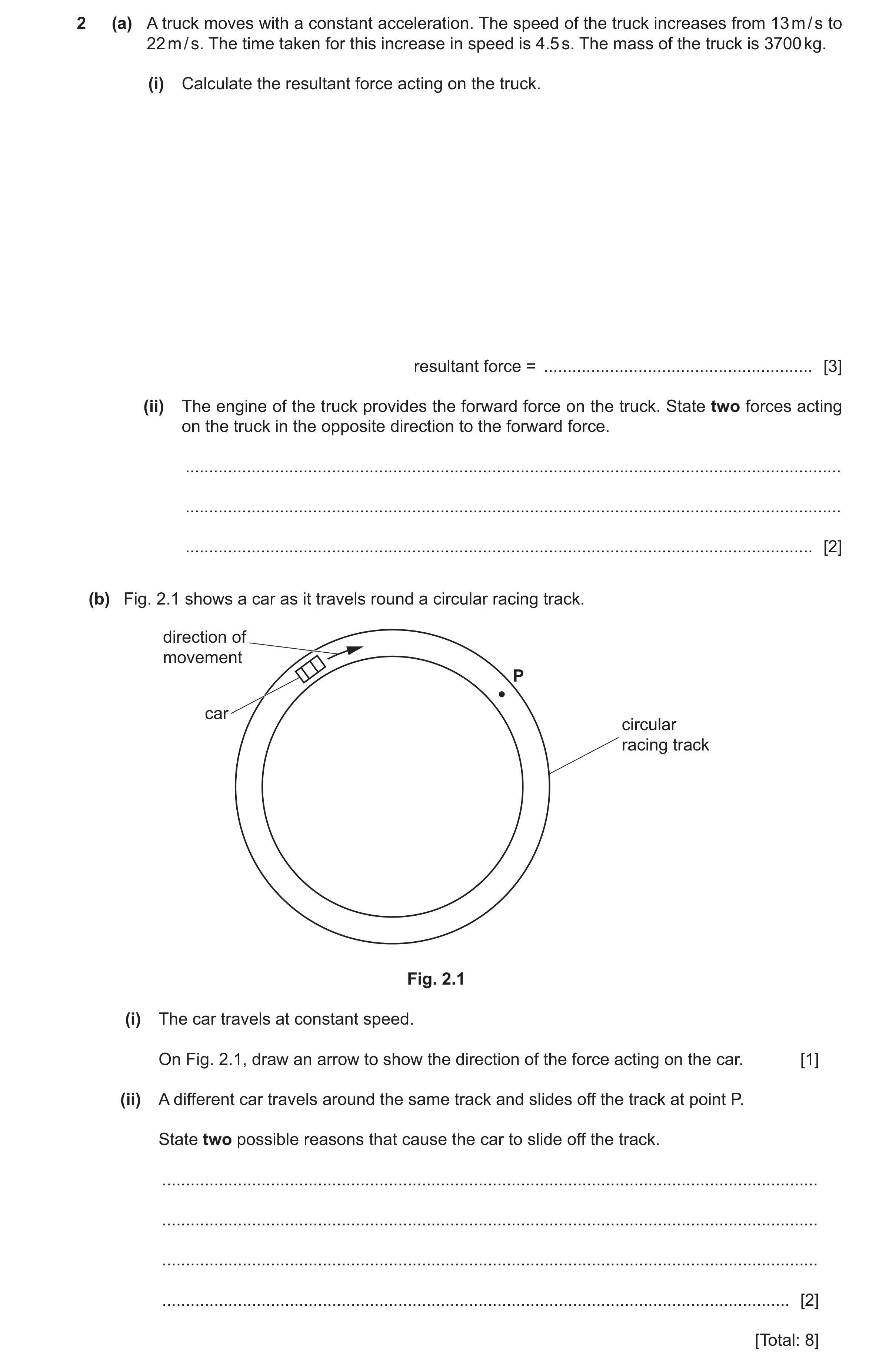
 83 / 83
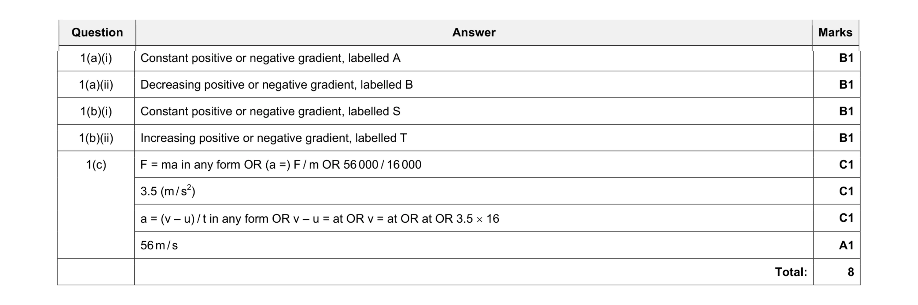 8
8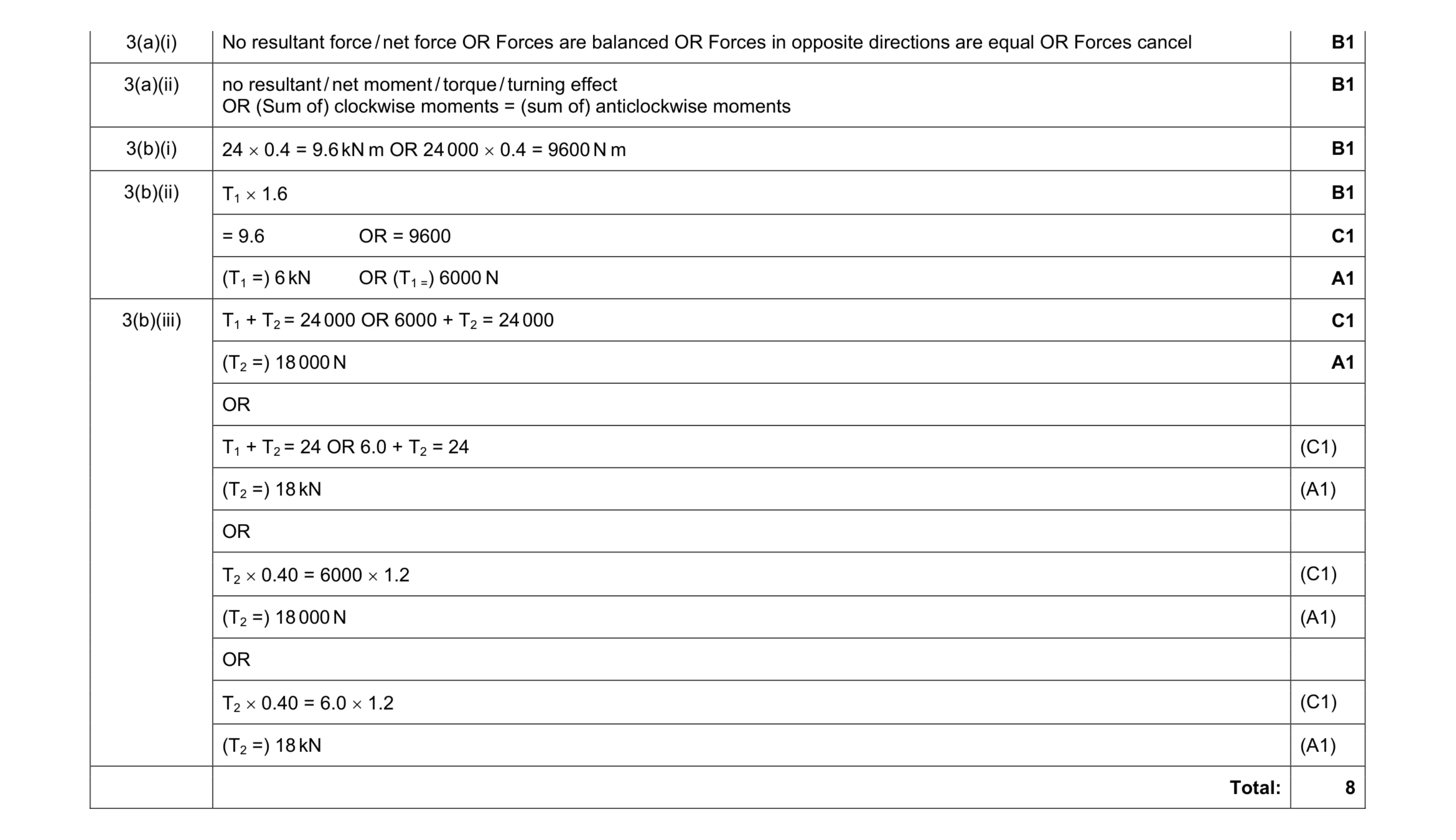 8
8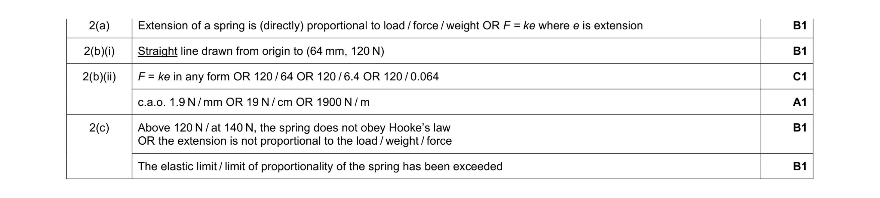 6
6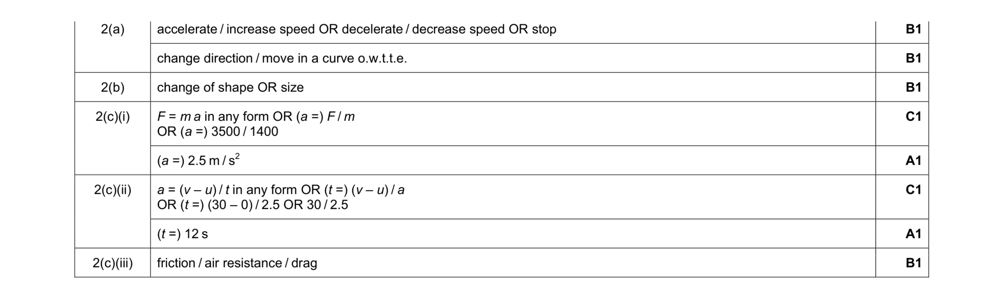 8
8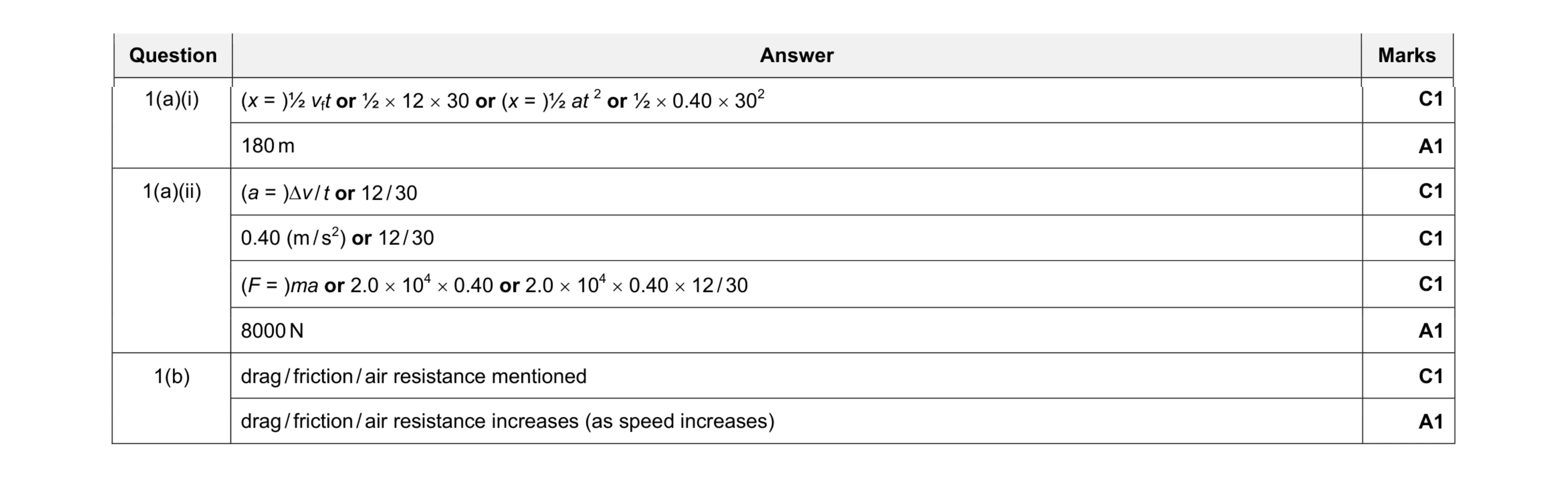 8
8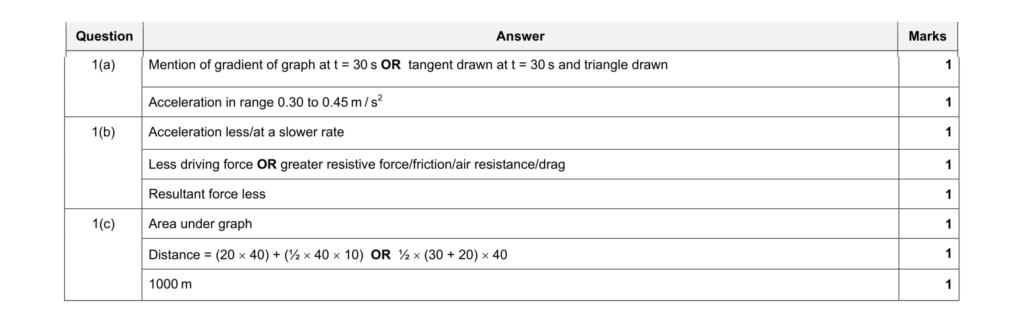 8
8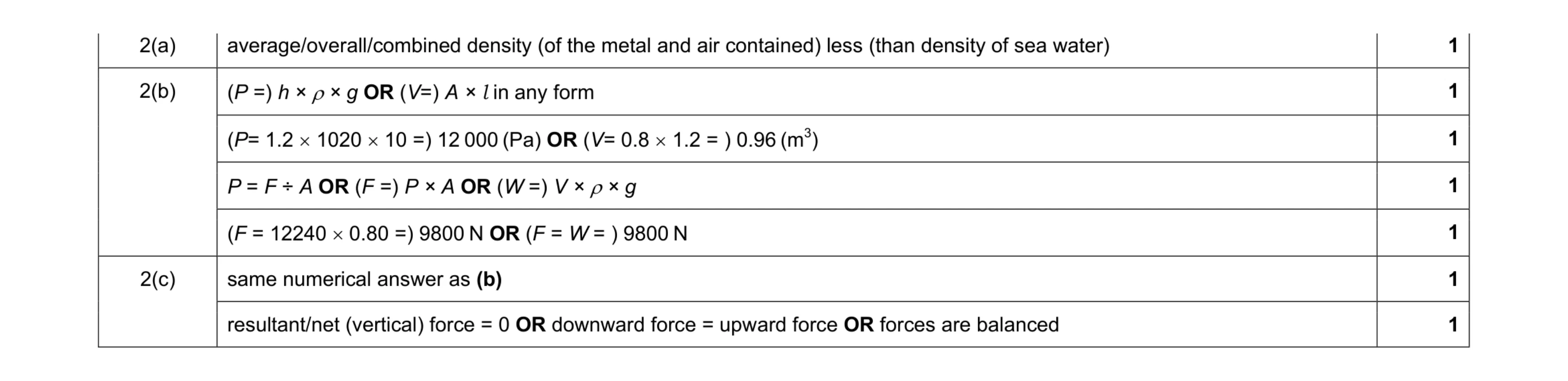 7
7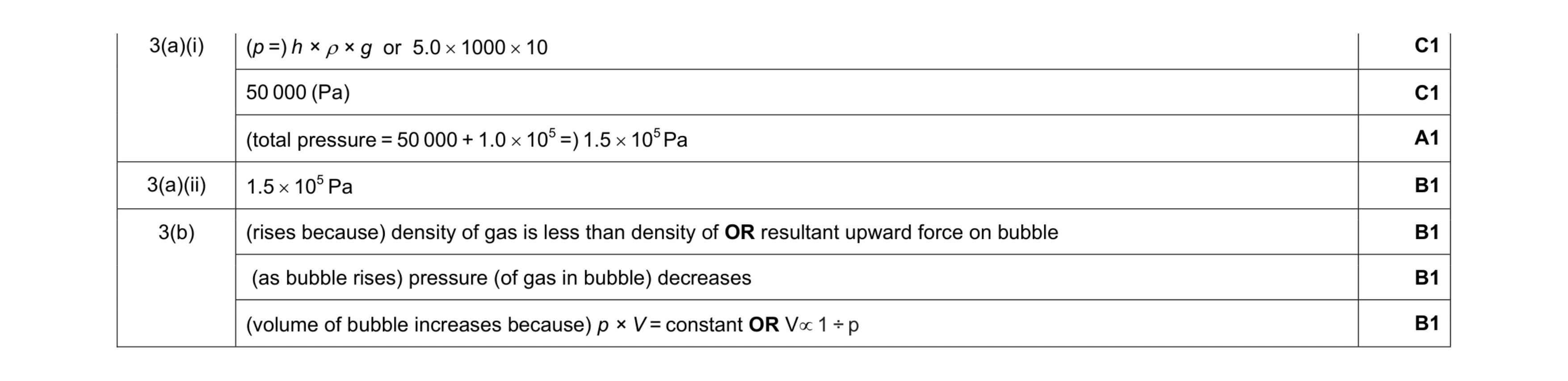 7
7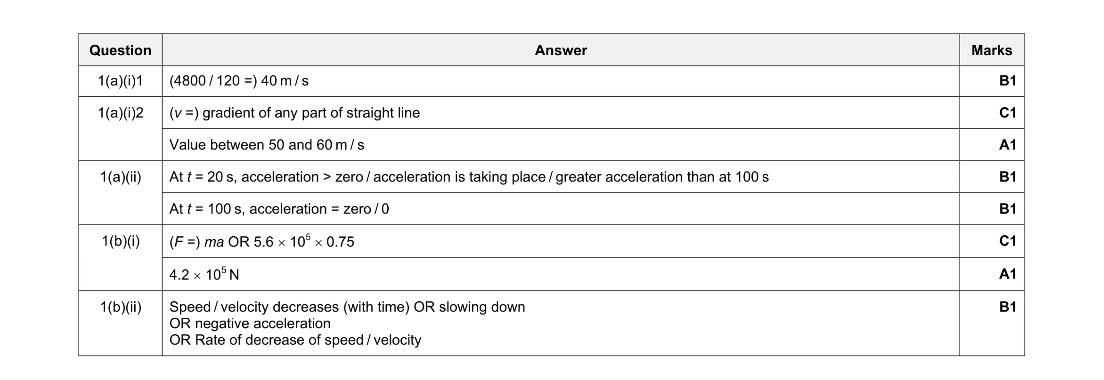 8
8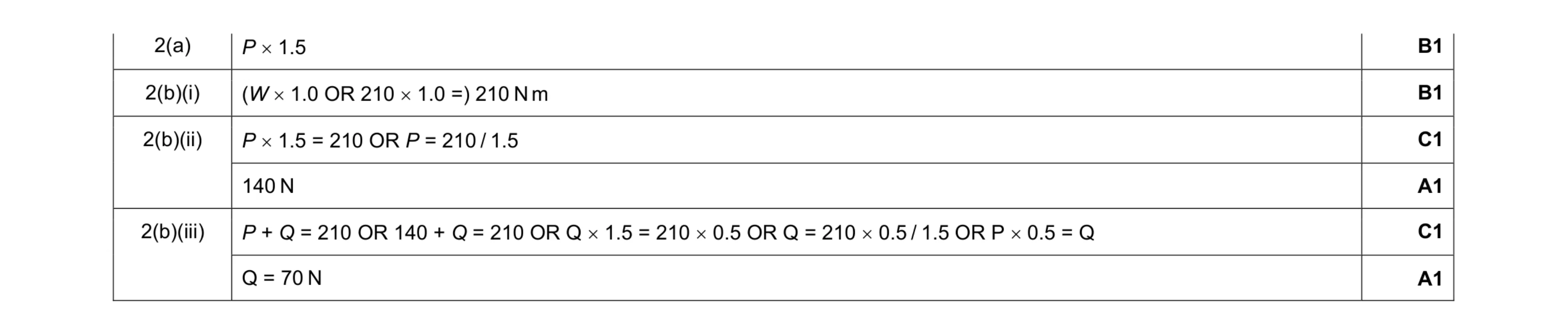 6
6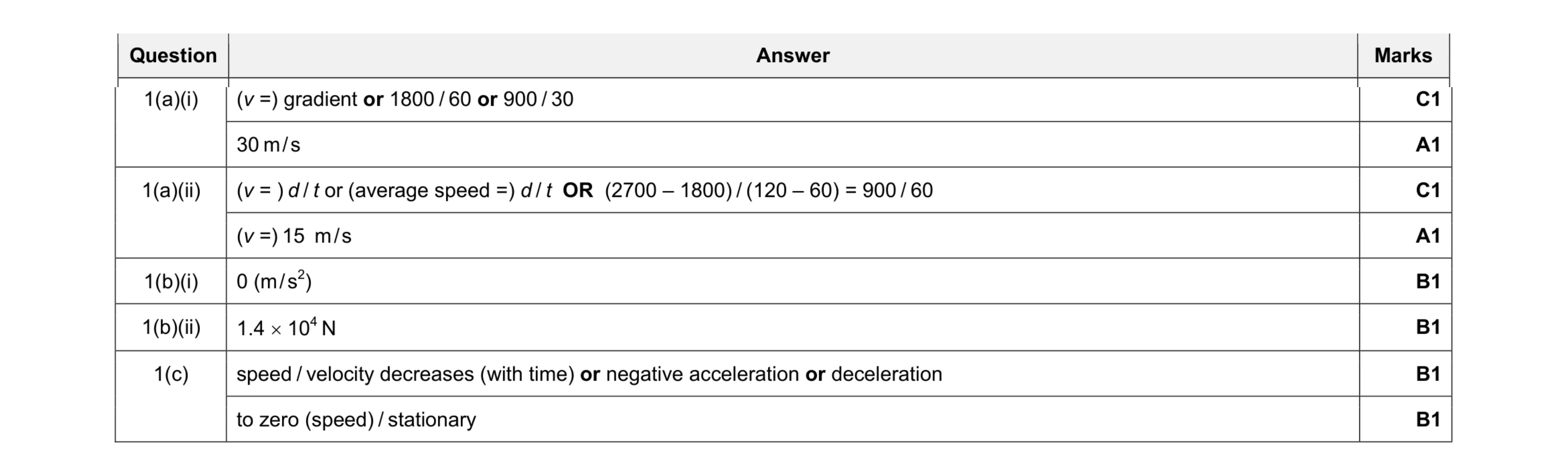 8
8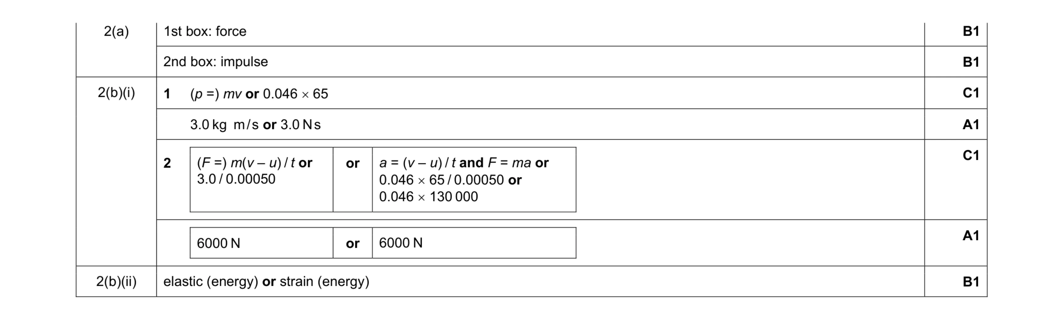 7
7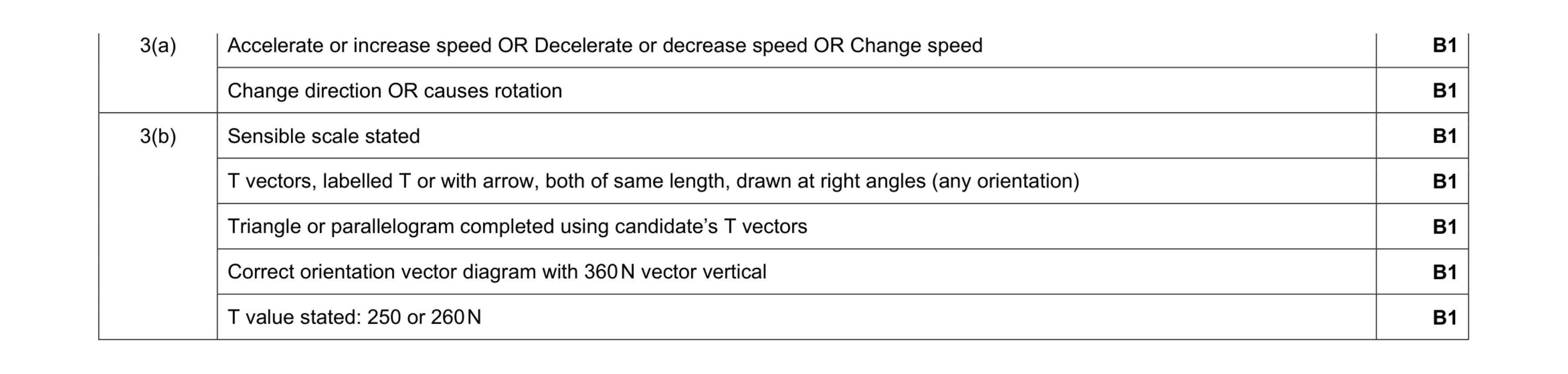 7
7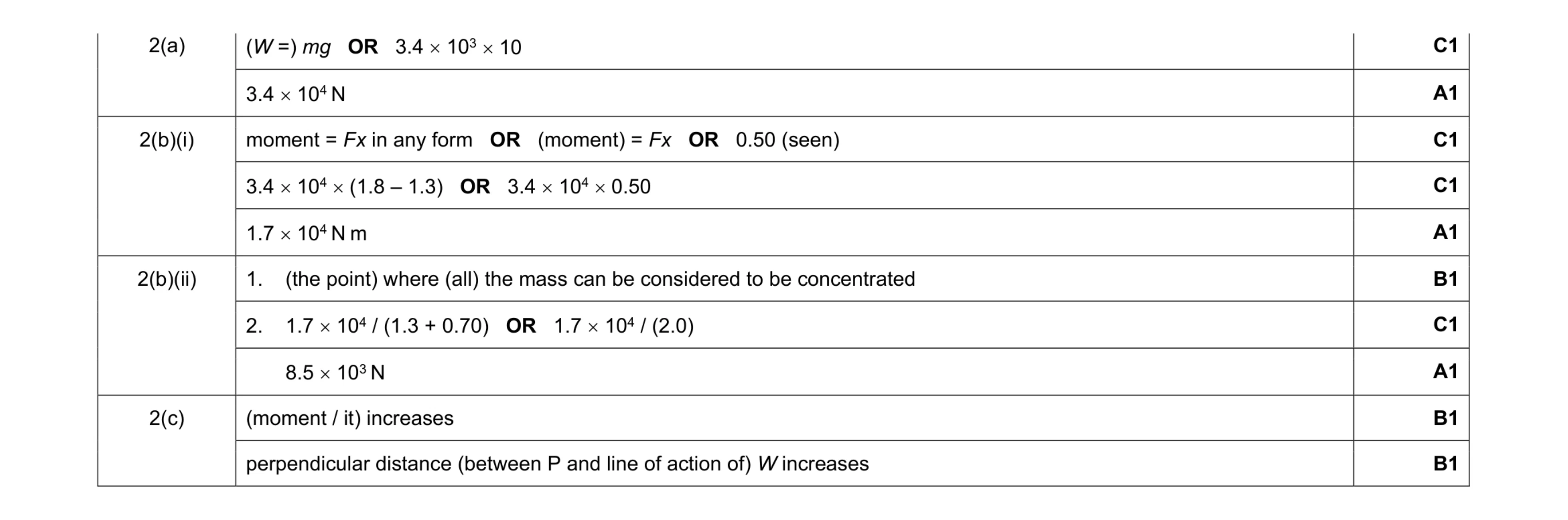 10
10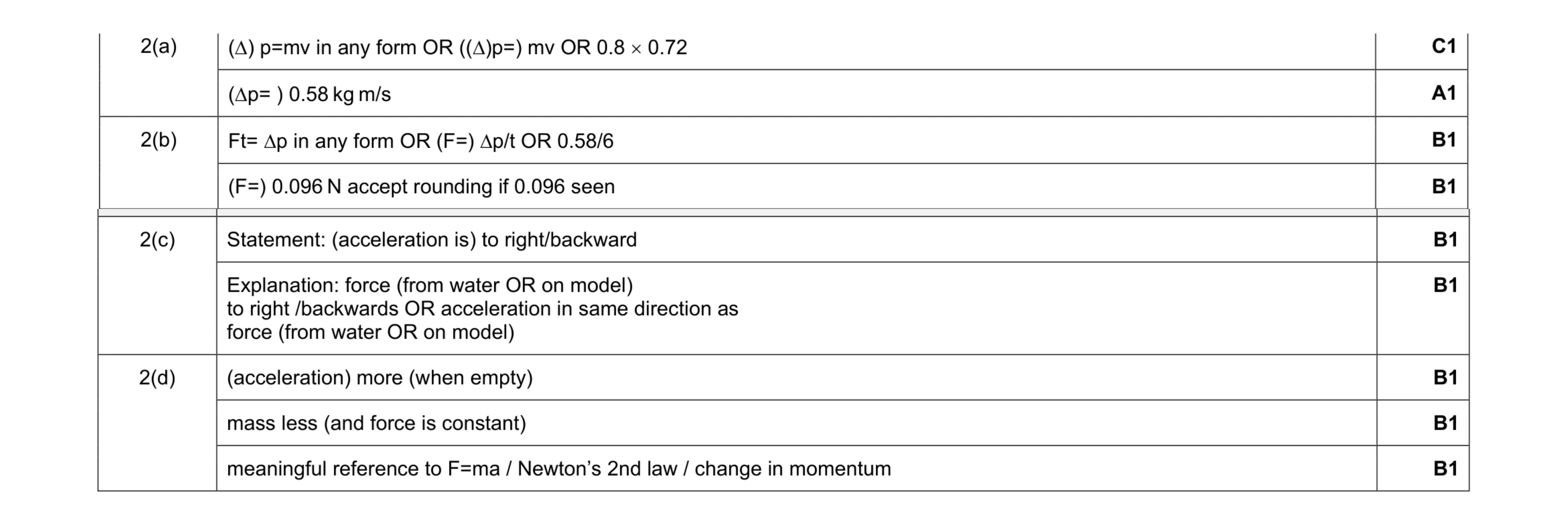 9
9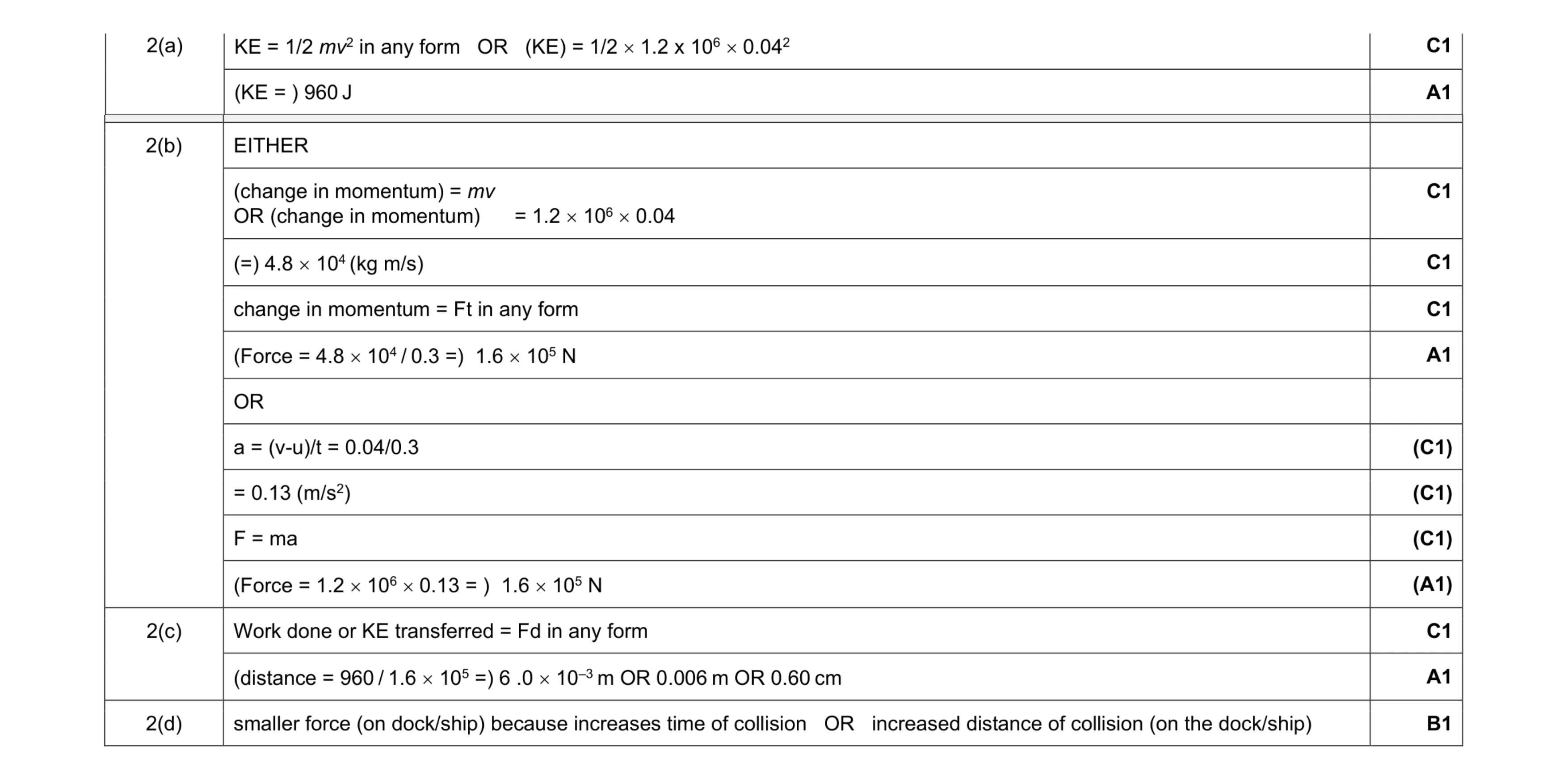 9
9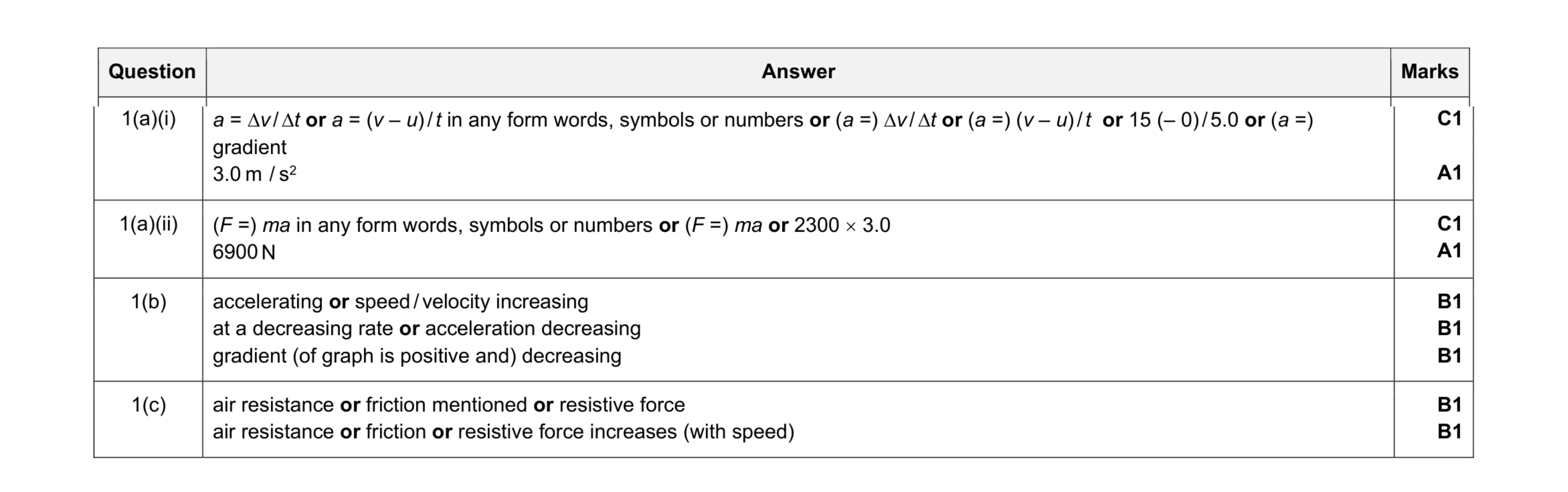 9
9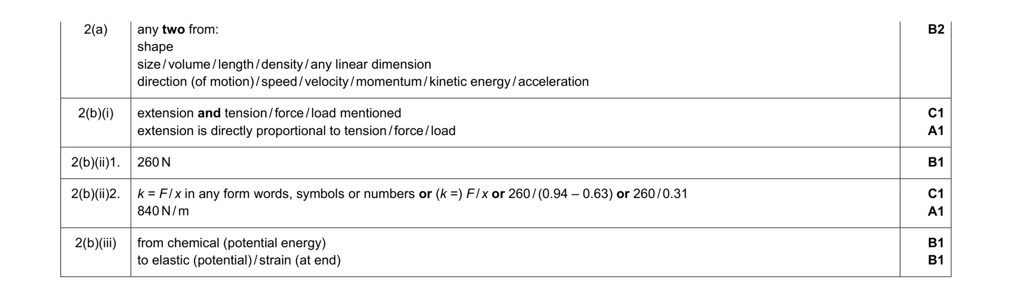 9
9 6
6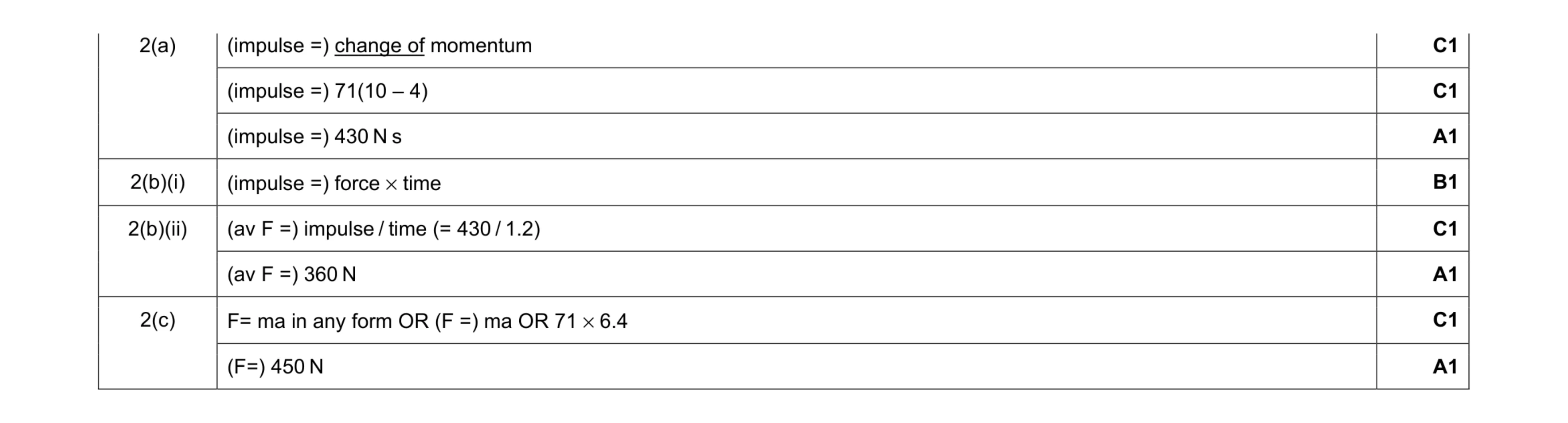 8
8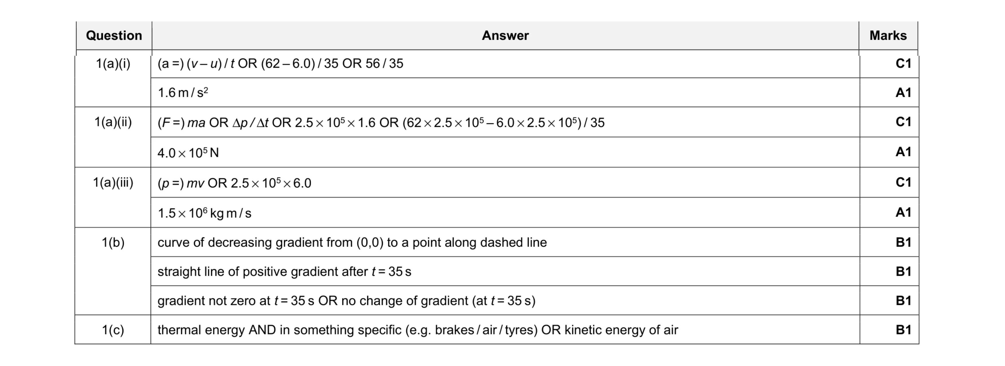 10
10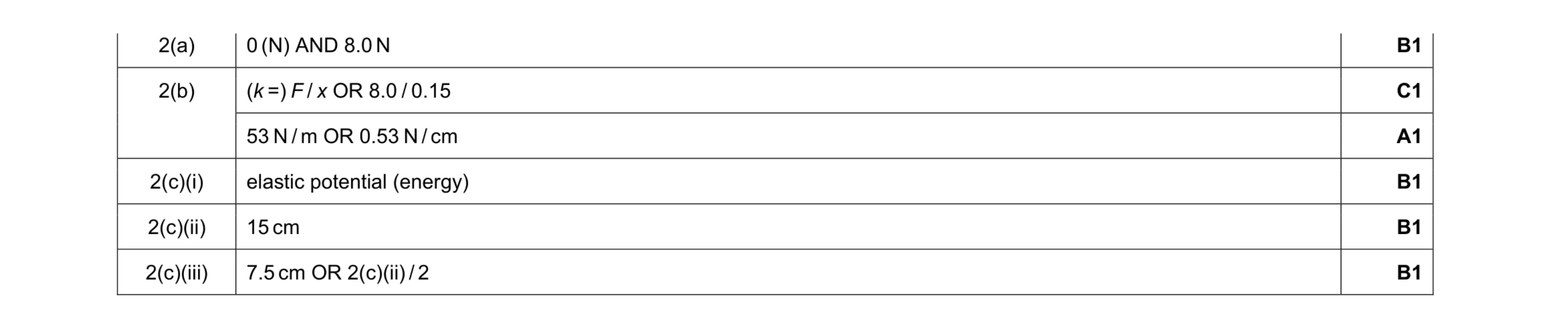 6
6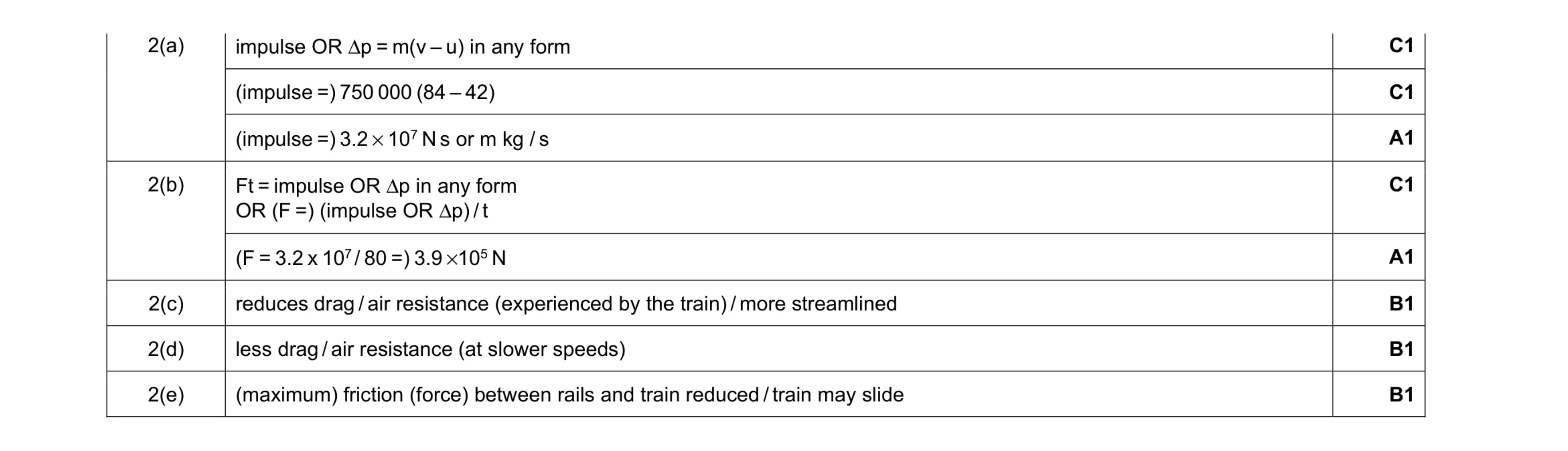 8
8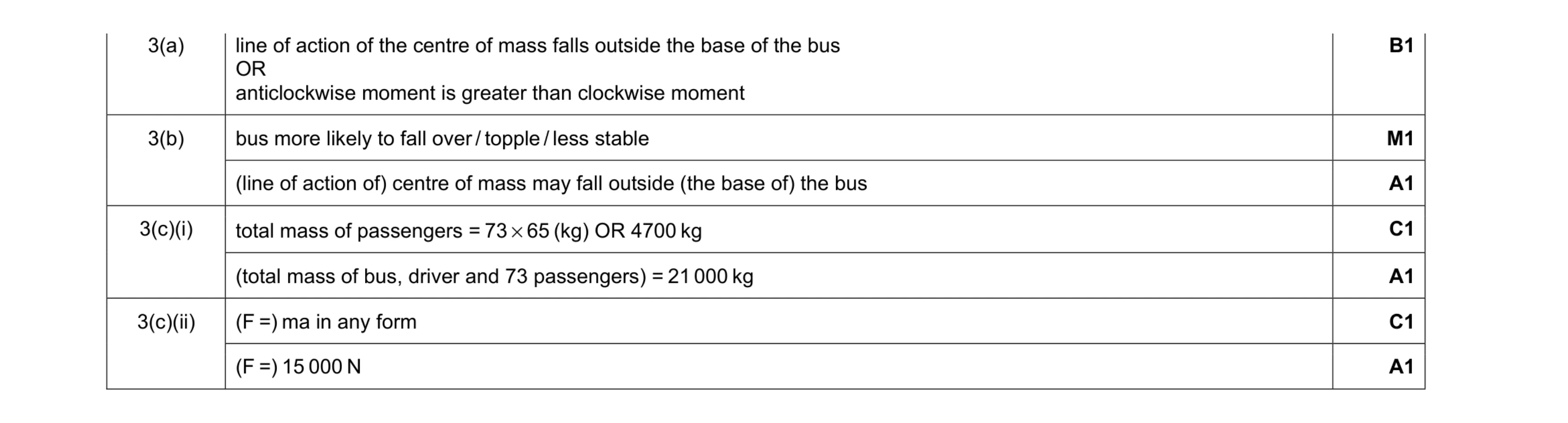 7
7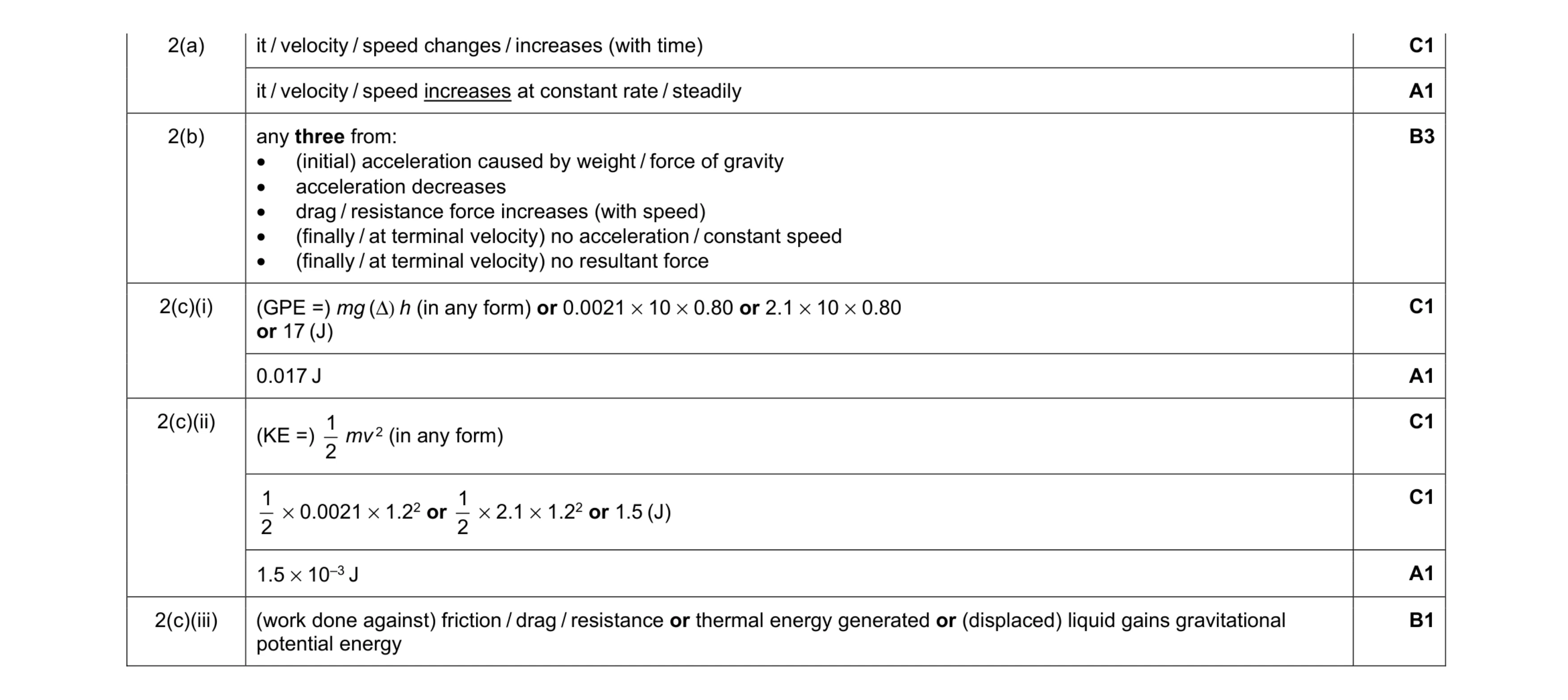 11
11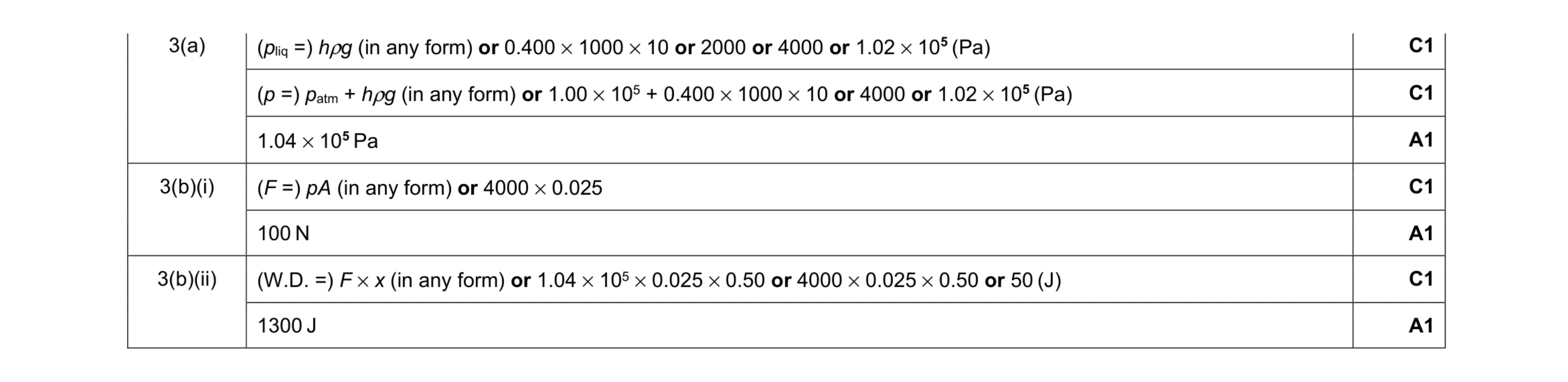 7
7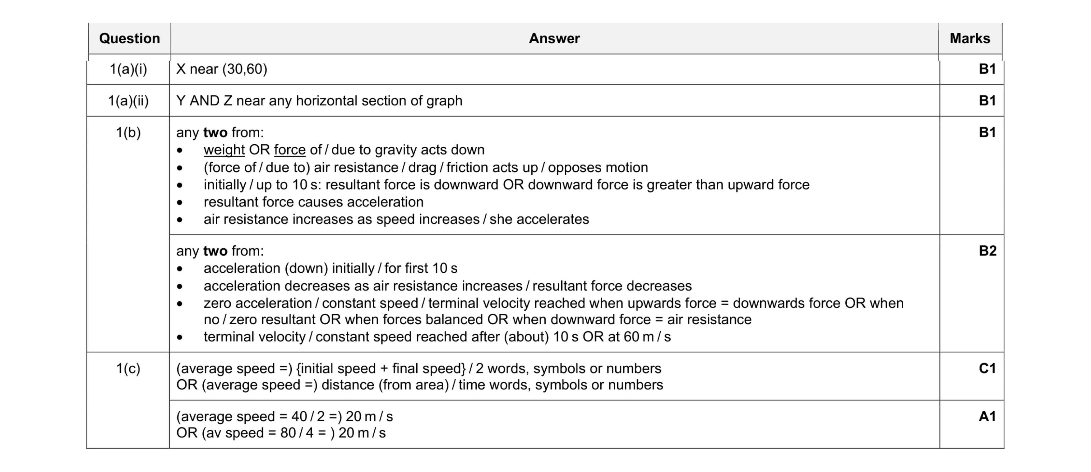 8
8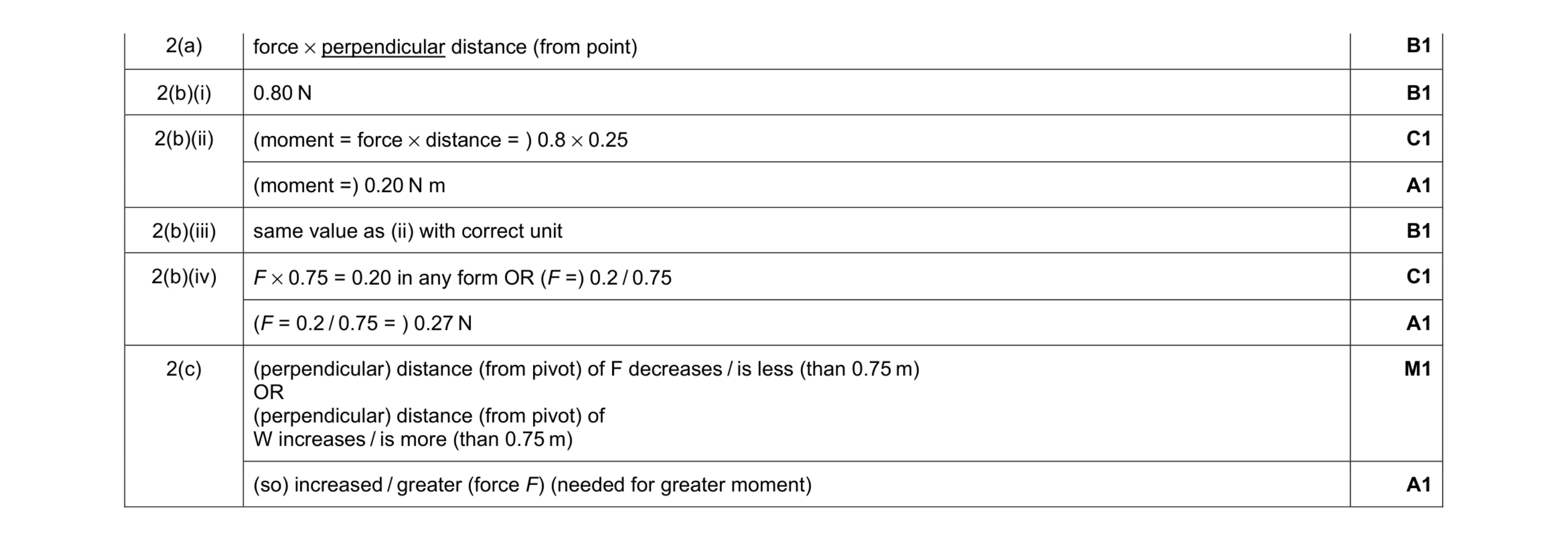 9
9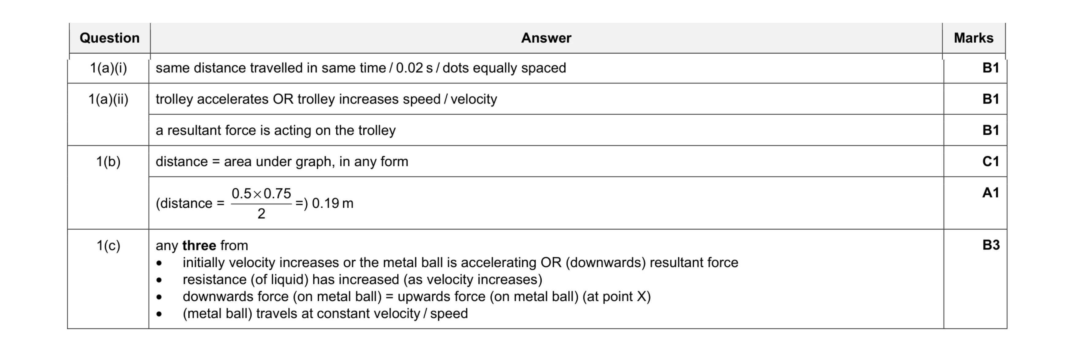 8
8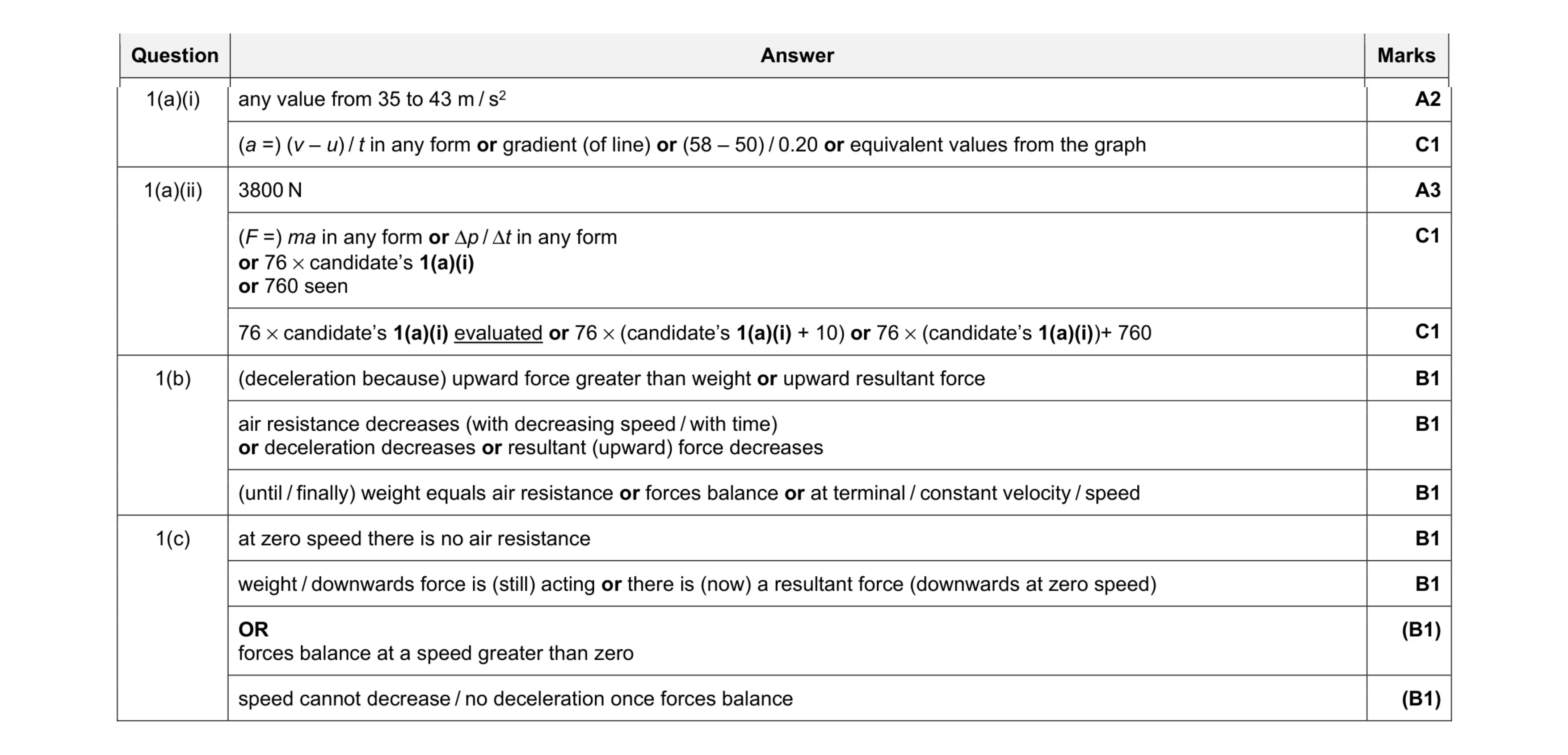 10
10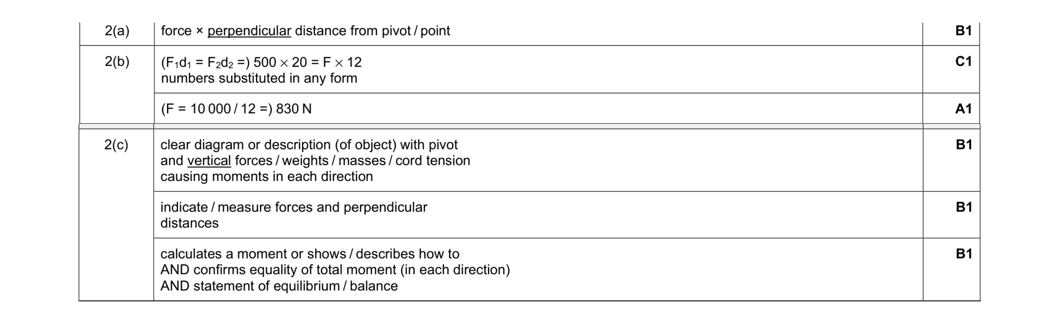 6
6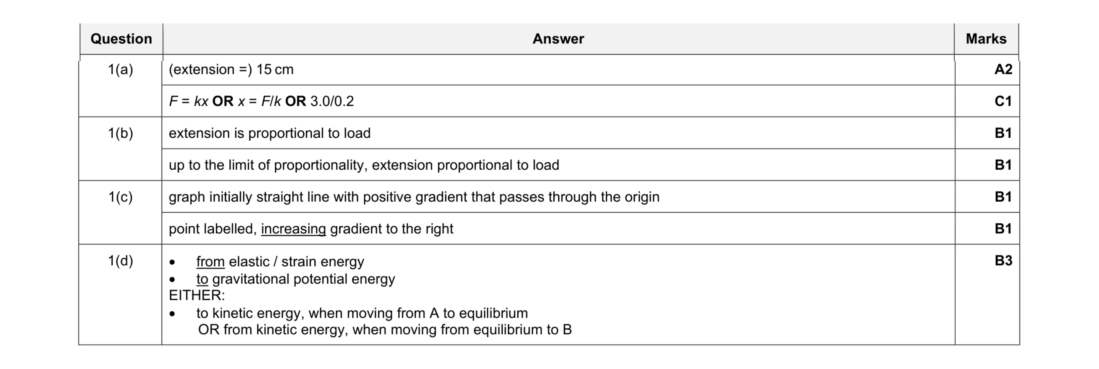 9
9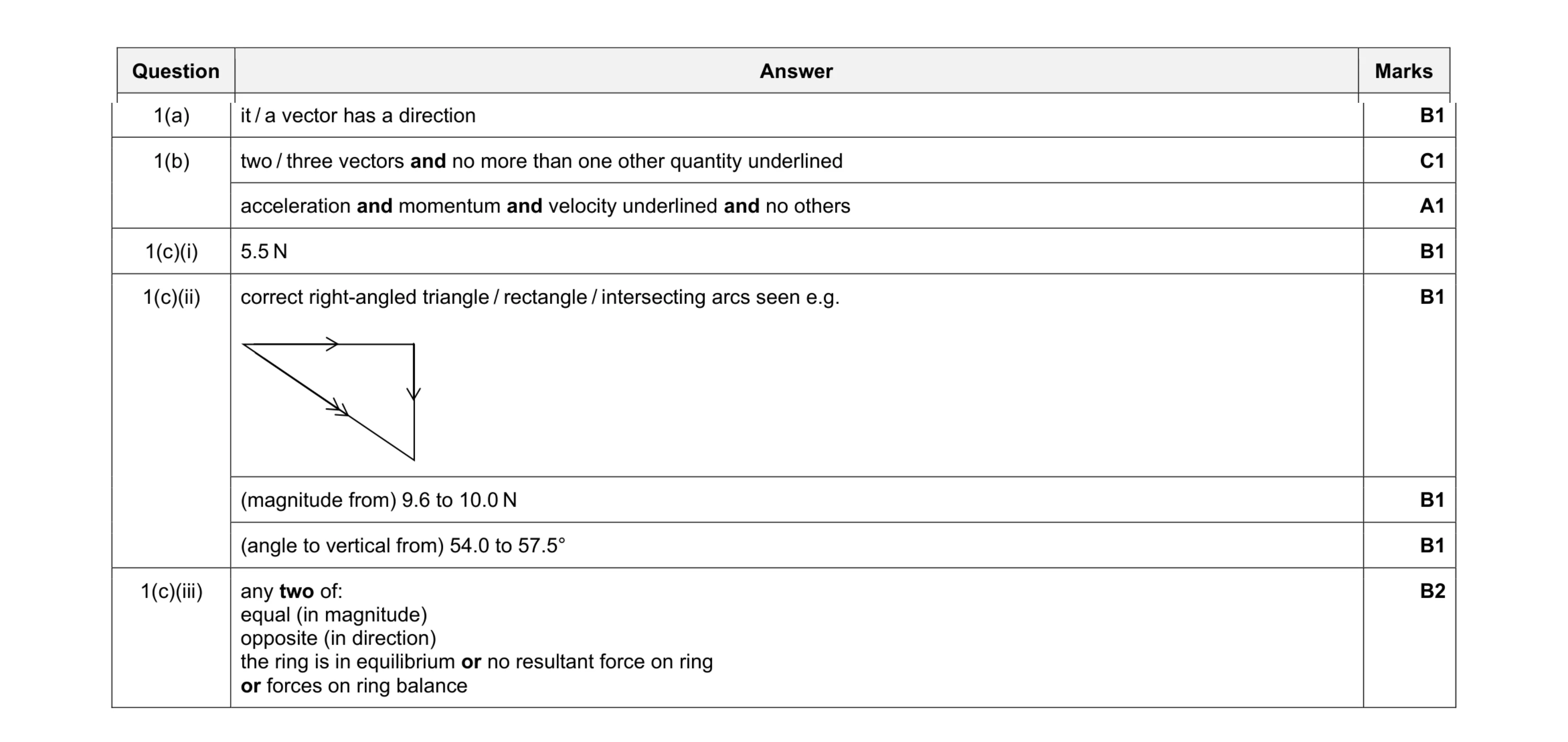 9
9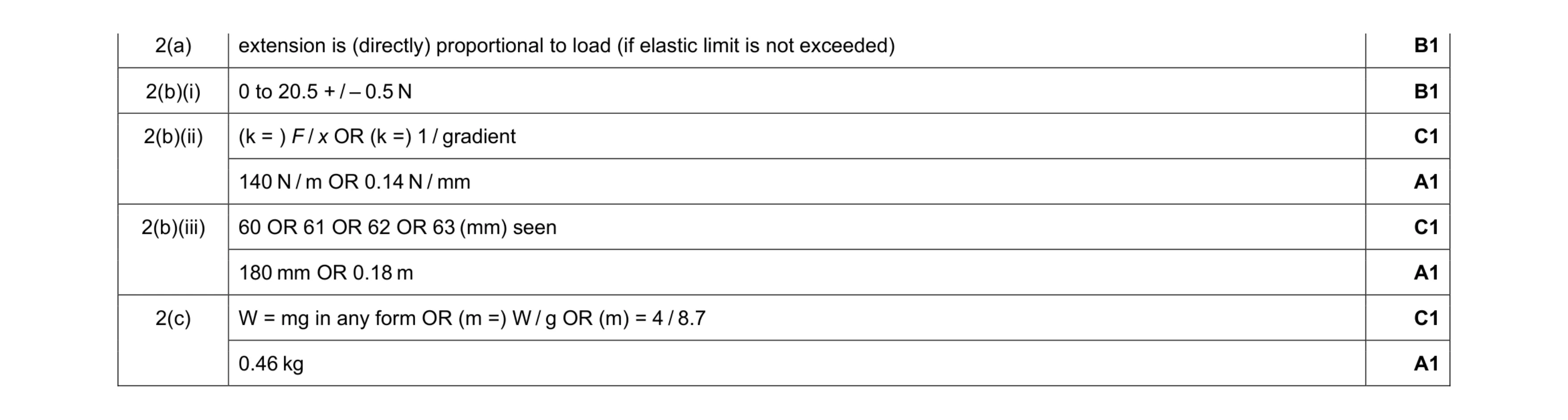 8
8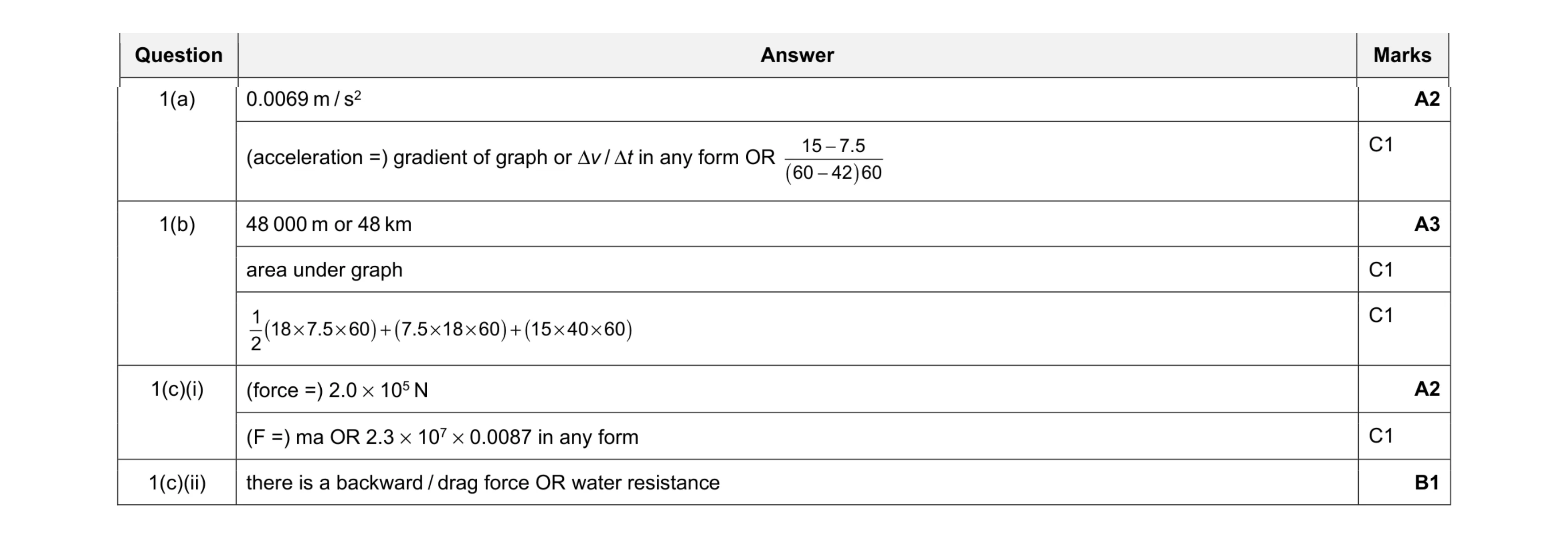 8
8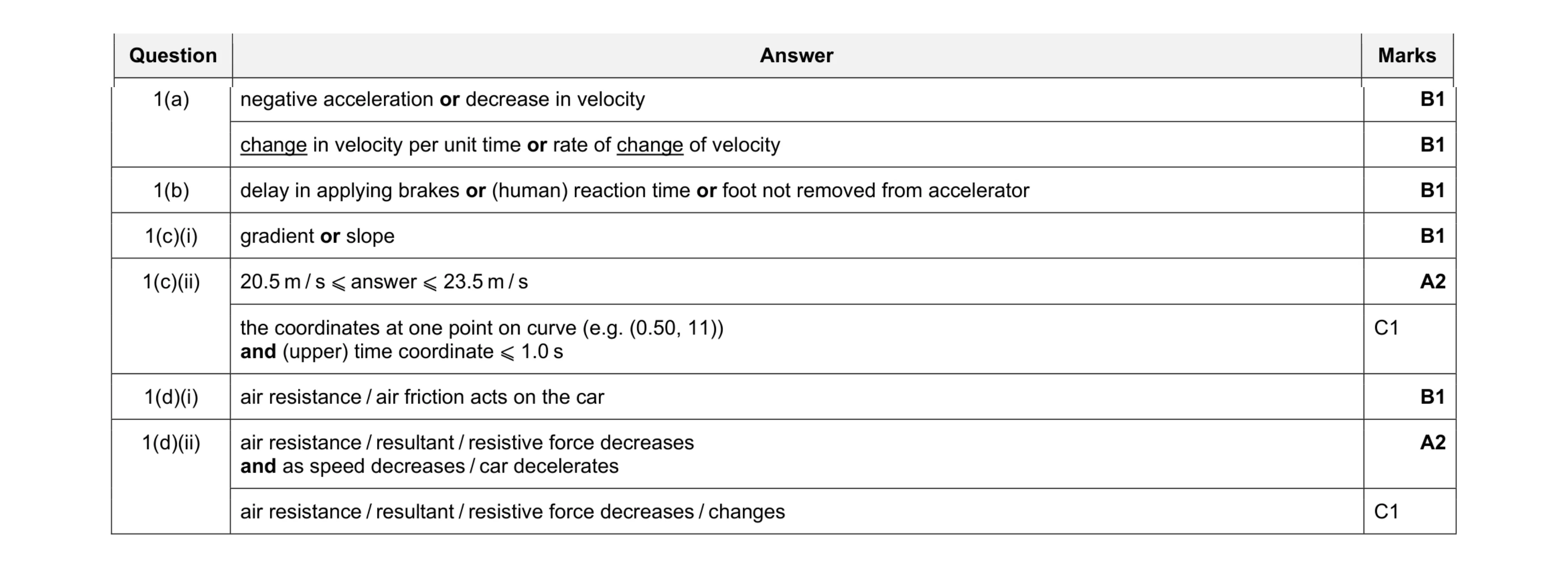 9
9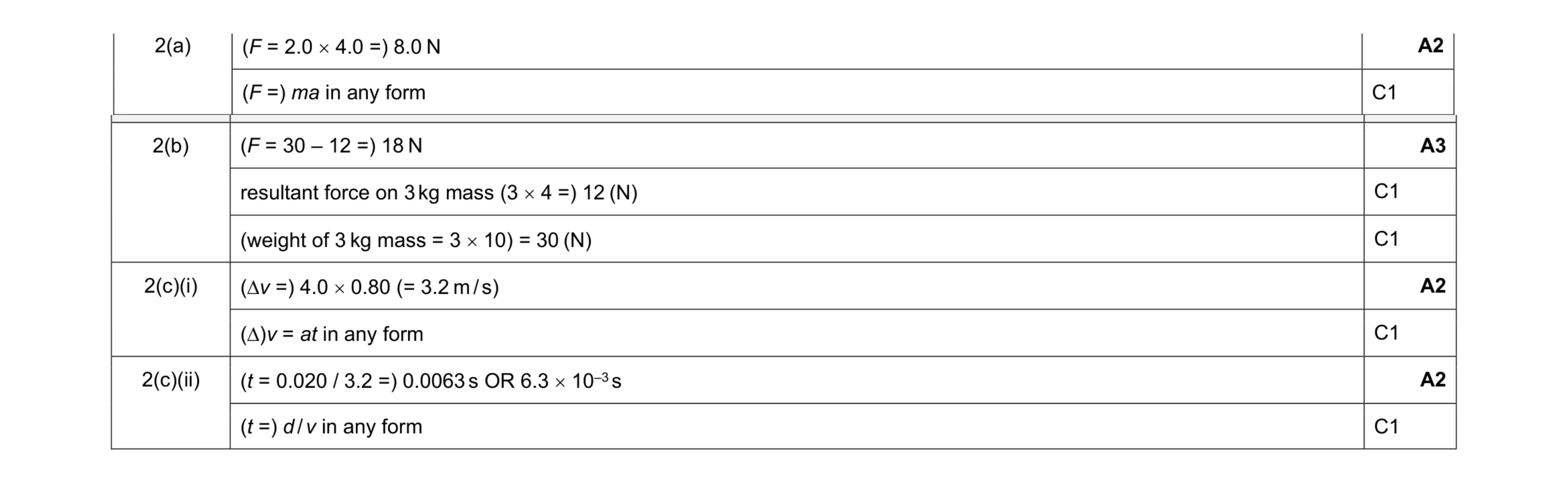 9
9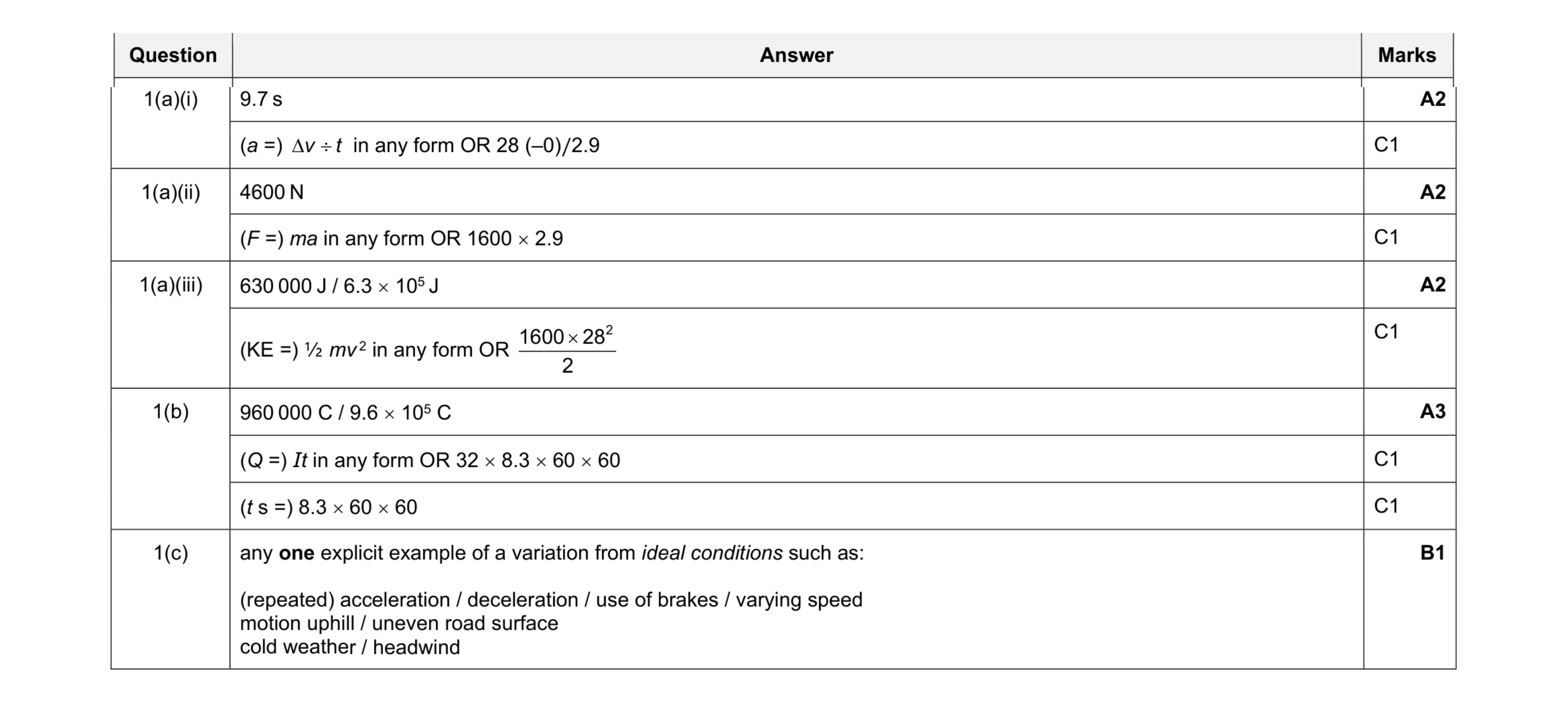 10
10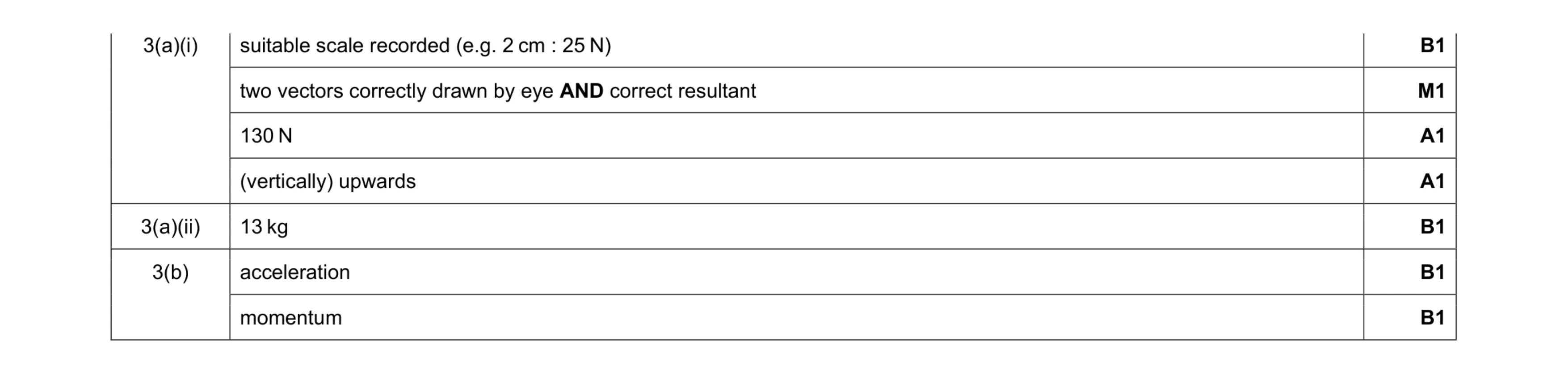 7
7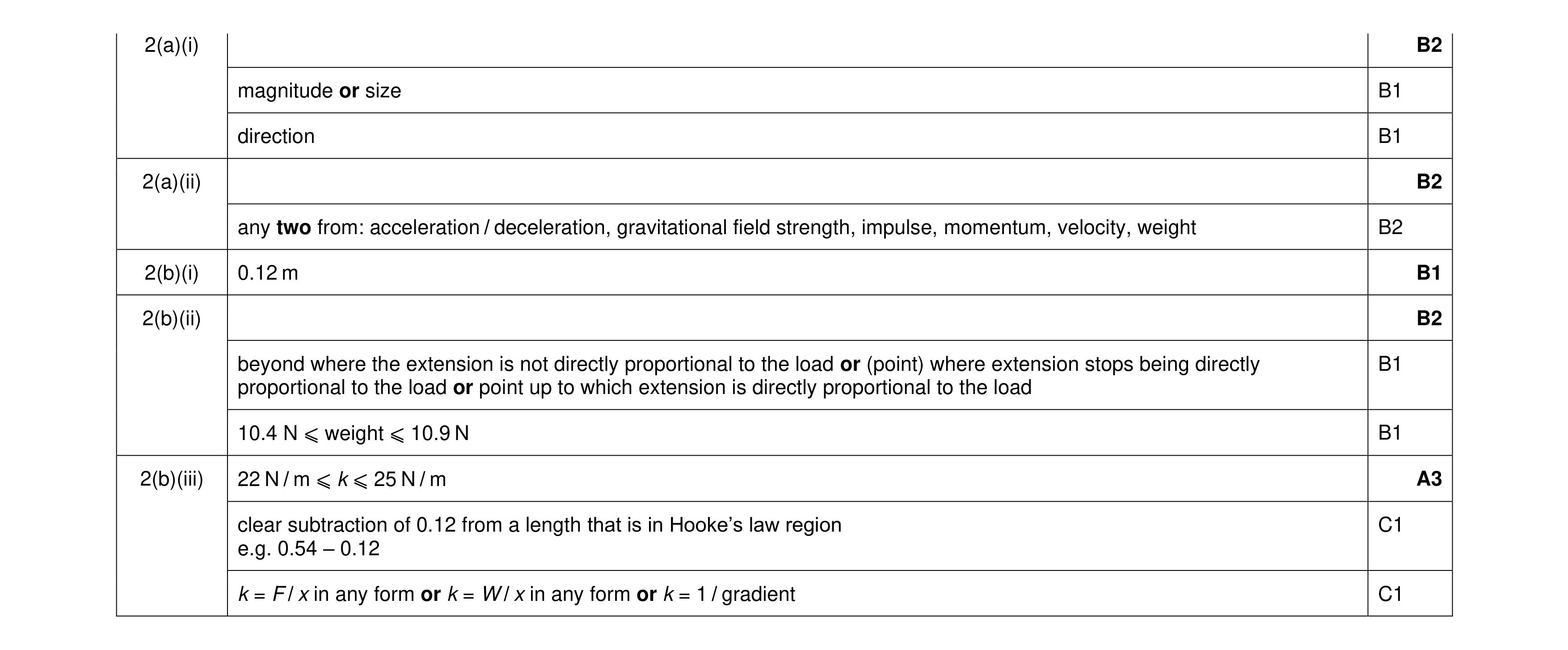 10
10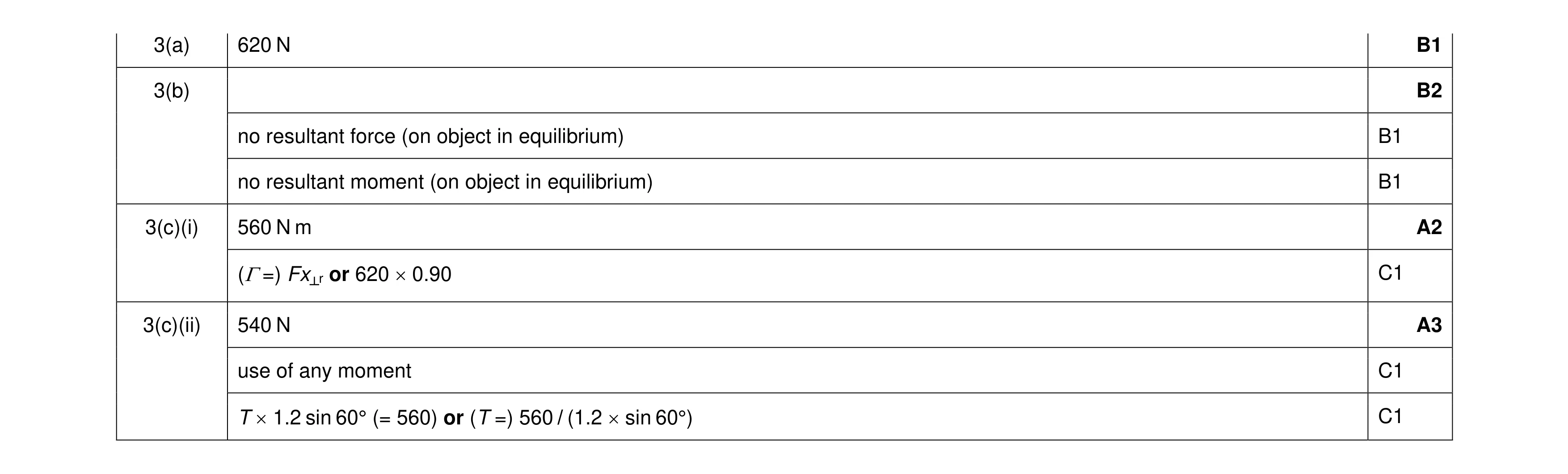 8
8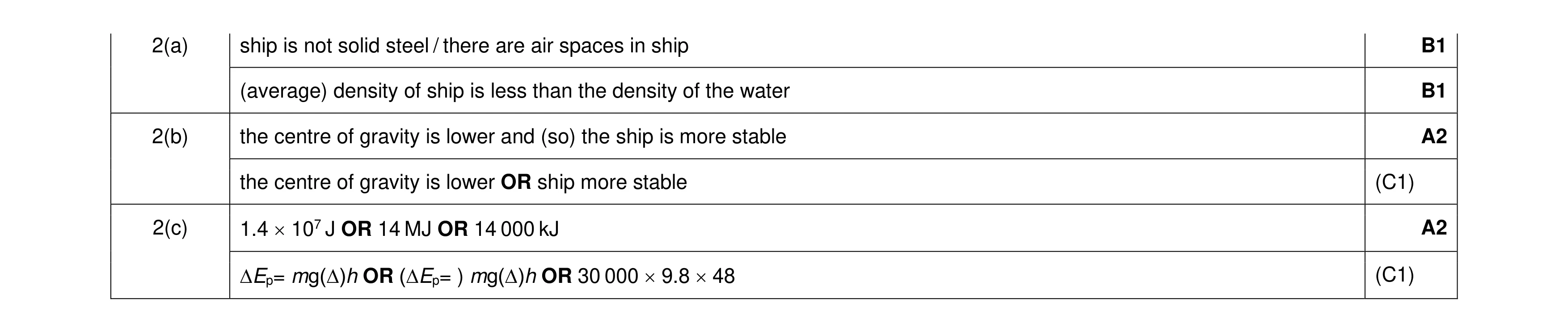 6
6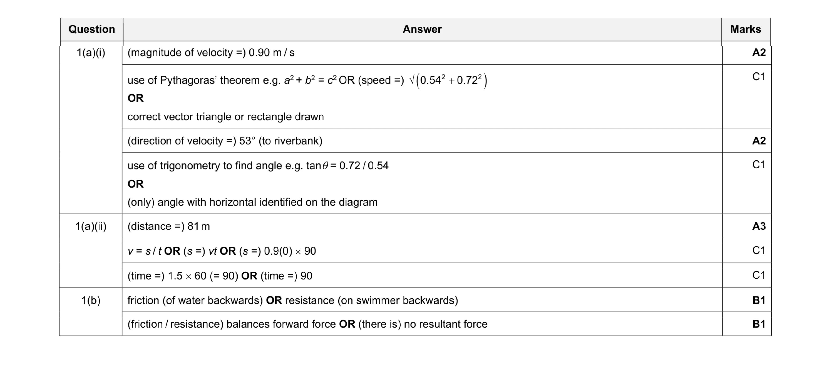 9
9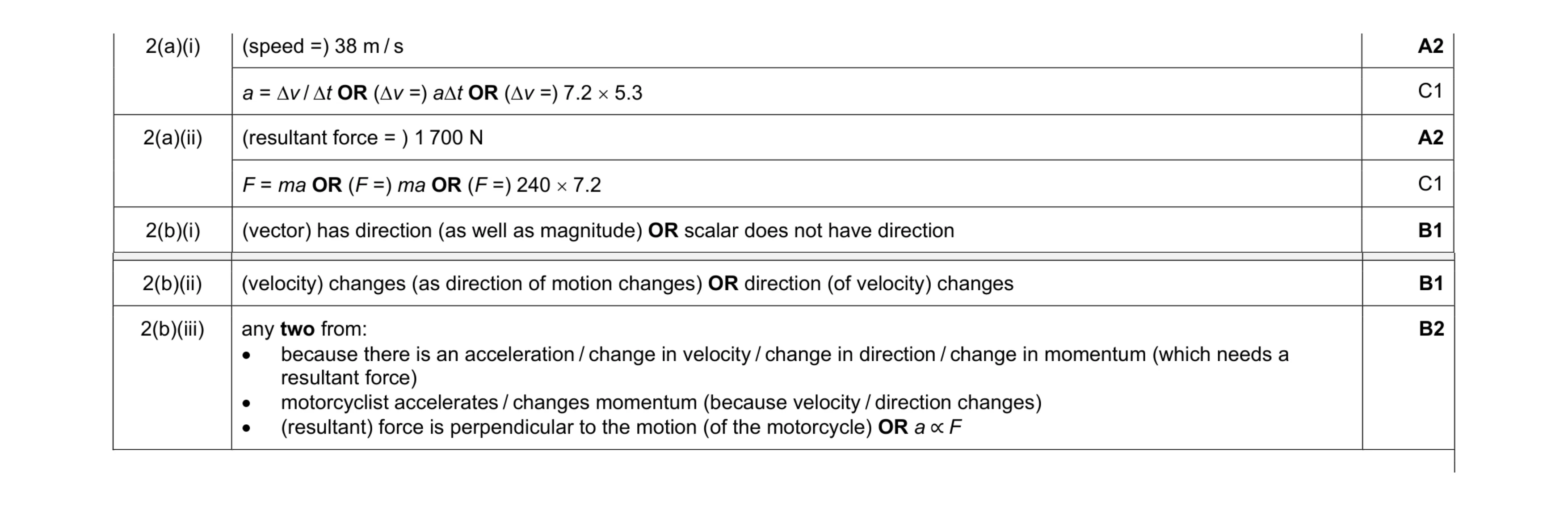 8
8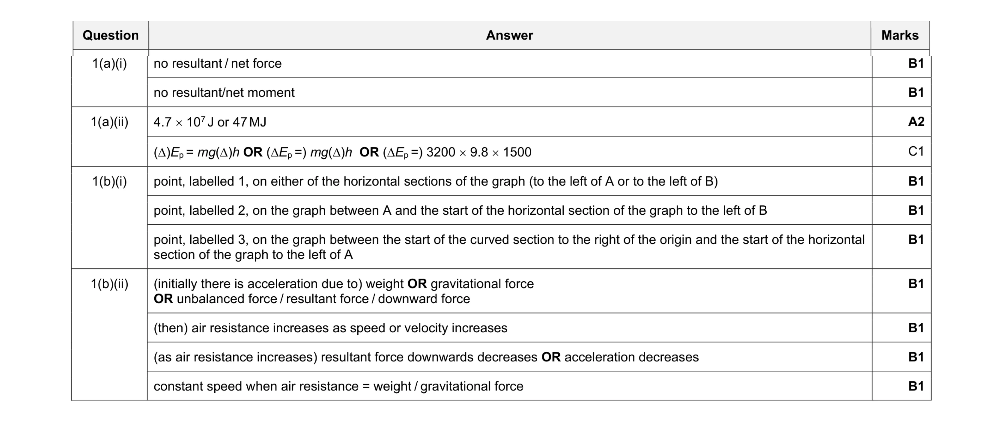 11
11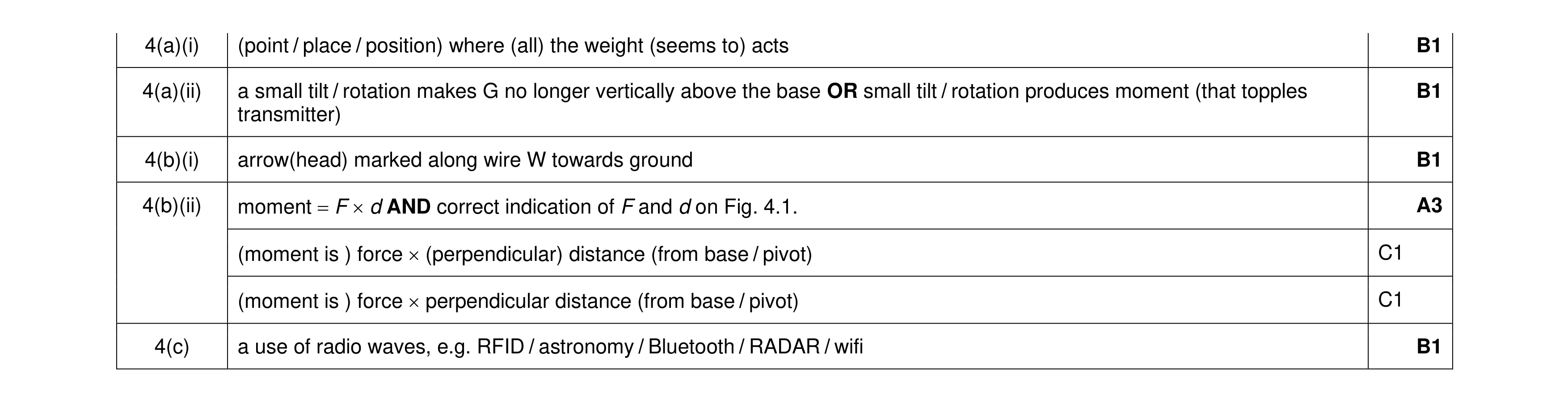 7
7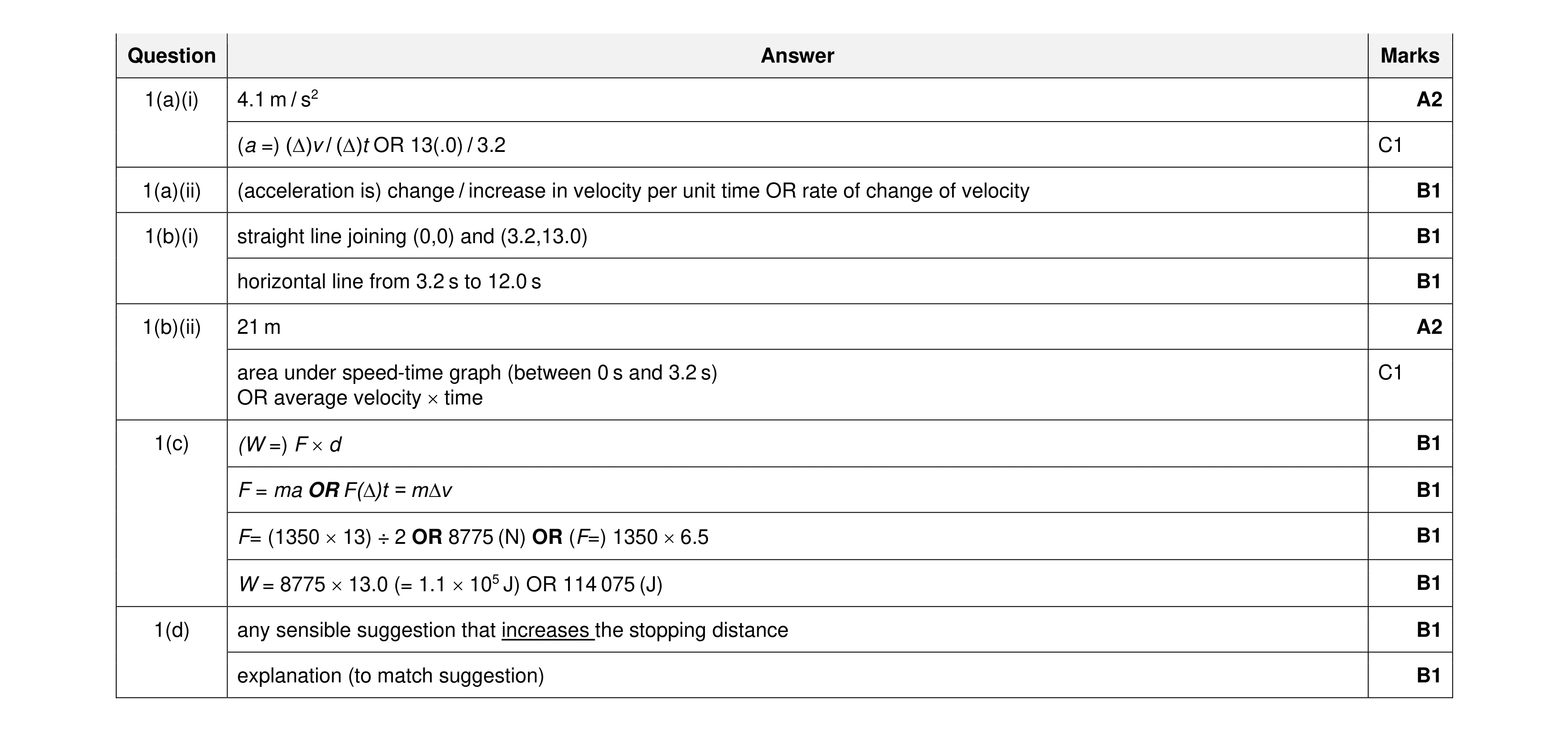 13
13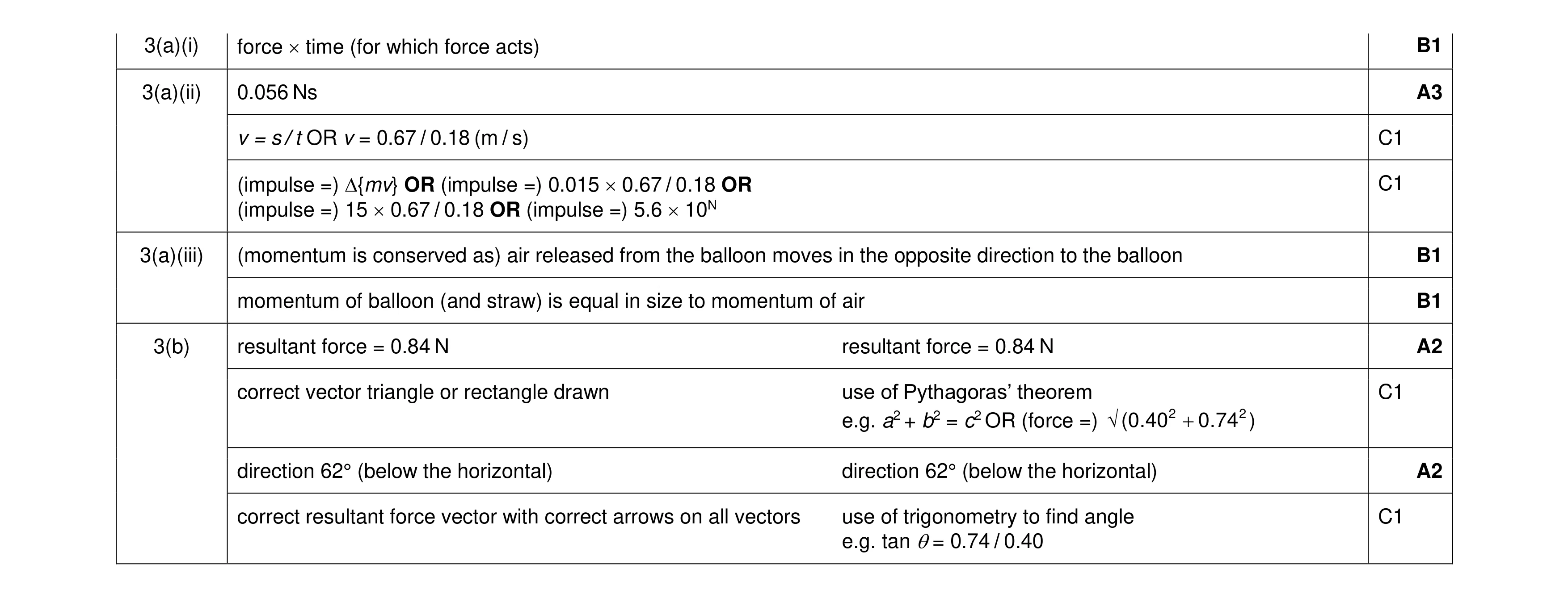 10
10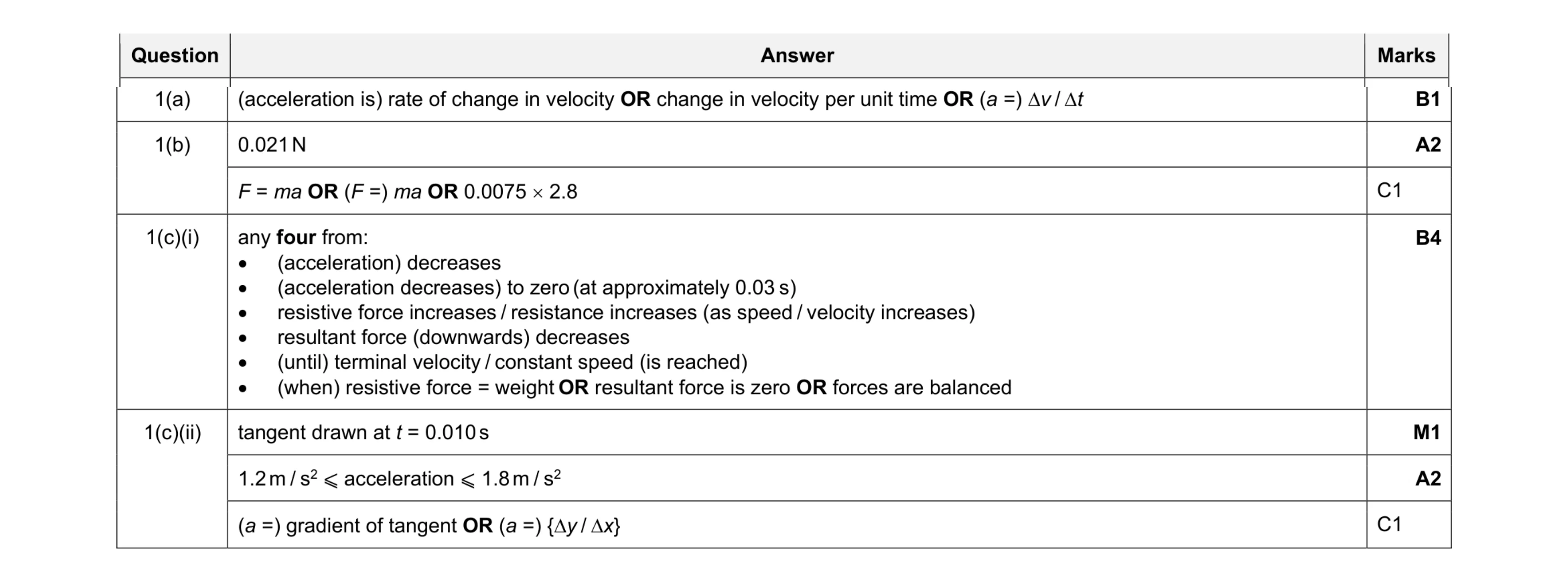 10
10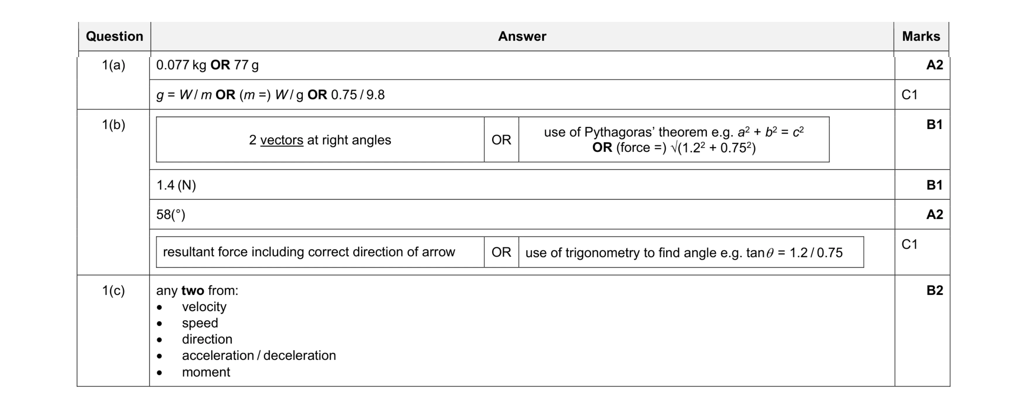 8
8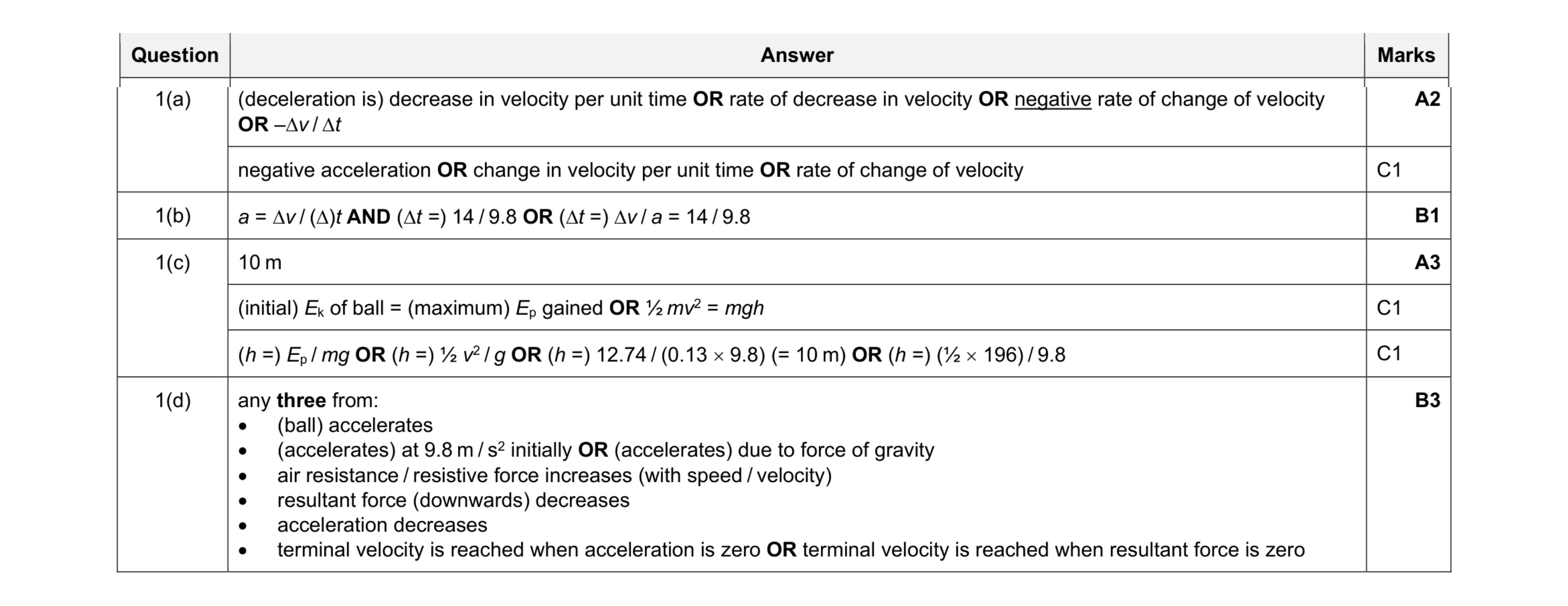 9
9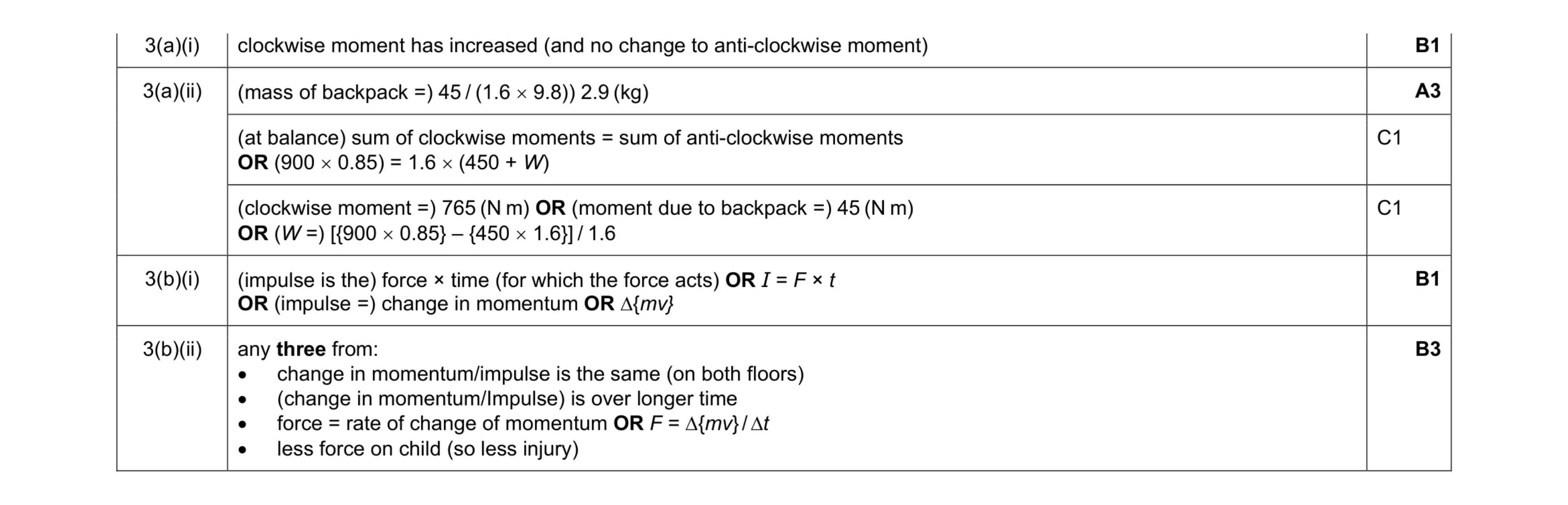 8
8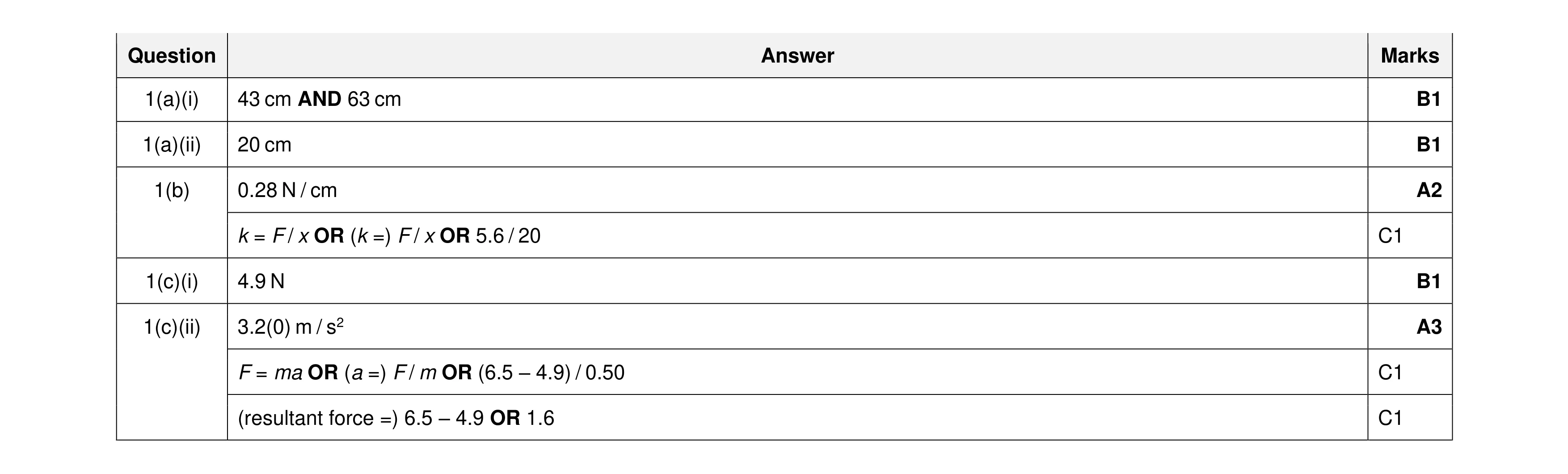 8
8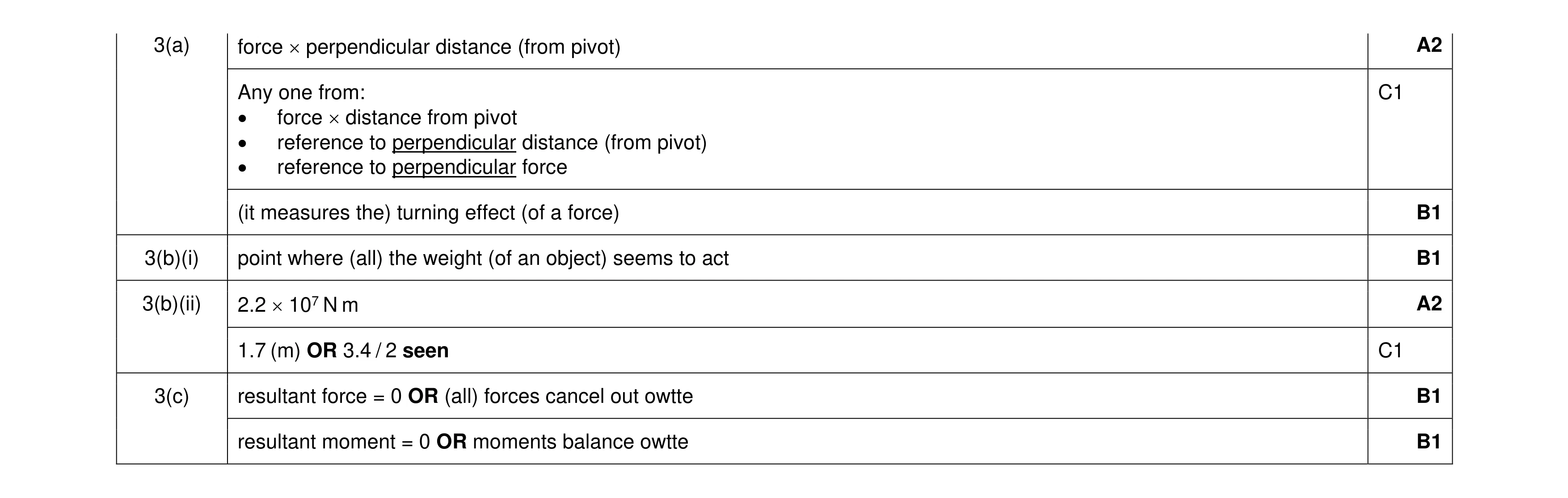 8
8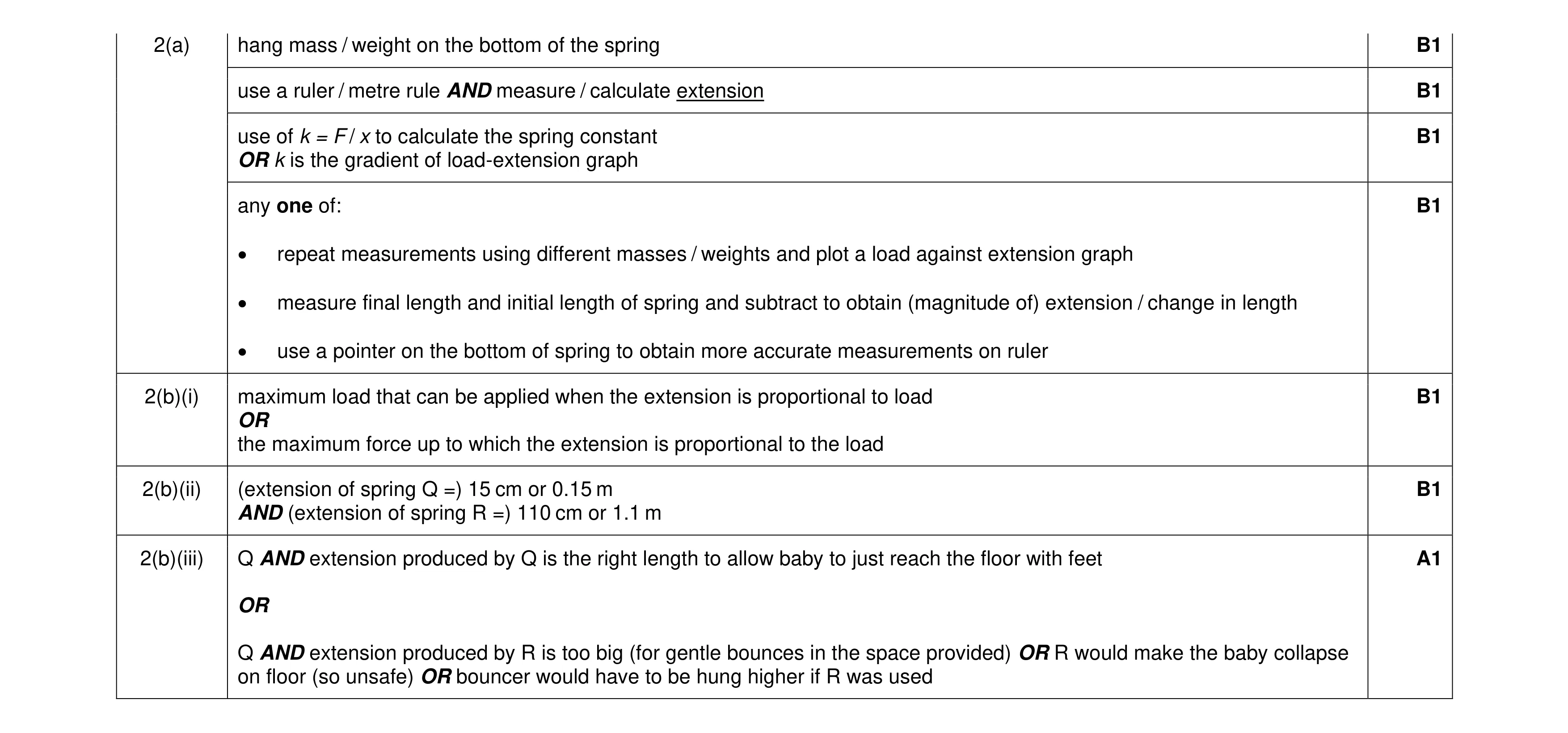 7
7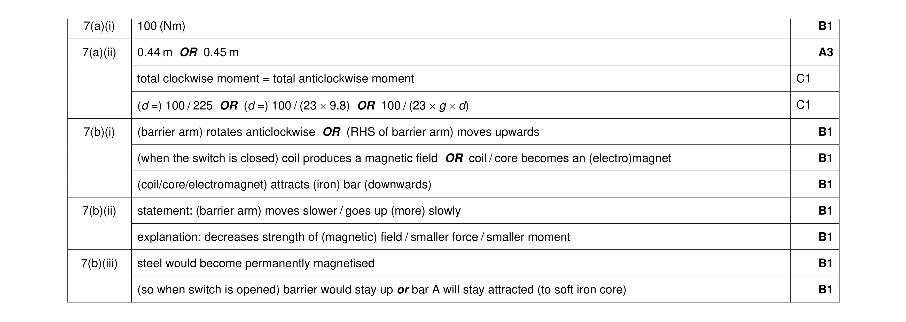 11
11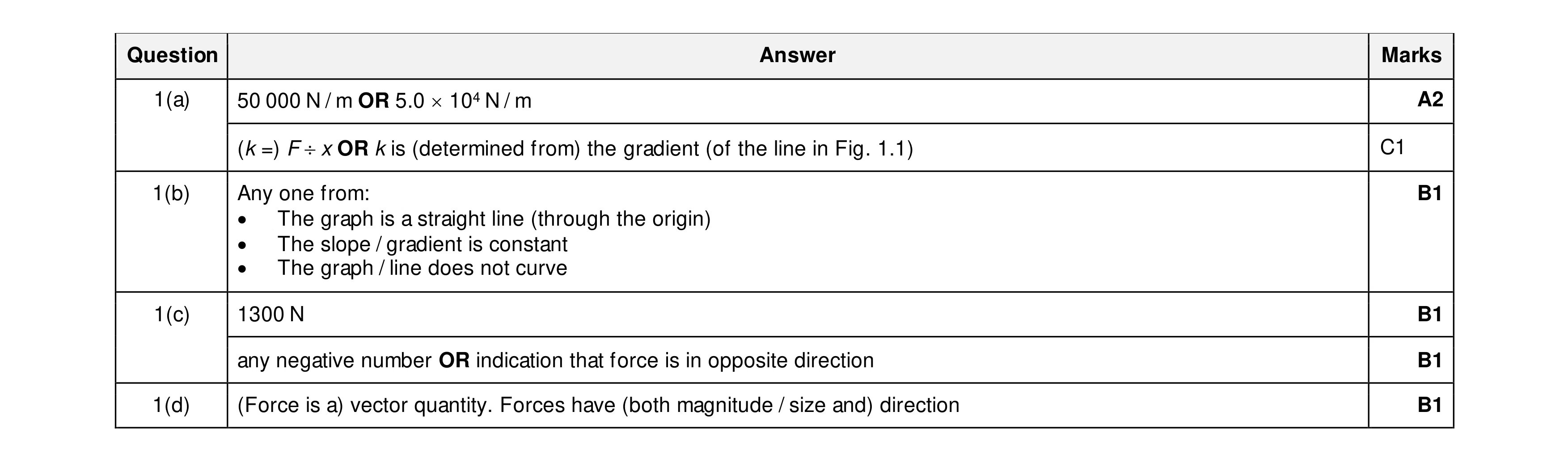 6
6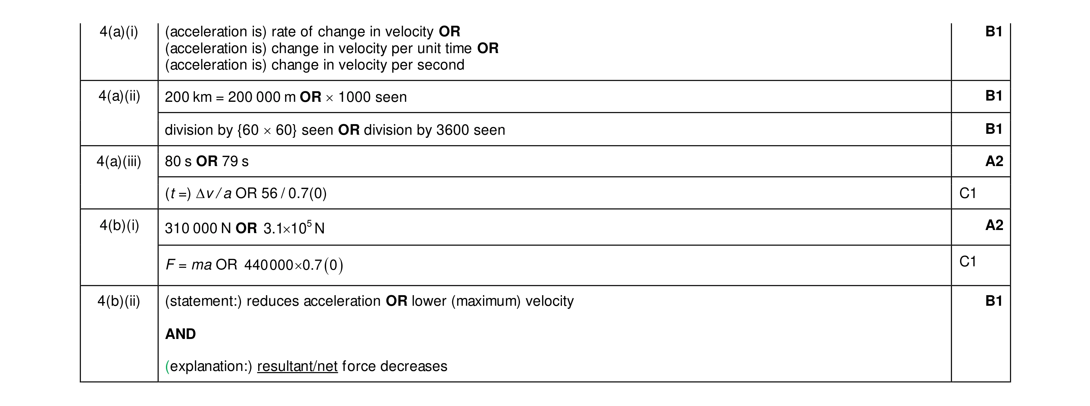 8
8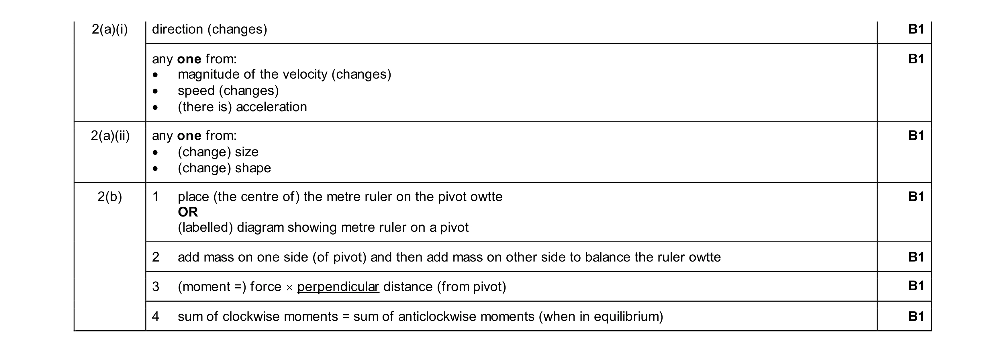 7
7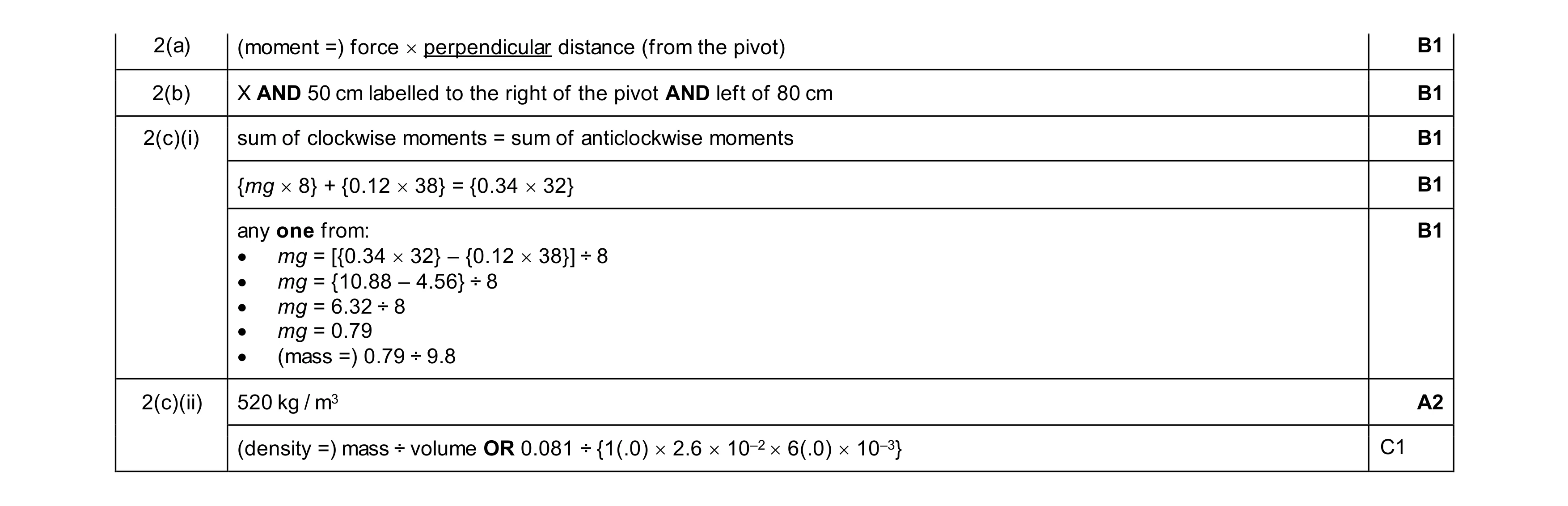 7
7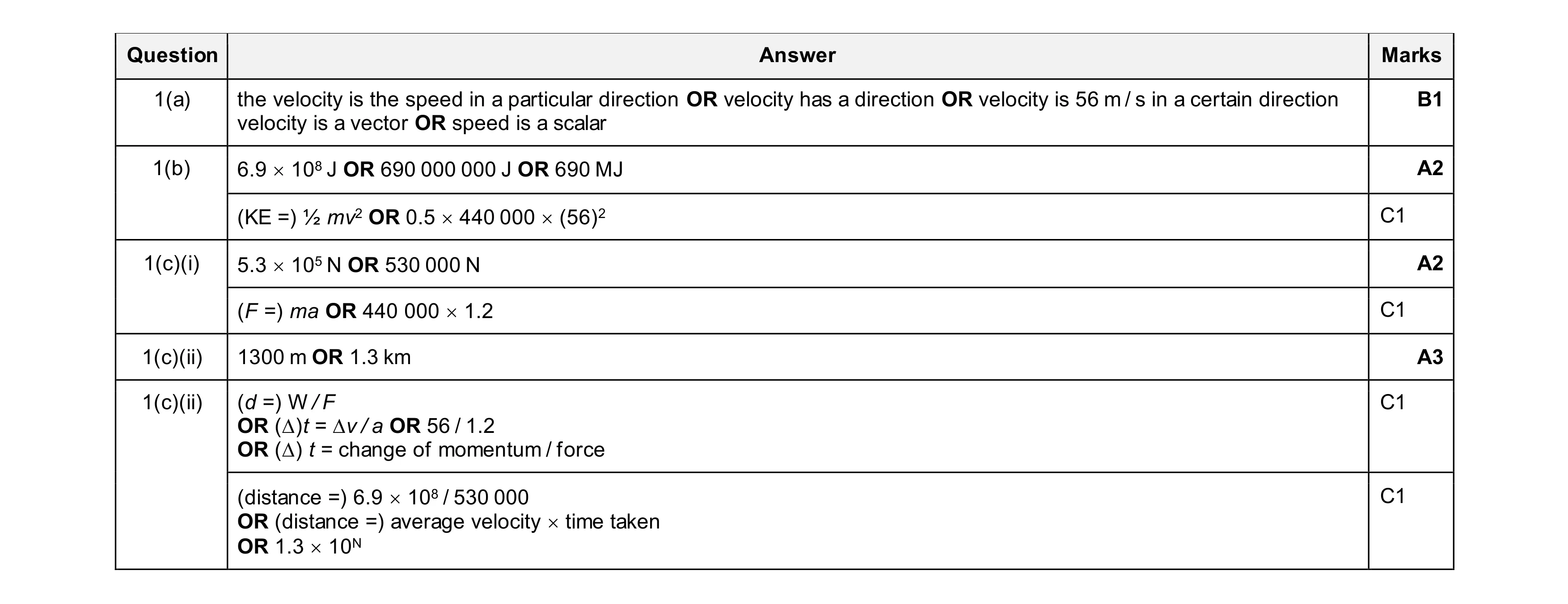 8
8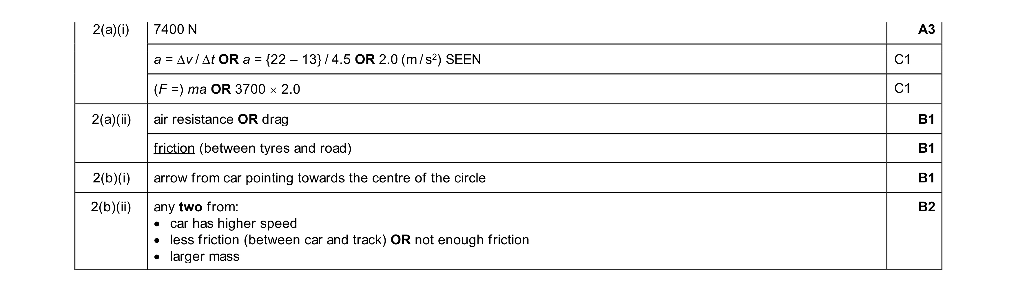 8
8 5
5