Questions as text
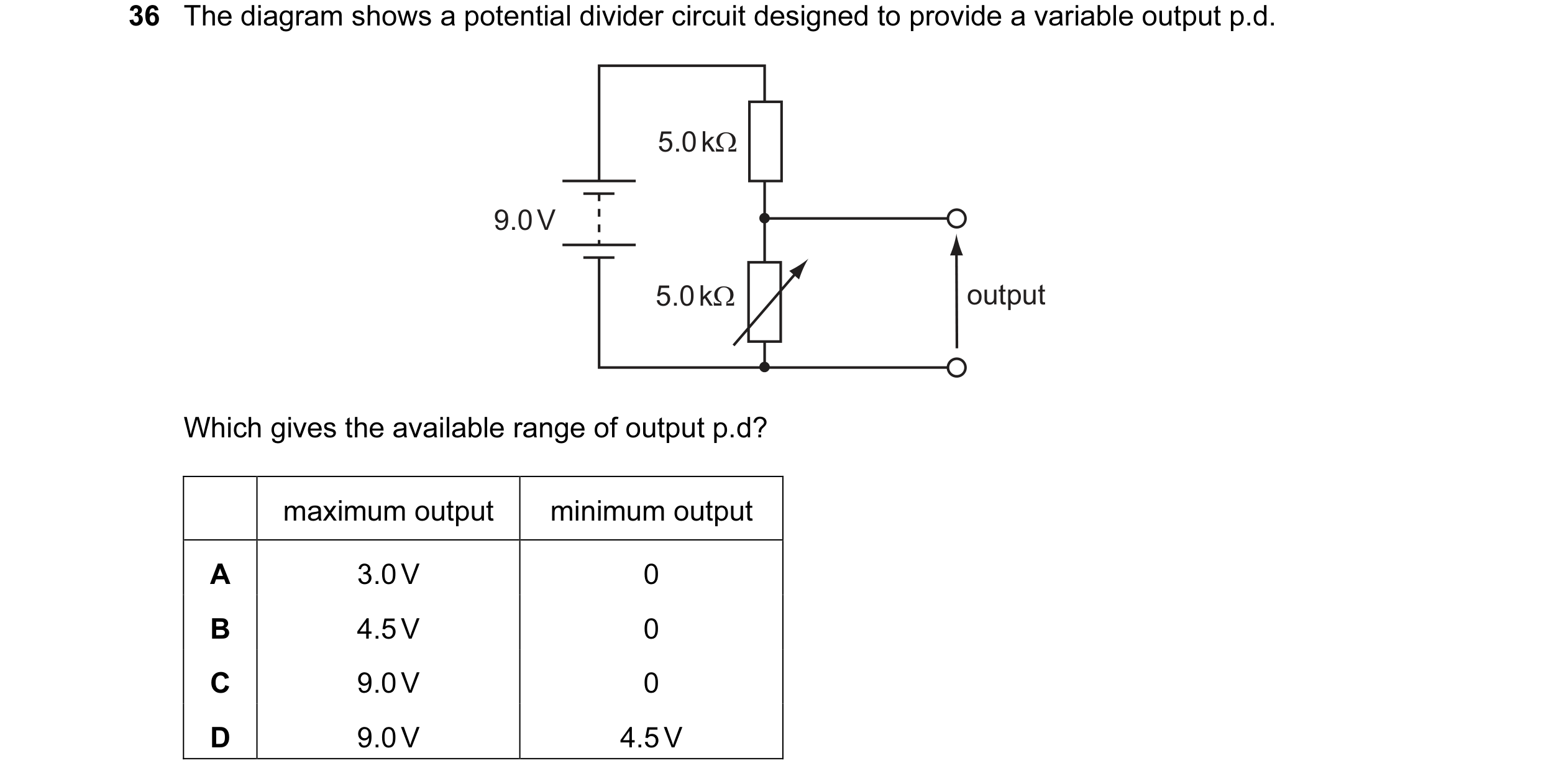
Q1 · The diagram shows a potential divider circuit designed to provide a variable output p.d 9702/11 Oct/Nov 2004
36 The diagram shows a potential divider circuit designed to provide a variable output p.d. 5.0 kΩ 9.0 V 5.0 kΩ output Which gives the available range of output p.d? maximum output minimum output A 3.0 V 0 B 4.5 V 0 C 9.0 V 0 D 9.0 V 4.5 V
1 marks
Answer: B
This question in 9702/11 Oct/Nov 2004
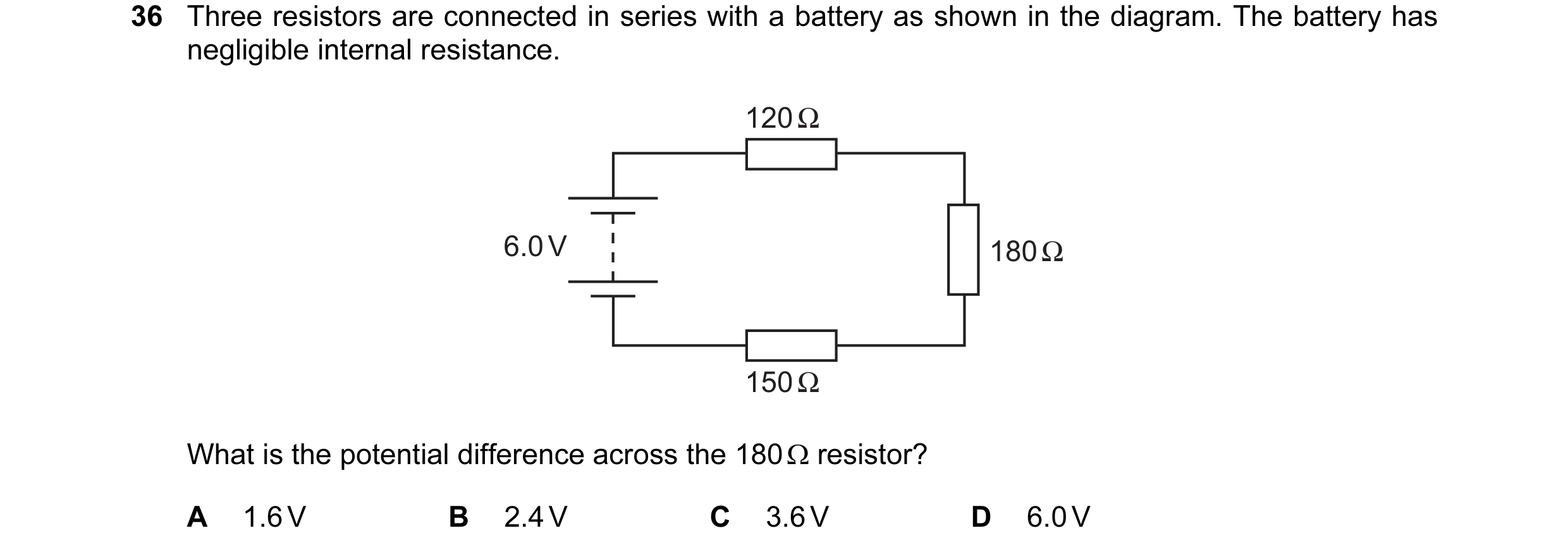
Q2 · Three resistors are connected in series with a battery as shown in the diagram 9702/11 Oct/Nov 2005
36 Three resistors are connected in series with a battery as shown in the diagram. The battery has negligible internal resistance. 120 Ω 6.0 V 180 Ω 150 Ω What is the potential difference across the 180 Ω resistor? A 1.6 V B 2.4 V C 3.6 V D 6.0 V
1 marks
Answer: B
This question in 9702/11 Oct/Nov 2005
Q3 · In the circuit below, the reading VT on the voltmeter changes from high to low as the… 9702/11 Oct/Nov 2005
37 In the circuit below, the reading VT on the voltmeter changes from high to low as the temperature of the thermistor changes. The reading VL on the voltmeter changes from high to low as the level of light on the light-dependent resistor (LDR) changes. VT VL V V The readings on VT and VL are both high. What are the conditions of temperature and light level? temperature light level A low low B low high C high low D high high
1 marks
Answer: C
This question in 9702/11 Oct/Nov 2005
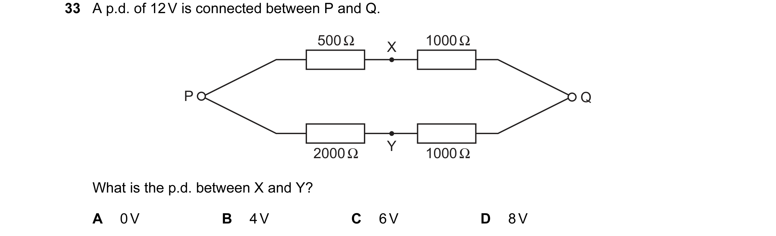
Question 4 9702/11 May/June 2006
33 A p.d. of 12 V is connected between P and Q. 500 Ω 1000 Ω X P Q Y 2000 Ω 1000 Ω What is the p.d. between X and Y? A 0 V B 4 V C 6 V D 8 V
1 marks
Answer: B
This question in 9702/11 May/June 2006
Q5 · The diagram shows a light-dependent resistor (LDR) and a thermistor forming a potential… 9702/11 May/June 2006
37 The diagram shows a light-dependent resistor (LDR) and a thermistor forming a potential divider. + – Under which set of conditions will the potential difference across the thermistor have the greatest value? illumination temperature A low low B high low C low high D high high
1 marks
Answer: B
This question in 9702/11 May/June 2006
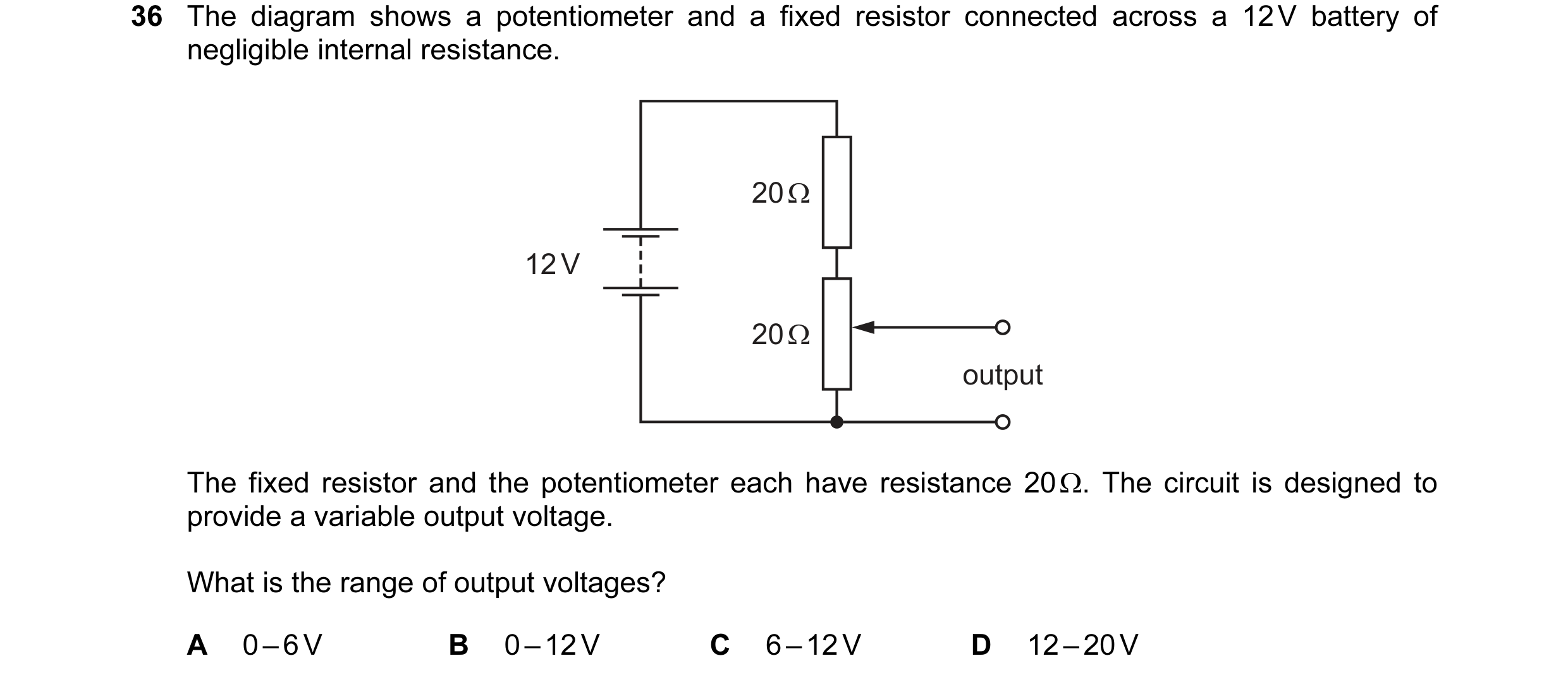
Q6 · The diagram shows a potentiometer and a fixed resistor connected across a 12 V battery of… 9702/11 Oct/Nov 2006
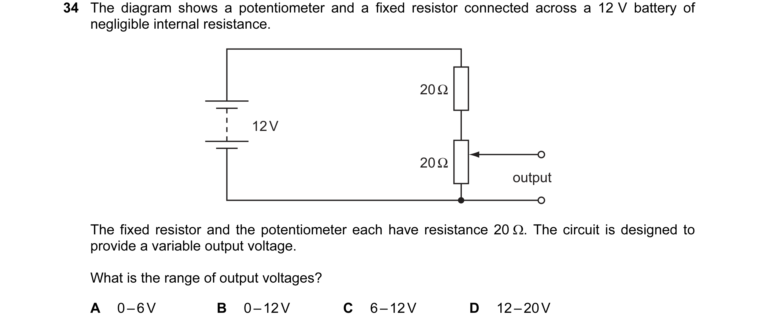
34 The diagram shows a potentiometer and a fixed resistor connected across a 12 V battery of negligible internal resistance. 20 Ω 12 V 20 Ω output The fixed resistor and the potentiometer each have resistance 20 Ω. The circuit is designed to provide a variable output voltage. What is the range of output voltages? A 0 – 6 V B 0 – 12 V C 6 – 12 V D 12 – 20 V
1 marks
Answer: A
This question in 9702/11 Oct/Nov 2006
Q7 · A cell of e.m.f 9702/11 May/June 2007
33 A cell of e.m.f. 2.0 V and negligible internal resistance is connected to the network of resistors shown. 5.0 kΩ 2.0 kΩ 2.0 V P Q 5.0 kΩ 3.0 kΩ S V1 is the potential difference between S and P. V2 is the potential difference between S and Q. What is the value of V1 – V2? A +0.50 V B +0.20 V C –0.20 V D –0.50 V
1 marks
Answer: C
This question in 9702/11 May/June 2007
Q8 · A circuit is set up with an LDR and a fixed resistor as shown 9702/11 May/June 2007
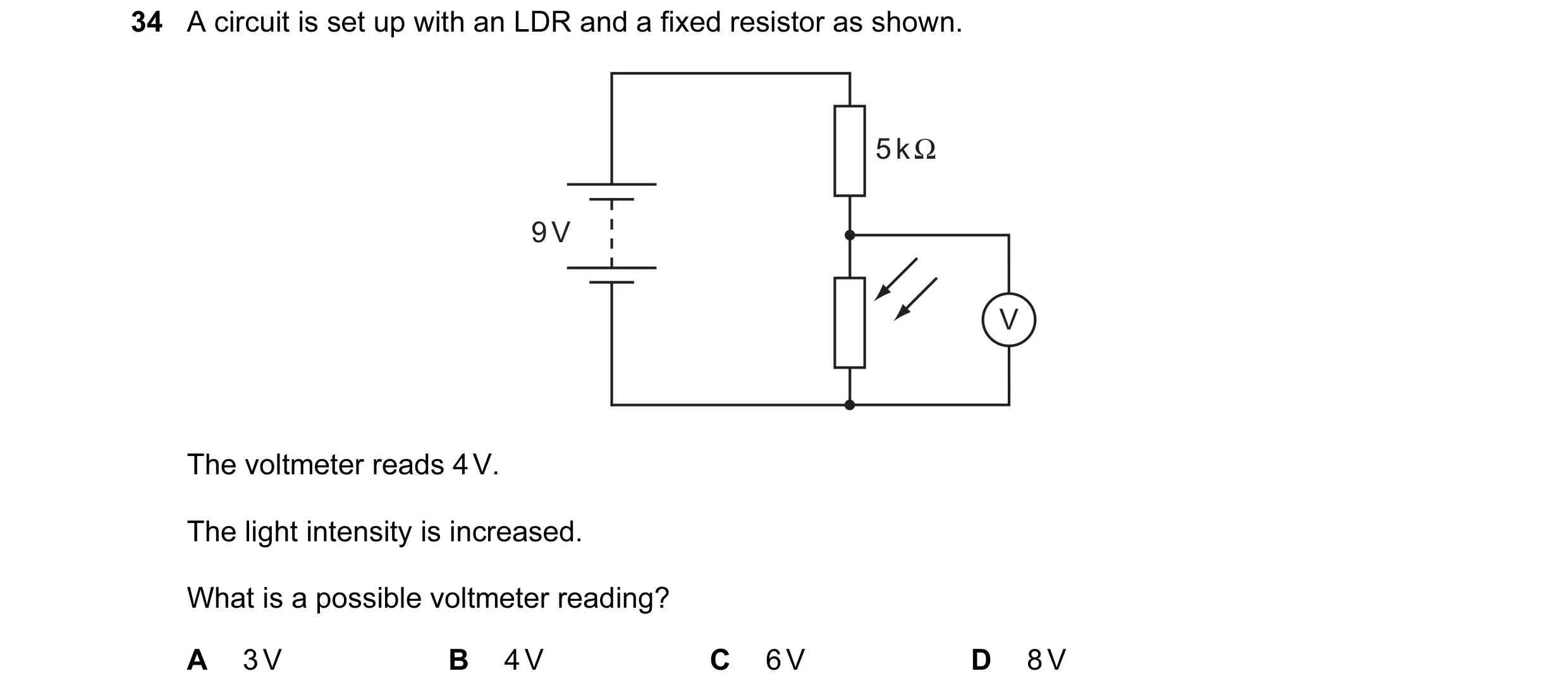
34 A circuit is set up with an LDR and a fixed resistor as shown. 5 k Ω 9 V V The voltmeter reads 4 V. The light intensity is increased. What is a possible voltmeter reading? A 3 V B 4 V C 6 V D 8 V
1 marks
Answer: A
This question in 9702/11 May/June 2007
Q9 · A thermistor and another component are connected to a constant voltage supply 9702/11 May/June 2008
36 A thermistor and another component are connected to a constant voltage supply. A voltmeter is connected across one of the components. The temperature of the thermistor is then reduced but no other changes are made. In which circuit will the voltmeter reading increase? A B V V C D V V
1 marks
Answer: D
This question in 9702/11 May/June 2008
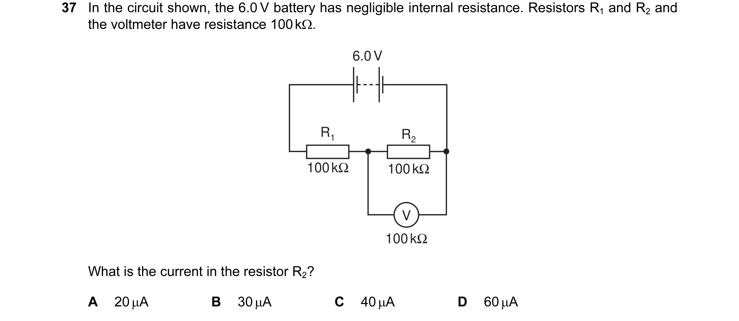
Q10 · In the circuit shown, the 6.0 V battery has negligible internal resistance 9702/11 May/June 2008
37 In the circuit shown, the 6.0 V battery has negligible internal resistance. Resistors R1 and R2 and the voltmeter have resistance 100 kΩ. 6.0 V R1 R2 100 kΩ 100 kΩ V 100 kΩ What is the current in the resistor R2? A 20 µA B 30 µA C 40 µA D 60 µA
1 marks
Answer: A
This question in 9702/11 May/June 2008
Q11 · The diagram shows a potentiometer circuit 9702/11 Oct/Nov 2008
37 The diagram shows a potentiometer circuit. E1 R X T Y E2 The contact T is placed on the wire and moved along the wire until the galvanometer reading is zero. The length XT is then noted. In order to calculate the potential difference per unit length on the wire XY, which value must also be known? A the e.m.f. of the cell E1 B the e.m.f. of the cell E2 C the resistance of resistor R D the resistance of the wire XY
1 marks
Answer: B
This question in 9702/11 Oct/Nov 2008
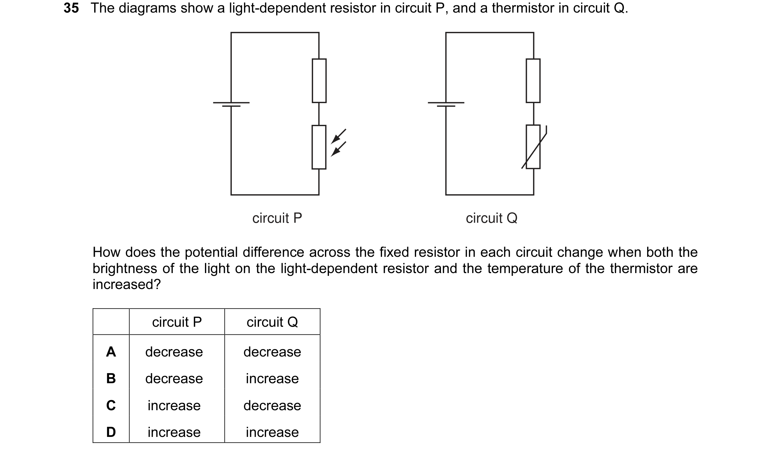
Q12 · The diagrams show a light-dependent resistor in circuit P, and a thermistor in circuit Q 9702/11 May/June 2009
35 The diagrams show a light-dependent resistor in circuit P, and a thermistor in circuit Q. circuit P circuit Q How does the potential difference across the fixed resistor in each circuit change when both the brightness of the light on the light-dependent resistor and the temperature of the thermistor are increased? circuit P circuit Q A decrease decrease B decrease increase C increase decrease D increase increase
1 marks
Answer: D
This question in 9702/11 May/June 2009
Q13 · A potential divider consisting of resistors of resistance R1 and R2 is connected to an… 9702/11 Oct/Nov 2009
35 A potential divider consisting of resistors of resistance R1 and R2 is connected to an input potential difference of V0 and gives an output p.d. of V. R2 V0 R1 V What is the value of V ? V R V R V R V ( R + R ) A 0 1 B 0 1 C 0 2 D 0 1 2 R R + R R + R R 2 1 2 1 2 1
1 marks
Answer: B
This question in 9702/11 Oct/Nov 2009
Q14 · A potential divider consisting of resistors of resistance R1 and R2 is connected to an… 9702/12 Oct/Nov 2009
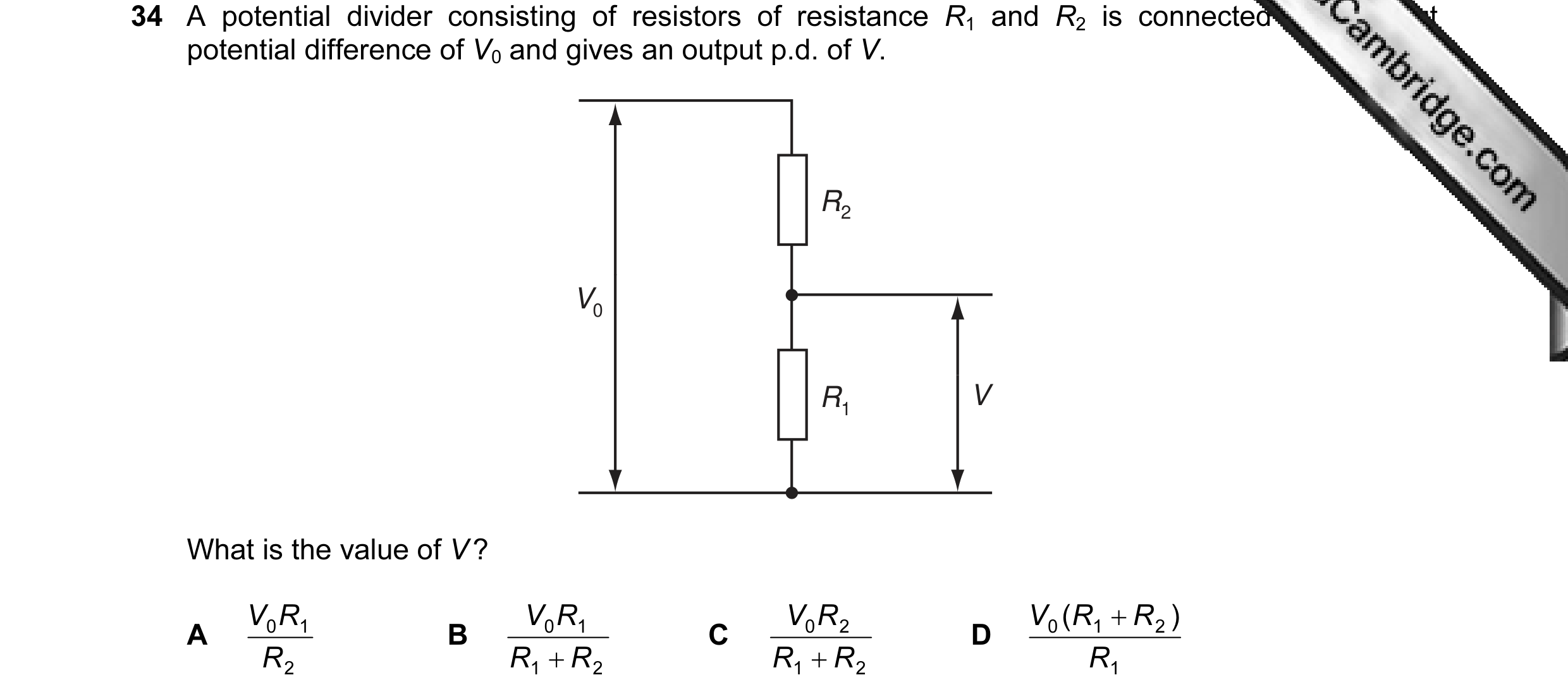
34 A potential divider consisting of resistors of resistance R1 and R2 is connected to an input potential difference of V0 and gives an output p.d. of V. R2 V0 R1 V What is the value of V ? V R V R V R V ( R + R ) A 0 1 B 0 1 C 0 2 D 0 1 2 R R + R R + R R 2 1 2 1 2 1
1 marks
Answer: B
This question in 9702/12 Oct/Nov 2009
Q15 · The diagram shows a potential divider circuit 9702/12 Oct/Nov 2010
36 The diagram shows a potential divider circuit. output voltage The light level increases. What is the effect on the resistance of the light-dependent resistor (LDR) and on the output voltage? resistance output voltage of the LDR A decreases decreases B decreases increases C increases decreases D increases increases
1 marks
Answer: B
This question in 9702/12 Oct/Nov 2010
Q16 · In the circuit below, P is a potentiometer of total resistance 10 Ω and Q is a fixed… 9702/13 Oct/Nov 2010
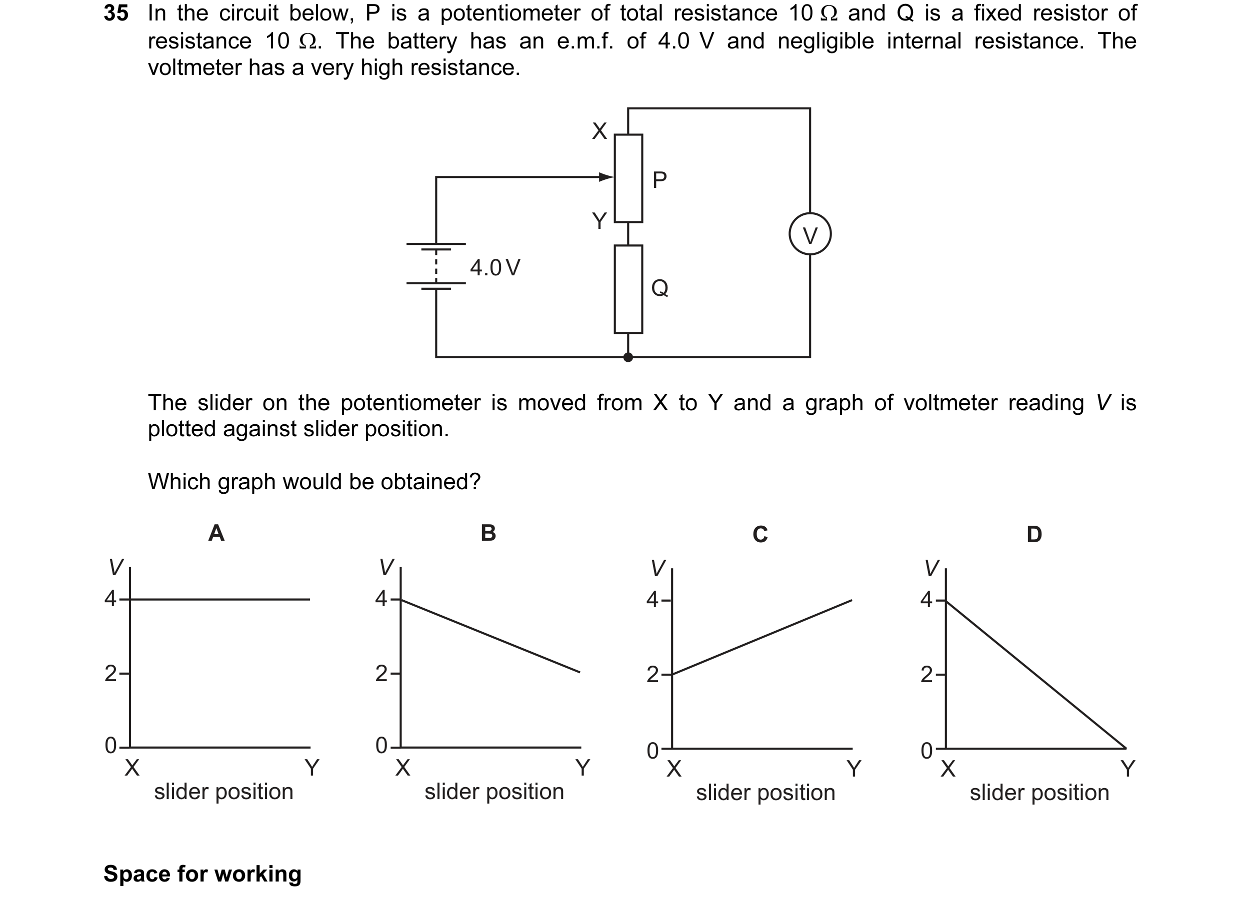
35 In the circuit below, P is a potentiometer of total resistance 10 Ω and Q is a fixed resistor of resistance 10 Ω. The battery has an e.m.f. of 4.0 V and negligible internal resistance. The voltmeter has a very high resistance. X P Y V 4.0 V Q The slider on the potentiometer is moved from X to Y and a graph of voltmeter reading V is plotted against slider position. Which graph would be obtained? A B C D V V V V 4 4 4 4 2 2 2 2 0 0 0 X 0 X X Y X Y Y Y slider position slider position slider position slider position Space for working
1 marks
Answer: A
This question in 9702/13 Oct/Nov 2010
Q17 · In the circuit shown, XY is a length L of uniform resistance wire 9702/11 May/June 2011
37 In the circuit shown, XY is a length L of uniform resistance wire. R1 and R2 are unknown resistors. J is a sliding contact that joins the junction of R1 and R2 to points on XY through a small signal lamp S. L x – X Y + J S R1 R2 V of the potential differences across R1 and R2, a point is found on XY at To determine the ratio 1 V 2 which the lamp is off. This point is at a distance x from X. V ? What is the value of the ratio 1 V 2 L x L − x x A B C D x L x L − x
1 marks
Answer: D
This question in 9702/11 May/June 2011
Q18 · The diagram shows a fixed resistor and a light-dependent resistor (LDR) in series with a… 9702/12 May/June 2011
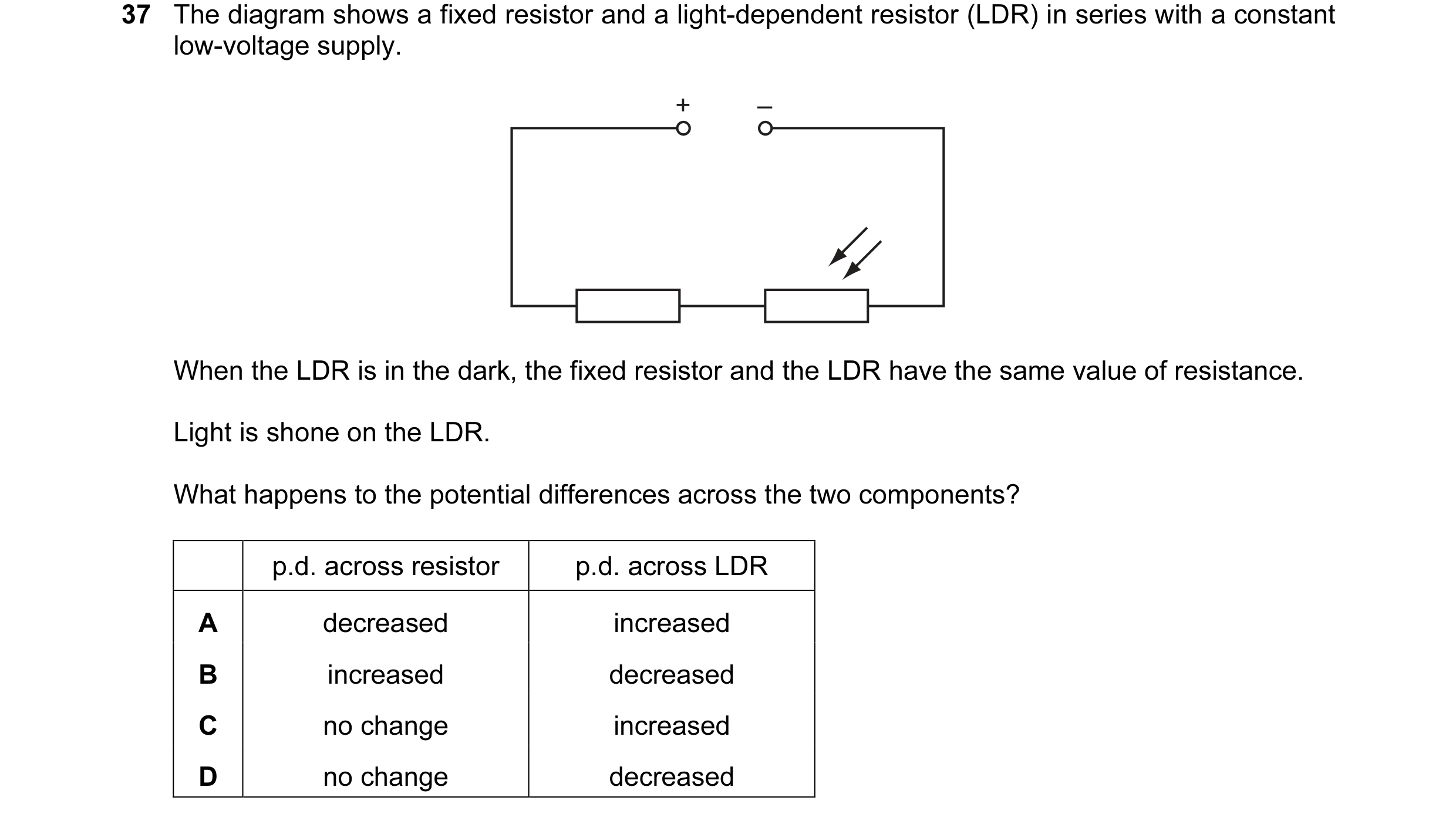
37 The diagram shows a fixed resistor and a light-dependent resistor (LDR) in series with a constant low-voltage supply. + – When the LDR is in the dark, the fixed resistor and the LDR have the same value of resistance. Light is shone on the LDR. What happens to the potential differences across the two components? p.d. across resistor p.d. across LDR A decreased increased B increased decreased C no change increased D no change decreased
1 marks
Answer: B
This question in 9702/12 May/June 2011
Q19 · In the circuit shown, XY is a length L of uniform resistance wire 9702/13 May/June 2011
36 In the circuit shown, XY is a length L of uniform resistance wire. R1 and R2 are unknown resistors. J is a sliding contact that joins the junction of R1 and R2 to points on XY through a small signal lamp S. L x – X Y + J S R1 R2 V of the potential differences across R1 and R2, a point is found on XY at To determine the ratio 1 V 2 which the lamp is off. This point is at a distance x from X. V ? What is the value of the ratio 1 V 2 L x L − x x A B C D x L x L − x Space for working
1 marks
Answer: D
This question in 9702/13 May/June 2011
Q20 · The diagram shows a potential divider circuit designed to provide a variable output p.d 9702/11 Oct/Nov 2011
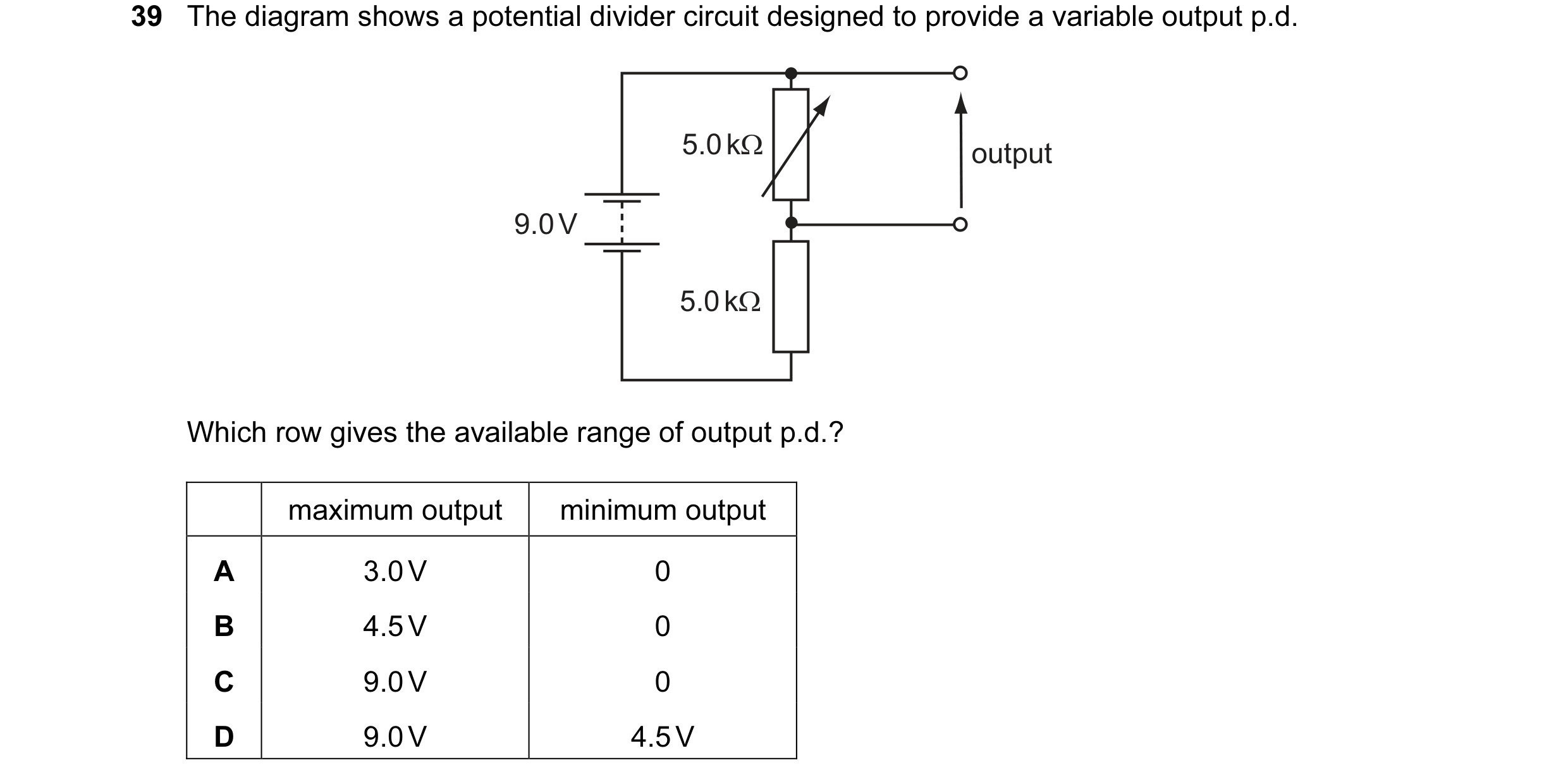
39 The diagram shows a potential divider circuit designed to provide a variable output p.d. 5.0 kΩ output 9.0 V 5.0 kΩ Which row gives the available range of output p.d.? maximum output minimum output A 3.0 V 0 B 4.5 V 0 C 9.0 V 0 D 9.0 V 4.5 V
1 marks
Answer: B
This question in 9702/11 Oct/Nov 2011
Q21 · The diagram shows a potential divider circuit which, by adjustment of the contact X, can… 9702/12 Oct/Nov 2011
37 The diagram shows a potential divider circuit which, by adjustment of the contact X, can be used to provide a variable potential difference between the terminals P and Q. X 4 kΩ P 25 V Q 1 kΩ What are the limits of this potential difference? A 0 and 5 V B 0 and 20 V C 0 and 25 V D 5 V and 25 V Space for working
1 marks
Answer: B
This question in 9702/12 Oct/Nov 2011
Q22 · A constant 60 V d.c 9702/12 Oct/Nov 2011
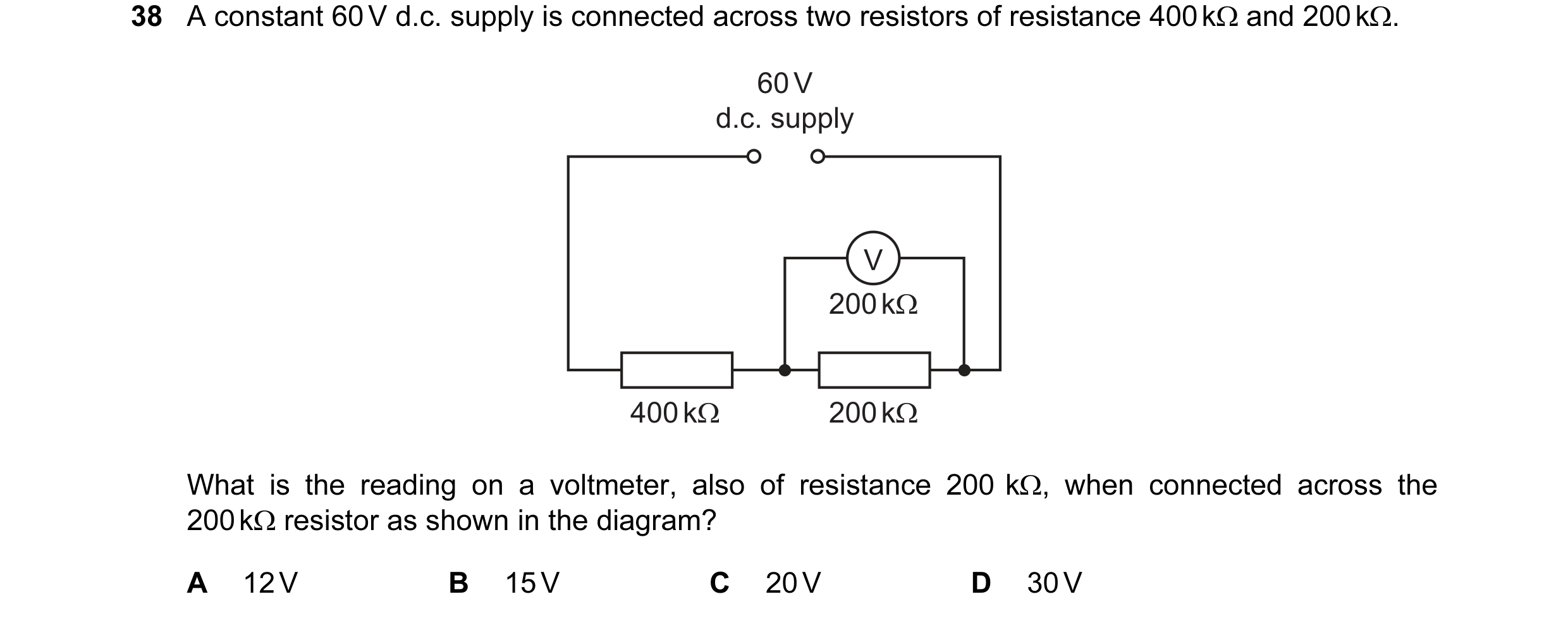
38 A constant 60 V d.c. supply is connected across two resistors of resistance 400 kΩ and 200 kΩ. 60 V d.c. supply V 200 kΩ 400 kΩ 200 kΩ What is the reading on a voltmeter, also of resistance 200 kΩ, when connected across the 200 kΩ resistor as shown in the diagram? A 12 V B 15 V C 20 V D 30 V
1 marks
Answer: A
This question in 9702/12 Oct/Nov 2011
Q23 · The diagram shows a potential divider circuit designed to provide a variable output p.d 9702/13 Oct/Nov 2011
40 The diagram shows a potential divider circuit designed to provide a variable output p.d. 5.0 kΩ output 9.0 V 5.0 kΩ Which row gives the available range of output p.d.? maximum output minimum output A 3.0 V 0 B 4.5 V 0 C 9.0 V 0 D 9.0 V 4.5 V Space for working
1 marks
Answer: B
This question in 9702/13 Oct/Nov 2011
Q24 · A light-dependent resistor (LDR) is connected in series with a resistor R and a battery 9702/12 May/June 2012
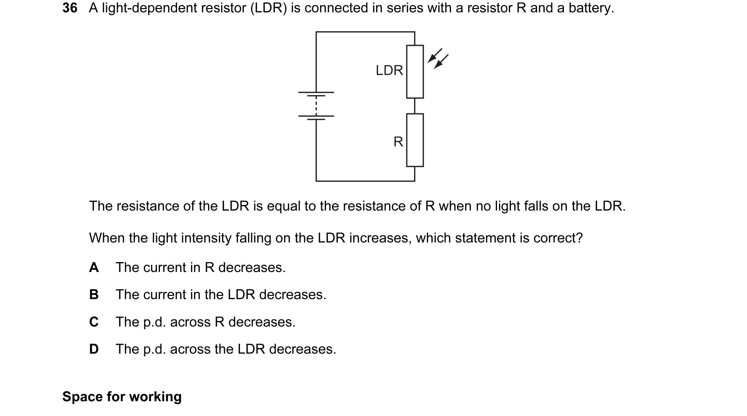
36 A light-dependent resistor (LDR) is connected in series with a resistor R and a battery. LDR R The resistance of the LDR is equal to the resistance of R when no light falls on the LDR. When the light intensity falling on the LDR increases, which statement is correct? A The current in R decreases. B The current in the LDR decreases. C The p.d. across R decreases. D The p.d. across the LDR decreases. Space for working
1 marks
Answer: D
This question in 9702/12 May/June 2012
Q25 · In a fire alarm system, a thermistor T has a resistance of 2000 Ω at room temperature 9702/11 Oct/Nov 2012
35 In a fire alarm system, a thermistor T has a resistance of 2000 Ω at room temperature. Its resistance decreases as the temperature increases. The alarm is triggered when the potential difference between X and Y reaches 4.5 V. 12 V T 150 Ω X Y What is the resistance of the thermistor when the alarm is triggered? A 90 Ω B 150 Ω C 250 Ω D 1300 Ω
1 marks
Answer: C
This question in 9702/11 Oct/Nov 2012
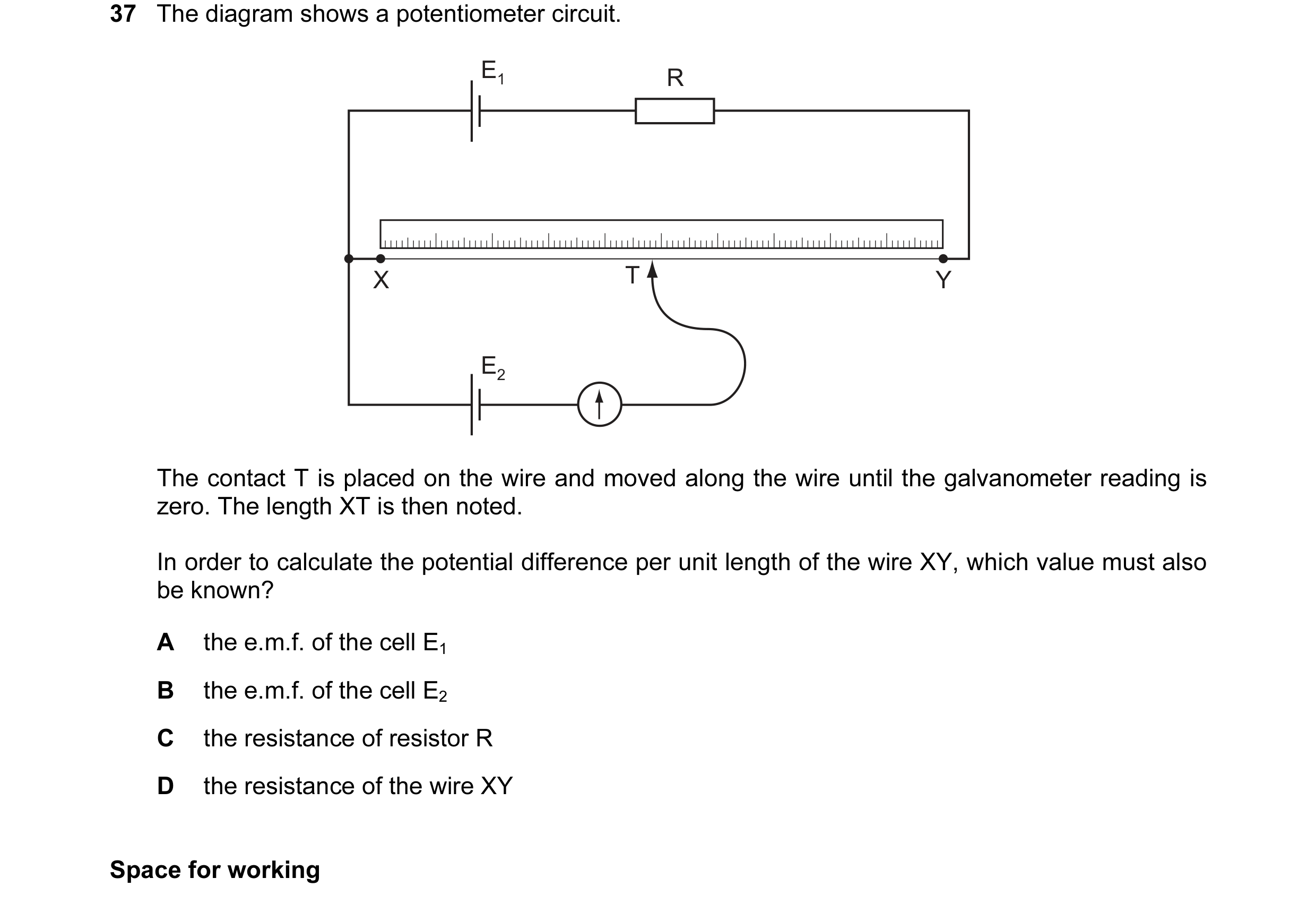
Q26 · The diagram shows a potentiometer circuit 9702/11 Oct/Nov 2012
37 The diagram shows a potentiometer circuit. E1 R X T Y E2 The contact T is placed on the wire and moved along the wire until the galvanometer reading is zero. The length XT is then noted. In order to calculate the potential difference per unit length of the wire XY, which value must also be known? A the e.m.f. of the cell E1 B the e.m.f. of the cell E2 C the resistance of resistor R D the resistance of the wire XY Space for working
1 marks
Answer: B
This question in 9702/11 Oct/Nov 2012
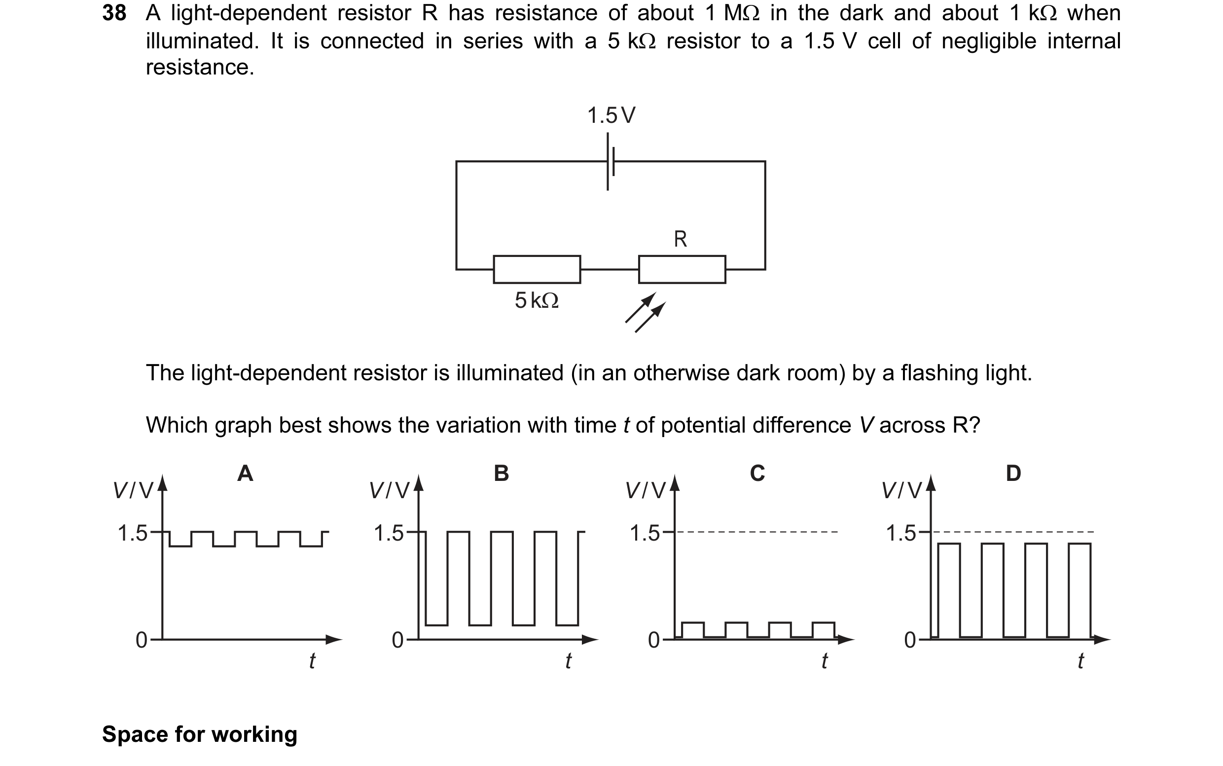
Q27 · A light-dependent resistor R has resistance of about 1 MΩ in the dark and about 1 kΩ when… 9702/12 Oct/Nov 2012
38 A light-dependent resistor R has resistance of about 1 MΩ in the dark and about 1 kΩ when illuminated. It is connected in series with a 5 kΩ resistor to a 1.5 V cell of negligible internal resistance. 1.5 V R 5 kΩ The light-dependent resistor is illuminated (in an otherwise dark room) by a flashing light. Which graph best shows the variation with time t of potential difference V across R? A B C D V / V V / V V / V V / V 1.5 1.5 1.5 1.5 0 0 0 0 t t t t Space for working
1 marks
Answer: B
This question in 9702/12 Oct/Nov 2012
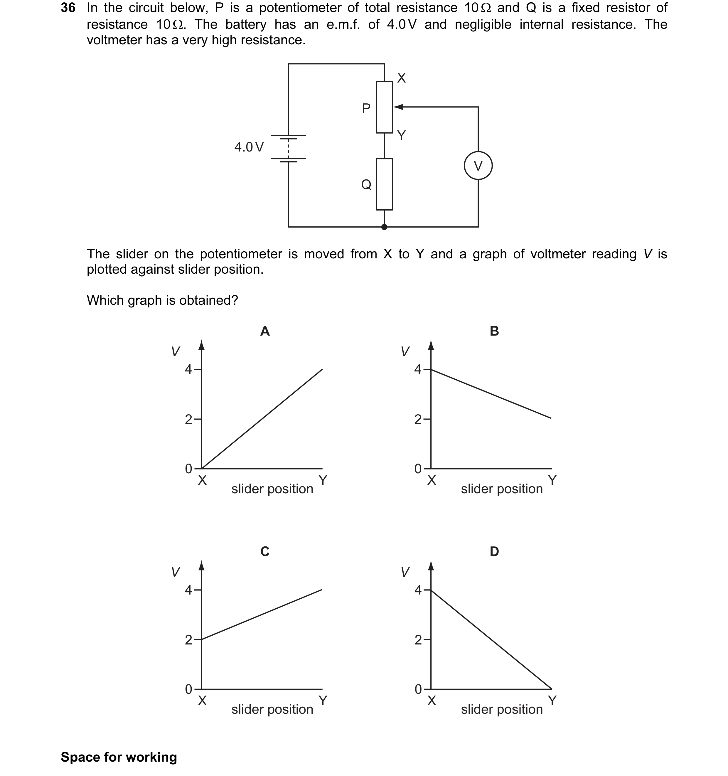
Q28 · In the circuit below, P is a potentiometer of total resistance 10 Ω and Q is a fixed… 9702/13 Oct/Nov 2012
36 In the circuit below, P is a potentiometer of total resistance 10 Ω and Q is a fixed resistor of resistance 10 Ω. The battery has an e.m.f. of 4.0 V and negligible internal resistance. The voltmeter has a very high resistance. X P Y 4.0 V V Q The slider on the potentiometer is moved from X to Y and a graph of voltmeter reading V is plotted against slider position. Which graph is obtained? A B V V 4 4 2 2 0 0 X slider position Y X slider position Y C D V V 4 4 2 2 0 0 X slider position Y X slider position Y Space for working
1 marks
Answer: B
This question in 9702/13 Oct/Nov 2012
Q29 · A circuit is set up as shown, supplied by a 3 V battery 9702/11 May/June 2013
35 A circuit is set up as shown, supplied by a 3 V battery. All resistances are 1 kΩ. 3 V V What will be the reading on the voltmeter? A 0 B 0.5 V C 1.0 V D 1.5 V
1 marks
Answer: B
This question in 9702/11 May/June 2013
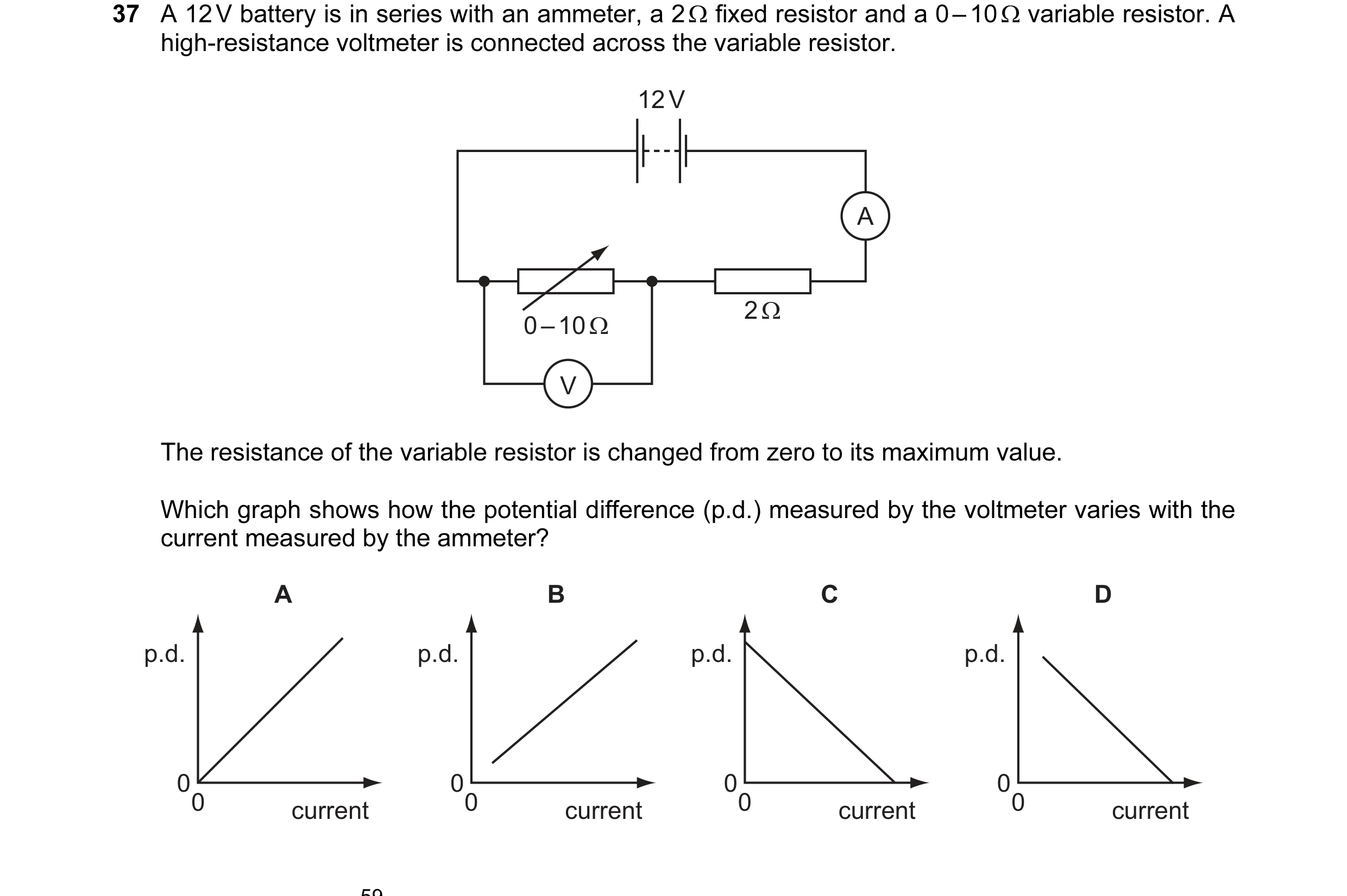
Q30 · A 12 V battery is in series with an ammeter, a 2 Ω fixed resistor and a 0 – 10 Ω variable… 9702/11 May/June 2013
37 A 12 V battery is in series with an ammeter, a 2 Ω fixed resistor and a 0 – 10 Ω variable resistor. A high-resistance voltmeter is connected across the variable resistor. 12 V A 2 Ω 0 – 10 Ω V The resistance of the variable resistor is changed from zero to its maximum value. Which graph shows how the potential difference (p.d.) measured by the voltmeter varies with the current measured by the ammeter? A B C D p.d. p.d. p.d. p.d. 00 00 00 00 current current current current
1 marks
Answer: D
This question in 9702/11 May/June 2013
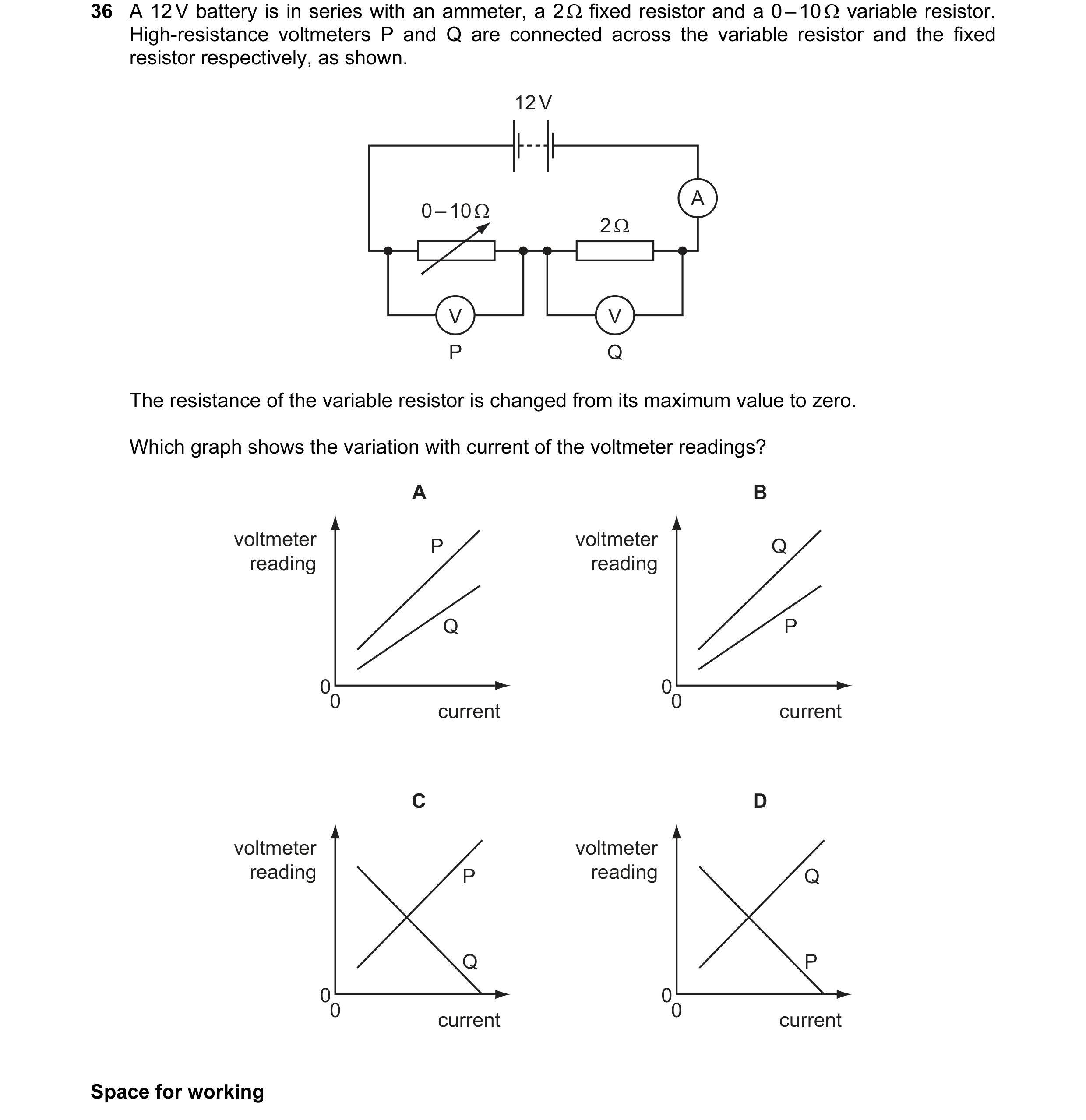
Q31 · A 12 V battery is in series with an ammeter, a 2 Ω fixed resistor and a 0 – 10 Ω variable… 9702/12 May/June 2013
36 A 12 V battery is in series with an ammeter, a 2 Ω fixed resistor and a 0 – 10 Ω variable resistor. High-resistance voltmeters P and Q are connected across the variable resistor and the fixed resistor respectively, as shown. 12 V A 0 – 10 Ω 2 Ω V V P Q The resistance of the variable resistor is changed from its maximum value to zero. Which graph shows the variation with current of the voltmeter readings? A B voltmeter P voltmeter Q reading reading Q P 00 00 current current C D voltmeter voltmeter reading P reading Q Q P 00 00 current current Space for working
1 marks
Answer: D
This question in 9702/12 May/June 2013
Q32 · In the circuit below, the reading VT on the voltmeter changes from high to low as the… 9702/12 May/June 2013
38 In the circuit below, the reading VT on the voltmeter changes from high to low as the temperature of the thermistor changes. The reading VL on the voltmeter changes from high to low as the level of light on the light-dependent resistor (LDR) changes. VT VL V V The readings VT and VL are both high. What are the conditions of temperature and light level? temperature light level A low low B low high C high low D high high Space for working
1 marks
Answer: C
This question in 9702/12 May/June 2013
Q33 · A 12 V battery is in series with an ammeter, a 2 Ω fixed resistor and a 0 – 10 Ω variable… 9702/13 May/June 2013
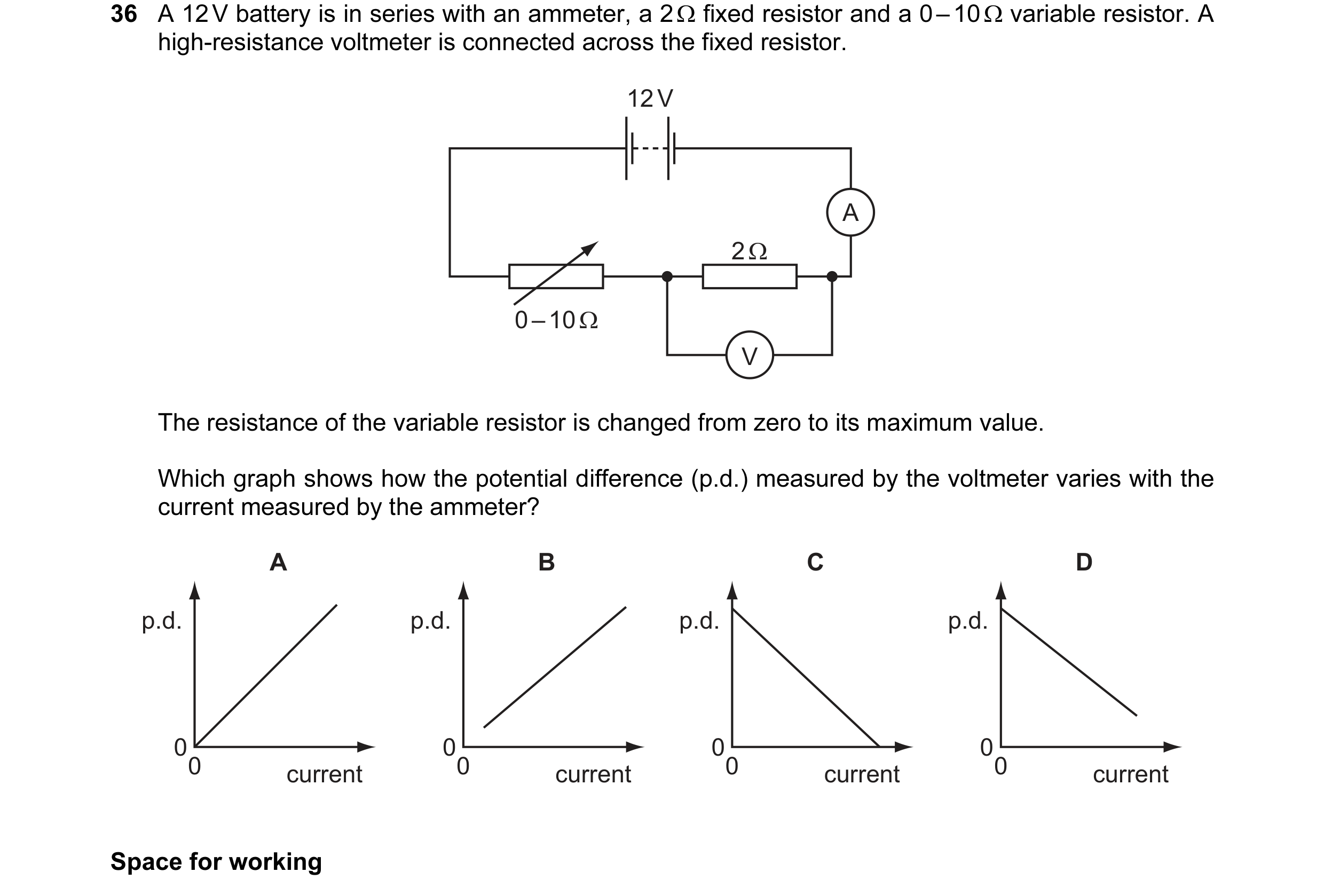
36 A 12 V battery is in series with an ammeter, a 2 Ω fixed resistor and a 0 – 10 Ω variable resistor. A high-resistance voltmeter is connected across the fixed resistor. 12 V A 2 Ω 0 – 10 Ω V The resistance of the variable resistor is changed from zero to its maximum value. Which graph shows how the potential difference (p.d.) measured by the voltmeter varies with the current measured by the ammeter? A B C D p.d. p.d. p.d. p.d. 00 00 00 00 current current current current Space for working
1 marks
Answer: B
This question in 9702/13 May/June 2013
Q34 · In the circuit below, P is a potentiometer of total resistance 10 Ω and Q is a fixed… 9702/11 Oct/Nov 2013
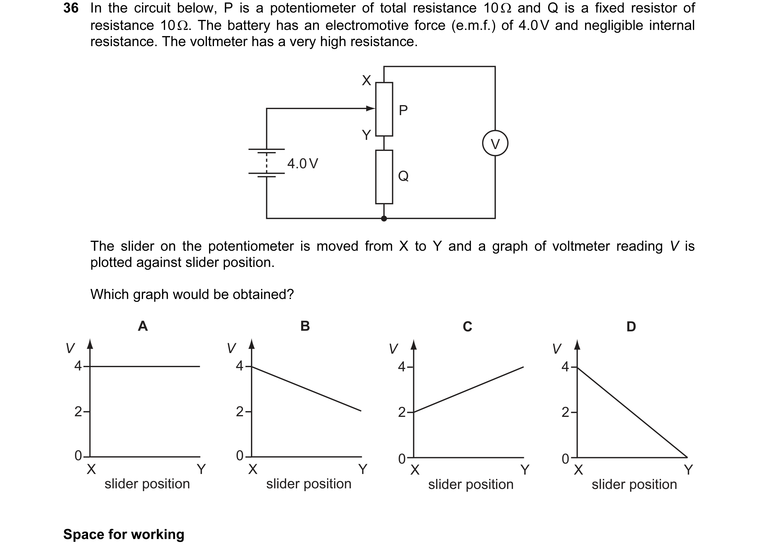
36 In the circuit below, P is a potentiometer of total resistance 10 Ω and Q is a fixed resistor of resistance 10 Ω. The battery has an electromotive force (e.m.f.) of 4.0 V and negligible internal resistance. The voltmeter has a very high resistance. X P Y V 4.0 V Q The slider on the potentiometer is moved from X to Y and a graph of voltmeter reading V is plotted against slider position. Which graph would be obtained? A B C D V V V V 4 4 4 4 2 2 2 2 0 0 0 X 0 X X Y X Y Y Y slider position slider position slider position slider position Space for working
1 marks
Answer: A
This question in 9702/11 Oct/Nov 2013
Q35 · A 2 Ω resistor and a 4 Ω resistor are connected to a cell 9702/11 Oct/Nov 2013
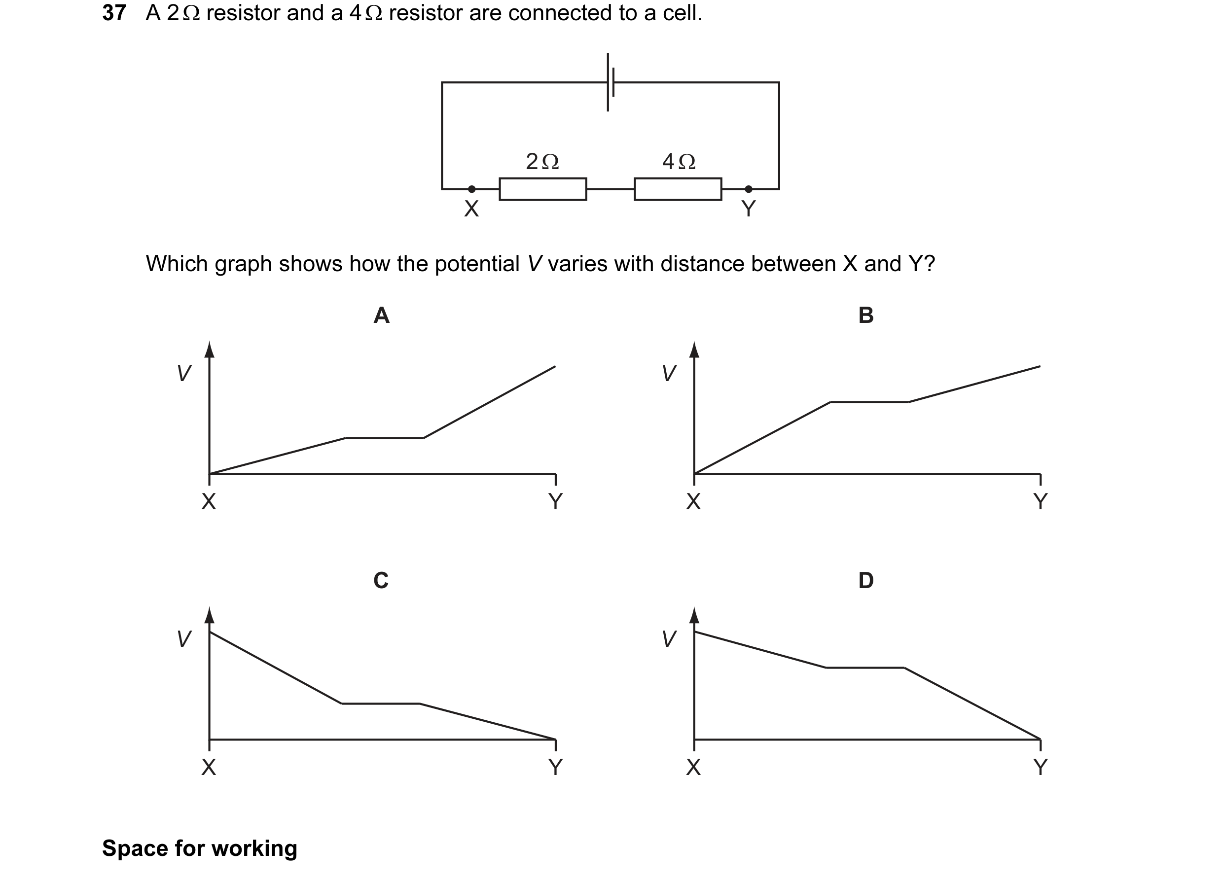
37 A 2 Ω resistor and a 4 Ω resistor are connected to a cell. 2 Ω 4 Ω X Y Which graph shows how the potential V varies with distance between X and Y? A B V V X Y X Y C D V V X Y X Y Space for working
1 marks
Answer: D
This question in 9702/11 Oct/Nov 2013
Q36 · In the circuit below, P is a potentiometer of total resistance 10 Ω and Q is a fixed… 9702/12 Oct/Nov 2013
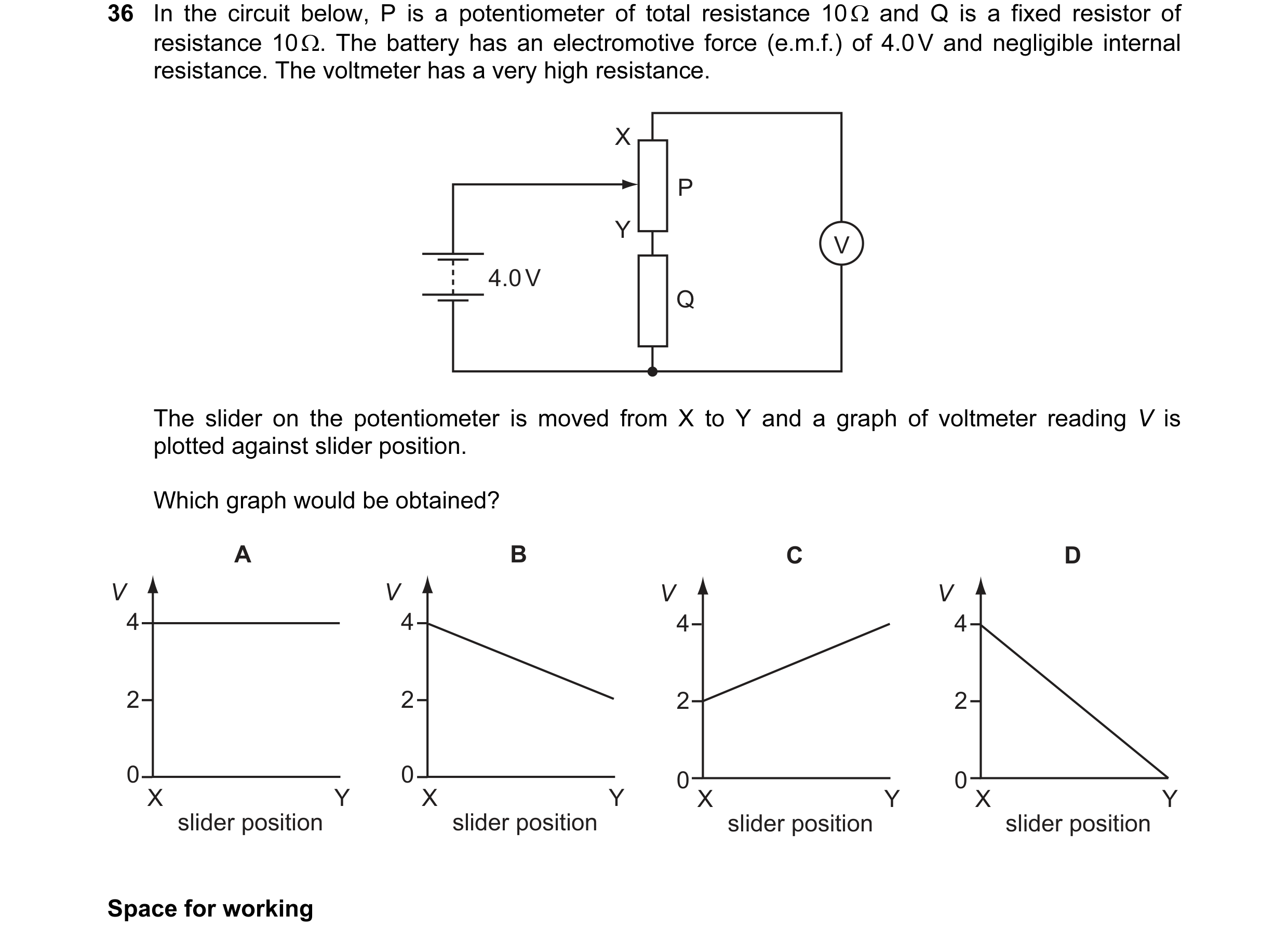
36 In the circuit below, P is a potentiometer of total resistance 10 Ω and Q is a fixed resistor of resistance 10 Ω. The battery has an electromotive force (e.m.f.) of 4.0 V and negligible internal resistance. The voltmeter has a very high resistance. X P Y V 4.0 V Q The slider on the potentiometer is moved from X to Y and a graph of voltmeter reading V is plotted against slider position. Which graph would be obtained? A B C D V V V V 4 4 4 4 2 2 2 2 0 0 0 X 0 X X Y X Y Y Y slider position slider position slider position slider position Space for working
1 marks
Answer: A
This question in 9702/12 Oct/Nov 2013
Q37 · A 2 Ω resistor and a 4 Ω resistor are connected to a cell 9702/12 Oct/Nov 2013
37 A 2 Ω resistor and a 4 Ω resistor are connected to a cell. 2 Ω 4 Ω X Y Which graph shows how the potential V varies with distance between X and Y? A B V V X Y X Y C D V V X Y X Y Space for working
1 marks
Answer: D
This question in 9702/12 Oct/Nov 2013
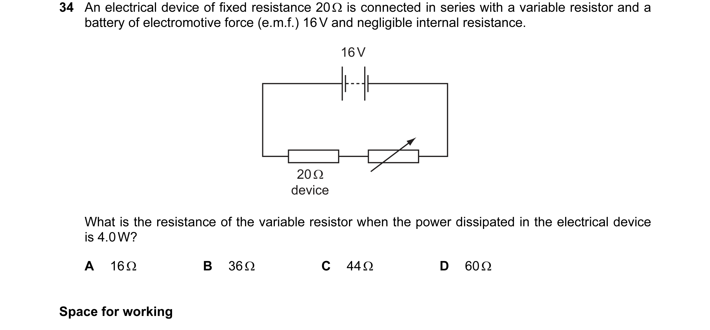
Q38 · An electrical device of fixed resistance 20 Ω is connected in series with a variable… 9702/13 Oct/Nov 2013
34 An electrical device of fixed resistance 20 Ω is connected in series with a variable resistor and a battery of electromotive force (e.m.f.) 16 V and negligible internal resistance. 16 V 20 Ω device What is the resistance of the variable resistor when the power dissipated in the electrical device is 4.0 W? A 16 Ω B 36 Ω C 44 Ω D 60 Ω Space for working
1 marks
Answer: A
This question in 9702/13 Oct/Nov 2013
Q39 · In the circuit shown, the resistance of the thermistor decreases as temperature increases 9702/13 Oct/Nov 2013
37 In the circuit shown, the resistance of the thermistor decreases as temperature increases. d.c. P supply V Q Which graph shows the variation with Celsius temperature θ of potential difference V between points P and Q ? A B C D V V V V 00 00 00 00 θ θ θ θ Space for working
1 marks
Answer: C
This question in 9702/13 Oct/Nov 2013
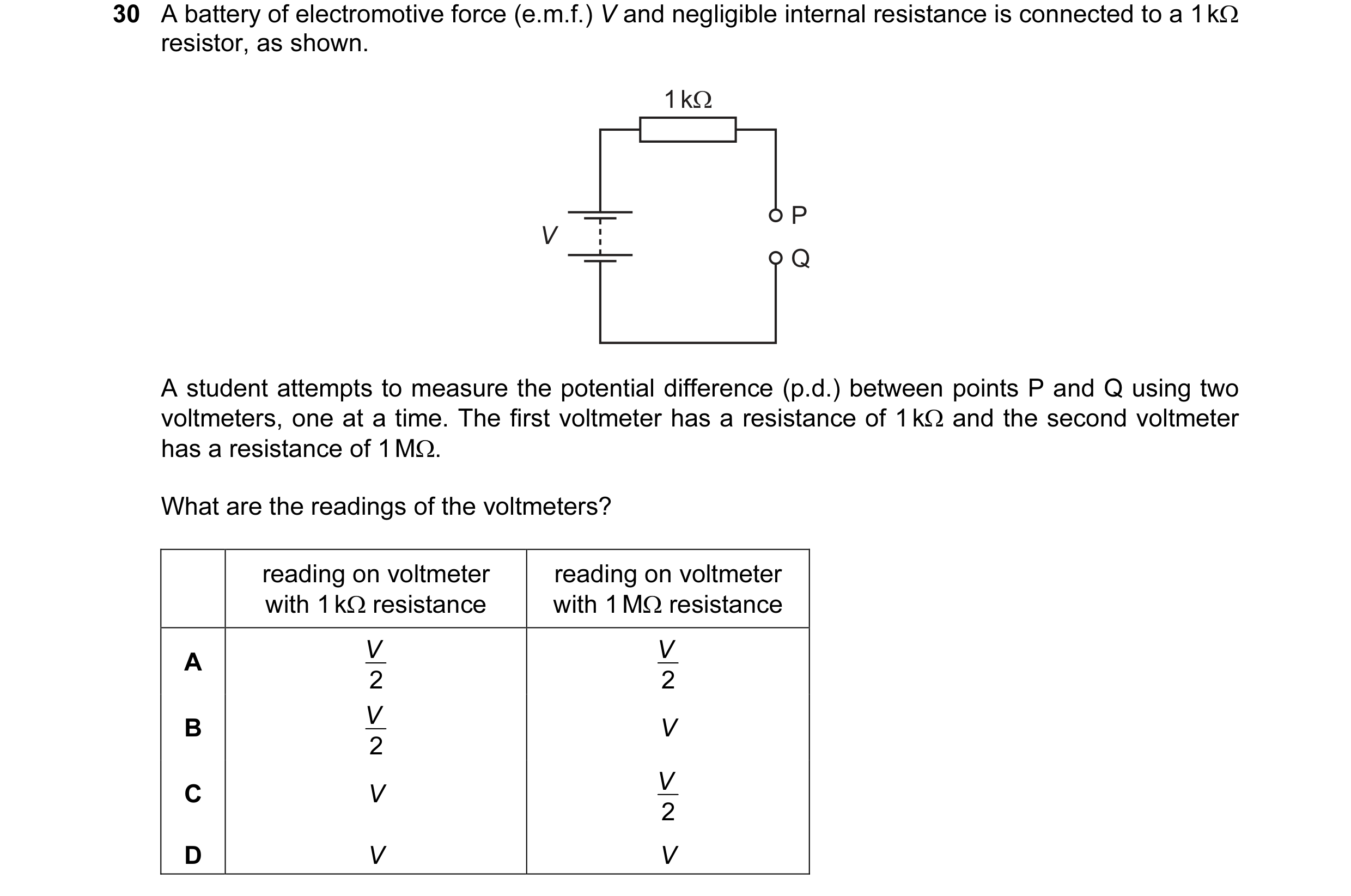
Q40 · A battery of electromotive force (e.m.f.) V and negligible internal resistance is… 9702/12 May/June 2014
30 A battery of electromotive force (e.m.f.) V and negligible internal resistance is connected to a 1 kΩ resistor, as shown. 1 kΩ P V Q A student attempts to measure the potential difference (p.d.) between points P and Q using two voltmeters, one at a time. The first voltmeter has a resistance of 1 kΩ and the second voltmeter has a resistance of 1 MΩ. What are the readings of the voltmeters? reading on voltmeter reading on voltmeter with 1 kΩ resistance with 1 MΩ resistance V V A 2 2 V B V 2 V C V 2 D V V
1 marks
Answer: B
This question in 9702/12 May/June 2014
Q41 · In the circuit shown, a light-dependent resistor (LDR) is connected to two resistors R1… 9702/12 May/June 2014
34 In the circuit shown, a light-dependent resistor (LDR) is connected to two resistors R1 and R2. The potential difference (p.d.) across R1 is V1 and the p.d. across R2 is V2. The current in the circuit is I. I R1 V1 R2 V2 Which statement about this circuit is correct? A The current I increases when the light intensity decreases. B The LDR is an ohmic conductor. C The p.d. V2 increases when the light intensity decreases. V is independent of light intensity. D The ratio 1 V 2 Space for working
1 marks
Answer: D
This question in 9702/12 May/June 2014
Q42 · A power supply and a solar cell are compared using the potentiometer circuit shown 9702/12 May/June 2014
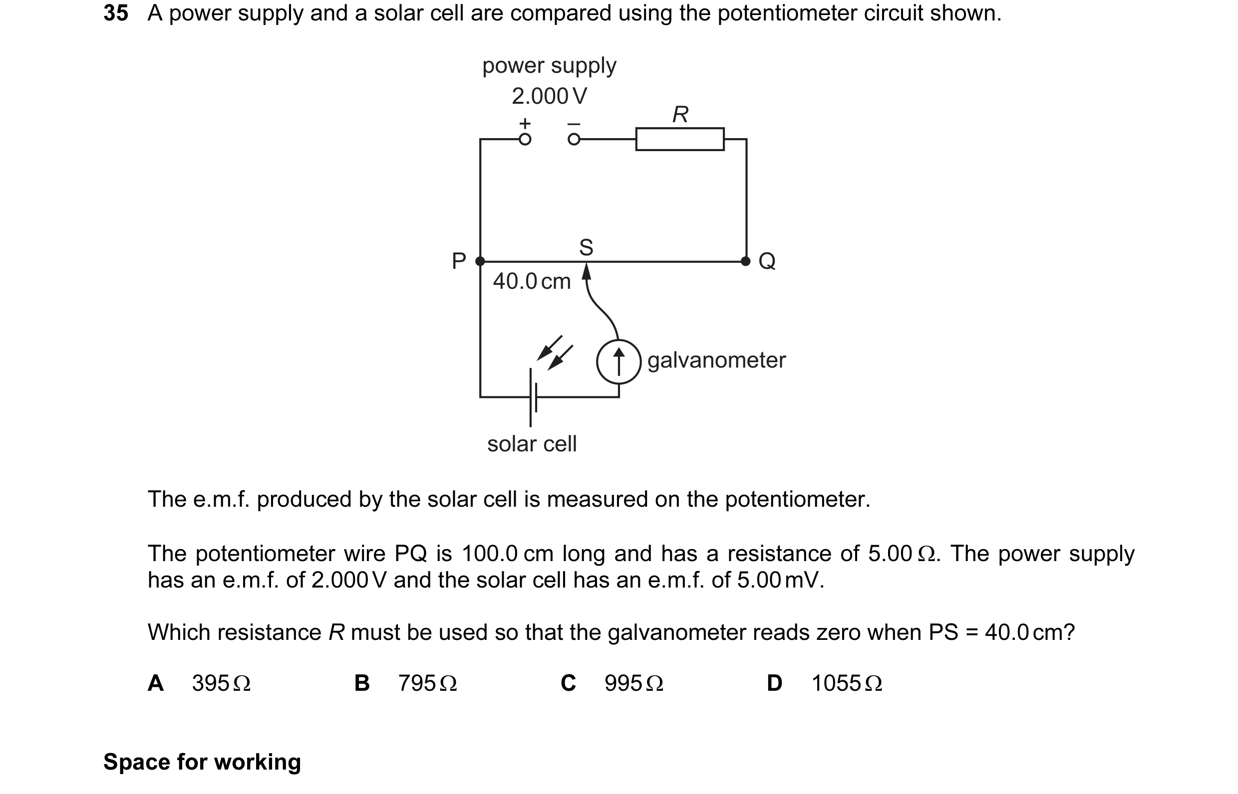
35 A power supply and a solar cell are compared using the potentiometer circuit shown. power supply 2.000 V + – R S P Q 40.0 cm galvanometer solar cell The e.m.f. produced by the solar cell is measured on the potentiometer. The potentiometer wire PQ is 100.0 cm long and has a resistance of 5.00 Ω. The power supply has an e.m.f. of 2.000 V and the solar cell has an e.m.f. of 5.00 mV. Which resistance R must be used so that the galvanometer reads zero when PS = 40.0 cm? A 395 Ω B 795 Ω C 995 Ω D 1055 Ω Space for working
1 marks
Answer: B
This question in 9702/12 May/June 2014
Q43 · In the circuit shown, all the resistors are identical 9702/12 May/June 2014
36 In the circuit shown, all the resistors are identical. V1 V4 V2 V3 The reading on voltmeter V1 is 8.0 V and the reading on voltmeter V2 is 1.0 V. What are the readings on the other voltmeters? reading on reading on voltmeter V3 / V voltmeter V4 / V A 1.5 1.0 B 3.0 2.0 C 4.5 3.0 D 6.0 4.0 Space for working
1 marks
Answer: B
This question in 9702/12 May/June 2014
Q44 · The diagram shows a light-dependent resistor (LDR) and a thermistor forming a potential… 9702/12 May/June 2014
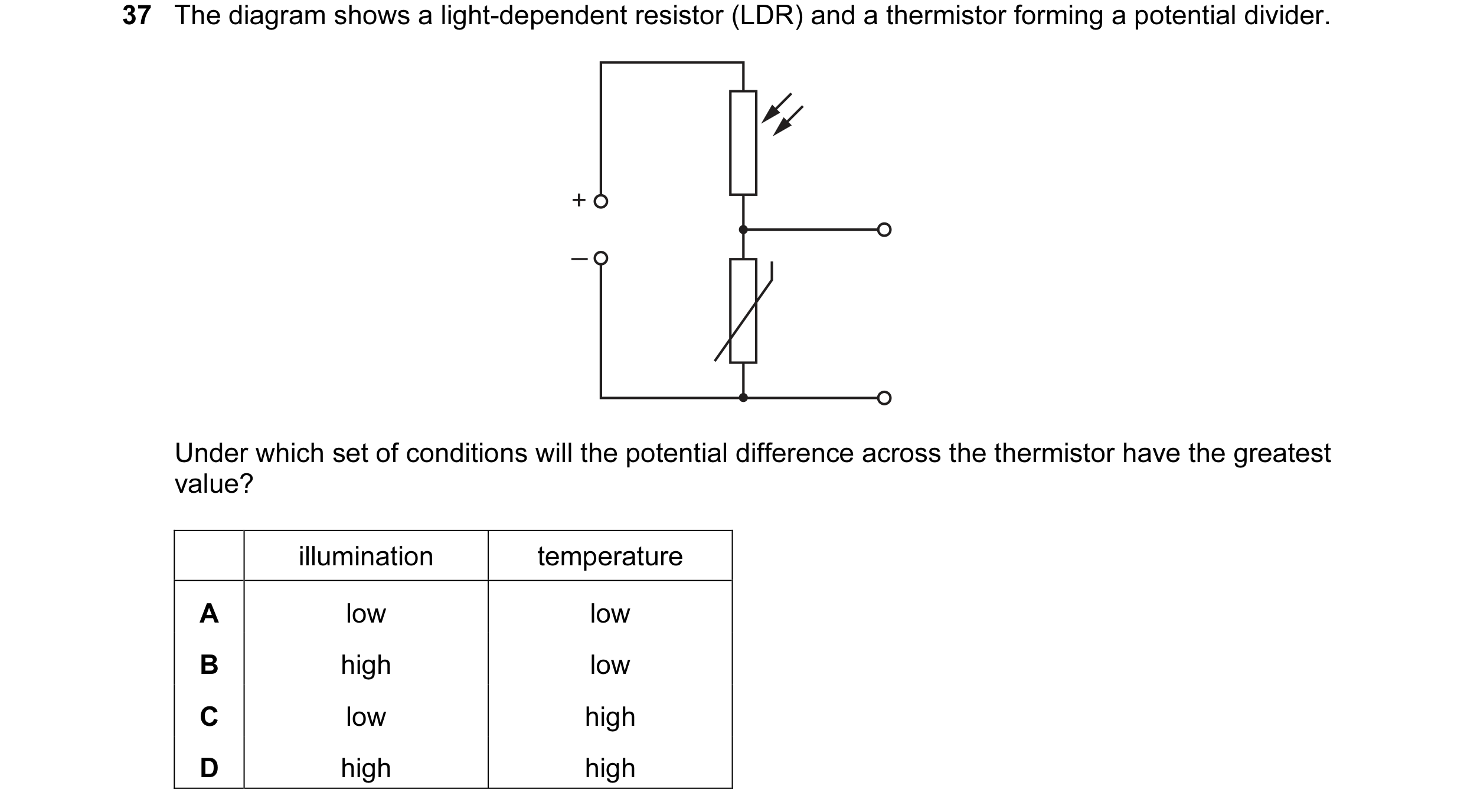
37 The diagram shows a light-dependent resistor (LDR) and a thermistor forming a potential divider. + – Under which set of conditions will the potential difference across the thermistor have the greatest value? illumination temperature A low low B high low C low high D high high
1 marks
Answer: B
This question in 9702/12 May/June 2014
Q45 · The diagrams show the same cell, ammeter, potentiometer and fixed resistor connected in… 9702/13 May/June 2014
36 The diagrams show the same cell, ammeter, potentiometer and fixed resistor connected in different ways. W X d d A A Y Z d d A A The distance d between the sliding contact and a particular end of the potentiometer is varied. The current measured is then plotted against the distance d. For which two circuits will the graphs be identical? A W and X B W and Y C X and Y D Y and Z Space for working
1 marks
Answer: A
This question in 9702/13 May/June 2014
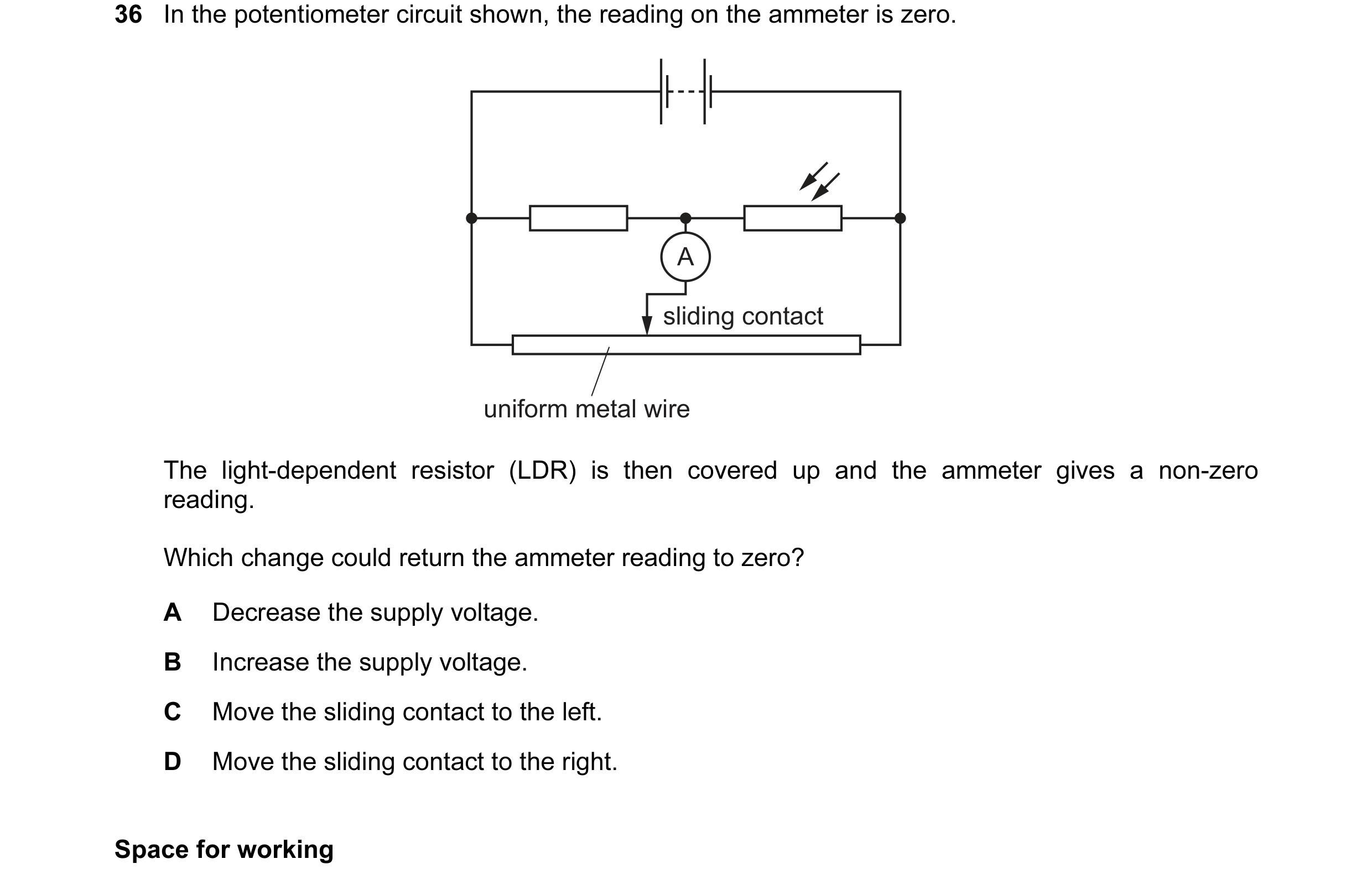
Q46 · In the potentiometer circuit shown, the reading on the ammeter is zero 9702/11 Oct/Nov 2014
36 In the potentiometer circuit shown, the reading on the ammeter is zero. A sliding contact uniform metal wire The light-dependent resistor (LDR) is then covered up and the ammeter gives a non-zero reading. Which change could return the ammeter reading to zero? A Decrease the supply voltage. B Increase the supply voltage. C Move the sliding contact to the left. D Move the sliding contact to the right. Space for working
1 marks
Answer: C
This question in 9702/11 Oct/Nov 2014
Q47 · In the potentiometer circuit shown, the reading on the ammeter is zero 9702/12 Oct/Nov 2014
36 In the potentiometer circuit shown, the reading on the ammeter is zero. A sliding contact uniform metal wire The light-dependent resistor (LDR) is then covered up and the ammeter gives a non-zero reading. Which change could return the ammeter reading to zero? A Decrease the supply voltage. B Increase the supply voltage. C Move the sliding contact to the left. D Move the sliding contact to the right. Space for working
1 marks
Answer: C
This question in 9702/12 Oct/Nov 2014
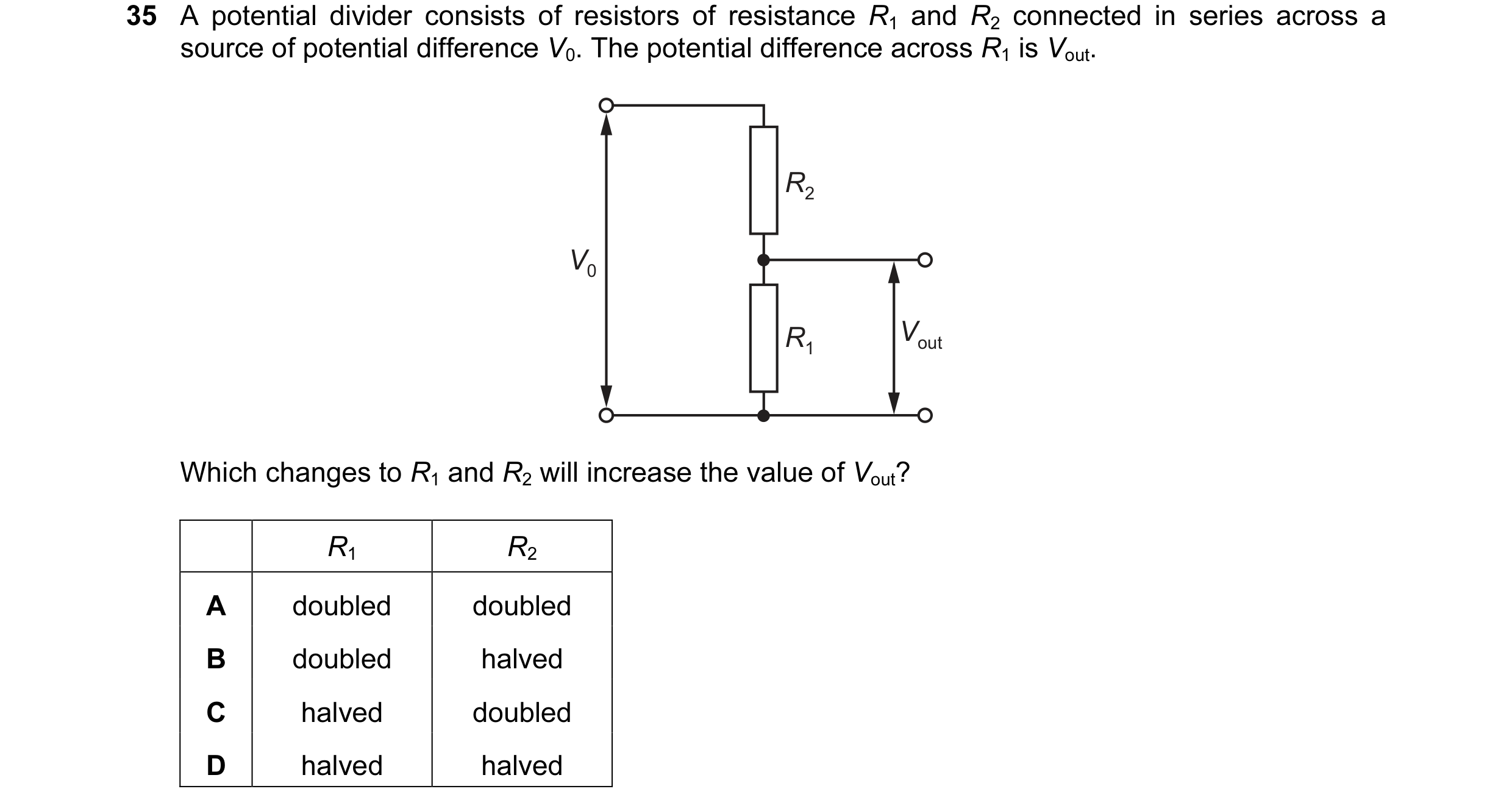
Q48 · A potential divider consists of resistors of resistance R1 and R2 connected in series… 9702/13 Oct/Nov 2014
35 A potential divider consists of resistors of resistance R1 and R2 connected in series across a source of potential difference V0. The potential difference across R1 is Vout. R2 V0 R1 Vout Which changes to R1 and R2 will increase the value of Vout? R1 R2 A doubled doubled B doubled halved C halved doubled D halved halved
1 marks
Answer: B
This question in 9702/13 Oct/Nov 2014
Q49 · A battery of electromotive force (e.m.f.) 6.0 V and negligible internal resistance is… 9702/11 May/June 2015
37 A battery of electromotive force (e.m.f.) 6.0 V and negligible internal resistance is connected in series with a resistor of resistance 6.0 Ω and a variable resistor of resistance from zero to 4.0 Ω. A voltmeter is connected across the variable resistor. The resistance of the variable resistor is changed. 6.0 V 6.0 Ω 0 – 4.0 Ω V What is the range of the voltmeter reading? A 0 V – 2.4 V B 0 V – 3.6 V C 2.4 V – 6.0 V D 3.6 V – 6.0 V
1 marks
Answer: A
This question in 9702/11 May/June 2015
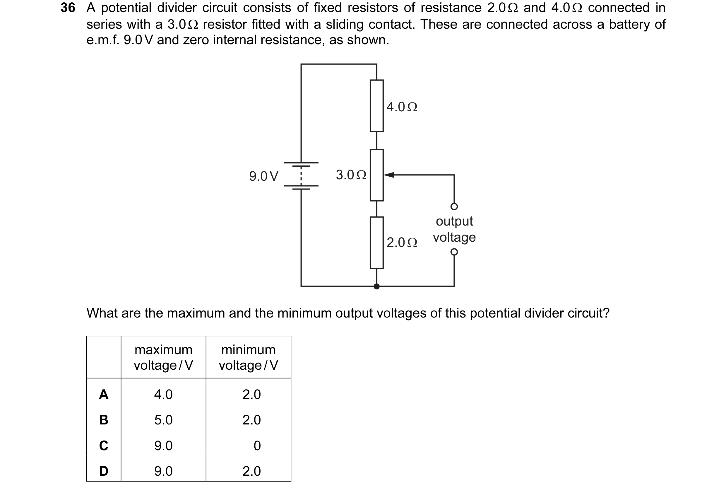
Q50 · A potential divider circuit consists of fixed resistors of resistance 2.0 Ω and 4.0 Ω… 9702/12 May/June 2015
36 A potential divider circuit consists of fixed resistors of resistance 2.0 Ω and 4.0 Ω connected in series with a 3.0 Ω resistor fitted with a sliding contact. These are connected across a battery of e.m.f. 9.0 V and zero internal resistance, as shown. 4.0 Ω 9.0 V 3.0 Ω output 2.0 Ω voltage What are the maximum and the minimum output voltages of this potential divider circuit? maximum minimum voltage / V voltage / V A 4.0 2.0 B 5.0 2.0 C 9.0 0 D 9.0 2.0
1 marks
Answer: B
This question in 9702/12 May/June 2015
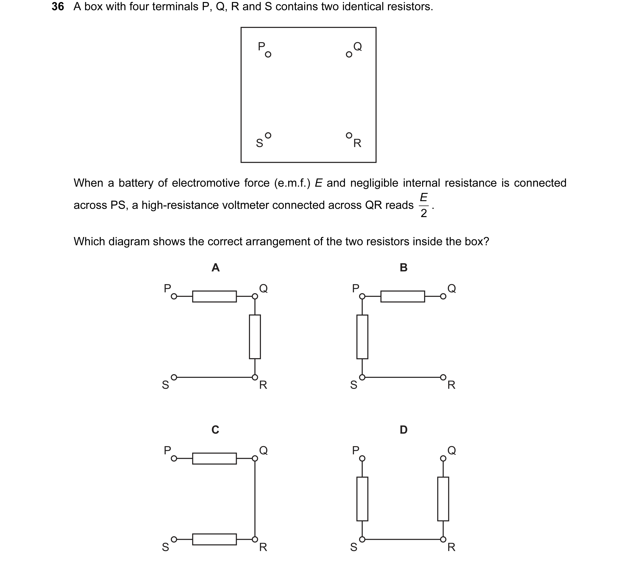
Q51 · A box with four terminals P, Q, R and S contains two identical resistors 9702/13 May/June 2015
36 A box with four terminals P, Q, R and S contains two identical resistors. P Q S R When a battery of electromotive force (e.m.f.) E and negligible internal resistance is connected E . across PS, a high-resistance voltmeter connected across QR reads 2 Which diagram shows the correct arrangement of the two resistors inside the box? A B P Q P Q S R S R C D P Q P Q S R S R
1 marks
Answer: A
This question in 9702/13 May/June 2015
Q52 · A thermistor and another component are connected to a constant voltage supply 9702/11 Oct/Nov 2015
34 A thermistor and another component are connected to a constant voltage supply. A voltmeter is connected across one of the components. The temperature of the thermistor is then reduced but no other changes are made. In which circuit will the voltmeter reading increase? A B V V C D V V
1 marks
Answer: C
This question in 9702/11 Oct/Nov 2015
Q53 · The diagram shows a potentiometer and a fixed resistor connected across a 12 V battery of… 9702/11 Oct/Nov 2015
36 The diagram shows a potentiometer and a fixed resistor connected across a 12 V battery of negligible internal resistance. 20 Ω 12 V 20 Ω output The fixed resistor and the potentiometer each have resistance 20 Ω. The circuit is designed to provide a variable output voltage. What is the range of output voltages? A 0 – 6 V B 0 – 12 V C 6 – 12 V D 12 – 20 V
1 marks
Answer: A
This question in 9702/11 Oct/Nov 2015
Q54 · In the circuit shown, X is a variable resistor whose resistance can be changed from 5.0 Ω… 9702/11 May/June 2016
34 In the circuit shown, X is a variable resistor whose resistance can be changed from 5.0 Ω to 500 Ω. The e.m.f. of the battery is 12.0 V. It has negligible internal resistance. 40 Ω 12.0 V X output What is the maximum range of values of potential difference across the output? A 1.3 V to 11.1 V B 1.3 V to 12.0 V C 1.5 V to 11.1 V D 1.5 V to 12.0 V
1 marks
Answer: A
This question in 9702/11 May/June 2016
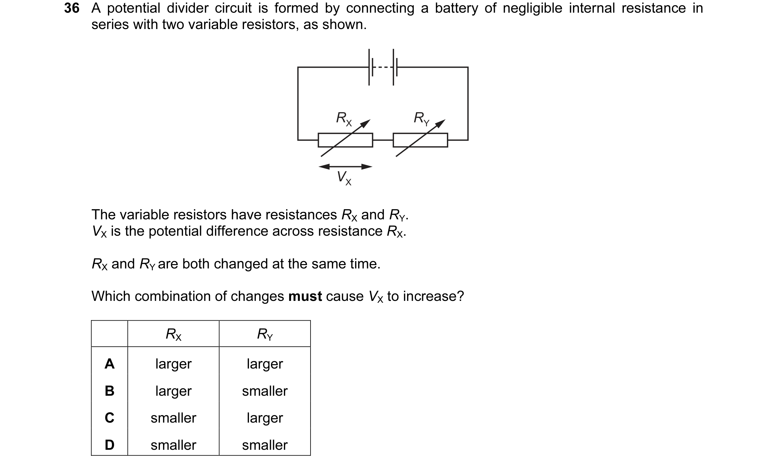
Q55 · A potential divider circuit is formed by connecting a battery of negligible internal… 9702/12 May/June 2016
36 A potential divider circuit is formed by connecting a battery of negligible internal resistance in series with two variable resistors, as shown. RX RY VX The variable resistors have resistances RX and RY. VX is the potential difference across resistance RX. RX and RY are both changed at the same time. Which combination of changes must cause VX to increase? RX RY A larger larger B larger smaller C smaller larger D smaller smaller
1 marks
Answer: B
This question in 9702/12 May/June 2016
Q56 · In the circuit shown, contact may be made at any point along the 3 Ω resistor… 9702/12 May/June 2016
37 In the circuit shown, contact may be made at any point along the 3 Ω resistor (potentiometer). 9 V 2 Ω 3 Ω 4 Ω output voltage The battery has e.m.f. 9 V and negligible internal resistance. What is the maximum range of the output voltage? A 0–2 V B 0–5 V C 2–3 V D 2–5 V
1 marks
Answer: D
This question in 9702/12 May/June 2016
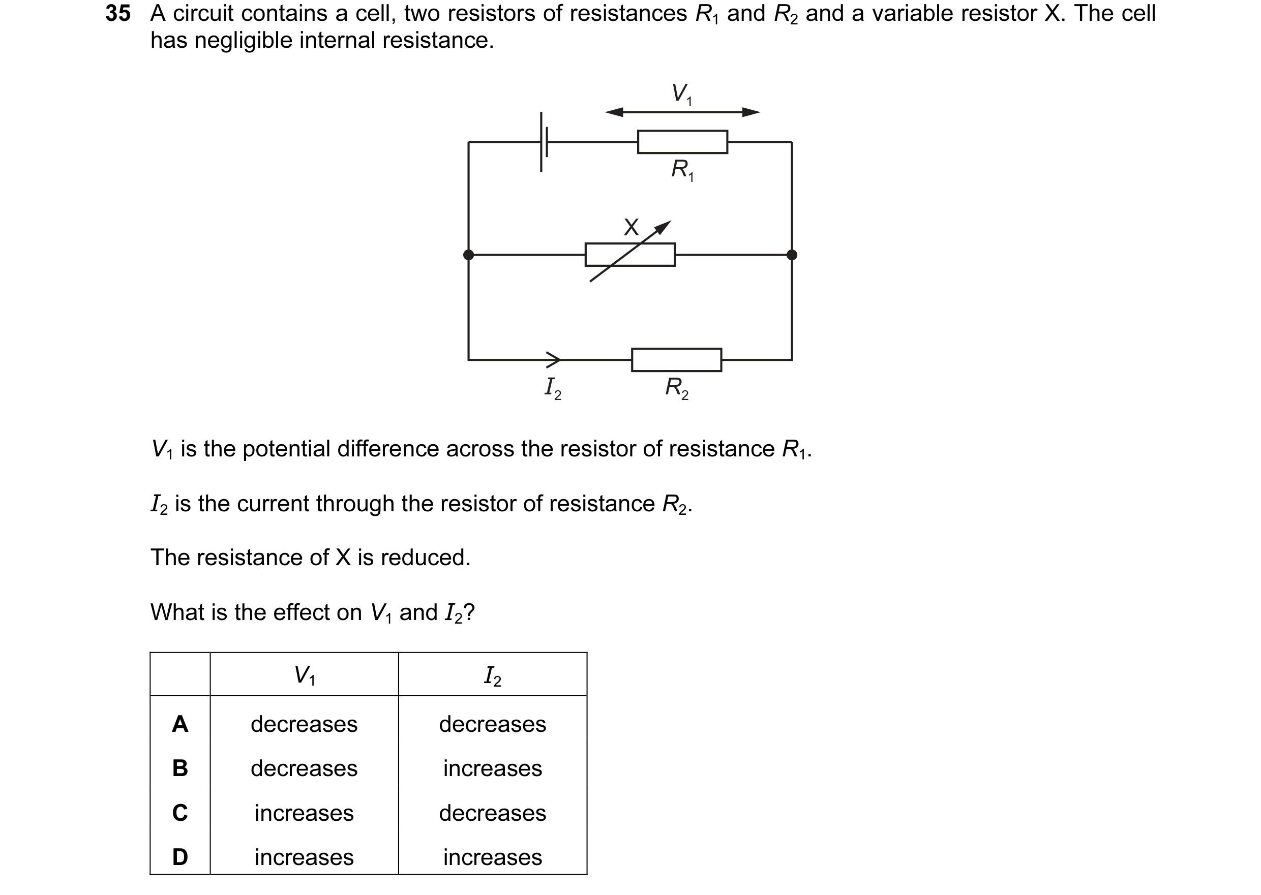
Q57 · A circuit contains a cell, two resistors of resistances R1 and R2 and a variable resistor… 9702/13 May/June 2016
35 A circuit contains a cell, two resistors of resistances R1 and R2 and a variable resistor X. The cell has negligible internal resistance. V1 R1 X I2 R2 V1 is the potential difference across the resistor of resistance R1. I2 is the current through the resistor of resistance R2. The resistance of X is reduced. What is the effect on V1 and I2? V1 I2 A decreases decreases B decreases increases C increases decreases D increases increases
1 marks
Answer: C
This question in 9702/13 May/June 2016
Q58 · A 100 cm potentiometer wire QT is connected in series with a 2.00 V cell 9702/13 May/June 2016
36 A 100 cm potentiometer wire QT is connected in series with a 2.00 V cell. Another circuit, consisting of a 2.00 V cell in series with resistors of resistance 4.00 Ω and 6.00 Ω, is set up alongside the potentiometer. Connections PQ and RS are then made so that the potential difference (p.d.) across the 4.00 Ω resistor is balanced against the p.d. across a length L of potentiometer wire. Both cells have negligible internal resistance. 2.00 V L S Q T P 4.00 Ω R 6.00 Ω 2.00 V What is the balance length L? A 0 cm B 40 cm C 60 cm D 100 cm
1 marks
Answer: B
This question in 9702/13 May/June 2016
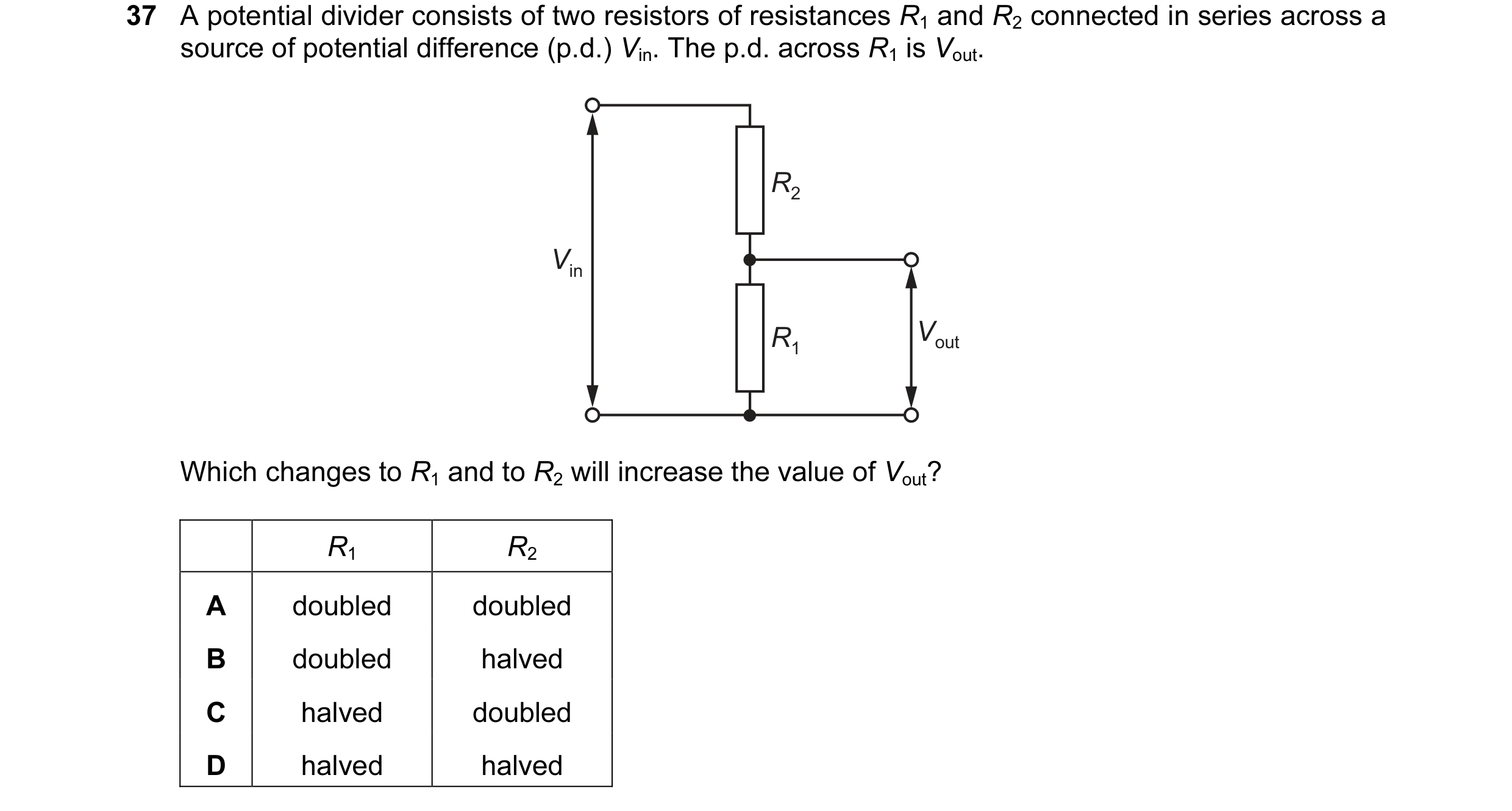
Q59 · A potential divider consists of two resistors of resistances R1 and R2 connected in… 9702/12 Feb/March 2017
37 A potential divider consists of two resistors of resistances R1 and R2 connected in series across a source of potential difference (p.d.) Vin. The p.d. across R1 is Vout. R2 Vin R1 Vout Which changes to R1 and to R2 will increase the value of Vout? R1 R2 A doubled doubled B doubled halved C halved doubled D halved halved
1 marks
Answer: B
This question in 9702/12 Feb/March 2017
Q60 · A computer is used to detect the change of position of a switch 9702/11 May/June 2017
36 A computer is used to detect the change of position of a switch. To detect the change of position, the computer requires a potential difference (p.d.) of 0 V to its input at one switch position and a p.d. of between 5 V and 7 V at the other switch position. For each of the circuits, assume the battery has negligible internal resistance. Which circuit provides an input voltage to the computer that enables it to detect the change of position of the switch? A B 1 kΩ 1 kΩ 9 V 9 V computer computer 1 kΩ input 2 kΩ input voltage voltage C D 2 kΩ 500 Ω 9 V 500 Ω 9 V 2 kΩ computer computer input input voltage voltage
1 marks
Answer: B
This question in 9702/11 May/June 2017
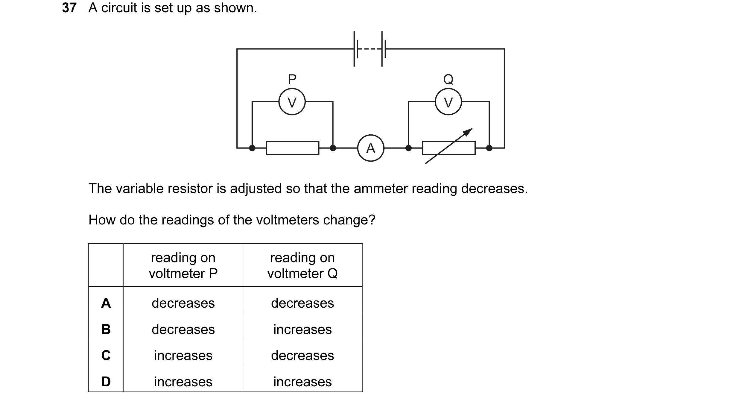
Q61 · A circuit is set up as shown 9702/12 May/June 2017
37 A circuit is set up as shown. P Q V V A The variable resistor is adjusted so that the ammeter reading decreases. How do the readings of the voltmeters change? reading on reading on voltmeter P voltmeter Q A decreases decreases B decreases increases C increases decreases D increases increases
1 marks
Answer: B
This question in 9702/12 May/June 2017
Q62 · A potential divider circuit consists of a cell of negligible internal resistance in… 9702/13 May/June 2017
36 A potential divider circuit consists of a cell of negligible internal resistance in series with two variable resistors of resistances R1 and R2. The potential difference (p.d.) across the cell is V0. The p.d. at the output is V. R1 V0 R2 V Which statement is correct? A When R1 increases, it takes a greater proportion of V0, so V decreases. B When R1 increases, the current through R1 and R2 decreases, so V increases. C When R2 decreases, it takes a smaller proportion of V0, so V increases. D When R2 increases, the current through R1 and R2 decreases, so V decreases.
1 marks
Answer: A
This question in 9702/13 May/June 2017
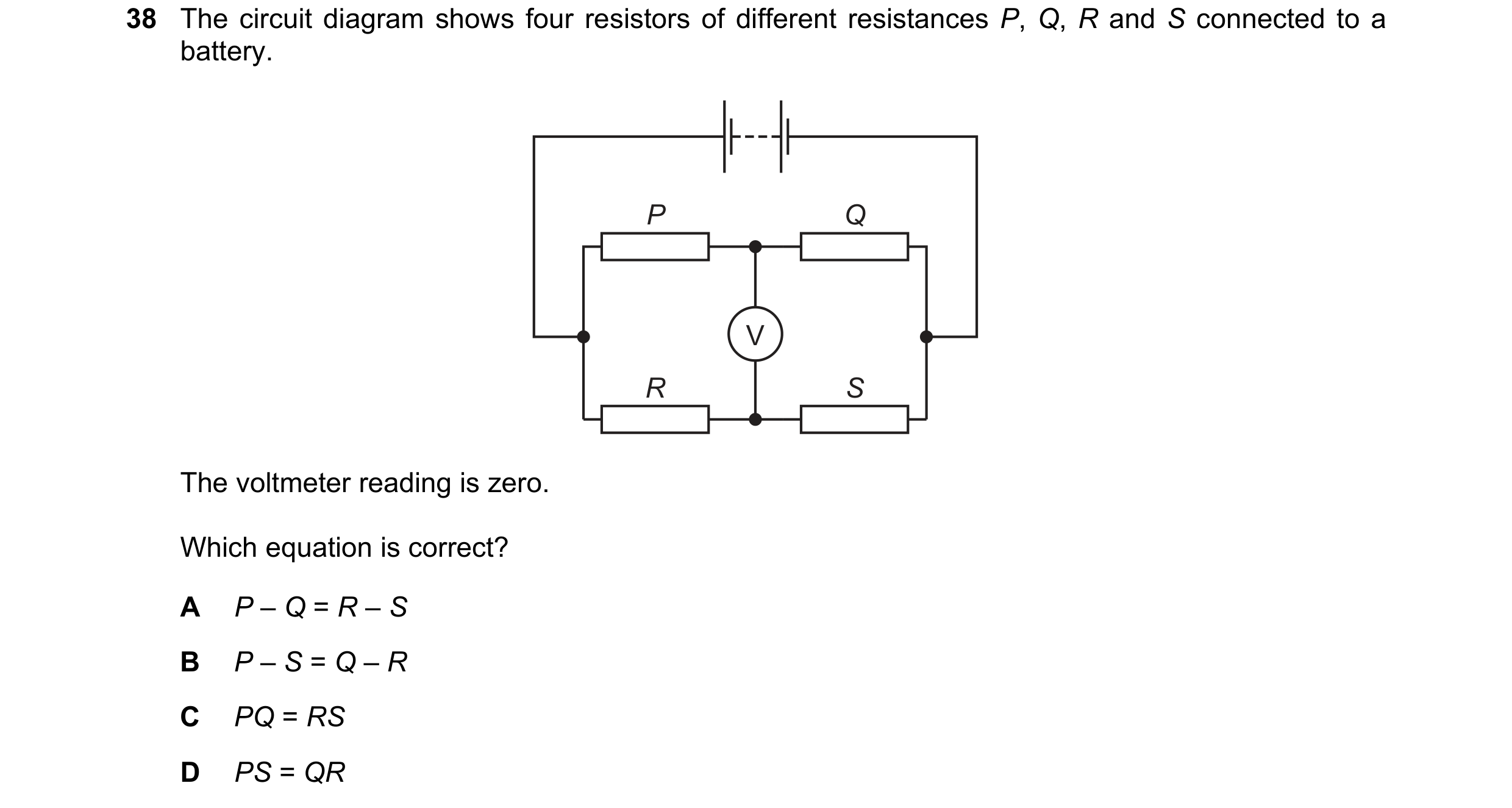
Q63 · The circuit diagram shows four resistors of different resistances P, Q, R and S connected… 9702/11 Oct/Nov 2017
38 The circuit diagram shows four resistors of different resistances P, Q, R and S connected to a battery. P Q V R S The voltmeter reading is zero. Which equation is correct? A P – Q = R – S B P – S = Q – R C PQ = RS D PS = QR
1 marks
Answer: D
This question in 9702/11 Oct/Nov 2017
Q64 · The diagram shows a potential divider connected to a 12 V supply of negligible internal… 9702/12 Oct/Nov 2017
38 The diagram shows a potential divider connected to a 12 V supply of negligible internal resistance. 300 Ω 12 V X 0 –100 Ω Y Which range of voltages can be obtained between X and Y? A 0 to 3 V B 0 to 4 V C 0 to 8 V D 0 to 9 V
1 marks
Answer: A
This question in 9702/12 Oct/Nov 2017
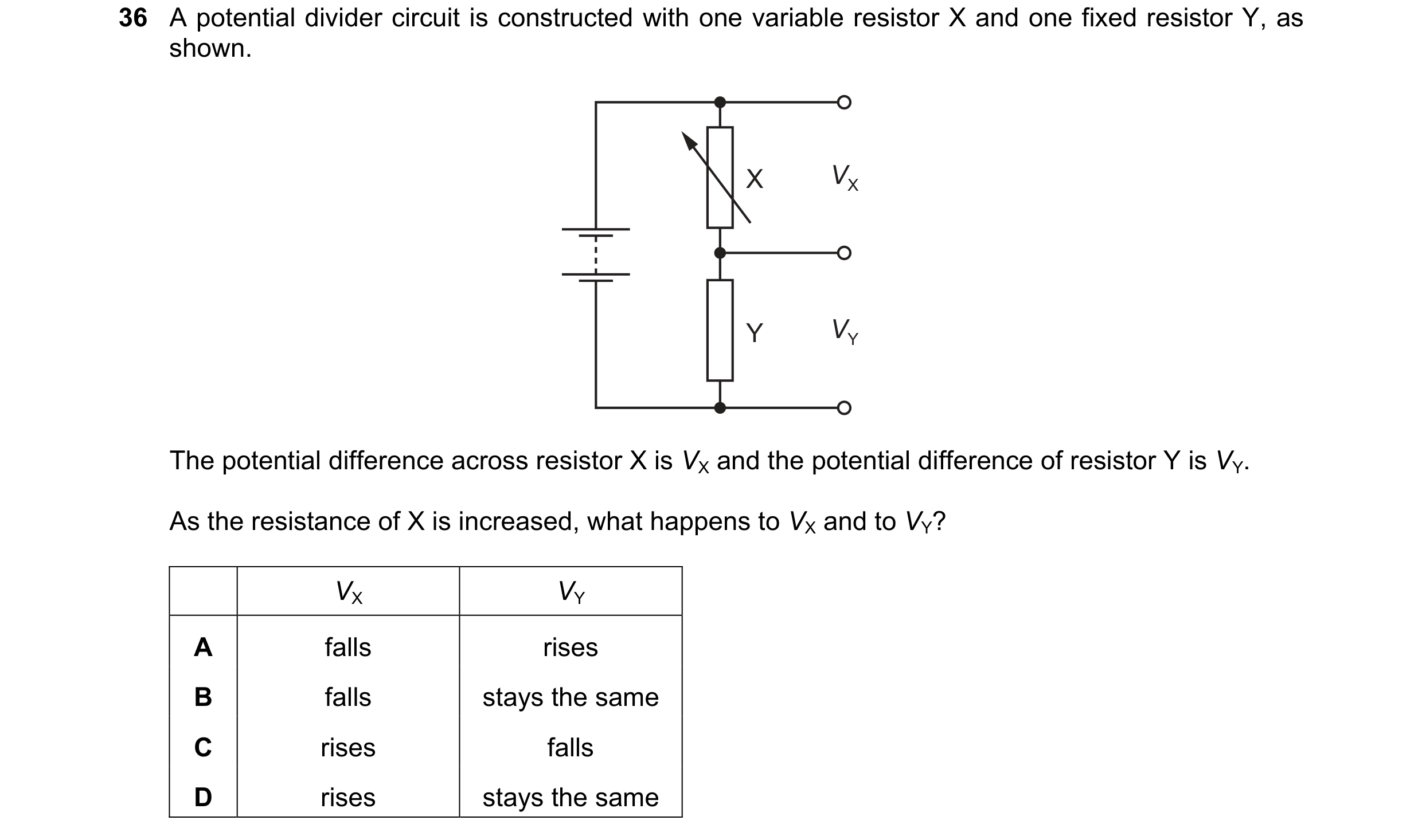
Q65 · A potential divider circuit is constructed with one variable resistor X and one fixed… 9702/12 Feb/March 2018
36 A potential divider circuit is constructed with one variable resistor X and one fixed resistor Y, as shown. X VX Y VY The potential difference across resistor X is VX and the potential difference of resistor Y is VY. As the resistance of X is increased, what happens to VX and to VY? VX VY A falls rises B falls stays the same C rises falls D rises stays the same
1 marks
Answer: C
This question in 9702/12 Feb/March 2018
Q66 · A cell of electromotive force (e.m.f.) E and negligible internal resistance is connected… 9702/12 Feb/March 2018
37 A cell of electromotive force (e.m.f.) E and negligible internal resistance is connected into a circuit, as shown. 2 Ω E 12 Ω 4 Ω V The voltmeter has a very high resistance and reads a potential difference Vout. Vout ? What is the ratio E A 1 B 1 C 1 D 2 6 3 2 3
1 marks
Answer: D
This question in 9702/12 Feb/March 2018
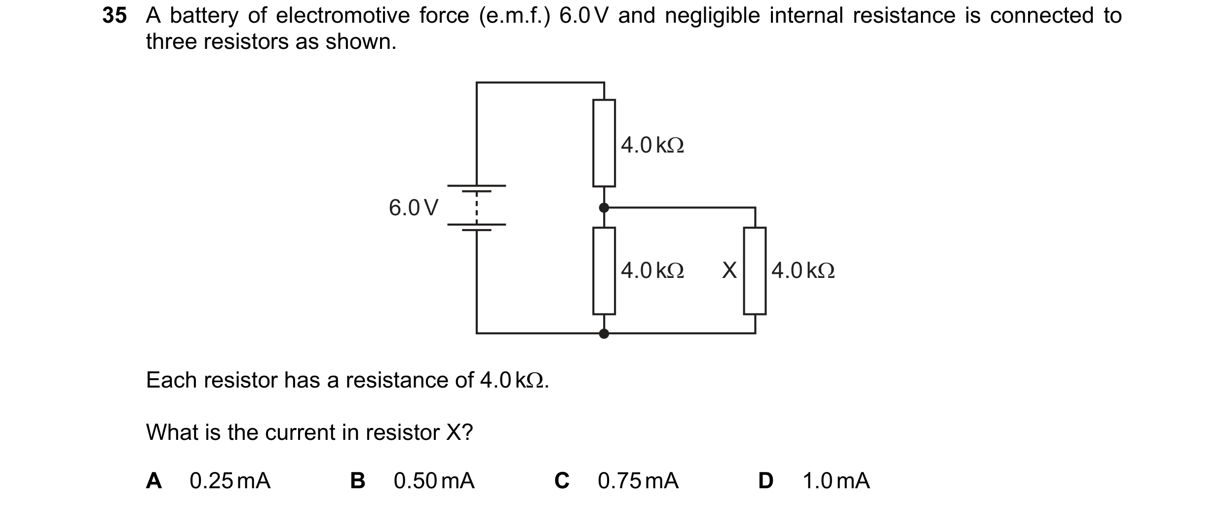
Q67 · A battery of electromotive force (e.m.f.) 6.0 V and negligible internal resistance is… 9702/11 May/June 2018
35 A battery of electromotive force (e.m.f.) 6.0 V and negligible internal resistance is connected to three resistors as shown. 4.0 kΩ 6.0 V 4.0 kΩ X 4.0 kΩ Each resistor has a resistance of 4.0 kΩ. What is the current in resistor X? A 0.25 mA B 0.50 mA C 0.75 mA D 1.0 mA
1 marks
Answer: B
This question in 9702/11 May/June 2018
Q68 · A uniform resistance wire XY of length 100 cm is connected in series with a cell L 9702/11 May/June 2018
36 A uniform resistance wire XY of length 100 cm is connected in series with a cell L. Another cell M is connected in series with resistors of resistances 5.00 Ω, 10.0 Ω and 15.0 Ω. L 100 cm X Y 12.5 cm A resistance wire 5.00 Ω 10.0 Ω 15.0 Ω P Q R S M The potential difference (p.d.) between P and Q is balanced against 12.5 cm of the resistance wire, so that the ammeter reads zero. The p.d. across the other resistors is then balanced against other lengths of the resistance wire. Which balanced lengths of resistance wire correspond to the connection points given in the table? connection balanced length / cm points A B C D Q and R 12.5 25.0 25.0 25.0 Q and S 62.5 62.5 75.0 62.5 P and R 37.5 37.5 37.5 12.5
1 marks
Answer: B
This question in 9702/11 May/June 2018
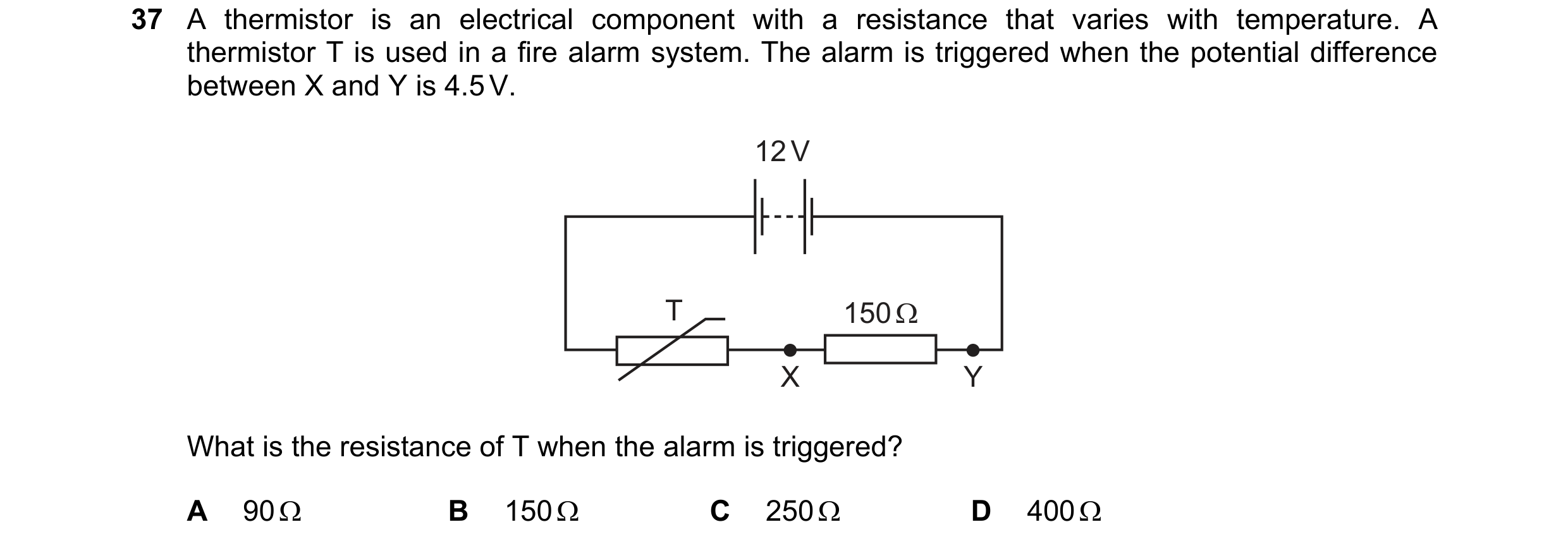
Q69 · A thermistor is an electrical component with a resistance that varies with temperature 9702/12 May/June 2018
37 A thermistor is an electrical component with a resistance that varies with temperature. A thermistor T is used in a fire alarm system. The alarm is triggered when the potential difference between X and Y is 4.5 V. 12 V T 150 Ω X Y What is the resistance of T when the alarm is triggered? A 90 Ω B 150 Ω C 250 Ω D 400 Ω
1 marks
Answer: C
This question in 9702/12 May/June 2018
Q70 · The circuit diagram shows a battery of electromotive force (e.m.f.) 9.0 V and negligible… 9702/13 May/June 2018
37 The circuit diagram shows a battery of electromotive force (e.m.f.) 9.0 V and negligible internal resistance. It is connected to two resistors of resistances 160 Ω and R. The output potential difference Vout is 4.0 V. 160 Ω 9.0 V R Vout = 4.0 V What is the resistance R ? A 32 Ω B 49 Ω C 71 Ω D 128 Ω
1 marks
Answer: D
This question in 9702/13 May/June 2018
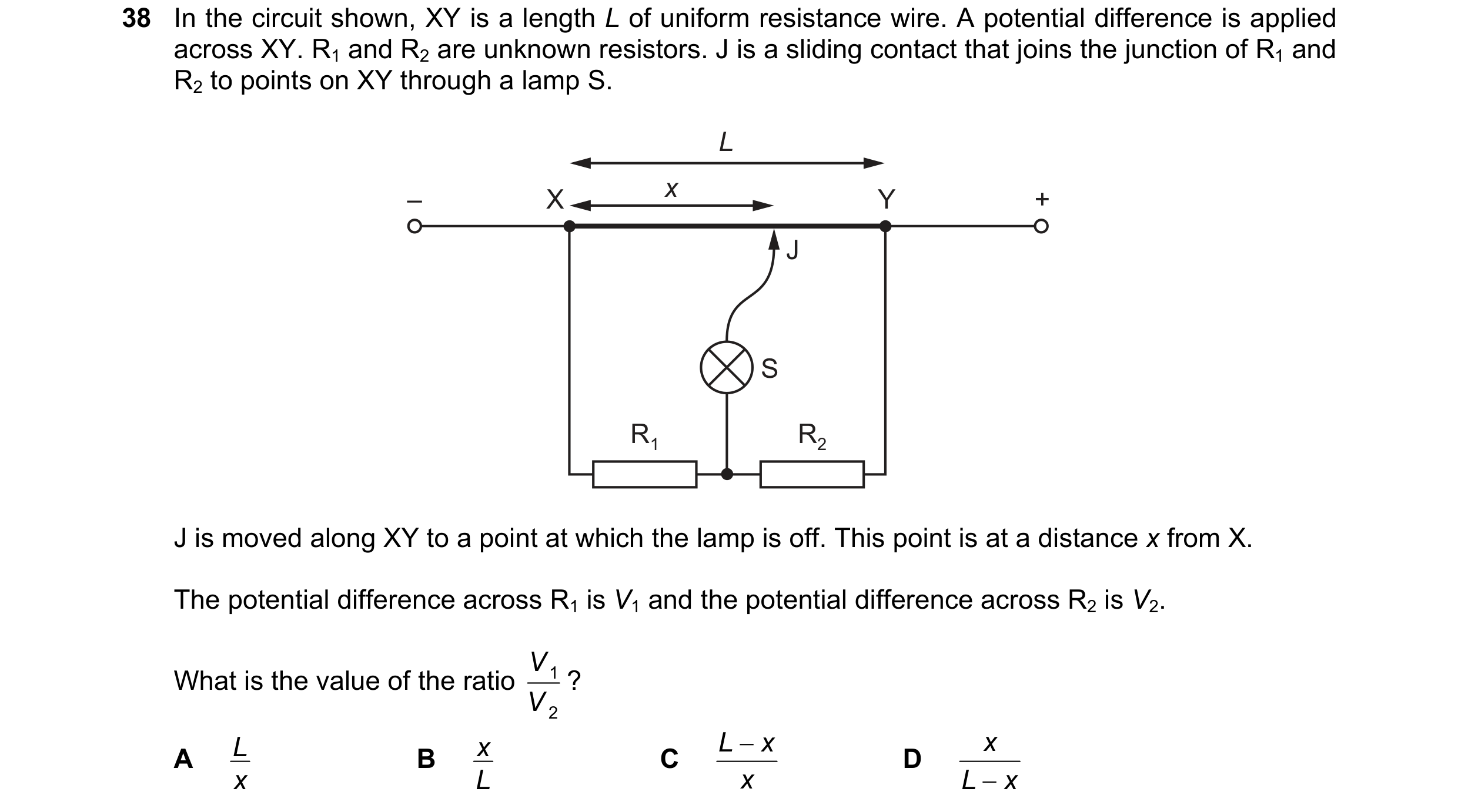
Q71 · In the circuit shown, XY is a length L of uniform resistance wire 9702/13 May/June 2018
38 In the circuit shown, XY is a length L of uniform resistance wire. A potential difference is applied across XY. R1 and R2 are unknown resistors. J is a sliding contact that joins the junction of R1 and R2 to points on XY through a lamp S. L x – X Y + J S R1 R2 J is moved along XY to a point at which the lamp is off. This point is at a distance x from X. The potential difference across R1 is V1 and the potential difference across R2 is V2. V ? What is the value of the ratio 1 V 2 L x L − x x A B C D x L x L − x
1 marks
Answer: D
This question in 9702/13 May/June 2018
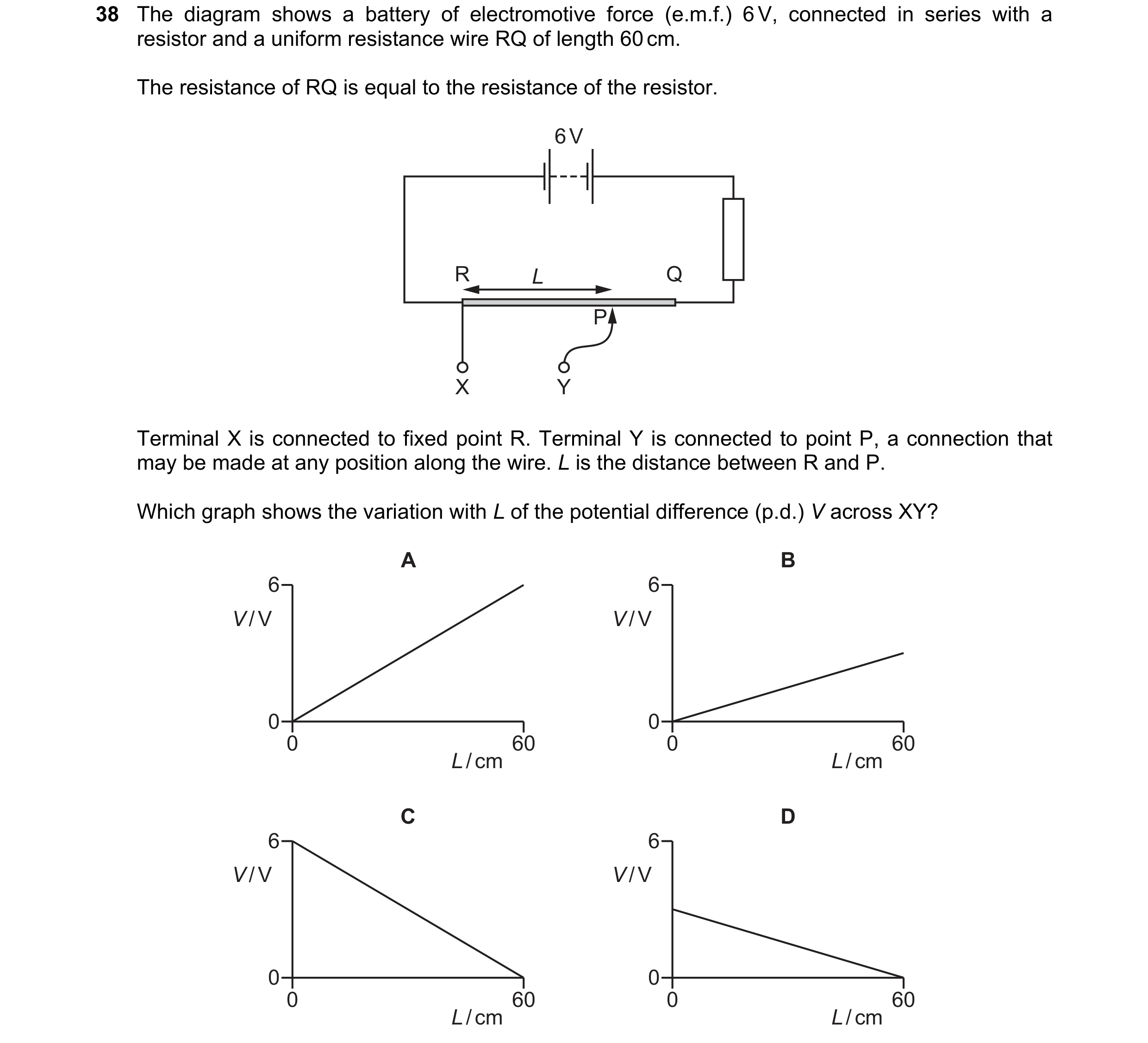
Q72 · The diagram shows a battery of electromotive force (e.m.f.) 6 V, connected in series with… 9702/11 Oct/Nov 2018
38 The diagram shows a battery of electromotive force (e.m.f.) 6 V, connected in series with a resistor and a uniform resistance wire RQ of length 60 cm. The resistance of RQ is equal to the resistance of the resistor. 6 V R L Q P X Y Terminal X is connected to fixed point R. Terminal Y is connected to point P, a connection that may be made at any position along the wire. L is the distance between R and P. Which graph shows the variation with L of the potential difference (p.d.) V across XY? A B 6 6 V / V V / V 0 0 0 60 0 60 L / cm L / cm C D 6 6 V / V V / V 0 0 0 60 0 60 L / cm L / cm
1 marks
Answer: B
This question in 9702/11 Oct/Nov 2018
Q73 · Two cells are investigated using a potentiometer 9702/12 Oct/Nov 2018
38 Two cells are investigated using a potentiometer. At the balance point, cell X gives a reading of 44 cm and cell Y gives a reading of 70 cm. 6 V 6 V R R 44 cm 70 cm cell X cell Y galvanometer galvanometer Which statement is not correct? A A potentiometer balance point results in zero current through the galvanometer. B At the balance point, the current through resistor R in both circuits is the same. C The electromotive force (e.m.f.) of cell X is larger than that of cell Y. D The value of the e.m.f. of each of the cells X and Y is less than 6 V.
1 marks
Answer: C
This question in 9702/12 Oct/Nov 2018
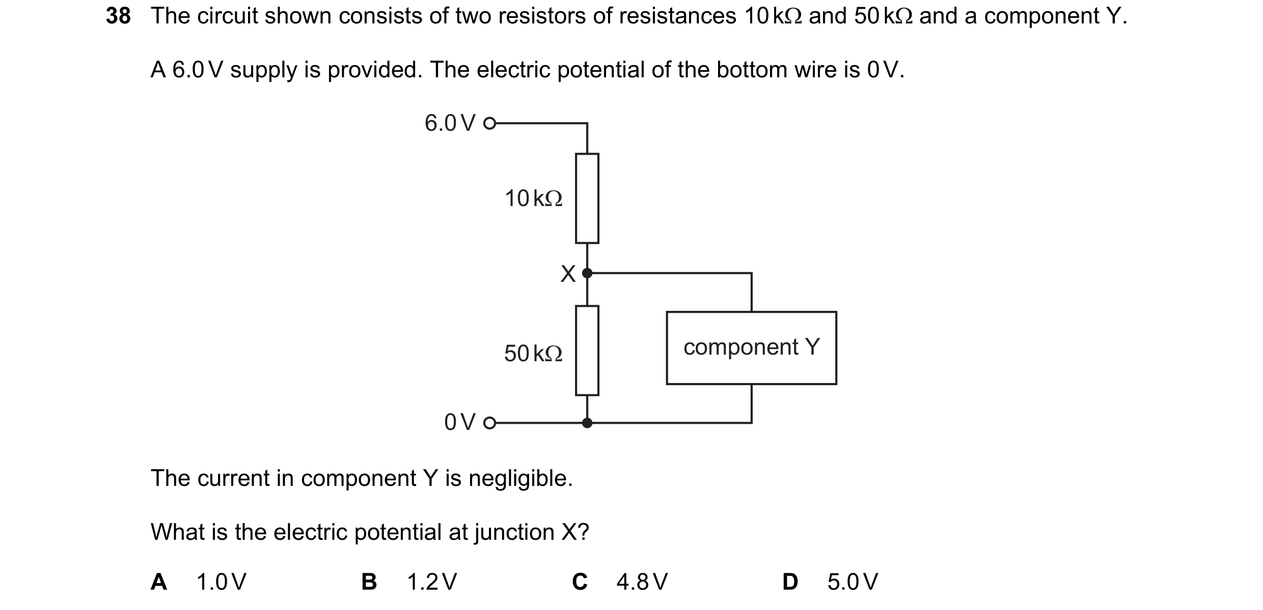
Q74 · The circuit shown consists of two resistors of resistances 10 kΩ and 50 kΩ and a… 9702/12 Feb/March 2019
38 The circuit shown consists of two resistors of resistances 10 kΩ and 50 kΩ and a component Y. A 6.0 V supply is provided. The electric potential of the bottom wire is 0 V. 6.0 V 10 kΩ X 50 kΩ component Y 0 V The current in component Y is negligible. What is the electric potential at junction X? A 1.0 V B 1.2 V C 4.8 V D 5.0 V
1 marks
Answer: D
This question in 9702/12 Feb/March 2019
Q75 · The diagram shows a potentiometer and a fixed resistor connected across a 12 V battery of… 9702/11 May/June 2019
38 The diagram shows a potentiometer and a fixed resistor connected across a 12 V battery of negligible internal resistance. fixed resistor 20 Ω 12 V 20 Ω output The fixed resistor and the potentiometer each have resistance 20 Ω. The circuit is designed to provide a variable output voltage. What is the range of output voltages? A 0 – 6 V B 0 – 12 V C 6 – 12 V D 12 – 20 V
1 marks
Answer: A
This question in 9702/11 May/June 2019
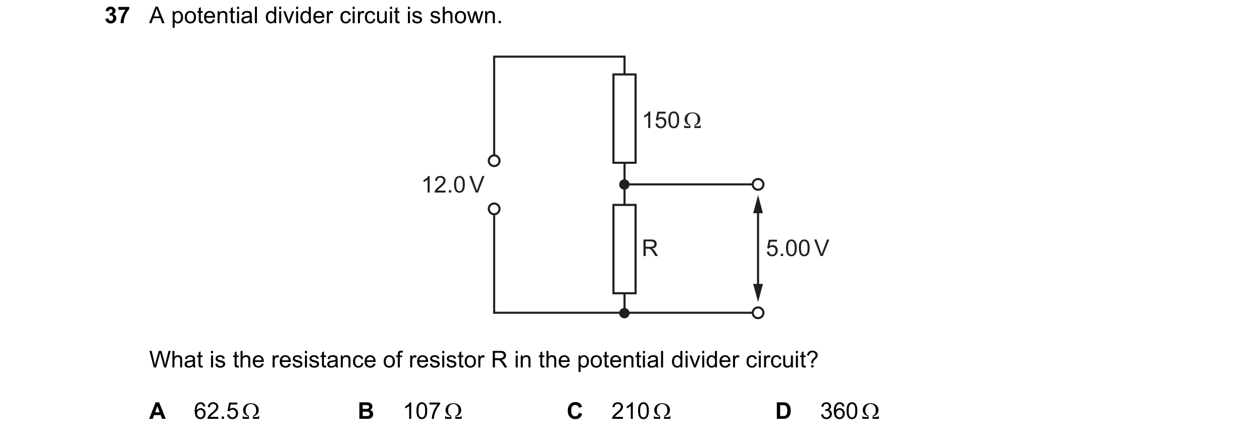
Q76 · A potential divider circuit is shown 9702/13 May/June 2019
37 A potential divider circuit is shown. 150 Ω 12.0 V R 5.00 V What is the resistance of resistor R in the potential divider circuit? A 62.5 Ω B 107 Ω C 210 Ω D 360 Ω
1 marks
Answer: B
This question in 9702/13 May/June 2019
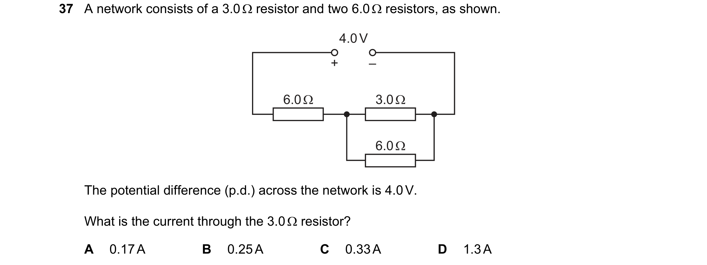
Q77 · A network consists of a 3.0 Ω resistor and two 6.0 Ω resistors, as shown 9702/11 Oct/Nov 2019
37 A network consists of a 3.0 Ω resistor and two 6.0 Ω resistors, as shown. 4.0 V + – 6.0 Ω 3.0 Ω 6.0 Ω The potential difference (p.d.) across the network is 4.0 V. What is the current through the 3.0 Ω resistor? A 0.17 A B 0.25 A C 0.33 A D 1.3 A
1 marks
Answer: C
This question in 9702/11 Oct/Nov 2019
Q78 · The diagram shows a variable resistor R and two fixed resistors connected in series in a… 9702/12 Oct/Nov 2019
37 The diagram shows a variable resistor R and two fixed resistors connected in series in a circuit to act as a potential divider. 6.0 V R 2.0 Ω 10 Ω 2.0 V The cell of electromotive force (e.m.f.) 6.0 V has negligible internal resistance. A cell of e.m.f. 2.0 V and a galvanometer are connected into the potential divider. The resistance of R is varied until the galvanometer reads zero. What is the resistance of resistor R? A 3.0 Ω B 5.0 Ω C 8.0 Ω D 18 Ω
1 marks
Answer: A
This question in 9702/12 Oct/Nov 2019
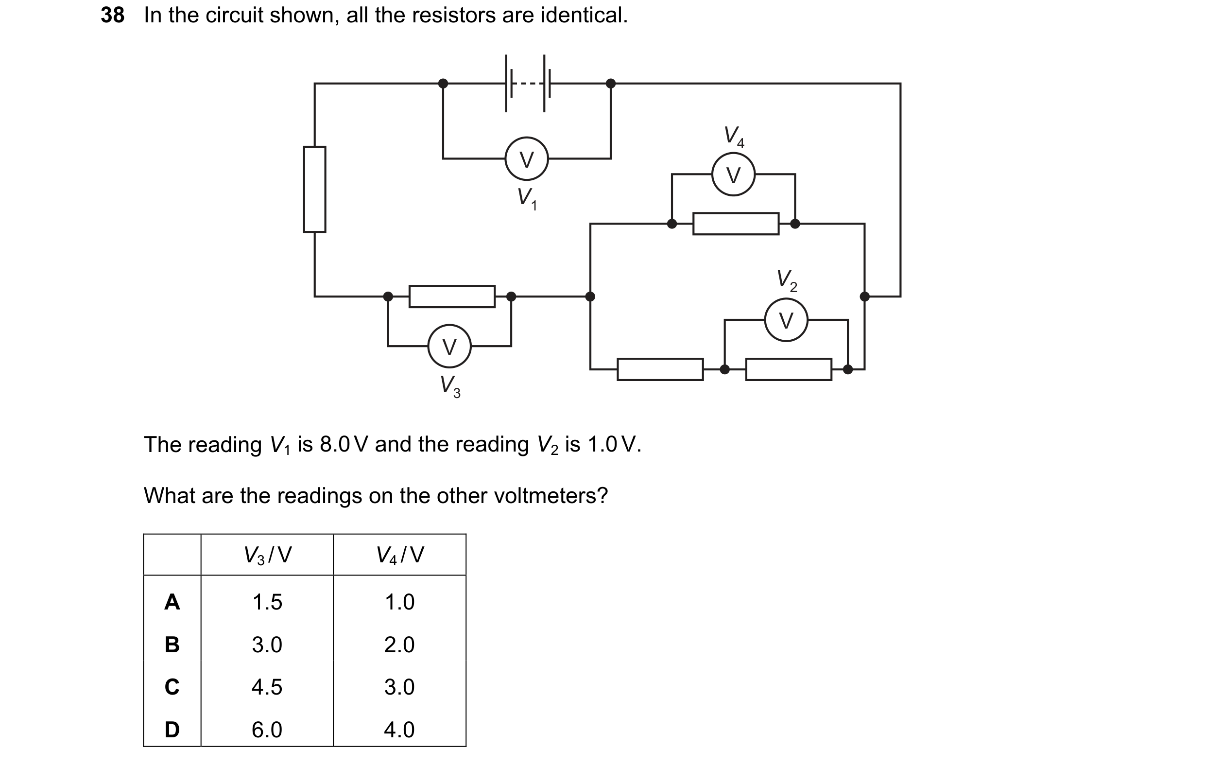
Q79 · In the circuit shown, all the resistors are identical 9702/13 Oct/Nov 2019
38 In the circuit shown, all the resistors are identical. V4 V V V1 V2 V V V3 The reading V1 is 8.0 V and the reading V2 is 1.0 V. What are the readings on the other voltmeters? V3 / V V4 / V A 1.5 1.0 B 3.0 2.0 C 4.5 3.0 D 6.0 4.0
1 marks
Answer: B
This question in 9702/13 Oct/Nov 2019
Q80 · In the circuits shown, the cell has negligible internal resistance 9702/12 Feb/March 2020
37 In the circuits shown, the cell has negligible internal resistance. Which diagram shows a potential divider circuit that can vary the potential difference (p.d.) across the lamp? A B C D
1 marks
Answer: C
This question in 9702/12 Feb/March 2020
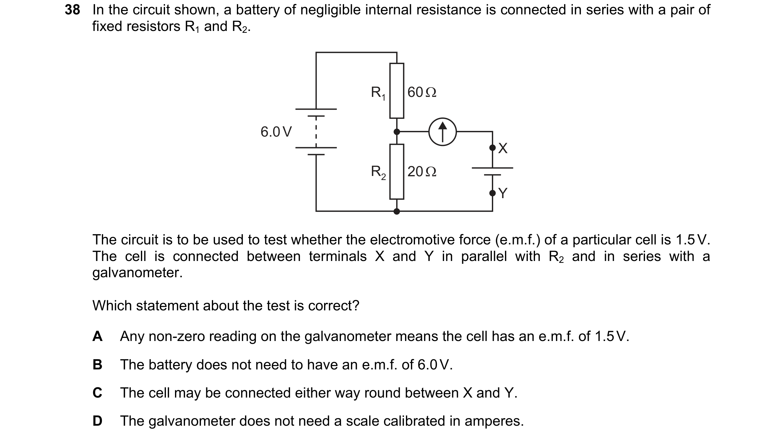
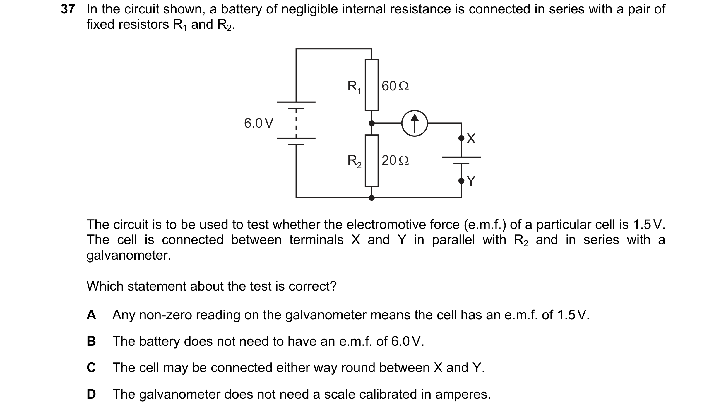
Q81 · In the circuit shown, a battery of negligible internal resistance is connected in series… 9702/11 May/June 2020
38 In the circuit shown, a battery of negligible internal resistance is connected in series with a pair of fixed resistors R1 and R2. R1 60 Ω 6.0 V X R2 20 Ω Y The circuit is to be used to test whether the electromotive force (e.m.f.) of a particular cell is 1.5 V. The cell is connected between terminals X and Y in parallel with R2 and in series with a galvanometer. Which statement about the test is correct? A Any non-zero reading on the galvanometer means the cell has an e.m.f. of 1.5 V. B The battery does not need to have an e.m.f. of 6.0 V. C The cell may be connected either way round between X and Y. D The galvanometer does not need a scale calibrated in amperes.
1 marks
Answer: D
This question in 9702/11 May/June 2020
Q82 · In the circuit shown, X is a variable resistor whose resistance can be changed from 5.0 Ω… 9702/12 May/June 2020
38 In the circuit shown, X is a variable resistor whose resistance can be changed from 5.0 Ω to 500 Ω. The electromotive force (e.m.f.) of the battery is 12.0 V. It has negligible internal resistance. 40 Ω 12.0 V X output What is the maximum range of values of potential difference across the output? A 1.3 V to 11.1 V B 1.3 V to 12.0 V C 1.5 V to 11.1 V D 1.5 V to 12.0 V
1 marks
Answer: A
This question in 9702/12 May/June 2020
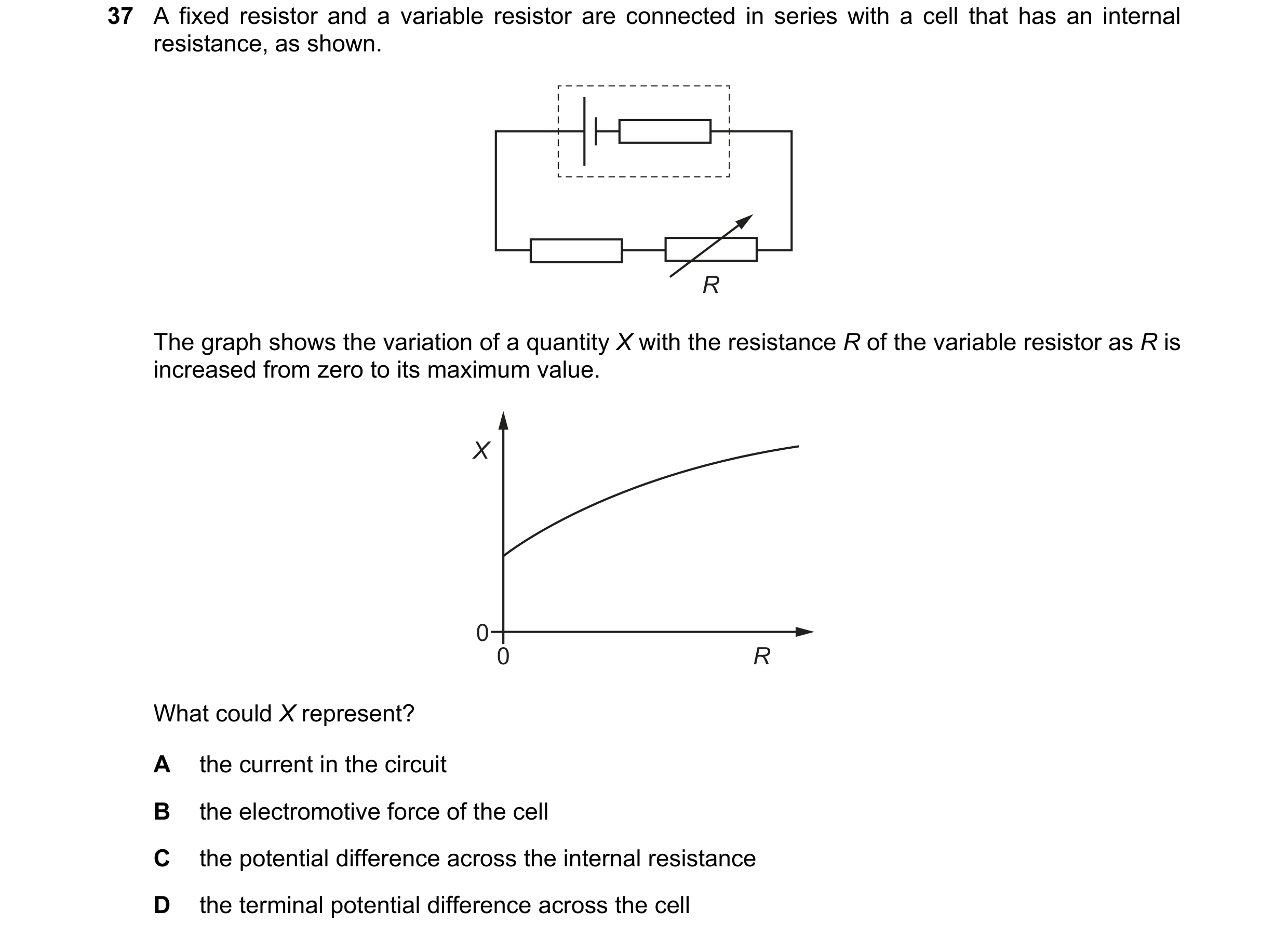
Q83 · A fixed resistor and a variable resistor are connected in series with a cell that has an… 9702/13 May/June 2020
37 A fixed resistor and a variable resistor are connected in series with a cell that has an internal resistance, as shown. R The graph shows the variation of a quantity X with the resistance R of the variable resistor as R is increased from zero to its maximum value. X 0 0 R What could X represent? A the current in the circuit B the electromotive force of the cell C the potential difference across the internal resistance D the terminal potential difference across the cell
1 marks
Answer: D
This question in 9702/13 May/June 2020
Q84 · A cell of electromotive force (e.m.f.) 4.0 V and negligible internal resistance is… 9702/13 May/June 2020
38 A cell of electromotive force (e.m.f.) 4.0 V and negligible internal resistance is connected to a fixed resistor of resistance 1.0 Ω and a potentiometer of maximum resistance 3.0 Ω, as shown. 4.0 V 3.0 Ω Y 1.0 Ω X Which range of potential differences can be obtained between the terminals X and Y? A 0 V to 3.0 V B 0 V to 4.0 V C 1.0 V to 3.0 V D 1.0 V to 4.0 V
1 marks
Answer: A
This question in 9702/13 May/June 2020
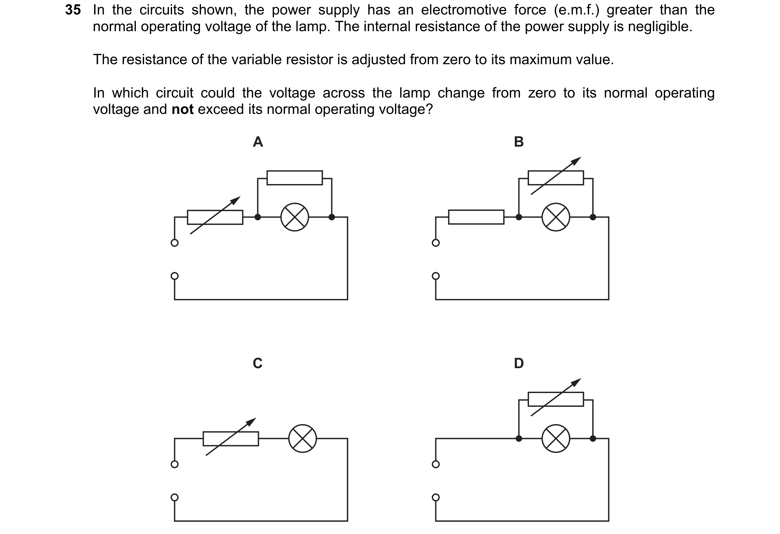
Q85 · In the circuits shown, the power supply has an electromotive force (e.m.f.) greater than… 9702/11 Oct/Nov 2020
35 In the circuits shown, the power supply has an electromotive force (e.m.f.) greater than the normal operating voltage of the lamp. The internal resistance of the power supply is negligible. The resistance of the variable resistor is adjusted from zero to its maximum value. In which circuit could the voltage across the lamp change from zero to its normal operating voltage and not exceed its normal operating voltage? A B C D
1 marks
Answer: B
This question in 9702/11 Oct/Nov 2020
Q86 · In the circuit shown, the 6.0 V battery has negligible internal resistance 9702/11 Oct/Nov 2020
37 In the circuit shown, the 6.0 V battery has negligible internal resistance. Resistors R1 and R2 and the voltmeter each have a resistance of 100 k. 6.0 V R1 R2 100 kΩ 100 kΩ V 100 kΩ What is the current in the resistor R2? A 20 A B 30 A C 40 A D 60 A
1 marks
Answer: A
This question in 9702/11 Oct/Nov 2020
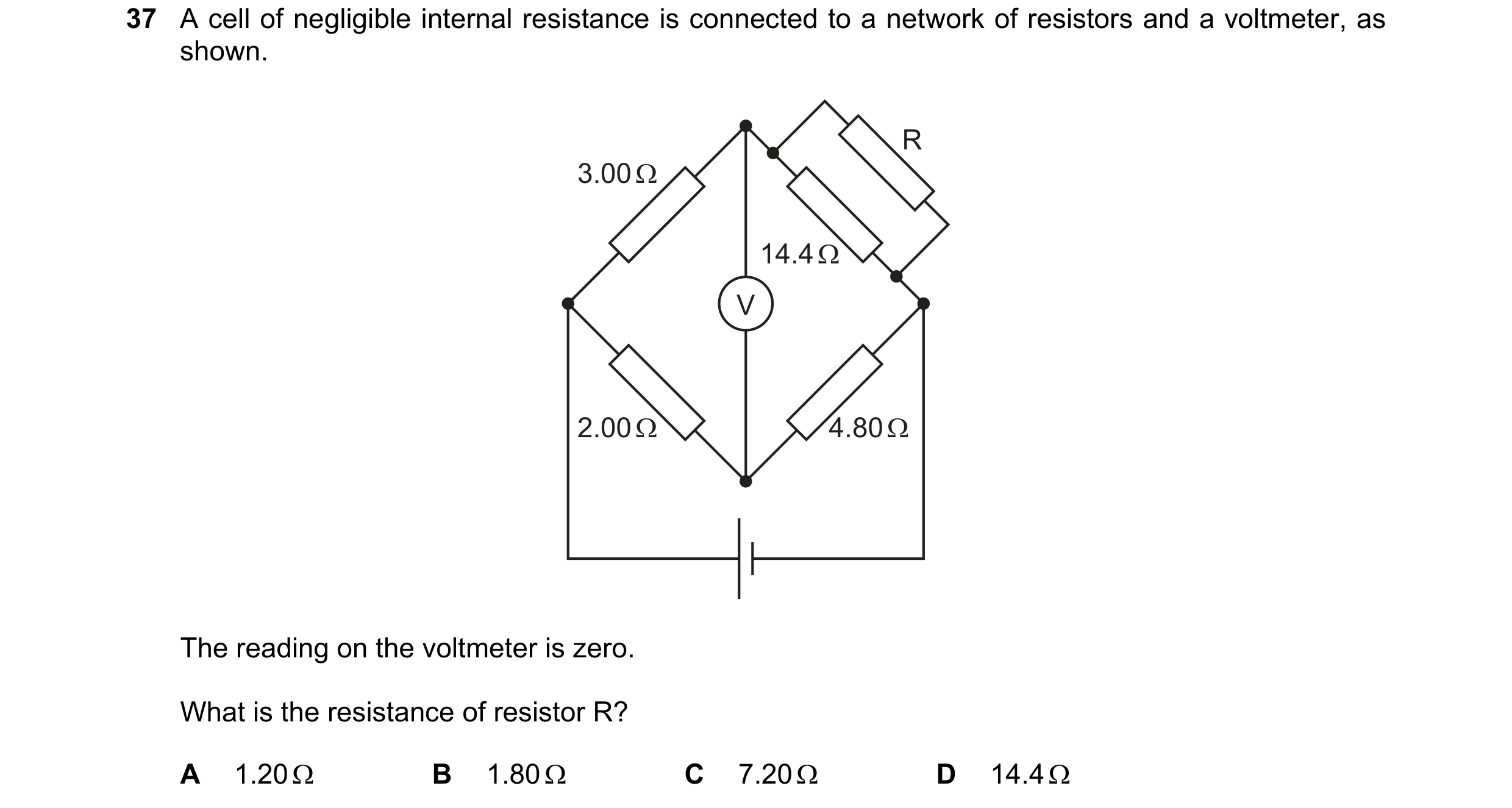
Q87 · A cell of negligible internal resistance is connected to a network of resistors and a… 9702/12 Oct/Nov 2020
37 A cell of negligible internal resistance is connected to a network of resistors and a voltmeter, as shown. R 3.00 Ω 14.4 Ω V 2.00 Ω 4.80 Ω The reading on the voltmeter is zero. What is the resistance of resistor R? A 1.20 B 1.80 C 7.20 D 14.4
1 marks
Answer: D
This question in 9702/12 Oct/Nov 2020
Q88 · A voltmeter is connected into a circuit with the polarity shown in the diagram 9702/12 Oct/Nov 2020
38 A voltmeter is connected into a circuit with the polarity shown in the diagram. Q + – 3 V V 3 V P The sliding contact is moved to end P of the potentiometer and then to end Q. What are the two readings of the voltmeter? sliding contact sliding contact at end P at end Q A 0 V 3 V B 0 V 6 V C 3 V 3 V D 3 V 6 V
1 marks
Answer: D
This question in 9702/12 Oct/Nov 2020
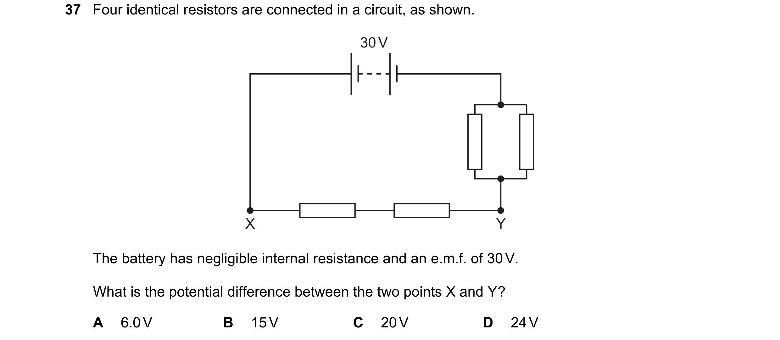
Q89 · Four identical resistors are connected in a circuit, as shown 9702/13 Oct/Nov 2020
37 Four identical resistors are connected in a circuit, as shown. 30 V X Y The battery has negligible internal resistance and an e.m.f. of 30 V. What is the potential difference between the two points X and Y? A 6.0 V B 15 V C 20 V D 24 V
1 marks
Answer: D
This question in 9702/13 Oct/Nov 2020
Q90 · A power supply and a solar cell are compared using the potentiometer circuit shown 9702/13 Oct/Nov 2020
38 A power supply and a solar cell are compared using the potentiometer circuit shown. power supply 2.000 V + – R S P Q 40.0 cm galvanometer solar cell The potentiometer wire PQ is 100.0 cm long and has a resistance of 5.00 . The power supply has an e.m.f. of 2.000 V and the solar cell has an e.m.f. of 5.00 mV. Which resistance R must be used so that the galvanometer reads zero when PS = 40.0 cm? A 395 B 405 C 795 D 805
1 marks
Answer: C
This question in 9702/13 Oct/Nov 2020
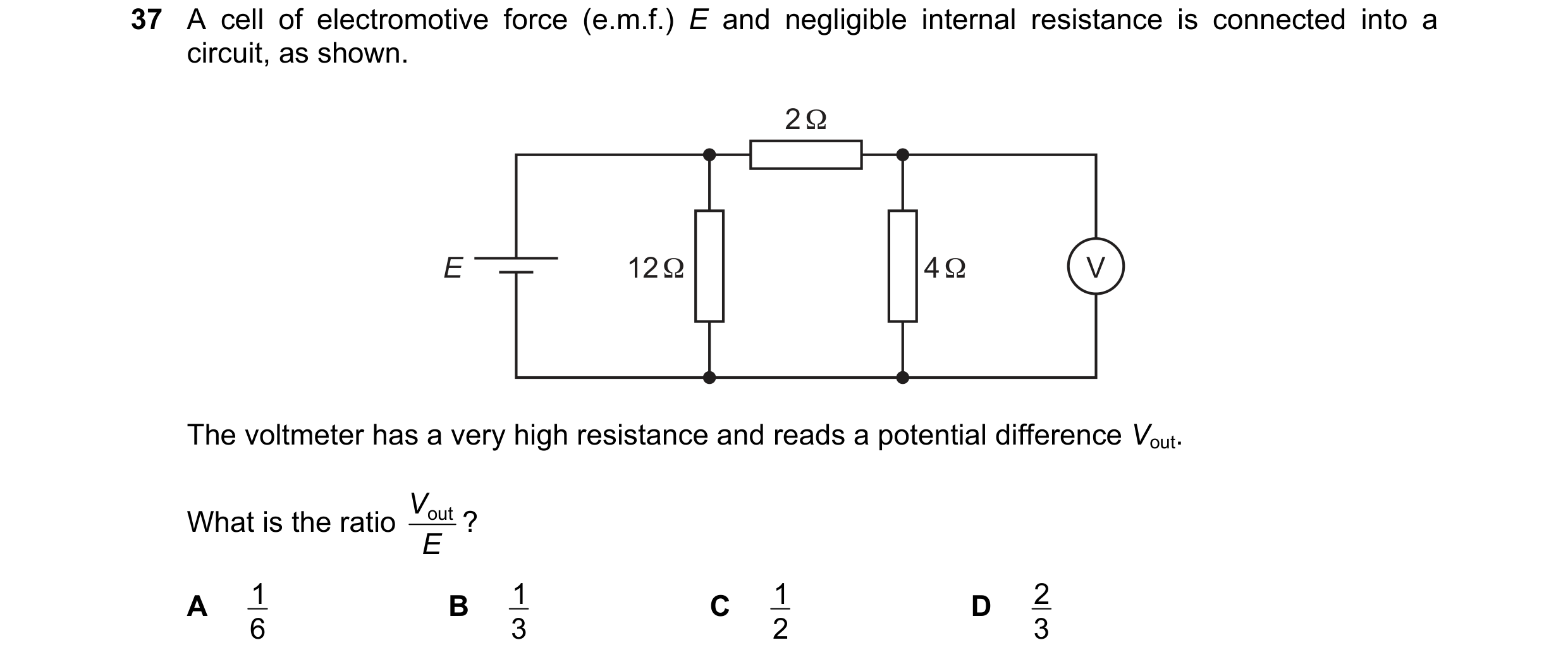
Q91 · A cell of electromotive force (e.m.f.) E and negligible internal resistance is connected… 9702/12 Feb/March 2021
37 A cell of electromotive force (e.m.f.) E and negligible internal resistance is connected into a circuit, as shown. 2 Ω E 12 Ω 4 Ω V The voltmeter has a very high resistance and reads a potential difference Vout. Vout ? What is the ratio E A 1 B 1 C 1 D 2 6 3 2 3
1 marks
Answer: D
This question in 9702/12 Feb/March 2021
Q92 · A battery is connected to a potentiometer 9702/12 Feb/March 2021
38 A battery is connected to a potentiometer. The potentiometer consists of a uniform resistance wire and a sliding contact P. P Q R d resistance V wire The potential difference (p.d.) V between the sliding contact P and end Q of the wire is measured using a voltmeter. The sliding contact P is moved from end Q to end R of the wire. Sliding contact P is distance d from Q. Which graph shows the variation with distance d of the p.d. V ? A B C D V V V V 0 0 0 0 d d d d 0 0 0 0
1 marks
Answer: A
This question in 9702/12 Feb/March 2021
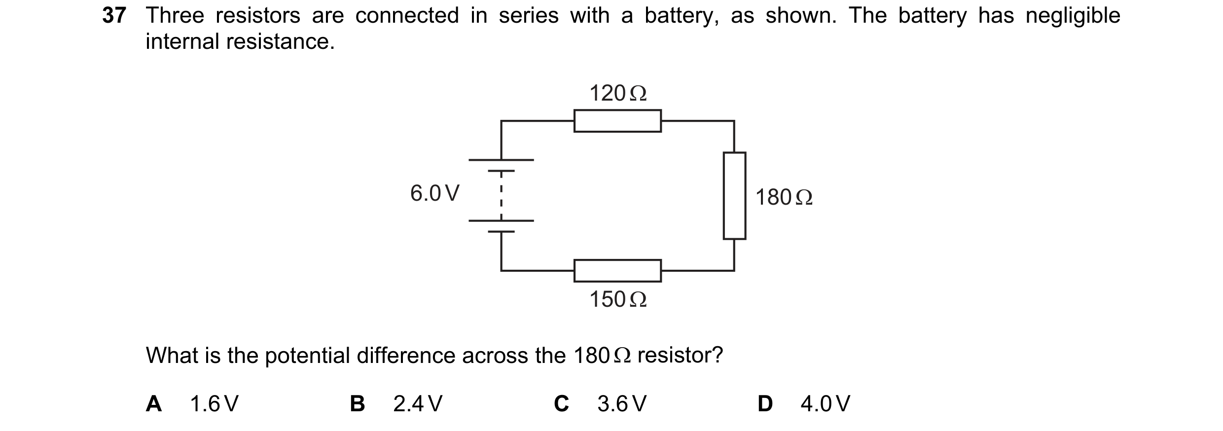
Q93 · Three resistors are connected in series with a battery, as shown 9702/11 May/June 2021
37 Three resistors are connected in series with a battery, as shown. The battery has negligible internal resistance. 120 Ω 6.0 V 180 Ω 150 Ω What is the potential difference across the 180 resistor? A 1.6 V B 2.4 V C 3.6 V D 4.0 V
1 marks
Answer: B
This question in 9702/11 May/June 2021
Q94 · In the circuit shown, a potentiometer of total resistance 120 is connected in parallel… 9702/13 May/June 2021
38 In the circuit shown, a potentiometer of total resistance 120 is connected in parallel with a resistor of resistance 150 and a resistor of resistance R. The battery has electromotive force (e.m.f.) 12 V and negligible internal resistance. 150 Ω 12 V 120 Ω V R The voltmeter reads 0 V when the slider of the potentiometer is 1 4 of the way from its lower end, as shown. What is resistance R ? A 30 B 38 C 50 D 450
1 marks
Answer: C
This question in 9702/13 May/June 2021
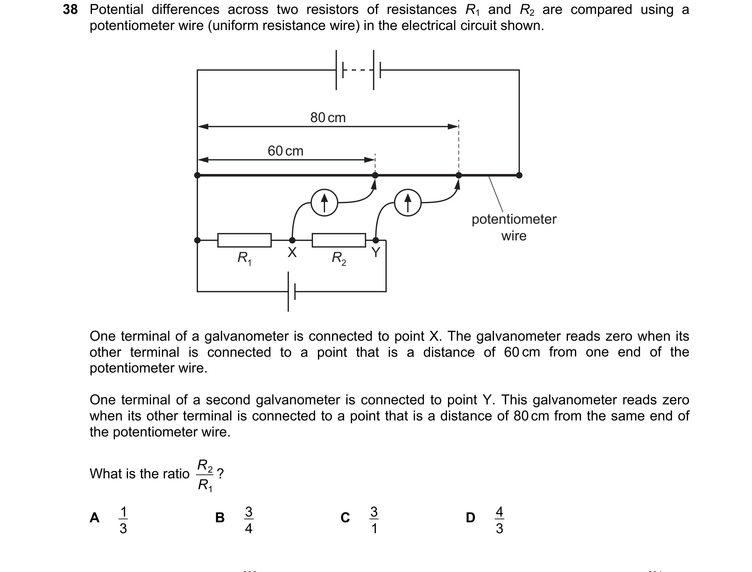
Q95 · Potential differences across two resistors of resistances R1 and R2 are compared using a… 9702/11 Oct/Nov 2021
38 Potential differences across two resistors of resistances R1 and R2 are compared using a potentiometer wire (uniform resistance wire) in the electrical circuit shown. 80 cm 60 cm potentiometer wire R1 X R2 Y One terminal of a galvanometer is connected to point X. The galvanometer reads zero when its other terminal is connected to a point that is a distance of 60 cm from one end of the potentiometer wire. One terminal of a second galvanometer is connected to point Y. This galvanometer reads zero when its other terminal is connected to a point that is a distance of 80 cm from the same end of the potentiometer wire. R What is the ratio R ? 2 1 A 3 1 B 3 4 C 3 1 D 3 4
1 marks
Answer: A
This question in 9702/11 Oct/Nov 2021
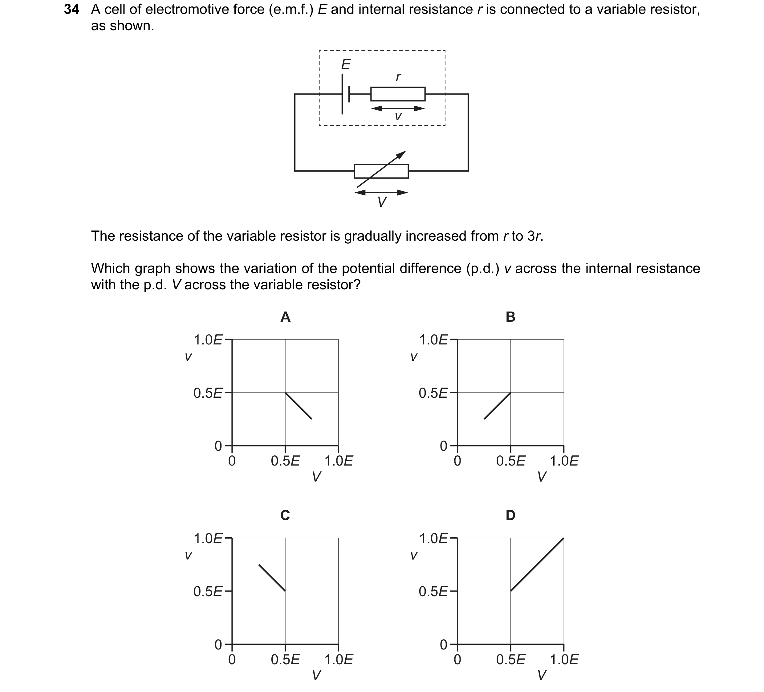
Q96 · A cell of electromotive force (e.m.f.) E and internal resistance r is connected to a… 9702/12 Feb/March 2022
34 A cell of electromotive force (e.m.f.) E and internal resistance r is connected to a variable resistor, as shown. E r v V The resistance of the variable resistor is gradually increased from r to 3r. Which graph shows the variation of the potential difference (p.d.) v across the internal resistance with the p.d. V across the variable resistor? A B 1.0E 1.0E v v 0.5E 0.5E 0 0 0 0.5E 1.0E 0 0.5E 1.0E V V C D 1.0E 1.0E v v 0.5E 0.5E 0 0 0 0.5E 1.0E 0 0.5E 1.0E V V
1 marks
Answer: A
This question in 9702/12 Feb/March 2022
Q97 · Acell has an electromotive force (e.m.f.) of 8.0 V and negligible internal resistance 9702/12 Feb/March 2022
36 Acell has an electromotive force (e.m.f.) of 8.0 V and negligible internal resistance. The cell forms
part of a circuit, as shown.
8.0V
The reading V; is 4.0V and the reading V2 is also 4.0V.
What is the resistance of resistor R?
A 0.509 B 2.0Q C 4.00 D 8.0Q
1 marks
Answer: B
This question in 9702/12 Feb/March 2022
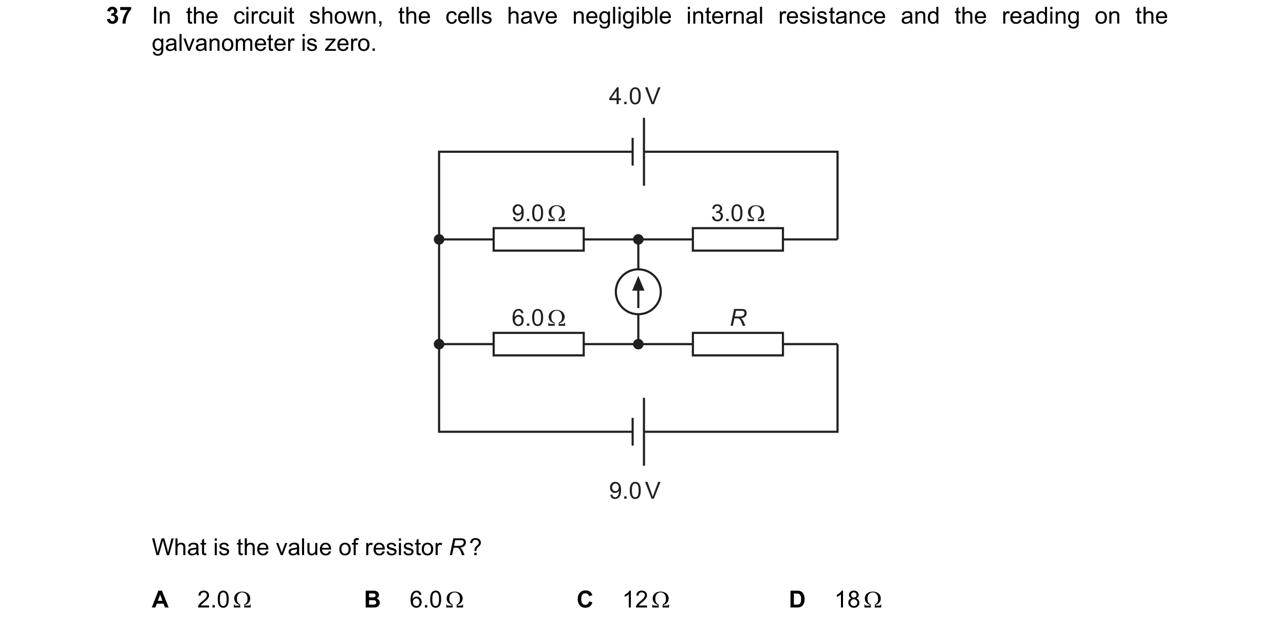
Q98 · In the circuit shown, the cells have negligible internal resistance and the reading on… 9702/12 Feb/March 2022
37 In the circuit shown, the cells have negligible internal resistance and the reading on the
galvanometer is zero.
4.0V
9.0V
What is the value of resistor R?
A 2.00 B 6.0Q C 120 D 18Q
1 marks
Answer: C
This question in 9702/12 Feb/March 2022
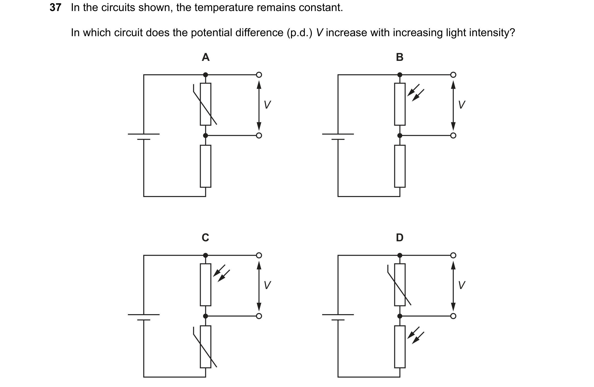
Q99 · In the circuits shown, the temperature remains constant 9702/11 May/June 2022
37 In the circuits shown, the temperature remains constant. In which circuit does the potential difference (p.d.) V increase with increasing light intensity? A B V V C D V V
1 marks
Answer: D
This question in 9702/11 May/June 2022
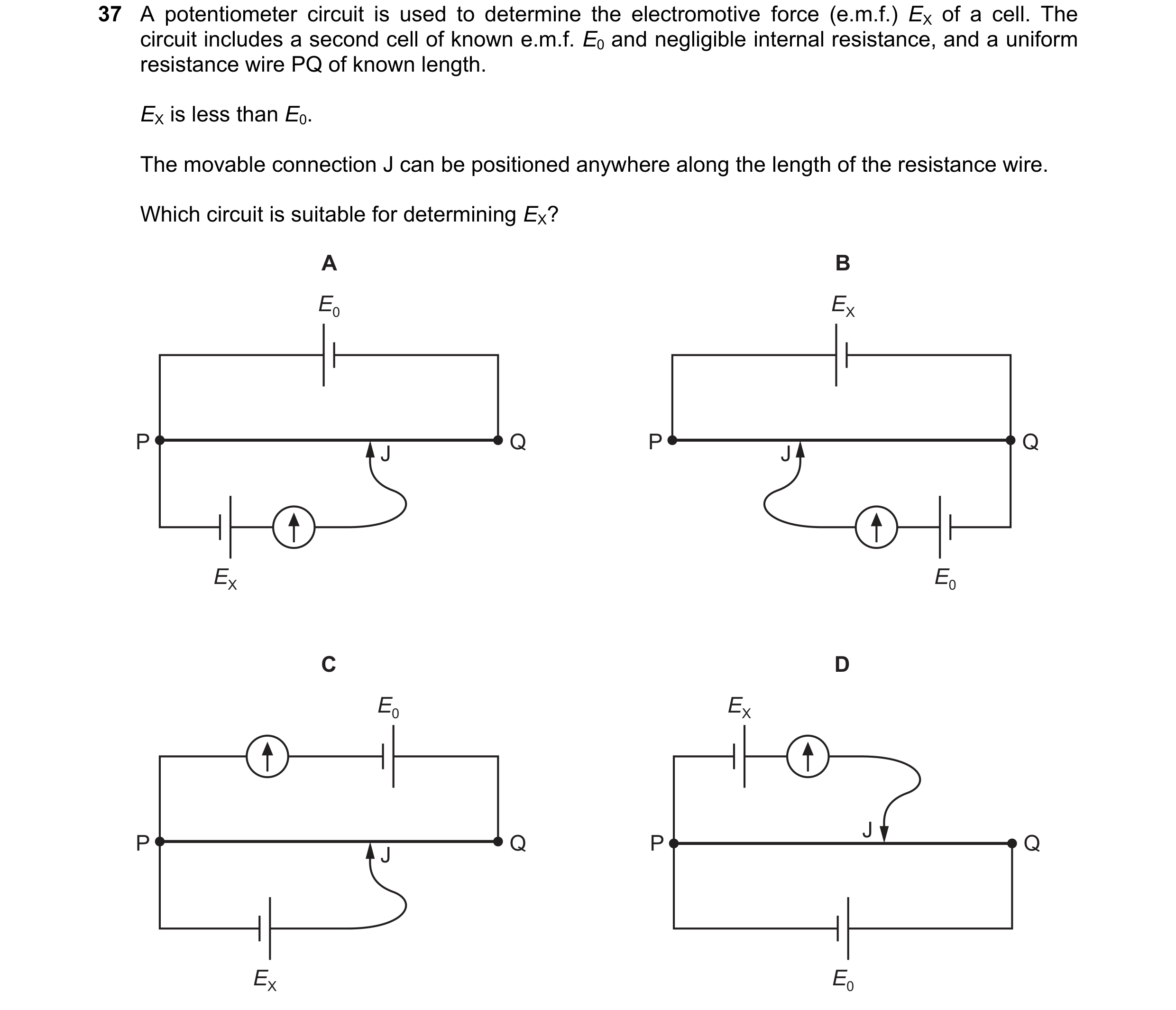
Q100 · A potentiometer circuit is used to determine the electromotive force (e.m.f.) EX of a cell 9702/12 May/June 2022
37 A potentiometer circuit is used to determine the electromotive force (e.m.f.) EX of a cell. The circuit includes a second cell of known e.m.f. E0 and negligible internal resistance, and a uniform resistance wire PQ of known length. EX is less than E0. The movable connection J can be positioned anywhere along the length of the resistance wire. Which circuit is suitable for determining EX? A B E0 EX P Q P Q J J EX E0 C D E0 EX J P Q P Q J EX E0
1 marks
Answer: D
This question in 9702/12 May/June 2022
Q101 · A battery of electromotive force (e.m.f.) 6.0 V and negligible internal resistance is… 9702/11 Oct/Nov 2022
37 A battery of electromotive force (e.m.f.) 6.0 V and negligible internal resistance is connected to a voltmeter and four other components, as shown. The voltmeter is connected between points X and Y. The positive terminal of the voltmeter is connected to X and the negative terminal of the voltmeter is connected to Y. + – 6.0 V X V Y Initially, the resistance of each of the four components is 1.0 k. Which change, on its own, will cause the voltmeter to show a positive reading? A Decrease the temperature of the thermistor. B Increase the resistance of the variable resistor. C Reduce the intensity of light incident on the light-dependent resistor (LDR). D Replace the fixed resistor with a 500 resistor.
1 marks
Answer: C
This question in 9702/11 Oct/Nov 2022
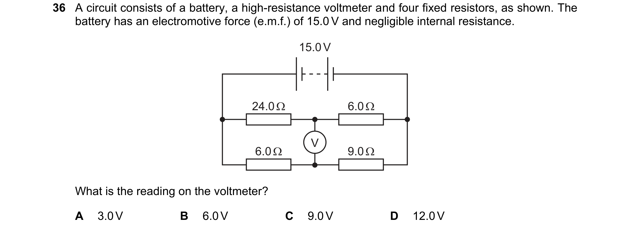
Q102 · A circuit consists of a battery, a high-resistance voltmeter and four fixed resistors, as… 9702/12 Oct/Nov 2022
36 A circuit consists of a battery, a high-resistance voltmeter and four fixed resistors, as shown. The
battery has an electromotive force (e.m.f.) of 15.0 V and negligible internal resistance.
15.0V
What is the reading on the voltmeter?
A 3.0V B 6.0V C 9.0V D 12.0V
1 marks
Answer: B
This question in 9702/12 Oct/Nov 2022
Q103 · A potential divider circuit is designed to detect the difference in temperature between… 9702/12 Oct/Nov 2022
37 A potential divider circuit is designed to detect the difference in temperature between two different places. X 20 mV Y V The cell has electromotive force (e.m.f.) 20 mV and negligible internal resistance. Initially, thermistors X and Y are at the same temperature and have the same resistance. The voltmeter reads 10 mV. X is then placed in a cold environment and its resistance doubles. Y is placed in a warm environment and its resistance halves. What is the new reading on the voltmeter? A 4 mV B 5 mV C 15 mV D 16 mV
1 marks
Answer: A
This question in 9702/12 Oct/Nov 2022
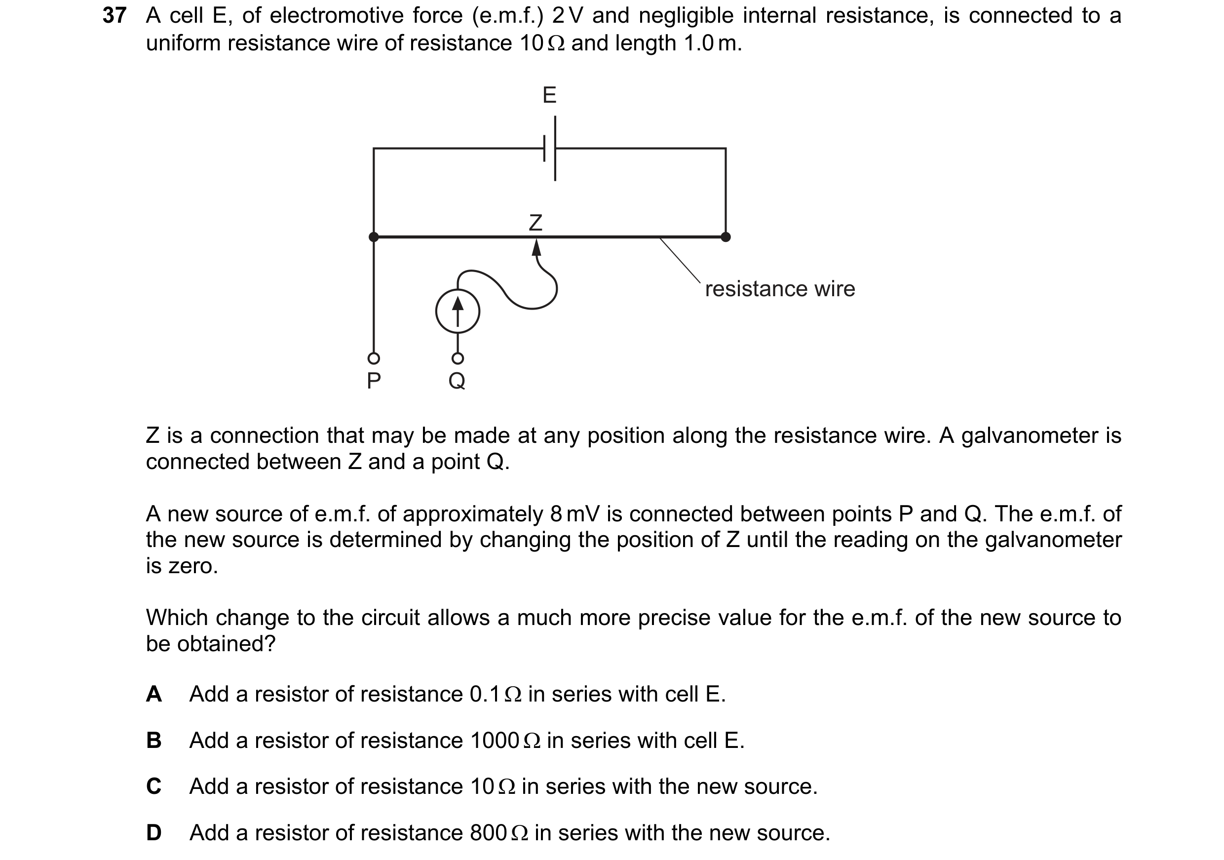
Q104 · A cell E, of electromotive force (e.m.f.) 2 V and negligible internal resistance, is… 9702/13 Oct/Nov 2022
37 A cell E, of electromotive force (e.m.f.) 2 V and negligible internal resistance, is connected to a uniform resistance wire of resistance 10 and length 1.0 m. E Z resistance wire P Q Z is a connection that may be made at any position along the resistance wire. A galvanometer is connected between Z and a point Q. A new source of e.m.f. of approximately 8 mV is connected between points P and Q. The e.m.f. of the new source is determined by changing the position of Z until the reading on the galvanometer is zero. Which change to the circuit allows a much more precise value for the e.m.f. of the new source to be obtained? A Add a resistor of resistance 0.1 in series with cell E. B Add a resistor of resistance 1000 in series with cell E. C Add a resistor of resistance 10 in series with the new source. D Add a resistor of resistance 800 in series with the new source.
1 marks
Answer: B
This question in 9702/13 Oct/Nov 2022
Q105 · A battery of negligible internal resistance is connected in series with a thermistor and… 9702/12 Feb/March 2023
37 A battery of negligible internal resistance is connected in series with a thermistor and a fixed
resistor of resistance 12.0kQ, as shown.
12.0kQ Vout
The table shows the resistance of the thermistor at two different temperatures.
temperature resistance of
[°C thermistor /kQ
20.0 12.0
50.0 5.00
The potential difference V.,, across the fixed resistor is 4.50V when the thermistor is at a
temperature of 20.0 °C.
What is Vou when the thermistor is at a temperature of 50.0°C?
A 2.65V B 3.18V C 6.35V D 10.8V
1 marks
Answer: C
This question in 9702/12 Feb/March 2023
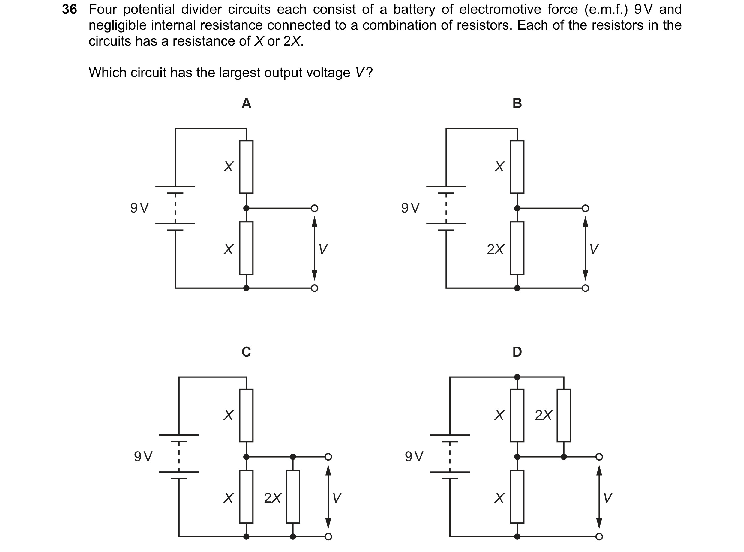
Q106 · Four potential divider circuits each consist of a battery of electromotive force (e.m.f.)… 9702/11 May/June 2023
36 Four potential divider circuits each consist of a battery of electromotive force (e.m.f.) 9 V and negligible internal resistance connected to a combination of resistors. Each of the resistors in the circuits has a resistance of X or 2X. Which circuit has the largest output voltage V ? A B X X 9 V 9 V X V 2X V C D X X 2X 9 V 9 V X 2X V X V
1 marks
Answer: B
This question in 9702/11 May/June 2023
Q107 · A voltmeter is connected into a circuit with the polarity shown 9702/11 May/June 2023
37 A voltmeter is connected into a circuit with the polarity shown. Q + – 3 V V 3 V P The sliding contact is moved to end P of the potentiometer and then to end Q. What are the two readings of the voltmeter? sliding contact sliding contact at end P at end Q A 0 V 3 V B 0 V 6 V C 3 V 3 V D 3 V 6 V
1 marks
Answer: D
This question in 9702/11 May/June 2023
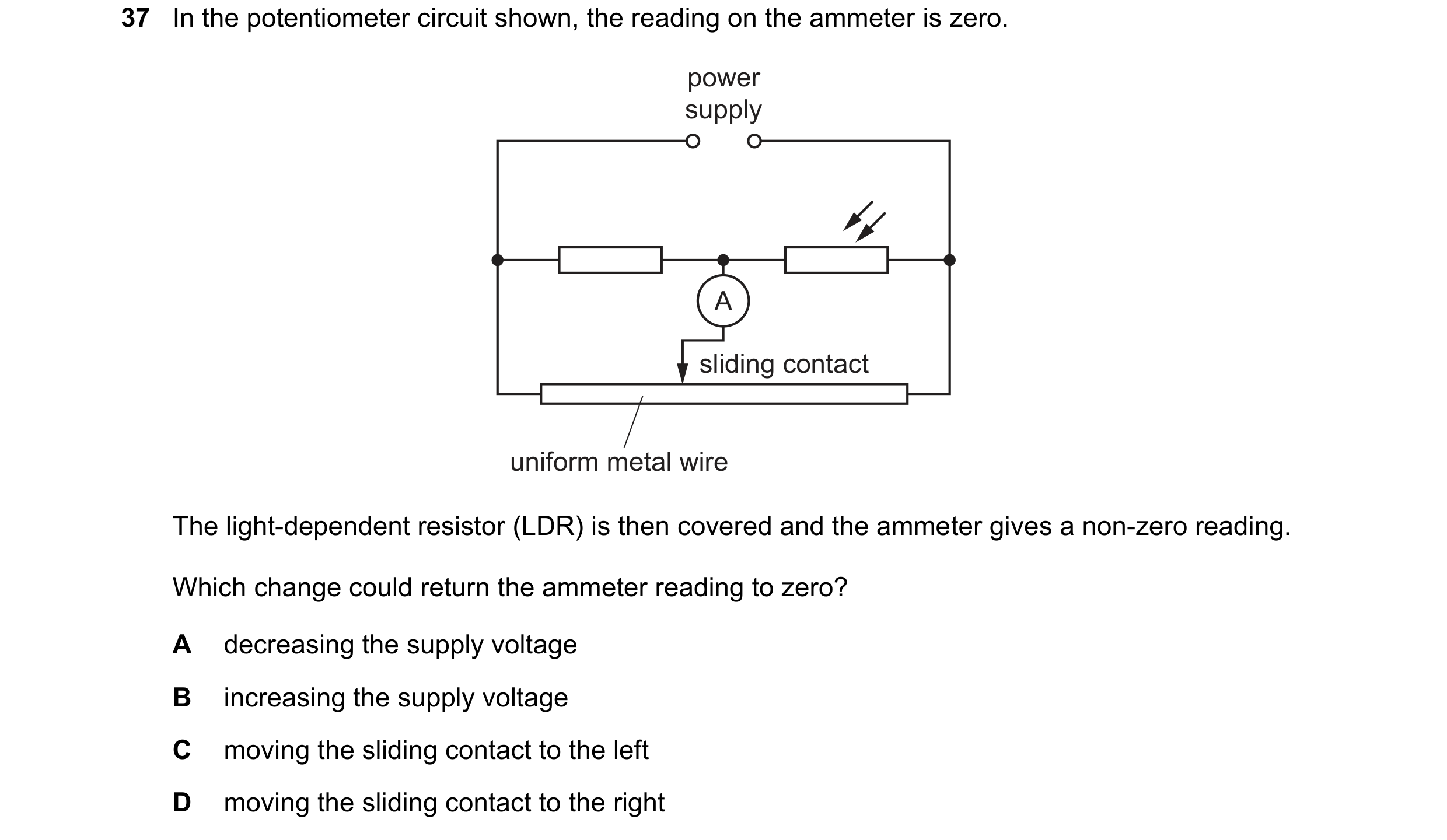
Q108 · In the potentiometer circuit shown, the reading on the ammeter is zero 9702/12 May/June 2023
37 In the potentiometer circuit shown, the reading on the ammeter is zero. power supply A sliding contact uniform metal wire The light-dependent resistor (LDR) is then covered and the ammeter gives a non-zero reading. Which change could return the ammeter reading to zero? A decreasing the supply voltage B increasing the supply voltage C moving the sliding contact to the left D moving the sliding contact to the right
1 marks
Answer: C
This question in 9702/12 May/June 2023
Q109 · A potentiometer circuit is used to investigate the electromotive force (e.m.f.) of a cell… 9702/13 May/June 2023
37 A potentiometer circuit is used to investigate the electromotive force (e.m.f.) of a cell X. driver cell 2.0 V Q P R sliding contact X resistance wire The e.m.f. of cell X is known to be approximately 0.50 V. The driver cell has negligible internal resistance and an e.m.f. of 2.0 V. The sliding contact is moved along the uniform resistance wire between ends Q and R to a point P where the reading on the galvanometer is zero. What is an expression for the approximate length QP? QR QR 2QR 3QR A B C D 4 3 3 4
1 marks
Answer: A
This question in 9702/13 May/June 2023
Q110 · In the circuit shown, a battery of negligible internal resistance is connected in series… 9702/12 Oct/Nov 2023
37 In the circuit shown, a battery of negligible internal resistance is connected in series with a pair of fixed resistors R1 and R2. R1 60 Ω 6.0 V X R2 20 Ω Y The circuit is to be used to test whether the electromotive force (e.m.f.) of a particular cell is 1.5 V. The cell is connected between terminals X and Y in parallel with R2 and in series with a galvanometer. Which statement about the test is correct? A Any non-zero reading on the galvanometer means the cell has an e.m.f. of 1.5 V. B The battery does not need to have an e.m.f. of 6.0 V. C The cell may be connected either way round between X and Y. D The galvanometer does not need a scale calibrated in amperes.
1 marks
Answer: D
This question in 9702/12 Oct/Nov 2023
Q111 · A battery of electromotive force (e.m.f.) 12V and negligible internal resistance is… 9702/13 Oct/Nov 2023
33 A battery of electromotive force (e.m.f.) 12V and negligible internal resistance is connected to a
fixed resistor of resistance 40 Q and a thermistor of resistance R;, as shown.
400
R;
Initially, the temperature of the thermistor is 15°C and the current in the circuit is 0.10A.
The temperature of the thermistor then changes, which causes the current to increase to 0.12A.
How does the temperature of the thermistor change and what is Ry; at the new temperature?
temperature Ry at new
of thermistor temperature /Q
A increases 60
B decreases 60
Cc increases 100
D decreases 100
1 marks
Answer: A
This question in 9702/13 Oct/Nov 2023
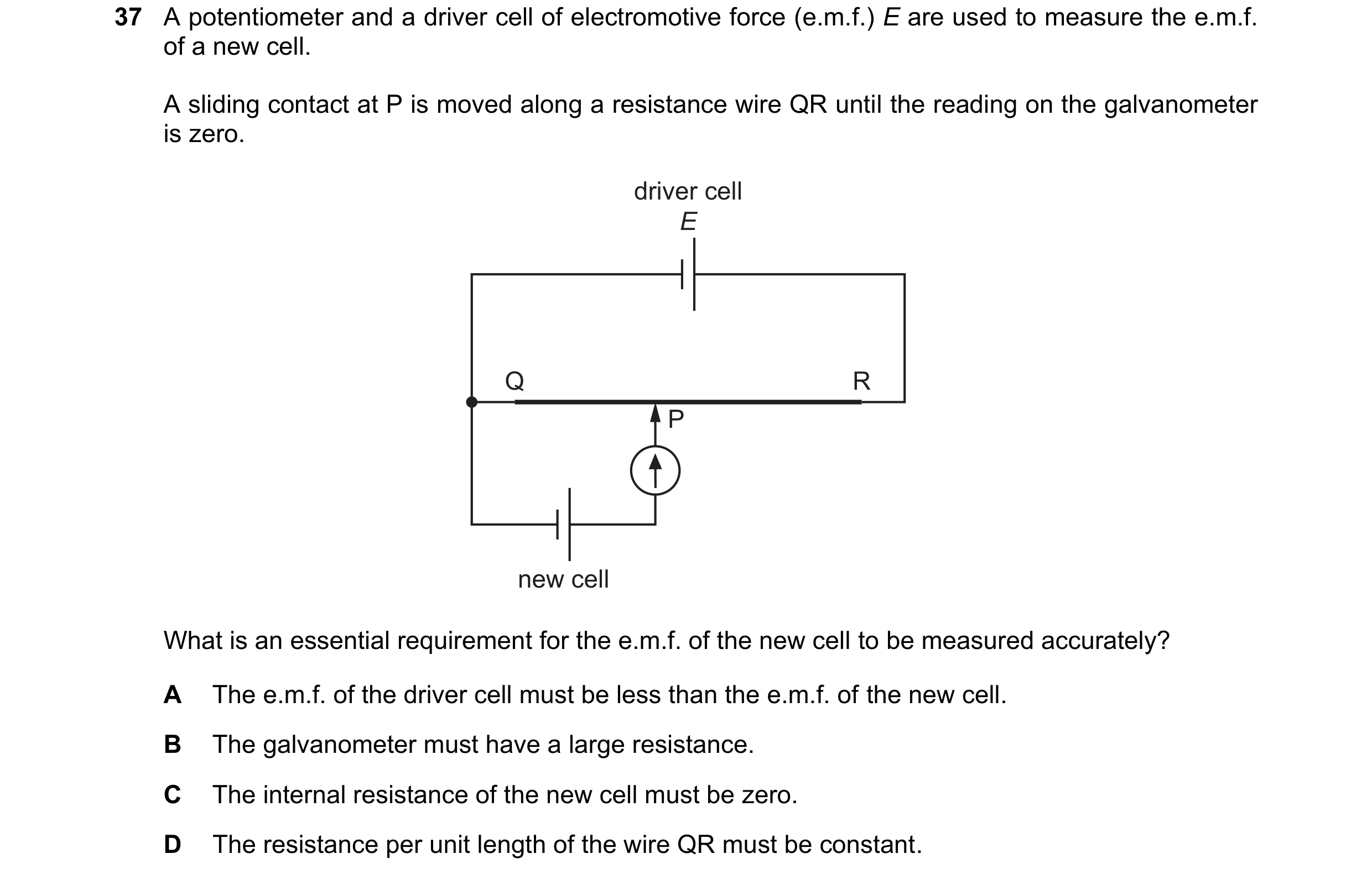
Q112 · A potentiometer and a driver cell of electromotive force (e.m.f.) E are used to measure… 9702/13 Oct/Nov 2023
37 A potentiometer and a driver cell of electromotive force (e.m.f.) E are used to measure the e.m.f. of a new cell. A sliding contact at P is moved along a resistance wire QR until the reading on the galvanometer is zero. driver cell E Q R P new cell What is an essential requirement for the e.m.f. of the new cell to be measured accurately? A The e.m.f. of the driver cell must be less than the e.m.f. of the new cell. B The galvanometer must have a large resistance. C The internal resistance of the new cell must be zero. D The resistance per unit length of the wire QR must be constant.
1 marks
Answer: D
This question in 9702/13 Oct/Nov 2023
Q113 · Which circuit results in output voltage Vout increasing with increasing temperature? 9702/11 May/June 2024
33 Which circuit results in output voltage Vout increasing with increasing temperature? A B Vout Vout C D Vout Vout
1 marks
Answer: C
This question in 9702/11 May/June 2024
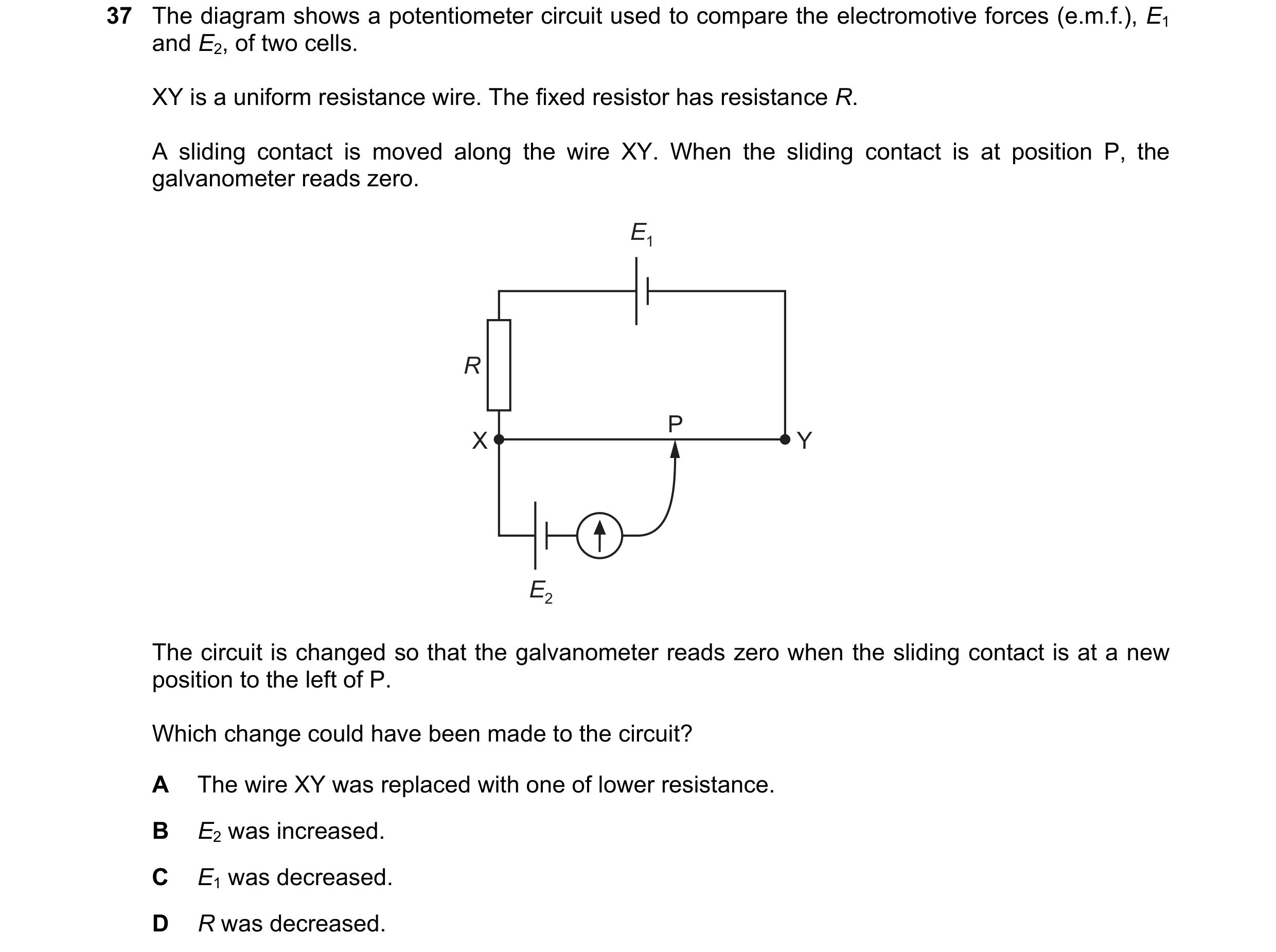
Q114 · The diagram shows a potentiometer circuit used to compare the electromotive forces… 9702/13 May/June 2024
37 The diagram shows a potentiometer circuit used to compare the electromotive forces (e.m.f.), E1 and E2, of two cells. XY is a uniform resistance wire. The fixed resistor has resistance R. A sliding contact is moved along the wire XY. When the sliding contact is at position P, the galvanometer reads zero. E1 R P X Y E2 The circuit is changed so that the galvanometer reads zero when the sliding contact is at a new position to the left of P. Which change could have been made to the circuit? A The wire XY was replaced with one of lower resistance. B E2 was increased. C E1 was decreased. D R was decreased.
1 marks
Answer: D
This question in 9702/13 May/June 2024
Q115 · The diagram shows a circuit with a light-dependent resistor (LDR) 9702/11 Oct/Nov 2024
32 The diagram shows a circuit with a light-dependent resistor (LDR).
6.0kQ
The ammeter reads zero current.
What is the resistance of the LDR?
A 6.0kQ B 18kQ C 26kQ D 30kQ
1 marks
Answer: B
This question in 9702/11 Oct/Nov 2024
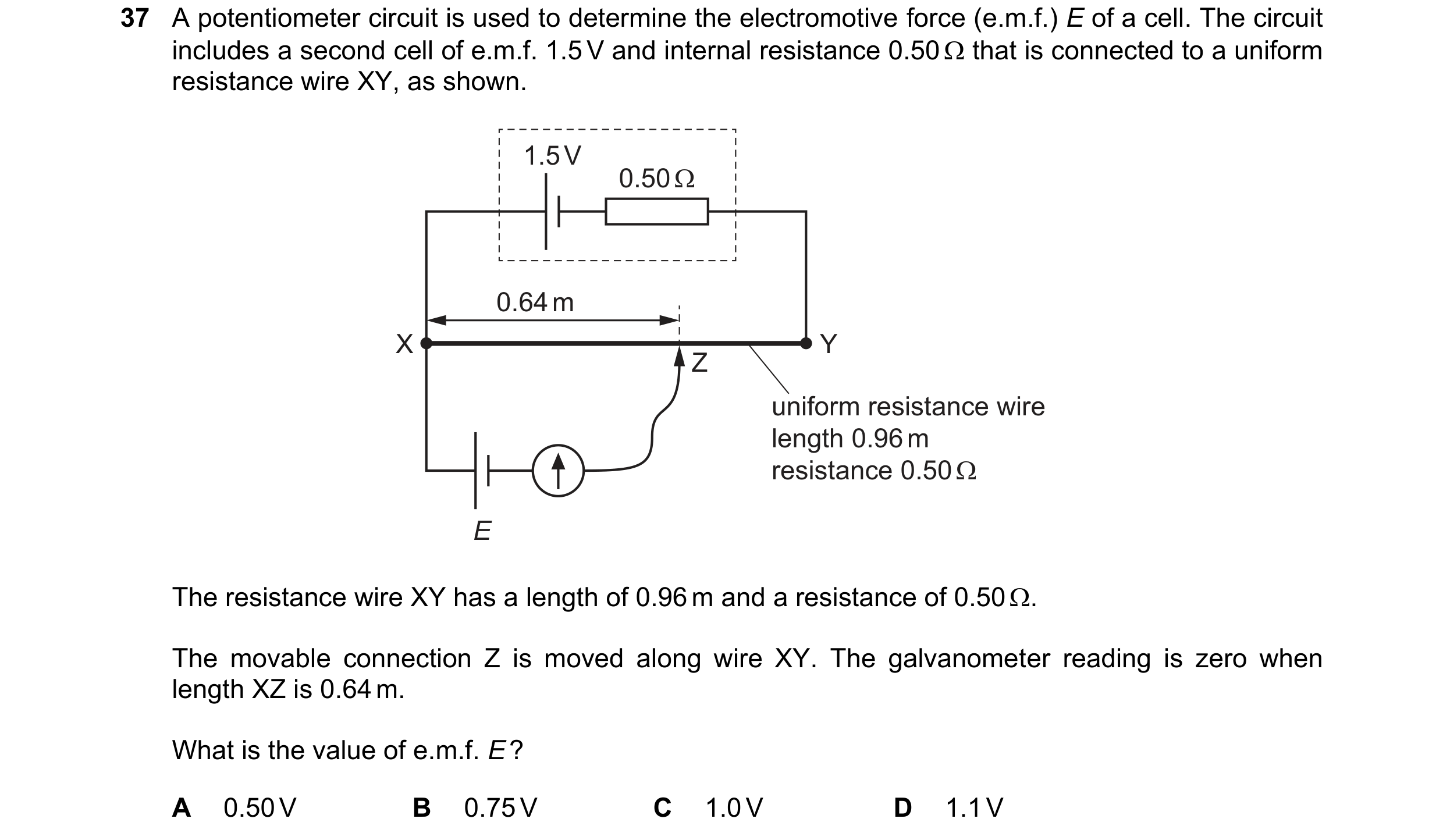
Q116 · A potentiometer circuit is used to determine the electromotive force (e.m.f.) E of a cell 9702/11 Oct/Nov 2024
37 A potentiometer circuit is used to determine the electromotive force (e.m.f.) E of a cell. The circuit
includes a second cell of e.m.f. 1.5 V and internal resistance 0.50 that is connected to a uniform
resistance wire XY, as shown.
poo oe
bee e ee s
uniform resistance wire
length 0.96m
resistance 0.50Q
E
The resistance wire XY has a length of 0.96 m and a resistance of 0.500.
The movable connection Z is moved along wire XY. The galvanometer reading is zero when
length XZ is 0.64m.
What is the value of e.m.f. E?
A 0.50V B 0.75V C 1.0V D 1.1V
1 marks
Answer: A
This question in 9702/11 Oct/Nov 2024
Q117 · The diagram shows part of a circuit that uses a potentiometer wire to measure a potential… 9702/13 Oct/Nov 2024
35 The diagram shows part of a circuit that uses a potentiometer wire to measure a potential difference (p.d.) in an external circuit. E I1 L1 Y X Z L2 I2 P Q The potentiometer wire XZ has length L1. It is connected to a cell of known electromotive force (e.m.f.) E that has negligible internal resistance. Terminals P and Q are connected to the external p.d. to be measured. The length of the potentiometer wire between points X and Y is L2. The ratio of the lengths L1 and L2 is used to determine the p.d. between P and Q in terms of E. Which condition must be met in order to determine this p.d.? A The current I1 must be zero. B The current I2 must be zero. C The p.d. across YZ must be zero. D The resistance of the external circuit must be zero.
1 marks
Answer: B
This question in 9702/13 Oct/Nov 2024
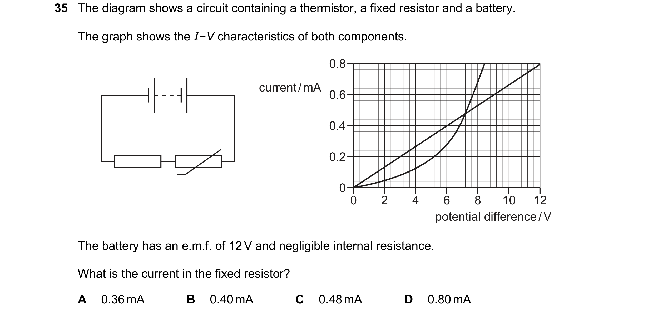
Q118 · The diagram shows a circuit containing a thermistor, a fixed resistor and a battery 9702/11 May/June 2025
35 The diagram shows a circuit containing a thermistor, a fixed resistor and a battery. The graph shows the I−V characteristics of both components. 0.8 current / mA 0.6 0.4 0.2 0 0 2 4 6 8 10 12 potential difference / V The battery has an e.m.f. of 12 V and negligible internal resistance. What is the current in the fixed resistor? A 0.36 mA B 0.40 mA C 0.48 mA D 0.80 mA
1 marks
Answer: A
This question in 9702/11 May/June 2025
Q119 · The diagram shows a cell of internal resistance 1.0R connected to a variable resistor 9702/12 May/June 2025
35 The diagram shows a cell of internal resistance 1.0R connected to a variable resistor. 1.0R When the variable resistor has an initial resistance of 2.0R, the current in the cell is I1 and the terminal potential difference (p.d.) across the cell is V1. The variable resistor is now adjusted to a new resistance of 4.0R. What is the new current in the cell and the new terminal p.d. across the cell? current terminal p.d. A 0.50I1 1.0V1 B 0.50I1 1.2V1 C 0.60I1 1.0V1 D 0.60I1 1.2V1
1 marks
Answer: D
This question in 9702/12 May/June 2025
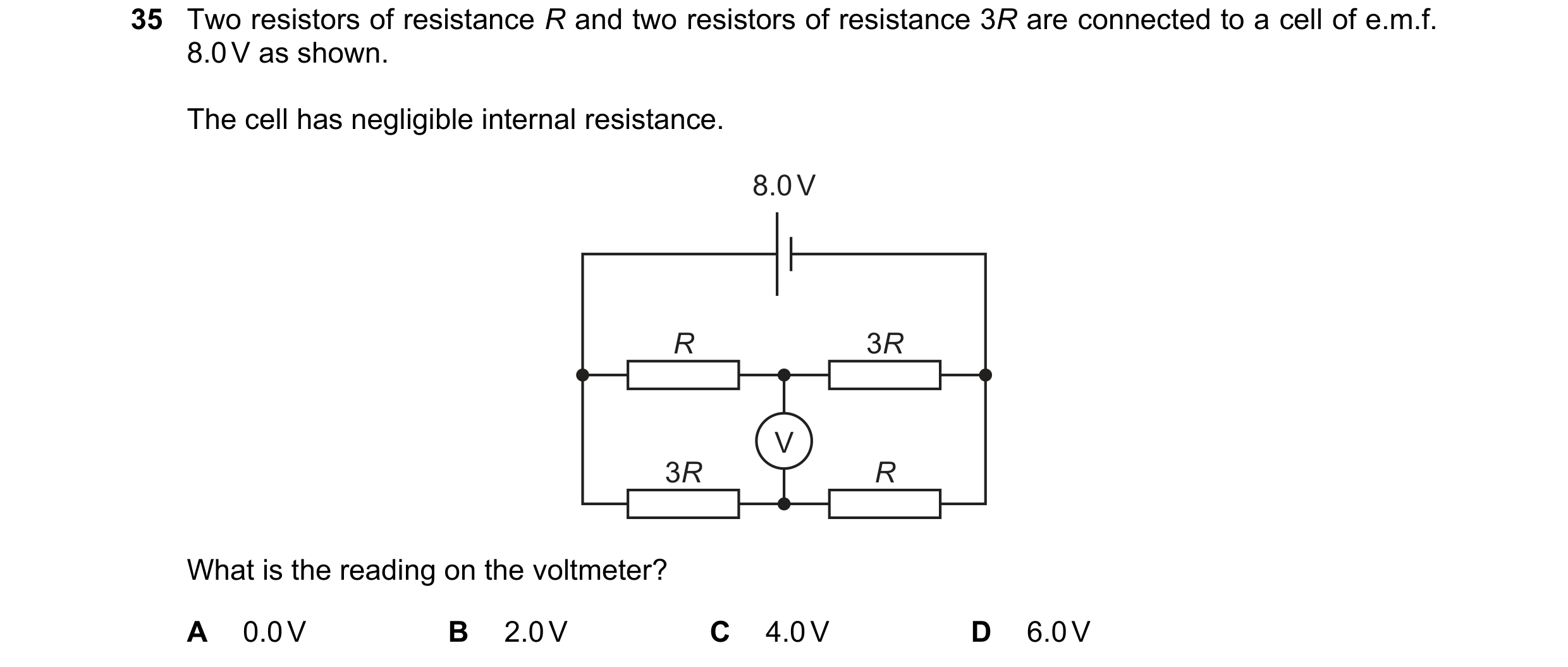
Q120 · Two resistors of resistance R and two resistors of resistance 3R are connected to a cell… 9702/13 May/June 2025
35 Two resistors of resistance R and two resistors of resistance 3R are connected to a cell of e.m.f. 8.0 V as shown. The cell has negligible internal resistance. 8.0 V R 3R V 3R R What is the reading on the voltmeter? A 0.0 V B 2.0 V C 4.0 V D 6.0 V
1 marks
Answer: C
This question in 9702/13 May/June 2025
Q121 · A battery of electromotive force (e.m.f.) 6.0V and negligible internal resistance is… 9702/14 May/June 2025
35 A battery of electromotive force (e.m.f.) 6.0V and negligible internal resistance is connected to
three resistors, as shown.
OV
6
my
60Q
0.12A
The current in the battery is 0.12A.
What is resistance R?
A 12Q B 300 C 500 D 60
1 marks
Answer: B
This question in 9702/14 May/June 2025
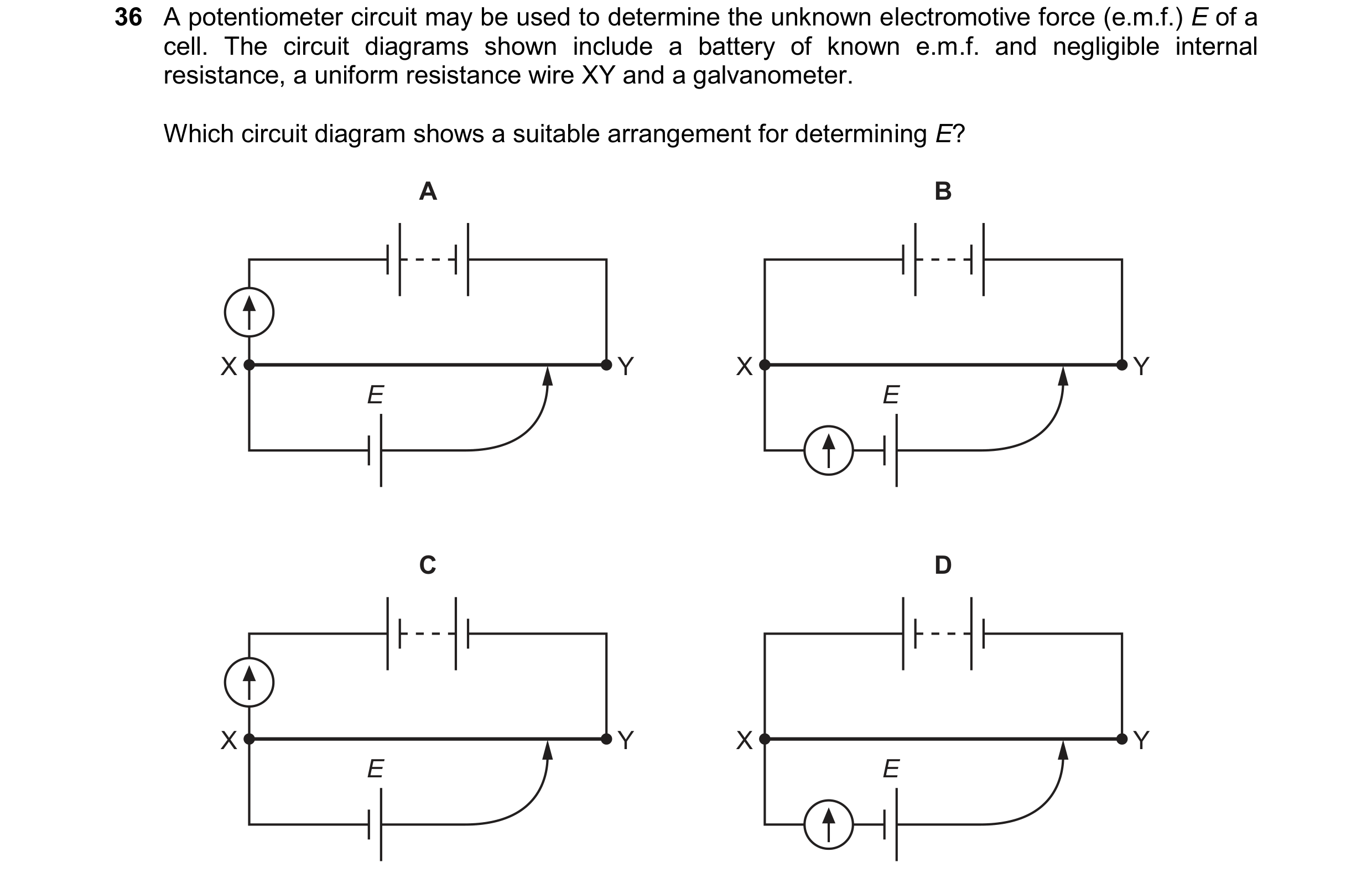
Q122 · A potentiometer circuit may be used to determine the unknown electromotive force (e.m.f.)… 9702/14 May/June 2025
36 A potentiometer circuit may be used to determine the unknown electromotive force (e.m.f.) E of a cell. The circuit diagrams shown include a battery of known e.m.f. and negligible internal resistance, a uniform resistance wire XY and a galvanometer. Which circuit diagram shows a suitable arrangement for determining E? A B X Y X Y E E C D X Y X Y E E
1 marks
Answer: B
This question in 9702/14 May/June 2025
Q123 · The diagram shows a circuit with a battery of electromotive force (e.m.f.) 60 V and… 9702/12 Oct/Nov 2025
35 The diagram shows a circuit with a battery of electromotive force (e.m.f.) 60 V and negligible internal resistance, a 20 k resistor, a thermistor and a voltmeter. The resistance of the thermistor is 20 k. V 60 V The temperature of the thermistor decreases, and this causes its resistance to change by 50%. After this change, what is the reading on the voltmeter? A 20 V B 24 V C 36 V D 40 V
1 marks
Answer: B
This question in 9702/12 Oct/Nov 2025
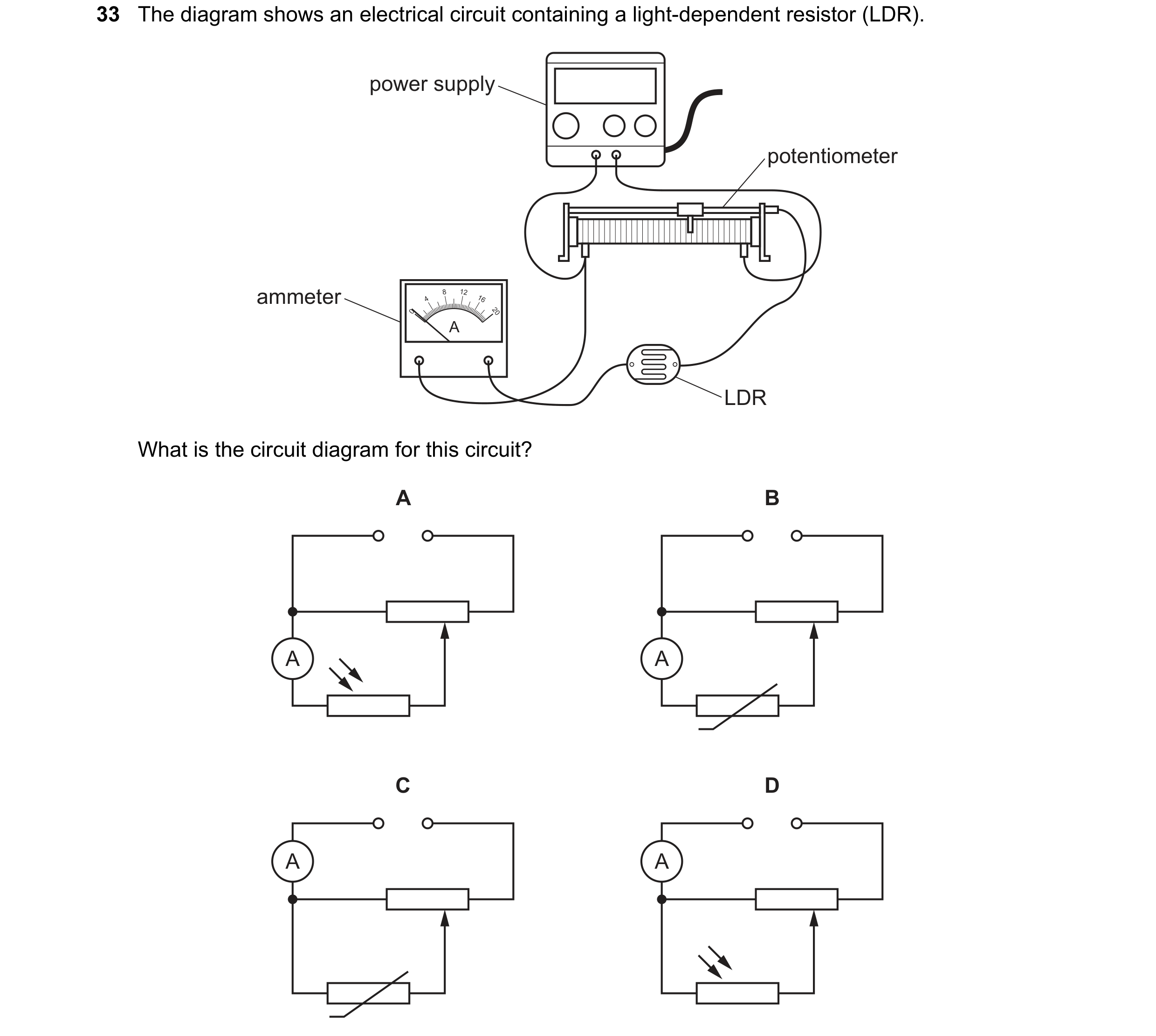
Q124 · The diagram shows an electrical circuit containing a light-dependent resistor (LDR) 9702/14 Oct/Nov 2025
33 The diagram shows an electrical circuit containing a light-dependent resistor (LDR). power supply potentiometer ammeter 4 8 12 16 0 20 A LDR What is the circuit diagram for this circuit? A B A A C D A A
1 marks
Answer: A
This question in 9702/14 Oct/Nov 2025
 1 / 67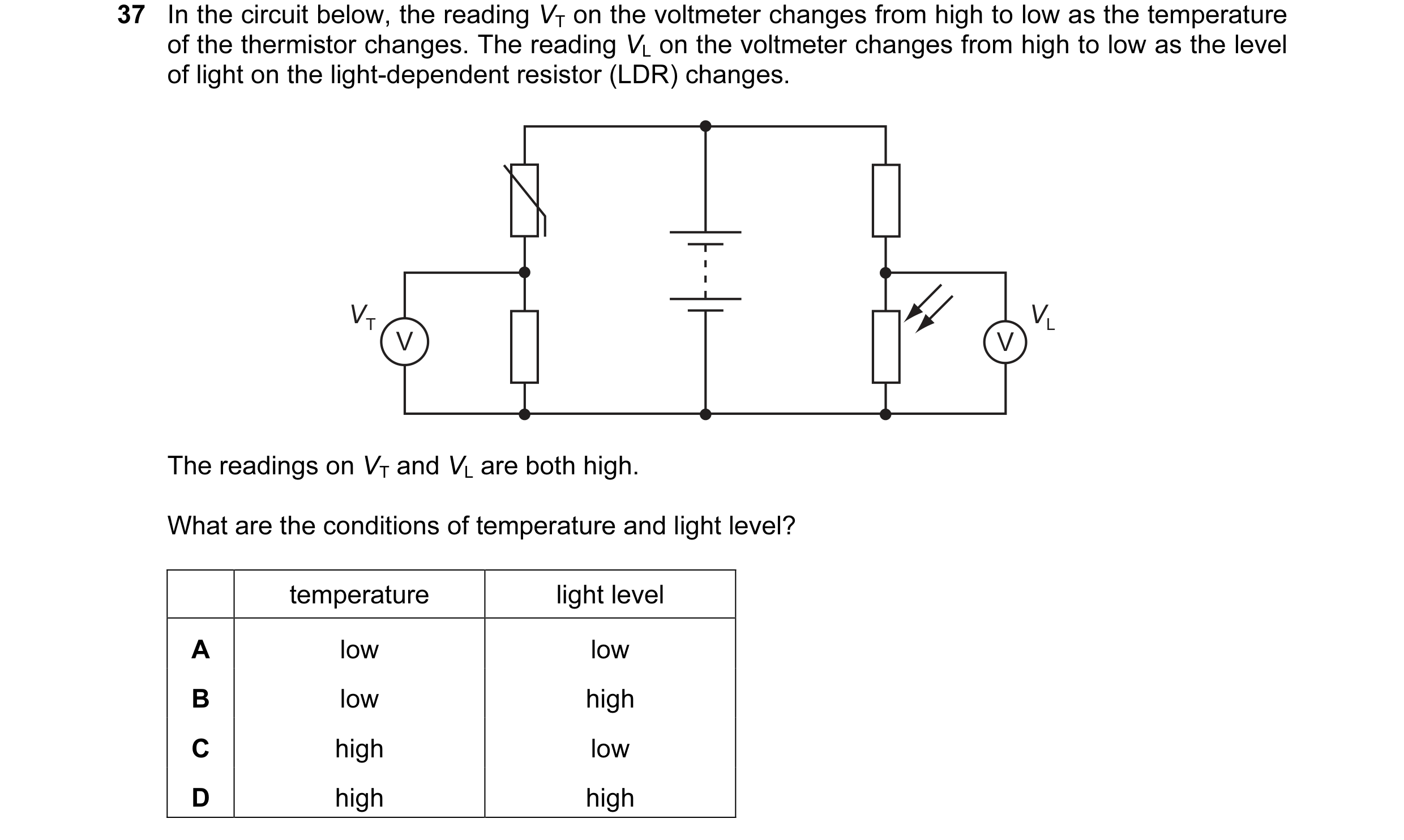
 2 / 67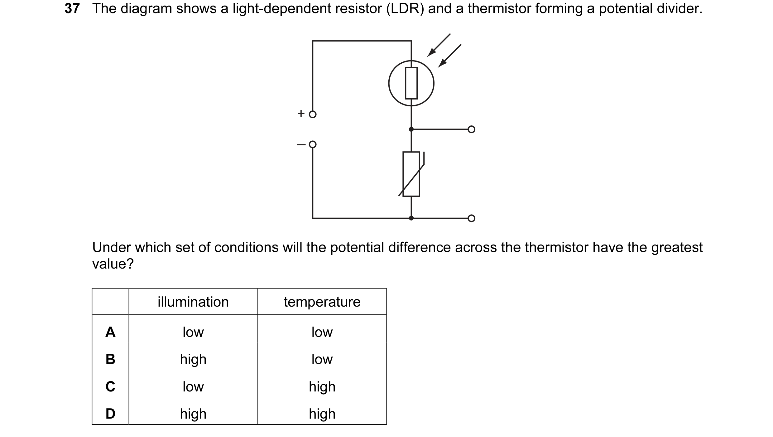
 3 / 67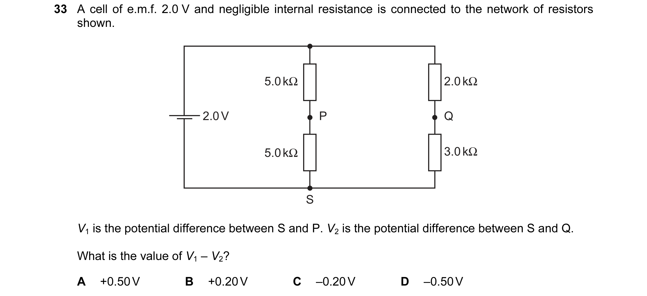
 4 / 67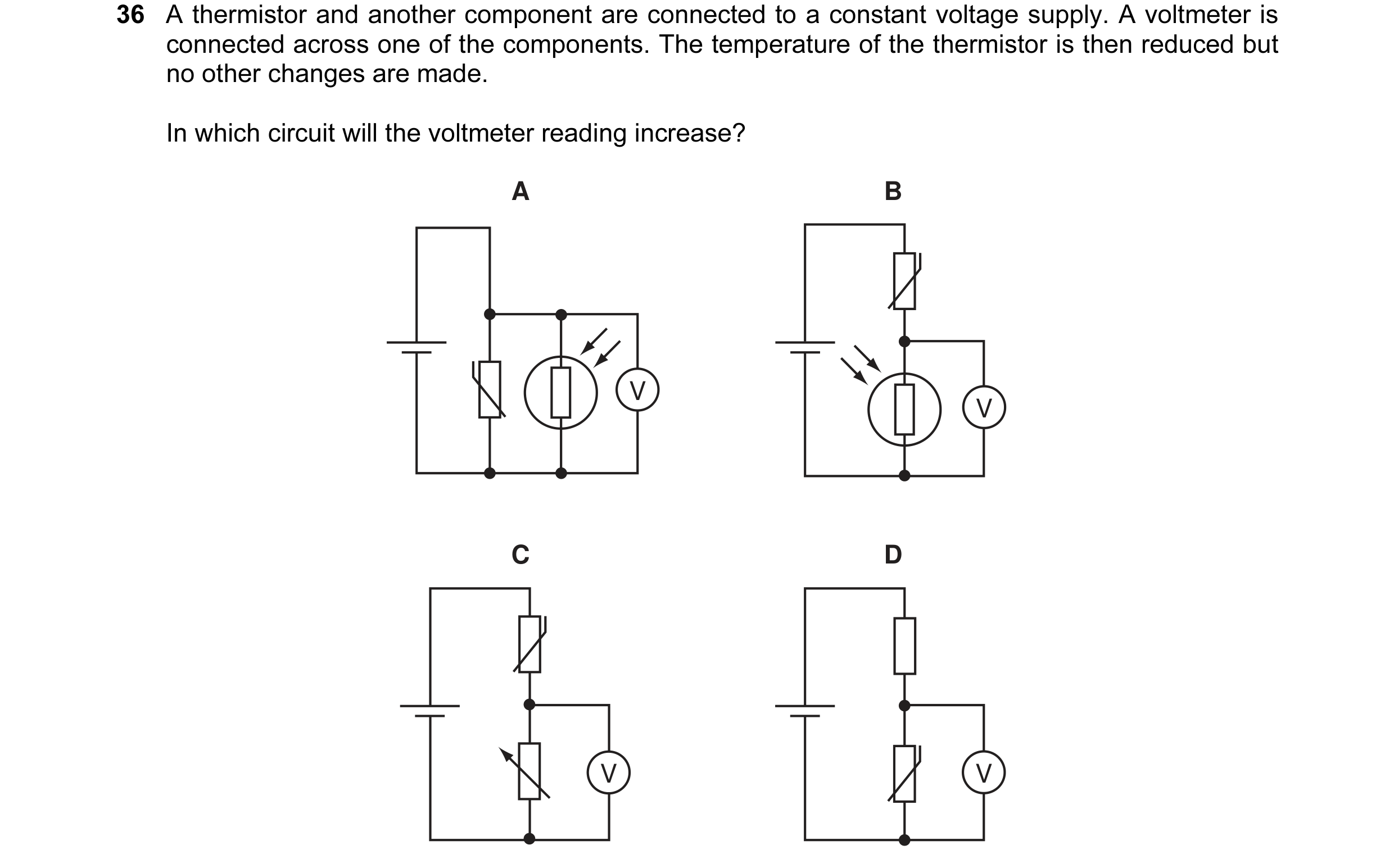
 5 / 67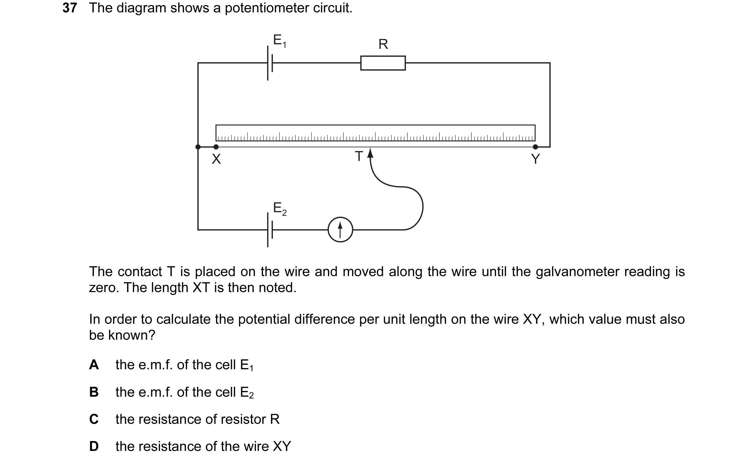
 6 / 67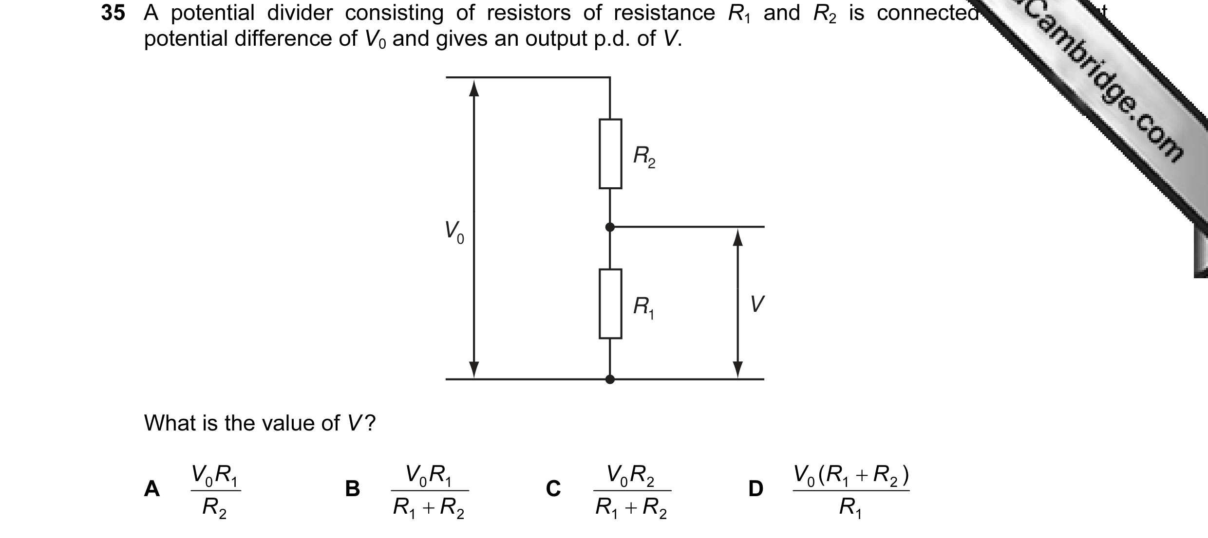
 7 / 67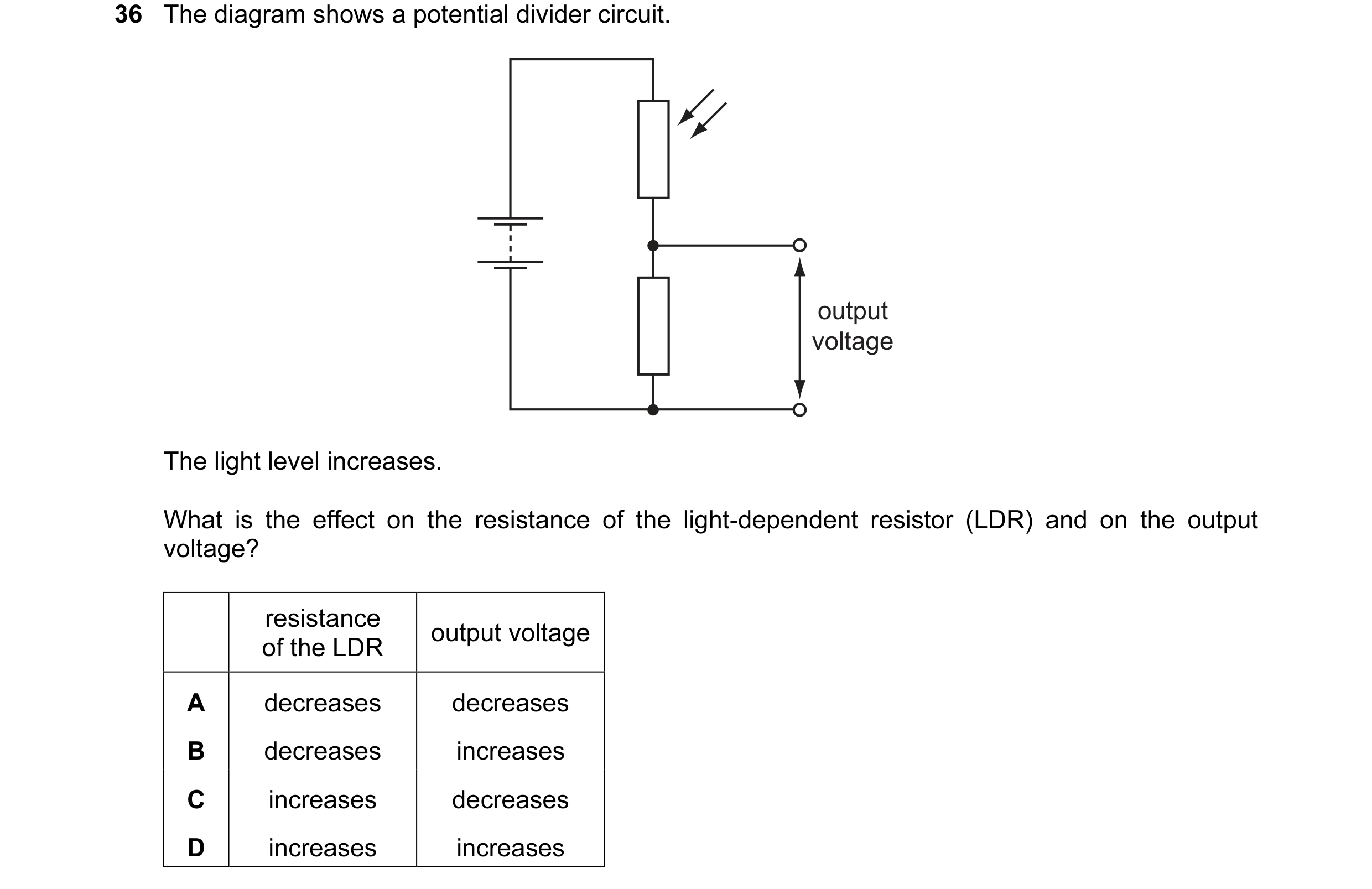
 8 / 67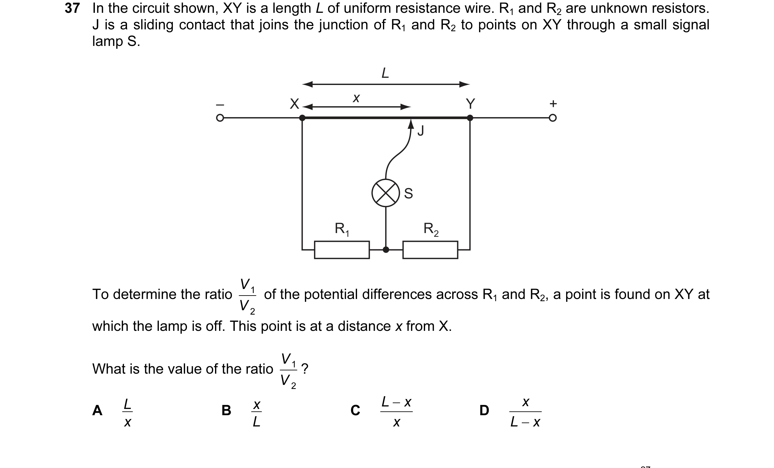
 9 / 67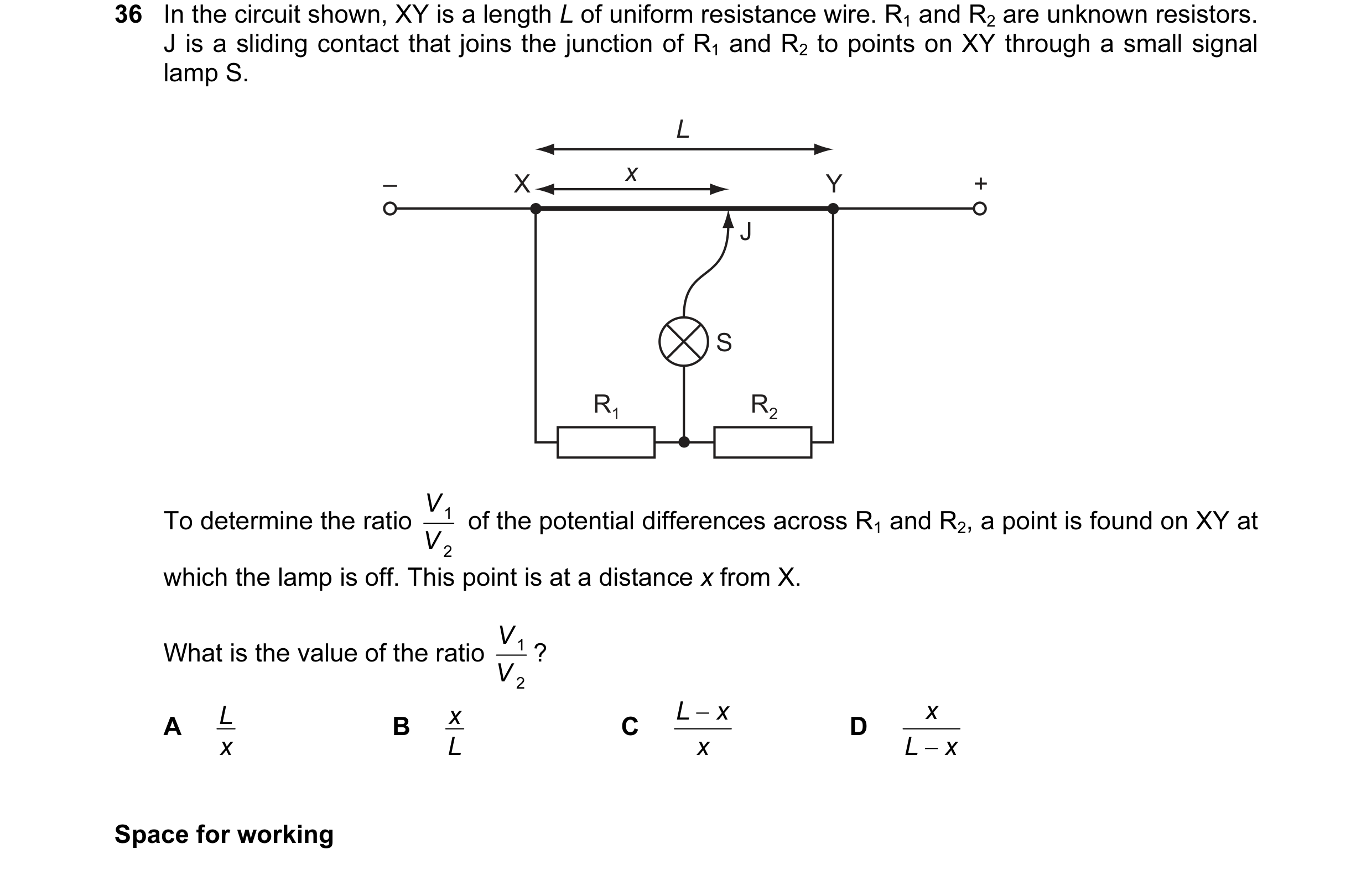
 10 / 67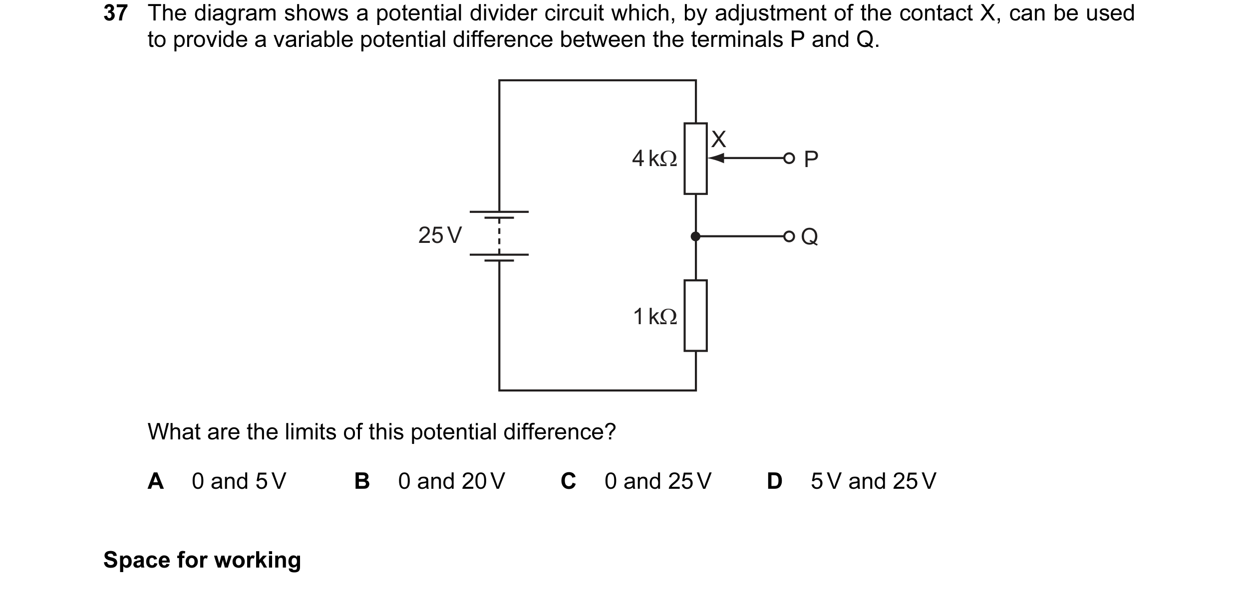
 11 / 67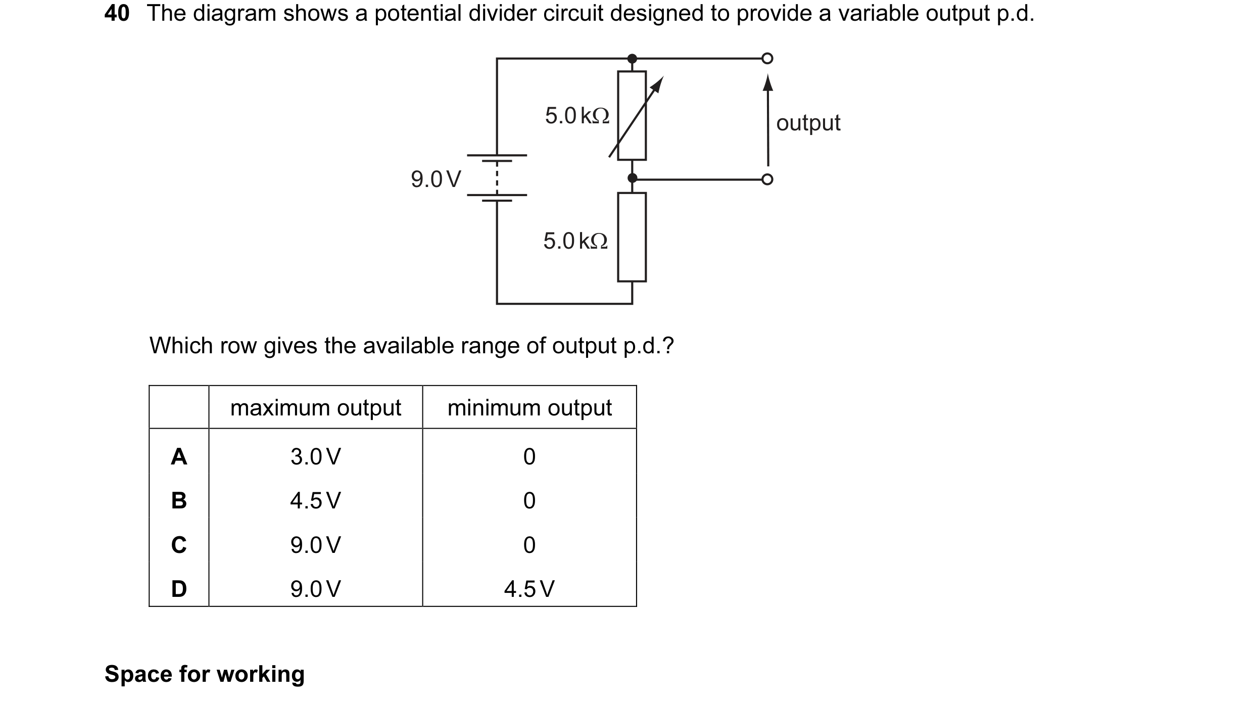
 12 / 67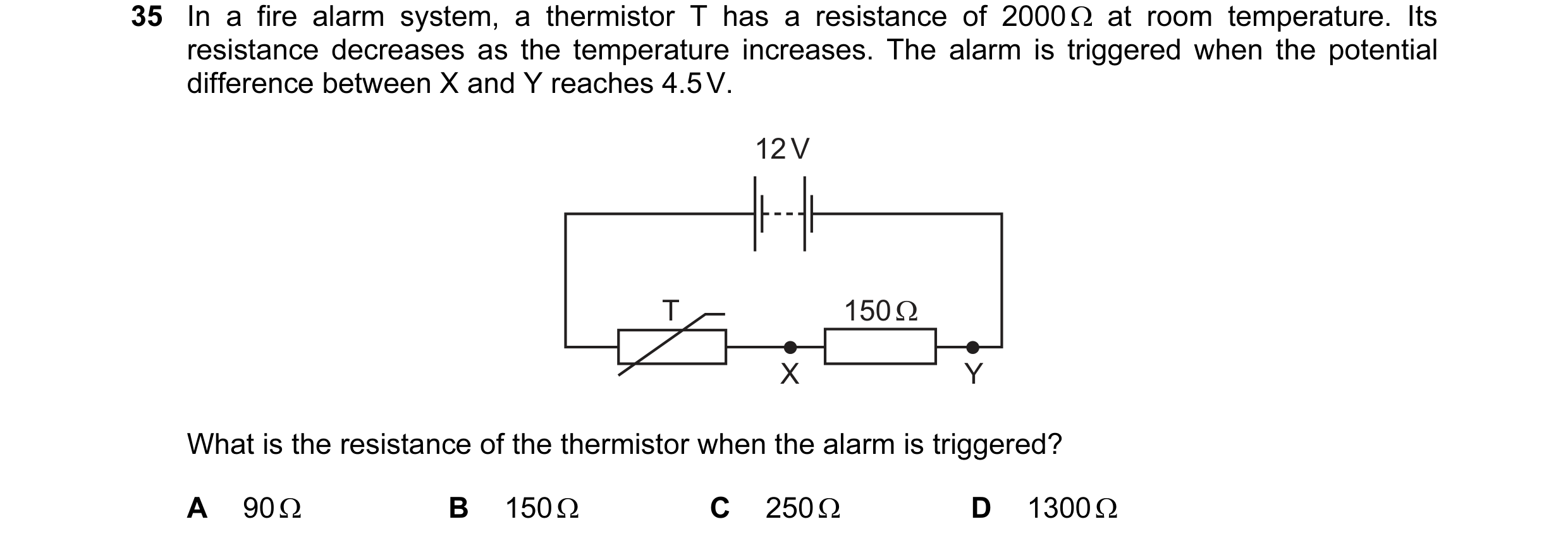
 13 / 67
 14 / 67
 15 / 67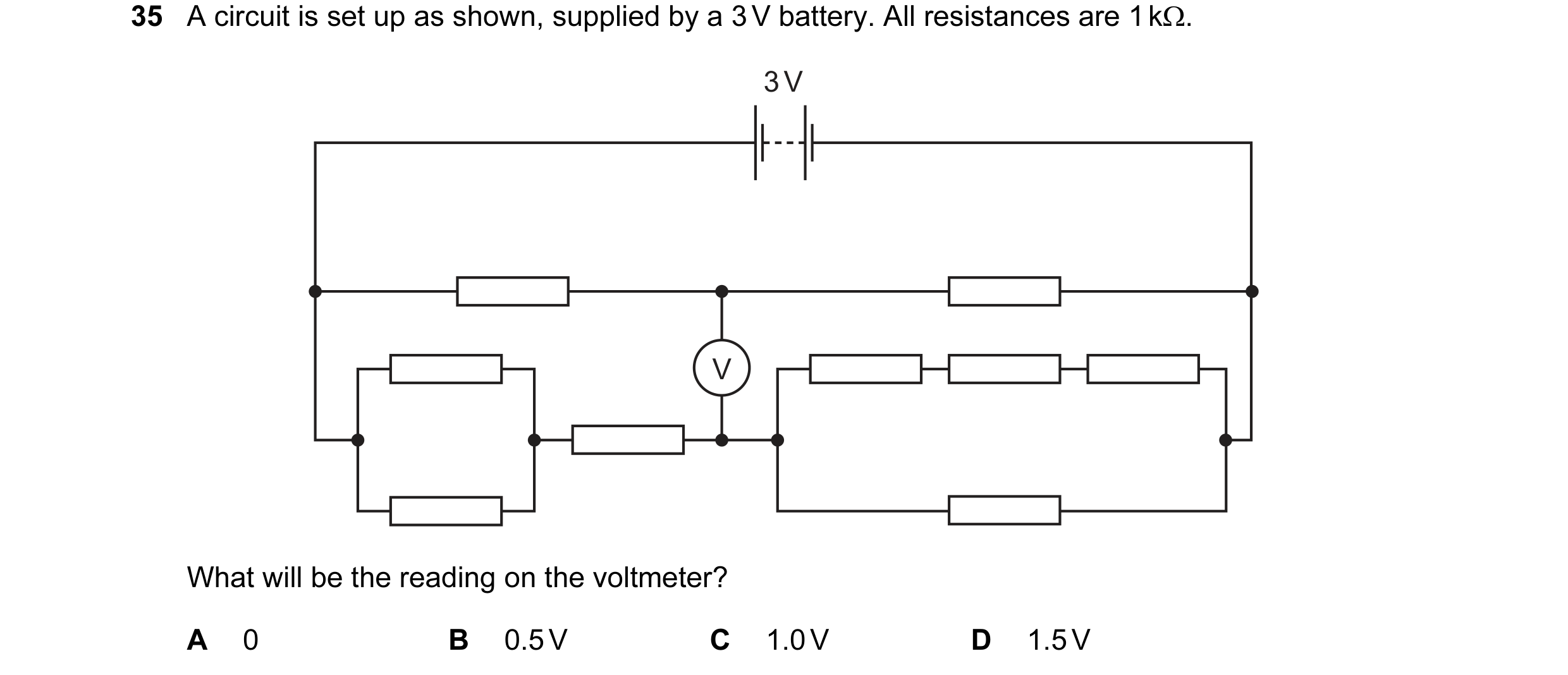
 16 / 67
 17 / 67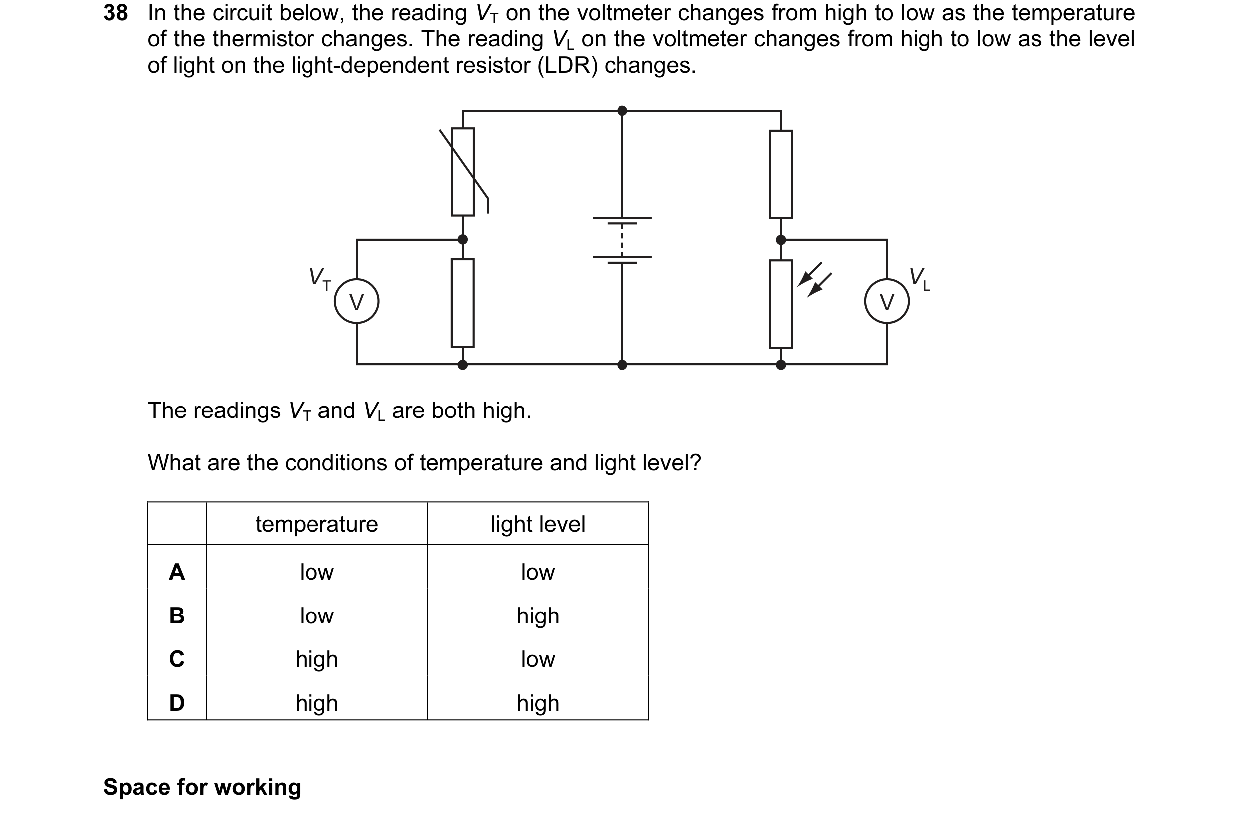
 18 / 67
 19 / 67
 20 / 67
 21 / 67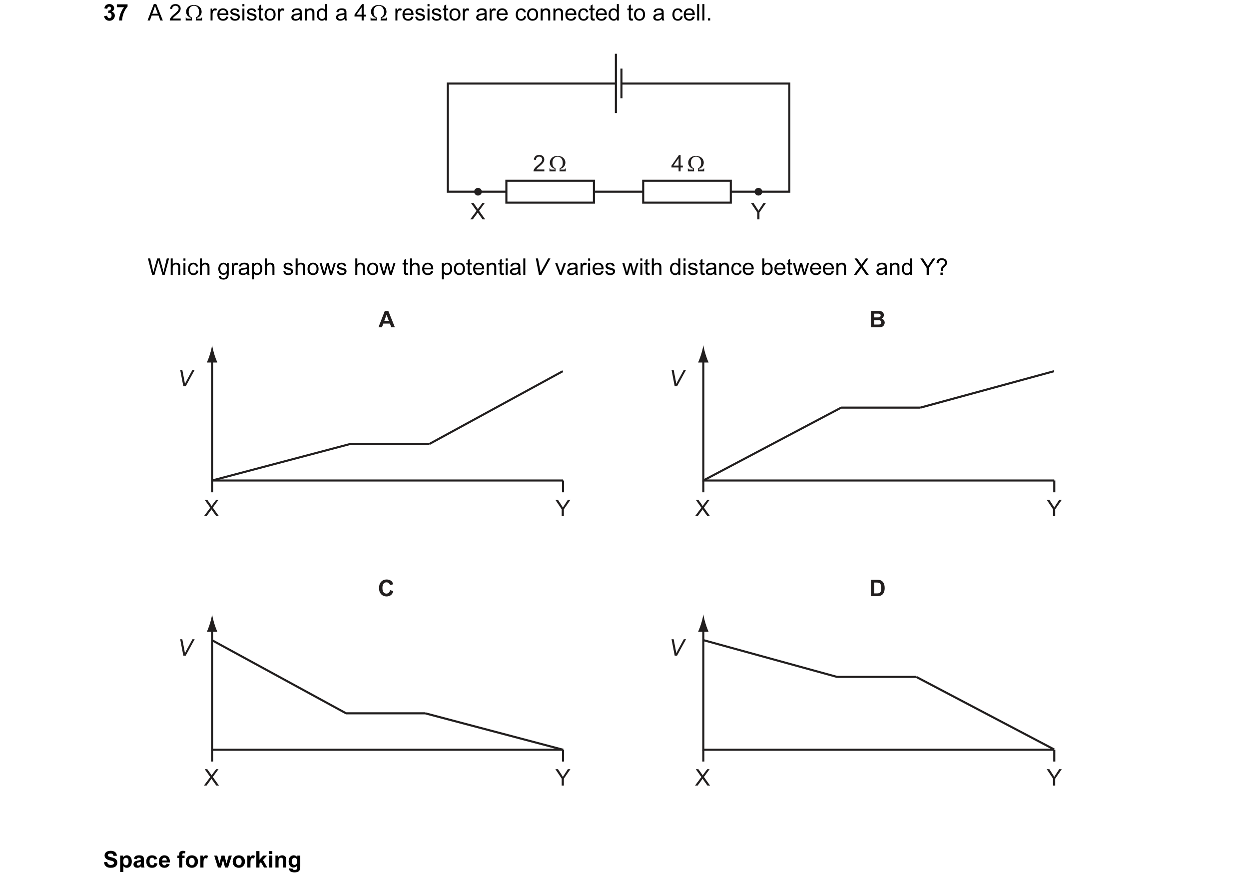
 22 / 67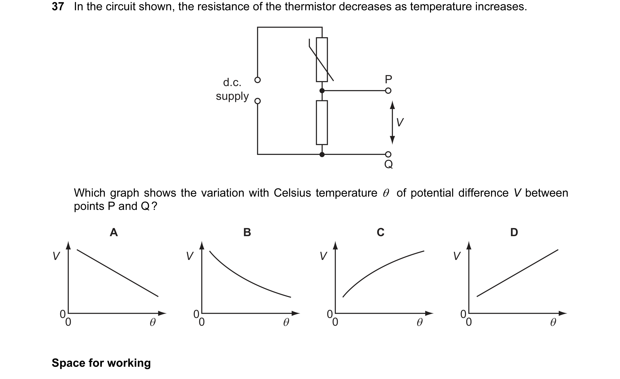
 23 / 67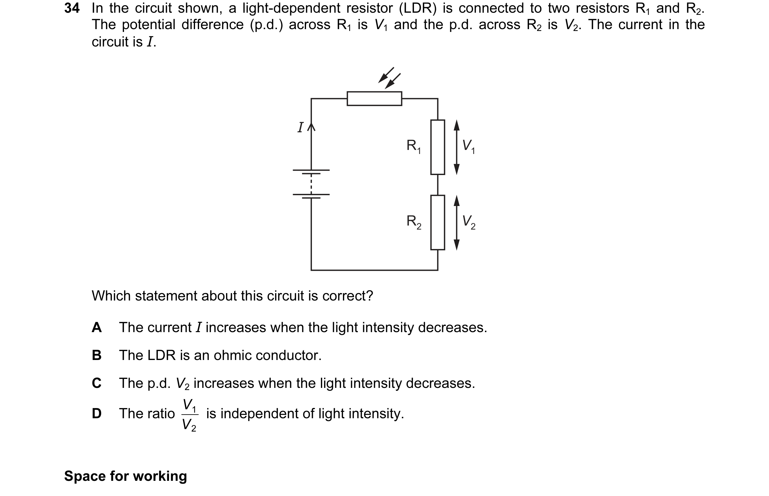
 24 / 67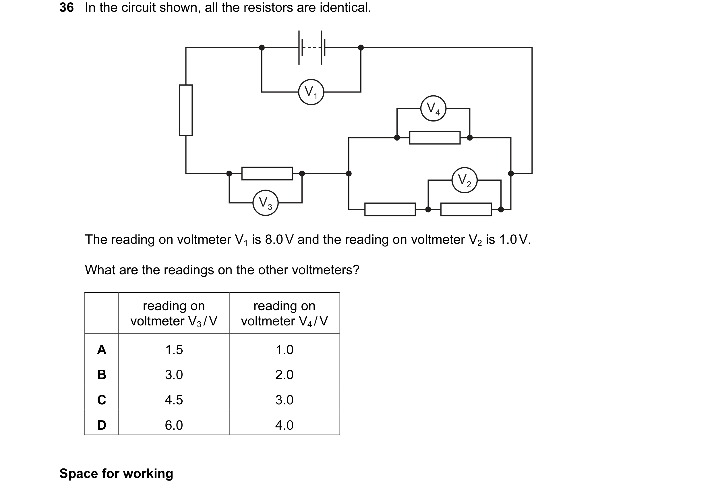
 25 / 67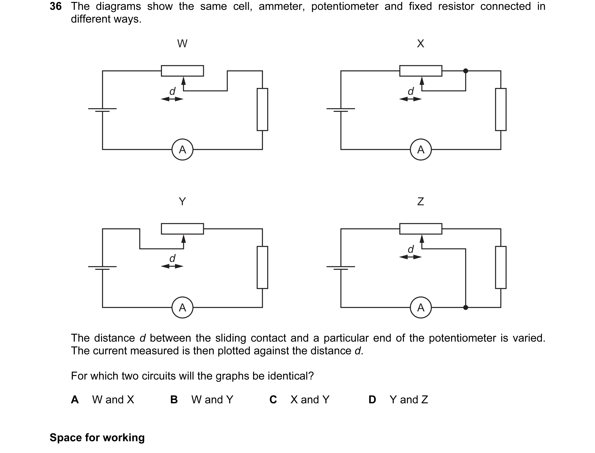
 26 / 67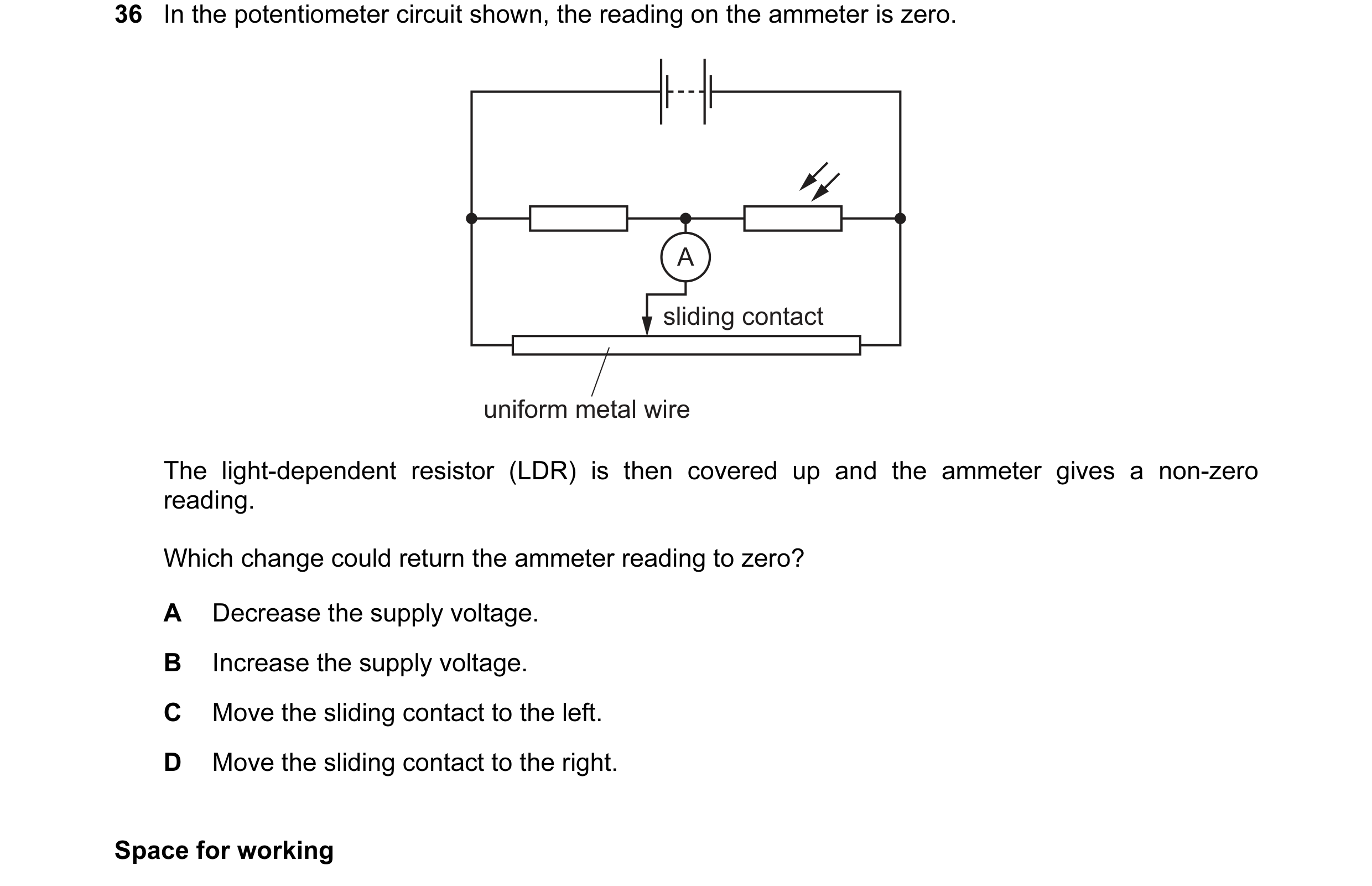
 27 / 67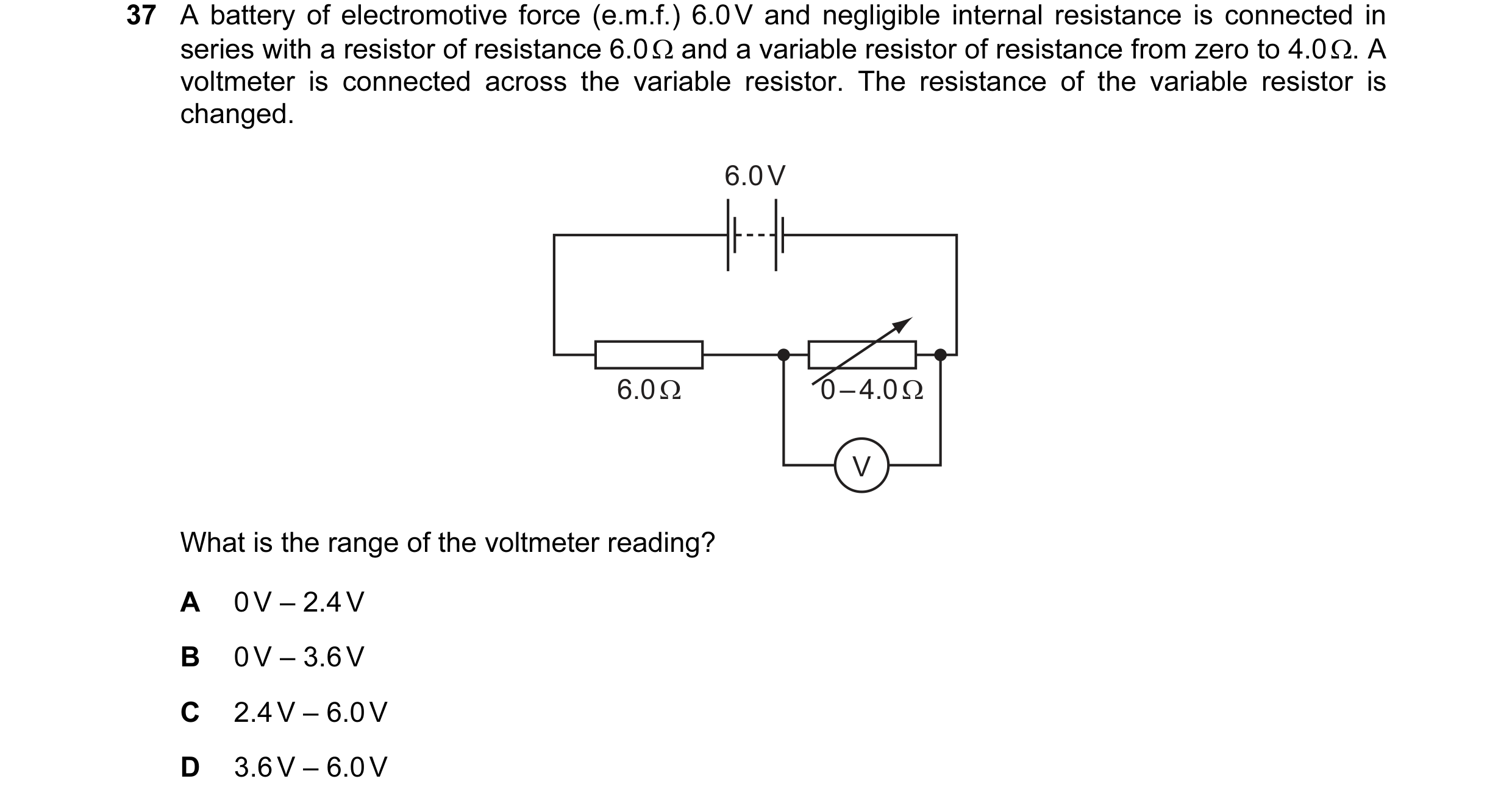
 28 / 67
 29 / 67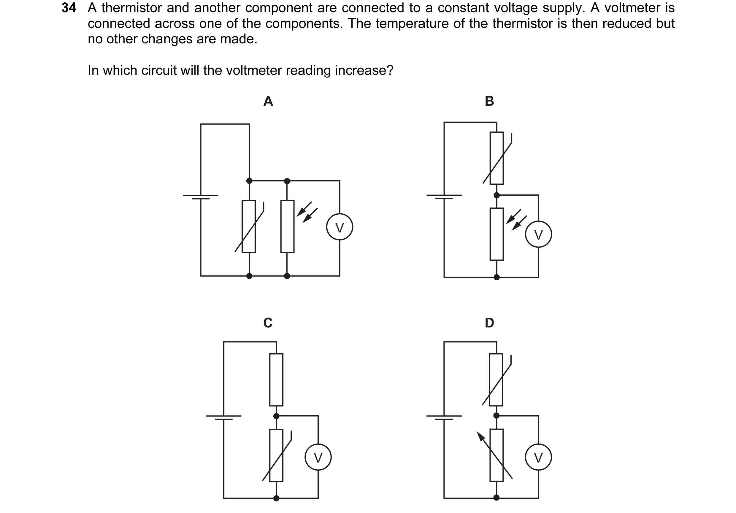
 30 / 67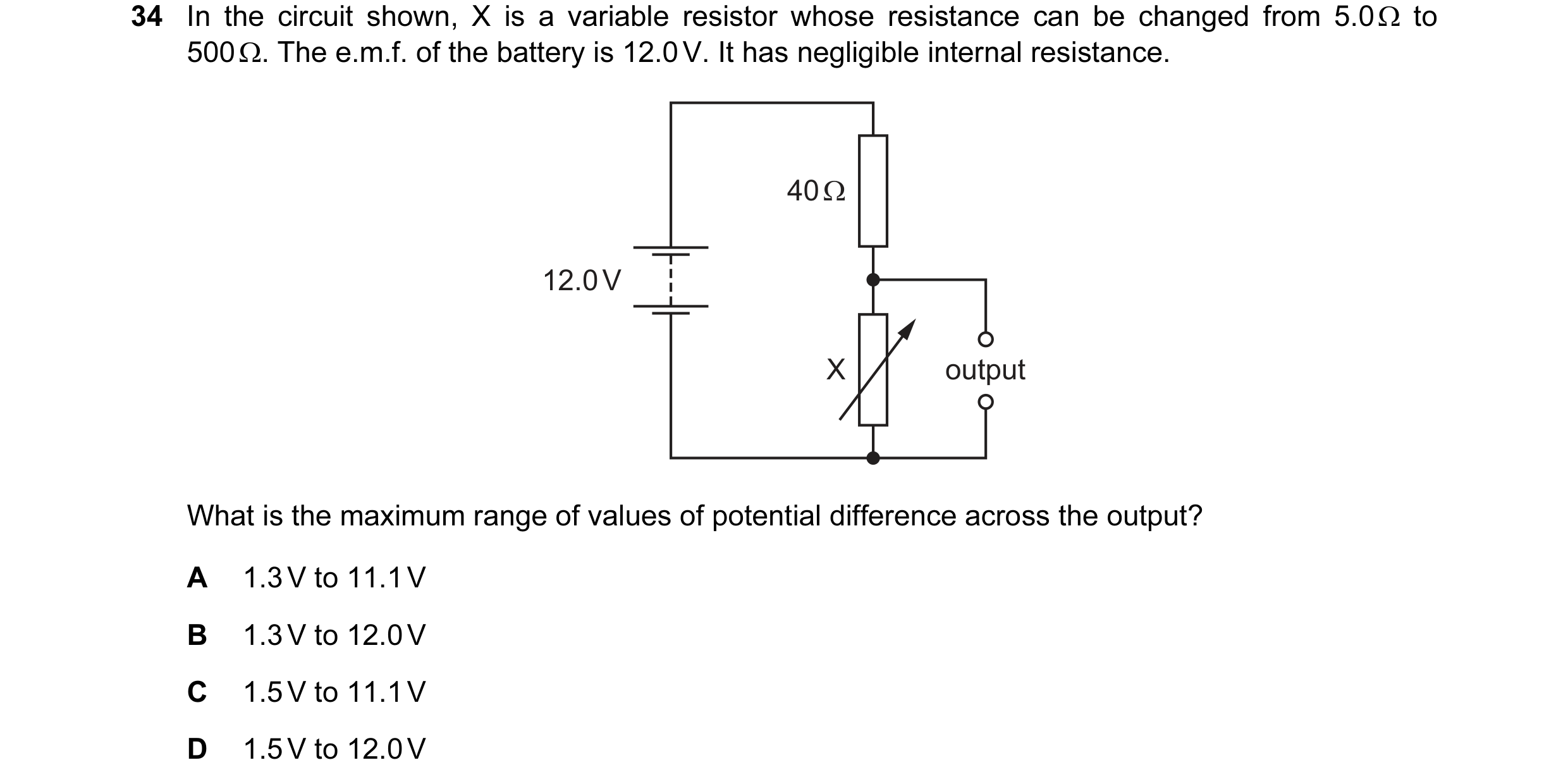
 31 / 67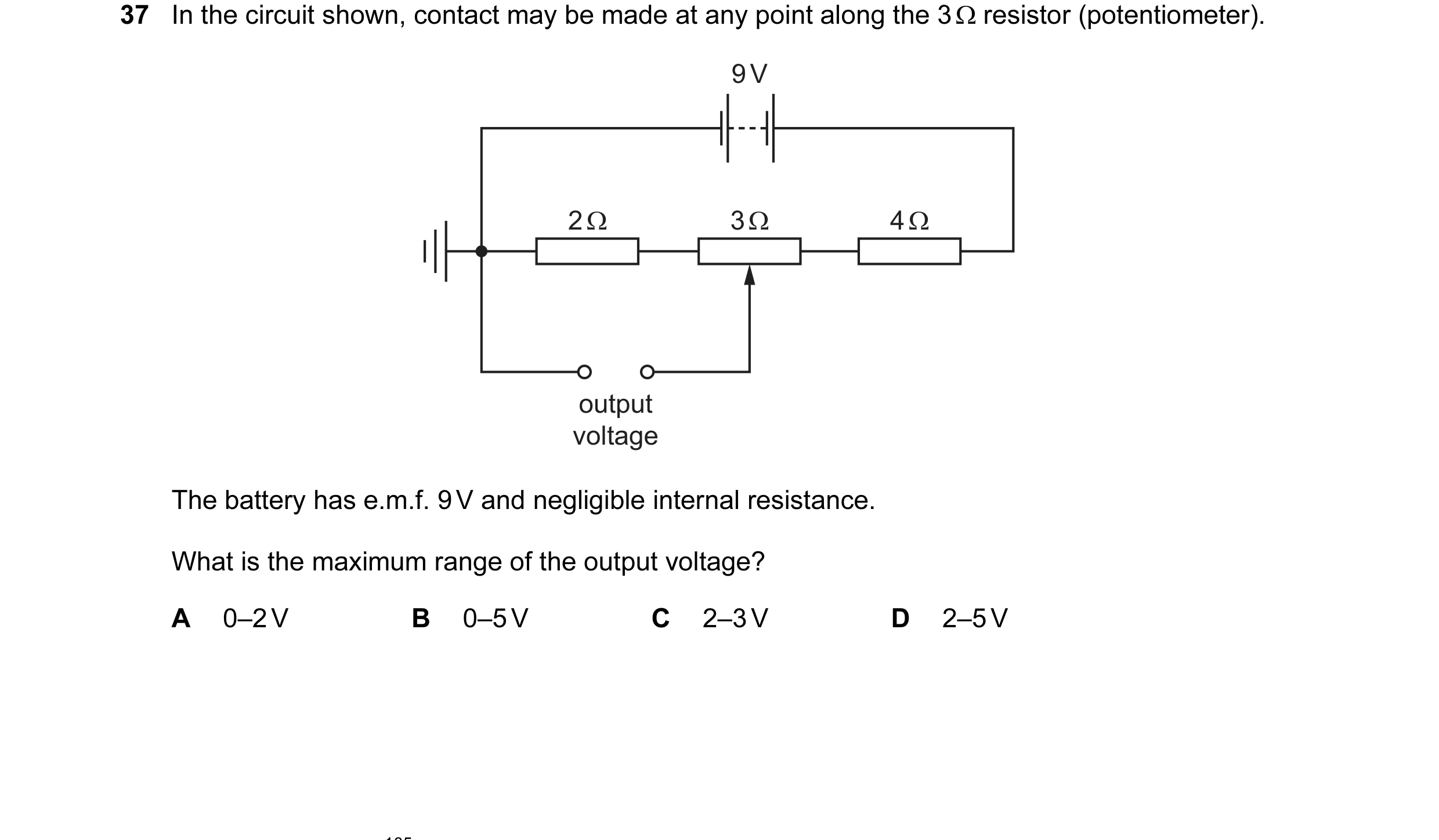
 32 / 67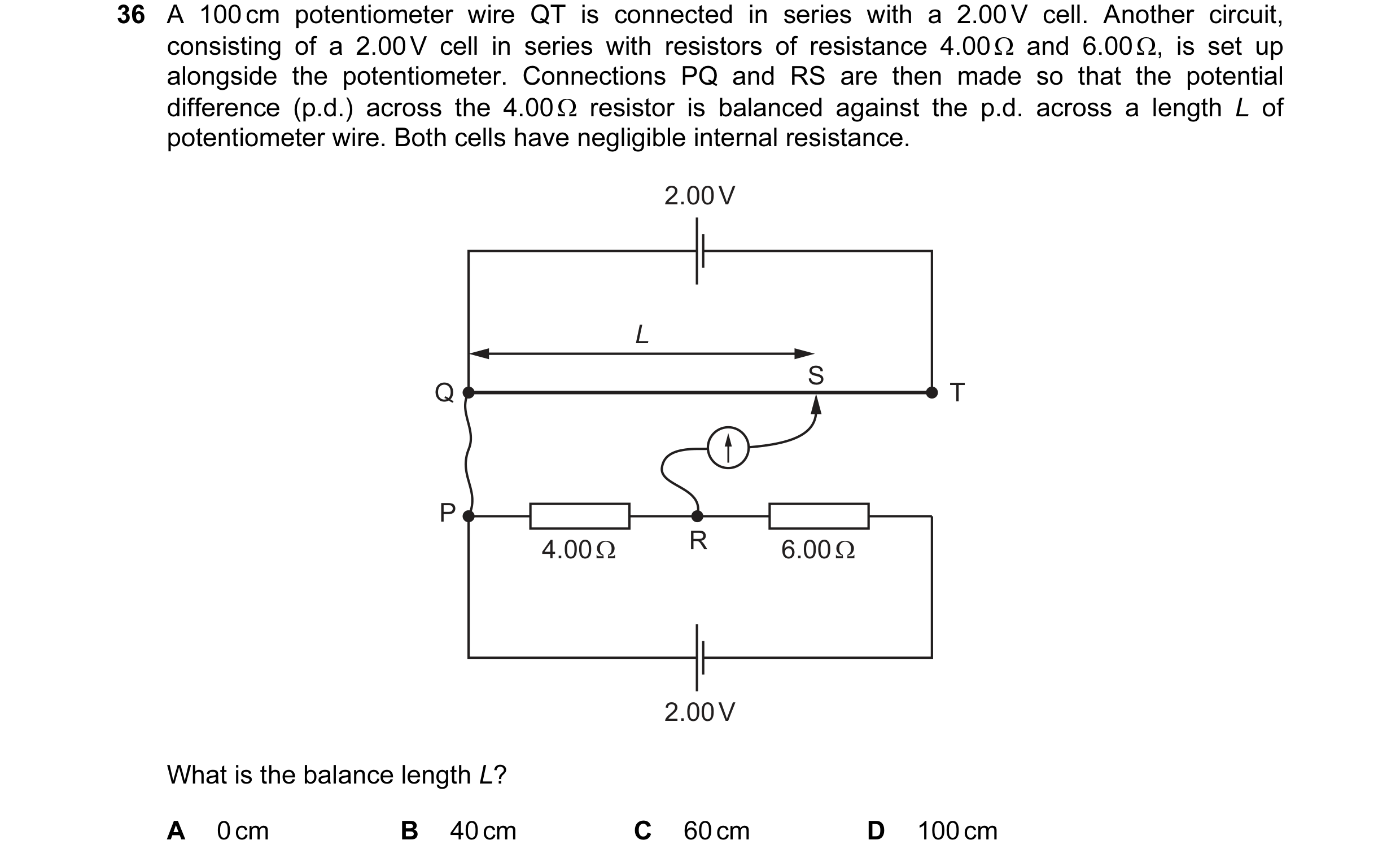
 33 / 67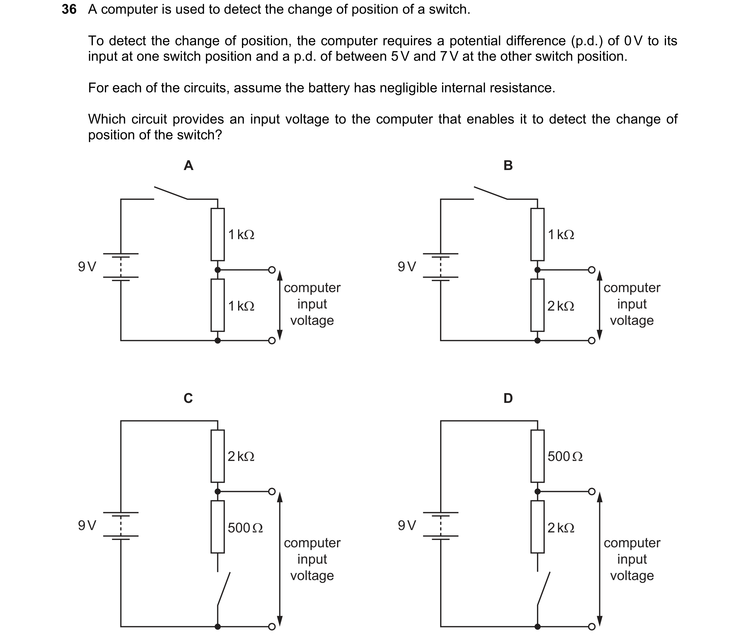
 34 / 67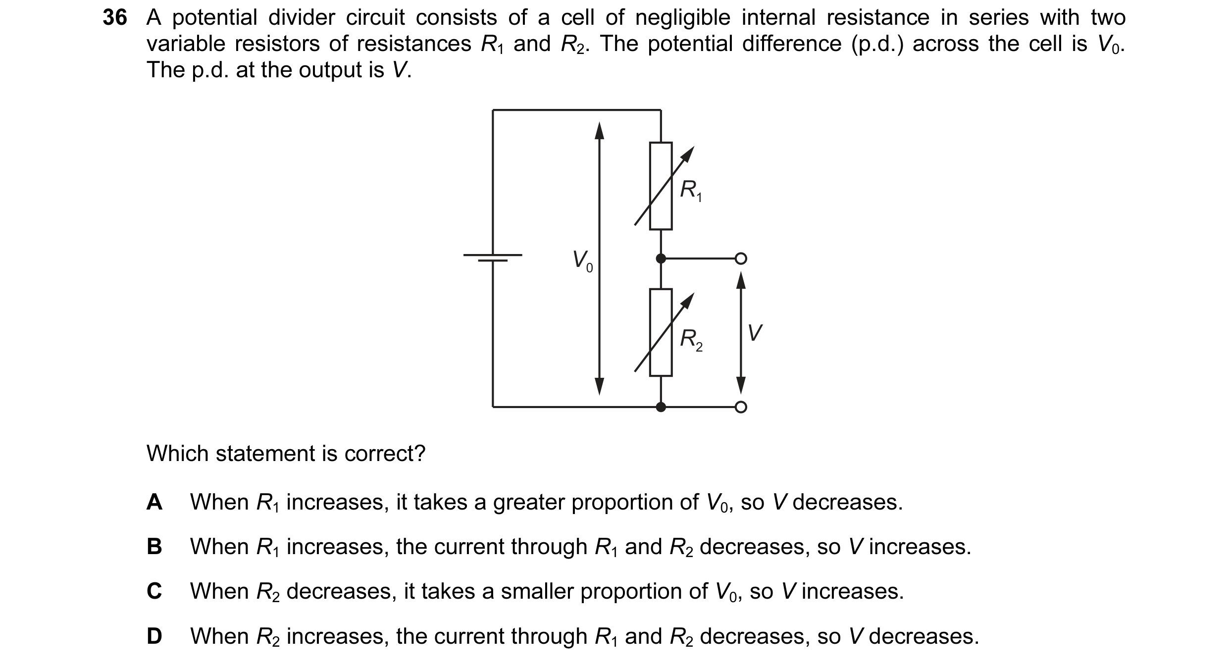
 35 / 67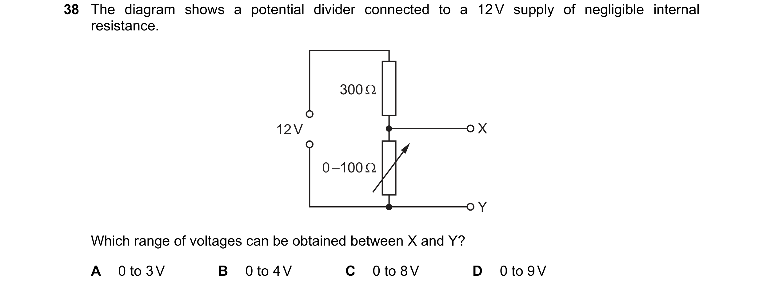
 36 / 67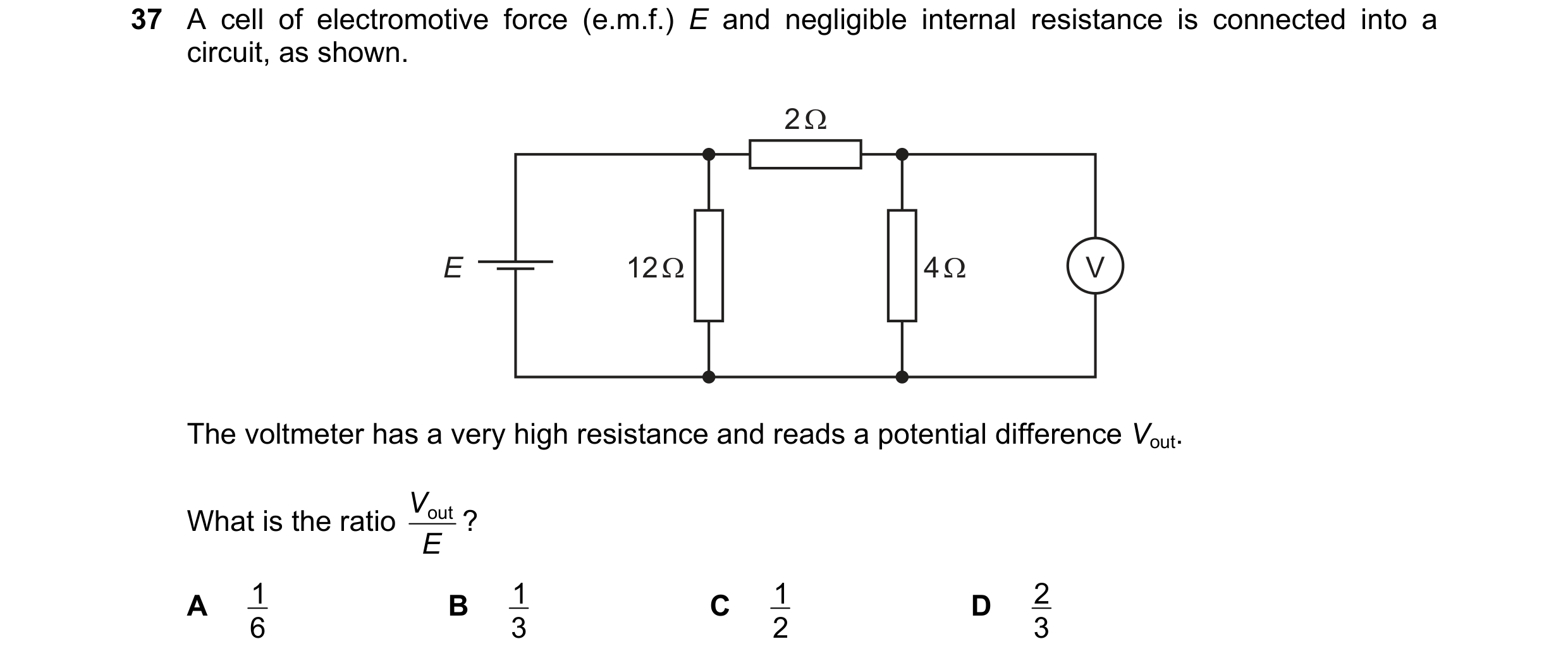
 37 / 67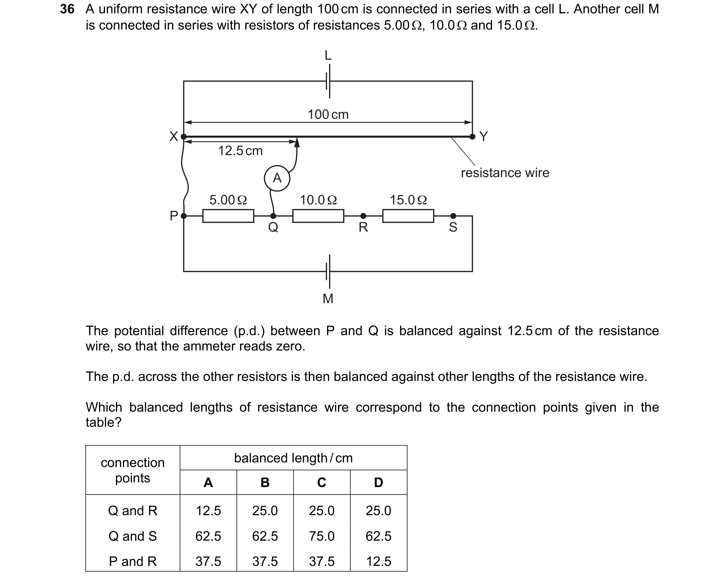
 38 / 67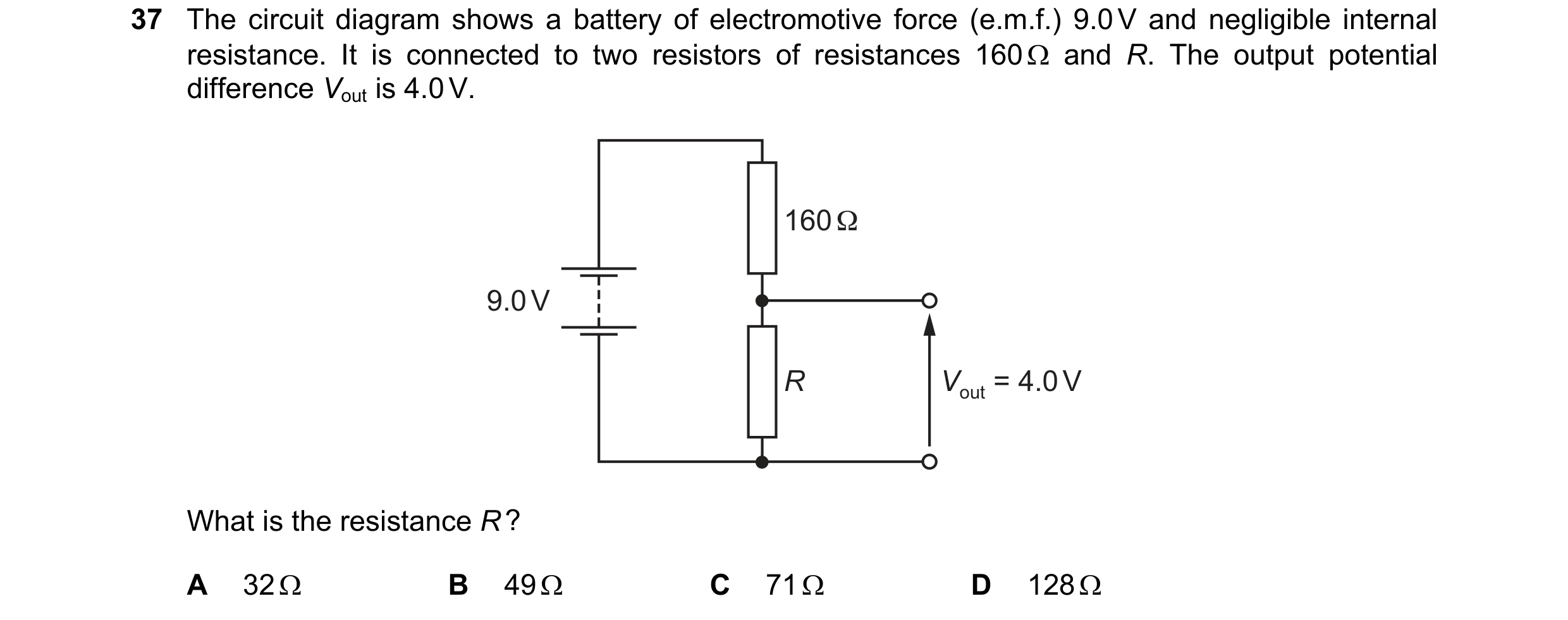
 39 / 67
 40 / 67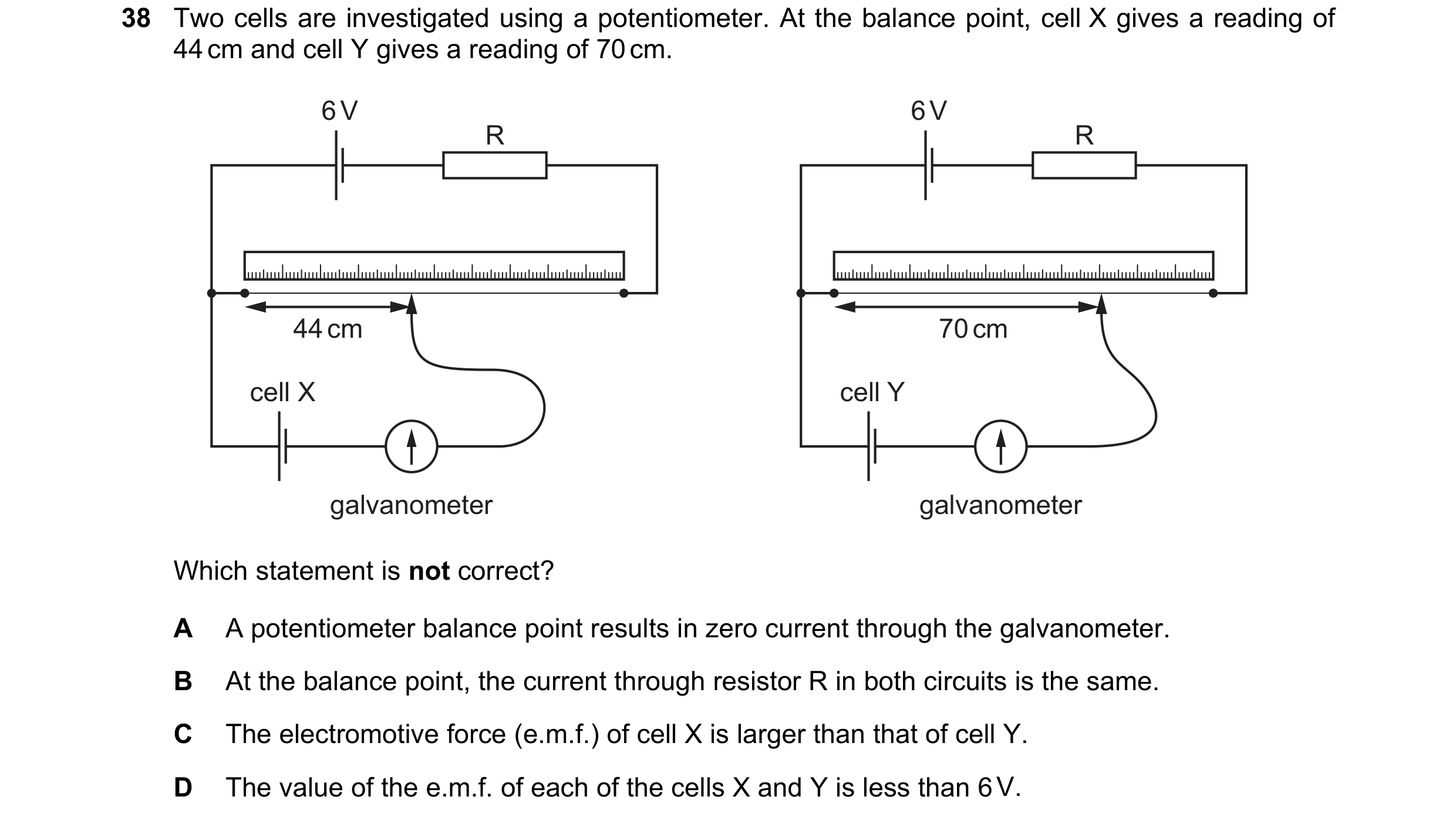
 41 / 67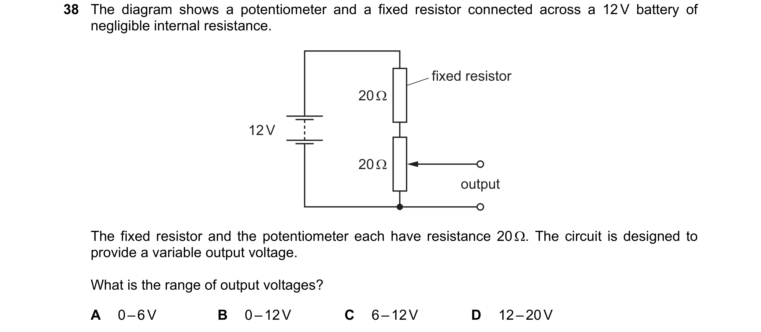
 42 / 67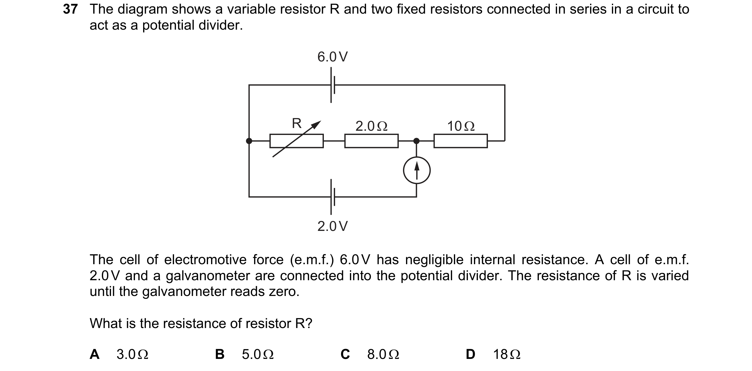
 43 / 67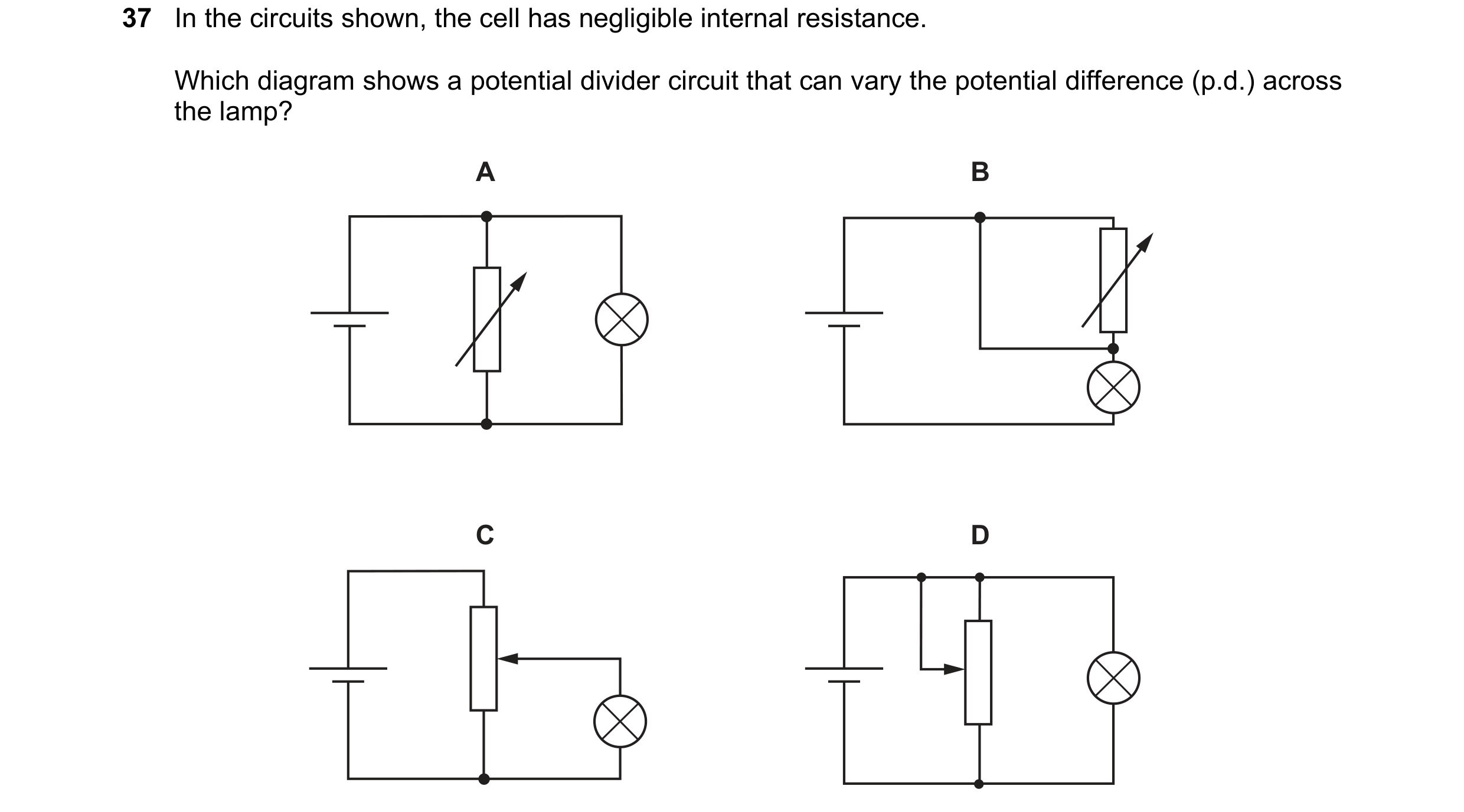
 44 / 67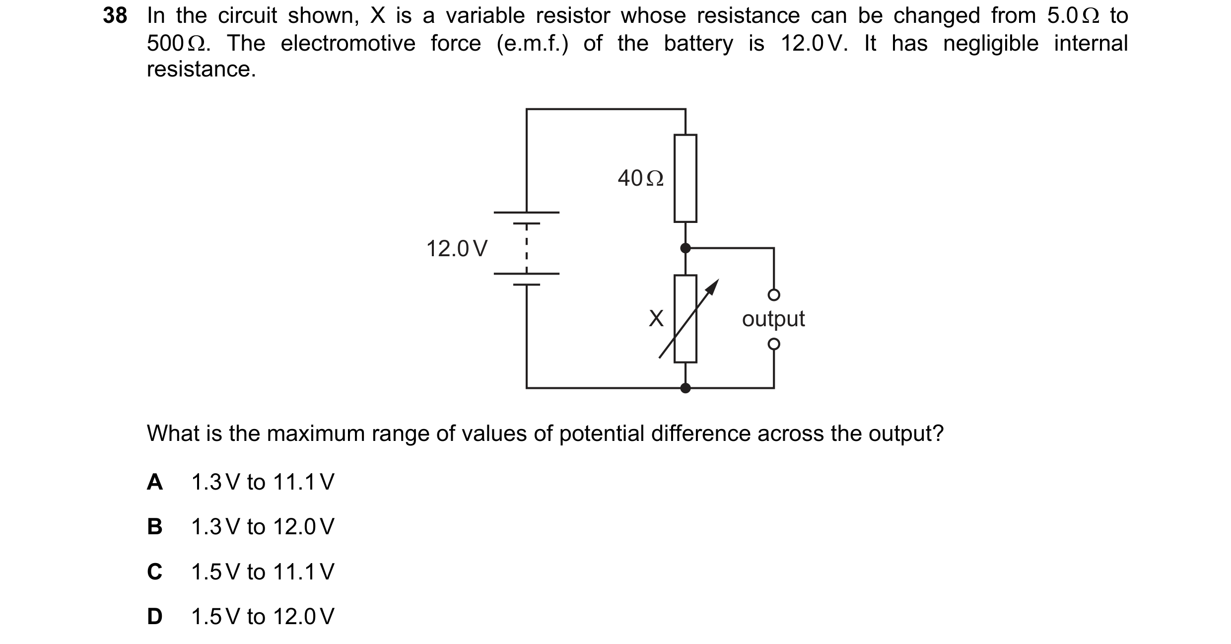
 45 / 67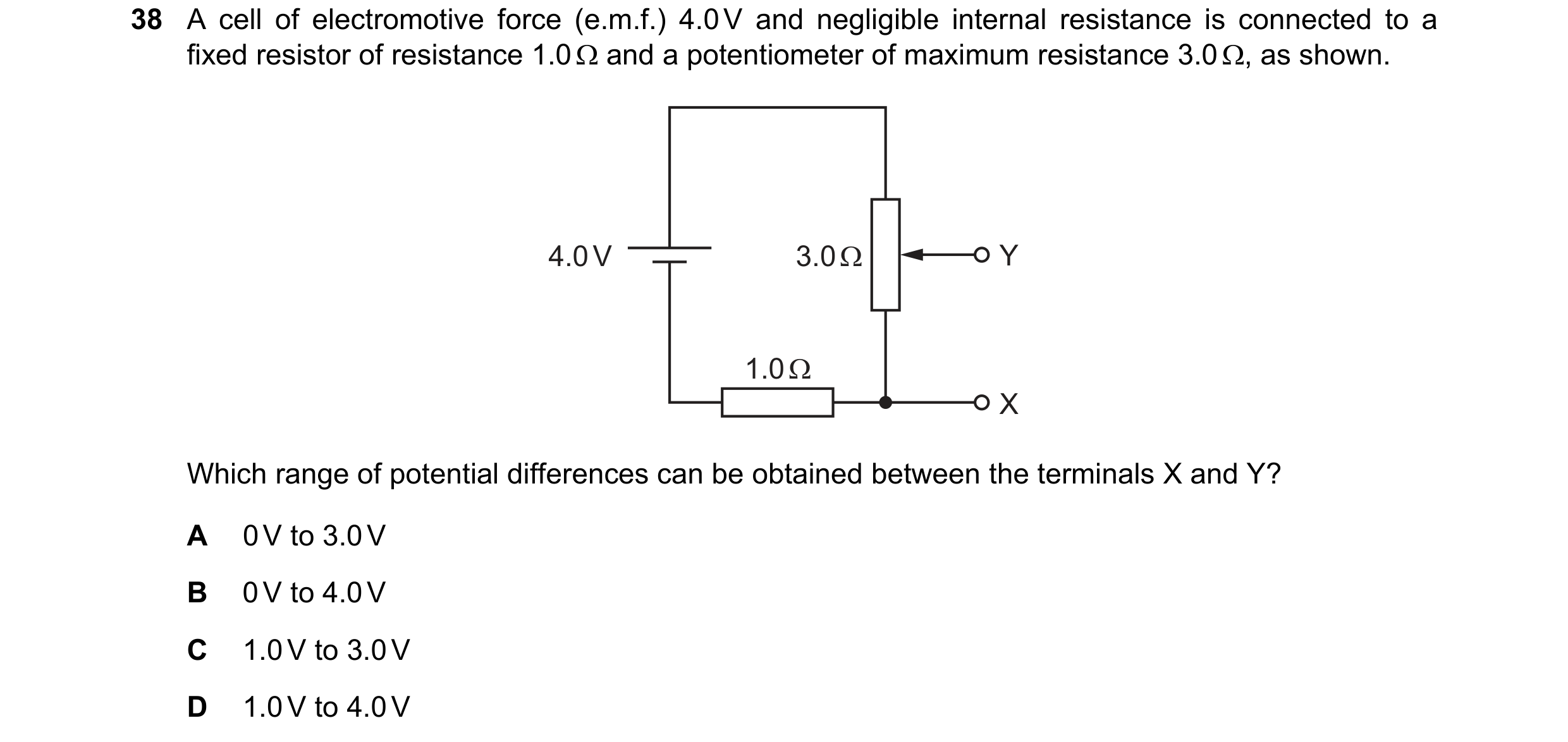
 46 / 67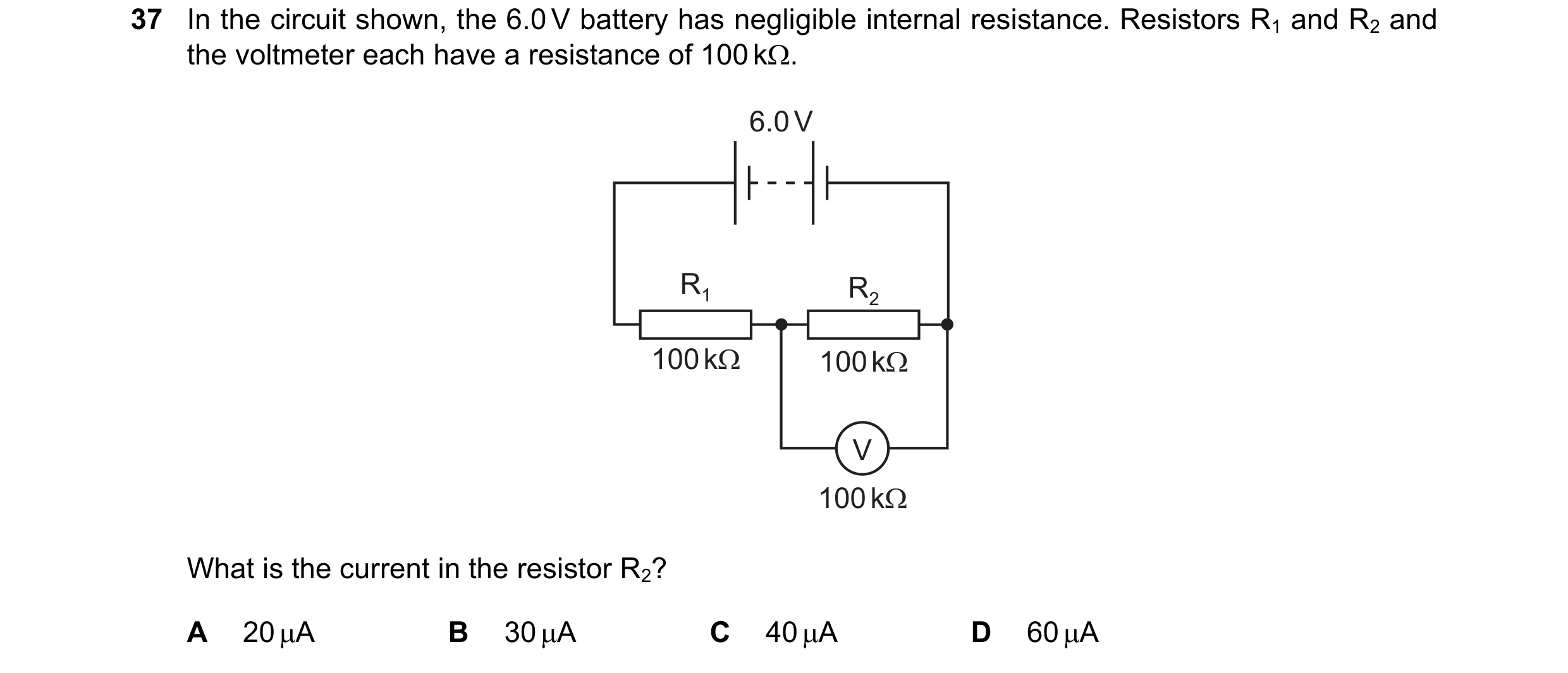
 47 / 67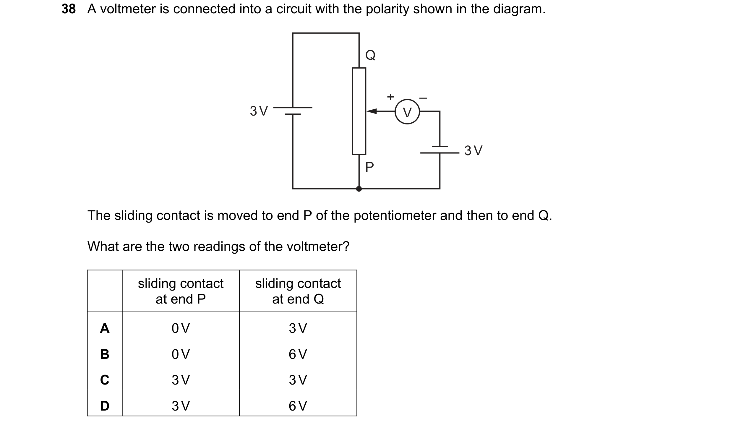
 48 / 67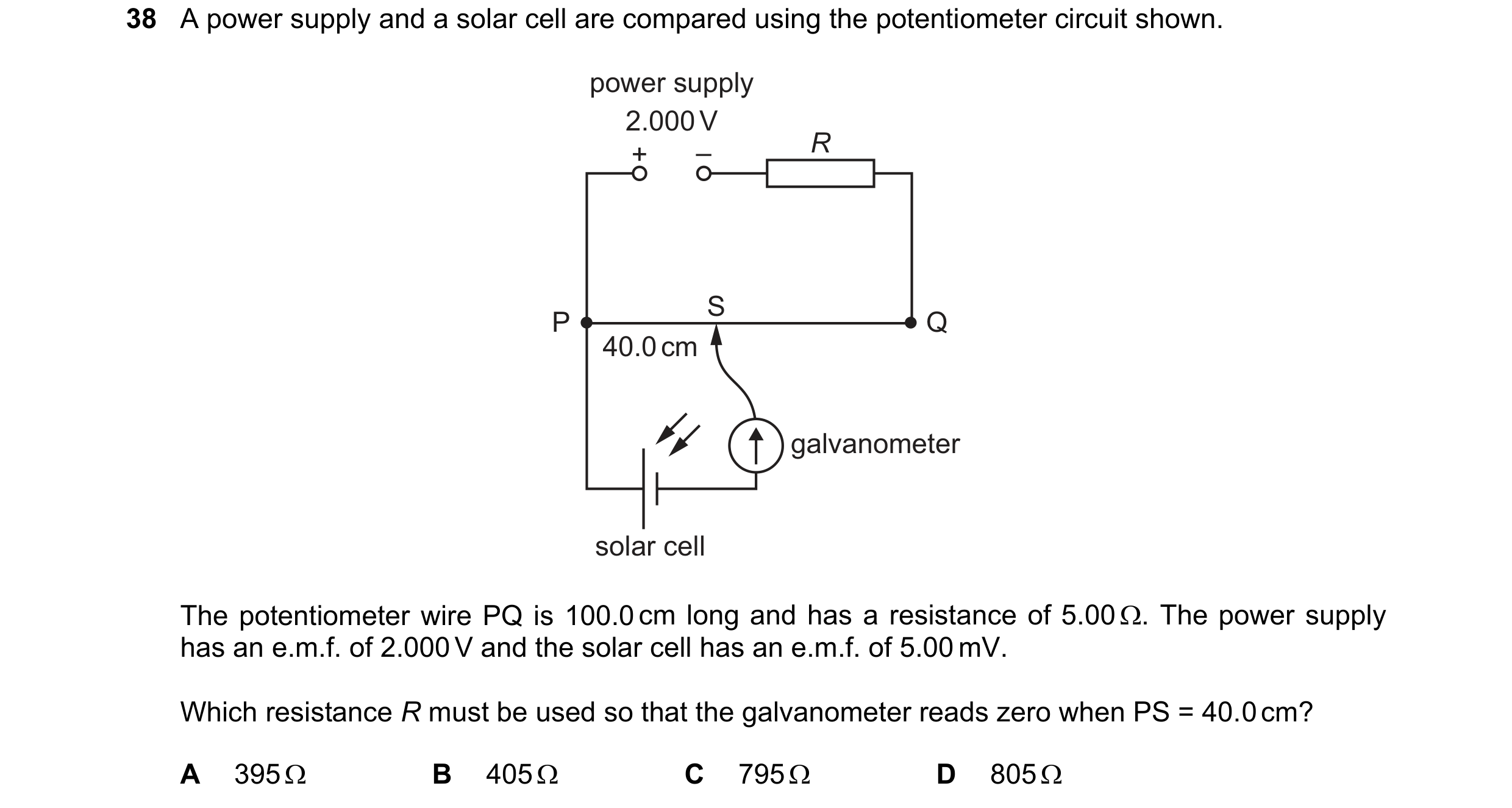
 49 / 67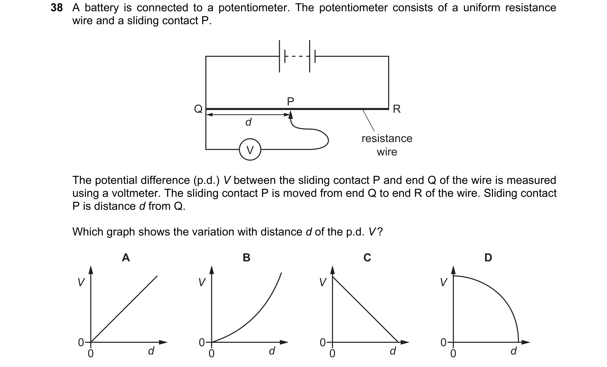
 50 / 67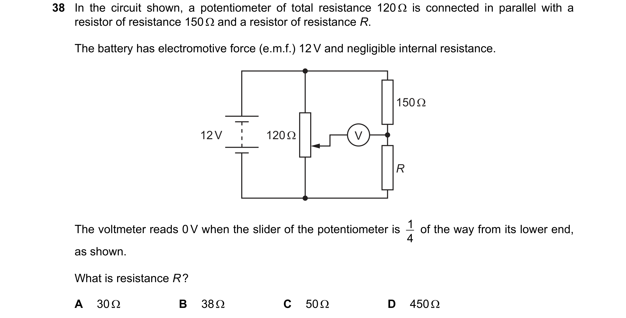
 51 / 67
 52 / 67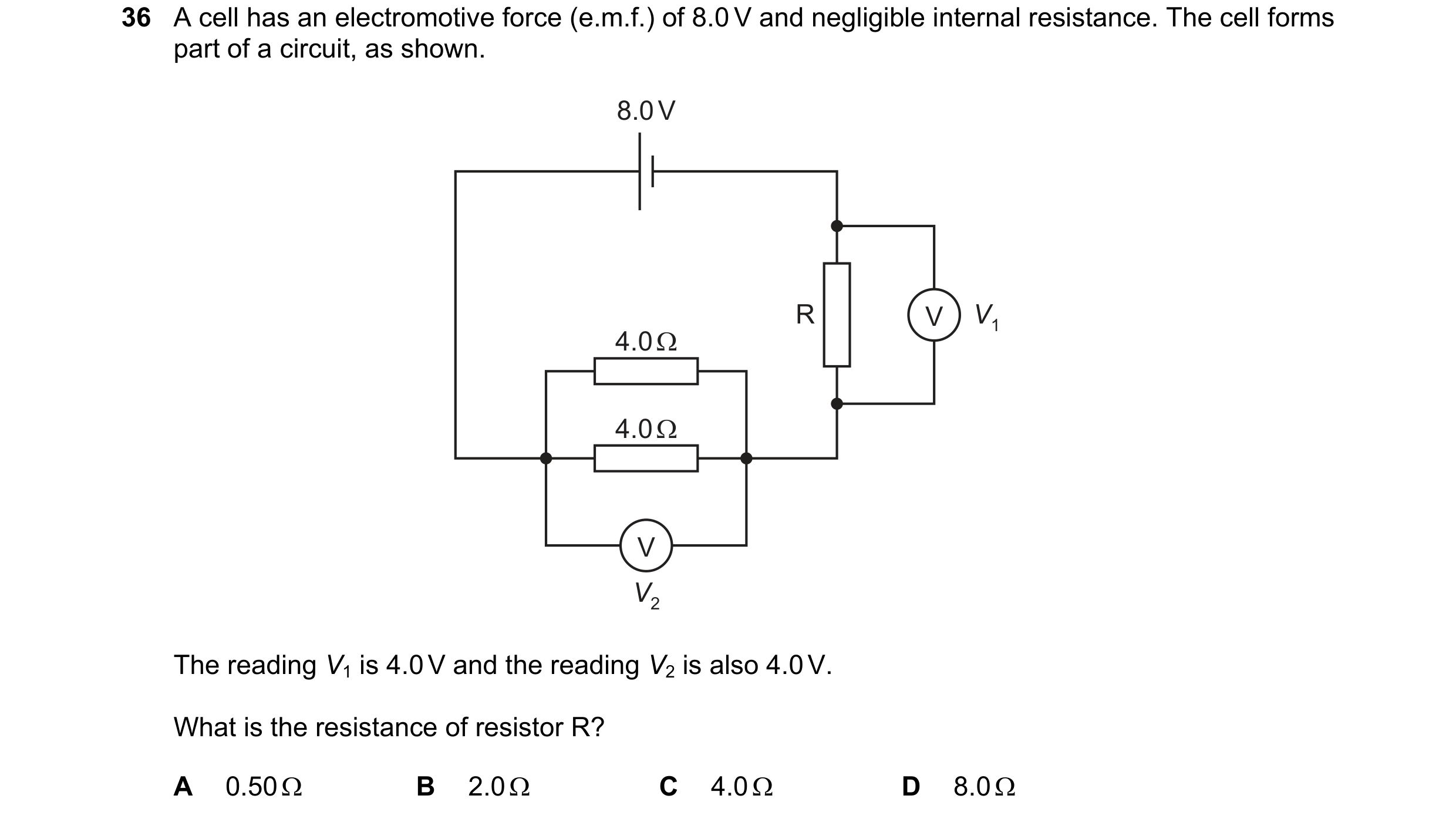
 53 / 67
 54 / 67
 55 / 67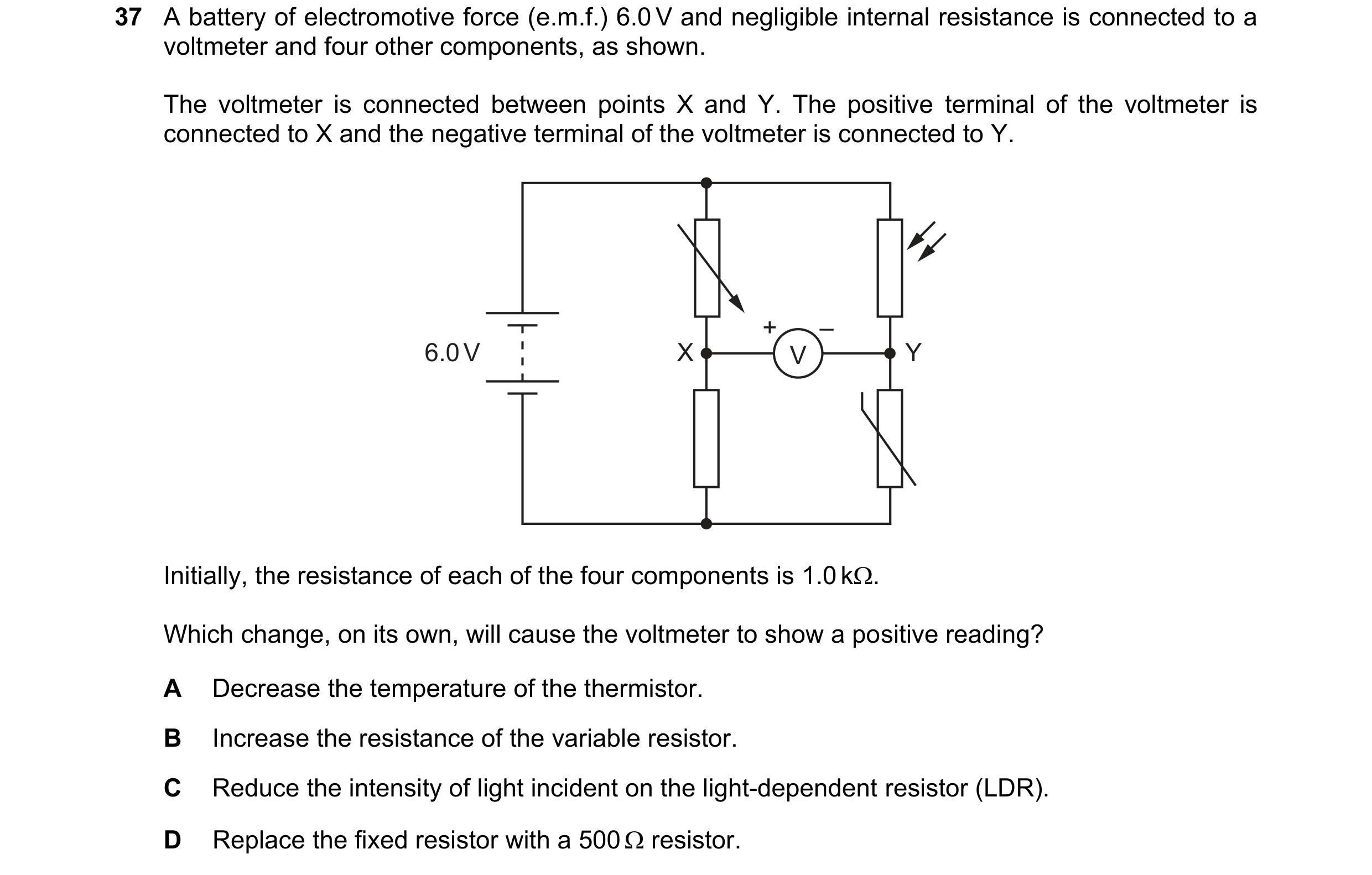
 56 / 67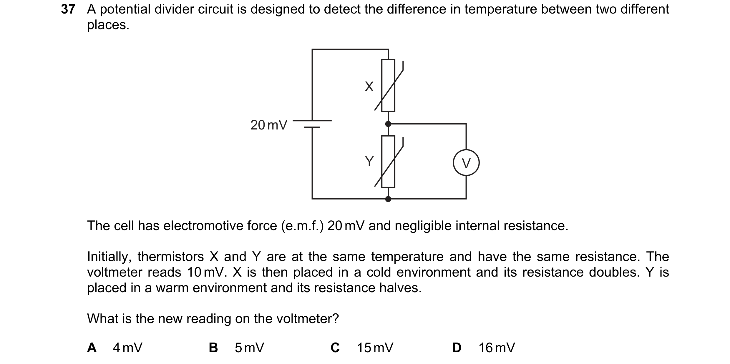
 57 / 67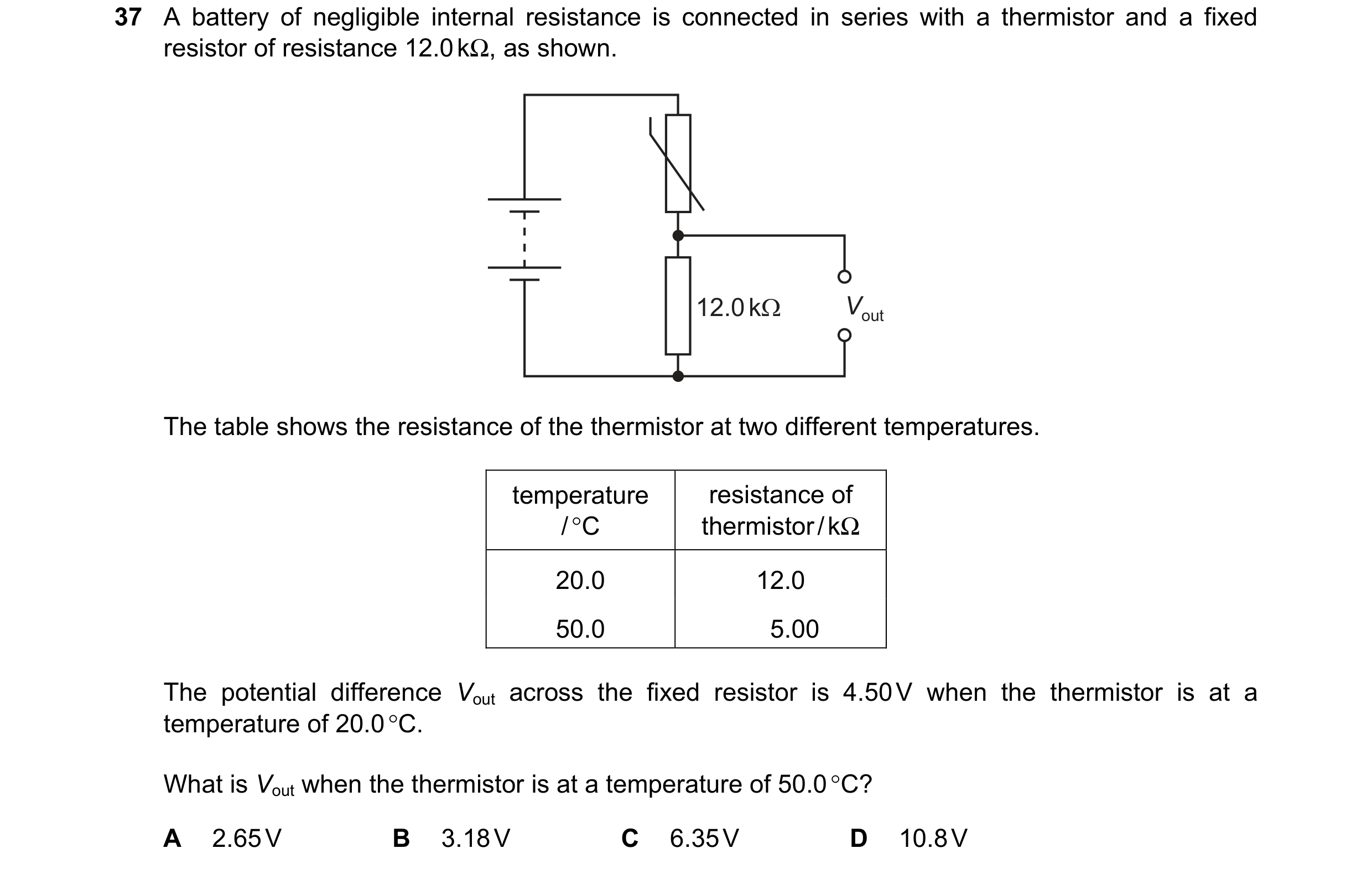
 58 / 67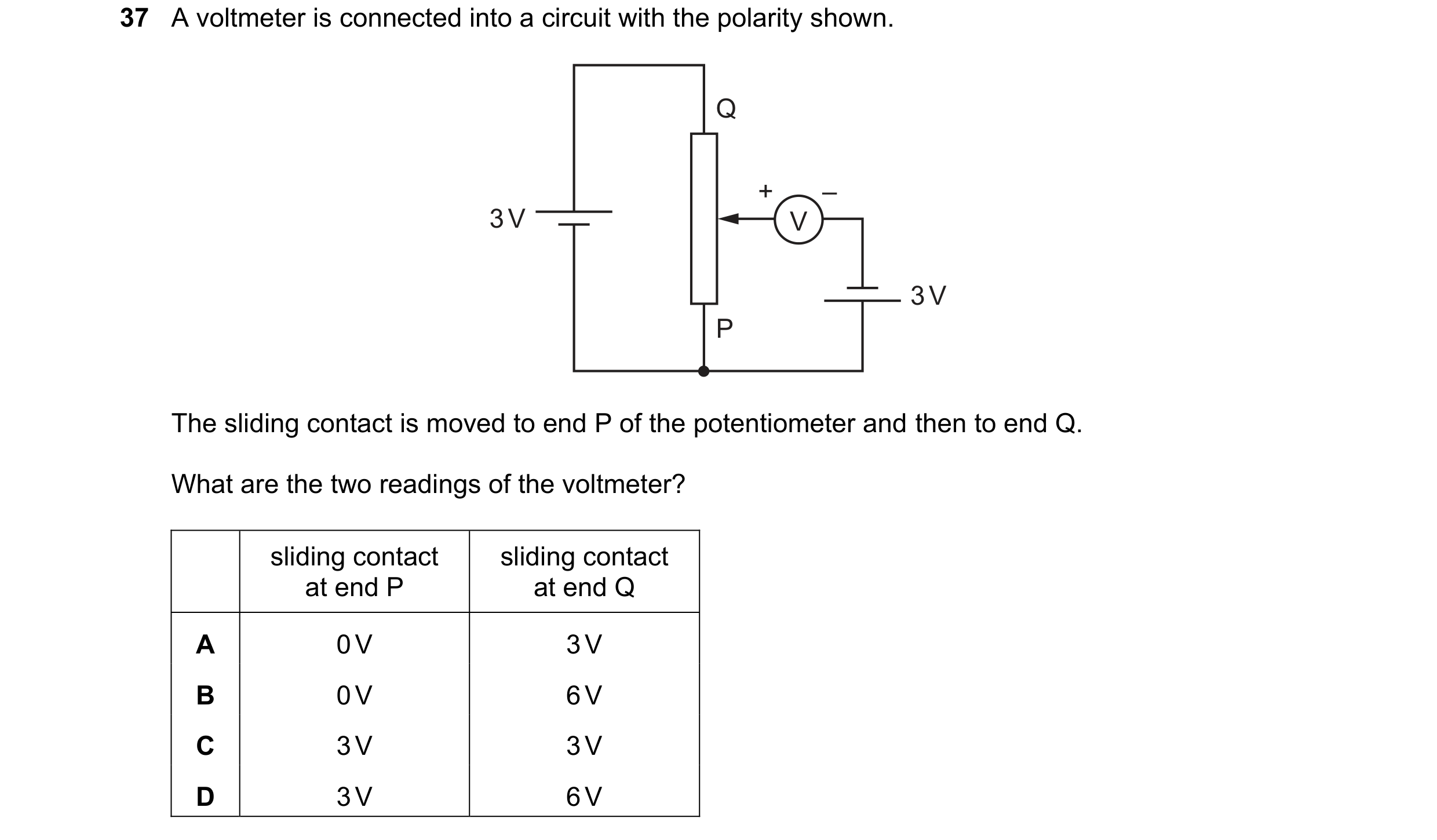
 59 / 67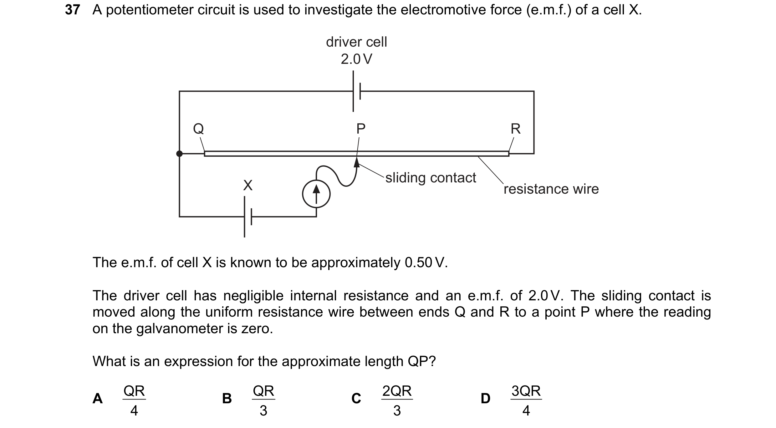
 60 / 67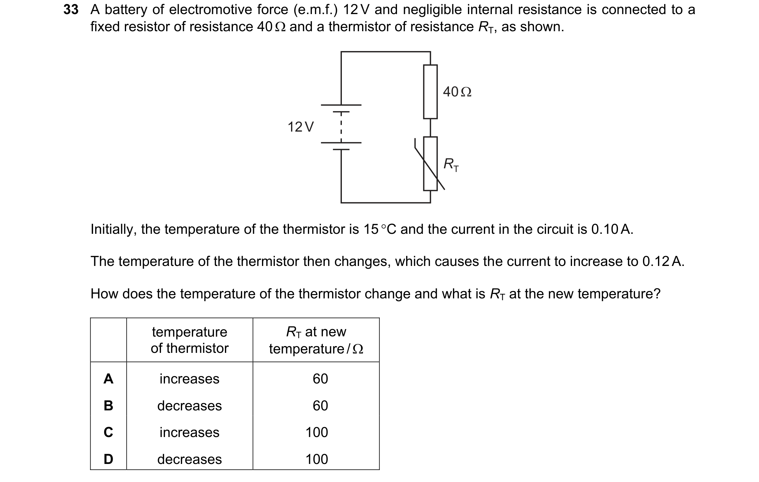
 61 / 67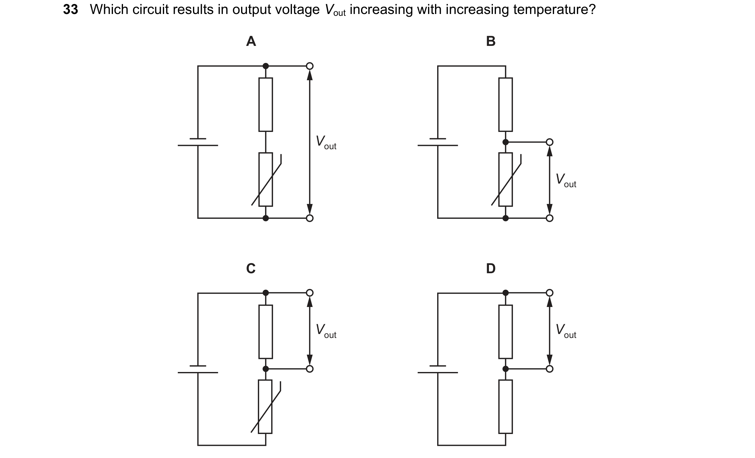
 62 / 67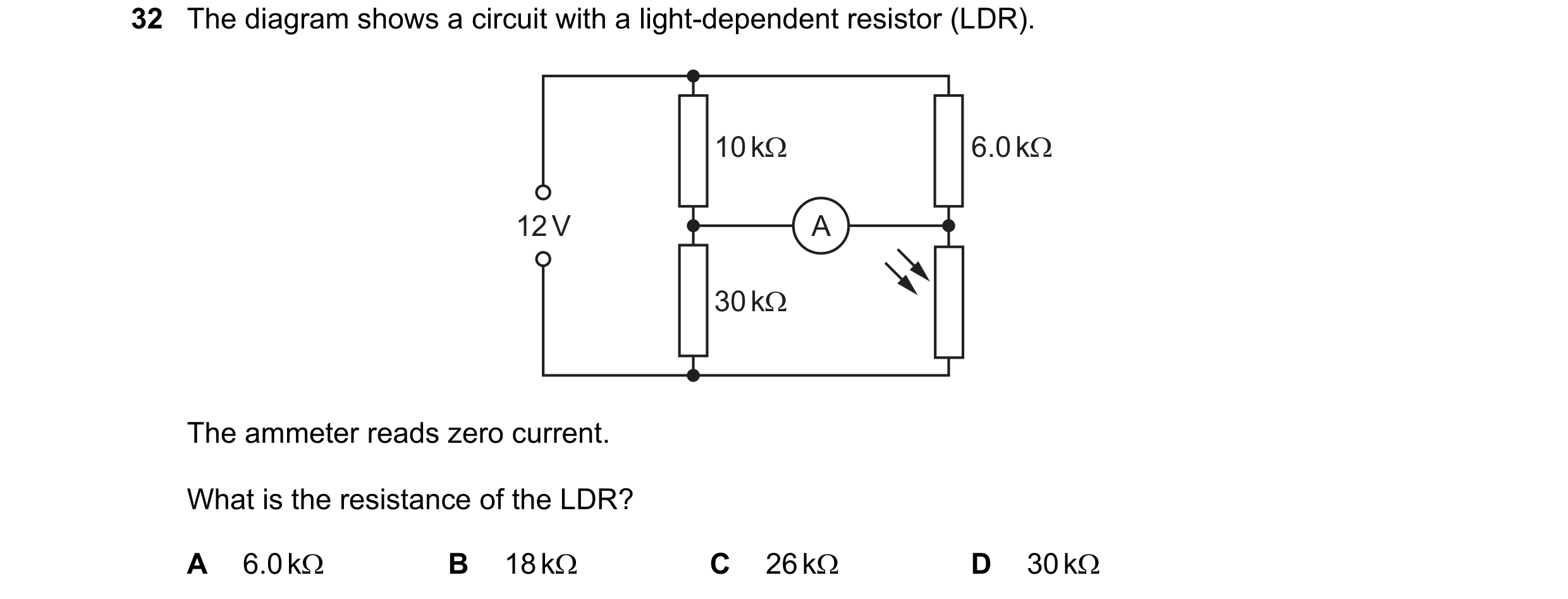
 63 / 67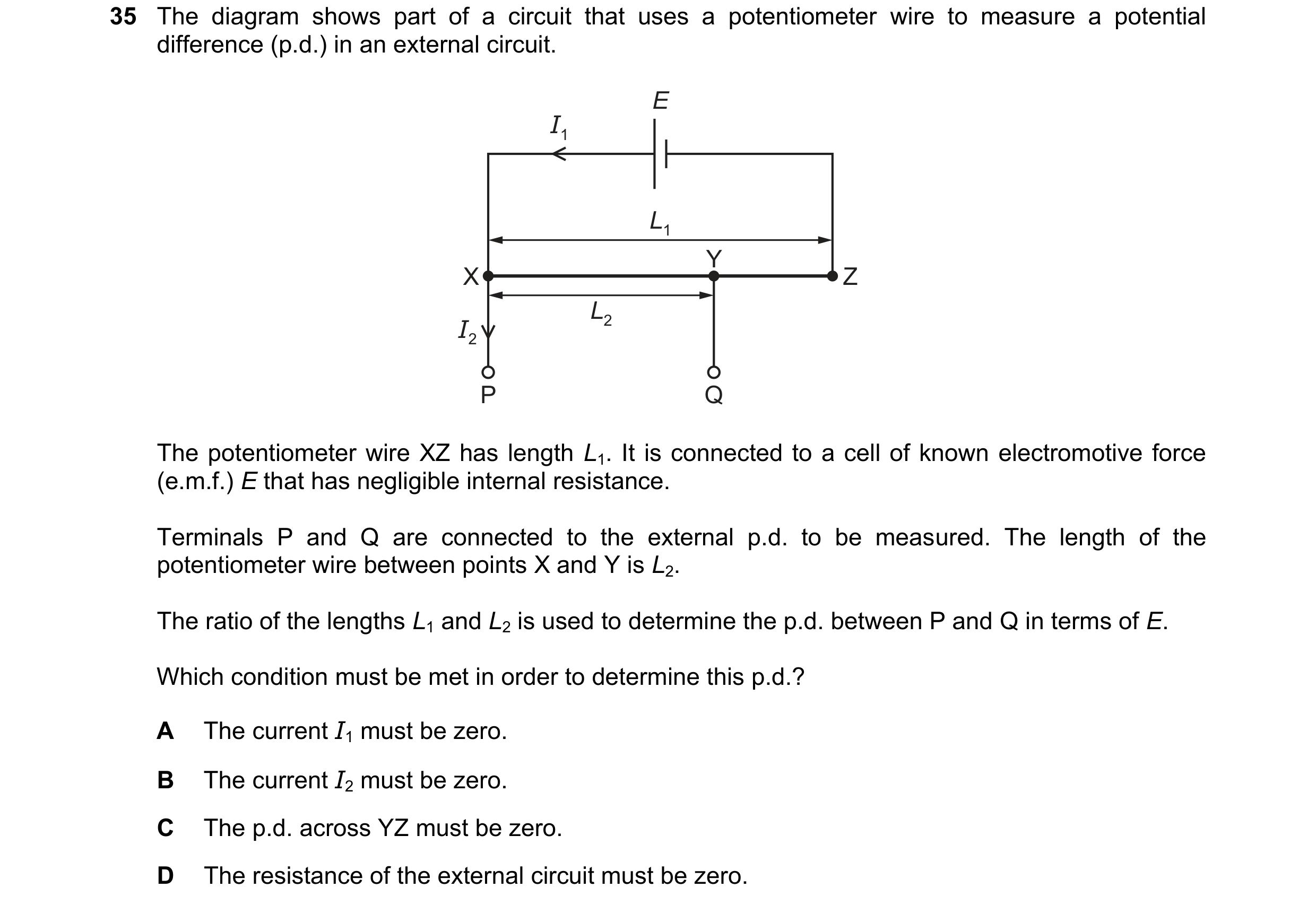
 64 / 67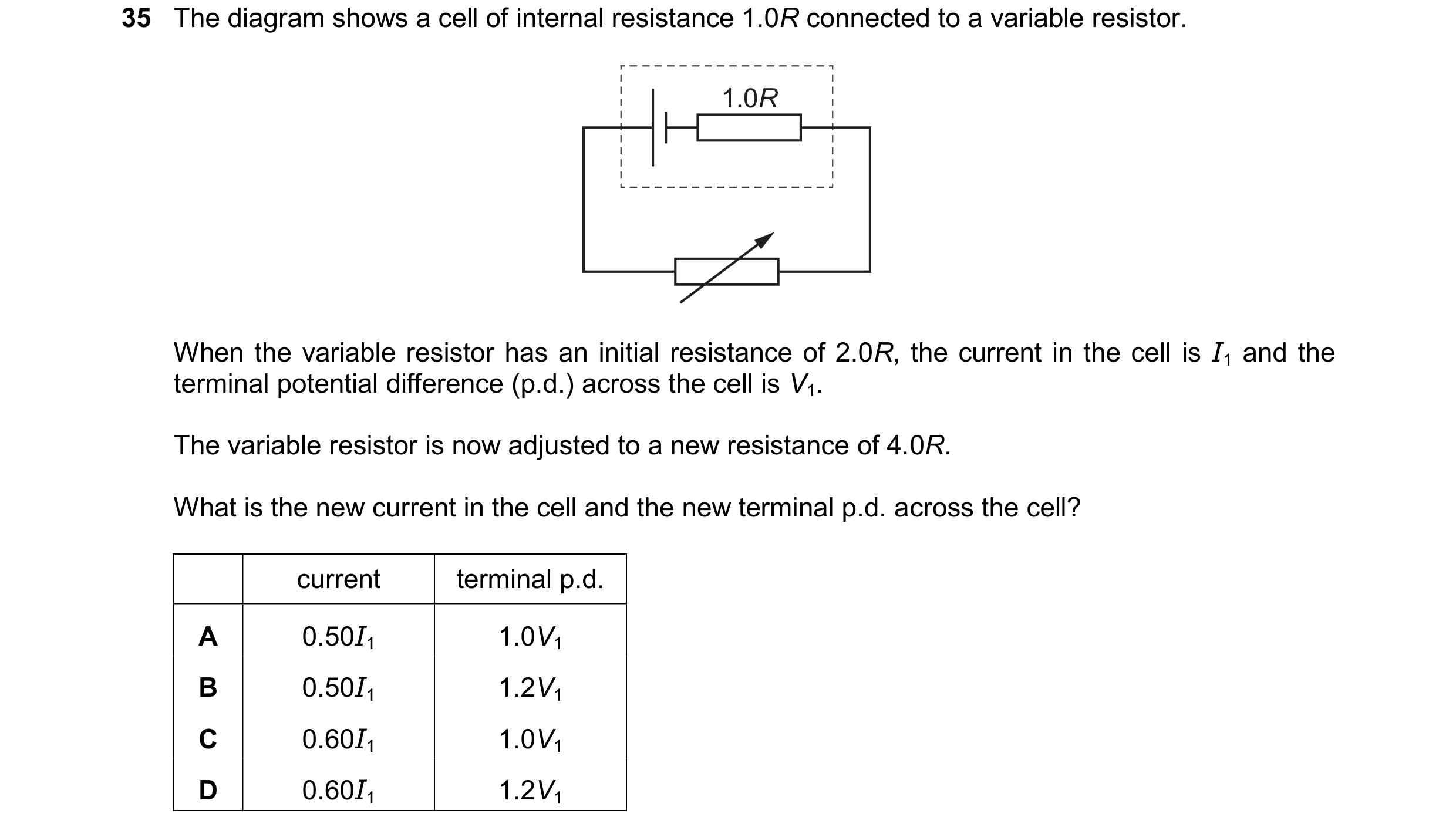
 65 / 67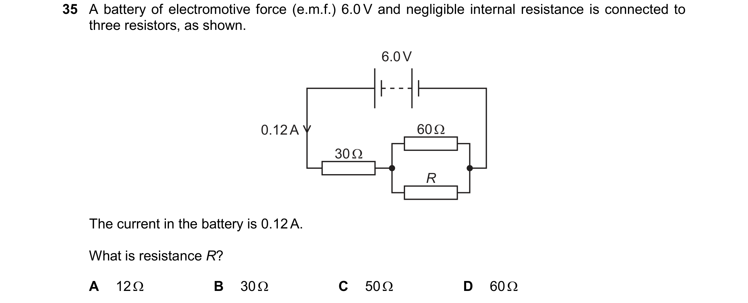
 66 / 67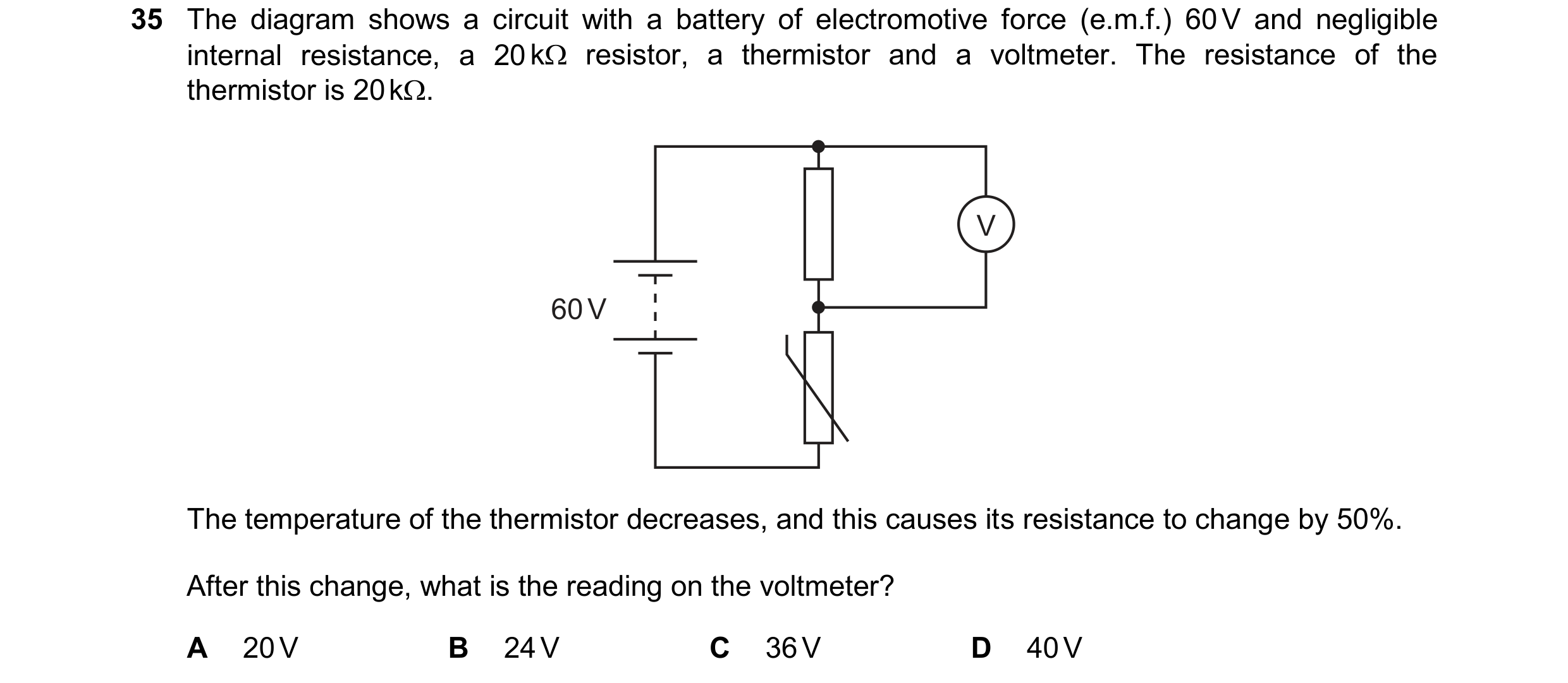
 67 / 67