Cambridge IGCSE Physics 0625 — 2025 Feb/March Paper 4 · Variant 2
0625/42/F/M/25 · 10 questions · 80 marks · ≈90 min
The question paper and its mark scheme, free to read here and free to download. This is Cambridge’s own paper, exactly as it was sat.
Question paper20 pages
Mark scheme14 pages
Answers below. Sit the paper first if you are practising.
Questions as text
Q1 · A force–extension graph for a spring
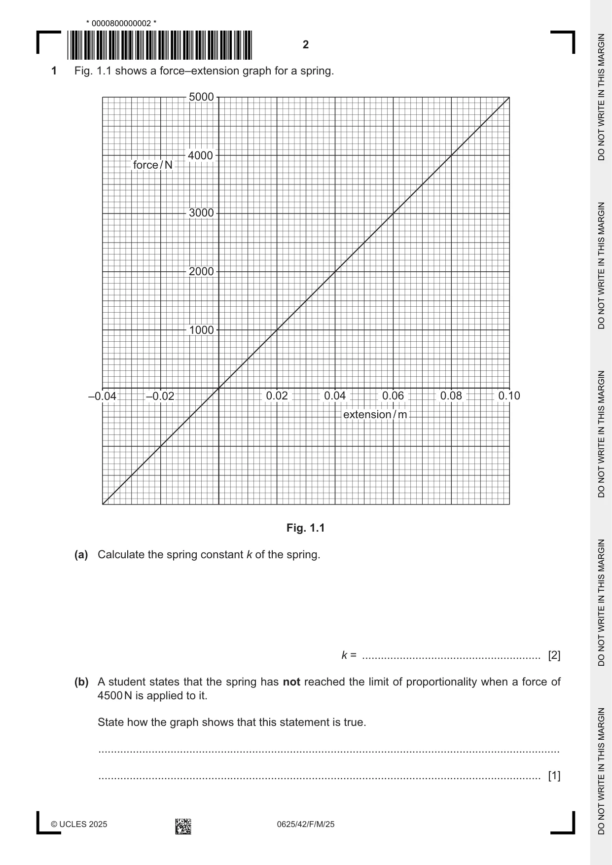
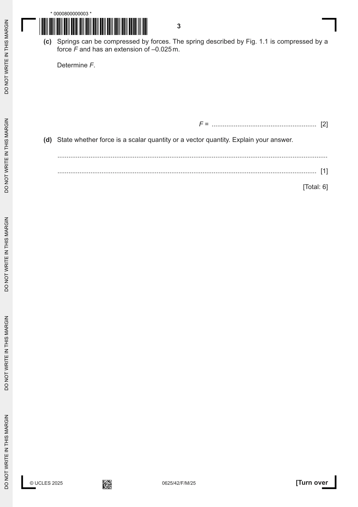
1 Fig. 1.1 shows a force–extension graph for a spring. 5000 4000 force / N 3000 2000 1000 –0.04 –0.02 0.02 0.04 0.06 0.08 0.10 extension / m Fig. 1.1 (a) Calculate the spring constant k of the spring. k = ......................................................... [2] (b) A student states that the spring has not reached the limit of proportionality when a force of 4500 N is applied to it. State how the graph shows that this statement is true. ................................................................................................................................................... ............................................................................................................................................. [1] (c) Springs can be compressed by forces. The spring described by Fig. 1.1 is compressed by a force F and has an extension of –0.025 m. Determine F. F = ......................................................... [2] (d) State whether force is a scalar quantity or a vector quantity. Explain your answer. ................................................................................................................................................... ............................................................................................................................................. [1] [Total: 6]
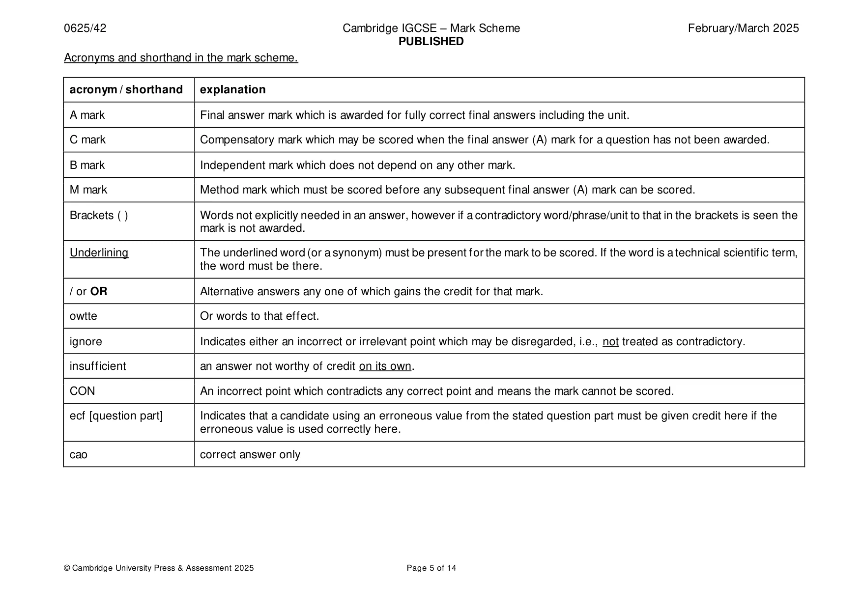
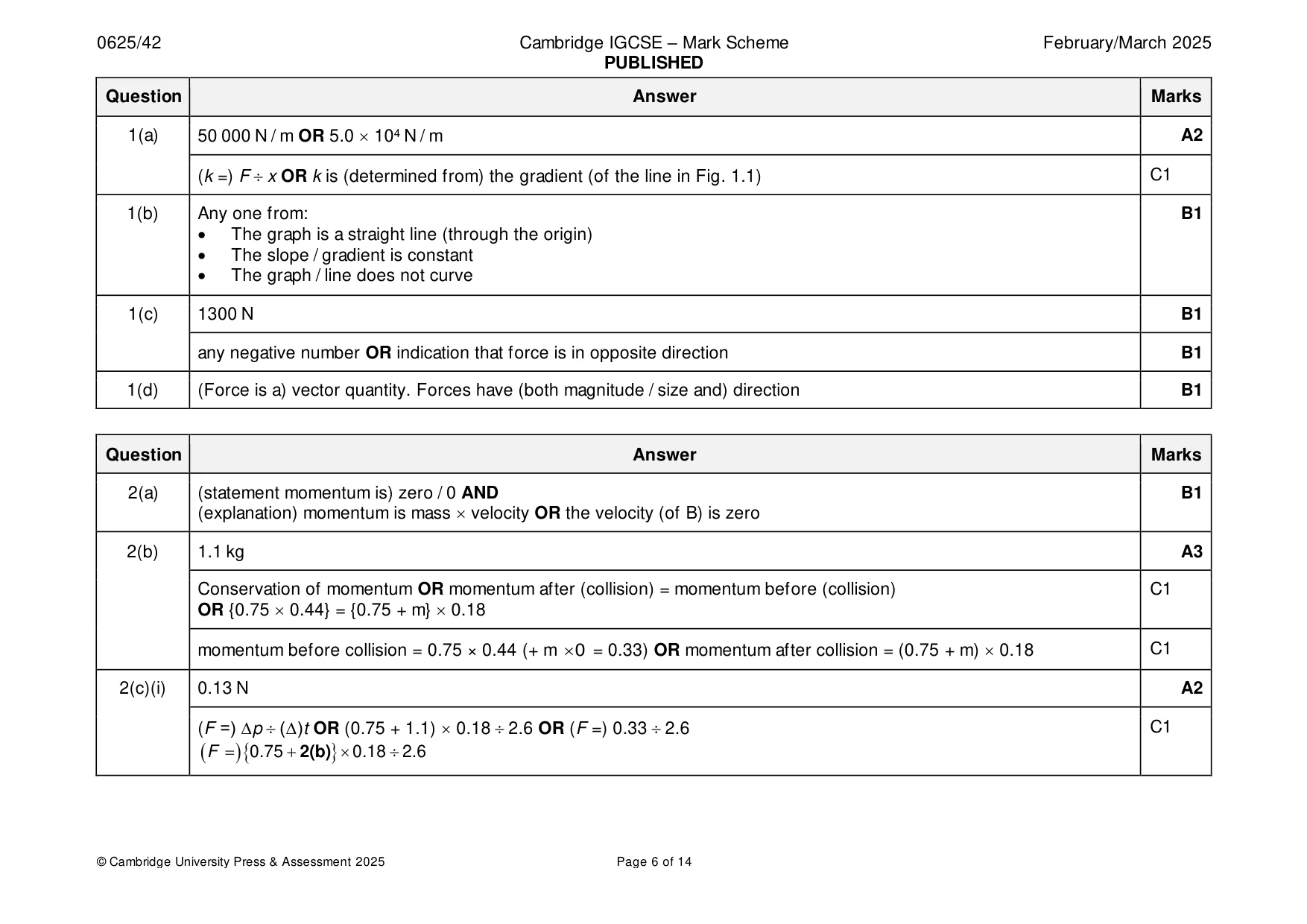
Mark scheme: Question Answer Marks 1(a) 50 000 N / m OR 5.0 104 N / m A2 (k =) F x OR k is (determined from) the gradient (of the line in Fig. 1.1) C1 1(b) Any one from: B1 • The graph is a straight line (through the origin) • The slope / gradient is constant • The graph / line does not curve 1(c) 1300 N B1 any negative number OR indication that force is in opposite direction B1 1(d) (Force is a) vector quantity. Forces have (both magnitude / size and) direction B1
Q2 · Trolley A and trolley B are on a horizontal, frictionless bench
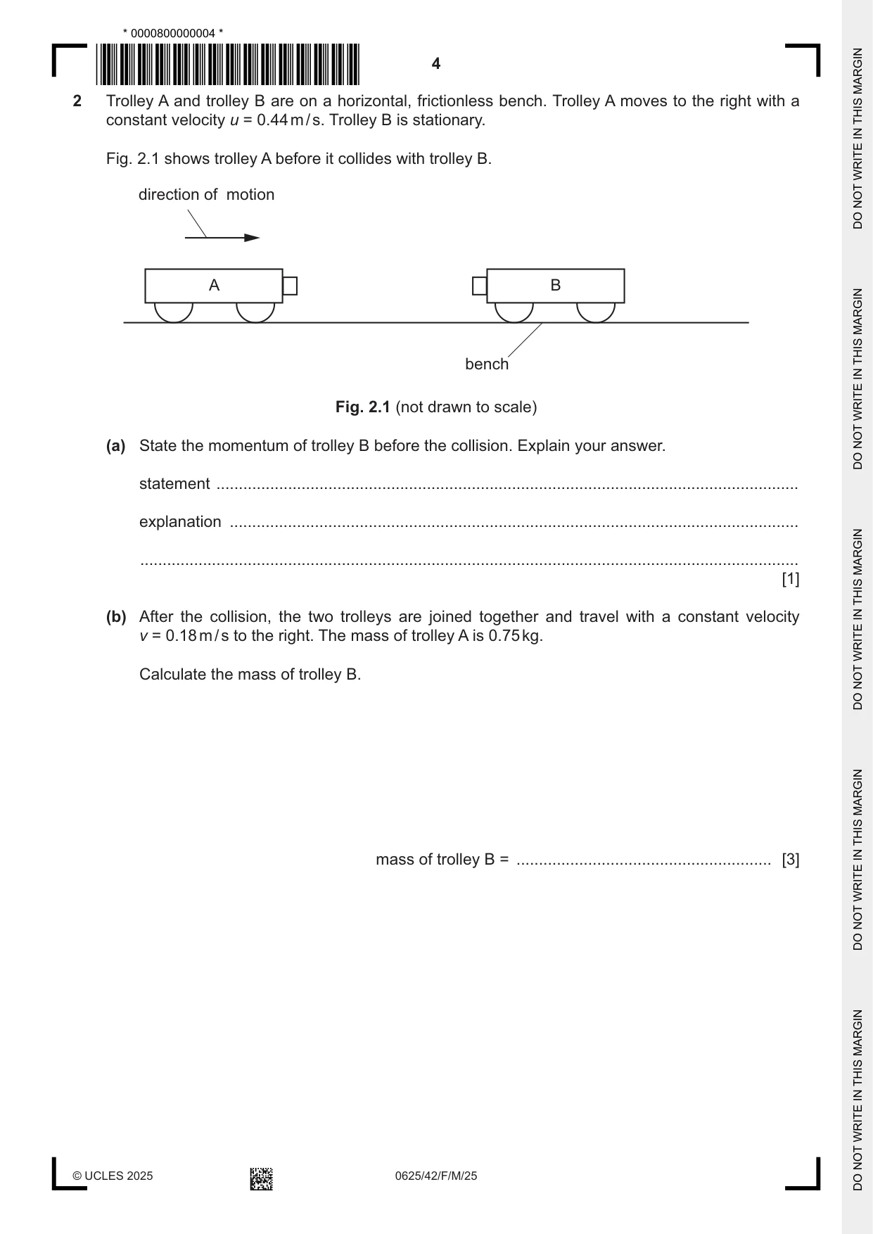
2 Trolley A and trolley B are on a horizontal, frictionless bench. Trolley A moves to the right with a constant velocity u = 0.44 m / s. Trolley B is stationary. Fig. 2.1 shows trolley A before it collides with trolley B. direction of motion A B bench Fig. 2.1 (not drawn to scale) (a) State the momentum of trolley B before the collision. Explain your answer. statement .................................................................................................................................. explanation ............................................................................................................................... ................................................................................................................................................... [1] (b) After the collision, the two trolleys are joined together and travel with a constant velocity v = 0.18 m / s to the right. The mass of trolley A is 0.75 kg. Calculate the mass of trolley B. mass of trolley B = ......................................................... [3] (c) (i) The trolleys move onto a rough surface which exerts a constant force F on the trolleys and brings them to rest in 2.6 s. Calculate F. F = ......................................................... [2] (ii) A different rough surface exerts a smaller resistive force on the trolleys. State how this affects the time taken to bring the trolleys to rest. Explain your answer. statement .......................................................................................................................... explanation ........................................................................................................................ ........................................................................................................................................... [1] [Total: 7]
Mark scheme: 2(a) (statement momentum is) zero / 0 AND B1 (explanation) momentum is mass velocity OR the velocity (of B) is zero 2(b) 1.1 kg A3 Conservation of momentum OR momentum after (collision) = momentum before (collision) C1 OR {0.75 0.44} = {0.75 + m} 0.18 momentum before collision = 0.75 × 0.44 (+ m 0 = 0.33) OR momentum after collision = (0.75 + m) 0.18 C1 2(c)(i) 0.13 N A2 (F =) ∆p (∆)t OR (0.75 + 1.1) 0.18 2.6 OR (F =) 0.33 2.6 C1 ( F = )0.75 + 2(b) 0.18 2.6 2(c)(ii) (time taken) Increases B1 AND use of F(∆)t = ∆{mv} OR F 1 / (∆)t OR same momentum change required
Q3 · A mains electric heater used to heat a small room
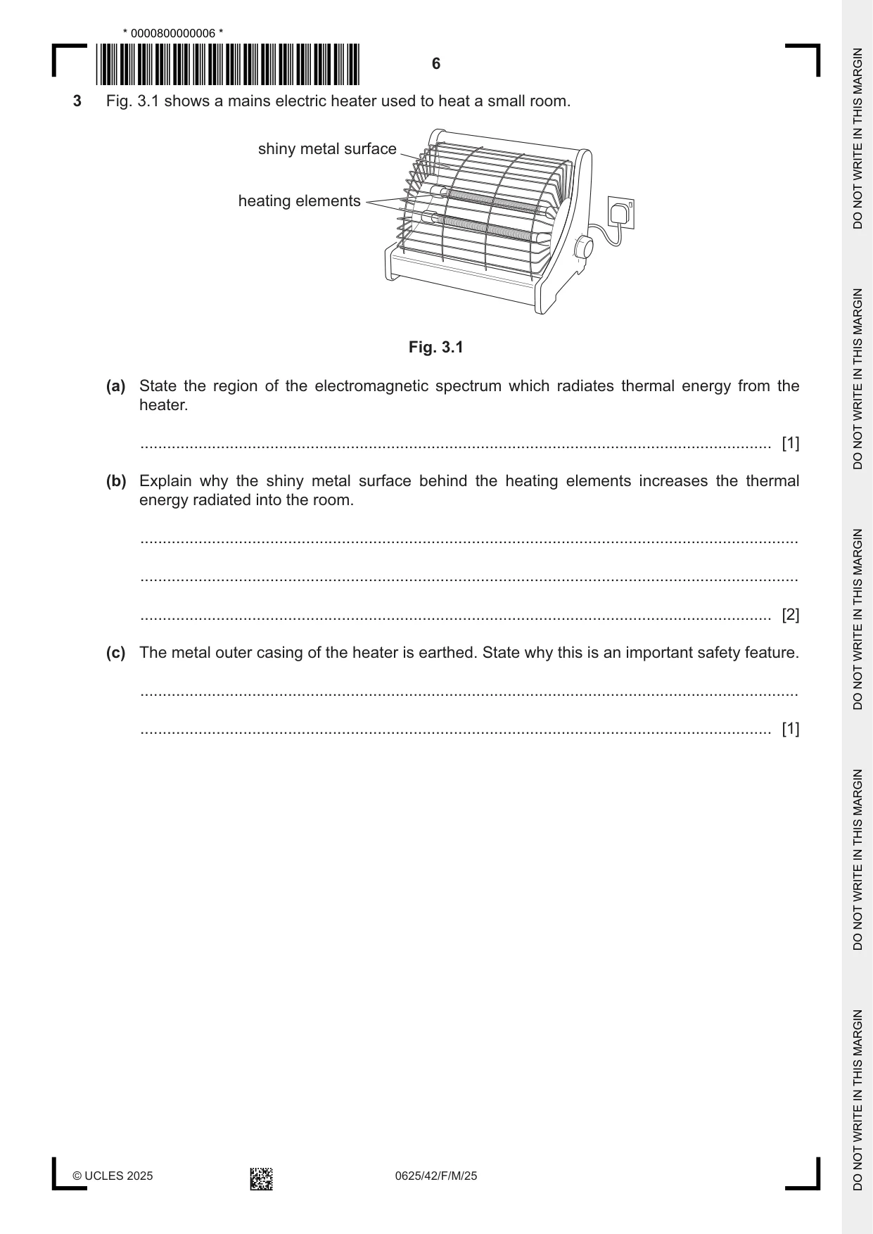
3 Fig. 3.1 shows a mains electric heater used to heat a small room. shiny metal surface heating elements Fig. 3.1 (a) State the region of the electromagnetic spectrum which radiates thermal energy from the heater. ............................................................................................................................................. [1] (b) Explain why the shiny metal surface behind the heating elements increases the thermal energy radiated into the room. ................................................................................................................................................... ................................................................................................................................................... ............................................................................................................................................. [2] (c) The metal outer casing of the heater is earthed. State why this is an important safety feature. ................................................................................................................................................... ............................................................................................................................................. [1] (d) The mains voltage is 230 V. The two identical heating elements are connected in parallel. Each heating element has a resistance of 89 Ω. (i) Calculate the current in one heating element. current = ......................................................... [2] (ii) Show that the electrical power of the heater is approximately 1200 W. State any equation you use in words or symbols. [2] (iii) The heater is 95% efficient at converting electrical work done to thermal energy. Calculate the thermal energy emitted by the heater in (d)(ii) in 60 s. Give your answer to two significant figures. thermal energy = ......................................................... [3] [Total: 11]
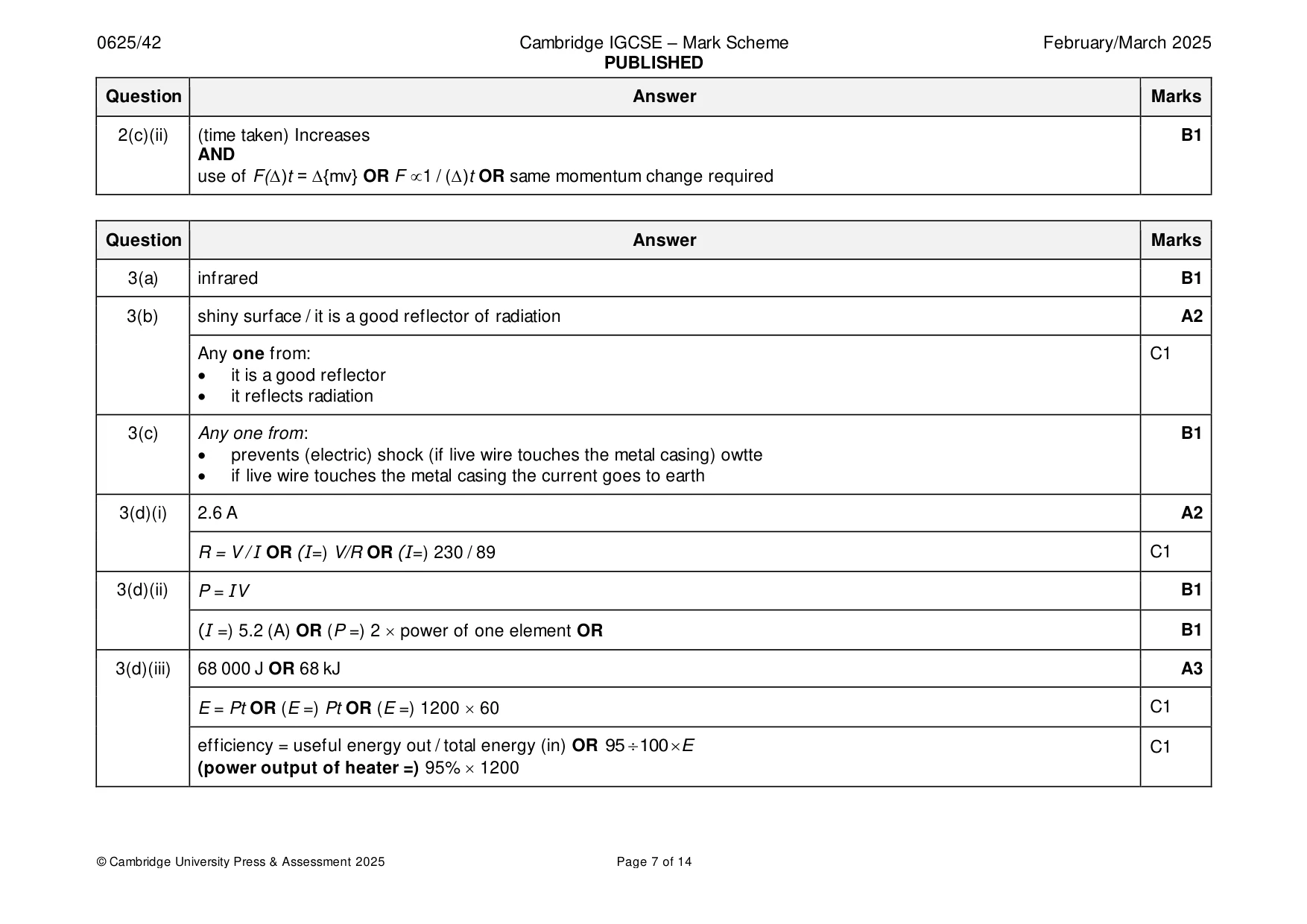
Mark scheme: 3(a) infrared B1 3(b) shiny surface / it is a good reflector of radiation A2 Any one from: C1 • it is a good reflector • it reflects radiation 3(c) Any one from: B1 • prevents (electric) shock (if live wire touches the metal casing) owtte • if live wire touches the metal casing the current goes to earth 3(d)(i) 2.6 A A2 R = V / I OR (I=) V/R OR (I=) 230 / 89 C1 3(d)(ii) P = IV B1 (I =) 5.2 (A) OR (P =) 2 power of one element OR B1 3(d)(iii) 68 000 J OR 68 kJ A3 E = Pt OR (E =) Pt OR (E =) 1200 60 C1 efficiency = useful energy out / total energy (in) OR 95 100 E C1 (power output of heater =) 95% 1200
Q4 · A train has a maximum speed of 200 km / h
4 A train has a maximum speed of 200 km / h. It accelerates from rest with constant acceleration of 0.70 m / s2. (a) (i) Define acceleration. ........................................................................................................................................... ..................................................................................................................................... [1] (ii) Show that the maximum speed of the train is approximately 56 m / s. [2] (iii) Calculate the time taken for the train to reach its maximum speed. time = ......................................................... [2] (b) (i) The train has a total mass of 440 000 kg. Calculate the force which causes the acceleration of the train. force = ......................................................... [2] (ii) The train travels into a headwind. The force of this headwind opposes the motion of the train. State and explain the effect of this force on the motion of the train. statement .......................................................................................................................... explanation ........................................................................................................................ ........................................................................................................................................... [1] [Total: 8]
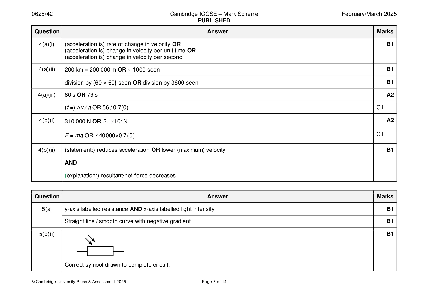
Mark scheme: 4(a)(i) (acceleration is) rate of change in velocity OR B1 (acceleration is) change in velocity per unit time OR (acceleration is) change in velocity per second 4(a)(ii) 200 km = 200 000 m OR 1000 seen B1 division by {60 60} seen OR division by 3600 seen B1 4(a)(iii) 80 s OR 79 s A2 (t =) ∆v / a OR 56 / 0.7(0) C1 4(b)(i) 310 000 N OR 3.11 0 5 N A2 F = ma OR 440 000 0.7 ( 0 ) C1 4(b)(ii) (statement:) reduces acceleration OR lower (maximum) velocity B1 AND (explanation:) resultant/net force decreases
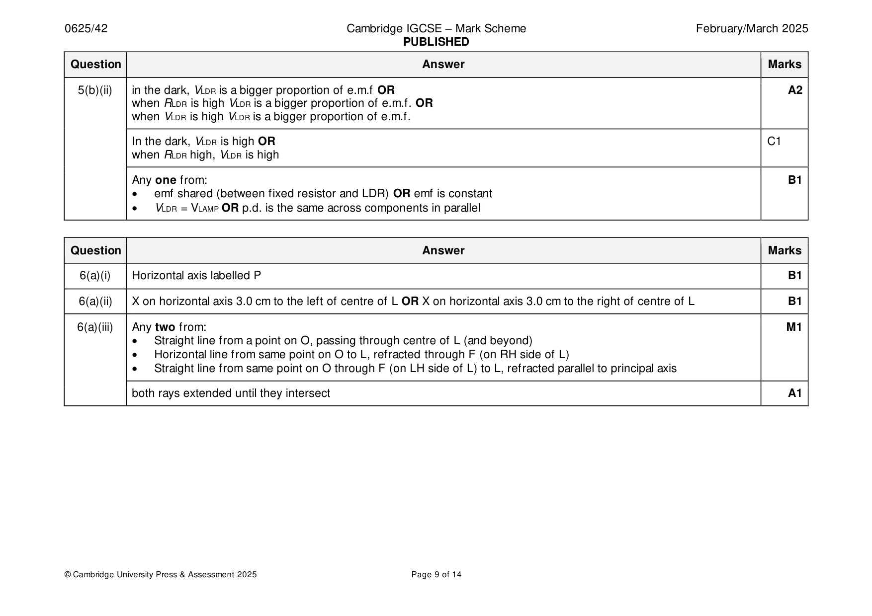
Q5 · A light-dependent resistor (LDR) has a low resistance in high light intensity and a high…
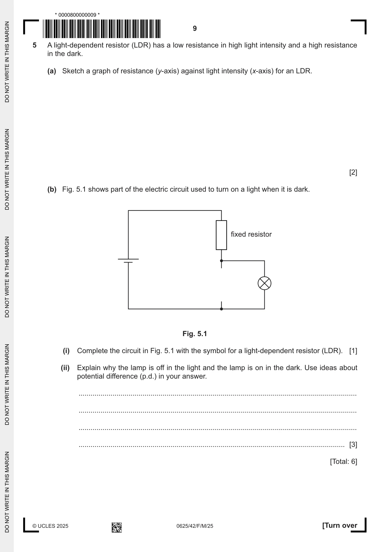
5 A light-dependent resistor (LDR) has a low resistance in high light intensity and a high resistance in the dark. (a) Sketch a graph of resistance (y-axis) against light intensity (x-axis) for an LDR. [2] (b) Fig. 5.1 shows part of the electric circuit used to turn on a light when it is dark. fixed resistor Fig. 5.1 (i) Complete the circuit in Fig. 5.1 with the symbol for a light-dependent resistor (LDR). [1] (ii) Explain why the lamp is off in the light and the lamp is on in the dark. Use ideas about potential difference (p.d.) in your answer. ........................................................................................................................................... ........................................................................................................................................... ........................................................................................................................................... ..................................................................................................................................... [3] [Total: 6]
Mark scheme: 5(a) y-axis labelled resistance AND x-axis labelled light intensity B1 Straight line / smooth curve with negative gradient B1 5(b)(i) B1 Correct symbol drawn to complete circuit. 5(b)(ii) in the dark, VLDR is a bigger proportion of e.m.f OR A2 when RLDR is high VLDR is a bigger proportion of e.m.f. OR when VLDR is high VLDR is a bigger proportion of e.m.f. In the dark, VLDR is high OR C1 when RLDR high, VLDR is high Any one from: B1 • emf shared (between fixed resistor and LDR) OR emf is constant • VLDR = VLAMP OR p.d. is the same across components in parallel
Q6 · An object O which is 5.0 cm away from the centre of a thin, converging lens L
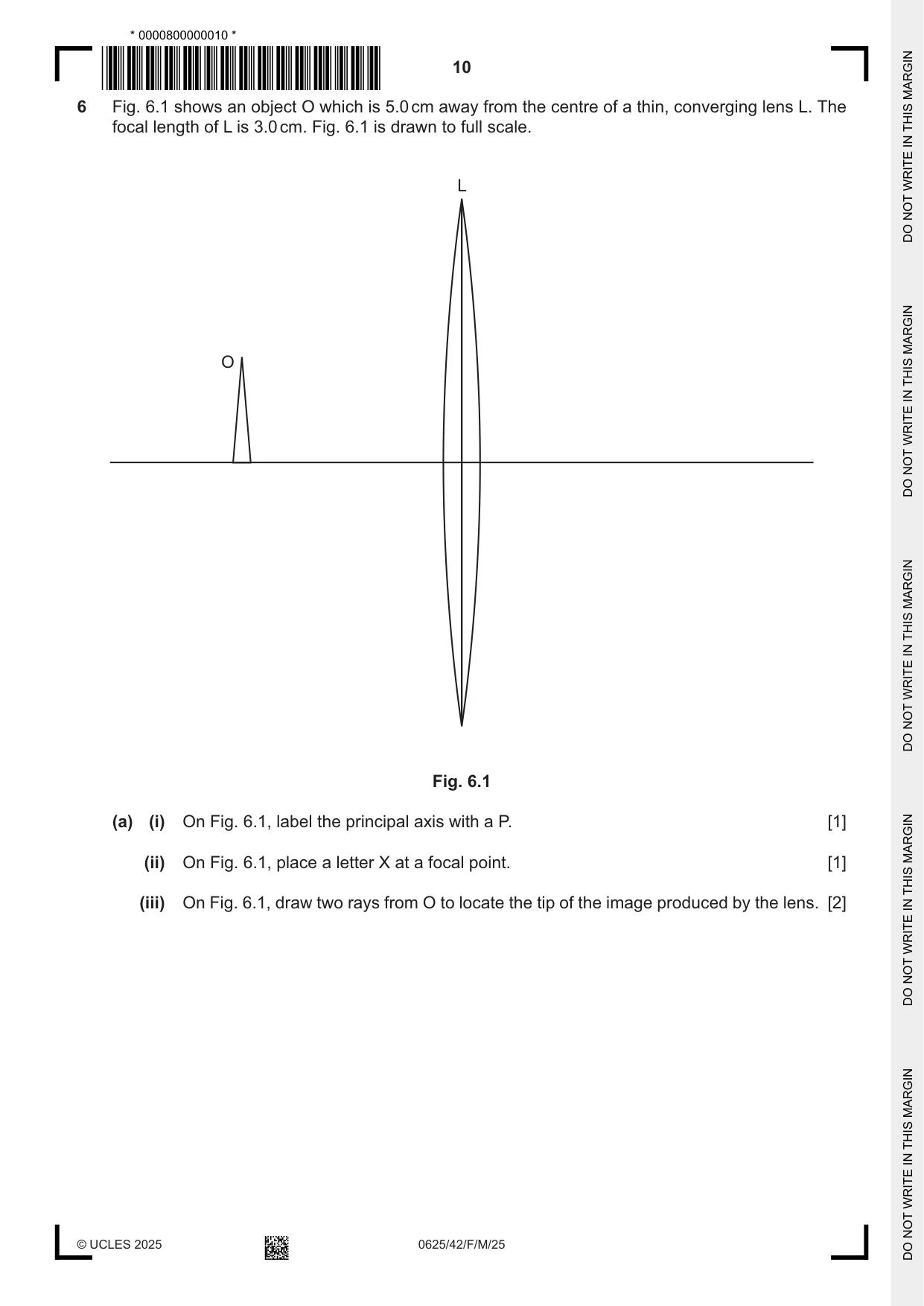
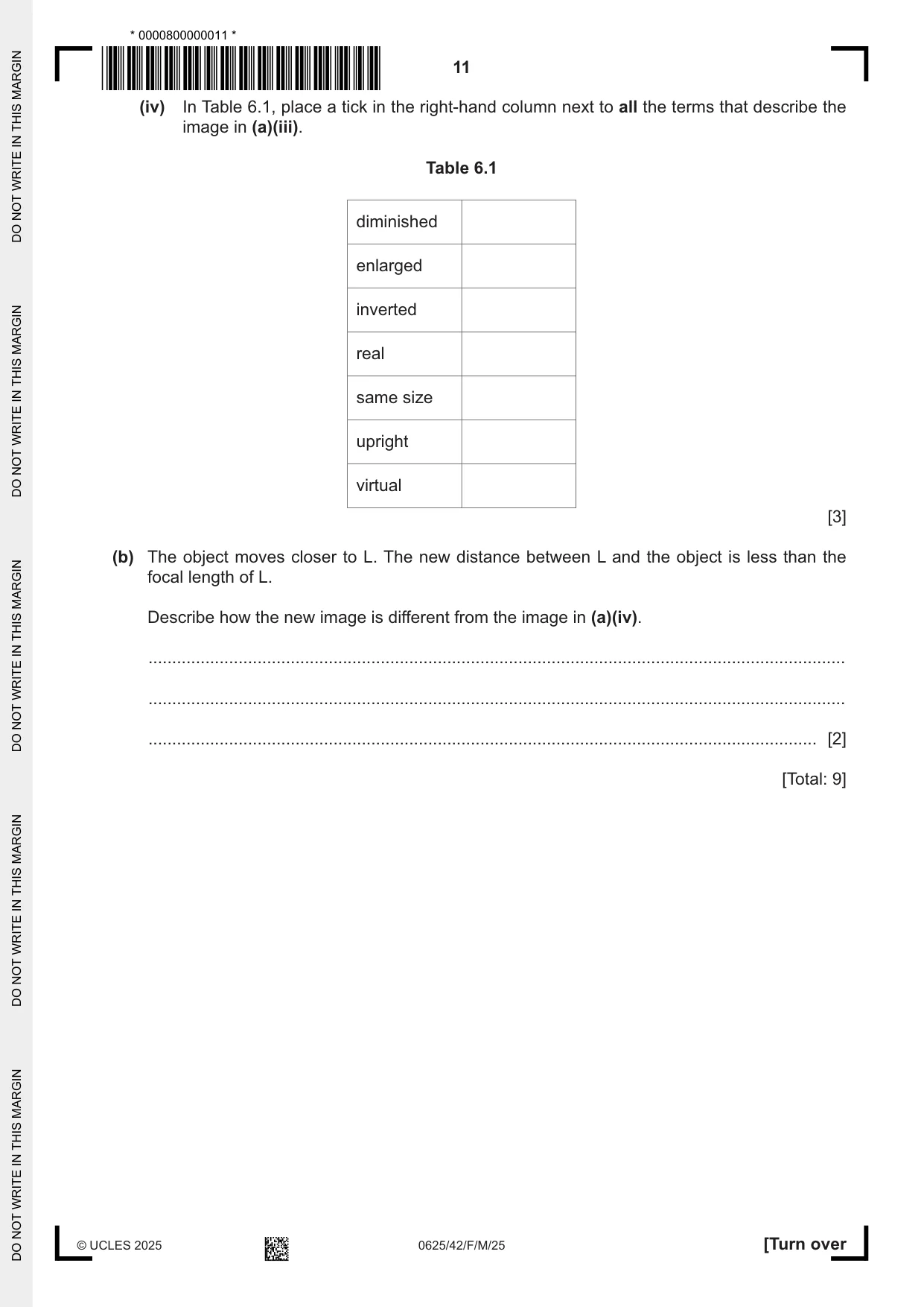
6 Fig. 6.1 shows an object O which is 5.0 cm away from the centre of a thin, converging lens L. The focal length of L is 3.0 cm. Fig. 6.1 is drawn to full scale. L O Fig. 6.1 (a) (i) On Fig. 6.1, label the principal axis with a P. [1] (ii) On Fig. 6.1, place a letter X at a focal point. [1] (iii) On Fig. 6.1, draw two rays from O to locate the tip of the image produced by the lens. [2] (iv) In Table 6.1, place a tick in the right-hand column next to all the terms that describe the image in (a)(iii). Table 6.1 diminished enlarged inverted real same size upright virtual [3] (b) The object moves closer to L. The new distance between L and the object is less than the focal length of L. Describe how the new image is different from the image in (a)(iv). ................................................................................................................................................... ................................................................................................................................................... ............................................................................................................................................. [2] [Total: 9]
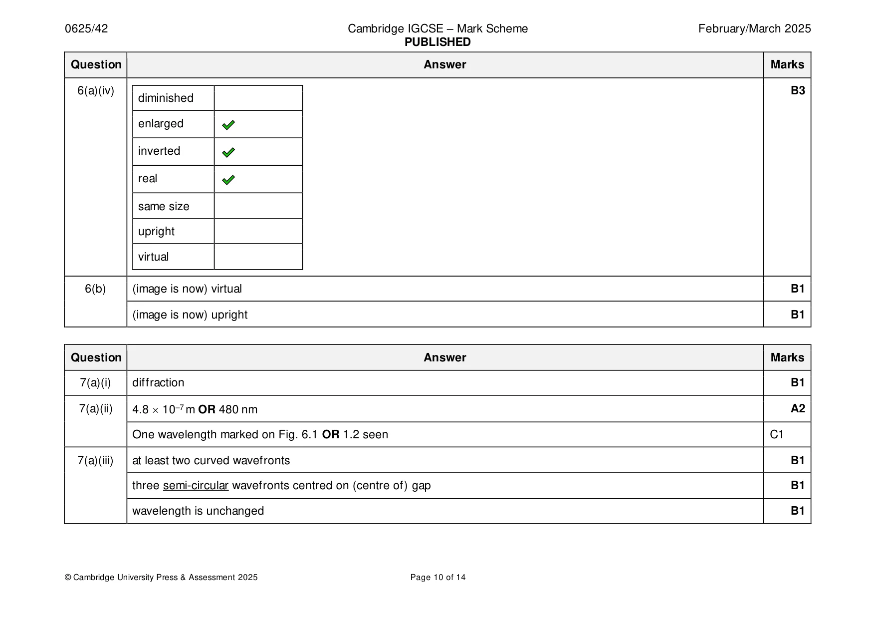
Mark scheme: 6(a)(i) Horizontal axis labelled P B1 6(a)(ii) X on horizontal axis 3.0 cm to the left of centre of L OR X on horizontal axis 3.0 cm to the right of centre of L B1 6(a)(iii) Any two from: M1 • Straight line from a point on O, passing through centre of L (and beyond) • Horizontal line from same point on O to L, refracted through F (on RH side of L) • Straight line from same point on O through F (on LH side of L) to L, refracted parallel to principal axis both rays extended until they intersect A1 6(a)(iv) B3 diminished enlarged inverted real same size upright virtual 6(b) (image is now) virtual B1 (image is now) upright B1
Q7 · A scale drawing of light waves approaching a narrow slit
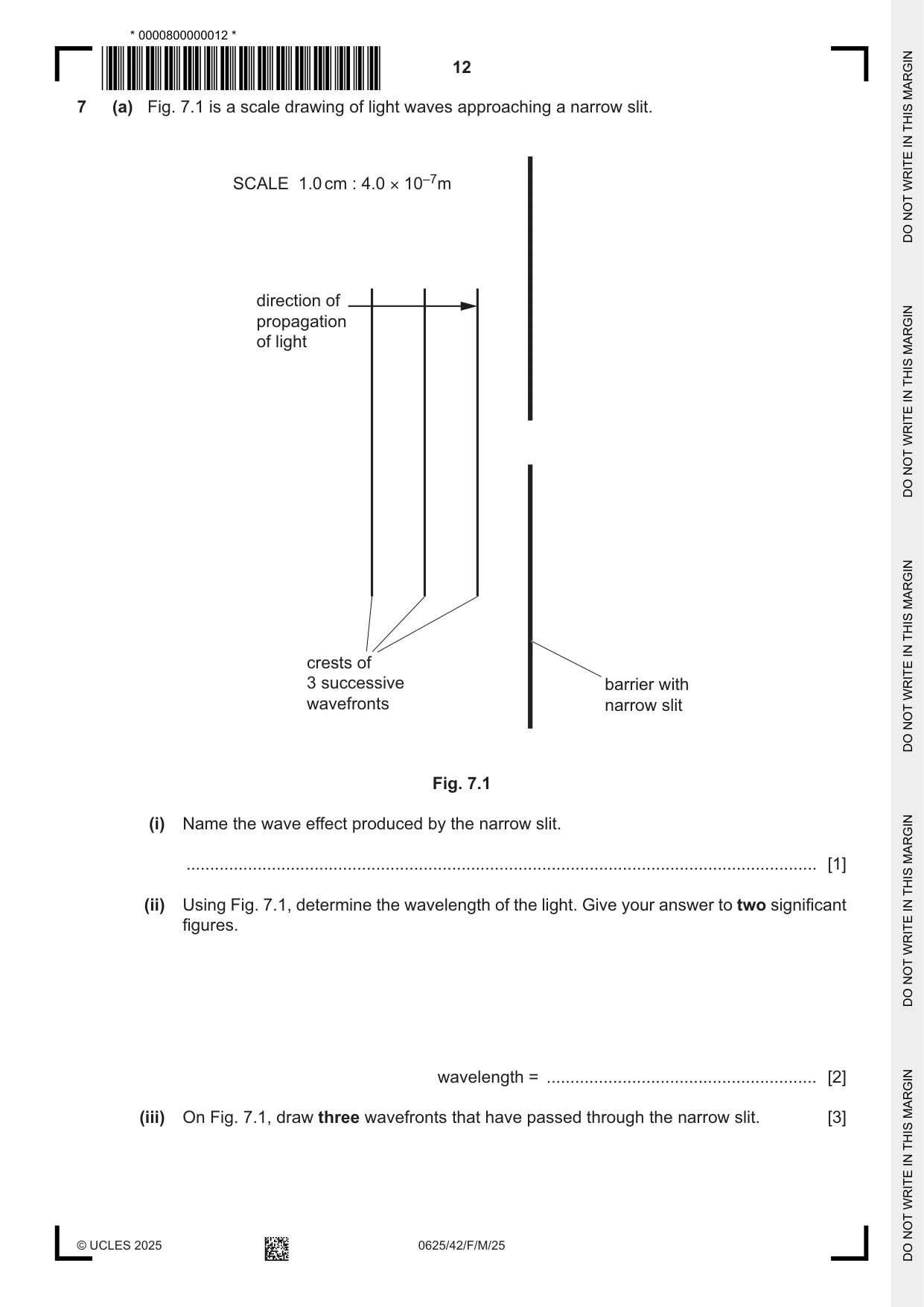
7 (a) Fig. 7.1 is a scale drawing of light waves approaching a narrow slit. SCALE 1.0 cm : 4.0 × 10⁻⁷m direction of propagation of light crests of 3 successive barrier with wavefronts narrow slit Fig. 7.1 (i) Name the wave effect produced by the narrow slit. ..................................................................................................................................... [1] (ii) Using Fig. 7.1, determine the wavelength of the light. Give your answer to two significant figures. wavelength = ......................................................... [2] (iii) On Fig. 7.1, draw three wavefronts that have passed through the narrow slit. [3] (b) A foghorn emits a sound with frequency 380 Hz. The sound is heard by a ship 2.5 km away from the foghorn. The speed of sound in air is 330 m / s. (i) Show that the wavelength of the sound is approximately 0.9 m. State any equation you use in words or symbols. [2] (ii) Calculate the time it takes for sound to travel to the ship from the foghorn. time = ......................................................... [2] [Total: 10]
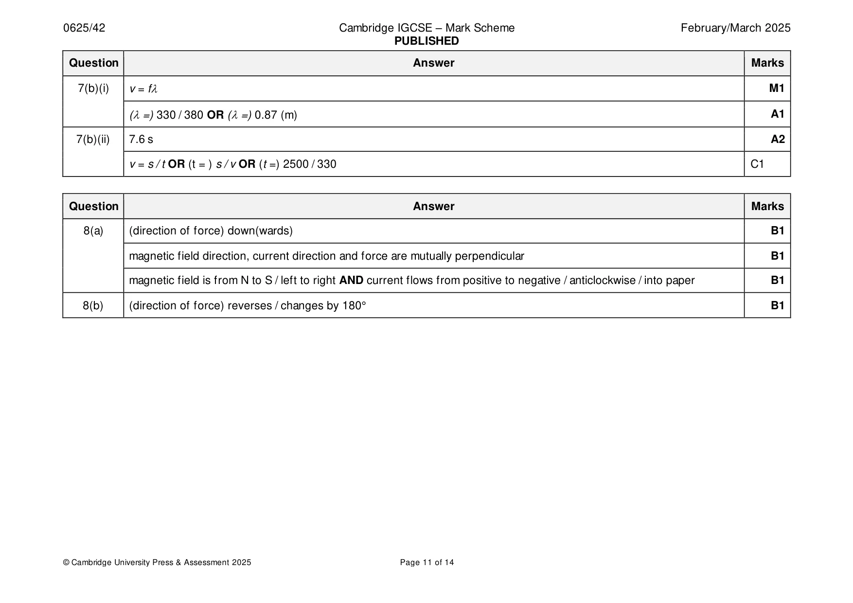
Mark scheme: 7(a)(i) diffraction B1 7(a)(ii) 4.8 10–7 m OR 480 nm A2 One wavelength marked on Fig. 6.1 OR 1.2 seen C1 7(a)(iii) at least two curved wavefronts B1 three semi-circular wavefronts centred on (centre of) gap B1 wavelength is unchanged B1 7(b)(i) v = f M1 (=) 330 / 380 OR (=) 0.87 (m) A1 7(b)(ii) 7.6 s A2 v = s / t OR (t = ) s / v OR (t =) 2500 / 330 C1
Q8 · A metal rod suspended in the magnetic field produced by a pair of permanent magnets
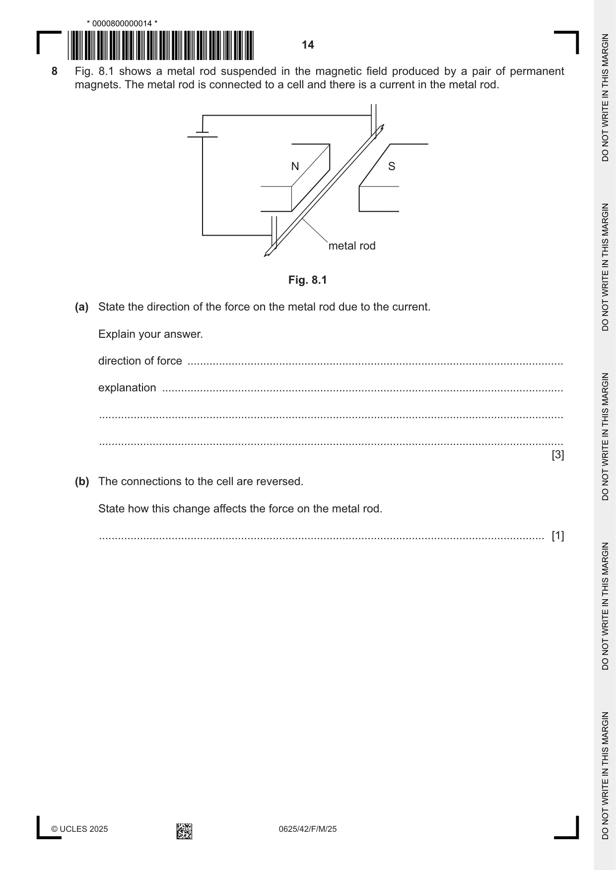
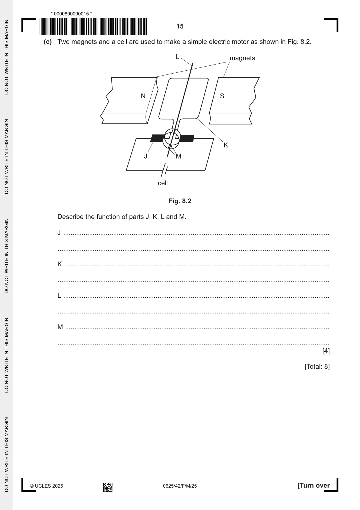
8 Fig. 8.1 shows a metal rod suspended in the magnetic field produced by a pair of permanent magnets. The metal rod is connected to a cell and there is a current in the metal rod. N S metal rod Fig. 8.1 (a) State the direction of the force on the metal rod due to the current. Explain your answer. direction of force ....................................................................................................................... explanation ............................................................................................................................... ................................................................................................................................................... ................................................................................................................................................... [3] (b) The connections to the cell are reversed. State how this change affects the force on the metal rod. ............................................................................................................................................. [1] (c) Two magnets and a cell are used to make a simple electric motor as shown in Fig. 8.2. L magnets N S K J M cell Fig. 8.2 Describe the function of parts J, K, L and M. J ................................................................................................................................................ ................................................................................................................................................... K ............................................................................................................................................... ................................................................................................................................................... L ................................................................................................................................................ ................................................................................................................................................... M ............................................................................................................................................... ................................................................................................................................................... [4] [Total: 8]
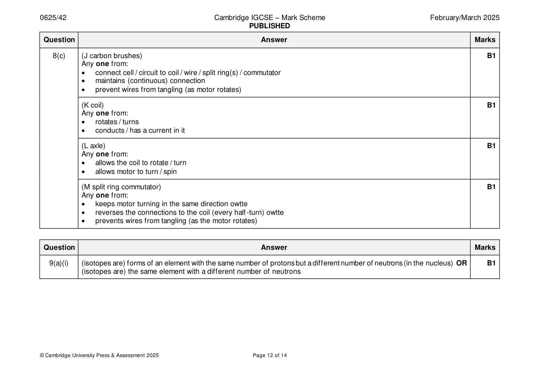
Mark scheme: 8(a) (direction of force) down(wards) B1 magnetic field direction, current direction and force are mutually perpendicular B1 magnetic field is from N to S / left to right AND current flows from positive to negative / anticlockwise / into paper B1 8(b) (direction of force) reverses / changes by 180° B1 8(c) (J carbon brushes) B1 Any one from: • connect cell / circuit to coil / wire / split ring(s) / commutator • maintains (continuous) connection • prevent wires from tangling (as motor rotates) (K coil) B1 Any one from: • rotates / turns • conducts / has a current in it (L axle) B1 Any one from: • allows the coil to rotate / turn • allows motor to turn / spin (M split ring commutator) B1 Any one from: • keeps motor turning in the same direction owtte • reverses the connections to the coil (every half-turn) owtte • prevents wires from tangling (as the motor rotates)
Q9 · Strontium-90 is a radioactive isotope of strontium
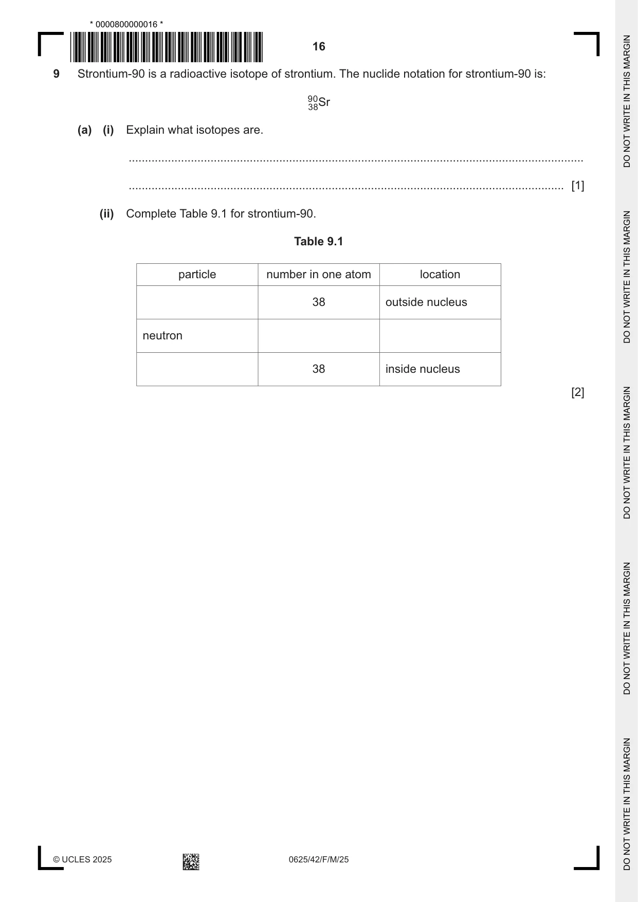
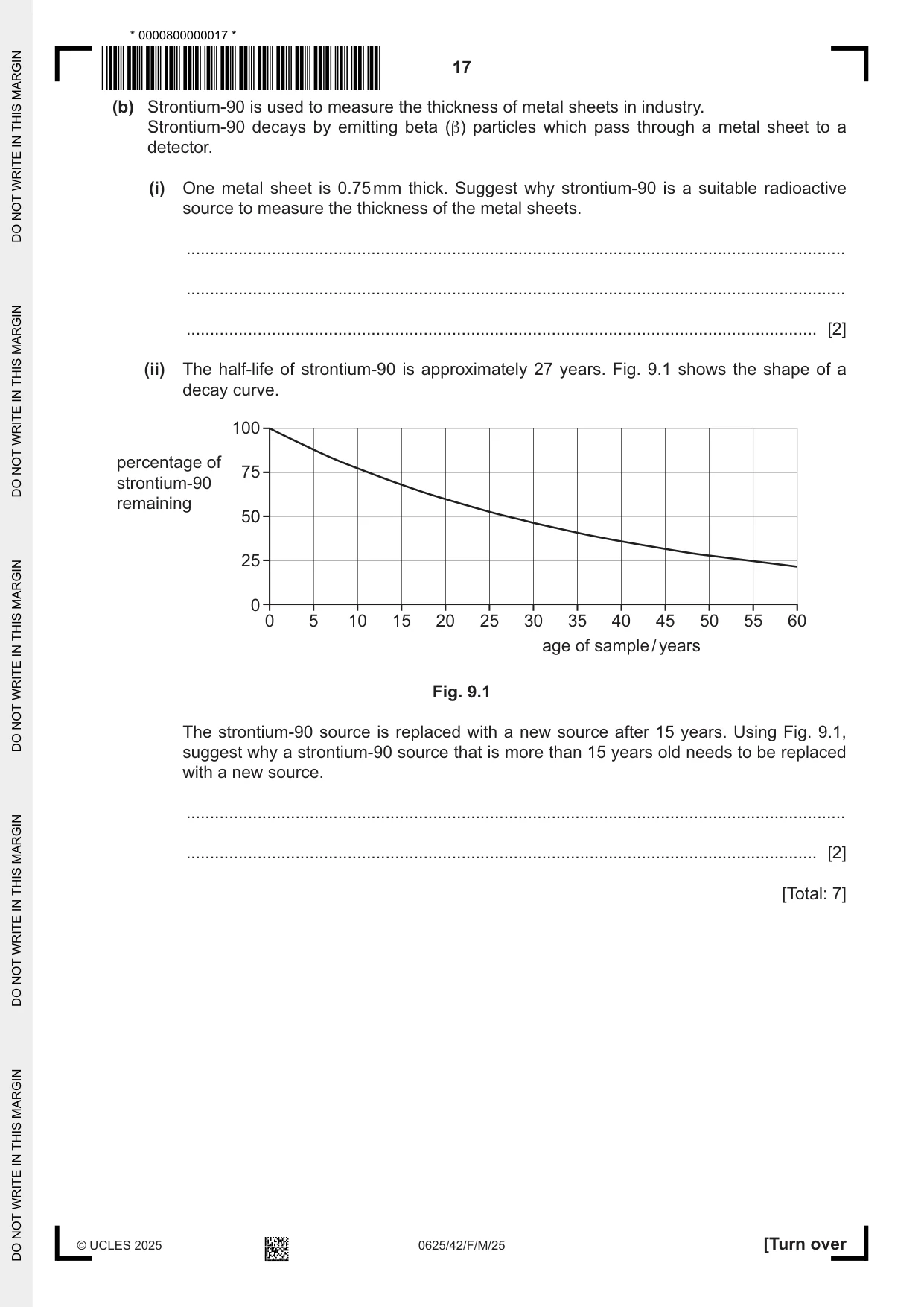
9 Strontium-90 is a radioactive isotope of strontium. The nuclide notation for strontium-90 is: 9 0 3 8Sr (a) (i) Explain what isotopes are. ........................................................................................................................................... ..................................................................................................................................... [1] (ii) Complete Table 9.1 for strontium-90. Table 9.1 particle number in one atom location 38 outside nucleus neutron 38 inside nucleus [2] (b) Strontium-90 is used to measure the thickness of metal sheets in industry. Strontium-90 decays by emitting beta (β) particles which pass through a metal sheet to a detector. (i) One metal sheet is 0.75 mm thick. Suggest why strontium-90 is a suitable radioactive source to measure the thickness of the metal sheets. ........................................................................................................................................... ........................................................................................................................................... ..................................................................................................................................... [2] (ii) The half-life of strontium-90 is approximately 27 years. Fig. 9.1 shows the shape of a decay curve. 100 percentage of 75 strontium-90 remaining 500 25 0 0 5 10 15 20 25 30 35 40 45 50 55 60 age of sample / years Fig. 9.1 The strontium-90 source is replaced with a new source after 15 years. Using Fig. 9.1, suggest why a strontium-90 source that is more than 15 years old needs to be replaced with a new source. ........................................................................................................................................... ..................................................................................................................................... [2] [Total: 7]
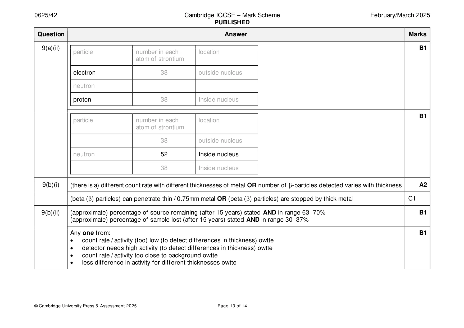
Mark scheme: 9(a)(i) (isotopes are) forms of an element with the same number of protons but a different number of neutrons (in the nucleus) OR B1 (isotopes are) the same element with a different number of neutrons 9(a)(ii) B1 particle number in each location atom of strontium electron 38 outside nucleus neutron proton 38 Inside nucleus B1 particle number in each location atom of strontium 38 outside nucleus neutron 52 Inside nucleus 38 Inside nucleus 9(b)(i) (there is a) different count rate with different thicknesses of metal OR number of -particles detected varies with thickness A2 (beta () particles) can penetrate thin / 0.75mm metal OR (beta () particles) are stopped by thick metal C1 9(b)(ii) (approximate) percentage of source remaining (after 15 years) stated AND in range 63–70% B1 (approximate) percentage of sample lost (after 15 years) stated AND in range 30–37% Any one from: B1 • count rate / activity (too) low (to detect differences in thickness) owtte • detector needs high activity (to detect differences in thickness) owtte • count rate / activity too close to background owtte • less difference in activity for different thicknesses owtte
Q10 · The path of the Earth as it orbits the Sun
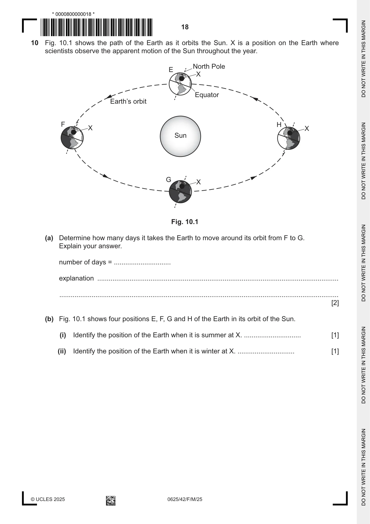
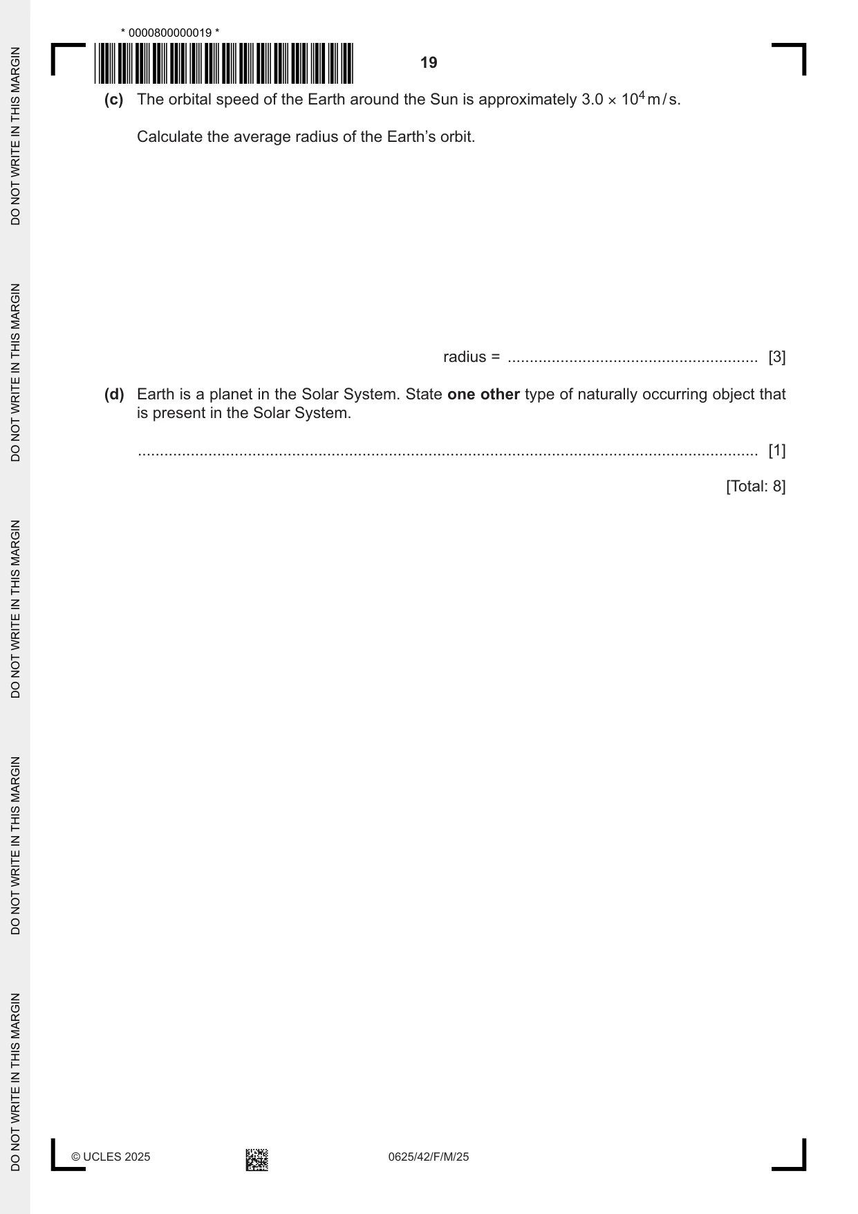
10 Fig. 10.1 shows the path of the Earth as it orbits the Sun. X is a position on the Earth where scientists observe the apparent motion of the Sun throughout the year. North Pole E X Equator Earth’s orbit F H X X Sun G X Fig. 10.1 (a) Determine how many days it takes the Earth to move around its orbit from F to G. Explain your answer. number of days = .............................. explanation ............................................................................................................................... ................................................................................................................................................... [2] (b) Fig. 10.1 shows four positions E, F, G and H of the Earth in its orbit of the Sun. (i) Identify the position of the Earth when it is summer at X. .............................. [1] (ii) Identify the position of the Earth when it is winter at X. .............................. [1] (c) The orbital speed of the Earth around the Sun is approximately 3.0 × 10⁴ m / s. Calculate the average radius of the Earth’s orbit. radius = ......................................................... [3] (d) Earth is a planet in the Solar System. State one other type of naturally occurring object that is present in the Solar System. ............................................................................................................................................. [1] [Total: 8]
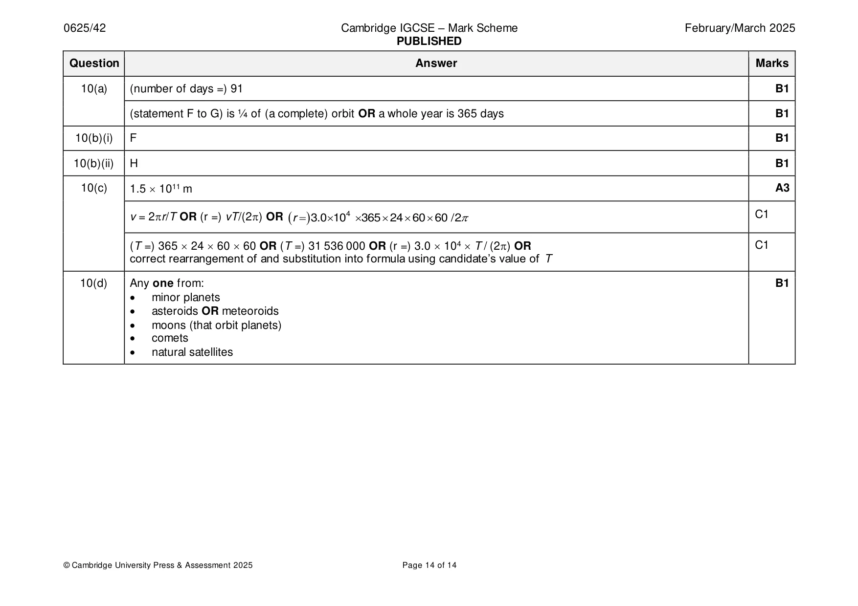
Mark scheme: 10(a) (number of days =) 91 B1 (statement F to G) is ¼ of (a complete) orbit OR a whole year is 365 days B1 10(b)(i) F B1 10(b)(ii) H B1 10(c) 1.5 1011 m A3 v = 2r/T OR (r =) vT/(2) OR ( r = ) 3.0 104 365 24 60 60 / 2 C1 (T =) 365 24 60 60 OR (T =) 31 536 000 OR (r =) 3.0 104 T / (2) OR C1 correct rearrangement of and substitution into formula using candidate’s value of T 10(d) Any one from: B1 • minor planets • asteroids OR meteoroids • moons (that orbit planets) • comets • natural satellites
What was in this paper
The subtopics covered by these 10 questions, and how many questions each got. Open one in a new tab to see every Cambridge question on it.
What you needed in this session
Cambridge’s own grade thresholds for 2025 Feb/March, Paper 4 · Variant 2. A higher threshold means an easier paper — the bar moves with how the cohort did.