Cambridge IGCSE Physics 0625 — 2017 Feb/March Paper 4 · Variant 2
0625/42/F/M/17 · 11 questions · 80 marks · ≈90 min
The question paper and its mark scheme, free to read here and free to download. This is Cambridge’s own paper, exactly as it was sat.
Question paper16 pages
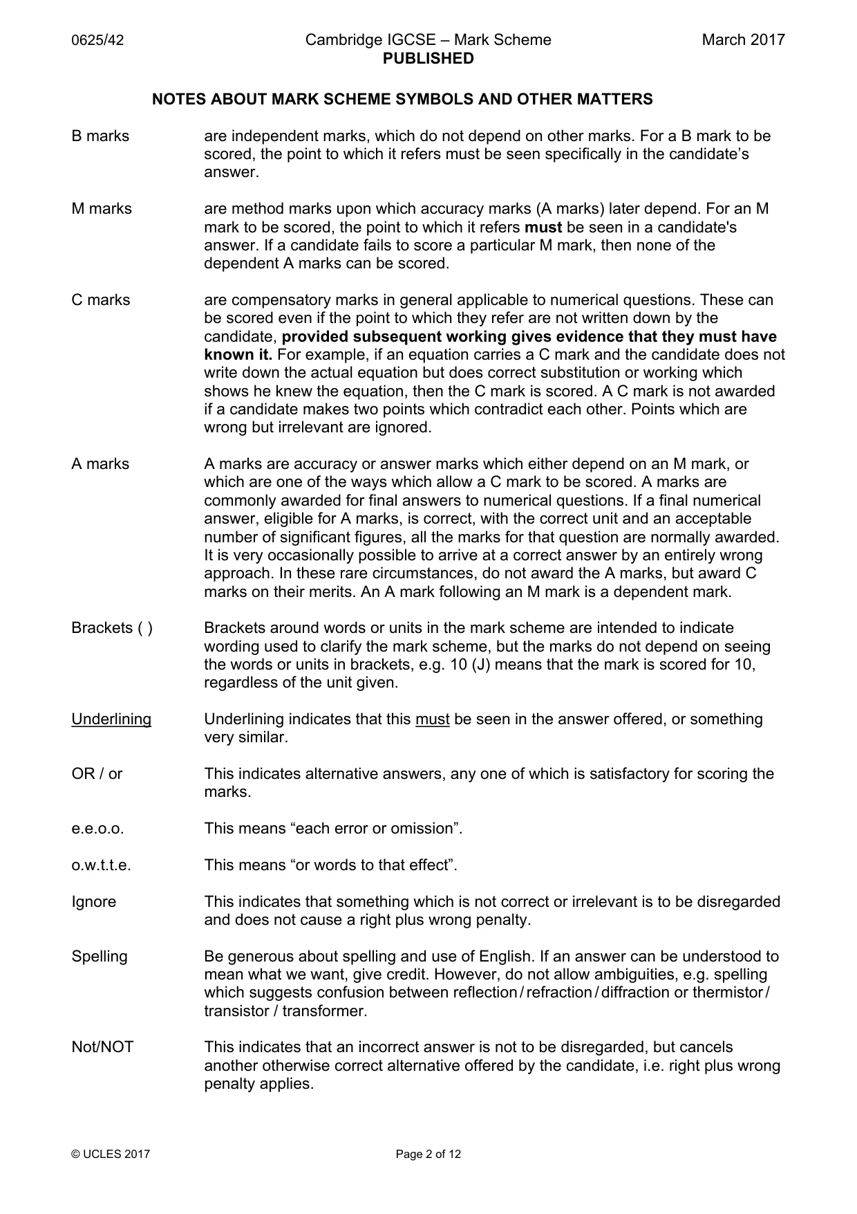
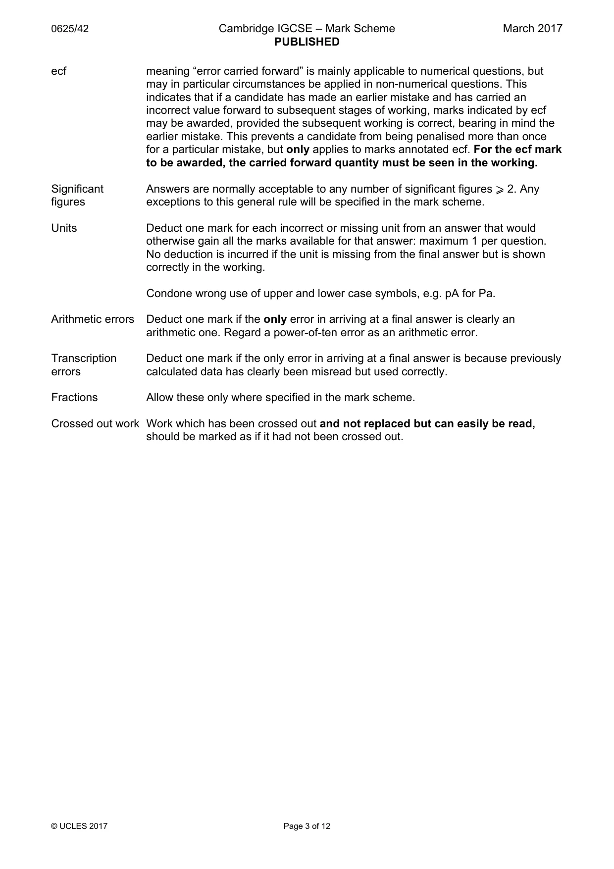
Mark scheme12 pages
Answers below. Sit the paper first if you are practising.
Questions as text
Q1 · The axes used to plot distance-time graphs
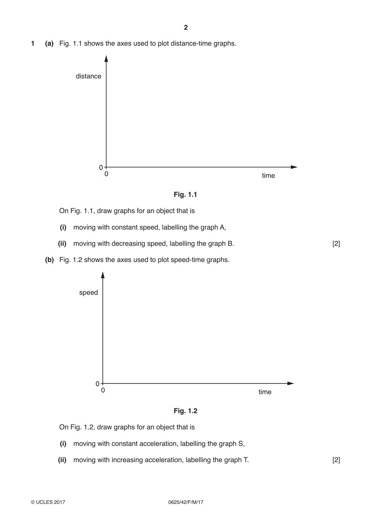
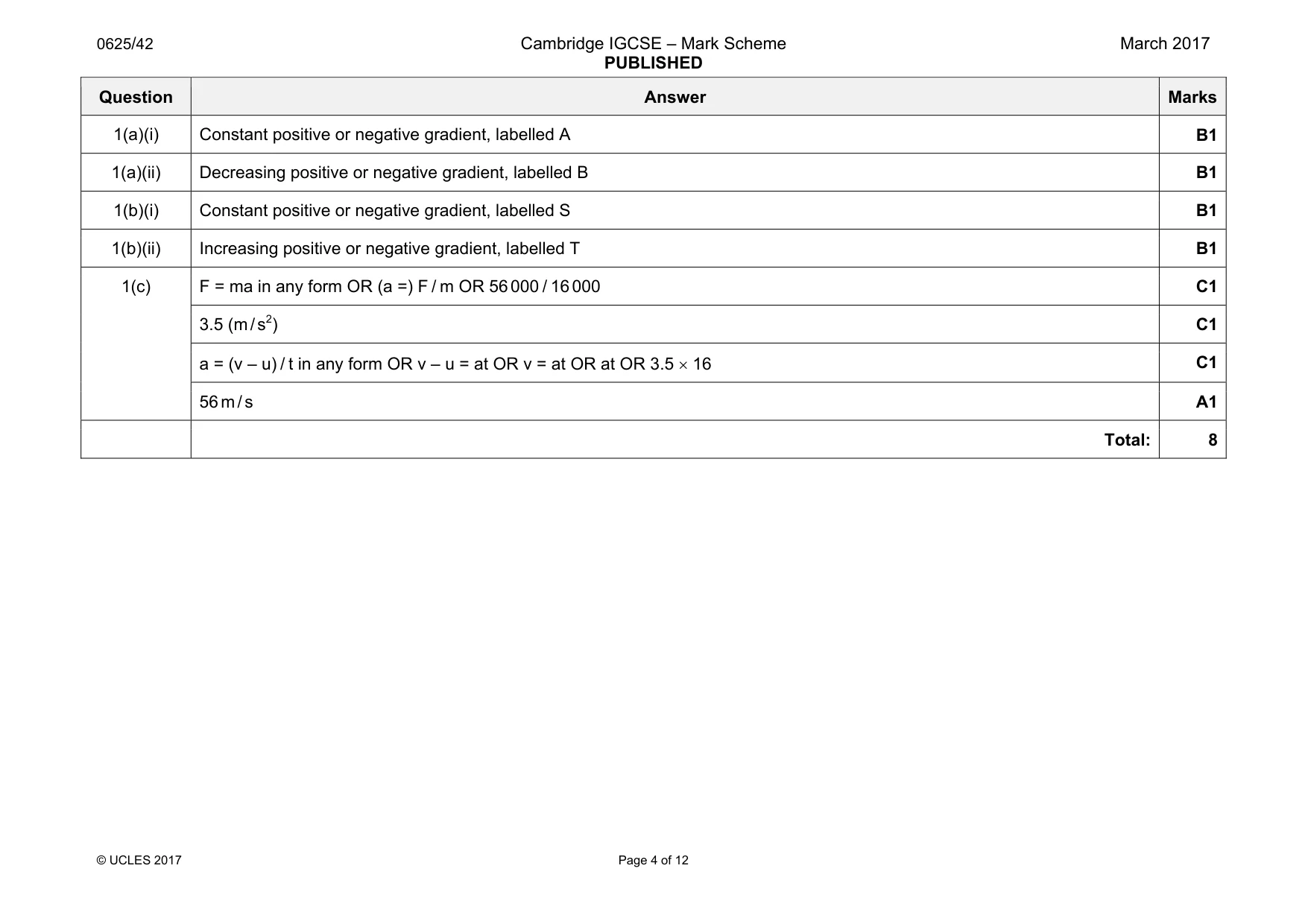
1 (a) Fig. 1.1 shows the axes used to plot distance-time graphs. distance 0 0 time Fig. 1.1 On Fig. 1.1, draw graphs for an object that is (i) moving with constant speed, labelling the graph A, (ii) moving with decreasing speed, labelling the graph B. [2] (b) Fig. 1.2 shows the axes used to plot speed-time graphs. speed 0 0 time Fig. 1.2 On Fig. 1.2, draw graphs for an object that is (i) moving with constant acceleration, labelling the graph S, (ii) moving with increasing acceleration, labelling the graph T. [2] (c) A plane is at rest on an airport runway. The brakes of the plane are released and the engine of the plane provides a constant accelerating force. Using the following data, calculate the take-off speed of the plane. Ignore any resistive forces. constant forward force = 56 000 N mass of plane = 16 000 kg time of travel along runway = 16 s speed = ...........................................................[4] [Total: 8]
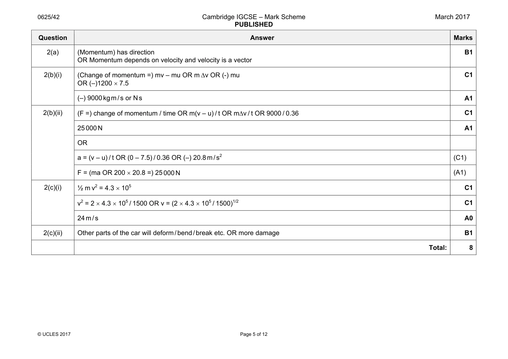
Mark scheme: 1(a)(i) Constant positive or negative gradient, labelled A B1 1(a)(ii) Decreasing positive or negative gradient, labelled B B1 1(b)(i) Constant positive or negative gradient, labelled S B1 1(b)(ii) Increasing positive or negative gradient, labelled T B1 1(c) F = ma in any form OR (a =) F / m OR 56 000 / 16 000 C1 3.5 (m / s2) C1 a = (v – u) / t in any form OR v – u = at OR v = at OR at OR 3.5 × 16 C1 56 m / s A1 Total: 8
Q2 · Explain why momentum is a vector quantity
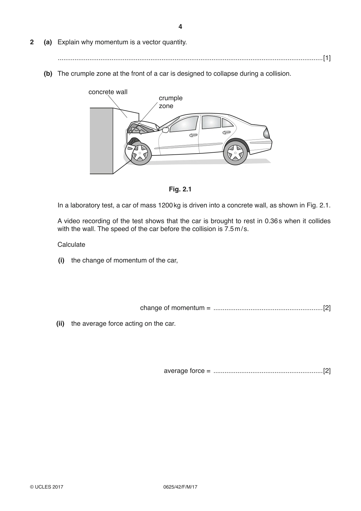
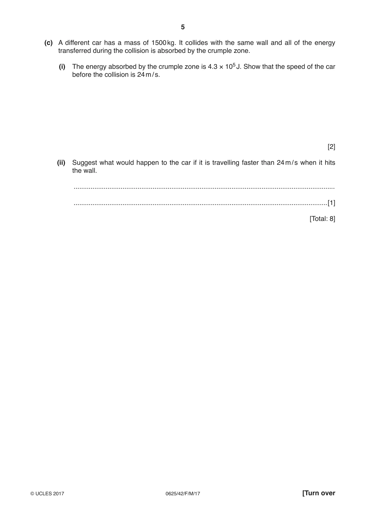
2 (a) Explain why momentum is a vector quantity. ...............................................................................................................................................[1] (b) The crumple zone at the front of a car is designed to collapse during a collision. concrete wall crumple zone Fig. 2.1 In a laboratory test, a car of mass 1200 kg is driven into a concrete wall, as shown in Fig. 2.1. A video recording of the test shows that the car is brought to rest in 0.36 s when it collides with the wall. The speed of the car before the collision is 7.5 m / s. Calculate (i) the change of momentum of the car, change of momentum = ...........................................................[2] (ii) the average force acting on the car. average force = ...........................................................[2] (c) A different car has a mass of 1500 kg. It collides with the same wall and all of the energy transferred during the collision is absorbed by the crumple zone. (i) The energy absorbed by the crumple zone is 4.3 × 10⁵ J. Show that the speed of the car before the collision is 24 m / s. [2] (ii) Suggest what would happen to the car if it is travelling faster than 24 m / s when it hits the wall. ........................................................................................................................................... .......................................................................................................................................[1] [Total: 8]
Mark scheme: 2(a) (Momentum) has direction OR Momentum depends on velocity and velocity is a vector B1 2(b)(i) (Change of momentum =) mv – mu OR m ∆v OR (-) mu OR (–)1200 × 7.5 C1 (–) 9000 kg m / s or N s A1 2(b)(ii) (F =) change of momentum / time OR m(v – u) / t OR m∆v / t OR 9000 / 0.36 C1 25 000 N A1 OR a = (v – u) / t OR (0 – 7.5) / 0.36 OR (–) 20.8 m / s2 (C1) F = (ma OR 200 × 20.8 =) 25 000 N (A1) 2(c)(i) ½ m v2 = 4.3 × 10⁵ C1 v2 = 2 × 4.3 × 105 / 1500 OR v = (2 × 4.3 × 105 / 1500)1/2 C1 24 m / s A0 2(c)(ii) Other parts of the car will deform / bend / break etc. OR more damage B1 Total: 8
Q3 · A stationary object is acted upon by a number of forces
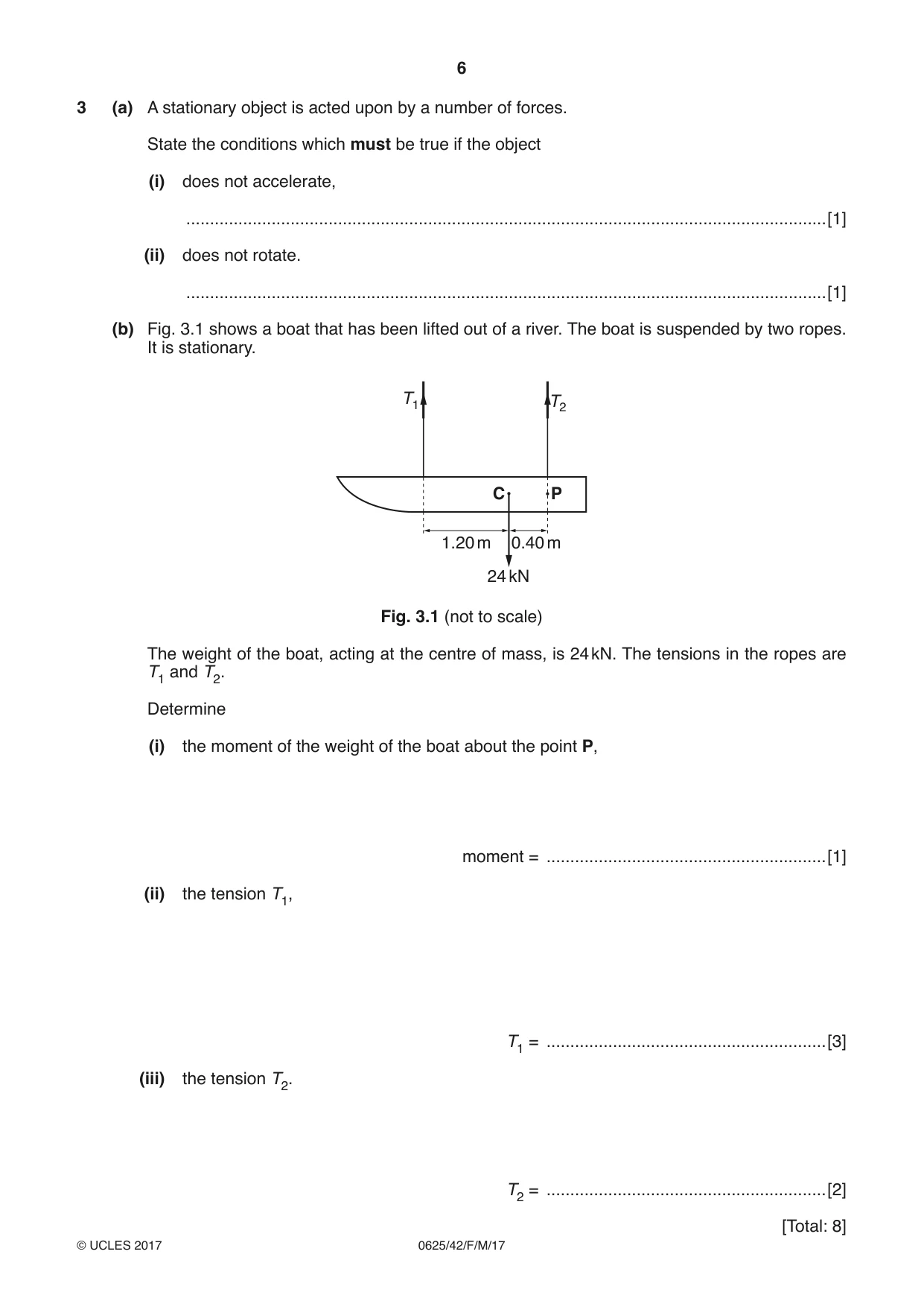
3 (a) A stationary object is acted upon by a number of forces. State the conditions which must be true if the object (i) does not accelerate, .......................................................................................................................................[1] (ii) does not rotate. .......................................................................................................................................[1] (b) Fig. 3.1 shows a boat that has been lifted out of a river. The boat is suspended by two ropes. It is stationary. T1 T2 C P 1.20 m 0.40 m 24 kN Fig. 3.1 (not to scale) The weight of the boat, acting at the centre of mass, is 24 kN. The tensions in the ropes are T1 and T2. Determine (i) the moment of the weight of the boat about the point P, moment = ...........................................................[1] (ii) the tension T1, T1 = ...........................................................[3] (iii) the tension T2. T2 = ...........................................................[2]
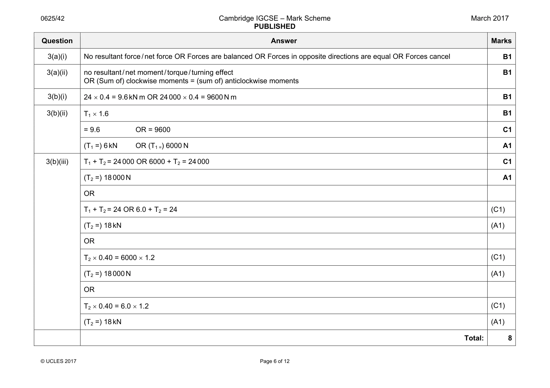
Mark scheme: 3(a)(i) No resultant force / net force OR Forces are balanced OR Forces in opposite directions are equal OR Forces cancel B1 3(a)(ii) no resultant / net moment / torque / turning effect OR (Sum of) clockwise moments = (sum of) anticlockwise moments B1 3(b)(i) 24 × 0.4 = 9.6 kN m OR 24 000 × 0.4 = 9600 N m B1 3(b)(ii) T1 × 1.6 B1 = 9.6 OR = 9600 C1 (T1 =) 6 kN OR (T1 =) 6000 N A1 3(b)(iii) T1 + T2 = 24 000 OR 6000 + T2 = 24 000 C1 (T2 =) 18 000 N A1 OR T1 + T2 = 24 OR 6.0 + T2 = 24 (C1) (T2 =) 18 kN (A1) OR T2 × 0.40 = 6000 × 1.2 (C1) (T2 =) 18 000 N (A1) OR T2 × 0.40 = 6.0 × 1.2 (C1) (T2 =) 18 kN (A1) Total: 8
Question 4
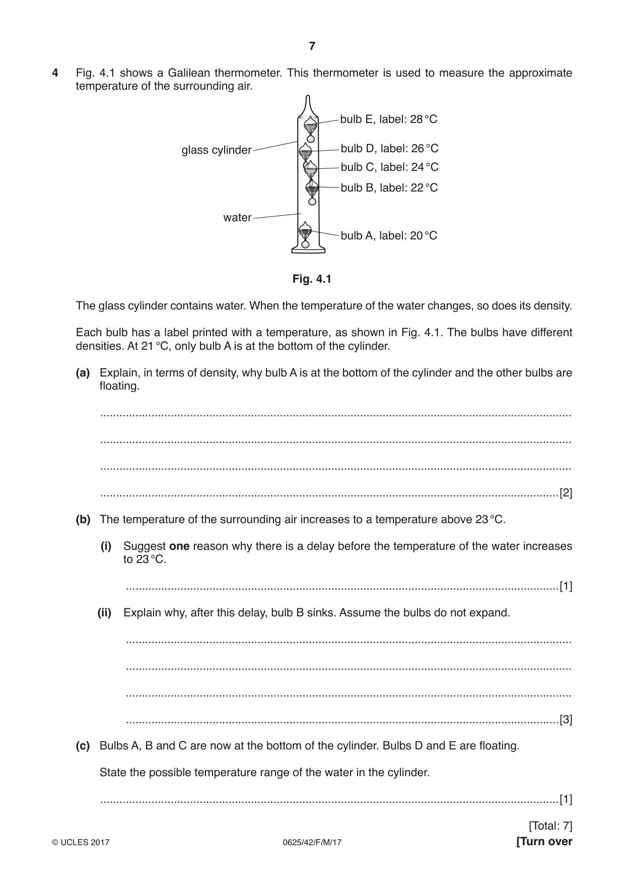
4 Fig. 4.1 shows a Galilean thermometer. This thermometer is used to measure the approximate temperature of the surrounding air. bulb E, label: 28 °C glass cylinder bulb D, label: 26 °C bulb C, label: 24 °C bulb B, label: 22 °C water bulb A, label: 20 °C Fig. 4.1 The glass cylinder contains water. When the temperature of the water changes, so does its density. Each bulb has a label printed with a temperature, as shown in Fig. 4.1. The bulbs have different densities. At 21 °C, only bulb A is at the bottom of the cylinder. (a) Explain, in terms of density, why bulb A is at the bottom of the cylinder and the other bulbs are floating. ................................................................................................................................................... ................................................................................................................................................... ................................................................................................................................................... ...............................................................................................................................................[2] (b) The temperature of the surrounding air increases to a temperature above 23 °C. (i) Suggest one reason why there is a delay before the temperature of the water increases to 23 °C. .......................................................................................................................................[1] (ii) Explain why, after this delay, bulb B sinks. Assume the bulbs do not expand. ........................................................................................................................................... ........................................................................................................................................... ........................................................................................................................................... .......................................................................................................................................[3] (c) Bulbs A, B and C are now at the bottom of the cylinder. Bulbs D and E are floating. State the possible temperature range of the water in the cylinder. ...............................................................................................................................................[1]
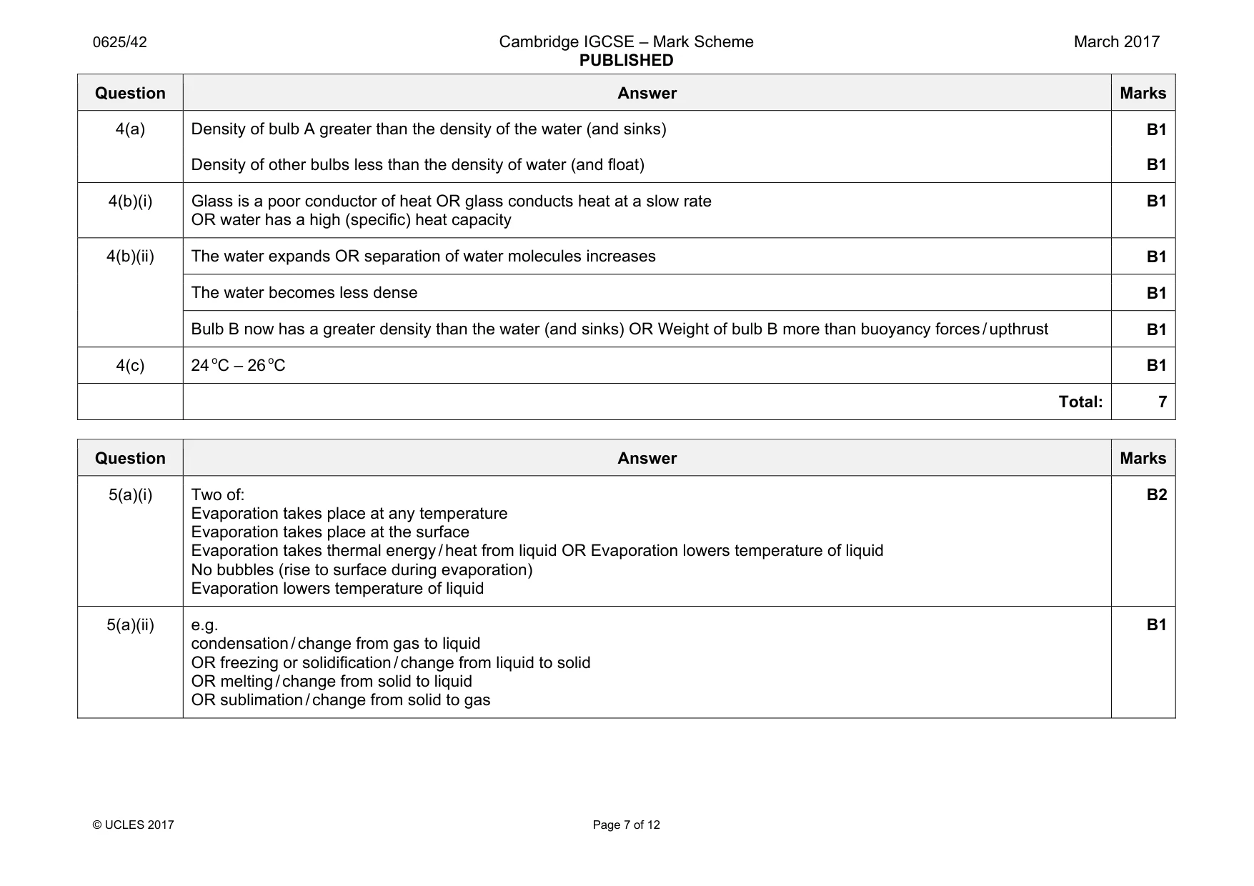
Mark scheme: 4(a) Density of bulb A greater than the density of the water (and sinks) B1 Density of other bulbs less than the density of water (and float) B1 4(b)(i) Glass is a poor conductor of heat OR glass conducts heat at a slow rate OR water has a high (specific) heat capacity B1 4(b)(ii) The water expands OR separation of water molecules increases B1 The water becomes less dense B1 Bulb B now has a greater density than the water (and sinks) OR Weight of bulb B more than buoyancy forces / upthrust B1 4(c) 24 oC – 26 oC B1 Total: 7
Q5 · State two ways in which evaporation is different from boiling
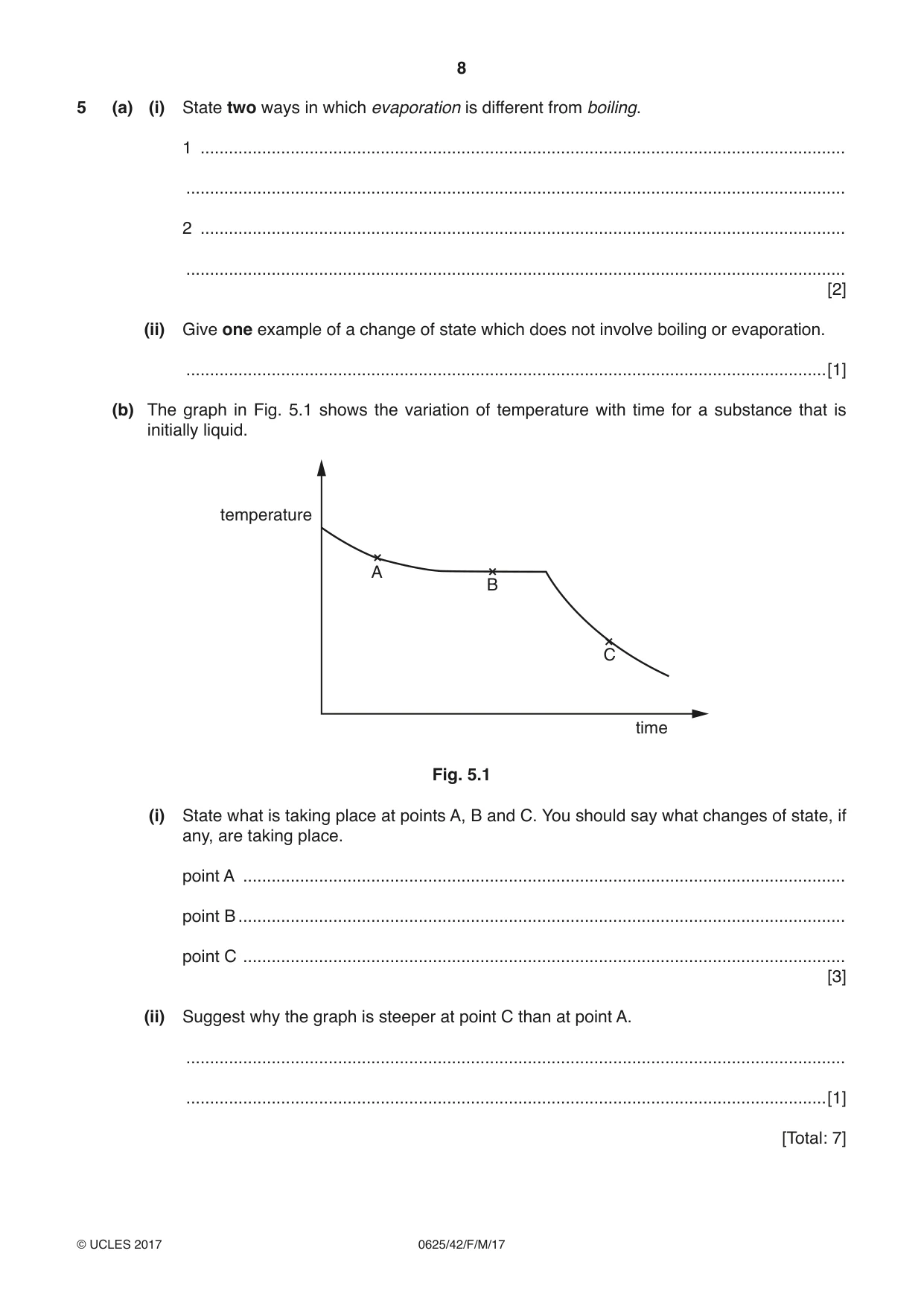
5 (a) (i) State two ways in which evaporation is different from boiling. 1 ........................................................................................................................................ ........................................................................................................................................... 2 ........................................................................................................................................ ........................................................................................................................................... [2] (ii) Give one example of a change of state which does not involve boiling or evaporation. .......................................................................................................................................[1] (b) The graph in Fig. 5.1 shows the variation of temperature with time for a substance that is initially liquid. temperature A B C time Fig. 5.1 (i) State what is taking place at points A, B and C. You should say what changes of state, if any, are taking place. point A ............................................................................................................................... point B ................................................................................................................................ point C ............................................................................................................................... [3] (ii) Suggest why the graph is steeper at point C than at point A. ........................................................................................................................................... .......................................................................................................................................[1] [Total: 7]
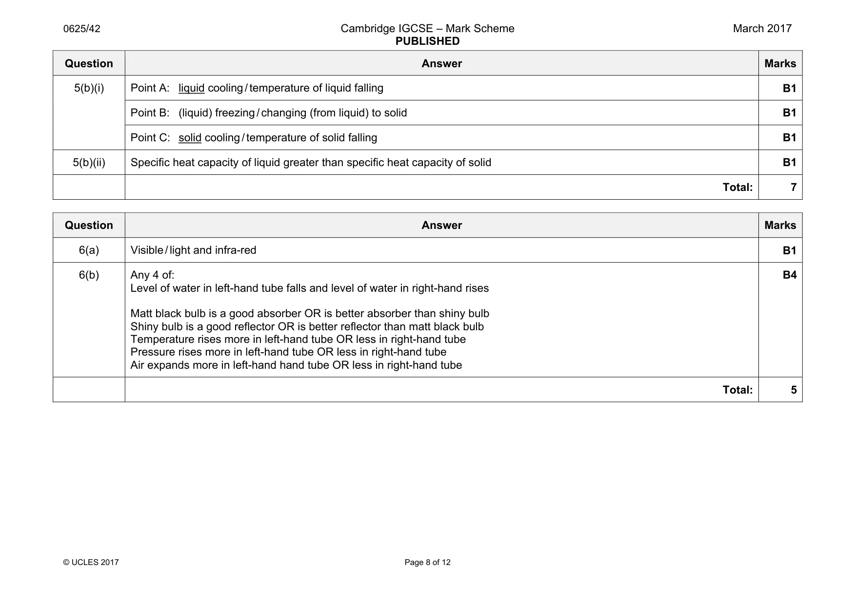
Mark scheme: 5(a)(i) Two of: Evaporation takes place at any temperature Evaporation takes place at the surface Evaporation takes thermal energy / heat from liquid OR Evaporation lowers temperature of liquid No bubbles (rise to surface during evaporation) Evaporation lowers temperature of liquid B2 5(a)(ii) e.g. condensation / change from gas to liquid OR freezing or solidification / change from liquid to solid OR melting / change from solid to liquid OR sublimation / change from solid to gas B1 Question Answer Marks 5(b)(i) Point A: liquid cooling / temperature of liquid falling B1 Point B: (liquid) freezing / changing (from liquid) to solid B1 Point C: solid cooling / temperature of solid falling B1 5(b)(ii) Specific heat capacity of liquid greater than specific heat capacity of solid B1 Total: 7
Q6 · Apparatus that is used to demonstrate some effects of the transfer of energy by radiation
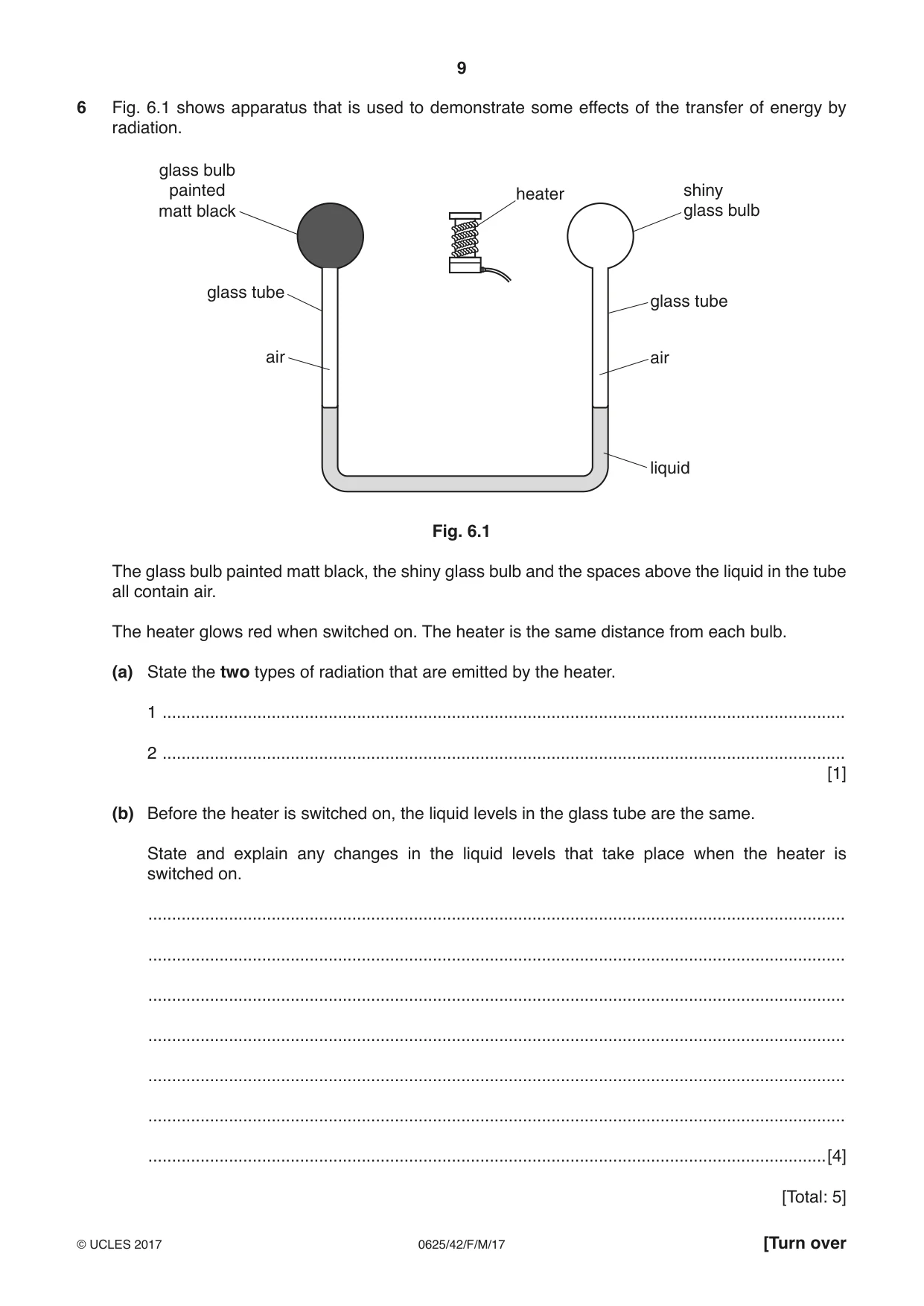
6 Fig. 6.1 shows apparatus that is used to demonstrate some effects of the transfer of energy by radiation. glass bulb painted heater shiny matt black glass bulb glass tube glass tube air air liquid Fig. 6.1 The glass bulb painted matt black, the shiny glass bulb and the spaces above the liquid in the tube all contain air. The heater glows red when switched on. The heater is the same distance from each bulb. (a) State the two types of radiation that are emitted by the heater. 1 ................................................................................................................................................ 2 ................................................................................................................................................ [1] (b) Before the heater is switched on, the liquid levels in the glass tube are the same. State and explain any changes in the liquid levels that take place when the heater is switched on. ................................................................................................................................................... ................................................................................................................................................... ................................................................................................................................................... ................................................................................................................................................... ................................................................................................................................................... ................................................................................................................................................... ...............................................................................................................................................[4] [Total: 5]
Mark scheme: 6(a) Visible / light and infra-red B1 6(b) Any 4 of: Level of water in left-hand tube falls and level of water in right-hand rises Matt black bulb is a good absorber OR is better absorber than shiny bulb Shiny bulb is a good reflector OR is better reflector than matt black bulb Temperature rises more in left-hand tube OR less in right-hand tube Pressure rises more in left-hand tube OR less in right-hand tube Air expands more in left-hand hand tube OR less in right-hand tube B4 Total: 5
Q7 · An object and its image formed by a converging lens
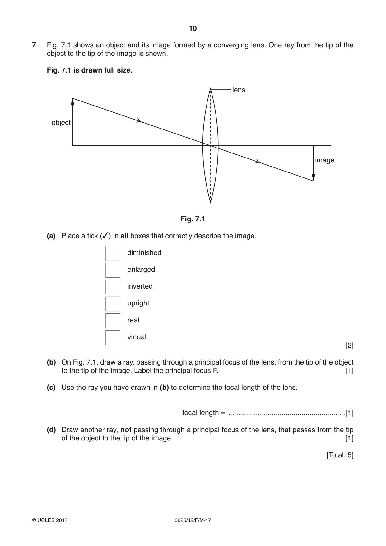
7 Fig. 7.1 shows an object and its image formed by a converging lens. One ray from the tip of the object to the tip of the image is shown. Fig. 7.1 is drawn full size. lens object image Fig. 7.1 (a) Place a tick (3) in all boxes that correctly describe the image. diminished enlarged inverted upright real virtual [2] (b) On Fig. 7.1, draw a ray, passing through a principal focus of the lens, from the tip of the object to the tip of the image. Label the principal focus F. [1] (c) Use the ray you have drawn in (b) to determine the focal length of the lens. focal length = ...........................................................[1] (d) Draw another ray, not passing through a principal focus of the lens, that passes from the tip of the object to the tip of the image. [1] [Total: 5]
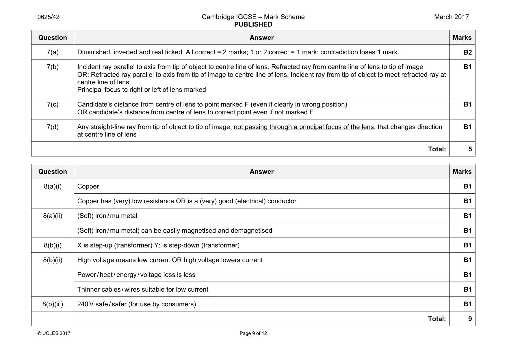
Mark scheme: 7(a) Diminished, inverted and real ticked. All correct = 2 marks; 1 or 2 correct = 1 mark; contradiction loses 1 mark. B2 7(b) Incident ray parallel to axis from tip of object to centre line of lens. Refracted ray from centre line of lens to tip of image OR: Refracted ray parallel to axis from tip of image to centre line of lens. Incident ray from tip of object to meet refracted ray at centre line of lens Principal focus to right or left of lens marked B1 7(c) Candidate’s distance from centre of lens to point marked F (even if clearly in wrong position) OR candidate’s distance from centre of lens to correct point even if not marked F B1 7(d) Any straight-line ray from tip of object to tip of image, not passing through a principal focus of the lens, that changes direction at centre line of lens B1 Total: 5
Q8 · A transformer consists of two coils of wire wound on a core
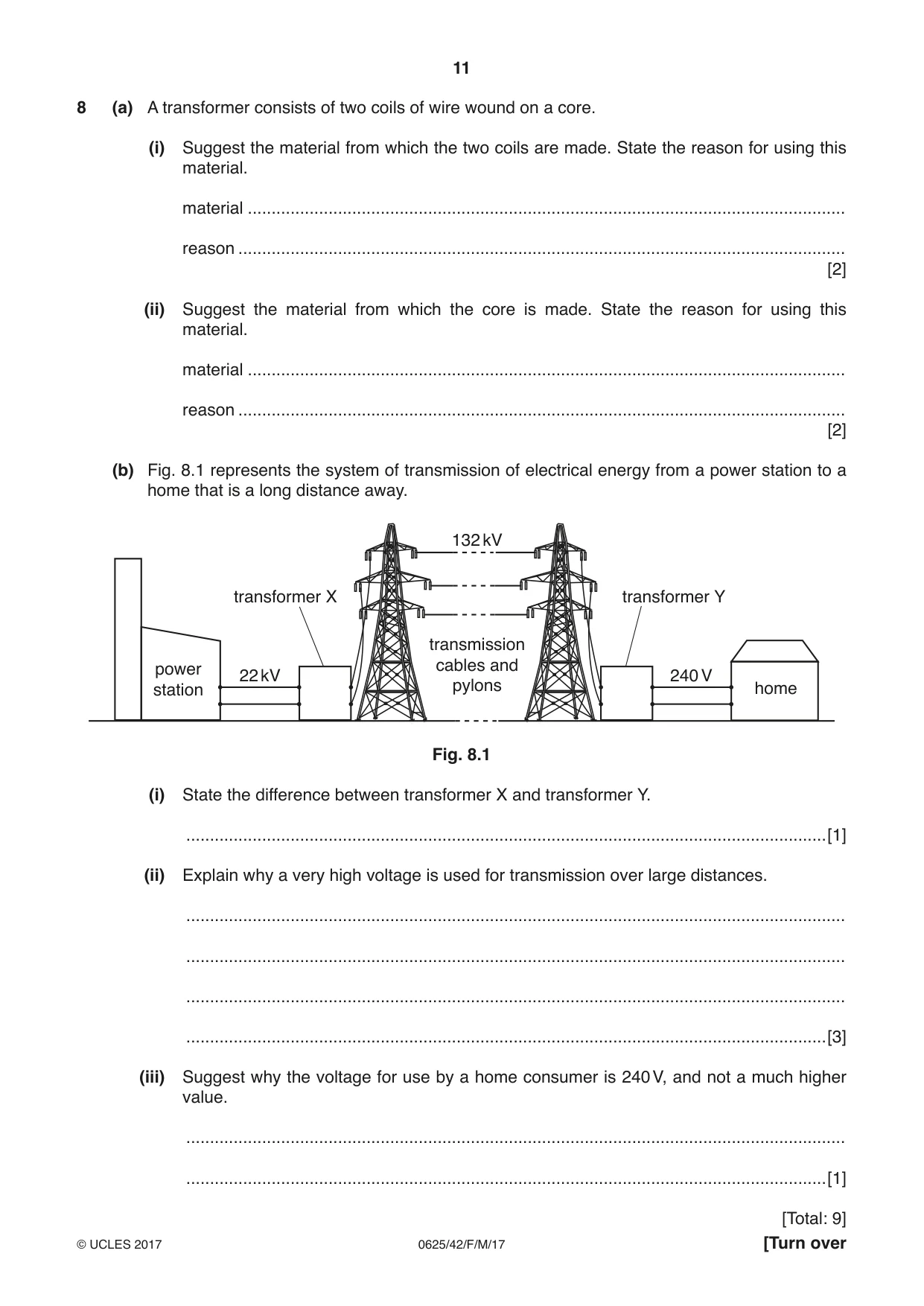
8 (a) A transformer consists of two coils of wire wound on a core. (i) Suggest the material from which the two coils are made. State the reason for using this material. material .............................................................................................................................. reason ................................................................................................................................ [2] (ii) Suggest the material from which the core is made. State the reason for using this material. material .............................................................................................................................. reason ................................................................................................................................ [2] (b) Fig. 8.1 represents the system of transmission of electrical energy from a power station to a home that is a long distance away. 132 kV transformer X transformer Y transmission power cables and 22 kV 240 V station pylons home Fig. 8.1 (i) State the difference between transformer X and transformer Y. .......................................................................................................................................[1] (ii) Explain why a very high voltage is used for transmission over large distances. ........................................................................................................................................... ........................................................................................................................................... ........................................................................................................................................... .......................................................................................................................................[3] (iii) Suggest why the voltage for use by a home consumer is 240 V, and not a much higher value. ........................................................................................................................................... .......................................................................................................................................[1] [Total: 9]
Mark scheme: 8(a)(i) Copper B1 Copper has (very) low resistance OR is a (very) good (electrical) conductor B1 8(a)(ii) (Soft) iron / mu metal B1 (Soft) iron / mu metal) can be easily magnetised and demagnetised B1 8(b)(i) X is step-up (transformer) Y: is step-down (transformer) B1 8(b)(ii) High voltage means low current OR high voltage lowers current B1 Power / heat / energy / voltage loss is less B1 Thinner cables / wires suitable for low current B1 8(b)(iii) 240 V safe / safer (for use by consumers) B1 Total: 9
Q9 · A graph of current against potential difference (p.d.) for a filament lamp
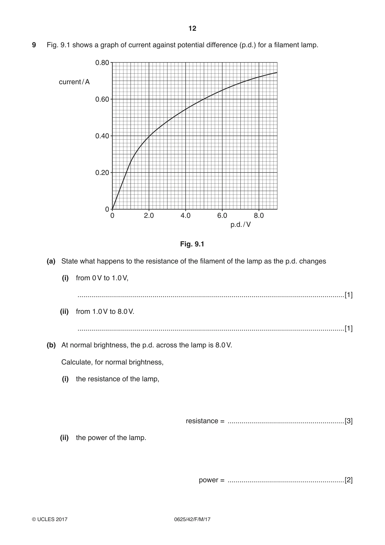
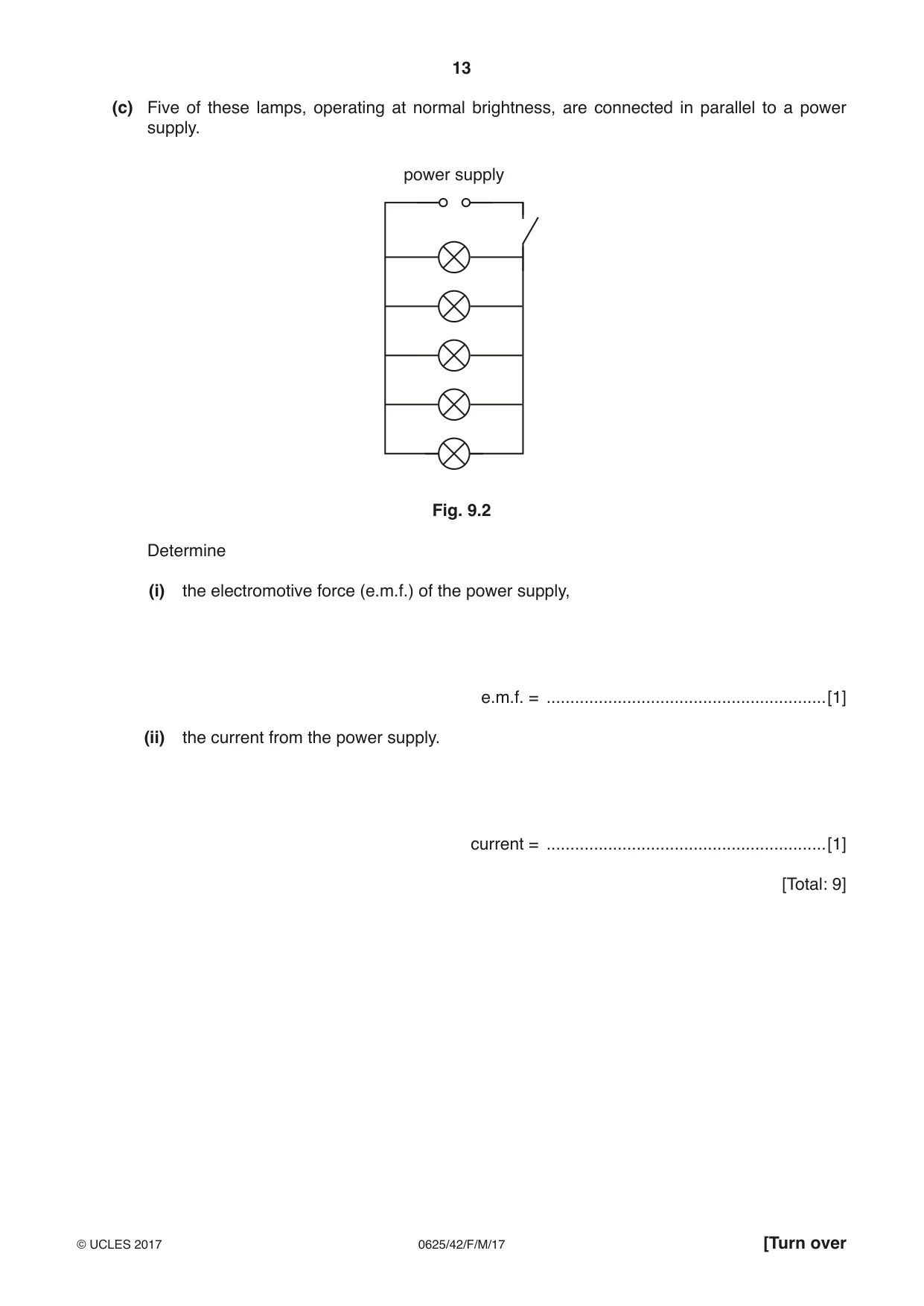
9 Fig. 9.1 shows a graph of current against potential difference (p.d.) for a filament lamp. 0.80 current / A 0.60 0.40 0.20 0 0 2.0 4.0 6.0 8.0 p.d. / V Fig. 9.1 (a) State what happens to the resistance of the filament of the lamp as the p.d. changes (i) from 0 V to 1.0 V, .......................................................................................................................................[1] (ii) from 1.0 V to 8.0 V. .......................................................................................................................................[1] (b) At normal brightness, the p.d. across the lamp is 8.0 V. Calculate, for normal brightness, (i) the resistance of the lamp, resistance = ...........................................................[3] (ii) the power of the lamp. power = ...........................................................[2] (c) Five of these lamps, operating at normal brightness, are connected in parallel to a power supply. power supply Fig. 9.2 Determine (i) the electromotive force (e.m.f.) of the power supply, e.m.f. = ...........................................................[1] (ii) the current from the power supply. current = ...........................................................[1] [Total: 9]
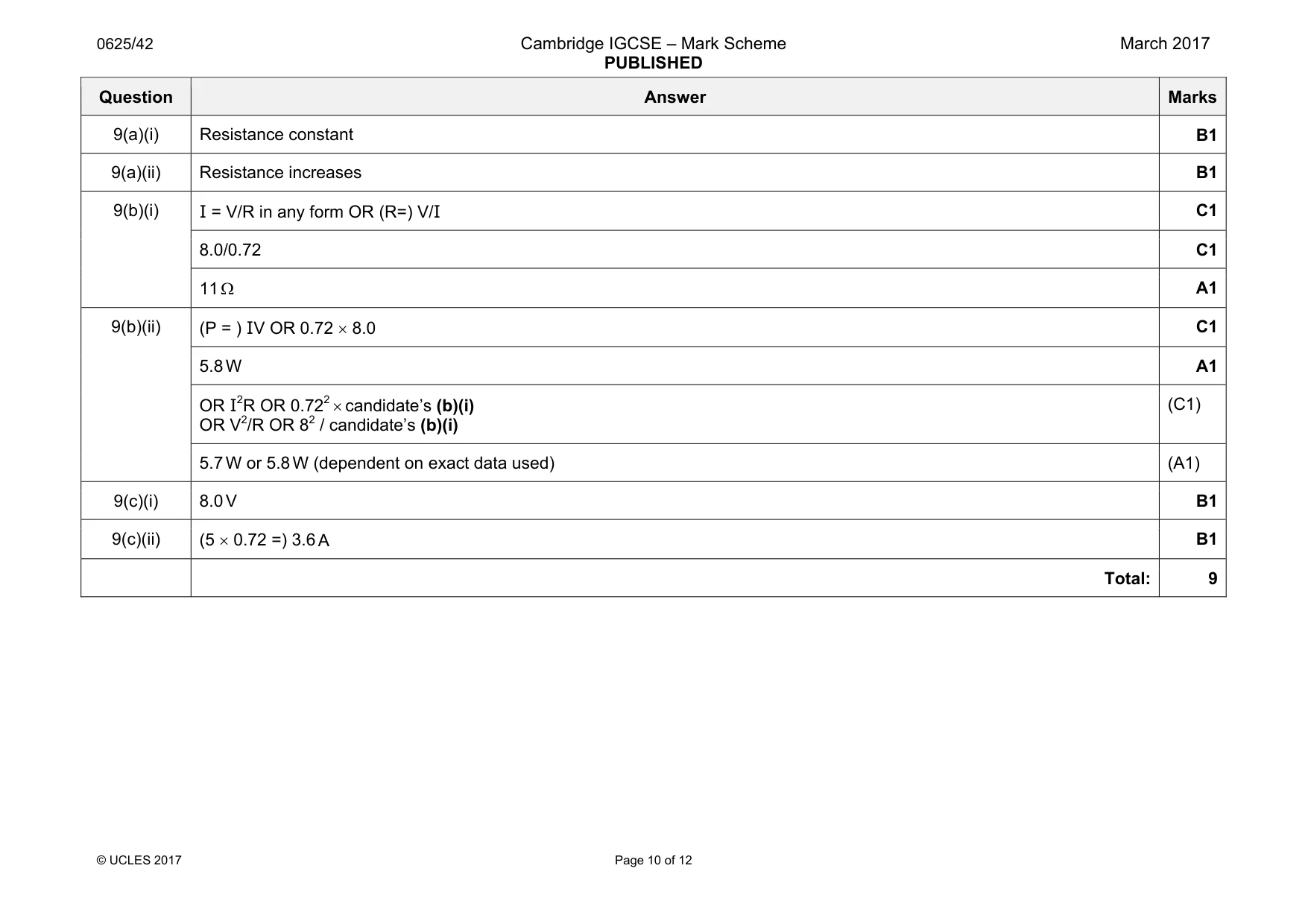
Mark scheme: 9(a)(i) Resistance constant B1 9(a)(ii) Resistance increases B1 9(b)(i) I = V/R in any form OR (R=) V/I C1 8.0/0.72 C1 11 Ω A1 9(b)(ii) (P = ) IV OR 0.72 × 8.0 C1 5.8 W A1 OR I2R OR 0.722 × candidate’s (b)(i) OR V2/R OR 82 / candidate’s (b)(i) (C1) 5.7 W or 5.8 W (dependent on exact data used) (A1) 9(c)(i) 8.0 V B1 9(c)(ii) (5 × 0.72 =) 3.6 A B1 Total: 9
Q10 · Describe, in terms of particles and the terminals of the battery, the movement of charge…
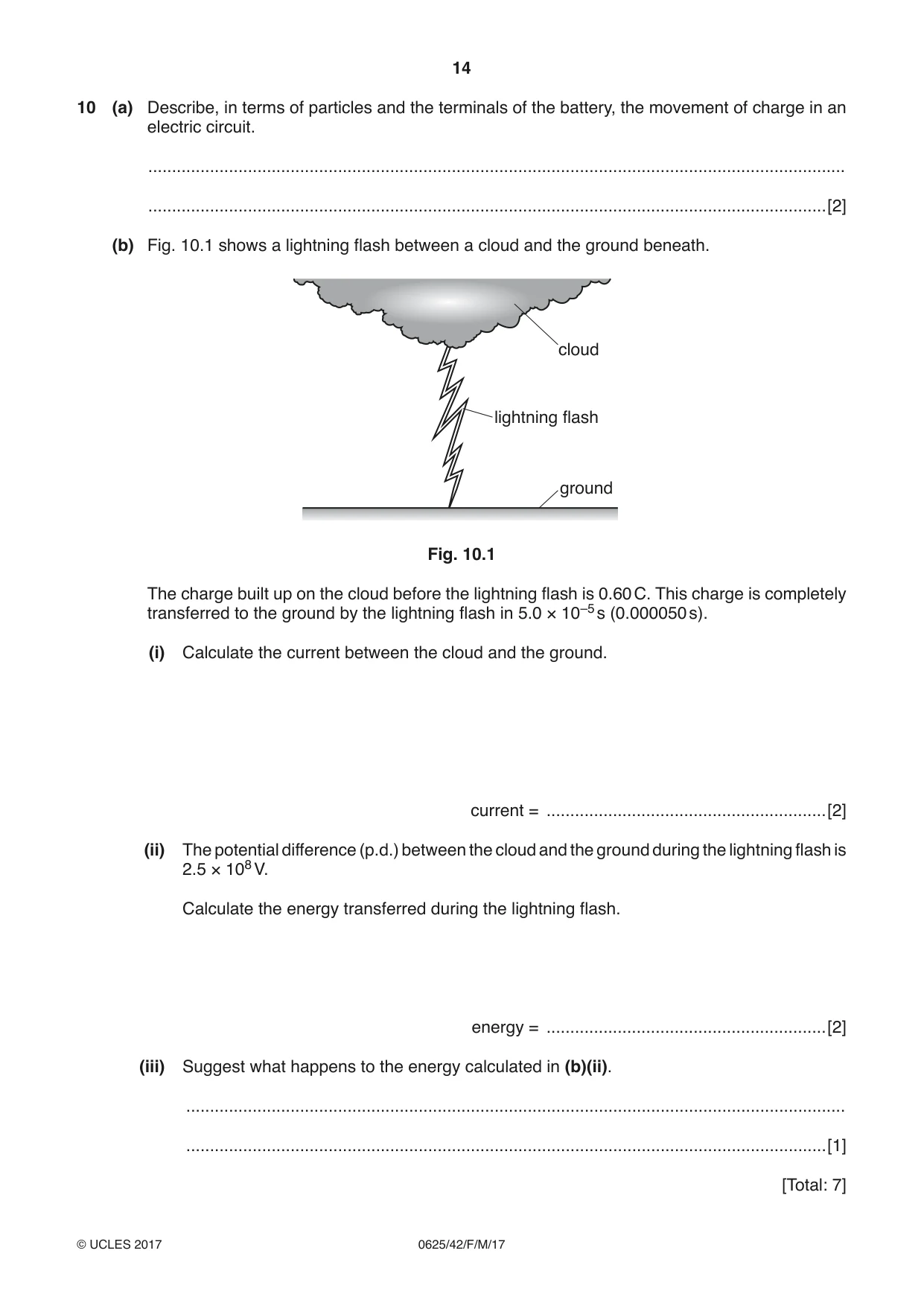
10 (a) Describe, in terms of particles and the terminals of the battery, the movement of charge in an electric circuit. ................................................................................................................................................... ...............................................................................................................................................[2] (b) Fig. 10.1 shows a lightning flash between a cloud and the ground beneath. cloud lightning flash ground Fig. 10.1 The charge built up on the cloud before the lightning flash is 0.60 C. This charge is completely transferred to the ground by the lightning flash in 5.0 × 10⁻⁵ s (0.000050 s). (i) Calculate the current between the cloud and the ground. current = ...........................................................[2] (ii) The potential difference (p.d.) between the cloud and the ground during the lightning flash is 2.5 × 10⁸ V. Calculate the energy transferred during the lightning flash. energy = ...........................................................[2] (iii) Suggest what happens to the energy calculated in (b)(ii). ........................................................................................................................................... .......................................................................................................................................[1] [Total: 7]
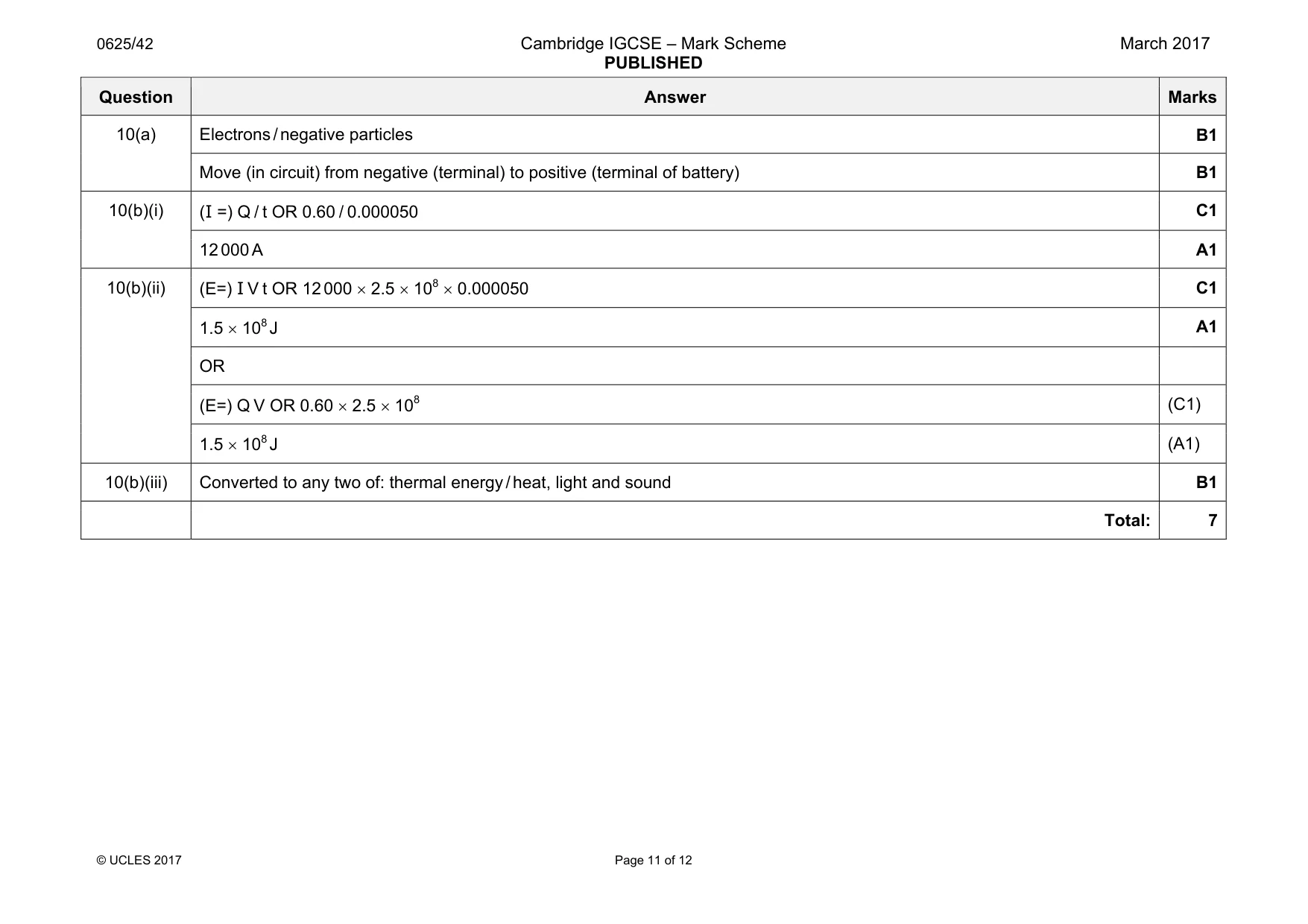
Mark scheme: 10(a) Electrons / negative particles B1 Move (in circuit) from negative (terminal) to positive (terminal of battery) B1 10(b)(i) (I =) Q / t OR 0.60 / 0.000050 C1 12 000 A A1 10(b)(ii) (E=) I V t OR 12 000 × 2.5 × 108 × 0.000050 C1 1.5 × 10⁸ J A1 OR (E=) Q V OR 0.60 × 2.5 × 108 (C1) 1.5 × 10⁸ J (A1) 10(b)(iii) Converted to any two of: thermal energy / heat, light and sound B1 Total: 7
Q11 · A radioactive source is placed 20 mm from a radiation detector, as shown in Fig
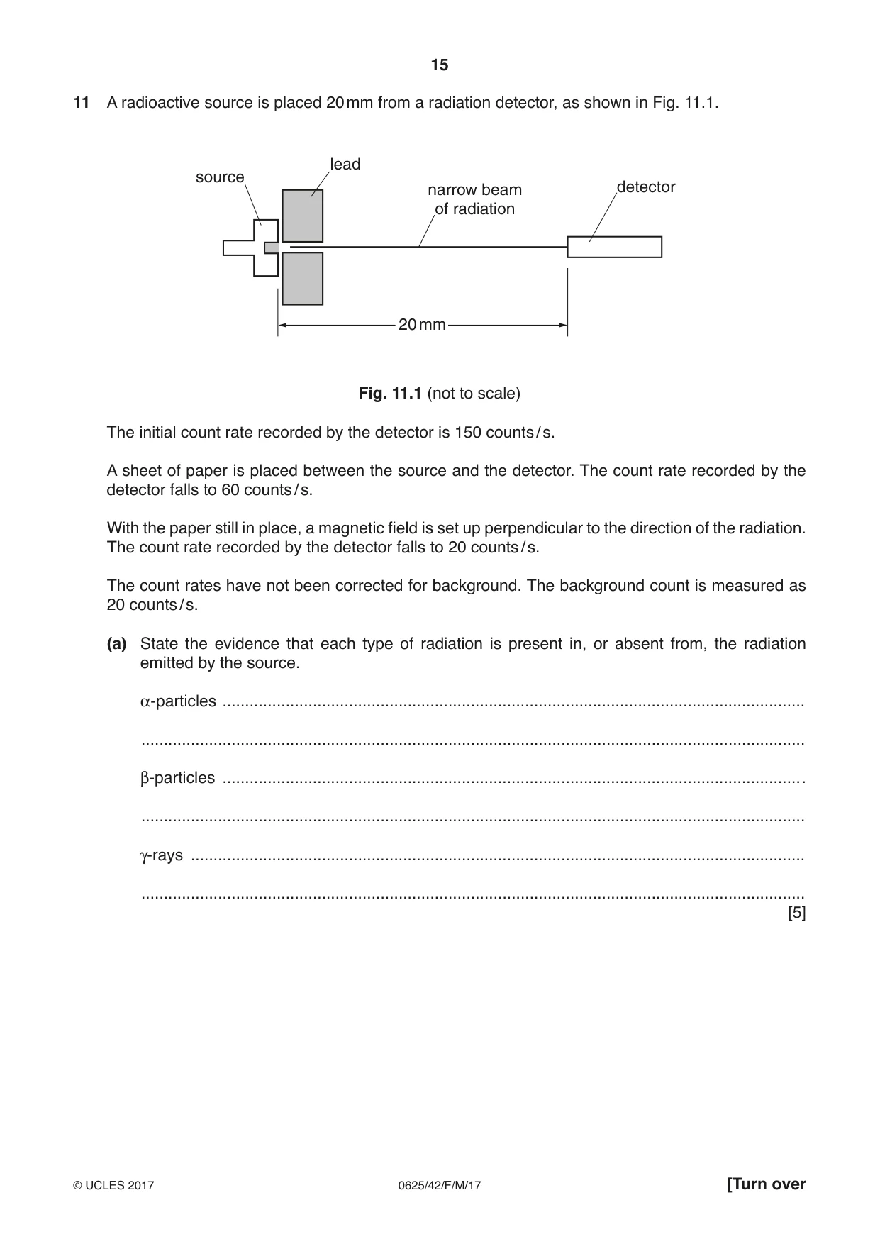
11 A radioactive source is placed 20 mm from a radiation detector, as shown in Fig. 11.1. lead source narrow beam detector of radiation 20 mm Fig. 11.1 (not to scale) The initial count rate recorded by the detector is 150 counts / s. A sheet of paper is placed between the source and the detector. The count rate recorded by the detector falls to 60 counts / s. With the paper still in place, a magnetic field is set up perpendicular to the direction of the radiation. The count rate recorded by the detector falls to 20 counts / s. The count rates have not been corrected for background. The background count is measured as 20 counts / s. (a) State the evidence that each type of radiation is present in, or absent from, the radiation emitted by the source. α-particles ................................................................................................................................. ................................................................................................................................................... β-particles ................................................................................................................................. ................................................................................................................................................... γ-rays ........................................................................................................................................ ................................................................................................................................................... [5] (b) Determine how much of the original count rate of 150 counts / s, if any, is due to each type of radiation. α-particles ................................................ counts / s β-particles ................................................ counts / s γ-rays ................................................ counts / s [2] [Total: 7]
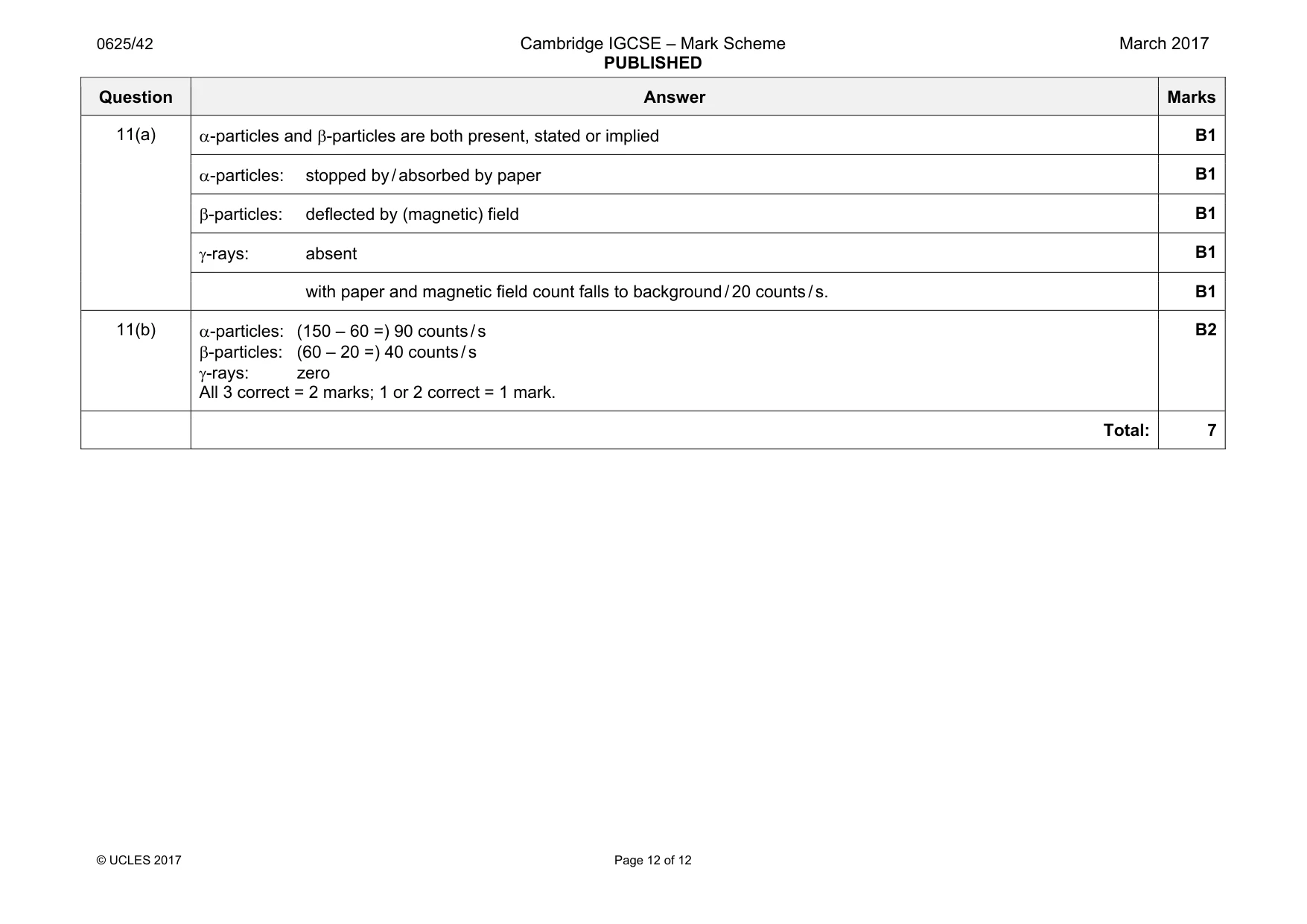
Mark scheme: 11(a) B1 α-particles: stopped by / absorbed by paper B1 β-particles: deflected by (magnetic) field B1 γ-rays: absent B1 with paper and magnetic field count falls to background / 20 counts / s. B1 11(b) α-particles: (150 – 60 =) 90 counts / s β-particles: (60 – 20 =) 40 counts / s γ-rays: zero All 3 correct = 2 marks; 1 or 2 correct = 1 mark. B2 Total: 7
What was in this paper
The subtopics covered by these 11 questions, and how many questions each got. Open one in a new tab to see every Cambridge question on it.
What you needed in this session
Cambridge’s own grade thresholds for 2017 Feb/March, Paper 4 · Variant 2. A higher threshold means an easier paper — the bar moves with how the cohort did.