Cambridge IGCSE Physics 0625 — 2017 May/June Paper 4 · Variant 1
0625/41/M/J/17 · 11 questions · 80 marks · ≈90 min
The question paper and its mark scheme, free to read here and free to download. This is Cambridge’s own paper, exactly as it was sat.
Question paper16 pages
Mark scheme11 pages
Answers below. Sit the paper first if you are practising.
Questions as text
Q1 · The speed-time graph for an ice skater
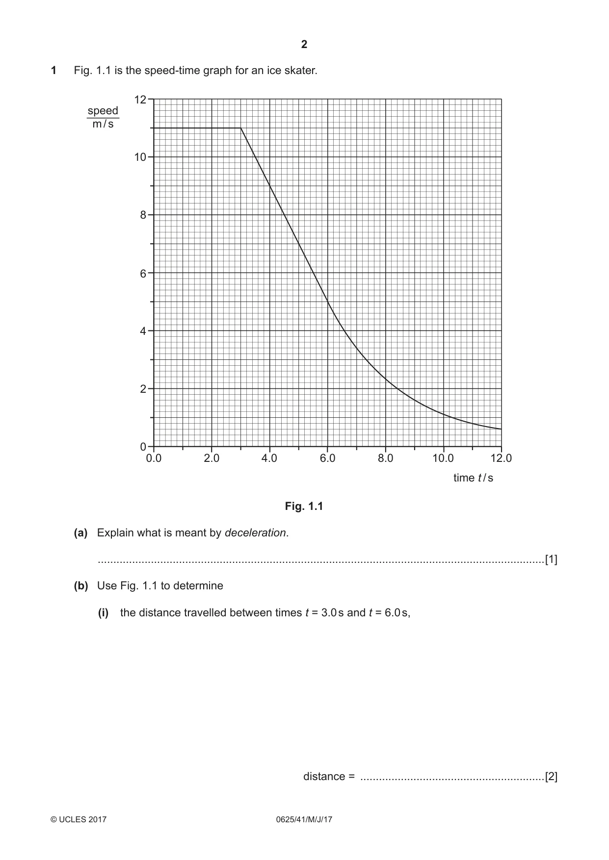
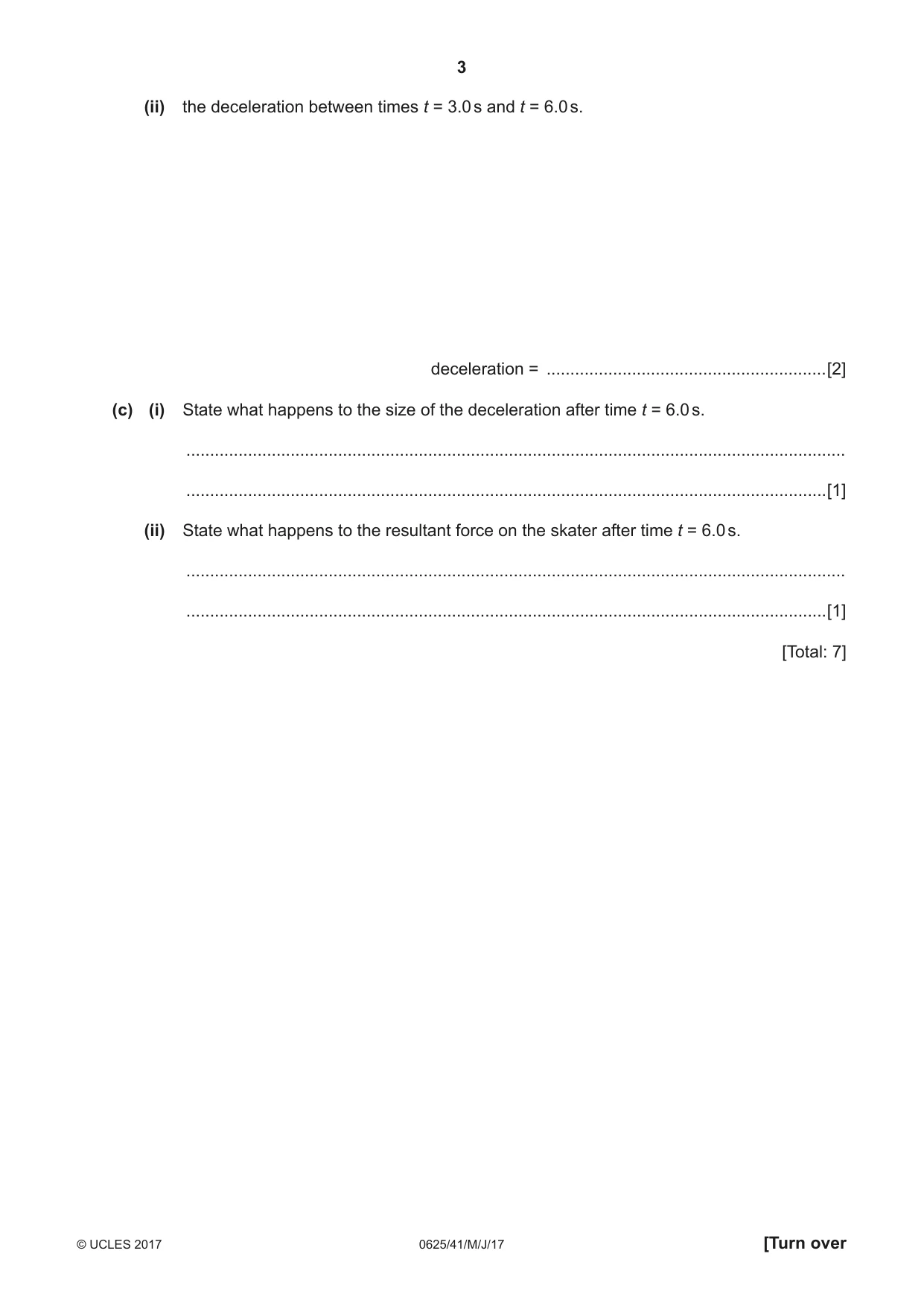
1 Fig. 1.1 is the speed-time graph for an ice skater. 12 speed m / s 10 8 6 4 2 0 0.0 2.0 4.0 6.0 8.0 10.0 12.0 time t / s Fig. 1.1 (a) Explain what is meant by deceleration. ...............................................................................................................................................[1] (b) Use Fig. 1.1 to determine (i) the distance travelled between times t = 3.0 s and t = 6.0 s, distance = ...........................................................[2] (ii) the deceleration between times t = 3.0 s and t = 6.0 s. deceleration = ...........................................................[2] (c) (i) State what happens to the size of the deceleration after time t = 6.0 s. ........................................................................................................................................... .......................................................................................................................................[1] (ii) State what happens to the resultant force on the skater after time t = 6.0 s. ........................................................................................................................................... .......................................................................................................................................[1] [Total: 7]
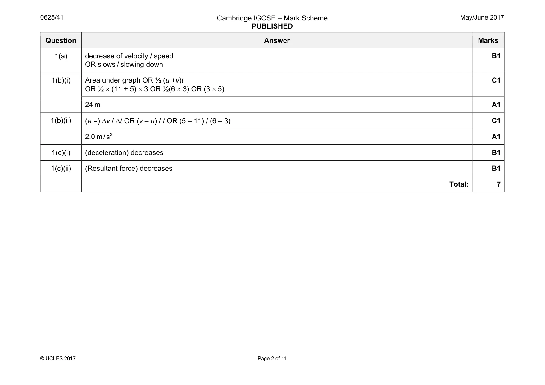
Mark scheme: 1(a) decrease of velocity / speed OR slows / slowing down B1 1(b)(i) Area under graph OR ½ (u +v)t OR ½ × (11 + 5) × 3 OR ½(6 × 3) OR (3 × 5) C1 24 m A1 1(b)(ii) (a =) ∆v / ∆t OR (v – u) / t OR (5 – 11) / (6 – 3) C1 2.0 m / s2 A1 1(c)(i) (deceleration) decreases B1 1(c)(ii) (Resultant force) decreases B1 Total: 7
Q2 · A footballer kicks a ball vertically upwards
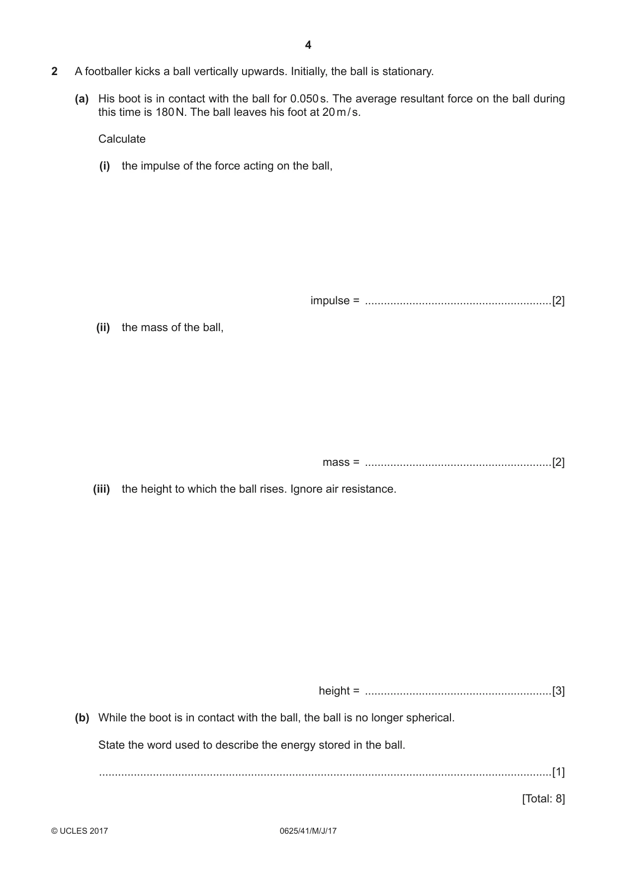
2 A footballer kicks a ball vertically upwards. Initially, the ball is stationary. (a) His boot is in contact with the ball for 0.050 s. The average resultant force on the ball during this time is 180 N. The ball leaves his foot at 20 m / s. Calculate (i) the impulse of the force acting on the ball, impulse = ...........................................................[2] (ii) the mass of the ball, mass = ...........................................................[2] (iii) the height to which the ball rises. Ignore air resistance. height = ...........................................................[3] (b) While the boot is in contact with the ball, the ball is no longer spherical. State the word used to describe the energy stored in the ball. ...............................................................................................................................................[1] [Total: 8]
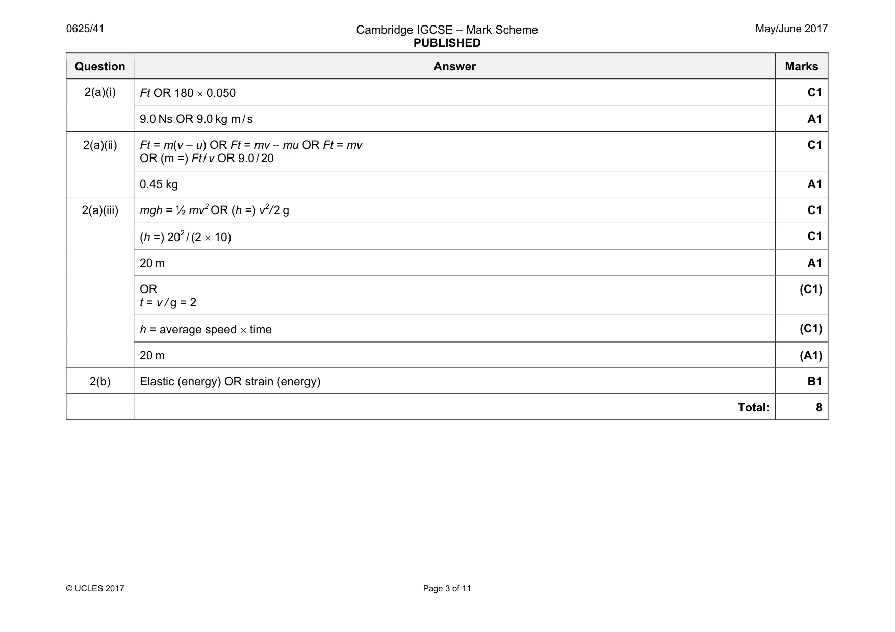
Mark scheme: 2(a)(i) C1 9.0 Ns OR 9.0 kg m / s A1 2(a)(ii) Ft = m(v – u) OR Ft = mv – mu OR Ft = mv OR (m =) Ft / v OR 9.0 / 20 C1 0.45 kg A1 2(a)(iii) mgh = ½ mv2 OR (h =) v2/ 2 g C1 (h =) 202 / (2 × 10) C1 20 m A1 OR t = v / g = 2 (C1) h = average speed × time (C1) 20 m (A1) 2(b) Elastic (energy) OR strain (energy) B1 Total: 8
Q3 · Remote sensing equipment on the surface of a distant planet
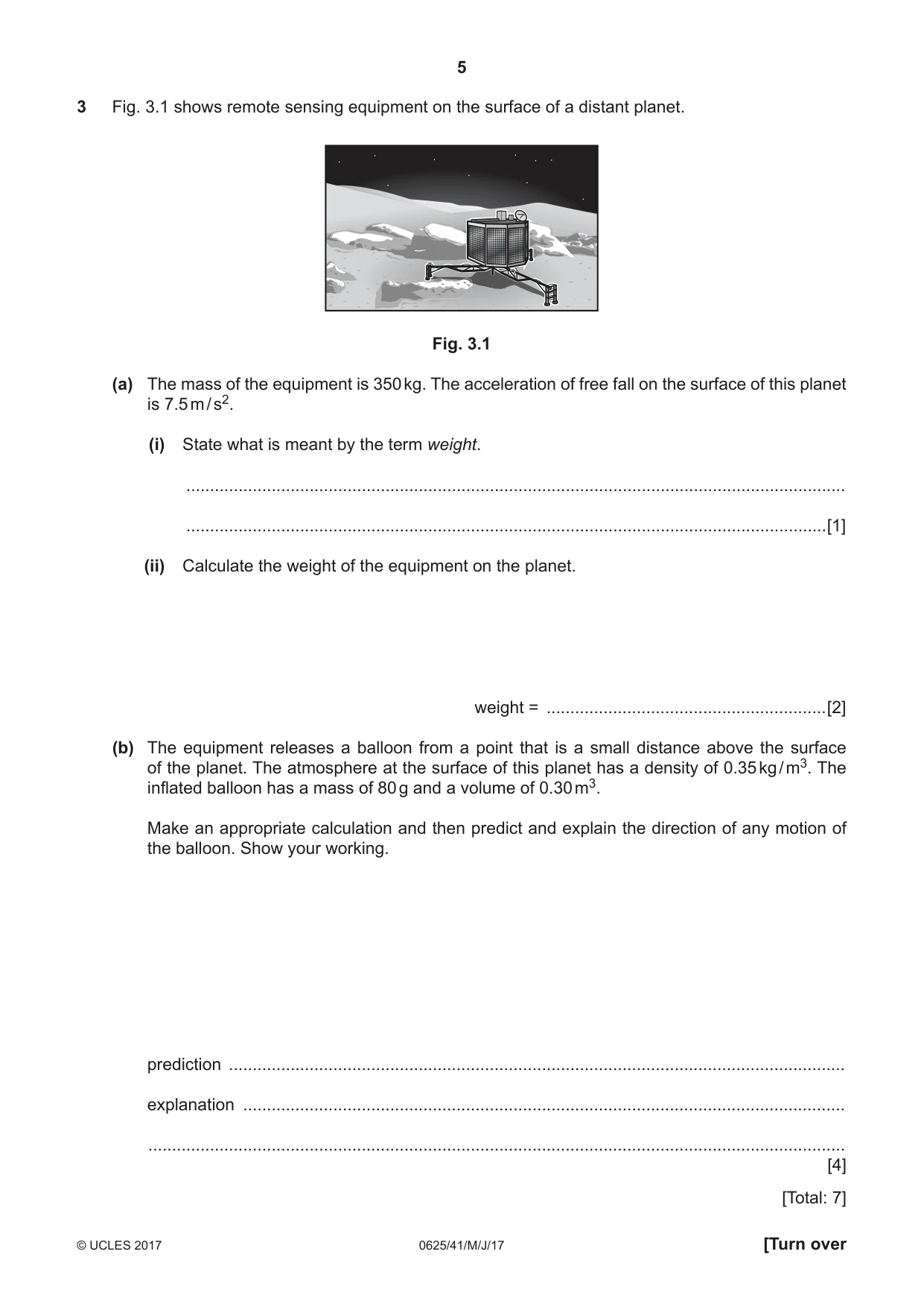
3 Fig. 3.1 shows remote sensing equipment on the surface of a distant planet. Fig. 3.1 (a) The mass of the equipment is 350 kg. The acceleration of free fall on the surface of this planet is 7.5 m / s2. (i) State what is meant by the term weight. ........................................................................................................................................... .......................................................................................................................................[1] (ii) Calculate the weight of the equipment on the planet. weight = ...........................................................[2] (b) The equipment releases a balloon from a point that is a small distance above the surface of the planet. The atmosphere at the surface of this planet has a density of 0.35 kg / m3. The inflated balloon has a mass of 80 g and a volume of 0.30 m3. Make an appropriate calculation and then predict and explain the direction of any motion of the balloon. Show your working. prediction .................................................................................................................................. explanation ............................................................................................................................... ................................................................................................................................................... [4] [Total: 7]
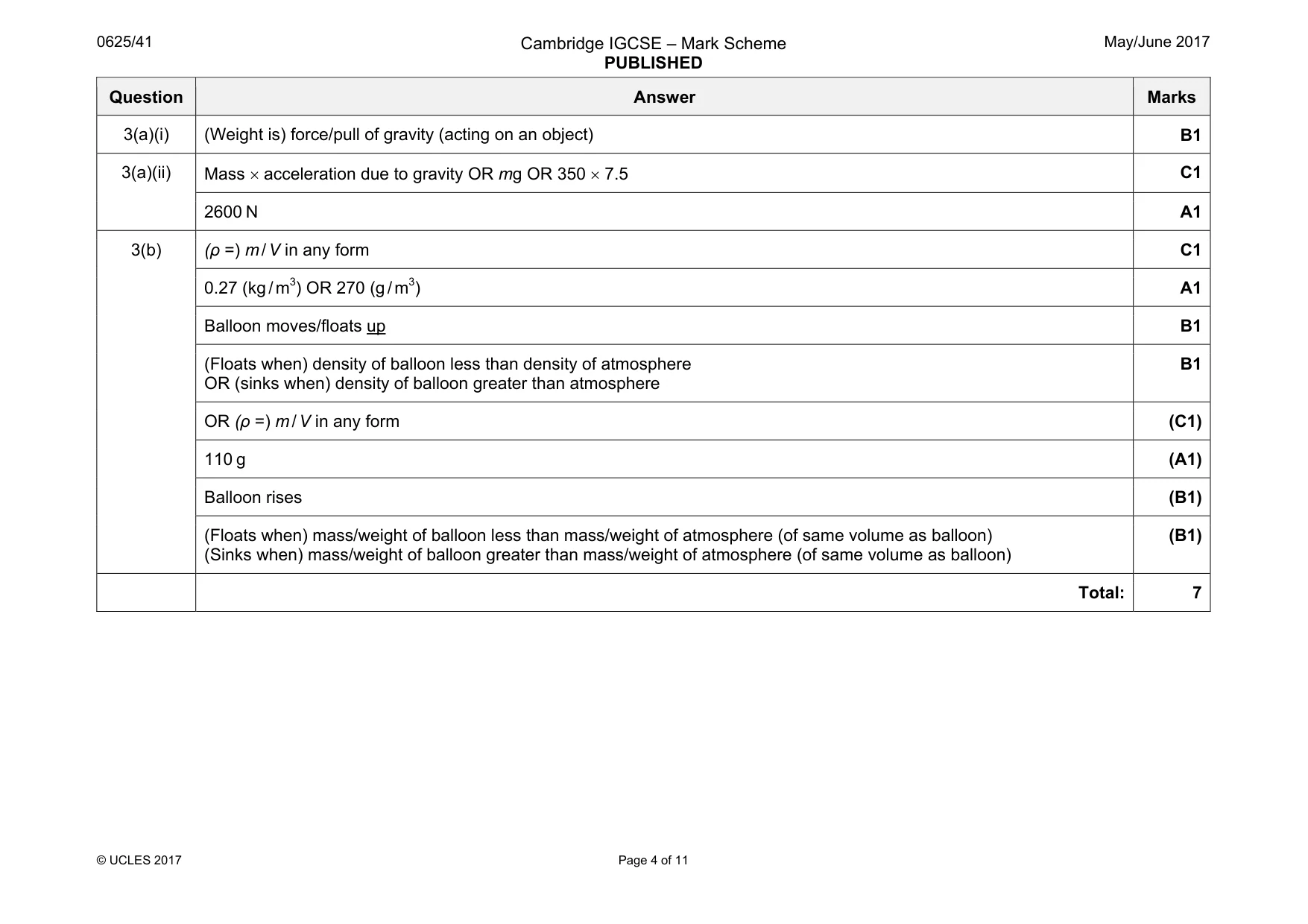
Mark scheme: 3(a)(i) (Weight is) force/pull of gravity (acting on an object) B1 3(a)(ii) Mass × acceleration due to gravity OR mg OR 350 × 7.5 C1 2600 N A1 3(b) (ρ =) m / V in any form C1 0.27 (kg / m3) OR 270 (g / m3) A1 Balloon moves/floats up B1 (Floats when) density of balloon less than density of atmosphere OR (sinks when) density of balloon greater than atmosphere B1 OR (ρ =) m / V in any form (C1) 110 g (A1) Balloon rises (B1) (Floats when) mass/weight of balloon less than mass/weight of atmosphere (of same volume as balloon) (Sinks when) mass/weight of balloon greater than mass/weight of atmosphere (of same volume as balloon) (B1) Total: 7
Q4 · A 240 V, 60 W lamp is connected to a 240 V supply
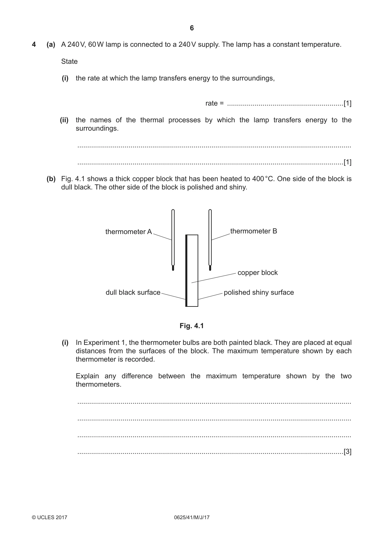
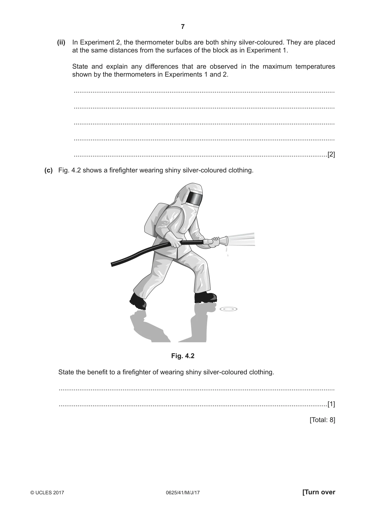
4 (a) A 240 V, 60 W lamp is connected to a 240 V supply. The lamp has a constant temperature. State (i) the rate at which the lamp transfers energy to the surroundings, rate = ...........................................................[1] (ii) the names of the thermal processes by which the lamp transfers energy to the surroundings. ........................................................................................................................................... .......................................................................................................................................[1] (b) Fig. 4.1 shows a thick copper block that has been heated to 400 °C. One side of the block is dull black. The other side of the block is polished and shiny. thermometer A thermometer B copper block dull black surface polished shiny surface Fig. 4.1 (i) In Experiment 1, the thermometer bulbs are both painted black. They are placed at equal distances from the surfaces of the block. The maximum temperature shown by each thermometer is recorded. Explain any difference between the maximum temperature shown by the two thermometers. ........................................................................................................................................... ........................................................................................................................................... ........................................................................................................................................... .......................................................................................................................................[3] (ii) In Experiment 2, the thermometer bulbs are both shiny silver-coloured. They are placed at the same distances from the surfaces of the block as in Experiment 1. State and explain any differences that are observed in the maximum temperatures shown by the thermometers in Experiments 1 and 2. ........................................................................................................................................... ........................................................................................................................................... ........................................................................................................................................... ........................................................................................................................................... .......................................................................................................................................[2] (c) Fig. 4.2 shows a firefighter wearing shiny silver-coloured clothing. Fig. 4.2 State the benefit to a firefighter of wearing shiny silver-coloured clothing. ................................................................................................................................................... ...............................................................................................................................................[1] [Total: 8]
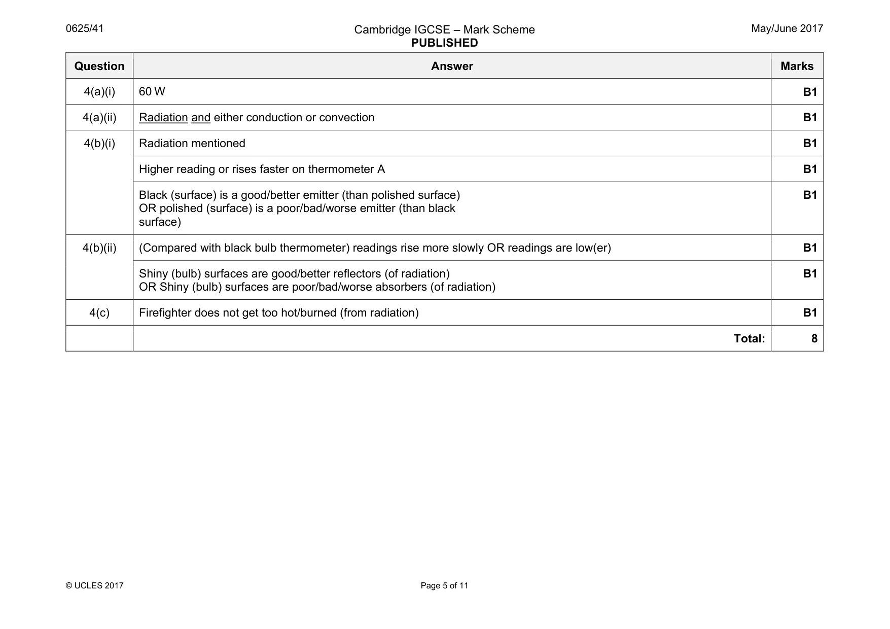
Mark scheme: 4(a)(i) 60 W B1 4(a)(ii) Radiation and either conduction or convection B1 4(b)(i) Radiation mentioned B1 Higher reading or rises faster on thermometer A B1 Black (surface) is a good/better emitter (than polished surface) OR polished (surface) is a poor/bad/worse emitter (than black surface) B1 4(b)(ii) (Compared with black bulb thermometer) readings rise more slowly OR readings are low(er) B1 Shiny (bulb) surfaces are good/better reflectors (of radiation) OR Shiny (bulb) surfaces are poor/bad/worse absorbers (of radiation) B1 4(c) Firefighter does not get too hot/burned (from radiation) B1 Total: 8
Q5 · Some gas trapped in a metal cylinder by a piston
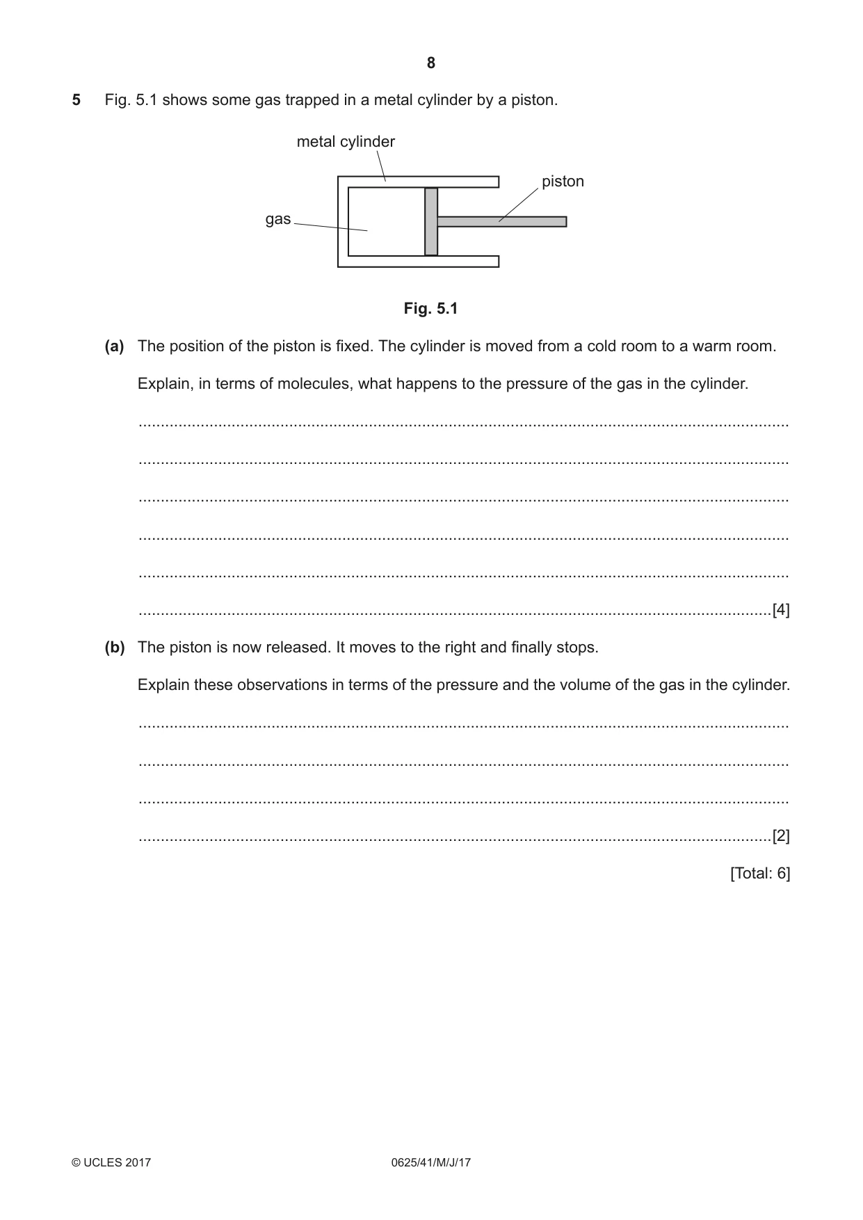
5 Fig. 5.1 shows some gas trapped in a metal cylinder by a piston. metal cylinder piston gas Fig. 5.1 (a) The position of the piston is fixed. The cylinder is moved from a cold room to a warm room. Explain, in terms of molecules, what happens to the pressure of the gas in the cylinder. ................................................................................................................................................... ................................................................................................................................................... ................................................................................................................................................... ................................................................................................................................................... ................................................................................................................................................... ...............................................................................................................................................[4] (b) The piston is now released. It moves to the right and finally stops. Explain these observations in terms of the pressure and the volume of the gas in the cylinder. ................................................................................................................................................... ................................................................................................................................................... ................................................................................................................................................... ...............................................................................................................................................[2] [Total: 6]
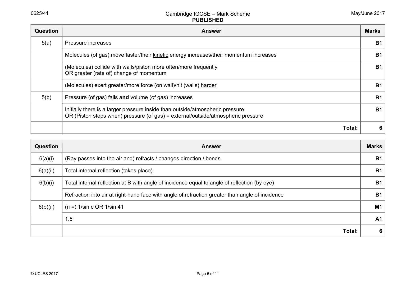
Mark scheme: 5(a) Pressure increases B1 Molecules (of gas) move faster/their kinetic energy increases/their momentum increases B1 (Molecules) collide with walls/piston more often/more frequently OR greater (rate of) change of momentum B1 (Molecules) exert greater/more force (on wall)/hit (walls) harder B1 5(b) Pressure (of gas) falls and volume (of gas) increases B1 Initially there is a larger pressure inside than outside/atmospheric pressure OR (Piston stops when) pressure (of gas) = external/outside/atmospheric pressure B1 Total: 6
Q6 · A ray of light in glass is incident on a boundary with air
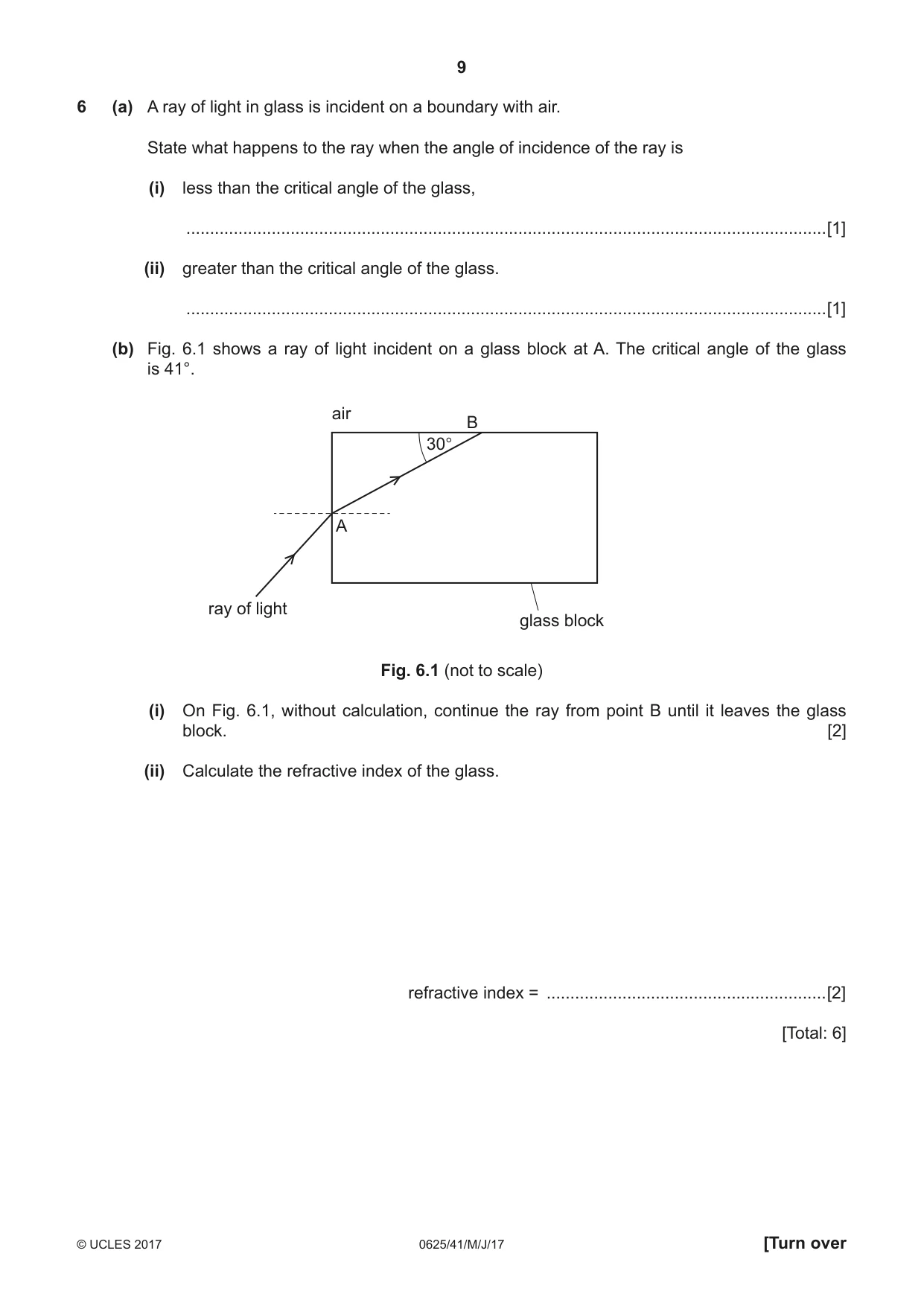
6 (a) A ray of light in glass is incident on a boundary with air. State what happens to the ray when the angle of incidence of the ray is (i) less than the critical angle of the glass, .......................................................................................................................................[1] (ii) greater than the critical angle of the glass. .......................................................................................................................................[1] (b) Fig. 6.1 shows a ray of light incident on a glass block at A. The critical angle of the glass is 41°. air B 30° A ray of light glass block Fig. 6.1 (not to scale) (i) On Fig. 6.1, without calculation, continue the ray from point B until it leaves the glass block. [2] (ii) Calculate the refractive index of the glass. refractive index = ...........................................................[2] [Total: 6]
Mark scheme: 6(a)(i) (Ray passes into the air and) refracts / changes direction / bends B1 6(a)(ii) Total internal reflection (takes place) B1 6(b)(i) Total internal reflection at B with angle of incidence equal to angle of reflection (by eye) B1 Refraction into air at right-hand face with angle of refraction greater than angle of incidence B1 6(b)(ii) (n =) 1/sin c OR 1/sin 41 M1 1.5 A1 Total: 6
Q7 · A loudspeaker produces a sound wave of constant frequency
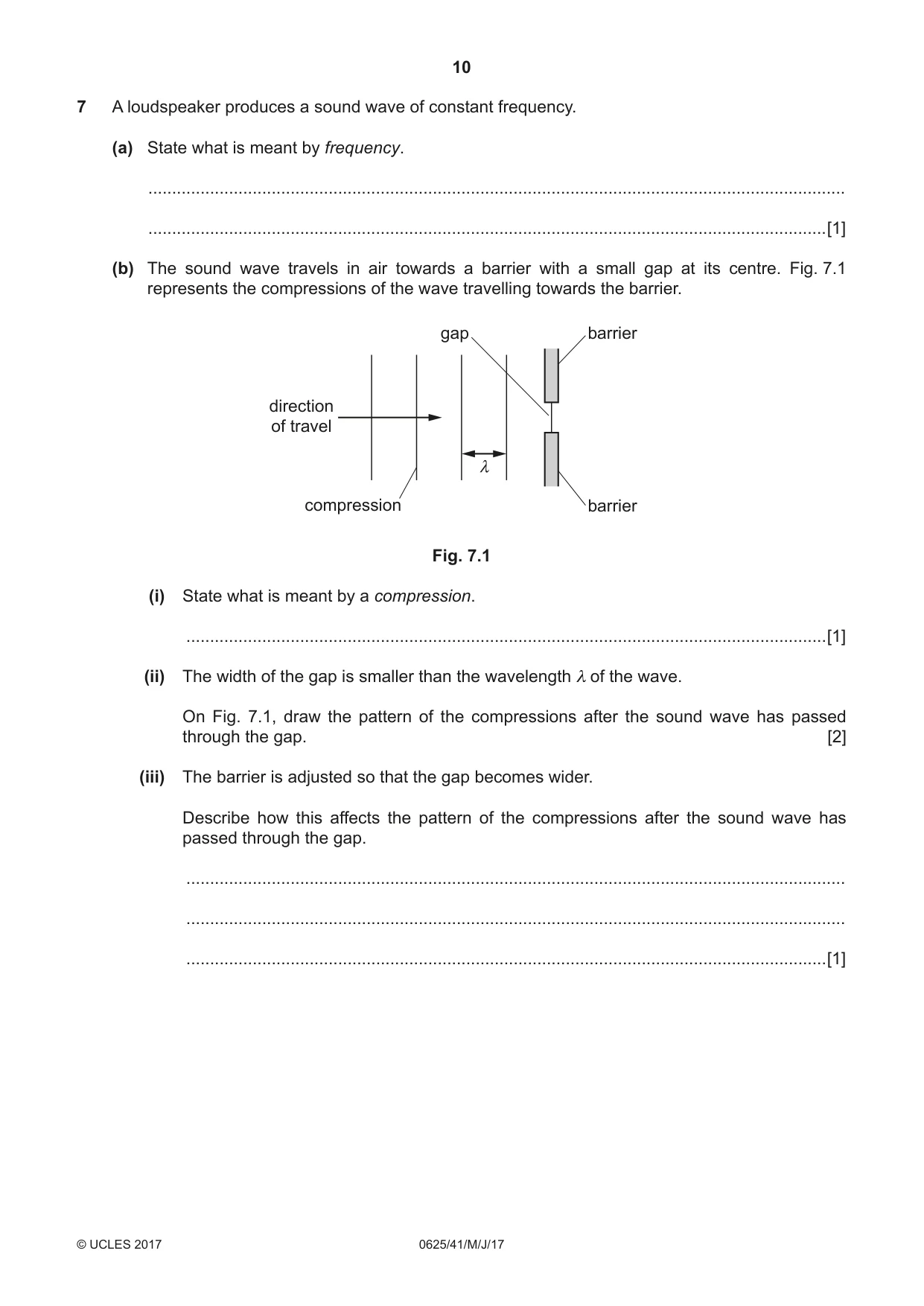
7 A loudspeaker produces a sound wave of constant frequency. (a) State what is meant by frequency. ................................................................................................................................................... ...............................................................................................................................................[1] (b) The sound wave travels in air towards a barrier with a small gap at its centre. Fig. 7.1 represents the compressions of the wave travelling towards the barrier. gap barrier direction of travel λ compression barrier Fig. 7.1 (i) State what is meant by a compression. .......................................................................................................................................[1] (ii) The width of the gap is smaller than the wavelength λ of the wave. On Fig. 7.1, draw the pattern of the compressions after the sound wave has passed through the gap. [2] (iii) The barrier is adjusted so that the gap becomes wider. Describe how this affects the pattern of the compressions after the sound wave has passed through the gap. ........................................................................................................................................... ........................................................................................................................................... .......................................................................................................................................[1] (c) The frequency of the sound wave is 6800 Hz. The speed of sound in air is 340 m / s. (i) Calculate the wavelength of the sound wave in air. wavelength = ...........................................................[2] (ii) State a typical value for the speed of sound in a liquid. .......................................................................................................................................[1] [Total: 8]
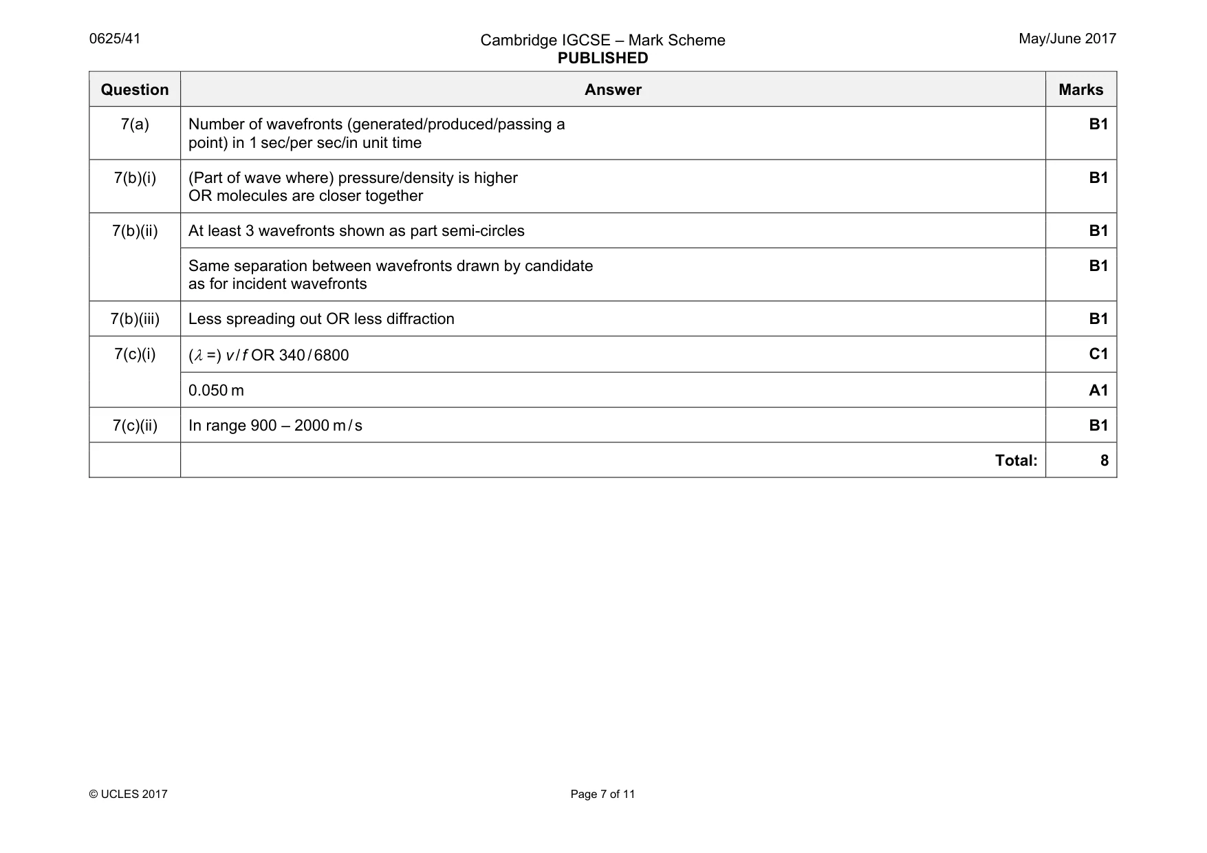
Mark scheme: 7(a) Number of wavefronts (generated/produced/passing a point) in 1 sec/per sec/in unit time B1 7(b)(i) (Part of wave where) pressure/density is higher OR molecules are closer together B1 7(b)(ii) At least 3 wavefronts shown as part semi-circles B1 Same separation between wavefronts drawn by candidate as for incident wavefronts B1 7(b)(iii) Less spreading out OR less diffraction B1 7(c)(i) (λ =) v / f OR 340 / 6800 C1 0.050 m A1 7(c)(ii) In range 900 – 2000 m / s B1 Total: 8
Q8 · A bar magnet is made of metal
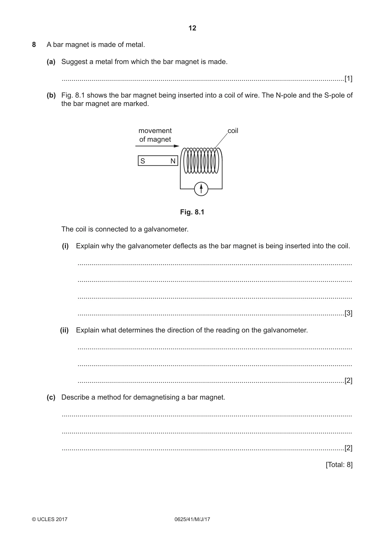
8 A bar magnet is made of metal. (a) Suggest a metal from which the bar magnet is made. ...............................................................................................................................................[1] (b) Fig. 8.1 shows the bar magnet being inserted into a coil of wire. The N-pole and the S-pole of the bar magnet are marked. movement coil of magnet S N Fig. 8.1 The coil is connected to a galvanometer. (i) Explain why the galvanometer deflects as the bar magnet is being inserted into the coil. ........................................................................................................................................... ........................................................................................................................................... ........................................................................................................................................... .......................................................................................................................................[3] (ii) Explain what determines the direction of the reading on the galvanometer. ........................................................................................................................................... ........................................................................................................................................... .......................................................................................................................................[2] (c) Describe a method for demagnetising a bar magnet. ................................................................................................................................................... ................................................................................................................................................... ...............................................................................................................................................[2] [Total: 8]
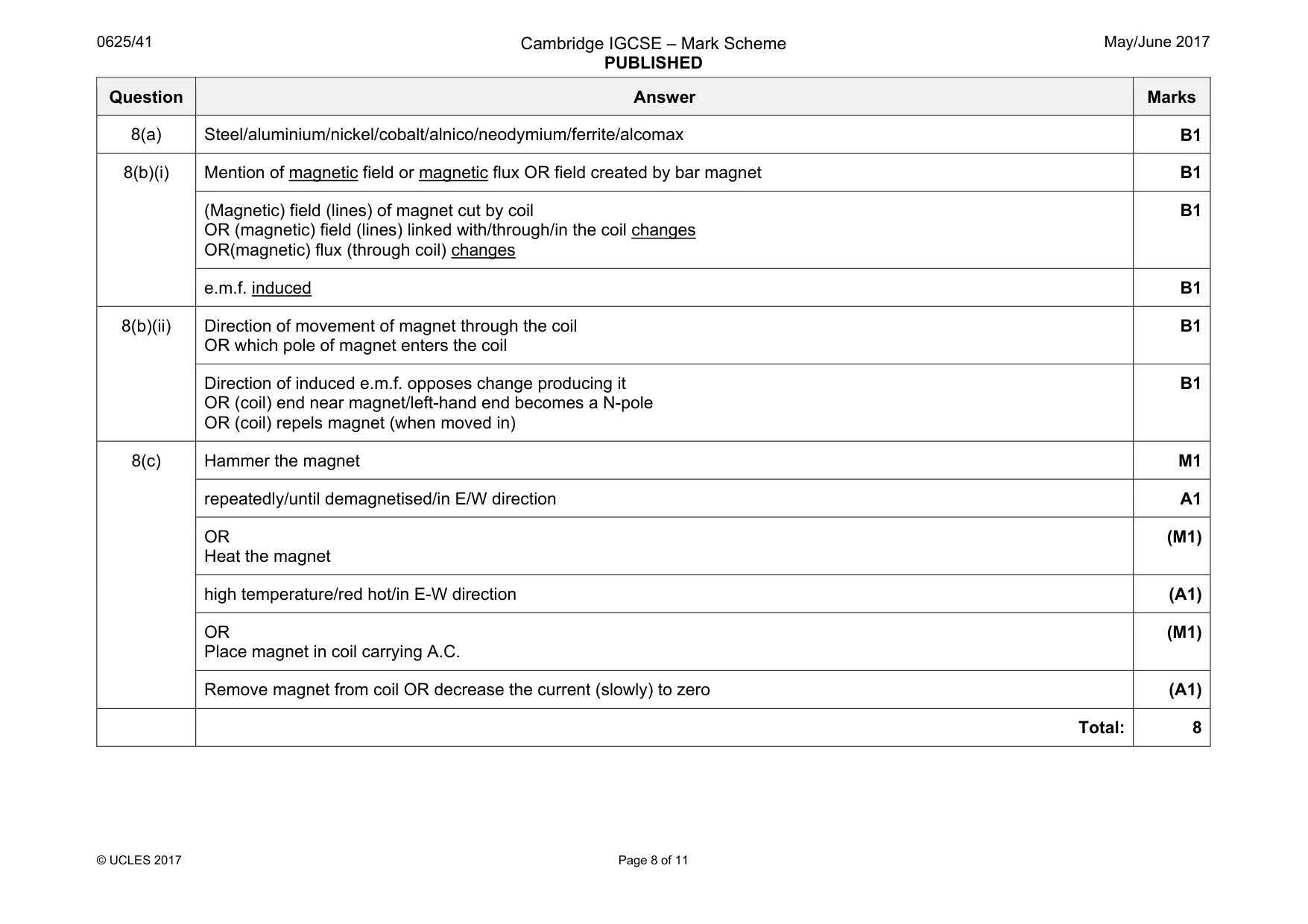
Mark scheme: 8(a) Steel/aluminium/nickel/cobalt/alnico/neodymium/ferrite/alcomax B1 8(b)(i) Mention of magnetic field or magnetic flux OR field created by bar magnet B1 (Magnetic) field (lines) of magnet cut by coil OR (magnetic) field (lines) linked with/through/in the coil changes OR(magnetic) flux (through coil) changes B1 e.m.f. induced B1 8(b)(ii) Direction of movement of magnet through the coil OR which pole of magnet enters the coil B1 Direction of induced e.m.f. opposes change producing it OR (coil) end near magnet/left-hand end becomes a N-pole OR (coil) repels magnet (when moved in) B1 8(c) Hammer the magnet M1 repeatedly/until demagnetised/in E/W direction A1 OR Heat the magnet (M1) high temperature/red hot/in E-W direction (A1) OR Place magnet in coil carrying A.C. (M1) Remove magnet from coil OR decrease the current (slowly) to zero (A1) Total: 8
Q9 · The resistance of a circuit component varies with the brightness of the light falling on…
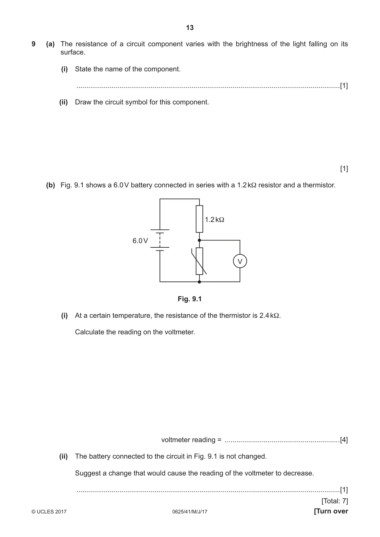
9 (a) The resistance of a circuit component varies with the brightness of the light falling on its surface. (i) State the name of the component. .......................................................................................................................................[1] (ii) Draw the circuit symbol for this component. [1] (b) Fig. 9.1 shows a 6.0 V battery connected in series with a 1.2 kΩ resistor and a thermistor. 1.2 kΩ 6.0 V V Fig. 9.1 (i) At a certain temperature, the resistance of the thermistor is 2.4 kΩ. Calculate the reading on the voltmeter. voltmeter reading = ...........................................................[4] (ii) The battery connected to the circuit in Fig. 9.1 is not changed. Suggest a change that would cause the reading of the voltmeter to decrease. .......................................................................................................................................[1] [Total: 7]
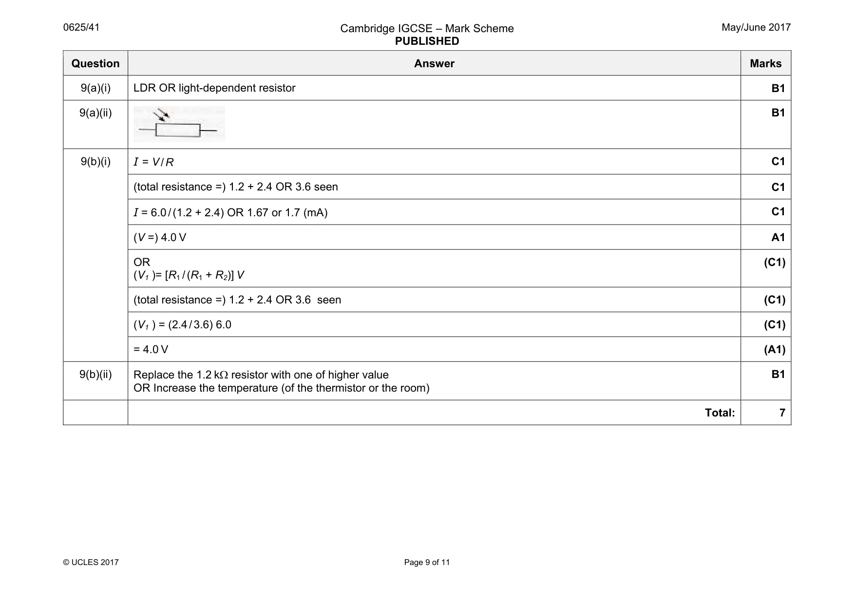
Mark scheme: 9(a)(i) LDR OR light-dependent resistor B1 9(a)(ii) B1 9(b)(i) I = V / R C1 (total resistance =) 1.2 + 2.4 OR 3.6 seen C1 I = 6.0 / (1.2 + 2.4) OR 1.67 or 1.7 (mA) C1 (V =) 4.0 V A1 OR (V1 )= [R1 / (R1 + R2)] V (C1) (total resistance =) 1.2 + 2.4 OR 3.6 seen (C1) (V1 ) = (2.4 / 3.6) 6.0 (C1) = 4.0 V (A1) 9(b)(ii) Replace the 1.2 kΩ resistor with one of higher value OR Increase the temperature (of the thermistor or the room) B1 Total: 7
Q10 · Describe the movement of charge that causes an object to become positively charged
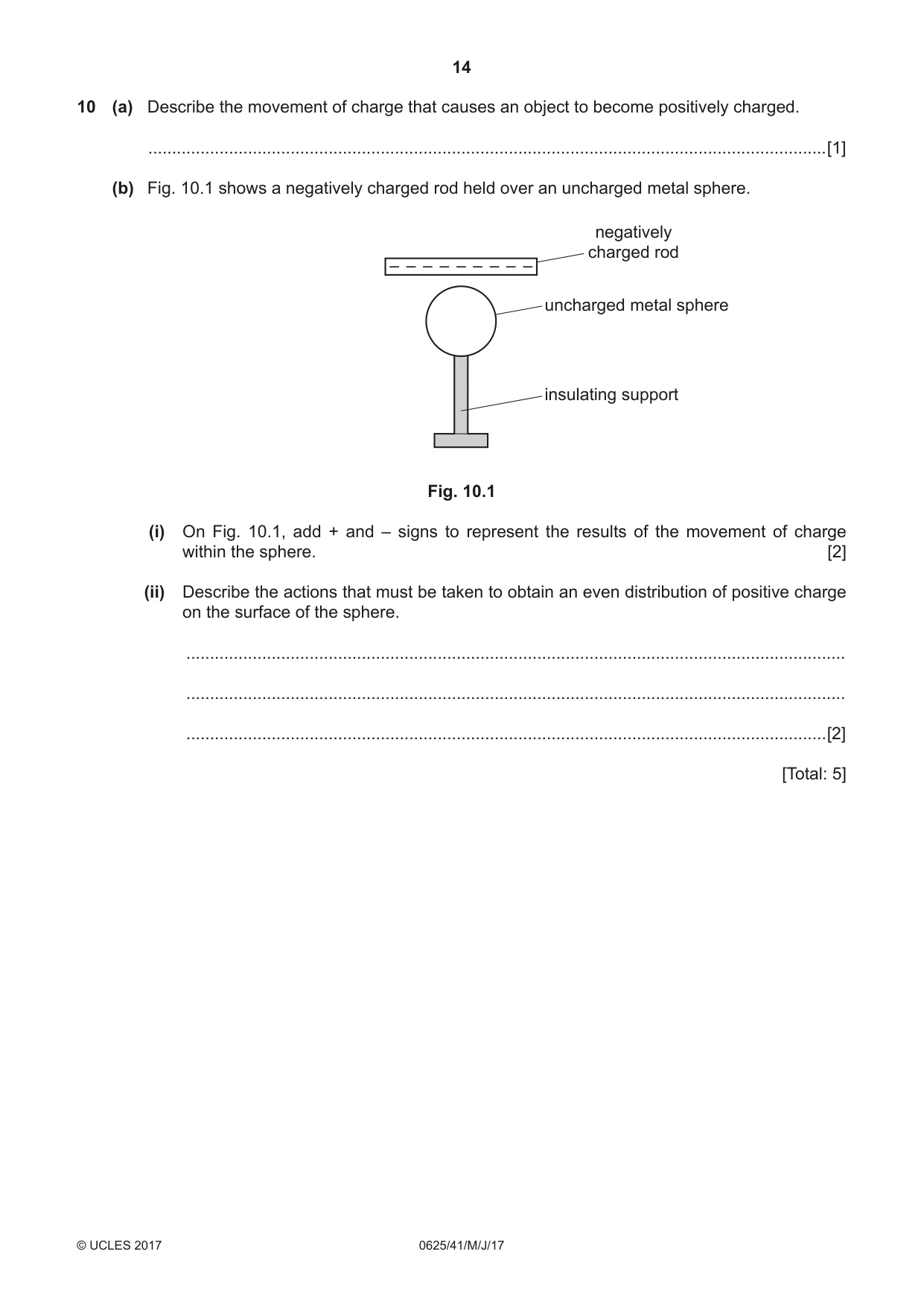
10 (a) Describe the movement of charge that causes an object to become positively charged. ...............................................................................................................................................[1] (b) Fig. 10.1 shows a negatively charged rod held over an uncharged metal sphere. negatively charged rod – – – – – – – – – uncharged metal sphere insulating support Fig. 10.1 (i) On Fig. 10.1, add + and – signs to represent the results of the movement of charge within the sphere. [2] (ii) Describe the actions that must be taken to obtain an even distribution of positive charge on the surface of the sphere. ........................................................................................................................................... ........................................................................................................................................... .......................................................................................................................................[2] [Total: 5]
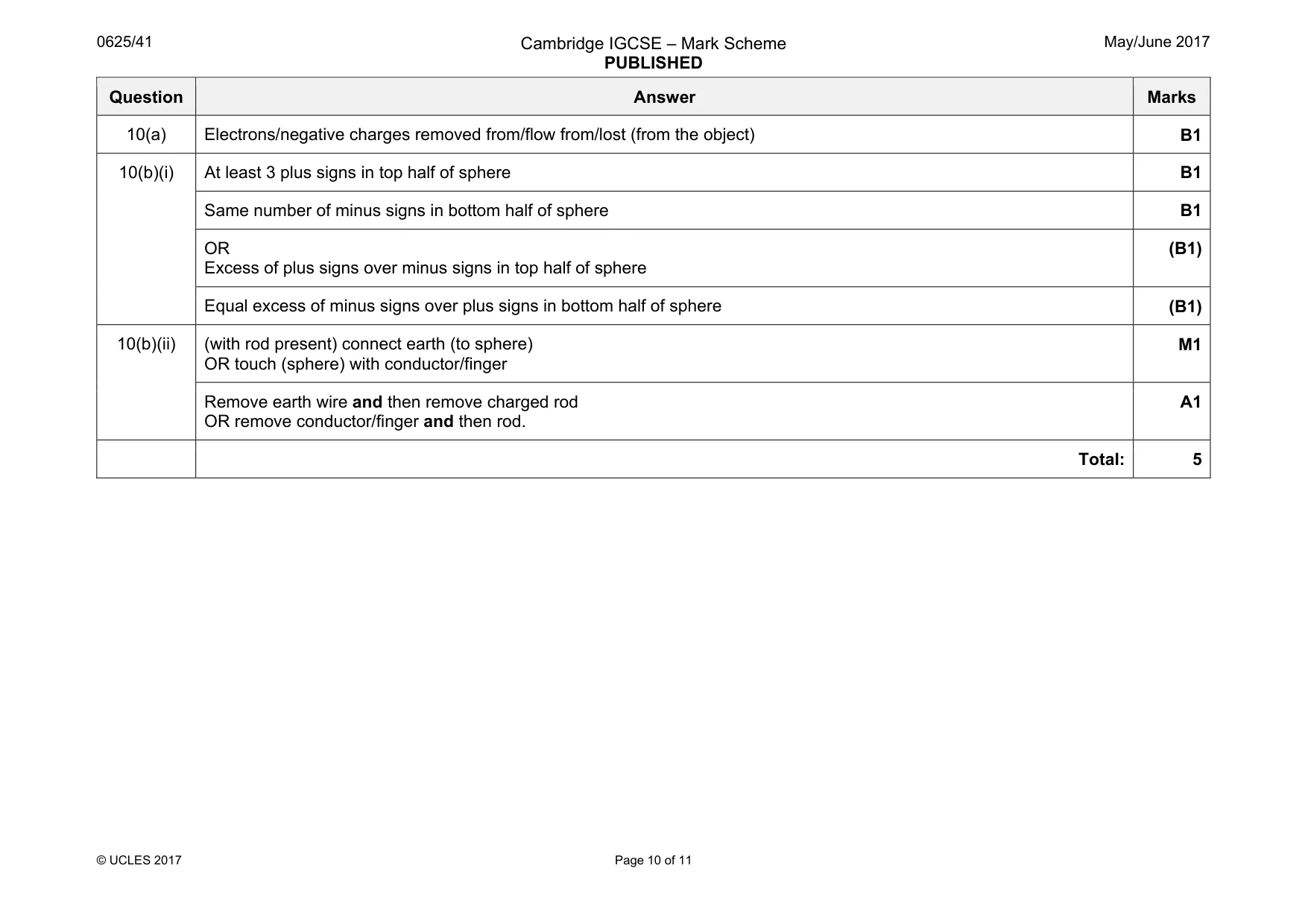
Mark scheme: 10(a) Electrons/negative charges removed from/flow from/lost (from the object) B1 10(b)(i) At least 3 plus signs in top half of sphere B1 Same number of minus signs in bottom half of sphere B1 OR Excess of plus signs over minus signs in top half of sphere (B1) Equal excess of minus signs over plus signs in bottom half of sphere (B1) 10(b)(ii) (with rod present) connect earth (to sphere) OR touch (sphere) with conductor/finger M1 Remove earth wire and then remove charged rod OR remove conductor/finger and then rod. A1 Total: 5
Q11 · A radioactive source is tested over a number of hours with a radiation detector
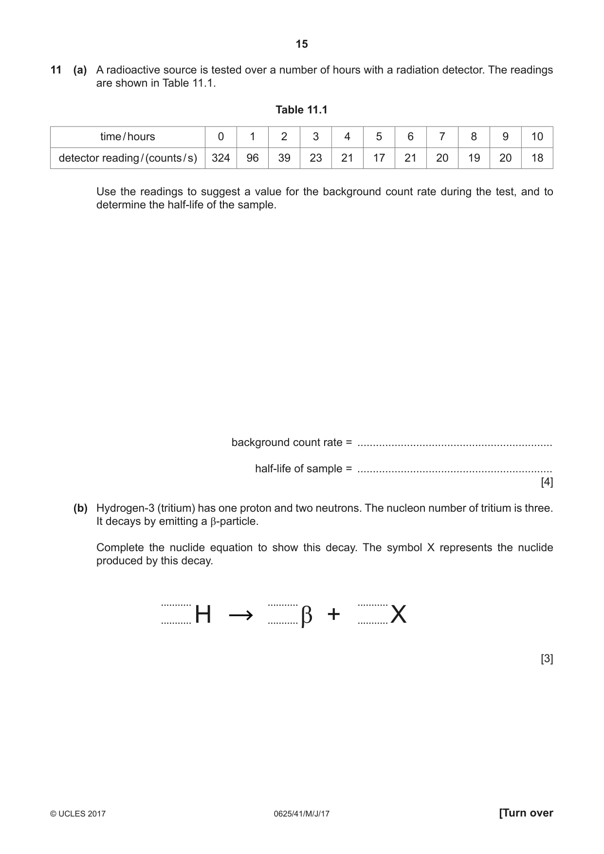
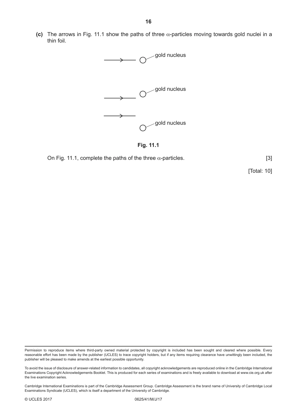
11 (a) A radioactive source is tested over a number of hours with a radiation detector. The readings are shown in Table 11.1. Table 11.1 time / hours 0 1 2 3 4 5 6 7 8 9 10 detector reading / (counts / s) 324 96 39 23 21 17 21 20 19 20 18 Use the readings to suggest a value for the background count rate during the test, and to determine the half-life of the sample. background count rate = ............................................................... half-life of sample = ............................................................... [4] (b) Hydrogen-3 (tritium) has one proton and two neutrons. The nucleon number of tritium is three. It decays by emitting a β-particle. Complete the nuclide equation to show this decay. The symbol X represents the nuclide produced by this decay. ........... ........... ........... ........... ........... ........... H β + X [3] (c) The arrows in Fig. 11.1 show the paths of three α-particles moving towards gold nuclei in a thin foil. gold nucleus gold nucleus gold nucleus Fig. 11.1 On Fig. 11.1, complete the paths of the three α-particles. [3] [Total: 10]
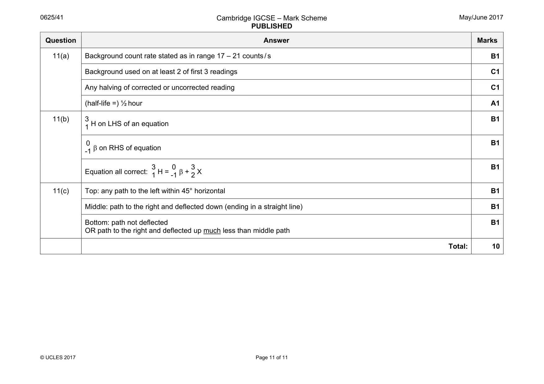
Mark scheme: 11(a) Background count rate stated as in range 17 – 21 counts / s B1 Background used on at least 2 of first 3 readings C1 Any halving of corrected or uncorrected reading C1 (half-life =) ½ hour A1 11(b) 3 1 H on LHS of an equation B1 0 -1 β on RHS of equation B1 Equation all correct: 3 1 H = 0 -1 β + 3 2 X B1 11(c) Top: any path to the left within 45° horizontal B1 Middle: path to the right and deflected down (ending in a straight line) B1 Bottom: path not deflected OR path to the right and deflected up much less than middle path B1 Total: 10
What was in this paper
The subtopics covered by these 11 questions, and how many questions each got. Open one in a new tab to see every Cambridge question on it.
What you needed in this session
Cambridge’s own grade thresholds for 2017 May/June, Paper 4 · Variant 1. A higher threshold means an easier paper — the bar moves with how the cohort did.