Cambridge IGCSE Physics 0625 — 2021 Oct/Nov Paper 4 · Variant 3
0625/43/O/N/21 · 11 questions · 80 marks · ≈90 min
The question paper and its mark scheme, free to read here and free to download. This is Cambridge’s own paper, exactly as it was sat.
Question paper20 pages


Mark scheme16 pages
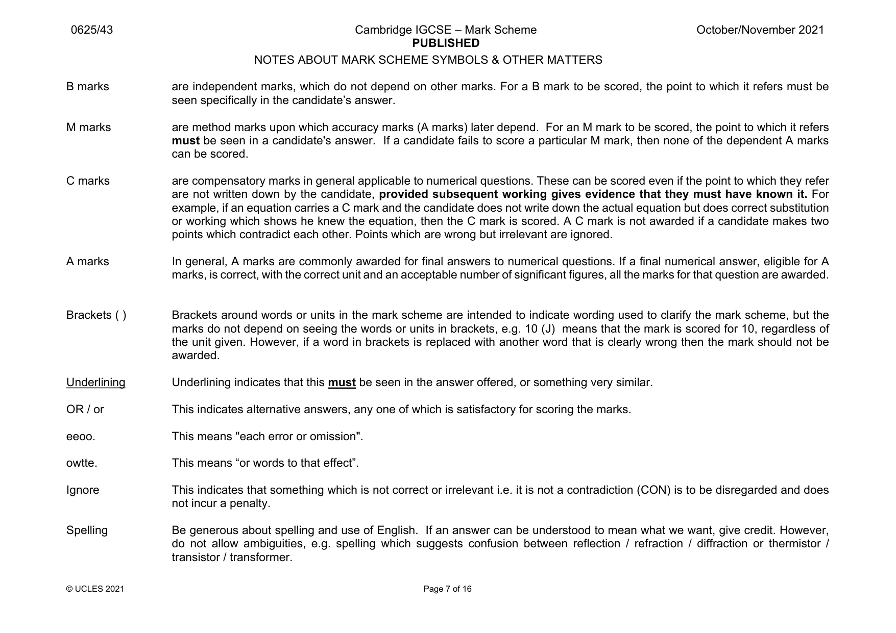
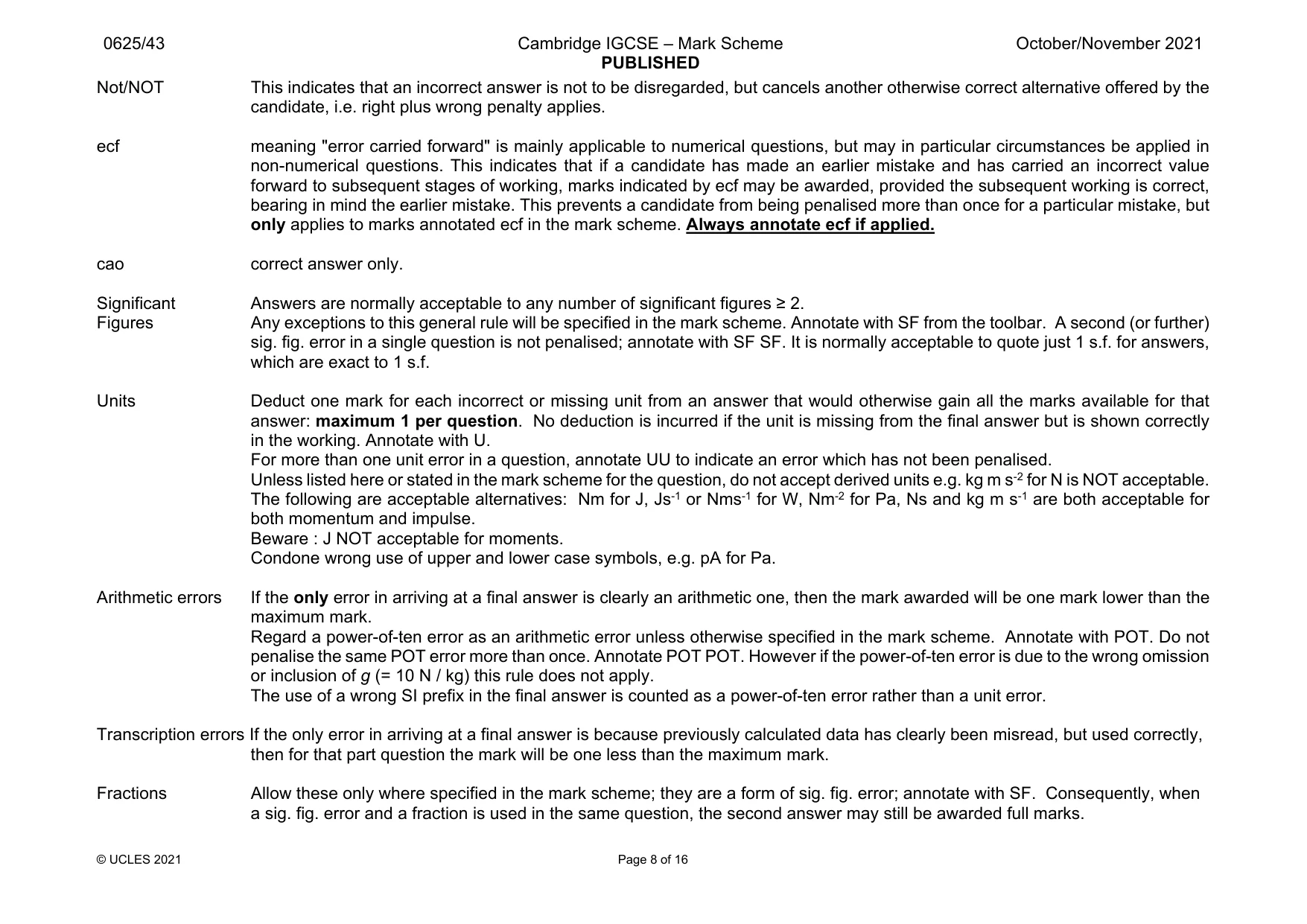
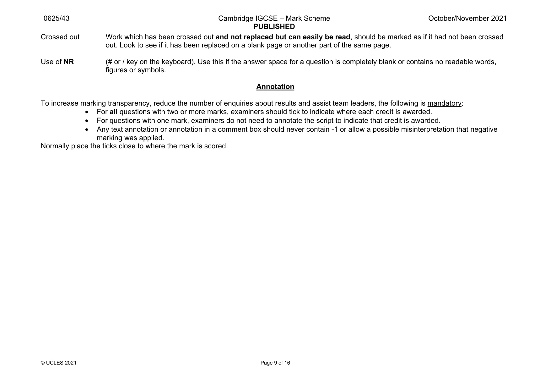
Answers below. Sit the paper first if you are practising.
Questions as text
Q1 · A ship sails in a straight line between two ports
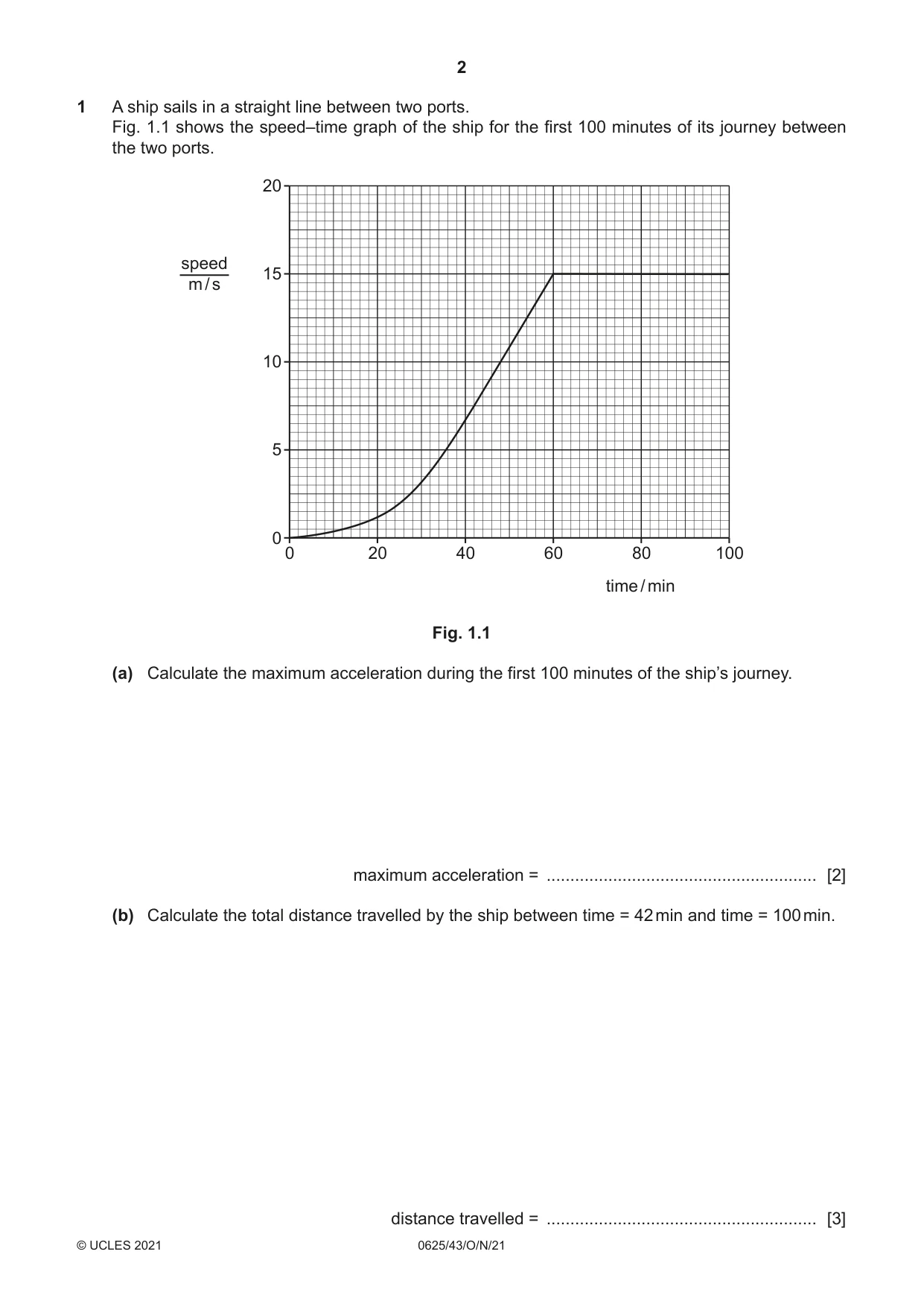
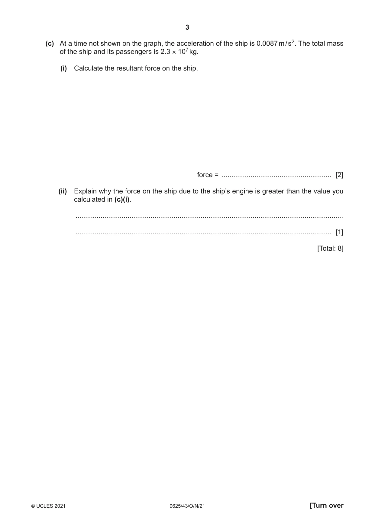
1 A ship sails in a straight line between two ports. Fig. 1.1 shows the speed–time graph of the ship for the first 100 minutes of its journey between the two ports. 20 speed 15 m / s 10 5 0 0 20 40 60 80 100 time / min Fig. 1.1 (a) Calculate the maximum acceleration during the first 100 minutes of the ship’s journey. maximum acceleration = ......................................................... [2] (b) Calculate the total distance travelled by the ship between time = 42 min and time = 100 min. distance travelled = ......................................................... [3] (c) At a time not shown on the graph, the acceleration of the ship is 0.0087 m / s2. The total mass of the ship and its passengers is 2.3 × 10⁷ kg. (i) Calculate the resultant force on the ship. force = ......................................................... [2] (ii) Explain why the force on the ship due to the ship’s engine is greater than the value you calculated in (c)(i). ........................................................................................................................................... ..................................................................................................................................... [1] [Total: 8]
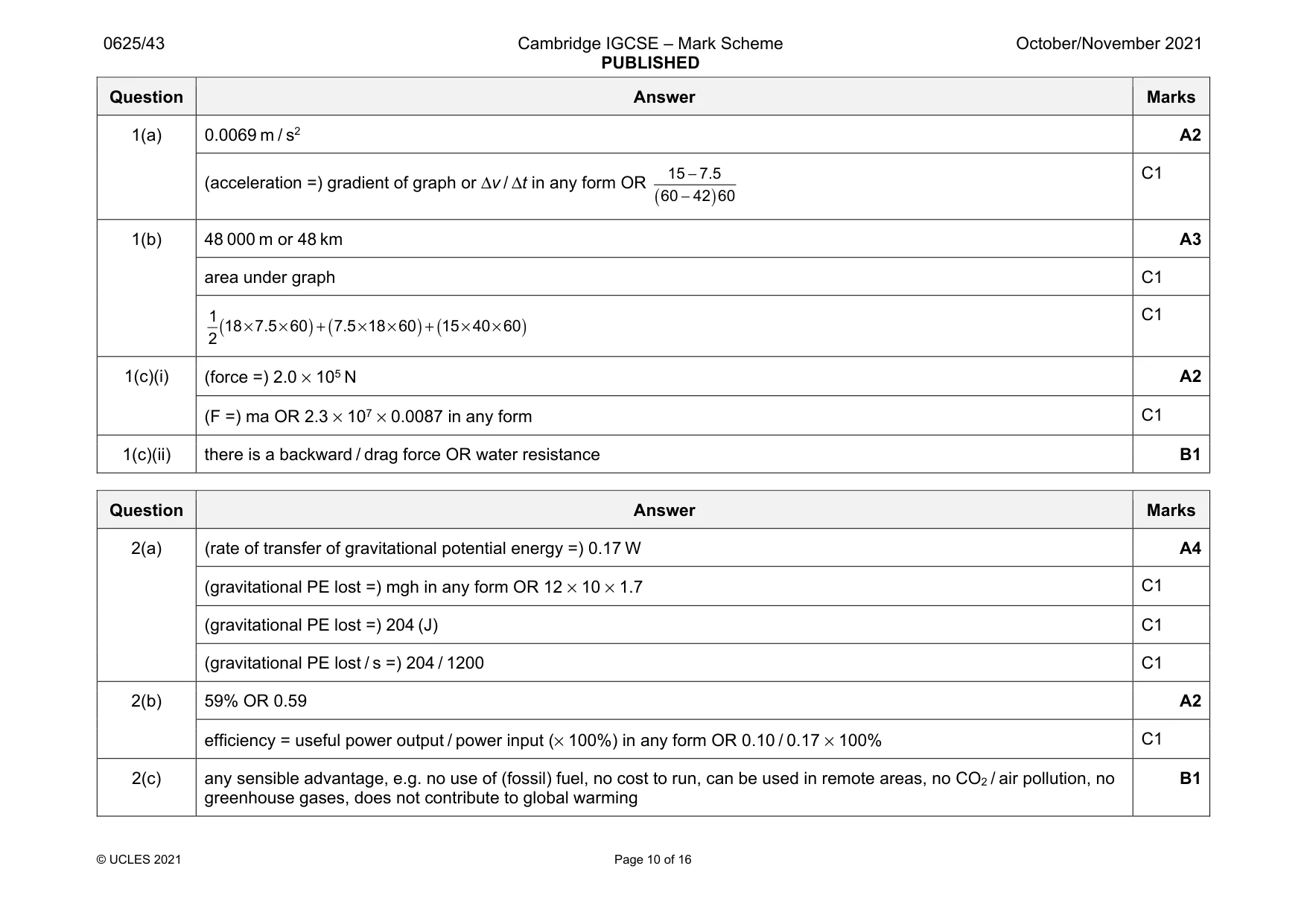
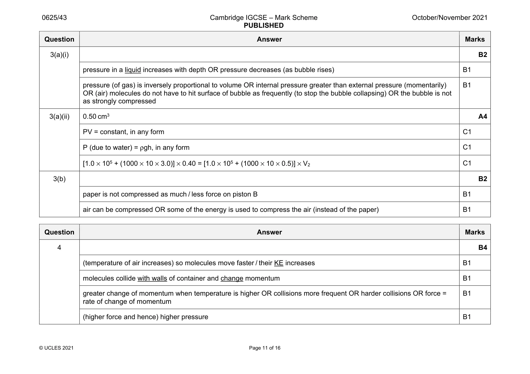
Mark scheme: 1(a) 0.0069 m / s2 A2 (acceleration =) gradient of graph or Δv / Δt in any form OR ( ) 15 7.5 60 42 60 − − C1 1(b) 48 000 m or 48 km A3 area under graph C1 ( ) ( ) ( ) 1 18 7.5 60 7.5 18 60 15 40 60 2 × × + × × + × × C1 1(c)(i) (force =) 2.0 × 10⁵ N A2 (F =) ma OR 2.3 × 107 × 0.0087 in any form C1 1(c)(ii) there is a backward / drag force OR water resistance B1
Q2 · A simplified version of a ‘gravity lamp’
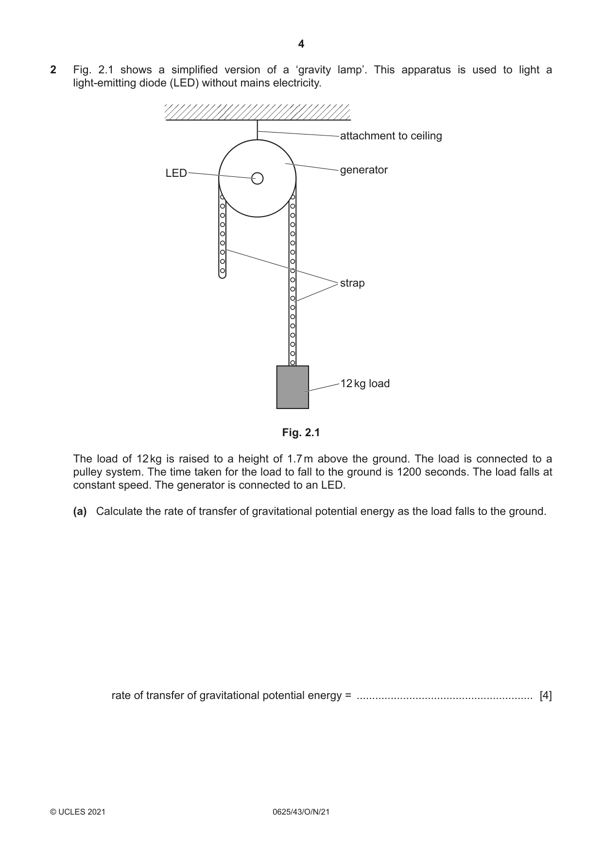
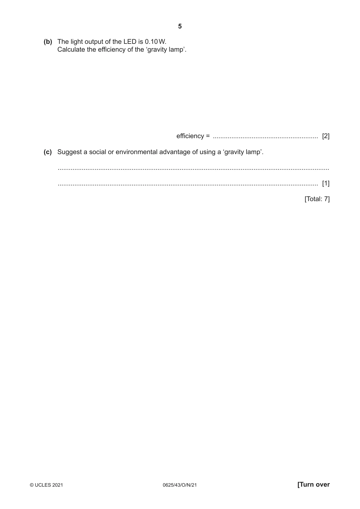
2 Fig. 2.1 shows a simplified version of a ‘gravity lamp’. This apparatus is used to light a light-emitting diode (LED) without mains electricity. attachment to ceiling generator LED strap 12 kg load Fig. 2.1 The load of 12 kg is raised to a height of 1.7 m above the ground. The load is connected to a pulley system. The time taken for the load to fall to the ground is 1200 seconds. The load falls at constant speed. The generator is connected to an LED. (a) Calculate the rate of transfer of gravitational potential energy as the load falls to the ground. rate of transfer of gravitational potential energy = ......................................................... [4] (b) The light output of the LED is 0.10 W. Calculate the efficiency of the ‘gravity lamp’. efficiency = ......................................................... [2] (c) Suggest a social or environmental advantage of using a ‘gravity lamp’. ................................................................................................................................................... ............................................................................................................................................. [1] [Total: 7]
Mark scheme: 2(a) (rate of transfer of gravitational potential energy =) 0.17 W A4 (gravitational PE lost =) mgh in any form OR 12 × 10 × 1.7 C1 (gravitational PE lost =) 204 (J) C1 (gravitational PE lost / s =) 204 / 1200 C1 2(b) 59% OR 0.59 A2 efficiency = useful power output / power input (× 100%) in any form OR 0.10 / 0.17 × 100% C1 2(c) any sensible advantage, e.g. no use of (fossil) fuel, no cost to run, can be used in remote areas, no CO2 / air pollution, no greenhouse gases, does not contribute to global warming B1
Q3 · A gas bubble is released at the bottom of a lake
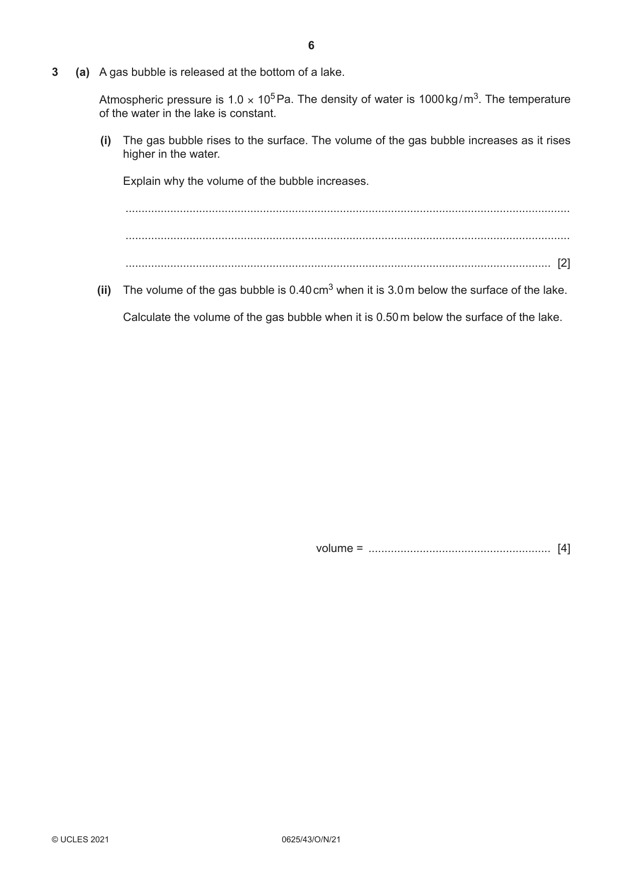
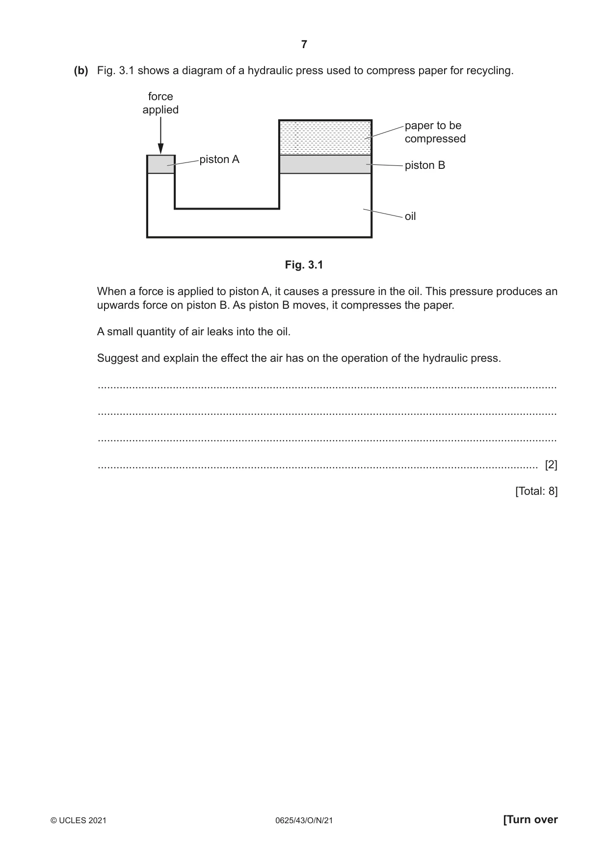
3 (a) A gas bubble is released at the bottom of a lake. Atmospheric pressure is 1.0 × 10⁵ Pa. The density of water is 1000 kg / m3. The temperature of the water in the lake is constant. (i) The gas bubble rises to the surface. The volume of the gas bubble increases as it rises higher in the water. Explain why the volume of the bubble increases. ........................................................................................................................................... ........................................................................................................................................... ..................................................................................................................................... [2] (ii) The volume of the gas bubble is 0.40 cm3 when it is 3.0 m below the surface of the lake. Calculate the volume of the gas bubble when it is 0.50 m below the surface of the lake. volume = ......................................................... [4] (b) Fig. 3.1 shows a diagram of a hydraulic press used to compress paper for recycling. force applied paper to be compressed piston A piston B oil Fig. 3.1 When a force is applied to piston A, it causes a pressure in the oil. This pressure produces an upwards force on piston B. As piston B moves, it compresses the paper. A small quantity of air leaks into the oil. Suggest and explain the effect the air has on the operation of the hydraulic press. ................................................................................................................................................... ................................................................................................................................................... ................................................................................................................................................... ............................................................................................................................................. [2] [Total: 8]
Mark scheme: 3(a)(i) B2 pressure in a liquid increases with depth OR pressure decreases (as bubble rises) B1 pressure (of gas) is inversely proportional to volume OR internal pressure greater than external pressure (momentarily) OR (air) molecules do not have to hit surface of bubble as frequently (to stop the bubble collapsing) OR the bubble is not as strongly compressed B1 3(a)(ii) 0.50 cm3 A4 PV = constant, in any form C1 P (due to water) = ρgh, in any form C1 [1.0 × 10⁵ + (1000 × 10 × 3.0)] × 0.40 = [1.0 × 10⁵ + (1000 × 10 × 0.5)] × V2 C1 3(b) B2 paper is not compressed as much / less force on piston B B1 air can be compressed OR some of the energy is used to compress the air (instead of the paper) B1
Q4 · Explain what happens to the pressure of a constant volume of air when the temperature of…
4 Explain what happens to the pressure of a constant volume of air when the temperature of the air increases. Use ideas of momentum of molecules in your explanation. .......................................................................................................................................................... .......................................................................................................................................................... .......................................................................................................................................................... .......................................................................................................................................................... .......................................................................................................................................................... .......................................................................................................................................................... .................................................................................................................................................... [4]
Mark scheme: 4 B4 (temperature of air increases) so molecules move faster / their KE increases B1 molecules collide with walls of container and change momentum B1 greater change of momentum when temperature is higher OR collisions more frequent OR harder collisions OR force = rate of change of momentum B1 (higher force and hence) higher pressure B1
Q5 · An aluminium saucepan and a steel saucepan have the same dimensions
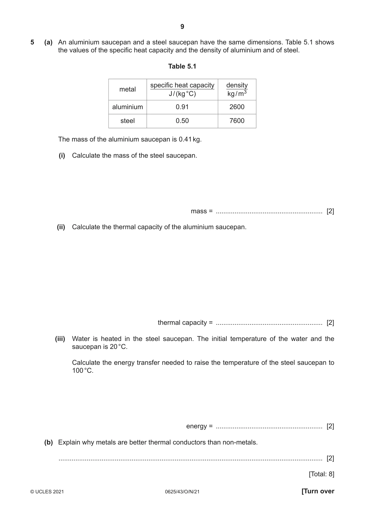
5 (a) An aluminium saucepan and a steel saucepan have the same dimensions. Table 5.1 shows the values of the specific heat capacity and the density of aluminium and of steel. Table 5.1 specific heat capacity density metal J / (kg °C) kg / m3 aluminium 0.91 2600 steel 0.50 7600 The mass of the aluminium saucepan is 0.41 kg. (i) Calculate the mass of the steel saucepan. mass = ......................................................... [2] (ii) Calculate the thermal capacity of the aluminium saucepan. thermal capacity = ......................................................... [2] (iii) Water is heated in the steel saucepan. The initial temperature of the water and the saucepan is 20 °C. Calculate the energy transfer needed to raise the temperature of the steel saucepan to 100 °C. energy = ......................................................... [2] (b) Explain why metals are better thermal conductors than non-metals. ............................................................................................................................................. [2] [Total: 8]
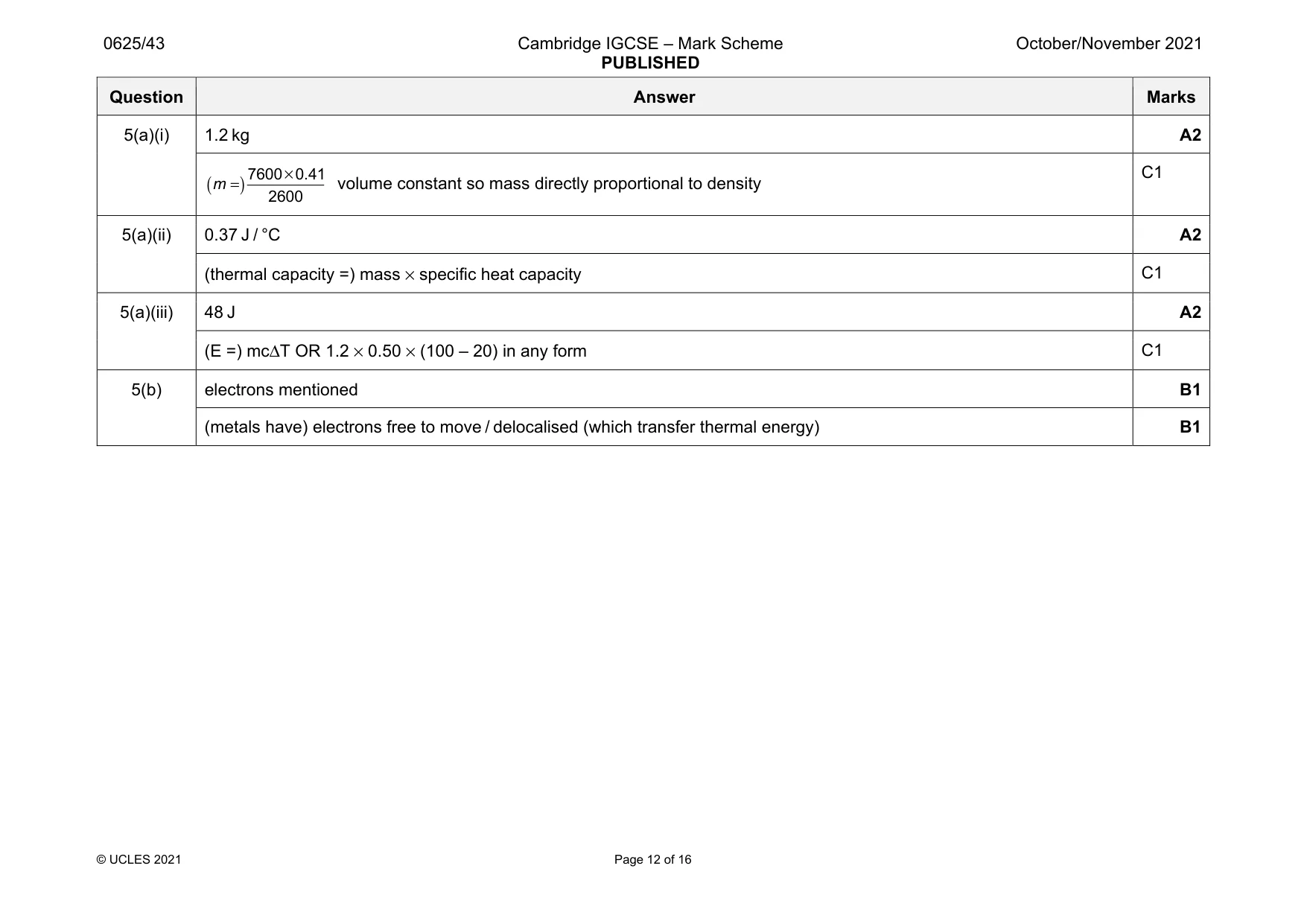
Mark scheme: 5(a)(i) 1.2 kg A2 ( ) 7600 0.41 2600 m × = volume constant so mass directly proportional to density C1 5(a)(ii) 0.37 J / °C A2 (thermal capacity =) mass × specific heat capacity C1 5(a)(iii) 48 J A2 (E =) mcΔT OR 1.2 × 0.50 × (100 – 20) in any form C1 5(b) electrons mentioned B1 (metals have) electrons free to move / delocalised (which transfer thermal energy) B1
Q6 · Describe an experiment to determine the speed of sound in air
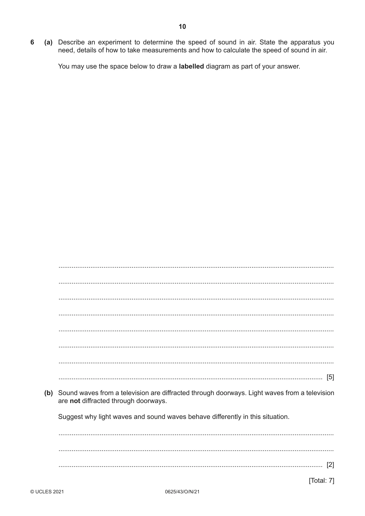
6 (a) Describe an experiment to determine the speed of sound in air. State the apparatus you need, details of how to take measurements and how to calculate the speed of sound in air. You may use the space below to draw a labelled diagram as part of your answer. ................................................................................................................................................... ................................................................................................................................................... ................................................................................................................................................... ................................................................................................................................................... ................................................................................................................................................... ................................................................................................................................................... ................................................................................................................................................... ............................................................................................................................................. [5] (b) Sound waves from a television are diffracted through doorways. Light waves from a television are not diffracted through doorways. Suggest why light waves and sound waves behave differently in this situation. ................................................................................................................................................... ................................................................................................................................................... ............................................................................................................................................. [2] [Total: 7]
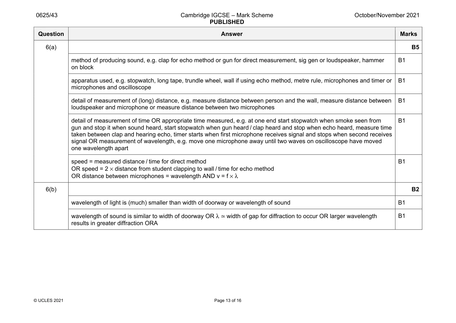
Mark scheme: 6(a) B5 method of producing sound, e.g. clap for echo method or gun for direct measurement, sig gen or loudspeaker, hammer on block B1 apparatus used, e.g. stopwatch, long tape, trundle wheel, wall if using echo method, metre rule, microphones and timer or microphones and oscilloscope B1 detail of measurement of (long) distance, e.g. measure distance between person and the wall, measure distance between loudspeaker and microphone or measure distance between two microphones B1 detail of measurement of time OR appropriate time measured, e.g. at one end start stopwatch when smoke seen from gun and stop it when sound heard, start stopwatch when gun heard / clap heard and stop when echo heard, measure time taken between clap and hearing echo, timer starts when first microphone receives signal and stops when second receives signal OR measurement of wavelength, e.g. move one microphone away until two waves on oscilloscope have moved one wavelength apart B1 speed = measured distance / time for direct method OR speed = 2 × distance from student clapping to wall / time for echo method OR distance between microphones = wavelength AND v = f × λ B1 6(b) B2 wavelength of light is (much) smaller than width of doorway or wavelength of sound B1 wavelength of sound is similar to width of doorway OR λ ≃ width of gap for diffraction to occur OR larger wavelength results in greater diffraction ORA B1
Q7 · A ray of green light emerging from one face of a glass prism
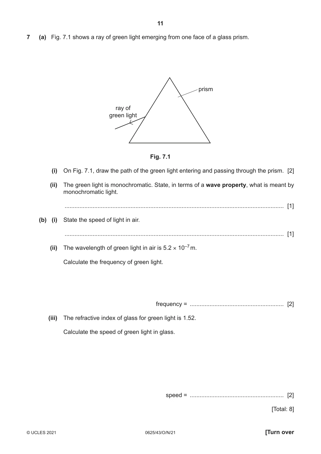
7 (a) Fig. 7.1 shows a ray of green light emerging from one face of a glass prism. prism ray of green light Fig. 7.1 (i) On Fig. 7.1, draw the path of the green light entering and passing through the prism. [2] (ii) The green light is monochromatic. State, in terms of a wave property, what is meant by monochromatic light. ..................................................................................................................................... [1] (b) (i) State the speed of light in air. ..................................................................................................................................... [1] (ii) The wavelength of green light in air is 5.2 × 10⁻⁷ m. Calculate the frequency of green light. frequency = ......................................................... [2] (iii) The refractive index of glass for green light is 1.52. Calculate the speed of green light in glass. speed = ......................................................... [2] [Total: 8]
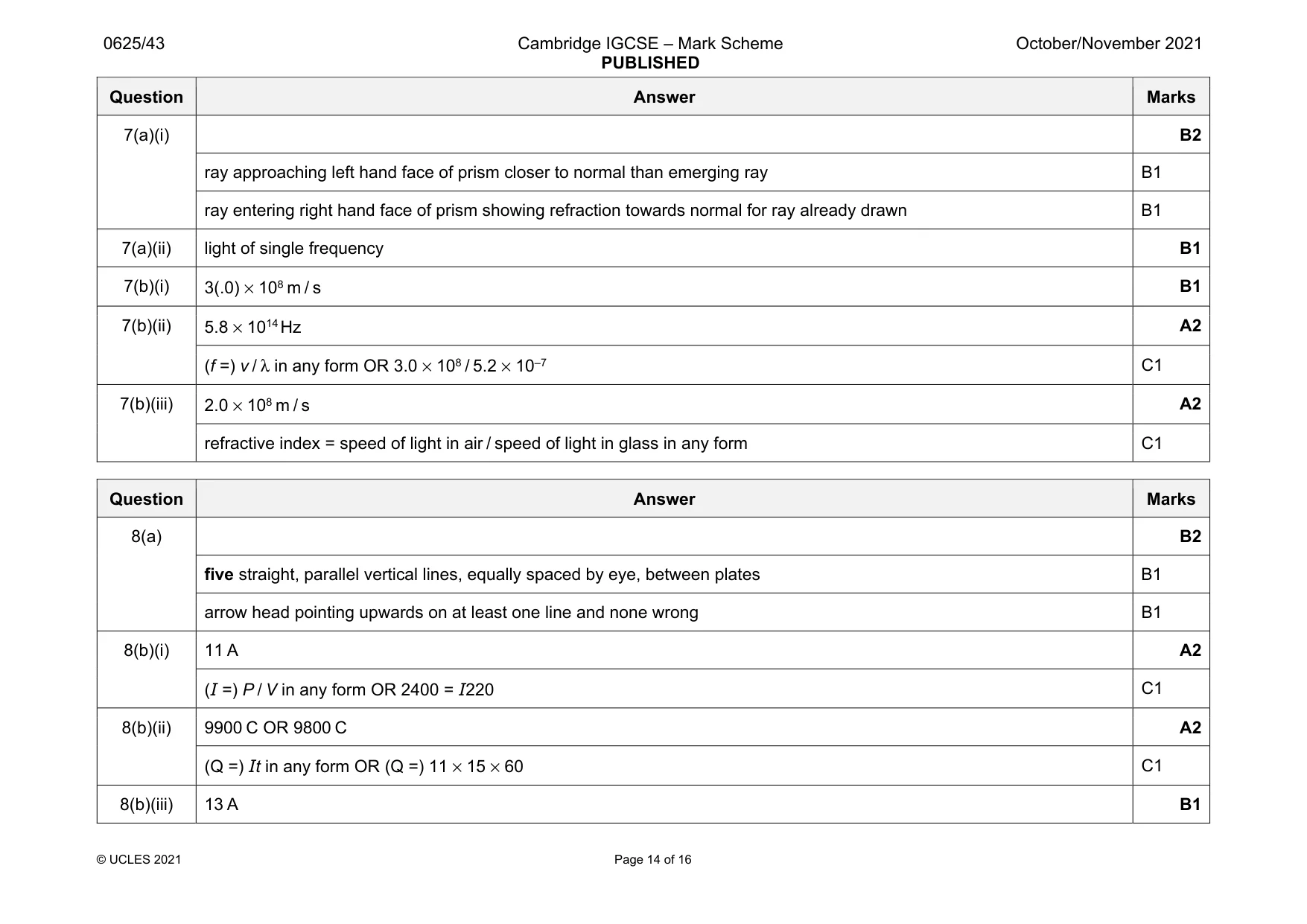
Mark scheme: 7(a)(i) B2 ray approaching left hand face of prism closer to normal than emerging ray B1 ray entering right hand face of prism showing refraction towards normal for ray already drawn B1 7(a)(ii) light of single frequency B1 7(b)(i) 3(.0) × 108 m / s B1 7(b)(ii) 5.8 × 10¹⁴ Hz A2 (f =) v / λ in any form OR 3.0 × 10⁸ / 5.2 × 10⁻⁷ C1 7(b)(iii) 2.0 × 10⁸ m / s A2 refractive index = speed of light in air / speed of light in glass in any form C1
Q8 · Two charged metal plates with a gap between them
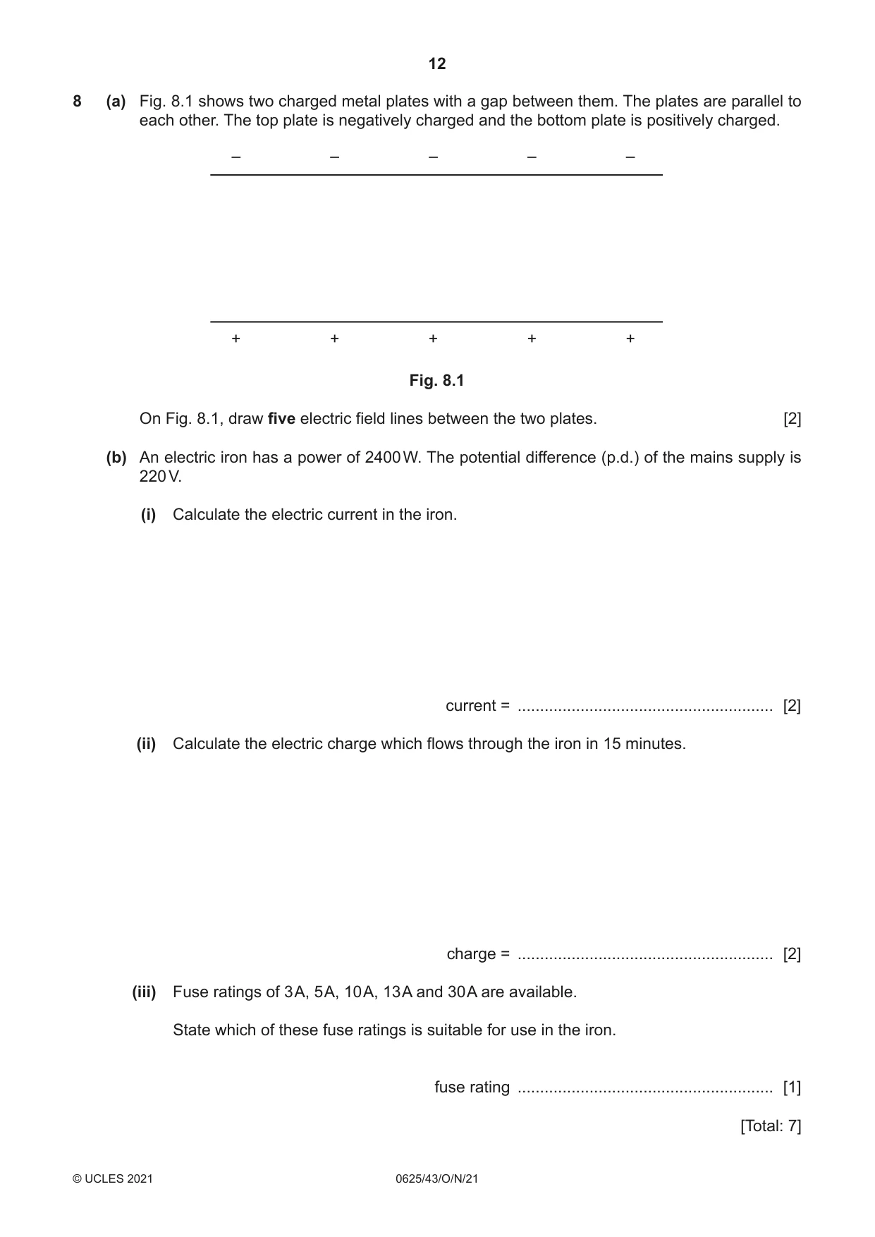
8 (a) Fig. 8.1 shows two charged metal plates with a gap between them. The plates are parallel to each other. The top plate is negatively charged and the bottom plate is positively charged. – – – – – + + + + + Fig. 8.1 On Fig. 8.1, draw five electric field lines between the two plates. [2] (b) An electric iron has a power of 2400 W. The potential difference (p.d.) of the mains supply is 220 V. (i) Calculate the electric current in the iron. current = ......................................................... [2] (ii) Calculate the electric charge which flows through the iron in 15 minutes. charge = ......................................................... [2] (iii) Fuse ratings of 3 A, 5 A, 10 A, 13 A and 30 A are available. State which of these fuse ratings is suitable for use in the iron. fuse rating ......................................................... [1] [Total: 7]
Mark scheme: 8(a) B2 five straight, parallel vertical lines, equally spaced by eye, between plates B1 arrow head pointing upwards on at least one line and none wrong B1 8(b)(i) 11 A A2 (I =) P / V in any form OR 2400 = I220 C1 8(b)(ii) 9900 C OR 9800 C A2 (Q =) It in any form OR (Q =) 11 × 15 × 60 C1 8(b)(iii) 13 A B1
Q9 · Current–potential difference (p.d.) graphs for a resistor, a thermistor and a filament…
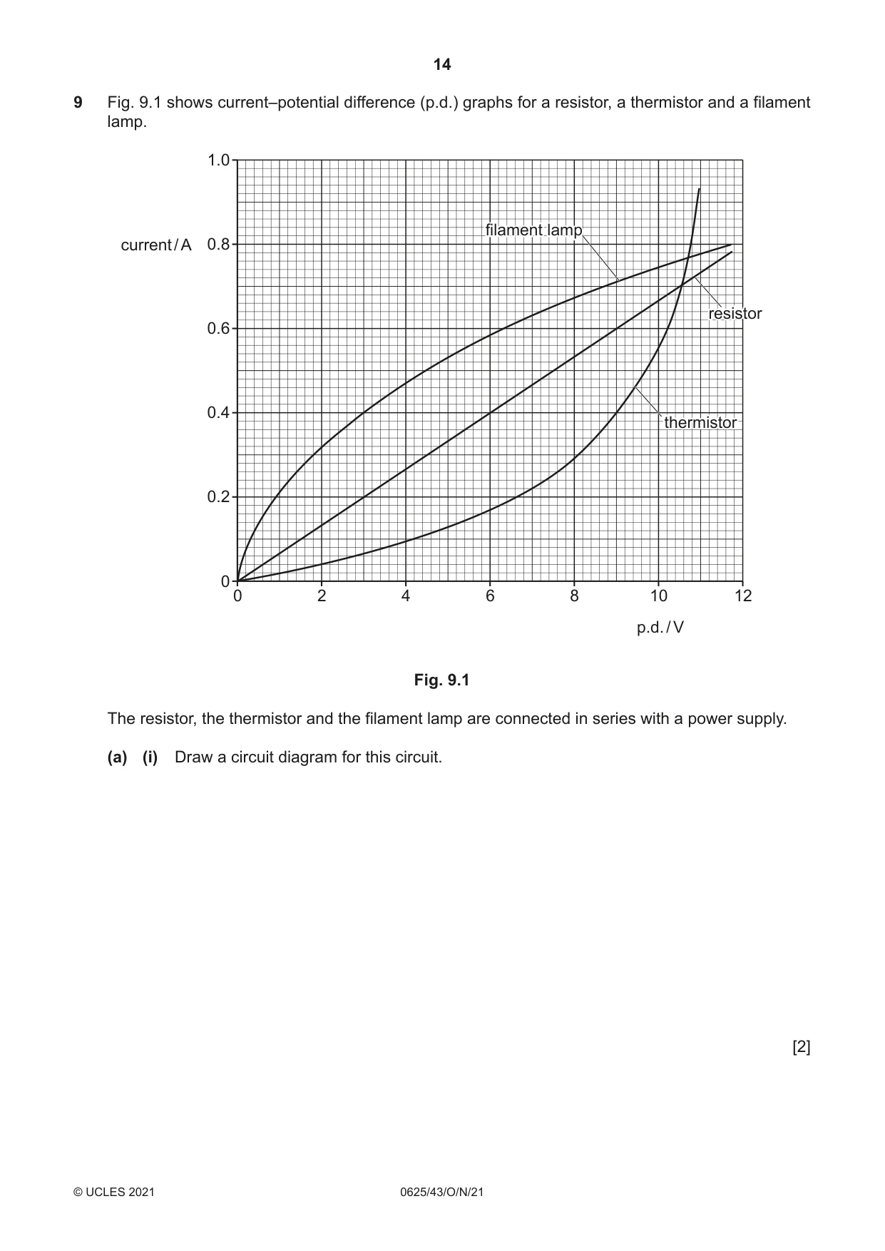
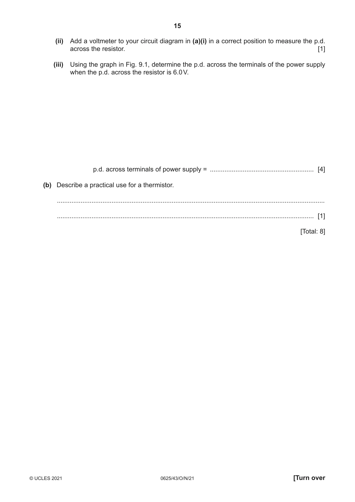
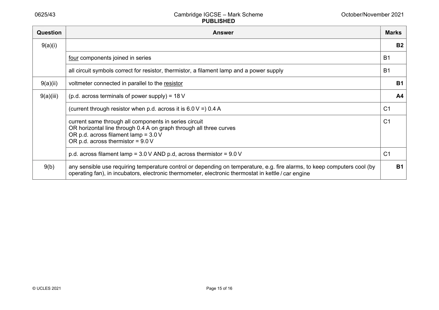
9 Fig. 9.1 shows current–potential difference (p.d.) graphs for a resistor, a thermistor and a filament lamp. 1.0 filamentfilament lamplamp current / A 0.8 resistorresistor 0.6 0.4 thermistorthermistor 0.2 0 0 2 4 6 8 10 12 p.d. / V Fig. 9.1 The resistor, the thermistor and the filament lamp are connected in series with a power supply. (a) (i) Draw a circuit diagram for this circuit. [2] (ii) Add a voltmeter to your circuit diagram in (a)(i) in a correct position to measure the p.d. across the resistor. [1] (iii) Using the graph in Fig. 9.1, determine the p.d. across the terminals of the power supply when the p.d. across the resistor is 6.0 V. p.d. across terminals of power supply = ......................................................... [4] (b) Describe a practical use for a thermistor. ................................................................................................................................................... ............................................................................................................................................. [1] [Total: 8]
Mark scheme: 9(a)(i) B2 four components joined in series B1 all circuit symbols correct for resistor, thermistor, a filament lamp and a power supply B1 9(a)(ii) voltmeter connected in parallel to the resistor B1 9(a)(iii) (p.d. across terminals of power supply) = 18 V A4 (current through resistor when p.d. across it is 6.0 V =) 0.4 A C1 current same through all components in series circuit OR horizontal line through 0.4 A on graph through all three curves OR p.d. across filament lamp = 3.0 V OR p.d. across thermistor = 9.0 V C1 p.d. across filament lamp = 3.0 V AND p.d, across thermistor = 9.0 V C1 9(b) any sensible use requiring temperature control or depending on temperature, e.g. fire alarms, to keep computers cool (by operating fan), in incubators, electronic thermometer, electronic thermostat in kettle / car engine B1
Q10 · A transformer has 500 turns on the primary coil and 25 turns on the secondary coil
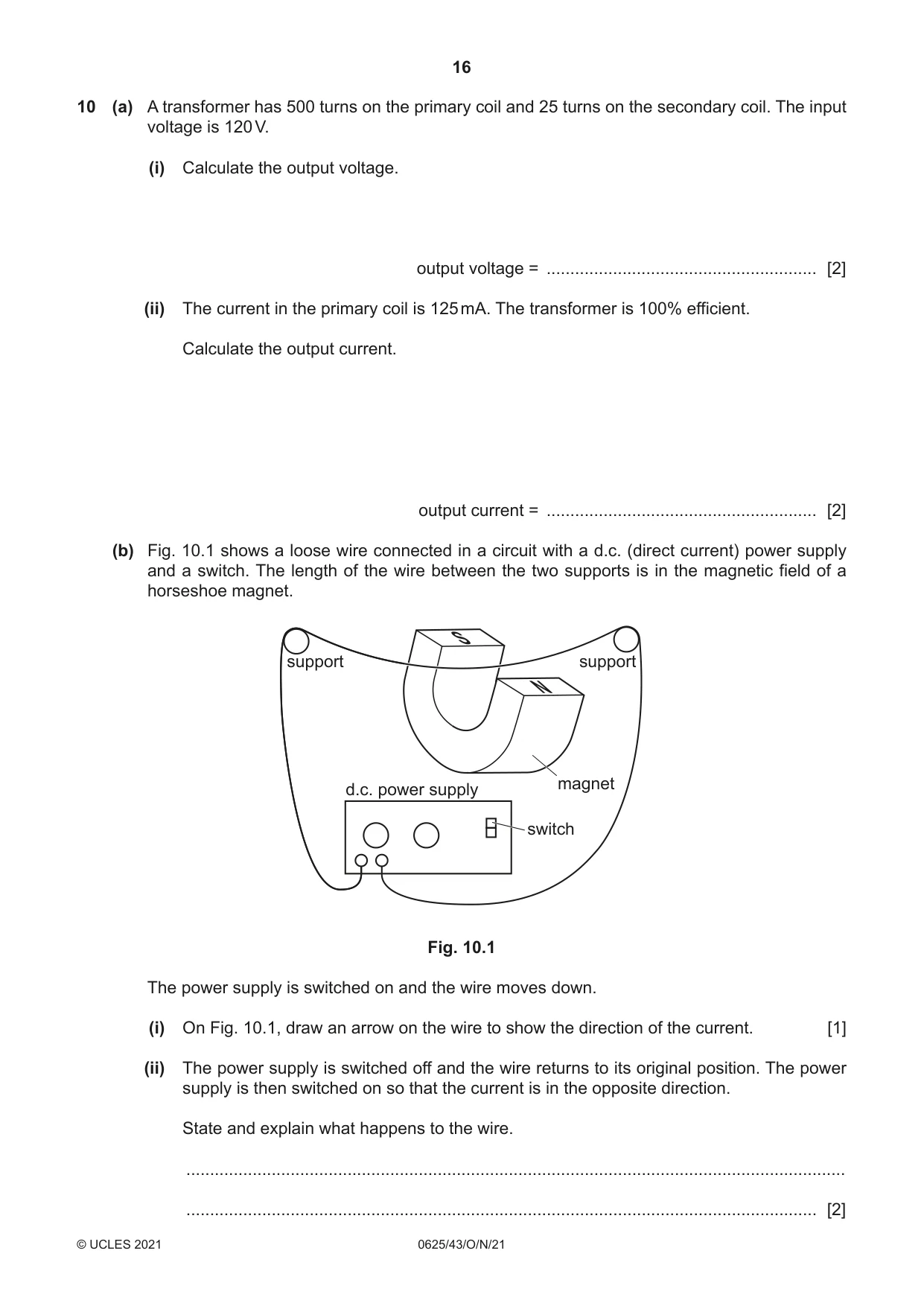
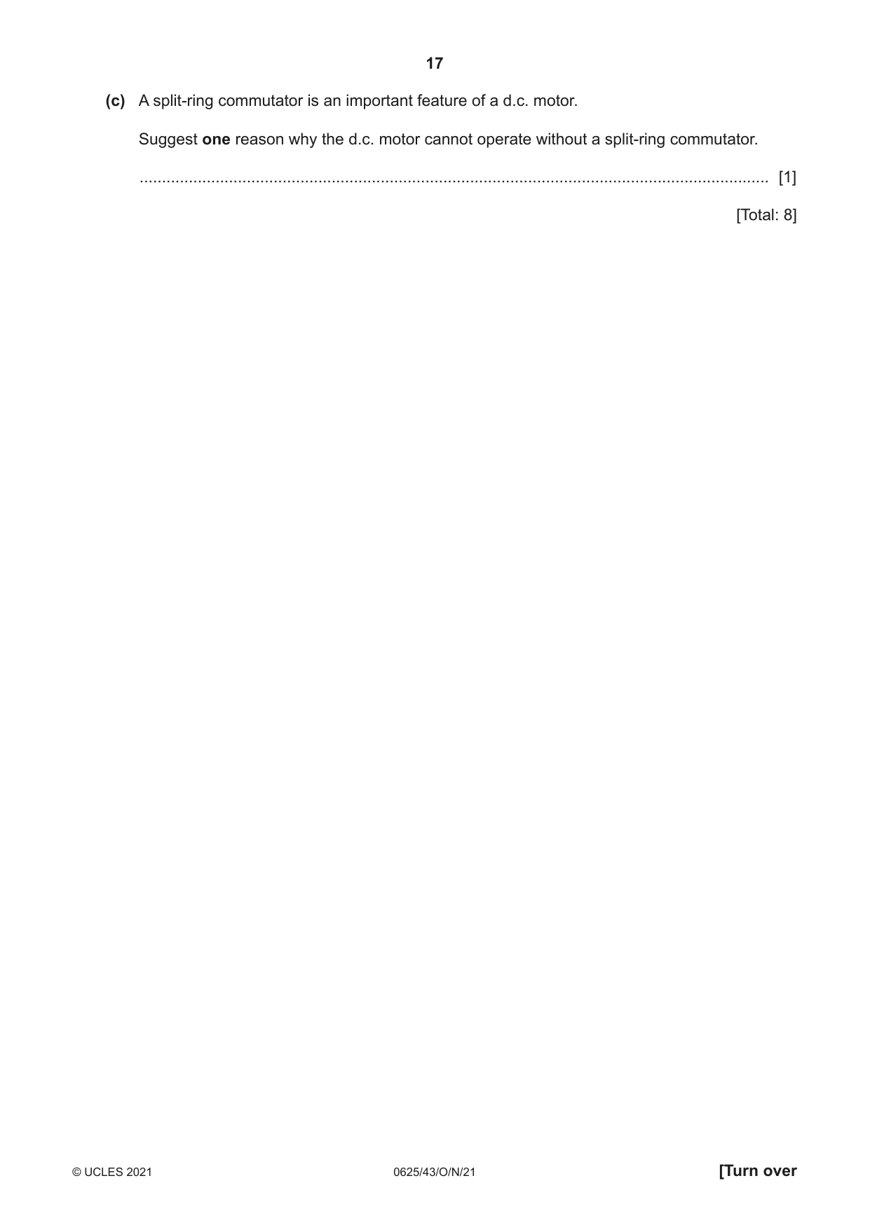
10 (a) A transformer has 500 turns on the primary coil and 25 turns on the secondary coil. The input voltage is 120 V. (i) Calculate the output voltage. output voltage = ......................................................... [2] (ii) The current in the primary coil is 125 mA. The transformer is 100% efficient. Calculate the output current. output current = ......................................................... [2] (b) Fig. 10.1 shows a loose wire connected in a circuit with a d.c. (direct current) power supply and a switch. The length of the wire between the two supports is in the magnetic field of a horseshoe magnet. S support support N magnet d.c. power supply switch Fig. 10.1 The power supply is switched on and the wire moves down. (i) On Fig. 10.1, draw an arrow on the wire to show the direction of the current. [1] (ii) The power supply is switched off and the wire returns to its original position. The power supply is then switched on so that the current is in the opposite direction. State and explain what happens to the wire. ........................................................................................................................................... ..................................................................................................................................... [2] (c) A split-ring commutator is an important feature of a d.c. motor. Suggest one reason why the d.c. motor cannot operate without a split-ring commutator. ............................................................................................................................................. [1] [Total: 8]
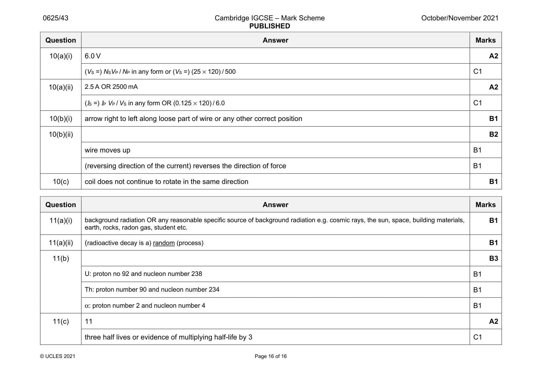
Mark scheme: 10(a)(i) 6.0 V A2 (VS =) NSVP / NP in any form or (VS =) (25 × 120) / 500 C1 10(a)(ii) 2.5 A OR 2500 mA A2 (IS =) IP VP / VS in any form OR (0.125 × 120) / 6.0 C1 10(b)(i) arrow right to left along loose part of wire or any other correct position B1 10(b)(ii) B2 wire moves up B1 (reversing direction of the current) reverses the direction of force B1 10(c) coil does not continue to rotate in the same direction B1
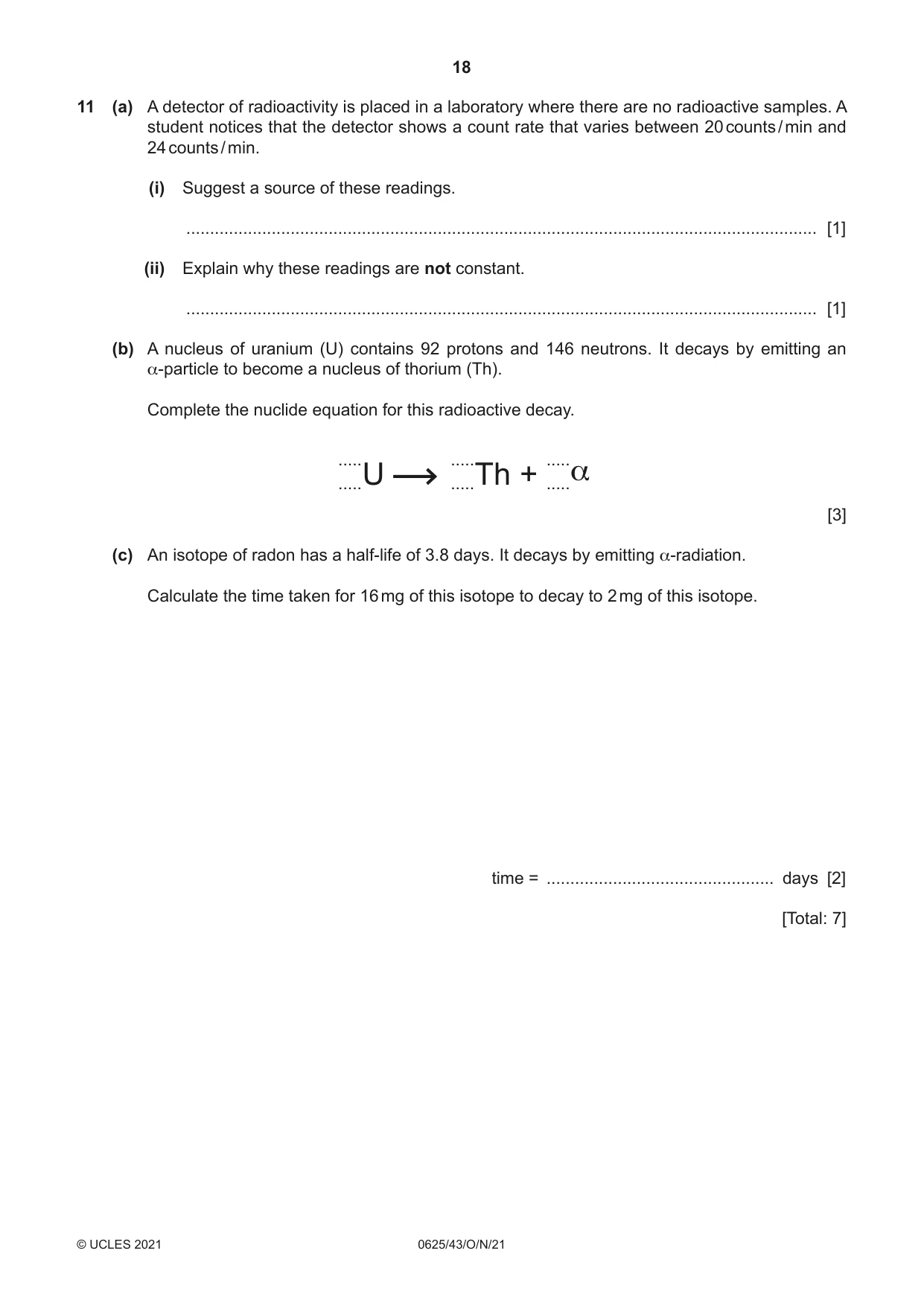
Q11 · A detector of radioactivity is placed in a laboratory where there are no radioactive…
11 (a) A detector of radioactivity is placed in a laboratory where there are no radioactive samples. A student notices that the detector shows a count rate that varies between 20 counts / min and 24 counts / min. (i) Suggest a source of these readings. ..................................................................................................................................... [1] (ii) Explain why these readings are not constant. ..................................................................................................................................... [1] (b) A nucleus of uranium (U) contains 92 protons and 146 neutrons. It decays by emitting an α-particle to become a nucleus of thorium (Th). Complete the nuclide equation for this radioactive decay. ..... ..... ..... .....U .....Th + .....α [3] (c) An isotope of radon has a half-life of 3.8 days. It decays by emitting α-radiation. Calculate the time taken for 16 mg of this isotope to decay to 2 mg of this isotope. time = ................................................ days [2] [Total: 7]
Mark scheme: 11(a)(i) earth, rocks, radon gas, student etc. B1 11(a)(ii) (radioactive decay is a) random (process) B1 11(b) B3 U: proton no 92 and nucleon number 238 B1 Th: proton number 90 and nucleon number 234 B1 α: proton number 2 and nucleon number 4 B1 11(c) 11 A2 three half lives or evidence of multiplying half-life by 3 C1
What was in this paper
The subtopics covered by these 11 questions, and how many questions each got. Open one in a new tab to see every Cambridge question on it.
What you needed in this session
Cambridge’s own grade thresholds for 2021 Oct/Nov, Paper 4 · Variant 3. A higher threshold means an easier paper — the bar moves with how the cohort did.