Cambridge IGCSE Physics 0625 — 2018 May/June Paper 4 · Variant 2
0625/42/M/J/18 · 11 questions · 80 marks · ≈90 min
The question paper and its mark scheme, free to read here and free to download. This is Cambridge’s own paper, exactly as it was sat.
Question paper20 pages


Mark scheme10 pages
Answers below. Sit the paper first if you are practising.
Questions as text
Q1 · The axes of a distance-time graph for an object moving in a straight line
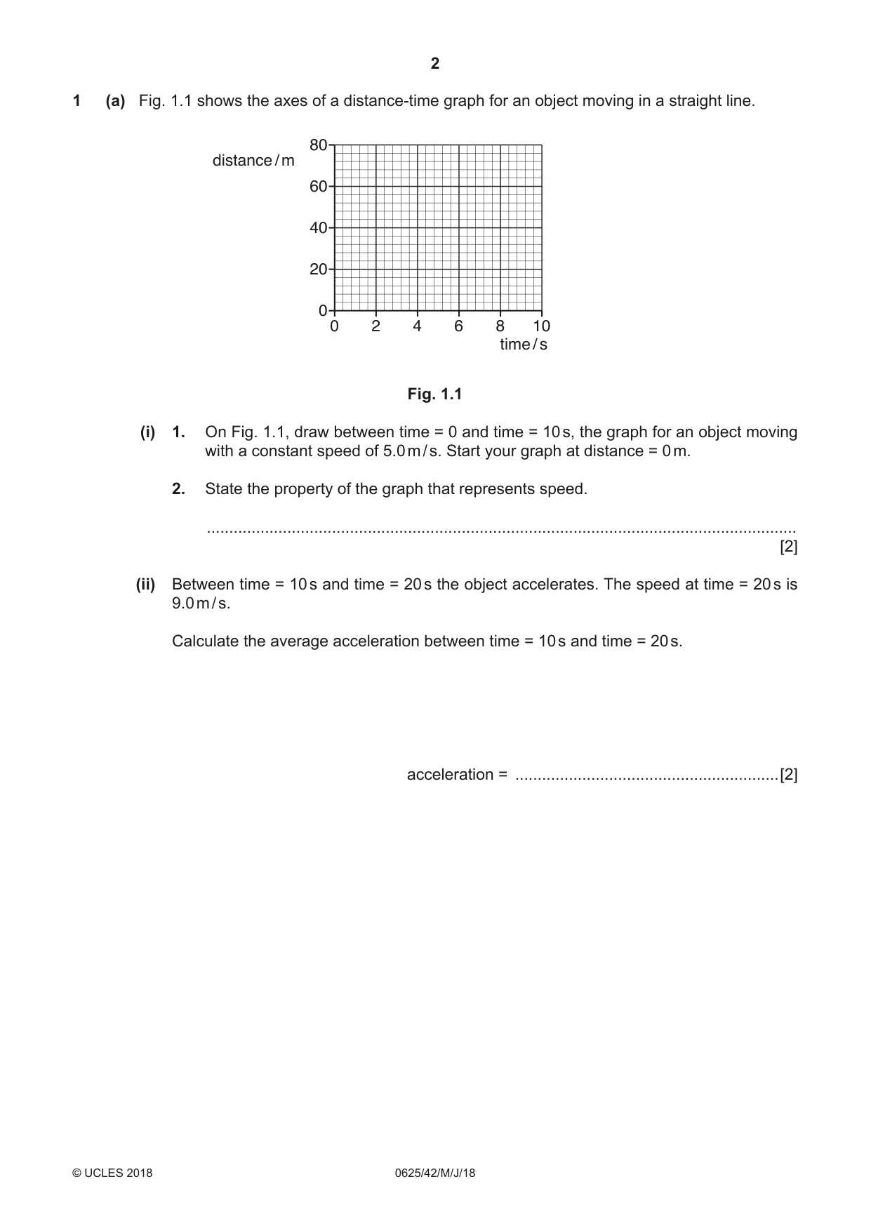
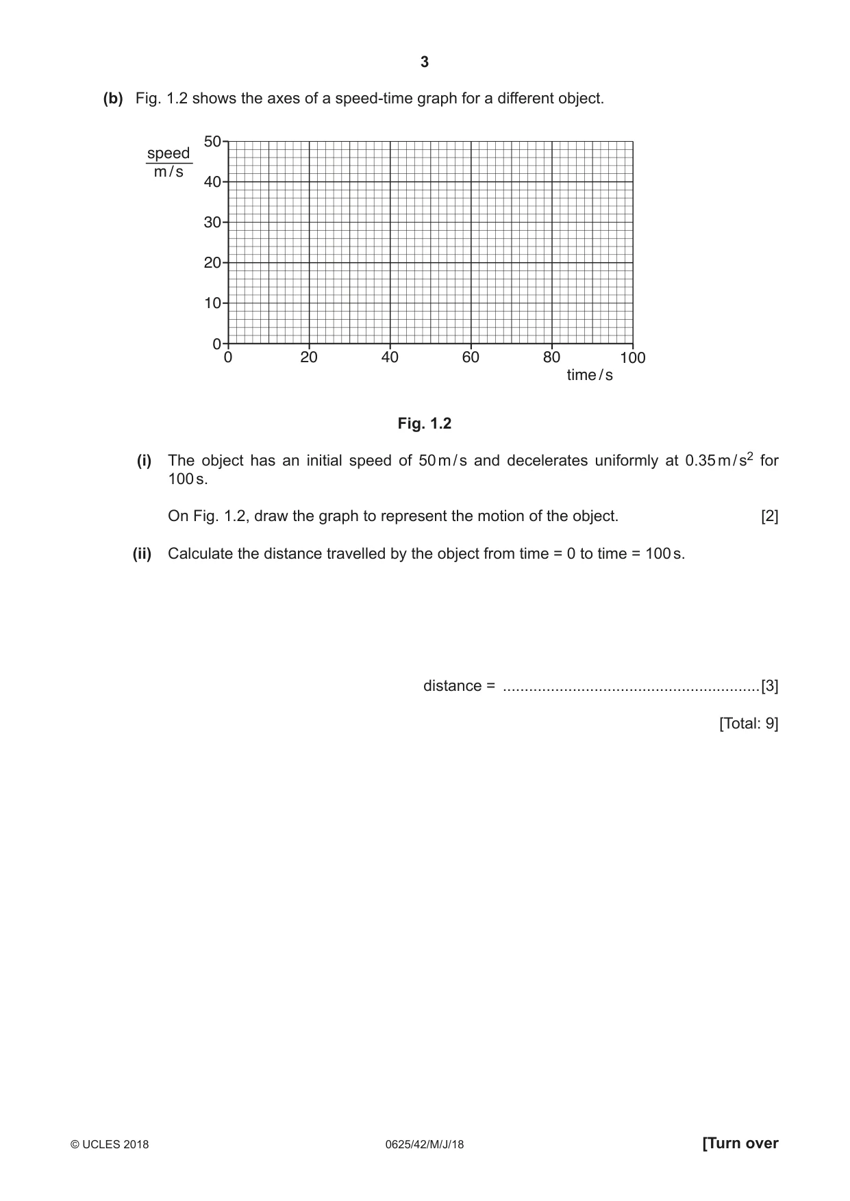
1 (a) Fig. 1.1 shows the axes of a distance-time graph for an object moving in a straight line. 80 distance / m 60 40 20 0 0 2 4 6 8 10 time / s Fig. 1.1 (i) 1. On Fig. 1.1, draw between time = 0 and time = 10 s, the graph for an object moving with a constant speed of 5.0 m / s. Start your graph at distance = 0 m. 2. State the property of the graph that represents speed. .................................................................................................................................... [2] (ii) Between time = 10 s and time = 20 s the object accelerates. The speed at time = 20 s is 9.0 m / s. Calculate the average acceleration between time = 10 s and time = 20 s. acceleration = ...........................................................[2] (b) Fig. 1.2 shows the axes of a speed-time graph for a different object. 50 speed m / s 40 30 20 10 0 0 20 40 60 80 100 time / s Fig. 1.2 (i) The object has an initial speed of 50 m / s and decelerates uniformly at 0.35 m / s2 for 100 s. On Fig. 1.2, draw the graph to represent the motion of the object. [2] (ii) Calculate the distance travelled by the object from time = 0 to time = 100 s. distance = ...........................................................[3] [Total: 9]
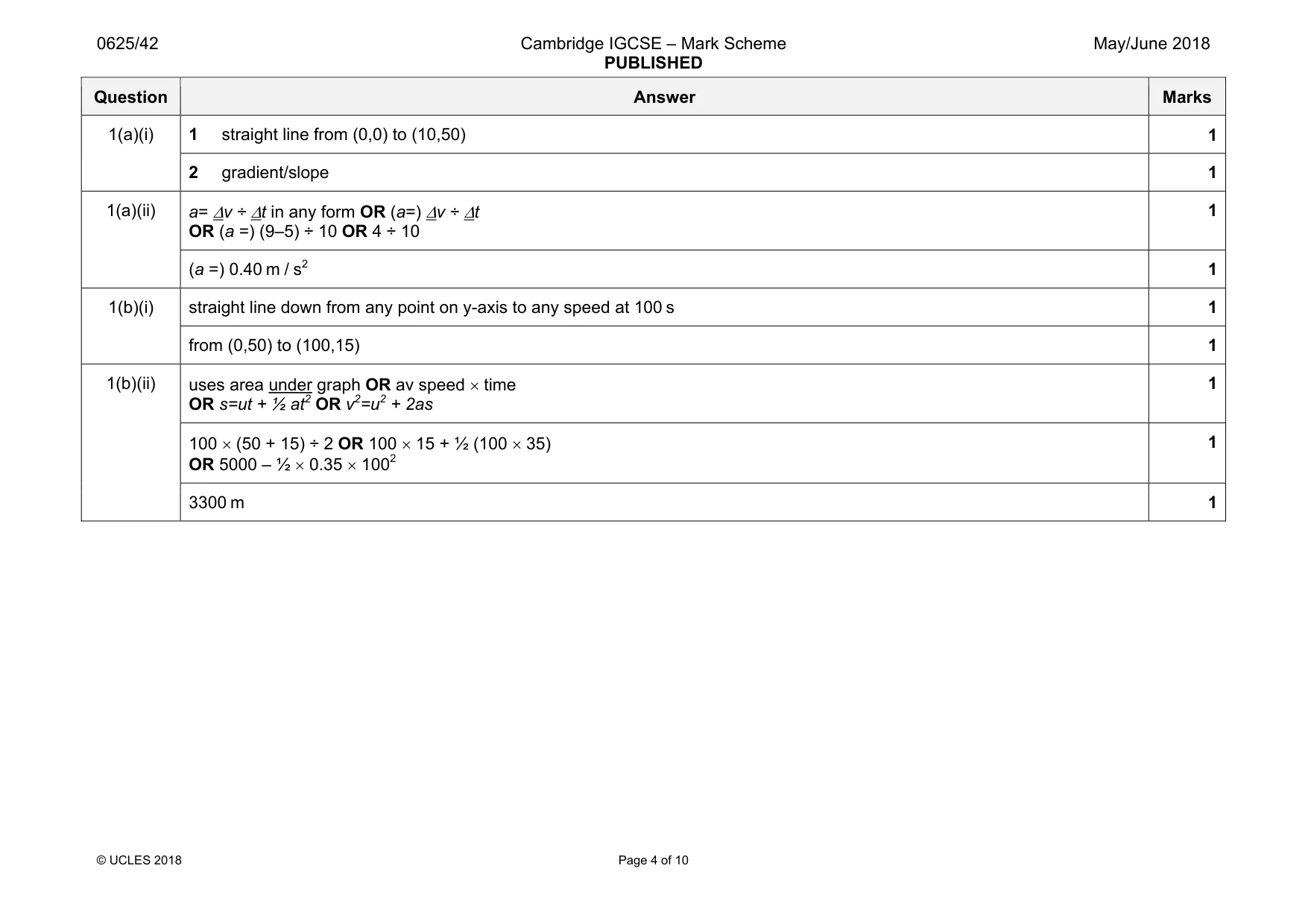
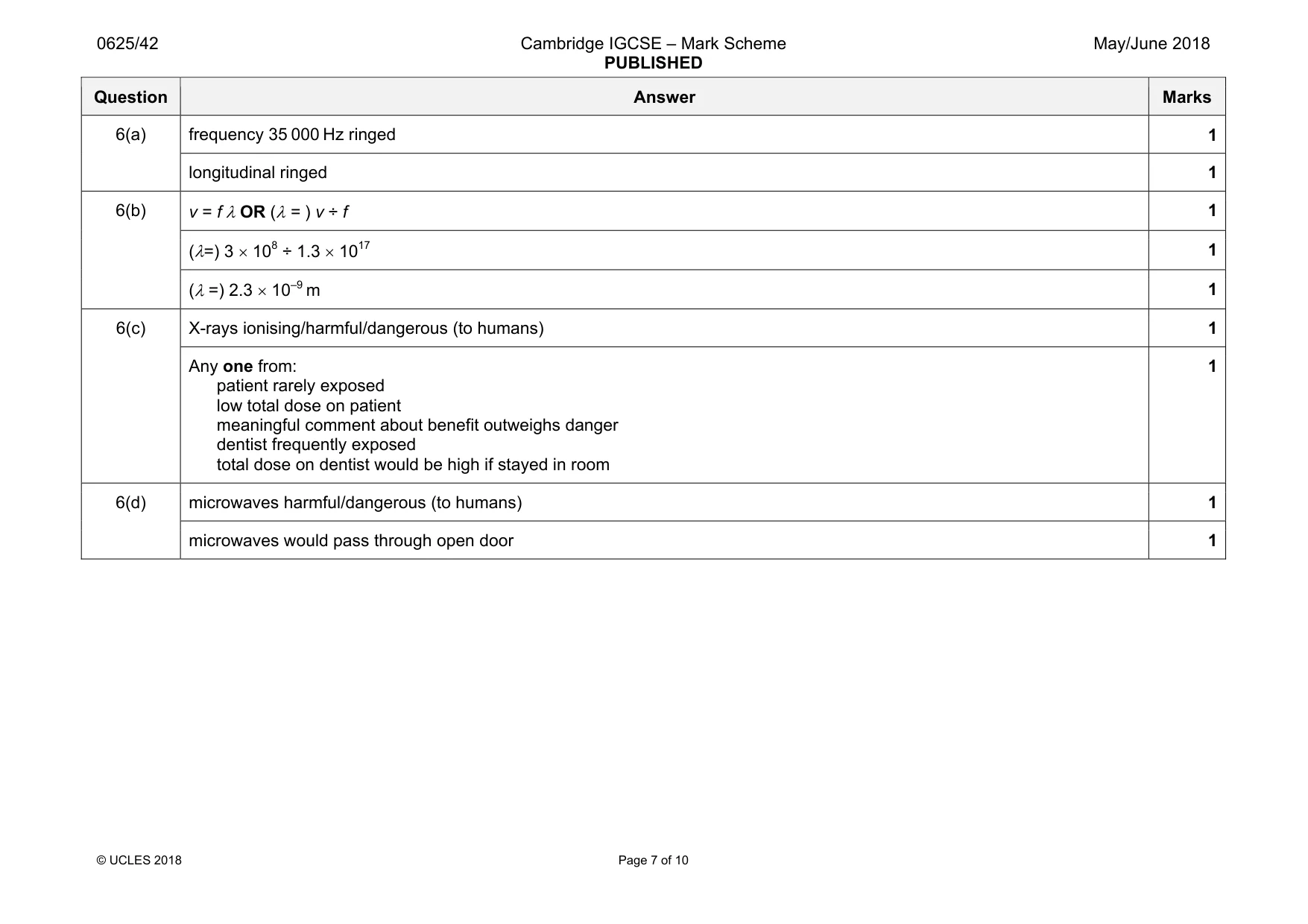
Mark scheme: 1(a)(i) 1 straight line from (0,0) to (10,50) 1 2 gradient/slope 1 1(a)(ii) a= ∆v ÷ ∆t in any form OR (a=) ∆v ÷ ∆t OR (a =) (9–5) ÷ 10 OR 4 ÷ 10 1 (a =) 0.40 m / s2 1 1(b)(i) straight line down from any point on y-axis to any speed at 100 s 1 from (0,50) to (100,15) 1 1(b)(ii) uses area under graph OR av speed × time OR s=ut + ½ at2 OR v2=u2 + 2as 1 100 × (50 + 15) ÷ 2 OR 100 × 15 + ½ (100 × 35) OR 5000 – ½ × 0.35 × 1002 1 3300 m 1
Q2 · A hollow metal cylinder containing air, floating in the sea
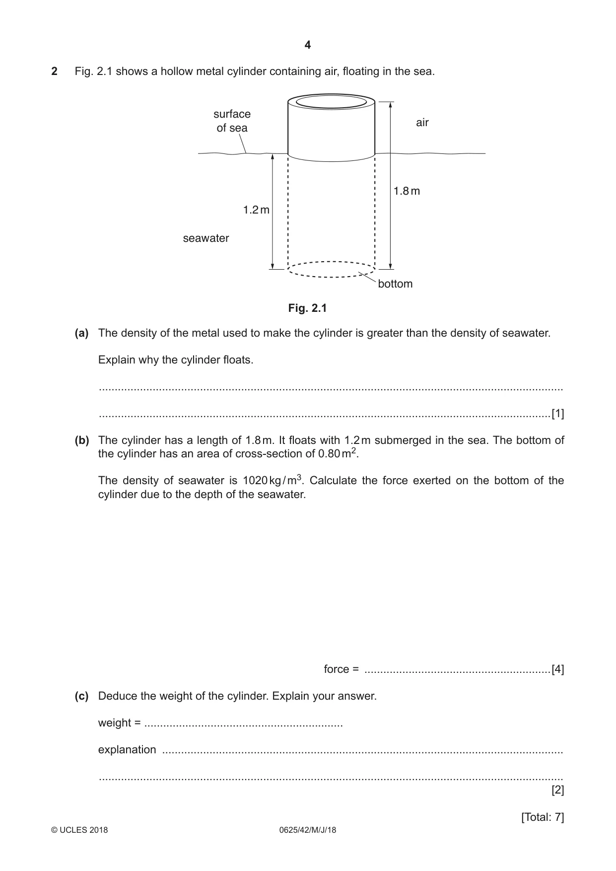
2 Fig. 2.1 shows a hollow metal cylinder containing air, floating in the sea. surface air of sea 1.8 m 1.2 m seawater bottom Fig. 2.1 (a) The density of the metal used to make the cylinder is greater than the density of seawater. Explain why the cylinder floats. ................................................................................................................................................... ...............................................................................................................................................[1] (b) The cylinder has a length of 1.8 m. It floats with 1.2 m submerged in the sea. The bottom of the cylinder has an area of cross-section of 0.80 m2. The density of seawater is 1020 kg / m3. Calculate the force exerted on the bottom of the cylinder due to the depth of the seawater. force = ...........................................................[4] (c) Deduce the weight of the cylinder. Explain your answer. weight = ............................................................... explanation ............................................................................................................................... ................................................................................................................................................... [2] [Total: 7]
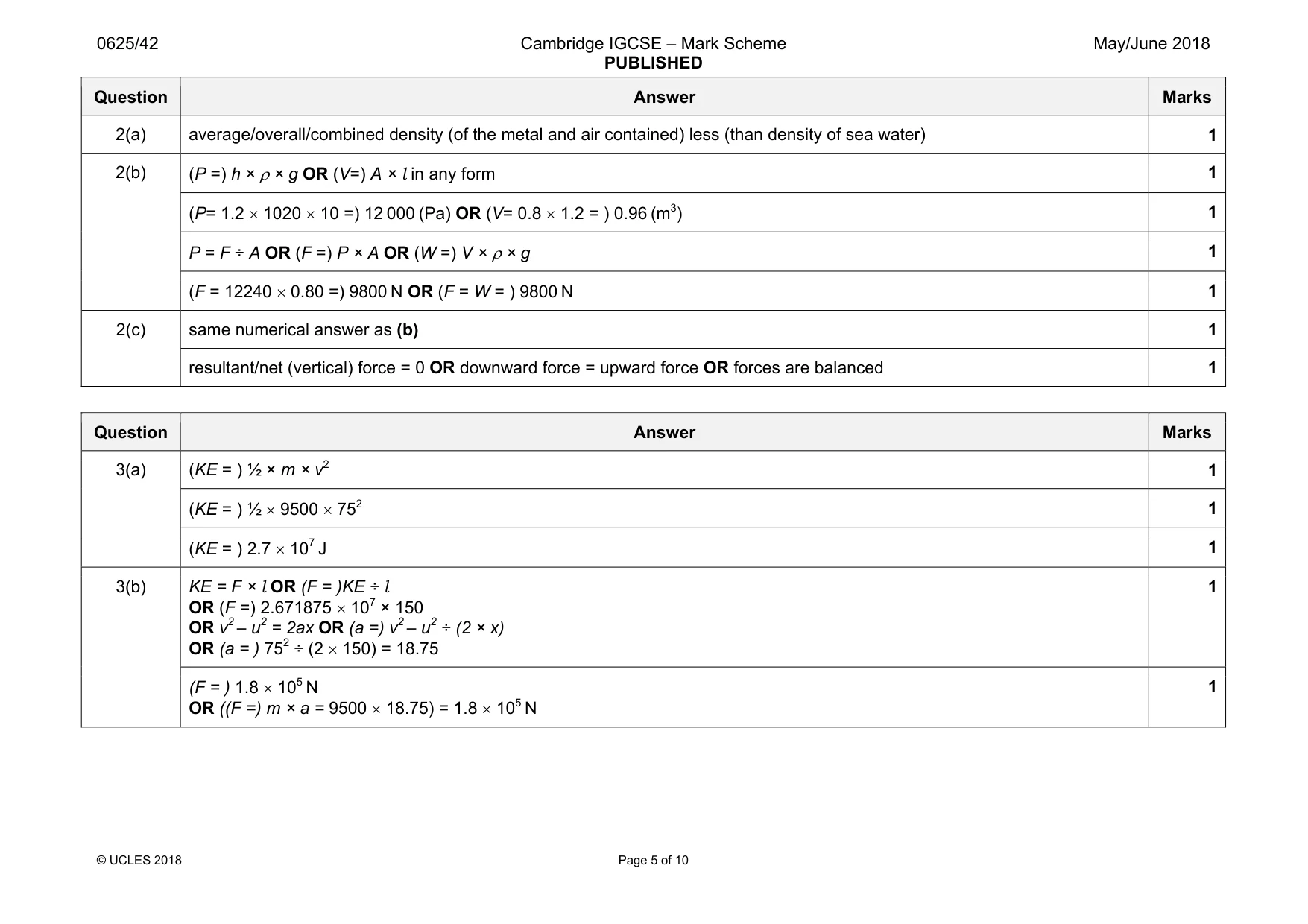
Mark scheme: 2(a) average/overall/combined density (of the metal and air contained) less (than density of sea water) 1 2(b) (P =) h × ρ × g OR (V=) A × l in any form 1 (P= 1.2 × 1020 × 10 =) 12 000 (Pa) OR (V= 0.8 × 1.2 = ) 0.96 (m3) 1 P = F ÷ A OR (F =) P × A OR (W =) V × ρ × g 1 (F = 12240 × 0.80 =) 9800 N OR (F = W = ) 9800 N 1 2(c) same numerical answer as (b) 1 resultant/net (vertical) force = 0 OR downward force = upward force OR forces are balanced 1
Q3 · An aircraft on the deck of an aircraft carrier
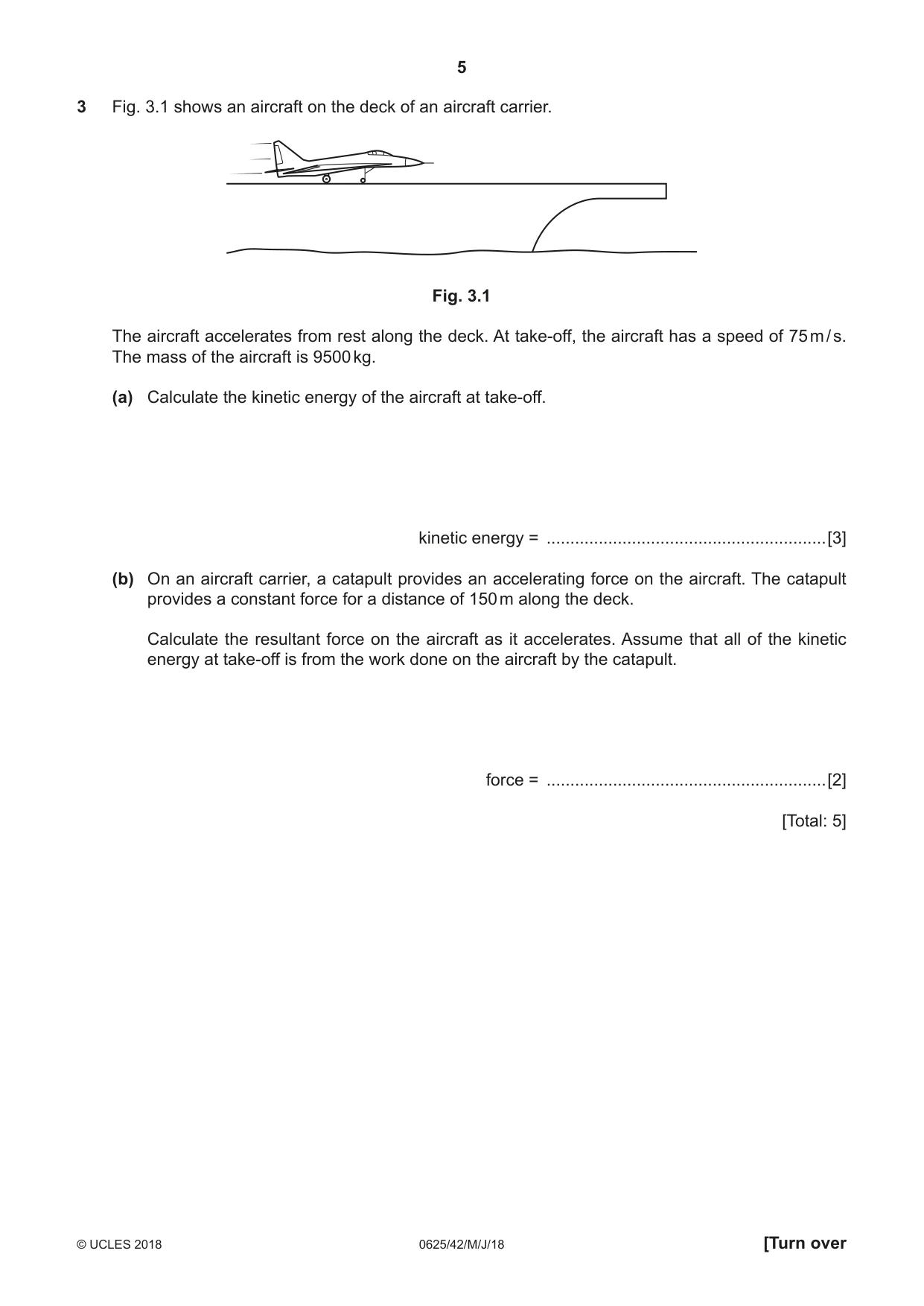
3 Fig. 3.1 shows an aircraft on the deck of an aircraft carrier. Fig. 3.1 The aircraft accelerates from rest along the deck. At take-off, the aircraft has a speed of 75 m / s. The mass of the aircraft is 9500 kg. (a) Calculate the kinetic energy of the aircraft at take-off. kinetic energy = ...........................................................[3] (b) On an aircraft carrier, a catapult provides an accelerating force on the aircraft. The catapult provides a constant force for a distance of 150 m along the deck. Calculate the resultant force on the aircraft as it accelerates. Assume that all of the kinetic energy at take-off is from the work done on the aircraft by the catapult. force = ...........................................................[2] [Total: 5]
Mark scheme: 3(a) 1 (KE = ) ½ × 9500 × 752 1 (KE = ) 2.7 × 10⁷ J 1 3(b) KE = F × l OR (F = )KE ÷ l OR (F =) 2.671875 × 107 × 150 OR v2 – u2 = 2ax OR (a =) v2 – u2 ÷ (2 × x) OR (a = ) 752 ÷ (2 × 150) = 18.75 1 (F = ) 1.8 × 10⁵ N OR ((F =) m × a = 9500 × 18.75) = 1.8 × 10⁵ N 1
Question 4
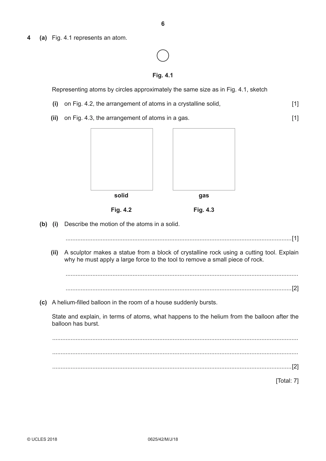
4 (a) Fig. 4.1 represents an atom. Fig. 4.1 Representing atoms by circles approximately the same size as in Fig. 4.1, sketch (i) on Fig. 4.2, the arrangement of atoms in a crystalline solid, [1] (ii) on Fig. 4.3, the arrangement of atoms in a gas. [1] solid gas Fig. 4.2 Fig. 4.3 (b) (i) Describe the motion of the atoms in a solid. .......................................................................................................................................[1] (ii) A sculptor makes a statue from a block of crystalline rock using a cutting tool. Explain why he must apply a large force to the tool to remove a small piece of rock. ........................................................................................................................................... .......................................................................................................................................[2] (c) A helium-filled balloon in the room of a house suddenly bursts. State and explain, in terms of atoms, what happens to the helium from the balloon after the balloon has burst. ................................................................................................................................................... ................................................................................................................................................... ...............................................................................................................................................[2] [Total: 7]
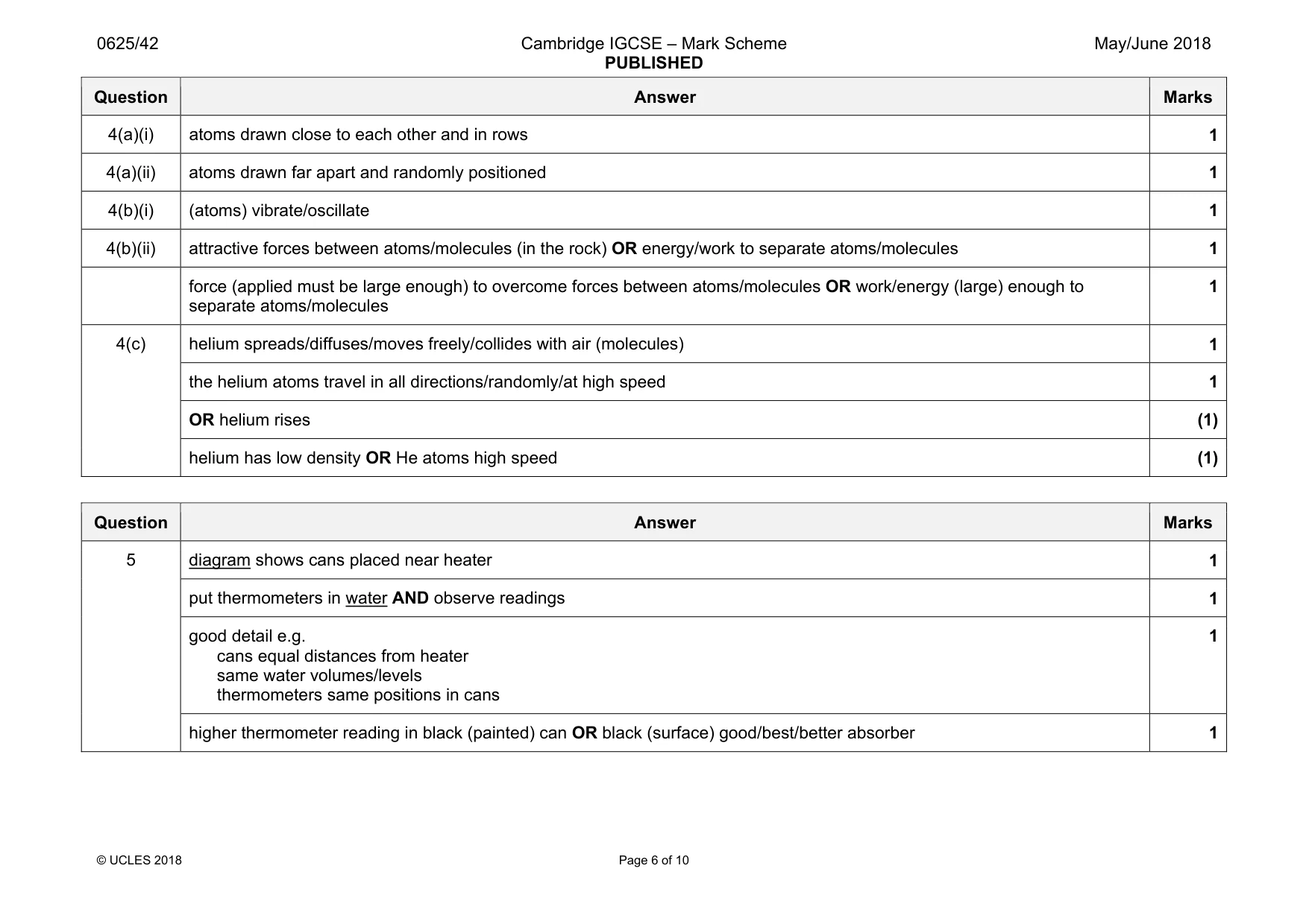
Mark scheme: 4(a)(i) atoms drawn close to each other and in rows 1 4(a)(ii) atoms drawn far apart and randomly positioned 1 4(b)(i) (atoms) vibrate/oscillate 1 4(b)(ii) attractive forces between atoms/molecules (in the rock) OR energy/work to separate atoms/molecules 1 force (applied must be large enough) to overcome forces between atoms/molecules OR work/energy (large) enough to separate atoms/molecules 1 4(c) helium spreads/diffuses/moves freely/collides with air (molecules) 1 the helium atoms travel in all directions/randomly/at high speed 1 OR helium rises (1) helium has low density OR He atoms high speed (1)
Q5 · A student wants to investigate good and bad absorbers of thermal radiation
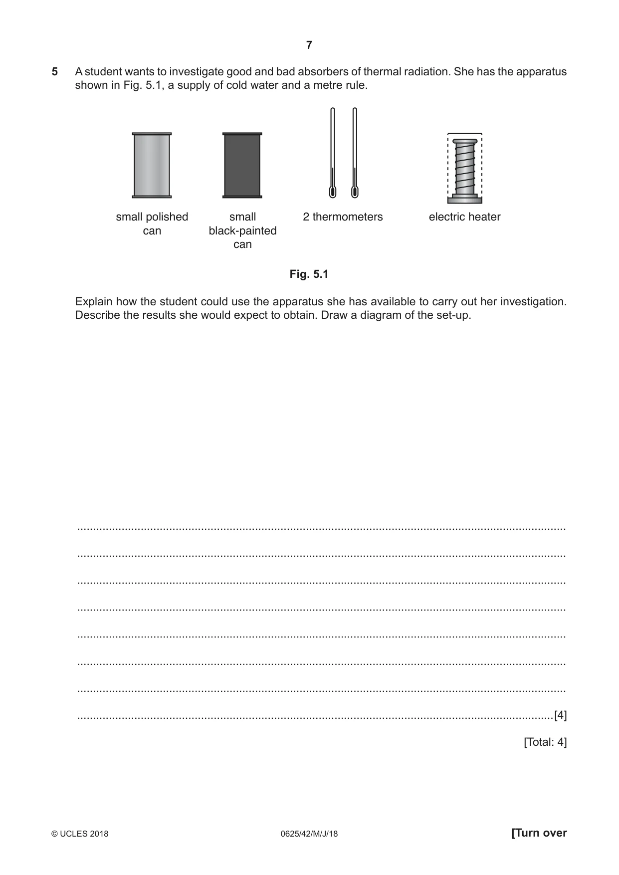
5 A student wants to investigate good and bad absorbers of thermal radiation. She has the apparatus shown in Fig. 5.1, a supply of cold water and a metre rule. small polished small 2 thermometers electric heater can black-painted can Fig. 5.1 Explain how the student could use the apparatus she has available to carry out her investigation. Describe the results she would expect to obtain. Draw a diagram of the set-up. .......................................................................................................................................................... .......................................................................................................................................................... .......................................................................................................................................................... .......................................................................................................................................................... .......................................................................................................................................................... .......................................................................................................................................................... .......................................................................................................................................................... ......................................................................................................................................................[4] [Total: 4]
Mark scheme: 5 diagram shows cans placed near heater 1 put thermometers in water AND observe readings 1 good detail e.g. cans equal distances from heater same water volumes/levels thermometers same positions in cans 1 higher thermometer reading in black (painted) can OR black (surface) good/best/better absorber 1
Q6 · Circle two of the following that apply to an ultrasound wave travelling in air
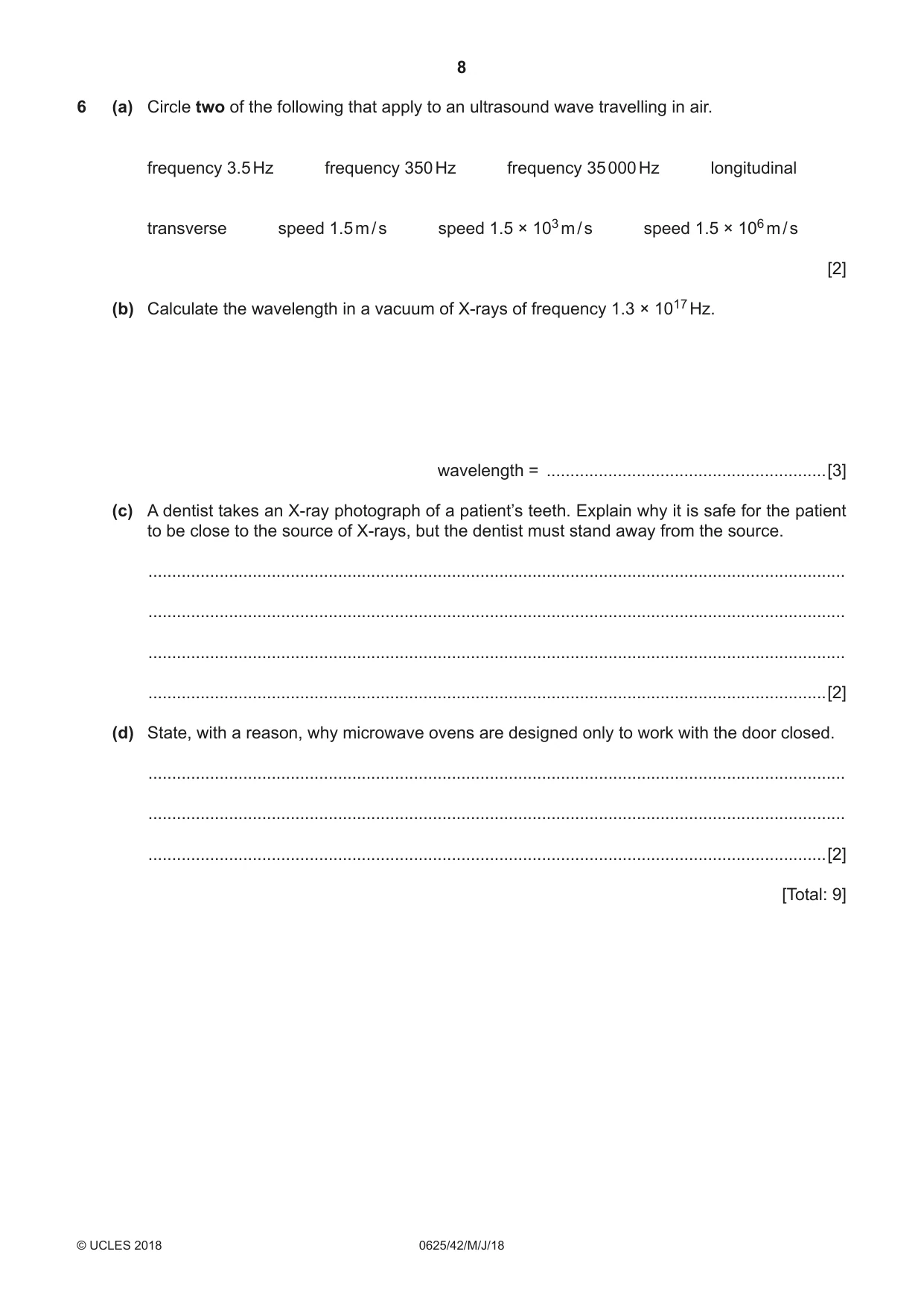
6 (a) Circle two of the following that apply to an ultrasound wave travelling in air. frequency 3.5 Hz frequency 350 Hz frequency 35 000 Hz longitudinal transverse speed 1.5 m / s speed 1.5 × 10³ m / s speed 1.5 × 10⁶ m / s [2] (b) Calculate the wavelength in a vacuum of X-rays of frequency 1.3 × 10¹⁷ Hz. wavelength = ...........................................................[3] (c) A dentist takes an X-ray photograph of a patient’s teeth. Explain why it is safe for the patient to be close to the source of X-rays, but the dentist must stand away from the source. ................................................................................................................................................... ................................................................................................................................................... ................................................................................................................................................... ...............................................................................................................................................[2] (d) State, with a reason, why microwave ovens are designed only to work with the door closed. ................................................................................................................................................... ................................................................................................................................................... ...............................................................................................................................................[2] [Total: 9]
Mark scheme: 6(a) frequency 35 000 Hz ringed 1 longitudinal ringed 1 6(b) v = f λ OR (λ = ) v ÷ f 1 (λ=) 3 × 10⁸ ÷ 1.3 × 10¹⁷ 1 (λ =) 2.3 × 10⁻⁹ m 1 6(c) X-rays ionising/harmful/dangerous (to humans) 1 Any one from: patient rarely exposed low total dose on patient meaningful comment about benefit outweighs danger dentist frequently exposed total dose on dentist would be high if stayed in room 1 6(d) microwaves harmful/dangerous (to humans) 1 microwaves would pass through open door 1
Q7 · A ray of light in water that is incident on a submerged, transparent plastic block
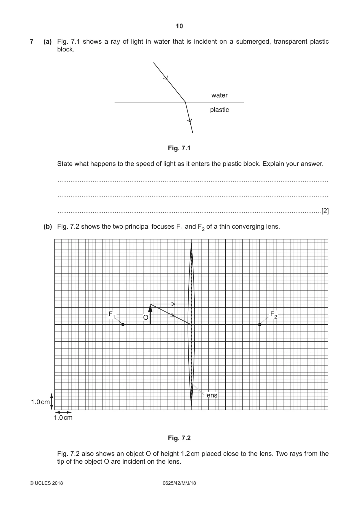
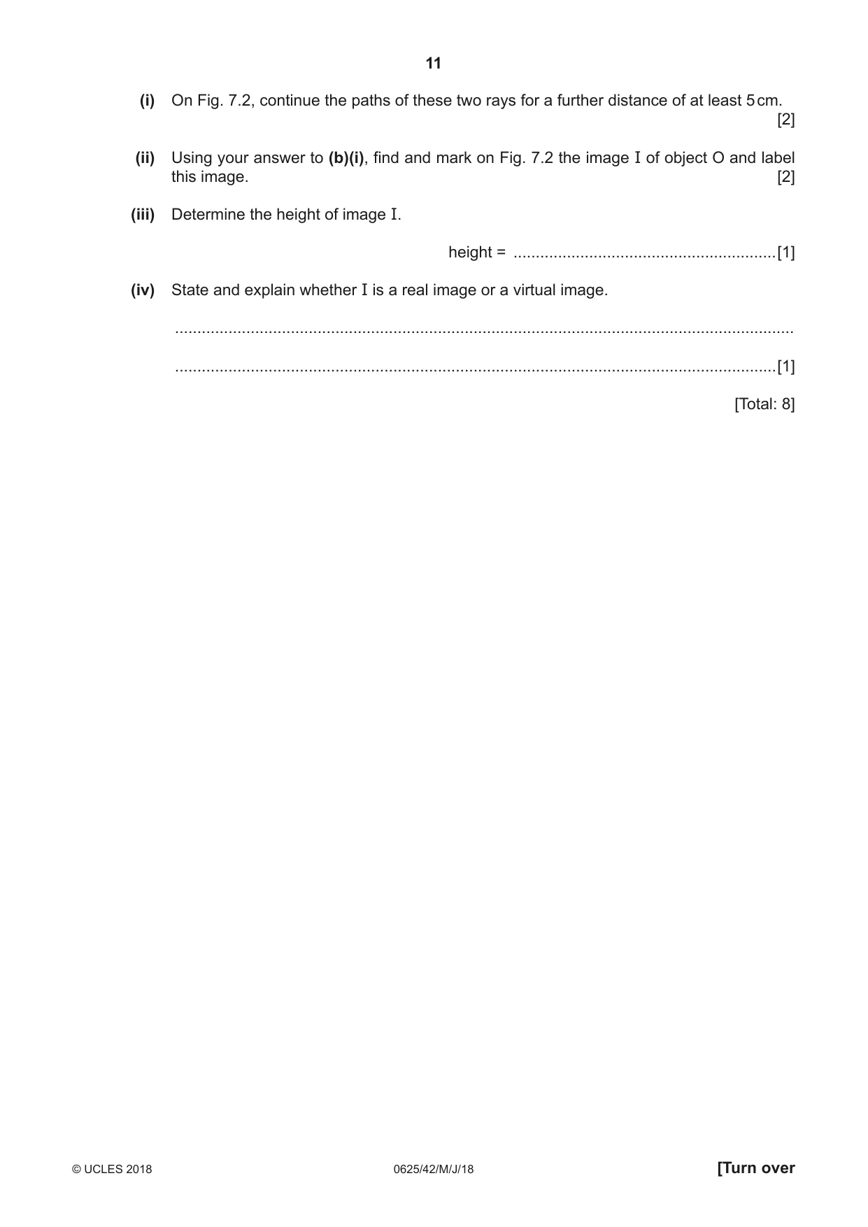
7 (a) Fig. 7.1 shows a ray of light in water that is incident on a submerged, transparent plastic block. water plastic Fig. 7.1 State what happens to the speed of light as it enters the plastic block. Explain your answer. ................................................................................................................................................... ................................................................................................................................................... ...............................................................................................................................................[2] (b) Fig. 7.2 shows the two principal focuses F1 and F2 of a thin converging lens. F1 F2 O lens 1.0 cm 1.0 cm Fig. 7.2 Fig. 7.2 also shows an object O of height 1.2 cm placed close to the lens. Two rays from the tip of the object O are incident on the lens. (i) On Fig. 7.2, continue the paths of these two rays for a further distance of at least 5 cm. [2] (ii) Using your answer to (b)(i), find and mark on Fig. 7.2 the image I of object O and label this image. [2] (iii) Determine the height of image I. height = ...........................................................[1] (iv) State and explain whether I is a real image or a virtual image. ........................................................................................................................................... .......................................................................................................................................[1] [Total: 8]
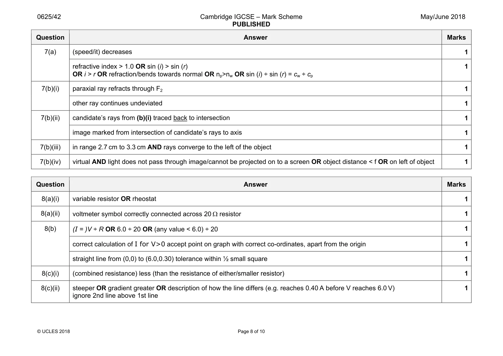
Mark scheme: 7(a) (speed/it) decreases 1 refractive index > 1.0 OR sin (i) > sin (r) OR i > r OR refraction/bends towards normal OR np>nw OR sin (i) ÷ sin (r) = cw ÷ cp 1 7(b)(i) paraxial ray refracts through F2 1 other ray continues undeviated 1 7(b)(ii) candidate’s rays from (b)(i) traced back to intersection 1 image marked from intersection of candidate’s rays to axis 1 7(b)(iii) in range 2.7 cm to 3.3 cm AND rays converge to the left of the object 1 7(b)(iv) virtual AND light does not pass through image/cannot be projected on to a screen OR object distance < f OR on left of object 1
Q8 · A circuit that contains a battery of electromotive force (e.m.f.) 6.0 V, an ammeter, a 20…
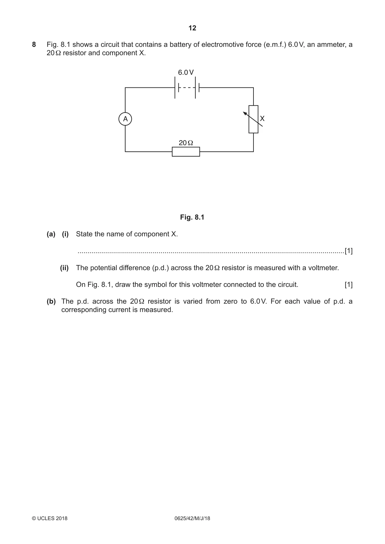
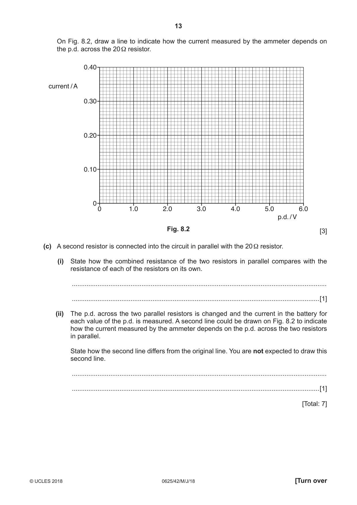
8 Fig. 8.1 shows a circuit that contains a battery of electromotive force (e.m.f.) 6.0 V, an ammeter, a 20 Ω resistor and component X. 6.0 V A X 20 Ω Fig. 8.1 (a) (i) State the name of component X. .......................................................................................................................................[1] (ii) The potential difference (p.d.) across the 20 Ω resistor is measured with a voltmeter. On Fig. 8.1, draw the symbol for this voltmeter connected to the circuit. [1] (b) The p.d. across the 20 Ω resistor is varied from zero to 6.0 V. For each value of p.d. a corresponding current is measured. On Fig. 8.2, draw a line to indicate how the current measured by the ammeter depends on the p.d. across the 20 Ω resistor. 0.40 current / A 0.30 0.20 0.10 0 0 1.0 2.0 3.0 4.0 5.0 6.0 p.d. / V Fig. 8.2 [3] (c) A second resistor is connected into the circuit in parallel with the 20 Ω resistor. (i) State how the combined resistance of the two resistors in parallel compares with the resistance of each of the resistors on its own. ........................................................................................................................................... .......................................................................................................................................[1] (ii) The p.d. across the two parallel resistors is changed and the current in the battery for each value of the p.d. is measured. A second line could be drawn on Fig. 8.2 to indicate how the current measured by the ammeter depends on the p.d. across the two resistors in parallel. State how the second line differs from the original line. You are not expected to draw this second line. ........................................................................................................................................... .......................................................................................................................................[1] [Total: 7]
Mark scheme: 8(a)(i) variable resistor OR rheostat 1 8(a)(ii) voltmeter symbol correctly connected across 20 Ω resistor 1 8(b) (I = )V ÷ R OR 6.0 ÷ 20 OR (any value < 6.0) ÷ 20 1 correct calculation of I for V>0 accept point on graph with correct co-ordinates, apart from the origin 1 straight line from (0,0) to (6.0,0.30) tolerance within ½ small square 1 8(c)(i) (combined resistance) less (than the resistance of either/smaller resistor) 1 8(c)(ii) steeper OR gradient greater OR description of how the line differs (e.g. reaches 0.40 A before V reaches 6.0 V) ignore 2nd line above 1st line 1
Q9 · A coil ABCD with two turns
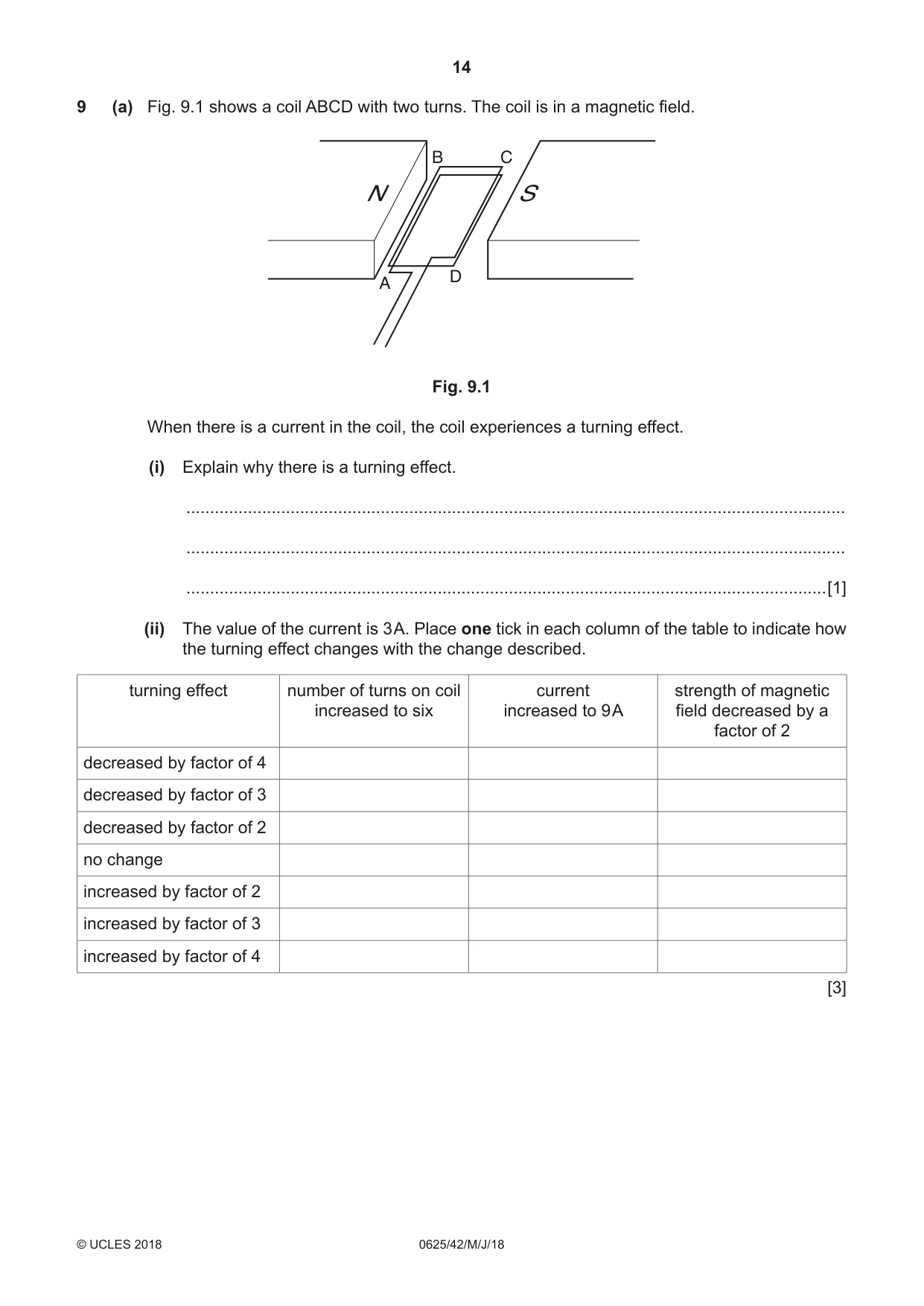
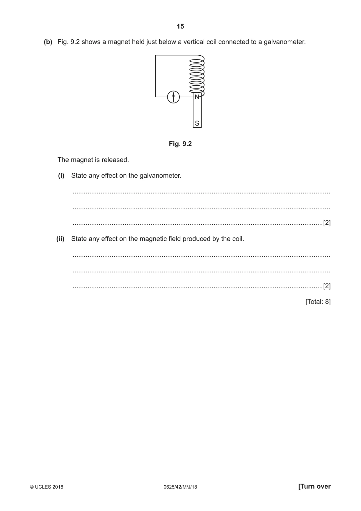
9 (a) Fig. 9.1 shows a coil ABCD with two turns. The coil is in a magnetic field. B C N S D A Fig. 9.1 When there is a current in the coil, the coil experiences a turning effect. (i) Explain why there is a turning effect. ........................................................................................................................................... ........................................................................................................................................... .......................................................................................................................................[1] (ii) The value of the current is 3 A. Place one tick in each column of the table to indicate how the turning effect changes with the change described. turning effect number of turns on coil current strength of magnetic increased to six increased to 9 A field decreased by a factor of 2 decreased by factor of 4 decreased by factor of 3 decreased by factor of 2 no change increased by factor of 2 increased by factor of 3 increased by factor of 4 [3] (b) Fig. 9.2 shows a magnet held just below a vertical coil connected to a galvanometer. N S Fig. 9.2 The magnet is released. (i) State any effect on the galvanometer. ........................................................................................................................................... ........................................................................................................................................... .......................................................................................................................................[2] (ii) State any effect on the magnetic field produced by the coil. ........................................................................................................................................... ........................................................................................................................................... .......................................................................................................................................[2] [Total: 8]
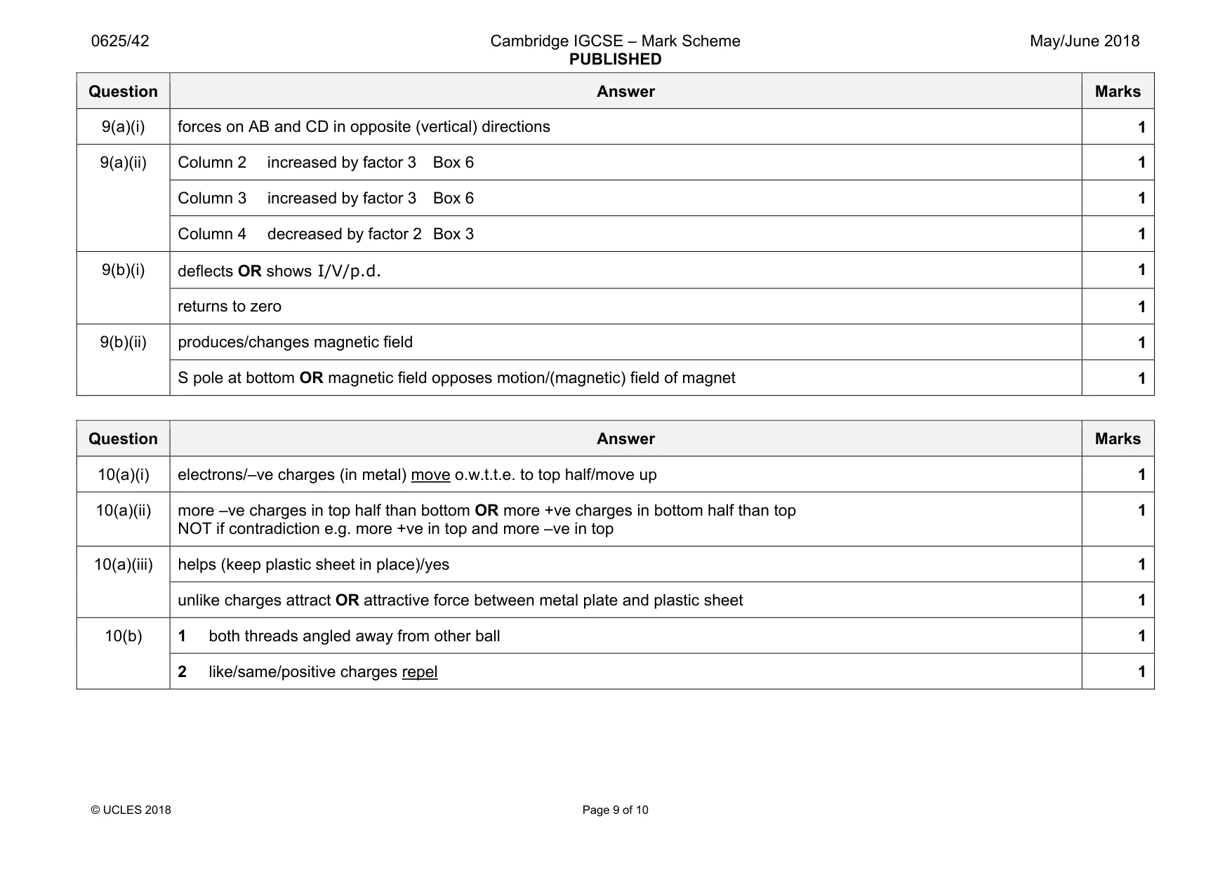
Mark scheme: 9(a)(i) forces on AB and CD in opposite (vertical) directions 1 9(a)(ii) Column 2 increased by factor 3 Box 6 1 Column 3 increased by factor 3 Box 6 1 Column 4 decreased by factor 2 Box 3 1 9(b)(i) deflects OR shows I/V/p.d. 1 returns to zero 1 9(b)(ii) produces/changes magnetic field 1 S pole at bottom OR magnetic field opposes motion/(magnetic) field of magnet 1
Q10 · An uncharged conducting metal plate rests on insulating supports
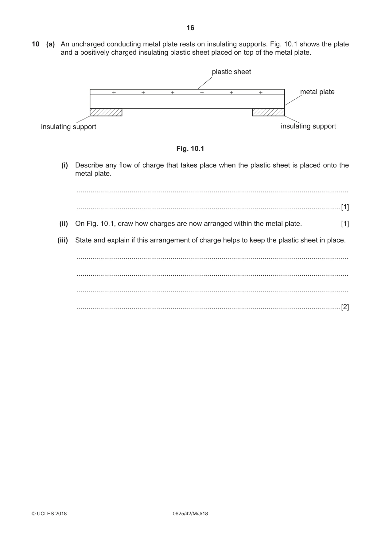
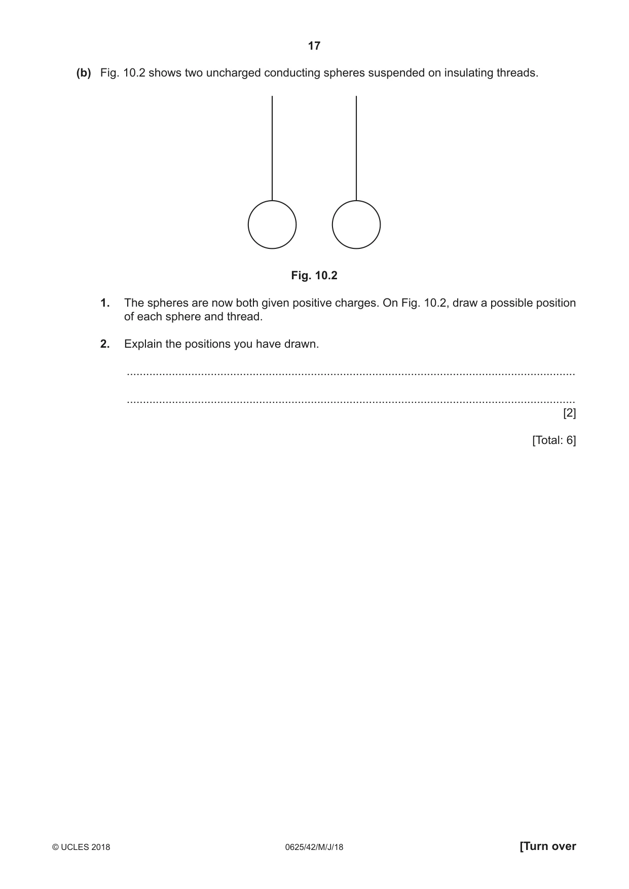
10 (a) An uncharged conducting metal plate rests on insulating supports. Fig. 10.1 shows the plate and a positively charged insulating plastic sheet placed on top of the metal plate. plastic sheet metal plate insulating support insulating support Fig. 10.1 (i) Describe any flow of charge that takes place when the plastic sheet is placed onto the metal plate. ........................................................................................................................................... .......................................................................................................................................[1] (ii) On Fig. 10.1, draw how charges are now arranged within the metal plate. [1] (iii) State and explain if this arrangement of charge helps to keep the plastic sheet in place. ........................................................................................................................................... ........................................................................................................................................... ........................................................................................................................................... .......................................................................................................................................[2] (b) Fig. 10.2 shows two uncharged conducting spheres suspended on insulating threads. Fig. 10.2 1. The spheres are now both given positive charges. On Fig. 10.2, draw a possible position of each sphere and thread. 2. Explain the positions you have drawn. ........................................................................................................................................... ........................................................................................................................................... [2] [Total: 6]
Mark scheme: 10(a)(i) electrons/–ve charges (in metal) move o.w.t.t.e. to top half/move up 1 10(a)(ii) more –ve charges in top half than bottom OR more +ve charges in bottom half than top NOT if contradiction e.g. more +ve in top and more –ve in top 1 10(a)(iii) helps (keep plastic sheet in place)/yes 1 unlike charges attract OR attractive force between metal plate and plastic sheet 1 10(b) 1 both threads angled away from other ball 1 2 like/same/positive charges repel 1
Q11 · A radioactive nucleus of uranium-235 decays to a nucleus of thorium and emits an…
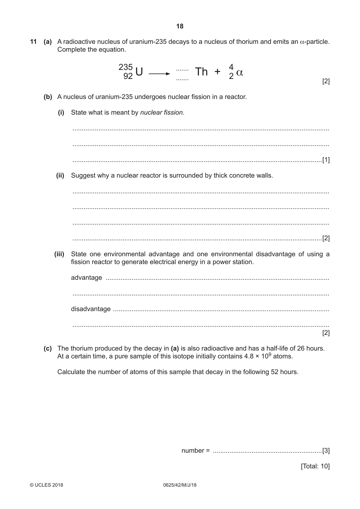
11 (a) A radioactive nucleus of uranium-235 decays to a nucleus of thorium and emits an α-particle. Complete the equation. 235 ....... U Th + 4 α 92 ....... 2 [2] (b) A nucleus of uranium-235 undergoes nuclear fission in a reactor. (i) State what is meant by nuclear fission. ........................................................................................................................................... ........................................................................................................................................... .......................................................................................................................................[1] (ii) Suggest why a nuclear reactor is surrounded by thick concrete walls. ........................................................................................................................................... ........................................................................................................................................... ........................................................................................................................................... .......................................................................................................................................[2] (iii) State one environmental advantage and one environmental disadvantage of using a fission reactor to generate electrical energy in a power station. advantage ......................................................................................................................... ........................................................................................................................................... disadvantage ..................................................................................................................... ........................................................................................................................................... [2] (c) The thorium produced by the decay in (a) is also radioactive and has a half-life of 26 hours. At a certain time, a pure sample of this isotope initially contains 4.8 × 10⁹ atoms. Calculate the number of atoms of this sample that decay in the following 52 hours. number = ...........................................................[3] [Total: 10]
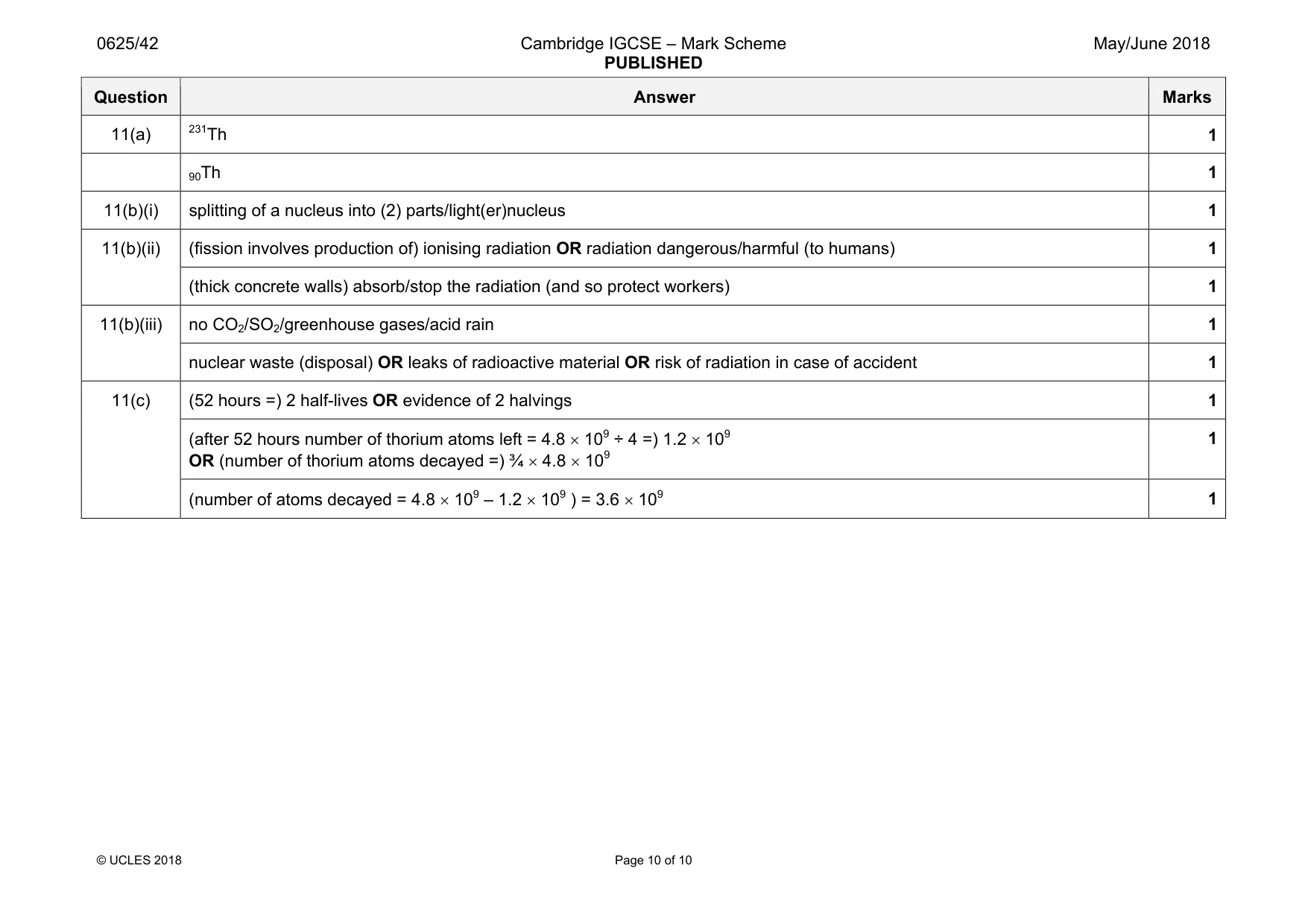
Mark scheme: 11(a) 1 90Th 1 11(b)(i) splitting of a nucleus into (2) parts/light(er)nucleus 1 11(b)(ii) (fission involves production of) ionising radiation OR radiation dangerous/harmful (to humans) 1 (thick concrete walls) absorb/stop the radiation (and so protect workers) 1 11(b)(iii) no CO2/SO2/greenhouse gases/acid rain 1 nuclear waste (disposal) OR leaks of radioactive material OR risk of radiation in case of accident 1 11(c) (52 hours =) 2 half-lives OR evidence of 2 halvings 1 (after 52 hours number of thorium atoms left = 4.8 × 10⁹ ÷ 4 =) 1.2 × 10⁹ OR (number of thorium atoms decayed =) ¾ × 4.8 × 10⁹ 1 (number of atoms decayed = 4.8 × 10⁹ – 1.2 × 10⁹ ) = 3.6 × 10⁹ 1
What was in this paper
The subtopics covered by these 11 questions, and how many questions each got. Open one in a new tab to see every Cambridge question on it.
What you needed in this session
Cambridge’s own grade thresholds for 2018 May/June, Paper 4 · Variant 2. A higher threshold means an easier paper — the bar moves with how the cohort did.