Questions as text
Q1 · A demonstration with magnets 0625/31 May/June 2017
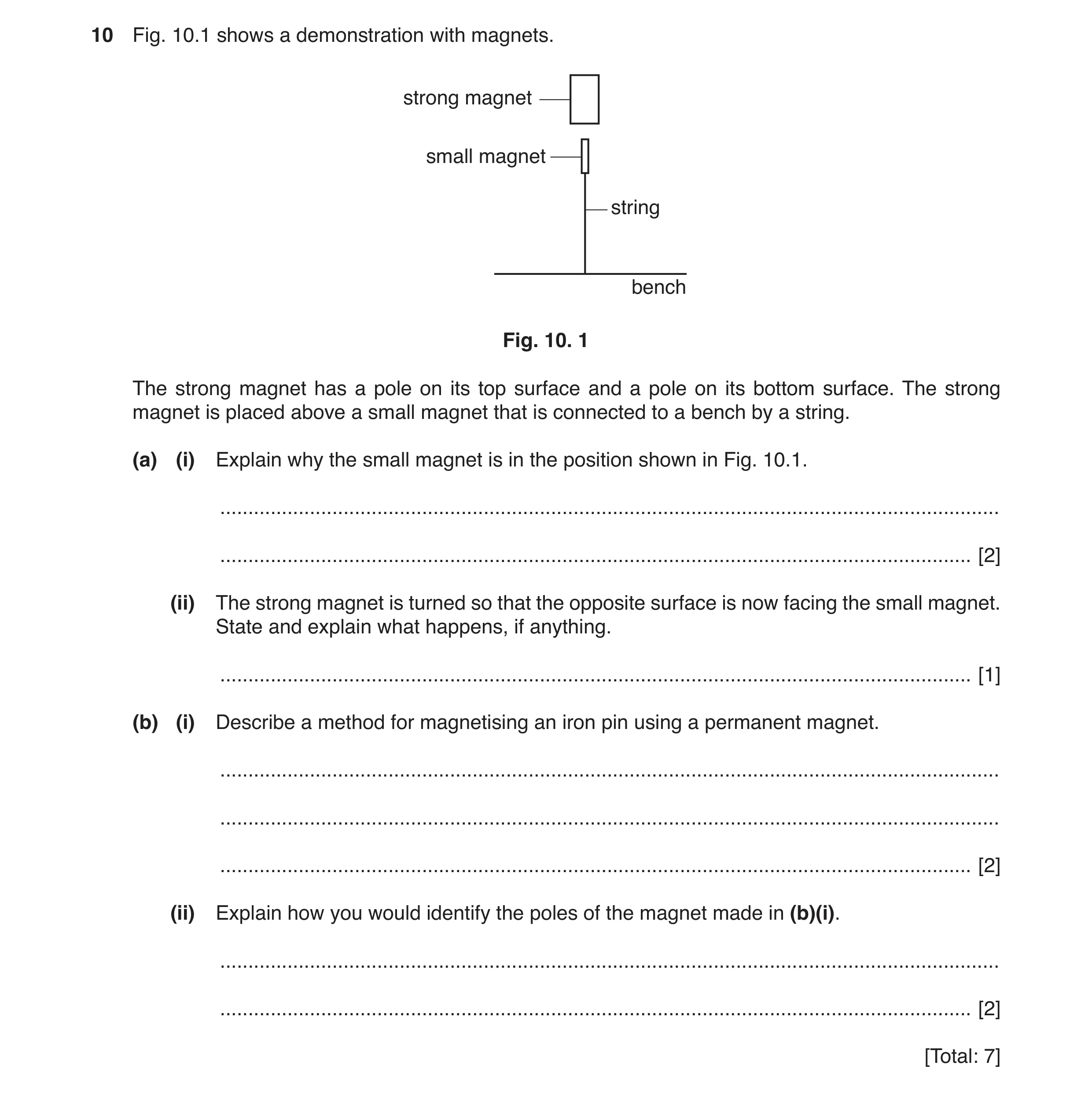
10 Fig. 10.1 shows a demonstration with magnets. strong magnet small magnet string bench Fig. 10. 1 The strong magnet has a pole on its top surface and a pole on its bottom surface. The strong magnet is placed above a small magnet that is connected to a bench by a string. (a) (i) Explain why the small magnet is in the position shown in Fig. 10.1. … … [2] (ii) The strong magnet is turned so that the opposite surface is now facing the small magnet. State and explain what happens, if anything. … [1] (b) (i) Describe a method for magnetising an iron pin using a permanent magnet. … … … [2] (ii) Explain how you would identify the poles of the magnet made in (b)(i). … … [2] [Total: 7]
7 marks
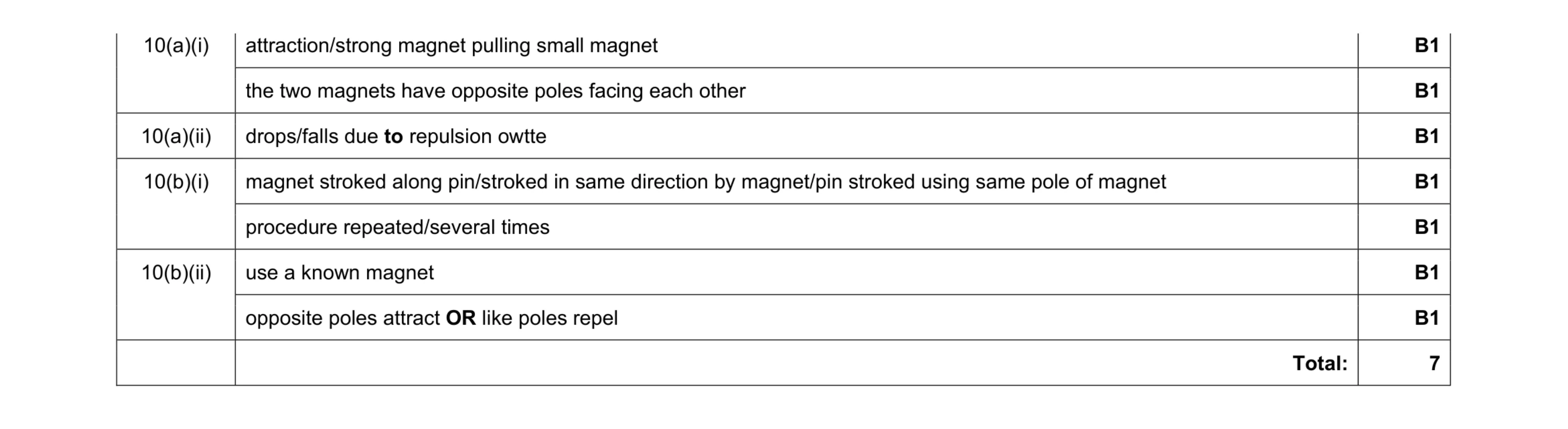
Mark scheme: 10(a)(i) attraction/strong magnet pulling small magnet B1 the two magnets have opposite poles facing each other B1 10(a)(ii) drops/falls due to repulsion owtte B1 10(b)(i) magnet stroked along pin/stroked in same direction by magnet/pin stroked using same pole of magnet B1 procedure repeated/several times B1 10(b)(ii) use a known magnet B1 opposite poles attract OR like poles repel B1 Total: 7
This question in 0625/31 May/June 2017
Question 2 0625/32 May/June 2017
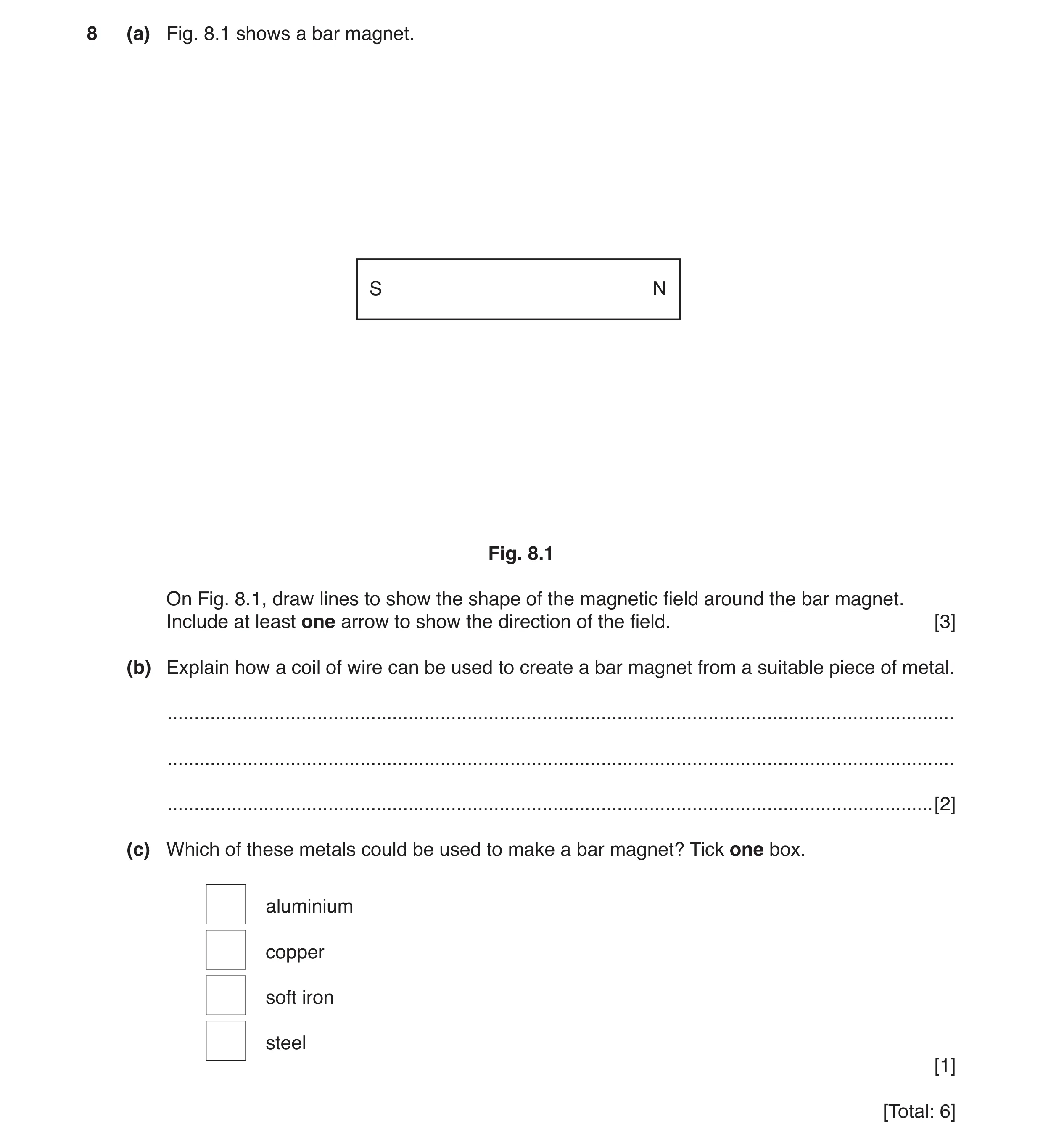
8 (a) Fig. 8.1 shows a bar magnet. S N Fig. 8.1 On Fig. 8.1, draw lines to show the shape of the magnetic field around the bar magnet. Include at least one arrow to show the direction of the field. [3] (b) Explain how a coil of wire can be used to create a bar magnet from a suitable piece of metal. … … … [2] (c) Which of these metals could be used to make a bar magnet? Tick one box. aluminium copper soft iron steel [1] [Total: 6]
6 marks
Mark scheme: 8(a) At least 2 curves drawn from one end of magnet to the other B1 pattern is symmetrical by eye above and below middle of magnet B1 Arrow from N to S B1 8(b) any 2 from: magnet/block/metal placed in coil coil connected to d.c. supply (d.c.) current in coil (for short time) B2 8(c) tick in 4th box steel B1 Total: 6
This question in 0625/32 May/June 2017
Q3 · A student has four similar metal bars 0625/33 May/June 2017
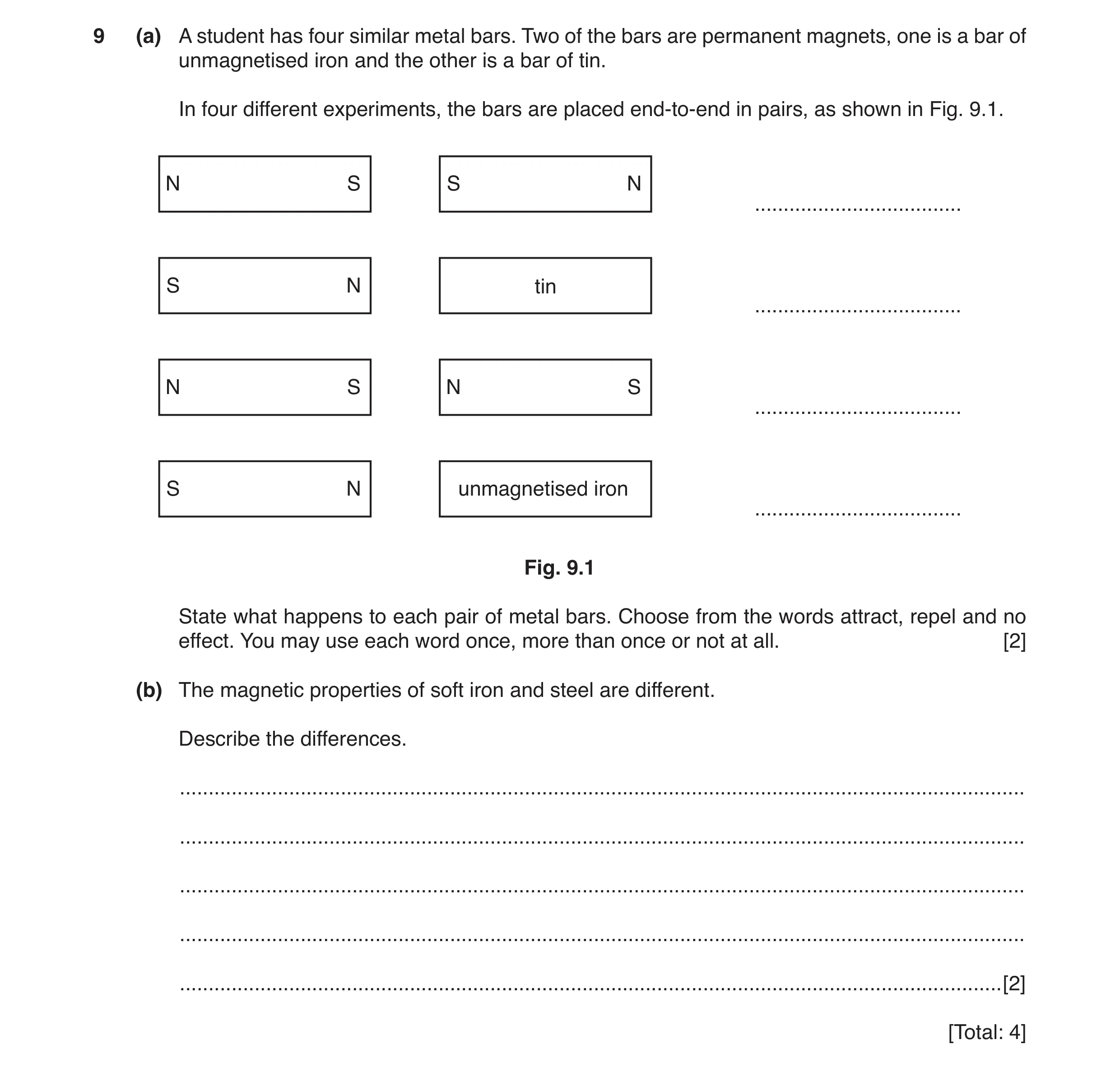
9 (a) A student has four similar metal bars. Two of the bars are permanent magnets, one is a bar of unmagnetised iron and the other is a bar of tin. In four different experiments, the bars are placed end-to-end in pairs, as shown in Fig. 9.1. N S S N … S N tin … N S N S … S N unmagnetised iron … Fig. 9.1 State what happens to each pair of metal bars. Choose from the words attract, repel and no effect. You may use each word once, more than once or not at all. [2] (b) The magnetic properties of soft iron and steel are different. Describe the differences. … … … … … [2] [Total: 4]
4 marks
Mark scheme: 9(a) repel no effect attract attract B2 9(b) any two from: (soft) iron is easily magnetised (but) loses its magnetism (very) quickly Steel is harder to magnetise and retains its magnetism (for a long time) B2 Total: 4
This question in 0625/33 May/June 2017
Q4 · A coil connected in series with a d.c 0625/33 May/June 2017
11 Fig. 11.1 shows a coil connected in series with a d.c. supply. A B coil Fig. 11.1 (a) Fig. 11.2 shows a plan view of the coil. The arrows represent the current direction at the top of the coil. A B Fig. 11.2 On Fig. 11.2, draw lines to show the magnetic field due to the current in the coil. • Draw two field lines above the line AB and two lines below it. • Add arrows to show the direction of the magnetic field. [3] (b) (i) An iron rod is placed inside the coil, as shown in Fig. 11.3. iron rod Fig. 11.3 State the name given to the combination of iron rod and coil when used in this way. … [1] (ii) The arrangement shown in Fig. 11.3 is adapted to a number of commercial uses. Suggest one of these uses. … [1] [Total: 5]
5 marks
Mark scheme: 11(a) Any two from: two curves/loops drawn from one end of coil to the other above line AB two curves/loops drawn from one end of coil to the other below line AB field pattern symmetrical by eye above and below line XY straight lines by eye within coil (accept some lines leaving side of coil near ends) B2 arrow from B to A B1 11(b)(i) electromagnet B1 11(b)(ii) Scrap yards/relay/motor/generator/(security) doors/(electric) bells B1 Total: 5
This question in 0625/33 May/June 2017
Q5 · A plotting compass and a bar magnet 0625/31 Oct/Nov 2017
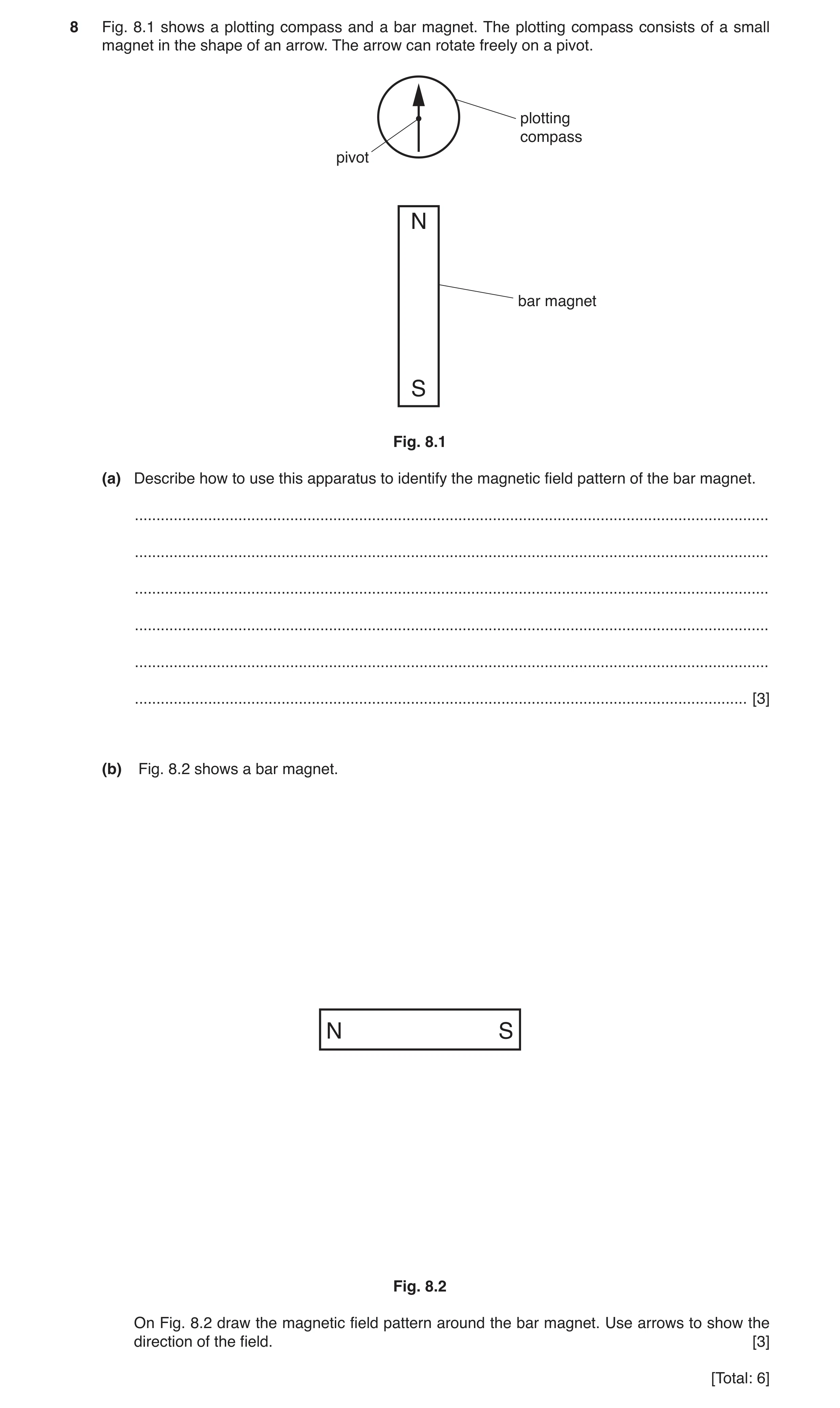
8 Fig. 8.1 shows a plotting compass and a bar magnet. The plotting compass consists of a small magnet in the shape of an arrow. The arrow can rotate freely on a pivot. plotting compass pivot N bar magnet S Fig. 8.1 (a) Describe how to use this apparatus to identify the magnetic field pattern of the bar magnet. … … … … … … [3] (b) Fig. 8.2 shows a bar magnet. N S Fig. 8.2 On Fig. 8.2 draw the magnetic field pattern around the bar magnet. Use arrows to show the direction of the field. [3] [Total: 6]
6 marks
Mark scheme: 8(a) Any 3 from: compass placed near magnet direction of compass needle marked change position of compass repeat (above procedure) join points( to show field lines) owtte B3 8(b) complete curved lines drawn in correct pattern B1 No lines crossing / symmetrical pattern B1 Correct direction indicated by arrow B1
This question in 0625/31 Oct/Nov 2017
Q6 · Some metals can be used to make permanent magnets 0625/32 Oct/Nov 2017
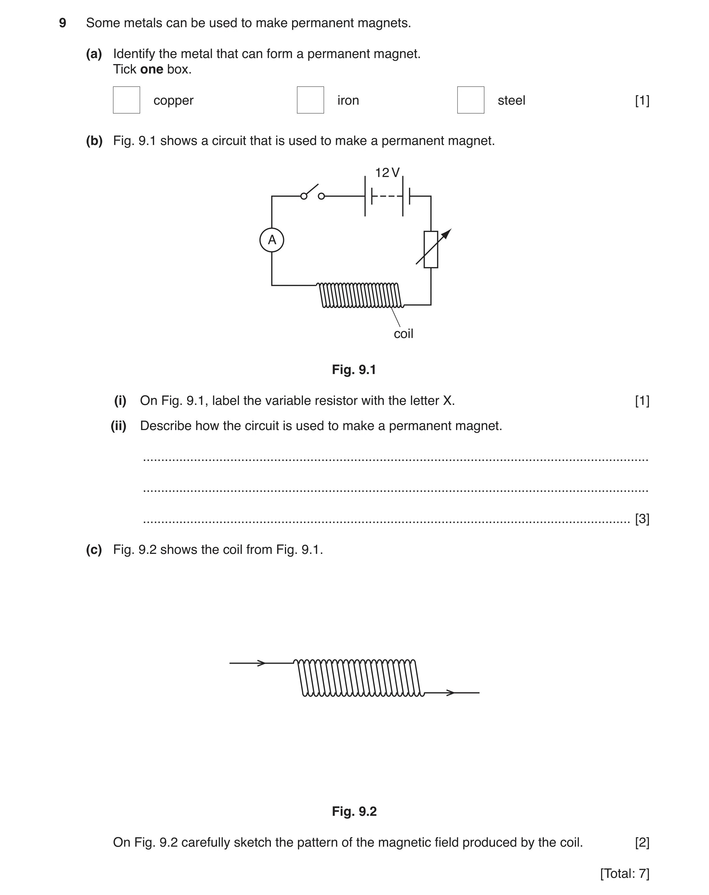
9 Some metals can be used to make permanent magnets. (a) Identify the metal that can form a permanent magnet. Tick one box. copper iron steel [1] (b) Fig. 9.1 shows a circuit that is used to make a permanent magnet. 12 V A coil Fig. 9.1 (i) On Fig. 9.1, label the variable resistor with the letter X. [1] (ii) Describe how the circuit is used to make a permanent magnet. … … … [3] (c) Fig. 9.2 shows the coil from Fig. 9.1. Fig. 9.2 On Fig. 9.2 carefully sketch the pattern of the magnetic field produced by the coil. [2] [Total: 7]
7 marks
Mark scheme: 9(a)(i) steel B1 9(b)(i) variable resistor indicated B1 9(b)(ii) (steel) bar inside coil B1 switch closed OR current increased through coil B1 bar moved through coil (in same direction) OR current decreased and switch opened B1 9(c) at least one complete correct field line through and above coil B1 at least one complete correct field line through and below coil B1
This question in 0625/32 Oct/Nov 2017
Q7 · A student places a bar magnet onto a sheet of paper, as shown in Fig 0625/33 Oct/Nov 2017
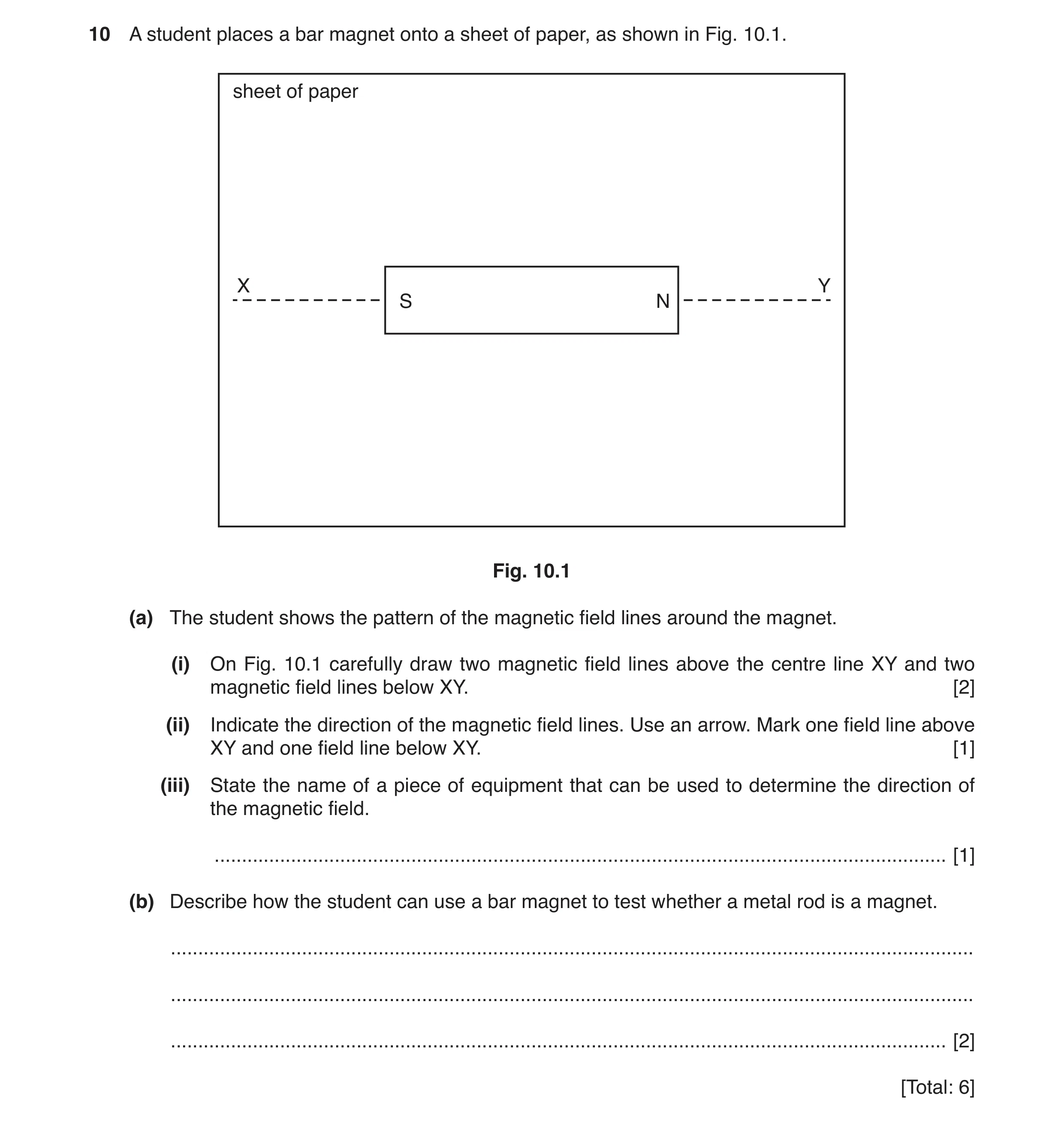
10 A student places a bar magnet onto a sheet of paper, as shown in Fig. 10.1. sheet of paper X Y S N Fig. 10.1 (a) The student shows the pattern of the magnetic field lines around the magnet. (i) On Fig. 10.1 carefully draw two magnetic field lines above the centre line XY and two magnetic field lines below XY. [2] (ii) Indicate the direction of the magnetic field lines. Use an arrow. Mark one field line above XY and one field line below XY. [1] (iii) State the name of a piece of equipment that can be used to determine the direction of the magnetic field. … [1] (b) Describe how the student can use a bar magnet to test whether a metal rod is a magnet. … … … [2] [Total: 6]
6 marks
Mark scheme: 10(a)(i) two curved field lines drawn above and below the magnet B1 lines start and finish at the poles of the magnet B1 10(a)(ii) both arrows point left B1 10(a)(iii) (plotting) compass B1 10(b) place end on end / see if attraction / repulsion occurs B1 repulsion at one end B1
This question in 0625/33 Oct/Nov 2017
Q8 · A balloon hanging from an insulating thread 0625/32 May/June 2018
10 (a) Fig. 10.1 shows a balloon hanging from an insulating thread. insulating thread balloon Fig. 10.1 (i) A student gives the balloon a positive charge. Which statement explains why the balloon becomes positively charged? Tick one box. The balloon gains electrons The balloon loses electrons The balloon gains protons The balloon loses protons [1] (ii) The student brings a charged rod close to the balloon as shown in Fig. 10.2. + + + + + + + charged + + rod + + + + Fig. 10.2 State the type of charge on the rod. … Explain your answer. … … [2] (b) Electrical charges can move easily through some materials. Draw a circle around each material that charges can move through easily. copper plastic rubber silver wood [1] [Total: 4]
4 marks
Mark scheme: 10(a)(i) second box (The balloon loses electrons) ticked 1 10(a)(ii) positive (charge) 1 like charge(s) repel 1 10(b) circle around copper AND silver 1
This question in 0625/32 May/June 2018
Q9 · A student magnetises a steel rod by using a permanent magnet 0625/33 May/June 2018
9 A student magnetises a steel rod by using a permanent magnet. (a) Describe a method that the student could use. You may draw a diagram to help you. … … … [2] (b) Explain how the student could test that the steel rod has been magnetised. … … … … [2] (c) Magnets can be made from soft iron or from steel. State one difference between the magnetic properties of soft iron and steel. … … … [1] [Total: 5]
5 marks
Mark scheme: 9(a) Any two from: pole of magnet placed on/near steel rod magnet stroked along rod owtte repeat strokes same direction 2 9(b) place pole of rod next to a known magnet 1 like poles repel 1 9(c) accept iron loses magnetism easily owtte or reverse argument 1
This question in 0625/33 May/June 2018
Q10 · A sheet of paper 0625/33 Oct/Nov 2018
8 Fig. 8.1 shows a sheet of paper. A bar magnet is underneath the paper. A student sprinkles iron filings onto the paper. paper position of magnet under paper Fig. 8.1 (a) On Fig. 8.1 Label the position of each pole of the magnet. Use the label N for the north pole and S • for the south pole. Draw one magnetic field line above the magnet and draw one magnetic field line below • the magnet. Add one arrow to show the direction of the magnetic field. • [4] (b) A student places a soft iron rod inside a coil of insulated wire. The coil is connected to a battery, as shown in Fig. 8.2. soft iron rod battery coil of insulated wire switch Fig. 8.2 (i) State the name given to the device shown in Fig. 8.2. … [1] (ii) The student puts one end of the device in Fig. 8.2 just above a pile of iron filings. He closes the switch for a short time and then opens it again. Describe the effect this has on the iron filings. … … [1] (iii) The student removes the soft iron rod and replaces it with a steel rod. He puts one end of the steel rod just above the pile of iron filings. He closes the switch for a short time and then opens it again. Describe the effect this has on the iron fillings. … … … [1] [Total: 7]
7 marks
Mark scheme: 8(a) N and S labelled at either end of magnet correct field line shown above magnet correct field line shown below magnet field points in direction N to S B4 8(b)(i) electromagnet B1 8(b)(ii) (soft iron) filings attracted, but (most) fall off when switch opened B1 8(b)(iii) (steel) (most / more / they) remain attached when switch opened B1
This question in 0625/33 Oct/Nov 2018
Question 11 0625/32 Feb/March 2019
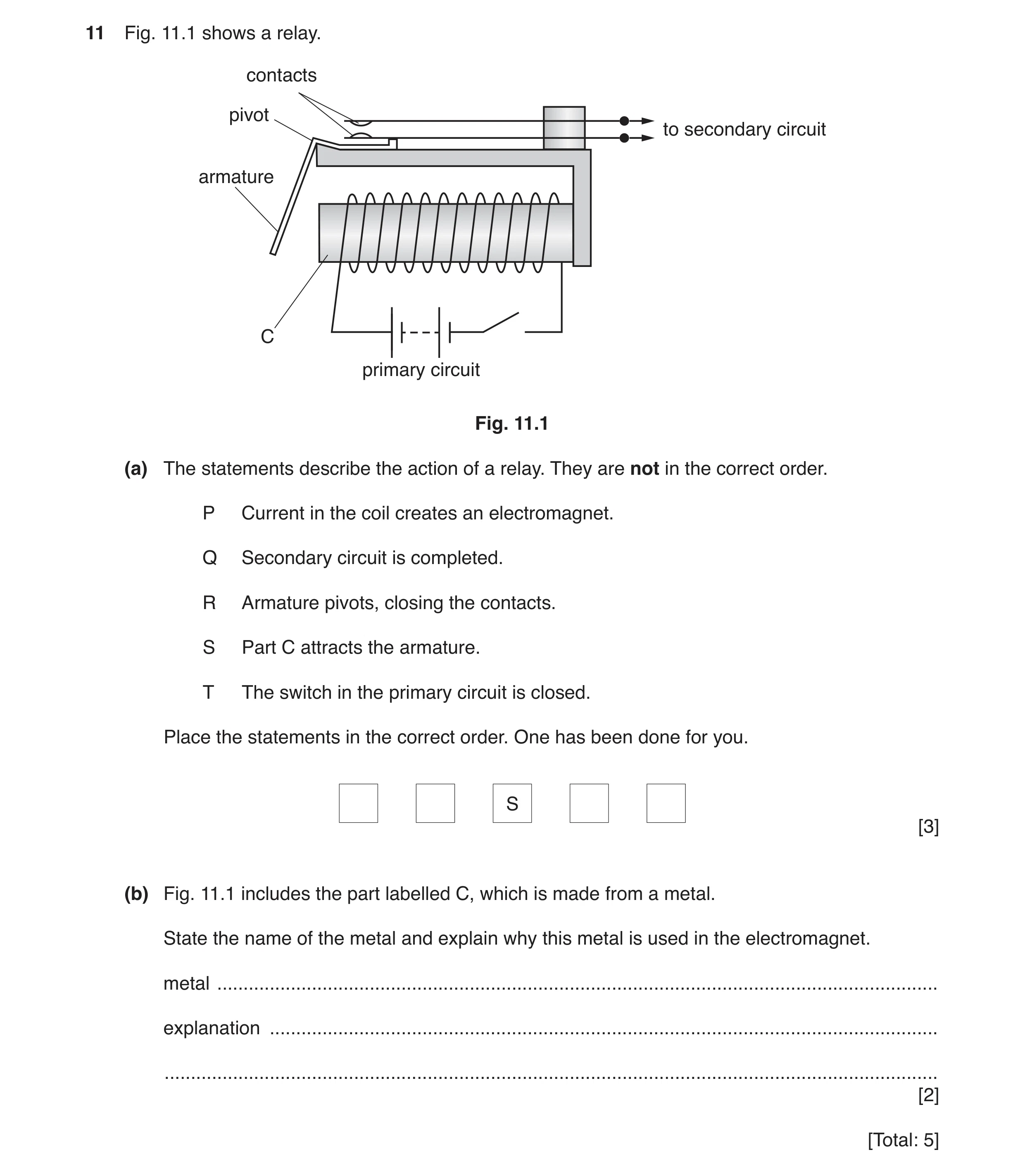
11 Fig. 11.1 shows a relay. contacts pivot to secondary circuit armature C primary circuit Fig. 11.1 (a) The statements describe the action of a relay. They are not in the correct order. P Current in the coil creates an electromagnet. Q Secondary circuit is completed. R Armature pivots, closing the contacts. S Part C attracts the armature. T The switch in the primary circuit is closed. Place the statements in the correct order. One has been done for you. S [3] (b) Fig. 11.1 includes the part labelled C, which is made from a metal. State the name of the metal and explain why this metal is used in the electromagnet. metal … explanation … … [2] [Total: 5]
5 marks
Mark scheme: 11(a) T P (S) R Q B3 11(b) (soft) iron B1 (forms a) temporary magnet B1
This question in 0625/32 Feb/March 2019
Q12 · The magnetic field pattern around a bar magnet 0625/32 May/June 2019
8 (a) Fig. 8.1 shows the magnetic field pattern around a bar magnet. Fig. 8.1 (i) On Fig. 8.1, mark the North and South poles of the magnet. Use the letter N for the North pole and S for the South pole. [1] (ii) A small bar of unmagnetised iron is placed next to a bar magnet, as shown in Fig. 8.2. magnet iron bar S N Fig. 8.2 The iron bar moves towards the magnet. Explain why the iron bar moves. … … … [2] (b) Fig. 8.3 shows a coil of wire wrapped around an iron core. A student uses these to make an electromagnet. coil iron core Fig. 8.3 (i) Complete the diagram in Fig. 8.3 to show how it could be used to make an electromagnet. [1] (ii) State one advantage of an electromagnet compared to a permanent magnet. … [1] [Total: 5]
5 marks
Mark scheme: 8(a)(i) poles correctly labelled S N B1 8 (a)(ii) Any two from iron bar becomes induced magnet with S pole nearest to (N pole of) magnet opposite poles attract B2 8(b)(i) ends of coil connected to power supply OR battery OR cell B1 8(b)(ii) can be switched on/off OR magnetised/demagnetised (easily) B1
This question in 0625/32 May/June 2019
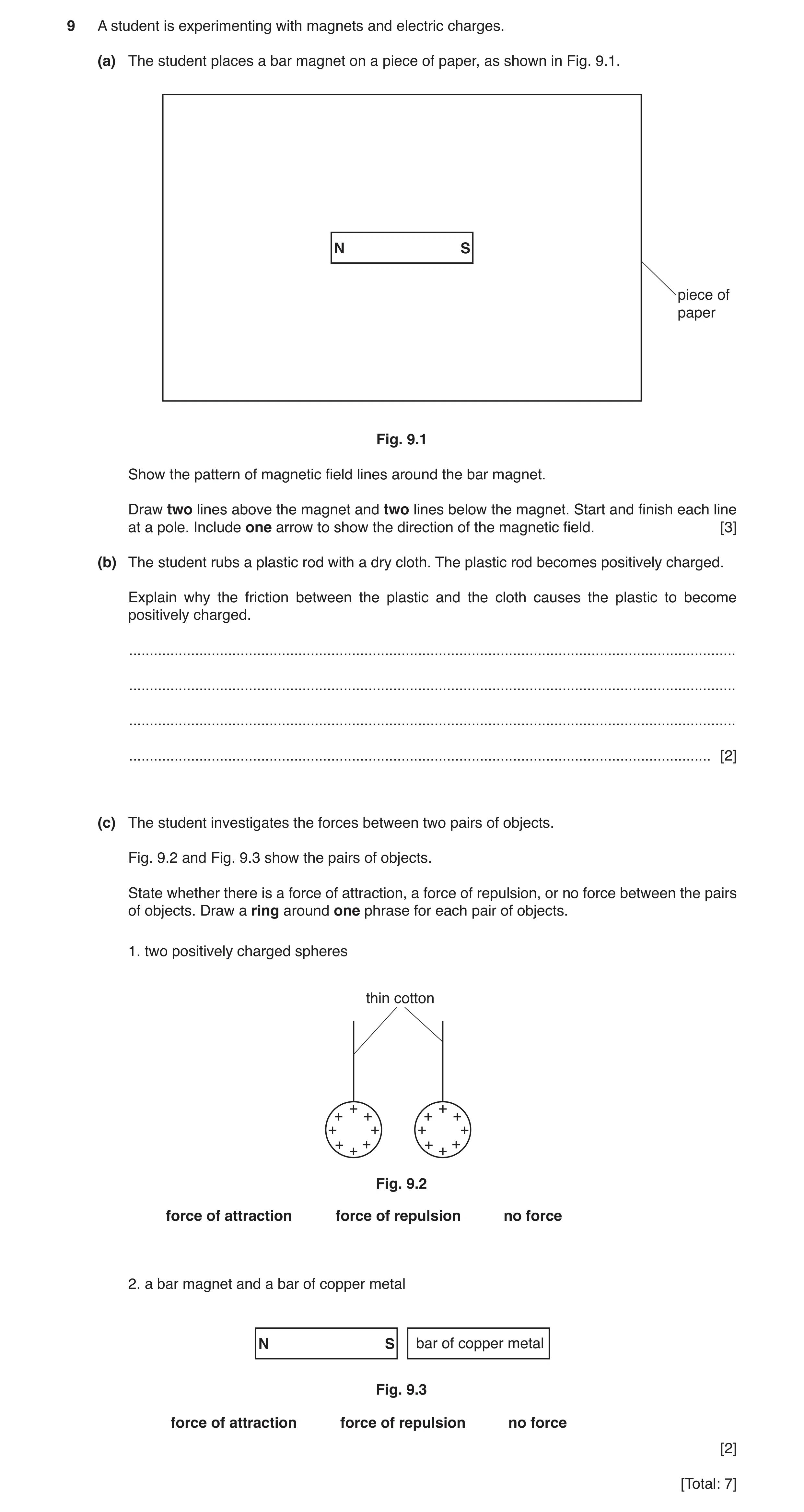
Q13 · A student is experimenting with magnets and electric charges 0625/31 Oct/Nov 2019
9 A student is experimenting with magnets and electric charges. (a) The student places a bar magnet on a piece of paper, as shown in Fig. 9.1. N S piece of paper Fig. 9.1 Show the pattern of magnetic field lines around the bar magnet. Draw two lines above the magnet and two lines below the magnet. Start and finish each line at a pole. Include one arrow to show the direction of the magnetic field. [3] (b) The student rubs a plastic rod with a dry cloth. The plastic rod becomes positively charged. Explain why the friction between the plastic and the cloth causes the plastic to become positively charged. … … … … [2] (c) The student investigates the forces between two pairs of objects. Fig. 9.2 and Fig. 9.3 show the pairs of objects. State whether there is a force of attraction, a force of repulsion, or no force between the pairs of objects. Draw a ring around one phrase for each pair of objects. 1. two positively charged spheres thin cotton + + + + + + + + + + + + + + + + Fig. 9.2 force of attraction force of repulsion no force 2. a bar magnet and a bar of copper metal N S bar of copper metal Fig. 9.3 force of attraction force of repulsion no force [2] [Total: 7]
7 marks
Mark scheme: 9(a) correct field pattern for bar magnet B1 no lines crossing and good detail of curvature B1 correct direction of arrow, i.e. out from N pole B1 9(b) electrons M1 move from the rod/to the cloth A1 9(c) 1. force of repulsion circled B1 2. no force circled B1
This question in 0625/31 Oct/Nov 2019
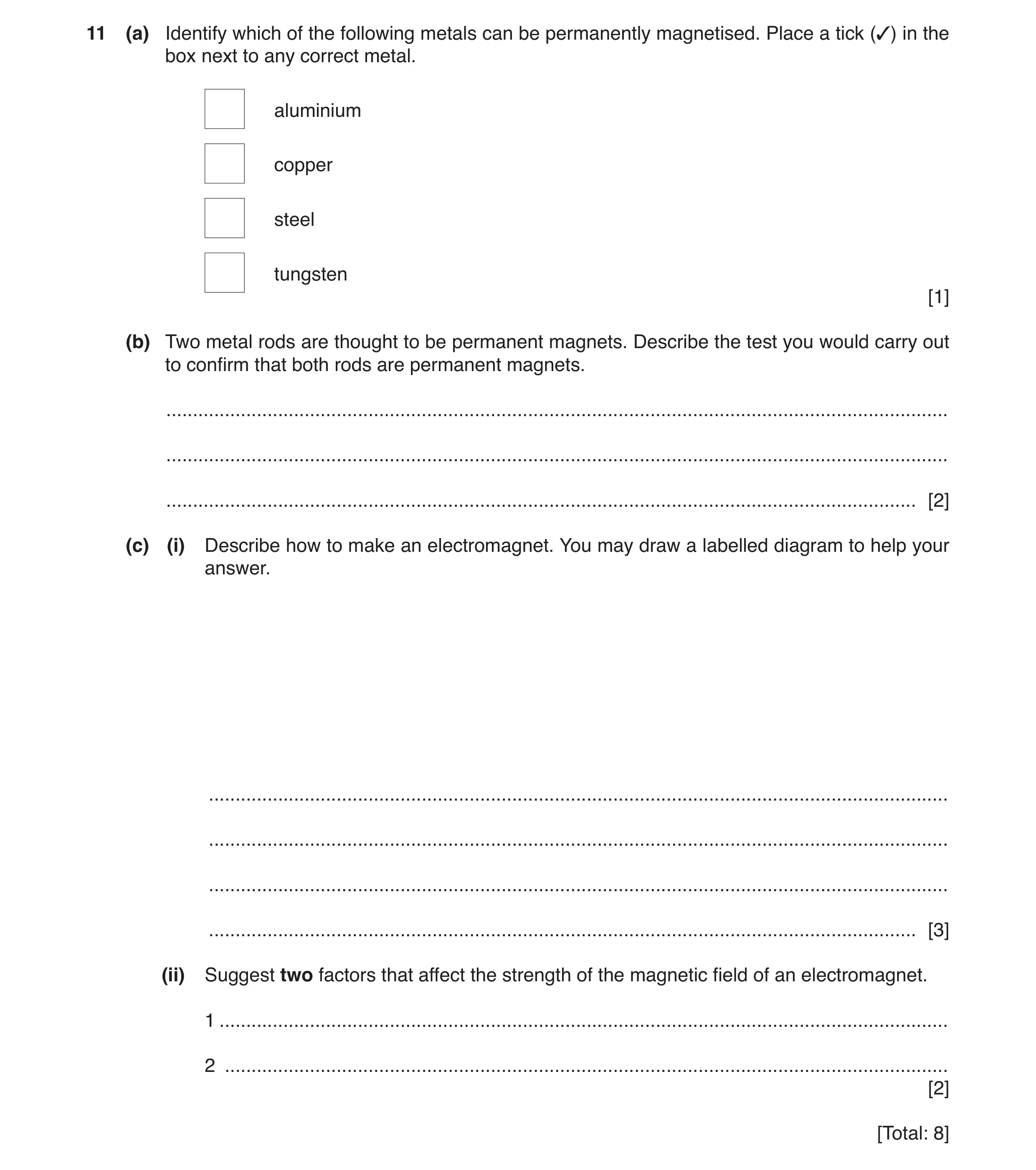
Q14 · Identify which of the following metals can be permanently magnetised 0625/32 Oct/Nov 2019
11 (a) Identify which of the following metals can be permanently magnetised. Place a tick (3) in the box next to any correct metal. aluminium copper steel tungsten [1] (b) Two metal rods are thought to be permanent magnets. Describe the test you would carry out to confirm that both rods are permanent magnets. … … … [2] (c) (i) Describe how to make an electromagnet. You may draw a labelled diagram to help your answer. … … … … [3] (ii) Suggest two factors that affect the strength of the magnetic field of an electromagnet. 1 … 2 … [2] [Total: 8]
8 marks
Mark scheme: 11(a) 3rd box ticked steel B1 11(b) place ends/poles together B1 repulsion (takes place) B1 11(c)(i) coil of wire B1 iron rod inside B1 coil connected to an (electrical) power supply OR current in coil B1 11(c)(ii) number of turns (in coil) B1 current (in coil) B1
This question in 0625/32 Oct/Nov 2019
Q15 · Two bar magnets are placed next to each other as shown in Fig 0625/33 Oct/Nov 2019
9 Two bar magnets are placed next to each other as shown in Fig. 9.1. magnet A magnet B Fig. 9.1 Magnet A is slowly moved towards magnet B. This causes magnet B to move away from magnet A. (a) (i) On Fig. 9.1, suggest the poles of each bar magnet. Label N and S on each of the magnets. [1] (ii) State the term used to describe the direction of the forces acting between magnet A and magnet B. … [1] (iii) Magnet B is removed and replaced with a steel bar of the same size. Describe what happens when magnet A is slowly moved towards the steel bar. … … [1] (b) A student makes an electromagnet. He places an iron rod inside a coil of wire and connects the coil to a d.c. power supply, as shown in Fig. 9.2. d.c. power supply iron rod coil Fig. 9.2 (i) The switch is closed so there is a current in the coil. The S pole of a bar magnet is placed near to each end of the iron rod in turn. Suggest what happens at each end of the iron rod and give a reason for your predictions. Suggestions … … … reason … … [2] (ii) The student removes the iron rod from the coil. The student places a steel rod inside the coil. He closes the switch and the steel rod becomes a magnet. He then opens the switch. The student removes the steel rod and moves it close to the iron rod. Describe and explain what happens as the two rods are moved close together. … … … [2] (iii) State one use for an electromagnet. … [1] [Total: 8]
8 marks
Mark scheme: 9(a)(i) either N and N OR S and S facing each other B1 9(a)(ii) repel / repulsion B1 9(a)(iii) attracted OR steel bar moves towards magnet A B1 9(b)(i) prediction: one end attracts AND the other end repels reason: like poles repel OR unlike poles attract B1 B1 9(b)(ii) they attract (because) steel forms a permanent magnet owtte B1 B1 9(b)(iii) sorting scrap metal OR doorbell OR relay OR (electric) motor OR circuit breakers B1
This question in 0625/33 Oct/Nov 2019
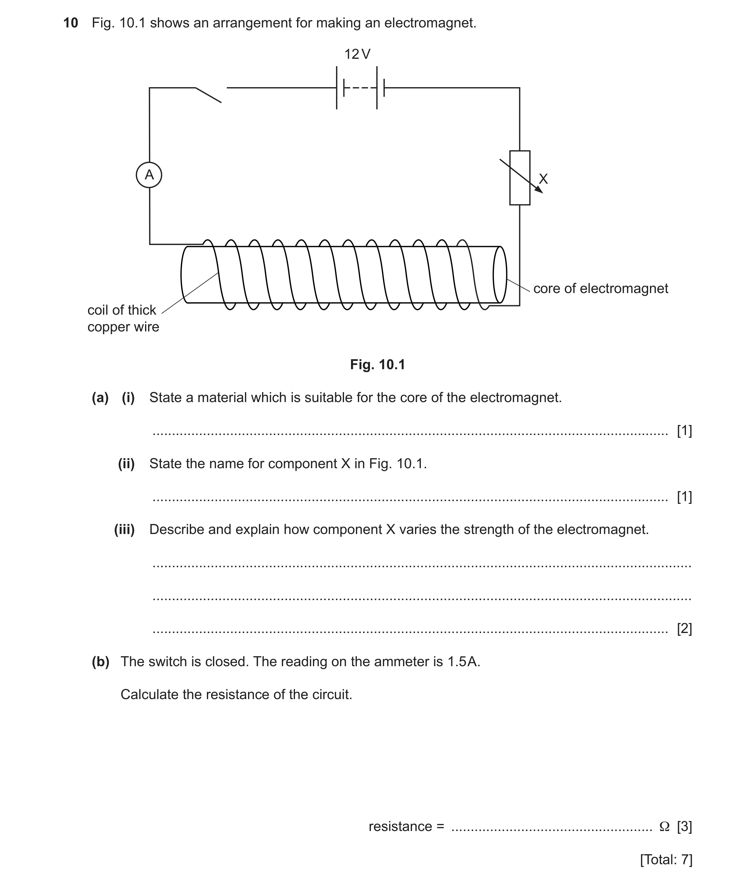
Q16 · An arrangement for making an electromagnet 0625/32 Feb/March 2020
10 Fig. 10.1 shows an arrangement for making an electromagnet. 12 V A X core of electromagnet coil of thick copper wire Fig. 10.1 (a) (i) State a material which is suitable for the core of the electromagnet. … [1] (ii) State the name for component X in Fig. 10.1. … [1] (iii) Describe and explain how component X varies the strength of the electromagnet. … … … [2] (b) The switch is closed. The reading on the ammeter is 1.5 A. Calculate the resistance of the circuit. resistance = … Ω [3] [Total: 7]
7 marks
Mark scheme: 10(a)(i) (soft) iron (bar) B1 10(a)(ii) variable resistor B1 10(a)(iii) any two from: increasing the resistance (will) decrease the current (decreasing the current will) decrease the strength (of the electromagnet) B2 10(b) (R =) V ÷ I in any form C1 (R =) 12 ÷ 1.5 C1 (R =) 8.0 (Ω) A1
This question in 0625/32 Feb/March 2020
Q17 · The magnetic field pattern around a bar magnet 0625/31 May/June 2020
9 (a) Fig. 9.1 shows the magnetic field pattern around a bar magnet. bar magnet Fig. 9.1 (i) On Fig. 9.1, write the letters N and S to indicate the north and south poles of the magnet. [1] (ii) Fig. 9.2 shows a soft-iron bar placed close to a permanent magnet. permanent magnet soft-iron bar Fig. 9.2 State and explain what happens to the soft-iron bar. You may draw on Fig. 9.2. … … … [3] (b) Three balls P, Q and R are electrically charged. The balls are suspended by threads of insulating material. Fig. 9.3 shows the arrangement. insulated thread – ball P ball R ball Q Fig. 9.3 Ball P is negatively charged. (i) State the charge on ball Q and the charge on ball R. ball Q … ball R … [2] (ii) Explain your answer for part (i) for the charge on ball Q. … … … [2] [Total: 8]
8 marks
Mark scheme: 9(a)(i) N and S poles correctly labelled B1 9(a)(ii) (iron bar and magnet) attract (each other) B1 (iron) bar becomes an induced magnet B1 with opposite pole next to pole of magnet B1 Question Answer Marks 9(b)(i) (charge on Q is) negative B1 (charge on R is) positive B1 9(b)(ii) (ball) Q is repelled (by negative charge on P) B1 has same charge (as on P) B1
This question in 0625/31 May/June 2020
Q18 · Some students plot the magnetic field lines around a bar magnet 0625/32 May/June 2020
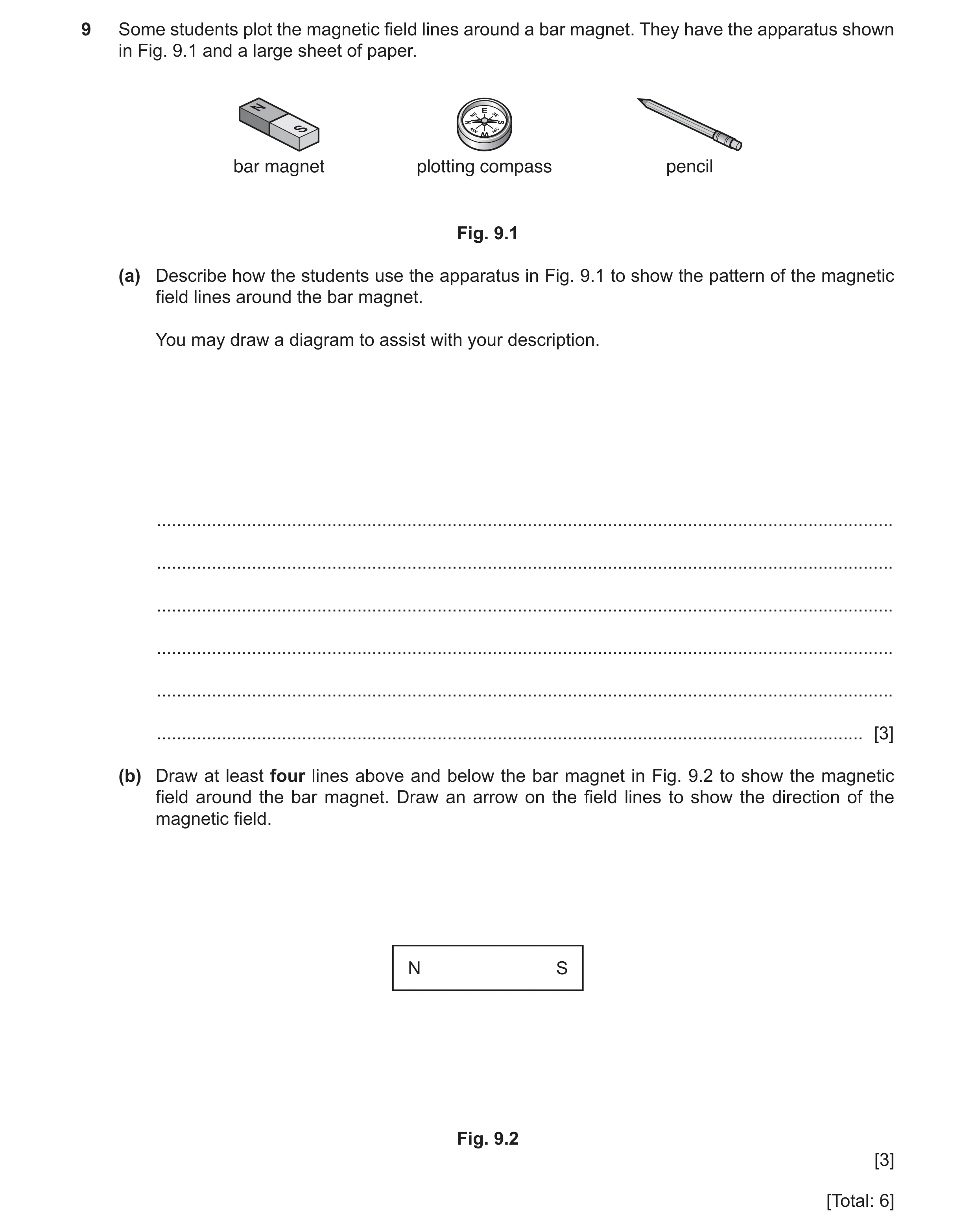
9 Some students plot the magnetic field lines around a bar magnet. They have the apparatus shown in Fig. 9.1 and a large sheet of paper. bar magnet plotting compass pencil Fig. 9.1 (a) Describe how the students use the apparatus in Fig. 9.1 to show the pattern of the magnetic field lines around the bar magnet. You may draw a diagram to assist with your description. … … … … … … [3] (b) Draw at least four lines above and below the bar magnet in Fig. 9.2 to show the magnetic field around the bar magnet. Draw an arrow on the field lines to show the direction of the magnetic field. N S Fig. 9.2 [3] [Total: 6]
6 marks
Mark scheme: 9(a) any three from: use of plotting compass next to magnet mark point of compass needle move compass other side of dot align needle with dot put dot other side of needle and repeat start again from another position next to magnet Question Answer Marks 9(b) any two from: no field lines crossing looping from N to S away from ends field lines straight out from ends B2 arrow(s) on field lines pointing N to S B1
This question in 0625/32 May/June 2020
Q19 · A student has a permanent bar magnet and two metal bars, as shown in Fig 0625/31 Oct/Nov 2020
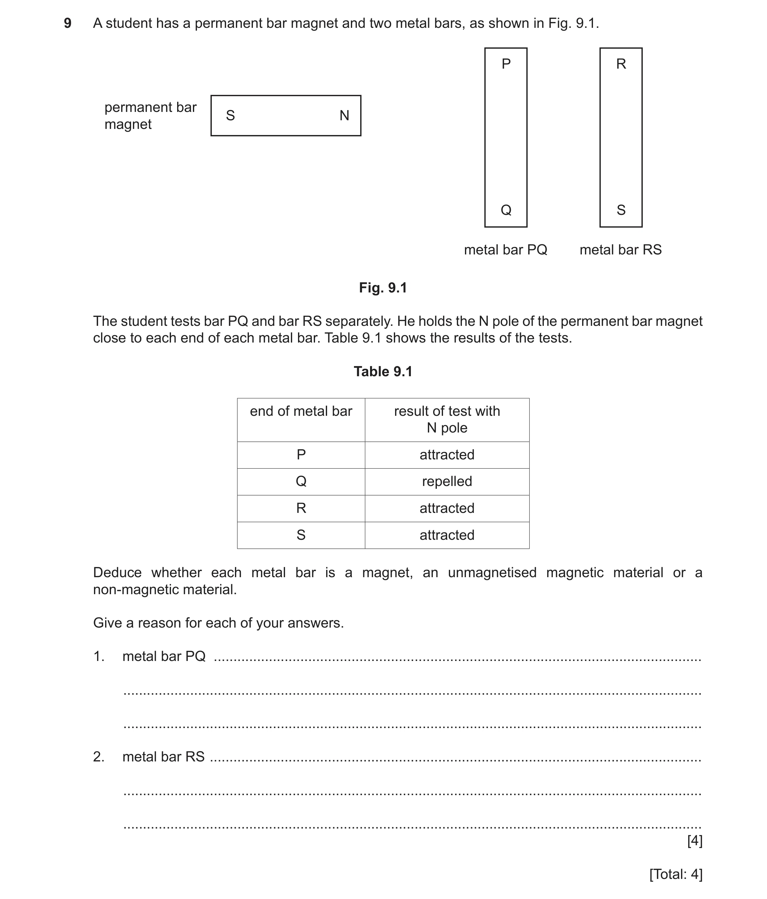
9 A student has a permanent bar magnet and two metal bars, as shown in Fig. 9.1. P R permanent bar S N magnet Q S metal bar PQ metal bar RS Fig. 9.1 The student tests bar PQ and bar RS separately. He holds the N pole of the permanent bar magnet close to each end of each metal bar. Table 9.1 shows the results of the tests. Table 9.1 end of metal bar result of test with N pole P attracted Q repelled R attracted S attracted Deduce whether each metal bar is a magnet, an unmagnetised magnetic material or a non-magnetic material. Give a reason for each of your answers. 1. metal bar PQ … … … 2. metal bar RS … … … [4] [Total: 4]
4 marks
Mark scheme: 9 1 (bar P–Q is a) (permanent) magnet M1 (because magnet) repels end Q A1 2 (bar R–S is an) unmagnetised magnetic material M1 (because magnet) attracts both ends (of R–S) A1
This question in 0625/31 Oct/Nov 2020
Q20 · A student tests whether a bar magnet affects three different materials 0625/32 Oct/Nov 2020
9 A student tests whether a bar magnet affects three different materials. Fig. 9.1 shows the bar magnet and a sample of each material A, B and C. A N S B C Fig. 9.1 The student tests each sample by holding each pole of the magnet close to one end of the sample. Table 9.1 shows his observations. Table 9.1 sample effect of N pole effect of S pole A attraction attraction B no effect no effect C attraction repulsion (a) Using the information in Table 9.1, draw a straight line from each sample to its correct property. Draw three lines. sample property A magnetic and magnetised B magnetic but not magnetised C non-magnetic [2] (b) Describe one method of producing a magnet from a bar of unmagnetised steel. … … … [2] (c) Another student does an experiment with some electrostatically charged plastic rods. Fig. 9.2 shows the student’s arrangement. negatively charged nylon plastic thread rod negatively charged plastic rod Fig. 9.2 Describe and explain what happens as the student brings one negatively charged rod close to the other negatively charged rod. … … … [2] [Total: 6]
6 marks
Mark scheme: 9(a) sample A magnetic and magnetised sample B magnetic but not magnetised sample C non-magnetic 9(b) use (same pole) of (permanent) magnet stroke bar (repeatedly) in same / one direction owtte OR place (bar / steel) in coil / solenoid current in coil OR connect coil to battery / power supply B2 9(c) rods repel OR move apart / away B1 like / same (type of) charges on both rods B1
This question in 0625/32 Oct/Nov 2020
Q21 · The magnetic field pattern around a bar magnet 0625/32 Feb/March 2021
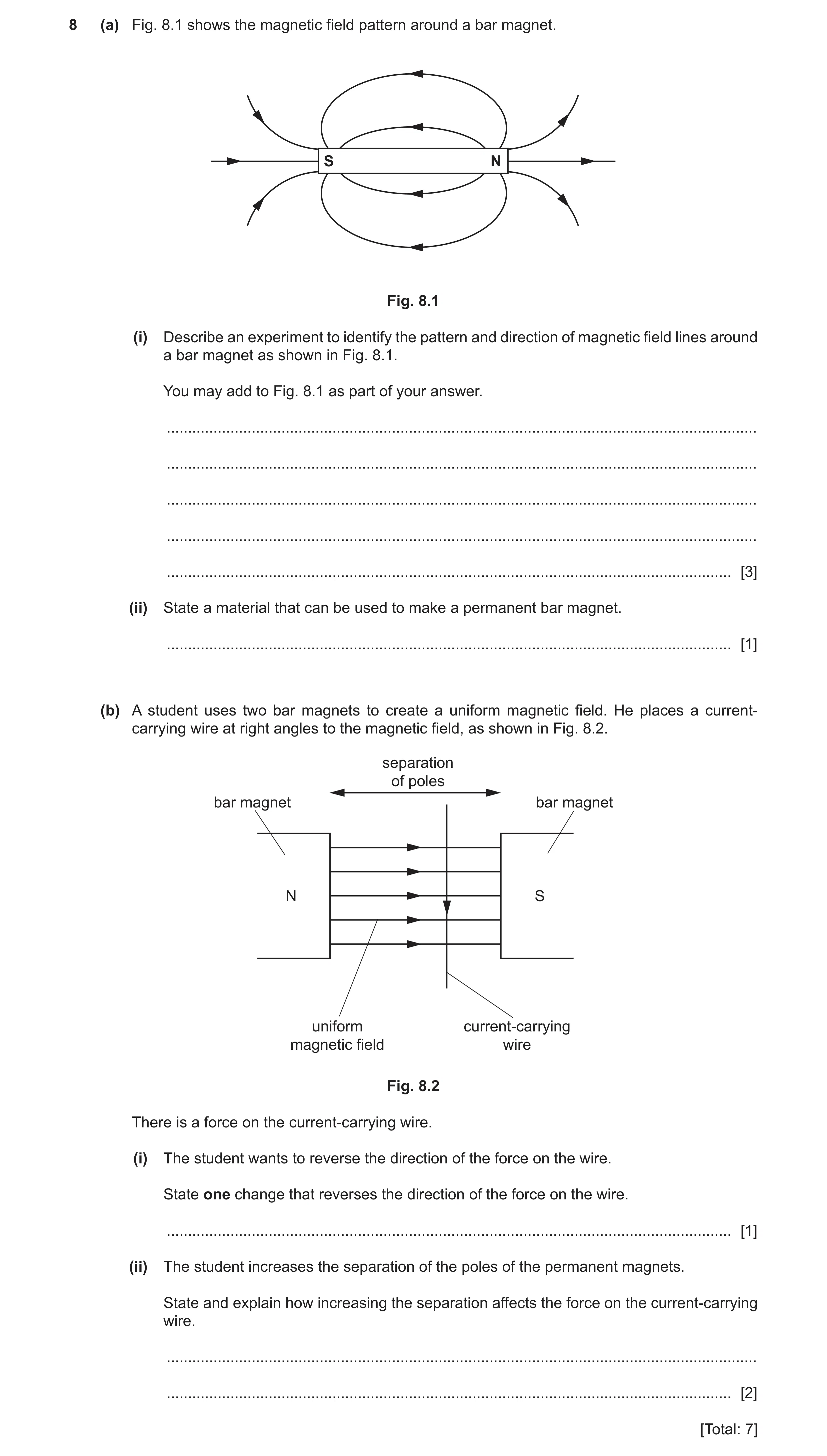
8 (a) Fig. 8.1 shows the magnetic field pattern around a bar magnet. S N Fig. 8.1 (i) Describe an experiment to identify the pattern and direction of magnetic field lines around a bar magnet as shown in Fig. 8.1. You may add to Fig. 8.1 as part of your answer. … … … … … [3] (ii) State a material that can be used to make a permanent bar magnet. … [1] (b) A student uses two bar magnets to create a uniform magnetic field. He places a current- carrying wire at right angles to the magnetic field, as shown in Fig. 8.2. separation of poles bar magnet bar magnet N S uniform current-carrying magnetic field wire Fig. 8.2 There is a force on the current-carrying wire. (i) The student wants to reverse the direction of the force on the wire. State one change that reverses the direction of the force on the wire. … [1] (ii) The student increases the separation of the poles of the permanent magnets. State and explain how increasing the separation affects the force on the current-carrying wire. … … [2] [Total: 7]
7 marks
Mark scheme: 8(a)(i) (plotting) compass OR iron filings B1 detail of method B1 use of (plotting) compass to give direction of field B1 8(a)(ii) steel B1 8(b)(i) reverse magnetic field owtte OR reverse current in wire B1 8(b)(ii) force is weaker B1 (because) magnetic field is weaker B1
This question in 0625/32 Feb/March 2021
Q22 · The box lists four materials 0625/31 May/June 2021
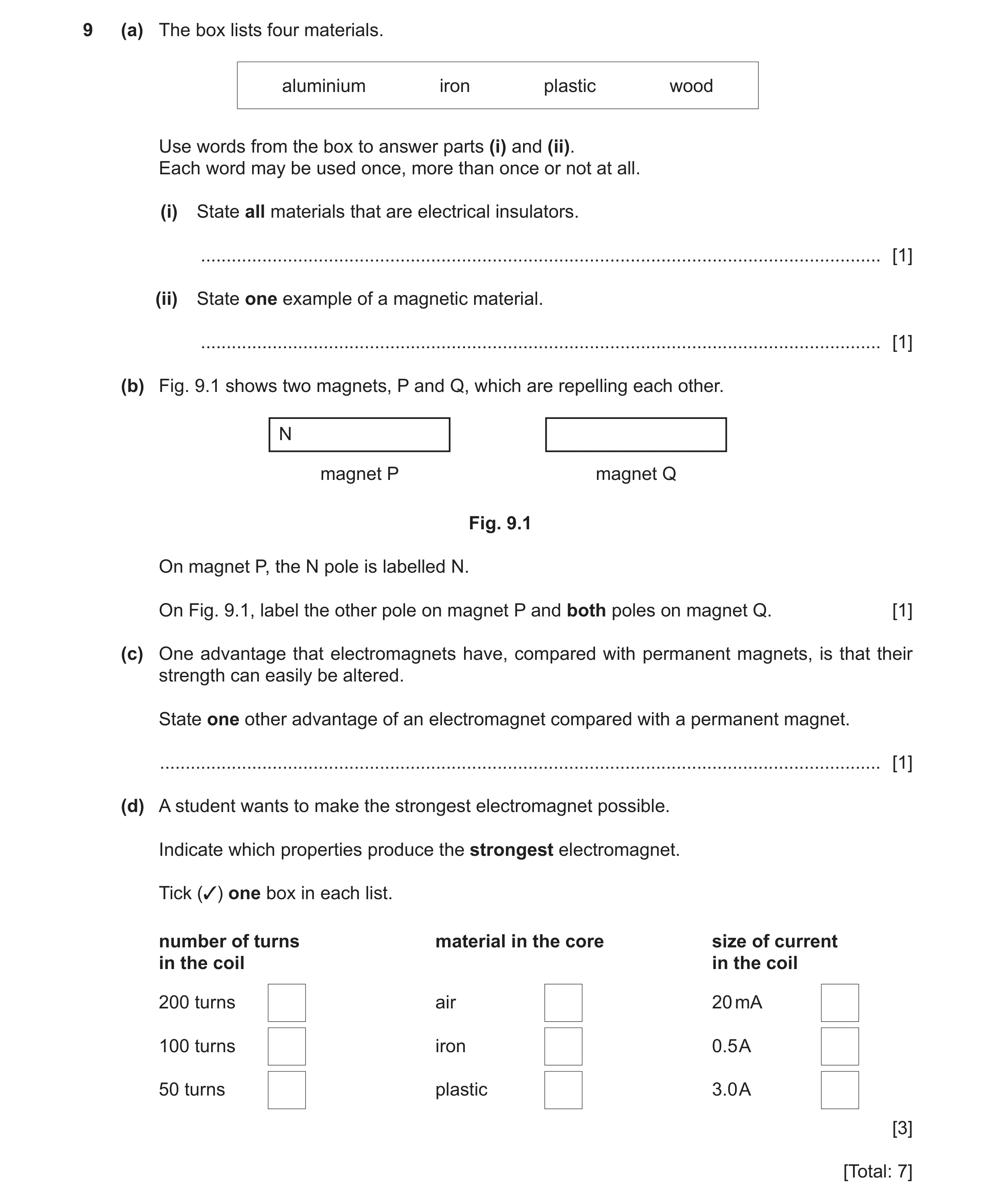
9 (a) The box lists four materials. aluminium iron plastic wood Use words from the box to answer parts (i) and (ii). Each word may be used once, more than once or not at all. (i) State all materials that are electrical insulators. … [1] (ii) State one example of a magnetic material. … [1] (b) Fig. 9.1 shows two magnets, P and Q, which are repelling each other. N magnet P magnet Q Fig. 9.1 On magnet P, the N pole is labelled N. On Fig. 9.1, label the other pole on magnet P and both poles on magnet Q. [1] (c) One advantage that electromagnets have, compared with permanent magnets, is that their strength can easily be altered. State one other advantage of an electromagnet compared with a permanent magnet. … [1] (d) A student wants to make the strongest electromagnet possible. Indicate which properties produce the strongest electromagnet. Tick (3) one box in each list. number of turns material in the core size of current in the coil in the coil 200 turns air 20 mA 100 turns iron 0.5 A 50 turns plastic 3.0 A [3] [Total: 7]
7 marks
Mark scheme: 9(a)(i) plastic AND wood B1 9(a)(ii) iron B1 9(b) B1 9(c) (electromagnet can be) switched off OR switched on B1 N S S N Question Answer Marks 9(d) feature 1: top box ticked (200 turns) B1 feature 2: middle box ticked (iron) B1 feature 3: bottom box ticked (3.0 A) B1
This question in 0625/31 May/June 2021
Q23 · Two uncharged balloons suspended from a beam by light thread 0625/33 May/June 2021
9 (a) Fig. 9.1 shows two uncharged balloons suspended from a beam by light thread. beam light thread balloons Fig. 9.1 The balloons are close to each other but not touching. In the box below, draw the position of the balloons when they both have a positive charge. beam [1] (b) Table 9.1 includes a list of materials. State whether each material is an electrical conductor or an electrical insulator. The first example is done for you. Table 9.1 material conductor or insulator copper conductor rubber wood iron gold [2] (c) An uncharged cloth rubs an uncharged plastic rod. The cloth becomes positively charged and the plastic rod becomes negatively charged. Explain how the cloth becomes positively charged. … … … … [3] [Total: 6]
6 marks
Mark scheme: 9(a) showing repulsion B1 9(b) insulators: rubber AND wood B1 conductors: iron AND gold B1 9(c) electrons / negative charges B1 move / transfer B1 from cloth to rod B1
This question in 0625/33 May/June 2021
Q24 · The magnetic field pattern around a bar magnet 0625/31 Oct/Nov 2021
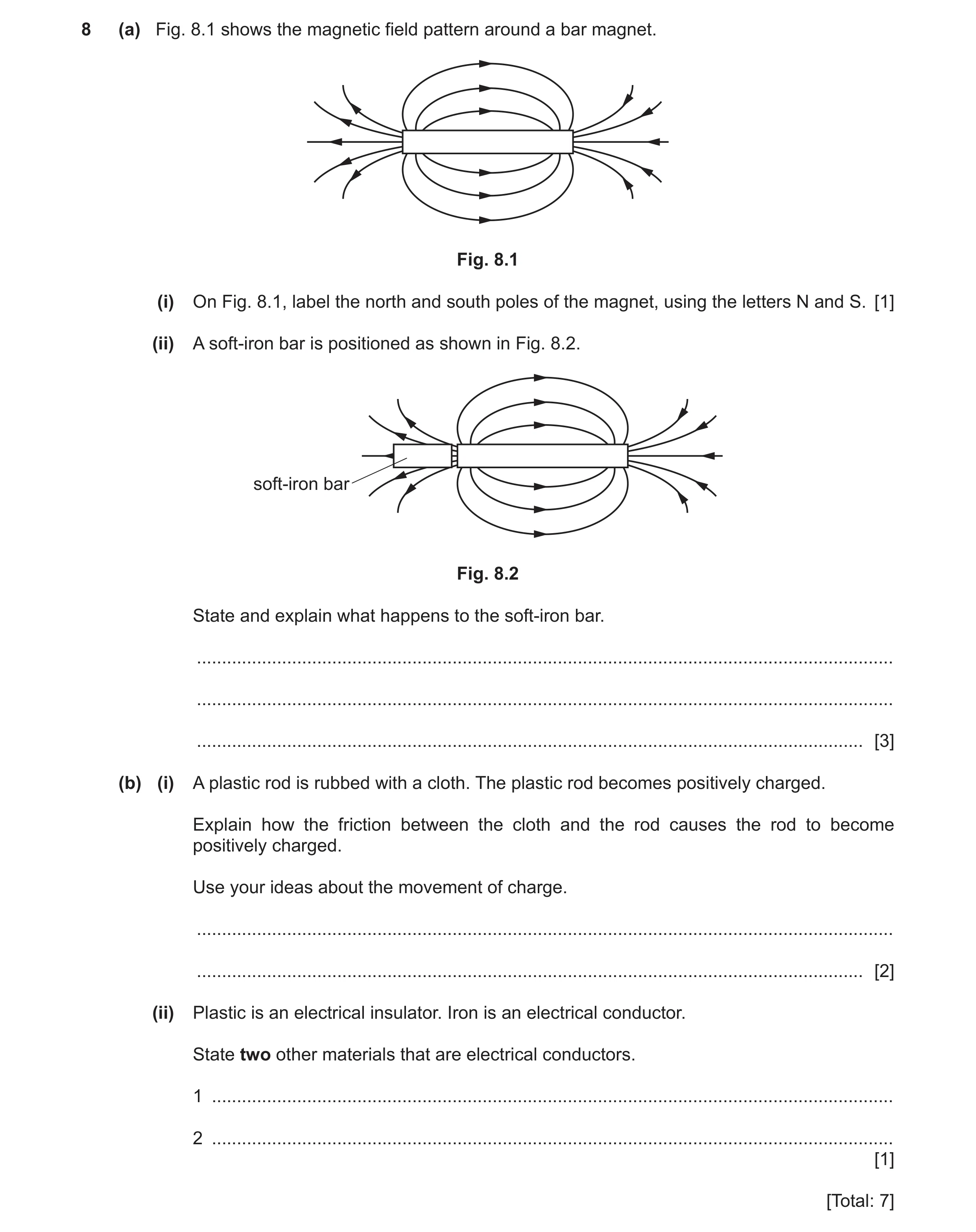
8 (a) Fig. 8.1 shows the magnetic field pattern around a bar magnet. Fig. 8.1 (i) On Fig. 8.1, label the north and south poles of the magnet, using the letters N and S. [1] (ii) A soft‑iron bar is positioned as shown in Fig. 8.2. soft-iron bar Fig. 8.2 State and explain what happens to the soft‑iron bar. … … … [3] (b) (i) A plastic rod is rubbed with a cloth. The plastic rod becomes positively charged. Explain how the friction between the cloth and the rod causes the rod to become positively charged. Use your ideas about the movement of charge. … … [2] (ii) Plastic is an electrical insulator. Iron is an electrical conductor. State two other materials that are electrical conductors. 1 … 2 … [1] [Total: 7]
7 marks
Mark scheme: 8(a)(i) N marked on left AND S on the right of magnet B1 8(a)(ii) (soft-iron / bar / it) is attracted to the (N pole of the) magnet B1 (soft-iron / bar / it) becomes induced magnet B1 with opposite pole nearest to magnet B1 8(b)(i) electrons move M1 from the rod OR to the cloth A1 8(b)(ii) TWO electrical conductors named B1
This question in 0625/31 Oct/Nov 2021
Q25 · A girl has eight objects made of different materials 0625/32 Oct/Nov 2021
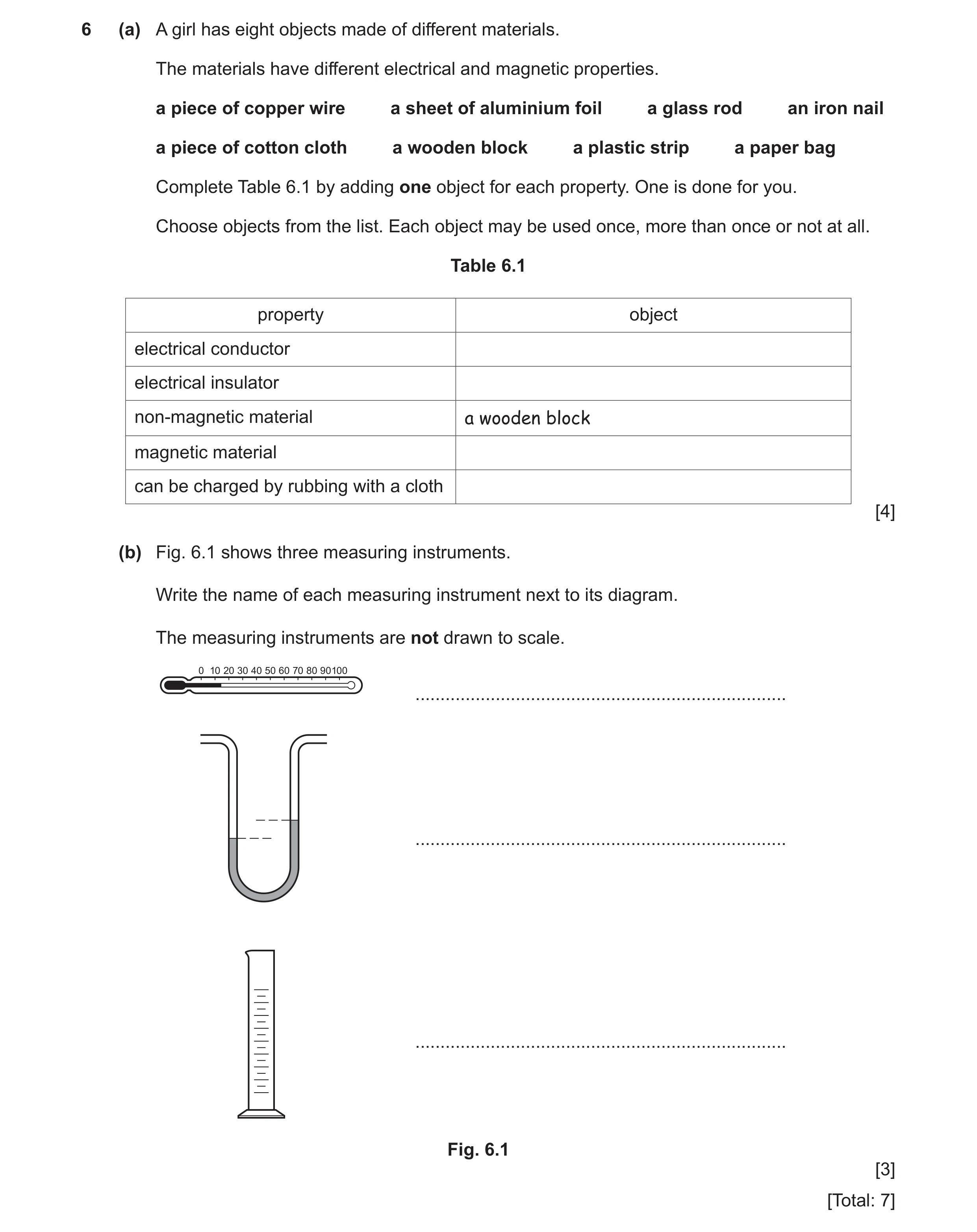
6 (a) A girl has eight objects made of different materials. The materials have different electrical and magnetic properties. a piece of copper wire a sheet of aluminium foil a glass rod an iron nail a piece of cotton cloth a wooden block a plastic strip a paper bag Complete Table 6.1 by adding one object for each property. One is done for you. Choose objects from the list. Each object may be used once, more than once or not at all. Table 6.1 property object electrical conductor electrical insulator non-magnetic material a wooden block magnetic material can be charged by rubbing with a cloth [4] (b) Fig. 6.1 shows three measuring instruments. Write the name of each measuring instrument next to its diagram. The measuring instruments are not drawn to scale. … … … Fig. 6.1 [3] [Total: 7]
7 marks
Mark scheme: 6(a) property object conductor copper wire OR aluminium foil OR iron nail insulator cotton cloth OR wooden block OR plastic strip OR paper bag OR glass rod non-magnetic a wooden block magnetic material iron nail can be charged by rubbing with a cloth plastic strip OR glass rod B1 B1 B1 B1 6(b) (liquid-in-glass) thermometer B1 manometer B1 measuring cylinder B1
This question in 0625/32 Oct/Nov 2021
Q26 · A bar magnet on a piece of card 0625/31 May/June 2022
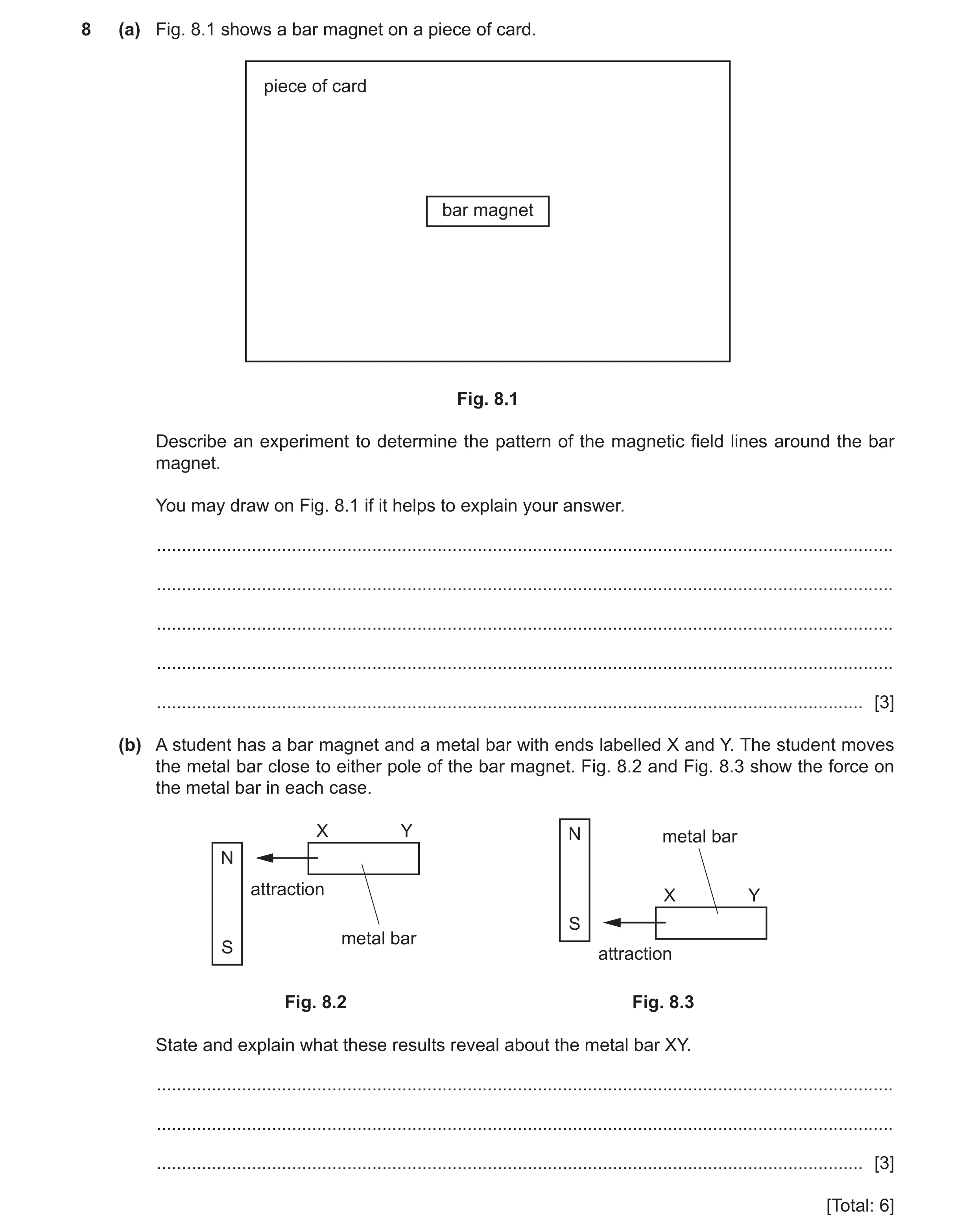
8 (a) Fig. 8.1 shows a bar magnet on a piece of card. piece of card bar magnet Fig. 8.1 Describe an experiment to determine the pattern of the magnetic field lines around the bar magnet. You may draw on Fig. 8.1 if it helps to explain your answer. … … … … … [3] (b) A student has a bar magnet and a metal bar with ends labelled X and Y. The student moves the metal bar close to either pole of the bar magnet. Fig. 8.2 and Fig. 8.3 show the force on the metal bar in each case. X Y N metal bar N attraction X Y S metal bar S attraction Fig. 8.2 Fig. 8.3 State and explain what these results reveal about the metal bar XY. … … … [3] [Total: 6]
6 marks
Mark scheme: 8(a) first method (use of plotting) compass(es) B1 idea of mark arrow position OR move compass in direction of arrow B1 start from different position(s) OR join up marks/draw lines (to show pattern) B1 OR alternative method (use of plotting) compass(es) (B1) place number of compasses around magnet (B1) idea that arrows line up to show pattern (B1) 8(b) (metal bar XY/it is soft) iron OR magnetic material/bar/metal B1 (so XY) must be unmagnetised B1 (because end X of XY or bar) attracts to (both) N pole and S pole B1
This question in 0625/31 May/June 2022
Q27 · A student has a box containing objects made of different materials 0625/32 May/June 2022
8 (a) A student has a box containing objects made of different materials. The objects are: aluminium foil a silver ring an iron bar a plastic strip a glass lens (i) State which objects are made of electrically insulating materials. … [1] (ii) State which object is made of a magnetic material. … [1] (b) Fig. 8.1 shows two magnets, X and Y. The magnets are attracting each other. N attraction magnet X magnet Y Fig. 8.1 On magnet X, the N pole is labelled N. On Fig. 8.1, complete the labelling for the magnetic poles of each magnet. [1] (c) The student attaches a thin cotton thread to each of two light metal spheres, P and Q. She suspends the spheres as shown in Fig. 8.2. thin cotton support thread P Q Fig. 8.2 (i) The student puts a positive charge on sphere P only. Complete the diagram in Fig. 8.3 to show the positions of the spheres. support Fig. 8.3 [1] (ii) The student puts a positive charge on sphere P and on sphere Q. Complete the diagram in Fig. 8.4 to show the positions of the spheres. support Fig. 8.4 [2] [Total: 6]
6 marks
Mark scheme: 8(a)(i) plastic strip AND glass lens B1 8(a)(ii) iron bar B1 Question Answer Marks 8(b) end of magnet X labelled S (pole) AND end of magnet Y nearest magnet X labelled N (pole) AND other end is S (pole) B1 8(c)(i) spheres drawn closer together B1 8(c)(ii) spheres drawn further apart M1 both strings at an angle to vertical A1
This question in 0625/32 May/June 2022
Q28 · A student has a bar magnet and a metal bar with ends X and Y 0625/31 Oct/Nov 2022
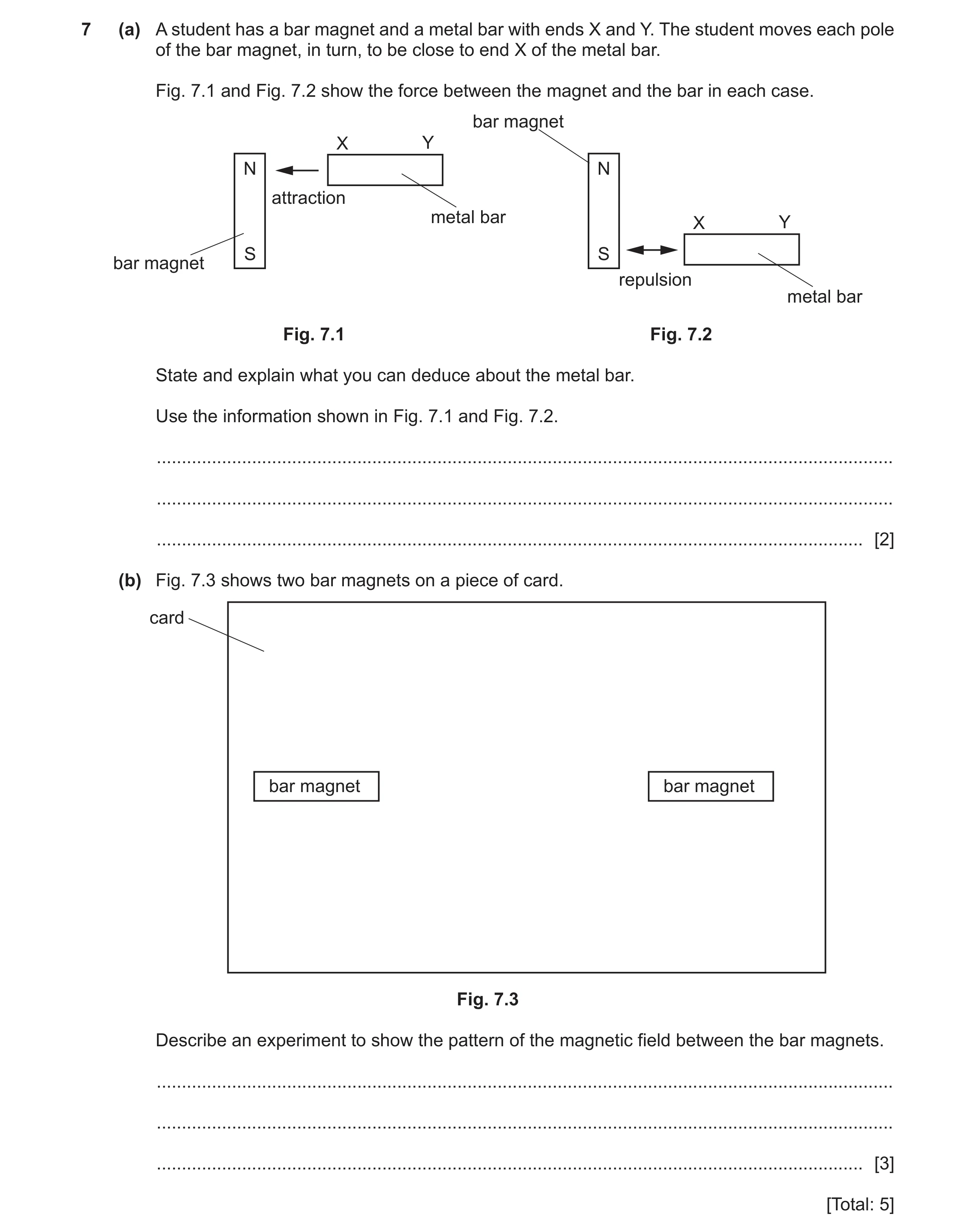
7 (a) A student has a bar magnet and a metal bar with ends X and Y. The student moves each pole of the bar magnet, in turn, to be close to end X of the metal bar. Fig. 7.1 and Fig. 7.2 show the force between the magnet and the bar in each case. bar magnet X Y N N attraction metal bar X Y S S bar magnet repulsion metal bar Fig. 7.1 Fig. 7.2 State and explain what you can deduce about the metal bar. Use the information shown in Fig. 7.1 and Fig. 7.2. … … … [2] (b) Fig. 7.3 shows two bar magnets on a piece of card. card bar magnet bar magnet Fig. 7.3 Describe an experiment to show the pattern of the magnetic field between the bar magnets. … … … [3] [Total: 5]
5 marks
Mark scheme: 7(a) any two from: B2 • (bar XY) is a (permanent) magnet • (because) end X is repelled (by magnet/S pole) • (so) end X is a S pole. 7(b) (plotting) compass placed at one point on / near magnet B1 (repeatedly mark and) move compass in direction of arrow B1 start from different positions (to show pattern) B1
This question in 0625/31 Oct/Nov 2022
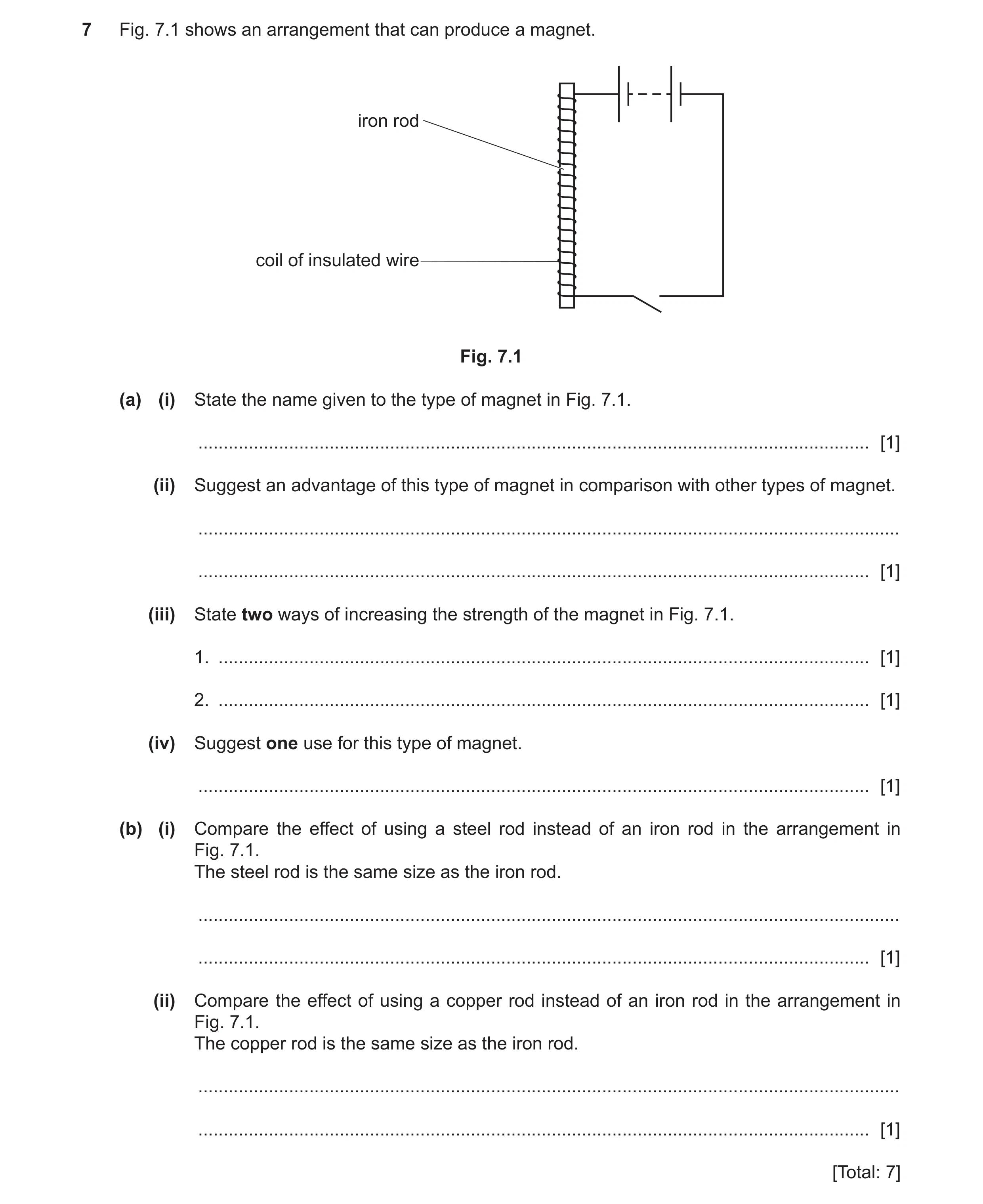
Q29 · An arrangement that can produce a magnet 0625/32 Oct/Nov 2022
7 Fig. 7.1 shows an arrangement that can produce a magnet. iron rod coil of insulated wire Fig. 7.1 (a) (i) State the name given to the type of magnet in Fig. 7.1. … [1] (ii) Suggest an advantage of this type of magnet in comparison with other types of magnet. … … [1] (iii) State two ways of increasing the strength of the magnet in Fig. 7.1. 1. … [1] 2. … [1] (iv) Suggest one use for this type of magnet. … [1] (b) (i) Compare the effect of using a steel rod instead of an iron rod in the arrangement in Fig. 7.1. The steel rod is the same size as the iron rod. … … [1] (ii) Compare the effect of using a copper rod instead of an iron rod in the arrangement in Fig. 7.1. The copper rod is the same size as the iron rod. … … [1] [Total: 7]
7 marks
Mark scheme: 7(a)(i) electro(magnet) B1 7(a)(ii) switch on and off / can control its strength B1 7(a)(iii) 1 increase current / emf / supply voltage B1 2 more turns (on coil) B1 7(a)(iv) scrap yard / metal separators / (door / alarm)bell / buzzers / relay / motor / MRI scanners / (magnetic) locks / (loud)speakers B1 7(b)(i) steel cannot be temporary magnet OR steel (will be) permanently magnetised owtte B1 7(b)(ii) not work / reduced strength owtte B1
This question in 0625/32 Oct/Nov 2022
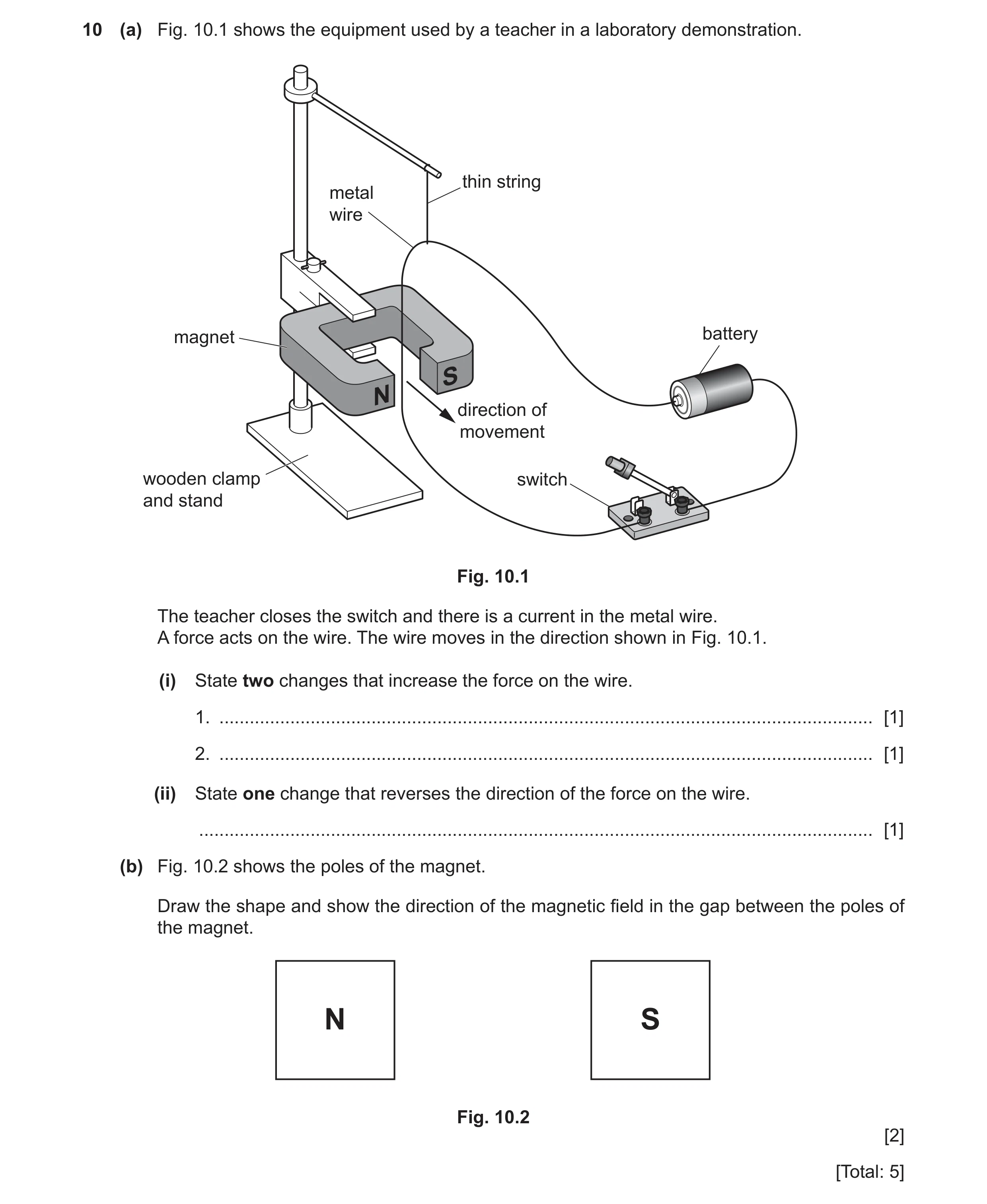
Q30 · The equipment used by a teacher in a laboratory demonstration 0625/32 Oct/Nov 2022
10 (a) Fig. 10.1 shows the equipment used by a teacher in a laboratory demonstration. thin string metal wire magnet battery S N direction of movement wooden clamp switch and stand Fig. 10.1 The teacher closes the switch and there is a current in the metal wire. A force acts on the wire. The wire moves in the direction shown in Fig. 10.1. (i) State two changes that increase the force on the wire. 1. … [1] 2. … [1] (ii) State one change that reverses the direction of the force on the wire. … [1] (b) Fig. 10.2 shows the poles of the magnet. Draw the shape and show the direction of the magnetic field in the gap between the poles of the magnet. N S Fig. 10.2 [2] [Total: 5]
5 marks
Mark scheme: 10(a)(i) 1 increase the current / pd / emf / voltage (of cell) B1 2 stronger magnet B1 10(a)(ii) reverse battery OR reverse current (direction) OR reverse magnetic field owtte B1 10(b) 3 or more correct lines B1 direction from N to S indicated B1
This question in 0625/32 Oct/Nov 2022
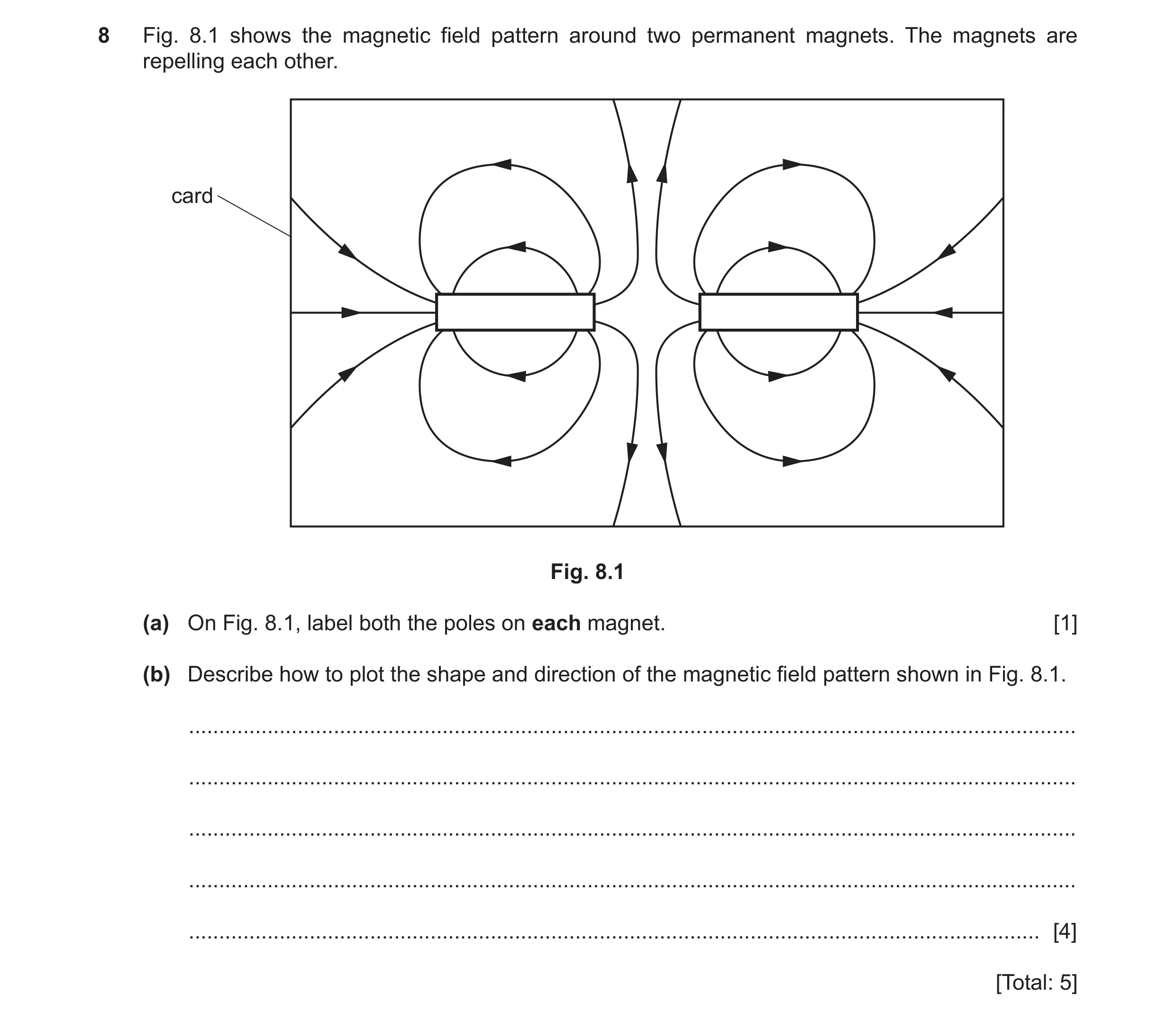
Q31 · The magnetic field pattern around two permanent magnets 0625/31 May/June 2023
8 Fig. 8.1 shows the magnetic field pattern around two permanent magnets. The magnets are repelling each other. card Fig. 8.1 (a) On Fig. 8.1, label both the poles on each magnet. [1] (b) Describe how to plot the shape and direction of the magnetic field pattern shown in Fig. 8.1. … … … … … [4] [Total: 5]
5 marks
Mark scheme: 8(a) two N / north poles on either side of gap B1 8(b) use of (plotting) compass or iron filings B1 use of (plotting) compass to show direction (of magnetic field line) B1 further details to method any two from: idea of sprinkle / scatter iron filings (around magnets) tap card to arrange filings along field lines / to show (magnetic field) pattern place compass near magnet mark point at end of arrow move compass OR multiple compasses in different positions idea of plotting more than one line B2
This question in 0625/31 May/June 2023
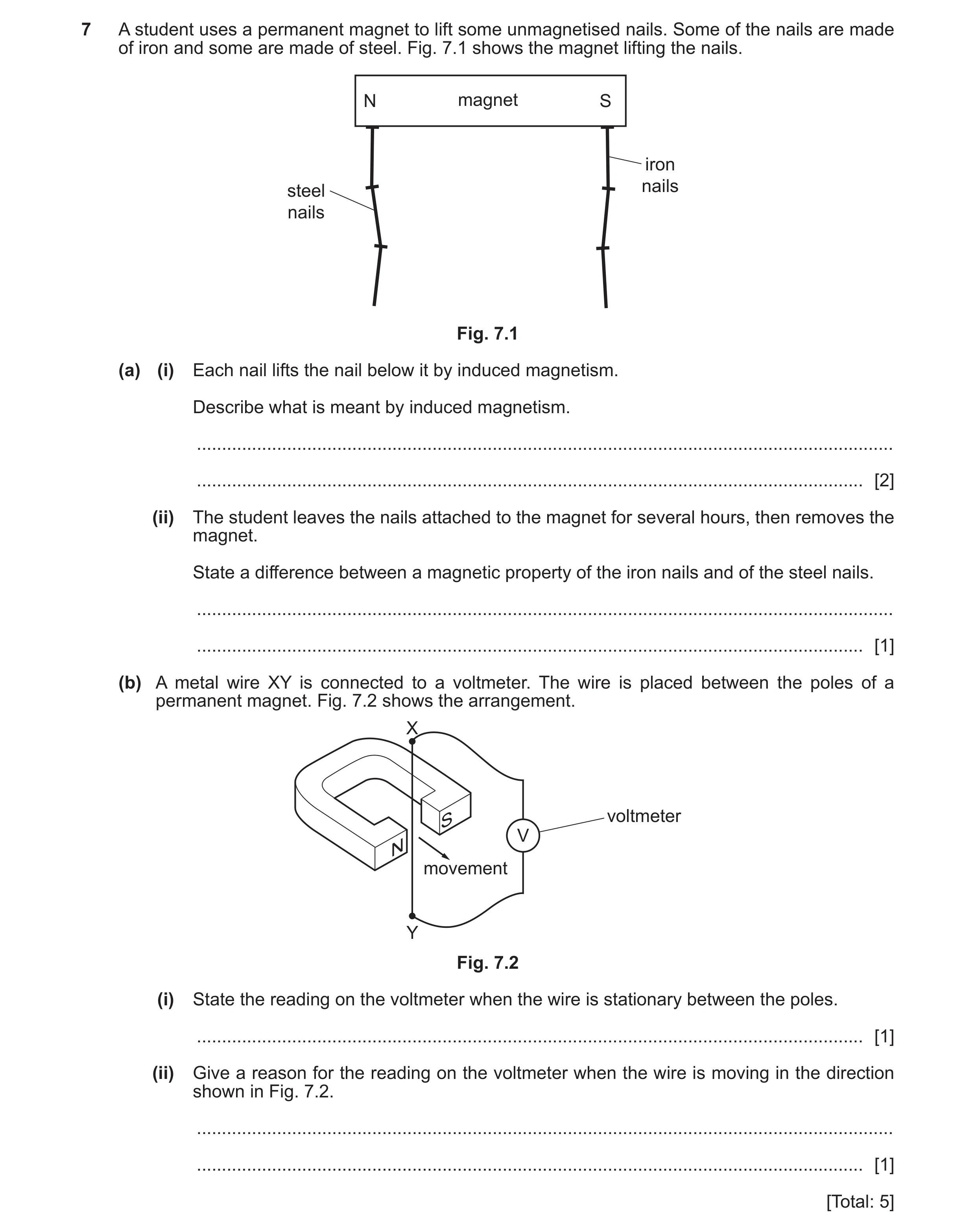
Q32 · A student uses a permanent magnet to lift some unmagnetised nails 0625/32 May/June 2023
7 A student uses a permanent magnet to lift some unmagnetised nails. Some of the nails are made of iron and some are made of steel. Fig. 7.1 shows the magnet lifting the nails. N magnet S iron steel nails nails Fig. 7.1 (a) (i) Each nail lifts the nail below it by induced magnetism. Describe what is meant by induced magnetism. … … [2] (ii) The student leaves the nails attached to the magnet for several hours, then removes the magnet. State a difference between a magnetic property of the iron nails and of the steel nails. … … [1] (b) A metal wire XY is connected to a voltmeter. The wire is placed between the poles of a permanent magnet. Fig. 7.2 shows the arrangement. X S voltmeter V N movement Y Fig. 7.2 (i) State the reading on the voltmeter when the wire is stationary between the poles. … [1] (ii) Give a reason for the reading on the voltmeter when the wire is moving in the direction shown in Fig. 7.2. … … [1] [Total: 5]
5 marks
Mark scheme: 7(a)(i) (nails or magnetic material or it) becomes magnetised OR is a magnet B1 (nails or magnetic material or it touching magnet has) the opposite pole to the pole on magnet B1 7(a)(ii) steel nails retain magnetism OR are magnetic B1 7(b)(i) no OR zero reading on voltmeter B1 7(b)(ii) (as conductor / wire) is cutting / linking with magnetic field (of magnet) B1
This question in 0625/32 May/June 2023
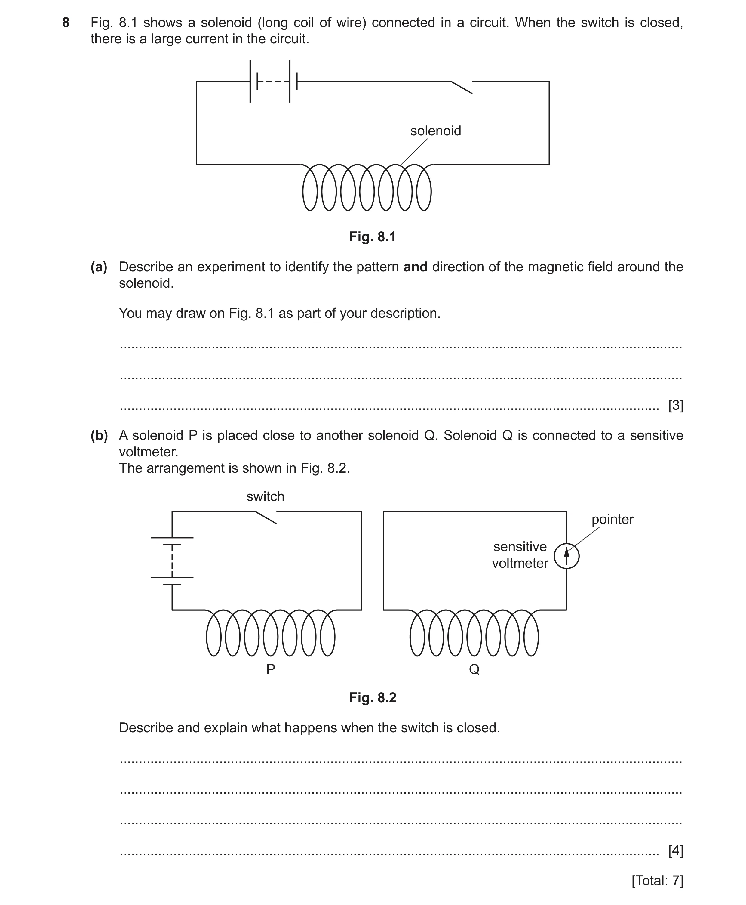
Q33 · A solenoid (long coil of wire) connected in a circuit 0625/31 Oct/Nov 2023
8 Fig. 8.1 shows a solenoid (long coil of wire) connected in a circuit. When the switch is closed, there is a large current in the circuit. solenoid Fig. 8.1 (a) Describe an experiment to identify the pattern and direction of the magnetic field around the solenoid. You may draw on Fig. 8.1 as part of your description. … … … [3] (b) A solenoid P is placed close to another solenoid Q. Solenoid Q is connected to a sensitive voltmeter. The arrangement is shown in Fig. 8.2. switch pointer sensitive voltmeter P Q Fig. 8.2 Describe and explain what happens when the switch is closed. … … … … [4] [Total: 7]
7 marks
Mark scheme: 8(a) (plotting) compass OR iron filings B1 detail of method B1 idea of using a (plotting) compass to give direction of magnetic field B1 8(b) any four from: B4 current in coil P (changing) magnetic field around / in coil P (magnetic field) links with / cuts coil Q an induced emf (across) coil Q OR voltage / current produced / generated in coil Q (induced emf) causes pointer on (sensitive) voltmeter to move when current steady no changing magnetic field OR no field (lines) cutting coil Q pointer then returns to zero
This question in 0625/31 Oct/Nov 2023
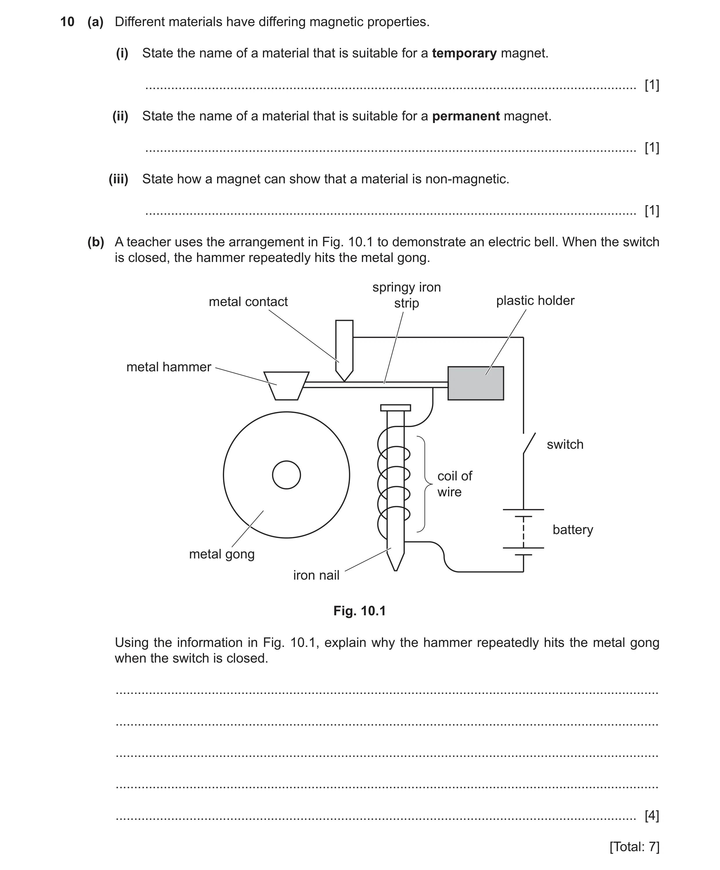
Q34 · Different materials have differing magnetic properties 0625/32 Oct/Nov 2023
10 (a) Different materials have differing magnetic properties. (i) State the name of a material that is suitable for a temporary magnet. … [1] (ii) State the name of a material that is suitable for a permanent magnet. … [1] (iii) State how a magnet can show that a material is non‑magnetic. … [1] (b) A teacher uses the arrangement in Fig. 10.1 to demonstrate an electric bell. When the switch is closed, the hammer repeatedly hits the metal gong. springy iron metal contact strip plastic holder metal hammer switch coil of wire battery metal gong iron nail Fig. 10.1 Using the information in Fig. 10.1, explain why the hammer repeatedly hits the metal gong when the switch is closed. … … … … … [4] [Total: 7]
7 marks
Mark scheme: 10(a)(i) (soft) iron B1 10(a)(ii) steel B1 10(a)(iii) magnet does not attract a non-magnetic material B1 10(b) any four from: B4 (when switch closed) there is a complete circuit current in the circuit magnetic effect (of current / in coil) owtte (coil and nail become) electromagnet (springy) iron (strip) attracted to (nail / electromagnet) circuit broken owtte springy iron strip springs back / makes contact (again) owtte
This question in 0625/32 Oct/Nov 2023
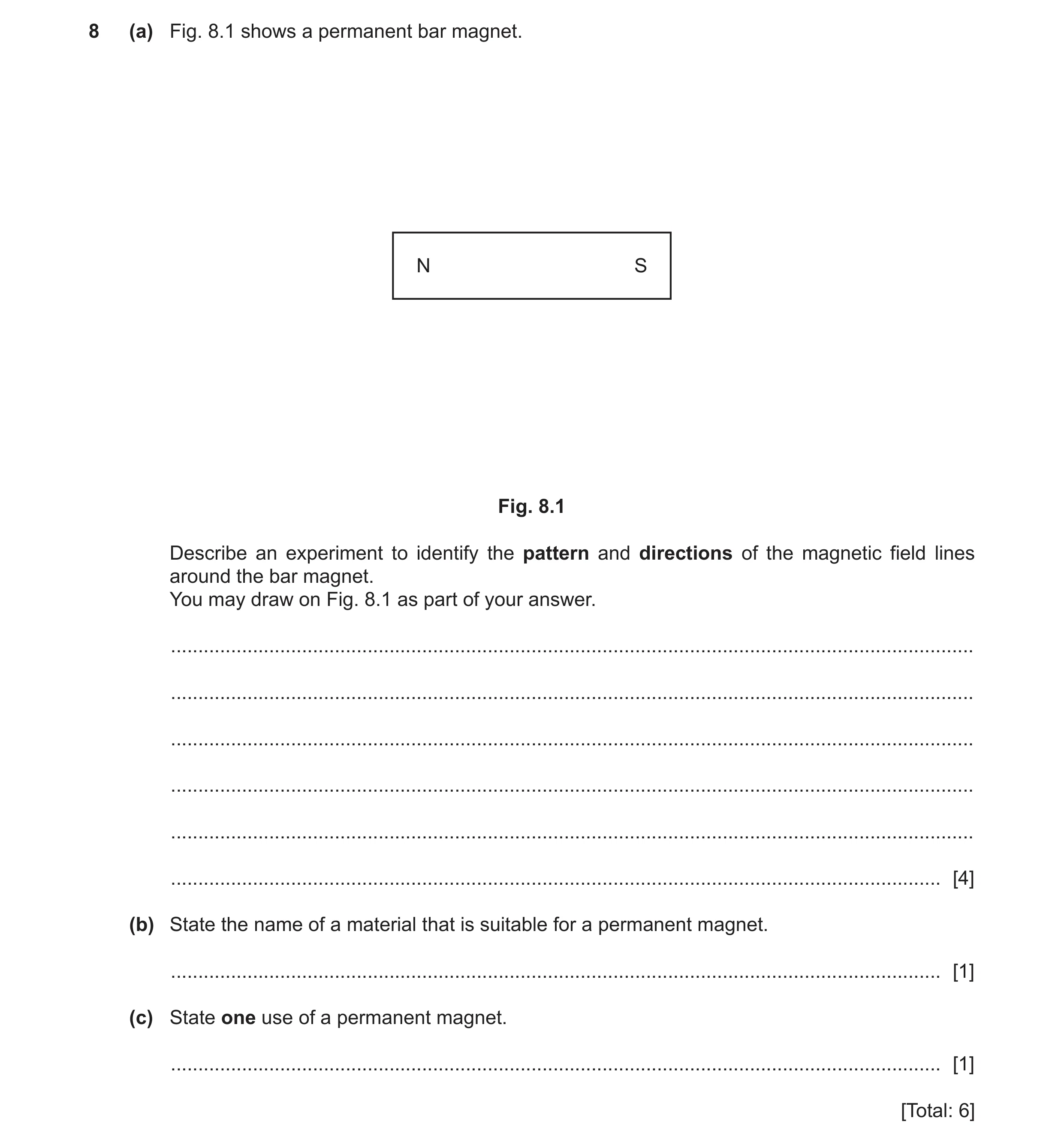
Q35 · A permanent bar magnet 0625/32 Feb/March 2024
8 (a) Fig. 8.1 shows a permanent bar magnet. N S Fig. 8.1 Describe an experiment to identify the pattern and directions of the magnetic field lines around the bar magnet. You may draw on Fig. 8.1 as part of your answer. … … … … … … [4] (b) State the name of a material that is suitable for a permanent magnet. … [1] (c) State one use of a permanent magnet. … [1] [Total: 6]
6 marks
Mark scheme: 8(a) use of compass to give direction of field lines B1 first method (use of plotting) compass(es) idea of mark arrow position OR move compass in direction of arrow start from different position(s) OR join up marks / draw lines B3 (to show pattern) OR alternative method (use of plotting) compass(es) place number of compasses around magnet idea that arrows line up to show pattern 8(b) steel B1 8(c) electric motors OR loudspeakers OR burglar alarms B1
This question in 0625/32 Feb/March 2024
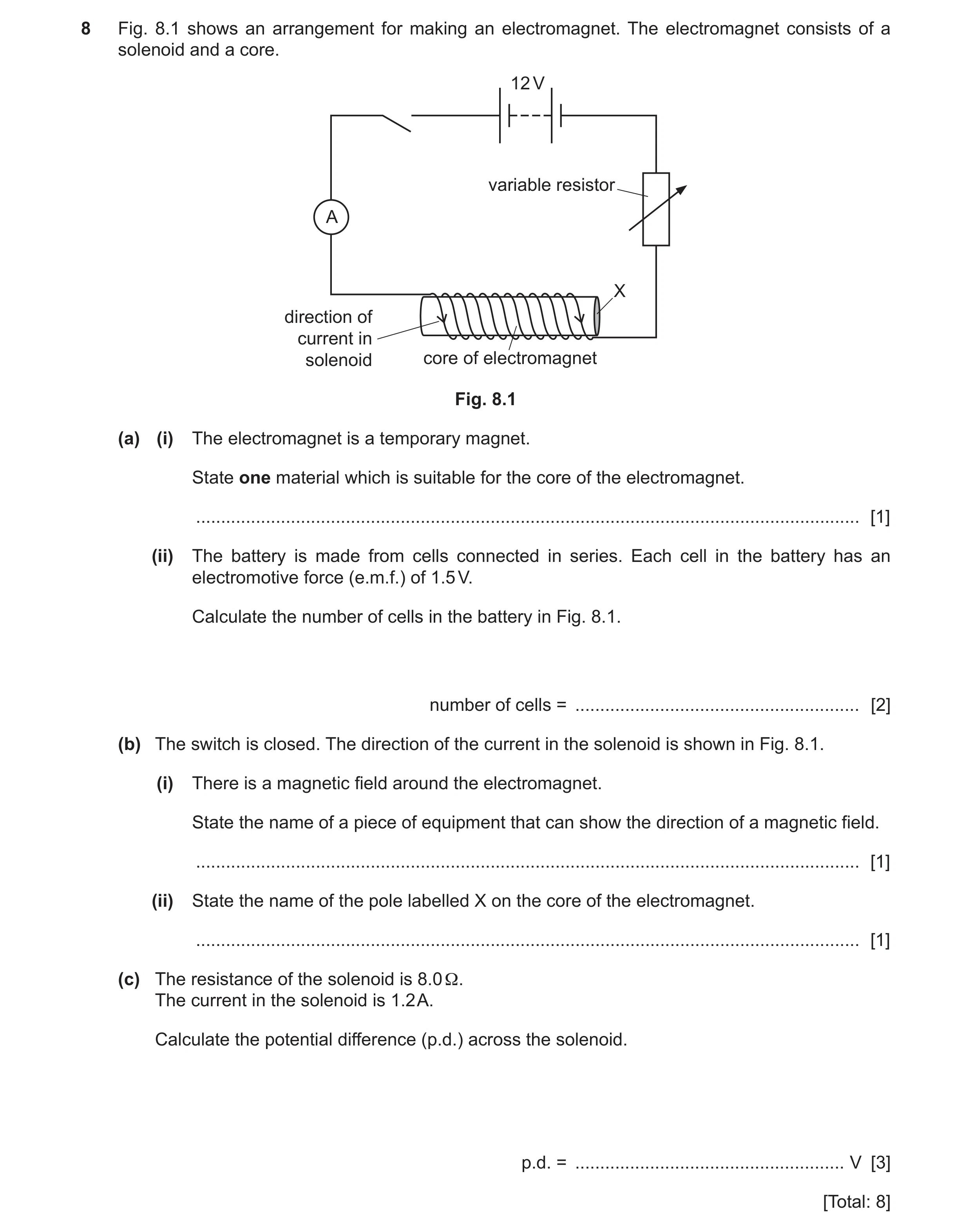
Q36 · An arrangement for making an electromagnet 0625/31 May/June 2024
8 Fig. 8.1 shows an arrangement for making an electromagnet. The electromagnet consists of a solenoid and a core. 12 V variable resistor A X direction of current in solenoid core of electromagnet Fig. 8.1 (a) (i) The electromagnet is a temporary magnet. State one material which is suitable for the core of the electromagnet. … [1] (ii) The battery is made from cells connected in series. Each cell in the battery has an electromotive force (e.m.f.) of 1.5 V. Calculate the number of cells in the battery in Fig. 8.1. number of cells = … [2] (b) The switch is closed. The direction of the current in the solenoid is shown in Fig. 8.1. (i) There is a magnetic field around the electromagnet. State the name of a piece of equipment that can show the direction of a magnetic field. … [1] (ii) State the name of the pole labelled X on the core of the electromagnet. … [1] (c) The resistance of the solenoid is 8.0 Ω. The current in the solenoid is 1.2 A. Calculate the potential difference (p.d.) across the solenoid. p.d. = … V [3] [Total: 8]
8 marks
Mark scheme: 8(a)(i) (soft) iron B1 8(a)(ii) 8 (cells) A2 (number of cells =) 12 ÷ 1.5 OR battery e.m.f ÷ e.m.f. of 1 cell (C1) 8(b)(i) (plotting) compass B1 8(b)(ii) north OR N (pole) B1 8(c) (V =) 9.6 (V) A3 (V =) 8(.0) 1.2 (C2) R = V ÷ I in any form OR (V =) I R (C1)
This question in 0625/31 May/June 2024
Q37 · Three devices: a compass, a transformer and an electromagnet 0625/33 May/June 2024
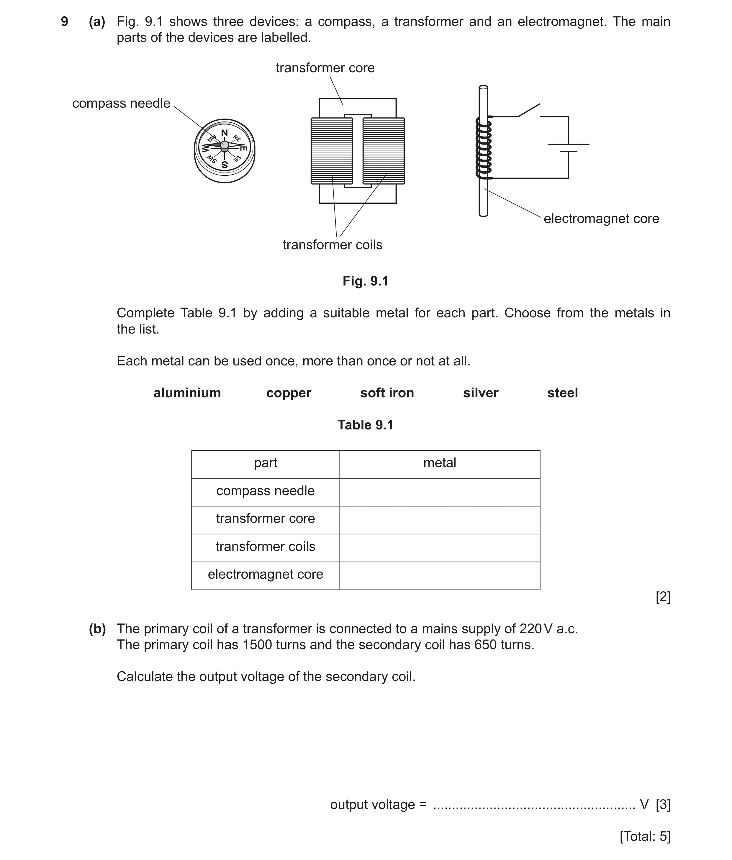
9 (a) Fig. 9.1 shows three devices: a compass, a transformer and an electromagnet. The main parts of the devices are labelled. transformer core compass needle electromagnet core transformer coils Fig. 9.1 Complete Table 9.1 by adding a suitable metal for each part. Choose from the metals in the list. Each metal can be used once, more than once or not at all. aluminium copper soft iron silver steel Table 9.1 part metal compass needle transformer core transformer coils electromagnet core [2] (b) The primary coil of a transformer is connected to a mains supply of 220 V a.c. The primary coil has 1500 turns and the secondary coil has 650 turns. Calculate the output voltage of the secondary coil. output voltage = … V [3] [Total: 5]
5 marks
Mark scheme: 9(a) part metal compass needle steel transformer core soft iron transformer coils copper / silver electromagnet core soft iron 4 correct – 2 marks 2 or 3 correct – 1 mark B2 9(b) 95 (V) A3 (Vs =) 650 / 1500 220 OR 1500 / 650 = 220 / Vs (C2) (Vp / Vs) = (Np / Ns) in any form (C1)
This question in 0625/33 May/June 2024
Q38 · Charges on an acetate strip and on a dry cloth 0625/32 Oct/Nov 2024
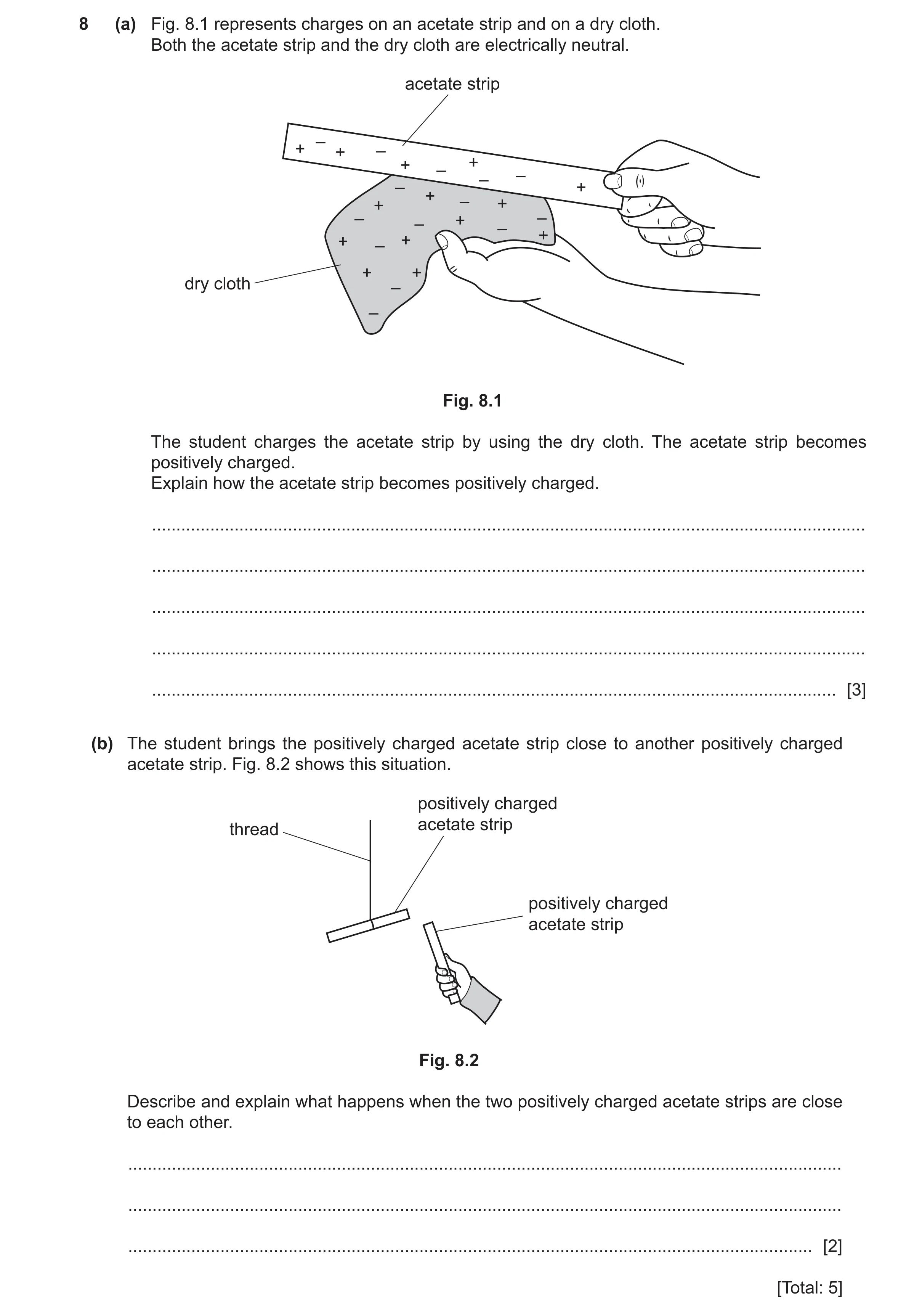
8 (a) Fig. 8.1 represents charges on an acetate strip and on a dry cloth. Both the acetate strip and the dry cloth are electrically neutral. acetate strip – + + – + – + – – – + + – + + – – + – – + + – + + + dry cloth – – Fig. 8.1 The student charges the acetate strip by using the dry cloth. The acetate strip becomes positively charged. Explain how the acetate strip becomes positively charged. … … … … … [3] (b) The student brings the positively charged acetate strip close to another positively charged acetate strip. Fig. 8.2 shows this situation. positively charged acetate strip thread positively charged acetate strip Fig. 8.2 Describe and explain what happens when the two positively charged acetate strips are close to each other. … … … [2] [Total: 5]
5 marks
Mark scheme: 8(a) friction OR rubbing (with cloth) owtte B1 electrons / negative charges move / transfer M1 from the acetate OR to the cloth A1 8(b) (strips) repel / move away (from each other) owtte M1 same charge (on both strips) / both / they have positive charge A1
This question in 0625/32 Oct/Nov 2024
Q39 · A student has six metal bars 0625/31 Oct/Nov 2025
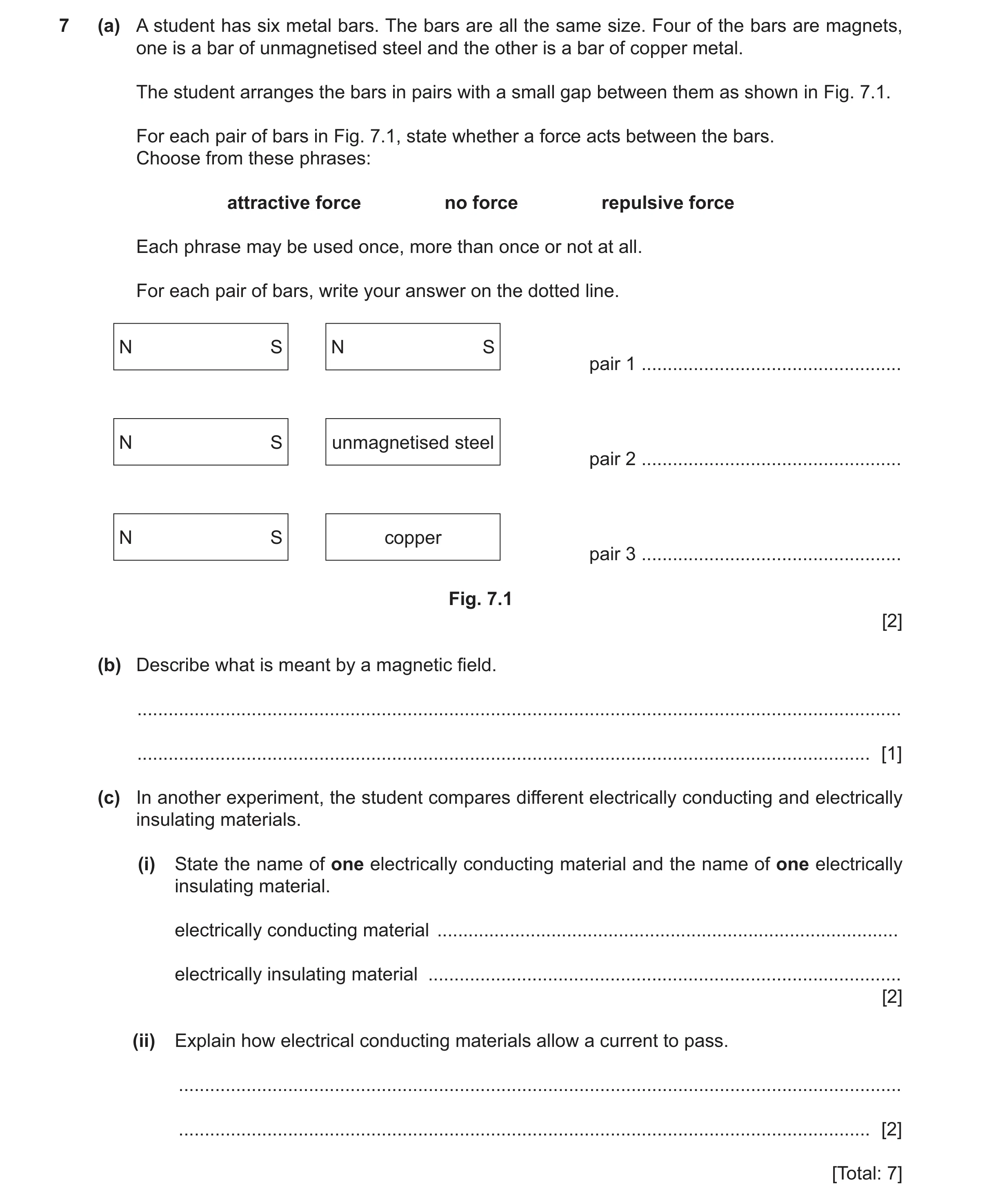
7 (a) A student has six metal bars. The bars are all the same size. Four of the bars are magnets, one is a bar of unmagnetised steel and the other is a bar of copper metal. The student arranges the bars in pairs with a small gap between them as shown in Fig. 7.1. For each pair of bars in Fig. 7.1, state whether a force acts between the bars. Choose from these phrases: attractive force no force repulsive force Each phrase may be used once, more than once or not at all. For each pair of bars, write your answer on the dotted line. N S N S pair 1 … N S unmagnetised steel pair 2 … N S copper pair 3 … Fig. 7.1 [2] (b) Describe what is meant by a magnetic field. … … [1] (c) In another experiment, the student compares different electrically conducting and electrically insulating materials. (i) State the name of one electrically conducting material and the name of one electrically insulating material. electrically conducting material … electrically insulating material … [2] (ii) Explain how electrical conducting materials allow a current to pass. … … [2] [Total: 7]
7 marks
Mark scheme: 7(a) (pair 1) attractive force B2 (pair 2) attractive force (pair 3) no force 7(b) region/area in which a magnet(ic pole) experiences a force B1 OR region/area in which a magnetic material experiences a force 7(c)(i) name of an electrically conducting material B1 name of an electrically insulating material B1 7(c)(ii) idea (they have) electrons/charges/ions M1 (that) can move (from ion to ion OR freely in conducting materials) A1
This question in 0625/31 Oct/Nov 2025
 1 / 46
 2 / 46
 3 / 46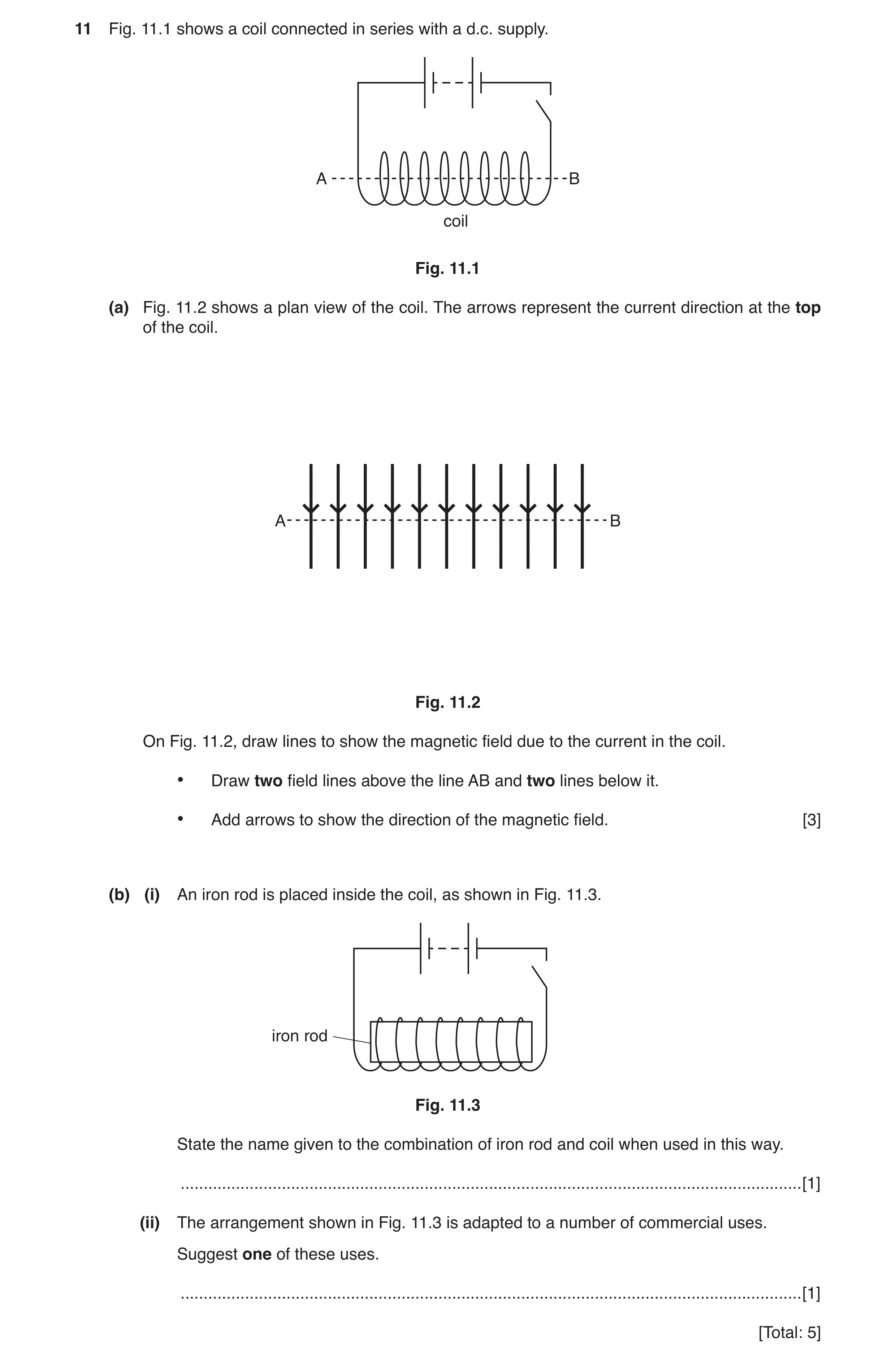
 7 / 46
 8 / 46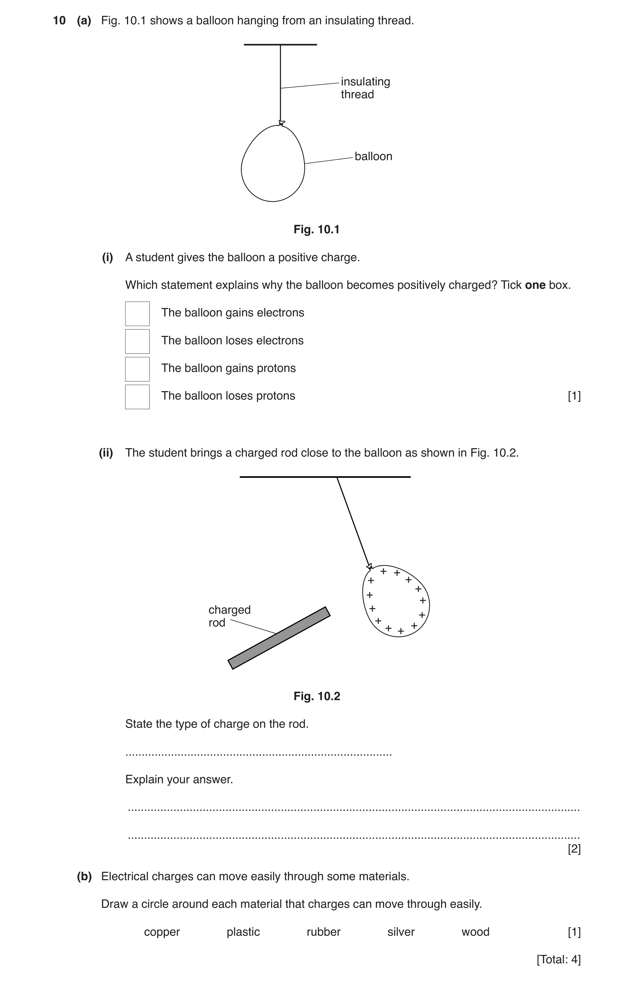
 10 / 46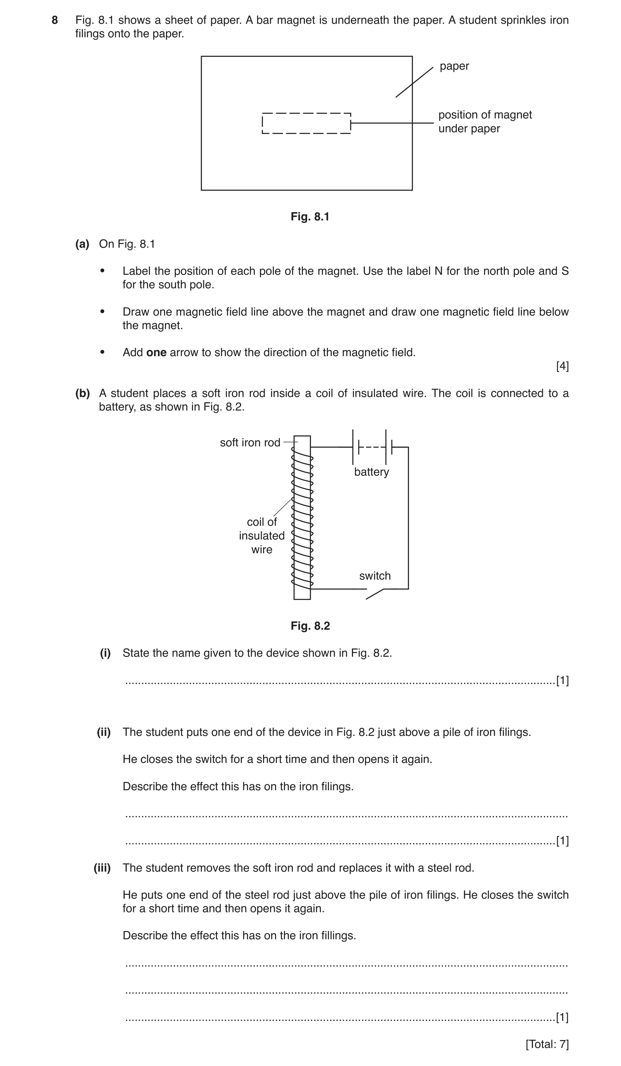
 12 / 46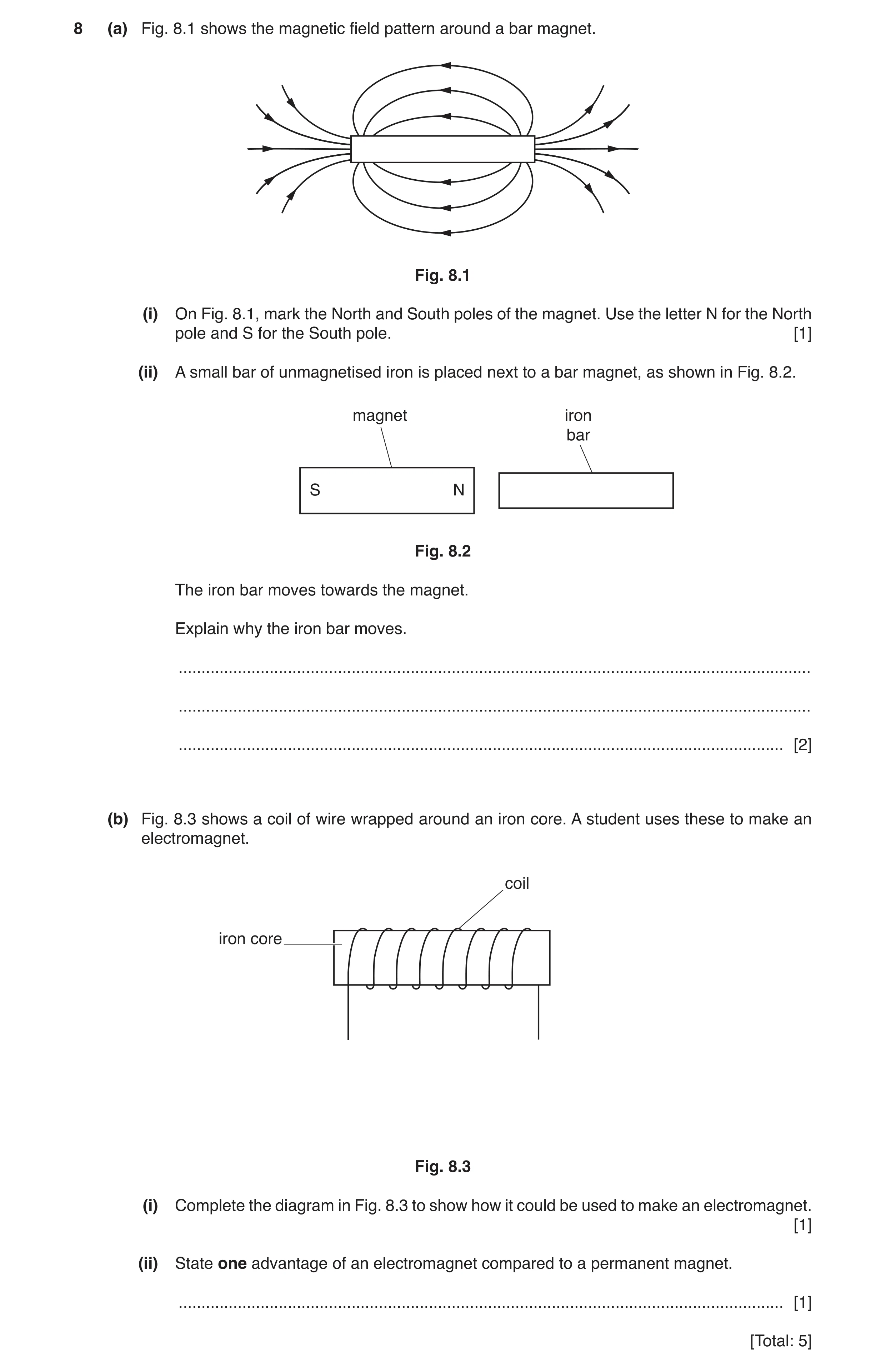
 16 / 46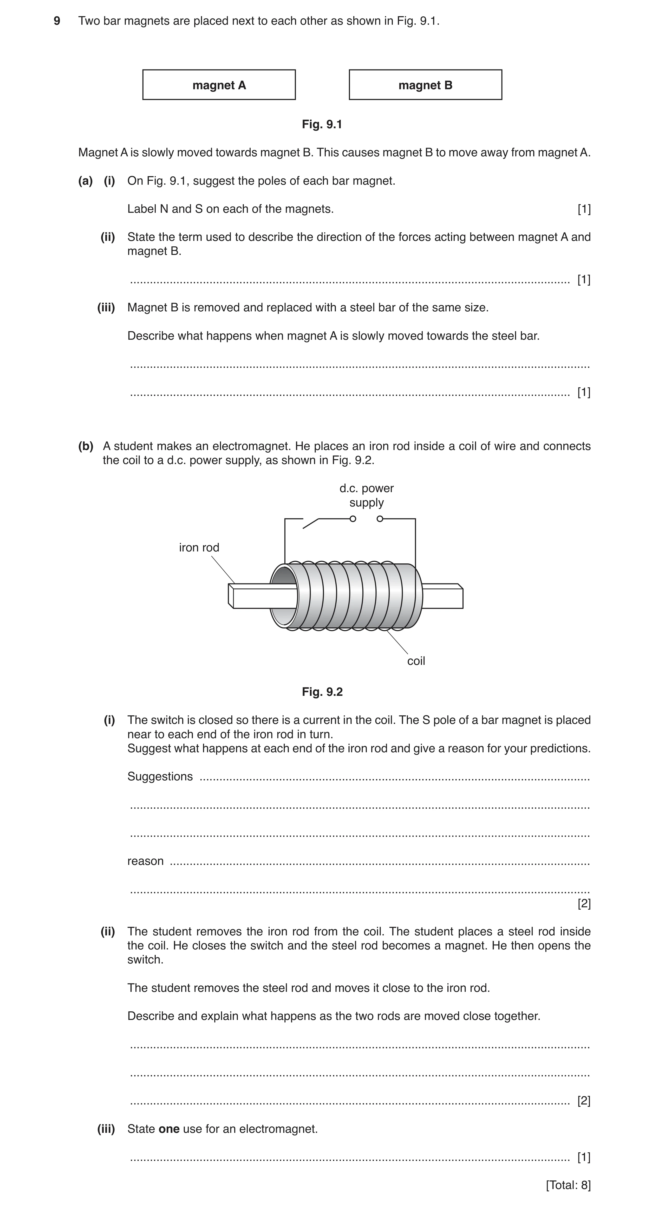
 19 / 46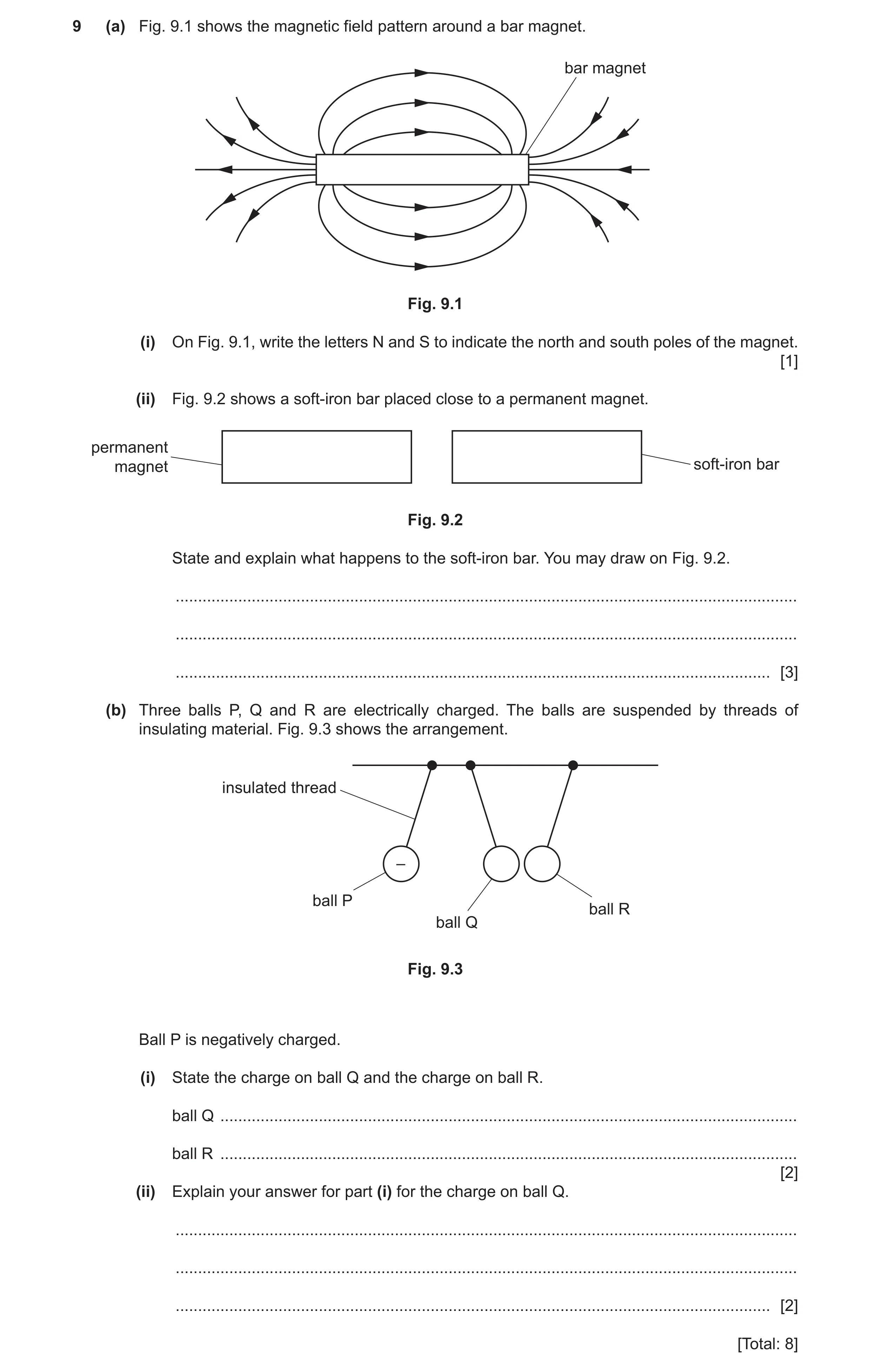
 22 / 46
 23 / 46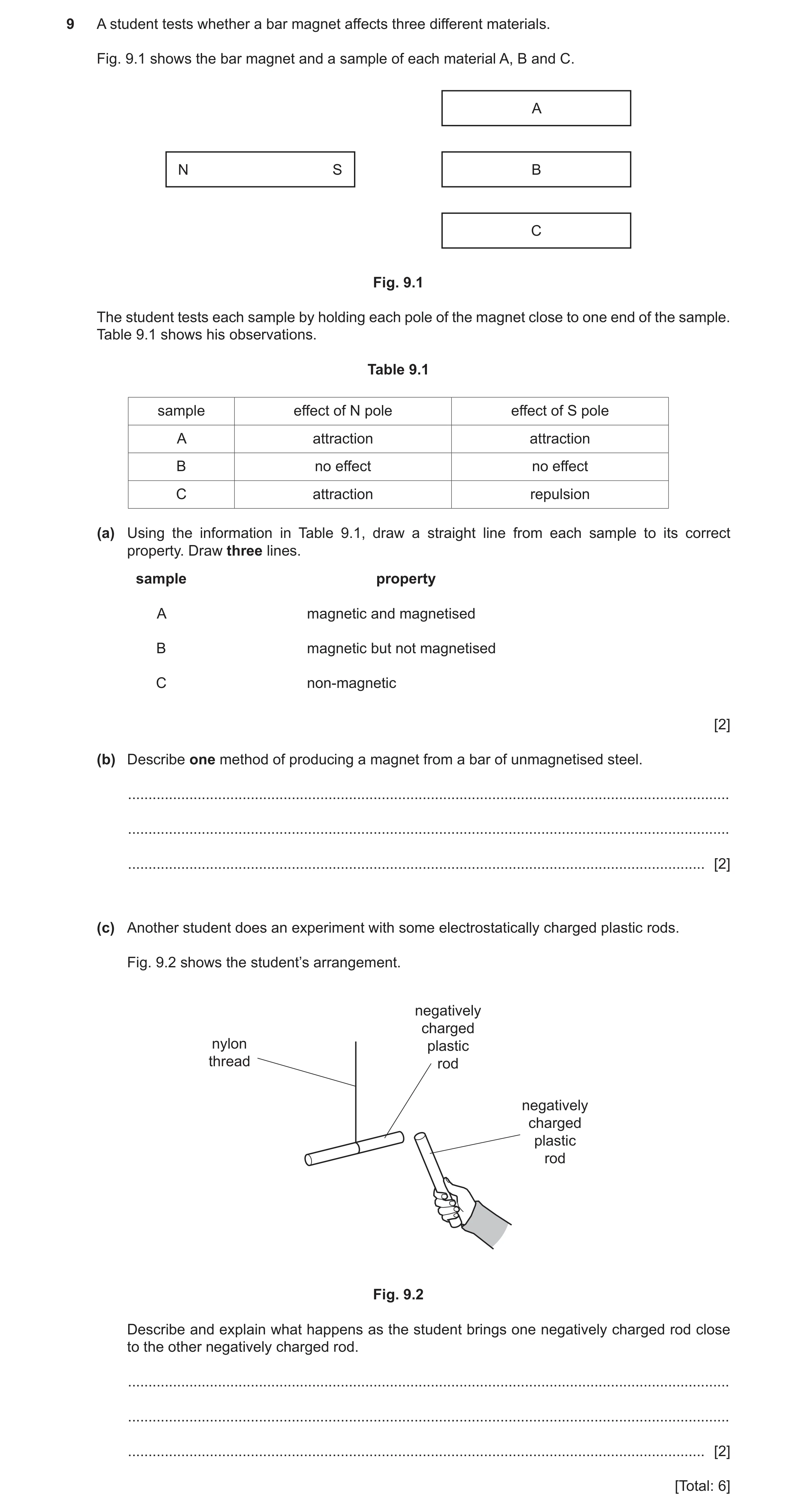
 27 / 46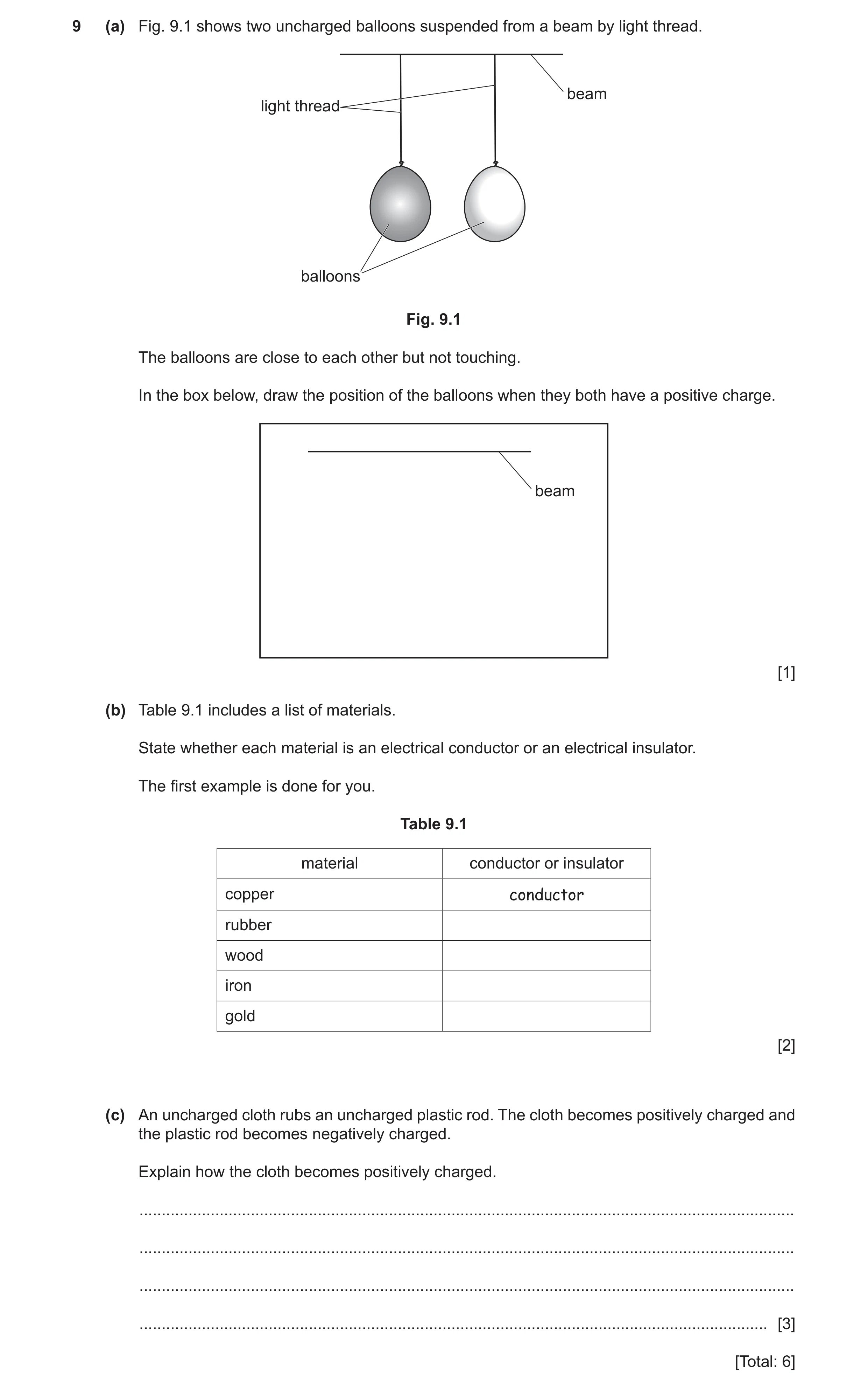
 30 / 46
 31 / 46
 32 / 46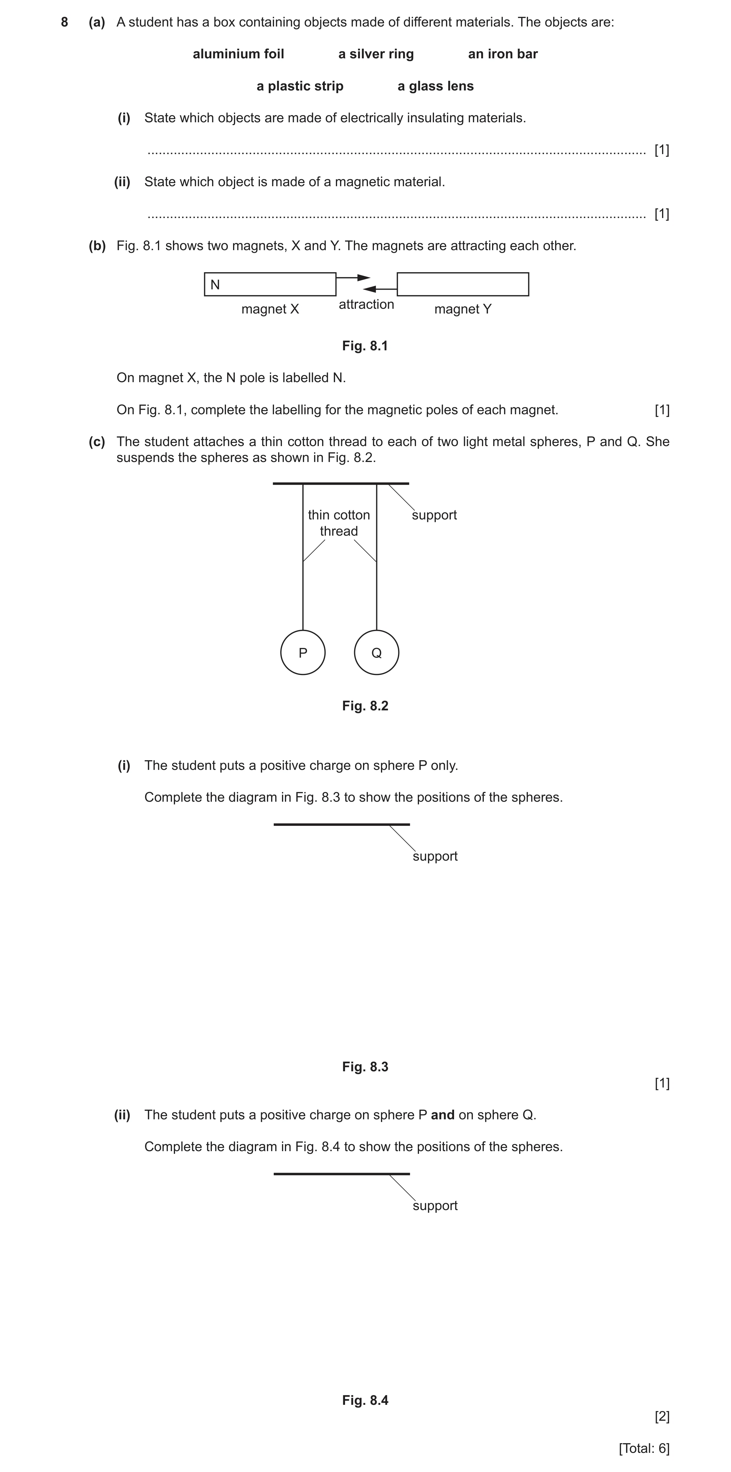
 35 / 46
 36 / 46
 37 / 46
 38 / 46
 39 / 46
 40 / 46
 41 / 46
 42 / 46
 43 / 46
 44 / 46
 45 / 46
 46 / 46
 7
7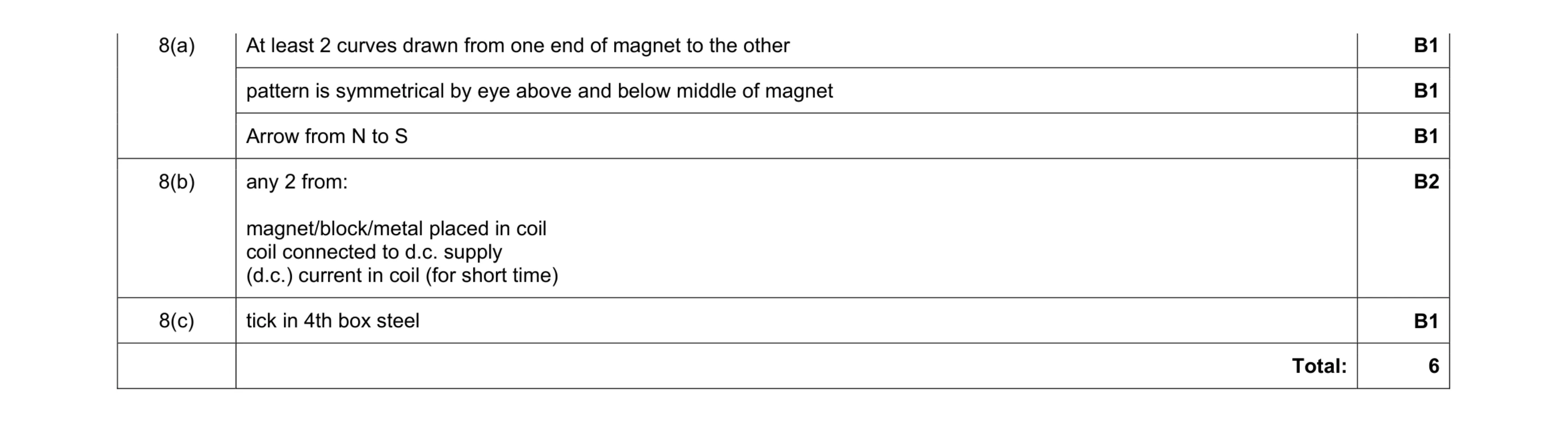 6
6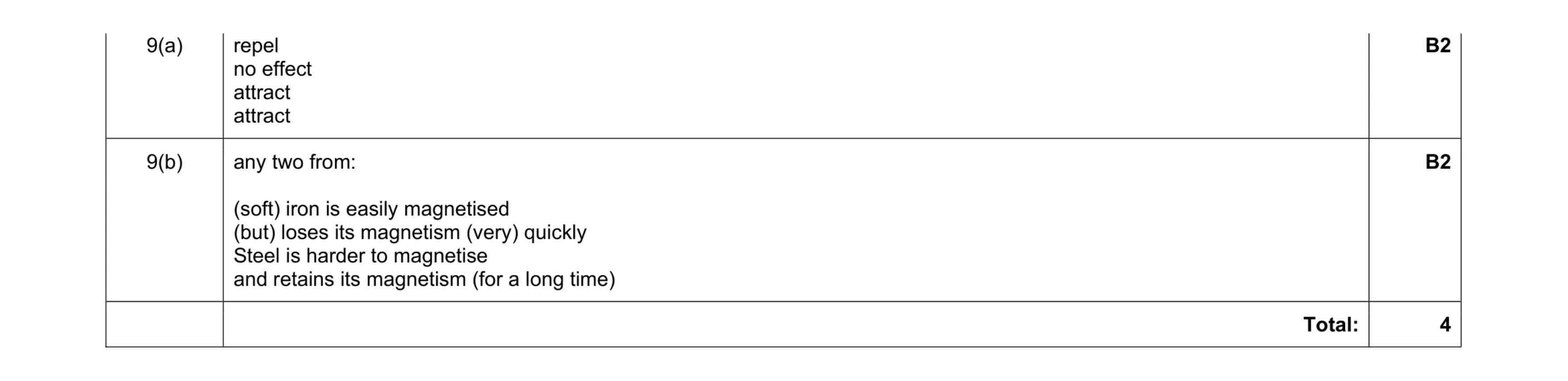 4
4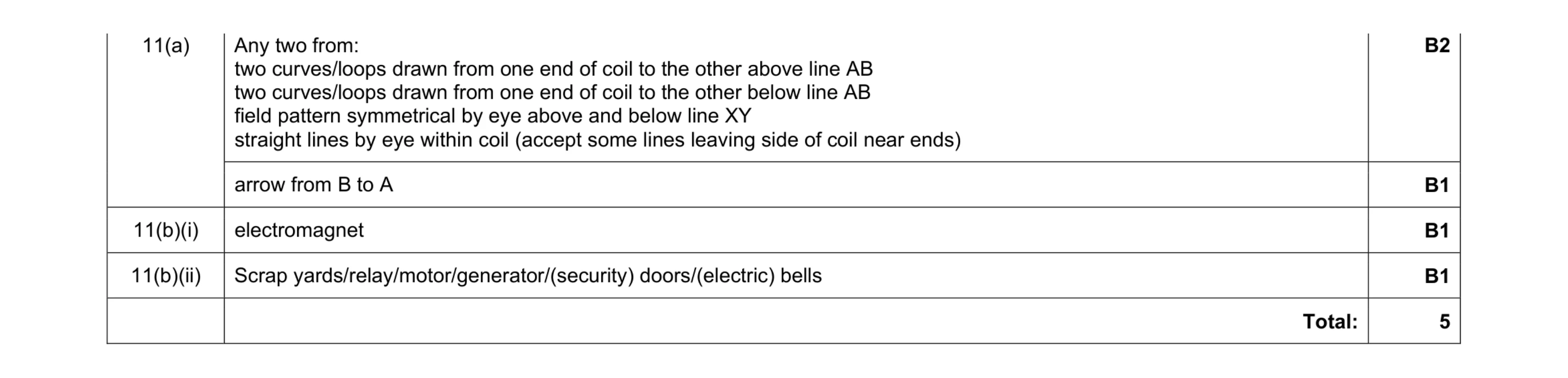 5
5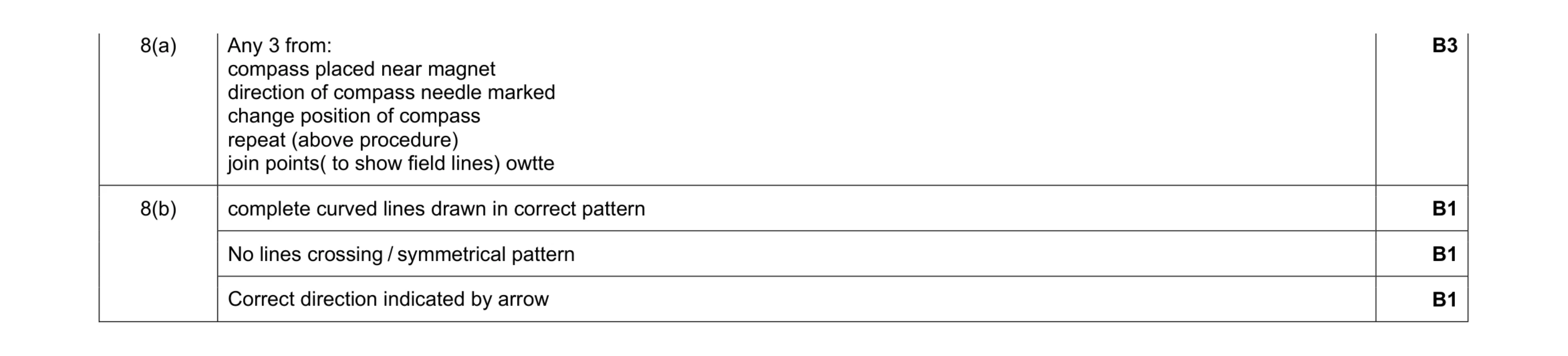 6
6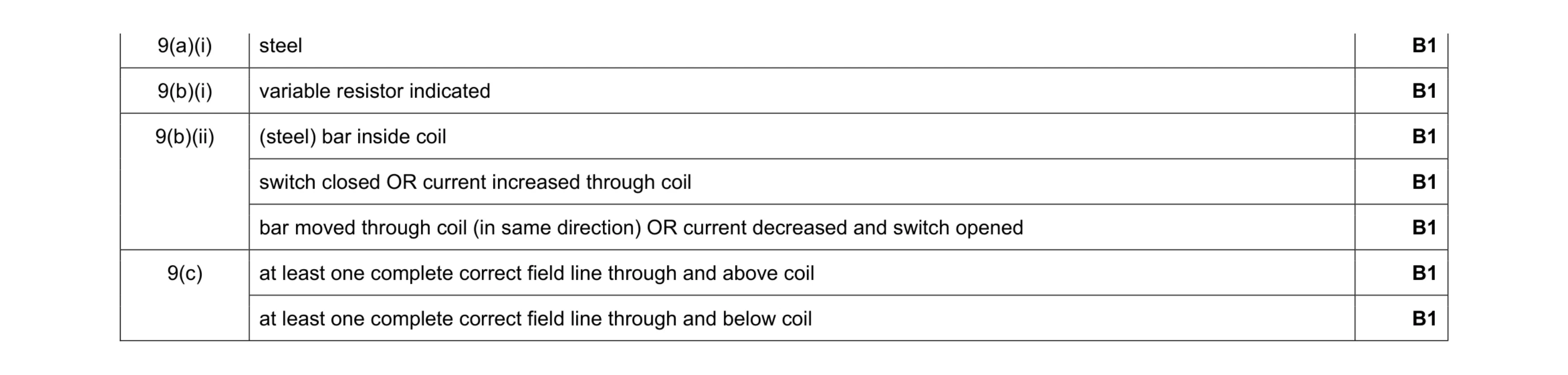 7
7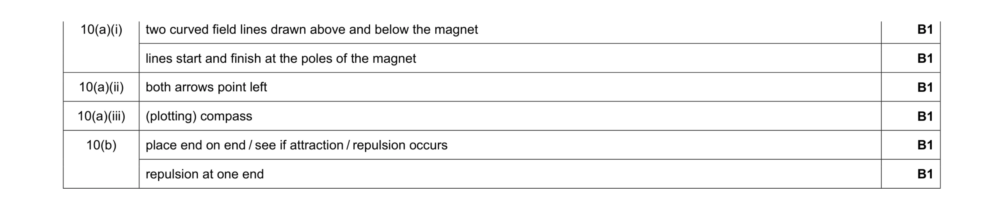 6
6 4
4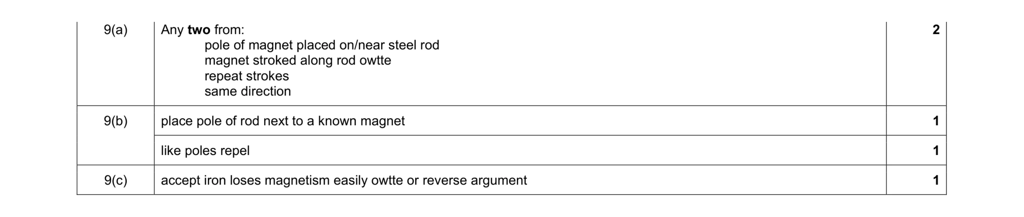 5
5 7
7 5
5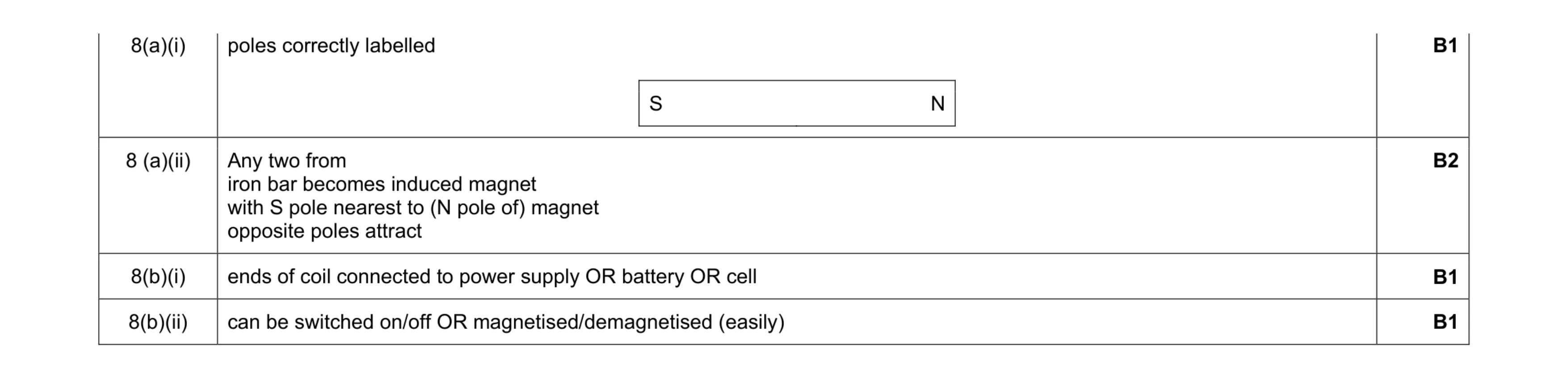 5
5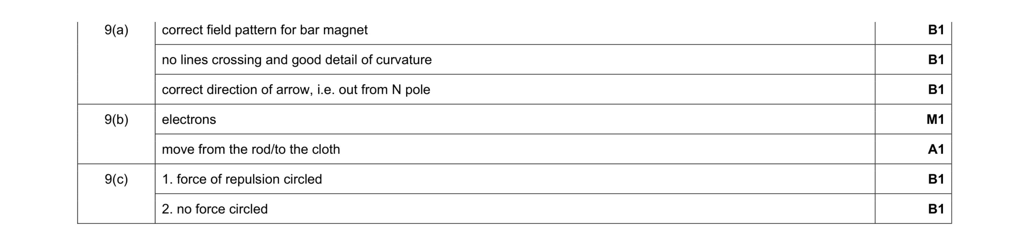 7
7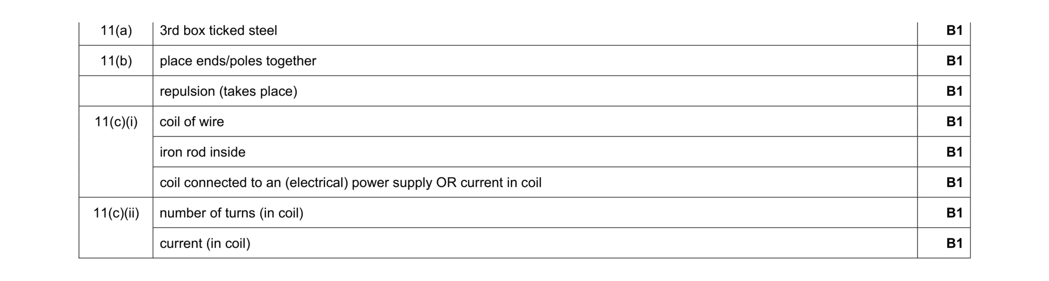 8
8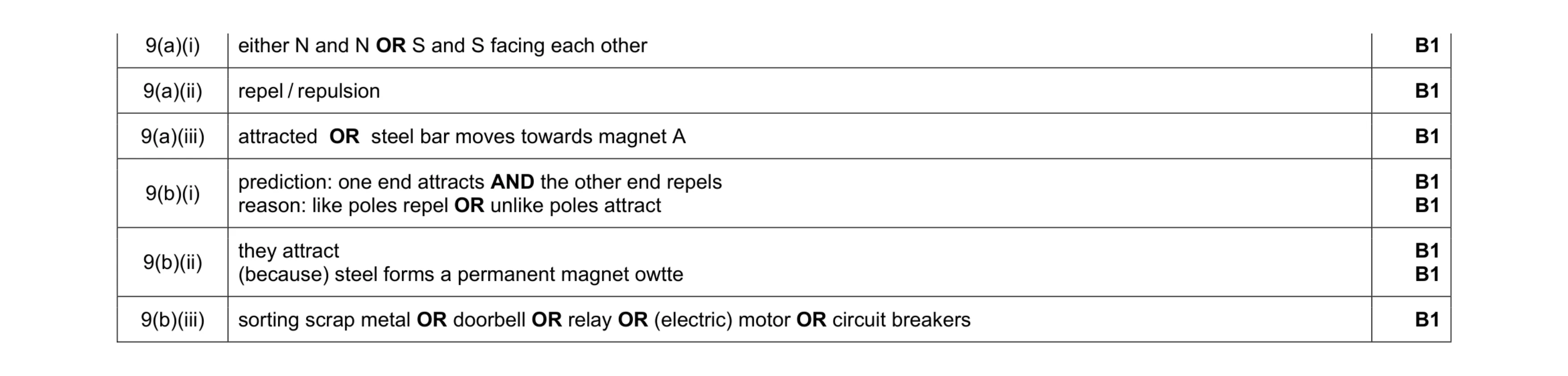 8
8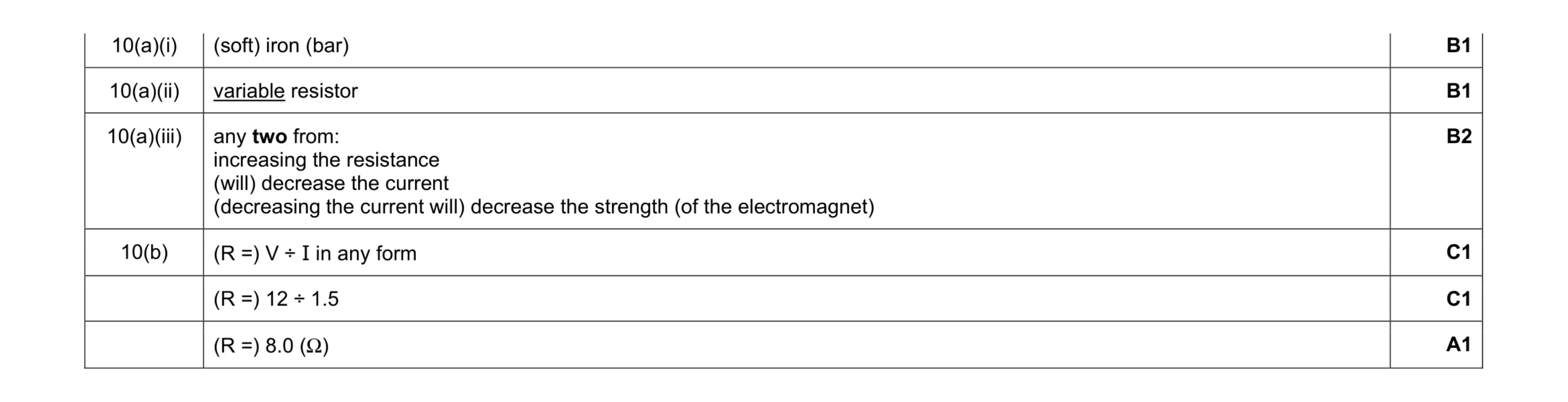 7
7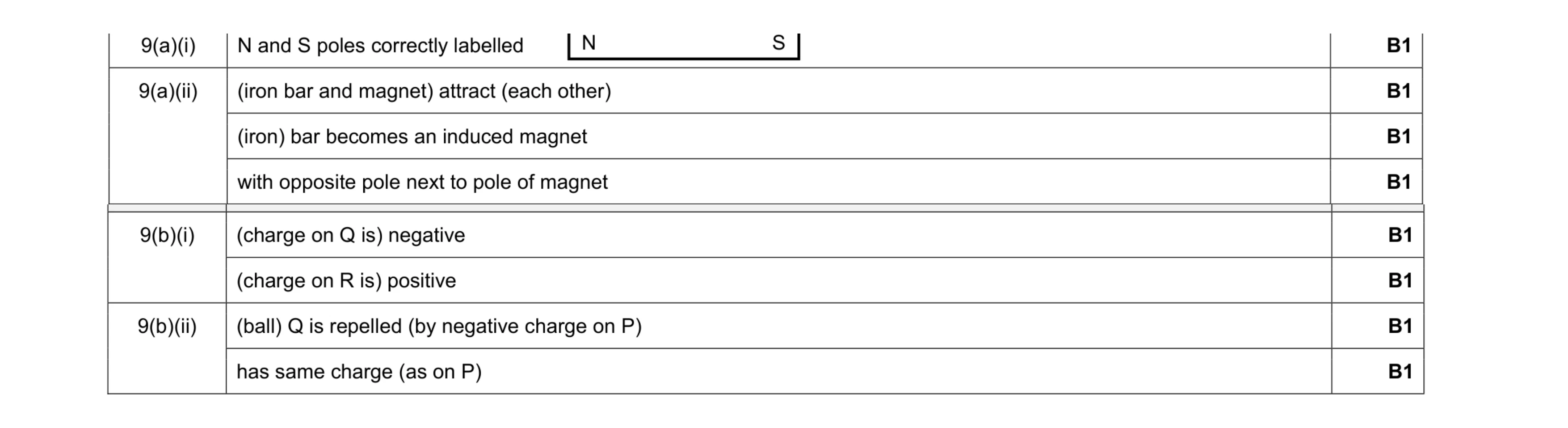 8
8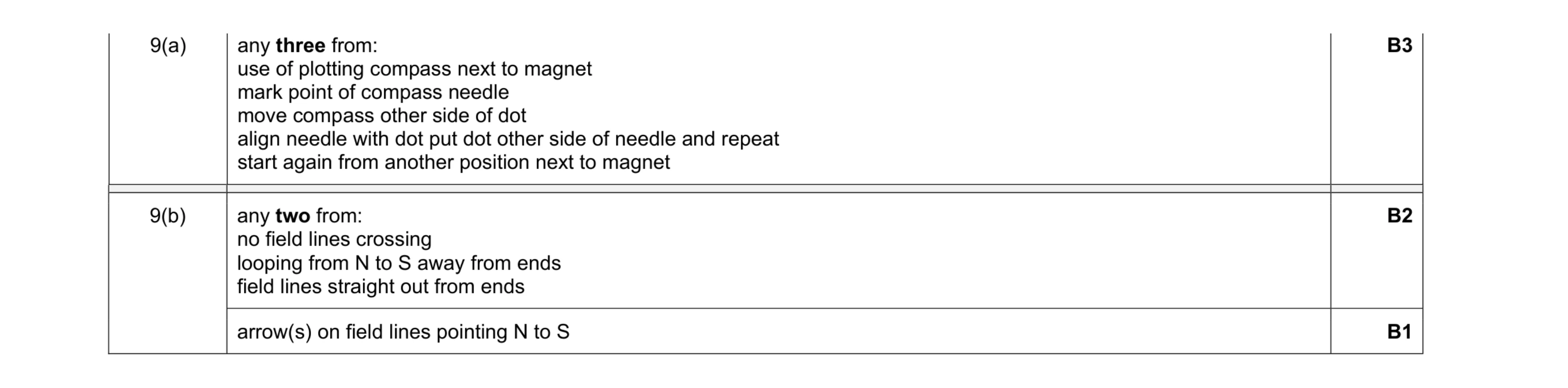 6
6 4
4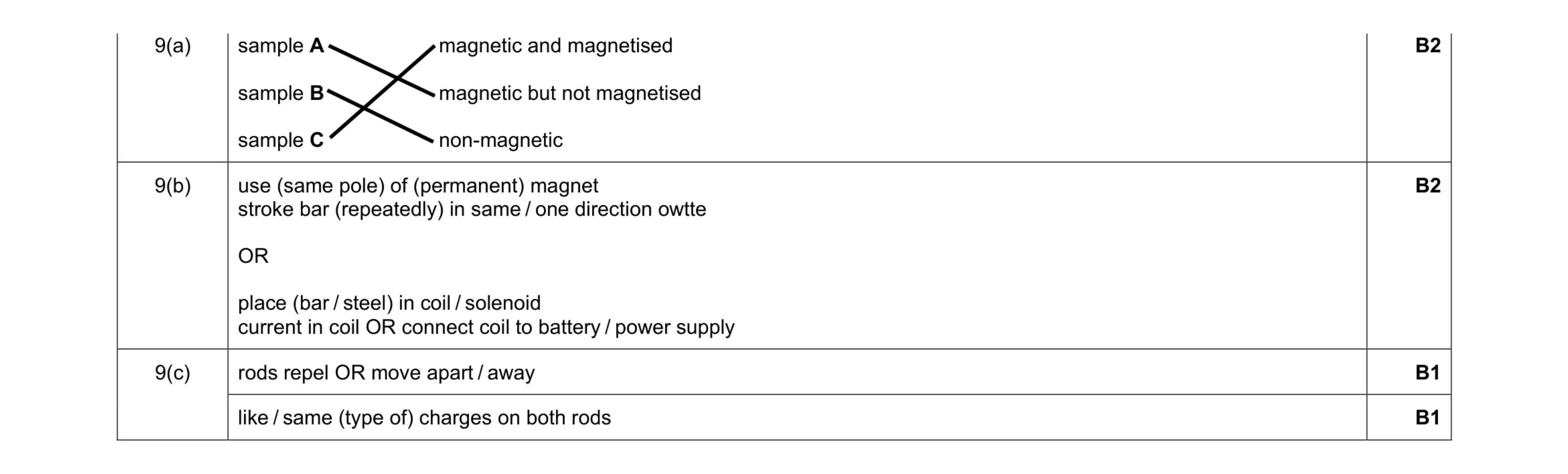 6
6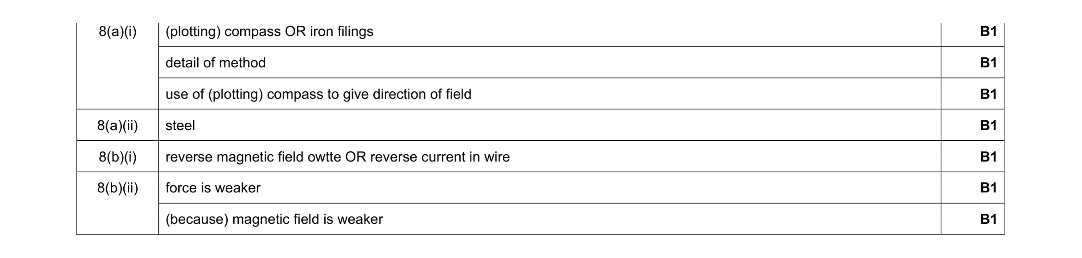 7
7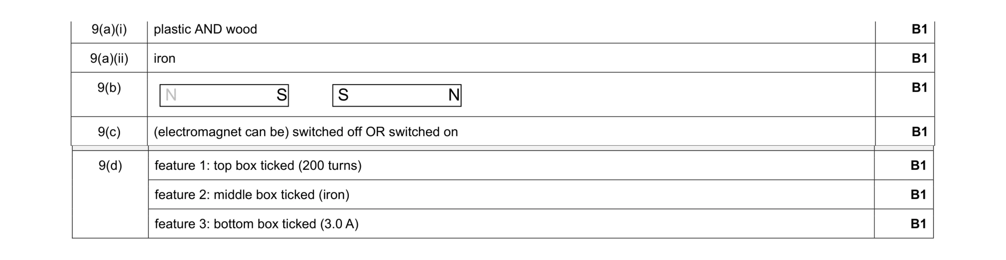 7
7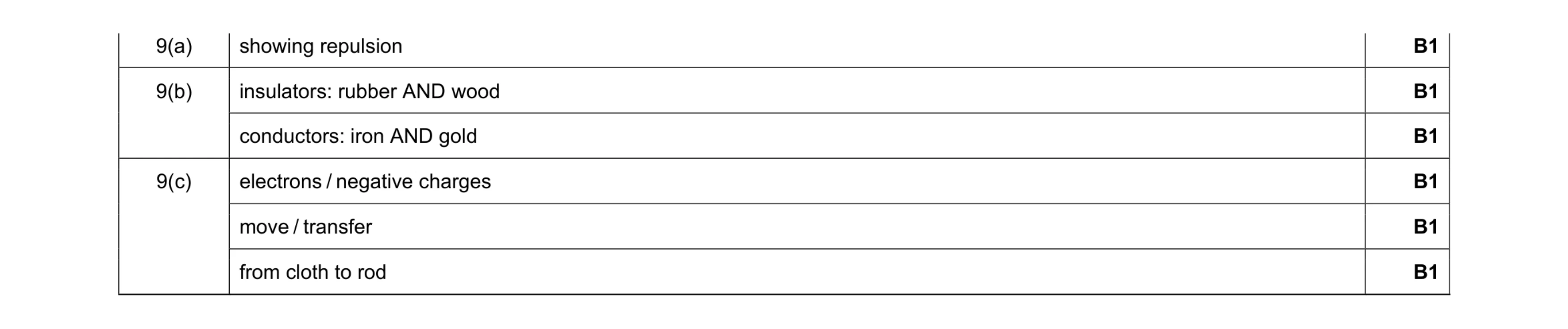 6
6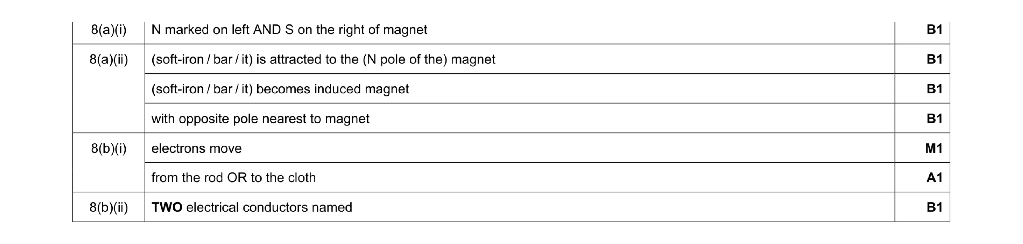 7
7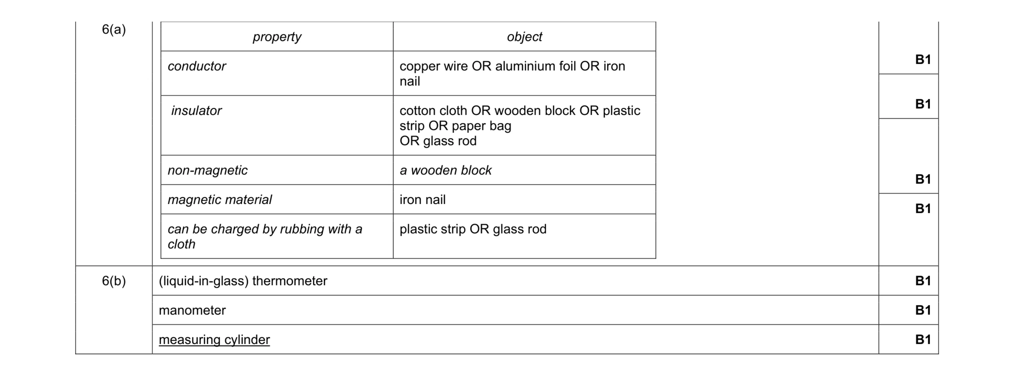 7
7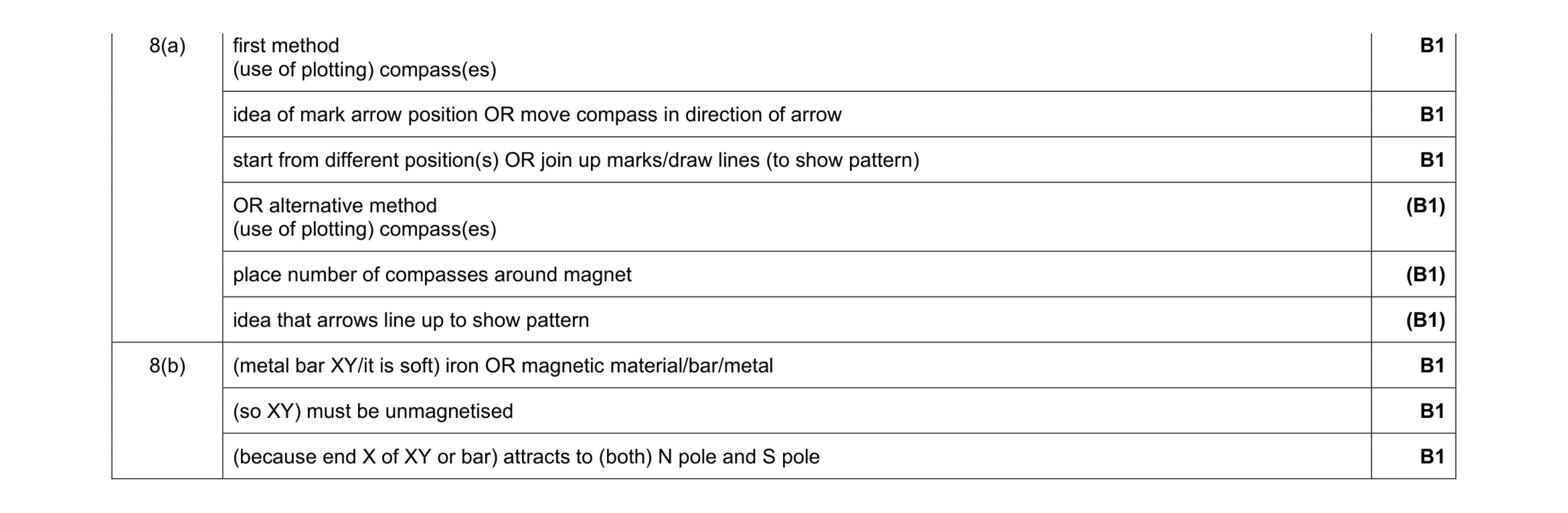 6
6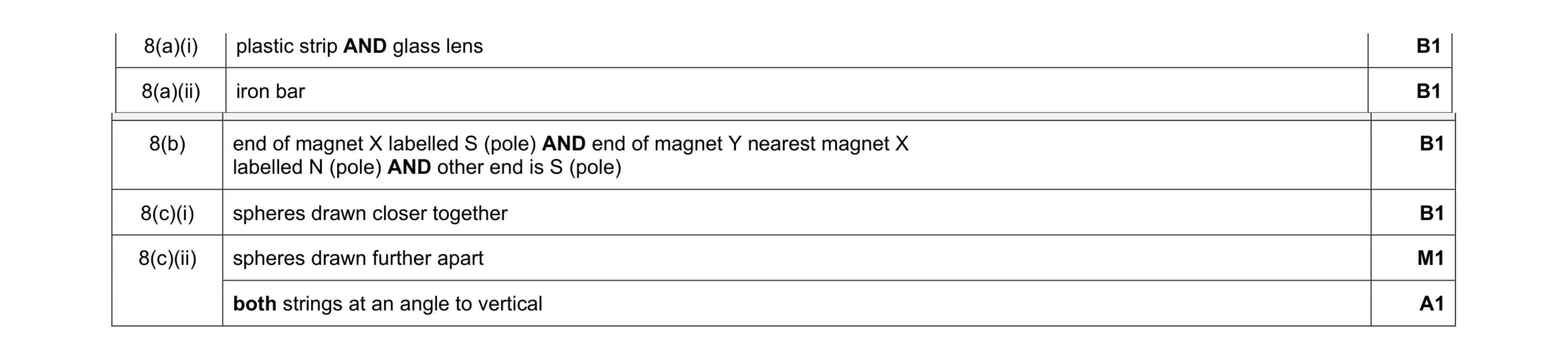 6
6 5
5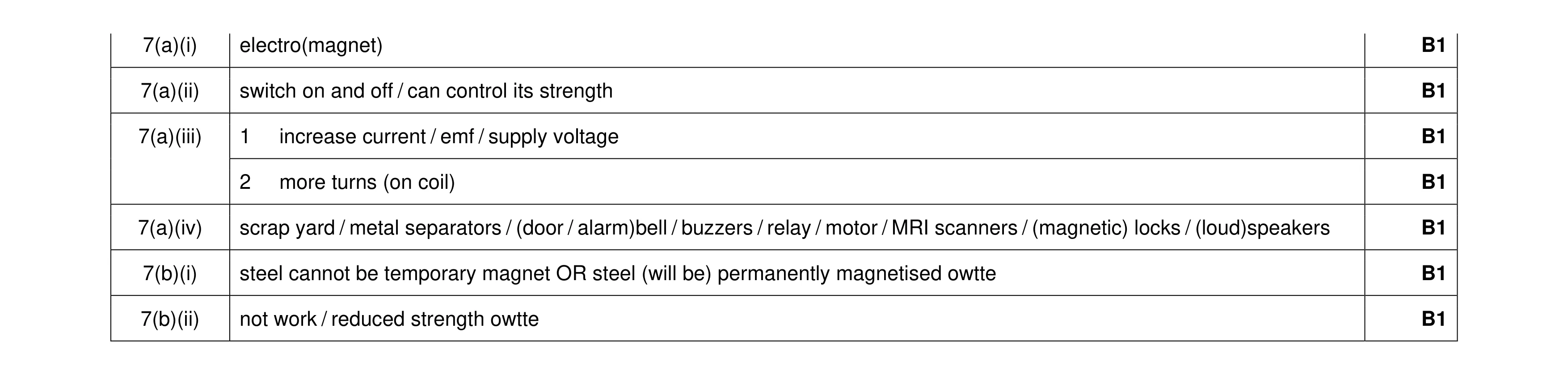 7
7 5
5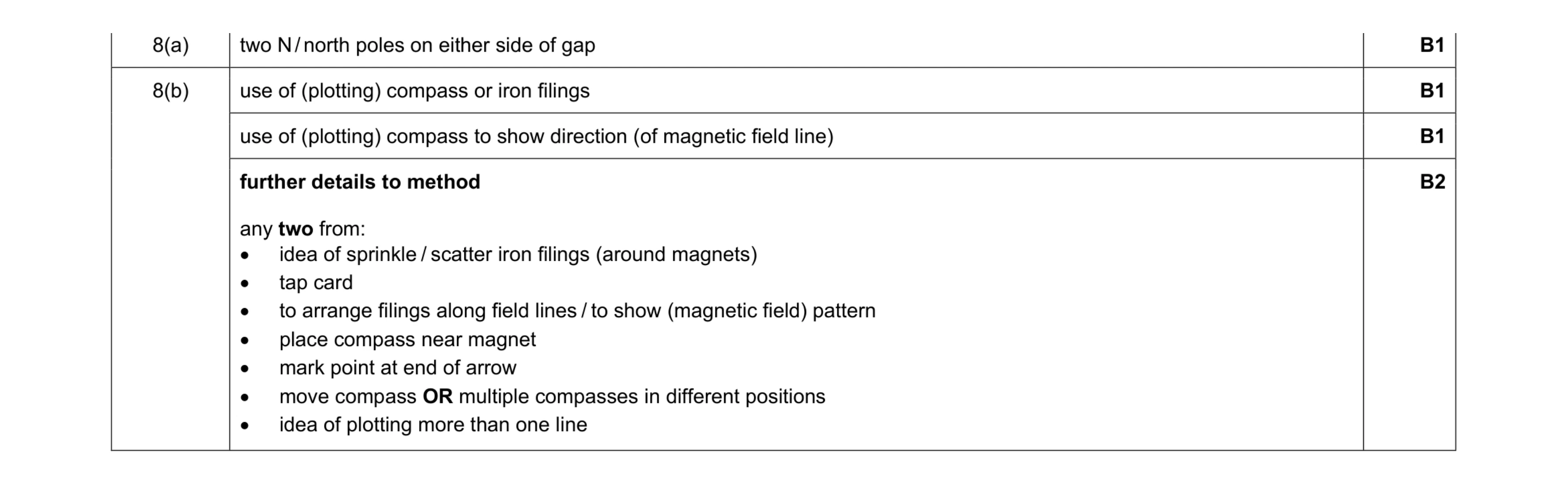 5
5 5
5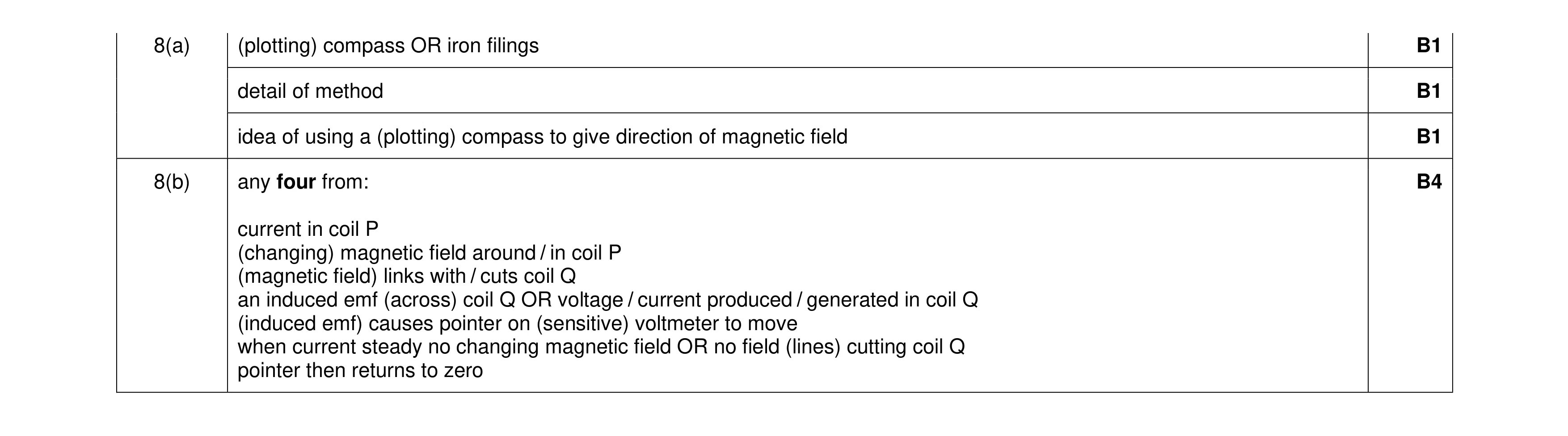 7
7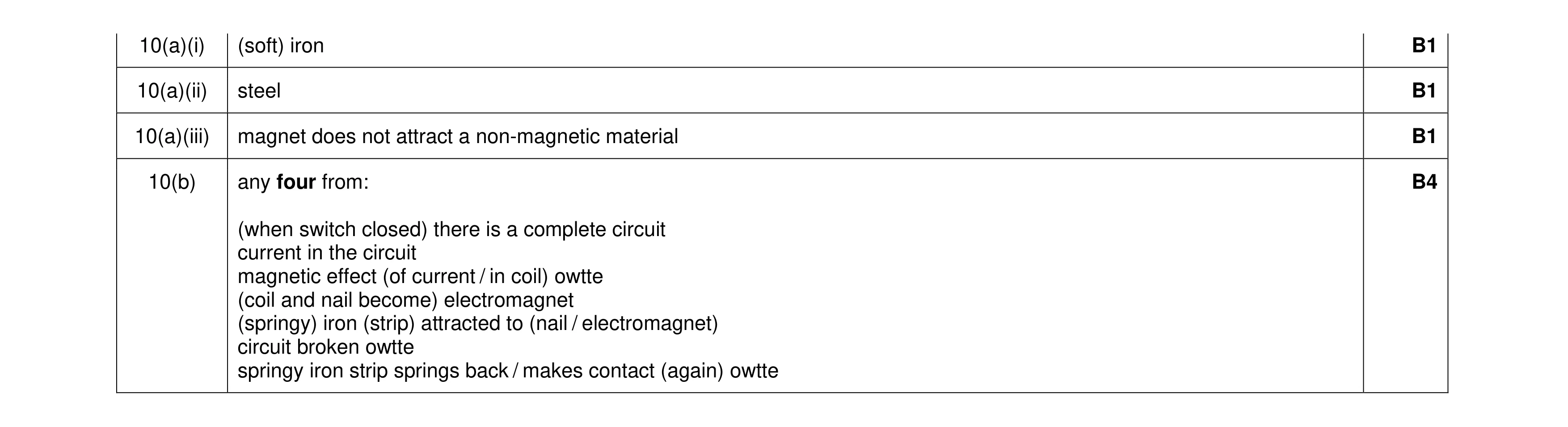 7
7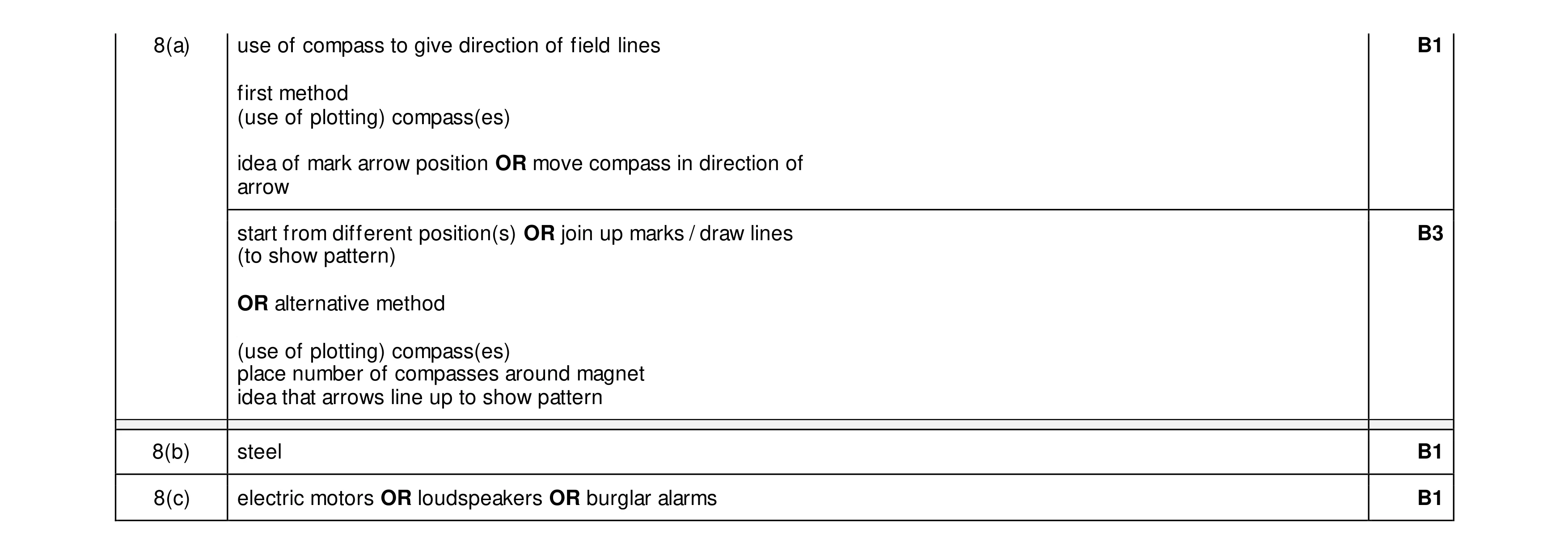 6
6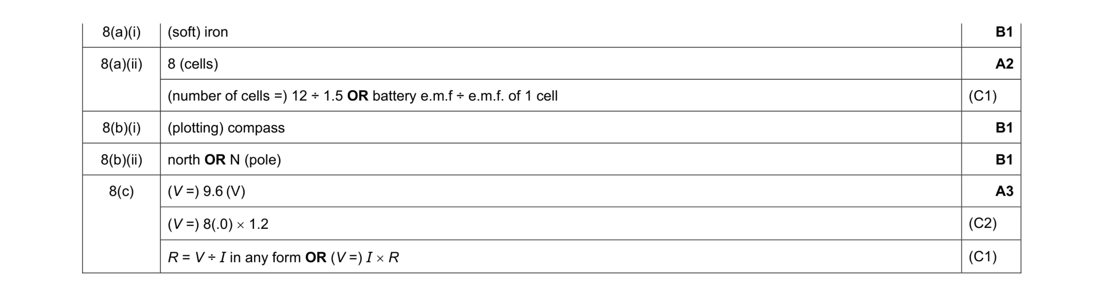 8
8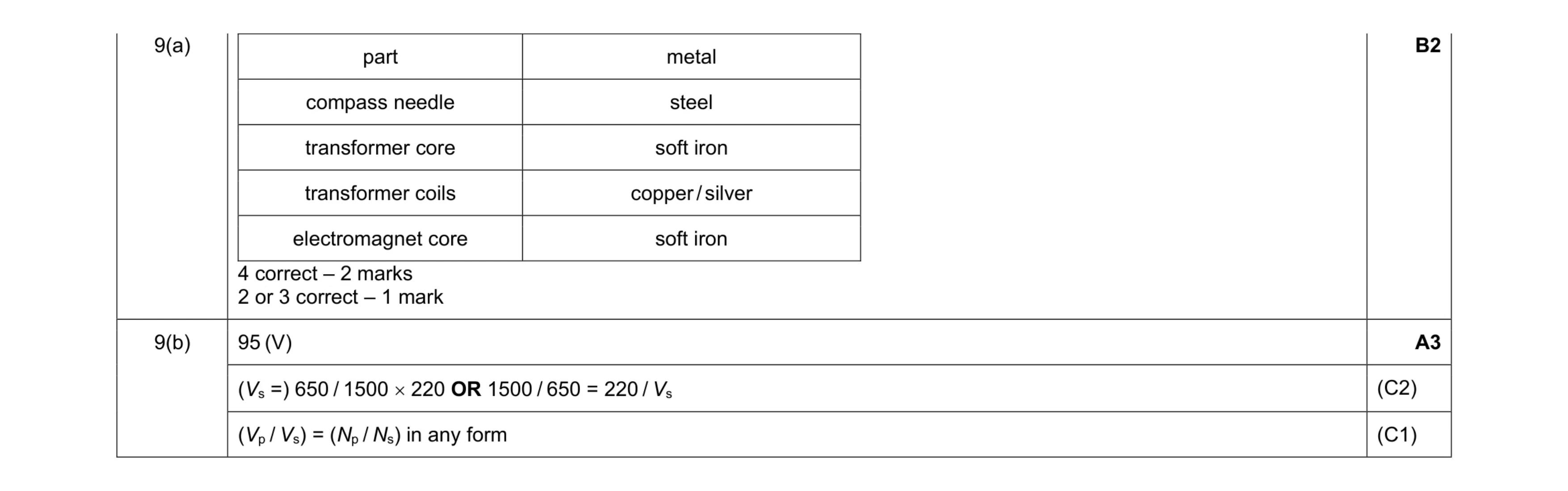 5
5 5
5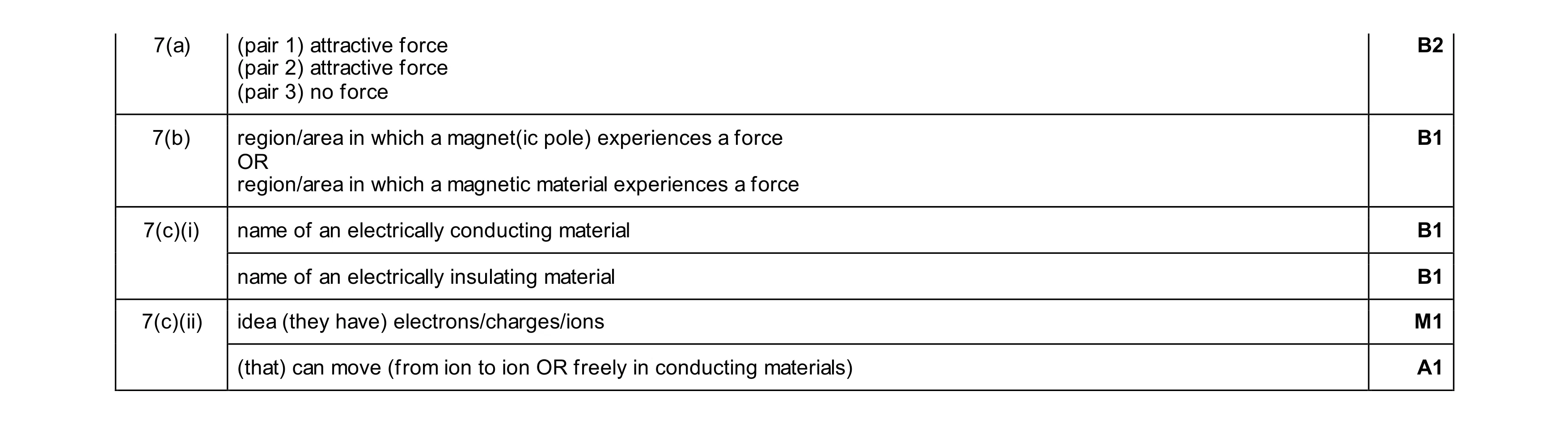 7
7