Questions as text
Q1 · A uniform beam is clamped at one end 9702/42 Feb/March 2017
3 A uniform beam is clamped at one end. A metal block of mass m is fixed to the other end of the beam causing it to bend, as shown in Fig. 3.1. beam metal block mass m equilibrium position x clamp displaced position Fig. 3.1 The block is given a small vertical displacement and then released so that it oscillates with simple harmonic motion. The acceleration a of the block is given by the expression k a =- x m where k is a constant for the beam and x is the vertical displacement of the block from its equilibrium position. (a) Explain how it can be deduced from the expression that the block moves with simple harmonic motion. … … … [2] (b) For the beam, k = 4.0 kg s–2. Show that the angular frequency ω of the oscillations is given by the expression 2 .0 ω = . m [2] (c) The initial amplitude of the oscillation of the block is 3.0 cm. Use the expression in (b) to determine the maximum kinetic energy of the oscillations. maximum kinetic energy = … J [3] (d) Over a certain interval of time, the maximum kinetic energy of the oscillations in (c) is reduced by 50%. It may be assumed that there is negligible change in the angular frequency of the oscillations. Determine the amplitude of oscillation. amplitude = … m [2] (e) Permanent magnets are now positioned so that the metal block oscillates between the poles, as shown in Fig. 3.2. metal block beam permanent magnets Fig. 3.2 The block is made to oscillate with the same initial amplitude as in (c). Use energy conservation to explain why the energy of the oscillations decreases more rapidly than in (d). … … … … … [3] [Total: 12]
12 marks
Mark scheme: 3(a) m is constant or k / m is constant and so acceleration / a proportional to displacement / x B1 negative sign shows that acceleration / a is in opposite direction to displacement / x or negative sign shows acceleration / a is towards fixed point B1 3(b) evidence of comparison to expression to a = – ω2x B1 ω2 = k/m or ω2 = 4.0/m hence ω = 2.0/√m A1 3(c) EK = ½ m ω2x0 2 or EK = ½mv 2 and v = ωx0 C1 = ½m (4.0/m) (3.0 × 10⁻²)2 C1 = 1.8 × 10⁻³ J A1 Question Answer Marks 3(d) new x0 = –3 [( ) ( 1.8 10 / 2 2 / ( / 4.0))] m m × × × or (EK ∝ x0 2 so) new x0 = –2 2 [½ 3.0 10 ( ) ] × × C1 = 2.12 × 10⁻² m A1 3(e) flux linked to block changes / flux is cut by block which induces an e.m.f. in block B1 (eddy) currents induced in block cause heating B1 thermal / heat energy comes from (kinetic / potential) energy of oscillations / block B1
This question in 9702/42 Feb/March 2017
Q2 · A bar magnet of mass 180 g is suspended from the free end of a spring, as illustrated in… 9702/41 May/June 2017
2 A bar magnet of mass 180 g is suspended from the free end of a spring, as illustrated in Fig. 2.1. spring magnet coil Fig. 2.1 The magnet hangs so that one pole is near the centre of a coil of wire. The coil is connected in series with a resistor and a switch. The switch is open. The magnet is displaced vertically and then allowed to oscillate with one pole remaining inside the coil. The other pole remains outside the coil. At time t = 0, the magnet is oscillating freely as it passes through its equilibrium position. At time t = 3.0 s, the switch in the circuit is closed. The variation with time t of the vertical displacement y of the magnet is shown in Fig. 2.2. 2.0 1.5 y / cm 1.0 0.5 0 0 1 2 3 4 5 6 7 8 9 t / s –0.5 –1.0 –1.5 –2.0 Fig. 2.2 (a) Determine, to two significant figures, the frequency of oscillation of the magnet. frequency = … Hz [2] (b) State whether the closing of the switch gives rise to light, heavy or critical damping. … [1] (c) Calculate the change in the energy ΔE of oscillation of the magnet between time t = 2.7 s and time t = 7.5 s. Explain your working. ΔE = … J [6] [Total: 9]
9 marks
Mark scheme: 2(a) e.g. period = 3 / 2.5 C1 frequency = 0.83 Hz A1 2(b) light (damping) B1 2(c) at 2.7 s, A0 = 1.5 (cm) B1 energy = ½ m × 4π2f 2A0 2 B1 = ½ × 0.18 × 4π2 × 0.832 × (1.5 × 10–2)2 = 5.51 × 10⁻⁴ (J) C1 at 7.5 s, A0 = 0.75 (cm) B1 energy = ¼ × 5.51 × 10⁻⁴ or energy = ½ × 0.18 × 4π2 × 0.832 × (0.75 × 10–2)2 C1 energy = 1.38 × 10⁻⁴ (J) change = (5.51 × 10⁻⁴ – 1.38 × 10⁻⁴) = 4.13 J A1
This question in 9702/41 May/June 2017
Q3 · A bar magnet of mass 250 g is suspended from the free end of a spring, as illustrated in… 9702/42 May/June 2017
3 A bar magnet of mass 250 g is suspended from the free end of a spring, as illustrated in Fig. 3.1. spring magnet coil Fig. 3.1 The magnet hangs so that one pole is near the centre of a coil of wire. The coil is connected in series with a resistor and a switch. The switch is open. The magnet is displaced vertically and then allowed to oscillate with one pole remaining inside the coil. The other pole remains outside the coil. At time t = 0, the magnet is oscillating freely as it passes through its equilibrium position. At time t = 6.0 s, the switch in the circuit is closed. The variation with time t of the vertical displacement y of the magnet is shown in Fig. 3.2. 2.0 1.5 y / cm 1.0 0.5 0 0 2 4 6 8 10 12 14 16 t / s –0.5 –1.0 –1.5 –2.0 Fig. 3.2 (a) For the oscillating magnet, use data from Fig. 3.2 to calculate, to two significant figures, (i) the frequency f, f = … Hz [2] (ii) the energy of the oscillations during the time t = 0 to time t = 6.0 s. energy = … J [3] (b) (i) State Faraday’s law of electromagnetic induction. … … … … [2] (ii) Use Faraday’s law and energy conservation to explain why the amplitude of the oscillations of the magnet reduces after time t = 6.0 s. … … … … … … [3] [Total: 10]
10 marks
Mark scheme: 3(a)(i) e.g. period = 6 / 2.5 C1 frequency = 0.42 Hz A1 3(a)(ii) energy = ½ m × 4π2f 2y0 2 C1 = ½ × 0.25 × 4π2 × 0.422 × (1.5 × 10–2)2 C1 = 2.0 × 10⁻⁴ J A1 3(b)(i) (induced) e.m.f. proportional to rate of M1 change of magnetic flux (linkage) or cutting of magnetic flux A1 3(b)(ii) coil cuts flux/field (of moving magnet) inducing e.m.f. in coil B1 (induced) current in resistor causes heating (effect) M1 thermal energy/heat derived from energy of oscillations (of magnet) A1
This question in 9702/42 May/June 2017
Q4 · A bar magnet of mass 180 g is suspended from the free end of a spring, as illustrated in… 9702/43 May/June 2017
2 A bar magnet of mass 180 g is suspended from the free end of a spring, as illustrated in Fig. 2.1. spring magnet coil Fig. 2.1 The magnet hangs so that one pole is near the centre of a coil of wire. The coil is connected in series with a resistor and a switch. The switch is open. The magnet is displaced vertically and then allowed to oscillate with one pole remaining inside the coil. The other pole remains outside the coil. At time t = 0, the magnet is oscillating freely as it passes through its equilibrium position. At time t = 3.0 s, the switch in the circuit is closed. The variation with time t of the vertical displacement y of the magnet is shown in Fig. 2.2. 2.0 1.5 y / cm 1.0 0.5 0 0 1 2 3 4 5 6 7 8 9 t / s –0.5 –1.0 –1.5 –2.0 Fig. 2.2 (a) Determine, to two significant figures, the frequency of oscillation of the magnet. frequency = … Hz [2] (b) State whether the closing of the switch gives rise to light, heavy or critical damping. … [1] (c) Calculate the change in the energy ΔE of oscillation of the magnet between time t = 2.7 s and time t = 7.5 s. Explain your working. ΔE = … J [6] [Total: 9]
9 marks
Mark scheme: 2(a) e.g. period = 3 / 2.5 C1 frequency = 0.83 Hz A1 2(b) light (damping) B1 2(c) at 2.7 s, A0 = 1.5 (cm) B1 energy = ½ m × 4π2f 2A0 2 B1 = ½ × 0.18 × 4π2 × 0.832 × (1.5 × 10–2)2 = 5.51 × 10⁻⁴ (J) C1 at 7.5 s, A0 = 0.75 (cm) B1 energy = ¼ × 5.51 × 10⁻⁴ or energy = ½ × 0.18 × 4π2 × 0.832 × (0.75 × 10–2)2 C1 energy = 1.38 × 10⁻⁴ (J) change = (5.51 × 10⁻⁴ – 1.38 × 10⁻⁴) = 4.13 J A1
This question in 9702/43 May/June 2017
Q5 · State, by reference to simple harmonic motion, what is meant by angular frequency 9702/41 Oct/Nov 2017
2 (a) State, by reference to simple harmonic motion, what is meant by angular frequency. … … [1] (b) A thin metal strip is clamped at one end so that it is horizontal. A load of mass M is attached to its free end. The load causes a displacement s of the end of the strip, as shown in Fig. 2.1. clamp s metal strip load mass M Fig. 2.1 The load is displaced vertically and then released. The load oscillates. The variation with the acceleration a of the displacement s of the load is shown in Fig. 2.2. 4.0 s / cm 3.0 2.0 1.0 –1.0 –0.8 –0.6 –0.4 –0.2 00 0.2 0.4 0.6 0.8 1.0 a / m s–2 Fig. 2.2 (i) Use Fig. 2.2 to determine 1. the displacement of the load before it is made to oscillate, displacement = … cm 2. the amplitude of the oscillations of the load. amplitude = … cm [2] (ii) Show that the load is undergoing simple harmonic motion. … … … … [3] (iii) Calculate the frequency of oscillation of the load. frequency = … Hz [3] [Total: 9]
9 marks
Mark scheme: 2(a) B1 2(b)(i) 1. displacement = 2.0 cm A1 2. amplitude = 1.5 cm A1 2(b)(ii) reference to displacement of oscillations or displacement from equilibrium position or displacement from 2.0 cm B1 straight line indicates acceleration ∝ displacement B1 negative gradient shows acceleration and displacement are in opposite directions B1 Question Answer Marks 2(b)(iii) ω2 = (–)1 / gradient or ω2 = (–)∆a / ∆s or a = (–)ω2x and correct value of x C1 = e.g. (1.8 / 0.03) or (0.9 / 0.015) or (1.2 / 0.02) etc. or 0.9 = ω2 × 0.015 = 60 C1 f = √60 / 2π = 1.2 Hz A1
This question in 9702/41 Oct/Nov 2017
Question 6 9702/42 Oct/Nov 2017
3 (a) (i) Define the radian. … … … [2] (ii) State, by reference to simple harmonic motion, what is meant by angular frequency. … … [1] (b) A thin metal strip, clamped horizontally at one end, has a load of mass M attached to its free end, as shown in Fig. 3.1. clamp L x oscillation of load metal strip load mass M Fig. 3.1 The metal strip bends, as shown in Fig. 3.1. When the free end of the strip is displaced vertically and then released, the mass oscillates in a vertical plane. Theory predicts that the variation of the acceleration a of the oscillating load with the displacement x from its equilibrium position is given by c a = – 3 x c ML m where L is the effective length of the metal strip and c is a positive constant. (i) Explain how the expression shows that the load is undergoing simple harmonic motion. … … … … [2] (ii) For a metal strip of length L = 65 cm and a load of mass M = 240 g, the frequency of oscillation is 3.2 Hz. Calculate the constant c. c = … kg m3 s–2 [3] [Total: 8]
8 marks
Mark scheme: 3(a)(i) angle (subtended) where arc (length) is equal to radius M1 (angle subtended) at the centre of a circle A1 3(a)(ii) angular frequency = 2π × frequency or 2π / period B1 3(b)(i) c / ML3 is a constant so acceleration is proportional to displacement B1 minus sign shows that acceleration and displacement are in opposite directions B1 3(b)(ii) c / ML3 = (2πf )2 C1 c = 4π2 × 3.22 × 0.24 × 0.653 C1 = 27 kg m3 s–2 A1
This question in 9702/42 Oct/Nov 2017
Q7 · State, by reference to simple harmonic motion, what is meant by angular frequency 9702/43 Oct/Nov 2017
2 (a) State, by reference to simple harmonic motion, what is meant by angular frequency. … … [1] (b) A thin metal strip is clamped at one end so that it is horizontal. A load of mass M is attached to its free end. The load causes a displacement s of the end of the strip, as shown in Fig. 2.1. clamp s metal strip load mass M Fig. 2.1 The load is displaced vertically and then released. The load oscillates. The variation with the acceleration a of the displacement s of the load is shown in Fig. 2.2. 4.0 s / cm 3.0 2.0 1.0 –1.0 –0.8 –0.6 –0.4 –0.2 00 0.2 0.4 0.6 0.8 1.0 a / m s–2 Fig. 2.2 (i) Use Fig. 2.2 to determine 1. the displacement of the load before it is made to oscillate, displacement = … cm 2. the amplitude of the oscillations of the load. amplitude = … cm [2] (ii) Show that the load is undergoing simple harmonic motion. … … … … [3] (iii) Calculate the frequency of oscillation of the load. frequency = … Hz [3] [Total: 9]
9 marks
Mark scheme: 2(a) B1 2(b)(i) 1. displacement = 2.0 cm A1 2. amplitude = 1.5 cm A1 2(b)(ii) reference to displacement of oscillations or displacement from equilibrium position or displacement from 2.0 cm B1 straight line indicates acceleration ∝ displacement B1 negative gradient shows acceleration and displacement are in opposite directions B1 Question Answer Marks 2(b)(iii) ω2 = (–)1 / gradient or ω2 = (–)∆a / ∆s or a = (–)ω2x and correct value of x C1 = e.g. (1.8 / 0.03) or (0.9 / 0.015) or (1.2 / 0.02) etc. or 0.9 = ω2 × 0.015 = 60 C1 f = √60 / 2π = 1.2 Hz A1
This question in 9702/43 Oct/Nov 2017
Q8 · A mass is undergoing simple harmonic motion with amplitude x0 9702/42 Feb/March 2018
3 (a) A mass is undergoing simple harmonic motion with amplitude x0. The maximum velocity of the mass has magnitude v0. On Fig. 3.1, show the variation with displacement x of the velocity v of the mass. v v0 0 −x0 0 x0 x −v0 Fig. 3.1 [2] (b) A straight stiff wire carries a constant current in a region of uniform magnetic flux density. The angle θ between the direction of the current and the direction of the magnetic field is varied. The maximum force on the wire is F0. On Fig. 3.2, show the variation with angle θ of the force F on the wire for values of θ between 0° and 90°. F0 F 0 0 90 θ/° Fig. 3.2 [2] (c) A sinusoidal supply has frequency 250 Hz and r.m.s. potential difference 2.8 V. On the axes of Fig. 3.3, show quantitatively the variation with time t of the voltage V for one cycle of the varying voltage. 8 V / V 6 4 2 00 1 2 3 4 5 t / ms −2 −4 −6 −8 Fig. 3.3 [2] (d) One particular fission reaction may be represented by the equation 23 9 52U + 10n 14516Ba + 9326Kr + 310n The variation with nucleon number A of the binding energy per nucleon BE is shown in Fig. 3.4. BE 0 0 A Fig. 3.4 On Fig. 3.4, mark on the line the position of (i) the nucleus 23952U (label this point U), (ii) the nucleus 14516Ba (label this point Ba), (iii) the nucleus 9326Kr (label this point Kr). [2] [Total: 8]
8 marks
Mark scheme: 3(a) reasonably shaped circle or oval surrounding the origin B1 closed loop passing through (0,±v0) and (±x0,0) B1 3(b) line from (0,0) to (90, F0) B1 curve with decreasing positive gradient, zero gradient at θ = 90 B1 3(c) reasonable sinusoidal wave, one cycle, period 4.0 ms B1 amplitude at 4.0 V B1 3(d) U near right-hand end of line with Ba between U and peak of graph B1 Ba on right hand side of peak and Kr between Ba and peak of graph B1
This question in 9702/42 Feb/March 2018
Q9 · A metal plate is made to vibrate vertically by means of an oscillator, as shown in Fig 9702/41 May/June 2018
2 A metal plate is made to vibrate vertically by means of an oscillator, as shown in Fig. 2.1. sand plate direction of oscillations oscillator Fig. 2.1 Some sand is sprinkled on to the plate. The variation with displacement y of the acceleration a of the sand on the plate is shown in Fig. 2.2. 5 4 a / m s–2 3 2 1 0 –10 –8 –6 –4 –2 0 2 4 6 8 10 y / mm –1 –2 –3 –4 –5 Fig. 2.2 (a) (i) Use Fig. 2.2 to show how it can be deduced that the sand is undergoing simple harmonic motion. … … … … [2] (ii) Calculate the frequency of oscillation of the sand. frequency = … Hz [2] (b) The amplitude of oscillation of the plate is gradually increased beyond 8 mm. The frequency is constant. At one amplitude, the sand is seen to lose contact with the plate. For the plate when the sand first loses contact with the plate, (i) state the position of the plate, … [1] (ii) calculate the amplitude of oscillation. amplitude = … mm [3] [Total: 8]
8 marks
Mark scheme: 2(a)(i) B1 negative gradient shows acceleration and displacement are in opposite directions B1 2(a)(ii) a = –ω2y and ω = 2πf 4.5 = (2π × f)2 × 8.0 × 10–3 (or other valid read-off) C1 f = 3.8 Hz A1 2(b)(i) maximum displacement upwards/above rest/above the equilibrium position B1 2(b)(ii) (just leaves plate when) acceleration = 9.81 m s–2 C1 9.81 = (2π × 3.8)2 × y0 or 9.81 = 563 × y0 C1 amplitude = 17 mm A1
This question in 9702/41 May/June 2018
Q10 · State two conditions necessary for a mass to be undergoing simple harmonic motion 9702/42 May/June 2018
4 (a) State two conditions necessary for a mass to be undergoing simple harmonic motion. 1. … … 2. … … [2] (b) A trolley of mass 950 g is held on a horizontal surface by means of two springs attached to fixed points P and Q, as shown in Fig. 4.1. trolley mass 950 g spring P Q Fig. 4.1 The springs, each having a spring constant k of 230 N m–1, are always extended. The trolley is displaced along the line of the springs and then released. The variation with time t of the displacement x of the trolley is shown in Fig. 4.2. x 0 0 t1 t Fig. 4.2 (i) 1. State and explain whether the oscillations of the trolley are heavily damped, critically damped or lightly damped. … … 2. Suggest the cause of the damping. … … … [3] (ii) The acceleration a of the trolley of mass m may be assumed to be given by the expression 2 k a = – x . d m n 1. Calculate the angular frequency ω of the oscillations of the trolley. ω = … rad s–1 [3] 2. Determine the time t1 shown on Fig. 4.2. t1 = … s [2] [Total: 10]
10 marks
Mark scheme: 4(a) acceleration proportional to displacement B1 acceleration directed towards fixed point or displacement and acceleration in opposite directions B1 4(b)(i) 1. amplitude decreases gradually so light damping or oscillations continue so light damping B1 2. loss of energy B1 due to friction in wheels or due to friction between wheels and surface (during slipping) or due to air resistance (on trolley) B1 4(b)(ii)1. ω2 = 2k / m C1 = (2 × 230) / 0.950 C1 ω = 22 rad s–1 A1 4(b)(ii)2. T = 2π / ω C1 T = (2π / 22) = 0.286 s time = 1.5T = 0.43 s A1
This question in 9702/42 May/June 2018
Q11 · A metal plate is made to vibrate vertically by means of an oscillator, as shown in Fig 9702/43 May/June 2018
2 A metal plate is made to vibrate vertically by means of an oscillator, as shown in Fig. 2.1. sand plate direction of oscillations oscillator Fig. 2.1 Some sand is sprinkled on to the plate. The variation with displacement y of the acceleration a of the sand on the plate is shown in Fig. 2.2. 5 4 a / m s–2 3 2 1 0 –10 –8 –6 –4 –2 0 2 4 6 8 10 y / mm –1 –2 –3 –4 –5 Fig. 2.2 (a) (i) Use Fig. 2.2 to show how it can be deduced that the sand is undergoing simple harmonic motion. … … … … [2] (ii) Calculate the frequency of oscillation of the sand. frequency = … Hz [2] (b) The amplitude of oscillation of the plate is gradually increased beyond 8 mm. The frequency is constant. At one amplitude, the sand is seen to lose contact with the plate. For the plate when the sand first loses contact with the plate, (i) state the position of the plate, … [1] (ii) calculate the amplitude of oscillation. amplitude = … mm [3] [Total: 8]
8 marks
Mark scheme: 2(a)(i) B1 negative gradient shows acceleration and displacement are in opposite directions B1 2(a)(ii) a = –ω2y and ω = 2πf 4.5 = (2π × f)2 × 8.0 × 10–3 (or other valid read-off) C1 f = 3.8 Hz A1 2(b)(i) maximum displacement upwards/above rest/above the equilibrium position B1 2(b)(ii) (just leaves plate when) acceleration = 9.81 m s–2 C1 9.81 = (2π × 3.8)2 × y0 or 9.81 = 563 × y0 C1 amplitude = 17 mm A1
This question in 9702/43 May/June 2018
Q12 · A U-tube contains liquid, as shown in Fig 9702/41 Oct/Nov 2018
3 A U-tube contains liquid, as shown in Fig. 3.1. x liquid x liquid L Fig. 3.1 Fig. 3.2 The total length of the column of liquid in the tube is L. The column of liquid is displaced so that the change in height of the liquid in each arm of the U-tube is x, as shown in Fig. 3.2. The liquid in the U-tube then oscillates with simple harmonic motion such that the acceleration a of the column is given by the expression 2 g a = – x e L o where g is the acceleration of free fall. (a) Calculate the period T of oscillation of the liquid column for a column length L of 19.0 cm. T = … s [3] (b) The variation with time t of the displacement x is shown in Fig. 3.3. +2.0 x / cm +1.0 0 0 T 2T 3T t –1.0 –2.0 Fig. 3.3 The period of oscillation of the liquid column of mass 18.0 g is T. The oscillations are damped. (i) Suggest one cause of the damping. … … [1] (ii) Calculate the loss in total energy of the oscillations during the first 2.5 periods of the oscillations. energy loss = … J [3] [Total: 7]
7 marks
Mark scheme: 3(a) C1 T = 2π / ω C1 ω2 = (2 × 9.81) / 0.19 ω = 10.2 (rad s–1) T = 2π / 10.2 = 0.62 s A1 3(b)(i) e.g. viscosity of liquid/friction within the liquid/viscous drag/friction between walls of tube and liquid B1 3(b)(ii) (maximum) KE = ½mv0 2 and v0 = ωx0 or energy = ½mω2x0 2 C1 change = ½ × 18 × 10–3 × 103 × [(2.0 × 10⁻²)2 – (0.95 ×10⁻²)2] C1 = 2.9 × 10⁻⁴ J A1
This question in 9702/41 Oct/Nov 2018
Q13 · A U-tube contains liquid, as shown in Fig 9702/42 Oct/Nov 2018
4 A U-tube contains liquid, as shown in Fig. 4.1. x x liquid L Fig. 4.1 Fig. 4.2 The total length of the liquid column is L. The column of liquid is displaced so that the change in height of the liquid level from the equilibrium position in each arm of the U-tube is x, as shown in Fig. 4.2. The liquid in the U-tube then oscillates such that its acceleration a is given by the expression 2 g a x =-d L n where g is the acceleration of free fall. (a) Show that the liquid column undergoes simple harmonic motion. [2] (b) The variation with time t of the displacement x is shown in Fig. 4.3. +2.0 x / cm +1.0 0 0 0.25 0.50 0.75 1.00 1.25 1.50 t / s –1.0 –2.0 Fig. 4.3 Use data from Fig. 4.3 to determine the length L of the liquid column. L = … m [3] (c) The oscillations shown in Fig. 4.3 are damped. (i) Suggest one cause of this damping. … … [1] (ii) Calculate the ratio total energy of oscillations after 1.5 complete oscillations total initial energy of oscillations ratio = … [2] [Total: 8]
8 marks
Mark scheme: 4(a) B1 g and L are constant (so a ∝ –x and hence s.h.m.) B1 4(b) T = 0.50 s and T = 2π / ω C1 ω2 = 2g / L C1 L = (2 × 9.81 × 0.502) / 4π2 = 0.12 m A1 4(c)(i) Any one from: • viscosity of liquid • friction within the liquid • viscous drag • friction/resistance between walls of tube and liquid B1 4(c)(ii) (maximum) KE = ½mv0 2 and v0 = ωx0 or energy = ½mω2x0 2 C1 ratio = (1.3 / 2.0)2 = 0.42 A1
This question in 9702/42 Oct/Nov 2018
Q14 · A U-tube contains liquid, as shown in Fig 9702/43 Oct/Nov 2018
3 A U-tube contains liquid, as shown in Fig. 3.1. x liquid x liquid L Fig. 3.1 Fig. 3.2 The total length of the column of liquid in the tube is L. The column of liquid is displaced so that the change in height of the liquid in each arm of the U-tube is x, as shown in Fig. 3.2. The liquid in the U-tube then oscillates with simple harmonic motion such that the acceleration a of the column is given by the expression 2 g a = – x e L o where g is the acceleration of free fall. (a) Calculate the period T of oscillation of the liquid column for a column length L of 19.0 cm. T = … s [3] (b) The variation with time t of the displacement x is shown in Fig. 3.3. +2.0 x / cm +1.0 0 0 T 2T 3T t –1.0 –2.0 Fig. 3.3 The period of oscillation of the liquid column of mass 18.0 g is T. The oscillations are damped. (i) Suggest one cause of the damping. … … [1] (ii) Calculate the loss in total energy of the oscillations during the first 2.5 periods of the oscillations. energy loss = … J [3] [Total: 7]
7 marks
Mark scheme: 3(a) C1 T = 2π / ω C1 ω2 = (2 × 9.81) / 0.19 ω = 10.2 (rad s–1) T = 2π / 10.2 = 0.62 s A1 3(b)(i) e.g. viscosity of liquid/friction within the liquid/viscous drag/friction between walls of tube and liquid B1 3(b)(ii) (maximum) KE = ½mv0 2 and v0 = ωx0 or energy = ½mω2x0 2 C1 change = ½ × 18 × 10–3 × 103 × [(2.0 × 10⁻²)2 – (0.95 ×10⁻²)2] C1 = 2.9 × 10⁻⁴ J A1
This question in 9702/43 Oct/Nov 2018
Q15 · A cylindrical tube, sealed at one end, has cross-sectional area A and contains some sand 9702/42 Feb/March 2019
3 A cylindrical tube, sealed at one end, has cross-sectional area A and contains some sand. The total mass of the tube and the sand is M. The tube floats upright in a liquid of density ρ, as illustrated in Fig. 3.1. tube cross-sectional area A sand liquid density ρ x equilibrium position of base of tube Fig. 3.1 The tube is pushed a short distance into the liquid and then released. (a) (i) State the two forces that act on the tube immediately after its release. … … [1] (ii) State and explain the direction of the resultant force acting on the tube immediately after its release. … … … [2] (b) The acceleration a of the tube is given by the expression Aρg a = – x M where x is the vertical displacement of the tube from its equilibrium position. Use the expression to explain why the tube undergoes simple harmonic oscillations in the liquid. … … … [2] (c) For a tube having cross-sectional area A of 4.5 cm2 and a total mass M of 0.17 kg, the period of oscillation of the tube is 1.3 s. (i) Determine the angular frequency ω of the oscillations. ω = … rad s–1 [2] (ii) Use your answer in (i) and the expression in (b) to determine the density ρ of the liquid in which the tube is floating. ρ = … kg m–3 [3] [Total: 10]
10 marks
Mark scheme: 3(a)(i) mention of upthrust and weight B1 3(a)(ii) upthrust is greater than the weight B1 (resultant force is) upwards B1 3(b) A, ρ, g and M are constant B1 either acceleration ∝ – displacement or acceleration ∝ displacement and (– sign indicates) a and x in opposite directions B1 3(c)(i) either ω = 2π / T or ω = 2πf and f = 1 / T C1 ω = 2π / 1.3 = 4.8 rad s–1 A1 3(c)(ii) ω2 = Aρg / m C1 4.832 = (4.5 × 10⁻⁴ × ρ × 9.81) / 0.17 C1 ρ = 900 kg m–3 A1
This question in 9702/42 Feb/March 2019
Q16 · A hollow tube, sealed at one end, has a cross-sectional area A of 24 cm2 9702/41 May/June 2019
3 A hollow tube, sealed at one end, has a cross-sectional area A of 24 cm2. The tube contains sand so that the total mass M of the tube and sand is 0.23 kg. The tube floats upright in a liquid of density t, as illustrated in Fig. 3.1. tube, area of cross-section A liquid, density t h sand Fig. 3.1 The depth of the bottom of the tube below the liquid surface is h. The tube is displaced vertically and then released. The variation with time t of the depth h is shown in Fig. 3.2. 8 h / cm 6 4 2 0 0 0.2 0.4 0.6 0.8 1.0 1.2 1.4 t / s Fig. 3.2 (a) Determine: (i) the amplitude, in metres, of the oscillations amplitude = … m [1] (ii) the frequency of oscillation of the tube in the liquid frequency = … Hz [2] (iii) the acceleration of the tube when h is a maximum. acceleration = … m s–2 [2] (b) The frequency f of oscillation of the tube is given by the expression tg 1 A f = 2π c M m where g is the acceleration of free fall. Calculate the density t of the liquid in which the tube is floating. t = … kg m–3 [2] (c) The oscillations illustrated in Fig. 3.2 are undamped. In practice, the liquid does cause light damping. On Fig. 3.2, draw a line to show light damping of the oscillations for time t = 0 to time t = 1.4 s. [3] [Total: 10]
10 marks
Mark scheme: 3(a)(i) amplitude = 0.020 m A1 3(a)(ii) T = 0.60 s C1 f = 1 / T = 1.7 Hz A1 3(a)(iii) a = (–)ω2x and [ω = 2πf or ω = 2π / T] C1 a = (4π2 / 0.602) × 2.0 × 10–2 = 2.2 m s–2 A1 3(b) 1.67 = (1 / 2π) × [(24 × 10–4 × ρ × 9.81) / 0.23]1/2 C1 ρ = 1.1 × 10³ kg m–3 A1 3(c) wave starting with a peak at (0,6) B1 wave with same period (or slightly greater) B1 peak height decreasing successively B1
This question in 9702/41 May/June 2019
Q17 · A spring is hung vertically from a fixed point 9702/42 May/June 2019
3 A spring is hung vertically from a fixed point. A mass M is hung from the other end of the spring, as illustrated in Fig. 3.1. spring L mass M Fig. 3.1 The mass is displaced downwards and then released. The subsequent motion of the mass is simple harmonic. The variation with time t of the length L of the spring is shown in Fig. 3.2. 16 L / cm 14 12 10 8 0 0.2 0.4 0.6 0.8 1.0 t / s Fig. 3.2 (a) State: (i) one time at which the mass is moving with maximum speed time = … s [1] (ii) one time at which the spring has maximum elastic potential energy. time = … s [1] (b) Use data from Fig. 3.2 to determine, for the motion of the mass: (i) the angular frequency ω ω = … rad s–1 [2] (ii) the maximum speed maximum speed = … m s–1 [2] (iii) the magnitude of the maximum acceleration. maximum acceleration = … m s–2 [2] (c) The mass M is now suspended from two springs, each identical to that in Fig. 3.1, as shown in Fig. 3.3. mass M Fig. 3.3 Suggest and explain the change, if any, in the period of oscillation of the mass. A numerical answer is not required. … … … [2] [Total: 10]
10 marks
Mark scheme: 3(a)(i) 0.10 s or 0.30 s or 0.50 s or 0.70 s or 0.90 s A1 3(a)(ii) 0 or 0.40 s or 0.80 s A1 3(b)(i) ω = 2π / T C1 = 2π / 0.40 = 16 rad s–1 A1 3(b)(ii) v0 = ωx0 C1 = 15.7 × 2.5 × 10–2 = 0.39 m s–1 A1 or tangent drawn at steepest part and working to show attempted calculation of gradient (C1) leading to v0 = 0.39 m s–1 (allow ± 0.15 m s–1) (A1) 3(b)(iii) a0 = ω 2x0 C1 a0 = (15.72 × 2.5 × 10–2) = 6.2 m s–2 A1 or a0 = ωv0 (C1) a0 = 15.7 × 0.39 = 6.2 m s–2 (A1) Question Answer Marks 3(c) period is shorter/lower B1 Any one from: • greater spring constant/stiffness • (restoring) force is greater (for any given extension) • acceleration is greater (for any given extension) • greater energy/maximum speed (for a given amplitude) B1
This question in 9702/42 May/June 2019
Q18 · A hollow tube, sealed at one end, has a cross-sectional area A of 24 cm2 9702/43 May/June 2019
3 A hollow tube, sealed at one end, has a cross-sectional area A of 24 cm2. The tube contains sand so that the total mass M of the tube and sand is 0.23 kg. The tube floats upright in a liquid of density t, as illustrated in Fig. 3.1. tube, area of cross-section A liquid, density t h sand Fig. 3.1 The depth of the bottom of the tube below the liquid surface is h. The tube is displaced vertically and then released. The variation with time t of the depth h is shown in Fig. 3.2. 8 h / cm 6 4 2 0 0 0.2 0.4 0.6 0.8 1.0 1.2 1.4 t / s Fig. 3.2 (a) Determine: (i) the amplitude, in metres, of the oscillations amplitude = … m [1] (ii) the frequency of oscillation of the tube in the liquid frequency = … Hz [2] (iii) the acceleration of the tube when h is a maximum. acceleration = … m s–2 [2] (b) The frequency f of oscillation of the tube is given by the expression tg 1 A f = 2π c M m where g is the acceleration of free fall. Calculate the density t of the liquid in which the tube is floating. t = … kg m–3 [2] (c) The oscillations illustrated in Fig. 3.2 are undamped. In practice, the liquid does cause light damping. On Fig. 3.2, draw a line to show light damping of the oscillations for time t = 0 to time t = 1.4 s. [3] [Total: 10]
10 marks
Mark scheme: 3(a)(i) amplitude = 0.020 m A1 3(a)(ii) T = 0.60 s C1 f = 1 / T = 1.7 Hz A1 3(a)(iii) a = (–)ω2x and [ω = 2πf or ω = 2π / T] C1 a = (4π2 / 0.602) × 2.0 × 10–2 = 2.2 m s–2 A1 3(b) 1.67 = (1 / 2π) × [(24 × 10–4 × ρ × 9.81) / 0.23]1/2 C1 ρ = 1.1 × 10³ kg m–3 A1 3(c) wave starting with a peak at (0,6) B1 wave with same period (or slightly greater) B1 peak height decreasing successively B1
This question in 9702/43 May/June 2019
Q19 · A mass is suspended vertically from a fixed point by means of a spring, as illustrated in… 9702/41 Oct/Nov 2019
4 A mass is suspended vertically from a fixed point by means of a spring, as illustrated in Fig. 4.1. spring mass Fig. 4.1 The mass is oscillating vertically. The variation with displacement x of the acceleration a of the mass is shown in Fig. 4.2. 1.5 a / m s–2 1.0 0.5 0 –1.5 –1.0 –0.5 0 0.5 1.0 1.5 x / cm –0.5 –1.0 –1.5 Fig. 4.2 (a) (i) State what is meant by the displacement of the mass on the spring. … … [1] (ii) Suggest how Fig. 4.2 shows that the mass is not performing simple harmonic motion. … … [1] (b) (i) The amplitude of oscillation of the mass may be changed. State the maximum amplitude x0 for which the oscillations are simple harmonic. x0 = … cm [1] (ii) For the simple harmonic oscillations of the mass, use Fig. 4.2 to determine the frequency of the oscillations. frequency = … Hz [3] (c) The maximum speed of the mass when oscillating with simple harmonic motion of amplitude x0 is v0. On Fig. 4.3, show the variation with displacement x of the velocity v of the mass for displacements from +x0 to –x0. v v0 0 –x0 0 x0 x –v0 Fig. 4.3 [2] [Total: 8]
8 marks
Mark scheme: 4(a)(i) distance from a (reference) point in a given direction B1 4(a)(ii) line is not straight or gradient is not constant B1 4(b)(i) 0.85–0.90 cm A1 4(b)(ii) a = – (2πf )2 x C1 e.g. 1.2 = 4π2 × f 2 × (0.90 × 10–2) C1 f = 1.8 Hz A1 4(c) complete circle/ellipse enclosing the origin B1 closed shape passing through (0, ±v0) and (±x0, 0) B1
This question in 9702/41 Oct/Nov 2019
Q20 · A mass is suspended vertically from a fixed point by means of a spring, as illustrated in… 9702/43 Oct/Nov 2019
4 A mass is suspended vertically from a fixed point by means of a spring, as illustrated in Fig. 4.1. spring mass Fig. 4.1 The mass is oscillating vertically. The variation with displacement x of the acceleration a of the mass is shown in Fig. 4.2. 1.5 a / m s–2 1.0 0.5 0 –1.5 –1.0 –0.5 0 0.5 1.0 1.5 x / cm –0.5 –1.0 –1.5 Fig. 4.2 (a) (i) State what is meant by the displacement of the mass on the spring. … … [1] (ii) Suggest how Fig. 4.2 shows that the mass is not performing simple harmonic motion. … … [1] (b) (i) The amplitude of oscillation of the mass may be changed. State the maximum amplitude x0 for which the oscillations are simple harmonic. x0 = … cm [1] (ii) For the simple harmonic oscillations of the mass, use Fig. 4.2 to determine the frequency of the oscillations. frequency = … Hz [3] (c) The maximum speed of the mass when oscillating with simple harmonic motion of amplitude x0 is v0. On Fig. 4.3, show the variation with displacement x of the velocity v of the mass for displacements from +x0 to –x0. v v0 0 –x0 0 x0 x –v0 Fig. 4.3 [2] [Total: 8]
8 marks
Mark scheme: 4(a)(i) distance from a (reference) point in a given direction B1 4(a)(ii) line is not straight or gradient is not constant B1 4(b)(i) 0.85–0.90 cm A1 4(b)(ii) a = – (2πf )2 x C1 e.g. 1.2 = 4π2 × f 2 × (0.90 × 10–2) C1 f = 1.8 Hz A1 4(c) complete circle/ellipse enclosing the origin B1 closed shape passing through (0, ±v0) and (±x0, 0) B1
This question in 9702/43 Oct/Nov 2019
Q21 · A body undergoes simple harmonic motion 9702/42 Feb/March 2020
3 (a) A body undergoes simple harmonic motion. The variation with displacement x of its velocity v is shown in Fig. 3.1. 0.4 v / m s–1 0.3 0.2 0.1 0 – 0.06 – 0.04 – 0.02 0 0.02 0.04 0.06 x / m – 0.1 – 0.2 – 0.3 – 0.4 Fig. 3.1 (i) State the amplitude xo of the oscillations. xo = … m [1] (ii) Calculate the period T of the oscillations. T = … s [3] (iii) On Fig. 3.1, label with a P a point where the body has maximum potential energy. [1] (b) A bar magnet is suspended from the free end of a spring, as shown in Fig. 3.2. spring magnet coil Fig. 3.2 One pole of the magnet is situated in a coil of wire. The coil is connected in series with a switch and a resistor. The switch is open. The magnet is displaced vertically and then released. The magnet oscillates with simple harmonic motion. (i) State Faraday’s law of electromagnetic induction. … … … … [2] (ii) The switch is now closed. Explain why the oscillations of the magnet are damped. … … … … … … [3] [Total: 10]
10 marks
Mark scheme: 3(a)(i) 0.050 m A1 3(a)(ii) ω = vo / xo C1 T = 2π / ω 0.42 = (2π × 0.050) / T C1 T = 0.75 s A1 3(a)(iii) one point labelled P where ellipse crosses displacement axis marked A1 3(b)(i) (induced) e.m.f. proportional to rate M1 of change of (magnetic) flux (linkage) A1 3(b)(ii) (there is) current in the circuit B1 either current causes thermal energy (dissipated) in resistor B1 thermal energy comes from energy of magnet B1 or current causes magnetic field around coil (B1) two fields cause an opposing force on magnet (B1)
This question in 9702/42 Feb/March 2020
Q22 · The piston in the cylinder of a car engine moves in the cylinder with simple harmonic… 9702/41 May/June 2020
3 The piston in the cylinder of a car engine moves in the cylinder with simple harmonic motion. The piston moves between a position of maximum height in the cylinder to a position of minimum height, as illustrated in Fig. 3.1. cylinder cylinder 9.8 cm piston piston maximum height minimum height Fig. 3.1 The distance moved by the piston between the positions shown in Fig. 3.1 is 9.8 cm. The mass of the piston is 640 g. At one particular speed of the engine, the piston completes 2700 oscillations in 1.0 minute. (a) For the oscillations of the piston in the cylinder, determine: (i) the amplitude amplitude = … cm [1] (ii) the frequency frequency = … Hz [1] (iii) the maximum speed maximum speed = … m s–1 [2] (iv) the speed when the top of the piston is 2.3 cm below its maximum height. speed = … m s–1 [2] (b) The acceleration of the piston varies. Determine the resultant force on the piston that gives rise to its maximum acceleration. force = … N [3] [Total: 9]
9 marks
Mark scheme: 3(a)(i) amplitude = 4.9 cm A1 3(a)(ii) frequency = 2700 / 60 = 45 Hz A1 3(a)(iii) v0 = x0ω and ω = 2πf C1 v0 = 4.9 × 10–2 × 2π × 45 = 14 m s–1 A1 3(a)(iv) v = ω (x02 – x2)½ = 2π × 45 × [(4.9 × 10⁻²)2 – (2.6 × 10⁻²)2]½ C1 = 12 m s–1 A1 Question Answer Marks 3(b) F = ma and a0 = v0ω or a0 = x0ω2 C1 F = 0.64 × 13.9 × 2π × 45 or 0.64 × 4.9 × (2π × 45)2 C1 = 2500 N A1
This question in 9702/41 May/June 2020
Q23 · A dish is made from a section of a hollow glass sphere 9702/42 May/June 2020
4 A dish is made from a section of a hollow glass sphere. The dish, fixed to a horizontal table, contains a small solid ball of mass 45 g, as shown in Fig. 4.1. ball surface mass 45 g of dish x C Fig. 4.1 The horizontal displacement of the ball from the centre C of the dish is x. Initially, the ball is held at rest with distance x = 3.0 cm. The ball is then released. The variation with time t of the horizontal displacement x of the ball from point C is shown in Fig. 4.2. 4 3 x / cm 2 1 0 0 1 2 3 4 5 6 7 t / s –1 –2 –3 –4 Fig. 4.2 The motion of the ball in the dish is simple harmonic with its acceleration a given by the expression a = x –(gR) where g is the acceleration of free fall and R is a constant that depends on the dimensions of the dish and the ball. (a) Use Fig. 4.2 to show that the angular frequency ω of oscillation of the ball in the dish is 2.9 rad s–1. [1] (b) Use the information in (a) to: (i) determine R R = … m [2] (ii) calculate the speed of the ball as it passes over the centre C of the dish. speed = … m s–1 [2] (c) Some moisture collects on the surface of the dish so that the motion of the ball becomes lightly damped. On the axes of Fig. 4.2, draw a line to show the lightly damped motion of the ball for the first 5.0 s after the release of the ball. [3] [Total: 8]
8 marks
Mark scheme: 4(a) (ω = 2π / T and T = 2.2 s so) ω = 2π / 2.2 = 2.9 rad s–1 4(b)(i) ω2 = g / R C1 R = 9.81 / 2.862 = 1.2 m A1 4(b)(ii) v0 = ωx0 C1 = 2.9 × 3.0 × 10–2 = 0.087 m s–1 A1 4(c) smooth wave starting at 3.0 cm when t = 0 B1 positions of peaks and troughs show same period (or slightly longer) B1 each peak and trough at lower amplitude than the previous one B1
This question in 9702/42 May/June 2020
Q24 · The piston in the cylinder of a car engine moves in the cylinder with simple harmonic… 9702/43 May/June 2020
3 The piston in the cylinder of a car engine moves in the cylinder with simple harmonic motion. The piston moves between a position of maximum height in the cylinder to a position of minimum height, as illustrated in Fig. 3.1. cylinder cylinder 9.8 cm piston piston maximum height minimum height Fig. 3.1 The distance moved by the piston between the positions shown in Fig. 3.1 is 9.8 cm. The mass of the piston is 640 g. At one particular speed of the engine, the piston completes 2700 oscillations in 1.0 minute. (a) For the oscillations of the piston in the cylinder, determine: (i) the amplitude amplitude = … cm [1] (ii) the frequency frequency = … Hz [1] (iii) the maximum speed maximum speed = … m s–1 [2] (iv) the speed when the top of the piston is 2.3 cm below its maximum height. speed = … m s–1 [2] (b) The acceleration of the piston varies. Determine the resultant force on the piston that gives rise to its maximum acceleration. force = … N [3] [Total: 9]
9 marks
Mark scheme: 3(a)(i) amplitude = 4.9 cm A1 3(a)(ii) frequency = 2700 / 60 = 45 Hz A1 3(a)(iii) v0 = x0ω and ω = 2πf C1 v0 = 4.9 × 10–2 × 2π × 45 = 14 m s–1 A1 3(a)(iv) v = ω (x02 – x2)½ = 2π × 45 × [(4.9 × 10⁻²)2 – (2.6 × 10⁻²)2]½ C1 = 12 m s–1 A1 Question Answer Marks 3(b) F = ma and a0 = v0ω or a0 = x0ω2 C1 F = 0.64 × 13.9 × 2π × 45 or 0.64 × 4.9 × (2π × 45)2 C1 = 2500 N A1
This question in 9702/43 May/June 2020
Q25 · A pendulum consists of a metal sphere P suspended from a fixed point by means of a… 9702/41 Oct/Nov 2020
3 A pendulum consists of a metal sphere P suspended from a fixed point by means of a thread, as illustrated in Fig. 3.1. thread L metal sphere P x Fig. 3.1 The centre of gravity of sphere P is a distance L from the fixed point. The sphere is pulled to one side and then released so that it oscillates. The sphere may be assumed to oscillate with simple harmonic motion. (a) State what is meant by simple harmonic motion. … … … [2] (b) The variation of the velocity v of sphere P with the displacement x from its mean position is shown in Fig. 3.2. v / m s–1 0.3 0.2 0.1 0 –10 –8 –6 –4 –2 0 2 4 6 8 10 x / cm –0.1 –0.2 –0.3 Fig. 3.2 Use Fig. 3.2 to determine the frequency f of the oscillations of sphere P. f = … Hz [3] (c) The period T of the oscillations of sphere P is given by the expression L T = 2π c g m where g is the acceleration of free fall. Use your answer in (b) to determine the length L. L = … m [2] (d) Another pendulum consists of a sphere Q suspended by a thread. Spheres P and Q are identical. The thread attached to sphere Q is longer than the thread attached to sphere P. Sphere Q is displaced and then released. The oscillations of sphere Q have the same amplitude as the oscillations of sphere P. On Fig. 3.2, sketch the variation of the velocity v with displacement x for sphere Q. [2] [Total: 9]
9 marks
Mark scheme: 3(a) acceleration (directly) proportional to displacement B1 acceleration in opposite direction to displacement or acceleration (directed) towards equilibrium position B1 3(b) v = ω(x02 – x2)½ and ω = 2πf or v0 = x0ω and ω = 2πf C1 substitution of any correct point from graph, e.g. for x = 0: 0.25 = 2πf × 8.8 × 10–2 C1 f = 0.45 Hz A1 3(c) 1 / 0.45 = 2π × (L / 9.81)½ C1 L = 1.2 m A1 3(d) ellipse about the origin with same intercepts on x-axis B1 ellipse about the origin crossing v-axis inside original loop B1
This question in 9702/41 Oct/Nov 2020
Q26 · A simple pendulum consists of a metal sphere suspended from a fixed point by means of a… 9702/42 Oct/Nov 2020
3 A simple pendulum consists of a metal sphere suspended from a fixed point by means of a thread, as illustrated in Fig. 3.1. thread L sphere mass 94.0 g 0.90 cm 12.7 cm Fig. 3.1 (not to scale) The sphere of mass 94.0 g is displaced to one side through a horizontal distance of 12.7 cm. The centre of gravity of the sphere rises vertically by 0.90 cm. The sphere is released so that it oscillates. The sphere may be assumed to oscillate with simple harmonic motion. (a) State what is meant by simple harmonic motion. … … … [2] (b) (i) State the kinetic energy of the sphere when the sphere returns to the displaced position shown in Fig. 3.1. kinetic energy = … J [1] (ii) Calculate the total energy ET of the oscillations. ET = … J [2] (iii) Use your answer in (ii) to show that the angular frequency ω of the oscillations of the pendulum is 3.3 rad s–1. [2] (c) The period T of oscillation of the pendulum is given by the expression L T = 2π g where g is the acceleration of free fall and L is the length of the pendulum. Use data from (b) to determine L. L = … m [3] [Total: 10]
10 marks
Mark scheme: 3(a) acceleration (directly) proportional to displacement B1 acceleration is in opposite direction to displacement or acceleration is (directed) towards a fixed point B1 3(b)(i) zero B1 3(b)(ii) ET is maximum potential energy = mgh ET = 94 × 10–3 × 9.81 × 0.90 × 10–2 C1 = 8.3 × 10⁻³ J A1 3(b)(iii) EMAX = ½ mv02 and v0 = ωx0 or EMAX = ½m(ωx0)2 C1 8.3 × 10–3 = ½ × 94 × 10–3 × ω2 × (12.7 × 10–2)2 …leading to ω = 3.3 rad s–1 A1 3(c) T = 2π / ω C1 2π / 3.3 = 2π × (L / 9.81)½ C1 L = 0.90 m A1
This question in 9702/42 Oct/Nov 2020
Q27 · A pendulum consists of a metal sphere P suspended from a fixed point by means of a… 9702/43 Oct/Nov 2020
3 A pendulum consists of a metal sphere P suspended from a fixed point by means of a thread, as illustrated in Fig. 3.1. thread L metal sphere P x Fig. 3.1 The centre of gravity of sphere P is a distance L from the fixed point. The sphere is pulled to one side and then released so that it oscillates. The sphere may be assumed to oscillate with simple harmonic motion. (a) State what is meant by simple harmonic motion. … … … [2] (b) The variation of the velocity v of sphere P with the displacement x from its mean position is shown in Fig. 3.2. v / m s–1 0.3 0.2 0.1 0 –10 –8 –6 –4 –2 0 2 4 6 8 10 x / cm –0.1 –0.2 –0.3 Fig. 3.2 Use Fig. 3.2 to determine the frequency f of the oscillations of sphere P. f = … Hz [3] (c) The period T of the oscillations of sphere P is given by the expression L T = 2π c g m where g is the acceleration of free fall. Use your answer in (b) to determine the length L. L = … m [2] (d) Another pendulum consists of a sphere Q suspended by a thread. Spheres P and Q are identical. The thread attached to sphere Q is longer than the thread attached to sphere P. Sphere Q is displaced and then released. The oscillations of sphere Q have the same amplitude as the oscillations of sphere P. On Fig. 3.2, sketch the variation of the velocity v with displacement x for sphere Q. [2] [Total: 9]
9 marks
Mark scheme: 3(a) acceleration (directly) proportional to displacement B1 acceleration in opposite direction to displacement or acceleration (directed) towards equilibrium position B1 3(b) v = ω(x02 – x2)½ and ω = 2πf or v0 = x0ω and ω = 2πf C1 substitution of any correct point from graph, e.g. for x = 0: 0.25 = 2πf × 8.8 × 10–2 C1 f = 0.45 Hz A1 3(c) 1 / 0.45 = 2π × (L / 9.81)½ C1 L = 1.2 m A1 3(d) ellipse about the origin with same intercepts on x-axis B1 ellipse about the origin crossing v-axis inside original loop B1
This question in 9702/43 Oct/Nov 2020
Q28 · The defining equation of simple harmonic motion is a = – ω 2x 9702/42 Feb/March 2021
4 (a) The defining equation of simple harmonic motion is a = – ω 2x. State the significance of the minus (–) sign in the equation. … … [1] (b) A trolley rests on a bench. Two identical stretched springs are attached to the trolley as shown in Fig. 4.1. The other end of each spring is attached to a fixed support. support support 18.0 cm bench trolley spring spring Fig. 4.1 The unstretched length of each spring is 12.0 cm. The spring constant of each spring is 8.0 N m–1. When the trolley is in equilibrium the length of each spring is 18.0 cm. The trolley is displaced 4.8 cm to one side and then released. Assume that resistive forces on the trolley are negligible. (i) Show that the resultant force on the trolley at the moment of release is 0.77 N. [2] (ii) The mass of the trolley is 250 g. Calculate the maximum acceleration a of the trolley. a = … m s–2 [1] (iii) Use your answer in (ii) to determine the period T of the subsequent oscillation. T = … s [3] (iv) The experiment is repeated with an initial displacement of the trolley of 2.4 cm. State and explain the effect, if any, this change has on the period of the oscillation of the trolley. … … … [2] [Total: 9]
9 marks
Mark scheme: 4(a) acceleration and displacement are in opposite directions B1 4(b)(i) F kx = ( ) ( ) 8.0 0.060 0.048 8.0 0.060 0.048 or = × − × + or 8.0 0.012 8.0 0.108 or × × M1 ( ) ( ) 8.0 0.012 8.0 0.108 0.77 F N Σ = × − × = or 0.864 0.096 0.77 F N Σ = − = A1 Question Answer Marks 4(b)(ii) F a m = 0.77 0.25 = 2 3.1 ms− = A1 4(b)(iii) a = – ω2x 3.1 0.048 ω = 8.04 ω = C1 T = 2 π / ω C1 T = 2π / 8.04 = 0.78 s A1 4(b)(iv) (resultant) force halved and distance halved B1 same T B1
This question in 9702/42 Feb/March 2021
Q29 · State what is meant by simple harmonic motion 9702/41 May/June 2021
3 (a) State what is meant by simple harmonic motion. … … … [2] (b) A trolley of mass m is held on a horizontal surface by means of two springs. One spring is attached to a fixed point P. The other spring is connected to an oscillator, as shown in Fig. 3.1. spring trolley spring oscillator P Fig. 3.1 The springs, each having spring constant k of 130 N m−1, are always extended. The oscillator is switched off. The trolley is displaced along the line of the springs and then released. The resulting oscillations of the trolley are simple harmonic. The acceleration a of the trolley is given by the expression ⎛ ⎞2k a = − x ⎝ ⎠m where x is the displacement of the trolley from its equilibrium position. The mass of the trolley is 840 g. Calculate the frequency f of oscillation of the trolley. f = … Hz [3] (c) The oscillator in (b) is switched on. The frequency of oscillation of the oscillator is varied, keeping its amplitude of oscillation constant. The amplitude of oscillation of the trolley is seen to vary. The amplitude is a maximum at the frequency calculated in (b). (i) State the name of the effect giving rise to this maximum. … [1] (ii) At any given frequency, the amplitude of oscillation of the trolley is constant. Explain how this indicates that there are resistive forces opposing the motion of the trolley. … … … [2] [Total: 8]
8 marks
Mark scheme: 3(a) acceleration (directly) proportional to displacement B1 acceleration is in opposite direction to displacement B1 3(b) ω2 = 2k / m and ω = 2πf C1 (2πf)2 = (2 × 130) / 0.84 C1 f = 2.8 Hz A1 3(c)(i) resonance B1 3(c)(ii) oscillator supplies energy (continuously) B1 energy of trolley constant so energy must be dissipated or without loss of energy the amplitude would continuously increase B1
This question in 9702/41 May/June 2021
Q30 · A U-shaped tube contains some liquid 9702/42 May/June 2021
3 A U-shaped tube contains some liquid. The liquid column in each half of the tube has length L, as shown in Fig. 3.1. x x L L Fig. 3.1 Fig. 3.2 The liquid columns are displaced vertically. The liquid then oscillates in the tube. The liquid levels are displaced from the equilibrium positions as shown in Fig. 3.2. The acceleration a of the liquid in the tube is related to the displacement x by the expression ⎛ g ⎞ a = − x ⎝ L ⎠ where g is the acceleration of free fall. (a) Explain how the expression shows that the liquid in the tube is undergoing simple harmonic motion. … … … … … [3] (b) The length L of each liquid column is 18 cm. Determine the period T of the oscillations. T = … s [3] (c) The oscillations of the liquid in the tube are damped. In any one complete cycle of the oscillations, the amplitude decreases by 6.0% of its value at the beginning of the oscillation. Determine the ratio energy of oscillations after 3 cycles . initial energy of oscillations ratio = … [3] [Total: 9]
9 marks
Mark scheme: 3(a) acceleration in opposite direction to displacement shown by – sign B1 g / L is constant M1 (so) acceleration is (directly) proportional to displacement A1 3(b) ω2 = g / L C1 ω = 2π / T or ω = 2πf and f = 1 / T C1 (2π / T)2 = 9.81 / 0.18 T = 0.85 s A1 3(c) energy ∝ x02 C1 (after 3 cycles,) amplitude = (0.94)3x0 = 0.83x0 C1 ratio final energy / initial energy = 0.832 = 0.69 A1
This question in 9702/42 May/June 2021
Q31 · State what is meant by simple harmonic motion 9702/43 May/June 2021
3 (a) State what is meant by simple harmonic motion. … … … [2] (b) A trolley of mass m is held on a horizontal surface by means of two springs. One spring is attached to a fixed point P. The other spring is connected to an oscillator, as shown in Fig. 3.1. spring trolley spring oscillator P Fig. 3.1 The springs, each having spring constant k of 130 N m−1, are always extended. The oscillator is switched off. The trolley is displaced along the line of the springs and then released. The resulting oscillations of the trolley are simple harmonic. The acceleration a of the trolley is given by the expression ⎛ ⎞2k a = − x ⎝ ⎠m where x is the displacement of the trolley from its equilibrium position. The mass of the trolley is 840 g. Calculate the frequency f of oscillation of the trolley. f = … Hz [3] (c) The oscillator in (b) is switched on. The frequency of oscillation of the oscillator is varied, keeping its amplitude of oscillation constant. The amplitude of oscillation of the trolley is seen to vary. The amplitude is a maximum at the frequency calculated in (b). (i) State the name of the effect giving rise to this maximum. … [1] (ii) At any given frequency, the amplitude of oscillation of the trolley is constant. Explain how this indicates that there are resistive forces opposing the motion of the trolley. … … … [2] [Total: 8]
8 marks
Mark scheme: 3(a) acceleration (directly) proportional to displacement B1 acceleration is in opposite direction to displacement B1 3(b) ω2 = 2k / m and ω = 2πf C1 (2πf)2 = (2 × 130) / 0.84 C1 f = 2.8 Hz A1 3(c)(i) resonance B1 3(c)(ii) oscillator supplies energy (continuously) B1 energy of trolley constant so energy must be dissipated or without loss of energy the amplitude would continuously increase B1
This question in 9702/43 May/June 2021
Q32 · A trolley on a track is attached by springs to fixed blocks X and Y, as shown in Fig 9702/41 Oct/Nov 2021
4 A trolley on a track is attached by springs to fixed blocks X and Y, as shown in Fig. 4.1. The track contains many small holes through which air is blown vertically upwards. This results in the trolley resting on a cushion of air rather than being in direct contact with the track. springs L trolley X Y fixed block holes track fixed block Fig. 4.1 The trolley is pulled to one side of its equilibrium position and then released so that it oscillates initially with simple harmonic motion. After a short time, the air blower is switched off. The variation with time t of the distance L of the trolley from block X is shown in Fig. 4.2. 30 L / cm 25 20 15 10 0 4 8 12 16 20 24 t / s Fig. 4.2 (a) Use Fig. 4.2 to determine: (i) the initial amplitude of the oscillations amplitude = … cm [1] (ii) the angular frequency ω of the oscillations ω = … rad s–1 [2] (iii) the maximum speed v0, in cm s–1, of the oscillating trolley. v0 = … cm s–1 [2] (b) Apart from the quantities in (a), describe what may be deduced from Fig. 4.2 about the motion of the trolley between time t = 0 and time t = 24 s. No calculations are required. … … … … … [3] (c) On Fig. 4.3, sketch the variation with L of the velocity v of the trolley for its first complete oscillation. 10 v / cm s–1 5 0 0 5 10 15 20 25 30 L / cm –5 –10 Fig. 4.3 [3] [Total: 11]
11 marks
Mark scheme: 4(a)(i) 5.0 cm A1 4(a)(ii) ω = 2π / T or ω = 2πf and f = 1 / T C1 ω = 2π / 4.0 = 1.6 rad s–1 A1 4(a)(iii) v0 = ωx0 C1 = 1.57 × 5.0 = 7.9 cm s–1 A1 4(b) • initial pull was to the right • distance from X to trolley (at equilibrium) is 20 cm • period is 4.0 s • initial motion undamped • motion becomes damped at/from 12 s • damping is light • maximum speed at 1 s, 3 s, etc. / stationary at 2 s, 4 s, etc. Any three points, 1 mark each B3 4(c) sketch: closed loop encircling (20, 0) B1 minimum L shown as 15 cm and maximum L shown as 25 cm B1 minimum v shown as –7.9 cm s–1 and maximum v shown as +7.9 cm s–1 B1
This question in 9702/41 Oct/Nov 2021
Q33 · A trolley on a smooth surface is attached by springs to fixed blocks as shown in Fig 9702/42 Oct/Nov 2021
4 A trolley on a smooth surface is attached by springs to fixed blocks as shown in Fig. 4.1. springs trolley fixed block smooth surface fixed block Fig. 4.1 The trolley oscillates horizontally about its equilibrium position with an amplitude of 12 cm. Fig. 4.2 shows the variation of the acceleration a of the trolley with displacement x from its equilibrium position. Friction between the trolley and the surface can be assumed to be negligible. 0.8 a / m s–2 0.4 0 –12 –8 – 4 0 4 8 12 x / cm – 0.4 –0.8 Fig. 4.2 (a) Describe the features of the line in Fig. 4.2 that demonstrate that the motion of the trolley is simple harmonic. … … … [2] (b) Use Fig. 4.2 to determine the period T of the oscillations of the trolley. T = … s [3] (c) (i) On the line of the graph of Fig. 4.2, label with the letter P one point where the kinetic energy of the trolley is zero. [1] (ii) On the line of the graph of Fig. 4.2, label with the letter Q an approximate position of one point where the kinetic energy of the trolley is equal to the potential energy stored in the springs. [1] [Total: 7]
7 marks
Mark scheme: 4(a) straight line through the origin B1 negative gradient B1 4(b) a = (–)ω2x and T = 2π / ω C1 e.g. ω = √(0.80 / 0.12) (any correct pair of values of a and x) ( = 2.58 rad s–1) C1 T = 2π / 2.58 = 2.4 s A1 4(c)(i) Point labelled P at one end of the line B1 4(c)(ii) Point labelled Q at displacement with magnitude more than half but less than maximum B1
This question in 9702/42 Oct/Nov 2021
Q34 · A trolley on a track is attached by springs to fixed blocks X and Y, as shown in Fig 9702/43 Oct/Nov 2021
4 A trolley on a track is attached by springs to fixed blocks X and Y, as shown in Fig. 4.1. The track contains many small holes through which air is blown vertically upwards. This results in the trolley resting on a cushion of air rather than being in direct contact with the track. springs L trolley X Y fixed block holes track fixed block Fig. 4.1 The trolley is pulled to one side of its equilibrium position and then released so that it oscillates initially with simple harmonic motion. After a short time, the air blower is switched off. The variation with time t of the distance L of the trolley from block X is shown in Fig. 4.2. 30 L / cm 25 20 15 10 0 4 8 12 16 20 24 t / s Fig. 4.2 (a) Use Fig. 4.2 to determine: (i) the initial amplitude of the oscillations amplitude = … cm [1] (ii) the angular frequency ω of the oscillations ω = … rad s–1 [2] (iii) the maximum speed v0, in cm s–1, of the oscillating trolley. v0 = … cm s–1 [2] (b) Apart from the quantities in (a), describe what may be deduced from Fig. 4.2 about the motion of the trolley between time t = 0 and time t = 24 s. No calculations are required. … … … … … [3] (c) On Fig. 4.3, sketch the variation with L of the velocity v of the trolley for its first complete oscillation. 10 v / cm s–1 5 0 0 5 10 15 20 25 30 L / cm –5 –10 Fig. 4.3 [3] [Total: 11]
11 marks
Mark scheme: 4(a)(i) 5.0 cm A1 4(a)(ii) ω = 2π / T or ω = 2πf and f = 1 / T C1 ω = 2π / 4.0 = 1.6 rad s–1 A1 4(a)(iii) v0 = ωx0 C1 = 1.57 × 5.0 = 7.9 cm s–1 A1 4(b) • initial pull was to the right • distance from X to trolley (at equilibrium) is 20 cm • period is 4.0 s • initial motion undamped • motion becomes damped at/from 12 s • damping is light • maximum speed at 1 s, 3 s, etc. / stationary at 2 s, 4 s, etc. Any three points, 1 mark each B3 4(c) sketch: closed loop encircling (20, 0) B1 minimum L shown as 15 cm and maximum L shown as 25 cm B1 minimum v shown as –7.9 cm s–1 and maximum v shown as +7.9 cm s–1 B1
This question in 9702/43 Oct/Nov 2021
Q35 · A small wooden block (cuboid) of mass m floats in water, as shown in Fig 9702/42 Feb/March 2022
3 A small wooden block (cuboid) of mass m floats in water, as shown in Fig. 3.1. wooden block mass m water density ρ Fig. 3.1 The top face of the block is horizontal and has area A. The density of the water is ρ. (a) State the names of the two forces acting on the block when it is stationary. … [1] (b) The block is now displaced downwards as shown in Fig. 3.2 so that the surface of the water is higher up the block. new position of water surface original position of water surface Fig. 3.2 State and explain the direction of the resultant force acting on the wooden block in this position. … … [1] (c) The block in (b) is now released so that it oscillates vertically. The resultant force F acting on the block is given by F = –Agρx where g is the gravitational field strength and x is the vertical displacement of the block from the equilibrium position. (i) Explain why the oscillations of the block are simple harmonic. … … … [2] (ii) Show that the angular frequency ω of the oscillations is given by Aρ g ω = . m [2] (d) The block is now placed in a liquid with a greater density. The block is displaced and released so that it oscillates vertically. The variation with displacement x of the acceleration a of the block is measured for the first half oscillation, as shown in Fig. 3.3. 3 a / m s–2 2 1 0 –0.02 –0.01 0 0.01 0.02 x / m –1 –2 Fig. 3.3 (i) Explain why the maximum negative displacement of the block is not equal to its maximum positive displacement. … … … [1] (ii) The mass of the block is 0.57 kg. Use Fig. 3.3 to determine the decrease ΔE in energy of the oscillation for the first half oscillation. E = … J [3] [Total: 10]
10 marks
Mark scheme: 3(a) upthrust, weight B1 3(b) upthrust greater than weight so (resultant force is) upwards B1 3(c)(i) A, g and ρ all constant so F ∝ x B1 minus sign means F and x are in opposite directions B1 3(c)(ii) F Agρx (a = so) a = ( ) m m − M1 2 Ag Ag so = hence = m m ρ ρ ω ω A1 3(d)(i) damping due to viscous forces B1 3(d)(ii) ( ) 2 2 0 1 E = m x 2 ω C1 ω2 = (–) gradient C1 ( ) 2 2 2 1 2 1 E = m (x x ) 2 ω − 2 2 2.3 1 0.57 ( )(0.020 0.016 ) 2 0.020 = × × − 3 = 4.7 10 J − × A1
This question in 9702/42 Feb/March 2022
Q36 · A pendulum consists of a bob (small metal sphere) attached to the end of a piece of string 9702/41 May/June 2022
4 A pendulum consists of a bob (small metal sphere) attached to the end of a piece of string. The other end of the string is attached to a fixed point. The bob oscillates with small oscillations about its equilibrium position, as shown in Fig. 4.1. string L equilibrium position bob x oscillations Fig. 4.1 (not to scale) The length L of the pendulum, measured from the fixed point to the centre of the bob, is 1.24 m. The acceleration a of the bob varies with its displacement x from the equilibrium position as shown in Fig. 4.2. 0.4 a / m s–2 0.2 0 –0.06 –0.04 –0.02 0 0.02 0.04 0.06 x / m –0.2 –0.4 Fig. 4.2 (a) State how Fig. 4.2 shows that the motion of the pendulum is simple harmonic. … … … [2] (b) (i) Use Fig. 4.2 to determine the angular frequency ω of the oscillations. ω = … rad s–1 [2] (ii) The angular frequency ω is related to the length L of the pendulum by k ω = L where k is a constant. Use your answer in (b)(i) to determine k. Give a unit with your answer. k = … unit … [2] (c) While the pendulum is oscillating, the length of the string is increased in such a way that the total energy of the oscillations remains constant. Suggest and explain the qualitative effect of this change on the amplitude of the oscillations. … … … [2] [Total: 8]
8 marks
Mark scheme: 4(a) straight line through origin shows that a is proportional to x B1 negative gradient shows that a is in opposite direction to x B1 4(b)(i) a0 = 2x0 or a = – 2x or 2 = – gradient C1 = (0.40 / 0.050) = 2.8 rad s–1 A1 4(b)(ii) k = 2L = 2.82 1.24 C1 = 9.7 m s–2 A1 4(c) (increasing L causes) to decrease or energy (= ½ m2x02) = ½ mkx02 / L (and L increases) M1 so amplitude increases A1
This question in 9702/41 May/June 2022
Q37 · State what is meant by resonance 9702/42 May/June 2022
4 (a) State what is meant by resonance. … … … [2] (b) Fig. 4.1 shows a heavy pendulum and a light pendulum, both suspended from the same piece of string. This string is secured at each end to fixed points. fixed points string heavy pendulum light pendulum Fig. 4.1 Both pendulums have the same natural frequency. The heavy pendulum is set oscillating perpendicular to the plane of the diagram. As it oscillates, it causes the light pendulum to oscillate. Fig. 4.2 shows the variation with time t of the displacements of the two pendulums for three oscillations. heavy displacement / cm 0 light 0 t / s Fig. 4.2 The variation with t of the displacement x of the light pendulum is given by x = 0.25 sin 5.0rt where x is in centimetres and t is in seconds. (i) Calculate the period T of the oscillations. T = … s [2] (ii) On Fig. 4.2, label both of the axes with the correct scales. Use the space below for any additional working that you need. [2] (iii) Determine the magnitude of the phase difference φ between the oscillations of the light and heavy pendulums. Give a unit with your answer. φ = … unit … [2] [Total: 8]
8 marks
Mark scheme: 4(a) oscillations (of object) at maximum amplitude B1 when driving frequency equals natural frequency (of object) B1 4(b)(i) T = 2 / C1 = 2 / 5.0 = 0.40 s A1 4(b)(ii) displacement scale labelled –1.0, –0.5, (0), 0.5, 1.0 on the 2 cm tick marks B1 t scale labelled 0.2, 0.4, 0.6, 0.8, 1.0, 1.2 on the 2 cm tick marks B1 4(b)(iii) ϕ = 2t / T = 2 0.10 / 0.40 or 2 0.30 / 0.40 C1 = 1.6 rad or 4.7 rad A1
This question in 9702/42 May/June 2022
Q38 · A pendulum consists of a bob (small metal sphere) attached to the end of a piece of string 9702/43 May/June 2022
4 A pendulum consists of a bob (small metal sphere) attached to the end of a piece of string. The other end of the string is attached to a fixed point. The bob oscillates with small oscillations about its equilibrium position, as shown in Fig. 4.1. string L equilibrium position bob x oscillations Fig. 4.1 (not to scale) The length L of the pendulum, measured from the fixed point to the centre of the bob, is 1.24 m. The acceleration a of the bob varies with its displacement x from the equilibrium position as shown in Fig. 4.2. 0.4 a / m s–2 0.2 0 –0.06 –0.04 –0.02 0 0.02 0.04 0.06 x / m –0.2 –0.4 Fig. 4.2 (a) State how Fig. 4.2 shows that the motion of the pendulum is simple harmonic. … … … [2] (b) (i) Use Fig. 4.2 to determine the angular frequency ω of the oscillations. ω = … rad s–1 [2] (ii) The angular frequency ω is related to the length L of the pendulum by k ω = L where k is a constant. Use your answer in (b)(i) to determine k. Give a unit with your answer. k = … unit … [2] (c) While the pendulum is oscillating, the length of the string is increased in such a way that the total energy of the oscillations remains constant. Suggest and explain the qualitative effect of this change on the amplitude of the oscillations. … … … [2] [Total: 8]
8 marks
Mark scheme: 4(a) straight line through origin shows that a is proportional to x B1 negative gradient shows that a is in opposite direction to x B1 4(b)(i) a0 = 2x0 or a = – 2x or 2 = – gradient C1 = (0.40 / 0.050) = 2.8 rad s–1 A1 4(b)(ii) k = 2L = 2.82 1.24 C1 = 9.7 m s–2 A1 4(c) (increasing L causes) to decrease or energy (= ½ m2x02) = ½ mkx02 / L (and L increases) M1 so amplitude increases A1
This question in 9702/43 May/June 2022
Q39 · An object is suspended from a spring that is attached to a fixed point as shown in Fig 9702/41 Oct/Nov 2022
3 An object is suspended from a spring that is attached to a fixed point as shown in Fig. 3.1. fixed point spring object oscillations equilibrium position Fig. 3.1 The object oscillates vertically with simple harmonic motion about its equilibrium position. (a) State the defining equation for simple harmonic motion. Identify the meaning of each of the symbols used to represent physical quantities. … … … [2] (b) The variation with displacement x from the equilibrium position of the velocity v of the object is shown in Fig. 3.2. 0.2 v / m s–1 0.1 0 – 0.12 – 0.08 – 0.04 0 0.04 0.08 0.12 x / m –– 0.20.1 – 0.2 Fig. 3.2 The variation with x of the potential energy EP of the oscillations of the object is shown in Fig. 3.3. 0.050 EP / J 0.025 0 – 0.12 – 0.08 – 0.04 0 0.04 0.08 0.12 x / m Fig. 3.3 Use Fig. 3.2 and Fig. 3.3 to: (i) determine the amplitude x0 of the oscillations x0 = … m [1] (ii) show that the angular frequency of the oscillations is 1.7 rad s–1 [2] (iii) determine the mass M of the object. M = … kg [2] (c) The oscillations of the object are now lightly damped. (i) State what is meant by damping. … … … [2] (ii) Assume that the damping does not change the angular frequency of the oscillations. On Fig. 3.2, sketch the variation with x of v when the amplitude of the oscillations is 0.060 m. [2] [Total: 11]
11 marks
Mark scheme: 3(a) a = – 2x M1 a = acceleration, x = displacement from equilibrium position and = angular frequency A1 3(b)(i) x0 = 0.12 m A1 3(b)(ii) v = (x02 – x2) C1 two (x, v) pairs correctly read from Fig. 3.2 (one may be (x0, 0) or value of x0 from (i)) e.g. 0.20 = (0.122 – 0) leading to = 1.7 rad s–1 A1 3(b)(iii) E = ½M 2x02 C1 0.050 = ½ M 1.672 0.122 A1 M = 2.5 kg or (EK)max = ½Mv02 (C1) 0.050 = ½ M 0.202 (A1) M = 2.5 kg 3(c)(i) loss of (total) energy (of system) B1 due to resistive forces B1 3(c)(ii) closed loop surrounding the origin with maximum x at ± 0.060 m passing through v = 0 B1 maximum velocity shown as ± 0.10 m s–1 passing through x = 0 B1
This question in 9702/41 Oct/Nov 2022
Q40 · The variation with time t of the height h above the ground of an object of mass 36 kg… 9702/42 Oct/Nov 2022
4 Fig. 4.1 shows the variation with time t of the height h above the ground of an object of mass 36 kg that is undergoing vertical simple harmonic motion. 18 h / cm 10 2 0 2 4 6 8 t / s Fig. 4.1 (a) For the oscillations of the object: (i) determine the amplitude x0, in cm x0 = … cm [1] (ii) show that the angular frequency ω is 1.6 rad s–1 [2] (iii) determine the total energy E. E = … J [3] (b) On Fig. 4.2, sketch the variation with h of the kinetic energy EK of the object. 0.4 EK / J 0.3 0.2 0.1 00 5 10 15 20 h / cm Fig. 4.2 [4] [Total: 10]
10 marks
Mark scheme: 4(a)(i) x0 = 8.0 cm A1 4(a)(ii) = 2 / T C1 = 2 / 4.0 = 1.6 rad s–1 A1 4(a)(iii) E = ½m2x02 C1 = ½ 36 1.62 0.0802 C1 = 0.29 J A1 4(b) dome-shaped curve, starting and ending at EK = 0 B1 maximum EK shown as 0.29 J B1 position of peak shown at h = 10.0 cm B1 line intercepts h-axis at h = 2.0 cm and at h = 18.0 cm B1
This question in 9702/42 Oct/Nov 2022
Q41 · An object is suspended from a spring that is attached to a fixed point as shown in Fig 9702/43 Oct/Nov 2022
3 An object is suspended from a spring that is attached to a fixed point as shown in Fig. 3.1. fixed point spring object oscillations equilibrium position Fig. 3.1 The object oscillates vertically with simple harmonic motion about its equilibrium position. (a) State the defining equation for simple harmonic motion. Identify the meaning of each of the symbols used to represent physical quantities. … … … [2] (b) The variation with displacement x from the equilibrium position of the velocity v of the object is shown in Fig. 3.2. 0.2 v / m s–1 0.1 0 – 0.12 – 0.08 – 0.04 0 0.04 0.08 0.12 x / m –– 0.20.1 – 0.2 Fig. 3.2 The variation with x of the potential energy EP of the oscillations of the object is shown in Fig. 3.3. 0.050 EP / J 0.025 0 – 0.12 – 0.08 – 0.04 0 0.04 0.08 0.12 x / m Fig. 3.3 Use Fig. 3.2 and Fig. 3.3 to: (i) determine the amplitude x0 of the oscillations x0 = … m [1] (ii) show that the angular frequency of the oscillations is 1.7 rad s–1 [2] (iii) determine the mass M of the object. M = … kg [2] (c) The oscillations of the object are now lightly damped. (i) State what is meant by damping. … … … [2] (ii) Assume that the damping does not change the angular frequency of the oscillations. On Fig. 3.2, sketch the variation with x of v when the amplitude of the oscillations is 0.060 m. [2] [Total: 11]
11 marks
Mark scheme: 3(a) a = – 2x M1 a = acceleration, x = displacement from equilibrium position and = angular frequency A1 3(b)(i) x0 = 0.12 m A1 3(b)(ii) v = (x02 – x2) C1 two (x, v) pairs correctly read from Fig. 3.2 (one may be (x0, 0) or value of x0 from (i)) e.g. 0.20 = (0.122 – 0) leading to = 1.7 rad s–1 A1 3(b)(iii) E = ½M 2x02 C1 0.050 = ½ M 1.672 0.122 A1 M = 2.5 kg or (EK)max = ½Mv02 (C1) 0.050 = ½ M 0.202 (A1) M = 2.5 kg 3(c)(i) loss of (total) energy (of system) B1 due to resistive forces B1 3(c)(ii) closed loop surrounding the origin with maximum x at ± 0.060 m passing through v = 0 B1 maximum velocity shown as ± 0.10 m s–1 passing through x = 0 B1
This question in 9702/43 Oct/Nov 2022
Q42 · An object is suspended from a vertical spring as shown in Fig 9702/42 Feb/March 2023
3 An object is suspended from a vertical spring as shown in Fig. 3.1. spring object oscillation Fig. 3.1 The object is displaced vertically and then released so that it oscillates, undergoing simple harmonic motion. Fig. 3.2 shows the variation with displacement x of the energy E of the oscillations. 7.0 P 6.0 5.0 4.0 Q E / mJ 3.0 R 2.0 1.0 0 –1.6 –1.2 –0.8 –0.4 0 0.4 0.8 1.2 1.6 x / cm Fig. 3.2 The kinetic energy, the potential energy and the total energy of the oscillations are each represented by one of the lines P, Q and R. (a) State the energy that is represented by each of the lines P, Q and R. P … Q … R … [2] (b) The object has a mass of 130 g. Determine the period of the oscillations. period = … s [4] (c) (i) State the cause of damping. … … [1] (ii) A light card is attached to the object. The object is displaced with the same initial amplitude and then released. During each complete oscillation the total energy of the system decreases by 8.0% of the total energy at the start of that oscillation. Determine the decrease in total energy, in mJ, of the system by the end of the first 6 complete oscillations. energy lost = … mJ [2] (iii) State, with a reason, the type of damping that the card introduces into the system. … … … [1] [Total: 10]
10 marks
Mark scheme: 3(a) P: total energy B2 Q: potential energy R: kinetic energy 3(b) E = ½m2x02 or E = ½mv02 and v0 = x0 C1 6.4 10 −3 = 1 0.130 2 0.0152 C1 2 (2 = 438) (= 20.9) T = 2 / C1 = 2 / 20.9 A1 = 0.30 s 3(c)(i) resistive forces B1 3(c)(ii) 0.926 C1 decrease in energy = 6.4 – (6.4 0.926) A1 = 2.5 mJ 3(c)(iii) light damping because the amplitude of oscillations gradually reduces B1 or light damping because the system still oscillates
This question in 9702/42 Feb/March 2023
Q43 · A small steel sphere is oscillating vertically on the end of a spring, as shown in Fig 9702/42 May/June 2023
4 A small steel sphere is oscillating vertically on the end of a spring, as shown in Fig. 4.1. spring steel sphere oscillations Fig. 4.1 The velocity v of the sphere varies with displacement x from its equilibrium position according to v = ± 9.7 (11 .6 - x 2) where v is in cm s–1 and x is in cm. (a) (i) Calculate the frequency of the oscillations. frequency = … Hz [2] (ii) Show that the amplitude of the oscillations is 3.4 cm. [1] (iii) Calculate the maximum acceleration a0 of the sphere. a0 = … m s–2 [2] (b) On Fig. 4.2, sketch the variation with x of the acceleration a of the sphere. 2 a0 a a0 0 – 4 – 2 0 2 4 x / cm – a0 – 2a0 Fig. 4.2 [3] (c) Describe, without calculation, the interchange between the potential energy and the kinetic energy of the oscillations. … … … … … [3] [Total: 11]
11 marks
Mark scheme: 4(a)(i) C1 f = 9.7 / 2 = 1.5 Hz A1 4(a)(ii) amplitude = √(11.6) = 3.4 cm A1 4(a)(iii) a0 = 2x0 C1 = 9.72 3.4 10–2 = 3.2 m s–2 A1 4(b) sketch: straight line through the origin with negative gradient B1 line with negative gradient passing through (+3.4, –a0) and (–3.4, +a0) B1 line with ends at x = 3.4 cm and a = a0 B1 4(c) sum of potential energy and kinetic energy is constant B1 at maximum displacement, kinetic energy is zero or at maximum displacement, potential energy is maximum B1 at zero displacement, kinetic energy is maximum or at zero displacement, potential energy is minimum B1
This question in 9702/42 May/June 2023
Q44 · A heavy metal sphere of mass 0.81 kg is suspended from a string 9702/41 Oct/Nov 2023
4 A heavy metal sphere of mass 0.81 kg is suspended from a string. The sphere is undergoing small oscillations from side to side, as shown in Fig. 4.1. string heavy sphere, mass 0.81 kg oscillations Fig. 4.1 The oscillations of the sphere may be considered to be simple harmonic with amplitude 0.036 m and period 3.0 s. (a) State what is meant by simple harmonic motion. … … … [2] (b) Calculate: (i) the angular frequency of the oscillations angular frequency = … rad s–1 [2] (ii) the total energy of the oscillations. total energy = … J [2] (c) The suspended sphere is now lowered into water. The sphere is given a sideways displacement of +0.036 m from its equilibrium position and is then released at time t = 0. The water causes the motion of the sphere to be critically damped. On Fig. 4.2, sketch the variation of the displacement x of the sphere from its equilibrium position with t from t = 0 to t = 6.0 s. 0.04 x / m 0.02 0 0 1 2 3 4 5 6 t / s – 0.02 – 0.04 Fig. 4.2 [3] [Total: 9]
9 marks
Mark scheme: 4(a) (motion in which) acceleration is (directly) proportional to displacement B1 (motion in which): B1 acceleration is (always) in the opposite direction to displacement or acceleration is (always) directed towards a fixed point 4(b)(i) = 2 / T C1 = 2 / 3.0 A1 = 2.1 rad s–1 4(b)(ii) E = ½m2x02 C1 = ½ 0.81 2.12 0.0362 A1 = 2.3 10–3 J 4(c) sketch: line starting at (0, 0.036) and not reaching x = 0.036 m at any other time B1 smooth curve, with no sudden changes in gradient, showing continuously decreasing magnitude of x from B1 maximum displacement at t = 0 to final displacement of zero where the gradient is also zero displacement reaches final value of zero between t = 0.75 s and t = 3.0 s at the latest B1
This question in 9702/41 Oct/Nov 2023
Q45 · An electron in a metal rod moves randomly about a mean position 9702/42 Oct/Nov 2023
4 An electron in a metal rod moves randomly about a mean position. When an alternating voltage is applied to the ends of the rod, the mean position can be considered to oscillate with simple harmonic motion along the axis of the rod. Fig. 4.1 shows the variation with time t of the displacement x of the mean position from a fixed point on the axis of the rod. 8 x / 10–15 m 4 0 0 0.1 0.2 0.3 0.4 t / μs Fig. 4.1 (a) (i) Determine the amplitude of the oscillations. amplitude = … m [1] (ii) Determine the angular frequency of the oscillations. angular frequency = … rad s–1 [1] (iii) Use your answers in (a)(i) and (a)(ii) to show that the maximum drift speed v0 of the electron is 1.1 × 10⁻⁷ m s–1. [2] (b) The rod has a cross-sectional area of 4.3 cm2 and contains a number density of conduction electrons (charge carriers) of 8.5 × 1028 m–3. All of the conduction electrons in the rod may be assumed to be oscillating in phase with, and with the same amplitude as, the oscillation shown in Fig. 4.1. (i) Use the information in (a)(iii) to calculate the magnitude I0 of the maximum current in the rod. I0 = … A [2] (ii) On Fig. 4.2, sketch the variation of the current I in the rod with time t between t = 0 and t = 0.40 μs. I0 I 0 0 0.1 0.2 0.3 0.4 t / μs –I0 Fig. 4.2 [2] (iii) Use your answers in (a)(ii) and (b)(i) to determine an expression for I in terms of t, where I is in A and t is in s. I = … [2] (iv) Determine the root-mean-square (r.m.s.) current in the rod. r.m.s. current = … A [1] [Total: 11]
11 marks
Mark scheme: 4(a)(i) amplitude = ½ 7.2 10–15 A1 = 3.6 10–15 m 4(a)(ii) = 2 / (0.20 10–6) A1 = 3.1 107 rad s–1 4(a)(iii) v0 = x0 C1 v0 = 3.1 107 3.6 10–15 = 1.1 10–7 m s–1 A1 4(b)(i) I0 = nAv0e C1 = 8.5 1028 4.3 10–4 1.1 10–7 1.60 10–19 = 0.64 A A1 4(b)(ii) sketch: two cycles of sinusoidal curve of amplitude I0 and period 0.20 s B1 correct phase, with I = +I0 at t = 0 B1 4(b)(iii) equation of form I = I0 cos t M1 value of I0 used matches answer to (b)(i) and value of used matches answer to (a)(ii) A1 [if (a)(ii) and (b)(i) correct then I = 0.64 cos (3.1 107 t)] 4(b)(iv) Ir.m.s. = I0 / √2 A1 = 0.64 / √2 = 0.45 A
This question in 9702/42 Oct/Nov 2023
Q46 · A heavy metal sphere of mass 0.81 kg is suspended from a string 9702/43 Oct/Nov 2023
4 A heavy metal sphere of mass 0.81 kg is suspended from a string. The sphere is undergoing small oscillations from side to side, as shown in Fig. 4.1. string heavy sphere, mass 0.81 kg oscillations Fig. 4.1 The oscillations of the sphere may be considered to be simple harmonic with amplitude 0.036 m and period 3.0 s. (a) State what is meant by simple harmonic motion. … … … [2] (b) Calculate: (i) the angular frequency of the oscillations angular frequency = … rad s–1 [2] (ii) the total energy of the oscillations. total energy = … J [2] (c) The suspended sphere is now lowered into water. The sphere is given a sideways displacement of +0.036 m from its equilibrium position and is then released at time t = 0. The water causes the motion of the sphere to be critically damped. On Fig. 4.2, sketch the variation of the displacement x of the sphere from its equilibrium position with t from t = 0 to t = 6.0 s. 0.04 x / m 0.02 0 0 1 2 3 4 5 6 t / s – 0.02 – 0.04 Fig. 4.2 [3] [Total: 9]
9 marks
Mark scheme: 4(a) (motion in which) acceleration is (directly) proportional to displacement B1 (motion in which): B1 acceleration is (always) in the opposite direction to displacement or acceleration is (always) directed towards a fixed point 4(b)(i) = 2 / T C1 = 2 / 3.0 A1 = 2.1 rad s–1 4(b)(ii) E = ½m2x02 C1 = ½ 0.81 2.12 0.0362 A1 = 2.3 10–3 J 4(c) sketch: line starting at (0, 0.036) and not reaching x = 0.036 m at any other time B1 smooth curve, with no sudden changes in gradient, showing continuously decreasing magnitude of x from B1 maximum displacement at t = 0 to final displacement of zero where the gradient is also zero displacement reaches final value of zero between t = 0.75 s and t = 3.0 s at the latest B1
This question in 9702/43 Oct/Nov 2023
Q47 · A block of mass m oscillates vertically on a spring, as shown in Fig 9702/42 May/June 2024
4 A block of mass m oscillates vertically on a spring, as shown in Fig. 4.1. spring block oscillations equilibrium position Fig. 4.1 The acceleration a of the block varies with displacement x from its equilibrium position, as shown in Fig. 4.2. 2A a A 0 –3Y –2Y –Y 0 Y 2Y 3Y x –A –2A Fig. 4.2 The amplitude of the oscillations is 3Y and the maximum acceleration is 2A. (a) Explain how Fig. 4.2 shows that the oscillations of the block are simple harmonic. … … … [2] (b) Deduce expressions, in terms of some or all of m, A and Y, for: (i) the angular frequency ω of the oscillations ω = … [1] (ii) the maximum speed v0 of the oscillations v0 = … [2] (iii) the energy E of the oscillations. E = … [2] (c) The period of the oscillations is 0.75 s and the value of 3Y is 1.8 cm. Determine an expression for x in terms of time t, where x is in cm and t is in seconds. x = … [2] [Total: 9]
9 marks
Mark scheme: 4(a) straight line through the origin shows that a is proportional to x B1 negative gradient shows that a and x are (always) in opposite directions B1 4(b)(i) a = –2x = √(2A / 3Y) A1 4(b)(ii) v0 = x0 C1 = 3Y √(2A / 3Y) = √(6AY) A1 4(b)(iii) E = ½ m2x02 C1 = ½ m (2A / 3Y) (3Y)2 = 3mAY A1 4(c) = 2 / T ( = 2 / 0.75) C1 x = 1.8 sin (8.4 t) A1
This question in 9702/42 May/June 2024
Q48 · State what is meant by simple harmonic motion 9702/41 Oct/Nov 2024
4 (a) State what is meant by simple harmonic motion. … … … [2] (b) A block is suspended from a spring, as shown in Fig. 4.1. spring block h floor Fig. 4.1 The block is pulled down and released at time t = 0. It then oscillates vertically with simple harmonic motion. Fig. 4.2 shows the variation of the velocity v of the block with height h of the base of the block above the floor. 10 v / cm s–1 5 0 0 2 4 6 8 10 12 h / cm –5 –10 Fig. 4.2 (i) Determine the amplitude, in cm, of the oscillations. amplitude = … cm [1] (ii) Show that the angular frequency of the oscillations is 3.2 rad s–1. [2] (iii) Calculate the period T of the oscillations. T = … s [2] (iv) On Fig. 4.3, sketch the variation of h with time t from t = 0 to t = 6.0 s. 10.0 h / cm 7.5 5.0 2.5 0 0 1 2 3 4 5 6 t / s Fig. 4.3 [4] [Total: 11]
11 marks
Mark scheme: 4(a) (motion in which) acceleration is (directly) proportional to displacement B1 (motion in which): B1 acceleration is (always) in the opposite direction to displacement or acceleration is (always) directed towards a fixed point 4(b)(i) amplitude = (9.5 – 3.5) / 2 A1 = 3.0 cm 4(b)(ii) = v0 / x0 C1 = 9.5 / 3.0 = 3.2 rad s–1 A1 4(b)(iii) T = 2 / C1 = 2 / 3.2 A1 = 2.0 s 4(b)(iv) attempted sinusoidal curve starting with a minimum at t = 0 B1 sinusoidal curve of period 2.0 s from t = 0 to t = 6.0 s B1 all peaks shown at h = 9.5 cm B1 all troughs shown at h = 3.5 cm B1
This question in 9702/41 Oct/Nov 2024
Q49 · A pendulum consisting of a metal sphere suspended by a thin string 9702/42 Oct/Nov 2024
5 Fig. 5.1 shows a pendulum consisting of a metal sphere suspended by a thin string. thin string metal sphere oscillations Fig. 5.1 (not to scale) The sphere undergoes small oscillations about its equilibrium position. The oscillations may be considered to be simple harmonic. Fig. 5.2 shows the variation with time t of the displacement x of the sphere from its equilibrium position. 0.02 x / m 0.01 0 0 0.2 0.4 0.6 0.8 1.0 1.2 t / s –0.01 –0.02 Fig. 5.2 (a) On Fig. 5.1, draw an arrow, from the centre of the sphere, to represent the direction of the resultant force acting on the sphere when it is in the position shown. [1] (b) The mass of the sphere is 0.15 kg. (i) State the amplitude of the oscillations. amplitude = … m [1] (ii) Determine the angular frequency of the oscillations. angular frequency = … rad s–1 [2] (iii) Calculate the total energy of the oscillations. total energy = … J [2] (c) On Fig. 5.3, sketch the variation with x of the kinetic energy EK of the sphere. 6 EK / 10–3 J 4 2 0 –0.02 –0.01 0 0.01 0.02 x / m Fig. 5.3 [3] [Total: 9]
9 marks
Mark scheme: 5(a) arrow from sphere, perpendicular to string, pointing left and down B1 5(b)(i) amplitude = 0.016 m A1 5(b)(ii) angular frequency = 2 / T C1 = 2 / 0.40 A1 = 16 rad s–1 5(b)(iii) total energy = ½m2x02 C1 = ½ 0.15 15.72 0.0162 A1 = 4.7 10–3 J 5(c) dome-shaped curve starting and ending on the x-axis, with peak at x = 0 B1 maximum EK shown as 4.7 10–3 J B1 minimum x shown as –0.016 m and maximum x shown as +0.016 m at the ends of the line B1
This question in 9702/42 Oct/Nov 2024
Q50 · State what is meant by simple harmonic motion 9702/43 Oct/Nov 2024
4 (a) State what is meant by simple harmonic motion. … … … [2] (b) A block is suspended from a spring, as shown in Fig. 4.1. spring block h floor Fig. 4.1 The block is pulled down and released at time t = 0. It then oscillates vertically with simple harmonic motion. Fig. 4.2 shows the variation of the velocity v of the block with height h of the base of the block above the floor. 10 v / cm s–1 5 0 0 2 4 6 8 10 12 h / cm –5 –10 Fig. 4.2 (i) Determine the amplitude, in cm, of the oscillations. amplitude = … cm [1] (ii) Show that the angular frequency of the oscillations is 3.2 rad s–1. [2] (iii) Calculate the period T of the oscillations. T = … s [2] (iv) On Fig. 4.3, sketch the variation of h with time t from t = 0 to t = 6.0 s. 10.0 h / cm 7.5 5.0 2.5 0 0 1 2 3 4 5 6 t / s Fig. 4.3 [4] [Total: 11]
11 marks
Mark scheme: 4(a) (motion in which) acceleration is (directly) proportional to displacement B1 (motion in which): B1 acceleration is (always) in the opposite direction to displacement or acceleration is (always) directed towards a fixed point 4(b)(i) amplitude = (9.5 – 3.5) / 2 A1 = 3.0 cm 4(b)(ii) = v0 / x0 C1 = 9.5 / 3.0 = 3.2 rad s–1 A1 4(b)(iii) T = 2 / C1 = 2 / 3.2 A1 = 2.0 s 4(b)(iv) attempted sinusoidal curve starting with a minimum at t = 0 B1 sinusoidal curve of period 2.0 s from t = 0 to t = 6.0 s B1 all peaks shown at h = 9.5 cm B1 all troughs shown at h = 3.5 cm B1
This question in 9702/43 Oct/Nov 2024
Q51 · A small crystal is made to vibrate with simple harmonic motion 9702/42 Feb/March 2025
4 A small crystal is made to vibrate with simple harmonic motion. The variation with time t of the displacement x of one surface of the crystal from its equilibrium position is shown in Fig. 4.1. 50 x / 10−6 m t / 10−6 s 0 0 0.1 0.2 0.3 0.4 0.5 0.6 –50 Fig. 4.1 (a) Show that the angular frequency of the vibration of the surface is 4.2 × 10⁷ rad s–1. [2] (b) Determine the maximum acceleration a0 of the vibration of the surface. a0 = … m s–2 [2] (c) The crystal may be modelled as a single mass of 2.4 × 10– 4 kg that vibrates as shown in Fig. 4.1. Calculate the total energy E of the vibrations. E = … J [3] (d) The crystal generates ultrasound waves that are used to obtain diagnostic information about internal structures. (i) The crystal is made from piezoelectric material. Explain how the crystal is made to vibrate. … … … … [2] (ii) A parallel beam of ultrasound waves is incident on a muscle‑bone boundary. Data for muscle and bone are given in Table 4.1. Table 4.1 material density / kg m–3 speed of sound / m s–1 muscle 1100 1600 bone 1900 4100 Calculate the percentage of the intensity of the ultrasound beam that is transmitted at this boundary. percentage transmitted = … % [3] [Total: 12]
12 marks
Mark scheme: 4(a) = 2 / T C1 = 2 / (0.15 10–6) = 4.2 107 rad s–1 A1 4(b) a0 = 2x0 C1 = (4.2 107)2 40 10–6 A1 = 7.1 1010 m s–2 4(c) E = ½m2xo2 C1 = ½ 2.4 10–4 (4.2 107)2 (40 10–6)2 C1 = 340 J A1 4(d)(i) apply alternating p.d. (to / across crystal) B1 applying p.d. to / across crystal causes it to distort B1 4(d)(ii) Z = c C1 Zm = 1100 1600 (= 1.76 106) Zb = 1900 4100 (= 7.79 106) intensity reflection co-efficient= [(7.79 – 1.76) / (7.79 + 1.76)]2 C1 = 0.40 or 40% percentage transmitted = 60% A1
This question in 9702/42 Feb/March 2025
Q52 · A cuboidal block floats in a liquid with its base horizontal, as shown in Fig 9702/41 May/June 2025
5 A cuboidal block floats in a liquid with its base horizontal, as shown in Fig. 5.1. block liquid surface h Fig. 5.1 The base of the block is at a depth h below the surface of the liquid. The block is displaced downwards by a small distance and then released so that it oscillates. Fig. 5.2 shows the variation with h of the acceleration a of the block. 1.0 a / m s–2 0 0 0.4 0.8 1.2 1.6 2.0 2.4 h / m –1.0 Fig. 5.2 Fig. 5.3 shows the variation with h of the kinetic energy EK of the block. 10 EK / J 5 0 0 0.4 0.8 1.2 1.6 2.0 2.4 h / m Fig. 5.3 (a) (i) Determine the amplitude of the oscillations. amplitude = … m [1] (ii) State what the line in Fig. 5.2 shows about the nature of the oscillations. … [1] (b) State three other quantitative conclusions that can be drawn from Fig. 5.2 and Fig. 5.3 about the block and its oscillations. Use the space for any working. 1 … … 2 … … 3 … … [3] (c) On Fig. 5.4, sketch the variation with h of the potential energy EP of the oscillations. 10 EP / J 5 0 0 0.4 0.8 1.2 1.6 2.0 2.4 h / m Fig. 5.4 [3] [Total: 8]
8 marks
Mark scheme: 5(a)(i) amplitude = 0.60 m A1 5(a)(ii) oscillations are simple harmonic B1 5(b) Any three points from: B3 • mean / equilibrium position is at h = 1.4 m • total energy of oscillations = 9.0 J • angular frequency of oscillations = 1.2 rad s–1 or period of oscillations = 5.1 s or frequency of oscillation = 0.19 Hz • maximum speed of block = 0.73 m s–1 • mass of block = 33 kg 5(c) U-shaped curve resting on h axis (with minimum at EP = 0) B1 curve from h = 0.8 m to h = 2.0 m, with minimum EP shown at h = 1.4 m B1 both end-points of curve shown at EP = 9.0 J B1
This question in 9702/41 May/June 2025
Q53 · State what is meant by simple harmonic motion 9702/42 May/June 2025
5 (a) State what is meant by simple harmonic motion. … … … [2] (b) A block is suspended by a spring. The block oscillates vertically with simple harmonic motion. The velocity v of the block varies with time t according to v = 0.56 cos 16t where v is in m s–1 and t is in s. (i) Calculate the period of the oscillation. period = … s [1] (ii) Determine the amplitude x0 of the oscillation. x0 = … m [2] (iii) Use your answer in (b)(ii) to determine the equation for v in terms of the displacement x of the block, where v is in m s–1 and x is in m. v = … [1] (iv) On Fig. 5.1, sketch the variation of v with x. 0.8 v / m s–1 0.4 0 –6 –4 –2 0 2 4 6 x / cm –0.4 –0.8 Fig. 5.1 [3] [Total: 9]
9 marks
Mark scheme: 5(a) (motion in which) acceleration is (directly) proportional to displacement B1 (motion in which) B1 acceleration is (always) in the opposite direction to displacement or acceleration is (always) directed towards a fixed point 5(b)(i) period = 2 / 16 A1 = 0.39 s 5(b)(ii) v0 = x0 or v0 = ( 2 2 C1 x 0 − 0 ) x0 = 0.56 / 16 A1 = 0.035 m 5(b)(iii) v = ±16 √(0.0352 – x2) A1 5(b)(iv) closed loop surrounding the origin B1 loop crosses v = 0 at maximum values of x at x = ± 3.5 cm B1 loop crosses x = 0 at maximum values of v at v = ± 0.56 m s–1 B1
This question in 9702/42 May/June 2025
Q54 · A cuboidal block floats in a liquid with its base horizontal, as shown in Fig 9702/43 May/June 2025
5 A cuboidal block floats in a liquid with its base horizontal, as shown in Fig. 5.1. block liquid surface h Fig. 5.1 The base of the block is at a depth h below the surface of the liquid. The block is displaced downwards by a small distance and then released so that it oscillates. Fig. 5.2 shows the variation with h of the acceleration a of the block. 1.0 a / m s–2 0 0 0.4 0.8 1.2 1.6 2.0 2.4 h / m –1.0 Fig. 5.2 Fig. 5.3 shows the variation with h of the kinetic energy EK of the block. 10 EK / J 5 0 0 0.4 0.8 1.2 1.6 2.0 2.4 h / m Fig. 5.3 (a) (i) Determine the amplitude of the oscillations. amplitude = … m [1] (ii) State what the line in Fig. 5.2 shows about the nature of the oscillations. … [1] (b) State three other quantitative conclusions that can be drawn from Fig. 5.2 and Fig. 5.3 about the block and its oscillations. Use the space for any working. 1 … … 2 … … 3 … … [3] (c) On Fig. 5.4, sketch the variation with h of the potential energy EP of the oscillations. 10 EP / J 5 0 0 0.4 0.8 1.2 1.6 2.0 2.4 h / m Fig. 5.4 [3] [Total: 8]
8 marks
Mark scheme: 5(a)(i) amplitude = 0.60 m A1 5(a)(ii) oscillations are simple harmonic B1 5(b) Any three points from: B3 • mean / equilibrium position is at h = 1.4 m • total energy of oscillations = 9.0 J • angular frequency of oscillations = 1.2 rad s–1 or period of oscillations = 5.1 s or frequency of oscillation = 0.19 Hz • maximum speed of block = 0.73 m s–1 • mass of block = 33 kg 5(c) U-shaped curve resting on h axis (with minimum at EP = 0) B1 curve from h = 0.8 m to h = 2.0 m, with minimum EP shown at h = 1.4 m B1 both end-points of curve shown at EP = 9.0 J B1
This question in 9702/43 May/June 2025
Q55 · State what is meant by simple harmonic motion 9702/44 May/June 2025
4 (a) State what is meant by simple harmonic motion. … … … [2] (b) A small sphere is suspended from a fixed point P by a string of negligible mass, as shown in Fig. 4.1. P string sphere Fig. 4.1 The sphere is given a small horizontal displacement and is then released. The variation with time of the horizontal velocity v of the sphere is shown in Fig. 4.2. 0.12 0.08 v / m s–1 0.04 0 t1 t2 t3 t4 t5 t6 t7 time –0.04 –0.08 –0.12 Fig. 4.2 (i) State two times at which the sphere is passing in the same direction through the equilibrium position. time … and time … [1] (ii) The time interval between t1 and t6 is 2.2 s. Calculate the frequency of oscillation of the sphere. frequency = … Hz [2] (c) The sphere in (b) is undergoing simple harmonic motion. Use your answer in (b)(ii) and data from Fig. 4.2 to determine the maximum displacement of the sphere from its equilibrium position. maximum displacement = … m [3] [Total: 8]
8 marks
Mark scheme: 4(a) (motion in which) acceleration is (directly) proportional to displacement B1 (motion in which) B1 acceleration is (always) in the opposite direction to displacement or acceleration is (always) directed towards a fixed point 4(b)(i) t1 and t5 B1 or t3 and t7 4(b)(ii) f = 1 / T C1 period = 2.2 / 1.25 A1 f = 1.25 / 2.2 = 0.57 Hz 4(c) v0 = x0 and = 2f C1 0.080 = 2 0.57 x0 C1 x0 = 0.022 m A1
This question in 9702/44 May/June 2025
Q56 · In terms of velocity and acceleration, describe uniform circular motion of an object 9702/41 Oct/Nov 2025
1 (a) In terms of velocity and acceleration, describe uniform circular motion of an object. … … … [2] (b) Fig. 1.1 shows the view from above of a polystyrene ball undergoing horizontal circular motion of radius R. shadow of polystyrene ball screen P x polystyrene ball B θ O R path of ball light Fig. 1.1 The ball is illuminated by parallel light so that a shadow of the ball forms on a screen placed on the opposite side of the ball from the light source. The line joining points O and P is perpendicular to the screen. The angular speed of the circular motion is ω. (i) State an expression, in terms of R and ω, for the speed v of the ball. v = … [1] (ii) Determine an expression, in terms of v and ω, for the centripetal acceleration of the ball. centripetal acceleration = … [2] (c) The ball in (b) is in the position shown in Fig. 1.1, such that line OB is at an angle θ to the line OP. (i) Determine an expression, in terms of R and θ, for the displacement x of the shadow from P. x = … [1] (ii) The value of θ is zero at time t = 0. State an expression for θ in terms of ω and t. θ = … [1] (iii) Use your answers in (c)(i) and (c)(ii) to show that x is given by x = R sin ω t. [1] (iv) Explain, with reference to the equation in (c)(iii), why the motion of the shadow of the ball on the screen may be modelled as simple harmonic. … … [1] (d) The circular motion of the ball in Fig. 1.1 has a diameter of 0.46 m and an angular speed of 1.9 rad s–1. For the simple harmonic motion of the shadow of the ball in Fig. 1.1, calculate: (i) the amplitude amplitude = … m [1] (ii) the period period = … s [2] (iii) the maximum acceleration. maximum acceleration = … m s–2 [2] (e) On Fig. 1.1, draw, and label with the letter A, the position of the shadow on the screen when the shadow has its maximum positive acceleration. [1] [Total: 15]
15 marks
Mark scheme: Question Answer Marks 1(a) velocity and acceleration both have constant magnitude B1 velocity is (always) perpendicular to acceleration B1 1(b)(i) v = R A1 1(b)(ii) a = R2 or a = v2 / R C1 a = v A1 1(c)(i) x = R sin A1 1(c)(ii) = t A1 1(c)(iii) clear substitution of = t into x = R sin leading to x = R sin t A1 1(c)(iv) equation is of the form x = x0 sin t (so simple harmonic motion) B1 1(d)(i) amplitude = 0.46 / 2 A1 = 0.23 m 1(d)(ii) = 2 / T C1 period = 2 / 1.9 A1 = 3.3 s 1(d)(iii) a0 = 2x0 C1 = 1.92 0.23 A1 = 0.83 m s–2 1(e) shadow on screen, labelled A, above left-hand edge of the circular path B1
This question in 9702/41 Oct/Nov 2025
Q57 · A steel ball on the end of a thin string oscillates with small oscillations, as shown in… 9702/42 Oct/Nov 2025
5 A steel ball on the end of a thin string oscillates with small oscillations, as shown in Fig. 5.1. thin string equilibrium position steel ball x oscillations Fig. 5.1 (not to scale) The displacement of the centre of the ball from its equilibrium position is x. (a) Fig. 5.2 shows the variation with x of the acceleration a of the ball. 15 a / cm s–2 10 5 0 – 2 – 1 0 1 2 x / cm – 5 – 10 – 15 Fig. 5.2 (i) Explain how Fig. 5.2 shows that the oscillations of the ball are simple harmonic. … … … [2] (ii) Determine the period T of the oscillations. T = … s [3] (b) At time t = 0, when the displacement of the ball has its maximum value, the ball is immersed in a trough containing thick oil so that the ball is just below the surface of the oil. This results in the subsequent motion of the ball being heavily damped. (i) State what is meant by damping. … … … [2] (ii) On Fig. 5.3, sketch a possible variation of the displacement x of the ball with t between t = 0 and t = 2T. 1.5 1.0 x / cm 0.5 0 0 T 2T t – 0.5 – 1.0 – 1.5 Fig. 5.3 [3] [Total: 10]
10 marks
Mark scheme: 5(a)(i) straight line through the origin shows that a is proportional to x B1 negative gradient shows that a is always in the opposite direction to x B1 5(a)(ii) a0 = 2x0 C1 = 2 / T C1 T = 2 √(x0 / a0) A1 = 2 √ (1.2 / 13) = 1.9 s 5(b)(i) loss of energy of oscillations B1 due to resistive force(s) B1 5(b)(ii) line starting from x = 1.2 cm at t = 0 B1 line starting from non-zero value of x from t = 0 to t = 2T that is entirely either above or below the t-axis B1 curve from t = 0 starting from non-zero x value, with both magnitude of x value and magnitude of gradient continuously B1 decreasing
This question in 9702/42 Oct/Nov 2025
Q58 · In terms of velocity and acceleration, describe uniform circular motion of an object 9702/43 Oct/Nov 2025
1 (a) In terms of velocity and acceleration, describe uniform circular motion of an object. … … … [2] (b) Fig. 1.1 shows the view from above of a polystyrene ball undergoing horizontal circular motion of radius R. shadow of polystyrene ball screen P x polystyrene ball B θ O R path of ball light Fig. 1.1 The ball is illuminated by parallel light so that a shadow of the ball forms on a screen placed on the opposite side of the ball from the light source. The line joining points O and P is perpendicular to the screen. The angular speed of the circular motion is ω. (i) State an expression, in terms of R and ω, for the speed v of the ball. v = … [1] (ii) Determine an expression, in terms of v and ω, for the centripetal acceleration of the ball. centripetal acceleration = … [2] (c) The ball in (b) is in the position shown in Fig. 1.1, such that line OB is at an angle θ to the line OP. (i) Determine an expression, in terms of R and θ, for the displacement x of the shadow from P. x = … [1] (ii) The value of θ is zero at time t = 0. State an expression for θ in terms of ω and t. θ = … [1] (iii) Use your answers in (c)(i) and (c)(ii) to show that x is given by x = R sin ω t. [1] (iv) Explain, with reference to the equation in (c)(iii), why the motion of the shadow of the ball on the screen may be modelled as simple harmonic. … … [1] (d) The circular motion of the ball in Fig. 1.1 has a diameter of 0.46 m and an angular speed of 1.9 rad s–1. For the simple harmonic motion of the shadow of the ball in Fig. 1.1, calculate: (i) the amplitude amplitude = … m [1] (ii) the period period = … s [2] (iii) the maximum acceleration. maximum acceleration = … m s–2 [2] (e) On Fig. 1.1, draw, and label with the letter A, the position of the shadow on the screen when the shadow has its maximum positive acceleration. [1] [Total: 15]
15 marks
Mark scheme: Question Answer Marks 1(a) velocity and acceleration both have constant magnitude B1 velocity is (always) perpendicular to acceleration B1 1(b)(i) v = R A1 1(b)(ii) a = R2 or a = v2 / R C1 a = v A1 1(c)(i) x = R sin A1 1(c)(ii) = t A1 1(c)(iii) clear substitution of = t into x = R sin leading to x = R sin t A1 1(c)(iv) equation is of the form x = x0 sin t (so simple harmonic motion) B1 1(d)(i) amplitude = 0.46 / 2 A1 = 0.23 m 1(d)(ii) = 2 / T C1 period = 2 / 1.9 A1 = 3.3 s 1(d)(iii) a0 = 2x0 C1 = 1.92 0.23 A1 = 0.83 m s–2 1(e) shadow on screen, labelled A, above left-hand edge of the circular path B1
This question in 9702/43 Oct/Nov 2025
Q59 · State what is meant by the frequency of the oscillations of an oscillating object 9702/44 Oct/Nov 2025
4 (a) State what is meant by the frequency of the oscillations of an oscillating object. … … [1] (b) An object is oscillating. Fig. 4.1 shows the variation of the acceleration a of the object with its displacement x from the equilibrium position. Fig. 4.2 shows the variation of the kinetic energy EK of the object with time t. 2 8 a / m s–2 EK / 10– 4 J 0 4 x / m –0.02 0 0.02 –2 0 0 0.2 0.4 0.6 0.8 t / s Fig. 4.1 Fig. 4.2 (i) Explain how Fig. 4.2 shows that the period of the oscillations is 0.80 s. … … … [1] (ii) Calculate the angular frequency ω of the oscillations. ω = … rad s–1 [2] (iii) Apart from the period, frequency and angular frequency of the oscillations, determine three other conclusions about the object and its oscillations that may be drawn from Fig. 4.1 and Fig. 4.2. The conclusions may be qualitative or quantitative. Use the space below for any working. 1 … … 2 … … 3 … … [3] (iv) Describe the interchange between kinetic energy and potential energy during the oscillations. Numerical values are not required. … … … … … [3] [Total: 10]
10 marks
Mark scheme: 4(a) number of oscillations per unit time B1 4(b)(i) kinetic energy (of object) reaches maximum / minimum / zero twice in a cycle A1 4(b)(ii) = 2 / T C1 = 2 / 0.80 or a0 = 2x0 = √(1.0 / 0.016) = 7.9 rad s–1 A1 4(b)(iii) Any three points from: B3 • oscillations are simple harmonic • amplitude = 0.016 m • maximum speed = 0.13 m s–1 • total energy of oscillations = 7.0 10–4 J • mass of object = 0.087 kg • maximum momentum = 0.011 kg m s–1 or 0.011 N s 4(b)(iv) Any two points from: B2 • kinetic energy is a maximum at zero displacement or kinetic energy is zero at maximum displacement • potential energy is zero at zero displacement or potential energy is a maximum at maximum displacement • kinetic energy is maximum when the potential energy is zero or potential energy is a maximum when the kinetic energy is zero kinetic energy + potential energy is constant B1
This question in 9702/44 Oct/Nov 2025
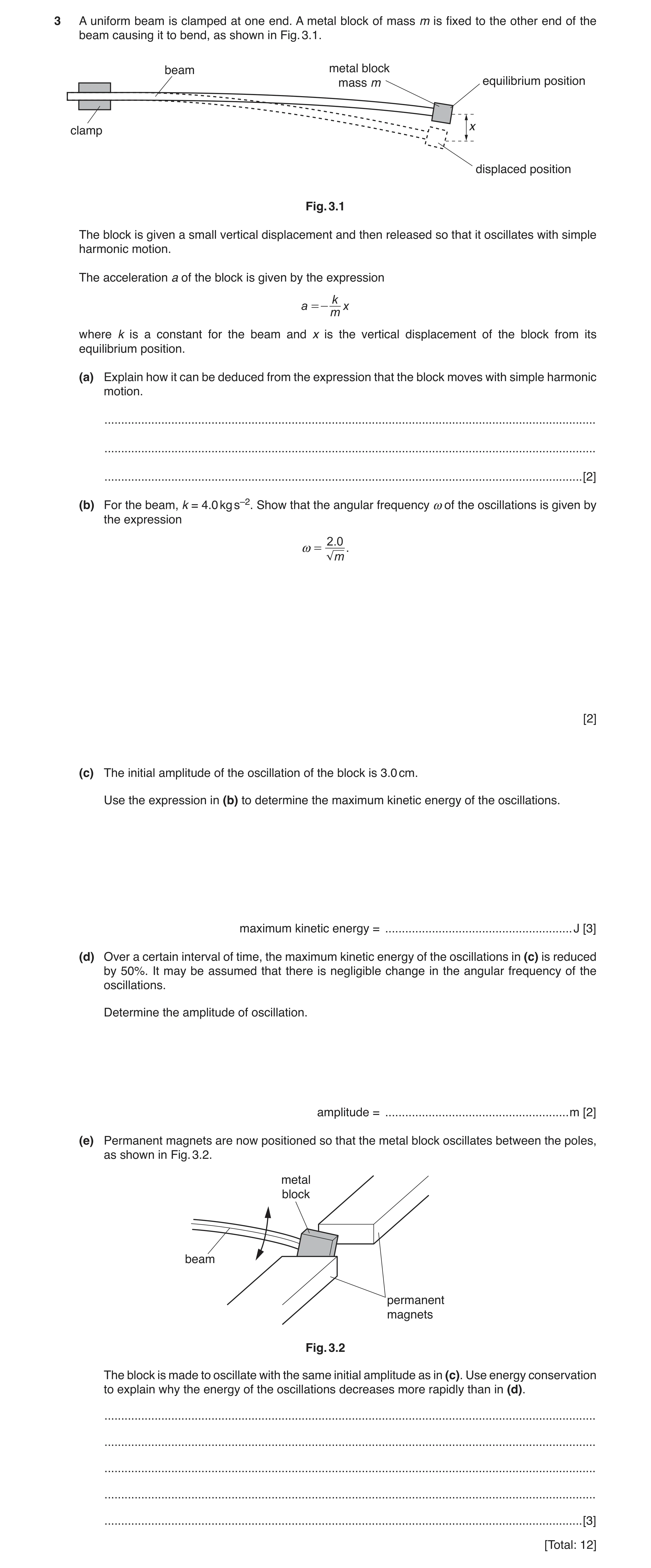
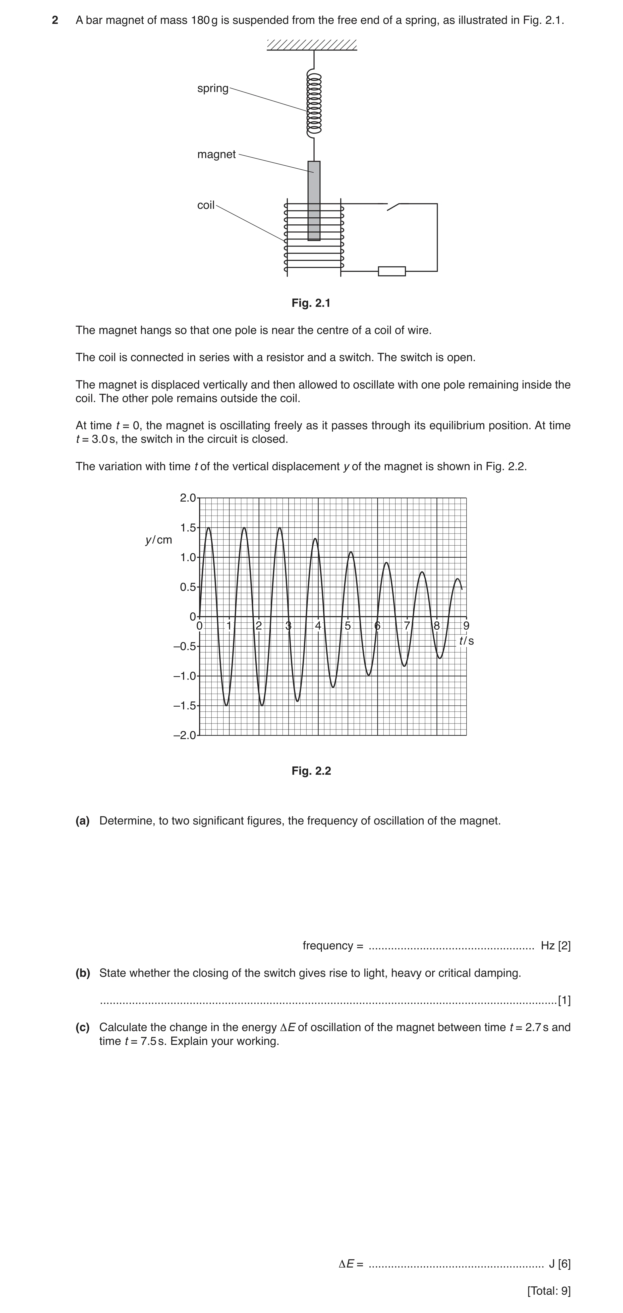
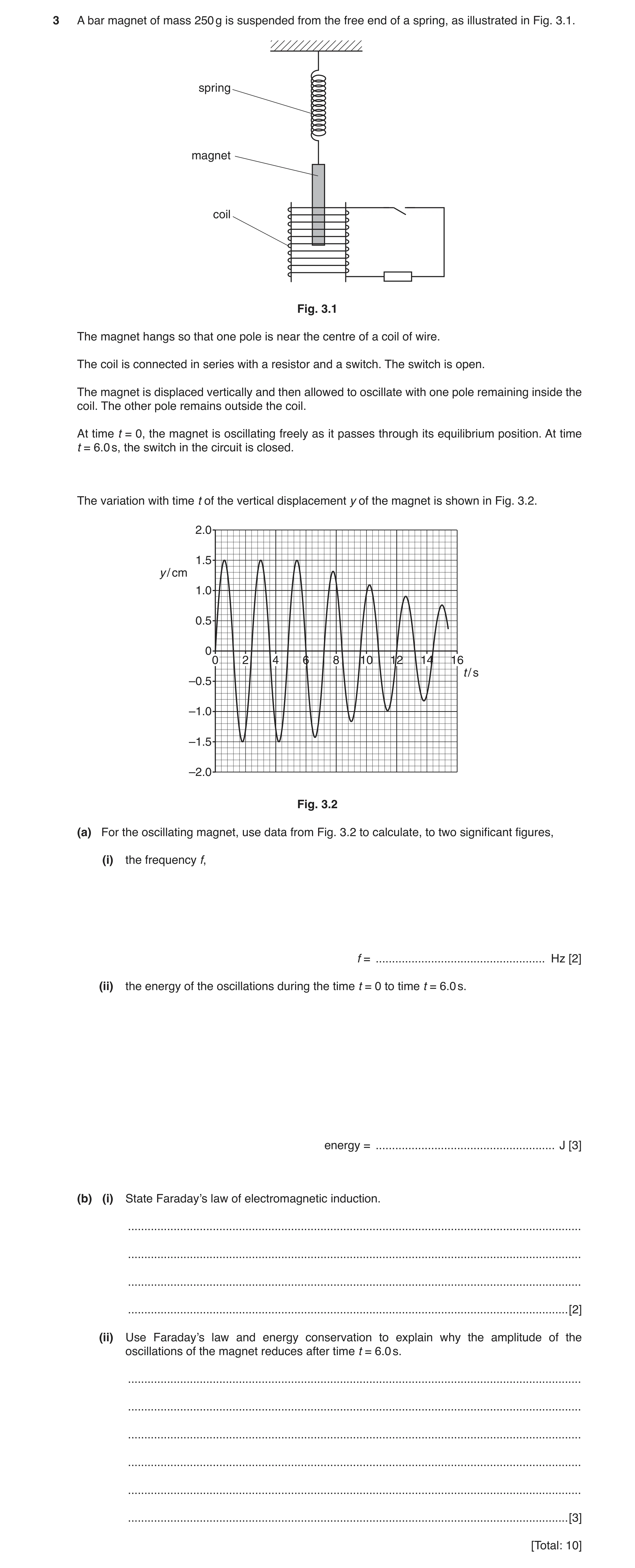
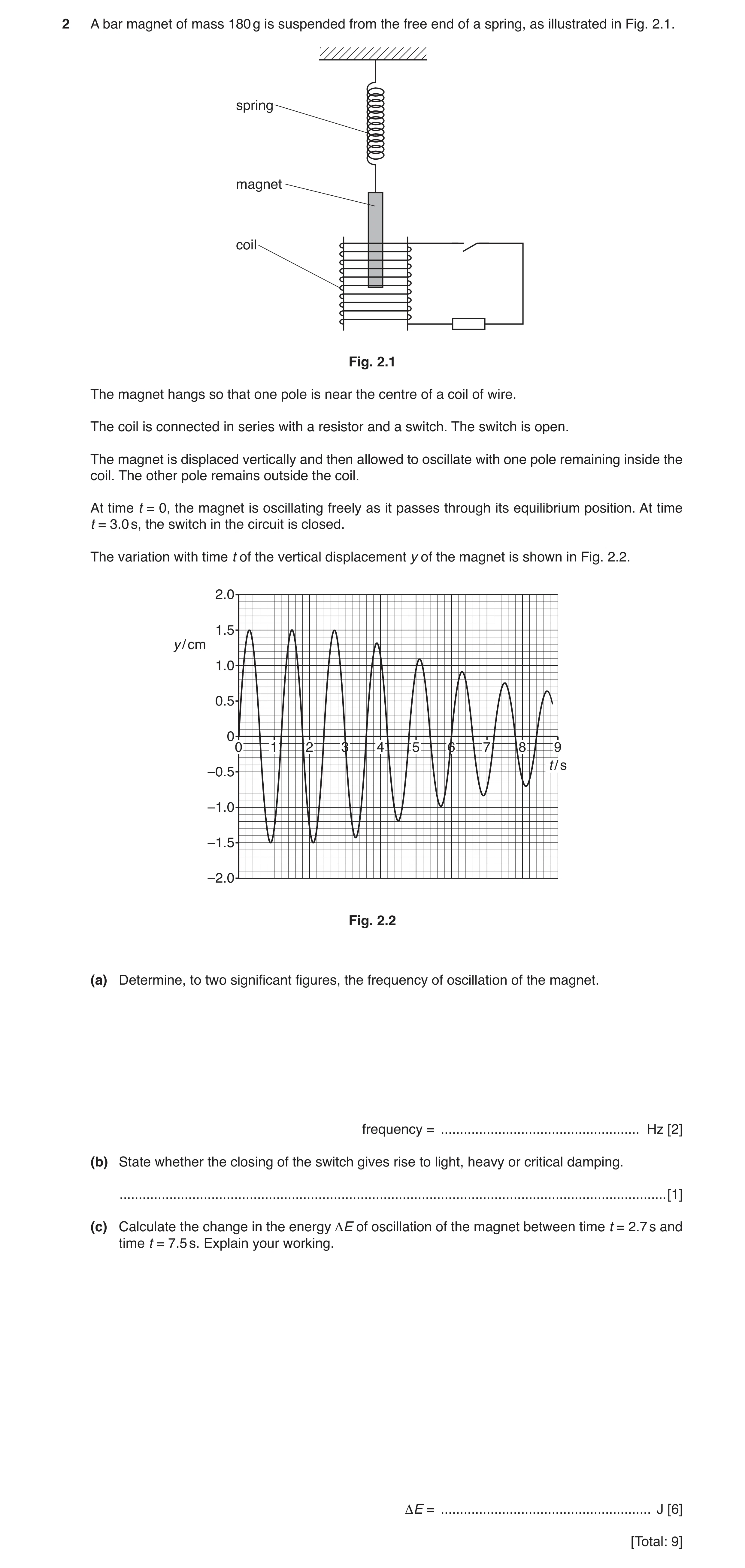
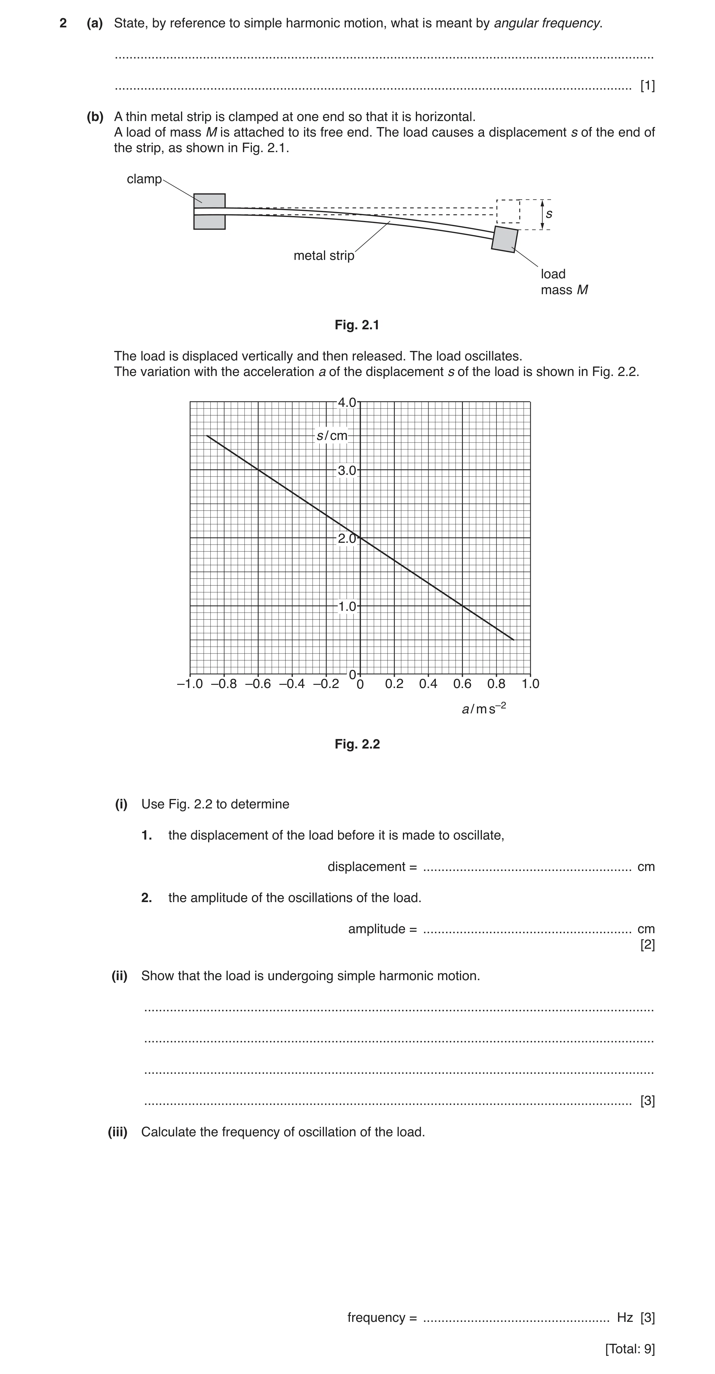
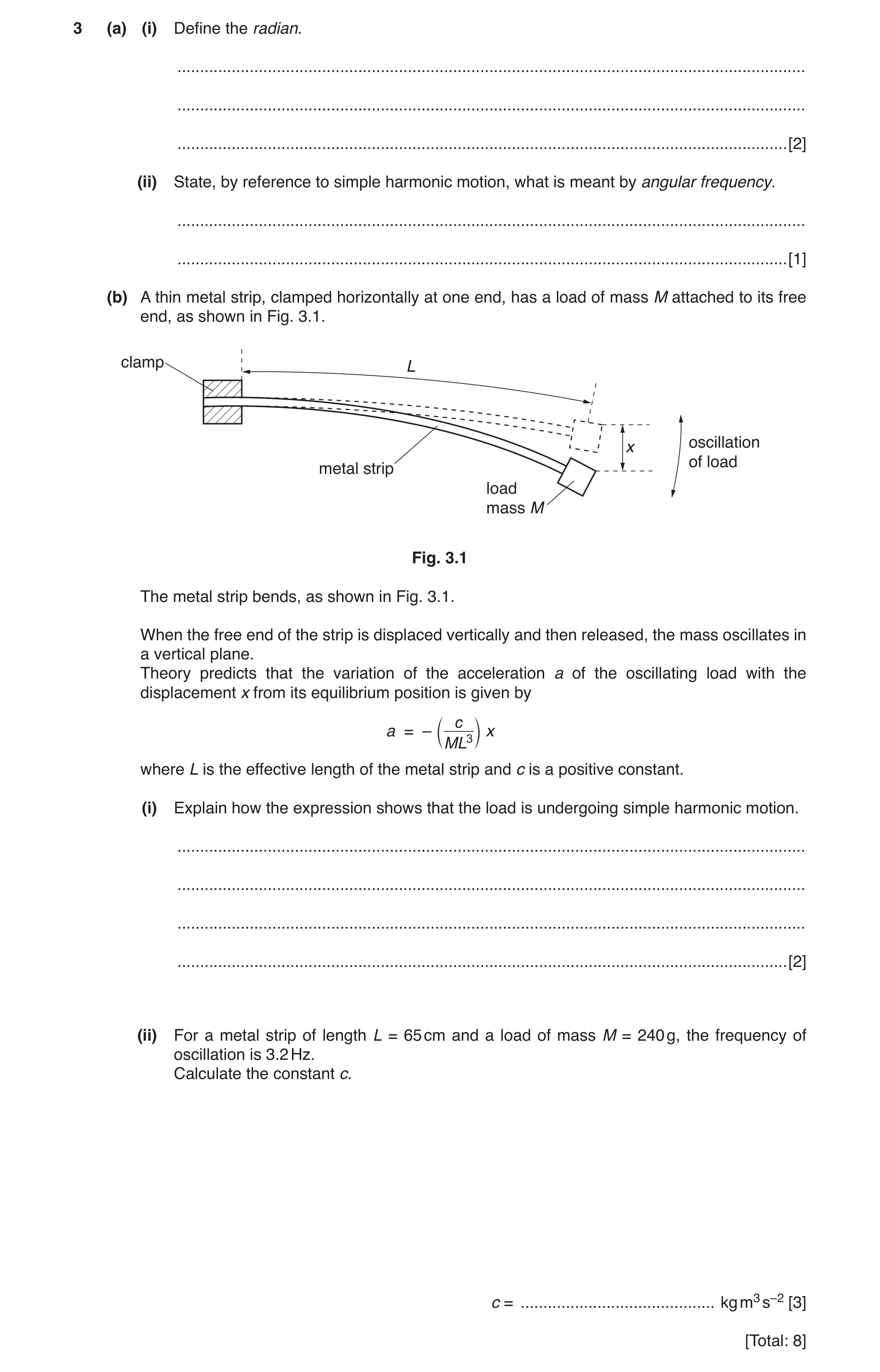
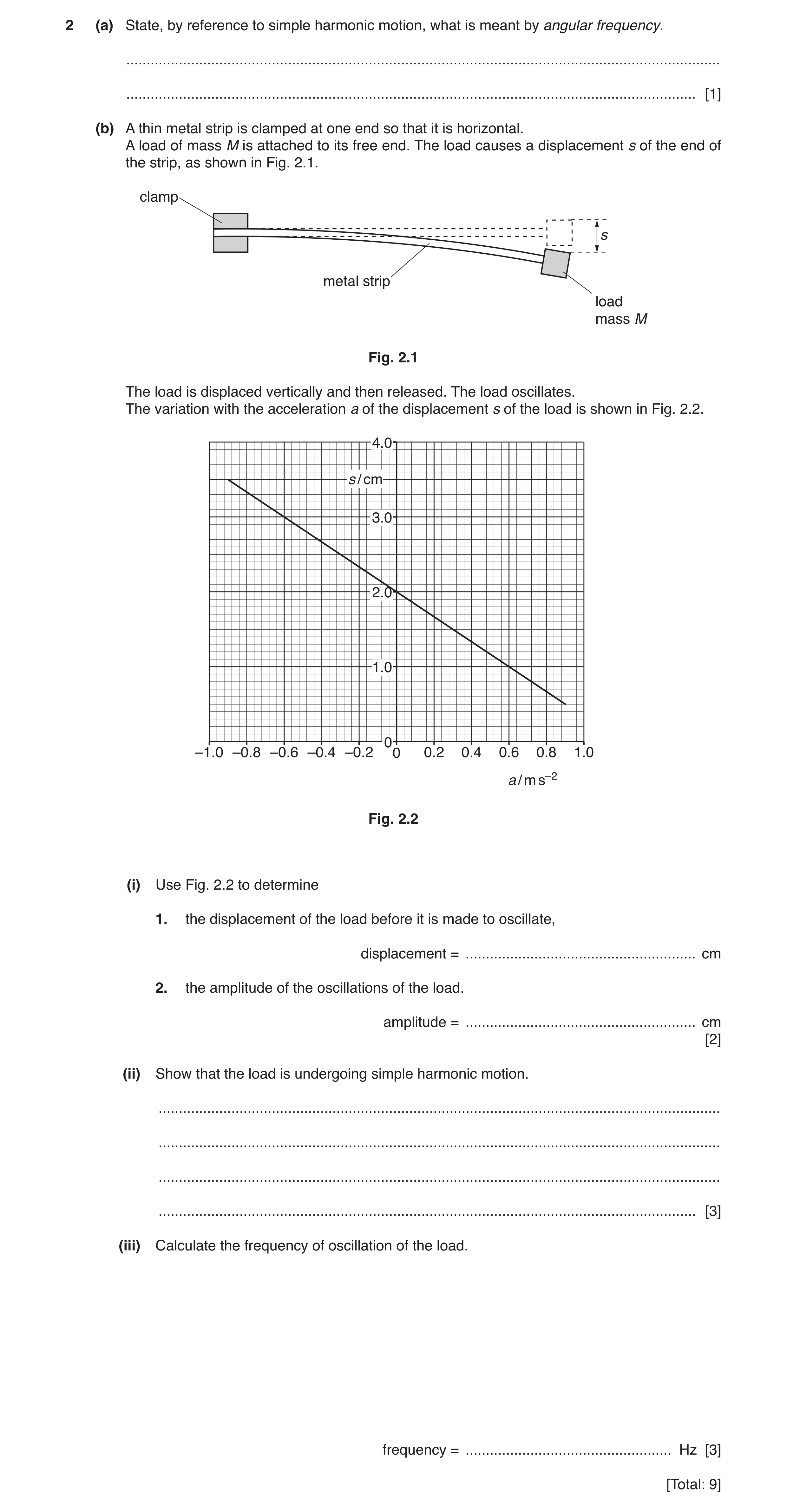
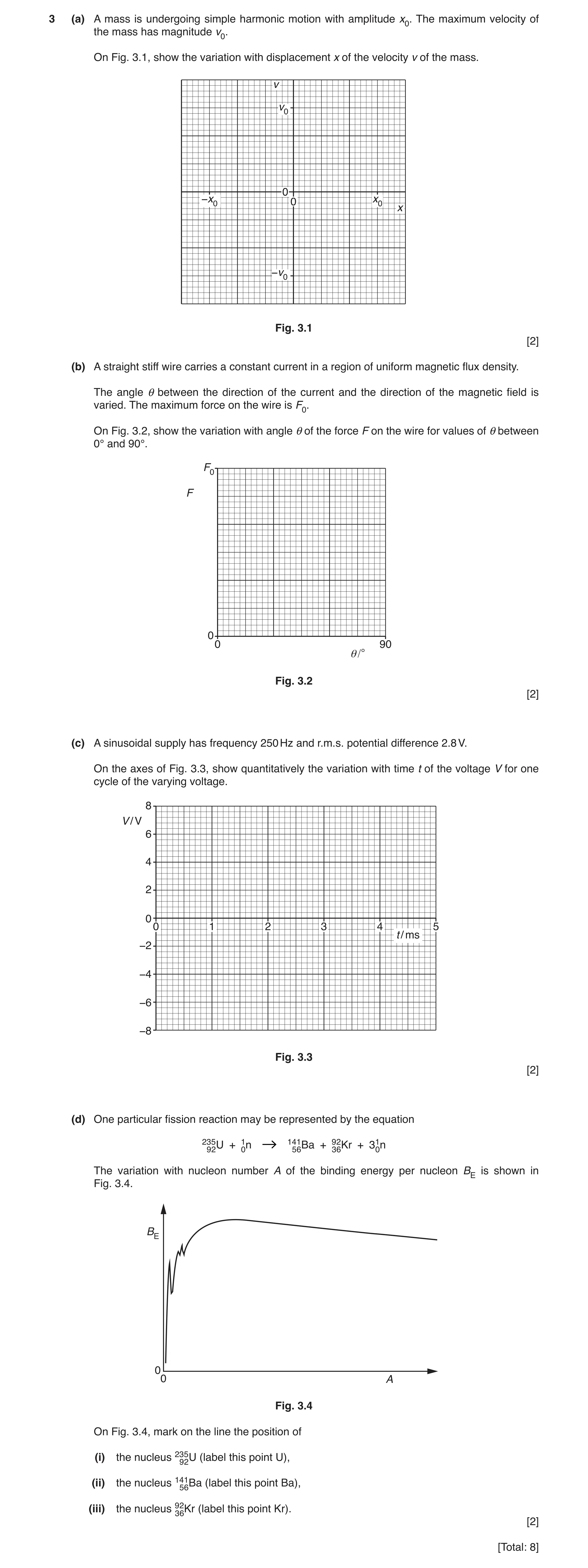
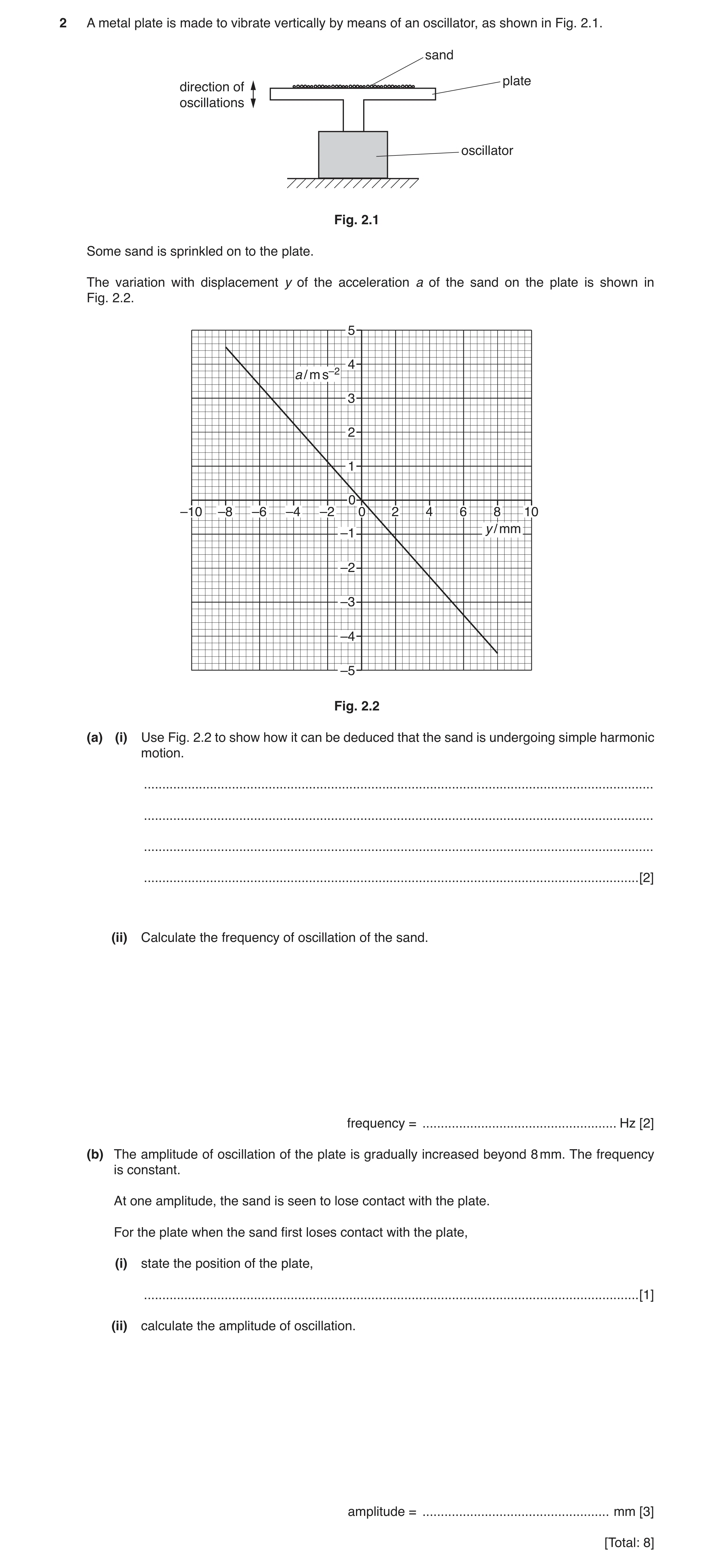
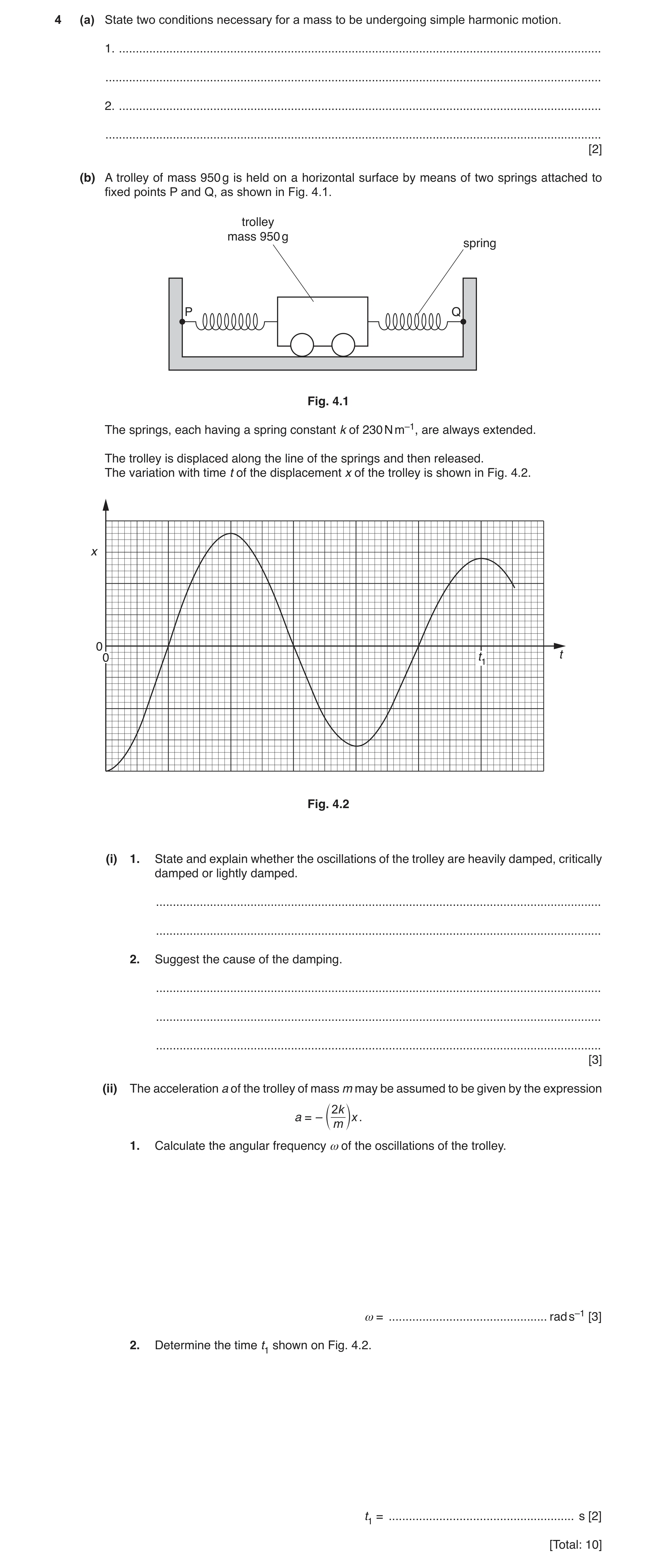
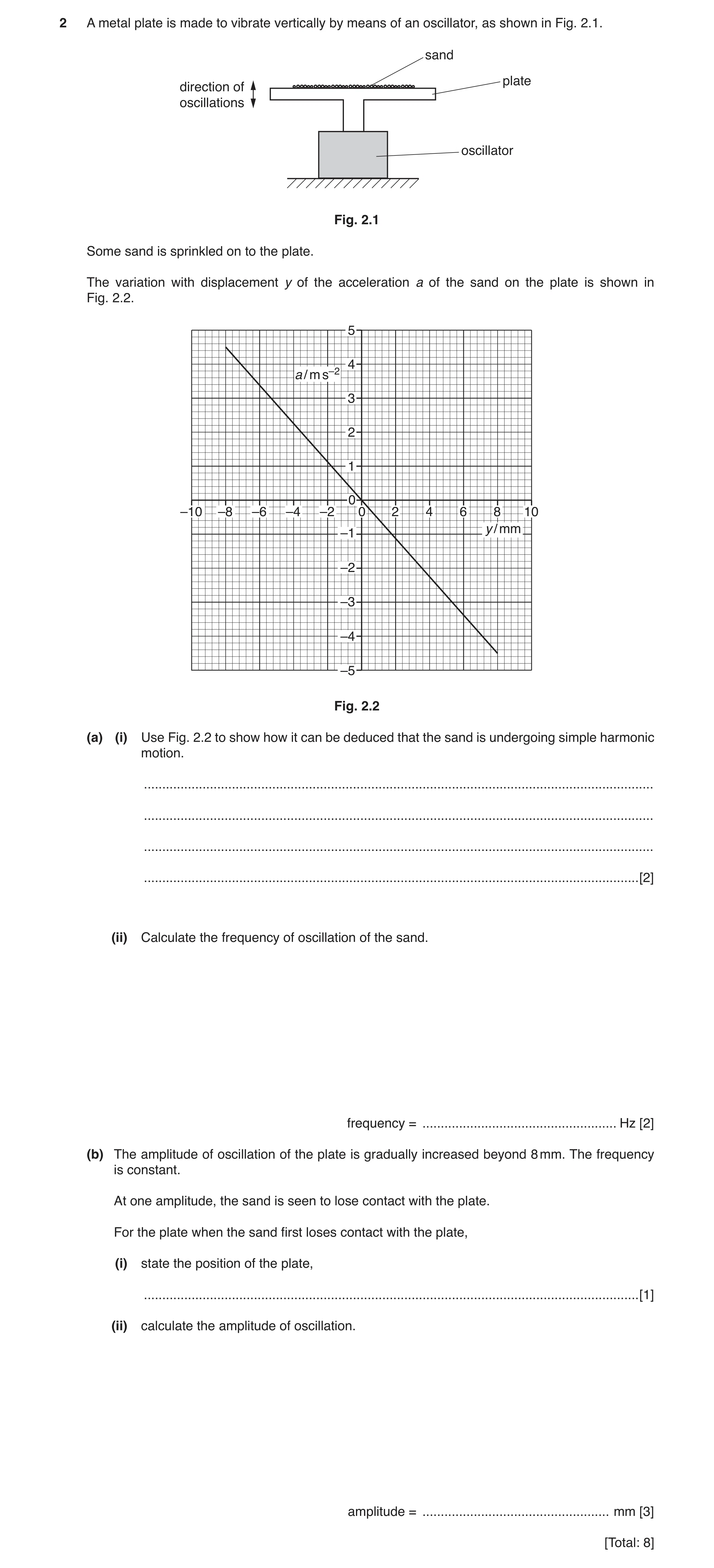
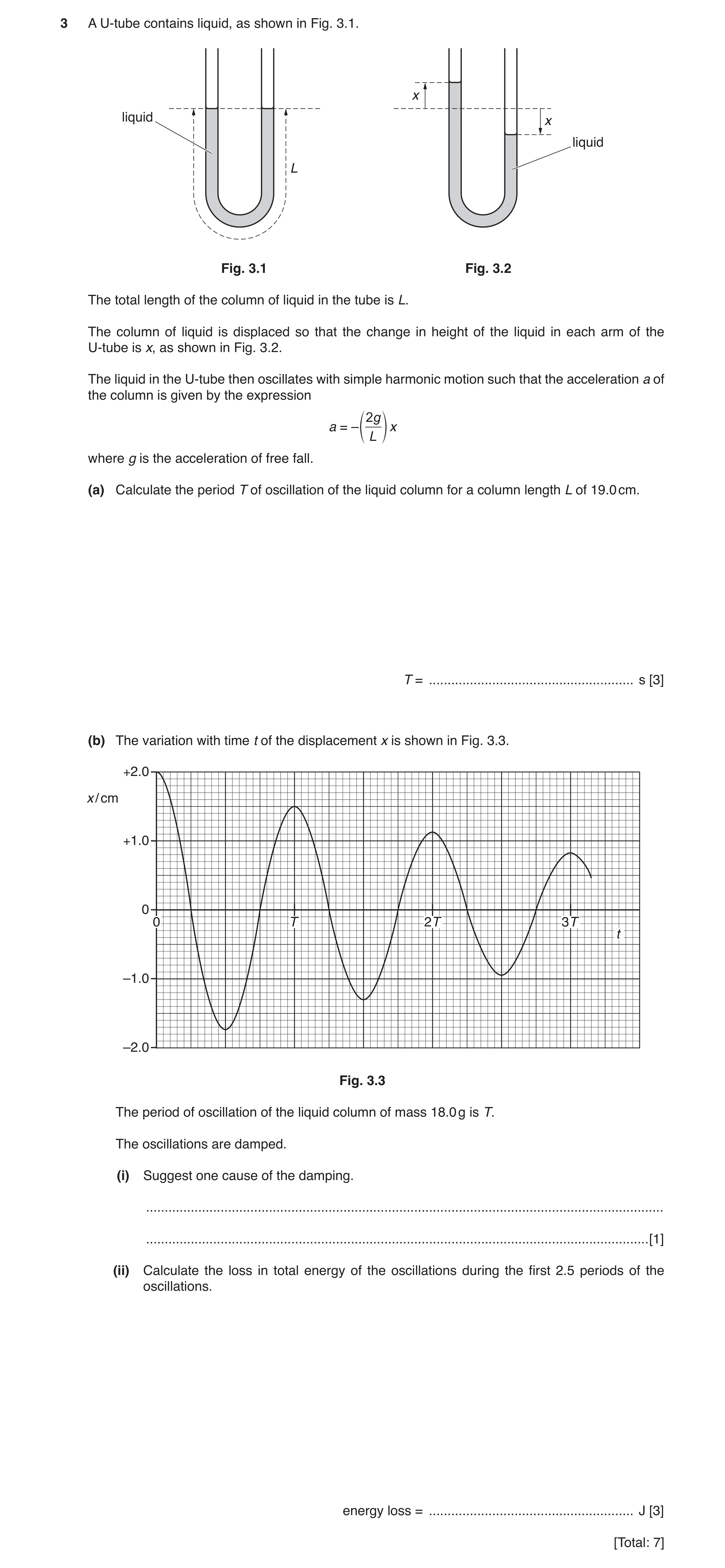
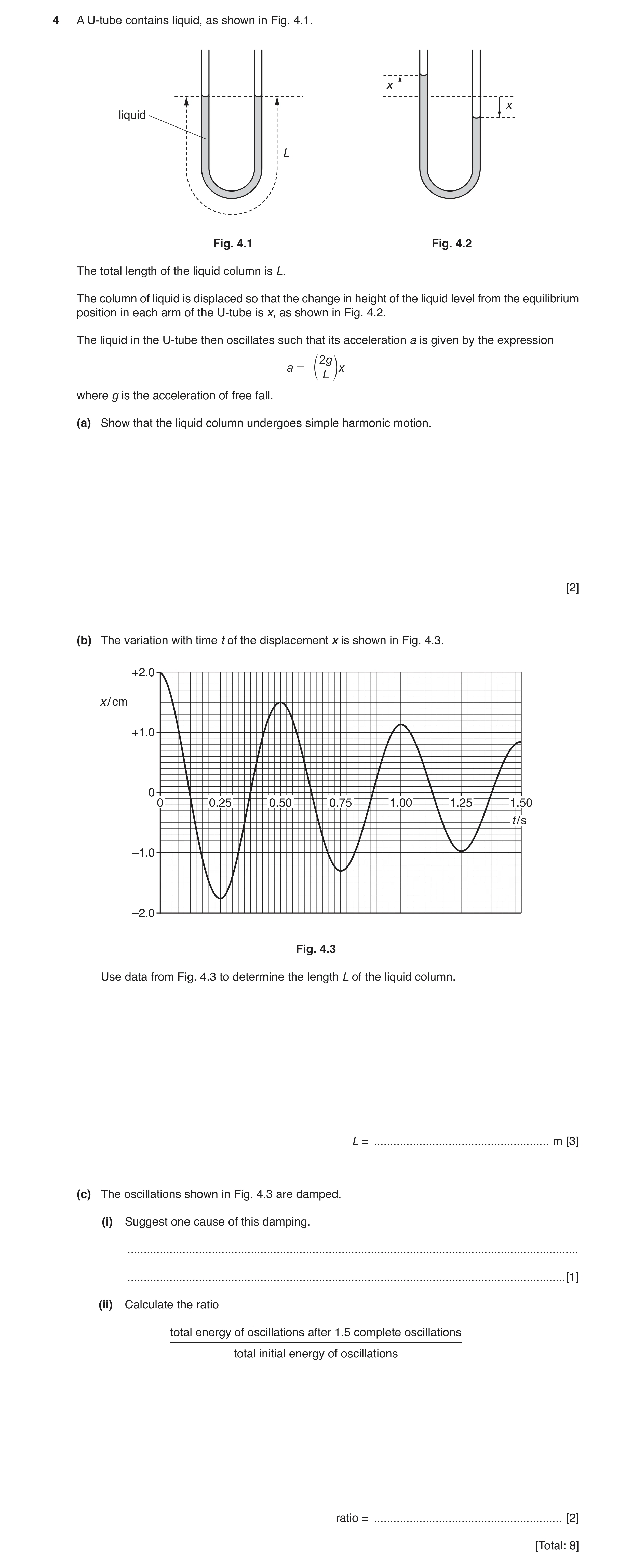
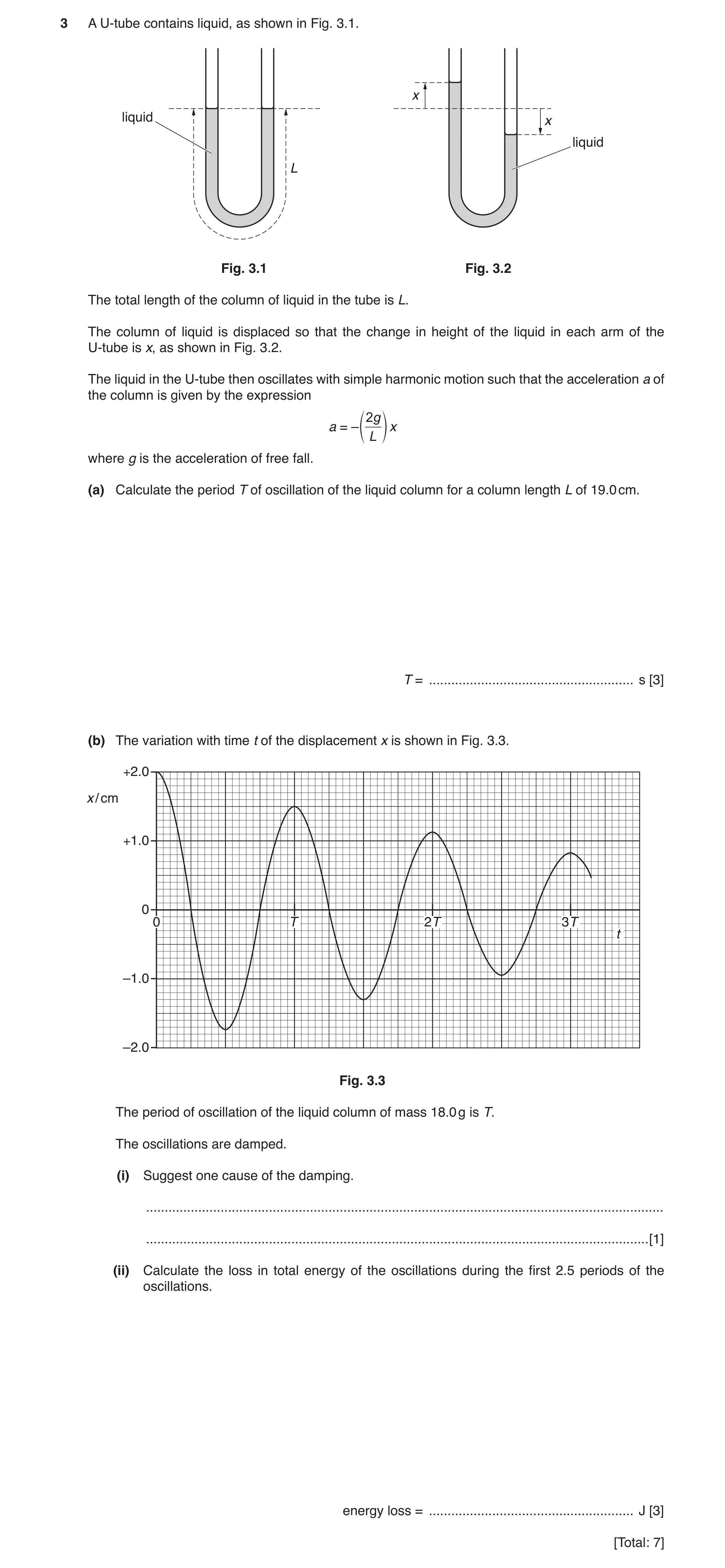
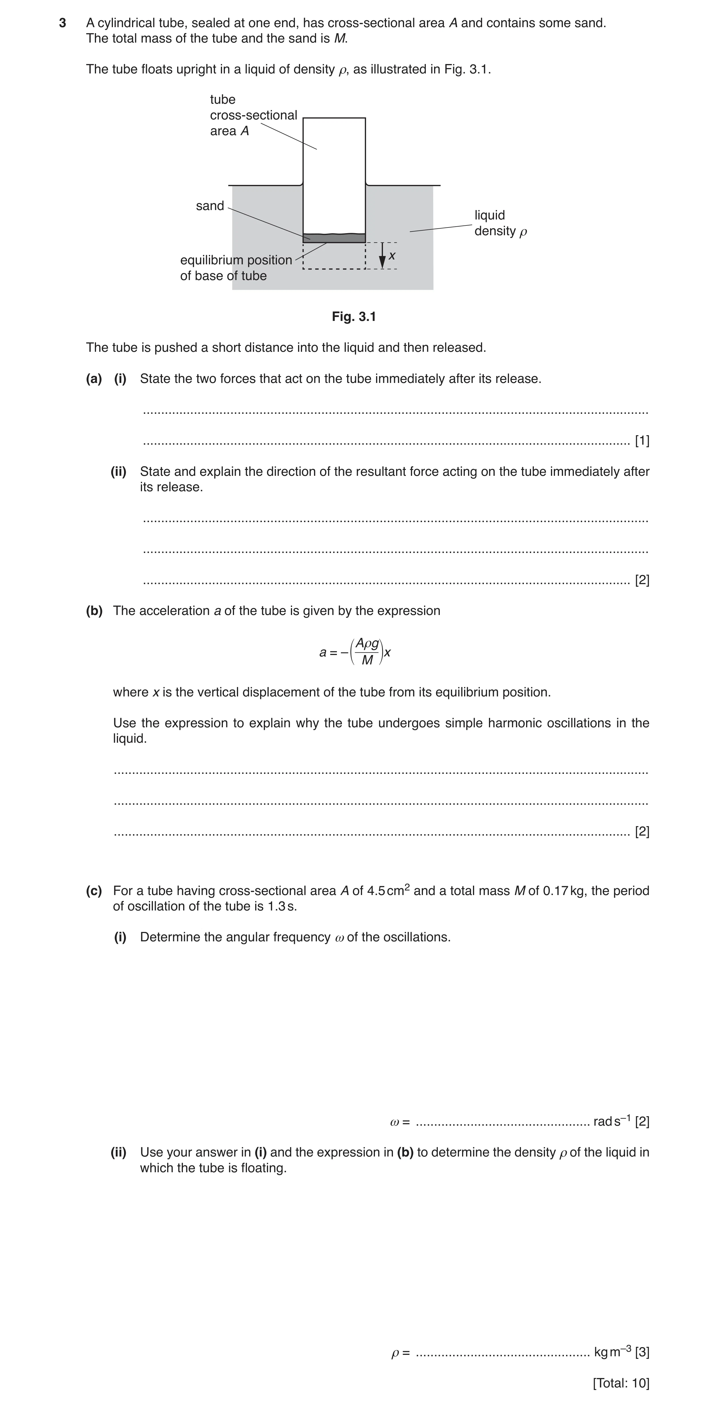
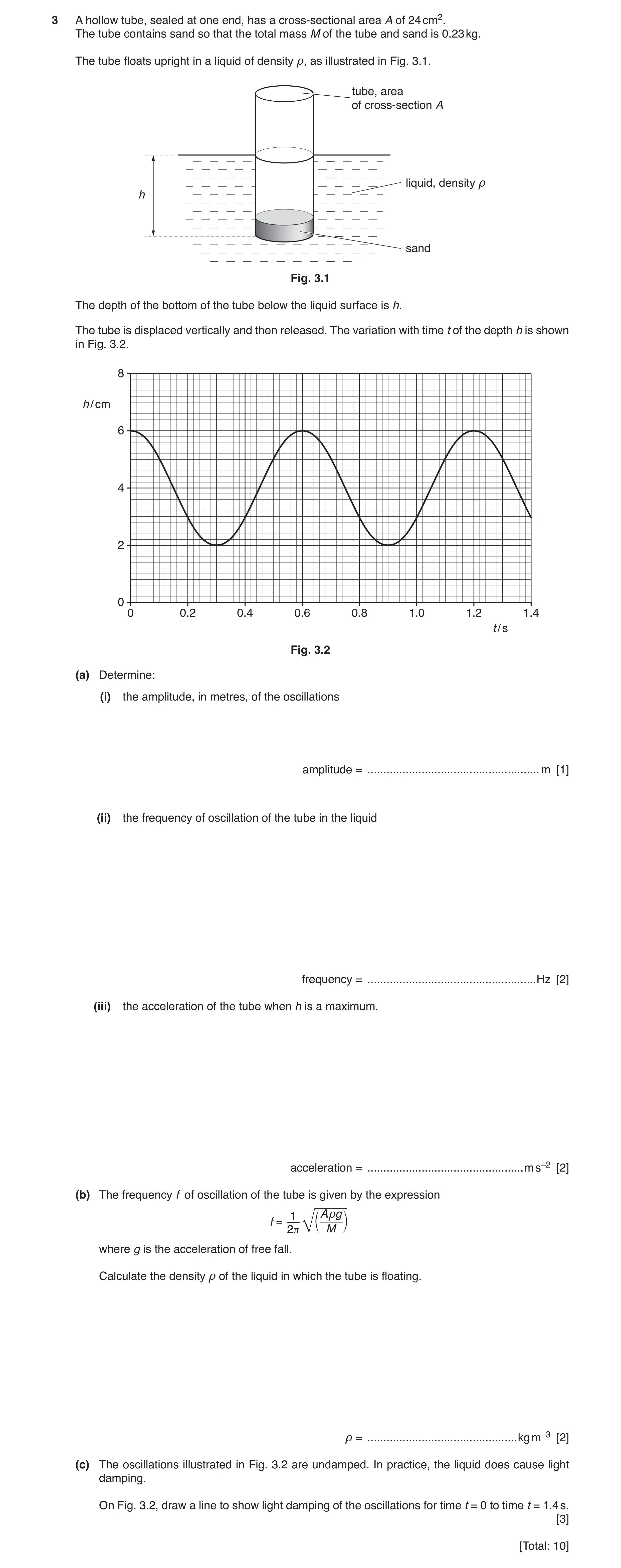
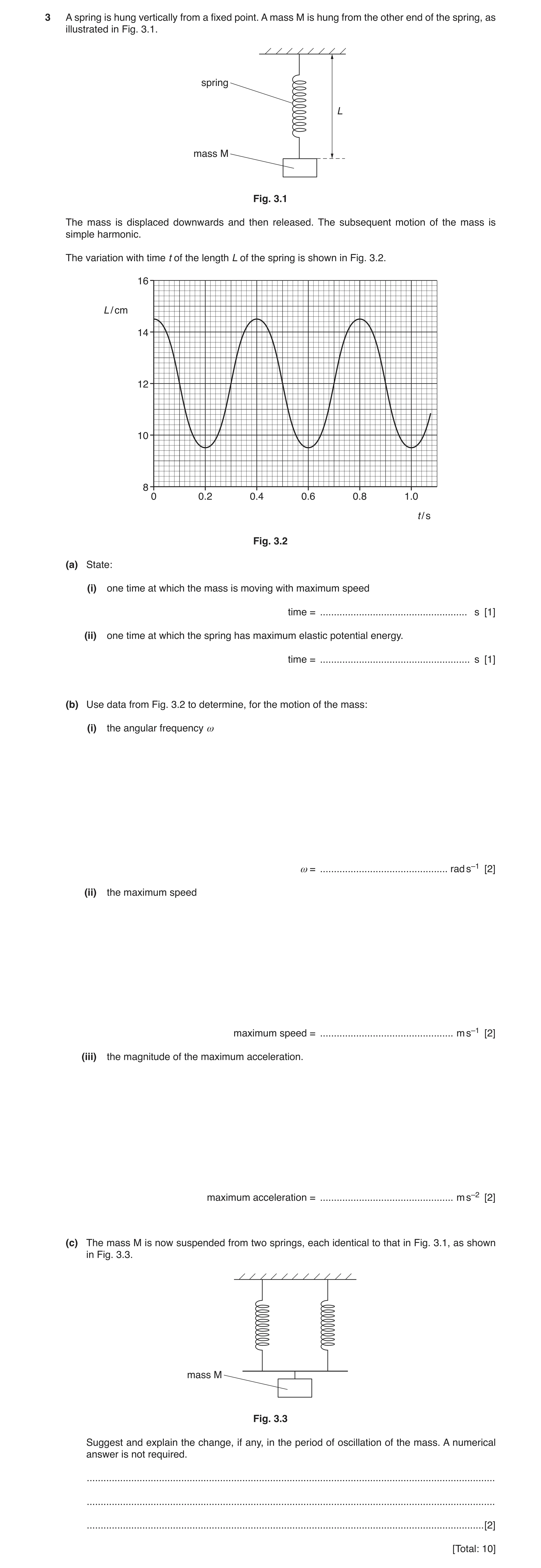
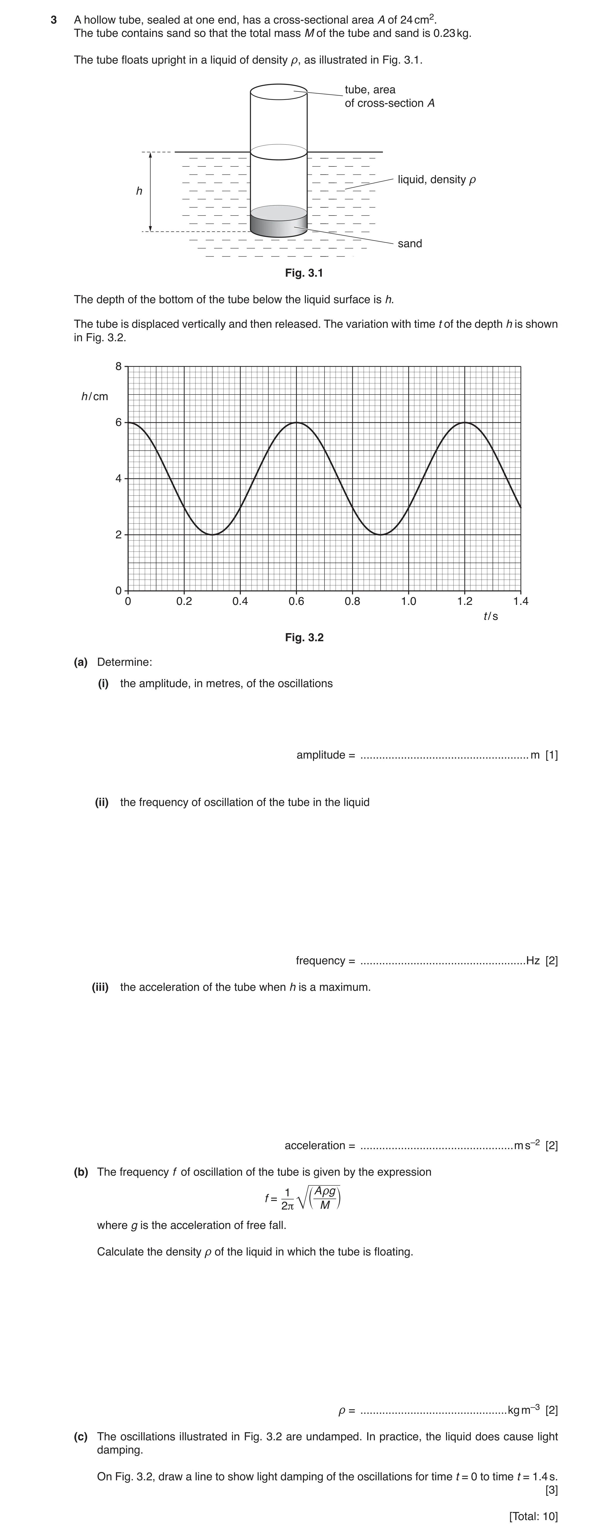
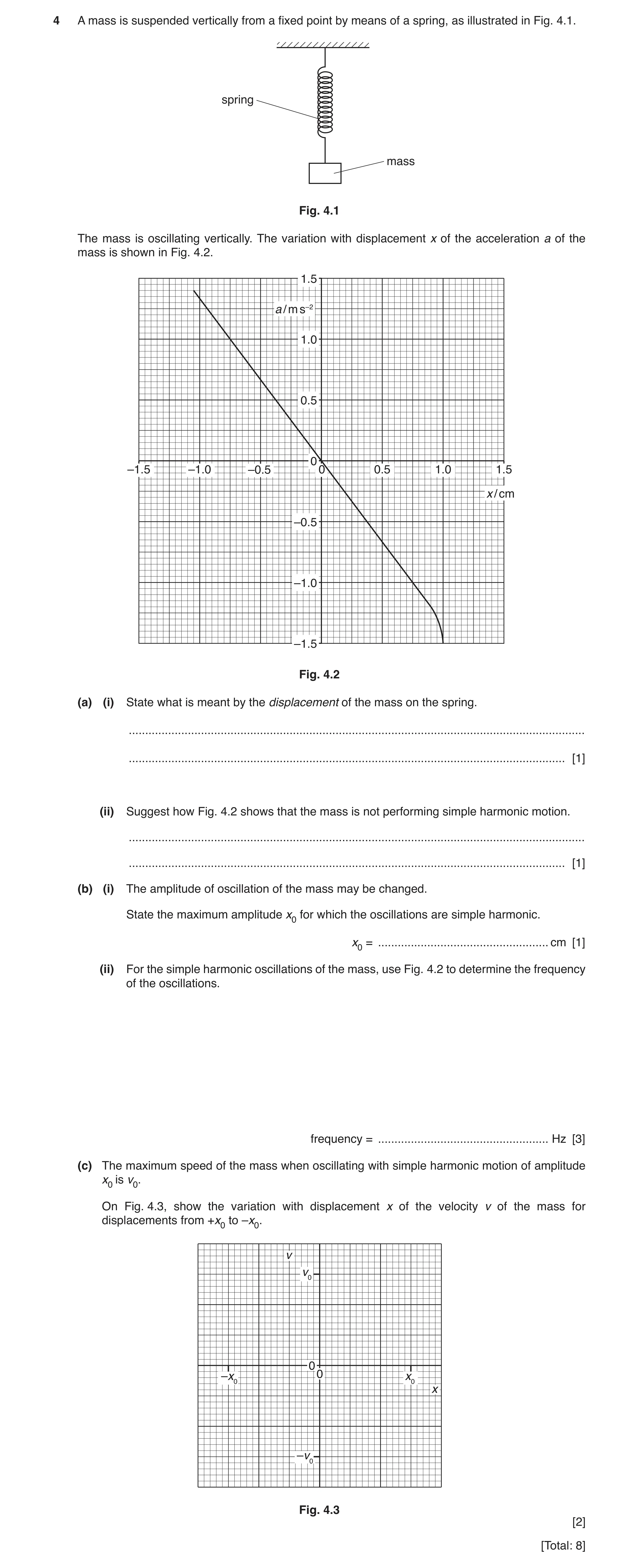
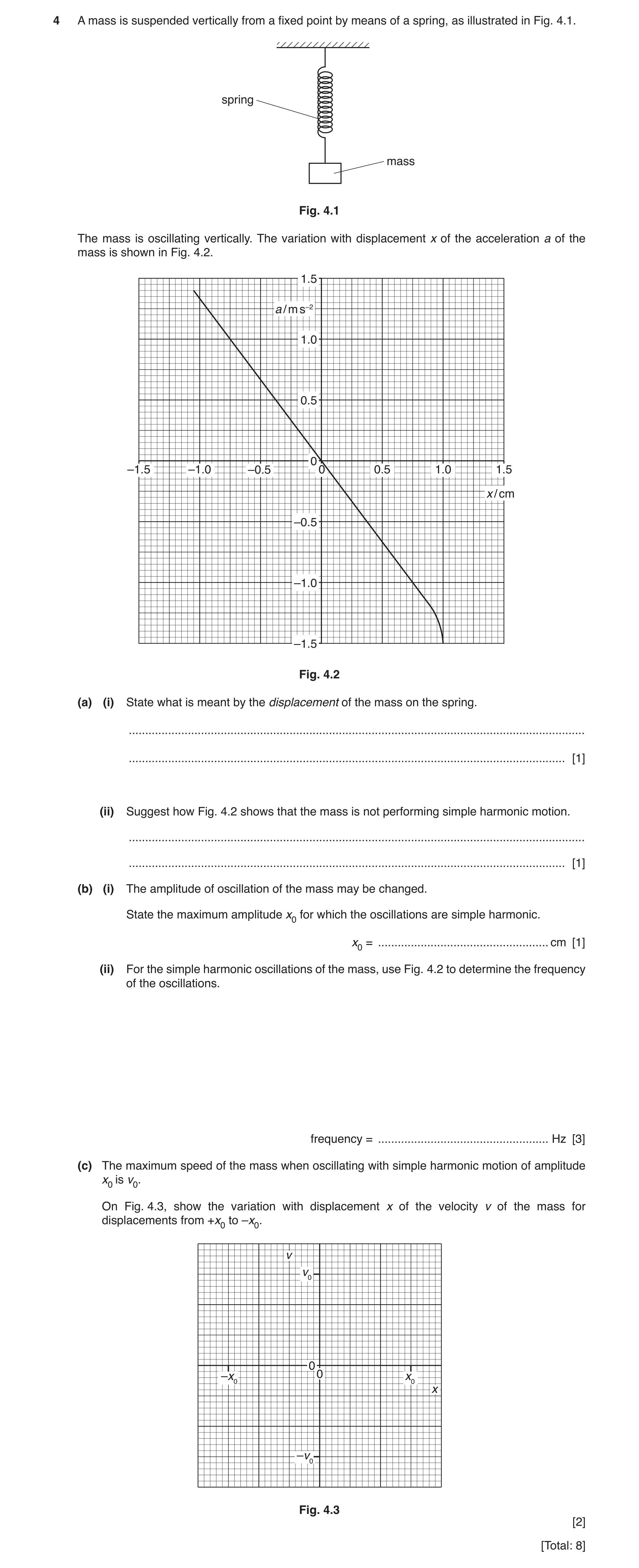
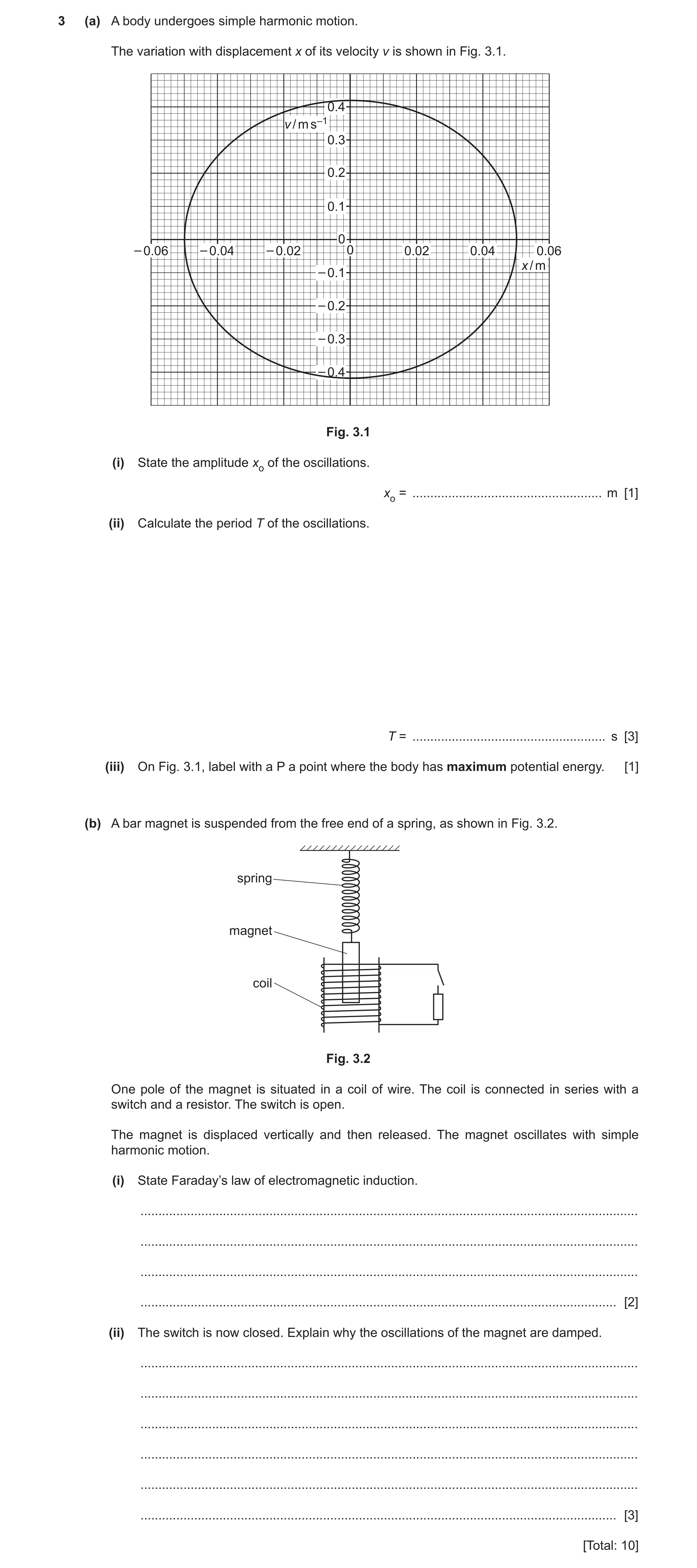
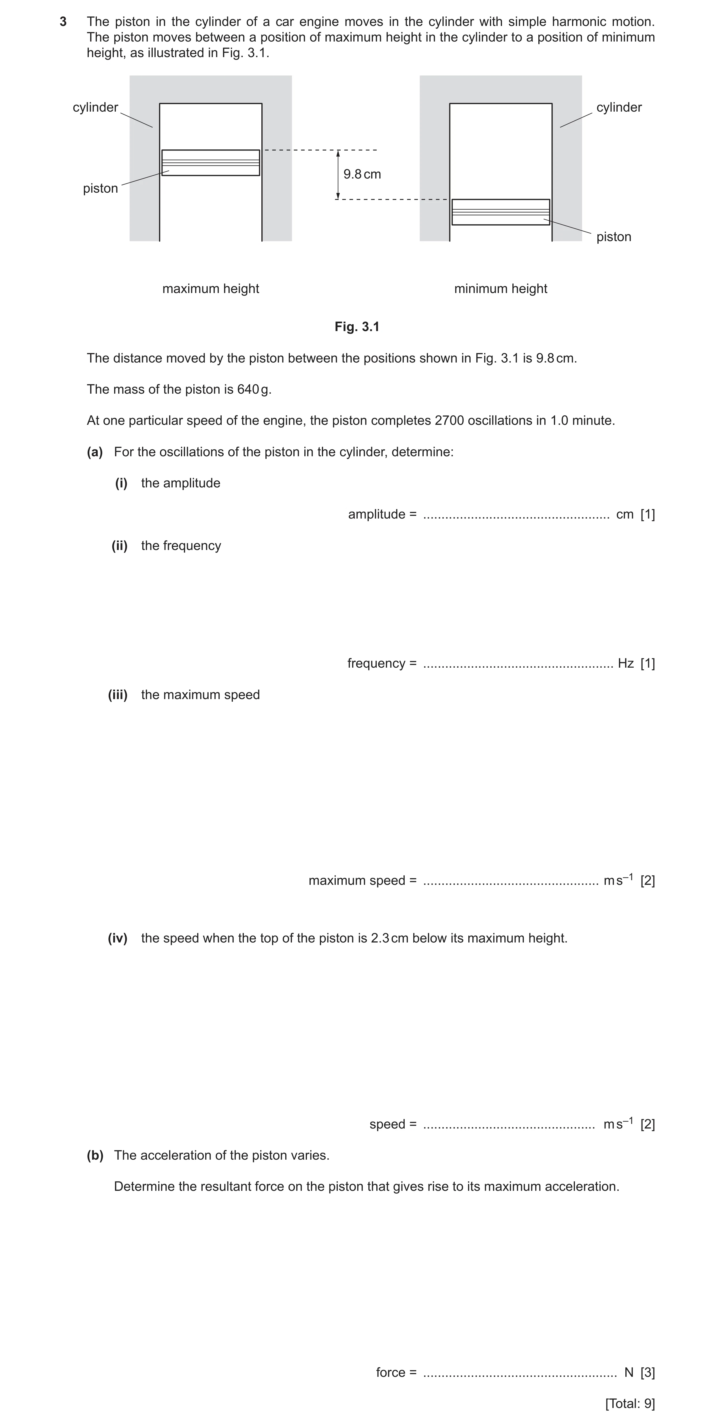
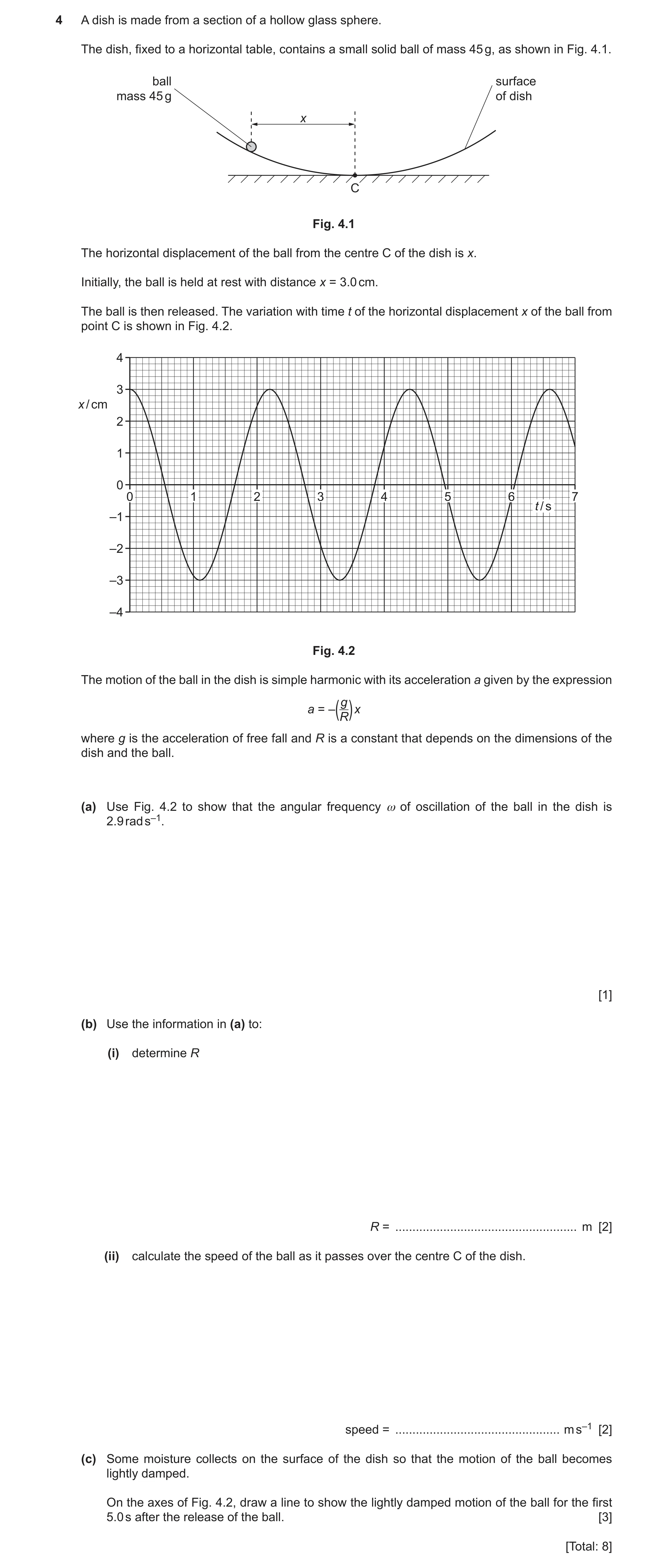
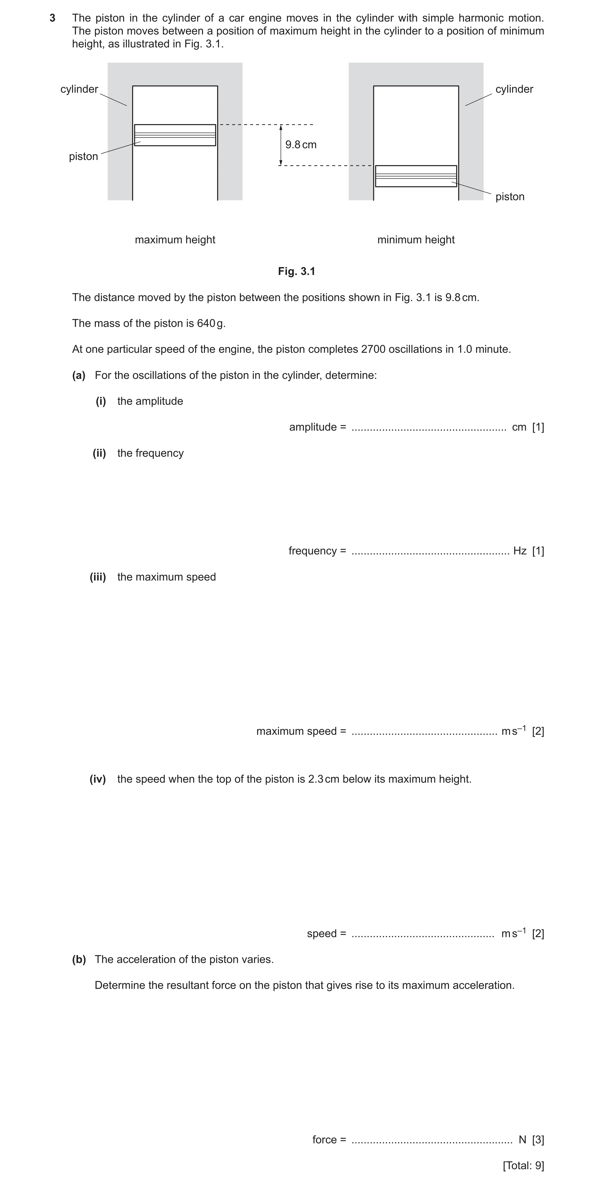
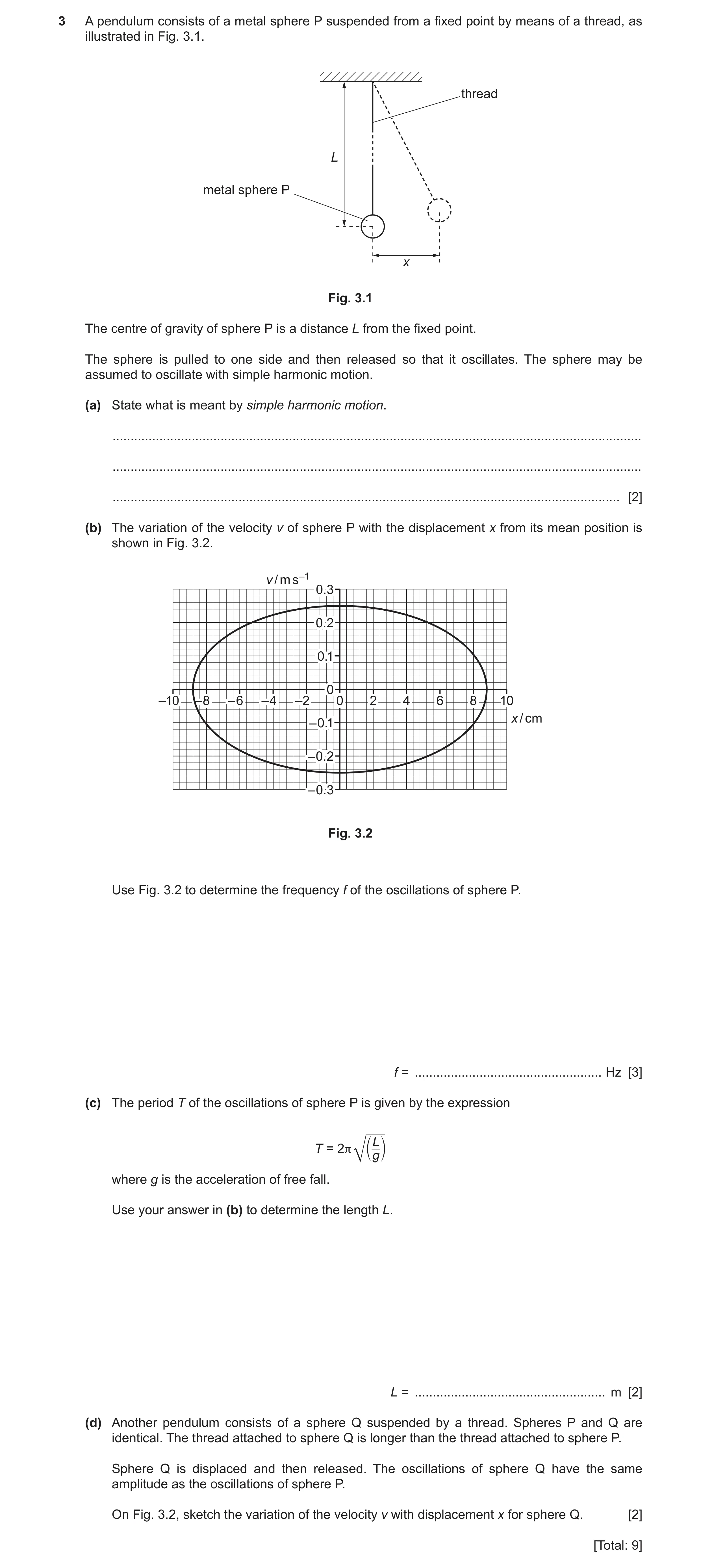
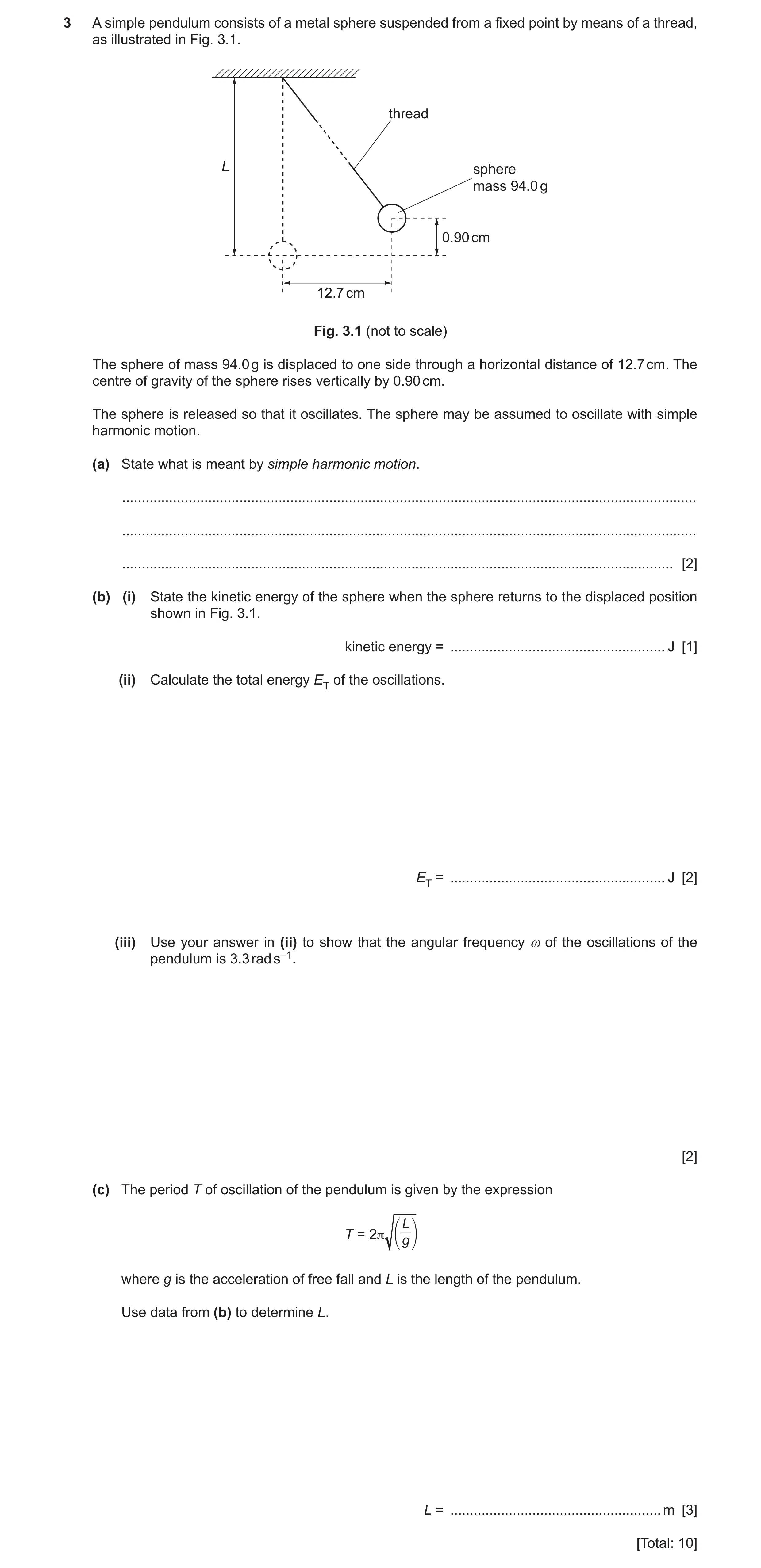
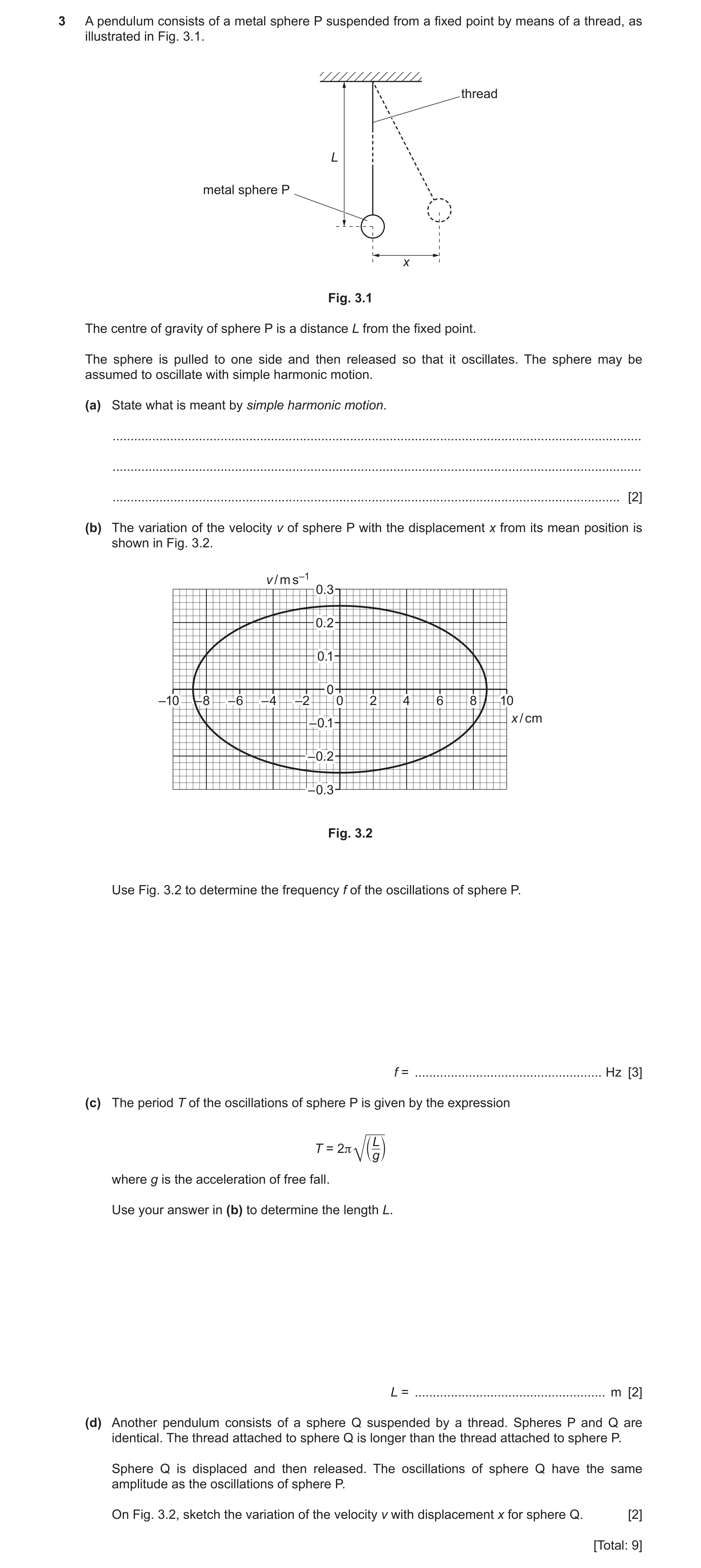
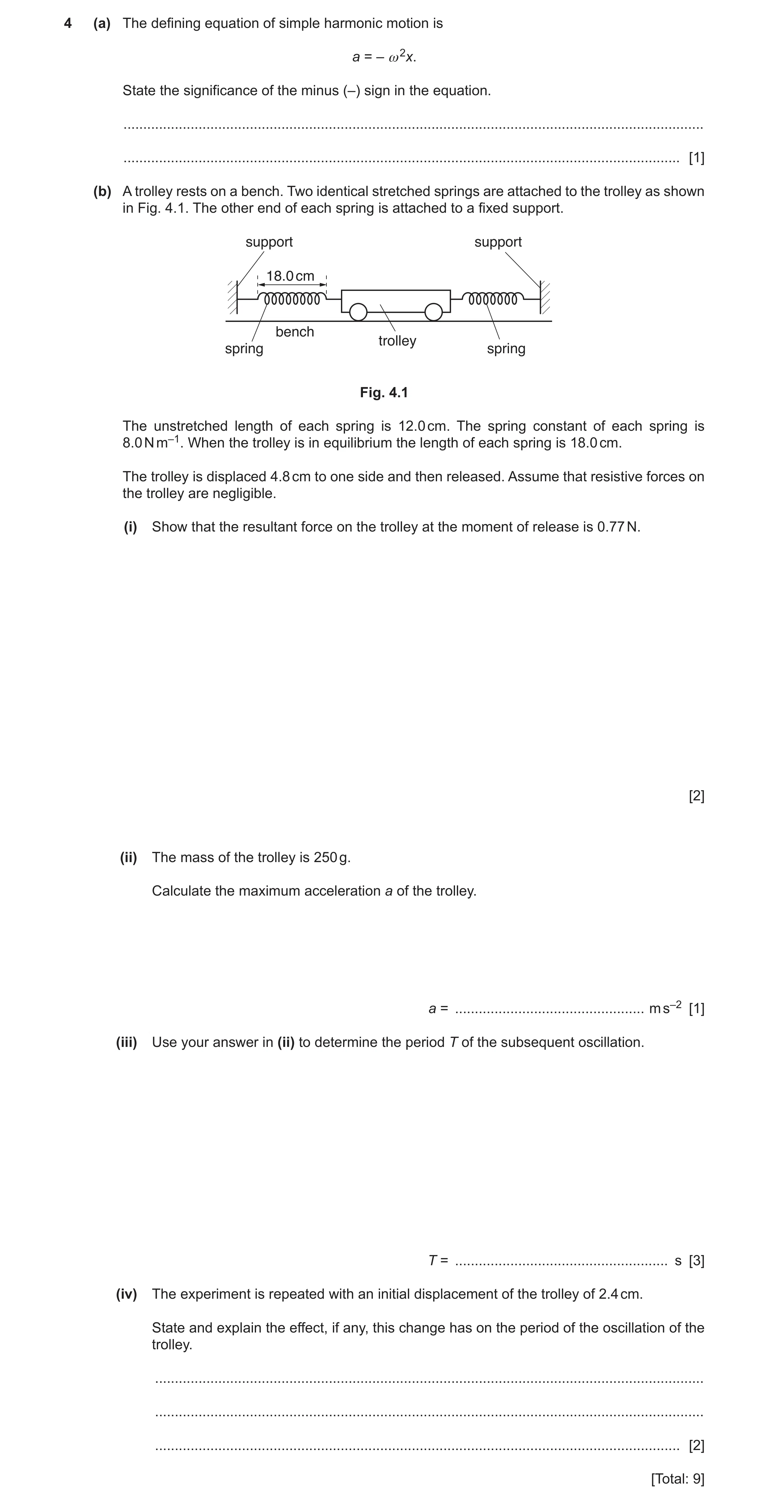
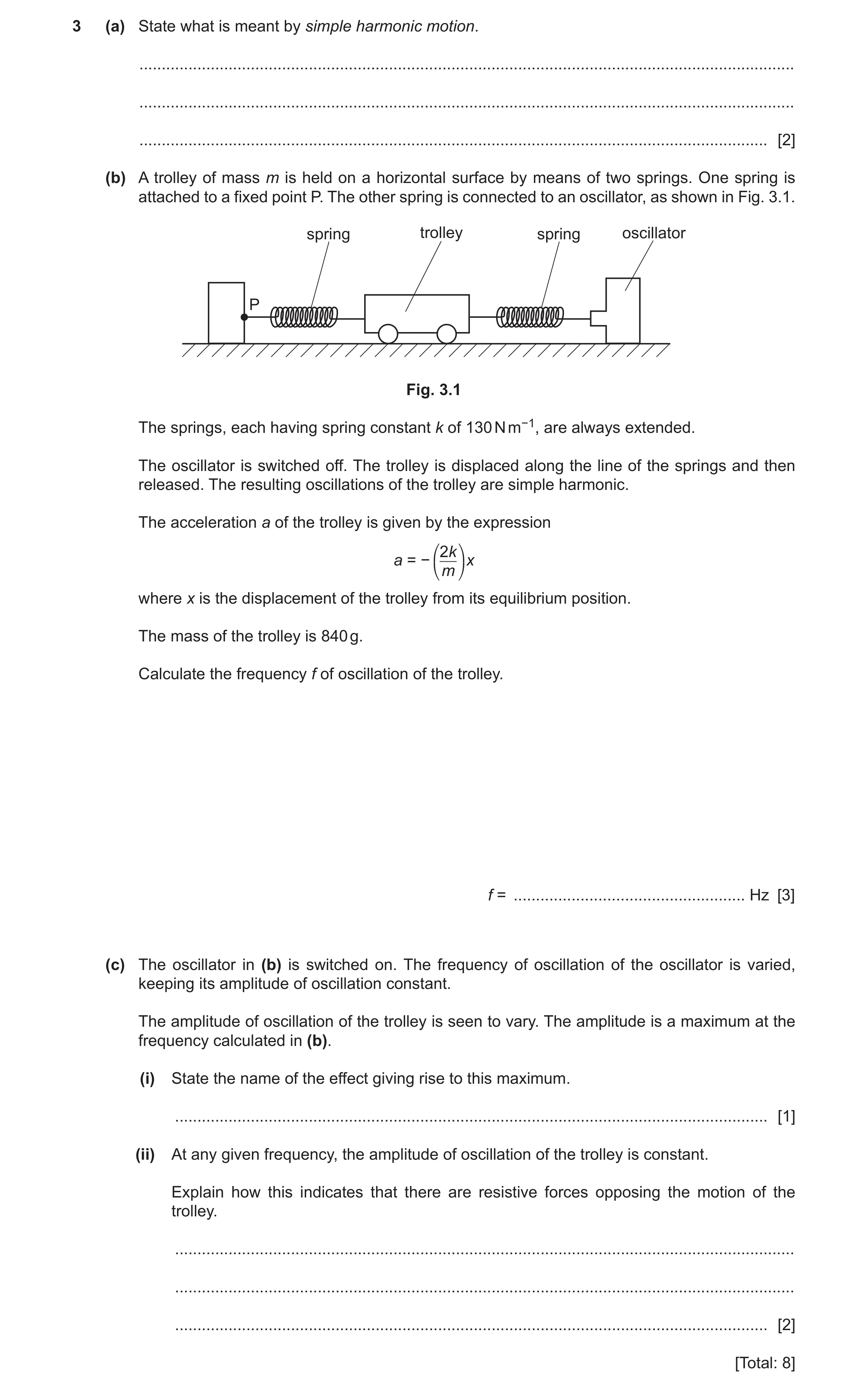
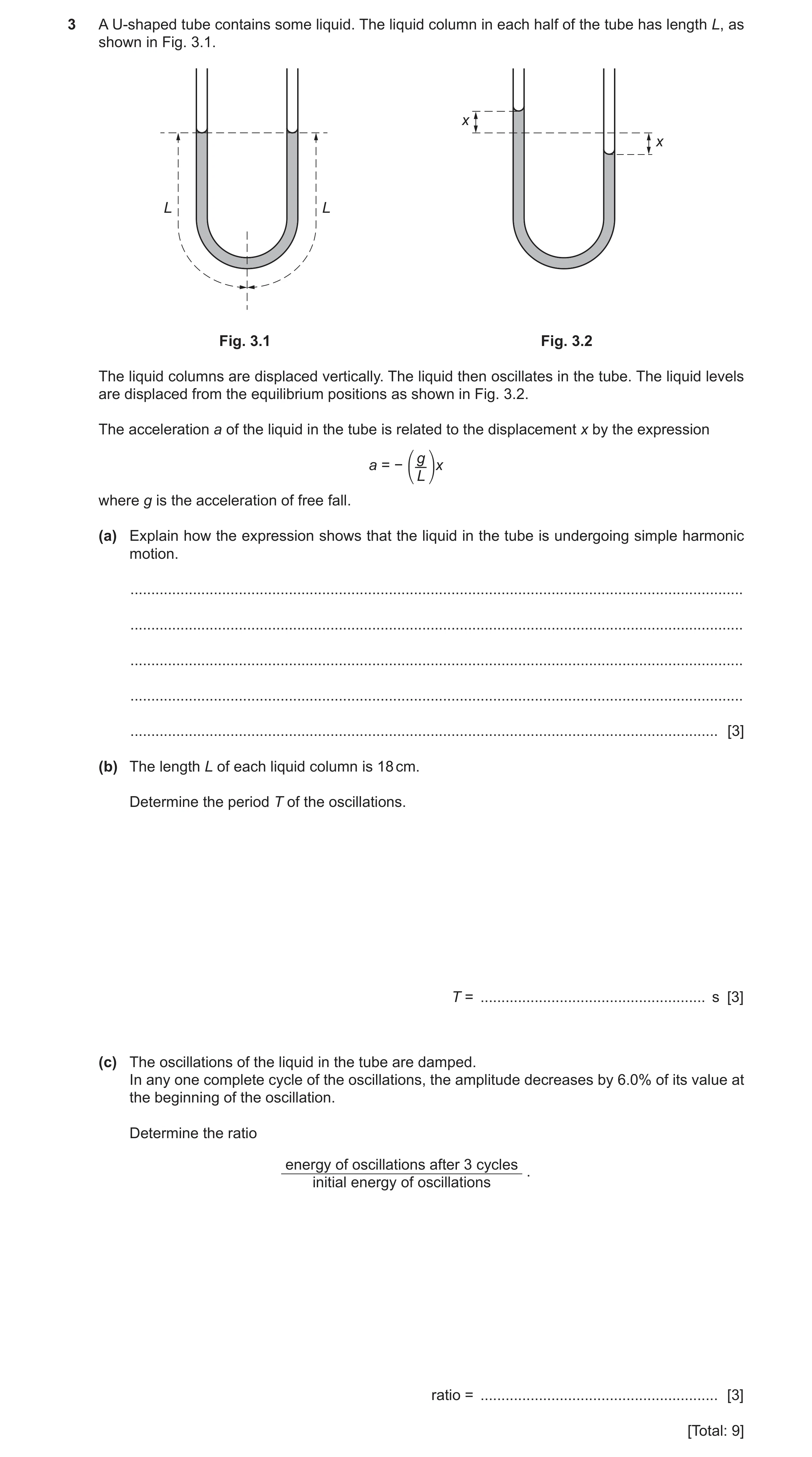
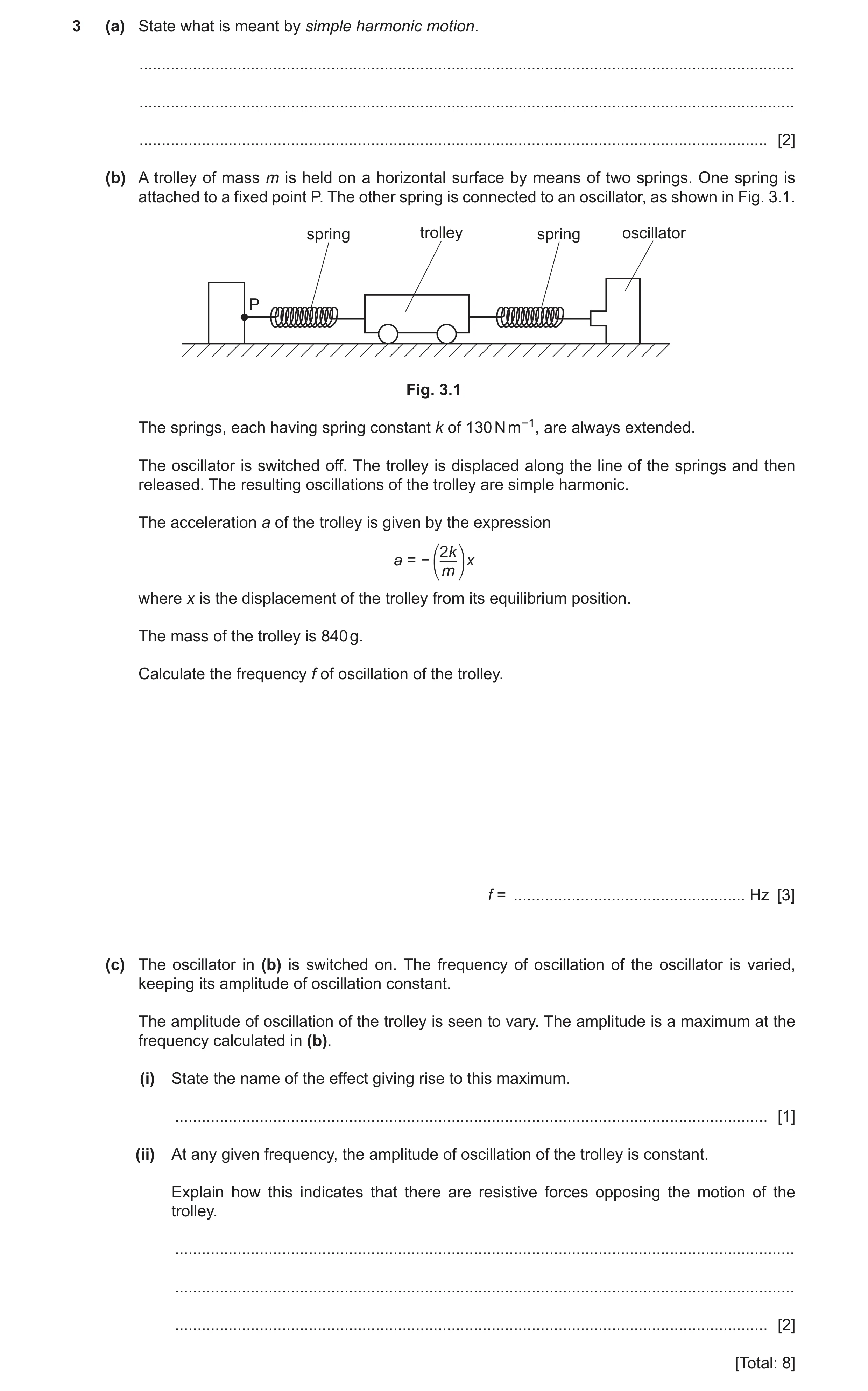

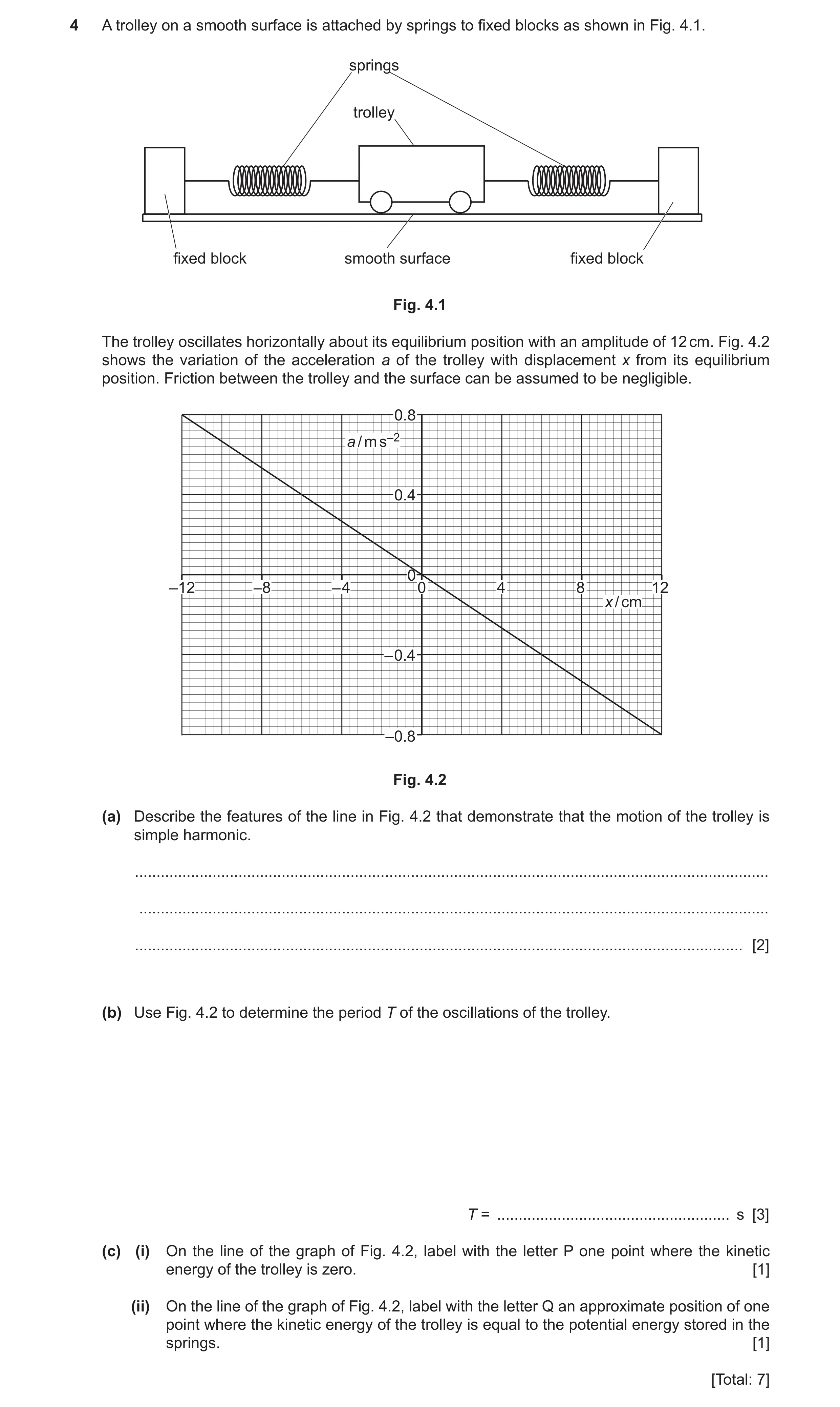
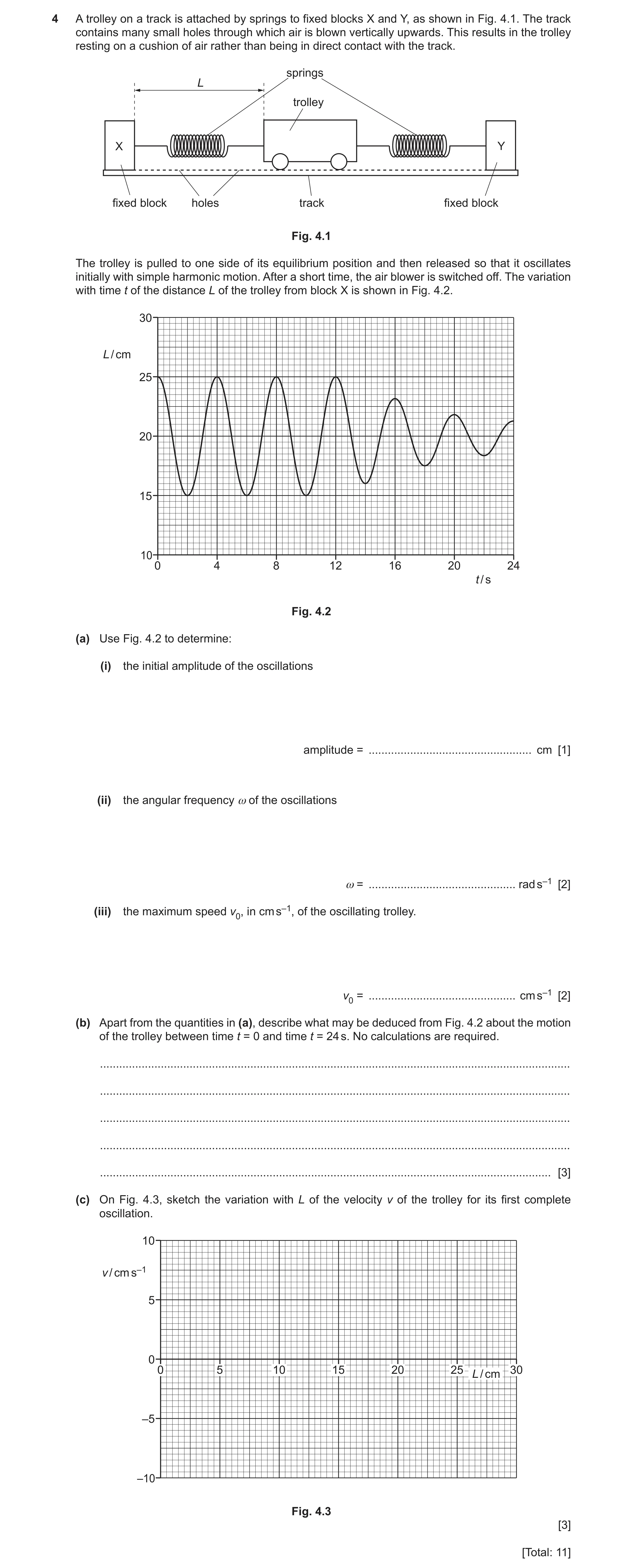
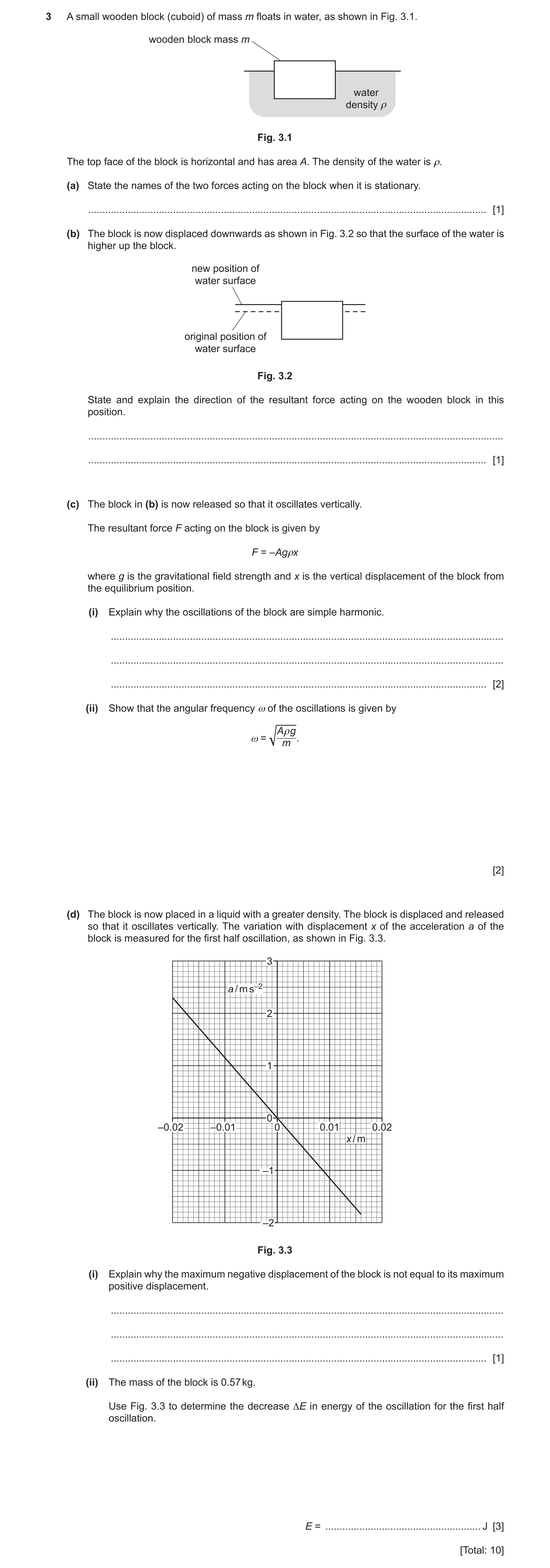
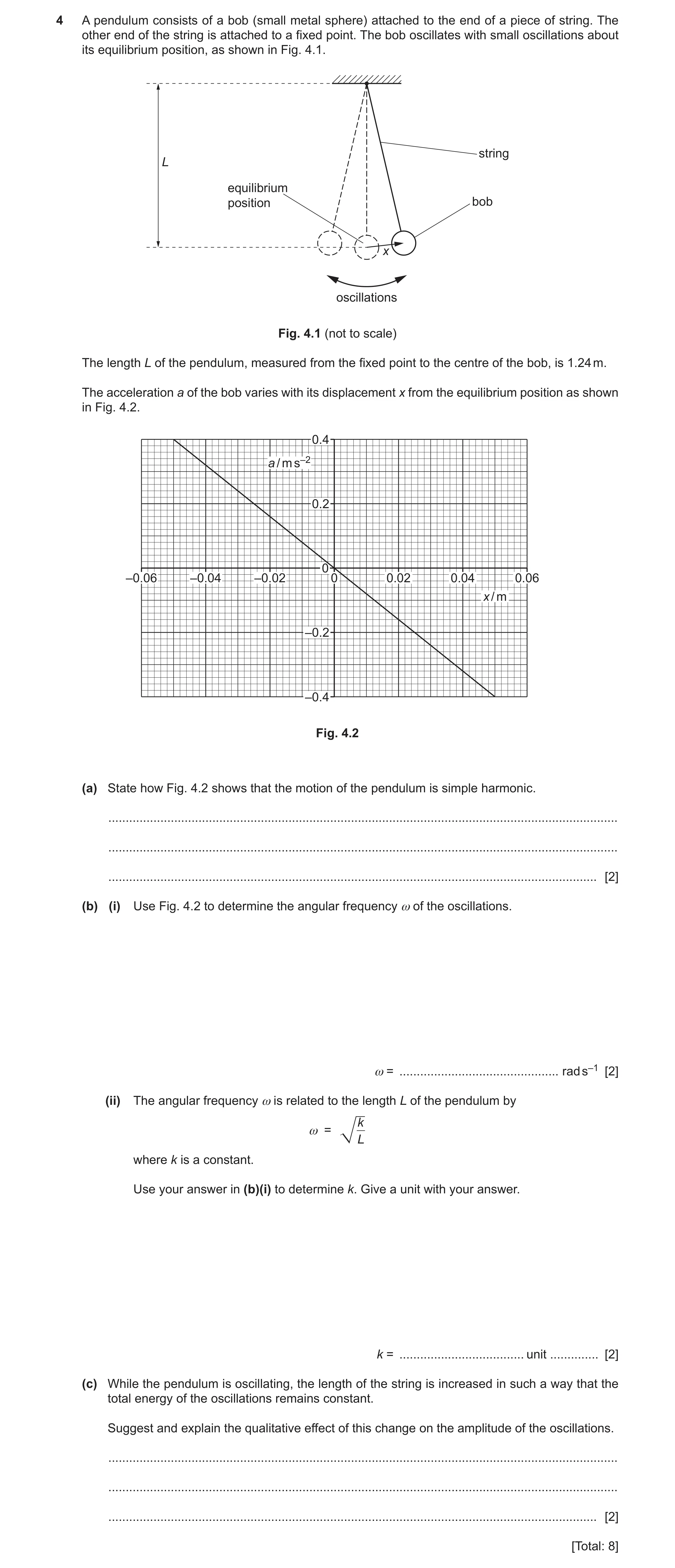
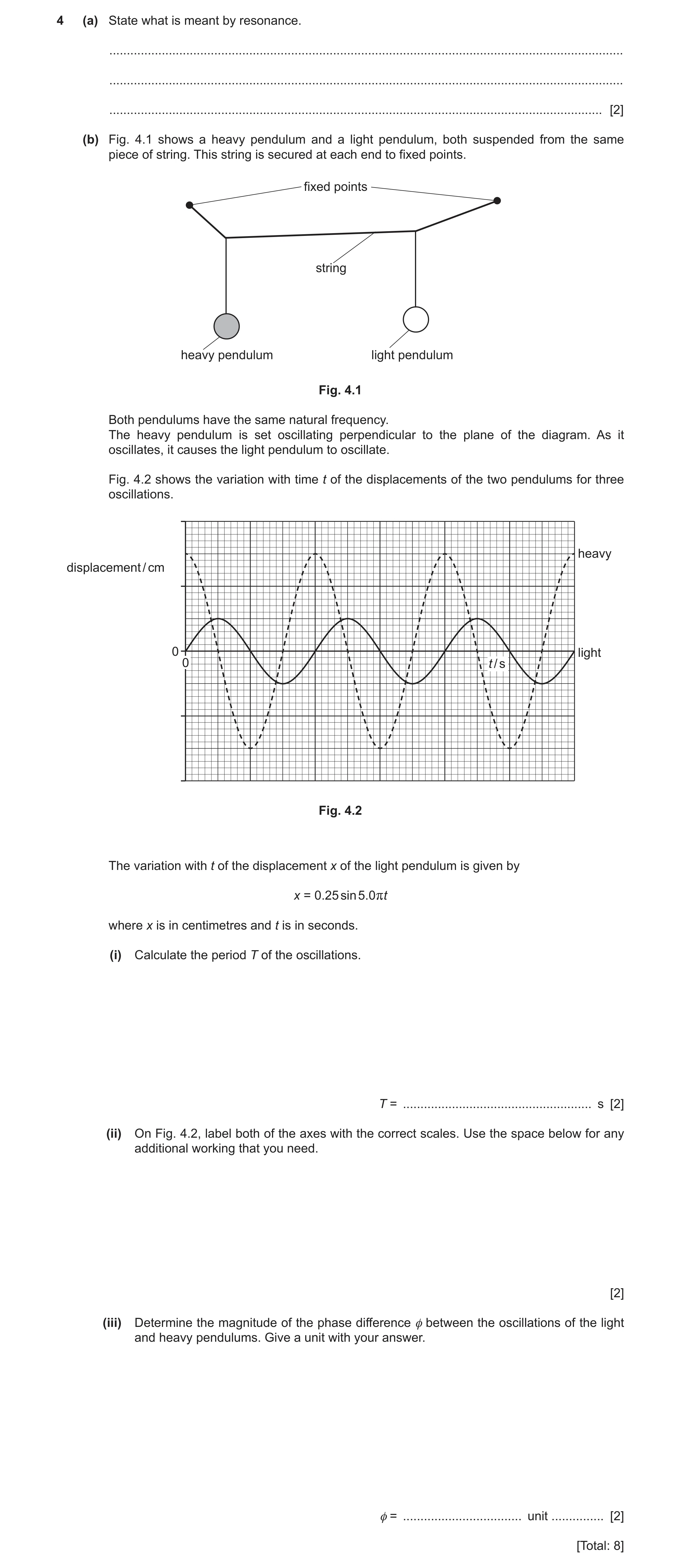
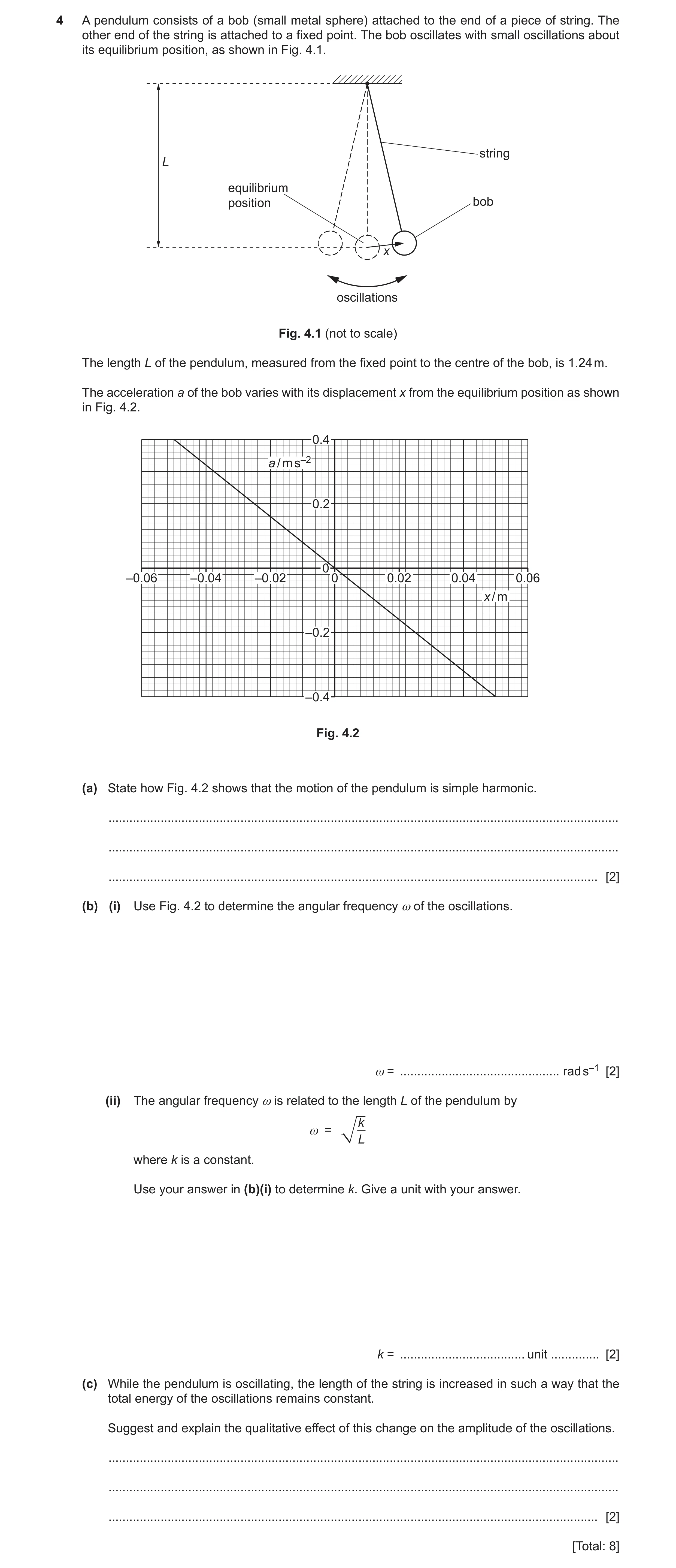
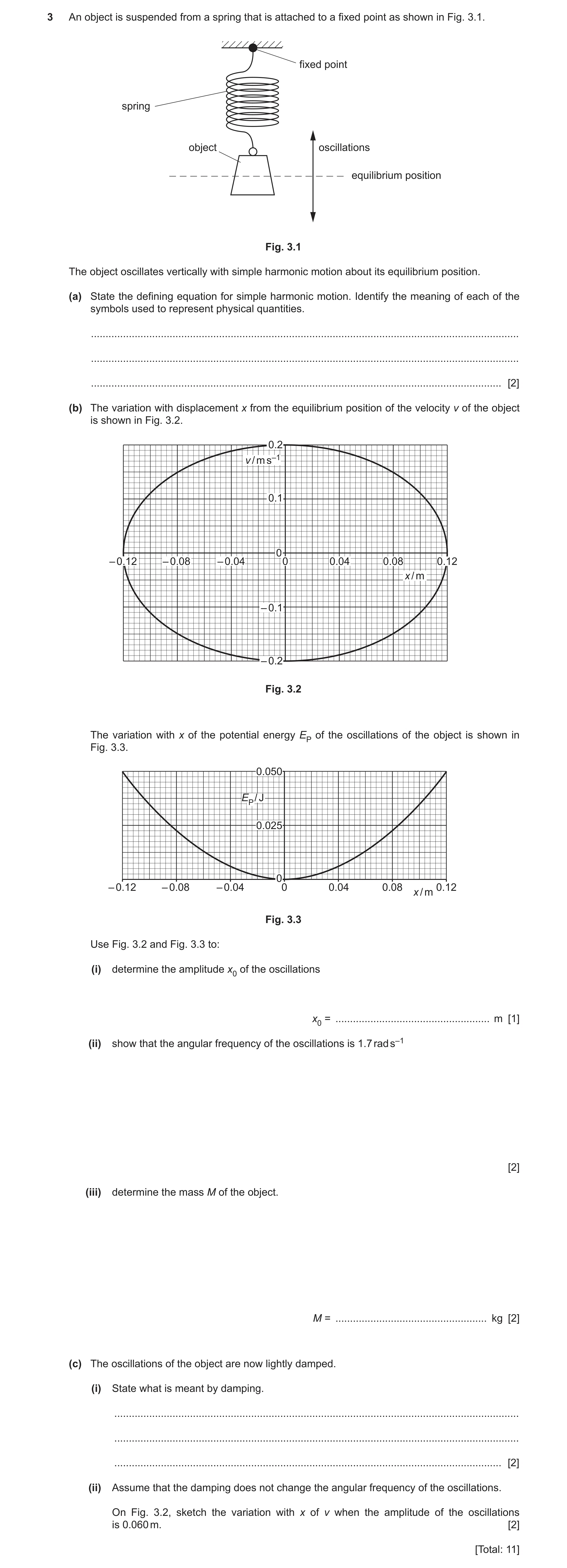
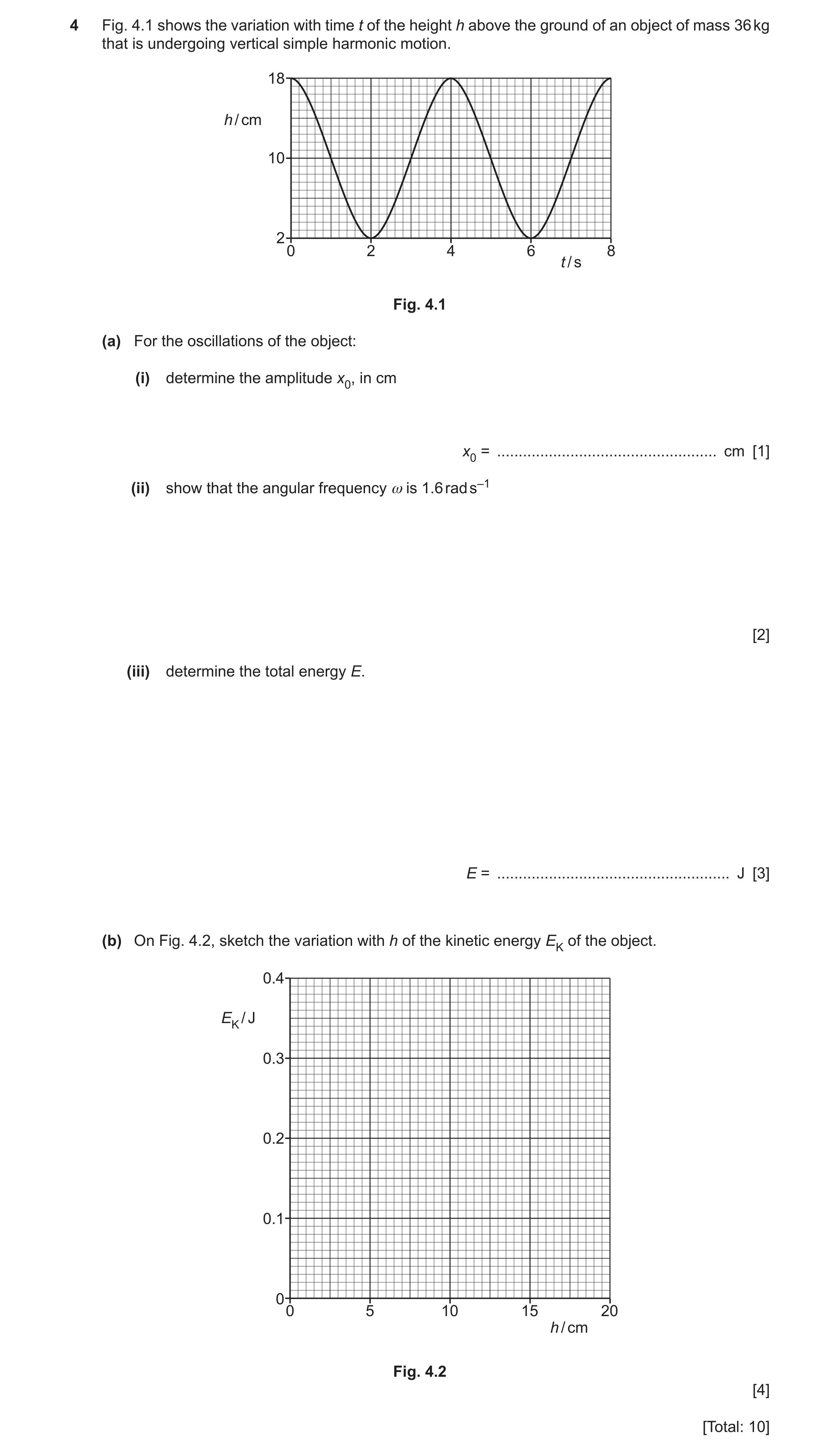
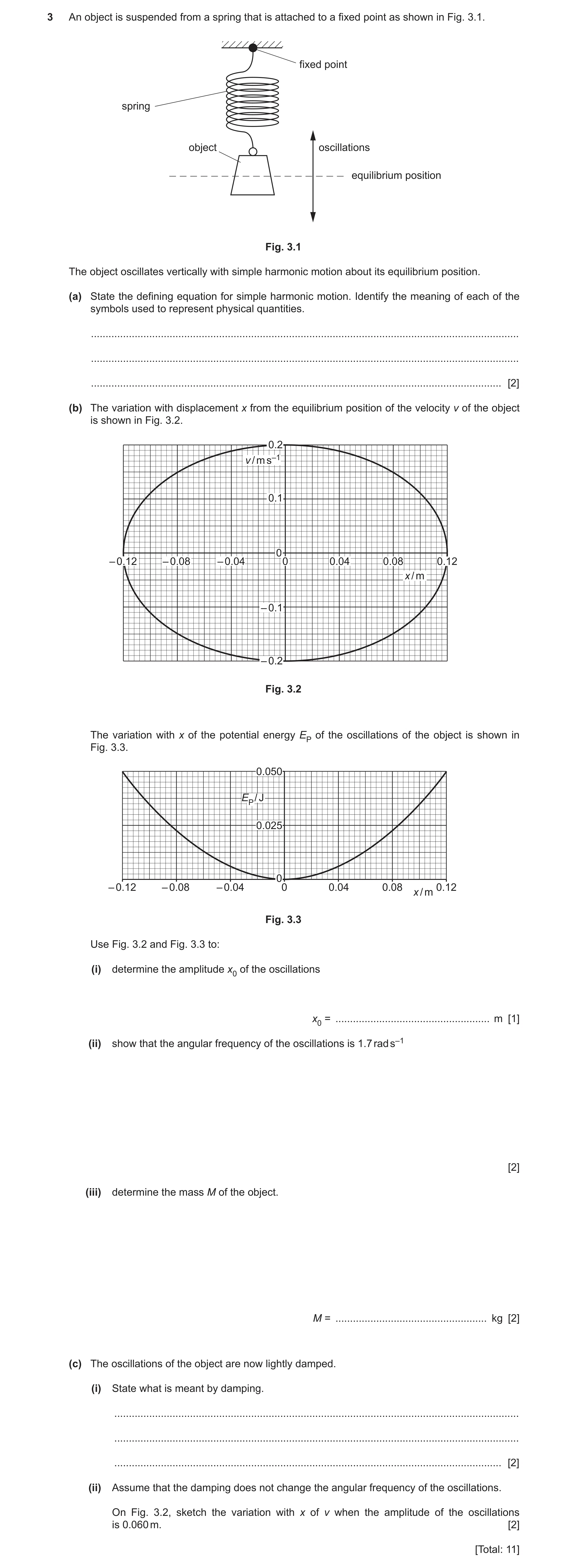
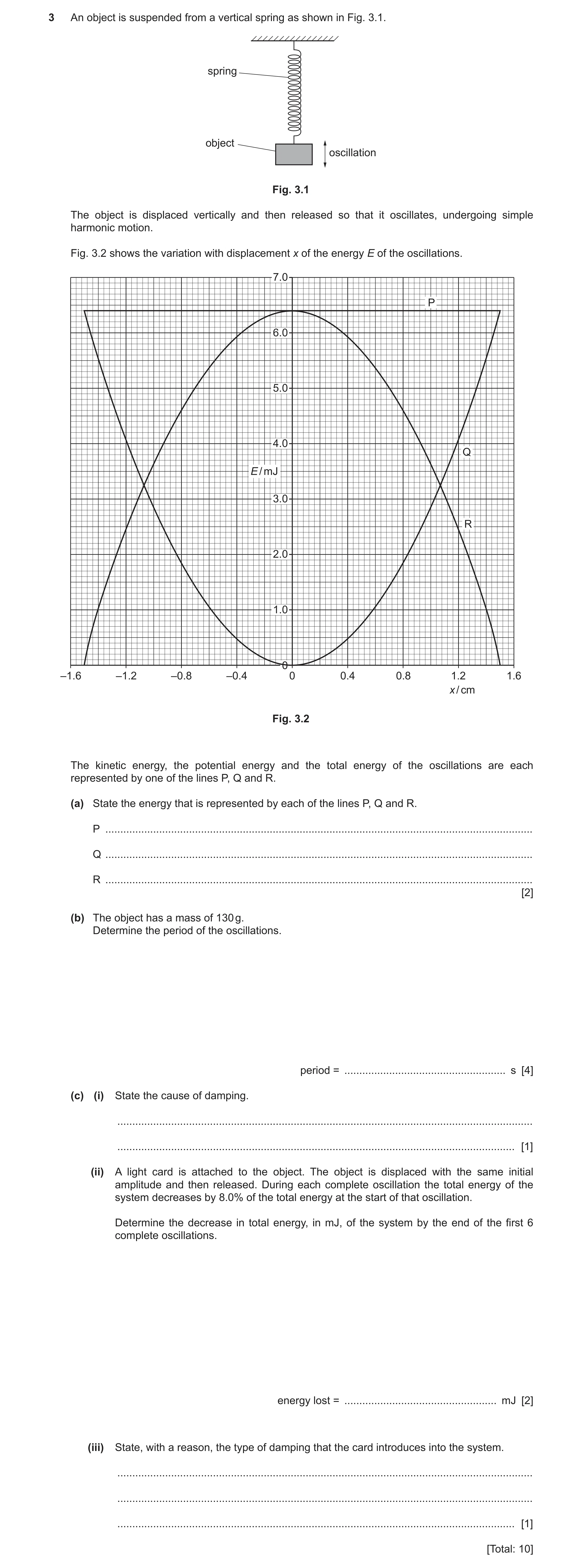
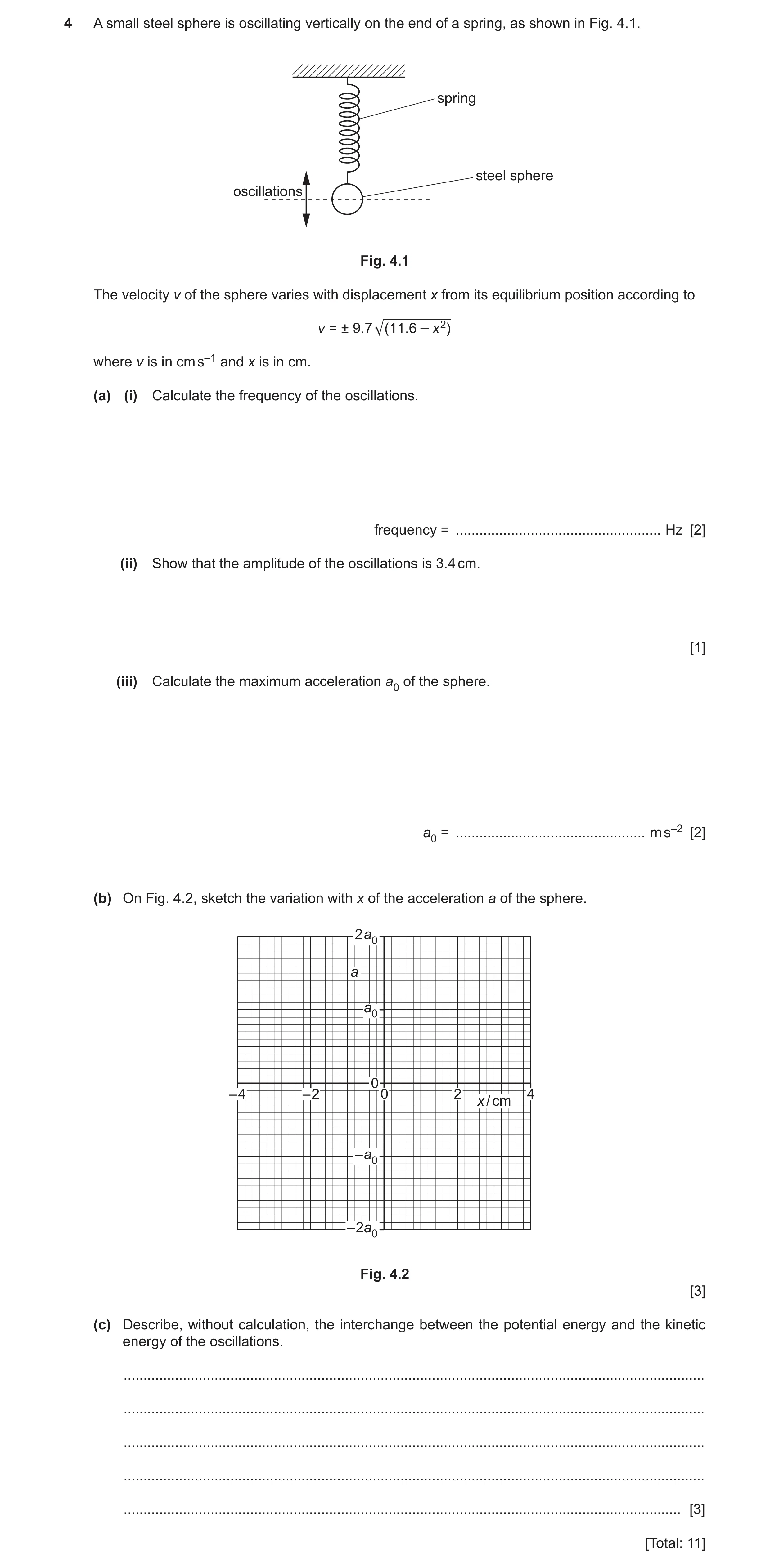
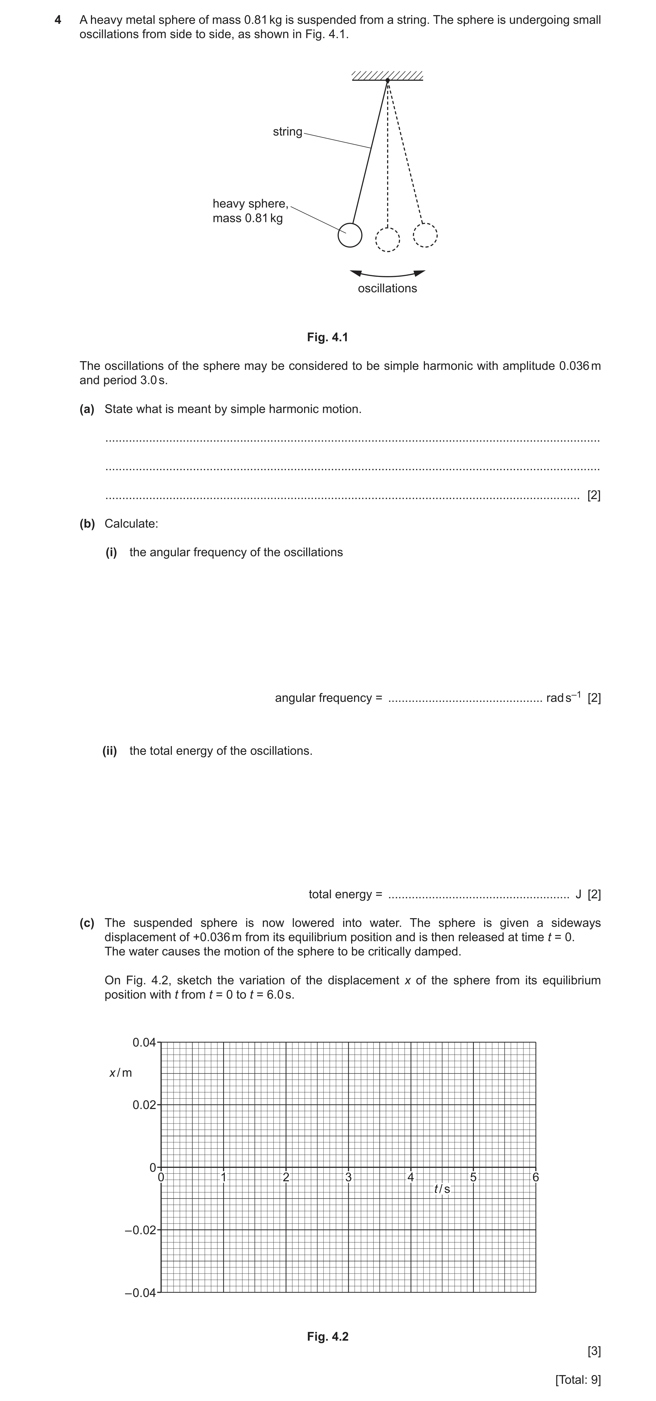
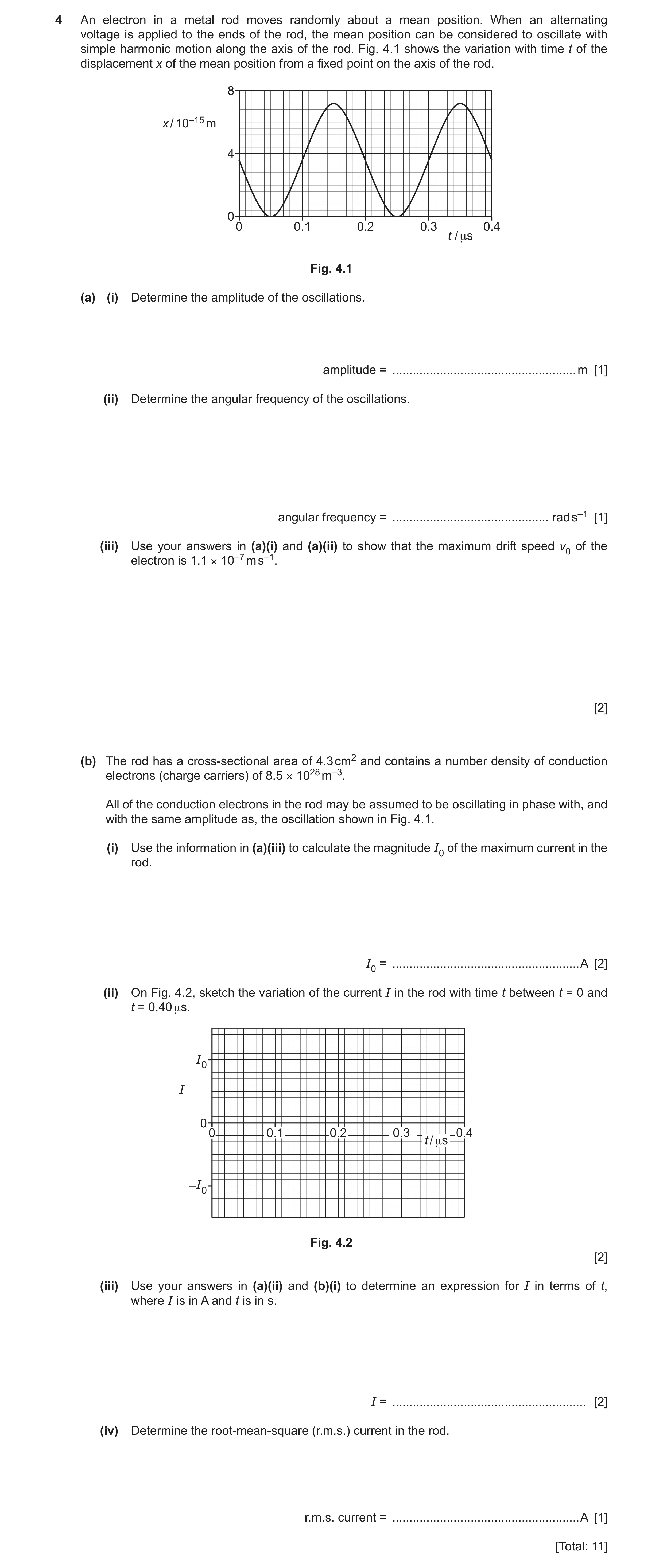
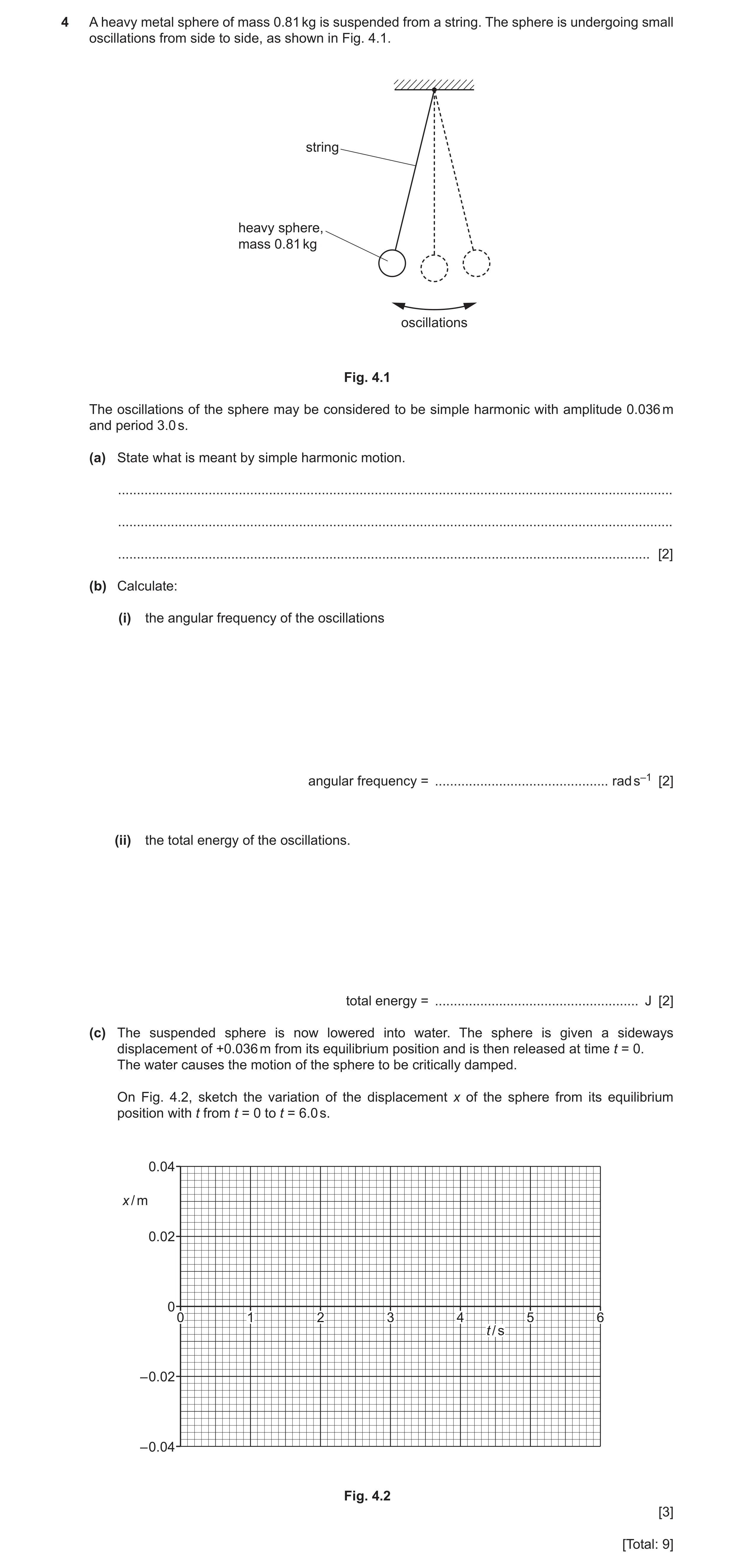
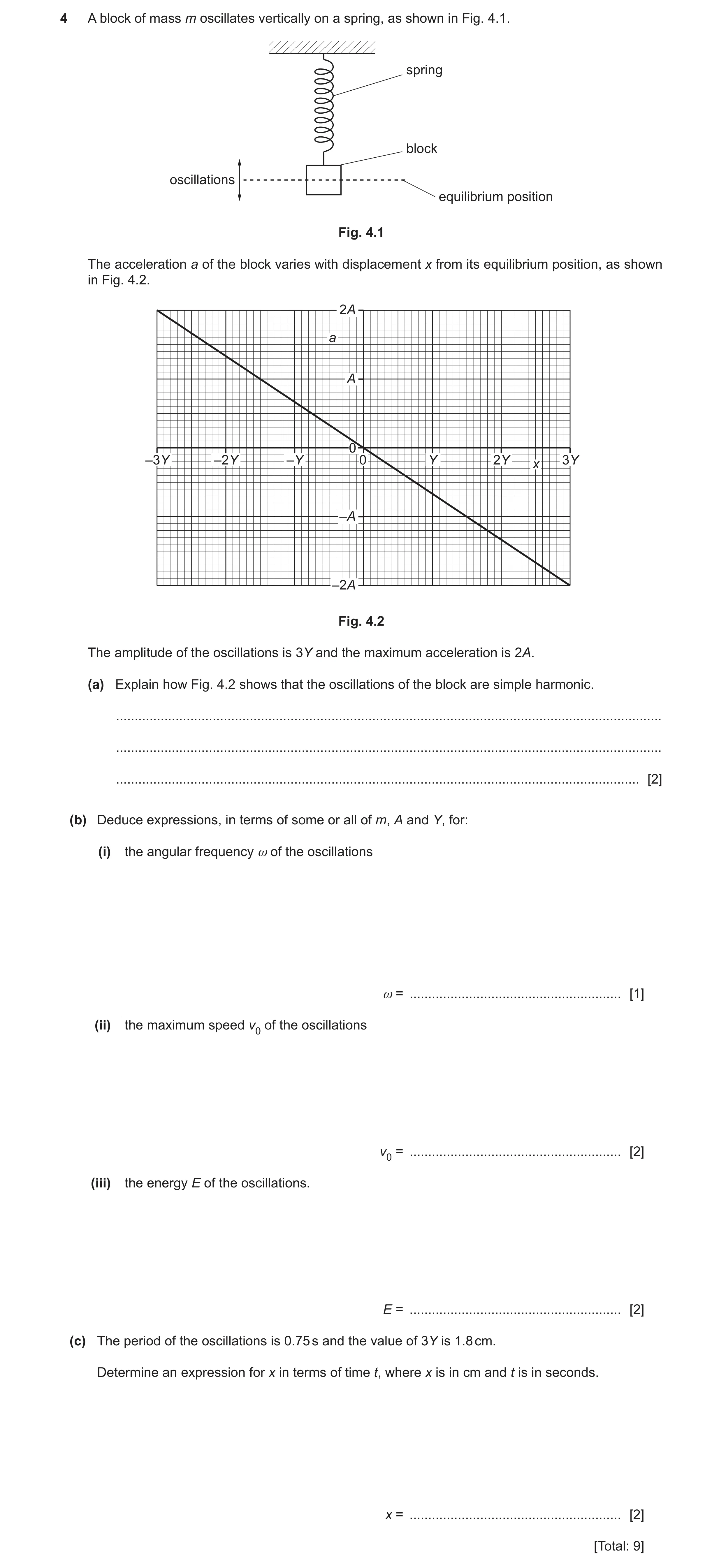
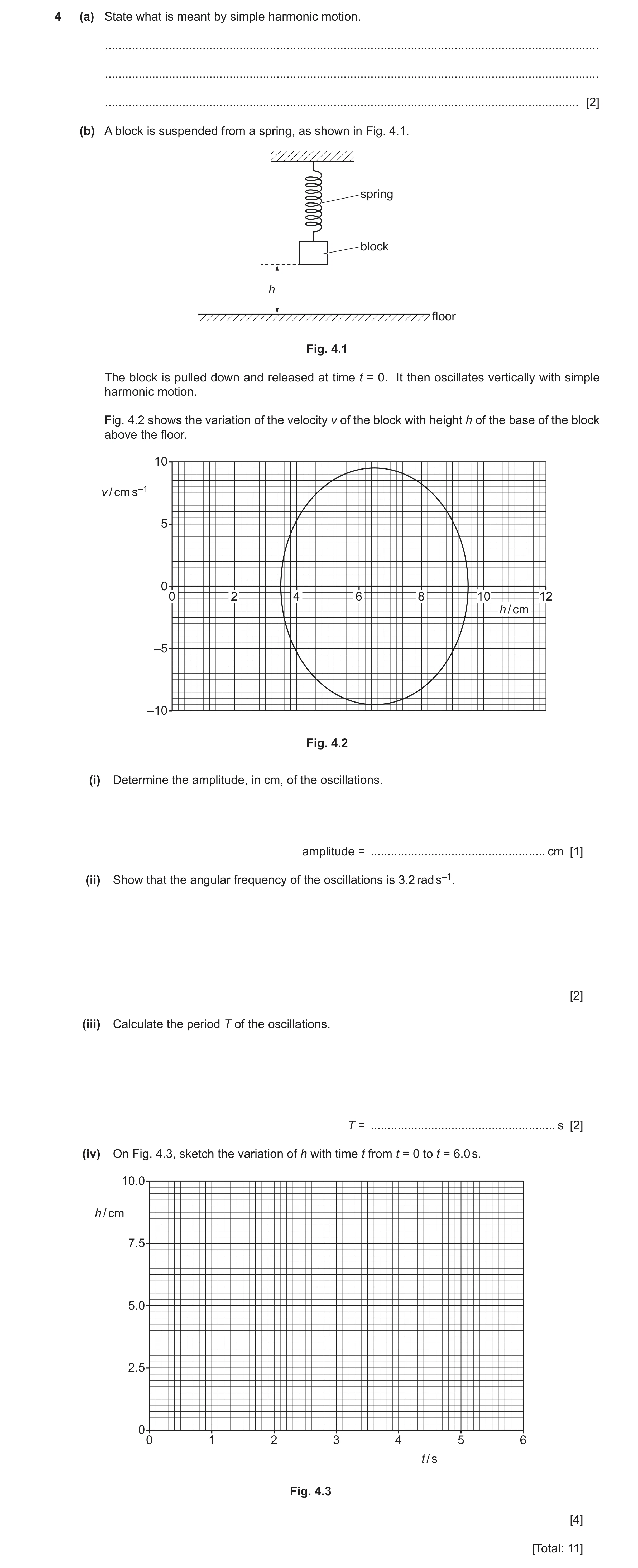
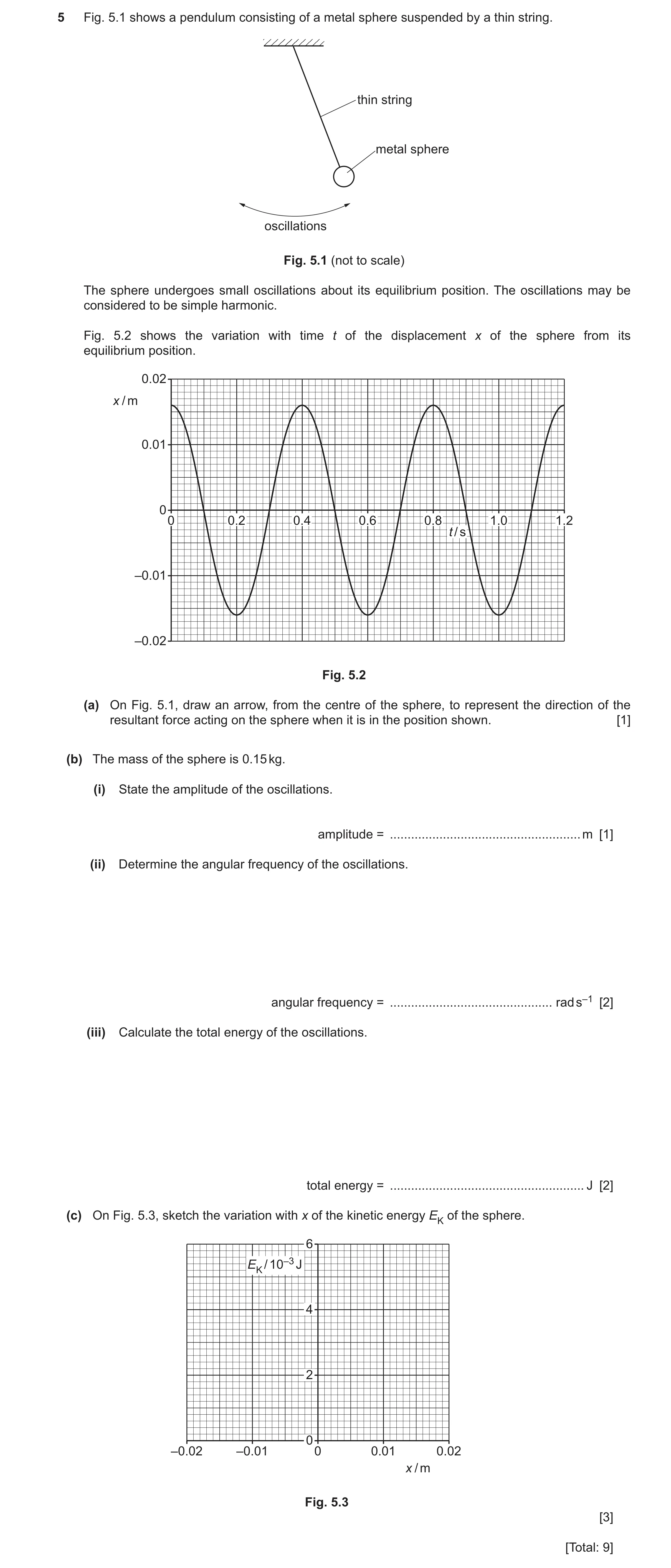
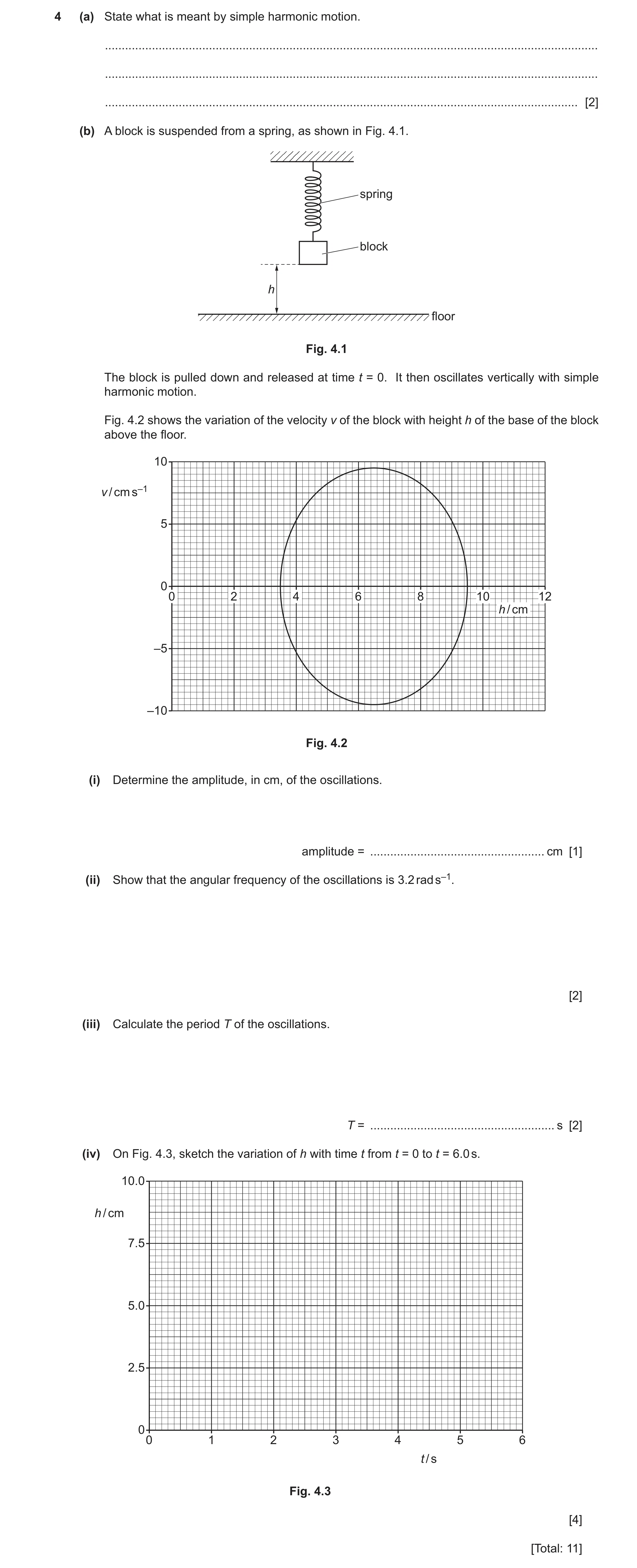
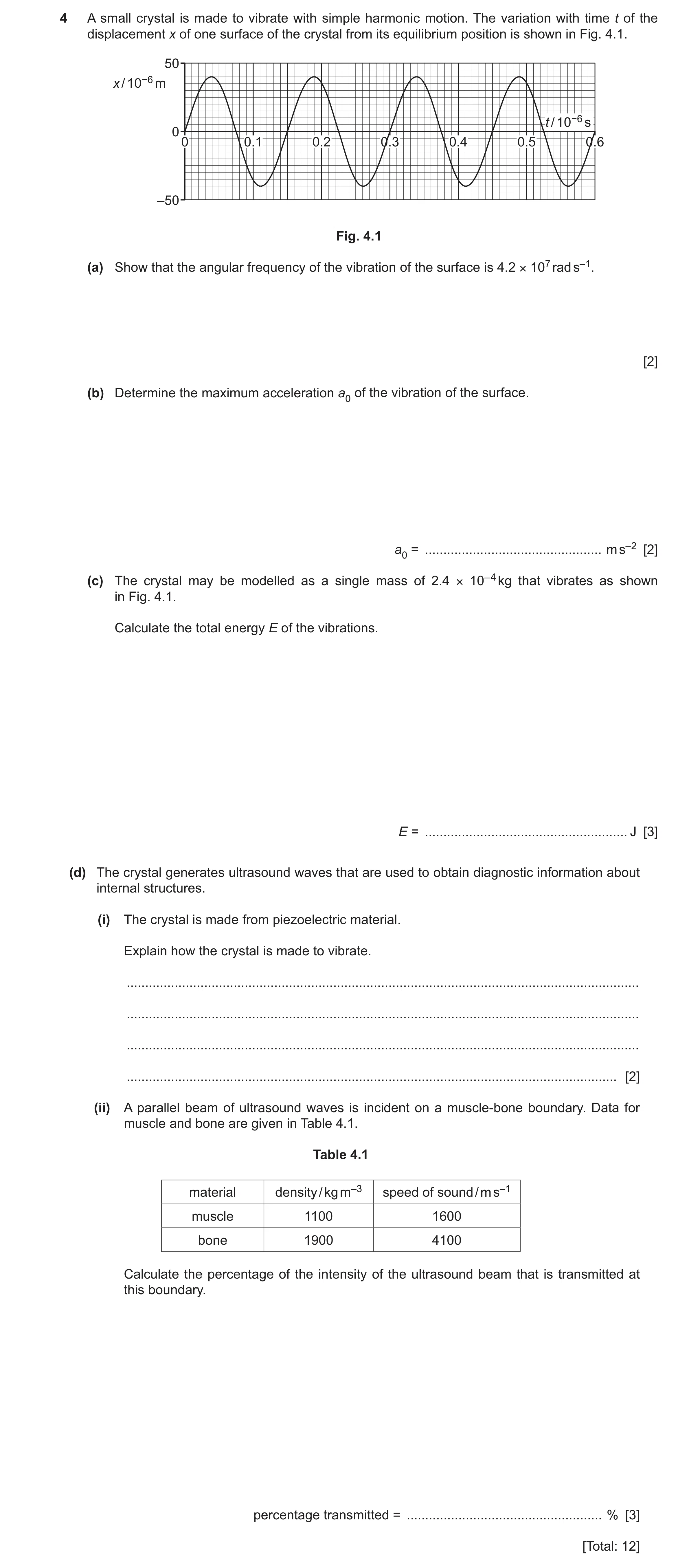
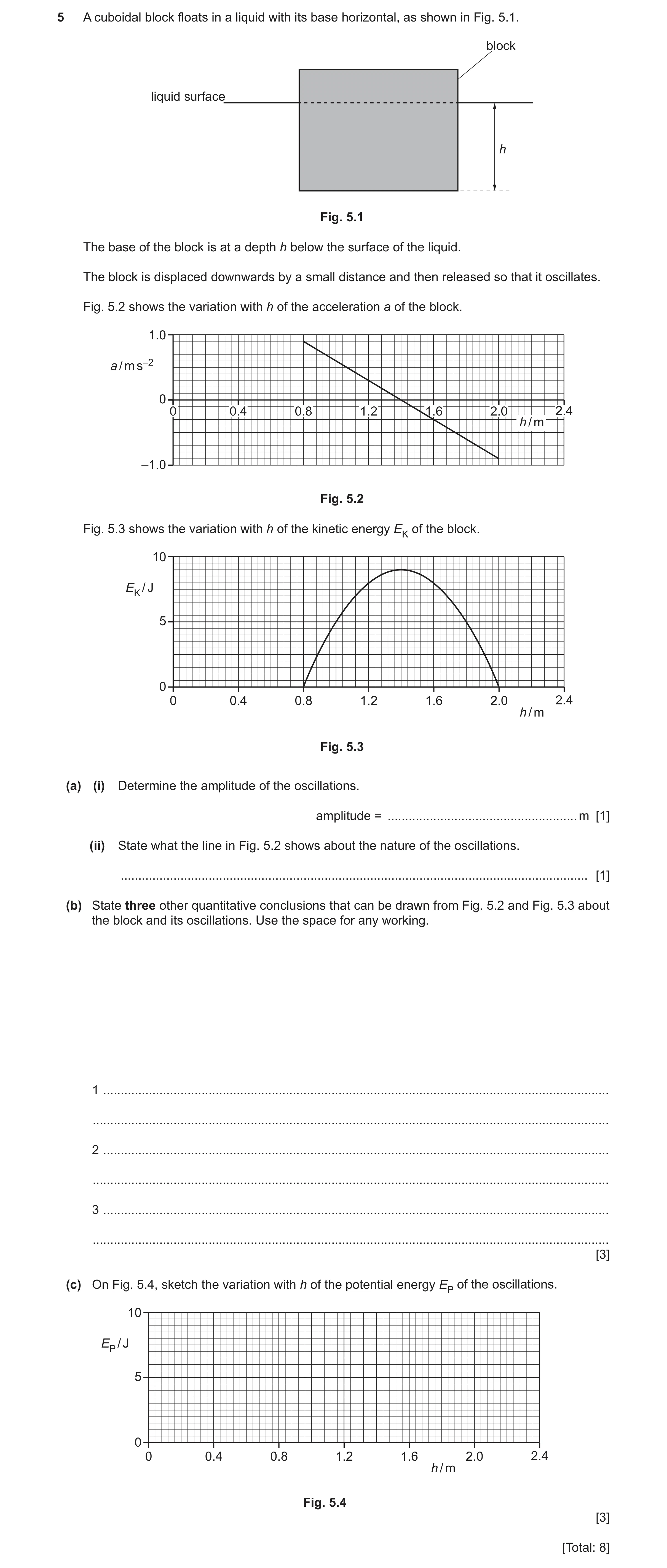
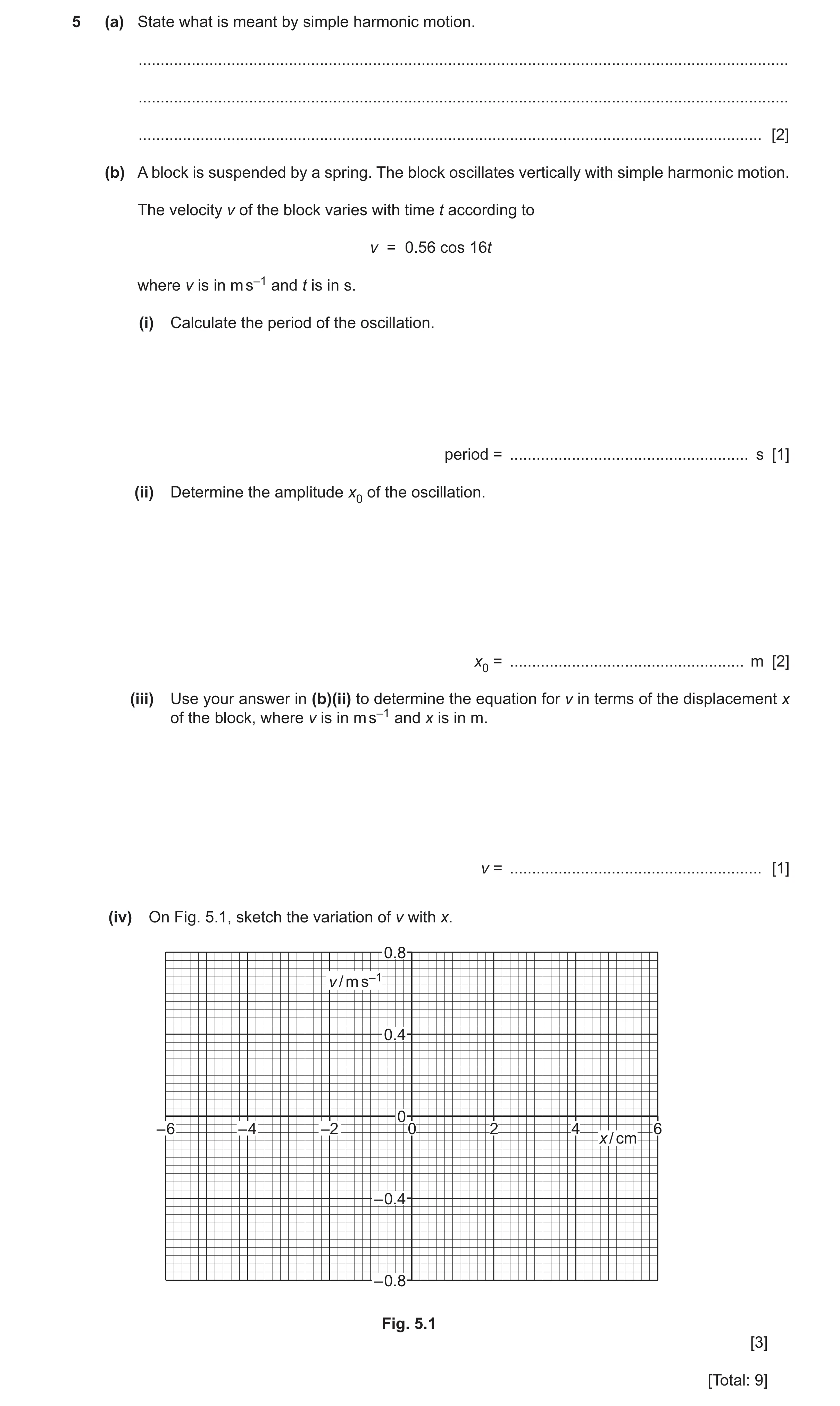
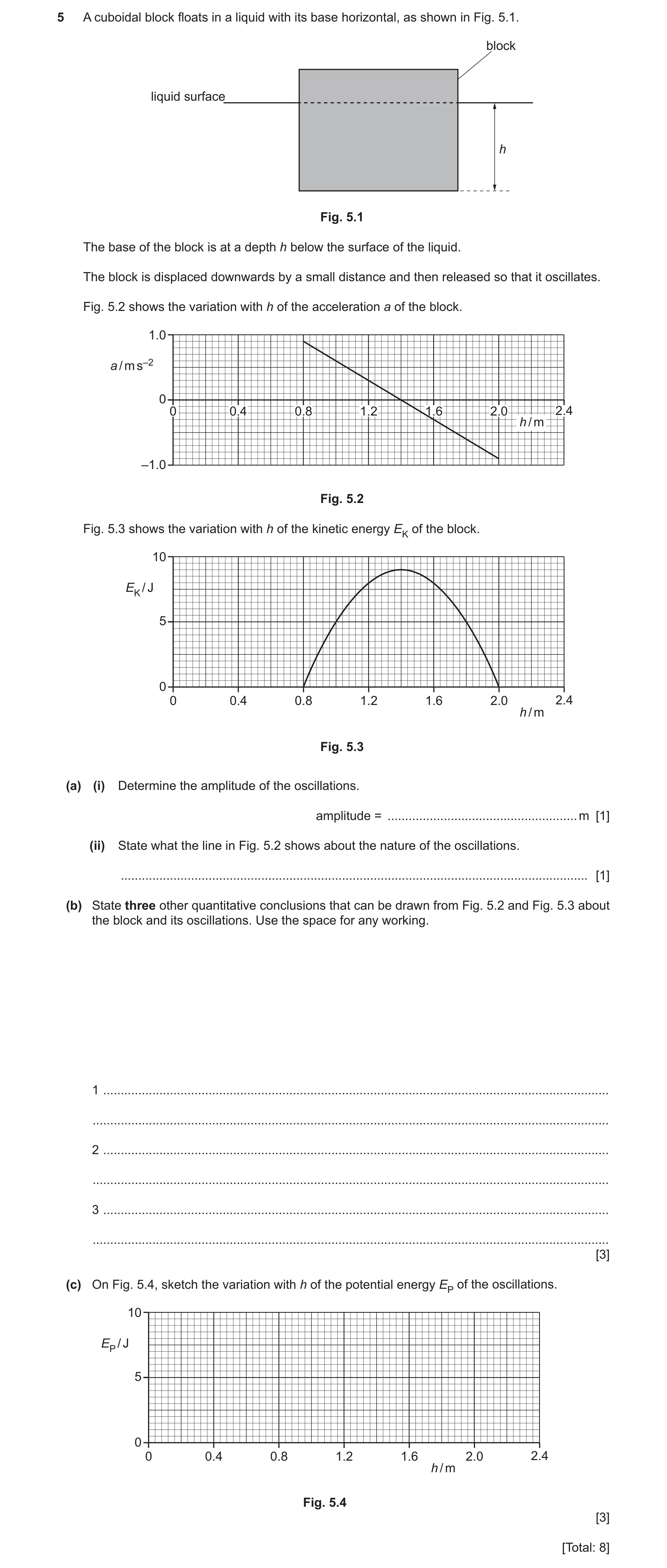
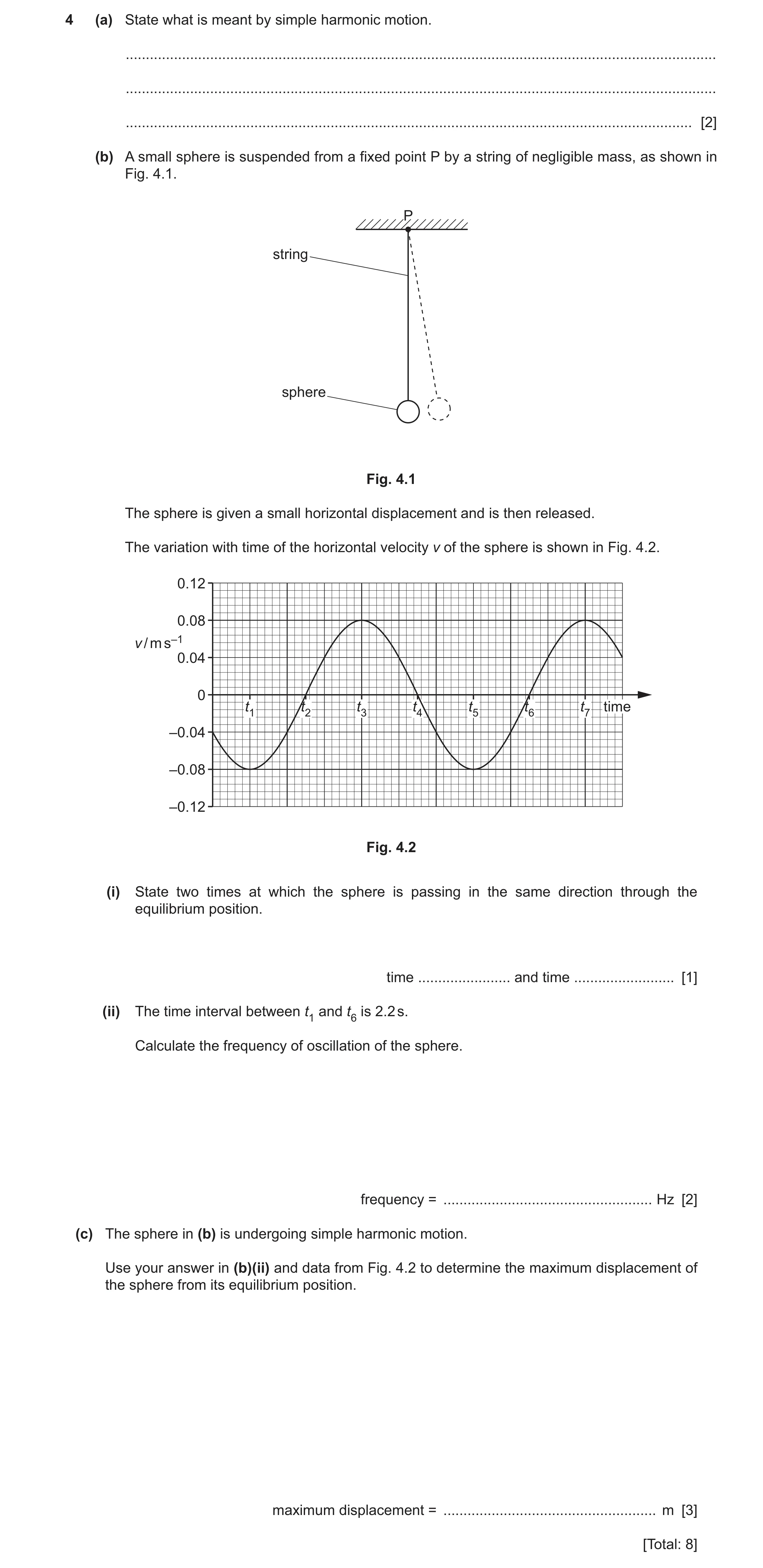
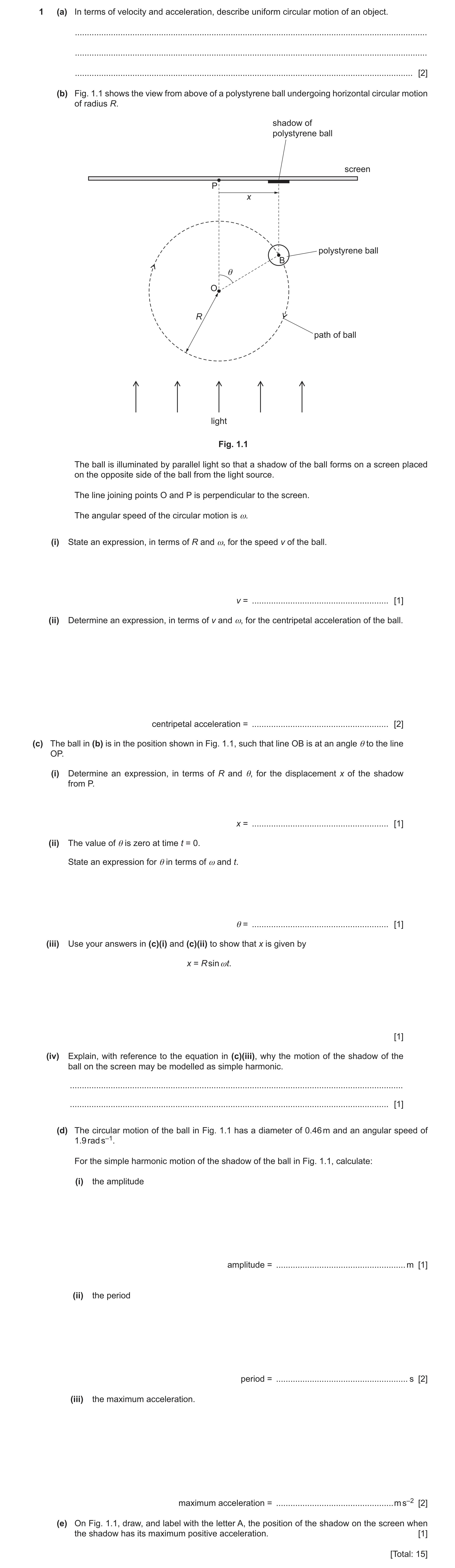
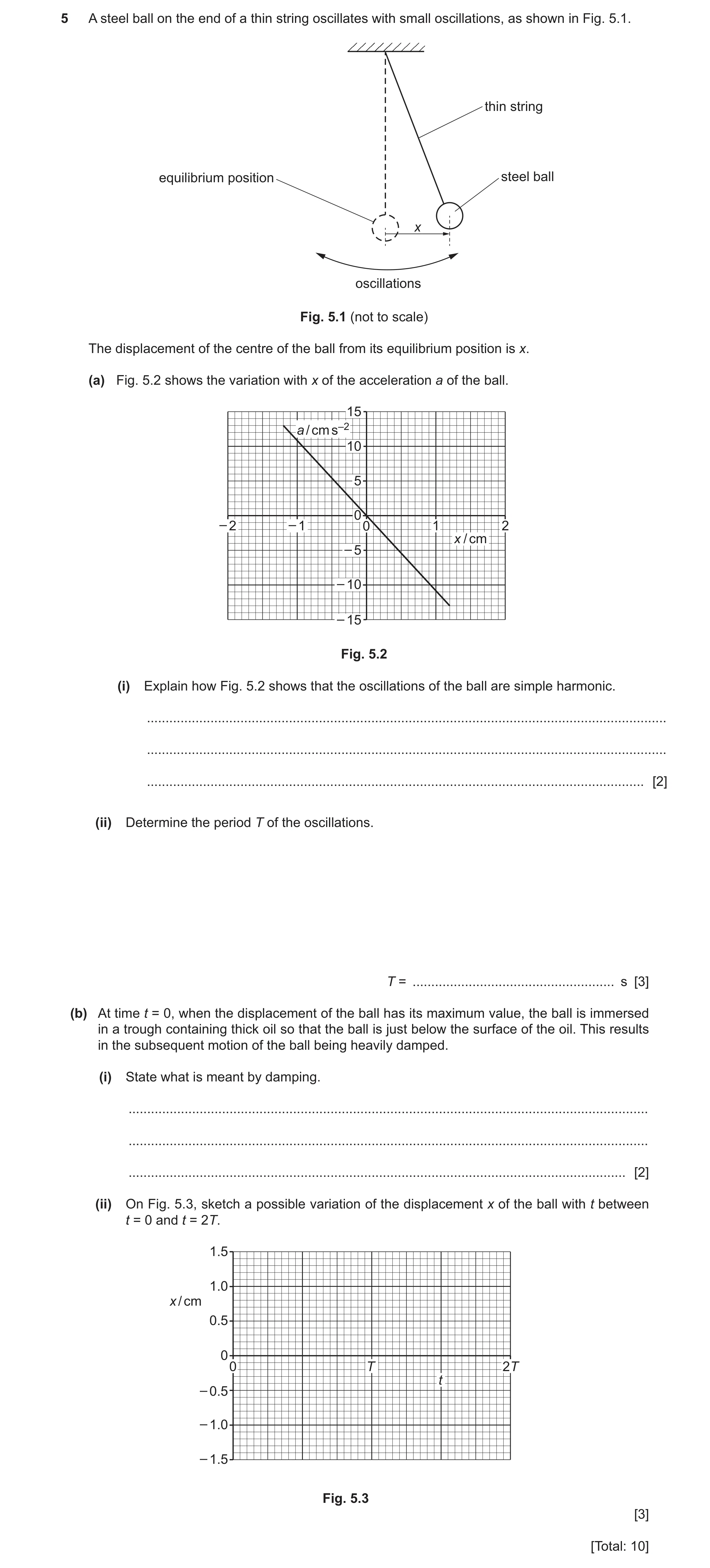
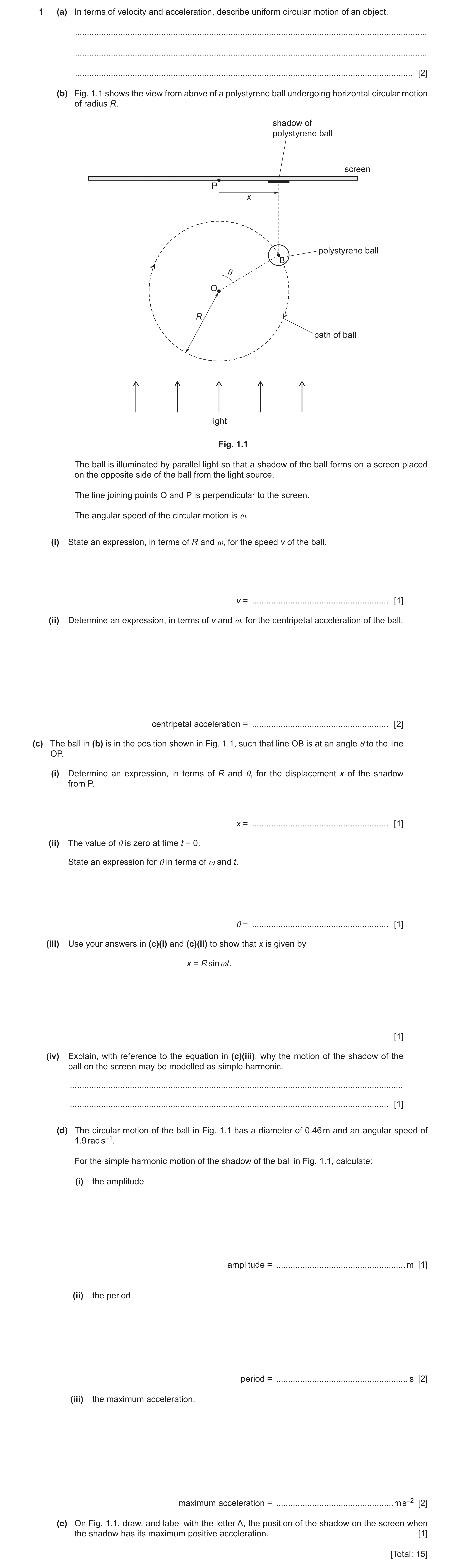
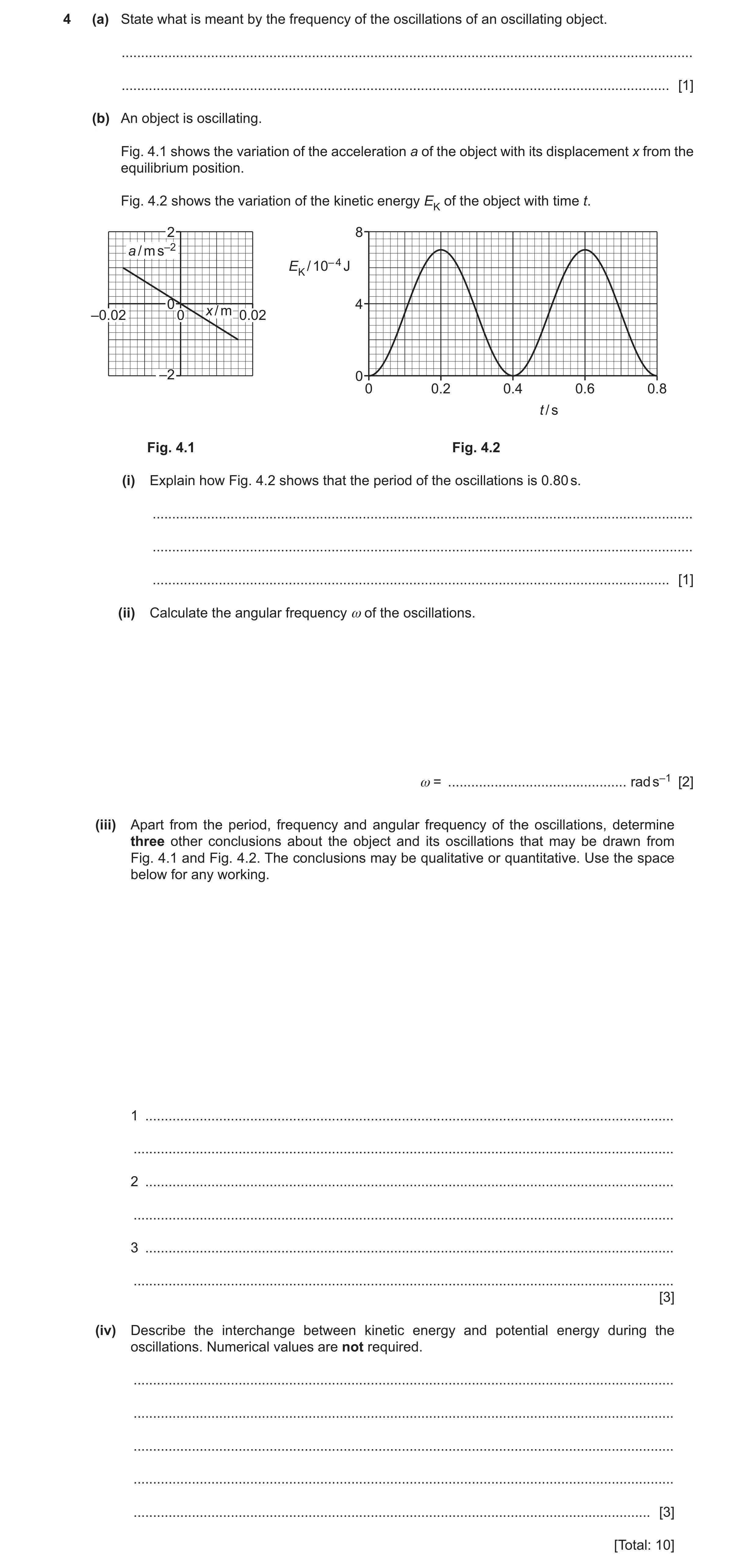
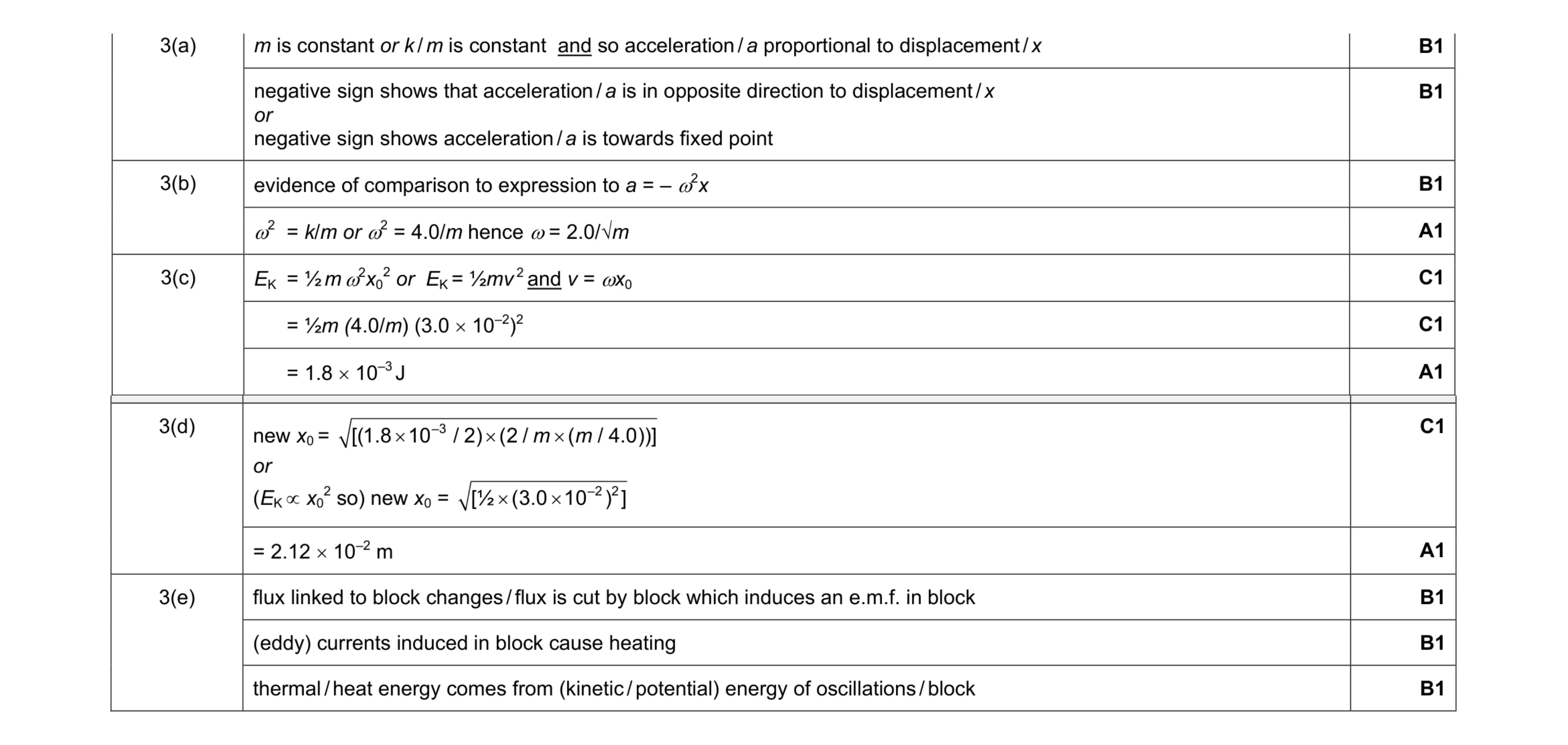 12
12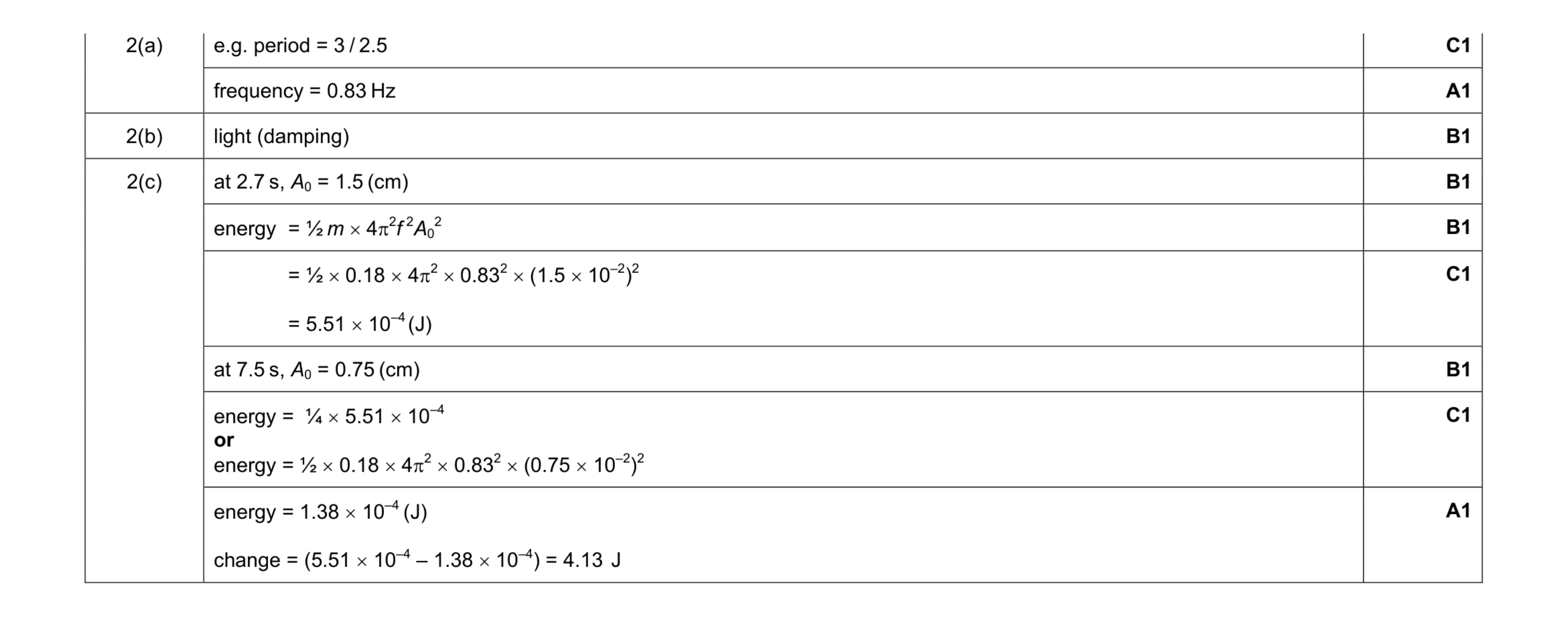 9
9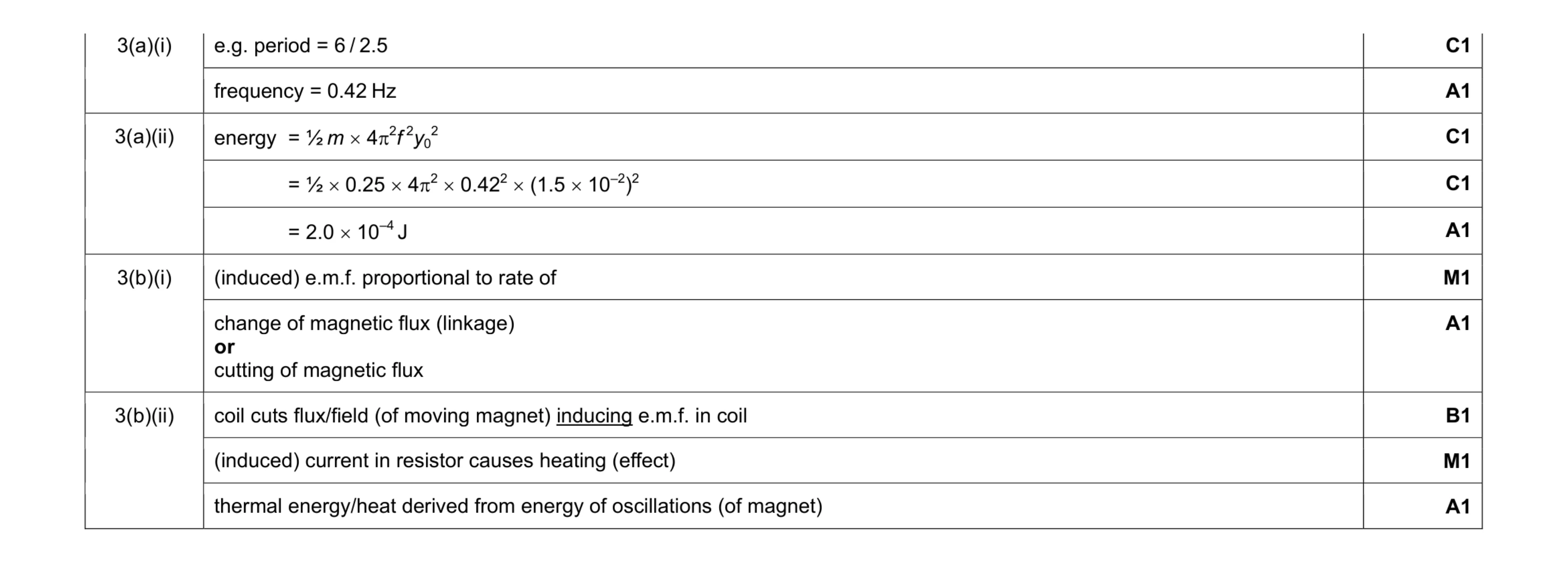 10
10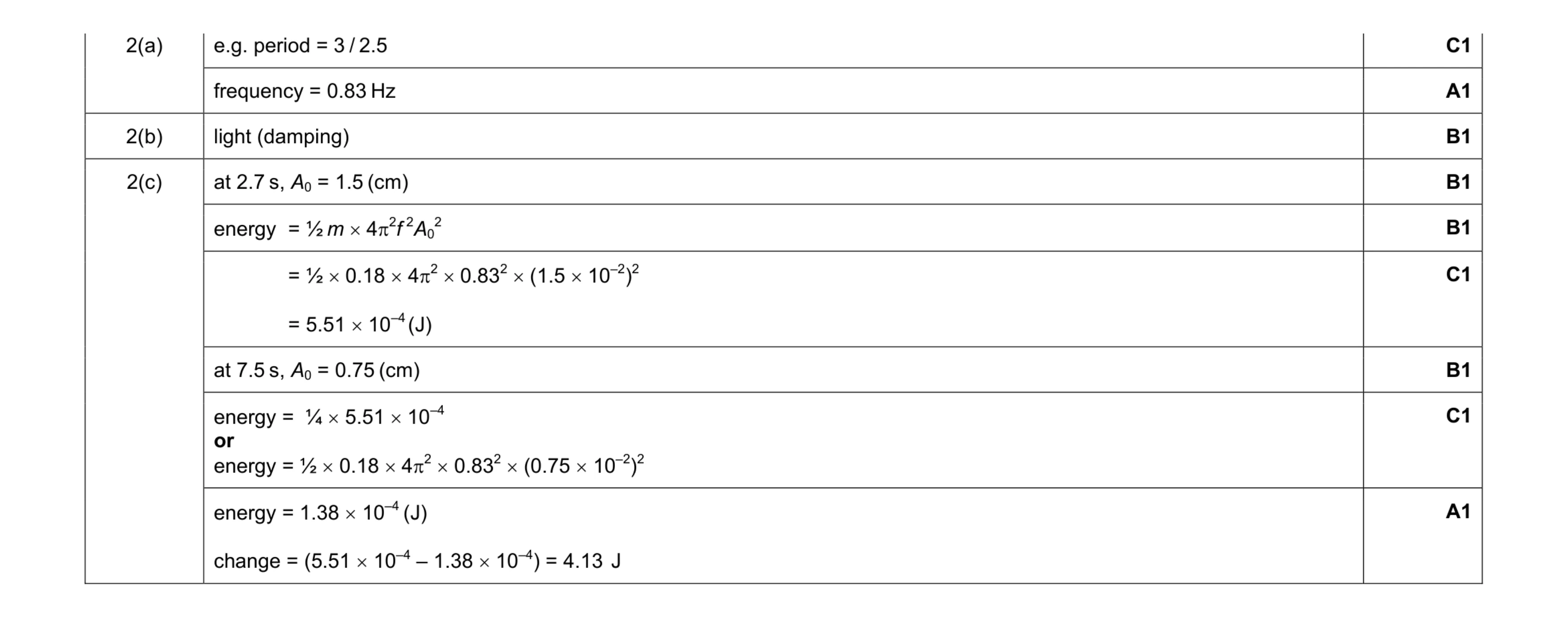 9
9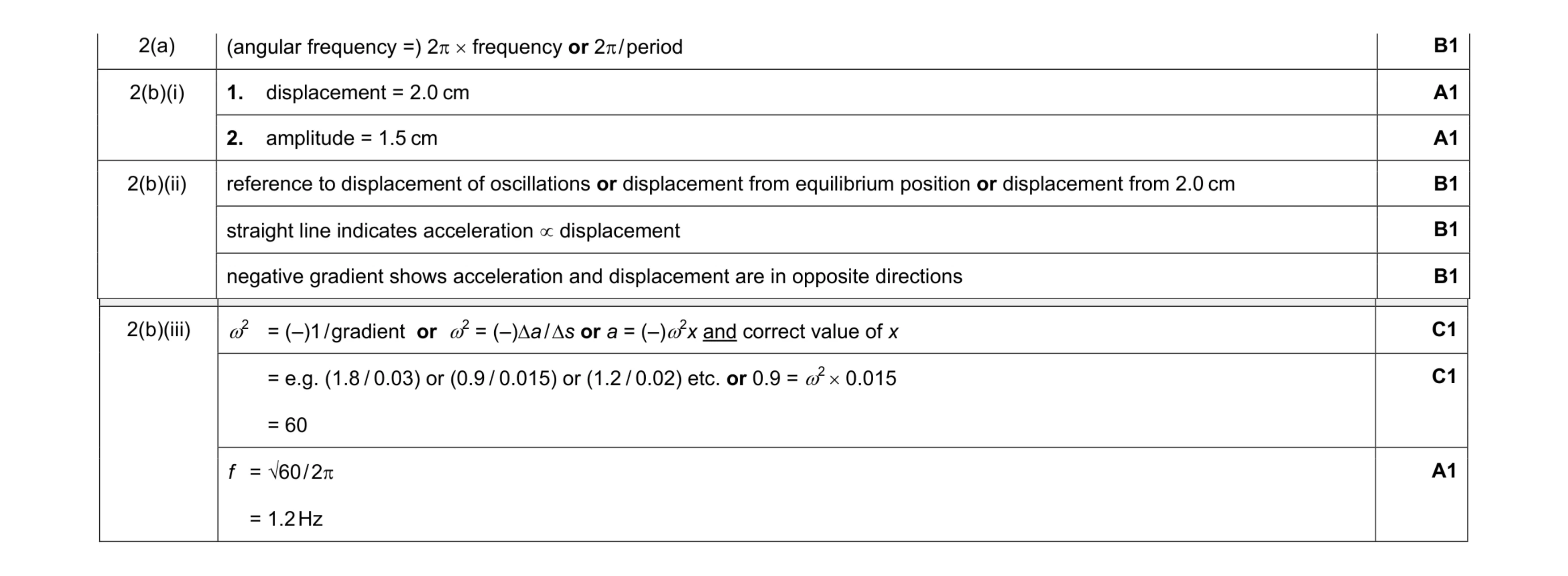 9
9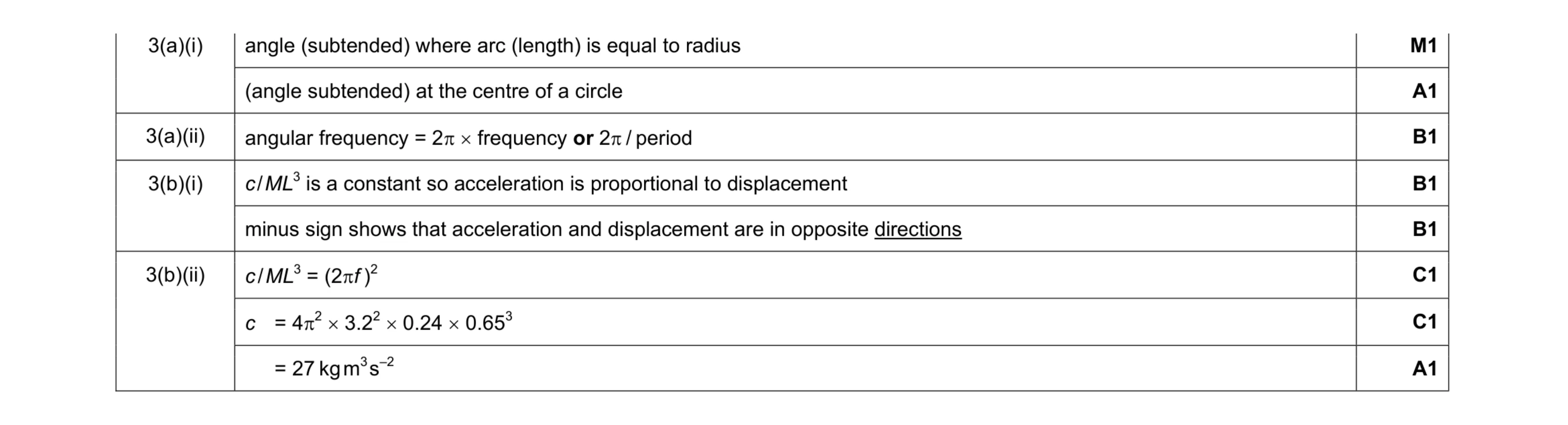 8
8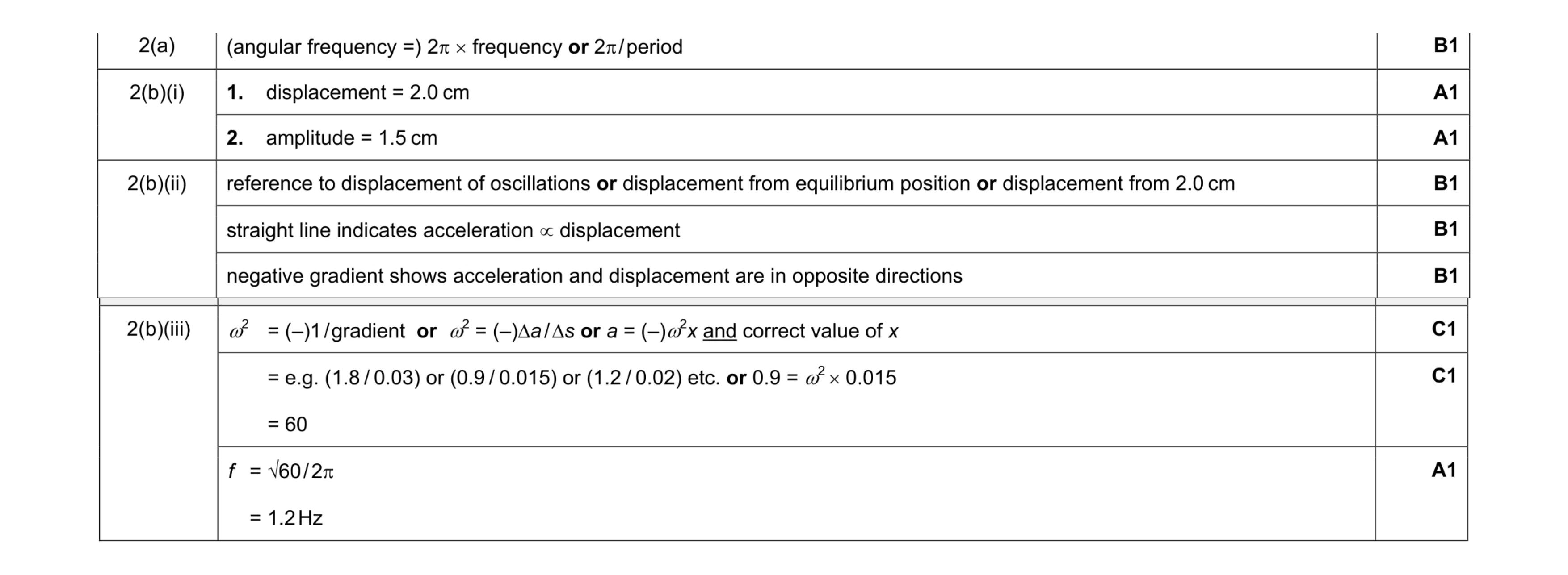 9
9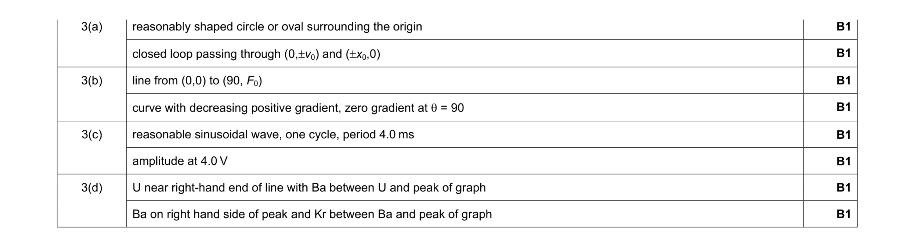 8
8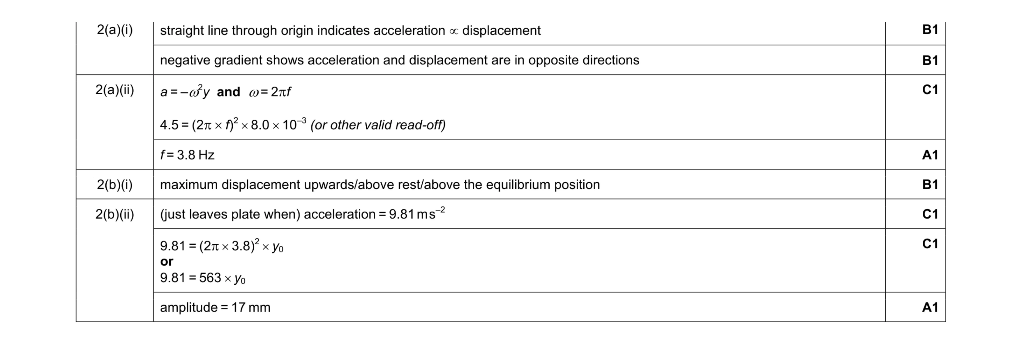 8
8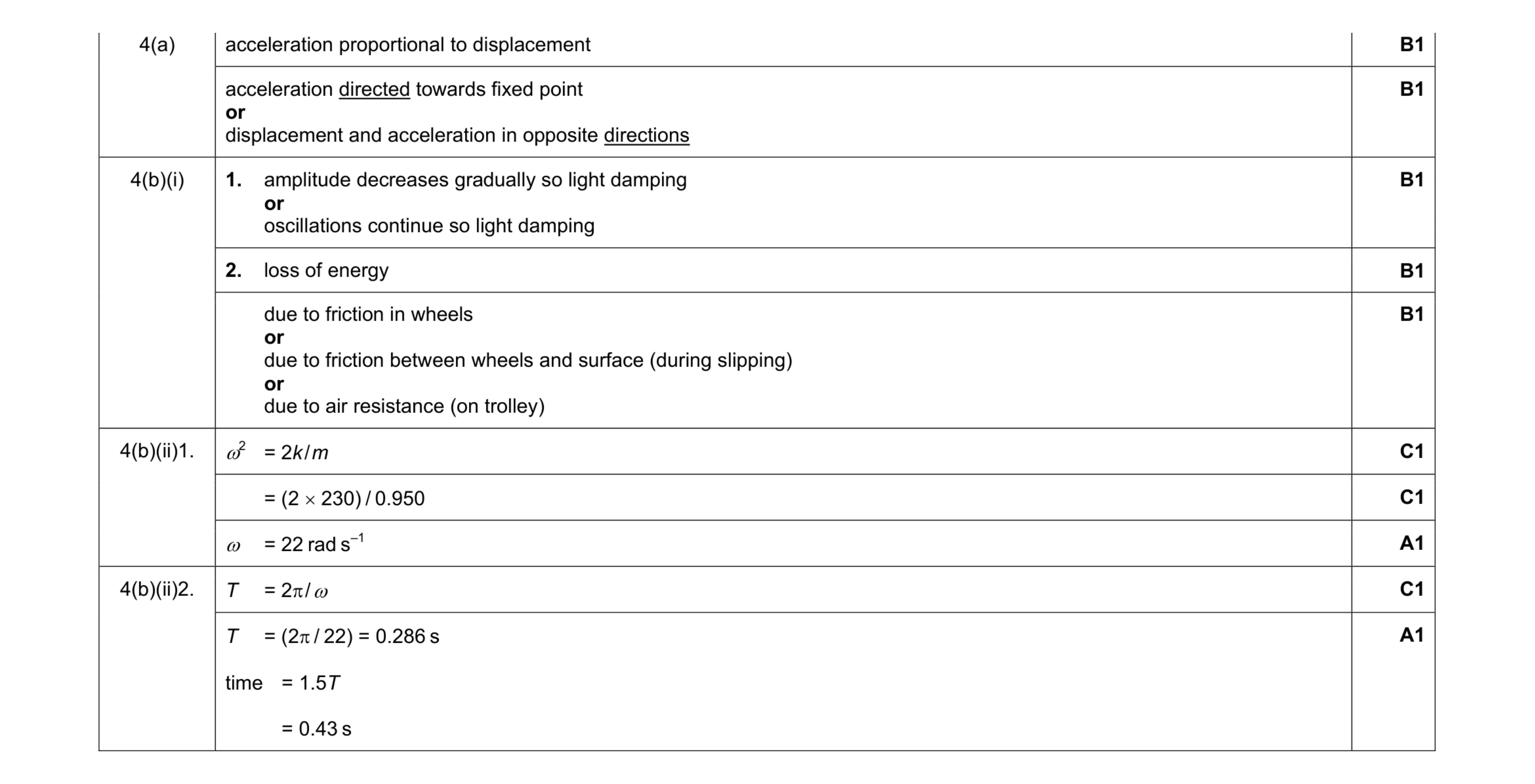 10
10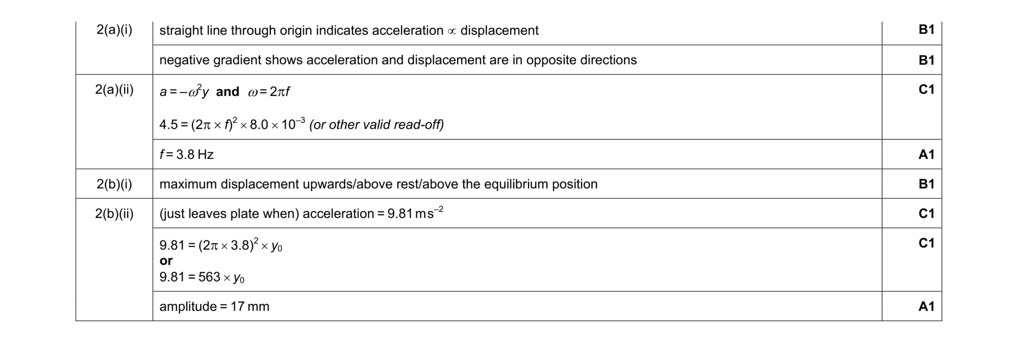 8
8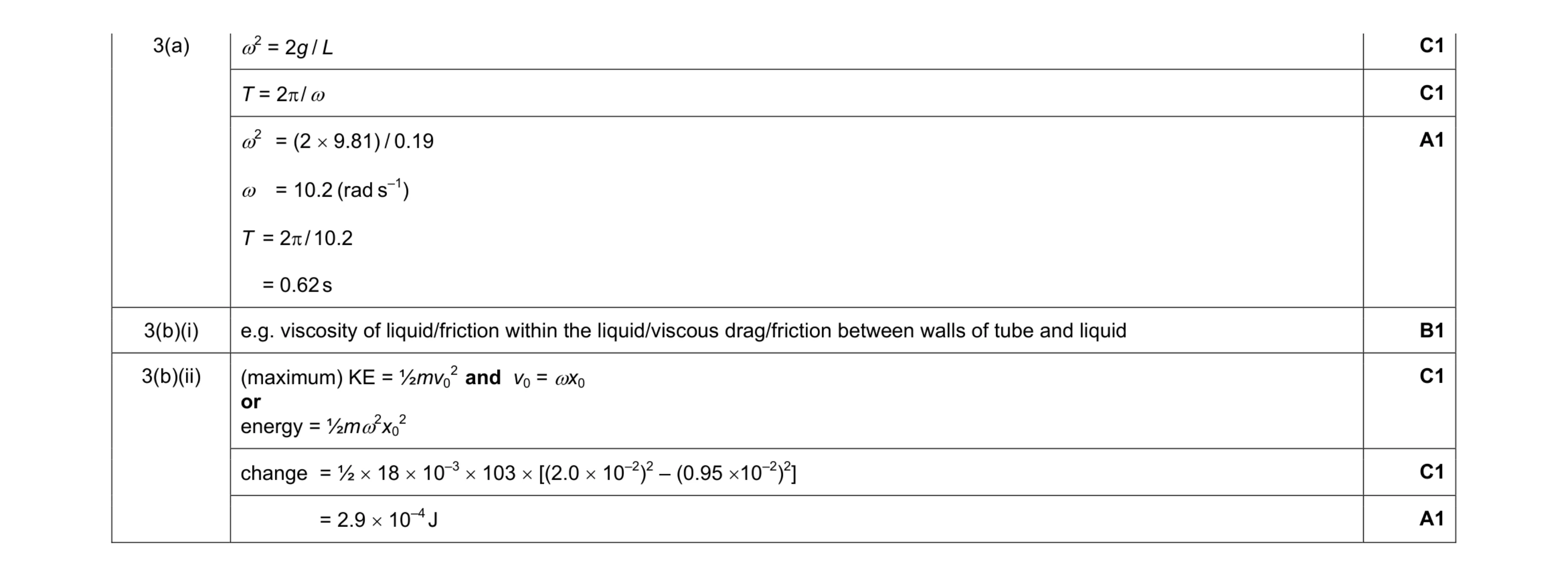 7
7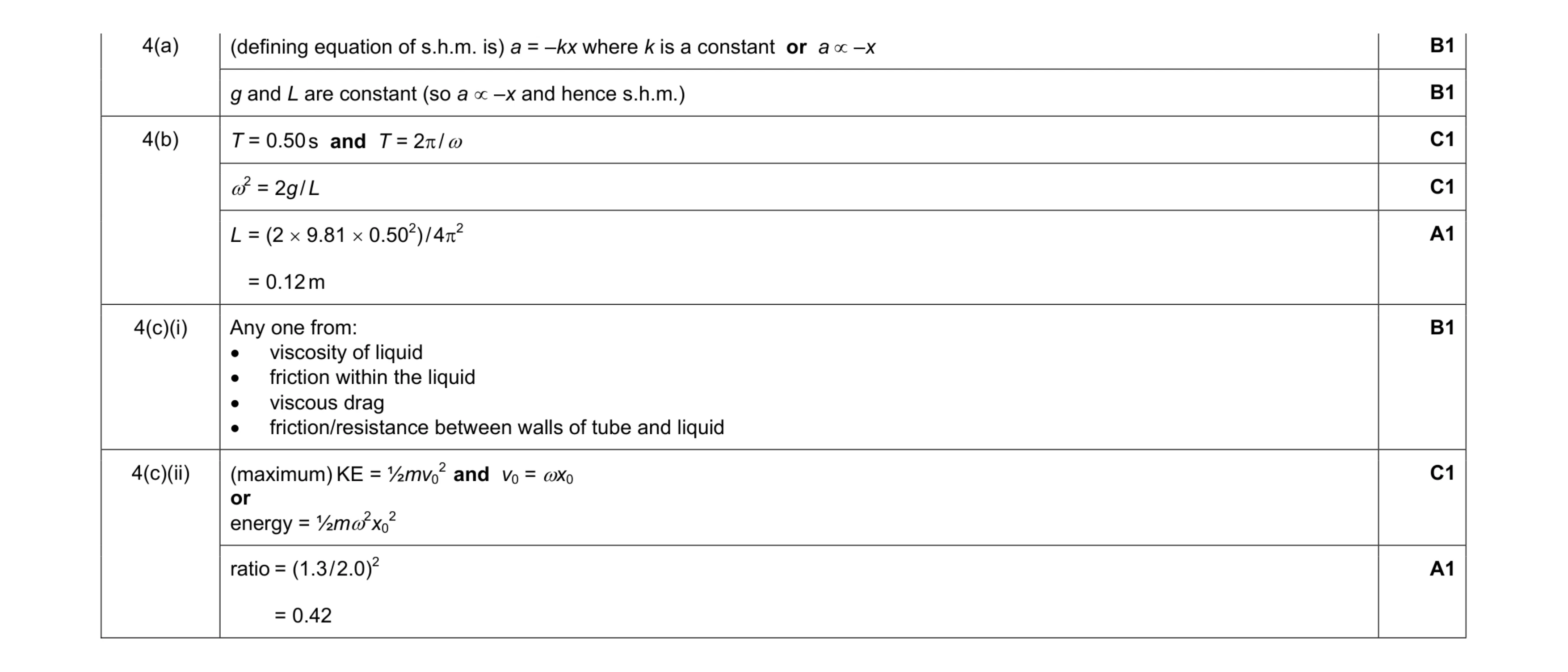 8
8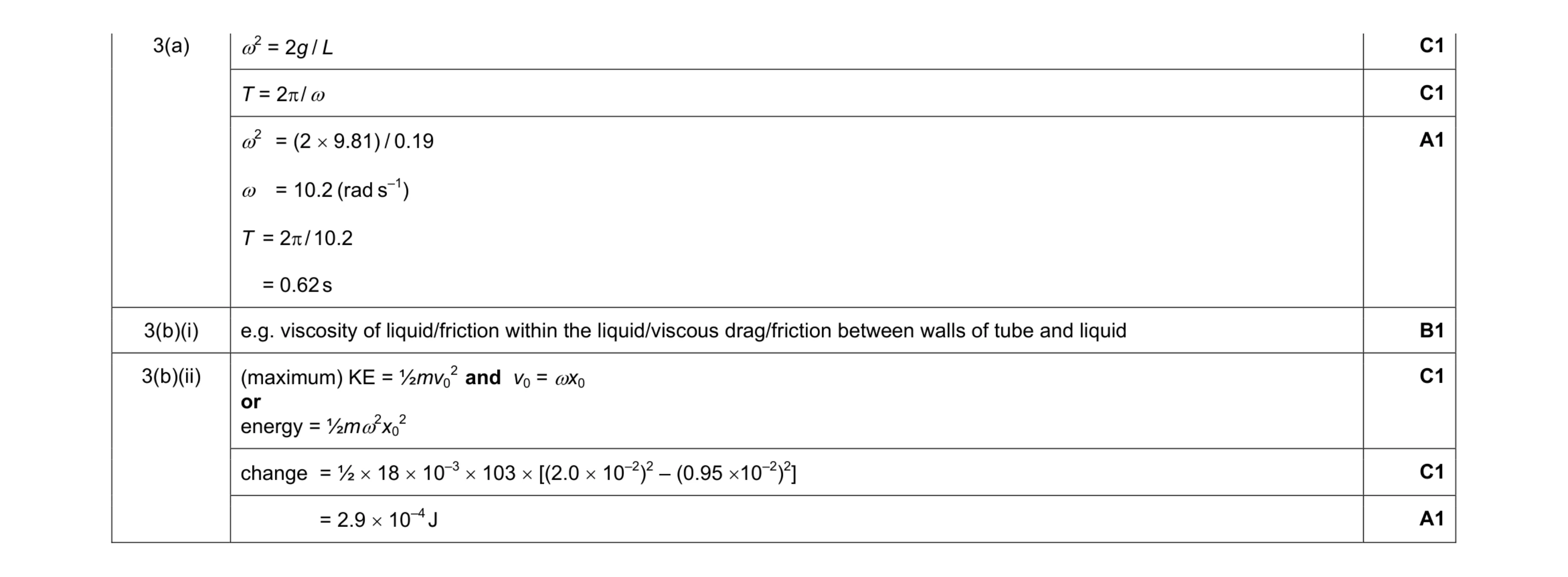 7
7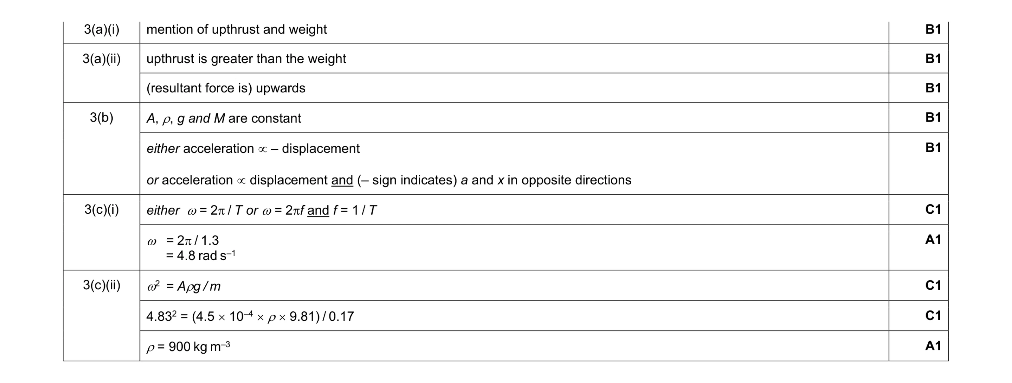 10
10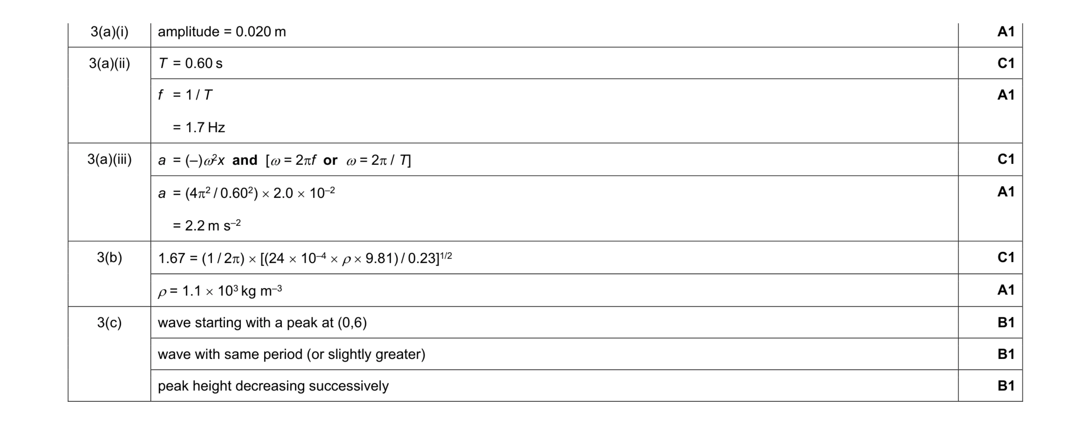 10
10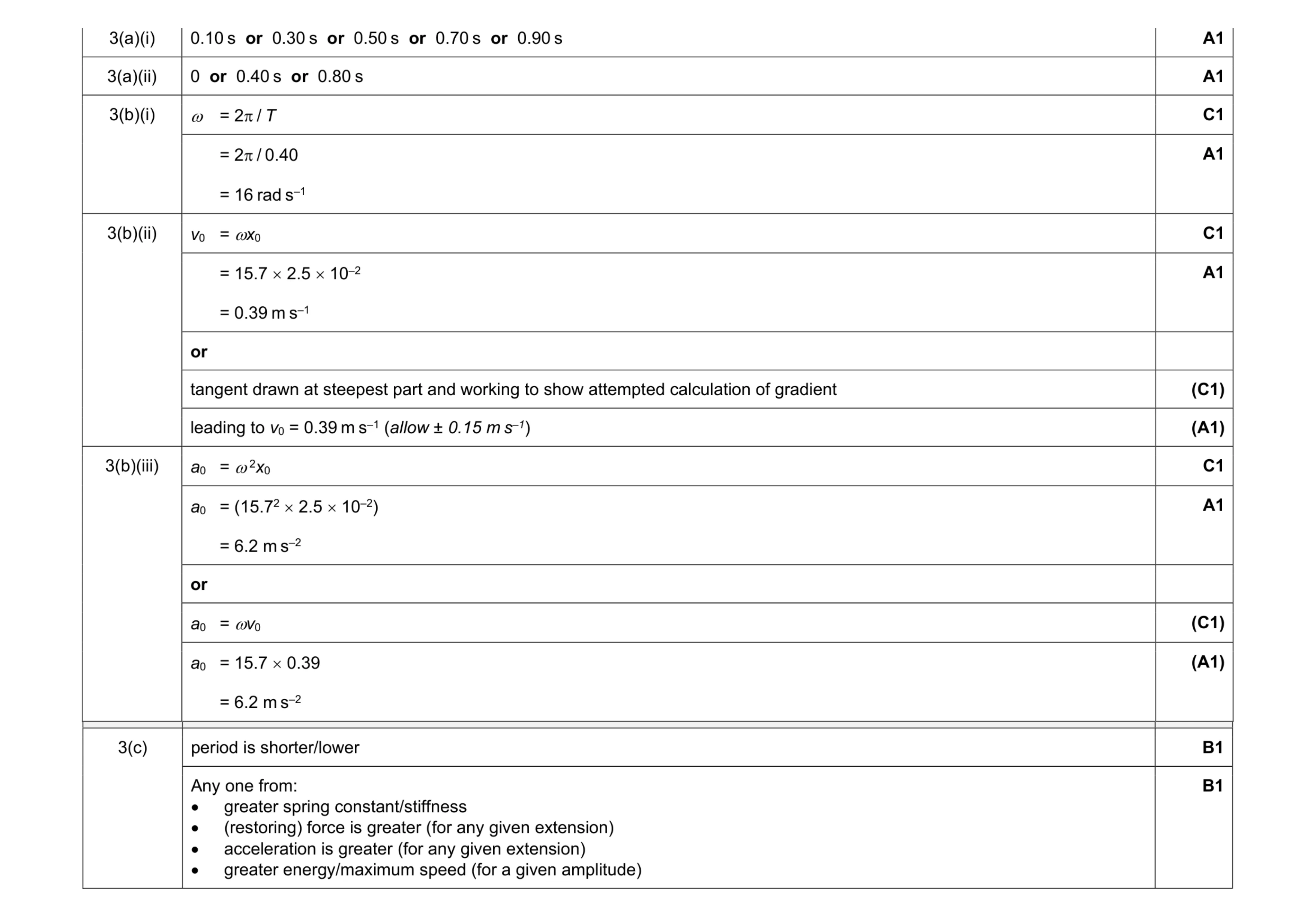 10
10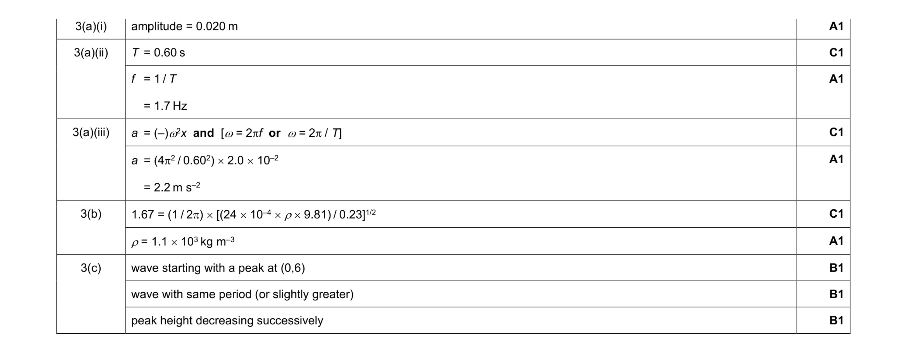 10
10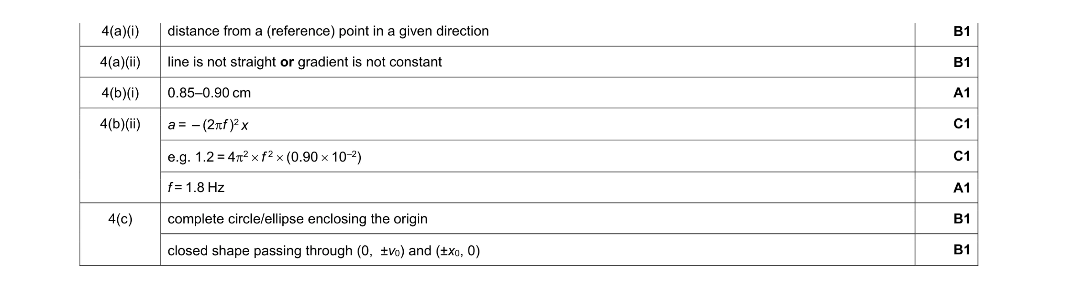 8
8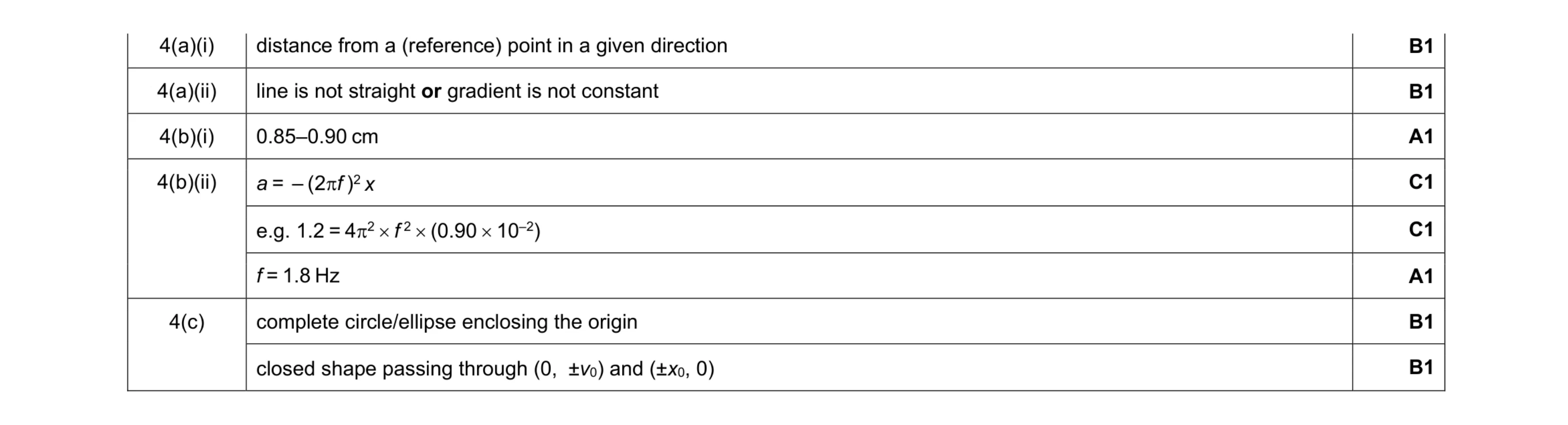 8
8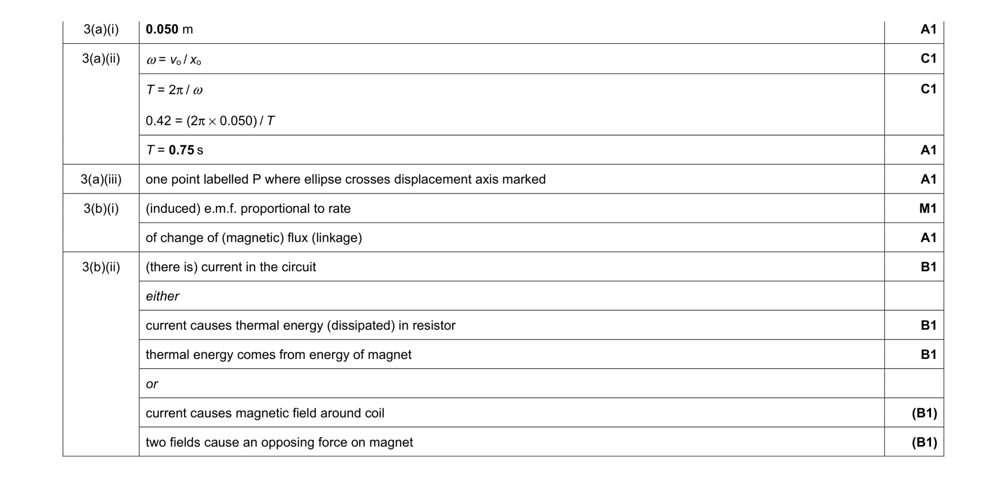 10
10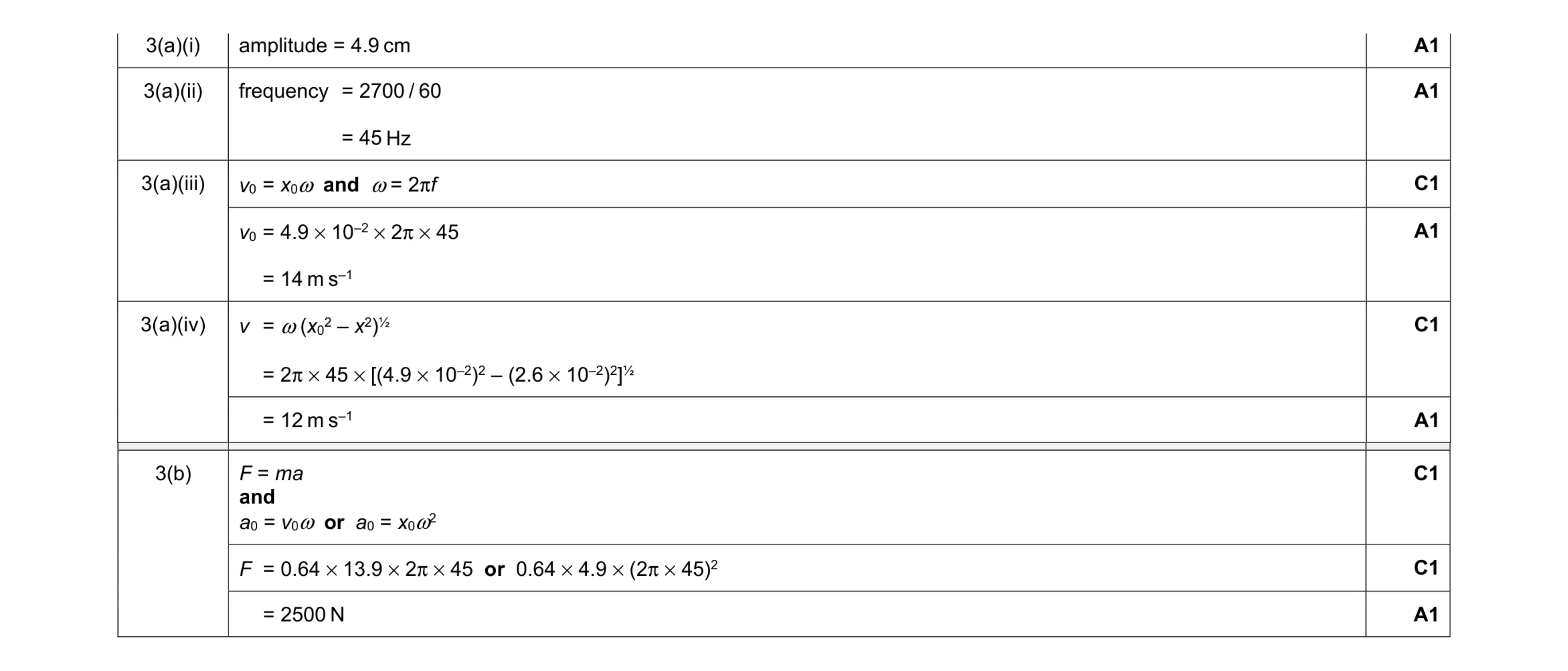 9
9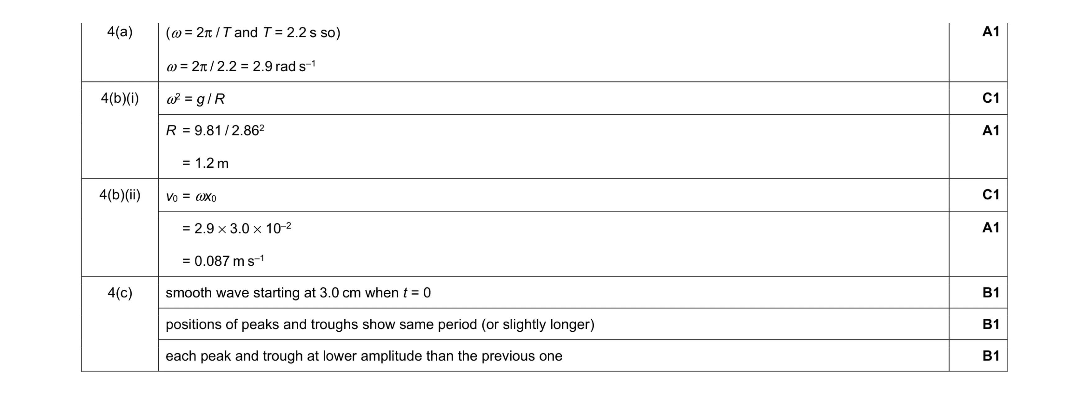 8
8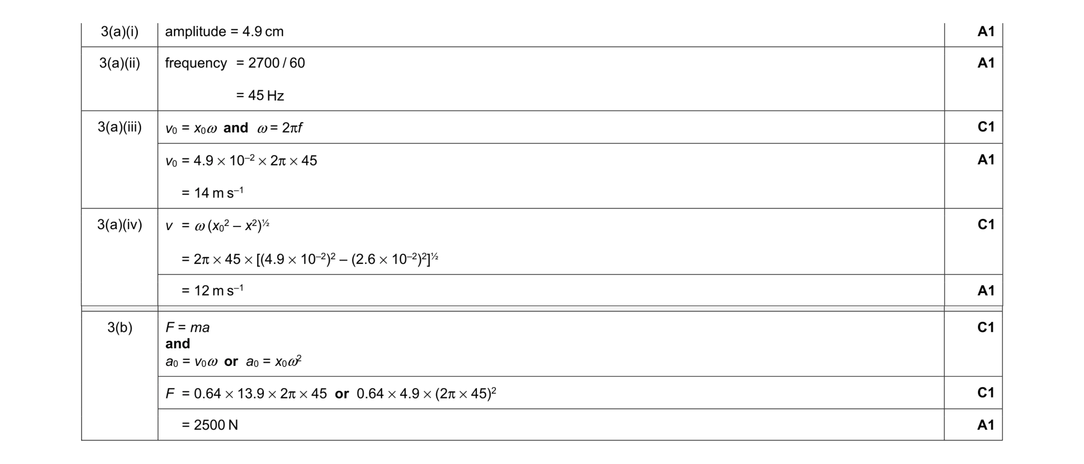 9
9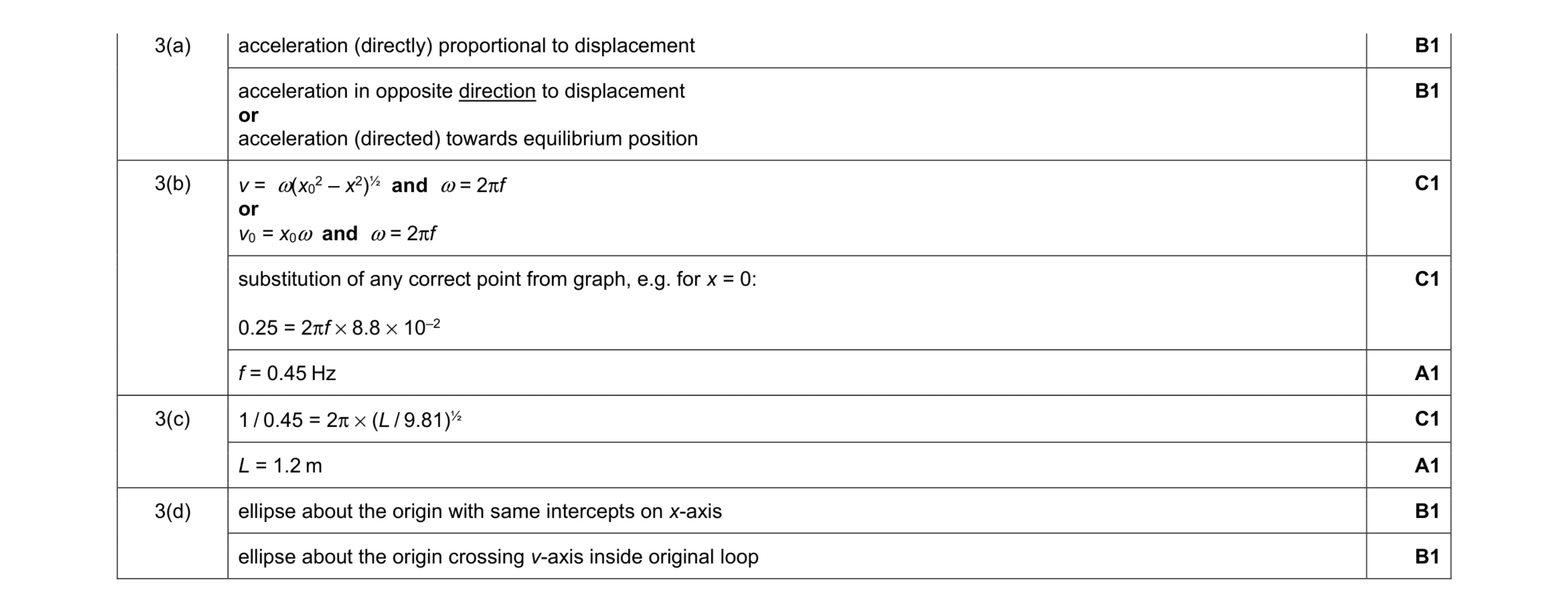 9
9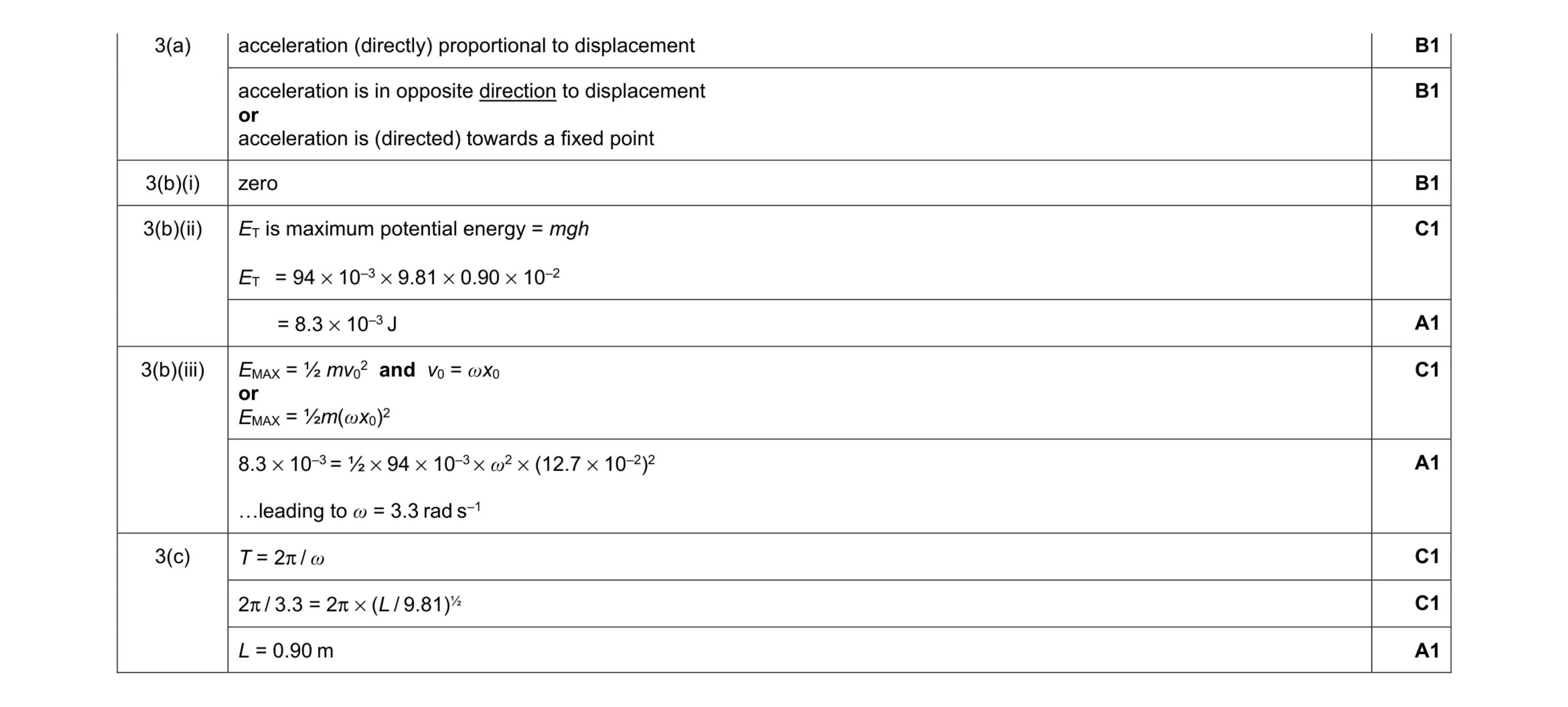 10
10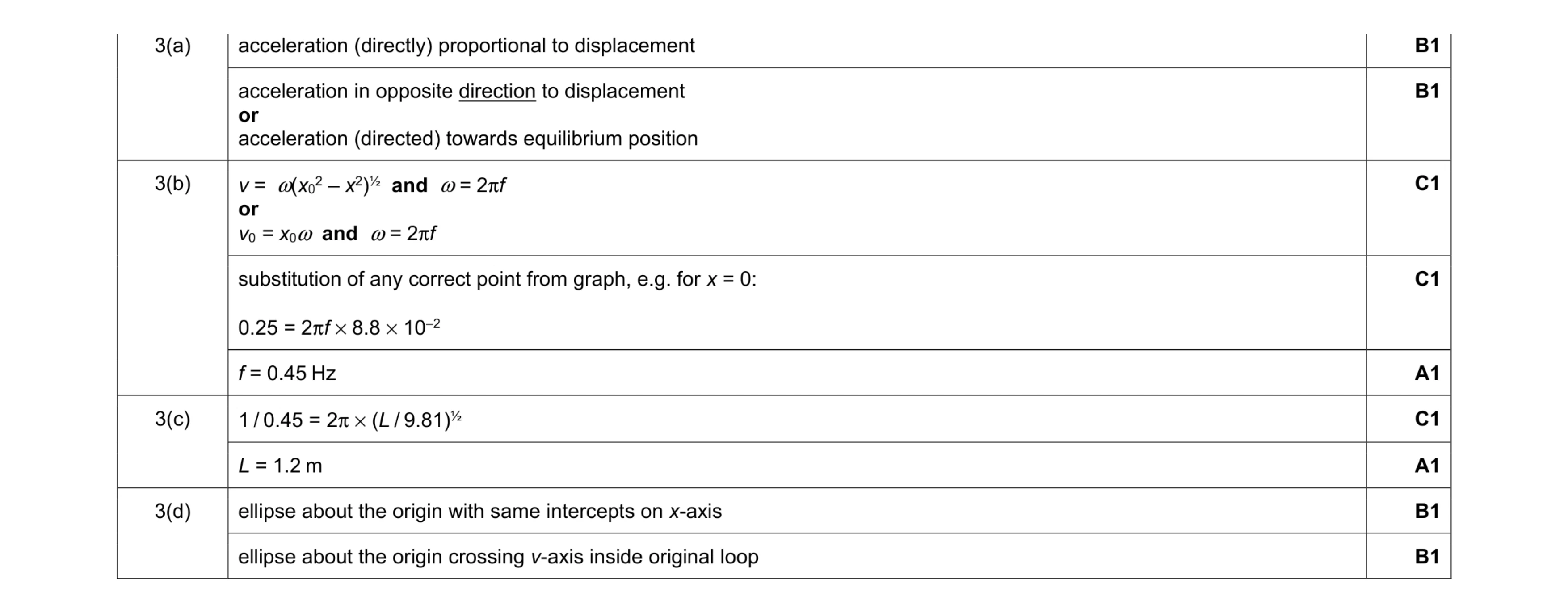 9
9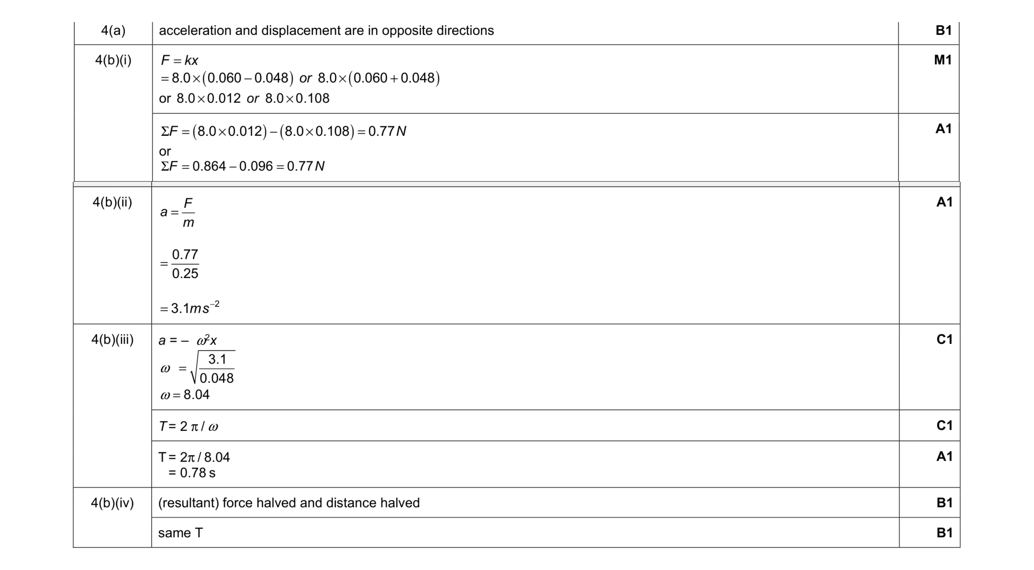 9
9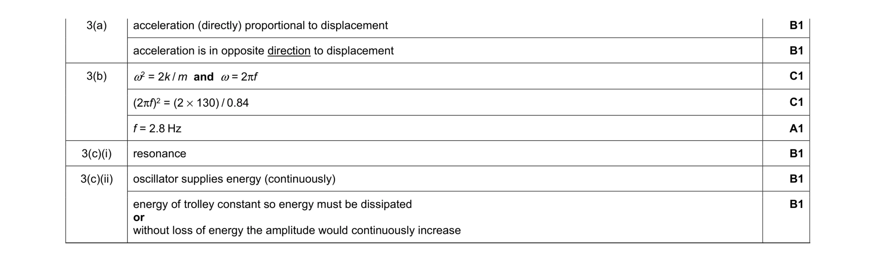 8
8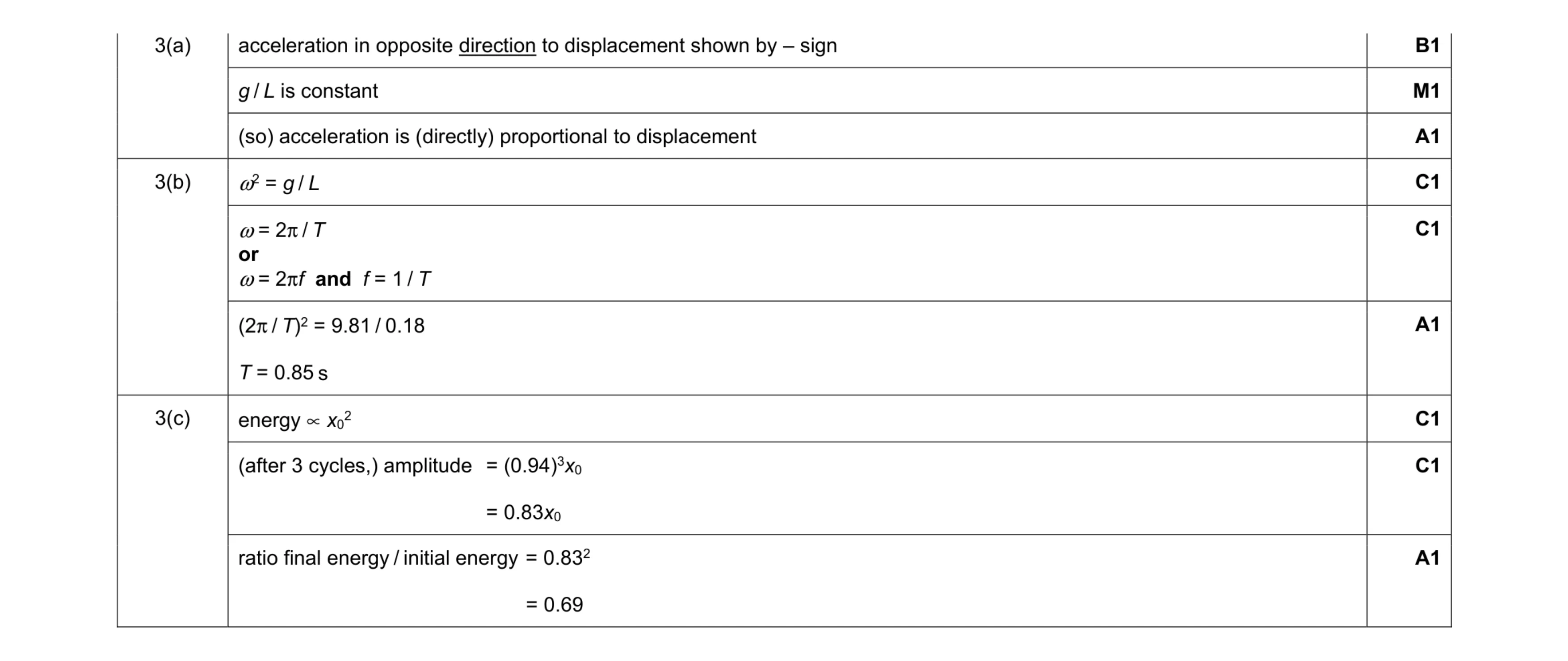 9
9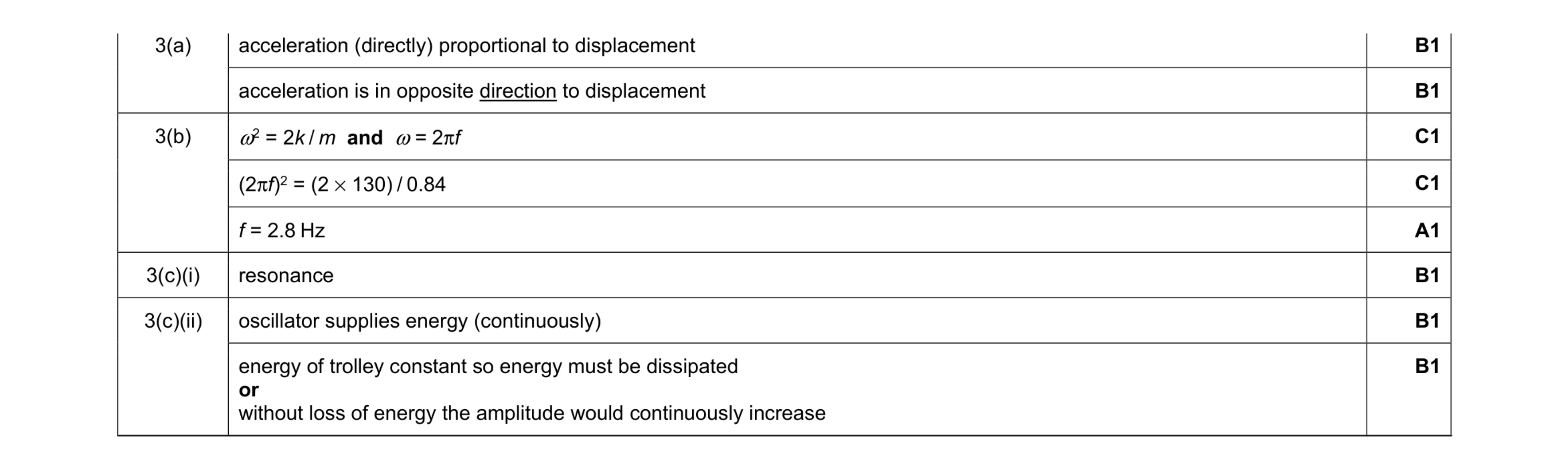 8
8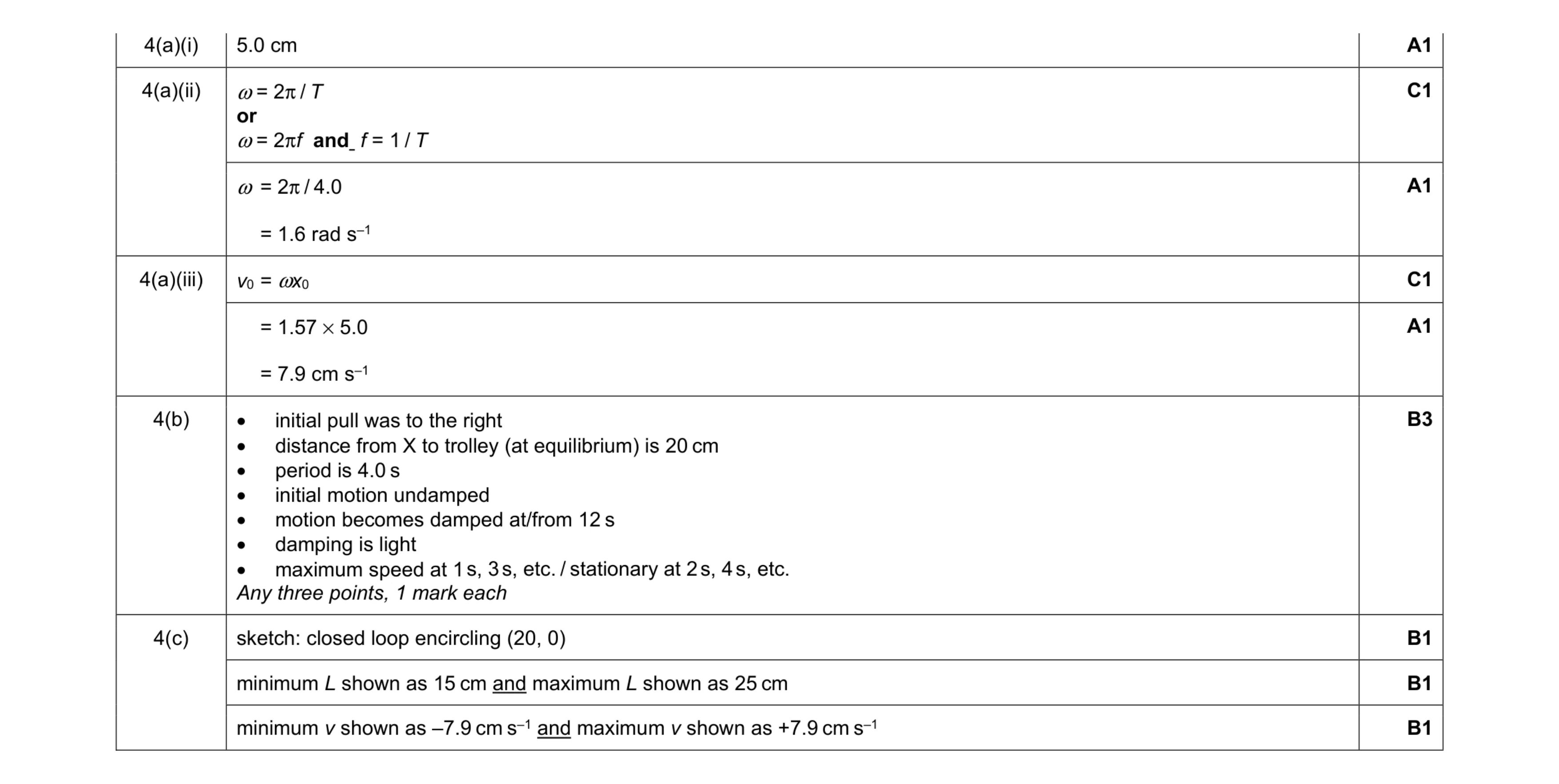 11
11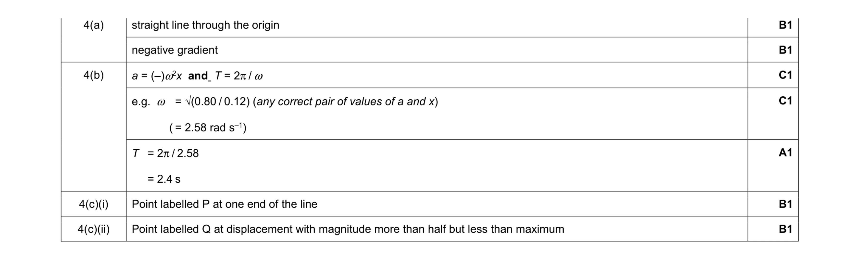 7
7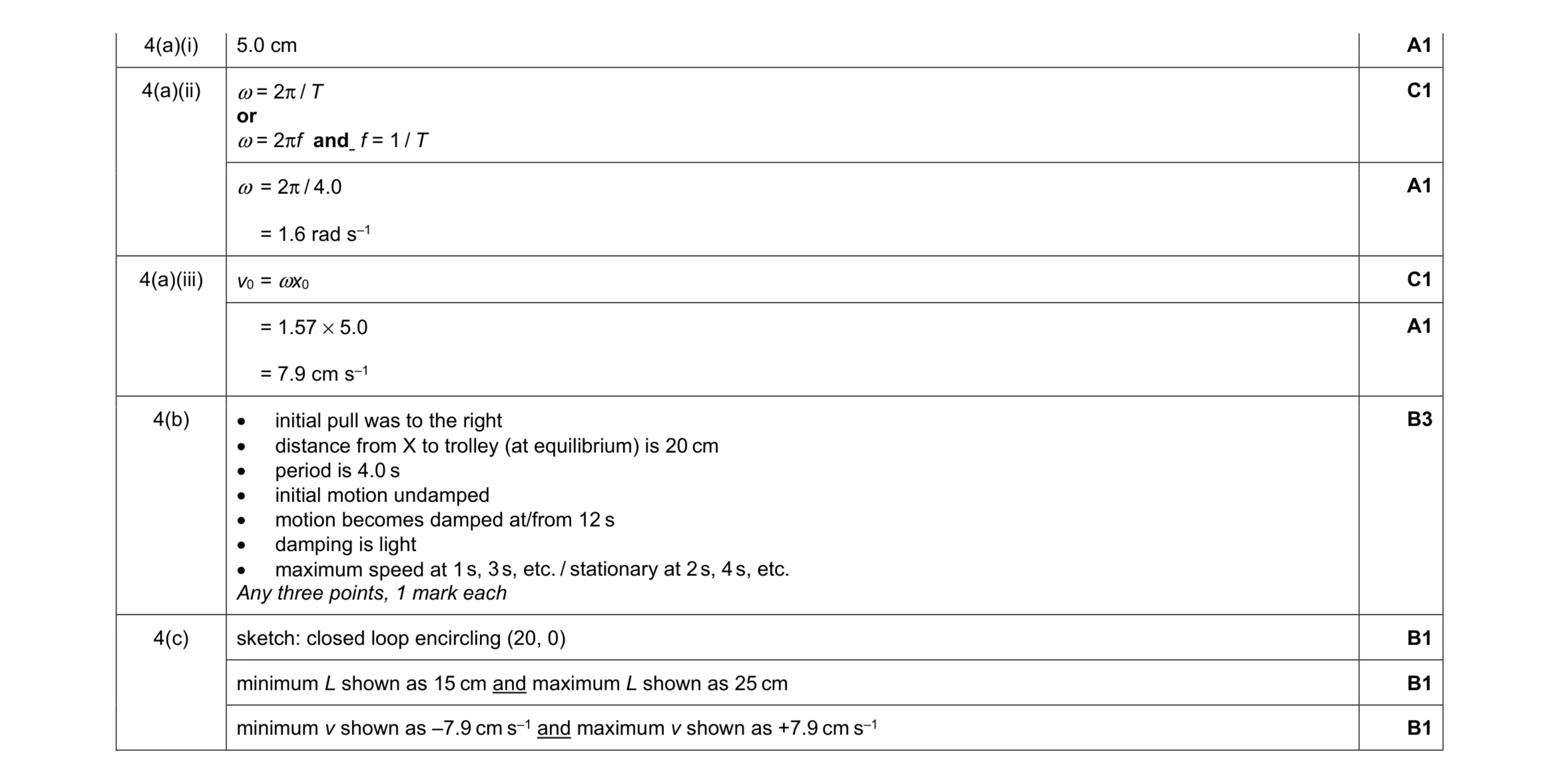 11
11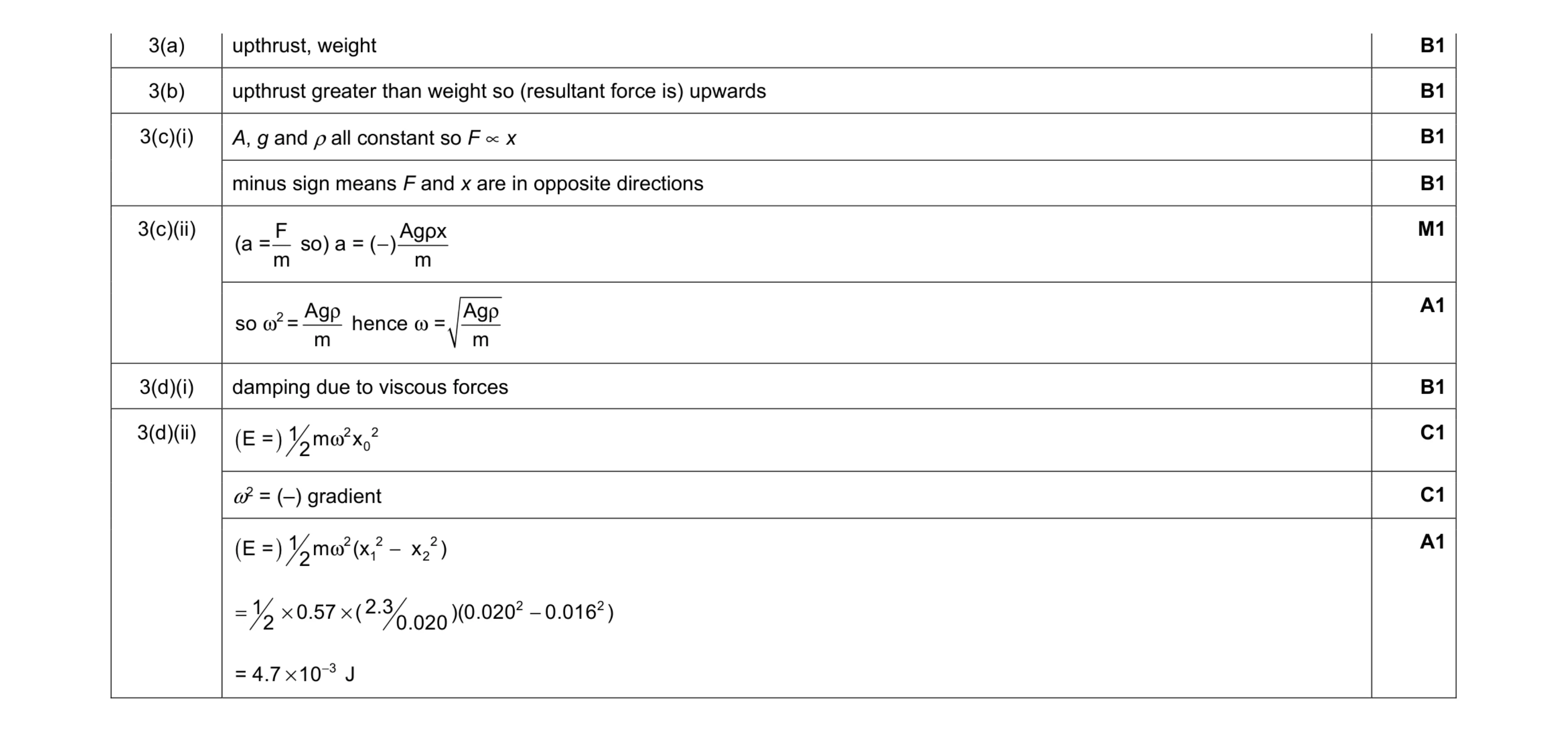 10
10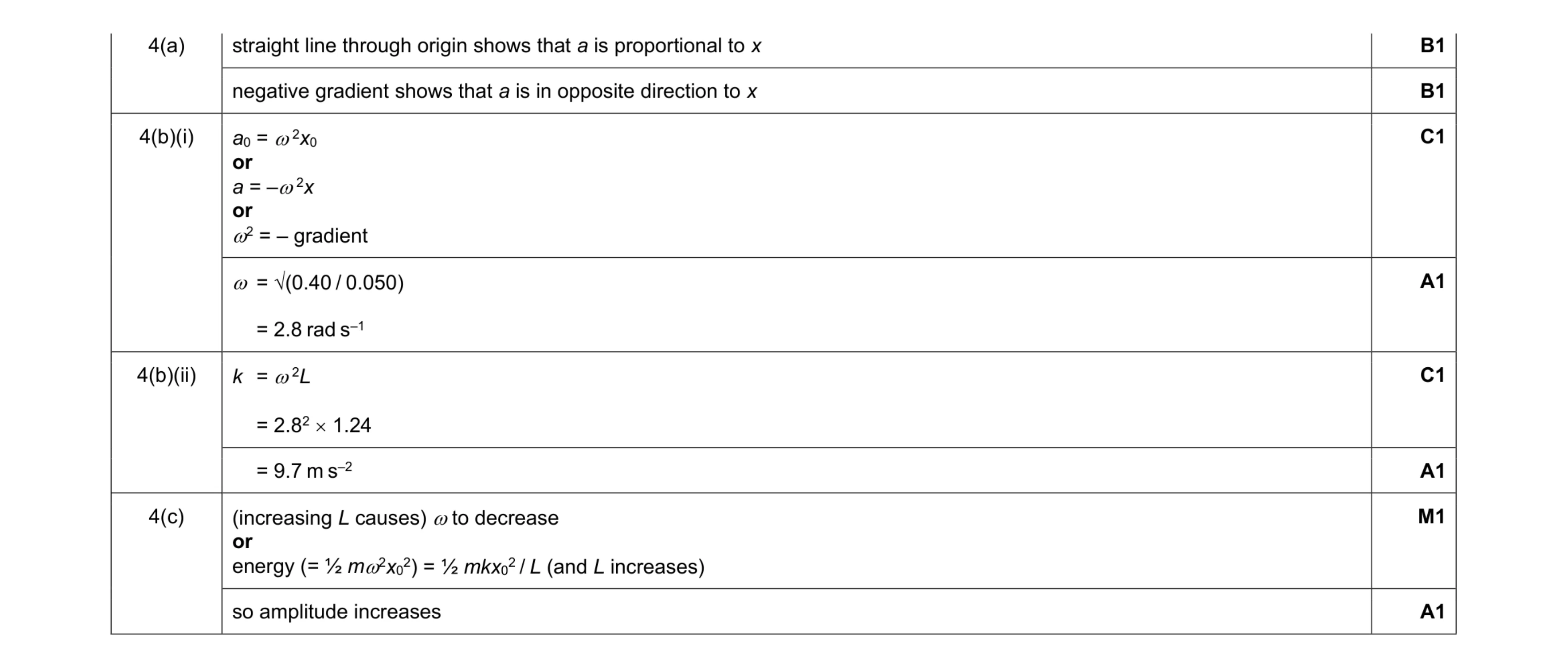 8
8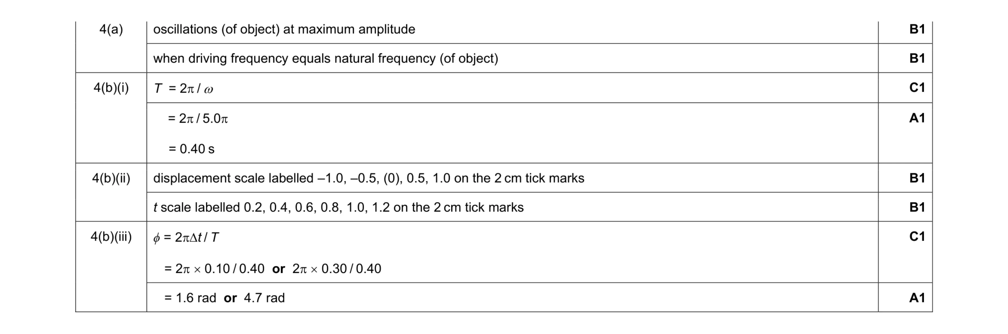 8
8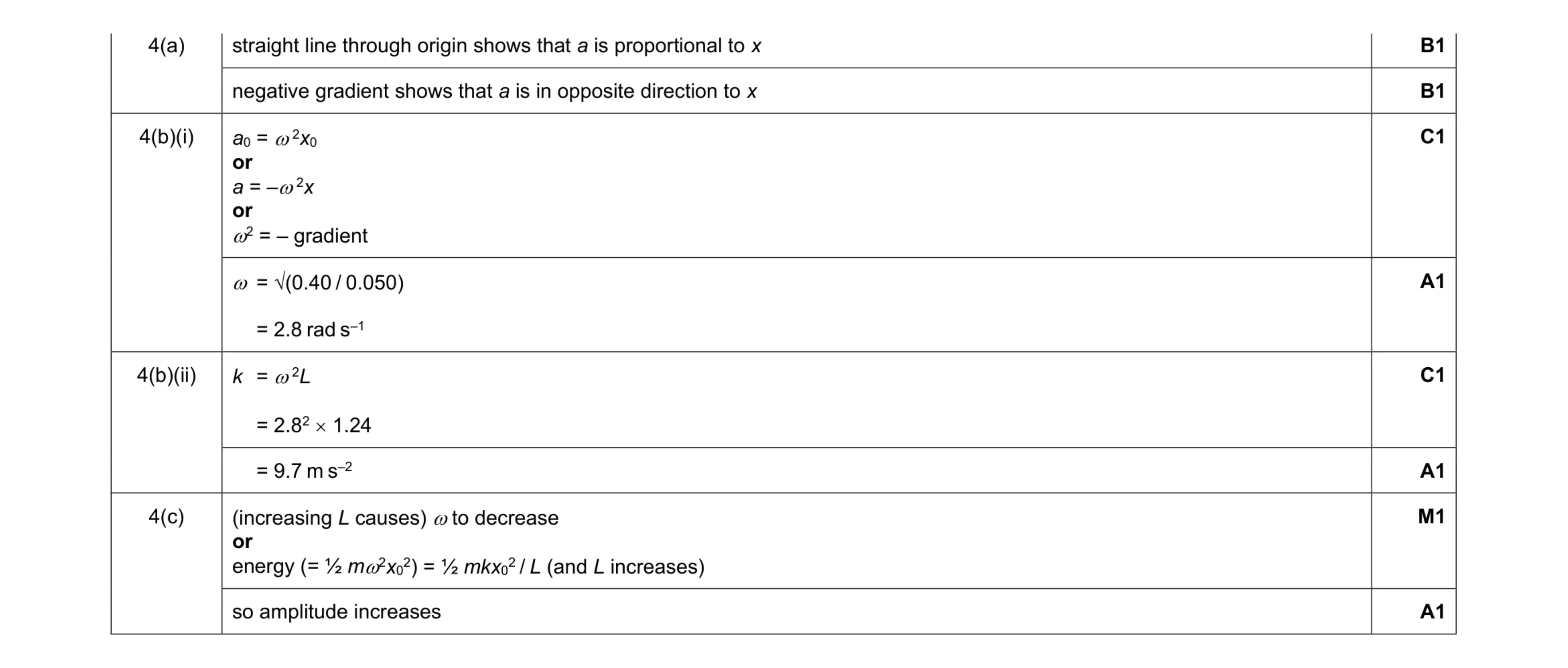 8
8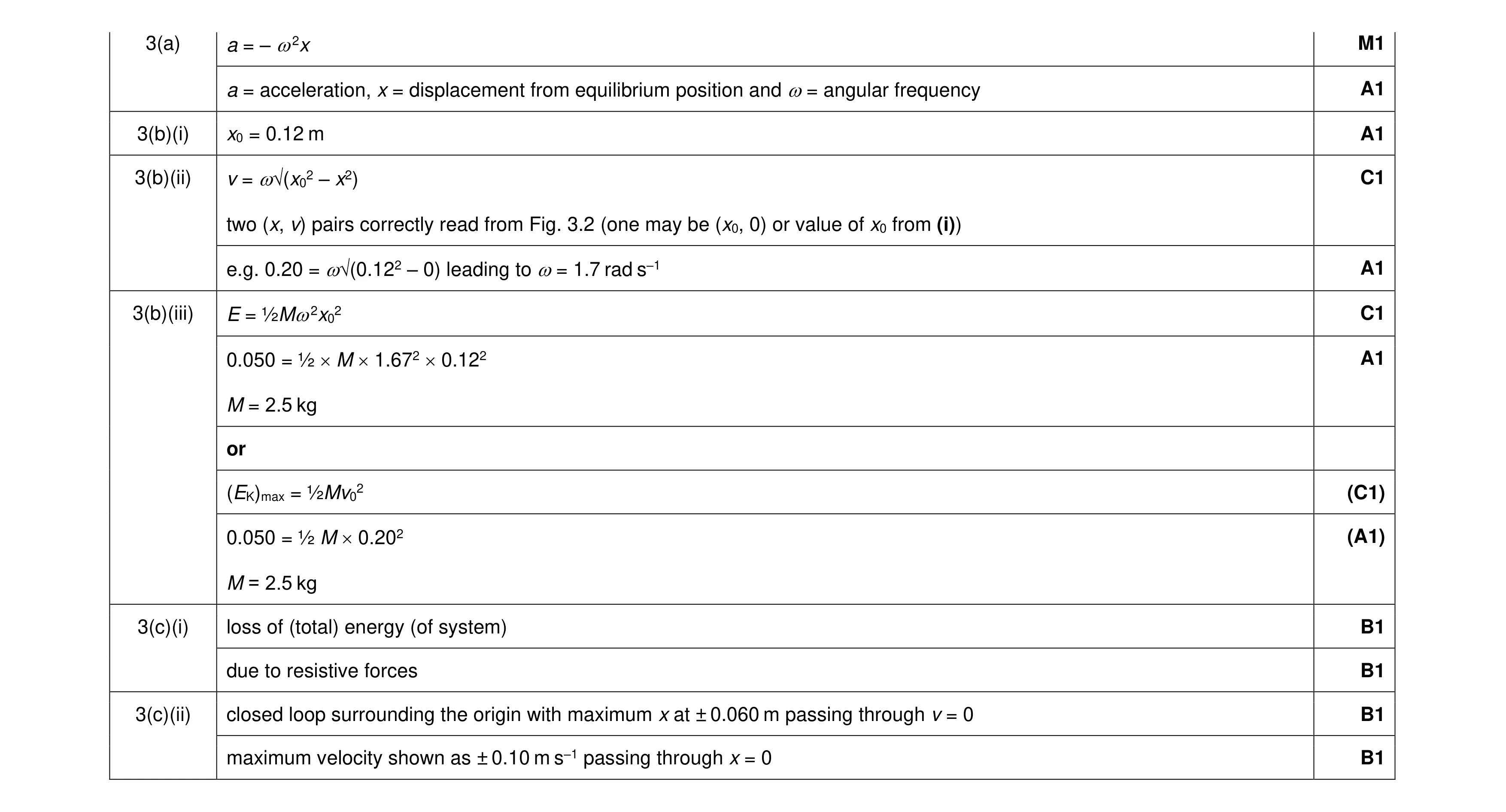 11
11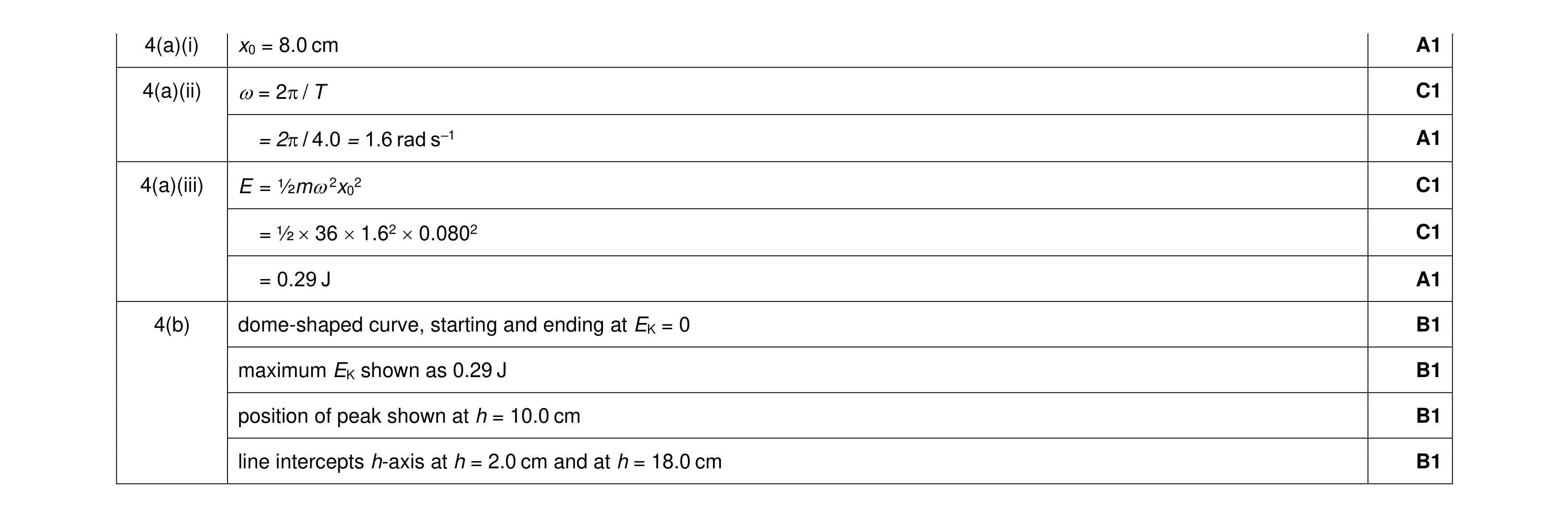 10
10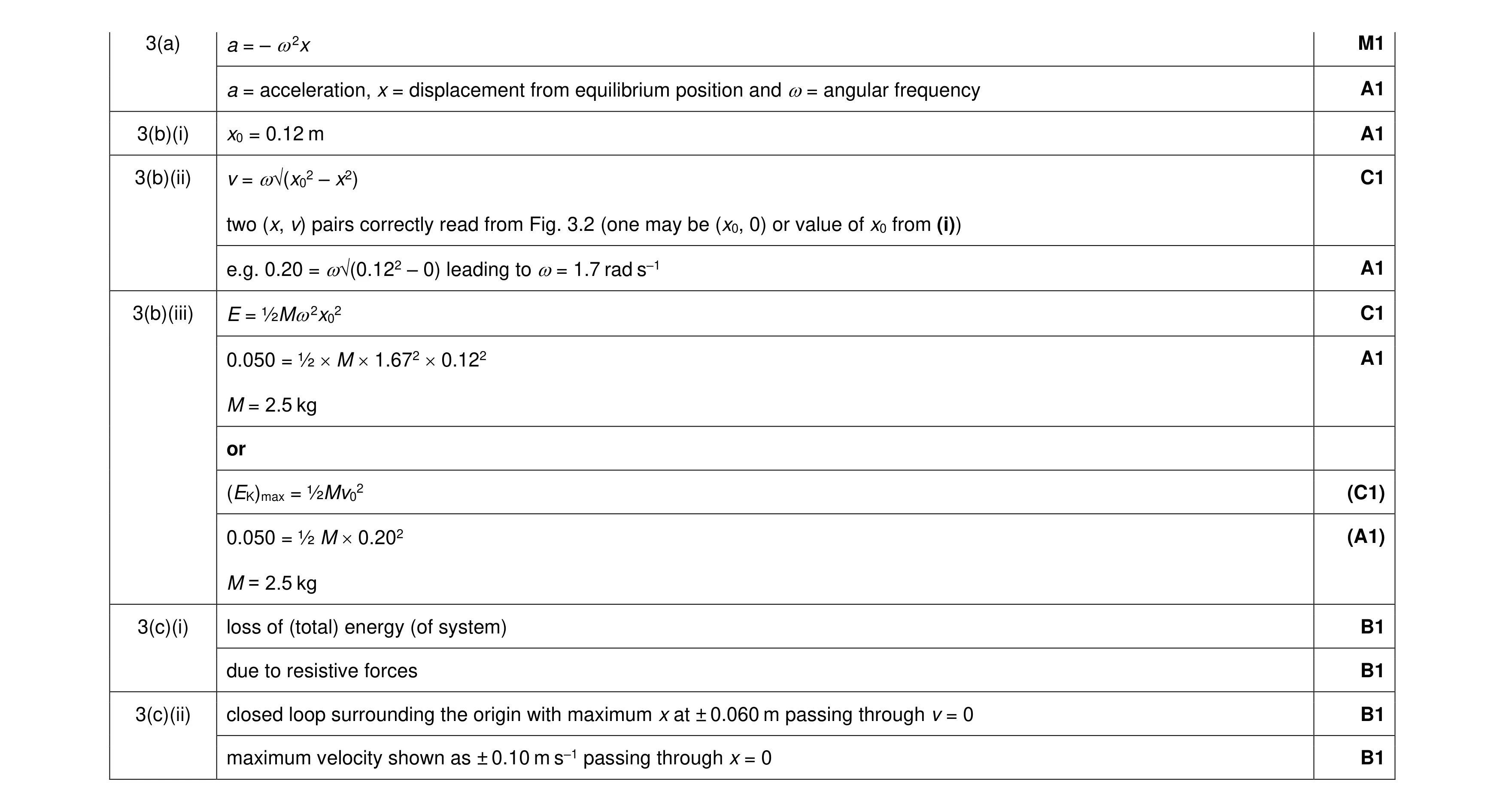 11
11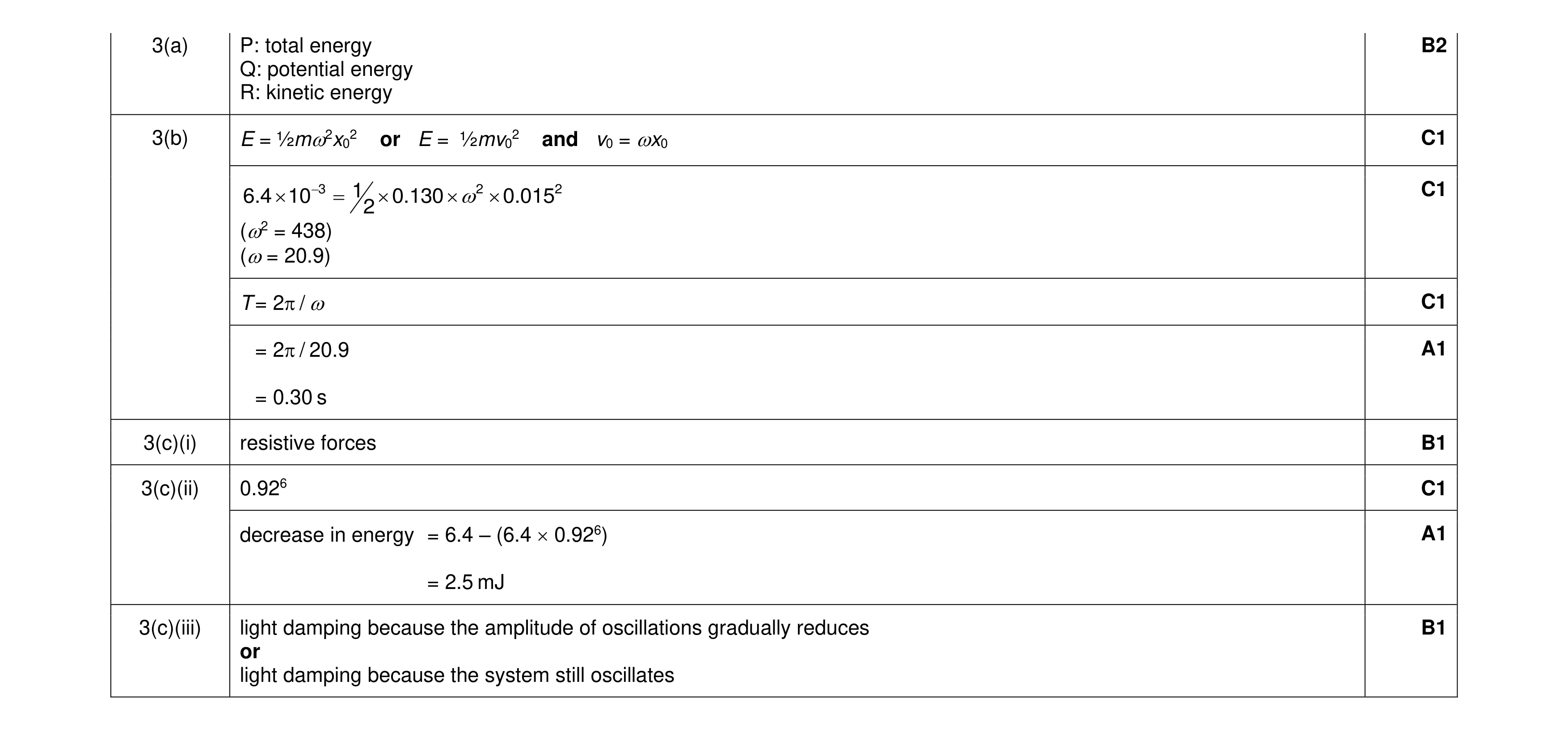 10
10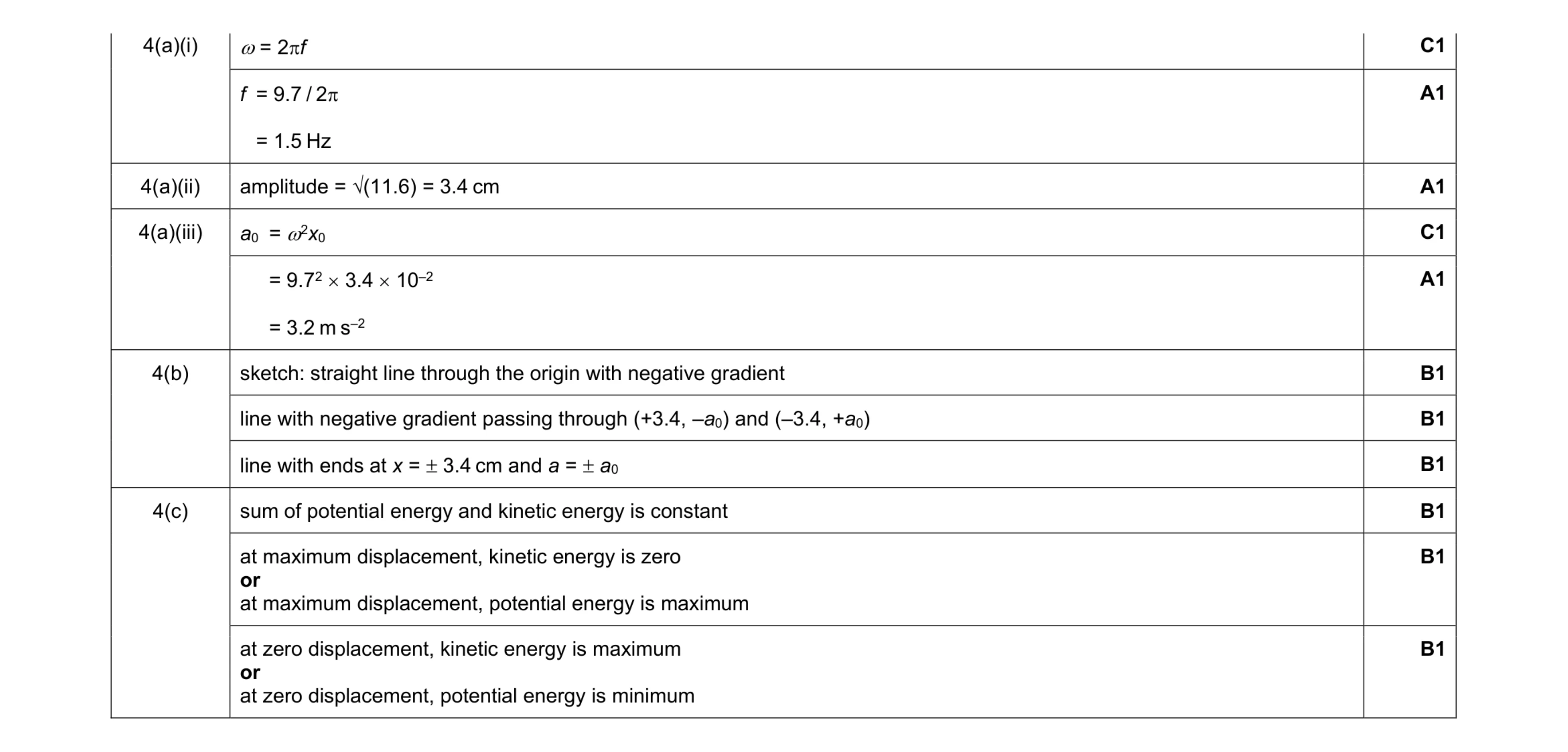 11
11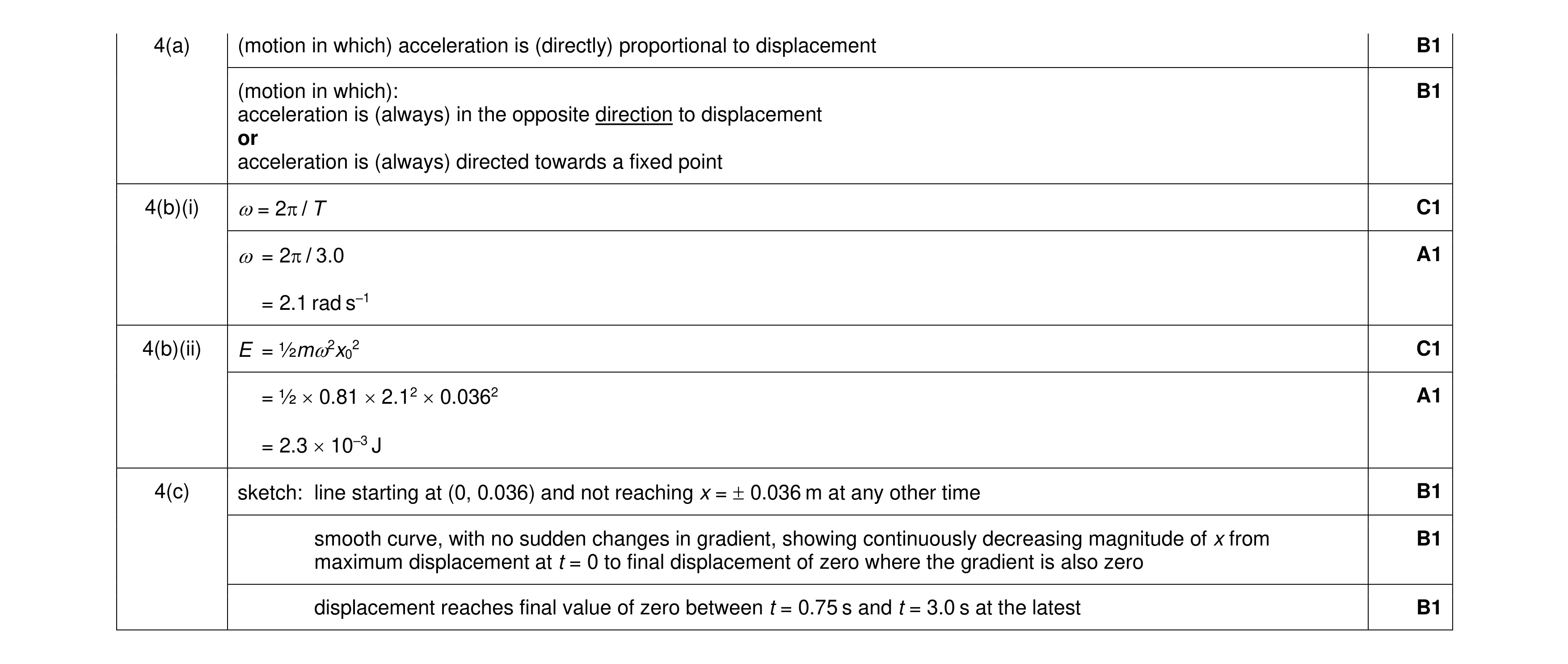 9
9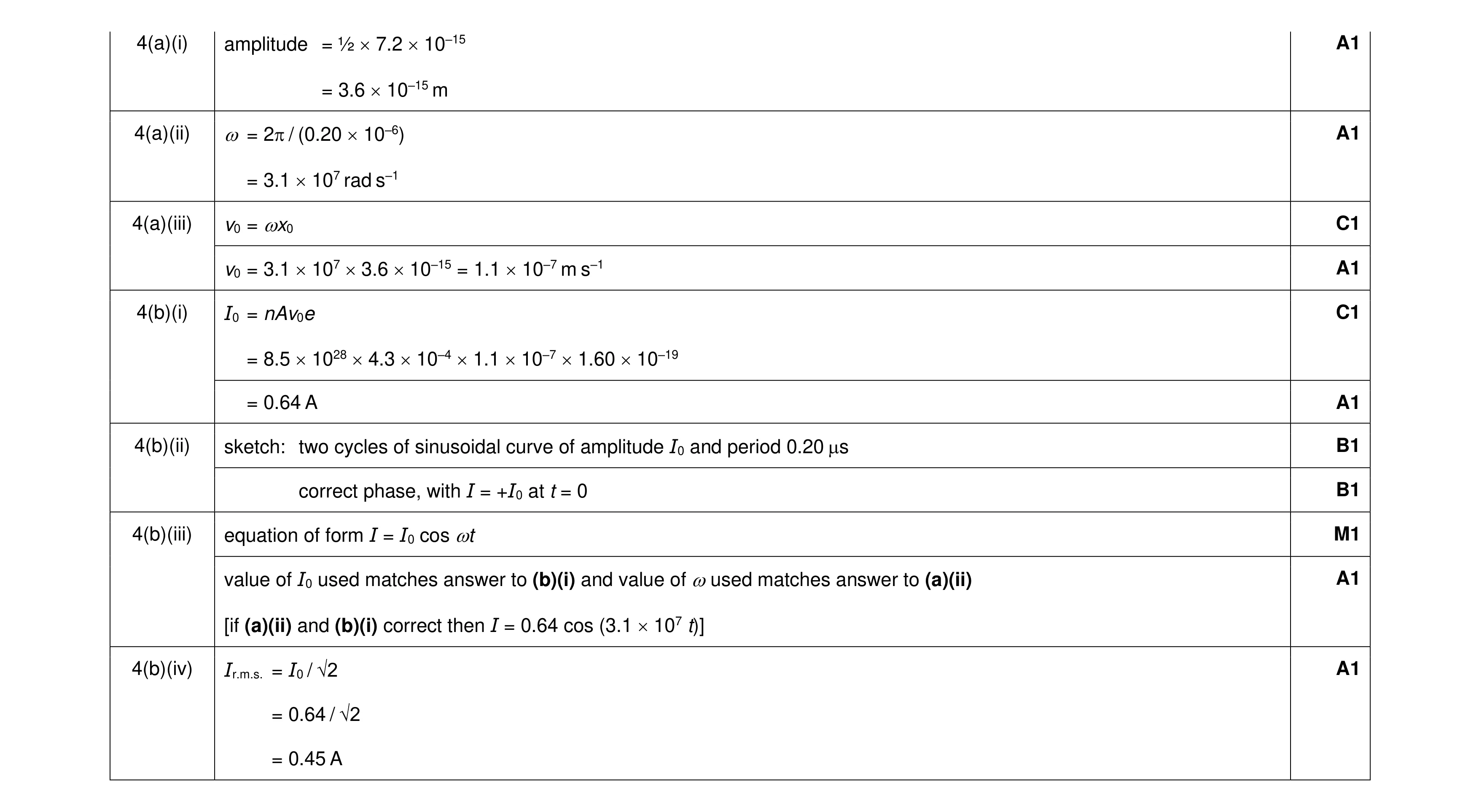 11
11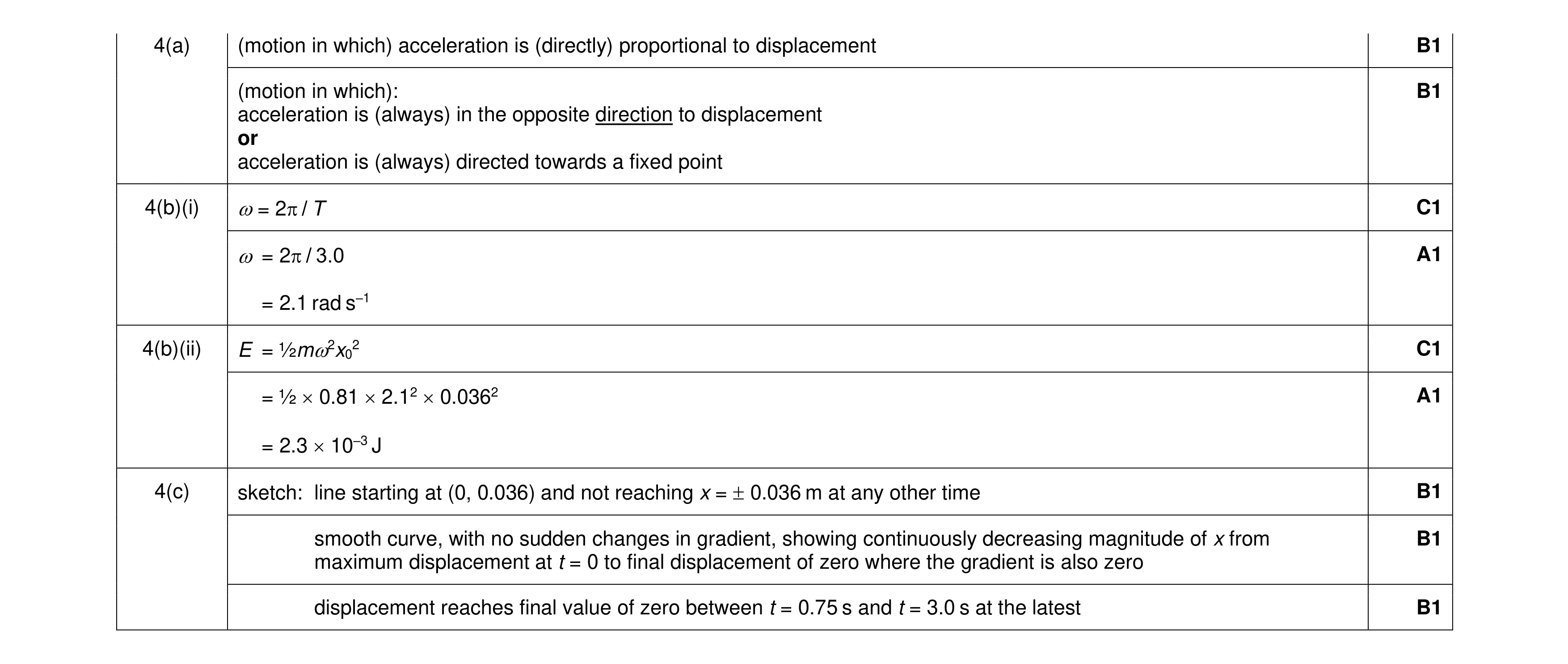 9
9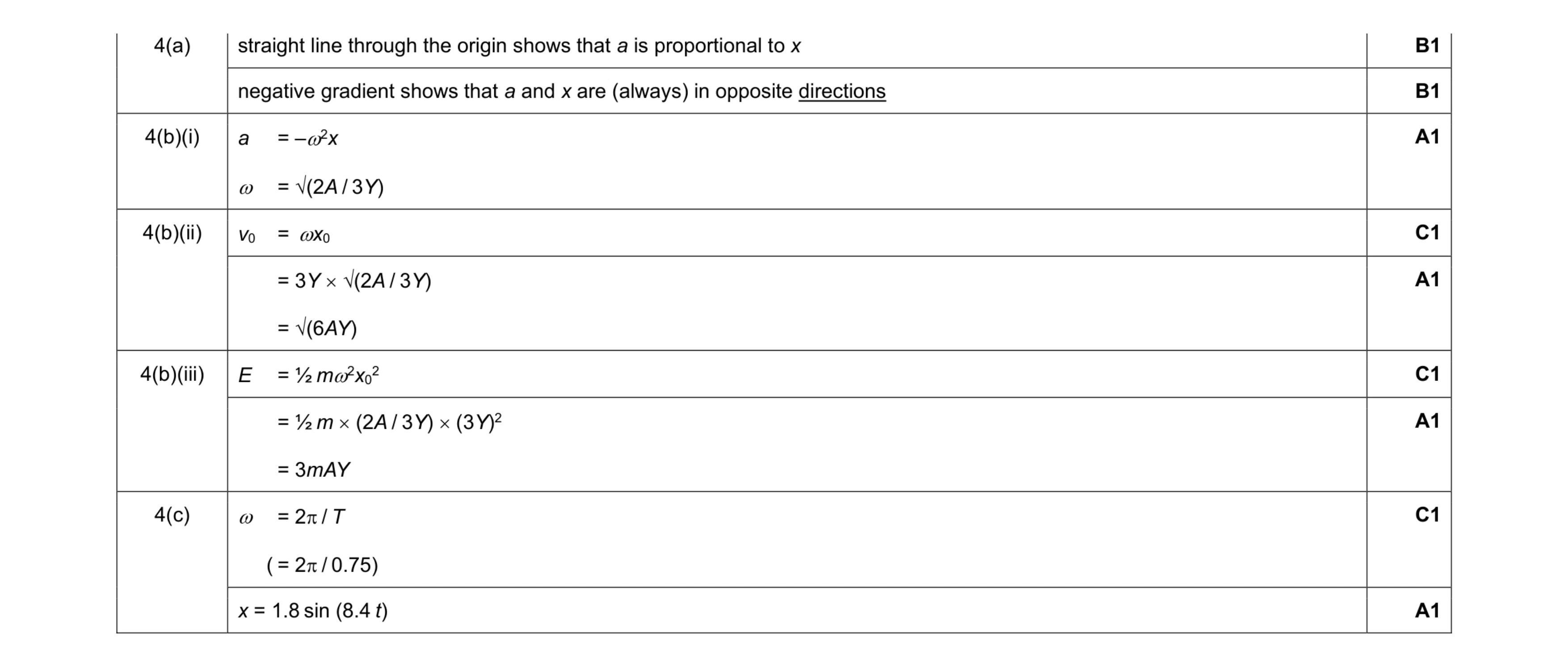 9
9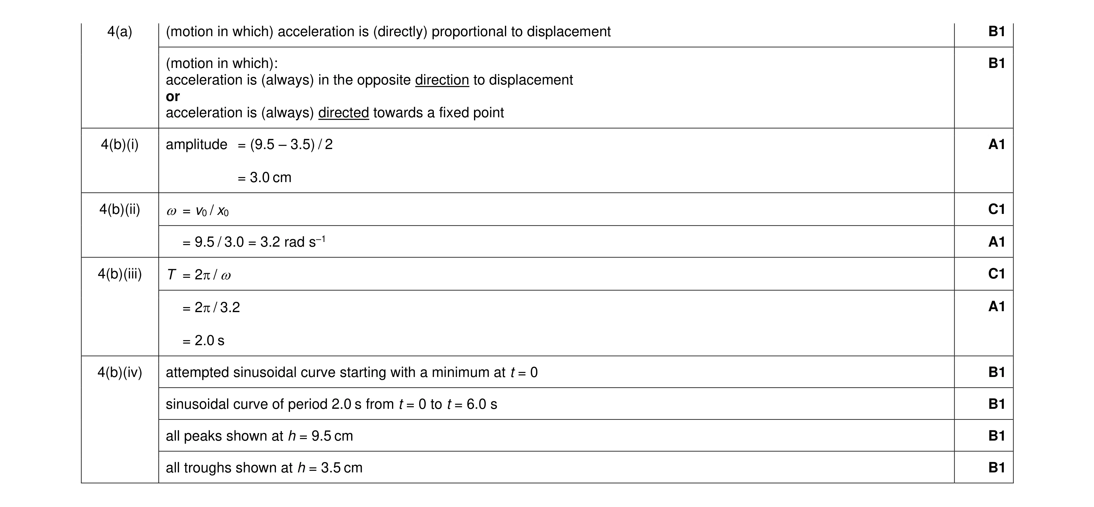 11
11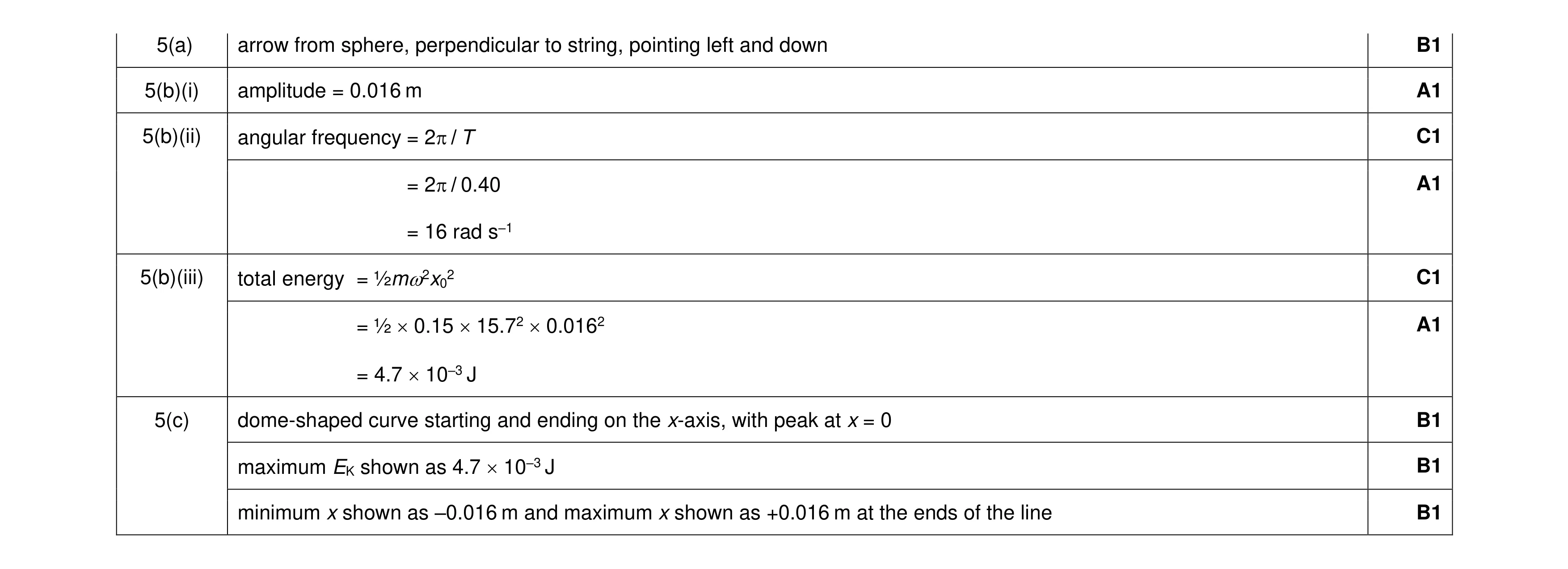 9
9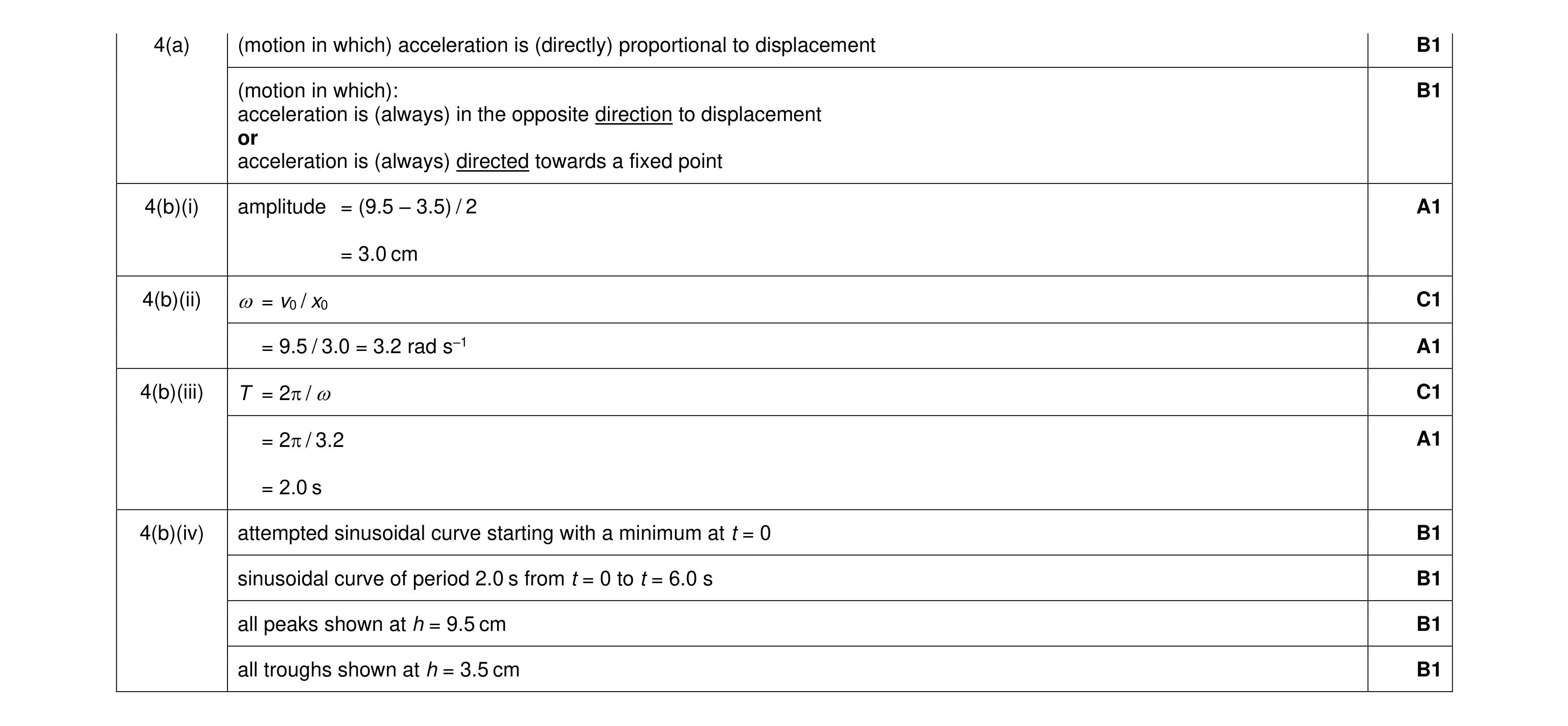 11
11 12
12 8
8 9
9 8
8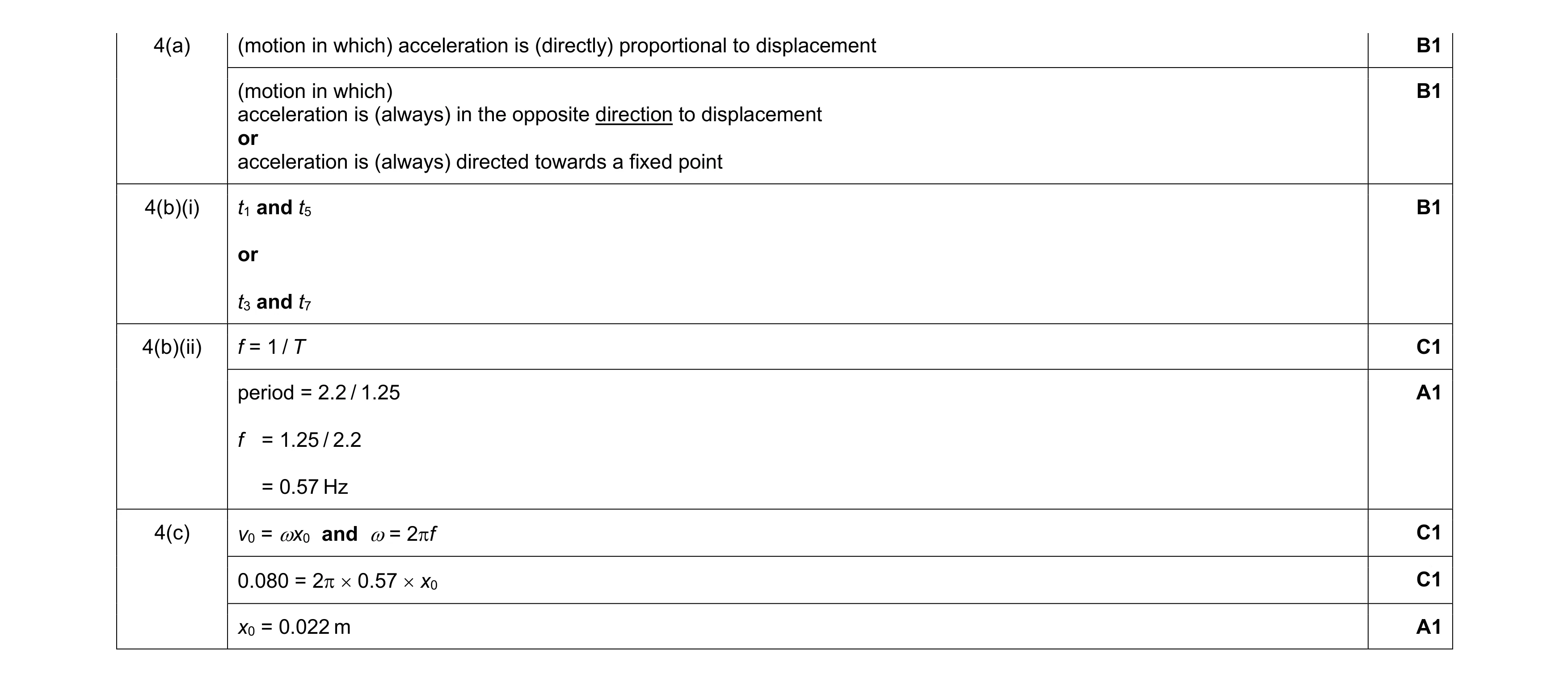 8
8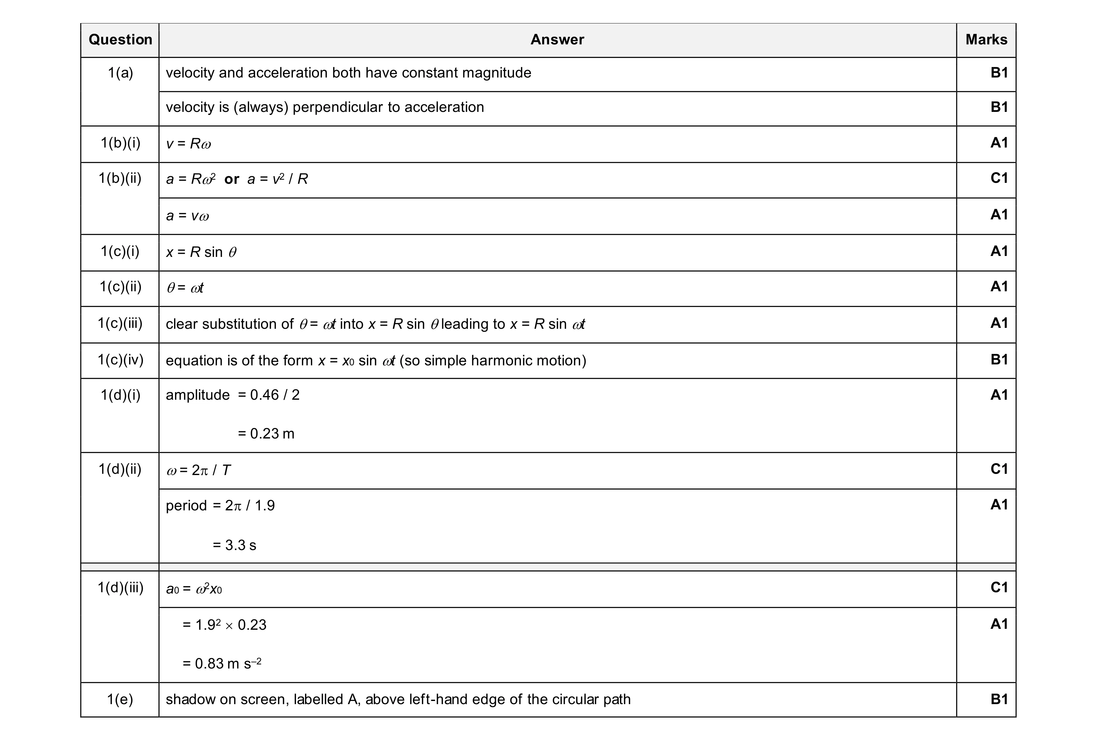 15
15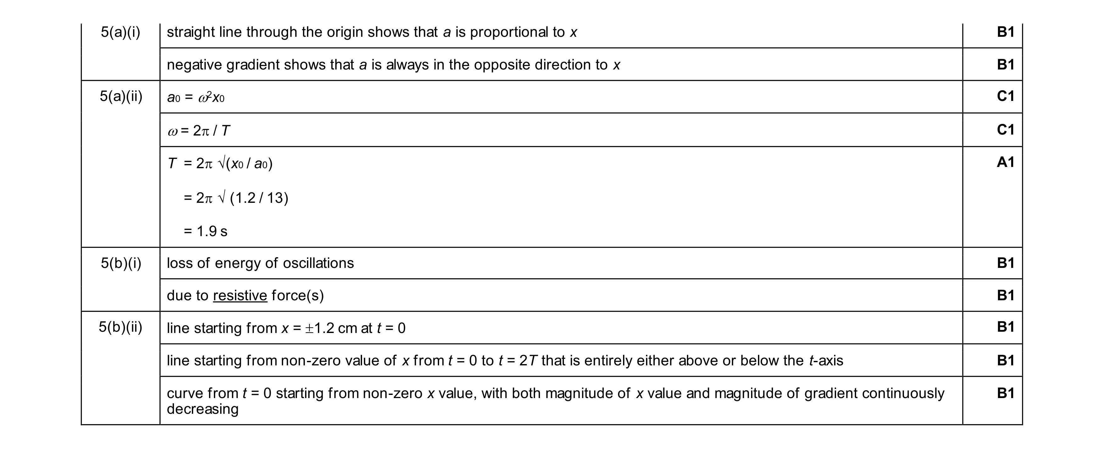 10
10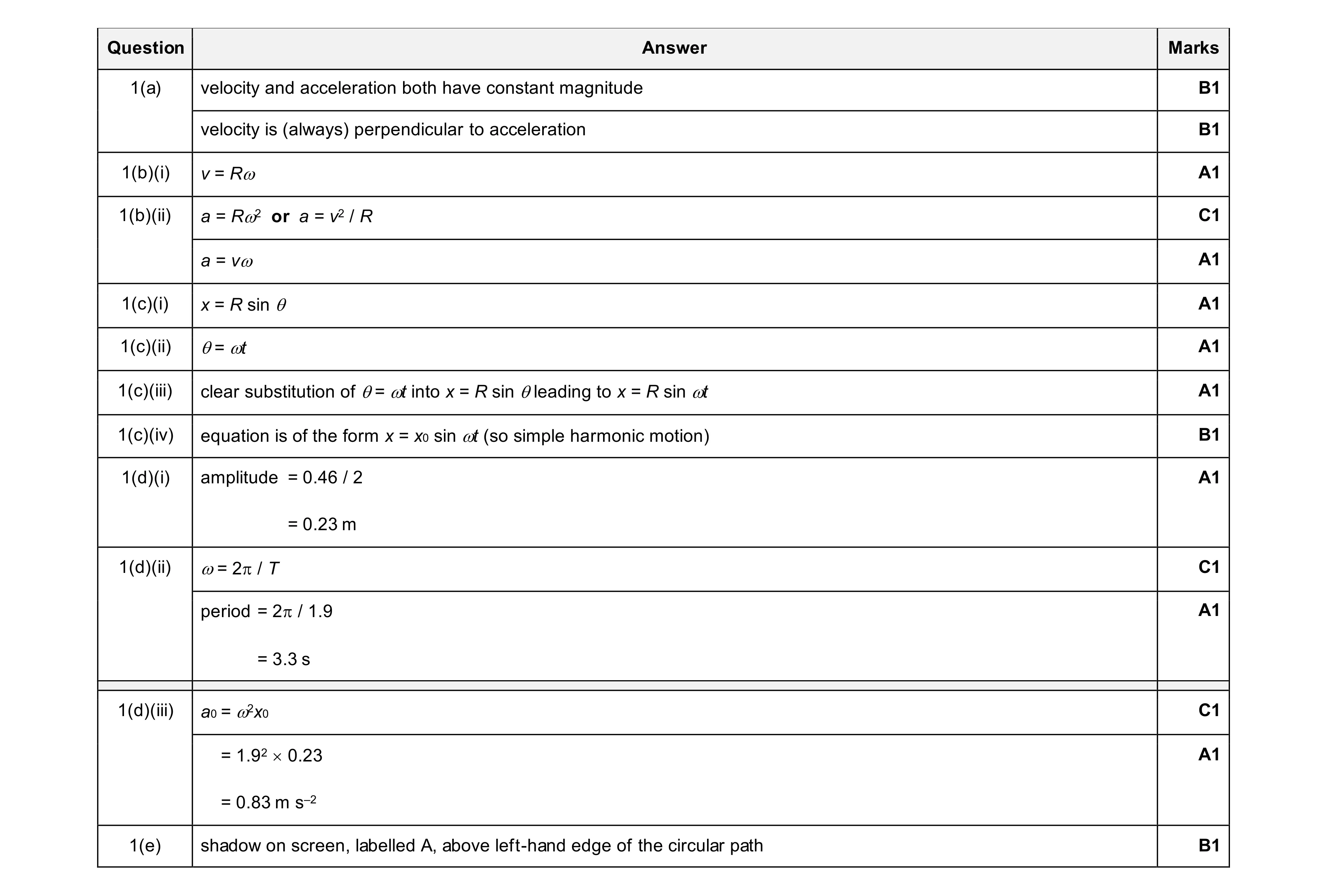 15
15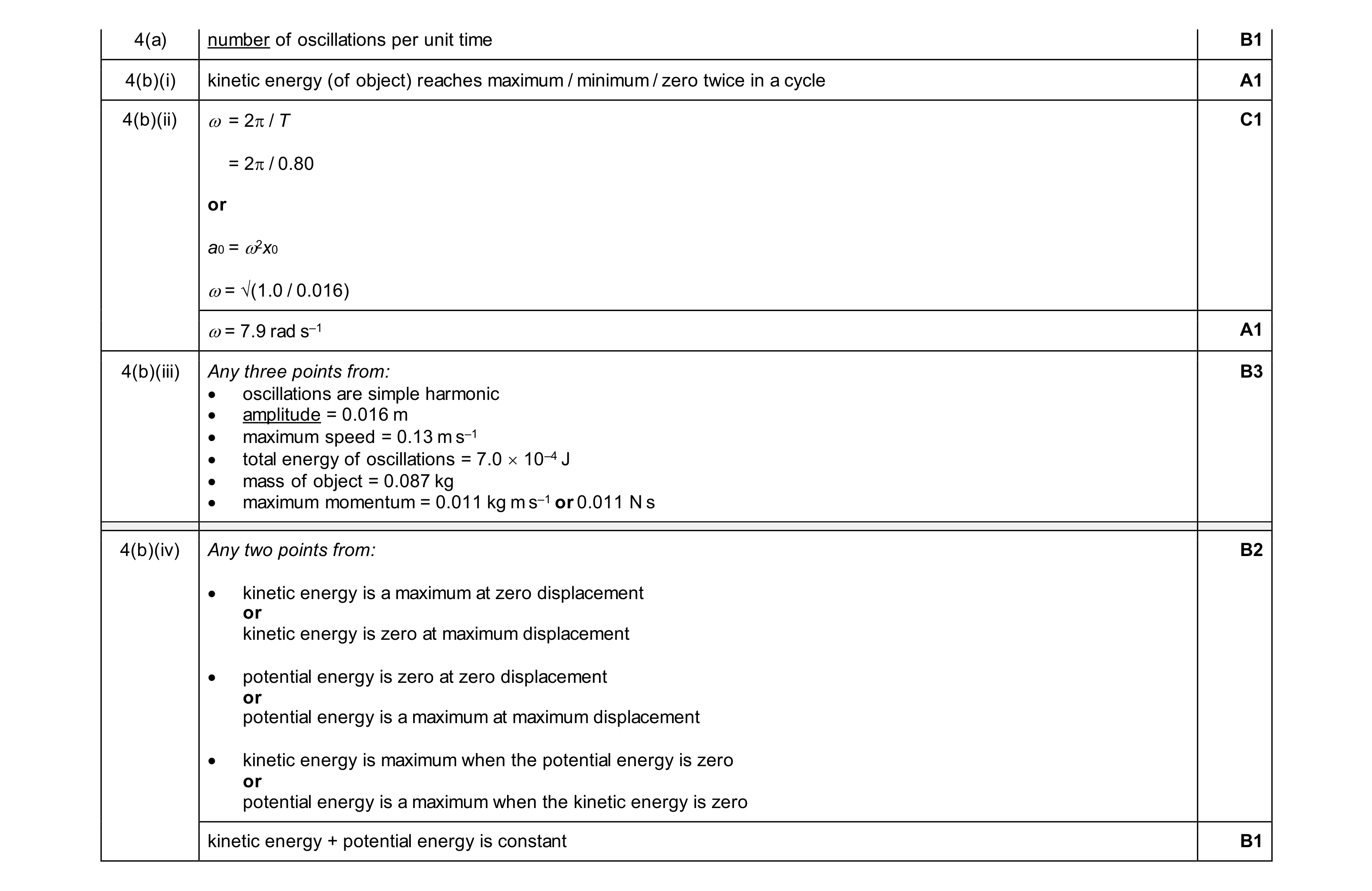 10
10