Cambridge A Level Physics 9702 — 2018 Feb/March Paper 4 · Variant 2
9702/42/F/M/18 · 13 questions · 100 marks · ≈113 min
The question paper and its mark scheme, free to read here and free to download. This is Cambridge’s own paper, exactly as it was sat.
Question paper28 pages

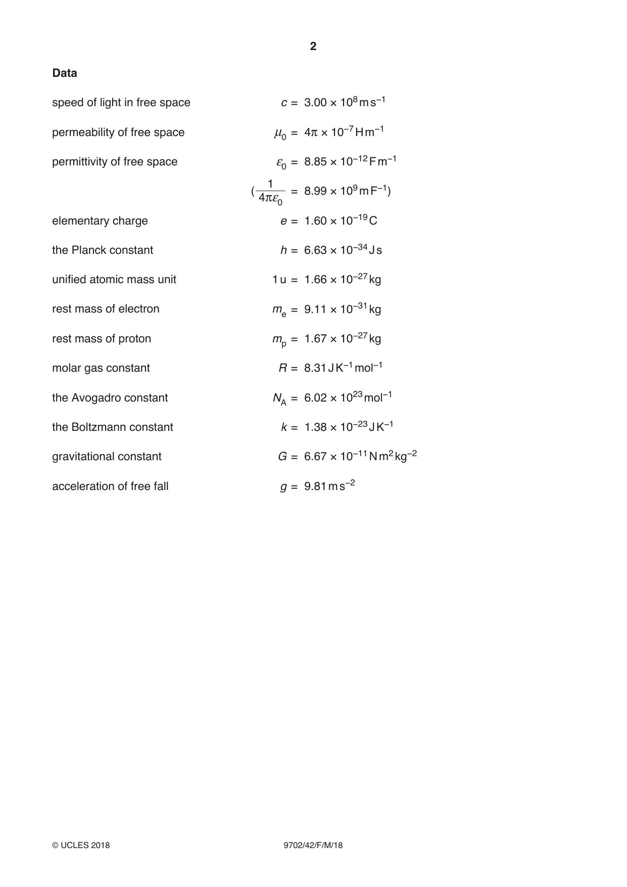
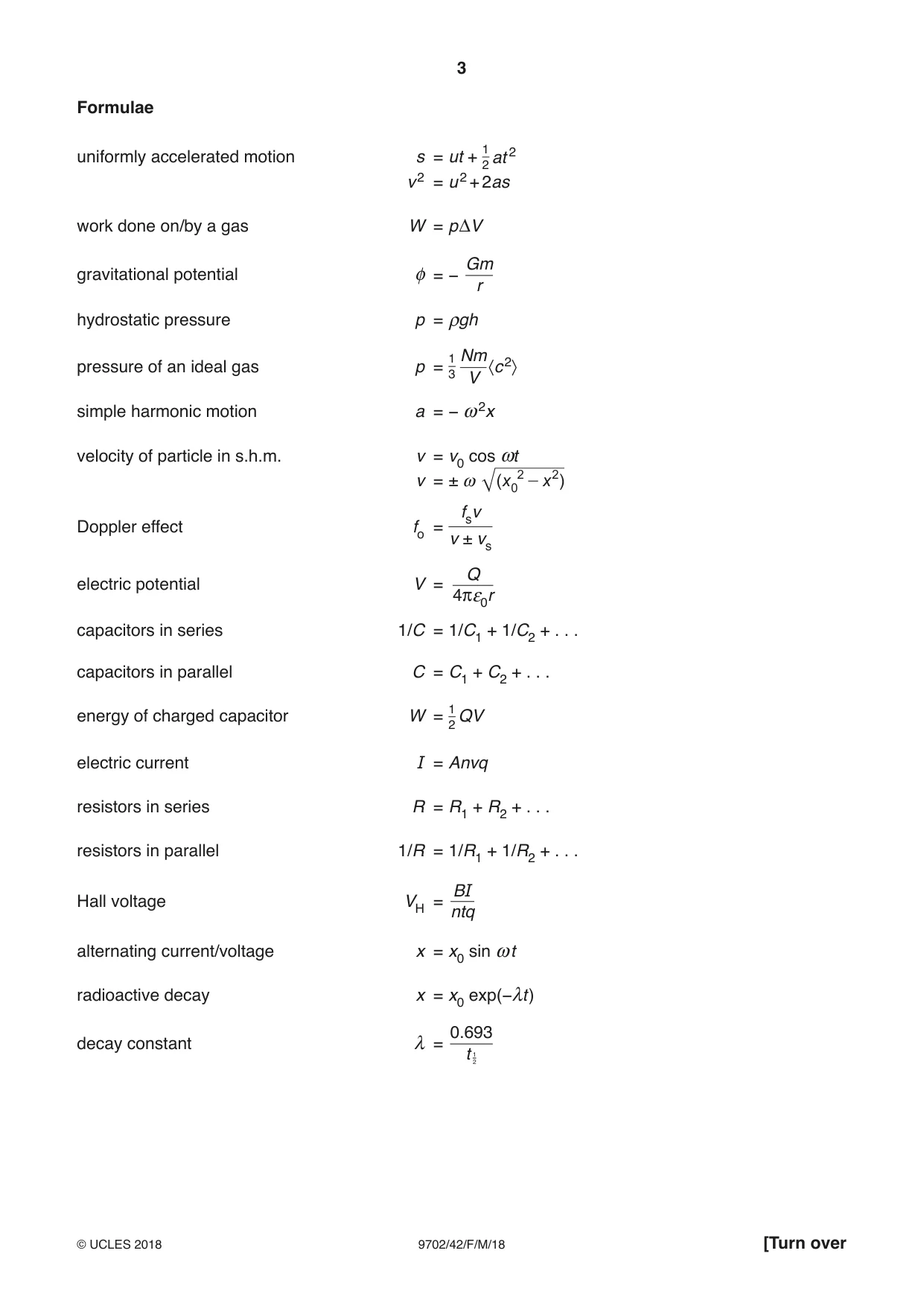
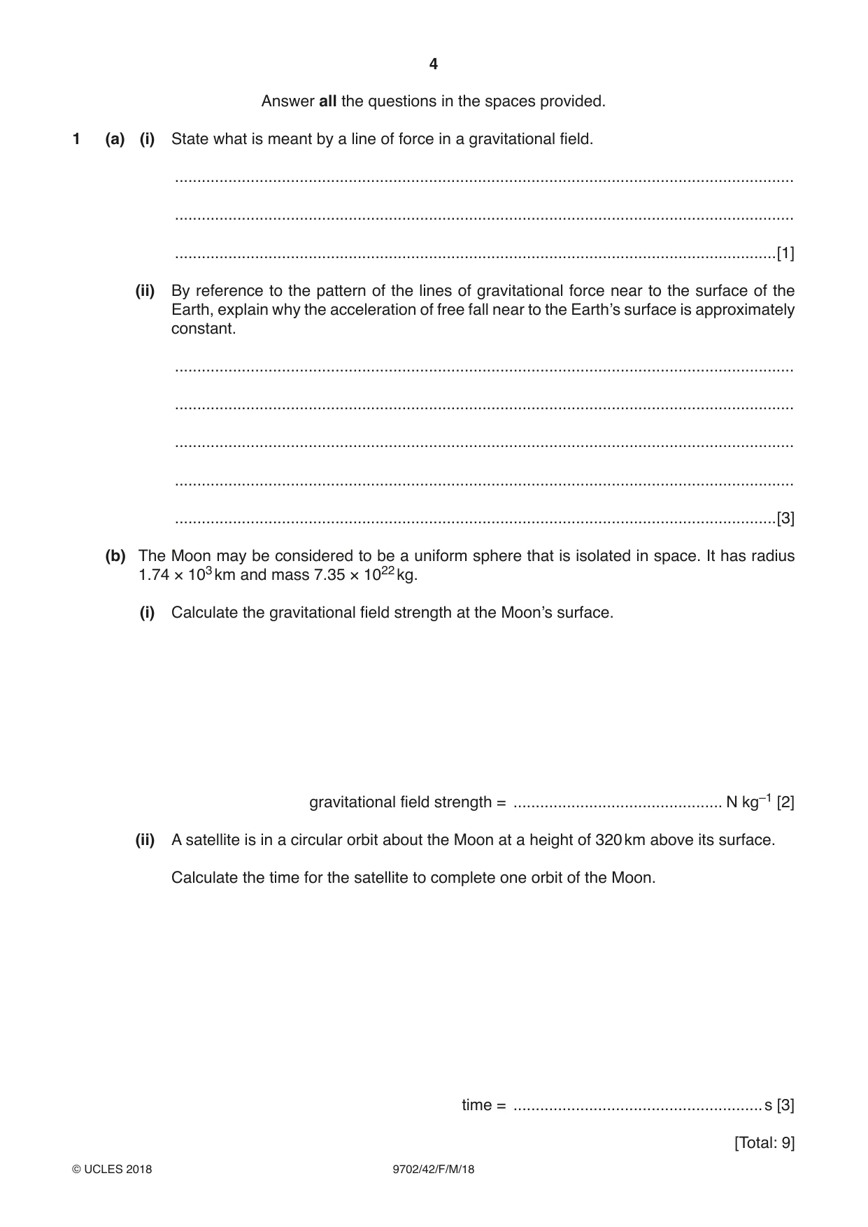
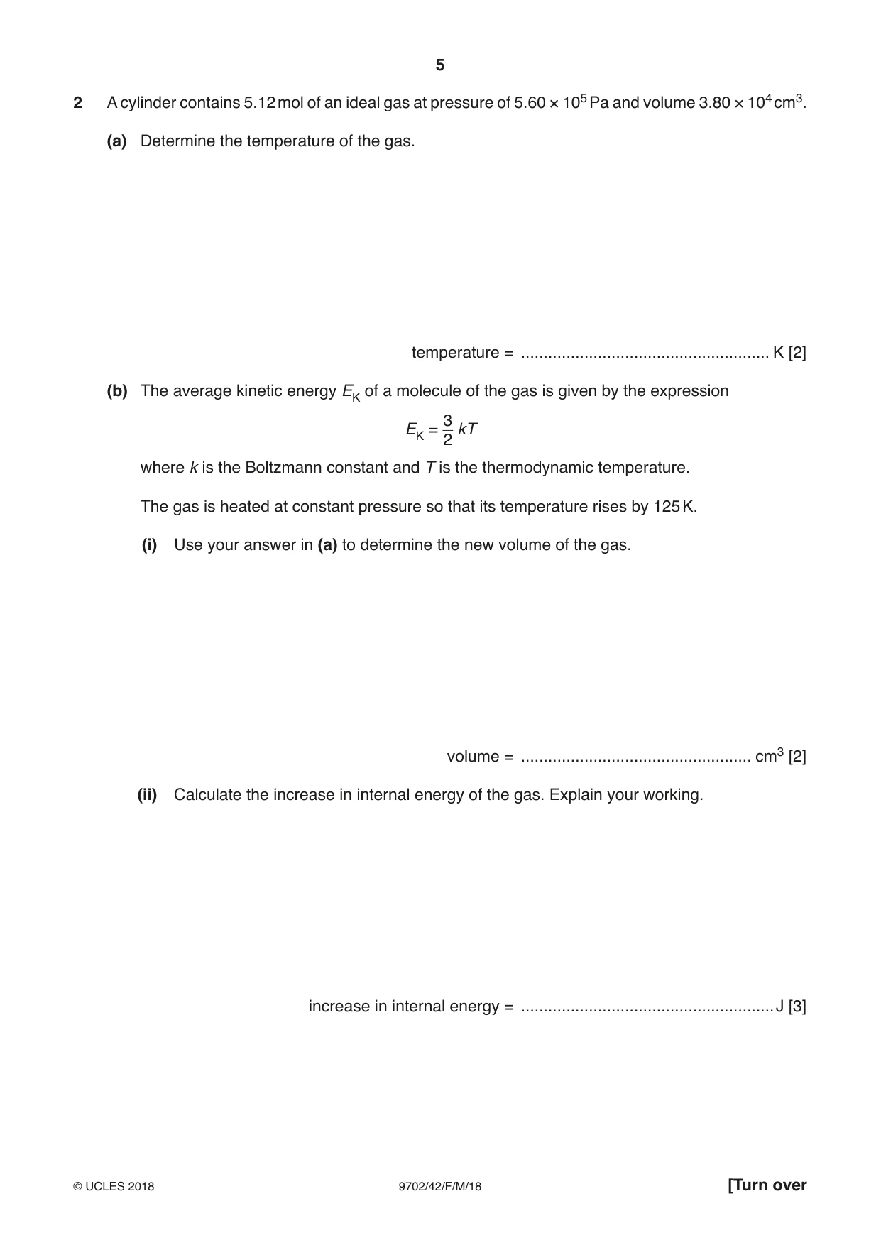

Mark scheme12 pages
Answers below. Sit the paper first if you are practising.

Questions as text
Q1 · State what is meant by a line of force in a gravitational field
1 (a) (i) State what is meant by a line of force in a gravitational field. ........................................................................................................................................... ........................................................................................................................................... .......................................................................................................................................[1] (ii) By reference to the pattern of the lines of gravitational force near to the surface of the Earth, explain why the acceleration of free fall near to the Earth’s surface is approximately constant. ........................................................................................................................................... ........................................................................................................................................... ........................................................................................................................................... ........................................................................................................................................... .......................................................................................................................................[3] (b) The Moon may be considered to be a uniform sphere that is isolated in space. It has radius 1.74 × 10³ km and mass 7.35 × 10²² kg. (i) Calculate the gravitational field strength at the Moon’s surface. gravitational field strength = ............................................... N kg–1 [2] (ii) A satellite is in a circular orbit about the Moon at a height of 320 km above its surface. Calculate the time for the satellite to complete one orbit of the Moon. time = ........................................................s [3] [Total: 9]
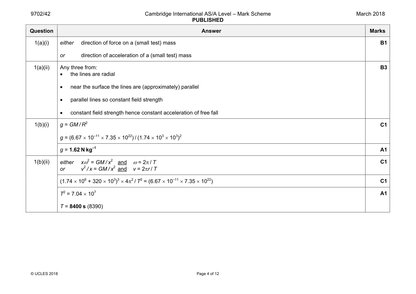
Mark scheme: 1(a)(i) either direction of force on a (small test) mass or direction of acceleration of a (small test) mass B1 1(a)(ii) Any three from: • the lines are radial • near the surface the lines are (approximately) parallel • parallel lines so constant field strength • constant field strength hence constant acceleration of free fall B3 1(b)(i) g = GM / R2 g = (6.67 × 10–11 × 7.35 × 1022) / (1.74 × 103 × 103)2 C1 g = 1.62 N kg–1 A1 1(b)(ii) either xω2 = GM / x2 and ω = 2π / T or v2 / x = GM / x2 and v = 2πr / T C1 (1.74 × 10⁶ + 320 × 103)3 × 4π2 / T2 = (6.67 × 10–11 × 7.35 × 1022) C1 T2 = 7.04 × 10⁷ T = 8400 s (8390) A1
Q2 · A cylinder contains 5.12 mol of an ideal gas at pressure of 5.60 × 10⁵ Pa and volume 3.80…
2 A cylinder contains 5.12 mol of an ideal gas at pressure of 5.60 × 10⁵ Pa and volume 3.80 × 104 cm3. (a) Determine the temperature of the gas. temperature = ....................................................... K [2] (b) The average kinetic energy EK of a molecule of the gas is given by the expression 3 EK = kT 2 where k is the Boltzmann constant and T is the thermodynamic temperature. The gas is heated at constant pressure so that its temperature rises by 125 K. (i) Use your answer in (a) to determine the new volume of the gas. volume = ................................................... cm3 [2] (ii) Calculate the increase in internal energy of the gas. Explain your working. increase in internal energy = ........................................................ J [3] (c) (i) Use your answer in (b)(i) to determine the external work done during the expansion of the gas. work done = ........................................................J [2] (ii) Calculate the total thermal energy required to heat the gas in (b). energy = ........................................................J [1] [Total: 10]
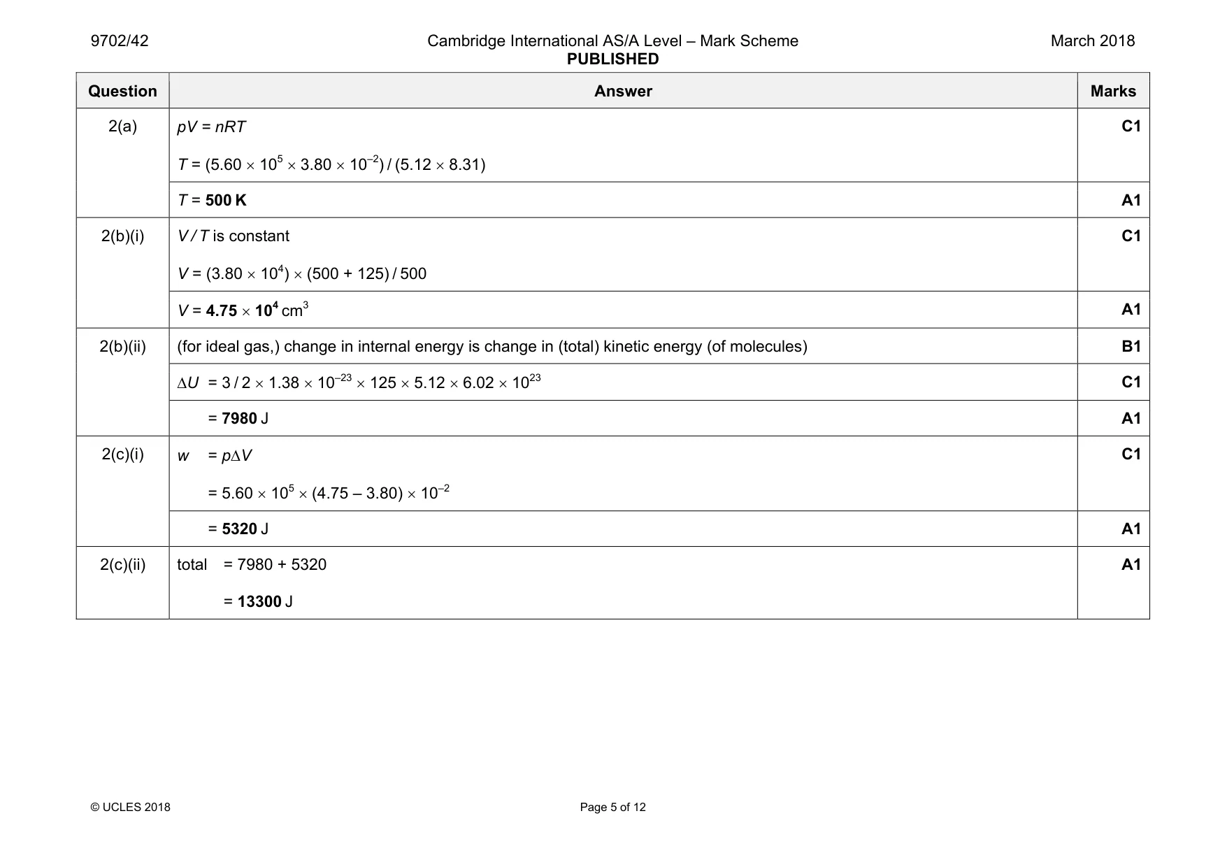
Mark scheme: 2(a) pV = nRT T = (5.60 × 105 × 3.80 × 10–2) / (5.12 × 8.31) C1 T = 500 K A1 2(b)(i) V / T is constant V = (3.80 × 104) × (500 + 125) / 500 C1 V = 4.75 × 104 cm3 A1 2(b)(ii) (for ideal gas,) change in internal energy is change in (total) kinetic energy (of molecules) B1 ∆U = 3 / 2 × 1.38 × 10–23 × 125 × 5.12 × 6.02 × 1023 C1 = 7980 J A1 2(c)(i) w = p∆V = 5.60 × 105 × (4.75 – 3.80) × 10–2 C1 = 5320 J A1 2(c)(ii) total = 7980 + 5320 = 13300 J A1
Q3 · A mass is undergoing simple harmonic motion with amplitude x0
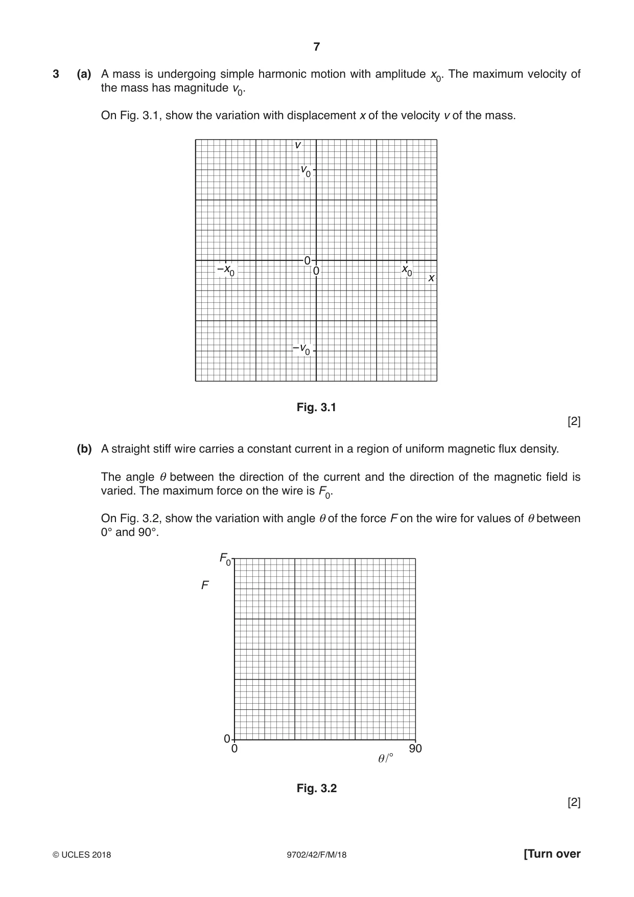
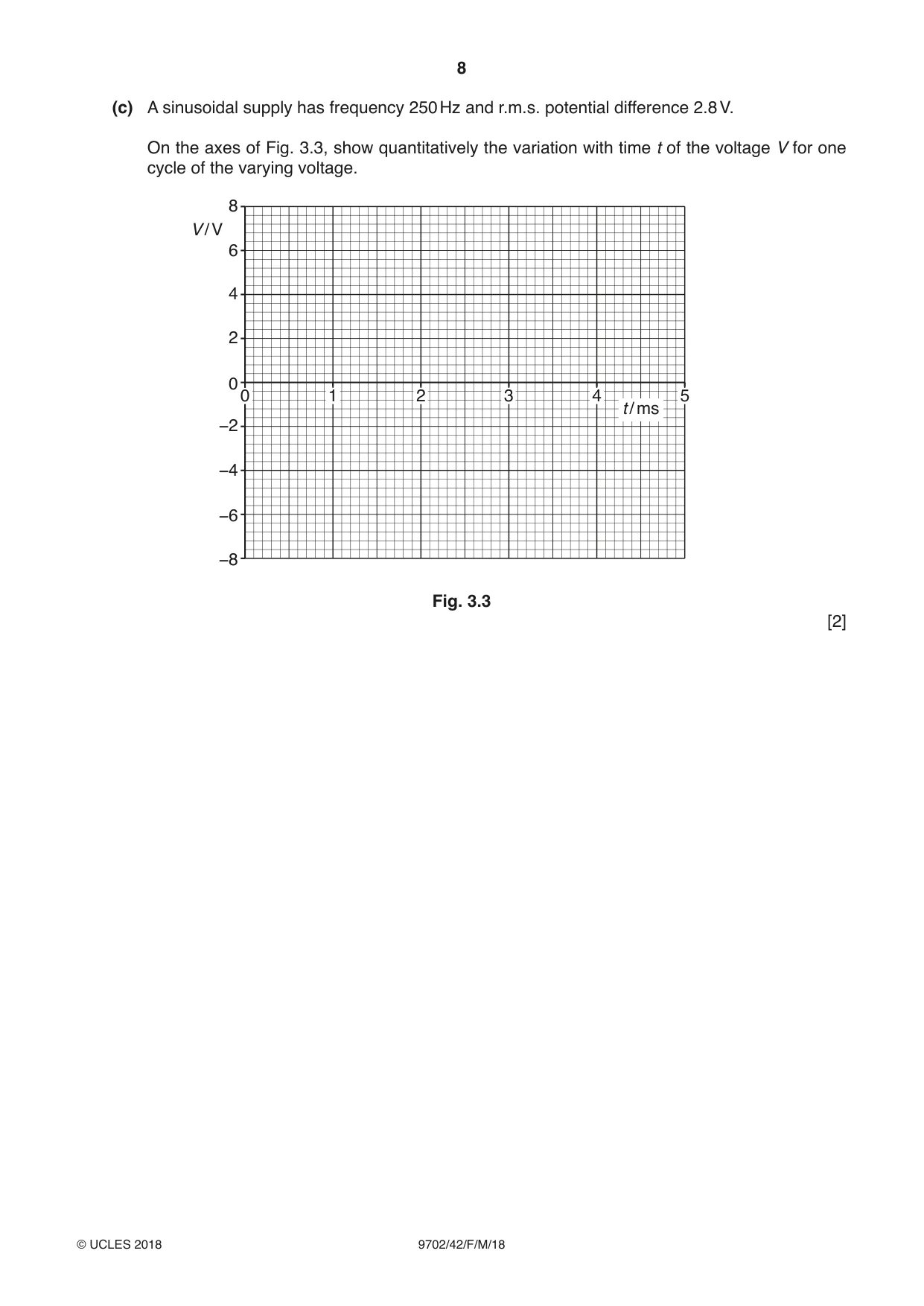
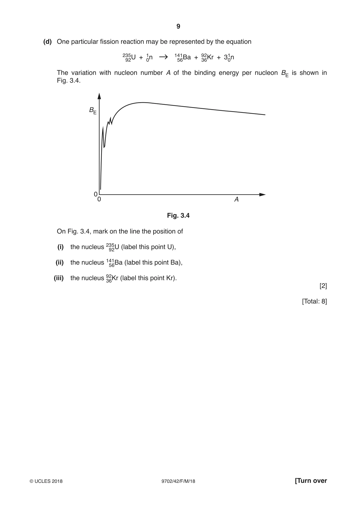
3 (a) A mass is undergoing simple harmonic motion with amplitude x0. The maximum velocity of the mass has magnitude v0. On Fig. 3.1, show the variation with displacement x of the velocity v of the mass. v v0 0 −x0 0 x0 x −v0 Fig. 3.1 [2] (b) A straight stiff wire carries a constant current in a region of uniform magnetic flux density. The angle θ between the direction of the current and the direction of the magnetic field is varied. The maximum force on the wire is F0. On Fig. 3.2, show the variation with angle θ of the force F on the wire for values of θ between 0° and 90°. F0 F 0 0 90 θ/° Fig. 3.2 [2] (c) A sinusoidal supply has frequency 250 Hz and r.m.s. potential difference 2.8 V. On the axes of Fig. 3.3, show quantitatively the variation with time t of the voltage V for one cycle of the varying voltage. 8 V / V 6 4 2 00 1 2 3 4 5 t / ms −2 −4 −6 −8 Fig. 3.3 [2] (d) One particular fission reaction may be represented by the equation 23 9 52U + 10n 14516Ba + 9326Kr + 310n The variation with nucleon number A of the binding energy per nucleon BE is shown in Fig. 3.4. BE 0 0 A Fig. 3.4 On Fig. 3.4, mark on the line the position of (i) the nucleus 23952U (label this point U), (ii) the nucleus 14516Ba (label this point Ba), (iii) the nucleus 9326Kr (label this point Kr). [2] [Total: 8]
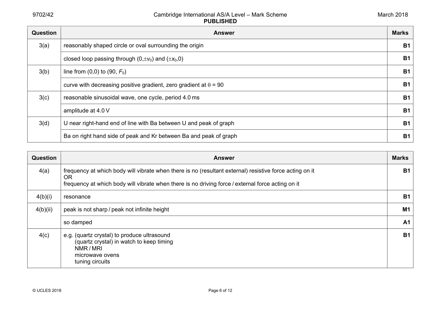
Mark scheme: 3(a) reasonably shaped circle or oval surrounding the origin B1 closed loop passing through (0,±v0) and (±x0,0) B1 3(b) line from (0,0) to (90, F0) B1 curve with decreasing positive gradient, zero gradient at θ = 90 B1 3(c) reasonable sinusoidal wave, one cycle, period 4.0 ms B1 amplitude at 4.0 V B1 3(d) U near right-hand end of line with Ba between U and peak of graph B1 Ba on right hand side of peak and Kr between Ba and peak of graph B1
Q4 · Explain what is meant by the natural frequency of vibration of a system
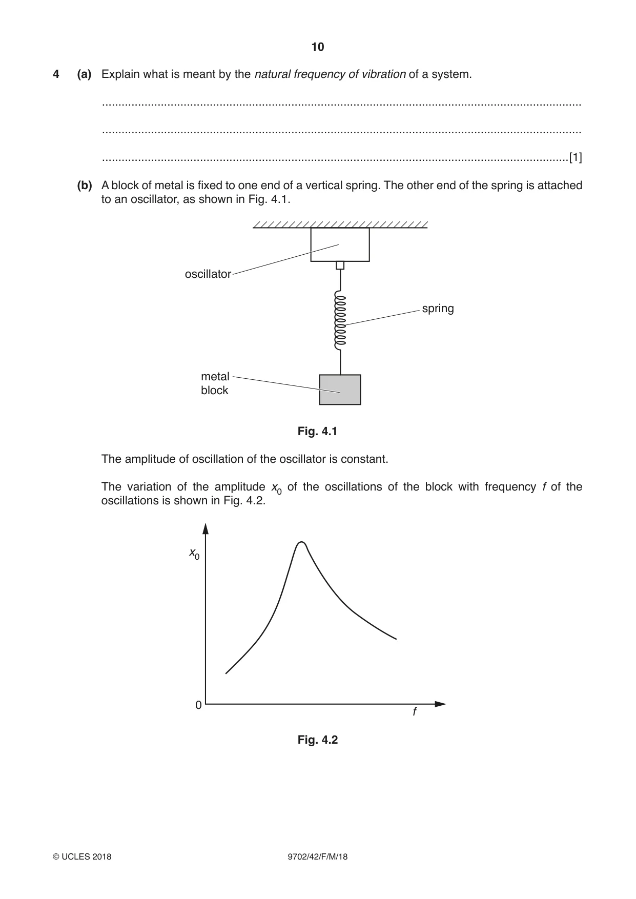
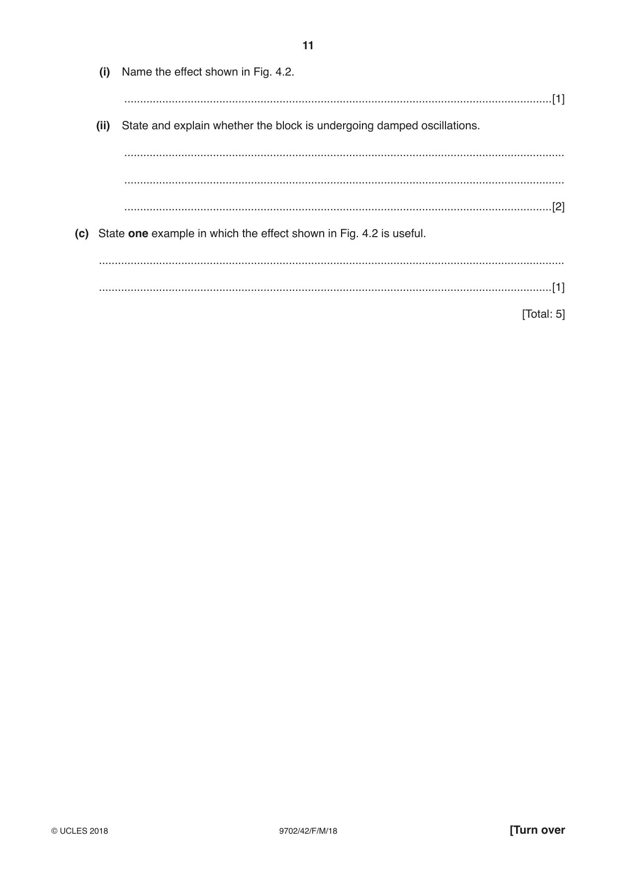
4 (a) Explain what is meant by the natural frequency of vibration of a system. ................................................................................................................................................... ................................................................................................................................................... ...............................................................................................................................................[1] (b) A block of metal is fixed to one end of a vertical spring. The other end of the spring is attached to an oscillator, as shown in Fig. 4.1. oscillator spring metal block Fig. 4.1 The amplitude of oscillation of the oscillator is constant. The variation of the amplitude x0 of the oscillations of the block with frequency f of the oscillations is shown in Fig. 4.2. x0 0 f Fig. 4.2 (i) Name the effect shown in Fig. 4.2. .......................................................................................................................................[1] (ii) State and explain whether the block is undergoing damped oscillations. ........................................................................................................................................... ........................................................................................................................................... .......................................................................................................................................[2] (c) State one example in which the effect shown in Fig. 4.2 is useful. ................................................................................................................................................... ...............................................................................................................................................[1] [Total: 5]
Mark scheme: 4(a) frequency at which body will vibrate when there is no (resultant external) resistive force acting on it OR frequency at which body will vibrate when there is no driving force / external force acting on it B1 4(b)(i) resonance B1 4(b)(ii) peak is not sharp / peak not infinite height M1 so damped A1 4(c) e.g. (quartz crystal) to produce ultrasound (quartz crystal) in watch to keep timing NMR / MRI microwave ovens tuning circuits B1
Q5 · Explain the main principles behind the use of ultrasound to obtain diagnostic information…
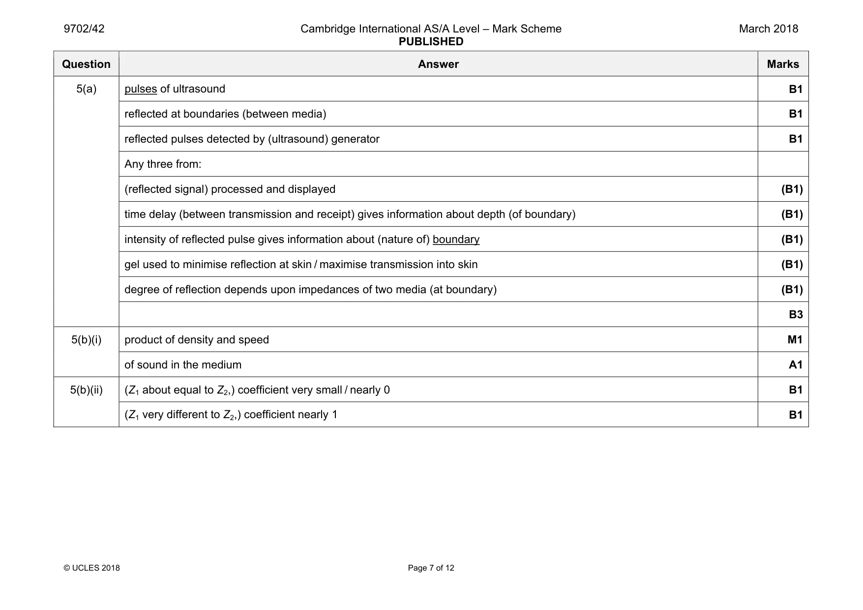
5 (a) Explain the main principles behind the use of ultrasound to obtain diagnostic information about internal body structures. ................................................................................................................................................... ................................................................................................................................................... ................................................................................................................................................... ................................................................................................................................................... ................................................................................................................................................... ................................................................................................................................................... ................................................................................................................................................... ................................................................................................................................................... ................................................................................................................................................... ................................................................................................................................................... ................................................................................................................................................... ...............................................................................................................................................[6] (b) (i) Define specific acoustic impedance. ........................................................................................................................................... ........................................................................................................................................... .......................................................................................................................................[2] (ii) Two media have specific acoustic impedances of Z1 and Z2. The magnitudes of the acoustic impedances may be almost equal or very different. State how these differences affect the intensity reflection coefficient at the boundary between the two media. Z1 ≈ Z2 ............................................................................................................................... ........................................................................................................................................... Z1 » Z2 or Z1 « Z2 .............................................................................................................. ........................................................................................................................................... [2] [Total: 10]
Mark scheme: 5(a) pulses of ultrasound B1 reflected at boundaries (between media) B1 reflected pulses detected by (ultrasound) generator B1 Any three from: (reflected signal) processed and displayed (B1) time delay (between transmission and receipt) gives information about depth (of boundary) (B1) intensity of reflected pulse gives information about (nature of) boundary (B1) gel used to minimise reflection at skin / maximise transmission into skin (B1) degree of reflection depends upon impedances of two media (at boundary) (B1) B3 5(b)(i) product of density and speed M1 of sound in the medium A1 5(b)(ii) (Z1 about equal to Z2,) coefficient very small / nearly 0 B1 (Z1 very different to Z2,) coefficient nearly 1 B1
Q6 · The digital transmission of speech may be represented using the block diagram of Fig
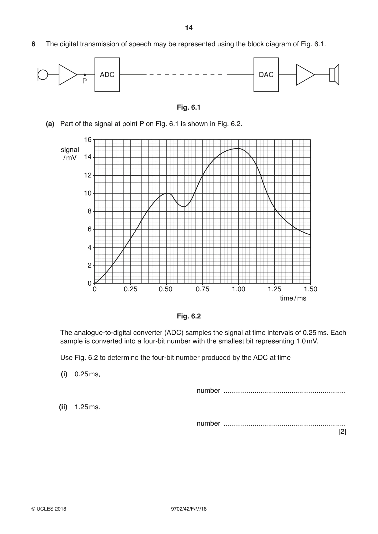
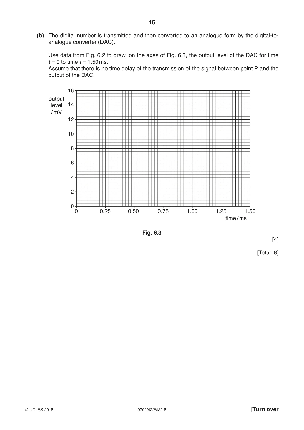
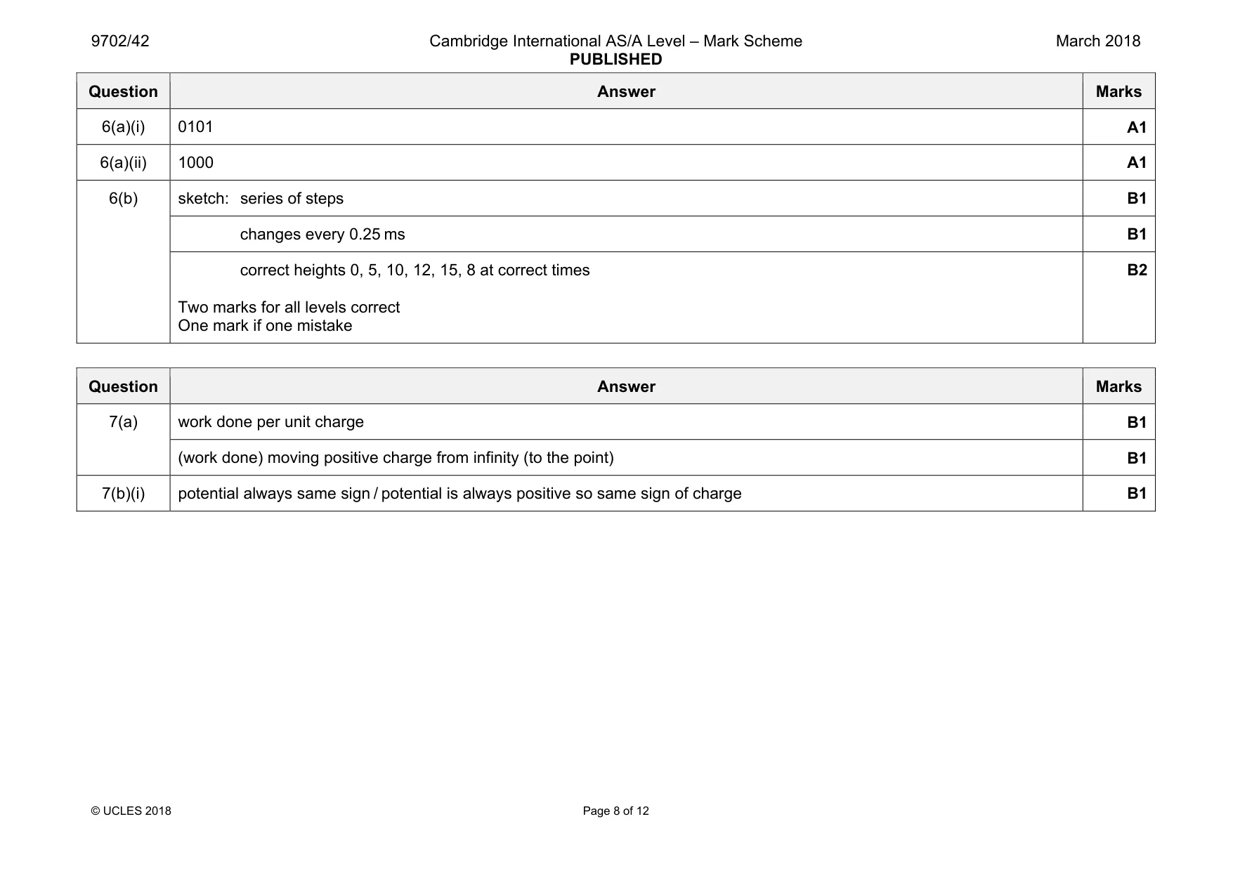
6 The digital transmission of speech may be represented using the block diagram of Fig. 6.1. ADC DAC P Fig. 6.1 (a) Part of the signal at point P on Fig. 6.1 is shown in Fig. 6.2. 16 signal / mV 14 12 10 8 6 4 2 0 0 0.25 0.50 0.75 1.00 1.25 1.50 time / ms Fig. 6.2 The analogue-to-digital converter (ADC) samples the signal at time intervals of 0.25 ms. Each sample is converted into a four-bit number with the smallest bit representing 1.0 mV. Use Fig. 6.2 to determine the four-bit number produced by the ADC at time (i) 0.25 ms, number ............................................................... (ii) 1.25 ms. number ............................................................... [2] (b) The digital number is transmitted and then converted to an analogue form by the digital-to- analogue converter (DAC). Use data from Fig. 6.2 to draw, on the axes of Fig. 6.3, the output level of the DAC for time t = 0 to time t = 1.50 ms. Assume that there is no time delay of the transmission of the signal between point P and the output of the DAC. 16 output level 14 / mV 12 10 8 6 4 2 0 0 0.25 0.50 0.75 1.00 1.25 1.50 time / ms Fig. 6.3 [4] [Total: 6]
Mark scheme: 6(a)(i) 0101 A1 6(a)(ii) 1000 A1 6(b) sketch: series of steps B1 changes every 0.25 ms B1 correct heights 0, 5, 10, 12, 15, 8 at correct times Two marks for all levels correct One mark if one mistake B2
Q7 · State what is meant by electric potential at a point
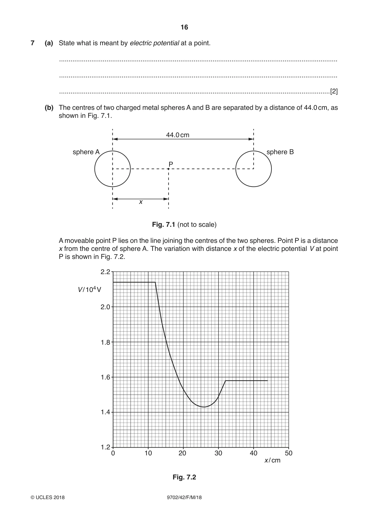
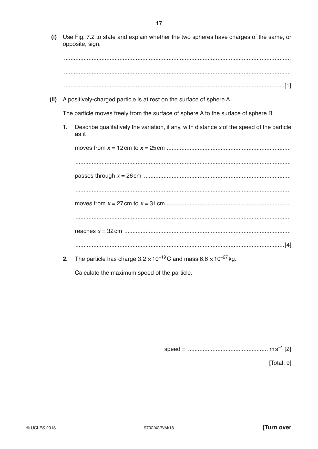
7 (a) State what is meant by electric potential at a point. ................................................................................................................................................... ................................................................................................................................................... ...............................................................................................................................................[2] (b) The centres of two charged metal spheres A and B are separated by a distance of 44.0 cm, as shown in Fig. 7.1. 44.0 cm sphere A sphere B P x Fig. 7.1 (not to scale) A moveable point P lies on the line joining the centres of the two spheres. Point P is a distance x from the centre of sphere A. The variation with distance x of the electric potential V at point P is shown in Fig. 7.2. 2.2 V / 104 V 2.0 1.8 1.6 1.4 1.2 0 10 20 30 40 50 x / cm Fig. 7.2 (i) Use Fig. 7.2 to state and explain whether the two spheres have charges of the same, or opposite, sign. ........................................................................................................................................... ........................................................................................................................................... .......................................................................................................................................[1] (ii) A positively-charged particle is at rest on the surface of sphere A. The particle moves freely from the surface of sphere A to the surface of sphere B. 1. Describe qualitatively the variation, if any, with distance x of the speed of the particle as it moves from x = 12 cm to x = 25 cm ............................................................................ .................................................................................................................................... passes through x = 26 cm .......................................................................................... .................................................................................................................................... moves from x = 27 cm to x = 31 cm ............................................................................ .................................................................................................................................... reaches x = 32 cm ...................................................................................................... ................................................................................................................................[4] 2. The particle has charge 3.2 × 10⁻¹⁹ C and mass 6.6 × 10⁻²⁷ kg. Calculate the maximum speed of the particle. speed = ................................................. m s–1 [2] [Total: 9]
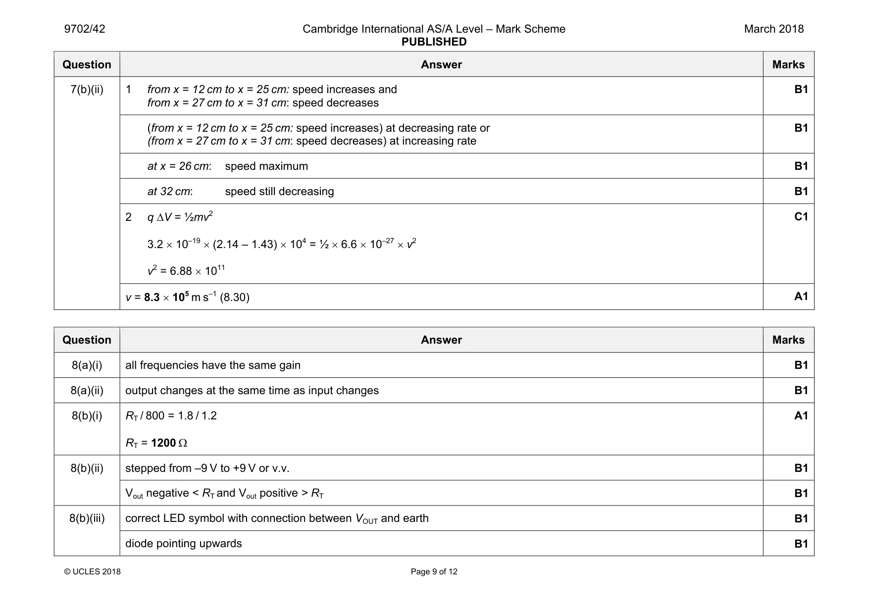
Mark scheme: 7(a) work done per unit charge B1 (work done) moving positive charge from infinity (to the point) B1 7(b)(i) potential always same sign / potential is always positive so same sign of charge B1 Question Answer Marks 7(b)(ii) 1 from x = 12 cm to x = 25 cm: speed increases and from x = 27 cm to x = 31 cm: speed decreases B1 (from x = 12 cm to x = 25 cm: speed increases) at decreasing rate or (from x = 27 cm to x = 31 cm: speed decreases) at increasing rate B1 at x = 26 cm: speed maximum B1 at 32 cm: speed still decreasing B1 2 q ∆V = ½mv2 3.2 × 10–19 × (2.14 – 1.43) × 104 = ½ × 6.6 × 10⁻²⁷ × v2 v2 = 6.88 × 10¹¹ C1 v = 8.3 × 10⁵ m s–1 (8.30) A1
Q8 · Two properties of an ideal operational amplifier (op-amp) are infinite bandwidth and…
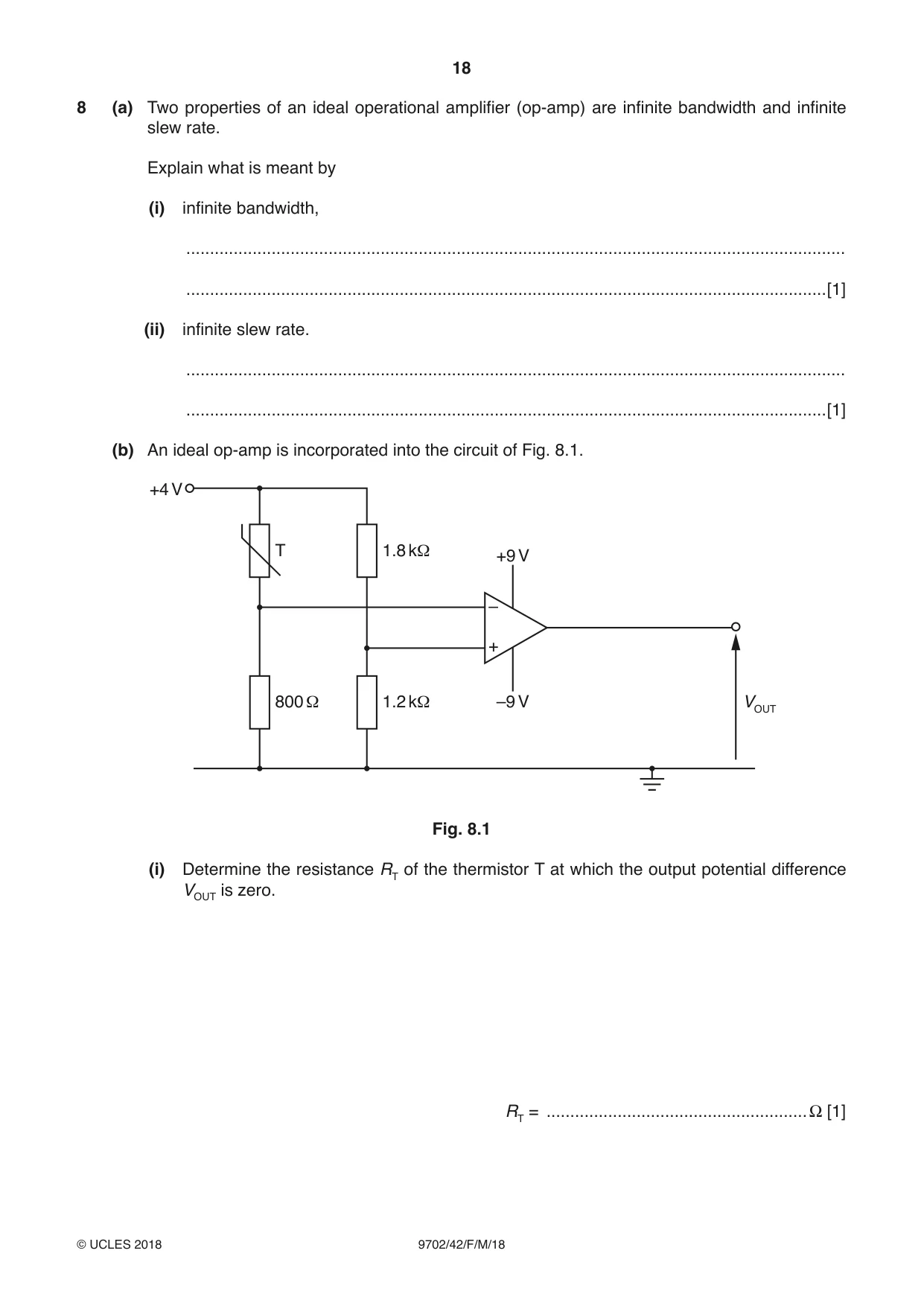
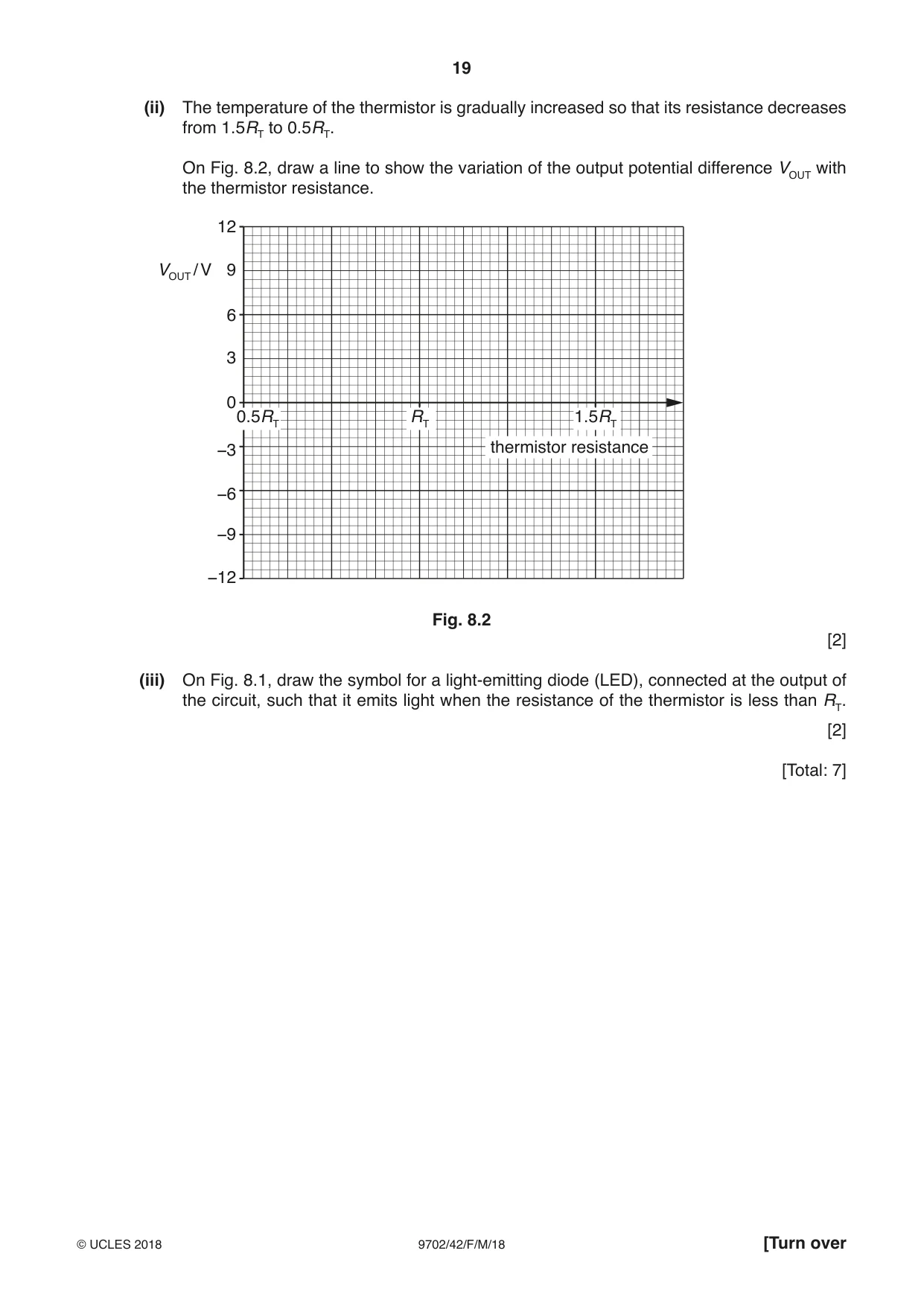
8 (a) Two properties of an ideal operational amplifier (op-amp) are infinite bandwidth and infinite slew rate. Explain what is meant by (i) infinite bandwidth, ........................................................................................................................................... .......................................................................................................................................[1] (ii) infinite slew rate. ........................................................................................................................................... .......................................................................................................................................[1] (b) An ideal op-amp is incorporated into the circuit of Fig. 8.1. +4 V T 1.8 kΩ +9 V – + 800 Ω 1.2 kΩ –9 V VOUT Fig. 8.1 (i) Determine the resistance RT of the thermistor T at which the output potential difference VOUT is zero. RT = ....................................................... Ω [1] (ii) The temperature of the thermistor is gradually increased so that its resistance decreases from 1.5RT to 0.5RT. On Fig. 8.2, draw a line to show the variation of the output potential difference VOUT with the thermistor resistance. 12 VOUT / V 9 6 3 0 0.5RT RT 1.5RT −3 thermistor resistance −6 −9 −12 Fig. 8.2 [2] (iii) On Fig. 8.1, draw the symbol for a light-emitting diode (LED), connected at the output of the circuit, such that it emits light when the resistance of the thermistor is less than RT. [2] [Total: 7]
Mark scheme: 8(a)(i) all frequencies have the same gain B1 8(a)(ii) output changes at the same time as input changes B1 8(b)(i) RT / 800 = 1.8 / 1.2 RT = 1200 Ω A1 8(b)(ii) stepped from –9 V to +9 V or v.v. B1 Vout negative < RT and Vout positive > RT B1 8(b)(iii) correct LED symbol with connection between VOUT and earth B1 diode pointing upwards B1
Q9 · A thin slice of conducting material has its faces PQRS and VWXY normal to a uniform…
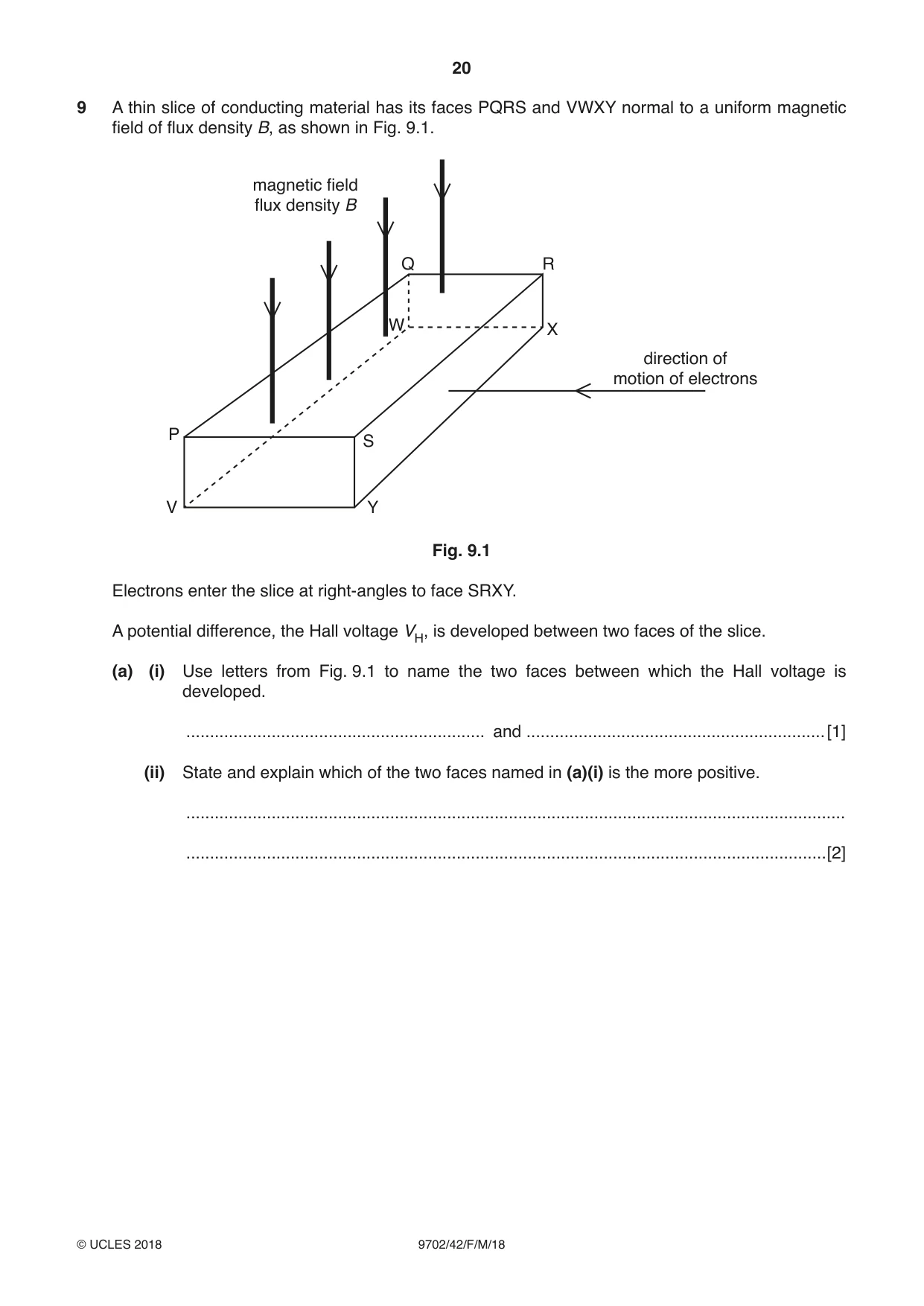
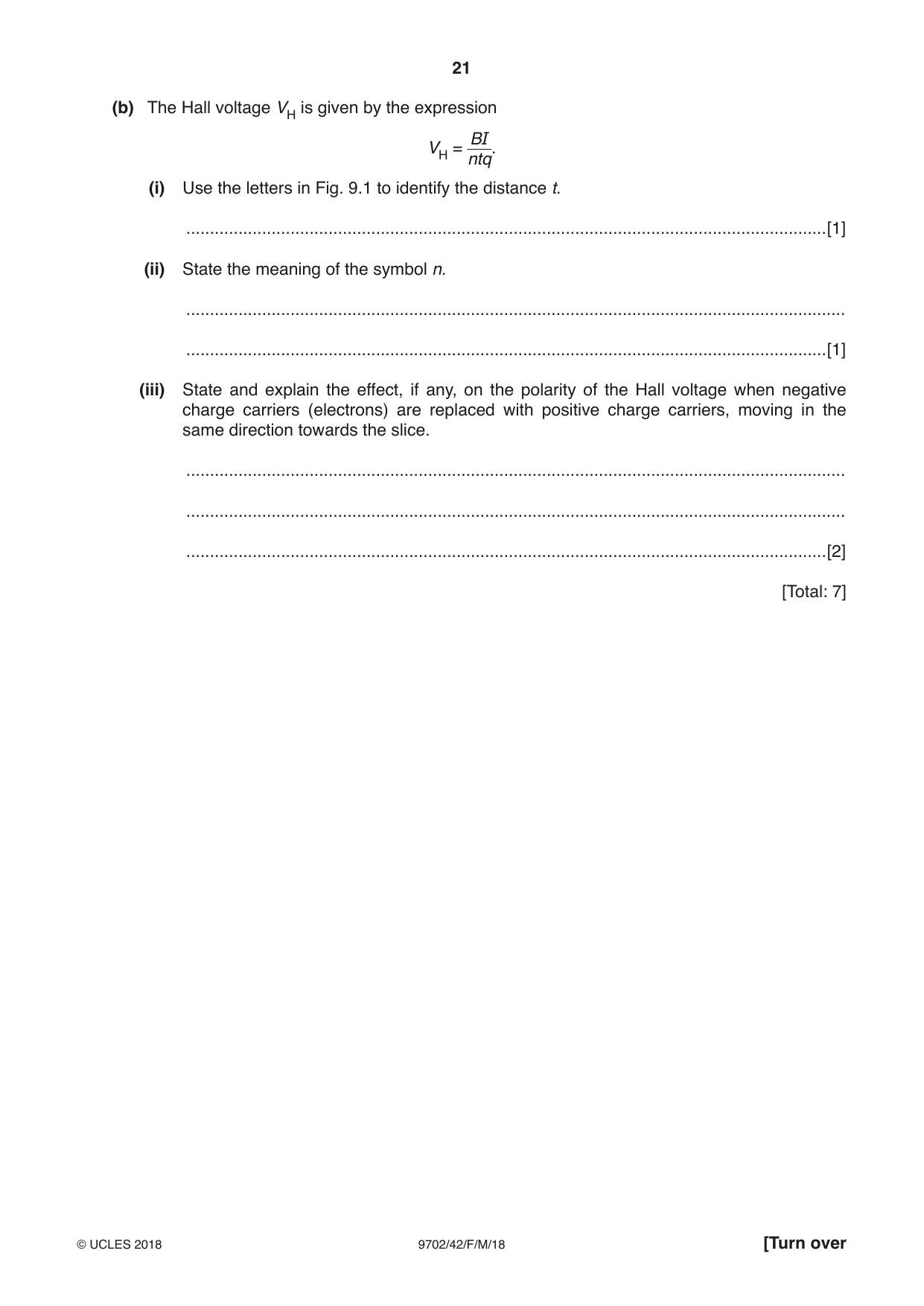
9 A thin slice of conducting material has its faces PQRS and VWXY normal to a uniform magnetic field of flux density B, as shown in Fig. 9.1. magnetic field flux density B Q R W X direction of motion of electrons P S V Y Fig. 9.1 Electrons enter the slice at right-angles to face SRXY. A potential difference, the Hall voltage VH, is developed between two faces of the slice. (a) (i) Use letters from Fig. 9.1 to name the two faces between which the Hall voltage is developed. ............................................................... and ............................................................... [1] (ii) State and explain which of the two faces named in (a)(i) is the more positive. ........................................................................................................................................... .......................................................................................................................................[2] (b) The Hall voltage VH is given by the expression BI VH = ntq. (i) Use the letters in Fig. 9.1 to identify the distance t. .......................................................................................................................................[1] (ii) State the meaning of the symbol n. ........................................................................................................................................... .......................................................................................................................................[1] (iii) State and explain the effect, if any, on the polarity of the Hall voltage when negative charge carriers (electrons) are replaced with positive charge carriers, moving in the same direction towards the slice. ........................................................................................................................................... ........................................................................................................................................... .......................................................................................................................................[2] [Total: 7]
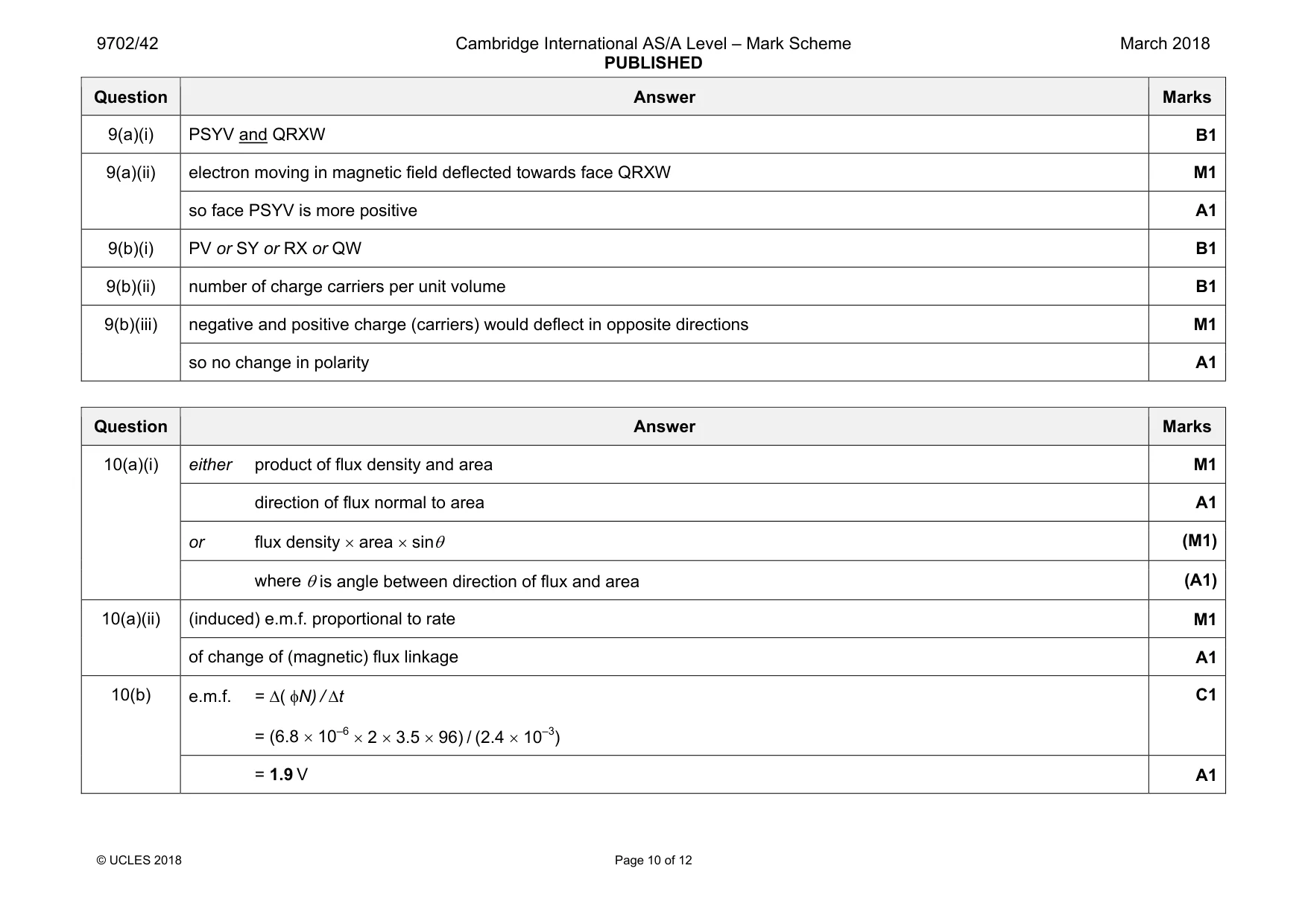
Mark scheme: 9(a)(i) PSYV and QRXW B1 9(a)(ii) electron moving in magnetic field deflected towards face QRXW M1 so face PSYV is more positive A1 9(b)(i) PV or SY or RX or QW B1 9(b)(ii) number of charge carriers per unit volume B1 9(b)(iii) negative and positive charge (carriers) would deflect in opposite directions M1 so no change in polarity A1
Question 10
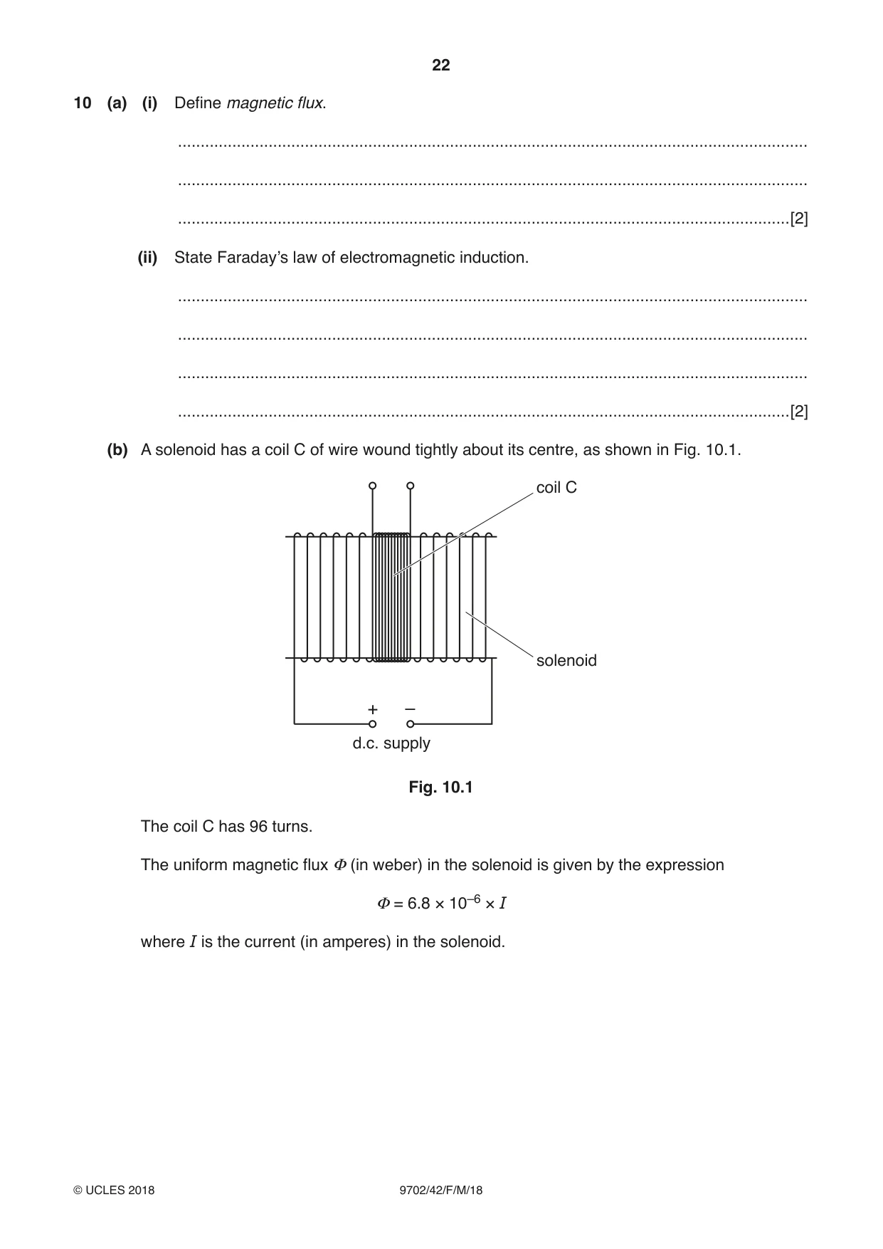
10 (a) (i) Define magnetic flux. ........................................................................................................................................... ........................................................................................................................................... .......................................................................................................................................[2] (ii) State Faraday’s law of electromagnetic induction. ........................................................................................................................................... ........................................................................................................................................... ........................................................................................................................................... .......................................................................................................................................[2] (b) A solenoid has a coil C of wire wound tightly about its centre, as shown in Fig. 10.1. coil C solenoid + – d.c. supply Fig. 10.1 The coil C has 96 turns. The uniform magnetic flux Φ (in weber) in the solenoid is given by the expression Φ = 6.8 × 10⁻⁶ × I where I is the current (in amperes) in the solenoid. Calculate the average electromotive force (e.m.f.) induced in coil C when a current of 3.5 A is reversed in the solenoid in a time of 2.4 ms. e.m.f. = ....................................................... V [2] (c) The d.c. supply in Fig. 10.1 is now replaced with a sinusoidal alternating supply. Describe qualitatively the e.m.f. that is now induced in coil C. ................................................................................................................................................... ................................................................................................................................................... ...............................................................................................................................................[2] [Total: 8]
Mark scheme: 10(a)(i) either product of flux density and area M1 direction of flux normal to area A1 or flux density × area × sinθ (M1) where θ is angle between direction of flux and area (A1) 10(a)(ii) (induced) e.m.f. proportional to rate M1 of change of (magnetic) flux linkage A1 10(b) e.m.f. = ∆( φN) / ∆t = (6.8 × 10–6 × 2 × 3.5 × 96) / (2.4 × 10⁻³) C1 = 1.9 V A1 Question Answer Marks 10(c) alternating C1 with same frequency as supply A1
Q11 · Some electron energy bands in a solid are shown in Fig
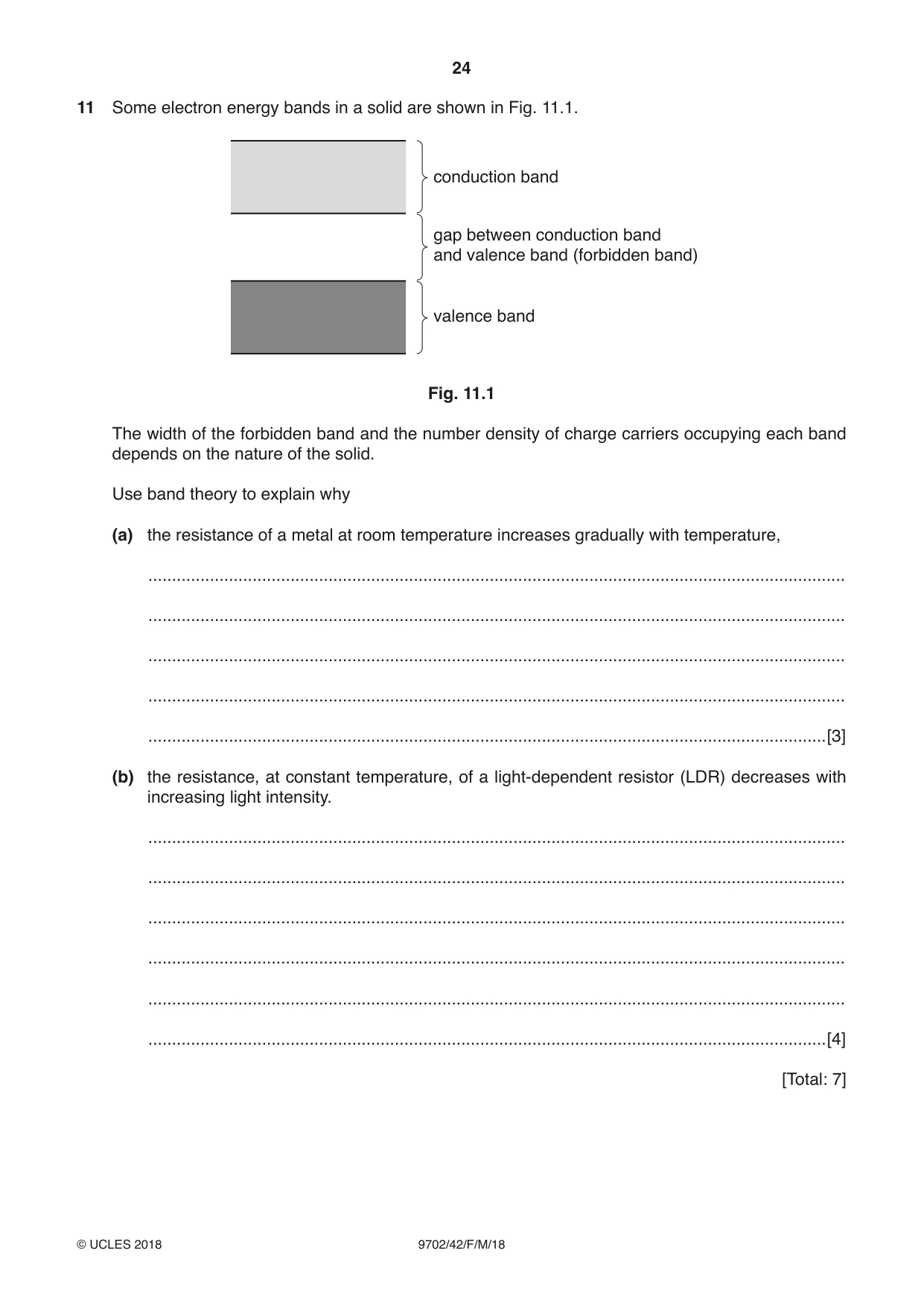
11 Some electron energy bands in a solid are shown in Fig. 11.1. conduction band gap between conduction band and valence band (forbidden band) valence band Fig. 11.1 The width of the forbidden band and the number density of charge carriers occupying each band depends on the nature of the solid. Use band theory to explain why (a) the resistance of a metal at room temperature increases gradually with temperature, ................................................................................................................................................... ................................................................................................................................................... ................................................................................................................................................... ................................................................................................................................................... ...............................................................................................................................................[3] (b) the resistance, at constant temperature, of a light-dependent resistor (LDR) decreases with increasing light intensity. ................................................................................................................................................... ................................................................................................................................................... ................................................................................................................................................... ................................................................................................................................................... ................................................................................................................................................... ...............................................................................................................................................[4] [Total: 7]
Mark scheme: 11(a) no forbidden band / valence and conduction bands overlap B1 no change in number of charge carriers (as temperature rises) B1 increased lattice vibrations so resistance increases B1 11(b) photons captured / absorbed by electrons in valence band B1 electrons promoted to conduction band B1 leaving holes in the valence band B1 more holes and / or electrons so resistance decreases B1
Q12 · Suggest two causes of lack of sharpness of an X-ray image
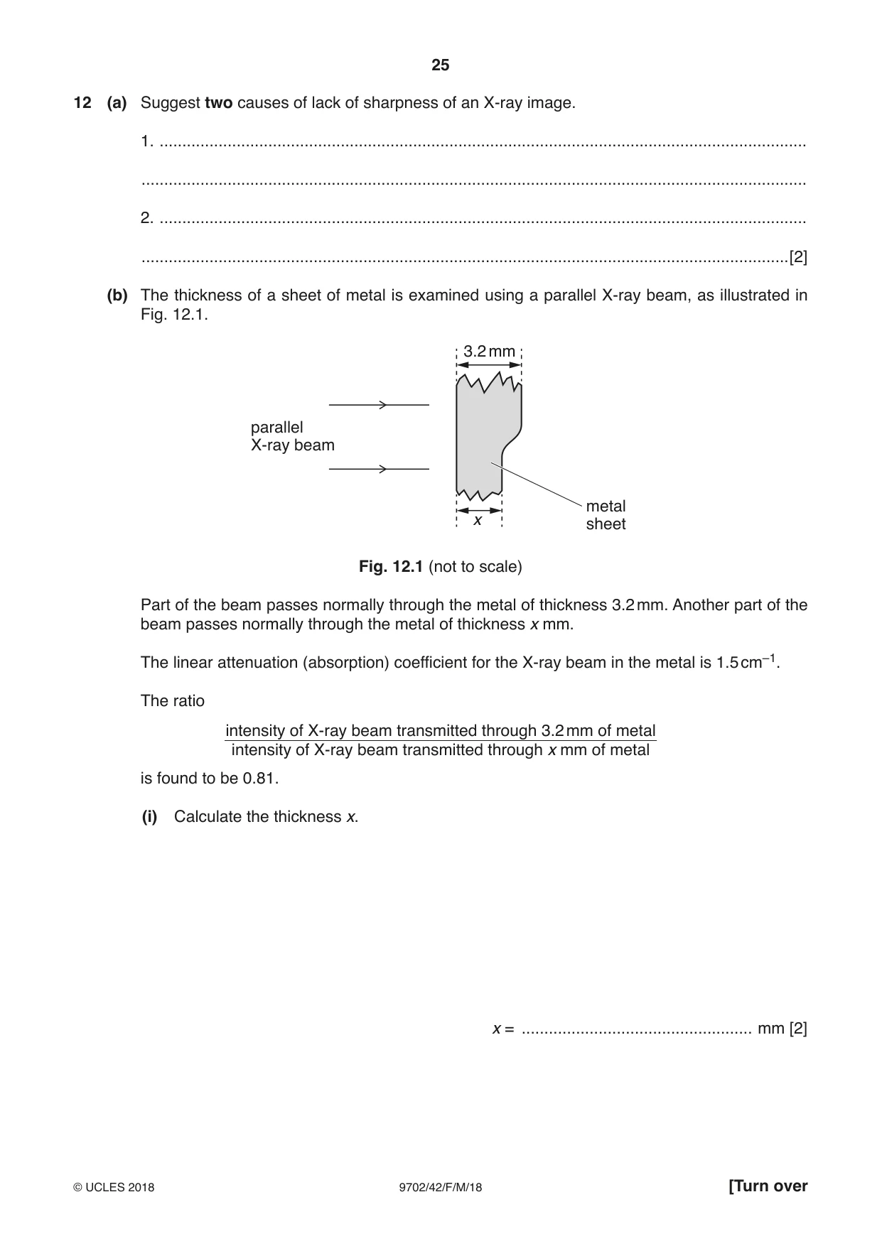
12 (a) Suggest two causes of lack of sharpness of an X-ray image. 1. ............................................................................................................................................... ................................................................................................................................................... 2. ............................................................................................................................................... ...............................................................................................................................................[2] (b) The thickness of a sheet of metal is examined using a parallel X-ray beam, as illustrated in Fig. 12.1. 3.2 mm parallel X-ray beam metal x sheet Fig. 12.1 (not to scale) Part of the beam passes normally through the metal of thickness 3.2 mm. Another part of the beam passes normally through the metal of thickness x mm. The linear attenuation (absorption) coefficient for the X-ray beam in the metal is 1.5 cm–1. The ratio intensity of X-ray beam transmitted through 3.2 mm of metal intensity of X-ray beam transmitted through x mm of metal is found to be 0.81. (i) Calculate the thickness x. x = ................................................... mm [2] (ii) The ratio of the intensities is also the ratio of the powers of the X-ray beams. Calculate this ratio in decibels. ratio = ..................................................... dB [2] [Total: 6]
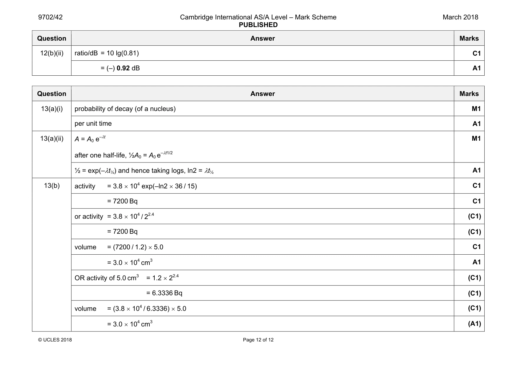
Mark scheme: 12(a) Any 2 from: scattering of X-ray beam / no lead grid lack of collimation of beam / aperture large anode area large beam p.d. low / photon energy low / X-ray soft B2 12(b)(i) 0.81 = (e–1.5 × 0.32) / (e–1.5 × x) C1 x = 1.8 mm A1 Question Answer Marks 12(b)(ii) ratio/dB = 10 lg(0.81) C1 = (–) 0.92 dB A1
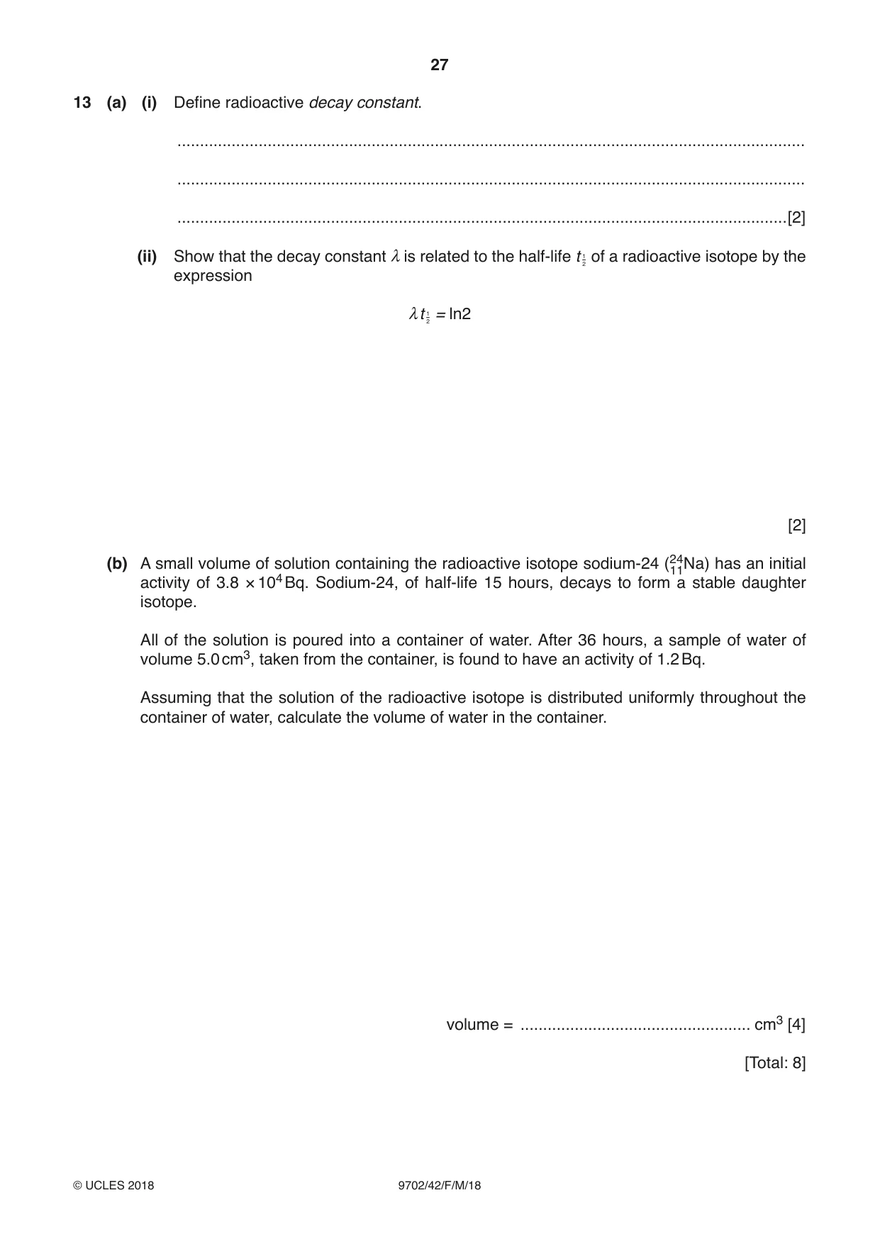
Q13 · Define radioactive decay constant
13 (a) (i) Define radioactive decay constant. ........................................................................................................................................... ........................................................................................................................................... .......................................................................................................................................[2] 1 (ii) Show that the decay constant λis related to the half-life t 2 of a radioactive isotope by the expression 1 λt 2 = ln2 [2] (b) A small volume of solution containing the radioactive isotope sodium-24 (2141Na) has an initial activity of 3.8 × 10⁴ Bq. Sodium-24, of half-life 15 hours, decays to form a stable daughter isotope. All of the solution is poured into a container of water. After 36 hours, a sample of water of volume 5.0 cm3, taken from the container, is found to have an activity of 1.2 Bq. Assuming that the solution of the radioactive isotope is distributed uniformly throughout the container of water, calculate the volume of water in the container. volume = ................................................... cm3 [4] [Total: 8]
Mark scheme: 13(a)(i) probability of decay (of a nucleus) M1 per unit time A1 13(a)(ii) A = A0 e–λt after one half-life, ½A0 = A0 e–λt1/2 M1 ½ = exp(–λt½) and hence taking logs, ln2 = λt½ A1 13(b) activity = 3.8 × 10⁴ exp(–ln2 × 36 / 15) C1 = 7200 Bq C1 or activity = 3.8 × 10⁴ / 22.4 (C1) = 7200 Bq (C1) volume = (7200 / 1.2) × 5.0 C1 = 3.0 × 104 cm3 A1 OR activity of 5.0 cm3 = 1.2 × 22.4 (C1) = 6.3336 Bq (C1) volume = (3.8 × 10⁴ / 6.3336) × 5.0 (C1) = 3.0 × 104 cm3 (A1)
What was in this paper
The subtopics covered by these 13 questions, and how many questions each got. Open one in a new tab to see every Cambridge question on it.
1Electric current1Electric potential1Electromagnetic induction1Force on a moving charge1Gravitational field1Practical circuits1Production and use of ultrasound1Production and use of X-rays1Radioactive decay1Resistance and resistivity1Simple harmonic oscillations1The first law of thermodynamics1What you needed in this session
Cambridge’s own grade thresholds for 2018 Feb/March, Paper 4 · Variant 2. A higher threshold means an easier paper — the bar moves with how the cohort did.