Cambridge A Level Physics 9702 — 2025 May/June Paper 4 · Variant 2
9702/42/M/J/25 · 10 questions · 100 marks · 120 min
The question paper and its mark scheme, free to read here and free to download. This is Cambridge’s own paper, exactly as it was sat.
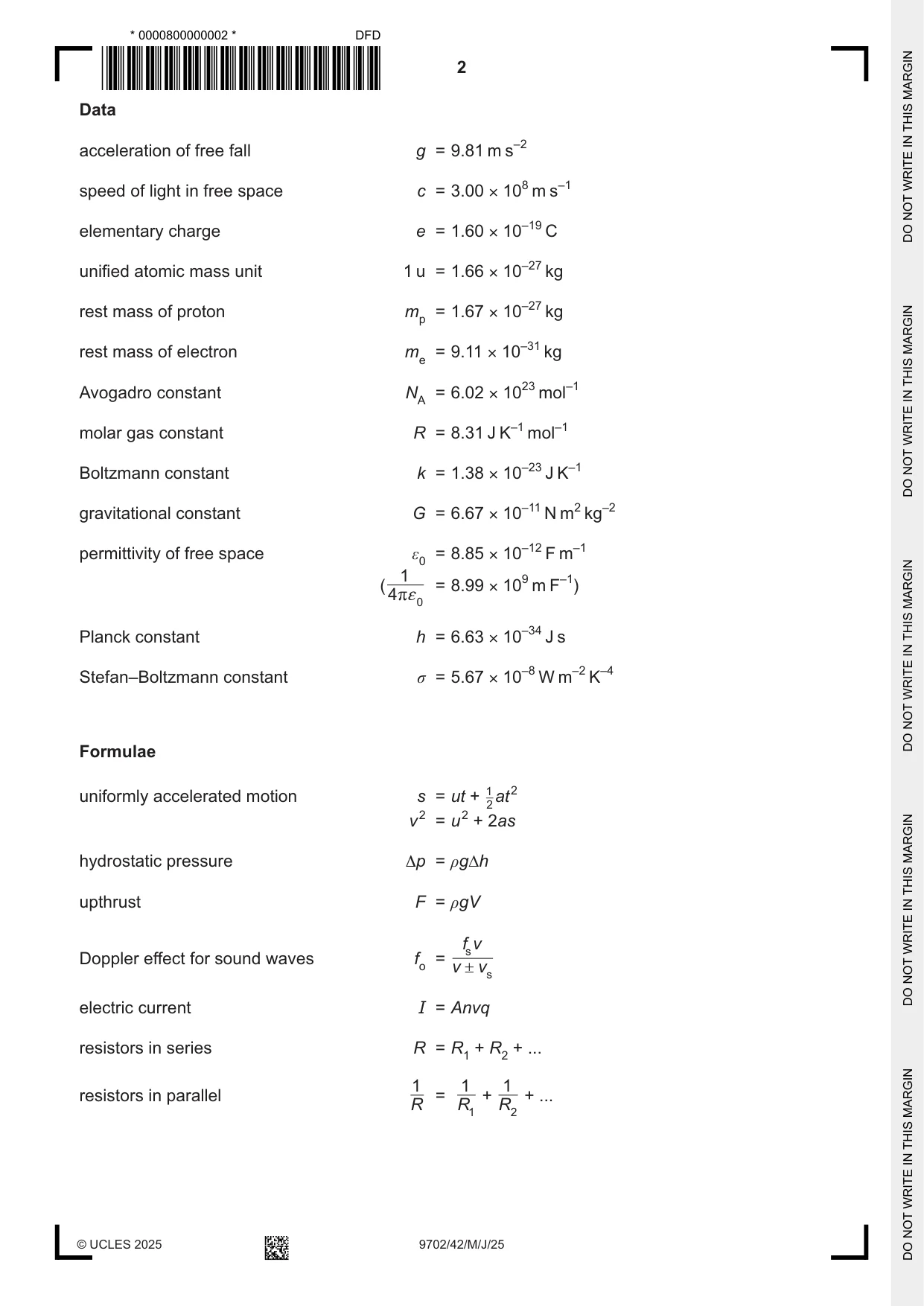
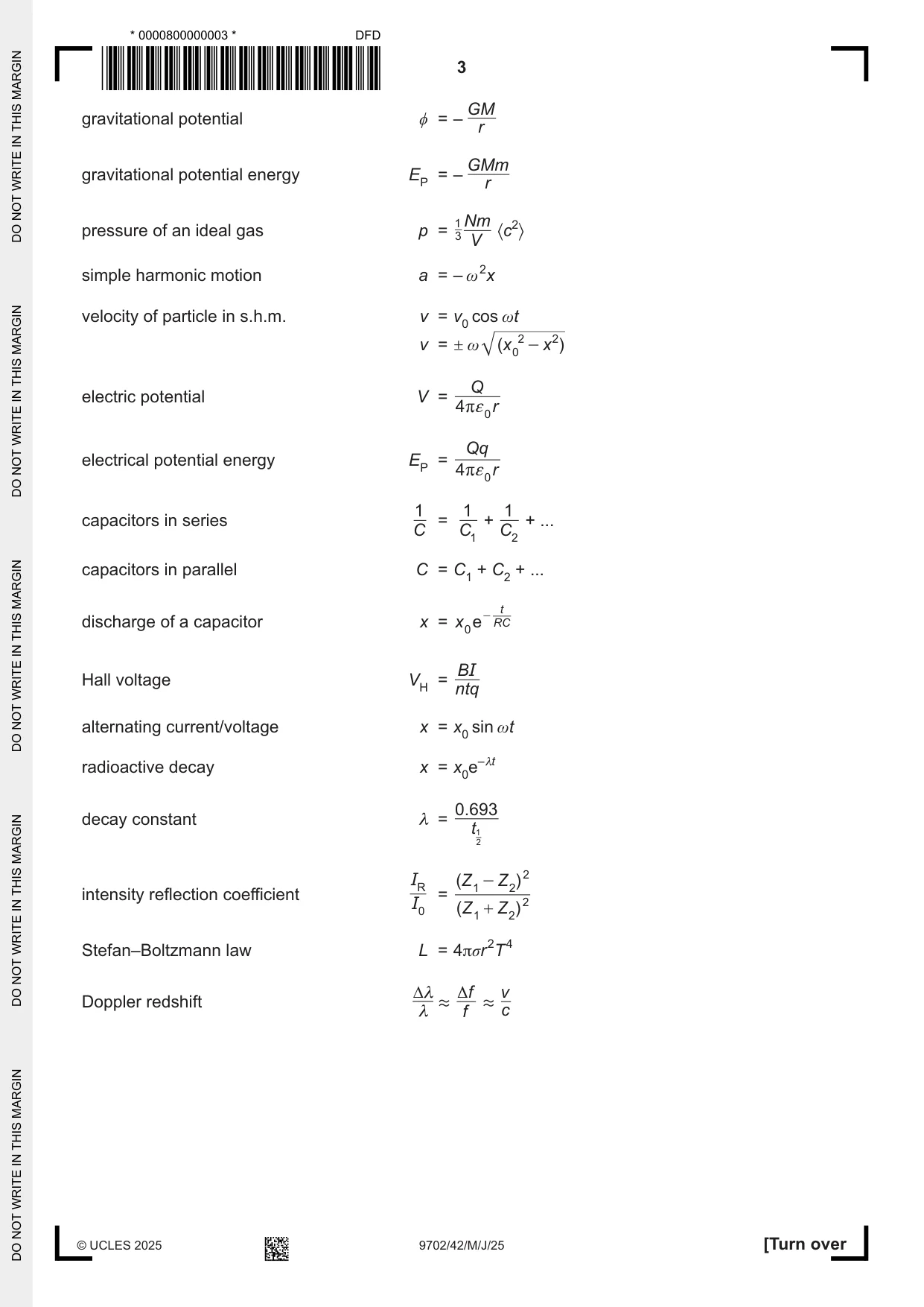
Question paper24 pages
Mark scheme18 pages
Answers below. Sit the paper first if you are practising.
Questions as text
Question 1
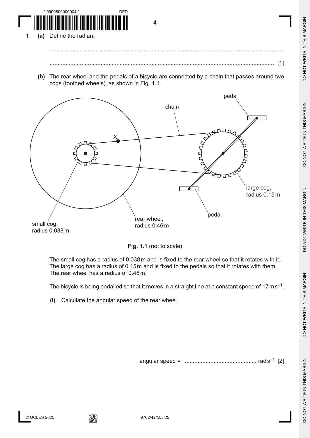
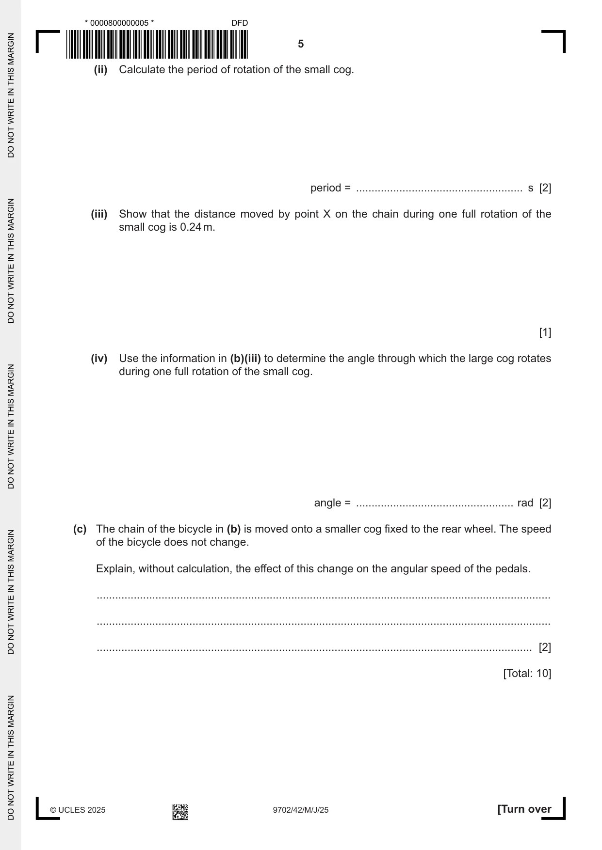
1 (a) Define the radian. ................................................................................................................................................... ............................................................................................................................................. [1] (b) The rear wheel and the pedals of a bicycle are connected by a chain that passes around two cogs (toothed wheels), as shown in Fig. 1.1. pedal chain X large cog, radius 0.15 m pedal rear wheel, small cog, radius 0.46 m radius 0.038 m Fig. 1.1 (not to scale) The small cog has a radius of 0.038 m and is fixed to the rear wheel so that it rotates with it. The large cog has a radius of 0.15 m and is fixed to the pedals so that it rotates with them. The rear wheel has a radius of 0.46 m. The bicycle is being pedalled so that it moves in a straight line at a constant speed of 17 m s–1. (i) Calculate the angular speed of the rear wheel. angular speed = .............................................. rad s–1 [2] (ii) Calculate the period of rotation of the small cog. period = ...................................................... s [2] (iii) Show that the distance moved by point X on the chain during one full rotation of the small cog is 0.24 m. [1] (iv) Use the information in (b)(iii) to determine the angle through which the large cog rotates during one full rotation of the small cog. angle = ................................................... rad [2] (c) The chain of the bicycle in (b) is moved onto a smaller cog fixed to the rear wheel. The speed of the bicycle does not change. Explain, without calculation, the effect of this change on the angular speed of the pedals. ................................................................................................................................................... ................................................................................................................................................... ............................................................................................................................................. [2] [Total: 10]
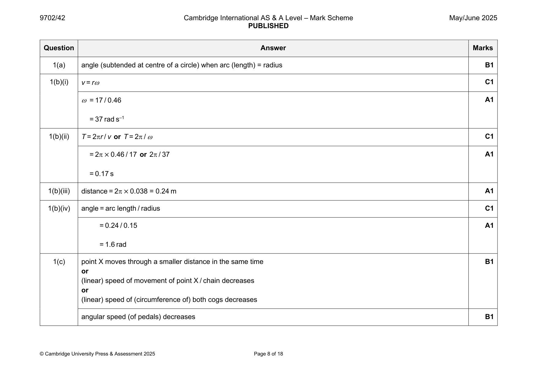
Mark scheme: Question Answer Marks 1(a) angle (subtended at centre of a circle) when arc (length) = radius B1 1(b)(i) v = r C1 = 17 / 0.46 A1 = 37 rad s–1 1(b)(ii) T = 2r / v or T = 2 / C1 = 2 × 0.46 / 17 or 2 / 37 A1 = 0.17 s 1(b)(iii) distance = 2 × 0.038 = 0.24 m A1 1(b)(iv) angle = arc length / radius C1 = 0.24 / 0.15 A1 = 1.6 rad 1(c) point X moves through a smaller distance in the same time B1 or (linear) speed of movement of point X / chain decreases or (linear) speed of (circumference of) both cogs decreases angular speed (of pedals) decreases B1
Q2 · State what is represented by a gravitational field line
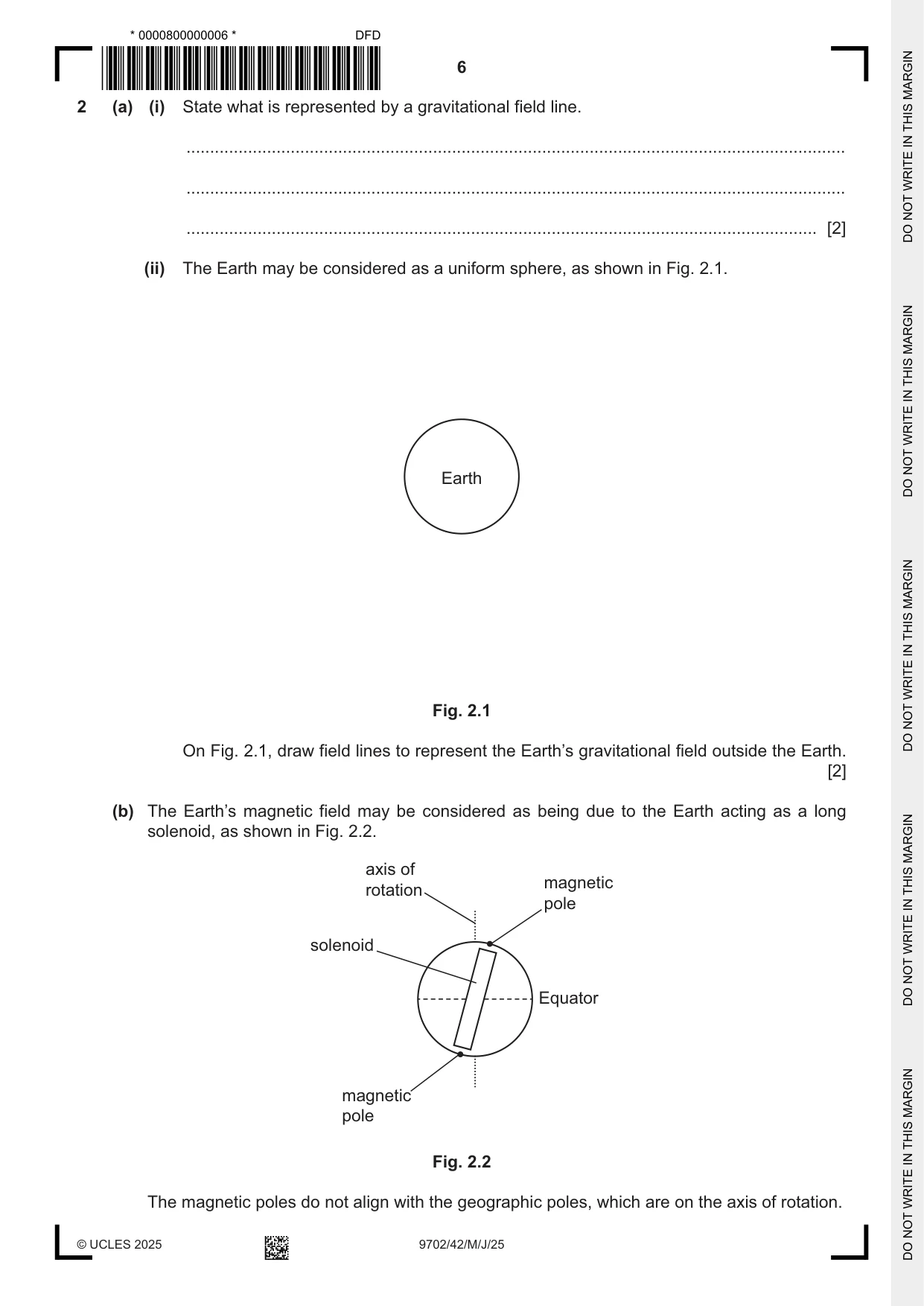
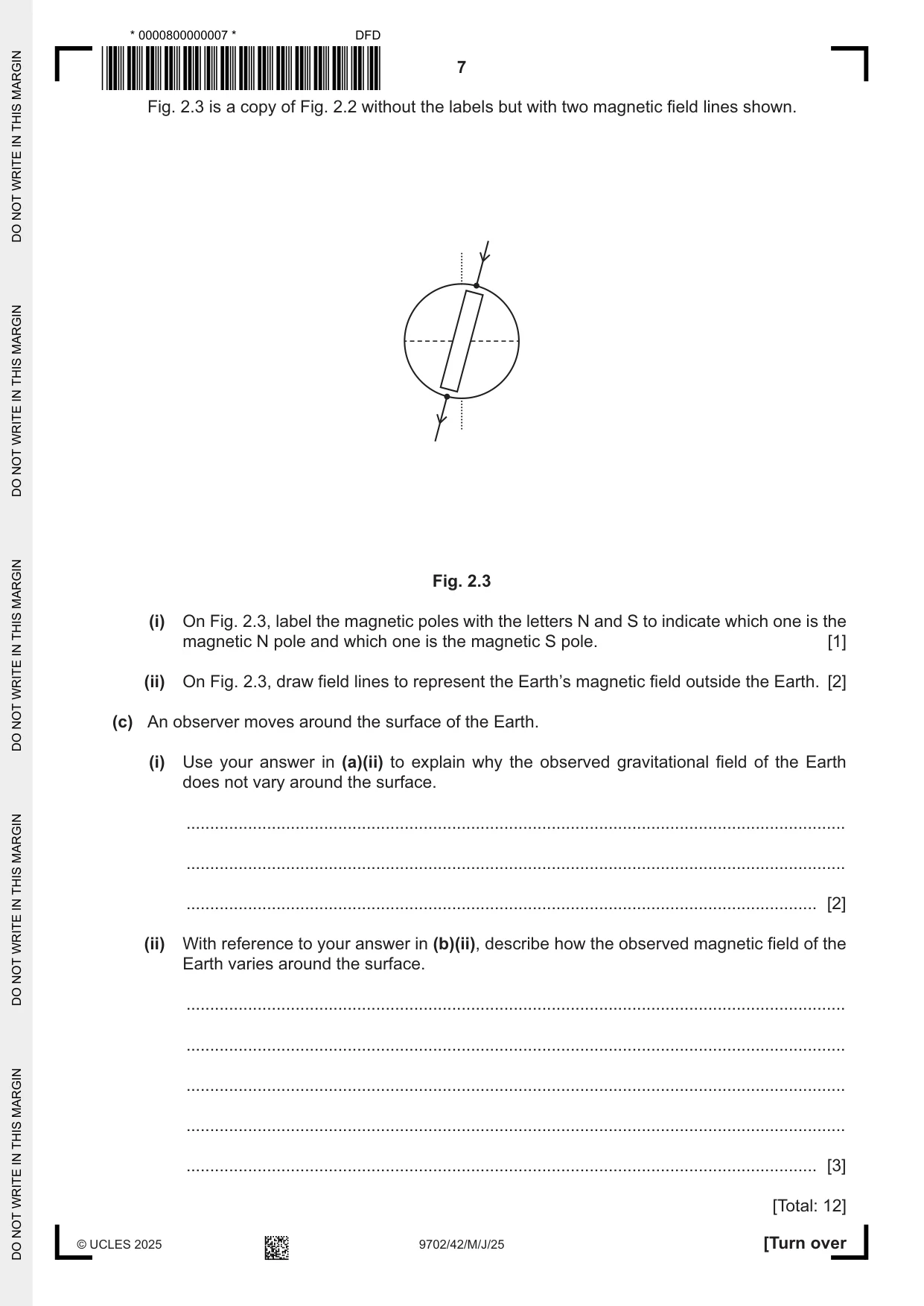
2 (a) (i) State what is represented by a gravitational field line. ........................................................................................................................................... ........................................................................................................................................... ..................................................................................................................................... [2] (ii) The Earth may be considered as a uniform sphere, as shown in Fig. 2.1. Earth Fig. 2.1 On Fig. 2.1, draw field lines to represent the Earth’s gravitational field outside the Earth. [2] (b) The Earth’s magnetic field may be considered as being due to the Earth acting as a long solenoid, as shown in Fig. 2.2. axis of magnetic rotation pole solenoid Equator magnetic pole Fig. 2.2 The magnetic poles do not align with the geographic poles, which are on the axis of rotation. Fig. 2.3 is a copy of Fig. 2.2 without the labels but with two magnetic field lines shown. Fig. 2.3 (i) On Fig. 2.3, label the magnetic poles with the letters N and S to indicate which one is the magnetic N pole and which one is the magnetic S pole. [1] (ii) On Fig. 2.3, draw field lines to represent the Earth’s magnetic field outside the Earth. [2] (c) An observer moves around the surface of the Earth. (i) Use your answer in (a)(ii) to explain why the observed gravitational field of the Earth does not vary around the surface. ........................................................................................................................................... ........................................................................................................................................... ..................................................................................................................................... [2] (ii) With reference to your answer in (b)(ii), describe how the observed magnetic field of the Earth varies around the surface. ........................................................................................................................................... ........................................................................................................................................... ........................................................................................................................................... ........................................................................................................................................... ..................................................................................................................................... [3] [Total: 12]
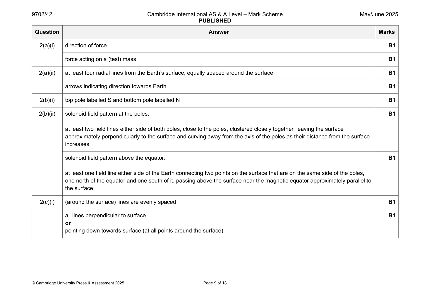
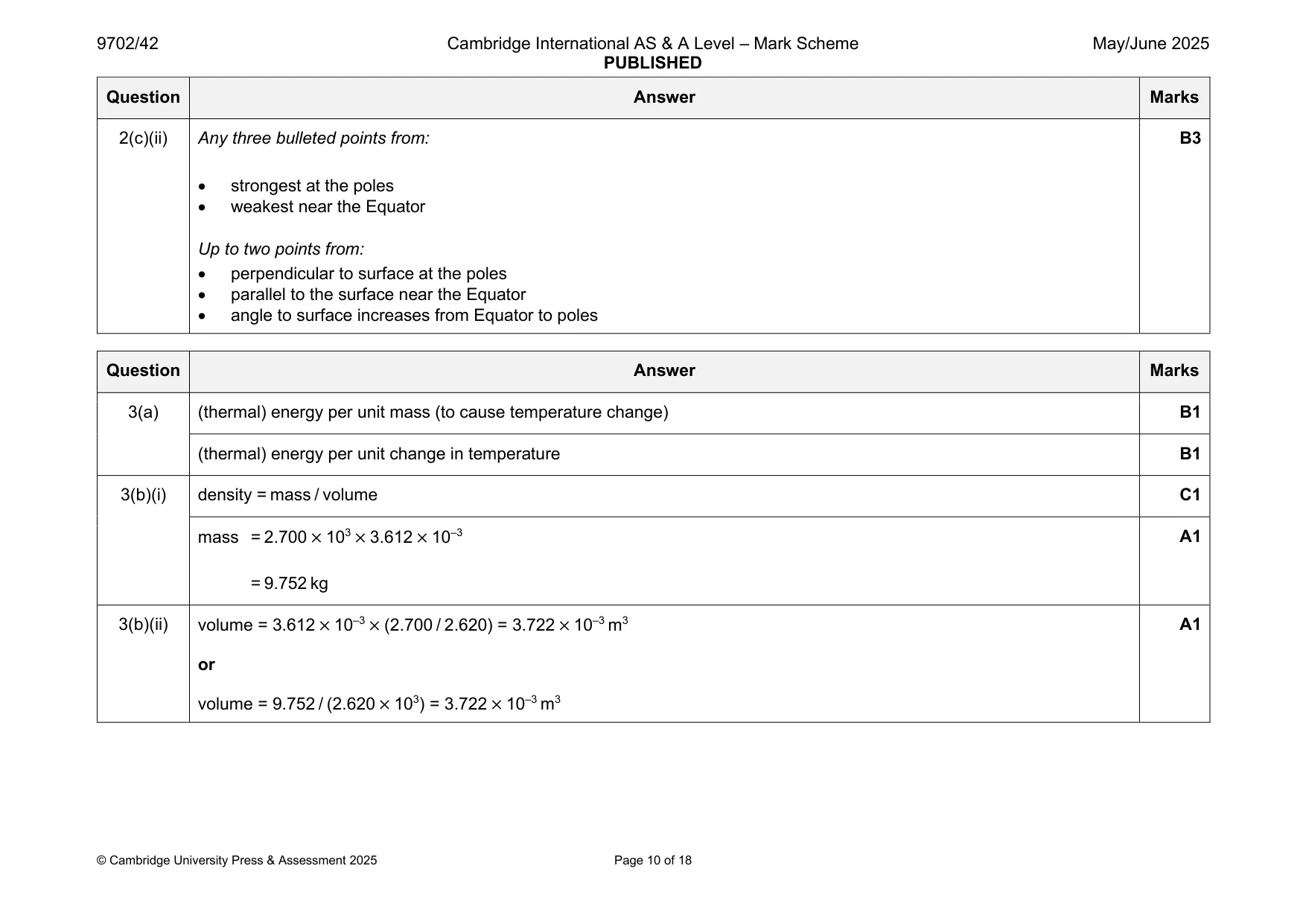
Mark scheme: 2(a)(i) direction of force B1 force acting on a (test) mass B1 2(a)(ii) at least four radial lines from the Earth’s surface, equally spaced around the surface B1 arrows indicating direction towards Earth B1 2(b)(i) top pole labelled S and bottom pole labelled N B1 2(b)(ii) solenoid field pattern at the poles: B1 at least two field lines either side of both poles, close to the poles, clustered closely together, leaving the surface approximately perpendicularly to the surface and curving away from the axis of the poles as their distance from the surface increases solenoid field pattern above the equator: B1 at least one field line either side of the Earth connecting two points on the surface that are on the same side of the poles, one north of the equator and one south of it, passing above the surface near the magnetic equator approximately parallel to the surface 2(c)(i) (around the surface) lines are evenly spaced B1 all lines perpendicular to surface B1 or pointing down towards surface (at all points around the surface) 2(c)(ii) Any three bulleted points from: B3 • strongest at the poles • weakest near the Equator Up to two points from: • perpendicular to surface at the poles • parallel to the surface near the Equator • angle to surface increases from Equator to poles
Q3 · Define specific heat capacity
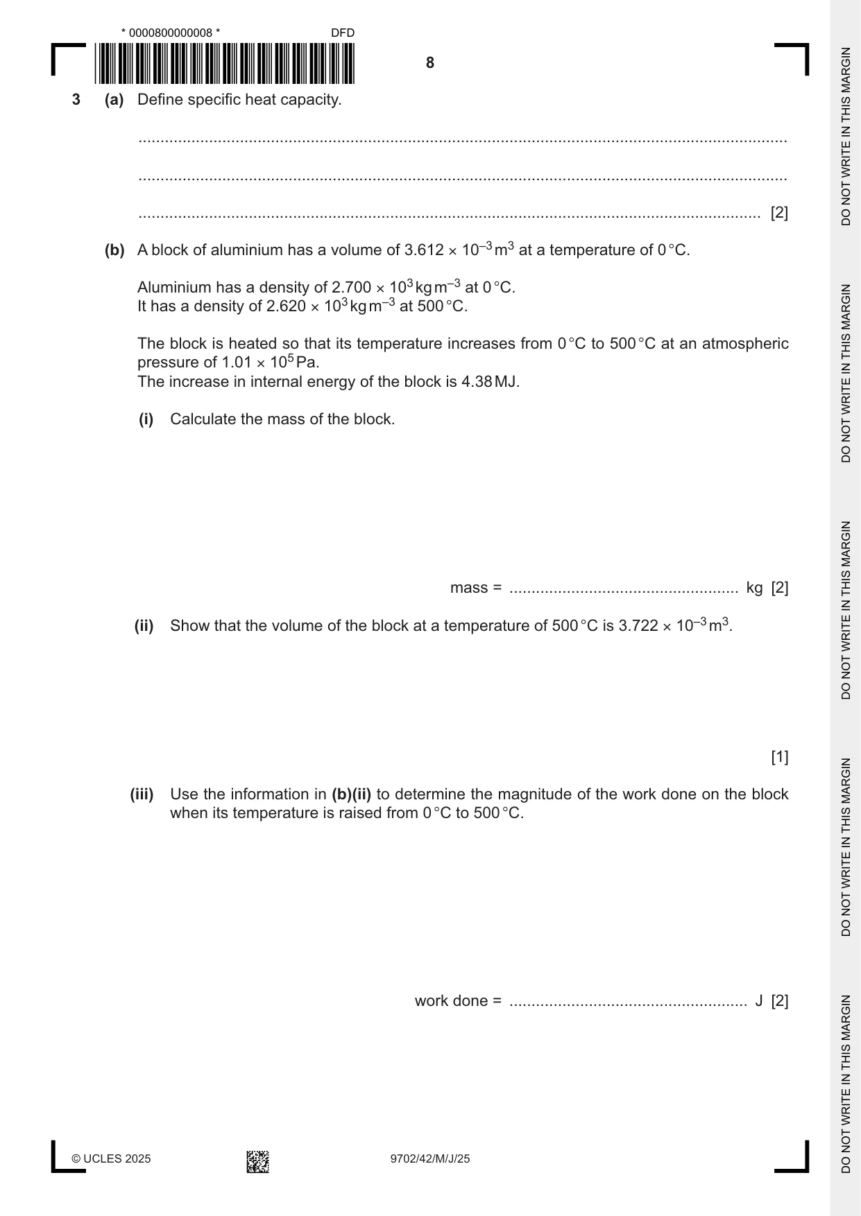
3 (a) Define specific heat capacity. ................................................................................................................................................... ................................................................................................................................................... ............................................................................................................................................. [2] (b) A block of aluminium has a volume of 3.612 × 10⁻³ m3 at a temperature of 0 °C. Aluminium has a density of 2.700 × 10³ kg m–3 at 0 °C. It has a density of 2.620 × 10³ kg m–3 at 500 °C. The block is heated so that its temperature increases from 0 °C to 500 °C at an atmospheric pressure of 1.01 × 10⁵ Pa. The increase in internal energy of the block is 4.38 MJ. (i) Calculate the mass of the block. mass = .................................................... kg [2] (ii) Show that the volume of the block at a temperature of 500 °C is 3.722 × 10⁻³ m3. [1] (iii) Use the information in (b)(ii) to determine the magnitude of the work done on the block when its temperature is raised from 0 °C to 500 °C. work done = ...................................................... J [2] (iv) Explain whether the work done on the block is positive or negative. ........................................................................................................................................... ........................................................................................................................................... ..................................................................................................................................... [2] (v) Use the first law of thermodynamics to determine, to three significant figures, a value for the specific heat capacity of aluminium. Explain your reasoning. Give a unit with your answer. specific heat capacity = ................................... unit .............. [3] (c) Without further calculation, suggest with a reason how doubling the pressure in (b) is likely to affect the answer in (b)(v). ................................................................................................................................................... ................................................................................................................................................... ............................................................................................................................................. [1] [Total: 13]
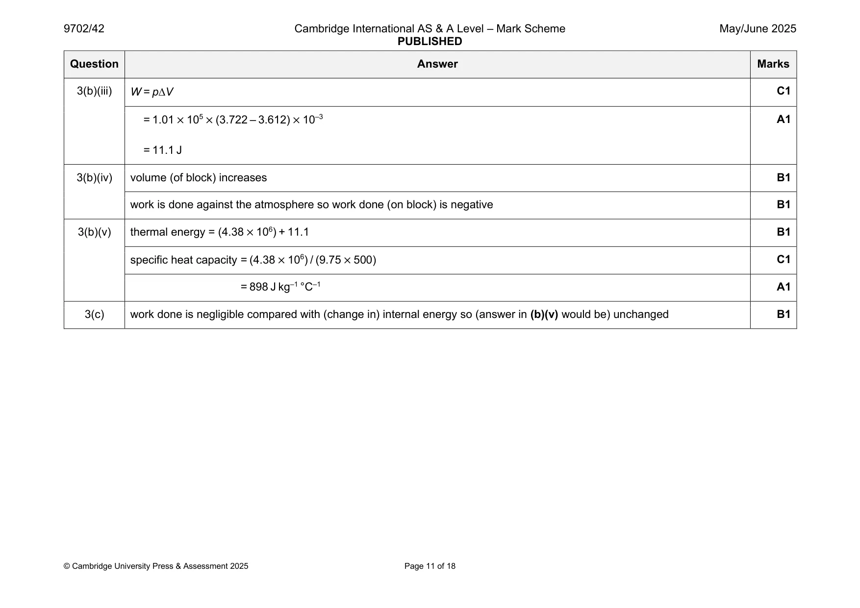
Mark scheme: 3(a) (thermal) energy per unit mass (to cause temperature change) B1 (thermal) energy per unit change in temperature B1 3(b)(i) density = mass / volume C1 mass = 2.700 × 103 × 3.612 × 10–3 A1 = 9.752 kg 3(b)(ii) volume = 3.612 × 10–3 × (2.700 / 2.620) = 3.722 × 10⁻³ m3 A1 or volume = 9.752 / (2.620 × 10³) = 3.722 × 10⁻³ m3 3(b)(iii) W = pV C1 = 1.01 × 105 × (3.722 – 3.612) × 10–3 A1 = 11.1 J 3(b)(iv) volume (of block) increases B1 work is done against the atmosphere so work done (on block) is negative B1 3(b)(v) thermal energy = (4.38 × 10⁶) + 11.1 B1 specific heat capacity = (4.38 × 10⁶) / (9.75 × 500) C1 = 898 J kg–1 °C–1 A1 3(c) work done is negligible compared with (change in) internal energy so (answer in (b)(v) would be) unchanged B1
Q4 · The equation of state for an ideal gas may be written as pVA = NBT where p is the…
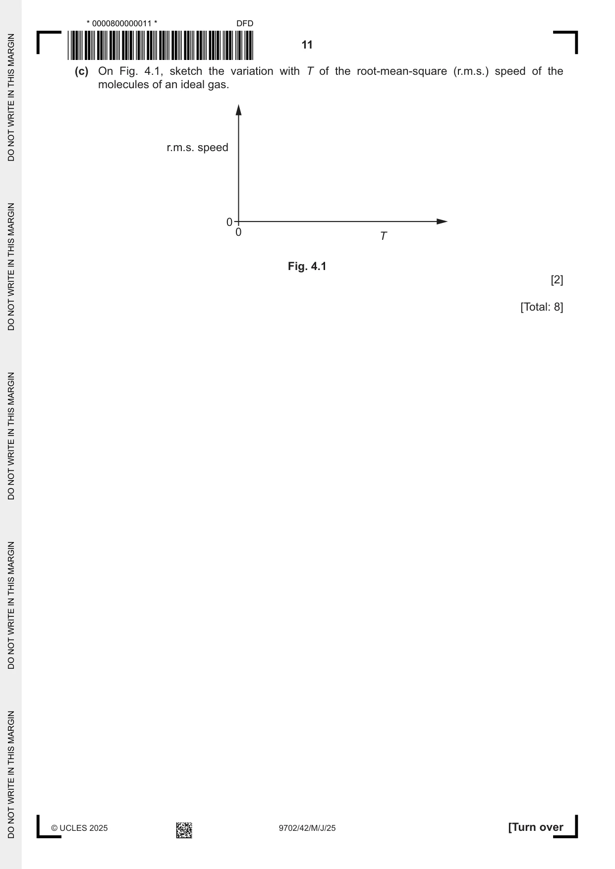
4 (a) The equation of state for an ideal gas may be written as pVA = NBT where p is the pressure of the gas, V is the volume of the gas, A is the Avogadro constant, B is another constant and N is the number of molecules of the gas. (i) State the meaning, in the equation, of the symbol T. ..................................................................................................................................... [1] (ii) Identify the constant B. ..................................................................................................................................... [1] (b) The product pV for an ideal gas is also given by pV = 1 Nm 〈c 2〉. 3 (i) State the meanings, in this equation, of the symbols m and 〈c 2〉. m: ...................................................................................................................................... 〈c 2〉: ................................................................................................................................... [2] (ii) Use the equations in (a) and (b) to derive an expression, in terms of A, B and T, for the mean kinetic energy EK of a molecule of the gas. EK = ......................................................... [2] (c) On Fig. 4.1, sketch the variation with T of the root-mean-square (r.m.s.) speed of the molecules of an ideal gas. r.m.s. speed 0 0 T Fig. 4.1 [2] [Total: 8]
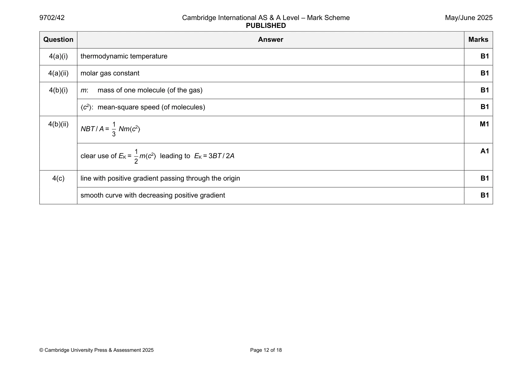
Mark scheme: 4(a)(i) thermodynamic temperature B1 4(a)(ii) molar gas constant B1 4(b)(i) m: mass of one molecule (of the gas) B1 〈c2〉: mean-square speed (of molecules) B1 4(b)(ii) 1 M1 NBT / A = Nm〈c2〉 3 1 A1 clear use of EK = m〈c2〉 leading to EK = 3BT / 2A 2 4(c) line with positive gradient passing through the origin B1 smooth curve with decreasing positive gradient B1
Q5 · State what is meant by simple harmonic motion
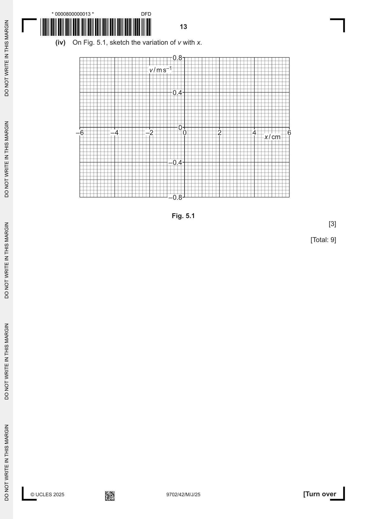
5 (a) State what is meant by simple harmonic motion. ................................................................................................................................................... ................................................................................................................................................... ............................................................................................................................................. [2] (b) A block is suspended by a spring. The block oscillates vertically with simple harmonic motion. The velocity v of the block varies with time t according to v = 0.56 cos 16t where v is in m s–1 and t is in s. (i) Calculate the period of the oscillation. period = ...................................................... s [1] (ii) Determine the amplitude x0 of the oscillation. x0 = ..................................................... m [2] (iii) Use your answer in (b)(ii) to determine the equation for v in terms of the displacement x of the block, where v is in m s–1 and x is in m. v = ......................................................... [1] (iv) On Fig. 5.1, sketch the variation of v with x. 0.8 v / m s–1 0.4 0 –6 –4 –2 0 2 4 6 x / cm –0.4 –0.8 Fig. 5.1 [3] [Total: 9]
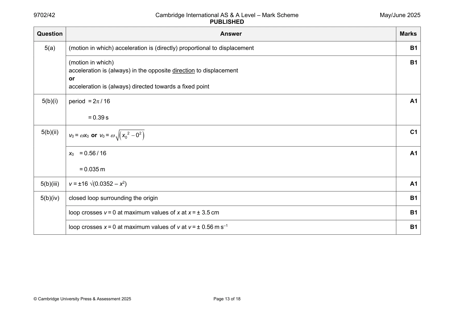
Mark scheme: 5(a) (motion in which) acceleration is (directly) proportional to displacement B1 (motion in which) B1 acceleration is (always) in the opposite direction to displacement or acceleration is (always) directed towards a fixed point 5(b)(i) period = 2 / 16 A1 = 0.39 s 5(b)(ii) v0 = x0 or v0 = ( 2 2 C1 x 0 − 0 ) x0 = 0.56 / 16 A1 = 0.035 m 5(b)(iii) v = ±16 √(0.0352 – x2) A1 5(b)(iv) closed loop surrounding the origin B1 loop crosses v = 0 at maximum values of x at x = ± 3.5 cm B1 loop crosses x = 0 at maximum values of v at v = ± 0.56 m s–1 B1
Q6 · Two parallel metal plates X and Y are separated by a distance of 0.041 m, as shown in Fig
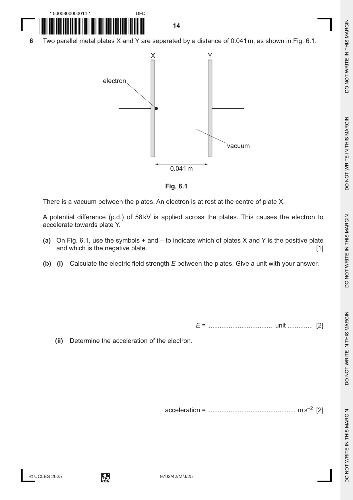
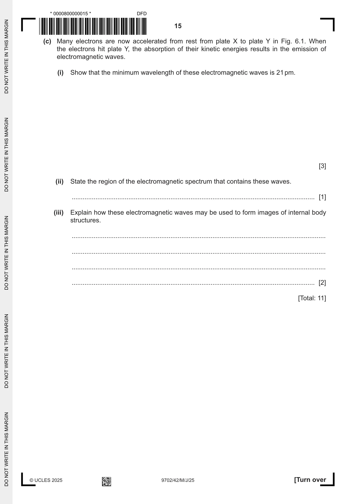
6 Two parallel metal plates X and Y are separated by a distance of 0.041 m, as shown in Fig. 6.1. X Y electron vacuum 0.041 m Fig. 6.1 There is a vacuum between the plates. An electron is at rest at the centre of plate X. A potential difference (p.d.) of 58 kV is applied across the plates. This causes the electron to accelerate towards plate Y. (a) On Fig. 6.1, use the symbols + and – to indicate which of plates X and Y is the positive plate and which is the negative plate. [1] (b) (i) Calculate the electric field strength E between the plates. Give a unit with your answer. E = ................................... unit .............. [2] (ii) Determine the acceleration of the electron. acceleration = ................................................ m s–2 [2] (c) Many electrons are now accelerated from rest from plate X to plate Y in Fig. 6.1. When the electrons hit plate Y, the absorption of their kinetic energies results in the emission of electromagnetic waves. (i) Show that the minimum wavelength of these electromagnetic waves is 21 pm. [3] (ii) State the region of the electromagnetic spectrum that contains these waves. ..................................................................................................................................... [1] (iii) Explain how these electromagnetic waves may be used to form images of internal body structures. ........................................................................................................................................... ........................................................................................................................................... ........................................................................................................................................... ..................................................................................................................................... [2] [Total: 11]
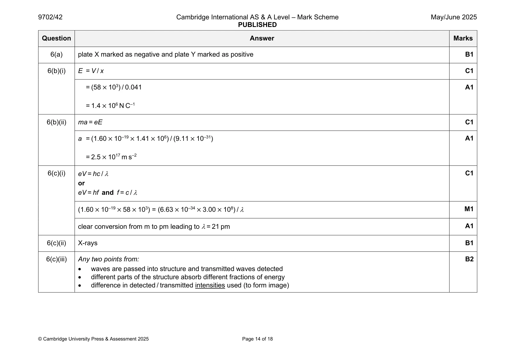
Mark scheme: 6(a) plate X marked as negative and plate Y marked as positive B1 6(b)(i) E = V / x C1 = (58 × 103) / 0.041 A1 = 1.4 × 10⁶ N C–1 6(b)(ii) ma = eE C1 a = (1.60 × 10–19 × 1.41 × 106) / (9.11 × 10⁻³¹) A1 = 2.5 × 10¹⁷ m s–2 6(c)(i) eV = hc / C1 or eV = hf and f = c / (1.60 × 10–19 × 58 × 103) = (6.63 × 10–34 × 3.00 × 108) / M1 clear conversion from m to pm leading to = 21 pm A1 6(c)(ii) X-rays B1 6(c)(iii) Any two points from: B2 • waves are passed into structure and transmitted waves detected • different parts of the structure absorb different fractions of energy • difference in detected / transmitted intensities used (to form image)
Q7 · A circuit containing a capacitor of capacitance C and a resistor of resistance R
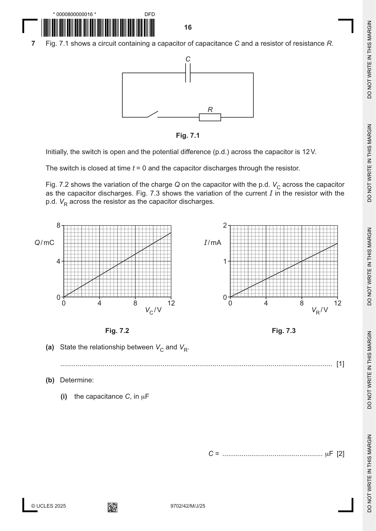
7 Fig. 7.1 shows a circuit containing a capacitor of capacitance C and a resistor of resistance R. C R Fig. 7.1 Initially, the switch is open and the potential difference (p.d.) across the capacitor is 12 V. The switch is closed at time t = 0 and the capacitor discharges through the resistor. Fig. 7.2 shows the variation of the charge Q on the capacitor with the p.d. VC across the capacitor as the capacitor discharges. Fig. 7.3 shows the variation of the current I in the resistor with the p.d. VR across the resistor as the capacitor discharges. 8 2 Q / mC I / mA 4 1 0 0 0 4 8 12 0 4 8 12 VC / V VR / V Fig. 7.2 Fig. 7.3 (a) State the relationship between VC and VR. ............................................................................................................................................. [1] (b) Determine: (i) the capacitance C, in μF C = .................................................... μF [2] (ii) the resistance R, in kΩ R = ................................................... kΩ [2] (iii) the time constant τ of the circuit. τ = ...................................................... s [2] (c) Use Fig. 7.2, Fig. 7.3 and your answer in (a) to explain why the variation of Q with t is exponential in nature. ................................................................................................................................................... ................................................................................................................................................... ................................................................................................................................................... ................................................................................................................................................... ............................................................................................................................................. [3] [Total: 10]
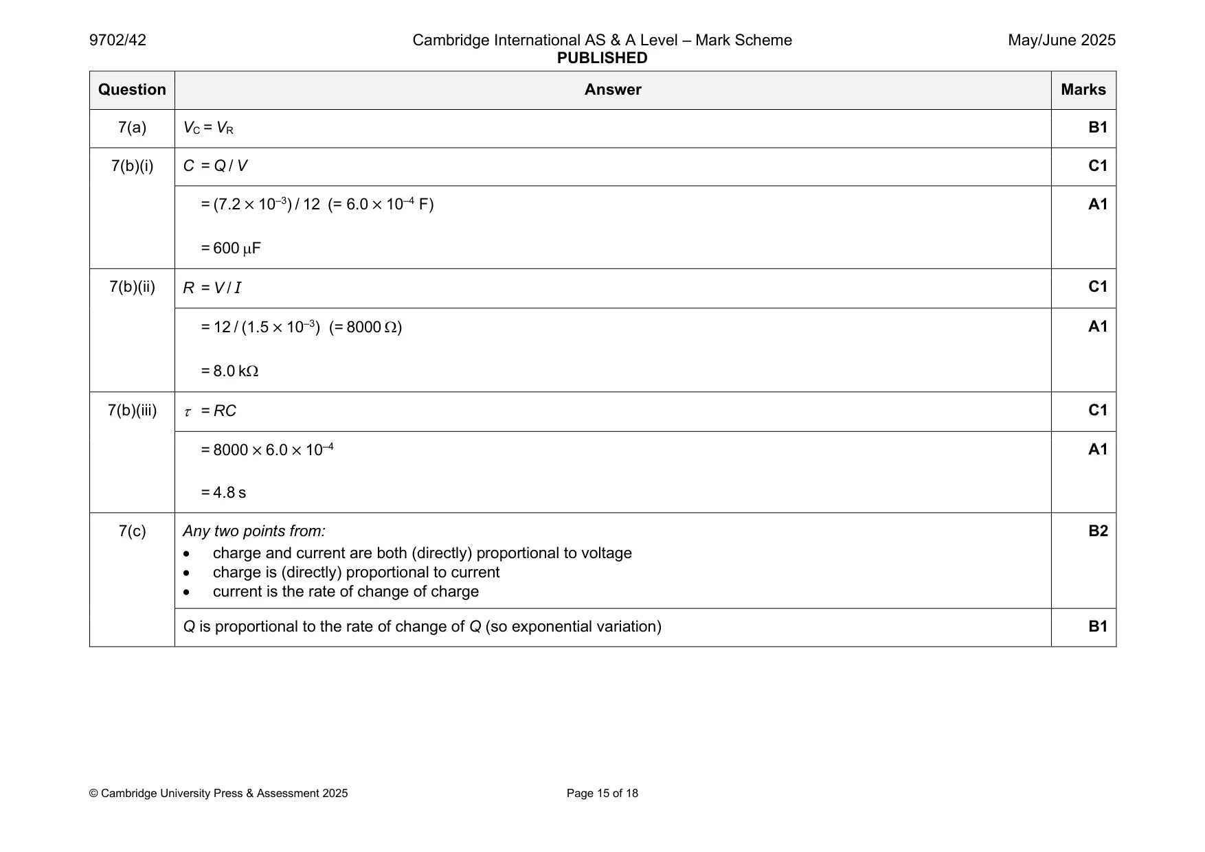
Mark scheme: 7(a) VC = VR B1 7(b)(i) C = Q / V C1 = (7.2 × 10⁻³) / 12 (= 6.0 × 10⁻⁴ F) A1 = 600 F 7(b)(ii) R = V / I C1 = 12 / (1.5 × 10⁻³) (= 8000 ) A1 = 8.0 k 7(b)(iii) = RC C1 = 8000 × 6.0 × 10–4 A1 = 4.8 s 7(c) Any two points from: B2 • charge and current are both (directly) proportional to voltage • charge is (directly) proportional to current • current is the rate of change of charge Q is proportional to the rate of change of Q (so exponential variation) B1
Q8 · A circuit that produces rectification of an alternating input voltage
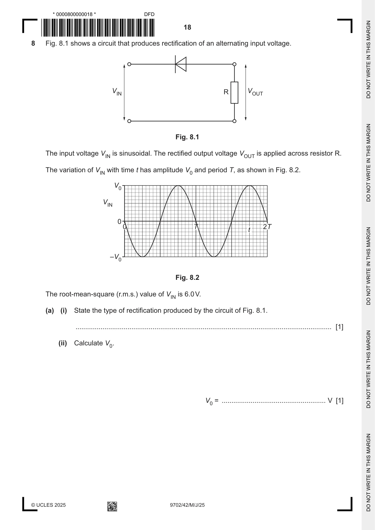
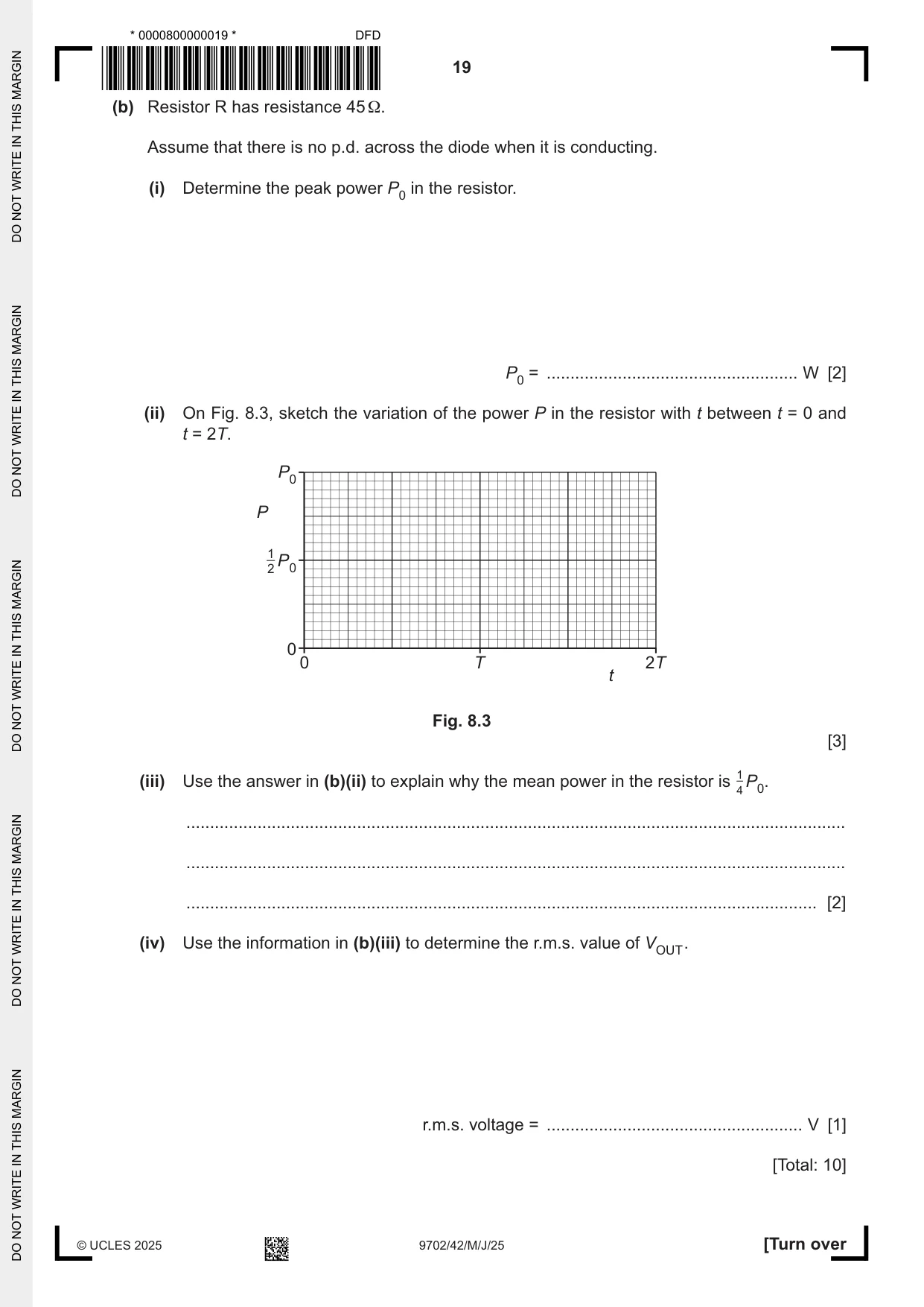
8 Fig. 8.1 shows a circuit that produces rectification of an alternating input voltage. VIN R VOUT Fig. 8.1 The input voltage VIN is sinusoidal. The rectified output voltage VOUT is applied across resistor R. The variation of VIN with time t has amplitude V0 and period T, as shown in Fig. 8.2. V0 VIN 0 0 T 2T t –V0 Fig. 8.2 The root-mean-square (r.m.s.) value of VIN is 6.0 V. (a) (i) State the type of rectification produced by the circuit of Fig. 8.1. ..................................................................................................................................... [1] (ii) Calculate V0. V0 = ...................................................... V [1] (b) Resistor R has resistance 45 Ω. Assume that there is no p.d. across the diode when it is conducting. (i) Determine the peak power P0 in the resistor. P0 = ..................................................... W [2] (ii) On Fig. 8.3, sketch the variation of the power P in the resistor with t between t = 0 and t = 2T. P0 P 1 2 P0 0 0 T 2T t Fig. 8.3 [3] (iii) Use the answer in (b)(ii) to explain why the mean power in the resistor is 14 P0. ........................................................................................................................................... ........................................................................................................................................... ..................................................................................................................................... [2] (iv) Use the information in (b)(iii) to determine the r.m.s. value of VOUT . r.m.s. voltage = ...................................................... V [1] [Total: 10]
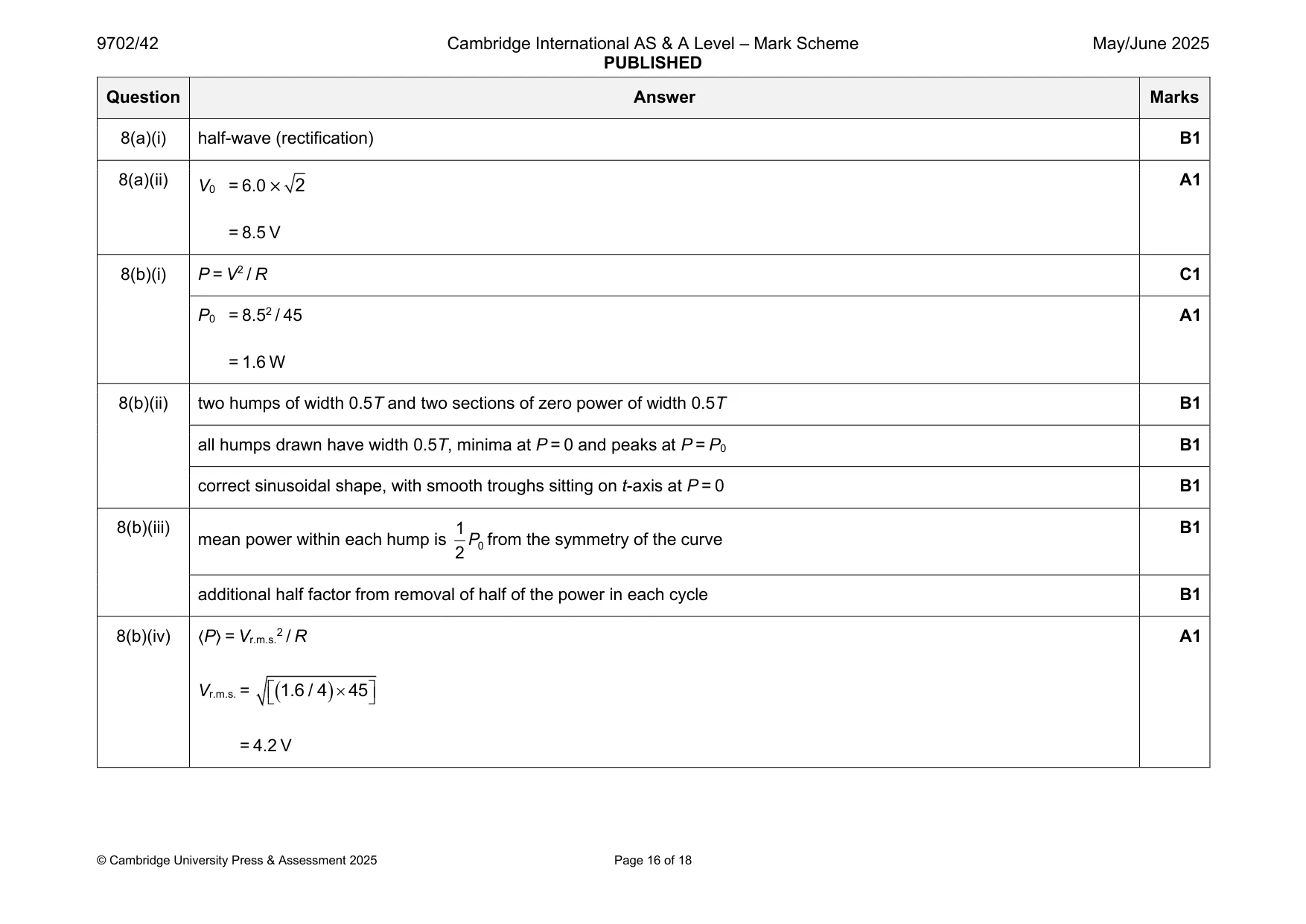
Mark scheme: 8(a)(i) half-wave (rectification) B1 8(a)(ii) A1 V0 = 6.0 × 2 = 8.5 V 8(b)(i) P = V2 / R C1 P0 = 8.52 / 45 A1 = 1.6 W 8(b)(ii) two humps of width 0.5T and two sections of zero power of width 0.5T B1 all humps drawn have width 0.5T, minima at P = 0 and peaks at P = P0 B1 correct sinusoidal shape, with smooth troughs sitting on t-axis at P = 0 B1 8(b)(iii) 1 B1 mean power within each hump is P0 from the symmetry of the curve 2 additional half factor from removal of half of the power in each cycle B1 8(b)(iv) 〈P〉 = Vr.m.s.2 / R A1 Vr.m.s. = ( 1.6 / 4 ) 45 = 4.2 V
Q9 · State what is meant by the photoelectric effect
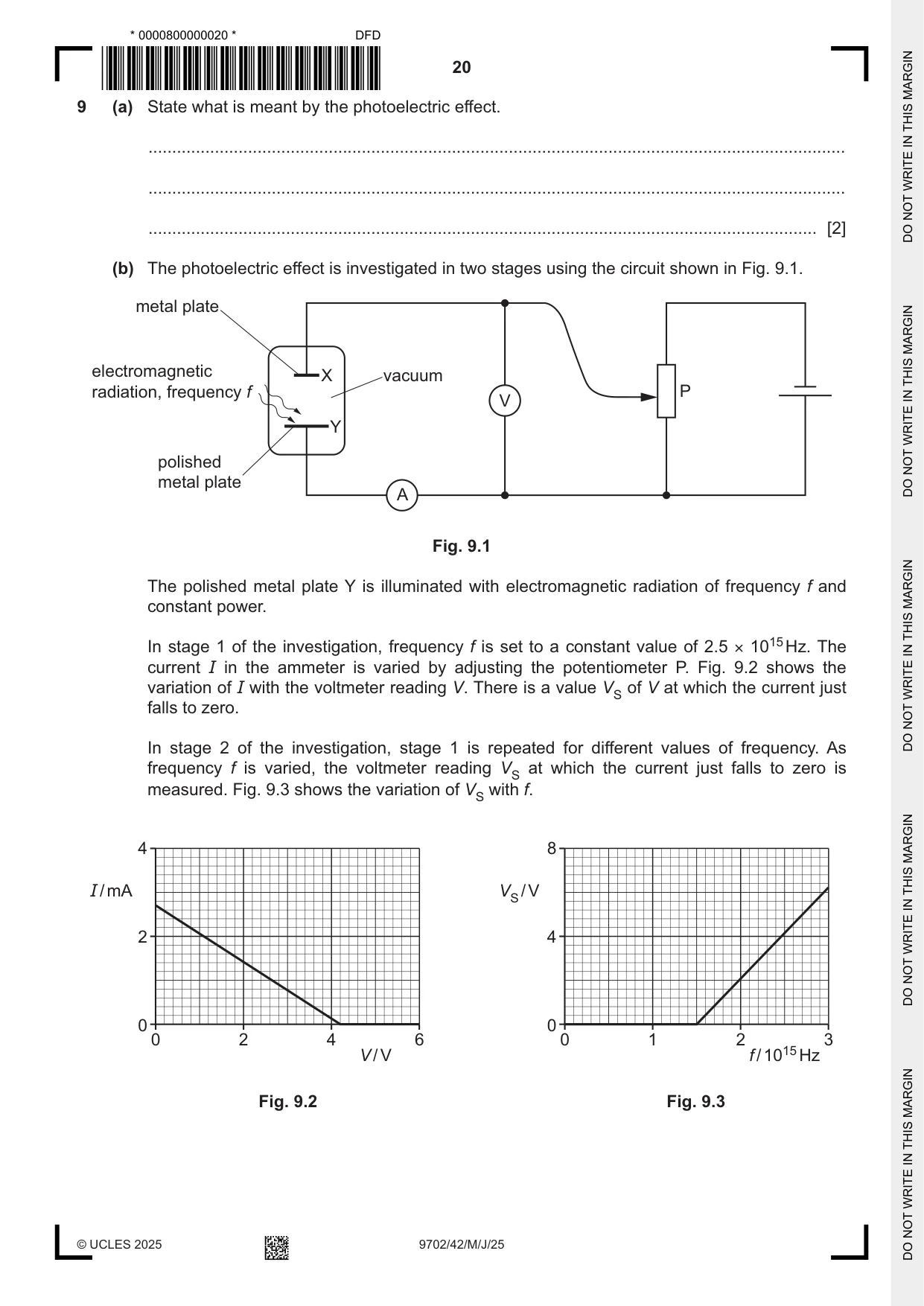
9 (a) State what is meant by the photoelectric effect. ................................................................................................................................................... ................................................................................................................................................... ............................................................................................................................................. [2] (b) The photoelectric effect is investigated in two stages using the circuit shown in Fig. 9.1. metal plate electromagnetic X vacuum radiation, frequency f P V Y polished metal plate A Fig. 9.1 The polished metal plate Y is illuminated with electromagnetic radiation of frequency f and constant power. In stage 1 of the investigation, frequency f is set to a constant value of 2.5 × 10¹⁵ Hz. The current I in the ammeter is varied by adjusting the potentiometer P. Fig. 9.2 shows the variation of I with the voltmeter reading V. There is a value VS of V at which the current just falls to zero. In stage 2 of the investigation, stage 1 is repeated for different values of frequency. As frequency f is varied, the voltmeter reading VS at which the current just falls to zero is measured. Fig. 9.3 shows the variation of VS with f. 4 8 I / mA VS / V 2 4 0 0 0 2 4 6 0 1 2 3 V / V f / 1015 Hz Fig. 9.2 Fig. 9.3 (i) Explain, with reference to photons, why VS depends on the frequency of the incident electromagnetic radiation. ........................................................................................................................................... ........................................................................................................................................... ........................................................................................................................................... ........................................................................................................................................... ........................................................................................................................................... ..................................................................................................................................... [3] (ii) State three quantitative conclusions that can be drawn from the results in Fig. 9.2 and Fig. 9.3. Use the space for any working. 1 ........................................................................................................................................ ........................................................................................................................................... 2 ........................................................................................................................................ ........................................................................................................................................... 3 ........................................................................................................................................ ........................................................................................................................................... [3] [Total: 8]
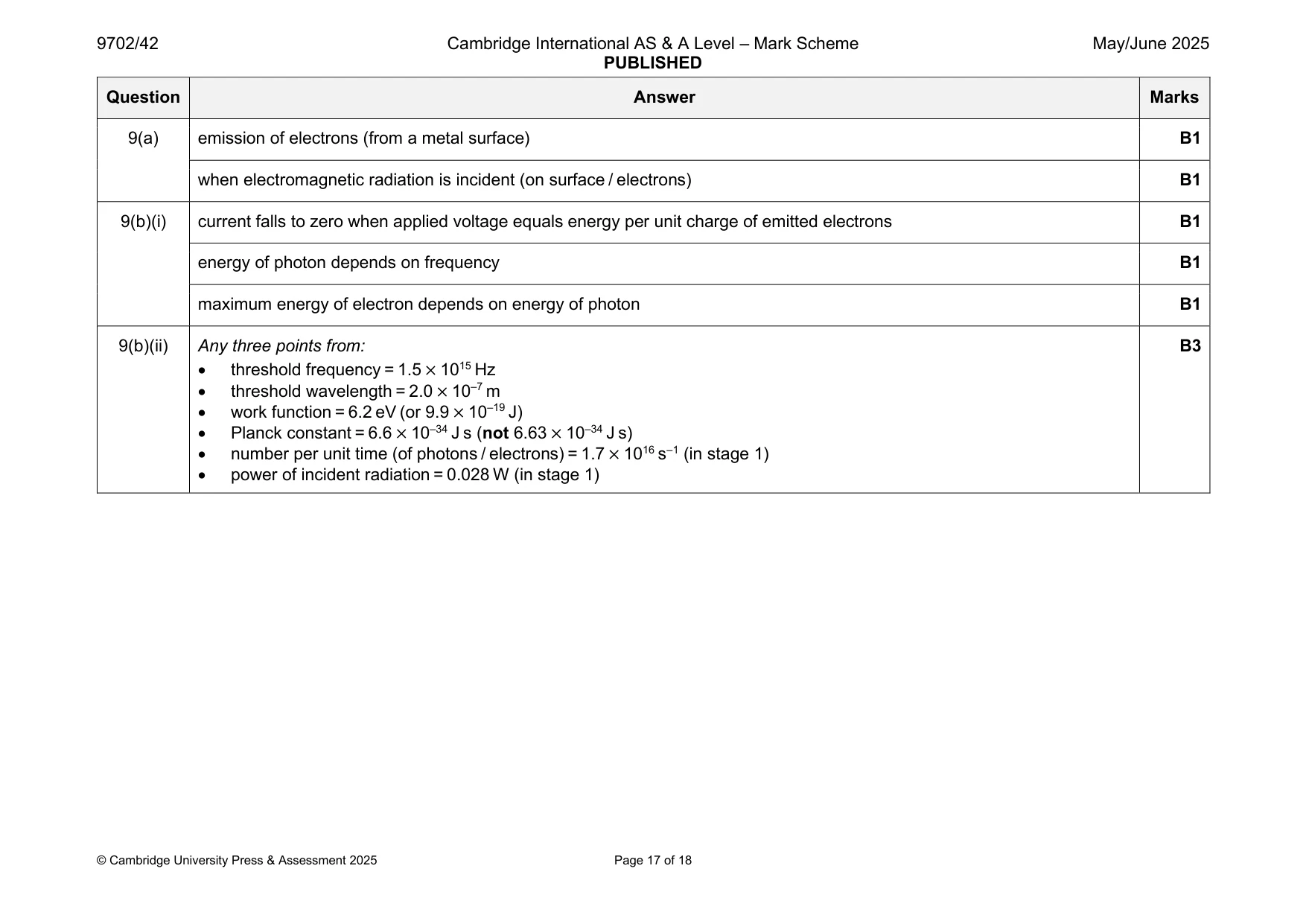
Mark scheme: 9(a) emission of electrons (from a metal surface) B1 when electromagnetic radiation is incident (on surface / electrons) B1 9(b)(i) current falls to zero when applied voltage equals energy per unit charge of emitted electrons B1 energy of photon depends on frequency B1 maximum energy of electron depends on energy of photon B1 9(b)(ii) Any three points from: B3 • threshold frequency = 1.5 × 10¹⁵ Hz • threshold wavelength = 2.0 × 10⁻⁷ m • work function = 6.2 eV (or 9.9 × 10⁻¹⁹ J) • Planck constant = 6.6 × 10⁻³⁴ J s (not 6.63 × 10⁻³⁴ J s) • number per unit time (of photons / electrons) = 1.7 × 10¹⁶ s–1 (in stage 1) • power of incident radiation = 0.028 W (in stage 1)
Q10 · Radioactive decay is a spontaneous process
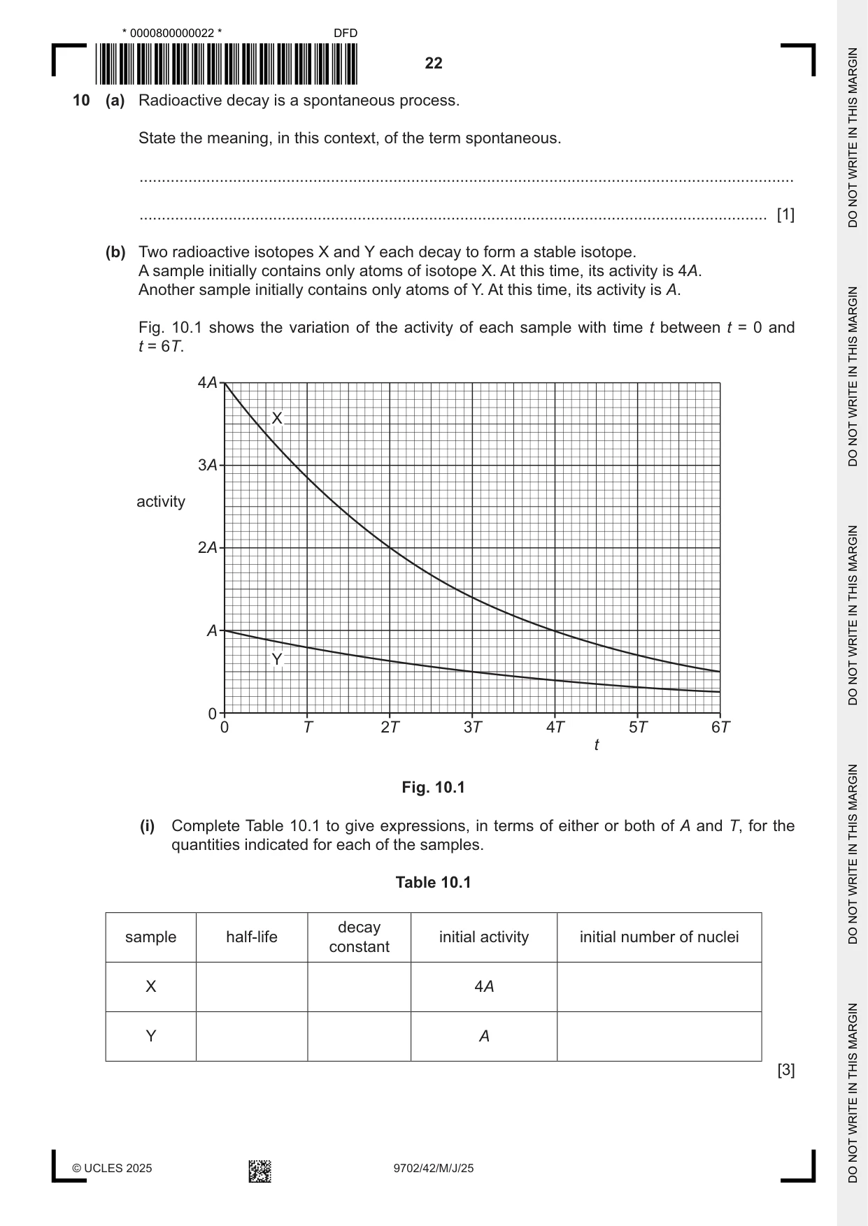
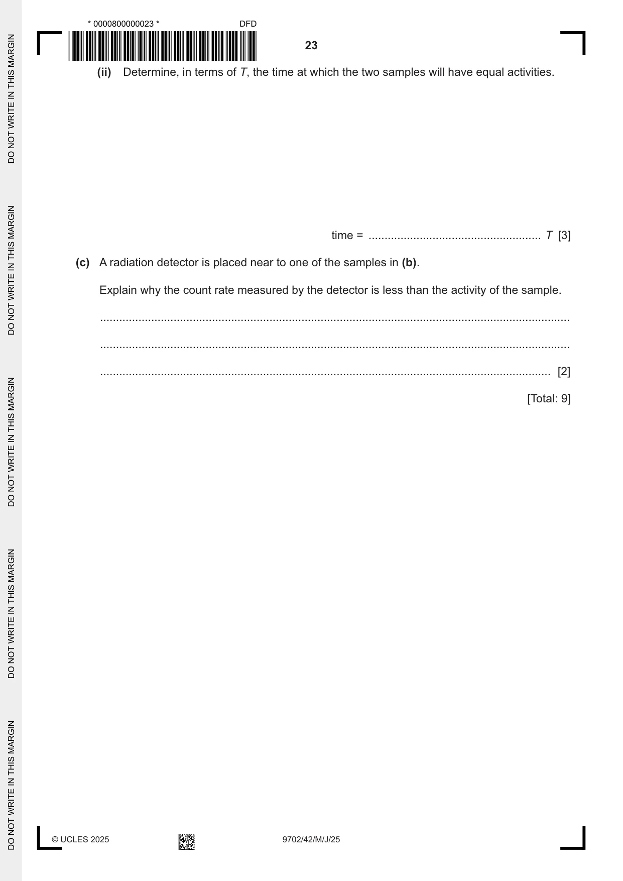
10 (a) Radioactive decay is a spontaneous process. State the meaning, in this context, of the term spontaneous. ................................................................................................................................................... ............................................................................................................................................. [1] (b) Two radioactive isotopes X and Y each decay to form a stable isotope. A sample initially contains only atoms of isotope X. At this time, its activity is 4A. Another sample initially contains only atoms of Y. At this time, its activity is A. Fig. 10.1 shows the variation of the activity of each sample with time t between t = 0 and t = 6T. 4A X 3A activity 2A A Y 0 0 T 2T 3T 4T 5T 6T t Fig. 10.1 (i) Complete Table 10.1 to give expressions, in terms of either or both of A and T, for the quantities indicated for each of the samples. Table 10.1 decay sample half-life initial activity initial number of nuclei constant X 4A Y A [3] (ii) Determine, in terms of T, the time at which the two samples will have equal activities. time = ...................................................... T [3] (c) A radiation detector is placed near to one of the samples in (b). Explain why the count rate measured by the detector is less than the activity of the sample. ................................................................................................................................................... ................................................................................................................................................... ............................................................................................................................................. [2] [Total: 9]
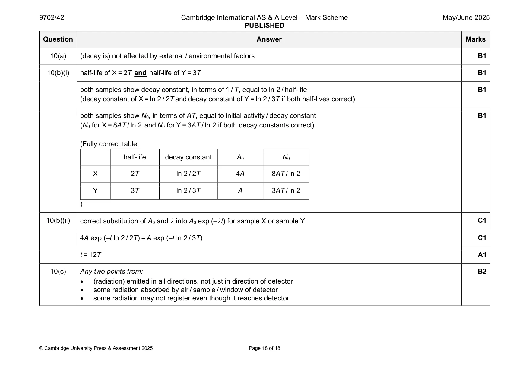
Mark scheme: 10(a) (decay is) not affected by external / environmental factors B1 10(b)(i) half-life of X = 2T and half-life of Y = 3T B1 both samples show decay constant, in terms of 1 / T, equal to ln 2 / half-life B1 (decay constant of X = ln 2 / 2T and decay constant of Y = ln 2 / 3T if both half-lives correct) both samples show N0, in terms of AT, equal to initial activity / decay constant B1 (N0 for X = 8AT / ln 2 and N0 for Y = 3AT / ln 2 if both decay constants correct) (Fully correct table: half-life decay constant A0 N0 X 2T ln 2 / 2T 4A 8AT / ln 2 Y 3T ln 2 / 3T A 3AT / ln 2 ) 10(b)(ii) correct substitution of A0 and into A0 exp (–t) for sample X or sample Y C1 4A exp (–t ln 2 / 2T) = A exp (–t ln 2 / 3T) C1 t = 12T A1 10(c) Any two points from: B2 • (radiation) emitted in all directions, not just in direction of detector • some radiation absorbed by air / sample / window of detector • some radiation may not register even though it reaches detector
What was in this paper
The subtopics covered by these 10 questions, and how many questions each got. Open one in a new tab to see every Cambridge question on it.
What you needed in this session
Cambridge’s own grade thresholds for 2025 May/June, Paper 4 · Variant 2. A higher threshold means an easier paper — the bar moves with how the cohort did.