Cambridge A Level Physics 9702 — 2019 Feb/March Paper 4 · Variant 2
9702/42/F/M/19 · 12 questions · 100 marks · ≈113 min
The question paper and its mark scheme, free to read here and free to download. This is Cambridge’s own paper, exactly as it was sat.
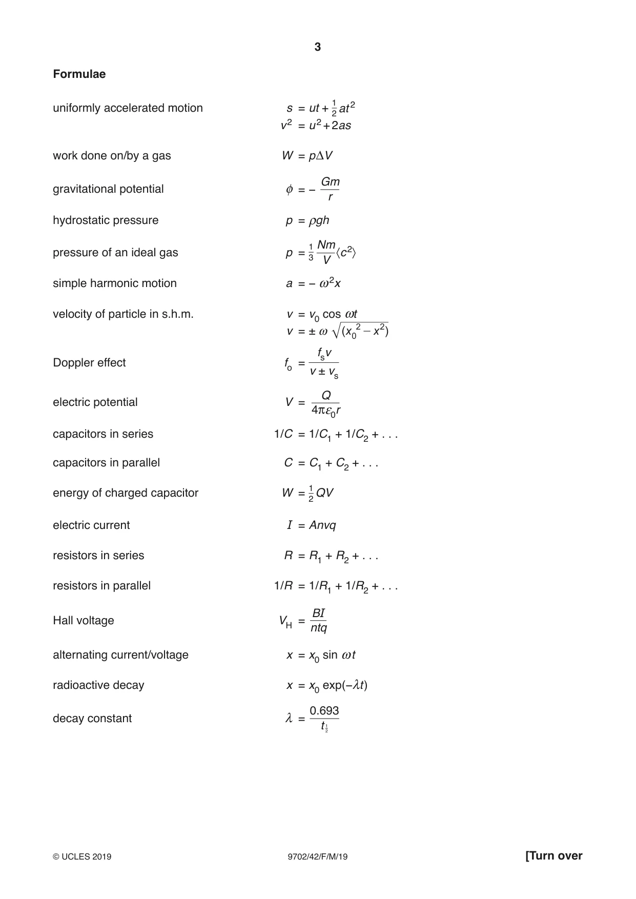
Question paper24 pages

Mark scheme12 pages
Answers below. Sit the paper first if you are practising.
Questions as text
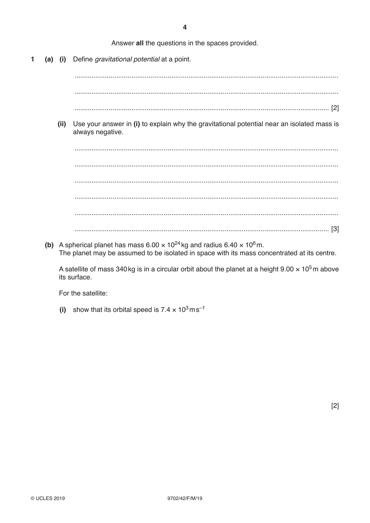
Q1 · Define gravitational potential at a point
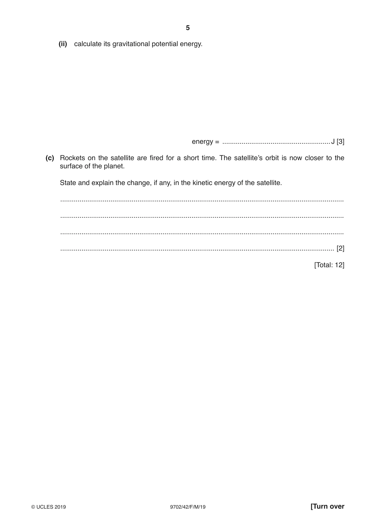
1 (a) (i) Define gravitational potential at a point. ........................................................................................................................................... ........................................................................................................................................... ...................................................................................................................................... [2] (ii) Use your answer in (i) to explain why the gravitational potential near an isolated mass is always negative. ........................................................................................................................................... ........................................................................................................................................... ........................................................................................................................................... ........................................................................................................................................... ........................................................................................................................................... ...................................................................................................................................... [3] (b) A spherical planet has mass 6.00 × 1024 kg and radius 6.40 × 10⁶ m. The planet may be assumed to be isolated in space with its mass concentrated at its centre. A satellite of mass 340 kg is in a circular orbit about the planet at a height 9.00 × 10⁵ m above its surface. For the satellite: (i) show that its orbital speed is 7.4 × 10³ m s–1 [2] (ii) calculate its gravitational potential energy. energy = ........................................................ J [3] (c) Rockets on the satellite are fired for a short time. The satellite’s orbit is now closer to the surface of the planet. State and explain the change, if any, in the kinetic energy of the satellite. ................................................................................................................................................... ................................................................................................................................................... ................................................................................................................................................... .............................................................................................................................................. [2] [Total: 12]
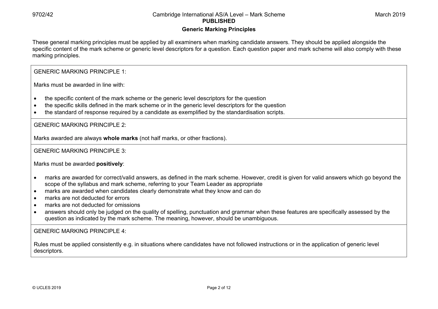
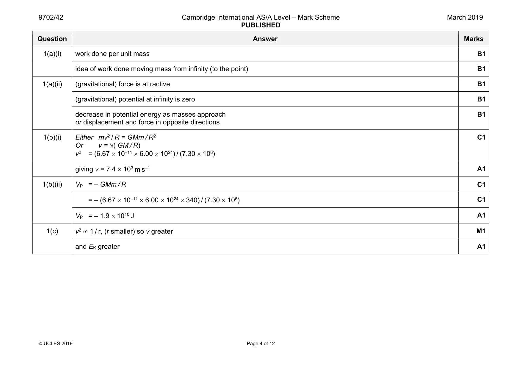
Mark scheme: 1(a)(i) work done per unit mass B1 idea of work done moving mass from infinity (to the point) B1 1(a)(ii) (gravitational) force is attractive B1 (gravitational) potential at infinity is zero B1 decrease in potential energy as masses approach or displacement and force in opposite directions B1 1(b)(i) Either mv2 / R = GMm / R2 Or v = √( GM / R) v2 = (6.67 × 10–11 × 6.00 × 1024) / (7.30 × 10⁶) C1 giving v = 7.4 × 10³ m s–1 A1 1(b)(ii) VP = – GMm / R C1 = – (6.67 × 10–11 × 6.00 × 1024 × 340) / (7.30 × 10⁶) C1 VP = – 1.9 × 10¹⁰ J A1 1(c) v2 ∝ 1 / r, (r smaller) so v greater M1 and EK greater A1
Q2 · The pressure p of an ideal gas having density ρ is given by the expression p = 13 ρ〈c2〉
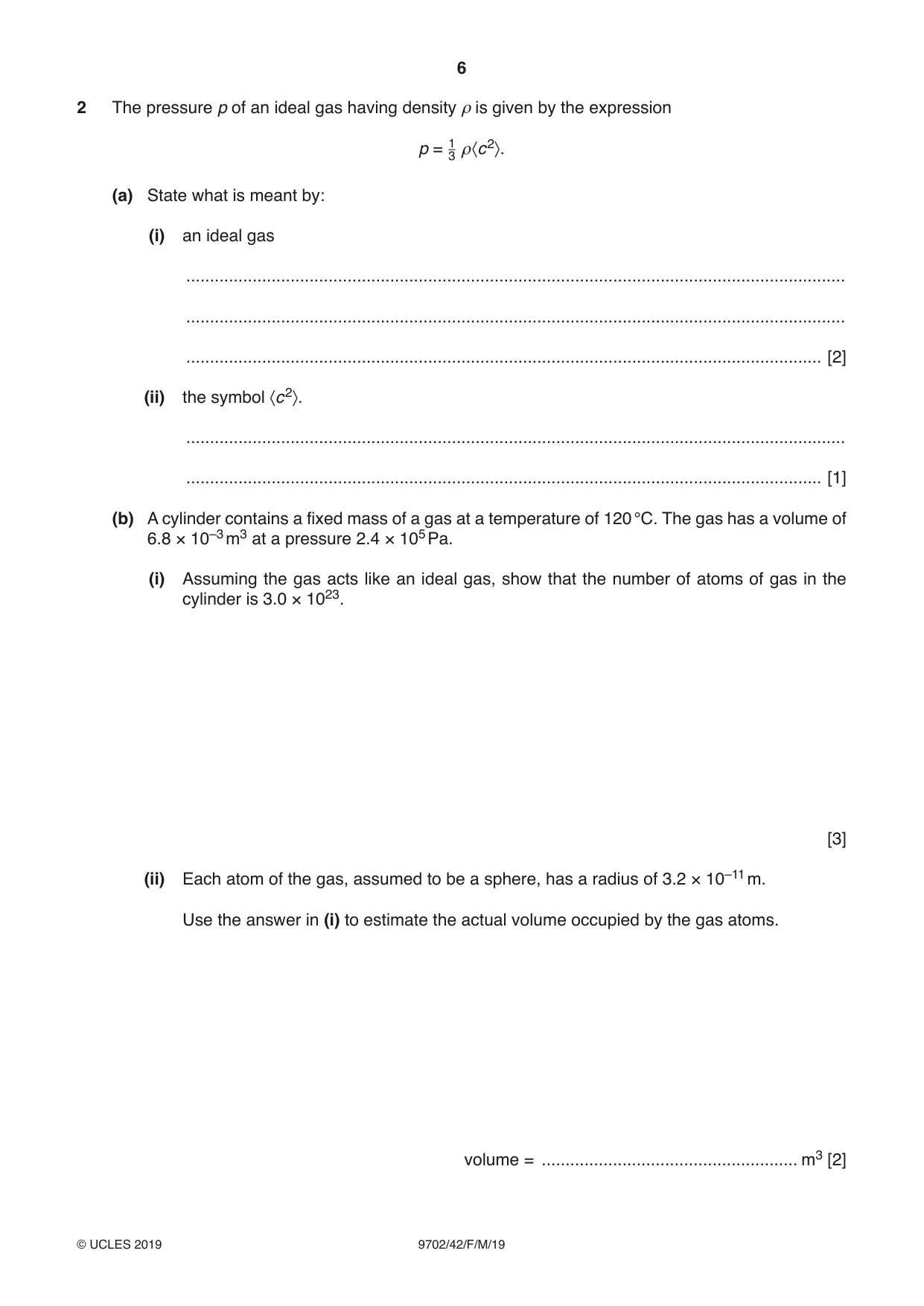
2 The pressure p of an ideal gas having density ρ is given by the expression p = 13 ρ〈c2〉. (a) State what is meant by: (i) an ideal gas ........................................................................................................................................... ........................................................................................................................................... ...................................................................................................................................... [2] (ii) the symbol 〈c2〉. ........................................................................................................................................... ...................................................................................................................................... [1] (b) A cylinder contains a fixed mass of a gas at a temperature of 120 °C. The gas has a volume of 6.8 × 10⁻³ m3 at a pressure 2.4 × 10⁵ Pa. (i) Assuming the gas acts like an ideal gas, show that the number of atoms of gas in the cylinder is 3.0 × 10²³. [3] (ii) Each atom of the gas, assumed to be a sphere, has a radius of 3.2 × 10⁻¹¹ m. Use the answer in (i) to estimate the actual volume occupied by the gas atoms. volume = ...................................................... m3 [2] (iii) One of the assumptions of the kinetic theory of gases is related to the volume of the atoms. State this assumption. Explain whether your answer in (ii) is consistent with this assumption. ........................................................................................................................................... ........................................................................................................................................... ........................................................................................................................................... ...................................................................................................................................... [2] [Total: 10]
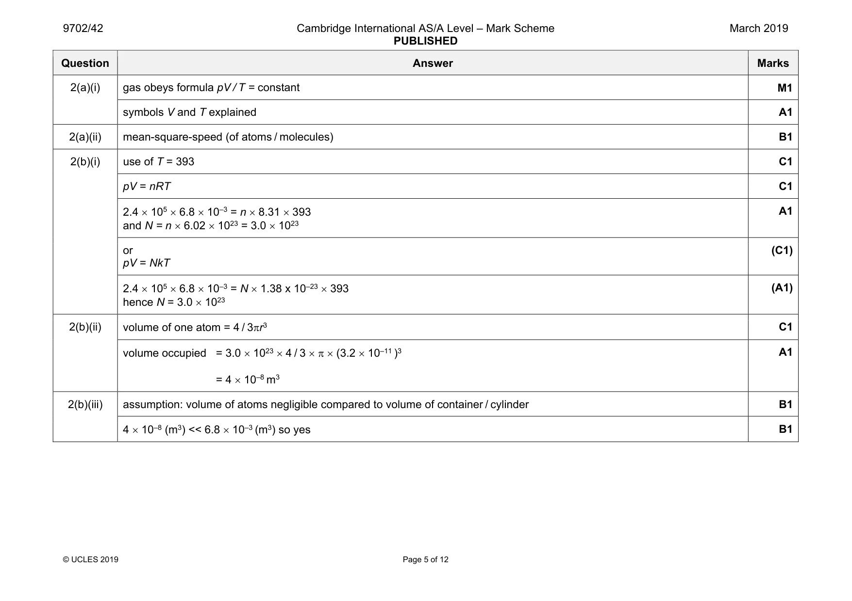
Mark scheme: 2(a)(i) gas obeys formula pV / T = constant M1 symbols V and T explained A1 2(a)(ii) mean-square-speed (of atoms / molecules) B1 2(b)(i) use of T = 393 C1 pV = nRT C1 2.4 × 105 × 6.8 × 10–3 = n × 8.31 × 393 and N = n × 6.02 × 1023 = 3.0 × 10²³ A1 or pV = NkT (C1) 2.4 × 105 × 6.8 × 10–3 = N × 1.38 x 10–23 × 393 hence N = 3.0 × 10²³ (A1) 2(b)(ii) volume of one atom = 4 / 3πr3 C1 volume occupied = 3.0 × 1023 × 4 / 3 × π × (3.2 × 10⁻¹¹ )3 = 4 × 10⁻⁸ m3 A1 2(b)(iii) assumption: volume of atoms negligible compared to volume of container / cylinder B1 4 × 10⁻⁸ (m3) << 6.8 × 10⁻³ (m3) so yes B1
Q3 · A cylindrical tube, sealed at one end, has cross-sectional area A and contains some sand
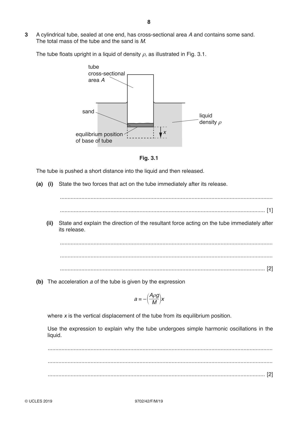
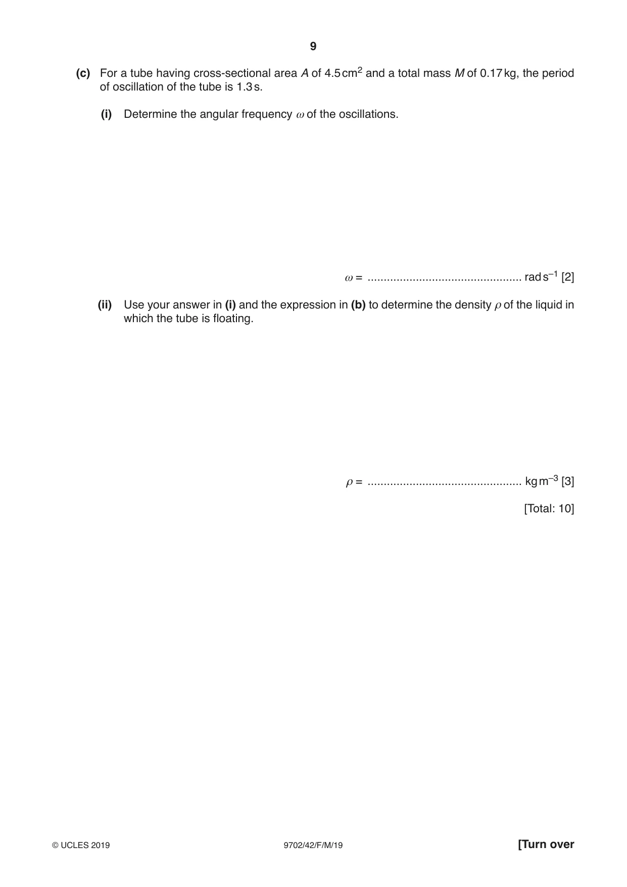
3 A cylindrical tube, sealed at one end, has cross-sectional area A and contains some sand. The total mass of the tube and the sand is M. The tube floats upright in a liquid of density ρ, as illustrated in Fig. 3.1. tube cross-sectional area A sand liquid density ρ x equilibrium position of base of tube Fig. 3.1 The tube is pushed a short distance into the liquid and then released. (a) (i) State the two forces that act on the tube immediately after its release. ........................................................................................................................................... ...................................................................................................................................... [1] (ii) State and explain the direction of the resultant force acting on the tube immediately after its release. ........................................................................................................................................... ........................................................................................................................................... ...................................................................................................................................... [2] (b) The acceleration a of the tube is given by the expression Aρg a = – x M where x is the vertical displacement of the tube from its equilibrium position. Use the expression to explain why the tube undergoes simple harmonic oscillations in the liquid. ................................................................................................................................................... ................................................................................................................................................... .............................................................................................................................................. [2] (c) For a tube having cross-sectional area A of 4.5 cm2 and a total mass M of 0.17 kg, the period of oscillation of the tube is 1.3 s. (i) Determine the angular frequency ω of the oscillations. ω = ................................................ rad s–1 [2] (ii) Use your answer in (i) and the expression in (b) to determine the density ρ of the liquid in which the tube is floating. ρ = ................................................ kg m–3 [3] [Total: 10]
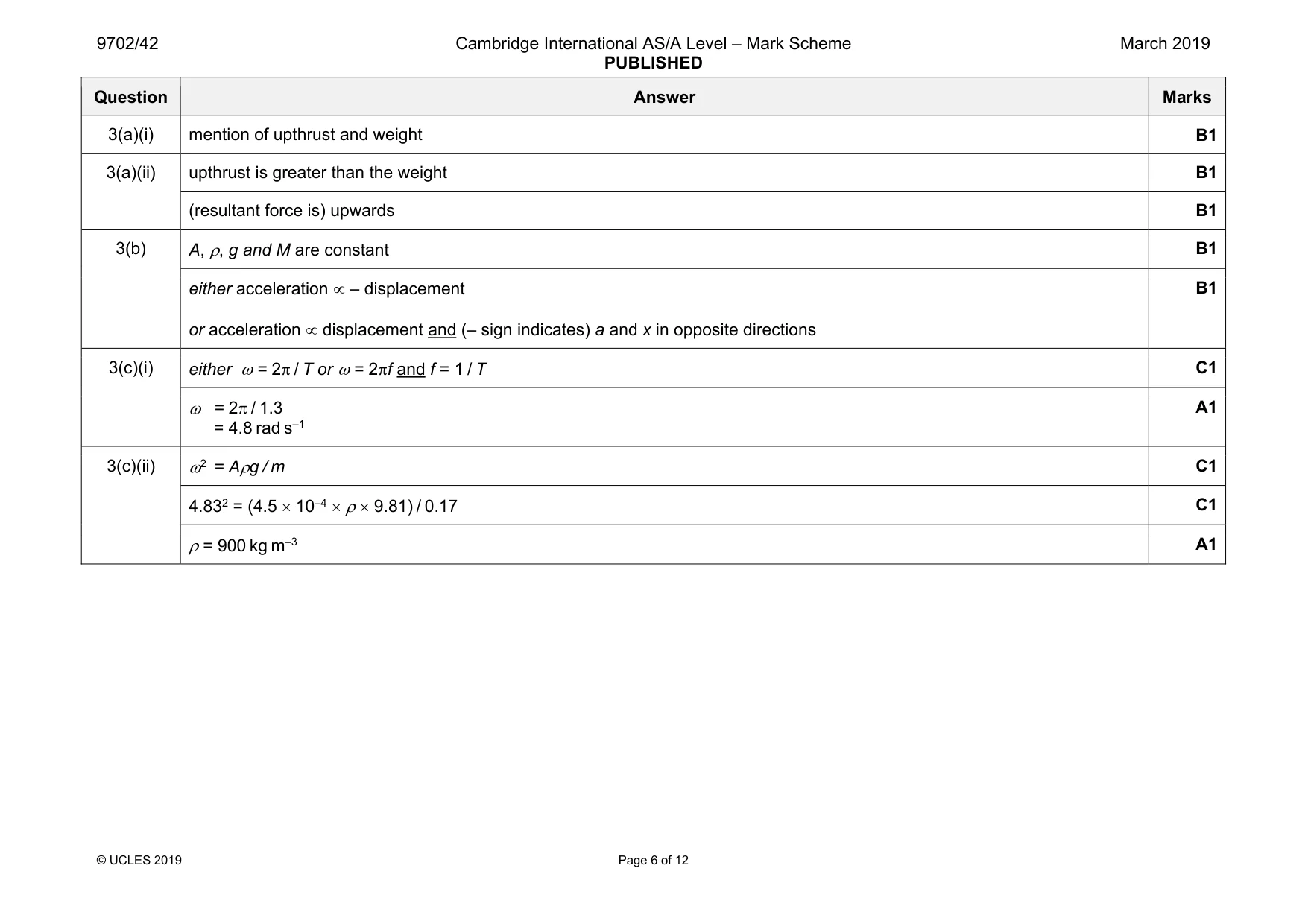
Mark scheme: 3(a)(i) mention of upthrust and weight B1 3(a)(ii) upthrust is greater than the weight B1 (resultant force is) upwards B1 3(b) A, ρ, g and M are constant B1 either acceleration ∝ – displacement or acceleration ∝ displacement and (– sign indicates) a and x in opposite directions B1 3(c)(i) either ω = 2π / T or ω = 2πf and f = 1 / T C1 ω = 2π / 1.3 = 4.8 rad s–1 A1 3(c)(ii) ω2 = Aρg / m C1 4.832 = (4.5 × 10⁻⁴ × ρ × 9.81) / 0.17 C1 ρ = 900 kg m–3 A1
Q4 · State three features of the orbit of a geostationary satellite
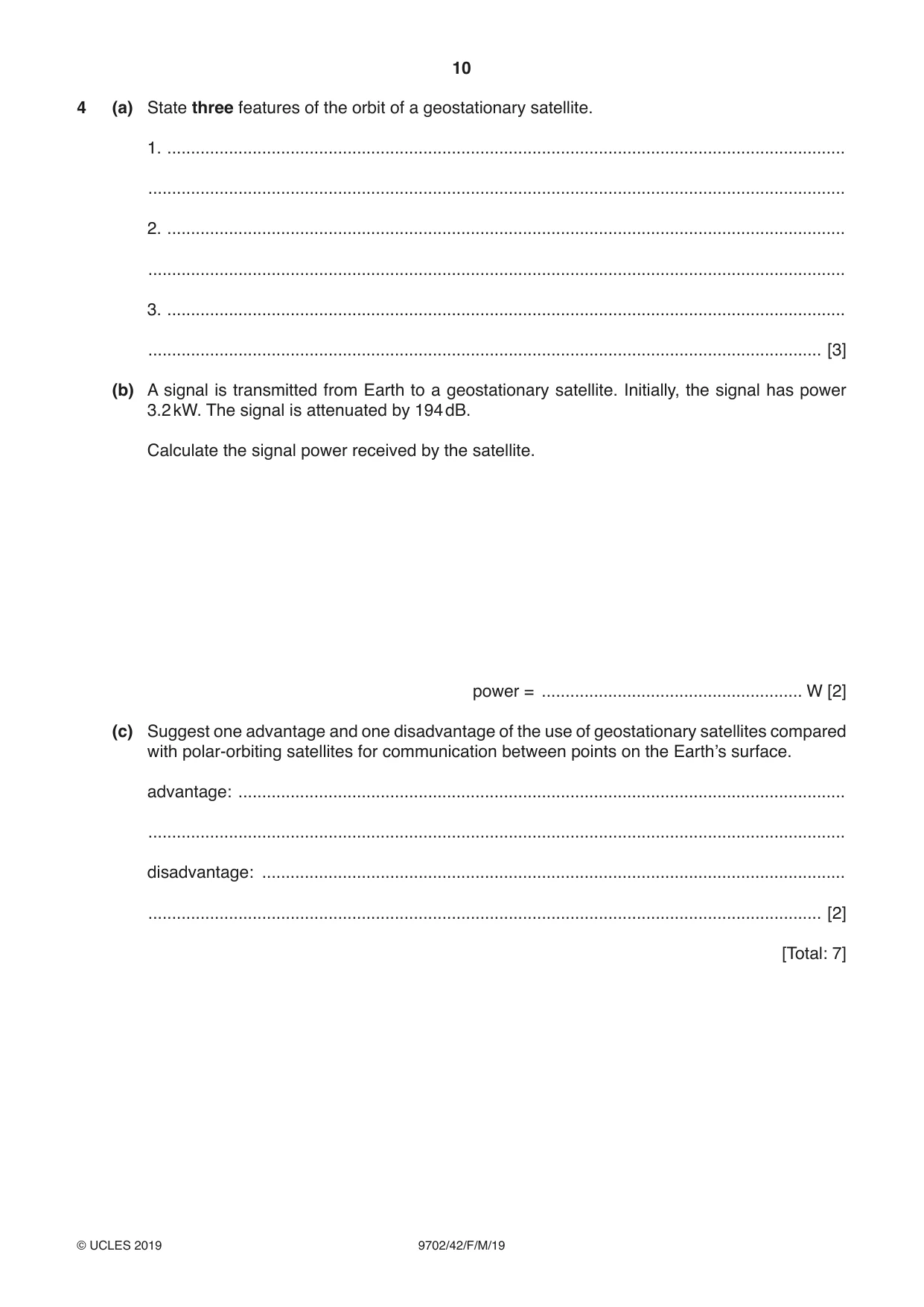
4 (a) State three features of the orbit of a geostationary satellite. 1. ............................................................................................................................................... ................................................................................................................................................... 2. ............................................................................................................................................... ................................................................................................................................................... 3. ............................................................................................................................................... .............................................................................................................................................. [3] (b) A signal is transmitted from Earth to a geostationary satellite. Initially, the signal has power 3.2 kW. The signal is attenuated by 194 dB. Calculate the signal power received by the satellite. power = ....................................................... W [2] (c) Suggest one advantage and one disadvantage of the use of geostationary satellites compared with polar-orbiting satellites for communication between points on the Earth’s surface. advantage: ................................................................................................................................ ................................................................................................................................................... disadvantage: ........................................................................................................................... .............................................................................................................................................. [2] [Total: 7]
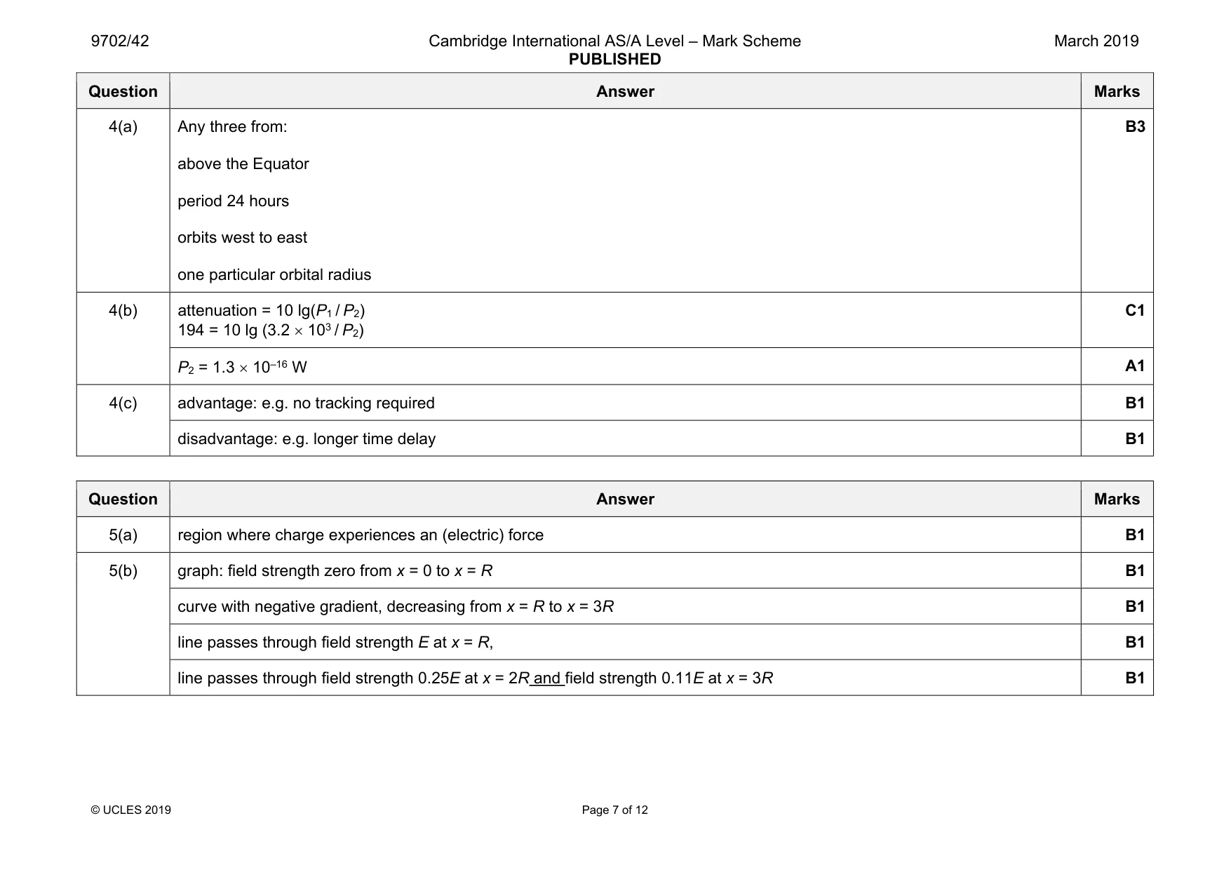
Mark scheme: 4(a) Any three from: above the Equator period 24 hours orbits west to east one particular orbital radius B3 4(b) attenuation = 10 lg(P1 / P2) 194 = 10 lg (3.2 × 10³ / P2) C1 P2 = 1.3 × 10⁻¹⁶ W A1 4(c) advantage: e.g. no tracking required B1 disadvantage: e.g. longer time delay B1
Q5 · State what is meant by an electric field
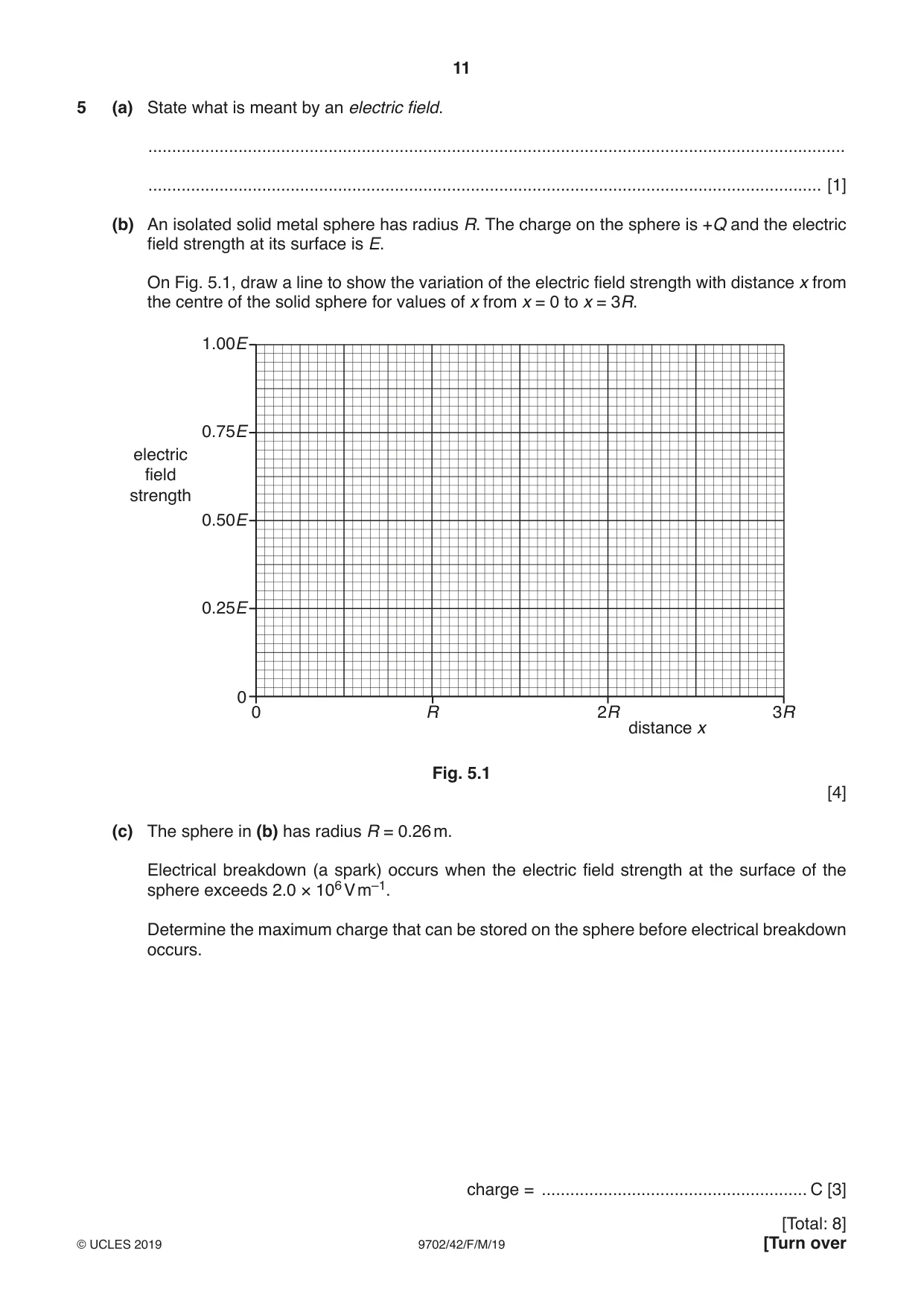
5 (a) State what is meant by an electric field. ................................................................................................................................................... .............................................................................................................................................. [1] (b) An isolated solid metal sphere has radius R. The charge on the sphere is +Q and the electric field strength at its surface is E. On Fig. 5.1, draw a line to show the variation of the electric field strength with distance x from the centre of the solid sphere for values of x from x = 0 to x = 3R. 1.00E 0.75E electric field strength 0.50E 0.25E 0 0 R 2R 3R distance x Fig. 5.1 [4] (c) The sphere in (b) has radius R = 0.26 m. Electrical breakdown (a spark) occurs when the electric field strength at the surface of the sphere exceeds 2.0 × 10⁶ V m–1. Determine the maximum charge that can be stored on the sphere before electrical breakdown occurs. charge = ........................................................ C [3]
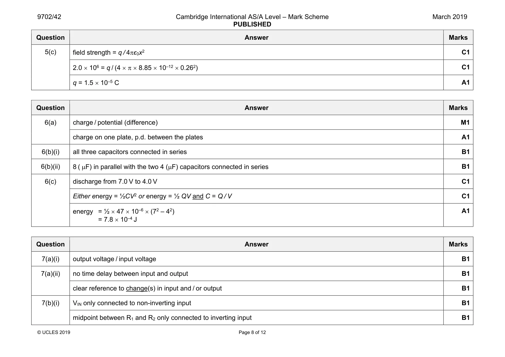
Mark scheme: 5(a) region where charge experiences an (electric) force B1 5(b) graph: field strength zero from x = 0 to x = R B1 curve with negative gradient, decreasing from x = R to x = 3R B1 line passes through field strength E at x = R, B1 line passes through field strength 0.25E at x = 2R and field strength 0.11E at x = 3R B1 Question Answer Marks 5(c) field strength = q / 4πϵ0x2 C1 2.0 × 106 = q / (4 × π × 8.85 × 10–12 × 0.262) C1 q = 1.5 × 10⁻⁵ C A1
Q6 · Define the capacitance of a parallel-plate capacitor
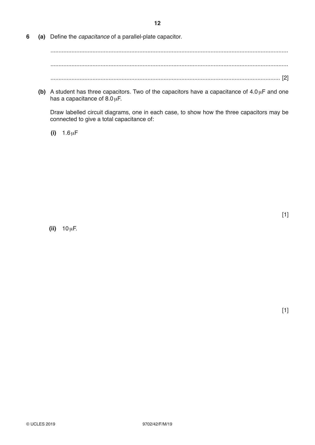
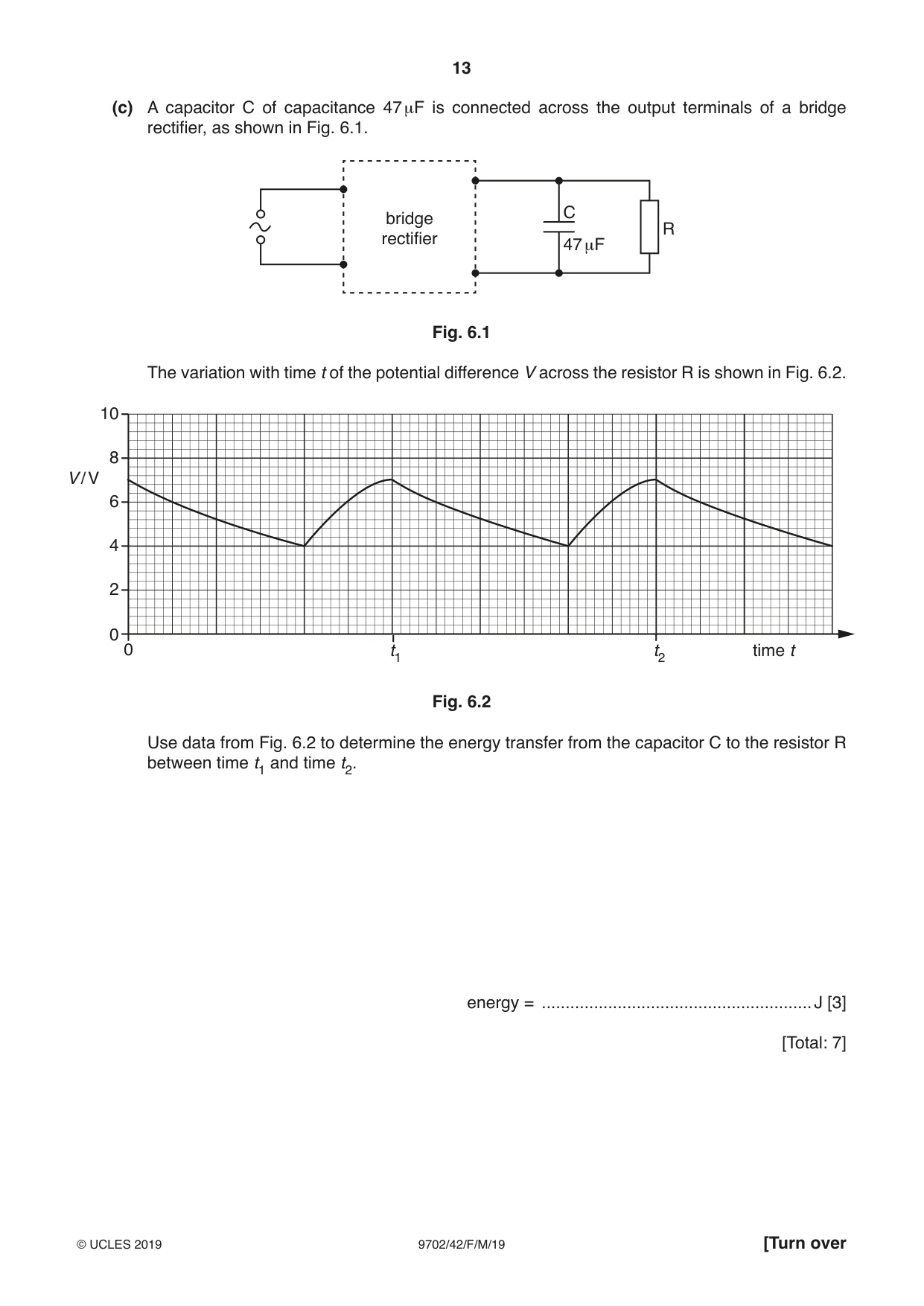
6 (a) Define the capacitance of a parallel-plate capacitor. ................................................................................................................................................... ................................................................................................................................................... .............................................................................................................................................. [2] (b) A student has three capacitors. Two of the capacitors have a capacitance of 4.0 μF and one has a capacitance of 8.0 μF. Draw labelled circuit diagrams, one in each case, to show how the three capacitors may be connected to give a total capacitance of: (i) 1.6 μF [1] (ii) 10 μF. [1] (c) A capacitor C of capacitance 47 μF is connected across the output terminals of a bridge rectifier, as shown in Fig. 6.1. C bridge R rectifier 47 μF Fig. 6.1 The variation with time t of the potential difference V across the resistor R is shown in Fig. 6.2. 10 8 V / V 6 4 2 0 0 t1 t2 time t Fig. 6.2 Use data from Fig. 6.2 to determine the energy transfer from the capacitor C to the resistor R between time t1 and time t2. energy = ......................................................... J [3] [Total: 7]
Mark scheme: 6(a) charge / potential (difference) M1 charge on one plate, p.d. between the plates A1 6(b)(i) all three capacitors connected in series B1 6(b)(ii) 8 ( µF) in parallel with the two 4 (µF) capacitors connected in series B1 6(c) discharge from 7.0 V to 4.0 V C1 Either energy = ½CV2 or energy = ½ QV and C = Q / V C1 energy = ½ × 47 × 10–6 × (72 – 42) = 7.8 × 10⁻⁴ J A1
Q7 · Two properties that an ideal operational amplifier (op-amp) would have are constant…
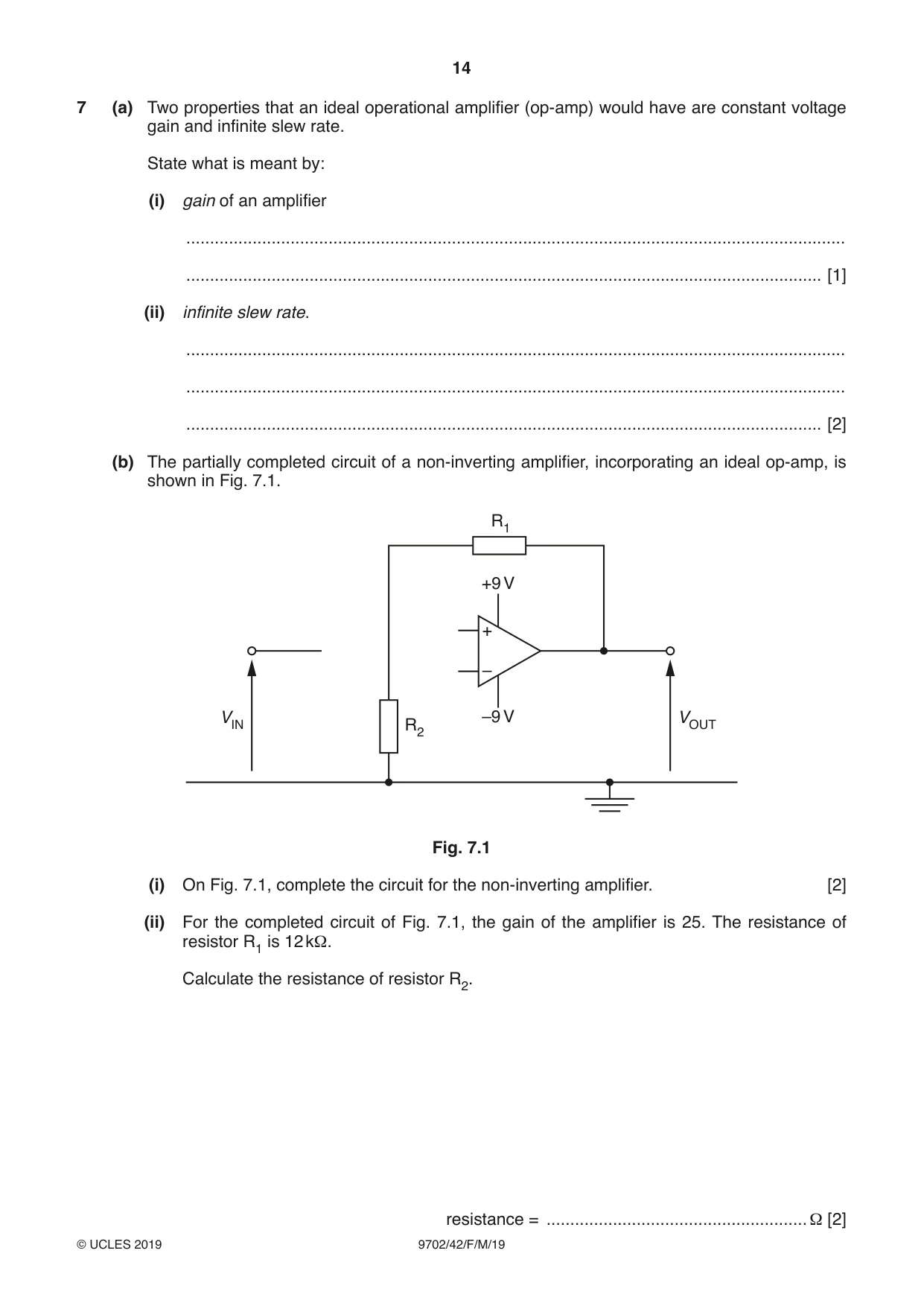
7 (a) Two properties that an ideal operational amplifier (op-amp) would have are constant voltage gain and infinite slew rate. State what is meant by: (i) gain of an amplifier ........................................................................................................................................... ...................................................................................................................................... [1] (ii) infinite slew rate. ........................................................................................................................................... ........................................................................................................................................... ...................................................................................................................................... [2] (b) The partially completed circuit of a non-inverting amplifier, incorporating an ideal op-amp, is shown in Fig. 7.1. R1 +9 V + – VIN –9 V VOUT R2 Fig. 7.1 (i) On Fig. 7.1, complete the circuit for the non-inverting amplifier. [2] (ii) For the completed circuit of Fig. 7.1, the gain of the amplifier is 25. The resistance of resistor R1 is 12 kΩ. Calculate the resistance of resistor R2. resistance = ....................................................... Ω [2] (iii) Calculate, for the amplifier gain of 25, the range of values of VIN for which the amplifier does not saturate. range from ....................... V to ........................ V [2] [Total: 9]
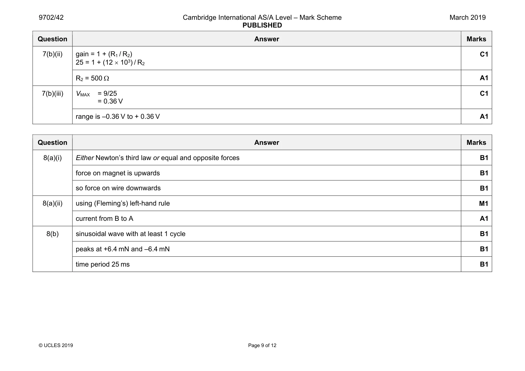
Mark scheme: 7(a)(i) output voltage / input voltage B1 7(a)(ii) no time delay between input and output B1 clear reference to change(s) in input and / or output B1 7(b)(i) VIN only connected to non-inverting input B1 midpoint between R1 and R2 only connected to inverting input B1 Question Answer Marks 7(b)(ii) gain = 1 + (R1 / R2) 25 = 1 + (12 × 103) / R2 C1 R2 = 500 Ω A1 7(b)(iii) VMAX = 9/25 = 0.36 V C1 range is –0.36 V to + 0.36 V A1
Q8 · A horseshoe magnet is placed on a top pan balance
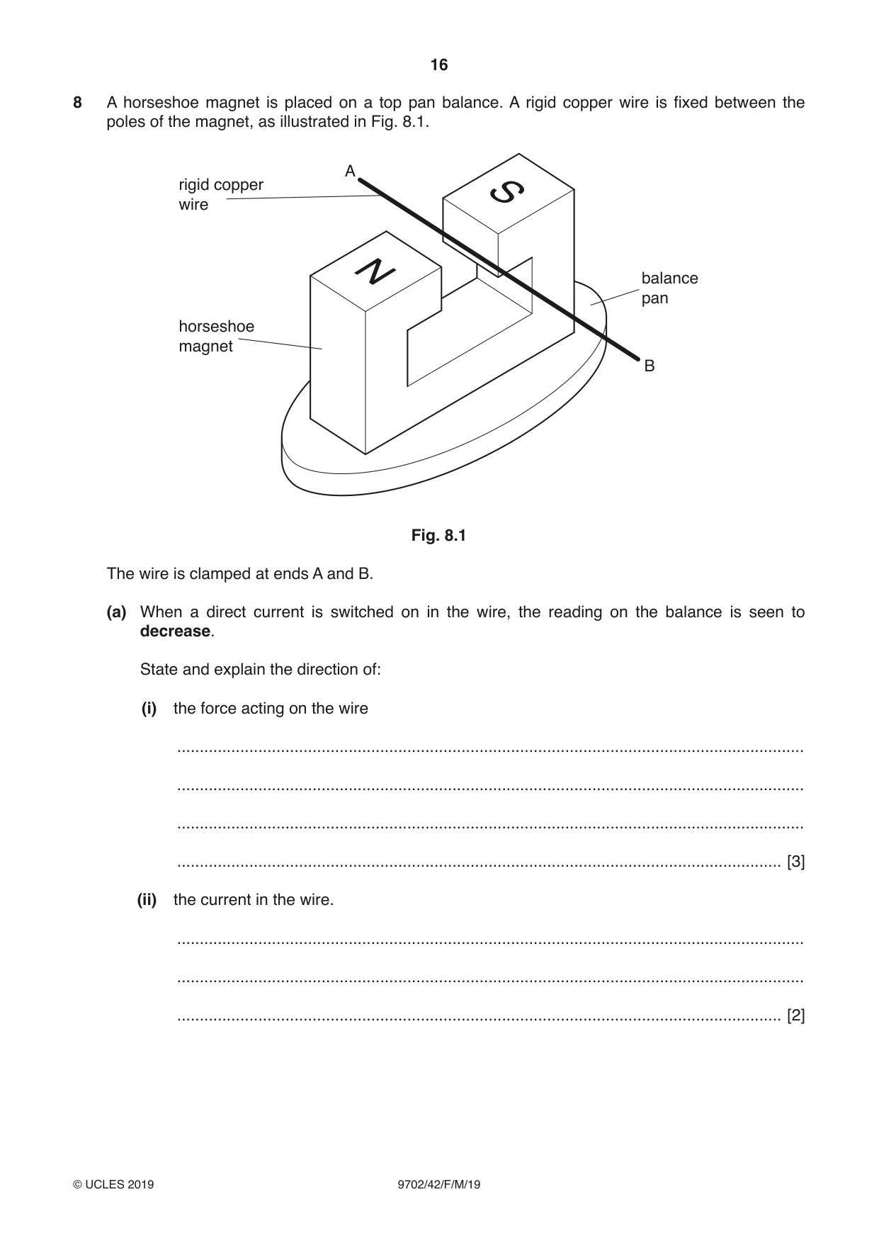
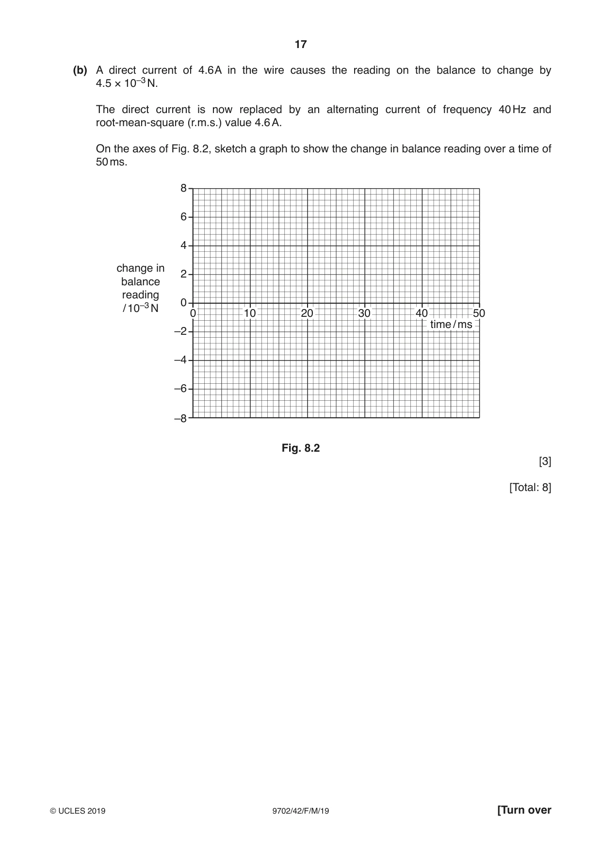
8 A horseshoe magnet is placed on a top pan balance. A rigid copper wire is fixed between the poles of the magnet, as illustrated in Fig. 8.1. A rigid copper wire balance pan horseshoe magnet B Fig. 8.1 The wire is clamped at ends A and B. (a) When a direct current is switched on in the wire, the reading on the balance is seen to decrease. State and explain the direction of: (i) the force acting on the wire ........................................................................................................................................... ........................................................................................................................................... ........................................................................................................................................... ...................................................................................................................................... [3] (ii) the current in the wire. ........................................................................................................................................... ........................................................................................................................................... ...................................................................................................................................... [2] (b) A direct current of 4.6 A in the wire causes the reading on the balance to change by 4.5 × 10⁻³ N. The direct current is now replaced by an alternating current of frequency 40 Hz and root-mean-square (r.m.s.) value 4.6 A. On the axes of Fig. 8.2, sketch a graph to show the change in balance reading over a time of 50 ms. 8 6 4 change in 2 balance reading 0 / 10–3 N 0 10 20 30 40 50 time / ms –2 –4 –6 –8 Fig. 8.2 [3] [Total: 8]
Mark scheme: 8(a)(i) Either Newton’s third law or equal and opposite forces B1 force on magnet is upwards B1 so force on wire downwards B1 8(a)(ii) using (Fleming’s) left-hand rule M1 current from B to A A1 8(b) sinusoidal wave with at least 1 cycle B1 peaks at +6.4 mN and –6.4 mN B1 time period 25 ms B1
Q9 · Outline the principles of computed tomography (CT) scanning
9 Outline the principles of computed tomography (CT) scanning. .......................................................................................................................................................... .......................................................................................................................................................... .......................................................................................................................................................... .......................................................................................................................................................... .......................................................................................................................................................... .......................................................................................................................................................... .......................................................................................................................................................... .......................................................................................................................................................... .......................................................................................................................................................... .......................................................................................................................................................... ..................................................................................................................................................... [5] [Total: 5]
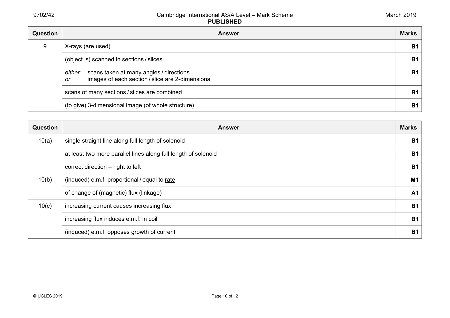
Mark scheme: 9 X-rays (are used) B1 (object is) scanned in sections / slices B1 either: scans taken at many angles / directions or images of each section / slice are 2-dimensional B1 scans of many sections / slices are combined B1 (to give) 3-dimensional image (of whole structure) B1
Q10 · A cross-section through a current-carrying solenoid is shown in Fig
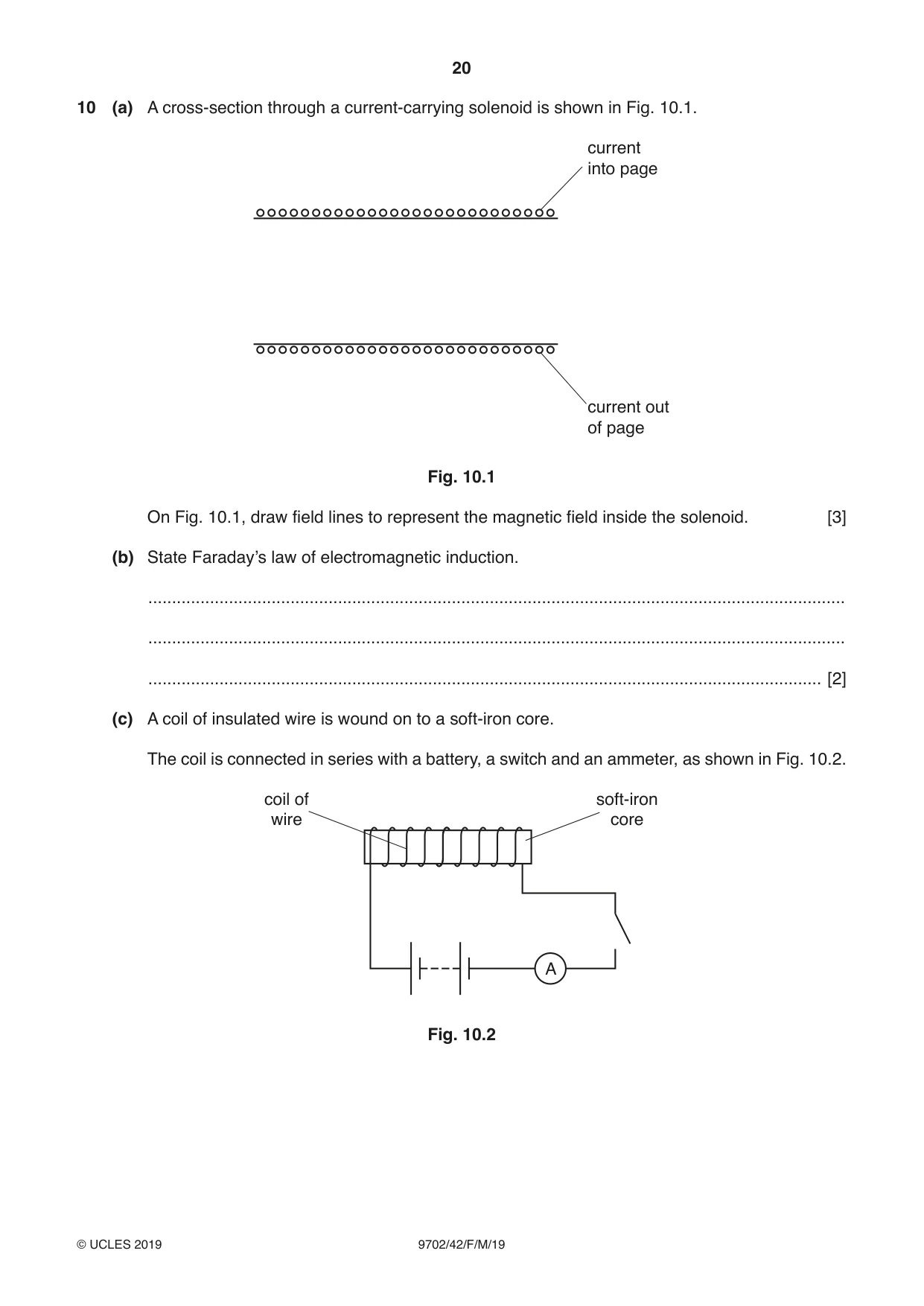
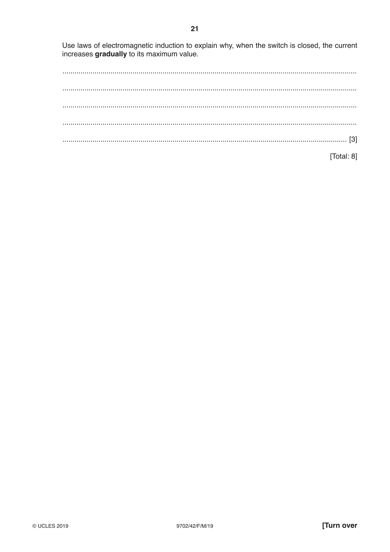
10 (a) A cross-section through a current-carrying solenoid is shown in Fig. 10.1. current into page current out of page Fig. 10.1 On Fig. 10.1, draw field lines to represent the magnetic field inside the solenoid. [3] (b) State Faraday’s law of electromagnetic induction. ................................................................................................................................................... ................................................................................................................................................... .............................................................................................................................................. [2] (c) A coil of insulated wire is wound on to a soft-iron core. The coil is connected in series with a battery, a switch and an ammeter, as shown in Fig. 10.2. coil of soft-iron wire core A Fig. 10.2 Use laws of electromagnetic induction to explain why, when the switch is closed, the current increases gradually to its maximum value. ................................................................................................................................................... ................................................................................................................................................... ................................................................................................................................................... ................................................................................................................................................... .............................................................................................................................................. [3] [Total: 8]
Mark scheme: 10(a) single straight line along full length of solenoid B1 at least two more parallel lines along full length of solenoid B1 correct direction – right to left B1 10(b) (induced) e.m.f. proportional / equal to rate M1 of change of (magnetic) flux (linkage) A1 10(c) increasing current causes increasing flux B1 increasing flux induces e.m.f. in coil B1 (induced) e.m.f. opposes growth of current B1
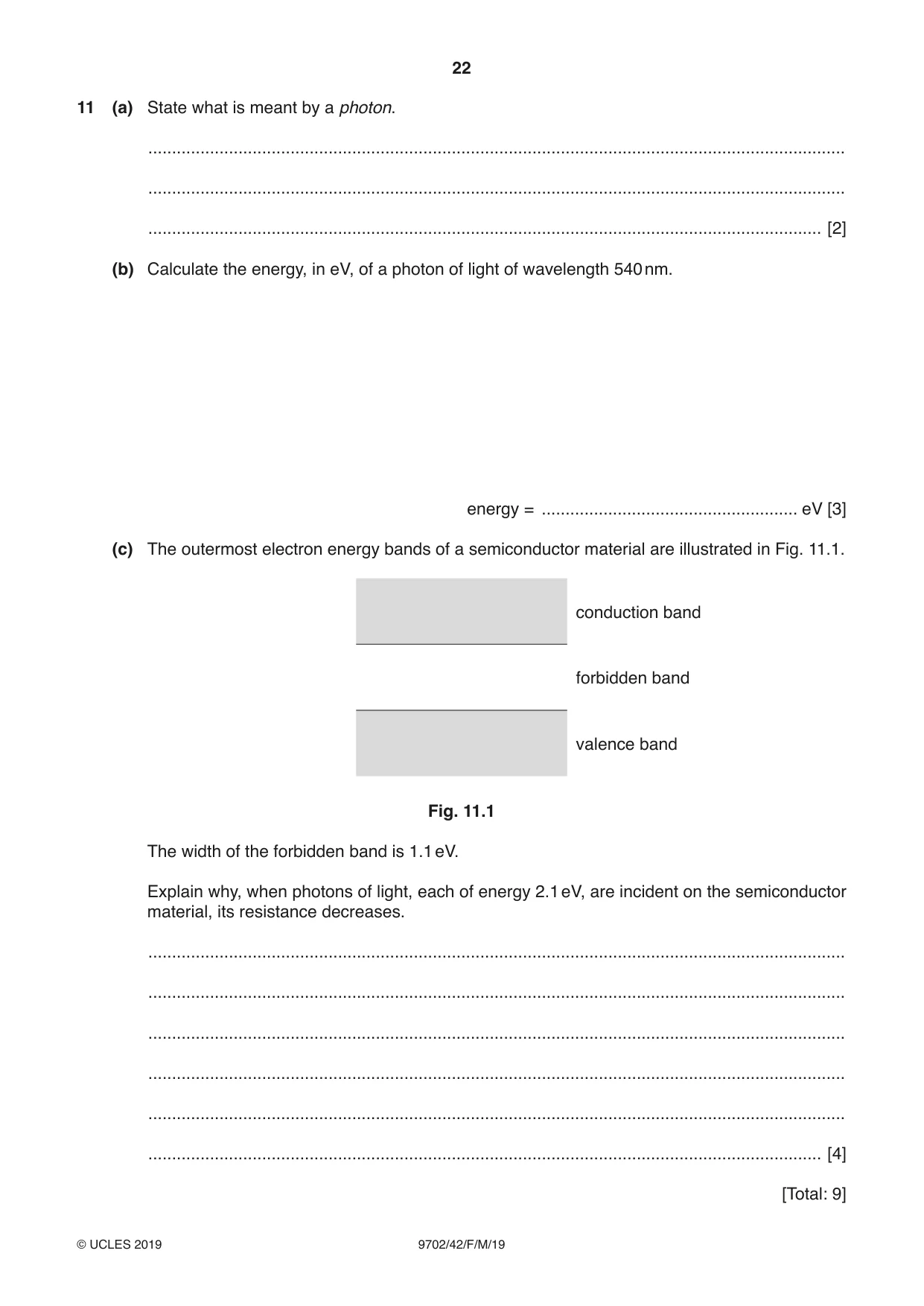
Q11 · State what is meant by a photon
11 (a) State what is meant by a photon. ................................................................................................................................................... ................................................................................................................................................... .............................................................................................................................................. [2] (b) Calculate the energy, in eV, of a photon of light of wavelength 540 nm. energy = ...................................................... eV [3] (c) The outermost electron energy bands of a semiconductor material are illustrated in Fig. 11.1. conduction band forbidden band valence band Fig. 11.1 The width of the forbidden band is 1.1 eV. Explain why, when photons of light, each of energy 2.1 eV, are incident on the semiconductor material, its resistance decreases. ................................................................................................................................................... ................................................................................................................................................... ................................................................................................................................................... ................................................................................................................................................... ................................................................................................................................................... .............................................................................................................................................. [4] [Total: 9]
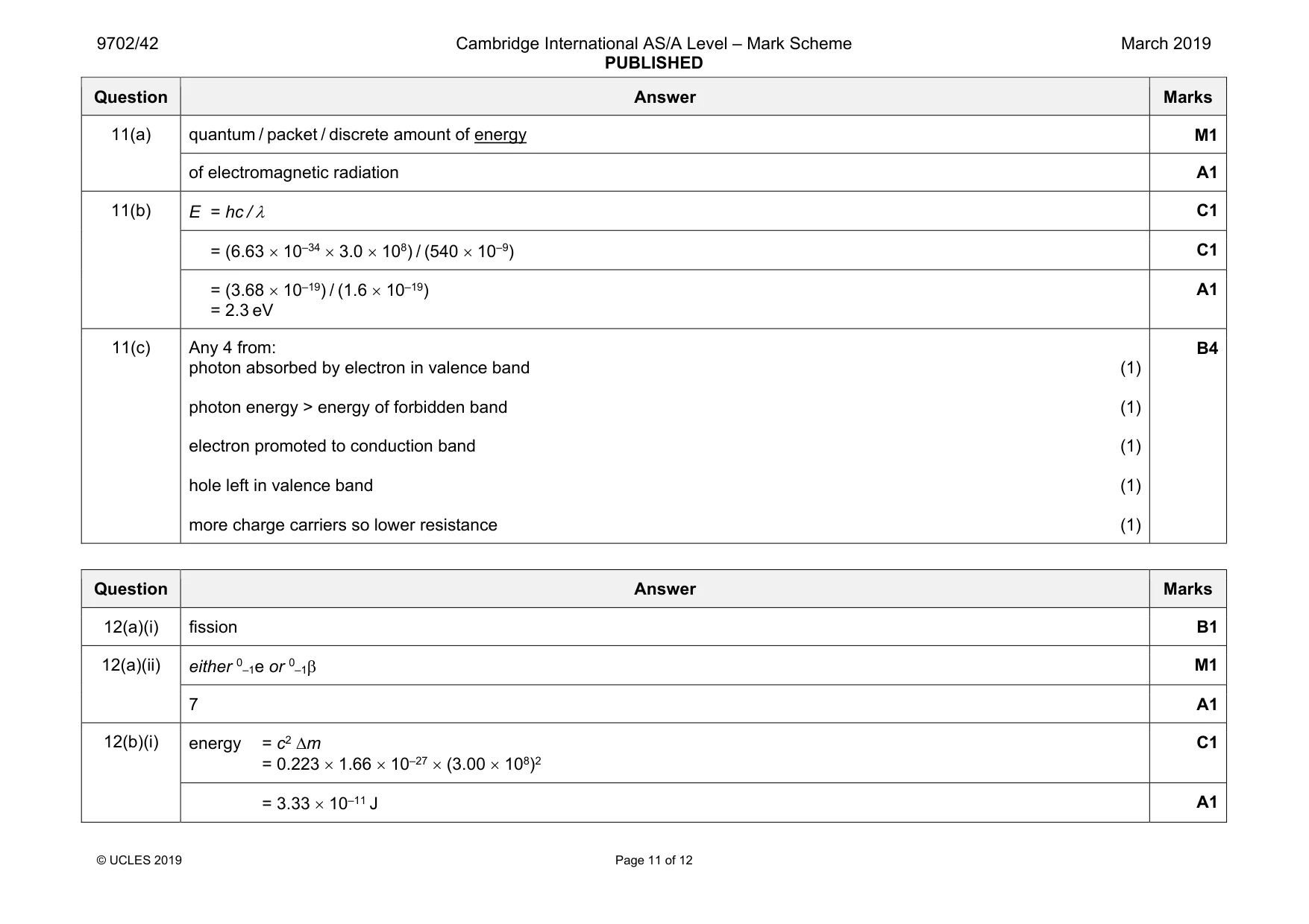
Mark scheme: 11(a) quantum / packet / discrete amount of energy M1 of electromagnetic radiation A1 11(b) E = hc / λ C1 = (6.63 × 10–34 × 3.0 × 108) / (540 × 10–9) C1 = (3.68 × 10⁻¹⁹) / (1.6 × 10⁻¹⁹) = 2.3 eV A1 11(c) Any 4 from: photon absorbed by electron in valence band (1) photon energy > energy of forbidden band (1) electron promoted to conduction band (1) hole left in valence band (1) more charge carriers so lower resistance (1) B4
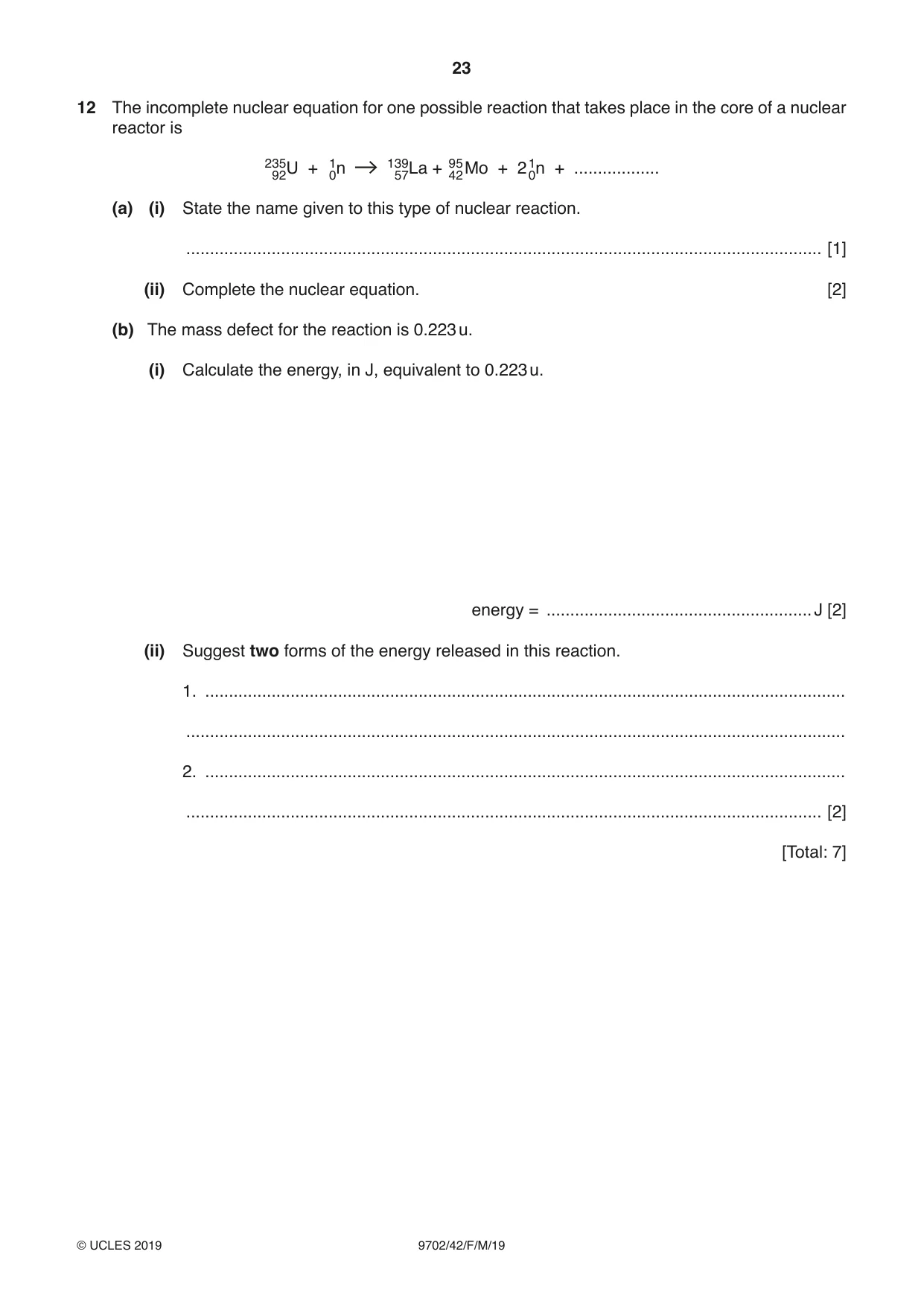
Q12 · The incomplete nuclear equation for one possible reaction that takes place in the core of…
12 The incomplete nuclear equation for one possible reaction that takes place in the core of a nuclear reactor is 23592U + 10n 13957La + 9542Mo + 210n + .................. (a) (i) State the name given to this type of nuclear reaction. ...................................................................................................................................... [1] (ii) Complete the nuclear equation. [2] (b) The mass defect for the reaction is 0.223 u. (i) Calculate the energy, in J, equivalent to 0.223 u. energy = ........................................................ J [2] (ii) Suggest two forms of the energy released in this reaction. 1. ....................................................................................................................................... ........................................................................................................................................... 2. ....................................................................................................................................... ...................................................................................................................................... [2] [Total: 7]
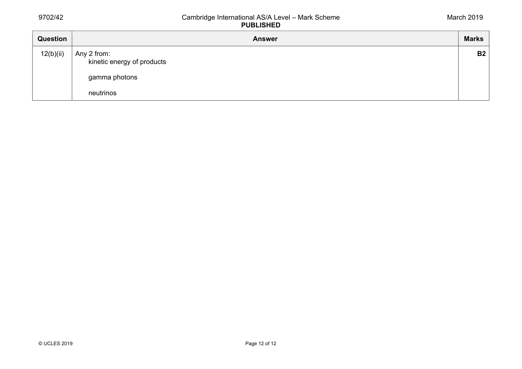
Mark scheme: 12(a)(i) fission B1 12(a)(ii) either 0–1e or 0–1β M1 7 A1 12(b)(i) energy = c2 ∆m = 0.223 × 1.66 × 10–27 × (3.00 × 108)2 C1 = 3.33 × 10⁻¹¹ J A1 Question Answer Marks 12(b)(ii) Any 2 from: kinetic energy of products gamma photons neutrinos B2
What was in this paper
The subtopics covered by these 12 questions, and how many questions each got. Open one in a new tab to see every Cambridge question on it.
2Capacitors and capacitance1Electric field of a point charge1Electromagnetic induction1Energy and momentum of a photon1Equilibrium of forces1Force on a current-carrying conductor1Kinetic theory of gases1Mass defect and nuclear binding energy1Practical circuits1Production and use of X-rays1What you needed in this session
Cambridge’s own grade thresholds for 2019 Feb/March, Paper 4 · Variant 2. A higher threshold means an easier paper — the bar moves with how the cohort did.