Cambridge A Level Physics 9702 — 2022 Oct/Nov Paper 4 · Variant 2
9702/42/O/N/22 · 10 questions · 100 marks · ≈113 min
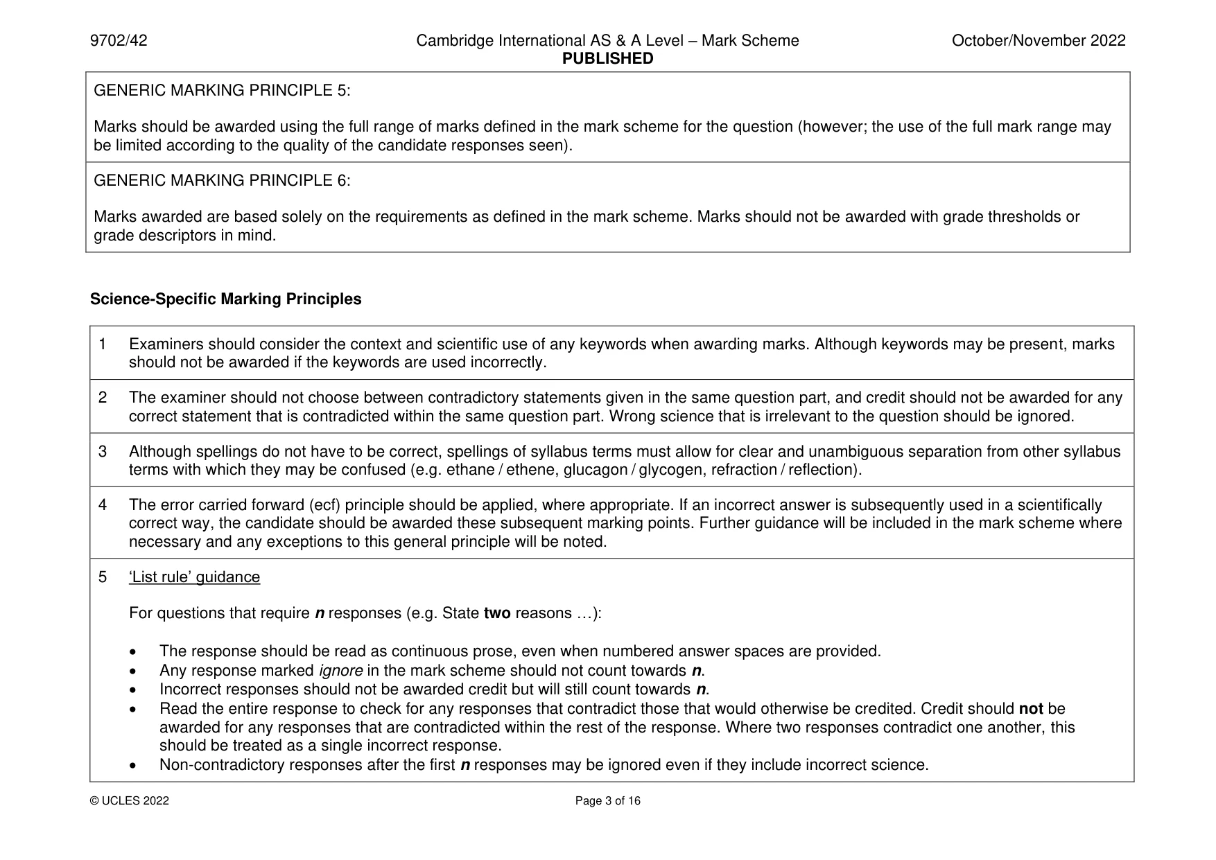
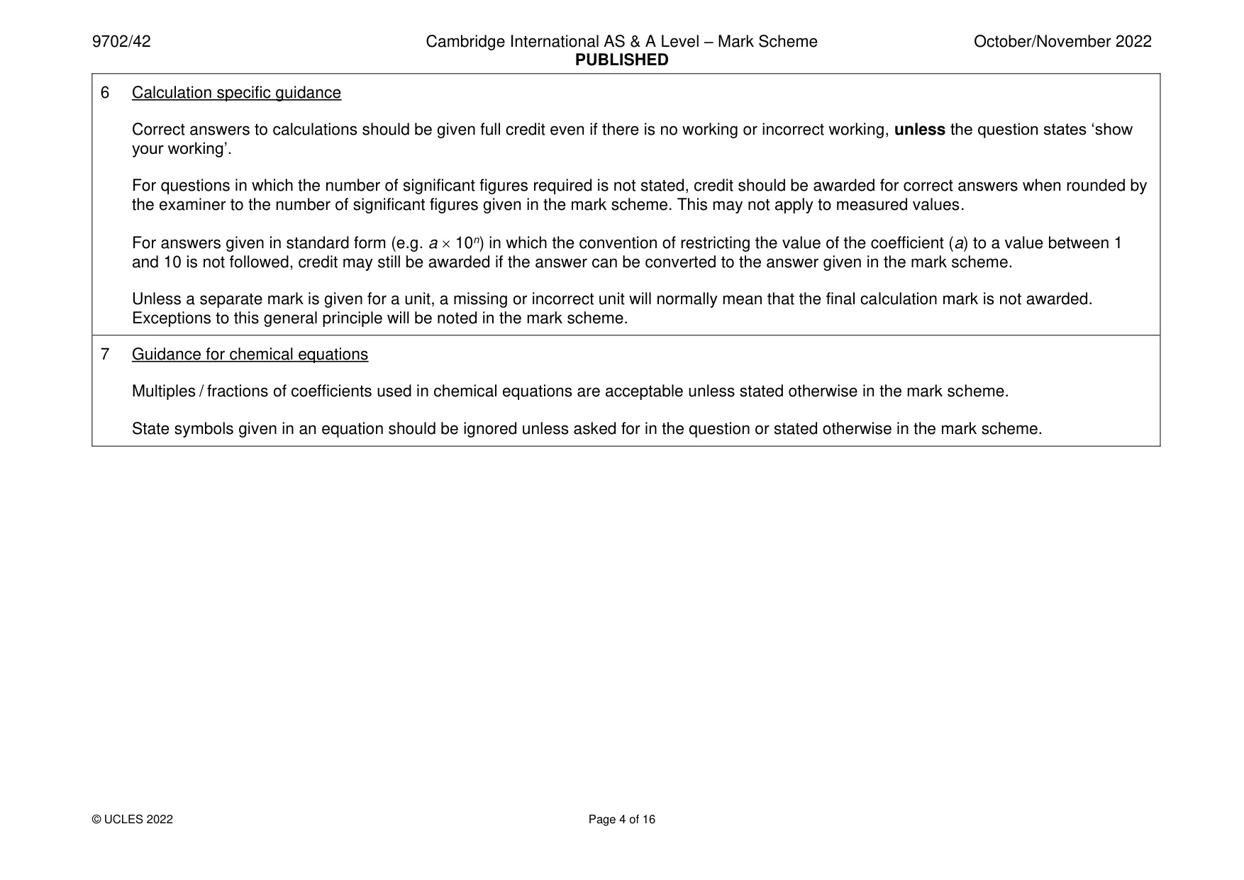
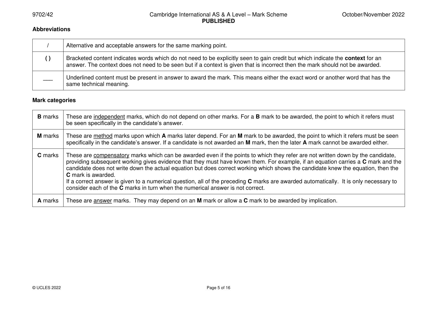
The question paper and its mark scheme, free to read here and free to download. This is Cambridge’s own paper, exactly as it was sat.
Question paper24 pages
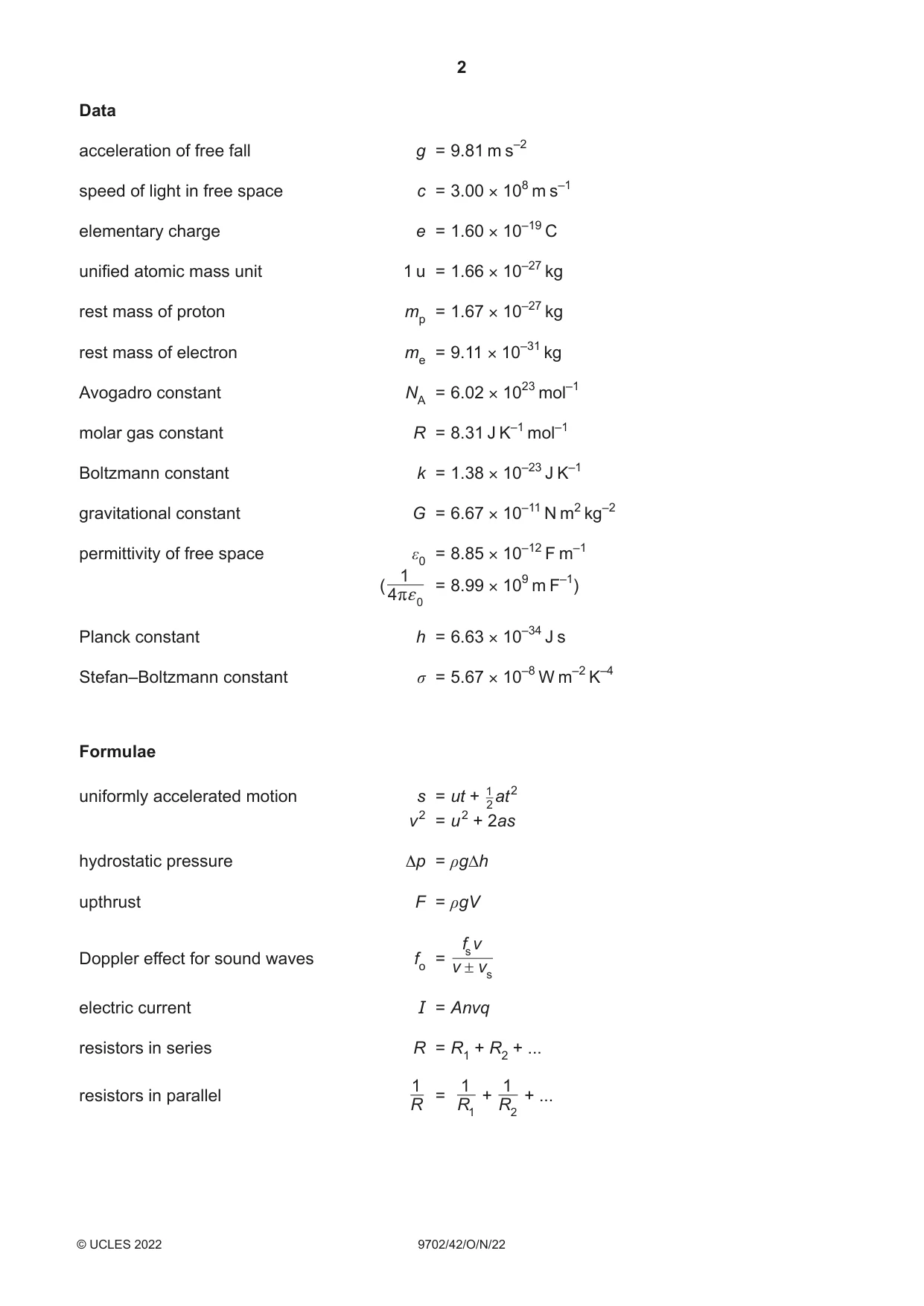
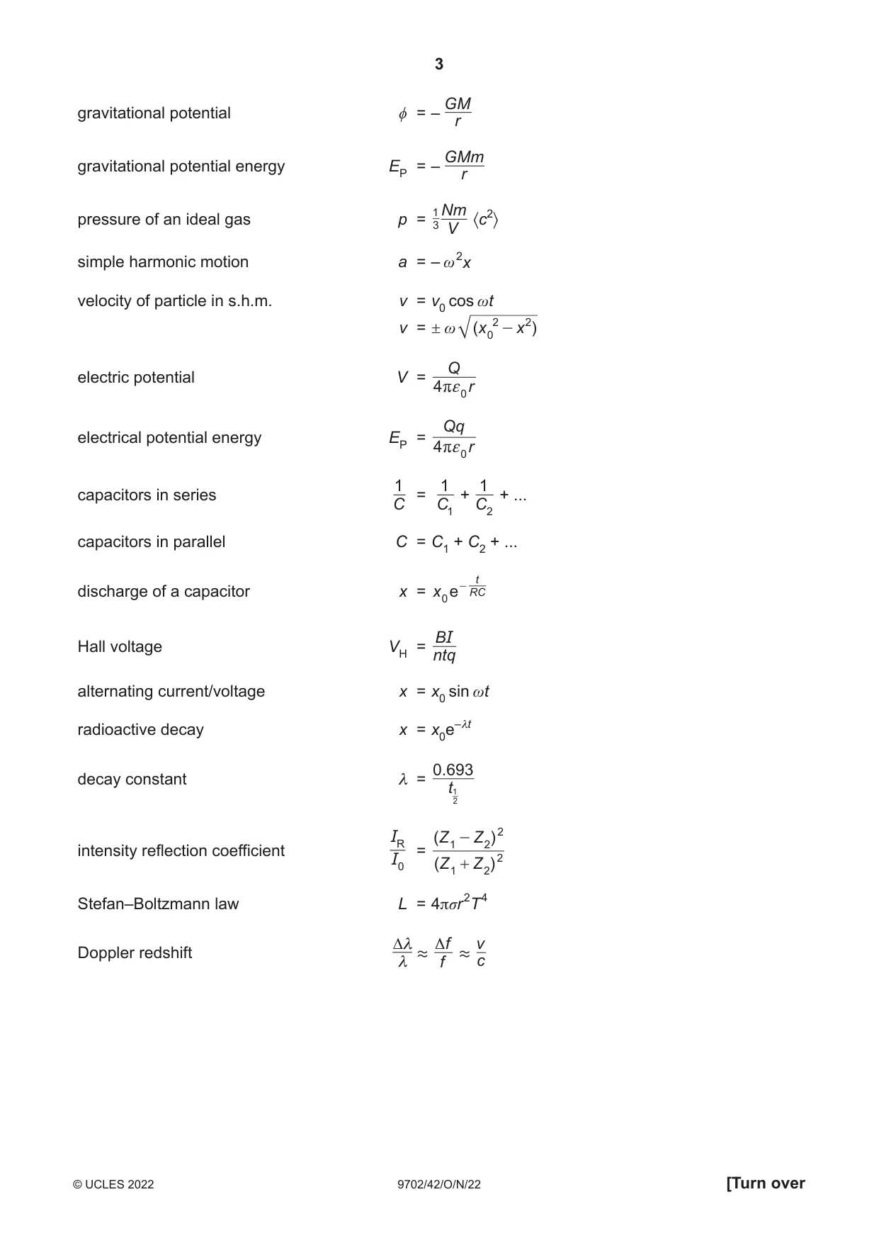


Mark scheme16 pages
Answers below. Sit the paper first if you are practising.

Questions as text
Question 1
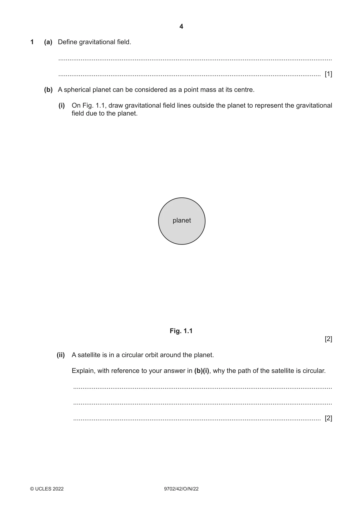
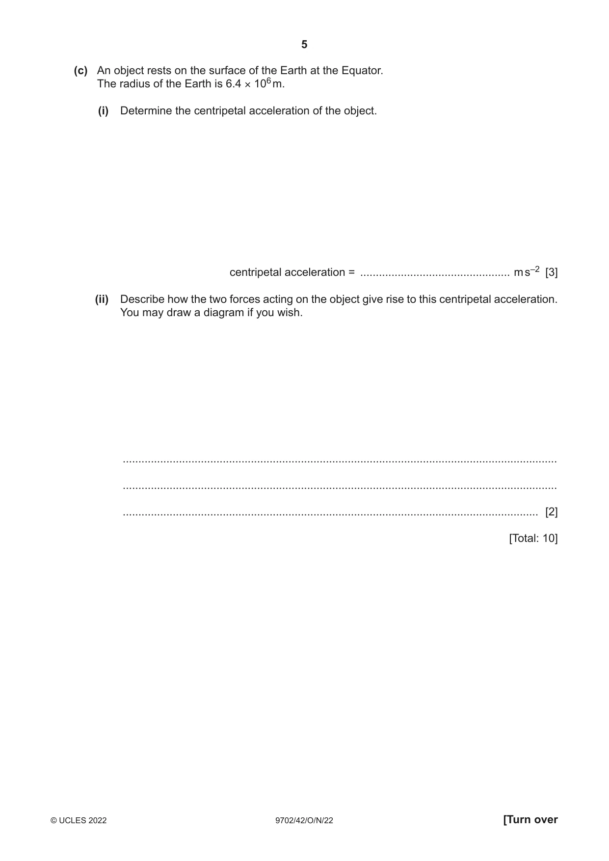
1 (a) Define gravitational field. ................................................................................................................................................... ............................................................................................................................................. [1] (b) A spherical planet can be considered as a point mass at its centre. (i) On Fig. 1.1, draw gravitational field lines outside the planet to represent the gravitational field due to the planet. planet Fig. 1.1 [2] (ii) A satellite is in a circular orbit around the planet. Explain, with reference to your answer in (b)(i), why the path of the satellite is circular. ........................................................................................................................................... ........................................................................................................................................... ..................................................................................................................................... [2] (c) An object rests on the surface of the Earth at the Equator. The radius of the Earth is 6.4 × 10⁶ m. (i) Determine the centripetal acceleration of the object. centripetal acceleration = ................................................ m s–2 [3] (ii) Describe how the two forces acting on the object give rise to this centripetal acceleration. You may draw a diagram if you wish. ........................................................................................................................................... ........................................................................................................................................... ..................................................................................................................................... [2] [Total: 10]
Mark scheme: Question Answer Marks 1(a) force per unit mass B1 1(b)(i) lines drawn are radial from the surface B1 arrows show pointing towards planet B1 1(b)(ii) field lines show force (on satellite) is towards centre of planet B1 or velocity of satellite is perpendicular to field lines (gravitational) force perpendicular to velocity causes centripetal acceleration B1 1(c)(i) T = 24 hours C1 a = r2 and = 2 / T C1 or a = v2 / r and v = 2r /T or a = 42r / T 2 a = (42 6.4 106) / (24 60 60)2 A1 = 0.034 m s–2 1(c)(ii) identification of the two forces acting on the object as gravitational force and (normal) contact force M1 gravitational force and normal contact force are in opposite directions, and their resultant causes the (centripetal) A1 acceleration
Q2 · Define specific heat capacity
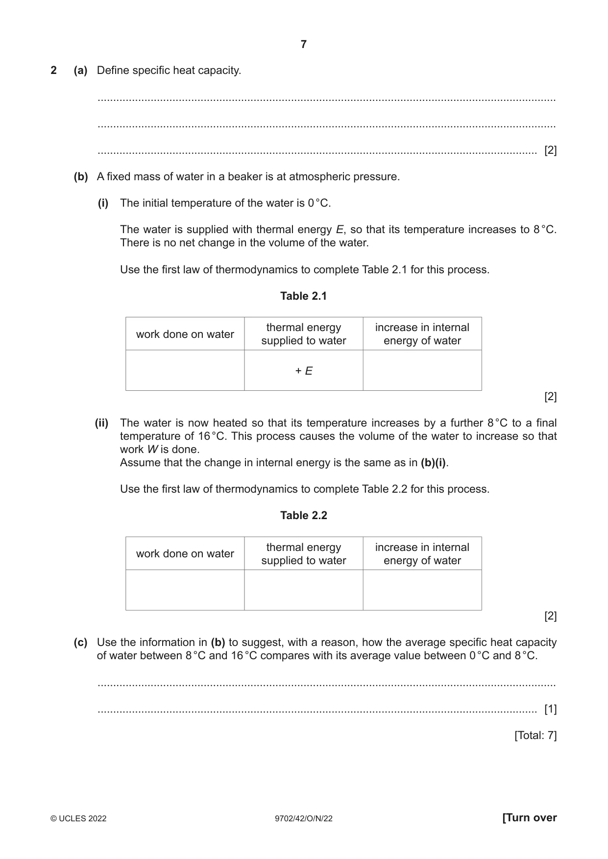
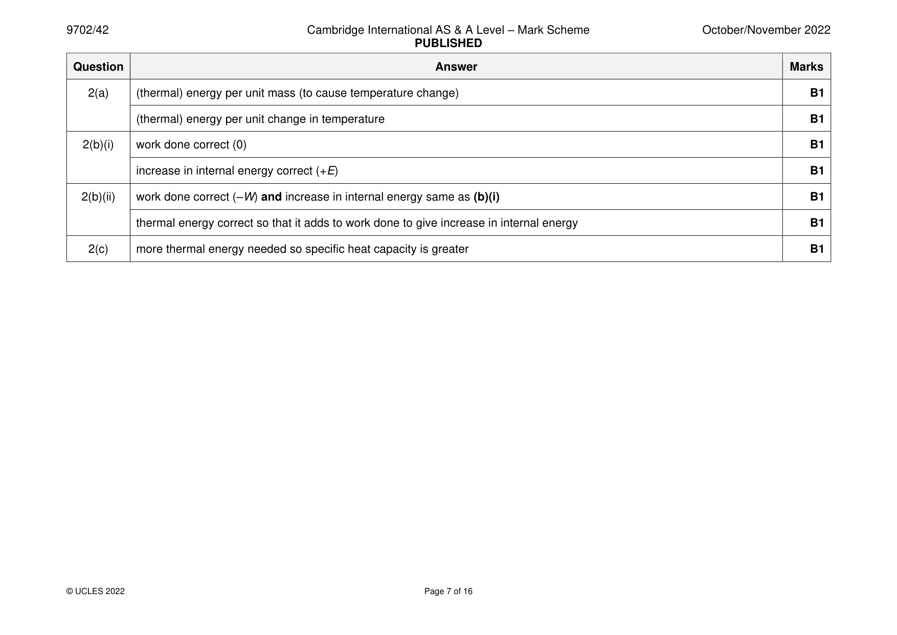
2 (a) Define specific heat capacity. ................................................................................................................................................... ................................................................................................................................................... ............................................................................................................................................. [2] (b) A fixed mass of water in a beaker is at atmospheric pressure. (i) The initial temperature of the water is 0 °C. The water is supplied with thermal energy E, so that its temperature increases to 8 °C. There is no net change in the volume of the water. Use the first law of thermodynamics to complete Table 2.1 for this process. Table 2.1 thermal energy increase in internal work done on water supplied to water energy of water + E [2] (ii) The water is now heated so that its temperature increases by a further 8 °C to a final temperature of 16 °C. This process causes the volume of the water to increase so that work W is done. Assume that the change in internal energy is the same as in (b)(i). Use the first law of thermodynamics to complete Table 2.2 for this process. Table 2.2 thermal energy increase in internal work done on water supplied to water energy of water [2] (c) Use the information in (b) to suggest, with a reason, how the average specific heat capacity of water between 8 °C and 16 °C compares with its average value between 0 °C and 8 °C. ................................................................................................................................................... ............................................................................................................................................. [1] [Total: 7]
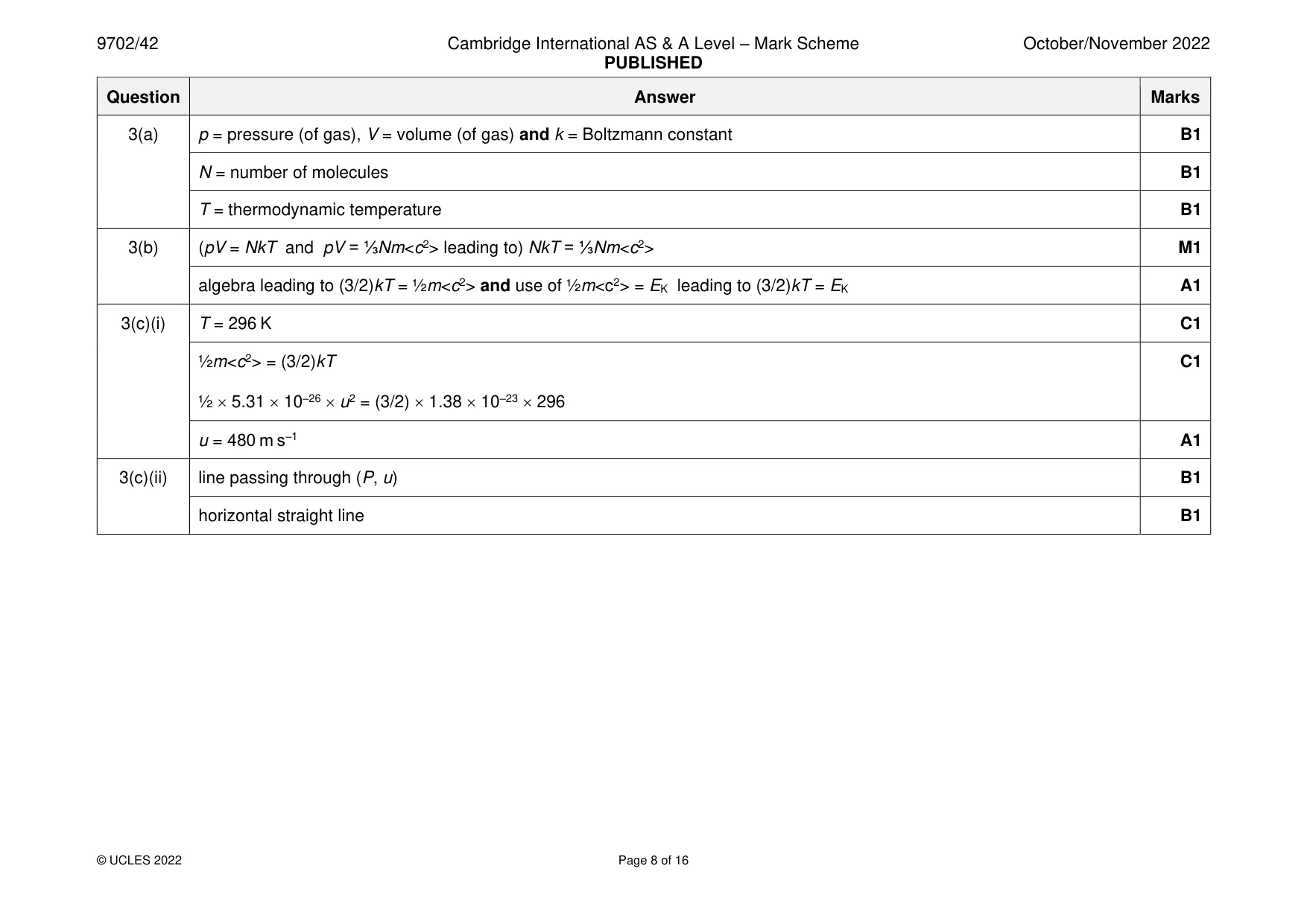
Mark scheme: 2(a) (thermal) energy per unit mass (to cause temperature change) B1 (thermal) energy per unit change in temperature B1 2(b)(i) work done correct (0) B1 increase in internal energy correct (+E) B1 2(b)(ii) work done correct (–W) and increase in internal energy same as (b)(i) B1 thermal energy correct so that it adds to work done to give increase in internal energy B1 2(c) more thermal energy needed so specific heat capacity is greater B1
Q3 · The equation of state for an ideal gas can be written as pV = NkT
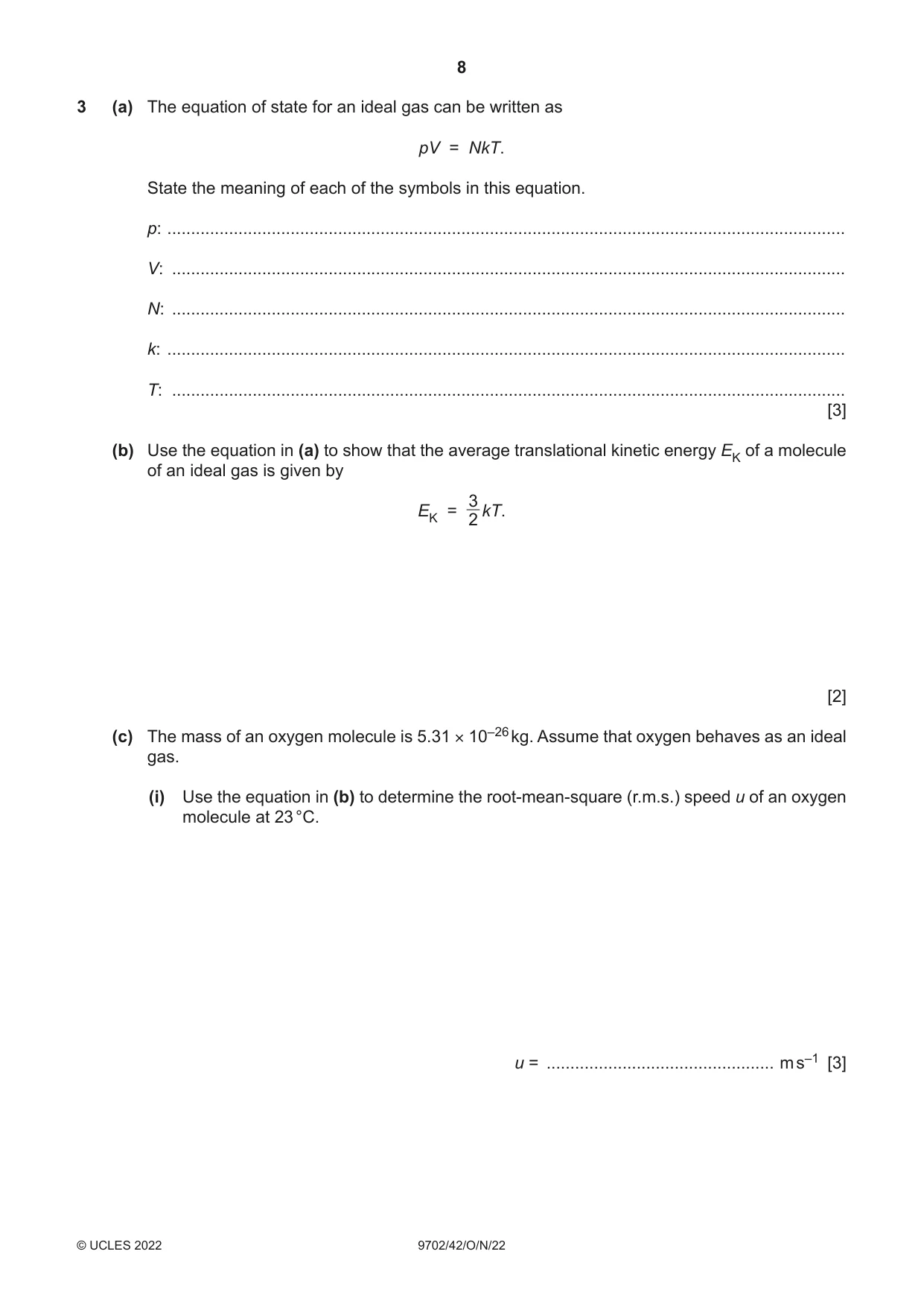
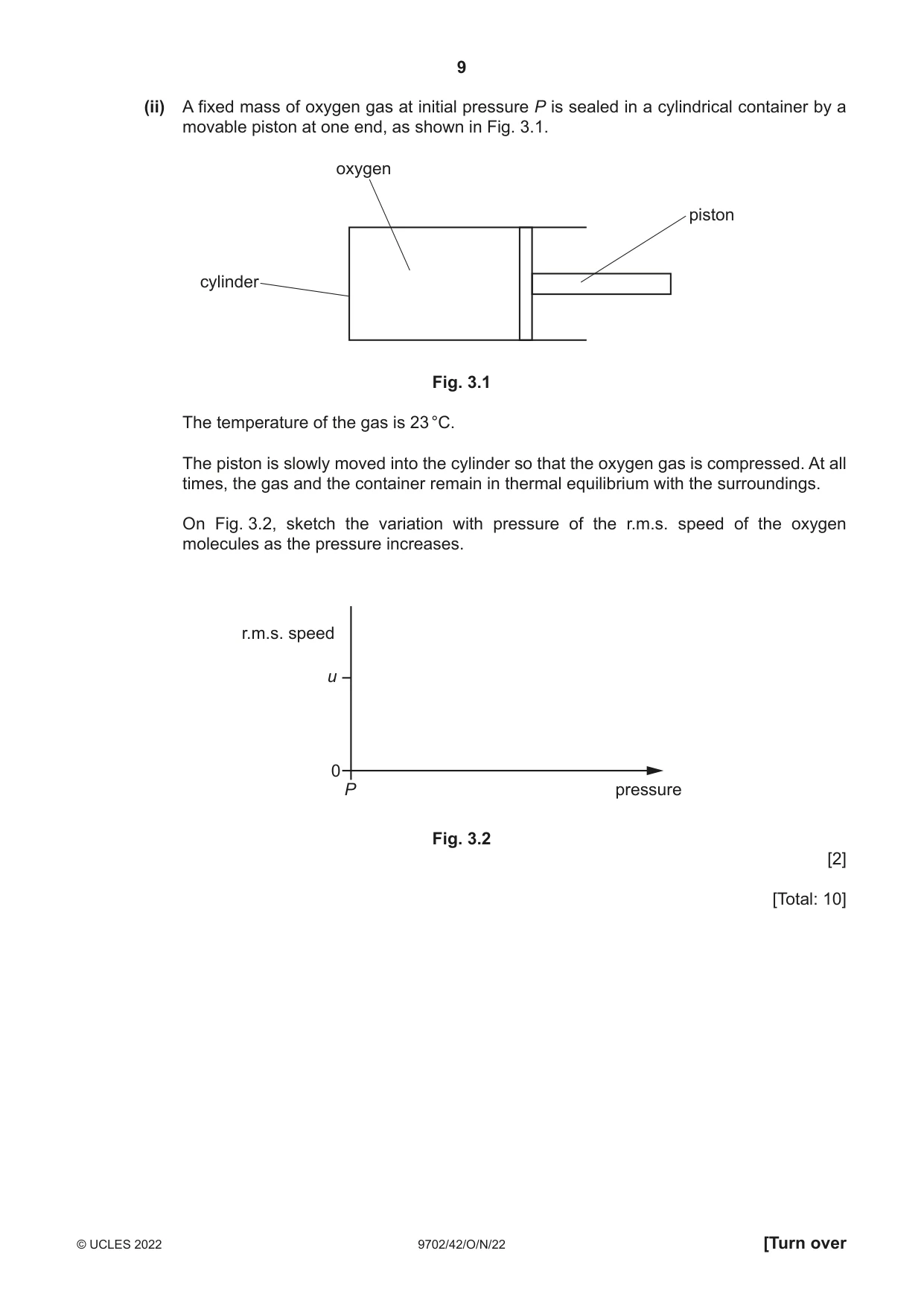
3 (a) The equation of state for an ideal gas can be written as pV = NkT. State the meaning of each of the symbols in this equation. p: ............................................................................................................................................... V: .............................................................................................................................................. N: .............................................................................................................................................. k: ............................................................................................................................................... T: .............................................................................................................................................. [3] (b) Use the equation in (a) to show that the average translational kinetic energy EK of a molecule of an ideal gas is given by 3 EK = 2 kT. [2] (c) The mass of an oxygen molecule is 5.31 × 10⁻²⁶ kg. Assume that oxygen behaves as an ideal gas. (i) Use the equation in (b) to determine the root-mean-square (r.m.s.) speed u of an oxygen molecule at 23 °C. u = ................................................ m s–1 [3] (ii) A fixed mass of oxygen gas at initial pressure P is sealed in a cylindrical container by a movable piston at one end, as shown in Fig. 3.1. oxygen piston cylinder Fig. 3.1 The temperature of the gas is 23 °C. The piston is slowly moved into the cylinder so that the oxygen gas is compressed. At all times, the gas and the container remain in thermal equilibrium with the surroundings. On Fig. 3.2, sketch the variation with pressure of the r.m.s. speed of the oxygen molecules as the pressure increases. r.m.s. speed u 0 P pressure Fig. 3.2 [2] [Total: 10]
Mark scheme: 3(a) p = pressure (of gas), V = volume (of gas) and k = Boltzmann constant B1 N = number of molecules B1 T = thermodynamic temperature B1 3(b) (pV = NkT and pV = ⅓Nm<c2> leading to) NkT = ⅓Nm<c2> M1 algebra leading to (3/2)kT = ½m<c2> and use of ½m<c2> = EK leading to (3/2)kT = EK A1 3(c)(i) T = 296 K C1 ½m<c2> = (3/2)kT C1 ½ 5.31 10–26 u2 = (3/2) 1.38 10–23 296 u = 480 m s–1 A1 3(c)(ii) line passing through (P, u) B1 horizontal straight line B1
Q4 · The variation with time t of the height h above the ground of an object of mass 36 kg…
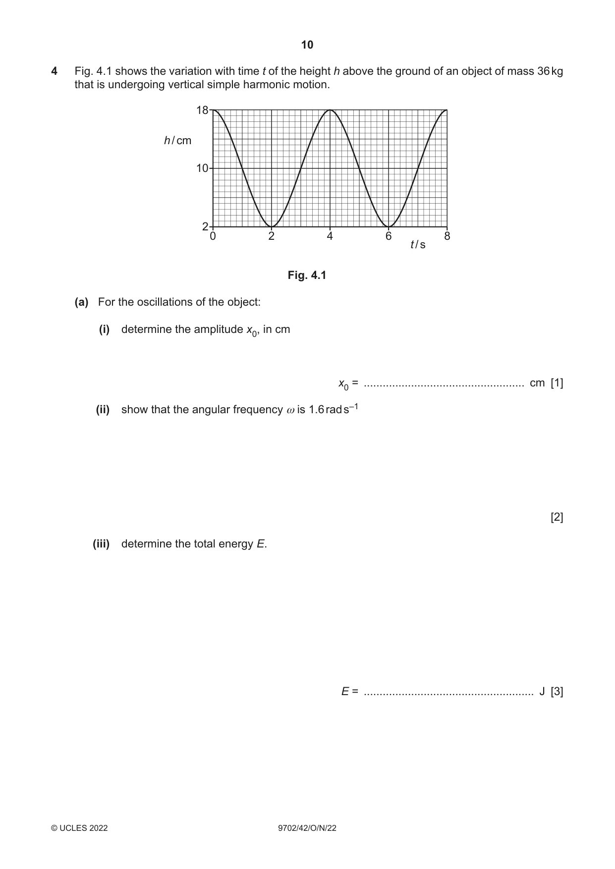
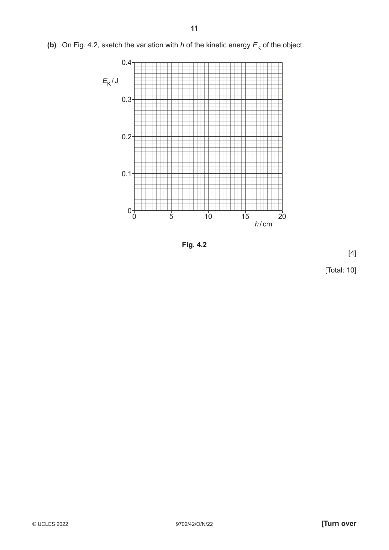
4 Fig. 4.1 shows the variation with time t of the height h above the ground of an object of mass 36 kg that is undergoing vertical simple harmonic motion. 18 h / cm 10 2 0 2 4 6 8 t / s Fig. 4.1 (a) For the oscillations of the object: (i) determine the amplitude x0, in cm x0 = ................................................... cm [1] (ii) show that the angular frequency ω is 1.6 rad s–1 [2] (iii) determine the total energy E. E = ...................................................... J [3] (b) On Fig. 4.2, sketch the variation with h of the kinetic energy EK of the object. 0.4 EK / J 0.3 0.2 0.1 00 5 10 15 20 h / cm Fig. 4.2 [4] [Total: 10]
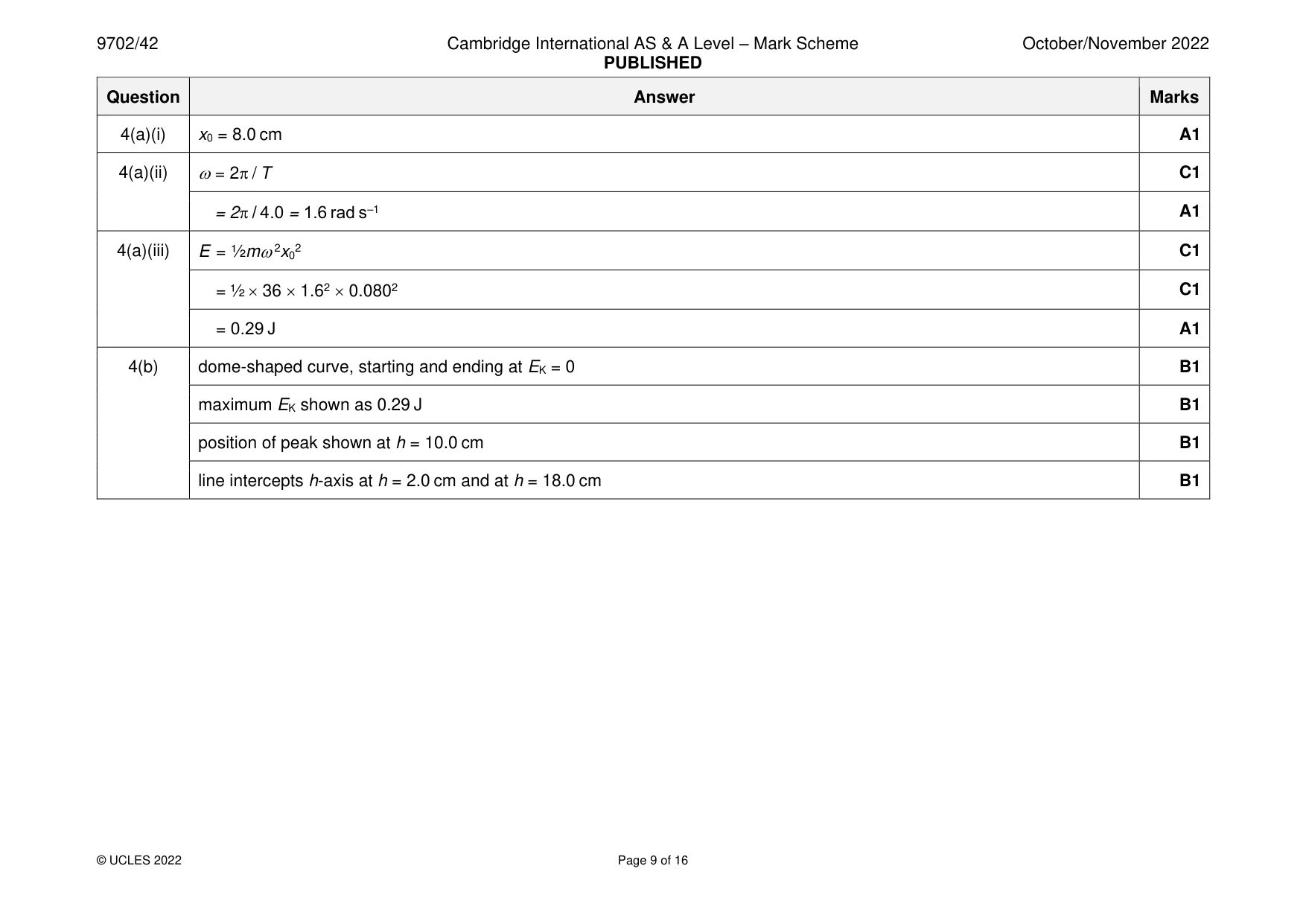
Mark scheme: 4(a)(i) x0 = 8.0 cm A1 4(a)(ii) = 2 / T C1 = 2 / 4.0 = 1.6 rad s–1 A1 4(a)(iii) E = ½m2x02 C1 = ½ 36 1.62 0.0802 C1 = 0.29 J A1 4(b) dome-shaped curve, starting and ending at EK = 0 B1 maximum EK shown as 0.29 J B1 position of peak shown at h = 10.0 cm B1 line intercepts h-axis at h = 2.0 cm and at h = 18.0 cm B1
Q5 · Define electric potential at a point
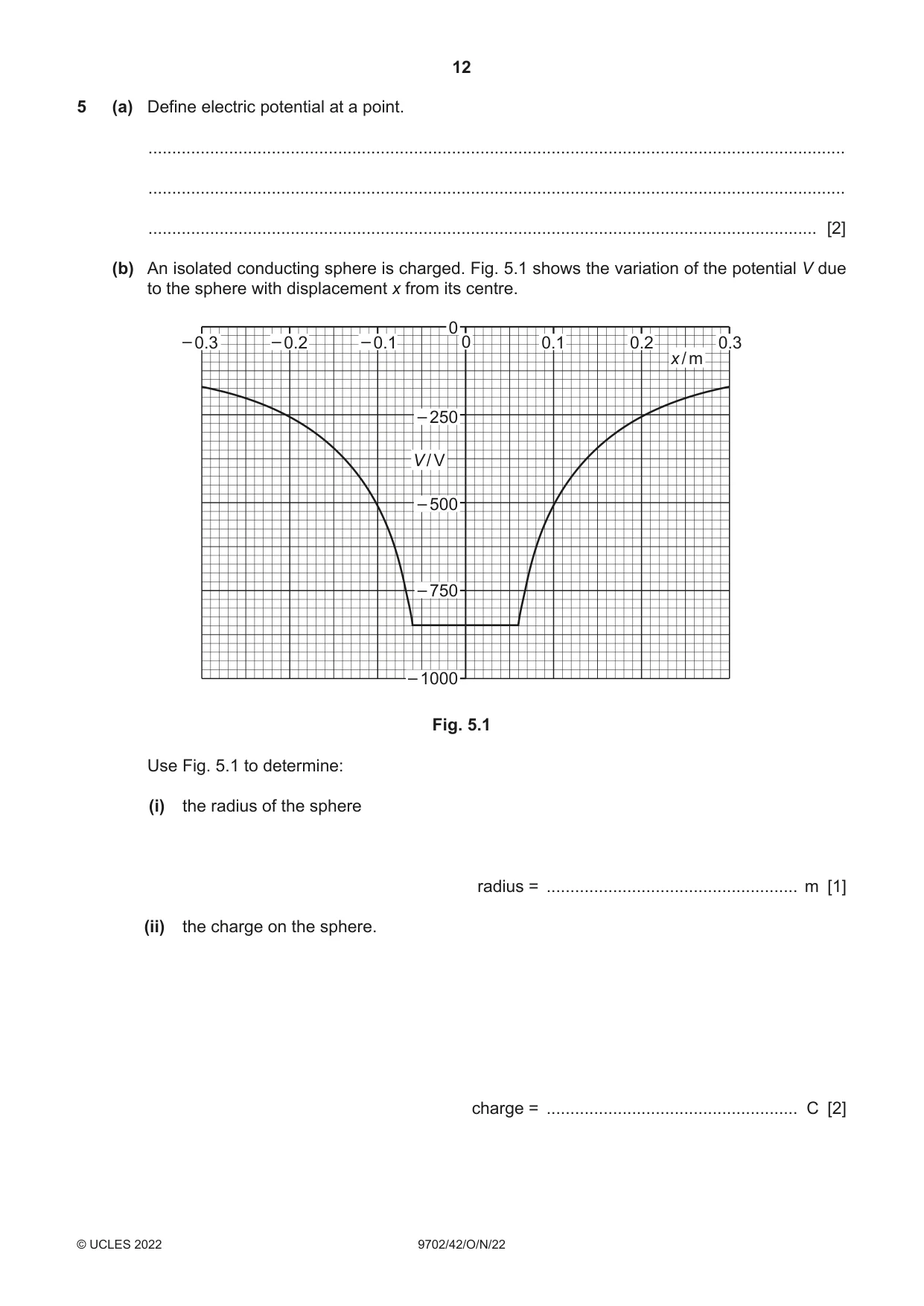
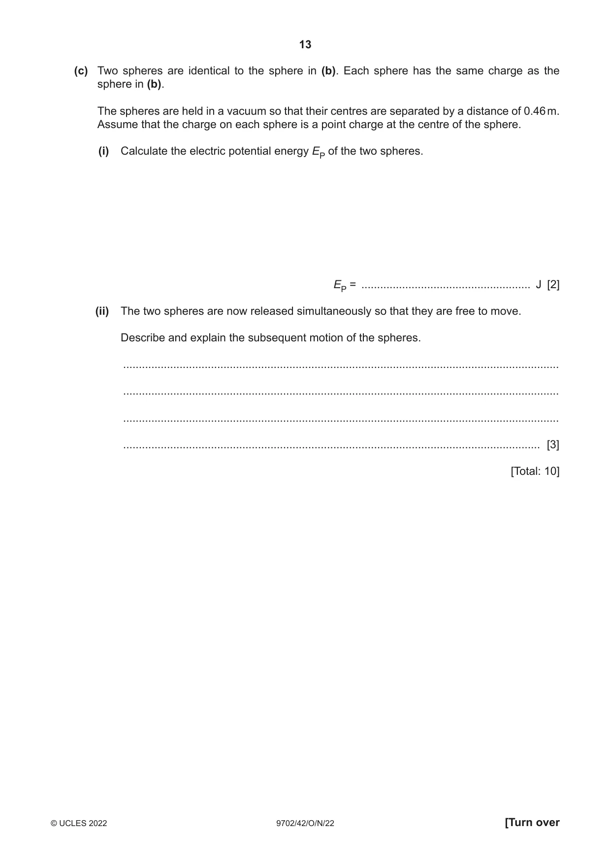
5 (a) Define electric potential at a point. ................................................................................................................................................... ................................................................................................................................................... ............................................................................................................................................. [2] (b) An isolated conducting sphere is charged. Fig. 5.1 shows the variation of the potential V due to the sphere with displacement x from its centre. 0 – 0.3 – 0.2 – 0.1 0 0.1 0.2 0.3 x / m – 250 V / V – 500 – 750 – 1000 Fig. 5.1 Use Fig. 5.1 to determine: (i) the radius of the sphere radius = ..................................................... m [1] (ii) the charge on the sphere. charge = ..................................................... C [2] (c) Two spheres are identical to the sphere in (b). Each sphere has the same charge as the sphere in (b). The spheres are held in a vacuum so that their centres are separated by a distance of 0.46 m. Assume that the charge on each sphere is a point charge at the centre of the sphere. (i) Calculate the electric potential energy EP of the two spheres. EP = ...................................................... J [2] (ii) The two spheres are now released simultaneously so that they are free to move. Describe and explain the subsequent motion of the spheres. ........................................................................................................................................... ........................................................................................................................................... ........................................................................................................................................... ..................................................................................................................................... [3] [Total: 10]
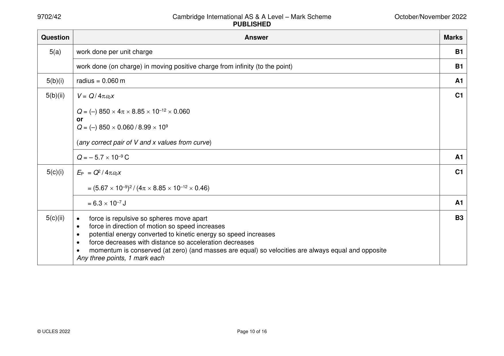
Mark scheme: 5(a) work done per unit charge B1 work done (on charge) in moving positive charge from infinity (to the point) B1 5(b)(i) radius = 0.060 m A1 5(b)(ii) V = Q / 40x C1 Q = (–) 850 4 8.85 10–12 0.060 or Q = (–) 850 0.060 / 8.99 109 (any correct pair of V and x values from curve) Q = – 5.7 10–9 C A1 5(c)(i) EP = Q2 / 40x C1 = (5.67 10–9)2 / (4 8.85 10–12 0.46) = 6.3 10–7 J A1 5(c)(ii) • force is repulsive so spheres move apart B3 • force in direction of motion so speed increases • potential energy converted to kinetic energy so speed increases • force decreases with distance so acceleration decreases • momentum is conserved (at zero) (and masses are equal) so velocities are always equal and opposite Any three points, 1 mark each
Q6 · A capacitor of capacitance C and a resistor of resistance R are connected as shown in Fig
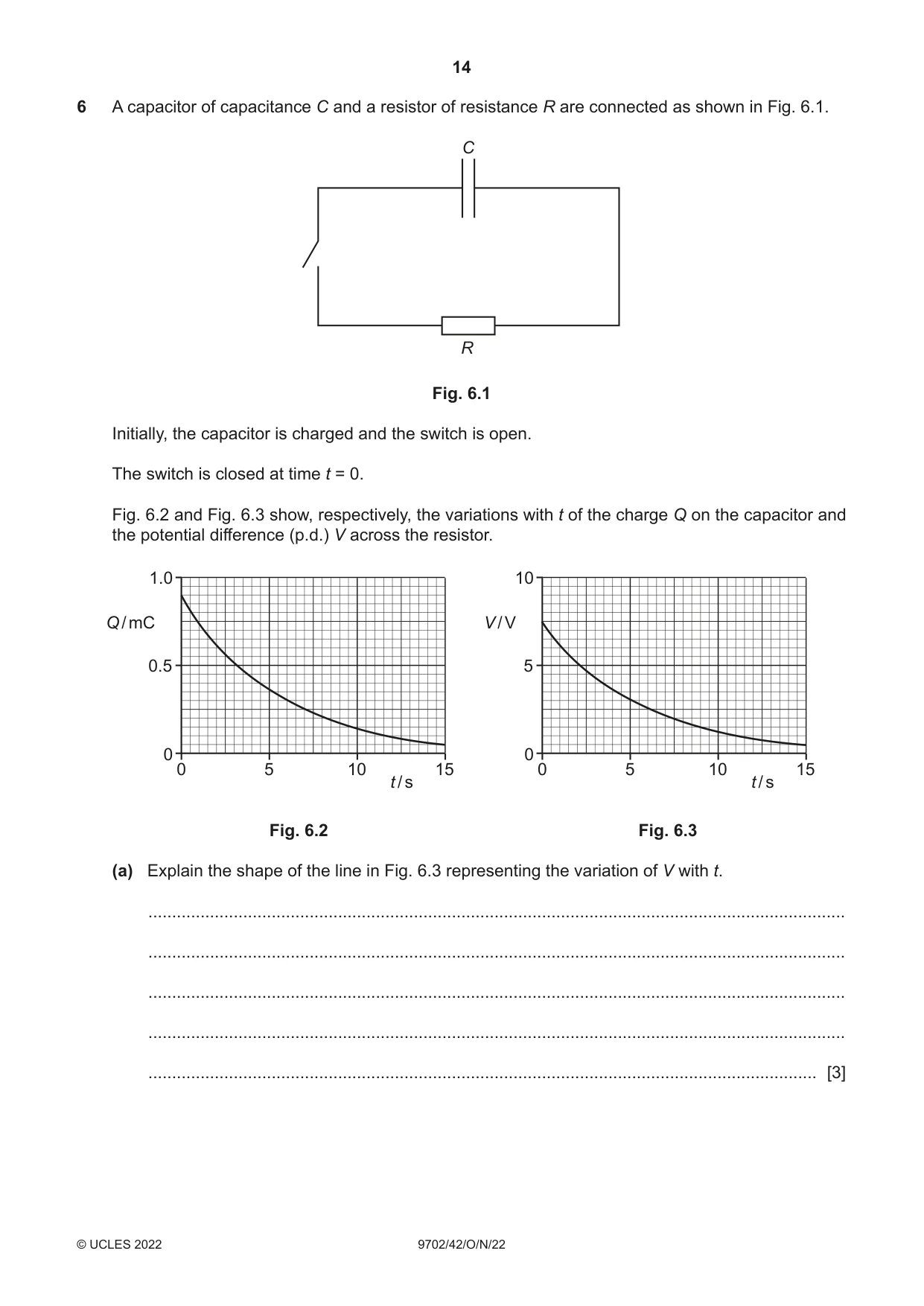
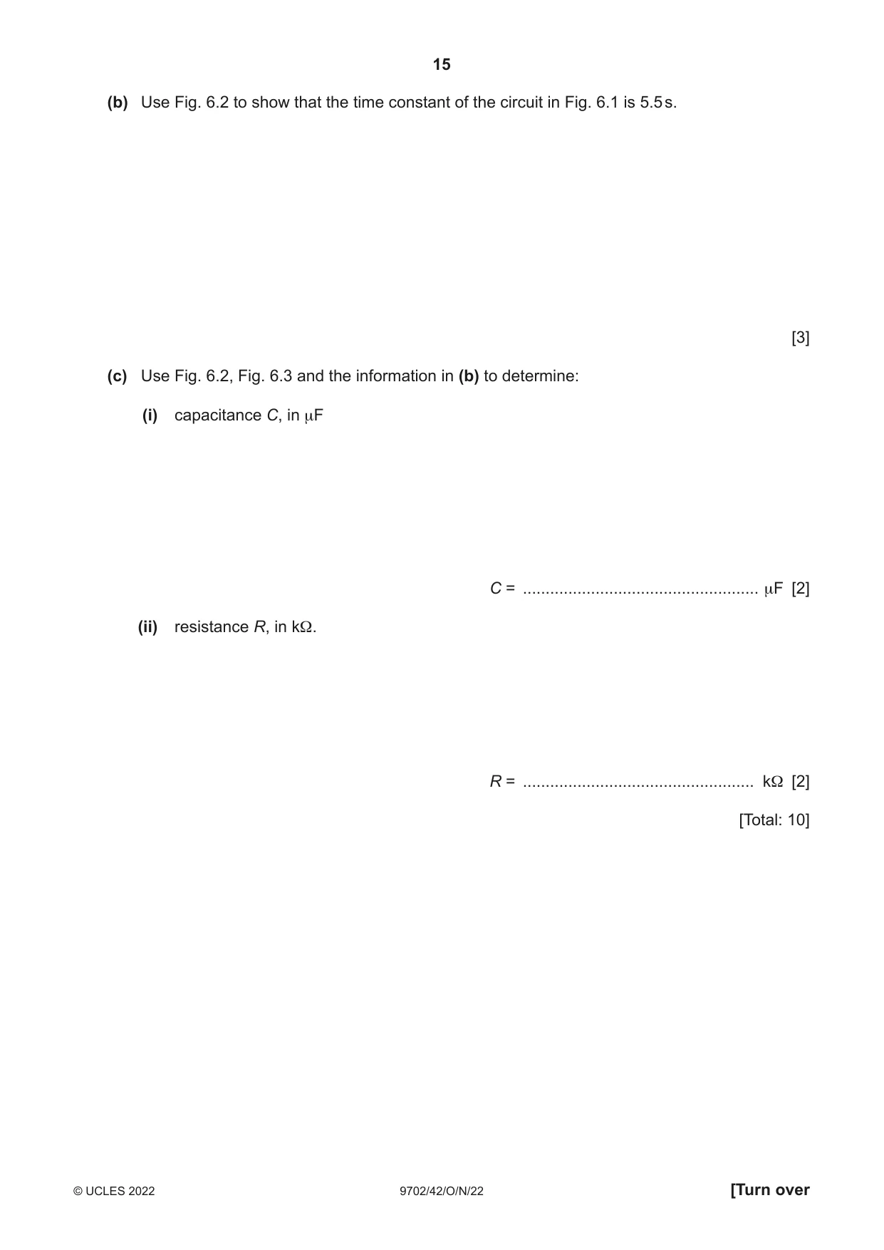
6 A capacitor of capacitance C and a resistor of resistance R are connected as shown in Fig. 6.1. C R Fig. 6.1 Initially, the capacitor is charged and the switch is open. The switch is closed at time t = 0. Fig. 6.2 and Fig. 6.3 show, respectively, the variations with t of the charge Q on the capacitor and the potential difference (p.d.) V across the resistor. 1.0 10 Q / mC V / V 0.5 5 0 0 0 5 10 15 0 5 10 15 t / s t / s Fig. 6.2 Fig. 6.3 (a) Explain the shape of the line in Fig. 6.3 representing the variation of V with t. ................................................................................................................................................... ................................................................................................................................................... ................................................................................................................................................... ................................................................................................................................................... ............................................................................................................................................. [3] (b) Use Fig. 6.2 to show that the time constant of the circuit in Fig. 6.1 is 5.5 s. [3] (c) Use Fig. 6.2, Fig. 6.3 and the information in (b) to determine: (i) capacitance C, in μF C = .................................................... μF [2] (ii) resistance R, in kΩ. R = ................................................... kΩ [2] [Total: 10]
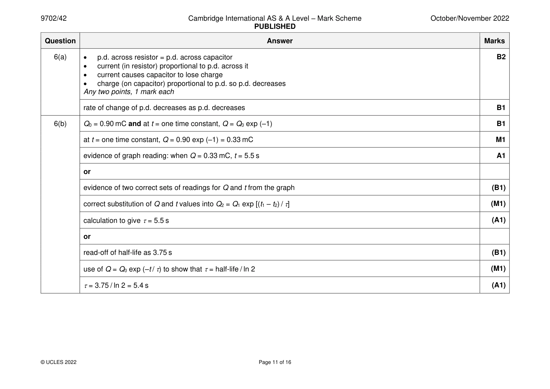
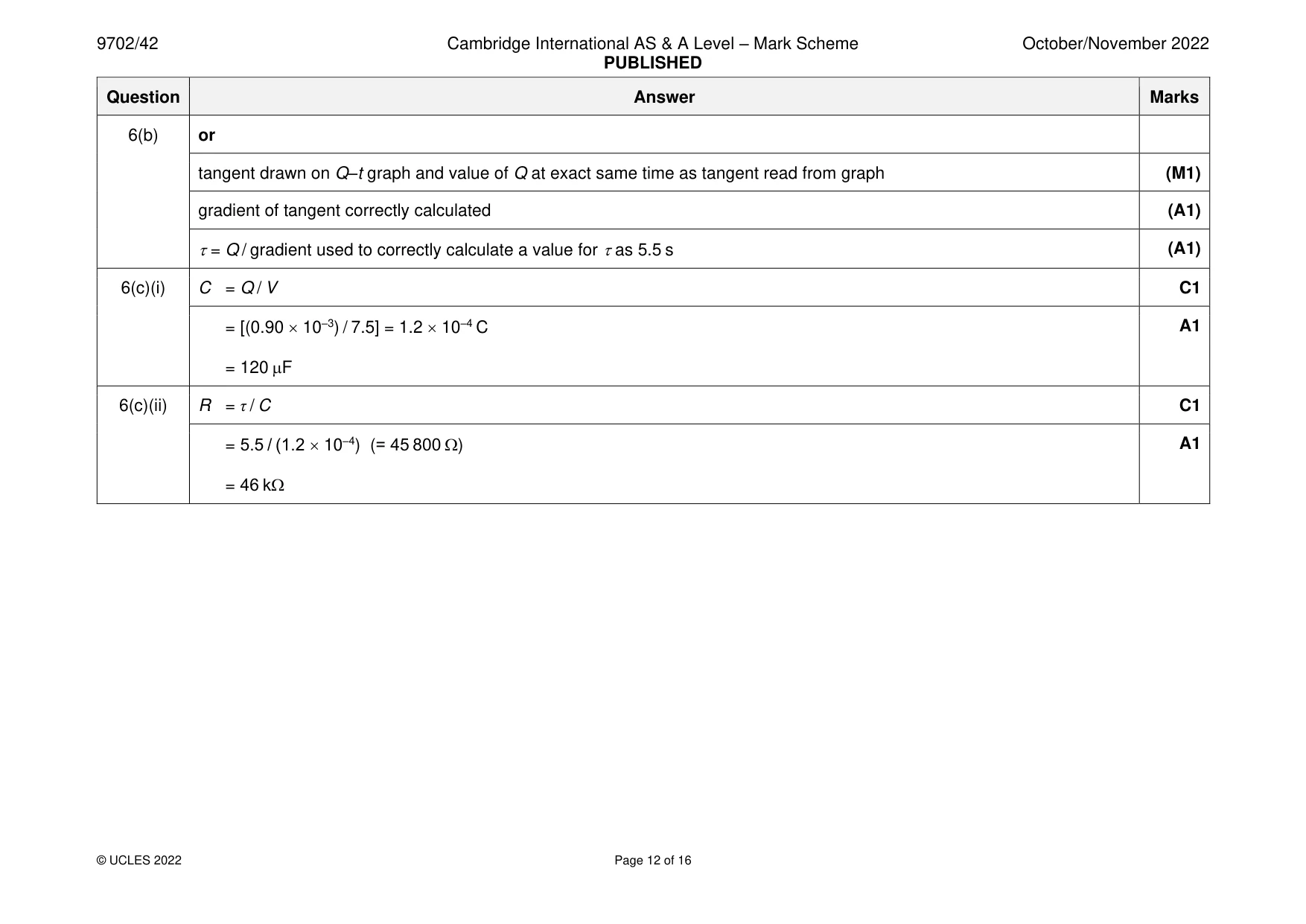
Mark scheme: 6(a) • p.d. across resistor = p.d. across capacitor B2 • current (in resistor) proportional to p.d. across it • current causes capacitor to lose charge • charge (on capacitor) proportional to p.d. so p.d. decreases Any two points, 1 mark each rate of change of p.d. decreases as p.d. decreases B1 6(b) Q0 = 0.90 mC and at t = one time constant, Q = Q0 exp (–1) B1 at t = one time constant, Q = 0.90 exp (–1) = 0.33 mC M1 evidence of graph reading: when Q = 0.33 mC, t = 5.5 s A1 or evidence of two correct sets of readings for Q and t from the graph (B1) correct substitution of Q and t values into Q2 = Q1 exp [(t1 – t2) / ] (M1) calculation to give = 5.5 s (A1) or read-off of half-life as 3.75 s (B1) use of Q = Q0 exp (–t / ) to show that = half-life / ln 2 (M1) = 3.75 / ln 2 = 5.4 s (A1) 6(b) or tangent drawn on Q–t graph and value of Q at exact same time as tangent read from graph (M1) gradient of tangent correctly calculated (A1) = Q / gradient used to correctly calculate a value for as 5.5 s (A1) 6(c)(i) C = Q / V C1 = [(0.90 10–3) / 7.5] = 1.2 10–4 C A1 = 120 F 6(c)(ii) R = τ / C C1 = 5.5 / (1.2 10–4) (= 45 800 ) A1 = 46 k
Q7 · Define magnetic flux density
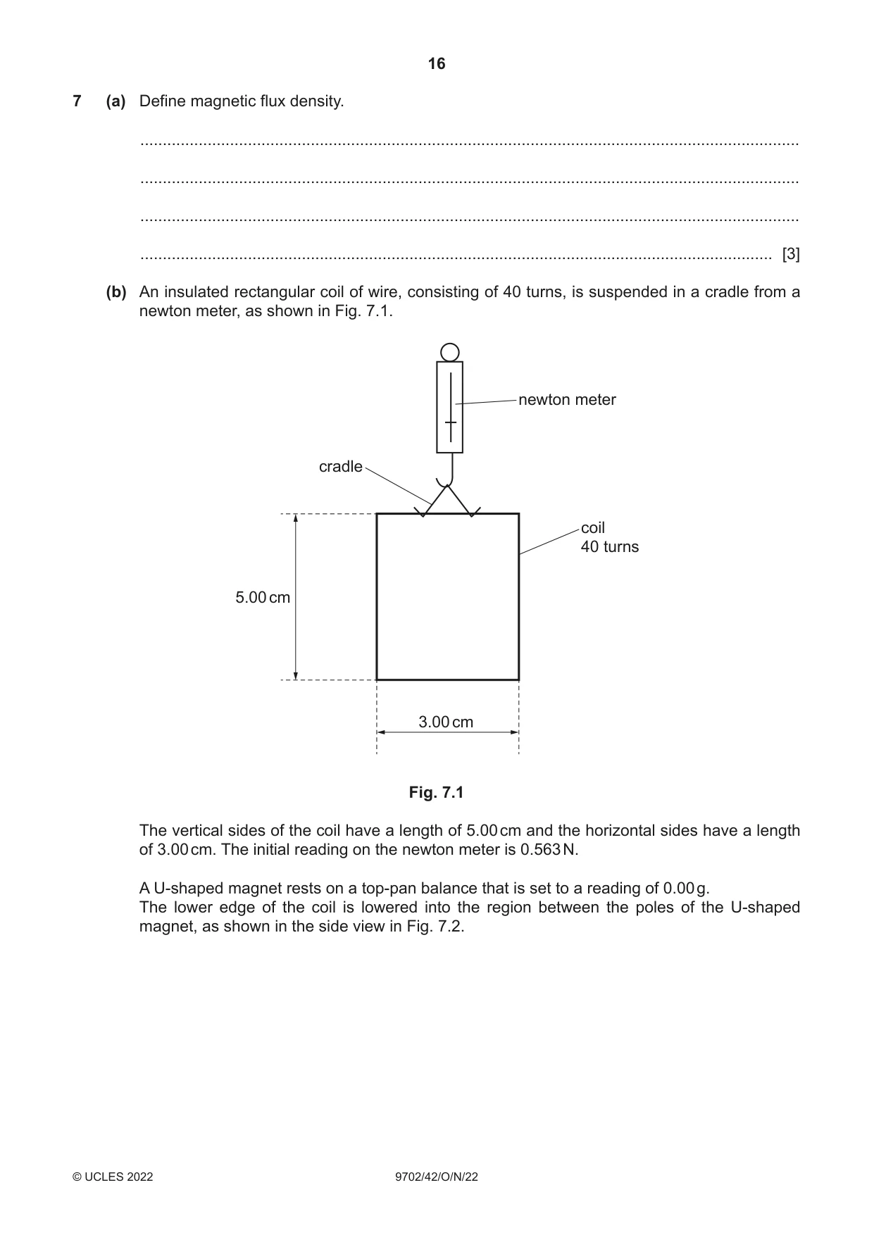
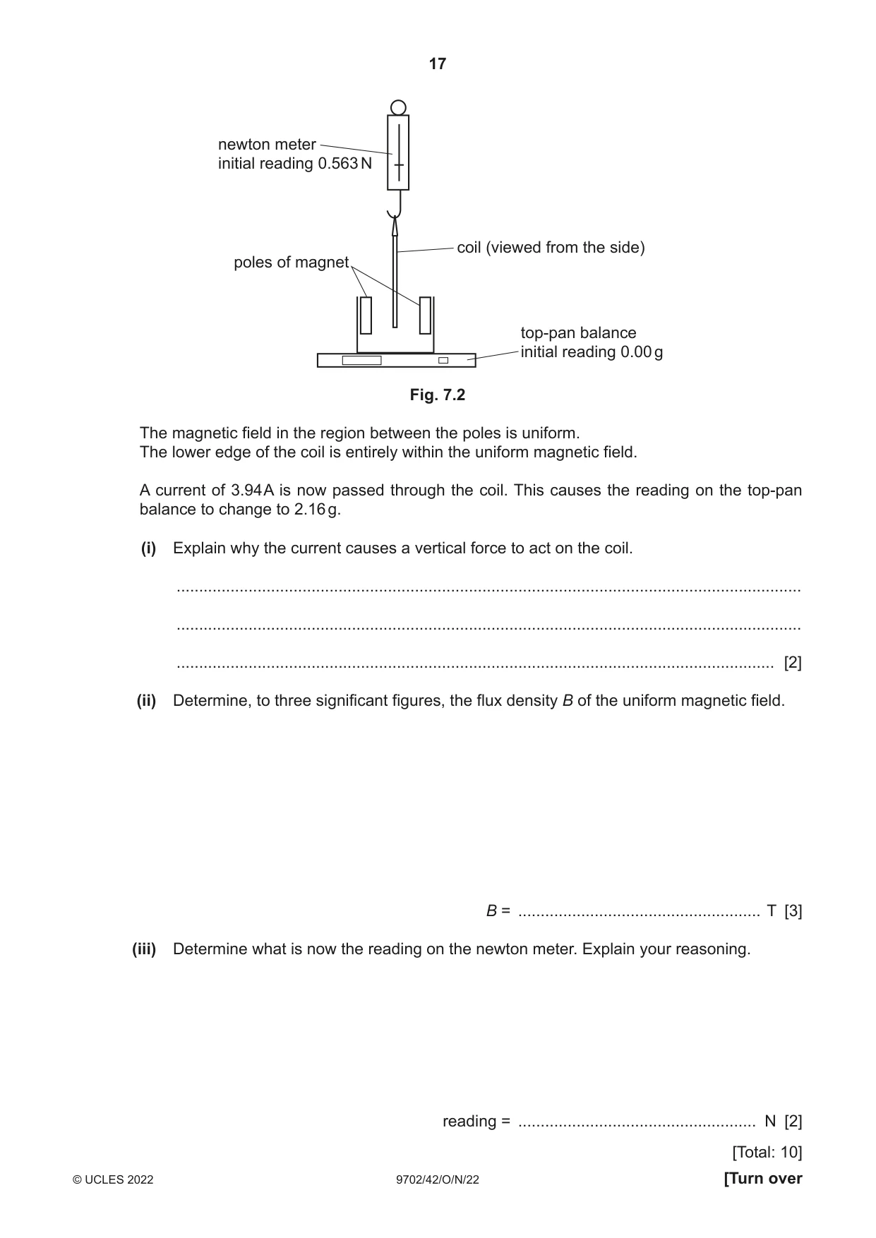
7 (a) Define magnetic flux density. ................................................................................................................................................... ................................................................................................................................................... ................................................................................................................................................... ............................................................................................................................................. [3] (b) An insulated rectangular coil of wire, consisting of 40 turns, is suspended in a cradle from a newton meter, as shown in Fig. 7.1. newton meter cradle coil 40 turns 5.00 cm 3.00 cm Fig. 7.1 The vertical sides of the coil have a length of 5.00 cm and the horizontal sides have a length of 3.00 cm. The initial reading on the newton meter is 0.563 N. A U-shaped magnet rests on a top-pan balance that is set to a reading of 0.00 g. The lower edge of the coil is lowered into the region between the poles of the U-shaped magnet, as shown in the side view in Fig. 7.2. newton meter initial reading 0.563 N coil (viewed from the side) poles of magnet top-pan balance initial reading 0.00 g Fig. 7.2 The magnetic field in the region between the poles is uniform. The lower edge of the coil is entirely within the uniform magnetic field. A current of 3.94 A is now passed through the coil. This causes the reading on the top-pan balance to change to 2.16 g. (i) Explain why the current causes a vertical force to act on the coil. ........................................................................................................................................... ........................................................................................................................................... ..................................................................................................................................... [2] (ii) Determine, to three significant figures, the flux density B of the uniform magnetic field. B = ...................................................... T [3] (iii) Determine what is now the reading on the newton meter. Explain your reasoning. reading = ..................................................... N [2] [Total: 10]
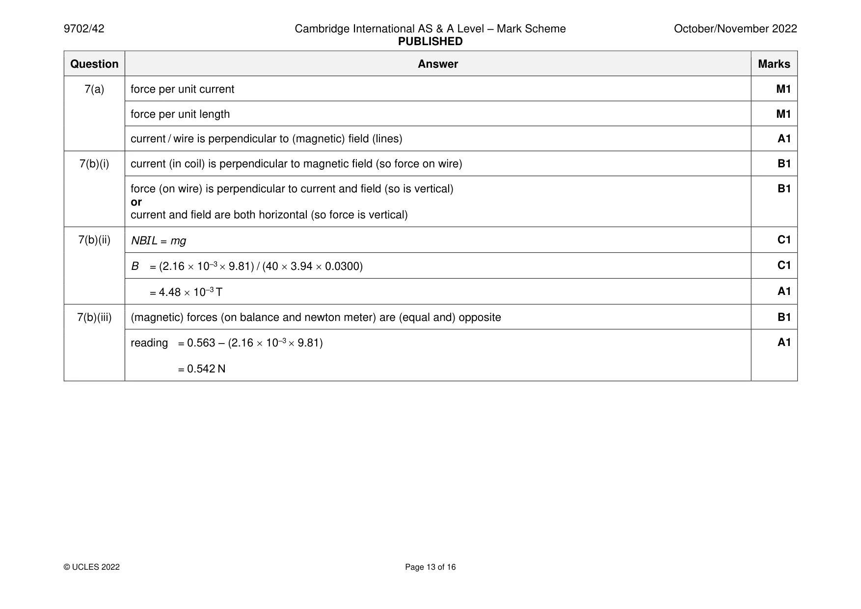
Mark scheme: 7(a) force per unit current M1 force per unit length M1 current / wire is perpendicular to (magnetic) field (lines) A1 7(b)(i) current (in coil) is perpendicular to magnetic field (so force on wire) B1 force (on wire) is perpendicular to current and field (so is vertical) B1 or current and field are both horizontal (so force is vertical) 7(b)(ii) NBIL = mg C1 B = (2.16 10–3 9.81) / (40 3.94 0.0300) C1 = 4.48 10–3 T A1 7(b)(iii) (magnetic) forces (on balance and newton meter) are (equal and) opposite B1 reading = 0.563 – (2.16 10–3 9.81) A1 = 0.542 N
Q8 · State Lenz’s law of electromagnetic induction
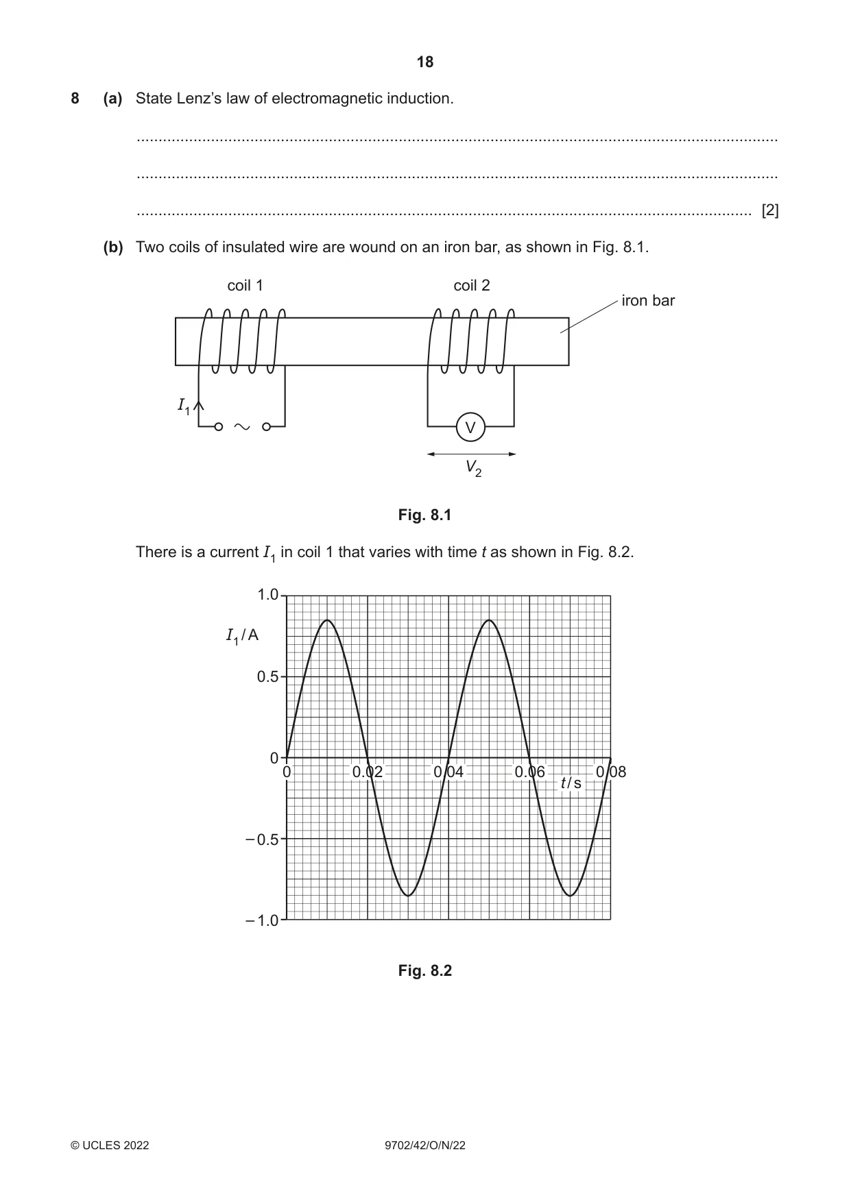
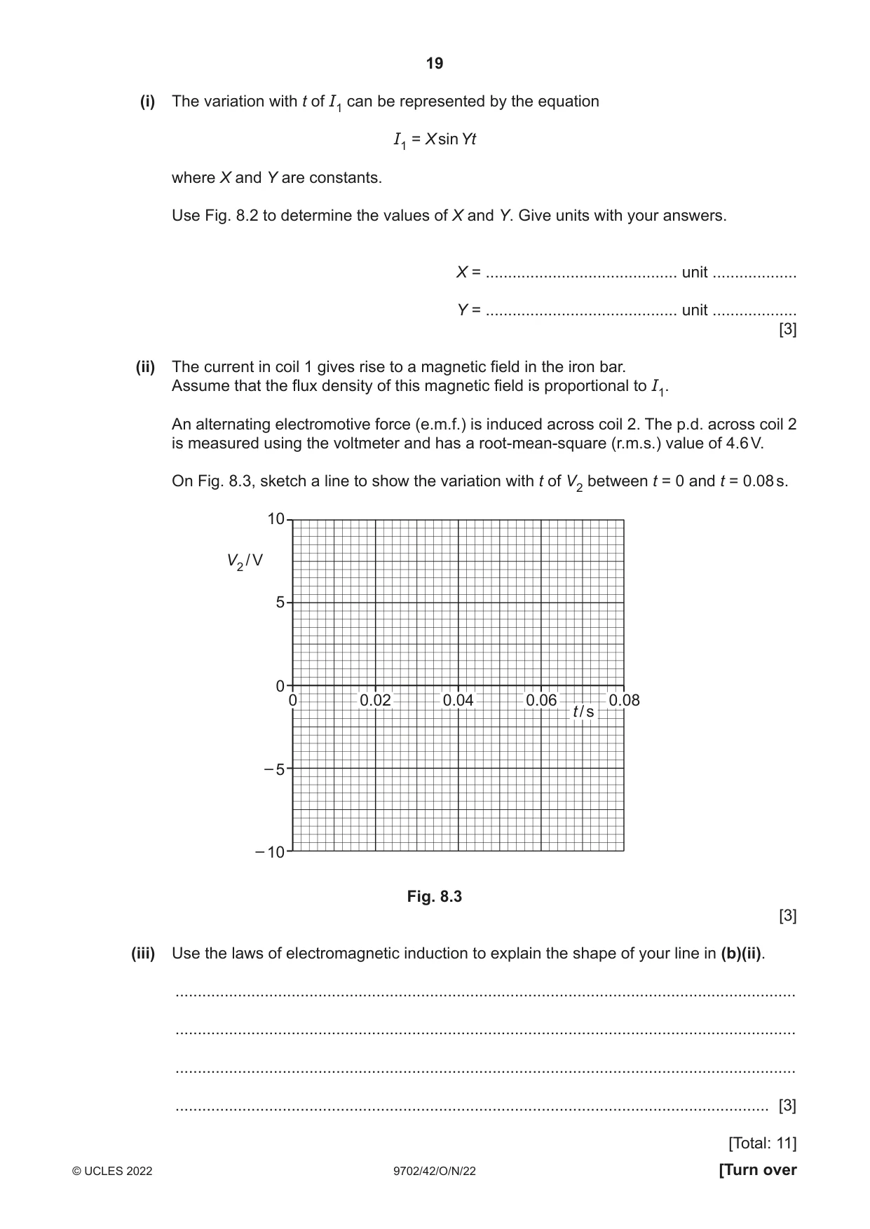
8 (a) State Lenz’s law of electromagnetic induction. ................................................................................................................................................... ................................................................................................................................................... ............................................................................................................................................. [2] (b) Two coils of insulated wire are wound on an iron bar, as shown in Fig. 8.1. coil 1 coil 2 iron bar I1 V V2 Fig. 8.1 There is a current I1 in coil 1 that varies with time t as shown in Fig. 8.2. 1.0 I1 / A 0.5 0 0 0.02 0.04 0.06 0.08 t / s – 0.5 – 1.0 Fig. 8.2 (i) The variation with t of I1 can be represented by the equation I1 = X sin Yt where X and Y are constants. Use Fig. 8.2 to determine the values of X and Y. Give units with your answers. X = ........................................... unit ................... Y = ........................................... unit ................... [3] (ii) The current in coil 1 gives rise to a magnetic field in the iron bar. Assume that the flux density of this magnetic field is proportional to I1. An alternating electromotive force (e.m.f.) is induced across coil 2. The p.d. across coil 2 is measured using the voltmeter and has a root-mean-square (r.m.s.) value of 4.6 V. On Fig. 8.3, sketch a line to show the variation with t of V2 between t = 0 and t = 0.08 s. 10 V2 / V 5 0 0 0.02 0.04 0.06 0.08 t / s – 5 – 10 Fig. 8.3 [3] (iii) Use the laws of electromagnetic induction to explain the shape of your line in (b)(ii). ........................................................................................................................................... ........................................................................................................................................... ........................................................................................................................................... ..................................................................................................................................... [3] [Total: 11]
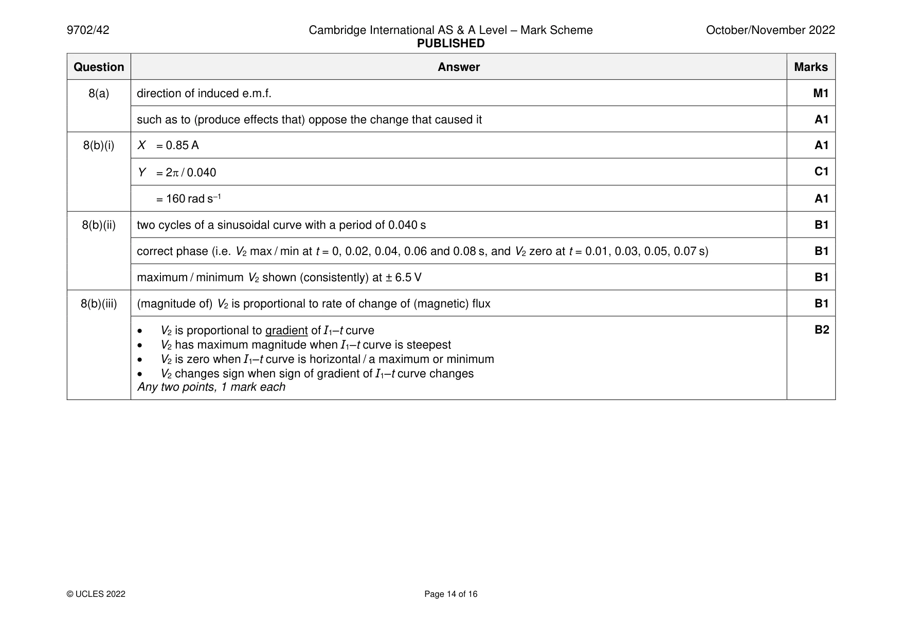
Mark scheme: 8(a) direction of induced e.m.f. M1 such as to (produce effects that) oppose the change that caused it A1 8(b)(i) X = 0.85 A A1 Y = 2 / 0.040 C1 = 160 rad s–1 A1 8(b)(ii) two cycles of a sinusoidal curve with a period of 0.040 s B1 correct phase (i.e. V2 max / min at t = 0, 0.02, 0.04, 0.06 and 0.08 s, and V2 zero at t = 0.01, 0.03, 0.05, 0.07 s) B1 maximum / minimum V2 shown (consistently) at ± 6.5 V B1 8(b)(iii) (magnitude of) V2 is proportional to rate of change of (magnetic) flux B1 • V2 is proportional to gradient of I1–t curve B2 • V2 has maximum magnitude when I1–t curve is steepest • V2 is zero when I1–t curve is horizontal / a maximum or minimum • V2 changes sign when sign of gradient of I1–t curve changes Any two points, 1 mark each
Q9 · The visible part of the emission spectrum from hydrogen gas in a laboratory on the Earth
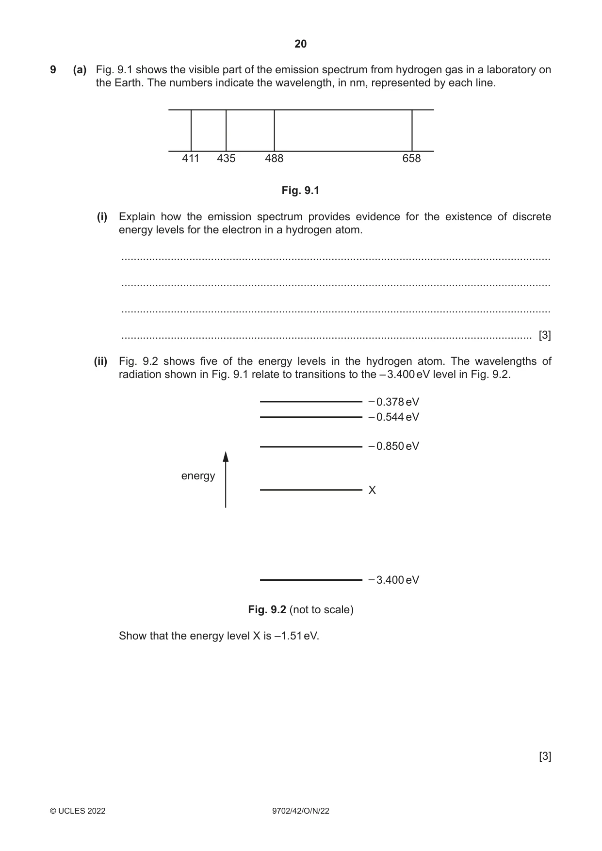
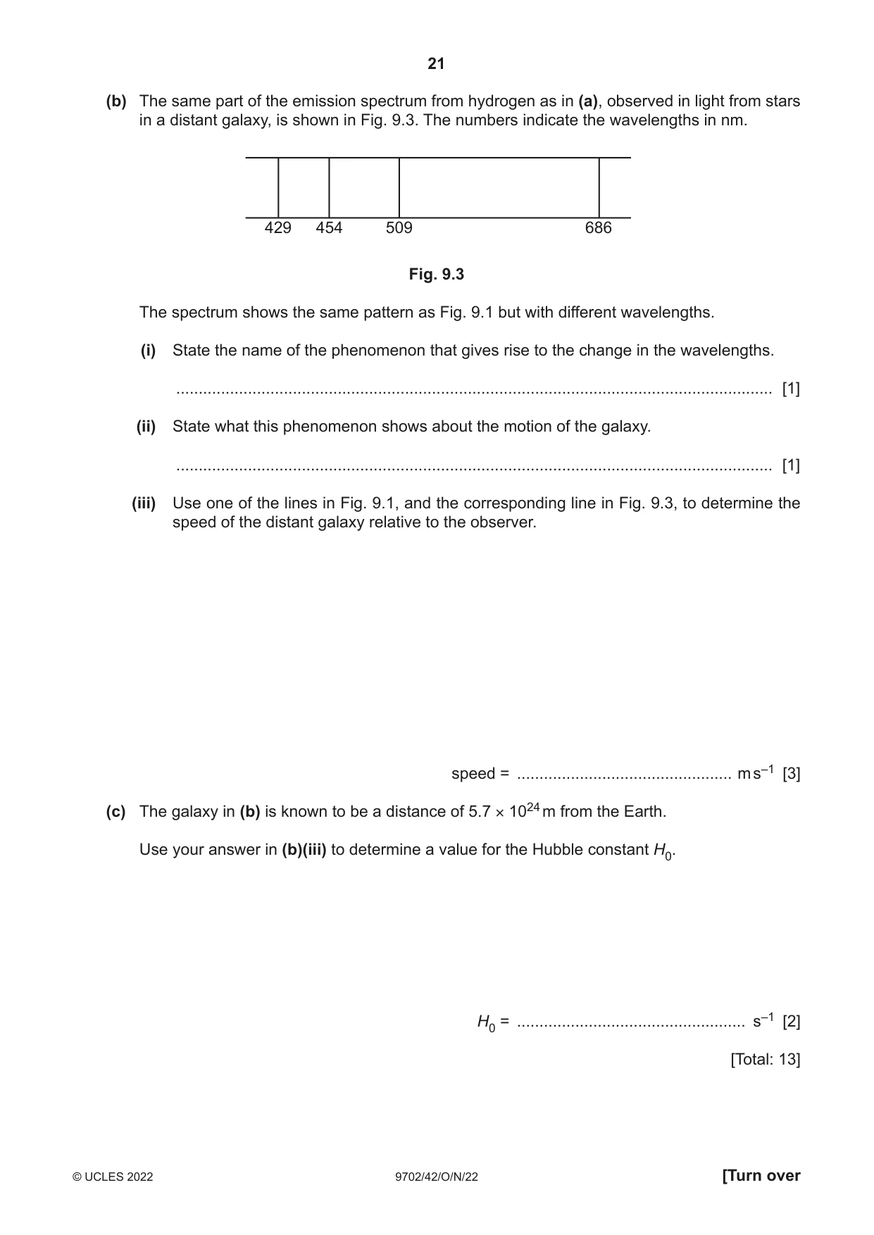
9 (a) Fig. 9.1 shows the visible part of the emission spectrum from hydrogen gas in a laboratory on the Earth. The numbers indicate the wavelength, in nm, represented by each line. 411 435 488 658 Fig. 9.1 (i) Explain how the emission spectrum provides evidence for the existence of discrete energy levels for the electron in a hydrogen atom. ........................................................................................................................................... ........................................................................................................................................... ........................................................................................................................................... ..................................................................................................................................... [3] (ii) Fig. 9.2 shows five of the energy levels in the hydrogen atom. The wavelengths of radiation shown in Fig. 9.1 relate to transitions to the – 3.400 eV level in Fig. 9.2. – 0.378 eV – 0.544 eV – 0.850 eV energy X – 3.400 eV Fig. 9.2 (not to scale) Show that the energy level X is –1.51 eV. [3] (b) The same part of the emission spectrum from hydrogen as in (a), observed in light from stars in a distant galaxy, is shown in Fig. 9.3. The numbers indicate the wavelengths in nm. 429 454 509 686 Fig. 9.3 The spectrum shows the same pattern as Fig. 9.1 but with different wavelengths. (i) State the name of the phenomenon that gives rise to the change in the wavelengths. ..................................................................................................................................... [1] (ii) State what this phenomenon shows about the motion of the galaxy. ..................................................................................................................................... [1] (iii) Use one of the lines in Fig. 9.1, and the corresponding line in Fig. 9.3, to determine the speed of the distant galaxy relative to the observer. speed = ................................................ m s–1 [3] (c) The galaxy in (b) is known to be a distance of 5.7 × 1024 m from the Earth. Use your answer in (b)(iii) to determine a value for the Hubble constant H0. H0 = ................................................... s–1 [2] [Total: 13]
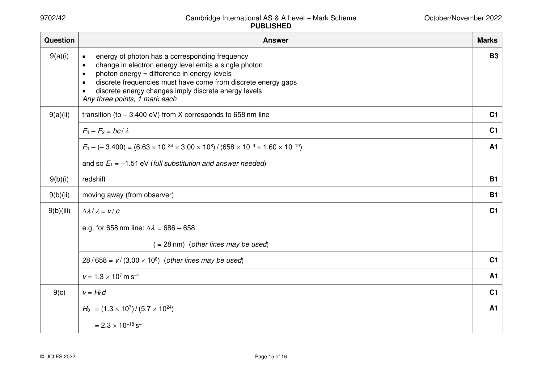
Mark scheme: 9(a)(i) • energy of photon has a corresponding frequency B3 • change in electron energy level emits a single photon • photon energy = difference in energy levels • discrete frequencies must have come from discrete energy gaps • discrete energy changes imply discrete energy levels Any three points, 1 mark each 9(a)(ii) transition (to – 3.400 eV) from X corresponds to 658 nm line C1 E1 – E2 = hc / C1 E1 – (– 3.400) = (6.63 10–34 3.00 108) / (658 10–9 1.60 10–19) A1 and so E1 = –1.51 eV (full substitution and answer needed) 9(b)(i) redshift B1 9(b)(ii) moving away (from observer) B1 9(b)(iii) / = v / c C1 e.g. for 658 nm line: = 686 – 658 ( = 28 nm) (other lines may be used) 28 / 658 = v / (3.00 108) (other lines may be used) C1 v = 1.3 107 m s–1 A1 9(c) v = H0d C1 H0 = (1.3 107) / (5.7 1024) A1 = 2.3 10–18 s–1
Q10 · Positron emission tomography (PET scanning) involves the detection of gamma-radiation in…
10 Positron emission tomography (PET scanning) involves the detection of gamma-radiation in order to identify the position of origin of positrons in the body. (a) (i) Positrons are not naturally present in the body. Explain how positrons come to be present in the body during PET scanning. ........................................................................................................................................... ........................................................................................................................................... ..................................................................................................................................... [2] (ii) Explain how positrons cause the emission of gamma-radiation from the body during PET scanning. ........................................................................................................................................... ........................................................................................................................................... ........................................................................................................................................... ..................................................................................................................................... [3] (b) Show that the wavelength of the gamma-radiation that is detected during PET scanning is approximately 2.4 pm. Explain your reasoning. [4] [Total: 9]
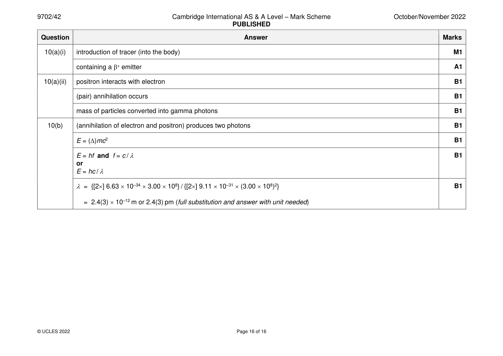
Mark scheme: 10(a)(i) introduction of tracer (into the body) M1 containing a + emitter A1 10(a)(ii) positron interacts with electron B1 (pair) annihilation occurs B1 mass of particles converted into gamma photons B1 10(b) (annihilation of electron and positron) produces two photons B1 E = ()mc2 B1 E = hf and f = c / B1 or E = hc / = {[2] 6.63 10–34 3.00 108} / {[2] 9.11 10–31 (3.00 108)2} B1 = 2.4(3) 10–12 m or 2.4(3) pm (full substitution and answer with unit needed)
What was in this paper
The subtopics covered by these 10 questions, and how many questions each got. Open one in a new tab to see every Cambridge question on it.
What you needed in this session
Cambridge’s own grade thresholds for 2022 Oct/Nov, Paper 4 · Variant 2. A higher threshold means an easier paper — the bar moves with how the cohort did.