Cambridge A Level Physics 9702 — 2020 Oct/Nov Paper 4 · Variant 1
9702/41/O/N/20 · 12 questions · 100 marks · ≈113 min
The question paper and its mark scheme, free to read here and free to download. This is Cambridge’s own paper, exactly as it was sat.
Question paper24 pages
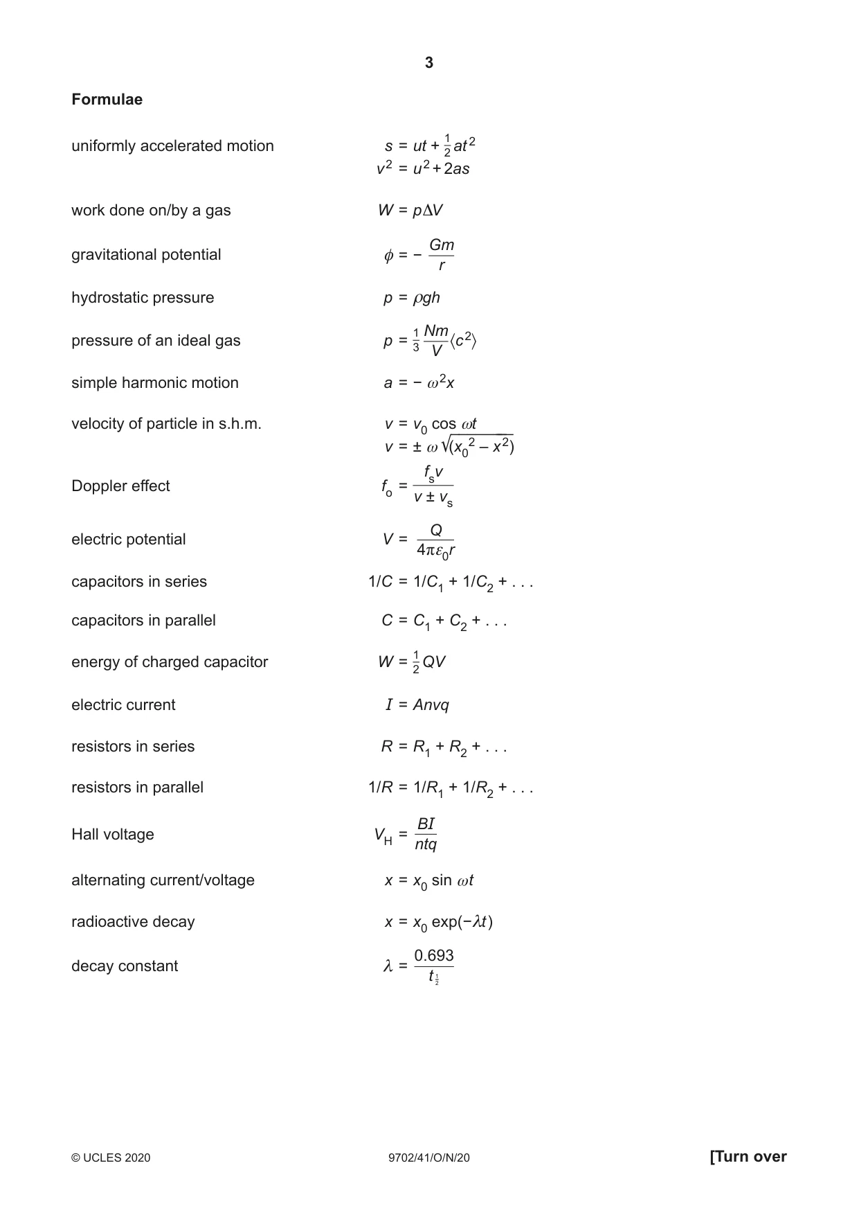



Mark scheme18 pages
Answers below. Sit the paper first if you are practising.

Questions as text
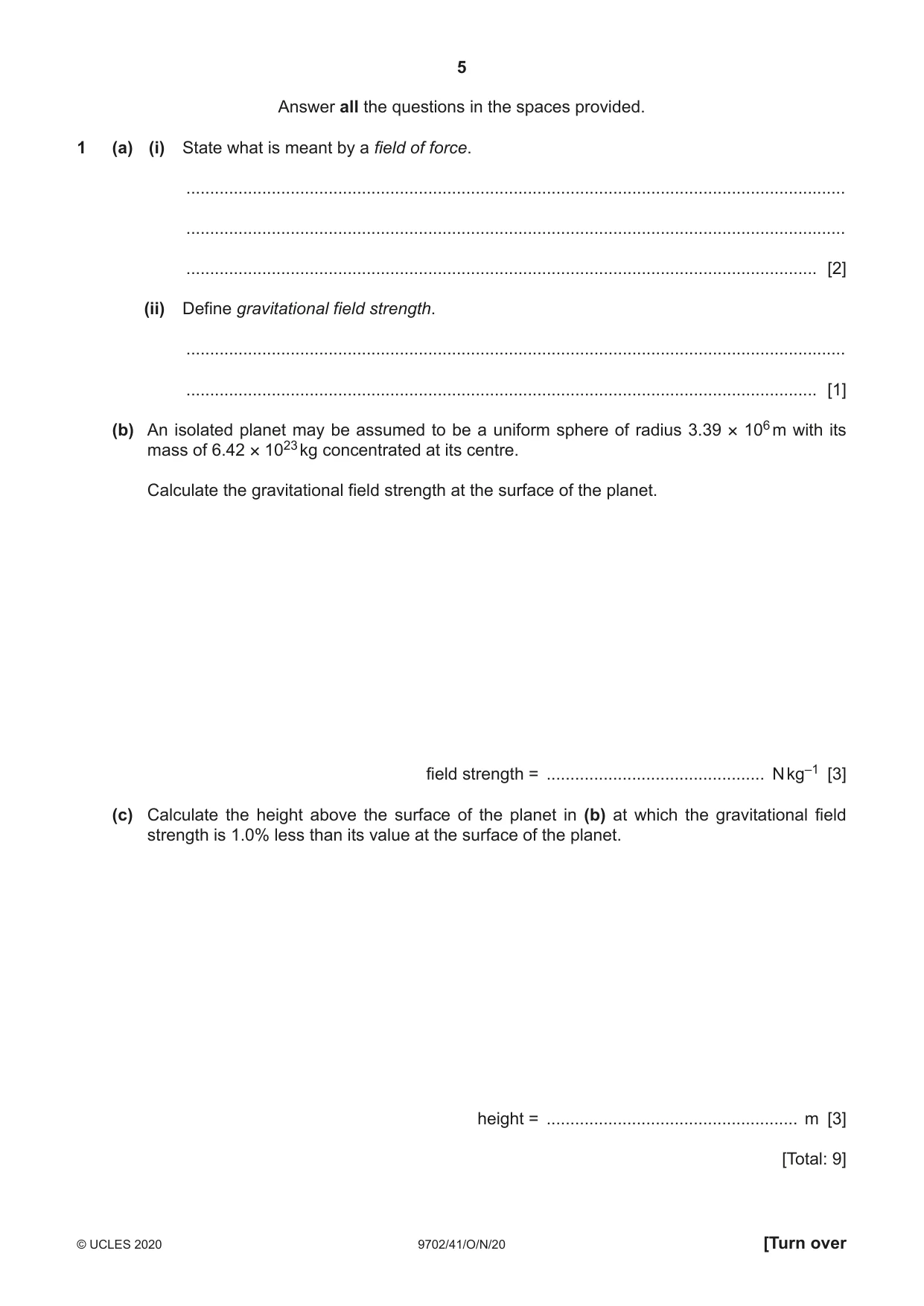
Q1 · State what is meant by a field of force
1 (a) (i) State what is meant by a field of force. ........................................................................................................................................... ........................................................................................................................................... ..................................................................................................................................... [2] (ii) Define gravitational field strength. ........................................................................................................................................... ..................................................................................................................................... [1] (b) An isolated planet may be assumed to be a uniform sphere of radius 3.39 × 10⁶ m with its mass of 6.42 × 10²³ kg concentrated at its centre. Calculate the gravitational field strength at the surface of the planet. field strength = .............................................. N kg–1 [3] (c) Calculate the height above the surface of the planet in (b) at which the gravitational field strength is 1.0% less than its value at the surface of the planet. height = ..................................................... m [3] [Total: 9]
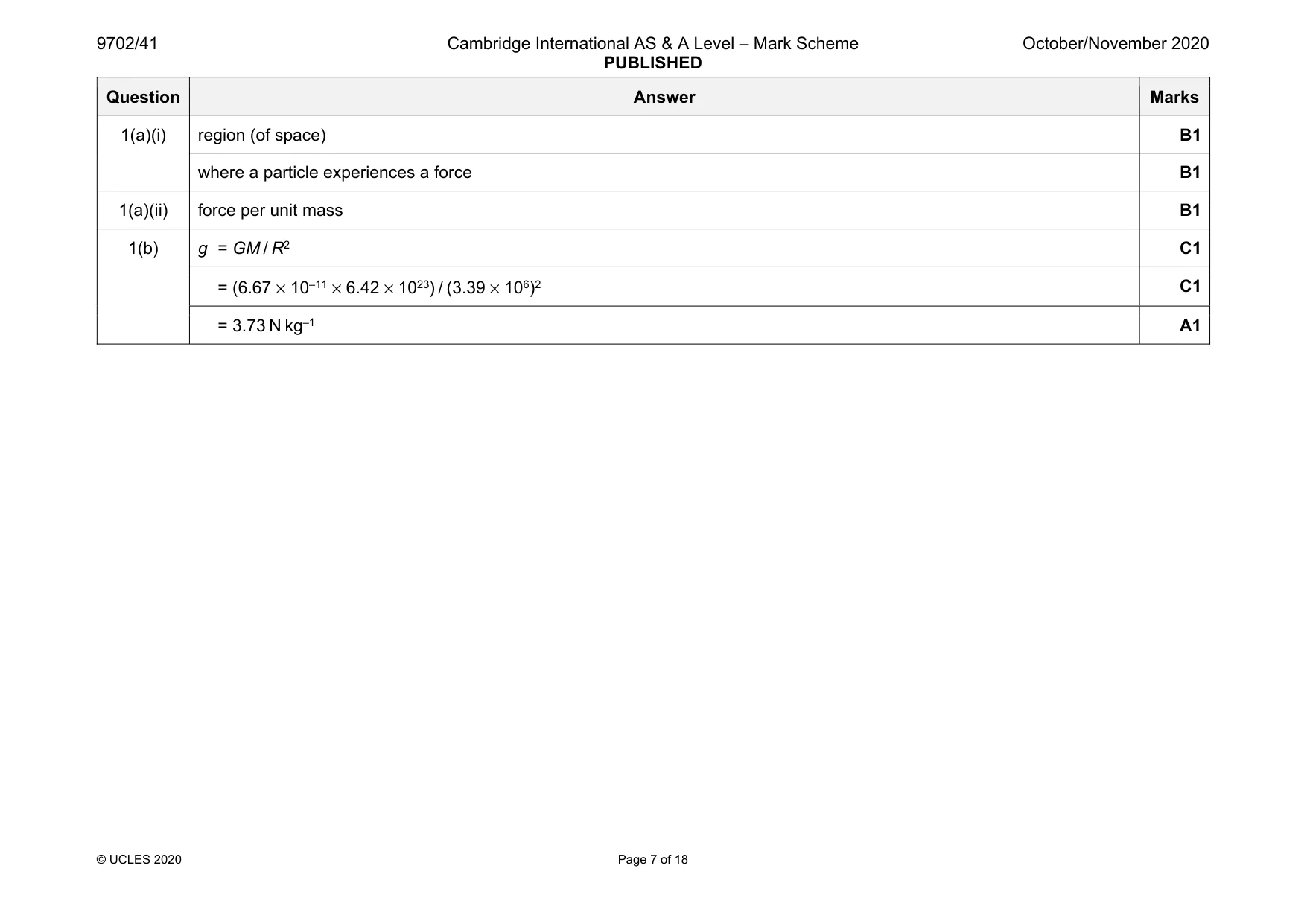
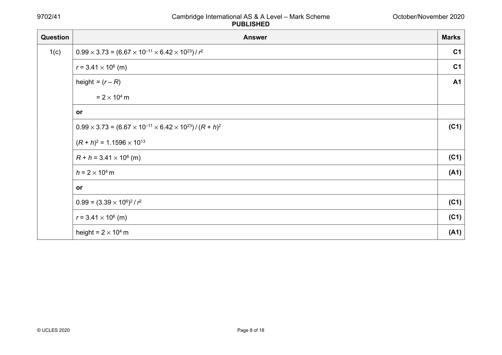
Mark scheme: 1(a)(i) region (of space) B1 where a particle experiences a force B1 1(a)(ii) force per unit mass B1 1(b) g = GM / R2 C1 = (6.67 × 10–11 × 6.42 × 1023) / (3.39 × 10⁶)2 C1 = 3.73 N kg–1 A1 Question Answer Marks 1(c) 0.99 × 3.73 = (6.67 × 10–11 × 6.42 × 1023) / r2 C1 r = 3.41 × 10⁶ (m) C1 height = (r – R) = 2 × 10⁴ m A1 or 0.99 × 3.73 = (6.67 × 10–11 × 6.42 × 1023) / (R + h)2 (R + h)2 = 1.1596 × 10¹³ (C1) R + h = 3.41 × 10⁶ (m) (C1) h = 2 × 10⁴ m (A1) or 0.99 = (3.39 × 10⁶)2 / r2 (C1) r = 3.41 × 10⁶ (m) (C1) height = 2 × 10⁴ m (A1)
Q2 · The first law of thermodynamics may be expressed as ΔU = (+q) + (+w) where ΔU is the…
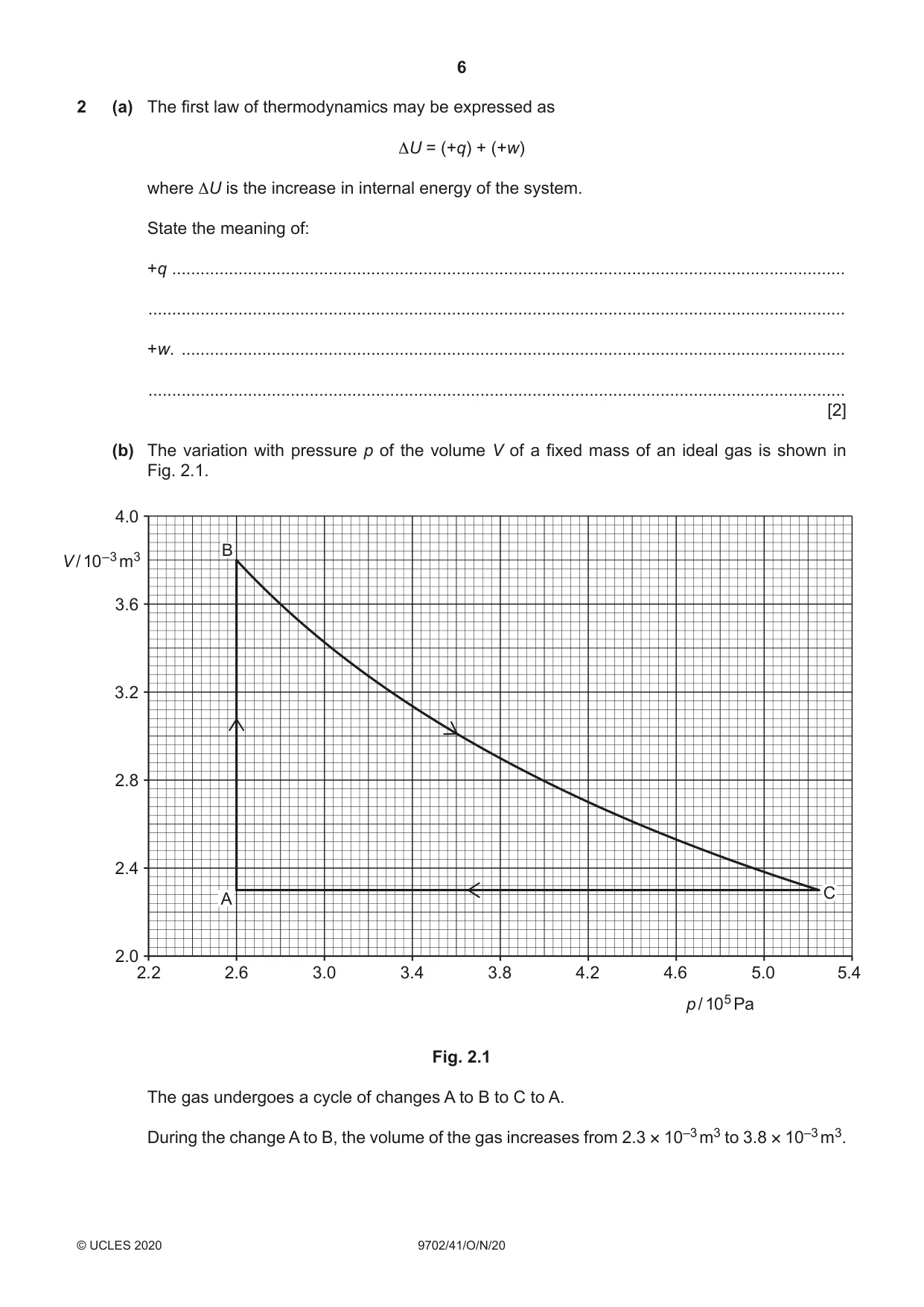
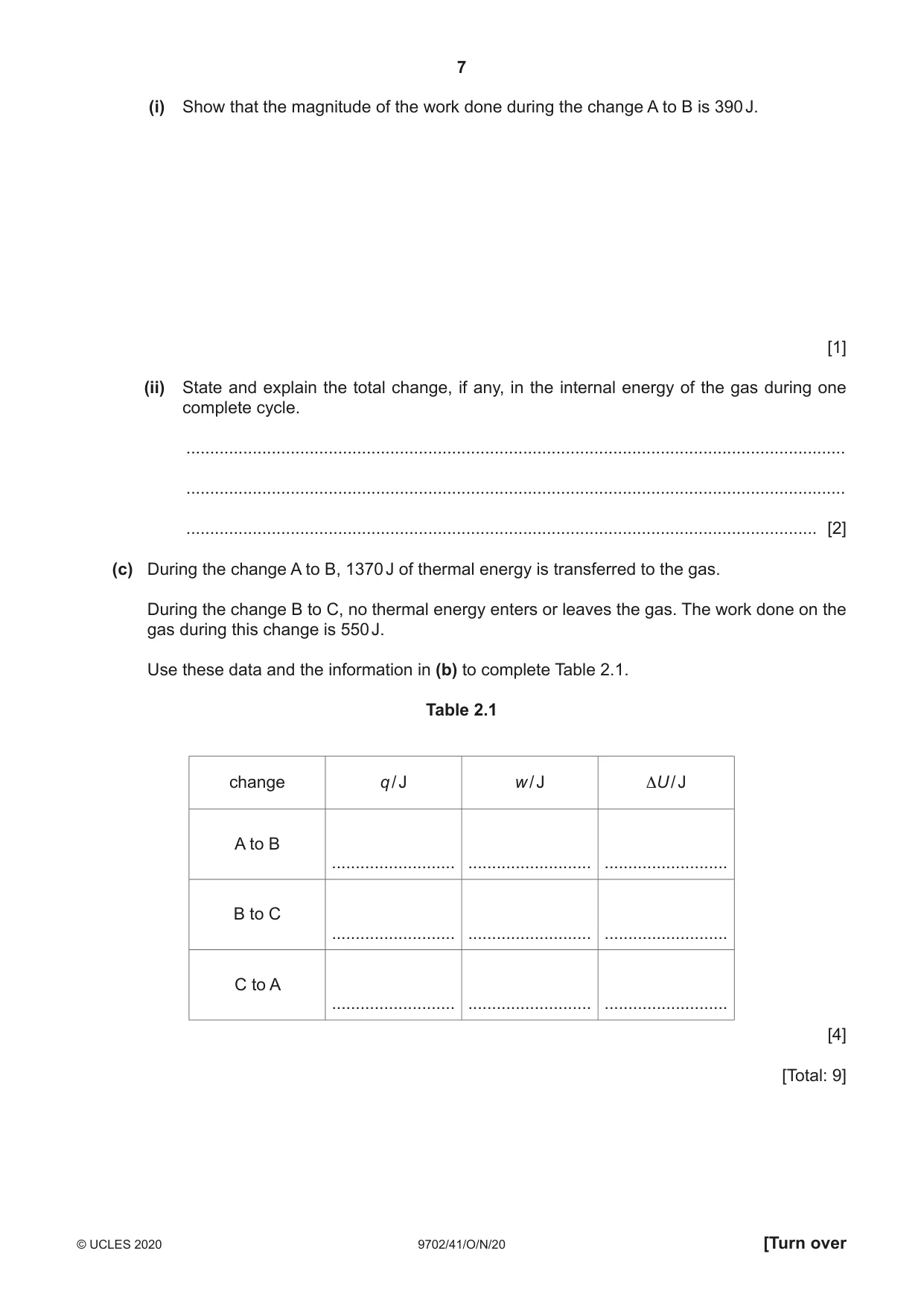
2 (a) The first law of thermodynamics may be expressed as ΔU = (+q) + (+w) where ΔU is the increase in internal energy of the system. State the meaning of: +q .............................................................................................................................................. ................................................................................................................................................... +w. ............................................................................................................................................ ................................................................................................................................................... [2] (b) The variation with pressure p of the volume V of a fixed mass of an ideal gas is shown in Fig. 2.1. 4.0 BV / 10–3 m3 3.6 3.2 2.8 2.4 C A 2.0 2.2 2.6 3.0 3.4 3.8 4.2 4.6 5.0 5.4 p / 105 Pa Fig. 2.1 The gas undergoes a cycle of changes A to B to C to A. During the change A to B, the volume of the gas increases from 2.3 × 10⁻³ m3 to 3.8 × 10⁻³ m3. (i) Show that the magnitude of the work done during the change A to B is 390 J. [1] (ii) State and explain the total change, if any, in the internal energy of the gas during one complete cycle. ........................................................................................................................................... ........................................................................................................................................... ..................................................................................................................................... [2] (c) During the change A to B, 1370 J of thermal energy is transferred to the gas. During the change B to C, no thermal energy enters or leaves the gas. The work done on the gas during this change is 550 J. Use these data and the information in (b) to complete Table 2.1. Table 2.1 change q / J w / J ΔU / J A to B .......................... .......................... .......................... B to C .......................... .......................... .......................... C to A .......................... .......................... .......................... [4] [Total: 9]
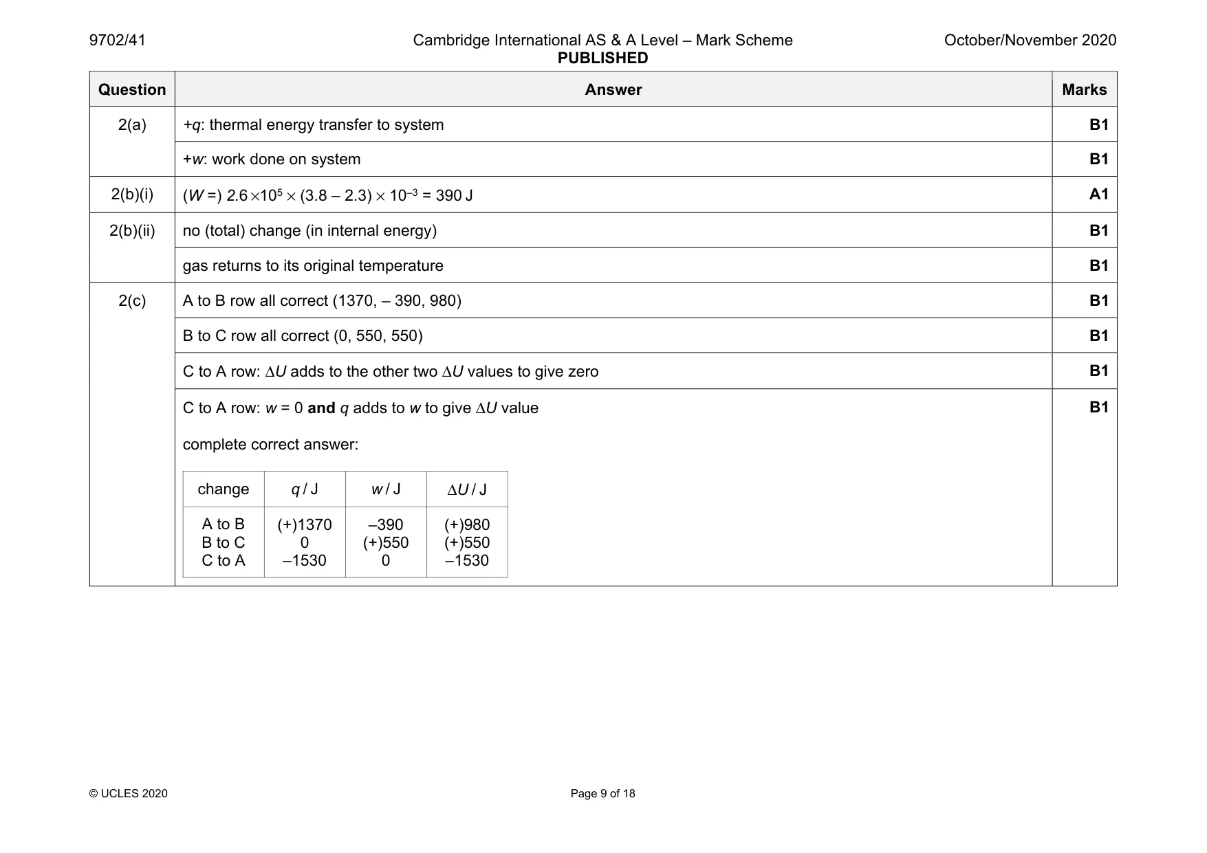
Mark scheme: 2(a) +q: thermal energy transfer to system B1 +w: work done on system B1 2(b)(i) (W =) 2.6 ×105 × (3.8 – 2.3) × 10–3 = 390 J A1 2(b)(ii) no (total) change (in internal energy) B1 gas returns to its original temperature B1 2(c) A to B row all correct (1370, – 390, 980) B1 B to C row all correct (0, 550, 550) B1 C to A row: ΔU adds to the other two ΔU values to give zero B1 C to A row: w = 0 and q adds to w to give ΔU value complete correct answer: change q / J w / J ΔU / J A to B B to C C to A (+)1370 0 –1530 –390 (+)550 0 (+)980 (+)550 –1530 B1
Q3 · A pendulum consists of a metal sphere P suspended from a fixed point by means of a…
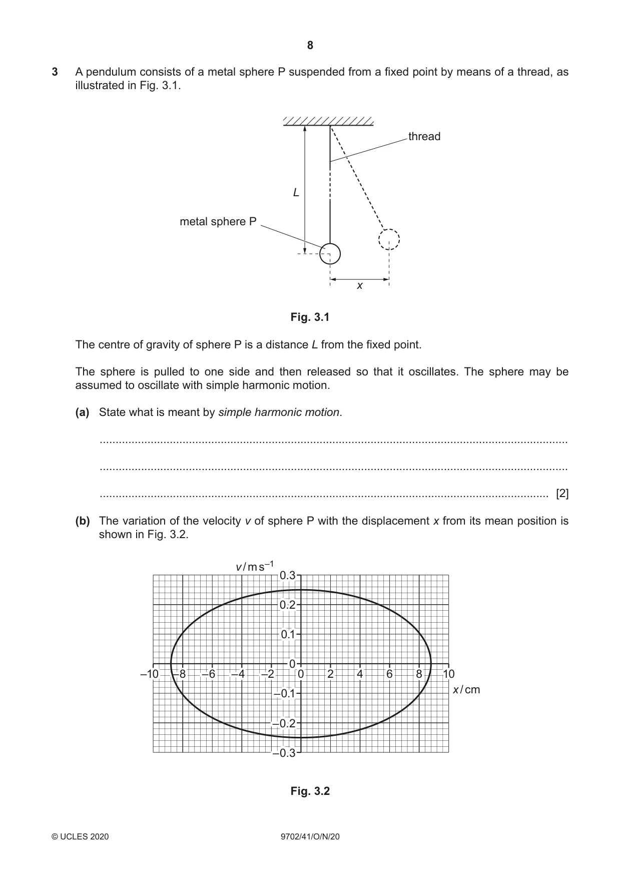
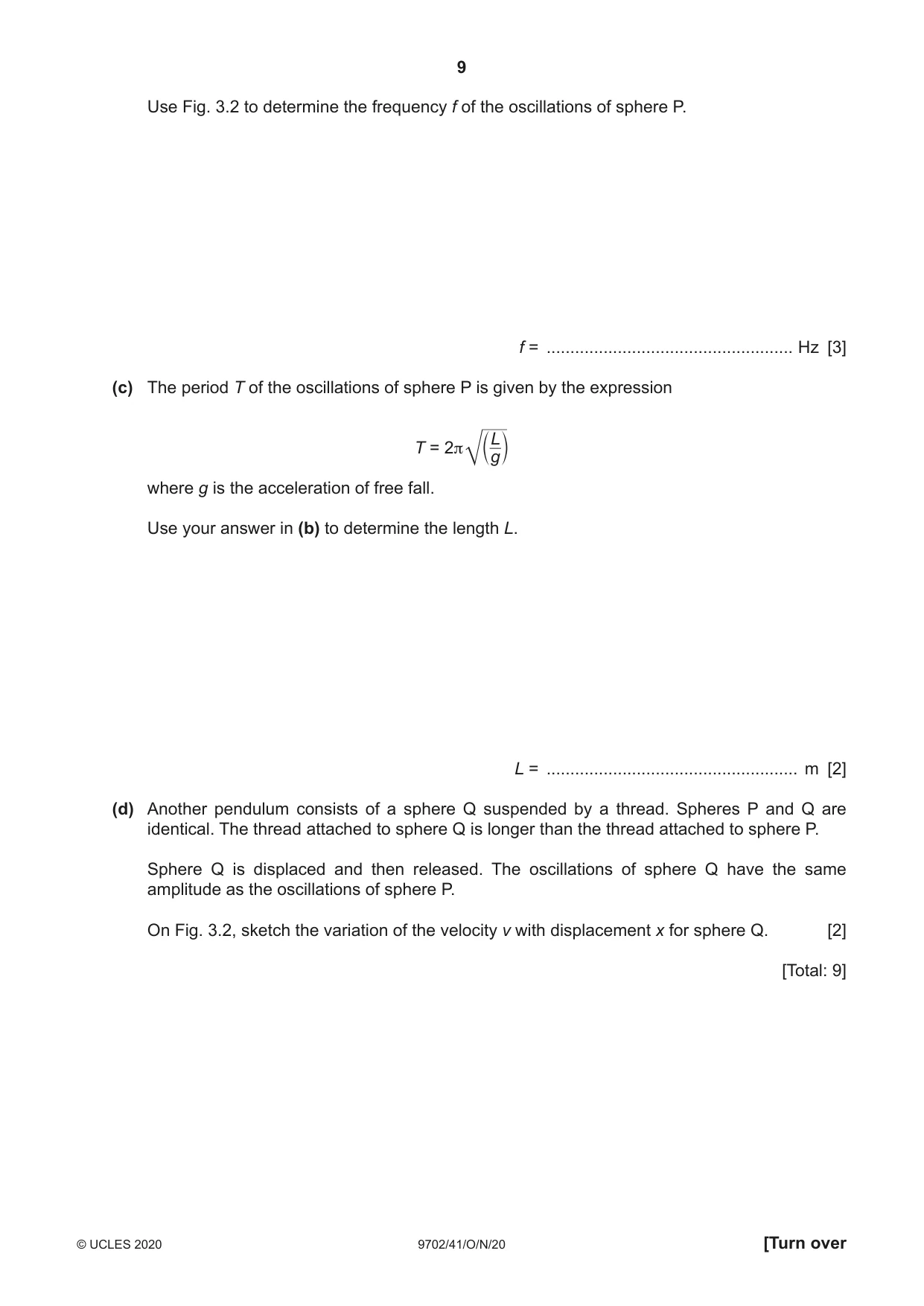
3 A pendulum consists of a metal sphere P suspended from a fixed point by means of a thread, as illustrated in Fig. 3.1. thread L metal sphere P x Fig. 3.1 The centre of gravity of sphere P is a distance L from the fixed point. The sphere is pulled to one side and then released so that it oscillates. The sphere may be assumed to oscillate with simple harmonic motion. (a) State what is meant by simple harmonic motion. ................................................................................................................................................... ................................................................................................................................................... ............................................................................................................................................. [2] (b) The variation of the velocity v of sphere P with the displacement x from its mean position is shown in Fig. 3.2. v / m s–1 0.3 0.2 0.1 0 –10 –8 –6 –4 –2 0 2 4 6 8 10 x / cm –0.1 –0.2 –0.3 Fig. 3.2 Use Fig. 3.2 to determine the frequency f of the oscillations of sphere P. f = .................................................... Hz [3] (c) The period T of the oscillations of sphere P is given by the expression L T = 2π c g m where g is the acceleration of free fall. Use your answer in (b) to determine the length L. L = ..................................................... m [2] (d) Another pendulum consists of a sphere Q suspended by a thread. Spheres P and Q are identical. The thread attached to sphere Q is longer than the thread attached to sphere P. Sphere Q is displaced and then released. The oscillations of sphere Q have the same amplitude as the oscillations of sphere P. On Fig. 3.2, sketch the variation of the velocity v with displacement x for sphere Q. [2] [Total: 9]
Mark scheme: 3(a) acceleration (directly) proportional to displacement B1 acceleration in opposite direction to displacement or acceleration (directed) towards equilibrium position B1 3(b) v = ω(x02 – x2)½ and ω = 2πf or v0 = x0ω and ω = 2πf C1 substitution of any correct point from graph, e.g. for x = 0: 0.25 = 2πf × 8.8 × 10–2 C1 f = 0.45 Hz A1 3(c) 1 / 0.45 = 2π × (L / 9.81)½ C1 L = 1.2 m A1 3(d) ellipse about the origin with same intercepts on x-axis B1 ellipse about the origin crossing v-axis inside original loop B1
Q4 · Explain the principles of the generation of ultrasound waves for use in medical diagnosis
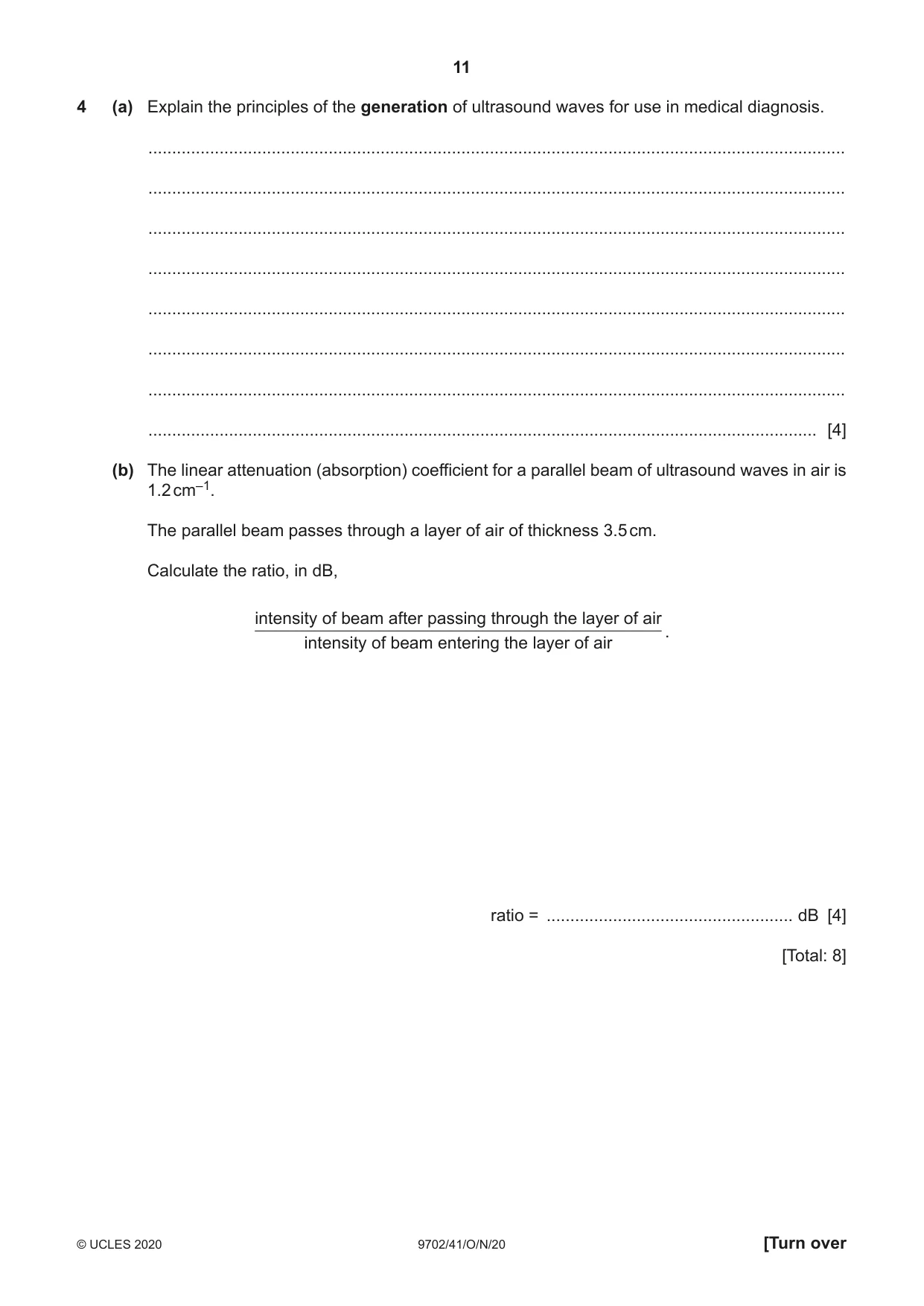
4 (a) Explain the principles of the generation of ultrasound waves for use in medical diagnosis. ................................................................................................................................................... ................................................................................................................................................... ................................................................................................................................................... ................................................................................................................................................... ................................................................................................................................................... ................................................................................................................................................... ................................................................................................................................................... ............................................................................................................................................. [4] (b) The linear attenuation (absorption) coefficient for a parallel beam of ultrasound waves in air is 1.2 cm–1. The parallel beam passes through a layer of air of thickness 3.5 cm. Calculate the ratio, in dB, intensity of beam after passing through the layer of air . intensity of beam entering the layer of air ratio = .................................................... dB [4] [Total: 8]
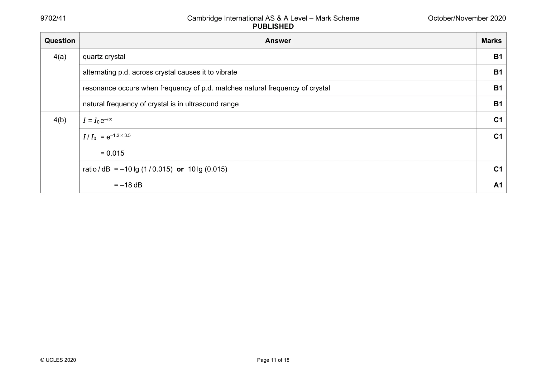
Mark scheme: 4(a) quartz crystal B1 alternating p.d. across crystal causes it to vibrate B1 resonance occurs when frequency of p.d. matches natural frequency of crystal B1 natural frequency of crystal is in ultrasound range B1 4(b) I = I0 e–μx C1 I / I0 = e–1.2 × 3.5 = 0.015 C1 ratio / dB = –10 lg (1 / 0.015) or 10 lg (0.015) C1 = –18 dB A1
Q5 · Define electric potential at a point
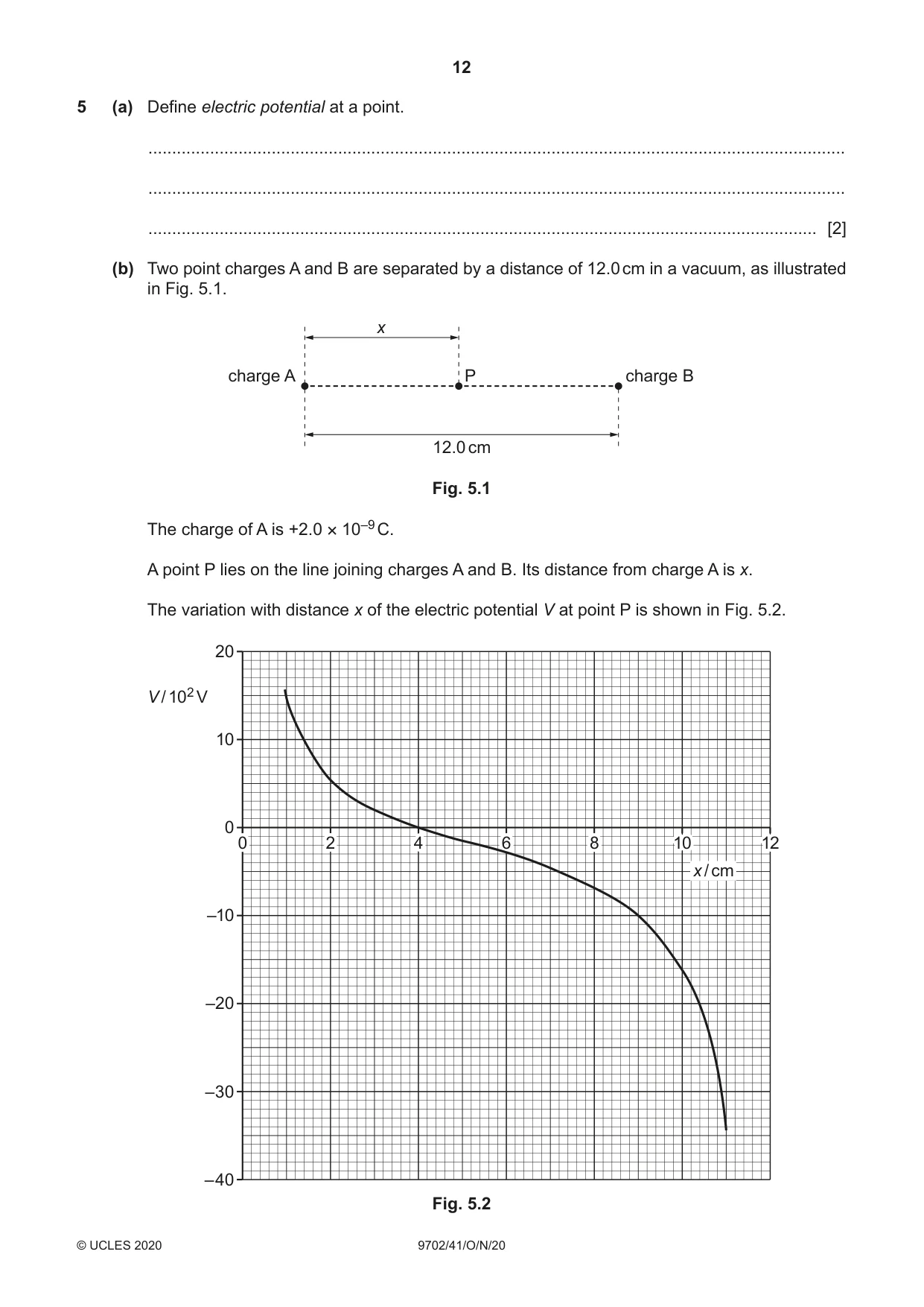
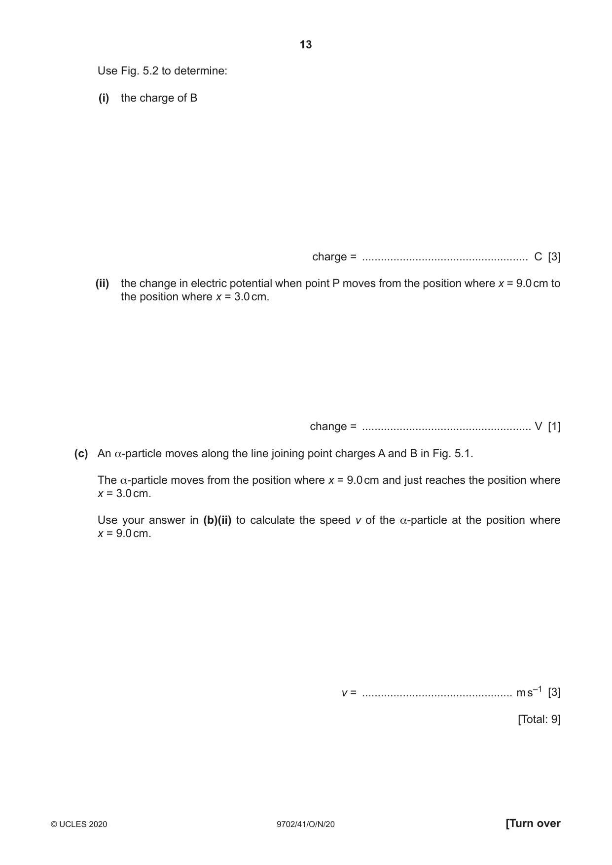
5 (a) Define electric potential at a point. ................................................................................................................................................... ................................................................................................................................................... ............................................................................................................................................. [2] (b) Two point charges A and B are separated by a distance of 12.0 cm in a vacuum, as illustrated in Fig. 5.1. x charge A P charge B 12.0 cm Fig. 5.1 The charge of A is +2.0 × 10⁻⁹ C. A point P lies on the line joining charges A and B. Its distance from charge A is x. The variation with distance x of the electric potential V at point P is shown in Fig. 5.2. 20 V / 102 V 10 0 0 2 4 6 8 10 12 x / cm –10 –20 –30 –40 Fig. 5.2 Use Fig. 5.2 to determine: (i) the charge of B charge = ..................................................... C [3] (ii) the change in electric potential when point P moves from the position where x = 9.0 cm to the position where x = 3.0 cm. change = ...................................................... V [1] (c) An α-particle moves along the line joining point charges A and B in Fig. 5.1. The α-particle moves from the position where x = 9.0 cm and just reaches the position where x = 3.0 cm. Use your answer in (b)(ii) to calculate the speed v of the α-particle at the position where x = 9.0 cm. v = ................................................ m s–1 [3] [Total: 9]
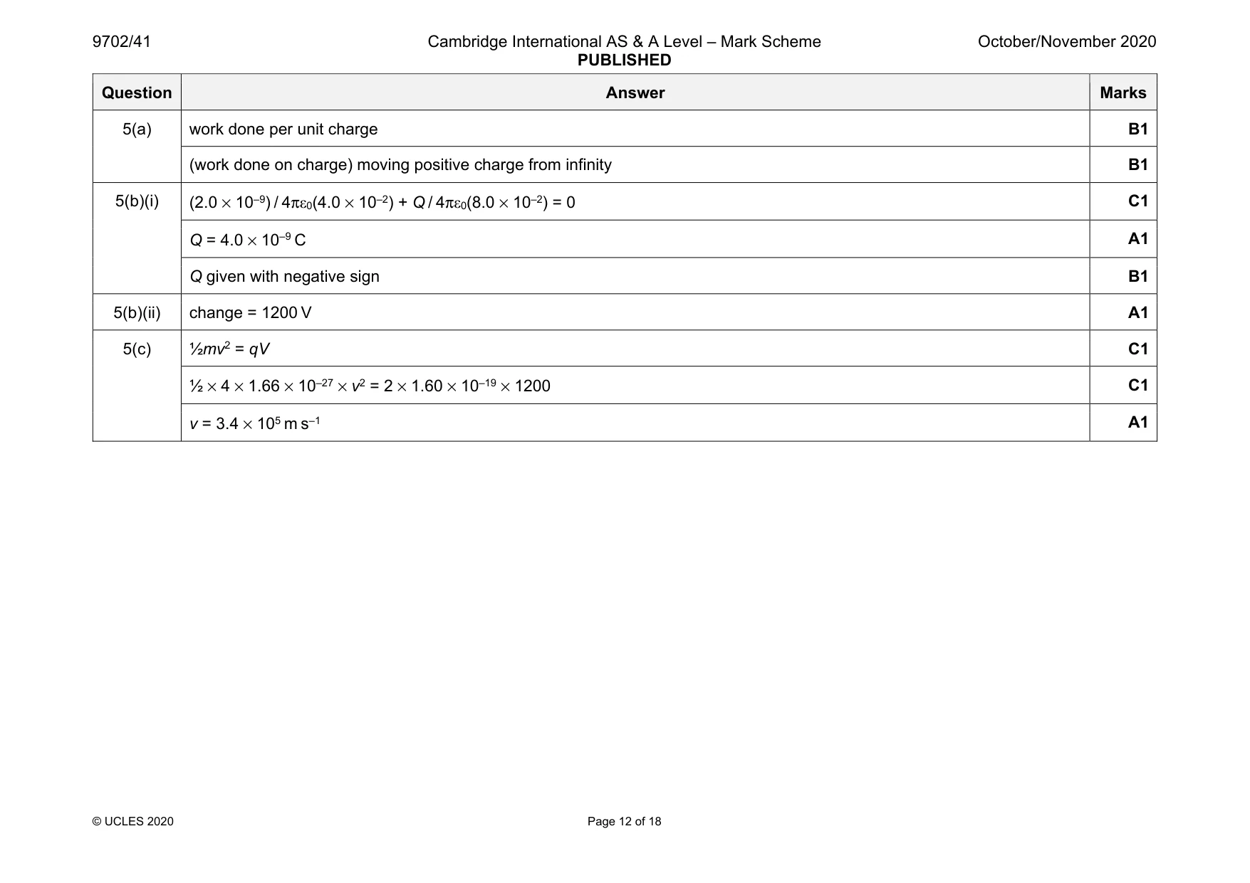
Mark scheme: 5(a) work done per unit charge B1 (work done on charge) moving positive charge from infinity B1 5(b)(i) (2.0 × 10⁻⁹) / 4πε0(4.0 × 10⁻²) + Q / 4πε0(8.0 × 10⁻²) = 0 C1 Q = 4.0 × 10⁻⁹ C A1 Q given with negative sign B1 5(b)(ii) change = 1200 V A1 5(c) ½mv2 = qV C1 ½ × 4 × 1.66 × 10–27 × v2 = 2 × 1.60 × 10–19 × 1200 C1 v = 3.4 × 10⁵ m s–1 A1
Q6 · Define the capacitance of a parallel plate capacitor
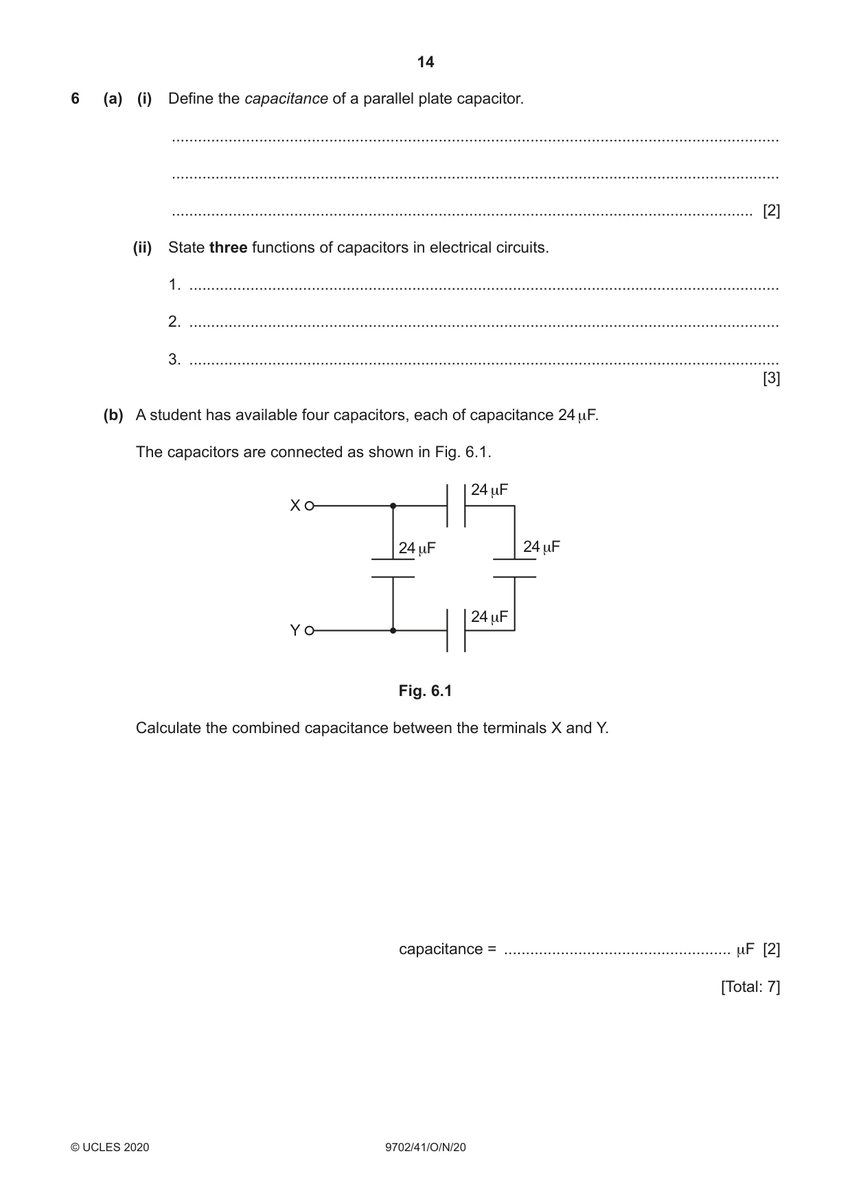
6 (a) (i) Define the capacitance of a parallel plate capacitor. ........................................................................................................................................... ........................................................................................................................................... ..................................................................................................................................... [2] (ii) State three functions of capacitors in electrical circuits. 1. ....................................................................................................................................... 2. ....................................................................................................................................... 3. ....................................................................................................................................... [3] (b) A student has available four capacitors, each of capacitance 24 μF. The capacitors are connected as shown in Fig. 6.1. 24 μF X 24 μF 24 μF 24 μF Y Fig. 6.1 Calculate the combined capacitance between the terminals X and Y. capacitance = .................................................... μF [2] [Total: 7]
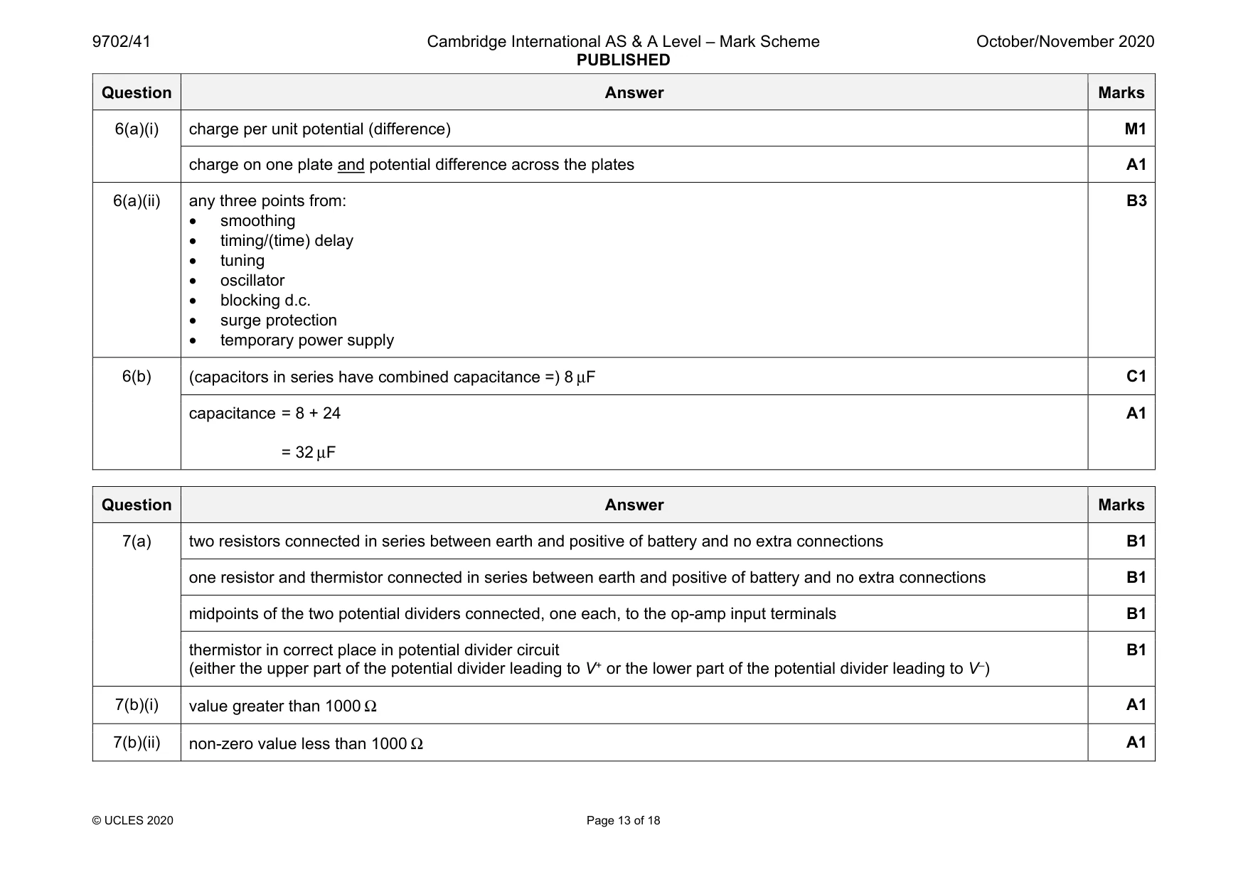
Mark scheme: 6(a)(i) charge per unit potential (difference) M1 charge on one plate and potential difference across the plates A1 6(a)(ii) any three points from: • smoothing • timing/(time) delay • tuning • oscillator • blocking d.c. • surge protection • temporary power supply B3 6(b) (capacitors in series have combined capacitance =) 8 μF C1 capacitance = 8 + 24 = 32 μF A1
Q7 · An ideal operational amplifier (op-amp) is to be used in a comparator circuit
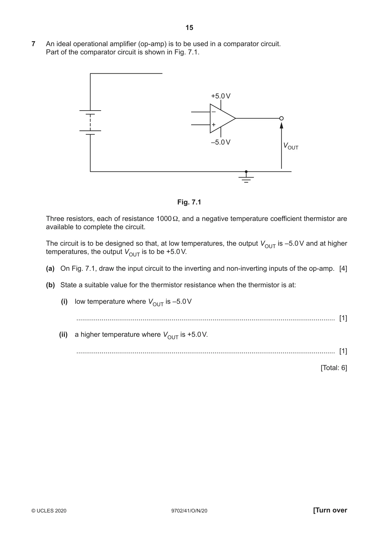
7 An ideal operational amplifier (op-amp) is to be used in a comparator circuit. Part of the comparator circuit is shown in Fig. 7.1. +5.0 V – + –5.0 V VOUT Fig. 7.1 Three resistors, each of resistance 1000 Ω, and a negative temperature coefficient thermistor are available to complete the circuit. The circuit is to be designed so that, at low temperatures, the output VOUT is –5.0 V and at higher temperatures, the output VOUT is to be +5.0 V. (a) On Fig. 7.1, draw the input circuit to the inverting and non-inverting inputs of the op-amp. [4] (b) State a suitable value for the thermistor resistance when the thermistor is at: (i) low temperature where VOUT is –5.0 V ..................................................................................................................................... [1] (ii) a higher temperature where VOUT is +5.0 V. ..................................................................................................................................... [1] [Total: 6]
Mark scheme: 7(a) two resistors connected in series between earth and positive of battery and no extra connections B1 one resistor and thermistor connected in series between earth and positive of battery and no extra connections B1 midpoints of the two potential dividers connected, one each, to the op-amp input terminals B1 thermistor in correct place in potential divider circuit (either the upper part of the potential divider leading to V+ or the lower part of the potential divider leading to V–) B1 7(b)(i) value greater than 1000 Ω A1 7(b)(ii) non-zero value less than 1000 Ω A1
Q8 · A slice of a conducting material has its face QRLK normal to a uniform magnetic field of…
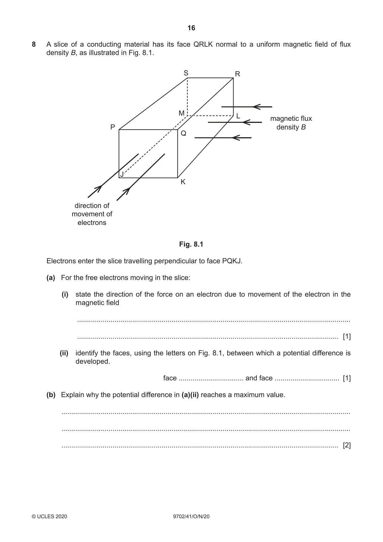
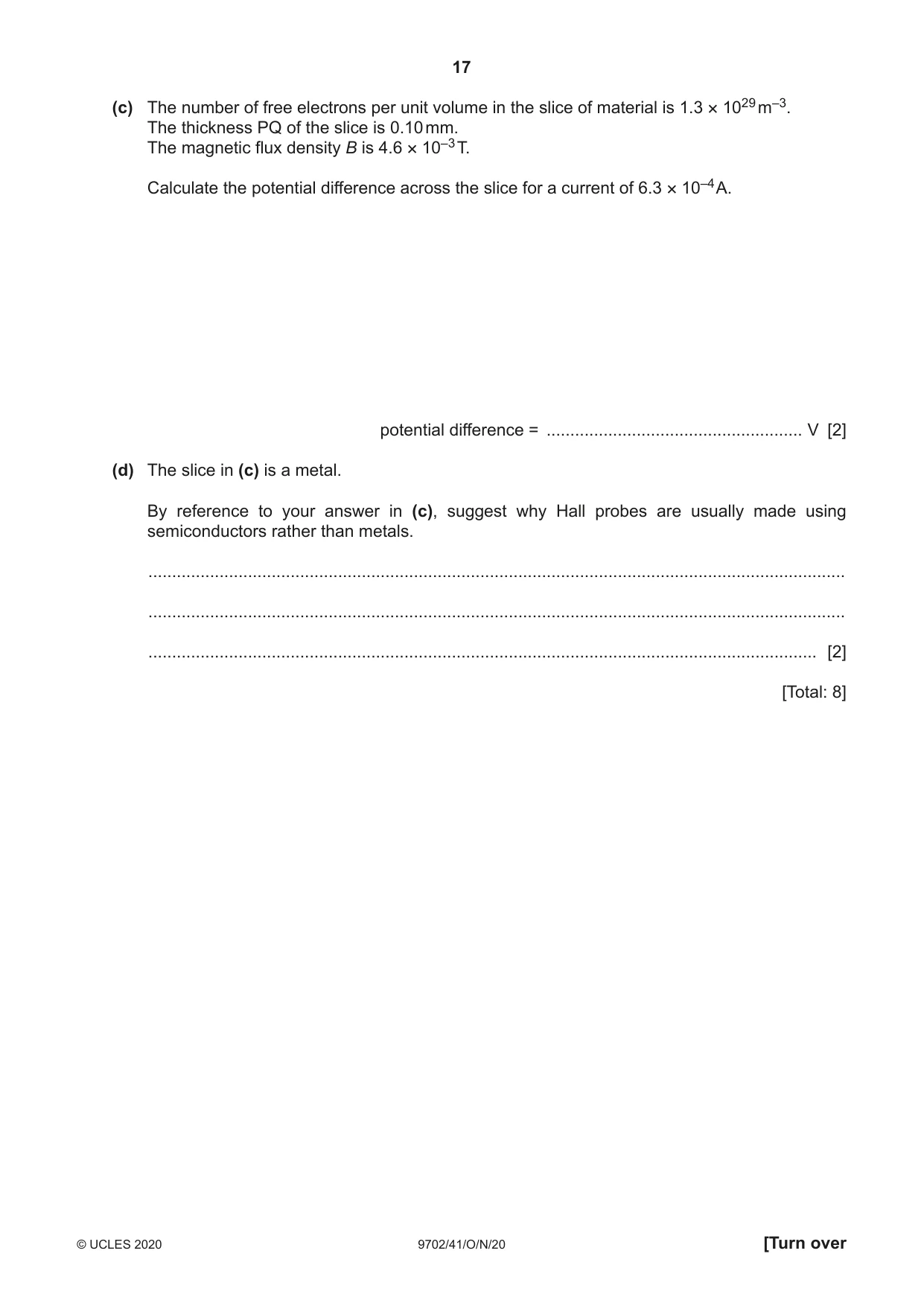
8 A slice of a conducting material has its face QRLK normal to a uniform magnetic field of flux density B, as illustrated in Fig. 8.1. S R M L magnetic flux P density B Q J K direction of movement of electrons Fig. 8.1 Electrons enter the slice travelling perpendicular to face PQKJ. (a) For the free electrons moving in the slice: (i) state the direction of the force on an electron due to movement of the electron in the magnetic field ........................................................................................................................................... ..................................................................................................................................... [1] (ii) identify the faces, using the letters on Fig. 8.1, between which a potential difference is developed. face ................................. and face ................................. [1] (b) Explain why the potential difference in (a)(ii) reaches a maximum value. ................................................................................................................................................... ................................................................................................................................................... ............................................................................................................................................. [2] (c) The number of free electrons per unit volume in the slice of material is 1.3 × 1029 m–3. The thickness PQ of the slice is 0.10 mm. The magnetic flux density B is 4.6 × 10⁻³ T. Calculate the potential difference across the slice for a current of 6.3 × 10⁻⁴ A. potential difference = ...................................................... V [2] (d) The slice in (c) is a metal. By reference to your answer in (c), suggest why Hall probes are usually made using semiconductors rather than metals. ................................................................................................................................................... ................................................................................................................................................... ............................................................................................................................................. [2] [Total: 8]
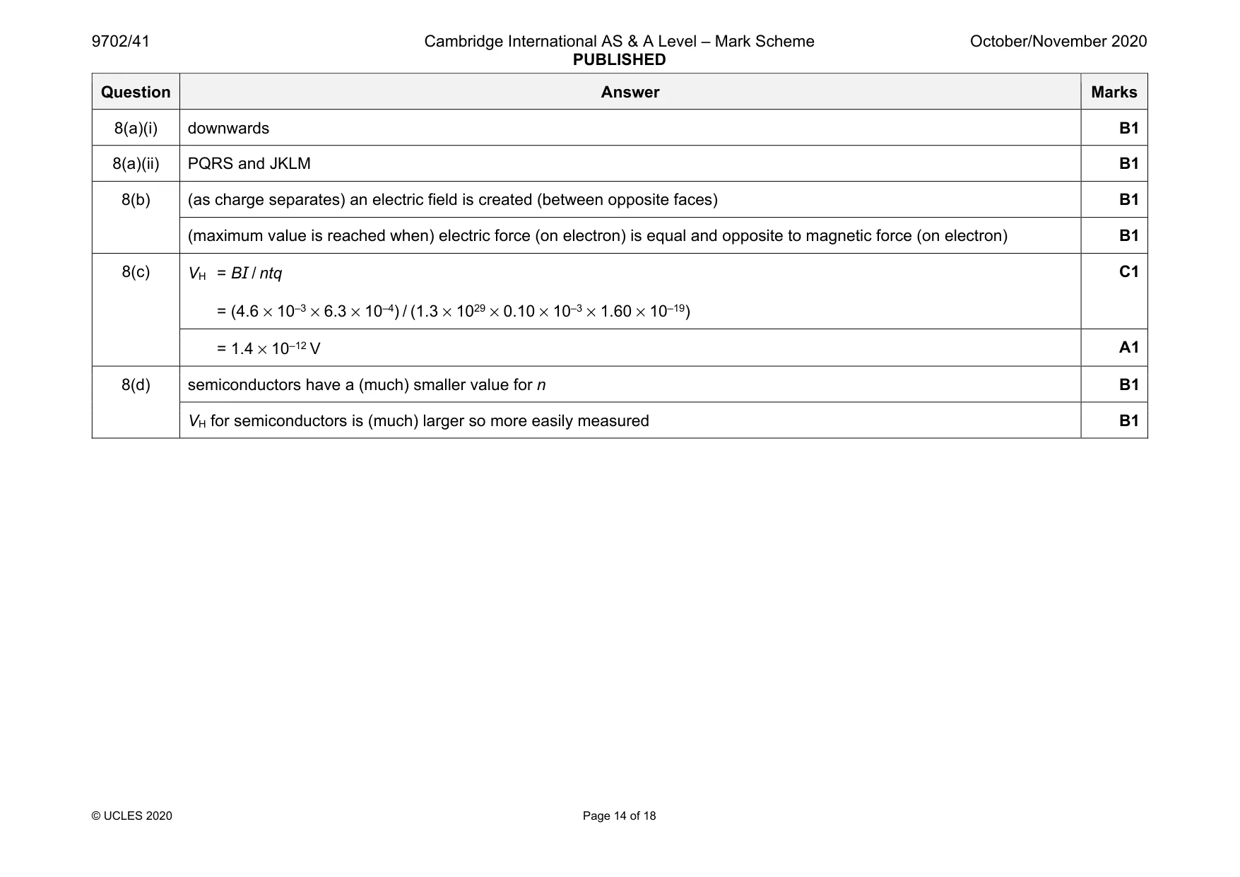
Mark scheme: 8(a)(i) downwards B1 8(a)(ii) PQRS and JKLM B1 8(b) (as charge separates) an electric field is created (between opposite faces) B1 (maximum value is reached when) electric force (on electron) is equal and opposite to magnetic force (on electron) B1 8(c) VH = BI / ntq = (4.6 × 10–3 × 6.3 × 10–4) / (1.3 × 1029 × 0.10 × 10–3 × 1.60 × 10–19) C1 = 1.4 × 10⁻¹² V A1 8(d) semiconductors have a (much) smaller value for n B1 VH for semiconductors is (much) larger so more easily measured B1
Question 9
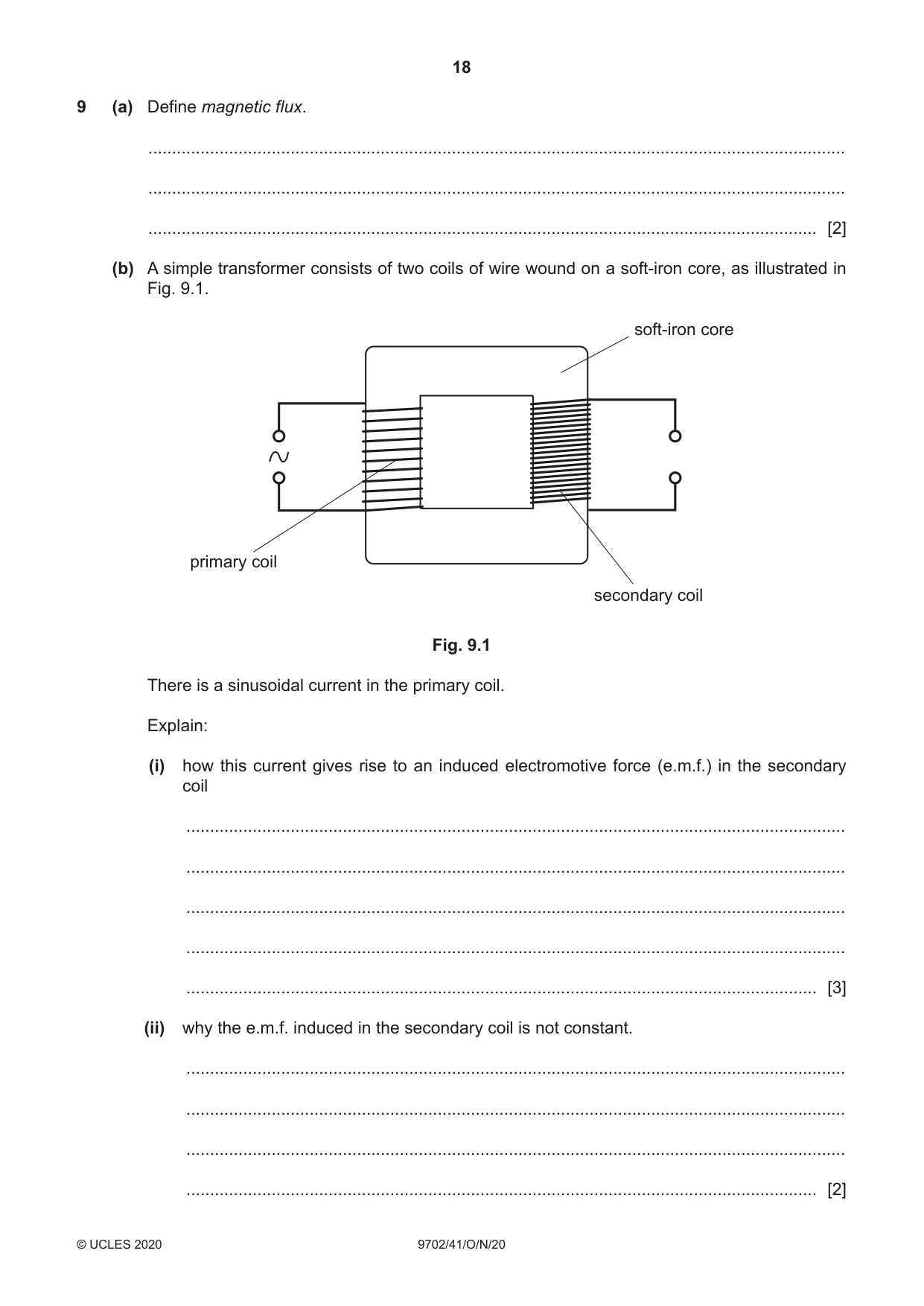
9 (a) Define magnetic flux. ................................................................................................................................................... ................................................................................................................................................... ............................................................................................................................................. [2] (b) A simple transformer consists of two coils of wire wound on a soft-iron core, as illustrated in Fig. 9.1. soft-iron core primary coil secondary coil Fig. 9.1 There is a sinusoidal current in the primary coil. Explain: (i) how this current gives rise to an induced electromotive force (e.m.f.) in the secondary coil ........................................................................................................................................... ........................................................................................................................................... ........................................................................................................................................... ........................................................................................................................................... ..................................................................................................................................... [3] (ii) why the e.m.f. induced in the secondary coil is not constant. ........................................................................................................................................... ........................................................................................................................................... ........................................................................................................................................... ..................................................................................................................................... [2] (c) Explain why the soft-iron core in (b) is laminated. ................................................................................................................................................... ................................................................................................................................................... ............................................................................................................................................. [2] [Total: 9]
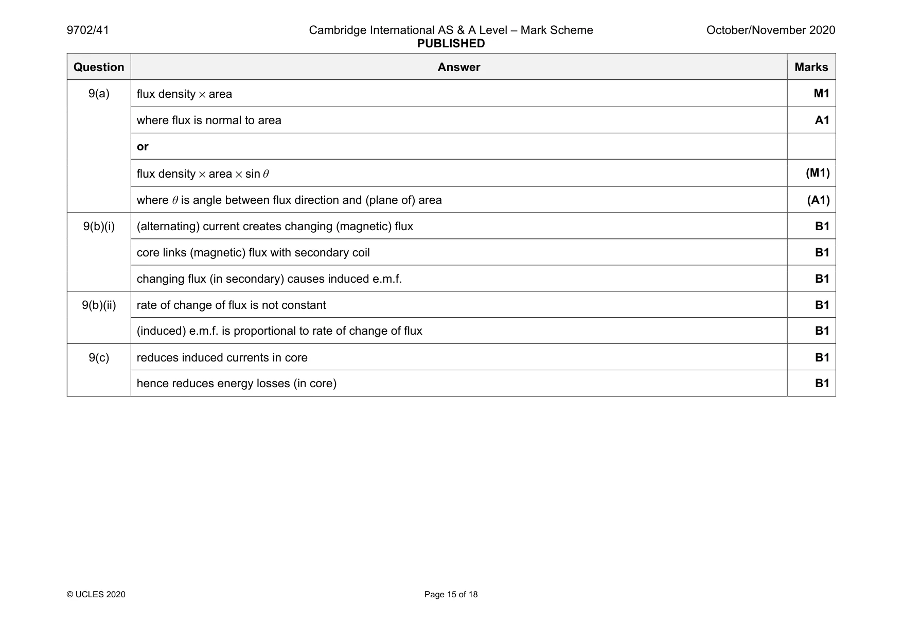
Mark scheme: 9(a) flux density × area M1 where flux is normal to area A1 or flux density × area × sin θ (M1) where θ is angle between flux direction and (plane of) area (A1) 9(b)(i) (alternating) current creates changing (magnetic) flux B1 core links (magnetic) flux with secondary coil B1 changing flux (in secondary) causes induced e.m.f. B1 9(b)(ii) rate of change of flux is not constant B1 (induced) e.m.f. is proportional to rate of change of flux B1 9(c) reduces induced currents in core B1 hence reduces energy losses (in core) B1
Q10 · Outline briefly the principles of computed tomography (CT scanning)
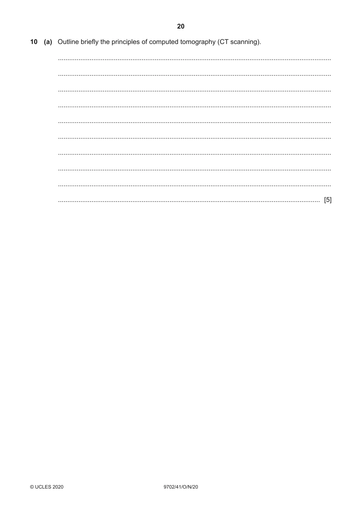
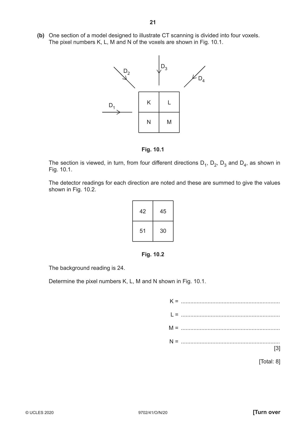
10 (a) Outline briefly the principles of computed tomography (CT scanning). ................................................................................................................................................... ................................................................................................................................................... ................................................................................................................................................... ................................................................................................................................................... ................................................................................................................................................... ................................................................................................................................................... ................................................................................................................................................... ................................................................................................................................................... ................................................................................................................................................... ............................................................................................................................................. [5] (b) One section of a model designed to illustrate CT scanning is divided into four voxels. The pixel numbers K, L, M and N of the voxels are shown in Fig. 10.1. D3 D2 D4 K L D1 N M Fig. 10.1 The section is viewed, in turn, from four different directions D1, D2, D3 and D4, as shown in Fig. 10.1. The detector readings for each direction are noted and these are summed to give the values shown in Fig. 10.2. 42 45 51 30 Fig. 10.2 The background reading is 24. Determine the pixel numbers K, L, M and N shown in Fig. 10.1. K = ............................................................... L = ............................................................... M = ............................................................... N = ............................................................... [3] [Total: 8]
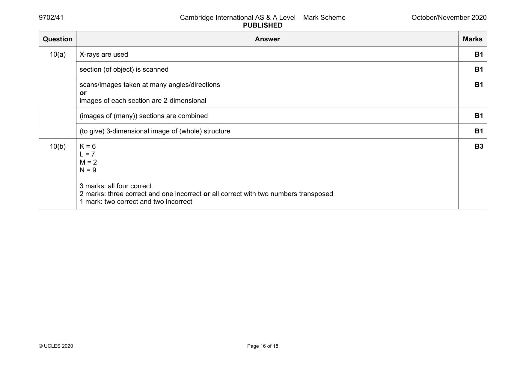
Mark scheme: 10(a) X-rays are used B1 section (of object) is scanned B1 scans/images taken at many angles/directions or images of each section are 2-dimensional B1 (images of (many)) sections are combined B1 (to give) 3-dimensional image of (whole) structure B1 10(b) K = 6 L = 7 M = 2 N = 9 3 marks: all four correct 2 marks: three correct and one incorrect or all correct with two numbers transposed 1 mark: two correct and two incorrect B3
Q11 · A photon of wavelength 540 nm collides with an isolated stationary electron, as…
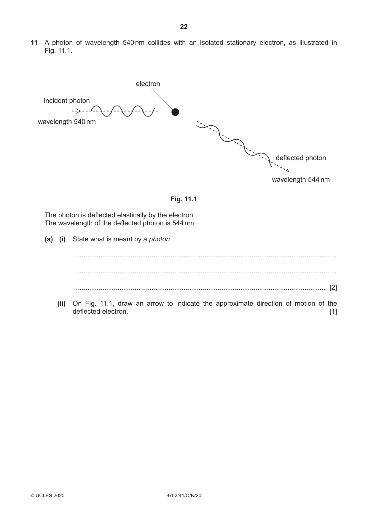
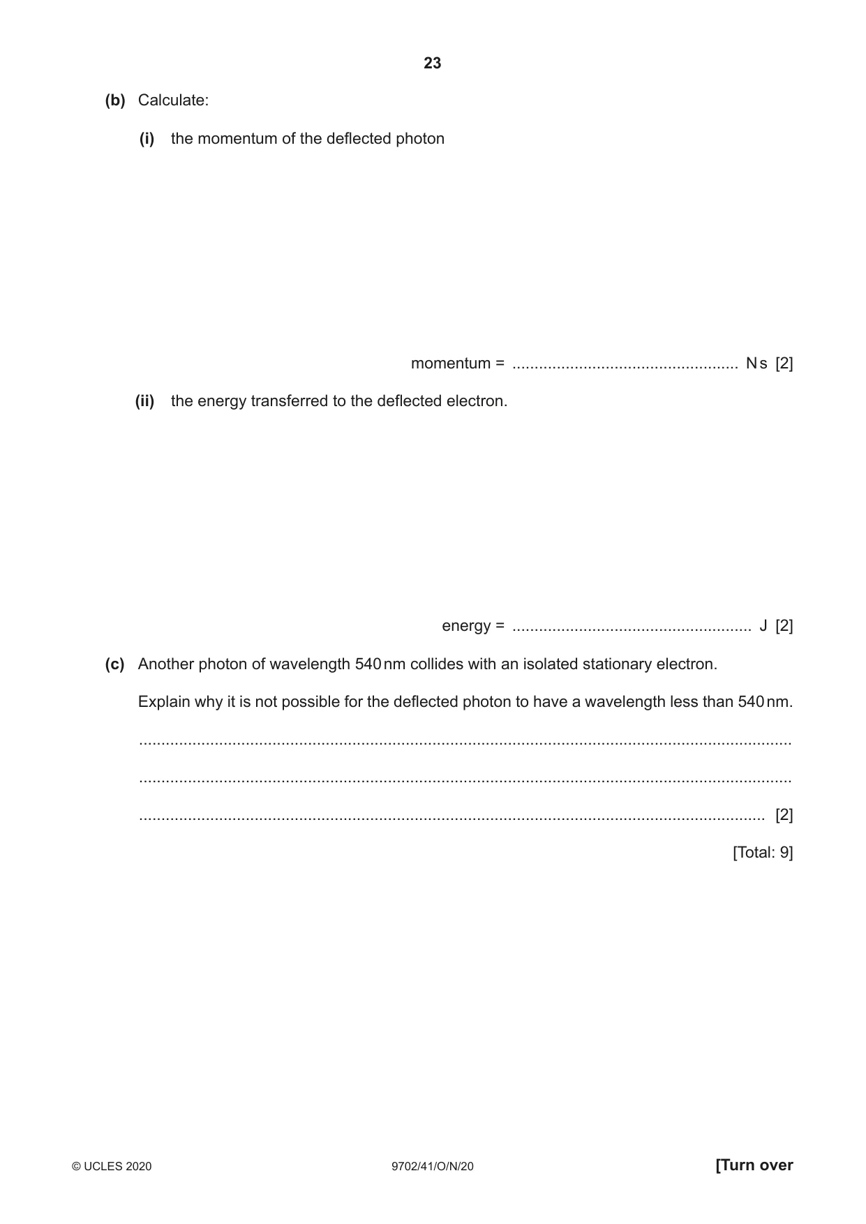
11 A photon of wavelength 540 nm collides with an isolated stationary electron, as illustrated in Fig. 11.1. electron incident photon wavelength 540 nm deflected photon wavelength 544 nm Fig. 11.1 The photon is deflected elastically by the electron. The wavelength of the deflected photon is 544 nm. (a) (i) State what is meant by a photon. ........................................................................................................................................... ........................................................................................................................................... ..................................................................................................................................... [2] (ii) On Fig. 11.1, draw an arrow to indicate the approximate direction of motion of the deflected electron. [1] (b) Calculate: (i) the momentum of the deflected photon momentum = ................................................... N s [2] (ii) the energy transferred to the deflected electron. energy = ...................................................... J [2] (c) Another photon of wavelength 540 nm collides with an isolated stationary electron. Explain why it is not possible for the deflected photon to have a wavelength less than 540 nm. ................................................................................................................................................... ................................................................................................................................................... ............................................................................................................................................. [2] [Total: 9]
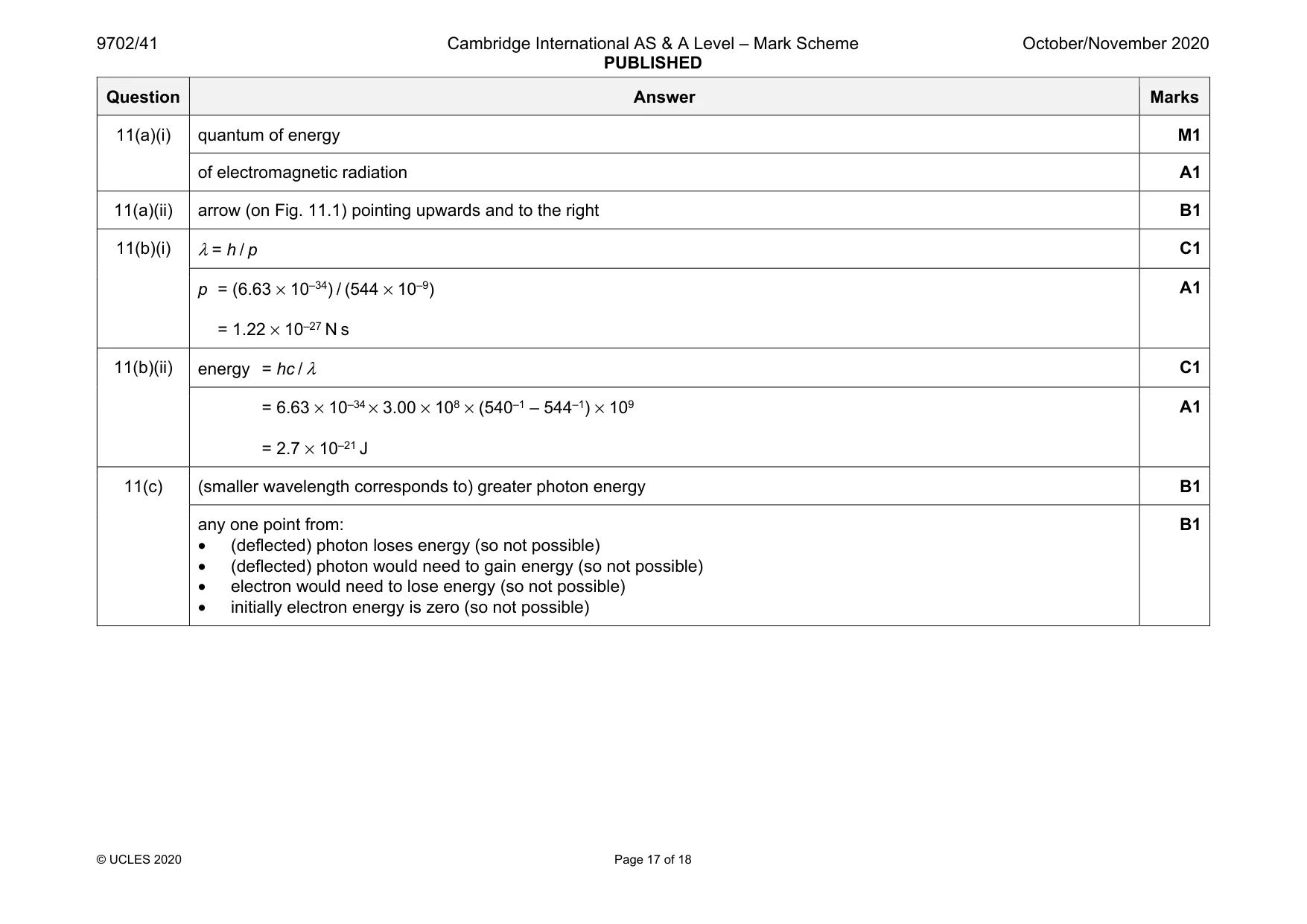
Mark scheme: 11(a)(i) quantum of energy M1 of electromagnetic radiation A1 11(a)(ii) arrow (on Fig. 11.1) pointing upwards and to the right B1 11(b)(i) λ = h / p C1 p = (6.63 × 10⁻³⁴) / (544 × 10–9) = 1.22 × 10⁻²⁷ N s A1 11(b)(ii) energy = hc / λ C1 = 6.63 × 10–34 × 3.00 × 108 × (540–1 – 544–1) × 109 = 2.7 × 10⁻²¹ J A1 11(c) (smaller wavelength corresponds to) greater photon energy B1 any one point from: • (deflected) photon loses energy (so not possible) • (deflected) photon would need to gain energy (so not possible) • electron would need to lose energy (so not possible) • initially electron energy is zero (so not possible) B1
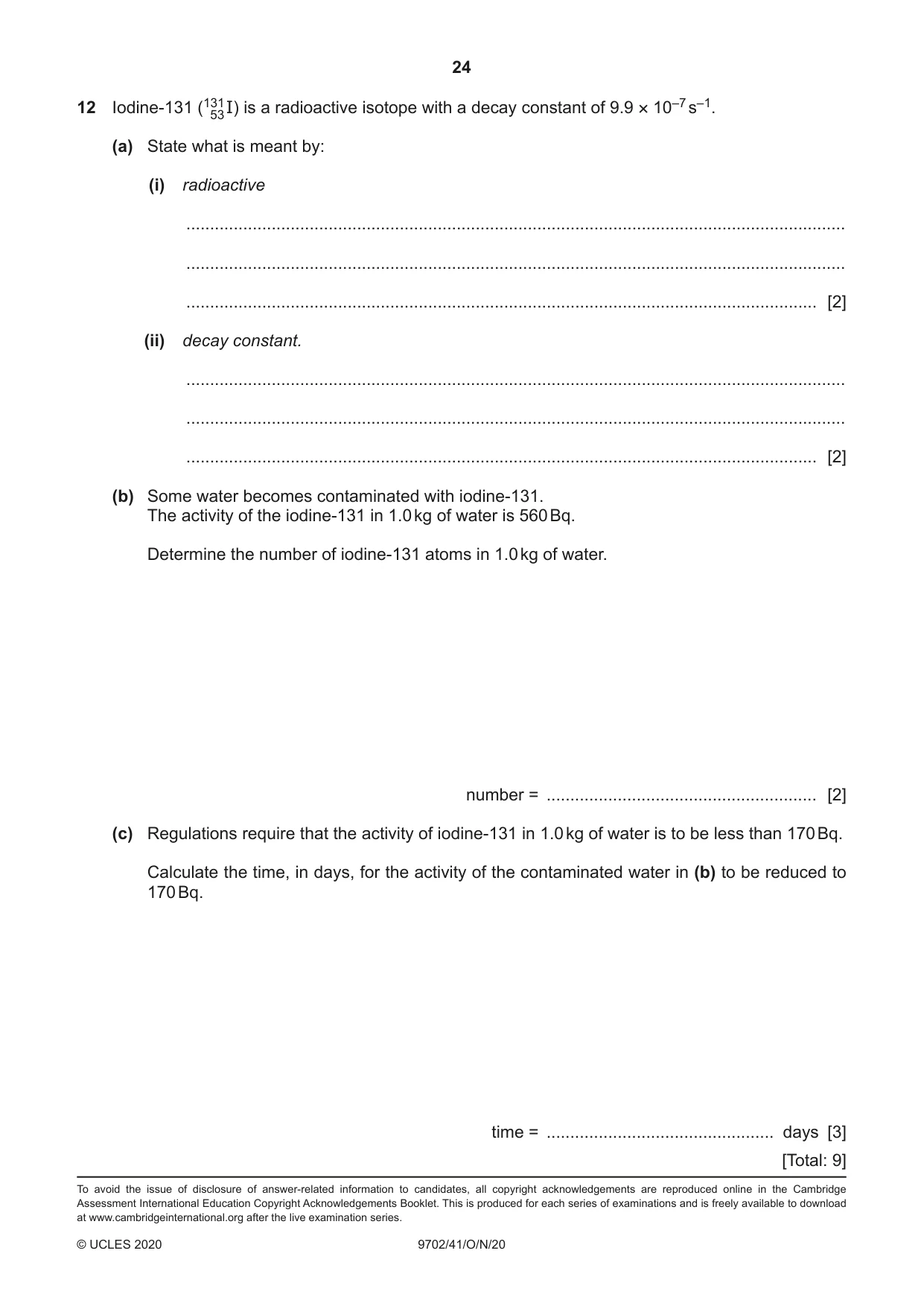
Q12 · Iodine-131 (13153 I) is a radioactive isotope with a decay constant of 9.9 × 10⁻⁷ s–1
12 Iodine-131 (13153 I) is a radioactive isotope with a decay constant of 9.9 × 10⁻⁷ s–1. (a) State what is meant by: (i) radioactive ........................................................................................................................................... ........................................................................................................................................... ..................................................................................................................................... [2] (ii) decay constant. ........................................................................................................................................... ........................................................................................................................................... ..................................................................................................................................... [2] (b) Some water becomes contaminated with iodine-131. The activity of the iodine-131 in 1.0 kg of water is 560 Bq. Determine the number of iodine-131 atoms in 1.0 kg of water. number = ......................................................... [2] (c) Regulations require that the activity of iodine-131 in 1.0 kg of water is to be less than 170 Bq. Calculate the time, in days, for the activity of the contaminated water in (b) to be reduced to 170 Bq. time = ................................................ days [3] [Total: 9]
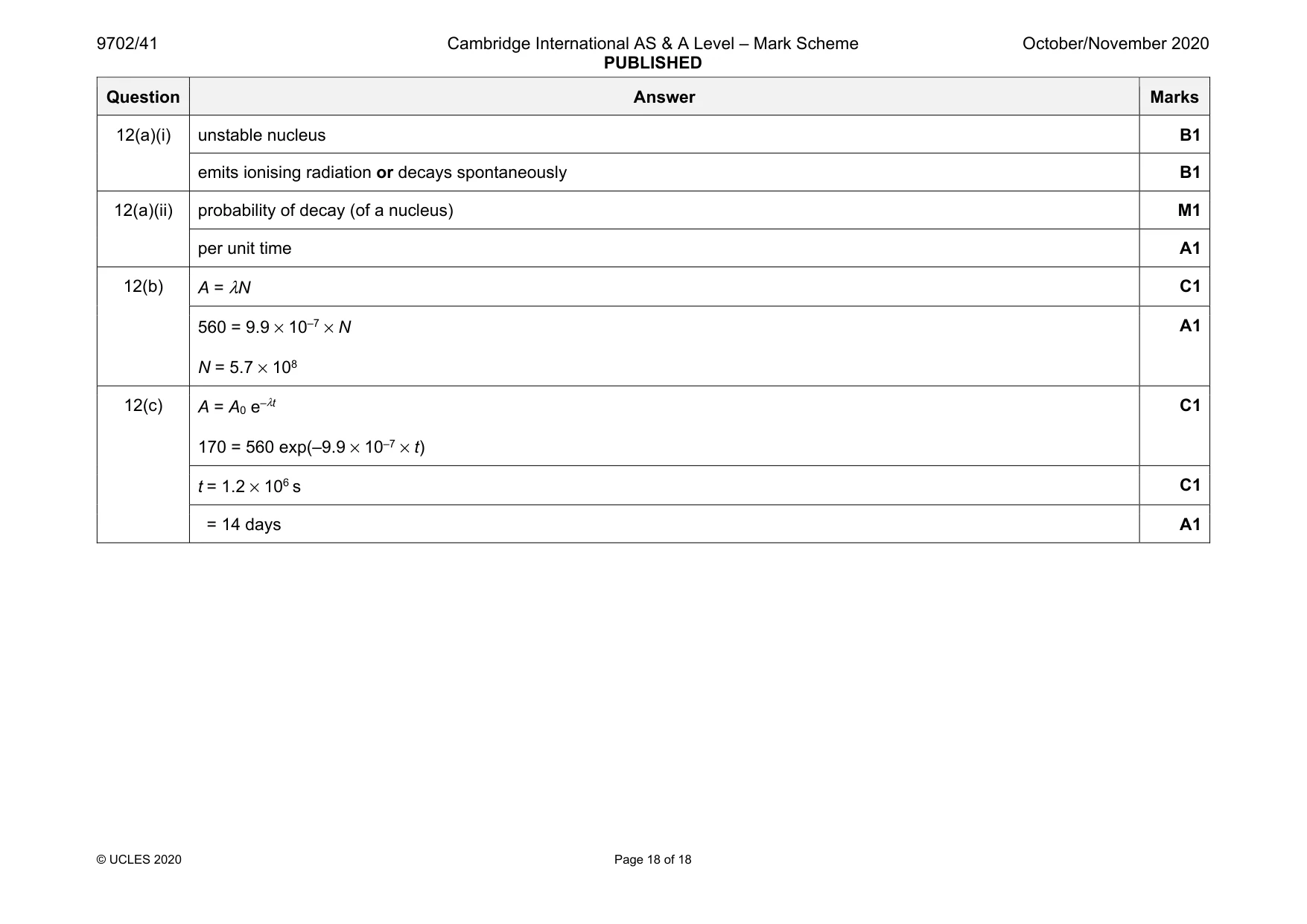
Mark scheme: 12(a)(i) unstable nucleus B1 emits ionising radiation or decays spontaneously B1 12(a)(ii) probability of decay (of a nucleus) M1 per unit time A1 12(b) A = λN C1 560 = 9.9 × 10⁻⁷ × N N = 5.7 × 10⁸ A1 12(c) A = A0 e–λt 170 = 560 exp(–9.9 × 10⁻⁷ × t) C1 t = 1.2 × 10⁶ s C1 = 14 days A1
What was in this paper
The subtopics covered by these 12 questions, and how many questions each got. Open one in a new tab to see every Cambridge question on it.
1Electric potential1Electromagnetic induction1Energy and momentum of a photon1Force on a moving charge1Gravitational field of a point mass1Potential dividers1Production and use of ultrasound1Production and use of X-rays1Radioactive decay1Simple harmonic oscillations1The first law of thermodynamics1What you needed in this session
Cambridge’s own grade thresholds for 2020 Oct/Nov, Paper 4 · Variant 1. A higher threshold means an easier paper — the bar moves with how the cohort did.