Cambridge A Level Physics 9702 — 2022 Oct/Nov Paper 4 · Variant 3
9702/43/O/N/22 · 10 questions · 100 marks · ≈113 min
The question paper and its mark scheme, free to read here and free to download. This is Cambridge’s own paper, exactly as it was sat.
Question paper24 pages
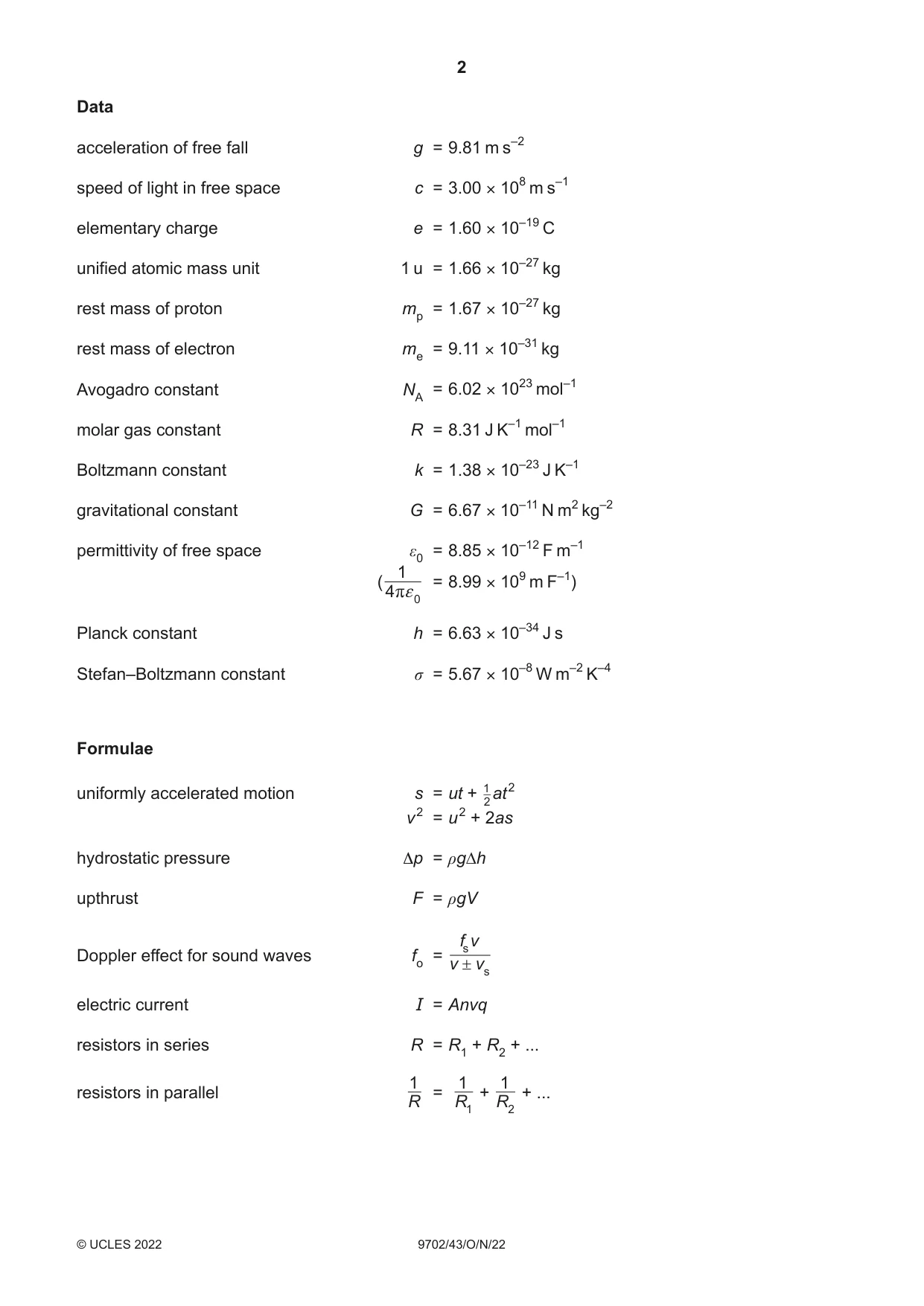
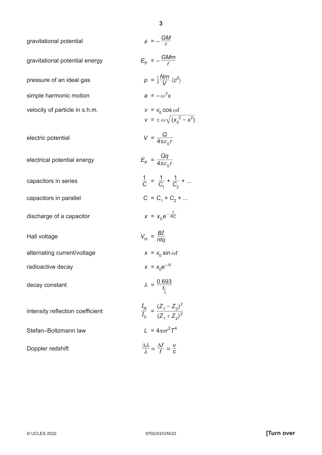



Mark scheme15 pages
Answers below. Sit the paper first if you are practising.
Questions as text
Q1 · State the equation for the gravitational force F between two point masses m1 and m2 that…
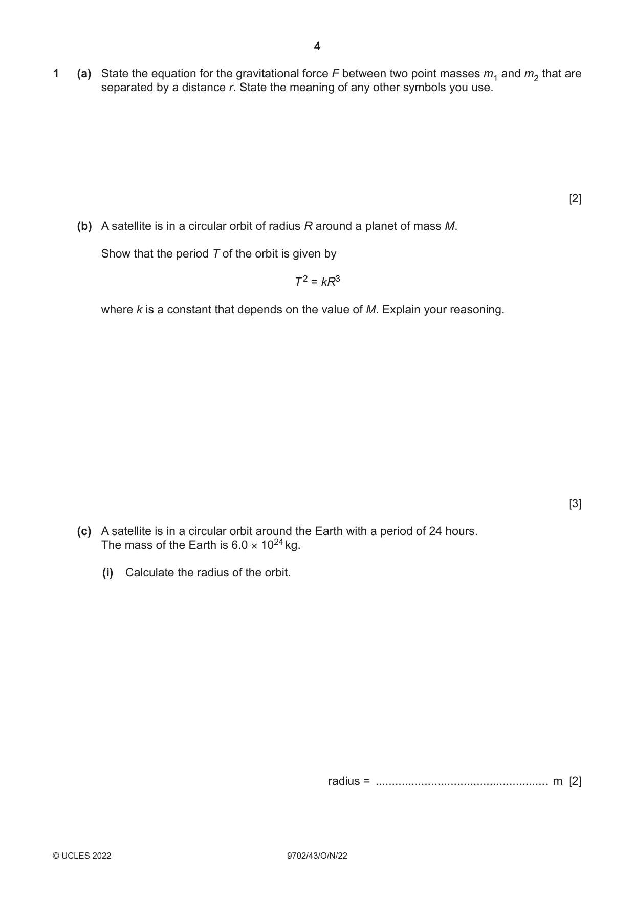
1 (a) State the equation for the gravitational force F between two point masses m1 and m2 that are separated by a distance r. State the meaning of any other symbols you use. [2] (b) A satellite is in a circular orbit of radius R around a planet of mass M. Show that the period T of the orbit is given by T 2 = kR3 where k is a constant that depends on the value of M. Explain your reasoning. [3] (c) A satellite is in a circular orbit around the Earth with a period of 24 hours. The mass of the Earth is 6.0 × 1024 kg. (i) Calculate the radius of the orbit. radius = ..................................................... m [2] (ii) State the two other conditions that must be met for the orbit to be geostationary. 1 ........................................................................................................................................ ........................................................................................................................................... 2 ........................................................................................................................................ ........................................................................................................................................... [2] [Total: 9]
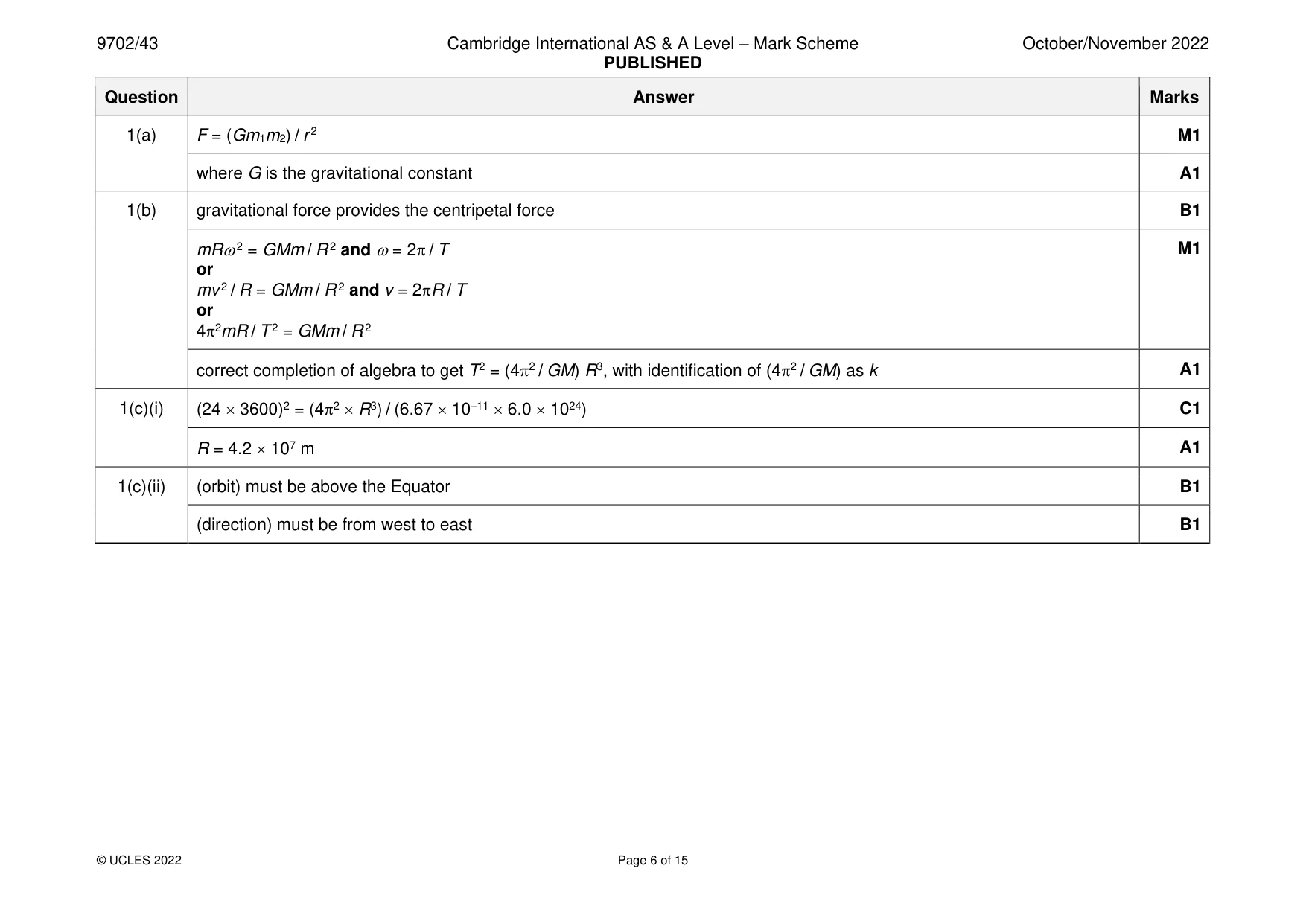
Mark scheme: Question Answer Marks 1(a) F = (Gm1m2) / r 2 M1 where G is the gravitational constant A1 1(b) gravitational force provides the centripetal force B1 mR 2 = GMm / R 2 and = 2 / T M1 or mv 2 / R = GMm / R 2 and v = 2R / T or 42mR / T 2 = GMm / R 2 correct completion of algebra to get T2 = (42 / GM) R3, with identification of (42 / GM) as k A1 1(c)(i) (24 3600)2 = (42 R3) / (6.67 10–11 6.0 1024) C1 R = 4.2 107 m A1 1(c)(ii) (orbit) must be above the Equator B1 (direction) must be from west to east B1
Q2 · A laboratory thermometer that is calibrated to measure temperature in degrees Celsius
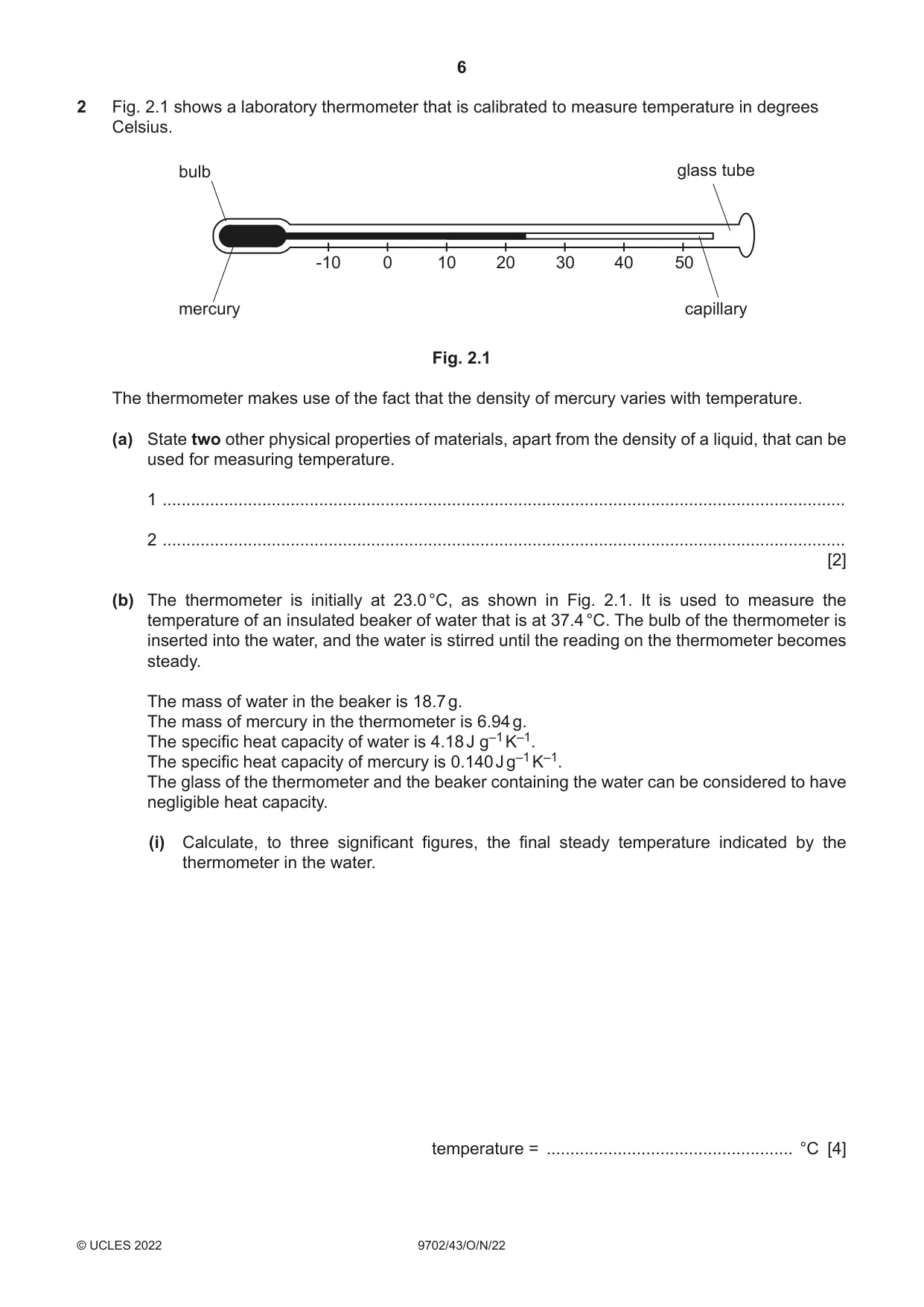
2 Fig. 2.1 shows a laboratory thermometer that is calibrated to measure temperature in degrees Celsius. bulb glass tube -10 0 10 20 30 40 50 mercury capillary Fig. 2.1 The thermometer makes use of the fact that the density of mercury varies with temperature. (a) State two other physical properties of materials, apart from the density of a liquid, that can be used for measuring temperature. 1 ................................................................................................................................................ 2 ................................................................................................................................................ [2] (b) The thermometer is initially at 23.0 °C, as shown in Fig. 2.1. It is used to measure the temperature of an insulated beaker of water that is at 37.4 °C. The bulb of the thermometer is inserted into the water, and the water is stirred until the reading on the thermometer becomes steady. The mass of water in the beaker is 18.7 g. The mass of mercury in the thermometer is 6.94 g. The specific heat capacity of water is 4.18 J g–1 K–1. The specific heat capacity of mercury is 0.140 J g–1 K–1. The glass of the thermometer and the beaker containing the water can be considered to have negligible heat capacity. (i) Calculate, to three significant figures, the final steady temperature indicated by the thermometer in the water. temperature = .................................................... °C [4] (ii) Suggest one change that could be made to the design of the thermometer that would enable it to give a more accurate measurement of temperature. ........................................................................................................................................... ..................................................................................................................................... [1] (c) (i) Explain why the thermometer in Fig. 2.1 does not provide a direct measurement of thermodynamic temperature. ........................................................................................................................................... ........................................................................................................................................... ..................................................................................................................................... [2] (ii) Thermodynamic temperature T may be determined by the behaviour of a type of substance for which T is proportional to the product of pressure and volume. State the name of this type of substance. ..................................................................................................................................... [1] [Total: 10]
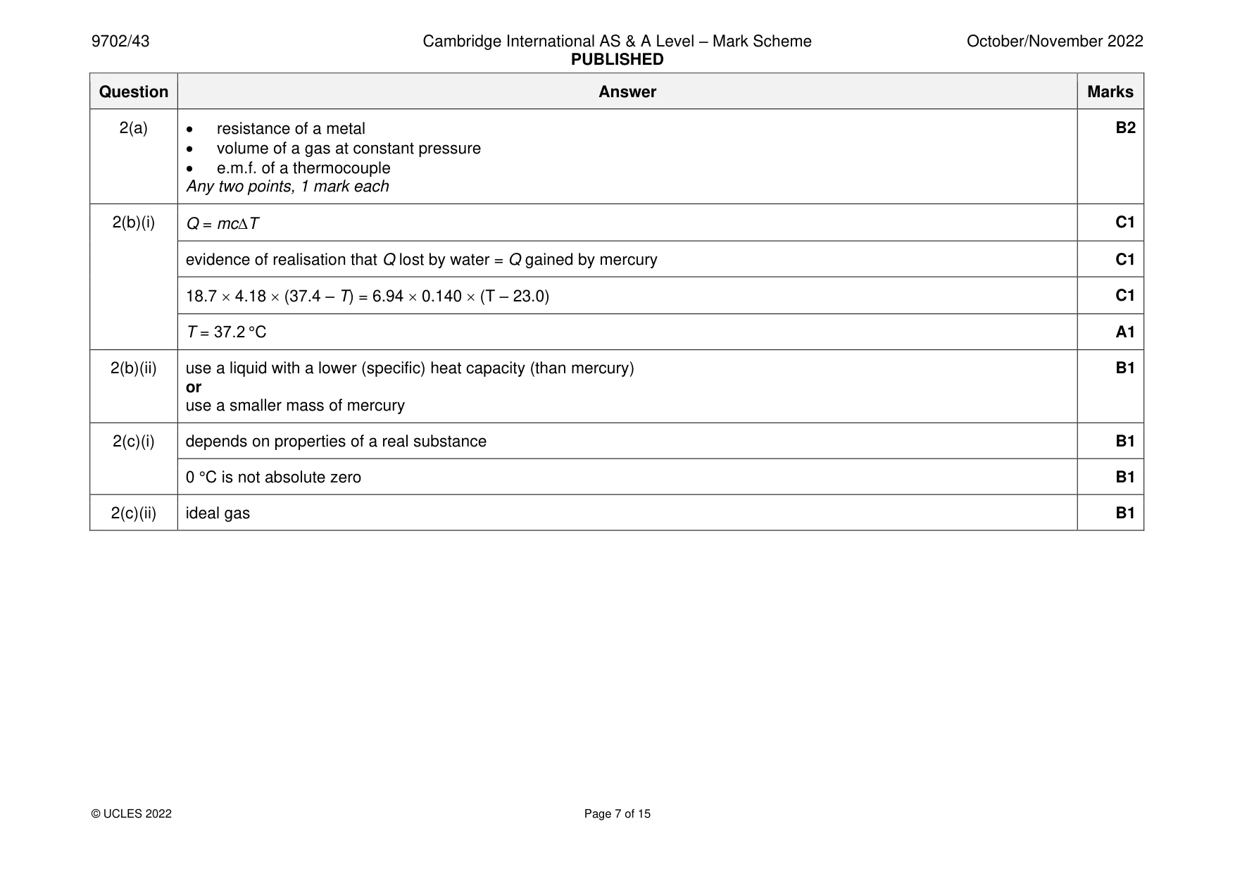
Mark scheme: 2(a) • resistance of a metal B2 • volume of a gas at constant pressure • e.m.f. of a thermocouple Any two points, 1 mark each 2(b)(i) Q = mcT C1 evidence of realisation that Q lost by water = Q gained by mercury C1 18.7 4.18 (37.4 – T) = 6.94 0.140 (T – 23.0) C1 T = 37.2 °C A1 2(b)(ii) use a liquid with a lower (specific) heat capacity (than mercury) B1 or use a smaller mass of mercury 2(c)(i) depends on properties of a real substance B1 0 °C is not absolute zero B1 2(c)(ii) ideal gas B1
Q3 · An object is suspended from a spring that is attached to a fixed point as shown in Fig
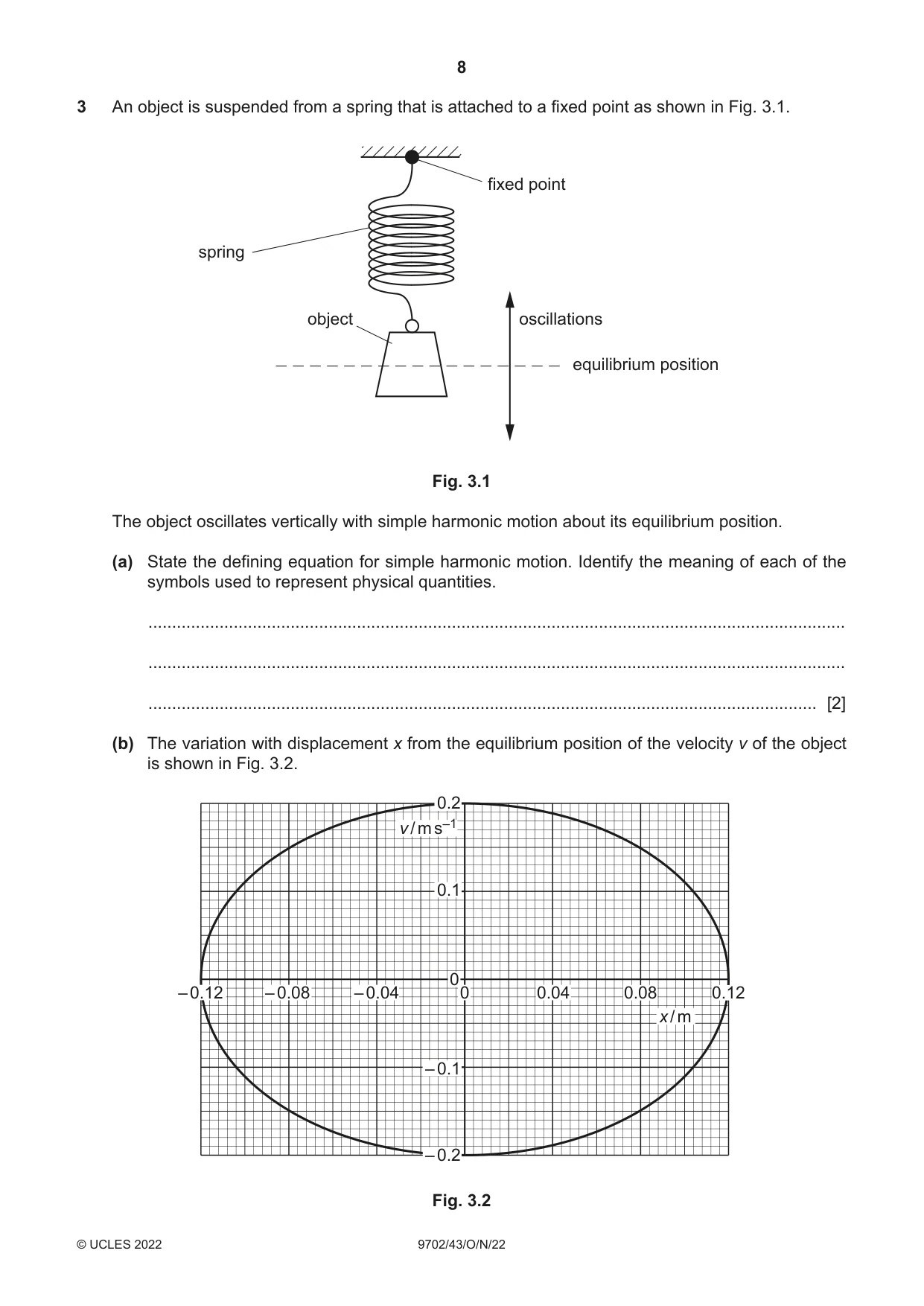
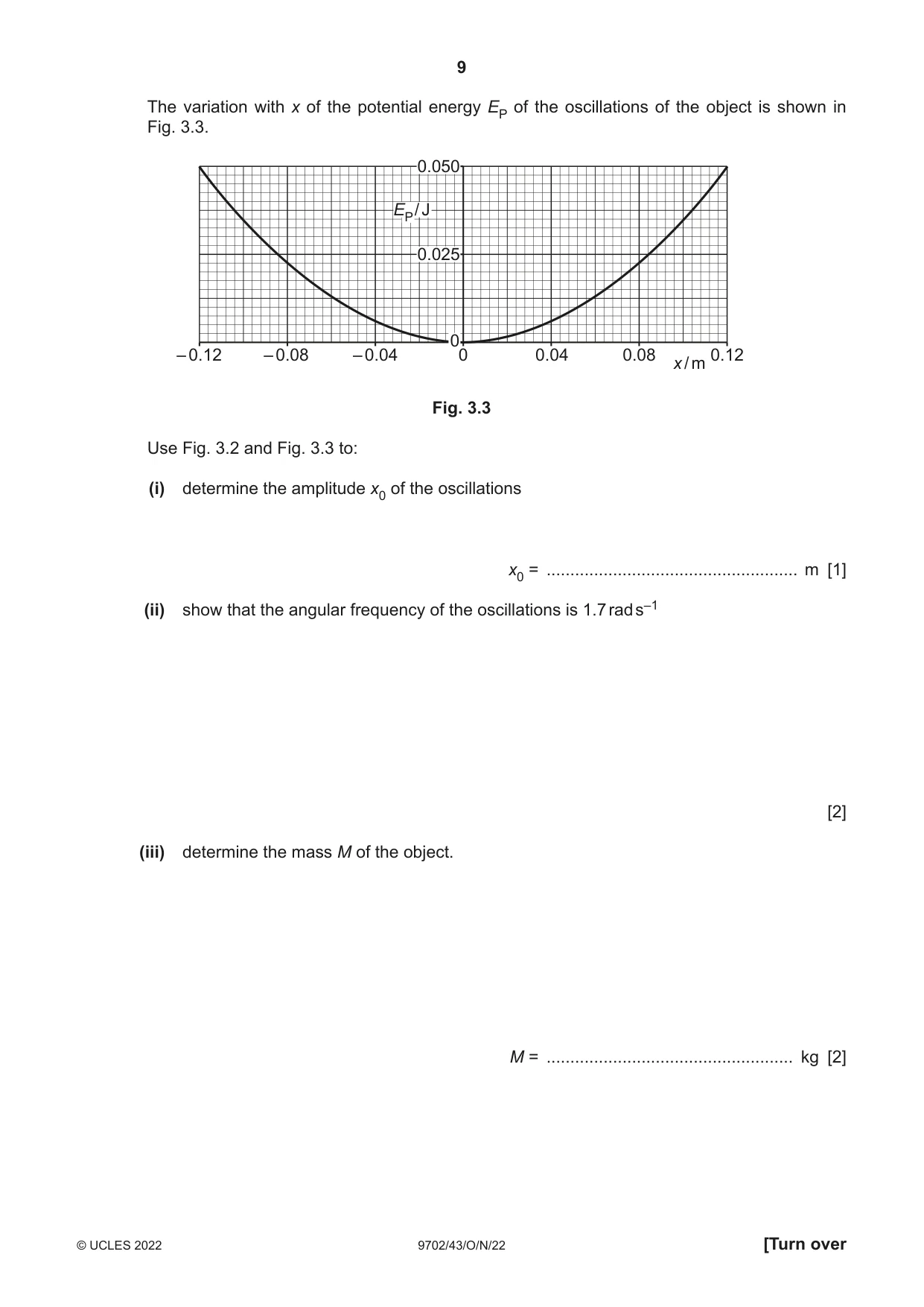
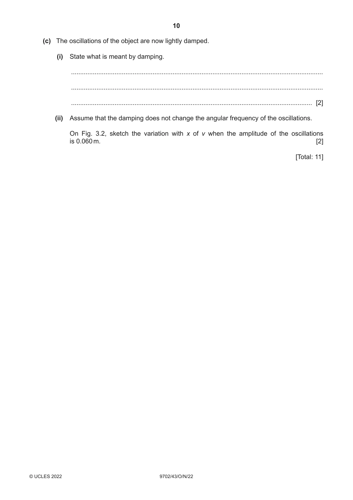
3 An object is suspended from a spring that is attached to a fixed point as shown in Fig. 3.1. fixed point spring object oscillations equilibrium position Fig. 3.1 The object oscillates vertically with simple harmonic motion about its equilibrium position. (a) State the defining equation for simple harmonic motion. Identify the meaning of each of the symbols used to represent physical quantities. ................................................................................................................................................... ................................................................................................................................................... ............................................................................................................................................. [2] (b) The variation with displacement x from the equilibrium position of the velocity v of the object is shown in Fig. 3.2. 0.2 v / m s–1 0.1 0 – 0.12 – 0.08 – 0.04 0 0.04 0.08 0.12 x / m –– 0.20.1 – 0.2 Fig. 3.2 The variation with x of the potential energy EP of the oscillations of the object is shown in Fig. 3.3. 0.050 EP / J 0.025 0 – 0.12 – 0.08 – 0.04 0 0.04 0.08 0.12 x / m Fig. 3.3 Use Fig. 3.2 and Fig. 3.3 to: (i) determine the amplitude x0 of the oscillations x0 = ..................................................... m [1] (ii) show that the angular frequency of the oscillations is 1.7 rad s–1 [2] (iii) determine the mass M of the object. M = .................................................... kg [2] (c) The oscillations of the object are now lightly damped. (i) State what is meant by damping. ........................................................................................................................................... ........................................................................................................................................... ..................................................................................................................................... [2] (ii) Assume that the damping does not change the angular frequency of the oscillations. On Fig. 3.2, sketch the variation with x of v when the amplitude of the oscillations is 0.060 m. [2] [Total: 11]
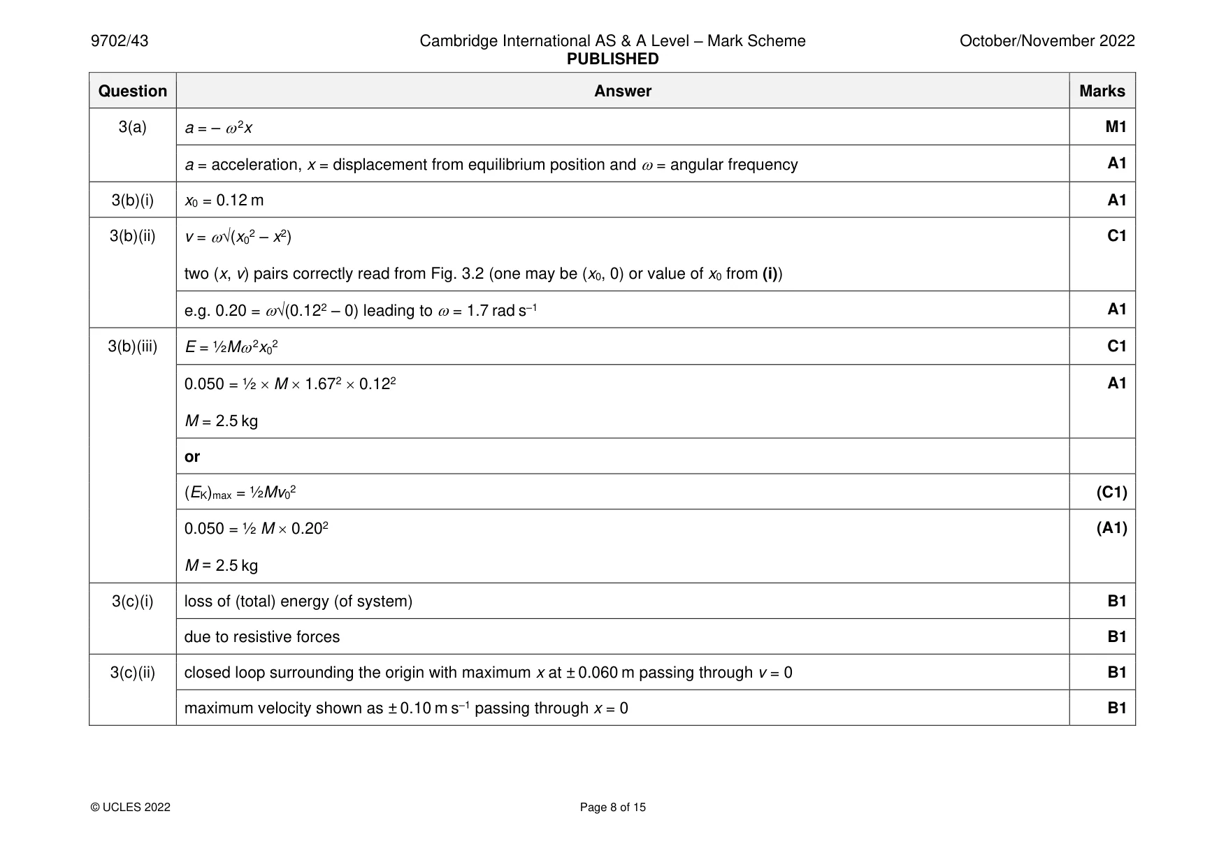
Mark scheme: 3(a) a = – 2x M1 a = acceleration, x = displacement from equilibrium position and = angular frequency A1 3(b)(i) x0 = 0.12 m A1 3(b)(ii) v = (x02 – x2) C1 two (x, v) pairs correctly read from Fig. 3.2 (one may be (x0, 0) or value of x0 from (i)) e.g. 0.20 = (0.122 – 0) leading to = 1.7 rad s–1 A1 3(b)(iii) E = ½M 2x02 C1 0.050 = ½ M 1.672 0.122 A1 M = 2.5 kg or (EK)max = ½Mv02 (C1) 0.050 = ½ M 0.202 (A1) M = 2.5 kg 3(c)(i) loss of (total) energy (of system) B1 due to resistive forces B1 3(c)(ii) closed loop surrounding the origin with maximum x at ± 0.060 m passing through v = 0 B1 maximum velocity shown as ± 0.10 m s–1 passing through x = 0 B1
Q4 · State what is indicated by the direction of an electric field line
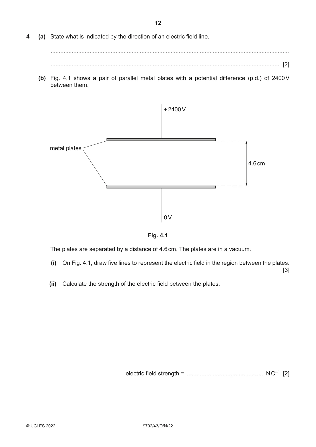
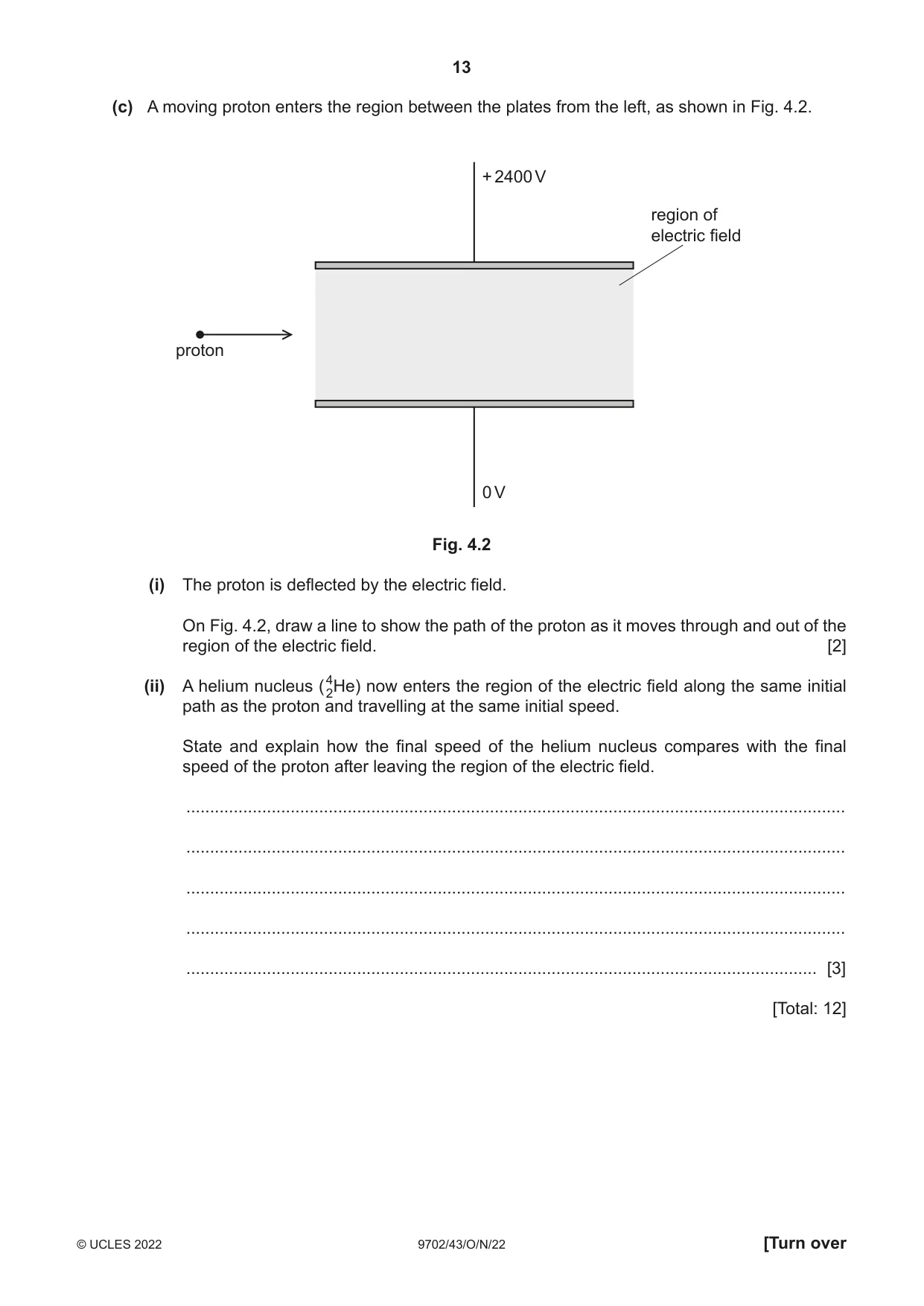
4 (a) State what is indicated by the direction of an electric field line. ................................................................................................................................................... ............................................................................................................................................. [2] (b) Fig. 4.1 shows a pair of parallel metal plates with a potential difference (p.d.) of 2400 V between them. + 2400 V metal plates 4.6 cm 0 V Fig. 4.1 The plates are separated by a distance of 4.6 cm. The plates are in a vacuum. (i) On Fig. 4.1, draw five lines to represent the electric field in the region between the plates. [3] (ii) Calculate the strength of the electric field between the plates. electric field strength = ............................................... N C–1 [2] (c) A moving proton enters the region between the plates from the left, as shown in Fig. 4.2. + 2400 V region of electric field proton 0 V Fig. 4.2 (i) The proton is deflected by the electric field. On Fig. 4.2, draw a line to show the path of the proton as it moves through and out of the region of the electric field. [2] (ii) A helium nucleus (42He) now enters the region of the electric field along the same initial path as the proton and travelling at the same initial speed. State and explain how the final speed of the helium nucleus compares with the final speed of the proton after leaving the region of the electric field. ........................................................................................................................................... ........................................................................................................................................... ........................................................................................................................................... ........................................................................................................................................... ..................................................................................................................................... [3] [Total: 12]
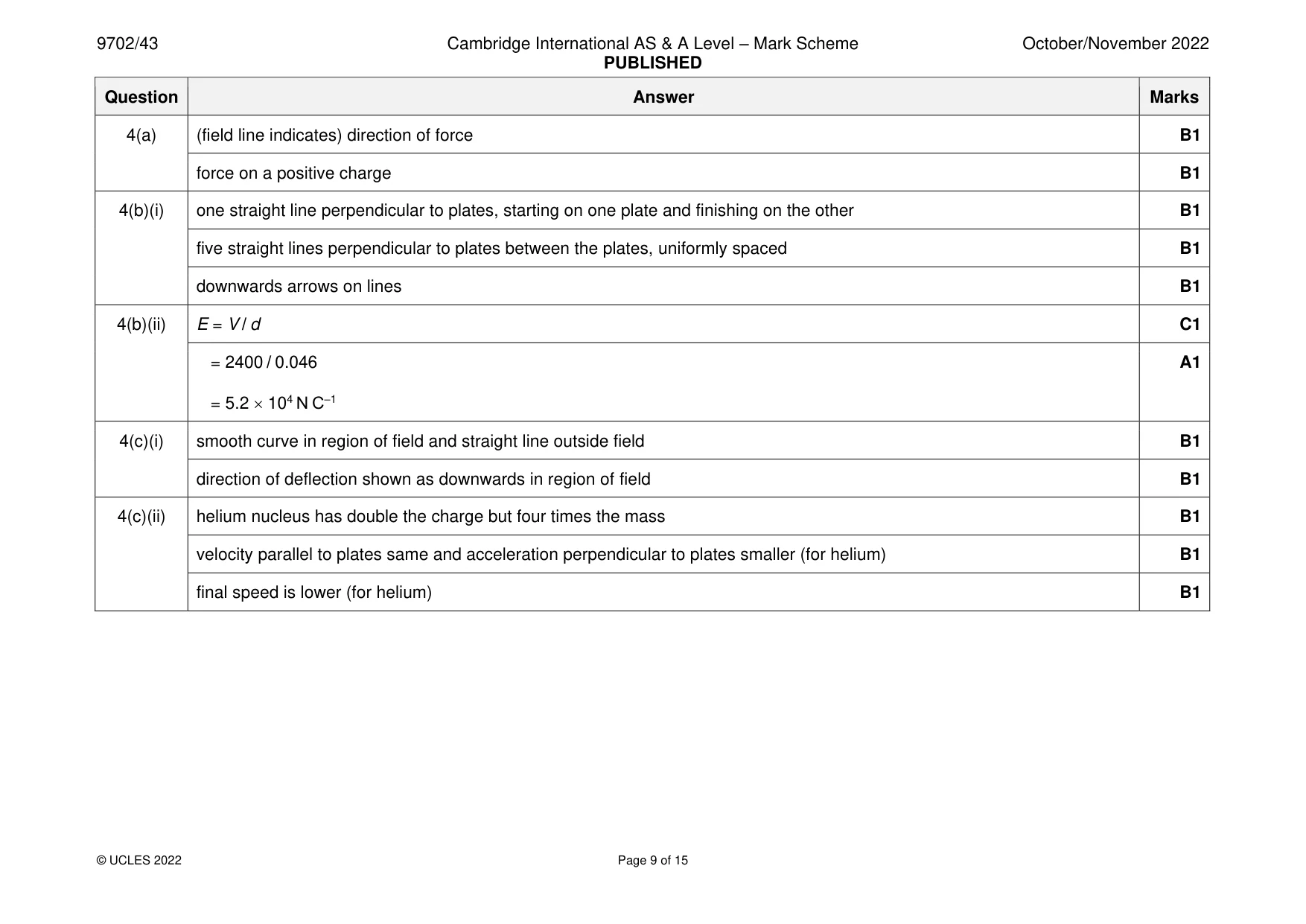
Mark scheme: 4(a) (field line indicates) direction of force B1 force on a positive charge B1 4(b)(i) one straight line perpendicular to plates, starting on one plate and finishing on the other B1 five straight lines perpendicular to plates between the plates, uniformly spaced B1 downwards arrows on lines B1 4(b)(ii) E = V / d C1 = 2400 / 0.046 A1 = 5.2 104 N C–1 4(c)(i) smooth curve in region of field and straight line outside field B1 direction of deflection shown as downwards in region of field B1 4(c)(ii) helium nucleus has double the charge but four times the mass B1 velocity parallel to plates same and acceleration perpendicular to plates smaller (for helium) B1 final speed is lower (for helium) B1
Q5 · A capacitor of capacitance 470 μF is connected to a battery of electromotive force…
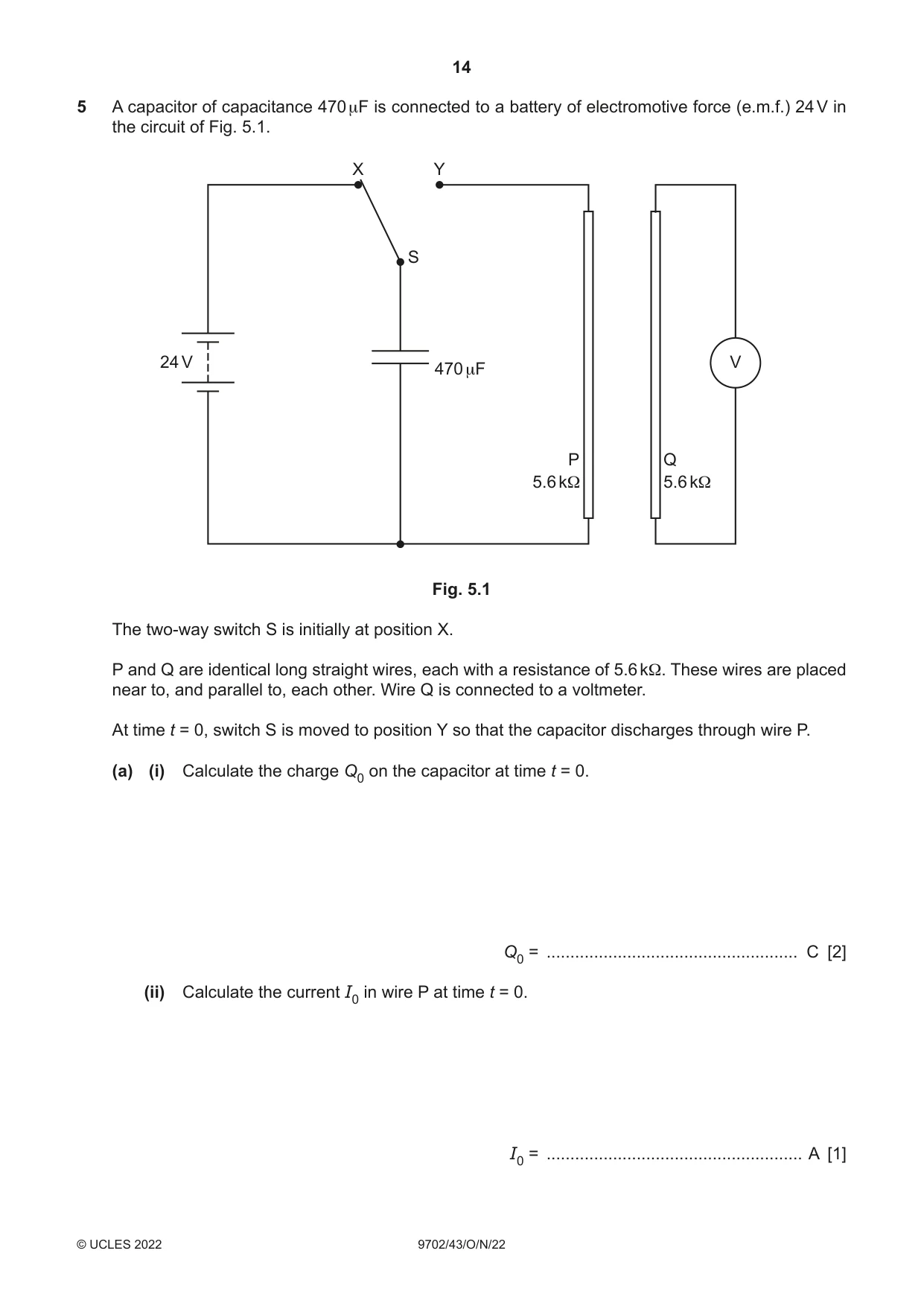
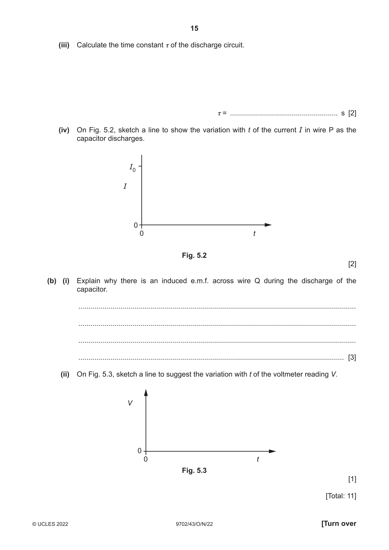
5 A capacitor of capacitance 470 μF is connected to a battery of electromotive force (e.m.f.) 24 V in the circuit of Fig. 5.1. X Y S 24 V V 470 μF P Q 5.6 kΩ 5.6 kΩ Fig. 5.1 The two-way switch S is initially at position X. P and Q are identical long straight wires, each with a resistance of 5.6 kΩ. These wires are placed near to, and parallel to, each other. Wire Q is connected to a voltmeter. At time t = 0, switch S is moved to position Y so that the capacitor discharges through wire P. (a) (i) Calculate the charge Q0 on the capacitor at time t = 0. Q0 = ..................................................... C [2] (ii) Calculate the current I0 in wire P at time t = 0. I0 = ...................................................... A [1] (iii) Calculate the time constant τ of the discharge circuit. τ = ...................................................... s [2] (iv) On Fig. 5.2, sketch a line to show the variation with t of the current I in wire P as the capacitor discharges. I0 I 0 0 t Fig. 5.2 [2] (b) (i) Explain why there is an induced e.m.f. across wire Q during the discharge of the capacitor. ........................................................................................................................................... ........................................................................................................................................... ........................................................................................................................................... ..................................................................................................................................... [3] (ii) On Fig. 5.3, sketch a line to suggest the variation with t of the voltmeter reading V. V 0 0 t Fig. 5.3 [1] [Total: 11]
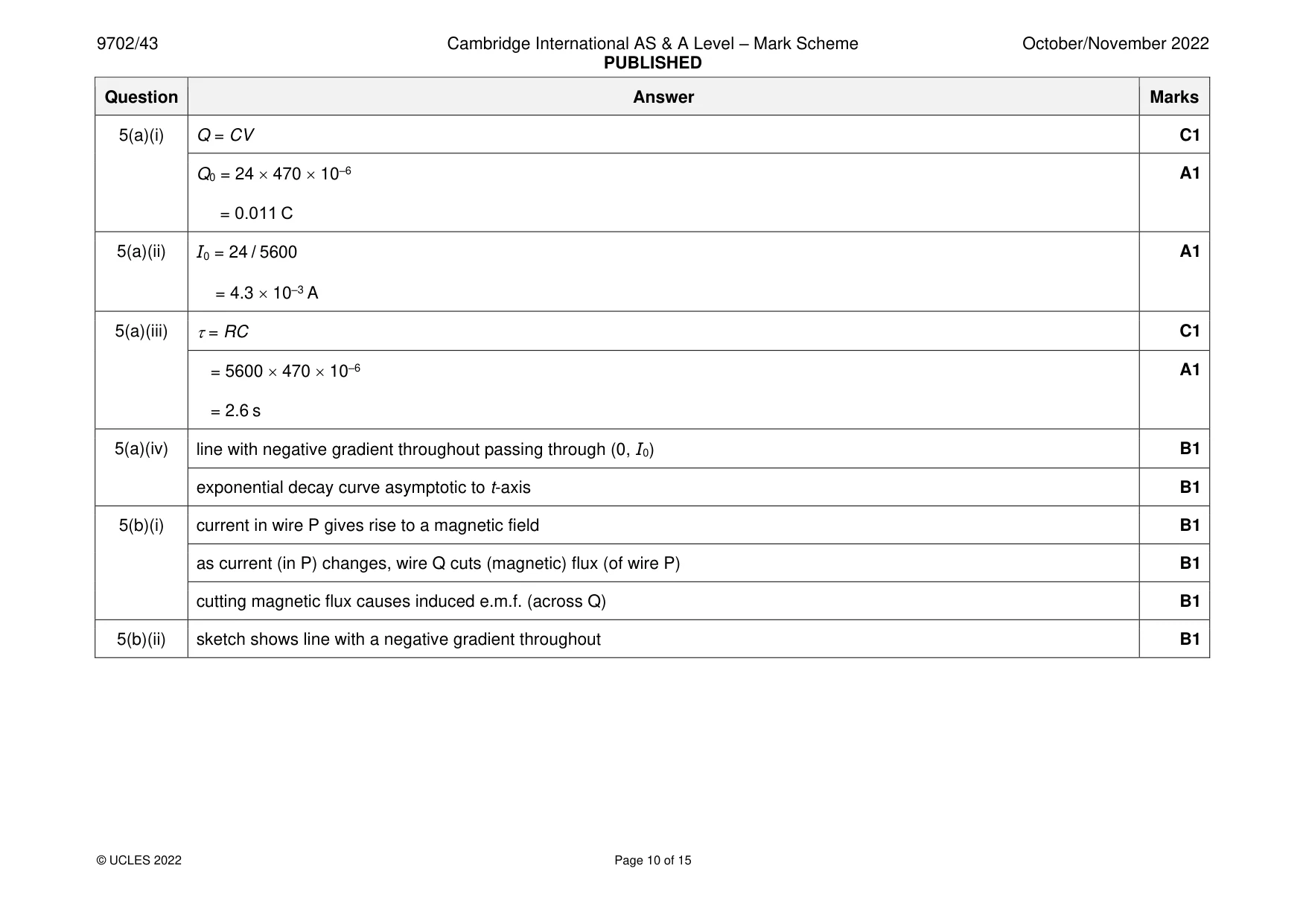
Mark scheme: 5(a)(i) Q = CV C1 Q0 = 24 470 10–6 A1 = 0.011 C 5(a)(ii) I0 = 24 / 5600 A1 = 4.3 10–3 A 5(a)(iii) = RC C1 = 5600 470 10–6 A1 = 2.6 s 5(a)(iv) line with negative gradient throughout passing through (0, I0) B1 exponential decay curve asymptotic to t-axis B1 5(b)(i) current in wire P gives rise to a magnetic field B1 as current (in P) changes, wire Q cuts (magnetic) flux (of wire P) B1 cutting magnetic flux causes induced e.m.f. (across Q) B1 5(b)(ii) sketch shows line with a negative gradient throughout B1
Q6 · A thin slice of semiconducting material used in a Hall probe
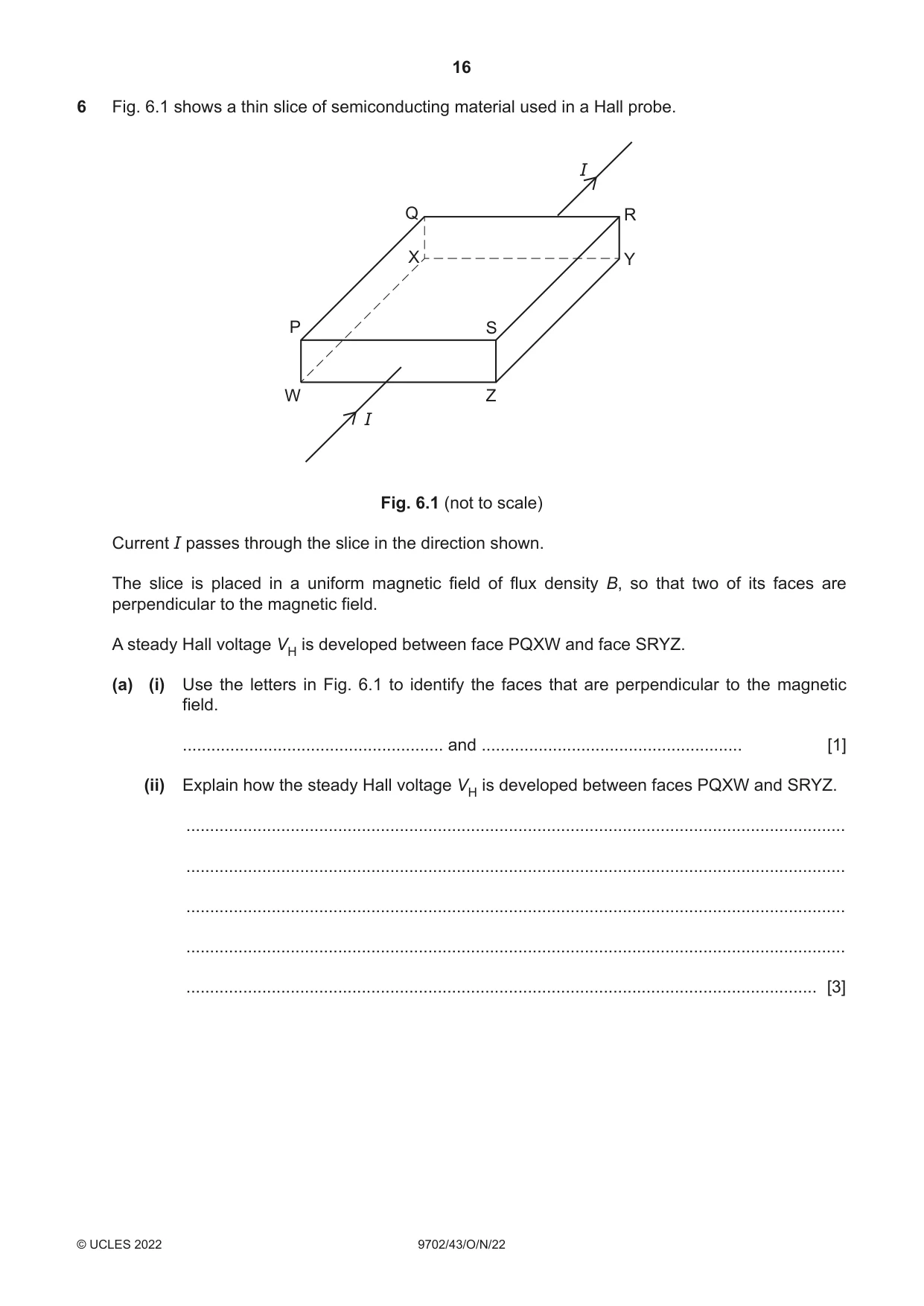
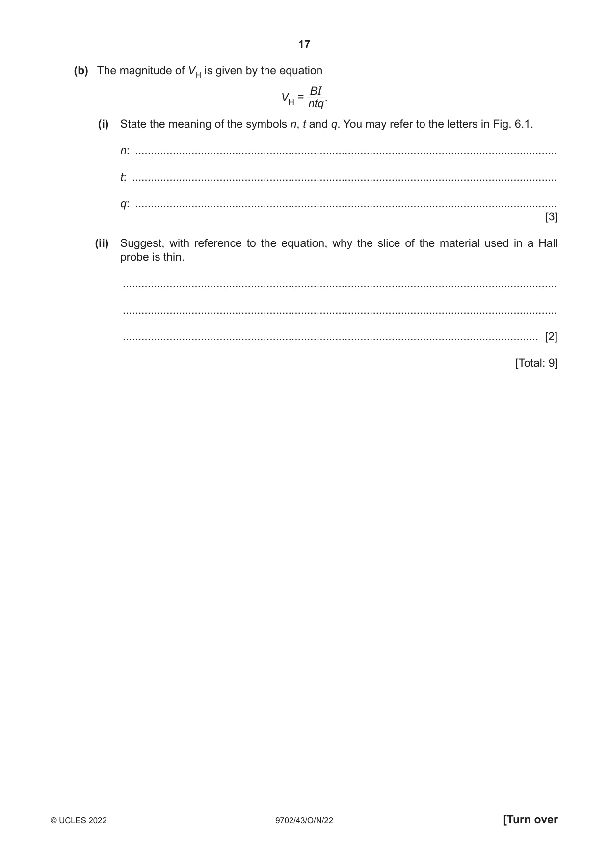
6 Fig. 6.1 shows a thin slice of semiconducting material used in a Hall probe. I Q R X Y P S W Z I Fig. 6.1 (not to scale) Current I passes through the slice in the direction shown. The slice is placed in a uniform magnetic field of flux density B, so that two of its faces are perpendicular to the magnetic field. A steady Hall voltage VH is developed between face PQXW and face SRYZ. (a) (i) Use the letters in Fig. 6.1 to identify the faces that are perpendicular to the magnetic field. ....................................................... and ....................................................... [1] (ii) Explain how the steady Hall voltage VH is developed between faces PQXW and SRYZ. ........................................................................................................................................... ........................................................................................................................................... ........................................................................................................................................... ........................................................................................................................................... ..................................................................................................................................... [3] (b) The magnitude of VH is given by the equation BI VH = ntq. (i) State the meaning of the symbols n, t and q. You may refer to the letters in Fig. 6.1. n: ....................................................................................................................................... t: ........................................................................................................................................ q: ....................................................................................................................................... [3] (ii) Suggest, with reference to the equation, why the slice of the material used in a Hall probe is thin. ........................................................................................................................................... ........................................................................................................................................... ..................................................................................................................................... [2] [Total: 9]
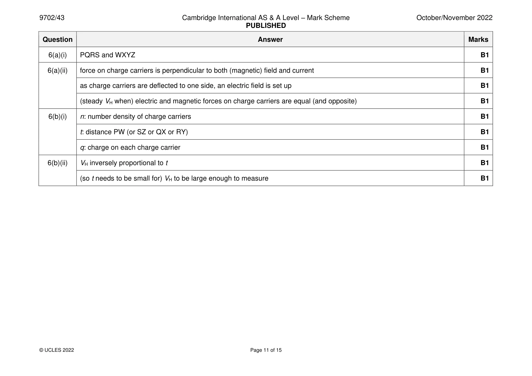
Mark scheme: 6(a)(i) PQRS and WXYZ B1 6(a)(ii) force on charge carriers is perpendicular to both (magnetic) field and current B1 as charge carriers are deflected to one side, an electric field is set up B1 (steady VH when) electric and magnetic forces on charge carriers are equal (and opposite) B1 6(b)(i) n: number density of charge carriers B1 t: distance PW (or SZ or QX or RY) B1 q: charge on each charge carrier B1 6(b)(ii) VH inversely proportional to t B1 (so t needs to be small for) VH to be large enough to measure B1
Q7 · A sinusoidal alternating voltage has a root-mean-square (r.m.s.) potential difference…
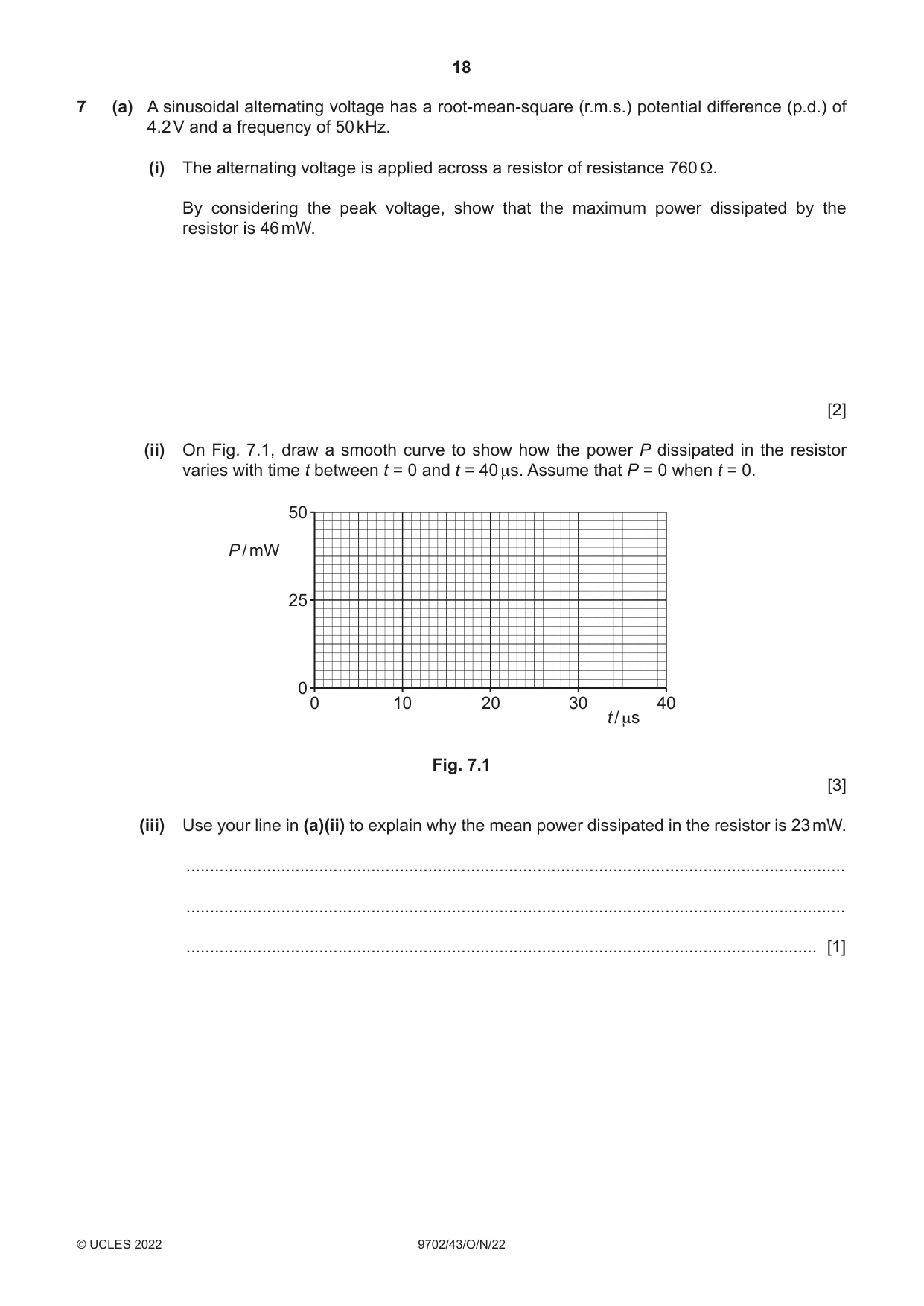
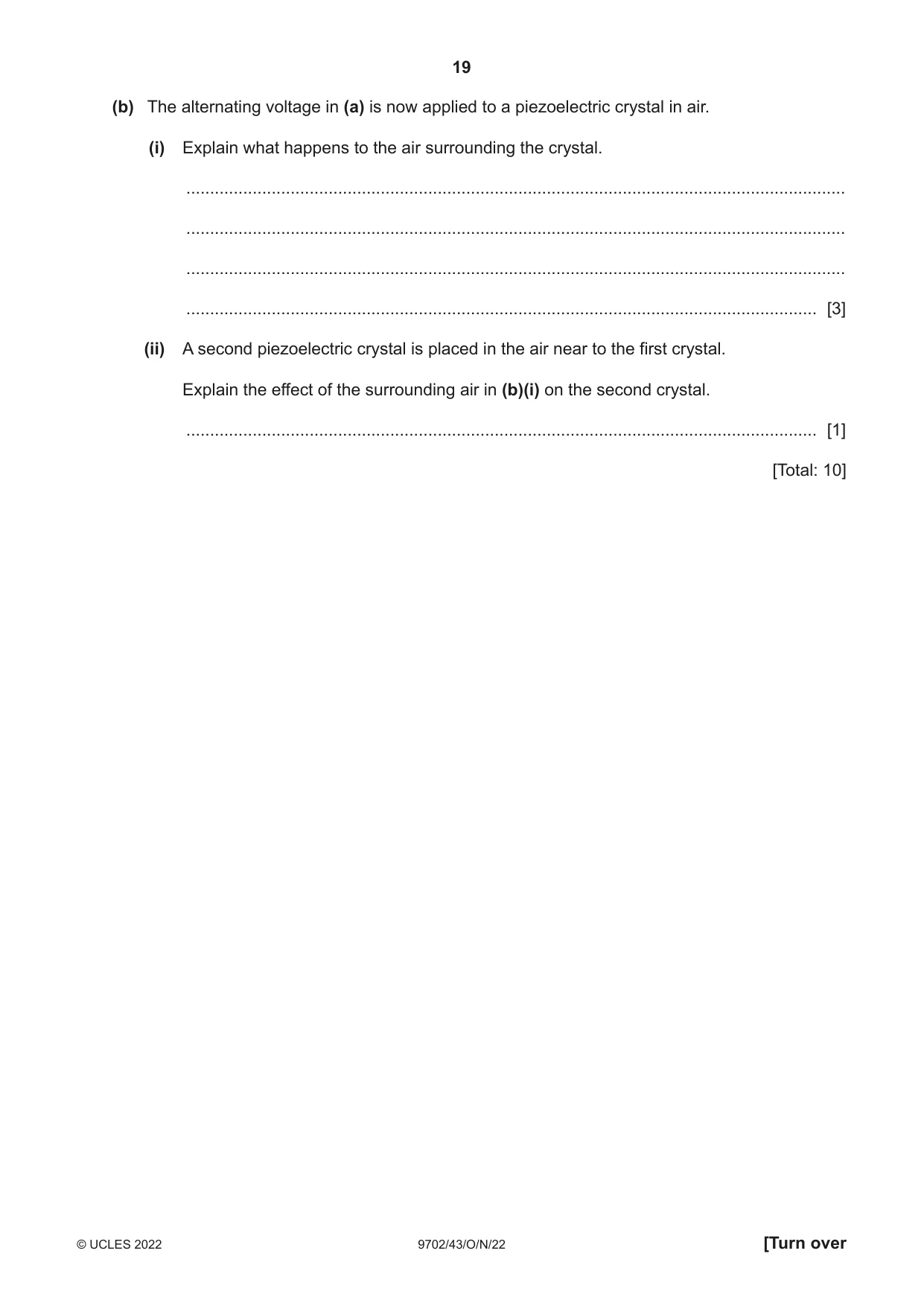
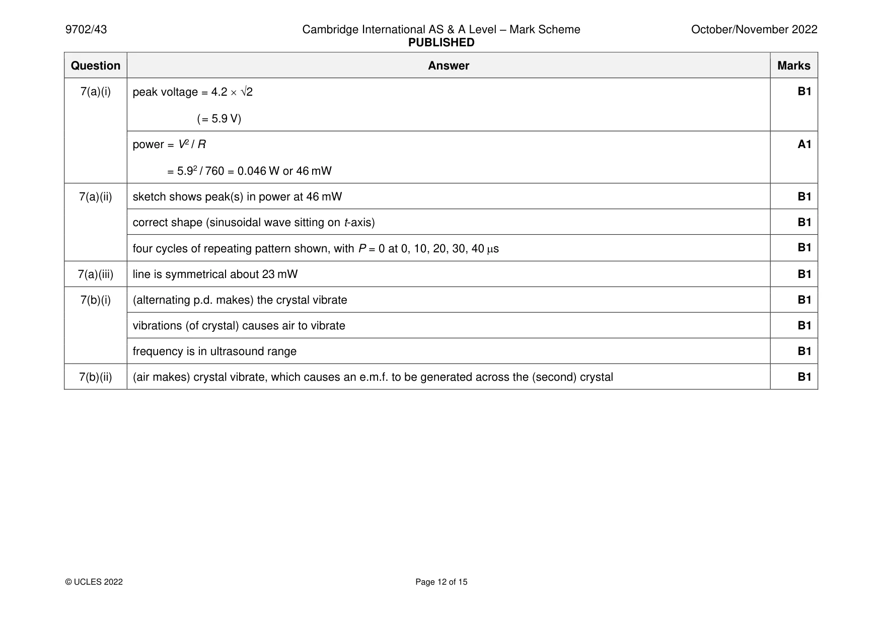
7 (a) A sinusoidal alternating voltage has a root-mean-square (r.m.s.) potential difference (p.d.) of 4.2 V and a frequency of 50 kHz. (i) The alternating voltage is applied across a resistor of resistance 760 Ω. By considering the peak voltage, show that the maximum power dissipated by the resistor is 46 mW. [2] (ii) On Fig. 7.1, draw a smooth curve to show how the power P dissipated in the resistor varies with time t between t = 0 and t = 40 μs. Assume that P = 0 when t = 0. 50 P / mW 25 0 0 10 20 30 40 t / μs Fig. 7.1 [3] (iii) Use your line in (a)(ii) to explain why the mean power dissipated in the resistor is 23 mW. ........................................................................................................................................... ........................................................................................................................................... ..................................................................................................................................... [1] (b) The alternating voltage in (a) is now applied to a piezoelectric crystal in air. (i) Explain what happens to the air surrounding the crystal. ........................................................................................................................................... ........................................................................................................................................... ........................................................................................................................................... ..................................................................................................................................... [3] (ii) A second piezoelectric crystal is placed in the air near to the first crystal. Explain the effect of the surrounding air in (b)(i) on the second crystal. ..................................................................................................................................... [1] [Total: 10]
Mark scheme: 7(a)(i) peak voltage = 4.2 2 B1 ( = 5.9 V) power = V2 / R A1 = 5.92 / 760 = 0.046 W or 46 mW 7(a)(ii) sketch shows peak(s) in power at 46 mW B1 correct shape (sinusoidal wave sitting on t-axis) B1 four cycles of repeating pattern shown, with P = 0 at 0, 10, 20, 30, 40 s B1 7(a)(iii) line is symmetrical about 23 mW B1 7(b)(i) (alternating p.d. makes) the crystal vibrate B1 vibrations (of crystal) causes air to vibrate B1 frequency is in ultrasound range B1 7(b)(ii) (air makes) crystal vibrate, which causes an e.m.f. to be generated across the (second) crystal B1
Q8 · State what is meant by the work function energy of a metal
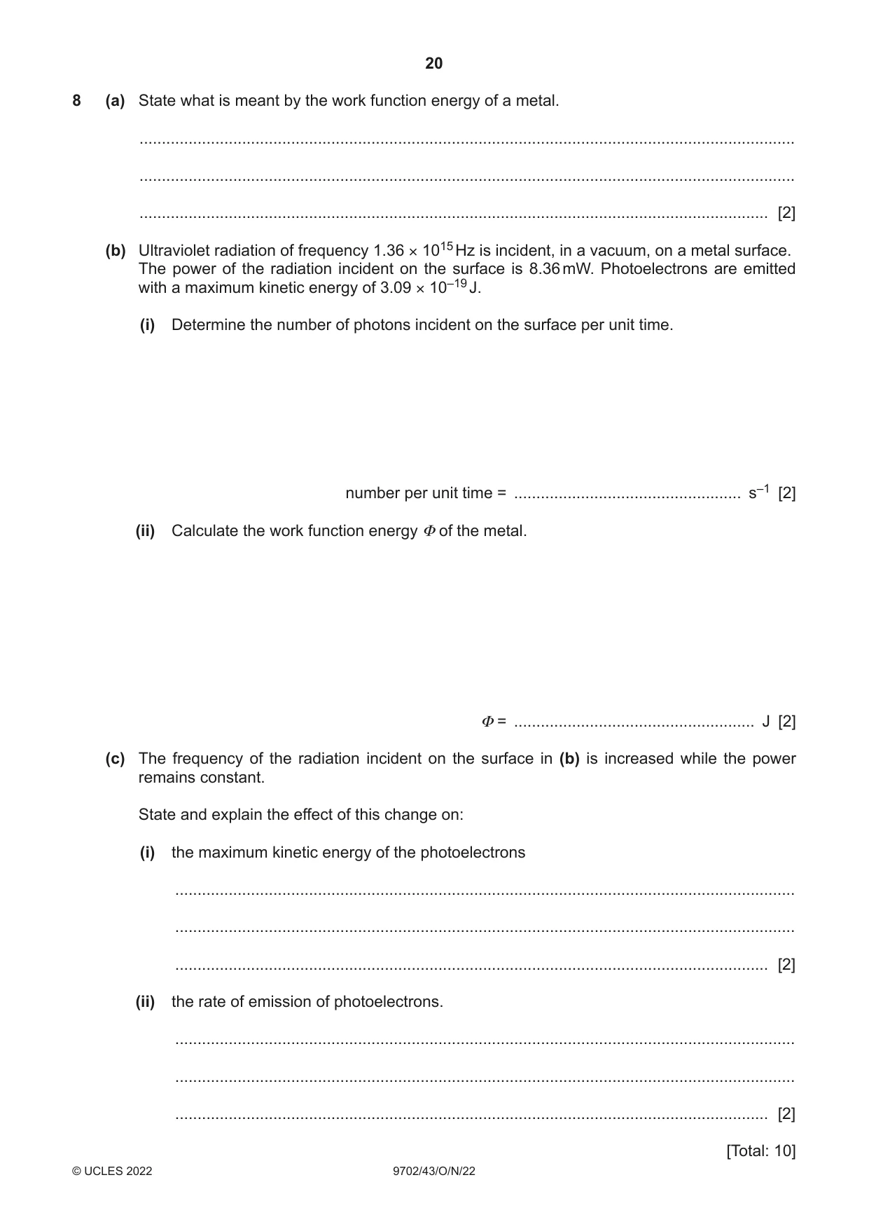
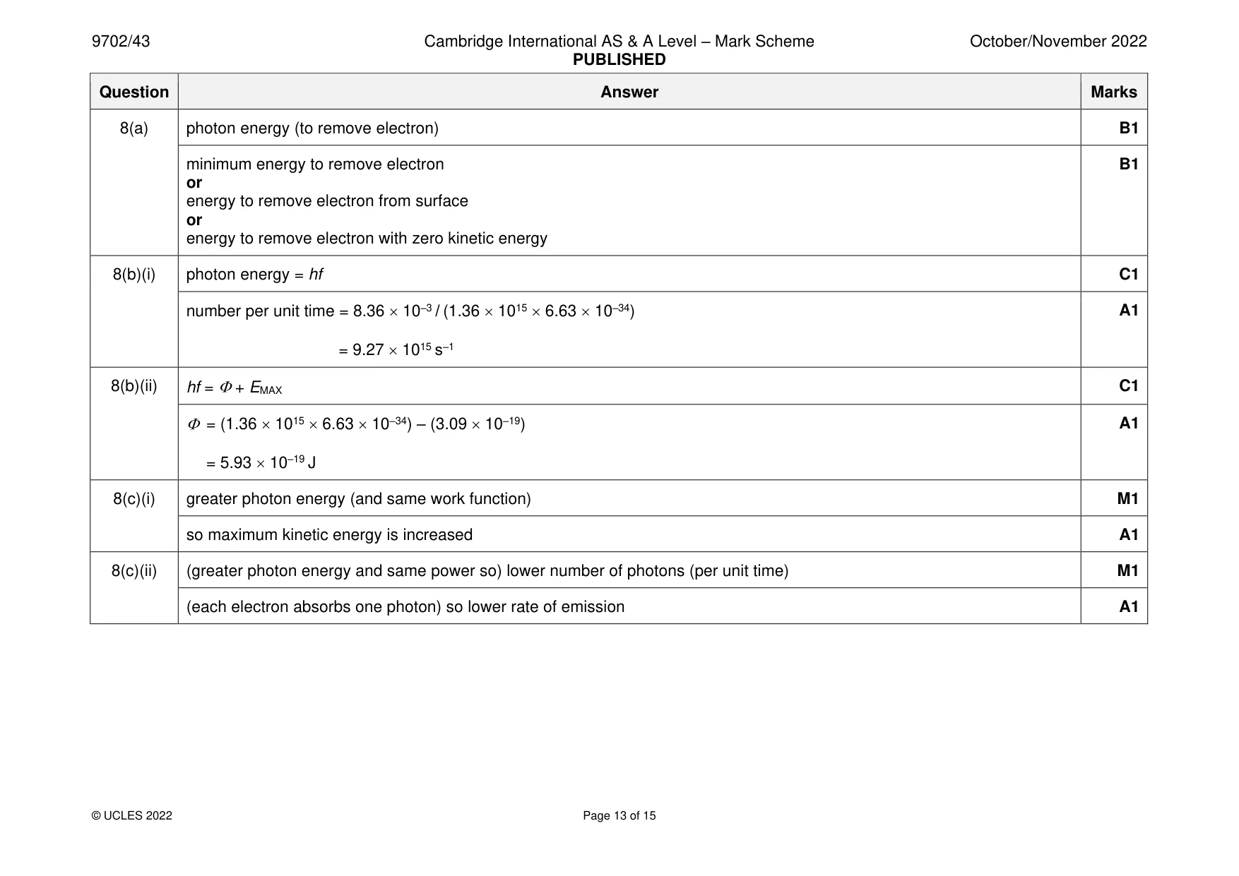
8 (a) State what is meant by the work function energy of a metal. ................................................................................................................................................... ................................................................................................................................................... ............................................................................................................................................. [2] (b) Ultraviolet radiation of frequency 1.36 × 10¹⁵ Hz is incident, in a vacuum, on a metal surface. The power of the radiation incident on the surface is 8.36 mW. Photoelectrons are emitted with a maximum kinetic energy of 3.09 × 10⁻¹⁹ J. (i) Determine the number of photons incident on the surface per unit time. number per unit time = ................................................... s–1 [2] (ii) Calculate the work function energy Φ of the metal. Φ = ...................................................... J [2] (c) The frequency of the radiation incident on the surface in (b) is increased while the power remains constant. State and explain the effect of this change on: (i) the maximum kinetic energy of the photoelectrons ........................................................................................................................................... ........................................................................................................................................... ..................................................................................................................................... [2] (ii) the rate of emission of photoelectrons. ........................................................................................................................................... ........................................................................................................................................... ..................................................................................................................................... [2] [Total: 10]
Mark scheme: 8(a) photon energy (to remove electron) B1 minimum energy to remove electron B1 or energy to remove electron from surface or energy to remove electron with zero kinetic energy 8(b)(i) photon energy = hf C1 number per unit time = 8.36 10–3 / (1.36 1015 6.63 10–34) A1 = 9.27 1015 s–1 8(b)(ii) hf = + EMAX C1 = (1.36 1015 6.63 10–34) – (3.09 10–19) A1 = 5.93 10–19 J 8(c)(i) greater photon energy (and same work function) M1 so maximum kinetic energy is increased A1 8(c)(ii) (greater photon energy and same power so) lower number of photons (per unit time) M1 (each electron absorbs one photon) so lower rate of emission A1
Q9 · State what is meant by the luminosity of a star
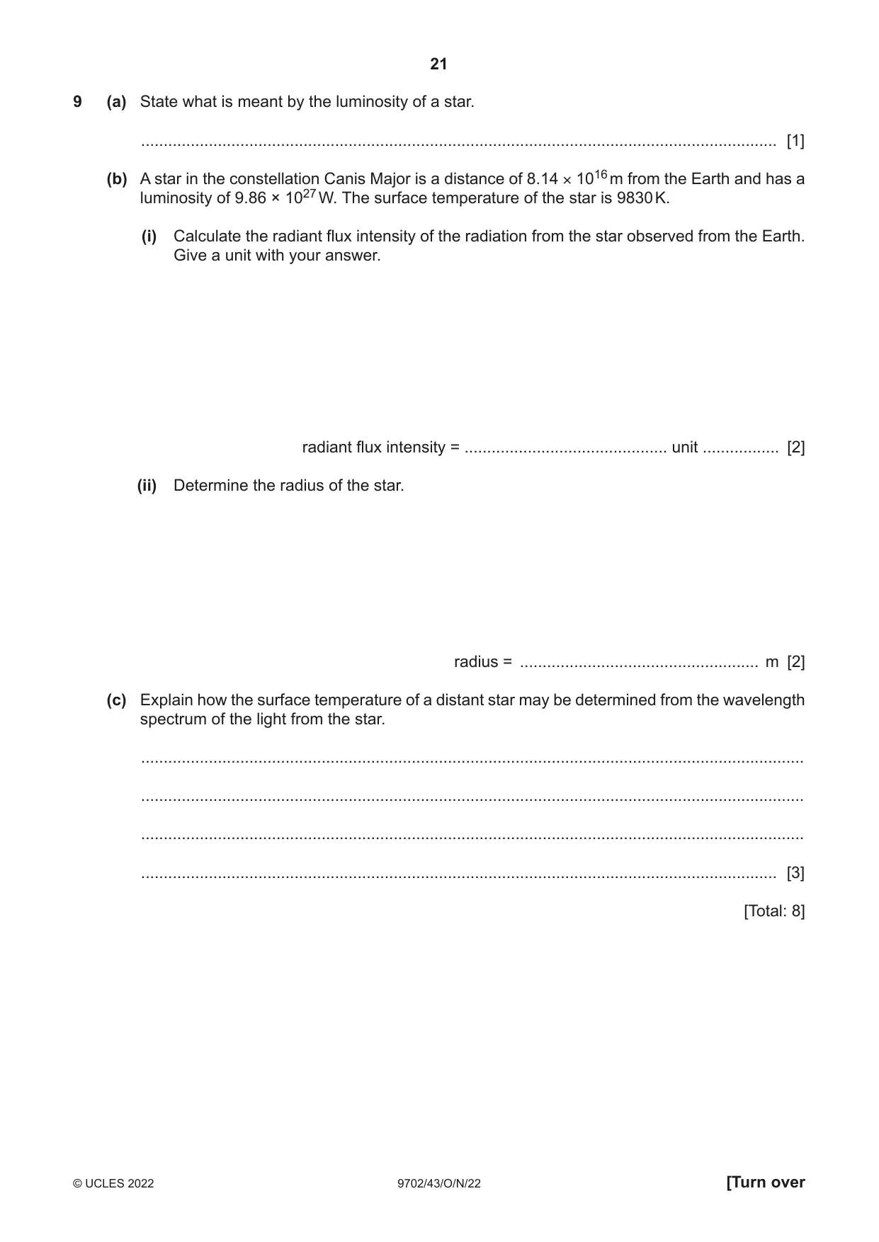
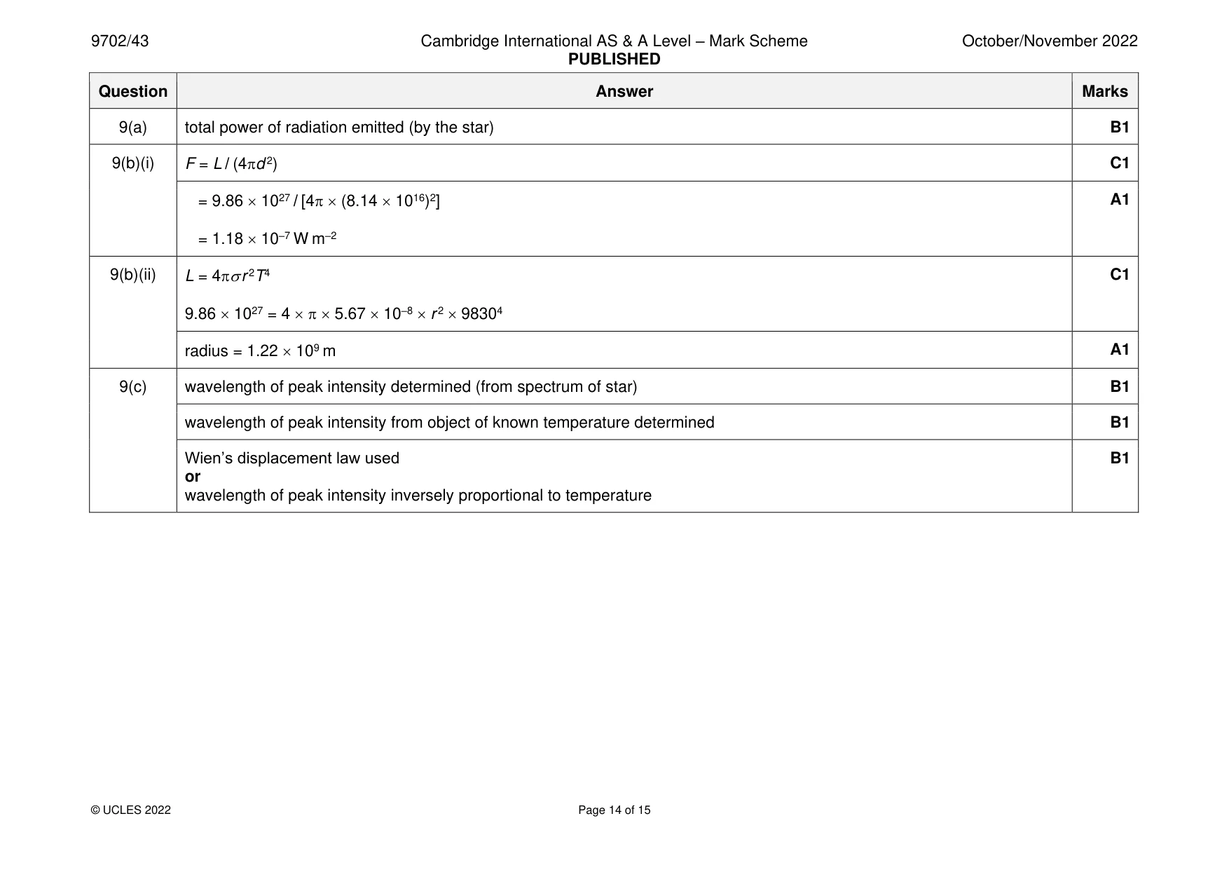
9 (a) State what is meant by the luminosity of a star. ............................................................................................................................................. [1] (b) A star in the constellation Canis Major is a distance of 8.14 × 10¹⁶ m from the Earth and has a luminosity of 9.86 × 1027 W. The surface temperature of the star is 9830 K. (i) Calculate the radiant flux intensity of the radiation from the star observed from the Earth. Give a unit with your answer. radiant flux intensity = ............................................. unit ................. [2] (ii) Determine the radius of the star. radius = ..................................................... m [2] (c) Explain how the surface temperature of a distant star may be determined from the wavelength spectrum of the light from the star. ................................................................................................................................................... ................................................................................................................................................... ................................................................................................................................................... ............................................................................................................................................. [3] [Total: 8]
Mark scheme: 9(a) total power of radiation emitted (by the star) B1 9(b)(i) F = L / (4d 2) C1 = 9.86 1027 / [4 (8.14 1016)2] A1 = 1.18 10–7 W m–2 9(b)(ii) L = 4 r 2T4 C1 9.86 1027 = 4 5.67 10–8 r 2 98304 radius = 1.22 109 m A1 9(c) wavelength of peak intensity determined (from spectrum of star) B1 wavelength of peak intensity from object of known temperature determined B1 Wien’s displacement law used B1 or wavelength of peak intensity inversely proportional to temperature
Q10 · Carbon-15 (156 C) is an isotope of carbon that undergoes radioactive decay to nitrogen-15…
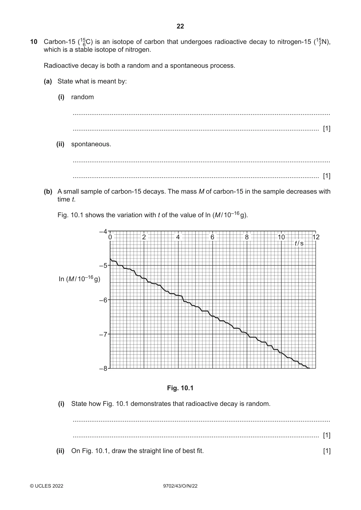
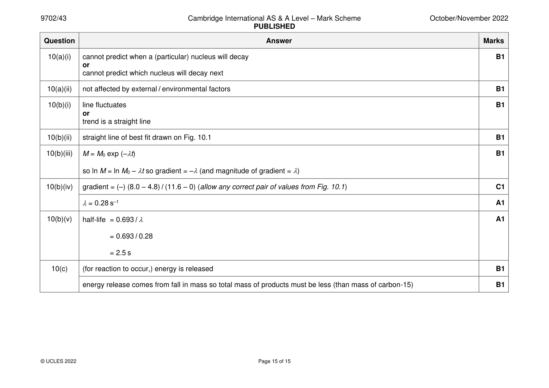
10 Carbon-15 (156 C) is an isotope of carbon that undergoes radioactive decay to nitrogen-15 (157 N), which is a stable isotope of nitrogen. Radioactive decay is both a random and a spontaneous process. (a) State what is meant by: (i) random ........................................................................................................................................... ..................................................................................................................................... [1] (ii) spontaneous. ........................................................................................................................................... ..................................................................................................................................... [1] (b) A small sample of carbon-15 decays. The mass M of carbon-15 in the sample decreases with time t. Fig. 10.1 shows the variation with t of the value of ln (M / 10–16 g). – 4 0 2 4 6 8 10 12 t / s – 5 In (M / 10–16 g) – 6 – 7 – 8 Fig. 10.1 (i) State how Fig. 10.1 demonstrates that radioactive decay is random. ........................................................................................................................................... ..................................................................................................................................... [1] (ii) On Fig. 10.1, draw the straight line of best fit. [1] (iii) Show that the decay constant λ of carbon-15 is given by the magnitude of the gradient of your line in (b)(ii). [1] (iv) Use your line in (b)(ii) to determine λ. Give a unit with your answer. λ = ....................................................... unit .......................... [2] (v) Use your answer in (b)(iv) to calculate the half-life of carbon-15. half-life = ...................................................... s [1] (c) The equation for the decay of carbon-15 can be written as 156C 157N + –1β0 + 00ν. State and explain how the mass of the products of the decay must compare with the mass of the carbon-15 nucleus. ................................................................................................................................................... ................................................................................................................................................... ............................................................................................................................................. [2] [Total: 10]
Mark scheme: 10(a)(i) cannot predict when a (particular) nucleus will decay B1 or cannot predict which nucleus will decay next 10(a)(ii) not affected by external / environmental factors B1 10(b)(i) line fluctuates B1 or trend is a straight line 10(b)(ii) straight line of best fit drawn on Fig. 10.1 B1 10(b)(iii) M = M0 exp (–t) B1 so ln M = ln M0 – t so gradient = –(and magnitude of gradient = ) 10(b)(iv) gradient = (–) (8.0 – 4.8) / (11.6 – 0) (allow any correct pair of values from Fig. 10.1) C1 = 0.28 s–1 A1 10(b)(v) half-life = 0.693 / A1 = 0.693 / 0.28 = 2.5 s 10(c) (for reaction to occur,) energy is released B1 energy release comes from fall in mass so total mass of products must be less (than mass of carbon-15) B1
What was in this paper
The subtopics covered by these 10 questions, and how many questions each got. Open one in a new tab to see every Cambridge question on it.
What you needed in this session
Cambridge’s own grade thresholds for 2022 Oct/Nov, Paper 4 · Variant 3. A higher threshold means an easier paper — the bar moves with how the cohort did.