Cambridge A Level Physics 9702 — 2019 May/June Paper 4 · Variant 2
9702/42/M/J/19 · 12 questions · 100 marks · ≈113 min
The question paper and its mark scheme, free to read here and free to download. This is Cambridge’s own paper, exactly as it was sat.
Question paper28 pages




Mark scheme14 pages
Answers below. Sit the paper first if you are practising.
Questions as text
Q1 · Two point masses are separated by a distance x in a vacuum
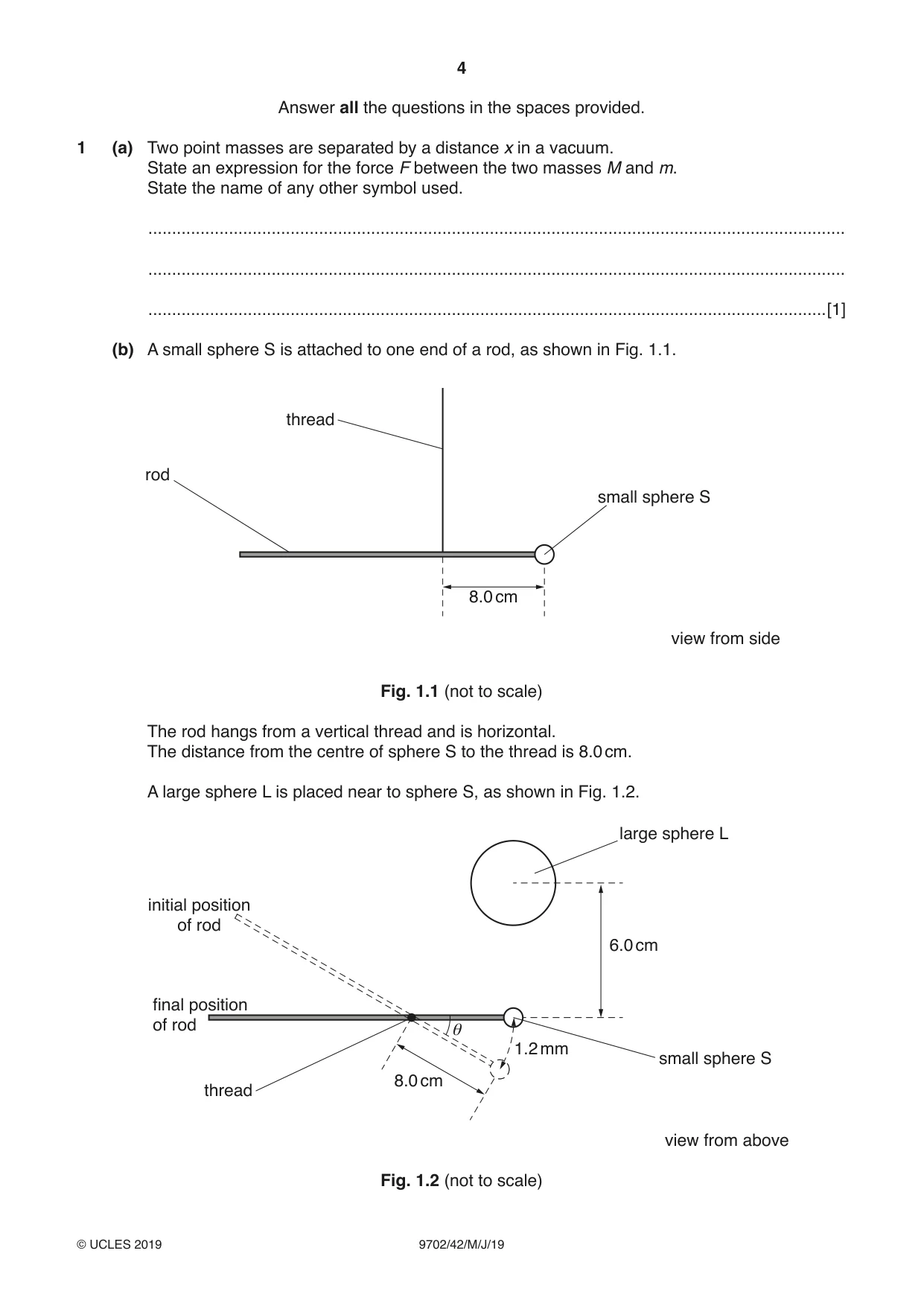
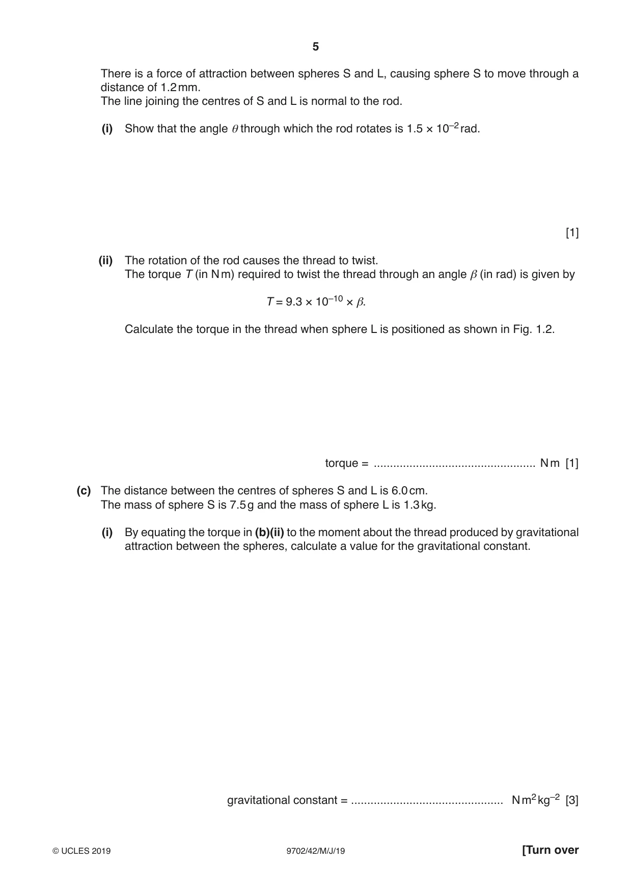
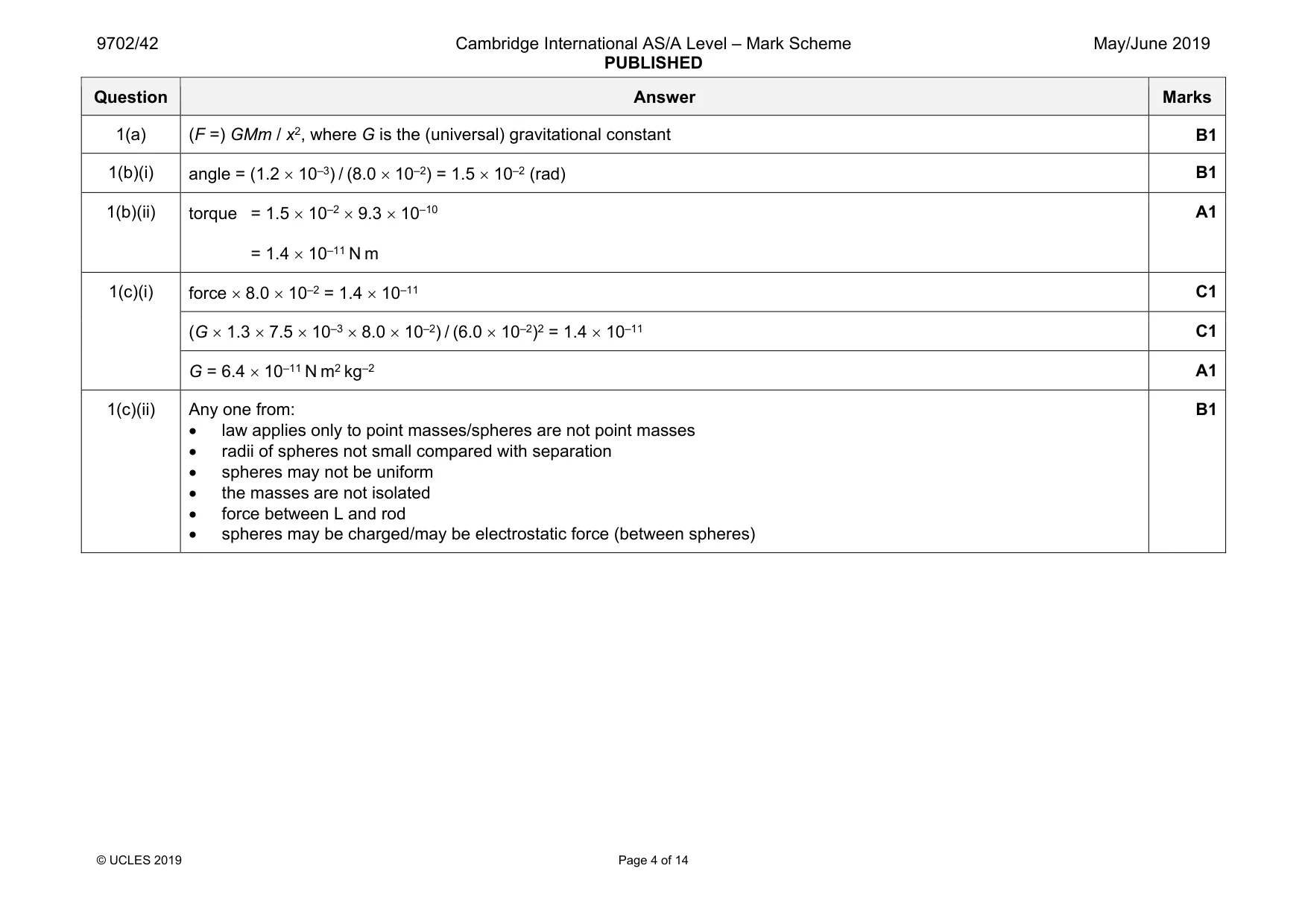
1 (a) Two point masses are separated by a distance x in a vacuum. State an expression for the force F between the two masses M and m. State the name of any other symbol used. ................................................................................................................................................... ................................................................................................................................................... ...............................................................................................................................................[1] (b) A small sphere S is attached to one end of a rod, as shown in Fig. 1.1. thread rod small sphere S 8.0 cm view from side Fig. 1.1 (not to scale) The rod hangs from a vertical thread and is horizontal. The distance from the centre of sphere S to the thread is 8.0 cm. A large sphere L is placed near to sphere S, as shown in Fig. 1.2. large sphere L initial position of rod 6.0 cm final position of rod θ 1.2 mm small sphere S 8.0 cm thread view from above Fig. 1.2 (not to scale) There is a force of attraction between spheres S and L, causing sphere S to move through a distance of 1.2 mm. The line joining the centres of S and L is normal to the rod. (i) Show that the angle θ through which the rod rotates is 1.5 × 10⁻² rad. [1] (ii) The rotation of the rod causes the thread to twist. The torque T (in N m) required to twist the thread through an angle β (in rad) is given by T = 9.3 × 10⁻¹⁰ × β. Calculate the torque in the thread when sphere L is positioned as shown in Fig. 1.2. torque = .................................................. N m [1] (c) The distance between the centres of spheres S and L is 6.0 cm. The mass of sphere S is 7.5 g and the mass of sphere L is 1.3 kg. (i) By equating the torque in (b)(ii) to the moment about the thread produced by gravitational attraction between the spheres, calculate a value for the gravitational constant. gravitational constant = ............................................... N m2 kg–2 [3] (ii) Suggest why the total force between the spheres may not be equal to the force calculated using Newton’s law of gravitation. ........................................................................................................................................... .......................................................................................................................................[1] [Total: 7]
Mark scheme: 1(a) (F =) GMm / x2, where G is the (universal) gravitational constant B1 1(b)(i) angle = (1.2 × 10⁻³) / (8.0 × 10⁻²) = 1.5 × 10⁻² (rad) B1 1(b)(ii) torque = 1.5 × 10–2 × 9.3 × 10–10 = 1.4 × 10⁻¹¹ N m A1 1(c)(i) force × 8.0 × 10–2 = 1.4 × 10⁻¹¹ C1 (G × 1.3 × 7.5 × 10–3 × 8.0 × 10–2) / (6.0 × 10⁻²)2 = 1.4 × 10⁻¹¹ C1 G = 6.4 × 10⁻¹¹ N m2 kg–2 A1 1(c)(ii) Any one from: • law applies only to point masses/spheres are not point masses • radii of spheres not small compared with separation • spheres may not be uniform • the masses are not isolated • force between L and rod • spheres may be charged/may be electrostatic force (between spheres) B1
Q2 · The first law of thermodynamics may be expressed in the form ΔU = q + w
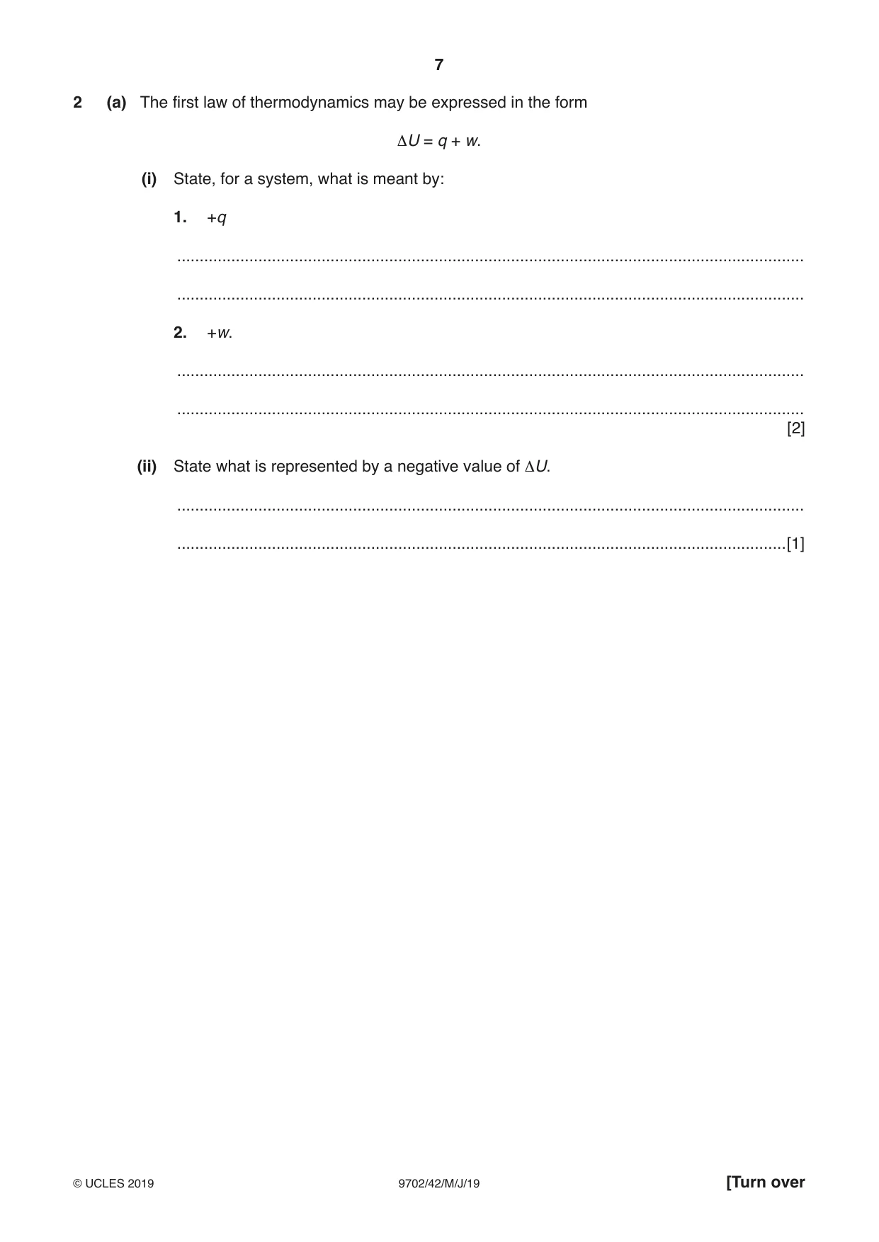
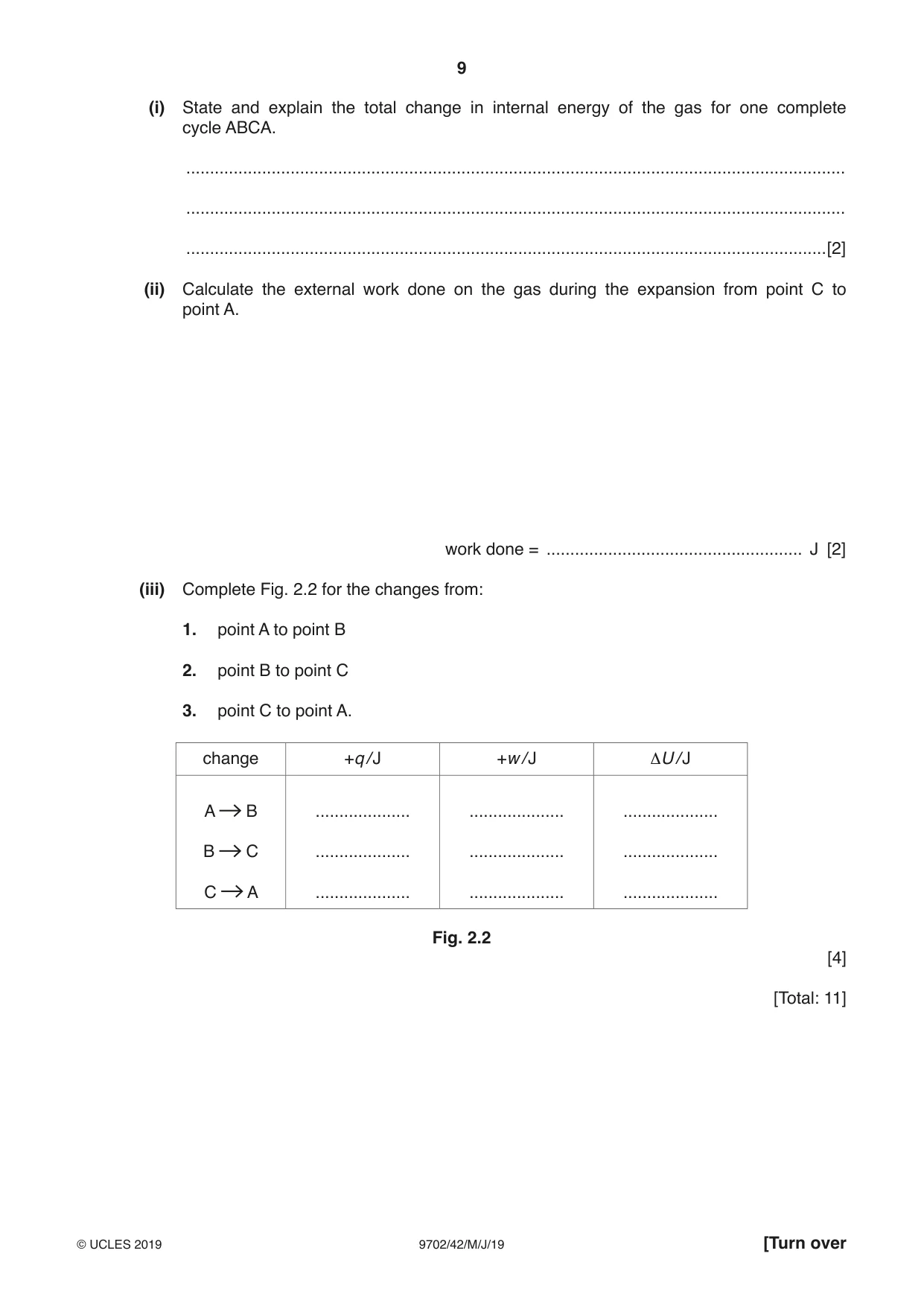
2 (a) The first law of thermodynamics may be expressed in the form ΔU = q + w. (i) State, for a system, what is meant by: 1. +q ........................................................................................................................................... ........................................................................................................................................... 2. +w. ........................................................................................................................................... ........................................................................................................................................... [2] (ii) State what is represented by a negative value of ΔU. ........................................................................................................................................... .......................................................................................................................................[1] (b) An ideal gas, sealed in a container, undergoes the cycle of changes shown in Fig. 2.1. 7.0 8.7 × 10⁻⁴ m3 B 6.6 × 10⁵ Pa 450 K 6.0 pressure / 105 Pa 5.0 4.0 2.4 × 10⁻³ m3 3.0 1.6 × 10⁵ Pa 8.7 × 10⁻⁴ m3 300 K 1.6 × 10⁵ Pa 110 K 2.0 C A 1.0 0.75 1.00 1.25 1.50 1.75 2.00 2.25 2.50 volume / 10–3 m3 Fig. 2.1 At point A, the gas has volume 2.4 × 10⁻³ m3, pressure 1.6 × 10⁵ Pa and temperature 300 K. The gas is compressed suddenly so that no thermal energy enters or leaves the gas during the compression. The amount of work done is 480 J so that, at point B, the gas has volume 8.7 × 10⁻⁴ m3, pressure 6.6 × 10⁵ Pa and temperature 450 K. The gas is now cooled at constant volume so that, between points B and C, 1100 J of thermal energy is transferred. At point C, the gas has pressure 1.6 × 10⁵ Pa and temperature 110 K. Finally, the gas is returned to point A. (i) State and explain the total change in internal energy of the gas for one complete cycle ABCA. ........................................................................................................................................... ........................................................................................................................................... .......................................................................................................................................[2] (ii) Calculate the external work done on the gas during the expansion from point C to point A. work done = ...................................................... J [2] (iii) Complete Fig. 2.2 for the changes from: 1. point A to point B 2. point B to point C 3. point C to point A. change +q / J +w / J ΔU / J A B .................... .................... .................... B C .................... .................... .................... C A .................... .................... .................... Fig. 2.2 [4] [Total: 11]
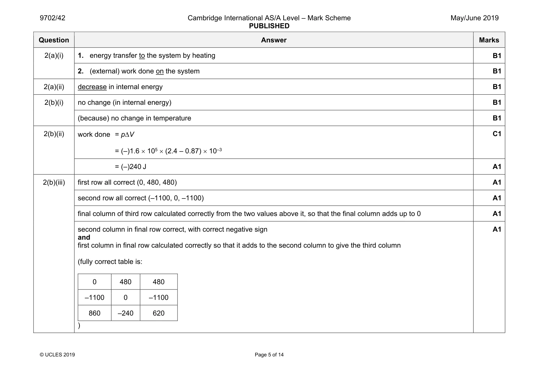
Mark scheme: 2(a)(i) 1. energy transfer to the system by heating B1 2. (external) work done on the system B1 2(a)(ii) decrease in internal energy B1 2(b)(i) no change (in internal energy) B1 (because) no change in temperature B1 2(b)(ii) work done = p∆V = (–)1.6 × 105 × (2.4 – 0.87) × 10–3 C1 = (–)240 J A1 2(b)(iii) first row all correct (0, 480, 480) A1 second row all correct (–1100, 0, –1100) A1 final column of third row calculated correctly from the two values above it, so that the final column adds up to 0 A1 second column in final row correct, with correct negative sign and first column in final row calculated correctly so that it adds to the second column to give the third column (fully correct table is: 0 480 480 –1100 0 –1100 860 –240 620 ) A1
Q3 · A spring is hung vertically from a fixed point
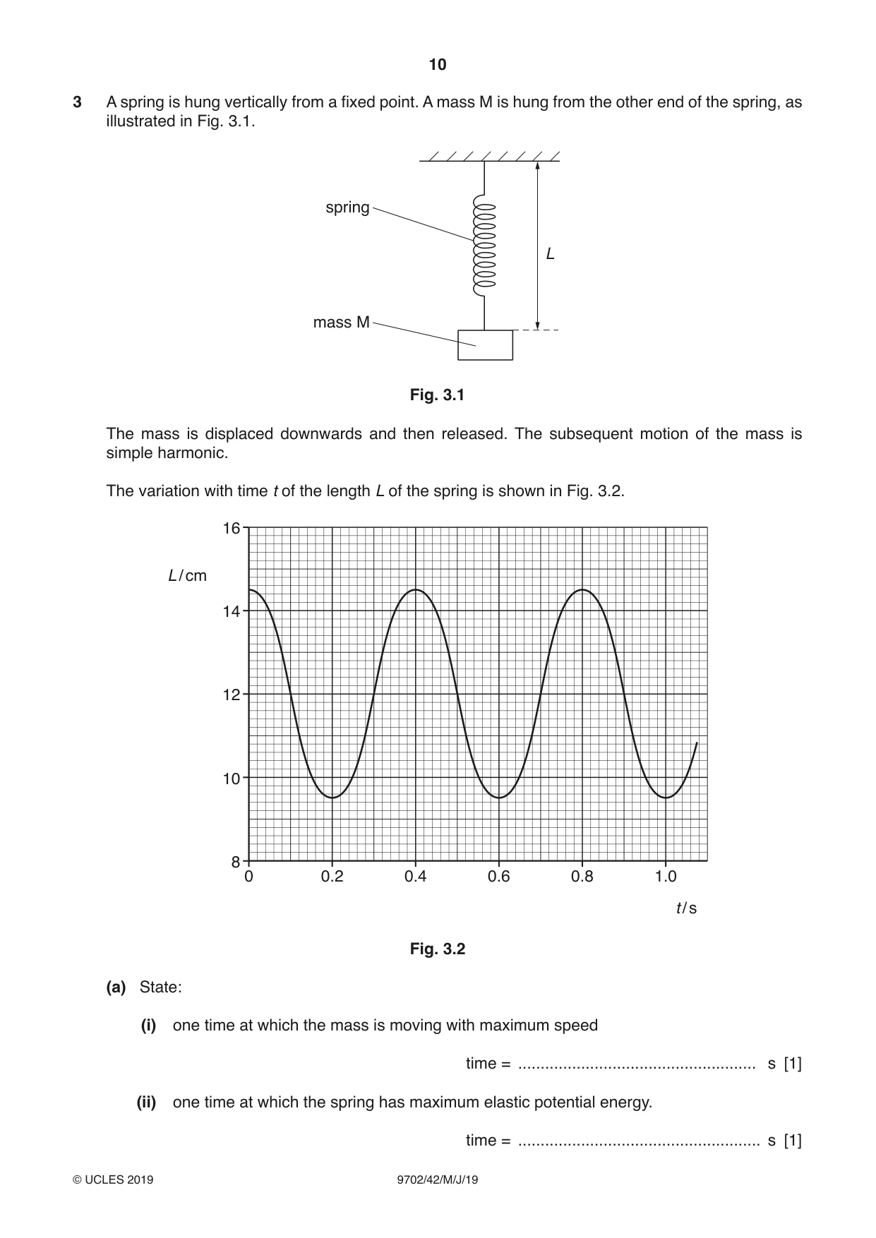
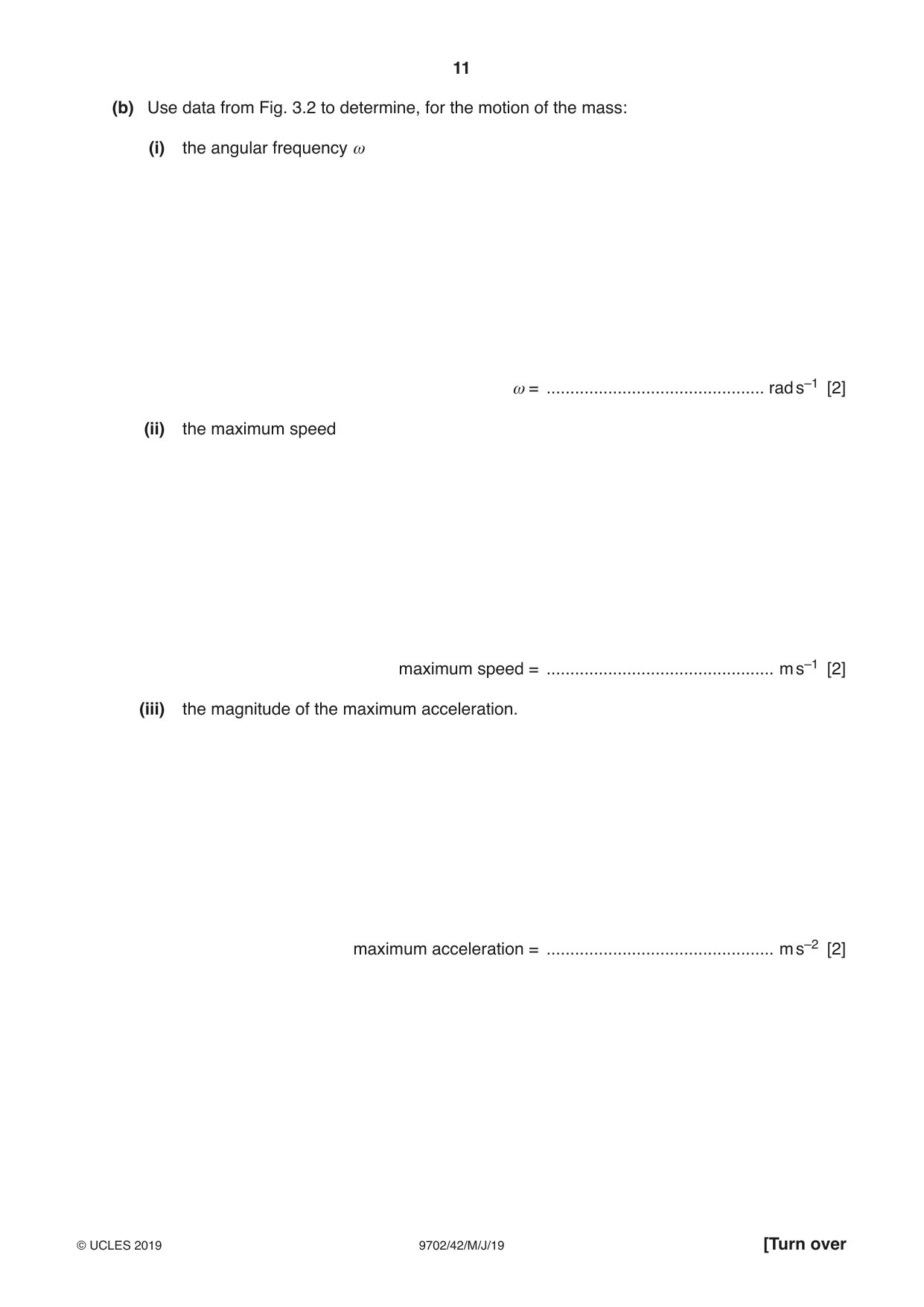
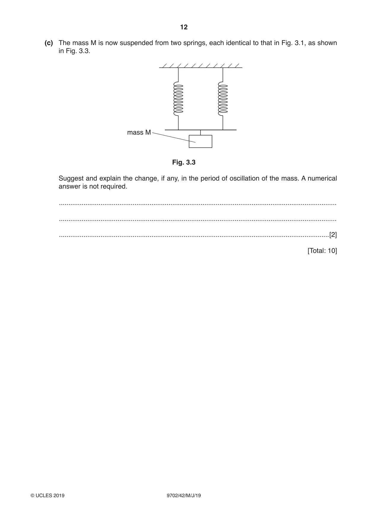
3 A spring is hung vertically from a fixed point. A mass M is hung from the other end of the spring, as illustrated in Fig. 3.1. spring L mass M Fig. 3.1 The mass is displaced downwards and then released. The subsequent motion of the mass is simple harmonic. The variation with time t of the length L of the spring is shown in Fig. 3.2. 16 L / cm 14 12 10 8 0 0.2 0.4 0.6 0.8 1.0 t / s Fig. 3.2 (a) State: (i) one time at which the mass is moving with maximum speed time = ..................................................... s [1] (ii) one time at which the spring has maximum elastic potential energy. time = ...................................................... s [1] (b) Use data from Fig. 3.2 to determine, for the motion of the mass: (i) the angular frequency ω ω = .............................................. rad s–1 [2] (ii) the maximum speed maximum speed = ................................................ m s–1 [2] (iii) the magnitude of the maximum acceleration. maximum acceleration = ................................................ m s–2 [2] (c) The mass M is now suspended from two springs, each identical to that in Fig. 3.1, as shown in Fig. 3.3. mass M Fig. 3.3 Suggest and explain the change, if any, in the period of oscillation of the mass. A numerical answer is not required. ................................................................................................................................................... ................................................................................................................................................... ...............................................................................................................................................[2] [Total: 10]
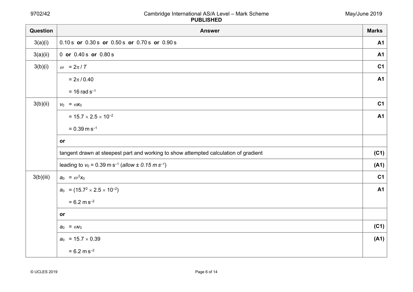
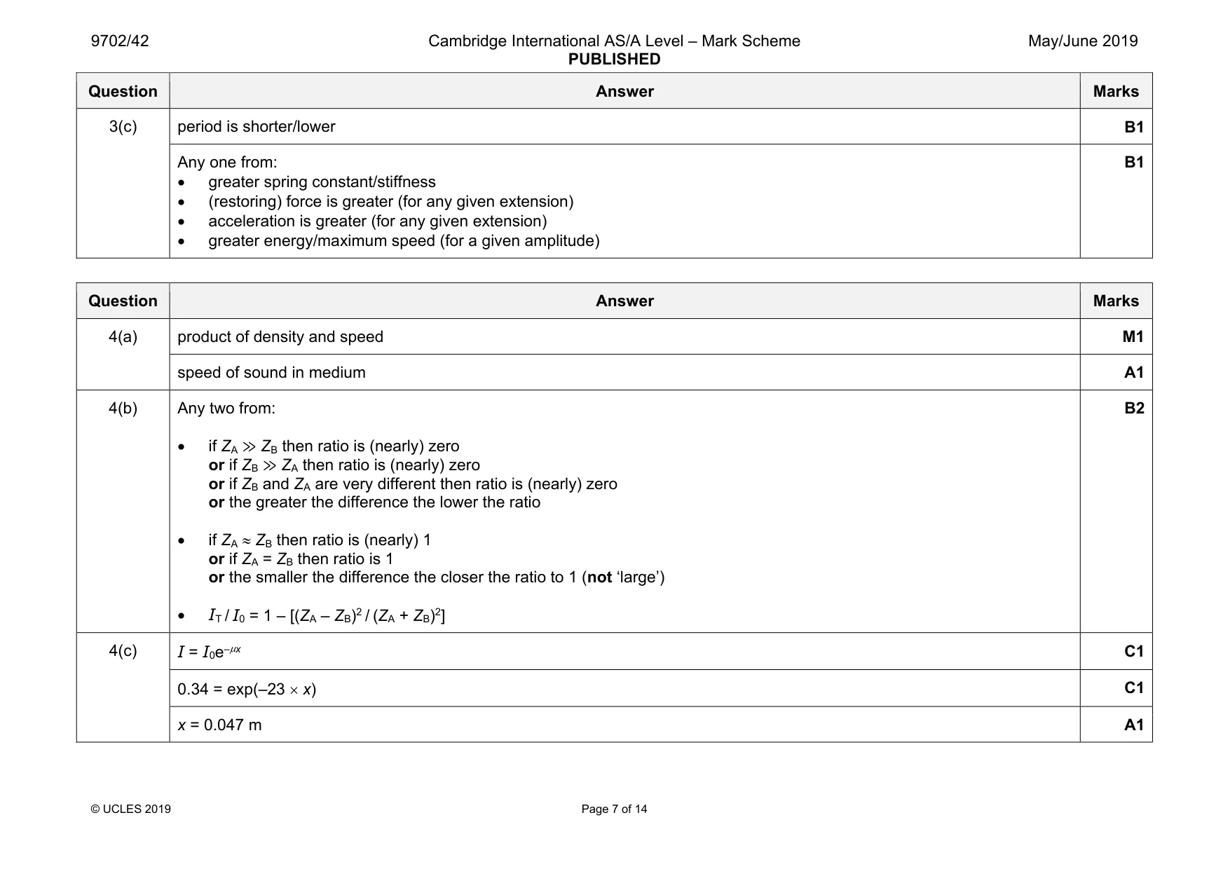
Mark scheme: 3(a)(i) 0.10 s or 0.30 s or 0.50 s or 0.70 s or 0.90 s A1 3(a)(ii) 0 or 0.40 s or 0.80 s A1 3(b)(i) ω = 2π / T C1 = 2π / 0.40 = 16 rad s–1 A1 3(b)(ii) v0 = ωx0 C1 = 15.7 × 2.5 × 10–2 = 0.39 m s–1 A1 or tangent drawn at steepest part and working to show attempted calculation of gradient (C1) leading to v0 = 0.39 m s–1 (allow ± 0.15 m s–1) (A1) 3(b)(iii) a0 = ω 2x0 C1 a0 = (15.72 × 2.5 × 10–2) = 6.2 m s–2 A1 or a0 = ωv0 (C1) a0 = 15.7 × 0.39 = 6.2 m s–2 (A1) Question Answer Marks 3(c) period is shorter/lower B1 Any one from: • greater spring constant/stiffness • (restoring) force is greater (for any given extension) • acceleration is greater (for any given extension) • greater energy/maximum speed (for a given amplitude) B1
Q4 · State what is meant by the specific acoustic impedance of a medium
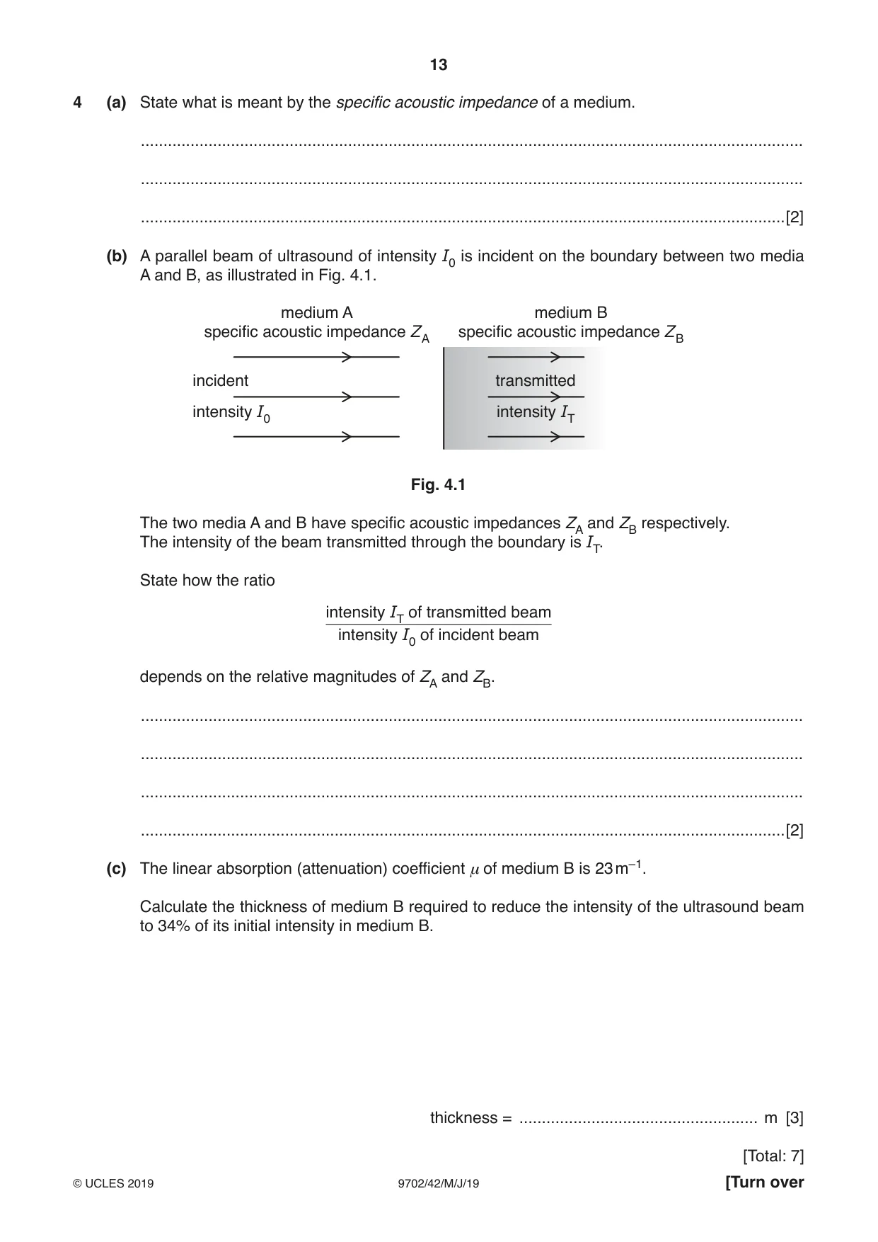
4 (a) State what is meant by the specific acoustic impedance of a medium. ................................................................................................................................................... ................................................................................................................................................... ...............................................................................................................................................[2] (b) A parallel beam of ultrasound of intensity I0 is incident on the boundary between two media A and B, as illustrated in Fig. 4.1. medium A medium B specific acoustic impedance ZA specific acoustic impedance ZB incident transmitted intensity I0 intensity IT Fig. 4.1 The two media A and B have specific acoustic impedances ZA and ZB respectively. The intensity of the beam transmitted through the boundary is IT. State how the ratio intensity IT of transmitted beam intensity I0 of incident beam depends on the relative magnitudes of ZA and ZB. ................................................................................................................................................... ................................................................................................................................................... ................................................................................................................................................... ...............................................................................................................................................[2] (c) The linear absorption (attenuation) coefficient μ of medium B is 23 m–1. Calculate the thickness of medium B required to reduce the intensity of the ultrasound beam to 34% of its initial intensity in medium B. thickness = ..................................................... m [3] [Total: 7]
Mark scheme: 4(a) product of density and speed M1 speed of sound in medium A1 4(b) Any two from: • if ZA ≫ ZB then ratio is (nearly) zero or if ZB ≫ ZA then ratio is (nearly) zero or if ZB and ZA are very different then ratio is (nearly) zero or the greater the difference the lower the ratio • if ZA ≈ ZB then ratio is (nearly) 1 or if ZA = ZB then ratio is 1 or the smaller the difference the closer the ratio to 1 (not ‘large’) • IT / I0 = 1 – [(ZA – ZB)2 / (ZA + ZB)2] B2 4(c) I = I0e–µx C1 0.34 = exp(–23 × x) C1 x = 0.047 m A1
Q5 · For a signal transmitted along an optic fibre, state what is meant by: (i) attenuation…
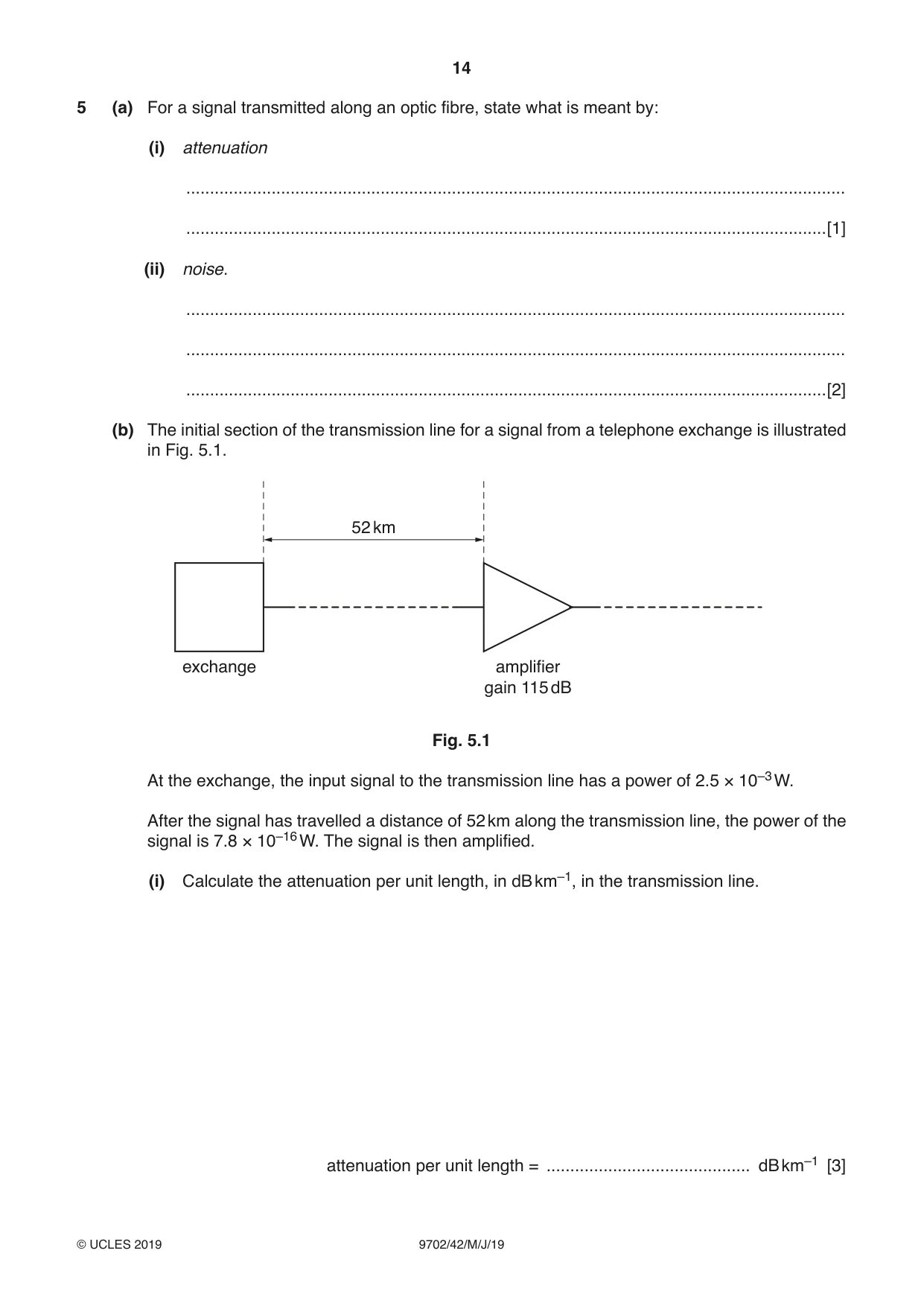
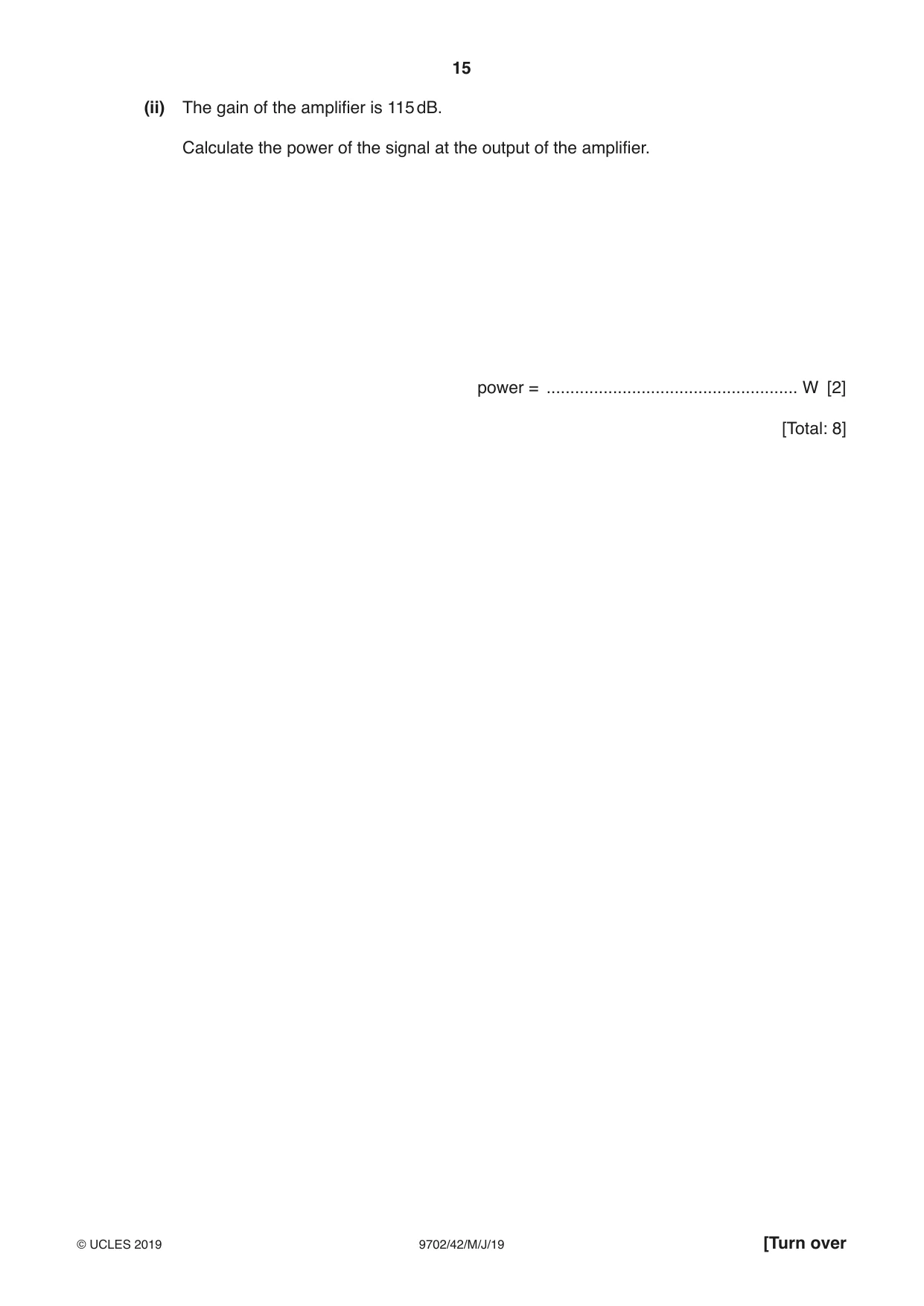
5 (a) For a signal transmitted along an optic fibre, state what is meant by: (i) attenuation ........................................................................................................................................... .......................................................................................................................................[1] (ii) noise. ........................................................................................................................................... ........................................................................................................................................... .......................................................................................................................................[2] (b) The initial section of the transmission line for a signal from a telephone exchange is illustrated in Fig. 5.1. 52 km exchange amplifier gain 115 dB Fig. 5.1 At the exchange, the input signal to the transmission line has a power of 2.5 × 10⁻³ W. After the signal has travelled a distance of 52 km along the transmission line, the power of the signal is 7.8 × 10⁻¹⁶ W. The signal is then amplified. (i) Calculate the attenuation per unit length, in dB km–1, in the transmission line. attenuation per unit length = ........................................... dB km–1 [3] (ii) The gain of the amplifier is 115 dB. Calculate the power of the signal at the output of the amplifier. power = ..................................................... W [2] [Total: 8]
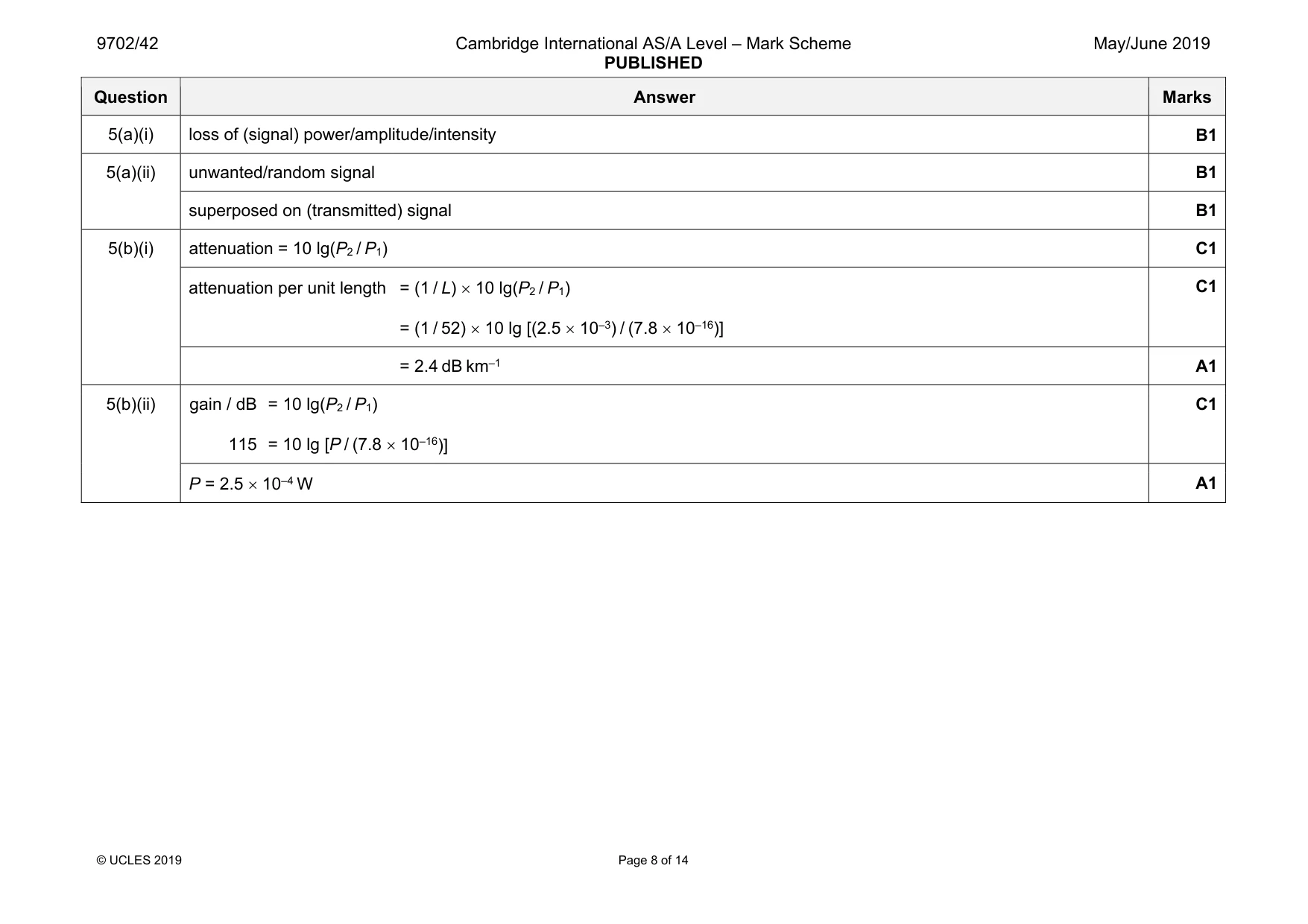
Mark scheme: 5(a)(i) loss of (signal) power/amplitude/intensity B1 5(a)(ii) unwanted/random signal B1 superposed on (transmitted) signal B1 5(b)(i) attenuation = 10 lg(P2 / P1) C1 attenuation per unit length = (1 / L) × 10 lg(P2 / P1) = (1 / 52) × 10 lg [(2.5 × 10⁻³) / (7.8 × 10⁻¹⁶)] C1 = 2.4 dB km–1 A1 5(b)(ii) gain / dB = 10 lg(P2 / P1) 115 = 10 lg [P / (7.8 × 10⁻¹⁶)] C1 P = 2.5 × 10⁻⁴ W A1
Q6 · State what is meant by electric potential at a point
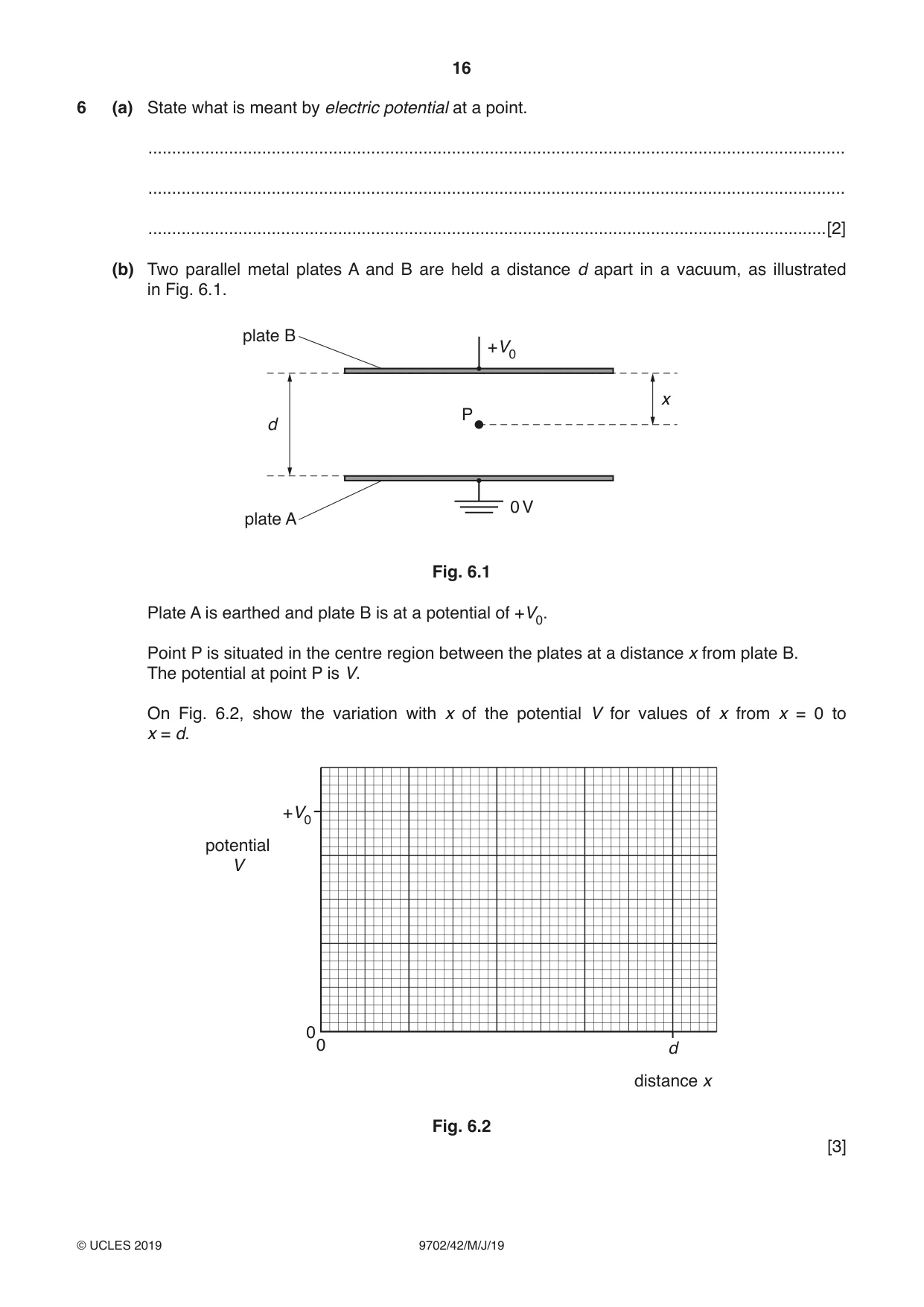
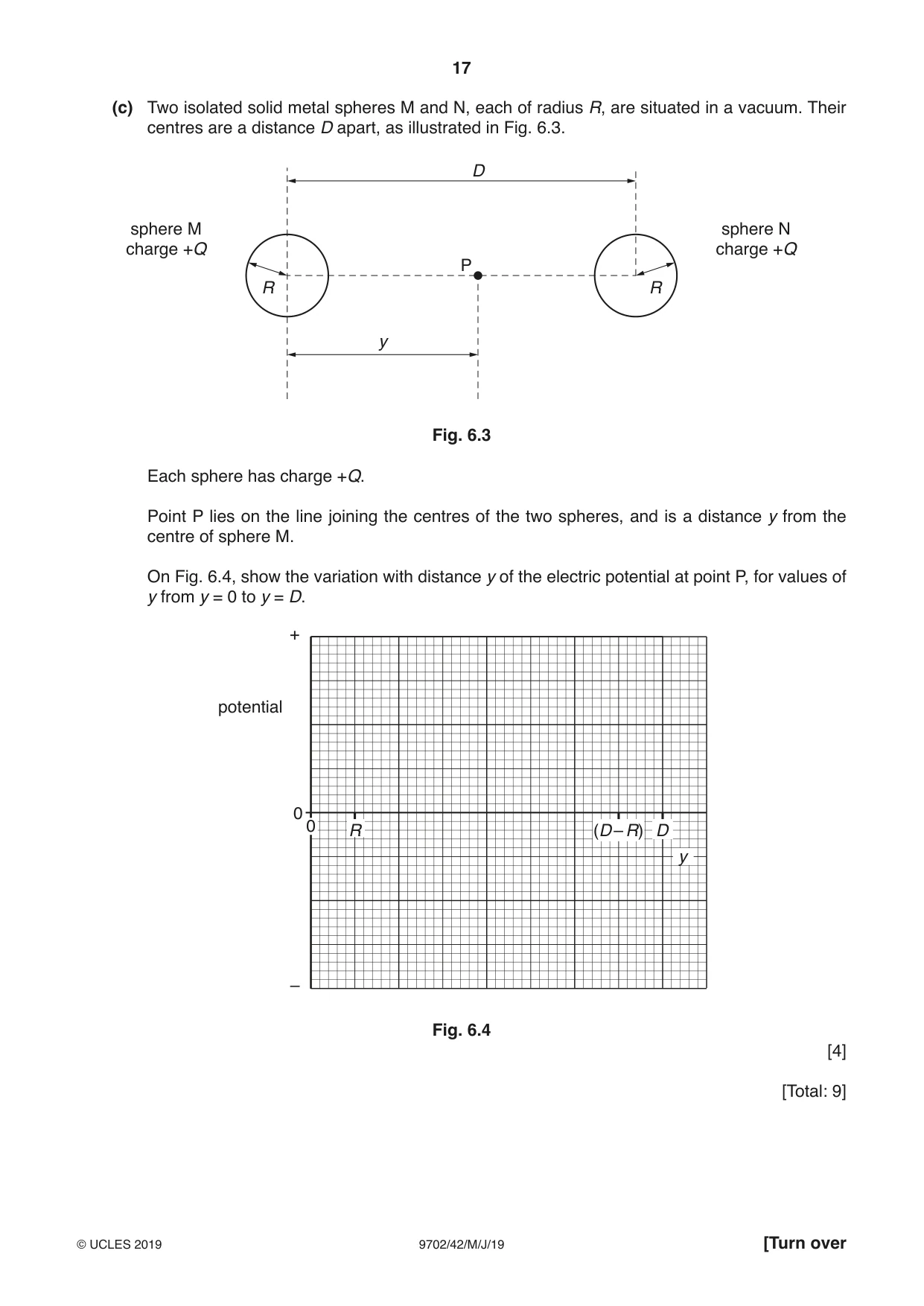
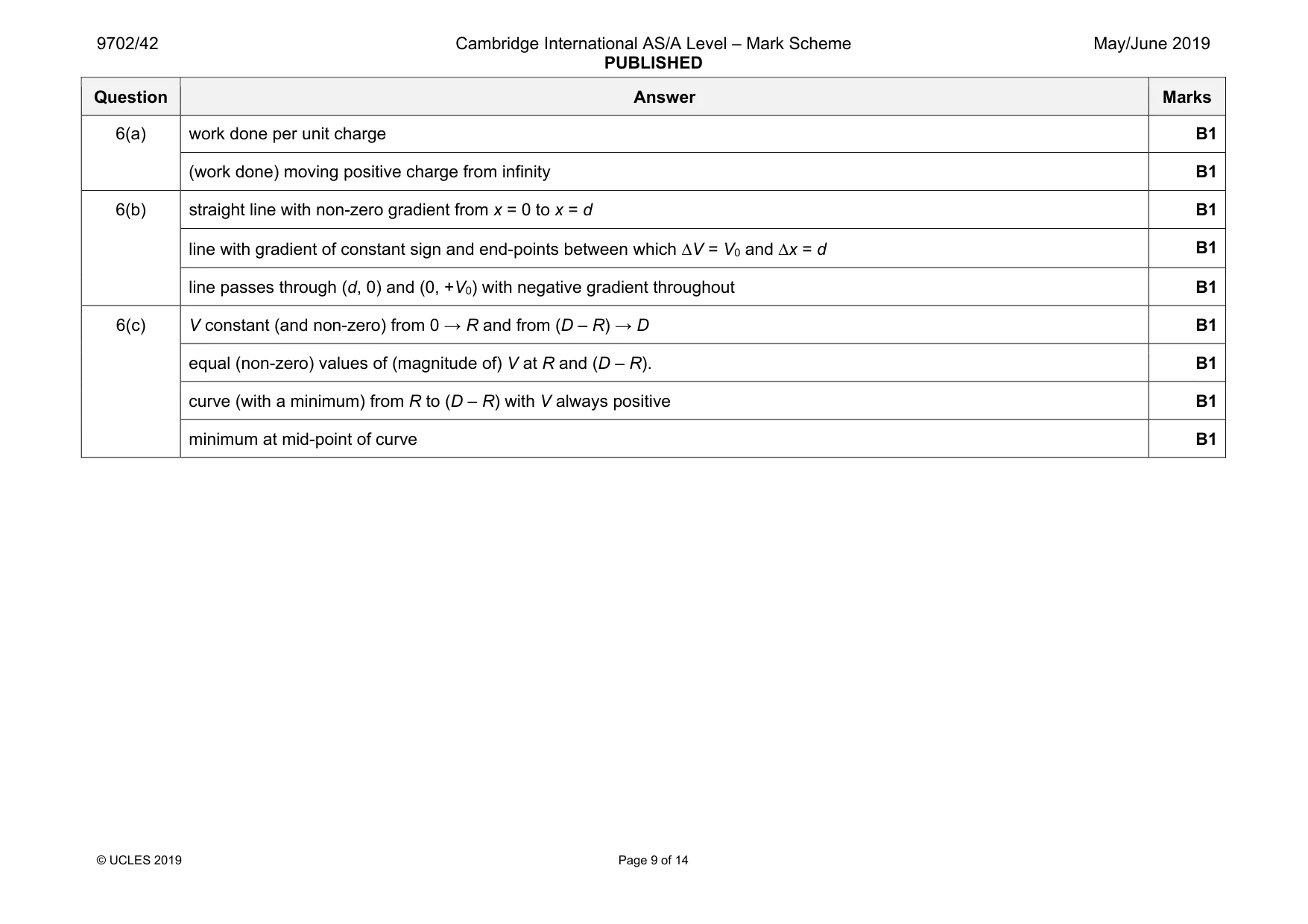
6 (a) State what is meant by electric potential at a point. ................................................................................................................................................... ................................................................................................................................................... ...............................................................................................................................................[2] (b) Two parallel metal plates A and B are held a distance d apart in a vacuum, as illustrated in Fig. 6.1. plate B +V0 x P d 0 V plate A Fig. 6.1 Plate A is earthed and plate B is at a potential of +V0. Point P is situated in the centre region between the plates at a distance x from plate B. The potential at point P is V. On Fig. 6.2, show the variation with x of the potential V for values of x from x = 0 to x = d. +V0 potential V 00 d distance x Fig. 6.2 [3] (c) Two isolated solid metal spheres M and N, each of radius R, are situated in a vacuum. Their centres are a distance D apart, as illustrated in Fig. 6.3. D sphere M sphere N charge +Q charge +Q P R R y Fig. 6.3 Each sphere has charge +Q. Point P lies on the line joining the centres of the two spheres, and is a distance y from the centre of sphere M. On Fig. 6.4, show the variation with distance y of the electric potential at point P, for values of y from y = 0 to y = D. + potential 0 0 R (D – R) D y – Fig. 6.4 [4] [Total: 9]
Mark scheme: 6(a) work done per unit charge B1 (work done) moving positive charge from infinity B1 6(b) straight line with non-zero gradient from x = 0 to x = d B1 line with gradient of constant sign and end-points between which ∆V = V0 and ∆x = d B1 line passes through (d, 0) and (0, +V0) with negative gradient throughout B1 6(c) V constant (and non-zero) from 0 → R and from (D – R) → D B1 equal (non-zero) values of (magnitude of) V at R and (D – R). B1 curve (with a minimum) from R to (D – R) with V always positive B1 minimum at mid-point of curve B1
Q7 · Use band theory to explain why the resistance of an intrinsic semiconductor decreases as…
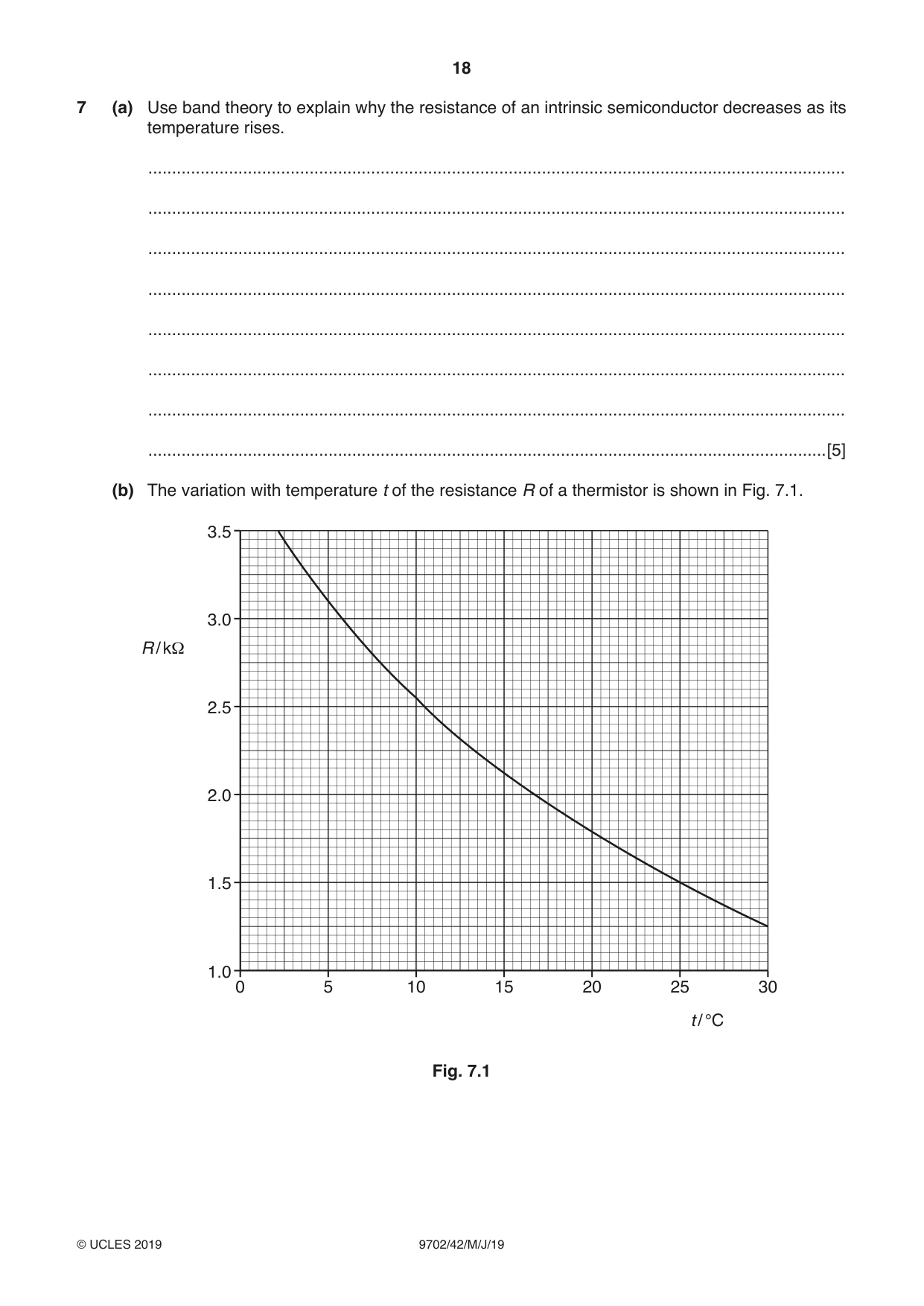
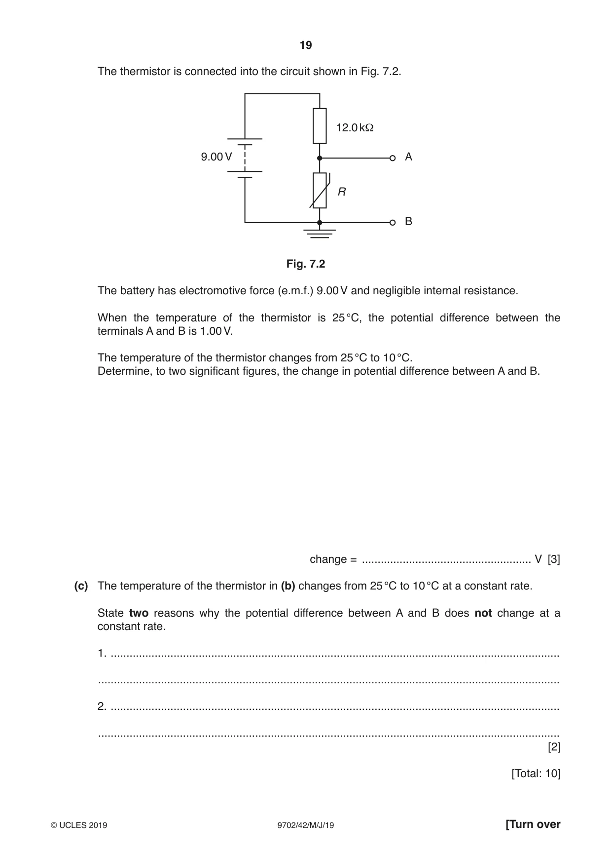
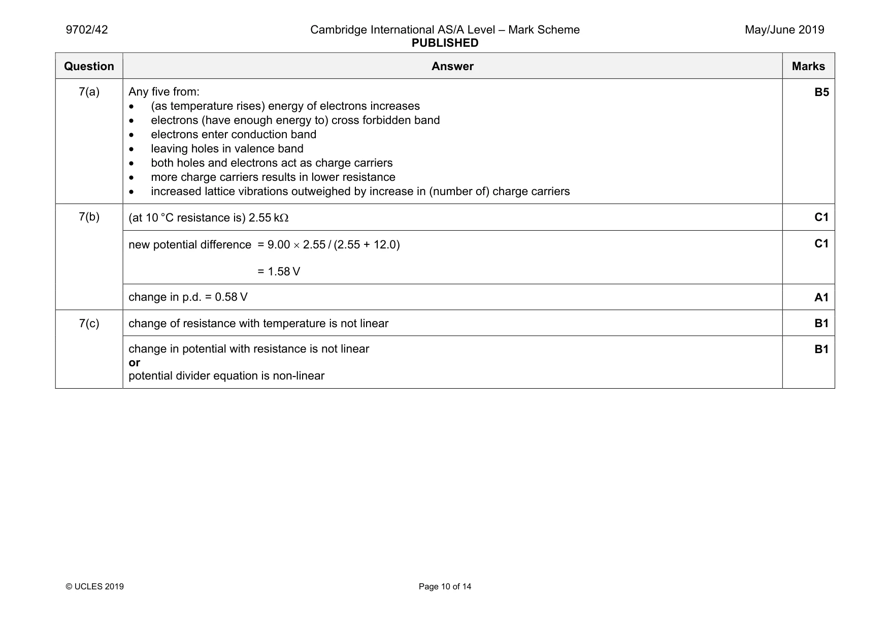
7 (a) Use band theory to explain why the resistance of an intrinsic semiconductor decreases as its temperature rises. ................................................................................................................................................... ................................................................................................................................................... ................................................................................................................................................... ................................................................................................................................................... ................................................................................................................................................... ................................................................................................................................................... ................................................................................................................................................... ...............................................................................................................................................[5] (b) The variation with temperature t of the resistance R of a thermistor is shown in Fig. 7.1. 3.5 3.0 R / kΩ 2.5 2.0 1.5 1.0 0 5 10 15 20 25 30 t / °C Fig. 7.1 The thermistor is connected into the circuit shown in Fig. 7.2. 12.0 kΩ 9.00 V A R B Fig. 7.2 The battery has electromotive force (e.m.f.) 9.00 V and negligible internal resistance. When the temperature of the thermistor is 25 °C, the potential difference between the terminals A and B is 1.00 V. The temperature of the thermistor changes from 25 °C to 10 °C. Determine, to two significant figures, the change in potential difference between A and B. change = ...................................................... V [3] (c) The temperature of the thermistor in (b) changes from 25 °C to 10 °C at a constant rate. State two reasons why the potential difference between A and B does not change at a constant rate. 1. ............................................................................................................................................... ................................................................................................................................................... 2. ............................................................................................................................................... ................................................................................................................................................... [2] [Total: 10]
Mark scheme: 7(a) Any five from: • (as temperature rises) energy of electrons increases • electrons (have enough energy to) cross forbidden band • electrons enter conduction band • leaving holes in valence band • both holes and electrons act as charge carriers • more charge carriers results in lower resistance • increased lattice vibrations outweighed by increase in (number of) charge carriers B5 7(b) (at 10 °C resistance is) 2.55 kΩ C1 new potential difference = 9.00 × 2.55 / (2.55 + 12.0) = 1.58 V C1 change in p.d. = 0.58 V A1 7(c) change of resistance with temperature is not linear B1 change in potential with resistance is not linear or potential divider equation is non-linear B1
Q8 · An electron is travelling in a vacuum at a speed of 3.4 × 10⁷ m s–1
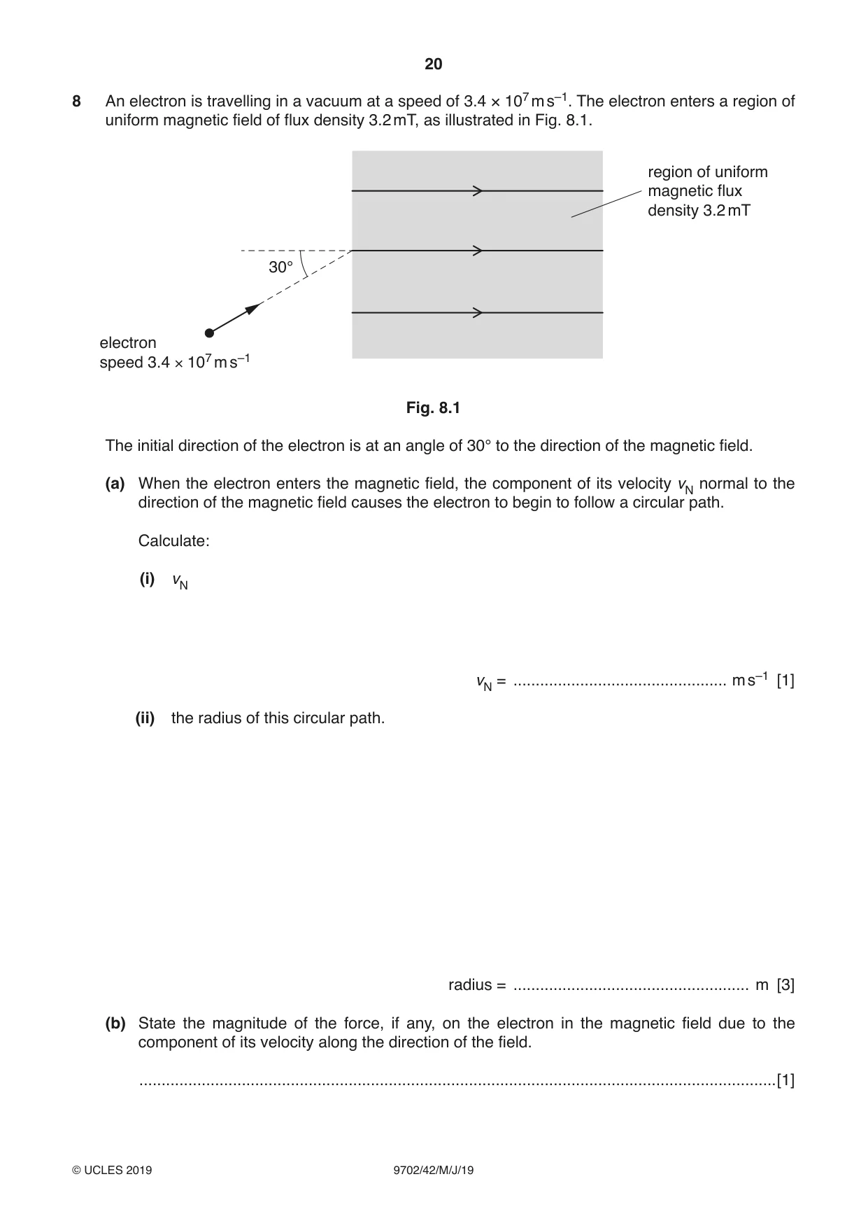
8 An electron is travelling in a vacuum at a speed of 3.4 × 10⁷ m s–1. The electron enters a region of uniform magnetic field of flux density 3.2 mT, as illustrated in Fig. 8.1. region of uniform magnetic flux density 3.2 mT 30° electron speed 3.4 × 10⁷ m s–1 Fig. 8.1 The initial direction of the electron is at an angle of 30° to the direction of the magnetic field. (a) When the electron enters the magnetic field, the component of its velocity vN normal to the direction of the magnetic field causes the electron to begin to follow a circular path. Calculate: (i) vN vN = ................................................ m s–1 [1] (ii) the radius of this circular path. radius = ..................................................... m [3] (b) State the magnitude of the force, if any, on the electron in the magnetic field due to the component of its velocity along the direction of the field. ...............................................................................................................................................[1] (c) Use information from (a) and (b) to describe the resultant path of the electron in the magnetic field. ................................................................................................................................................... ...............................................................................................................................................[1] [Total: 6]
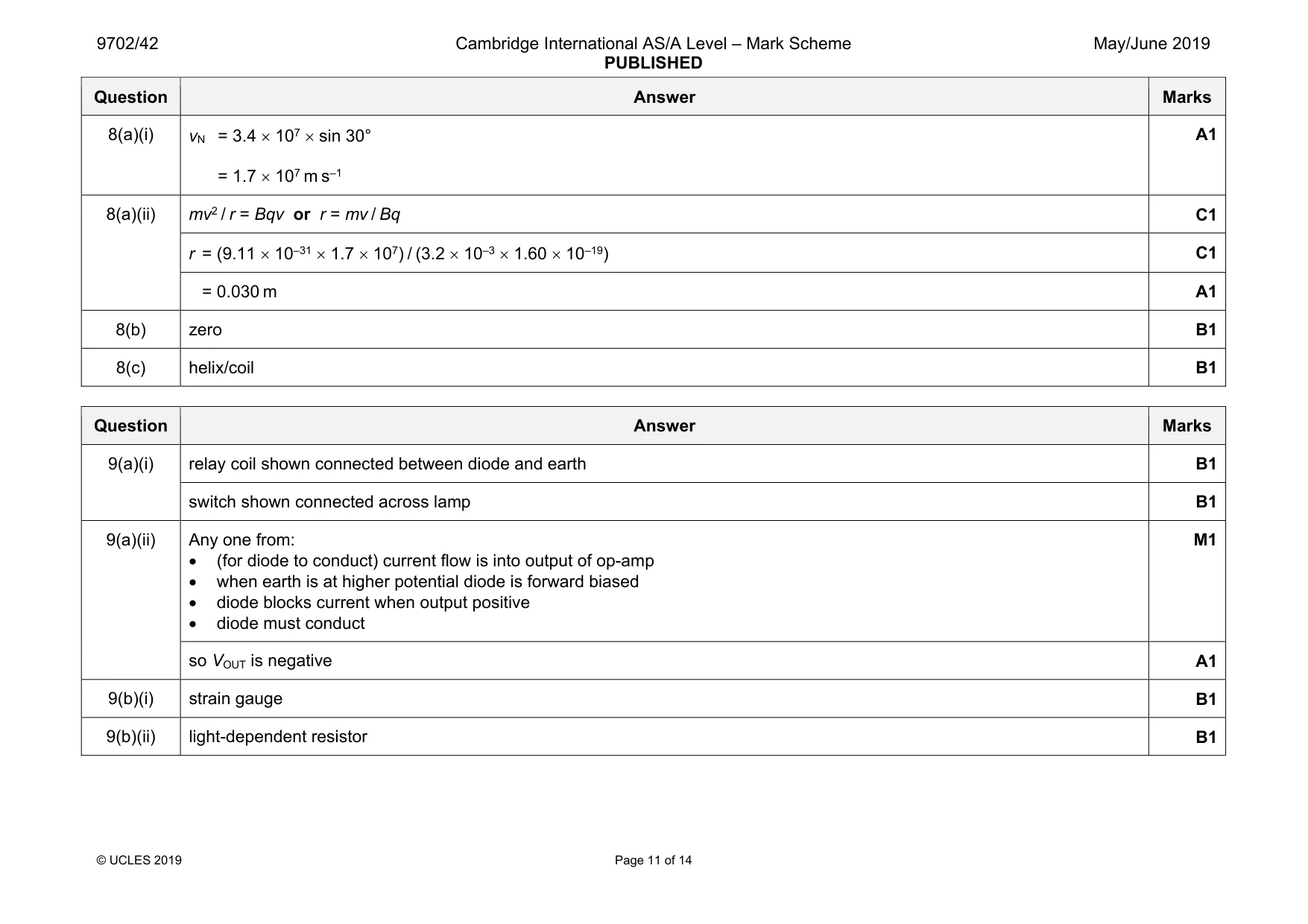
Mark scheme: 8(a)(i) = 1.7 × 10⁷ m s–1 A1 8(a)(ii) mv2 / r = Bqv or r = mv / Bq C1 r = (9.11 × 10–31 × 1.7 × 107) / (3.2 × 10–3 × 1.60 × 10–19) C1 = 0.030 m A1 8(b) zero B1 8(c) helix/coil B1
Q9 · Part of a circuit incorporating an operational amplifier (op-amp) is shown in Fig
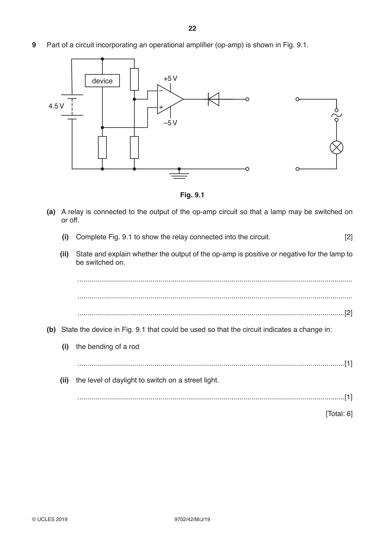
9 Part of a circuit incorporating an operational amplifier (op-amp) is shown in Fig. 9.1. +5 V device – 4.5 V + –5 V Fig. 9.1 (a) A relay is connected to the output of the op-amp circuit so that a lamp may be switched on or off. (i) Complete Fig. 9.1 to show the relay connected into the circuit. [2] (ii) State and explain whether the output of the op-amp is positive or negative for the lamp to be switched on. ........................................................................................................................................... ........................................................................................................................................... .......................................................................................................................................[2] (b) State the device in Fig. 9.1 that could be used so that the circuit indicates a change in: (i) the bending of a rod .......................................................................................................................................[1] (ii) the level of daylight to switch on a street light. .......................................................................................................................................[1] [Total: 6]
Mark scheme: 9(a)(i) relay coil shown connected between diode and earth B1 switch shown connected across lamp B1 9(a)(ii) Any one from: • (for diode to conduct) current flow is into output of op-amp • when earth is at higher potential diode is forward biased • diode blocks current when output positive • diode must conduct M1 so VOUT is negative A1 9(b)(i) strain gauge B1 9(b)(ii) light-dependent resistor B1
Q10 · State Faraday’s law of electromagnetic induction
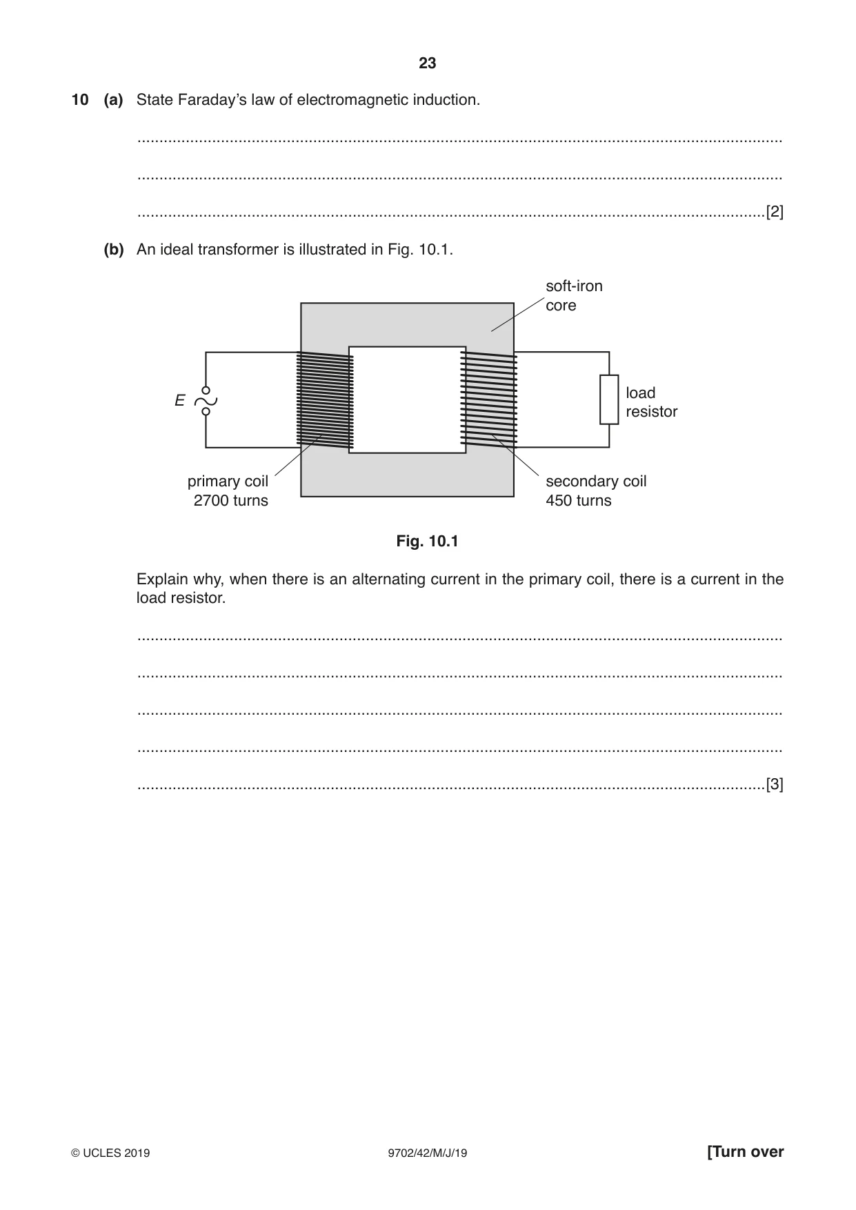
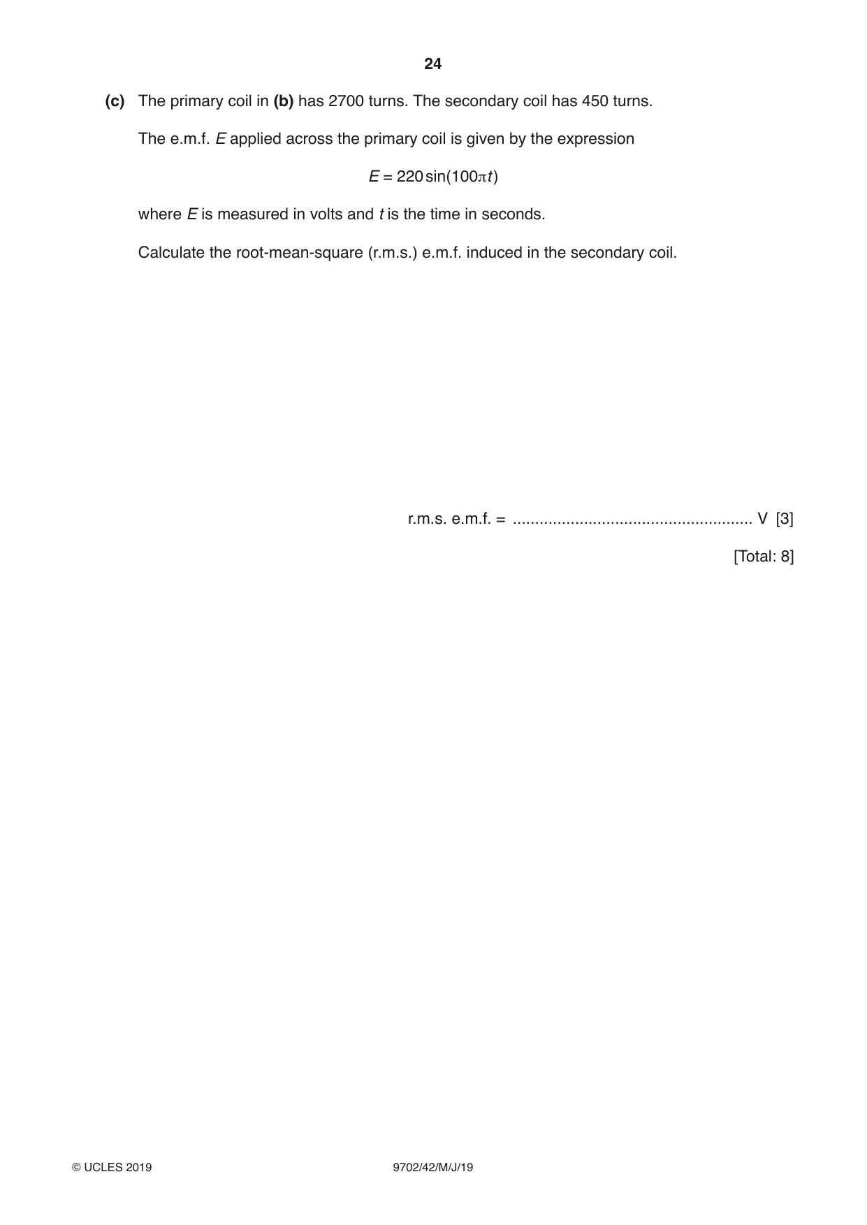
10 (a) State Faraday’s law of electromagnetic induction. ................................................................................................................................................... ................................................................................................................................................... ...............................................................................................................................................[2] (b) An ideal transformer is illustrated in Fig. 10.1. soft-iron core load E resistor primary coil secondary coil 2700 turns 450 turns Fig. 10.1 Explain why, when there is an alternating current in the primary coil, there is a current in the load resistor. ................................................................................................................................................... ................................................................................................................................................... ................................................................................................................................................... ................................................................................................................................................... ...............................................................................................................................................[3] (c) The primary coil in (b) has 2700 turns. The secondary coil has 450 turns. The e.m.f. E applied across the primary coil is given by the expression E = 220 sin(100πt ) where E is measured in volts and t is the time in seconds. Calculate the root-mean-square (r.m.s.) e.m.f. induced in the secondary coil. r.m.s. e.m.f. = ...................................................... V [3] [Total: 8]
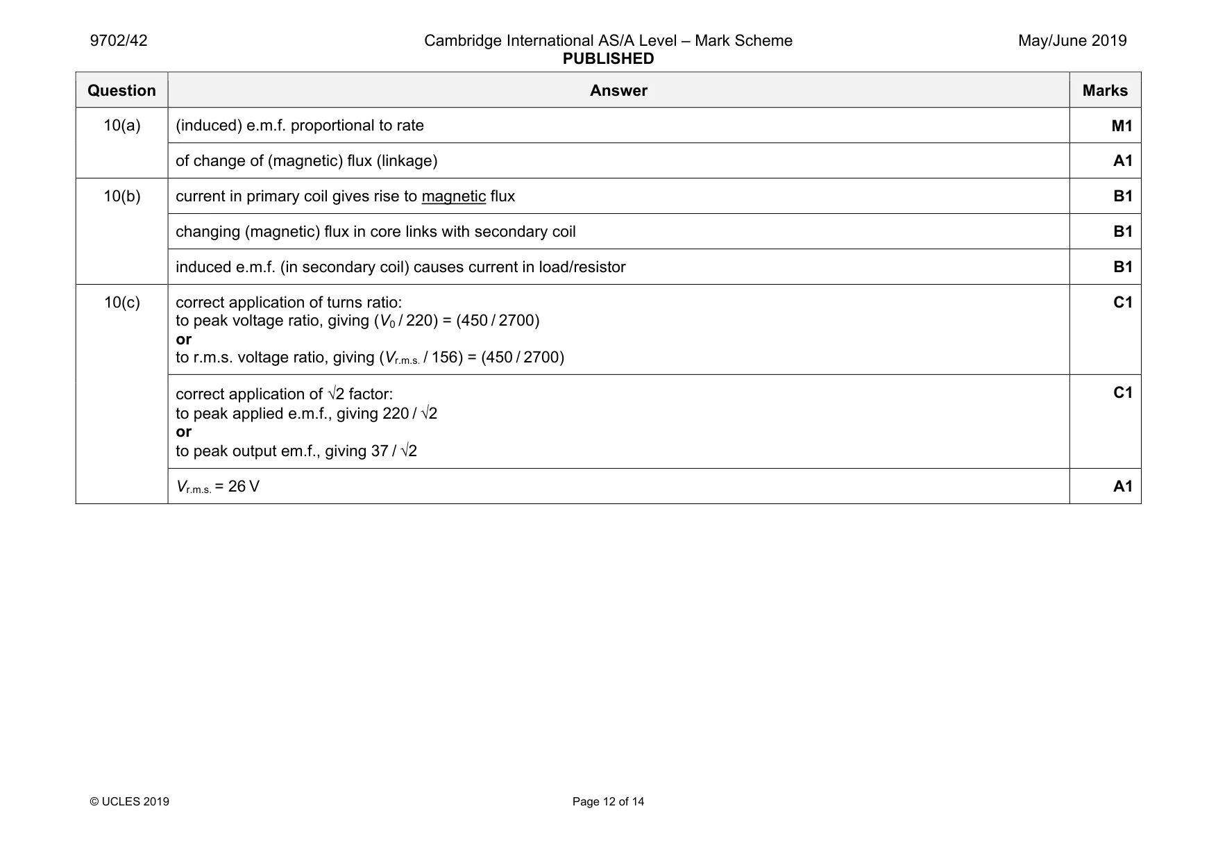
Mark scheme: 10(a) (induced) e.m.f. proportional to rate M1 of change of (magnetic) flux (linkage) A1 10(b) current in primary coil gives rise to magnetic flux B1 changing (magnetic) flux in core links with secondary coil B1 induced e.m.f. (in secondary coil) causes current in load/resistor B1 10(c) correct application of turns ratio: to peak voltage ratio, giving (V0 / 220) = (450 / 2700) or to r.m.s. voltage ratio, giving (Vr.m.s. / 156) = (450 / 2700) C1 correct application of √2 factor: to peak applied e.m.f., giving 220 / √2 or to peak output em.f., giving 37 / √2 C1 Vr.m.s. = 26 V A1
Q11 · State what is meant by a photon
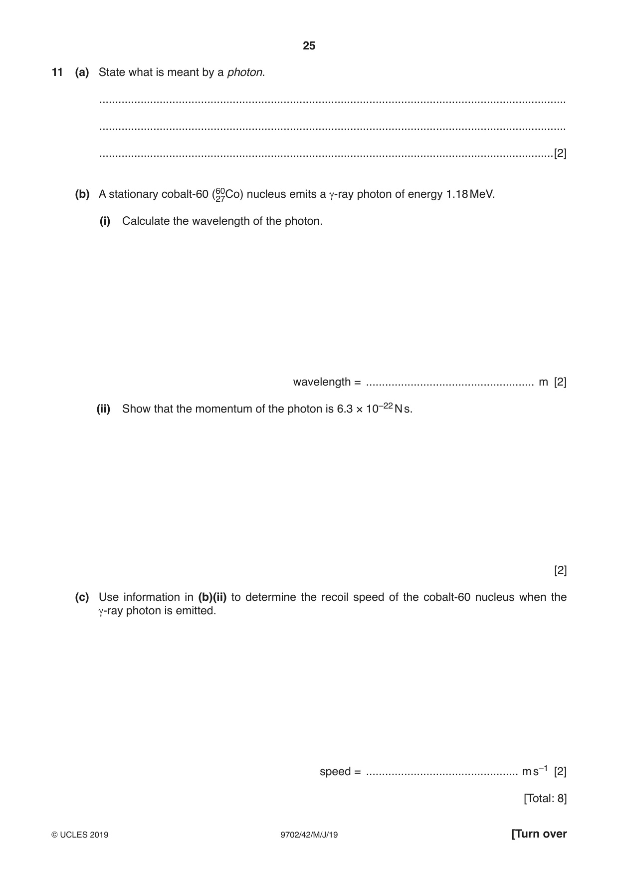
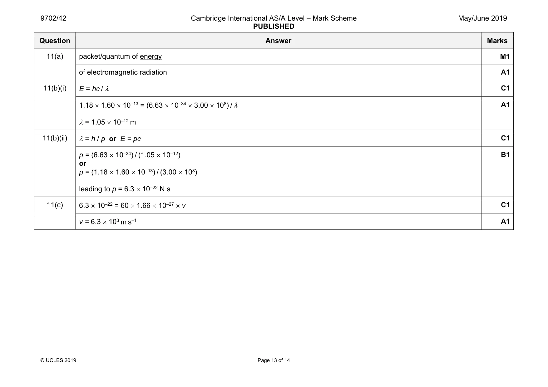
11 (a) State what is meant by a photon. ................................................................................................................................................... ................................................................................................................................................... ...............................................................................................................................................[2] (b) A stationary cobalt-60 (6027Co) nucleus emits a γ-ray photon of energy 1.18 MeV. (i) Calculate the wavelength of the photon. wavelength = ..................................................... m [2] (ii) Show that the momentum of the photon is 6.3 × 10⁻²² N s. [2] (c) Use information in (b)(ii) to determine the recoil speed of the cobalt-60 nucleus when the γ-ray photon is emitted. speed = ................................................ m s–1 [2] [Total: 8]
Mark scheme: 11(a) packet/quantum of energy M1 of electromagnetic radiation A1 11(b)(i) E = hc / λ C1 1.18 × 1.60 × 10–13 = (6.63 × 10–34 × 3.00 × 108) / λ λ = 1.05 × 10⁻¹² m A1 11(b)(ii) λ = h / p or E = pc C1 p = (6.63 × 10⁻³⁴) / (1.05 × 10⁻¹²) or p = (1.18 × 1.60 × 10–13) / (3.00 × 10⁸) leading to p = 6.3 × 10⁻²² N s B1 11(c) 6.3 × 10–22 = 60 × 1.66 × 10–27 × v C1 v = 6.3 × 10³ m s–1 A1
Q12 · State what is meant by the binding energy of a nucleus
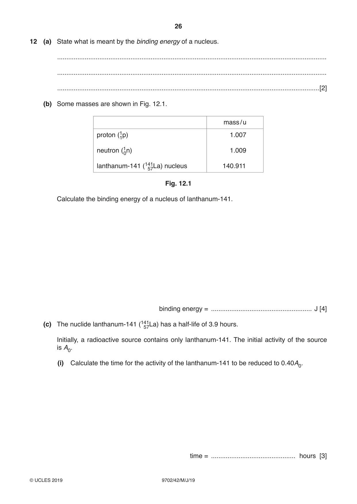
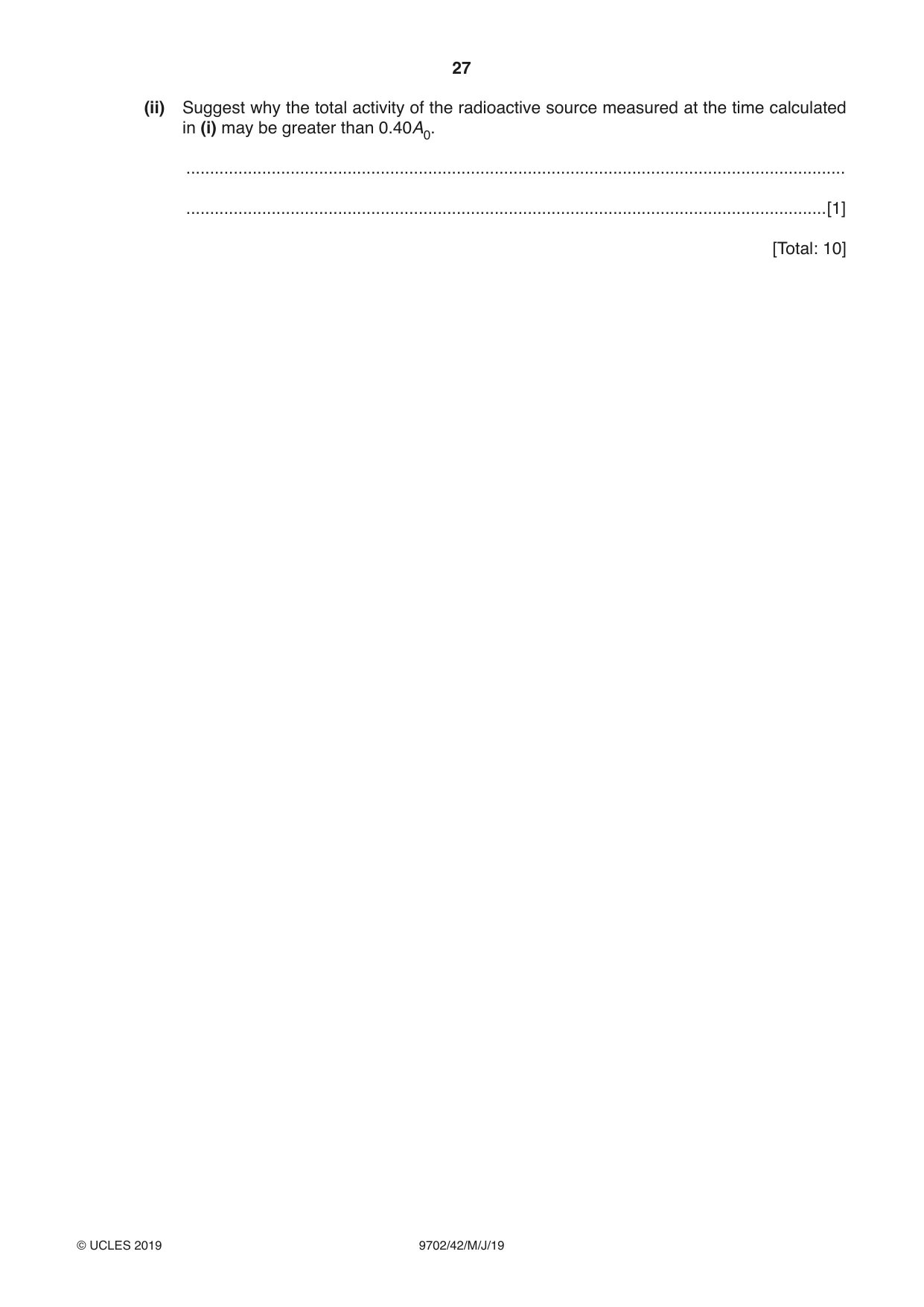
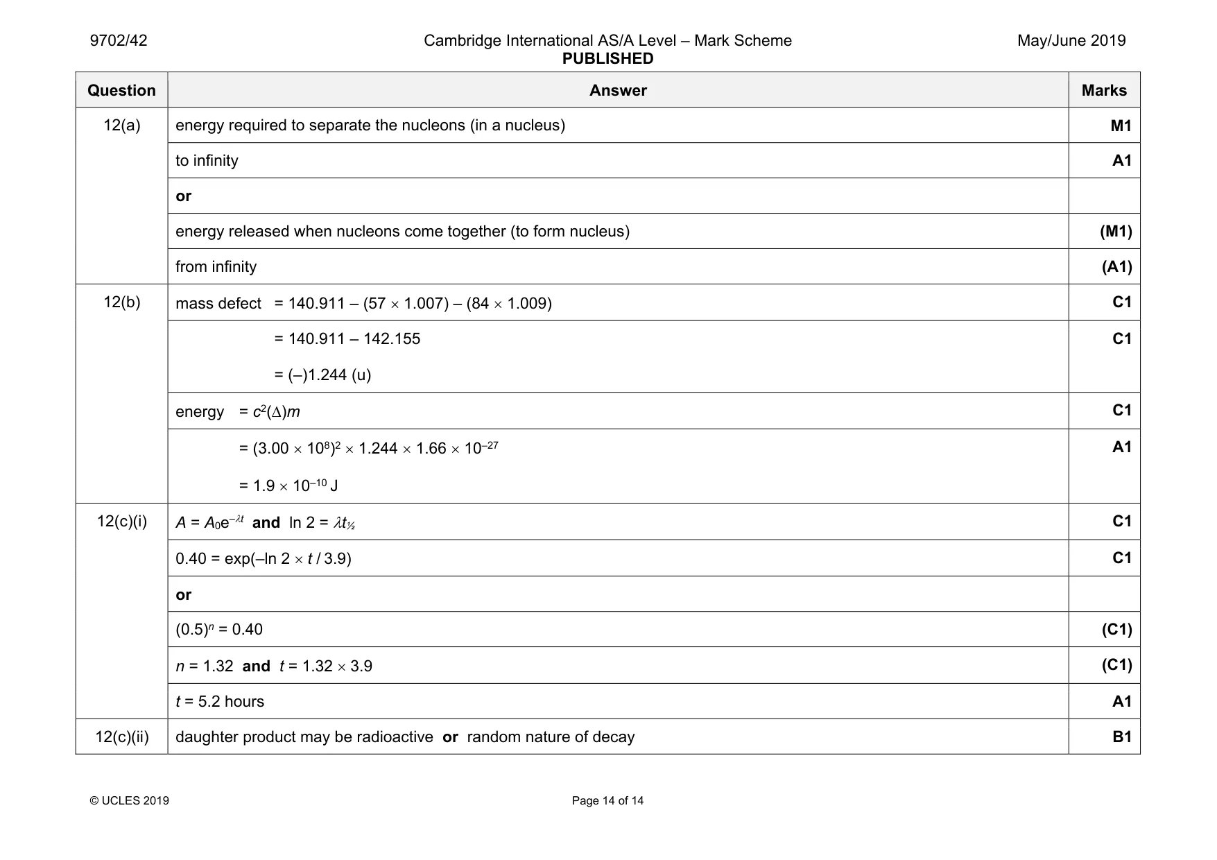
12 (a) State what is meant by the binding energy of a nucleus. ................................................................................................................................................... ................................................................................................................................................... ...............................................................................................................................................[2] (b) Some masses are shown in Fig. 12.1. mass / u proton (11p) 1.007 neutron (10n) 1.009 lanthanum-141 (14157La) nucleus 140.911 Fig. 12.1 Calculate the binding energy of a nucleus of lanthanum-141. binding energy = ....................................................... J [4] (c) The nuclide lanthanum-141 (14157La) has a half-life of 3.9 hours. Initially, a radioactive source contains only lanthanum-141. The initial activity of the source is A0. (i) Calculate the time for the activity of the lanthanum-141 to be reduced to 0.40A0. time = .............................................. hours [3] (ii) Suggest why the total activity of the radioactive source measured at the time calculated in (i) may be greater than 0.40A0. ........................................................................................................................................... .......................................................................................................................................[1] [Total: 10]
Mark scheme: 12(a) energy required to separate the nucleons (in a nucleus) M1 to infinity A1 or energy released when nucleons come together (to form nucleus) (M1) from infinity (A1) 12(b) mass defect = 140.911 – (57 × 1.007) – (84 × 1.009) C1 = 140.911 – 142.155 = (–)1.244 (u) C1 energy = c2(∆)m C1 = (3.00 × 10⁸)2 × 1.244 × 1.66 × 10–27 = 1.9 × 10⁻¹⁰ J A1 12(c)(i) A = A0e–λt and ln 2 = λt½ C1 0.40 = exp(–ln 2 × t / 3.9) C1 or (0.5)n = 0.40 (C1) n = 1.32 and t = 1.32 × 3.9 (C1) t = 5.2 hours A1 12(c)(ii) daughter product may be radioactive or random nature of decay B1
What was in this paper
The subtopics covered by these 12 questions, and how many questions each got. Open one in a new tab to see every Cambridge question on it.
1Electromagnetic induction1Electromagnetic spectrum1Energy and momentum of a photon1Energy in simple harmonic motion1Force on a moving charge1Gravitational force between point masses1Mass defect and nuclear binding energy1Practical circuits1Production and use of ultrasound1Resistance and resistivity1The first law of thermodynamics1What you needed in this session
Cambridge’s own grade thresholds for 2019 May/June, Paper 4 · Variant 2. A higher threshold means an easier paper — the bar moves with how the cohort did.