Cambridge A Level Physics 9702 — 2021 Oct/Nov Paper 4 · Variant 3
9702/43/O/N/21 · 12 questions · 100 marks · ≈113 min
The question paper and its mark scheme, free to read here and free to download. This is Cambridge’s own paper, exactly as it was sat.
Question paper28 pages



Mark scheme15 pages
Answers below. Sit the paper first if you are practising.
Questions as text
Q1 · With reference to velocity and acceleration, describe uniform circular motion
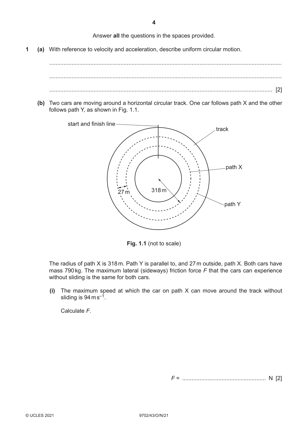
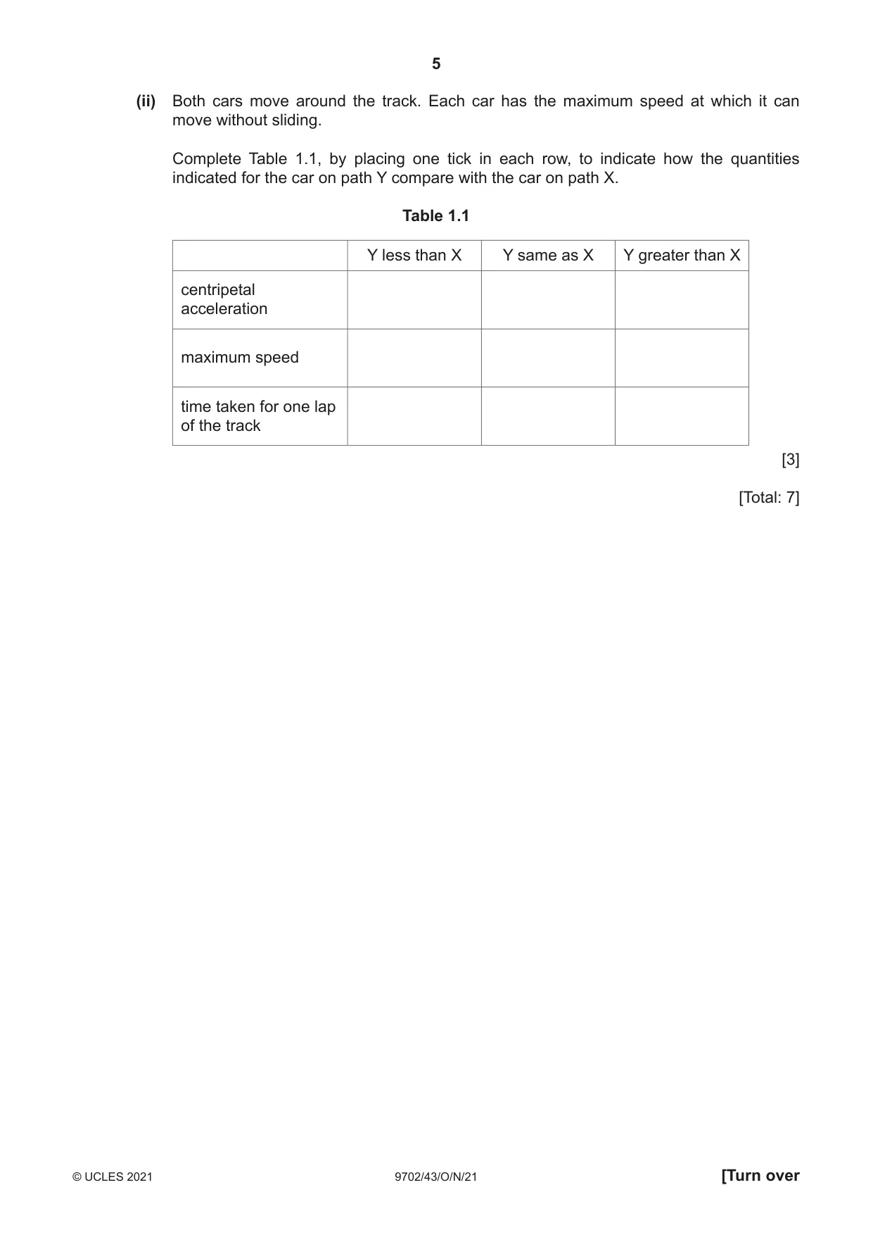
1 (a) With reference to velocity and acceleration, describe uniform circular motion. ................................................................................................................................................... ................................................................................................................................................... ............................................................................................................................................. [2] (b) Two cars are moving around a horizontal circular track. One car follows path X and the other follows path Y, as shown in Fig. 1.1. start and finish line track path X 318 m 27 m path Y Fig. 1.1 (not to scale) The radius of path X is 318 m. Path Y is parallel to, and 27 m outside, path X. Both cars have mass 790 kg. The maximum lateral (sideways) friction force F that the cars can experience without sliding is the same for both cars. (i) The maximum speed at which the car on path X can move around the track without sliding is 94 m s–1. Calculate F. F = ..................................................... N [2] (ii) Both cars move around the track. Each car has the maximum speed at which it can move without sliding. Complete Table 1.1, by placing one tick in each row, to indicate how the quantities indicated for the car on path Y compare with the car on path X. Table 1.1 Y less than X Y same as X Y greater than X centripetal acceleration maximum speed time taken for one lap of the track [3] [Total: 7]
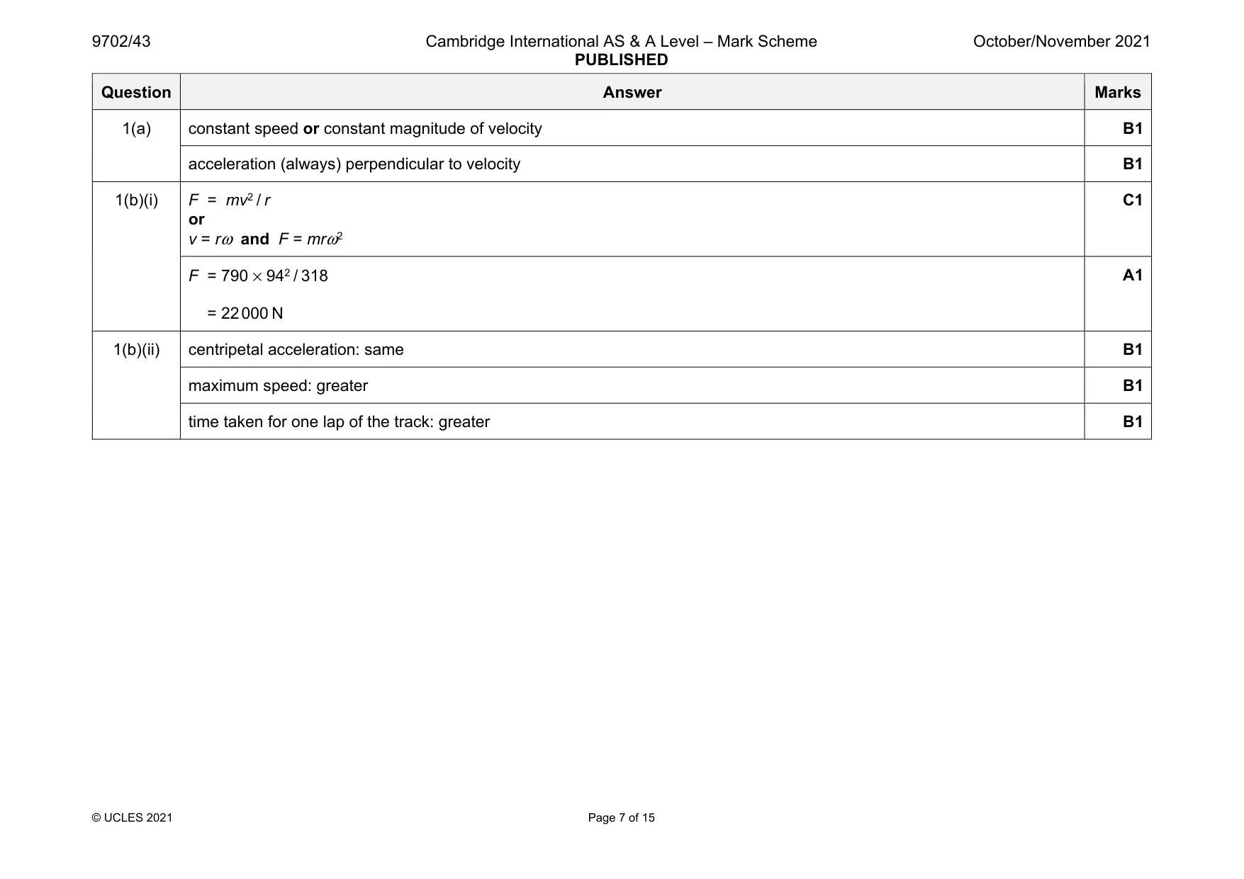
Mark scheme: 1(a) constant speed or constant magnitude of velocity B1 acceleration (always) perpendicular to velocity B1 1(b)(i) F = mv2 / r or v = rω and F = mrω2 C1 F = 790 × 942 / 318 = 22 000 N A1 1(b)(ii) centripetal acceleration: same B1 maximum speed: greater B1 time taken for one lap of the track: greater B1
Question 2
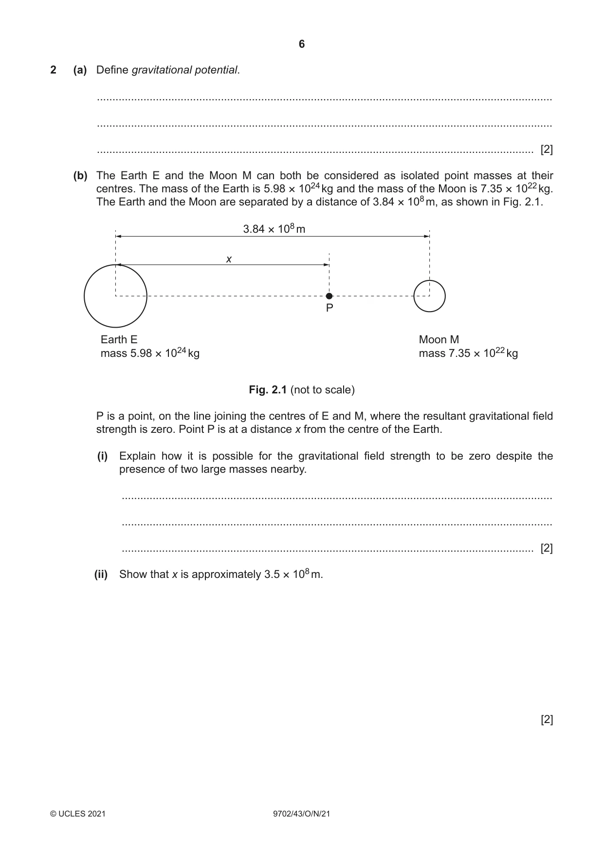
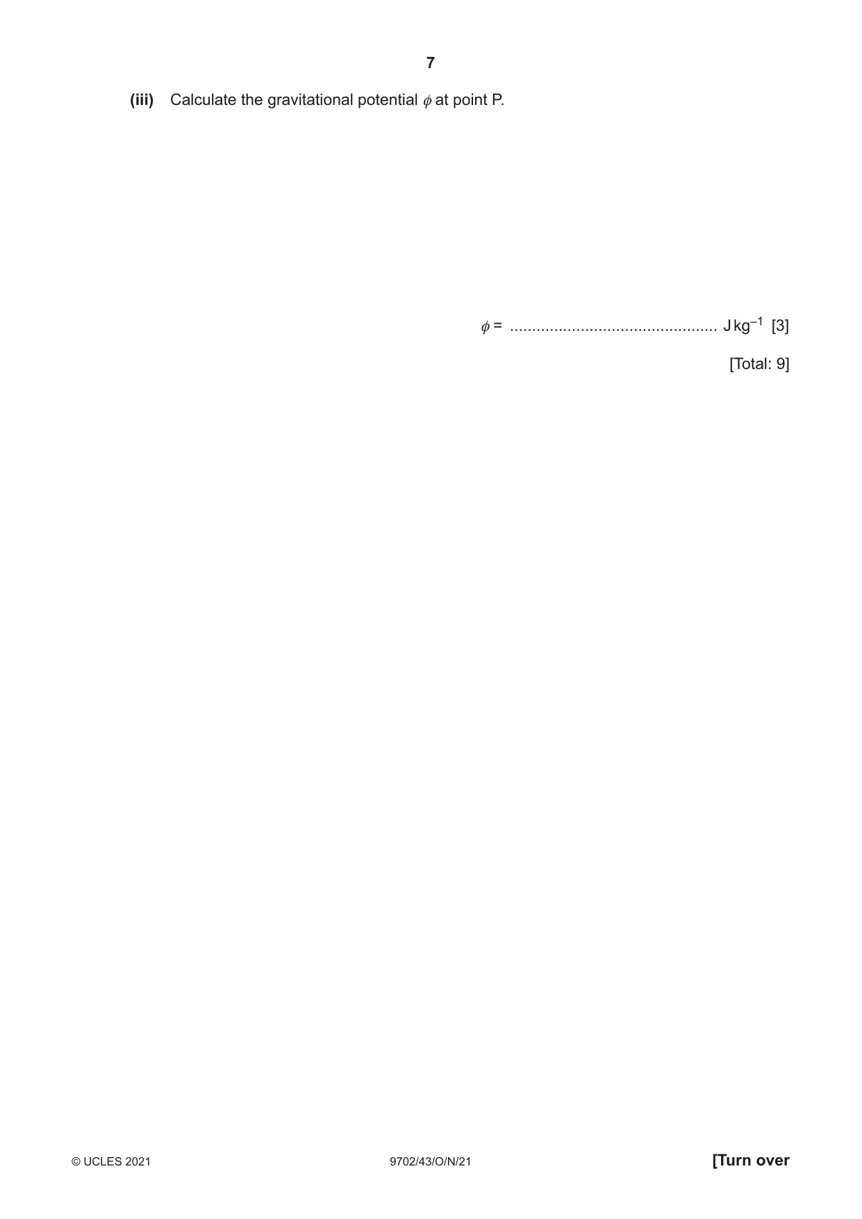
2 (a) Define gravitational potential. ................................................................................................................................................... ................................................................................................................................................... ............................................................................................................................................. [2] (b) The Earth E and the Moon M can both be considered as isolated point masses at their centres. The mass of the Earth is 5.98 × 1024 kg and the mass of the Moon is 7.35 × 10²² kg. The Earth and the Moon are separated by a distance of 3.84 × 10⁸ m, as shown in Fig. 2.1. 3.84 × 10⁸ m x P Earth E Moon M mass 5.98 × 1024 kg mass 7.35 × 10²² kg Fig. 2.1 (not to scale) P is a point, on the line joining the centres of E and M, where the resultant gravitational field strength is zero. Point P is at a distance x from the centre of the Earth. (i) Explain how it is possible for the gravitational field strength to be zero despite the presence of two large masses nearby. ........................................................................................................................................... ........................................................................................................................................... ..................................................................................................................................... [2] (ii) Show that x is approximately 3.5 × 10⁸ m. [2] (iii) Calculate the gravitational potential φ at point P. φ = ............................................... J kg–1 [3] [Total: 9]
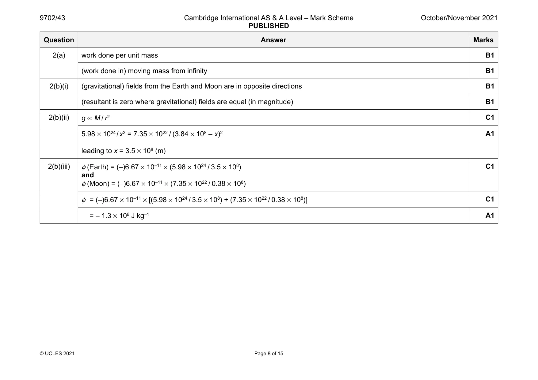
Mark scheme: 2(a) work done per unit mass B1 (work done in) moving mass from infinity B1 2(b)(i) (gravitational) fields from the Earth and Moon are in opposite directions B1 (resultant is zero where gravitational) fields are equal (in magnitude) B1 2(b)(ii) g ∝ M / r2 C1 5.98 × 1024 / x2 = 7.35 × 10²² / (3.84 × 10⁸ – x)2 leading to x = 3.5 × 10⁸ (m) A1 2(b)(iii) φ (Earth) = (–)6.67 × 10–11 × (5.98 × 1024 / 3.5 × 10⁸) and φ (Moon) = (–)6.67 × 10–11 × (7.35 × 1022 / 0.38 × 10⁸) C1 φ = (–)6.67 × 10⁻¹¹ × [(5.98 × 1024 / 3.5 × 10⁸) + (7.35 × 10²² / 0.38 × 10⁸)] C1 = – 1.3 × 10⁶ J kg–1 A1
Q3 · Define specific heat capacity
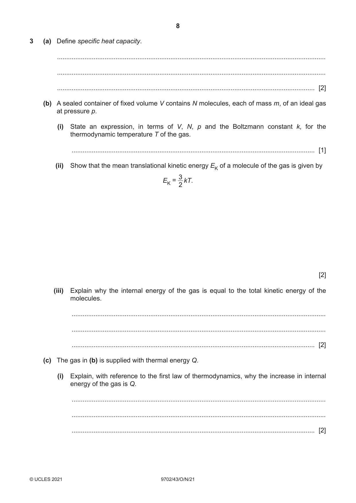
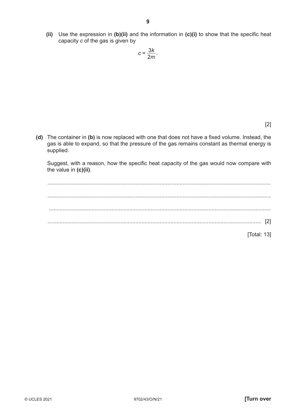
3 (a) Define specific heat capacity. ................................................................................................................................................... ................................................................................................................................................... ............................................................................................................................................. [2] (b) A sealed container of fixed volume V contains N molecules, each of mass m, of an ideal gas at pressure p. (i) State an expression, in terms of V, N, p and the Boltzmann constant k, for the thermodynamic temperature T of the gas. ..................................................................................................................................... [1] (ii) Show that the mean translational kinetic energy EK of a molecule of the gas is given by 3 EK = kT. 2 [2] (iii) Explain why the internal energy of the gas is equal to the total kinetic energy of the molecules. ........................................................................................................................................... ........................................................................................................................................... ..................................................................................................................................... [2] (c) The gas in (b) is supplied with thermal energy Q. (i) Explain, with reference to the first law of thermodynamics, why the increase in internal energy of the gas is Q. ........................................................................................................................................... ........................................................................................................................................... ..................................................................................................................................... [2] (ii) Use the expression in (b)(ii) and the information in (c)(i) to show that the specific heat capacity c of the gas is given by 3k c = . 2m [2] (d) The container in (b) is now replaced with one that does not have a fixed volume. Instead, the gas is able to expand, so that the pressure of the gas remains constant as thermal energy is supplied. Suggest, with a reason, how the specific heat capacity of the gas would now compare with the value in (c)(ii). ................................................................................................................................................... ................................................................................................................................................... .................................................................................................................................................. ............................................................................................................................................. [2] [Total: 13]
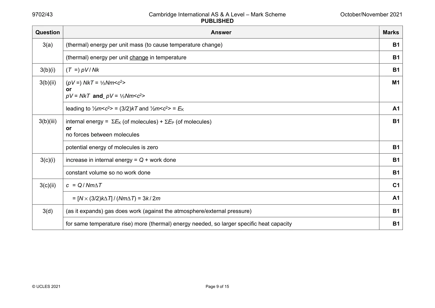
Mark scheme: 3(a) (thermal) energy per unit mass (to cause temperature change) B1 (thermal) energy per unit change in temperature B1 3(b)(i) (T =) pV / Nk B1 3(b)(ii) (pV =) NkT = ⅓Nm<c2> or pV = NkT and pV = ⅓Nm<c2> M1 leading to ½m<c2> = (3/2)kT and ½m<c2> = EK A1 3(b)(iii) internal energy = ΣEK (of molecules) + ΣEP (of molecules) or no forces between molecules B1 potential energy of molecules is zero B1 3(c)(i) increase in internal energy = Q + work done B1 constant volume so no work done B1 3(c)(ii) c = Q / NmΔT C1 = [N × (3/2)kΔT] / (NmΔT) = 3k / 2m A1 3(d) (as it expands) gas does work (against the atmosphere/external pressure) B1 for same temperature rise) more (thermal) energy needed, so larger specific heat capacity B1
Q4 · A trolley on a track is attached by springs to fixed blocks X and Y, as shown in Fig
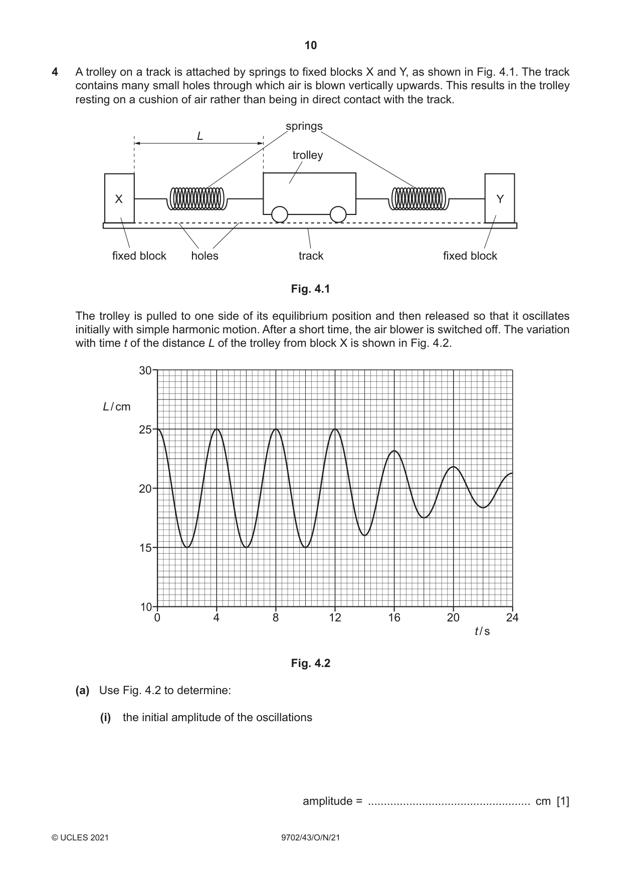
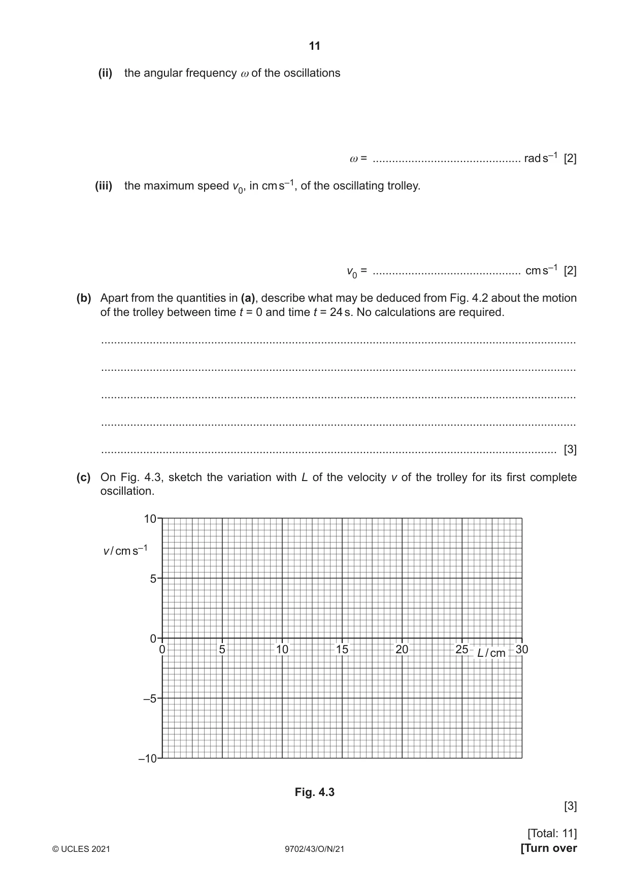
4 A trolley on a track is attached by springs to fixed blocks X and Y, as shown in Fig. 4.1. The track contains many small holes through which air is blown vertically upwards. This results in the trolley resting on a cushion of air rather than being in direct contact with the track. springs L trolley X Y fixed block holes track fixed block Fig. 4.1 The trolley is pulled to one side of its equilibrium position and then released so that it oscillates initially with simple harmonic motion. After a short time, the air blower is switched off. The variation with time t of the distance L of the trolley from block X is shown in Fig. 4.2. 30 L / cm 25 20 15 10 0 4 8 12 16 20 24 t / s Fig. 4.2 (a) Use Fig. 4.2 to determine: (i) the initial amplitude of the oscillations amplitude = ................................................... cm [1] (ii) the angular frequency ω of the oscillations ω = .............................................. rad s–1 [2] (iii) the maximum speed v0, in cm s–1, of the oscillating trolley. v0 = .............................................. cm s–1 [2] (b) Apart from the quantities in (a), describe what may be deduced from Fig. 4.2 about the motion of the trolley between time t = 0 and time t = 24 s. No calculations are required. ................................................................................................................................................... ................................................................................................................................................... ................................................................................................................................................... ................................................................................................................................................... ............................................................................................................................................. [3] (c) On Fig. 4.3, sketch the variation with L of the velocity v of the trolley for its first complete oscillation. 10 v / cm s–1 5 0 0 5 10 15 20 25 30 L / cm –5 –10 Fig. 4.3 [3] [Total: 11]
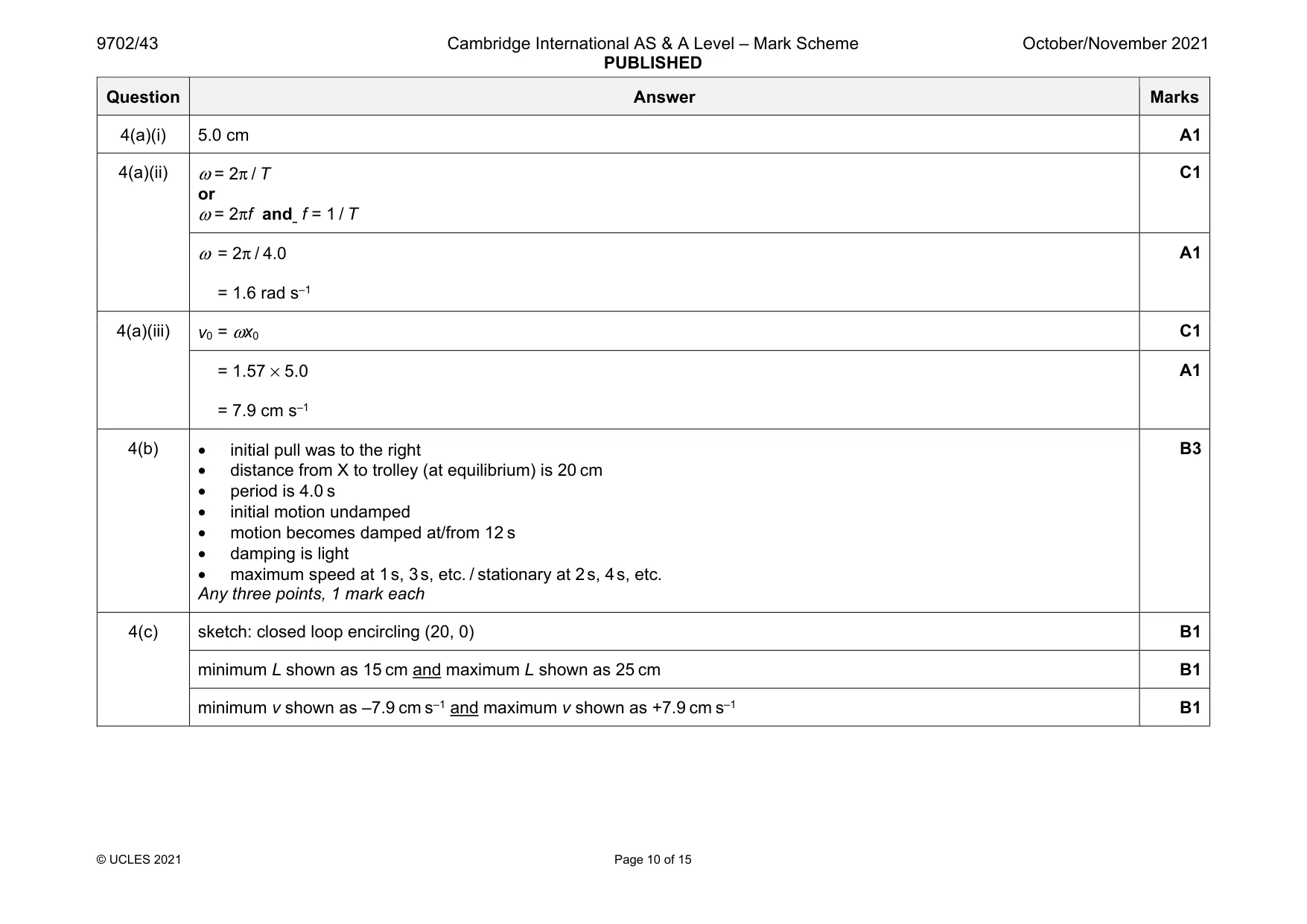
Mark scheme: 4(a)(i) 5.0 cm A1 4(a)(ii) ω = 2π / T or ω = 2πf and f = 1 / T C1 ω = 2π / 4.0 = 1.6 rad s–1 A1 4(a)(iii) v0 = ωx0 C1 = 1.57 × 5.0 = 7.9 cm s–1 A1 4(b) • initial pull was to the right • distance from X to trolley (at equilibrium) is 20 cm • period is 4.0 s • initial motion undamped • motion becomes damped at/from 12 s • damping is light • maximum speed at 1 s, 3 s, etc. / stationary at 2 s, 4 s, etc. Any three points, 1 mark each B3 4(c) sketch: closed loop encircling (20, 0) B1 minimum L shown as 15 cm and maximum L shown as 25 cm B1 minimum v shown as –7.9 cm s–1 and maximum v shown as +7.9 cm s–1 B1
Q5 · An analogue signal is to be transmitted to a receiver
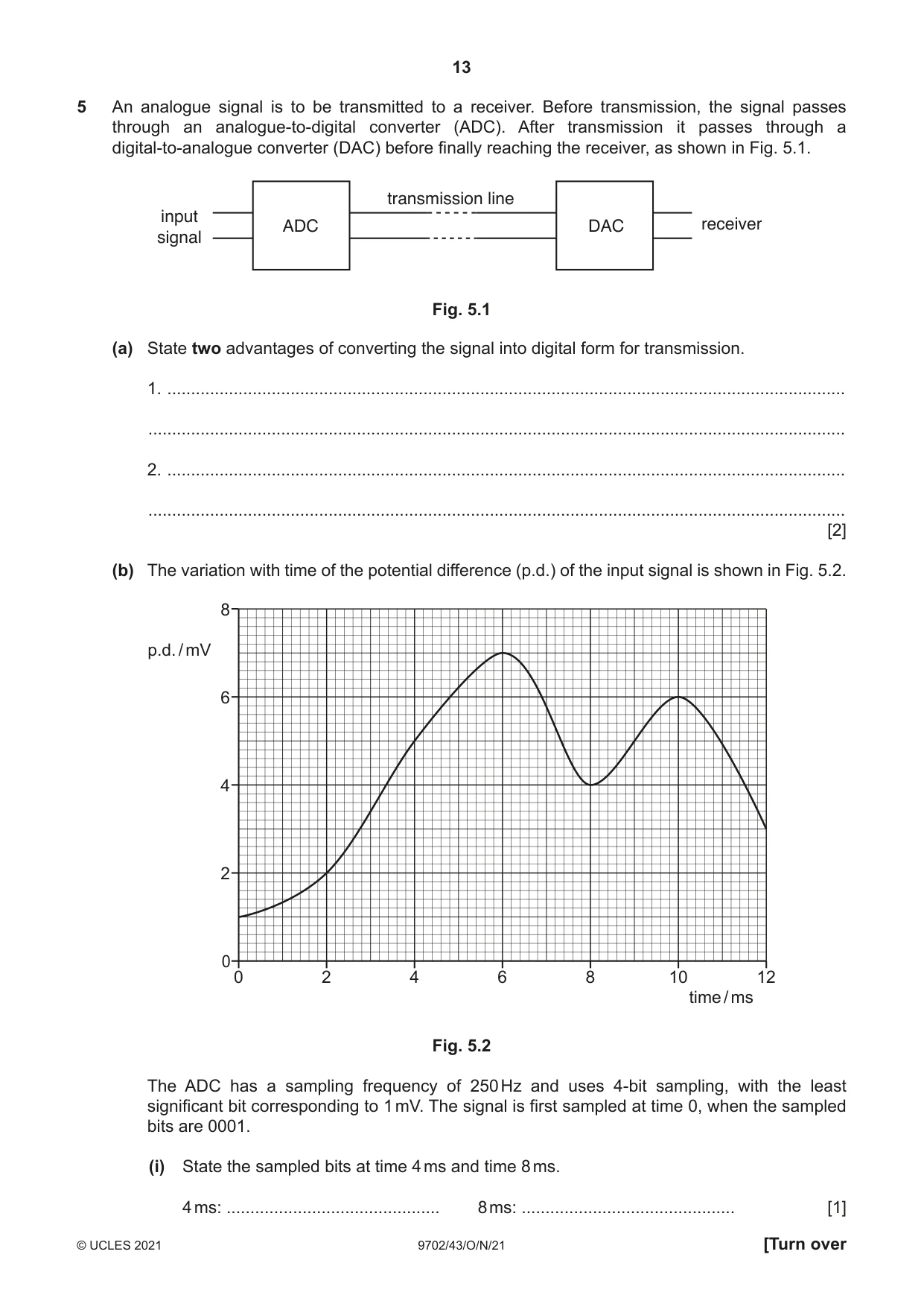
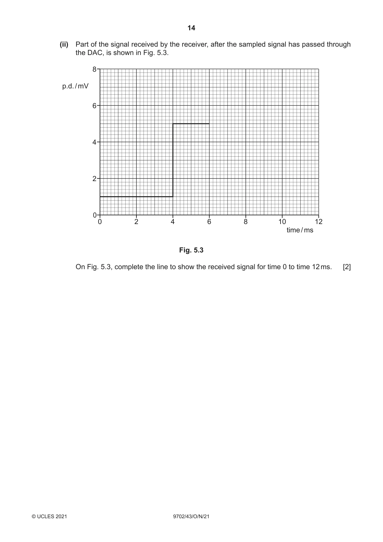
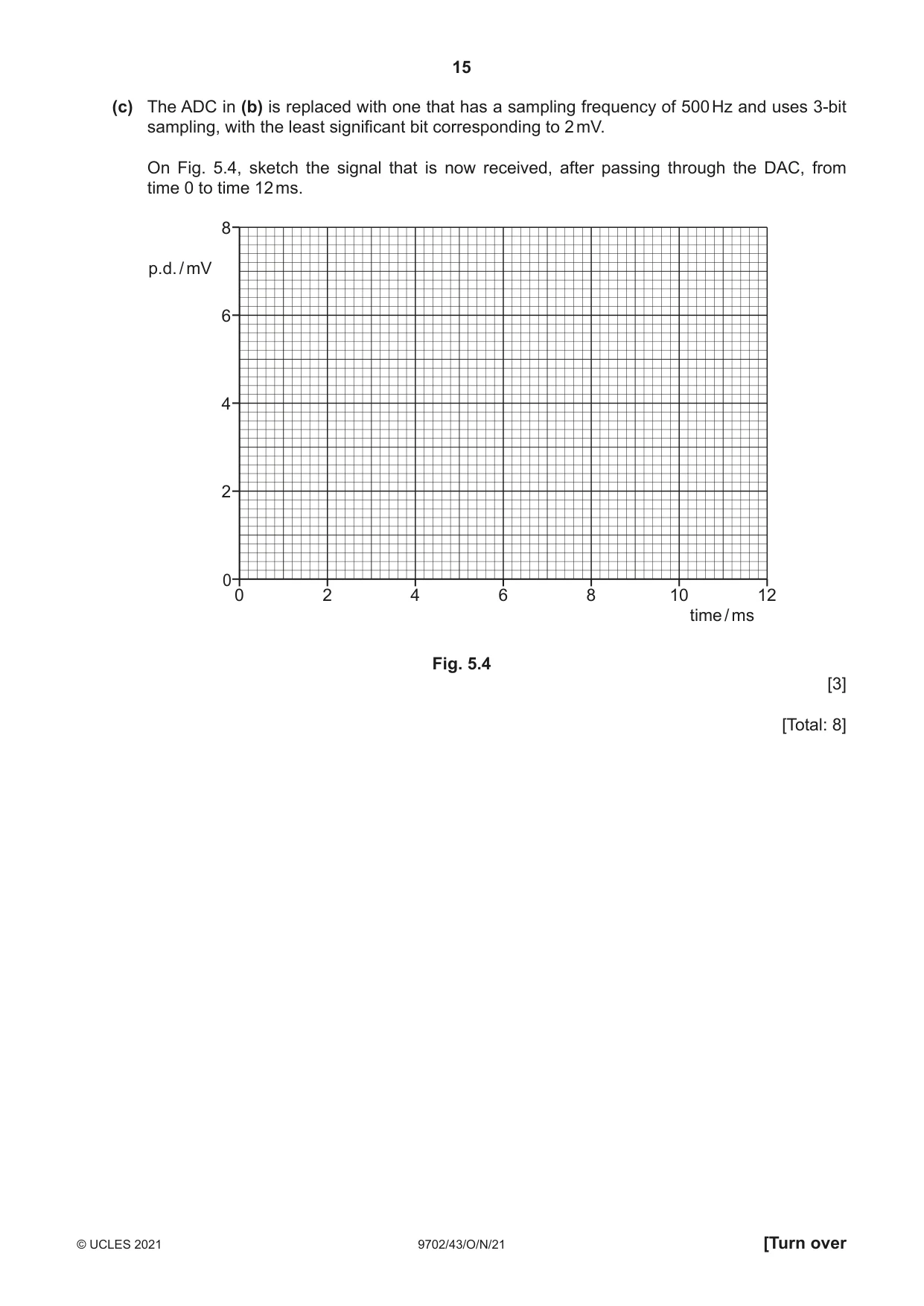
5 An analogue signal is to be transmitted to a receiver. Before transmission, the signal passes through an analogue-to-digital converter (ADC). After transmission it passes through a digital-to-analogue converter (DAC) before finally reaching the receiver, as shown in Fig. 5.1. transmission line input ADC DAC receiver signal Fig. 5.1 (a) State two advantages of converting the signal into digital form for transmission. 1. ............................................................................................................................................... ................................................................................................................................................... 2. ............................................................................................................................................... ................................................................................................................................................... [2] (b) The variation with time of the potential difference (p.d.) of the input signal is shown in Fig. 5.2. 8 p.d. / mV 6 4 2 0 0 2 4 6 8 10 12 time / ms Fig. 5.2 The ADC has a sampling frequency of 250 Hz and uses 4-bit sampling, with the least significant bit corresponding to 1 mV. The signal is first sampled at time 0, when the sampled bits are 0001. (i) State the sampled bits at time 4 ms and time 8 ms. 4 ms: ............................................. 8 ms: ............................................. [1] (ii) Part of the signal received by the receiver, after the sampled signal has passed through the DAC, is shown in Fig. 5.3. 8 p.d. / mV 6 4 2 0 0 2 4 6 8 10 12 time / ms Fig. 5.3 On Fig. 5.3, complete the line to show the received signal for time 0 to time 12 ms. [2] (c) The ADC in (b) is replaced with one that has a sampling frequency of 500 Hz and uses 3-bit sampling, with the least significant bit corresponding to 2 mV. On Fig. 5.4, sketch the signal that is now received, after passing through the DAC, from time 0 to time 12 ms. 8 p.d. / mV 6 4 2 0 0 2 4 6 8 10 12 time / ms Fig. 5.4 [3] [Total: 8]
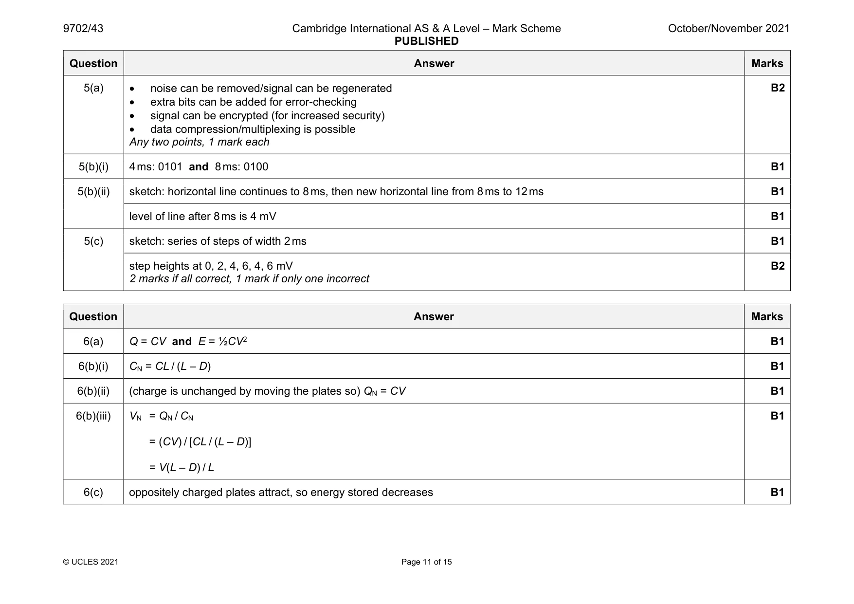
Mark scheme: 5(a) • noise can be removed/signal can be regenerated • extra bits can be added for error-checking • signal can be encrypted (for increased security) • data compression/multiplexing is possible Any two points, 1 mark each B2 5(b)(i) 4 ms: 0101 and 8 ms: 0100 B1 5(b)(ii) sketch: horizontal line continues to 8 ms, then new horizontal line from 8 ms to 12 ms B1 level of line after 8 ms is 4 mV B1 5(c) sketch: series of steps of width 2 ms B1 step heights at 0, 2, 4, 6, 4, 6 mV 2 marks if all correct, 1 mark if only one incorrect B2
Q6 · A capacitor consists of two parallel metal plates, separated by air, at a variable…
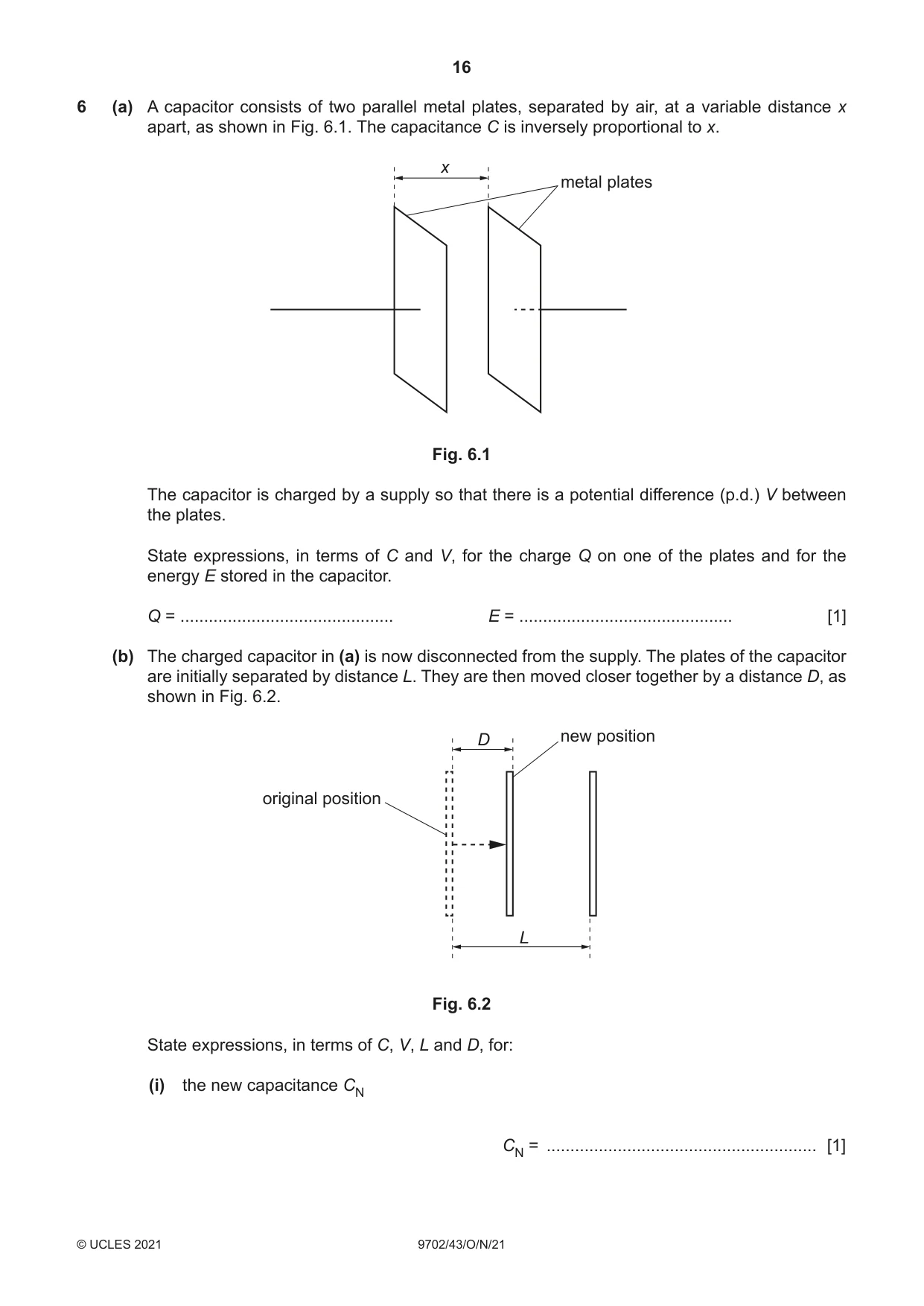
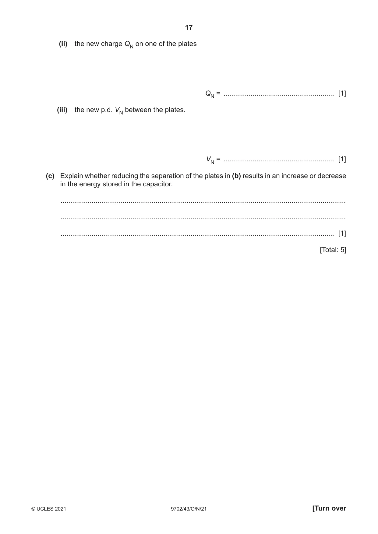
6 (a) A capacitor consists of two parallel metal plates, separated by air, at a variable distance x apart, as shown in Fig. 6.1. The capacitance C is inversely proportional to x. x metal plates Fig. 6.1 The capacitor is charged by a supply so that there is a potential difference (p.d.) V between the plates. State expressions, in terms of C and V, for the charge Q on one of the plates and for the energy E stored in the capacitor. Q = ............................................. E = ............................................. [1] (b) The charged capacitor in (a) is now disconnected from the supply. The plates of the capacitor are initially separated by distance L. They are then moved closer together by a distance D, as shown in Fig. 6.2. D new position original position L Fig. 6.2 State expressions, in terms of C, V, L and D, for: (i) the new capacitance CN CN = ......................................................... [1] (ii) the new charge QN on one of the plates QN = ......................................................... [1] (iii) the new p.d. VN between the plates. VN = ......................................................... [1] (c) Explain whether reducing the separation of the plates in (b) results in an increase or decrease in the energy stored in the capacitor. ................................................................................................................................................... ................................................................................................................................................... ............................................................................................................................................. [1] [Total: 5]
Mark scheme: 6(a) Q = CV and E = ½CV2 B1 6(b)(i) CN = CL / (L – D) B1 6(b)(ii) (charge is unchanged by moving the plates so) QN = CV B1 6(b)(iii) VN = QN / CN = (CV) / [CL / (L – D)] = V(L – D) / L B1 6(c) oppositely charged plates attract, so energy stored decreases B1
Q7 · State two properties of an ideal operational amplifier (op-amp)
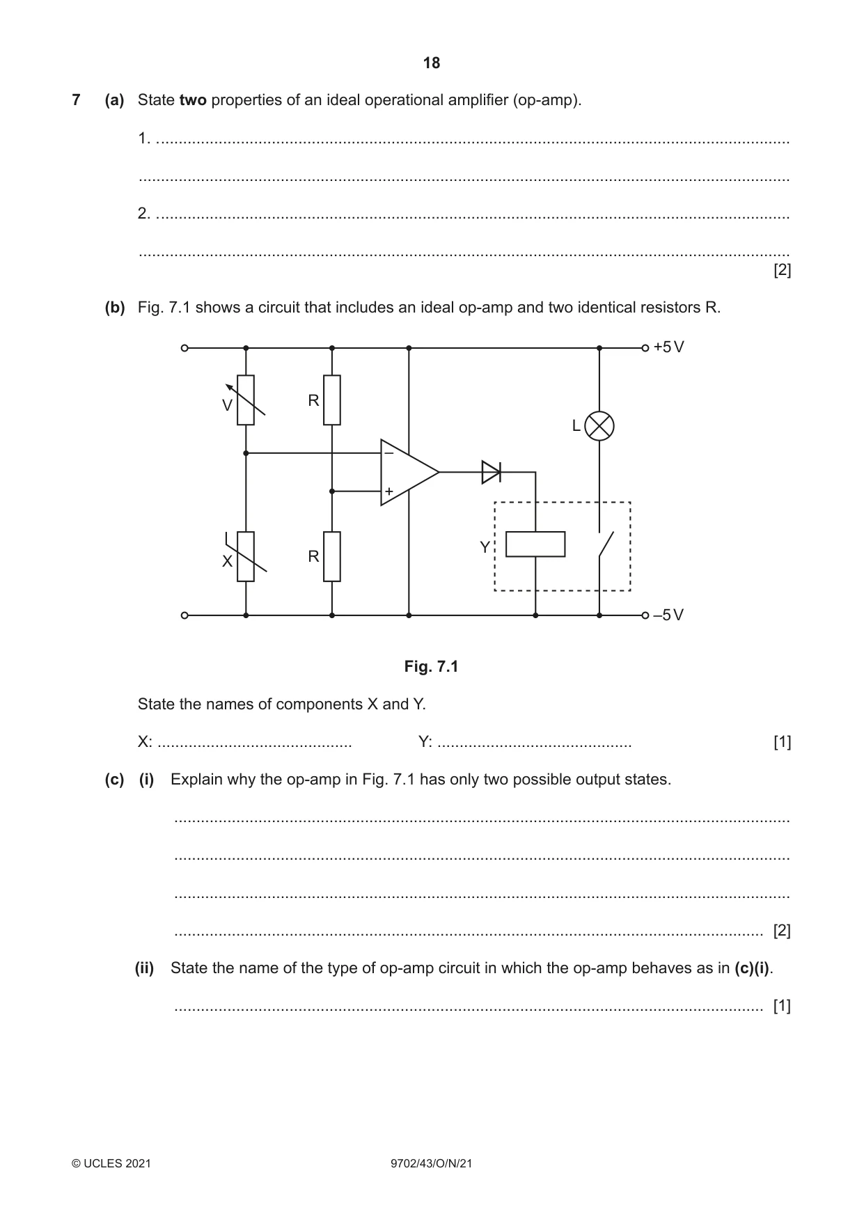
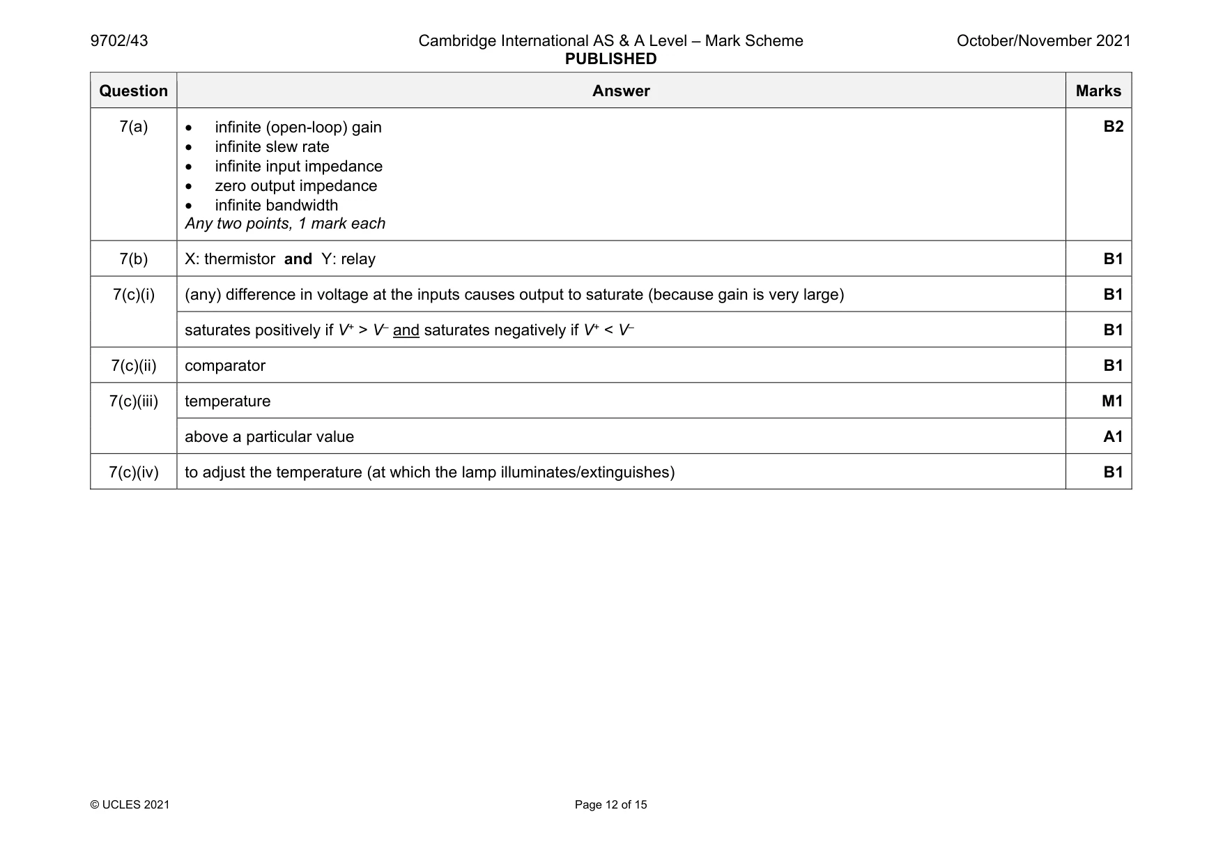
7 (a) State two properties of an ideal operational amplifier (op-amp). 1. . .............................................................................................................................................. ................................................................................................................................................... 2. . .............................................................................................................................................. ................................................................................................................................................... [2] (b) Fig. 7.1 shows a circuit that includes an ideal op-amp and two identical resistors R. +5 V R V L – + Y R X –5 V Fig. 7.1 State the names of components X and Y. X: ............................................ Y: ............................................ [1] (c) (i) Explain why the op-amp in Fig. 7.1 has only two possible output states. ........................................................................................................................................... ........................................................................................................................................... ........................................................................................................................................... ..................................................................................................................................... [2] (ii) State the name of the type of op-amp circuit in which the op-amp behaves as in (c)(i). ..................................................................................................................................... [1] (iii) Describe the environmental condition under which the lamp L in Fig. 7.1 will light. ........................................................................................................................................... ........................................................................................................................................... ..................................................................................................................................... [2] (iv) Suggest the purpose of the variable resistor V in the circuit. ........................................................................................................................................... ..................................................................................................................................... [1] [Total: 9]
Mark scheme: 7(a) • infinite (open-loop) gain • infinite slew rate • infinite input impedance • zero output impedance • infinite bandwidth Any two points, 1 mark each B2 7(b) X: thermistor and Y: relay B1 7(c)(i) (any) difference in voltage at the inputs causes output to saturate (because gain is very large) B1 saturates positively if V+ > V– and saturates negatively if V+ < V– B1 7(c)(ii) comparator B1 7(c)(iii) temperature M1 above a particular value A1 7(c)(iv) to adjust the temperature (at which the lamp illuminates/extinguishes) B1
Question 8
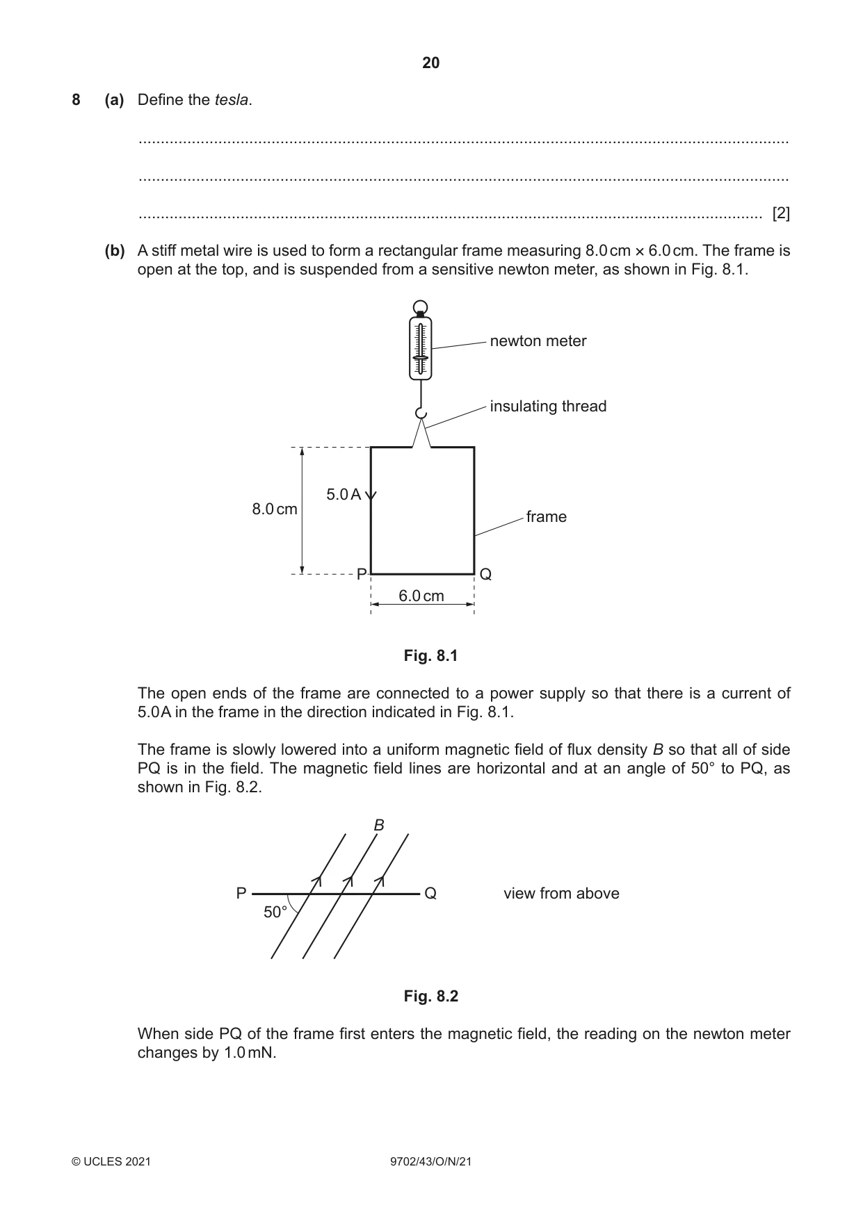
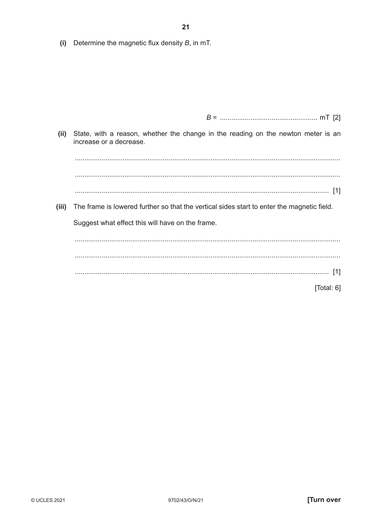
8 (a) Define the tesla. ................................................................................................................................................... ................................................................................................................................................... ............................................................................................................................................. [2] (b) A stiff metal wire is used to form a rectangular frame measuring 8.0 cm × 6.0 cm. The frame is open at the top, and is suspended from a sensitive newton meter, as shown in Fig. 8.1. newton meter insulating thread 5.0 A 8.0 cm frame P Q 6.0 cm Fig. 8.1 The open ends of the frame are connected to a power supply so that there is a current of 5.0 A in the frame in the direction indicated in Fig. 8.1. The frame is slowly lowered into a uniform magnetic field of flux density B so that all of side PQ is in the field. The magnetic field lines are horizontal and at an angle of 50° to PQ, as shown in Fig. 8.2. B P Q view from above 50° Fig. 8.2 When side PQ of the frame first enters the magnetic field, the reading on the newton meter changes by 1.0 mN. (i) Determine the magnetic flux density B, in mT. B = ................................................... mT [2] (ii) State, with a reason, whether the change in the reading on the newton meter is an increase or a decrease. ........................................................................................................................................... ........................................................................................................................................... ..................................................................................................................................... [1] (iii) The frame is lowered further so that the vertical sides start to enter the magnetic field. Suggest what effect this will have on the frame. ........................................................................................................................................... ........................................................................................................................................... ..................................................................................................................................... [1] [Total: 6]
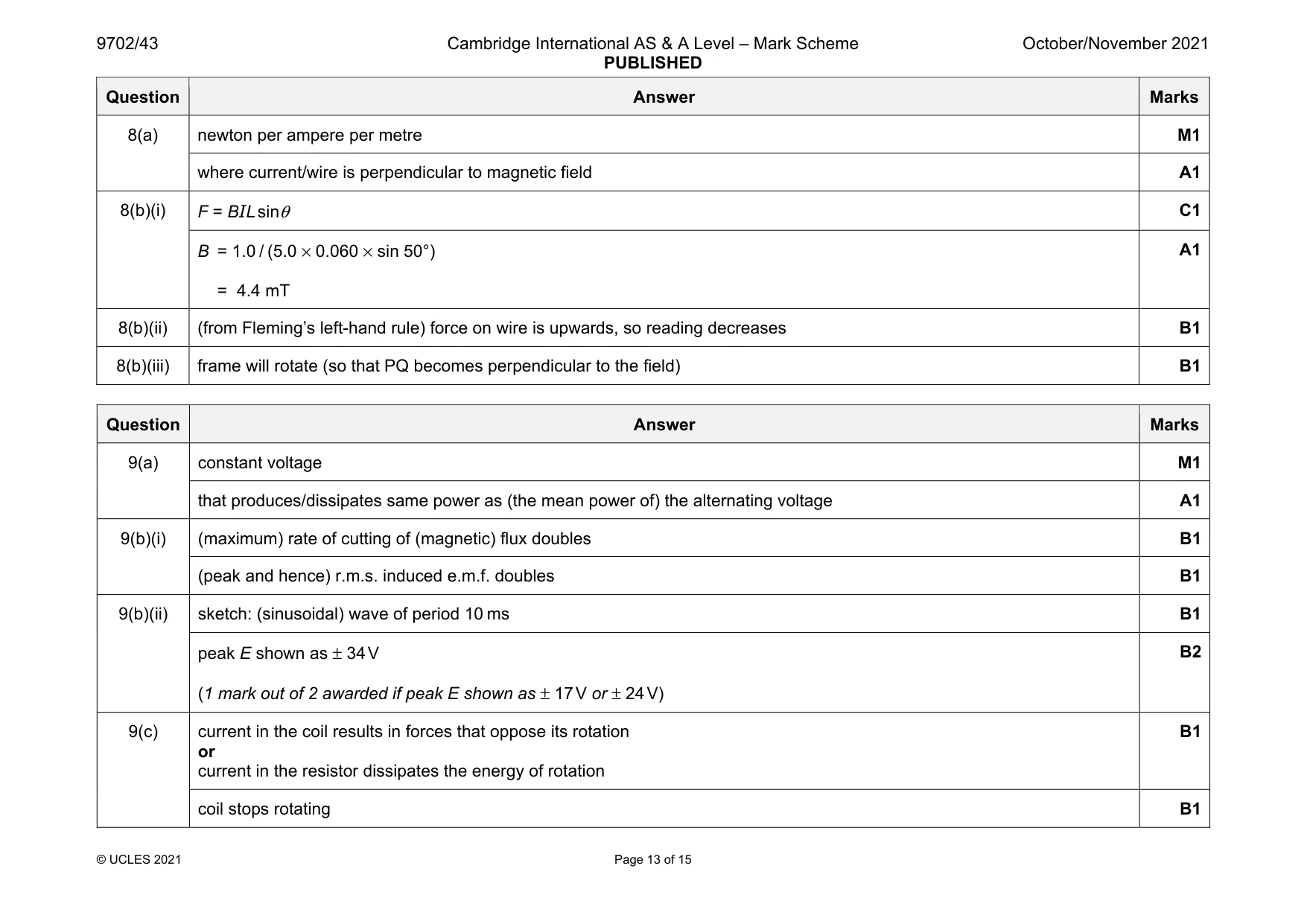
Mark scheme: 8(a) newton per ampere per metre M1 where current/wire is perpendicular to magnetic field A1 8(b)(i) F = BIL sinθ C1 B = 1.0 / (5.0 × 0.060 × sin 50°) = 4.4 mT A1 8(b)(ii) (from Fleming’s left-hand rule) force on wire is upwards, so reading decreases B1 8(b)(iii) frame will rotate (so that PQ becomes perpendicular to the field) B1
Q9 · State, by reference to the power dissipated in a resistor, what is meant by the…
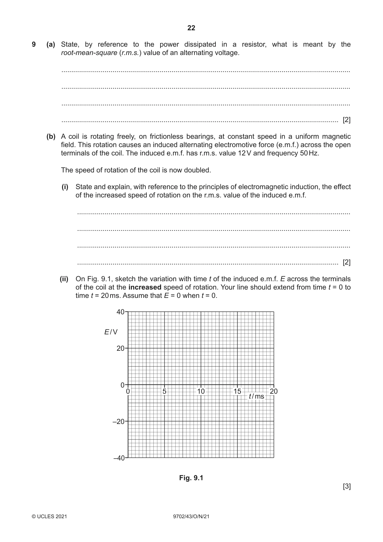
9 (a) State, by reference to the power dissipated in a resistor, what is meant by the root-mean-square (r.m.s.) value of an alternating voltage. ................................................................................................................................................... ................................................................................................................................................... ................................................................................................................................................... ............................................................................................................................................. [2] (b) A coil is rotating freely, on frictionless bearings, at constant speed in a uniform magnetic field. This rotation causes an induced alternating electromotive force (e.m.f.) across the open terminals of the coil. The induced e.m.f. has r.m.s. value 12 V and frequency 50 Hz. The speed of rotation of the coil is now doubled. (i) State and explain, with reference to the principles of electromagnetic induction, the effect of the increased speed of rotation on the r.m.s. value of the induced e.m.f. ........................................................................................................................................... ........................................................................................................................................... ........................................................................................................................................... ..................................................................................................................................... [2] (ii) On Fig. 9.1, sketch the variation with time t of the induced e.m.f. E across the terminals of the coil at the increased speed of rotation. Your line should extend from time t = 0 to time t = 20 ms. Assume that E = 0 when t = 0. 40 E / V 20 0 0 5 10 15 20 t / ms –20 –40 Fig. 9.1 [3] (c) State and explain the effect on the motion of the coil in (b) of connecting a load resistor across its terminals. ................................................................................................................................................... ................................................................................................................................................... ................................................................................................................................................... ............................................................................................................................................. [2] [Total: 9]
Mark scheme: 9(a) constant voltage M1 that produces/dissipates same power as (the mean power of) the alternating voltage A1 9(b)(i) (maximum) rate of cutting of (magnetic) flux doubles B1 (peak and hence) r.m.s. induced e.m.f. doubles B1 9(b)(ii) sketch: (sinusoidal) wave of period 10 ms B1 peak E shown as ± 34 V (1 mark out of 2 awarded if peak E shown as ± 17 V or ± 24 V) B2 9(c) current in the coil results in forces that oppose its rotation or current in the resistor dissipates the energy of rotation B1 coil stops rotating B1
Q10 · State an experimental phenomenon that provides evidence for: (i) the particulate nature…
10 (a) State an experimental phenomenon that provides evidence for: (i) the particulate nature of electromagnetic radiation ..................................................................................................................................... [1] (ii) the wave nature of matter. ..................................................................................................................................... [1] (b) A particle of matter moves with momentum p. (i) State the equation that gives the effective wavelength λ of the particle. State the name of any other symbols used. [2] (ii) State the name given to the wavelength of the moving particle. ..................................................................................................................................... [1] (c) Electrons are accelerated from rest through a potential difference (p.d.) of 4.8 kV. (i) Show that the final speed of the electrons is 4.1 × 10⁷ m s–1. [2] (ii) Calculate the effective wavelength of a beam of electrons moving at the speed in (c)(i). wavelength = ..................................................... m [2] [Total: 9]
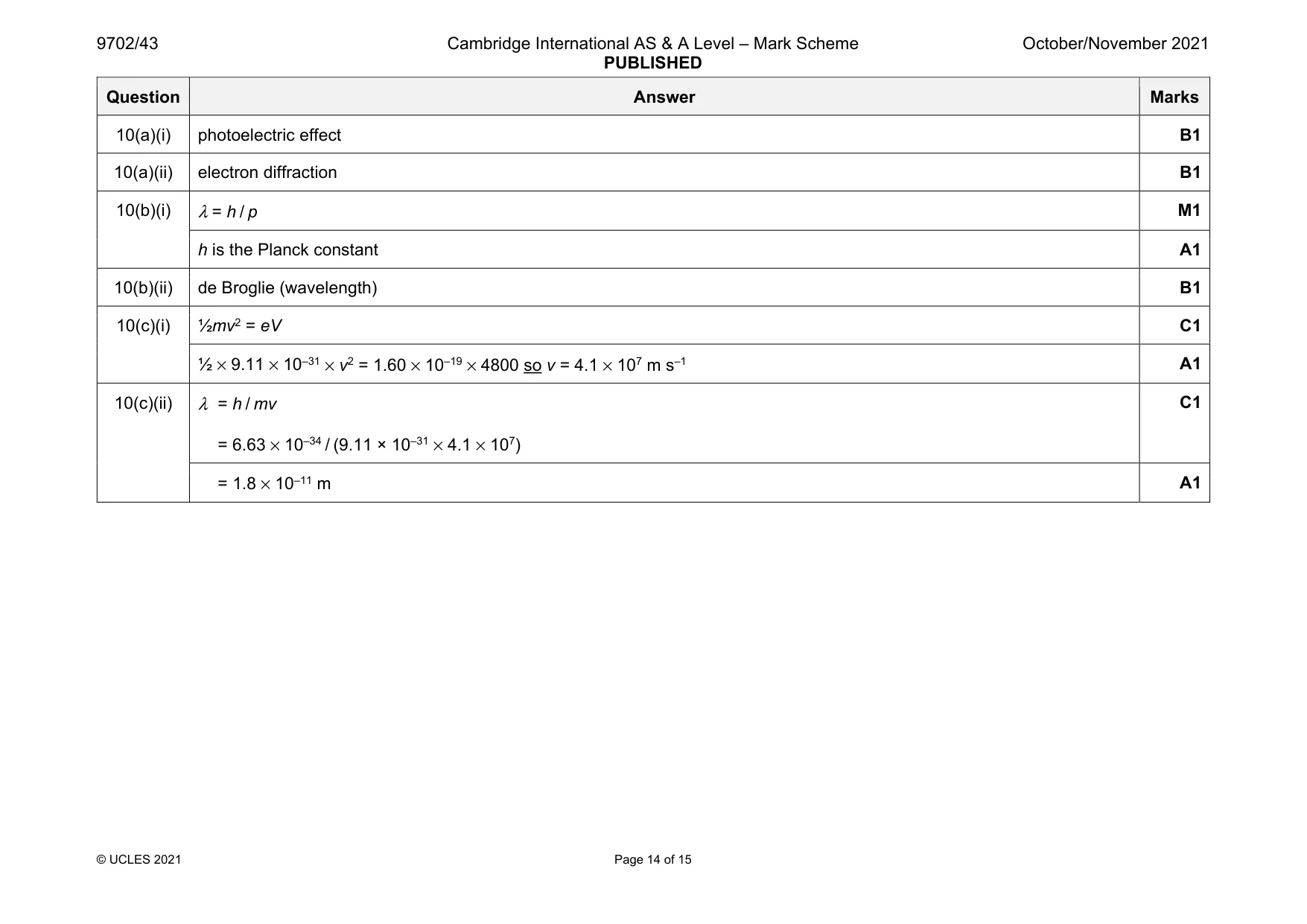
Mark scheme: 10(a)(i) photoelectric effect B1 10(a)(ii) electron diffraction B1 10(b)(i) λ = h / p M1 h is the Planck constant A1 10(b)(ii) de Broglie (wavelength) B1 10(c)(i) ½mv2 = eV C1 ½ × 9.11 × 10–31 × v2 = 1.60 × 10–19 × 4800 so v = 4.1 × 10⁷ m s–1 A1 10(c)(ii) λ = h / mv = 6.63 × 10⁻³⁴ / (9.11 × 10–31 × 4.1 × 107) C1 = 1.8 × 10⁻¹¹ m A1
Q11 · State, for an X-ray image, what is meant by: (i) sharpness…
11 (a) State, for an X-ray image, what is meant by: (i) sharpness ........................................................................................................................................... ..................................................................................................................................... [1] (ii) contrast. ........................................................................................................................................... ..................................................................................................................................... [1] (b) A parallel X-ray beam passes through a thickness of 2.3 cm of soft body tissue. The intensity of the emerging beam is 12% of the intensity of the incident beam. Calculate the linear attenuation (absorption) coefficient μ of the soft body tissue. Give a unit with your answer. μ = .......................................... unit ..................... [3] (c) In medical diagnosis, X-rays may be used to produce a single X-ray image or may be used in computed tomography (CT scanning). Suggest an advantage and a disadvantage of CT scanning compared with single X-ray imaging for diagnosis. advantage: ................................................................................................................................ ................................................................................................................................................... disadvantage: ........................................................................................................................... ................................................................................................................................................... [2] [Total: 7]
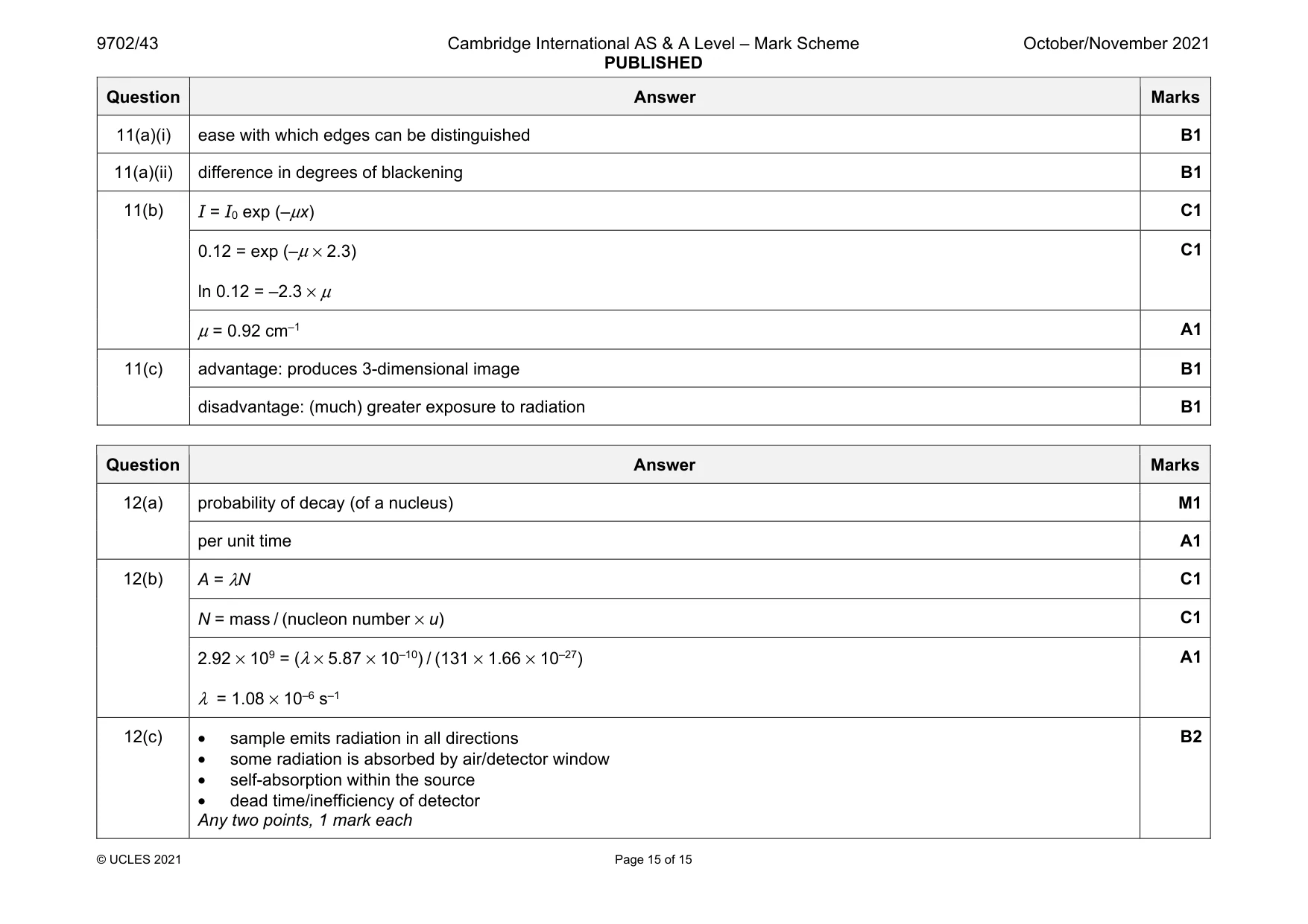
Mark scheme: 11(a)(i) ease with which edges can be distinguished B1 11(a)(ii) difference in degrees of blackening B1 11(b) I = I0 exp (–μx) C1 0.12 = exp (–μ × 2.3) ln 0.12 = –2.3 × μ C1 μ = 0.92 cm–1 A1 11(c) advantage: produces 3-dimensional image B1 disadvantage: (much) greater exposure to radiation B1
Q12 · Define radioactive decay constant
12 (a) Define radioactive decay constant. ................................................................................................................................................... ................................................................................................................................................... ............................................................................................................................................. [2] (b) A sample of radioactive iodine-131 (13153 I) of mass 5.87 × 10⁻¹⁰ kg has an activity of 2.92 × 10⁹ Bq. Determine the decay constant of iodine-131. decay constant = ................................................... s–1 [3] (c) Suggest two reasons why a detector placed near to the sample in (b) would record a count rate much less than 2.92 × 10⁹ counts per second. 1. ............................................................................................................................................... ................................................................................................................................................... 2. ............................................................................................................................................... ................................................................................................................................................... [2] [Total: 7]
Mark scheme: 12(a) probability of decay (of a nucleus) M1 per unit time A1 12(b) A = λN C1 N = mass / (nucleon number × u) C1 2.92 × 109 = (λ × 5.87 × 10⁻¹⁰) / (131 × 1.66 × 10–27) λ = 1.08 × 10⁻⁶ s–1 A1 12(c) • sample emits radiation in all directions • some radiation is absorbed by air/detector window • self-absorption within the source • dead time/inefficiency of detector Any two points, 1 mark each B2
What was in this paper
The subtopics covered by these 12 questions, and how many questions each got. Open one in a new tab to see every Cambridge question on it.
1Centripetal acceleration1Electromagnetic induction1Force on a current-carrying conductor1Gravitational field of a point mass1Practical circuits1Production and use of X-rays1Radioactive decay1Rectification and smoothing1Simple harmonic oscillations1The first law of thermodynamics1Wave-particle duality1What you needed in this session
Cambridge’s own grade thresholds for 2021 Oct/Nov, Paper 4 · Variant 3. A higher threshold means an easier paper — the bar moves with how the cohort did.