Cambridge A Level Physics 9702 — 2025 Feb/March Paper 4 · Variant 2
9702/42/F/M/25 · 10 questions · 100 marks · 120 min
The question paper and its mark scheme, free to read here and free to download. This is Cambridge’s own paper, exactly as it was sat.
Question paper28 pages

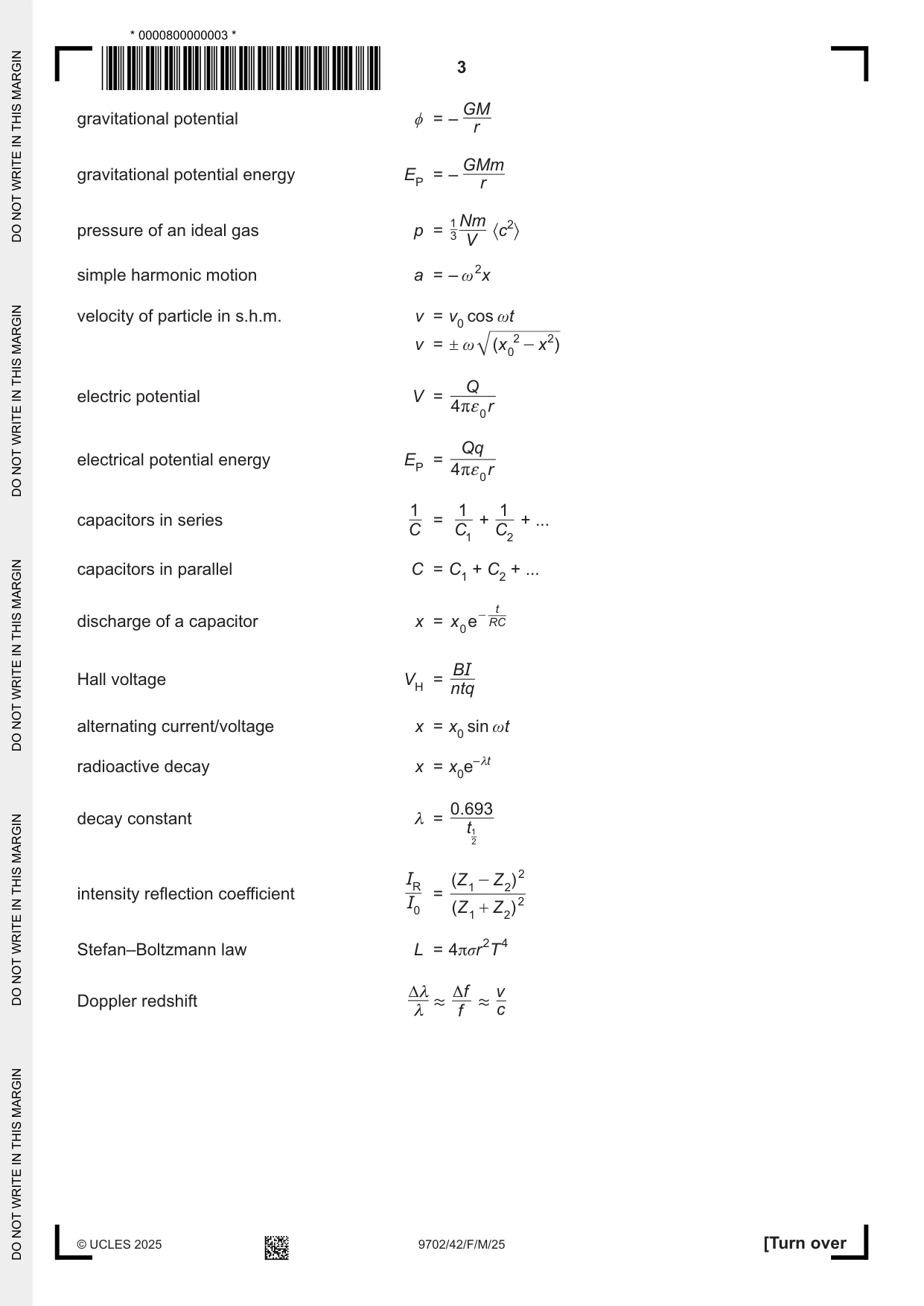



Mark scheme14 pages
Answers below. Sit the paper first if you are practising.
Questions as text
Q1 · A steel ball is placed on the inside surface of a hollow circular cone
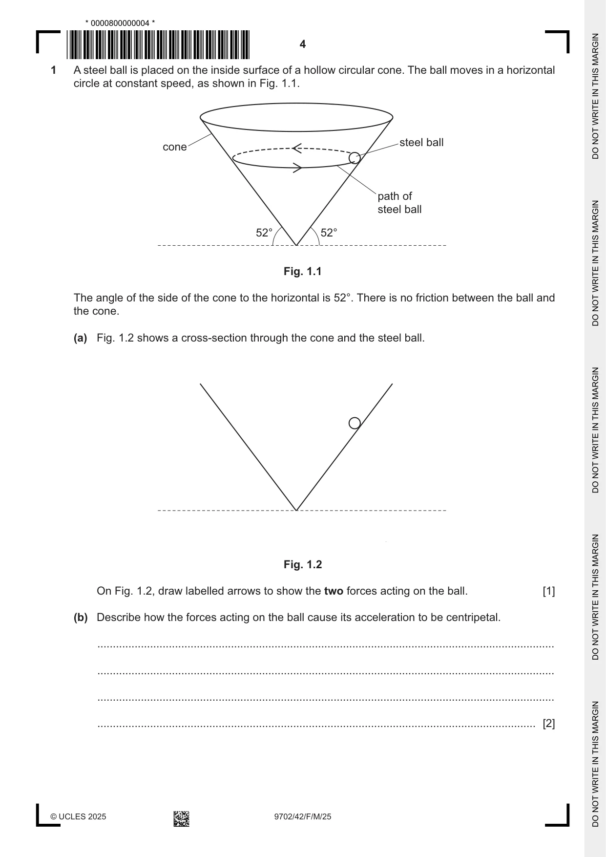
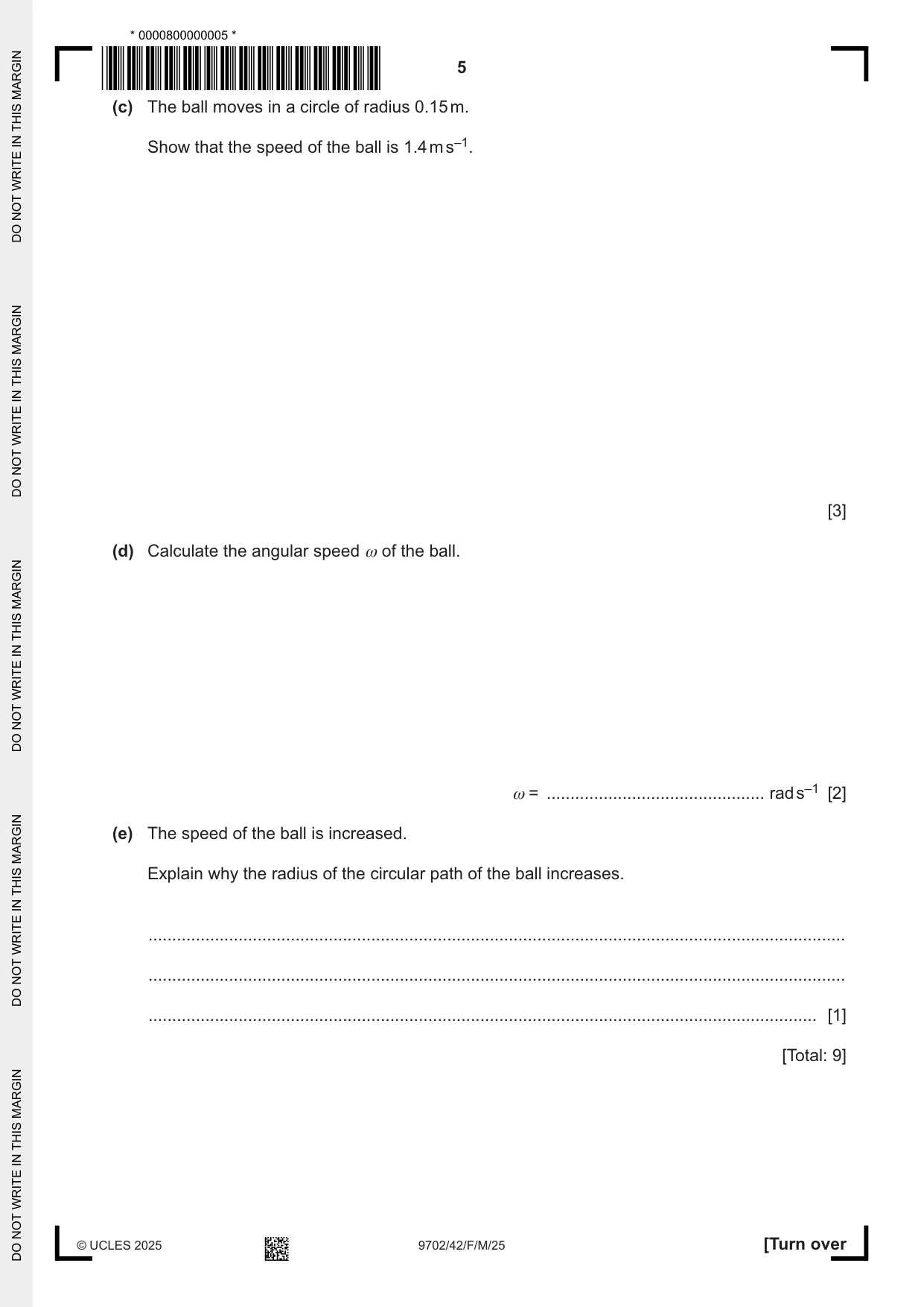
1 A steel ball is placed on the inside surface of a hollow circular cone. The ball moves in a horizontal circle at constant speed, as shown in Fig. 1.1. steel ball cone path of steel ball 52° 52° Fig. 1.1 The angle of the side of the cone to the horizontal is 52°. There is no friction between the ball and the cone. (a) Fig. 1.2 shows a cross‑section through the cone and the steel ball. Fig. 1.2 On Fig. 1.2, draw labelled arrows to show the two forces acting on the ball. [1] (b) Describe how the forces acting on the ball cause its acceleration to be centripetal. ................................................................................................................................................... ................................................................................................................................................... ................................................................................................................................................... ............................................................................................................................................. [2] (c) The ball moves in a circle of radius 0.15 m. Show that the speed of the ball is 1.4 m s–1. [3] (d) Calculate the angular speed ω of the ball. ω = .............................................. rad s–1 [2] (e) The speed of the ball is increased. Explain why the radius of the circular path of the ball increases. ................................................................................................................................................... ................................................................................................................................................... ............................................................................................................................................. [1] [Total: 9]
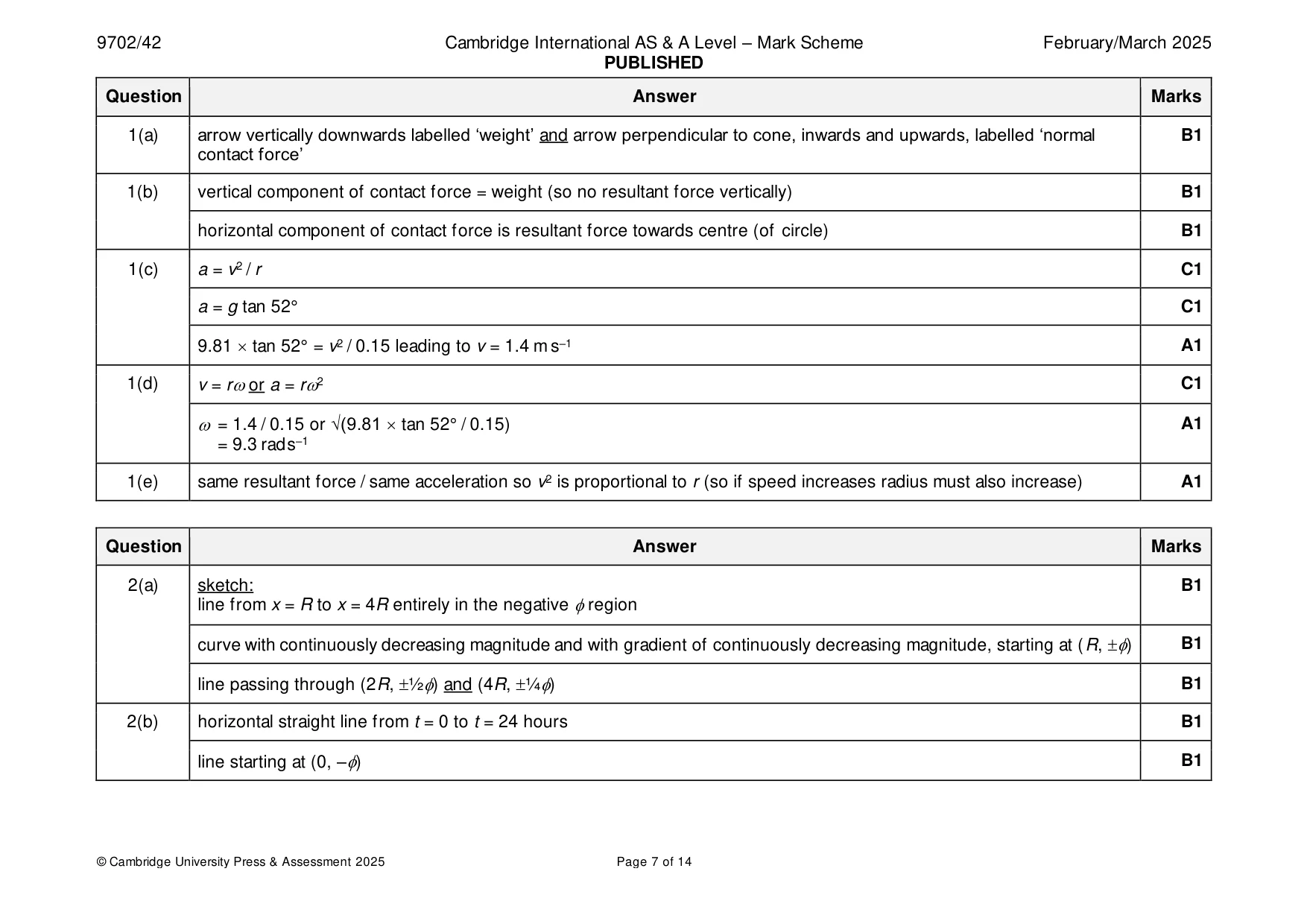
Mark scheme: Question Answer Marks 1(a) arrow vertically downwards labelled ‘weight’ and arrow perpendicular to cone, inwards and upwards, labelled ‘normal B1 contact force’ 1(b) vertical component of contact force = weight (so no resultant force vertically) B1 horizontal component of contact force is resultant force towards centre (of circle) B1 1(c) a = v2 / r C1 a = g tan 52° C1 9.81 tan 52° = v2 / 0.15 leading to v = 1.4 m s–1 A1 1(d) v = ror a = r2 C1 = 1.4 / 0.15 or √(9.81 tan 52° / 0.15) A1 = 9.3 rad s–1 1(e) same resultant force / same acceleration so v2 is proportional to r (so if speed increases radius must also increase) A1
Q2 · The magnitude of the gravitational potential on the surface of a planet of radius R is φ
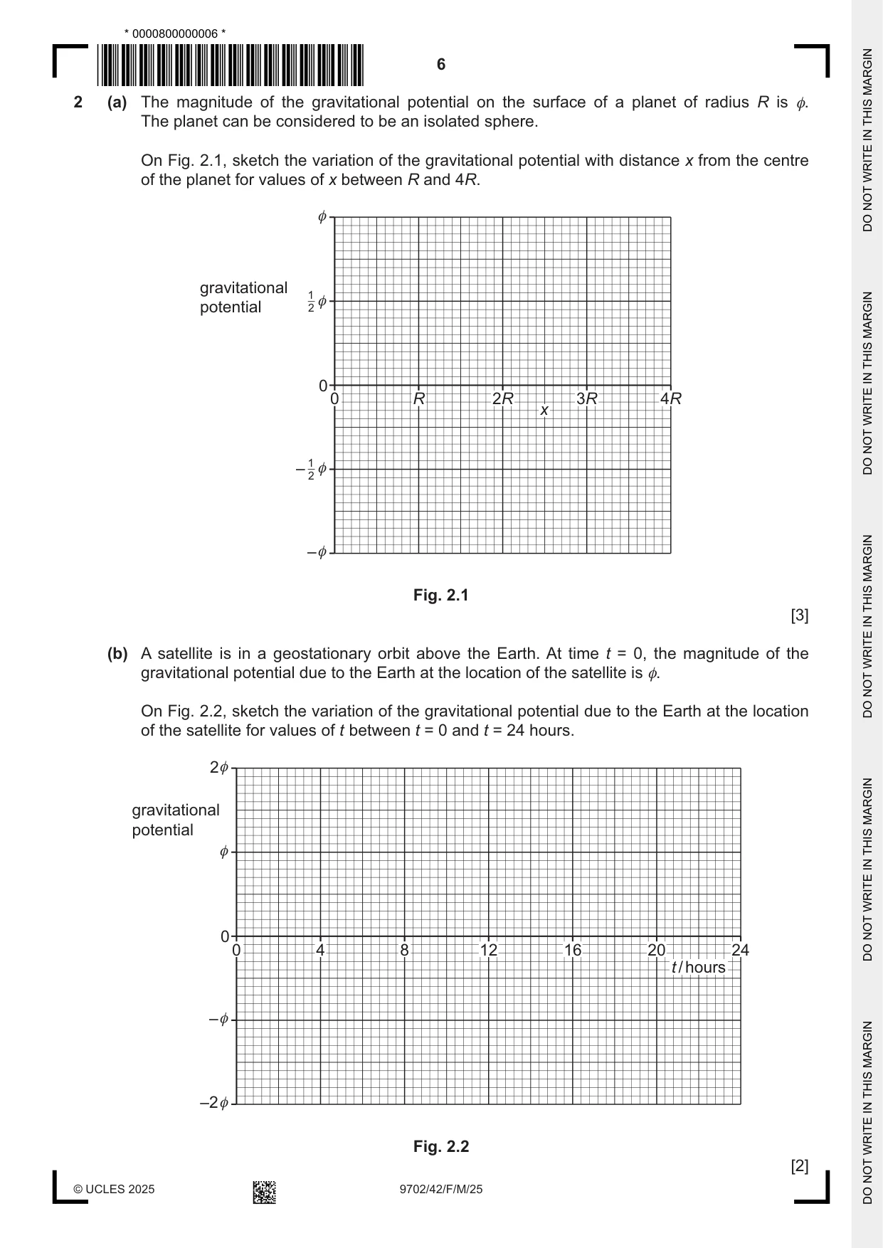
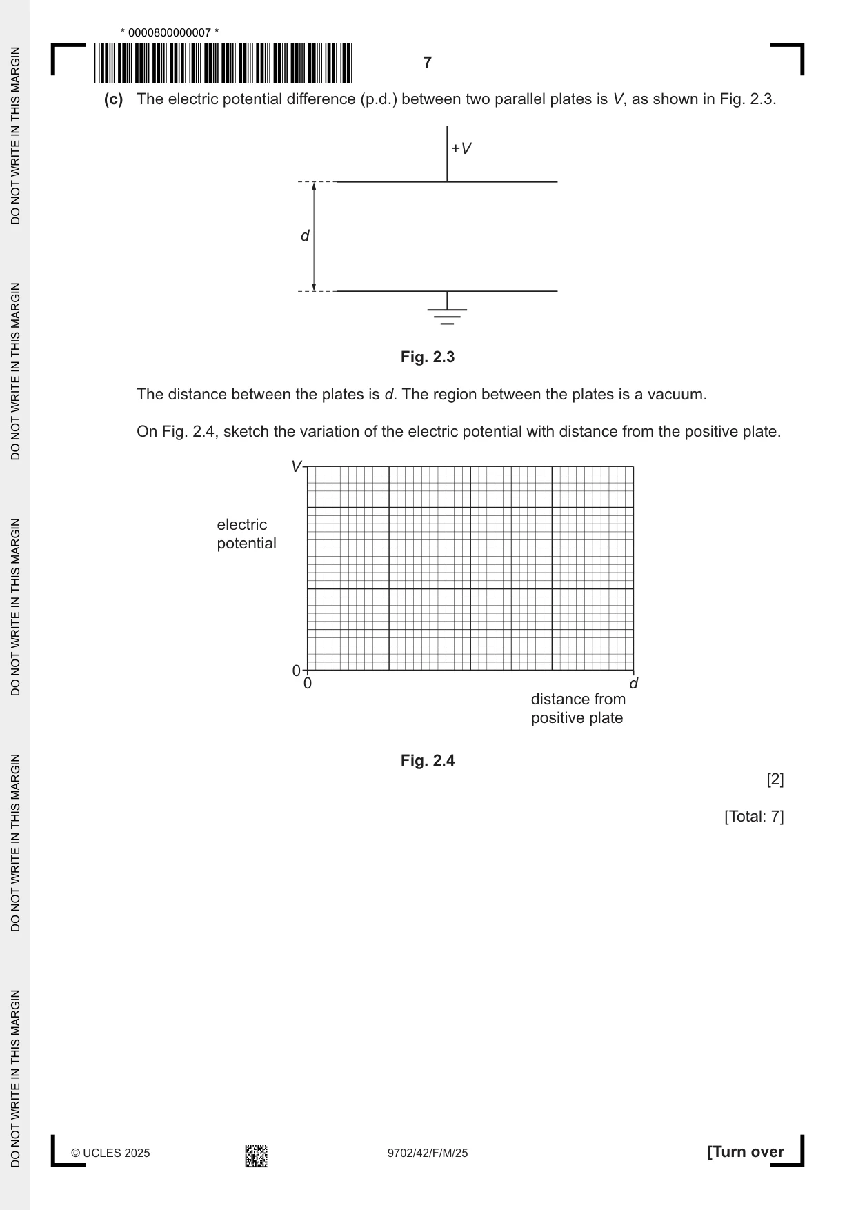
2 (a) The magnitude of the gravitational potential on the surface of a planet of radius R is φ. The planet can be considered to be an isolated sphere. On Fig. 2.1, sketch the variation of the gravitational potential with distance x from the centre of the planet for values of x between R and 4R. φ gravitational 1 φ potential 2 0 0 R 2R 3R 4R x – 1 φ 2 – φ Fig. 2.1 [3] (b) A satellite is in a geostationary orbit above the Earth. At time t = 0, the magnitude of the gravitational potential due to the Earth at the location of the satellite is φ. On Fig. 2.2, sketch the variation of the gravitational potential due to the Earth at the location of the satellite for values of t between t = 0 and t = 24 hours. 2φ gravitational potential φ 0 0 4 8 12 16 20 24 t / hours – φ –2 φ Fig. 2.2 [2] (c) The electric potential difference (p.d.) between two parallel plates is V, as shown in Fig. 2.3. +V d Fig. 2.3 The distance between the plates is d. The region between the plates is a vacuum. On Fig. 2.4, sketch the variation of the electric potential with distance from the positive plate. V electric potential 0 0 d distance from positive plate Fig. 2.4 [2] [Total: 7]
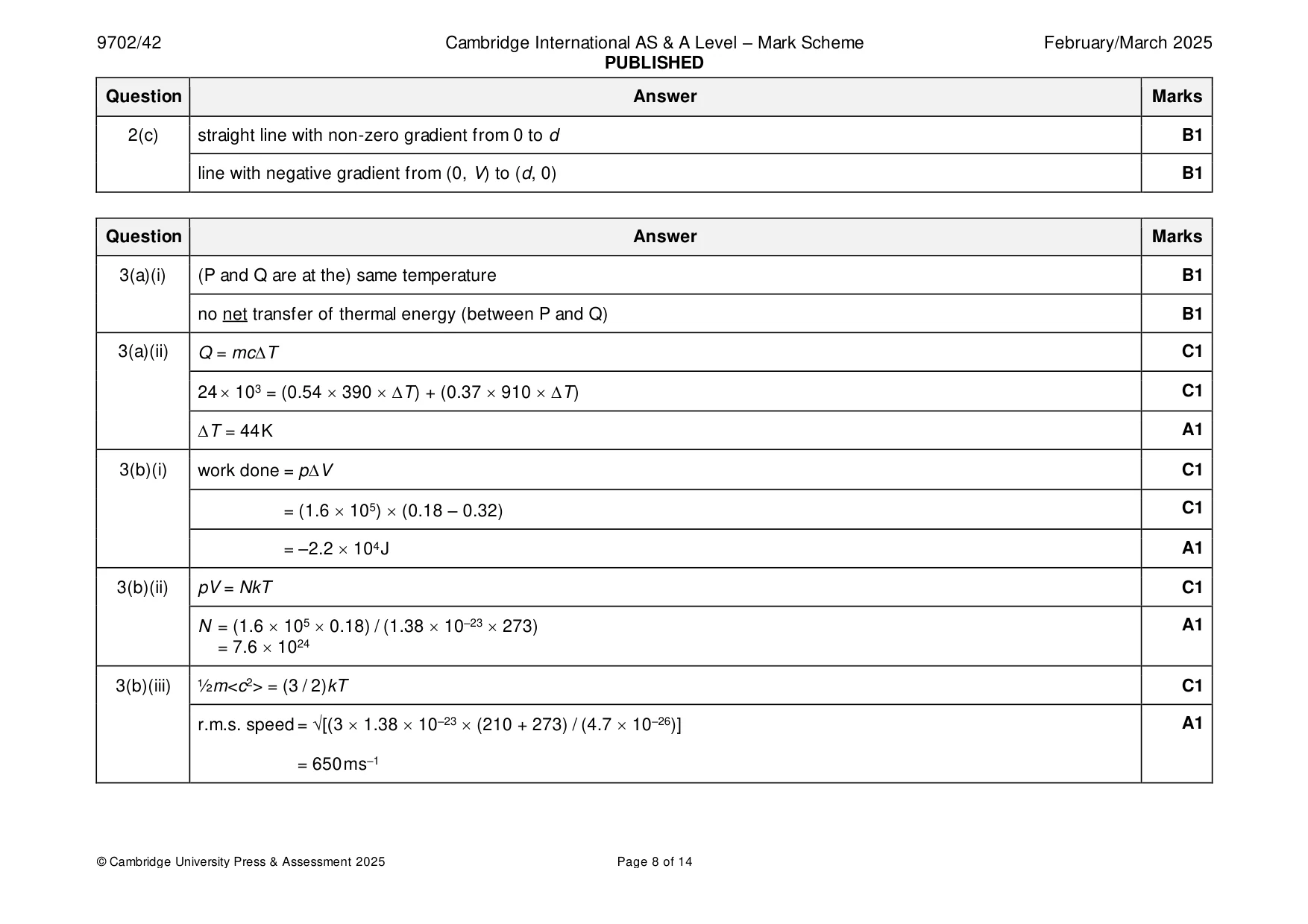
Mark scheme: 2(a) sketch: B1 line from x = R to x = 4R entirely in the negative region curve with continuously decreasing magnitude and with gradient of continuously decreasing magnitude, starting at (R, ) B1 line passing through (2R, ½) and (4R, ¼) B1 2(b) horizontal straight line from t = 0 to t = 24 hours B1 line starting at (0, –) B1 2(c) straight line with non-zero gradient from 0 to d B1 line with negative gradient from (0, V) to (d, 0) B1
Q3 · Two metal cuboids P and Q are in thermal contact with each other
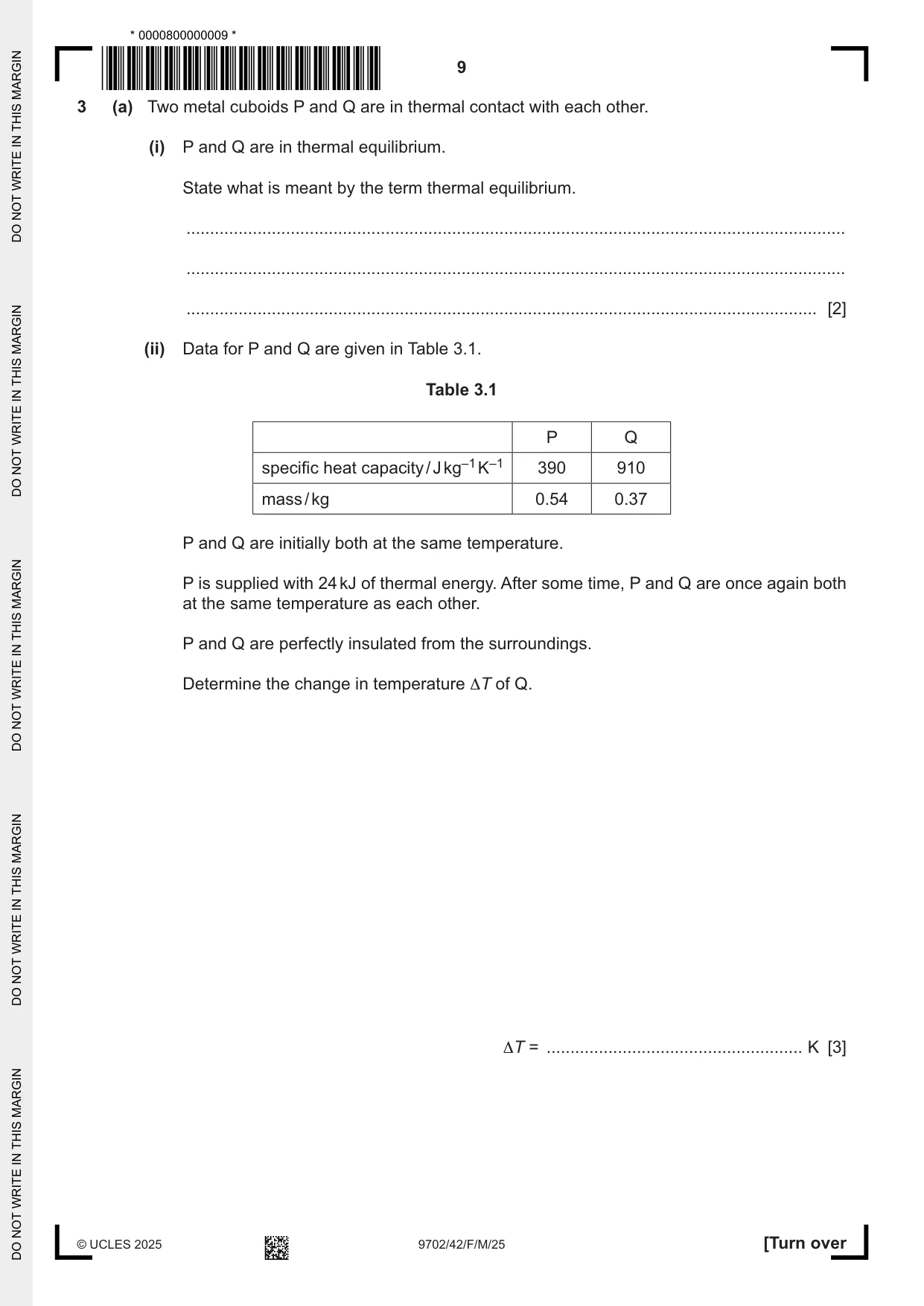
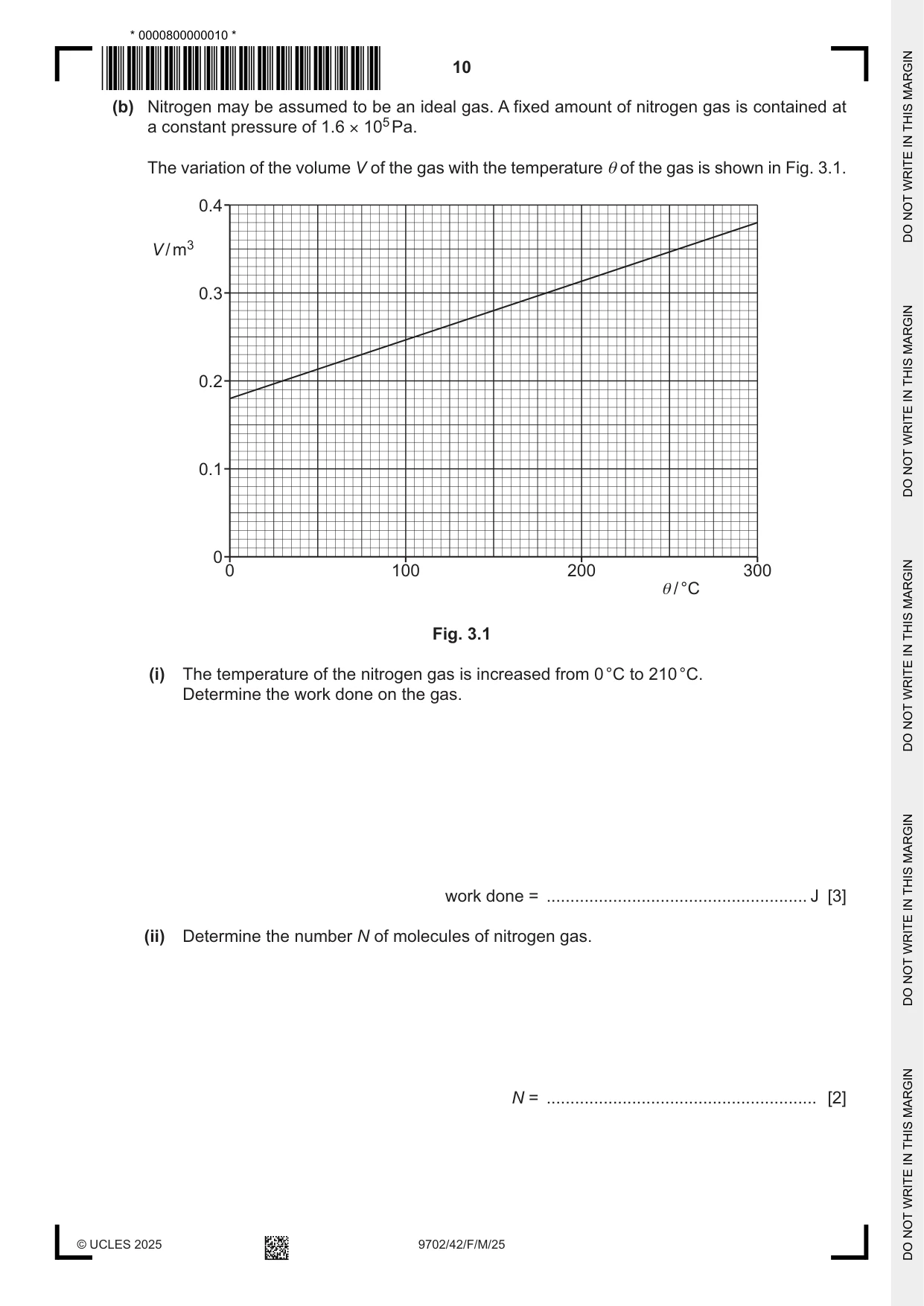
3 (a) Two metal cuboids P and Q are in thermal contact with each other. (i) P and Q are in thermal equilibrium. State what is meant by the term thermal equilibrium. ........................................................................................................................................... ........................................................................................................................................... ..................................................................................................................................... [2] (ii) Data for P and Q are given in Table 3.1. Table 3.1 P Q specific heat capacity / J kg–1 K–1 390 910 mass / kg 0.54 0.37 P and Q are initially both at the same temperature. P is supplied with 24 kJ of thermal energy. After some time, P and Q are once again both at the same temperature as each other. P and Q are perfectly insulated from the surroundings. Determine the change in temperature ΔT of Q. ΔT = ...................................................... K [3] (b) Nitrogen may be assumed to be an ideal gas. A fixed amount of nitrogen gas is contained at a constant pressure of 1.6 × 10⁵ Pa. The variation of the volume V of the gas with the temperature θ of the gas is shown in Fig. 3.1. 0.4 V / m3 0.3 0.2 0.1 0 0 100 200 300 θ / °C Fig. 3.1 (i) The temperature of the nitrogen gas is increased from 0 °C to 210 °C. Determine the work done on the gas. work done = ....................................................... J [3] (ii) Determine the number N of molecules of nitrogen gas. N = ......................................................... [2] (iii) The mass of a nitrogen molecule is 4.7 × 10⁻²⁶ kg. Calculate the root‑mean‑square (r.m.s.) speed of a nitrogen molecule at 210 °C. r.m.s. speed = ................................................ m s–1 [2] [Total: 12]
Mark scheme: 3(a)(i) (P and Q are at the) same temperature B1 no net transfer of thermal energy (between P and Q) B1 3(a)(ii) Q = mcT C1 24 103 = (0.54 390 T) + (0.37 910 T) C1 T = 44 K A1 3(b)(i) work done = pV C1 = (1.6 105) (0.18 – 0.32) C1 = –2.2 104 J A1 3(b)(ii) pV = NkT C1 N = (1.6 105 0.18) / (1.38 10–23 273) A1 = 7.6 1024 3(b)(iii) ½m<c2> = (3 / 2)kT C1 r.m.s. speed = √[(3 1.38 10–23 (210 + 273) / (4.7 10–26)] A1 = 650 m s–1
Q4 · A small crystal is made to vibrate with simple harmonic motion
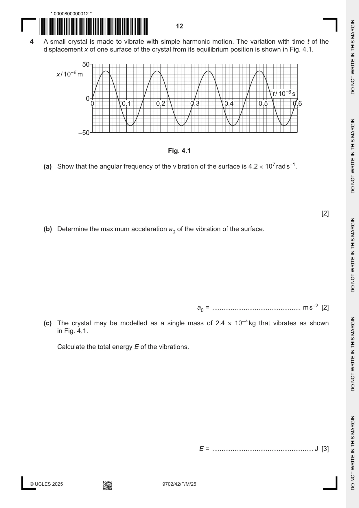
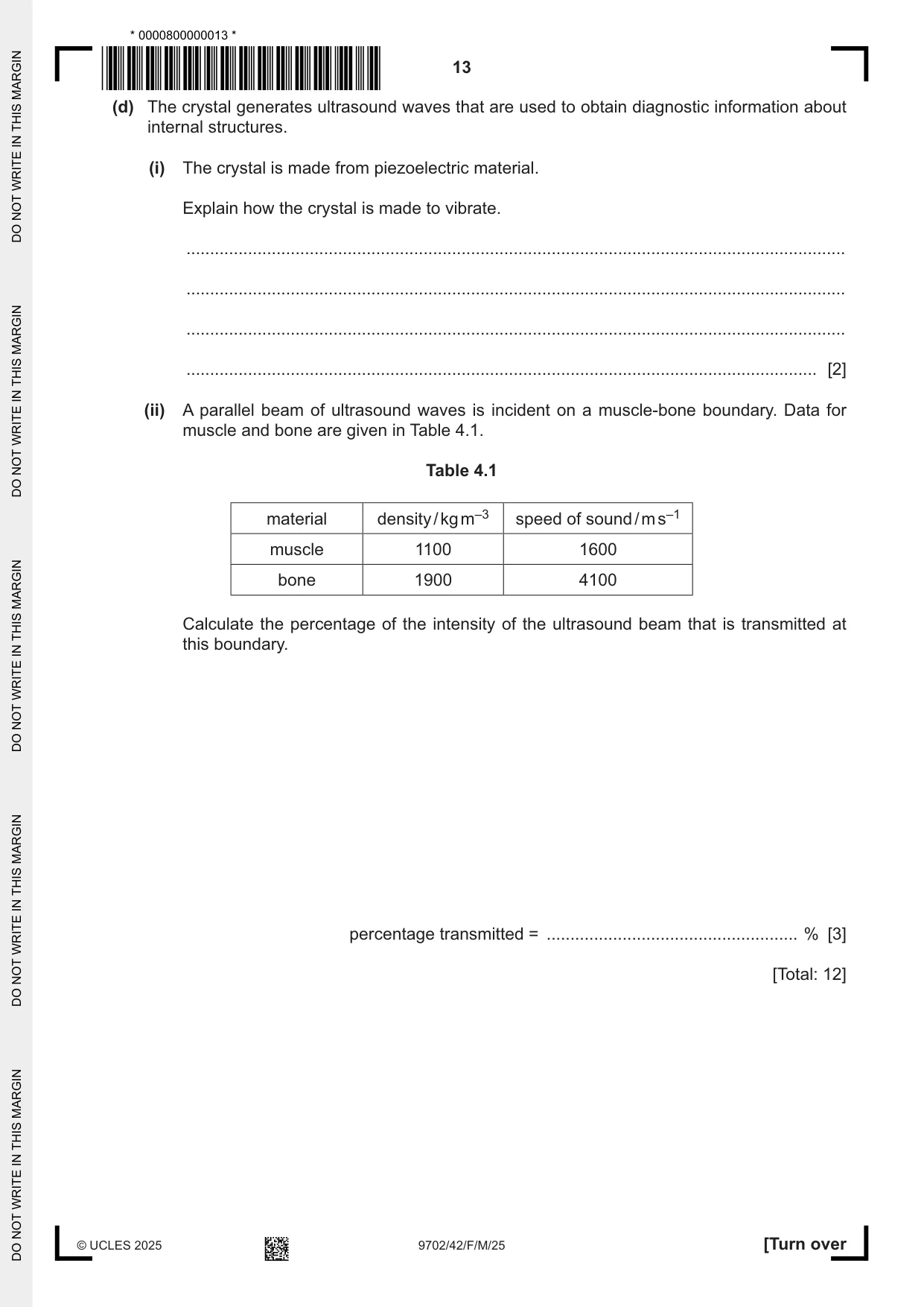
4 A small crystal is made to vibrate with simple harmonic motion. The variation with time t of the displacement x of one surface of the crystal from its equilibrium position is shown in Fig. 4.1. 50 x / 10−6 m t / 10−6 s 0 0 0.1 0.2 0.3 0.4 0.5 0.6 –50 Fig. 4.1 (a) Show that the angular frequency of the vibration of the surface is 4.2 × 10⁷ rad s–1. [2] (b) Determine the maximum acceleration a0 of the vibration of the surface. a0 = ................................................ m s–2 [2] (c) The crystal may be modelled as a single mass of 2.4 × 10– 4 kg that vibrates as shown in Fig. 4.1. Calculate the total energy E of the vibrations. E = ....................................................... J [3] (d) The crystal generates ultrasound waves that are used to obtain diagnostic information about internal structures. (i) The crystal is made from piezoelectric material. Explain how the crystal is made to vibrate. ........................................................................................................................................... ........................................................................................................................................... ........................................................................................................................................... ..................................................................................................................................... [2] (ii) A parallel beam of ultrasound waves is incident on a muscle‑bone boundary. Data for muscle and bone are given in Table 4.1. Table 4.1 material density / kg m–3 speed of sound / m s–1 muscle 1100 1600 bone 1900 4100 Calculate the percentage of the intensity of the ultrasound beam that is transmitted at this boundary. percentage transmitted = ..................................................... % [3] [Total: 12]
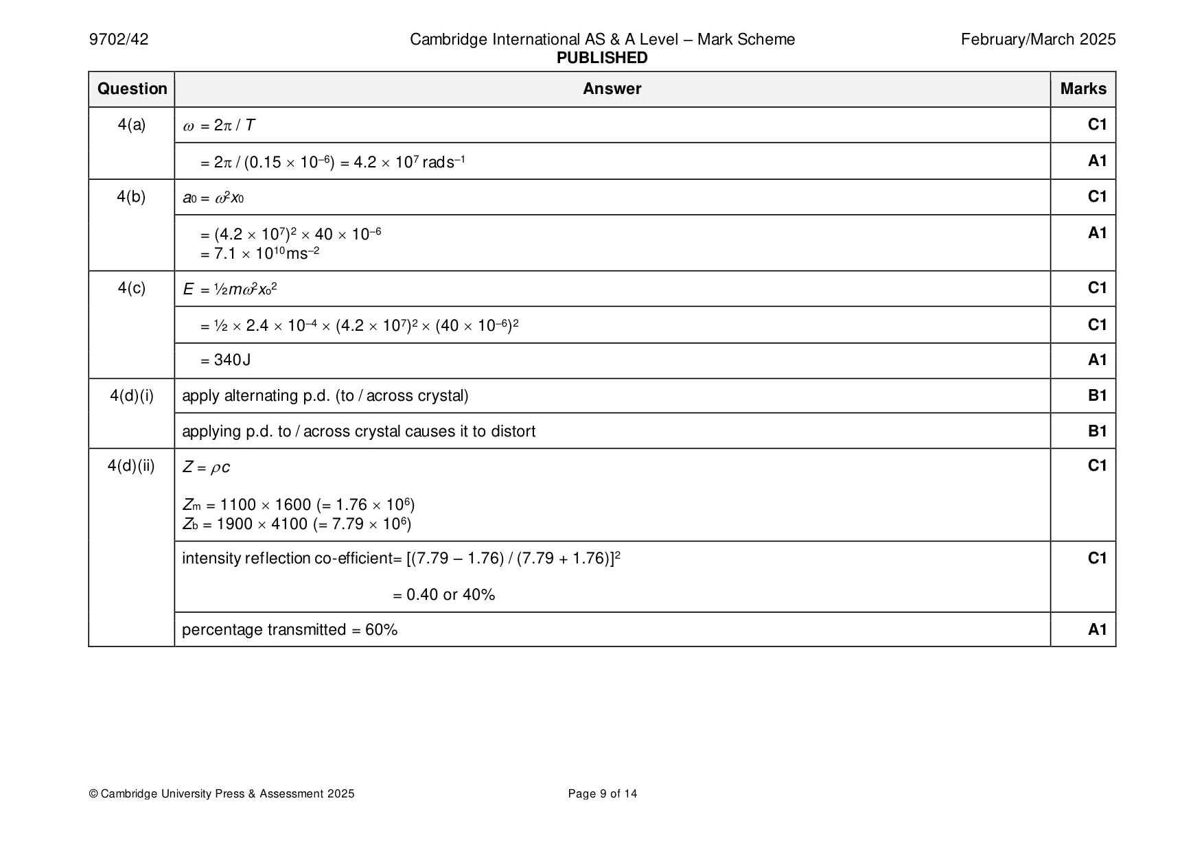
Mark scheme: 4(a) = 2 / T C1 = 2 / (0.15 10–6) = 4.2 107 rad s–1 A1 4(b) a0 = 2x0 C1 = (4.2 107)2 40 10–6 A1 = 7.1 1010 m s–2 4(c) E = ½m2xo2 C1 = ½ 2.4 10–4 (4.2 107)2 (40 10–6)2 C1 = 340 J A1 4(d)(i) apply alternating p.d. (to / across crystal) B1 applying p.d. to / across crystal causes it to distort B1 4(d)(ii) Z = c C1 Zm = 1100 1600 (= 1.76 106) Zb = 1900 4100 (= 7.79 106) intensity reflection co-efficient= [(7.79 – 1.76) / (7.79 + 1.76)]2 C1 = 0.40 or 40% percentage transmitted = 60% A1
Q5 · A capacitor of capacitance C1 is connected in series with a second capacitor of…
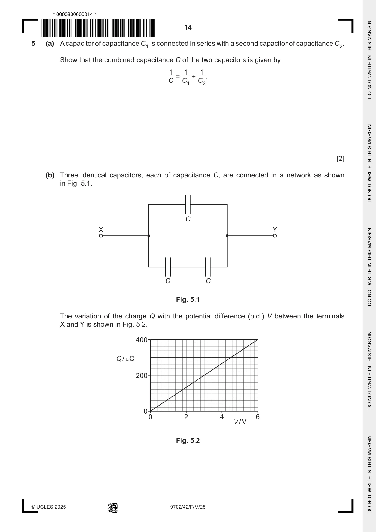
5 (a) A capacitor of capacitance C1 is connected in series with a second capacitor of capacitance C2. Show that the combined capacitance C of the two capacitors is given by 1 1 1 = + . C C1 C2 [2] (b) Three identical capacitors, each of capacitance C, are connected in a network as shown in Fig. 5.1. C X Y C C Fig. 5.1 The variation of the charge Q with the potential difference (p.d.) V between the terminals X and Y is shown in Fig. 5.2. 400 Q / μC 200 0 0 2 4 6 V / V Fig. 5.2 Show that C is equal to 44 µF. [3] (c) The capacitor network in Fig. 5.1 is charged and then connected to a resistor of resistance 54 kΩ. The capacitor network discharges through the resistor. (i) Determine the time constant τ of the circuit. Give a unit with your answer. τ = ............................... unit .................. [2] (ii) Determine the time taken for the discharge current to reduce to 15% of the initial discharge current. time = ....................................................... s [2] [Total: 9]
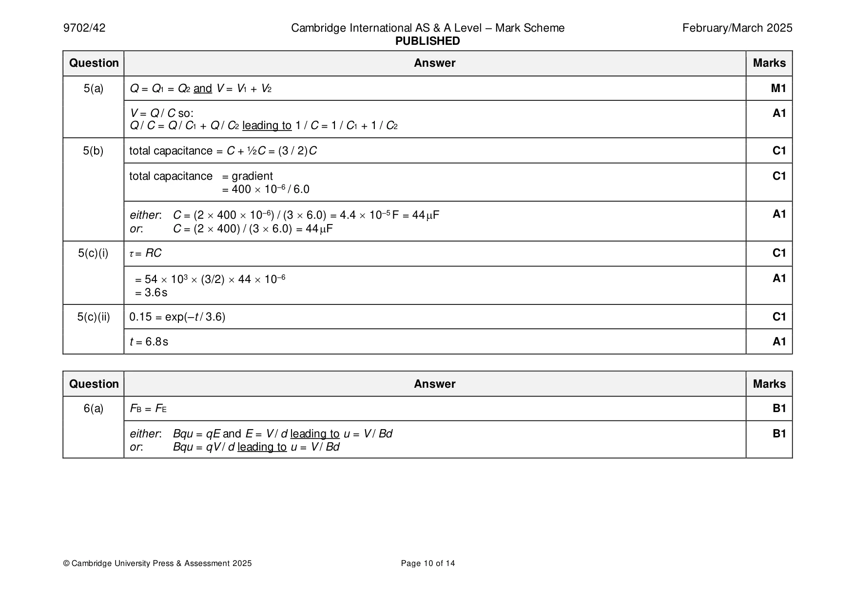
Mark scheme: 5(a) Q = Q1 = Q2 and V = V1 + V2 M1 V = Q / C so: A1 Q / C = Q / C1 + Q / C2 leading to 1 / C = 1 / C1 + 1 / C2 5(b) total capacitance = C + ½C = (3 / 2)C C1 total capacitance = gradient C1 = 400 10–6 / 6.0 either: C = (2 400 10–6) / (3 6.0) = 4.4 10–5 F = 44 F A1 or: C = (2 400) / (3 6.0) = 44 F 5(c)(i) τ = RC C1 = 54 103 (3/2) 44 10–6 A1 = 3.6 s 5(c)(ii) 0.15 = exp(–t / 3.6) C1 t = 6.8 s A1
Q6 · An electric field and a magnetic field are used to form a velocity selector
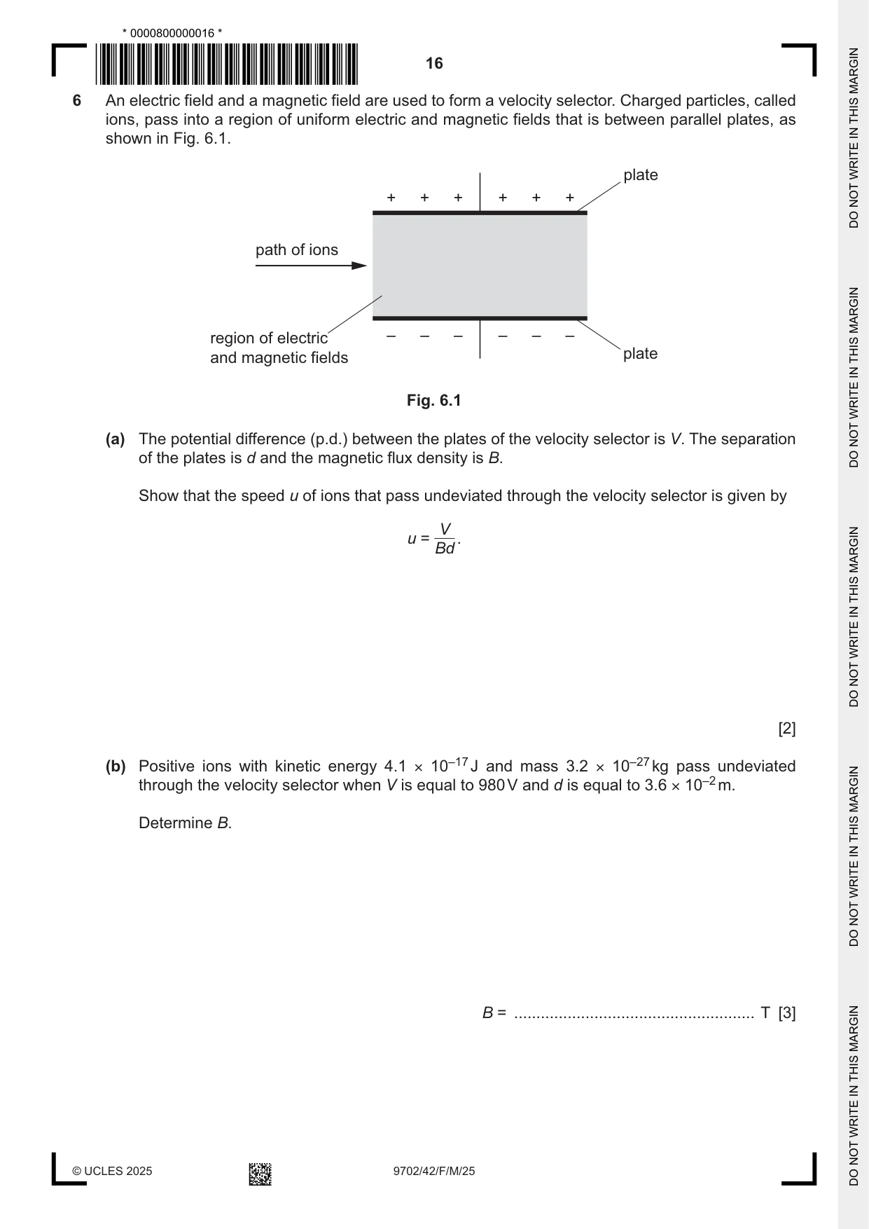
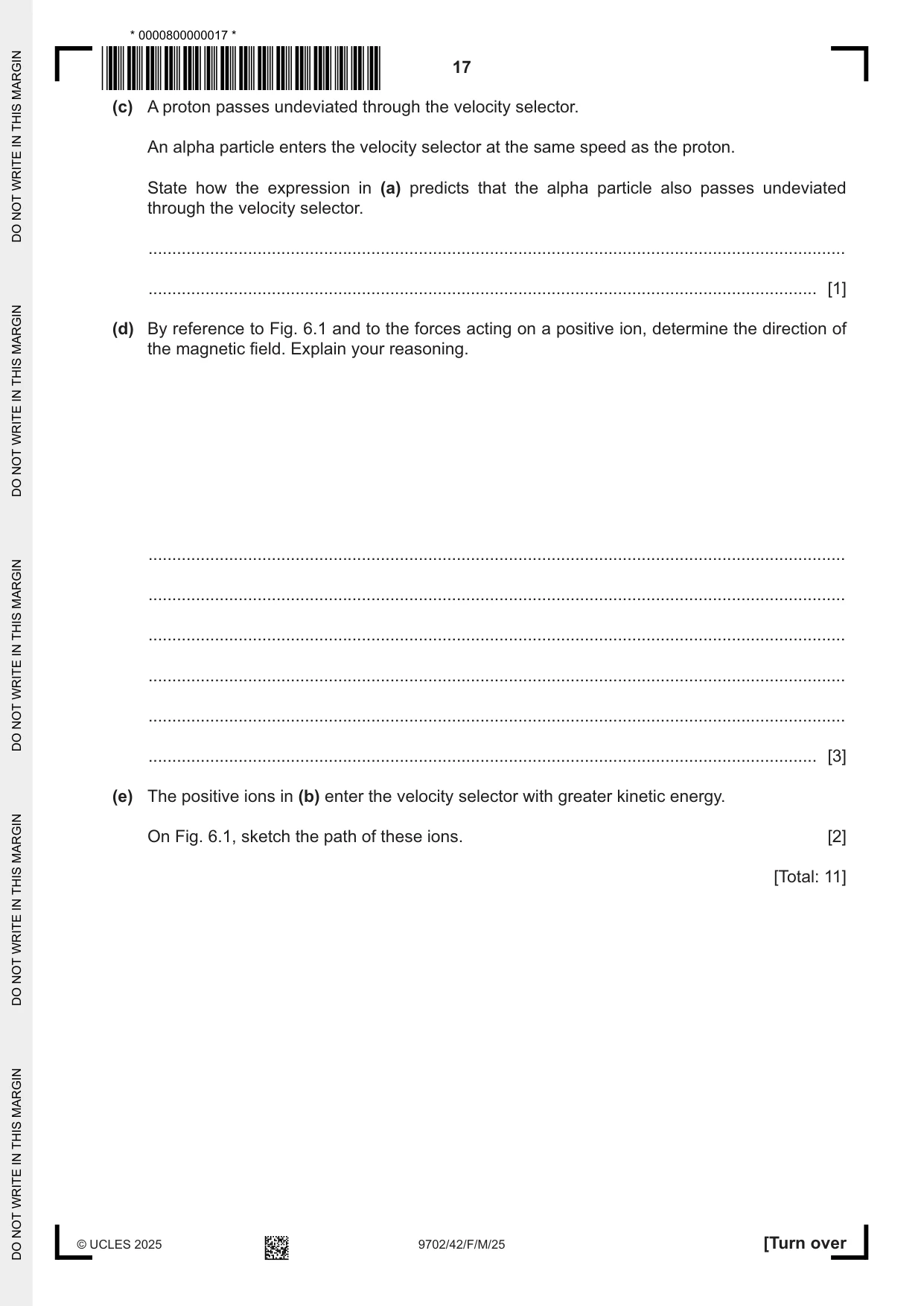
6 An electric field and a magnetic field are used to form a velocity selector. Charged particles, called ions, pass into a region of uniform electric and magnetic fields that is between parallel plates, as shown in Fig. 6.1. plate + + + + + + path of ions region of electric – – – – – – and magnetic fields plate Fig. 6.1 (a) The potential difference (p.d.) between the plates of the velocity selector is V. The separation of the plates is d and the magnetic flux density is B. Show that the speed u of ions that pass undeviated through the velocity selector is given by V u = . Bd [2] (b) Positive ions with kinetic energy 4.1 × 10⁻¹⁷ J and mass 3.2 × 10⁻²⁷ kg pass undeviated through the velocity selector when V is equal to 980 V and d is equal to 3.6 × 10⁻² m. Determine B. B = ...................................................... T [3] (c) A proton passes undeviated through the velocity selector. An alpha particle enters the velocity selector at the same speed as the proton. State how the expression in (a) predicts that the alpha particle also passes undeviated through the velocity selector. ................................................................................................................................................... ............................................................................................................................................. [1] (d) By reference to Fig. 6.1 and to the forces acting on a positive ion, determine the direction of the magnetic field. Explain your reasoning. ................................................................................................................................................... ................................................................................................................................................... ................................................................................................................................................... ................................................................................................................................................... ................................................................................................................................................... ............................................................................................................................................. [3] (e) The positive ions in (b) enter the velocity selector with greater kinetic energy. On Fig. 6.1, sketch the path of these ions. [2] [Total: 11]
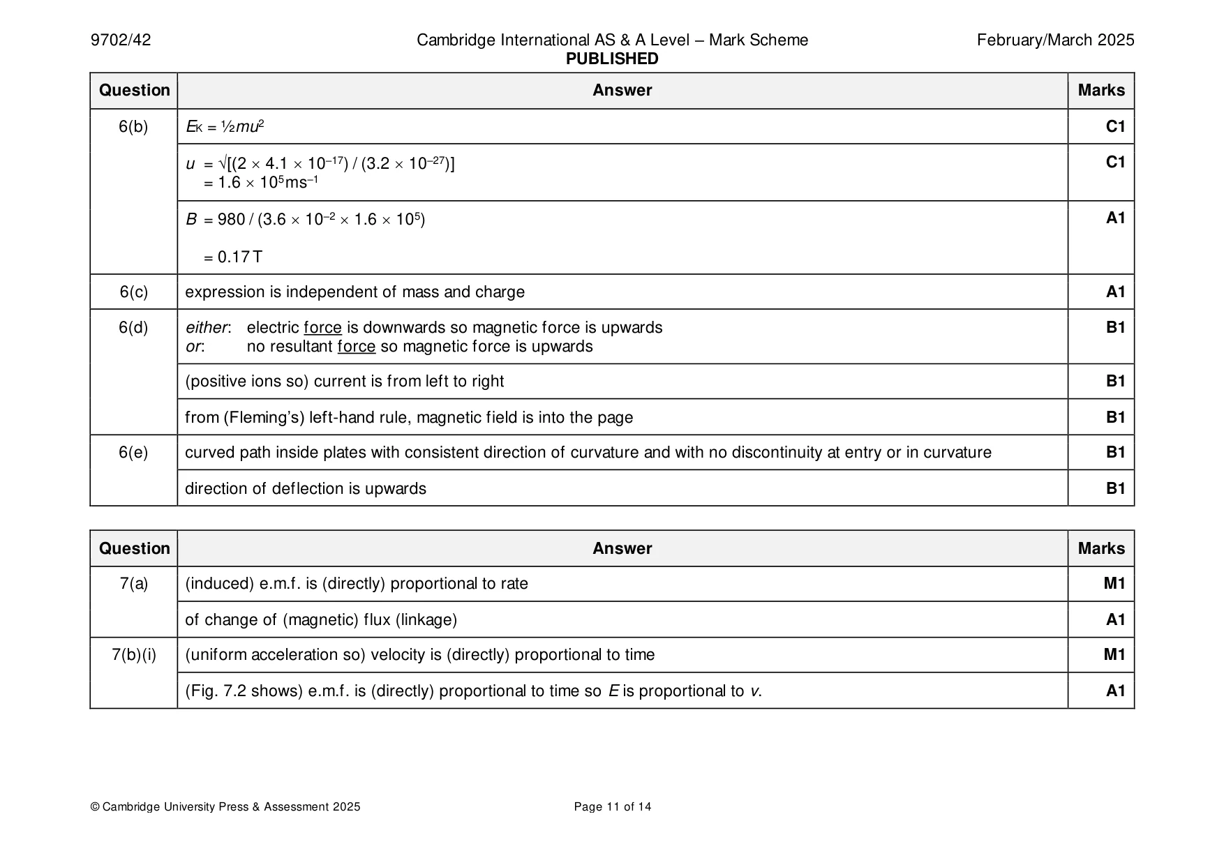
Mark scheme: 6(a) FB = FE B1 either: Bqu = qE and E = V / d leading to u = V / Bd B1 or: Bqu = qV / d leading to u = V / Bd 6(b) EK = ½mu2 C1 u = √[(2 4.1 10–17) / (3.2 10–27)] C1 = 1.6 105 m s–1 B = 980 / (3.6 10–2 1.6 105) A1 = 0.17 T 6(c) expression is independent of mass and charge A1 6(d) either: electric force is downwards so magnetic force is upwards B1 or: no resultant force so magnetic force is upwards (positive ions so) current is from left to right B1 from (Fleming’s) left-hand rule, magnetic field is into the page B1 6(e) curved path inside plates with consistent direction of curvature and with no discontinuity at entry or in curvature B1 direction of deflection is upwards B1
Q7 · State Faraday’s law of electromagnetic induction
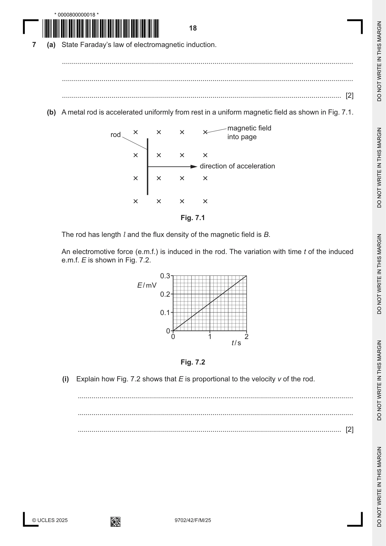
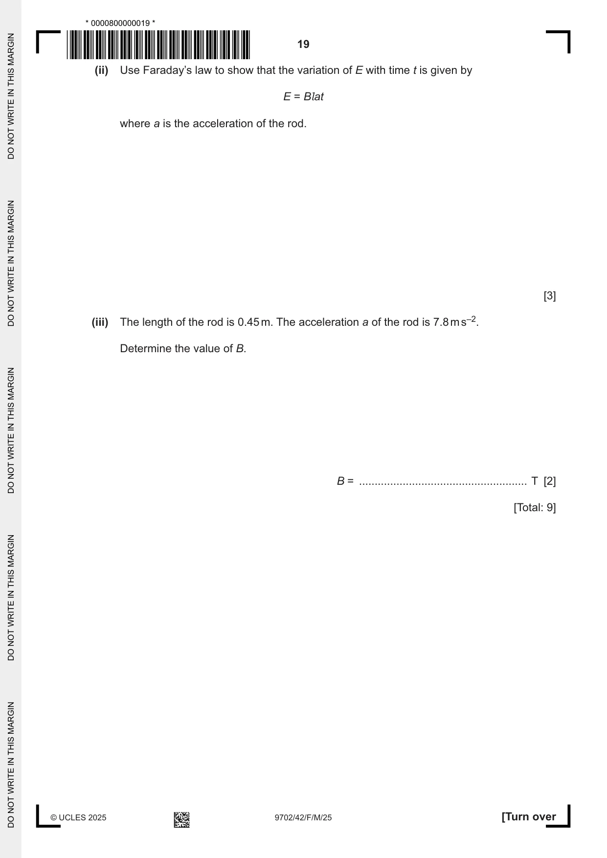
7 (a) State Faraday’s law of electromagnetic induction. ................................................................................................................................................... ................................................................................................................................................... ............................................................................................................................................. [2] (b) A metal rod is accelerated uniformly from rest in a uniform magnetic field as shown in Fig. 7.1. magnetic field rod into page direction of acceleration Fig. 7.1 The rod has length l and the flux density of the magnetic field is B. An electromotive force (e.m.f.) is induced in the rod. The variation with time t of the induced e.m.f. E is shown in Fig. 7.2. 0.3 E / mV 0.2 0.1 0 0 1 2 t / s Fig. 7.2 (i) Explain how Fig. 7.2 shows that E is proportional to the velocity v of the rod. ........................................................................................................................................... ........................................................................................................................................... ..................................................................................................................................... [2] (ii) Use Faraday’s law to show that the variation of E with time t is given by E = Blat where a is the acceleration of the rod. [3] (iii) The length of the rod is 0.45 m. The acceleration a of the rod is 7.8 m s–2. Determine the value of B. B = ...................................................... T [2] [Total: 9]
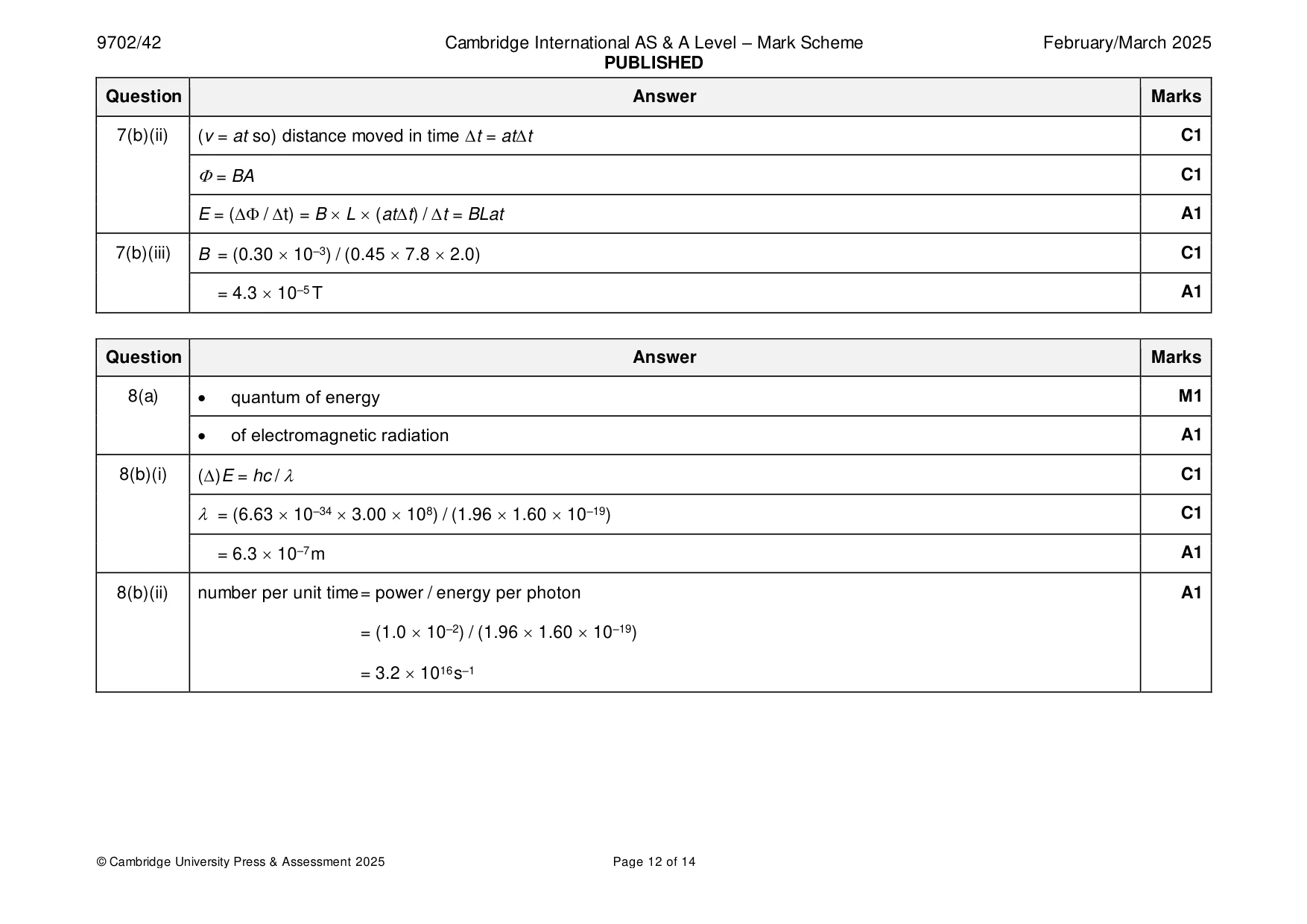
Mark scheme: 7(a) (induced) e.m.f. is (directly) proportional to rate M1 of change of (magnetic) flux (linkage) A1 7(b)(i) (uniform acceleration so) velocity is (directly) proportional to time M1 (Fig. 7.2 shows) e.m.f. is (directly) proportional to time so E is proportional to v. A1 7(b)(ii) (v = at so) distance moved in time t = att C1 = BA C1 E = ( / t) = B L (att) / t = BLat A1 7(b)(iii) B = (0.30 10–3) / (0.45 7.8 2.0) C1 = 4.3 10–5 T A1
Q8 · State what is meant by a photon
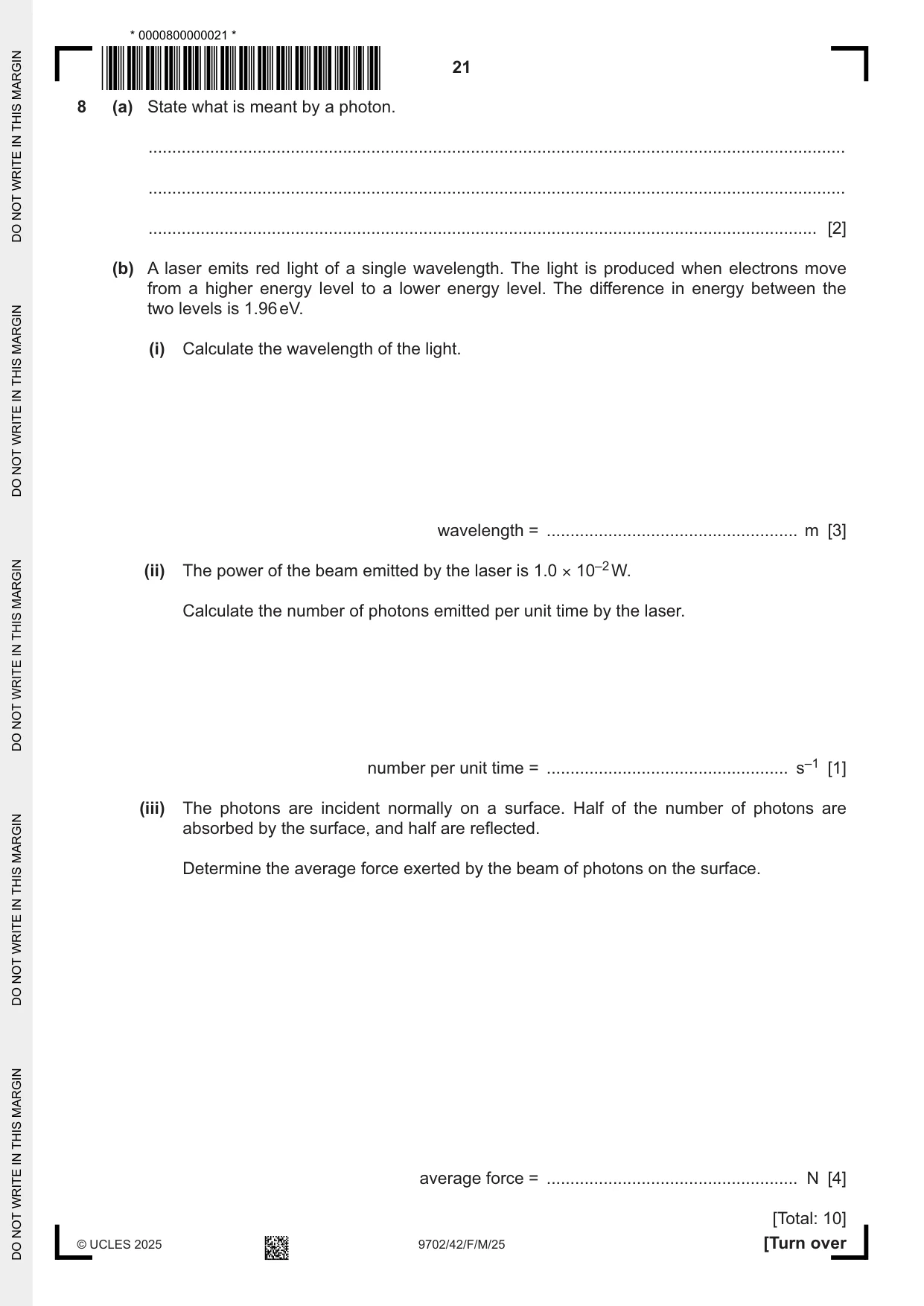
8 (a) State what is meant by a photon. ................................................................................................................................................... ................................................................................................................................................... ............................................................................................................................................. [2] (b) A laser emits red light of a single wavelength. The light is produced when electrons move from a higher energy level to a lower energy level. The difference in energy between the two levels is 1.96 eV. (i) Calculate the wavelength of the light. wavelength = ..................................................... m [3] (ii) The power of the beam emitted by the laser is 1.0 × 10⁻² W. Calculate the number of photons emitted per unit time by the laser. number per unit time = ................................................... s–1 [1] (iii) The photons are incident normally on a surface. Half of the number of photons are absorbed by the surface, and half are reflected. Determine the average force exerted by the beam of photons on the surface. average force = ..................................................... N [4] [Total: 10]
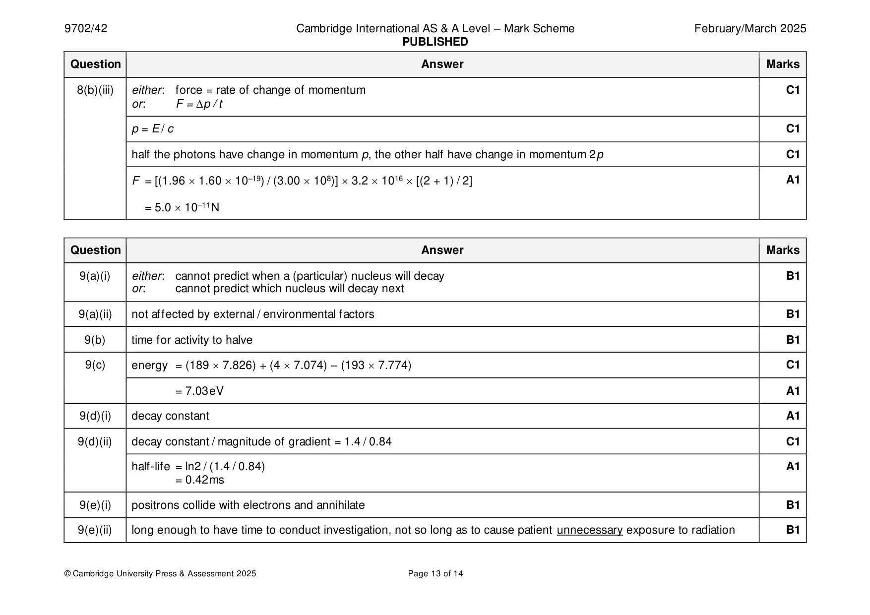
Mark scheme: 8(a) • quantum of energy M1 • of electromagnetic radiation A1 8(b)(i) ()E = hc / C1 = (6.63 10–34 3.00 108) / (1.96 1.60 10–19) C1 = 6.3 10–7 m A1 8(b)(ii) number per unit time = power / energy per photon A1 = (1.0 10–2) / (1.96 1.60 10–19) = 3.2 1016 s–1 8(b)(iii) either: force = rate of change of momentum C1 or: F = p / t p = E / c C1 half the photons have change in momentum p, the other half have change in momentum 2p C1 F = [(1.96 1.60 10–19) / (3.00 108)] 3.2 1016 [(2 + 1) / 2] A1 = 5.0 10–11 N
Q9 · Polonium‑193 (19384Po) is an unstable nuclide
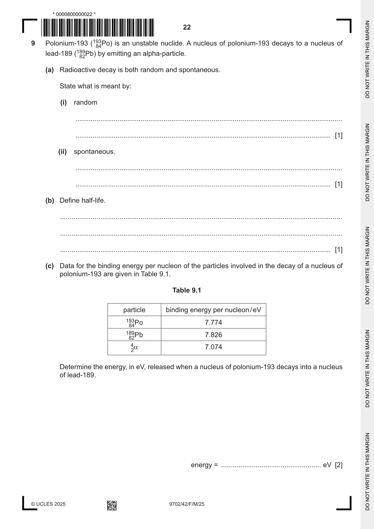
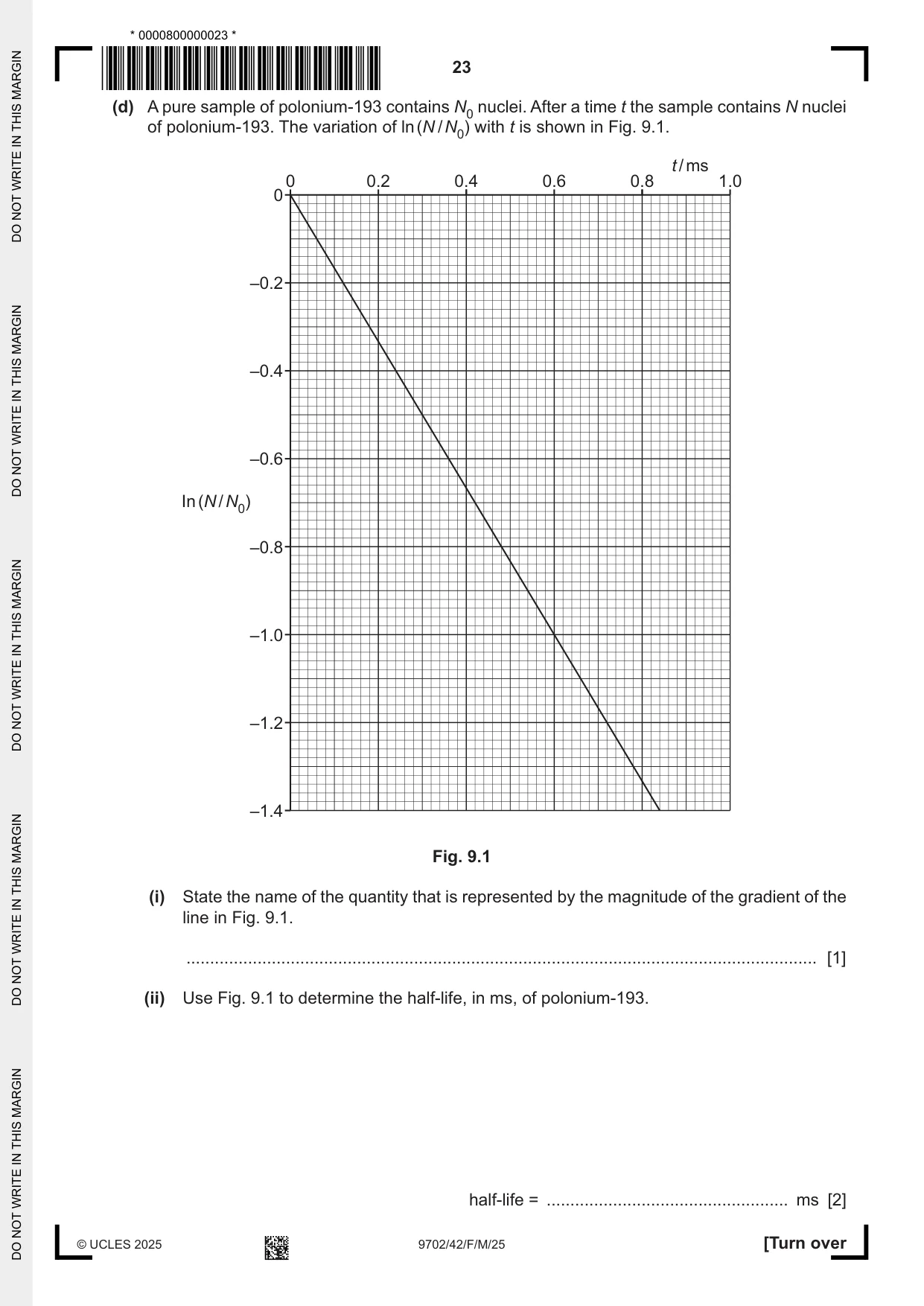
9 Polonium‑193 (19384Po) is an unstable nuclide. A nucleus of polonium‑193 decays to a nucleus of lead‑189 (18982Pb) by emitting an alpha‑particle. (a) Radioactive decay is both random and spontaneous. State what is meant by: (i) random ........................................................................................................................................... ..................................................................................................................................... [1] (ii) spontaneous. ........................................................................................................................................... ..................................................................................................................................... [1] (b) Define half‑life. ................................................................................................................................................... ................................................................................................................................................... ............................................................................................................................................. [1] (c) Data for the binding energy per nucleon of the particles involved in the decay of a nucleus of polonium‑193 are given in Table 9.1. Table 9.1 particle binding energy per nucleon / eV 19384Po 7.774 18982Pb 7.826 4α 7.074 2 Determine the energy, in eV, released when a nucleus of polonium‑193 decays into a nucleus of lead‑189. energy = .................................................... eV [2] (d) A pure sample of polonium‑193 contains N0 nuclei. After a time t the sample contains N nuclei of polonium‑193. The variation of ln (N / N0) with t is shown in Fig. 9.1. t / ms 0 0.2 0.4 0.6 0.8 1.0 0 –0.2 –0.4 –0.6 In (N / N0) –0.8 –1.0 –1.2 –1.4 Fig. 9.1 (i) State the name of the quantity that is represented by the magnitude of the gradient of the line in Fig. 9.1. ..................................................................................................................................... [1] (ii) Use Fig. 9.1 to determine the half‑life, in ms, of polonium‑193. half‑life = ................................................... ms [2] (e) Positron emission tomography (PET scanning) uses a radioactive tracer. (i) State what happens to the positrons emitted by the tracer. ........................................................................................................................................... ..................................................................................................................................... [1] (ii) Explain why a tracer with a half‑life of approximately 2 hours is a suitable tracer to use. ........................................................................................................................................... ..................................................................................................................................... [1] [Total: 10]
Mark scheme: 9(a)(i) either: cannot predict when a (particular) nucleus will decay B1 or: cannot predict which nucleus will decay next 9(a)(ii) not affected by external / environmental factors B1 9(b) time for activity to halve B1 9(c) energy = (189 7.826) + (4 7.074) – (193 7.774) C1 = 7.03 eV A1 9(d)(i) decay constant A1 9(d)(ii) decay constant / magnitude of gradient = 1.4 / 0.84 C1 half-life = ln2 / (1.4 / 0.84) A1 = 0.42 ms 9(e)(i) positrons collide with electrons and annihilate B1 9(e)(ii) long enough to have time to conduct investigation, not so long as to cause patient unnecessary exposure to radiation B1
Q10 · State what is meant by the luminosity of a star
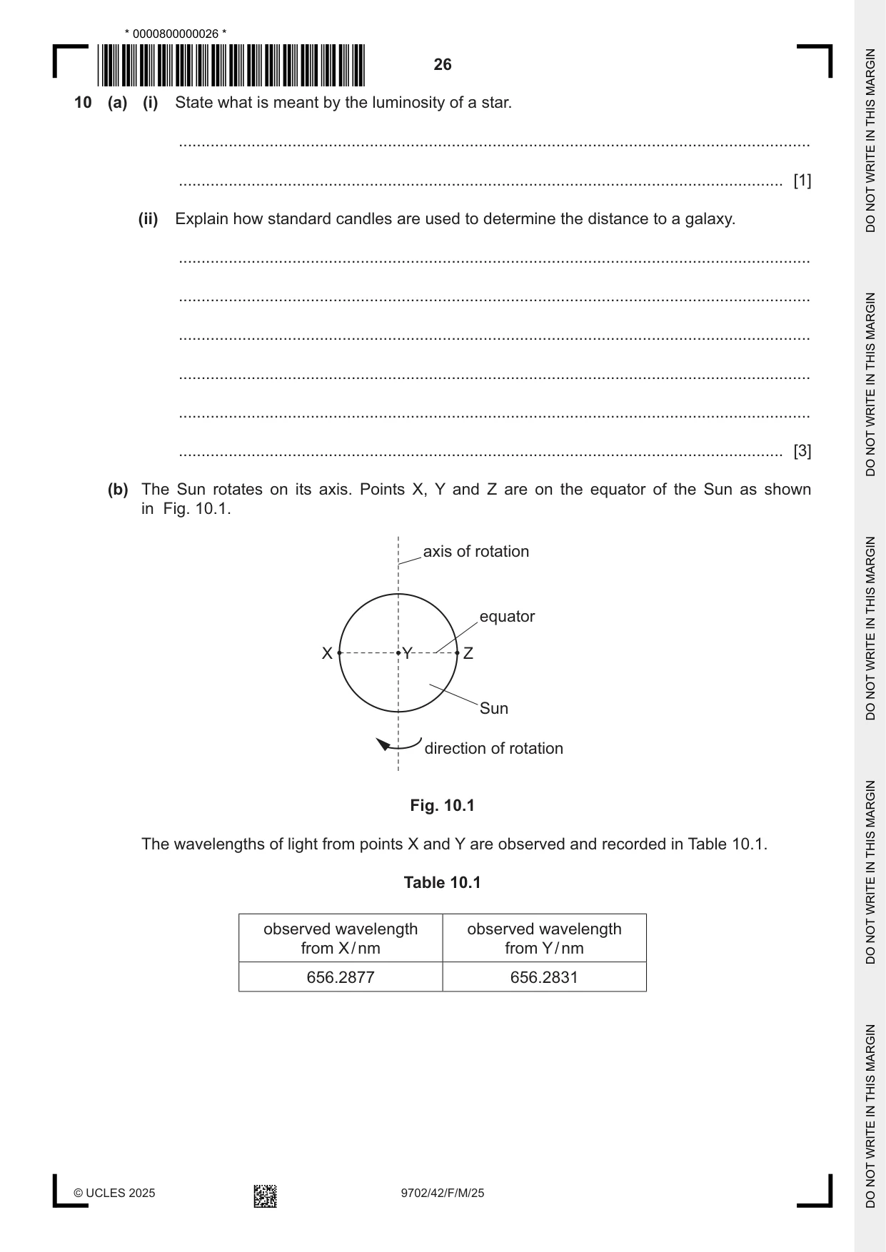
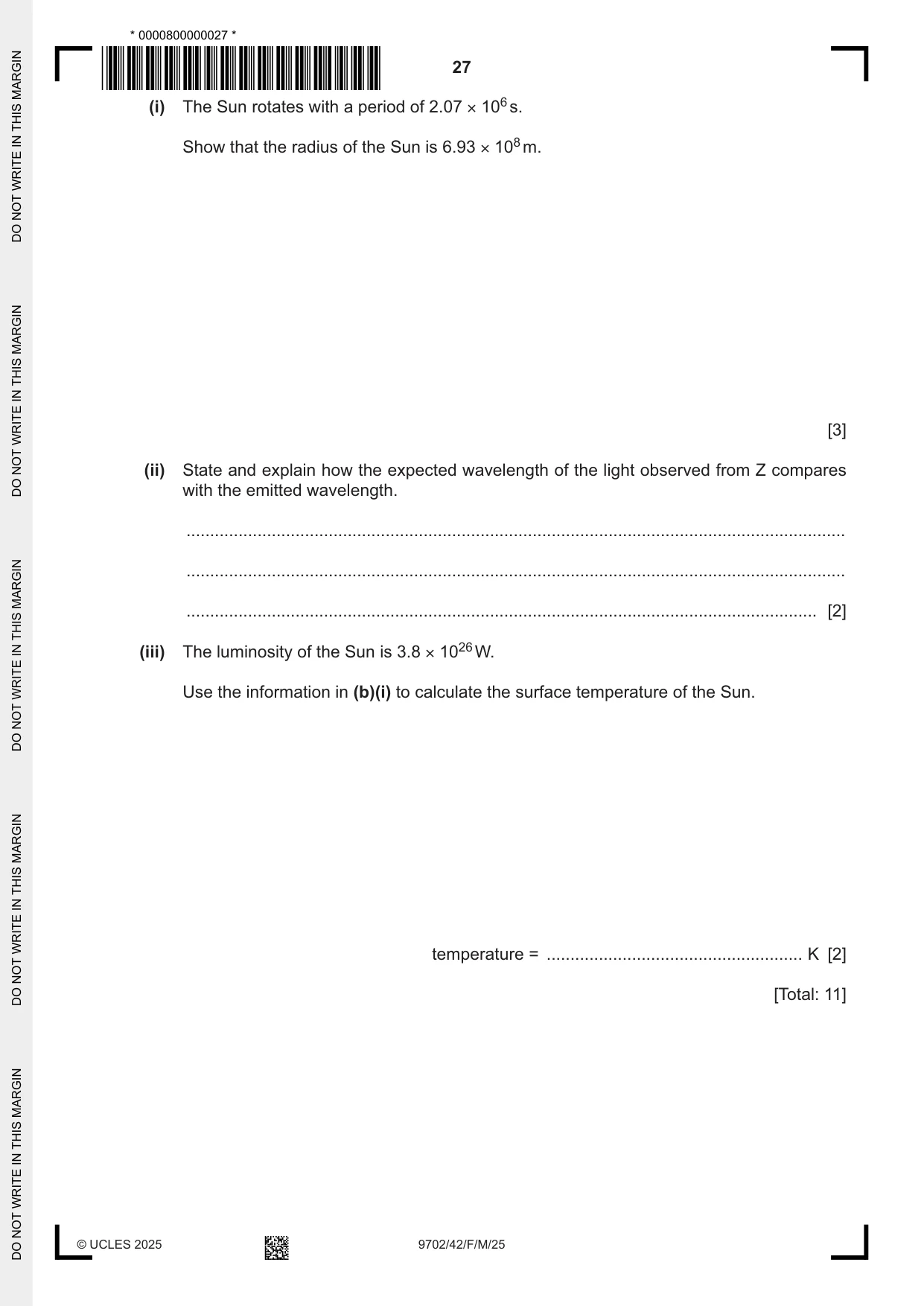
10 (a) (i) State what is meant by the luminosity of a star. ........................................................................................................................................... ..................................................................................................................................... [1] (ii) Explain how standard candles are used to determine the distance to a galaxy. ........................................................................................................................................... ........................................................................................................................................... ........................................................................................................................................... ........................................................................................................................................... ........................................................................................................................................... ..................................................................................................................................... [3] (b) The Sun rotates on its axis. Points X, Y and Z are on the equator of the Sun as shown in Fig. 10.1. axis of rotation equator X Y Z Sun direction of rotation Fig. 10.1 The wavelengths of light from points X and Y are observed and recorded in Table 10.1. Table 10.1 observed wavelength observed wavelength from X / nm from Y / nm 656.2877 656.2831 (i) The Sun rotates with a period of 2.07 × 10⁶ s. Show that the radius of the Sun is 6.93 × 10⁸ m. [3] (ii) State and explain how the expected wavelength of the light observed from Z compares with the emitted wavelength. ........................................................................................................................................... ........................................................................................................................................... ..................................................................................................................................... [2] (iii) The luminosity of the Sun is 3.8 × 1026 W. Use the information in (b)(i) to calculate the surface temperature of the Sun. temperature = ...................................................... K [2] [Total: 11]
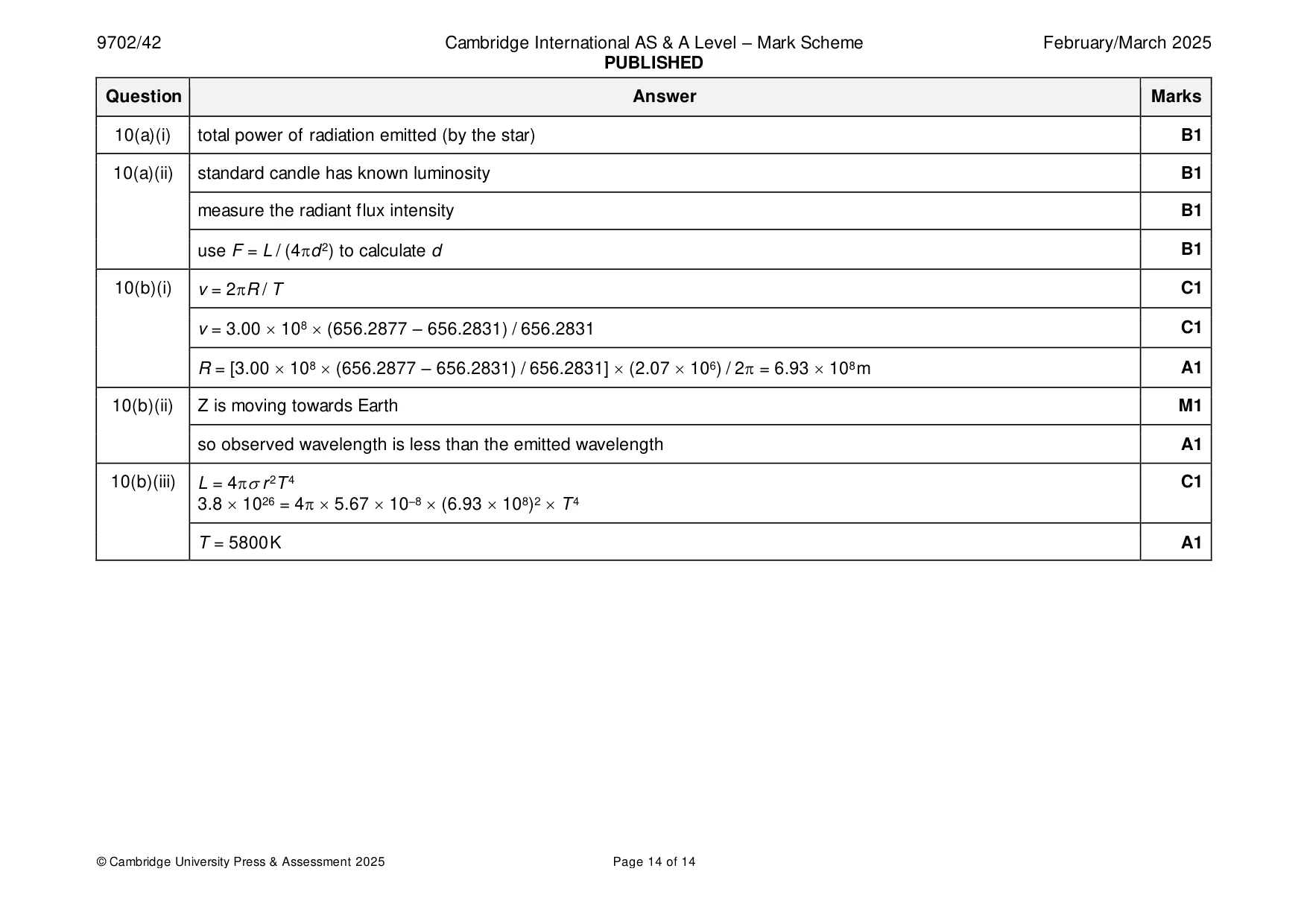
Mark scheme: 10(a)(i) total power of radiation emitted (by the star) B1 10(a)(ii) standard candle has known luminosity B1 measure the radiant flux intensity B1 use F = L / (4d 2) to calculate d B1 10(b)(i) v = 2R / T C1 v = 3.00 108 (656.2877 – 656.2831) / 656.2831 C1 R = [3.00 108 (656.2877 – 656.2831) / 656.2831] (2.07 106) / 2 = 6.93 108 m A1 10(b)(ii) Z is moving towards Earth M1 so observed wavelength is less than the emitted wavelength A1 10(b)(iii) L = 4r 2T 4 C1 3.8 1026 = 4 5.67 10–8 (6.93 108)2 T 4 T = 5800 K A1
What was in this paper
The subtopics covered by these 10 questions, and how many questions each got. Open one in a new tab to see every Cambridge question on it.
What you needed in this session
Cambridge’s own grade thresholds for 2025 Feb/March, Paper 4 · Variant 2. A higher threshold means an easier paper — the bar moves with how the cohort did.