Cambridge A Level Physics 9702 — 2017 Feb/March Paper 4 · Variant 2
9702/42/F/M/17 · 12 questions · 100 marks · ≈113 min
The question paper and its mark scheme, free to read here and free to download. This is Cambridge’s own paper, exactly as it was sat.
Question paper24 pages


Mark scheme11 pages
Answers below. Sit the paper first if you are practising.
Questions as text
Q1 · Define gravitational potential at a point
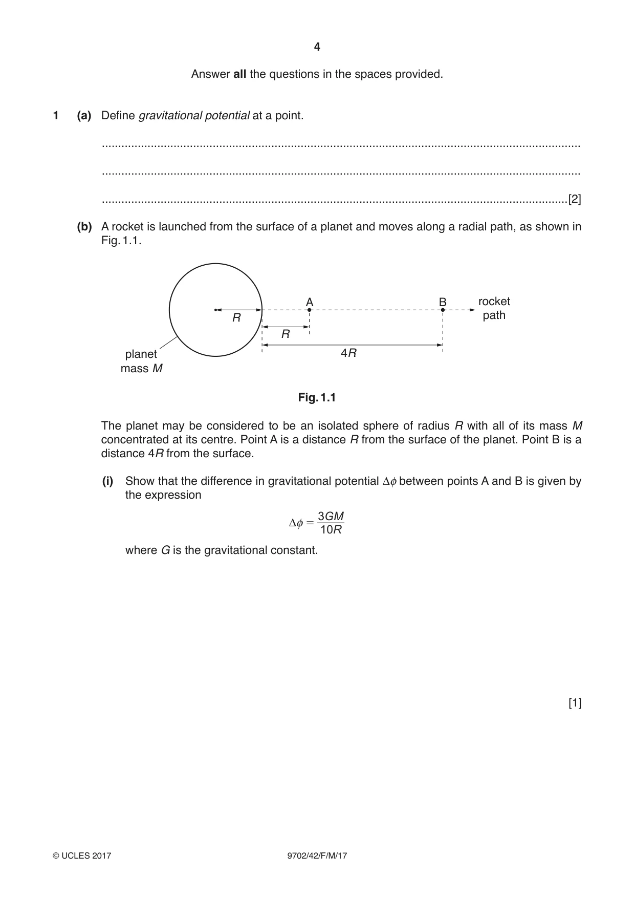
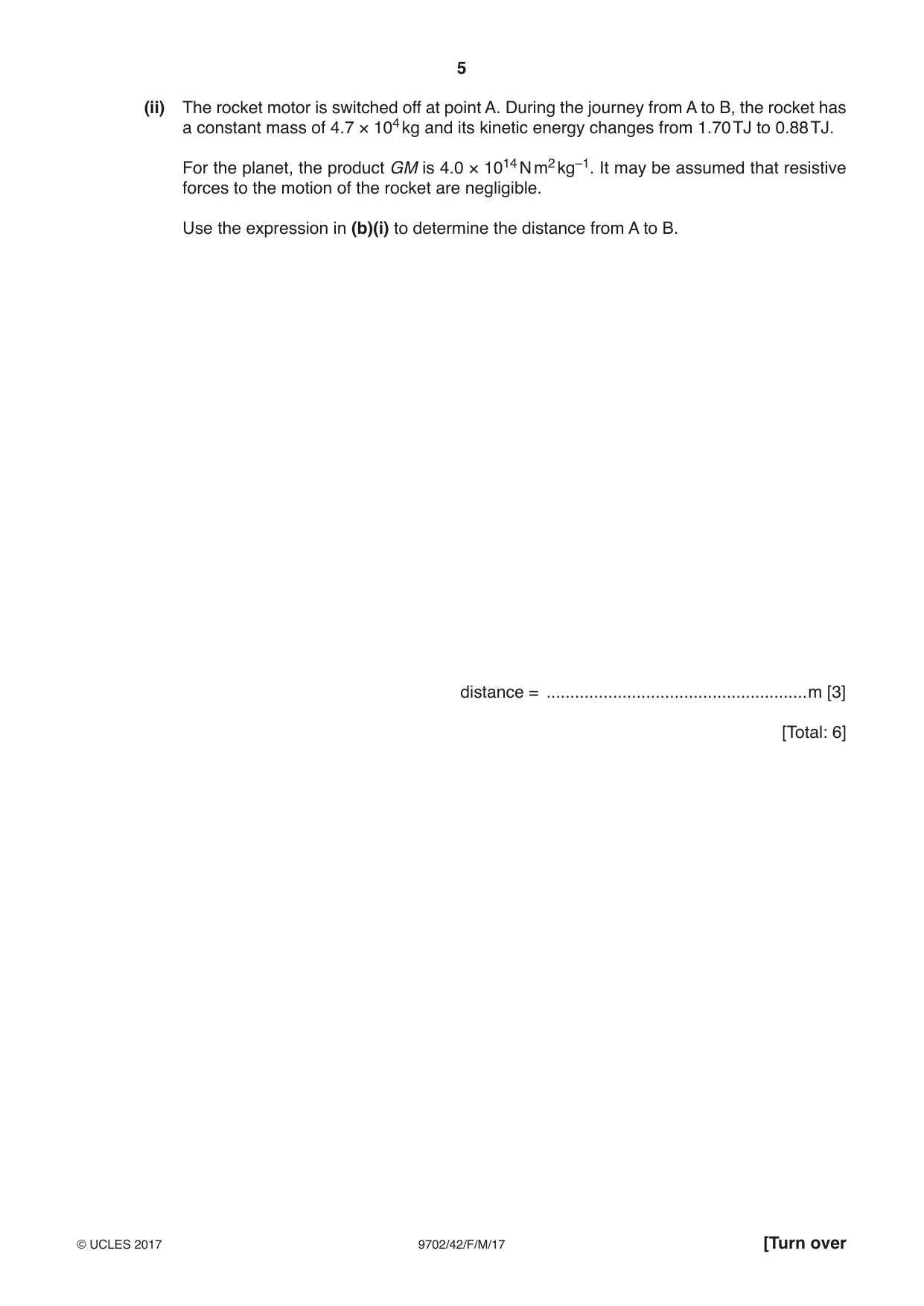
1 (a) Define gravitational potential at a point. ................................................................................................................................................... ................................................................................................................................................... ...............................................................................................................................................[2] (b) A rocket is launched from the surface of a planet and moves along a radial path, as shown in Fig. 1.1. A B rocket R path R planet 4R mass M Fig. 1.1 The planet may be considered to be an isolated sphere of radius R with all of its mass M concentrated at its centre. Point A is a distance R from the surface of the planet. Point B is a distance 4R from the surface. (i) Show that the difference in gravitational potential Δφ between points A and B is given by the expression 3 GM Δφ = 10 R where G is the gravitational constant. [1] (ii) The rocket motor is switched off at point A. During the journey from A to B, the rocket has a constant mass of 4.7 × 10⁴ kg and its kinetic energy changes from 1.70 TJ to 0.88 TJ. For the planet, the product GM is 4.0 × 10¹⁴ N m2 kg–1. It may be assumed that resistive forces to the motion of the rocket are negligible. Use the expression in (b)(i) to determine the distance from A to B. distance = .......................................................m [3] [Total: 6]
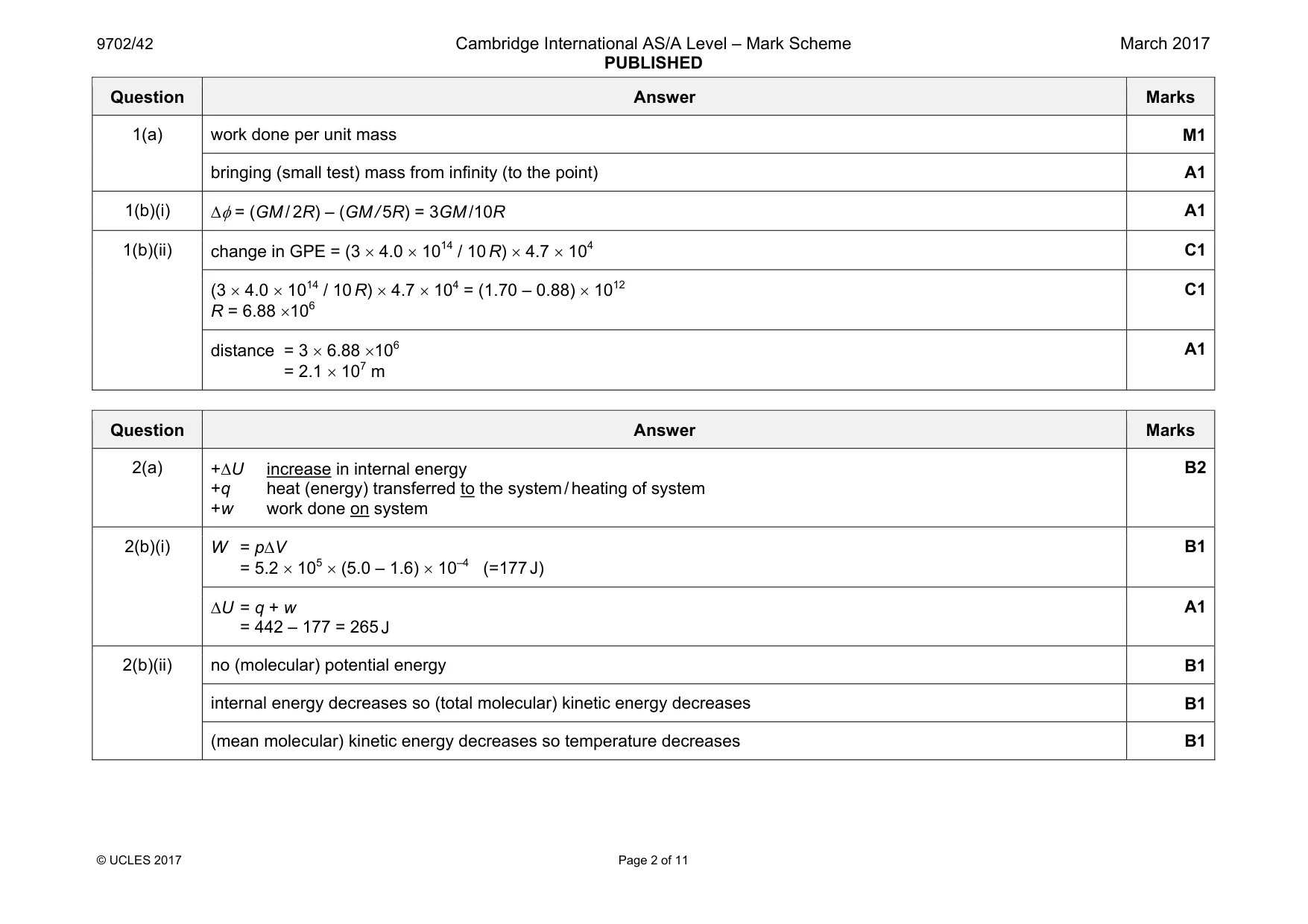
Mark scheme: 1(a) work done per unit mass M1 bringing (small test) mass from infinity (to the point) A1 1(b)(i) ∆φ = (GM / 2R) – (GM / 5R) = 3GM /10R A1 1(b)(ii) change in GPE = (3 × 4.0 × 1014 / 10 R) × 4.7 × 10⁴ C1 (3 × 4.0 × 1014 / 10 R) × 4.7 × 104 = (1.70 – 0.88) × 1012 R = 6.88 ×10⁶ C1 distance = 3 × 6.88 ×106 = 2.1 × 10⁷ m A1
Q2 · The first law of thermodynamics can be represented by the expression ΔU = q + w
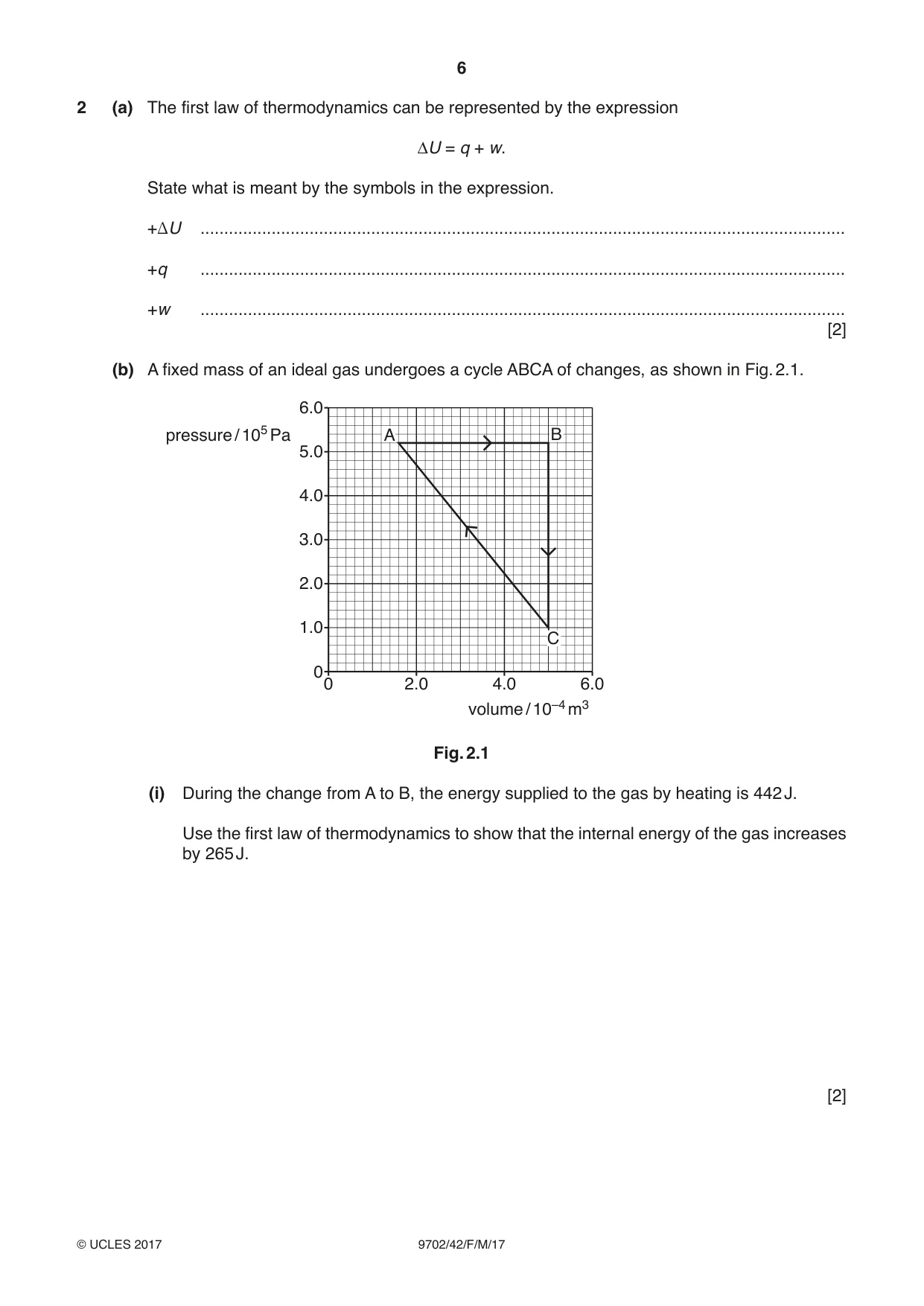
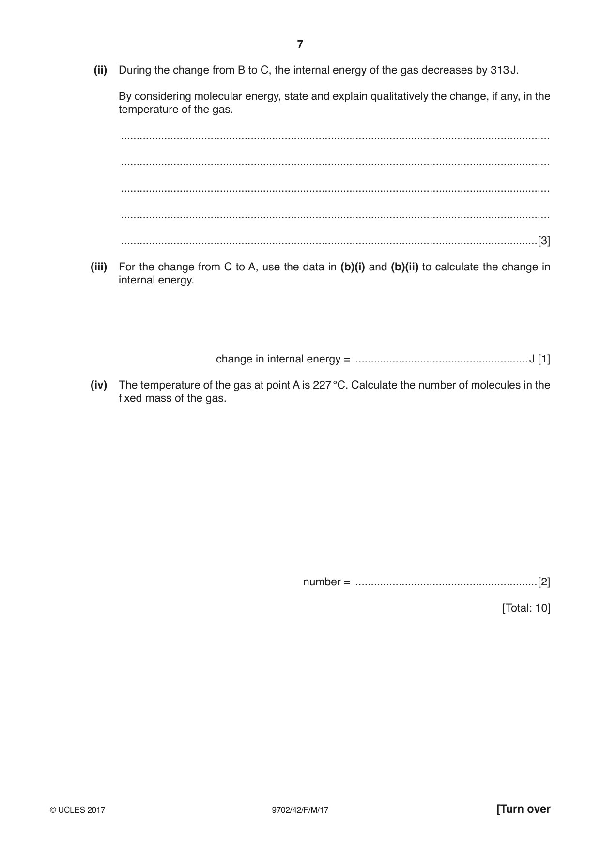
2 (a) The first law of thermodynamics can be represented by the expression ΔU = q + w. State what is meant by the symbols in the expression. +DU ........................................................................................................................................ +q ........................................................................................................................................ +w ........................................................................................................................................ [2] (b) A fixed mass of an ideal gas undergoes a cycle ABCA of changes, as shown in Fig. 2.1. 6.0 pressure / 105 Pa A B 5.0 4.0 3.0 2.0 1.0 C 0 0 2.0 4.0 6.0 volume / 10–4 m3 Fig. 2.1 (i) During the change from A to B, the energy supplied to the gas by heating is 442 J. Use the first law of thermodynamics to show that the internal energy of the gas increases by 265 J. [2] (ii) During the change from B to C, the internal energy of the gas decreases by 313 J. By considering molecular energy, state and explain qualitatively the change, if any, in the temperature of the gas. ........................................................................................................................................... ........................................................................................................................................... ........................................................................................................................................... ........................................................................................................................................... .......................................................................................................................................[3] (iii) For the change from C to A, use the data in (b)(i) and (b)(ii) to calculate the change in internal energy. change in internal energy = ........................................................J [1] (iv) The temperature of the gas at point A is 227 °C. Calculate the number of molecules in the fixed mass of the gas. number = ...........................................................[2] [Total: 10]
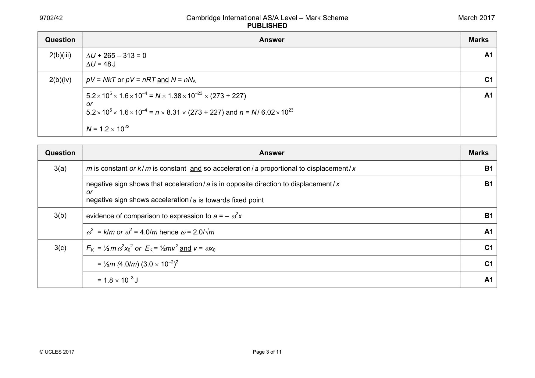
Mark scheme: 2(a) +q heat (energy) transferred to the system / heating of system +w work done on system B2 2(b)(i) W = p∆V = 5.2 × 105 × (5.0 – 1.6) × 10–4 (=177 J) B1 ∆U = q + w = 442 – 177 = 265 J A1 2(b)(ii) no (molecular) potential energy B1 internal energy decreases so (total molecular) kinetic energy decreases B1 (mean molecular) kinetic energy decreases so temperature decreases B1 Question Answer Marks 2(b)(iii) ∆U + 265 – 313 = 0 ∆U = 48 J A1 2(b)(iv) pV = NkT or pV = nRT and N = nNA C1 5.2 × 105 × 1.6 × 10–4 = N × 1.38 × 10–23 × (273 + 227) or 5.2 × 105 × 1.6 × 10–4 = n × 8.31 × (273 + 227) and n = N / 6.02 × 10²³ N = 1.2 × 10²² A1
Q3 · A uniform beam is clamped at one end
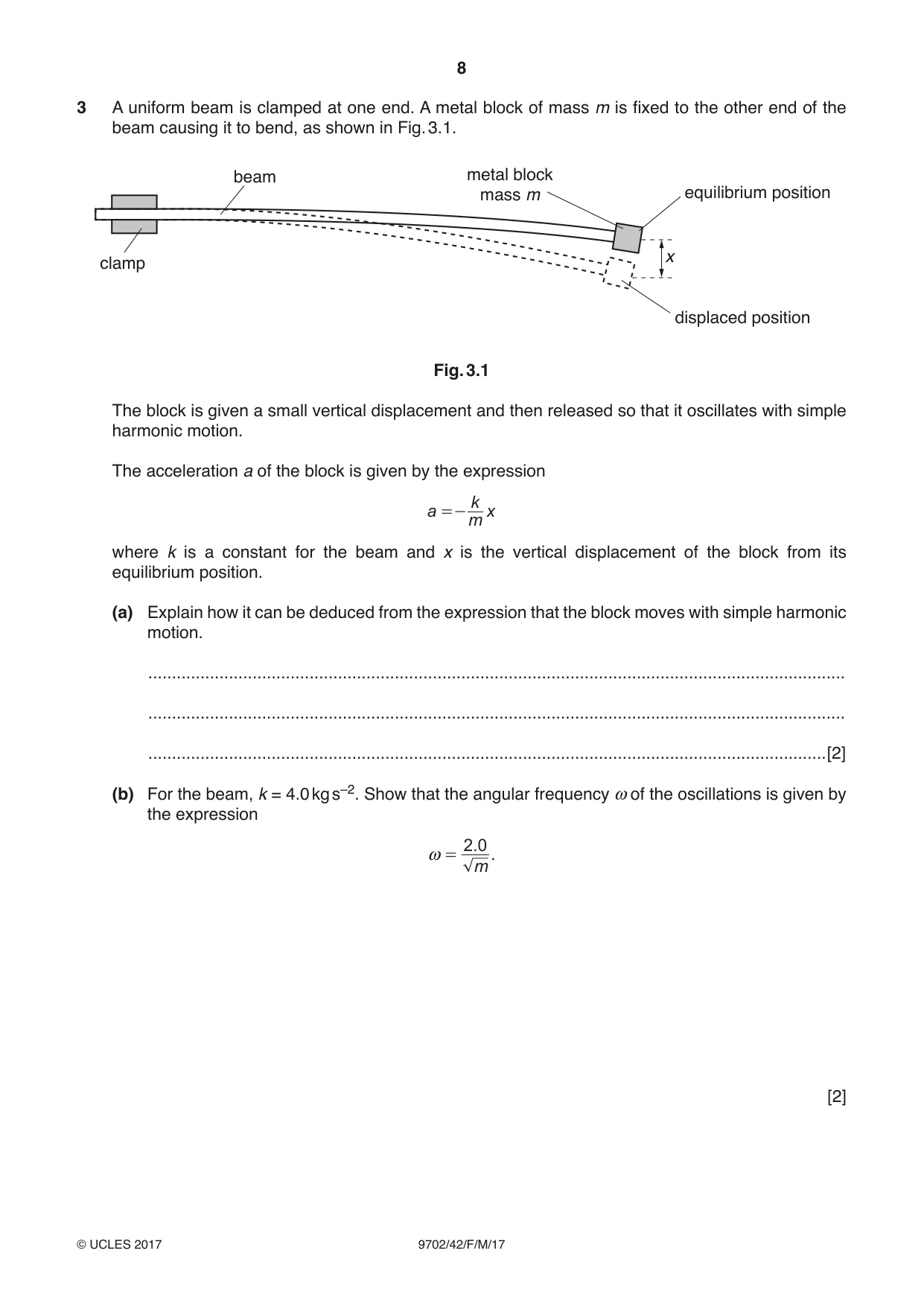
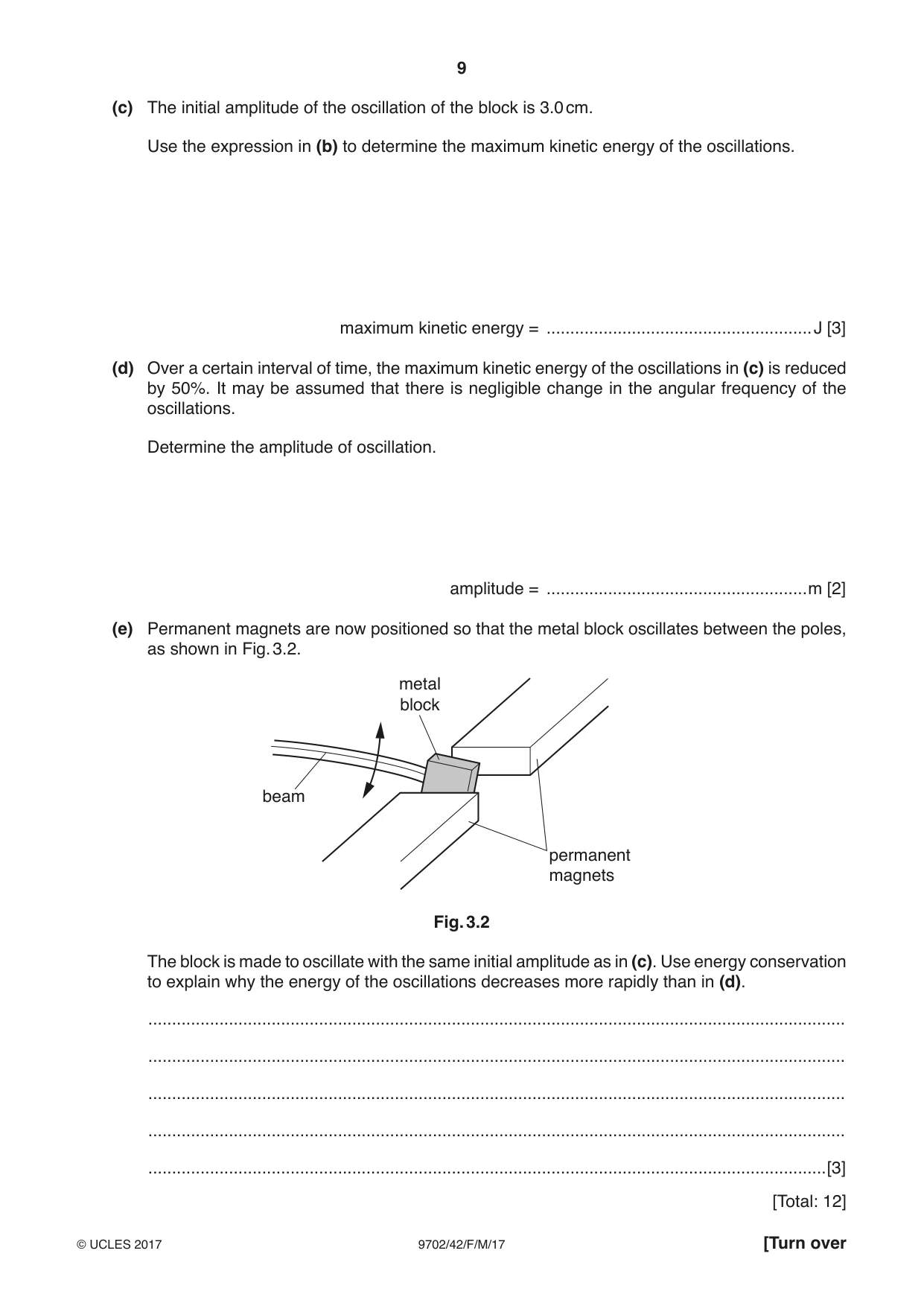
3 A uniform beam is clamped at one end. A metal block of mass m is fixed to the other end of the beam causing it to bend, as shown in Fig. 3.1. beam metal block mass m equilibrium position x clamp displaced position Fig. 3.1 The block is given a small vertical displacement and then released so that it oscillates with simple harmonic motion. The acceleration a of the block is given by the expression k a =- x m where k is a constant for the beam and x is the vertical displacement of the block from its equilibrium position. (a) Explain how it can be deduced from the expression that the block moves with simple harmonic motion. ................................................................................................................................................... ................................................................................................................................................... ...............................................................................................................................................[2] (b) For the beam, k = 4.0 kg s–2. Show that the angular frequency ω of the oscillations is given by the expression 2 .0 ω = . m [2] (c) The initial amplitude of the oscillation of the block is 3.0 cm. Use the expression in (b) to determine the maximum kinetic energy of the oscillations. maximum kinetic energy = ........................................................J [3] (d) Over a certain interval of time, the maximum kinetic energy of the oscillations in (c) is reduced by 50%. It may be assumed that there is negligible change in the angular frequency of the oscillations. Determine the amplitude of oscillation. amplitude = .......................................................m [2] (e) Permanent magnets are now positioned so that the metal block oscillates between the poles, as shown in Fig. 3.2. metal block beam permanent magnets Fig. 3.2 The block is made to oscillate with the same initial amplitude as in (c). Use energy conservation to explain why the energy of the oscillations decreases more rapidly than in (d). ................................................................................................................................................... ................................................................................................................................................... ................................................................................................................................................... ................................................................................................................................................... ...............................................................................................................................................[3] [Total: 12]
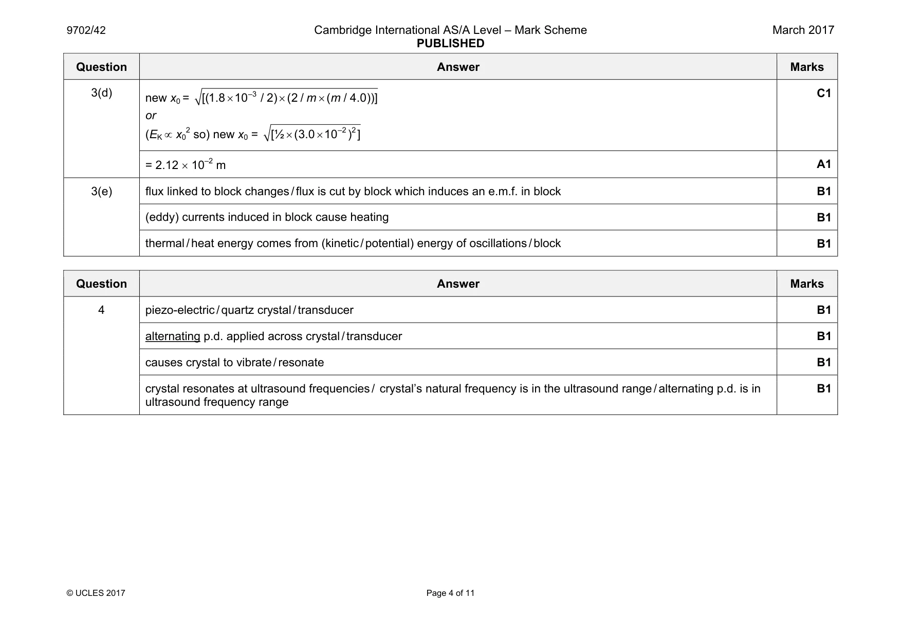
Mark scheme: 3(a) m is constant or k / m is constant and so acceleration / a proportional to displacement / x B1 negative sign shows that acceleration / a is in opposite direction to displacement / x or negative sign shows acceleration / a is towards fixed point B1 3(b) evidence of comparison to expression to a = – ω2x B1 ω2 = k/m or ω2 = 4.0/m hence ω = 2.0/√m A1 3(c) EK = ½ m ω2x0 2 or EK = ½mv 2 and v = ωx0 C1 = ½m (4.0/m) (3.0 × 10⁻²)2 C1 = 1.8 × 10⁻³ J A1 Question Answer Marks 3(d) new x0 = –3 [( ) ( 1.8 10 / 2 2 / ( / 4.0))] m m × × × or (EK ∝ x0 2 so) new x0 = –2 2 [½ 3.0 10 ( ) ] × × C1 = 2.12 × 10⁻² m A1 3(e) flux linked to block changes / flux is cut by block which induces an e.m.f. in block B1 (eddy) currents induced in block cause heating B1 thermal / heat energy comes from (kinetic / potential) energy of oscillations / block B1
Q4 · Explain the main principles of the generation of ultrasound waves for medical use
4 Explain the main principles of the generation of ultrasound waves for medical use. .......................................................................................................................................................... .......................................................................................................................................................... .......................................................................................................................................................... .......................................................................................................................................................... .......................................................................................................................................................... .......................................................................................................................................................... .......................................................................................................................................................... .......................................................................................................................................................... .......................................................................................................................................................... ......................................................................................................................................................[4] [Total: 4]
Mark scheme: 4 piezo-electric / quartz crystal / transducer B1 alternating p.d. applied across crystal / transducer B1 causes crystal to vibrate / resonate B1 crystal resonates at ultrasound frequencies / crystal’s natural frequency is in the ultrasound range / alternating p.d. is in ultrasound frequency range B1
Q5 · State three advantages of an optic fibre compared to a metal wire for the transmission of…
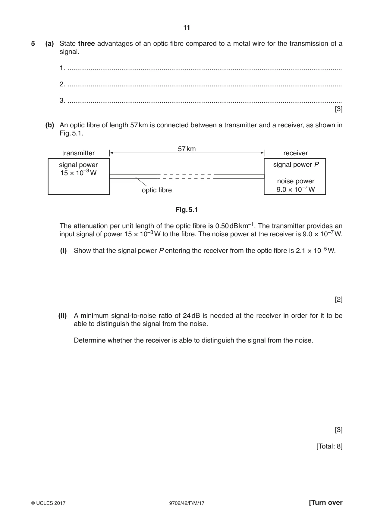
5 (a) State three advantages of an optic fibre compared to a metal wire for the transmission of a signal. 1. ............................................................................................................................................... 2. ............................................................................................................................................... 3. ............................................................................................................................................... [3] (b) An optic fibre of length 57 km is connected between a transmitter and a receiver, as shown in Fig. 5.1. 57 km transmitter receiver signal power signal power P 15 × 10–3 W noise power optic fibre 9.0 × 10⁻⁷ W Fig. 5.1 The attenuation per unit length of the optic fibre is 0.50 dB km–1. The transmitter provides an input signal of power 15 × 10–3 W to the fibre. The noise power at the receiver is 9.0 × 10⁻⁷ W. (i) Show that the signal power P entering the receiver from the optic fibre is 2.1 × 10⁻⁵ W. [2] (ii) A minimum signal-to-noise ratio of 24 dB is needed at the receiver in order for it to be able to distinguish the signal from the noise. Determine whether the receiver is able to distinguish the signal from the noise. [3] [Total: 8]
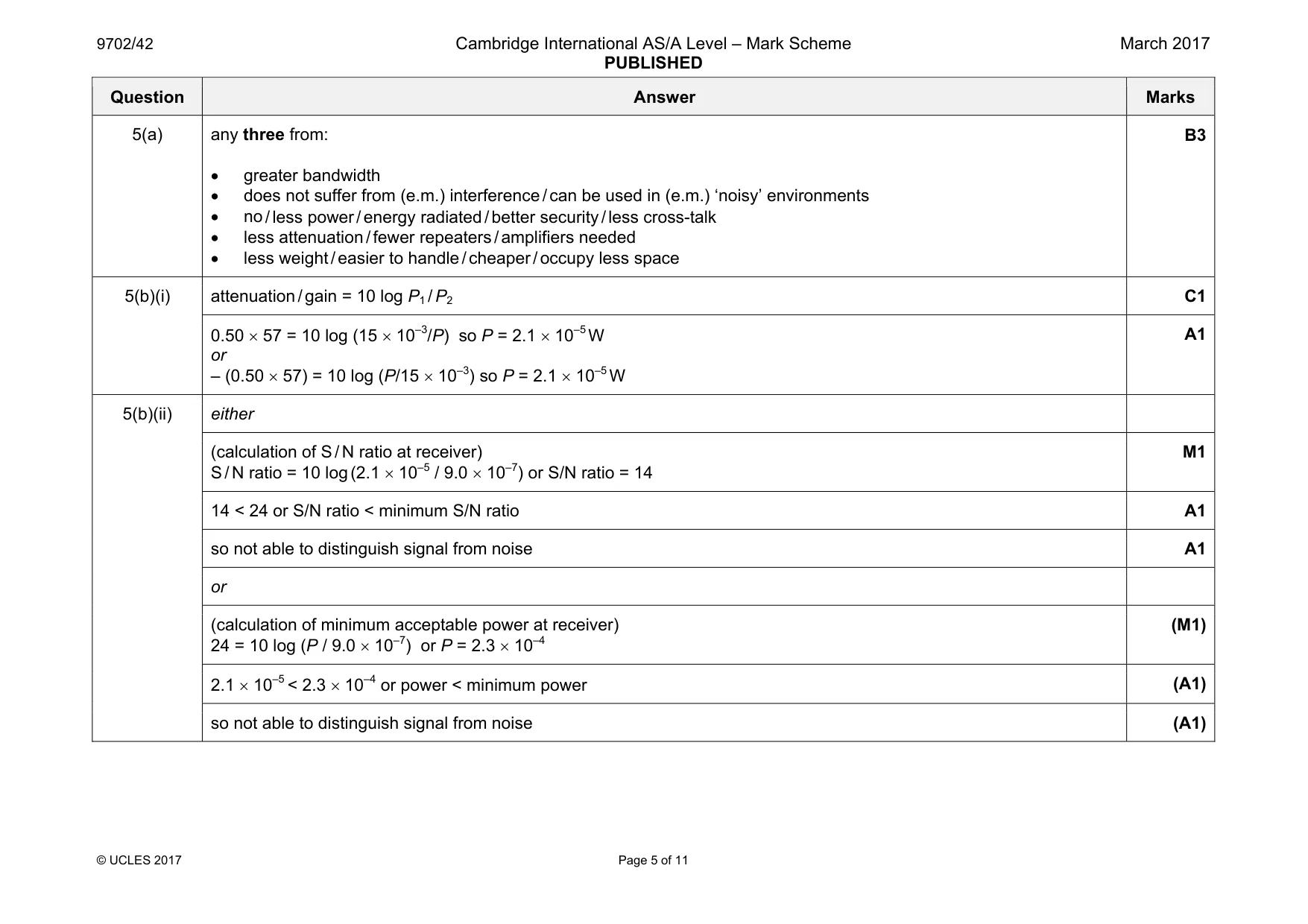
Mark scheme: 5(a) any three from: • greater bandwidth • does not suffer from (e.m.) interference / can be used in (e.m.) ‘noisy’ environments • no / less power / energy radiated / better security / less cross-talk • less attenuation / fewer repeaters / amplifiers needed • less weight / easier to handle / cheaper / occupy less space B3 5(b)(i) attenuation / gain = 10 log P1 / P2 C1 0.50 × 57 = 10 log (15 × 10–3/P) so P = 2.1 × 10⁻⁵ W or – (0.50 × 57) = 10 log (P/15 × 10–3) so P = 2.1 × 10⁻⁵ W A1 5(b)(ii) either (calculation of S / N ratio at receiver) S / N ratio = 10 log (2.1 × 10⁻⁵ / 9.0 × 10⁻⁷) or S/N ratio = 14 M1 14 < 24 or S/N ratio < minimum S/N ratio A1 so not able to distinguish signal from noise A1 or (calculation of minimum acceptable power at receiver) 24 = 10 log (P / 9.0 × 10⁻⁷) or P = 2.3 × 10⁻⁴ (M1) 2.1 × 10⁻⁵ < 2.3 × 10⁻⁴ or power < minimum power (A1) so not able to distinguish signal from noise (A1)
Q6 · State one similarity and one difference between the electric field lines and the…
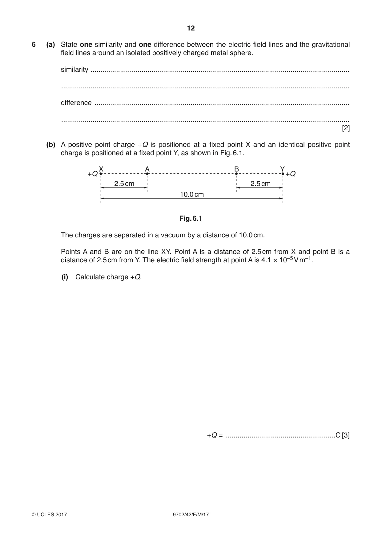
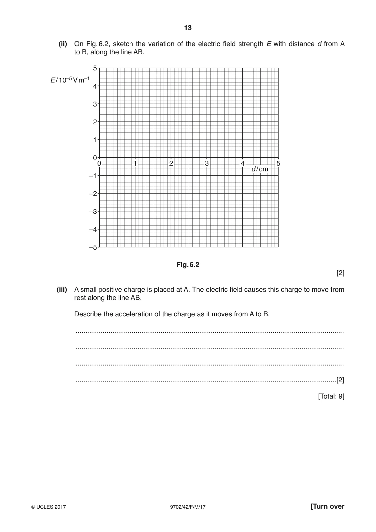
6 (a) State one similarity and one difference between the electric field lines and the gravitational field lines around an isolated positively charged metal sphere. similarity .................................................................................................................................... ................................................................................................................................................... difference .................................................................................................................................. ................................................................................................................................................... [2] (b) A positive point charge +Q is positioned at a fixed point X and an identical positive point charge is positioned at a fixed point Y, as shown in Fig. 6.1. X A B Y +Q +Q 2.5 cm 2.5 cm 10.0 cm Fig. 6.1 The charges are separated in a vacuum by a distance of 10.0 cm. Points A and B are on the line XY. Point A is a distance of 2.5 cm from X and point B is a distance of 2.5 cm from Y. The electric field strength at point A is 4.1 × 10⁻⁵ V m–1. (i) Calculate charge +Q. +Q = ........................................................C [3] (ii) On Fig. 6.2, sketch the variation of the electric field strength E with distance d from A to B, along the line AB. 5 E / 10–5 V m–1 4 3 2 1 0 0 1 2 3 4 5 d / cm –1 –2 –3 –4 –5 Fig. 6.2 [2] (iii) A small positive charge is placed at A. The electric field causes this charge to move from rest along the line AB. Describe the acceleration of the charge as it moves from A to B. ........................................................................................................................................... ........................................................................................................................................... ........................................................................................................................................... .......................................................................................................................................[2] [Total: 9]
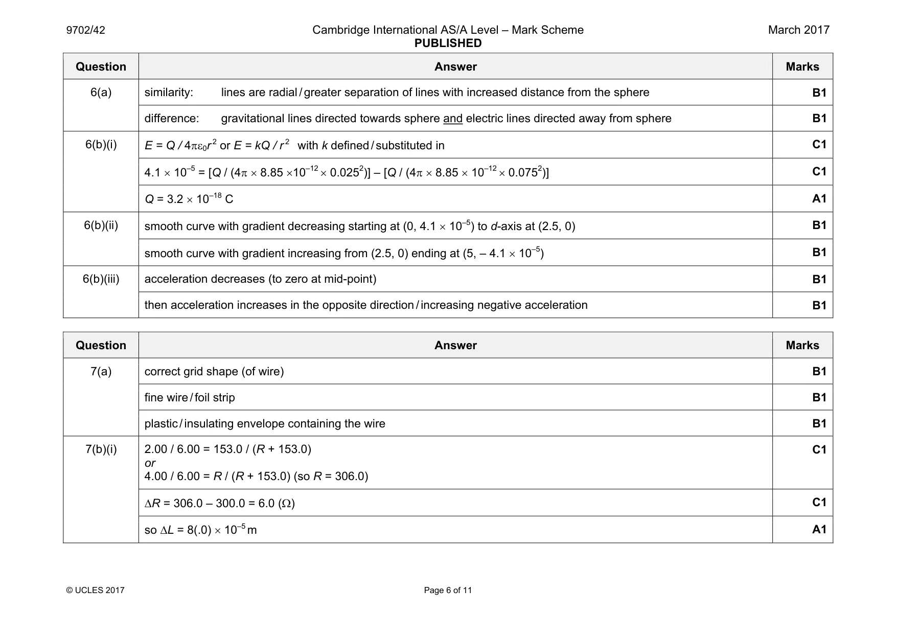
Mark scheme: 6(a) similarity: lines are radial / greater separation of lines with increased distance from the sphere B1 difference: gravitational lines directed towards sphere and electric lines directed away from sphere B1 6(b)(i) E = Q / 4πε0r 2 or E = kQ / r 2 with k defined / substituted in C1 4.1 × 10–5 = [Q / (4π × 8.85 ×10–12 × 0.0252)] – [Q / (4π × 8.85 × 10–12 × 0.0752)] C1 Q = 3.2 × 10⁻¹⁸ C A1 6(b)(ii) smooth curve with gradient decreasing starting at (0, 4.1 × 10⁻⁵) to d-axis at (2.5, 0) B1 smooth curve with gradient increasing from (2.5, 0) ending at (5, – 4.1 × 10⁻⁵) B1 6(b)(iii) acceleration decreases (to zero at mid-point) B1 then acceleration increases in the opposite direction / increasing negative acceleration B1
Q7 · Describe, with a labelled diagram, the structure of a metal-wire strain gauge
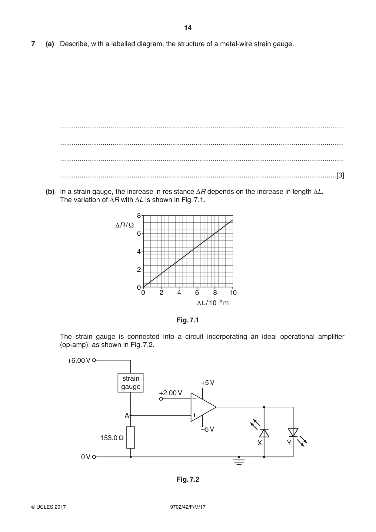
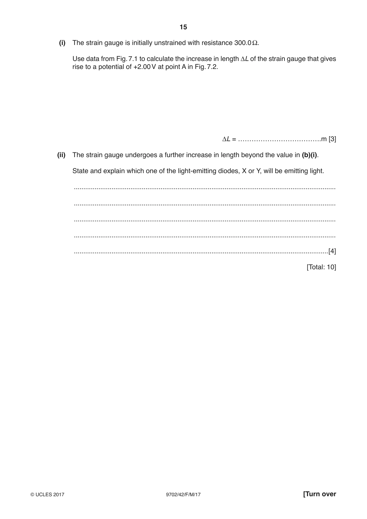
7 (a) Describe, with a labelled diagram, the structure of a metal-wire strain gauge. ................................................................................................................................................... ................................................................................................................................................... ................................................................................................................................................... ...............................................................................................................................................[3] (b) In a strain gauge, the increase in resistance ΔR depends on the increase in length ΔL. The variation of ΔR with ΔL is shown in Fig. 7.1. 8 ΔR / Ω 6 4 2 0 0 2 4 6 8 10 ΔL / 10–5 m Fig. 7.1 The strain gauge is connected into a circuit incorporating an ideal operational amplifier (op-amp), as shown in Fig. 7.2. +6.00 V strain +5 V gauge +2.00 V – A + –5 V 153.0 Ω X Y 0 V Fig. 7.2 (i) The strain gauge is initially unstrained with resistance 300.0 Ω. Use data from Fig. 7.1 to calculate the increase in length ΔL of the strain gauge that gives rise to a potential of +2.00 V at point A in Fig. 7.2. ΔL = ……………………………….m [3] (ii) The strain gauge undergoes a further increase in length beyond the value in (b)(i). State and explain which one of the light-emitting diodes, X or Y, will be emitting light. ........................................................................................................................................... ........................................................................................................................................... ........................................................................................................................................... ........................................................................................................................................... .......................................................................................................................................[4] [Total: 10]
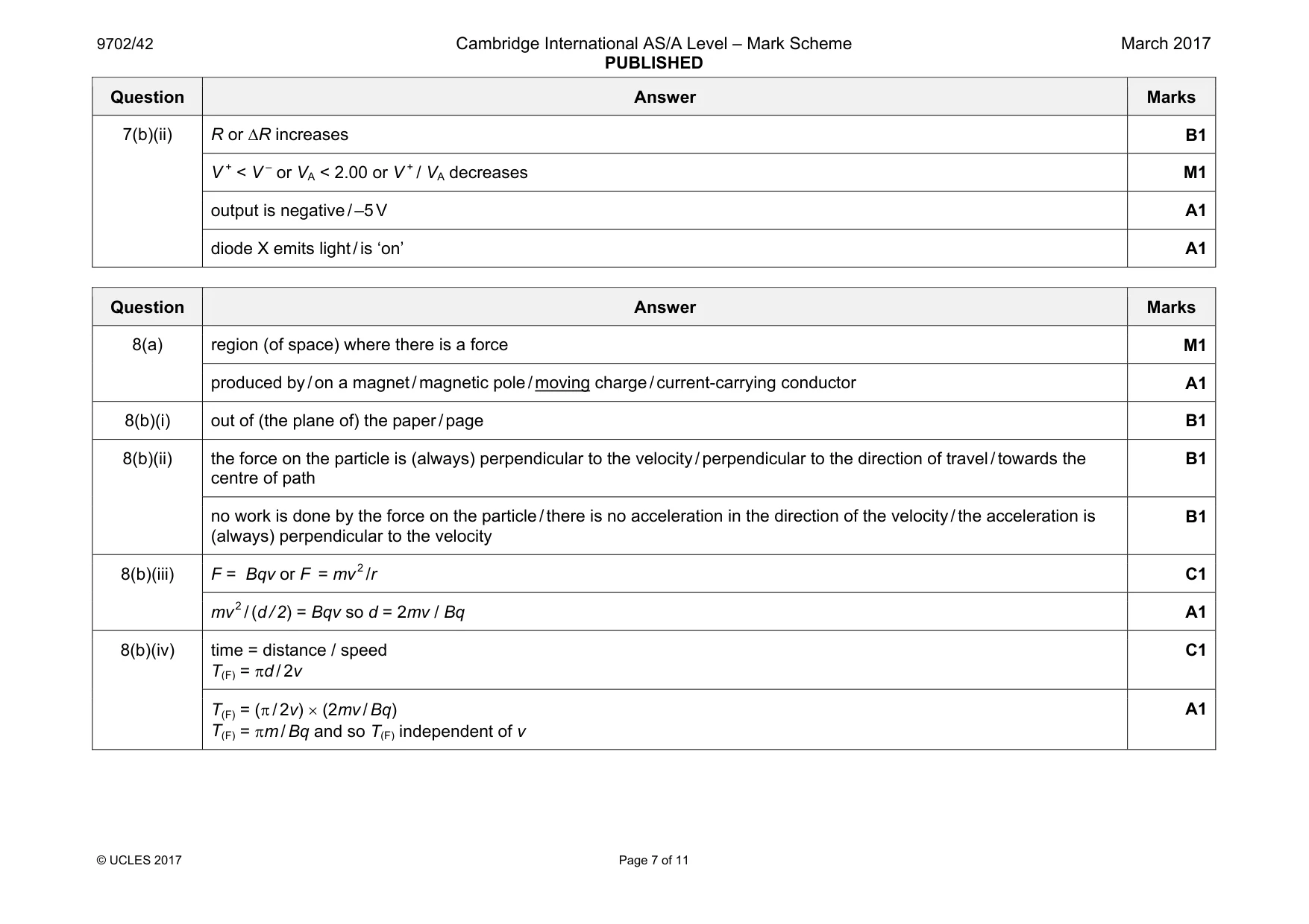
Mark scheme: 7(a) correct grid shape (of wire) B1 fine wire / foil strip B1 plastic / insulating envelope containing the wire B1 7(b)(i) 2.00 / 6.00 = 153.0 / (R + 153.0) or 4.00 / 6.00 = R / (R + 153.0) (so R = 306.0) C1 ∆R = 306.0 – 300.0 = 6.0 (Ω) C1 so ∆L = 8(.0) × 10–5 m A1 Question Answer Marks 7(b)(ii) R or ∆R increases B1 V + < V – or VA < 2.00 or V + / VA decreases M1 output is negative / –5 V A1 diode X emits light / is ‘on’ A1
Q8 · State what is meant by a magnetic field
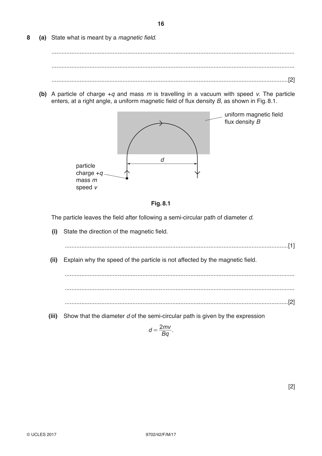
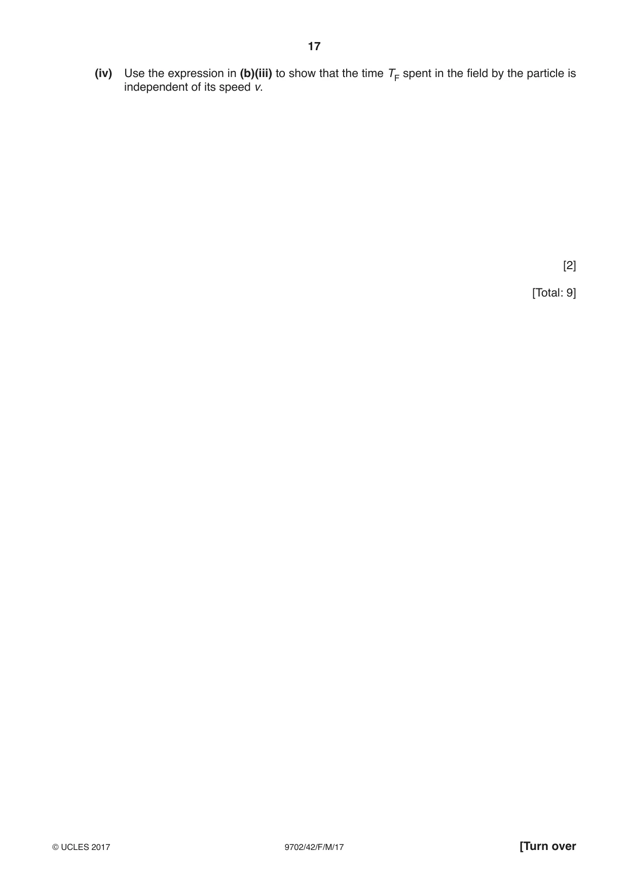
8 (a) State what is meant by a magnetic field. ................................................................................................................................................... ................................................................................................................................................... ...............................................................................................................................................[2] (b) A particle of charge +q and mass m is travelling in a vacuum with speed v. The particle enters, at a right angle, a uniform magnetic field of flux density B, as shown in Fig. 8.1. uniform magnetic field flux density B d particle charge +q mass m speed v Fig. 8.1 The particle leaves the field after following a semi-circular path of diameter d. (i) State the direction of the magnetic field. .......................................................................................................................................[1] (ii) Explain why the speed of the particle is not affected by the magnetic field. ........................................................................................................................................... ........................................................................................................................................... .......................................................................................................................................[2] (iii) Show that the diameter d of the semi-circular path is given by the expression 2 mv d = . Bq [2] (iv) Use the expression in (b)(iii) to show that the time TF spent in the field by the particle is independent of its speed v. [2] [Total: 9]
Mark scheme: 8(a) region (of space) where there is a force M1 produced by / on a magnet / magnetic pole / moving charge / current-carrying conductor A1 8(b)(i) out of (the plane of) the paper / page B1 8(b)(ii) the force on the particle is (always) perpendicular to the velocity / perpendicular to the direction of travel / towards the centre of path B1 no work is done by the force on the particle / there is no acceleration in the direction of the velocity / the acceleration is (always) perpendicular to the velocity B1 8(b)(iii) F = Bqv or F = mv 2 /r C1 mv 2 / (d / 2) = Bqv so d = 2mv / Bq A1 8(b)(iv) time = distance / speed T(F) = πd / 2v C1 T(F) = (π / 2v) × (2mv / Bq) T(F) = πm / Bq and so T(F) independent of v A1
Q9 · An ideal transformer is shown in Fig
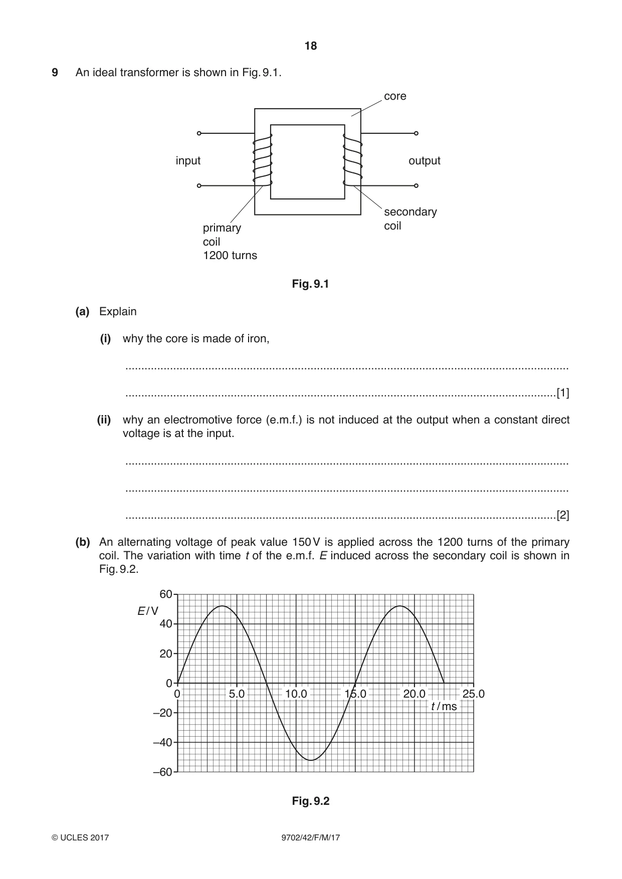
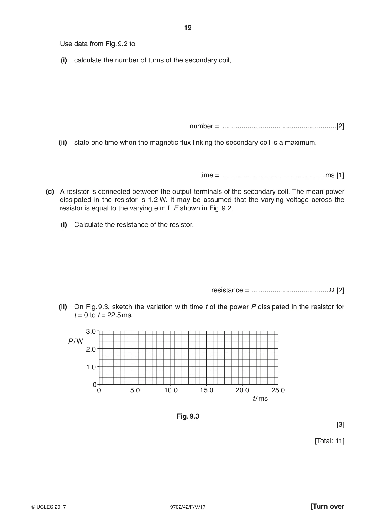
9 An ideal transformer is shown in Fig. 9.1. core input output secondary primary coil coil 1200 turns Fig. 9.1 (a) Explain (i) why the core is made of iron, ........................................................................................................................................... .......................................................................................................................................[1] (ii) why an electromotive force (e.m.f.) is not induced at the output when a constant direct voltage is at the input. ........................................................................................................................................... ........................................................................................................................................... .......................................................................................................................................[2] (b) An alternating voltage of peak value 150 V is applied across the 1200 turns of the primary coil. The variation with time t of the e.m.f. E induced across the secondary coil is shown in Fig. 9.2. 60 E / V 40 20 0 0 5.0 10.0 15.0 20.0 25.0 t / ms –20 –40 –60 Fig. 9.2 Use data from Fig. 9.2 to (i) calculate the number of turns of the secondary coil, number = ...........................................................[2] (ii) state one time when the magnetic flux linking the secondary coil is a maximum. time = .....................................................ms [1] (c) A resistor is connected between the output terminals of the secondary coil. The mean power dissipated in the resistor is 1.2 W. It may be assumed that the varying voltage across the resistor is equal to the varying e.m.f. E shown in Fig. 9.2. (i) Calculate the resistance of the resistor. resistance = ........................................Ω [2] (ii) On Fig. 9.3, sketch the variation with time t of the power P dissipated in the resistor for t = 0 to t = 22.5 ms. 3.0 P / W 2.0 1.0 0 0 5.0 10.0 15.0 20.0 25.0 t / ms Fig. 9.3 [3] [Total: 11]
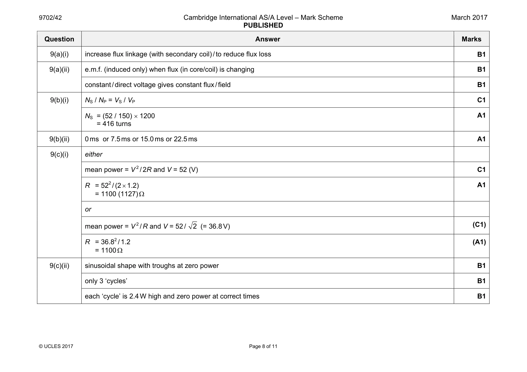
Mark scheme: 9(a)(i) increase flux linkage (with secondary coil) / to reduce flux loss B1 9(a)(ii) e.m.f. (induced only) when flux (in core/coil) is changing B1 constant / direct voltage gives constant flux / field B1 9(b)(i) NS / NP = VS / VP C1 NS = (52 / 150) × 1200 = 416 turns A1 9(b)(ii) 0 ms or 7.5 ms or 15.0 ms or 22.5 ms A1 9(c)(i) either mean power = V 2 / 2R and V = 52 (V) C1 R = 522 / (2 × 1.2) = 1100 (1127) Ω A1 or mean power = V 2 / R and V = 52 / 2 (= 36.8 V) (C1) R = 36.82 / 1.2 = 1100 Ω (A1) 9(c)(ii) sinusoidal shape with troughs at zero power B1 only 3 ‘cycles’ B1 each ‘cycle’ is 2.4 W high and zero power at correct times B1
Q10 · State what is meant by a photon
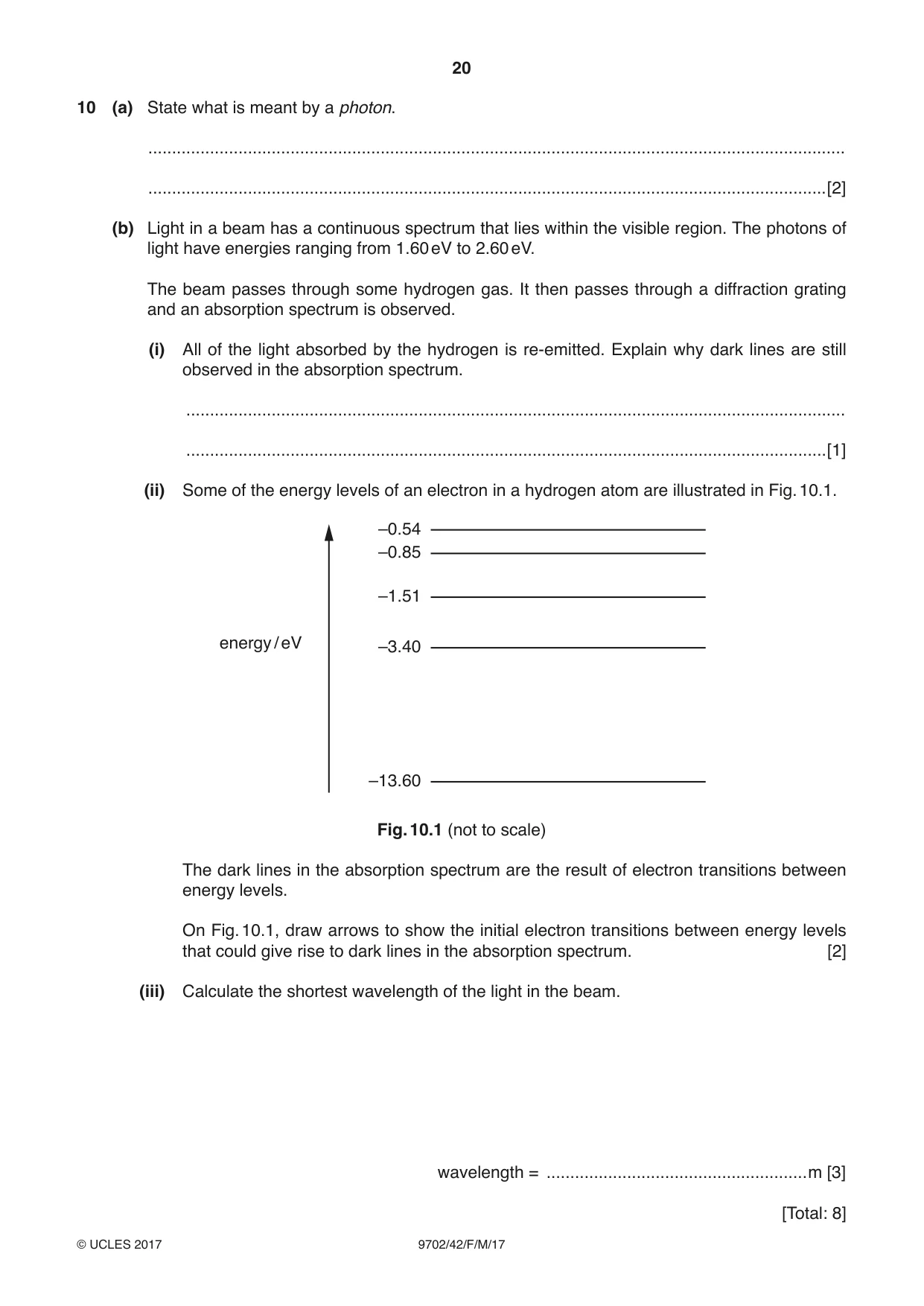
10 (a) State what is meant by a photon. ................................................................................................................................................... ...............................................................................................................................................[2] (b) Light in a beam has a continuous spectrum that lies within the visible region. The photons of light have energies ranging from 1.60 eV to 2.60 eV. The beam passes through some hydrogen gas. It then passes through a diffraction grating and an absorption spectrum is observed. (i) All of the light absorbed by the hydrogen is re-emitted. Explain why dark lines are still observed in the absorption spectrum. ........................................................................................................................................... .......................................................................................................................................[1] (ii) Some of the energy levels of an electron in a hydrogen atom are illustrated in Fig. 10.1. –0.54 –0.85 –1.51 energy / eV –3.40 –13.60 Fig. 10.1 (not to scale) The dark lines in the absorption spectrum are the result of electron transitions between energy levels. On Fig. 10.1, draw arrows to show the initial electron transitions between energy levels that could give rise to dark lines in the absorption spectrum. [2] (iii) Calculate the shortest wavelength of the light in the beam. wavelength = .......................................................m [3] [Total: 8]
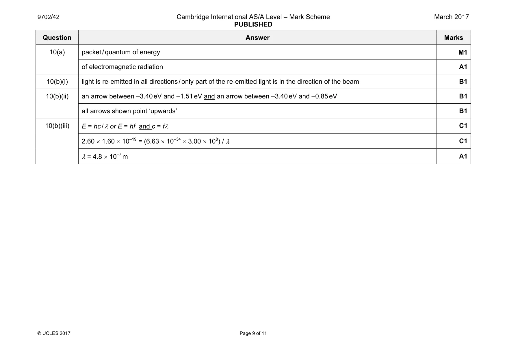
Mark scheme: 10(a) packet / quantum of energy M1 of electromagnetic radiation A1 10(b)(i) light is re-emitted in all directions / only part of the re-emitted light is in the direction of the beam B1 10(b)(ii) an arrow between –3.40 eV and –1.51 eV and an arrow between –3.40 eV and –0.85 eV B1 all arrows shown point ‘upwards’ B1 10(b)(iii) E = hc / λ or E = hf and c = fλ C1 2.60 × 1.60 × 10–19 = (6.63 × 10–34 × 3.00 × 108) / λ C1 λ = 4.8 × 10⁻⁷ m A1
Q11 · Use band theory to explain why, unlike a copper wire, the resistance of an intrinsic…
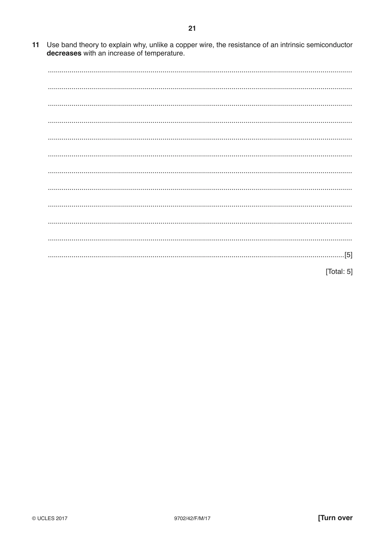
11 Use band theory to explain why, unlike a copper wire, the resistance of an intrinsic semiconductor decreases with an increase of temperature. .......................................................................................................................................................... .......................................................................................................................................................... .......................................................................................................................................................... .......................................................................................................................................................... .......................................................................................................................................................... .......................................................................................................................................................... .......................................................................................................................................................... .......................................................................................................................................................... .......................................................................................................................................................... .......................................................................................................................................................... .......................................................................................................................................................... ......................................................................................................................................................[5] [Total: 5]
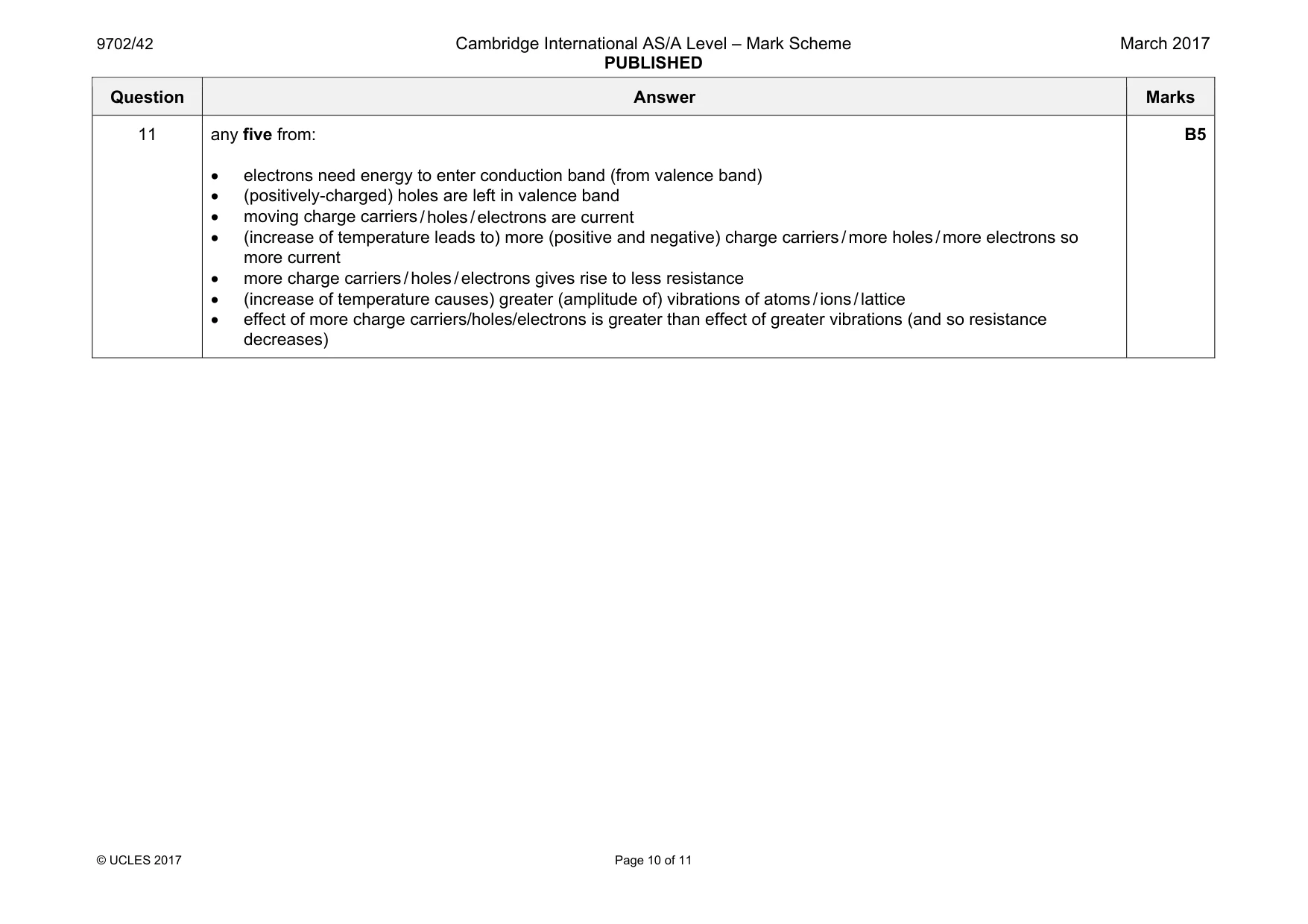
Mark scheme: 11 any five from: • electrons need energy to enter conduction band (from valence band) • (positively-charged) holes are left in valence band • moving charge carriers / holes / electrons are current • (increase of temperature leads to) more (positive and negative) charge carriers / more holes / more electrons so more current • more charge carriers / holes / electrons gives rise to less resistance • (increase of temperature causes) greater (amplitude of) vibrations of atoms / ions / lattice • effect of more charge carriers/holes/electrons is greater than effect of greater vibrations (and so resistance decreases) B5
Q12 · Define the binding energy of a nucleus
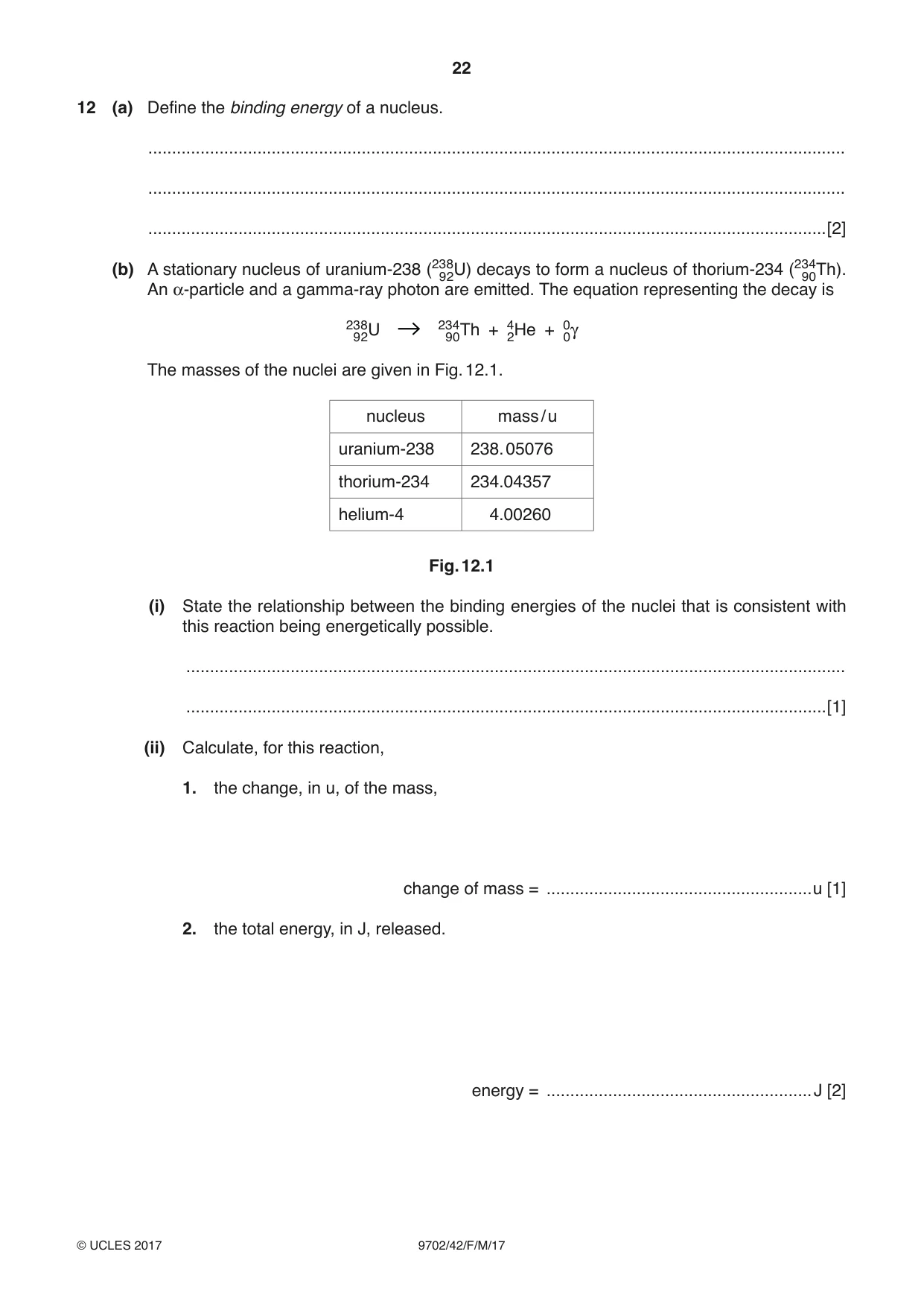
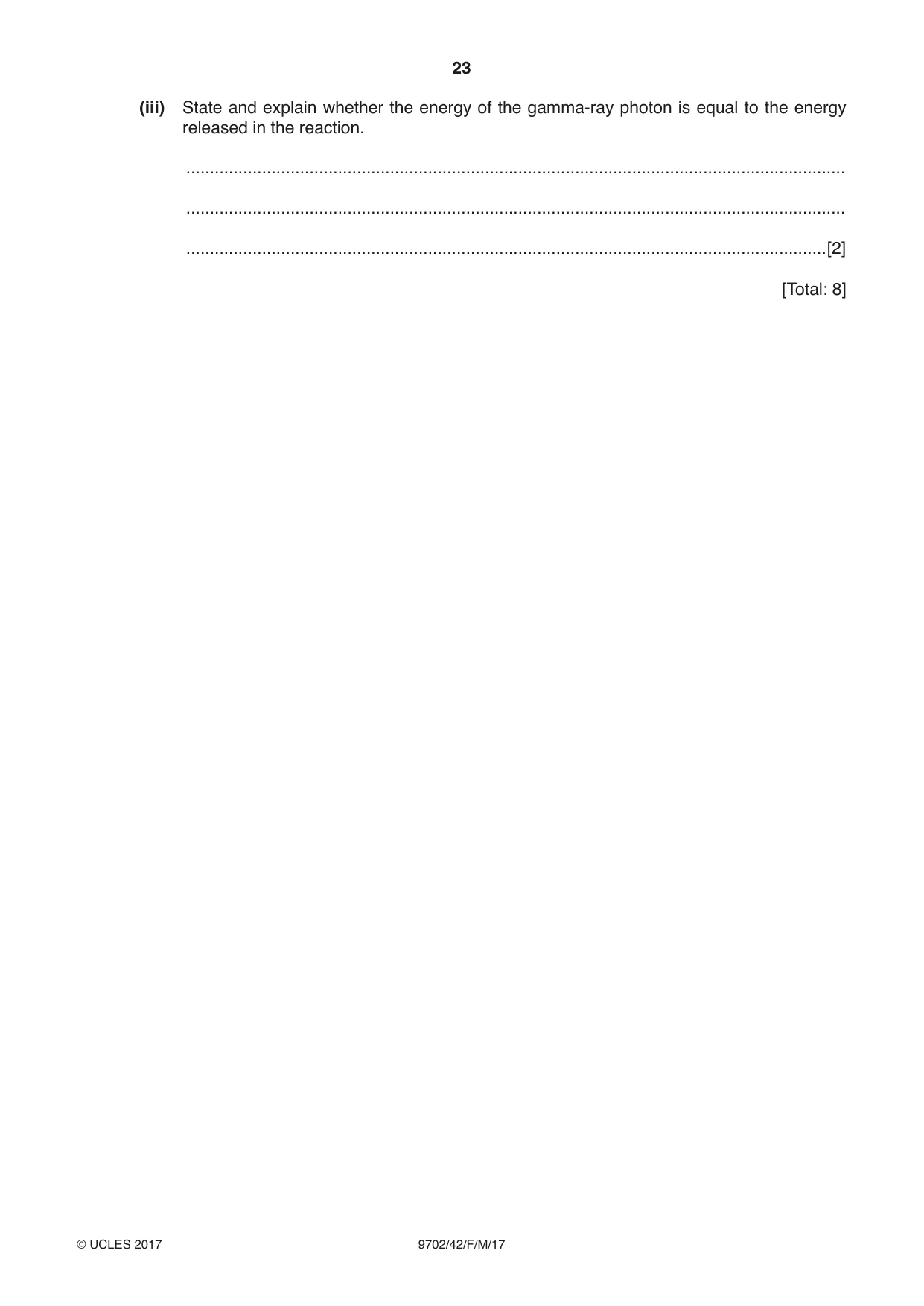
12 (a) Define the binding energy of a nucleus. ................................................................................................................................................... ................................................................................................................................................... ...............................................................................................................................................[2] (b) A stationary nucleus of uranium-238 (23982U) decays to form a nucleus of thorium-234 (239 40Th). An α-particle and a gamma-ray photon are emitted. The equation representing the decay is 23 9 82U 23940Th + 42He + 00γ The masses of the nuclei are given in Fig. 12.1. nucleus mass / u uranium-238 238. 05076 thorium-234 234.04357 helium-4 4.00260 Fig. 12.1 (i) State the relationship between the binding energies of the nuclei that is consistent with this reaction being energetically possible. ........................................................................................................................................... .......................................................................................................................................[1] (ii) Calculate, for this reaction, 1. the change, in u, of the mass, change of mass = ........................................................u [1] 2. the total energy, in J, released. energy = ........................................................J [2] (iii) State and explain whether the energy of the gamma-ray photon is equal to the energy released in the reaction. ........................................................................................................................................... ........................................................................................................................................... .......................................................................................................................................[2] [Total: 8]
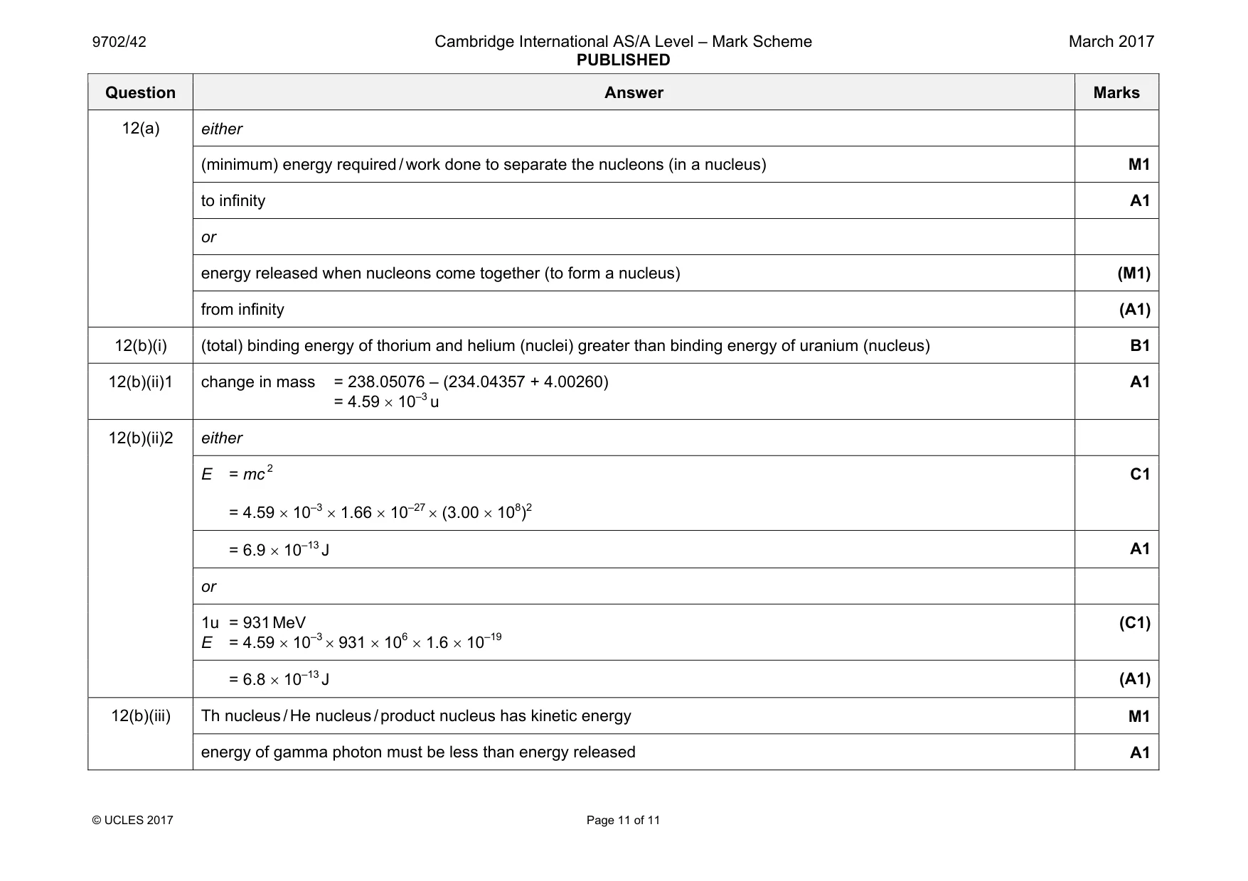
Mark scheme: 12(a) either (minimum) energy required / work done to separate the nucleons (in a nucleus) M1 to infinity A1 or energy released when nucleons come together (to form a nucleus) (M1) from infinity (A1) 12(b)(i) (total) binding energy of thorium and helium (nuclei) greater than binding energy of uranium (nucleus) B1 12(b)(ii)1 change in mass = 238.05076 – (234.04357 + 4.00260) = 4.59 × 10⁻³ u A1 12(b)(ii)2 either E = mc 2 = 4.59 × 10–3 × 1.66 × 10–27 × (3.00 × 108)2 C1 = 6.9 × 10⁻¹³ J A1 or 1u = 931 MeV E = 4.59 × 10–3 × 931 × 106 × 1.6 × 10–19 (C1) = 6.8 × 10⁻¹³ J (A1) 12(b)(iii) Th nucleus / He nucleus / product nucleus has kinetic energy M1 energy of gamma photon must be less than energy released A1
What was in this paper
The subtopics covered by these 12 questions, and how many questions each got. Open one in a new tab to see every Cambridge question on it.
1Electromagnetic induction1Energy in simple harmonic motion1Energy levels in atoms and line spectra1Force on a moving charge1Gravitational potential1Mass defect and nuclear binding energy1Potential dividers1Production and use of ultrasound1Progressive waves1Resistance and resistivity1The first law of thermodynamics1What you needed in this session
Cambridge’s own grade thresholds for 2017 Feb/March, Paper 4 · Variant 2. A higher threshold means an easier paper — the bar moves with how the cohort did.