Cambridge A Level Physics 9702 — 2021 Oct/Nov Paper 4 · Variant 2
9702/42/O/N/21 · 12 questions · 100 marks · ≈113 min
The question paper and its mark scheme, free to read here and free to download. This is Cambridge’s own paper, exactly as it was sat.
Question paper24 pages



Mark scheme19 pages
Answers below. Sit the paper first if you are practising.


Questions as text
Q1 · State what is meant by centripetal acceleration
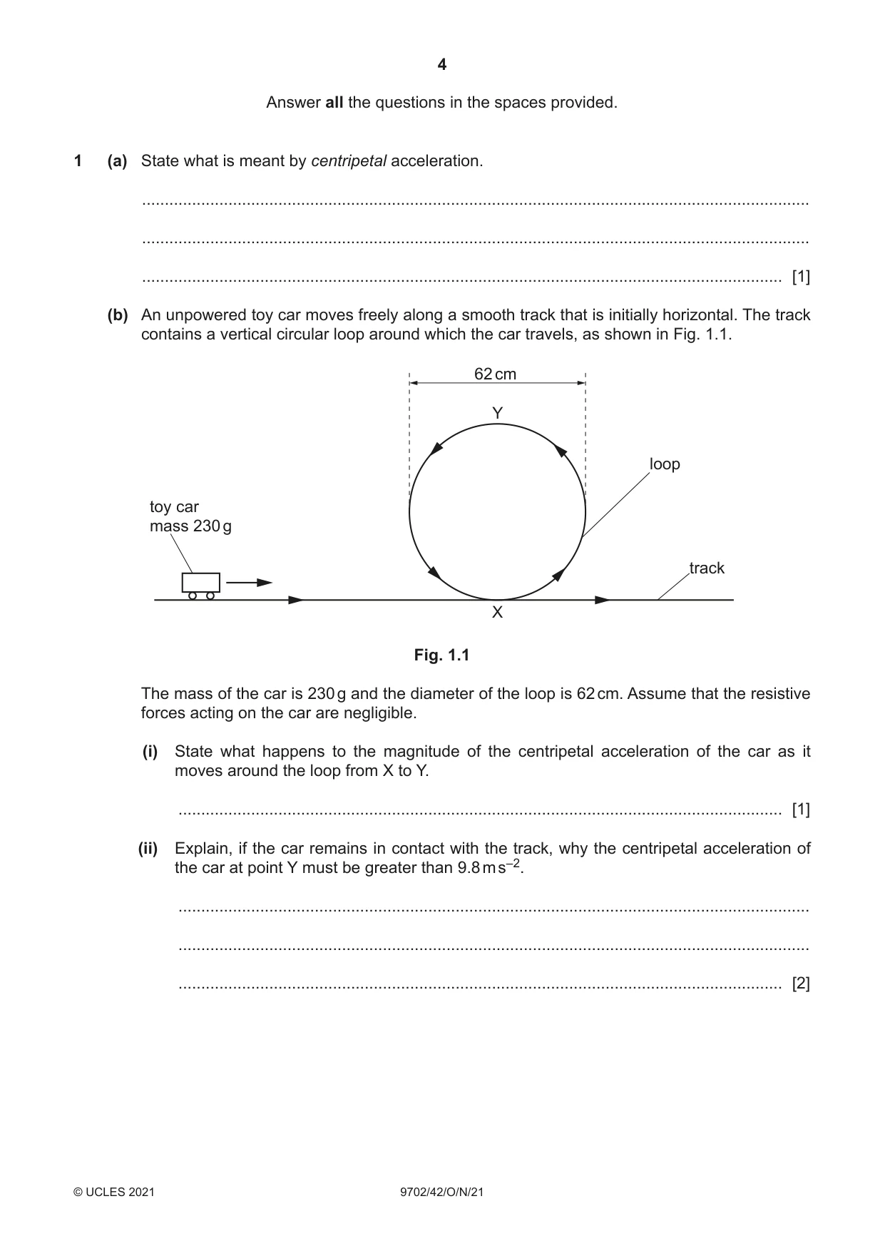
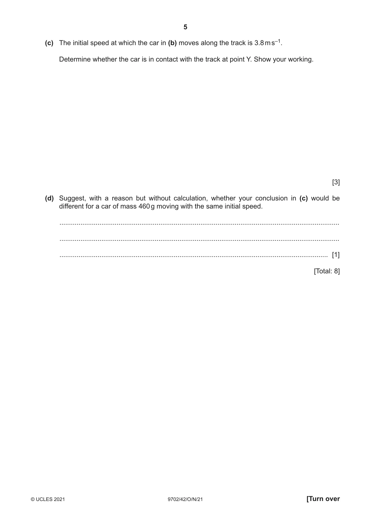
1 (a) State what is meant by centripetal acceleration. ................................................................................................................................................... ................................................................................................................................................... ............................................................................................................................................. [1] (b) An unpowered toy car moves freely along a smooth track that is initially horizontal. The track contains a vertical circular loop around which the car travels, as shown in Fig. 1.1. 62 cm Y loop toy car mass 230 g track X Fig. 1.1 The mass of the car is 230 g and the diameter of the loop is 62 cm. Assume that the resistive forces acting on the car are negligible. (i) State what happens to the magnitude of the centripetal acceleration of the car as it moves around the loop from X to Y. ..................................................................................................................................... [1] (ii) Explain, if the car remains in contact with the track, why the centripetal acceleration of the car at point Y must be greater than 9.8 m s–2. ........................................................................................................................................... ........................................................................................................................................... ..................................................................................................................................... [2] (c) The initial speed at which the car in (b) moves along the track is 3.8 m s–1. Determine whether the car is in contact with the track at point Y. Show your working. [3] (d) Suggest, with a reason but without calculation, whether your conclusion in (c) would be different for a car of mass 460 g moving with the same initial speed. ................................................................................................................................................... ................................................................................................................................................... ............................................................................................................................................. [1] [Total: 8]
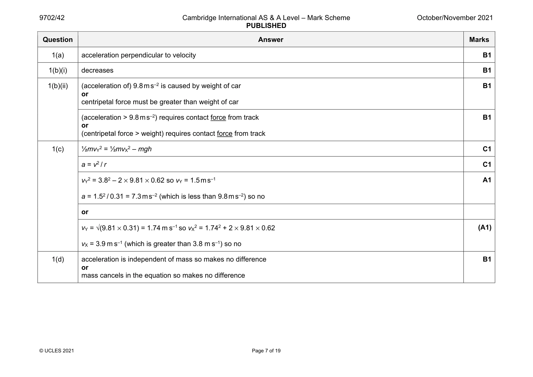
Mark scheme: 1(a) acceleration perpendicular to velocity B1 1(b)(i) decreases B1 1(b)(ii) (acceleration of) 9.8 m s–2 is caused by weight of car or centripetal force must be greater than weight of car B1 (acceleration > 9.8 m s–2) requires contact force from track or (centripetal force > weight) requires contact force from track B1 1(c) ½mvY2 = ½mvX2 – mgh C1 a = v2 / r C1 vY2 = 3.82 – 2 × 9.81 × 0.62 so vY = 1.5 m s–1 a = 1.52 / 0.31 = 7.3 m s–2 (which is less than 9.8 m s–2) so no A1 or vY = √(9.81 × 0.31) = 1.74 m s–1 so vX2 = 1.742 + 2 × 9.81 × 0.62 vX = 3.9 m s–1 (which is greater than 3.8 m s–1) so no (A1) 1(d) acceleration is independent of mass so makes no difference or mass cancels in the equation so makes no difference B1
Q2 · State the relationship between gravitational potential and gravitational field strength
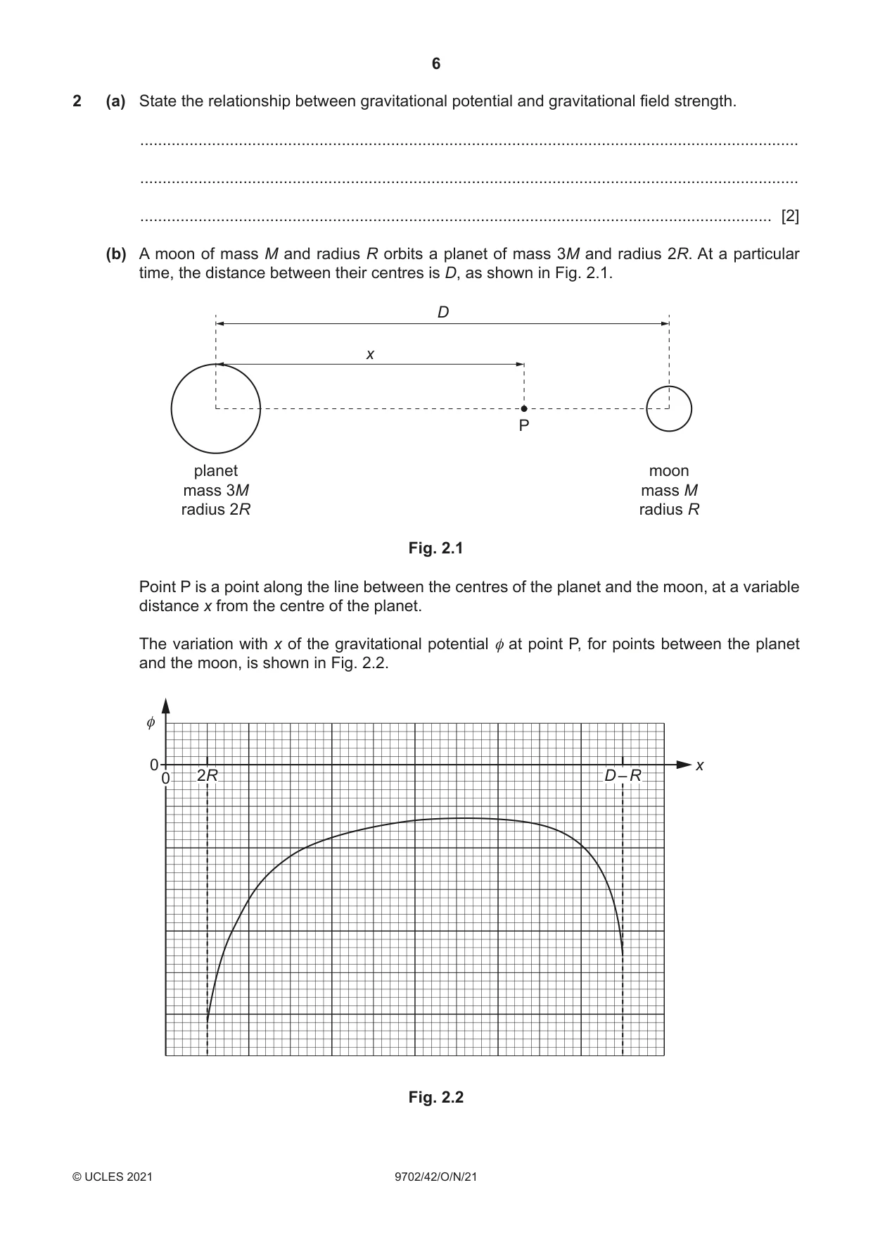
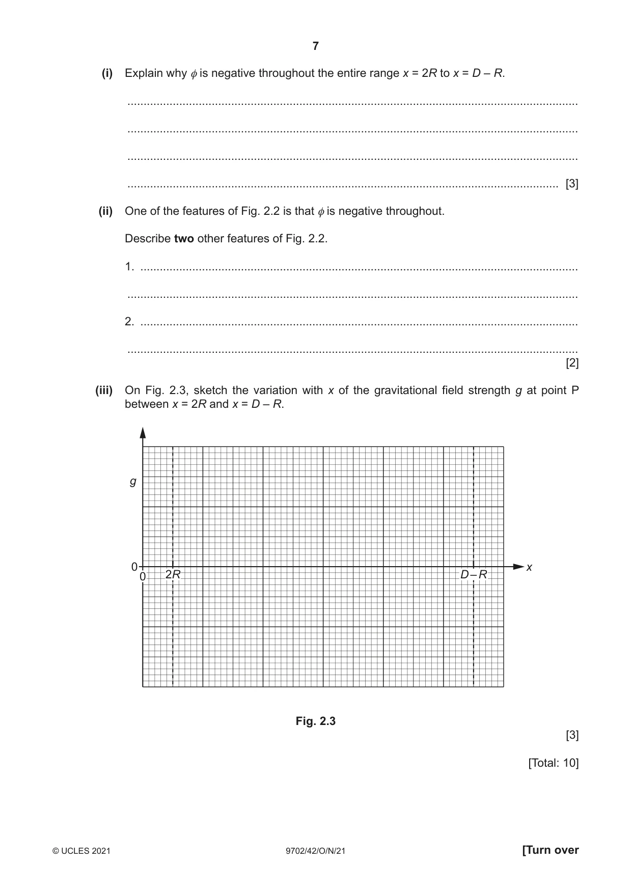
2 (a) State the relationship between gravitational potential and gravitational field strength. ................................................................................................................................................... ................................................................................................................................................... ............................................................................................................................................. [2] (b) A moon of mass M and radius R orbits a planet of mass 3M and radius 2R. At a particular time, the distance between their centres is D, as shown in Fig. 2.1. D x P planet moon mass 3M mass M radius 2R radius R Fig. 2.1 Point P is a point along the line between the centres of the planet and the moon, at a variable distance x from the centre of the planet. The variation with x of the gravitational potential φ at point P, for points between the planet and the moon, is shown in Fig. 2.2. φ 0 x 0 2R D – R Fig. 2.2 (i) Explain why φ is negative throughout the entire range x = 2R to x = D – R. ........................................................................................................................................... ........................................................................................................................................... ........................................................................................................................................... ..................................................................................................................................... [3] (ii) One of the features of Fig. 2.2 is that φ is negative throughout. Describe two other features of Fig. 2.2. 1. ....................................................................................................................................... ........................................................................................................................................... 2. ....................................................................................................................................... ........................................................................................................................................... [2] (iii) On Fig. 2.3, sketch the variation with x of the gravitational field strength g at point P between x = 2R and x = D – R. g 0 x 0 2R D – R Fig. 2.3 [3] [Total: 10]
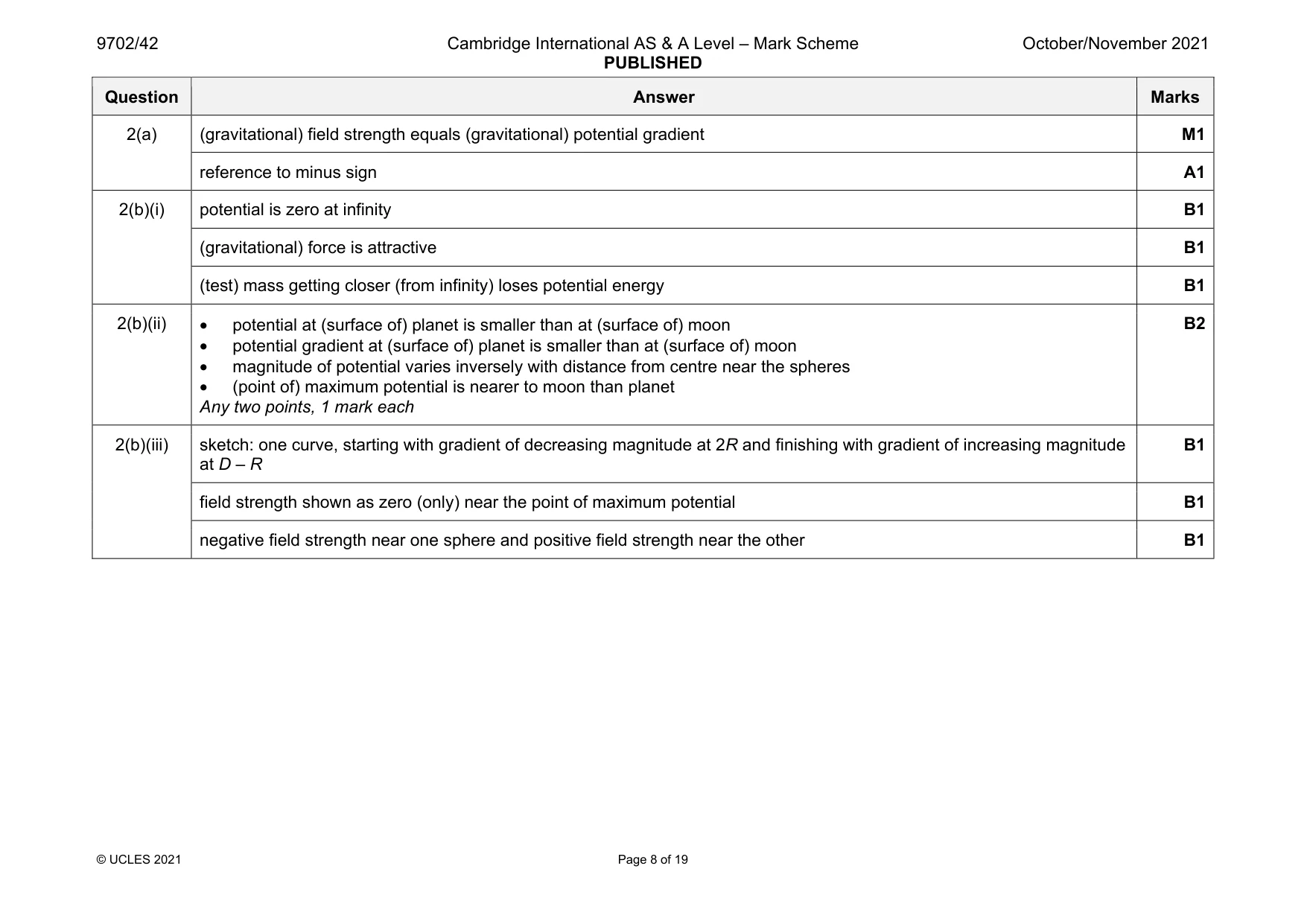
Mark scheme: 2(a) (gravitational) field strength equals (gravitational) potential gradient M1 reference to minus sign A1 2(b)(i) potential is zero at infinity B1 (gravitational) force is attractive B1 (test) mass getting closer (from infinity) loses potential energy B1 2(b)(ii) • potential at (surface of) planet is smaller than at (surface of) moon • potential gradient at (surface of) planet is smaller than at (surface of) moon • magnitude of potential varies inversely with distance from centre near the spheres • (point of) maximum potential is nearer to moon than planet Any two points, 1 mark each B2 2(b)(iii) sketch: one curve, starting with gradient of decreasing magnitude at 2R and finishing with gradient of increasing magnitude at D – R B1 field strength shown as zero (only) near the point of maximum potential B1 negative field strength near one sphere and positive field strength near the other B1
Q3 · One of the assumptions of the kinetic theory of gases is that all collisions involving…
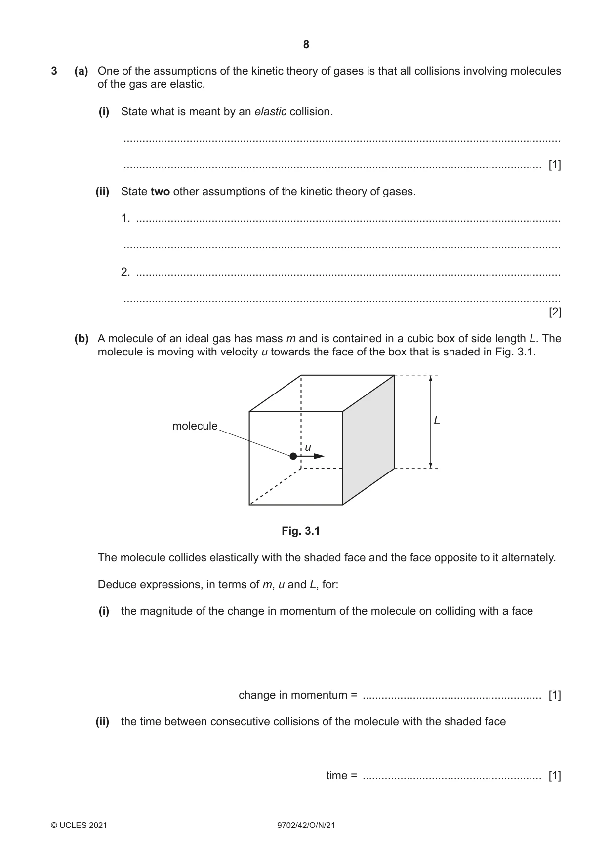
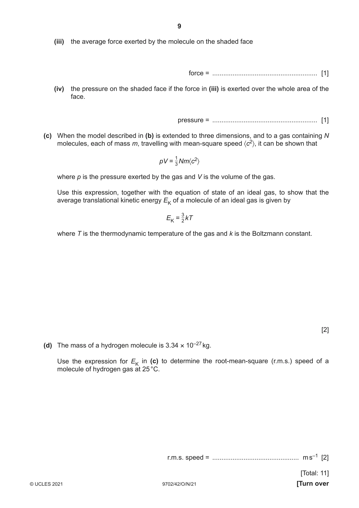
3 (a) One of the assumptions of the kinetic theory of gases is that all collisions involving molecules of the gas are elastic. (i) State what is meant by an elastic collision. ........................................................................................................................................... ..................................................................................................................................... [1] (ii) State two other assumptions of the kinetic theory of gases. 1. ....................................................................................................................................... ........................................................................................................................................... 2. ....................................................................................................................................... ........................................................................................................................................... [2] (b) A molecule of an ideal gas has mass m and is contained in a cubic box of side length L. The molecule is moving with velocity u towards the face of the box that is shaded in Fig. 3.1. L molecule u Fig. 3.1 The molecule collides elastically with the shaded face and the face opposite to it alternately. Deduce expressions, in terms of m, u and L, for: (i) the magnitude of the change in momentum of the molecule on colliding with a face change in momentum = ......................................................... [1] (ii) the time between consecutive collisions of the molecule with the shaded face time = ......................................................... [1] (iii) the average force exerted by the molecule on the shaded face force = ......................................................... [1] (iv) the pressure on the shaded face if the force in (iii) is exerted over the whole area of the face. pressure = ......................................................... [1] (c) When the model described in (b) is extended to three dimensions, and to a gas containing N molecules, each of mass m, travelling with mean-square speed 〈c2〉, it can be shown that 1 pV = 3 Nm〈c2〉 where p is the pressure exerted by the gas and V is the volume of the gas. Use this expression, together with the equation of state of an ideal gas, to show that the average translational kinetic energy EK of a molecule of an ideal gas is given by 3 EK = 2 kT where T is the thermodynamic temperature of the gas and k is the Boltzmann constant. [2] (d) The mass of a hydrogen molecule is 3.34 × 10⁻²⁷ kg. Use the expression for EK in (c) to determine the root-mean-square (r.m.s.) speed of a molecule of hydrogen gas at 25 °C. r.m.s. speed = ............................................... m s–1 [2] [Total: 11]
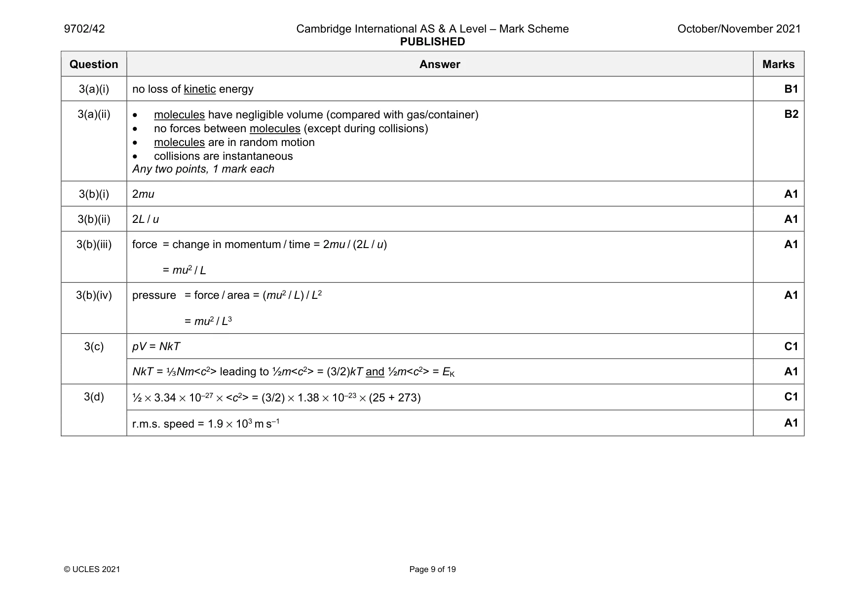
Mark scheme: 3(a)(i) no loss of kinetic energy B1 3(a)(ii) • molecules have negligible volume (compared with gas/container) • no forces between molecules (except during collisions) • molecules are in random motion • collisions are instantaneous Any two points, 1 mark each B2 3(b)(i) 2mu A1 3(b)(ii) 2L / u A1 3(b)(iii) force = change in momentum / time = 2mu / (2L / u) = mu2 / L A1 3(b)(iv) pressure = force / area = (mu2 / L) / L2 = mu2 / L3 A1 3(c) pV = NkT C1 NkT = ⅓Nm<c2> leading to ½m<c2> = (3/2)kT and ½m<c2> = EK A1 3(d) ½ × 3.34 × 10⁻²⁷ × <c2> = (3/2) × 1.38 × 10–23 × (25 + 273) C1 r.m.s. speed = 1.9 × 10³ m s–1 A1
Q4 · A trolley on a smooth surface is attached by springs to fixed blocks as shown in Fig
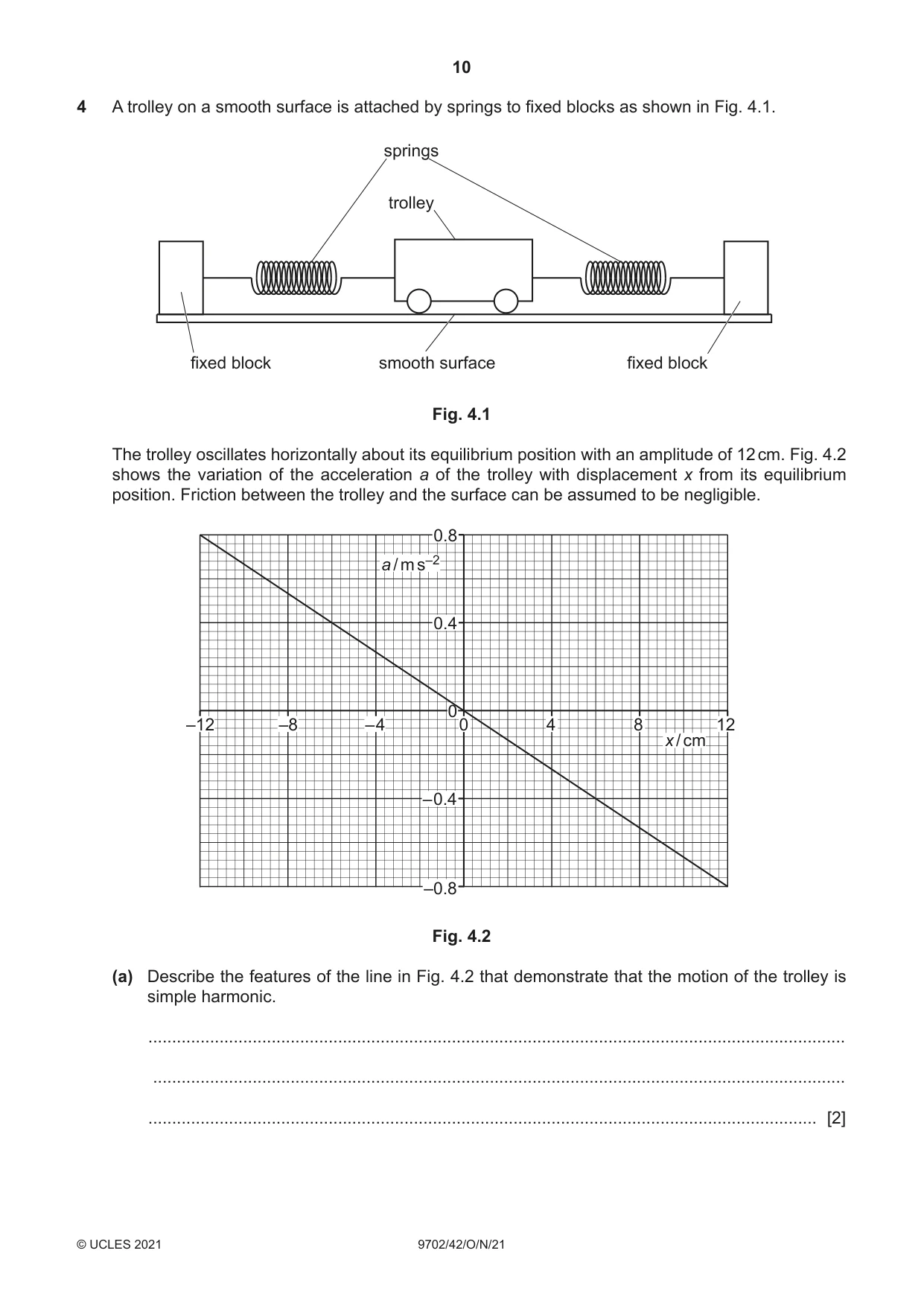
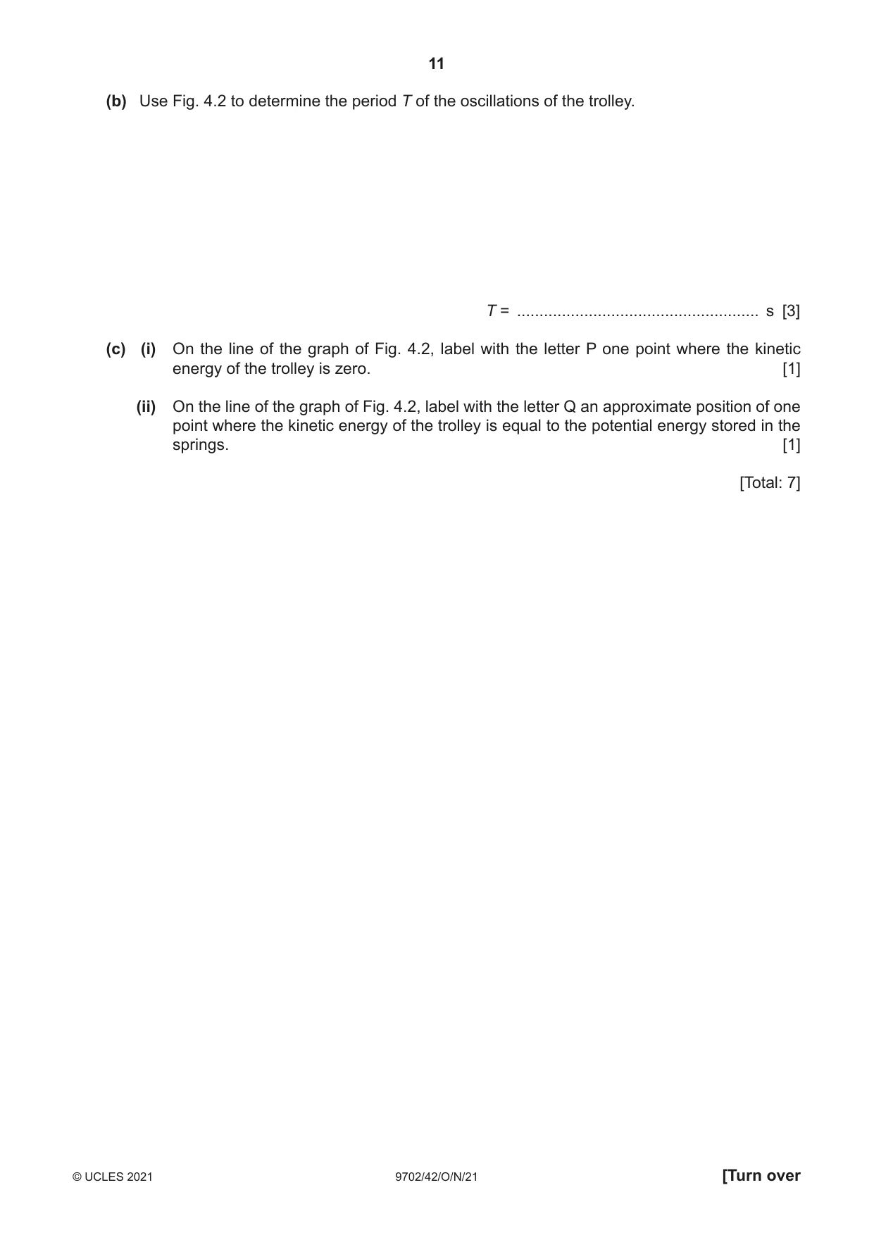
4 A trolley on a smooth surface is attached by springs to fixed blocks as shown in Fig. 4.1. springs trolley fixed block smooth surface fixed block Fig. 4.1 The trolley oscillates horizontally about its equilibrium position with an amplitude of 12 cm. Fig. 4.2 shows the variation of the acceleration a of the trolley with displacement x from its equilibrium position. Friction between the trolley and the surface can be assumed to be negligible. 0.8 a / m s–2 0.4 0 –12 –8 – 4 0 4 8 12 x / cm – 0.4 –0.8 Fig. 4.2 (a) Describe the features of the line in Fig. 4.2 that demonstrate that the motion of the trolley is simple harmonic. ................................................................................................................................................... .................................................................................................................................................. ............................................................................................................................................. [2] (b) Use Fig. 4.2 to determine the period T of the oscillations of the trolley. T = ...................................................... s [3] (c) (i) On the line of the graph of Fig. 4.2, label with the letter P one point where the kinetic energy of the trolley is zero. [1] (ii) On the line of the graph of Fig. 4.2, label with the letter Q an approximate position of one point where the kinetic energy of the trolley is equal to the potential energy stored in the springs. [1] [Total: 7]
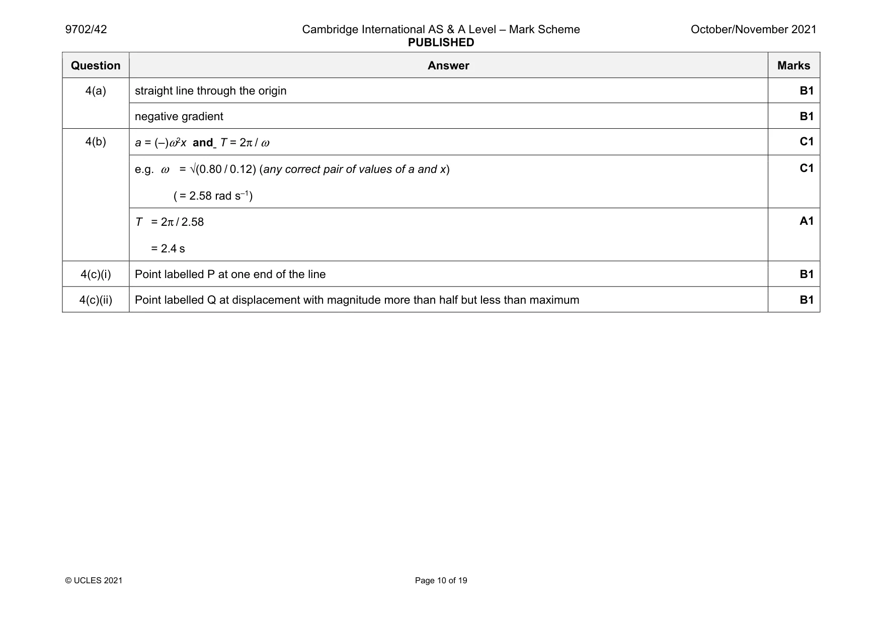
Mark scheme: 4(a) straight line through the origin B1 negative gradient B1 4(b) a = (–)ω2x and T = 2π / ω C1 e.g. ω = √(0.80 / 0.12) (any correct pair of values of a and x) ( = 2.58 rad s–1) C1 T = 2π / 2.58 = 2.4 s A1 4(c)(i) Point labelled P at one end of the line B1 4(c)(ii) Point labelled Q at displacement with magnitude more than half but less than maximum B1
Q5 · When audio signals are transmitted over long distances, modulation of radio waves is used
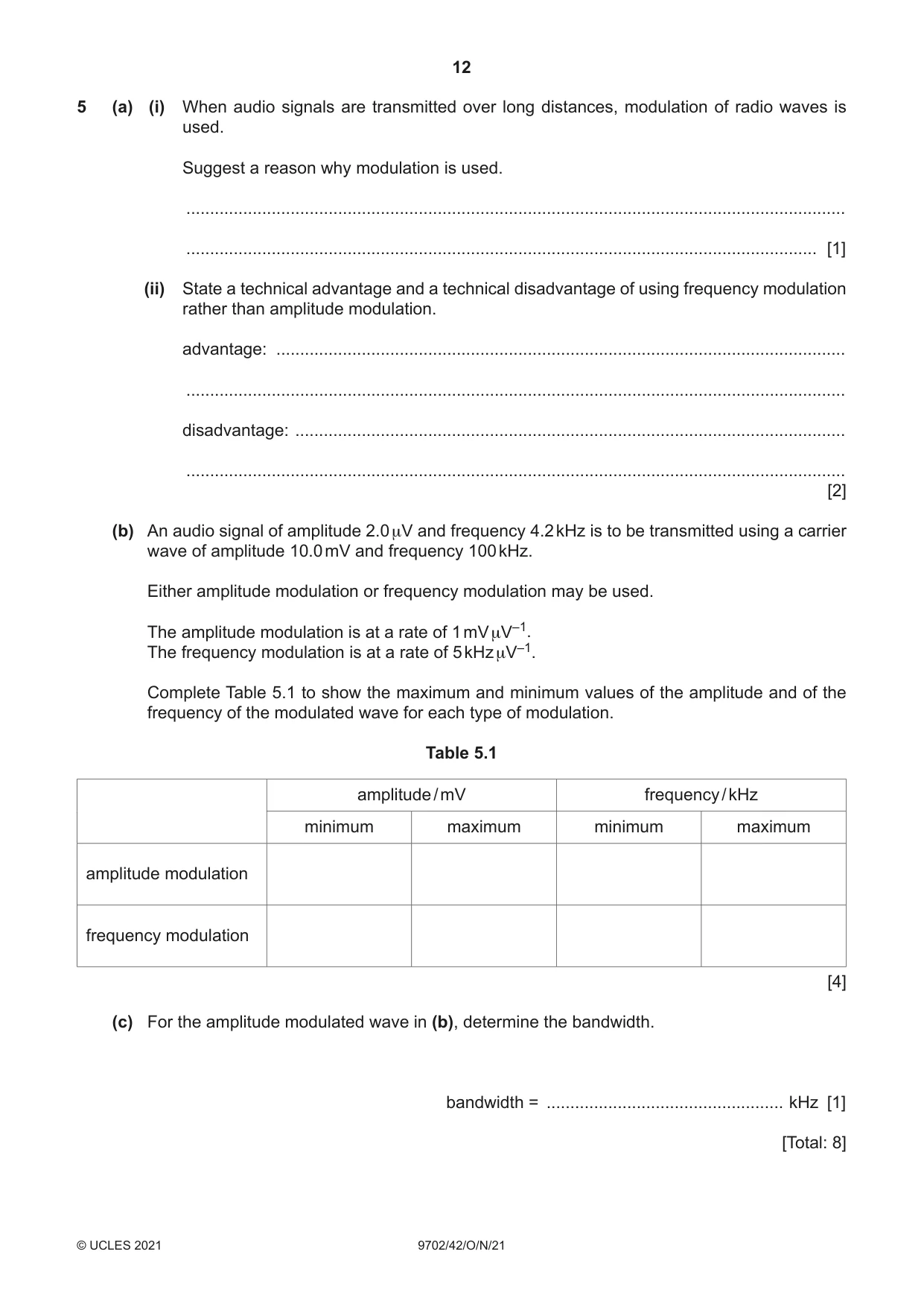
5 (a) (i) When audio signals are transmitted over long distances, modulation of radio waves is used. Suggest a reason why modulation is used. ........................................................................................................................................... ..................................................................................................................................... [1] (ii) State a technical advantage and a technical disadvantage of using frequency modulation rather than amplitude modulation. advantage: ........................................................................................................................ ........................................................................................................................................... disadvantage: .................................................................................................................... ........................................................................................................................................... [2] (b) An audio signal of amplitude 2.0 μV and frequency 4.2 kHz is to be transmitted using a carrier wave of amplitude 10.0 mV and frequency 100 kHz. Either amplitude modulation or frequency modulation may be used. The amplitude modulation is at a rate of 1 mV μV–1. The frequency modulation is at a rate of 5 kHz μV–1. Complete Table 5.1 to show the maximum and minimum values of the amplitude and of the frequency of the modulated wave for each type of modulation. Table 5.1 amplitude / mV frequency / kHz minimum maximum minimum maximum amplitude modulation frequency modulation [4] (c) For the amplitude modulated wave in (b), determine the bandwidth. bandwidth = .................................................. kHz [1] [Total: 8]
Mark scheme: 5(a)(i) unmodulated (radio) waves would interfere with each other or not modulating would require aerials too long (to be practical) B1 5(a)(ii) advantage: • can transmit higher frequencies • higher quality reproduction • less prone to interference • same frequency can be used in different areas (any one point) B1 disadvantage: • takes up greater bandwidth • shorter range of transmission • requires a greater number of transmitting aerials (any one point) B1 5(b) AM amplitude: min. 8 mV and max. 12 mV B1 AM frequency: min. 100 kHz and max. 100 kHz B1 FM amplitude: min. 10 mV and max. 10 mV B1 FM frequency: min. 90 kHz and max. 110 kHz B1 5(c) 8.4 kHz A1
Question 6
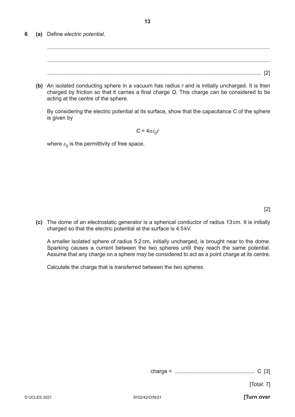
6 (a) Define electric potential. ................................................................................................................................................... ................................................................................................................................................... ............................................................................................................................................. [2] (b) An isolated conducting sphere in a vacuum has radius r and is initially uncharged. It is then charged by friction so that it carries a final charge Q. This charge can be considered to be acting at the centre of the sphere. By considering the electric potential at its surface, show that the capacitance C of the sphere is given by C = 4πε0r where ε0 is the permittivity of free space. [2] (c) The dome of an electrostatic generator is a spherical conductor of radius 13 cm. It is initially charged so that the electric potential at the surface is 4.5 kV. A smaller isolated sphere of radius 5.2 cm, initially uncharged, is brought near to the dome. Sparking causes a current between the two spheres until they reach the same potential. Assume that any charge on a sphere may be considered to act as a point charge at its centre. Calculate the charge that is transferred between the two spheres. charge = ..................................................... C [3] [Total: 7]
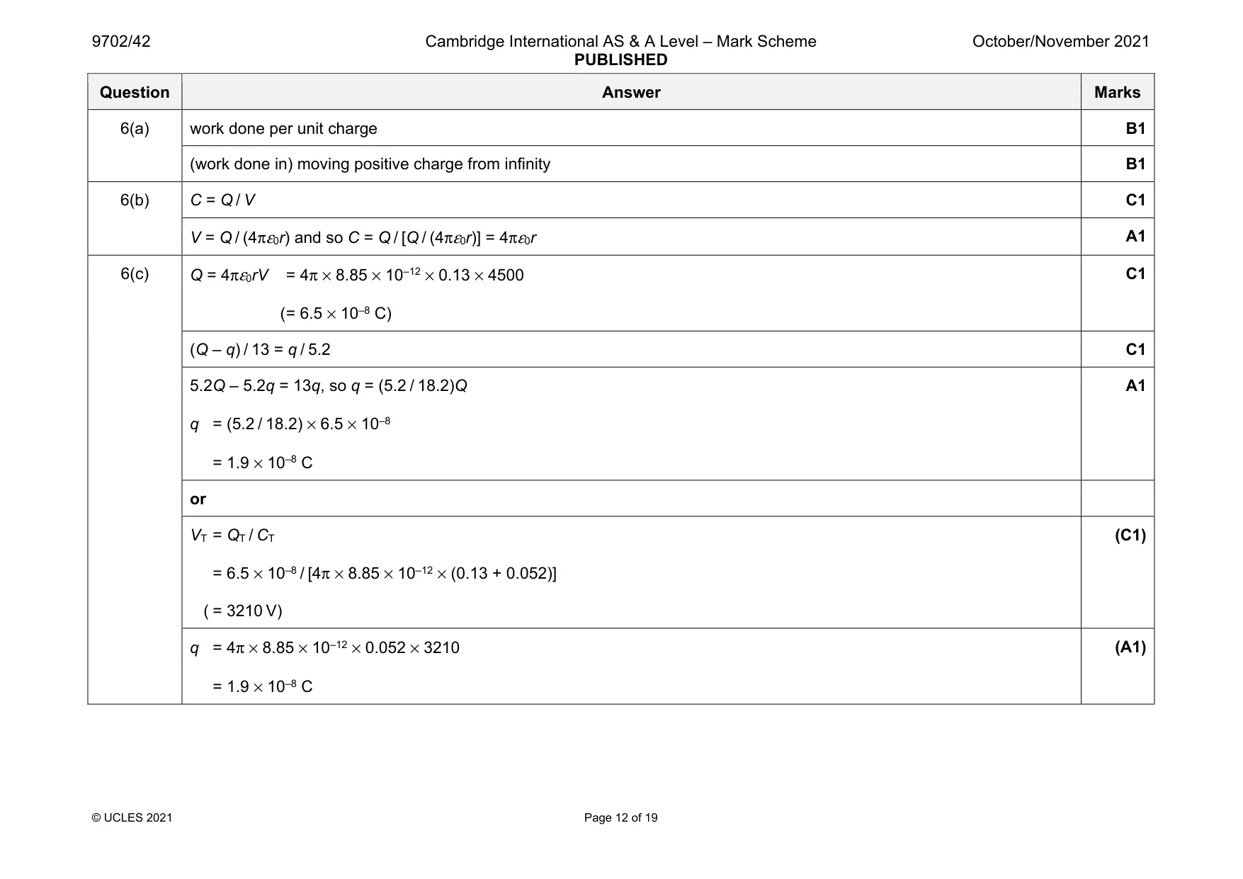
Mark scheme: 6(a) work done per unit charge B1 (work done in) moving positive charge from infinity B1 6(b) C = Q / V C1 V = Q / (4πε0r) and so C = Q / [Q / (4πε0r)] = 4πε0r A1 6(c) Q = 4πε0rV = 4π × 8.85 × 10–12 × 0.13 × 4500 ( = 6.5 × 10⁻⁸ C) C1 (Q – q) / 13 = q / 5.2 C1 5.2Q – 5.2q = 13q, so q = (5.2 / 18.2)Q q = (5.2 / 18.2) × 6.5 × 10–8 = 1.9 × 10⁻⁸ C A1 or VT = QT / CT = 6.5 × 10⁻⁸ / [4π × 8.85 × 10–12 × (0.13 + 0.052)] ( = 3210 V) (C1) q = 4π × 8.85 × 10–12 × 0.052 × 3210 = 1.9 × 10⁻⁸ C (A1)
Q7 · An operational amplifier (op-amp) has two input terminals and one output terminal
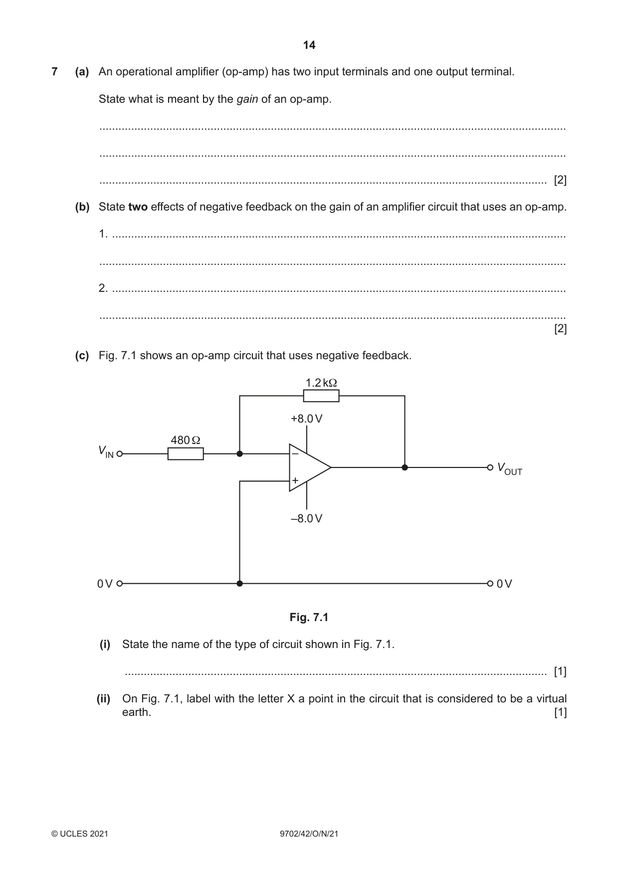
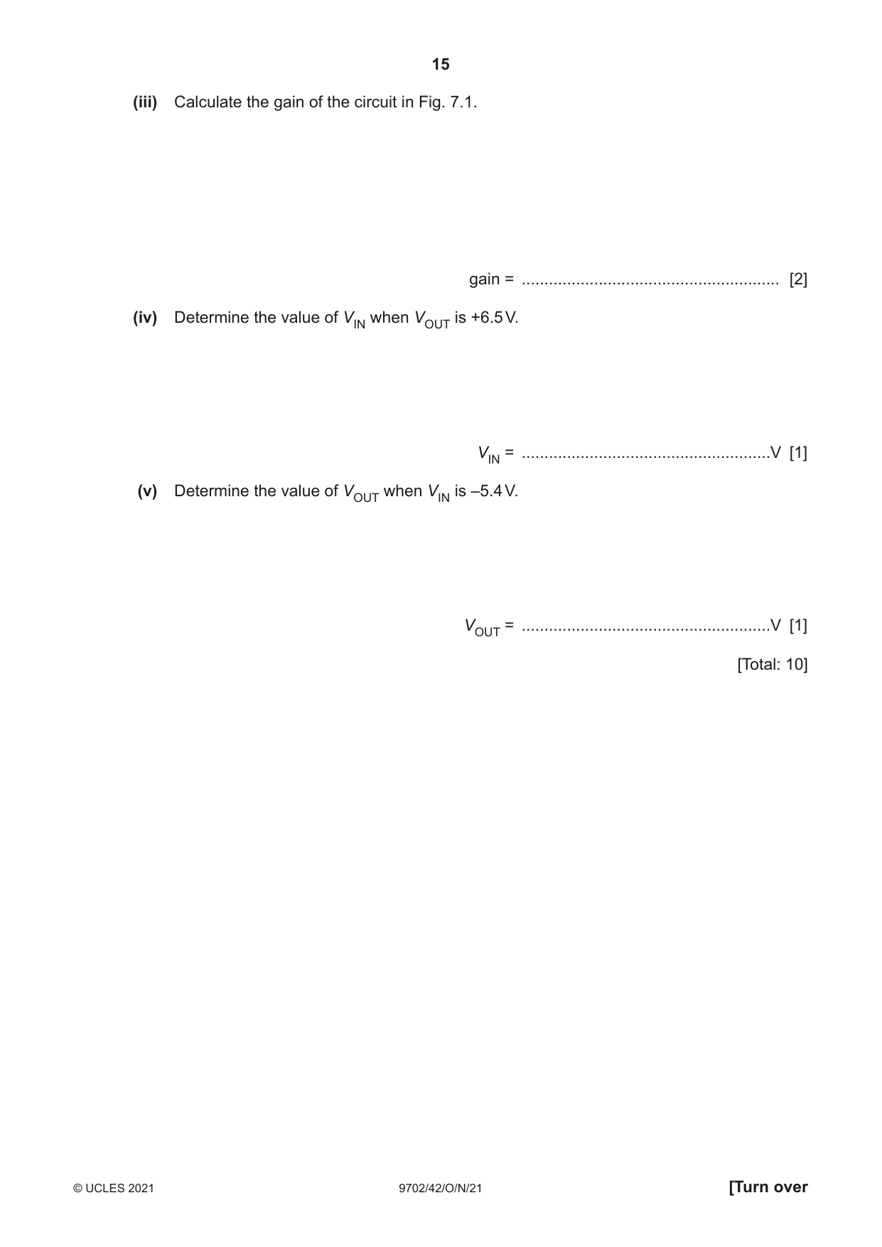
7 (a) An operational amplifier (op-amp) has two input terminals and one output terminal. State what is meant by the gain of an op-amp. ................................................................................................................................................... ................................................................................................................................................... ............................................................................................................................................. [2] (b) State two effects of negative feedback on the gain of an amplifier circuit that uses an op-amp. 1. ............................................................................................................................................... ................................................................................................................................................... 2. ............................................................................................................................................... ................................................................................................................................................... [2] (c) Fig. 7.1 shows an op-amp circuit that uses negative feedback. 1.2 kΩ +8.0 V 480 Ω VIN – VOUT + –8.0 V 0 V 0 V Fig. 7.1 (i) State the name of the type of circuit shown in Fig. 7.1. ..................................................................................................................................... [1] (ii) On Fig. 7.1, label with the letter X a point in the circuit that is considered to be a virtual earth. [1] (iii) Calculate the gain of the circuit in Fig. 7.1. gain = ......................................................... [2] (iv) Determine the value of VIN when VOUT is +6.5 V. VIN = .......................................................V [1] (v) Determine the value of VOUT when VIN is –5.4 V. VOUT = .......................................................V [1] [Total: 10]
Mark scheme: 7(a) output voltage / input voltage M1 input (voltage) is difference between (inverting and non-inverting) inputs A1 7(b) • reduces the gain • greater bandwidth • more stable Any two points, 1 mark each B2 7(c)(i) inverting amplifier B1 7(c)(ii) X marked anywhere between right-hand edge of 480 Ω resistor, left-hand edge of 1.2 kΩ resistor and the inverting input B1 7(c)(iii) gain = (–)Rf / Ri C1 = (–)1200 / 480 = –2.5 A1 7(c)(iv) VIN = 6.5 / (–2.5) = –2.6 V A1 7(c)(v) (–2.5) × (–5.4) = +13.5 V, and so output saturates VOUT = (+)8.0 V A1
Q8 · Two long straight parallel wires P and Q carry currents into the plane of the paper, as…
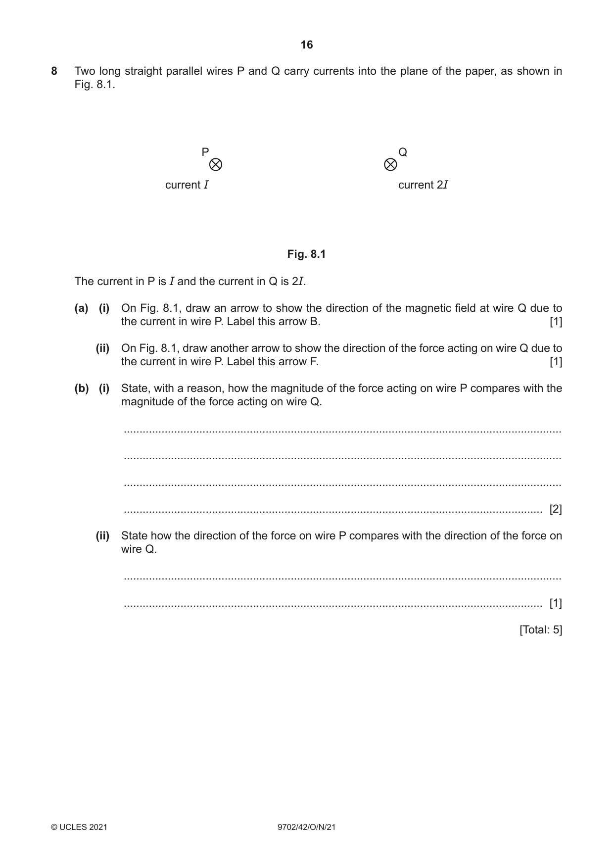
8 Two long straight parallel wires P and Q carry currents into the plane of the paper, as shown in Fig. 8.1. P Q current I current 2I Fig. 8.1 The current in P is I and the current in Q is 2I. (a) (i) On Fig. 8.1, draw an arrow to show the direction of the magnetic field at wire Q due to the current in wire P. Label this arrow B. [1] (ii) On Fig. 8.1, draw another arrow to show the direction of the force acting on wire Q due to the current in wire P. Label this arrow F. [1] (b) (i) State, with a reason, how the magnitude of the force acting on wire P compares with the magnitude of the force acting on wire Q. ........................................................................................................................................... ........................................................................................................................................... ........................................................................................................................................... ..................................................................................................................................... [2] (ii) State how the direction of the force on wire P compares with the direction of the force on wire Q. ........................................................................................................................................... ..................................................................................................................................... [1] [Total: 5]
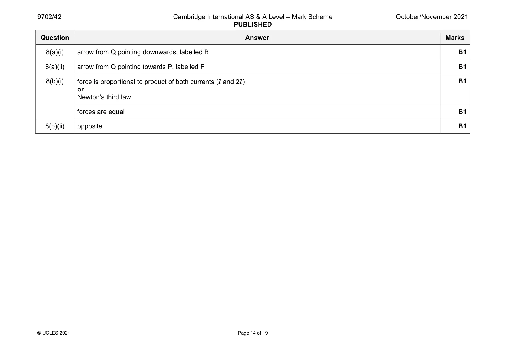
Mark scheme: 8(a)(i) arrow from Q pointing downwards, labelled B B1 8(a)(ii) arrow from Q pointing towards P, labelled F B1 8(b)(i) force is proportional to product of both currents (I and 2I) or Newton’s third law B1 forces are equal B1 8(b)(ii) opposite B1
Q9 · State what is meant by: (i) the photoelectric effect…
9 (a) State what is meant by: (i) the photoelectric effect ........................................................................................................................................... ........................................................................................................................................... ..................................................................................................................................... [2] (ii) work function energy. ........................................................................................................................................... ..................................................................................................................................... [1] (b) A polished calcium plate in a vacuum is investigated by illuminating the surface with light. It is found that no photoelectric current is produced when the frequency of the light is less than 6.93 × 10¹⁴ Hz. (i) State the name of the frequency below which no photoelectric current is produced. ..................................................................................................................................... [1] (ii) Explain how the photon model of electromagnetic radiation accounts for this phenomenon. ........................................................................................................................................... ........................................................................................................................................... ........................................................................................................................................... ..................................................................................................................................... [3] (iii) Calculate the work function energy, in eV, of calcium. work function energy = .................................................... eV [2] [Total: 9]
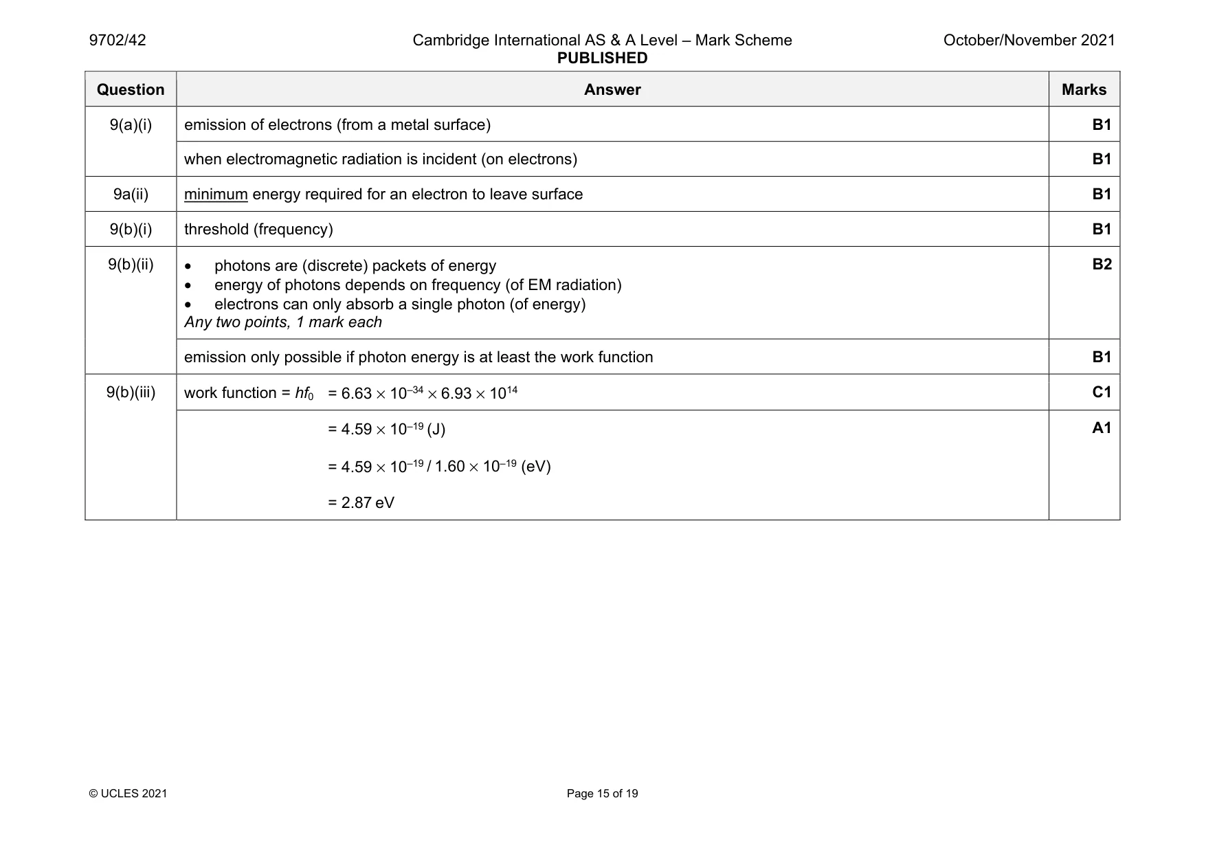
Mark scheme: 9(a)(i) emission of electrons (from a metal surface) B1 when electromagnetic radiation is incident (on electrons) B1 9a(ii) minimum energy required for an electron to leave surface B1 9(b)(i) threshold (frequency) B1 9(b)(ii) • photons are (discrete) packets of energy • energy of photons depends on frequency (of EM radiation) • electrons can only absorb a single photon (of energy) Any two points, 1 mark each B2 emission only possible if photon energy is at least the work function B1 9(b)(iii) work function = hf0 = 6.63 × 10–34 × 6.93 × 1014 C1 = 4.59 × 10⁻¹⁹ (J) = 4.59 × 10⁻¹⁹ / 1.60 × 10⁻¹⁹ (eV) = 2.87 eV A1
Q10 · A simple laminated iron-cored transformer consisting of a primary coil of 25 000 turns…
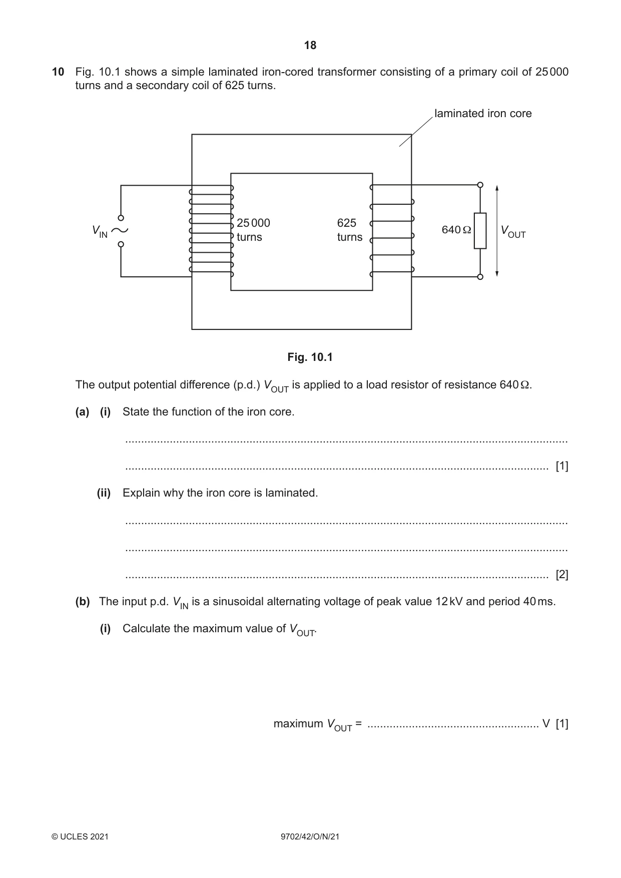
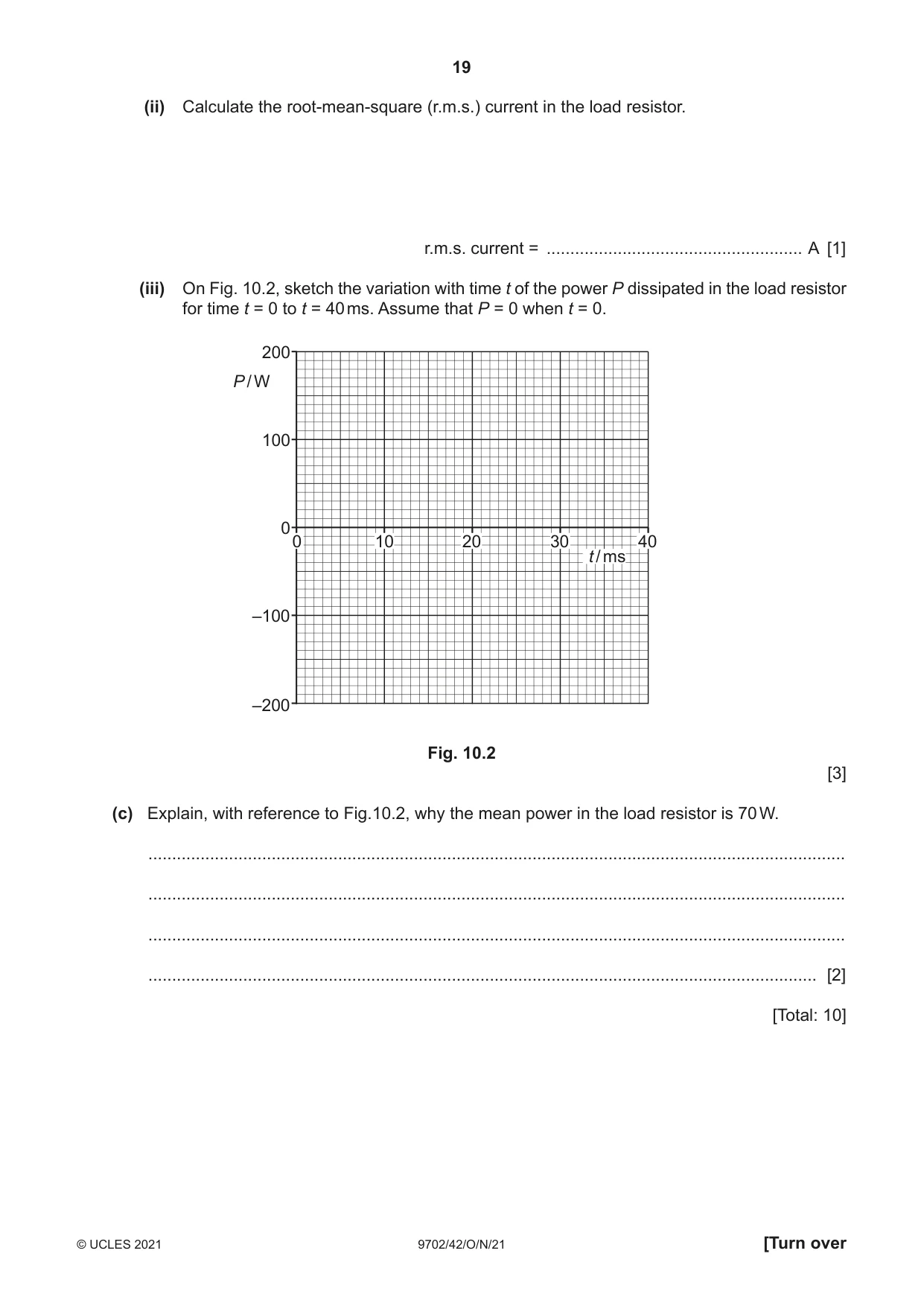
10 Fig. 10.1 shows a simple laminated iron-cored transformer consisting of a primary coil of 25 000 turns and a secondary coil of 625 turns. laminated iron core 25 000 625 VIN 640 Ω VOUT turns turns Fig. 10.1 The output potential difference (p.d.) VOUT is applied to a load resistor of resistance 640 Ω. (a) (i) State the function of the iron core. ........................................................................................................................................... ..................................................................................................................................... [1] (ii) Explain why the iron core is laminated. ........................................................................................................................................... ........................................................................................................................................... ..................................................................................................................................... [2] (b) The input p.d. VIN is a sinusoidal alternating voltage of peak value 12 kV and period 40 ms. (i) Calculate the maximum value of VOUT. maximum VOUT = ...................................................... V [1] (ii) Calculate the root-mean-square (r.m.s.) current in the load resistor. r.m.s. current = ...................................................... A [1] (iii) On Fig. 10.2, sketch the variation with time t of the power P dissipated in the load resistor for time t = 0 to t = 40 ms. Assume that P = 0 when t = 0. 200 P / W 100 0 0 10 20 30 40 t / ms –100 –200 Fig. 10.2 [3] (c) Explain, with reference to Fig.10.2, why the mean power in the load resistor is 70 W. ................................................................................................................................................... ................................................................................................................................................... ................................................................................................................................................... ............................................................................................................................................. [2] [Total: 10]
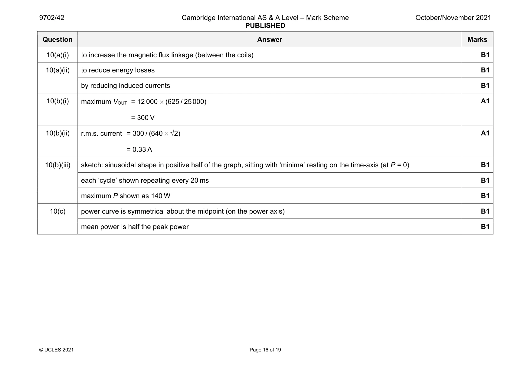
Mark scheme: 10(a)(i) to increase the magnetic flux linkage (between the coils) B1 10(a)(ii) to reduce energy losses B1 by reducing induced currents B1 10(b)(i) maximum VOUT = 12 000 × (625 / 25 000) = 300 V A1 10(b)(ii) r.m.s. current = 300 / (640 × √2) = 0.33 A A1 10(b)(iii) sketch: sinusoidal shape in positive half of the graph, sitting with ‘minima’ resting on the time-axis (at P = 0) B1 each ‘cycle’ shown repeating every 20 ms B1 maximum P shown as 140 W B1 10(c) power curve is symmetrical about the midpoint (on the power axis) B1 mean power is half the peak power B1
Q11 · A piezoelectric transducer containing a quartz crystal is used to obtain diagnostic…
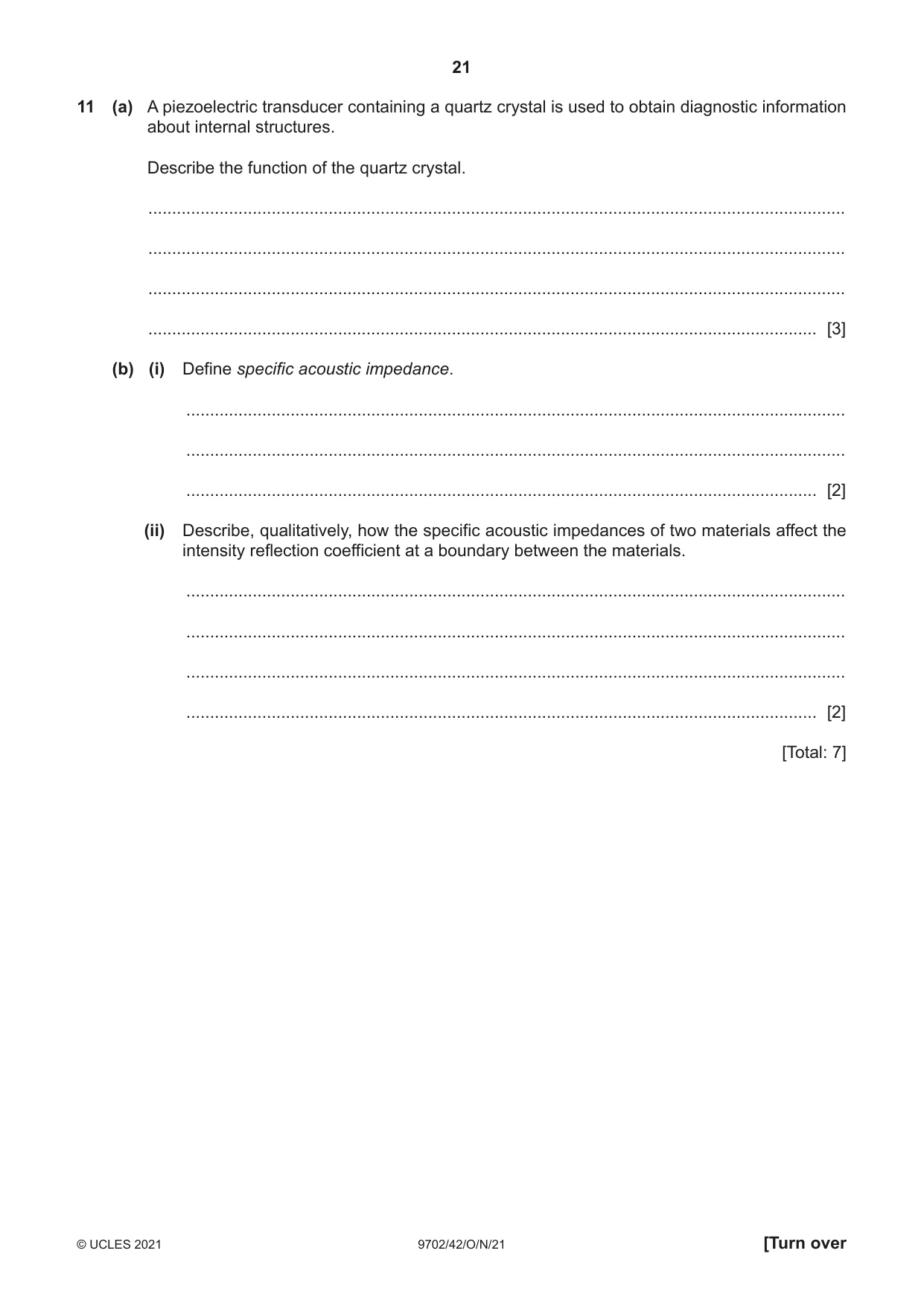
11 (a) A piezoelectric transducer containing a quartz crystal is used to obtain diagnostic information about internal structures. Describe the function of the quartz crystal. ................................................................................................................................................... ................................................................................................................................................... ................................................................................................................................................... ............................................................................................................................................. [3] (b) (i) Define specific acoustic impedance. ........................................................................................................................................... ........................................................................................................................................... ..................................................................................................................................... [2] (ii) Describe, qualitatively, how the specific acoustic impedances of two materials affect the intensity reflection coefficient at a boundary between the materials. ........................................................................................................................................... ........................................................................................................................................... ........................................................................................................................................... ..................................................................................................................................... [2] [Total: 7]
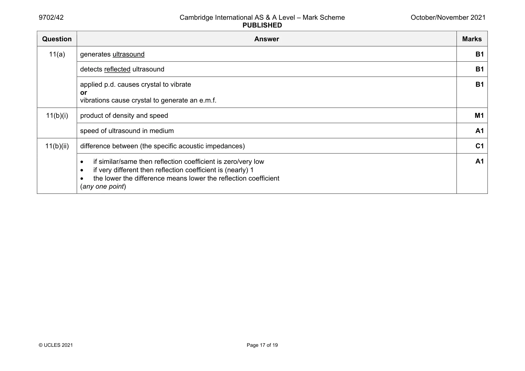
Mark scheme: 11(a) generates ultrasound B1 detects reflected ultrasound B1 applied p.d. causes crystal to vibrate or vibrations cause crystal to generate an e.m.f. B1 11(b)(i) product of density and speed M1 speed of ultrasound in medium A1 11(b)(ii) difference between (the specific acoustic impedances) C1 • if similar/same then reflection coefficient is zero/very low • if very different then reflection coefficient is (nearly) 1 • the lower the difference means lower the reflection coefficient (any one point) A1
Q12 · Radioactive decay is both random and spontaneous
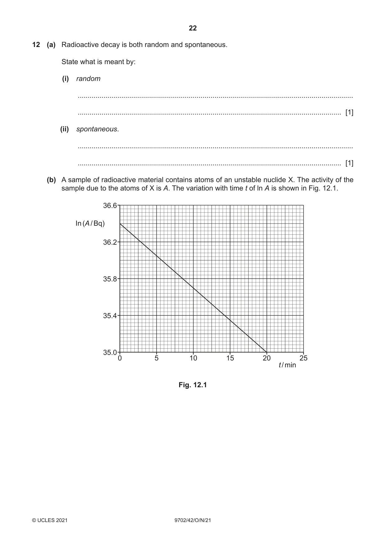
12 (a) Radioactive decay is both random and spontaneous. State what is meant by: (i) random ........................................................................................................................................... ..................................................................................................................................... [1] (ii) spontaneous. ........................................................................................................................................... ..................................................................................................................................... [1] (b) A sample of radioactive material contains atoms of an unstable nuclide X. The activity of the sample due to the atoms of X is A. The variation with time t of ln A is shown in Fig. 12.1. 36.6 In (A / Bq) 36.2 35.8 35.4 35.00 5 10 15 20 25 t / min Fig. 12.1 (i) Use Fig. 12.1 to determine the half-life, in minutes, of nuclide X. half-life = .................................................. min [3] (ii) At time t = 0, the mass of the atoms of X in the sample is 5.66 × 10⁻⁷ kg. Determine the nucleon number of X. nucleon number = ......................................................... [3] [Total: 8]
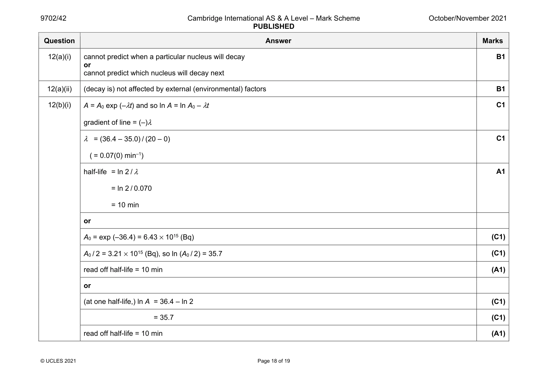
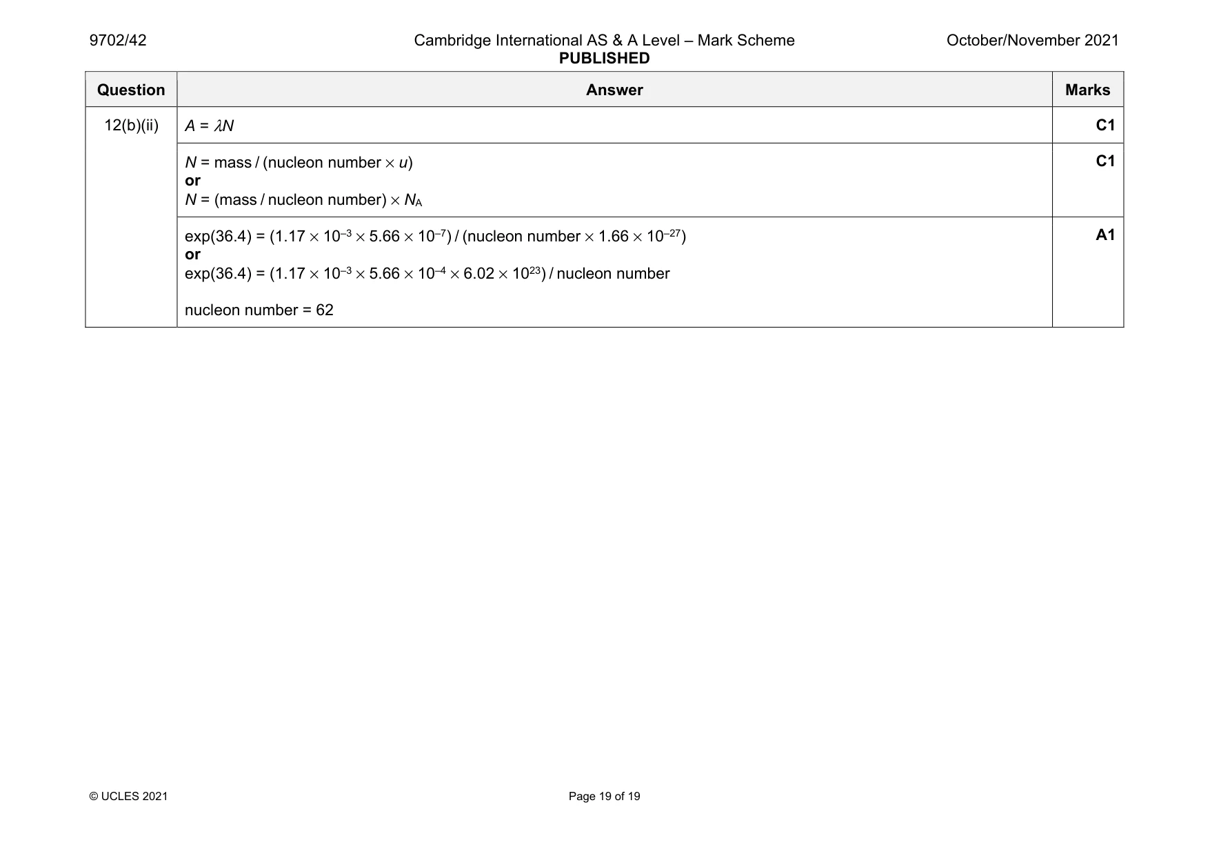
Mark scheme: 12(a)(i) cannot predict when a particular nucleus will decay or cannot predict which nucleus will decay next B1 12(a)(ii) (decay is) not affected by external (environmental) factors B1 12(b)(i) A = A0 exp (–λt) and so ln A = ln A0 – λt gradient of line = (–)λ C1 λ = (36.4 – 35.0) / (20 – 0) ( = 0.07(0) min–1) C1 half-life = ln 2 / λ = ln 2 / 0.070 = 10 min A1 or A0 = exp (–36.4) = 6.43 × 10¹⁵ (Bq) (C1) A0 / 2 = 3.21 × 10¹⁵ (Bq), so ln (A0 / 2) = 35.7 (C1) read off half-life = 10 min (A1) or (at one half-life,) ln A = 36.4 – ln 2 (C1) = 35.7 (C1) read off half-life = 10 min (A1) Question Answer Marks 12(b)(ii) A = λN C1 N = mass / (nucleon number × u) or N = (mass / nucleon number) × NA C1 exp(36.4) = (1.17 × 10–3 × 5.66 × 10–7) / (nucleon number × 1.66 × 10⁻²⁷) or exp(36.4) = (1.17 × 10–3 × 5.66 × 10–4 × 6.02 × 1023) / nucleon number nucleon number = 62 A1
What was in this paper
The subtopics covered by these 12 questions, and how many questions each got. Open one in a new tab to see every Cambridge question on it.
1Electric potential1Electromagnetic induction1Electromagnetic spectrum1Force on a current-carrying conductor1Gravitational potential1Kinetic theory of gases1Photoelectric effect1Practical circuits1Production and use of ultrasound1Radioactive decay1Simple harmonic oscillations1What you needed in this session
Cambridge’s own grade thresholds for 2021 Oct/Nov, Paper 4 · Variant 2. A higher threshold means an easier paper — the bar moves with how the cohort did.